NVIPT_Course_Guide NVIPT Course Guide
User Manual: NVIPT_Course_Guide
Open the PDF directly: View PDF ![]() .
.
Page Count: 528 [warning: Documents this large are best viewed by clicking the View PDF Link!]

NetVanta IP Telephony
Certification course - ATSP/IP Telephony
Course Guide
Revision 7/2009

Trademarks
Any brand names and product names included in this manual are trademarks, registered
trademarks, or trade names of their respective holders.
To the Holder of the Manual
The contents of this manual are current as of the date of publication. ADTRAN reserves the
right to change the contents without prior notice.
In no event will ADTRAN be liable for any special, incidental, or consequential damages or for
commercial losses even if ADTRAN has been advised thereof as a result of issue of this
publication.
901 Explorer Boulevard
P.O. Box 140000
Huntsville, AL 35814-4000
Phone: (256) 963-8000
©2009 ADTRAN, Inc.
All Rights Reserved.
Printed in U.S.A.
Customer Service, Product Support Information, and Training
ADTRAN will replace or repair this product within five years from the date of shipment if the
product does not meet its published specification, or if it fails while in service.
A return material authorization (RMA) is required prior to returning equipment to ADTRAN. For
service, RMA requests, training, or more information, see the toll-free contact numbers given
below.
Presales Inquiries and Applications Support
Please contact your local distributor, ADTRAN Applications Engineering, or ADTRAN Sales:
Applications Engineering (800) 615-1176
Sales (800) 827-0807
Post-Sale Support
Please contact your local distributor first. If your local distributor cannot help, please contact
ADTRAN Technical Support and have the unit serial number available.
Technical Support (888) 4ADTRAN
The Custom Extended Services (ACES) program offers multiple types and levels of service
plans which allow you to choose the kind of assistance you need. For questions, call the ACES
Help Desk.
ACES Help Desk (888) 874-2237
Training
The Enterprise Network (EN) Technical Training offers training on our most popular products.
These courses include overviews on product features and functions while covering
applications of ADTRAN's product lines. ADTRAN provides a variety of training options,
including customized training and courses taught at our facilities or at your site. For more
information about training, please contact your Territory Manager or the Enterprise Training
Coordinator.
Training Phone (800) 615-1176, ext. 7500
Training Fax (256) 963-6700
Training Email training@adtran.com
Web Site www.adtran.com/training


NetVanta IP Telephony Course Guide
Certification Course – ATSP/IP Telephony
July 2009
Revision date 7/6/09

Table of Contents

Table of Contents
NetVanta IP Telephony Course

Table of Contents
NetVanta IP Telephony Course
NetVanta IP Telephony Course Guide
Module 1: IP Telephony Solutions Overview ................................................................ 1-1
- ADTRAN Introduction
- NetVanta Series Overview
- ADTRAN’s IP Telephony Solutions
o IP Communications Platforms
o IP PBX Solutions
o IP Business Gateways
o IP Telephone Options
- NetVanta 7000 Interfaces
- ADTRAN’s IP Telephony Features
- Key NetVanta IP Telephony Applications
Module 2: Introduction to NetVanta 7000 Series Data Configuration ............................ 2-1
- Introduction to the ADTRAN Operating System (AOS)
- Introduction to NetVanta 7000 Series Web-Based GUI
- Understanding System Factory Defaults
- Understanding Switch Factory Defaults
- Understanding Router Factory Defaults
- Understanding Firewall Factory Defaults
Module 3: Introduction to NetVanta 7000 Series Voice Configuration .......................... 3-1
- Introduction to the NetVanta 7000 Series Switchboard
- Voice Settings – Dial Plan
- Voice Settings – Classes of Service
- Voice Stations – User Accounts
- Voice Stations – Ring Group
- Voice Stations – Operator Group
- Voice Trunks - Introduction
- Voice Trunks – Analog Voice Trunk Configuration
- Introduction to Voice Troubleshooting
Module 4: ADTRAN Phone Configuration Files ............................................................ 4-1
- ADTRAN/Polycom IP Phones Introduction
- ADTRAN/Polycom phone configuration files
- Modification of phone configuration files
- Troubleshooting the boot process of the ADTRAN IP 700 Series phone
Module 5: NetVanta 7000 Series Key System Application ........................................... 5-1
- NetVanta 7000 Series Key System Application Introduction
- Voice Trunk Review
- Shared Line Accounts Configuration
- Enabling Hands Free Auto-Answer
- Understanding and Configuring System Modes
- Troubleshooting the NetVanta 7000 Series Key System Application
Module 6: NetVanta 7000 Series IP PBX Application ................................................... 6-1
- NetVanta 7000 Series IP PBX Application Introduction

Table of Contents
NetVanta IP Telephony Course
- Voice Trunk Configuration (T1-RBS and ISDN PRI)
- Creating and Configuring a Multi-level Auto Attendant
- Creating and Configuring Dial by Name DIrectories
- Busy Lamp Field and Public Park Zone Configuration
- Call Logging (Station Message Detail Recording-SMDR)
- Voice Troubleshooting in a NetVanta 7000 Series IP PBX Application
Module 7: NetVanta 7000 Data Configuration Part 2 .................................................... 7-1
- Switch/Router Concepts
- Creating Additional VLAN Interfaces
- Configuring Firewall Policies
- Setting up a DMZ Network
- Quality of Service Concepts
- QoS Map Configuration
- Basic Firewall and QoS Troubleshooting
Module 8: NetVanta 7000 Remote Telephony Applications .......................................... 8-1
- Introduction of NetVanta 7000 Remote Telephony Applications
- Service Provider SIP Trunk Configuration
- SIP Networking Between Sites
- Remote User Configuration Preview
- VoIP Quality Monitoring (VQM) Introduction
- Troubleshooting Voice in a NetVanta 7000 Series Remote Telephony Application
Module 9: NetVanta 7000 Series Miscellaneous Tools and Utilities ............................. 9-1
- Introduction of the following Tools:
o Top Talkers
o Top Visited Web Sites
o Wireless Controller
o n-Command
- System Utilities
o Port Mirroring
o Firmware Upgrades
o Configuration Backup
NetVanta IP Telephony Lab Exercises (Lab Guide)
NetVanta 7100 Exercise - Out of the Box .................................................................... L1-1
NetVanta 7100 Exercise - Basic Installation and Call Handling ................................... L2-1
NetVanta 7100 Exercise - Small Office Key System ................................................... L3-1
NetVanta 7100 Exercise - IP PBX - Multiple Trunk Installation ................................... L4-1
NetVanta 7100 Exercise - Auto Attendant Call Flow ................................................... L5-1
NetVanta 7100 Exercise – Carrier SIP Trunk ............................................................. L6-1

Module 1: ADTRAN IP Telephony
Solutions Overview

Module 1: ADTRAN IP Telephony Solutions Overview
1-2 NetVanta IP Telephony Course

Module 1: ADTRAN IP Telephony Solutions Overview
NetVanta IP Telephony Course 1-3
Module Objectives
Module Objectives
•ADTRAN Introduction
•NetVanta Series Overview
•Introduce ADTRAN’s IP Telephony Solutions
–IP Communications Platforms
–IP PBX Solutions
–IP Business Gateways
–IP Telephone Options
•Outline the NetVanta 7100 Interfaces
•Discuss ADTRAN’s IP Telephony Features
•Cover Key NetVanta IP Telephony Applications

Module 1: ADTRAN IP Telephony Solutions Overview
1-4 NetVanta IP Telephony Course
Module 1: ADTRAN IP Telephony Solutions Overview
NetVanta IP Telephony Course 1-5
ADTRAN, Inc.
ADTRAN, Inc.
•Global provider of networking and communications
equipment
•Widely deployed by carriers, distributed enterprises,
and Small-and-Medium-sized businesses (SMBs)
•Headquartered in Huntsville, Alabama
•Product Distribution
–Value Added Resellers
–Distributors
ADTRAN, Inc. is a leading global supplier of networking and communications equipment
with an innovative portfolio of more than 1,700 solutions for use in the last mile of today’s
telecommunications networks. Widely deployed by carriers, distributed enterprises and
Small- to Medium-sized Businesses (SMB), ADTRAN solutions enable voice, data, video,
and Internet communications across copper, fiber and wireless network infrastructures. Our
solutions are currently in use by every major U.S. service provider and many global ones,
as well as by thousands of public, private and governmental organizations worldwide.

Module 1: ADTRAN IP Telephony Solutions Overview
1-6 NetVanta IP Telephony Course
ADTRAN Support
ADTRAN Support
•Free First-Class Telephone Support
–Presales
•Applications Engineering (800) 615-1176
–Post-sales
•Technical Support (888) 4ADTRAN
•Industry Leading 5 or 10 year Warranty
•No Cost Software Updates
•ACES Installation and
Maintenance Services
–Guaranteed response time
–Onsite or phone installation
–Guaranteed replacement plans
Every product is backed by an industry-leading five-year warranty, best-in-class telephone
technical support from our team of degreed engineers, and is eligible for free firmware
upgrades.
The ADTRAN product warranty includes a return-to-factory repair and replacement
program and free technical phone support. Technical support engineers are accessible for
both pre- and post-sales support. ADTRAN Custom Extended Services (ACES) is also
available for an extended guarantee and rapid response time. Priority access to technical
and installation support is guaranteed with a 30-minute call back and on-site product
replacement in as few as four hours, depending on the service plan selected.

Module 1: ADTRAN IP Telephony Solutions Overview
NetVanta IP Telephony Course 1-7
NetVanta Series
NetVanta Series
•ADTRAN IP Telephony Solutions built on successful
router/switch platform
–Industry-leading LAN/WAN infrastructure
–Feature-rich Router and PoE Switch
–Full suite of QoS for delay sensitive VOIP traffic
–Built-in security
–Excellent Service/Support
Module 1: ADTRAN IP Telephony Solutions Overview
1-8 NetVanta IP Telephony Course
NetVanta Series Overview
IP Router
•56/64K, T1, Multi-T1, T3
•RIP V1/V2, OSPF,BGP
•PPP, PPPoE, Frame
Relay, HDLC
•MLPPP/MLFR
•DHCP Client/Server
•Class-based Weighted
Fair Queuing, Low
Latency Queuing
•Diffserv aware/mark
VPN, Firewall
•Stateful Inspection
Firewall
•NAT (1:1), NAPT
(Many:1)
•DoS Protection
•Access Control Lists
•IPSec
•DES/3DES/AES
Encryption
Ethernet Switch
•Fast Ethernet and
Gigabit Switches
•Managed
•Auto-Rate, Auto
Duplex
•Auto-MDI/MDI-X
•802.1D Spanning Tree
•VLAN
•802.1p CoS
•802.3af Power over
Ethernet
•15.4 watts for each of
the 24 ports
NetVanta Series Overview

Module 1: ADTRAN IP Telephony Solutions Overview
NetVanta IP Telephony Course 1-9
ADTRAN IP Telephony Solutions
ADTRAN IP Telephony Solutions
•IP Communications Platform
–NetVanta 7100
•IP PBX
–NetVanta 7060
•IP Business Gateways
–NetVanta 6355
–Total Access 900 Series
•IP Phones
–ADTRAN 700 Series
–ADTRAN/Polycom IP Phones
IP Communication Platform
The NetVanta 7100 represents a break through in next-generation communication systems.
This unique Office in a Box contains everything businesses need to deploy a converged IP
voice and data network for small- to medium-sized offices with up to 100 stations,
including a full-function IP PBX for voice. It includes an integrated24-port Power over
Ethernet (PoE) switch-router for data, a stateful inspection firewall for security, Virtual
Private Network (VPN) for secure Internet tunneling, and a DSU/CSU for network
termination. The only other requirements for deploying your VoIP network are
connections from the service provider and cables to the desktop.
IP PBX
The NetVanta 7060 simplifies the implementation of VoIP for businesses that already have
an IP data network established. The NetVanta 7060 complements the existing network,
quickly enabling VoIP by providing IP PBX functionality which includes SIP-based
telephony features, voice mail (3000 messages, eight ports), multilevel auto attendant,
caller ID name/number and all the other features a business needs for a complete VoIP
network.

Module 1: ADTRAN IP Telephony Solutions Overview
1-10 NetVanta IP Telephony Course
IP Business Gateways
ADTRAN IP Business Gateways are purpose built devices that include a variety of
advanced routing, security, and voice functionality for Hosted IP applications.
Ideally suited for SMB and distributed enterprise networks, this category of products
includes the Total Access 900 and 900e Series of dual and multi-T1 platforms that include
analog and SIP gateway, robust IP router, firewall and VPN functionality.
The NetVanta 6355 platform provides a unique, all-in-one solution for Hosted VoIP. This
product combines all of the IP voice functionality, SIP gateway, router, firewall/VPN
features of the Total Access 900/900e Series with a managed 24-port PoE switch into a
single 1U chassis.
ADTRAN IP Phones
ADTRAN offers SIP phones designed to address the growing converged VoIP and IP
telephony marketplace. The new ADTRANIP 700 Series of phones includes the IP 706, a
six-line version and the IP 712, a 12-line version and both phones are designed with a large
backlit display. ADTRAN IP phones offer an affordable, feature-rich VoIP solution that
delivers unsurpassed quality and performance.
ADTRAN-Polycom IP Phones
Working together, ADTRAN and Polycom have partnered to deliver a full line of IP
telephones. The phones integrate seamlessly with ADTRAN’s NetVanta and Total
Access® 900 Series VoIP products. The ADTRAN-enabled IP stations include the IP 430
(two-line), IP 650 (six-lines) and IP 650 Expansion Module. The combination of
ADTRAN’s award-winning VoIP equipment with a broad line of ADTRAN-Polycom IP
phones and accessories offers a cost-effective, simplified VoIP internetworking solution.

Module 1: ADTRAN IP Telephony Solutions Overview
NetVanta IP Telephony Course 1-11
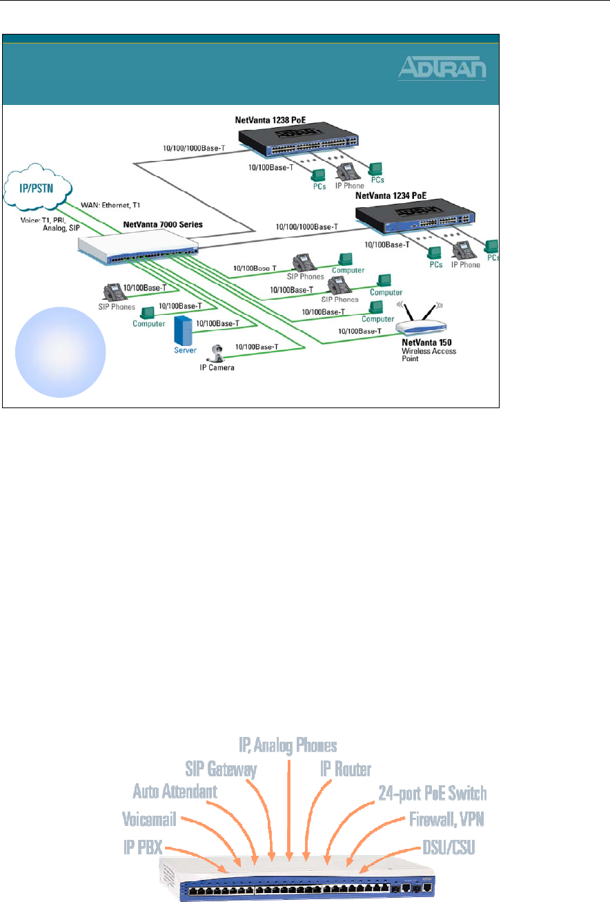
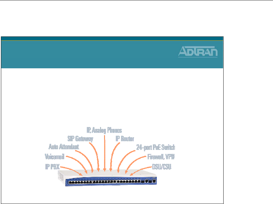
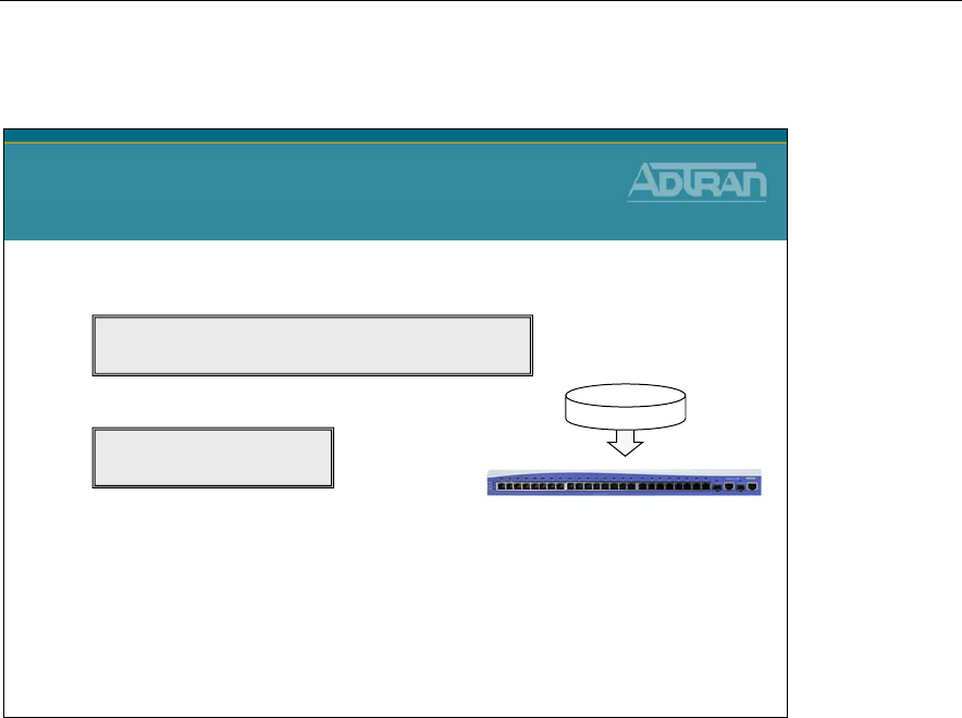
IP Communication Platform – NetVanta 7100
DSU/CSU
VPN/Firewall
24 Port
Ethernet Switch
IP Router
PBX Controller
SIP Gateway
Voicemail
NetVanta 7100
IP Communication Platform
NetVanta 7100
Traditional
Multi-box Approach
Multiple Functions in a Single Box
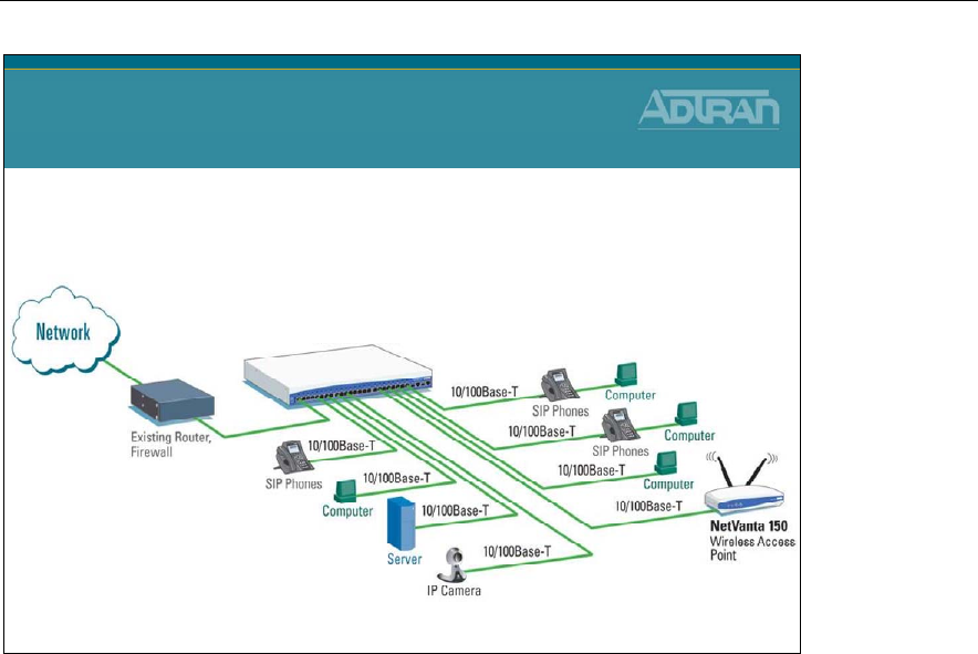
The NetVanta 7000 Series offers all the business-class functionality a Small-to-Medium
sized Business (SMB) requires, at an affordable price. The all-in-one platform consolidates
multiple functions in a single, easy-to-manage platform. Both the NetVanta 7100 and 7060
include multiple levels of auto-attendant function and a system scheduler. This allows the
customization of auto-attendant functions based on the time or day settings programmed.
The NetVanta 7000 Series also works in key system mode and PBX mode for increased
flexibility and ease of use.
Module 1: ADTRAN IP Telephony Solutions Overview
1-12 NetVanta IP Telephony Course
IP Communication Platform
NetVanta 7100
Up to 100
SIP Users
Office-in-a-Box
The NetVanta 7100 is a complete voice and data networking solution for business
locations of up to 100 SIP Users. This innovative platform includes an IP PBX, voice mail,
multilevel auto attendant, full-featured IP router, firewall, Virtual Private Network (VPN),
24-port Power over Ethernet (PoE) (802.3af) Fast Ethernet switch with Gigabit uplinks,
and two expansion slots for Network Interface Modules (NIMs) and Voice Interface
Modules (VIMs). The NetVanta 7100 IP PBX functionality includes SIP-based telephony
features such as voice mail (12 hours, eight ports), multilevel auto attendant (eight ports),
caller ID name/number, Shared Line Appearances (SLA), Busy Lamp Field (BLF), Class
of Service (CoS), trunk groups, music on hold, overhead paging and a number of call
options including call coverage lists, forwarding of calls to a cell phone and email
notification of voice mail.
Module 1: ADTRAN IP Telephony Solutions Overview
NetVanta IP Telephony Course 1-13
IP PBX – NetVanta 7060
DSU/CSU
Limited
IP Router
Capabilities
PBX Controller
SIP Gateway
Voicemail
24 Port
Ethernet Switch
IP PBX
NetVanta 7060
NetVanta 7060
Traditional
Multi-box Approach
NetVanta 7060
The NetVanta 7060 is an IP telephony solution ideal for business locations that already
have an IP data network established with routing and VPN functionality. The NetVanta
7060 is an unbundled solution providing IP PBX functionality which includes SIP-based
telephony features, voice mail (3000 messages, eight ports), multilevel auto attendant,
caller ID name/number, COS, trunk groups, music on hold, overhead paging, and a number
of call options including call coverage lists, forwarding of calls to a cell phone, and email
notification of voice mail.
Module 1: ADTRAN IP Telephony Solutions Overview
1-14 NetVanta IP Telephony Course
NetVanta 7060
IP PBX
NetVanta 7060
•Interoperates with external data equipment
ADTRAN’s new NetVanta® 7060 IP PBX is designed to work in a multi-vendor
environment so businesses that already have modern robust data networking equipment
can add the NetVanta 7060 as their phone system. The NetVanta 7060 includes the phone
system capabilities businesses need and can interoperate with external routers, firewall and
Virtual Private Networking (VPN) devices.
• Uses existing IP data equipment
• Provides PBX phone system, including voice mail and auto attendant
• Provides integrated 24 port Power over Ethernet (PoE) switch
Module 1: ADTRAN IP Telephony Solutions Overview
NetVanta IP Telephony Course 1-15
IP Business Gateway – Total Access 900 Series
TA 900 Series
DSU/CSU
VPN/Firewall
IP Router
SIP Gateway
IP Business Gateway
Total Access 900 Series
Traditional
Multi-box Approach
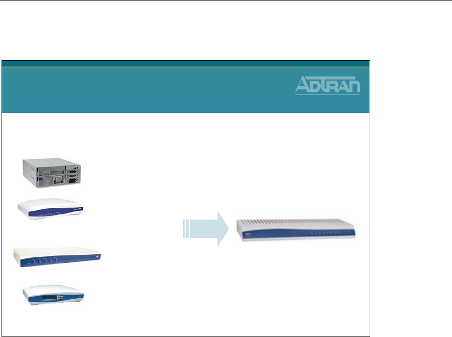
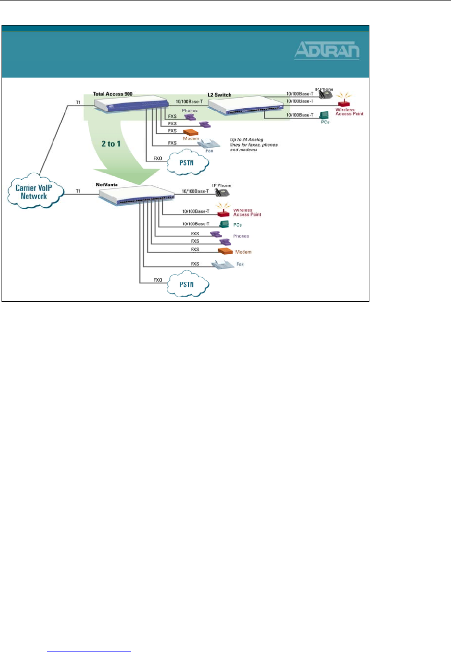
The Total Access 900 Series of IP Business Gateways combine the functionality of
ADTRAN's industry-leading integrated access devices with a SIP and analog gateway to
provide Incumbent Local Exchange Carriers (ILECs), Competitive Local Exchange
Carriers (CLECs), and Internet Service Providers (ISPs) a cost-effective IP network
strategy for VoIP deployment, with support for legacy equipment. The Total Access 900
and 900e Series allow carriers to deliver SIP trunks, hosted PBX, and other voice and data
services such as Dedicated Internet Access (DIA) to small and medium businesses, quickly
and cost-effectively.
Module 1: ADTRAN IP Telephony Solutions Overview
1-16 NetVanta IP Telephony Course
IP Business Gateway
Total Access 900 Series
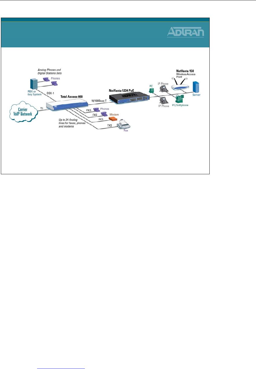
Total Access 900 Series Features and Benefits
• Carrier-class, cost-effective multi-T1/dual Ethernet IP Business Gateway for
integrated services such as VoIP
• Supports up to 24 analog interfaces for legacy equipment
• Integral DSX-1 PRI/CAS for PBX connectivity
• Transparent proxy with survivability for network outages
• Voice Quality Monitoring (VQM) for enhanced Quality of Service (QoS)
• Compatible with industry leading softswitches and call agents
• Integral full-featured IP router for data support and Internet access
• Stateful inspection firewall for network security
• Quality of Service (QoS) for delay sensitive traffic like VoIP
• Command Line Interface (CLI) mimics industry de facto standard
• Feature-rich ADTRAN Operating System (AOS)
• Industry-leading 10-year North American warranty
• Four T1 WAN interfaces/two Ethernet interfaces/24 FXS analog interfaces
• Visit www.adtran.com for Alternate Configurations with part numbers for chassis
with some number of FXS and some number of FXO interfaces for mixed mode
analog environments
Module 1: ADTRAN IP Telephony Solutions Overview
NetVanta IP Telephony Course 1-17
IP Business Gateway – NetVanta 6355
DSU/CSU
VPN/Firewall
24 Port
Ethernet Switch
IP Router
SIP Gateway
IP Business Gateway
NetVanta 6355
NetVanta 6355
Traditional
Multi-box Approach
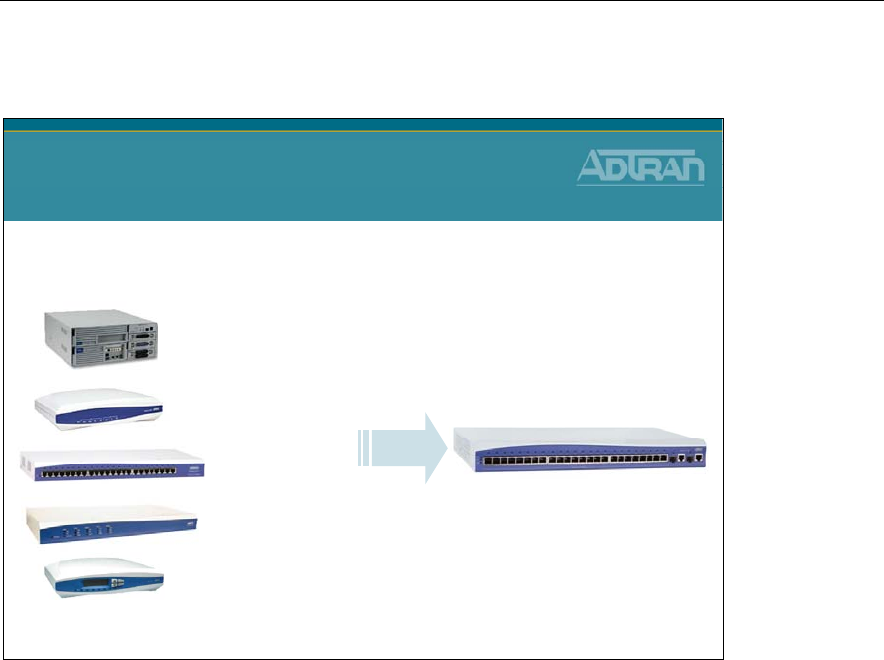
The NetVanta 6355 IP Business Gateway is a unique, all-in-one solution for Hosted VoIP
PBX services, Internet access, and business connectivity. This powerful platform combines
the voice functionality of ADTRAN’s industry leading Total Access 900e Multiservice
Access Device and the widely deployed NetVanta Power over Ethernet (PoE) Switch-
Router into a compact 1U chassis. This all-in-one product includes a robust SIP-Gateway,
a full-featured IP router, stateful inspection firewall, VPN, 24-port powered (802.3af ) Fast
Ethernet switch with Gigabit uplinks, and two expansion slots for Network and Voice
Interface Modules (NIM/VIMs).
Module 1: ADTRAN IP Telephony Solutions Overview
1-18 NetVanta IP Telephony Course
6355
IP Business Gateway
NetVanta 6355
• Further Integration
NetVanta 6355 Features and Benefits
• All-in-one Hosted IP voice and data solution
• Integral SIP gateway, router, PoE switch, and security
• Full-featured IP router supporting up to three T1s for data and Internet access
• Managed, 24-port PoE (802.3af) switch
• Stateful inspection firewall for network security
• IPSec VPN for secure corporate connectivity across the Internet
• Compatible with industry-leading softswitches and call agents
• Up to 10 analog POTS interfaces with remote survivability
• Supports IP amd analog phones/phone systems; fax machines, modems, and
Wireless Access Points (WAPs)
• Dynamic bandwidth allocation enables more efficient utilization
• Standardized G.729a voice compression requires less bandwidth per voice call
• Industry-leading warranty
Visit www.adtran.com for additional information on the NetVanta 6355.
Module 1: ADTRAN IP Telephony Solutions Overview
NetVanta IP Telephony Course 1-19
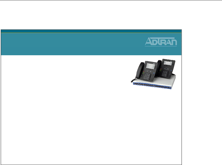
ADTRAN IP 700 Series Phones
ADTRAN IP 700 Series Phones
•ADTRAN IP Phones:
–IP 706: 6 lines
–IP 712: 12 lines
•Supports multiple SIP registrations
•Busy Lamp Field and Shared Line Appearance Support
•High Quality Full Duplex Speaker Phone
•Dual 10/100 Switched Ethernet Ports
•Large Backlit Display
•802.3af Power over Ethernet
•Adjustable base stand
•Wall mountable
•Headset jack with Electronic Hook Switch Detection
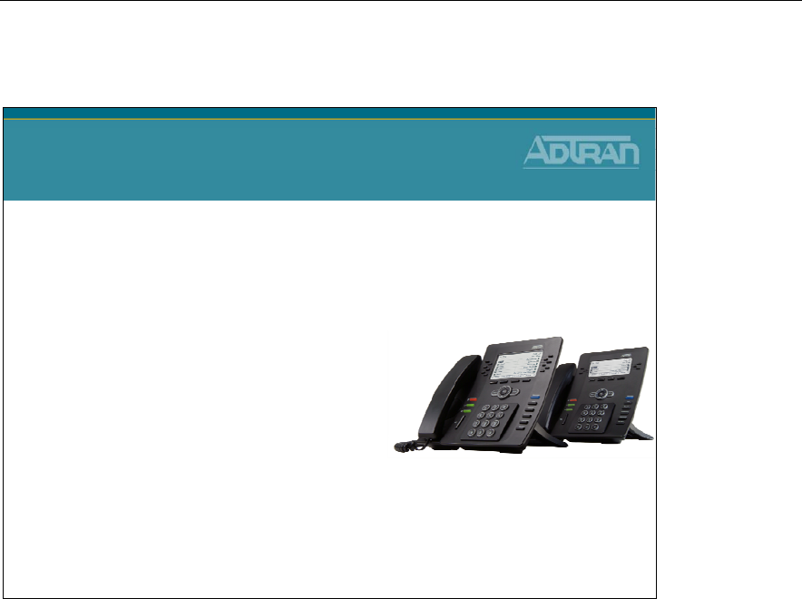
ADTRAN® offers SIP-enabled phones designed to address the growing converged Voice
over IP (VoIP) and IP telephony marketplace for small businesses and multi-site
enterprises. The ADTRAN IP 706, a six-button programmable phone and the IP 712, a 12-
button expanded version offer an affordable and standards-based solution that delivers
unsurpassed quality and performance.
Ease of Use, Style and Productivity
The ADTRAN IP 700 Series of telephones delivers an attractive and functional business-
class telephone for today’s businesses, all at affordable and cost-effective prices. In
addition to the appealing desktop style for business offices of any type, users will
appreciate the large, backlit, easy-to-read LCD screens and well-designed layout of
frequently used buttons and functions. On screen menus and navigation keys work together
in an intuitive, user-friendly manner. ADTRAN’s IP phones are designed to provide
enhanced efficiency and convenience for the user.
Enhanced Functionality
ADTRAN IP phones are available in either six- or 12-line versions, supporting multiple
call functions. Dedicated keys are available for the most common user functions with
additional programmable soft keys. On-screen menus enable users to quickly change
directory information and phone settings, as well as view a history of internal/external and
missed calls, and program distinctive ring tones for specific calls. The phones include an
adjustable desk stand or can be wall mounted and feature high-quality, full-duplex

Module 1: ADTRAN IP Telephony Solutions Overview
1-20 NetVanta IP Telephony Course
speakers engineered for clear, hands-free communication. An integrated headset jack with
electronic hook-switch eliminates the need for mechanical handset lifter. The overall
enhanced functionality for the price makes ADTRAN IP phones among the most cost-
efficient business-class IP phones.
Quick, Easy Set-up
The ADTRAN 700 Series features an intuitive, Graphical User Interface (GUI) for easy
set-up and installation. The phones can be directly powered from the NetVanta 7000 Series
or a Power over Ethernet (PoE) switch, providing inline power and eliminating the need
for a separate power supply. ADTRAN phones can be locally powered, allowing for
multiple options for worry-free installation and ease of use. The phones also have two
Ethernet ports to connect to a PC for converged voice and data across a single wiring
infrastructure.
IP 700 Series Product Features
• Fully interoperable with NetVanta 7000 Series
• Six or 12 programmable buttons
• Large backlit display
• Message waiting indicator
• Integrated headset jack
• Web-based management
• Distinctive ring tones
• Multiple call appearances
• Three-way conferencing
• Busy Lamp Field (BLF)
• Shared Line Appearance (SLA)
• Hands-free auto-answer intercom
• High-quality full-duplex speaker phone
Module 1: ADTRAN IP Telephony Solutions Overview
NetVanta IP Telephony Course 1-21
Interoperability with Polycom IP Phones
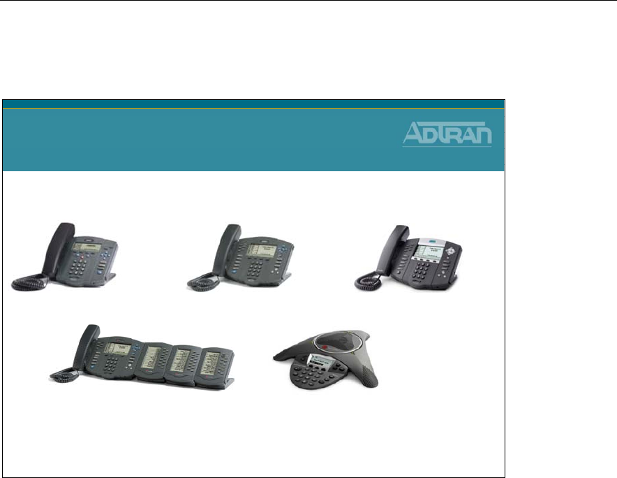
IP 430 – 2 line IP 601 – 6 line IP 650 – HD
IP 6000
Conference Phone
Expansion Modules
Attendant Console
Interoperability with
Polycom IP Phones
Others: IP 301
IP 320/330
IP 501
IP 550
and more…
To complement the new ADTRAN 700 Series of IP phones, Polycom IP phones offer
additional VoIP solutions for an extended range of business applications.
Some of the Supported Polycom Phones Include:
• IP 601 Three-line IP Phone
• IP 650 Six-line High Definition IP Phone
• IP Expansion Module Attendant Console
• IP 6000 Conference Phone
Module 1: ADTRAN IP Telephony Solutions Overview
1-22 NetVanta IP Telephony Course
ADTRAN/Phone Features
ADTRAN/Phone Features
•Call Drop
•Call Forward (All, Busy, No Answer)
•Call Forward to Outside Line (Cell Phone)
•Call Hold
•Caller ID Name/Number
•Call Logs
•Call Park
•Call Park Retrieve
•Call Transfer
•Call Waiting
•Conferencing (3-person)
•Do Not Disturb
•Handsfree Auto Answer Intercom
•Headset Jack
•Message Waiting Light
•Missed Call Indicator
•Multiple Call Appearances
•Music on Hold
•Mute
•Overhead Paging
•Redial
•Speakerphone
•Volume Control
Module 1: ADTRAN IP Telephony Solutions Overview
NetVanta IP Telephony Course 1-23
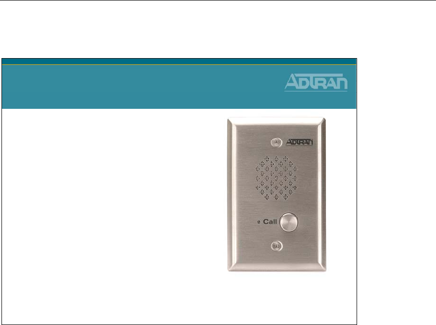
ADTRAN Analog Door Phone
ADTRAN Analog Door Phone
•Single-gang Wall box
•Analog Speakerphone
•Line powered
•Weather-resistant
•Stainless steel finish
•System supports multiple
door phones
•1 Year Warranty
The ADTRAN® ADP-40 is an analog speakerphone primarily used for entry applications
such as door or gate communication, business delivery entrances, and residential,
commercial, or industrial door security. The ADP-40 complements the NetVanta 7000 line
by providing a rugged communication endpoint to any entry way. Once a person’s identity
is announced through the door phone, a phone user enters a special code which allows the
door to open.
The ADP-40 offers a weather-resistant design that is easy to install in new or existing
construction. It fits flush in any single gang electrical box and receives power directly from
the telephone line. With weather and vandal resistant features that include an 18-guage
stainless steel faceplate, Mylar speaker, hex drive mounting screws, a stainless steel
speaker screen, and gaskets for the faceplate, microphone, and speaker, the ADP-40 can be
installed inside or outside.
This full featured entry phone supports auto answer to enable remote communications of
the area immediately around the speakerphone, intelligent call progress detection for
automatic hang-up when a call is completed, and microphone and speaker volume controls.
The ADP-40 conveniently connects directly to one of the analog station (FXS) ports on the
NetVanta 7100. The user account for the station port can be configured as a hotline phone
to allow the ADP-40 to call a specific extension or a ring group when the Call button is
pressed. Once off hook, a phone user dials a code that controls the relay latch to open the
door.
Module 1: ADTRAN IP Telephony Solutions Overview
1-24 NetVanta IP Telephony Course
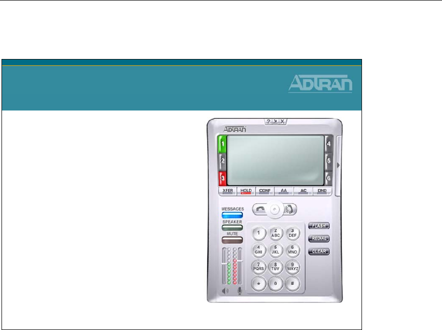
ADTRAN IP Softphone
ADTRAN IP Softphone
•PC SoftPhone
•SIP-based
•Requires headset / microphone
•Familiar functions
–VoiceMail Indicator
–Transfer, Conf, Hold, etc.
The ADTRAN IP SoftPhone is an intuitive software application designed to enable Voice
over Internet Protocol (VoIP) communication from your laptop or desktop PC and works
seamlessly with ADTRAN’s IP telephony product lines.
The IP SoftPhone is easy to use and offers a built-in audio tuning wizard that helps
simplify setup. Any audio devices available to the host PC such as USB headsets or PC
speakers can be used with the SoftPhone. The “Speaker” button offers single-button
selection to switch between headset or speaker phone devices.
The IP SoftPhone offers six call appearances with conferencing capability and other
familiar features like transfer, hold, do-not disturb, and a message waiting indicator. These
features offer mobile employees many of the same convenient capabilities they enjoy when
in the office.
The ADTRAN IP SoftPhone improves productivity by enabling users to have quick access
to their address book and call logs to identify recently received calls, missed calls, and
dialed calls. The ADTRAN IP SoftPhone can be configured using the same extension as
the user’s office phone or as a completely separate extension.
By using Virtual Private Networks (VPNs), remote and mobile workers can use the
ADTRAN IP SoftPhone with any Internet connection and be confident that the voice and
data traffic is secure and private. VPNs provide encryption and ensure the security of the
data and voice traffic between the corporate network and a remote office Internet
connection or wireless hotspot or hotel broadband connection.
Module 1: ADTRAN IP Telephony Solutions Overview
NetVanta IP Telephony Course 1-25
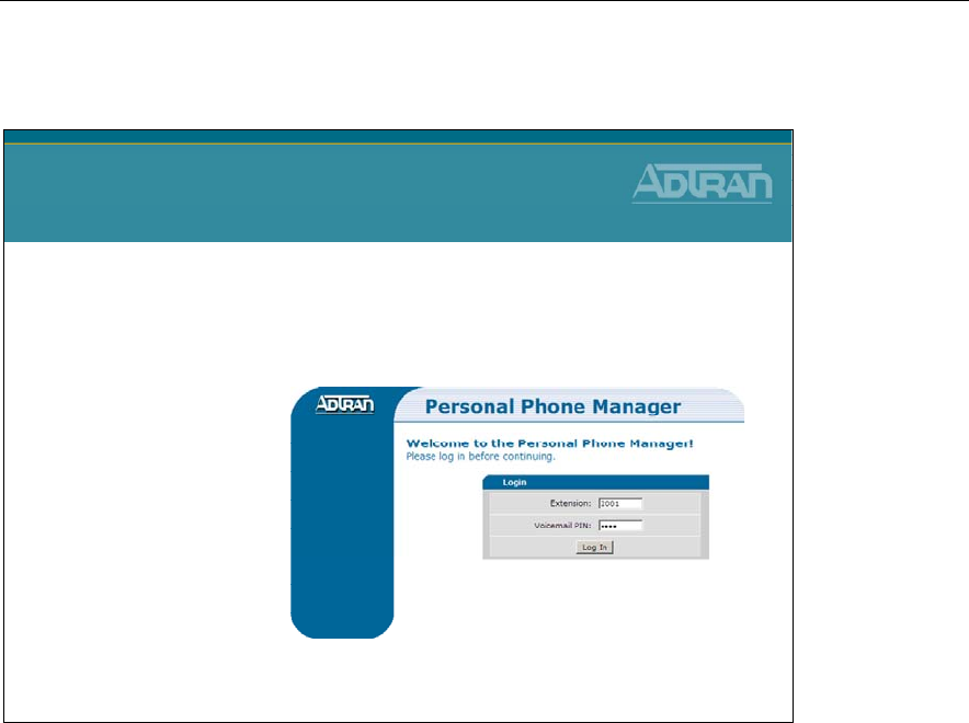
PC-based Phone Manager
PC-based Phone Manager
•Web-based utility
•User can customize phone settings
–System Directory
–Speed Dial
–Click to dial
–Call Coverage
–Call Forwarding
The Personal Phone Manager is an easy-to-use Web-based utility browser provided by
NetVanta 7000 Series platforms that is designed so each user can customize phone
settings. These settings include speed dial, call coverage, and view directory and include
the click-to-dial feature for quick-and-easy phone number dialing.

Module 1: ADTRAN IP Telephony Solutions Overview
1-26 NetVanta IP Telephony Course
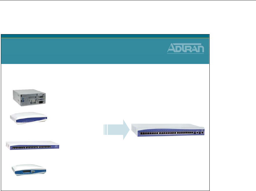
IP Telephony Product Portfolio - Summary
IP Telephony Product Portfolio
Summary
IP Phones
IP Communications
Platforms IP PBX IP Business
Gateways
NetVanta 7100
IP PBX + Router + VPN
Integrated 24 Port POE Switch
IP 706, 712
NetVanta 7060
IP PBX + Limited Routing/no VPN
Integrated 24 Port POE Switch
NetVanta 6355
SIP Gateway + Router + VPN
Integrated 24 Port POE Switch
Total Access 900 Series
SIP Gateway + Router + VPN
Each IP telephony solution simplifies the migration to VoIP and resolves complicated
network assessments and equipment interoperability issues. Our products offer
significantly lower initial costs and ongoing maintenance expenses, when compared to
traditional systems. Cost savings are achieved by consolidating voice and data networks,
reducing monthly service charges and eliminating expensive add-on phone and voicemail
licenses. From our integrated VoIP and data communication platforms to our IP PBX
Systems and IP Phones, our IP telephony solutions deliver years of reliable service.
ADTRAN IP telephony Solutions:
• Are Ideal for small to medium businesses
• Make your communication network flexible and affordable
• Provide feature-rich, standards-based solutions that scale
• Resolve complicated network assessments and interoperability issues
• Reduce TCO, significantly lowering initial and ongoing costs
Module 1: ADTRAN IP Telephony Solutions Overview
NetVanta IP Telephony Course 1-27
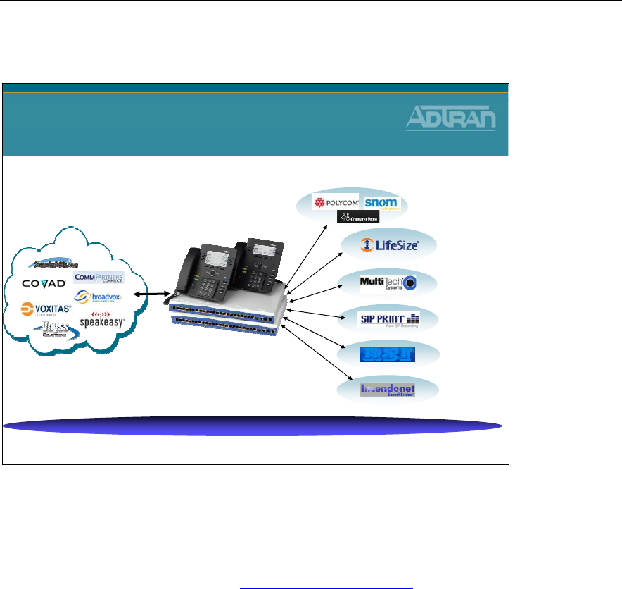
ADTRAN IPT Alliances
ADTRAN IPT Alliances
Enables Total Solutions Sales
IP End Points
Hi Def
Video Conf.
FAX
Server
Call
Recording
Call
Accounting
Speech
Recognition
The ADTRAN Alliance Program expands the reach of IP communications solutions to
small- and medium-sized businesses. The ADTRAN Alliance Program is collaboration
with best-in-breed technology and service providers that complement the NetVanta 7000
converged IP PBX Series and enable ADTRAN solutions providers to deliver world class
integrated network solutions. Visit www.adtran.com/alliance for additional information.
SIP Trunking Service Provider Alliances
SIP Trunking Service Providers offer IP telephony service offerings that are certified to be
fully interoperable with the NetVanta 7000 Series. The combination of the NetVanta 7000
Series with these services offers SMB customers proven ways to cost-effectively transition
to converged voice and data networking.
IP Telephony Technology Partners
Innovative solutions that have been strategically chosen to address specific applications in
conjunction with the NetVanta 7000 Series. These best-of-breed partners include Polycom,
CounterPath, SNOM, Incendonet, LifeSize, SIP Print, MultiTech, and RSI. The
combination of the NetVanta 7000 Series and the complementary partner solutions now
enable service and solutions providers to offer a broader, more comprehensive solution
with the added benefit of proven interoperability to meet the growing SMB and Enterprise
market needs for IP Telephony solutions.
Module 1: ADTRAN IP Telephony Solutions Overview
1-28 NetVanta IP Telephony Course
Data Feature Summary
Data Feature Summary
•24 port PoE Switch
•802.3af PoE (24 ports)
–15.4 Watts per port
•802.1Q VLANs
•Feature Rich IP Router
•Layer 2 and Layer 3 QoS
•DHCP Server
•Voice Quality Monitoring/Top Talkers
•Top Websites Report
•Stateful Firewall
•VPN (5 tunnels)
•Wi-Fi Access Controller
–NetVanta wireless access points (8)
PoE
SwitchRouter DHCP
Server VPN
Firewall IP phones
Analog phones
Voicemail
Auto attendant
SIP Gateway
PBX, Key system
Data Networking
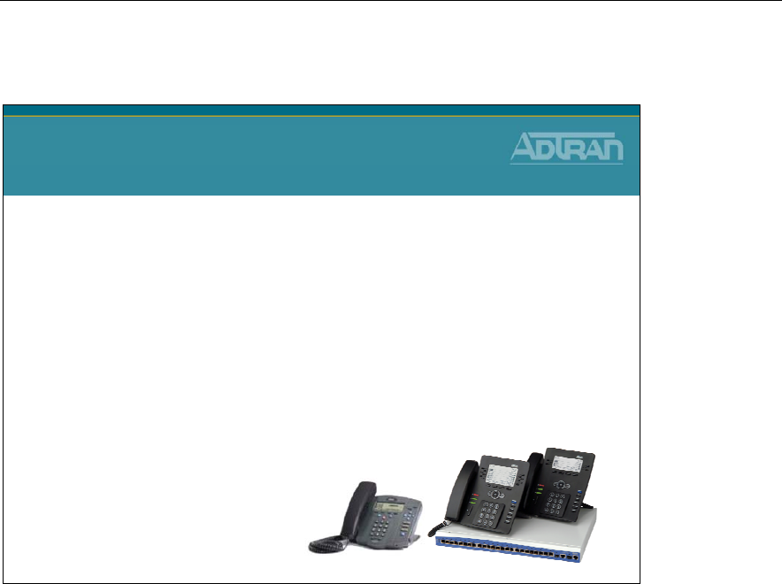
The NetVanta® 7100 is an integrated IP data networking and telephony solution designed
to simplify Voice over IP (VoIP) and IP telephony for business locations of up to 100
employees. This one-box solution combines multiple data and voice functions into a
single, affordable platform. The ADTRAN® NetVanta 7100 IP Communication Platform
includes a router, 24 port Power over Ethernet (PoE) switch, firewall, Virtual Private
Network (VPN), Wireless LAN controller, SIP Gateway, and business-class phone system
with integrated voice mail and automated attendant.
Module 1: ADTRAN IP Telephony Solutions Overview
NetVanta IP Telephony Course 1-29
Voice Feature Summary
Voice Feature Summary
•PBX and key system modes
•No phone or voicemail licenses
•Supports up to 100 SIP stations,
•Supports up to 10 Analog stations
•Supports SIP, T1/PRI and Analog Trunks
•Supports ADTRAN IP 706/712 and certified Polycom phones
•SIP/PSTN Gateway
•Zone Paging
•Internal voice mail (3000 messages, 8 ports)
•Multilevel auto attendant (8 ports)
•Shared Line Appearance (SLA)
•Shared Call Appearance (SCA)
•Dial by name directory
•System Scheduler
•Voice Quality Monitoring (VQM) and Mean Opinion Score (MOS)
•Music-on-hold input, paging output, door relay
The NetVanta 7100 is a complete voice and data networking solution for business
locations of up to 100 stations. This innovative platform includes an IP PBX, voice mail,
multilevel auto attendant, full-featured IP router, firewall, Virtual Private Network (VPN),
24-port Power over Ethernet (PoE) (802.3af) Fast Ethernet switch with Gigabit uplinks,
and two expansion slots for Network Interface Modules (NIMs) and Voice Interface
Modules (VIMs).
The NetVanta 7100 IP PBX functionality includes SIP-based telephony features such as
voice mail (store up to 3000 messages, eight ports), multilevel auto attendant (eight ports),
caller ID name/number, Shared Line Appearances (SLA), Busy Lamp Field (BLF), Class
of Service (CoS), trunk groups, music on hold, overhead paging and a number of call
options including call coverage lists, forwarding of calls to a cell phone and email
notification of voice mail.
Module 1: ADTRAN IP Telephony Solutions Overview
1-30 NetVanta IP Telephony Course
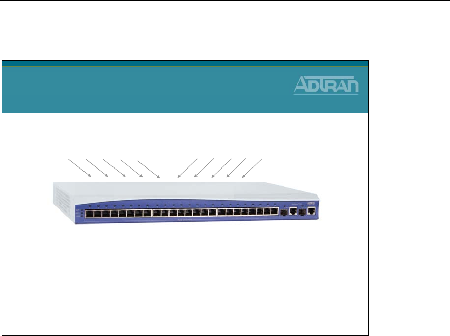
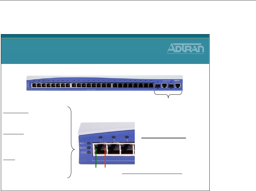
NetVanta 7000 Series – Front Panel
NetVanta 7000 Series
Front Panel
•24 10/100 PoE ports
–Ethernet 0/1 - 0/24
–802.3af (15.4 watts per port)
–Auto-Rate /Auto-Duplex / Auto-MDI/MDI-X
•2 10/100/1000 ports
–Gigabit 0/1 - 0/2
–Copper or Fiber (SFP)
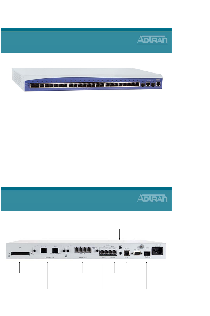
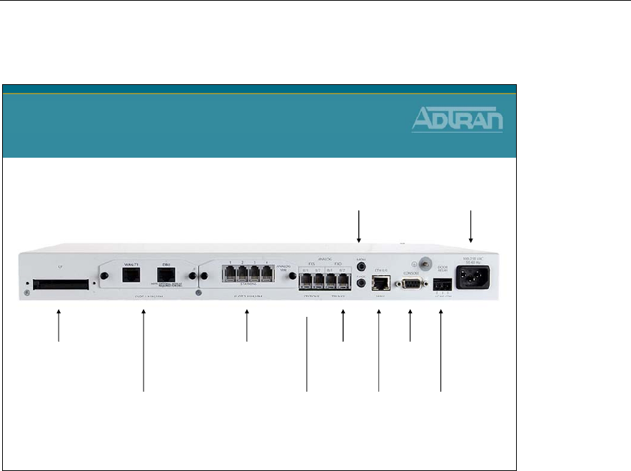
NetVanta 7000 Series - Rear Panel
Compact Flash
Voicemail Storage
NIM/VIM Slot 1 Analog
Stations
(2)
NIM/VIM Slot 2
WAN
Ethernet
Port
Music on Hold Input,
Paging output
Door
Relay
Analog
Trunks
(2)
NetVanta 7000 Series
Rear Panel
Module 1: ADTRAN IP Telephony Solutions Overview
NetVanta IP Telephony Course 1-31
Network Interface Modules (NIMs)
WAN T1/1 WAN T1/2 DDS
WAN-T1 DBU
Dual T1 (data only)
T1 (data only)
Network Interface Modules (NIMs)
T1/FT1 NIM
Provides a network interface for a fractional or full T1 for NetVanta 1000, 3000, 4000, and
7000 series products
Dual T1 NIM
Terminates two full or fractional T1s or two T1s aggregated together / Integral DSU/CSU
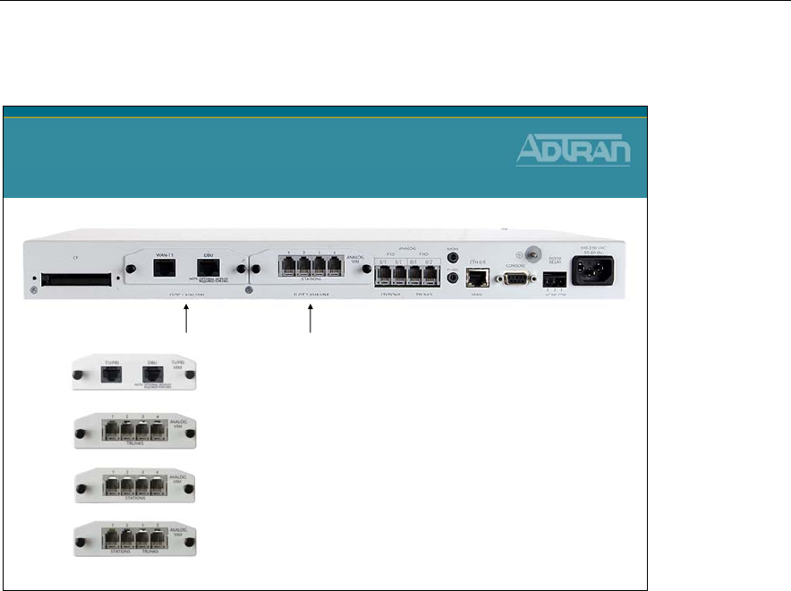
Module 1: ADTRAN IP Telephony Solutions Overview
1-32 NetVanta IP Telephony Course
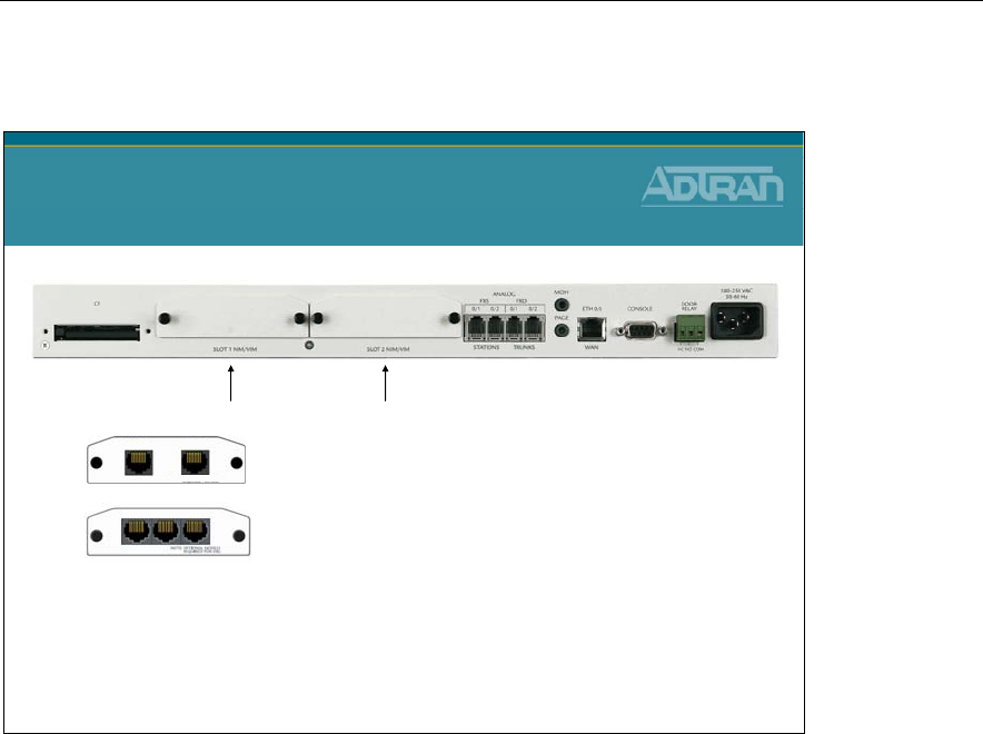
Voice Interface Modules (VIMs)
Voice Interface Modules (VIMs)
4-Port Analog Trunk (FXO)
4-Port Analog Station (FXS)
Dual Analog Trunk/Station (2 each)
T1/PRI
NetVanta T1/PRI Voice Interface Module
Provides one RBS T1 or one PRI (5E, DMS100, or National) interface for termination of
TDM voice trunks
NetVanta Analog 4-Port Trunk Voice Interface Module
Provides four analog RJ-11 trunk (FXO) ports for termination of PSTN circuits / Supports
loop-start and ground-start and captures Caller ID name/number using FSK / Part 68
compliant
NetVanta Analog 4-Port Station Voice Interface Module
Provides four analog RJ-11 station (FXS) ports for connection to analog devices such as
POTS phones, FAX machines, and/or modems / Delivers Caller ID name/number using
FSK / Loop-start/DTMF / Includes ring generator
NetVanta Analog 2-Trunk/2-Station Voice Interface Module
Provides two analog RJ-11 trunk (FXO) ports for termination of PSTN circuits / Supports
loop-start and ground-start and captures Caller ID name/number using FSK / Part 68
compliant / Provides two analog RJ-11 station (FXS) ports for connection to analog
devices such as POTS phones, FAX machines, and/or modems / Delivers Caller ID
name/number using FSK / Loop-start/DTMF / Includes ring generator
Module 1: ADTRAN IP Telephony Solutions Overview
NetVanta IP Telephony Course 1-33
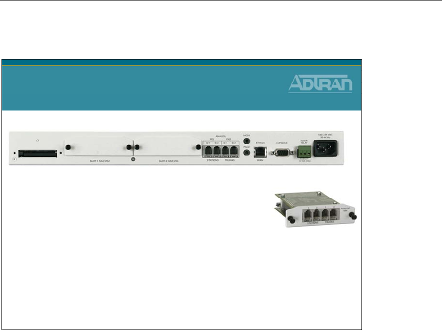
NetVanta 7000 Series - Port Configurations
•
4 Analog Trunk, 4 Analog Station, 24 PoE
•
6 Analog Trunk, 6 Analog Station, 24 PoE
•
8 Analog Trunk, 4 Analog Station, 24 PoE
•
10 Analog Trunk, 2 Analog Station, 24 PoE
•
1 T1/PRI, 6 Analog Station, 24 PoE
NetVanta 7000 Series
Port Configurations
The NetVanta 7100 chassis provides two analog trunk and station interfaces and two
expansion slots. For additional trunk and station connectivity, the NetVanta 7100 offers
several Voice Interface Modules (VIMs). These include a four-port analog (FXO) trunk
module, TI/PRI trunk module which supports voice or integrated voice and data, and a
four-port analog (FXS) station module. A combination module which provides two analog
stations and two analog trunks is also available.

Module 1: ADTRAN IP Telephony Solutions Overview
1-34 NetVanta IP Telephony Course
SIP Trunking
NetVanta 7000 Series Solution
SIP Trunking
• Direct Connectivity of NetVanta 7XXX to
Carrier’s SIP Trunk Service
For businesses that want to make full use of their new generation IP communication
solution, the NetVanta® 7100 and 7060 provide SIP Trunking capabilities between the
business and the local Service Provider. SIP trucking is a dynamic and efficient IP link that
can carry voice and data traffic, replace the traditional TDM trunks and lower monthly
service costs for the business.
• Converge voice and data across single trunk
• Dynamic bandwidth allocation for voice and data traffic
• Can support local, long distance and Internet
• Interoperable with a variety of carrier SIP Trunking services
• Direct Connectivity of NV 7100 to Carrier’s SIP Trunk Service

Module 1: ADTRAN IP Telephony Solutions Overview
NetVanta IP Telephony Course 1-35
SIP Networking
NetVanta 7000 Series Solution
SIP Networking
•3-4 Digit Dialing Between Sites
•VPN Between Sites
•Toll Bypass
•Access Remote Site Local Trunks
The ADTRAN NetVanta 7000 Series will support SIP networking between multiple
locations. With SIP Networking, businesses will be able to connect multiple sites and have
three- to four-digit dialing, local call routing and survivability, and on-net calls for toll
bypass. The NetVanta 7100 and 7060 are best for locations that need local voice mail;
while ADTRAN’s NetVanta 6355 IP Business Gateway provides the ideal solution for
locations that will use a central NetVanta 7000 voice mail.
• Links multiple sites together
• Supports inter-office, three- to four-digit dialing
• Provides local PSTN access

Module 1: ADTRAN IP Telephony Solutions Overview
1-36 NetVanta IP Telephony Course
Remote Site Solutions
NetVanta 7000 Series Solution
Remote Sites
•3-4 Digit Dialing Between Sites
•VPN Between Sites
•Use Central Voicemail
•Use Central Auto Attendant
•Total of 100 Stations in Network
•Remote PSTN trunks
NetVanta 6355
IP Gateway
NetVanta 7000
Up to 100 Stations
In Customer Network
Remote Sites
NetVanta 3448
Multiservice Router
NetVanta 3120
SOHO Router
PSTN
PSTN
IP
The ADTRAN NetVanta 7000 Series will support SIP networking between multiple
locations. The NetVanta 7100 and 7060 are best for locations that need local voice mail;
while ADTRAN’s NetVanta 6355 IP Business Gateway provides the ideal solution for
locations that will use a central NetVanta 7000 voice mail. The remote site NetVanta 3448
router or 6355 can provide local survivability as well by continuity to route intra-office
calls, or where provisioned, directly to a local PSTN for guaranteeing phone service. The
NetVanta 7100 and NetVanta 3120 enable secure, always-on, voice, data and high-speed
data access to business resources from a remote home office.
Module 1: ADTRAN IP Telephony Solutions Overview
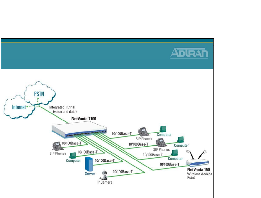
NetVanta IP Telephony Course 1-37
Integrated T1 /PRI
NetVanta 7000 Series Solution
Integrated T1/PRI
Using the NetVanta 7000 Series T1/PRIVoice Interface Module (VIM), customers can
consolidate separate voice lines and Internet access onto a single T1 or PRI trunk. Small-
to Medium-sized Business (SMB) locations with analog business lines and high-speed
Internet access can benefit from lower monthly costs, higher reliability, and added capacity
for growth through T1/PRIconsolidation. Check with your service provider for attractive
offers on integrated T1/PRI circuits and terminate the service with the NetVanta 7000
Series T1/PRI VIM for an ideal business-grade Voice over IP (VoIP) solution.
• Supports up to 24 T1 channels
• Supports up to 23 PRI channels
• Consolidates voice and data
• Reduces monthly service costs
Module 1: ADTRAN IP Telephony Solutions Overview
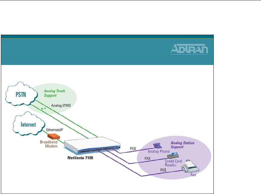
1-38 NetVanta IP Telephony Course
Analog Trunks & Stations
NetVanta 7000 Series Solution
Analog Trunks & Stations
ADTRAN’s NetVanta® 7100 is ideal for businesses that need a combination of IP and
analog communications. Along with IP interfaces, the NetVanta 7100 can support analog
trunks, analog phones, fax machines and credit card readers without the need for analog
telephone adapters.
• Eliminates the need for additional analog telephone adaptors
• Supports up to 10 analog ports
• Enables analog data devices to achieve higher-speed performance
Module 1: ADTRAN IP Telephony Solutions Overview
NetVanta IP Telephony Course 1-39
Module Objectives
Module Summary
At the end of this module, you should be able to:
•Discuss ADTRAN’s IP Telephony Solutions
•Discuss ADTRAN’s IP Telephony Features
•Recognize Key NetVanta IP Telephony Applications
All in One “Office in a Box”

Module 1: ADTRAN IP Telephony Solutions Overview
1-40 NetVanta IP Telephony Course

Module 2: Introduction to NetVanta
7000 Series Data Configuration

Module 2: Introduction to NetVanta 7000 Series Data Configuration
2-2 NetVanta IP Telephony Course

Module 2: Introduction to NetVanta 7000 Series Data Configuration
NetVanta IP Telephony Course 2-3
Module Objectives
Objectives
•Introduce the ADTRAN Operating System (AOS)
•Introduce the NetVanta 7000 Web-Based GUI
•Understand System Factory Defaults
•Understand Switch Factory Defaults
•Understand Router Factory Defaults
•Understand Firewall Factory Defaults

Module 2: Introduction to NetVanta 7000 Series Data Configuration
2-4 NetVanta IP Telephony Course
Module 2: Introduction to NetVanta 7000 Series Data Configuration
NetVanta IP Telephony Course 2-5
NetVanta 7000 Front Panel
NetVanta 7000 Front Panel
PORT LEDs (G1 and other port LEDs)
-Off Disabled or no connection
-Green (solid) Enabled/link up
-Yellow (blinking) Activity Tx/Rx
SLOT1 / 2
-Off No NIM or administratively down
-Green (solid) Enabled/link up
-Red (solid) Alarm condition
-Yellow (solid) In test
STAT
-Green (blinking) Power-up
-Green (solid) Power on/ self-test passed
-Red (solid) Power on/ self-test failed
2 Gigabit Ethernet interface
Gigabit SFP/1000Base-T uplink
24 Ethernet / Fast Ethernet ports
10/100 Base-T Ports
- Auto-sensing 10/100 MBPS
- Auto-MDI/MDX (Crossover)
- Auto-Full/Half duplex
PoE Swith RJ-45 PORT LEDs
-Green 48V applied to interface
-Red
Fault detected on interface
Left
LED
Right
LED
Front Panel RJ-45 Ports and LEDS
The NetVanta front panels contain twenty-four 10/100BaseT Ethernet ports (RJ-45). These
ports are consecutively numbered one through twenty-four, from left to right, with the
numbers screened directly above each port. Status LEDs for each of these ports are located
directly over these numbers.
Front Panel Gigabit Ethernet Interfaces and LEDs
The NetVanta 7000 front panel also contains two Gigabit Ethernet interfaces. These
interfaces are provided as RJ-45 jacks or SFP slots and are labeled G1 and G2.
Power Over Ethernet
The NetVanta 7000 Power over Ethernet (PoE) interfaces provide the ability to detect
attached powered devices (PD) and deliver 48 VDC to the PD via existing CAT5 cabling.
The PoE interfaces are fully compliant with the IEEE 802.3af power over Ethernet
standard. By default, the PoE ports automatically discover and provide power to IEEE-
compliant PDs.
Module 2: Introduction to NetVanta 7000 Series Data Configuration
2-6 NetVanta IP Telephony Course
NetVanta 7000 Rear Panel
Compact
Flash
NetVanta 7000 Rear Panel
NIM/VIM Slot 1 Analog
Stations
(2)
NIM/VIM Slot 2 DB9
Console
WAN
Ethernet
Port
Music on Hold Input,
Paging output AC 120/
240 VAC
Door
Relay
Analog
Trunks
(2)
The NetVanta 7000 rear panel contains a power connection and a single DB-9 (female)
interface (labeled CONSOLE) used for connecting to a VT100 terminal or a PC running
VT100 terminal emulation software. The rear panel also includes the Ethernet port (labeled
ETH 0/0) for WAN and/or administration connectivity, dual analog stations and trunks,
compact flash (CF), message on hold (MOH), PAGE, and alarm contacts (DOOR
RELAY). In addition, the NetVanta 7000 contains modular network interfaces that accept
a variety of modules.

Module 2: Introduction to NetVanta 7000 Series Data Configuration
NetVanta IP Telephony Course 2-7
NetVanta 7000 Memory
NetVanta 7000 Memory
•FLASH (32 Mbytes)
–boot code storage / compressed application code storage
–store non-volatile configuration data (startup-config)
–store non-volatile dynamic voice config (dynvoice-config)
–retains contents when NetVanta is powered down
•CFLASH (256 Mbytes)
–Non-volatile storage of Voicemail and User prompts
–Firmware and configs can be stored here
–Can store up to 3000 voicemail messages
–retains contents when NetVanta is powered down
•RAM (128 Mbytes)
–running copy of the application code
–running copy of the configuration file (running-config)
Flash memory is non-volatile memory and is where the boot code, compressed application
code, saved configurations, and startup-configurations are stored. Everything in Flash is
saved when the NetVanta is powered down. The NetVanta has the ability to save different
user defined configurations that may be loaded into the running-configuration in RAM.
The number of configuration files that can be saved is only limited by the amount of Flash
memory used.
RAM (Random Access Memory) is the main memory and contains a running copy of the
application code, a running copy of the configuration file, and is considered volatile
memory. Therefore, it is cleared when the NetVanta AOS device is powered down. The
actual compressed application code is stored in Flash, but is uncompressed and stored in
RAM upon device bootup. Changes to the running-configuration are also stored here.
This is why it is important to save or write your configuration changes to FLASH and
therefore include them in your startup-configuration file. The type of RAM typically
incorporated in the AOS devices is dynamic RAM (DRAM).
The CF (CompactFlash) slot supports a small flash memory module. The memory chips
are enclosed in a case and retain data after they are removed from the system. The
CompactFlash card may be used to store configuration files and AOS images.
Module 2: Introduction to NetVanta 7000 Series Data Configuration
2-8 NetVanta IP Telephony Course
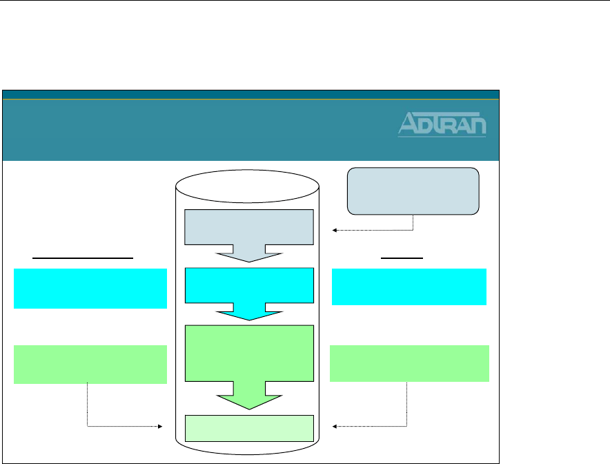
Boot Process
Enter Bootstrap mode:
Bootstrap>
Boot Process
Boot code
Application Code
startup-config
&
dynvoice-config
Ready
Uncompressed from FLASH
and executed in RAM
ExistsDoes not Exist
Loaded from NVRAM to RAM
and processed line by line
NetVanta 7000 starts with
defaults
NetVanta 7000
On power up, the boot
code looks for a valid
application image
If needed, password recovery can
be done from the Bootstrap mode
Unit Boot Up
Plug the unit into the wall and turn on the power. The unit begins the boot up process,
which includes the following:
• The Power-On Self Test runs.
- This test checks the unit hardware for normal operation. The hardware includes the
central processing unit (CPU), the memory, and the interfaces.
• The Bootstrap Startup Program (factory set in the ROM) runs.
- The Bootstrap Startup Program is read by the unit to discover the proper source for
the operating system image.
• The operating system image is loaded into RAM.
• The configuration files startup-config and dynvoice-config saved in NVRAM are
loaded into RAM, where they are accessed by the unit and then executed one line at a
time.

Module 2: Introduction to NetVanta 7000 Series Data Configuration
NetVanta IP Telephony Course 2-9
Configuration Methods
Configuration Methods
Two Configuration methods
•ADTRAN Operating System (CLI)
–Connect a PC’s VT100 Terminal
–Console port, telnet, secure shell
•Web-Based GUI
–PC with installed web browser
–HTTP (port 80) or HTTPS (port 443)
–Internet Explorer 5 or Higher; Firefox 1.5 or Higher
The NetVanta products can be configured through the Command Line Interface (CLI) or
the Web-based Graphical Interface (GUI). Both are enabled from the factory.
Module 2: Introduction to NetVanta 7000 Series Data Configuration
2-10 NetVanta IP Telephony Course
Console Port Connection
Console
Console Port Connection
•Use a DB-9 (male) to DB-9 (female) straight-through
serial cable
•Open a VT-100 session with the NetVanta 7100
•Configure the COM port with the following
parameters:
–Data Rate: 9600
–Data Bits: 8
–Parity Bits: None
–Stop Bits: 1
–Flow Control: None
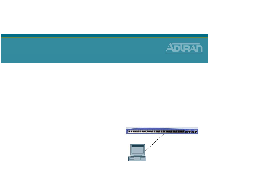
ACCESSING THE CLI
Access the AOS CLI via the CONSOLE port or a Telnet session. To establish a connection
to the NetVanta unit’s CONSOLE port, you need the following items:
• VT100 terminal or PC (with VT100 terminal emulation software)
• Straight-through serial cable with a DB-9 (male) connector on one end and the
appropriate interface for your terminal or PC communication port on the other end
a. Connect the DB-9 (male) connector of your serial cable to the CONSOLE port on the
rear panel of the unit.
b. Connect the other end of the serial cable to the terminal or PC.
c. Insert the connector of the provided power cord into the power interface on the rear
panel of the unit, and plug the cord into a standard electrical outlet.
d. Once the unit is powered up, open a VT100 terminal session using the following
settings: 9600 baud, 8 data bits, no parity bits, and 1 stop bit.
e. Press <Enter> to activate the AOS CLI.
f. Enter “enable” at the > prompt and then the enable password when prompted
- The default enable password is password
Module 2: Introduction to NetVanta 7000 Series Data Configuration
NetVanta IP Telephony Course 2-11
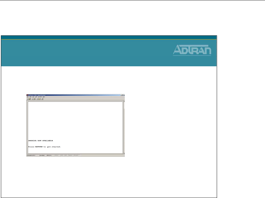
ADTRAN Operating System
ADTRAN Operating System
•ADTRAN Operating System
–Command Line Interface (CLI)
–Press RETURN to access the basic ADTRAN OS security
level
When you first log into the unit, or if your session has timed out, you will see the screen
above. Simply press <Return> or <enter> to log back into the NetVanta.
Note: This allows you to access the NetVanta’s Command Line Interface.
Module 2: Introduction to NetVanta 7000 Series Data Configuration
2-12 NetVanta IP Telephony Course
Command Security Levels
Command Security Levels
Two Command Security Levels
–Each security level supports a specific set of commands
•Basic Level (Initial Level)
NV7100>
–display system information with show command
–perform traceroute, ping, and telnet
–enter the enable (privileged) level
•Enable Level
NV7100#
–manage the startup and running configurations
–use the debug commands
–enter the Global Configuration mode
NV7100>
enable
Password : ********
NV7100#
There are two command security modes, each one supporting a specific set of commands.
When first logging into the NetVanta via the Command Line Interface (CLI), you are in
Basic mode.
Basic Mode
Interaction with your unit begins at the Basic mode. The commands supported at this
command tier are limited, as is interaction with the unit itself. The Basic mode is to keep
users without access to the higher tiered commands from changing the preferred
configurations of the unit.
Enable Mode
Enable mode is the privileged mode in the command hierarchy, one step up from the Basic
mode. ADTRAN suggests that a password be required to access the Enable mode.
From the Enable mode, you can access the configurations of your product as well as
handle the boot settings and running configuration, among other things.
Module 2: Introduction to NetVanta 7000 Series Data Configuration
NetVanta IP Telephony Course 2-13
Global Configuration Mode
NV7100#
configure terminal
NV7100(config)#
Global Configuration Mode
•Enter from the Enable level
•From this mode you can:
–set the system’s enable password(s)
–configure the system global IP parameters
–enter any of the other configuration modes
Global configuration mode allows the user to set the system’s enable passwords, configure
the global IP parameters, and enter into any of the other configuration modes.
To see the commands available to the Global configuration mode, type a question mark at
the prompt. A list of commands and brief description of their function will be displayed.
Module 2: Introduction to NetVanta 7000 Series Data Configuration
2-14 NetVanta IP Telephony Course
Specific Configuration Modes
Specific Configuration Modes
•Global Configuration Mode
NV7100(config)#
•Line Configuration Mode
NV7100(config-con0)# (config)# line con 0
NV7100(config-telnet0)# (config)# line tel 0
•Router Configuration Mode
NV7100(config-rip)# (config)# router rip
NV7100(config-ospf)# (config)# router ospf
•Interface Configuration Mode
NV7100(config-eth 0/1)# (config)# int eth 0/1
NV7100(config-t1 1/1)# (config)# int t1 1/1
–Type exit to return to Global Config mode
–Type <ctrl> “z” to exit out of Config mode
NV7100(config-rip)#
<ctrl> z
NV7100#
NV7100(config-rip)#
exit
NV7100(config)#
The Global configuration mode allows the user to make changes that are ‘global’ to the
unit, and not specific to one interface. A configuration change made in Global
configuration mode would affect all the enabled interfaces in the device.
Examples of the various configuration modes are displayed below:
Mode Access by… Sample Prompt Operation
Global Entering config while at
the Enable command
security level prompt.
Example:
>enable
#config t
(config)# • Set the system’s Enable-
level password(s)
• Configure the system global
IP parameters
• Configure the SNMP
parameters
• Enter any of the other
configuration modes

Module 2: Introduction to NetVanta 7000 Series Data Configuration
NetVanta IP Telephony Course 2-15
Line Specifying a line (console
or Telnet) while at the
Global Configuration
mode prompt.
For example:
>enable
#config t
(config)#line console 0
(config-con0)# • Configure the console
terminal settings (data rate,
login password, etc.)
• Create Telnet login and
specify parameters (login
password, etc.)
Router Enter router rip or
router ospf while at the
Global Configuration
mode prompt.
For example:
>enable
#config t
(config)#router rip
(config-rip)# • Configure RIP or OSPF
parameters
• Suppress route updates
• Redistribute information
from outside routing sources
(protocols)
Interface Specify an interface (T1,
Ethernet, Switchport,
Frame Relay, PPP, etc.)
while in the Global
Configuration mode.
For example:
>enable
#config t
(config)#int eth 0/1
(config-eth 0/1)#
(The above prompt
is for the first
Ethernet
switchport
interface located
on the front panel
of the unit.)
• Configure parameters for the
available LAN and WAN
interfaces
Module 2: Introduction to NetVanta 7000 Series Data Configuration
2-16 NetVanta IP Telephony Course
Help Tools
Help Tools
•“?” Command
–List available commands
–List options available to command
–Auto finish
NV7100#
?
NV7100#
show ?
NV7100#
tr <Tab>
NV7100#
traceroute
Arguably, the ? is the most used command in the CLI. No matter if one is a novice or
expert the ? is a valuable resource. There are thousands of commands and parameters in
the AOS and the ? allows one to search for the elusive directive.
To aid in the execution and at times the correction of commands the AOS includes shortcut
keys. These shortcuts move the cursor forward and backward on the command line.
Further information regarding these Help tools is available on the following pages.

Module 2: Introduction to NetVanta 7000 Series Data Configuration
NetVanta IP Telephony Course 2-17
The following shortcut keys are available from the CLI configuration:
Shortcut Description
Up arrow key To re-display a previously entered command, use the up arrow key. Continuing to
press the up arrow key cycles through all commands entered starting with the most
recent command.
<Tab> key Pressing the <Tab> key after entering a partial (but unique) command will complete
the command, display it on the command prompt line, and wait for further input.
? The ADTRAN CLI contains help to guide you through the configuration process.
Using the question mark, do any of the following:
Display a list of all subcommands in the current mode. For example:
(config-t1 1/1)#coding ?
ami - Alternate Mark Inversion
b8zs - Bipolar Eight Zero Substitution
Display a list of available commands beginning with certain letter(s). For example:
(config)#ip d?
default-gateway dhcp-server domain-lookup domain-name domain-proxy
Obtain syntax help for a specific command by entering the command, a space, and then
a question mark (?). The ADTRAN CLI displays the range of values and a brief
description of the next parameter expected for that particular command. For example:
(config-eth 0/1)#mtu ?
<64-1500> - MTU (bytes)
<Ctrl + A> Jump to the beginning of the displayed command line. This shortcut is helpful when
using the no form of commands (when available). For example, pressing <Ctrl + A>
at the following prompt will place the cursor directly after the #:
config(eth-0/1)#ip address 192.168.10.1 255.255.255.0
<Ctrl + E> Jump to the end of the displayed command line. For example, pressing <Ctrl + E> at
the following prompt will place the cursor directly after the 1:
config(eth-0/1)#ip address 192.168.10.1
<Ctrl + U> Clears the current displayed command line. The following provides an example of the
<Ctrl + U> feature:
config(eth-0/1)#ip address 192.168.10.1 255.255.255.0 (Press <Ctrl + U> here)
config(eth-0/1)#
auto finish You need only enter enough letters to identify a command as unique. For example,
entering int t1 1/1 at the Global configuration prompt provides you access to the
configuration parameters for the specified T1 interface. Entering interface t1 1/1
would work as well, but is not necessary.

Module 2: Introduction to NetVanta 7000 Series Data Configuration
2-18 NetVanta IP Telephony Course
General Command Introduction
General Command Introduction
•Basic security level
–show version
–enable
•Enable security level
–show flash
–show cflash
–show startup-config
–show running-config
–copy running-config startup-confi
Module 2: Introduction to NetVanta 7000 Series Data Configuration
NetVanta IP Telephony Course 2-19
show version command
NV7100>
show version
ADTRAN, Inc. OS version A2.03.00.E
Mainline Version: M00
Checksum: 8A30C916, built on Fri Mar 27 08:22:35 2009
Upgrade key: fb9ab213c71d061d002d70615ed80777
Boot ROM version 15.01.00
Checksum: 0F45, built on: Thu Apr 26 10:28:09 2007
Copyright (c) 1999-2007, ADTRAN, Inc.
Platform: NetVanta 7100, part number 1200796E1
Serial number G17A8905
Flash: 33554432 bytes DRAM: 134217728 bytes
NV7100 uptime is 3 days, 19 hours, 8 minutes, 13 seconds
slot 0, DSP 1
DSP software version: G1.A2.02.17
DSP hardware version: Freescale MSC7116
Total channels: 20
System returned to ROM by Software Watchdog
Current system image file is "NONVOL:/NV7100A-A2-03-00-E.biz"
Boot system image file is "NONVOL:/NV7100A-A2-03-00-E.biz"
Primary system configuration file is "startup-config"
NV7100#
show version command
•Displays system hardware and software info
Use the show version command to display the current AOS version information.
Other key information that appears from the show version output is the NetVanta unit
information including the part number and serial number.
Module 2: Introduction to NetVanta 7000 Series Data Configuration
2-20 NetVanta IP Telephony Course
show flash command
show flash command
•List files stored in FLASH
NV7100#
show flash
158 000000000000-directory.xml
462 000000000000.cfg
20280 adtran-sip.cfg
939 adtran_000000000000.txt
163 adtran_boot.txt
:
119 customer-sip.cfg
7890 defaultpolycom.cfg
2512
dynvoice-config
12164
startup-config
837 polycomboot.cfg
739 polycomboot_remote.cfg
779 polycomConfigDefaults.cfg
130729 sip.cfg
87 sip.ver
14540095
NV7100A-A2-03-00-E.biz
15055905 bytes used, 15684030 available, 30739935 total
NV7100#
startup-config / dynvoice-config
text files that are read and executed
line by line at startup
.biz file
the NetVanta 7100 application image
The show flash command may be executed from the Enable security mode and shows
what is currently stored in the Flash portion of NVRAM. In this output, the “.biz” file is
the application image, or the firmware. Generally, any application images will have a .biz
extension. There may be multiple image files stored in flash with a .biz extension. The
sizes of each of the files are listed in front of the file names. The total space used and
available is also shown.
To view the image that was loaded upon startup, type the show version command.
Other files listed in flash include the startup-configuration file, the startup-config.bak
file, and any other configuration files that have been created.
The startup-config file is a text file that is read and executed line by line at startup. If no
startup-config file exists and no other file is specified to be used at startup, the router will
load with factory default settings. If a startup-config file does exist and no other file is
specified to be used at startup, the NetVanta will always use this file named startup-config
to load the initial configuration. The startup-config.bak file is a backup file that is
automatically created and updated as changes are made to the startup-config file.
Module 2: Introduction to NetVanta 7000 Series Data Configuration
NetVanta IP Telephony Course 2-21
show cflash command
show cflash command
•List files stored in Compact FLASH
–System Default Prompts
•General System prompts
•Used with Auto Attendant, Voicemail, etc..
–Voicemail
•Name, temporary, external, and internal greetings
•Messages
NV7100#
show cflash
373 000000000000.cfg
(dir) 0 AA
(dir) 0 ADTRAN
(dir) 0 Polycom
845 polycomboot.cfg
739 polycomboot_remote.cfg
(dir) 0 SystemDefaultPrompts
(dir) 0 VoiceMail
29847552 bytes used, 225980416 available, 255827968 total
NV7100#
AA - Stores Auto Attendant Files
ADTRAN - Stores ADTRAN phone config files
Polycom - Stores Polycom phone config files
Use the show cflash command to display a list of all files currently stored in
CompactFlash® memory or details about a specific file stored in CompactFlash memory.
Module 2: Introduction to NetVanta 7000 Series Data Configuration
2-22 NetVanta IP Telephony Course
show startup-config
NV7100#
show startup-config
show startup-config
•Display the startup configuration
–startup-config is located in NVRAM
–startup-config is loaded from NVRAM to RAM and processed
line by line at startup
To show the contents of the startup-config file, use the command show startup-config at
the Enable security mode. The startup-config file is stored in the Flash portion of
NVRAM and will be displayed line by line to the screen output when executing this
command. If no startup-config file exists, the router will show a message stating that “File
does not exist.”
Module 2: Introduction to NetVanta 7000 Series Data Configuration
NetVanta IP Telephony Course 2-23
show running-config
NV7100#
show running-config
show running-config
•Display the running configuration
–running-config is located in RAM
–Cleared when the NetVanta 7000 is powered down
Use the show running-config command to display all the non-default parameters contained
in the current running configuration file. Specific portions of the running configuration
may be displayed, based on the command entered. Variations of this command can be seen
by issuing “show run ?” .
Module 2: Introduction to NetVanta 7000 Series Data Configuration
2-24 NetVanta IP Telephony Course
show running-config verbose
NV7100#
show running-config
verbose
:
line con 0
no login
password ""
line-timeout 15
databits 8
parity none
stopbits 1
speed 9600
no flowcontrol software in
:
Partial output displayed...
Default Settings
•Examine the running configuration along with the
NetVanta 7000 default settings
The show running-configuration output only displays the basic configuration settings and
any changes made from the default configuration settings. The show running-
configuration verbose command displays all of the default and non-default configured
parameters in the NetVanta device.

Module 2: Introduction to NetVanta 7000 Series Data Configuration
NetVanta IP Telephony Course 2-25
show dynvoice-config
NV7100#
show dynvoice-config
Using 1025 bytes
!
voice user 2000
connect sip
cos "public_phones"
first-name "Default"
last-name "IP Phone"
password "1234"
phone model adtran 480i
codec-group g711_first
voicemail notify schedule Sunday 12:00 am
!
voice user 2001
connect fxs 0/1
cos "normal_users"
first-name "Analog FXS"
last-name "Port 0/1"
password "1234"
:
:
show dynvoice-config
•Display Dynamic Voice configuration
Continued…
!
voice user 2002
connect fxs 0/2
cos "normal_users"
first-name "Analog FXS"
last-name "Port 0/2"
password "1234"
:
:
!
!
voice operator-group
type all
num-rings 4
member 2001
login-member 2001
member 2002
coverage aa
Partial output displayed...
Stores Voice Users and Ring Groups
Use the show dynvoice-config command to display the dynamic voice configuration. This
file stores voice user and ring group configuration.
The dynvoice-config file is stored in the Flash portion of NVRAM and will be displayed
line by line to the screen when executing this command.
Module 2: Introduction to NetVanta 7000 Series Data Configuration
2-26 NetVanta IP Telephony Course
Saving Configuration
NVRAM
or
NV7100#
copy running-config startup-config
NV7100#
write memory
Saving Configuration
•Save current configuration to startup-config
–startup-config is located in NVRAM
–NVRAM retains contents when the NetVanta 7000 is
powered down
–startup-config is read and executed line by line at startup
In order to save any changes that were made to the configuration since the unit was
powered on, you must copy the running configuration into the startup configuration file in
NVRAM.
The following commands may be used to save the configuration:
NV7100# copy running-config startup-config
NV7100# write memory
Module 2: Introduction to NetVanta 7000 Series Data Configuration
NetVanta IP Telephony Course 2-27
Factory-default Command
Factory-default Command
•Restore unit to factory-default settings
–This command erases the current startup-config and
dynvoice-config files, and then creates the factory delivered
startup-config and dynvoice-config files before rebooting
NV7100#
factory-default
WARNING - Restoring the factory default settings will erase
the current startup configuration and will reboot the unit.
Restore factory default settings?[y/n]
Use the factory-default command to reset the unit to the factory default settings.
After you issue this command, the system responds by first warning you that restoring the
factory default settings will erase the current configurations. It then asks if you would like
to proceed. Choose n to return to the command prompt (no configuration changes are
made). Choose y to erase the startup-configuration, replace it with the factory-default
configuration, and reboot the unit. After reboot, the new configuration takes effect.
The only files that are affected by the factory-default are startup-config and dynvoice-
config. No other files are removed or modified.
• IP phones look for configuration files from the boot server at boot. If you wish to
default the unit and phones, the phone configuration files must be removed also.
• Phone configuration files are created by the NetVanta 7000 when creating new
voice users for ADTRAN and Polycom phones. These files will be covered in a
later module.

Module 2: Introduction to NetVanta 7000 Series Data Configuration
2-28 NetVanta IP Telephony Course
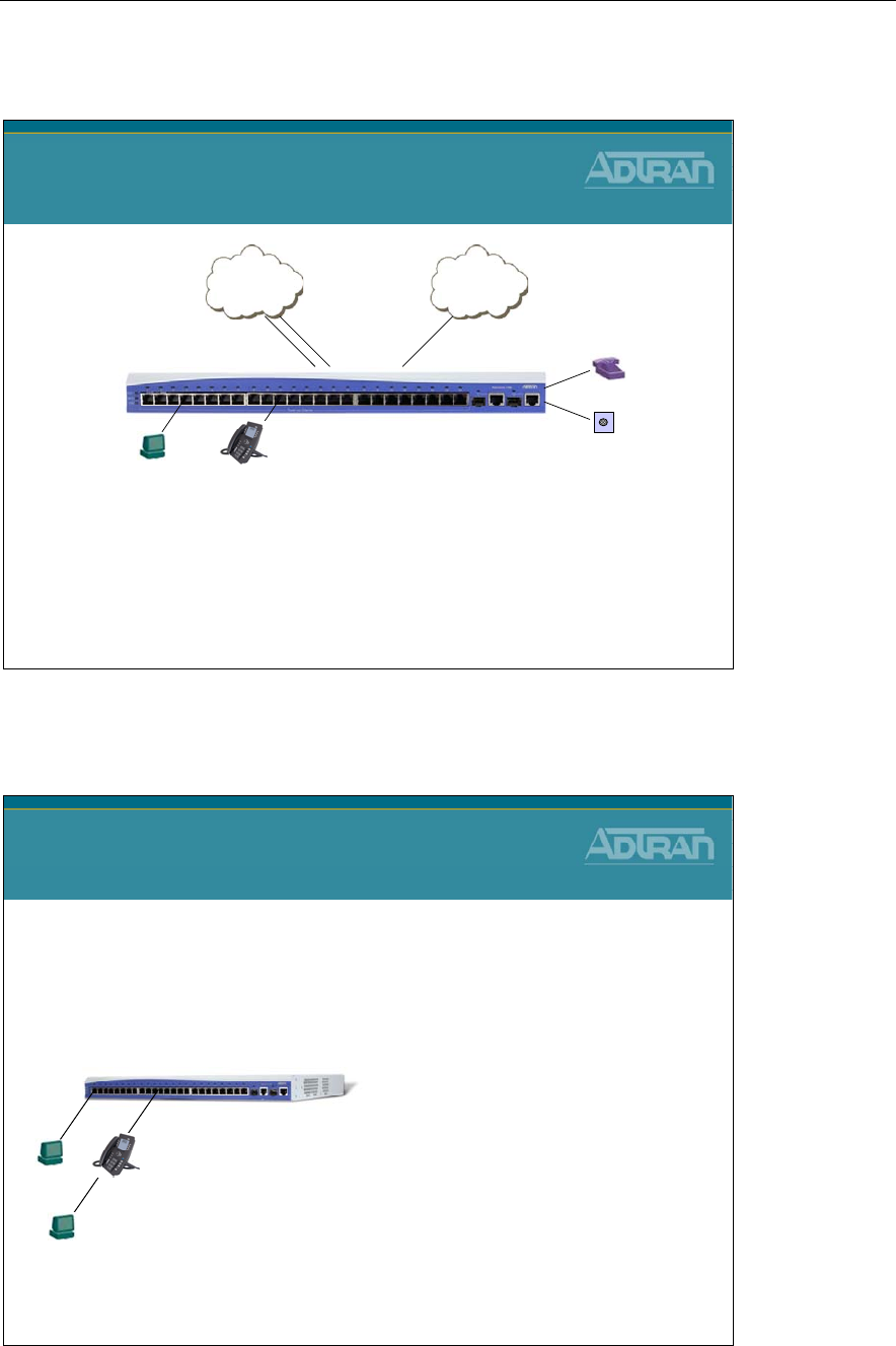
Module 2: Introduction to NetVanta 7000 Series Data Configuration
NetVanta IP Telephony Course 2-29
NetVanta 7000 - Factory Default Configuration
NetVanta 7000
Factory Default Configuration
INTERNETPSTN
Analog - FXO Ethernet WAN
Phone - FXS
Door Phone - FXS
The NetVanta 7000 is delivered from the factory with a
default configuration that will allow you to quickly deploy
a complete IP telephony and Data networking Solution.
NetVanta 7000 - Data (VLAN) Factory Defaults
NetVanta 7100
NetVanta 7000
Data (VLAN) Factory Defaults
Ethernet 0/1-24
Enabled (activated with no shutdown)
Speed/Duplex/Cable Type: auto
Switchport mode: trunk
Allowed VLANs: all
Native VLAN: 1
Spanning Tree Mode: edgeport
Gigabit 0/1-2
Enabled (activated with no shutdown)
Speed/Duplex/Cable Type: auto
VLAN membership: trunk
DATA VLAN
VLAN 1
IP Address: 10.10.10.1/24
Native VLAN: 1
VOICE VLAN
VLAN 2
IP Address: 10.10.20.1/24
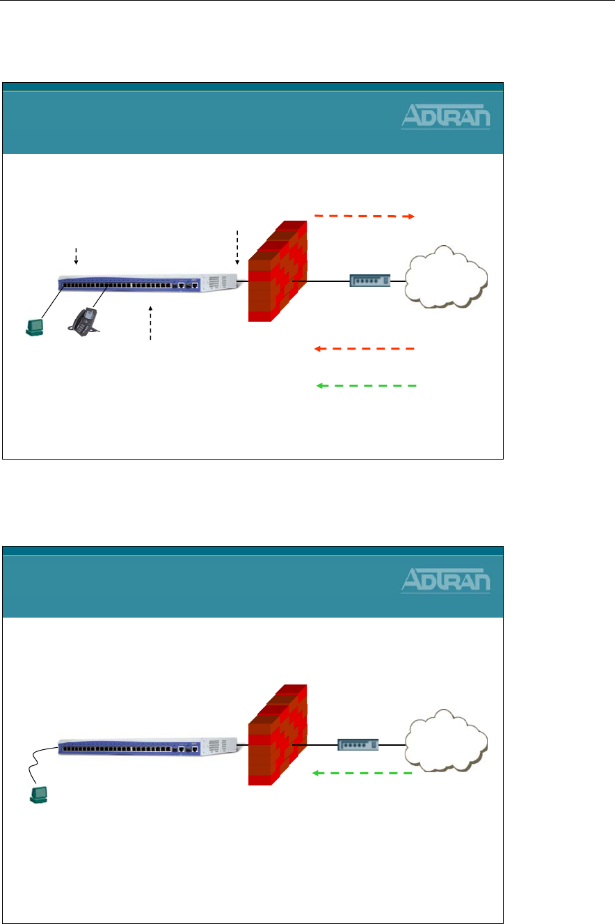
Module 2: Introduction to NetVanta 7000 Series Data Configuration
2-30 NetVanta IP Telephony Course
NetVanta 7100 - Data Factory Defaults
Internet
NetVanta 7100
No traffic
allowed in to LAN
All traffic
allowed out
Firewall enabled
DATA DHCP Server:
Enabled
Network 10.10.10.0 /24
Default Route: 10.10.10.1
DNS: 10.10.10.1
TFTP Server: 10.10.10.1
Option 157: Boot Parameters for
ADTRAN IP Phones
NetVanta 7100
Data Factory Defaults
VOICE DHCP Server:
Enabled
Network 10.10.20.0 /24
Default Route: 10.10.20.1
DNS: 10.10.20.1
TFTP Server: 10.10.20.1
Option 157: Boot Parameters for
ADTRAN IP Phones
ETH 0/0
WAN
DHCP Client
Except the following:
SIP (UDP Port 5060)
WAN ADMIN Access
Secure Shell - ssh
Secure Web - https
NetVanta 7100 - Mgmt Factory Defaults
Enable password: password
Internet
NetVanta 7100
LAN ADMIN Access
telnet / ssh
http / https
ftp / tftp
Username: admin
Password: password
NetVanta 7100
Mgmt Factory Defaults
Management IP Address:
VLAN 1:
10.10.10.1 /24
VLAN 2:
10.10.20.1 /24
WAN ADMIN Access
Secure Shell - ssh
Secure Web - https
Console: no login
VT100: 9600, 8, n, 1,
no flow control
Phone FTP Account
Username: polycomftp
Password: password
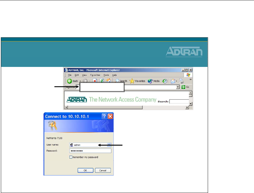
Module 2: Introduction to NetVanta 7000 Series Data Configuration
NetVanta IP Telephony Course 2-31
Access the NetVanta 7000 GUI
Access the NetVanta 7000 GUI
1) Enter IP address/admin
of NetVanta 7000
Default IP Address:
10.10.10.1
2) Enter username and password
Default username: admin
Default password: password
10.10.10.1/admin
The Web-based Graphical User Interface (GUI) is enabled from the factory. If the web
interface has been disabled or you wish to enable it with another NetVanta product, the
minimum configuration would be:
- Turn on web server (ip http server)
- Add username and password (username admin password password)
- Assign IP address to VLAN or router interface
ACCESSING THE GUI
1. Connect the unit to your PC using the first Ethernet (eth 0/1) port on the front of the
unit
2. Set your PC to obtain an IP address automatically via Dynamic Host Configuration
Protocol (DHCP) or change your PC to a fixed IP address of 10.10.10.2
- If you cannot change the PC’s IP address, you will need to change the unit’s IP
address using the CLI
3. Enter the unit’s IP address/admin in your browser address line
- The default IP address is 10.10.10.1/admin
4. You will then be prompted for the username and password
- The default settings are admin and password
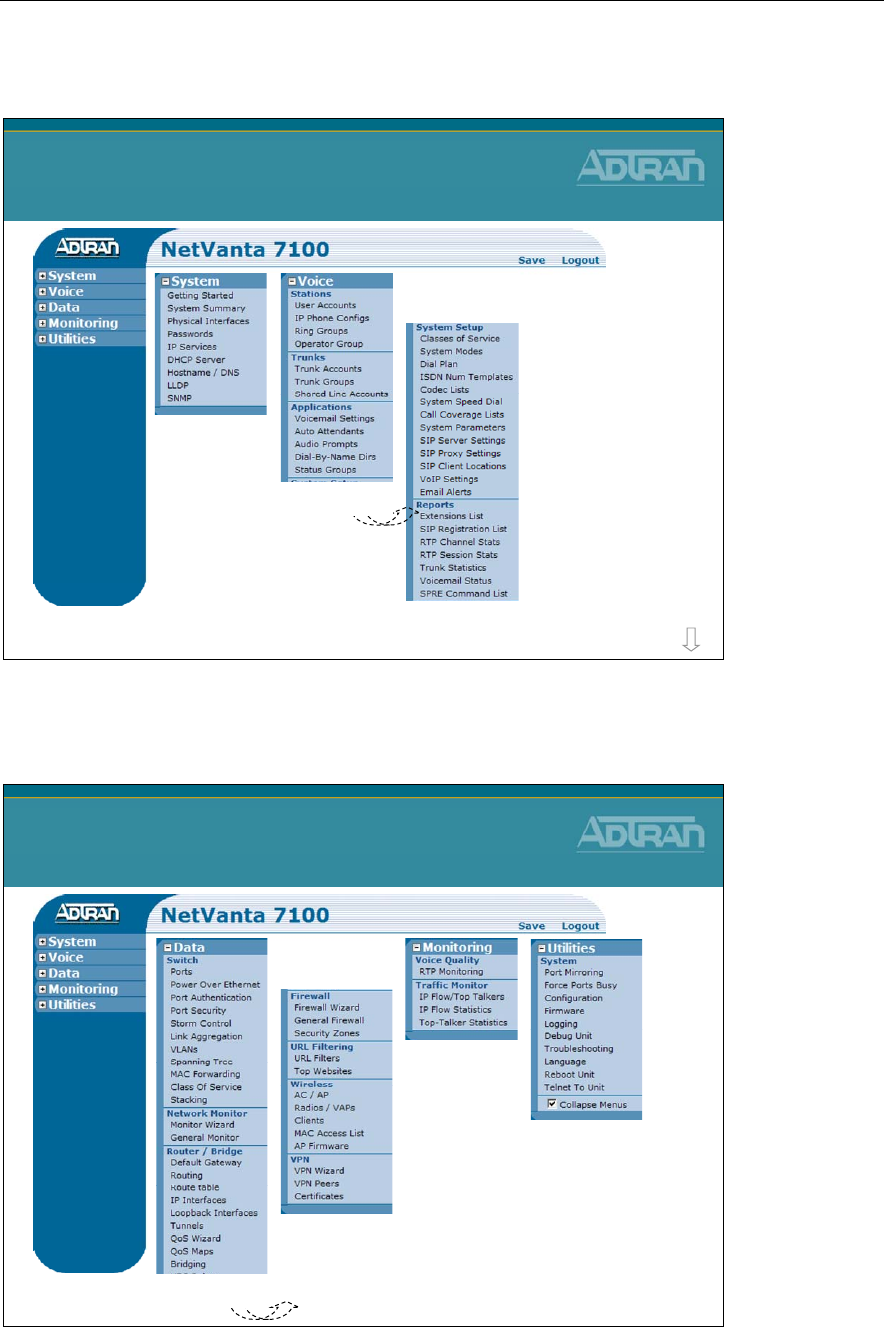
Module 2: Introduction to NetVanta 7000 Series Data Configuration
2-32 NetVanta IP Telephony Course
NetVanta 7000 Menus
NetVanta 7000 Menus
Voice Continued...
more
NetVanta 7000 Menus
NetVanta 7000 Menus
Data Continued...
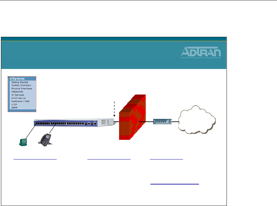
Module 2: Introduction to NetVanta 7000 Series Data Configuration
NetVanta IP Telephony Course 2-33
NetVanta 7000 - System Factory Defaults
Internet
NetVanta 7100
NetVanta 7000
System Factory Defaults
ETH 0/0
WAN
DHCP Client
Enable password: password
Services Enabled:
telnet / ssh
http / https
tftp / sntp
ADMIN ACCESS
Username: admin
Password: password
DNS Proxy: Enabled
DHCP Server
Data: 10.10.10.0 network
Voice: 10.10.20.0 network
Phone FTP Account
Username: polycomftp
Password: password
From the factory, the NetVanta Web-Based GUI is enabled and ready to be accessed. The
NetVanta is shipped from the factory with the services shown above.
ADTRAN strongly recommends that you change the default passwords shown above.
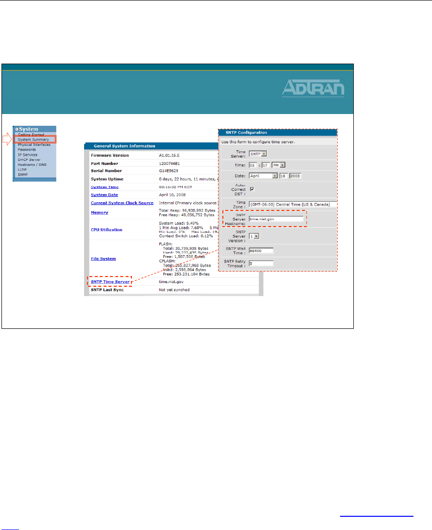
Module 2: Introduction to NetVanta 7000 Series Data Configuration
2-34 NetVanta IP Telephony Course
System/System Summary
•SNTP Configuration
System / System Summary
- Define SNTP Server (Simple Network Time Protocol)
The System Summary screen allows the user to view general system information regarding
the NetVanta 7000. This includes the firmware version, the part number, serial number,
and system uptime. System time and date may also be viewed (and set) on this screen.
Current System Clock Source
The preferred timing source for the system is defined here. The NetVanta 7000 can have
up to two independent T1 clock sources when a PRI is used. Select the T1/PRI interface to
configure the system timing source for the voice subsystem.
Configurable menu items such as system time and date are indicated by blue underlined
text. The user may click on these items to make changes. Non-configurable items are
shown in black text and are read-only status fields that may not be configured through this
menu.
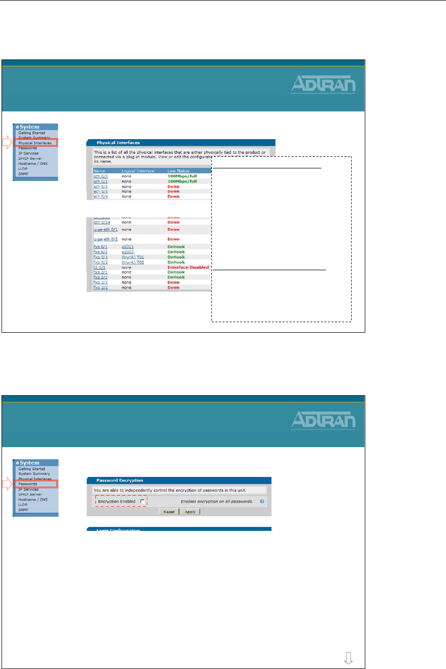
Module 2: Introduction to NetVanta 7000 Series Data Configuration
NetVanta IP Telephony Course 2-35
System/Physical Interfaces
•List available Physical Interfaces
System / Physical Interfaces
•Includes NIM/VIM interfaces
Physical Interfaces: Built In
eth 0/0 WAN port
eth 0/1 - eth 0/24 Switch ports
gig 0/1 - gig 0/2 Gig switch ports
fxs 0/1 - fxs 0/1 Station Ports
fxo 0/1 - fxo 0/2 Trunk Ports
Physical Interfaces: Modular
t1 1/1 T1/ PRI port
Fxs 2/1 - 2/2 Station ports
Fxo 2/1 - 2/2 Trunk port
System/Passwords
•Password Encryption
–Enabling this feature will encrypt all existing
passwords and any passwords entered in the future
–When disabled, all passwords entered will be clear
text
–Example:
•Clear text: username admin password password
•Encrypted: username "admin" password encrypted
"171fa669387f868ae7438c2154f6ae69bcb2"
System / Passwords
more
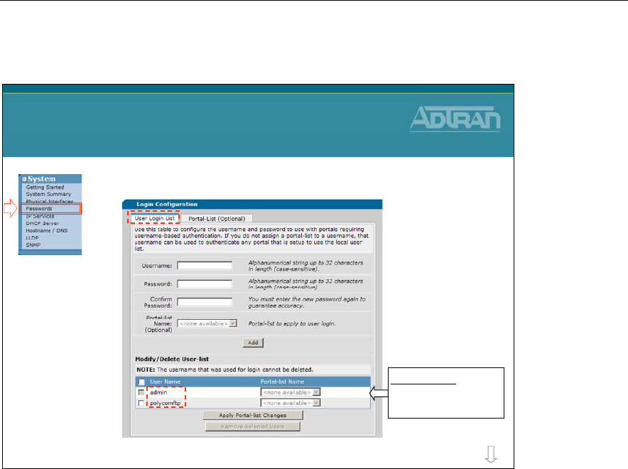
Module 2: Introduction to NetVanta 7000 Series Data Configuration
2-36 NetVanta IP Telephony Course
System/Passwords
•User Login List
System / Passwords
more
Default User
Username: admin
Password: password
Users created here
can be given access
to http, https, telnet,
ssh, and ftp
User Login List
Use this table to configure the username and password to use for all protocols requiring a
user name-based authentication system, including FTP server authentication, line (login
local-user list), HTTP, HTTPS, SSH, and Telnet access.
The username can be assigned a Portal List defining the specific application that this user
will have access to. If you do not assign a portal-list to a username, that username can be
used to authenticate any portal that is setup to use the local user list.
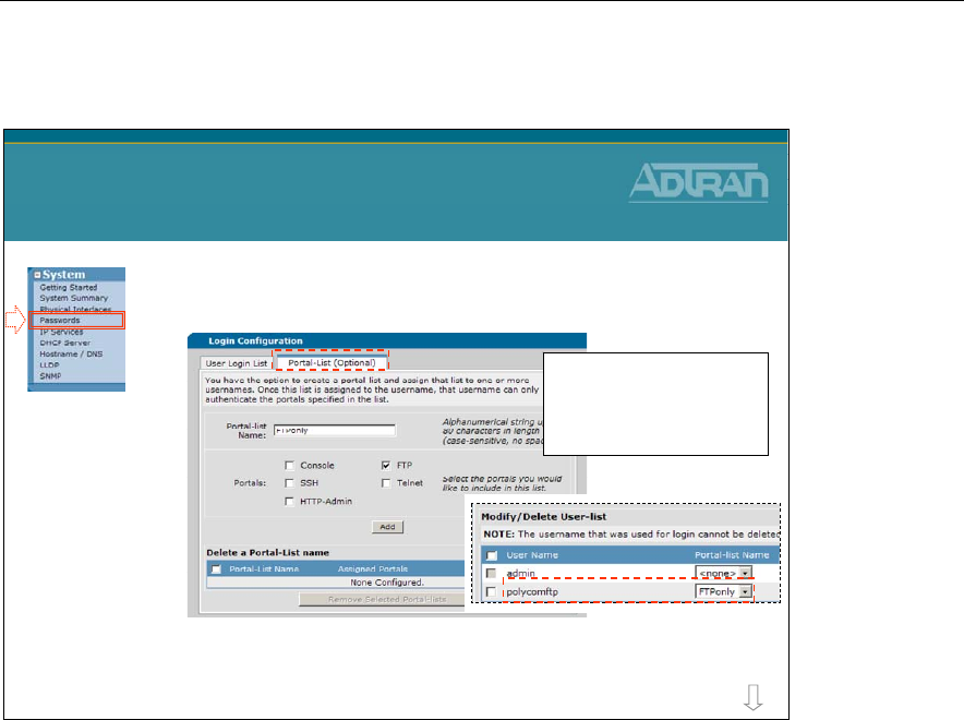
Module 2: Introduction to NetVanta 7000 Series Data Configuration
NetVanta IP Telephony Course 2-37
System/Passwords
•Portal-List allow users to be created with
restricted access modes
–Does not enable privilege levels
–Simply allows a user to access the router using only the
specified services or lines
System / Passwords
1. Create the portal list with
associated services and/or
lines
2. Assign users to a portal list
more
Portal-List (Optional)
You have the option to create a portal-list and assign that list to one or more usernames.
Once this list is assigned to the username, that username can only authenticate the portals
specified in the list as shown below:
- Console
- FTP
- SSH
- Telnet
- HTTP-Admin
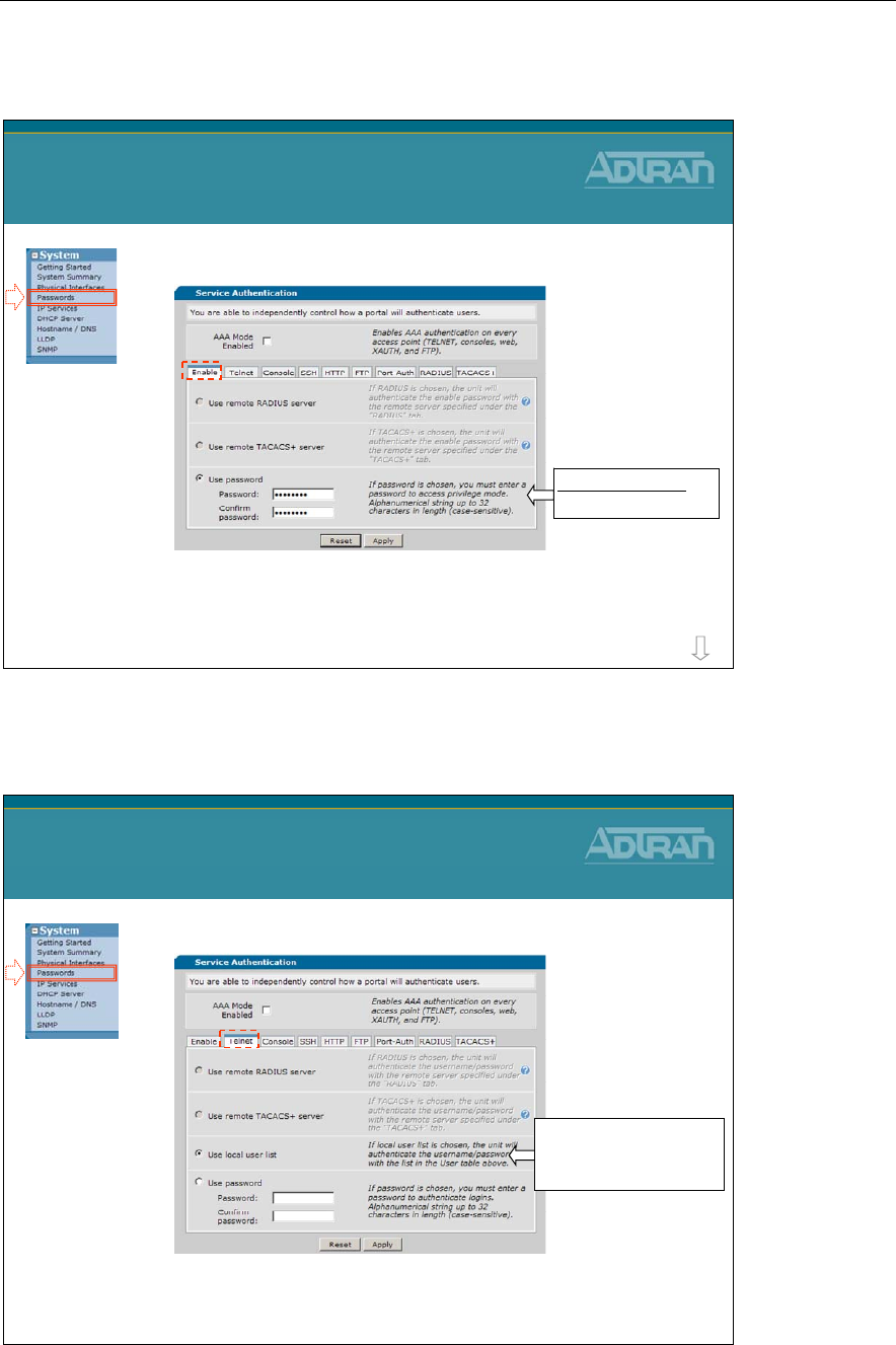
Module 2: Introduction to NetVanta 7000 Series Data Configuration
2-38 NetVanta IP Telephony Course
System/Passwords
•Enable Password
–The enable password is required to access the
privileged “enable” mode from the command line of
the ADTRAN Operating System
System / Passwords
more
Default Password
password
System/Passwords
•Telnet Password
–The telnet password is required to remotely login to
the command line of the ADTRAN Operating System
System / Passwords
Local user list is default
to username: admin and
password: password
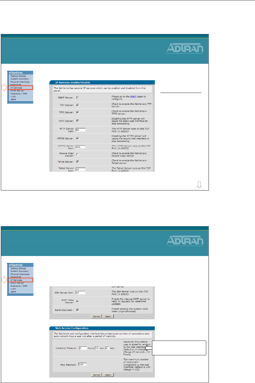
Module 2: Introduction to NetVanta 7000 Series Data Configuration
NetVanta IP Telephony Course 2-39
System/IP Services
•Enable/disable desired IP Services
System / IP Services
NetVanta Servers:
-SNMP
-FTP
-TFTP
-HTTP
-HTTPS
-SCP
-Telnet
- SSH
-SNTP more
System/IP Services
•IP Services (Continued…)
System / IP Services
Default inactivity timer:
10 minutes
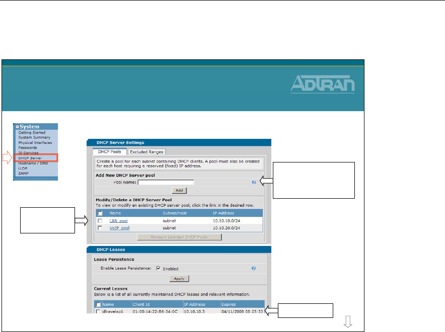
Module 2: Introduction to NetVanta 7000 Series Data Configuration
2-40 NetVanta IP Telephony Course
System/DHCP Server
•DHCP Server Configuration
System / DHCP Server
more
DHCP Leases
Click to edit
existing pool
Type name and click
Add to create new
DHCP server pool
The DHCP Server is enabled by default for both VLAN 1 and VLAN 2. The DHCP Server
pool for VLAN 1, the data network, provides IP addresses from the 10.10.10.0 /24
network. The DHCP Server pool for VLAN 2, the voice network, provides IP addresses
from the 10.10.20.0 /24 network.
If there is an existing DHCP server that you wish to use, there are a couple of options:
a. Remove the default DHCP server for VLAN 1 (typically for PCs on the LAN) and
leave the default DHCP server for VLAN 2 (used by IP Phones)
b. Remove the DHCP Server pools for both VLAN 1 and VLAN 2 and allow the existing
DHCP server to service both VLANs
Note: If the NetVanta 7060/7100 DHCP server is not used, DHCP Options (66 and
157) will need to be configured on the existing DHCP server. Review the default
configuration of the DHCP server pools for details and syntax.
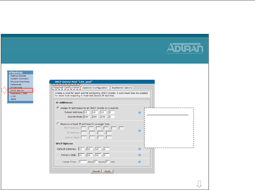
Module 2: Introduction to NetVanta 7000 Series Data Configuration
NetVanta IP Telephony Course 2-41
DHCP Server Pool – Required Configuration
•LAN_pool Required DHCP parameters
System / DHCP Server
more
DATA DHCP Pool
SA: 10.10.10.0
SM: 255.255.255.0
DG: 10.10.10.1
DNS: 10.10.10.1
Lease: 1 day
- DHCP pool for VLAN 1 (Data network)
The DHCP Server pool for VLAN 1, the data network, provides IP addresses from the
10.10.10.0 /24 network. Untagged traffic that enters a Switchport will be assigned to the
native VLAN, VLAN 1 by default. Since the IP address assigned to interface VLAN 1 falls
in the subnet 10.10.10.0 /24, it uses the DHCP pool LAN_Pool.
REQUIRED DHCP CONFIGURATION
IP Address Subnet
The IP addresses on the assigned subnet that are NOT excluded will be assigned to clients.
A Pool can be created to reserve a fixed IP address for a specific host. Host will always be
assigned this IP address and network mask. Typically the MAC address is set to the host's
Ethernet adapter MAC address.
Default Gateway
The default-gateway IP address that the DHCP server will assign to clients. When
specifying a router to use, verify that the router is on the same subnet as the DHCP client.
Typically, the default-gateway should be set to the IP address of an interface on the unit
you are configuring.
Primary DNS
If DNS proxy is enabled, the unit will forward DNS requests sent to any of its interface IP
addresses to the DNS servers. These servers can be obtained dynamically from an ISP or
configured statically on the Hostname/DNS page.
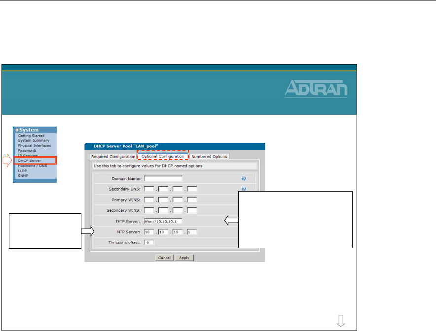
Module 2: Introduction to NetVanta 7000 Series Data Configuration
2-42 NetVanta IP Telephony Course
DHCP Server Pool – Optional Configuration
•LAN_pool Optional DHCP parameters
System / DHCP Server
more
TFTP Server: tftp://10.10.10.1
Note: This is option 66
A default Polycom phone
request this option to learn the
identity of the boot server
The Network Time
Protocol server is
set to the NV 7100
A list of NTP time servers can be found on NIST’s web site
http://tf.nist.gov/timefreq/service/time-servers.html
Example: time-a.nist.gov - 129.6.15.28
Domain Name
The Domain that the DHCP Clients will be a member of.
Secondary DNS
Clients will use secondary DNS if name resolution with primary fails.
Primary WINS
Needed for Microsoft Networking so clients can resolve NetBIOS names. Clients will
typically use secondary WINS if NetBIOS name resolution fails with primary.
TFTP Server
Host name (or address) of the TFTP server given to any requesting DHCP client. The
default value of tftp://10.10.10.1 is used by factory default Polycom phones during the
initial boot. A boot files tell the Polycom phone to use FTP after initial boot.
NTP Server
Network Time Protocol IP address served to a DHCP client. By default, the NetVanta
7XXX is the NTP server for LAN clients. The public time server used by the NetVanta
7XXX is configured from the System/Summary menu.
Timezone offset
Timezone offset in hours (-12 to 12). There are 25 integer World Time Zones from -12
through 0 (GMT) to +12. Each one is 15° of Longitude as measured East and West from
the Prime Meridian of the World at Greenwich, England. Set for your region.
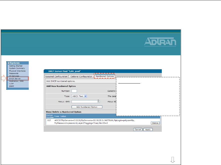
Module 2: Introduction to NetVanta 7000 Series Data Configuration
NetVanta IP Telephony Course 2-43
DHCP Server Pool – Numbered Options
•LAN_pool Numbered DHCP Options
•The IP 700 Series phone uses site-specific
Option 157 to request boot parameters
System / DHCP Server
more
Option 157
TftpServers=0.0.0.0
FtpServers=10.10.20.1:/ADTRAN
FtpLogin=polycomftp
FtpPassword=password
Layer2Tagging=True
VlanID=2
DHCP numbered options describe a generic DHCP option to be published to the DHCP
client. The admin may specify any number of generic options to be published to the client.
Number
Generic option number. Valid values are 0-255.
Type
The data type for the numbered option:
- Ascii Text
- Hex
- IP Address
ASCII Text
ASCII text data for the option.
The IP 700 Series phone uses site-specific Option 157 to provide the following information
to the phones: TftpServers=0.0.0.0, FtpServers=10.10.20.1:/ADTRAN,
FtpLogin=polycomftp, FtpPassword=password, Layer2Tagging=True, VlanID=2
* Option 157 must be set on both the LAN_pool and the VoIP_pool to direct the phones to
the correct boot server.

Module 2: Introduction to NetVanta 7000 Series Data Configuration
2-44 NetVanta IP Telephony Course
System/DHCP Server
•VoIP_pool Required DHCP parameters
System / DHCP Server
more
- DHCP pool for VLAN 2 (Voice network)
VOICE DHCP Pool
SA: 10.10.20.0
SM: 255.255.255.0
DG: 10.10.20.1
DNS: 10.10.20.1
Lease: 1 day
The DHCP Server pool for VLAN 2, the voice network, provides IP addresses from the
10.10.20.0 /24 network. Generally, IP phones will learn and tag voice traffic with a VLAN
ID of 2. Since the IP address assigned to interface VLAN 2 falls in the subnet 10.10.20.0
/24, it uses the DHCP pool VoIP_Pool.
Other than IP addresses, the DHCP server pools LAN_Pool and VoIP_Pool are identical.
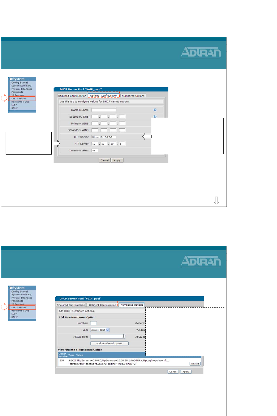
Module 2: Introduction to NetVanta 7000 Series Data Configuration
NetVanta IP Telephony Course 2-45
System/DHCP Server
•VoIP_pool Optional DHCP parameters
System / DHCP Server
more
TFTP Server: tftp://10.10.20.1
Note: This is option 66
A default Polycom phone
request this option to learn the
identity of the boot server
The Network Time
Protocol server is
set to the NV 7100
A list of NTP time servers can be found on NIST’s web site
http://tf.nist.gov/timefreq/service/time-servers.html
Example: time-a.nist.gov - 129.6.15.28
System/DHCP Server
•VoIP_pool Numbered DHCP Options
•The IP 700 Series phone uses site-specific
Option 157 to request boot parameters
System / DHCP Server
Option 157
TftpServers=0.0.0.0
FtpServers=10.10.20.1:/ADTRAN
FtpLogin=polycomftp
FtpPassword=password
Layer2Tagging=True
VlanID=2
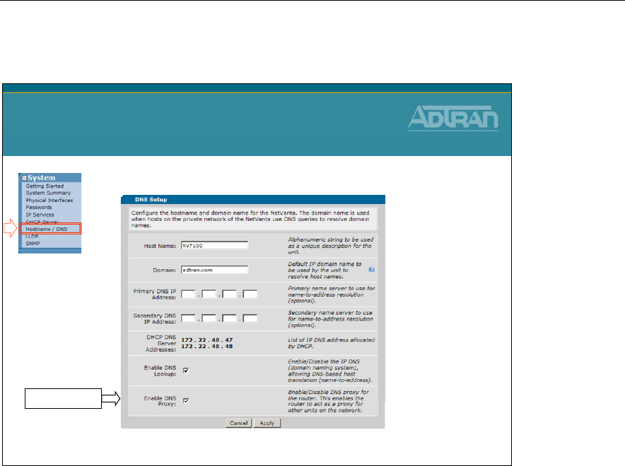
Module 2: Introduction to NetVanta 7000 Series Data Configuration
2-46 NetVanta IP Telephony Course
System/Hostname/DNS
•DNS Proxy
System / Hostname / DNS
- The NetVanta 7100 will proxy for clients on the network
DNS Proxy
Host Name
Alphanumeric string to be used as a unique description for the unit.
Domain
Default IP domain name to be used by the unit to resolve host names.
Primary /Seconday DNS IP Address:
Primary/Seconday name server to use for name-to-address resolution (optional).
DHCP DNS Server Addresses:
List of IP DNS address allocated by DHCP.
Enable DNS Lookup:
Enable/Disable the IP DNS (domain naming system), allowing DNS-based host translation
(name-to-address).
Enable DNS Proxy
By default, DHCP clients send DNS request to the NetVanta 7XXX. With DNS Proxy
enabled, The NetVanta 7XXX will forward the DNS request to the DNS server it learned
on it WAN. The Ethernet 0/0 WAN interface is configured as a DHCP client by default.
If the NetVanta 7XXX DHCP pools are configured with the ISPs DNS server IP address,
DNS Proxy can be disabled.
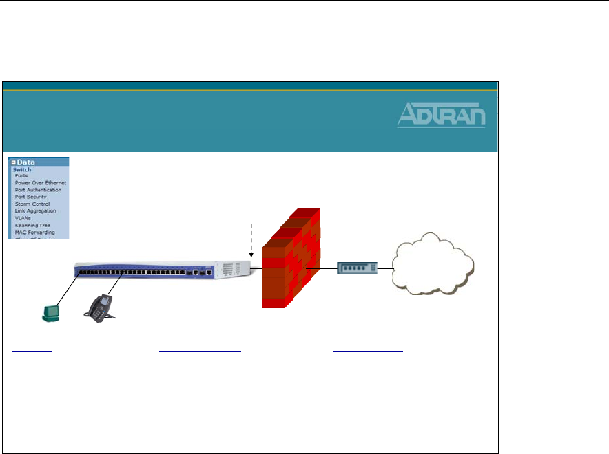
Module 2: Introduction to NetVanta 7000 Series Data Configuration
NetVanta IP Telephony Course 2-47
NetVanta 7000 Data/Switch Factory Defaults
Internet
NetVanta 7100
NetVanta 7000
Data / Switch Factory Defaults
ETH 0/0
WAN
DHCP Client
Ethernet 0/1-24
Enabled (activated with no shut)
Speed/Duplex/Cable Type: auto
Switchport mode: trunk
Allowed VLANs: all
Native VLAN: 1
Spanning Tree Mode: edgeport
VLANs
Data - VLAN 1
IP Address: 10.10.10.1/24
Voice - VLAN 2
IP Address: 10.10.20.1/24
Gigabit 0/1-2
Enabled (activated with no shut)
Speed/Duplex/Cable Type: auto
VLAN membership: trunk
VLAN 1 is defined with an IP address of 10.10.10.1 255.255.255.0
VLAN 2 is defined with an IP address of 10.10.20.1 255.255.255.0
It is often necessary to change the VLAN IP address scheme on a NetVanta 7100 from its
factory default settings. This is usually done at the request of the customer so that the
NetVanta 7100 can reside in an existing network without requiring changes to devices
currently running on that network.
If changing the current IP scheme, additional settings will need to be applied in order to
have proper phone operation when VLAN subnet changes have been applied. Include the
following areas when making your IP changes:
- DHCP Pools
- IP Phone Config – Boot Settings tab
- IP Phone Configs – Default Settings tab
- Firewall Policies
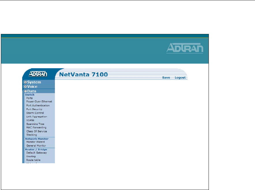
Module 2: Introduction to NetVanta 7000 Series Data Configuration
2-48 NetVanta IP Telephony Course
Switch Factory Defaults VLANs
Switch Factory Defaults
VLANs
What is a VLAN?
A VLAN (Virtual LAN) acts like an
ordinary LAN, but connected devices
don't have to be physically connected
to the same segment.
Virtual Local Area Network (VLAN)
Routers, computers and other data devices have the ability to send a type of message
known as a “broadcast message”. Broadcast messages are sent to every device or node
within a given network or subnetwork. Common functions of broadcast messages are to
identify when network devices are enabled and available, to advertise services, and to
request address resolution. Many of these types of messages are vital to network
operation. Yet, the frequency of these messages and the number of devices on a network
transmitting these messages could cause network congestion. Unlike collision domains,
which may be divided based on Layer 2 MAC Addresses, broadcast domains typically
exist at the logical or network layer of the OSI model. An example of this is when a
broadcast message is defined for the broadcast address (10.10.10.255) of the
(10.10.10.0/24) network. A Layer 2 switch would forward this message (or IP packet) out
all switch ports, as it does not know which end devices are members of the 10.10.10.0/24
network. A router is the device that recognizes this.
So, the question exists, how would a switch break up broadcast domains? Or, is this
function only available in a Layer 3 device such as a router?
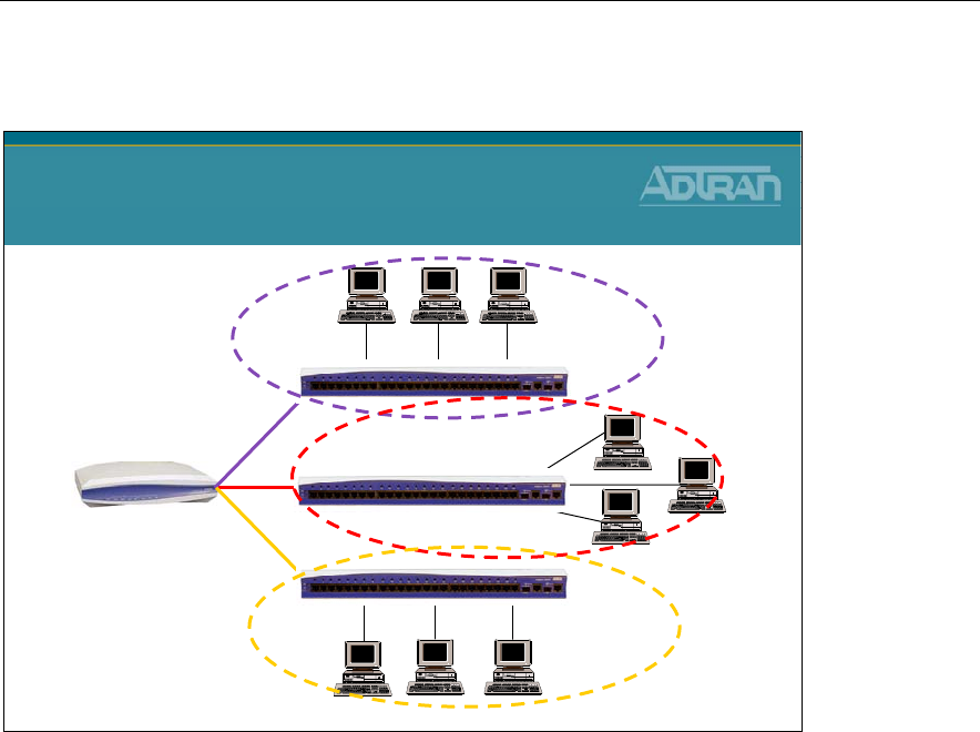
Module 2: Introduction to NetVanta 7000 Series Data Configuration
NetVanta IP Telephony Course 2-49
Switch Factory Defaults With Out VLANs
Switch Factory Defaults
With Out VLANs
Broadcast Domain 1
Broadcast Domain 2
Broadcast Domain 3
In a single Layer 2 switch, without the use of virtual local area networks (VLANs), this
function is not possible. Separate switches create separate broadcast domains so that
broadcast messages from attached devices do not get sent to devices attached to the other
switches, unless sent through the router. Every device connected to a single switch will
receive all broadcast traffic generated by any end device connected to that same switch.
This is not the most streamlined or cost-effective approach to designing a network.
Purchasing switches simply to break up a broadcast domain, and not based on port density
and performance, may lead to wasted switch ports and underutilized resources. An
alternative solution is the use of VLANs in a single switch.
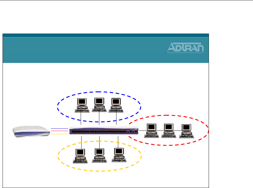
Module 2: Introduction to NetVanta 7000 Series Data Configuration
2-50 NetVanta IP Telephony Course
Switch Factory Defaults With VLANs
Switch Factory Defaults
With VLANs
Broadcast Domain 1 (VLAN 1)
Broadcast Domain 2 (VLAN 2)
Broadcast Domain 3 (VLAN 3)
Incorporating VLANs
Basic components of VLANs: A VLAN or Virtual Local Area Network is designed to
provide a logical segmentation of devices which may be based on function or application,
rather than physical location. VLANs provide the ability to break up broadcast domains in
a switch by segmenting the ports of the switch based on their VLAN ID.
Incorporating VLANs into a typical network allows for control and segmentation of that
network. By using VLANs, a single switch may accomplish the same task as the previous
diagram by creating separate broadcast domains but still allowing inter-vlan routing to
occur (provided each switch and VLAN has a connection to the router). Multiple end-user
devices may be connected to a single switch but belong to different numbered VLANs.
Even though the devices are physically connected to the same switch, they would not be
able to communicate without the aid of the router or other layer 3 device. (The router has
the ability to route or talk between VLANs.) In essence, a VLAN breaks up a broadcast
domain by allowing broadcast messages transmitted by devices that are connected to
switchports with a specific VLAN membership ID to only be received by devices
connected to switchports with that same VLAN membership ID.
VLANs are able to span devices. Therefore, if trunk communication exists between two
switches, devices connected to switchports that have the same VLAN membership ID on
both switches are able to transmit and receive traffic within that VLAN without a router
present.
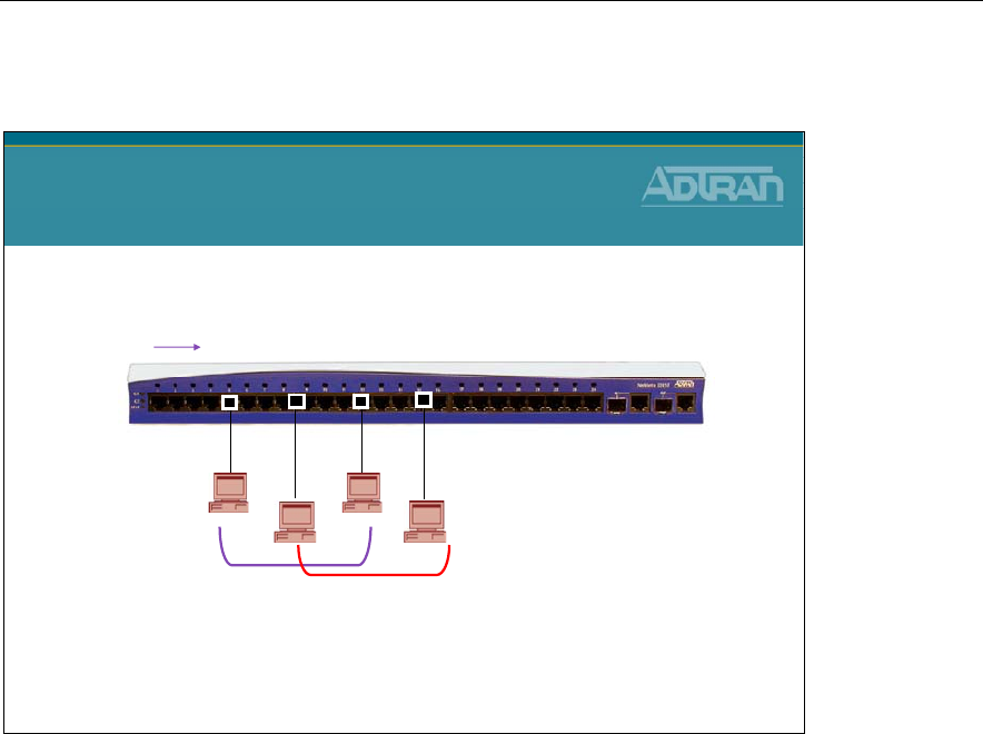
Module 2: Introduction to NetVanta 7000 Series Data Configuration
NetVanta IP Telephony Course 2-51
Port-Based VLAN
Port-Based VLAN
5912 15
Port #
VLAN # 100 VLAN # 101
The NetVanta switchports support port-based or static VLANs. Static VLANs are created
by manually assigning a VLAN number to a specific interface in configuration. The end-
device attached to that interface does not know the VLAN exists, as the switch is
responsible for determining which VLAN the traffic came from and then forwarding
broadcasts to other members of the same VLAN. Therefore, any device attached to a
switchport defined with a specific VLAN ID would be able to transmit messages to other
devices that are attached to switchports with the same VLAN ID.
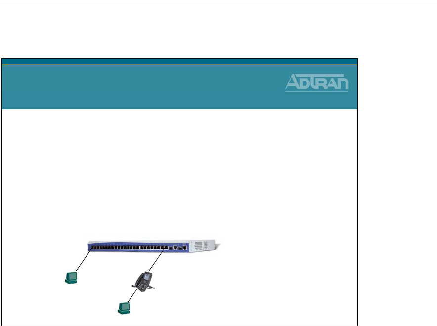
Module 2: Introduction to NetVanta 7000 Series Data Configuration
2-52 NetVanta IP Telephony Course
Types of VLAN Ports
Types of VLAN Ports
•Access Port
–Only a member of 1 VLAN
•Trunk Port
–Allows multiple VLANs (VLAN Trunking)
–802.1Q is the standard supported for VLAN Trunking
–By default, all active VLANs are allowed to transmit and
receive traffic on a trunk port
Phone learns and tags Voice = VLAN 2
PC traffic untagged – goes to native vlan = VLAN 1
PC traffic untagged
Goes to native vlan,
VLAN 1
All ports default as
Trunk Port
with Native VLAN 1
There are two types of VLAN ports that may be configured on the NetVanta: access ports
and trunk ports.
Access ports may only be a member of one VLAN. Each switchport may be assigned a
single access VLAN. Therefore, if connecting between devices a separate port is needed
for each VLAN in access mode. This is a valid application, but will quickly use up
available physical interfaces. However, a port may be used to transport multiple VLANs,
typically in between switchports of different units or to a Layer 3 device such as a router.
This port is known as a “trunk port”.
Trunk ports are the other type of VLAN ports that may be configured in a NetVanta
switch. A trunk port may carry multiple VLANs across a single interface. Trunk ports are
used to connect to other devices that may also need to communicate with those VLANs, or
to allow inter-vlan routing.
A trunk is a point to point link that transmits and receives traffic between switches or
between switches and routers. Trunks can carry traffic from multiple VLANs and can
extend VLANs across an entire network. On a NetVanta unit, any switchport may be used
for trunking. The standard for VLAN trunking is defined by the IEEE 802.1Q standard.
This is the method that is supported in the NetVanta AOS devices.
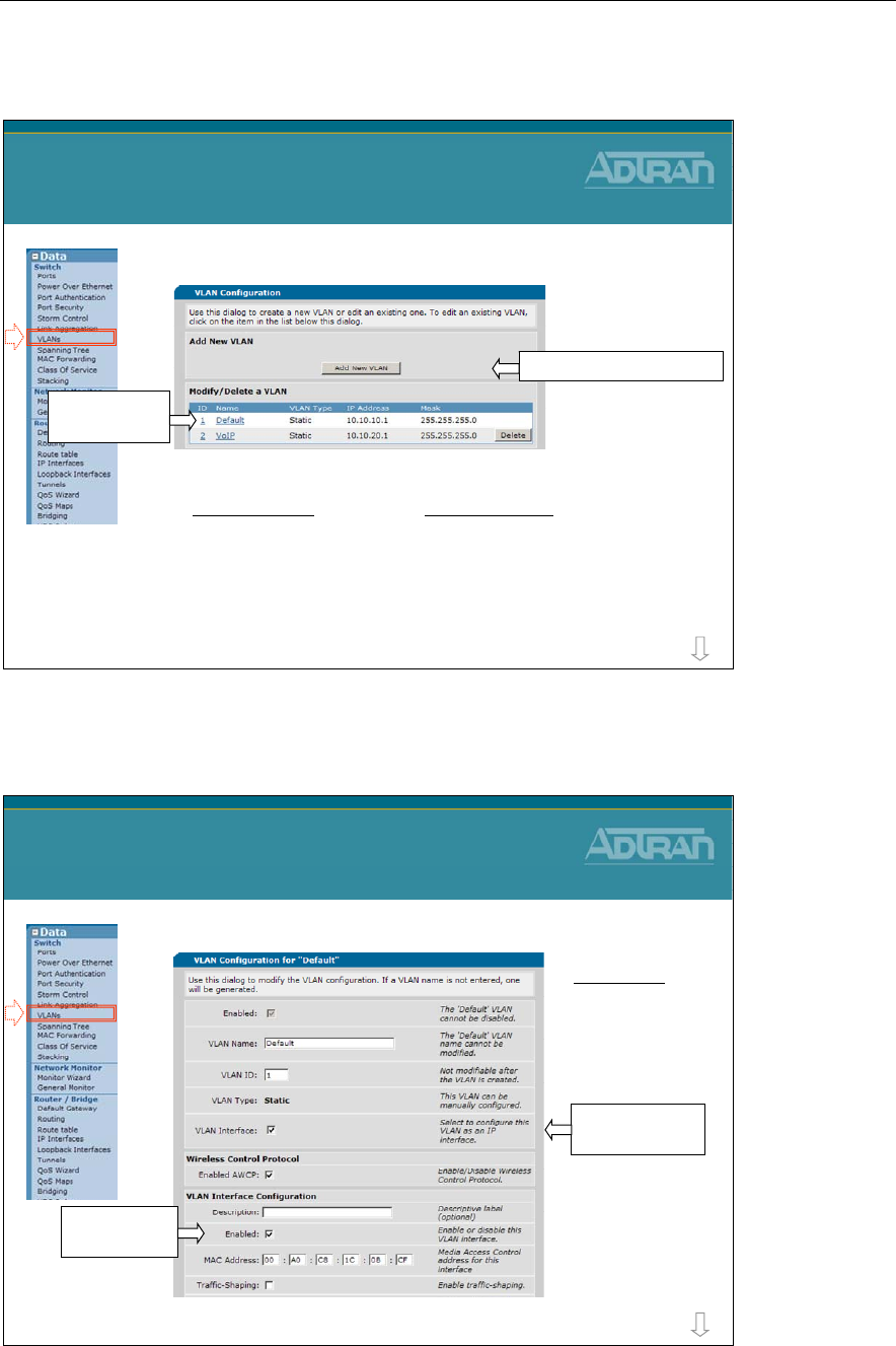
Module 2: Introduction to NetVanta 7000 Series Data Configuration
NetVanta IP Telephony Course 2-53
Data/Switch/VLANs
•VLAN Configuration
Data / Switch / VLANs
Click to edit
existing VLAN
Click to Add a new VLAN
Data – VLAN 1
IP: 10.10.10.1
SM: 255.255.255.0
Voice – VLAN 2
IP: 10.10.20.1
SM: 255.255.255.0
more
Data/Switch/VLANs
•Data VLAN
Data / Switch / VLANs
Enable IP on this
interface
Enable VLAN
interface
more
Data VLAN
Name: Default
ID: 1
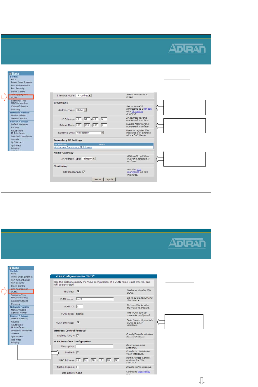
Module 2: Introduction to NetVanta 7000 Series Data Configuration
2-54 NetVanta IP Telephony Course
Data/Switch/VLANs
•Data VLAN (Continued…)
Data / Switch / VLANs
Data VLAN
Name: Default
ID: 1
Address Type
set to Static
VLAN IP address
and subnet mask
Media-Gateway
set to Primary
Data/Switch/VLANs
•Voice VLAN
Data / Switch / VLANs
Enable IP on this
interface
Enable VLAN
interface
more
Voice VLAN
Name: VoIP
ID: 2
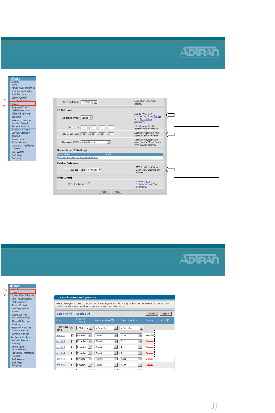
Module 2: Introduction to NetVanta 7000 Series Data Configuration
NetVanta IP Telephony Course 2-55
Data/Switch/VLANs
•Voice VLAN (Continued…)
Data / Switch / VLANs
Voice VLAN
Name: VoIP
ID: 2
Address Type
set to Static
VLAN IP address
and subnet mask
Media-Gateway
set to Primary
Data/Switch/Ports
•Switch Port Configuration
Data / Switch / Ports
more
* With Spanning-tree running, switchports take 50 seconds to reach the forwarding state.
With the Edge port mode enabled, active ports immediately go to forwarding state.
Port Configuration
Edge Port Mode: Enabled
Membership: Trunk
Speed/Duplex: Auto
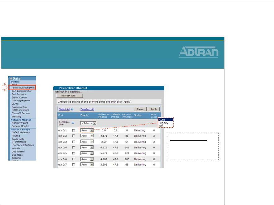
Module 2: Introduction to NetVanta 7000 Series Data Configuration
2-56 NetVanta IP Telephony Course
Data/Switch/Power Over Ethernet
•Power Over Ethernet
–The default setting of Auto will detect attached Powered
Devices (PDs) and deliver 48 VDC, compliant with the
IEEE 802.3af power-over-Ethernet standard
Data / Switch / Power Over Ethernet
Power Options
Auto: Detect 802.3af
Legacy: Non 802.3af
Off: Power disabled
Power over Ethernet (PoE) technology provides the ability to detect attached Powered
Devices (PDs) and deliver 48 VDC to the PD via existing CAT5 cabling. The NetVanta
7000 units are fully compliant with the power delivery options called out in the IEEE
802.3af Power over Ethernet specification. By default, the PoE interfaces discover and
provide power to IEEE compliant PDs.
To disable power detection and supply, change the PoE port setting to Off. This can also
be used as a quick toggle to power cycle phones. Remove power, click apply to remove
power. Then change setting back to Auto and then click Apply to restore power to phone.
The Legacy option, enables power detection and supply of legacy non-IEEE 802.3af
compliant PDs.
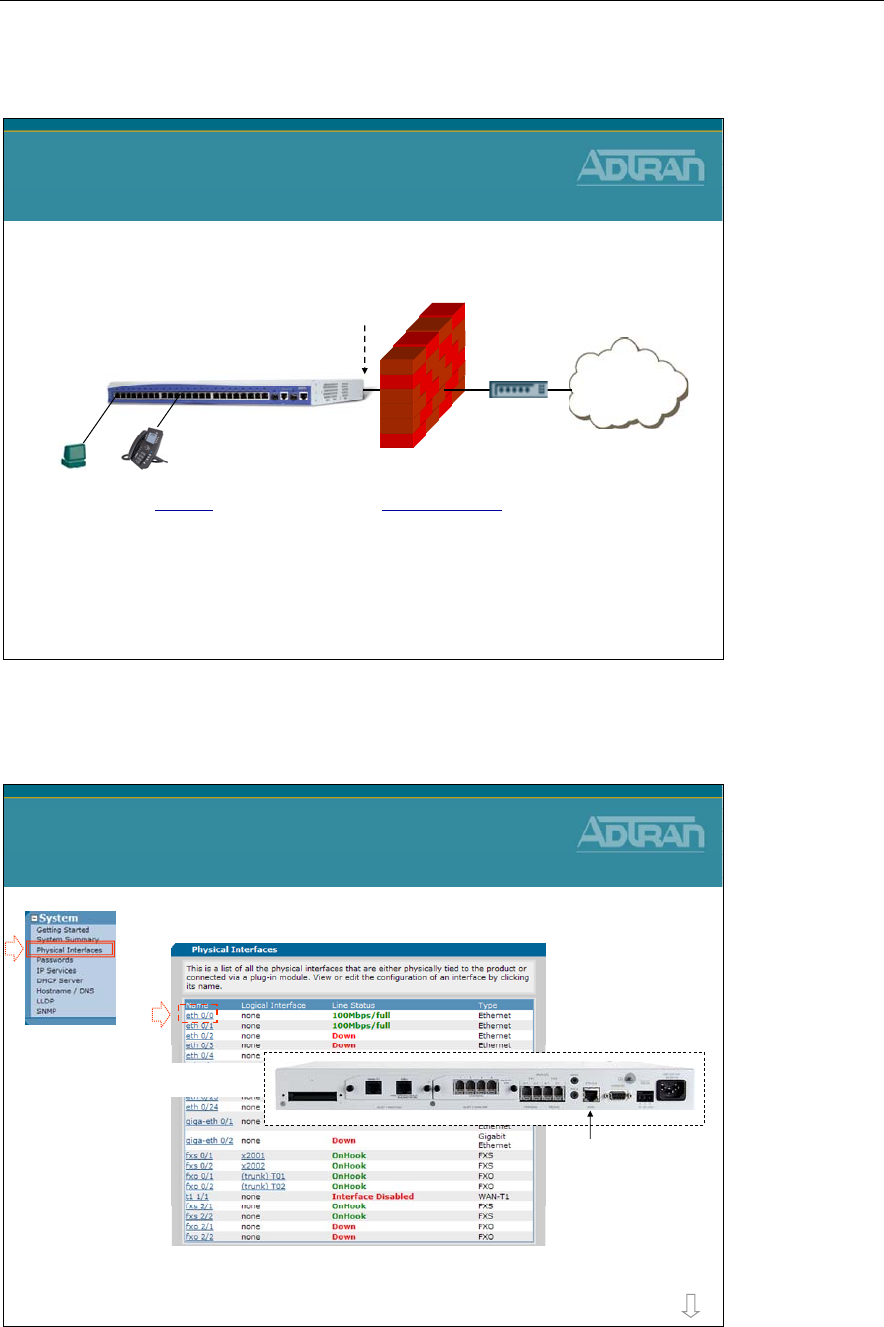
Module 2: Introduction to NetVanta 7000 Series Data Configuration
NetVanta IP Telephony Course 2-57
NetVanta 7000 - Router Factory Defaults
Internet
NetVanta 7100
NetVanta 7000
Router Factory Defaults
ETH 0/0
WAN
DHCP Client
Ethernet 0/1-24
Switchport mode: trunk
Allowed VLANs: all
Native VLAN: 1
VLANs
Data - VLAN 1
IP Address: 10.10.10.1/24
Voice - VLAN 2
IP Address: 10.10.20.1/24
WAN Ethernet 0/0
•Interface Ethernet 0/0 (WAN) Configuration
WAN Ethernet 0/0
more
•Click to edit interface eth 0/0
WAN
Ethernet
Port
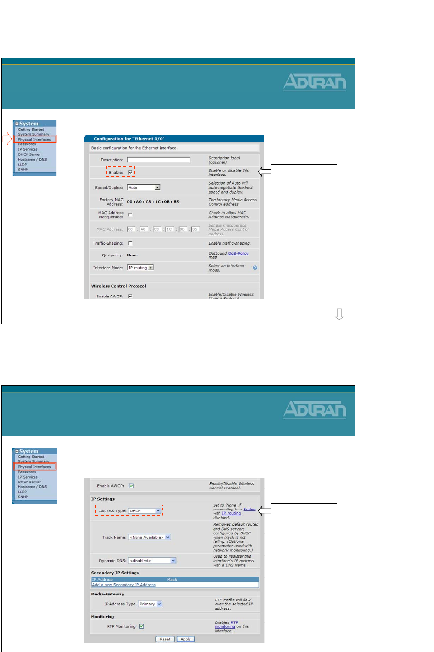
Module 2: Introduction to NetVanta 7000 Series Data Configuration
2-58 NetVanta IP Telephony Course
WAN Ethernet 0/0
•Interface Ethernet 0/0 (WAN) Configuration
WAN Ethernet 0/0
more
Interface enabled
WAN Ethernet 0/0
•Interface Ethernet 0/0 (WAN) Configuration
WAN Ethernet 0/0
DHCP Client
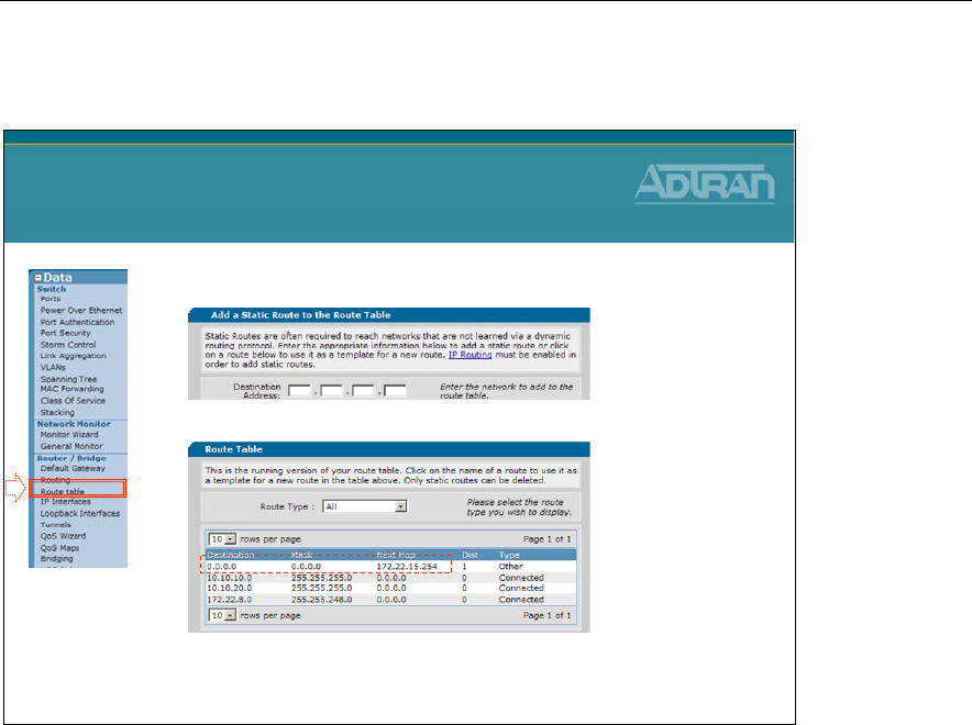
Module 2: Introduction to NetVanta 7000 Series Data Configuration
NetVanta IP Telephony Course 2-59
Data / Router / Route table
•Default Route to ISP
Data / Router / Route table
* From the factory, interface Ethernet 0/0 is configured as a DHCP client.
The default route is learned from the ISP by default.
From the factory, interface Ethernet 0/0 is configured as a DHCP client. Not only does the
interface get assigned an IP address, it also receives a default route and the primary DNS
server.
If interface Ethernet 0/0 is being assigned a static IP address, you must manually define the
default route used by the NetVanta 7XXX.
To Configure a Default Route, set following:
Destination Address: 0.0.0.0
Destination Mask: 0.0.0.0
Gateway: Enter next hop (gateway)
or
Select WAN interface

Module 2: Introduction to NetVanta 7000 Series Data Configuration
2-60 NetVanta IP Telephony Course
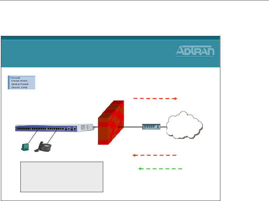
Module 2: Introduction to NetVanta 7000 Series Data Configuration
NetVanta IP Telephony Course 2-61
NetVanta 7100 - Data/Firewall Factory Defaults
NetVanta 7100
Data / Firewall Factory Defaults
Internet
NetVanta 7100
No traffic
allowed in to LAN
All traffic
allowed out
Firewall enabled
The factory default NetVanta
7100 has two security zones
- Public
-Private
PUBLICPRIVATE
Except the following:
SIP (UDP Port 5060)
WAN ADMIN Access
Secure Shell - ssh
Secure Web - https
The factory default NetVanta 7100 allows (and NATs) all traffic going to the internet.
UDP port 5060 SIP traffic, secure shell, and secure web traffic are the only traffic allowed
in the PUBLIC interface by default.
The NetVanta 7100 is equipped with a stateful inspection firewall. A stateful inspection
firewall operates by monitoring traffic passing through it. It only allows traffic it is
specifically configured to allow as well as return traffic matching traffic that was
specifically allowed.
For example, if a computer sends a request to a web site, through the firewall, it is only
necessary to configure an allow (NAT) for the outbound traffic, the traffic from the
requesting computer to the web server. The response traffic from the website will be
automatically allowed. All traffic that has not been initiated from within the network will
be automatically blocked unless otherwise specified.
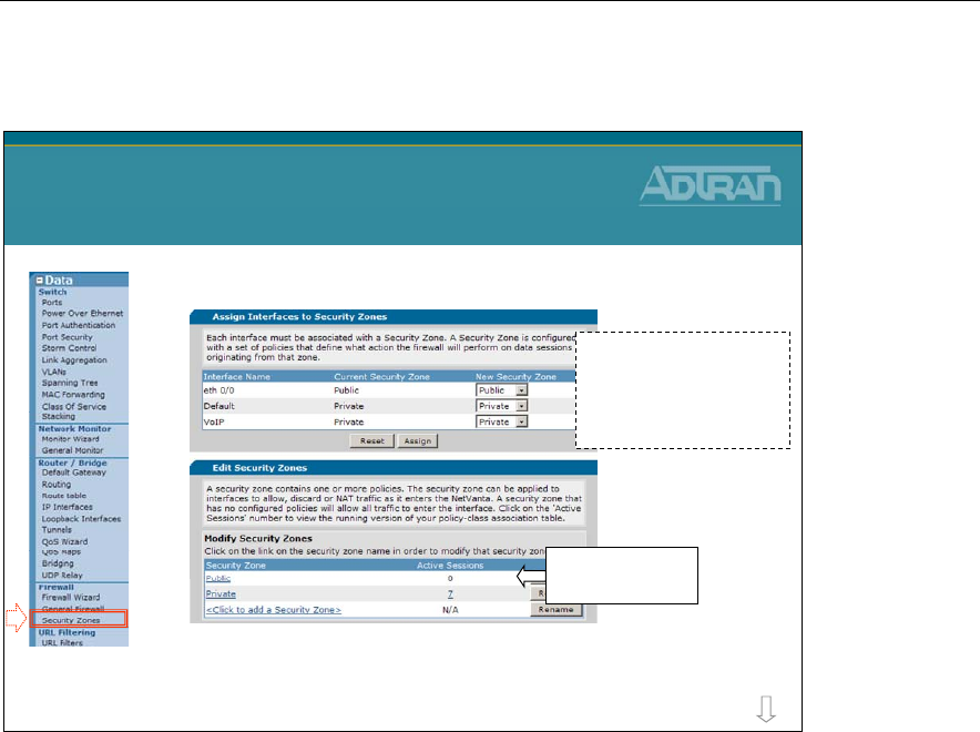
Module 2: Introduction to NetVanta 7000 Series Data Configuration
2-62 NetVanta IP Telephony Course
Data/Firewall - Security Zones
•Firewall Configuration
–The Factory Default NetVanta 7100 has two
security zones (Public and Private)
Data / Firewall
Security Zones
more
Click to edit exist
Security Zone
Eth 0/0 is assigned to
Public security zone and
the Data and Voice
VLANS are assigned to
the Private security zone
Each interface should be associated with a Security Zone. A Security Zone is configured
with a set of policies that define what action the firewall will perform on data sessions
originating from that zone. A security zone that has no configured policies will allow all
traffic to enter the interface.
The Public and Private Security Zone listed above are present with the factory delivered
NetVanta 7100. The firewall inspects traffic inbound. To control traffic coming from the
Internet, modify the Public Security Zone. To control traffic coming from VLAN 1 or
VLAN 2, modify the Private Security Zone.
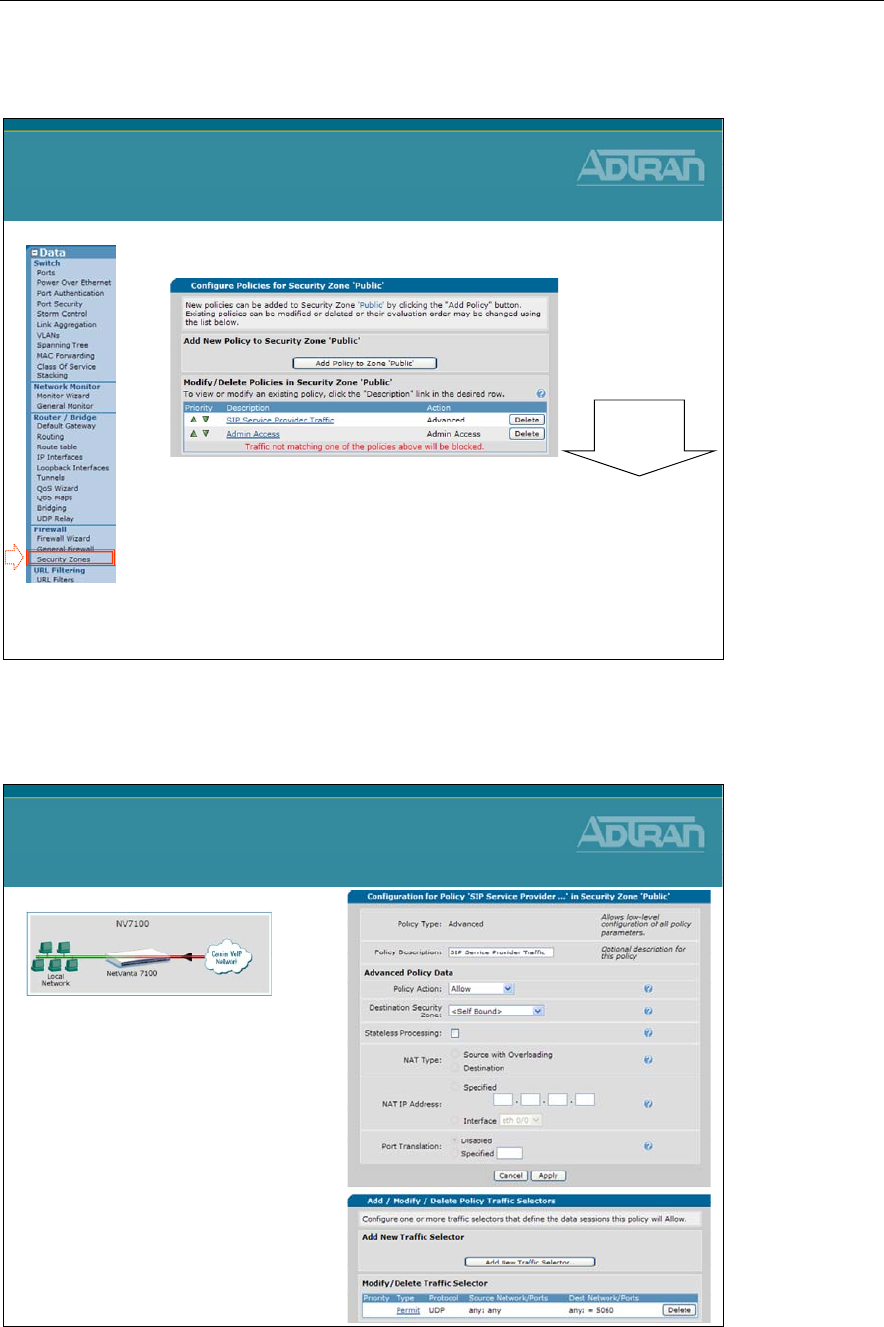
Module 2: Introduction to NetVanta 7000 Series Data Configuration
NetVanta IP Telephony Course 2-63
Data/Firewall - Public Security Zone
•Access from Outside the NetVanta 7100
–SIP Service Provider Traffic
•Allow SIP (UDP 5060) traffic in
–Admin Access
•Allow allows https and ssh access from the Public security
zone
Data / Firewall
Public Security Zone
Top down
processing
Public Security Zone - SIP Service Provider Traffic
Public Security Zone
SIP Service Provider Traffic
•The SIP Service Provider
policy allows SIP – UDP
port 5060 from anywhere
in to the NetVanta 7100
–If this is truly from a SIP
service provider, the traffic
selector should be modified
defining the source as the
specific IP address of
service provider
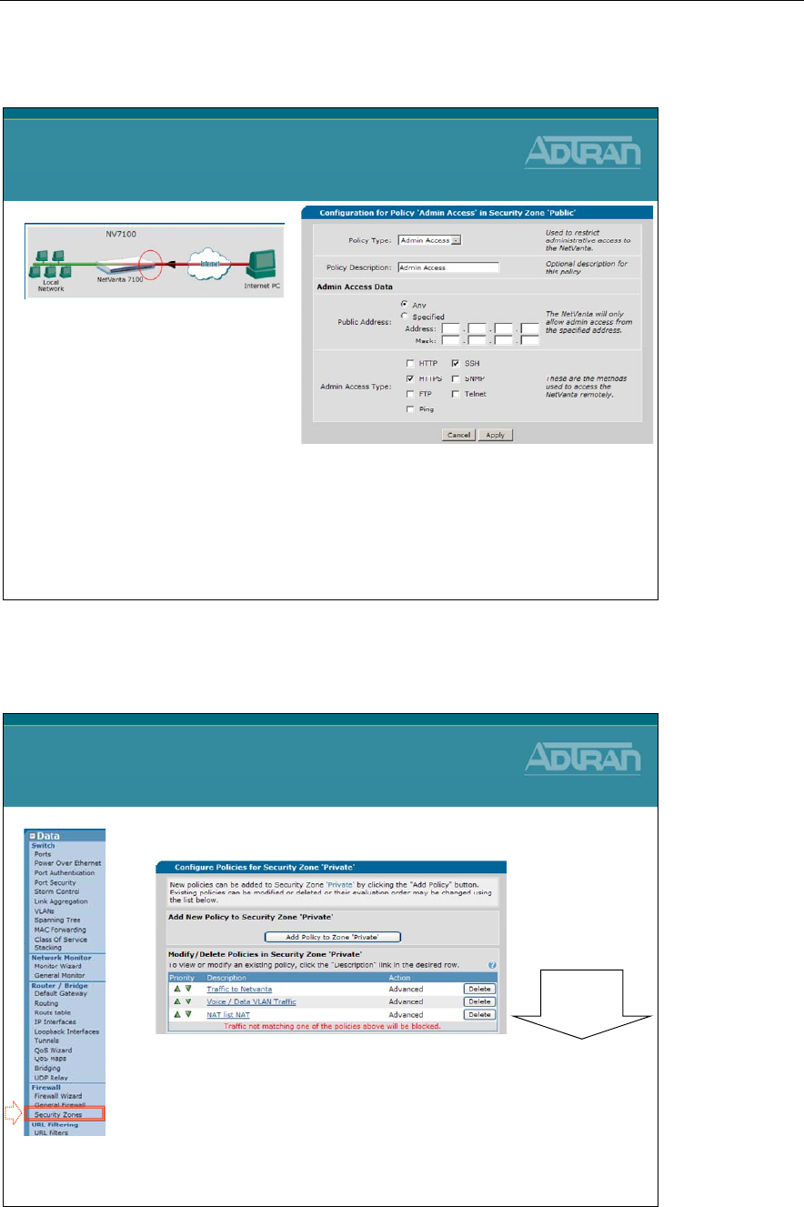
Module 2: Introduction to NetVanta 7000 Series Data Configuration
2-64 NetVanta IP Telephony Course
Public Security Zone – Admin Access
Public Security Zone
Admin Access
•The Admin Access policy
allows https and ssh
access from the Public
security zone by default
–Can be more specific
–Could also allow other admin
traffic such as:
•HTTP, FTP, SNMP, Telnet, and
Ping
Data/Firewall - Private Security Zone
•Access from LAN
–Traffic to NetVanta
•Inside traffic with destination of NetVanta 7100 allowed
–Voice / Data VLAN Traffic
•Allow VLAN to VLAN traffic
–NAT list NAT
•Allow all traffic going to Internet
Data / Firewall
Private Security Zone
Top down
processing
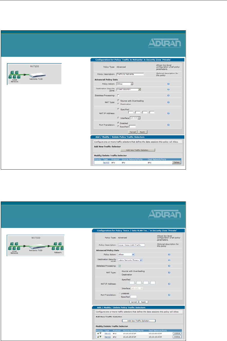
Module 2: Introduction to NetVanta 7000 Series Data Configuration
NetVanta IP Telephony Course 2-65
Private Security Zone – Traffic to NetVanta
Private Security Zone
Traffic to NetVanta
•Inside traffic with a
destination of the
NetVanta 7100 is allowed
–Examples:
•SIP
•RTP
•DHCP
•TFTP
•FTP
Private Security Zone – Voice / Data VLAN Traffic
Private Security Zone
Voice / Data VLAN Traffic
•Allow VLAN to VLAN traffic
•Required if you want to
allow the following:
–PC with Softphone
to call a SIP hard phone
–PC to access WEB GUI of an IP
phone
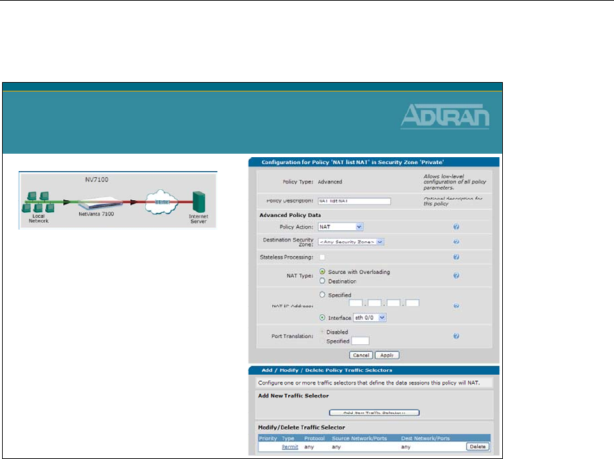
Module 2: Introduction to NetVanta 7000 Series Data Configuration
2-66 NetVanta IP Telephony Course
Private Security Zone – NAT list NAT
Private Security Zone
NAT list NAT
•Allow all traffic going
to Internet
–Traffic selectors matches
all traffic
–Outbound traffic is translated
from the private inside IP
address to the public IP
address assigned to the
outgoing interface

Module 2: Introduction to NetVanta 7000 Series Data Configuration
NetVanta IP Telephony Course 2-67
Module Objectives
Module Summary
At the end of this module, you should be able to:
•Perform basic navigation in the ADTRAN OS
•Navigate the NetVanta 7000 Web-Based GUI
•Understand System Factory Defaults
•Understand Switch Factory Defaults
•Understand Router Factory Defaults
•Understand Firewall Factory Defaults

Module 2: Introduction to NetVanta 7000 Series Data Configuration
2-68 NetVanta IP Telephony Course

Module 3: Introduction to NetVanta
7000 Series Voice Configuration

Module 3: Introduction to NetVanta 7000 Series Voice Configuration
3-2 NetVanta IP Telephony Course

Module 3: Introduction to NetVanta 7000 Series Voice Configuration
NetVanta IP Telephony Course 3-3
Module Objectives
Module Objectives
•Introduce the NetVanta 7000 Switchboard
•Voice Settings
–Dial Plan
–Classes of Service
•Voice Stations
–User Accounts
–Ring Group
–Operator Group
•Voice Trunks
–Trunk Introduction
–Analog Voice Trunk Configuration

Module 3: Introduction to NetVanta 7000 Series Voice Configuration
3-4 NetVanta IP Telephony Course
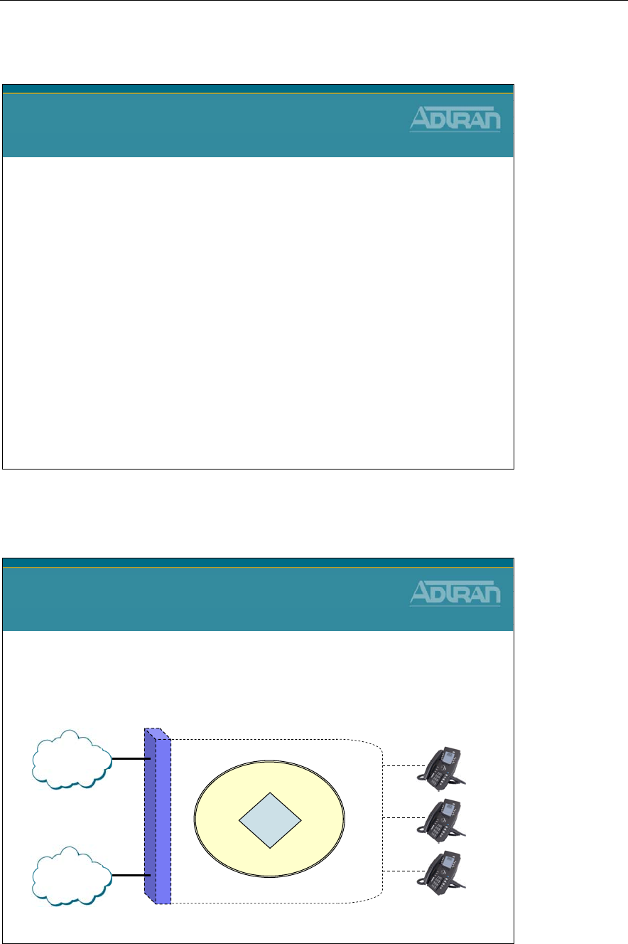
Module 3: Introduction to NetVanta 7000 Series Voice Configuration
NetVanta IP Telephony Course 3-5
NetVanta 7000 Switchboard – Call Routing
NetVanta IP Telephony Course
NetVanta 7000 Switchboard
Call Routing
NetVanta 7000 Switchboard
Switchboard
• The switchboard in AOS voice products ensures that
inbound and outbound phone calls are routed to the
proper voice station, trunk, or other extension
NetVanta 7000 Switchboard
PSTN
VOIP
?
NetVanta 7000
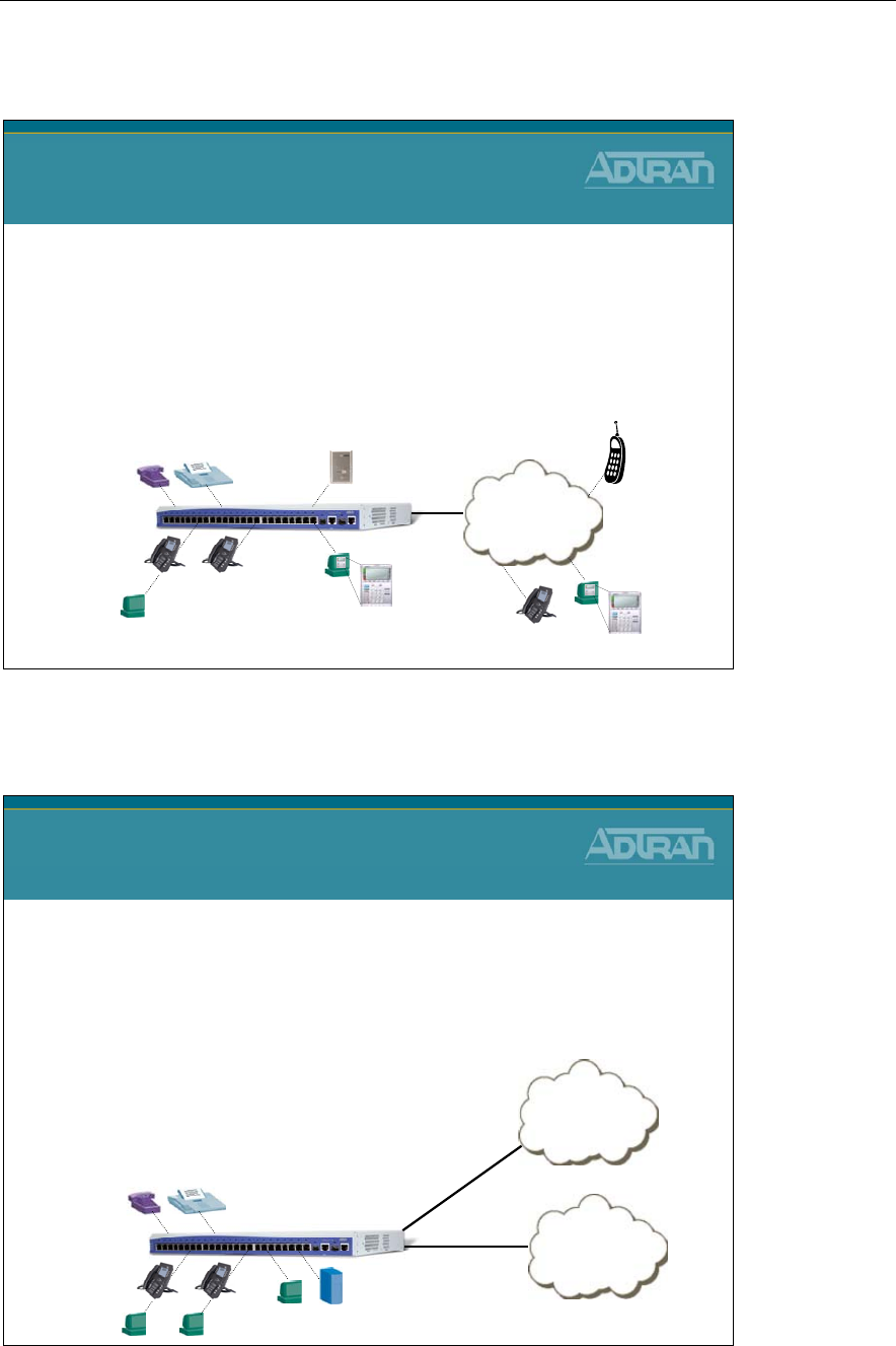
Module 3: Introduction to NetVanta 7000 Series Voice Configuration
3-6 NetVanta IP Telephony Course
Voice - Stations
Voice – Stations
•The Voice Station “User Accounts” are the individual voice
users on the system
•Supported Voice Station Phone Types:
•SIP
•Analog
•Virtual
Analog
Users
SIP
Users
SIP
Users
PSTN
or
VOIP
Virtual
User
Voice - Trunks
Voice - Trunks
•Trunk lines connect the NetVanta 7000 to the outside
world. They are delivered from the carrier and may
be digital or analog.
•Supported Voice Trunk Types
–Analog
–T1-RBS
–T1-ISDN PRI
–SIP
PSTN
Analog or T1
Carrier
VOIP Network
SIP
NetVanta
7000
Module 3: Introduction to NetVanta 7000 Series Voice Configuration
NetVanta IP Telephony Course 3-7
ANI/DNIS
NetVanta 7000 Switchboard
ANI/DNIS
•By default, the NetVanta 7000 makes call routing
decisions based on DNIS
–ANI -Automatic Number Identification
•the calling party’s information
•typically represents the caller's number
–DNIS -Dialed Number Identification Service
•the called party’s information
•typically represents the number that the originating caller dialed
ANI
Calling Party DNIS
Called Party
To: DNIS
From: ANI
ANI – Automatic Number Identification
ANI is a service that provides the receiver of a telephone call with the number of the
calling phone. For example, ANI is used by emergency dispatchers to quickly respond to
an emergency when the caller is unable to report their location. The emergency dispatchers
are able to use the two parts of ANI to locate the caller and retrieve the caller’s telephone
number. The two parts of ANI are its information digits and the calling party’s telephone
number. The information digits designate class of service (CoS) and are transmitted by
dual tone multi-frequency (DTMF) tones or in-band multi-frequency (MF) signaling. This
information may sound like caller ID, but it is a separate entity that is transmitted with the
phone call, even if caller ID blocking is activated, allowing receivers of the information to
determine the calling party’s phone number and in some cases location.
DNIS – Dial Number Identification Service
Most call routing is based on DNIS. The DNIS system routes calls either locally or through
the network based on DNIS matching. In this method of call routing, calls are routed to
voice stations based on whether the DNIS of the call matches a call account number, an
alias to the call account, or the Session Initiation Protocol (SIP) identity of the call account.
If there is a match, the call is routed to that account. DNIS call routing employs weighted
DNIS matching, meaning calls with the most exact DNIS match or the lowest cost are
routed first.
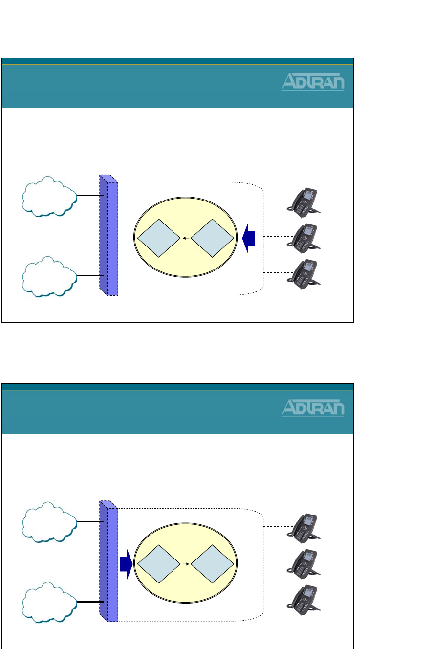
Module 3: Introduction to NetVanta 7000 Series Voice Configuration
3-8 NetVanta IP Telephony Course
NetVanta 7000 Switchboard - Call Routing
Switchboard
• Switchboard call handling from Station
– SB attempts to send calls to voice stations first, then voice
trunk groups
NetVanta 7000 Switchboard
Call Routing
PSTN
VOIP
Trunk
Match Station
Match
NetVanta 7000
NetVanta 7000 Switchboard - Call Routing
Switchboard
• Switchboard call handling from Trunk
– SB attempts to send calls to voice stations first, then voice
trunk groups
NetVanta 7000 Switchboard
Call Routing
PSTN
VOIP
Station
Match Trunk
Match
NetVanta 7000
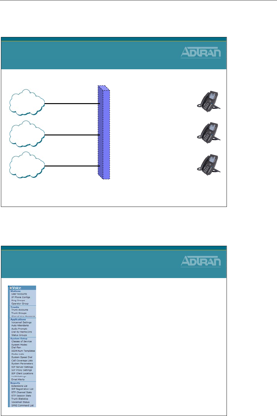
Module 3: Introduction to NetVanta 7000 Series Voice Configuration
NetVanta IP Telephony Course 3-9
NetVanta 7000 Switchboard Call Routing
NetVanta 7000 Switchboard
Call Routing
Analog
•Voice Users
•Ring Groups
•Operator Group (0)
•Mailbox
•Auto Attendant (x8200)
•Voicemail (x8500)
•Leave Voicemail (x8504)
•Overhead Paging (x8000)
•Special Prefix Codes
•Speed Dial
•Alias
•DID
ISDN DID Number >
SIP
Trunk Number >
SIP User >
NetVanta 7000 Series – Voice Menus
NetVanta 7000 Series
Voice Menus
Voice configuration is primarily accomplished
from the NetVanta 7000 Voice menus
The following topics are covered in this module:
•Stations
- phone users, phone configs, ring and operator groups
–Voice Users
–Ring/Operator Group
•Trunks
- Define circuit connected to your carrier's trunk lines
–Analog Trunks
•Applications
- Voice applications such as Auto Attendant
•System Setup
- Define system voice parameters
–Dial Plan
–Classes of Service
•Reports
- Voice statistics

Module 3: Introduction to NetVanta 7000 Series Voice Configuration
3-10 NetVanta IP Telephony Course
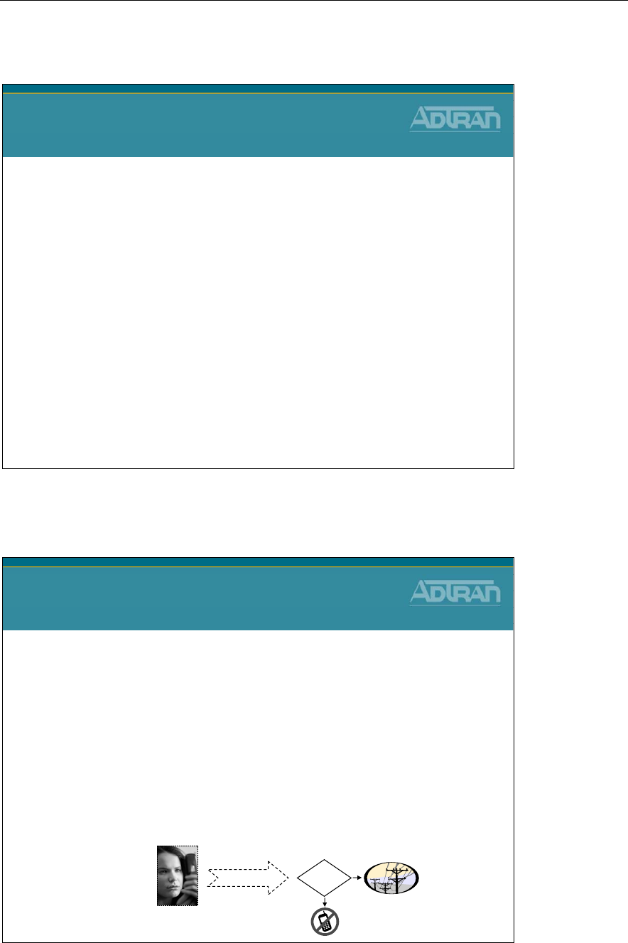
Module 3: Introduction to NetVanta 7000 Series Voice Configuration
NetVanta IP Telephony Course 3-11
Voice/System Setup – Dial Plan
NetVanta IP Telephony Course
Voice System Setup
Dial Plan
Voice/System Setup - Dial Plan
Voice System Setup
Dial Plan
•The Dial Plan tells the NetVanta 7000 how to route
calls and assigns a dialing type to a given number
template
–For example, what is an extension, local number, long
distance number, etc..
•The defined dialing type and number template works
in conjunction with Classes of Service
–Determines whether a user has permission to dial a given
number
9-555-5555 ?

Module 3: Introduction to NetVanta 7000 Series Voice Configuration
3-12 NetVanta IP Telephony Course
Voice/System Setup - Dial Plan
Valid Template Characters
The valid template characters are: 0-9 , () - M N X [] $
0-9 - any single digit matches only itself
X - any single digit 0-9
N - any single digit 2-9
M - any single digit 1-8
[ ] - any single digit of those within the bracket
$ - any number string dialed
- () , - punctuation characters that are ignored
Examples: MXXX - match digits 1000 to 8999
963-81XX - match 963-8100 to 963-8199
963-812[0,1,2] - match 963-8120 to 963-8122
963-$ - match all numbers that start with 963
Voice System Setup
Dial Plan
•Valid template characters
–0-9 - any single digit matches only itself
–X - any single digit 0-9
–N - any single digit 2-9
–M - any single digit 1-8
–[ ] - any single digit defined within bracket
–$ - any number string dialed
–- () , - punctuation characters that are ignored
Module 3: Introduction to NetVanta 7000 Series Voice Configuration
NetVanta IP Telephony Course 3-13
Voice/System Setup - Dial Plan
Dial Plan - Configuration
1. Select Voice / System Setup / Dial Plan from
the NetVanta 7100 menus
2. Select 7-Digit or 10-Digit dialing based on
how users normally dial local numbers
–7 digit 9-NXX-XXXX
–10 digit 9-NXX-NXX-XXXX
3. In the Dial Plan Template field, enter valid
characters for desired number pattern
Dial Plan
Configuration
Default Templates
911, 9-911 - Always Permitted
0 - Internal Operator
MXXX - Extensions
9-NXX-XXXX - Local
9-1-NXX-NXX-XXXX - Long Distance
9-1-800-NXX-XXXX - Toll Free
(also 866/877/888)
9-0-NXX-NXX-XXXX - Operator Assistance
9-011-$ - International
Undefined - Specified Carrier
Undefined - 900 Calls
Voice System Setup
Dial Plan
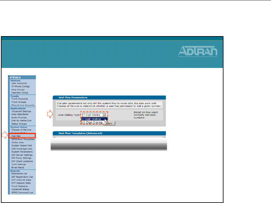
Module 3: Introduction to NetVanta 7000 Series Voice Configuration
3-14 NetVanta IP Telephony Course
Dial Plan - Define Local Dialing Type
Setting Local Dialing Type
The Local Dialing Type is default to 7-digits but can easily be changed to 10-digits if
required for your area.
1) Select Voice / System Setup / Dial Plan from the NetVanta 7100 menus.
2) Select 7-Digit or 10-Digit dialing based on how users normally dial local numbers.
- If 7 Digit Dialing is selected, the “Local” dial plan number type template is defined as
9-NXX-XXXX
- If 10 Digit Dialing is selected, the “Local” dial plan number type template is defined
as 9-NXX-NXX-XXXX
1. Select the Voice / System Setup / Dial Plan
menu
2. Set Local Dialing Type to 7 or 10 digit dialing
–Based on how users normally dial local numbers
•7 digit dialing: 9-NXX-XXXX
•10 digit dialing: 9-NXX-NXX-XXXX
Dial Plan
Define Local Dialing Type
1
2
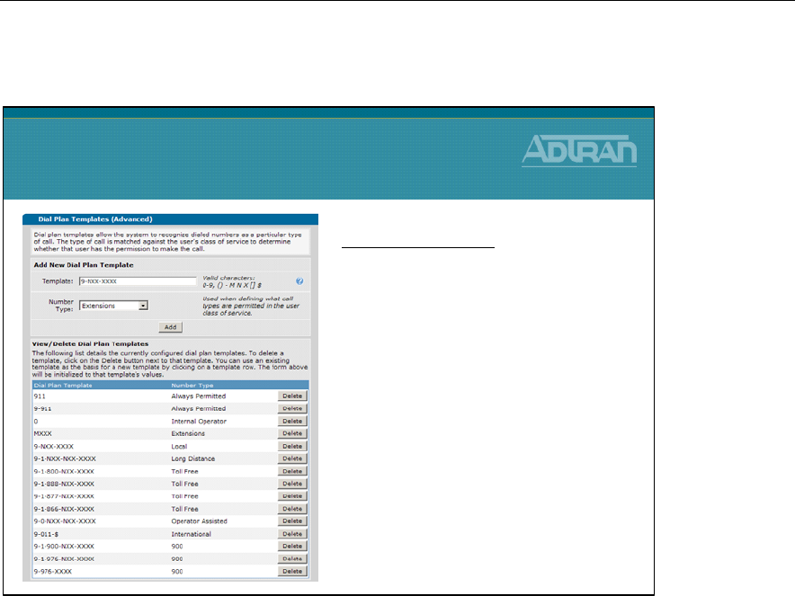
Module 3: Introduction to NetVanta 7000 Series Voice Configuration
NetVanta IP Telephony Course 3-15
Dial Plan - Define Dial Plan Template
Dial Plan Templates
Dial plan templates allow the system to recognize dialed numbers as a particular type of
call. The type of call is matched against the user's class of service to determine whether
that user has the permission to make the call.
Create or Modify Dial Plan Template
The dial plan template is used when defining what call types are permitted in the user class
of service. It is also used as a number complete match when dialing from analog phones.
1) Select Voice / System Setup / Dial Plan from the NetVanta 7100 menus.
2) In the Dial Plan Template field, enter valid characters for desired number pattern.
3) Select the Number Type that the entered pattern will be associated with. If there is an
existing template that matches this number type, and is no longer needed, it can be
deleted.
Dial Plan
Define Dial Plan Template
Dial Plan Template
•The default Dial Plan can be
modified to fit your calling plan
•To Create a new Dial Plan template
1. Type new number pattern in the
Template field
2. Specify the Number Type
3. Click Add
•To modify an existing template,
delete the existing template and add
a new one

Module 3: Introduction to NetVanta 7000 Series Voice Configuration
3-16 NetVanta IP Telephony Course
Module 3: Introduction to NetVanta 7000 Series Voice Configuration
NetVanta IP Telephony Course 3-17
Voice/System Setup - Classes of Service
NetVanta IP Telephony Course
Voice System Setup
Classes of Service
Voice/System Setup - Classes of Service
Voice System Setup
Classes of Service
•A Class of Service (CoS) defines a set of user
permissions for making voice calls
•A CoS is required before a user can make calls (other
than to the operator and 911)
•The permissions include the types of calls and
actions a voice user can perform
Some call types
restricted for this group
All call types allowed
for this group
Module 3: Introduction to NetVanta 7000 Series Voice Configuration
3-18 NetVanta IP Telephony Course
Voice/System Setup - Classes of Service
Classes of Service - Basic Configuration Steps
Classes of Service
Basic Configuration Steps
1. Select Voice / System Setup / Classes of
Service from the NetVanta 7100 menus
2. Click an existing Class of Service to modify
the permissions for users assigned to that
Class of Service or select one of the
Undefined Classes of Service to create your
own
3. Specify permitted call types and desired voice
actions for users assigned to this Class of
Service
Voice System Setup
Classes of Service
•There are four default Classes of Service
–normal_users
•allow all call types except international and 900 calls
•can not unlock the door by default
–public_phones
•allow internal, local, and toll-free calls
•many CoS voice features disabled
–executive_users
•allow all call types
•all CoS voice features enabled
–door_phone
•allow only internal calls
•all CoS voice features disabled
–You can also create your own Class of Service
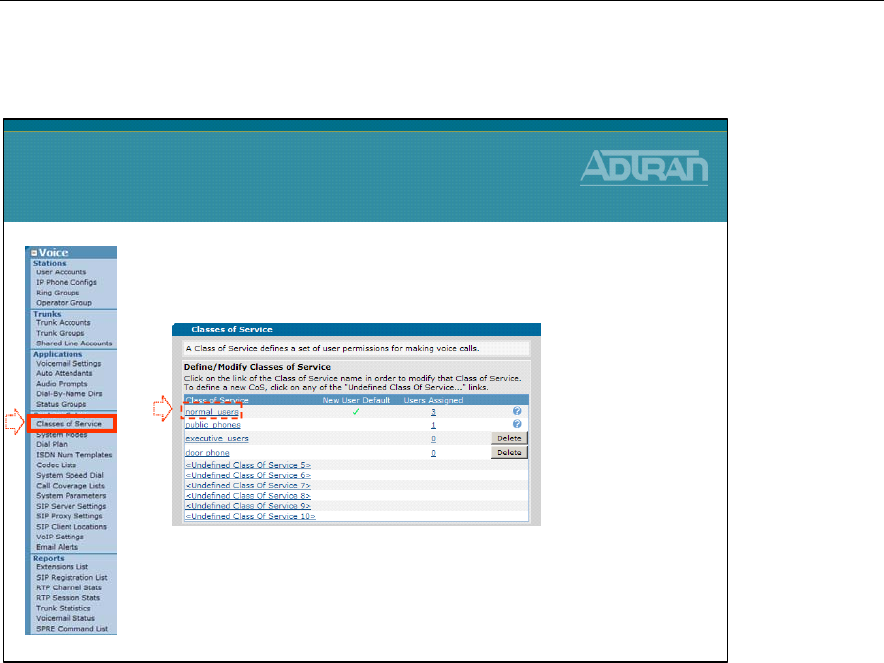
Module 3: Introduction to NetVanta 7000 Series Voice Configuration
NetVanta IP Telephony Course 3-19
Classes of Service – Modify a Class of Service
Modify a Classes of Service
1) Select Voice / System Setup / Classes of Service from the NetVanta 7100 menus.
2) Click an existing Class of Service to modify the permissions for users assigned to that
Class of Service or select one of the Undefined Classes of Service to create your own.
3) Specify permitted call types and desired voice actions for users assigned to this Class
of Service.
Classes of Service
Modify a Class of Service
1. Select the Voice / System Setup / Classes of
Service menu
2. Click the Class of Service to be modified
–The Modify Class of Service screen appears
12
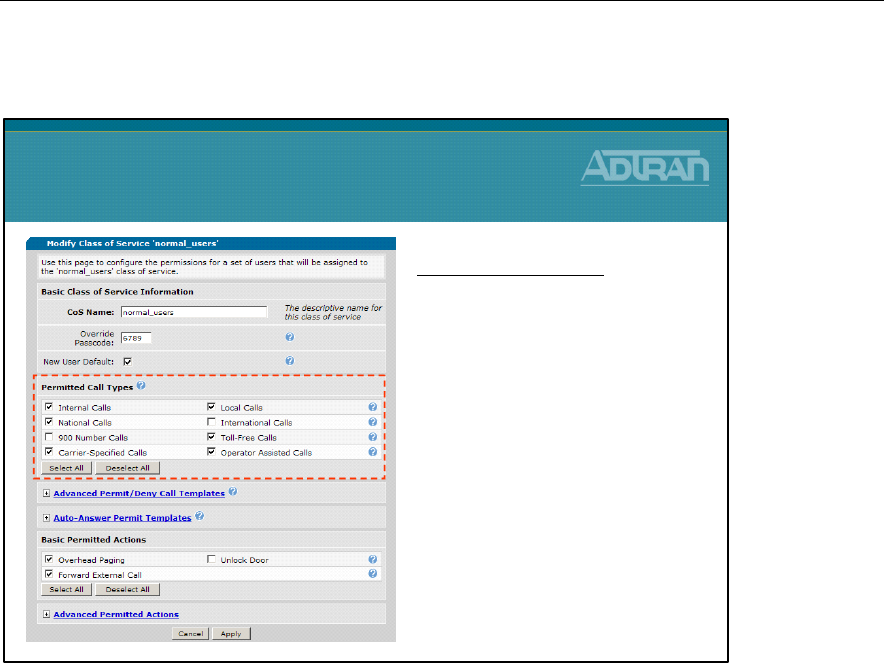
Module 3: Introduction to NetVanta 7000 Series Voice Configuration
3-20 NetVanta IP Telephony Course
Classes of Service - Permitted Call Types
Class of Service - Permitted Call Types
Permitted Call Types determine what type of calls that a user is permitted to make as a
member of this class of service. Note that ranges of phone numbers are assigned to the call
types (e.g. 9-NXX-XXXX = Local Calls) from the Dial Plan menu.
Internal Calls
Members of this CoS are permitted to make internal extension-to-extension calls (2XXX
through 8XXX).
Local Calls
Members of this CoS are permitted to make local calls 9-NXX-XXXX.
National Calls
Members of this CoS are permitted to make national long distance calls 9-1-NXX-NXX-
XXXX.
International Calls
Members of this CoS are permitted to make international long distance calls 9-011-$.
900-Number Calls
Members of this CoS are permitted to make national 1-900-NXX-XXXX and local 976-
XXXX pay-per-service calls.
Classes of Service
Permitted Call Types
Permitted Call Types
•Determines the type of calls a
user is permitted to make as a
member of this class of service
•The pattern for the different call
types was defined in the Voice /
System Setup / Dial Plan menu
•Customized Call types can be
added by selecting Advanced
Permit/Deny Call Templates

Module 3: Introduction to NetVanta 7000 Series Voice Configuration
NetVanta IP Telephony Course 3-21
Toll-Free Calls
Members of this CoS are permitted to make national toll-free calls 9-1-800-NXX-XXXX
including those to area codes 800, 888, 877, 866, and 855.
Carrier-Specified Calls
Members of this CoS are permitted to specify the long distance service provider for each
call using a 'PIC' code 1010XXX-NXX-NXX-XXXX.
Operator Assisted Calls
Members of this CoS are permitted to dial an outside operator for assistance with making
calls 9-0-NXX-NXX-XXXX.
Advanced Permit/Deny Call Templates
Click the 'Configure Advanced Templates' button to configure templates that require more
detail such as area codes, etc.
- Permit Templates - Use this section to add and delete specific call templates that users
in this Class of Service can dial. All calls matching the specified pattern will be
permitted.
- Deny Template - Use this section to add and delete specific call templates that users in
this Class of Service can NOT dial. All calls matching the specified pattern will be
denied.

Module 3: Introduction to NetVanta 7000 Series Voice Configuration
3-22 NetVanta IP Telephony Course
Classes of Service - Override Passcode
Basic Class of Service Information
CoS Name
The descriptive name for this class of service.
Override Passcode
This 4-digit code is used in conjunction with the Class of Service (CoS) Override feature
(*90), enabling a user to override an extension's configured CoS with the ‘this users' CoS
as represented by this Override Passcode.
New User Default
When creating a new user, apply this Class of Service (CoS) automatically.
Classes of Service
Override Passcode
Override Passcode
•A 4-digit code used with the
SPRE code *90 to override a
phones configured (CoS).
–Format *90xxxx
(x = passcode of CoS)
•For example, if a voice user
(assigned to the normal_users
Class of Service) wishes to
place a call from a phone
assigned to the Public CoS, the
user would enter *906789

Module 3: Introduction to NetVanta 7000 Series Voice Configuration
NetVanta IP Telephony Course 3-23
Hand Free Auto-Answer
Hands Free Auto-Answer is an intercom like feature. A user initiates a call to a SIP phone.
Instead of requiring the recipient to answer the call, the (speaker) phone automatically
answers and users are able to start a conversation.
Auto-Answer Permit Templates
Only voice users assigned to a Class of Service with an Auto-Answer permit template are
allowed to place hands free auto answer calls.
Hands Free Auto-Answer Configuration
1) Select Voice / System Setup / Classes of Service from the NetVanta 7100 menus.
2) Edit the Class of Service that contains the voice users you wish to allow to place hands
free calls.
3) Define the auto-answer permit template that users in this Class of Service can dial
hands free.
Optional - Give voice users permission to block incoming auto-answer calls
- Configured per Class of Service
Optional - Block incoming auto-answer calls for specific voice user
- Configured per specific voice user extension
Placing Hands Free Auto-Answer Calls
To place an Auto-Answer call, the digits ** must precede the number. The prefix can be
dialed before or with the extension.
For example, a user could place two calls: ** and then 2004,
Or a user could dial **2004
x2003 x2004
**2004
Speaker
Hello Bob!
Hello Bob!

Module 3: Introduction to NetVanta 7000 Series Voice Configuration
3-24 NetVanta IP Telephony Course
Blocking Auto-Answer Calls
Users with the Class of Service option ‘Auto Answer Do Not Disturb’ enabled can block
incoming auto-answer calls with a SPRE code.
• When a user does not want to receive an Auto-Answer call, they can dial *971
• When user wishes to receive Auto-Answer calls again, they can dial *970
Note: There is also a per user Auto-Answer Do Not Disturb option. If enabled, any
incoming Auto-Answer calls will ring normally instead of being automatically answered
by the phone.
Hands Free Auto-Answer - No Permission or Blocked
If an Auto-Answer call is initiated by a user that “does not” have permission to do so, a
normal call is placed. (No Auto-Answer functionality)
If an Auto-Answer call is received by a user that has blocked the functionality a normal
call is placed. (No Auto-Answer functionality)
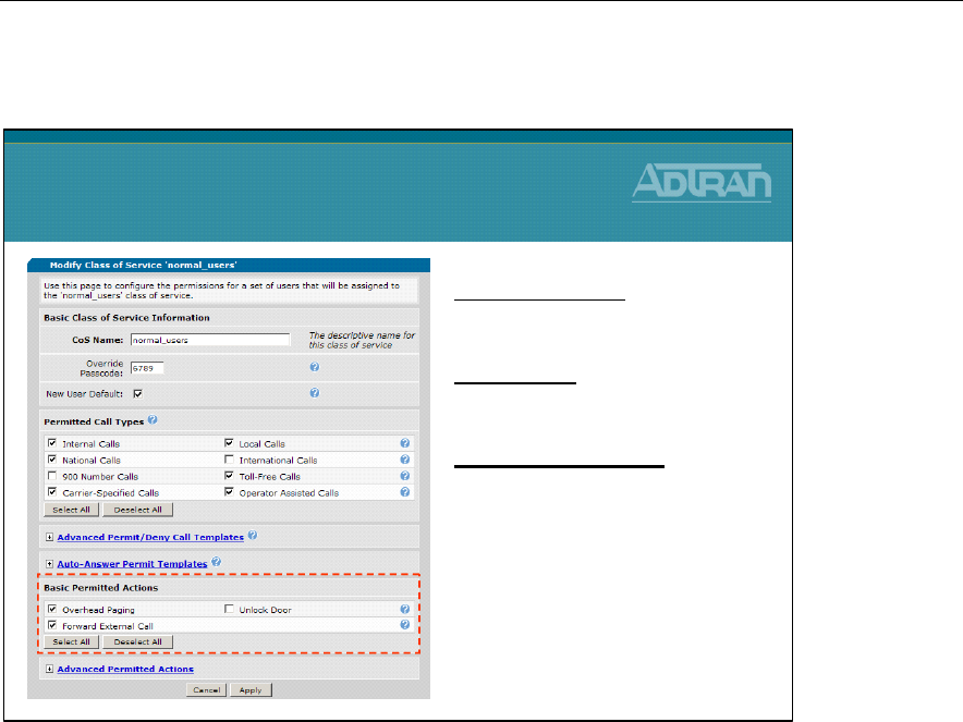
Module 3: Introduction to NetVanta 7000 Series Voice Configuration
NetVanta IP Telephony Course 3-25
Classes of Service - Basic Permitted Actions
Class of Service - Basic Permitted Actions
Overhead Paging
Select to allow users to make overhead pages.
Forward External Call
Select to allow users to forward an extension to an external number.
Unlock Door
Select to allow users to utilize the Remote Door Unlock feature.
Classes of Service
Basic Permitted Actions
Overhead Paging
•Allow users to make overhead
pages
Unlock Door
•Allow users to utilize the
Remote Door Unlock feature
Forward External Call
•Allow users to forward an
extension to an external number
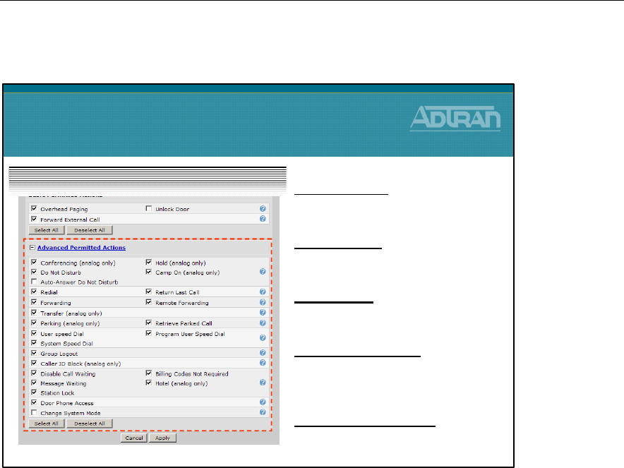
Module 3: Introduction to NetVanta 7000 Series Voice Configuration
3-26 NetVanta IP Telephony Course
Classes of Service - Advanced Permitted Actions
Class of Service - Advanced Permitted Actions
Conferencing
Select to allow a user to establish conference calls.
Hold
Select to allow a user to put calls on hold.
Do Not Disturb
Select to allow a user to place an extension in Do Not Disturb mode.
Camp On
Select to allow a user to request a callback when a busy number becomes idle.
Auto-Answer Do Not Disturb
Select to allow a user to force incoming Auto-Answer calls to ring the phone instead.
Redial
Select to allow a user to use the redial functionality of the system to redial the last dialed
number.
Return Last Call
Select to allow a user to return the call of the last incoming caller.
Forwarding
Select to allow a user to enable call forwarding.
Classes of Service
Advanced Permitted Actions
Do Not Disturb
•Allow user to place an extension
in Do Not Disturb mode
Group Logout
•Allow a user to logout of a call
group
Station Lock
•Allow a user to place their
extension in a locked mode
Door Phone Access
•Allow a user to make calls to the
intercom designated as the
'door phone'
Change System Mode
•Allow a user to change the
current system mode

Module 3: Introduction to NetVanta 7000 Series Voice Configuration
NetVanta IP Telephony Course 3-27
Remote Forwarding
Select to allow a user to enable call forwarding from a remote location.
Transfer
Select to allow a user to transfer calls to an internal user.
Parking
Select to allow a user to park calls to a public hold zone.
Retrieve Parked Call
Select to allow a user to retrieve parked calls from a public hold zone.
User Speed Dial
Select to allow a user to have personal speed dial numbers.
Program User Speed Dial
Select to allow a user to modify his personal speed dial numbers.
System Speed Dial
Select to allow a user to utilize the system speed dial numbers.
Group Logout
Select to allow a user to logout of a call group.
Caller ID Block
Select to allow a user to block caller ID for outbound calls.
Disable Call Waiting
Select to allow a user to disable the shared call appearance known as call waiting (if
available).
Billing Codes Not Required
If selected, the user does not have to enter a billing code prior to dialing a number.
Message Waiting
Select to allow a user to change the manner in which message notification takes place.
Hotel
Select to allow a user to login to a phone designated for hotelling or hotdesking.
Station Lock
Select to allow a user to place his extension in a locked mode.
Door Phone Access
Select to allow a user to make calls to the intercom designated as the 'door phone'.
Change System Mode
Select to allow a user to change the current system mode of the unit.

Module 3: Introduction to NetVanta 7000 Series Voice Configuration
3-28 NetVanta IP Telephony Course

Module 3: Introduction to NetVanta 7000 Series Voice Configuration
NetVanta IP Telephony Course 3-29
Voice Stations - User Accounts
NetVanta IP Telephony Course
Voice Stations
User Accounts
Voice Stations
The Voice Station menus include User Accounts, Ring Groups, and Operator Group. The
User Accounts configuration screen allows you to create a user account for every
telephone user in the NetVanta 7000 Series system. The Ring Group menu allows you to
define a group of user accounts that can be called in a coordinated way with a single
extension. From the Operator Group menu, you define the members of the Operator
Group.
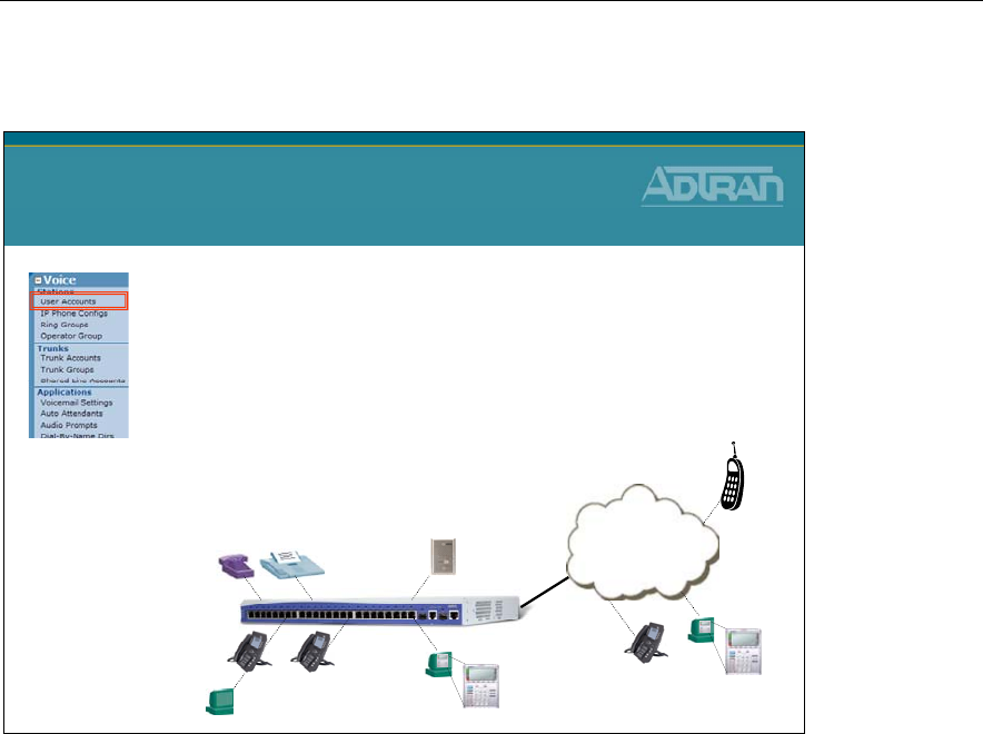
Module 3: Introduction to NetVanta 7000 Series Voice Configuration
3-30 NetVanta IP Telephony Course
Voice Stations - User Accounts
•The User Accounts menu is used to create
voice users in the NetVanta 7000.
•Three different phone types can be defined for
Voice Users:
–SIP
–Analog Stations
–Virtual
Voice Stations
User Accounts
Analog
Users
SIP
Users
SIP
Users
PSTN
or
VOIP
Virtual
User
User Stations Accounts define phone users in the NetVanta 7100. The three different
phone types that can be defined for Voice Users are:
SIP - user account is associated with a SIP port
Analog Stations – user is associated with a physical FXS interface
Virtual - user account is not associated with a physical port
Module 3: Introduction to NetVanta 7000 Series Voice Configuration
NetVanta IP Telephony Course 3-31
User Accounts - Analog Users
User Accounts
Analog Users
•An Analog Voice user associates a physical
Analog FXS port with a voice user
•Analog Station accounts are required with the
following:
–traditional analog telephones
–door phones
–faxes
–modems
–credit card readers
Analog Station Voice Users
Voice users with a Phone Type of Analog Station associate a physical Analog FXS port
with a voice user. The selection of the phone type Analog Station is required when creating
voice users for traditional analog telephones, door phones, faxes, modems, or credit card
readers.
To Create an Analog User Account
1. Select Voice / Stations / User Accounts from the NetVanta 7000 menus
2. Assign users extension and name
3. Select Phone Type Analog Station
4. Select the physical FXS Port
5. Define user parameters such as Classes of Service and Voicemail settings

Module 3: Introduction to NetVanta 7000 Series Voice Configuration
3-32 NetVanta IP Telephony Course
User Accounts - SIP Voice User
User Accounts
SIP Voice User
•A SIP voice user is a voice user that
communicates using the SIP standard
–The NetVanta 7000 is designed to meet SIP
standards and is interoperable with many SIP-
compliant telephones
–The SIP voice user could be associated with a SIP-
compliant telephone or an IP SoftPhone running on
your laptop or desktop PC
–When creating a SIP Voice User, phone
configuration files can be created for recognized
phone models
–The phone configuration files are created in the
NetVanta 7000’s flash memory (CFLASH by
default)
SIP Voice User
A SIP voice user is a voice user that communicates using the SIP standard. The NetVanta
7100 is designed to meet SIP standards and is interoperable with many SIP-compliant
telephones. The SIP voice user could be associated with a SIP-compliant telephone or an
IP SoftPhone running on your laptop or desktop PC.
To Create a SIP User Account
1. Select Voice / Stations / User Accounts from the NetVanta 7000 menus
2. Assign users extension and name
3. Select Phone Type SIP
4. Choose New Address then type phones MAC Address
- Phone configuration files are created for recognized phone models and stored in
7000 CFLASH by default
- If MAC address “Not Set” is selected, no configuration files are created
5. Define user parameters such as Classes of Service and Voicemail settings

Module 3: Introduction to NetVanta 7000 Series Voice Configuration
NetVanta IP Telephony Course 3-33
User Accounts - Virtual User
User Accounts
Virtual User
•A Virtual User is a voice user that is not tied
to a physical interface
–Creating virtual users may be useful for employees
who do not need a permanent phone in an office
–Virtual users can be given Voicemail ability and call
forwarding capabilities
–When in the office, the virtual users can login into
an analog phone that has the hotel feature enabled
(shared-desk application)
Virtual Voice Users
A Virtual User is a voice user that is not tied to a physical interface. Creating virtual users
may be useful for employees who do not need a permanent phone in an office. Virtual
users can be given Voicemail ability and call forwarding capabilities. When in the office,
the virtual users can login into an analog phone that has the hotel feature enabled. (shared-
desk application)
To Create a Virtual User Account
1. Select Voice / Stations / User Accounts from the NetVanta 7000 menus
2. Assign users extension and name
3. Select Phone Type Virtual
4. Define user parameters such as Classes of Service and Voicemail settings
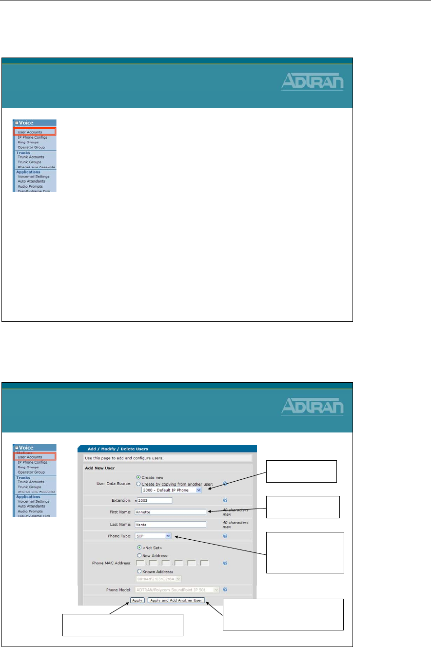
Module 3: Introduction to NetVanta 7000 Series Voice Configuration
3-34 NetVanta IP Telephony Course
Creating New User Accounts
Creating New User Accounts
1. Select Voice / Stations / User Accounts from
the NetVanta 7000 menus
2. Assign users extension and name
3. Select Phone Type
•Analog, SIP, or Virtual
•If analog, select available FXS port
•If known SIP phone model, enter MAC address
4. Define user parameters such as Classes of
Service and Voicemail settings
New User Screen
New User Screen
Can use existing user
as a template
Clicking Apply enters the Edit User
screen for the new user
Clicking Apply and Add Another
User creates the new user but stays
on this screen
First/Last name for
internal Caller ID
Choose Phone Type:
-SIP
-Analog
-Virtual
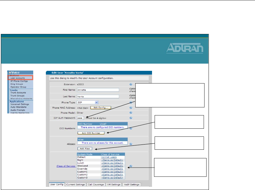
Module 3: Introduction to NetVanta 7000 Series Voice Configuration
NetVanta IP Telephony Course 3-35
Edit User Screen
Edit User Screen
Class of Service can be
assigned per System Mode
(Day/Night)
Configures DID numbers
for this account.
Used to authenticate a SIP station if
SIP INVITE or registration
authentication is enabled.
Default: 1234
Configures aliases for
this account.
Voice User Settings
The Voice User Settings are the settings that can be seen or modified while editing a voice
user. When a new voice user is created, you are placed in the Edit <voice user> screen
where the settings below display.
Editing Voice Users - Initial Screen
Extension
Assigned when a voice user is created and can not be modified
First Name
(Optional) 40 characters max
Last Name
(Optional) 40 characters max
Phone Type - Analog Station
User account is associated with an Analog FXS port. If Analog Station is not displayed as
an option, it is because there are no available FXS ports.
Phone Type – SIP
User account is associated with a SIP port
Phone Type – Virtual
User account is not associated with a physical port

Module 3: Introduction to NetVanta 7000 Series Voice Configuration
3-36 NetVanta IP Telephony Course
Phone MAC Address (SIP ONLY)
Optionally enter the MAC Address of this user's SIP phone. Note that a phone
configuration file can be created for this phone only if a complete MAC Address is
entered.
SIP Auth Password (SIP ONLY)
The SIP Auth Password is used to authenticate a SIP station if SIP INVITE or registration
authentication is enabled.
Phone Port: (ANALOG ONLY)
If Phone Type is Analog Station: The physical Analog FXS port to associate with this user
account. If Phone Type is Virtual: Not used
Login PIN (SIP)
The SIP Auth Password is used to authenticate a SIP station if SIP INVITE or registration
authentication is enabled.
Login PIN (ANALOG or VIRTUAL)
The Login PIN is used to log into and out of analog phones. This allows a user to "take
over" another person's phone or for "hotdesking"
DID Numbers
Configures DID numbers for this account. The table shows all existing DID numbers (you
may have to scroll to see all of them) and whether each number is currently valid. A
number is considered valid if it matches any trunk's DID prefix and digit count. If no DID
information has been configured in trunks, then all numbers are considered valid.
• To add a new DID number, click the Add DID Number button just below the DID
Number table and enter the DID number in the popup box.
• To delete a DID number, click the Delete button next to the number you want to delete.
Aliases
Configures aliases for this account. The table shows all existing aliases (you may have to
scroll to see all of them).
• To add a new alias, click the Add Alias button just below the Alias table and enter the
new alias for this account in the popup box.
• To delete an alias, click the Delete button next to the alias you want to delete.
Class of Service
Configures this user's Class of Service.
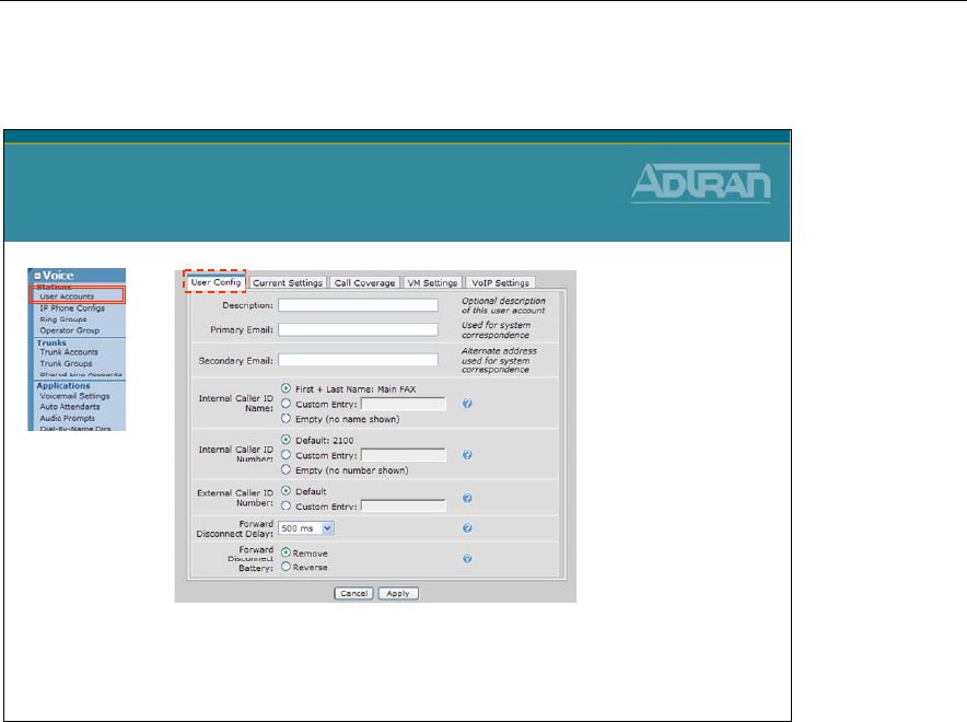
Module 3: Introduction to NetVanta 7000 Series Voice Configuration
NetVanta IP Telephony Course 3-37
Edit User – User Config Tab
Edit User – User Config Tab
The User Config tab allows you to configure the user’s email address, caller ID settings,
and Forward Disconnect for analog users.
Description
Optional description of this user account
Primary Email
Used for system correspondence
Secondary Email
Alternate address used for system correspondence
Internal Caller ID – Name
Configures the name portion of the Caller ID display for internal calls made by this user.
• First + Last Name - Sets Caller ID Name to be the configured first and last name.
• Custom Entry - Sets the Caller ID Name to be the value entered in the adjacent text
box.
• Empty - Sets the Caller ID Name to be empty.
• Note: The system has no control over Caller ID Name display for external calls.

Module 3: Introduction to NetVanta 7000 Series Voice Configuration
3-38 NetVanta IP Telephony Course
Internal Caller ID – Number
Configures the number portion of the Caller ID display for internal calls made by this user.
• Default - Sets the internal Caller ID Number to be the extension of this user account.
• Custom Entry - Sets the internal Caller ID Number to the the value entered in text
box.
• Empty - Sets the internal Caller ID Number to be empty.
External Caller ID – Number
Configures the number portion of the Caller ID display for external calls made by this user.
Note that external Caller ID info is only sent if delivered out particular T1 interfaces such
as Feature Group D or PRI.
• Default - Automatically sets the external Caller ID Number to be the first DID entry if
one exists, otherwise it’s set to nothing.
• Custom Entry - Sets the external Caller ID Number to the value entered in the
adjacent text box.
Forward Disconnect Delay
Setting Forward disconnect delay enables the removal or reversal of battery for the
specified amount of time. When the unit removes/reverses the battery current, the
connected equipment will acknowledge this condition by dropping the line.
Forward Disconnect Battery
Select whether the connected equipment expects battery removal or reversal.
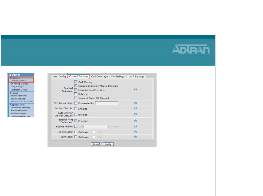
Module 3: Introduction to NetVanta 7000 Series Voice Configuration
NetVanta IP Telephony Course 3-39
Edit User – Current Settings Tab
Edit User – Current Settings Tab
The Current Settings tab allows you to change voice settings for this user.
Call Waiting
If checked, call waiting is enabled on this user account.
Include in System Phone Directory
If checked, the user will be included in the dial-by-name directory.
Forward Courtesy Ring
If checked, the user's phone will issue a short "blip" ring when a call comes in as a
reminder that the phone is forwarded.
Hotelling
If checked, another user can log into this user's phone without logging this user out first.
Useful for shared-desk applications.
Inbound Caller ID Blocked
If checked, no inbound Caller ID information will be delivered to this user's phone.
Call Forwarding
If checked, this user's extension is forwared to the number displayed

Module 3: Introduction to NetVanta 7000 Series Voice Configuration
3-40 NetVanta IP Telephony Course
Do Not Disturb
If checked, Do Not Disturb is enabled and all calls will go directly to the user's call
coverage list.
Special Ring Cadences
If checked, the phone will ring with a different cadence depending on the call type, such as
internal, external, or priority calls. If unchecked, the phone will always ring with the
default cadence.
Hotline Phone
If checked, a call will be immediately placed to the configured number when this user goes
offhook
Admin Lock
Displays current administrative lock
User Lock
Displays current user lock
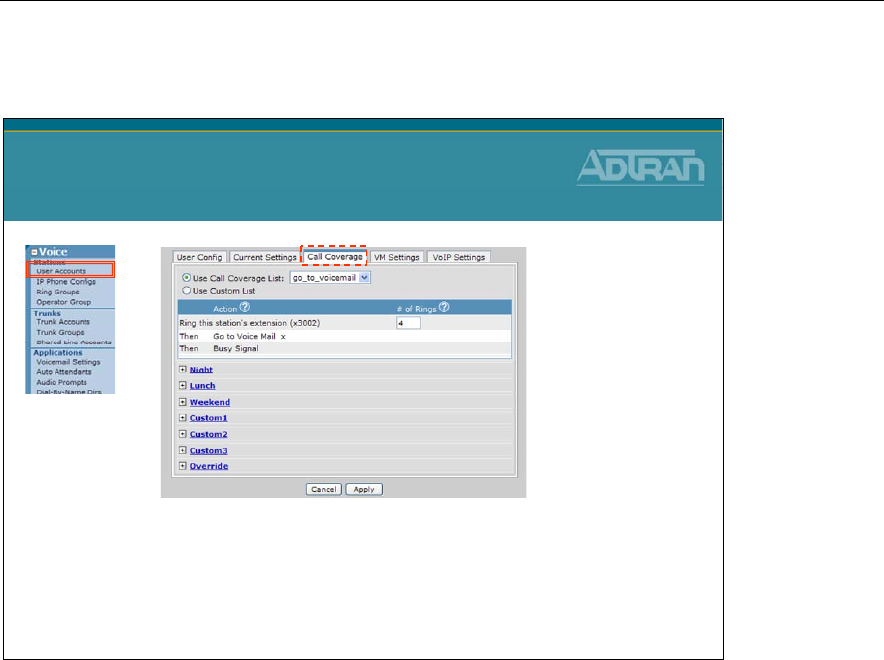
Module 3: Introduction to NetVanta 7000 Series Voice Configuration
NetVanta IP Telephony Course 3-41
Edit User – Call Coverage Tab
Edit User – Call Coverage Tab
The Call Coverage tab displays the call coverage settings for this user. If the user has been
assigned to a Call Coverage List, you can view the settings on this page. You can also
create a custom Call Coverage List only for this User Account. Use the question mark
symbol to assist with the configuration settings.
Use Call Coverage List
Used to make a copy of the selected global Call Coverage List for this specific extension.
Modifications made to this copy do not affect the original global list.
Use Custom List
Create a custom list of how to handle a call when no one answers the phone.
Action
Actions on a list are evaluated in the order displayed.
# of Rings
If there is no response after this many rings (or the extension is busy), the next item in the
call coverage list will be tried.
If a value of 0 is used, the call coverage list will only be processed if the station is busy.
Otherwise, the phone will ring indefinitely.

Module 3: Introduction to NetVanta 7000 Series Voice Configuration
3-42 NetVanta IP Telephony Course
System Modes
Call coverage can be configured per system mode. The number of rings between call
coverage choices can also be set per system mode. Voice users, ring groups, and operator
group, shared line accounts can use the global or custom call coverage list.
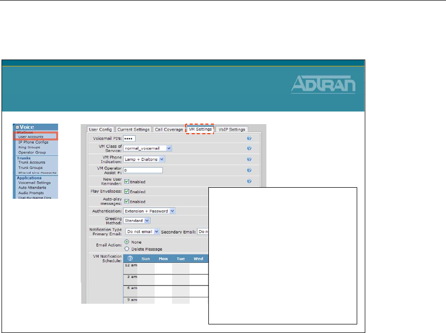
Module 3: Introduction to NetVanta 7000 Series Voice Configuration
NetVanta IP Telephony Course 3-43
Edit User – VM Settings Tab
Edit User – VM Settings Tab
•New user wizard for mailbox setup
•Configurable voicemail options
–Voicemail Pin
–Voicemail Class of Service
–Voicemail Phone Indication
–Operator Assist Number
–Envelope playback
–Auto-play of messages
–Authentication options
–Voicemail Greeting Method
–Voicemail Notification Email
•Text File
•WAV File
The VM Settings tab allows you to edit the user’s voicemail settings such as VM Phone
Indication and VM Notification Schedule.
Voicemail PIN
Sets the password the user must enter to access the voicemail system
VM Class of Service
The voicemail class of service assigned to this user account
VM Phone Indication
Lamp + Dialtone - use both the message waiting lamp and stutter dial tone to indicate new
voicemail
• Lamp Only - use the message waiting lamp to indicate new voicemail
• Dialtone Only - use a stutter dialtone to indicate new voicemail
• Off - no indication of new voicemail
VM Operator Assist #
This number will be dialed if a caller requests to speak with the operator while leaving a
voicemail.

Module 3: Introduction to NetVanta 7000 Series Voice Configuration
3-44 NetVanta IP Telephony Course
New User Reminder
Checking this box alerts the Voicemail system to prompt the user to record their name. The
recorded name is subsequently used for playback within the system.
Play Envelopes
When enabled, envelopes preceding voice messages will be played. An envelope includes
the Calling party and the Date/Time information about a message.
Auto-play messages
When enabled, voice message playback will begin automatically after logging into your
voice mailbox.
Authentication
Choose the authentication method to be used when logging into your voice mailbox. From
valid phones, authenticate using:
• mailbox/password
• password only
• no authentication
WARNING: Selecting “None” will allow anyone who knows your extension to hear your
messages.
Greeting Method
Choose the greeting that will be heard by callers leaving voice messages. The Default
greeting is your recorded name. To record Standard and Alternate greetings, login to your
voicemail via your phone and follow the instructions under the Greetings menu.
Voicemail Notification Schedule
The Voicemail Notification Schedule configures when and how the system will notify this
user when they receive a voicemail message. To configure the schedule:
1. Click the Add Range button below the schedule detail.
2. Enter the start and end times for the range. A 'range' is a range of time during the week
that will have the same notification type.
3. Select the notification type to use. The available options are to send an email to the
primary email address or the secondary email address. These addresses are configured
in the User Config tab on this page.
4. Click the Apply button just below the Enabled Actions selection.
This will add a schedule range to both the graphic schedule display as well as the schedule
detail table. You can edit an existing range by clicking on the Start Day/Time text link in
the detail table. You can delete an existing range by clicking the Delete button next to the
range in the detail table that you want to remove.
Remember to click the Apply button at the bottom of the page to save the schedule
changes. You will lose your changes if you do not click the Apply button.
Module 3: Introduction to NetVanta 7000 Series Voice Configuration
NetVanta IP Telephony Course 3-45
New User Wizard for Mailbox
Voicemail Feature
New User Wizard for Mailbox Setup
•User prompted to record name/greeting and setup
password first time through
“Welcome to the Voicemail Setup Wizard. As
a new user you will need to configure various
aspects of your voicemail prior to using it.”
“To setup your mailbox press 1,to skip
setup of your voicemail account and run the
wizard again the next time you log in press 2,
for help press 0.”
New User Wizard for Mailbox
Voicemail Feature
New User Wizard for Mailbox Setup
•
To setup your mailbox press 1….
–If new user presses 1 they will be prompted to complete the
following:
“Record your name after the tone and press #
when you’re finished.”
:
“Record your standard greeting after the tone
and press # when you’re finished.”
:
“Your password is used to provide security for
your messages. You should set it to something
different than your extension and it must be 4
digits long. After the tone enter your 4 digit
password followed by the # sign.
:
Module 3: Introduction to NetVanta 7000 Series Voice Configuration
3-46 NetVanta IP Telephony Course
Configurable VM Authentication
Voicemail Feature
Configurable VM Authentication
•From valid phones, authenticate using:
–mailbox/password
–password only
–no authentication
•Authentication options function with the SPRE code
*98
or when pressing the
Messages
key on the
ADTRAN and Polycom phones
–When dialing voicemail extension you will always be asked
for your mailbox/password combination
Voicemail Notification Email
Voicemail Feature
Voicemail Notification Email
•Email notification when voicemail has been left
•Select between
–NOT being notified via email
–an email that contains only text
–email with voicemail message attached in WAV format
•Optional “Delete Message” after sending a voicemail
as an email attachment
•Voicemail Notification schedule

Module 3: Introduction to NetVanta 7000 Series Voice Configuration
NetVanta IP Telephony Course 3-47
Enabling Email Notification of Voicemail Messages
Configuring voicemail notification consists of selecting the time of day and specifying
email addresses the system will use to notify users when they receive a new voicemail
message. When this feature is configured, the system sends an email alert to the specified
email address.
1. To allow email notification, the system administrator must first configure the
outgoing mail server settings under Utilities > Logging > Email Forwarding menu.
The minimum configuration required is to configure the Email Server (IP address)
and the Email Sender (email address).
2. Navigate to the Voice > Stations > User Accounts menu and edit voice user.
3. On the Edit User screen, scroll down to the User Config tab and set (or edit) the
email address(es) to use for voicemail notification.
4. From the VM Settings tab, set the Notification Type for the Primary or Secondary
Email to None, Text, or attach WAV.
5. From the VM Setting tab, select the Add Range button.
- The Add Notification Schedule Range menu appears. Enter the Start Day/Time and
End Day/Time times for the voicemail notification range. A range is the period of
time during the week that will have the same notification type. The schedule range
added here will appear in the VM Notification Schedule graph.
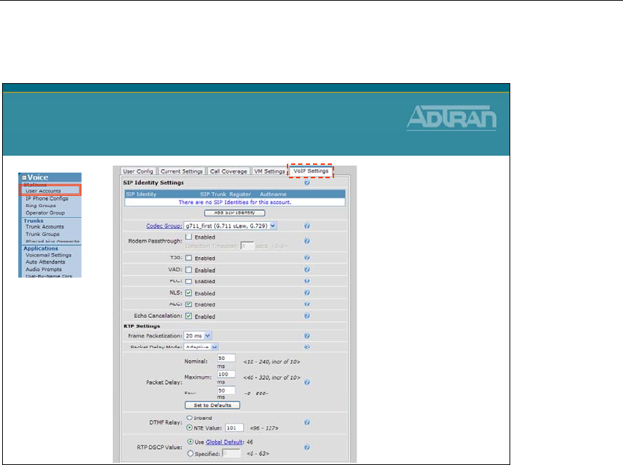
Module 3: Introduction to NetVanta 7000 Series Voice Configuration
3-48 NetVanta IP Telephony Course
Edit User – VoIP Settings Tab
Edit User – VoIP Settings Tab
The VoIP Settings tab allows you to edit the user’s voice over IP settings like codec group,
VAD, and RTP settings.
SIP Identity Settings
Configures SIP Identities for this account. The table shows all existing SIP Id's (you may
have to scroll to see all of them).
• To add a new SIP Id, click the Add SIP Identity button just below the SIP Identity table
and enter the new SIP Id for this account in the popup box.
• Click the Delete button next to the SIP Id entry if you wish to remove it.
SIP Identity
Enter this user's SIP Identity. Currently, this value must be equal to the user's extension.
Associated SIP Trunk
Select the SIP Trunk this station will use for registration purposes.
Trunk Registration
Select whether or not this user should register with selected the SIP Trunk.

Module 3: Introduction to NetVanta 7000 Series Voice Configuration
NetVanta IP Telephony Course 3-49
Trunk Authentication
Optionally, set the authentication information for this station. If 'Not Set' is chosen, the unit
will use the registration trunk authentication data if it exists. Otherwise, no authentication
data will be sent.
Codec Group
Select the codec group to use for this station account.
Modem Passthrough
When Modem Passthrough is enabled and an existing call detects a modem or fax tone, the
unit will automatically renegotiate with the far end to be modem-compatible (switch to
G.711, all voice improvements turned off, packet delay set to Fax).
T38
When T.38 is enabled and an existing call detects a fax tone, the unit will automatically
renegotiate with the far end to be T.38.
VAD
When Voice Activity Detection is enabled, silence is not transmitted over the network,
only audible speech. When VAD is enabled, the sound quality is slightly degraded but the
connection monopolizes much less bandwidth.
PLC
Enables/disables Packet Loss Concealment. When enabled, the unit will try to reconstruct
sound lost from dropped packets.
NLS
Enables/disables the echo canceller's Non-Linear Suppression. When enabled, acoustic
echo should be reduced.
ALC
Enables/disables the Automatic Leveling Control. When enabled, reduces received RTP
signals to a predefined level.
Echo Cancellation
When enabled, reflected noise is cancelled from the transmitted voice signal. Echo
cancellation should normally only be disabled if the voice station is connected to a fax
machine or modem.
RTP Settings
Frame Packetization
Select the number of audio samples in ms (1 frame/sample is 10 ms) included in a single
RTP packet.
Packet Delay Mode
Configures the operation mode of the jitter buffer for VoIP calls involving this account.

Module 3: Introduction to NetVanta 7000 Series Voice Configuration
3-50 NetVanta IP Telephony Course
• Adaptive - The buffer's delay starts at the nominal delay setting but will increase up to
the delay setting if it detects that an intolerable number of packets are being discarded
due to jitter. Conversely, the buffer will decrease the amount of delay if it can afford to.
• Fixed - The buffer's delay stays at the nominal setting at all times.
Packet Delay
Configures various packet delay settings for this account.
• Nominal - For voice calls, the nominal delay value represents the desired amount of
packet delay. In adaptive mode, the buffer may increase this value up to the maximum
delay. In fixed mode, the delay is constantly set at this value.
• Maximum - For voice calls, the maximum delay value represents the maximum delay
to which the adaptive jitter buffer can grow.
• Fax - If Modem Passthrough is enabled and modem/fax tones are detected, the packet
delay setting will be switched to this value.
DTMF Relay
Select how DTMF tones are to be transmitted over RTP. If out of band (NTE), also enter
the NTE value.
RTP DSCP Value
Select the DiffServe code point for this station's RTP packets. Either use the global default
(which will change as the global default changes) or specify a value for this station only.
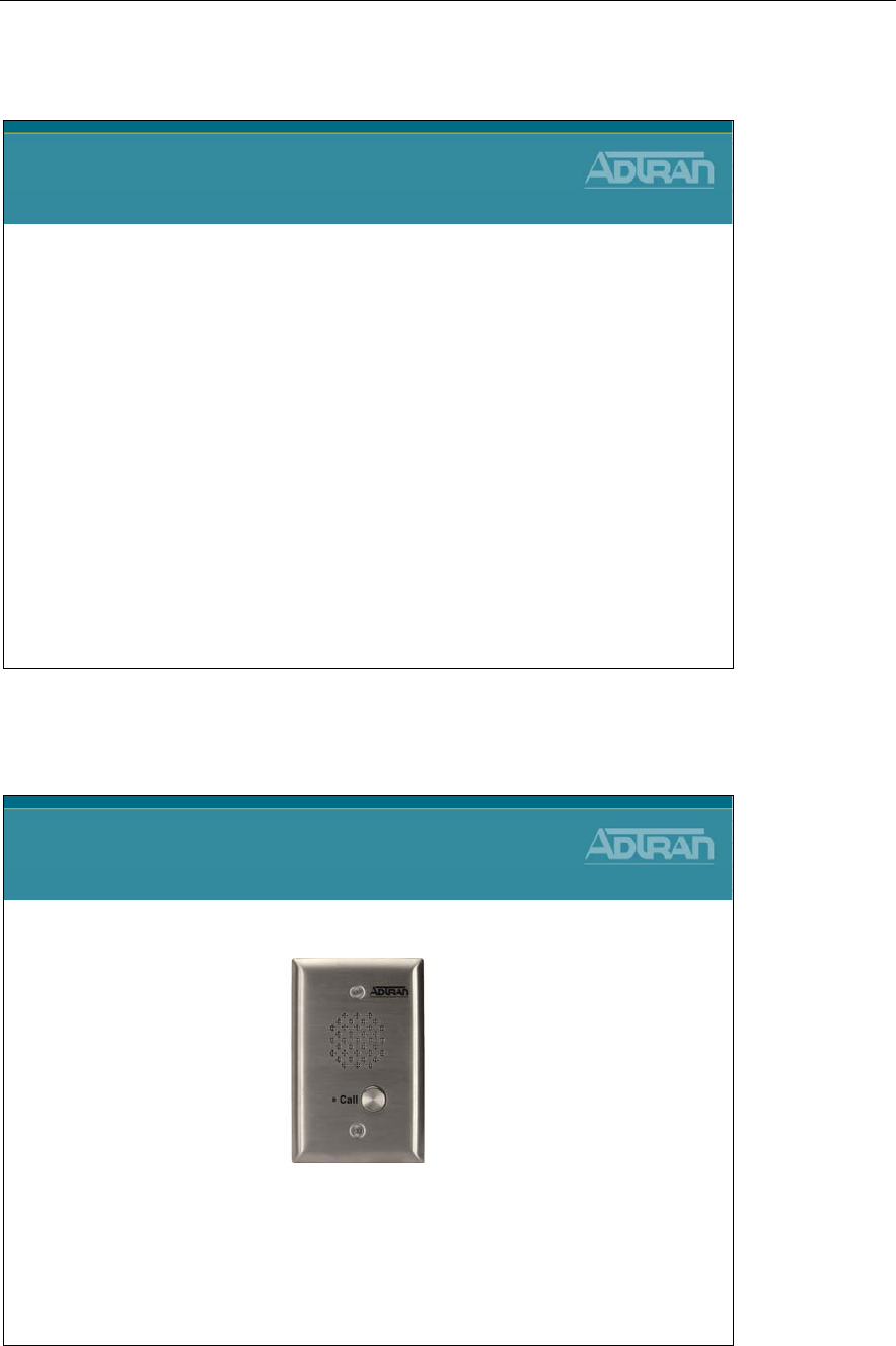
Module 3: Introduction to NetVanta 7000 Series Voice Configuration
NetVanta IP Telephony Course 3-51
Creating Voice User Account Examples
NetVanta IP Telephony Course
Voice Stations
Creating Voice User Examples
ADTRAN ADP-40 Door phone
Analog Voice User
ADTRAN ADP-40 Door phone
The ADTRAN ADP-40 is a brushed stainless steel, compact, weather
and vandal resistant, telephone line powered speakerphone designed to
provide two-way hands free communication.
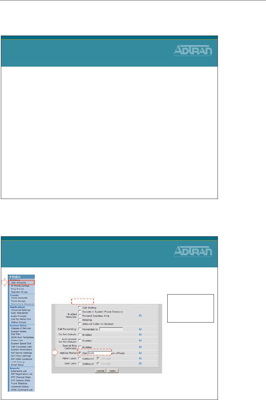
Module 3: Introduction to NetVanta 7000 Series Voice Configuration
3-52 NetVanta IP Telephony Course
Door Phone Configuration Summary
ADTRAN ADP-40 Door Phone
Configuration Summary
1. After installation of the door phone, attach the
phones RJ-11 connector to one of the NetVanta
7000 FXS ports
2. Create a Ring Group to define the phones that will
ring and the call flow when someone presses the call
button on the door phone
3. Create an analog station account for the door phone
4. Configure the analog station account to dial the Ring
Group when button is pressed
The user’s forward disconnect should be left at the default of 500ms.
Door phone Configuration
1. From the Voice / Stations / User Accounts
menu, create Analog Voice user for door phone
2. From the Current Setting tab, enable Hotline
and set Dial to number to automatically call
Door Phone Configuration
Enable Hotline
1
Set Class of Service to
door phone
Other settings should
be disabled
2
When someone presses
door phone, it will dial
extension entered here
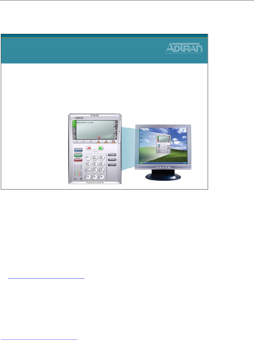
Module 3: Introduction to NetVanta 7000 Series Voice Configuration
NetVanta IP Telephony Course 3-53
ADTRAN IP SoftPhone
ADTRAN IP SoftPhone
•Optional IP SoftPhone
•Turns PC or laptop into easy to use telephone
•Ideal for remote office or access while traveling
•Compatible with USB headsets for hands-free
operation
The ADTRAN IP SoftPhone is an intuitive software application designed to enable VoIP
communication from your laptop or desktop PC. It offers many business features including
transfer, conference, forward, hold, do-not-disturb and quick access to the address book
and call logs such as recently received calls, missed calls and placed calls. The SoftPhone
is ideal for business, home office, or mobile communications.
NOTE: The SoftPhone must be registered with the serial number that was received with
the SoftPhone order. You can download the ADTRAN IP SoftPhone at any time by going
to www.adtran.com/softphone.
License Key: When starting the ADTRAN IP SoftPhone for the first time, you will be
prompted for a product-specific license key. Copy and paste this vendor-provided key into
the on-screen field labeled License Key. You must have an active connection to the
Internet when this is done.
The ADTRAN IP SoftPhone User Manual and additional information can be found at
www.adtran.com/softphone.
.
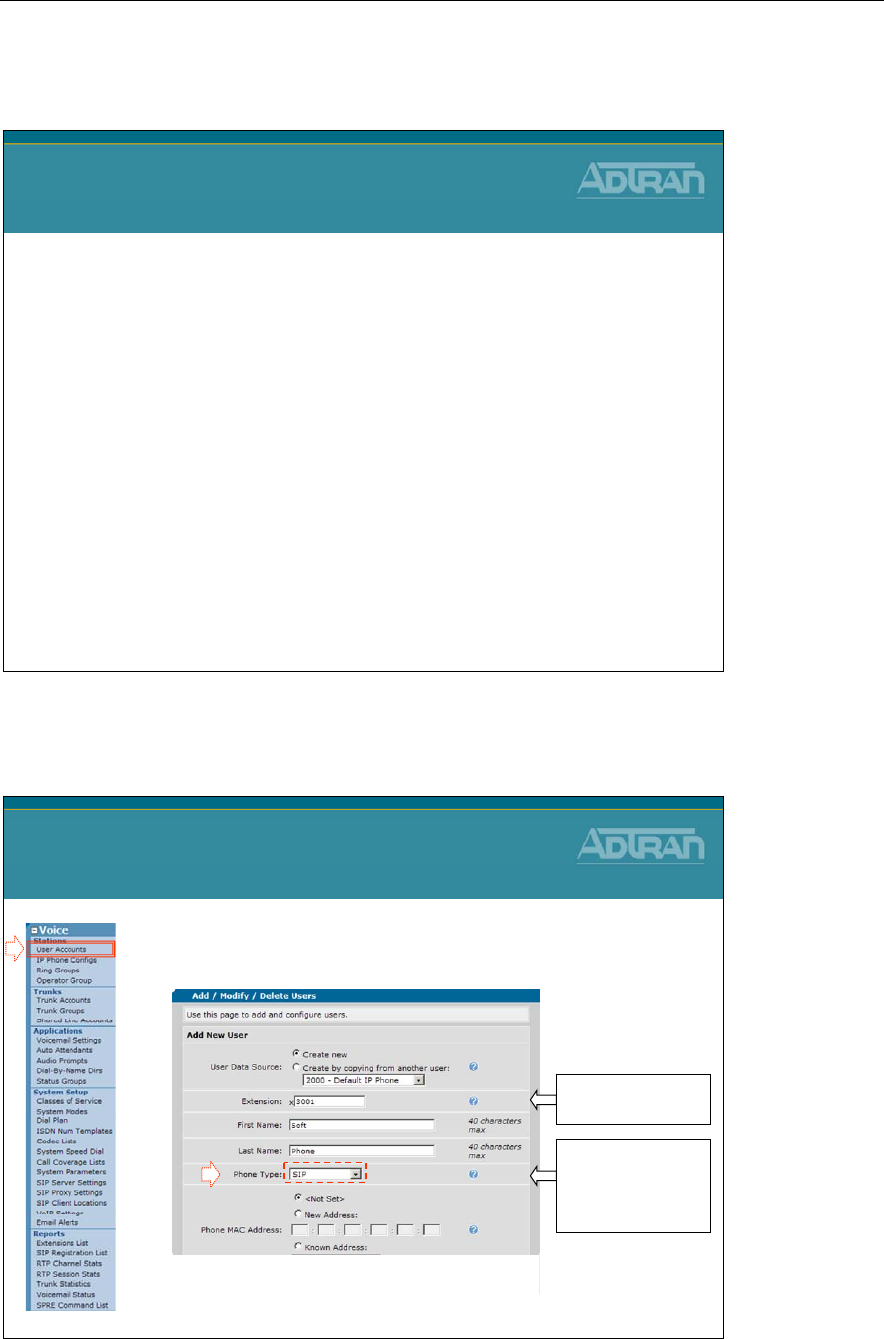
Module 3: Introduction to NetVanta 7000 Series Voice Configuration
3-54 NetVanta IP Telephony Course
IP SoftPhone - Configuration Summary
ADTRAN IP SoftPhone
Configuration Summary
1. From the NetVanta 7000, create a SIP user for this
client
2. Install the ADTRAN IP SoftPhone on the user’s PC
3. License the ADTRAN IP Softphone using the
instructions provided at purchase
4. Add a SIP account to the Softphone that matches a
user on the NetVanta 7000
Creating a SIP User for the IP SoftPhone
1. From the Voice / Stations / User Accounts
menu, create a SIP User Account
–Create a SIP user account that will match a user created in SoftPhone
Creating a SIP User for the
IP SoftPhone
1
2
Enter extension
and name
Select Phone Type
SIP and Phone
MAC Address to
<Not Set>
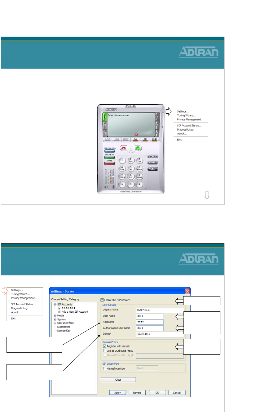
Module 3: Introduction to NetVanta 7000 Series Voice Configuration
NetVanta IP Telephony Course 3-55
IP SoftPhone – Configure SoftPhone
ADTRAN IP SoftPhone
Configure SoftPhone
1. If not running, start the ADTRAN IP Softphone
2. Right mouse-click anywhere in the SoftPhone
display area
3. Click Settings…
more
IP SoftPhone – Configuration Settings
ADTRAN IP SoftPhone
Configuration Settings
• Create a SIP account that matches user created in the NetVanta 7000
Matches an
extension in
NetVanta 7000
•
The new user will register with the NetVanta 7000
Register with
domain
Match user’s password
in the NetVanta 7000
Point to the NetVanta
7000 as the SIP server
Enable account

Module 3: Introduction to NetVanta 7000 Series Voice Configuration
3-56 NetVanta IP Telephony Course
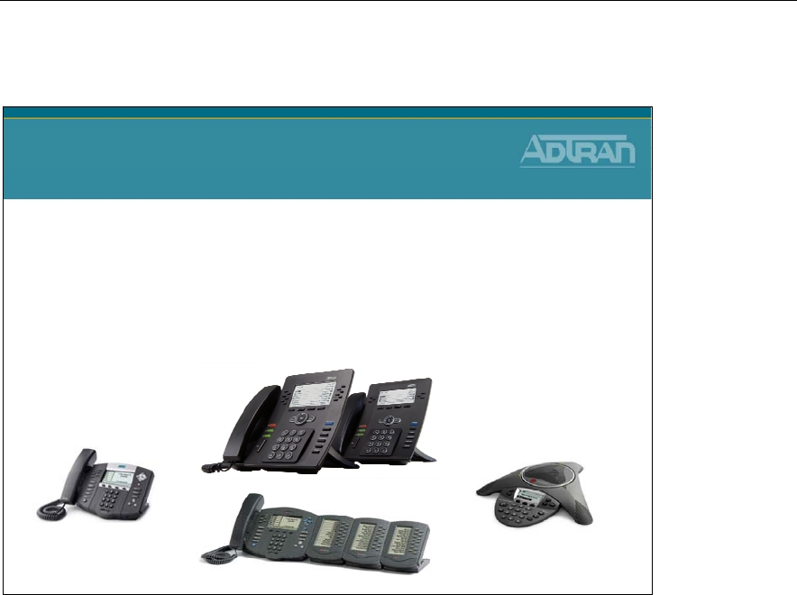
Module 3: Introduction to NetVanta 7000 Series Voice Configuration
NetVanta IP Telephony Course 3-57
SIP User Account – Known Phone Models
SIP User Account
Known Phone Models
•Phone configuration files are created for recognized
phone models and stored in 7000 CFLASH by default
–The phone will load this configuration file at boot
–Phone configuration files define phone features, user
information, SIP Server, etc…
Standard SIP phones load configuration files that define most of the IP phone features and
configuration parameters. When the phone boots, it loads configuration files based on its
MAC address. The NetVanta 7000 stores phone configuration files in CFLASH.
- ADTRAN phone configuration files are stored in the CFLASH ADTRAN folder
- Polycom phone configuration files are stored in the CFLASH Polycom folder
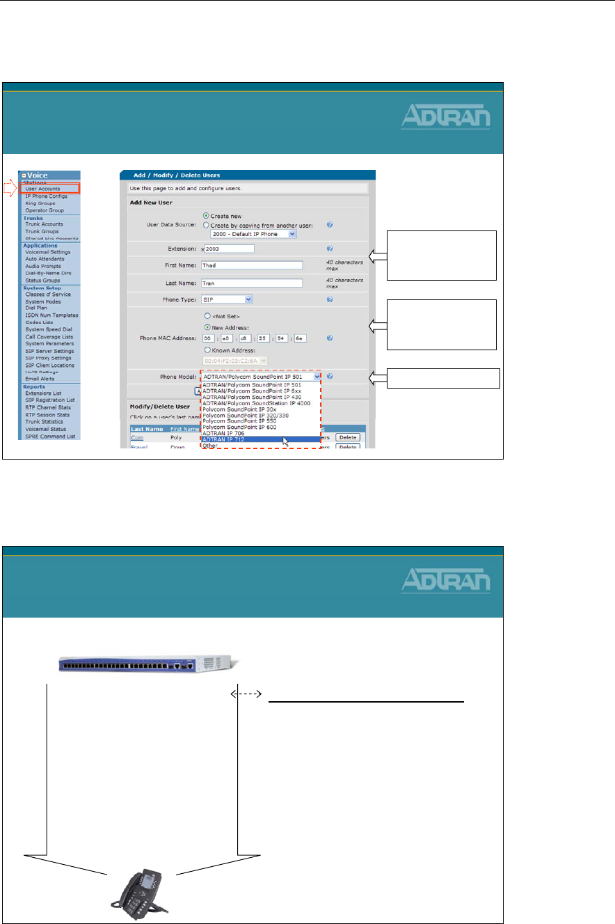
Module 3: Introduction to NetVanta 7000 Series Voice Configuration
3-58 NetVanta IP Telephony Course
Creating a SIP User for a Known Phone Model
Creating a SIP User for a
Known Phone Model
Enter extension,
name, and select
Phone Type SIP
Select New Address
and then the phones
MAC Address
Choose Phone Model
Known Phone Model – Configuration File
Known Phone Model
Configuration File
adtran_[MAC Address].cfg
An ADTRAN phone will look for its
own adtran_[MAC].txt file
- Instructs phone on files to load
- Phone settings for the specific
phone
- Created when user added in GUI
NetVanta 7100 – Boot Server
adtran_00a0c825546e.txt
Include adtran_firmware_712.txt
Include adtran_boot.txt
Include adtran_global.txt
Include adtran_customer.txt
Language_English.xml
adtran_phonebook.csv
iconpixmap.bmp
* Phone Configuration Files are covered in Module 4
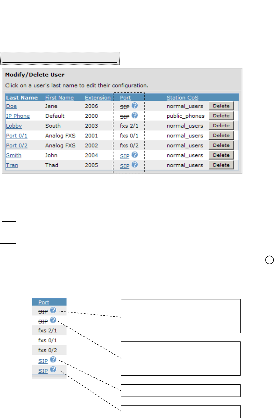
Module 3: Introduction to NetVanta 7000 Series Voice Configuration
NetVanta IP Telephony Course 3-59
SIP User Status
The status of a SIP user can be seen from the Voice / Stations / User Accounts screen.
Registration Status
If the SIP user has registered with the NetVanta 7100, a line displays below the word
SIP.
If the SIP user has not registered with the NetVanta 7100, a line displays though the word
SIP.
A bubble displays next to the SIP user’s port. If you place your cursor over the bubble,
information about the SIP user will display.
SIP Status Information Examples
Voice / Stations / User Accounts
?
Phone MAC: Not Set
Phone MAC: 00:A0:C8:25:54:0C
Extension 2006 is configured for a SIP
port but is not currently registered.
Phone MAC: Not Set
Extension 2000 is configured for a SIP
port but is not currently registered.
Phone MAC: 00:A0:C8:25:51:9C

Module 3: Introduction to NetVanta 7000 Series Voice Configuration
3-60 NetVanta IP Telephony Course
Hotelling
(Analog Only)
The Hotelling option allows users to log into a hotel enabled phone. When hotelling is
enabled, a user can log into a user's phone without logging the current user out first. Useful
for shared-desk applications.
Hotteling must be enabled for for both the Voice User of the analog phone and the Virtual
voice user that will have permission to log into a hotel enabled phone.
To Enable Hotelling
1) From Voice / Stations / User Accounts, create or edit the analog Voice User that will
allow hotelling.
2) From the voice User’s Current Settings tab, enable the Hotelling option and then click
Apply.
Hotelling must be enabled on the phone that will allow Hotelling and it must be enabled
for the users that will be allowed to log into a Hotel enabled phone.
Note: The User will also need to be assigned to a Class of Service that permits the use of
the Hotel feature.
Logging into a Hotel enabled phone
From the hotel enabled analog phone issue the following SPRE codes to login or logout:
Hotel Login: *46xxxx#pppp# (*HO)
xxxx: Virtual user’s account number
pppp: Virtual user’s password
Hotel Logout: *47pppp# (*HQ)
Virtual User Status
When a virtual user is logged into a hotel enabled phone, a bubble will display next to
the users port. If you place your cursor over the bubble, the login status of the virtual user
or hotel enabled phone will display.
?
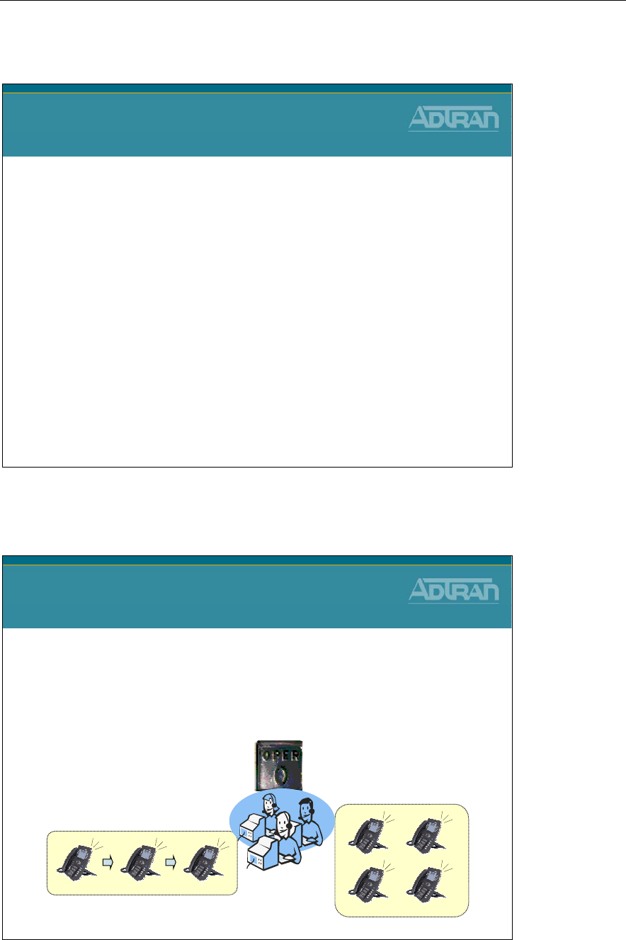
Module 3: Introduction to NetVanta 7000 Series Voice Configuration
NetVanta IP Telephony Course 3-61
Voice Stations - Ring Groups/Operator Group
NetVanta IP Telephony Course
Voice Stations
Ring Groups/Operator Group
Voice Stations - Ring Groups
Voice – Stations
Ring/Operator Group Menu
•Define a group of user accounts that can be called in a
coordinated way with a single extension
–The incoming caller ID from a group member denotes a group call
with a "GRP:" prefix

Module 3: Introduction to NetVanta 7000 Series Voice Configuration
3-62 NetVanta IP Telephony Course
Voice Stations - Ring Groups
Voice Stations
Ring Groups
There are four types of ring groups:
•Linear Hunt Group
–Calls will be distributed to members in the order that they
were added to the ring group
•All Ring
–Calls will ring all members and the first extension to
answer will receive the call
•UCD
–Calls will be distributed to members in the order that they
were added, but in a uniform, round-robin fashion
•Executive Ring
–Calls will ring both the executive's and assistant's
extensions but use the executive's call coverage
Ring All Ring Group
• Rings all members simultaneously
• Members can login or logout
• Group call coverage; single voice mail box for the group
• Call-waiting disabled while on a group call and receive a group call
Linear Ring Group
• Rings members one at a time, always starting with the first member in the group
• Members can login or logout
• Group call coverage; single voice mail box for the group
• Call-waiting disabled while on a group call and receive a group call

Module 3: Introduction to NetVanta 7000 Series Voice Configuration
NetVanta IP Telephony Course 3-63
Uniform Call Distribution (UCD) Ring Group
• Rings members one at a time, starting with the next member
• Members can login or logout
• Group call coverage; single voice mail box for the group
• Call-waiting disabled while on a group call and receive a group call
Executive Ring Group
• Members include executive and assistant extension
• Rings both members
• Uses executive's call coverage for voice mail
Ring Group Configuration
1. Select Voice / Stations / Ring Group from the NetVanta 7000 menus
2. Assign extension and description
3. Select Ring Group Type (All, Linear, UCD, Executive)
4. Add members (voice users) to ring group
5. Define max calls allowed into ring group
6. Configure Call Coverage and Voicemail settings for ring group

Module 3: Introduction to NetVanta 7000 Series Voice Configuration
3-64 NetVanta IP Telephony Course
Ring Group - Logging in and out of group
Ring Group
Logging in and out of group
•The Admin can log users in and out from the
Voice / Stations/ Ring Group screen
•Members can login to a Group with a SPRE
code when they want to receive calls to the
group and logout using a SPRE code when
they do not want to receive calls to the group
–From the desired phone:
•Group Login: *55xxxx* (*LL)
xxxx: Group number
•Group Logout: *56xxxx* (*LO)
Logging in and out of Groups
Members can login to a Group with a SPRE code when they want to receive calls to the
group and logout using a SPRE code when they do not want to receive calls to the group.
From the desired phone, enter the following SPRE codes to login or logout:
Group Login: *55xxxx* (*LL)
xxxx: Group number
Group Logout: *56xxxx* (*LO)
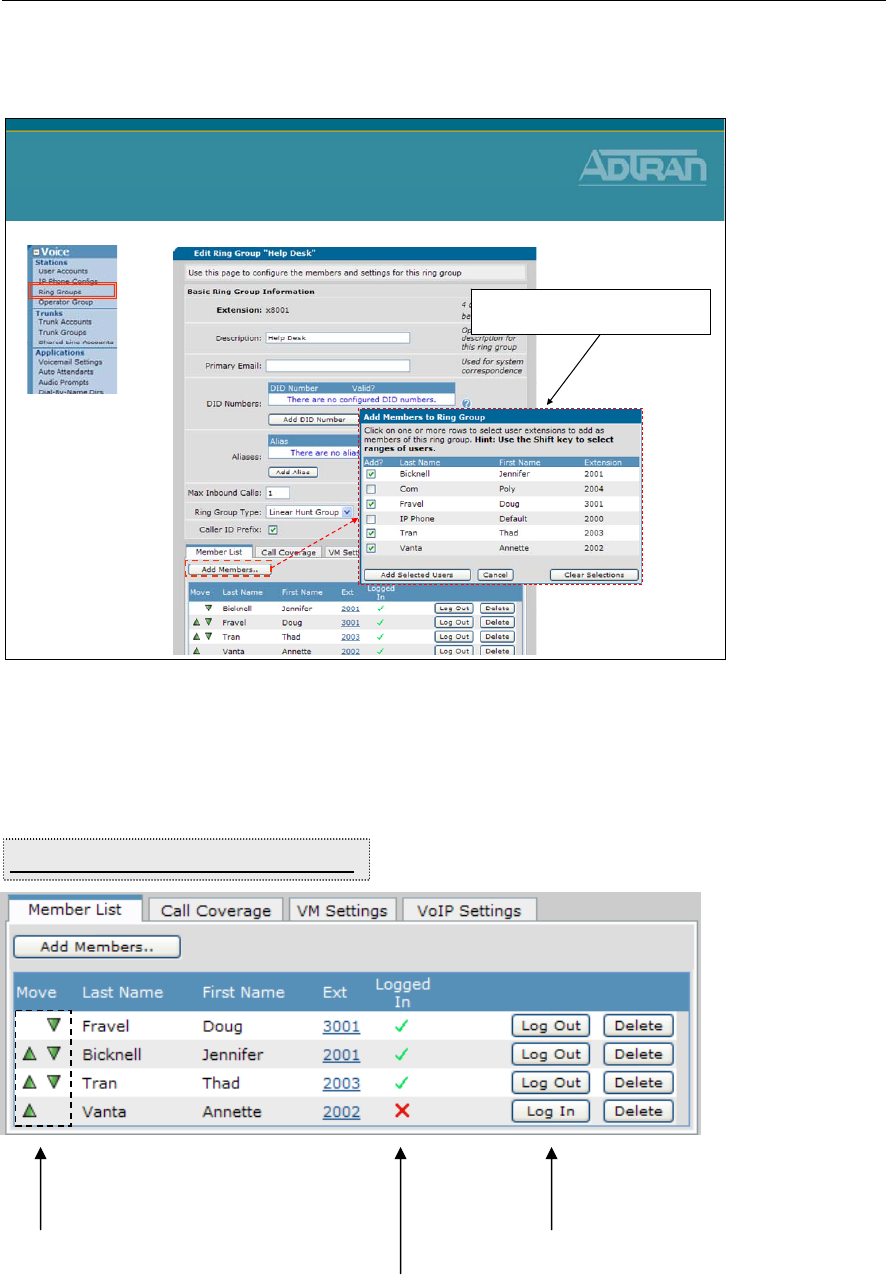
Module 3: Introduction to NetVanta 7000 Series Voice Configuration
NetVanta IP Telephony Course 3-65
Ring Group - Configuration
Ring Group
Configuration
Add users that will be allowed to
log in and out of this group
If the Caller-ID Prefix option is selected, when a call comes into the group, incoming
Caller_ID displays "GRP:" along with the originating Caller-ID.
Members can be logged in or out of a group
Member status
Voice / Stations / Ring Groups
The up and down arrows
can be used to change the
call progression order of
the group’s voice users

Module 3: Introduction to NetVanta 7000 Series Voice Configuration
3-66 NetVanta IP Telephony Course
Module 3: Introduction to NetVanta 7000 Series Voice Configuration
NetVanta IP Telephony Course 3-67
Voice Stations - Operator Group
Voice Stations
Operator Group
•The Operator Group is a special ring group
that rings the members of the operator group
when ‘0’ is dialed
•Members can login and logout of the Operator
Group so that their phones do not ring when
they do not want to receive operator calls
•Internal extensions will receive a priority ring
cadence when called from members of the
operator group
Operator Group
• Rings all members simultaneously
• Members can login or logout
• Group call coverage; single voice mail box for the group
• Internal extensions receive priority ring cadence when called from operator extensions
• Configured to use Linear Ring, UCD Ring, or All Ring
• Optional Operator Calling-Party ID
Operator Group Configuration
1. Select Voice / Stations / Operator Group from the NetVanta 7000 menus
2. Select Group Type (All, Linear, UCD)
3. Add members (voice users) to group
4. Define max calls allowed into group
5. Configure Call Coverage and Voicemail settings for Operator group
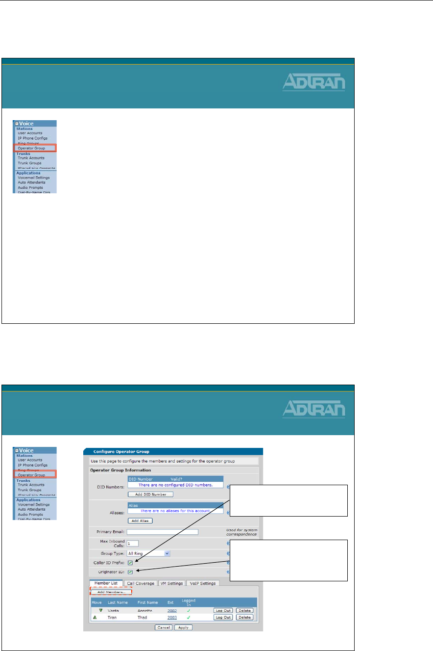
Module 3: Introduction to NetVanta 7000 Series Voice Configuration
3-68 NetVanta IP Telephony Course
Operator Group - Logging in and out of group
Operator Group
Logging in and out of group
•The
Admin
can log users in and out from the
Voice / Stations/ Operator Group screen
•
Members
can login to Operator Group with a
SPRE code when they want to receive calls to
the group and logout using a SPRE code
when they do not want to receive calls to the
group
–From the desired phone:
•Operator Group Login: *550* (*LL
0 is Group #
•Operator Group Logout: *560* (*LO)
Operator Group - Configuration
Operator Group
Configuration
Shows "OPR:" caller ID prefix for
all group members when receiving
a call on the group's extension.
When enabled, the members of the
operator group will be identified
with "Operator" CID when placing
a call.

Module 3: Introduction to NetVanta 7000 Series Voice Configuration
NetVanta IP Telephony Course 3-69
Voice Ring Group / Operator Group Settings
The Ring Group / Operator Group Settings are the settings that can be seen or modified
while editing a ring group. When a new ring group is created, you are placed in the Edit
<Ring Group> screen where the settings below display.
Editing Ring Group / Operator Group - Initial Screen
Extension
The extension associated with this ring group
Description
Optional description for this ring group
Primary Email
Used for system correspondence
DID Numbers
Configures DID numbers for this account. The table shows all existing DID numbers (you
may have to scroll to see all of them) and whether each number is currently valid. A
number is considered valid if it matches any trunk's DID prefix and digit count. If no DID
information has been configured in trunks, then all numbers are considered valid.
• To add a new DID number, click the Add DID Number button just below the DID
Number table and enter the DID number in the popup box.
• To delete a DID number, click the Delete button next to the number you want to delete.
Aliases
Configures aliases for this account. The table shows all existing aliases (you may have to
scroll to see all of them).
• To add a new alias, click the Add Alias button just below the Alias table and enter the
new alias for this account in the popup box.
• To delete an alias, click the Delete button next to the alias you want to delete.
Max Inbound Calls
Enter the number of concurrent inbound calls allowed into this group (1-9). Any further
concurrent calls will go directly to call coverage.
Ring Group Type
• Linear Hunt Group - Calls will be distributed to members in the order that they were
added to the ring group.
• All Ring - Calls will ring all members and the first extension to answer will receive the
call.
• UCD - Calls will be distributed to members in the order that they were added, but in a
uniform, round-robin fashion.

Module 3: Introduction to NetVanta 7000 Series Voice Configuration
3-70 NetVanta IP Telephony Course
• Executive Ring - Calls will ring both the executive's and assistant's extensions but use
the executive's call coverage.
Caller ID Prefix (Ring Group)
Shows "GRP:" caller ID prefix for all group members when receiving a call on the group's
extension.
Caller ID Prefix (Operator Group)
Shows "OPR:" caller ID prefix for all group members when receiving a call on the group's
extension.
Originator ID (Operator Group)
When enabled, the members of the operator group will be identified with "Operator" CID
when placing a call.
Editing Ring Group / Operator Group – Members List Tab
The Members List tab displays all the users that are in this ring group. Once a member has
been added, the move arrows can be used to change the order of the member in the group.
It also displays the status of which members are currently logged into the group.
Add Members Button
Click on one or more rows to select user extensions to add as members of this ring group.
Hint: Use the Shift key to select ranges of users.
Log In / Log Out Button
Members can be logged in or out of a group by the admin
Editing Ring Group / Operator Group – Call Coverage Tab
Define what happens when a call is not answered by members of this ring group. A call
will always follow the ring group’s call coverage, not the individual members call
coverage.
Editing Ring Group / Operator Group – VM Settings Tab
The VM Settings tab allows you to edit the user’s voicemail settings such as VM Phone
Indication and VM Notification Schedule.
Voicemail PIN
Sets the password the user must enter to access the voicemail system. Password must be 4
digits.
VM Class of Service

Module 3: Introduction to NetVanta 7000 Series Voice Configuration
NetVanta IP Telephony Course 3-71
The voicemail class of service assigned to this ring grop
VM Operator Assist #
This number will be dialed if a caller requests to speak with the operator while leaving a
voicemail.
New User Reminder
Checking this box alerts the Voicemail system to prompt the user to record their name. The
recorded name is subsequently used for playback within the system.
Play Envelopes
When enabled, envelopes preceding voice messages will be played. An envelope includes
the Calling party and the Date/Time information about a message.
Auto-play messages
When enabled, voice message playback will begin automatically after logging into your
voice mailbox.
Authentication
Choose the authentication method to be used when logging into your voice mailbox. From
valid phones, authenticate using:
• mailbox/password
• password only
• no authentication
WARNING: Selecting “None” will allow anyone who knows your extension to hear your
messages.
Notification Type Primary Email (future)
When being notified that a voicemail has been left, the type of notification may be chosen.
• Select between NOT being notified via email, an email that contains only text, or an
email that has the voicemail message attached in WAV format.
• The Operator Group and Ring Groups simply need to have their email addresses
configured to begin receiving voicemail notifications.
• User Accounts, however, must define a notification schedule for this setting to have an
effect.
Greeting Method
Choose the greeting that will be heard by callers leaving voice messages. The Default
greeting is your recorded name. To record Standard and Alternate greetings, login to your
voicemail via your phone and follow the instructions under the Greetings menu.

Module 3: Introduction to NetVanta 7000 Series Voice Configuration
3-72 NetVanta IP Telephony Course
Editing Ring Group / Operator Group – VoIP Settings Tab
The VoIP Settings tab allows you to configure SIP Identities for this ring group.
SIP Identity Settings
Configures SIP Identities for this account. The table shows all existing SIP Id's (you may
have to scroll to see all of them).
• To add a new SIP Id, click the Add SIP Identity button just below the SIP Identity table
and enter the new SIP Id for this account in the popup box.
• Click the Delete button next to the SIP Id entry if you wish to remove it.
SIP Identity
Enter this user's SIP Identity. Currently, this value must be equal to the user's extension.
Associated SIP Trunk
Select the SIP Trunk this station will use for registration purposes.
Trunk Registration
Select whether or not this user should register with selected the SIP Trunk.
Trunk Authentication
Optionally, set the authentication information for this station. If 'Not Set' is chosen, the unit
will use the registration trunk authentication data if it exists. Otherwise, no authentication
data will be sent.
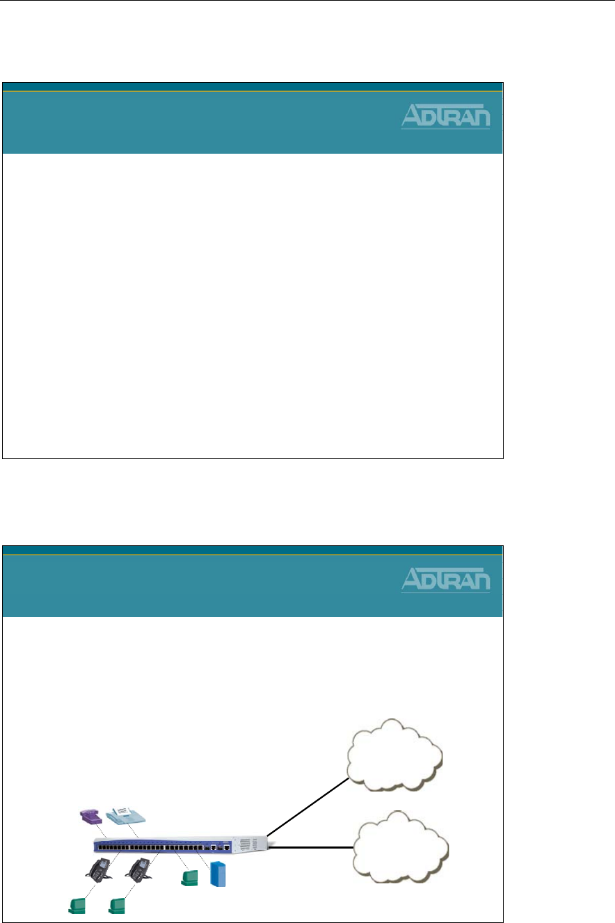
Module 3: Introduction to NetVanta 7000 Series Voice Configuration
NetVanta IP Telephony Course 3-73
Trunks
NetVanta IP Telephony Course
Voice Trunks
Voice - Trunks
Voice - Trunks
•
Trunk
lines connect the NetVanta 7000 to the outside
world. They are delivered from the carrier and may
be digital or analog.
–NetVanta 7000 Supported Trunk Types
•Analog
•T1-RBS
•T1-ISDN PRI
•SIP PSTN
Analog or T1
Carrier
VOIP Network
SIP
NetVanta
7000
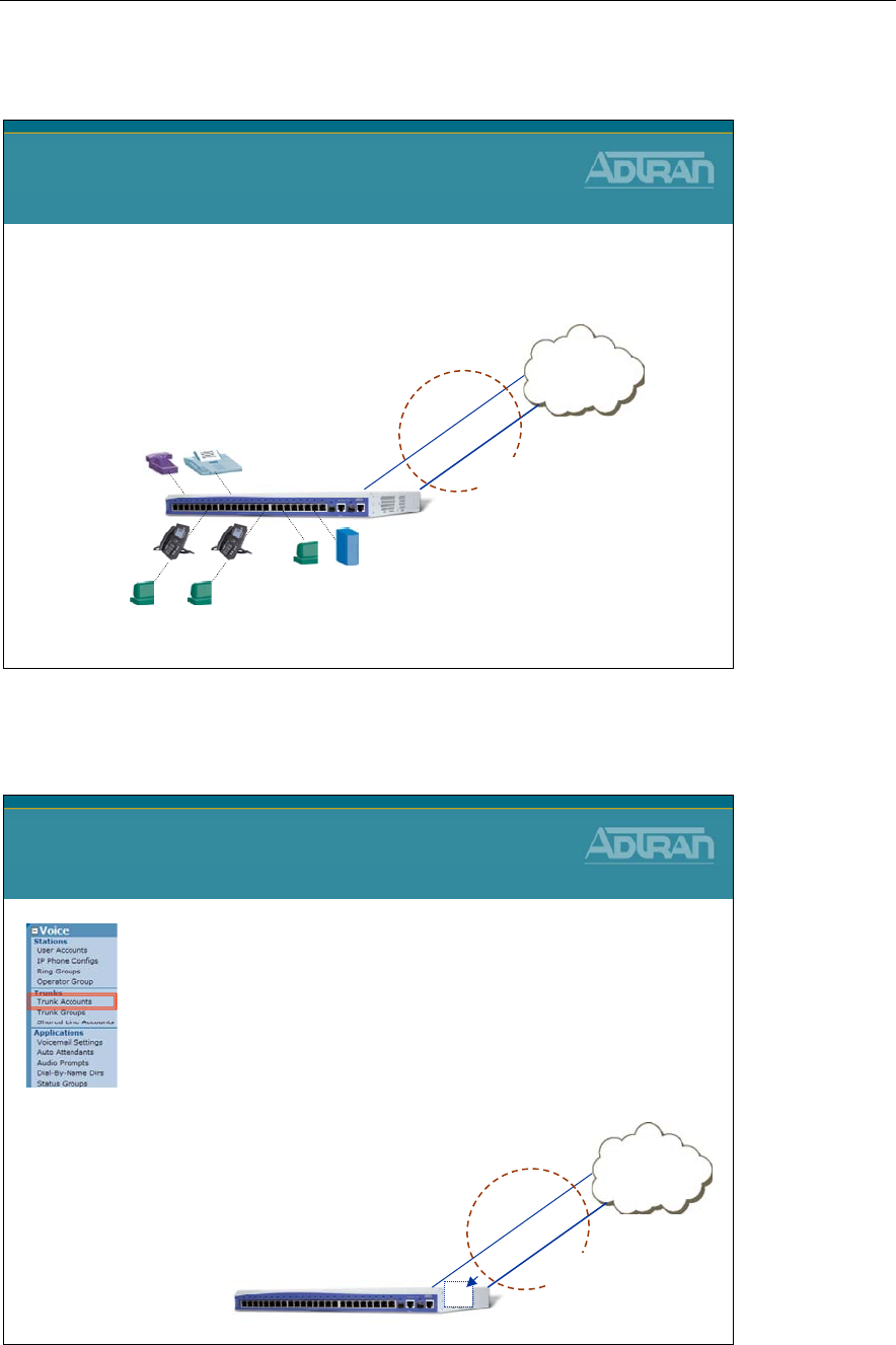
Module 3: Introduction to NetVanta 7000 Series Voice Configuration
3-74 NetVanta IP Telephony Course
NetVanta 7100 Voice Trunks
PSTN
NetVanta 7000 Voice Trunks
•NetVanta 7000 Trunk Components
–Trunk Accounts
–Trunk Groups
Trunk Acct T02
Trunk Acct T01
Trunk
Group
NetVanta
7000
NetVanta 7100 Voice Trunks - Trunk Accounts
NetVanta 7000 Voice Trunks
Trunk Accounts
•Trunk Accounts are created to define the
following trunk line parameters:
–Type of Trunk
•Analog, RBS, PRI, or SIP
–Physical interface
•FXO or T1
–Settings of your service provider
•Trunk number, DID digits being received, etc
PSTN
FXO
0/1
Trunk Acct T02
NetVanta 7000
Trunk Acct T01
FXO
0/2
Trunk
Group
AA
8200
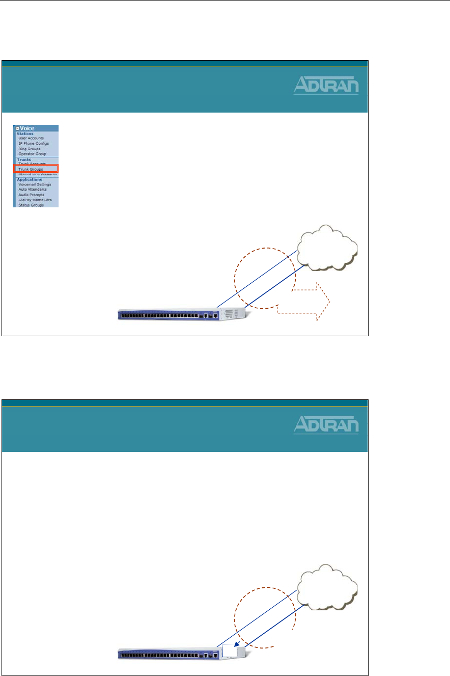
Module 3: Introduction to NetVanta 7000 Series Voice Configuration
NetVanta IP Telephony Course 3-75
NetVanta 7100 Voice Trunks - Trunk Groups
Calls
Allowed
Out
NetVanta 7000 Voice Trunks
Trunk Groups
•Trunk Groups combine one or more Trunk
Accounts
•Trunk Groups control the following:
–Resources used for outbound calls
–Outbound Call Templates are assigned to the Trunk
Group to define calls allowed out this Trunk Group
–Can also restrict calls allowed out
–Least Cost Routing
PSTN
FXO
0/1
Trunk Acct T02
NetVanta 7000
Trunk Acct T01
FXO
0/2
Trunk
Group
NV 7100 Voice Trunks - Factory Default Config
NetVanta 7000 Voice Trunks
Factory Default Config
•Trunk Account T01
–Physical Interface = FXO 0/1
–Inbound call goes to Auto Attendant (8200)
•Trunk Account T02
–Physical Interface = FXO 0/2
–Inbound call goes to Auto Attendant (8200)
•Analog Trunk Group
–Includes both T01 and T02
–All calls allowed out
(except 900 numbers)
PSTN
FXO
0/1
Trunk Acct T02
NetVanta 7000
Trunk Acct T01
FXO
0/2
Trunk
Group
AA
8200
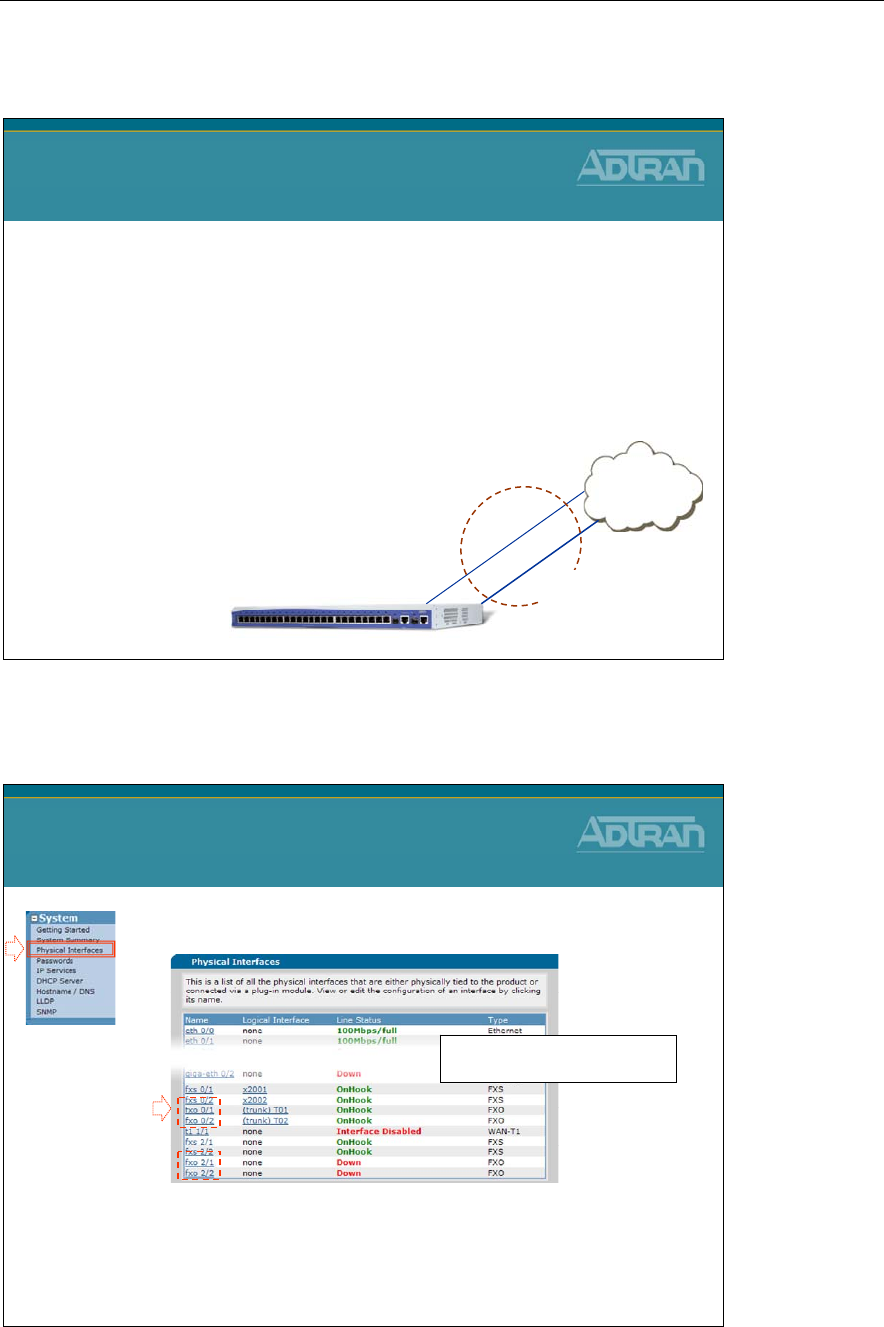
Module 3: Introduction to NetVanta 7000 Series Voice Configuration
3-76 NetVanta IP Telephony Course
Analog Trunk - Basic Configuration Steps
Analog Trunk
Basic Configuration Steps
1. Configure Trunk Physical Interface
–FXO interfaces enabled by default
2. Create Trunk Account
–Configure trunk number, caller-id, etc..
–Assign FXO port(s)
3. Create Trunk Group
–Add Trunk Account members
–Define outbound call templates
PSTN
FXO
0/1
Trunk Acct T02
NetVanta 7000
Trunk Acct T01
FXO
0/2
Trunk
Group
1) Configure Physical Interface
1. Select the System / Physical Interfaces menu
2. Click the FXO interface to be edited
–
FXO interfaces are enabled by default
Analog Trunk Configuration
1) Configure Physical Interface
The built in and modular physical
interfaces display on this screen
1
2
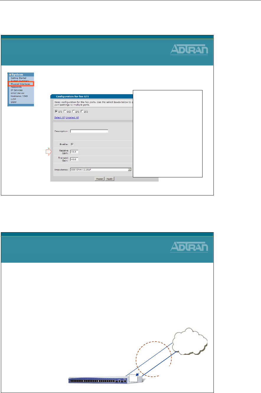
Module 3: Introduction to NetVanta 7000 Series Voice Configuration
NetVanta IP Telephony Course 3-77
1) Configure Physical Interface
3. Optional
: Interface Gain and Impedance can
be adjusted if needed
Analog Trunk Configuration
1) Configure Physical Interface
Receive Gain:
- When increasing this value, the
signal being received on this port
sounds louder
-When decreasing this value, the
signal being received on this port
sounds softer
Transmit Gain:
- When increasing this value, the
signal being transmitted to the far
end sounds louder
- When decreasing this value, the
signal being transmitted to the far
end sounds softer
3
Analog Trunk - Basic Configuration Steps
Analog Trunk
Basic Configuration Steps
1. Configure Trunk Physical Interface
–FXO interfaces enabled by default
2. Create Trunk Account
–Configure trunk number, caller-id, etc..
–Assign FXO port(s)
3. Create Trunk Group
–Add Trunk Account members
–Define outbound call templates
PSTN
FXO
0/1
Trunk Acct T02
NetVanta 7000
Trunk Acct T01
FXO
0/2
Trunk
Group
AA
8200
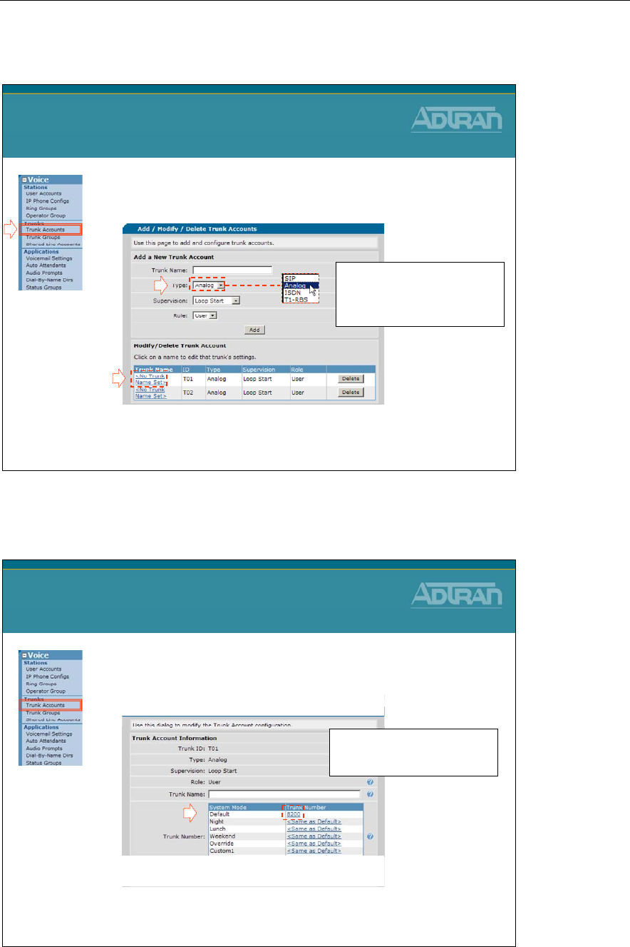
Module 3: Introduction to NetVanta 7000 Series Voice Configuration
3-78 NetVanta IP Telephony Course
2) Create Trunk Account
1. Select the Voice / Trunks / Trunk Accounts
menu
2. Create (or edit) an Analog Trunk Account
–In this example, we will edit a default Trunk Account
Analog Trunk Configuration
2) Create Trunk Account
- Type Trunk Name
- Set Type to Analog
- Supervision can be Loop Start
or Ground Start.
1
2
2) Create Trunk Account
3. Define the Trunk Number used for this Trunk
Account
–Inbound calls on this trunk will be routed to the
defined Trunk Number
Analog Trunk Configuration
2) Create Trunk Account
By default, inbound calls on the
Analog trunk go to the Auto
Attendant extension 8200
3
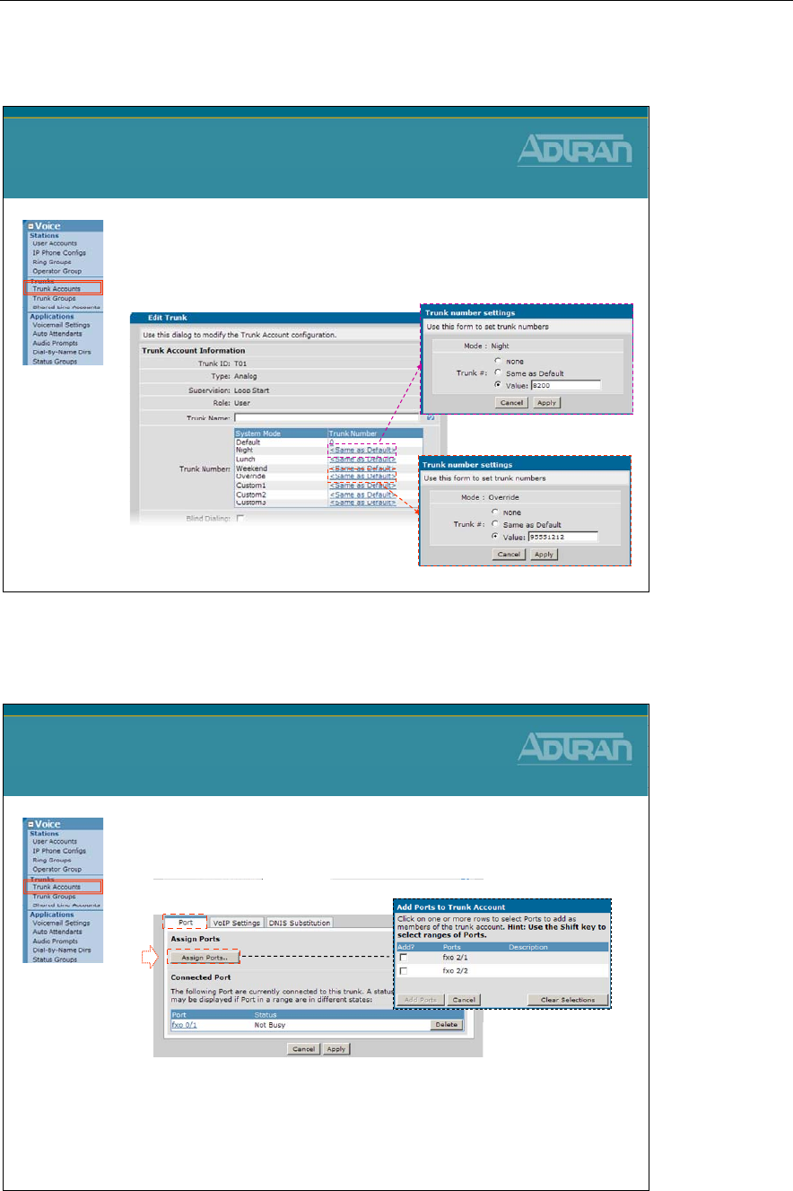
Module 3: Introduction to NetVanta 7000 Series Voice Configuration
NetVanta IP Telephony Course 3-79
2) Create Trunk Account
Analog Trunk Configuration
2) Create Trunk Account
•Optional - Define a Trunk Number per System
Mode
–None / Same as Default / Value – extension/number
2) Create Trunk Account
4. Specify the physical interface(s) this trunk
account will use for voice calls
–Click one or more FXO interfaces to be added
Analog Trunk Configuration
2) Create Trunk Account
4
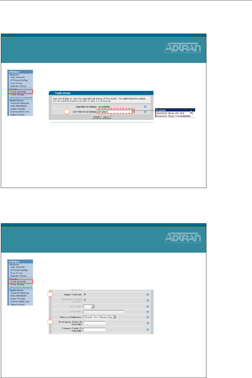
Module 3: Introduction to NetVanta 7000 Series Voice Configuration
3-80 NetVanta IP Telephony Course
2) Create Trunk Account
•
Optional
: Administrative Status
–Enabled by default
–Configurable Trunk status Options:
•Enabled - Trunk operates as normal
•Disabled: Busy On Idle - Current calls stay active, but no
new calls are accepted
•Disabled: Busy Immediately - All current calls are torn
down, and no new calls are accepted
Analog Trunk Configuration
2) Create Trunk Account
2) Create Trunk Account
•
Optional
: Reject External
–Unselect to allow trunk to trunk calls
•
Optional
: Emergency Caller ID Override
–Specify the calling party number presented on
outbound emergency calls
Analog Trunk Configuration
2) Create Trunk Account
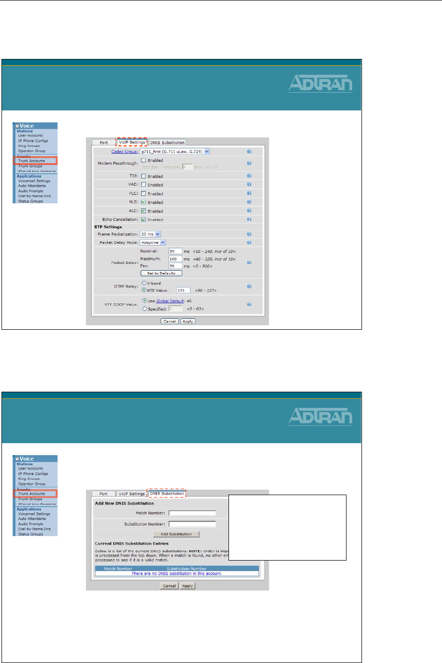
Module 3: Introduction to NetVanta 7000 Series Voice Configuration
NetVanta IP Telephony Course 3-81
2) Create Trunk Account
•
Optional
: Adjust VoIP settings for this interface
Analog Trunk Configuration
2) Create Trunk Account
2) Create Trunk Account
•
Optional
: Add DNIS substitution
–Examples:
•Match: NXX-XXXX Subst: 256-NXX-XXXX
•Match: 1-NXX-XXX-XXXX Subst: NXX-XXX-XXXX
•Match: 1-NXX-NXX-XXXX Subst: 10-10-220-NXX-NXX-XXXX
Analog Trunk Configuration
2) Create Trunk Account
Order is important:
- Multiple match statements can be
entered per trunk account
- The first valid match that is
found for outbound numbers will
be used
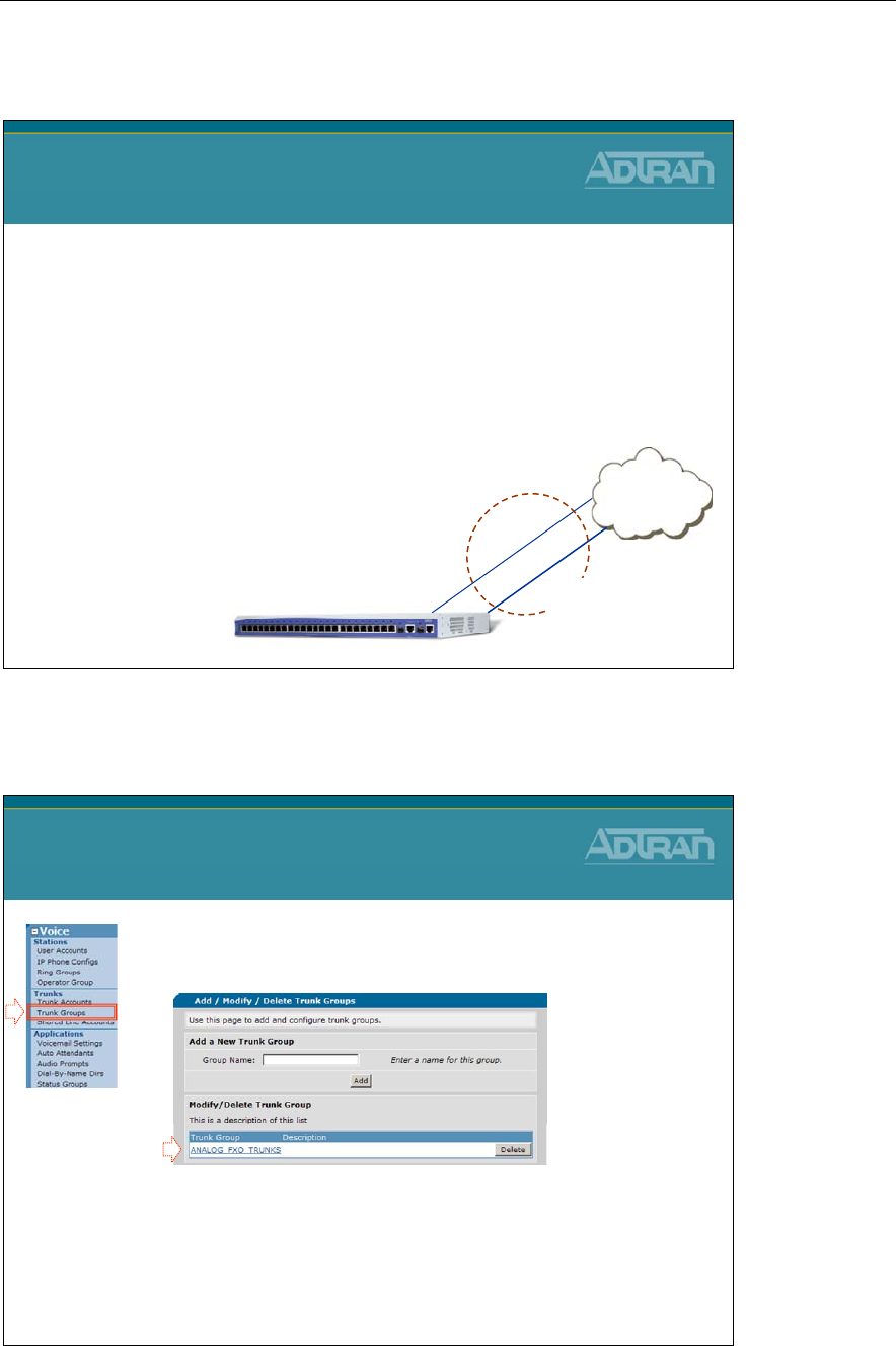
Module 3: Introduction to NetVanta 7000 Series Voice Configuration
3-82 NetVanta IP Telephony Course
Analog Trunk - Basic Configuration Steps
Analog Trunk
Basic Configuration Steps
1. Configure Trunk Physical Interface
–FXO interfaces enabled by default
2. Create Trunk Account
–Configure trunk number, caller-id, etc..
–Assign FXO port(s)
3. Create Trunk Group
–Add Trunk Account members
–Define outbound call templates
PSTN
FXO
0/1
Trunk Acct T02
NetVanta 7000
Trunk Acct T01
FXO
0/2
Trunk
Group
3) Create Trunk Group
1. Select the Voice / Trunks / Trunk Groups
menu
2. Create (or edit) a Trunk Group
–In this example, we will edit the default Trunk Group
Analog Trunk Configuration
3) Create Trunk Group
1
2
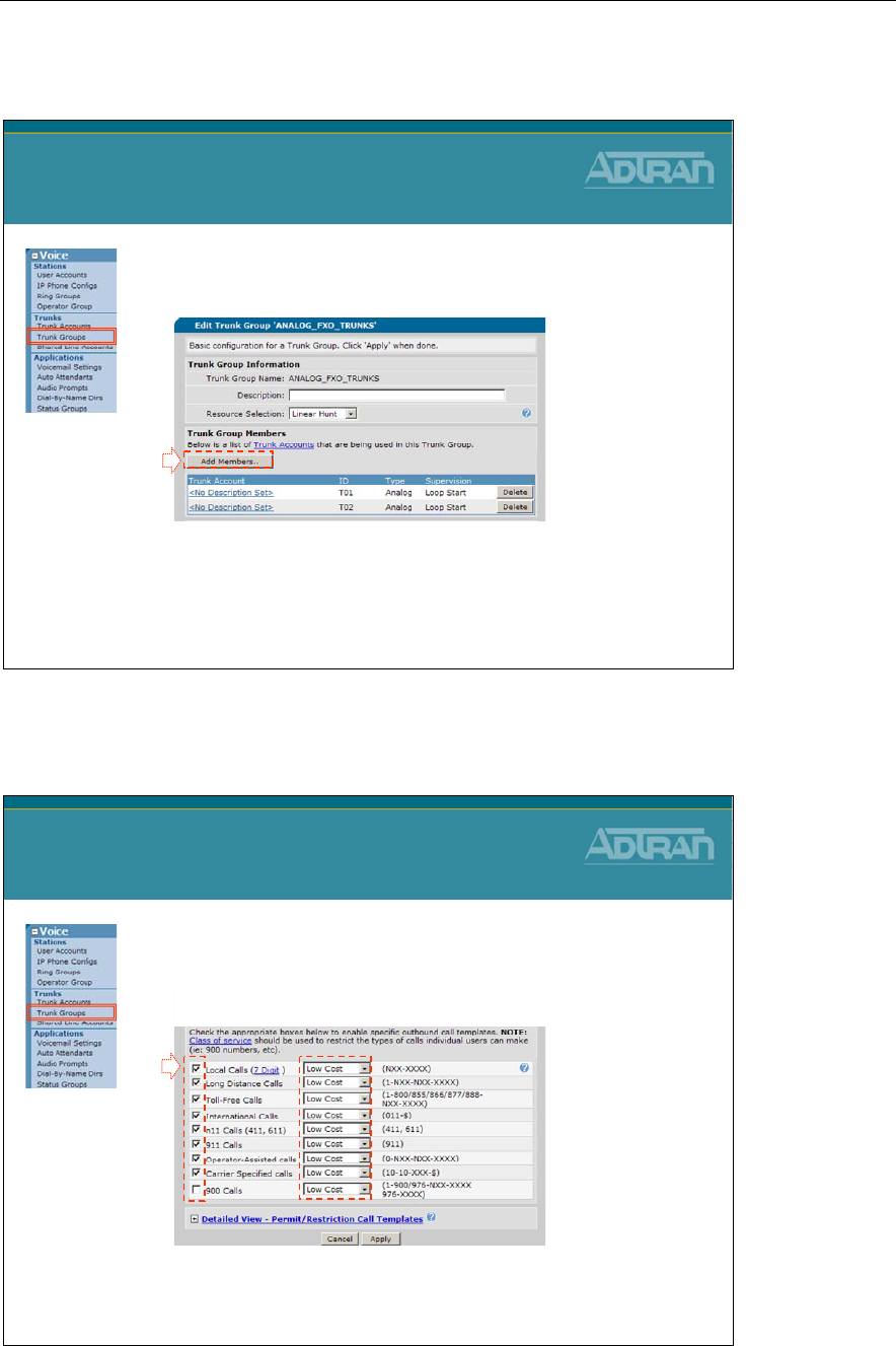
Module 3: Introduction to NetVanta 7000 Series Voice Configuration
NetVanta IP Telephony Course 3-83
3) Create Trunk Group
3. Click Add Members to add existing Trunk
Accounts to this Trunk Group
–Multiple Trunk Accounts can belong to a Trunk
Group as long as they share the same calling plan
Analog Trunk Configuration
3) Create Trunk Group
3
3) Create Trunk Group
4. Outbound Call Template
–Define call types allowed out this Trunk Group
–
Optional
: Define cost for each type of call
•Least cost routing
Analog Trunk Configuration
3) Create Trunk Group
4

Module 3: Introduction to NetVanta 7000 Series Voice Configuration
3-84 NetVanta IP Telephony Course
Module 3: Introduction to NetVanta 7000 Series Voice Configuration
NetVanta IP Telephony Course 3-85
Introduction to Voice Troubleshooting
NetVanta IP Telephony Course
Introduction to Voice Troubleshooting
Introduction to Voice Troubleshooting
Introduction to
Voice Troubleshooting
•A Few Components to consider in a Converged
Voice and Data network
•Endpoints
–SIP phones, Softphone, Analog phones, FAX, etc…
•Interfaces
–Ethernet, FXS, FXO, T1, PRI, etc…
•Services
–DHCP, Boot Server, Registration Server, SIP Server, etc…
•Data network
–Switching, Routing, Firewall, VPN, QoS, Data Services, etc...
•Voice network
–Voice User, Dial Plan, CoS, Trunks, QoS, Voicemail, etc…
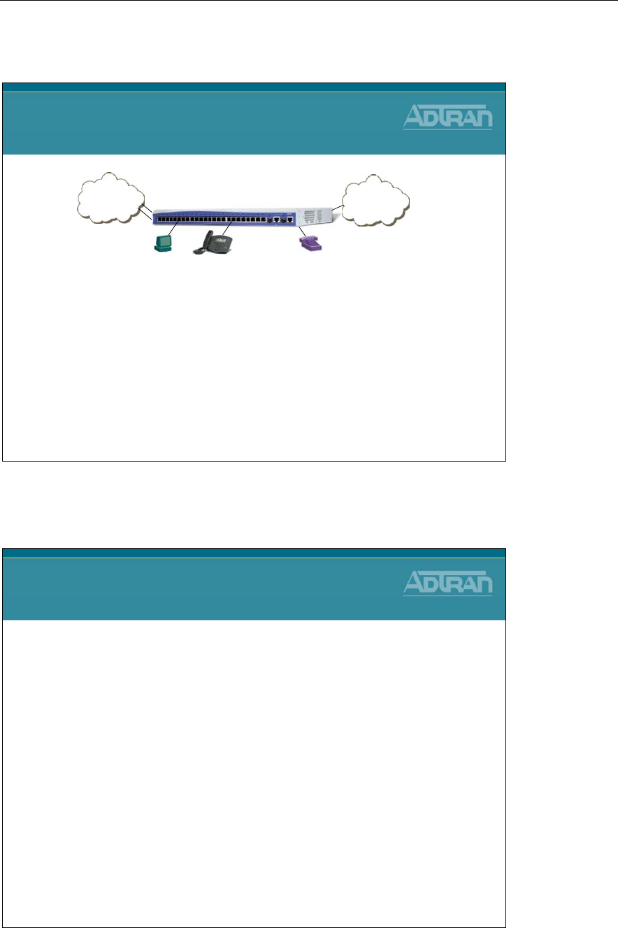
Module 3: Introduction to NetVanta 7000 Series Voice Configuration
3-86 NetVanta IP Telephony Course
Introduction to Voice Troubleshooting
Introduction to
Voice Troubleshooting
Digits gathered – number type match?
Dial Plan
Permission to call number?
Class of Service
Local Station match?
Voice Users
Trunk match? Resource available?
Trunk Groups
Dialed user’s location known? Available? SIP Proxy
SIP Registration
User’s Phone functional? DHCP Server,
Boot Server,
SIP Registration
NetVanta 7000
INTERNET
PSTN
Voice Troubleshooting
Voice Troubleshooting
•The NetVanta 7000 provides numerous voice
troubleshooting commands. Below are a few that we
will introduce in this module:
–show run voice
–show run voice user
–show run voice verbose
–show voice users
–debug voice summary
–undebug all
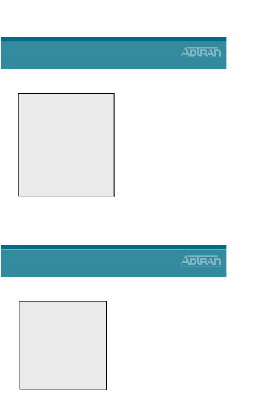
Module 3: Introduction to NetVanta 7000 Series Voice Configuration
NetVanta IP Telephony Course 3-87
show run voice
show run voice
•Display only voice running configuration
NV7000#
show run voice
Building configuration...
!
voice feature-mode local
voice forward-mode local
!
voice dial-plan 0 always-permitted 911
voice dial-plan 1 always-permitted 9-911
voice dial-plan 2 internal-operator 0
voice dial-plan 3 extensions MXXX
voice dial-plan 4 local 9-NXX-XXXX
voice dial-plan 5 long-distance 9-1-NXX-NXX-XXXX
voice dial-plan 6 toll-free 9-1-800-NXX-XXXX
:
!
voice class-of-service normal_users
override-passcode 6789
default-level
block-caller-id
:
* Partial output displayed
show run voice user
show run voice user
•Display voice user configuration
NV7000#
show run voice user
Building configuration...
!
voice user 2000
connect sip
cos "public_phones"
first-name "Default"
last-name "IP Phone"
password "1234"
:
:
voice user 2001
connect fxs 0/1
cos "normal_users“
:
* Partial output displayed
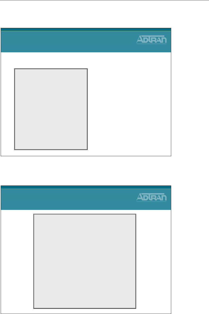
Module 3: Introduction to NetVanta 7000 Series Voice Configuration
3-88 NetVanta IP Telephony Course
show run voice verbose
show run voice verbose
•Display detailed voice running configurations
NV7000#
show run voice verbose
Building configuration...
!
voice prompt-language English
!
voice country-code 1
voice international-prefix 011
no voice international-prefix abbreviated
voice transfer unattended
!
voice overhead-paging extension 8000
!
voice feature-mode local
voice flashhook threshold 300 1000
voice timeouts interdigit 4
voice timeouts connected 12
voice timeouts alerting 5
voice hold-reminder 10 30
voice park-return 60
:
:
* Partial output displayed
show voice Commands
NV7000#
show voice ?
alias - display voice alias configuration
ani - ani substitution parameters
available - list fxs ports that are not associated with a user
dial-plan - number complete templates
did - direct inward dialing
directory - show directory(s) and included users
door-phone - display the door-phone account
extensions - current voice extensions and status
grouped-trunk - voice trunk groups
line - voice line stations
loopback - Show status on loopback accounts
mail - display voicemail information
operator-group - ring groups
phone-files - files required for sip phone configuration
quality-stats - display voice quality stats for all calls
ring-group - ring groups
service-mode - current voice service mode
speed-dial - system speed dial
spre - view spre (special prefix) codes
status-group - status groups
switchboard - voice switchboard extensions
system-mode - Current voice system mode
trunk - voice trunks
users - voice user stations
show voice commands
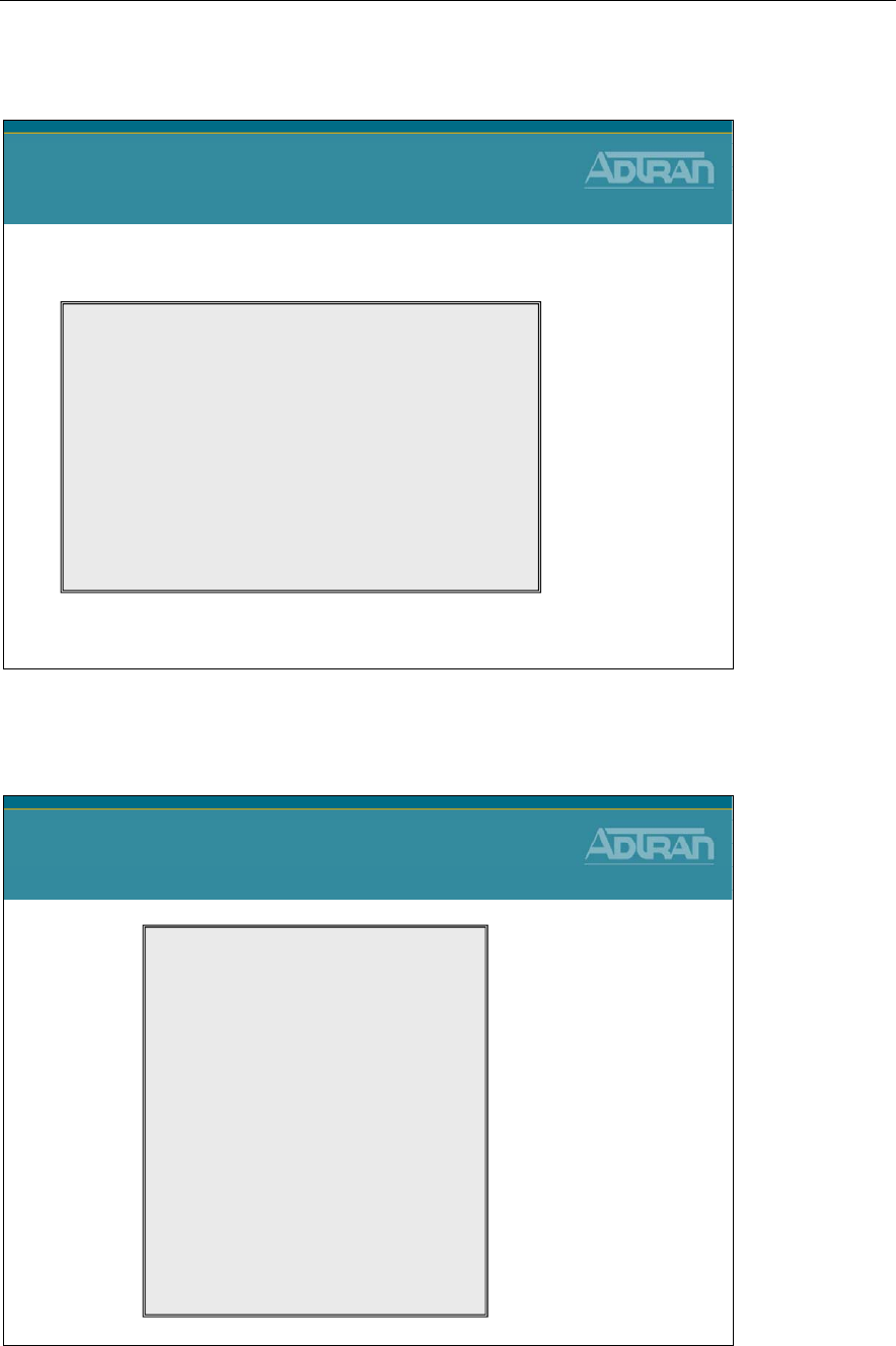
Module 3: Introduction to NetVanta 7000 Series Voice Configuration
NetVanta IP Telephony Course 3-89
show voice users
show voice users
•Display all voice stations
NV7000#
show voice users
First Last Ext Interface Description
--------------------------------------------------------------------------------
Default IP Phone 2000 ip
Analog FXS Port 0/1 2001 fxs 0/1
Analog FXS Port 0/2 2002 fxs 0/2
South Lobby 2003 fxs 2/1
John Smith 2004 virtual
Thad Tran 2005 ip
Annette Vanta 3001 virtual
Total number of configured voice users: 7
debug voice Commands
NV7000#
debug voice ?
<cr>
account-status - station account-status events
autoattendant - autoattendant events
dsp - DSP events
lineaccount - line account events
linemanager - line manager events
loopback - Loopback events
mail - voicemail events
phoneconfig - ip phone config utility events
phonemanager - phone manager events
promptstudio - prompt-studio events
proxydial - proxy dial events
rtp - rtp events
smdr - smdr events
stationaccount - station account events
statusgroups - status group events
summary - simple voice events
switchboard - switchboard events
toneservices - tone services events
trunkaccount - trunk account events
trunkmanager - trunk manager events
trunkport - trunkport events
verbose - detailed voice events
debug voice commands
Module 3: Introduction to NetVanta 7000 Series Voice Configuration
3-90 NetVanta IP Telephony Course
debug voice summary
NV7000#
debug voice summary
16:55:22 VOICE.SUMMARY voice user 2005 cos allowed the call to Extensions
16:55:22 VOICE.SUMMARY 2005 is calling 2006 (2006).
16:55:24 VOICE.SUMMARY 2005 is connected to 2006 (2006)
16:55:28 VOICE.SUMMARY Call from 2005 to 2006 (2006) ended by 2006: normal clearing
17:01:54 VOICE.SUMMARY voice user 2006 cos allowed the call to Extensions
17:01:54 VOICE.SUMMARY 2006 is calling T01 (911).
17:01:56 VOICE.SUMMARY 2006 is connected to T01 (911)
17:02:04 VOICE.SUMMARY Call from 2006 to T01 (911) ended by T01: normal clearing
debug voice summary
•Summarize voice events
Turning off Debug
Turning off Debug
•Turn off one debug command
•Turn off all active debug commands
•Show active debug commands
NV7000#
no debug <specific debug command>
NV7000#
undebug all
NV7000#
show debug

Module 3: Introduction to NetVanta 7000 Series Voice Configuration
NetVanta IP Telephony Course 3-91
Module Summary
Module Summary
•At the end of this module, you should be able to:
•Understand basic call routing
•Modify the NetVanta 7000 Dial Plan
•Create and modify Voice Classes of Service
•Create and modify Voice User Accounts
•Create and modify Ring Groups/Operator Group
•Configure Analog Voice Trunks
•Perform basic Voice Troubleshooting

Module 3: Introduction to NetVanta 7000 Series Voice Configuration
3-92 NetVanta IP Telephony Course

Module 4: ADTRAN Phone
Configuration Files

Module 4: ADTRAN Phone Configuration Files
4-2 NetVanta IP Telephony Course

Module 4: ADTRAN Phone Configuration Files
NetVanta IP Telephony Course 4-3
Module Objectives
Module Objectives
•Introduce the ADTRAN/Polycom IP Phones
•Introduce the ADTRAN/Polycom phone config files
•Modify phone configuration files
•Troubleshoot the boot process of the ADTRAN IP 700
Series phone

Module 4: ADTRAN Phone Configuration Files
4-4 NetVanta IP Telephony Course
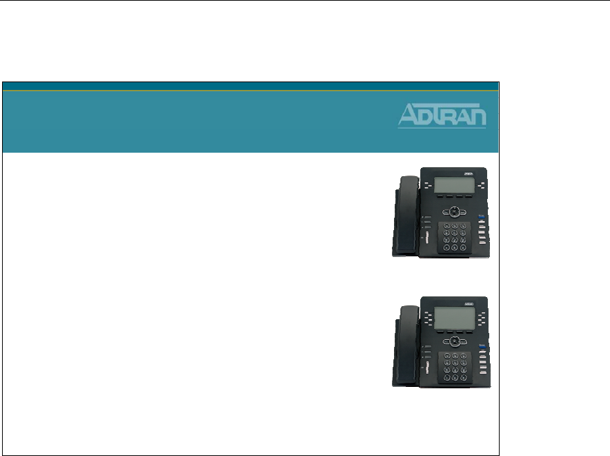
Module 4: ADTRAN Phone Configuration Files
NetVanta IP Telephony Course 4-5
ADTRAN IP 700 Series Phones
ADTRAN IP 700 Series Phones
•Two Models:
–IP 706: 6 lines
–IP 712: 12 lines
•Supports Multiple SIP registrations
•Busy Lamp Field and Shared Line Appearance Support
•High Quality Full Duplex Speaker Phone
•Dual 10/100 Switched Ethernet Ports
•Large Backlit Display
•802.3af Power over Ethernet
•Adjustable base stand
•Wall mountable
•Headset jack with Electronic Hook Switch Detection
The ADTRAN IP phones are available in either 6 line or 12 line versions, supporting
multiple call functions. Dedicated keys are available for the most common user functions
with additional programmable soft keys. On-screen menus enable users to quickly change
directory information and phone settings, as well as view a history of internal/external and
missed calls, and program distinctive ring tones for specific calls. The phones include an
adjustable desk stand or can be wall mounted and feature high-quality, full duplex speakers
engineered for clear, hands-free communication. An integrated headset jack with electronic
hook-switch eliminates the need for a mechanical handset lifter. The overall enhanced
functionality for the price makes ADTRAN IP phones among the most cost-efficient
business-class IP phones.
The ADTRAN 700 Series features an intuitive, Graphical User Interface (GUI) for easy
set-up and installation. The phones can be directly powered from the NetVanta® 7000
Series or a Power over Ethernet (PoE) switch, providing inline power and eliminating the
need for a separate power supply. The phones also have two Ethernet ports to connect to a
PC for converged voice and data across a single wiring infrastructure. ADTRAN phones
can be locally powered, allowing for multiple options for worry-free installation and ease
of use.
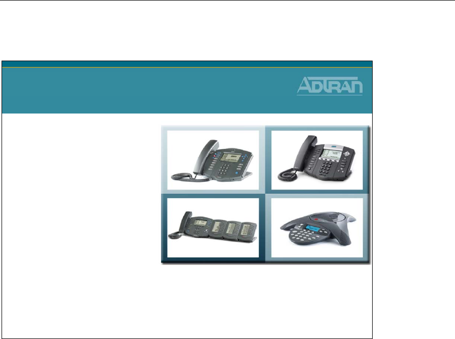
Module 4: ADTRAN Phone Configuration Files
4-6 NetVanta IP Telephony Course
Polycom Phones - Supported by ADTRAN
Polycom Phones
Supported by ADTRAN
IP 430
– two lines
IP 650 –
High Definition
Audio, six lines
IP 650 with Expansion
Modules
– ideal for “power
user” or attendant console, up
to 48 lines
IP 6000
– conference room
speaker phone
Plus more…
ADTRAN and Polycom have joined forces to deliver
a best of breed solution for the VoIP market
ADTRAN and Polycom have worked together to ensure interoperability of the Polycom
SoundPoint IP 300, 400, 500, 600, 4000, and 6000 series of SIP phones with the ADTRAN
IP Telephony solutions.
ADTRAN's NetVanta 7000 series also supports the Polycom SoundPoint 650 IP phone for
multiline attendant applications or high definition voice clarity. The Polycom SoundPoint
IP 650 incorporates Polycom's HD Voice Technology and wideband audio for over twice
the voice quality and clarity. The IP 650 can also be equipped with up to three Expansion
Modules for attendant console applications delivering up to 48 buttons.

Module 4: ADTRAN Phone Configuration Files
NetVanta IP Telephony Course 4-7
Buttons and Menus
NetVanta IP Telephony Course
ADTRAN IP Phones
Buttons and Menus
The next few pages are a basic guide to using the ADTRAN IP 700 series phone. For more
detailed information, refer to the IP 700 Series Phone User Manual, as well as other
resources available at: www.adtran.com/phones.
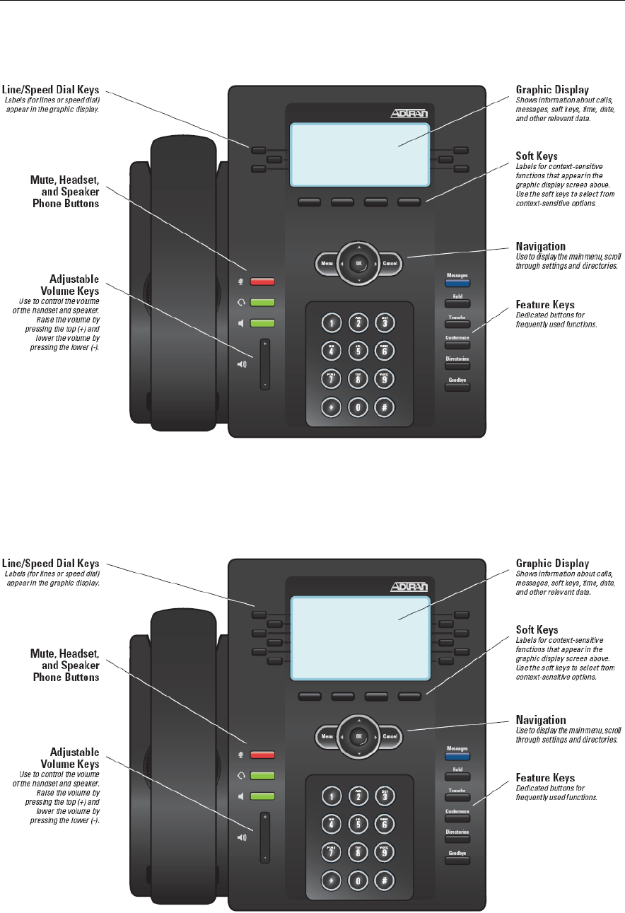
Module 4: ADTRAN Phone Configuration Files
4-8 NetVanta IP Telephony Course
IP 706 Phone Diagram
IP 712 Phone Diagram
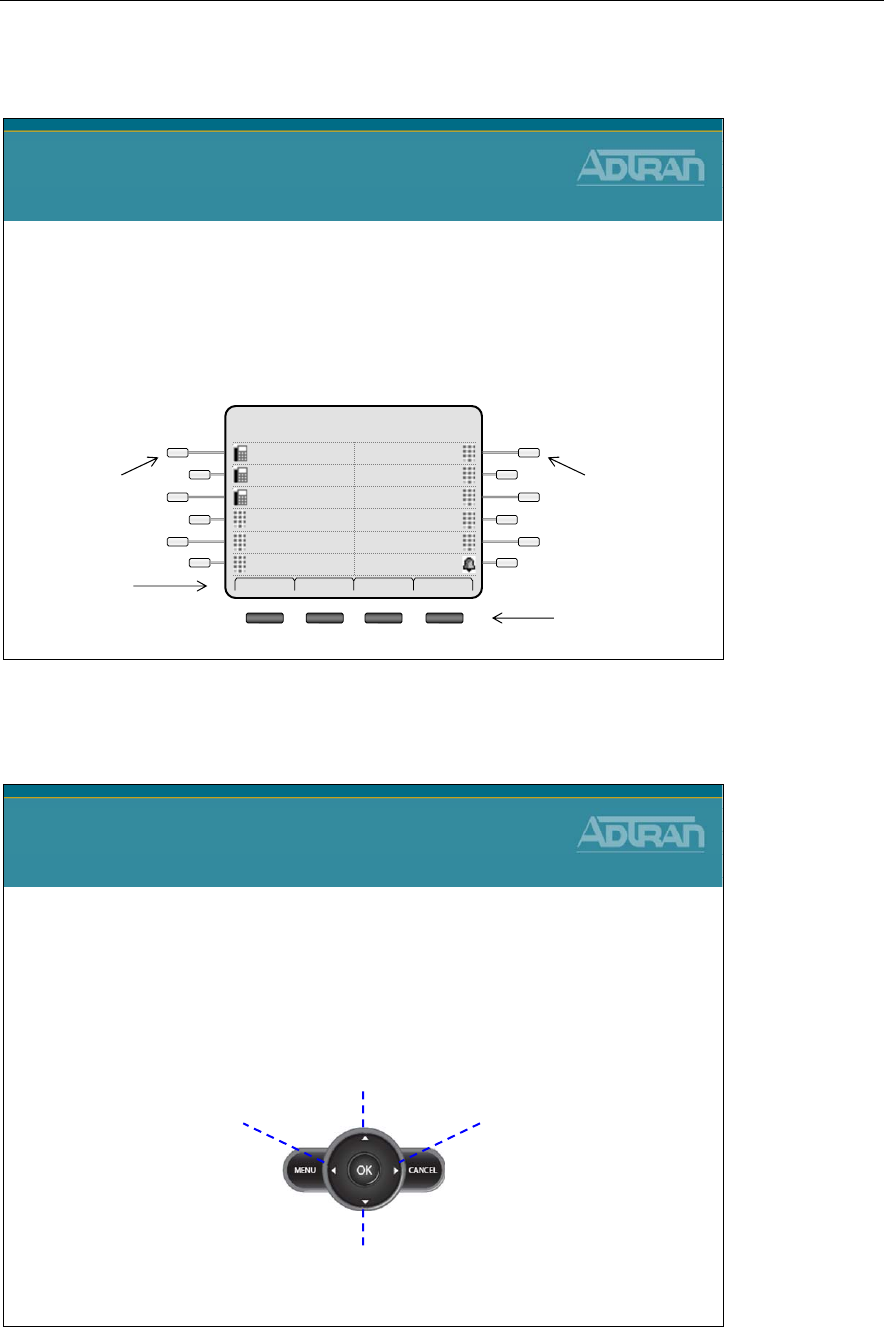
Module 4: ADTRAN Phone Configuration Files
NetVanta IP Telephony Course 4-9
Line Keys
Line Keys
•Line keys can be programmed as one of the
following:
–secondary extension, SLA, or BLF/DSS
–speed dial entry
–a shortcut to the Do Not Disturb (DND) feature
ADTRAN 07/04/09
2:30pm
DNDFrank
HomeCheryl
SPEEDWade
SPEED3003
SPEED2003
Fred2003
Dial Redial Pickup More
Line Keys
1 through 6 Line Keys
7 through 12
Soft Key
Menu Options 4 Soft Keys
Menu Navigation Bar
Menu Navigation Bar
•The navigation bar enables you to scroll through the
menus presented on the LCD display, as well as
make selections
Personal Contacts
Missed Calls
Placed
Calls
Incoming
Calls
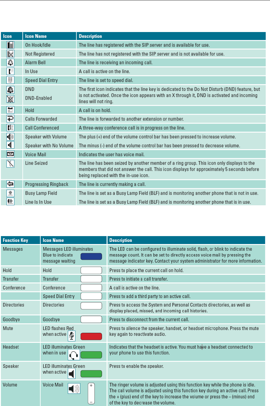
Module 4: ADTRAN Phone Configuration Files
4-10 NetVanta IP Telephony Course
ADTRAN IP 700 Series Phone Icons
ADTRAN IP 700 Series Phone Function Keys
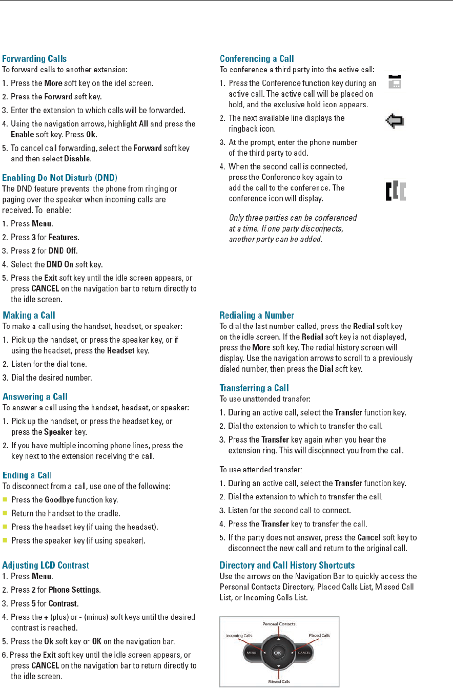
Module 4: ADTRAN Phone Configuration Files
NetVanta IP Telephony Course 4-11
ADTRAN IP 700 Series Phone Functions

Module 4: ADTRAN Phone Configuration Files
4-12 NetVanta IP Telephony Course
Phone Feature Quick Reference

Module 4: ADTRAN Phone Configuration Files
NetVanta IP Telephony Course 4-13
Provisioning Methods
NetVanta IP Telephony Course
ADTRAN IP Phones
Provisioning Methods
Provisioning Method - Order of Precedence
• Parameters manually entered using either the phone’s LCD Menus (Phone Settings) or
via the administrator’s Web interface (Phone Manager) have the highest priority and
override parameters received from all other sources.
• Parameters received in a configuration file override those received from DHCP and
defaults.
• Parameters returned by DHCP (if it is enabled) override default settings.
• Default parameters are used if no other source is available.

Module 4: ADTRAN Phone Configuration Files
4-14 NetVanta IP Telephony Course
ADTRAN IP Phones - Provisioning Methods
ADTRAN IP Phones
Provisioning Methods
•Local phone based configuration
–Local phone LCD Menus (Phone Settings)
•Password = 1234
–Web interface (Phone Manager - user)
•<ip address>
•Username = user
•Password = password
–Web interface (Phone Manager - admin)
•<ip address>/admin
•Username = admin
•Password = password
•Centrally Provisioned from Boot Server (NetVanta 7000)
–Consist of Global and per-phone configuration files
•DHCP
–Can set a limited number of parameters
•including the location of configuration files
MANAGING IP 700 SERIES PHONES
There are multiple ways to manage ADTRAN IP 700 Series phones, each providing a
different management approach.
• Password-protected administrator’s Web interface (Phone Manager) to view and
change current settings on a single phone.
o <ip address>/admin or <ip address> (for user interface)
o Username = admin Username = user
o Password = password Password = password
• Phone’s LCD Menu to view and modify current settings locally.
o Password = 1234 (Changed to 456 after connected to NetVanta 7000)
• Configuration files to automatically download parameters upon phone startup and
update firmware. (These files are created by the NetVanta 7000)
• Dynamic Host Configuration Protocol (DHCP) to set a limited number of
parameters including the location of configuration files.
In this class, most configuration changes of the IP phones will be done from the NetVanta
7000 web interface. Visit www.adtran.com/phones to download the IP 700 Series Phone
Administrator Guide for additional phone information.
Module 4: ADTRAN Phone Configuration Files
NetVanta IP Telephony Course 4-15
ADTRAN IP 700 - User Interface Menus
ADTRAN IP 700
LCD Menus
1. Phone Label 8. Password
2. Clock 9. Reset
3. Set Rings 0. Misc
4. Language
5. Contrast
6. Network
7. Line Keys
1. General
2. Network
3. Line Keys
4. Firmware Ver.
5. Diagnostics
Phone Status Menu
Phone Settings Menu
1. Phone Status
2. Phone Settings
3. Features
4. Directories
Ok
Main Menu
Exit
Edit Exit
Ok Exit
1. Park Pickup
2. DND Off
Features Menu
Ok Exit
1. Personal
2. System
3. Missed Calls
4. Incoming Calls
5. Placed Calls
Directories Menu
Ok Exit
Default Password: 1234
The LCD menus provide another method for controlling and interfacing with the IP phone.
Many programmable features of the phone can be accessed using the LCD menu. All keys,
whether line, soft, or function keys, interact with the LCD menus.
Example Phones Settings that can be changed (See User Guide for others)
To change the time/date format, use the following steps:
1. Press Menu, then 2 for Phone Settings
2. Press 2 for Clock
3. Press 2 for Time Format or 3 for Date Format
4. Using the arrow keys on the navigation bar, scroll to the desired time format
5. Press the Select soft key to select the highlighted option
6. Press the Ok soft key or OK on the navigation bar
7. Press the Exit soft key until the idle screen appears, or press CANCEL on the
navigation bar to return directly to the idle screen
To adjust the LCD display contrast, use the following steps:
1. Press Menu, then 2 for Phone Settings
2. Press 5 for Contrast
3. Press the + (plus) or - (minus) soft keys until the desired contrast is reached
4. Press the Ok soft key or OK on the navigation bar
5. Press the Exit soft key until the idle screen appears, or press CANCEL on the
navigation bar to return directly to the idle screen

Module 4: ADTRAN Phone Configuration Files
4-16 NetVanta IP Telephony Course
ADTRAN IP Phone - DHCP Provisioning Method
ADTRAN IP Phone
DHCP Provisioning Method
•The IP 700 Series phone uses site-specific Option
157 to provide the following information to the
phones:
–TftpServers=0.0.0.0
–FtpServers=10.10.20.1:/ADTRAN
–FtpLogin=polycomftp
–FtpPassword=password
–Layer2Tagging=True
–VlanID=2
* Option 157 must be set on both the LAN_pool and the
VoIP_pool to direct the phones to the correct boot server.
The NetVanta 7000 Series Product ships with the following default configuration
regarding phones:
• DHCP Server
- Enabled
- Option 157 defines the boot server as ftp://10.10.20.1/ADTRAN, FTP Username
and Password, and VLAN ID
• FTP Server
- Enabled
- Pointing to CFLASH filesystem
- Default FTP Username and Password defined
• ADTRAN IP 7xx Phones
- The IP 7xx phones depend on DHCP Option 157 to program their boot parameters
during the DHCP process
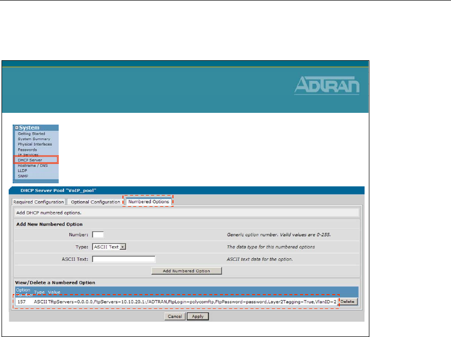
Module 4: ADTRAN Phone Configuration Files
NetVanta IP Telephony Course 4-17
ADTRAN IP Phone - DCHP Option 157
•Numbered DHCP option 157 has been added
to both the DATA and Voice DHCP Pools
ADTRAN IP Phone
DHCP Option 157
Below is the default configuration for the two DHCP Server Pools
ip dhcp-server pool "LAN_pool"
network 10.10.10.0 255.255.255.0
dns-server 10.10.10.1
default-router 10.10.10.1
tftp-server tftp://10.10.10.1
ntp-server 10.10.10.1
timezone-offset -6:00
option 157 ascii TftpServers=0.0.0.0,FtpServers=10.10.20.1:/ADTRAN,
FtpLogin=polycomftp,FtpPassword=password,Layer2Tagging=True,VlanID=2
ip dhcp-server pool "VoIP_pool"
network 10.10.20.0 255.255.255.0
dns-server 10.10.20.1
default-router 10.10.20.1
tftp-server tftp://10.10.20.1
ntp-server 10.10.20.1
timezone-offset -6:00
option 157 ascii TftpServers=0.0.0.0,FtpServers=10.10.20.1:/ADTRAN,
FtpLogin=polycomftp,FtpPassword=password,Layer2Tagging=True,VlanID=2
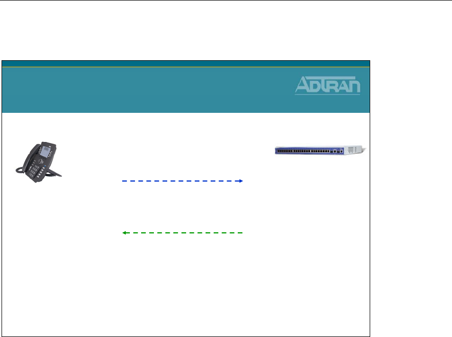
Module 4: ADTRAN Phone Configuration Files
4-18 NetVanta IP Telephony Course
ADTRAN IP Phone - DHCP Process
IP Address: 10.10.10.x
Option 157: =
TftpServers=0.0.0.0,
FtpServers=10.10.20.1:/ADTRAN,
FtpLogin=polycomftp,
FtpPassword=password,
Layer2Tagging=True,
VlanID=2,
etc
2) DHCP OFFER / ACK (VLAN 1)
NetVanta 7100
1) DHCP DISCOVER / REQUEST (VLAN 1)
Request for IP Address, DHCP Option 157, etc
ADTRAN IP Phone
DHCP Process
VLAN 1 is the
Native VLAN
ADTRAN IP Phone
configured for DHCP
by default
ADTRAN IP Phone
ADTRAN phone attached to NetVanta 7100 Ethernet Port
DHCP Request Process
A default IP 700 series phone is programmed to request DHCP parameters at boot. The
first time the phone boots, the request comes in on the Native VLAN. (VLAN 1 by default)
Besides for boot server information, the phone is assigned a Voice VLAN. (VLAN 2 by
default) At that point, the phone releases the IP address from the Native VLAN and then
does a new DHCP request on VLAN 2.
DHCP Debug Output (debug ip dhcp-server)
2009.07.01 18:49:59 DHCP.SERVER Processing Discover Message (Xid = e1ea0b59) on
10.10.10.0/255.255.255.0 from 00:A0:C8:25:55:50
2009.07.01 18:49:59 DHCP.SERVER Offering IP Address 10.10.10.5 to 00:A0:C8:25:55:50
2009.07.01 18:50:04 DHCP.SERVER Processing Request Message (Xid = e1ea0b59) on
10.10.10.0/255.255.255.0 from 00:A0:C8:25:55:50
2009.07.01 18:50:04 DHCP.SERVER Server sent an Ack to the client
2009.07.01 18:50:04 DHCP.SERVER Processing Release Message (Xid = e1ea0b50) on
10.10.10.0/255.255.255.0 from 00:A0:C8:25:55:50
2009.07.01 18:50:04 DHCP.SERVER No Reply required
2009.07.01 18:50:31 DHCP.SERVER Processing Discover Message (Xid = e1ea26cb) on
10.10.20.0/255.255.255.0 from 00:A0:C8:25:55:50
2009.07.01 18:50:31 DHCP.SERVER Offering IP Address 10.10.20.2 to 00:A0:C8:25:55:50
2009.07.01 18:50:36 DHCP.SERVER Processing Request Message (Xid = e1ea26cb) on
10.10.20.0/255.255.255.0 from 00:A0:C8:25:55:50
2009.07.01 18:50:36 DHCP.SERVER Server sent an Ack to the client
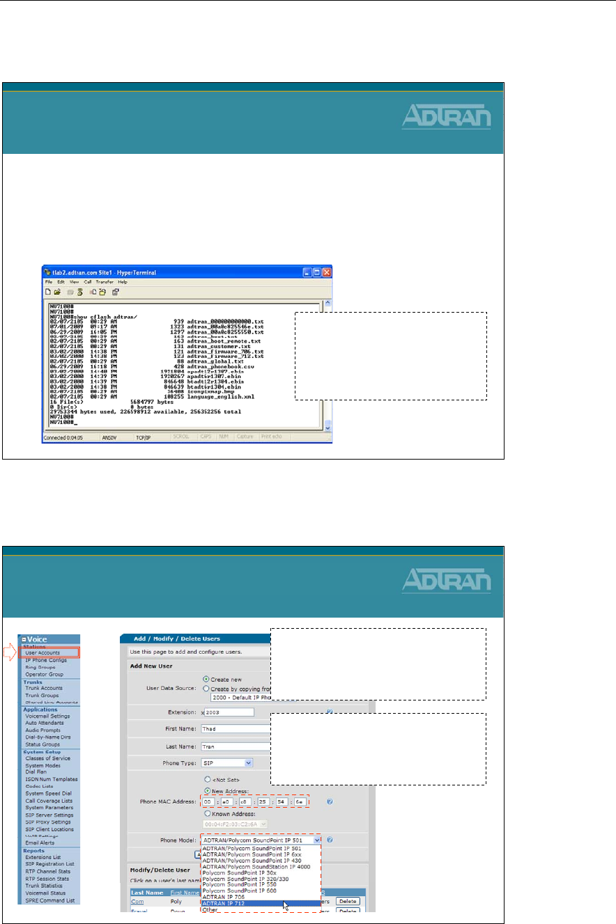
Module 4: ADTRAN Phone Configuration Files
NetVanta IP Telephony Course 4-19
NetVanta 7000 - Boot Server
NetVanta 7000 - Boot Server
•Numerous files are created by the NetVanta 7000
and the ADTRAN/Polycom phones
•The NetVanta 7000 functions as the boot server for
IP phones
- Files are stored in CFLASH of the
NetVanta 7000
- Allows global and per-phone
configuration to be managed
centrally
Creation of Phone Config Files
Creation of Phone Config Files
When the MAC address and Phone
Model are entered for a new user,
phone configuration files are created
and stored in CFLASH
The configuration files define SIP
user registration, server, phone
features, and many other phone
parameters.

Module 4: ADTRAN Phone Configuration Files
4-20 NetVanta IP Telephony Course
ADTRAN IP Phone Configuration Files
ADTRAN IP Phone
Configuration Files
•A unique configuration file is required for each phone. The MAC
address of the phone is used to identify the appropriate file for
downloading.
•When the phone boots up, it checks the FTP/TFTP server for its
specific configuration file.
•The file must be stored on the FTP/TFTP server in the following
format:
–adtran_<mac address>.txt
•Lowercase letters only
•If the phone cannot find its MAC address-based configuration
file, it will download the file
adtran_000000000000.txt
and
use it as the main configuration file
NOTE: Most configuration file changes can be done from the GUI.
Configuration Files Rules
• Each parameter must appear on its own line
• A <name> <value> pair is entered for each parameter
• The <name> <value> may be separated by an arbitrary number of spaces or tabs
• Any combination of uppercase or lowercase letters can be used within the
configuration file because it is not case sensitive
• Spaces are not permitted in any of the configuration values unless quote marks are
used
• Comments may be included in a configuration file by starting the comment line
with the # character
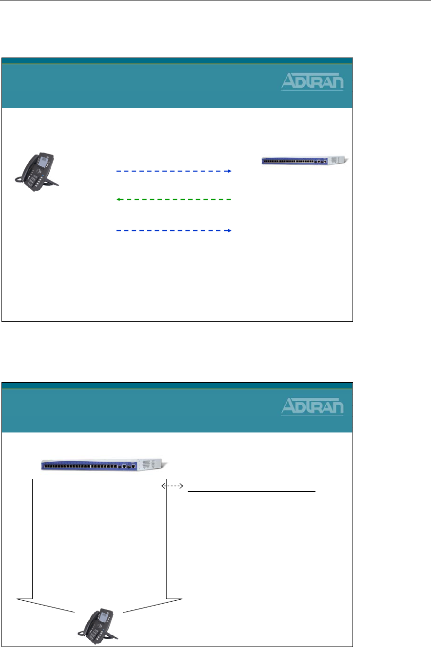
Module 4: ADTRAN Phone Configuration Files
NetVanta IP Telephony Course 4-21
ADTRAN IP Phone - Config File Request Process
1) Request adtran_<mac address>.txt
ADTRAN IP Phone
Config File Request Process
Initial DHCP Process Complete
no <MAC> file on server - continue
2) Request adtran_000000000000.txt
NetVanta 7100
ADTRAN IP Phone
Phone Config Files - Unassigned Phones
Phone Config Files
Unassigned Phones
adtran_000000000000.cfg
If a phone does not find its own
adtran_[MAC].cfg file, it will use this
one, and establish a baseline
configuration
-Instructs phone on files to load
- Delivered by ADTRAN with a
Factory default system.
NetVanta 7100 – Boot Server
adtran_000000000000.txt
Include adtran_boot.txt
Include adtran_global.txt
Include adtran_customer.txt
Language_English.xml
adtran_phonebook.csv
iconpixmap.bmp
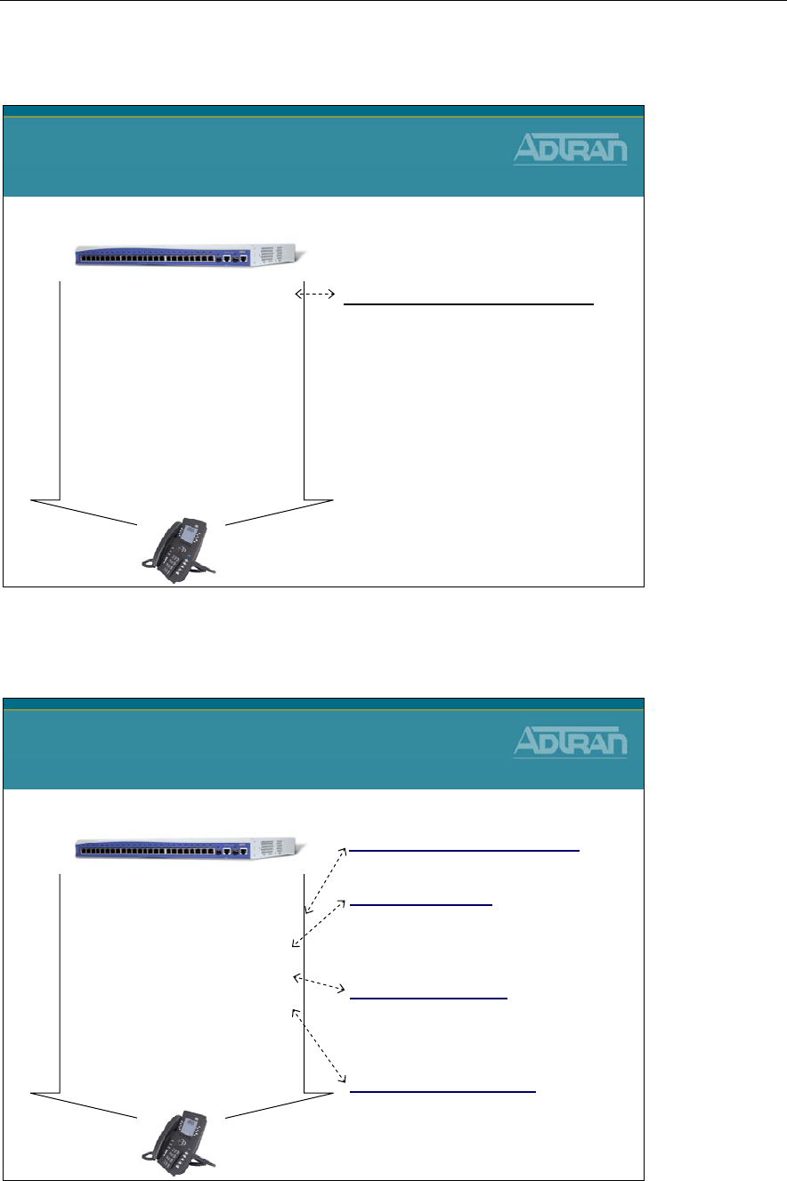
Module 4: ADTRAN Phone Configuration Files
4-22 NetVanta IP Telephony Course
Phone Config Files - Assigned Phones
Phone Config Files
Assigned Phones
adtran_[MAC Address].cfg
An ADTRAN phone will look for its
own adtran_[MAC].txt file
- Instructs phone on files to load
- Phone settings for the specific
phone
- Created when user added in GUI
NetVanta 7100 – Boot Server
adtran_00a0c825542b.txt
Include adtran_firmware_712.txt
Include adtran_boot.txt
Include adtran_global.txt
Include adtran_customer.txt
Language_English.xml
adtran_phonebook.csv
iconpixmap.bmp
Phone Config Files - Assigned Phones
Phone Config Files
Assigned Phones
NetVanta 7100 – Boot Server
adtran_00a0c825542b.txt
Include adtran_firmware_712.txt
Include adtran_boot.txt
Include adtran_global.txt
Include adtran_customer.txt
Language_English.xml
adtran_phonebook.csv
iconpixmap.bmp
adtran_boot.txt
A boot config file used by ADTRAN IP
phones. Can be used to define the FTP
server, username, and password for phones
adtran_firmware_712.txt
Specifies firmware file used by phone
adtran_global.txt
ADTRAN global IP phone configuration
file. Can contain settings that ADTRAN
assigns to all ADTRAN IP phones.
adtran_customer.txt
Customer Specific Configuration settings
for all ADTRAN IP phones
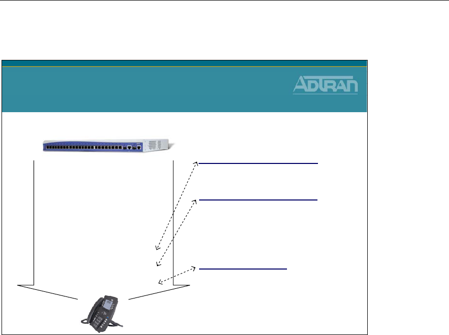
Module 4: ADTRAN Phone Configuration Files
NetVanta IP Telephony Course 4-23
Phone Config Files - Assigned Phones
Phone Config Files
Assigned Phones
NetVanta 7100 – Boot Server
adtran_00a0c825542b.txt
Include adtran_firmware_712.txt
Include adtran_boot.txt
Include adtran_global.txt
Include adtran_customer.txt
Language_English.xml
adtran_phonebook.csv
iconpixmap.bmp
adtran_phonebook.csv
A comma separated file that can be edited to
hold information for up to 300 contacts.
Allows the phone users to access the phone
book via the Directories key on the phone.
Language_English.xml
Defines language used by phone
iconpixmap.bmp
Bitmap file that contains the splash screen
presented during boot up and
the phone icon images
IP 700 Series Phone Boot Process
1. Phone boots and requests DHCP parameters
2. NetVanta 7000 Series Product responds with these parameters:
a. IP address, subnet mask, and gateway in VLAN 1 (10.10.10.0)
b. DHCP Option 157 defines the boot server as ftp://10.10.20.1/ADTRAN, FTP
Username and Password, and VLAN ID of 2.
3. The phone then reboots and requests DHCP parameters in VLAN 2 (10.10.20.0)
4. The phone attempts to download the following files via FTP:
a. adtran_mac.txt (where “mac” is the MAC address of the phone)
b. adtran_firmware_7xx.txt (7xx will be specific to configured phone model)
c. adtran_boot.txt
d. adtran_global.txt
e. adtran_customer.txt
f. Language_English.xml
g. adtran_phonebook.csv
h. iconpixmap.bmp
5. Once the files are downloaded, the phone will attempt to register to the NetVanta 7000
Series Product based on he information in adtran_mac.txt.

Module 4: ADTRAN Phone Configuration Files
4-24 NetVanta IP Telephony Course
IP 700 Series Phone Configuration Files
adtran_<MAC ADDRESS>.txt (MAC address of the phone)
An ADTRAN phone will look for its own adtran_[MAC].txt file based on its MAC
address. This file contains SIP Registration information, phone settings for the specific
phone, and pointers to other files to be loaded.
adtran_firmware_706.txt
Specifies firmware file used by the ADTRAN IP 706 phone
adtran_firmware_712.txt
Specifies firmware file used by the ADTRAN IP 706 phone
adtran_boot.txt
A boot config file used by local ADTRAN IP phones. Of all settings in file today, it uses
the phone password to change the LCD password from the default “1234” to “456”.
adtran_boot_remote.txt
A boot config file used by remote ADTRAN IP phones.
adtran_global.txt
ADTRAN global IP phone configuration file. Contains settings that ADTRAN assigns to
all ADTRAN IP phones.
adtran_customer.txt
This file is where customizations for all IP 700 phones on the system would be configured.
Language_English.xml
Defines the phone language file used by phone
adtran_phonebook.csv
This is the System Directory for the IP 700 phones stored in Comma-Separated Value
(CSV) format. Can be edited to hold information for up to 300 contacts. Allows the phone
users to access the phone book via the Directories key on the phone.
iconpixmap.bmp
Bitmap file that contains the splash screen presented during boot up and the phone icon
images.
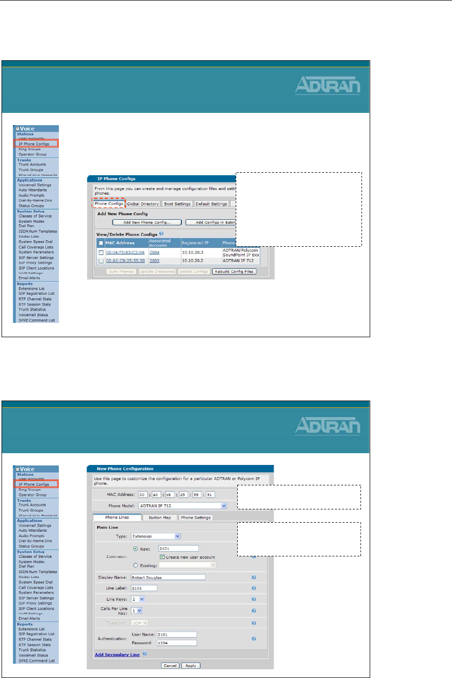
Module 4: ADTRAN Phone Configuration Files
NetVanta IP Telephony Course 4-25
IP Phone Configs Menu
•The IP Phone Configs menu can be used to
create or modify phone configuration files that
are stored in FLASH or CFLASH
–The table above displays all of the known phone
configuration files in the unit's CFLASH memory
based upon MAC Address
IP Phone Configs Menu
adtran_<MAC Address>.txt
- adtran_00a0c8255550.txt
-
Stored in CFLASH/ADTRAN
<MAC Address>.cfg
- 0004f203c26a.cfg
- Stored in CFLASH/Polycom
Add New Phone Config
Add New Phone Config
Enter MAC Address, Phone
Model, Extension, and other
options for this phone config
A new Phone Configuration file
can be created from this menu
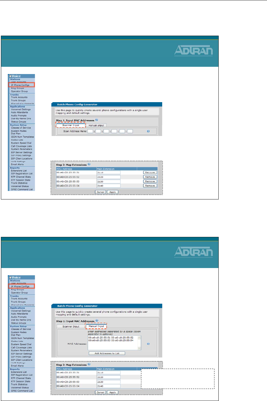
Module 4: ADTRAN Phone Configuration Files
4-26 NetVanta IP Telephony Course
Batch Phone Config Generator - Scanner
•Handheld Scanner Input
–Make sure the input carat is on the first textbox,
then use a handheld scanner to scan the address
–enter the main extension that should be associated
with each MAC address
Batch Phone Config Generator
Add New Phone Config – Manual Input
•Manual Input
–Enter multiple MAC Addresses by hand in the text
box, then click the Add Addresses to List button
Batch Phone Config Generator
- enter the main extension that
should be associated with
each MAC address
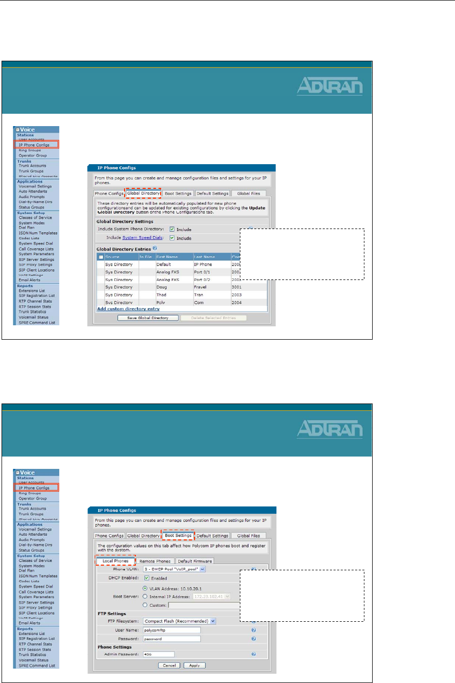
Module 4: ADTRAN Phone Configuration Files
NetVanta IP Telephony Course 4-27
Global Directory
•Creation and modification of the Global
directory is done from this tab
Global Directory
adtran_phonebook.csv
-
Stored in CFLASH/ADTRAN
000000000000-directory.xml
- Stored in CFLASH/Polycom
Boot Settings – Local Phones
•Boot parameters for Polycom phones
–Voice VLAN / Boot Server FTP Username / Password
Boot Settings
Local Phones
adtran_boot.txt
-
Stored in CFLASH/ADTRAN
polycomboot.cfg
- Stored in CFLASH/Polycom
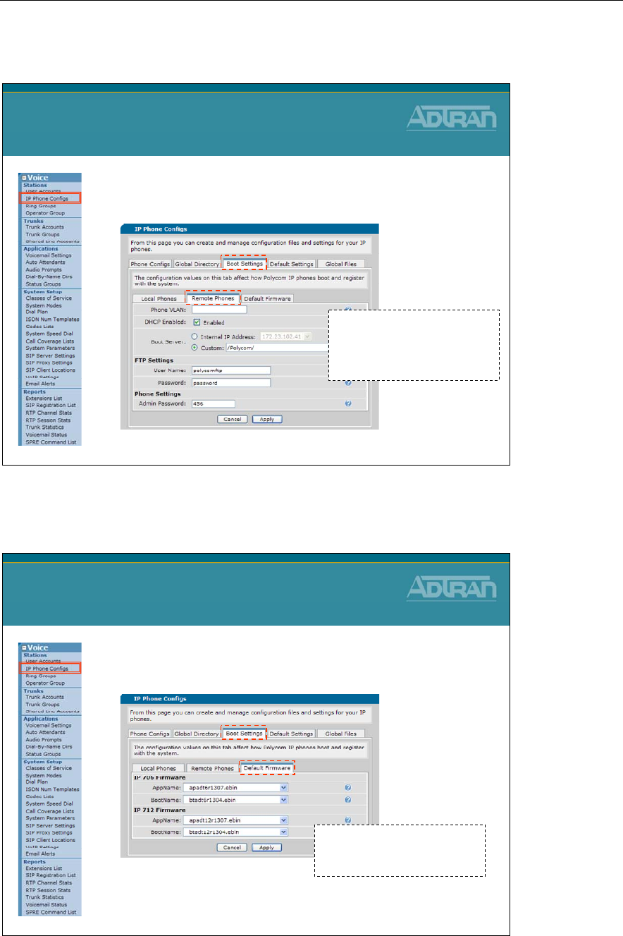
Module 4: ADTRAN Phone Configuration Files
4-28 NetVanta IP Telephony Course
Boot Settings – Remote Phones
•Boot parameters for Remote Polycom phones
–Voice VLAN / Boot Server FTP Username / Password
Boot Settings
Remote Phones
adtran_boot_remote.txt
-
Stored in CFLASH/ADTRAN
polycomboot_remote.cfg
- Stored in CFLASH/Polycom
Boot Settings – Default Firmware
•Specify current Application and Bootcode to
be used by ADTRAN IP 700 phones
Boot Settings
Default Firmware
adtran_firmware_706.txt
adtran_firmware_712.txt
-
Stored in CFLASH/ADTRAN
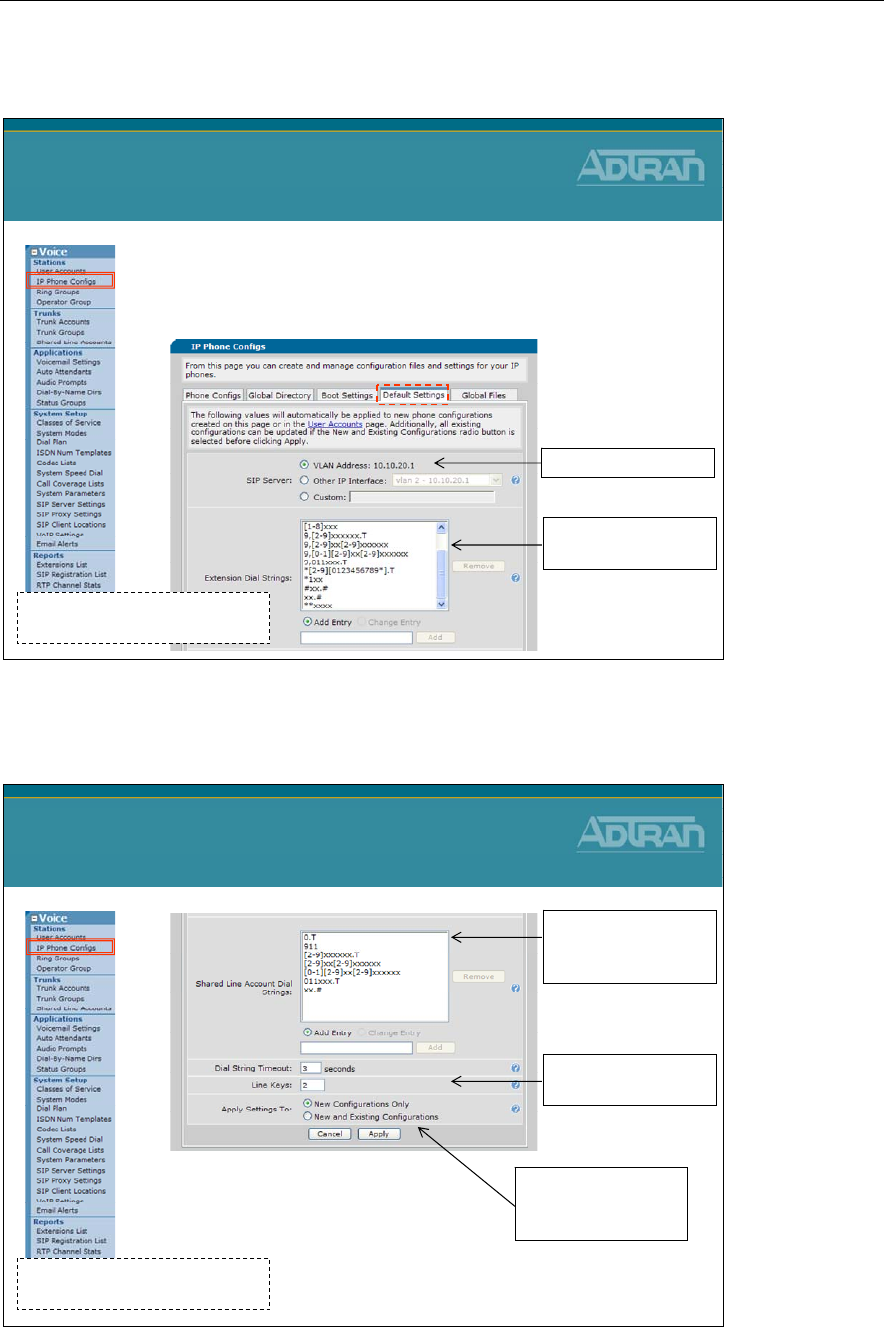
Module 4: ADTRAN Phone Configuration Files
NetVanta IP Telephony Course 4-29
Default Settings
•The values here will automatically be applied
to new phone configurations created on this
page or in the User Accounts page
Default Settings
polycomConfigDefaults.cfg
-
Stored in FLASH
Default SIP Server
Dial Plan used by
the IP Phones
Default Settings
Default Settings
(Continued…)
Dial Plan used by
the IP Phones for
Share Line Account
Default # of line
keys on phone
Can apply settings
to New and
Existing user.
polycomConfigDefaults.cfg
-
Stored in FLASH
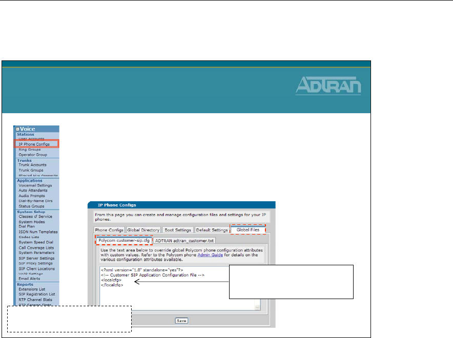
Module 4: ADTRAN Phone Configuration Files
4-30 NetVanta IP Telephony Course
Global Files – Polycom customer-sip.cfg
•This screen can be used to customize all the
Polycom phones
–All Polycom phones will load this file
–Valid options from Polycom’s Admin Guide can be
added to the screen
Global Files
Polycom customer-sip.cfg
customer-sip.cfg
-
Stored in CFLASH/Polycom
Enter valid Polycom option
between the <localcfg> and
</localcfg>
Polycom Customization Examples:
To Disable the Call Waiting Beep
The Call Waiting beep is enabled by default on the Polycom phones. To disable it, the
following could be entered on the Global Files screen
<CALLWAITING se.pat.callProg.6.inst.1.type="silence" se.pat.callProg.6.inst.1.value="10"/>
<CALLWAITINGLONG se.pat.callProg.7.name="long call waiting"
se.pat.callProg.7.inst.1.type="silence" se.pat.callProg.7.inst.1.value="10"
se.pat.callProg.7.inst.2.type="silence" se.pat.callProg.7.inst.2.value="150"
se.pat.callProg.7.inst.3.type="silence" se.pat.callProg.7.inst.3.value="10"/>
Hold reminder on Polycom Phones
By default Polycom phones do not beep every so often to let you know that you have a call
on hold. Add the following line on the Global Files screen to enable this feature:
<localReminder call.hold.localReminder.enabled="1"/>
The above examples and other can be found in the Knowledge Base at kb.adtran.com.
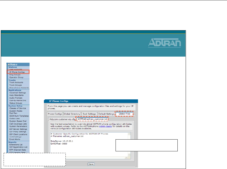
Module 4: ADTRAN Phone Configuration Files
NetVanta IP Telephony Course 4-31
Global Files – adtran_customer.txt
•This screen can be used to customize all the
ADTRAN IP 700 phones
–All ADTRAN IP 700 phones will load this file
–Valid options from ADTRAN’s IP 700 Admin Guide
can be added to the screen
Global Files
adtran_customer.txt
adtran_customer.txt
-
Stored in CFLASH/ADTRAN
Enter valid ADTRAN IP 700
options in this area
ADTRAN Customization Examples:
To Disable the Call Waiting Beep
By default ADTRAN IP 700 Series beep when there is a call waiting. To disable it, the
following could be entered on the Global Files screen. Verify that it is entered exactly as
shown below.
ToneDefine 1,0,0,0,0,0,0,0,0,1,0,0x0000,10,1,0,10,0,0
ToneMap Wait,1
Hold reminder on ADTRAN IP 700 Phones
By default ADTRAN IP 700 Series phones do not beep every so often to let you know that
you have a call on hold.. Add the following line on the Global Files screen to enable this
feature:
HoldReminder XX
where XX is the frequency in seconds that you would like the phone to play the hold reminder
The above examples and other can be found in the Knowledge Base at kb.adtran.com.

Module 4: ADTRAN Phone Configuration Files
4-32 NetVanta IP Telephony Course
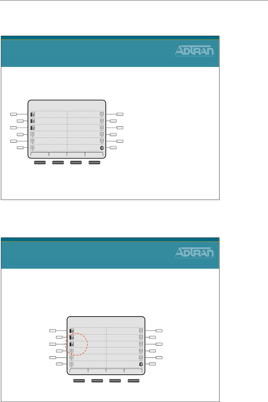
Module 4: ADTRAN Phone Configuration Files
NetVanta IP Telephony Course 4-33
ADTRAN IP - Registrations/Line Keys
ADTRAN IP Phone
Registrations/Line Keys
• The ADTRAN IP phones support multiple registrations
and programmable line keys
Registration: a SIP alias or
phone number
Line key: a button on the
phone beside the display
Call: a SIP session
- Registrations can appear on multiple line keys
- Speed dial can be configured by admin or user
Thad Tran 05/1/08
1:26 pm
DNDSPEED
SPEEDSPEED
SPEEDSPEED
SPEED3003
PAGE2003
DOOR PHONE2003
Dial Redial Pickup More
ADTRAN IP Phones - Adding Line Registrations
ADTRAN IP Phone Configuration
Adding Line Registrations
1. Modify Phone Configuration file in GUI
2. Add secondary line key
3. Reboot/sync phone to load new configuration
Thad Tran 05/1/08
1:26 pm
DNDSPEED
SPEEDSPEED
SPEEDSPEED
SPEED3003
PAGE2003
DOOR PHONE2003
Dial Redial Pickup More
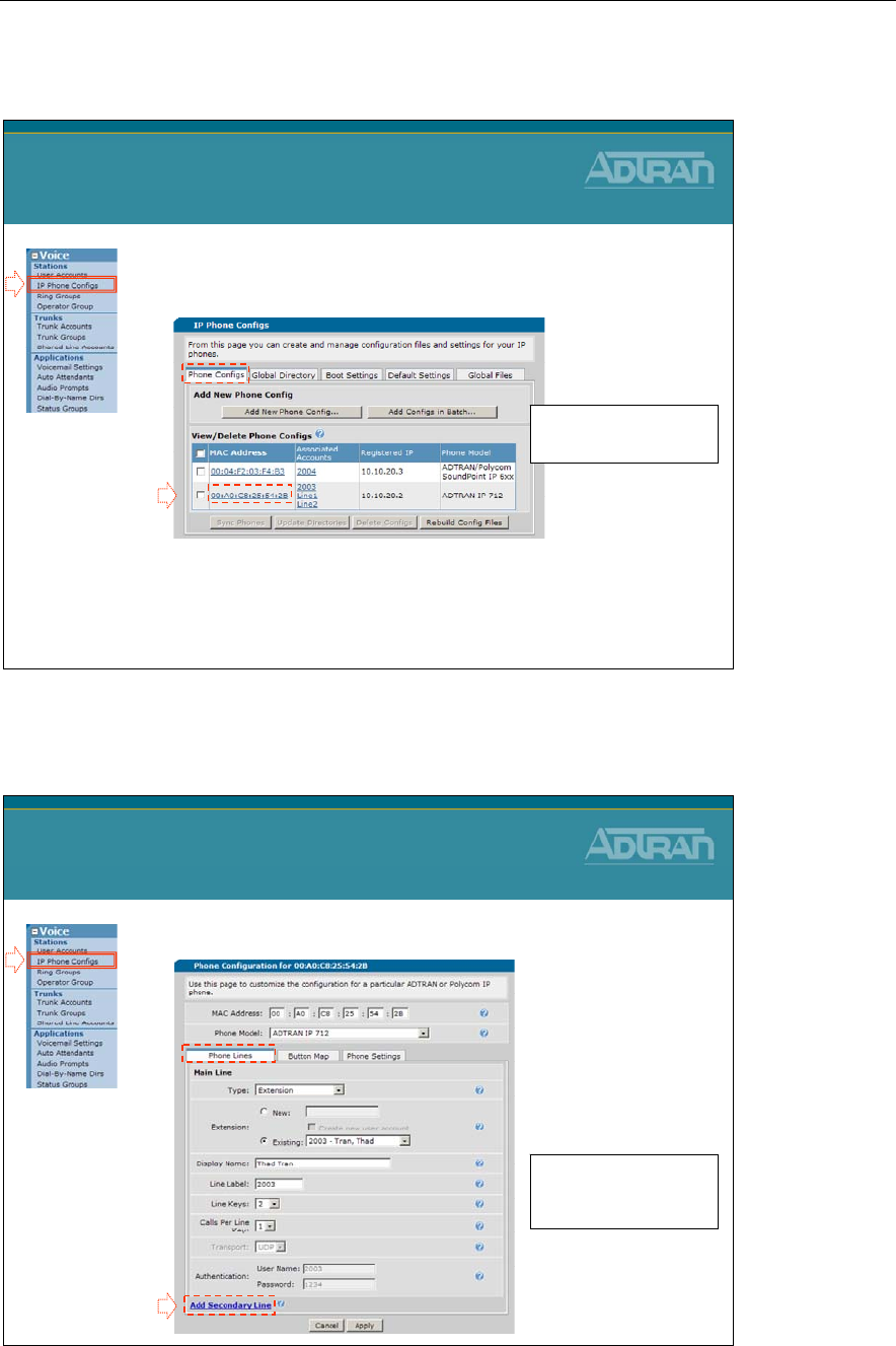
Module 4: ADTRAN Phone Configuration Files
4-34 NetVanta IP Telephony Course
ADTRAN IP Phones - Adding Line Registrations
1. Select the Voice / Stations / IP Phone Configs
menu
2. Select the MAC address of the phone that
you wish to add a line key (registration) to
ADTRAN IP Phone Configuration
Adding Line Registrations
1
2
New line keys (registrations)
can be added by editing the
phone config file
ADTRAN IP Phones - Adding Line Registrations
3. Click Add Secondary Line
ADTRAN IP Phone Configuration
Adding Line Registrations
3
The Line Label and number
of Line Keys for the first
registration can be changed
from this first menu
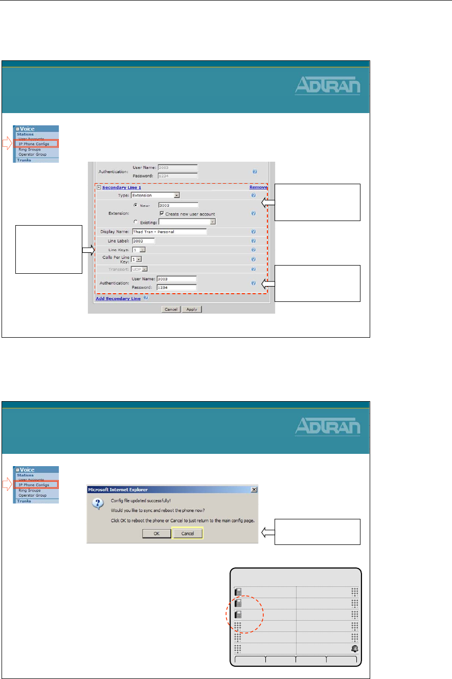
Module 4: ADTRAN Phone Configuration Files
NetVanta IP Telephony Course 4-35
ADTRAN IP Phones - Adding Line Registrations
4. Define Secondary Line Parameters
ADTRAN IP Phone Configuration
Adding Line Registrations
Enter New Extension
and select Create
new user account
Enter User Name
and Password and
then click Apply
Enter Display
Name, Line
Label, and #of
line keys
ADTRAN IP Phones - Adding Line Registrations
5. Reboot phone to load new configuration
ADTRAN IP Phone Configuration
Adding Line Registrations
The Message box above displays
after making changes to the phone
configuration file
- Clicking OK will sync and reboot the phone
- Clicking Cancel will return you to the main
config page without rebooting the phone
Click Cancel –We
will sync phone later
Thad Tran 05/1/08
1:26 pm
DNDSPEED
SPEEDSPEED
SPEEDSPEED
SPEED3003
SPEED2003
SPEED2003
Dial Redial Pickup More
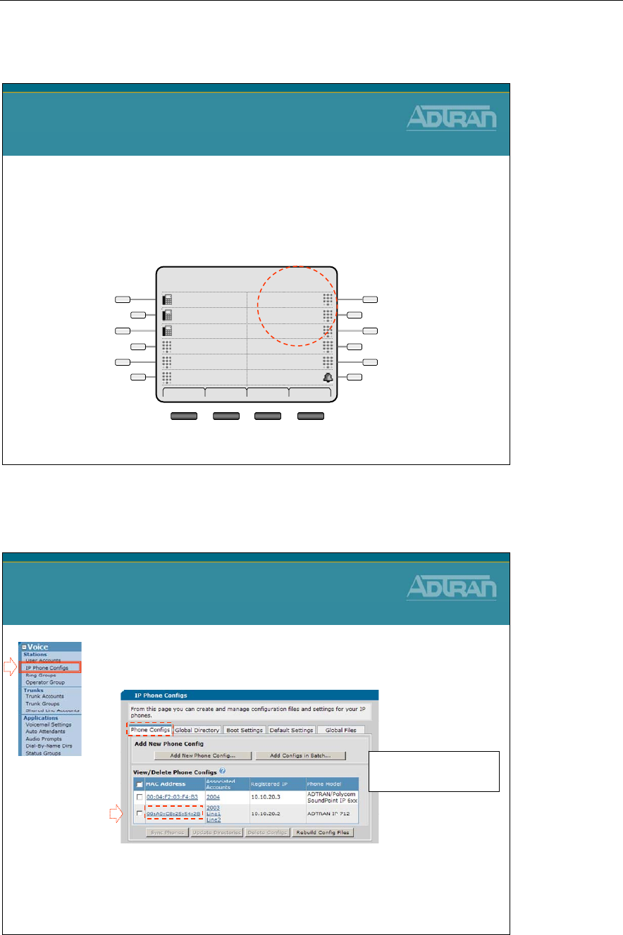
Module 4: ADTRAN Phone Configuration Files
4-36 NetVanta IP Telephony Course
ADTRAN IP Phones - Map Line Key as Speed Dial
ADTRAN IP Phone Configuration
Map Line Key as Speed Dial
1. Modify phone configuration file in GUI
2. Map line key as speed dial
3. Reboot/sync phone to load new configuration
Thad Tran 05/1/08
1:26 pm
DNDSPEED
SPEEDSPEED
SPEEDSPEED
SPEED3003
PAGE2003
DOOR PHONE2003
Dial Redial Pickup More
ADTRAN IP Phone - Map Line Key as Speed Dial
1. Select the Voice / Stations / IP Phone Configs
menu
2. Select the MAC address of the phone that
you wish to add a line key (registration) to
ADTRAN IP Phone Configuration
Map Line Key as Speed Dial
1
2
New line keys (registrations)
can be added by editing the
phone config file
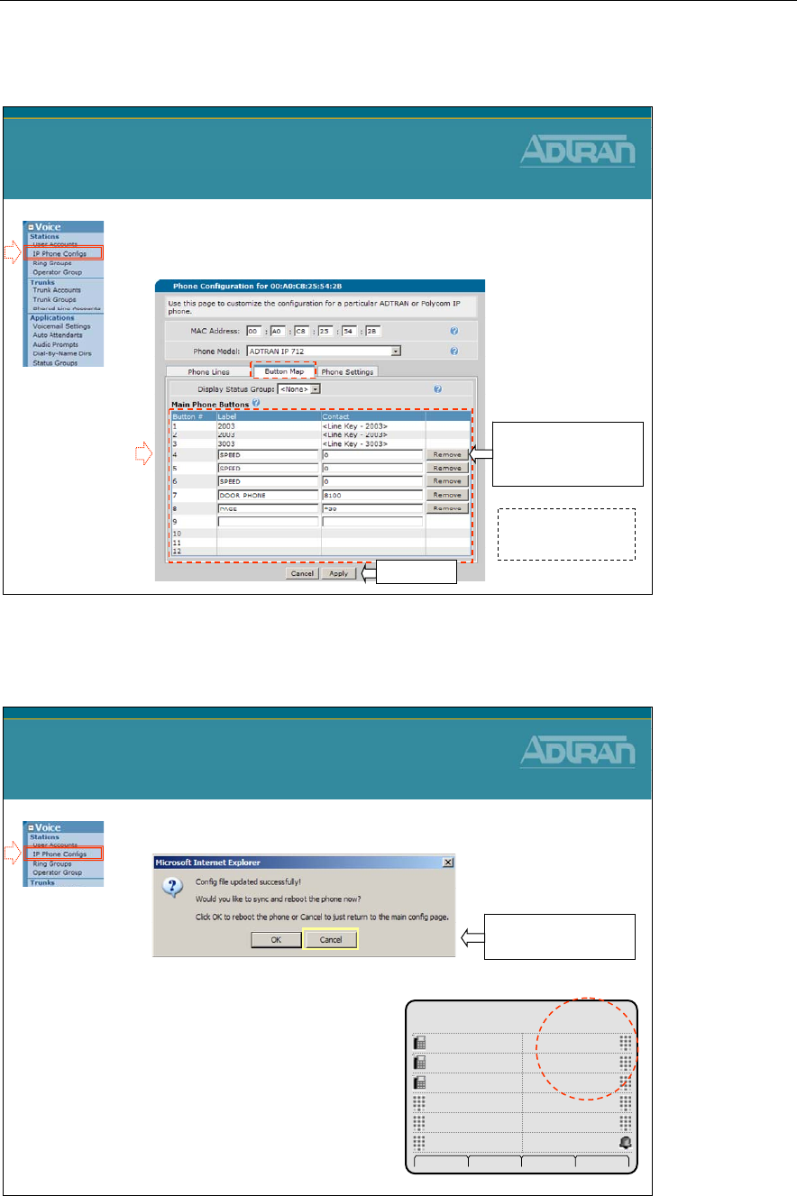
Module 4: ADTRAN Phone Configuration Files
NetVanta IP Telephony Course 4-37
ADTRAN IP Phones - Map Line Key as Speed Dial
3. Add a Page Overhead and Door Phone
Speed Dial to the phone
ADTRAN IP Phone Configuration
Map Line Key as Speed Dial
3
Enter Label and
Contact number for
each line key
The buttons with the
SPEED label can be
mapped by user on phone
Click Apply
ADTRAN IP Phones - Map Line Key as Speed Dial
4. Reboot phone to load new configuration
ADTRAN IP Phone Configuration
Map Line Key as Speed Dial
The Message box above displays
after making changes to the phone
configuration file
- Clicking OK will sync and reboot the phone
- Clicking Cancel will return you to the main
config page without rebooting the phone
Click Cancel –We
will sync phone later
Thad Tran 05/1/08
1:26 pm
DNDSPEED
SPEEDSPEED
SPEEDSPEED
SPEED3003
PAGE2003
DOOR PHONE2003
Dial Redial Pickup More
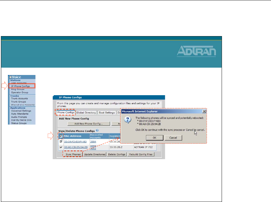
Module 4: ADTRAN Phone Configuration Files
4-38 NetVanta IP Telephony Course
ADTRAN IP Phones - Syncing IP Phones
1. Select the Voice / Stations / IP Phone Configs
menu
2. Select the MAC address for specific/all phones
and then click Sync Phones
–Attempts to sync/reboot selected phones. This action is only
possible if the phone is either registered with the unit or if it is
directly connected to the unit with inline power.
ADTRAN IP Phone Configuration
Syncing IP Phones
1
2
Module 4: ADTRAN Phone Configuration Files
NetVanta IP Telephony Course 4-39
Troubleshooting IP Phones
NetVanta IP Telephony Course
Troubleshooting IP Phones
ADTRAN IP Phones – Boot Process
1) DHCP Request Process
Phone obtains IP and learns the boot server IP
address
ADTRAN IP Phone
Boot Process
NetVanta 7100
ADTRAN IP Phone
2) File Request Process
Load phone config files, learn user identity and
registrar SIP server
3) SIP Registration
Register location with SIP server
debug ip dhcp-server
show ip dhcp-server binding
debug ip ftp-server
debug ip tftp server events
(Polycom)
debug sip stack messages summary
show sip user-registration
Module 4: ADTRAN Phone Configuration Files
4-40 NetVanta IP Telephony Course
debug ip dhcp-server
NV7000#
debug ip dhcp-server
… DHCP.SERVER Processing Discover Message (Xid = e1ea0b59) on
10.10.10.0/255.255.255.0 from 00:A0:C8:25:55:50
… DHCP.SERVER Offering IP Address
10.10.10.5
to 00:A0:C8:25:55:50
… DHCP.SERVER Processing Request Message (Xid = e1ea0b59) on
10.10.10.0/255.255.255.0 from 00:A0:C8:25:55:50
… DHCP.SERVER Server sent an Ack to the client
… DHCP.SERVER Processing Release Message (Xid = e1ea0b50) on
10.10.10.0/255.255.255.0 from 00:A0:C8:25:55:50
… DHCP.SERVER Processing Discover Message (Xid = e1ea26cb) on
10.10.20.0/255.255.255.0 from 00:A0:C8:25:55:50
… DHCP.SERVER Offering IP Address
10.10.20.2
to 00:A0:C8:25:55:50
… DHCP.SERVER Processing Request Message (Xid = e1ea26cb) on
10.10.20.0/255.255.255.0 from 00:A0:C8:25:55:50
… DHCP.SERVER Server sent an Ack to the client
debug ip dhcp-server
•Display real-time messages associated with Dynamic
Host Configuration Protocol (DHCP) server operation
show ip dhcp-server binding
NV7000#
show ip dhcp-server binding
IP Address Client Id Lease Expiration Client Name
10.10.20.3 01:00:04:f2:03:c2:04 Jul 02 2009 4:08 PM HunterPC
10.10.20.2 01:00:a0:c8:25:55:26 Jul 02 2009 6:50 PM ShanePC
10.10.20.4 01:00:a0:c8:25:55:28 Jul 02 2009 6:50 PM MathewPC
show ip dhcp-server binding
•Display the Dynamic Host Client Protocol (DHCP)
server client table with associated information
Module 4: ADTRAN Phone Configuration Files
NetVanta IP Telephony Course 4-41
debug ip ftp-server
NV7000#
debug ip ftp-server
FTP: NLST command - 'adtran_00a0c8255550.txt' transfer complete.
FTP: NLST command - 'adtran_firmware_712.txt' transfer complete.
FTP: NLST command - 'adtran_boot.txt' transfer complete.
FTP: NLST command - 'adtran_global.txt' transfer complete.
FTP: NLST command - 'adtran_customer.txt' transfer complete.
FTP: NLST command - 'Language_English.xml' transfer complete.
FTP: NLST command - 'adtran_phonebook.csv' transfer complete.
FTP: NLST command - 'iconpixmap.bmp' transfer complete.
debug ip ftp-server
•Display real-time messages associated with File
Transfer Protocol (FTP) server events in the
NetVanta 7000
debug sip stack messages summary
NV7000#
debug sip stack messages summary
18:51:24 SIP.STACK MSGSUM Rx: REGISTER sip:10.10.20.1:5060 IP/2.0
18:51:24 SIP.STACK MSGSUM Tx: SIP/2.0 401 Unauthorized
18:51:24 SIP.STACK MSGSUM Rx: REGISTER sip:10.10.20.1:5060 IP/2.0
18:51:24 SIP.STACK MSGSUM Tx: SIP/2.0 200 OK
18:51:24 SIP.STACK MSGSUM Tx: NOTIFY sip:2003@10.10.20.2 SIP/2.0
18:51:24 SIP.STACK MSGSUM Rx: SIP/2.0 200 OK
debug sip stack messages summary
•Activate SIP debug messages in real-time and
displays only a summary (first line) of the available
messages
Module 4: ADTRAN Phone Configuration Files
4-42 NetVanta IP Telephony Course
show sip user-registration
NV7000#
show sip user-registration
EXTENSION TYPE IP ADD PORT PROT EXPIRES
----------------- ----------------------------- ------------- ----- ------ -------------
2003 Adtran-SIP-IP712/v1.3.7 10.10.20.2 5060 UDP 3559
2004 PolycomSoundPointIP601 10.10.20.3 5060 UDP 2838
Total phones registered: 2
show sip user-registration
•Display local SIP server registration information

Module 4: ADTRAN Phone Configuration Files
NetVanta IP Telephony Course 4-43
ADTRAN IP 700 Phone Boot Process - SAMPLE DEBUG OUT
# debug ip dhcp-server
# debug ip ftp-server
# debug sip stack messages summary
2009.07.01 18:49:59 DHCP.SERVER Processing Discover Message (Xid = e1ea0b59) on
10.10.10.0/255.255.255.0 from 00:A0:C8:25:55:50
2009.07.01 18:49:59 DHCP.SERVER Offering IP Address
10.10.10.5
to 00:A0:C8:25:55:50
2009.07.01 18:49:59 DHCP.SERVER Server sent an Offer to the client
2009.07.01 18:50:04 DHCP.SERVER Processing Request Message (Xid = e1ea0b59) on
10.10.10.0/255.255.255.0 from 00:A0:C8:25:55:50
2009.07.01 18:50:04 DHCP.SERVER Server sent an Ack to the client
2009.07.01 18:50:04 DHCP.SERVER Processing
Release
Message (Xid = e1ea0b50) on
10.10.10.0/255.255.255.0 from 00:A0:C8:25:55:50
2009.07.01 18:50:04 DHCP.SERVER No Reply required
2009.07.01 18:50:31 DHCP.SERVER Processing Discover Message (Xid = e1ea26cb) on
10.10.20.0/255.255.255.0 from 00:A0:C8:25:55:50
2009.07.01 18:50:31 DHCP.SERVER Offering IP Address
10.10.20.2
to 00:A0:C8:25:55:50
2009.07.01 18:50:31 DHCP.SERVER Server sent an Offer to the client
2009.07.01 18:50:36 DHCP.SERVER Processing Request Message (Xid = e1ea26cb) on
10.10.20.0/255.255.255.0 from 00:A0:C8:25:55:50
2009.07.01 18:50:36 DHCP.SERVER Server sent an Ack to the client
FTP: USER command - Password required for 'polycomftp'.
FTP: USER command - User 'polycomftp' logged in .
FTP: TYPE command - Type is set to I.
FTP: CWD command - directory changed to '/ADTRAN'.
FTP: PORT command - opening port from 10.10.20.2.
FTP: BINARY data connection for ls (10.10.20.2,1025).
FTP: NLST command - '
adtran_00a0c8255550.txt
' transfer complete.
FTP: PORT command - opening port from 10.10.20.2.
FTP: BINARY data connection for adtran_00a0c8255550.txt (10.10.20.2,1026).
FTP: RETR command - BINARY transfer complete.
2009.07.01 18:50:47 IP.FTP SERVER (RETR) Transfer of file '/ADTRAN/adtran_00a0c8255550.txt'
complete for remote host '10.10.20.2'.
FTP: USER command - Password required for 'polycomftp'.
FTP: USER command - User 'polycomftp' logged in .
FTP: TYPE command - Type is set to I.
FTP: CWD command - directory changed to '/ADTRAN'.
FTP: PORT command - opening port from 10.10.20.2.
FTP: BINARY data connection for ls (10.10.20.2,1028).
FTP: NLST command -
'adtran_firmware_712.txt'
transfer complete.
FTP: PORT command - opening port from 10.10.20.2.
FTP: BINARY data connection for adtran_firmware_712.txt (10.10.20.2,1029).
FTP: RETR command - BINARY transfer complete.
2009.07.01 18:50:50 IP.FTP SERVER (RETR) Transfer of file '/ADTRAN/adtran_firmware_712.txt'
complete for remote host '10.10.20.2'.FTP: USER command - Password required for 'polycomftp'.
FTP: USER command - User 'polycomftp' logged in .
FTP: TYPE command - Type is set to I.
FTP: CWD command - directory changed to '/ADTRAN'.

Module 4: ADTRAN Phone Configuration Files
4-44 NetVanta IP Telephony Course
FTP: PORT command - opening port from 10.10.20.2.
FTP: BINARY data connection for ls (10.10.20.2,1031).
FTP: NLST command -
'adtran_boot.txt'
transfer complete.
FTP: PORT command - opening port from 10.10.20.2.
FTP: BINARY data connection for adtran_boot.txt (10.10.20.2,1032).
FTP: RETR command - BINARY transfer complete.
2009.07.01 18:50:51 IP.FTP SERVER (RETR) Transfer of file '/ADTRAN/adtran_boot.txt' complete for
remote host '10.10.20.2'.NV7100#FTP: USER command - Password required for 'polycomftp'.
FTP: USER command - User 'polycomftp' logged in .
FTP: TYPE command - Type is set to I.
FTP: CWD command - directory changed to '/ADTRAN'.
FTP: PORT command - opening port from 10.10.20.2.
FTP: BINARY data connection for ls (10.10.20.2,1034).
FTP: NLST command -
'adtran_global.txt'
transfer complete.
FTP: PORT command - opening port from 10.10.20.2.
FTP: BINARY data connection for adtran_global.txt (10.10.20.2,1035).
FTP: RETR command - BINARY transfer complete.
2009.07.01 18:50:53 IP.FTP SERVER (RETR) Transfer of file '/ADTRAN/adtran_global.txt' complete for
remote host '10.10.20.2'.FTP: USER command - Password required for 'polycomftp'.
FTP: USER command - User 'polycomftp' logged in .
FTP: TYPE command - Type is set to I.
FTP: CWD command - directory changed to '/ADTRAN'.
FTP: PORT command - opening port from 10.10.20.2.
FTP: BINARY data connection for ls (10.10.20.2,1037).
FTP: NLST command -
'adtran_customer.txt'
transfer complete.
FTP: PORT command - opening port from 10.10.20.2.
FTP: BINARY data connection for adtran_customer.txt (10.10.20.2,1038).
FTP: RETR command - BINARY transfer complete.
2009.07.01 18:50:54 IP.FTP SERVER (RETR) Transfer of file '/ADTRAN/adtran_customer.txt' complete for
remote host '10.10.20.2'.
FTP: USER command - Password required for 'polycomftp'.
FTP: USER command - User 'polycomftp' logged in .
FTP: TYPE command - Type is set to I.
FTP: CWD command - directory changed to '/ADTRAN'.
FTP: PORT command - opening port from 10.10.20.2.
FTP: BINARY data connection for ls (10.10.20.2,1040).
FTP: NLST command -
'Language_English.xml'
transfer complete.
FTP: PORT command - opening port from 10.10.20.2.
FTP: BINARY data connection for Language_English.xml (10.10.20.2,1041).
FTP: RETR command - BINARY transfer complete.
2009.07.01 18:51:00 IP.FTP SERVER (RETR) Transfer of file '/ADTRAN/Language_English.xml' complete
for remote host '10.10.20.2'.
FTP: USER command - Password required for 'polycomftp'.
FTP: USER command - User 'polycomftp' logged in .
FTP: TYPE command - Type is set to I.
FTP: CWD command - directory changed to '/ADTRAN'.
FTP: PORT command - opening port from 10.10.20.2.
FTP: BINARY data connection for ls (10.10.20.2,1043).
FTP: NLST command -
'adtran_phonebook.csv'
transfer complete.
FTP: PORT command - opening port from 10.10.20.2.
FTP: BINARY data connection for adtran_phonebook.csv (10.10.20.2,1044).
FTP: RETR command - BINARY transfer complete.

Module 4: ADTRAN Phone Configuration Files
NetVanta IP Telephony Course 4-45
2009.07.01 18:51:05 IP.FTP SERVER (RETR) Transfer of file '/ADTRAN/adtran_phonebook.csv' complete
for remote host '10.10.20.2'.
FTP: USER command - Password required for 'polycomftp'.
FTP: USER command - User 'polycomftp' logged in .
FTP: TYPE command - Type is set to I.
FTP: CWD command - directory changed to '/ADTRAN'.
FTP: PORT command - opening port from 10.10.20.2.
FTP: BINARY data connection for ls (10.10.20.2,1046).
FTP: NLST command -
'iconpixmap.bmp'
transfer complete.
FTP: PORT command - opening port from 10.10.20.2.
FTP: BINARY data connection for iconpixmap.bmp (10.10.20.2,1047).
FTP: RETR command - BINARY transfer complete.
2009.07.01 18:51:09 IP.FTP SERVER (RETR) Transfer of file '/ADTRAN/iconpixmap.bmp' complete for
remote host '10.10.20.2'.
18:51:24 SIP.STACK MSGSUM Rx: REGISTER sip:10.10.20.1:5060 SIP/2.0
18:51:24 SIP.STACK MSGSUM Tx: SIP/2.0 401 Unauthorized
18:51:24 SIP.STACK MSGSUM Rx: REGISTER sip:10.10.20.1:5060 SIP/2.0
18:51:24 SIP.STACK MSGSUM Tx: SIP/2.0 200 OK
18:51:24 SIP.STACK MSGSUM Tx: NOTIFY sip:2003@10.10.20.2 SIP/2.0
18:51:24 SIP.STACK MSGSUM Rx: SIP/2.0 200 OK
NV7100#
show debug
debug ip dhcp-server
debug ip ftp-server
debug sip stack messages summary
NV7100#
undebug all
NV7100#
show ip dhcp-server binding
IP Address Client Id Lease Expiration Client Name
10.10.20.3 01:00:04:f2:03:c2:6a Jul 02 2009 4:08 PM
10.10.20.2 01:00:a0:c8:25:55:50 Jul 02 2009 6:50 PM
NV7100#
show sip user-registraiontion
EXTENSION TYPE IP ADDRESS PORT PROT EXPIRES
---------- ------------------------------ ---------------- ----- ---- -------
2003 Adtran-SIP-IP712/v1.3.7 10.10.20.2 5060 UDP 3559
2004 PolycomSoundPointIP-SPIP_601.. 10.10.20.3 5060 UDP 2838
Total phones registered: 2

Module 4: ADTRAN Phone Configuration Files
4-46 NetVanta IP Telephony Course

Module 4: ADTRAN Phone Configuration Files
NetVanta IP Telephony Course 4-47
Module Objectives
Module Objectives
At the end of this module, you should:
•Have a basic understanding of ADTRAN phone
configuration files
•Be able to modify phone configuration files in the GUI
•Troubleshoot the boot process of the ADTRAN IP 700
series phone

Module 4: ADTRAN Phone Configuration Files
4-48 NetVanta IP Telephony Course
Module 4: ADTRAN Phone Configuration Files
NetVanta IP Telephony Course 4-49
Polycom IP Phones - Provisioning Methods
NetVanta IP Telephony Course
ADTRAN/Polycom IP Phones
Provisioning Methods
Remainder of Module is
Reference Only
Polycom IP Phones - Provisioning Methods
ADTRAN/Polycom IP Phone
Provisioning Methods
•Local phone based configuration
–Local phone user interface (Phone Settings)
–Web interface (Phone Manager)
•Centrally Provisioned from Boot Server
–Consist of Global and per-phone configuration files
•DHCP
–Can set a limited number of parameters
•including the location of configuration files

Module 4: ADTRAN Phone Configuration Files
4-50 NetVanta IP Telephony Course
Polycom Default Passwords
Polycom Phones - Installation Process
Polycom Phones
Installation Process
•Regardless of whether or not you will be installing a
centrally provisioned system, there are two steps
required to get your phones up and running
–1) Basic TCP/IP Network Setup
•IP address and subnet mask
•Local setup on phone
–2) Application Configuration
•SIP application specific parameters
•Setup done with Configuration files that are stored on boot server
Polycom Default Passwords
•Web interface
–Username = Polycom
–Password = 456
•Admin interface on the hard phone
–Password = 456
–User password - 123
(not used much)
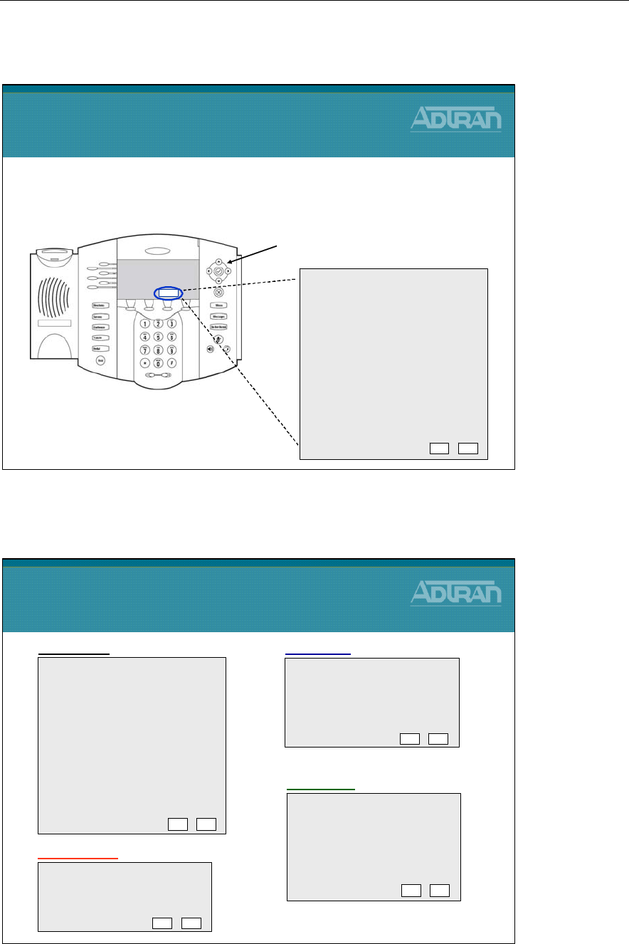
Module 4: ADTRAN Phone Configuration Files
NetVanta IP Telephony Course 4-51
Polycom Phones - TCP/IP Network Setup
Polycom Phones - Default Setup Menu
DHCP Client: Enabled
DHCP Menu:…
Phone IP Addr: 000.000.000.000
Subnet Mask: 000.000.000.000
IP Gateway: 000.000.000.000
Server Menu:…
SNTP Address: 000.000.000.000
GMT Offset: 0
DNS Server: 000.000.000.000
DNS Alt. Server: 000.000.000.000
DNS Domain:
Ethernet Menu: …
EM Power: Enabled
Exit Edit
Polycom Phones
Default Setup Menu
Server Type: FTP
Server Address: 0.0.0.0
Server User: PlcmSpIp
Server Password: ****
File Tx Tries: 3
Retry Wait: 1
Prov. String: Default
CDP: Enabled
VLAN Id:
LAN Port Mode: Auto
PC Port Mode: Auto
Ethernet Menu
Server Menu
Default FTP Username and Password:
PlcmSpIp PlcmSpIp
EDIT EXIT
EDIT EXIT
SETUP Menu
Timeout: 3
Boot Server: Option 66
BootSrv Opt: 150
BootSrv Type: IP Address
VLAN Disc: Disabled
VLAN Disc Opt: 129
DHCP Menu
EDIT EXIT
Polycom Phones
TCP/IP Network Setup
•When phone first boots, press the
SETUP
softkey
•Enter password:
default = 456
Enter Password: 456
SETUP
DHCP Client: Enabled
DHCP Menu:…
Phone IP Addr: 000.000.000.000
Subnet Mask: 000.000.000.000
IP Gateway: 000.000.000.000
Server Menu:…
SNTP Address: 000.000.000.000
GMT Offset: 0
DNS Server: 000.000.000.000
DNS Alt. Server: 000.000.000.000
DNS Domain:
Ethernet Menu: …
Syslog Menu: …
EM Power: Enabled
Exit Edit
Navigate with arrow keys
“PLUG IN PHONES”
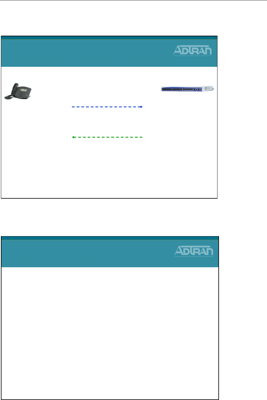
Module 4: ADTRAN Phone Configuration Files
4-52 NetVanta IP Telephony Course
Polycom Phones - DHCP Process
Boot Server
Boot Server
•A boot server allows global and per-phone
configuration to be managed centrally
•Configuration files are text XML-format files
–Most configuration files are created automatically by the
NetVanta 7100 when a new voice user is created
–Phone configuration files could also be created manually and
edited using an XML editor
–Downloaded by the phones at boot time
•The boot server also facilitates automated application
upgrades, diagnostics, and a measure of fault
tolerance
IP Address: 10.10.10.x
Boot Server(66): tftp://10.10.10.1
NTP Server(42): 10.10.10.1, etc
2)
DHCP
OFFER / ACK (VLAN 1)
NetVanta 7100
1)
DHCP
DISCOVER / REQUEST (VLAN 1)
Request for IP Address, Boot Server(66), NTP Server(42) etc
Polycom Phones
DHCP Process
VLAN 1 is the
Native VLAN
Polycom Phone
configured for DHCP
by default
Polycom Phone
Polycom phone attached to NetVanta 7100 Ethernet Port
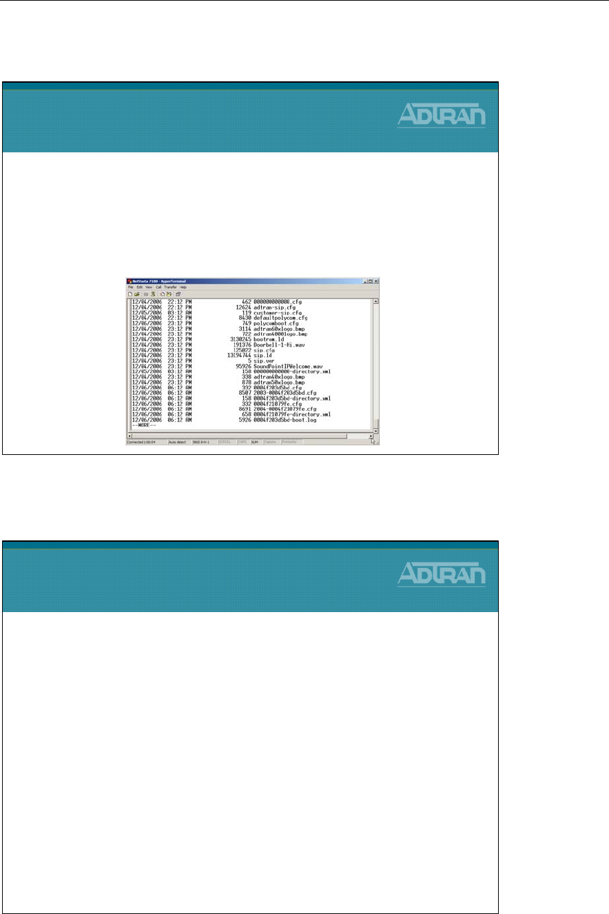
Module 4: ADTRAN Phone Configuration Files
NetVanta IP Telephony Course 4-53
Boot Server Files
Configuration Files
Configuration Files
•The phone configuration files consist of master configuration
files and application configuration files.
•Master Configuration Files
–Instructs phone on files to load
–000000000000.cfg or [MAC].cfg
•Application Configuration Files
–Application configuration files dictate the behavior of the phone
once it is running the executable specified in the master
configuration file
–defaultpolycom.cfg, Ext-[MAC].cfg
customer-sip.cfg, adtran-sip.cfg, sip.cfg
Boot Server Files
•Numerous files are created by the NetVanta 7100
and the Polycom phones
•The NetVanta 7100 can function as the boot server
for IP phones
–Files are stored in Flash or CFLASH of the NetVanta 7100
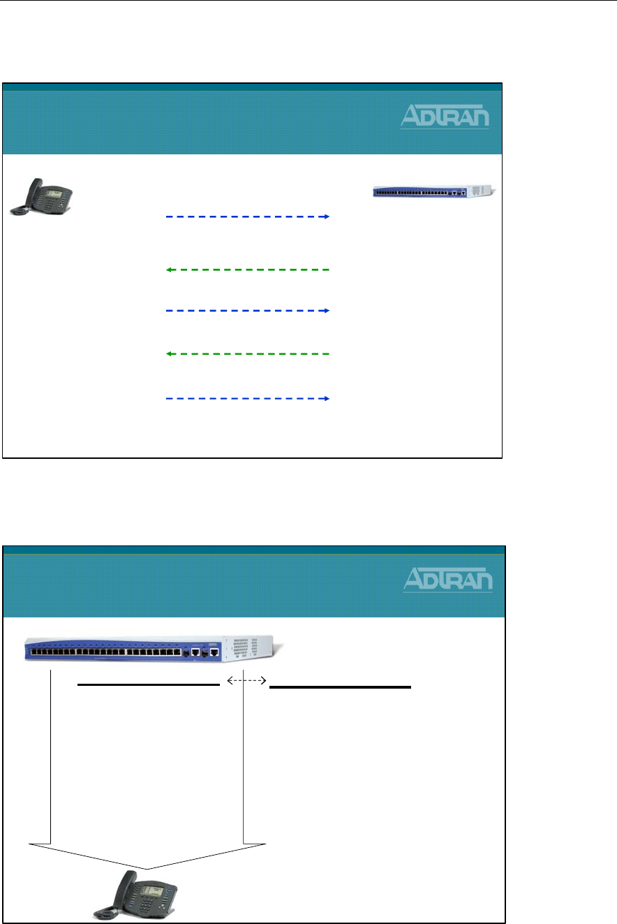
Module 4: ADTRAN Phone Configuration Files
4-54 NetVanta IP Telephony Course
Polycom Phones - File Request Process
Phone Config Files - Unassigned Phones
Phone Config Files
Unassigned Phones
NetVanta 7100 – Boot Server
000000000000.cfg
If a phone does not find its own
[MAC].cfg file, it will use this one,
and establish a baseline configuration
-Instructs phone on files to load
- Delivered by ADTRAN with a Factory
default system.
000000000000.cfg
sip.ld
polycomboot.cfg
customer-sip.cfg
adtran-sip.cfg
defaultpolycom.cfg
sip.cfg
000000000000-directory.xml
Request [MAC].cfg (looks for its own MAC address)
NetVanta 7100
1)
Request bootrom.ld
from Boot Server
Loads new boot code if different and then formats phone
If not different, continues boot process
Polycom Phones
File Request Process
Bootrom.ld is the Polycom phones boot code that is responsible for loading the SIP application
Polycom Phone
Initial DHCP Process Complete
2)
Request Master Configuration File
from Boot Server
Same or no bootrom.ld on server - continue
No [MAC].cfg file on server
3)
Request Master Configuration File
from Boot Server
Request 000000000000.cfg
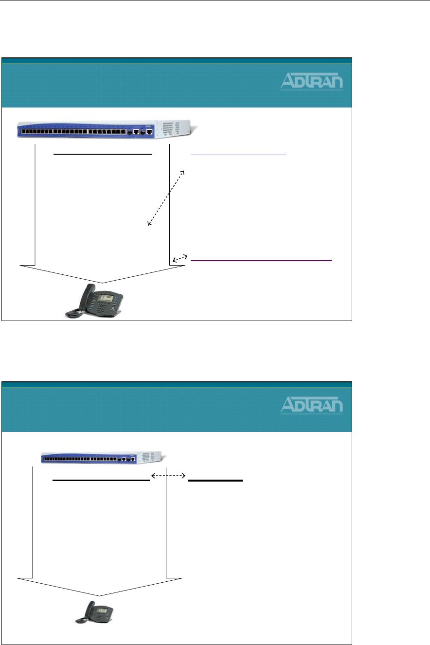
Module 4: ADTRAN Phone Configuration Files
NetVanta IP Telephony Course 4-55
Phone Config Files - Unassigned Phones
Phone Config Files - Assigned Phones
Phone Config Files
Assigned Phones
[MAC].cfg
A Polycom phone will look for its
own [MAC].cfg file
-Instructs phone on files to load
- Created when you add a SIP user and
define MAC address of phone
NetVanta 7100 – Boot Server
0004f2034c0b.cfg
sip.ld
polycomboot.cfg
customer-sip.cfg
2004-0004f2034c0b.cfg
adtran-sip.cfg
sip.cfg
Phone Config Files
Unassigned Phones
NetVanta 7100 – Boot Server
defaultpolycom.cfg
Default phone settings for unassigned
phones
Typical parameters include:
-display name
- unique addresses (
ext 2000
)
000000000000-directory.xml
Used to seed new phones with an
initial directory
000000000000.cfg
sip.ld
polycomboot.cfg
customer-sip.cfg
adtran-sip.cfg
defaultpolycom.cfg
sip.cfg
000000000000-directory.xml
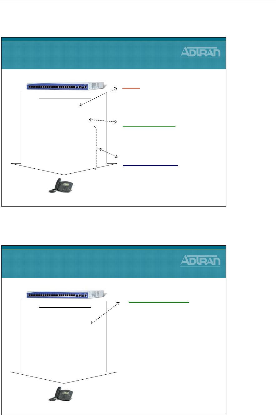
Module 4: ADTRAN Phone Configuration Files
4-56 NetVanta IP Telephony Course
Phone Config Files - Assigned Phones
Phone Config Files - polycomboot.cfg
Phone Config Files
polycomboot.cfg
polycomboot.cfg
•Provides “zero touch” phone
provisioning
•Created by dealer in GUI
•BootRom setup menu and the
application SIP configuration
menu can be set in this file
•Typical parameters include:
–Voice VLAN
–Boot Server
–FTP Username / Password
* The VLAN id is no longer set via DHCP option 129. It is “hard” set in this
file. It can now be seen in the phone menu under Network Configuration.
NetVanta 7100 – Boot Server
0004f2034c0b.cfg
sip.ld
polycomboot.cfg
customer-sip.cfg
2004-0004f2034c0b.cfg
adtran-sip.cfg
sip.cfg
Phone Config Files
Assigned Phones
polycomboot.cfg
Sets the boot parameters for all SIP
phones
- Created by dealer in GUI
sip.ld
The Polycom phone SIP firmware
image file (phone application)
- Uploaded to flash by dealer
Other “.cfg” files
SIP application settings for phones
NetVanta 7100 – Boot Server
0004f2034c0b.cfg
sip.ld
polycomboot.cfg
customer-sip.cfg
2004-0004f2034c0b.cfg
adtran-sip.cfg
sip.cfg
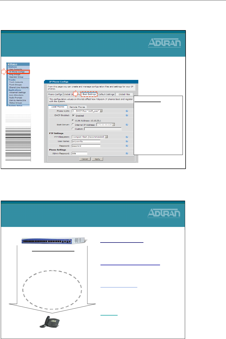
Module 4: ADTRAN Phone Configuration Files
NetVanta IP Telephony Course 4-57
Phone Config Files - Editing polycomboot.cfg
Phone Config - SIP App. Settings for Phones
adtran-sip.cfg
Contains the default settings that ADTRAN
chooses to employ on the Polycom phones
- Examples: ADTRAN logo, ringtones, etc
2004-0004f2034c0b.cfg
Phone settings for the specific phone
- Created when user added in GUI
NetVanta 7100 – Boot Server
0004f2034c0b.cfg
sip.ld
polycomboot.cfg
customer-sip.cfg
2004-0004f2034c0b.cfg
adtran-sip.cfg
sip.cfg
Phone Config Files
SIP Application Settings for Phones
customer-sip.cfg
Dealer/User can customize this file
- Examples: logos, wav files, etc.
sip.cfg
Default settings from Polycom. This file
should not be modified.
1. From the Voice / Stations / IP Phone Configs
menu, select the Boot Settings tab
Phone Config Files
Editing polycomboot.cfg
1
Boot Settings
- Set Phone VLAN
-Define Boot Server
- Specify where phone
config files are stored
- Set FTP username and
password
- Change phone Admin
password
2
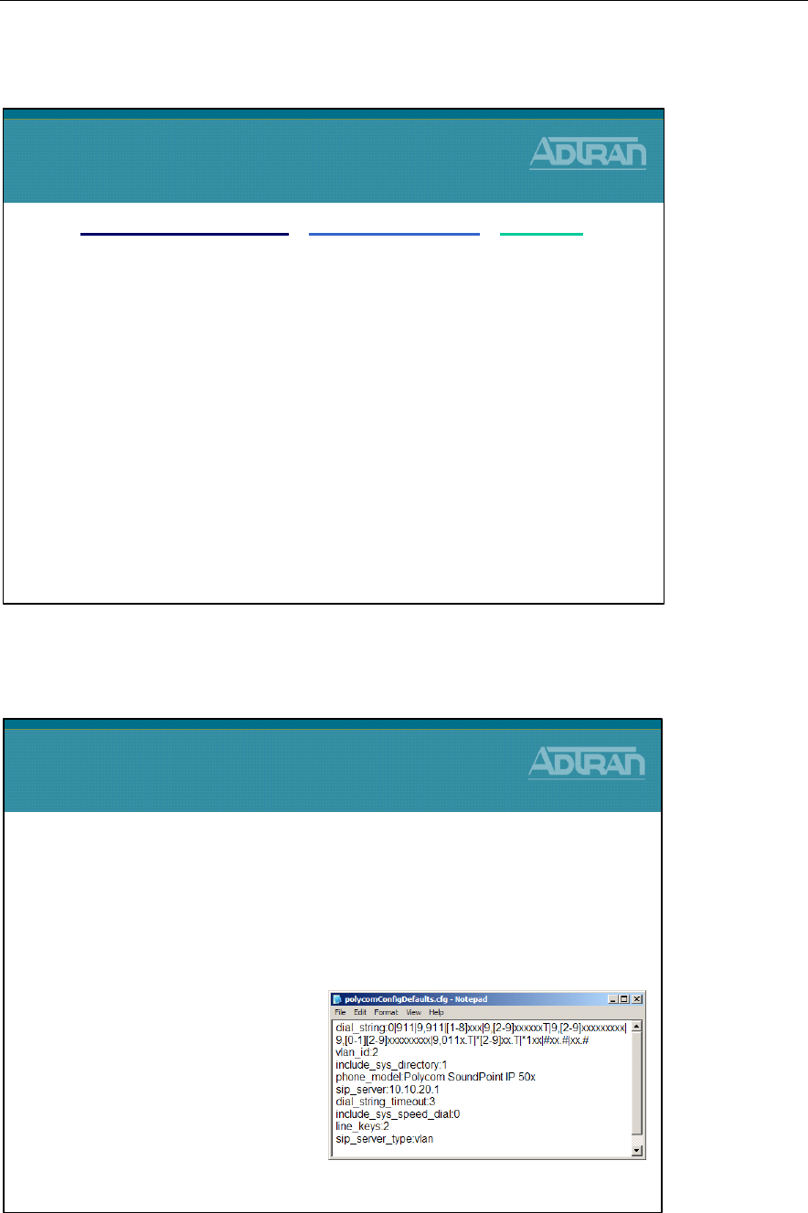
Module 4: ADTRAN Phone Configuration Files
4-58 NetVanta IP Telephony Course
Phone Config - SIP App. Settings for Phones
polycomConfigDefaults.cfg
Default Polycom Configuration File
polycomConfigDefaults.cfg
•A text file that contains default Polycom configuration
values that will automatically be applied to new phone
configurations created by the NetVanta 7100
–This file is defined and created
from the Default Settings tab of
the NetVanta 7100 IP Phone
Configs screen
•Included parameters:
–Default Dial Plan Digit Map
–Default Phone Model
–Number of Line Keys
•Reasons for the 3 separate SIP config files
–Polycom modifies the sip.cfg file occasionally
•ADTRAN has needed this ability also
–If customers have modified sip.cfg and made it unique, then it
will be difficult for them to upgrade to new Polycom revisions
that require an updated sip.cfg file.
•The 3 files allow…
–Polycom to have their own SIP configurations that can be
updated.
–ADTRAN to have our own SIP configurations that can be
updated.
–The customer still has the ability to customize the SIP settings,
and update ADTRAN and/or Polycom SIP configs.
customer-sip.cfg, adtran-sip.cfg, sip.cfg
Phone Config Files
SIP Application Settings for Phones
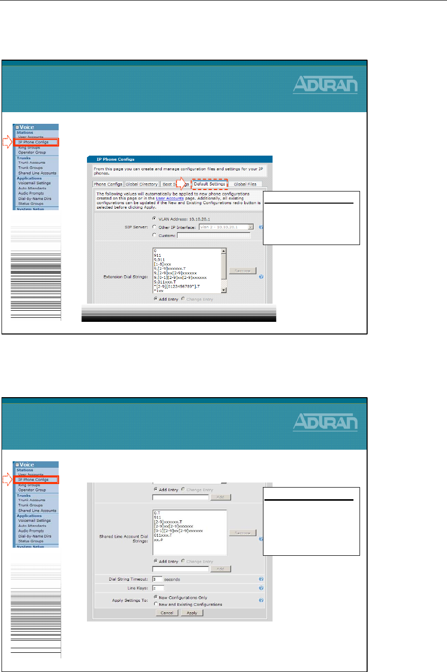
Module 4: ADTRAN Phone Configuration Files
NetVanta IP Telephony Course 4-59
Phone Config Files - polycomConfigDefaults.cfg
Phone Config Files - polycomConfigDefaults.cfg
•Boot Settings tab continued…
Phone Config Files
polycomConfigDefaults.cfg
1
Default Phone Settings
- Shared Line Account Dial
String patterns
- Dial String Timeout
- # of Line Keys
1. From the Voice / Stations / IP Phone Configs
menu, select the Default Settings tab
Phone Config Files
polycomConfigDefaults.cfg
1
2
Default Phone Settings
-SIP Server
- Dial String pattern for
extensions

Module 4: ADTRAN Phone Configuration Files
4-60 NetVanta IP Telephony Course
Other Polycom Files
Other Polycom Files (Continued)
Other Polycom Files
(Continued)…
•SoundPointIPWelcome.wav
–Wav file that's played when phone boots
•Doorbell-1-Hi.wav
–Doorbell Wav file that can be used for door phone
•adtran40xlogo.bmp
–Bitmap for IP430 phone (monochrome – 94x23) pixels)
•adtran50xlogo.bmp
–Bitmap for IP500 phone (4 bit grayscale - 114x51 pixels)
•adtran60xlogo.bmp
–Bitmap for IP600 phone (4 bit grayscale – 209x109 pixels)
•adtran4000logo.bmp
–Bitmap for IP4000 phone (4 bit grayscale – 150x33) pixels)
Other Polycom Files
•bootrom.ld
–Generic program designed to load the application (SIP). The
bootROM application uses the network to query the boot server for
upgrades or configuration changes.
•sip.ld
–The SIP firmware image file (phone application)
•sip.ver
–Version number of SIP image
•[MAC]-phone.cfg
–Local configuration changes made on the phone and uploaded to
the boot server if allowed
•[MAC]-directory.xml
–Per Phone Directory
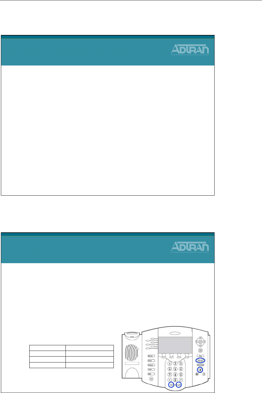
Module 4: ADTRAN Phone Configuration Files
NetVanta IP Telephony Course 4-61
Other Polycom Files (Continued)
Manual Reboot of Phone
Manual Reboot of Phone
•Rebooting from phone menu
–The menu option is called Restart Phone and it is found in
the Settings menu
•Rebooting with phone key combination
–For the key combination, press and hold the following keys
simultaneously until a confirmation tone is heard or for about
three seconds:
Reboot initiated
*, # , Volu me+, SelectSoundStation® IP 4000:
Volume-, Volume+ , Mute, MessagesSoundPoin t® IP 600 and 601:
Volume-, Volume+ , Hold, MessagesSoundPoin t® IP 500 and 501:
Volume-, V olume+, Hold, Do Not Disturb SoundPoin t® IP 300 and 301:
Other Polycom Files
(Continued)…
•[MAC].app.log
–The application log file is uploaded periodically or when the
local copy reaches a predetermined size.
•[MAC].boot.log
–The boot log file is uploaded to the boot server after every
reboot. A ~now-boot.log or ~now-app.log version of these
files may also be seen.
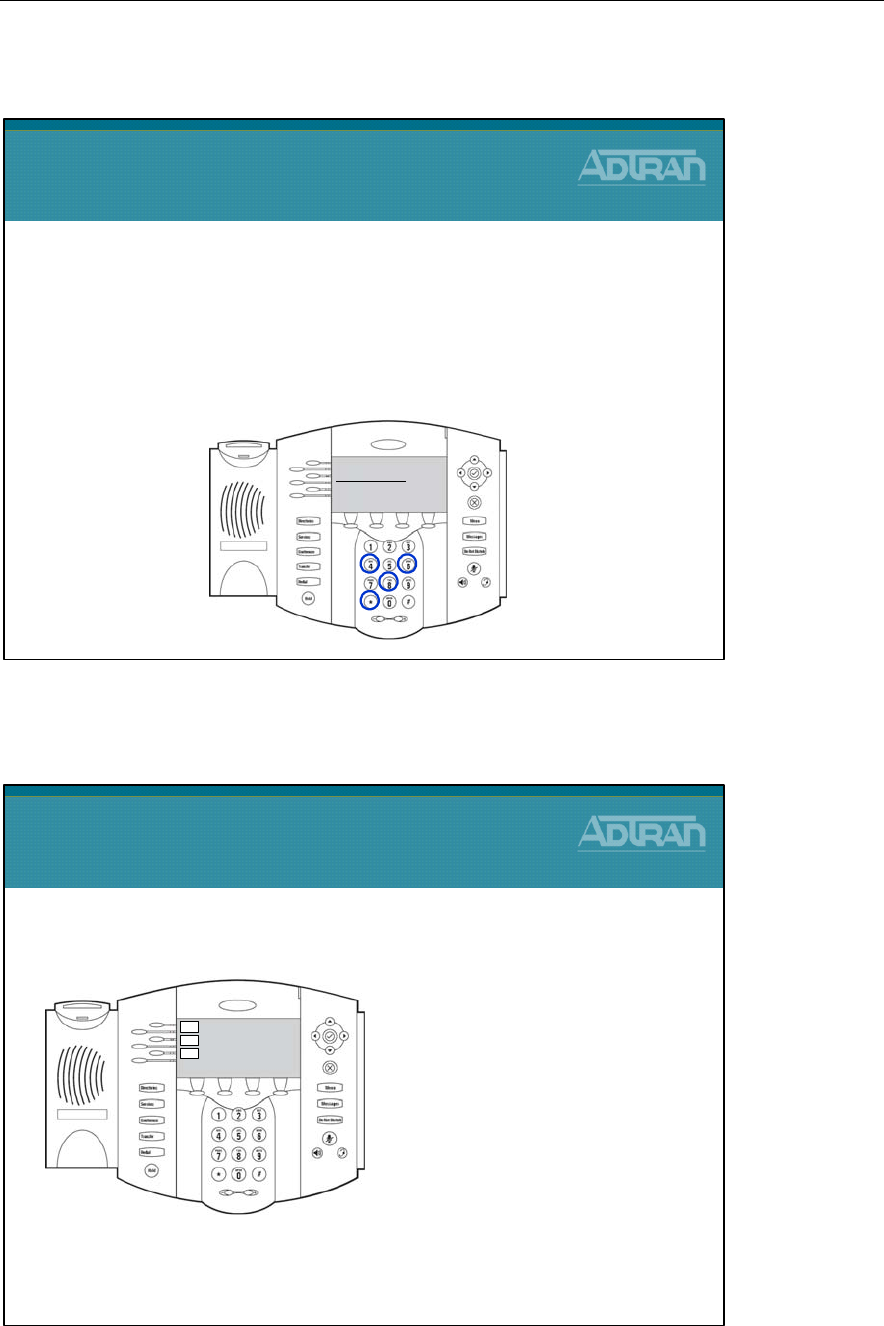
Module 4: ADTRAN Phone Configuration Files
4-62 NetVanta IP Telephony Course
Reset to Factory Default
Registration, Line and Call Appearance
2004
2004
3004
Polycom phones can support multiple registrations, line
appearances, and call appearances
Registration: a SIP alias or
phone number
Line key: a button on the
phone beside the display
Call: a SIP session
- Registrations can appear on multiple line keys
- Line keys can have multiple calls
Registration, Line, and Call
Appearance
Reset to Factory Default
•The basic network configuration can be reset to
factory defaults
–Simultaneously press and hold the 4, 6, 8 and * dial pad keys
until the password prompt appears
–Enter the administrator password to initiate the reset
Flash settings reset
Admin Password:

Module 4: ADTRAN Phone Configuration Files
NetVanta IP Telephony Course 4-63
Module Objectives
Module Objectives
At the end of this module, you should:
•Have a basic understanding of ADTRAN phone
configuration files
•Be able to modify phone configuration files in the GUI

Module 4: ADTRAN Phone Configuration Files
4-64 NetVanta IP Telephony Course

Module 5: NetVanta 7000 Key
System Application

Module 5: NetVanta 7000 Key System Application
5-2 NetVanta IP Telephony Course

Module 5: NetVanta 7000 Key System Application
NetVanta IP Telephony Course 5-3
Module Objectives
Module Objectives
•Introduce NetVanta 7000 Key System Applications
•Voice Trunk Review
•Configure Shared Line Accounts
•Enable Hands Free Auto-Answer
•Introduce and Configure System Modes
•Conduct Voice Troubleshooting in a NetVanta 7000
Key System Application

Module 5: NetVanta 7000 Key System Application
5-4 NetVanta IP Telephony Course
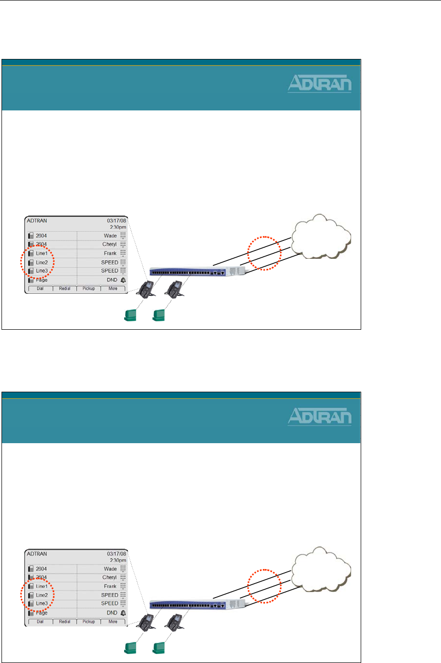
Module 5: NetVanta 7000 Key System Application
NetVanta IP Telephony Course 5-5
NetVanta 7000 - Key System Application
NetVanta 7000
Key System Application
•What is a Key System?
–Key Systems are typically used in small office environments
–Allow a group of telephones to access a number of individual
telephone lines
–Characterized by telephones with buttons used to access, or
answer, lines
PSTN
NetVanta 7000
Analog
Trunks
Line 1
Line 2
Line 3
NetVanta 7000 - Key System Features
NetVanta 7000
Key System Features
•Configuration of the following features are
introduced in this section:
–Shared Line Appearance (SLA)
–Hands-free Auto-Answer
–System Scheduler (Day/Night)
PSTN
NetVanta 7000
Analog
Trunks
Line 1
Line 2
Line 3

Module 5: NetVanta 7000 Key System Application
5-6 NetVanta IP Telephony Course
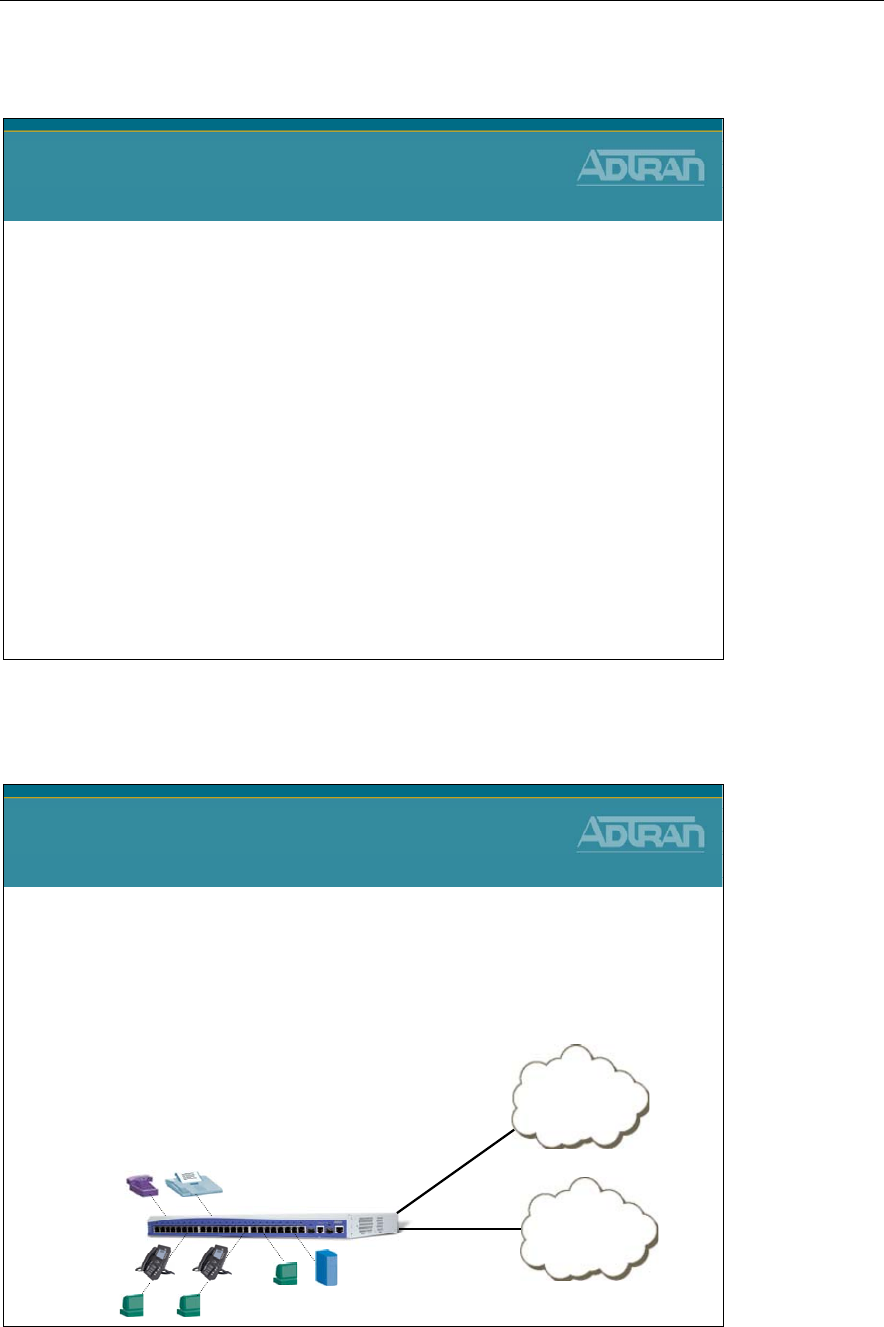
Module 5: NetVanta 7000 Key System Application
NetVanta IP Telephony Course 5-7
Voice Trunk Review
NetVanta IP Telephony Course
Voice Trunk Review
Voice Trunk Review
Voice Trunk Review
•Trunk lines connect the NetVanta 7000 to the outside
world. They are delivered from the carrier and may
be digital or analog.
–Supported Voice Trunk Types
•Analog
•T1-RBS
•T1-ISDN PRI
•SIP PSTN
Analog or T1
Carrier
VOIP Network
SIP
NetVanta
7000
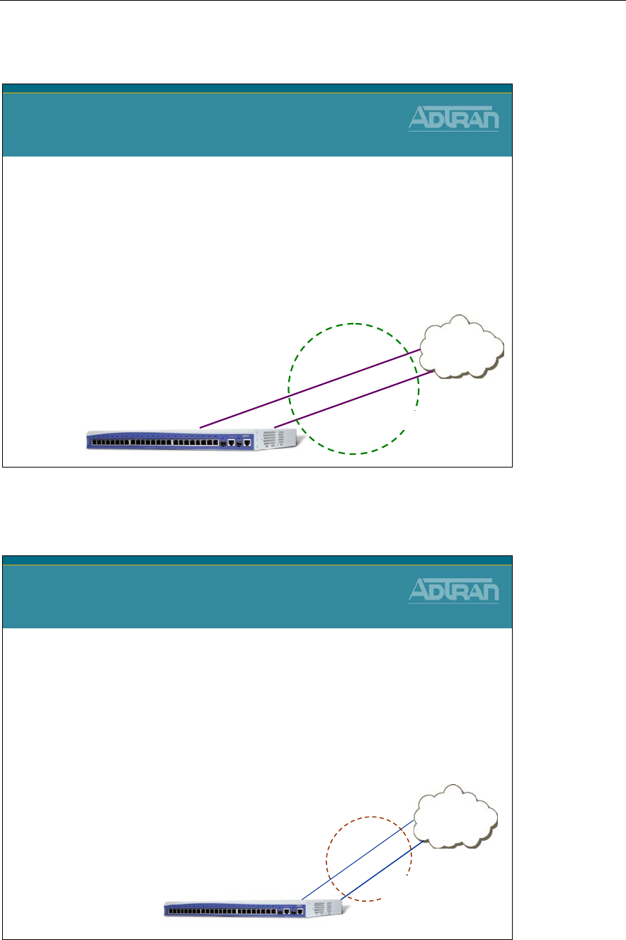
Module 5: NetVanta 7000 Key System Application
5-8 NetVanta IP Telephony Course
Factory Default Review
NetVanta 7000 Voice Trunks
Factory Default Review
•Trunk Account T01
–Physical Interface = FXO 0/1
–Inbound call goes to Auto Attendant (8200)
•Trunk Account T02
–Physical Interface = FXO 0/2
–Inbound call goes to Auto Attendant (8200)
•Analog Trunk Group
–Includes both T01 and T02
–All calls allowed out
(accept 900 #s)
PSTN
NetVanta 7000
Trunk Account T01
Trunk Account T02
Analog Trunk Group
FXO
0/1
FXO
0/2
Basic Configuration Steps
Analog Trunk Review
Basic Configuration Steps
1. Configure Trunk Physical Interface
–FXO interfaces enabled by default
2. Create Trunk Account
–Configure trunk number, caller-id, etc..
–Assign physical FXO port(s)
3. Create Trunk Group
–Add Trunk Account members
–Define outbound call templates
PSTN
FXO
0/1
Trunk Acct T02
NetVanta 7000
Trunk Acct T01
FXO
0/2
Trunk
Group
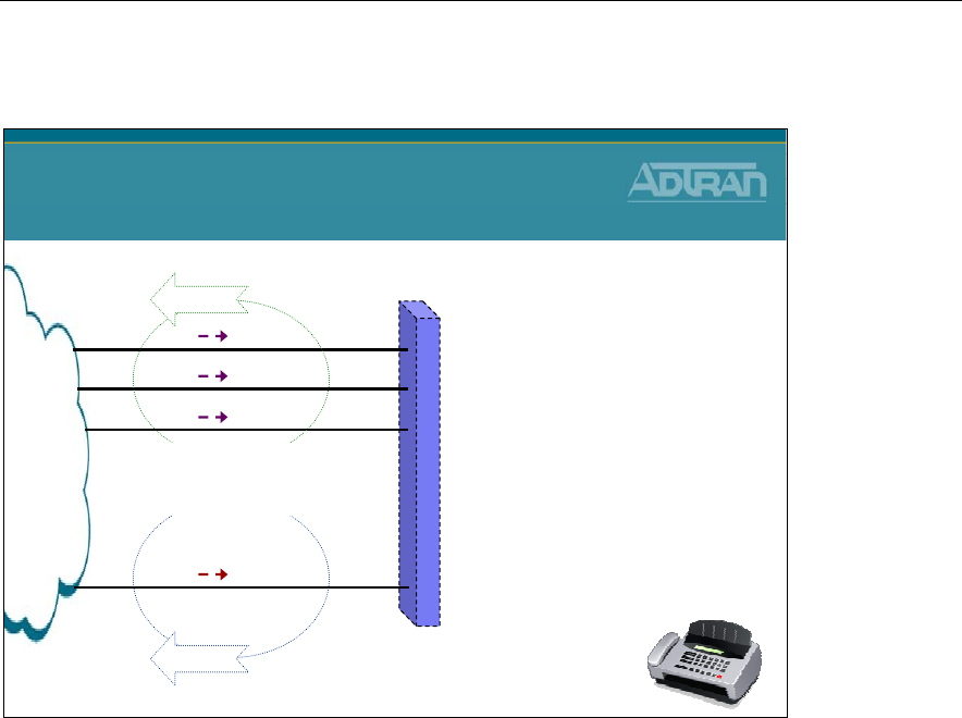
Module 5: NetVanta 7000 Key System Application
NetVanta IP Telephony Course 5-9
Trunk Accounts/Groups Review
NetVanta 7000 Voice Trunks
Accounts/Groups Review
PSTN
T01
T02
T03
T04
AA 8200
AA 8200
AA 8200
FAX 2800
Trunk Group 1
FXO 0/1
FXO 0/2
FXO 2/1
FXO 2/2
* Trunk Accounts T01- T03
- Inbound calls go to Auto Attendant
* Trunk Account T04
- Dedicated FAX Line
* Trunk Group 1
- All calls allowed out at a low cost
* Trunk Group 2
- All calls allowed out at a high cost
Extension
2800
Trunk Group 2
Low Cost
High Cost

Module 5: NetVanta 7000 Key System Application
5-10 NetVanta IP Telephony Course

Module 5: NetVanta 7000 Key System Application
NetVanta IP Telephony Course 5-11
Shared Line Appearance
NetVanta IP Telephony Course
Shared Line Appearance
A Shared Line Appearance (SLA) is a configurable portion of the NetVanta 7000 that
allows system administrators to enable the key system mode on the unit. A Shared Line
Account is created and then linked to the IP phone’s line keys and functions similar to a
key system where the system enables multiple phone users to share the same analog trunk
lines. SLAs allow businesses to cut the cost of providing individual analog phone lines
from the carrier to each analog phone station in their facility.
For example, company XYZ has 16 sales employees that need a secondary extension on
their ADTRAN desktop IP phones. Instead of ordering an additional 16 trunk lines,
company XYZ orders three analog trunk lines and shares the lines between the sales team
phone users.

Module 5: NetVanta 7000 Key System Application
5-12 NetVanta IP Telephony Course
SLAs offer features, such as public hold/retrieve, line status display on subscribers' phones,
and the ability to place an outbound call out of a selected trunk.
Outlined below are key aspects of SLAs:
- SLAs can only be associated with analog trunks.
- Inbound calls on an SLA notify every SIP-based IP phone that registers to it.
- SLAs can be seized by pressing the appropriate line key(s) on the phone.
- The status of an SLA will be updated on all other phones registered to that line. Status
conditions include idle, ringing, busy, and hold.
- A busy SLA cannot be seized by other SIP-based IP phones. Barge or monitoring of
the SLA is NOT supported.
- SLAs can have coverage to auto attendant (AA), voicemail (VM), operator, extension,
and an external number.
Using Public Hold
When using SLAs, calls that are put on hold are referred to as being on Public Hold, which
means that every user on that particular SLA has access to the call placed on hold. Also,
any phone registered to that SLA will be able to see the hold status and retrieve the call by
pressing the line key corresponding to the call on their phone.
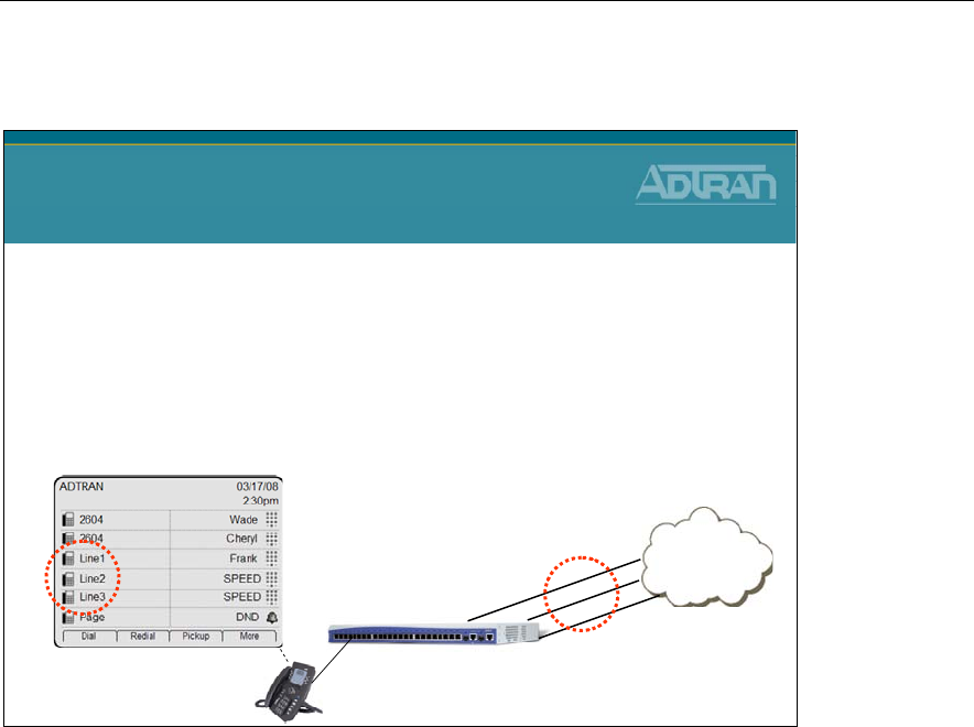
Module 5: NetVanta 7000 Key System Application
NetVanta IP Telephony Course 5-13
Shared Line Appearance
Shared Line Appearance
•Description
–The key system functionality for SLA is targeted to make the
IP PBX experience similar to existing key systems that some
end users are accustomed to
–A “Shared Line Appearance” refers to a line key on a phone
that maps to an analog trunk
PSTN
NetVanta 7000
Analog
Trunks
(FXO Interfaces)
Line 1
Line 2
Line 3
SLAs and Analog Trunk Lines
In order for analog trunk lines to appear and be accessible for incoming and outgoing calls
for multiple IP phone users, the trunk line(s) must be configured and linked to an SLA.
Once the SLA is associated with the trunk line, the SLA can be linked to individual
phones. Prior to the introduction of SLAs, all calls were routed out the trunk groups and
were only subjected to the permit/deny templates assigned under the trunk group settings.
Now, SLAs contain their own set of permit/deny templates. This application allows trunk
accounts that are used as SLAs to also be included in an outbound trunk group. Therefore,
when a user presses the corresponding line key on a phone that only has SLA’s extensions
programmed, they are subjected to the SLA’s Accept/Reject Templates. When running
AOS A1 firmware or later, the SLA Accept/Reject Templates are not applied to inbound
and outbound calls if the phone has a private line (user account) programmed. Instead, the
individual user assigned class of service permission settings are applied to all outbound
calls.
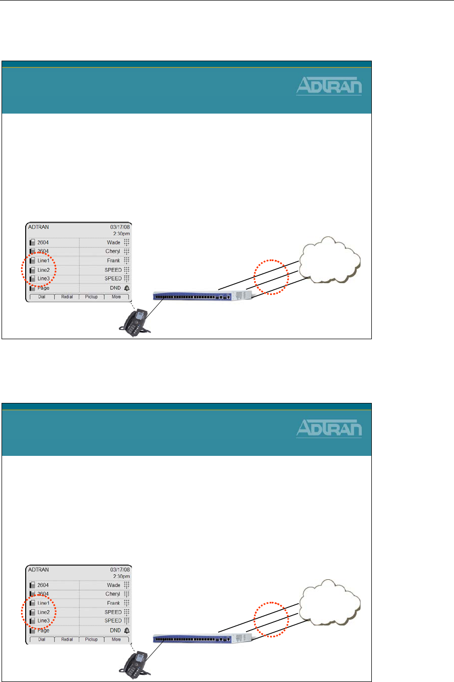
Module 5: NetVanta 7000 Key System Application
5-14 NetVanta IP Telephony Course
Shared Line Appearance - Features
Shared Line Appearance
Features
–Inbound calls on a LINE notify every SIP phone that registers
to the line
–A LINE can be seized by selecting the LINE button on the
phone
–The status of a LINE will be updated on all other phones
registered to that line
•Status will include IDLE, RINGING, BUSY, and HOLD
PSTN
NetVanta 7000
Analog
Trunks
Line 1
Line 2
Line 3
Shared Line Appearance - Features (Continued)
Shared Line Appearance
Features (Continued…)
–A LINE on hold may be retrieved by any other SIP Phone
that registers on the LINE
–A busy LINE cannot be seized by other SIP Phones
•Barge or Monitoring of the LINE is NOT supported
–A LINE can have coverage to AA, VM, Operator, extension,
and an external number
PSTN
NetVanta 7000
Analog
Trunks
Line 1
Line 2
Line 3
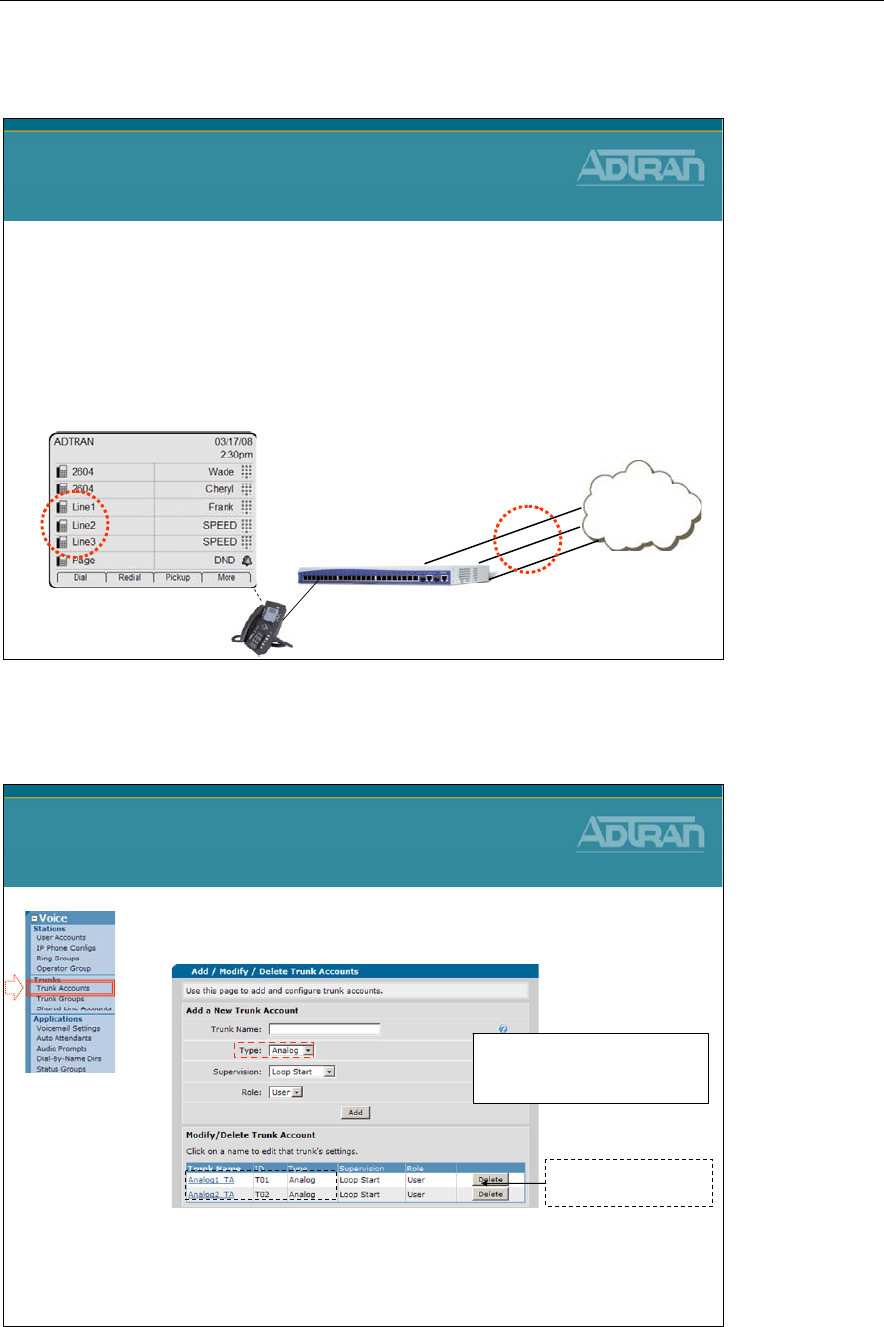
Module 5: NetVanta 7000 Key System Application
NetVanta IP Telephony Course 5-15
Shared Line Appearance - Basic Configuration
Shared Line Appearance
Basic Configuration Steps
1. Create Analog Trunk Accounts
2. Create Shared Line Accounts (SLA)
–Specify the Trunk Account that will be associated to this
SLA
–Configure Accept/Reject template for this SLA
3. Configure key on phone as a SLA
PSTN
NetVanta 7000
Analog
Trunks
(FXO Interfaces)
Line 1
Line 2
Line 3
1) Create Trunk Account
1) Create Analog Trunk Accounts
(as done in past)
– Create one Analog Trunk Account per incoming analog
line (FXO interface)
SLA Configuration
1) Create Trunk Account
Analog3_TA
1
- Set Type to Analog
- Supervision can be Loop Start or
Ground Start.
The first two TAs have
already been created
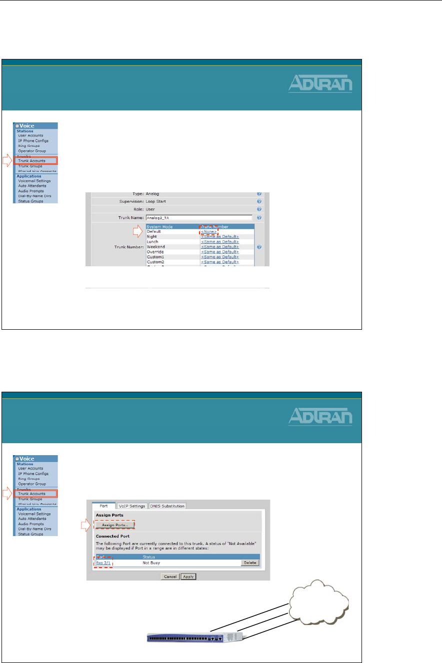
Module 5: NetVanta 7000 Key System Application
5-16 NetVanta IP Telephony Course
1) Create Trunk Account
2) Remove the existing extension number
– Inbound calls will go to all users registered to the
Shared Line Account (SLA)
– A different Trunk Number could be assigned for
each of the System Modes
SLA Configuration
1) Create Trunk Account
2
1) Create Trunk Account
3) Assign one FXO interface per Trunk Account
SLA Configuration
1) Create Trunk Account
3
PSTN
NetVanta 7100
T02 –FXO 0/1
T02 –FXO 0/2
T03 –FXO 2/1
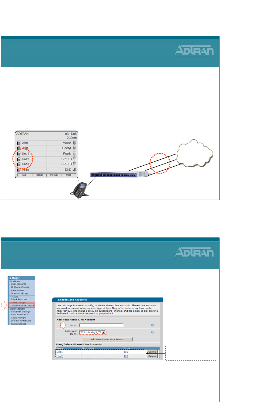
Module 5: NetVanta 7000 Key System Application
NetVanta IP Telephony Course 5-17
Shared Line Appearance - Basic Configuration
Shared Line Appearance
Basic Configuration Steps
1. Create Analog Trunk Accounts
2. Create Shared Line Accounts (SLA)
–Specify the Trunk Account that will be associated to this
SLA
–Configure Accept/Reject template for this SLA
3. Configure key on phone as a SLA
PSTN
NetVanta 7000
Analog
Trunks
(FXO Interfaces)
Line 1
Line 2
Line 3
2) Shared Line Accounts
1) Select the Voice / Trunks / Shared Line
Accounts menu
2) Create one Shared Line Account per Analog Trunk
Account
– Select the Analog Trunk Account that this shared line will
be associated with
SLA Configuration
2) Shared Line Accounts
1
2
Line3
The first two SLAs have
already been created
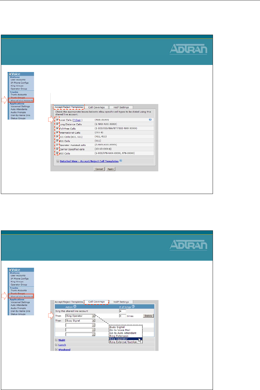
Module 5: NetVanta 7000 Key System Application
5-18 NetVanta IP Telephony Course
2) Shared Line Accounts
3) Specify the type of calls that will be allowed
out with this Shared Line Account
SLA Configuration
2) Shared Line Accounts
3
2) Shared Line Accounts
4) Define the Call Coverage that will be used for
this Shared Line Account
– A different Call Coverage could be defined for each
of the System Modes
SLA Configuration
2) Shared Line Accounts
4
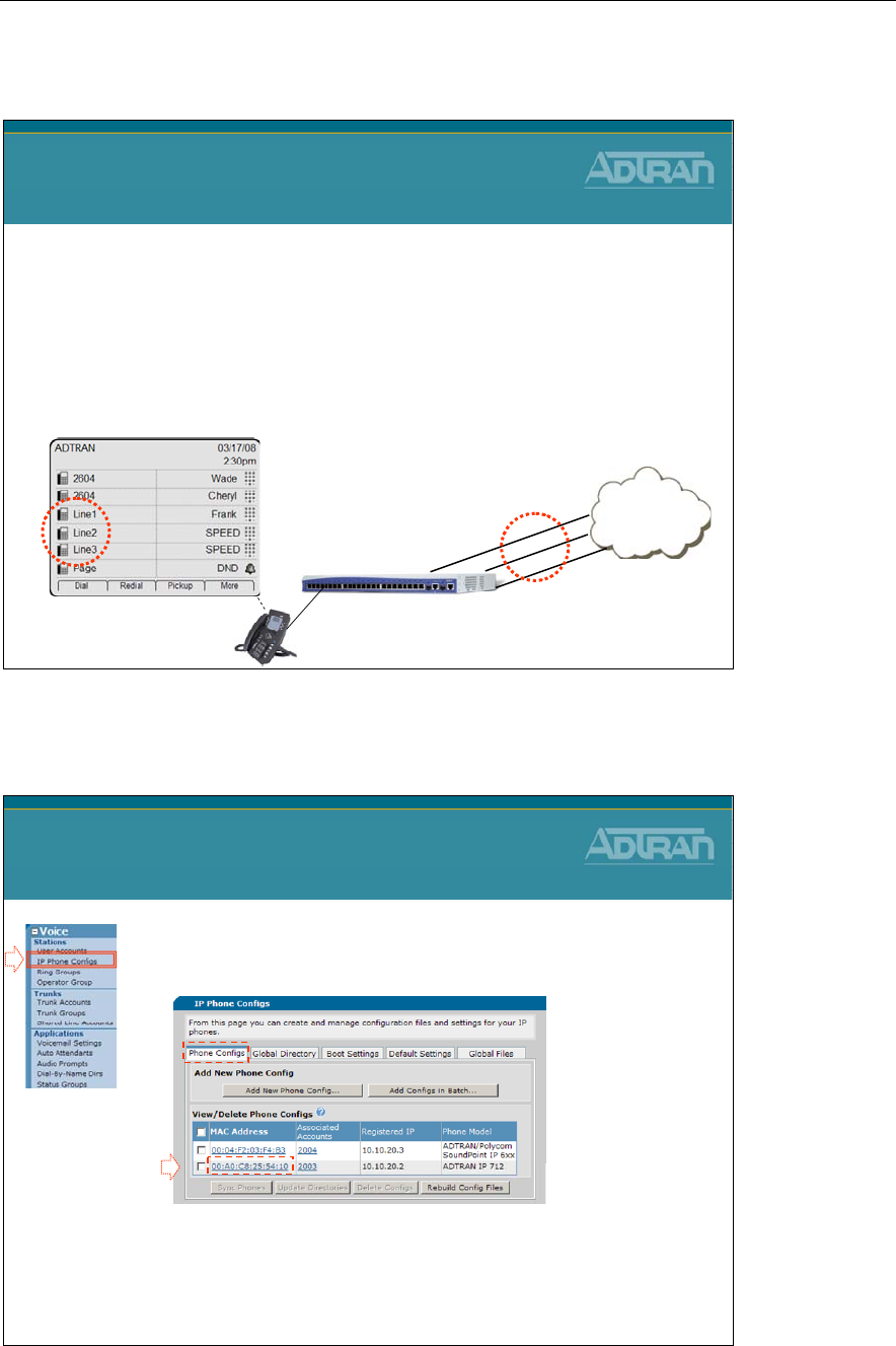
Module 5: NetVanta 7000 Key System Application
NetVanta IP Telephony Course 5-19
Shared Line Appearance - Basic Configuration
Shared Line Appearance
Basic Configuration Steps
1. Create Analog Trunk Accounts
2. Create Shared Line Accounts (SLA)
–Specify the Trunk Account that will be associated to this
SLA
–Configure Accept/Reject template for this SLA
3. Configure key on phone as a SLA
PSTN
NetVanta 7000
Analog
Trunks
(FXO Interfaces)
Line 1
Line 2
Line 3
3) Line Key on Phone
1) Select the Voice / Stations / IP Phone Configs
menu
2) Select the MAC address of the phone you wish to add
a shared line to
SLA Configuration
3) Line Key on Phone
1
2
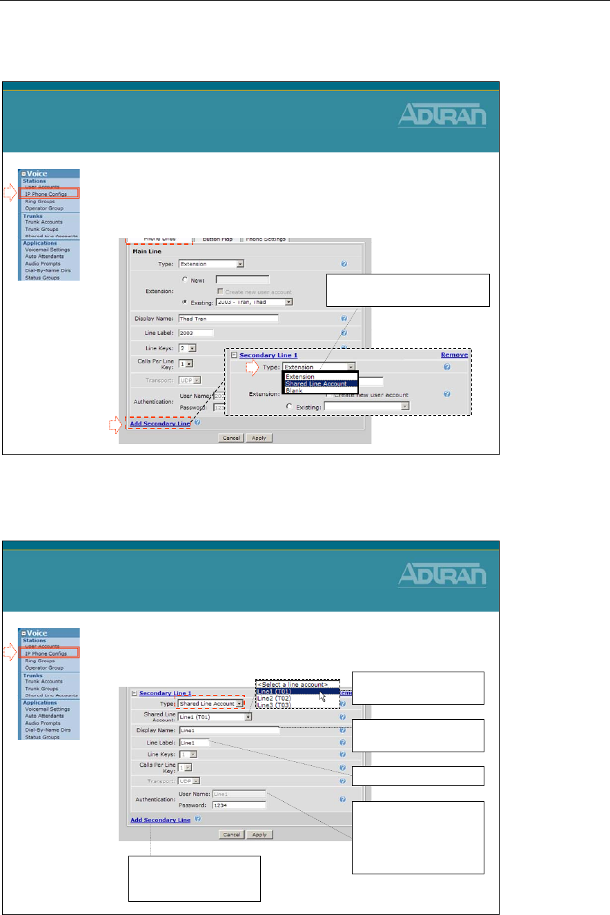
Module 5: NetVanta 7000 Key System Application
5-20 NetVanta IP Telephony Course
3) Line Key on Phone
3) Add a secondary line below the existing
extension line keys
SLA Configuration
3) Line Key on Phone
3
4
4) Configure the Type as Shared
Line Account
3) Line Key on Phone
5) Configure SLA parameters
SLA Configuration
3) Line Key on Phone
Specify the SLA (trunk)
that the voice line will use
Name used for SIP
signaling
Line key text label
Password used for this line's
registration. Same as the
extension and SIP
Authentication password of
the associated user account.
Repeat the above steps to
add additional shared lines
to the phone
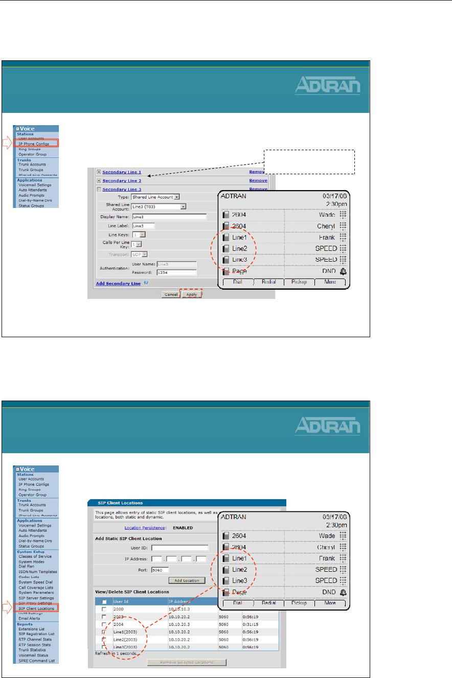
Module 5: NetVanta 7000 Key System Application
NetVanta IP Telephony Course 5-21
3) Line Key on Phone
6) Click Apply and then reboot the phone
– After phone reboots, the new Shared Line Accounts
appear on phone
SLA Configuration
3) Line Key on Phone
The first two LINES have
already been configured
Shared Line Account - View Registration
• Shared Line Accounts are registered with the
NetVanta 7000
Shared Line Account
View Registration

Module 5: NetVanta 7000 Key System Application
5-22 NetVanta IP Telephony Course

Module 5: NetVanta 7000 Key System Application
NetVanta IP Telephony Course 5-23
Hands Free Auto Answer
NetVanta IP Telephony Course
Handsfree Auto Answer
Hands Free Auto Answer
Handsfree Auto Answer
•Hands Free Auto-Answer is an intercom like feature
–User initiates a call to a SIP phone
–Instead of requiring the recipient to answer the call, the
phone automatically answers and starts a conversation
•Supported with:
–ADTRAN IP 706 and IP 712
–Many Polycom Phones - (IP 650, IP 601, IP 501, IP 430)
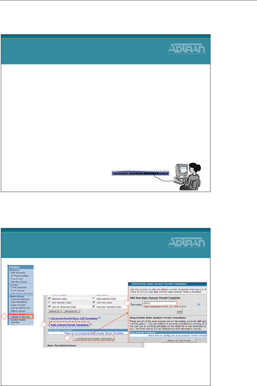
Module 5: NetVanta 7000 Key System Application
5-24 NetVanta IP Telephony Course
Hands Free Auto Answer - Basic Configuration
Handsfree Auto Answer
Basic Configuration Steps
1. Configure auto-answer permit template
–Template defined per voice Class of Service
2. Optional – Give voice users permission to block
incoming auto-answer calls
–Configured per voice Class of Service
3. Optional – Block incoming auto-answer calls for
specific voice user
–Configured per specific voice user extension
1) Configure AA Permit Template
1) From Voice / System Setup / Classes of
Service, edit desired Class of Service
2) Auto-Answer permit templates area created per
Class of Service
– Configuration is very similar to the call accept template
3
2
Hands-Free AA Configuration
1) Configure AA Permit template
1
4
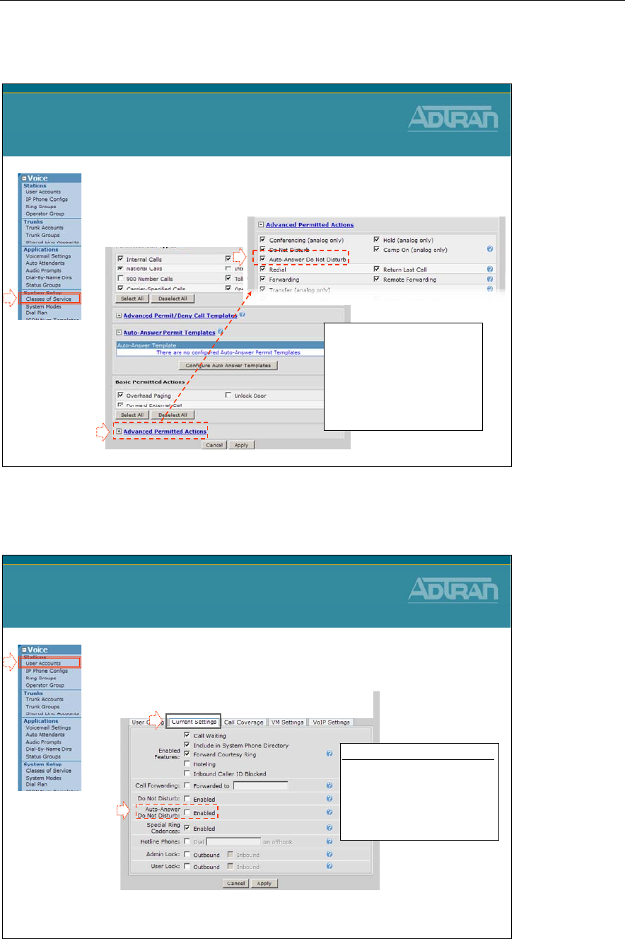
Module 5: NetVanta 7000 Key System Application
NetVanta IP Telephony Course 5-25
2) Block Incoming AA calls
• Optional – Per CoS, allow users to block
incoming auto-answer calls
Hands-Free AA Configuration
2) Block Incoming AA calls
1
2
-When a user does not want
to receive an Auto-Answer
call, they can dial
*971
- When user wishes to
receive Auto-Answer calls
again, they can dial
*970
3
3) Block Incoming AA calls
• Optional – Block incoming auto-answer calls
for specific user
– While editing a Voice User, select the Current Settings tab
Hands-Free AA Configuration
3) Block Incoming AA calls
1
2
3
Auto-Answer Do Not Disturb
If checked, any incoming
Auto-Answer calls will ring
normally instead of being
automatically answered by
the phone
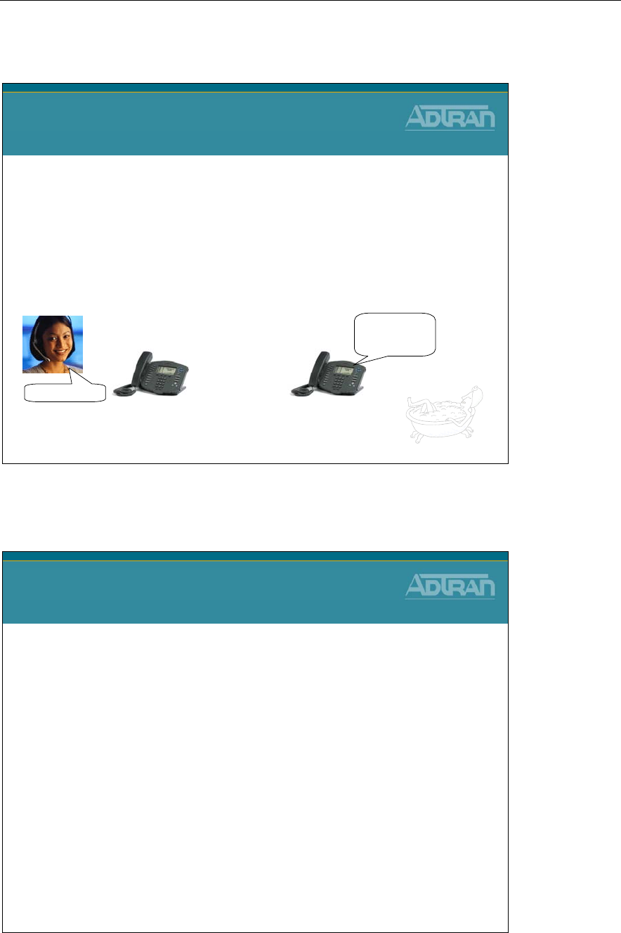
Module 5: NetVanta 7000 Key System Application
5-26 NetVanta IP Telephony Course
Hands Free Auto-Answer - Placing Call
Hands Free Auto-Answer
Placing Call
•To place an Auto-Answer call, the digits ** must
precede the number
–The prefix can be dialed before or with the extension
–For example, a user could place two calls:
•**
and then
MXXX
, or a user could dial
**MXXX
x2003 x2004
**2004
Speaker
Hello Bob!
Hello Bob!
Hands Free AA - No Permission or Blocked
Hands Free Auto-Answer
No Permission or Blocked
•Auto-Answer call initiated by a user that “does not
have permission” to do so
–Normal call is placed
–No Auto-Answer functionality
•Auto-Answer call is received by a user that has
blocked the functionality
–A normal call is placed
–No Auto-Answer functionality

Module 5: NetVanta 7000 Key System Application
NetVanta IP Telephony Course 5-27
System Scheduler
NetVanta IP Telephony Course
System Scheduler
System Scheduler - What is it?
Voice System Scheduler
What is it?
•System Scheduler allows a user to define different
configuration parameters based on day and time
–Change voice users call privileges
–Redirect incoming calls to a different number
–Schedule different Auto Attendant greetings
–Define different call coverage
Module 5: NetVanta 7000 Key System Application
5-28 NetVanta IP Telephony Course
System Scheduler - Modes of Operation
Voice System Scheduler
Modes of Operation
System Scheduler has two modes of operation:
•Automatic Mode
–A schedule can be defined to transition system modes at
predetermined days and times, automatically
–When a schedule is defined and active, no manual modes
can be enabled, except for the override mode
•Once the override mode is enabled, it stays in effect until manually
disabled
•Manual Mode
–Allows users to set the mode of operation manually
–Once a mode is selected, the mode stays in effect until
manually changed
–All manual changes to system mode can occur via BLF and
SPRE codes
System Scheduler - Predefined Modes
Voice System Scheduler
Predefined Modes
•The are several predefined modes and custom
modes where the schedule can be modified:
–Default
–Night
–Lunch
–Weekend
–Custom1
–Custom2
–Custom3
–Override

Module 5: NetVanta 7000 Key System Application
NetVanta IP Telephony Course 5-29
System Mode Feature
System Mode Operation is a feature in the NetVanta 7000 that allows a user to define
different configuration parameters, such as User Class of Service, Trunk Account Number,
and Call Coverage, based on the current mode. There are 7 configurable System Modes
with one Override option. The System Mode can be configured to change on a schedule at
a specific transition time or can be manually switched by the user without a schedule.
The 7 System Modes are:
- Default
- Night
- Lunch
- Weekend
- Custom1
- Custom2
- Custom3
- Override (enable/disable; stays in effect until disabled)
System Modes can be enabled by schedule, web interface, Auto Attendant digit action, or
SPRE code. They can be monitored by a BLF key in a Status Group (IP 601, IP 706, IP712
phones).
Configuration Overview
1. Determine if scheduled or manual operation is desired and define a schedule for
each System Mode if required.
2. Determine inbound call flow for Trunk Accounts and configure appropriately for
each System Mode.
3. Determine Call Coverage for User Accounts, Operator Group, and any other Ring
Groups and configure appropriately for each System Mode.
4. Determine Class of Service for User Accounts and configure appropriately for each
System Mode
Allowing the Change of System Mode
In order to allow a phone to dial a SPRE code or use a BLF key to change the System
Mode, this action must be enabled in the Advanced Permitted Actions for the Class of
Service applied to the desired User Account. This applies to changing to any System Mode
in Manual Operation, or to enabling Override in Scheduled Operation.
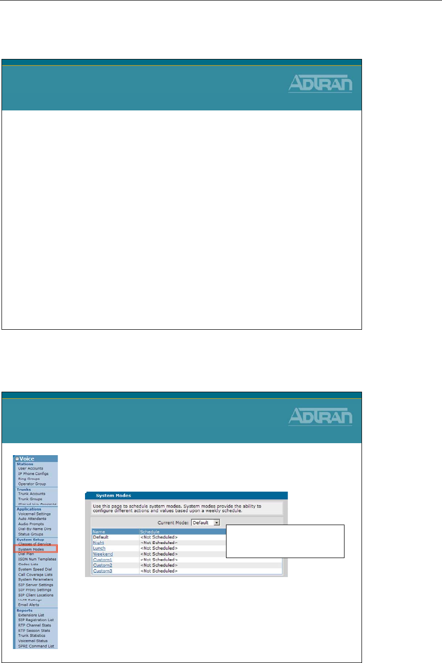
Module 5: NetVanta 7000 Key System Application
5-30 NetVanta IP Telephony Course
System Scheduler Override Mode
Voice System Scheduler
Override Mode
•When a schedule is defined and active, no manual
modes can be enabled, except for the override mode
•Once the override mode is enabled, it stays in effect
until manually disabled
•If override mode is enabled and a scheduled
transition occurs, the override remains and the
transition is ignored
•When the override is disabled, the currently
scheduled mode of operation takes effect
•The user/admin defines the action taken when in the
override mode
System Mode Configuration
Voice System Scheduler
System Mode Configuration
1. Select Voice / System Setup / System Modes
from the NetVanta 7XXX menus
2. Click one of the existing System modes
3. Define schedule for the selected System Mode
By default, NO system mode
commands are configured - the
unit operates in the Default mode
NOTE: Only define a schedule if you want the system mode to
automatically change based on time of day/day of week
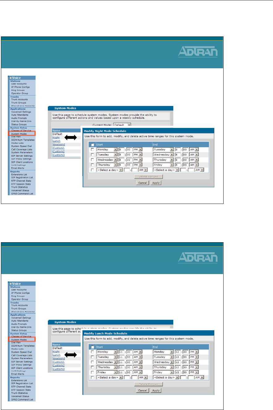
Module 5: NetVanta 7000 Key System Application
NetVanta IP Telephony Course 5-31
System Modes - Example
System Modes
Example
Night System Mode Example
–System will transition into the Night system mode at
5 PM and back to the Default system mode at 8 AM
System Modes - Example
System Modes
Example
Lunch System Mode Example
–System will transition into the Lunch system mode
at 11:30 AM and back to the Default system mode
at 12:30 PM each week day
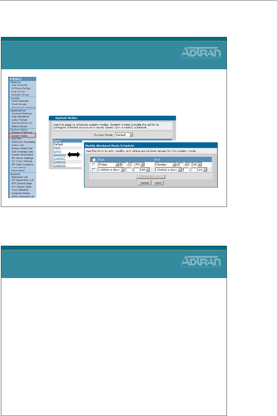
Module 5: NetVanta 7000 Key System Application
5-32 NetVanta IP Telephony Course
System Modes - Example
System Modes
Example
Weekend System Mode Example
–System will transition into the Weekend system
mode at 5 PM Friday and back to the Default
system mode at 8 AM Monday
System Modes - Where can they be applied?
Voice System Modes
Where can they be applied?
•Voice User - Class of Service
–The CoS can be set to change for the user based on the current
system mode
–Defines the types of phone service that will be available to the user
during the time period
•Voice Account – Trunk Number
–Activate different system modes of operation that redirect incoming
calls to a different number depending on the specified mode
•Could have different Auto Attendants based on time and day
•Call Coverage
–Call coverage can be configured per system mode
–The number of rings between call coverage choices can also be set
per system mode
•Voice users, ring groups, and operator group, shared line accounts
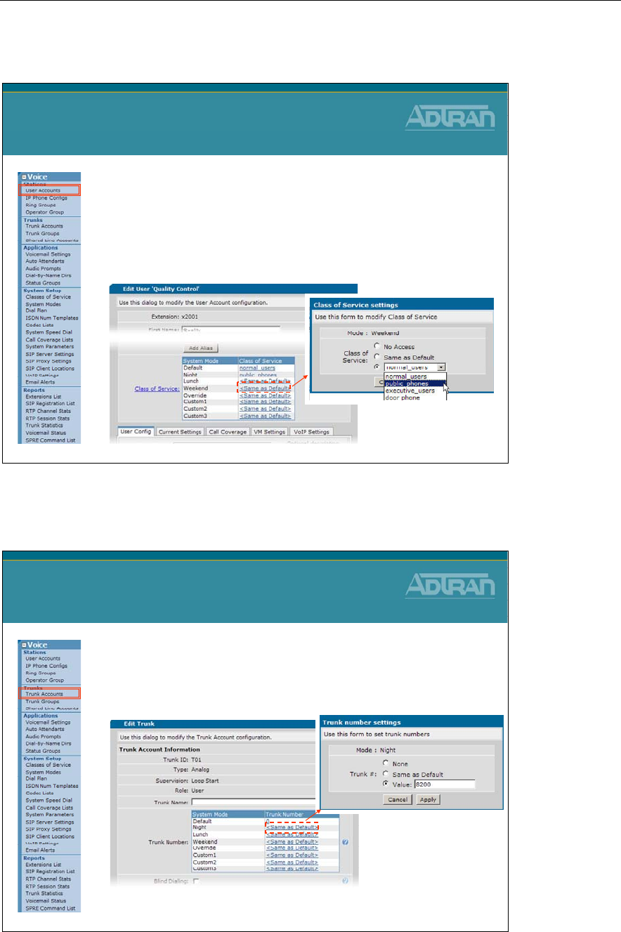
Module 5: NetVanta 7000 Key System Application
NetVanta IP Telephony Course 5-33
Assigning System Modes - User Account CoS
Assigning System Modes
User Account Class of Service
1. Edit an existing voice user
2. Define Class of Service per System Mode
–No Access
–Same as Default
–An existing Class of Service
Assigning System Modes - Trunk Number
Assigning System Modes
Voice Account – Trunk Number
1. Edit an existing Trunk Account
2. Define Trunk Number per System Mode
–None / Same as Default / Value - extension
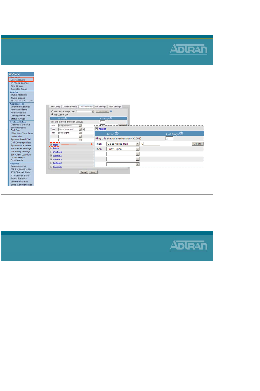
Module 5: NetVanta 7000 Key System Application
5-34 NetVanta IP Telephony Course
Assigning System Modes - Call Coverage
Assigning System Modes
Call Coverage
1. Edit an existing voice user or ring group
2. Define Call Coverage per System Mode
–Voice User Accounts / Ring Group / Operator Group
System Modes - Methods to Change
Voice System Modes
Methods to Change
•Automatically switch based on schedule
•Web
•Auto Attendant
•SPRE Code
•BLF/SPRE Code
* If the system is in override, the unit will ignore any schedule that exists
- The unit will stay in override until manually changed
- This command is saved into the dynvoice-config file to preserve the
state of the unit in case of power failure
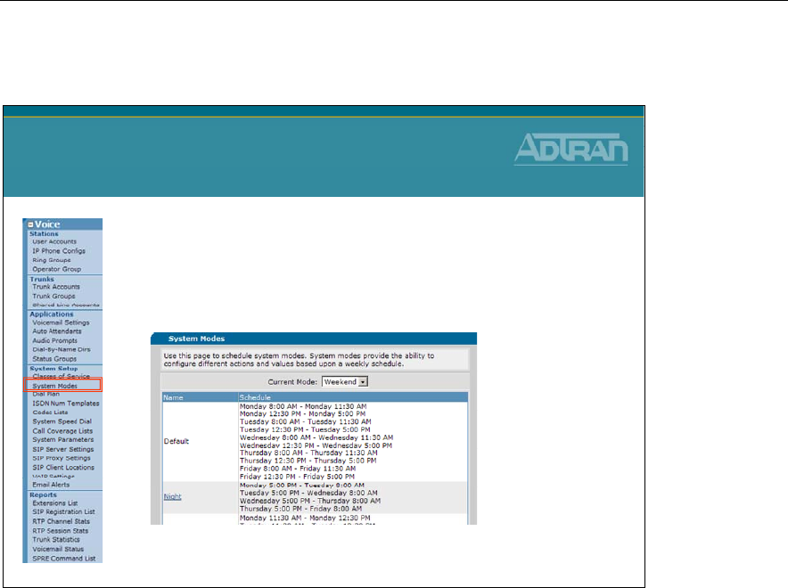
Module 5: NetVanta 7000 Key System Application
NetVanta IP Telephony Course 5-35
Changing System Mode - Switch as Scheduled
Changing System Mode
Switch at Scheduled Time
•The System Mode will automatically change
at scheduled time
–If placed in the Override mode, it will no longer change
until taken out of the Override mode
Scheduled Operation
The NetVanta 7000 can be configured to automatically switch System Modes based on a
schedule defined for each System Mode. When a schedule is defined for System Modes,
the only option to disable the schedule is via the Override mode. Override is an
enable/disable function. Once the NetVanta 7000 is in Override mode, it will remain there
until Override is disabled (via BLF, SPRE, Auto Attendant or web interface). Override
functions as a Toggle; to disable Override mode from the Auto Attendant, you must select
Override mode from the choices given.
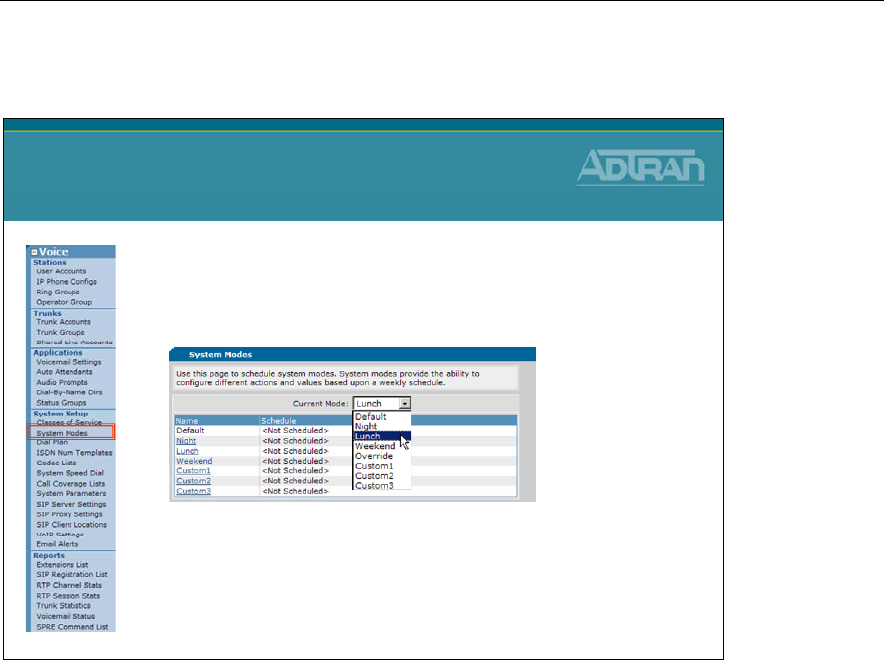
Module 5: NetVanta 7000 Key System Application
5-36 NetVanta IP Telephony Course
Changing System Mode - Manually Change in GUI
Changing System Mode
Manually Change in GUI
•If no day/time schedule has been configured,
the admin can manually set the mode of
operation in the GUI
•Once a mode is selected, the mode stays in
effect until manually changed
NOTE: If a day/time schedule has been defined, the only mode that can be
selected from this menu is Override.
The voice current-mode command can also be used to manually activate a particular
system mode on the unit from the command line.
NV7000 (config)# voice current-mode default
voice current-mode lunch
voice current-mode night
voice current-mode override
voice current-mode weekend
voice current-mode custom1
voice current-mode custom2
voice current-mode custom3
This command is used to put the unit into a specific system mode. The unit remains in the
activated system mode until it is changed manually.
* If a day/time schedule has been defined, the only mode that can be set here is override.
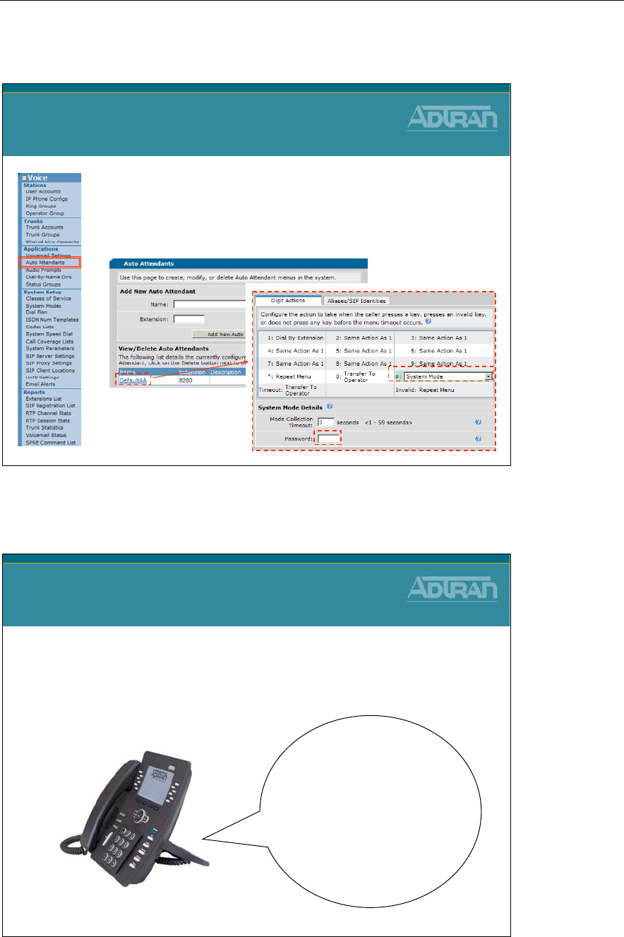
Module 5: NetVanta 7000 Key System Application
NetVanta IP Telephony Course 5-37
Changing System Mode - Auto Attendant
Changing System Mode
Auto Attendant
1. Edit an Auto Attendant
2. Set a Digit Action to System Mode
3. Define Password for System Mode
Changing System Mode - Auto Attendant
Changing System Mode
Auto Attendant
•A voice user who presses the digit action for System
Mode will hear the following:
PASSWORD?
The Current System Mode is Default
To Transition to Night Mode Press 2
To Transition to Lunch Mode Press 3
To Transition to Weekend Mode Press 4
To Transition to Custom1 Mode Press 5
To Transition to Custom2 Mode Press 6
To Transition to Custom3 Mode Press 7
To Transition to Override Mode Press 8
To Cancel Press *
Module 5: NetVanta 7000 Key System Application
5-38 NetVanta IP Telephony Course
Changing System Mode - SPRE Mode
Changing System Mode
SPRE Code
•The Special PREfix (SPRE) code
*20n
can be used to change
the System Mode
•*20n Values for “n”
–0 = Default,
–1 = Night,
–2 = Lunch
–3 = Weekend
–4 = Custom1
–5 = Custom2
–6 = Custom3
–7 = Override
SPRE Codes used to Change System Mode
Dial the SPRE code for the desired System Mode from any phone.
The SPRE Codes to enable/disable System Modes are these:
- *200 – Default
- *201 – Night
- *202 – Lunch
- *203 – Weekend
- *204 – Custom1
- *205 – Custom2
- *206 – Custom 3
-
*207 – Override
Allowing the Change of System Mode
In order to allow a phone to dial a SPRE code or use a BLF key to change the System
Mode, this action must be enabled in the Advanced Permitted Actions for the Class of
Service applied to the desired User Account. This applies to changing to any System Mode
in Manual Operation, or to enabling Override in Scheduled Operation.
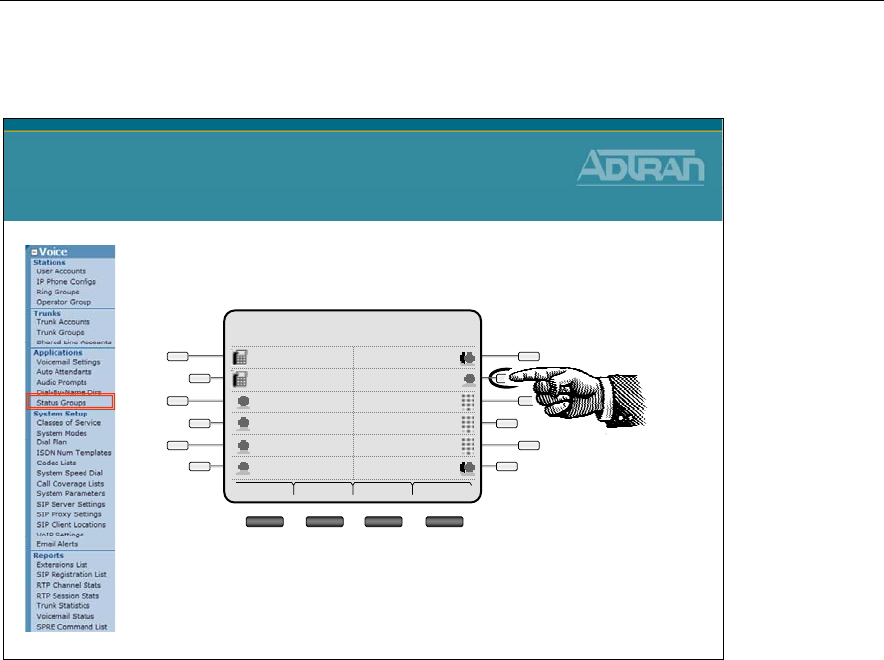
Module 5: NetVanta 7000 Key System Application
NetVanta IP Telephony Course 5-39
Changing System Mode - BLF/SPRE Code
Changing System Mode
BLF/SPRE Code
•System Mode configured as line key
Frank 05/5/08
10:15pm
Mailbox 8001Park 2
SPEEDPark 1
SPEEDWade
SPEEDCheryl
Lunch2003
Default2003
Dial Redial Pickup More
BLF Key in Status Group
A Status Group can be created to use a BLF to switch enable the different System Modes.
A user would press the key associated with the desired System Mode to enable it.
For example, when the customer leaves the office for the day, they would press the Night
key to enable Night mode. When they return to the office in the morning, they would press
the Default mode to return to Default (“Day”) mode. In Manual Operation, the Override
option functions as just another Custom System Mode.
Allowing the Change of System Mode
In order to allow a phone to dial a SPRE code or use a BLF key to change the System
Mode, this action must be enabled in the Advanced Permitted Actions for the Class of
Service applied to the desired User Account. This applies to changing to any System Mode
in Manual Operation, or to enabling Override in Scheduled Operation.

Module 5: NetVanta 7000 Key System Application
5-40 NetVanta IP Telephony Course

Module 5: NetVanta 7000 Key System Application
NetVanta IP Telephony Course 5-41
Key System Applications - Troubleshooting
NetVanta IP Telephony Course
Key System Applications
Troubleshooting
Troubleshooting SLAs
Troubleshooting SLAs
Shared Line Account Review:
•Configuration:
–Is the proper trunk account associated with the SLA?
–Are the proper call types checked in the Accept/Reject
Templates in the SLA Config?
–Is the proper call coverage defined in the SLA Config?
•Check the SLA registration with the phone
–Is SIP password correct in the SLA Config?

Module 5: NetVanta 7000 Key System Application
5-42 NetVanta IP Telephony Course
Troubleshooting System Mode
Troubleshooting System Mode
System Mode Review:
•If “any” schedule has been defined in the Voice
Settings / System Mode screen, the NetVanta 7000 is
operating in the Automatic mode
–System will automatically change based on time and day
–Override Mode is used to take the system out of the
Automatic mode and perform defined Override Mode settings
–Stays in Override Mode until taken out of Override Mode
•Changing System mode with SPRE code or BLF
–The Class of Service setting “Change System Mode” must be
enabled for the admin user that needs this ability
Troubleshooting Auto Answer
Troubleshooting Auto Answer
Hands Free Auto Answer Review:
•No Auto Answer Calls are allowed by default
•Class of Service setting
–Define which users can place Auto Answer Calls
–Template defines who Auto Answer calls can be placed to
•**
is used to place Auto Answer call
•Is feature disabled for user? (SPRE code *971)
–Use SPRE code *970 to enable
Module 5: NetVanta 7000 Key System Application
NetVanta IP Telephony Course 5-43
show interface fxo 0/1
show interface fxo 0/1
•View the statistics for the specified interface
NV7000#
show int fxo 0/1
fxo 0/1 is UP
Two-wire Status: Onhook
Test Status: INACTIVE
No Tests
Impedance: 600 ohms +2.16uF
Transmit Gain: +0.0dB
Receive Gain: +0.0dB
Measured ERL: not available - run 'test erl'
The default Impedance setting is 600 Ω+ 2.16 µF. The unit may require a different setting
to correct echo issues. For assistance, refer to the Echo Return Loss Measurement Guide
on ADTRAN’s Knowledge Base at kb.adtran.com.
show interface fxs 0/1 realtime
show interface fxs 0/1 realtime
•View interface statistics real time
NV7000#
show int fxs 0/1 realtime
--------------------------------------------------------------------------------
fxs 0/1 is UP
Two-wire Status is: Onhook
Test Status is INACTIVE
No Tests
Impedance is: 600 ohms +2.16uF
Transmit Gain is: -6.0dB
Receive Gain is: -3.0dB
Ring voltage is: 50 Vrms
Signal Mode: Loop-Start
Caller ID Format is: Multiple Data Message Format
--------------------------------------------------------------------------------
Exit - 'Ctrl-C', Freeze - 'f', Resume - 'r'
- Onhook
- Offhook
- Ringing
Module 5: NetVanta 7000 Key System Application
5-44 NetVanta IP Telephony Course
debug voice summary
NV7000#
debug voice summary
16:55:22 VOICE.SUMMARY voice user 2005 cos allowed the call to Extensions
16:55:22 VOICE.SUMMARY 2005 is calling 2006 (2006).
16:55:24 VOICE.SUMMARY 2005 is connected to 2006 (2006)
16:55:28 VOICE.SUMMARY Call from 2005 to 2006 (2006) ended by 2006: normal clearing
17:01:54 VOICE.SUMMARY voice user 2006 cos allowed the call to Extensions
17:01:54 VOICE.SUMMARY 2006 is calling T01 (911).
17:01:56 VOICE.SUMMARY 2006 is connected to T01 (911)
17:02:04 VOICE.SUMMARY Call from 2006 to T01 (911) ended by T01: normal clearing
debug voice summary
•View call routing summary real time
–Can confirm proper trunk is being used
Voice Trunk ID
debug interface fxo
debug interface fxo
•View interface events real time
NV7000#
debug interface fxo
2009.07.03 10:24:10 FXO.0/1
Ringing Detected
670041432 ms
2009.07.03 10:24:12 FXO.0/1 Ringing Removed 670043432 ms
2009.07.03 10:24:12 FXO.0/1 Normal Battery Detected 670043432 ms
2009.07.03 10:24:13 FXO.0/1
Offhook
670044481 ms
2009.07.03 10:24:13 FXO.0/1 Loop Current found - Battery detected, reset debounce 670044532 ms
2009.07.03 10:24:13 FXO.0/1 Normal Battery Detected 670044532 ms
2009.07.03 10:24:30 FXO.0/1
Loop Current not present - Battery removed,
debounce
670061842 ms
2009.07.03 10:24:30 FXO.0/1 No Battery Detected 670061872 ms
2009.07.03 10:24:31 FXO.0/1
Onhook
670062372 ms
2009.07.03 10:24:31 FXO.0/1 Reverse Battery Detected 670062382 ms
2009.07.03 10:24:31 FXO.0/1 Normal Battery Detected 670062472 ms
2009.07.03 10:24:31 FXO.0/1 Onhook 670062972 ms
- The output above displays an incoming call from the PSTN on trunk FXO 0/1
Incoming Call
Disconnect
Module 5: NetVanta 7000 Key System Application
NetVanta IP Telephony Course 5-45
debug voice phonemanager
debug voice phonemanager
•Display all phone manager event messages real time
NV7000#
debug voice phonemanager
11:25:44:832 PM.0:1 Idle Processed OFFHOOK
11:25:44:832 PM.0:1 State change >> Idle->Requesting Dialtone
11:25:44:832 PM.0:1 Requesting Dialtone CACHG:ReqDigits on primary CA
11:25:44:832 PM.0:1 State change >> Requesting Dialtone->SendingDigits
11:25:46:973 PM.0:1 SendingDigits Digit
2
processed
11:25:48:033 PM.0:1 SendingDigits Digit
0
processed
11:25:49:194 PM.0:1 SendingDigits Digit
0
processed
11:25:50:454 PM.0:1 SendingDigits Digit
3
processed
11:25:50:455 PM.0:1 State change >> SendingDigits->Call Pending
11:25:50:457 PM.2003 Ca:0 SipPM_Idle rcvd: CAS_Ringing
* Partial output displayed
- Could also use “debug voice toneservices” to see tone events
View digits as
entered from
Analog phone

Module 5: NetVanta 7000 Key System Application
5-46 NetVanta IP Telephony Course
Module Summary
Module Summary
•At the end of this module, you should be able to:
•Recognize NetVanta 7000 Key System Applications
•Configure Shared Line Accounts
•Enable Hands Free Auto-Answer
•Configure System Modes
•Conduct Voice Troubleshooting in a NetVanta 7000
Key System Application

Module 6: NetVanta 7000 IP PBX
Application

Module 6: NetVanta 7000 IP PBX Application
6-2 NetVanta IP Telephony Course

Module 6: NetVanta 7000 IP PBX Application
NetVanta IP Telephony Course 6-3
Module Objectives
Module Objectives
•Introduce NetVanta 7000 IP PBX Applications
•Configure Voice Trunks – T1-RBS/ISDN PRI
•Create and Configure a Multi-level Auto Attendant
•Create and Configure Dial by Name Directories
•Configure Busy Lamp Field/ Public Park Zones
•Log Calls – Station Message Detail Recording
(SMDR)
•Conduct Voice Troubleshooting in a NetVanta 7000
IP PBX Application

Module 6: NetVanta 7000 IP PBX Application
6-4 NetVanta IP Telephony Course
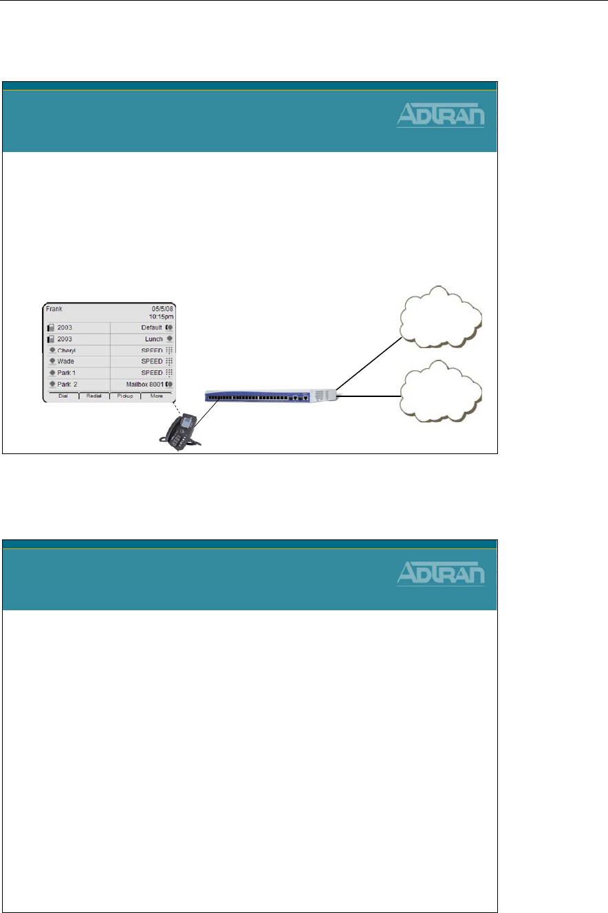
Module 6: NetVanta 7000 IP PBX Application
NetVanta IP Telephony Course 6-5
NetVanta 7000 - IP PBX Application
NetVanta 7000
IP PBX Application
•What is a PBX?
–Private Branch eXchange
–Designed for larger businesses
–Offer more features/functionality than key systems
–Outside lines are selected dynamically based on dialed
phone number
PSTN
NetVanta 7000
ISDN
Long Distance
Local
NetVanta 7000 - IP PBX Application
NetVanta 7000
IP PBX Application
•Configuration of the following IP PBX Application
features are introduced in this section:
–Voice Trunks – T1-RBS/ISDN PRI
–Multi-level Auto Attendant
–Dial by Name Directories
–Busy Lamp Field/ Public Park Zones
–Logging Calls - SMDR

Module 6: NetVanta 7000 IP PBX Application
6-6 NetVanta IP Telephony Course
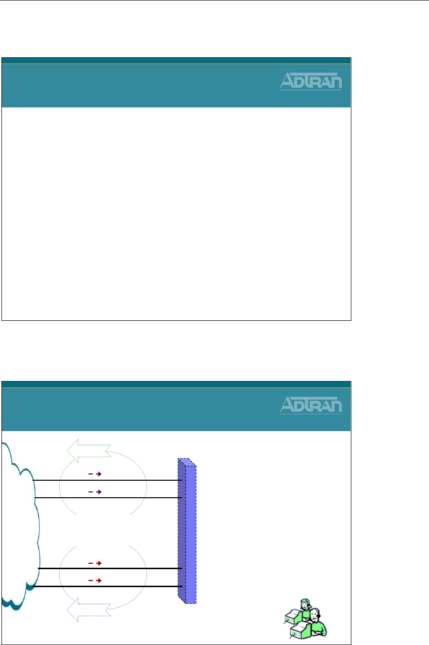
Module 6: NetVanta 7000 IP PBX Application
NetVanta IP Telephony Course 6-7
Voice Trunks
NetVanta IP Telephony Course
Voice Trunks Account/Group Review
Voice Trunks – T1 – RBS
Voice Trunks – T1 – ISDN PRI
Voice Trunks - Accounts/Groups Review
NetVanta 7000 Voice Trunks
Accounts/Groups Review
PSTN
T01
T02
T03
T04
Operator
Operator
RG 8001
RG 8001
Trunk Group 1
FXO 0/1
FXO 0/2
FXO 2/1
FXO 2/2
* Trunk Accounts T01 - T02
- Inbound calls go to Operator
* Trunk Account T03 - T04
- Inbound calls go to Ring Group
* Trunk Group 1
- All calls allowed out at a low cost
* Trunk Group 2
- All calls allowed out at a high cost
Trunk Group 2
Low Cost
High Cost Ring Group
8001
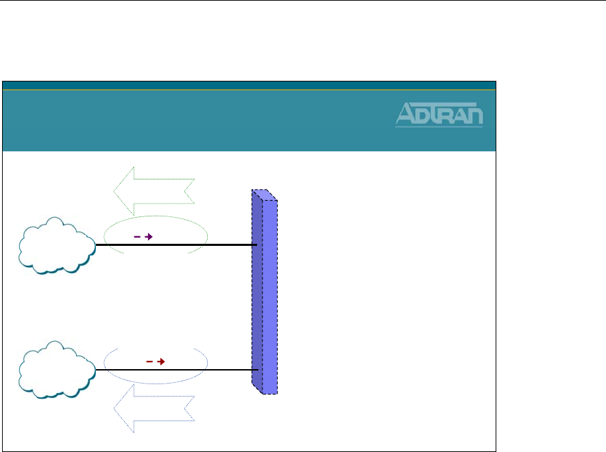
Module 6: NetVanta 7000 IP PBX Application
6-8 NetVanta IP Telephony Course
Voice Trunks - Accounts/Groups Review
NetVanta 7000 Voice Trunks
Accounts/Groups Review
T01
T02
AA 8200
DID
Trunk Group 1
FXO 0/2
T1 1/1
* Trunk Accounts T01
- Inbound calls go to Auto Attendant
* Trunk Account T02
- Inbound calls goes to DID
* Trunk Group 1
- Local calls allowed out at low cost
- Long distance allowed at high cost
* Trunk Group 2
- Long distance allowed out at low cost
- Local calls allowed at high cost
LD
LOCAL
Trunk Group 2
Local – High $
LD – Low $
Local – Low $
LD – High $
Analog
ISDN
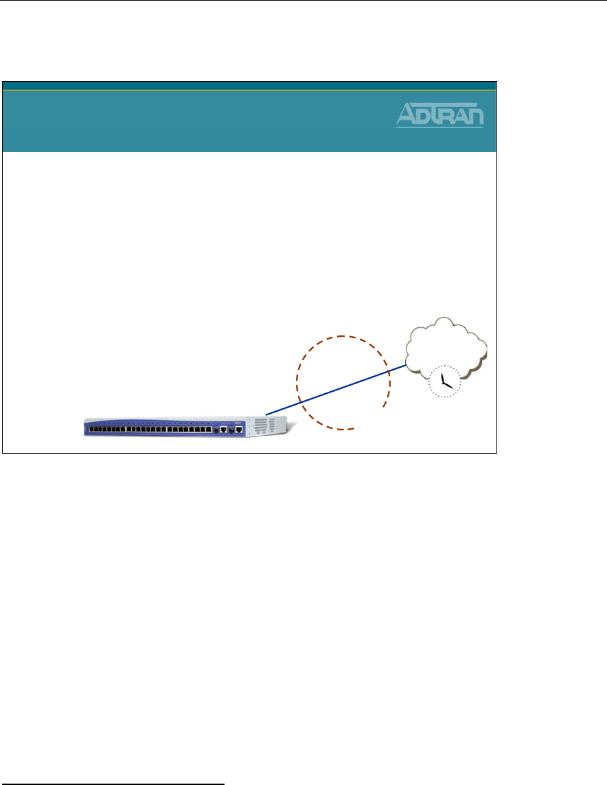
Module 6: NetVanta 7000 IP PBX Application
NetVanta IP Telephony Course 6-9
T1-RBS Trunk - Basic Configuration Steps
T1-RBS Trunk
Basic Configuration Steps
1. Set Primary system Timing Source
2. Configure Physical T1 Interface
–DS0 selection, framing, line coding
3. Create Trunk Account
–Supervision settings defined by Telco
•E&M Wink, E&M Immediate, Loop Start, Ground Start, Feature Group D
–Assign DS0s
4. Create Trunk Group
–Add Trunk Account members
–Define outbound call templates
PSTN
NetVanta 7000
Trunk Account
Trunk Group
T1
1/1
T1-RBS
The term T1 circuit is commonly used to identify a multiplexed 24 channel, 1.544 Mbps
digital data circuit providing communications between two facilities or from a local service
provider. T1 refers to the transport of a DS-1 formatted signal onto a copper, fiber or
wireless medium for deploying voice, data or video-conferencing services. T1 connections
provide up to 24 64 kbps DS0 channels and use the RBS scheme to pass call signaling
status information.
Robbed Bit Signaling: The process where the least significant bit in the 6th and 12th
frame (of a SF T1) and the 16 & 24th frame (of an ESF T1) is "robbed" for voice
A,B,C,and D signaling bits. These signaling bits indicate on/off-hook conditions etc.
The T1-RBS trunk can terminate a line from the provider (Telco) or be a termination point
acting as the network to a PBX or key system requiring a T1 circuit.
T1-RBS Trunk Configuration
1. Set primary system timing source
2. Configure physical T1 interface and DSO selection
3. Create a T1-RBS Trunk Account
4. Create a Trunk Group

Module 6: NetVanta 7000 IP PBX Application
6-10 NetVanta IP Telephony Course
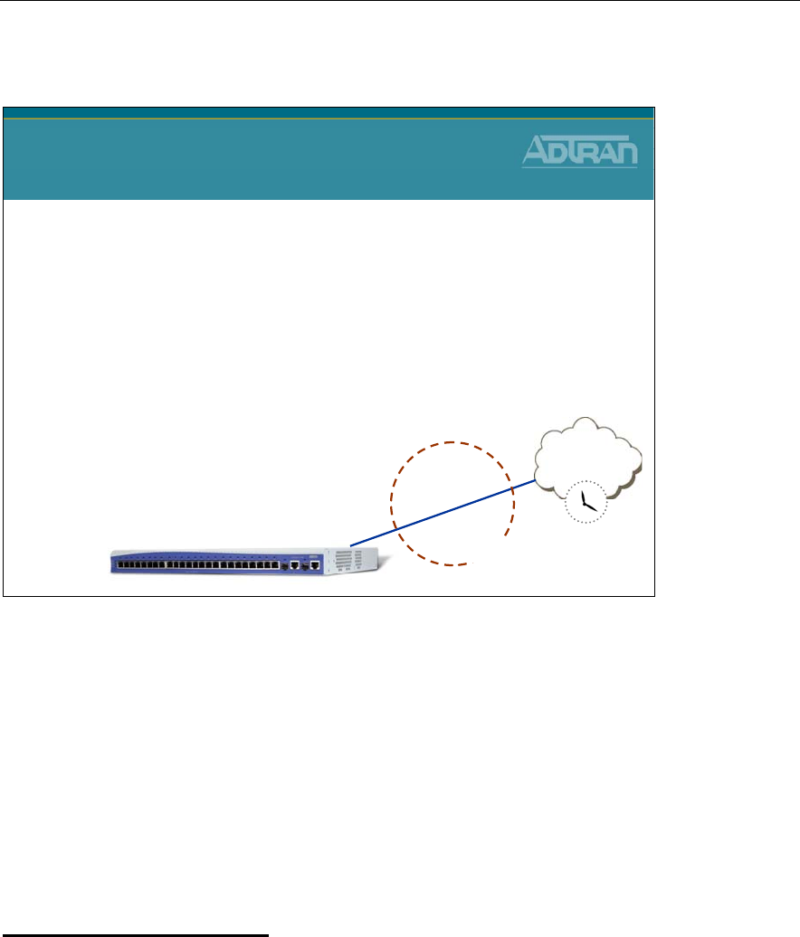
Module 6: NetVanta 7000 IP PBX Application
NetVanta IP Telephony Course 6-11
T1-ISDN PRI Trunk - Basic Configuration Steps
T1-ISDN PRI Trunk
Basic Configuration Steps
1. Set Primary system Timing Source
2. Configure Physical T1 Interface
–DS0 selection, framing, line coding
3. Configure logical ISDN PRI Interface
–ISDN switch type, emulation mode, digits transferred, etc…
4. Create Trunk Account
–Select ISDN interface
5. Create Trunk Group
–Add Trunk Account members
–Define outbound call templates
PSTN
NetVanta 7000
Trunk Account
Trunk Group
T1
1/1
T1-ISDN PRI
The Integrated Digital Service Network (ISDN) Primary Rate Interface (PRI) is a circuit
composed of 23 bearer (B) channels and 1 data (D) channel. ISDN PRI is an international
standard for digital communications, allowing a full range of enhanced services supporting
voice and data. The 23 B channels are used to transmit voice and/or data over an all-digital
public switched telephone network. The D channel is used to transmit out-of-band
signaling for the B channels that controls dialing numbers and features like call waiting.
The NetVanta 7000 can support the following ISDN PRI switch types: 1. National ISDN 2.
AT&T 4ESS, Lucent 5ESS. Nortel DMS-100, and Euro ISDN.
ISDN Trunk Configuration
1. Set primary system timing source
2. Configure physical T1 interface and DSO selection
3. Configure logical PRI interface
4. Create an ISDN Trunk Account
5. Create an ISDN Trunk Group

Module 6: NetVanta 7000 IP PBX Application
6-12 NetVanta IP Telephony Course
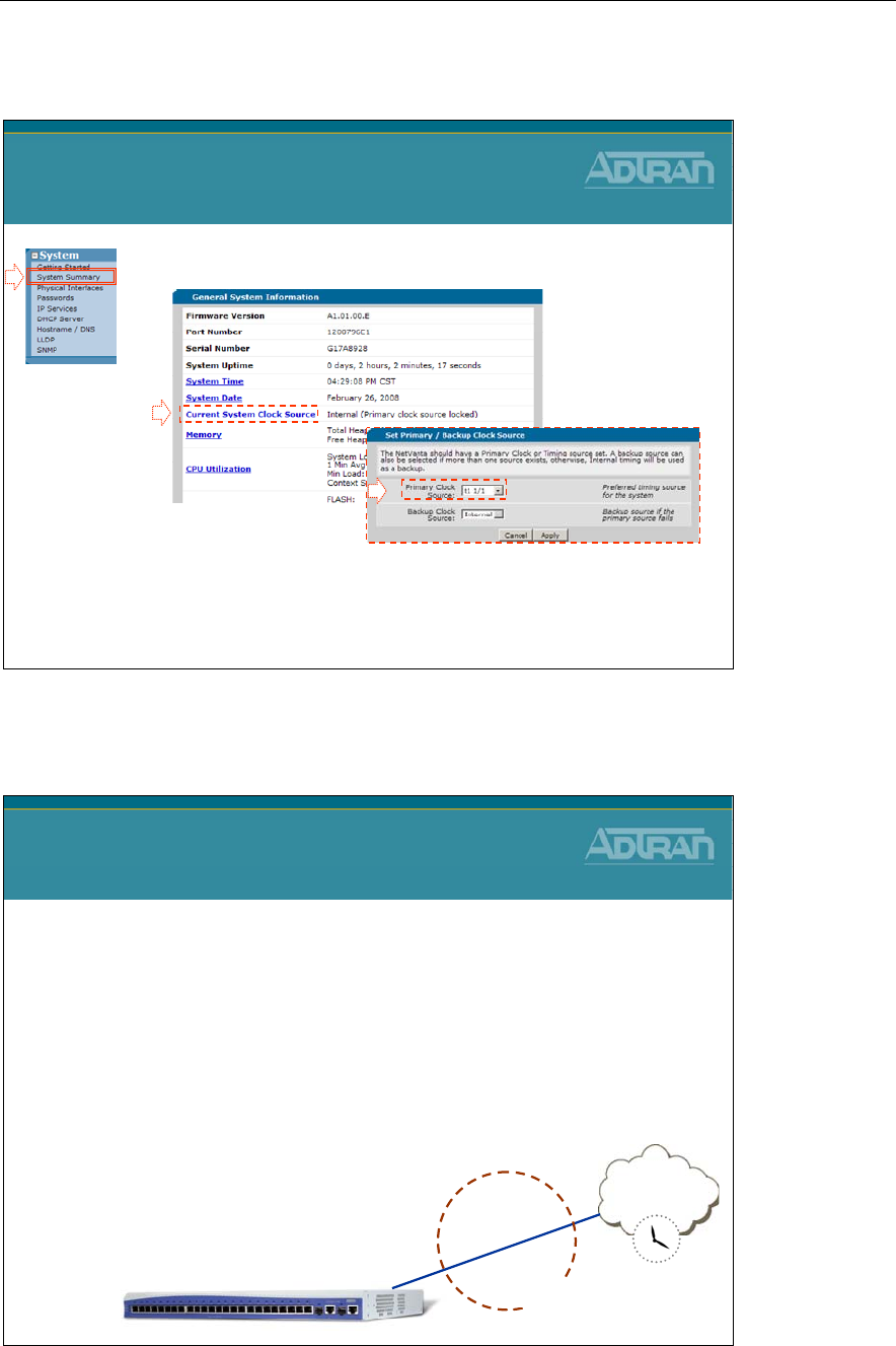
Module 6: NetVanta 7000 IP PBX Application
NetVanta IP Telephony Course 6-13
1) Set System Timing
1. Select the System / System Summary menu
2. Click Current System Clock Source
3. Define the preferred system timing source
T1 Trunk Configuration
1) Set System Timing
1
2
3
T1-ISDN PRI Trunk - Basic Configuration Steps
T1-ISDN PRI Trunk
Basic Configuration Steps
1. Set Primary system Timing Source
2. Configure Physical T1 Interface
–DS0 selection, framing, line coding
3. Configure logical ISDN PRI Interface
–ISDN switch type, emulation mode, digits transferred, etc…
4. Create Trunk Account
–Select ISDN interface
5. Create Trunk Group
–Add Trunk Account members
–Define outbound call templates
PSTN
NetVanta 7000
Trunk Account
Trunk Group
T1
1/1
T1-ISDN PRI
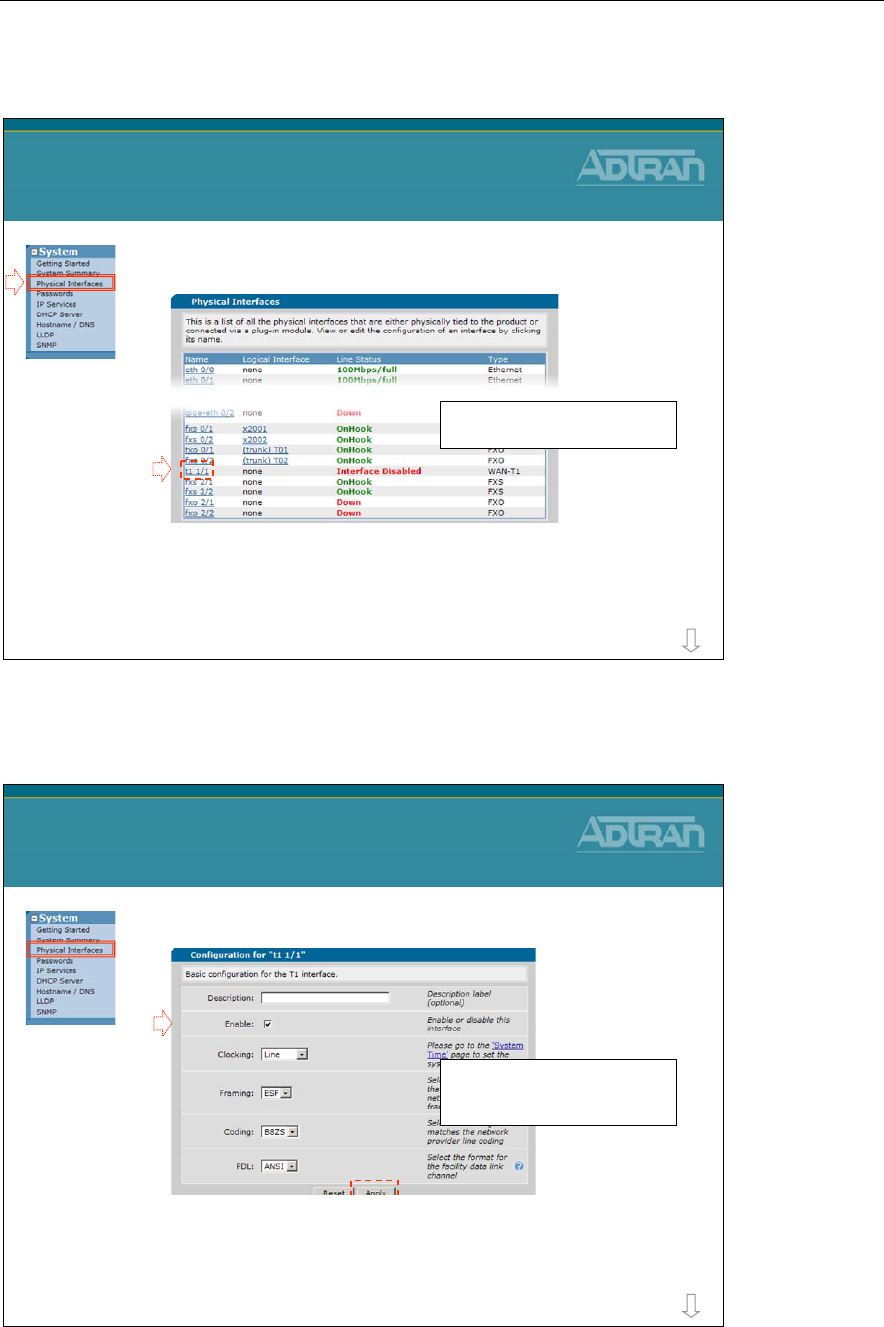
Module 6: NetVanta 7000 IP PBX Application
6-14 NetVanta IP Telephony Course
2) Configure Physical T1
1. Select the System / Physical Interfaces menu
2. Click the T1 interface to be edited
T1 Trunk Configuration
2) Configure Physical T1
The built in and modular physical
interfaces display on this screen
1
2
more
2) Configure Physical T1
3. Enable the T1 interface
–You must click the Apply button before continuing
to the next step (DS0 configuration)
T1 Trunk Configuration
2) Configure Physical T1
3
The T1 parameters are usually left
at default but can be changed to
match customers network
more
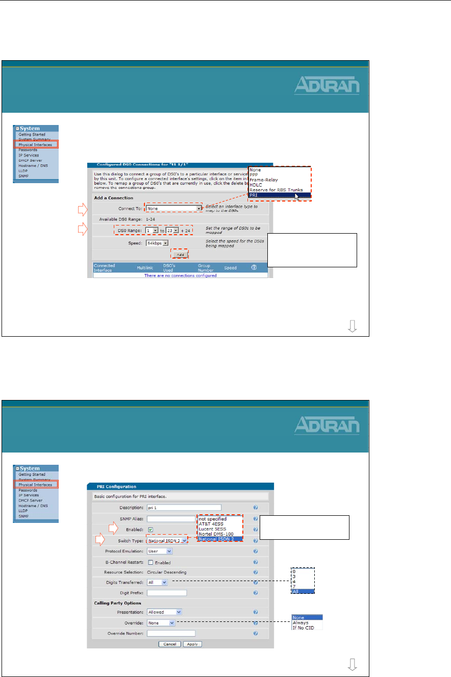
Module 6: NetVanta 7000 IP PBX Application
NetVanta IP Telephony Course 6-15
2) Configure Physical T1
4. Add a PRI Connection
5. Define the DS0 Range for this connection
T1-PRI Trunk Configuration
2) Configure Physical T1
4
Click Add when ready to
create this logical PRI
connection
5
more
3) Configure PRI Interface
1. Enable the Logical PRI Connection
2. Define the ISDN Switch Type
T1-PRI Trunk Configuration
3) Configure PRI Interface
1
Remaining PRI
parameters are optional
2
more
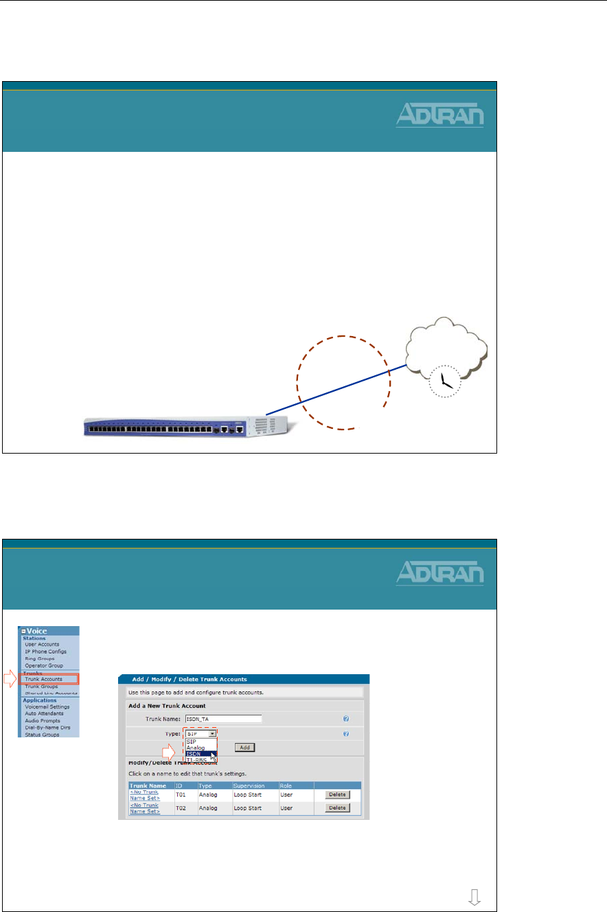
Module 6: NetVanta 7000 IP PBX Application
6-16 NetVanta IP Telephony Course
T1-ISDN PRI Trunk - Basic Configuration Steps
T1-ISDN PRI Trunk
Basic Configuration Steps
1. Set Primary system Timing Source
2. Configure Physical T1 Interface
–DS0 selection, framing, line coding
3. Configure logical ISDN PRI Interface
–ISDN switch type, emulation mode, digits transferred, etc…
4. Create Trunk Account
–Select ISDN interface
5. Create Trunk Group
–Add Trunk Account members
–Define outbound call templates
PSTN
NetVanta 7000
Trunk Account
Trunk Group
T1
1/1
T1-ISDN PRI
4) Create Trunk Account
1. Select the Voice / Trunks / Trunk Accounts
menu
2. Create an ISDN Trunk Account
–Enter name, set type to ISDN, and then click ADD
T1-PRI Trunk Configuration
4) Create Trunk Account
1
2
more
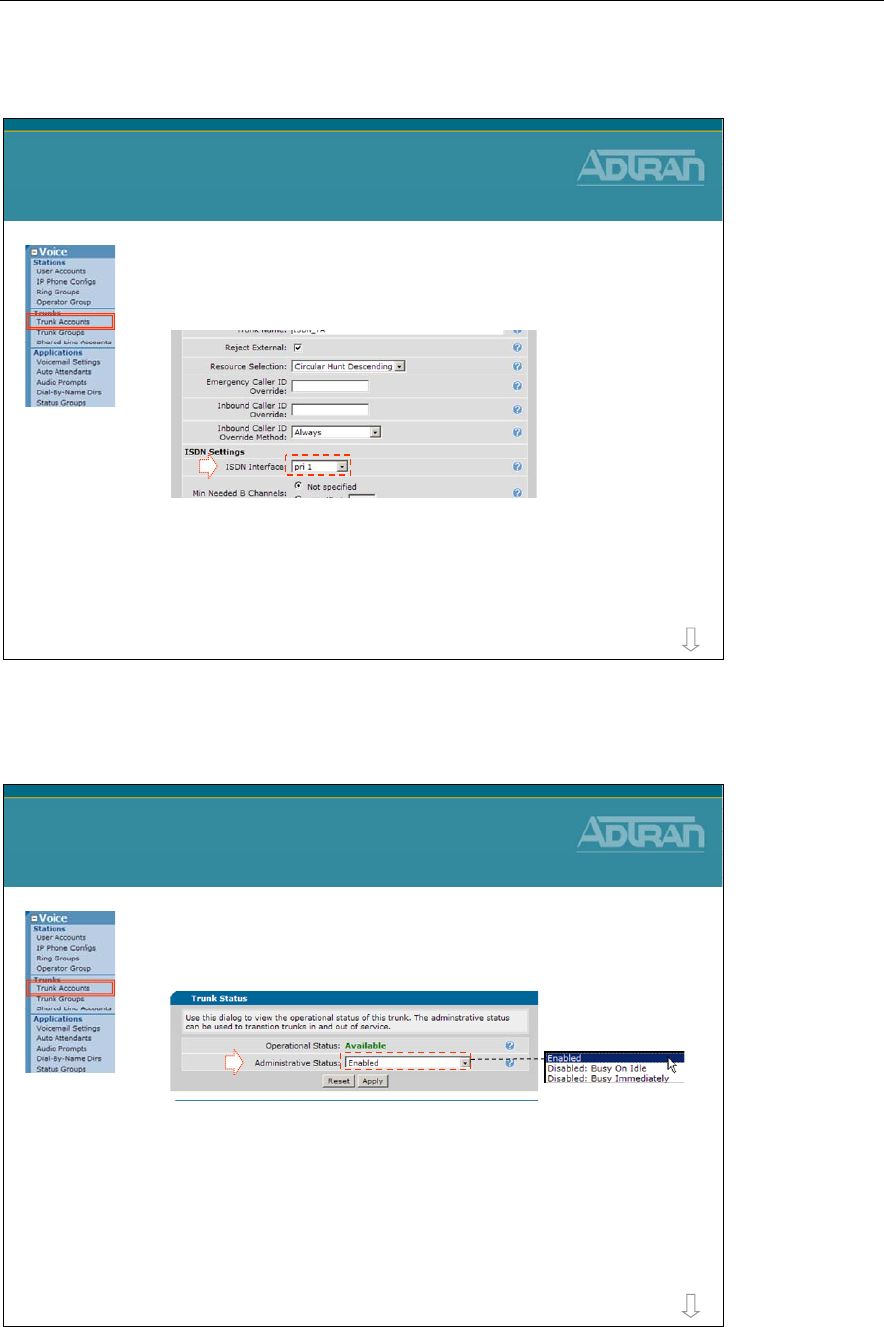
Module 6: NetVanta 7000 IP PBX Application
NetVanta IP Telephony Course 6-17
4) Create Trunk Account
3. Select the ISDN interface “PRI 1”
–The logical “PRI 1” interface was created in the
“Connect To” step of the T1 configuration
T1-PRI Trunk Configuration
4) Create Trunk Account
3
more
4) Create Trunk Account
•Optional: Administrative Status
–Enabled by default
–Configurable Trunk status Options:
•Enabled - Trunk operates as normal
•Disabled: Busy On Idle - Current calls stay active, but no
new calls are accepted
•Disabled: Busy Immediately - All current calls are torn
down, and no new calls are accepted
T1-PRI Trunk Configuration
4) Create Trunk Account
more
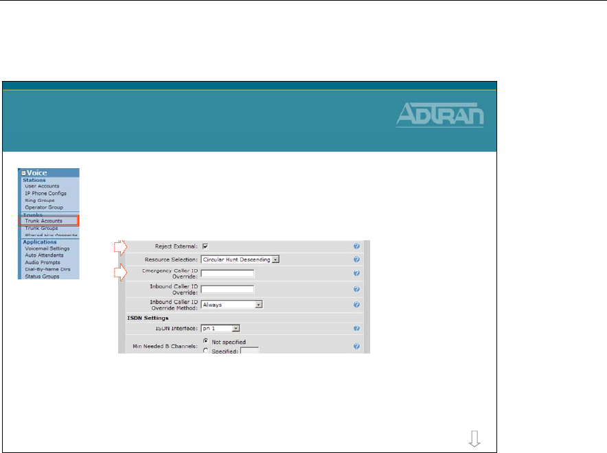
Module 6: NetVanta 7000 IP PBX Application
6-18 NetVanta IP Telephony Course
4) Create Trunk Account
•Optional: Reject External
–Unselect to allow trunk to trunk calls
•Optional: Emergency Caller ID Override
–Specify the calling party number presented on
outbound emergency calls
T1-PRI Trunk Configuration
4) Create Trunk Account
more
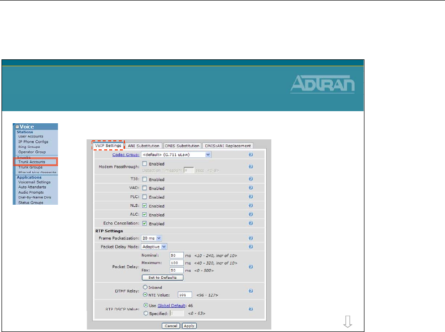
Module 6: NetVanta 7000 IP PBX Application
NetVanta IP Telephony Course 6-19
ISDN TA – VoIP Settings Tab
•Optional: Adjust VoIP settings for this interface
T1-PRI Trunk Configuration
4) Create Trunk Account
more
The VoIP Settings tab allows you to edit the trunk’s voice over IP settings like codec
group, VAD, and RTP settings.
Codec Group
Select the codec group to use for this station account.
Modem Passthrough
When Modem Passthrough is enabled and an existing call detects a modem or fax tone, the
unit will automatically renegotiate with the far end to be modem-compatible (switch to
G.711, all voice improvements turned off, packet delay set to Fax).
T38
When T.38 is enabled and an existing call detects a fax tone, the unit will automatically
renegotiate with the far end to be T.38.
VAD
When Voice Activity Detection is enabled, silence is not transmitted over the network,
only audible speech. When VAD is enabled, the sound quality is slightly degraded but the
connection monopolizes much less bandwidth.
PLC
Enables/disables Packet Loss Concealment. When enabled, the unit will try to reconstruct
sound lost from dropped packets.

Module 6: NetVanta 7000 IP PBX Application
6-20 NetVanta IP Telephony Course
NLS
Enables/disables the echo canceller's Non-Linear Suppression. When enabled, acoustic
echo should be reduced.
ALC
Enables/disables the Automatic Leveling Control. When enabled, reduces received RTP
signals to a predefined level.
Echo Cancellation
When enabled, reflected noise is cancelled from the transmitted voice signal. Echo
cancellation should normally only be disabled if the voice station is connected to a fax
machine or modem.
RTP Settings
Frame Packetization
Select the number of audio samples in ms (1 frame/sample is 10 ms) included in a single
RTP packet.
Packet Delay Mode
Configures the operation mode of the jitter buffer for VoIP calls involving this account.
• Adaptive - The buffer's delay starts at the nominal delay setting but will increase up to
the delay setting if it detects that an intolerable number of packets are being discarded
due to jitter. Conversely, the buffer will decrease the amount of delay if it can afford to.
• Fixed - The buffer's delay stays at the nominal setting at all times.
Packet Delay
Configures various packet delay settings for this account.
• Nominal - For voice calls, the nominal delay value represents the desired amount of
packet delay. In adaptive mode, the buffer may increase this value up to the maximum
delay. In fixed mode, the delay is constantly set at this value.
• Maximum - For voice calls, the maximum delay value represents the maximum delay
to which the adaptive jitter buffer can grow.
• Fax - If Modem Passthrough is enabled and modem/fax tones are detected, the packet
delay setting will be switched to this value.
DTMF Relay
Select how DTMF tones are to be transmitted over RTP. If out of band (NTE), also enter
the NTE value.
RTP DSCP Value
Select the DiffServe code point for this station's RTP packets. Either use the global default
(which will change as the global default changes) or specify a value for this station only.
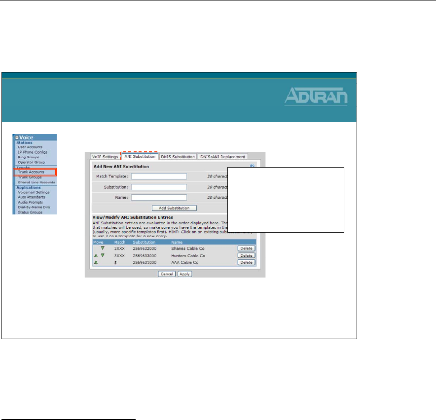
Module 6: NetVanta 7000 IP PBX Application
NetVanta IP Telephony Course 6-21
ISDN TA – ANI Substitution Tab
•Optional: Add ANI substitution
–Examples:
•match ani "2XXX" substitute "2569632000" name "Shanes Cable Co"
•match ani "3XXX" substitute "2569633000" name "Hunters Cable Co"
•match ani "$" substitute "2569631000" name "AAA Cable Co"
T1-PRI Trunk Configuration
4) Create Trunk Account
Order is important:
- Multiple match statements can be
entered per trunk account
- The first valid match that is
found for outbound numbers will
be used
Use ANI Substitution on this trunk to convert out-going Caller ID digits. Additionally, if
supported by this device, the name of the calling party may be defined. Example uses are
shown below:
ANI Substitution Examples:
Match: 2XXX Subst: 2569632000 name Shanes Cable Co
- Calls from 2XXX extensions will have an outbound Caller-id number of 256962000
and Caller-ID name Shanes Cable Co
Match: 3XXX Subst: 2569633000 name Hunters Cable Co
- Calls from 3XXX extensions will have an outbound Caller-id number of 256963000
and Caller-ID name Hunters Cable Co
Match: $ Subst: 2569631000 name AAA Cable Co
- Calls from all other extensions will have an outbound Caller-id number of
256961000 and Caller-ID name AAA Cable Co
Multiple ANI substitution entries can be added to each trunk. The first valid match that is
found for outbound numbers will be used. Order of input is important.
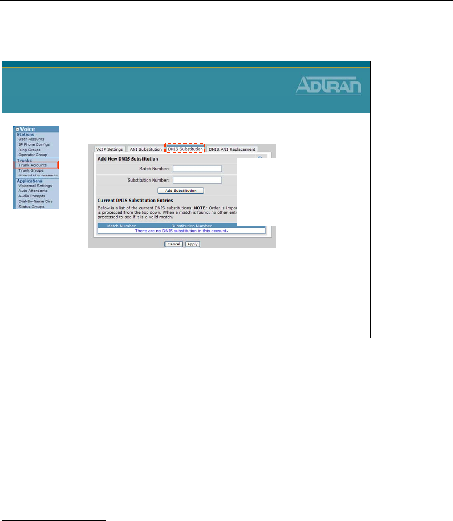
Module 6: NetVanta 7000 IP PBX Application
6-22 NetVanta IP Telephony Course
ISDN TA – DNSI Substitution Tab
•Optional: Add DNIS substitution
–Examples:
•Match: NXX-XXXX Subst: 256-NXX-XXXX
•Match: 1-256-XXX-XXXX Subst: NXX-XXX-XXXX
•Match: 1-NXX-NXX-XXXX Subst: 10-10-220-NXX-NXX-XXXX
T1-PRI Trunk Configuration
4) Create Trunk Account
Order is important:
- Multiple match statements can be
entered per trunk account
- The first valid match that is
found for outbound numbers will
be used
Use DNIS Substitution if a dialed number should be replaced with a specific number of
your choosing.
Match Number
Specifies the dialed number that you are trying to match
Substitution Number
Specifies the number that will be sent in place of the number that was matched
Wildcard Characters:
0-9 Match exact digit only
X Match any single digit 0-9
N Match any single digit 2-9
[ ] Match any digit in the list.
For example [1,4,6] matches 1, 4, and 6 only,
while [1-3,5] matches 1 through 3 and 5
$ Match any number, must occur at end of pattern
- ( ) , Punctuation characters ignored unless used within [ ]

Module 6: NetVanta 7000 IP PBX Application
NetVanta IP Telephony Course 6-23
DNIS Substitution Examples:
1. Match: NXX-XXXX Subst: 256-NXX-XXXX
Format a call for 10 digit dialing
2. Match: 1-NXX-XXX-XXXX Subst: NXX-XXX-XXXX
Format LD call for 10 digit dialing
3. Match: 1-NXX-NXX-XXXX Subst: 10-10-220-NXX-NXX-XXXX
Insert a LD call Pick code for a particular carrier
4. Match: 411 Subst: 256-555-1212
Redirect 411 information calls
Multiple DNIS substitution entries can be added to each trunk. The first valid match that is
found for outbound numbers will be used. Order of input is important.
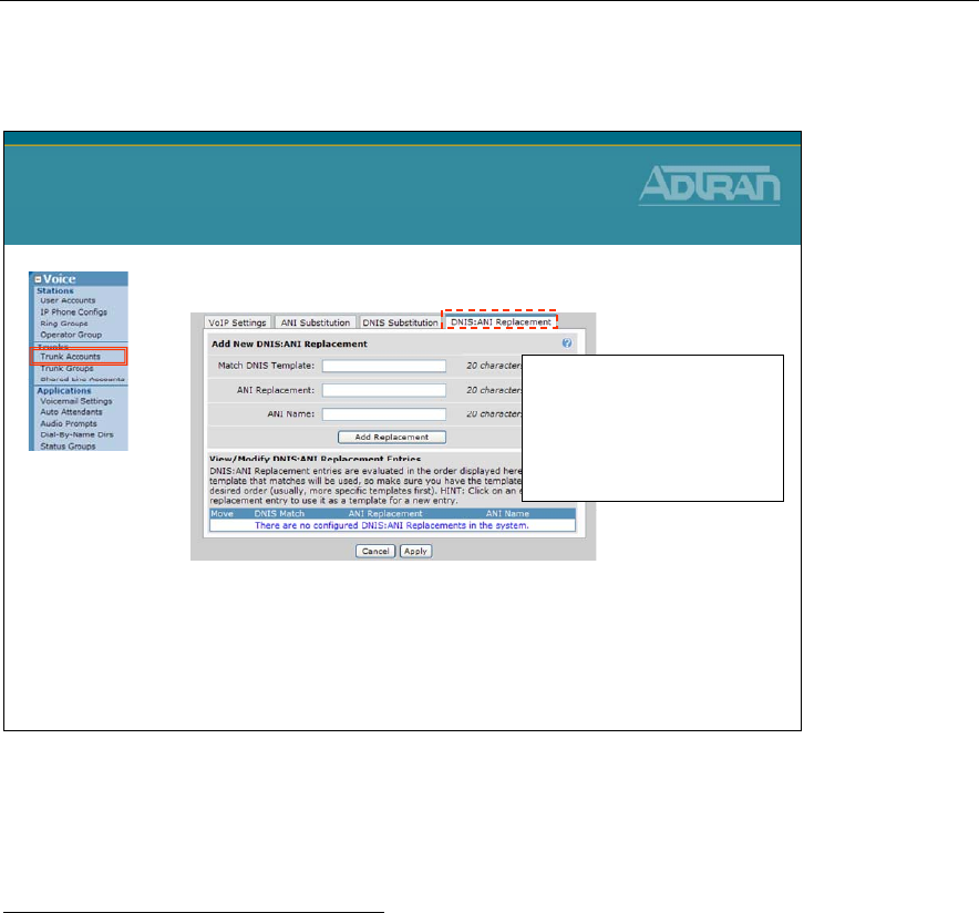
Module 6: NetVanta 7000 IP PBX Application
6-24 NetVanta IP Telephony Course
ISDN TA – DNIS:ANI Replacement Tab
•Optional: Add DNIS:ANI Replacement
–Examples:
•match dnis "1NXXNXXXXXX" replace ani "18884238726"
name "National Network Co“
•match dnis “NXXXXXX" replace ani "9638716 " name
“Huntsville Network Co“
T1-PRI Trunk Configuration
4) Create Trunk Account
Order is important:
- Multiple match statements can be
entered per trunk account
- The first valid match that is
found for outbound numbers will
be used
Use DNIS:ANI Replacement on this trunk to convert out-going Caller ID digits (ANI)
based on the digits dialed(DNIS). Additionally, if supported by this device, the name of the
calling party may be defined. Example uses are shown below:
DNIS:ANI Replacement Examples:
match dnis "1NXXNXXXXXX" replace ani "18884238726" name "National Network Co“
- If a long distance number is dialed, set ANI digits to an 888 number
match dnis “NXXXXXX" replace ani "9638716 " name “Huntsville Network Co“
- If a local number is dialed, set ANI digits to a local number
Multiple DNIS:ANI replacement entries can be added to each trunk. The first valid match
that is found for outbound numbers will be used. Order of input is important.
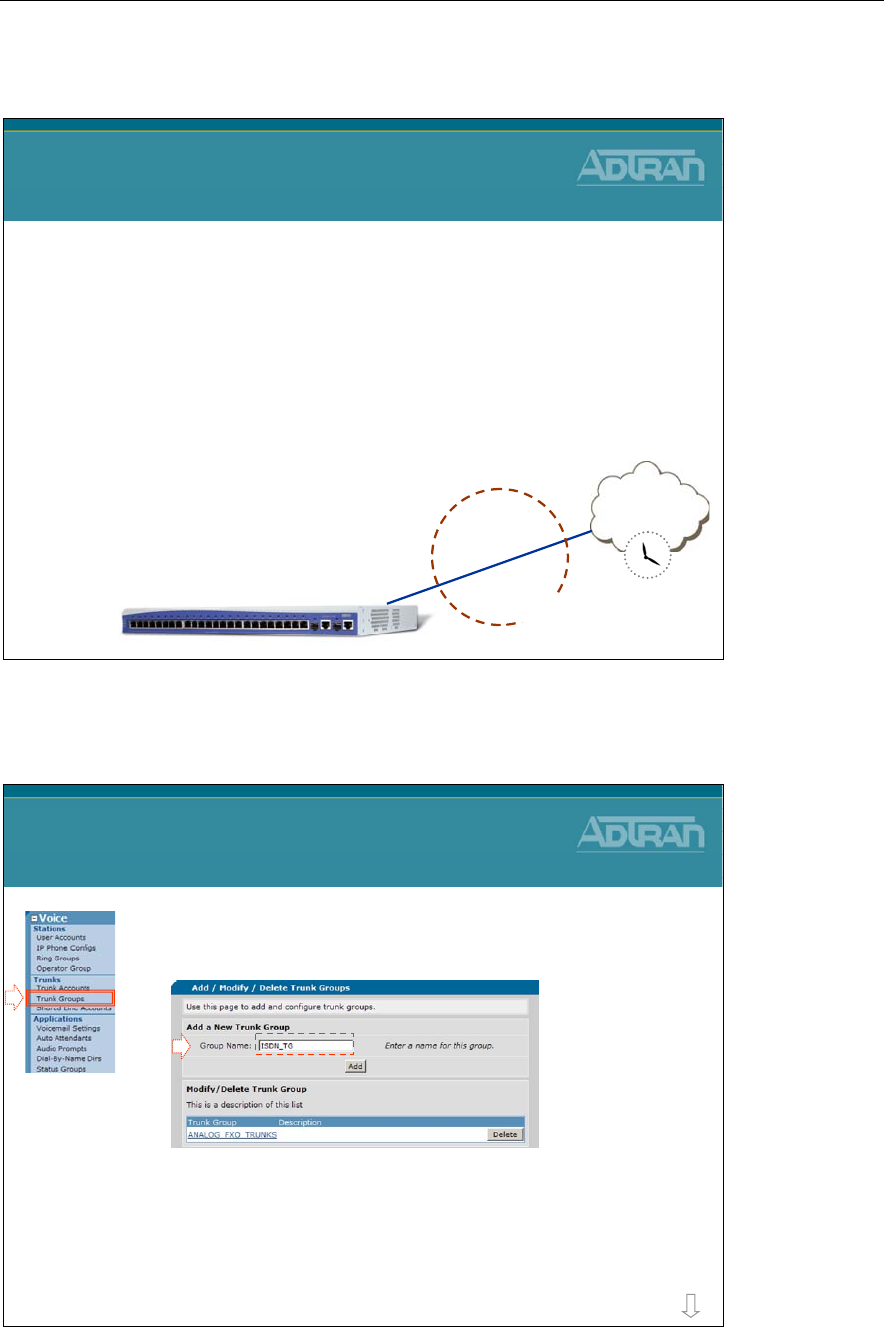
Module 6: NetVanta 7000 IP PBX Application
NetVanta IP Telephony Course 6-25
T1-ISDN PRI Trunk - Basic Configuration Steps
T1-ISDN PRI Trunk
Basic Configuration Steps
1. Set Primary system Timing Source
2. Configure Physical T1 Interface
–DS0 selection, framing, line coding
3. Configure logical ISDN PRI Interface
–ISDN switch type, emulation mode, digits transferred, etc…
4. Create Trunk Account
–Select ISDN interface
5. Create Trunk Group
–Add Trunk Account members
–Define outbound call templates
PSTN
NetVanta 7000
Trunk Account
Trunk Group
T1
1/1
T1-ISDN PRI
5) Create Trunk Group
1. Select the Voice / Trunks / Trunk Groups
menu
2. Create (or edit) a Trunk Group
–Enter new Group Name then click Add
T1-PRI Trunk Configuration
5) Create Trunk Group
1
2
more
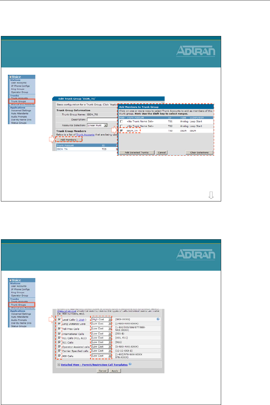
Module 6: NetVanta 7000 IP PBX Application
6-26 NetVanta IP Telephony Course
5) Create Trunk Group
3. Click Add Members to add existing Trunk
Accounts to this trunk group
4. Add the ISDN Trunk Account that was just
created to this Trunk Group
T1-PRI Trunk Configuration
5) Create Trunk Group
3
4
more
5) Create Trunk Group
4. Outbound Call Template
–Define call types allowed out this Trunk Group
–Optional: Define cost for each type of call
•Least cost routing
T1-PRI Trunk Configuration
5) Create Trunk Group
4
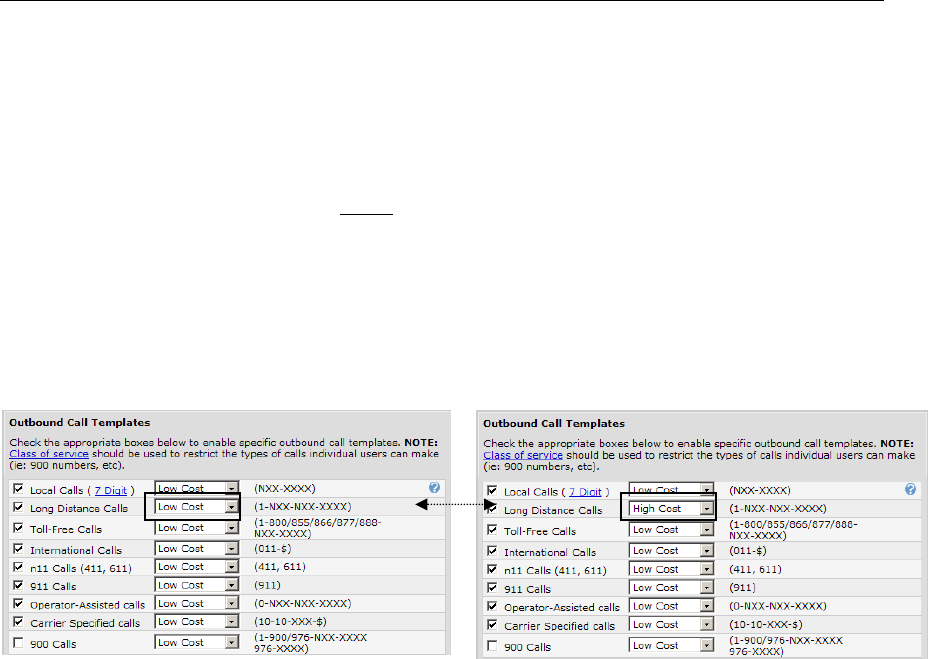
Module 6: NetVanta 7000 IP PBX Application
NetVanta IP Telephony Course 6-27
Emergency 911, Redundancy, and Least Cost Routing
E911 calling is a priority as well as Redundancy. The NetVanta 7000 addresses both of
these issues under Trunk Accounts. For example, an application with multiple analog
trunks will enable E911 dialing on every trunk. No single trunk failure will prohibit E911
access.
Additionally, each of these Trunk Accounts may be placed in separate Trunk Groups. This
will allow each Outbound Call attribute to be assigned a Cost on every trunk. Long
Distance may be less expensive on a particular trunk, so it may be given a lower cost than
long distance dialing on the other trunks. This provides Least Cost Routing.
Long Distance calls will go out the trunk on the left first because it has a lower cost. If
there are no available channels on it then LD calls will go out the trunk on the right.

Module 6: NetVanta 7000 IP PBX Application
6-28 NetVanta IP Telephony Course
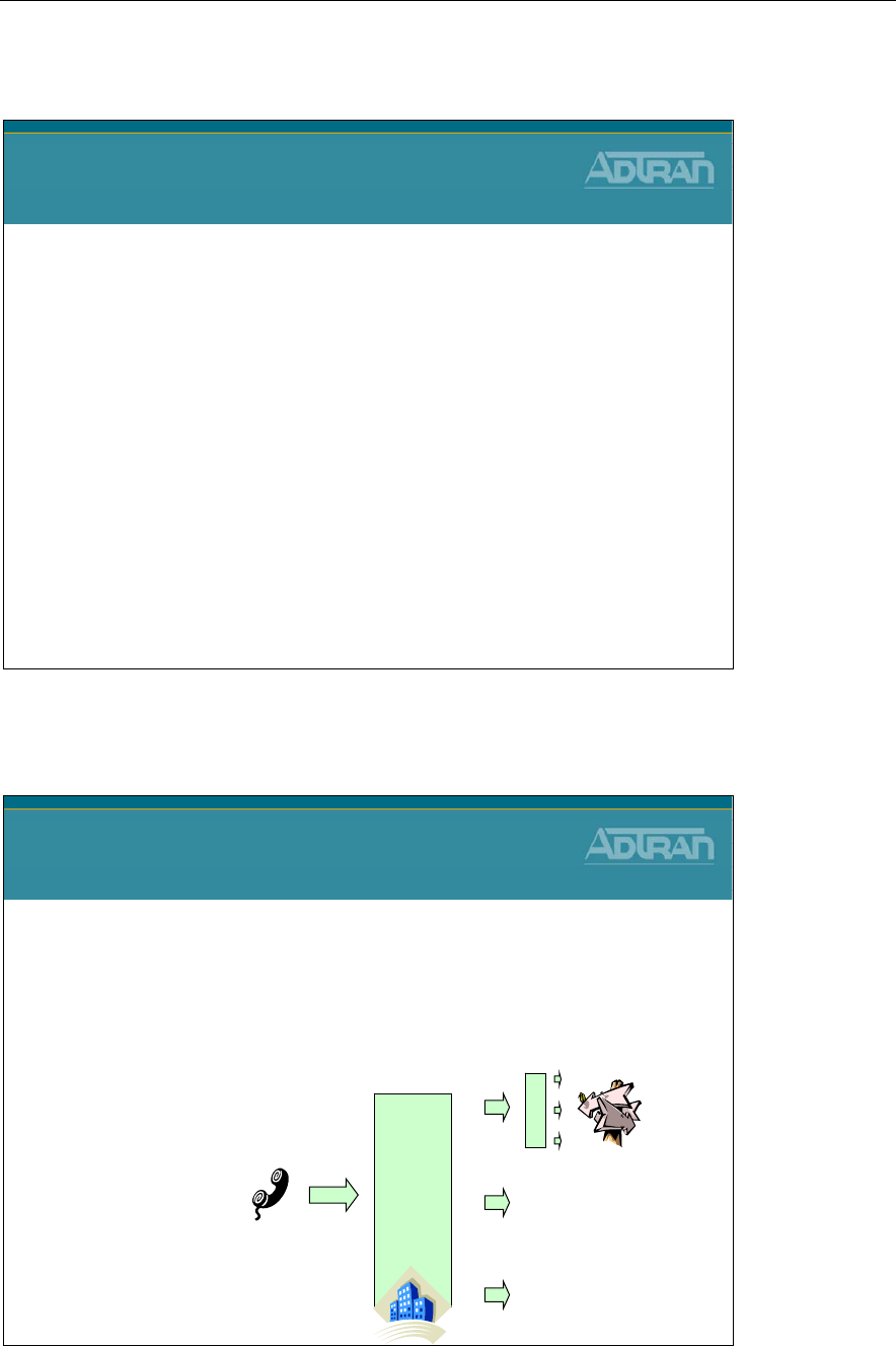
Module 6: NetVanta 7000 IP PBX Application
NetVanta IP Telephony Course 6-29
Auto Attendant
NetVanta IP Telephony Course
Auto Attendant
Multilevel Auto Attendant
Multilevel Auto Attendant
•Multiple Attendants
•Multiple Levels per Attendant
•Several different actions available for each pressed
digit
•Prompt Management
Company
Greeting
1
2
9
:
- Dial by Extension
- Dial by Name
- External Number
- Voice Mailbox
- Operator
- Recording
- Digit Match Action
- Change System Mode
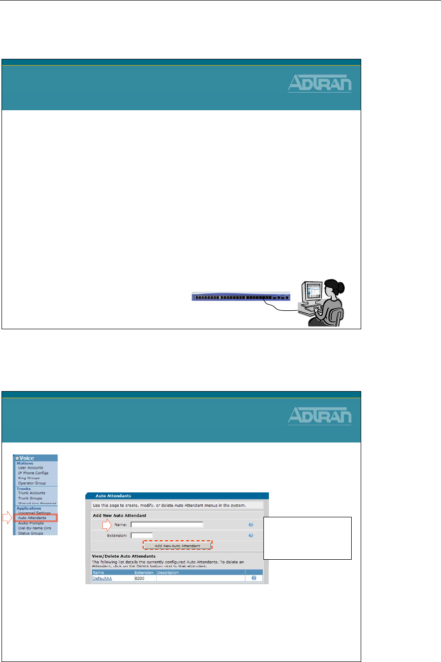
Module 6: NetVanta 7000 IP PBX Application
6-30 NetVanta IP Telephony Course
Auto Attendant - Basic Configuration Steps
Auto Attendant
Basic Configuration Steps
1. Create Auto Attendant Menu
2. Record the audio greeting for Menu prompt
3. Define at least one Digit Action
1) Create AA Menu
1. Select the Voice / Applications / Auto
Attendants menu
2. Create the Main Auto Attendant Menu
–Assign name, AA extension, then click Add
Auto Attendant Configuration
1) Create AA Menu
1
2
Main
8201
- The extension must be a
valid, unique extension
for this new Auto
Attendant.
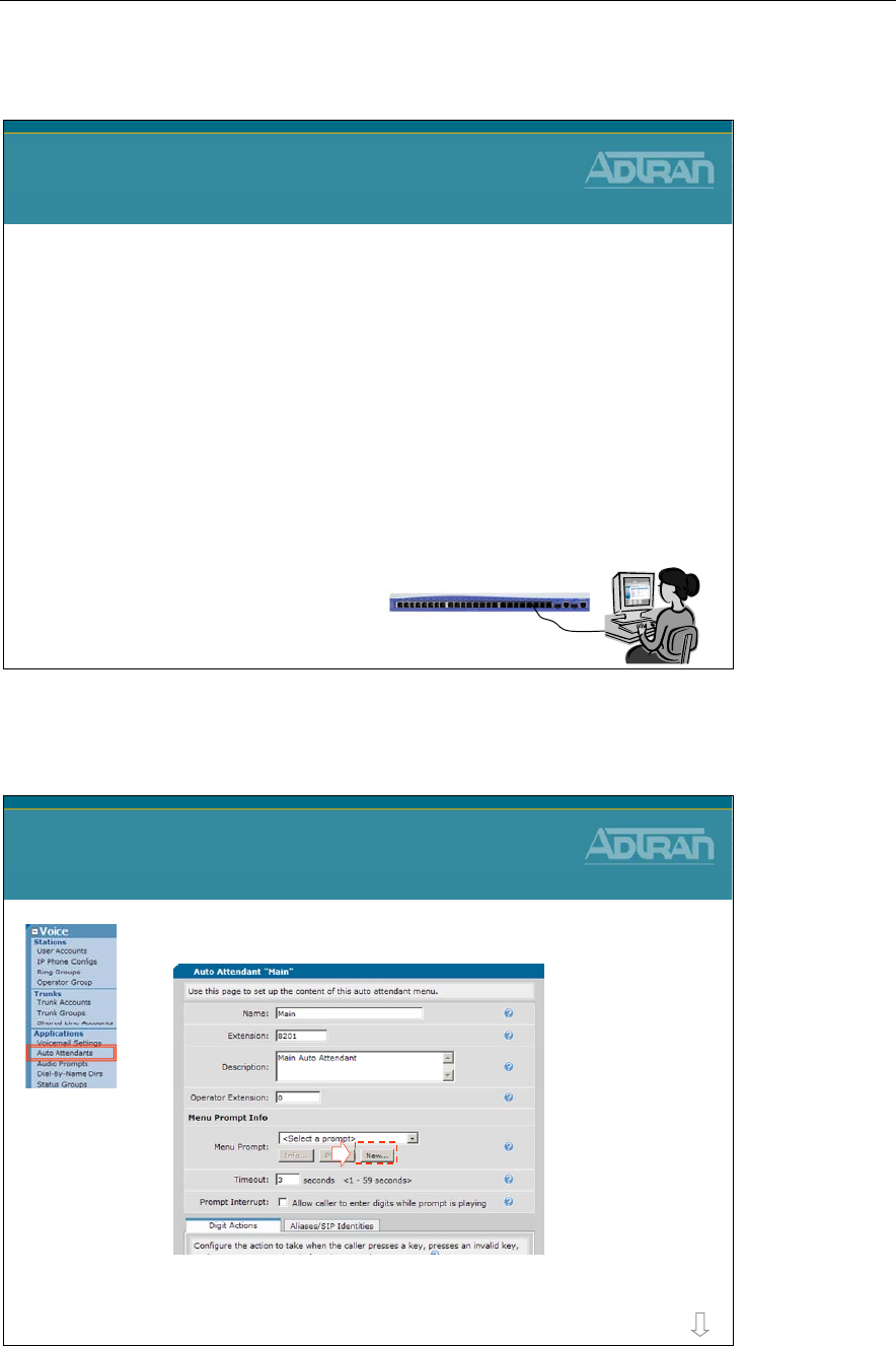
Module 6: NetVanta 7000 IP PBX Application
NetVanta IP Telephony Course 6-31
Auto Attendant - Basic Configuration Steps
Auto Attendant
Basic Configuration Steps
1. Create Auto Attendant Menu
2. Record the audio greeting for Menu prompt
3. Define at least one Digit Action
2) Record Audio Greeting
Auto Attendant Configuration
2) Record Audio Greeting
1
1. Record the audio greeting for the Menu prompt
more
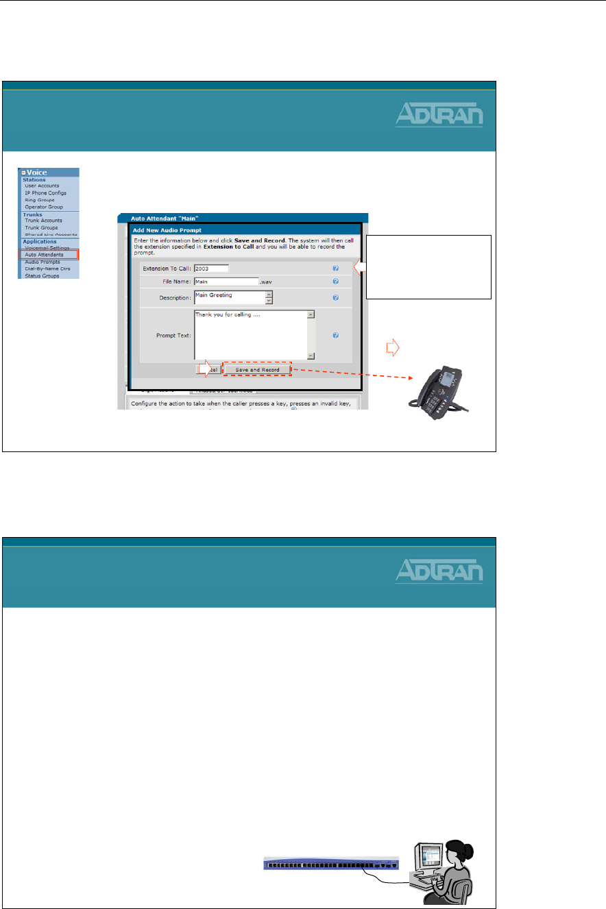
Module 6: NetVanta 7000 IP PBX Application
6-32 NetVanta IP Telephony Course
2) Record Audio Greeting
Auto Attendant Configuration
2) Record Audio Greeting
Answer phone
Record Greeting
3
x2003
4
1. Record the audio greeting for Menu prompt
(Continued…)
2
Enter extension to call,
File name of WAV file,
optional description and
prompt text
Auto Attendant - Basic Configuration Steps
Auto Attendant
Basic Configuration Steps
1. Create Auto Attendant Menu
2. Record the audio greeting for Menu prompt
3. Define at least one Digit Action
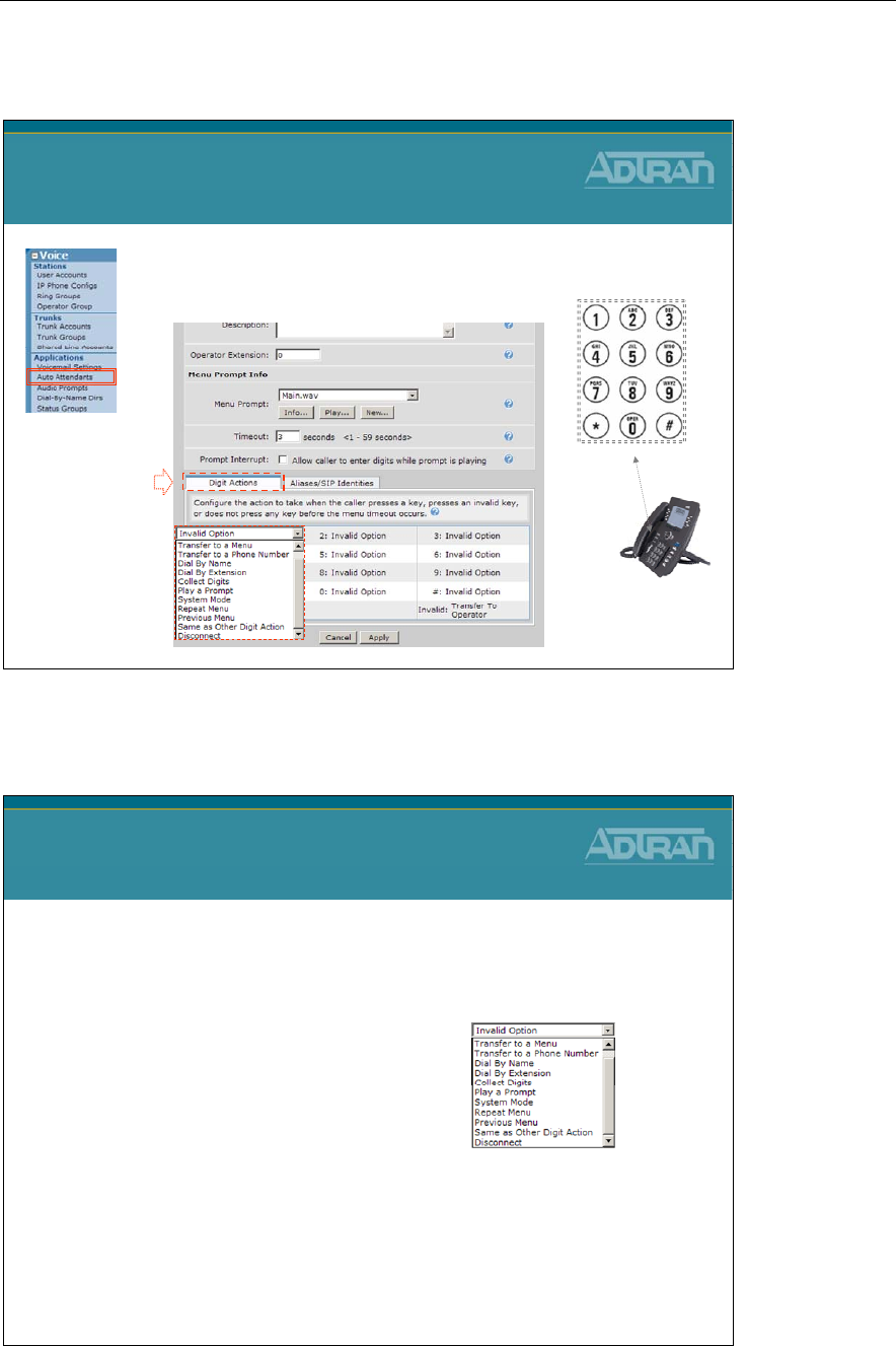
Module 6: NetVanta 7000 IP PBX Application
NetVanta IP Telephony Course 6-33
3) Define Digit Actions
Auto Attendant Configuration
3) Define Digit Actions
1
1. Define at least one Digit Action
Auto Attendant - Digit Actions
Auto Attendant
Digit Actions
•Different actions available for each pressed digit:
–Transfer to a Menu
–Transfer to a Phone Number
–Dial By Name
–Dial By Extension
–Collect Digits
–Play a Prompt
–System Mode
–Repeat Menu
–Previous Menu
–Same as Other Digit Action
–Disconnect
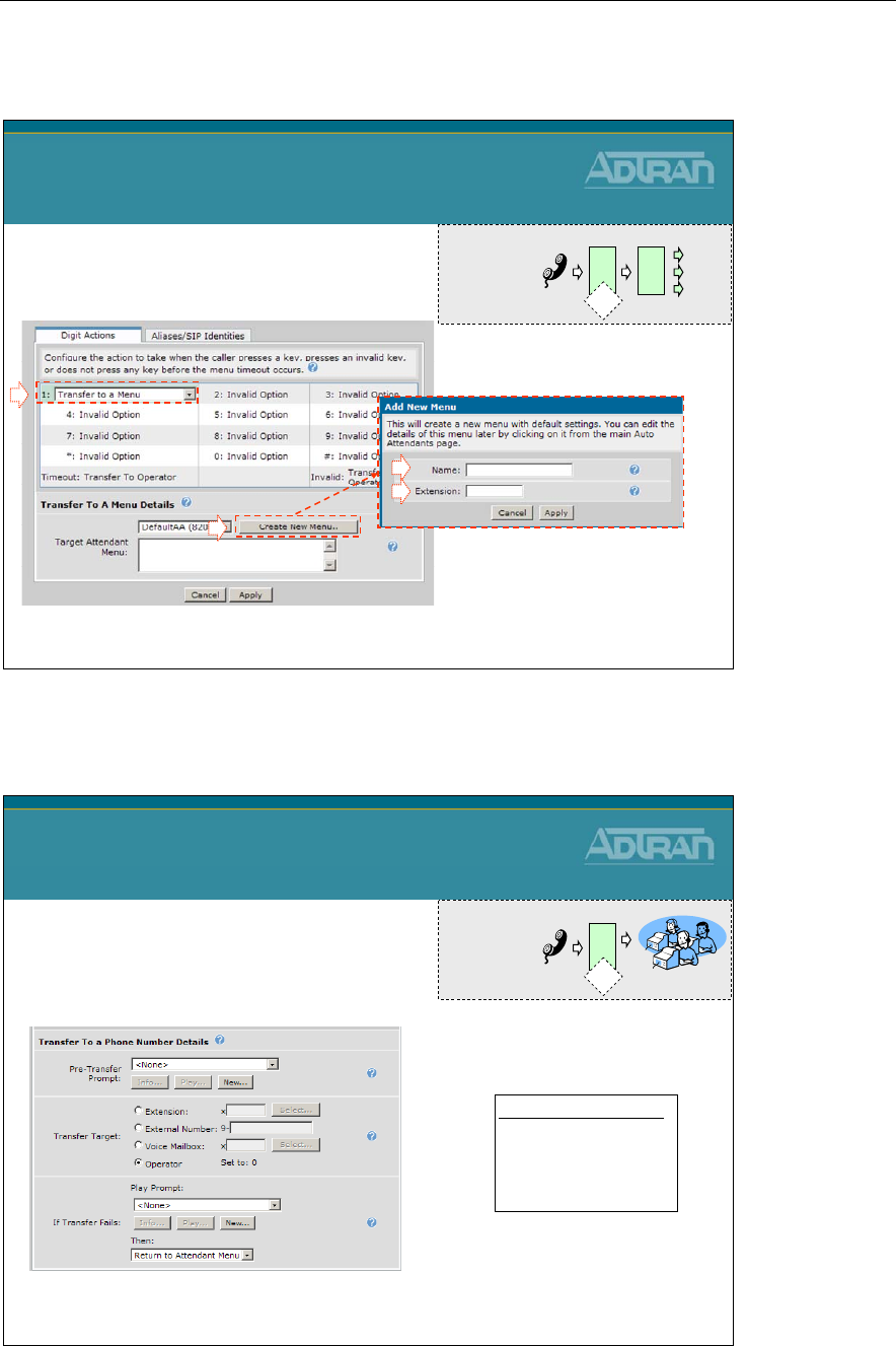
Module 6: NetVanta 7000 IP PBX Application
6-34 NetVanta IP Telephony Course
AA Digit Actions - Transfer to a Menu
Auto Attendant Digit Actions
Transfer to a Menu
•Control of the call is passed to a
different Auto Attendant
- The new Auto Attendant menu is
created here but can be edited later
1
2
3
4
CustSrv
8202
A A
1
A A
User presses 1to
go to another menu
AA Digit Actions - Transfer to a Phone #
Auto Attendant Digit Actions
Transfer to a Phone Number
•The caller is transferred to a
specified number or voicemail box
Valid Transfer Targets
- Extension
- External Number
- Voice Mailbox
-Operator
3Sales
A A
User presses 3for the
Sales Department
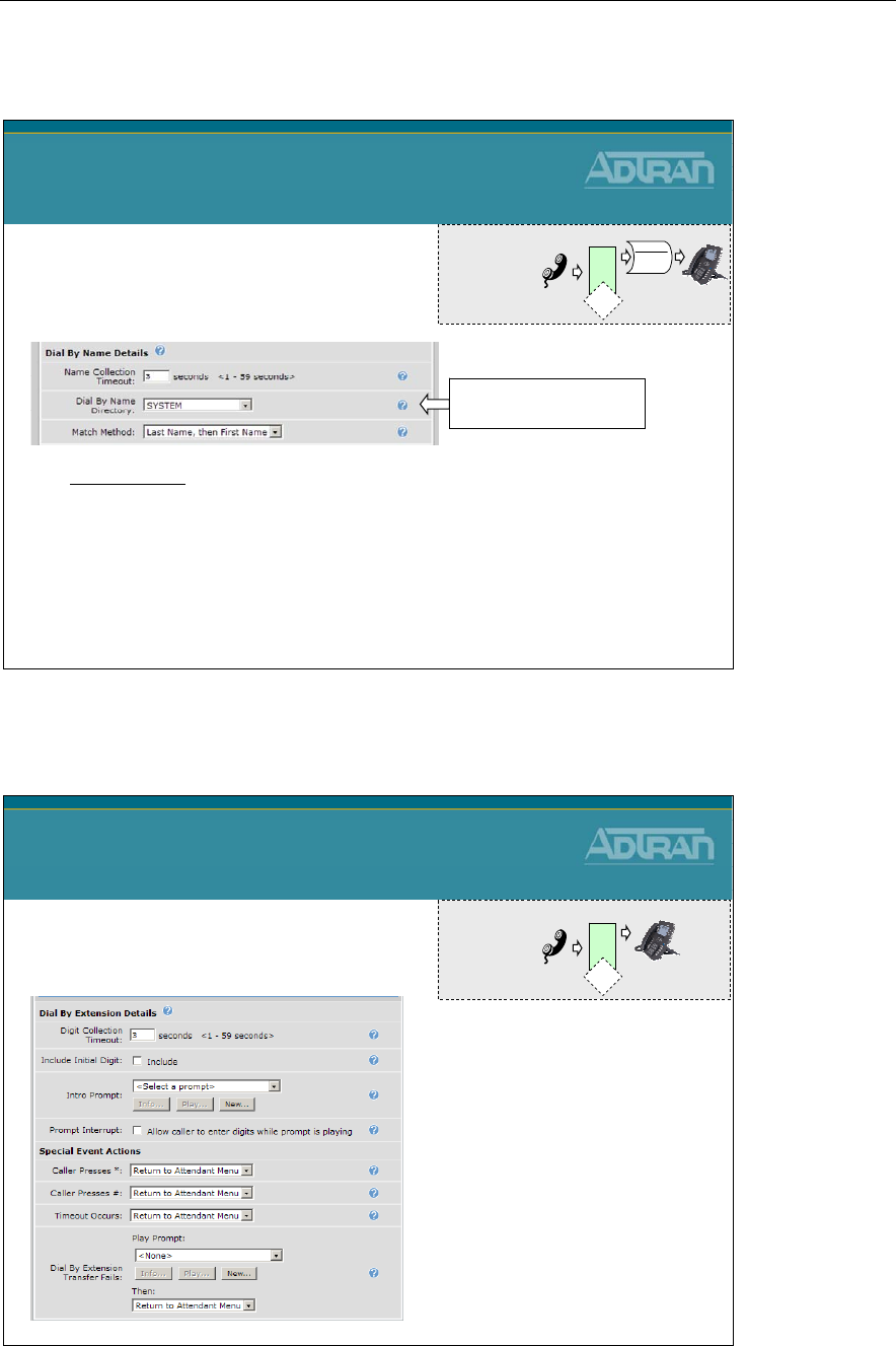
Module 6: NetVanta 7000 IP PBX Application
NetVanta IP Telephony Course 6-35
AA Digit Actions - Dial By Name
Auto Attendant Digit Actions
Dial By Name
•Matches the caller's input
against a defined set of names
- The default SYSTEM dial by name directory contains all users that are
included in the System directory
Select Existing Dial By
Name Directory
Match Methods
- Last Name, then First Name
- First Name, then Last Name
- Either method
Directory
Thad
Annette
Thad
th
A A
User presses
th (84) for Thad
AA Digit Actions - Dial By Extension
2003 x2003
A A
User presses 2003
for known extension
Auto Attendant Digit Actions
Dial By Extension
•Transfers the call to an extension
entered in by the caller
"If you know your
party's extension..."
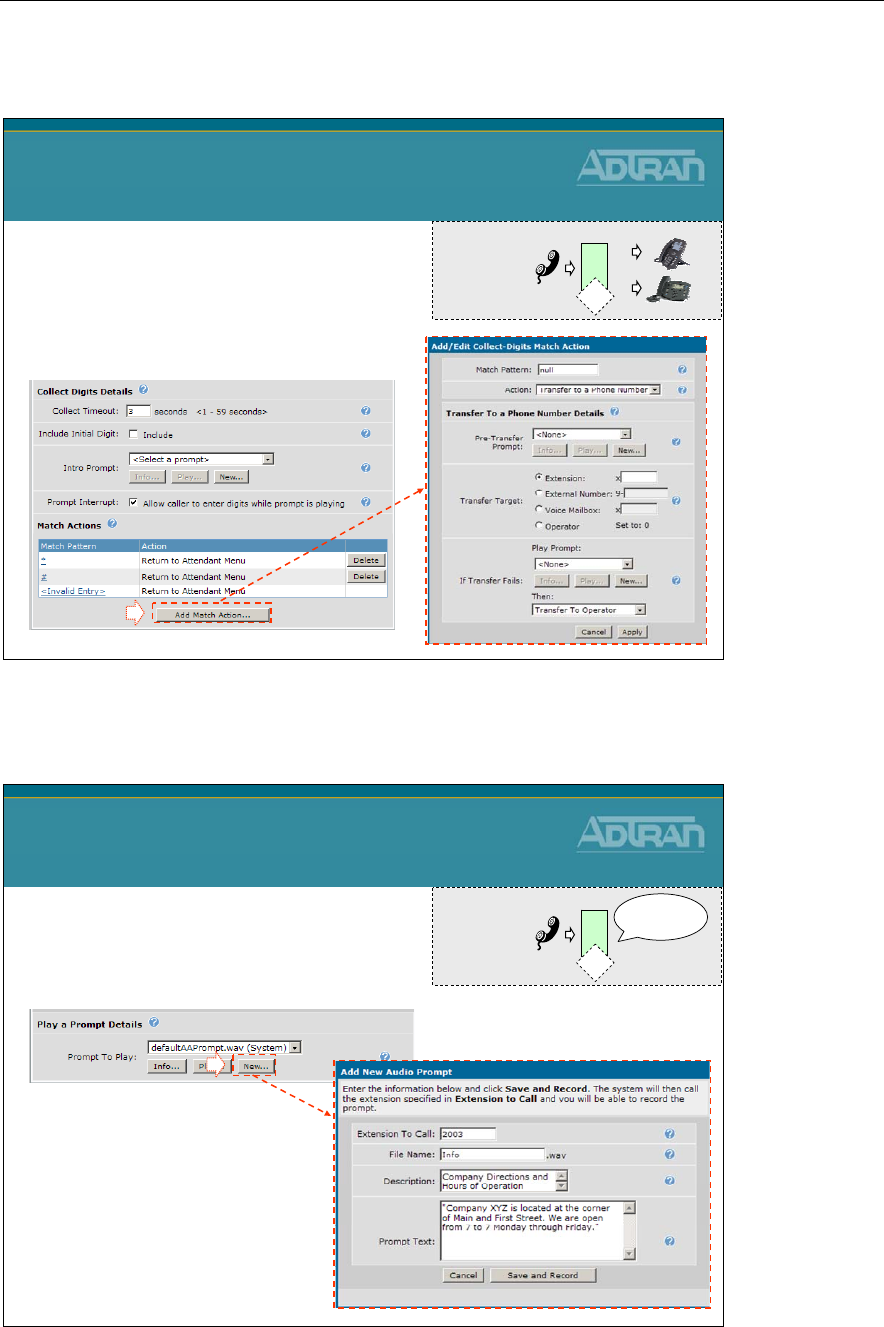
Module 6: NetVanta 7000 IP PBX Application
6-36 NetVanta IP Telephony Course
AA Digit Actions - Collect Digits
6
?3
A A
User presses N(6) for
night or D(3) for day
Auto Attendant Digit Actions
Collect Digits
•Matches numbers entered in by
the caller against set templates
and performs various actions
based on the match.
1
AA Digit Actions - Play a Prompt
Auto Attendant Digit Actions
Play a Prompt
•Plays an audio prompt and
then returns the caller to this
Auto Attendant menu
1
5
Hours of
Operation
A A
User presses 5to
hear hours of operation
Useful for store
hours/directions/etc…
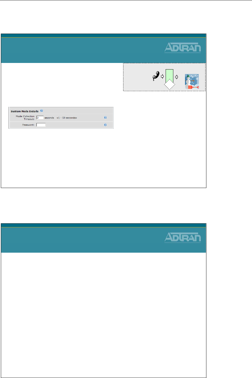
Module 6: NetVanta 7000 IP PBX Application
NetVanta IP Telephony Course 6-37
AA Digit Actions - System Mode
Auto Attendant Digit Actions
System Mode
•The System Mode action
provides a way to change the
current system mode of the unit
#
A A
User presses #,
password, and then 8
-The password assigned above must be
entered before the caller can change the
current system mode
A voice user who presses the digit action for
System Mode will hear the following:
PASSWORD?
The Current System Mode is Default
To Transition to Night Mode Press 2
To Transition to Lunch Mode Press 3
To Transition to Weekend Mode Press 4
To Transition to Custom1 Mode Press 5
To Transition to Custom2 Mode Press 6
To Transition to Custom3 Mode Press 7
To Transition to Override Mode Press 8
To Cancel Press *
Override
System Mode
AA Digit Actions - Other Digit Actions
Auto Attendant Digit Actions
Other Digit Actions
•Repeat Menu
–Starts this Auto Attendant's menu prompt over and waits for caller
input
•Previous Menu
–Returns control of the call to the previous Auto Attendant
–Previous Menu works in conjunction with Transfer To a Menu to
allow the caller to navigate through the various Auto Attendant
menus
•Same as Other Digit Action
–Sets this event's action to be exactly the same as another event's
action
•Disconnect
–Terminates the call after optionally playing a prompt
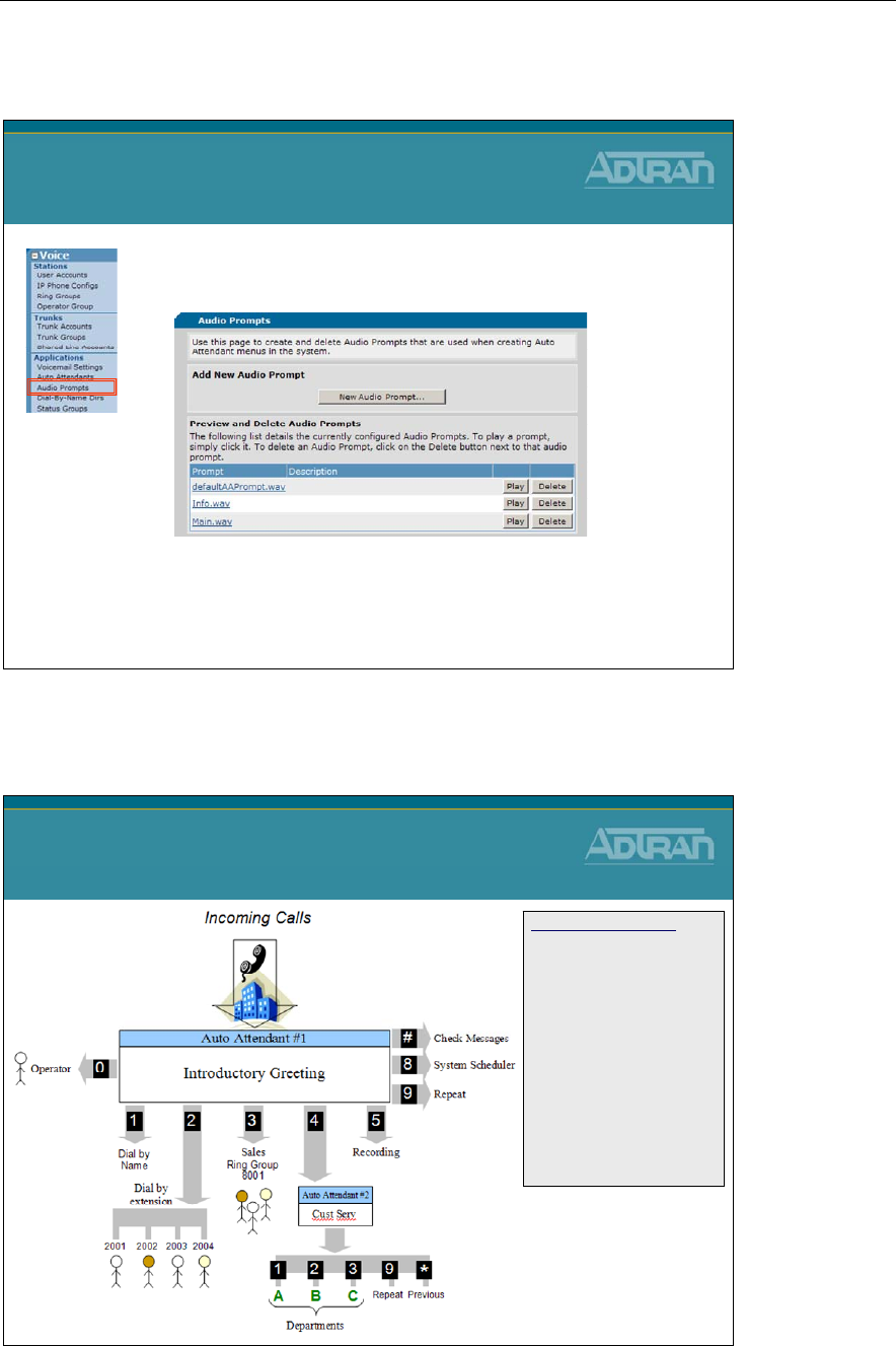
Module 6: NetVanta 7000 IP PBX Application
6-38 NetVanta IP Telephony Course
Auto Attendant - Prompt Management
Auto Attendant
Prompt Management
- Prompts can be recorded on the fly while creating and
editing an attendant menu
- The Audio Prompts menu allows for creation, viewing,
editing of all known prompts in the system
•Prompts can easily be recorded and played
via the Web GUI
Auto Attendant Example
Auto Attendant Example
Introductory Greeting
"Thank you for calling
Company XYZ. If you know
the extension number of the
party you are trying to reach,
please dial it at any time; if the
number is not known, press’1’
to dial by name; if you are
calling for the Sales Department
press '3'; for Customer Service
press ‘4'; for company hours of
operation and location
information press ‘5'; To repeat
the selections, press ‘9’; Press
‘0’ or stay on line for the
operator.”

Module 6: NetVanta 7000 IP PBX Application
NetVanta IP Telephony Course 6-39
Dial-by-Name Directory
NetVanta IP Telephony Course
Dial-by-Name Directory
Dial-by-Name Directory
Dial-by-Name Directory
•A default System directory that adds/removes users
automatically
•Admin-definable directories containing customizable
set of users/ring groups
•Users can be added both with the system name as
well as aliases to handle different spellings or
nicknames
•Name Searching
–Can search by first name, last name, or either
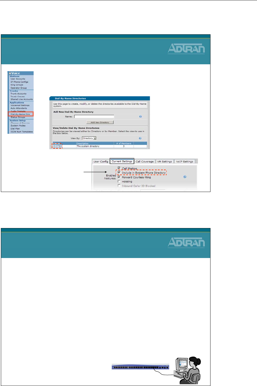
Module 6: NetVanta 7000 IP PBX Application
6-40 NetVanta IP Telephony Course
Dial-by-Name Directory - Default SYSTEM Directory
Dial-by-Name Directory
Default SYSTEM Directory
•The SYSTEM Directory contains all users that
have the “Include in System Phone Directory”
option enabled
Voice / Stations /User Accounts / Edit “specific user”
This option is configured in the Current
Settings tab of the specific voice user
Dial-by-Name Directory - Basic Configuration
Dial-by-Name Directory
Basic Configuration Steps
1. Create a new Dial-By-Name Directory
2. Add Users to the Directory
3. Optional – Add Alias to Directory
4. Configure Directory as a Digit Action in an Auto
Attendant
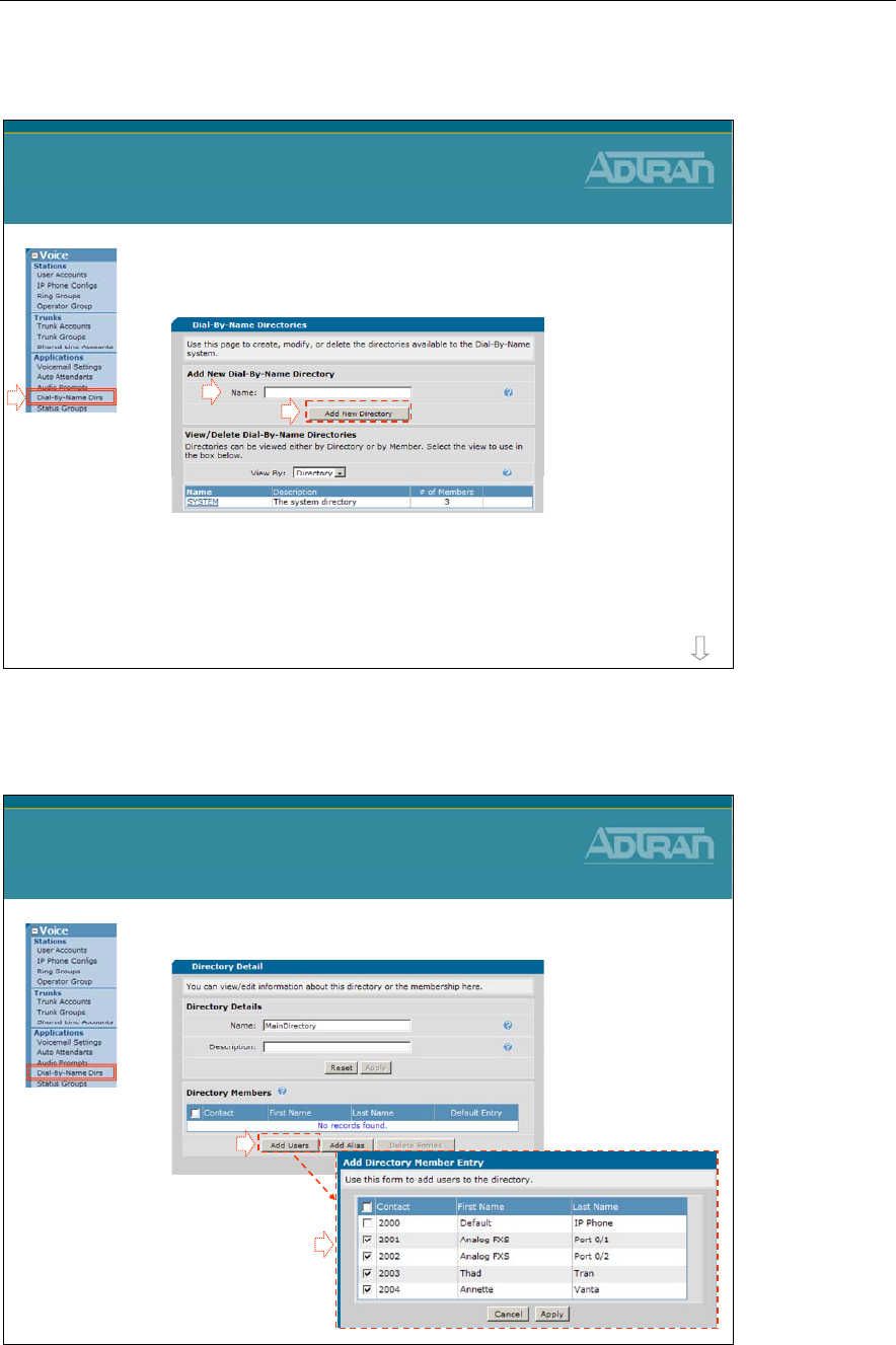
Module 6: NetVanta 7000 IP PBX Application
NetVanta IP Telephony Course 6-41
1) Create new Dial-By-Name Directory
Dial-by-Name Directory Configuration
1) Create new Dial-By-Name Dir.
12
3
MainDirectory
1. Select the Voice / Applications / Dial-By-
Name Dirs menu
2. Type name and then click Add New Directory
more
2) Add Users to the Directory
Dial-by-Name Directory Configuration
2) Add Users to the Directory
1. Click Add Users
2. Select from the list
of available voice users
1
2
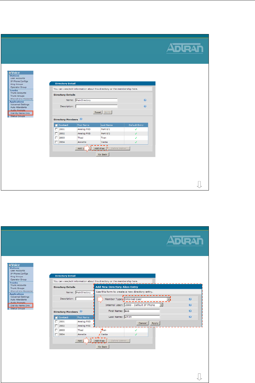
Module 6: NetVanta 7000 IP PBX Application
6-42 NetVanta IP Telephony Course
3) Optional – Add Alias to Directory
Dial-by-Name Directory Configuration
3) Optional – Add Alias to Dir.
1
- An Alias can be added for an internal system user
or a phone number such as a ring group
1. Click Add Alias
more
3) Optional – Add Alias to Directory
Dial-by-Name Directory Configuration
3) Optional – Add Alias to Dir.
- Add an alternate name for an internal system user
2. Add Alias for an Internal User
1
2
more
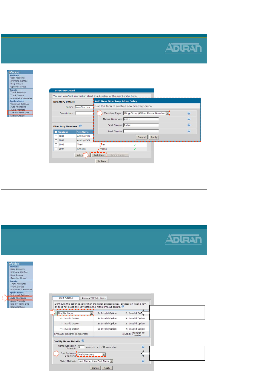
Module 6: NetVanta 7000 IP PBX Application
NetVanta IP Telephony Course 6-43
3) Optional – Add Alias to Directory
Dial-by-Name Directory Configuration
3) Optional – Add Alias to Dir.
- Add an Alias for a phone number that “is not” an
internal system user
2. Add Alias for Ring Group/Other Phone
Number
1
2
4) Assign Directory in Auto Attendant
Dial-by-Name Directory Configuration
4) Assign Dir. in Auto Attendant
3
2
1. Edit an Auto Attendant from the Voice /
Applications / Auto Attendants menu
1
2) Set a Digit Action to
Dial By Name
3) Assign existing Dial
By Name Directory

Module 6: NetVanta 7000 IP PBX Application
6-44 NetVanta IP Telephony Course

Module 6: NetVanta 7000 IP PBX Application
NetVanta IP Telephony Course 6-45
Busy Lamp Field/Public Park Zones
NetVanta IP Telephony Course
Busy Lamp Field/ Public Park Zones
Busy Lamp Field
Busy Lamp Field
•Monitor busy or idle status
–Another phone
–Public park zone
–System mode
–Mailbox
•DSS function also supported on the same phone
•Supported with the ADTRAN 700 Series and
SoundPoint IP 601/650 only
–Other SIP and analog phones
can be monitored using BLF
DSS: Direct Station Select
BLF: Busy Lamp Field
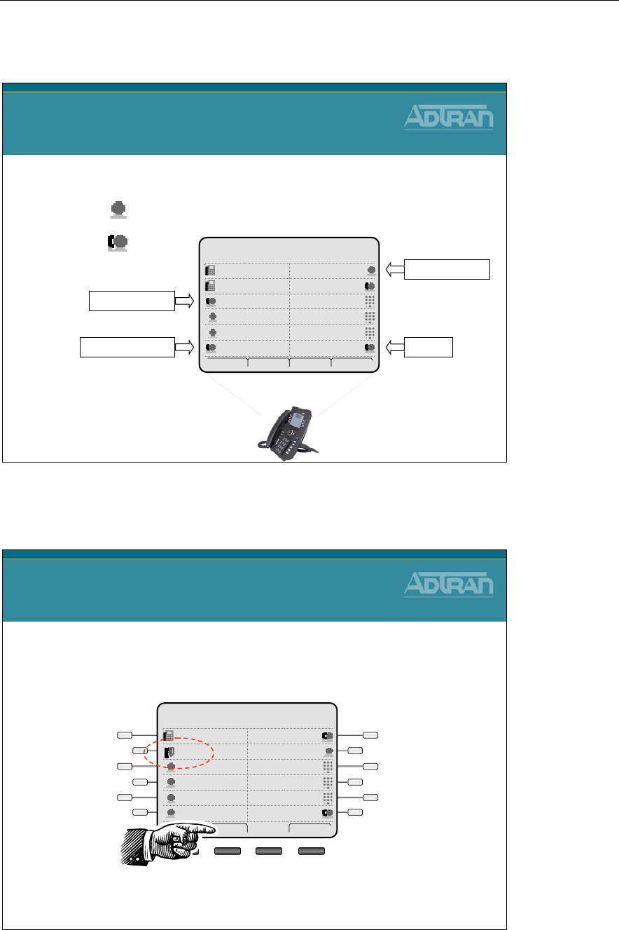
Module 6: NetVanta 7000 IP PBX Application
6-46 NetVanta IP Telephony Course
Busy Lamp Field
Busy Lamp Field
•Status Indicator
–Idle
–Busy
Frank 05/5/08
12:15pm
Mailbox 8001Park 2
SPEEDPark 1
SPEEDWade
SPEEDCheryl
Lunch2003
Default2003
Dial Redial Pickup More
Voice Account
Public Park Zone
System Mode
Mailbox
Public Park Zones - Parking Active Call
Public Park Zones
Parking Active Call
•Call is answered and parked in “Park 1” zone
Frank 05/5/08
10:15pm
Mailbox 8001Park 2
SPEEDPark 1
SPEEDWade
SPEEDCheryl
Lunch2003
Default2003
Hold Park Endcall
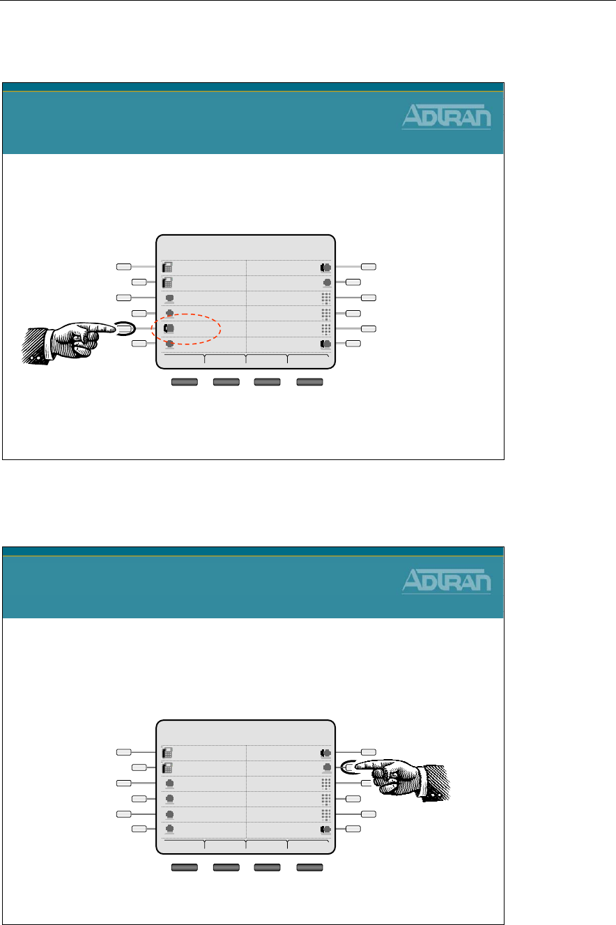
Module 6: NetVanta 7000 IP PBX Application
NetVanta IP Telephony Course 6-47
Public Park Zones - Parking Active Call
Public Park Zones
Parking Active Call
•Call is available for Retrieval
Frank 05/5/08
10:15pm
Mailbox 8001Park 2
SPEEDRetrieve 1
SPEEDWade
SPEEDCheryl
Lunch2003
Default2003
Dial Redial Pickup More
Busy Lamp Field - System Scheduler
Busy Lamp Field
System Scheduler
•Early Lunch – the NetVanta 7000 is manually
changed from the Default System Mode to the Lunch
System Mode
Frank 05/5/08
10:15pm
Mailbox 8001Park 2
SPEEDPark 1
SPEEDWade
SPEEDCheryl
Lunch2003
Default2003
Dial Redial Pickup More
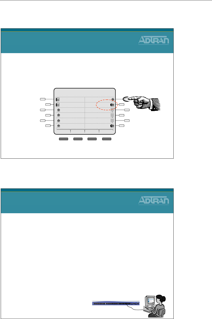
Module 6: NetVanta 7000 IP PBX Application
6-48 NetVanta IP Telephony Course
Busy Lamp Field - System Scheduler
Busy Lamp Field
System Scheduler
•The NetVanta 7000 will stay in the Lunch System
Mode until manually changed back to the Default or
other System Modes
Frank 05/5/08
1:30pm
Mailbox 8001Park 2
SPEEDPark 1
SPEEDWade
SPEEDCheryl
Lunch2003
Default2003
Dial Redial Pickup More
Busy Lamp Field - Basic Configuration Steps
Busy Lamp Field/Public Park Zones
Basic Configuration Steps
1. Create a Status Group
2. Add members to the Status Group
–Members can be users, park zones, system modes, or a
mailbox to be monitored
3. Configure SIP phone to subscribe to Status group
–Subscribe to Status Group in the IP Phone Configs Menu
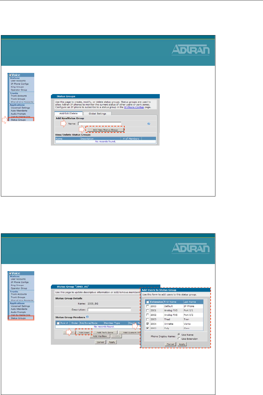
Module 6: NetVanta 7000 IP PBX Application
NetVanta IP Telephony Course 6-49
1) Create Status Group
1. Select the Voice / Applications / Status
Groups menu
2. Type name for new Status Group
3. Click Add New Status Group
Busy Lamp Field Configuration
1) Create Status Group
- A Status Group is created to define the voice users, park zones,
system modes, or a mailbox to be monitored
12
3
2003_SG
2) Add Members to Status Group
- BLF buttons can also be used as a speed dial or direct station select
(DSS) for that user
- BLF buttons may also be used when invoking transfers
2
1
Busy Lamp Field Configuration
2) Add Members to Status Group
1. Click Add Users
2. Select from existing voice users
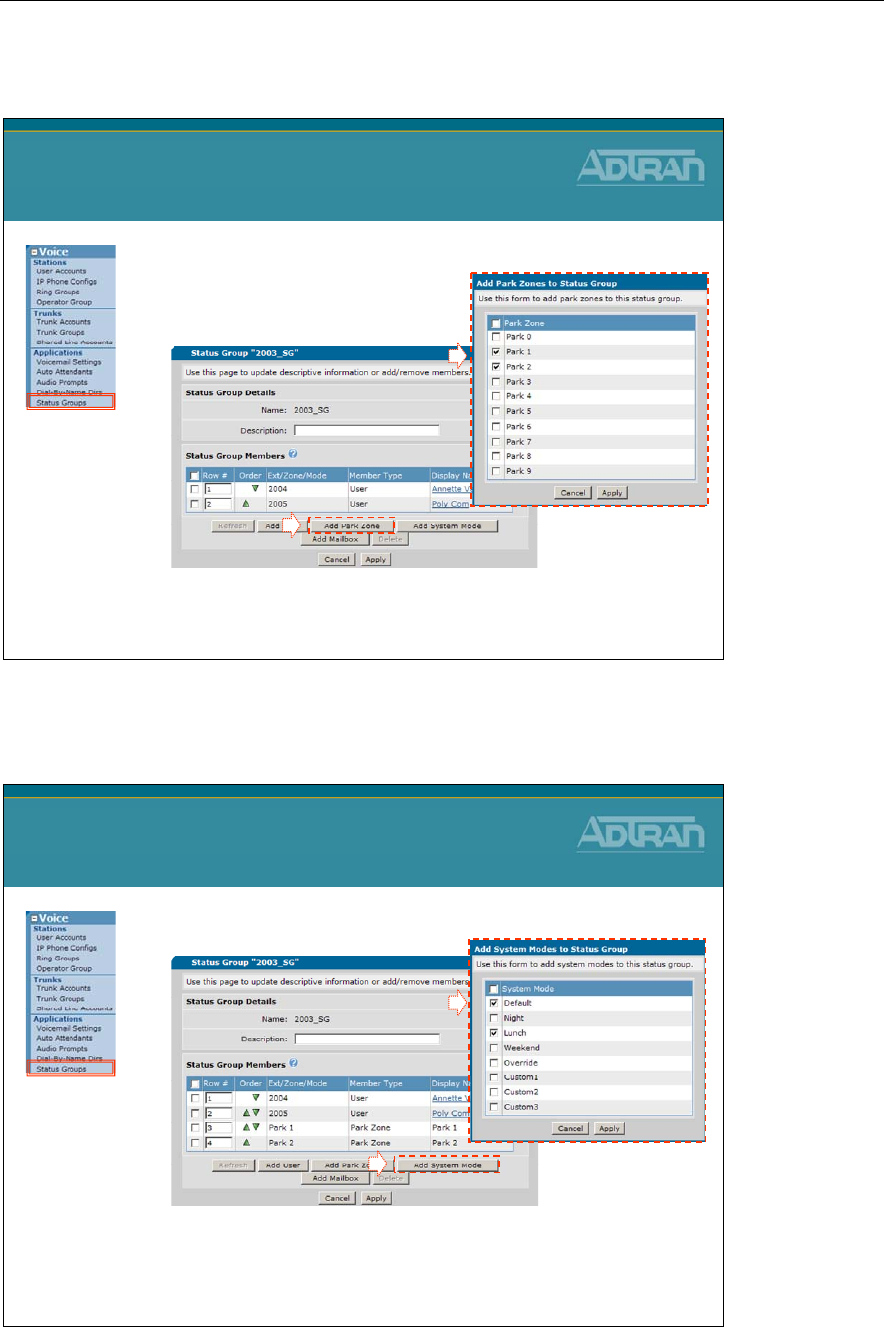
Module 6: NetVanta 7000 IP PBX Application
6-50 NetVanta IP Telephony Course
2) Add Members to Status Group
1
Busy Lamp Field Configuration
2) Add Members to Status Group
2
1. Click Add Park Zones
2. Add Parks Zones to be monitored
2) Add Members to Status Group
1
Busy Lamp Field Configuration
2) Add Members to Status Group
2
1. Click Add System Mode
2. Add System Modes to be monitored
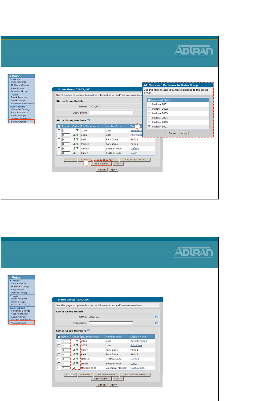
Module 6: NetVanta 7000 IP PBX Application
NetVanta IP Telephony Course 6-51
2) Add Members to Status Group
1
Busy Lamp Field Configuration
2) Add Members to Status Group
2
1. Click Add Mailbox
2. Add Mailbox to be monitored
2) Add Members to Status Group
Busy Lamp Field Configuration
2) Add Members to Status Group
•Optional – Change order of Status Group
members
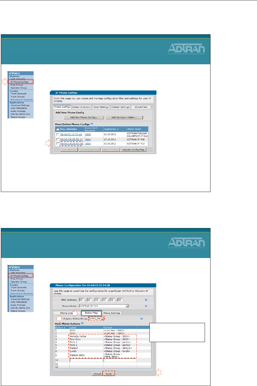
Module 6: NetVanta 7000 IP PBX Application
6-52 NetVanta IP Telephony Course
3) Subscribe to Status Group
1. Select the Voice / Stations / IP Phone Configs
menu
2. Configure phone to subscribe to Status Group
–Select the MAC Address of phone that will monitor
the Status Group
Busy Lamp Field Configuration
3) Subscribe to Status Group
1
2
3) Subscribe to Status Group
Busy Lamp Field Configuration
3) Subscribe to Status Group
- The Status Group will
display below the line keys
that are currently configured
3
4
5
- Click Apply to sync
and reboot phone
2. Configure phone to subscribe to Status Group
(Continued…)
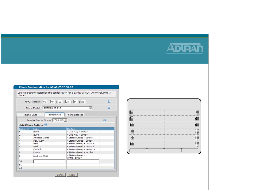
Module 6: NetVanta 7000 IP PBX Application
NetVanta IP Telephony Course 6-53
3) Subscribe to Status Group
Busy Lamp Field Configuration
3) Subscribe to Status Group
•Phone Display after reboot
Thad Tran 05/5/08
12:15pm
SPEEDPark 2
SPEEDPark 1
SPEEDPoly Com
Mailbox 8001Annette Vanta
Lunch2003
Default2003
Dial Redial Pickup More

Module 6: NetVanta 7000 IP PBX Application
6-54 NetVanta IP Telephony Course

Module 6: NetVanta 7000 IP PBX Application
NetVanta IP Telephony Course 6-55
Logging Calls
NetVanta IP Telephony Course
Logging Calls
Station Message Detail Recoding
(SMDR)
Logging Methods
Logging Methods
•Real-Time Event messages are generated by many
parts of the NetVanta 7000 and can be displayed
real-time in the console or telnet session or logged to
the following:
–Internal event-log
–External syslog-server.
–SMTP mail server.
•Can filter which events are logged based on severity
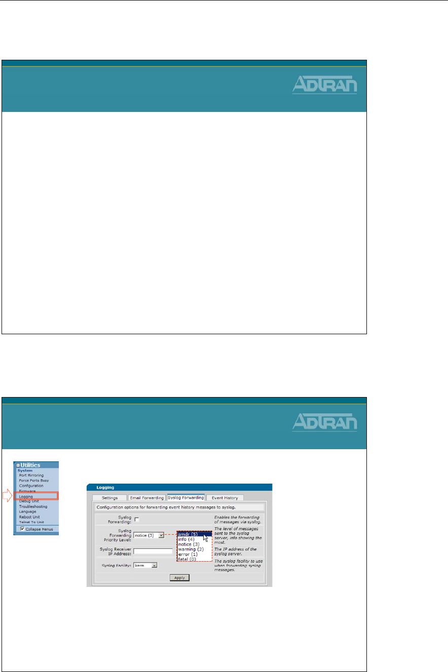
Module 6: NetVanta 7000 IP PBX Application
6-56 NetVanta IP Telephony Course
Logging – SMDR
Logging - SMDR
•The NetVanta 7000 supports sending SMDR events
to an external logging server
•SMDR events are sent AFTER the call is completed
•SMDR messages contain information about the call
including
–Time initiated
–Billing code
–Billable Duration
–Trunk
•Requires an external host running a syslog server
•Sends messages on UDP port 514
SMDR - Station Messaging Detail Record (Call Detail Records)
Utilities / System - Logging – SMDR
•Enable SMDR Logging
1. Enable Syslog Forwarding
2. Set Syslog Forwarding Priority Level to SMDR
3. Define IP address of Syslog server
4. Optional – define Syslog facility
Utilities / System
Logging - SMDR
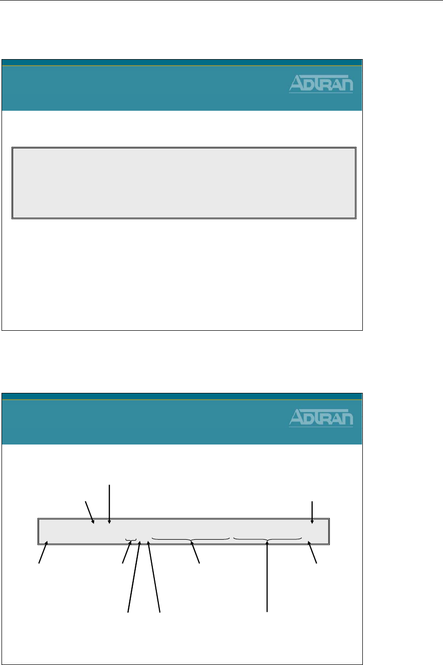
Module 6: NetVanta 7000 IP PBX Application
NetVanta IP Telephony Course 6-57
Logging – SMDR Events
Logging - SMDR Events
•Sample SMDR Log
2008.04.30 13:52:51 SMDR 369 04/30/2008 13:52:49 0.0 0 I 00/00 Dawn Ella 3001 00/01 Rob Wade 5001 0 N
2008.04.30 13:52:53 SMDR 368 04/30/2008 13:52:51 0.0 0 I 00/00 Dawn Ella 3001 00/01 Bob Sup 2003 0 N
2008.04.30 13:57:01 SMDR 370 04/30/2008 13:53:35 3.4 0 I 00/01 Rob Wade 5001 00/01 T01 8041000 0 N
2008.04.30 13:57:41 SMDR 371 04/30/2008 13:57:27 0.2 0 E 00/01 8081000 00/01 AutoAttendantAc 8200 0 N
2008.04.30 13:59:11 SMDR 372 04/30/2008 13:57:39 1.5 0 I 00/01 8081000 00/01 Dawn Ella 3001 0 RBA
2008.04.30 14:05:28 SMDR 373 04/30/2008 14:02:46 2.7 0 I 00/01 Dawn Ella 3001 00/01 T01 8091001 0 N
2008.04.30 14:05:28 SMDR 374 04/30/2008 14:02:40 2.8 0 I 00/00 Dawn Ella 3001 00/00 Rob Wade 5001 0 N
Logging – SMDR Events
Logging - SMDR Events
edt~ SMDR 373 sdt~ 2.7 0I00/01 Dawn Ella 3001 00/01 T01 8091001 0N
End date / time Call Duration
(minutes)
Billing Code Call Type
Originating slot/port,
name, number
Destination slot/port,
name, number
Conference Flag
(C or NC)
Special Handling Flag;
N(one), F(wd), T(xfr), P(ark)
edt~=end date/time
sdt~=start date/time
Start date / time
Record #
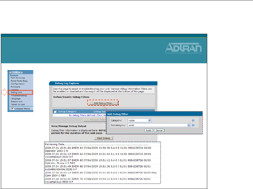
Module 6: NetVanta 7000 IP PBX Application
6-58 NetVanta IP Telephony Course
debug voice smdr
•View SMDR events with Debug
debug voice smdr

Module 6: NetVanta 7000 IP PBX Application
NetVanta IP Telephony Course 6-59
Troubleshooting
NetVanta IP Telephony Course
Troubleshooting
Layer 1 Troubleshooting T1 Alarm Conditions
View T1 Alarms and Errors
Detailed troubleshooting can be accomplished via the Command Line Interface (CLI) via
either a console or telnet connection.
The show interface t1 1/1 command shows the up/down state of the T1 along with the
following:
• Alarm state (current/history)
• Framing and coding
• Clock source
• Test mode
• Channel status
• Signal state (A/B bits)
• Performance statistics

Module 6: NetVanta 7000 IP PBX Application
6-60 NetVanta IP Telephony Course
show int t1 1/1 – No Alarms
show int t1 1/1
•Display the T1 interface – No Alarms
NV7000#
show int t1 1/1
t1 1/1 is UP
Receiver has no alarms
T1 coding is B8ZS, framing is ESF
Clock source is line, FDL type is ANSI
Line build-out is 0dB
No remote loopbacks, No network loopbacks
Acceptance of remote loopback requests enabled
Tx Alarm Enable: rai
Last clearing of counters 01:05:16
loss of frame : 0
loss of signal : 0
AIS alarm : 0
Remote alarm : 1, last occurred 00:21:23
DS0 Status: 123456789012345678901234
------------------------------XXXXX
Status Legend: '-' = DS0 is not allocated
'X' = DS0 is allocated (nailed)
:
* Continues on next slide
show int t1 1/1
(Continued…)
Continued…
Signaling Bit Status: 123456789012345678901234
RxA: -------------------------------11111
RxB: -------------------------------11111
TxA: ------------------------------ 11111
TxB: -------------------------------01111
123456789012345678901234
Line Status: -- No Alarms --
5 minute input rate 0 bits/sec, 0 packets/sec
5 minute output rate 0 bits/sec, 0 packets/sec
Current Performance Statistics:
0 Errored Seconds, 0 Bursty Errored Seconds
0 Severely Errored Seconds, 0 Severely Errored Frame Seconds
0 Unavailable Seconds, 0 Path Code Violations
0 Line Code Violations, 0 Controlled Slip Seconds
0 Line Errored Seconds, 0 Degraded Minutes
TDM group 1, line protocol is not set
Encapsulation is not set
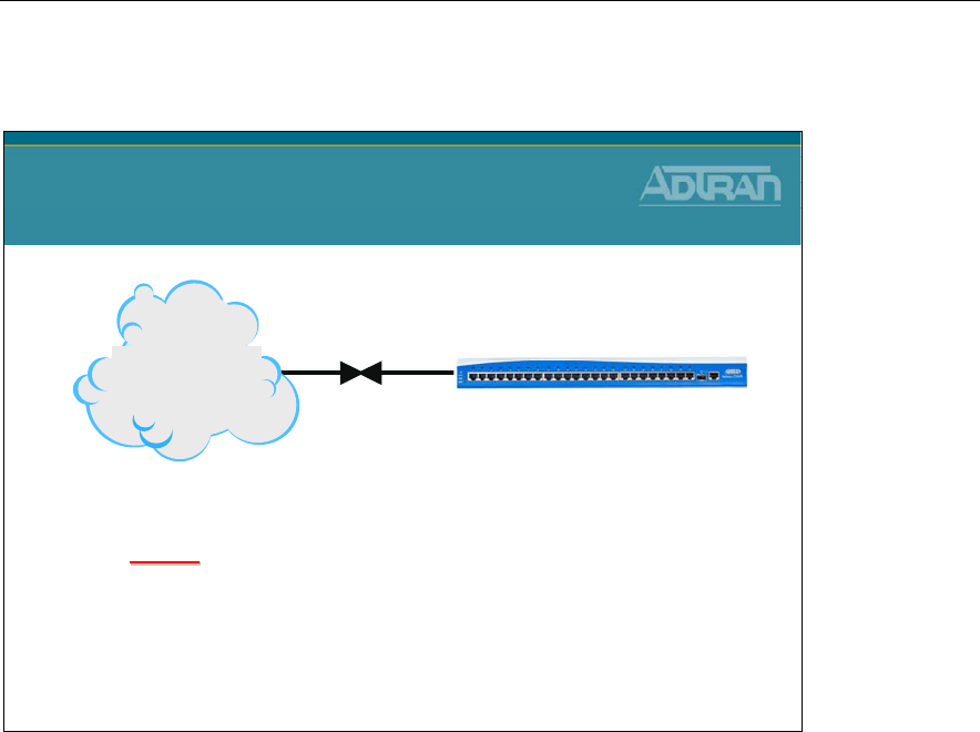
Module 6: NetVanta 7000 IP PBX Application
NetVanta IP Telephony Course 6-61
T1 - Red Alarm
RED
RED
CSU/DSU experiences an out
CSU/DSU experiences an out-
-of
of-
-frame
frame
condition for more than 2.5 seconds (
condition for more than 2.5 seconds (-
-receive
receive
signal condition)
signal condition)
X
X
T1 Alarm Conditions
Telephone
Network
Red Alarm is declared when the CSU cannot synchronize on the framing pattern on the
network interface. This may be due to excessive errors on the T1 or an incorrect framing
pattern. Red Alarm will be declared if an Out of Frame (OOF) condition exists for 2.5
seconds or more. A common cause of Red Alarm is a mismatch on framing configuration
(D4 versus ESF) between the telco and the customer’s CSU.

Module 6: NetVanta 7000 IP PBX Application
6-62 NetVanta IP Telephony Course
T1 - Yellow Alarm
T1 RX
T1 RX
T1 TX
T1 TX
Telephone
Network
X
X
T1 Alarm Conditions
YELLOW
YELLOW
-
-CSU/DSU responds to Red alarm
CSU/DSU responds to Red alarm
condition by transmitting yellow alarm to inform
condition by transmitting yellow alarm to inform
far end of alarm condition (far end signal
far end of alarm condition (far end signal
condition)
condition)
Remote Alarm Indication (RAI) is being received at the Network Interface to indicate that
the far end is in Red Alarm. It may be inferred that the path from the far end to the near
end is good since the RAI is being received successfully. (Note: "far end" refers only to the
far end of the local loop, which may extend to the customers' "other" site or may only go to
an intermediate Central Office.) This is inferred because framing must be adequate in order
to receive a transmitted Yellow alarm.
In ESF, the Yellow Alarm is transmitted over the Facility Data Link (FDL). In SF (or D4),
it is transmitted inband, by setting the second bit in every DS0 to zero; consequently, it is
possible for payload data to mimic the code and cause a "false yellow alarm".
Any time a unit is in Red Alarm it will always be transmitting Yellow alarm toward the far
end. There will be no indication of this on the local unit. The only indication will be at the
far end unit if the transmit path is functioning properly.
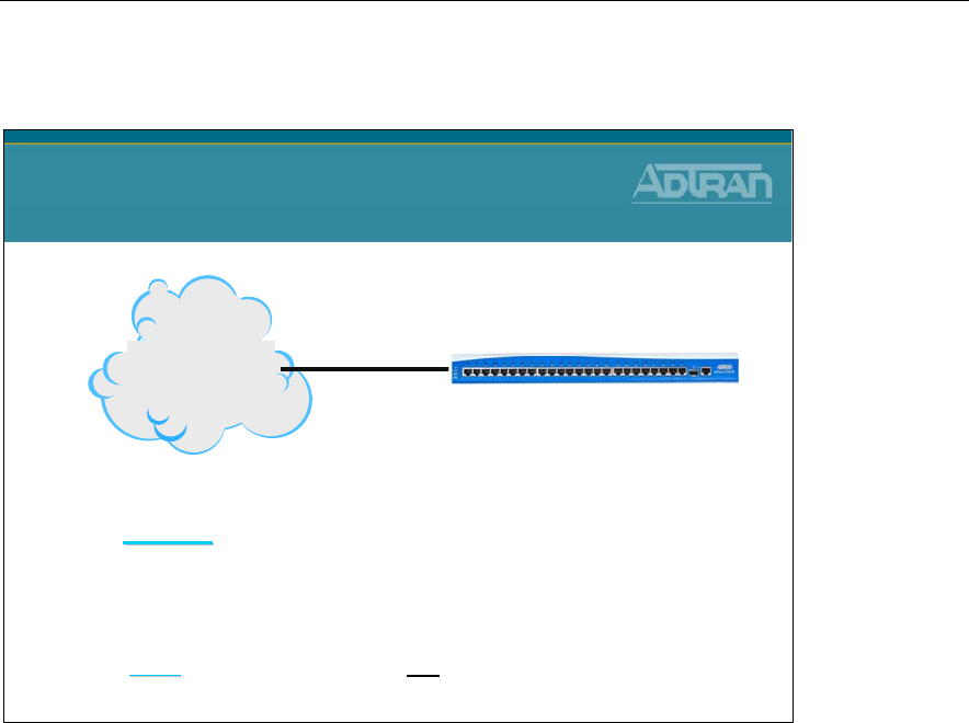
Module 6: NetVanta 7000 IP PBX Application
NetVanta IP Telephony Course 6-63
T1 – Blue Alarm
Telephone
Network
X
X
BLUE
BLUE alarm is also known as
alarm is also known as AIS
AIS (Alarm Indication Signal)
(Alarm Indication Signal)
T1 Alarm Conditions
BLUE
BLUE
-
-Blue alarm indicates network trouble
Blue alarm indicates network trouble
upstream from the NetVanta 7000
upstream from the NetVanta 7000
Blue alarm indicates network trouble upstream from the NetVanta 7000. BLUE alarm is
also known as AIS (Alarm Indication Signal) or an All 1’s pattern.
LOS (LOS of Signal)
A LOS is an alarm indication that occurs when the CSU does not receive a valid T1 signal
(i.e., approximately 1.544 Mbps, nominally 3V peak). A common cause of LOS is an
improperly wired cable from the demarcation point to the TSU. Additionally, if excessive
zeros are received on an AMI line, LOS can be declared.
When an LOS condition is present the Red alarm will always be active because framing is
absent as well.
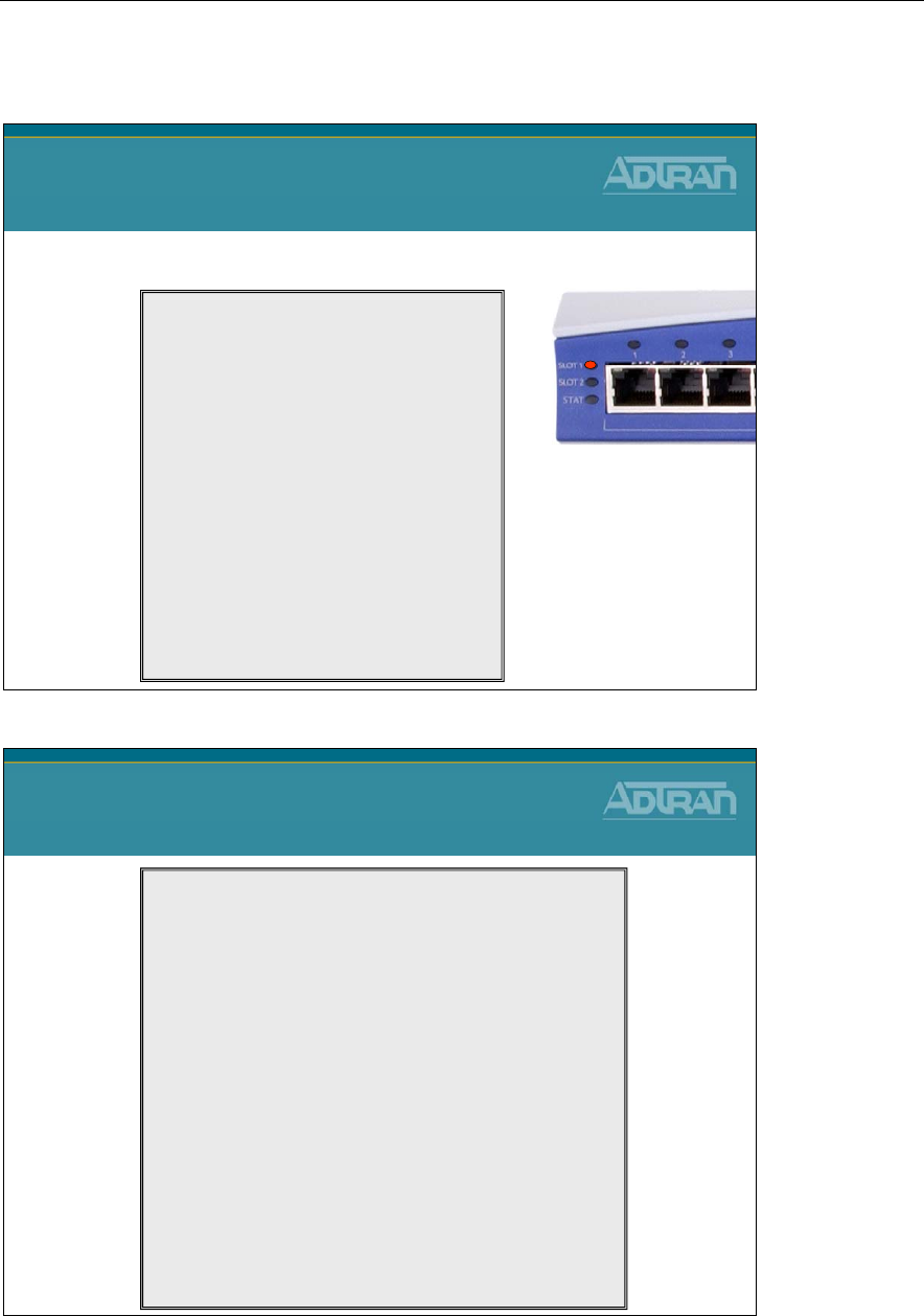
Module 6: NetVanta 7000 IP PBX Application
6-64 NetVanta IP Telephony Course
show int t1 1/1 – In Alarm
show int t1 1/1 – In Alarm
•Display the T1 interface – In Alarm
NV7000#
show int t1 1/1
t1 1/1 is DOWN
Transmitter is sending remote alarm
Receiver has loss of signal, loss of frame
T1 coding is B8ZS, framing is ESF
Clock source is line, FDL type is ANSI
Line build-out is 0dB
No remote loopbacks, No network loopbacks
Acceptance of remote loopback requests enabled
Tx Alarm Enable: rai
Last clearing of counters 20:26:52
loss of frame : 1, current duration 00:02:45
loss of signal : 1, current duration 00:02:44
AIS alarm : 0
Remote alarm : 0
DS0 Status: 123456789012345678901234
XXXXXXXXXXXXXXXXXXXXXXXX
Status Legend: '-' = DS0 is not allocated
'X' = DS0 is allocated (nailed)
* Continues on next slide
show int t1 1/1
(Continued…)
Continued…
Signaling Bit Status: 123456789012345678901234
RxA: ------------------------
RxB: ------------------------
TxA: ------------------------
TxB: ------------------------
123456789012345678901234
Line Status: -- LOS -- Red -- Tx Yellow --
5 minute input rate 0 bits/sec, 0 packets/sec
5 minute output rate 0 bits/sec, 0 packets/sec
Current Performance Statistics:
10 Errored Seconds, 0 Bursty Errored Seconds
0 Severely Errored Seconds, 167 Severely Errored Frame Seconds
167 Unavailable Seconds, 0 Path Code Violations
1 Line Code Violations, 1 Controlled Slip Seconds
0 Line Errored Seconds, 0 Degraded Minutes
TDM group 1, line protocol is not set
Encapsulation is not set
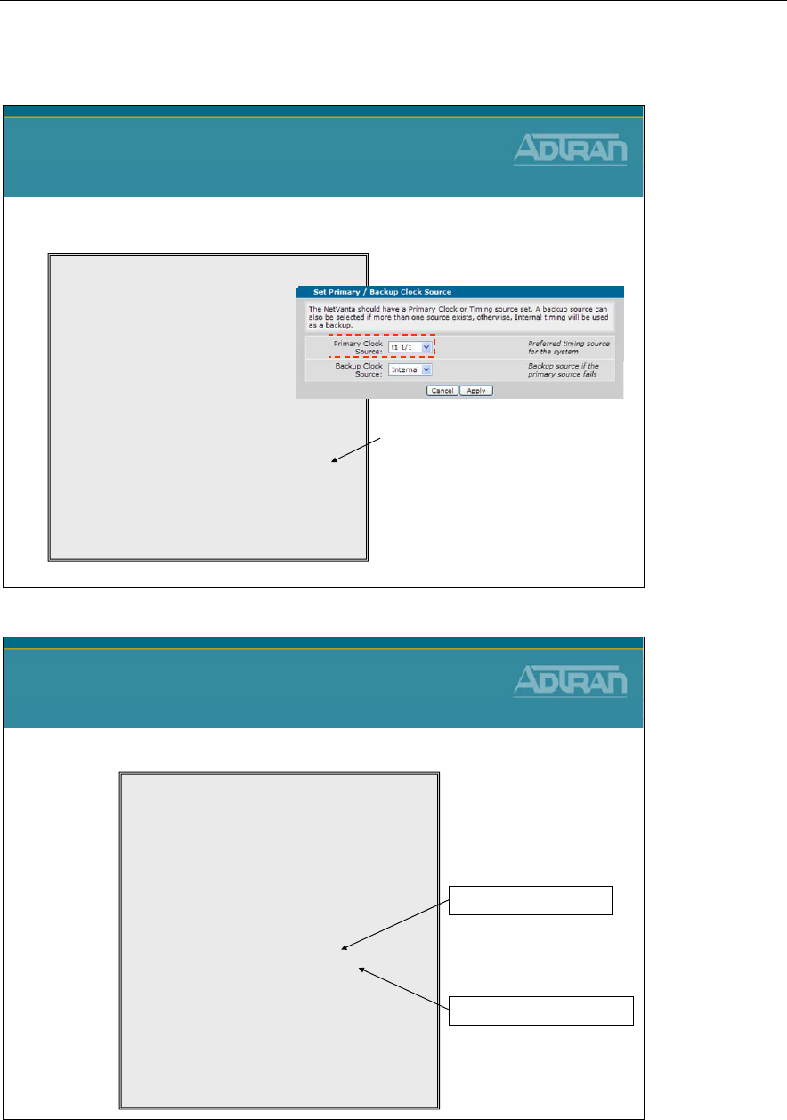
Module 6: NetVanta 7000 IP PBX Application
NetVanta IP Telephony Course 6-65
show int pri 1
show int pri 1
•Display the ISDN PRI interface
NV7000#
show int pri 1
pri 1 is DOWN
Description: pri 1
Switch protocol National ISDN 2
calling-party override none
calling-party presentation allowed
calling-party name
calling-party number
area-code
connect t1 1/1 tdm-group 1
digits transferred all prefix
isdn name-delivery none
role user
Number Conversion as dialed
resource-selection circular
Channel status 123456789012345678901234
--------------------------------. . . . .
Legend: - = Unallocated . = Inactive
A = Active B channel B = Backup D channel
D = Active D channel M = Maintenance
R = Restart
:
No D channel ?
Check System Clock Source from
the System Summary screen
show int pri 1
•Display the ISDN PRI interface
NV7000#
show int pri 1
pri 1 is UP
Description: pri 1
Switch protocol: National ISDN 2
Signaling role: user (TE)
Calling-party override: disabled
Calling-party presentation: allowed
Calling-party number: (no number configured)
digits transferred 4
ISDN name-delivery: disabled
Connected interface: t1 1/1 tdm-group 1
Channel status 123456789012345678901234
------------------- . . AAD
Legend: - = Unallocated . = Inactive
A = Active B channel B = Backup D channel
D = Active D channel M = Maintenance
R = Restart
329 packets input, 1701 bytes, 0 no buffer
0 runts, 0 giants, 0 throttles
37 input errors, 1 CRC, 28 frame
8 abort, 0 discards, 0 overruns
441 packets output, 2068 bytes, 0 underruns
PRI 1 D channel is UP
PRI Channels in use
Module 6: NetVanta 7000 IP PBX Application
6-66 NetVanta IP Telephony Course
debug isdn l2-formatted
debug isdn l2-formatted
•Display ISDN Layer 2 formatted messages
NV7000# debug isdn l2-formatted
14:57:09 ISDN.L2_FMT PRI 1 =====================================================
14:57:09 ISDN.L2_FMT PRI 1 Recd = Sapi:00 C/R:C Tei:00
14:57:09 ISDN.L2_FMT PRI 1 Ctl:INFO Ns:4 Nr:4
14:57:09 ISDN.L2_FMT PRI 1 Prot:08 CRL:2 CRV:0002
14:57:09 ISDN.L2_FMT PRI 1 M - 05 SETUP
14:57:09 ISDN.L2_FMT PRI 1 IE - 04 BEARER CAPABILITY Len=3
14:57:09 ISDN.L2_FMT PRI 1 80 Xfer Cap.:SPEECH
14:57:09 ISDN.L2_FMT PRI 1 90 Xfer Rate:64k
14:57:09 ISDN.L2_FMT PRI 1 A2 Layer 1:u-Law
14:57:09 ISDN.L2_FMT PRI 1 IE - 18 CHANNEL ID Len=3
14:57:09 ISDN.L2_FMT PRI 1 A1 Primary Rate
14:57:09 ISDN.L2_FMT PRI 1 Intfc ID:IMPLICIT
14:57:09 ISDN.L2_FMT PRI 1 Pref/Excl:PREFERRED
14:57:09 ISDN.L2_FMT PRI 1 D-Chan Indicated:NO
14:57:09 ISDN.L2_FMT PRI 1 Chan. Sel:FOLLOWS
14:57:09 ISDN.L2_FMT PRI 1 83 Numb/Map:NUMBER
14:57:09 ISDN.L2_FMT PRI 1 97 Channel:23
14:57:09 ISDN.L2_FMT PRI 1 IE - 6C CALLING PARTY # Len=12
14:57:09 ISDN.L2_FMT PRI 1 21 Numb. Type:NATIONAL
14:57:09 ISDN.L2_FMT PRI 1 Numb. Plan:ISDN/Telephony
14:57:09 ISDN.L2_FMT PRI 1 80 Presentation:ALLOWED
14:57:09 ISDN.L2_FMT PRI 1 Ph.# 8884238726
14:57:09 ISDN.L2_FMT PRI 1 IE - 70 CALLED PARTY # Len=11
14:57:09 ISDN.L2_FMT PRI 1 A1 Numb. Type:NATIONAL
14:57:09 ISDN.L2_FMT PRI 1 Numb. Plan:ISDN/Telephony
14:57:09 ISDN.L2_FMT PRI 1 Ph.# 2568012003
debug isdn endpoint
debug isdn endpoint
•Display ISDN endpoint events
NV7000# debug isdn endpoint
15:17:13 ISDN.EP PRI 1 Incoming call :'2568012003' from '8884238726'.
15:17:13 ISDN.EP PRI 1 Call from 8884238726, wait for Name Facility msg
15:17:16 ISDN.EP PRI 1 Call from 8884238726 - timeout waiting for Name Facility
15:17:16 ISDN.EP PRI 1 Incoming number '2568012003' converted to '2003'
15:17:16 ISDN.EP PRI 1 Incoming call to '2568012003' accepted
15:17:40 ISDN.EP PRI 1 Call to '2568012003' connected.
15:17:59 ISDN.EP PRI 1 Call to '2568012003' Process clearing. CCR 16
Physical Interface / PRI Config
- Digits Transferred set to 4
Module 6: NetVanta 7000 IP PBX Application
NetVanta IP Telephony Course 6-67
debug voice summary
NV7000#
debug voice summary
13:50:44:007 VOICE.SUMMARY voice user 2003 cos allowed the call to Long Distance
13:50:44:009 VOICE.SUMMARY 2003 is calling
T03
(12568022003).
13:50:46:743 VOICE.SUMMARY RTP for Call from 0 to 12568022003: Codec PCMU
13:50:49:931 VOICE.SUMMARY 2003 is connected to
T03
(12568022003)
13:50:54:493 VOICE.SUMMARY Call from 2003 to
T03
(12568022003) ended by 2003:
13:51:24:119 VOICE.SUMMARY
T01
is calling AutoAttendantAcct (8200).
13:51:24:421 VOICE.SUMMARY RTP for Call from 8021000 to 8200: Codec G729
13:51:24:421 VOICE.SUMMARY
T01
is connected to AutoAttendantAcct (8200)
13:51:27:598 VOICE.SUMMARY
T01
is calling 2003 (2003).
13:51:27:843 VOICE.SUMMARY Call from
T01
to AutoAttendantAcct (8200) ended by Au
toAttendantAcct: normal clearing
debug voice summary
•View call routing summary real time
–Can confirm proper trunk is being used
Voice Trunk ID
debug voice autoattendant
debug voice autoattendant
•Display Auto Attendant events
NV7000# debug voice autoattendant
16:07:06 VXMLInterpreter vxml.8201 Ca:0 # Started prompt 'CFLASH:/AA/Prompts/Main.wav'
16:08:35 VXMLInterpreter vxml.8201 Ca:0 ProcessingLogic.dtmf input '0101' matched '‘
16:08:35 VXMLInterpreter vxml.8201 Ca:0 # Started prompt 'CFLASH:/AA/Prompts/HOLD.wav'
16:08:37 VXMLInterpreter vxml.8201 Ca:0
Transfering call to 'tel:8301‘
16:08:37 VXMLInterpreter vxml.8301 Ca:2 # Started prompt 'CFLASH:/AA/Prompts/Choice.wav'
16:08:52 VXMLInterpreter vxml.8301 Ca:2 ProcessingLogic.dtmf input '3' matched ''
16:08:57 VXMLInterpreter vxml.8301 Ca:2
Transfering call to 'tel:912568012003‘
* Partial output displayed
Module 6: NetVanta 7000 IP PBX Application
6-68 NetVanta IP Telephony Course
debug voice mail
debug voice mail
•Display Voicemail events
NV7000# debug voice mail
16:27:10:073 VOICEMAIL.Appearance Acct SC: CA 0: 8500 to VM DigitGathering.
16:26:23 VXMLInterpreter vxml. Ca:0 # Set 'VMTargetBox' to '2003‘
VoiceMail.MailboxManager: Sending New Message Filename of
CFLASH:/VoiceMail/Messages/G04Q26RMCI.wav to VSCO for Mailbox 2003
* Partial output displayed

Module 6: NetVanta 7000 IP PBX Application
NetVanta IP Telephony Course 6-69
Module Summary
Module Summary
•At the end of this module, you should be able to:
•Recognize NetVanta 7000 IP PBX Applications
•Configure T1–RBS/ISDN PRI Voice Trunks
•Create and Configure a Multi-level Auto Attendant
•Create and Configure Dial by Name Directories
•Configure Busy Lamp Field/ Public Park Zones
•Enable SMDR Call Logging
•Conduct Voice Troubleshooting in a NetVanta 7000
IP PBX Application

Module 6: NetVanta 7000 IP PBX Application
6-70 NetVanta IP Telephony Course

Module 7: NetVanta 7000 Series
Data Configuration – Part 2

Module 7: NetVanta 7000 Series Data Configuration – Part 2
7-2 NetVanta IP Telephony Course

Module 7: NetVanta 7000 Series Data Configuration – Part 2
NetVanta IP Telephony Course 7-3
Module Objectives
Module Objectives
•Discuss Switch/Router concept
•Create another VLAN interface
•Configure Firewall policies
•Create a network DMZ
•Introduce Quality of Service concepts
•Configure QoS Maps
•Basic Firewall and QoS troubleshooting

Module 7: NetVanta 7000 Series Data Configuration – Part 2
7-4 NetVanta IP Telephony Course
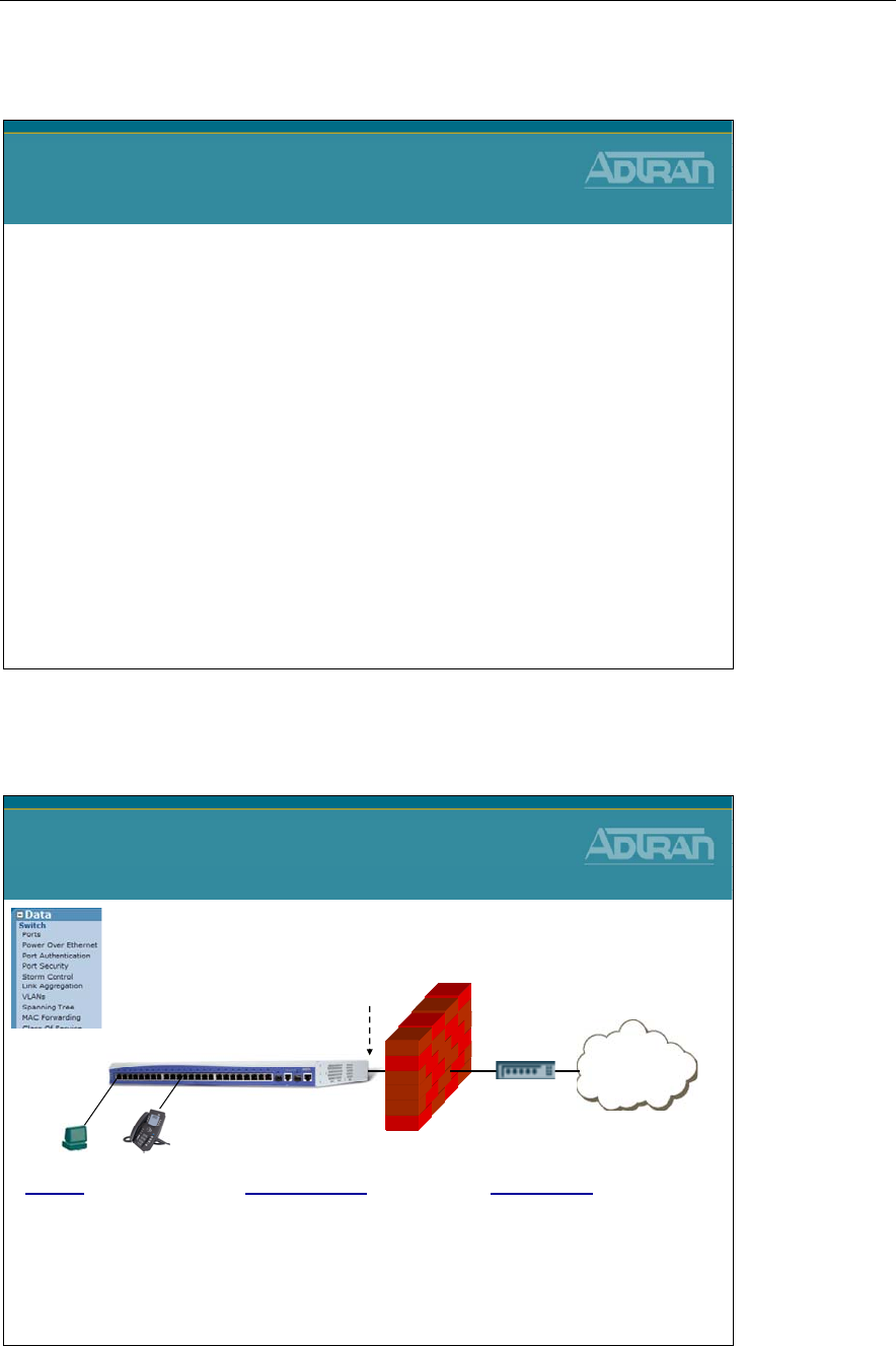
Module 7: NetVanta 7000 Series Data Configuration – Part 2
NetVanta IP Telephony Course 7-5
VLAN (Network) Interfaces
NetVanta IP Telephony Course
VLAN (Network) Interfaces
Data / Switch Defaults Review
Internet
NetVanta 7100
Data / Switch Defaults Review
ETH 0/0
WAN
DHCP Client
Ethernet 0/1-24
Switchport mode: trunk
Allowed VLANs: all
Native VLAN: 1
Spanning Tree Mode: edgeport
VLANs
Data - VLAN 1
IP Address: 10.10.10.1/24
Voice - VLAN 2
IP Address: 10.10.20.1/24
Gigabit 0/1-2
VLAN membership: trunk
Allowed VLANs: all
Native VLAN: 1

Module 7: NetVanta 7000 Series Data Configuration – Part 2
7-6 NetVanta IP Telephony Course
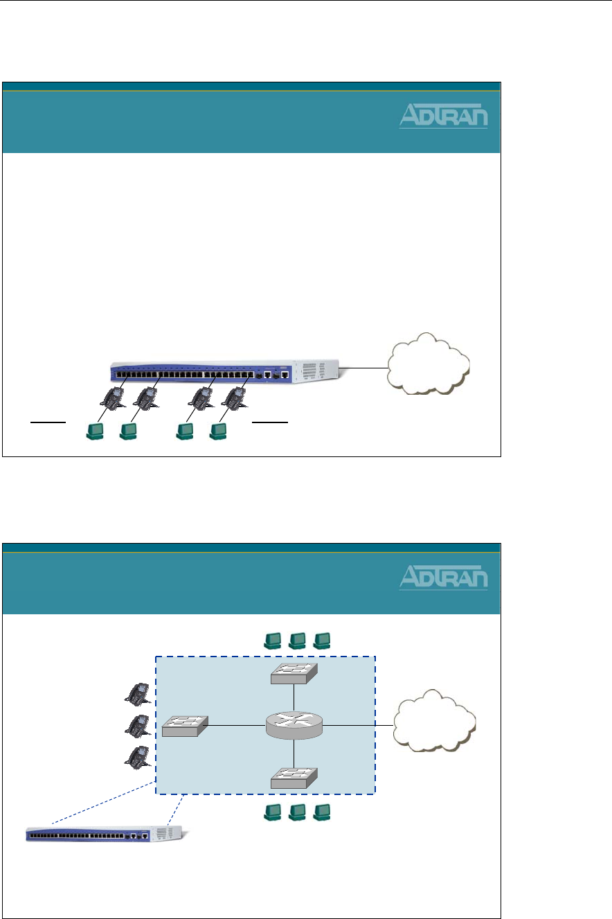
Module 7: NetVanta 7000 Series Data Configuration – Part 2
NetVanta IP Telephony Course 7-7
Adding Network Interfaces
Adding Network Interfaces
NetVanta 7100
Solution: Create Another Network Segment
1) Create VLAN
2) Assign IP Address to VLAN
3) Change Native VLAN on desired ports
Company XYZ has two departments. Both departments have
IP phones that will reside on VLAN 2. The PCs for each
department need to be on isolated network segments.
Internet
eth 0/0
Dept A
VLAN 1
Ports 1-12
Dept B
VLAN 3
Ports 13-24
Voice = VLAN 2
NetVanta 7100 - Switch Router Concept
Internet
NetVanta 7100
Switch Router Concept
eth 0/0int vlan 2
NetVanta 7100
To Create Another Network Segment
1) Create VLAN
2) Assign IP Address to VLAN
3) Assign Switchport to VLAN
int vlan 3
int vlan 1

Module 7: NetVanta 7000 Series Data Configuration – Part 2
7-8 NetVanta IP Telephony Course
VLAN Interfaces
VLANs can be configured with IP information to allow the built in router to route
information between them. This is known as Inter-VLAN routing. The VLAN becomes an
actual router interface with it own unique network IP address. The IP address assigned to
the VLAN interface will act as the default gateway to devices connected to ports that are
members of this VLAN.
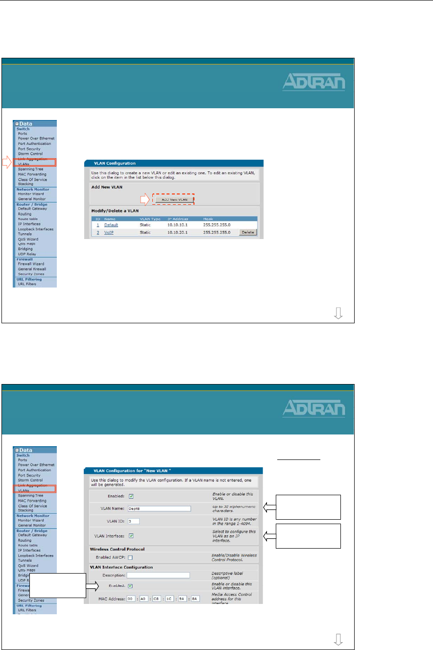
Module 7: NetVanta 7000 Series Data Configuration – Part 2
NetVanta IP Telephony Course 7-9
To Create a New VLAN
1) From the VLANs screen, select Add
New VLAN
– The NetVanta 7100 supports up to 255 active VLANs
To Create a New VLAN
more
To Create a New VLAN
2) Configure new VLAN
To Create a New VLAN
more
Enable IP on this
interface
Enable VLAN
interface
New VLAN
Name: DeptB
ID: 3
Assign VLAN
Name and ID
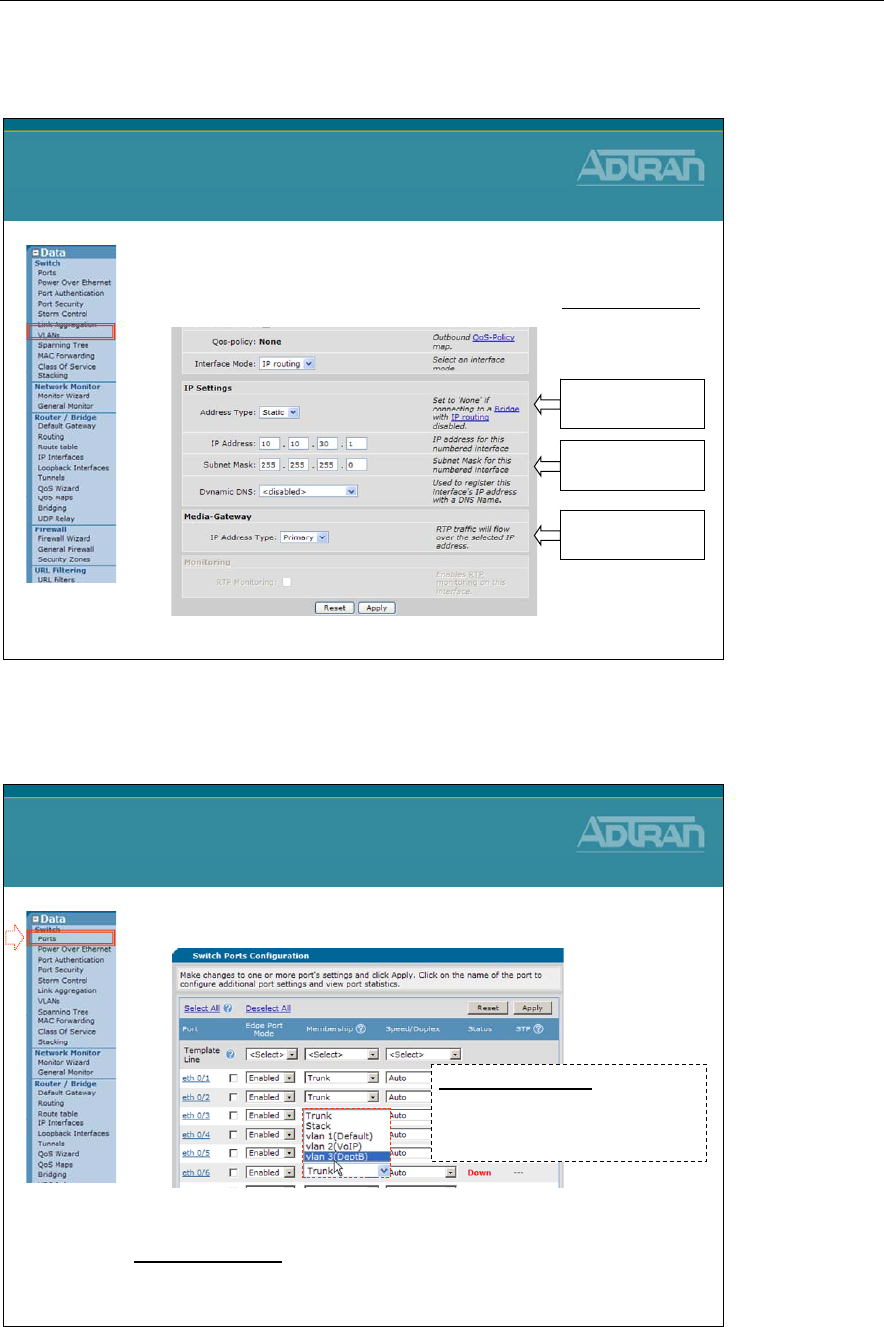
Module 7: NetVanta 7000 Series Data Configuration – Part 2
7-10 NetVanta IP Telephony Course
To Create a New VLAN
2) Configure new VLAN
(Continued…)
To Create a New VLAN
Static IP Address
10.10.30.1
255.255.255.0
Address Type
set to Static
VLAN IP address
and subnet mask
Media-Gateway
set to Primary
To Create a New VLAN
3) Assign Switchport to VLAN
To Create a New VLAN
Port Membership:
Trunk: Allow all VLANs
Specific Access Port -
VLAN: allow assigned VLAN only
InterVLAN Routing:
Traffic from one VLAN destined for another VLAN must go through the
router. Firewall policies can be configured to allow or disallow.
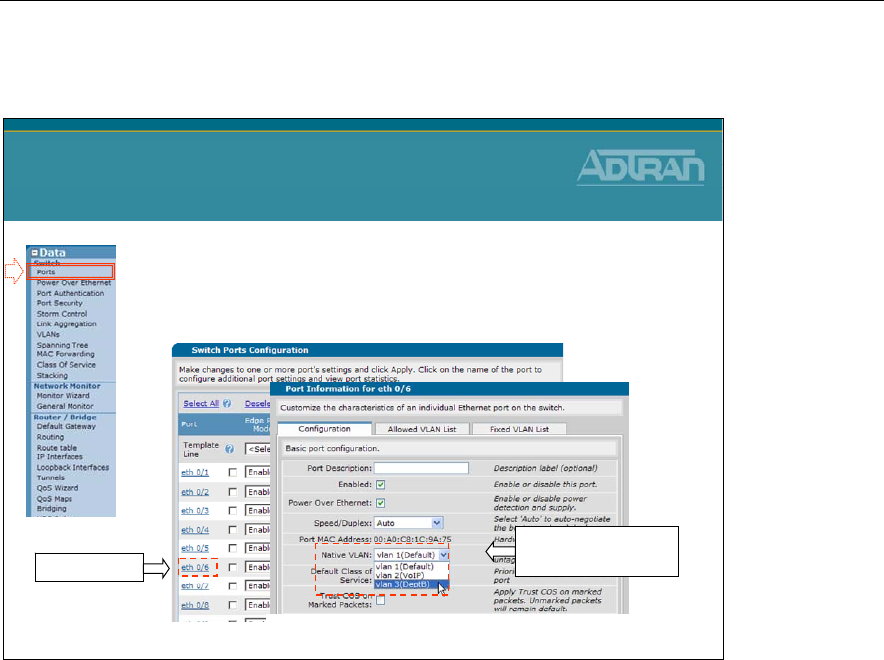
Module 7: NetVanta 7000 Series Data Configuration – Part 2
NetVanta IP Telephony Course 7-11
Native VLAN
•Untagged packets received on interface are
considered a part of the native VLAN ID
–Default = VLAN 1 (Can change per port)
Native VLAN
2) Choose Native
VLAN for this port
1) Select port
A Switchport configured as a Trunk port (802.1Q) allows all VLANs by default. When
traffic enters a switchport, it knows what VLAN it is assigned to based on the 802.1Q
VLAN ID. The Native VLAN option is used to associate untagged (no VLAN ID) traffic
to a VLAN. By default, untagged traffic is assigned to VLAN 1.
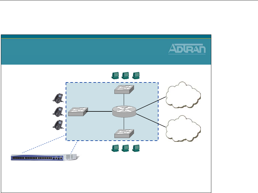
Module 7: NetVanta 7000 Series Data Configuration – Part 2
7-12 NetVanta IP Telephony Course
NetVanta 7100 - Switch Router Concept
Internet
NetVanta 7100
Switch Router Concept
eth 0/0
int vlan 1
int vlan 2
NetVanta 7100
int vlan 3
To Create Backup WAN
1) Create VLAN
2) Assign IP Address to VLAN
3) Assign switchport to VLAN
Internet
int vlan ?
•Would also configure backup route
and firewall policies for backup WAN
As illustrated in an earlier example, a routable VLAN interface can be created by adding a
new VLAN, assigning an IP address to that VLAN, and then assigning the new VLAN to a
Switchport. This new routable interface can be an additional LAN network, an isolated
DMZ, or a backup WAN as illustrated above.
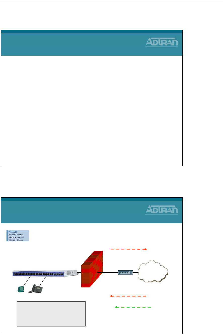
Module 7: NetVanta 7000 Series Data Configuration – Part 2
NetVanta IP Telephony Course 7-13
Firewall Configuration
NetVanta IP Telephony Course
Firewall Configuration
NetVanta 7100 - Data/Firewall Factory Defaults
NetVanta 7100
Data / Firewall Factory Defaults
Internet
NetVanta 7100
No traffic allowed in to LAN
All traffic allowed out
Firewall enabled
The factory default NetVanta
7100 has two security zones
- Public
-Private
PUBLICPRIVATE
Except the following:
SIP (UDP Port 5060)
WAN ADMIN Access
Secure Shell - ssh
Secure Web - https

Module 7: NetVanta 7000 Series Data Configuration – Part 2
7-14 NetVanta IP Telephony Course
The factory default NetVanta 7100 allows (and NATs) all traffic going to the internet.
UDP port 5060 SIP traffic, secure shell, and secure web traffic are the only traffic allowed
in the PUBLIC interface by default. The policies allowing this traffic can be removed if
you do not currently wish to allow that type of traffic.
The NetVanta 7100 is equipped with a stateful inspection firewall. A stateful inspection
firewall operates by monitoring traffic passing through it. It only allows traffic it is
specifically configured to allow as well as return traffic matching traffic that was
specifically allowed.
For example, if a computer sends a request to a web site, through the firewall, it is only
necessary to configure an allow for the outbound traffic, the traffic from the requesting
computer to the web server. The response traffic from the website will be automatically
allowed. All traffic that has not been initiated from within the network will be
automatically blocked unless otherwise specified.
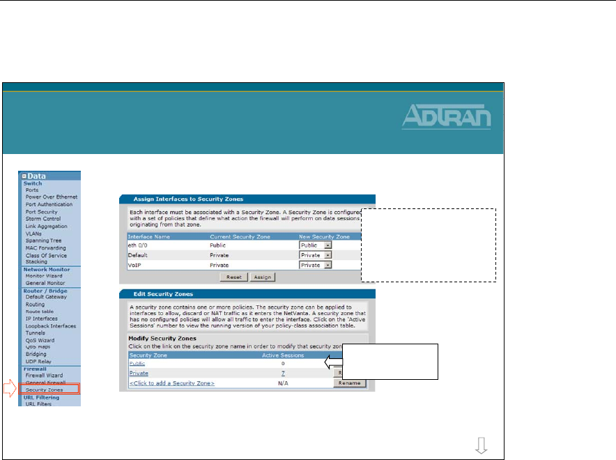
Module 7: NetVanta 7000 Series Data Configuration – Part 2
NetVanta IP Telephony Course 7-15
Data/Firewall - Security Zones
•Firewall Configuration
–The Factory Default NetVanta 7100 has two
security zones (Public and Private)
Data / Firewall
Security Zones
more
Click to edit exist
Security Zone
Eth 0/0 is assigned to
Public security zone and
the Data and Voice
VLANS are assigned to
the Private security zone
Each interface should be associated with a Security Zone. A Security Zone is configured
with a set of policies that define what action the firewall will perform on data sessions
originating from that zone. A security zone that has no configured policies will allow all
traffic to enter the interface.
The Public and Private Security Zone listed above are present with the factory delivered
NetVanta 7100. The firewall inspects traffic inbound. To control traffic coming from the
Internet, modify the Public Security Zone. To control traffic coming from VLAN 1 or
VLAN 2, modify the Private Security Zone.
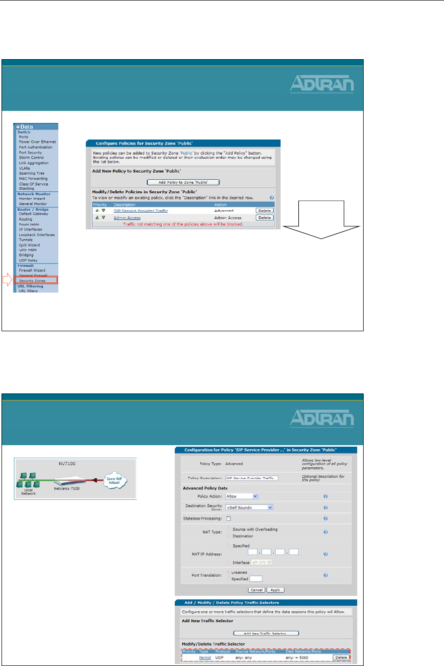
Module 7: NetVanta 7000 Series Data Configuration – Part 2
7-16 NetVanta IP Telephony Course
Data/Firewall - Public Security Zone
•Access from Outside the NetVanta 7100
–SIP Service Provider Traffic
•Allow SIP (UDP 5060) traffic in
–Admin Access
•Allow allows https and ssh access from the Public security
zone
Data / Firewall
Public Security Zone
Top down
processing
Public Security Zone - SIP Service Provider Traffic
Public Security Zone
SIP Service Provider Traffic
•The SIP Service Provider
policy allows SIP – UDP
port 5060 from anywhere
in to the NetVanta 7100
–If this is truly from a SIP
service provider, the traffic
selector should be modified
defining the source as the
specific IP address of
service provider
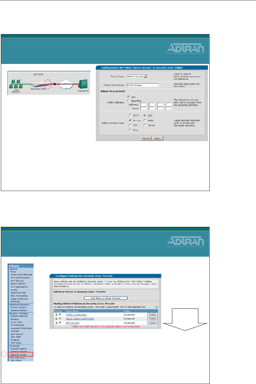
Module 7: NetVanta 7000 Series Data Configuration – Part 2
NetVanta IP Telephony Course 7-17
Public Security Zone – Admin Access
Public Security Zone
Admin Access
•The Admin Access policy
allows https and ssh
access from the Public
security zone by default
–Can be more specific
–Could also allow other admin
traffic such as:
•HTTP, FTP, SNMP, Telnet, and
Ping
Data/Firewall - Private Security Zone
•Access from LAN
–Traffic to NetVanta
•Inside traffic with destination of NetVanta 7100 allowed
–Voice / Data VLAN Traffic
•Allow VLAN to VLAN traffic
–NAT list NAT
•Allow all traffic going to Internet
Data / Firewall
Private Security Zone
Top down
processing

Module 7: NetVanta 7000 Series Data Configuration – Part 2
7-18 NetVanta IP Telephony Course
Private Security Zone – Traffic to NetVanta
Private Security Zone
Traffic to NetVanta
•Inside traffic with a
destination of the
NetVanta 7100 is allowed
–Examples:
•SIP
•RTP
•DHCP
•TFTP
•FTP
Private Security Zone – Voice / Data VLAN Traffic
Private Security Zone
Voice / Data VLAN Traffic
•Allow VLAN to VLAN traffic
•Required if you want to
allow the following:
–PC with Softphone
to call a SIP hard phone
–PC to access WEB GUI of an IP
phone
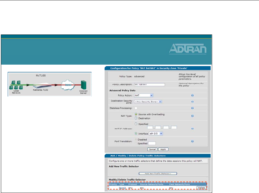
Module 7: NetVanta 7000 Series Data Configuration – Part 2
NetVanta IP Telephony Course 7-19
Private Security Zone – NAT list NAT
Private Security Zone
NAT list NAT
•Allow all traffic going
to Internet
–Traffic selectors matches
all traffic
–Outbound traffic is translated
from the private inside IP
address to the public IP
address assigned to the
outgoing interface

Module 7: NetVanta 7000 Series Data Configuration – Part 2
7-20 NetVanta IP Telephony Course
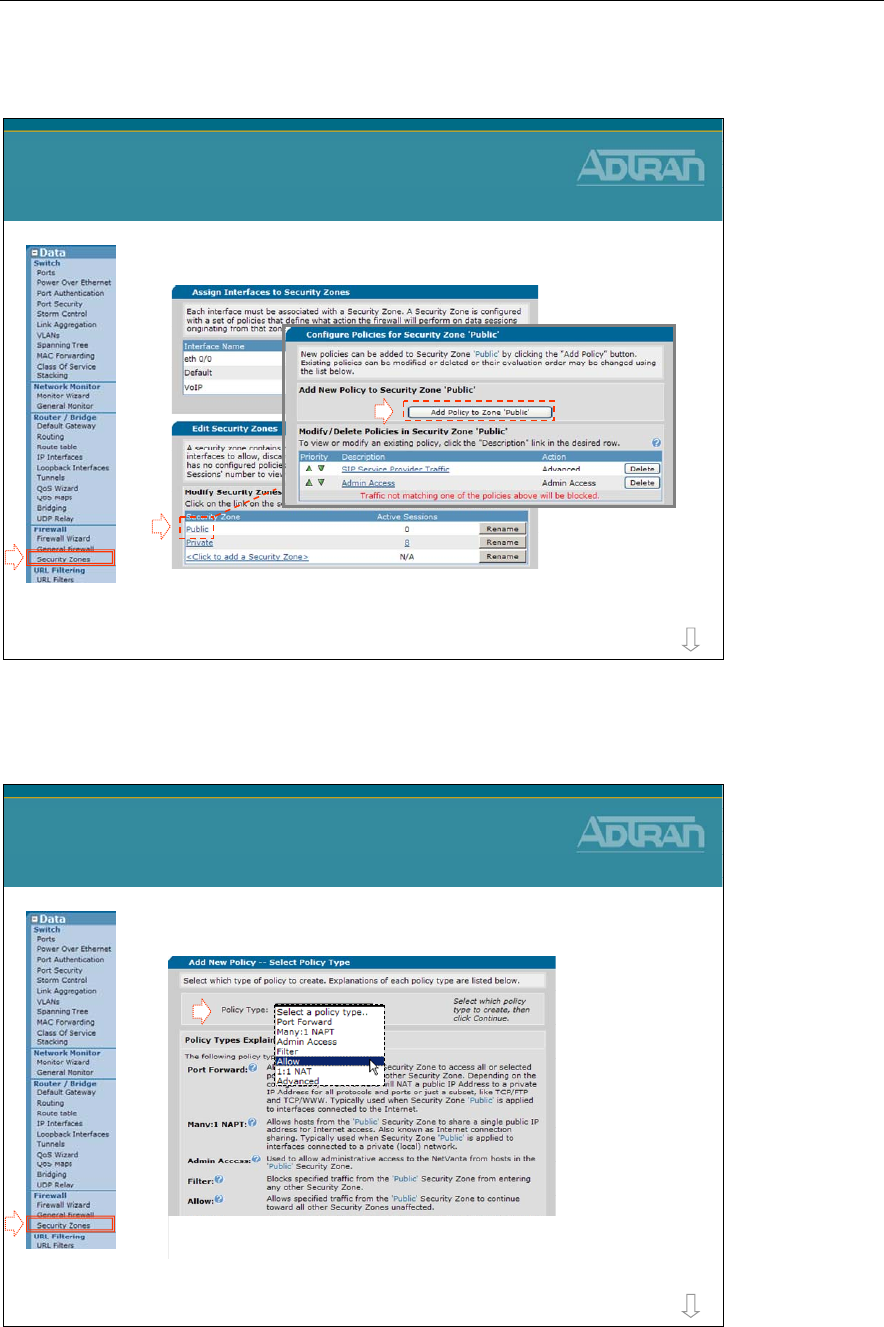
Module 7: NetVanta 7000 Series Data Configuration – Part 2
NetVanta IP Telephony Course 7-21
Security Zones - Adding New Policies
1) Select desired Security Zone
– A Security Zone is configured with a set of policies that define
what action the firewall will perform on data sessions originating
from that zone (inbound)
Data / Firewall Security Zones
Adding New Policies
1
more
2
3
Security Zones - Adding New Policies
2) Select Policy Type
3) Configure new Policy Settings
- Based on Policy Type selected
Data / Firewall / Security Zones
Adding New Policies
more
1
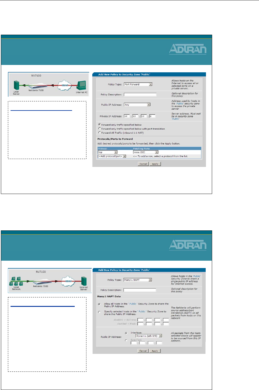
Module 7: NetVanta 7000 Series Data Configuration – Part 2
7-22 NetVanta IP Telephony Course
Security Zones Policies – Port Forward
Security Zone Policies
Port Forward
Port Forward Policy
Allows hosts from the
selected Security Zone to
access all or selected
ports on a private server
in another Security Zone
Security Zones Policies – Many:1 NAPT
Security Zone Policies
Many:1 NAPT
Many:1 NAPT Policy
Allows hosts from the
selected Security Zone to
share a single public IP
address for Internet
access. Also known as
Internet connection
sharing
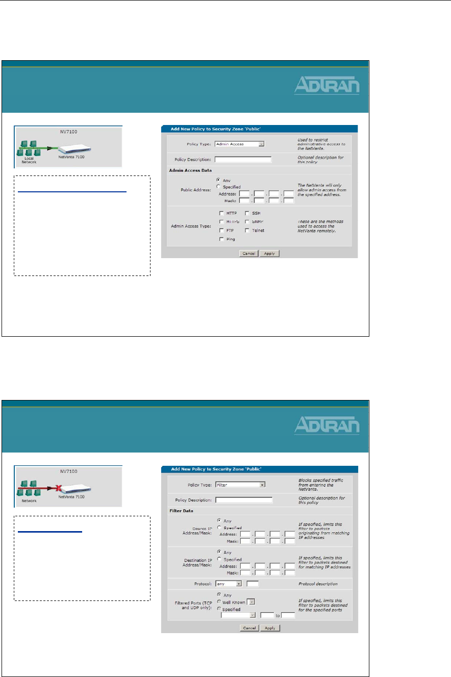
Module 7: NetVanta 7000 Series Data Configuration – Part 2
NetVanta IP Telephony Course 7-23
Security Zones Policies – Admin Access
Security Zone Policies
Admin Access
Admin Access Policy
Used to allow
administrative access to
the NetVanta from hosts
in the selected Security
Zone
Security Zones Policies – Filter
Security Zone Policies
Filter
Filter Policy
Blocks specified traffic
from the selected Security
Zone from entering any
other Security Zone
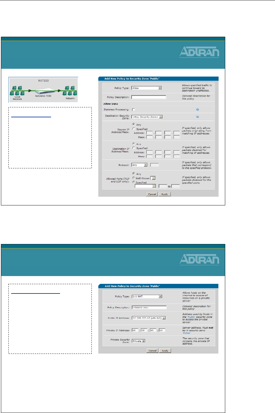
Module 7: NetVanta 7000 Series Data Configuration – Part 2
7-24 NetVanta IP Telephony Course
Security Zones Policies – Allow
Security Zone Policies
Allow
Allow Policy
Allows specified traffic
from the selected Security
Zone to continue toward
all other Security Zones
unaffected
Security Zones Policies – 1:1 NAT
1:1 NAT Policy
Forwards traffic destined
for an IP address on the
system to a specific IP
address in another
security zone by changing
the destination IP address
Security Zone Policies
1:1 NAT
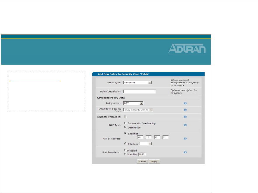
Module 7: NetVanta 7000 Series Data Configuration – Part 2
NetVanta IP Telephony Course 7-25
Security Zones Policies – Advanced
Advanced Policy
Allows low-level
configuration of all policy
parameters
Security Zone Policies
Advanced

Module 7: NetVanta 7000 Series Data Configuration – Part 2
7-26 NetVanta IP Telephony Course
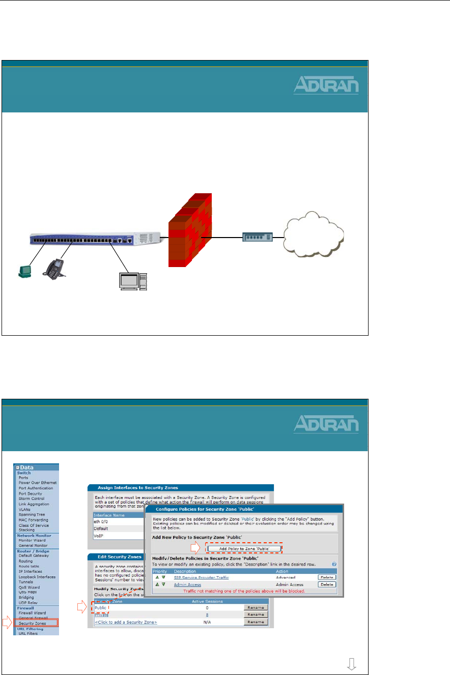
Module 7: NetVanta 7000 Series Data Configuration – Part 2
NetVanta IP Telephony Course 7-27
Firewall Example - Public Web Server
Data / Firewall Example
Public Web Server
1. Modify the Public Security Zone
2. Add a Port Forwarding Rule
–Traffic destined to public IP address - port 80, will be
forward to the private IP address of the web server
* Placing public web server in DMZ is covered later in this module
Internet
NetVanta 7100
PUBLIC
PRIVATE
Web Server
Private IP: 10.10.50.2
XYZ
Firewall Example – Add Port Forwarding Rule
1) Modify the Public Security Zone
2) Add a policy to zone Public
Data / Firewall Example
Add Port Forwarding Rule
more
1
2
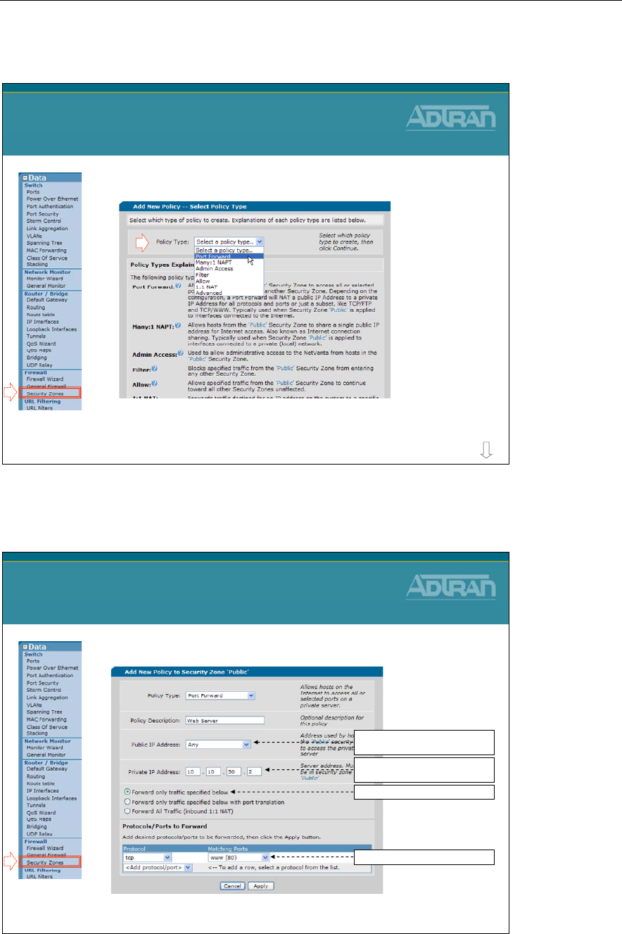
Module 7: NetVanta 7000 Series Data Configuration – Part 2
7-28 NetVanta IP Telephony Course
Firewall Example – Add Port Forwarding Rule
3) Add an Port Forward policy
Data / Firewall Example
Add Port Forwarding Rule
more
Firewall Example – Add Port Forwarding Rule
4) Configure Port Forward policy parameters
Data / Firewall Example
Add Port Forwarding Rule
Specify private IP address of web
server on inside network
Leave “only traffic specified”
If Public IP Address is DHCP, leave
“Any”, otherwise select Public IP.
Set matching port to www(80)
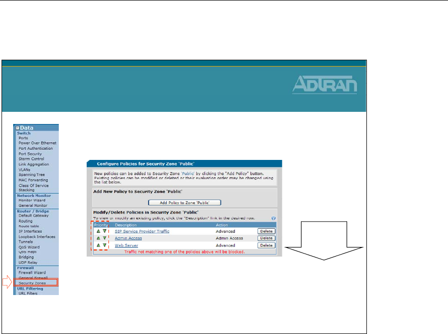
Module 7: NetVanta 7000 Series Data Configuration – Part 2
NetVanta IP Telephony Course 7-29
Firewall Example – Port Forwarding Rule
•New “Web Server” Port Forwarding Rule was
added to bottom of Policy list
–Arrow keys can be used to change the order of
rules.
Data / Firewall Example
Port Forwarding Rule
Top down
processing

Module 7: NetVanta 7000 Series Data Configuration – Part 2
7-30 NetVanta IP Telephony Course
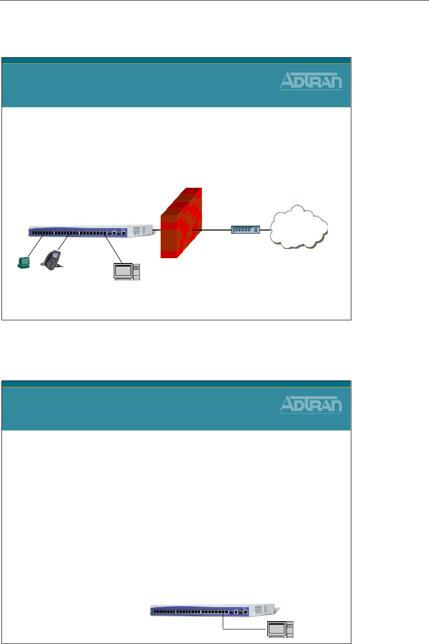
Module 7: NetVanta 7000 Series Data Configuration – Part 2
NetVanta IP Telephony Course 7-31
NetVanta 7100 - DMZ
NetVanta 7100
DMZ
Internet
NetVanta 7100
PUBLIC
PRIVATE
Web Server
XYZ
A network DMZ (demilitarized zone) is an isolated network used to host an
organization's external services. It adds an additional level of security. Only
specified traffic is allowed into the DMZ. No traffic initiated from the
outside is allowed into the PRIVATE LAN. If an external attacker breaks
into a server in the DMZ, they only have access to that server, not the
PRIVATE LAN.
DMZ
NetVanta 7100 - DMZ
NetVanta 7100
Creating a DMZ
1. Create a DMZ VLAN
–Assign an IP Address to the new DMZ VLAN
–Assign a switch port to the DMZ VLAN
2. Create a new DMZ Security Zone
–Block traffic initiated in the DMZ security zone from entering
the NetVanta 7100
–Assign the new DMZ VLAN to the new DMZ security zone
3. Add a Port Forwarding rule for Web traffic
–Forward all www traffic destined to the NetVanta 7100
public interface in to a web server located in the new DMZ
VLAN NetVanta 7100
Web Server
XYZ
DMZ
* Step by step instructions
included with this document

Module 7: NetVanta 7000 Series Data Configuration – Part 2
7-32 NetVanta IP Telephony Course
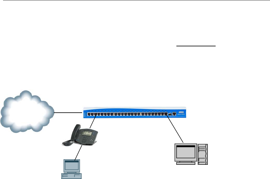
Module 7: NetVanta 7000 Series Data Configuration – Part 2
NetVanta IP Telephony Course 7-33
NetVanta 7100 - DMZ Creation
NetVanta 7100 Firewall Configuration
In this exercise you will add a DMZ VLAN to the NetVanta 7100 and then make it
routable by assigning an IP address to it. You will then create a Port Forwarding policy to
forward web traffic destined to the Public interface of the NetVanta 7100 in to a web
server located in the DMZ VLAN. Finally, you will create a DMZ security zone to block
traffic initiated within the DMZ VLAN.
DMZ Creation Overview
1. Create a DMZ VLAN
- Assign an IP Address to the new DMZ VLAN
- Assign a switch port to the DMZ VLAN
2. Create a new DMZ Security Zone
- Block traffic initiated in the DMZ security zone from entering the NetVanta 7100
- Assign the new DMZ VLAN to the new DMZ security zone
3. Add a Port Forwarding rule for Web traffic
- Forward all www traffic destined to the NetVanta 7100 public interface in to a web
server located in the new DMZ VLAN
Web Server
10.10.50.2
ETH 0/0
NetVanta 7100
ISP
X
YZ
ETH 0/24
DMZ VLAN
VLAN ID: 5
IP Address: 10.10.50.1
Subnet Mask: 255.255.255.0
DMZ Port: Eth 0/24
In
st
r
ucto
r L
ed
Ex
e
r
c
i
se

Module 7: NetVanta 7000 Series Data Configuration – Part 2
7-34 NetVanta IP Telephony Course
SETUP
This exercise builds on the NetVanta 7100 factory default configuration
Plug the NetVanta 7100 in to an AC power source.
Connect one end of an Ethernet cable to Ethernet port of the PC (Configured as DHCP
Client) and the other end to Ethernet 0/1 on the NetVanta 7100.
Connect an Ethernet cable between Ethernet 0/0 of the NetVanta 7100. Connect the
other end to the Internet connection provided by your ISP.
From your PC, open the installed browser (if not already open) and enter
10.10.10.1/admin in the Address field. The NetVanta login window appears. Enter
admin as the username, password as the password, and then click the OK button.
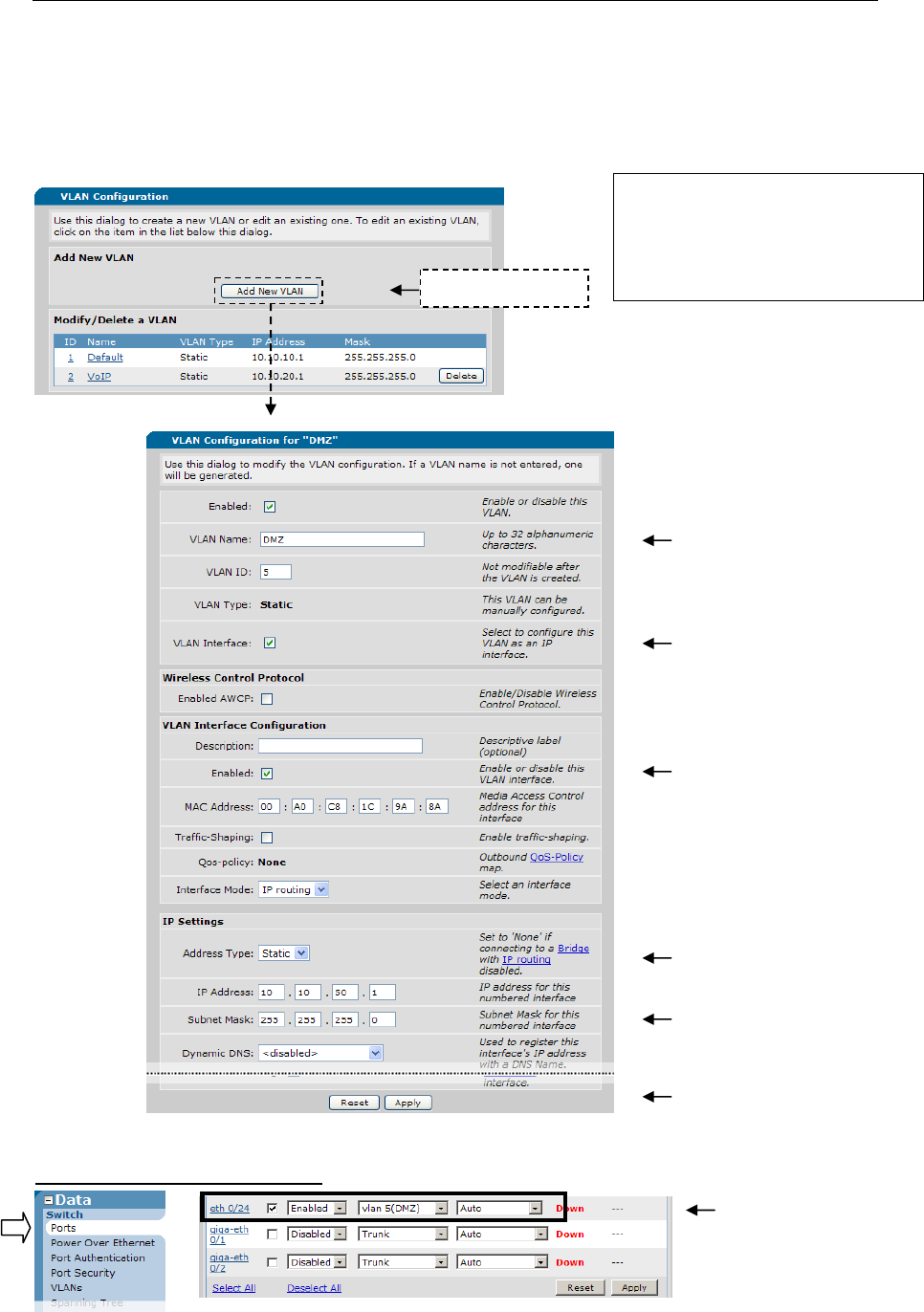
Module 7: NetVanta 7000 Series Data Configuration – Part 2
NetVanta IP Telephony Course 7-35
Step 1) Create a new VLAN to be used for a DMZ
From the NetVanta 7100 Data / Switch / VLANs screen, add a new VLAN, enable IP, and
configure the IP address for the DMZ VLAN. Then add port eth 0/24 to the DMZ VLAN.
Data / Switch / Ports Screen
1) Add new VLAN
8) Add port eth 0/24 to the
DMZ VLAN then click
Apply
2) Enable, name, and
assign VLAN ID
3) Enable IP on this
VLAN interface
4) Enable VLAN (layer 3)
6) Assign static IP address
10.10.50.1
255.255.255.0
7) Click Apply
VLAN Name: DMZ
VLAN ID: 5
VLAN IP Address: 10.10.50.1
Subnet Mask: 255.255.255.0
5) Select Static
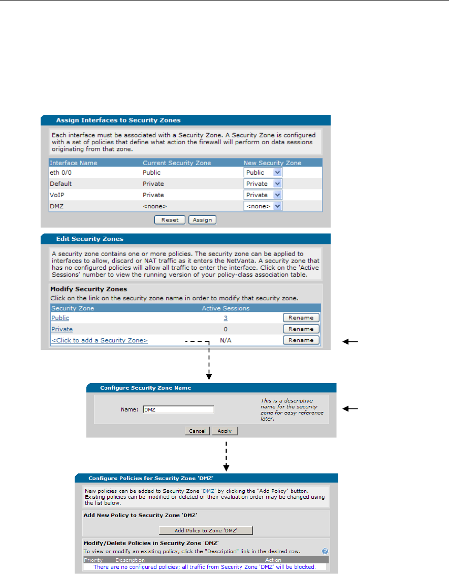
Module 7: NetVanta 7000 Series Data Configuration – Part 2
7-36 NetVanta IP Telephony Course
Step 2) Create a new Security Zone for the DMZ
From the NetVanta 7100 Data / Firewall / Security Zones screen configure an ‘Unused
Security Zone’ to be used as the DMZ. This security zone will be configured to block
traffic initiated from within the DMZ VLAN.
1) Click to add a new
Security Zone
2) Type ‘DMZ’ for the
Security Zone name and
then click Apply
A new security zone has been created. By default, there are no configured polices in this
security zone. All traffic initiated from within the DMZ Security Zone will be blocked from
entering the NetVanta 7100.
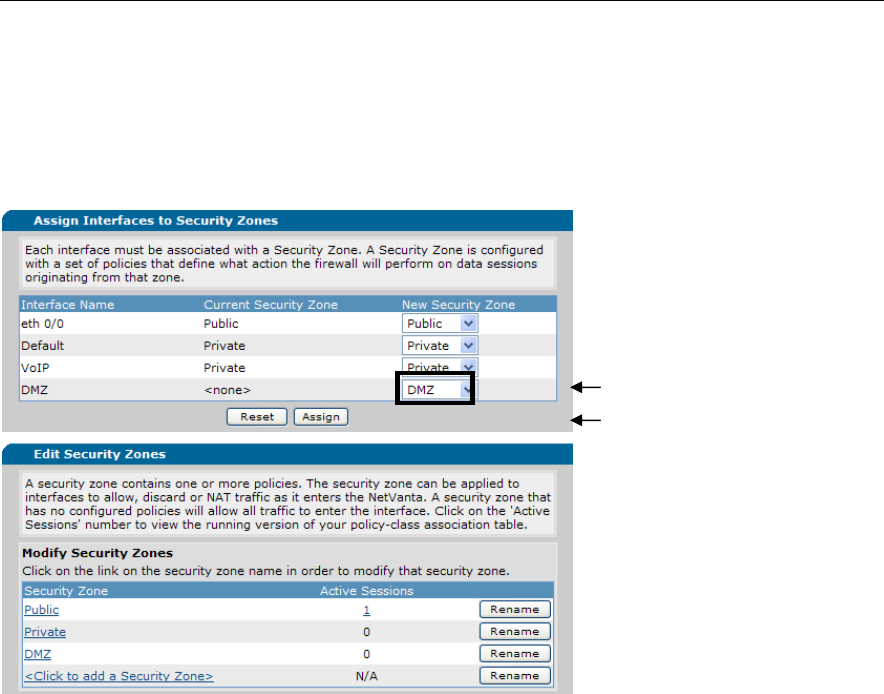
Module 7: NetVanta 7000 Series Data Configuration – Part 2
NetVanta IP Telephony Course 7-37
Step 2 (Continued…) Assign VLAN #5 to the DMZ Security Zone
From the Data / Firewall / Security Zones screen, place interface DMZ (VLAN #5) in the
new DMZ security zone. All traffic originating in the DMZ VLAN will be blocked from
entering the NetVanta 7100.
1) Select DMZ as the
Security Zone
2) Click Assign
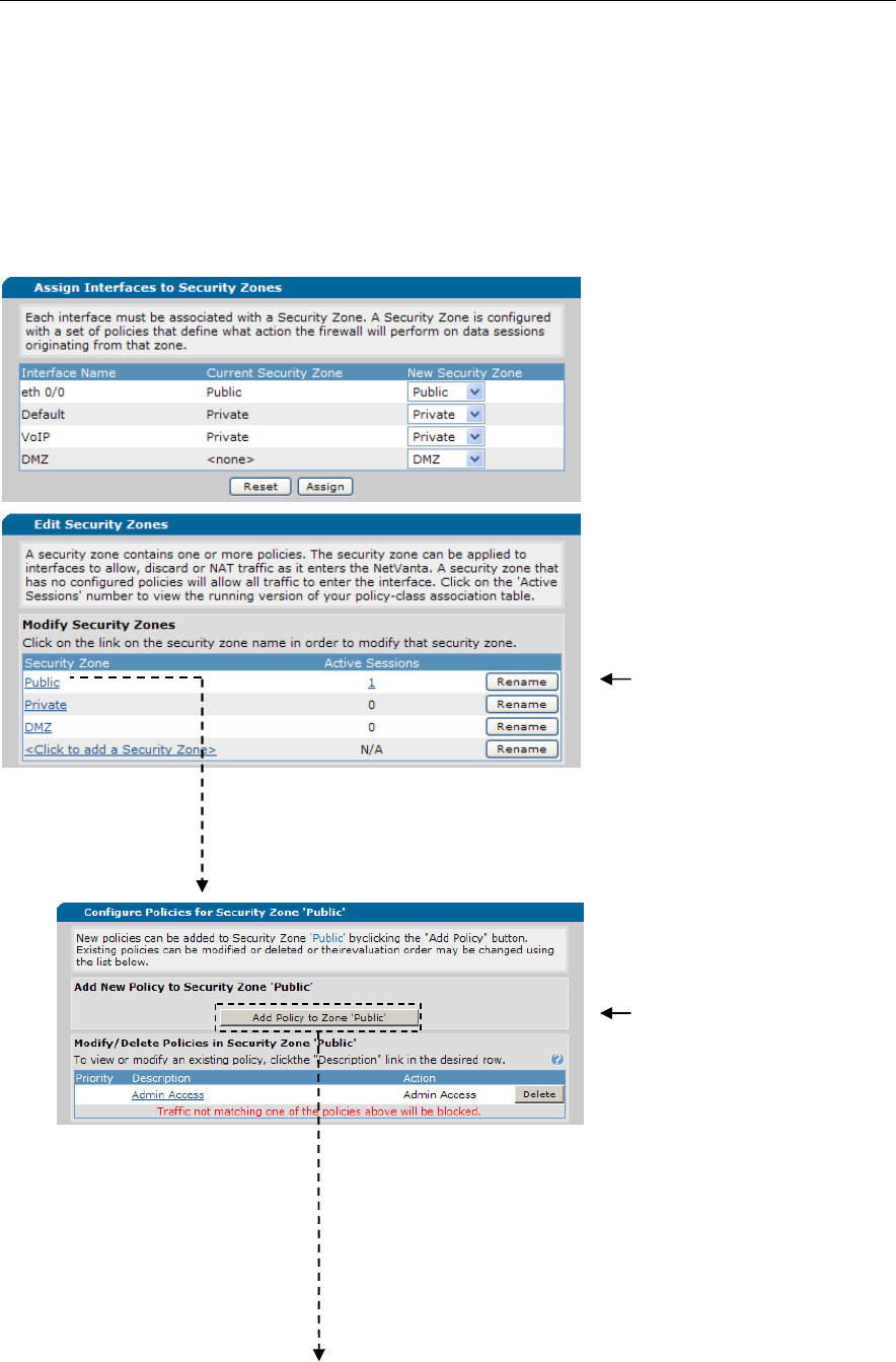
Module 7: NetVanta 7000 Series Data Configuration – Part 2
7-38 NetVanta IP Telephony Course
Step 3) Add a Port Forwarding Rule
From the Data / Firewall / Security Zones screen, add a port forwarding rule to the Public
Security Zone. The new rule will be configured to forward all WEB traffic destined to the
public IP address of the NetVanta 7100 in to the private IP address of the WEB server
located in the DMZ security zone.
1) Select the Public Security
Zone
2) Click Add Policy to
Zone Public
Continues on next page
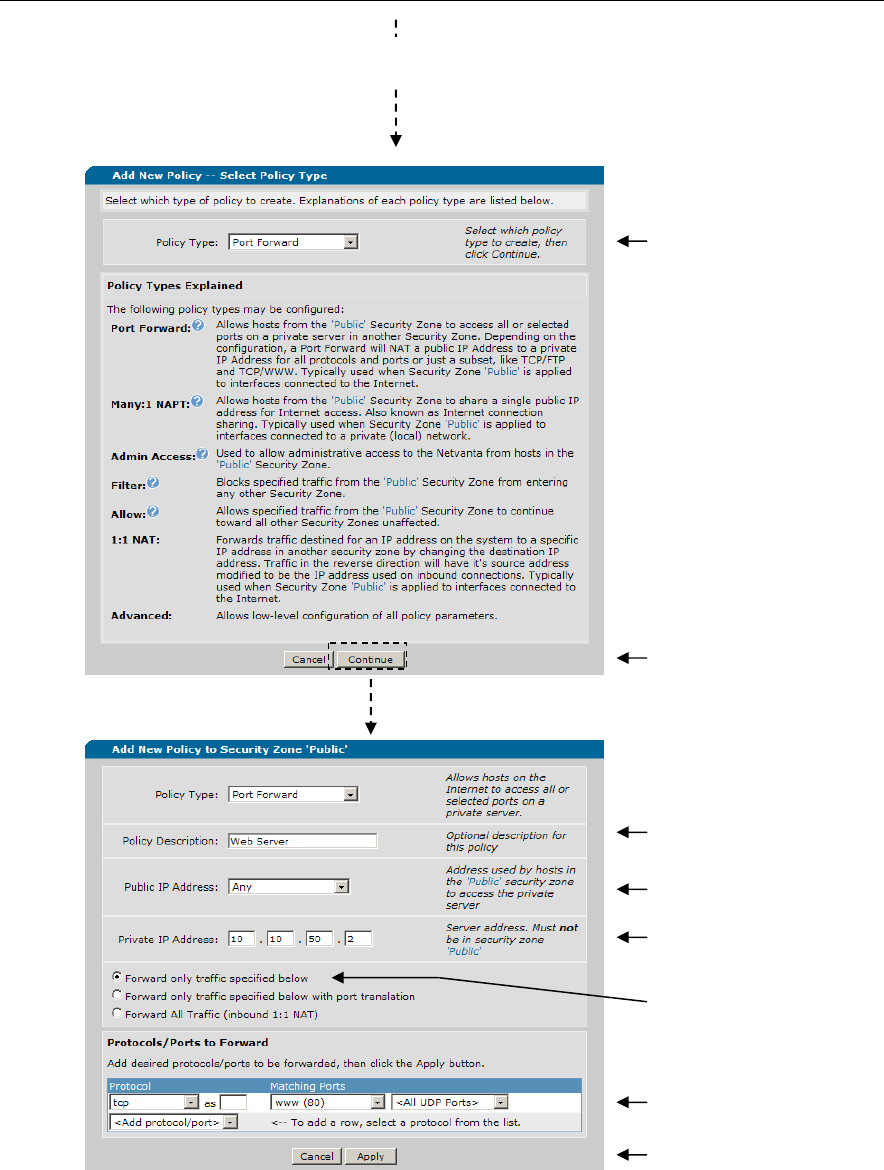
Module 7: NetVanta 7000 Series Data Configuration – Part 2
NetVanta IP Telephony Course 7-39
Add a Port Forwarding Rule (Continued…)
The new port forwarding rule has been added to the Public security zone. All port
80 web traffic destined for the public IP address of the NetVanta 7100 will be
forward in to the private IP address of the WEB server located in the DMZ security
zone.
3) Select Policy Type Port
Forward
4) Click Continue
5) Enter description
6) Set Public IP
Address to Any
7) Set Private IP
Address to 10.10.50.2
8) Choose the “Forward
only traffic specified
below” option button
9) Set matching port to
www (port 80)
10) Click Apply

Module 7: NetVanta 7000 Series Data Configuration – Part 2
7-40 NetVanta IP Telephony Course
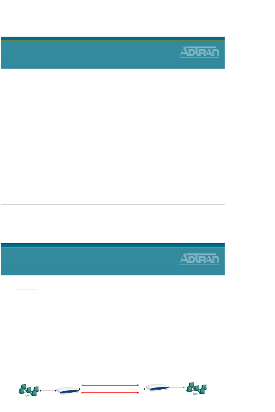
Module 7: NetVanta 7000 Series Data Configuration – Part 2
NetVanta IP Telephony Course 7-41
Quality of Service
NetVanta IP Telephony Course
Quality of Service
Quality of Service (QoS)
(QoS) – A technique used to differentiate between packet
types and allow important traffic to receive higher priority
• A diverse mixture of protocols typically share the same data
path in today’s networks
• Different traffic types can impact each other across the connection
• QoS is intended to allow certain applications to achieve the level of
performance considered necessary for optimal function
• The whole point is to provide a predictable level of service
VoIP (requires low latency)
Streaming Video
(requires consistent delay)
Quality of Service (QoS)
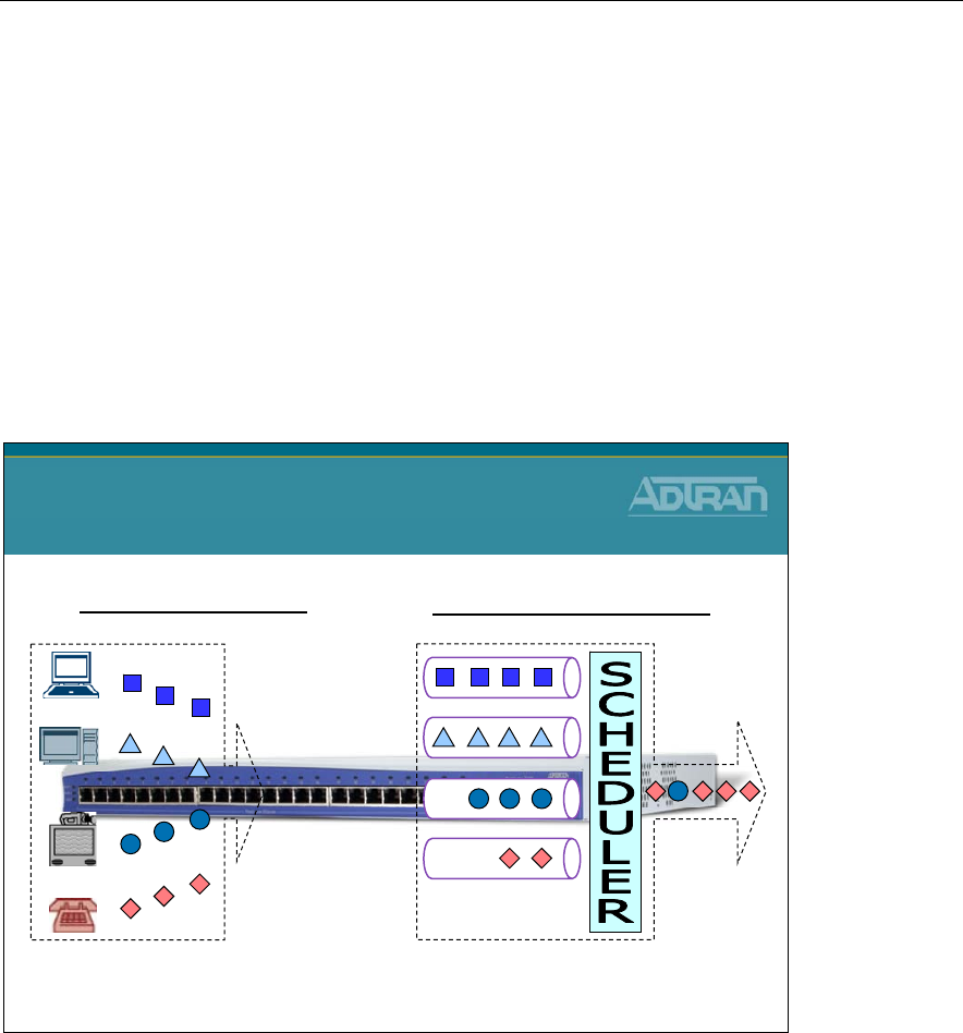
Module 7: NetVanta 7000 Series Data Configuration – Part 2
7-42 NetVanta IP Telephony Course
Quality of Service (QoS) is a technique used to differentiate between packet types and
allow important traffic to receive higher priority. In a non-QoS-enabled IP network, all
packets generally receive the same best-effort service. QoS is intended to allow
applications that may require a certain type of network performance to be able to achieve
that level of performance. Network applications require different types of response. Some
may need very low latency, like Voice over IP. Others can handle longer latency, but need
consistent delay. An example of this is streaming video. QoS helps give these types of
applications a predictable level of service.
Basic Layer 3 QoS Operation
Basic Layer 3 QoS Operation
Classify / Mark Queue / Schedule
DiffServ / IP Precedence
(IP v4 TOS byte marking)
FIFO / WFQ / LLQ / CBWFQ
:
:
The basic operation of QoS involves classifying the different types of traffic and then
marking the traffic to give a certain level of priority. Marking might be done by the
originating equipment or by the router. Queuing only takes place when the transmitting
interface is congested (or full). Traffic is placed in queues where it waits to get serviced
out the transmitting interface. There are different scheduling methods that can be used to
schedule traffic from the queues to the transmitting interface. We will look at the
scheduling methods supported by the NetVanta AOS products in this module.
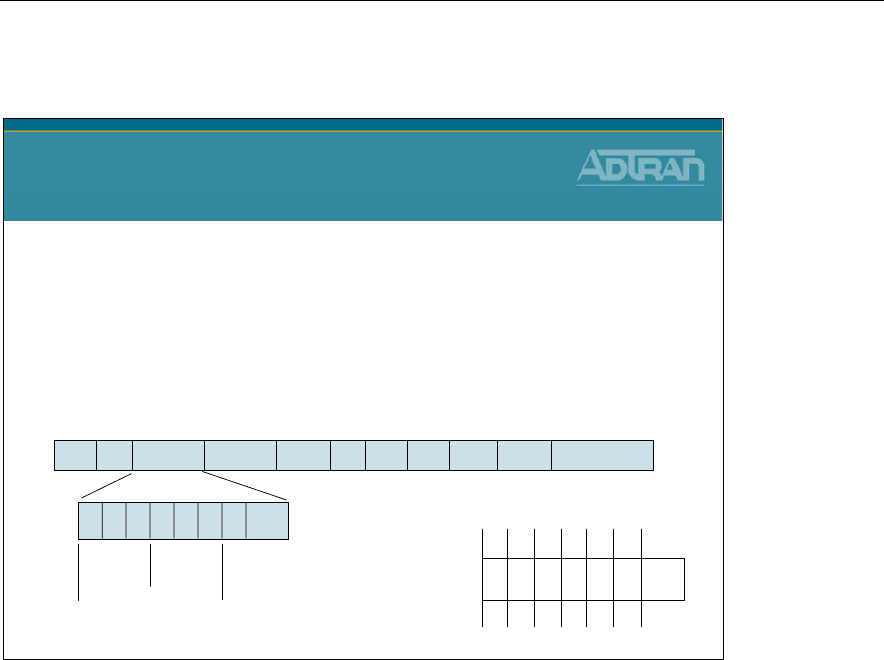
Module 7: NetVanta 7000 Series Data Configuration – Part 2
NetVanta IP Telephony Course 7-43
Layer 3 QoS - Type of Service Byte
Ver Len ToS (DS) Len ID Offset TTL Prot FCS IP SA IP DA Data
7 6 5 4 3 2 1 0
IPP Unused
DSCP
Layer 3 QoS
Type of Service Byte
IP version 4 Type-of-Service (TOS) byte
–Can be used to mark prioritization or special handling
•Traditional model: IP Precedence
–3 bits used for priority/8 levels of priority
•Differentiated services model: DiffServ
–Six bits called DS Code Points/ 64 possible forwarding behaviors
–Backward compatible with IP Precedence
RFC 2474 - Definition of the DS Field
32 16 8 4 2 1DSCP=46
4 2 1IPP=5
1 0 1 1 1 0
00
TOS
To mark, or tag traffic with different priorities Type of Service (TOS) byte in the IP packet
is used. The TOS byte can be used two different ways. The traditional means of tagging
the packet with a priority value was done using only three bits of the TOS byte – bits 7, 6,
and 5. This method is referred to as the IP Precedence value. Using these three bits of the
TOS, the IP Precedence value allows for eight levels of differentiation.
More commonly, six bits of the TOS are used to define the DiffServ, or Differentiated
Services Code Point (DSCP) value. Bits 7, 6, 5, 4, 3, and 2 in the TOS field define the
DSCP. The DiffServ bits allow for 64 levels of priority, but are also backward compatible
with IP Precedence values.
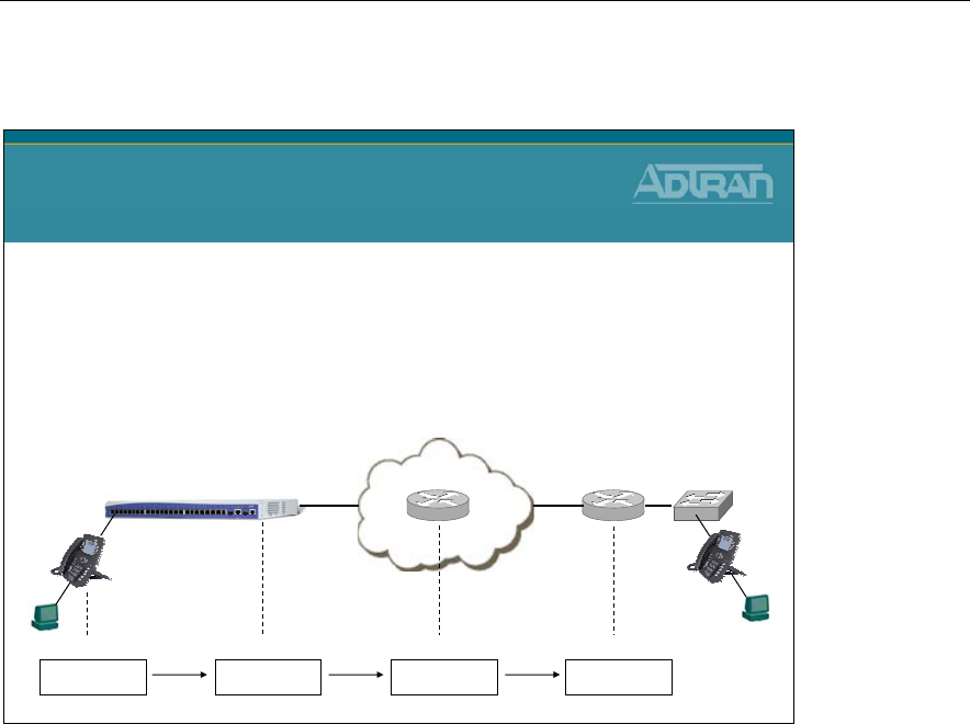
Module 7: NetVanta 7000 Series Data Configuration – Part 2
7-44 NetVanta IP Telephony Course
Layer 3 QoS - Type of Service Byte
Layer 3 QoS
Type of Service Byte
NetVanta 7000
101110
00
ToS
101110
00
ToS
101110
00
ToS
101110
00
ToS
•Layer 3 QoS “ToS” is End to End
–Once ToS is written, does not change unless rewritten
•Per Hop Behavior
–Each router must be configured to give special treatment
•Otherwise, “Best Effort”
As shown above, layer 3 QoS is considered End to End. Once the IP Type of Service field
is written, it does not change as it routes from one network to another. The only way it
changes is if someone rewrites it.
Even though layer 3 QoS is considered End to End, it is still a Per Hop Behavior. In order
for a packet to get special treatment, the router that the packet crosses must be configured
to give this packet special treatment.

Module 7: NetVanta 7000 Series Data Configuration – Part 2
NetVanta IP Telephony Course 7-45
Layer 3 QoS - Type of Service Byte
DSCP IP Precedence
0-7 0
8-15 1
16-23 2
24-31 3
32-39 4
40-47 5
48-55 6
56-63 7
DSCP Values are translated to IP
Precedence Values
Layer 3 QoS
Type of Service Byte
In order for DSCP bits to be backward compatible with IP Precedence values, the DSCP
ranges are mapped to corresponding IPP values. These values are known as Class-Selector
per-hop Behaviors. In these per-hop behaviors, the last three bits of the DSCP value are
set to zero, so only the first three bits are significant for differentiating the eight classes of
service. The chart shown here indicates the values for these Class-Selector per-hop
Behaviors.
DiffServ Value DSCP First 3 Bits
(IPP) IPP Value Traffic Type
0 000000 000 0 Routine
8 001000 001 1 Priority
16 010000 010 2 Immediate
24 011000 011 3 Flash
32 100000 100 4 Flash Override
40 101000 101 5 Critical
48 110000 110 6 Internetwork Control
56 111000 111 7 Network Control

Module 7: NetVanta 7000 Series Data Configuration – Part 2
7-46 NetVanta IP Telephony Course
IP ToS Byte and IP Precedence
IP ToS Byte
Precedence Bits Class Name Decimal Value
0 000 Routine 0 (0x00)
1 001 Priority 32 (0x20)
2 010 Immediate 64 (0x40)
3 011 Flash 96 (0x60)
4 100 Flash Override 128 (0x80)
5 101 Critical 160 (0xA0)
6 110 Internetwork Ctl 192 (0xC0)
7 111 Network Control 224 (0xE0)
The IP Precedence values provide network routers with information about what kind of
traffic is contained in the IP packet. Based on the IP Precedence values, some networks
(when supported) can offer special handling to certain packets. In addition, providing IP
Precedence values to critical traffic (such as route information) ensures that critical packets
will always be delivered regardless of network congestion. This traffic is often critical to
network and internetwork operation. In general, the higher the IP Precedence value, the
more important the traffic and the better handling it should receive in the network. It is
important to remember that not all equipment in the public IP network will be configured
to recognize and handle IP precedence values. While it is a good idea to set the values for
critical traffic, it does not guarantee special handling. As just discussed, the IP Precedence
value uses the first three high-order bits of the TOS field to define precedence values. This
chart lists the IP Precedence value, the TOS bits and class name of the priority value.

Module 7: NetVanta 7000 Series Data Configuration – Part 2
NetVanta IP Telephony Course 7-47
DSCP Classes
DSCP Class Name Binary Value Decimal Value
BE (Best Effort) 000000 0
AF11 (Assured Forwarding) (RFC 2597) 001010 10
AF12 001100 12
AF13 001110 14
AF21 010010 18
AF22 010100 20
AF23 010110 22
AF31 011010 26
AF32 011100 28
AF33 011110 30
AF41 100010 34
AF42 100100 36
AF43 100110 38
EF (Expedited Forwarding) (RFC 2598) 101110 46
Assured Forwarding PHB
The flexibility of DiffServ allows for more developed sub-classes of service within each
main class using the last three bits of the DSCP. As defined in RFC2597, the Assured
Forwarding PHB creates four main classes of service: AF1, AF2, AF3, AF4
The first three bits of the DSCP specify the class and the last bit is always zero. Each class
is separated into subclasses using the two remaining bits in the DSCP (bits 3 and 4). The
subclasses are divided based on the likelihood that packets in the class are dropped in the
event of network congestion. The higher the value for bits 3 and 4, the greater the
likelihood that the packets will be dropped. The following table lists the Assured
Forwarding PHB subclasses and their corresponding DSCP bits and values.
Expedited Forwarding PHB
RFC2598 created a new DiffServ PHB intended to provide the best service possible on an
IP network. Packets using the Expedited Forwarding PHB markings should be provided
service to reduce latency, jitter, dropped packets, and be guaranteed bandwidth during the
entire end-to-end transmission journey through the network. The DSCP value for the
Expedited Forwarding PHB is 46 (DSCP bits are 101110).
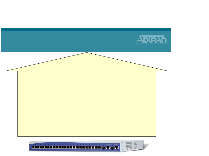
Module 7: NetVanta 7000 Series Data Configuration – Part 2
7-48 NetVanta IP Telephony Course
ADTRAN OS - QoS Support (Outbound)
NetVanta - ADTRAN OS
QoS Support (Outbound)
Outbound (PPP/FR/HDLC/ATM WAN ports)
–DiffServ aware/marking
–Queuing (Scheduling) Methods
•First In First Out
•Weighted Fair Queuing (WFQ)
•Low Latency Queuing
•Class Based Weighted Fair Queuing
–Frame Relay Fragmentation (FRF.12)
–PPP Fragmentation
Outbound QoS occurs in the AOS devices on WAN interfaces (i.e. PPP, Frame Relay)
when there is congestion on the interface. The equipment recognizes IPP or DSCP values
that are already marked, or the device may also tag the traffic.
Once traffic is tagged, it is scheduled using one of several queuing methods. The AOS
devices support First In First Out (FIFO), Weighted Fair Queuing (WFQ), Class-Based
Weighted Fair Queuing (CBWFQ), or Low Latency Queuing (LLQ). Frame Relay
Fragmentation (FRF.12) and PPP Fragmentation are also supported. We will discuss these
queuing methods in more detail over the next few slides.
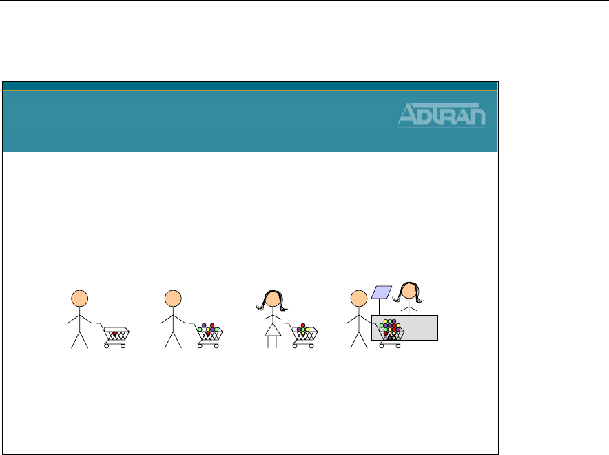
Module 7: NetVanta 7000 Series Data Configuration – Part 2
NetVanta IP Telephony Course 7-49
Layer 3 Queuing Methods - First In First Out
Waiting in line on a first come, first served basis is similar to how FIFO works. When you go to the
grocery store and are ready to check out, you wait in line to be processed by the cashier. The
cashier will process each person in line based on the order in which they arrived. It doesn’t matter
how many groceries you have in your shopping cart or how much of a hurry you are in. You must
wait until customers in front of you are processed first.
Layer 3 Queuing Methods
First In First Out
First In First Out (FIFO)
–Most common and simplest to implement
–Packets are transmitted in the order they are placed in the queue
–Works best in situations where the ingress and egress ports are similarly
matched in speed
–Not adequate for time sensitive traffic
First In First Out (FIFO) queuing is familiar to almost everyone. This method is what we
are used to in everyday life. Consider a single line at the grocery store. When you go to
the grocery store and are ready to check out, you wait in line to be processed by the
cashier. The cashier will process each person in line based on the order in which they
arrived. It does not matter how many groceries you have in your shopping cart or how
much of a hurry you are in. You must wait until customers in front of you are processed
first. Waiting in line on a first come, first served basis is similar to how FIFO works.
Packets are transmitted simply in the order they are placed in the queue. This method
works best in situations where the ingress and egress ports are similarly matched in speed,
but it is not adequate for time sensitive traffic, such as Voice over IP.
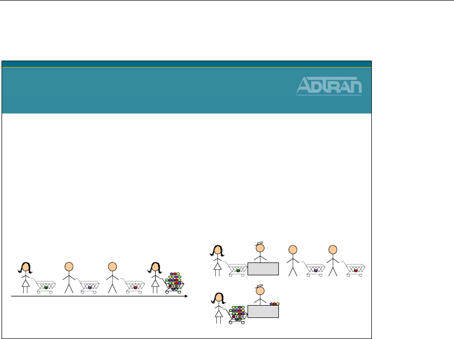
Module 7: NetVanta 7000 Series Data Configuration – Part 2
7-50 NetVanta IP Telephony Course
Layer 3 Queuing Methods - Weighted Fair Queuing
Layer 3 Queuing Methods
Weighted Fair Queuing
Weighted Fair Queuing (WFQ)
–Enabled by default on WAN interfaces with speed E1 or less
–WFQ uses a number of individual queues, one for each flow or conversation
–Up to 256 conversation queues
–Conversations determined by hash of src/dest IP address, ports, protocol type, and IP
Precedence value
–Each flow or traffic class is assigned weight based on IP Precedence
–Provides priority among unequally weighted flows
–Prevents small volume, interactive traffic such as Telnet from being starved out by high
volume traffic such as FTP
Another queuing type supported by the AOS devices is Weighted Fair Queuing (WFQ).
WFQ is the default queuing method on WAN interfaces with a speed of E1 or less. WFQ
uses queues for each conversation flow, and there can be up to 256 conversation queues on
the single WAN interface. Conversations are determined by a combination of the
source/destination IP address, ports, protocol type, and IP Precedence value. Each
conversation flow is then assigned a weight based on IP Precedence to ensure priority.
Traffic marked with a higher IPP value, or interactive traffic will be given more weight or
'priority' when waiting to get out the WAN interface. For example, interactive traffic such
as Telnet would be given priority over high volume traffic such as FTP. Going back to our
grocery line example, this is similar to having a 10 items or less express lane. If someone
has only a few items that will be quick to process, they can go to the express lane. If they
have many items that may take a little longer to process, the customer goes to the regular
line.
The differentiating factor here is that both lines can be processed simultaneously, so the
people with few items no longer have to wait in the same line as those with a lot of items.
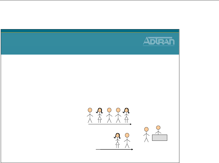
Module 7: NetVanta 7000 Series Data Configuration – Part 2
NetVanta IP Telephony Course 7-51
Layer 3 Queuing Methods - Low Latency Queuing
An easy way to visualize how low latency
queuing works is to think about how airline
passengers are processed for check-in at the
airport. Frequent Fliers are often able to get
into a separate “high priority” line where they
will be processed by the next available agent.
Infrequent fliers in the “normal line” are
processed as long as there is no one waiting
in the high priority line.
High Priority Line (i.e. medallion)
(always processed first)
Normal Line
(processed when no one is in the
High Priority Line)
Layer 3 Queuing Methods
Low Latency Queuing
Low Latency Queuing
–Used to guarantee that specific types of traffic receive as much of the bandwidth
as needed
–Single priority queue for flows that are latency sensitive
–Traffic placed in priority queue will be serviced before all other traffic
–All flows not matching PQ match criteria would be processed by WFQ
–Queue criteria can be based on protocol, IP Precedence/DiffServ markings, or
traffic defined by an access-list
While Weighted Fair Queuing processes multiple lines at the same time, Low Latency
Queuing guarantees that as long as there are people in the priority line, no other lines will
be processed. In other words, Low Latency Queuing reserves a single queue for priority
traffic and low latency traffic is placed in that queue. This queue is then always serviced
before other queues. This guarantees that specific types of traffic receive as much of the
bandwidth as needed. All other traffic that does not match the priority queue criteria is
processed via WFQ. Queue criteria can be configured based on protocol, IP Precedence
values, DiffServ markings, or traffic defined by an access-list.
An easy way to visualize how low latency queuing works is to think about how airline
passengers are processed for check-in at the airport. Frequent Fliers are often able to get
into a separate 'high priority' line where the next available agent will process them.
Infrequent fliers in the 'normal line' are only processed as long as there is no one waiting in
the high priority line.

Module 7: NetVanta 7000 Series Data Configuration – Part 2
7-52 NetVanta IP Telephony Course
Layer 3 Queuing Methods - Class Based WFQ
Layer 3 Queuing Methods
Class Based WFQ
•Class Based Weighted Fair Queuing
–Used to guarantee that specific types of traffic receive as
much of the bandwidth as needed
–Single priority queue which is serviced first for flows that are
latency sensitive, as previously described with LLQ
–Up to four bandwidth queues that reserve interface
bandwidth for other types of traffic
–Bandwidth queues are serviced after the priority queue
–Traffic not in the priority queue or the bandwidth queues is
serviced by WFQ
Finally, Class-Based Weighted Fair Queuing (CBWFQ) combines some of the attributes of
Low Latency Queuing (LLQ) and regular Weighted Fair Queuing (WFQ) to provide
priority traffic as much bandwidth as needed, assign bandwidth to other classes of traffic,
and process remaining traffic using Weighted Fair Queuing. A single priority queue is used
for latency sensitive traffic, which is serviced first as previously described with LLQ. Up
to four bandwidth queues may also be configured that reserve interface bandwidth for
other types of traffic that are grouped into 'classes' by the user. These bandwidth queues
are serviced after the priority queue, and finally, traffic not in the priority queue or the
bandwidth queues is serviced by WFQ. Next we will look at configuration parameters for
each of these queuing methods.
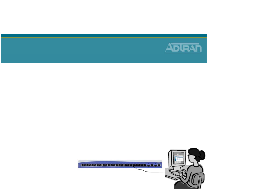
Module 7: NetVanta 7000 Series Data Configuration – Part 2
NetVanta IP Telephony Course 7-53
NetVanta 7100 - Layer 3 QoS Configuration
NetVanta 7100
Layer 3 QoS Configuration
Basic Configuration Steps
1. Configure Bandwidth (Assumed)
2. Choose a Queue Type
–Weighted Fair Queuing
–Low Latency Queuing (QoS Maps)
–Class Based Weighted Fair Queuing (QoS Maps)
3. Fragment links less than 768Kbps
–PPP or Frame Relay
4. Rate Limit on interface with slow upstream limit
–Ethernet or VLAN interfaces
Layer 3 queuing can be configured in three general steps. The first step is to configure
bandwidth values on affected interfaces. This is an informational parameter that is used in
cost calculations by the queuing algorithms. Bandwidth is configured at interface
configuration mode. The second step is to choose a queuing method and configure
parameters associated with that type of queuing. Finally, you will want to fragment any
WAN interfaces with links of 768 Kbps or less to avoid delays caused by long packets.
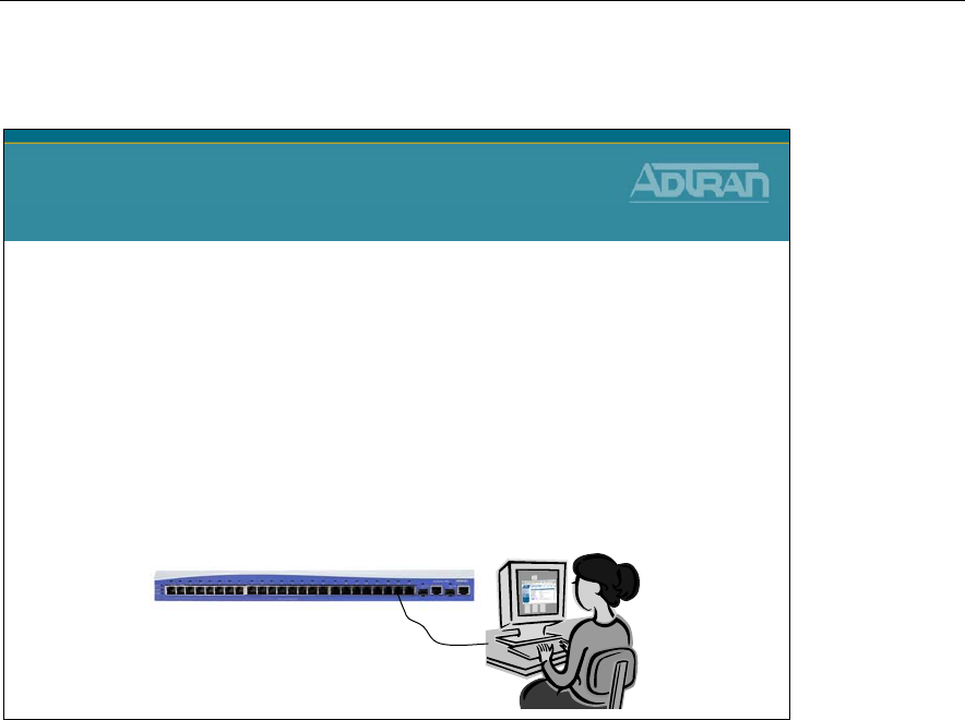
Module 7: NetVanta 7000 Series Data Configuration – Part 2
7-54 NetVanta IP Telephony Course
QoS Map Configuration - Low Latency Queuing
QoS Map Configuration
Low Latency Queuing (LLQ)
Basic Configuration Steps
1. Create the QoS map
2. Specify traffic to match
3. Configure priority queue bandwidth
4. Assign QoS Map to outgoing interface
Low Latency, and Class-Based Weighted Fair Queuing require a few more configuration
steps: First you will create a QoS Map. Within the QoS Map, you will define matching
traffic, and then use a set command to specify an action to apply to the matching traffic. A
priority command is available to configure the priority queue used in LLQ and CBWFQ,
and a bandwidth statement will define bandwidth reserved for different 'classes' of traffic
used in CBWFQ. Finally, you will apply the QoS Map to a WAN interface.
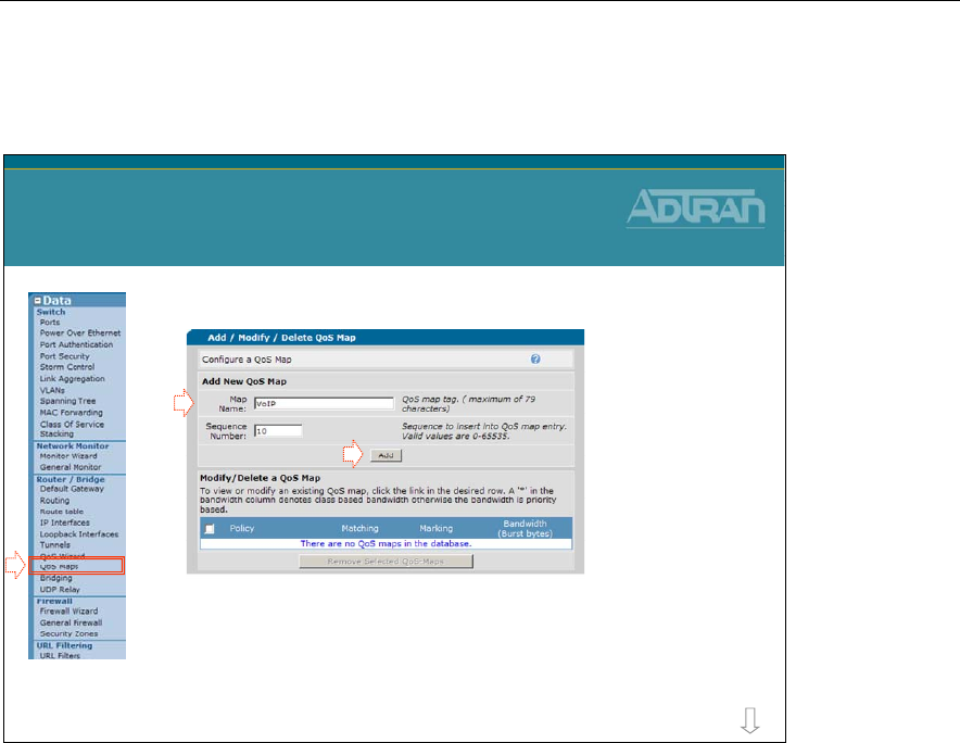
Module 7: NetVanta 7000 Series Data Configuration – Part 2
NetVanta IP Telephony Course 7-55
QoS Map Configuration
1. Select the Data / Router / QoS Maps menu
2. Type QoS map name, assign sequence
number, and then click Add to create QoS
map
QoS Map Configuration
QoS Map Configuration
more
2
The first step in Low Latency or Class-Based Weighted Fair Queuing configuration is to
create a QoS map. A QoS map is a named list with sequenced entries. An entry contains a
single match reference and one or more actions. The actions are then performed on traffic
matching the QoS policy criteria. Multiple map entries for the QoS map are differentiated
by sequence number, but the sequence number is also used to assign match order. The
router searches maps with the lowest number first. Once created, a QoS map must be
applied to an interface in order to actively process traffic.
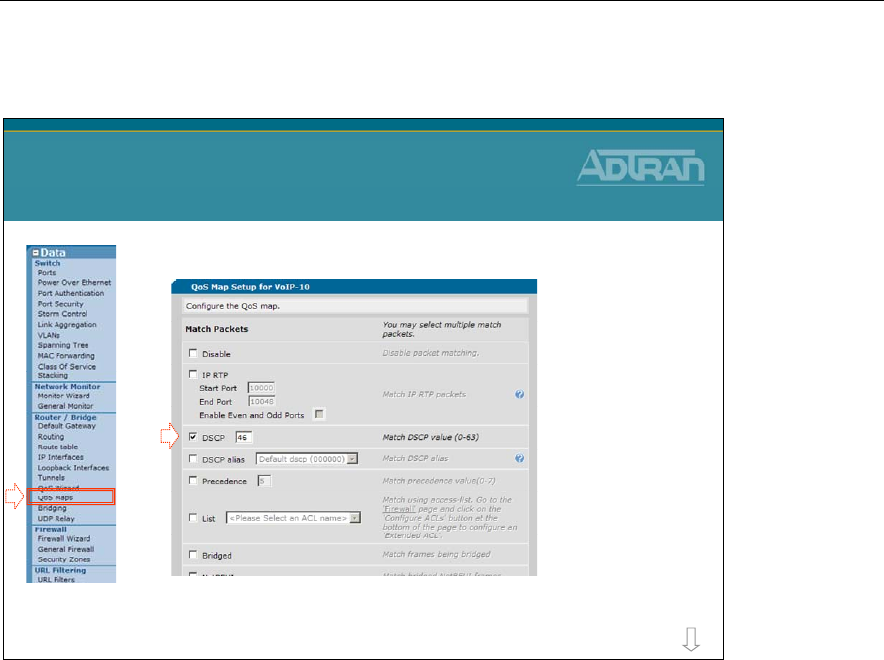
Module 7: NetVanta 7000 Series Data Configuration – Part 2
7-56 NetVanta IP Telephony Course
QoS Map Configuration
3. Specify traffic this QoS will match
QoS Map Configuration
QoS Map Configuration
more
3
QoS policies contain at least one match reference and one or more action items (using the
priority, bandwidth, or set commands).
The match section specifies the criteria used when determining whether incoming traffic is
a candidate for the QoS policy action items. Multiple match statements can exist within
the same QoS policy, allowing a single QoS policy to service various types of traffic. Use
the Match Packets section to specify which traffic should be processed by this QoS map.
Possible Match selections:
dscp <value>
ip rtp <port #>
ip rtp <begin port range> <end port range>
ip rtp <begin port range> <end port range> all
Access Control List
precedence <value>
protocol bridge
protocol bridge netbeui

Module 7: NetVanta 7000 Series Data Configuration – Part 2
NetVanta IP Telephony Course 7-57
QoS Map Configuration
4. Configure Priority Queue Bandwidth
–Low Latency Queuing (LLQ)
QoS Map Configuration
QoS Map Configuration
more
4
Click to Apply to
create QoS map
To enable Low Latency Queuing (LLQ) the priority option is used to provide a high-
priority queue, prioritizing this traffic above all others. If no traffic is present in any other
queue, priority traffic is allowed to burst up to the interface rate; otherwise, priority traffic
above the specified bandwidth is dropped.
The priority queue is intended for constant bit rate traffic such as voice, due to the rate
limiting. The sum of the bandwidths reserved by priority commands for all entries of a
QoS map cannot exceed the max-reserved-bandwidth rate specified for the interfaces that
the map is applied to.
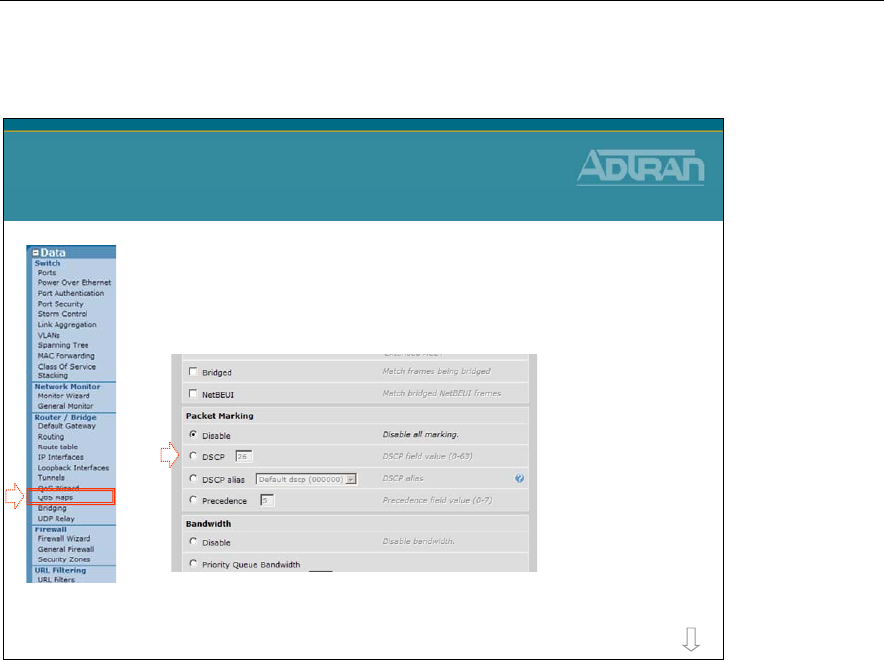
Module 7: NetVanta 7000 Series Data Configuration – Part 2
7-58 NetVanta IP Telephony Course
QoS Map Configuration
•Optional – Configure DSCP or IP Precedence
Packet Marking
QoS Map Configuration
QoS Map Configuration
more
When traffic matches the configured criteria, you may specify an action to be performed
on that traffic. If traffic matched is not already marked with a DSCP or IPP value, use
Packet Marking to mark the packet a DSCP value (0-63) or an IP precedence value (0-7)
before packet leaves the router interface.
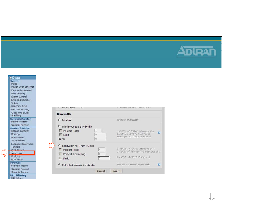
Module 7: NetVanta 7000 Series Data Configuration – Part 2
NetVanta IP Telephony Course 7-59
QoS Map Configuration
•Optional – Configure Bandwidth for Traffic Class
–Class Based Weighted Fair Queue
QoS Map Configuration
QoS Map Configuration
more
When configuring CBWFQ, the bandwidth option is used to specify bandwidth allocation
for individual traffic classes.
Options include:
Percent Total
Allocates a minimum bandwidth for a traffic class, specifying the minimum as a
percentage of the total interface bandwidth.
Percent remaining
Allocates a minimum bandwidth for a traffic class, specifying the minimum, as a
percentage of the total interface bandwidth not allocated to priority classes in the QoS map.
Limt
Allocates the minimum bandwidth for a traffic class, specifying the minimum as an
absolute bandwidth in kilobits per second. Range is 8 to 2,000,000 Kbps.
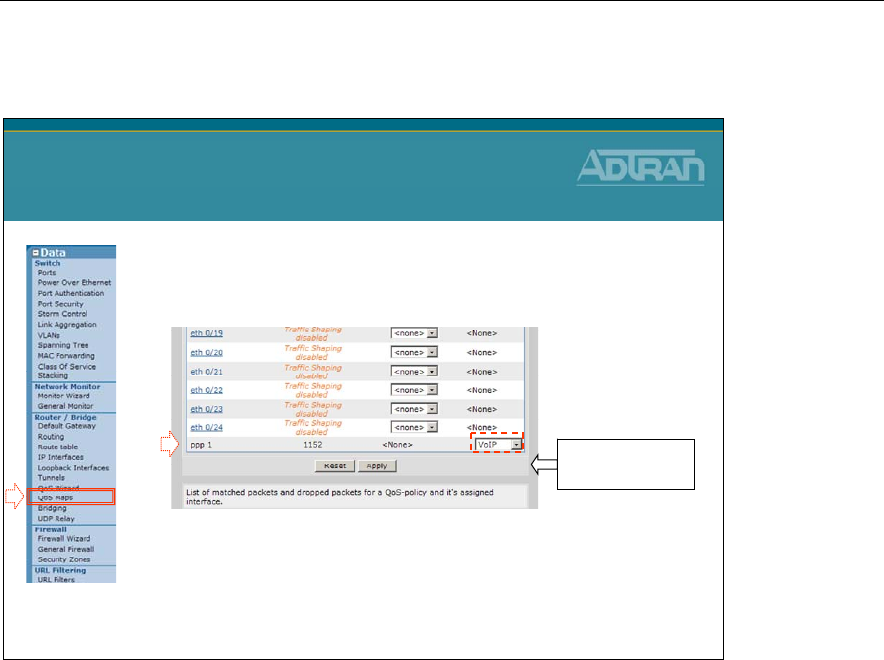
Module 7: NetVanta 7000 Series Data Configuration – Part 2
7-60 NetVanta IP Telephony Course
QoS Map Configuration
5. Assign Outbound QoS-policy to the interface
–The QoS Map is assigned to the outgoing
transmitting router interface
QoS Map Configuration
QoS Map Configuration
5
Click to Apply to
assign map
Once created, a QoS map must be applied to an interface in order to actively process
traffic. Any traffic for the interface that is not sent to the priority queue is sent using the
default queuing method for the interface (such as weighted fair queuing).
Note: A QoS map can not be applied to a router Ethernet or VLAN interface until Traffic
Shaping is enabled on that interface.
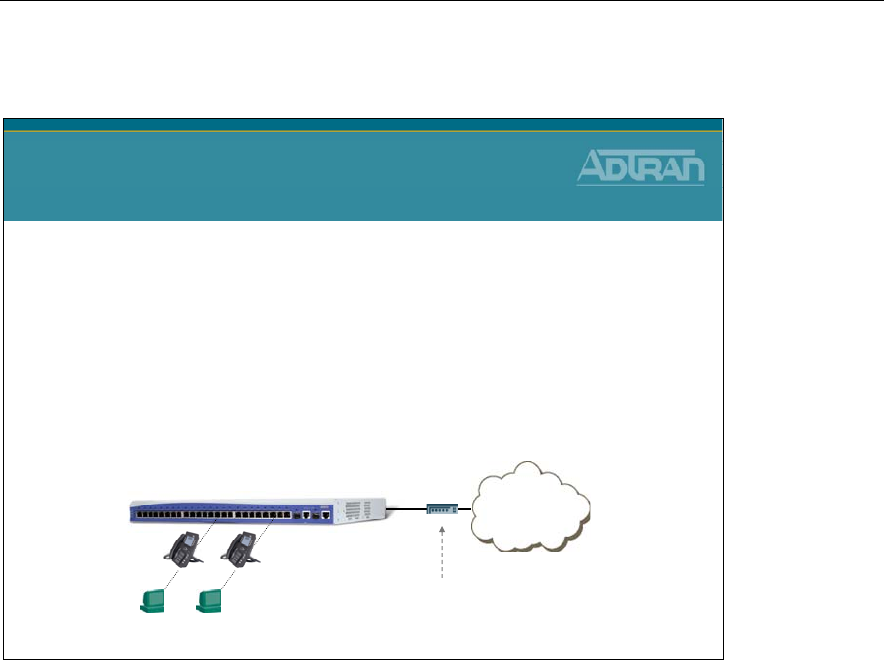
Module 7: NetVanta 7000 Series Data Configuration – Part 2
NetVanta IP Telephony Course 7-61
QoS Map Configuration - Rate Limiting
QoS Map Configuration
Rate Limiting
•The WAN connection may be an Ethernet connection
to a broadband modem
•It may be necessary to rate limit the Ethernet or VLAN
interface to the upstream bandwidth
•This does not affect downstream bandwidth
Internet
NetVanta 7100
Eth 0/0
Example: A modem with an
upstream limit of 768K
The WAN connection may be an Ethernet connection to a broadband modem. Traffic
shaping can be used to limit an Ethernet segment to a particular rate or to specify use of
QoS on Ethernet or VLAN interfaces. The traffic-shape rate command allows traffic to
be limited on upstream, or outbound traffic only. This command does not affect
downstream bandwidth. The value specified is the outbound rate of bits per second. By
default, traffic-shaping is disabled. Variations of this command include:
Rate Limiting - Basic Configuration Steps
1. Edit the Ethernet or VLAN interface
2. Enable traffic-shaping
3. Set the outbound rate
4. Assign QoS Map to outgoing interface
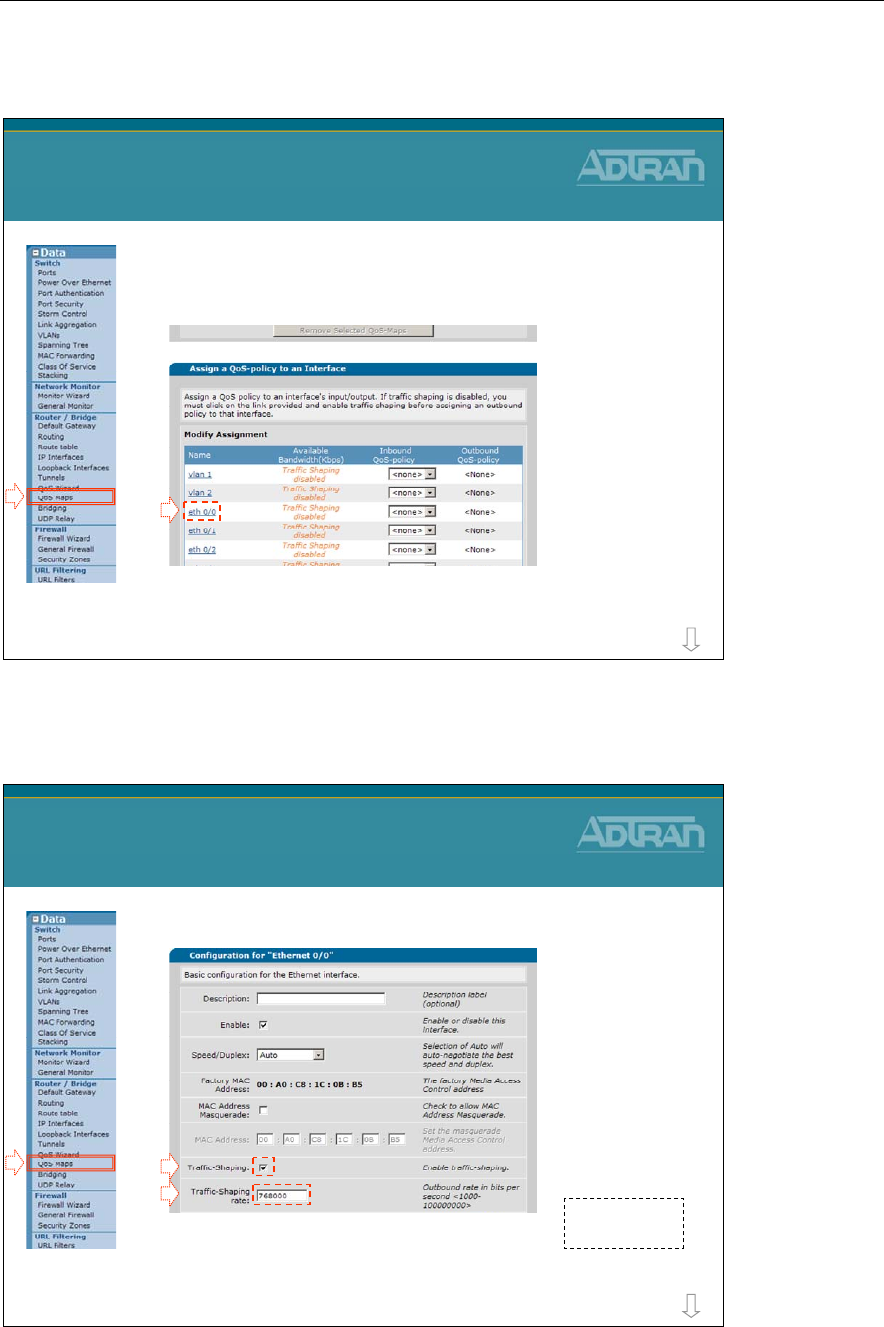
Module 7: NetVanta 7000 Series Data Configuration – Part 2
7-62 NetVanta IP Telephony Course
QoS Map Configuration - Rate Limiting
1. From the QoS Maps screen select eth 0/0
QoS Map Configuration
Rate Limiting
more
1
QoS Map Configuration - Rate Limiting
2. Enable traffic-shaping for this interface
3. Set the outbound rate in bits per second
QoS Map Configuration
Rate Limiting
more
2
3
Click to Apply
after setting
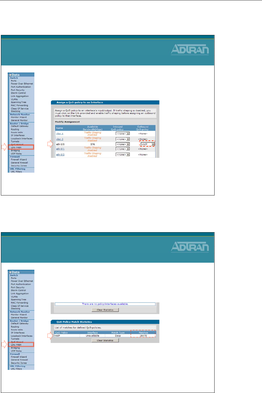
Module 7: NetVanta 7000 Series Data Configuration – Part 2
NetVanta IP Telephony Course 7-63
QoS Map Configuration
4. Assign Outbound QoS-policy to the interface
–Traffic-shaping must be enabled on an Ethernet/VLAN
interface before a QoS map can be applied
QoS Map Configuration
QoS Map Configuration
4
QoS Map Configuration
5. Confirm specified traffic is being matched by
the QoS map
–Also confirm that other traffic is not be matched by the
QoS map
QoS Map Configuration
QoS Map Configuration
5

Module 7: NetVanta 7000 Series Data Configuration – Part 2
7-64 NetVanta IP Telephony Course
Module 7: NetVanta 7000 Series Data Configuration – Part 2
NetVanta IP Telephony Course 7-65
Basic Firewall and QoS Troubleshooting
NetVanta IP Telephony Course
Basic Firewall and QoS
Troubleshooting
show ip interfaces brief
show ip interfaces brief
•Display status of all IP interfaces
NV7000#
show ip interfaces brief
Interface IP Address Status Protocol
eth 0/0 172.23.102.41 UP UP
vlan 1 10.10.10.1 UP UP
vlan 2 10.10.20.1 UP UP
NV7100#
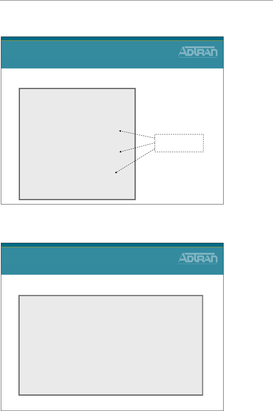
Module 7: NetVanta 7000 Series Data Configuration – Part 2
7-66 NetVanta IP Telephony Course
show ip policy-stats
show ip policy-stats
•View access firewall policy statistics
NV7000#
show ip policy-stats
Current sessions: 7
Maximum sessions: 30000
Policy-class "Private":
2 current sessions (10000 max)
Entry 1 - allow list self self
555935 in bytes, 1813280 out bytes, 625 hits
Entry 2 - allow list InterVLAN stateless
0 in bytes, 0 out bytes, 0 hits
Entry 3 - nat source list NAT interface eth 0/0 overload
2513596 in bytes, 2481556 out bytes, 11 hits
Policy-class "Public":
5 current sessions (10000 max)
Entry 1 - allow list SIP self
275901 in bytes, 226455 out bytes, 50 hits
Entry 2 - allow list Admin self
6008462 in bytes, 21224947 out bytes, 8329 hits
:
View number of
hits per policy
* Partial output displayed
show ip policy-sessions
show ip policy-sessions
•View current policy-class associations
NV7000#
show ip policy-sessions
Src IP Address Src Port Dest IP Address Dst Port NAT IP Address NAT Port
-------------------- ----------- --------------------- ----------- --------------------- ------------
Policy class "Private":
udp (45) -> Public
10.10.20.2 3000 172.23.102.42 50024 s 172.23.102.41 50020
udp (45) -> Public
10.10.20.3 2227 172.23.102.42 50023 s 172.23.102.41 50019
Policy class "Public":
udp (45) -> Private
172.23.102.42 50025 172.23.102.41 50021 d 10.10.20.2 3001
udp (45) -> Private
172.23.102.42 50022 172.23.102.41 50018 d 10.10.20.3 2226
* Partial output displayed
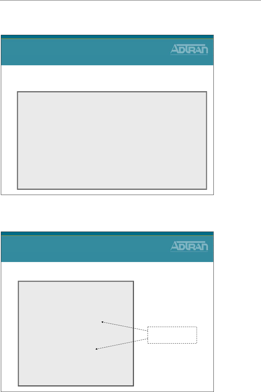
Module 7: NetVanta 7000 Series Data Configuration – Part 2
NetVanta IP Telephony Course 7-67
reload in command
reload in command
•Reload after a time interval
–Useful with remote configuration (may help get you out of a jam)
NV7000#
reload in ?
<input> - Delay before reload (mmm or hhh:mm)
NV7100# reload in 15
Save System Configuration? [y/n]
n
Reload scheduled in 15 minutes
You are about to reboot the system. Continue?[y/n]
y
2009.07.05 15:52:06 OPERATING_SYSTEM System reboot scheduled in 15 minutes!
NV7100# reload cancel
******RELOAD CANCELLED******
2009.07.05 15:59:41 OPERATING_SYSTEM Scheduled system reboot cancelled.
show qos map
show qos map
•Display QoS Map Statistics
NV7000#
show qos map
qos map VoIP
map entry 10
match IP packets with a dscp value of 46
priority bandwidth: 50 (% of total) burst: default
packets matched by map: 68372
map entry 20
match IP packets with a dscp value of 26
class bandwidth: 10 (% of remaining)
packets matched by map: 78
Interfaces using qos map VoIP:
eth 0/0:Output (enabled)
NV7100#
View packets
matched per entry
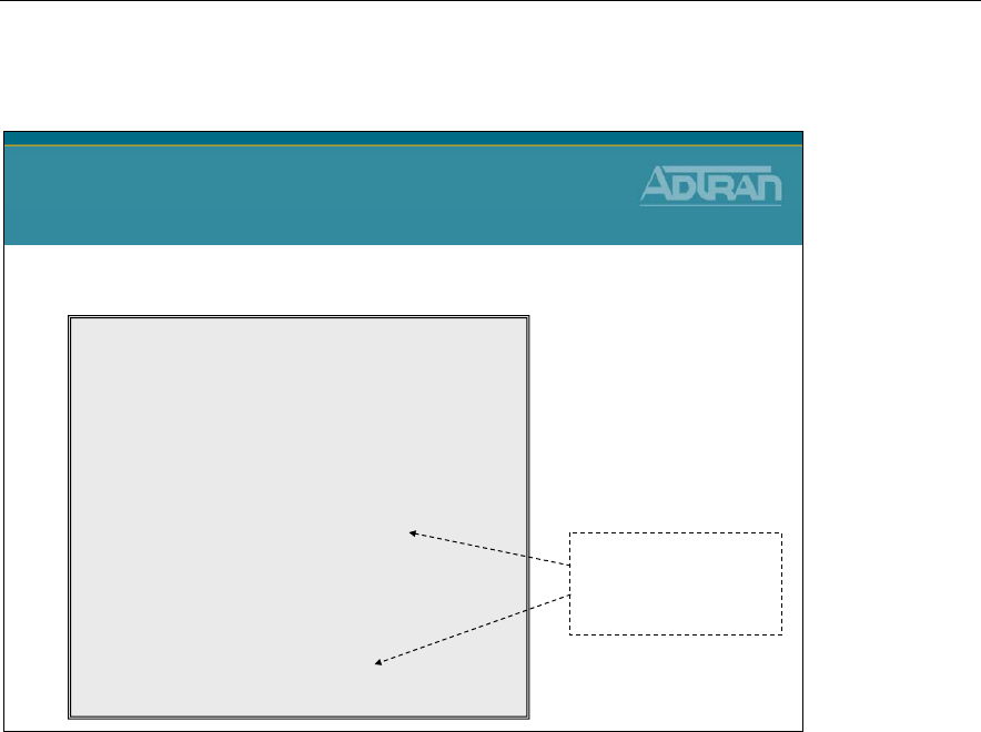
Module 7: NetVanta 7000 Series Data Configuration – Part 2
7-68 NetVanta IP Telephony Course
show qos map interface
show qos map int eth 0/0
•Display QoS Map Statistics for specific interface
NV7000#
show qos map interface ethernet 0/0
eth 0/0
qos-policy out: VoIP
map entry 10
match IP packets with a dscp value of 46
priority bandwidth: 50 (% of total)
burst budget 9364/9600 bytes (current/max)
packets matched on interface: 81158
packets dropped: 0
map entry 20
match IP packets with a dscp value of 26
class bandwidth: 10 (% of remaining)
conversation: 233
packets matched on interface: 0
packets dropped: 0
- View packets
matched per entry
- Check drop status

Module 7: NetVanta 7000 Series Data Configuration – Part 2
NetVanta IP Telephony Course 7-69
Module Summary
Module Summary
•At the end of this module, you should be able to:
•Create VLAN interfaces
•Configure Firewall policies
•Create a network DMZ
•Understand Quality of Service concepts
•Configure QoS Maps
•Perform basic Firewall and QoS troubleshooting

Module 7: NetVanta 7000 Series Data Configuration – Part 2
7-70 NetVanta IP Telephony Course

Module 8: NetVanta 7000 Remote
Telephony Applications

Module 8: NetVanta 7000 Remote Telephony Applications
8-2 NetVanta IP Telephony Course

Module 8: NetVanta 7000 Remote Telephony Applications
NetVanta IP Telephony Course 8-3
Module Objectives
Module Objectives
•Introduce NetVanta 7000 Remote Telephony
Applications
•Configure Service Provider SIP Trunk
•Configure SIP Networking between Sites
•Preview Remote User Configuration
•Introduce VoIP Quality Monitoring (VQM)
•Conduct Voice Troubleshooting in a NetVanta 7000
Remote Telephony Application

Module 8: NetVanta 7000 Remote Telephony Applications
8-4 NetVanta IP Telephony Course
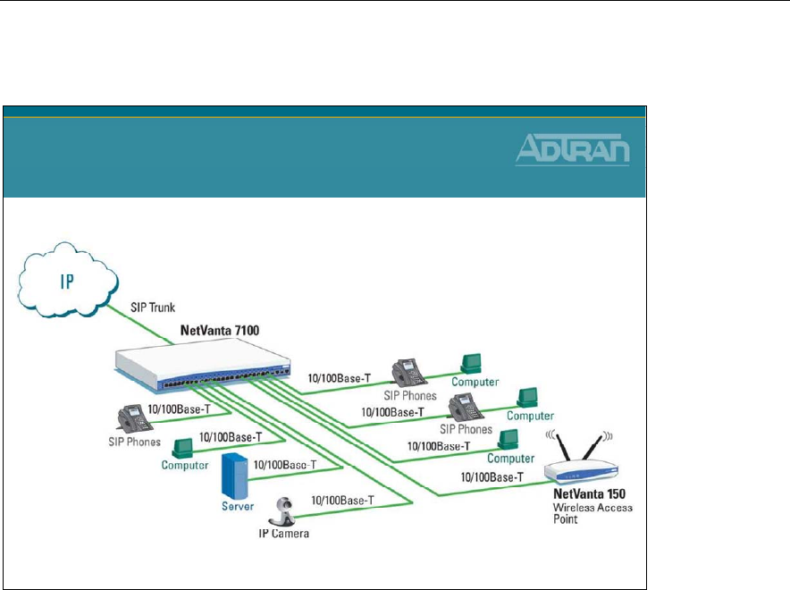
Module 8: NetVanta 7000 Remote Telephony Applications
NetVanta IP Telephony Course 8-5
SIP Trunking
NetVanta 7000 Series Solution
SIP Trunking
• Direct Connectivity of NetVanta 7000 to
Service Provider’s SIP Trunk Service
For businesses that are looking for ways to reduce costs, ADTRAN's SIP Trunking is an
ideal solution. SIP trunking is a packet-based service which will dynamically consolidate
all voice and data traffic over a single IP circuit and enables the SIP Service Provider to
carry local, domestic and international long distance, and toll free calls, in addition to
video, email, Internet, and other data. The combination of ADTRAN's NetVanta 7000
Series IP PBX and the service provider's SIP trunk offers a proven solution for not only
reducing immediate costs, but also ongoing savings up to 40% each month.
• Integrates Multiple Functions into Single Solution including PBX, Switch, Router,
Firewall/VPN functions
• Provides Key System Functionality across SIP Trunking such as Busy Lamp Field
(BLF) and Share Line Appearances (SLA)
• Built in Quality of Service for Voice to monitor and report VoIP performance
statistics.
ADTRAN's SIP Trunking alliances offer proven ways to consolidate voice and data onto a
converged IP service that lowers costs and achieves high quality reliable service - all
backed by industry leading service and support.

Module 8: NetVanta 7000 Remote Telephony Applications
8-6 NetVanta IP Telephony Course
SIP Trunking Overview
SIP is the industry standard ASCII-based peer to peer signaling protocol responsible for
the initiation and management of IP voice communication sessions. SIP is designed to
control call setup and tear down between IP endpoint devices. The basic function of SIP is
to locate endpoints, signal a desire to communicate, establish sessions, and tear down
sessions between endpoints. The current version of SIP (2.0) is defined in RFC 3261.
SIP Trunks Overview
Voice over IP (VoIP) rapidly gained popularity due to the cost savings achieved by
simultaneously routing voice calls and data over the same network, eliminating the need
for separate voice and data circuits at customer premises. The common method of
combining voice and data together on one circuit is PRI. PRI carries voice traffic over the
dedicated channels with the data channels, and routes or terminates the voice traffic
between two PRI-compatible private branch exchanges (PBXs) or key systems. The more
advanced alternative to a PRI trunk is a SIP trunk.
SIP trunking is a packet-based voice service that routes calls over an IP network to an IP-
compatible PBX or voice switch using SIP signaling to place and receive calls. The typical
SIP trunk service provider offers extensive cost savings, compared to conventional trunk
services. The IP connection to the provider carries all traffic, such as local, long distance,
and toll free calls, video, email, Internet, data, and other media over a single circuit. Calls
into public switched telephone network (PSTN) are also handled by the SIP service
provider by passing the calls off to a media gateway that connects to the PSTN for users
not using VoIP service.
AOS SIP networking is an interconnection of NetVanta 7000 Series units or ADTRAN IP
Business Gateways over an IP network. The SIP networking configuration is very similar
to configuring SIP trunking between a NetVanta 7000 Series unit and a service provider’s
SIP trunking service. The main difference is that configuring the SIP registrar is not
required.
SIP Trunking Advantages
Using SIP trunks has advantages over PRI(s) such as more significant cost savings, and
control over the number of channels on the trunk (SIP trunks can be purchased in
increments of simultaneous calls or DIDs). When connected to an ADTRAN IP PBX
device, the SIP trunk solution offers all the traditional hosted telephony features of a PRI.
Reference configuration guides on compatible AOS voice features (such as source and
ANI based routing (SABR), voice quality monitoring (VQM), voicemail, etc.), are
available on your AOS Documentation CD shipped with your AOS unit or visit our
website at http://kb.adtran.com.
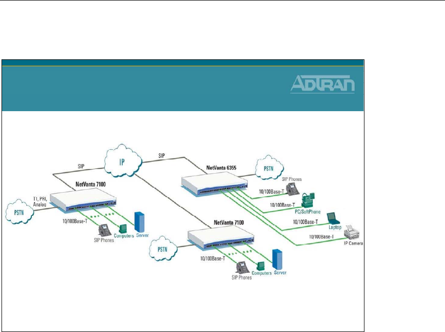
Module 8: NetVanta 7000 Remote Telephony Applications
NetVanta IP Telephony Course 8-7
SIP Networking
NetVanta 7000 Series Solution
SIP Networking
•3-4 Digit Dialing Between Sites
•VPN Between Sites
•Toll Bypass
•Access Remote Site Local Trunks
The ADTRAN NetVanta 7000 Series supports SIP Networking between multiple
locations. With SIP networking, businesses can connect multiple sites and have three- to
four-digit dialing, local call routing and survivability, and on-net calls for toll bypass. The
NetVanta 7100 and 7060 are best for locations that need local voice mail; while
ADTRAN's NetVanta 6355 IP Business Gateway and Total Access 900 Series provide the
ideal solution for locations that will use a central NetVanta 7000 voice mail.
• Links multiple sites together to reduce costs
• Direct dials between offices
• Supports inter-office, three- to four-digit dialing
• Provides local PSTN access
• Allows local sites to share remote site trunks
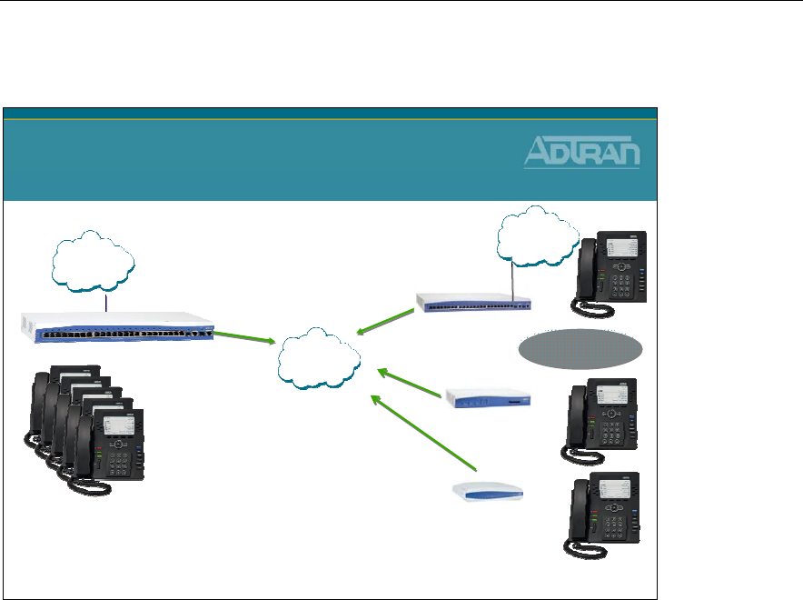
Module 8: NetVanta 7000 Remote Telephony Applications
8-8 NetVanta IP Telephony Course
Remote Sites
NetVanta 7000 Series Solution
Remote Sites
•3-4 Digit Dialing Between Sites
•VPN Between Sites
•Use Central Voicemail
•Use Central Auto Attendant
•Total of 100 Stations in Network
•Remote PSTN trunks
NetVanta 6355
IP Gateway
NetVanta 7000
Up to 100 Stations
In Customer Network
Remote Sites
NetVanta 3448
Multiservice Router
NetVanta 3120
SOHO Router
PSTN
PSTN
IP
SIP trunking feature allows remote IP Business Gateways, such as the ADTRAN Total
Access 900(e) Series and NetVanta 6355, to connect to a central IPT device (NetVanta
7000 Series) for the use of local trunks at each remote location. This application functions
similar to a single PBX with each remote user registering back to the IPT either via
transparent proxy (SIP) or directly (analog phones). The phones at the remote locations
rely on the main site (IPT device) to provide voicemail and auto attendant services to
incoming calls.
The NetVanta 7100 and NetVanta 3120 enable secure, always-on, voice, data and high-
speed data access to business resources from a remote home office. Using a single cable or
DSL broadband connection and secure IPSec-compliant VPN NetVanta technology,
workers can have the same convenience and functionality in their home office.
• Ideal solution to extend voice/data capabilities to small, remote offices
• Enables one or more teleworkers to have same features as the main business office
• Improves teleworking productivity
• Provides phone feature transparency over IP connectivity
• Uses the same desktop phone at remote home or small offices
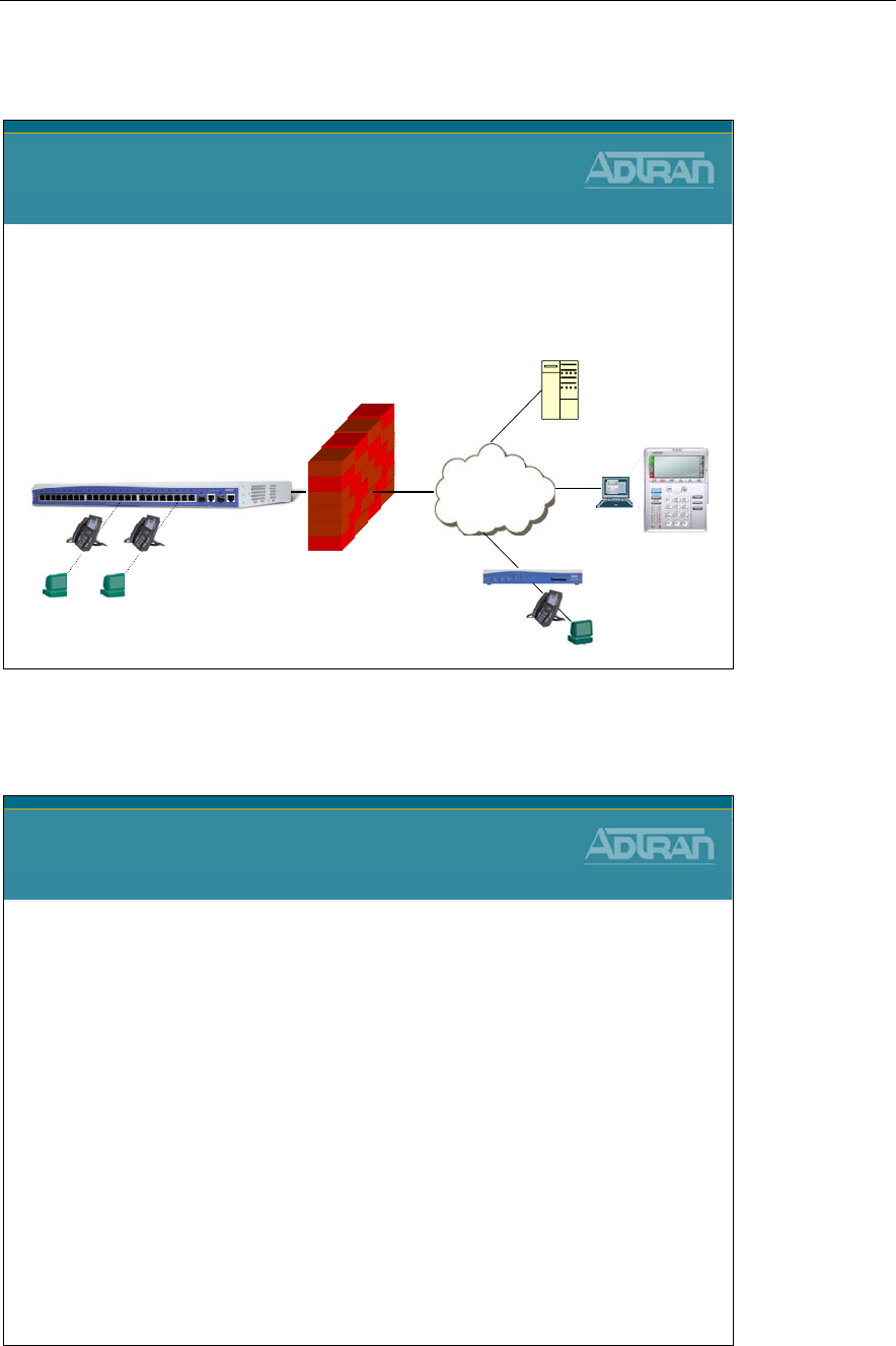
Module 8: NetVanta 7000 Remote Telephony Applications
NetVanta IP Telephony Course 8-9
NetVanta 7000 - Remote Telephony Applications
NetVanta 7000
Remote Telephony Applications
•Configuration of the following Remote Telephony
Applications are introduced in this section:
–Service Provider SIP Trunk
–SIP Networking
–Preview Remote User
–Enable VQM
Internet
NetVanta 7000
PUBLICPRIVATE
Remote User
Home Office
Remote User
Softphone
SIP
Service Provider
Service Provider SIP Trunk Configuration
NetVanta IP Telephony Course
Service Provider SIP Trunk
Configuration

Module 8: NetVanta 7000 Remote Telephony Applications
8-10 NetVanta IP Telephony Course
Service Provider SIP Trunk
NetVanta 7000 Series Solution
Service Provider SIP Trunk
• Direct Connectivity of NetVanta 7000 to
Service Provider’s SIP Trunk Service
To configure an incoming SIP trunk from your service provider, verify that NetVanta 7000
Series Call Routing Mode and Transfer Mode are set to Local (feature support is provided
internally by the NetVanta unit). The softswitch only has control of the call routing up to
the SIP trunk interface. The ADTRAN IPT device will send and receive all basic SIP call
setup messages and will accept advanced setup messages, but the REFER and INVITE
with Replaces (SIP signaling methods) messages will not be sent out the trunk (T01). The
incoming SIP trunk will behave similar to a PRI and all the traditionally supported call
features will remain functional. The use of the SIP trunk can be controlled with other IPT
features, such as SABR and least cost routing (LCR). Only one service-provider SIP trunk
is allowed in this application. Precise trunk group and dial plan configuration allow users
to take advantage of the LCR out of any trunk configured on the system. In the illustration,
the additional trunk (T02) that is directly connected to the PSTN can be analog, T1, or PRI.
T02 can be mainly used for local calls by assigning a high cost to the long distance
outbound call template, or it can be used for survivability during possible failure of the
main SIP trunk service.
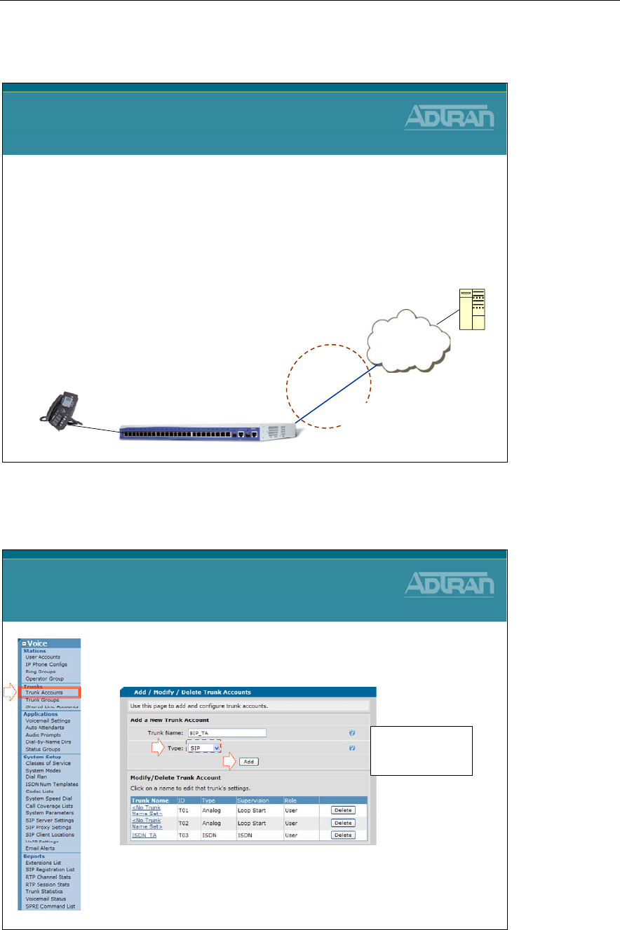
Module 8: NetVanta 7000 Remote Telephony Applications
NetVanta IP Telephony Course 8-11
Provider SIP Trunk - Basic Configuration Steps
Service Provider SIP Trunk
Basic Configuration Steps
1. Create Trunk Account
–Configure SIP and Registrar servers
–Register Your Number
(Optional)
2. Create Trunk Group
–Add SIP Trunk Account
–Define outbound call templates
3. Configure SIP Identity
(Optional)
–Register Your Number ISP
Trunk Acct T03
NetVanta 7000
Trunk
Group
Eth
0/0
Service Provider
SIP Server
Voice User
SIP Trunk Configuration - 1) Create Trunk Account
1. Select the Voice / Trunks / Trunk Accounts
menu
2. Create a SIP Trunk Account
•Will be used to point to Service Provider’s SIP Server
Provider SIP Trunk Configuration
1) Create Trunk Account
- Type Trunk Name
- Set Type to SIP
-Click Add
1
2
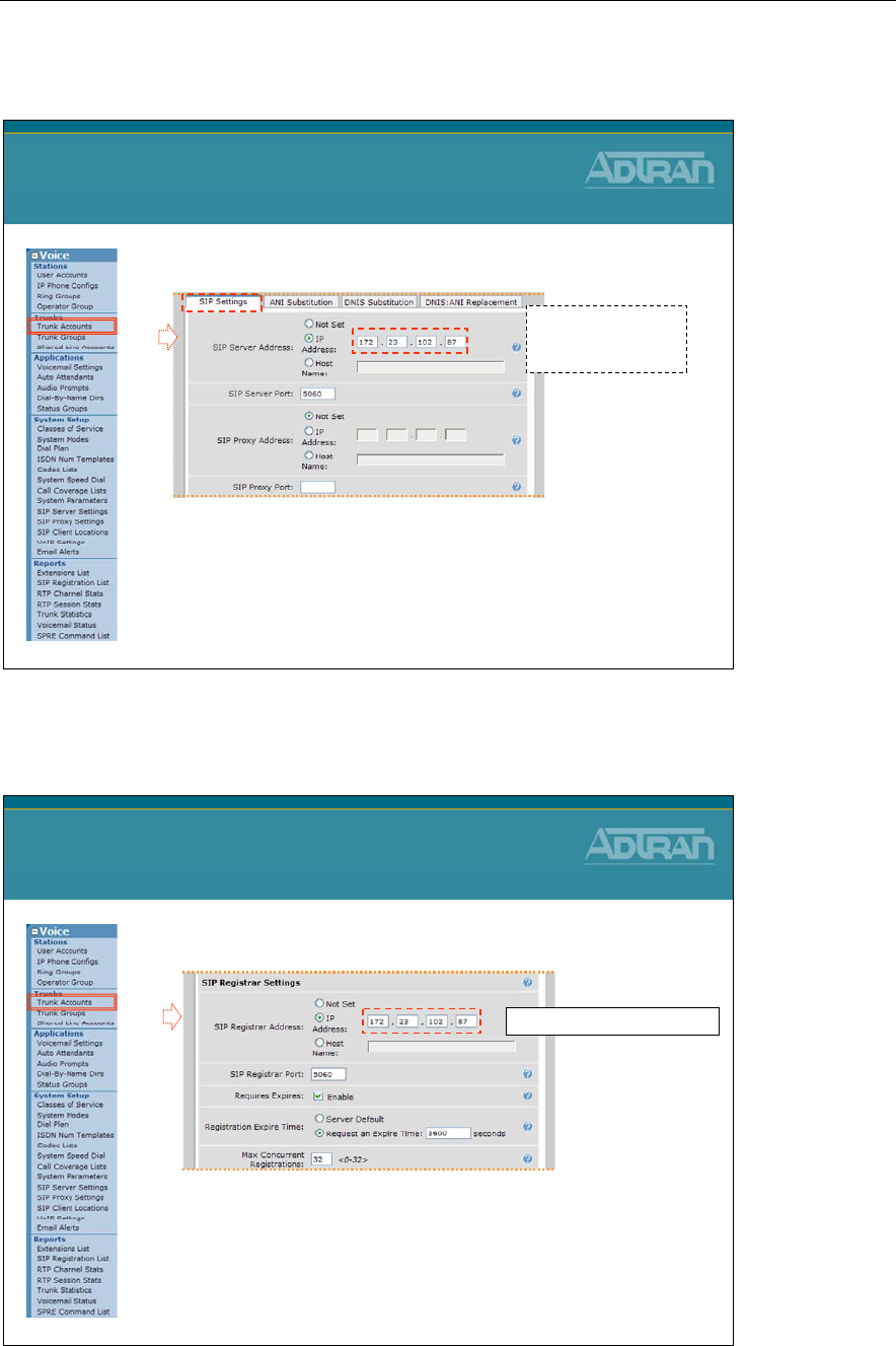
Module 8: NetVanta 7000 Remote Telephony Applications
8-12 NetVanta IP Telephony Course
SIP Trunk Account - Define SIP Server Address
3. Define address or host name of SIP Server
–Default SIP server Port is 5060
•Define SIP Proxy Server address if one is being used
Provider SIP Trunk Configuration
1) Create Trunk Account
(Cont..)
Service Provider’s SIP
Server IP Address or
Host Name
3
SIP Trunk Account - Define SIP Registrar Address
4. Define SIP Registrar address or host name
–Default SIP Registrar Port is 5060
Provider SIP Trunk Configuration
1) Create Trunk Account
(Cont..)
Providers Registrar IP Address
4
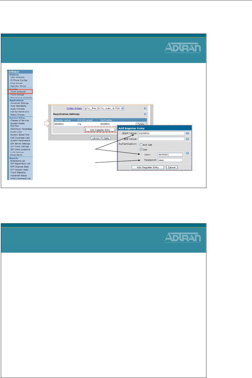
Module 8: NetVanta 7000 Remote Telephony Applications
NetVanta IP Telephony Course 8-13
SIP Trunk Account - Register Number
5. Register the Number provided from the SIP
Service Provider
–You should receive a username, password, and
Service Provider’s SIP Server address
Provider SIP Trunk Configuration
1) Create Trunk Account
(Cont..)
5
Enter username
Enter password
If user’s phone number does not match the SIP username entered here, an Alias will
need to be configured matching the SIP username to the actual user extension
Calling Party – ANI Substitution
Calling Party - ANI Substitution
•Problem: Many SIP Service Providers will reject a call from an
unknown number, that is, a number not registered to their switch
–Problems can occur when a user on the NetVanta 7000 forwards their
phone to an external number
–When the user locally forwards their phone, the original calling party
information will be preserved and sent in the From header of the SIP
INVITE back out to the provider’s softswitch
•Solution: Configure Calling Party (ANI) Match/Substitutions to
allow forwarding of calls out a SIP Trunk
–Create an ANI Substitution template to match all numbers
–This will be used to replace the From header on forwarded calls along
with all other calls routed out the SIP trunk
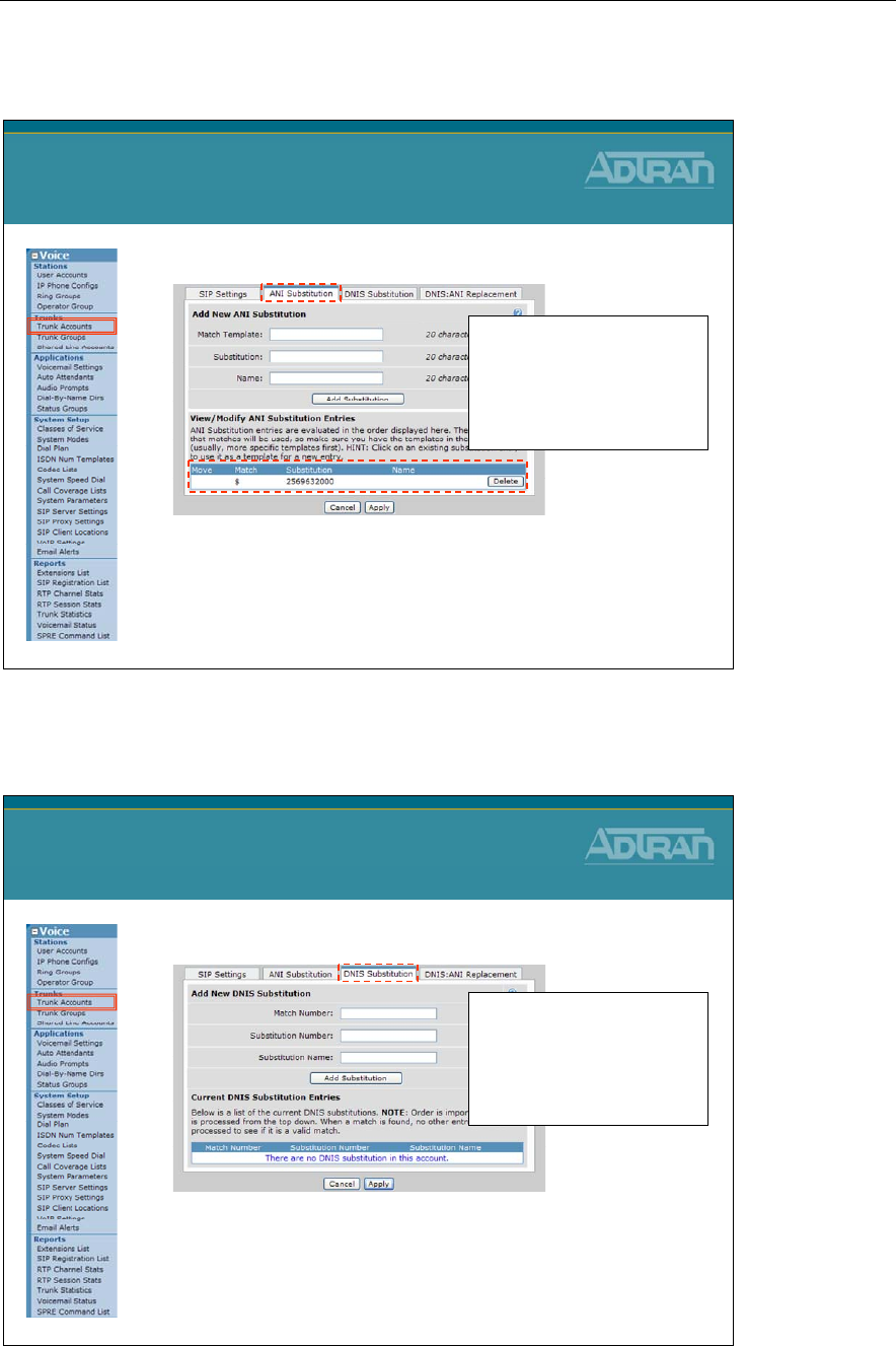
Module 8: NetVanta 7000 Remote Telephony Applications
8-14 NetVanta IP Telephony Course
SIP Trunk Account – ANI Substitution
•Optional: Add ANI substitution
–Examples:
•match ani "2XXX" substitute "2569632100" name "Shanes Cable Co"
•match ani "3XXX" substitute "2569632200" name "Hunters Cable Co"
•match ani "$" substitute "2569632000"
Provider SIP Trunk Configuration
1) Create Trunk Account
(Cont..)
Order is important:
- Multiple match statements can be
entered per trunk account
- The first valid match that is
found for outbound numbers will
be used
SIP Trunk Account – DNIS Substitution
•Optional: Add DNIS substitution
–Examples:
•Match: NXX-XXXX Subst: 256-NXX-XXXX
•Match: 1-256-XXX-XXXX Subst: NXX-XXX-XXXX
•Match: 1-NXX-NXX-XXXX Subst: 10-10-220-NXX-NXX-XXXX
Provider SIP Trunk Configuration
1) Create Trunk Account
(Cont..)
Order is important:
- Multiple match statements can be
entered per trunk account
- The first valid match that is
found for outbound numbers will
be used
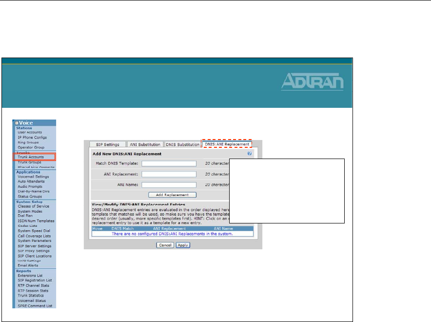
Module 8: NetVanta 7000 Remote Telephony Applications
NetVanta IP Telephony Course 8-15
SIP Trunk Account – DNIS:ANI Replacement
•Optional: Add DNIS:ANI Replacement
–Examples:
•match dnis "1NXXNXXXXXX" replace ani "18884238726"
name "National Network Co“
•match dnis “NXXXXXX" replace ani "9638716 " name
“Huntsville Network Co“
Provider SIP Trunk Configuration
1) Create Trunk Account
(Cont..)
Order is important:
- Multiple match statements can be
entered per trunk account
- The first valid match that is
found for outbound numbers will
be used

Module 8: NetVanta 7000 Remote Telephony Applications
8-16 NetVanta IP Telephony Course
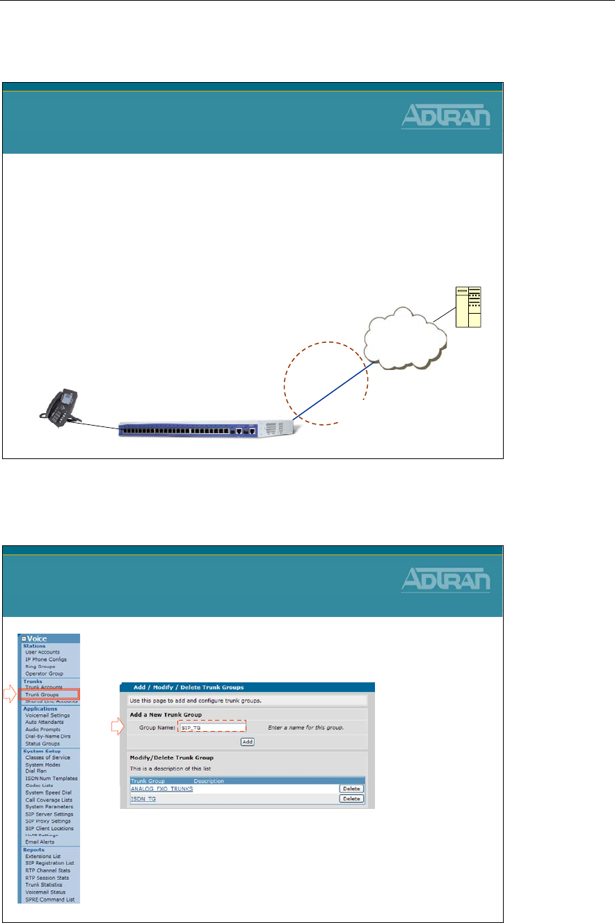
Module 8: NetVanta 7000 Remote Telephony Applications
NetVanta IP Telephony Course 8-17
Provider SIP Trunk - Basic Configuration Steps
Service Provider SIP Trunk
Basic Configuration Steps
1. Create Trunk Account
–Configure SIP and registrar servers
–Optional - Register Your Number
(Optional)
2. Create Trunk Group
–Add SIP Trunk Account
–Define outbound call templates
3. Configure SIP Identity
(Optional)
–Register Your Number ISP
Trunk Acct T03
NetVanta 7000
Trunk
Group
Eth
0/0
Service Provider
SIP Server
Voice User
SIP Trunk Configuration - 2) Create Trunk Group
1. Select the Voice / Trunks / Trunk Groups
menu
2. Create a Trunk Group
–Point to the new SIP Trunk Account
–Define call types allowed out this Trunk Group
Provider SIP Trunk Configuration
2) Create Trunk Group
1
2
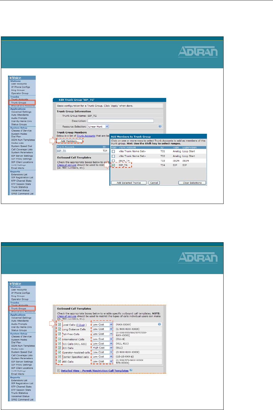
Module 8: NetVanta 7000 Remote Telephony Applications
8-18 NetVanta IP Telephony Course
Trunk Group – Add SIP Trunk Account
3. Click Add Members to add existing SIP Trunk
Account to this Trunk Group
Provider SIP Trunk Configuration
2) Create Trunk Group
3
Trunk Group – Define Outbound Call Template
4. Outbound Call Template
–Define call types allowed out this SIP Trunk Group
–Optional: Define cost for each type of call
•Least cost routing
Provider SIP Trunk Configuration
2) Create Trunk Group
4
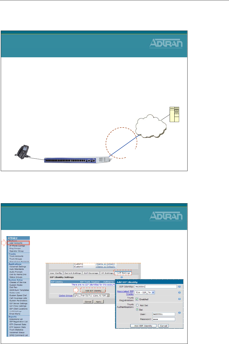
Module 8: NetVanta 7000 Remote Telephony Applications
NetVanta IP Telephony Course 8-19
Provider
SIP Trunk - Basic Configuration Steps
Service Provider SIP Trunk
Basic Configuration Steps
1. Create Trunk Account
–Configure SIP and registrar servers
–Optional - Register Your Number
(Optional)
2. Create Trunk Group
–Add SIP Trunk Account
–Define outbound call templates
3. Configure SIP Identity
(Optional)
–Register Your Number ISP
Trunk Acct T03
NetVanta 7000
Trunk
Group
Eth
0/0
Service Provider
SIP Server
Voice User
SIP Trunk Configuration - 3) Configure SIP Identity
•Optional – Add a SIP Identity to configure the
SIP registration options for a user, ring group, or
auto attendant
Provider SIP Trunk Configuration
3) Configure SIP Identity
- Enable the SIP Trunk this station
will use for registration purposes.
- Enter username and password used
for registration
SIP identity would be done in place of the SIP TA Registration process
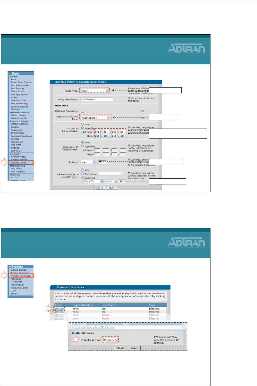
Module 8: NetVanta 7000 Remote Telephony Applications
8-20 NetVanta IP Telephony Course
Additional VoIP Config – Allow UDP 5060
• Allow UDP traffic in Public Security Zone (WAN)
Additional VoIP Configuration
Allow UDP 5060 traffic
Set Protocol to UDP
If known, specify the Remote WAN
IP as the source address
Set to Self Bound
Set port equal to 5060
Create Allow Policy
Additional VoIP Config - Eth 0/0 Media Gateway
• Enable WAN Eth 0/0 media-gateway as
Primary
- Specifies that RTP traffic will be sourced from the Primary IP
address of this interface
Additional VoIP Configuration
Eth 0/0
Media Gateway
1
2
3
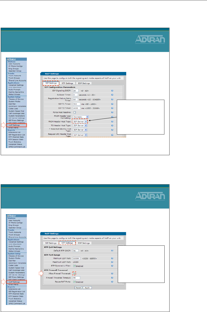
Module 8: NetVanta 7000 Remote Telephony Applications
NetVanta IP Telephony Course 8-21
Additional VoIP Config - VoIP / SIP Settings
• Select the Voice / System Setup / VoIP Settings
menu
– Leave SIP From Header Host Type as SIP Server
Additional VoIP Configuration
VoIP Settings / SIP Settings
-Leave SIP Server when
connecting to SIP Service
Provider
-Set to Local when setting
up SIP Networking
between NetVanta 7000s
Additional VoIP Config - VoIP / RTP Settings
• Allow RTP traffic associated with the allowed
SIP traffic
Additional VoIP Configuration
VoIP Settings / RTP Settings
Allow Firewall Traversal
is enabled by default. This
allows the 7000 to open
holes in the firewall for
RTP streams that have
been created by SIP
negotiation

Module 8: NetVanta 7000 Remote Telephony Applications
8-22 NetVanta IP Telephony Course

Module 8: NetVanta 7000 Remote Telephony Applications
NetVanta IP Telephony Course 8-23
SIP Networking Configuration
NetVanta IP Telephony Course
SIP Networking Configuration
SIP Networking Features
• Links multiple sites together to reduce costs
• Support for up to 10 SIP trunks
o Remote devices or service provider
• Direct dials between offices
o Supports inter-office, three- to four-digit dialing
o Transfer calls between sites
• Provides local PSTN access
o Allows local sites to share remote site trunks
Independent Sites
o Each Site has own Voicemail and Auto Attendant
o Can not forward to a Mailbox (Could forward in email)

Module 8: NetVanta 7000 Remote Telephony Applications
8-24 NetVanta IP Telephony Course
SIP Networking
NetVanta 7000 Series Solution
SIP Networking
•3-4 Digit Dialing Between Sites
•VPN Between Sites
•Toll Bypass
•Access Remote Site Local Trunks
In the SIP Networking application shown above, the NetVanta 7000 Series unit at the main
location is connected to remote NetVanta 7000 Series. This type of SIP networking
application can support a maximum of ten remote SIP trunks at each site. Voice users
connected to the NetVanta 7000 Series at Site A will be able to connect to all endpoints at
all locations, including access to voicemail, auto attendant, ring groups, and other phone
users. Voicemail features will not be extended across the facing SIP trunks; each IPT will
have local voicemail and auto attendant services. Remote users will not be automatically
entered into the system directory at remote locations. Also, remote users will not appear in
the selection list boxes for Trunk Number and Ring Groups. Precise trunk group and dial
plan configuration will allow users to take advantage of the LCR out of any trunk
configured on the system. Each NetVanta 7000 Series Call Routing Mode, Forward Mode,
and Transfer Mode must be set to Local.
Each remote site can also have a SIP trunk connection to an IP Business Gateway (Total
Access 900(e) or NetVanta 6355). In the illustration, the additional trunk that is directly
connected to the PSTN can be analog, T1, or PRI. This trunk can be mainly used for local
calls by assigning a high cost to the long distance outbound call template, or it can be used
for survivability during possible failure of the main SIP trunk service.
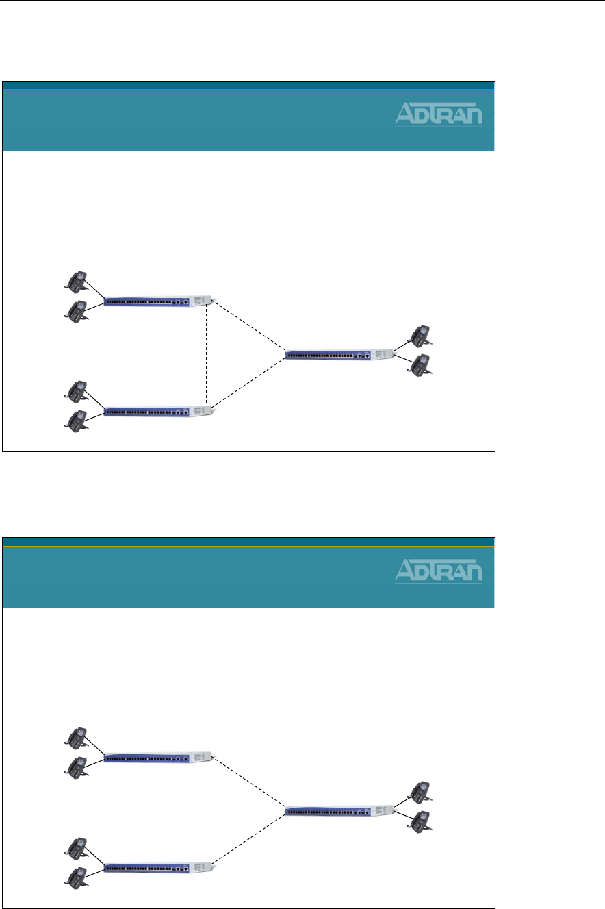
Module 8: NetVanta 7000 Remote Telephony Applications
NetVanta IP Telephony Course 8-25
SIP Networking – Design Considerations
SIP Trunks
SIP Networking
Design Considerations
•Fully Meshed SIP Trunks
•Each site has unique extensions
–2XXX, 3XXX, 4XXX, etc…
–21XX, 22XX, 23XX, etc…
Local Users
2XXX
Local Users
3XXX
Local Users
4XXX
4XXX >
< 3XXX
4XXX >
< 3XXX2XXX >
NetVanta 7000
NetVanta 7000
NetVanta 7000
< 2XXX
Each site has local PSTN (not shown)
SIP Networking – Design Considerations
SIP Trunks
SIP Networking
Design Considerations
•Hub & Spoke SIP Trunk
•Each site has unique extensions
–2XXX, 3XXX, 4XXX, etc…
–21XX, 22XX, 23XX, etc…
Local Users
2XXX
Local Users
3XXX
Local Users
4XXX
4XXX >
< 3XXX
3XXX >
NetVanta 7000
NetVanta 7000
NetVanta 7000
< 2XXX
4XXX >
2XXX >
Each site has local PSTN (not shown)
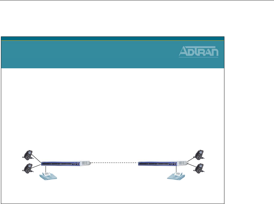
Module 8: NetVanta 7000 Remote Telephony Applications
8-26 NetVanta IP Telephony Course
SIP Networking – Design Considerations
SIP Trunk
SIP Networking
Design Considerations
•Each site has same extensions
–Requires use of an extra digit for use as a site identifier
•For example, 5along with extension 2XXX could cause the call to route out
the SIP trunk to the other site (52XXX)
–Dial plan at both sites needs to be modified for both the System
and the IP phones
•Extension = MXXX and 52XXX
2003 NetVanta 7000
Each site has local PSTN (not shown)
2004
NetVanta 7000 2003
2004
2000 2000
52XXX >< 52XXX
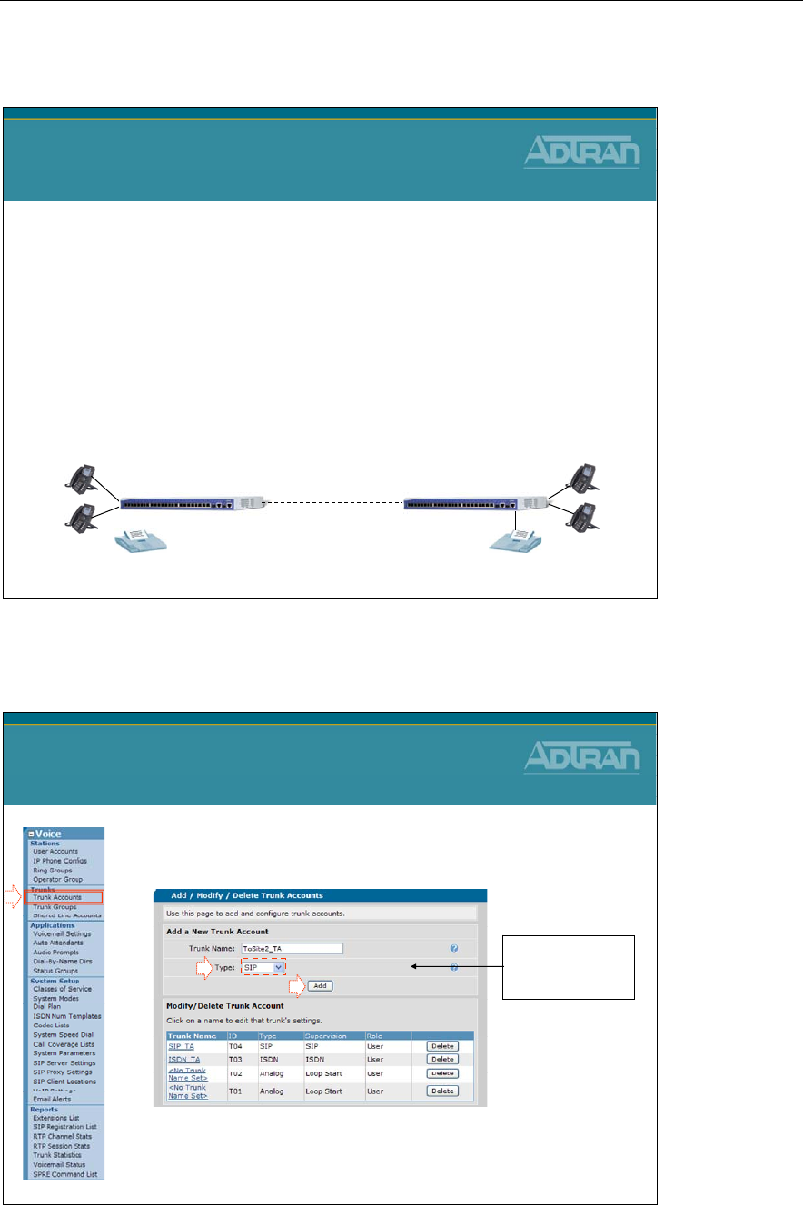
Module 8: NetVanta 7000 Remote Telephony Applications
NetVanta IP Telephony Course 8-27
SIP Networking – Basic Configuration Steps
SIP Networking
Basic Configuration Steps
1. Create Trunk Account
–Configure SIP server as other sides WAN IP
–Configure the SIP FROM Header Host Type
–Configure DNSI substitution (if required)
2. Create Trunk Group
–Add SIP Trunk Account
–Define outbound call templates for other site
SIP Trunk
2003 NetVanta 7000
2004
NetVanta 7000 2003
2004
2000 2000
52XXX >< 52XXX
SIP Networking – 1) Create Trunk Account
1. Select the Voice / Trunks / Trunk Accounts
menu
2. Create a SIP Trunk Account
•Will be used to point to remote site WAN IP address
SIP Networking Configuration
1) Create Trunk Account
- Type Trunk Name
-Set Type to SIP
-Click Add
1
2
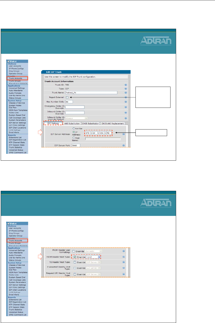
Module 8: NetVanta 7000 Remote Telephony Applications
8-28 NetVanta IP Telephony Course
Trunk Account – Define Remote Site WAN IP
3. Define address Remote Site WAN IP address
SIP Networking Configuration
1) Create Trunk Account
(Cont..)
Disable Reject
External if you
want to allow Trunk
to Trunk calls
3
Remote WAN IP
Trunk Account – Configure FROM Header
4. From the Trunk Accounts SIP settings tab,
configure the FROM Header Host Type
as Local
•This overrides the global default setting found
on the System Setup / VoIP Settings / SIP
Settings tab
SIP Networking Configuration
1) Create Trunk Account
(Cont..)
4
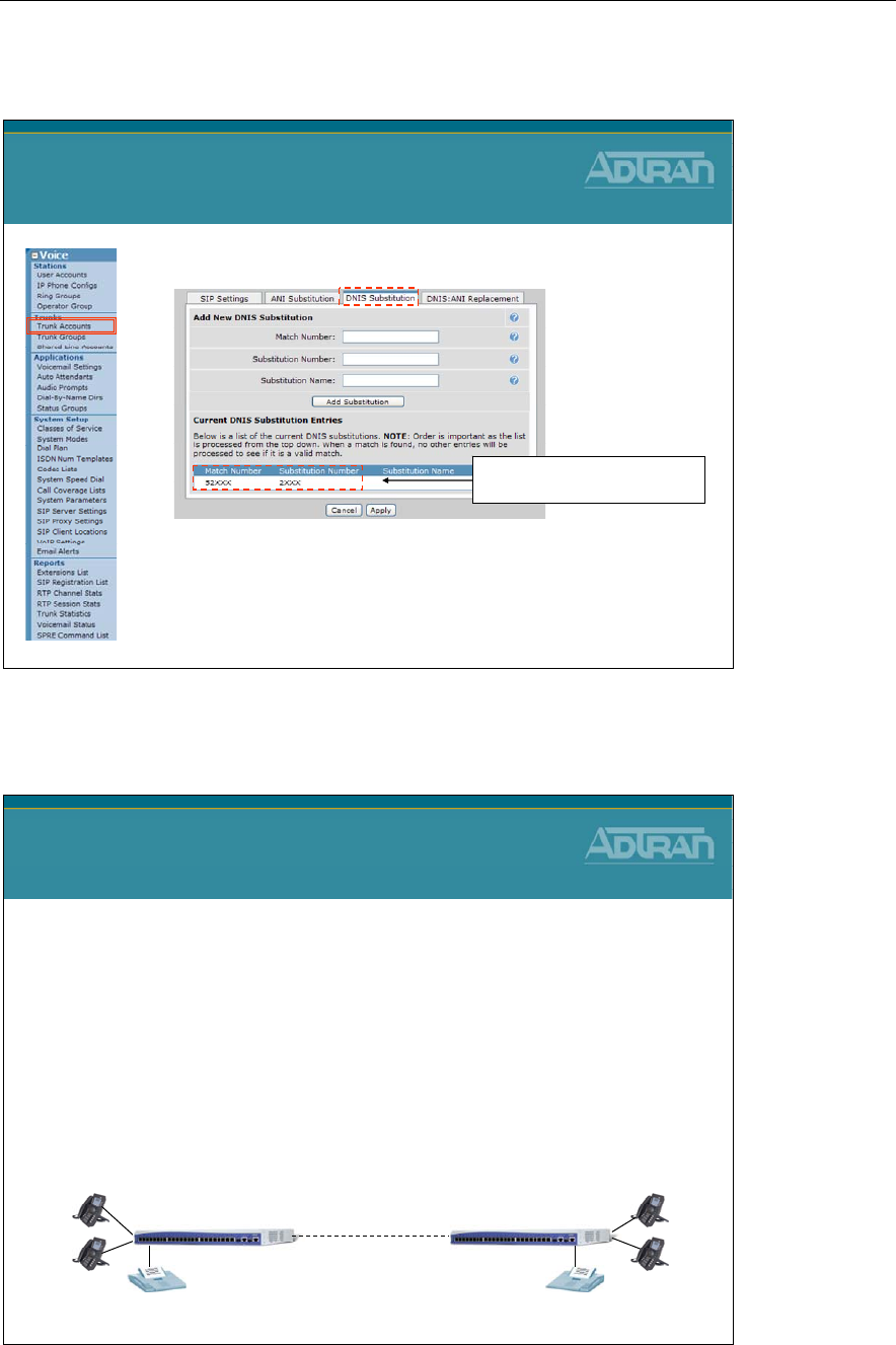
Module 8: NetVanta 7000 Remote Telephony Applications
NetVanta IP Telephony Course 8-29
Trunk Account – DNIS Substitution
•Optional: Add DNIS substitution
–If both sides have the same extension, additional
digits are needed to point calls out a particular trunk
•Once the call routing decision has been made, the extra
digit(s) need to be removed before sending call
SIP Networking Configuration
1) Create Trunk Account
(Cont..)
In this example, the leading 5will
be removed before sending call
SIP Networking - Basic Configuration Steps
SIP Networking
Basic Configuration Steps
1. Create Trunk Account
–Configure SIP server as other sides WAN IP
–Configure the SIP FROM Header Host Type
–Configure DNSI substitution (if required)
2. Create Trunk Group
–Add SIP Trunk Account
–Define outbound call templates for other site
SIP Trunk
2003 NetVanta 7000
2004
NetVanta 7000 2003
2004
2000 2000
52XXX >< 52XXX
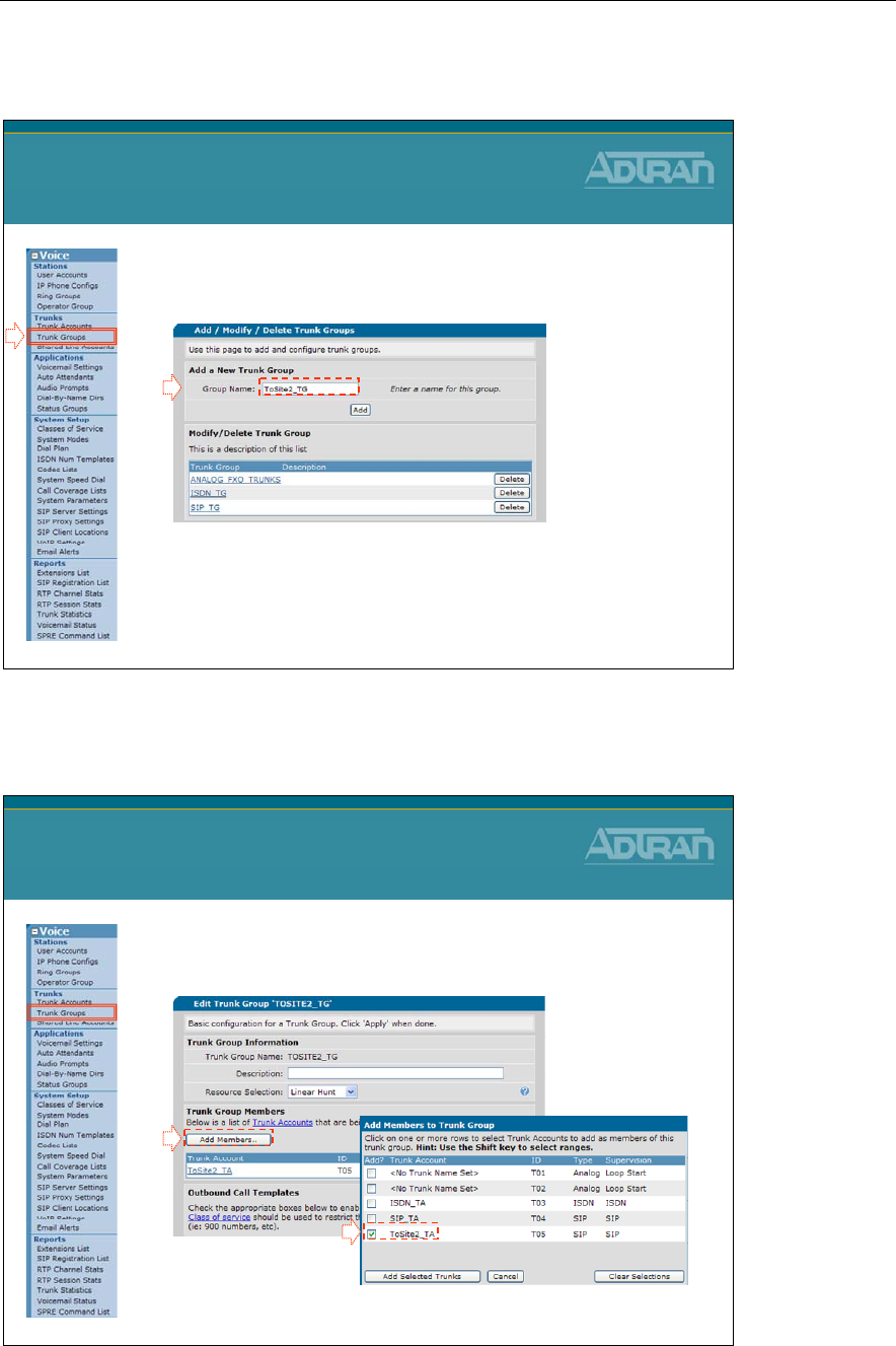
Module 8: NetVanta 7000 Remote Telephony Applications
8-30 NetVanta IP Telephony Course
SIP Trunk Configuration - 2) Create Trunk Group
1. Select the Voice / Trunks / Trunk Groups
menu
2. Create a Trunk Group
–Points to the new SIP Trunk Account
–Define call types allowed to other site
SIP Networking Configuration
2) Create Trunk Group
1
2
Trunk Group – Add SIP Trunk Account
3. Click Add Members to add the Remote Site
Trunk Account to this Trunk Group
SIP Networking Configuration
2) Create Trunk Group
3
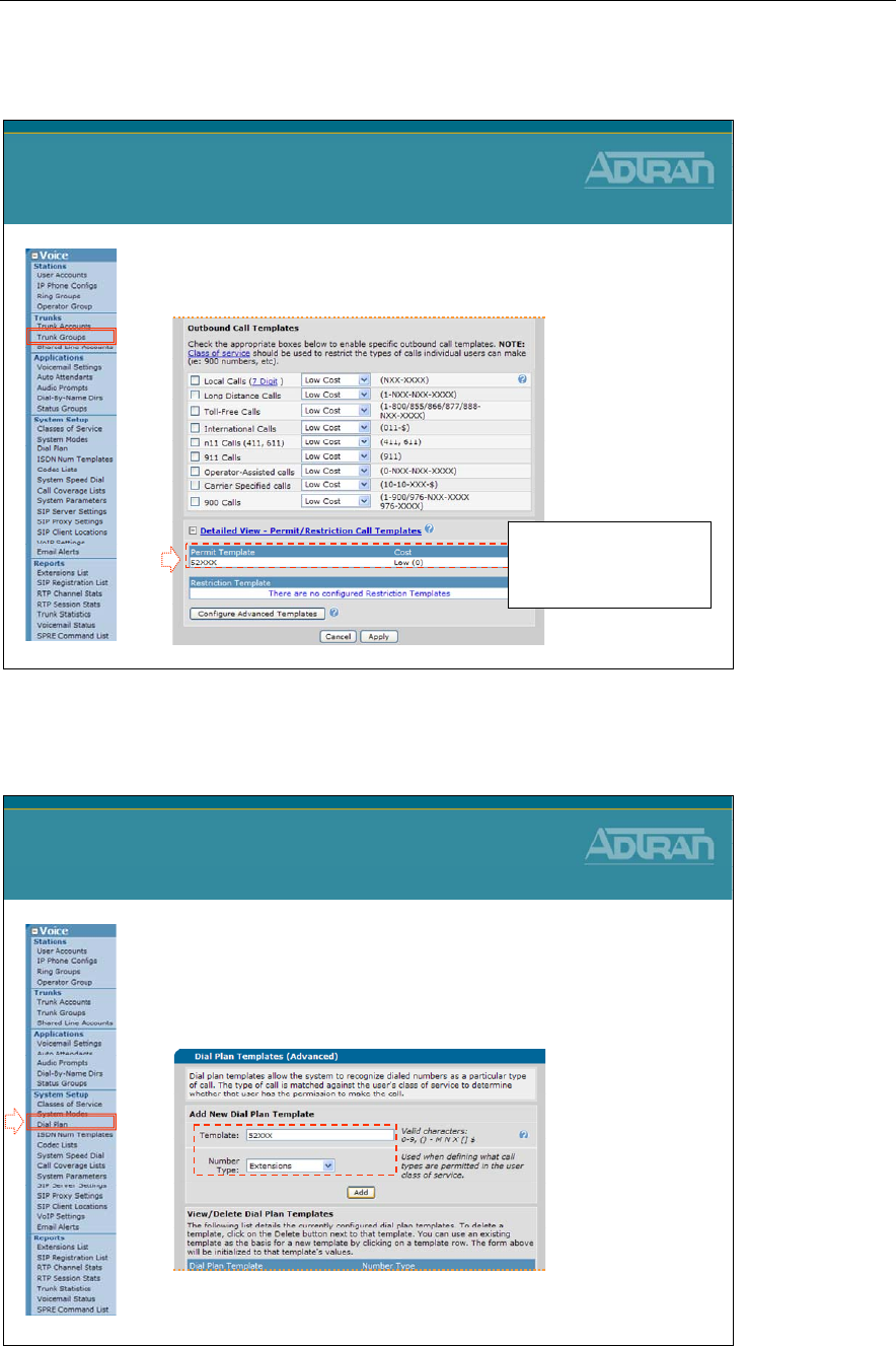
Module 8: NetVanta 7000 Remote Telephony Applications
NetVanta IP Telephony Course 8-31
Trunk Group – Define Outbound Call Template
4. Add a custom Call Template
–Define remote sites extension pattern
SIP Networking Configuration
2) Create Trunk Group
4
Under Advanced Templates,
configure the extension
pattern that will be used to
route calls to the remote site
SIP Networking – System Dial Plan
• Note: Configuration in the next two slides only needs to be done if
both sides have the same extensions. An extra digit will be used
as a site identifier – In this example 5 (52XXX)
1. Select Voice / System Setup / Dial Plan
2. For our example, add 52XXX as an Extension
SIP Networking Configuration
System Dial Plan
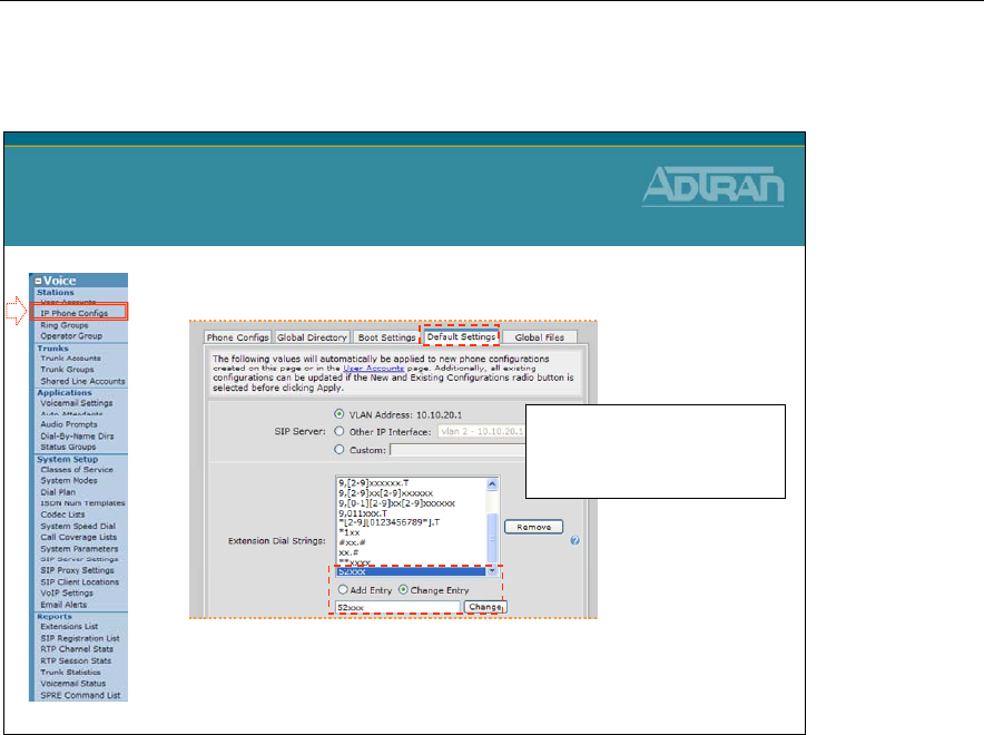
Module 8: NetVanta 7000 Remote Telephony Applications
8-32 NetVanta IP Telephony Course
SIP Networking – IP Phone Configs Dial Plan
1. Select Voice / Stations / IP Phones Configs
2. Add 52XXX to the Extension Dial Strings
– Note: The existing extension pattern of [12345678]xxx could also be
changed to [1234678]xxx (removing 5XXX as an extension)
SIP Networking Configuration
IP Phone Configs Dial Plan
When finish, click Apply Settings
To: New and Existing
Configurations to modify existing
phone configuration files
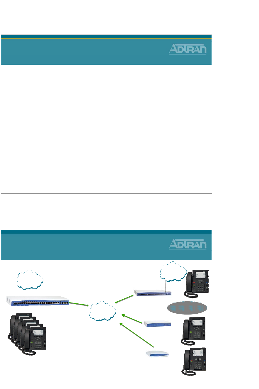
Module 8: NetVanta 7000 Remote Telephony Applications
NetVanta IP Telephony Course 8-33
Remote User Preview
NetVanta IP Telephony Course
Remote User Preview
Configuration Guide can be found at
kb.adtran.com
NetVanta 7000 Solution – Remote Sites
NetVanta 7000 Series Solution
Remote Sites
•3-4 Digit Dialing Between Sites
•VPN Between Sites
•Use Central Voicemail
•Use Central Auto Attendant
•Total of 100 Stations in Network
•Remote PSTN trunks
NetVanta 6355
IP Gateway
NetVanta 7000
Up to 100 Stations
In Customer Network
Remote Sites
NetVanta 3448
Multiservice Router
NetVanta 3120
SOHO Router
PSTN
PSTN
IP
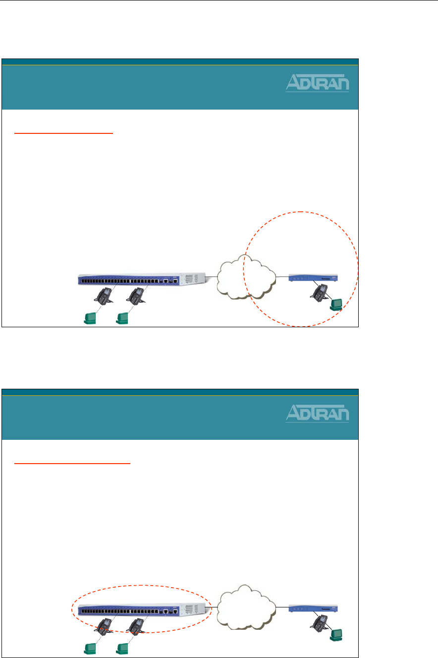
Module 8: NetVanta 7000 Remote Telephony Applications
8-34 NetVanta IP Telephony Course
Remote User - Basic Configuration Steps
Remote User – Home Office
Basic Configuration Steps
Remote NetVanta
1. Normal router configuration
–Change LAN IP to 192.168.1.0 /24
2. Normal firewall configuration
–Allow UDP traffic in WAN
3. Add DHCP Boot Server option for phone
–Option 66 for Polycom phones
–Option 157 for ADTRAN phones
Internet
NetVanta
7000
Remote User
Home Office
WAN IP:
10.200.201.61
WAN IP:
10.200.200.67 LAN IP:
192.168.1.0 /24
Remote User - Basic Configuration Steps
Remote User – Home Office
Basic Configuration Steps
Local NetVanta 7000
1. Remote Phone Configuration
–Create SIP User by defining MAC Address for remote phone
–Define Boot Settings for remote phones
–Set Boot Profile of new SIP user to Remote Phone
2. Firewall Configuration
–Allow SIP and FTP traffic in WAN
3. VoIP Settings
–SIP from header / RTP Firewall Traversal
–WAN media-gateway
Internet
NetVanta
7000
Remote User
Home Office
WAN IP:
10.200.201.61
WAN IP:
10.200.200.67 LAN IP:
192.168.1.0 /24
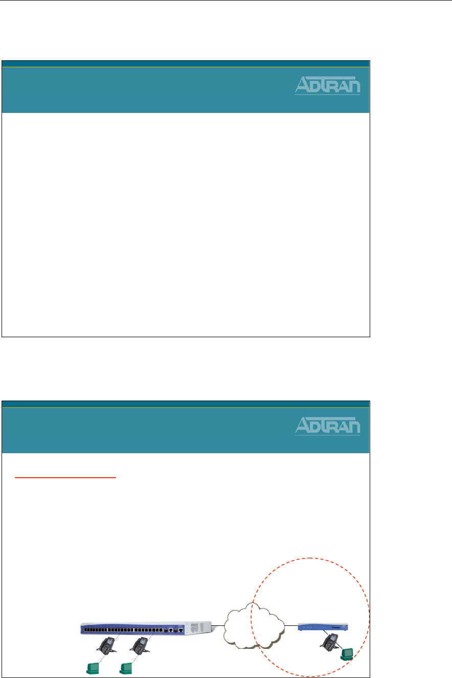
Module 8: NetVanta 7000 Remote Telephony Applications
NetVanta IP Telephony Course 8-35
VPN Preview
NetVanta IP Telephony Course
VPN Preview
Configuration Guide can be found at
kb.adtran.com
Remote User over VPN - Basic Configuration
Remote User over VPN
Basic Configuration Steps
Remote NetVanta
1. Router/DHCP/VoIP settings config
–Same as remote user with no VPN
2. Remote LAN to NetVanta 7000 LAN VPN tunnel
–RTP traffic
3. Remote LAN to NetVanta 7000 WAN VPN tunnel
–SIP, FTP, Voicemail, and Auto Attendant traffic
Internet
NetVanta
7000
Remote User
Home Office
WAN IP:
10.200.201.61
WAN IP:
10.200.200.67 LAN IP:
192.168.1.0 /24
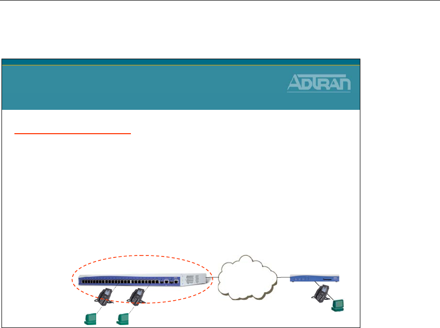
Module 8: NetVanta 7000 Remote Telephony Applications
8-36 NetVanta IP Telephony Course
Remote User Over VPN - Basic Configuration
Remote User Over VPN
Basic Configuration Steps
Local NetVanta 7000
1. Remote Phone Configuration
–Create SIP User by defining MAC Address for remote phone
–Define Boot Settings for remote phones
–Set Boot Profile of new SIP user to Remote Phone
2. WAN media-gateway enabled
3. Local NV 7000 LAN to Remote LAN VPN tunnel
–RTP traffic
4. Local NV 7000 WAN to Remote LAN VPN tunnel
–SIP, FTP, Voicemail, and Auto Attendant traffic
Internet
NetVanta
7000
Remote User
Home Office
WAN IP:
10.200.201.61
WAN IP:
10.200.200.67 LAN IP:
192.168.1.0 /24

Module 8: NetVanta 7000 Remote Telephony Applications
NetVanta IP Telephony Course 8-37
VoIP Quality Monitoring
NetVanta IP Telephony Course
VoIP Quality Monitoring (VQM)
VQM – What is it?
VQM – What is it?
•Voice Quality Monitoring
–Provides visibility into VoIP networks
–VoIP network troubleshooting and monitoring
–Works in conjunction with QoS
–Graphically intuitive web interface
•Allows network device to make real-time VoIP quality
measurements on SIP-signaled RTP VoIP calls
•Measurements provide live and historical
performance data on a per-call basis (inbound and
outbound)
•Call quality monitoring using MOS, delay, jitter,
packet loss and out of order packets

Module 8: NetVanta 7000 Remote Telephony Applications
8-38 NetVanta IP Telephony Course
VQM – How it benefits you!
VQM – How it benefits you!
•Improves customer VoIP experience
–VoIP performance can be proactively monitored
•Provides visibility into VoIP networks
–Identify problem areas: Local LAN, Remote LAN, or WAN
–Identify interface errors
–Verify QoS configurations
–Monitor network utilization
•Reduces Operating Expense
–Reduce turn up time
–Allows remote monitoring of VoIP performance
–Reduce truck rolls
•Reduces Downtime
–Segments network issues
VQM – Understanding Terms
VQM – Understanding Terms
•Quality of Service (QoS) - The ability to assigning priority to
specific network traffic
•Mean Opinion Score (MOS) - a numerical measure of the quality
of human speech at the destination end of a circuit
–A MOS score ranges from 1 to 5
–Acceptable MOS scores are 4 and above
•Delay - The amount of time between the transmission and
reception of packets
•Jitter - Variations in the total delay for a single packet
•Loss - Packets dropped along the way
•Out of Order - Packets received out of order causes
reassembling problems
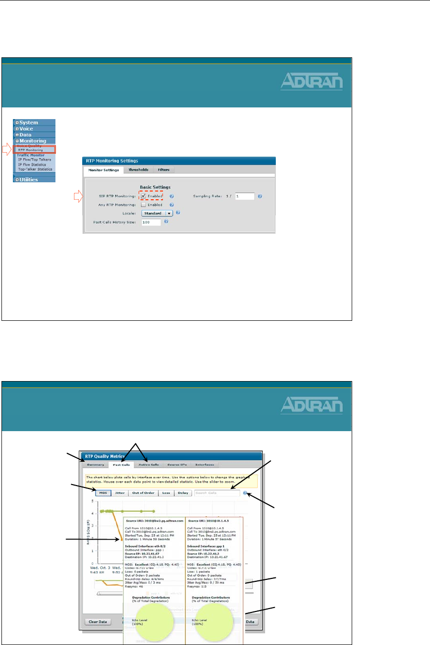
Module 8: NetVanta 7000 Remote Telephony Applications
NetVanta IP Telephony Course 8-39
Enabling VQM
1. Select the Monitoring / Voice Quality / RTP
Monitoring menu
2. Enable SIP RTP Monitoring
•This enables the ability to monitor RTP streams
associated with SIP traffic that traverse the filewall
Enabling VQM
1
2
VQM – Graphically Intuitive Interface
VQM - Graphically
Intuitive Interface
An example of a data
point on the graph
with a low MOS (1.86)
indicates poor voice
quality. Use your
mouse to hover over
any data point allows
you to see detailed
information
pertaining to that
specific call.
Use the slider bar
with color-coded
interfaces to filter
RTP streams.
Use the Search Field
to sort a large
number of data
points.
Summary tab shows
overall network health
Review Past Calls or monitor Active Calls in real-time
Export data as
Comma Delimited or
XML
Monitor Mean Opinion
Score (MOS), Jitter, and
Out of Order, Lost, or
Delayed packets Hovering over the
question mark offers
examples of
multiple-term search
and valid filters.
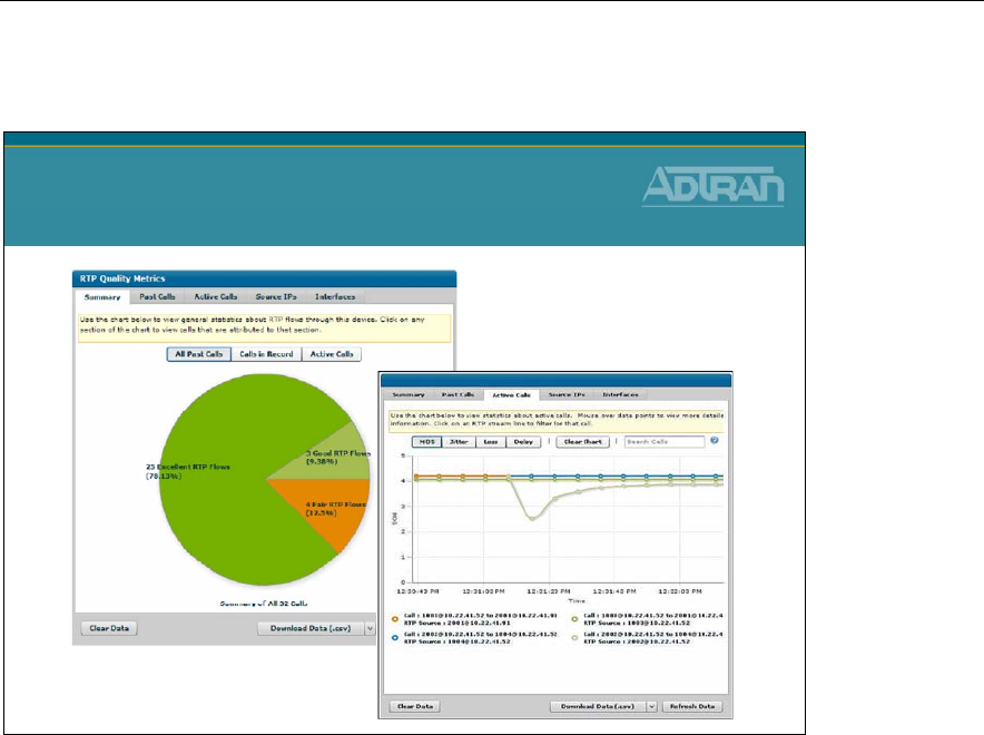
Module 8: NetVanta 7000 Remote Telephony Applications
8-40 NetVanta IP Telephony Course
VQM - Demonstration
VQM – Demonstration
www.adtran.com/VQM
Module 8: NetVanta 7000 Remote Telephony Applications
NetVanta IP Telephony Course 8-41
Troubleshooting
NetVanta IP Telephony Course
Troubleshooting
show sip user-registration
NV7000#
show sip user-registration
EXTENSION TYPE IP ADDRESS PORT PROT EXPIRES
----------------- --------------------------------- ---------------- -------- ------- ------------
2003 Adtran-SIP-IP712/v1.3.7 10.10.20.2 5060 UDP 3537
2004 PolycomSoundPointIP_601.. 10.10.20.3 5060 UDP 2009
Total phones registered: 2
show sip user-registration
•Display local SIP Server registration information
Module 8: NetVanta 7000 Remote Telephony Applications
8-42 NetVanta IP Telephony Course
show sip trunk-registration
NV7000#
show sip trunk-registration
Trk Identity Reg'd Grant Expires Success Failed Requests Challenges Rollovers
---- --------- -------- ------- --------- ----------- ------- ------------ --------------- ------------
T04 9635501 Yes 3600 833 9 0 18 9 0
Total Displayed: 1
show sip trunk-registration
•Display local SIP Trunk registration information
sip trunk-registration force-register
NV7100#
sip trunk-registration force-register
sip trunk-registration force-register
•Force a SIP registration
Module 8: NetVanta 7000 Remote Telephony Applications
NetVanta IP Telephony Course 8-43
debug sip stack message summary
NV7000#
debug sip stack messages summary
15:16:35 SIP.STACK MSGSUM Tx: REGISTER sip:172.23.102.87:5060 SIP/2.0
15:16:35 SIP.STACK MSGSUM Rx: SIP/2.0 401 Unauthorized
15:16:35 SIP.STACK MSGSUM Tx: REGISTER sip:172.23.102.87:5060 SIP/2.0
15:16:35 SIP.STACK MSGSUM Rx: SIP/2.0 200 OK
15:16:35 SIP.STACK MSGSUM Rx: NOTIFY sip:9635501@172.23.102.41 SIP/2.0
15:16:35 SIP.STACK MSGSUM Tx: SIP/2.0 200 OK NV7100#
15:16:52 SIP.STACK MSGSUM Tx: NOTIFY sip:2003@10.10.20.2 SIP/2.0
15:16:53 SIP.STACK MSGSUM Rx: SIP/2.0 200 OK
debug sip stack messages
•View a summary of SIP messages (first line only)
debug voice summary
NV7000#
debug voice summary
15:22:47:830 VOICE.SUMMARY voice user 2001 cos allowed the call to Local
15:22:47:832 VOICE.SUMMARY 2001 is calling
T04
(9635502).
15:22:51:681 VOICE.SUMMARY RTP for Call from 2001 to 9635502: Codec PCMU
15:22:51:683 VOICE.SUMMARY 2001 is connected to
T04
(9635502)
15:22:57:845 VOICE.SUMMARY Call from 2001 to
T04
(9635502) ended by 2001:
15:23:23:178 VOICE.SUMMARY
T03
is calling 2003 (2003).
15:23:26:316 VOICE.SUMMARY RTP for Call from 2003 to 2003: Codec PCMU
15:23:26:317 VOICE.SUMMARY
T03
is connected to 2003 (2003)
15:23:31:612 VOICE.SUMMARY Call from
T03
to 2003 (2003) ended by T03:
15:23:41:532 VOICE.SUMMARY voice user 2003 cos allowed the call to Local
15:23:41:534 VOICE.SUMMARY 2003 is calling
T01
(8021000).
15:23:43:950 VOICE.SUMMARY RTP for Call from 0 to 8021000: Codec PCMU
15:23:43:951 VOICE.SUMMARY 2003 is connected to
T01
(8021000)
15:23:52:842 VOICE.SUMMARY Call from 2003 to
T01
(8021000) ended by 2003:
debug voice summary
•View call routing summary real time
–Can confirm proper trunk is being used
Voice Trunk ID

Module 8: NetVanta 7000 Remote Telephony Applications
8-44 NetVanta IP Telephony Course
Module Summary
Module Summary
•At the end of this module, you should be able to:
•Recognize NetVanta 7000 Remote Telephony
Applications
•Configure Service Provider SIP Trunk
•Configure SIP Networking between Sites
•Enable VoIP Quality Monitoring (VQM)
•Conduct Voice Troubleshooting in a NetVanta 7000
Remote Telephony Application

Module 9: NetVanta 7000
Miscellaneous Tools and Utilities

Module 9: NetVanta 7000 Miscellaneous Tools and Utilities
9-2 NetVanta IP Telephony Course

Module 9: NetVanta 7000 Miscellaneous Tools and Utilities
NetVanta IP Telephony Course 9-3
Module Objectives
Module Objectives
•Introduce the following Tools:
–Top Talkers
–Top Visited Web Sites
–Wireless Controller
–n-Command
•Introduce System Utilities
–Port Mirroring
–Firmware Upgrades
–Configuration Backup

Module 9: NetVanta 7000 Miscellaneous Tools and Utilities
9-4 NetVanta IP Telephony Course
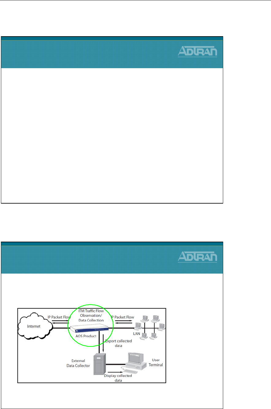
Module 9: NetVanta 7000 Miscellaneous Tools and Utilities
NetVanta IP Telephony Course 9-5
Top Talkers
Top Talkers
Top Talkers
•Top Talkers enhances ITM by adding a simple
internal data collector to NetVanta Products
•Integrated Traffic Monitoring (ITM) is a method of tracking traffic flow patterns
across interfaces on a network using Netflow v9 as an export protocol for maximum
operability with external data collectors.
NetVanta 7100
Top Talkers
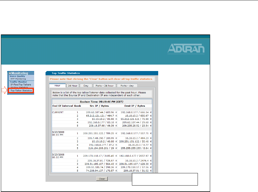
Module 9: NetVanta 7000 Miscellaneous Tools and Utilities
9-6 NetVanta IP Telephony Course
Top Talkers Statistics
Top Talkers Statistics
•Configuration Guide for ITM
is available kb.adtran.com
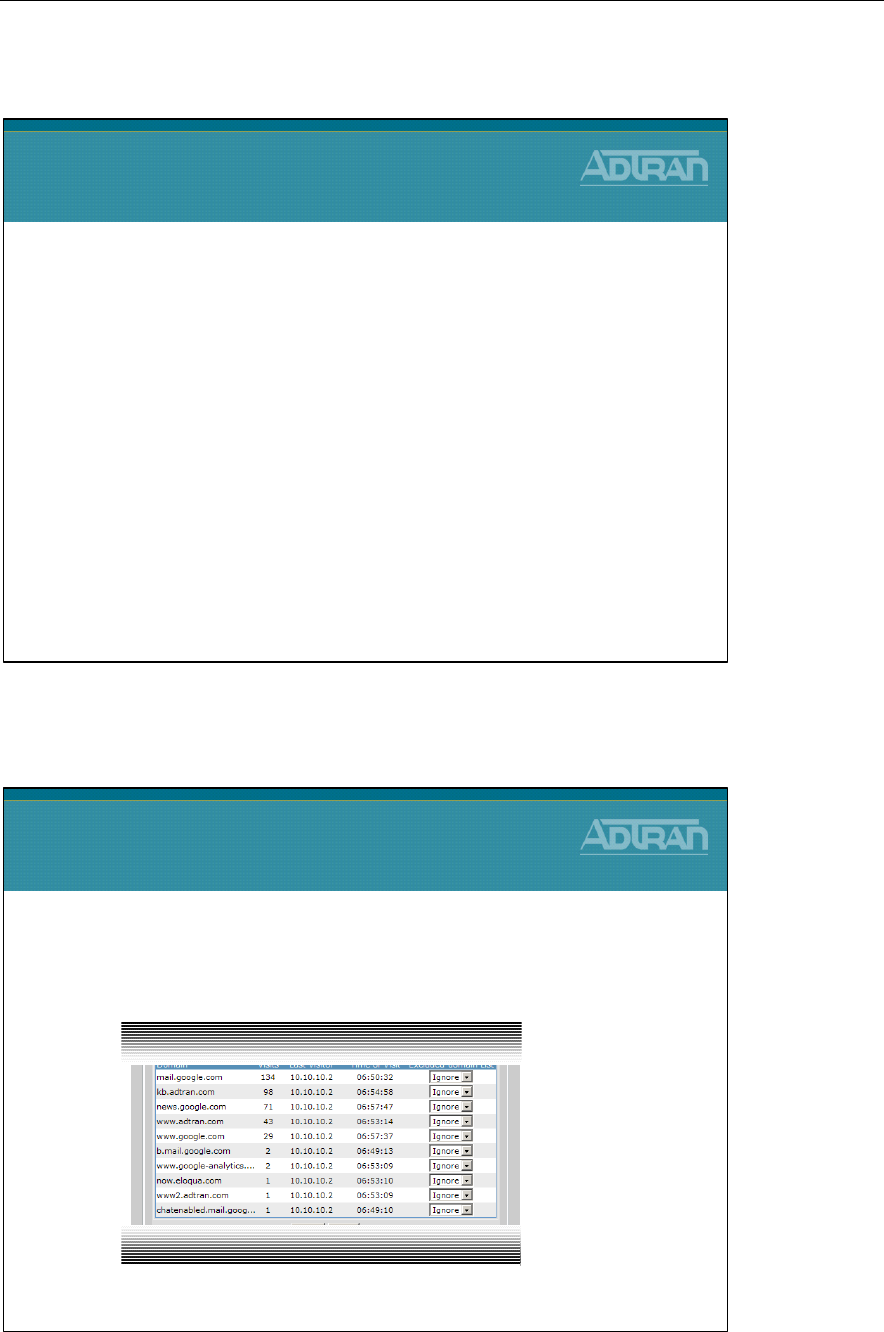
Module 9: NetVanta 7000 Miscellaneous Tools and Utilities
NetVanta IP Telephony Course 9-7
Top Visited Web Sites
Top Visited Web Sites
Top Visited Web Sites
•Report top websites requested by users
–Can be used without a Websense server
NetVanta 7100
Top Visited Web Sites
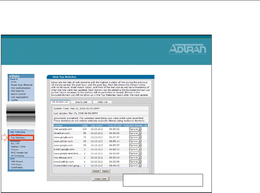
Module 9: NetVanta 7000 Miscellaneous Tools and Utilities
9-8 NetVanta IP Telephony Course
View Top Websites
View Top Websites
•Configuration Guide for Top Websites
is available at kb.adtran.com
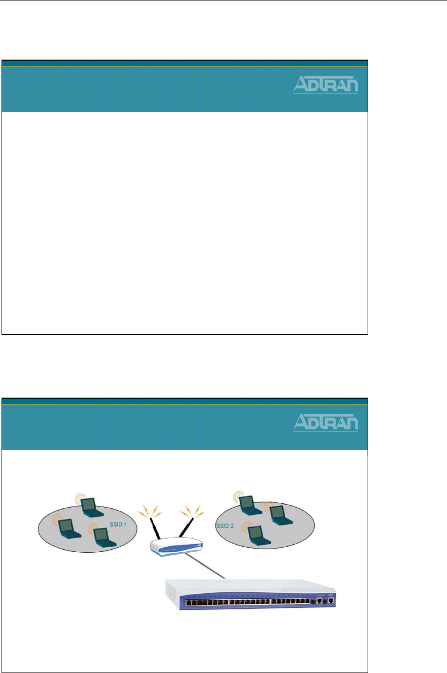
Module 9: NetVanta 7000 Miscellaneous Tools and Utilities
NetVanta IP Telephony Course 9-9
Wireless Controller
Wireless Controller
Wireless Controller
•Wi-Fi enable the NetVanta 7100
NetVanta 7100
Wireless Controller
NetVanta 150
Wireless Access Point
NetVanta 7100
Wireless Controller
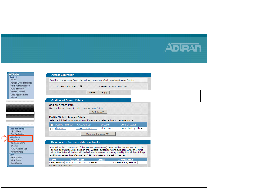
Module 9: NetVanta 7000 Miscellaneous Tools and Utilities
9-10 NetVanta IP Telephony Course
Wireless Configuration
• Manage Access Points from GUI
Wireless Configuration
•Configuration Guide for Wireless
is available at kb.adtran.com
Module 9: NetVanta 7000 Miscellaneous Tools and Utilities
NetVanta IP Telephony Course 9-11
n-Command
Added Value To Dealers
n
n-
-Command
Command
Enterprise Edition:
Enterprise Edition:
Network Productivity
Network Productivity
Suite
Suite
ADDED VALUE TO DEALERS
ADDED VALUE TO DEALERS
NetVanta 7100
n-Command

Module 9: NetVanta 7000 Miscellaneous Tools and Utilities
9-12 NetVanta IP Telephony Course
ADTRAN – Management Solution
n-Command – What is it?
n-Command – What is it?
•n-Command is a suite of productivity tools that help IT
departments save time and money on daily network operations
–VARs also use n-Command to offer their customers value-add
services
•n-Command is designed to facilitate global device activities:
–Firmware Upgrades
–Configuration changes
–Configuration Backups
–Asset management
•n-Command is NOT an NMS that monitors performance, detects
alarms or provides performance reports
–It complements any NMS system that may already exist since it
focuses on features that a NMS does not support
ADTRAN - Management Solution
•Individual Device Configuration
–Familiar Command Line Interface (CLI)
–Web Browser
•For easy graphical device configuration
•Manage Large Deployments of Devices
–n-Command
•Configuration Management
•Asset Management
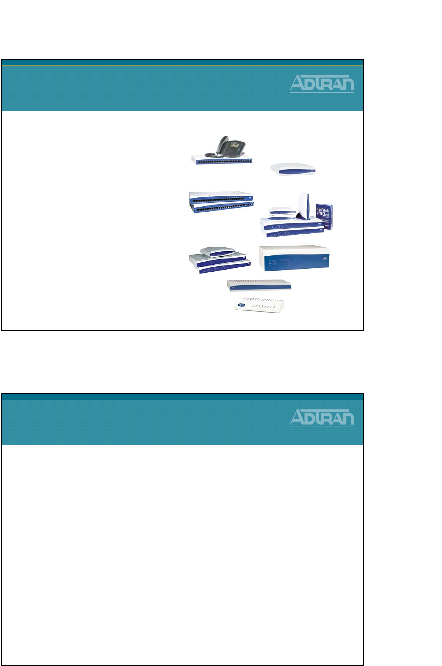
Module 9: NetVanta 7000 Miscellaneous Tools and Utilities
NetVanta IP Telephony Course 9-13
n-Command: Product Support
n-Command: Services Offered
n-Command: Services Offered
•Manage Multiple Customer Networks: Separate customer
networks by creating different Folders or Sub-Folders
–Flexibility to organize each customer’s network devices differently
–Modify user access per folder/customer network
•Inventory: Keep track of Customer Inventory - Device part
number, serial number, firmware revision, boot code revision,
etc…
–Provide an Excel Inventory Report periodically or when requested
•Configuration Changes: Make Configuration changes to multiple
Devices and keep a log of all user activity per device
–Push changes to a single device or large numbers of devices
quickly
–Provides a detailed summary of the job upon completion
•Uses Secure Communication (SSH and Secure Copy)
n-Command: Product Support
•* Supports all NetVanta AOS products and more …
–NetVanta 7000 Series
–NetVanta 300 Series
–NetVanta 1000 Series
–NetVanta 2000 Series
–NetVanta 3k, 4k, & 5k Series
–TA 900 Series
–TA 600/850 MDL
•(Add-on Module)

Module 9: NetVanta 7000 Miscellaneous Tools and Utilities
9-14 NetVanta IP Telephony Course
n-Command: Services Offered
n-Command Specifics
n-Command Specifics
•ACL Manager (Policy Pushing)
–Quickly change Access Control lists used for packet
selection on interfaces, QOS and Firewall Polices etc...
•Find & Mark Common ACL Statements in existing ACLs
•Create / Edit / Delete / Insert Templates
•Syntax Checking
•Preview of ACL after change / View “Fix Up” Code
•Backup Configuration Before / After ACL change
•Fail Safe Push of “Fix Up” Code
•Device Log of All actions
n-Command: Services Offered
•Backup Configuration: Schedule recurring configuration backups and
monitor for any unexpected changes in configuration
–NetVanta 7100 – Backup the full system including:
•All Phone Files
•All NetVanta data and voice configs
•VoiceMail Greetings (Note: VoiceMail Messages are not backed up)
–Send e-mail notification summary if a config. change is found or if the
running config. and startup config. are different
•Configuration Restore: Quickly restore a previous configuration based
on a date or event to one or many devices
•Firmware Update: Notify customer whenever a new firmware revision is
available for their devices, and update their firmware without a truck roll
•Uses Secure Communication (SSH and Secure Copy)
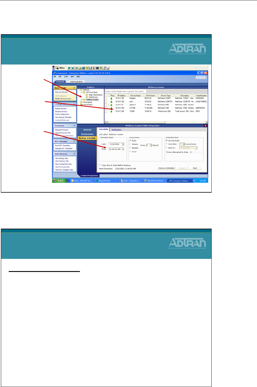
Module 9: NetVanta 7000 Miscellaneous Tools and Utilities
NetVanta IP Telephony Course 9-15
Folder Management
n-Command Part Numbers
n-Command Part Numbers
Part Number & Description:Part Number & Description:
•n-Command Enterprise Edition CD* 1950843L1
•500-node Incremental License 1950844L1
•250-node Incremental License 1950844L2
•2-Client Incremental License 1950845L1
•ACL Manager Module 1950850L1
•Total Access 600/850 Module 1950852L1
•Annual Maintenance - Access to download patches, upgrades
and phone support
–n-Command Enterprise Edition CD comes with support for 100-Nodes, 5-
Clients, and one year of software maintenance included
Folder Management
Create Folders and
sub-folders
Drag Devices
into folders
Set Automatic
backup
schedule on a
folder basis
Set User
Permissions on a
per Folder basis

Module 9: NetVanta 7000 Miscellaneous Tools and Utilities
9-16 NetVanta IP Telephony Course
n-Command – Other Info
n-Command – Other Info.
•There is a worthwhile flash video on our web site
which a customer can watch. It demonstrates all
functionality.
www.adtran.com/n-command
•Demo disks are available through our publication
department. It allows all features to work, but is
limited to 5-nodes.
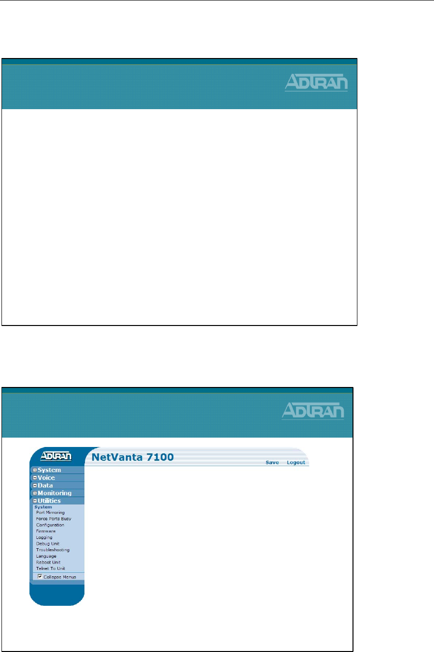
Module 9: NetVanta 7000 Miscellaneous Tools and Utilities
NetVanta IP Telephony Course 9-17
Utilities Menu
NetVanta 7000 - Utilities Menu
NetVanta 7100
Utilities Menu
NetVanta 7100 Utilities menu includes the following:
•Port Mirroring
•Force Ports Busy
•Configuration
•Firmware
•Logging
•Debug Unit
•Troubleshooting
•Language Reboot Unit
•Telnet To Unit
NetVanta 7100
Utilities Menu
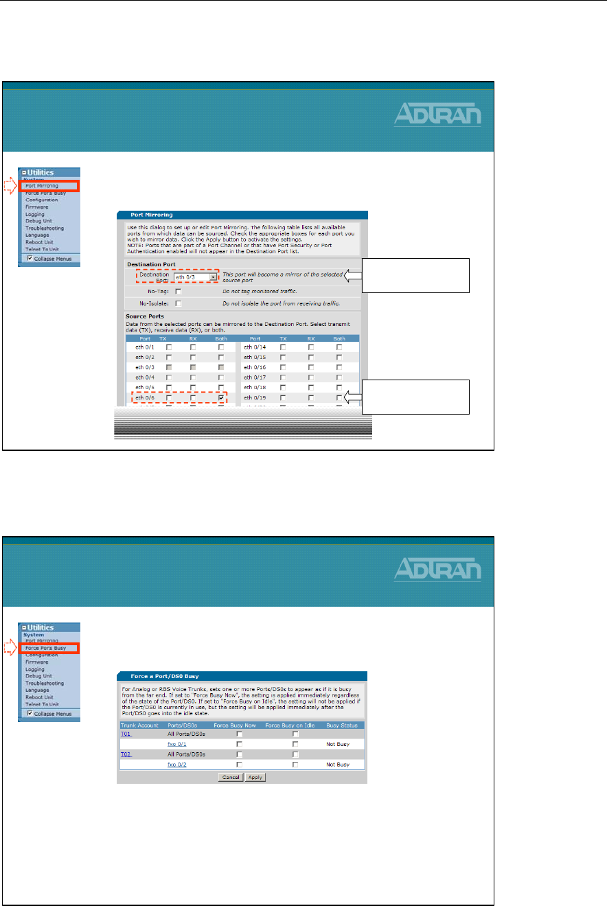
Module 9: NetVanta 7000 Miscellaneous Tools and Utilities
9-18 NetVanta IP Telephony Course
Utilities / System - Port Mirroring
Utilities / System - Force Ports Busy
•Force ports busy for maintenance
–Analog and RBS Voice Trunks
–Force Busy Now
•Setting immediately applied
–Force Busy on Idle
•Setting applied when port becomes idle
Utilities / System
Force Ports Busy
•Mirror (copy) source traffic from a source port
to a destination port
Utilities / System
Port Mirroring
2) Select destination
port to copy to
1) Select source
port(s) to copy from
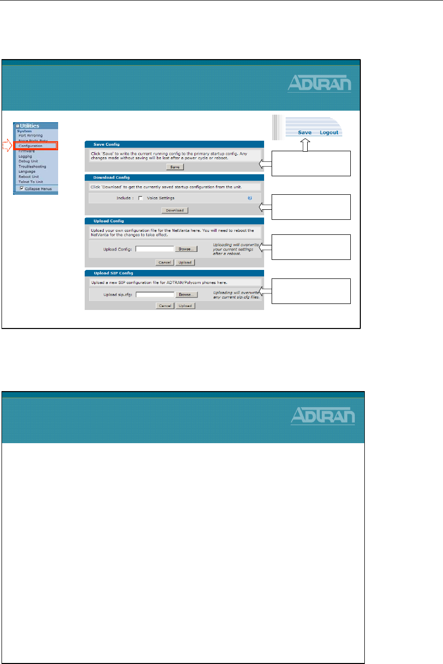
Module 9: NetVanta 7000 Miscellaneous Tools and Utilities
NetVanta IP Telephony Course 9-19
Utilities / System - Configuration
Firmware Upgrades
Firmware Upgrades
•Firmware upgrades can be handled in mass with n-
Command
•Firmware upgrades can be done via the Web GUI
•Firmware upgrades can be done via the command
line
–FTP
–TFTP
–SCP
•Saving / Backup Configuration
Utilities / System
Configuration
Same function as
copy run start
Save config to any
location on your PC
Upload a config to
from your PC
Upload sip.cfg from
your PC
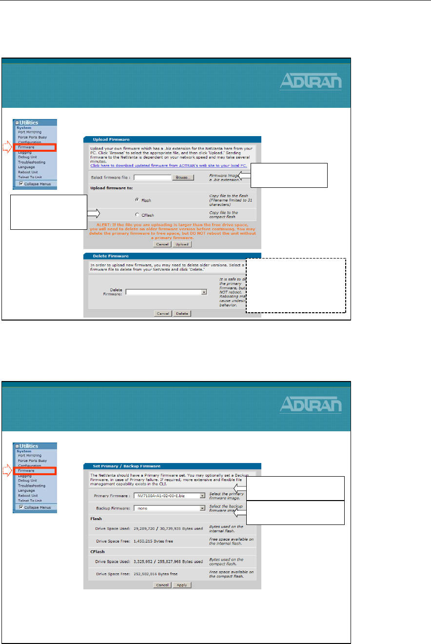
Module 9: NetVanta 7000 Miscellaneous Tools and Utilities
9-20 NetVanta IP Telephony Course
Utilities / System - Firmware
Utilities / System - Firmware
2. Set Primary and Backup Firmware Image
3. Click Apply and then reboot to complete the
firmware up grade process
Utilities / System
Firmware
1) Set the Primary
firmware as the new image
2) Set the Backup
Firmware as the old image
1. Upload the Firmware image to NetVanta 7100
Utilities / System
Firmware
1) Select firmware
to be uploaded
NOTE: You may need to
delete other firmware
images before uploading
the new firmware, or
choose to upload to CFlash
2) Specify FLASH
or CFLASH and
then click Upload
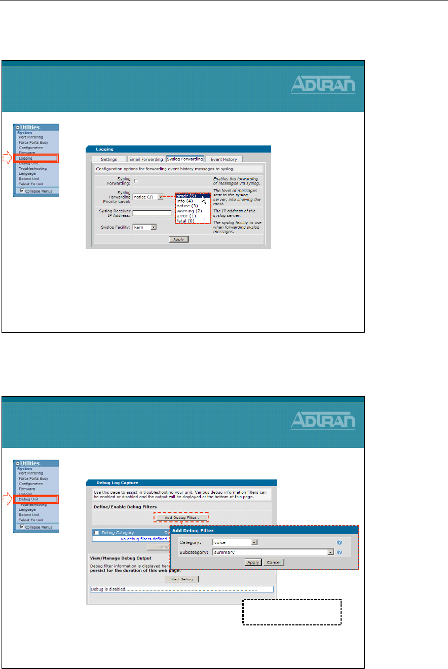
Module 9: NetVanta 7000 Miscellaneous Tools and Utilities
NetVanta IP Telephony Course 9-21
Utilities / System - Logging – SMDR
Utilities / System - Debug Unit
•View debug events real time
1. Select Add Debug Filter
2. Choose a Category
3. Choose Sub-category
4. Click Start Debug
Utilities / System
Debug Unit
Debug information will
display on screen here
•Enable SMDR Logging
1. Enable Syslog Forwarding
2. Set Syslog Forwarding Priority Level to SMDR
3. Define IP address of Syslog server
4. Optional – define Syslog facility
Utilities / System
Logging - SMDR
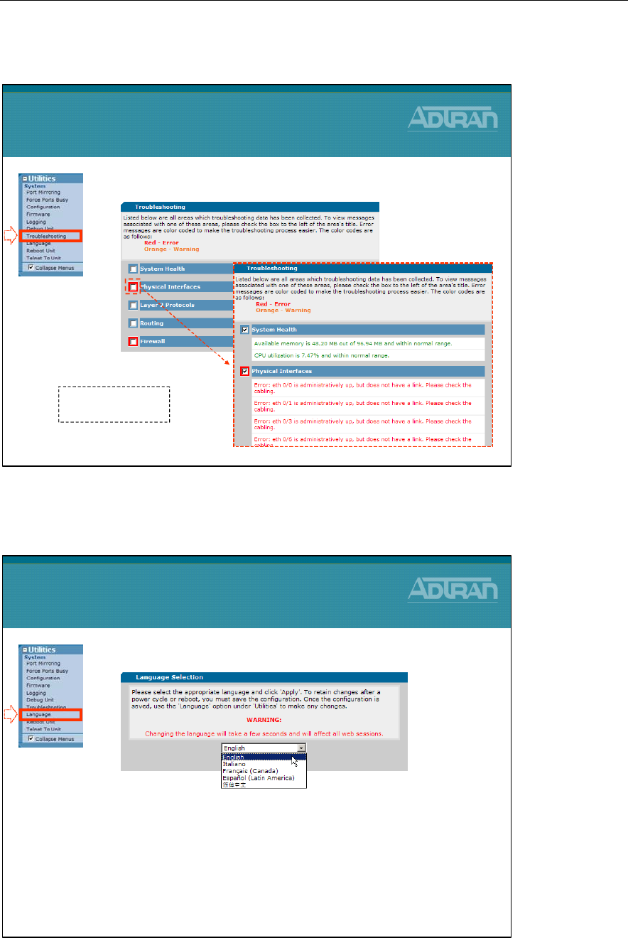
Module 9: NetVanta 7000 Miscellaneous Tools and Utilities
9-22 NetVanta IP Telephony Course
Utilities / System - Troubleshooting
Utilities / System - Language
•Select appropriate language used by system
Utilities / System
Language
•System health and troubleshooting aid
Utilities / System
Troubleshooting
Displays errors and
possible solutions
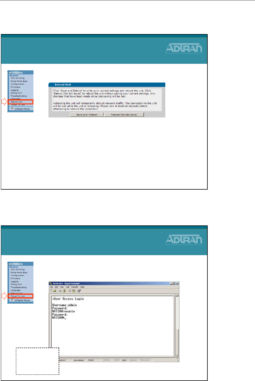
Module 9: NetVanta 7000 Miscellaneous Tools and Utilities
NetVanta IP Telephony Course 9-23
Utilities / System - Reboot Unit
Utilities / System - Telnet To Unit
•Access the Command Line Interface through
an IP connection using Telnet
Utilities / System
Telnet To Unit
Default Username:
admin
Default Password:
password
•Rebooting the NetVanta 7100
–Save and Reboot
•Saves the running configuration to startup-config and
dynvoice-config
–Reboot (Do Not Save)
•Reboots the unit without saving
Utilities / System
Reboot Unit

Module 9: NetVanta 7000 Miscellaneous Tools and Utilities
9-24 NetVanta IP Telephony Course
Module Summary
Module Summary
•At the end of this module, you should be:
•Familiar with the following Tools:
–Top Talkers
–Top Visited Web Sites
–Wireless Controller
–n-Command
•Troubleshoot with Port Mirroring
•Upgrade the NetVanta 7000 Firmware
•Save and backup configurations
