Nakamichi_Dragon_Modification_with_ANT4066 Nakamichi Dragon Modification With ANT4066
User Manual: Nakamichi_Dragon_Modification_with_ANT4066
Open the PDF directly: View PDF ![]() .
.
Page Count: 3
Alex Nikitin, A.N.T. Audio 2nd October 2009
http://www.ant-audio.co.uk
Nakamichi Dragon Cassette Deck Modification
using ANT4066 high linearity quad analogue switch
Nakamichi Dragon is probably the most well known of all cassette decks – for its unique features
and build quality. Unfortunately, its playback sound quality is somewhat compromised by CMOS
switching ICs on the outputs of playback EQ amplifiers – IC502 and IC602, uPC4066BC according
to the service manual. 4066 chip is notoriously non-linear and introduces high-order distortion in
the signal path. In the Dragon it is used in a non-standard fashion with asymmetrical power supply
and that does not help matters either. New ANT4066 replacement hybrid IC used in place of
uPC4066BC for the first time allows to improve playback quality of the Dragon with minimal
modifications of the circuit and with a possibility to revert to the original version by just unplugging
the replacement chips and inserting the original ICs into the DIL sockets.
As the uPC4066BC chips in the Dragon supplied with +12/-2.2V supply and control voltages are
0/+12V, it is impossible to replace these ICs without translating the control levels to +12/-12V as
required by ANT4066 in this situation. Fortunately, the chosen level translation circuit will also
allow the original chip to operate as before.
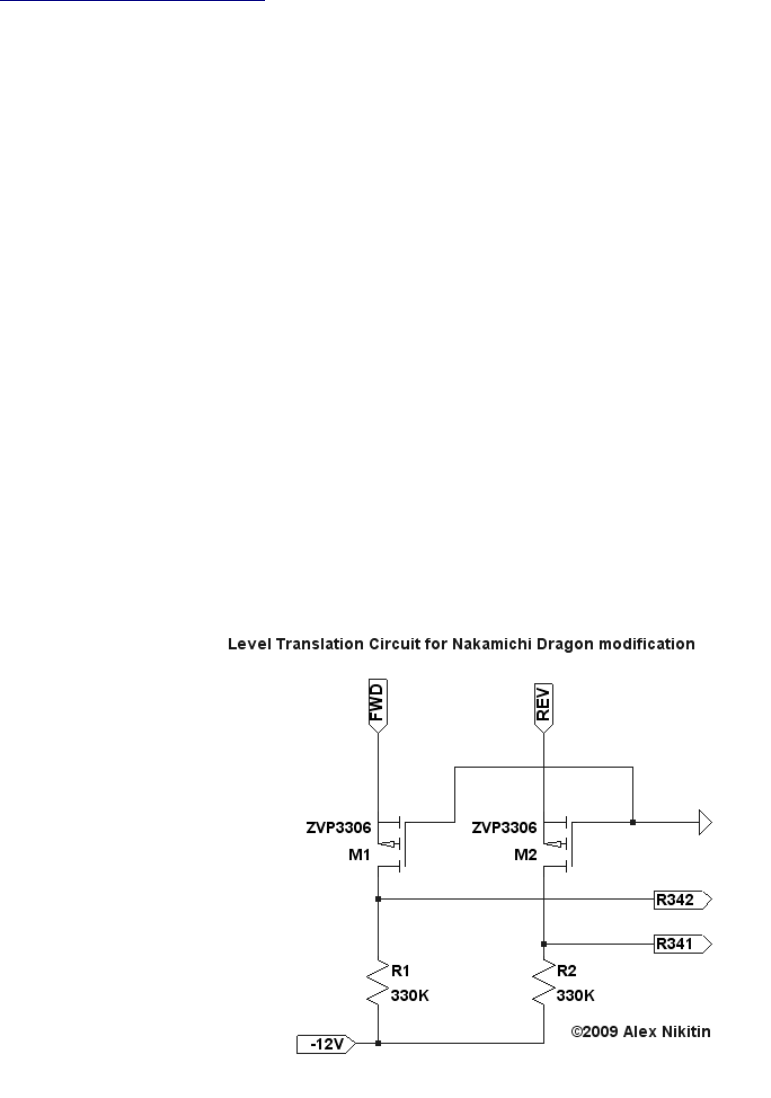
Here is the schematics for the Level Translation Circuit (LTC):
As you may see, only 2 small-signal MOSFETs and two resistors are required. Following pictures
illustrate the modification: 1) a part of Nakamichi Dragon schematics with the LTC inserted and 2)
a possible way of wiring the LTC on the PCB of the Dragon. In short – two wire links in series with
R341 and R342 should be removed and on their place two MOSFETs are soldered. Middle pins of
MOSFETs (Gates) connected together and then to the ground plane link on the PCB with a bit of
wire. Two additional 330K resistors connected between R342, R341 and -12V supply. IC 502 and
IC602 unsoldered from the PCB (using a solder braid) and two 14-pin DIL sockets are soldered in
these positions. Now it will be possible to either insert the replacement ANT4066 modules or the
original ICs for comparative listening. Please bear in mind that all active components here are
static-sensitive so a proper anti-static precautions should be observed, including a grounding wrist
strap.
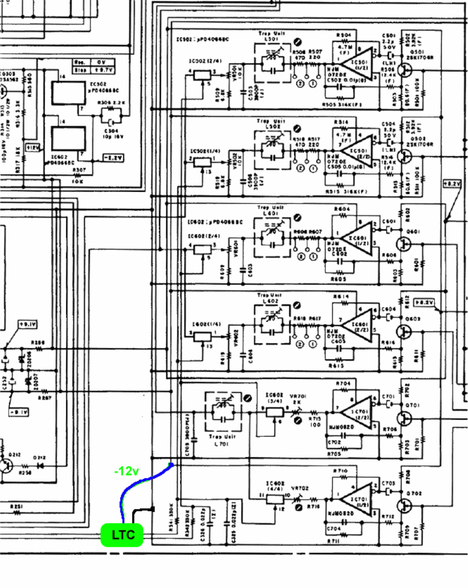
Part of Nakamich Dragon schematics showing where the LTC is inserted.
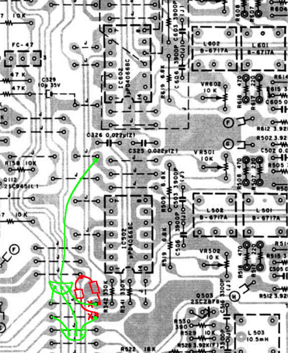
PCB layout. Two wire links removed (shown by red crosses), two 330K resistors soldered (shown
in red), two MOSFETs ZVP3306 are soldered from the top of the PCB in place of links and their
gates connected together and than to the ground on the PCB by a bit of wire. PCB is shown from
the tracks side!
