RealPro ToolKit Navigator FP_Real Pro_Tool Kit_6_0_User_Guide FP Real Pro Tool Kit 6 0 User Guide
Navigator FP RealPro ToolKit 6.0 User Guide Navigator FP RealPro ToolKit 6.0 User Guide
User Manual: Navigator FP_RealPro_ToolKit_6_0_User_Guide
Open the PDF directly: View PDF ![]() .
.
Page Count: 233 [warning: Documents this large are best viewed by clicking the View PDF Link!]
- 1. System Requirements
- 2. Software Installation / Removal
- 3. Inspect
- 4. Ink
- 5. Ink Compensation
- 6. Ink Histogram
- 7. Link
- 8. Search
- 9. Tool
- 10. Eye
- 11. Trap
- 12. Nest
- 12.1. Background
- 12.2. Overview
- 12.3. Step & Repeat With Chart
- 12.4. Settings and Formulae in Step and Repeat
- 12.5. Step and Repeat with CAD Layout
- 12.6. Interactive Step and Repeat
- 12.7. Bleed
- 12.8. Adjust Overlap
- 12.9. Station Numbers
- 12.10. Anchor Tool
- 12.11. Align to Margin
- 12.12. Reverse CAD
- 12.13. CAD Ticket
- 12.14. The Graphic Manager
- 12.15. Appendix : Examples of Step and Repeat Formula
- 13. Mark
- 13.1. Background
- 13.2. Overview
- 13.3. GUI Description
- 13.4. Adding a Mark
- 13.5. Configuring Marks Settings
- 13.5.1 Ink Settings
- 13.5.2 Ink Setting for Register and Trim marks
- 13.5.3 Ink
- 13.5.4 Overprint
- 13.5.5 Ignore Inks
- 13.5.6 Ink Settings for Solid Ink Patches and (single colour) Image Marks
- 13.5.7 Ink
- 13.5.8 With Step
- 13.5.9 White Underprint
- 13.5.10 Ink Setting for multi-coloured Image Marks
- 13.5.11 Ink Setting for single colour Image Mark
- 13.5.12 Ink Setting for Text Marks
- 13.5.13 Ink Setting for Graduation Marks
- 13.5.14 Ink Setting: Only use inks from One-Up
- 13.6. Setting Mark Position
- 13.7. Mark Specific Settings
- 13.8. Corner Marks
- 13.9. Ellipse Marks
- 13.10. Graduation Marks
- 13.11. Image Marks
- 13.12. Station Number
- 13.13. Mark Management
- 13.14. Marks Parameters Set
- 14. Basic Functions
- 15. Variable Manager
- 16. Tiff Maker
- 17. E-Connector
- 18. Effects
- 19. Seamless
- 20. Warp
- 21. Shortcut keys
- 22. Updating the License key

V 6.0 User Guide
Doc1-2448
Issue 01

Contents
1. System Requirements 1
2. Software Installation / Removal 2
2.1. Mac 2
2.1.1 Installation 2
2.1.2 Starting Adobe Illustrator 5
2.1.3 Uninstalling the Software 5
2.2. PC 6
2.2.1 Installation 6
2.2.2 Starting Adobe Illustrator 9
2.2.3 Uninstalling the Software 9
3. Inspect 11
3.1. Overview 11
3.2. Inspect Workflow 11
3.2.1 Parameter Configuration 11
3.2.2 General 12
3.2.3 Ink Parameters 12
3.2.4 Image Parameters 13
3.2.5 Font Parameters 14
3.2.6 Other Parameters 14
3.3. Running Preflight 15
4. Ink 17
4.1. Overview 17
4.2. Ink Manager 17
4.2.1 Set Ink Type 18
4.2.2 Auto Ink Sequence 18
4.2.3 Darkest Ink Mark 18
4.2.4 Convert Inks to CMYK 19
4.2.5 Convert Ink 19
4.2.6 Knockout 20
4.2.7 Pack Ink Book 21
4.3. Ink Mix 24
4.3.1 Changing the colour of an object 25
4.3.2 Adding a new swatch to the Ink Swatch palette 25
4.3.3 Editing a swatch in the Ink Swatch palette 25
4.3.4 Deleting a swatch from the Ink Swatch palette 26
4.4. Image Channel Mapping 26
4.4.1 Usage 26
4.5. Keep Spot Colour in Blend 29
4.5.1 Usage 29
4.6. Ink Coverage 29
4.6.1 Usage 29
4.7. Limitations of Ink 30
5. Ink Compensation 32
5.1. Overview 32
5.2. Creating an Ink Compensation Zone 33
6. Ink Histogram 36
6.1. Overview 36
6.1.1 Usage 36
7. Link 39
7.1. Overview 39
7.2. Operation 39
7.2.1 Export Images 39
8. Search 41
8.1. Overview 41
8.2. Usage 41
8.2.1 Search Controls 41
- iii -
8.2.2 All Objects 42
8.2.3 Search Conditions 43
8.3. Limitations 48
9. Tool 49
9.1. Overview 49
9.2. Selection Tools 50
9.2.1 Area Selection Tool 50
9.2.2 Area Direct Selection Tool 50
9.3. RP Gradient Tool 50
9.3.1 Usage 50
9.4. Line Pathfinder 52
9.4.1 Usage 52
9.5. Path Editing Tools 52
9.5.1 Retrace Tool 53
9.5.2 Retrace Other Way 53
9.5.3 Split Tool 53
9.5.4 Distort Tool 53
9.5.5 Intersect Tool 54
9.5.6 Join Path Tool 54
9.6. Expand Text Width 54
9.6.1 Usage 54
9.7. Node Optimisation 55
9.7.1 Usage 55
9.7.2 Example 56
9.8. Foreign Art To Gray 56
9.8.1 Usage 57
9.9. Bitmap Outline 57
9.9.1 Usage 57
- iv -
9.10. RP Guide Tool 58
9.10.1 Usage 58
9.11. RP Align 58
9.11.1 Usage 58
9.12. RP Clip 61
9.12.1 Usage 61
9.12.2 Example 61
9.13. Guide Line 62
9.13.1 Usage 62
10. Eye 64
10.1. Overview 64
10.2. Preview 64
10.2.1 GUI 65
10.3. Navigator 73
10.3.1 GUI 74
10.3.2 Usage 74
10.4. Limitations 74
11. Trap 76
11.1. Overview 76
11.2. Automatic Trapping 76
11.2.1 Usage 76
11.2.2 Trap Ticket 76
11.2.3 Trap Colour Pairs 90
11.3. Interactive Trapping 94
11.3.1 Overview 94
11.3.2 Usage 94
11.4. Rich Black 95
11.4.1 Overview 95
- v -
11.4.2 Usage 95
11.5. White Underprint 96
11.5.1 Overview 96
11.5.2 Usage 96
11.6. Viewing the Trap Area 98
11.6.1 Trap Preview 98
11.6.2 Using the AI Layer controls 99
11.7. Limitations 99
12. Nest 101
12.1. Background 101
12.1.1 Terminology 101
12.2. Overview 101
12.3. Step & Repeat With Chart 103
12.3.1 Preparing the Structure/Artwork Unit for Step & Repeat 103
12.3.2 Step & Repeat 105
12.4. Settings and Formulae in Step and Repeat 106
12.5. Step and Repeat with CAD Layout 110
12.6. Interactive Step and Repeat 114
12.7. Bleed 118
12.8. Adjust Overlap 120
12.8.1 Relative Position of AB 120
12.8.2 Search Overlap Area 121
12.8.3 AB Box Selection Tool 121
12.8.4 Distinguish File 122
12.9. Station Numbers 123
12.9.1 Station Number Settings 123
12.10. Anchor Tool 124
12.11. Align to Margin 125
- vi -
12.12. Reverse CAD 125
12.13. CAD Ticket 126
12.14. The Graphic Manager 127
12.15. Appendix : Examples of Step and Repeat Formula 130
12.15.1 Formula for Sheet Fed Labels and Cartons 130
12.15.2 Formula for Narrow Web Flexo V1 130
12.15.3 Formula for narrow web Flexo V2 130
12.15.4 Formula for Narrow Web Flexo V3 131
13. Mark 132
13.1. Background 132
13.2. Overview 132
13.3. GUI Description 132
13.4. Adding a Mark 133
13.4.1 Prerequisites 133
13.5. Configuring Marks Settings 134
13.5.1 Ink Settings 134
13.5.2 Ink Setting for Register and Trim marks 134
13.5.3 Ink 135
13.5.4 Overprint 135
13.5.5 Ignore Inks 136
13.5.6 Ink Settings for Solid Ink Patches and (single colour) Image Marks 136
13.5.7 Ink 136
13.5.8 With Step 136
13.5.9 White Underprint 138
13.5.10 Ink Setting for multi-coloured Image Marks 139
13.5.11 Ink Setting for single colour Image Mark 142
13.5.12 Ink Setting for Text Marks 143
13.5.13 Ink Setting for Graduation Marks 143
- vii -
13.5.14 Ink Setting: Only use inks from One-Up 145
13.6. Setting Mark Position 145
13.6.1 Do Not Adjust Mark 146
13.7. Mark Specific Settings 147
13.7.1 Centre Marks 147
13.8. Corner Marks 149
13.9. Ellipse Marks 153
13.10. Graduation Marks 154
13.10.1 Defining Patches 154
13.10.2 Inks 156
13.10.3 Numbers 157
13.10.4 Examples of Graduation Marks 158
13.11. Image Marks 159
13.12. Station Number 160
13.12.1 Station Number Mark Controls 160
13.13. Mark Management 162
13.14. Marks Parameters Set 163
14. Basic Functions 165
14.1. Background 165
14.2. Overview 165
14.3. Pack Selection Tool 165
14.3.1 Objects with registration marks 165
14.3.2 RP Selection Tool 166
14.4. Output PDF 167
14.4.1 Scaling and media when exporting PDF 167
14.4.2 Checks and warnings when exporting PDF 167
14.5. Output PDFin SamePoint 168
14.5.1 Usage 168
- viii -
14.6. Trim and Media box 169
15. Variable Manager 172
15.1. Background 172
15.2. Usage 172
16. Tiff Maker 174
16.1. Background 174
16.2. Overview 174
16.3. Basic output from TIFF Maker 175
16.4. TIFF Maker Settings 176
16.5. Advanced Settings 178
16.6. Limitations 179
17. E-Connector 181
17.1. Background 181
17.2. E-Connector Overview 181
17.3. Composite Output File Procedure 182
17.4. Output Separations Procedure 183
17.5. Parameter Panels 185
17.5.1 Task 185
17.6. Settings 186
17.7. Separations setting 188
17.8. Advanced Settings 189
17.8.1 Separations naming rule 190
17.8.2 Using a Fixed Directory 190
17.8.3 Fast Forward 190
17.9. Parameter Set 191
17.10. Limitations 192
18. Effects 193
18.1. Noise 193
- ix -

18.2. Curves 194
19. Seamless 197
19.1. Background 197
19.2. Overview 197
19.3. Seamless Nesting on a Fixed Sheet Size 197
19.3.1 Resizing the unit image 201
19.4. Seamless Nesting with Fixed Parameters 204
19.5. Using the Unit Edit 205
19.6. Using Unit Replace 205
19.7. Seamless Nesting Parameters 205
19.8. Limitations 207
20. Warp 208
20.1. Background 208
20.2. Overview 208
20.3. Circular Warp 208
20.4. Conic Warp 210
20.5. Complex Warp 214
20.5.1 Adjust Grid 215
20.5.2 Standard Grid 217
21. Shortcut keys 219
21.1. Shortcut Keys 219
21.1.1 How to change shortcut keys 219
21.1.2 Default Shortcuts: 220
22. Updating the License key 222
- x -

1. System Requirements
1. System Requirements
Mac Windows
Language English English
Operating System Mac OSX™ 10.6 or above Windows 7™ 64 Bit
Hardware
CPU: Intel® Core2™ Duo pro-
cessor
* Memory 4 GB or above
Hard disk: 40 GB free space
or above
Display: 1024 x 768 colour or
above
CPU: Intel® Core2™ Duo pro-
cessor
* Memory: 4 GB or above
Hard disk: 40 GB free space
or above
Display: 1024 x 768 colour or
above
Adobe® Illustrator®
Version
Adobe® Illustrator® CS6 (64
Bit) or CC(64 Bit)
Adobe® Illustrator® CS6 (64
Bit) or CC(64 Bit)
* This is the minimum requirement, to process complex files the amount of memory should be
increased to at least 8 GB. (16 GBrecommended).
- 1 -
2. Software Installation / Removal
2. Software Installation / Removal
2.1. Mac
2.1.1 Installation
During the installation you may be prompted to enter an administrative password in order to update
your software. These steps are not shown in the detail below.
There are two versions of RealPro Toolkit V6.0 for the Mac, one for use with Adobe Illustrator CS6,
the other for use with Adobe Illustrator CC. The installation process is the same in both cases.
Ensure that the correct version is used.
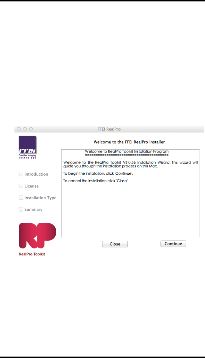
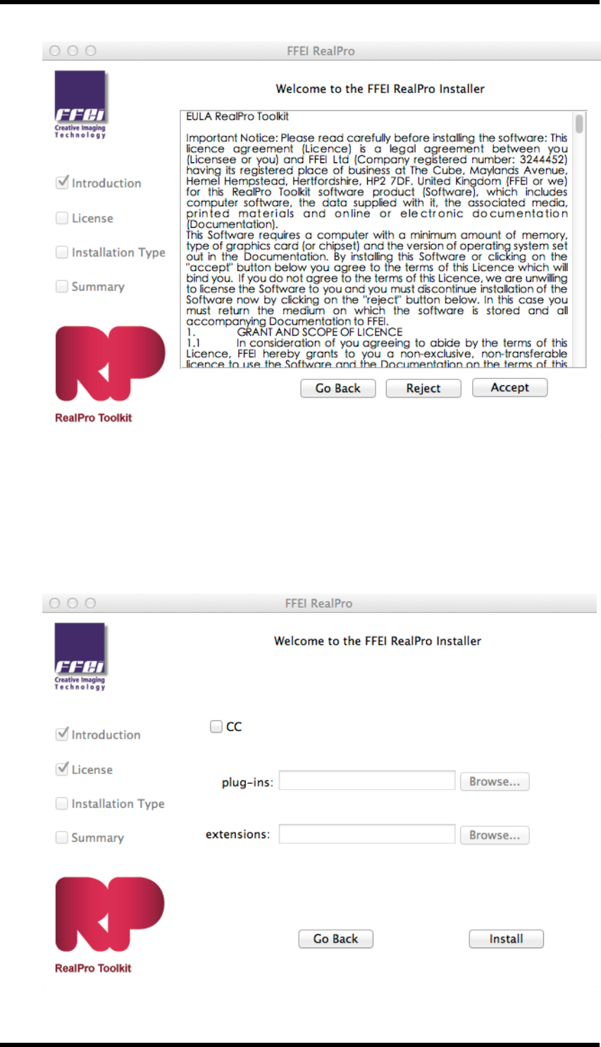
1. Double-click the RealPro setup icon to start the installation.
The “Welcome to the FFEI RealPro Installer” information window will appear.
2. Click the “Continue” button.
The “Software License Agreement” information window will appear.
- 2 -
2. Software Installation / Removal
3. Read the licence information then click the “Accept” button, or click "Reject" to cancel the
installation.
4. The “Installation Type” window will appear. Click on the check box to choose the version of
Adobe Illustrator.
- 3 -
2. Software Installation / Removal
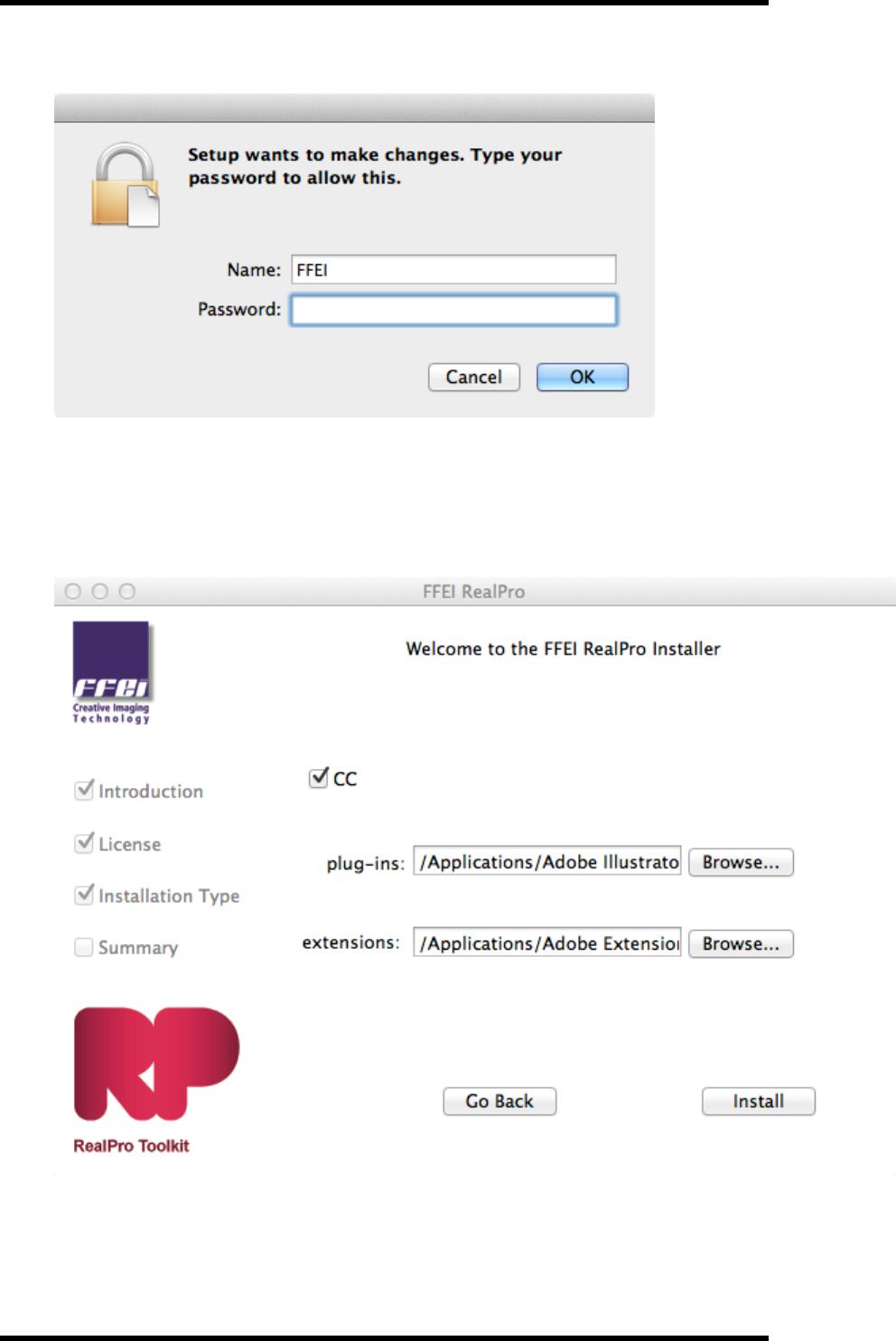
5. You may then be prompted to authorise the installation.
6. The Adobe Illustrator plug-ins folder, and path to the Adobe Extension Manager will then
be automatically displayed. If the installation folder cannot be recognised or you want to
install RealPro Toolkit in another location, click on the Browse button and select another des-
tination.
7. Click “Install”.
The “Installing RealPro Toolkit” window will appear and the installation will start.
- 4 -
2. Software Installation / Removal
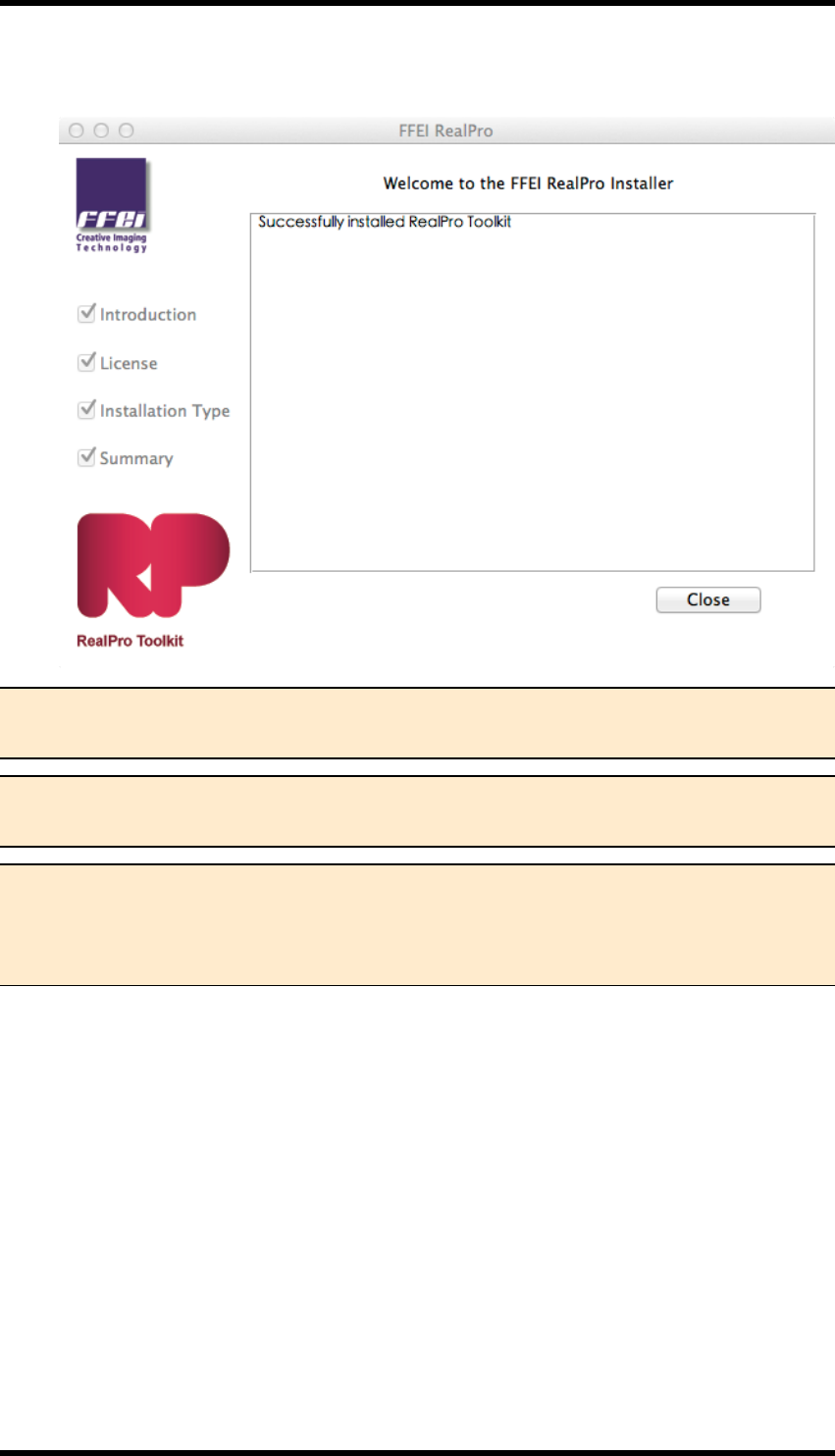
8. When the successfully installed window appears, click “Close” to complete the installation.
Note 1. After a successful installation, a new folder named ‘FFEI RealPro’ will be created
in the AI plug-ins folder.
Note 2. TheRealPro Toolkit License Update application will be added to the FFEI
RealPro folder. (See note 1 above)
Note 3. The HASP Dongle Driver will be installed on the same disk as RealPro Toolkit
However, the HASP Dongle Driver must be added to the system disk before it will be
available; if AI is not installed on the system disk drive, then you need add the HASP
Dongle Driver to the system disk.
2.1.2 Starting Adobe Illustrator
1. Insert the HASP dongle in one of the computer's USB ports.
The dongle driver software will be installed.
2. Start Adobe Illustrator.
3. In Adobe Illustrator, open the Window menu and check that RealPro is in the list of options.
2.1.3 Uninstalling the Software
To uninstall RealPro Toolkit, go to the Adobe Illustrator Application folder and open the Plug-ins
folder. Inside the Plug-ins folder is a folder called FFEI RealPro. To uninstall the software, delete
- 5 -
2. Software Installation / Removal
this folder.
The extensions should also be removed using the Adobe Extension Manager.
2.2. PC
2.2.1 Installation
Double-click the installer for RealPro Toolkit Setup.exe on the installation disc; follow the instruc-
tions and installation steps as outlined in the install program to complete the software installation.
There are two versions of RealPro Toolkit V6.0 for the PC, one for use with Adobe Illustrator CS6,
the other for use with Adobe Illustrator CC. The installation process is the same in both cases.
Ensure that the correct version is used.
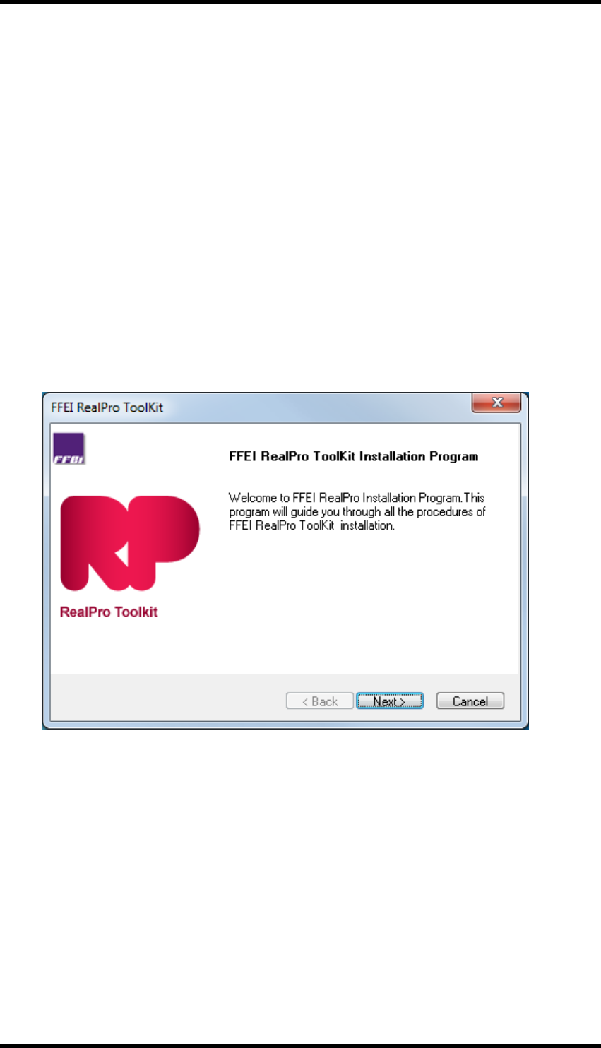
1. Double-click the RealPro Toolkit installer to start the installation.
The “FFEI RealPro Installation Program” information window will appear.
2. Click the “Next” button.
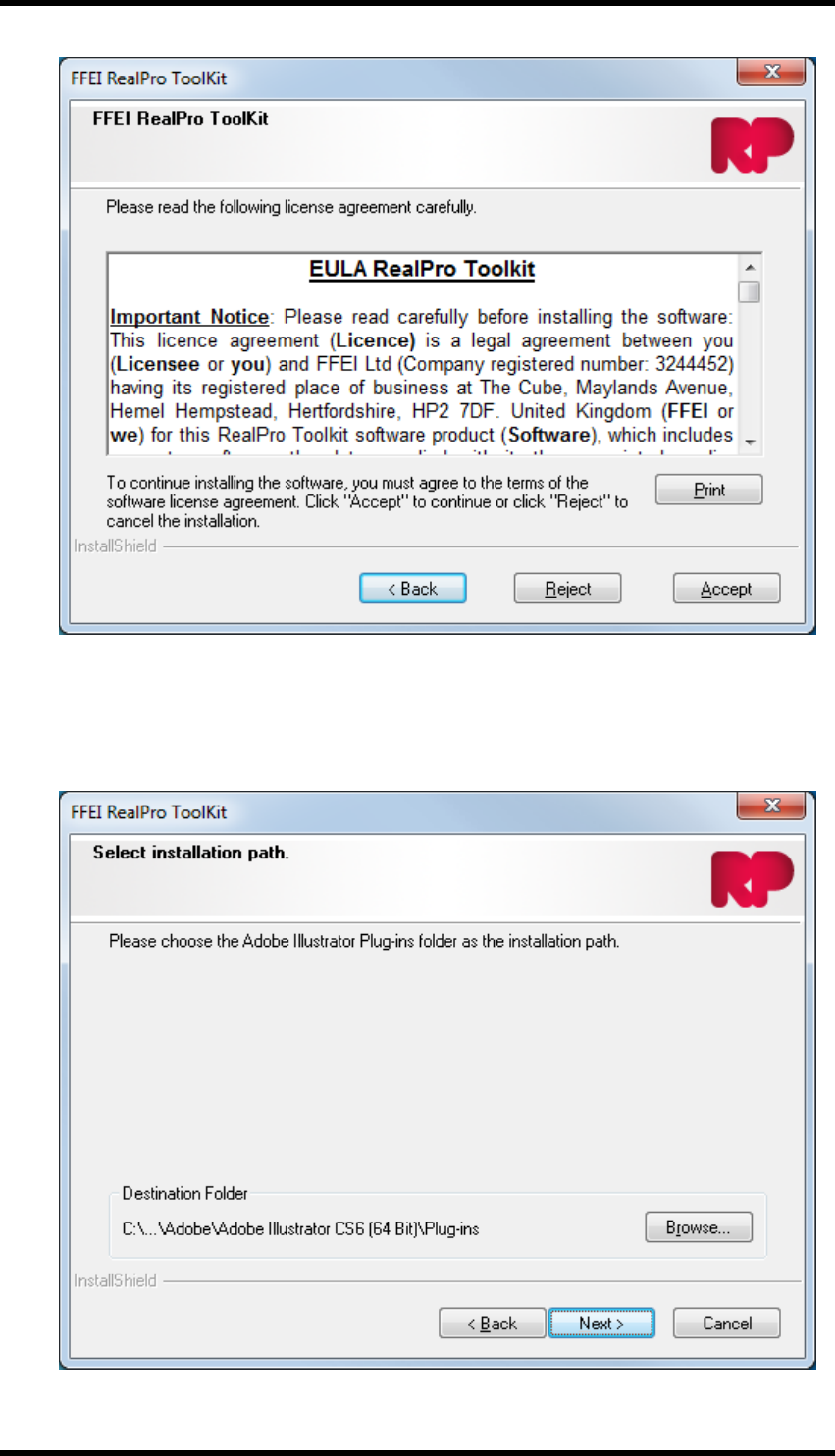
The “Software License Agreement” information window will appear.
- 6 -
2. Software Installation / Removal
3. Read the licence information then click the “Yes” button to Agree or click "No" to cancel the
installation.
If "Yes" is clicked the Select Installation Path window will be displayed.
- 7 -
2. Software Installation / Removal
4. Click on the appropriate check box to choose the version of Adobe Illustrator, then the install-
ation folder will automatically be displayed. If the installation folder cannot be recognised or
you want to install RealPro Toolkit in other path, click on the Browse button to set other des-
tination.
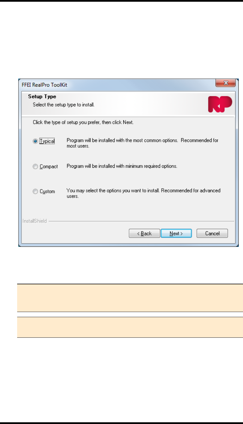
5. Click "Next".
The "Setup Type" window will be displayed.
6. Click the Typical Option and click “Next”
The “Installing RealPro Toolkit” window will appear and the installation will start.
Note 1. The Compact option should not be selected. The Custom option, which
should only be used by advanced users, allows the RealPro Tool Kit, Licence
Upgrade Program and the dongle driver software to be installed separately.
Note 2. During the initial part of the installation, it may appear that no progress is
being made. Allow a few minutes for the installation to complete.
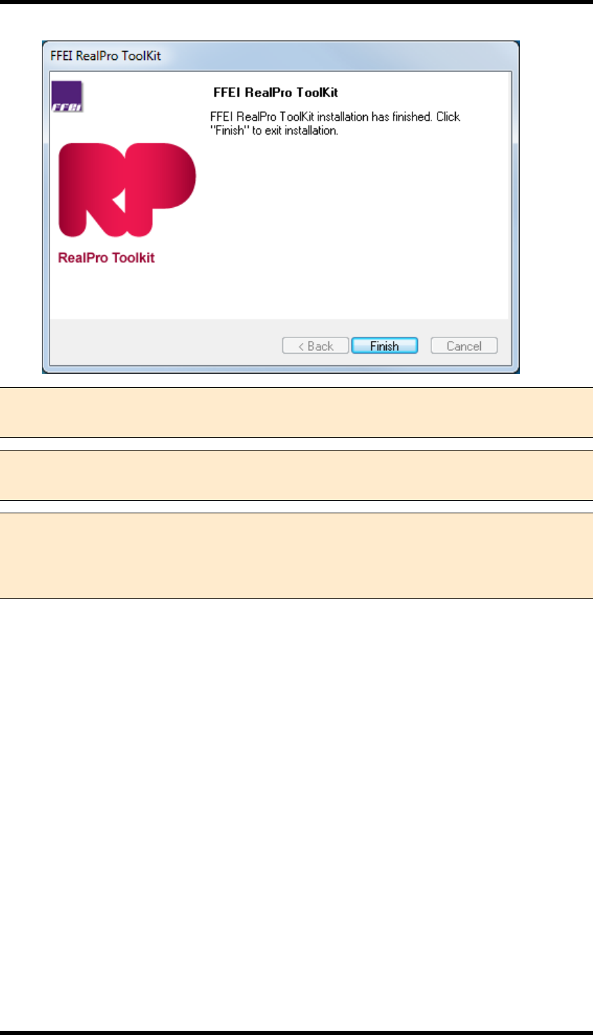
7. When the Successfully Installed window appears, click “Finish” to complete the installation.
- 8 -
2. Software Installation / Removal
Note 1. After a successful installation, a new folder named ‘FFEI RealPro’ will be added
to the AI plug-ins folder.
Note 2. The RealPro Toolkit License Update application will be added to the RealPro
folder. (See note 1 above)
Note 3. The HASP Dongle Driver will be installed on the same disk as RealPro toolkit
However, the HASP Dongle Driver must be added to the system disk before it will be
available; if AI is not installed on the system disk drive, then you need add the HASP
Dongle Driver to the system disk.
2.2.2 Starting Adobe Illustrator
1. Insert the HASP dongle in one of the PC's USB ports.
The dongle driver software will be installed.
2. Start Adobe Illustrator.
3. In Adobe Illustrator, open the Window menu and check that the RealPro is in the list of
options.
2.2.3 Uninstalling the Software
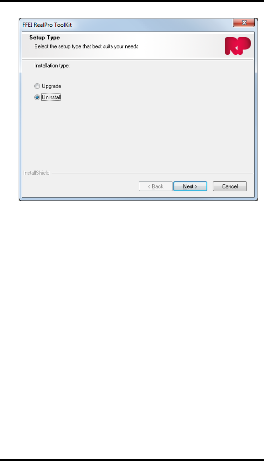
1. Open the Windows control panel and double-click Programs and Features" then select
"FFEI RealPro Toolkit". Click on Uninstall
The Setup Type window will be displayed.
- 9 -
2. Software Installation / Removal
2. Select the Uninstall option and click "Next".
A confirmation dialogue box will be displayed.
3. Click "OK".
4. The software will be uninstalled.
5. Launch the Adobe Extension Manager application and remove the extensions.
- 10 -

3. Inspect
3. Inspect
3.1. Overview
Inspect is a plug-in which allows the operator to perform a set of pre-defined checks on an Adobe
Illustrator (AI) document. These checks are used to locate potentially problematic objects and will
be specific to the printing processes in use.
A simple traffic light system is used to indicate whether a check has identified a problem or not. The
number of problems of each type is shown and navigation tools help the operator to locate and fix
issues.
A GREEN traffic light indicates that the check has been made and no matching objects have been
identified.
A RED traffic light indicates that the check has been carried out and matching objects have been
found.
A report detailing the result of the preflight run can be exported as a text file.
Sets of checks can be saved as Parameter Sets for repeated use, and can be exported for use on
other systems or to be held in a central repository.
3.2. Inspect Workflow
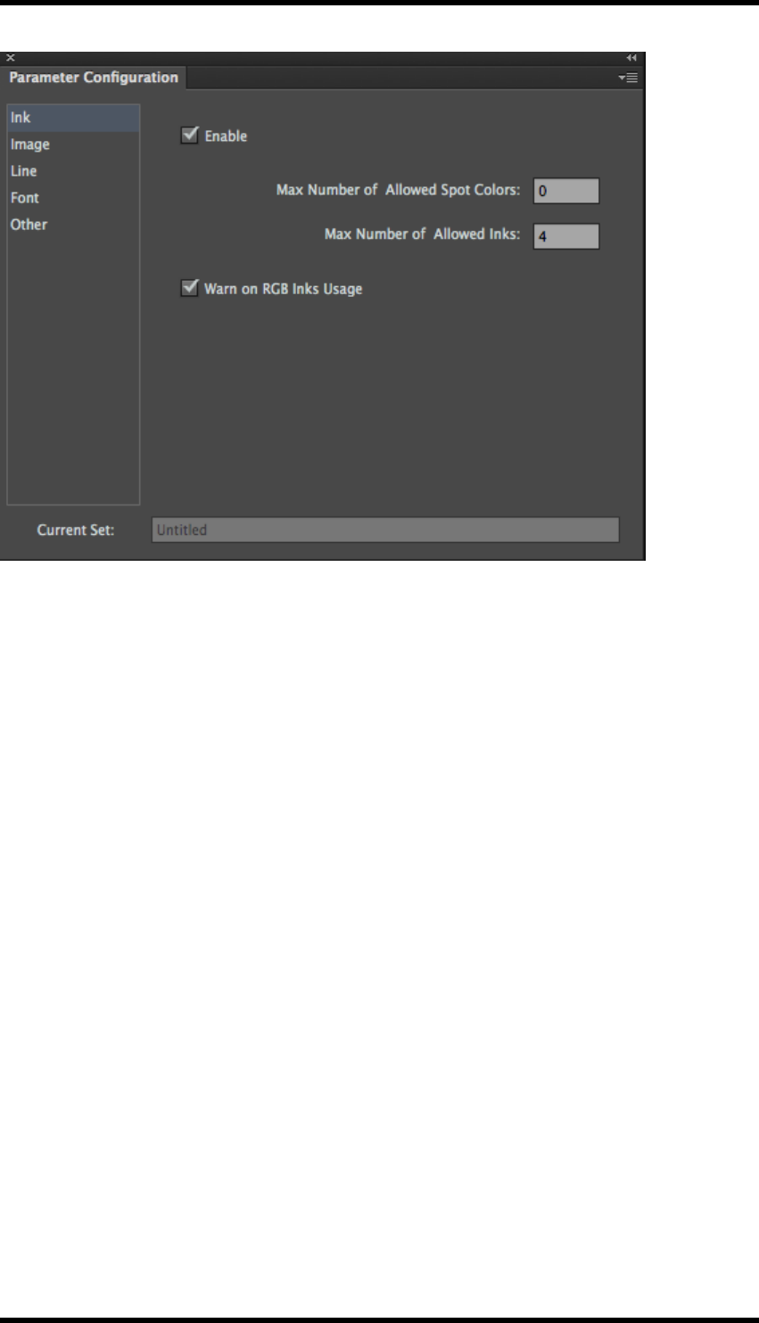
3.2.1 Parameter Configuration
Open the Parameter Configuration tool by selecting Window > RealPro > Inspect > Parameter
Configuration
The current parameter set is displayed. (Name shown in the Current Set field)
- 11 -
3. Inspect
Controls are available from the tool’s side pull down menu to manage the parameter sets:
New Set – Creates a new parameter set, with the same settings as the current set.
Open Set… – Opens a previously saved set.
Save Set... – Saves the current values to the open set.
Save Set As… – Saves the current values to a new set.
Delete Set... – Allows deletion of any of the previously saved sets.
Import Set... – Imports a set from an external file.
Export Set... – Saves the set to an external file. The name of the set is replaced by
the file name.
Restore – Restores the current set to its last saved state.
3.2.2 General
Each set of checks has an Enable switch which allows the user to enable or disable the set of
checks in a preflight run.
3.2.3 Ink Parameters
Max Number of Allowed Spot Colours: If the number of spot colours in a document exceeds this
value, the preflight check will indicate a problem.
Max Number of Allowed Inks: If the total number of inks in a document exceeds this value, the
preflight check will indicate a problem.
- 12 -

3. Inspect
Warn on RGB Inks Usage: When enabled, if RGB inks are used in the document the preflight
check will indicate a problem.
3.2.4 Image Parameters
Format
The preflight checks will check for the existence of the image types selected from this list. A RED
traffic light indicates that the image type exists in the document. GREEN indicates that the check
has been made and no images of this type have been found.
Note This set of checks has no influence on other checks made on images.
Resolution
Contone Images: Checks for minimum and maximum image resolution of contone images.
Bitmap Images: Checks for minimum and maximum image resolution of bitmap images.
Colour Mode
The preflight checks for the existence of selected colour modes in images. A RED traffic light indic-
ates that the image colour mode exists in the document. GREEN indicates that the check has been
made and no images with this colour mode have been found.
Image Info
Enabling the Check Image Information option instructs the preflight to display the meta-data relat-
ing to each image. E.g. name, format, software name, colour mode, set time, modification time, res-
olution, Halftone (Yes/No), Transfer function (Yes/No), PSColorManagement (Yes/No), ICC Profile
(Yes/No), and file path. (This data is also included in any exported preflight report).
Other
The preflight checks will check for the existence of images with any of the enabled attributes. A
RED traffic light indicates that the image with the attribute exists in the document. GREEN indic-
ates that the check has been made and no images with this attribute have been found.
Line Parameters
Checks can be made on minimum line widths used in the document.
Min. Width for Single Ink Line – Strokes on lines for single-ink objects
Min. Width for Multiple Ink Line – Strokes on lines for multiple-ink objects
Min. Width for Line (Less than 100 %) – Strokes on lines where the ink value is less than 100 %
If the unit of measure is included, values entered in these field will be automatically converted to the
unit of measure for stroke, as defined in the Adobe Illustrator preferences.
- 13 -

3. Inspect
e.g. If the unit of measure for strokes is set to mm, entering a value of 5 pt will result in the indicated
value of 1.764 mm
3.2.5 Font Parameters
Checks can be made on minimum font sizes used in the document
Min. Font Size for Single Ink Font – Text made up from a single-ink.
Min. Font Size for Multiple Ink Font – Text made up from multiple-inks
Min. Font Size for Font (Less than 100 %) – Text where the ink value is less than 100 %
If the unit of measure is included, values entered in these fields will be automatically converted to
the unit of measure for type, as defined in the AI preferences.
e.g. If the unit of measure for type is set to mm, entering a value of 5 pt will result in the indicated
value of 1.764 mm
Further checks can be made for the existence of specific font types:
True Type
Open Type
Bitmap without PS Outline
A RED traffic light indicates that the font type exists in the document. GREEN indicates that the
check has been made and no fonts of this type have been found.
An additional control exists to enable checking for text with a minimum text stroke width.
3.2.6 Other Parameters
Flat Tint
Checks that any tints are within the minimum to maximum dot percentage range. By default, this
doesn’t include the checking of solid objects (Dot percentage =100 %)
Include Solid – The presence of flat tint objects with dot percentage of 100 % is included in the Flat
Tint check.
Gradient
Checks that any gradients are within the minimum to maximum dot percentage range.
Others
Min. Object Size – Checks for objects smaller than the minimum object size. An additional control
determines whether the size is determined by the length/height of an object or the length of a diag-
onal across the object.
Min. Gap – Checks for objects separated by less than the distance specified.(Range is between 0
& 0.5mm, default value is 0.1mm)
- 14 -
3. Inspect
Check for Non-Print Layers – Checks for the existence of non-printing layers. Note that objects
on non-printing layers are not checked by the preflight run.
White Overprint Object – Checks for the existence of white overprint objects.
Black Knockout Object – Checks for the existence of black knockout objects that have a dot per-
centage equal to, or greater than, the specified value.
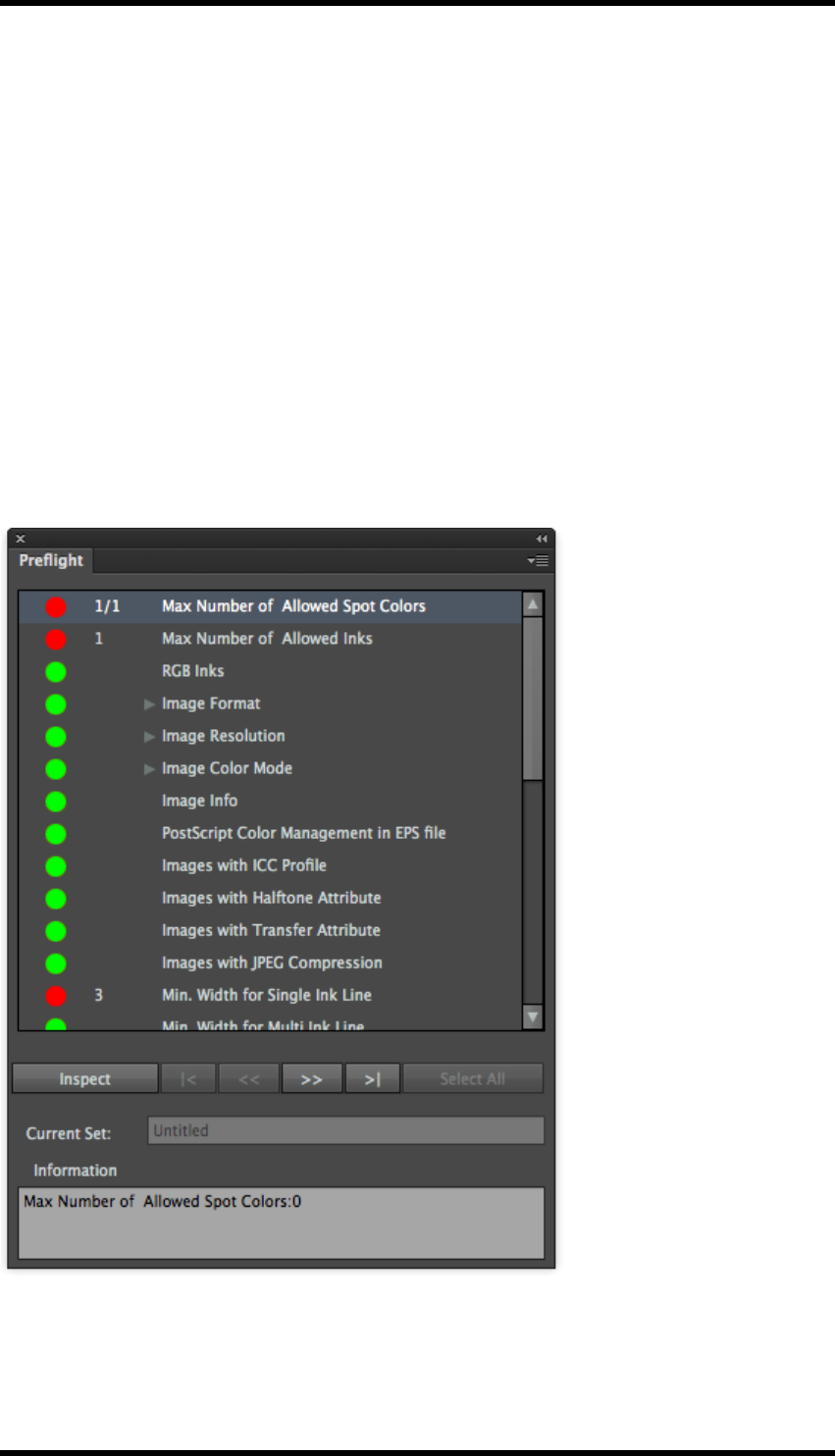
3.3. Running Preflight
Select Window > RealPro > Inspect > Preflight to open the Preflight window.
The parameter set to be used for the preflight run is displayed in the Current Set field. If the set
name has a ‘+’ suffix, the set has not yet been saved.
To use a different parameter set, use the Parameter Configuration tool as described above.
Click on Inspect to run the preflight.
Checks will be listed in the upper part of the Preflight window along with a traffic light indication of
the result.
- 15 -

3. Inspect
If the preflight has found objects matching a check criteria, the number of objects discovered will be
displayed.
Clicking on a particular check will automatically select the first of the discovered objects. The num-
ber of objects will then be modified indicating that the first of the instances is selected. E.g. 1/25
If Show Info is enabled in the side pull-down menu an information panel is shown at the bottom of
the window displaying information about the check that has been done. Image meta data will also be
displayed in this window if that has been enabled and the Image Information check selected.
If Zoom to Selection is enabled in the side pull-down menu the display will zoom into the selected
object.
The operator can navigate to the second, third etc., objects using the controls underneath the list.
Objects can then be modified as required.
Select All: Selects all the objects discovered by the selected check.
Any changes to the parameter set will cause the previous preflight run results to be cleared.
The preflight report can be exported as a text file by selecting the Export Preflight Report option
from the side pull-down menu.
- 16 -

4. Ink
4. Ink
4.1. Overview
The Ink plug-in provides functionality to control inks within an Adobe Illustrator (AI) document and
thus the separations produced for printing. This is mainly handled by the Ink Manager tool.
Additional tools are available for a number of ink related functions:
Ink Mix
Allowing the operator to create custom colours from inks in the AI document.
Image Channel Mapping
Supports the conversion of inks in images to other inks present in the document.
Keep Spot Colour in Blend
Converts CMYK blends to spot colour blends.
4.2. Ink Manager
Select Window > RealPro > Ink > Ink Manager to open the Ink manager window.
The Ink Manager holds information about each ink used in the AI document. This data, however,
must be updated manually. This can be done in a number of ways:
lBy selecting Window > RealPro > Ink > Update Ink Manager
lUsing the keyboard shortcut: PC:Alt+Ctrl+U Mac: Alt+Cmd+U
- 17 -

4. Ink
lFrom the Ink Manager side pull-down menu select Update Ink List
lClicking on the Update Ink List button in the Ink Manager window
The ink list should be updated after the operator has made changes to the inks in the AI document.
4.2.1 Set Ink Type
The ink type is used to affect how the ink traps, the options are:
lNormal – Standard trapping behaviour
lOpaque – Ink will be trapped at object edges only, underlying inks will not be trapped
lVarnish – Ink will not be trapped, underlying inks will be trapped
lStructural – Ink will not be trapped. (Used for cut lines etc.)
CMYK inks are set to Normal by default and cannot be changed.
4.2.2 Auto Ink Sequence
This function sorts the inks listed by the Ink Manager from darkest to lightest, a second run of this
function will sort from lightest to darkest. This sets the order in which the inks trap.
The Auto Ink Sequence function can be run by:
lClicking on the Auto Ink Sequence button in the Ink Manager window.
lFrom the Ink Manager side pull-down menu select Auto Ink Sequence
Inks can be manually sorted by selecting an ink in the Ink Manager window, and dragging it to the
required position in the list.
Note: Using the Auto Ink Sequence functions will reset the darkest ink mark.
4.2.3 Darkest Ink Mark
Within the Marks plug-in tool there is the option to output printer’s marks using the darkest ink used
in the document. Setting that data is achieved using the ink manager.
The darkest ink is indicated in the Ink Manager by the black flag to the left of the ink. This is set auto-
matically when the ink list is updated, or when the list is sorted using the Auto Ink Sequence func-
tion.
To manually set the darkest ink:
Select the required ink, then either:
lClick on the Darkest Mark button in the Ink Manager window
lFrom the side pull-down menu, select Darkest Mark
- 18 -

4. Ink
4.2.4 Convert Inks to CMYK
Inks can be converted from spot colours to process colours using this functionality. Single or mul-
tiple inks may be converted, or all the spot colour inks can be converted in a single operation.
Notes:
lCMYK conversion is based on the spot colour LAB values using the ICC profile selected in
the AI colour management preference
lAny graphics must be embedded to be affected by this process
lThe ink data associated with Mesh, Live Paint groups and images will not be affected
To convert a single or multiple inks to CMYK
1. Select the required ink from the Ink Manager. Multiple inks may be selected by using
Ctrl+click or using Shift+click to choose a range of inks.
2. The inks can then be converted by either:
Clicking on the Convert to CMYK button in the Ink Manager window
From the Ink Manager side pull-down menu, selecting Convert to CMYK
To convert all inks to CMYK
From the Ink Manager side pull-down menu, select Convert All Spot Inks to CMYK.
After conversion, the Ink Manager is automatically updated.
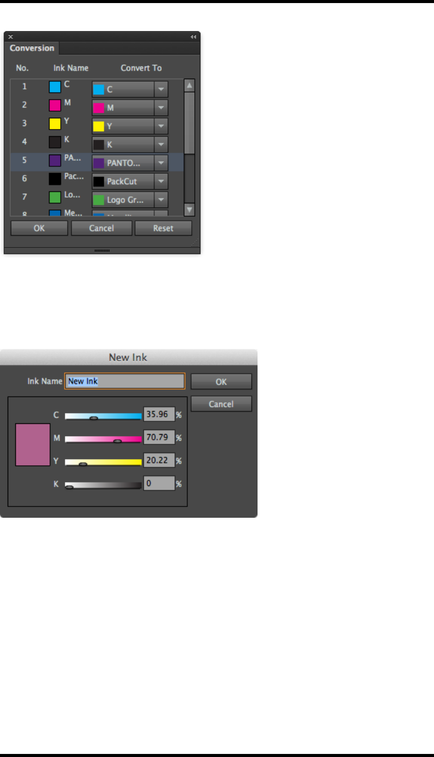
4.2.5 Convert Ink
Any ink in the document can be converted to any other ink, or removed, using this function.
Select Convert To ...from the side pull-down menu, or click on the Convert To ...button.
- 19 -
4. Ink
Choose the ink to convert to from the pull down list adjacent to the ink you wish to convert. Select-
ing NULL removes the ink from the document.
Selecting Custom Ink will display a dialogue box which allows you to define a new ink not present
in the job:
Click on OK once the ink has been defined to return to the conversion dialogue.
When all the required selections have been made, click on OK to action the changes.
4.2.6 Knockout
The default behaviour when inks lie on top of one another is for the lower ink to be knocked out. Set-
ting the AI attribute of the upper object to overprint causes the inks to be laid down on top of each
other. The control in Ink Manager allows the operator to decide whether or not individual underlying
inks knockout when an overprinting object is present.
Select the object that is overprinting.
In the Ink Manager, select the tick box associated with the underlying inks that should be forced to
knockout.
- 20 -
4. Ink
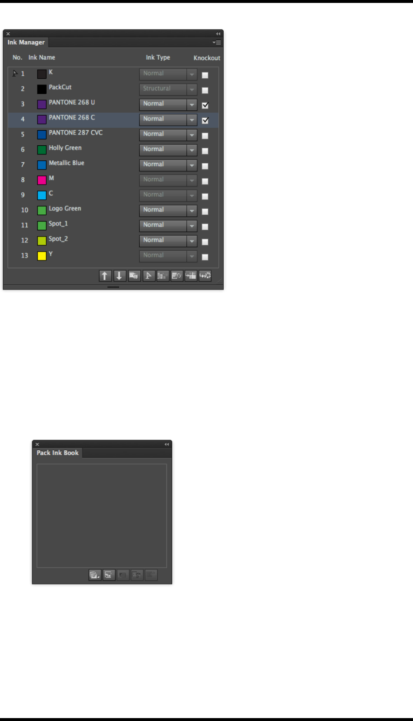
4.2.7 Pack Ink Book
The Pack Ink Book is a library of user created colours and inks from the DIC, Pantone solid coated
and Pantone solid uncoated libraries. These can then be used in the AI document and by the
RealPro Toolkit Ink Mix, Image Channel Mapping and Ink Manager functions.
Usage
1. From the Ink Manager side pull-down menu, select Pack Ink Book.
The Pack Ink Book window is then displayed.
2. To add an ink from one of the libraries, click on the Open Ink Book button, then select the
appropriate library.
- 21 -
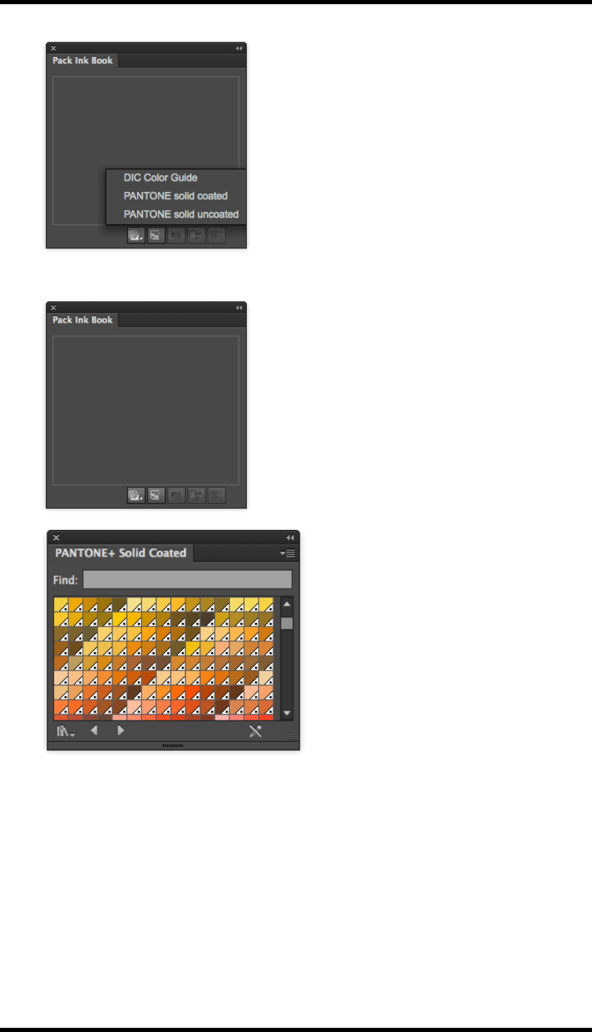
4. Ink
A second window will open displaying the swatches in the selected library.
The side pull-down menu provides tools for controlling the way the swatches are displayed.
3. Clicking on a swatch will add it to the Pack Ink Book.
- 22 -
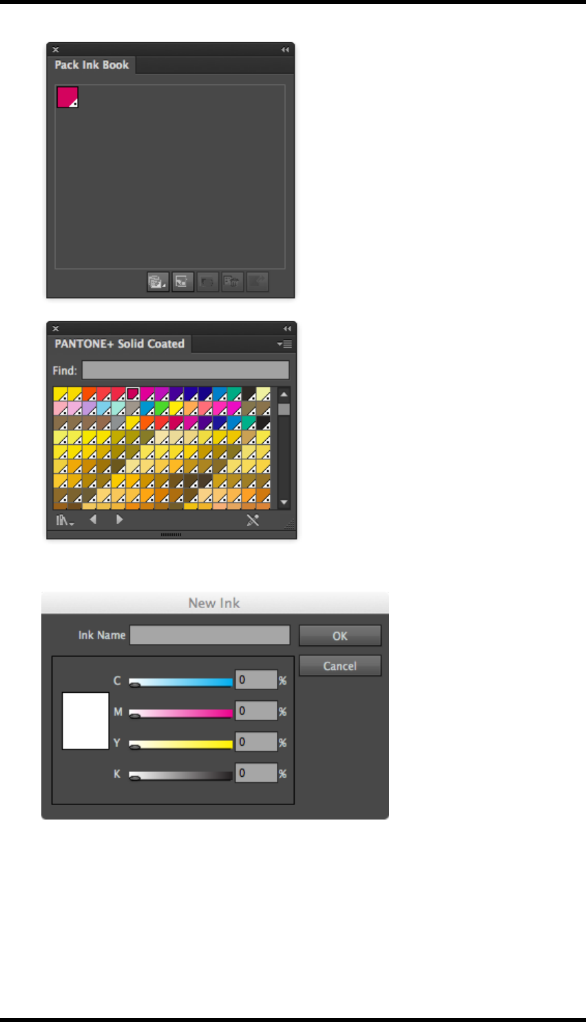
4. Ink
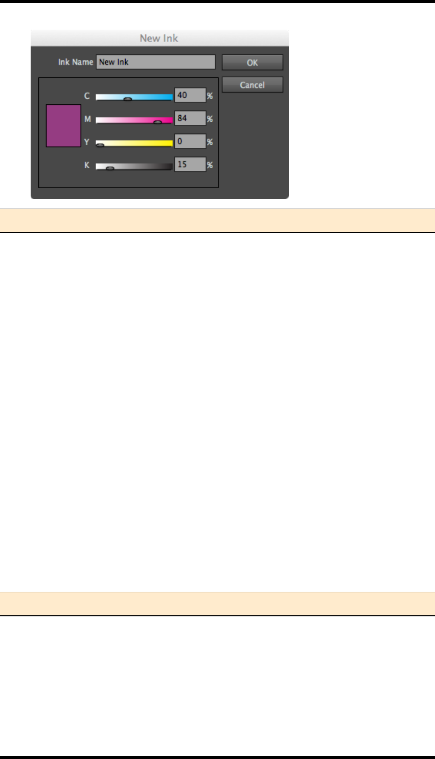
4. Inks can also be created manually by clicking on the New Ink button.
5. Select the percentages of CMYK to be used and name the ink. Then click OK.
The ink will be added to the Pack Ink Book.
6. To edit an ink, select the ink, and then click on the Ink Option button.
- 23 -
4. Ink
Note: Non CMYK inks cannot be edited, and all the settings will be greyed out
When in the Pack Ink Book, the colour can be used within the AI document.
To allow its use in other functions, the ink can be added to the Ink Manager even though it is not
used in the AI document. Select the ink, and then click on the Add to Ink Manager button. The Ink
Manager will be updated with the new ink.
To delete an ink, select the ink, and then click the Delete Ink button, the ink will be removed from
the Pack Ink Book, however if the ink is used, it will not be removed from the document.
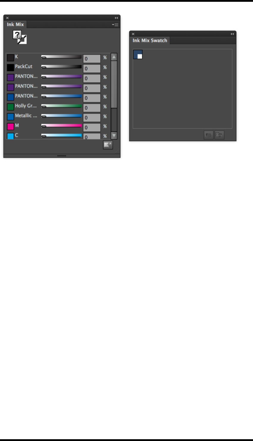
4.3. Ink Mix
Ink Mix provides tools to create colours made up from inks within the document and so modify the
colours of objects.
These new colours can be added to a Toolkit Ink Swatch palette for convenience and re-use.
This extends the basic AI functionality in that colours can be created using spot inks.
1. The ink mix window is accessed by selecting Window > RealPro > Ink > Ink Mix
2. The ink mix swatch palette can be displayed in one of two ways:
By selecting Window > RealPro > Ink > Ink Mix Swatch
From the Ink Mix side pull-down menu, select Ink Mix Swatch
Note: The Ink Manager must be updated before this tool can be used.
- 24 -
4. Ink
4.3.1 Changing the colour of an object
1. Select an object.
The combination of inks used in that object is shown in the Ink Mix widow.
2. Select either fill or stroke.
3. Adjust the ink percentages to change the colour of the object.
4.3.2 Adding a new swatch to the Ink Swatch palette
1. Make sure that no objects are selected. Create the new colour by varying the ink per-
centages of the inks required.
2. Click on the Add to Swatch button, or from the side pull-down menu select Add to Swatch.
The new colour will appear in the swatch palette, it will be named “Mixed Ink x” where x is a
unique number.
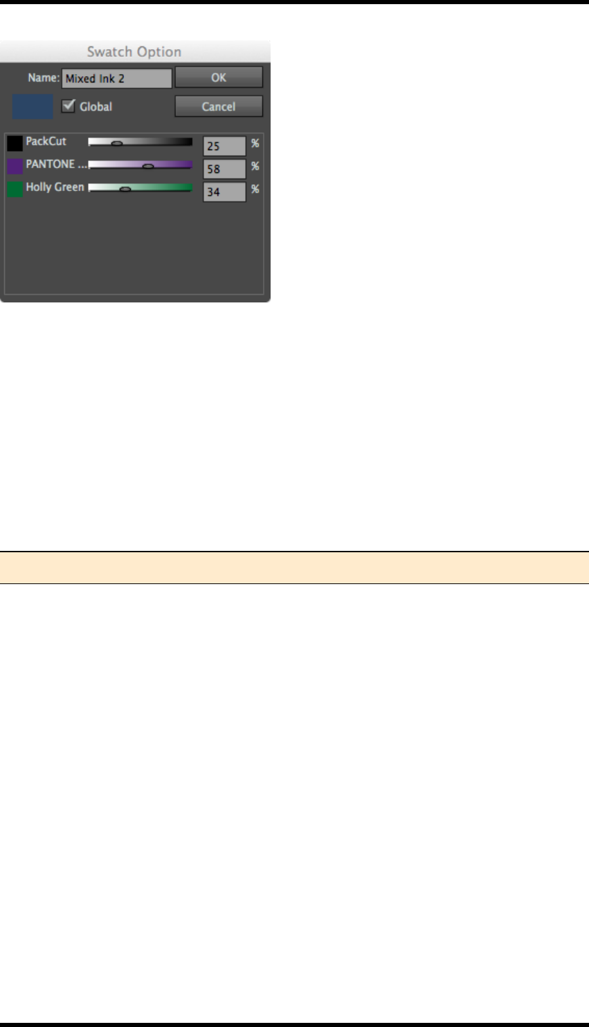
4.3.3 Editing a swatch in the Ink Swatch palette
Select a swatch from the palette, then either click the Swatch Option button, or double-click the
swatch in the palette.
The Swatch Option window is displayed:
- 25 -
4. Ink
The name of the swatch, and the mix of inks used can be changed as required. Note that you cannot
add a new ink in order to modify the colour.
4.3.4 Deleting a swatch from the Ink Swatch palette
Select a swatch from the palette, and then click on the Delete Swatch button.
The swatch is removed from the palette.
4.4. Image Channel Mapping
The image channel mapping tool allows the operator to change any ink colour channel within an
embedded or linked image to any ink in the document.
Note: The Ink Manager must be updated before this tool can be used.
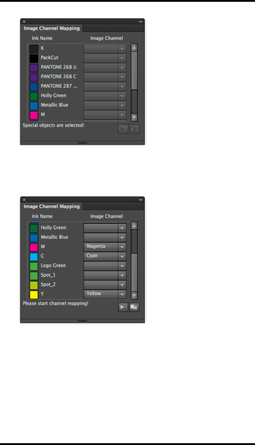
4.4.1 Usage
1. Open the Image Channel Mapping tool by selecting: Window > RealPro > Ink > Image
Channel Mapping
The Image Channel Mapping window is displayed.
- 26 -
4. Ink
At this point all the controls are greyed out.
2. Select the document image to be modified.
The window is then updated and shows the channels that exist in the image.
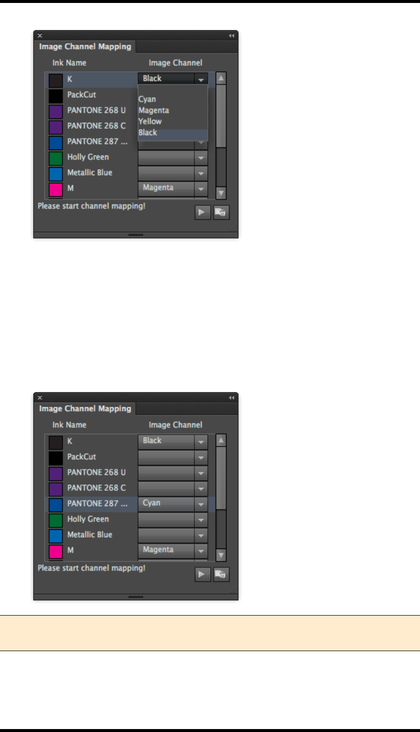
3. Select the ink to be added to the existing channel.
4. From the drop down menu, select the channel to which the ink is to be added.
- 27 -
4. Ink
5. Click Apply Update.
The image will then be modified.
6. If the requirement is to replace a colour channel rather than add to it, set the image channel
for the ink to be replaced to <blank.>.
7. Click Apply update to action the change.
In the example below, the Cyan image channel has been replaced with Pantone 287 CVC.
Note: If the image is exported and opened in another application, it will be seen as an ‘N-
Channel’ image.
- 28 -
4. Ink
4.5. Keep Spot Colour in Blend
The default behaviour of AI when creating a blend between a spot colour and another colour is to pro-
duce a CMYK blend. This tool allows the operator to modify that blend to use the spot colour in the
blend instead of CMYK.
4.5.1 Usage
1. Create a blend between two objects, at least one of which must be a spot colour.
2. Select the blend object, then select Window > RealPro > Ink > Keep Spot Colour in
Blend.
If it is not possible for the tool to modify the blend a warning message is displayed.
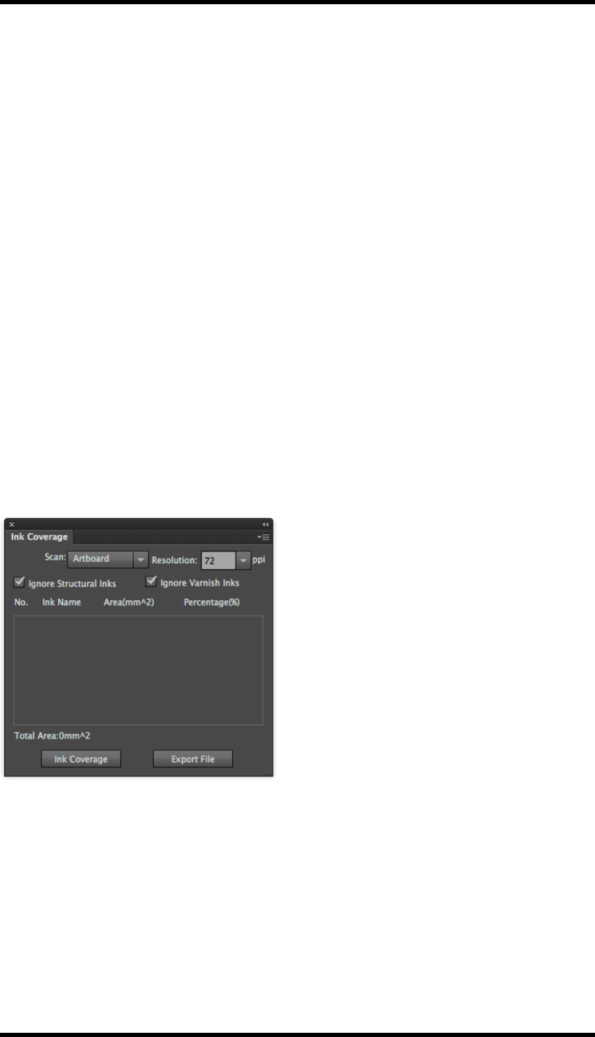
4.6. Ink Coverage
The Ink coverage function calculates the ink usage within a defined area, Artboard, Sheet,
Plate,TrimBox, MediaBox, Margin or BleedBox. This data can then be exported to a text (.txt) file for
use in calculating product cost etc.
4.6.1 Usage
Select Window >RealPro >Ink >Ink Coverage the Ink Coverage dialogue box will be displayed;
Scan:Select the area to be scanned. The options will not include those areas not defined in the
AIdocument.
Resolution: Select the required output resolution. Default is 72ppi. Range is from 36 to 1000ppi
Choose whether to include Structural and/or Varnish inks in the calculation.
Click on Ink Coverage to apply the settings and calculate the coverage. An example of the updated
dialogue is shown below:
- 29 -
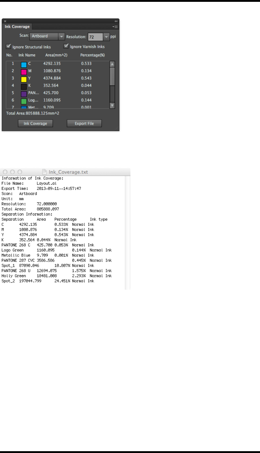
4. Ink
The inks are listed in the same order as in the Ink Manager.
Click on ExportFile to create a text file describing the ink coverage. Example below:
4.7. Limitations of Ink
1. Ink Manager cannot discover inks in AI files when the colour mode is RGB
2. Ink Manager cannot read the inks of hidden objects / hidden layers or objects on non-printed
layers.
3. The spot inks of image data cannot be converted to process inks.
4. Multi-colour text, special effects and linked images can not be processed by the ink con-
version process.
5. It is not possible to replace inks in 3D special effect objects with <blank>.
- 30 -

4. Ink
6. Mesh, Live Paint groups, image data and 3D special objects are not affected when inks are
converted to spot.
7. The objects with outer glow, inner glow, shadow and neon glow effects are not affected when
inks are converted to spot.
8. Mesh, Live Paint groups and Image data cannot use mixed colours.
9. Symbols, symbol sets and patterns cannot support the undo operation.
10. The function “Keep spot colour in blend” currently supports only simple blend objects. These
are blend objects formed by two colour blocks with only one fill for each or with only one
stroke for each. The function cannot be applied to other types of complicated blend objects
such as blend objects formed by one colour block with a stroke and the other one with a fill.
Under these circumstances, there will be a warning to show this function cannot be applied.
11. Image Channel Mapping can only support either images with AI recognized CMYK mode, or
with Device N, Separation & Indexed colour spaces.
12. DCS images are not supported in image channel mapping.
- 31 -

5. Ink Compensation
5. Ink Compensation
5.1. Overview
Ink Compensation provides a method of removing unwanted effects by filling the non printed area of
the plate with a gradient creating an even distribution of ink.
Before Ink Compensation
After Ink Compensation
- 32 -
5. Ink Compensation
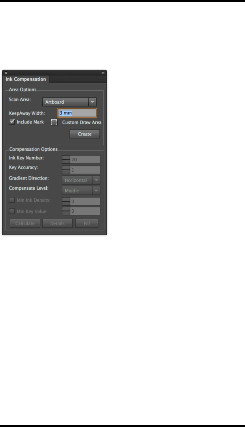
5.2. Creating an Ink Compensation Zone
Create a nested layout file.
Select Window >RealPro >Ink >Ink Compensation. The Ink Compensation palette will be
displayed.
Area Options
Scan Area: This defines the zone to which the compensation will be applied. Options are Artboard,
Plate or Sheet.
KeepAway Width:This setting determines the gap between the one up artwork (bleed line) and the
compensation area.
Include Mark:Select whether or not any mark areas form part of the zone or not.
Custom Draw Area:It is possible to create a custom zone by clicking on this button then drawing a
rectangle on the layout.
Create:Click on this button to create the required zone. The border is shown on the layout as a blue
line.
Compensation Options
Ink Key Number:Set the number of ink keys to be used when printing this plate.
Key Accuracy:Sets the precision of each key.
Gradient Direction:Sets the direction for the gradient. Options are Horizontal or Vertical.
- 33 -
5. Ink Compensation
Compensation Level: Sets the intensity of the compensation gradient. Options are Low, Middle or
High
Min Ink Density:Sets the minimum ink density used in the gradient.
Min Key Value:Sets the minimum compensation value for the ink keys.
Calculate:Calculates the compensation values required but does not apply it.
Details: Opens a dialogue box showing the ink compensation values to be applied.
Fill: Fills the non printed area with the required gradient.
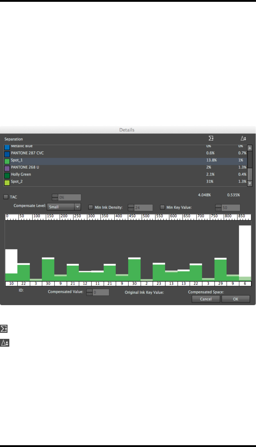
Compensation Details
Separations can be individually selected to view and modify the effect of the compensation.
Indicates the amount of ink coverage in the zone.
Indicates the amount of compensation to be applied in the zone.
TAC:The Total Area Coverage (TAC) can be limited by selecting this option and entering a value in
the adjacent field.
Compensated:Sets the compensation level for the selected ink only.
Minimum Ink Density: Sets the minimum density for the selected ink.
Minimum Ink Key: Sets the minimum key density for the selected ink.
- 34 -
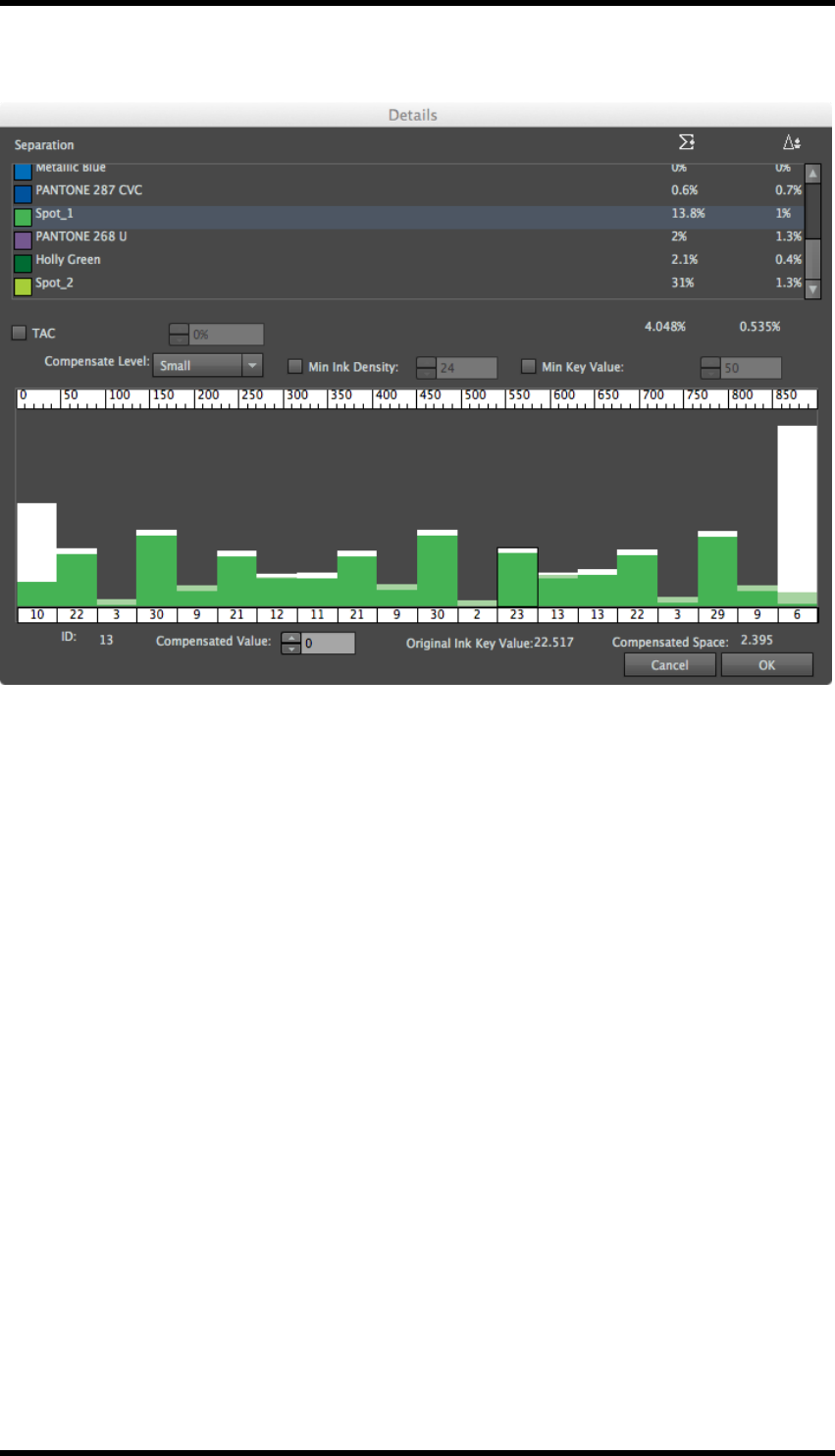
5. Ink Compensation
Click on an individual key to view/change the values shown below:
ID:Indicates the number of the selected ink key
Compensated: Sets the compensation value for the selected key.
Original Ink:Displays the original value of ink for the selected key
Compensated: Displays the maximum compensation level for the key.
If changes are made, clicking on OK will save those modifications, clicking on Cancel will discard
them.
- 35 -
6. Ink Histogram
6. Ink Histogram
6.1. Overview
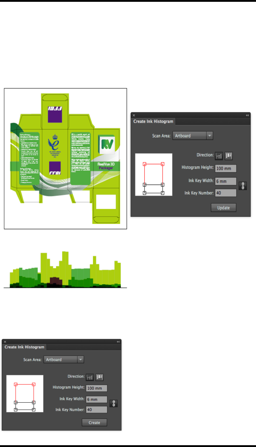
The Ink Histogram provides a simple method of displaying the ink consumption.
The histogram shows the consumption of ink in for each separation:
6.1.1 Usage
Select Window >RealPro >Mark >Create Ink Histogram. The Create Ink Histogram palette
will be displayed.
- 36 -
6. Ink Histogram
Scan Area: Select the area to be analysed when producing the histogram. Options are:Artboard,
Sheet, Plate, Trimbox and Mediabox.
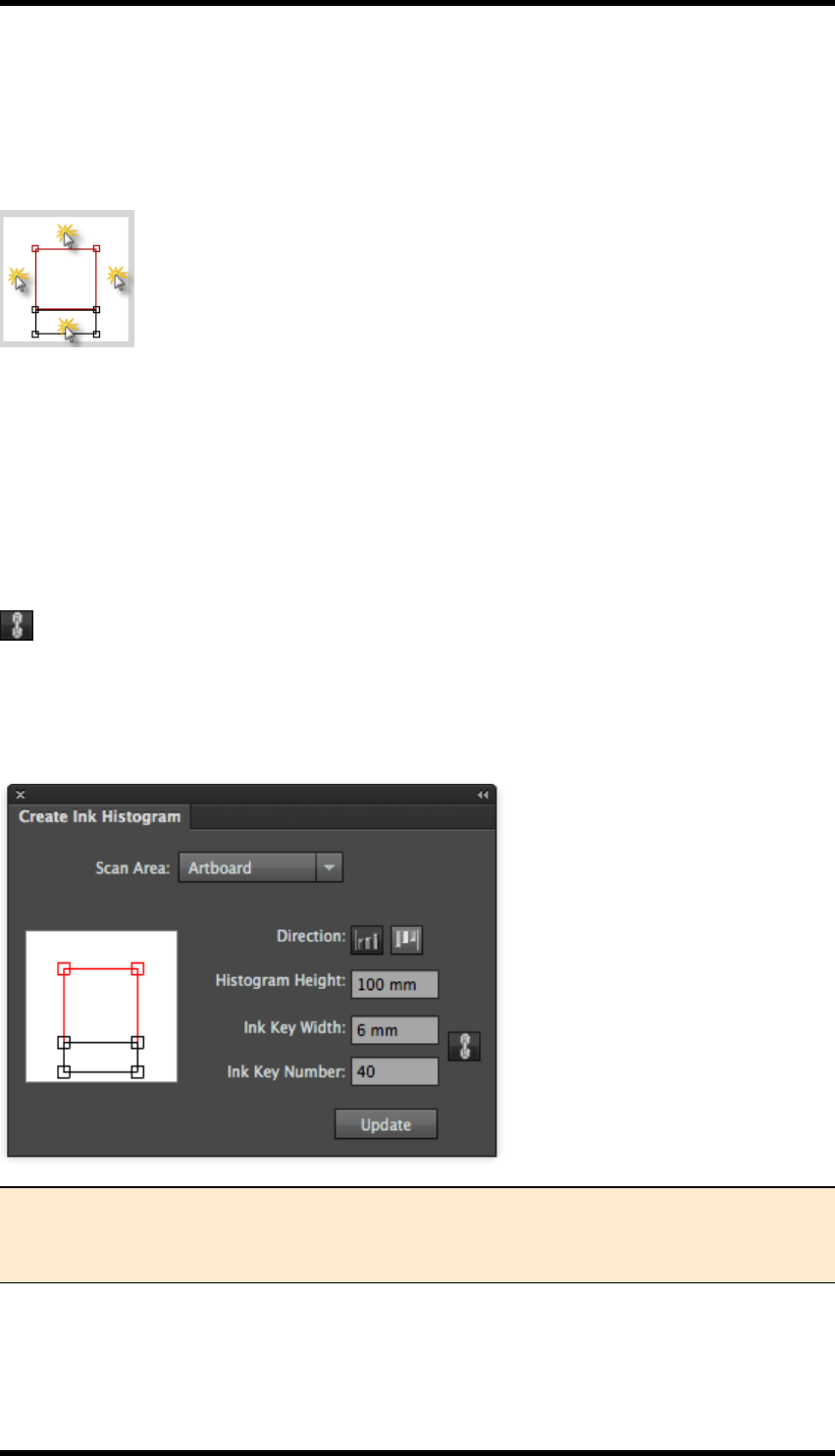
Position:The position of the histogram is selected using the graphical interface as shown below.
simply click in the appropriate area.
Direction: Click on the appropriate button to set the orientation of the histogram.
Histogram Height:Selects the height of the area used when drawing the histogram.
Ink Key Width:Sets the width of each ink key. (Normally the same as the width of a single key
zone).
Ink Key Number:Sets the number of ink keys in use across the scan area. (Range is from 1 to
100)
The lock button,this locks the relationship between the Ink Key Width and the Ink Key Num-
ber. As one value is changed, the other will automatically update.
Click on the Create button to calculate & display the histogram.
Once the histogram has been created, the Create button is replaced with an Update button.
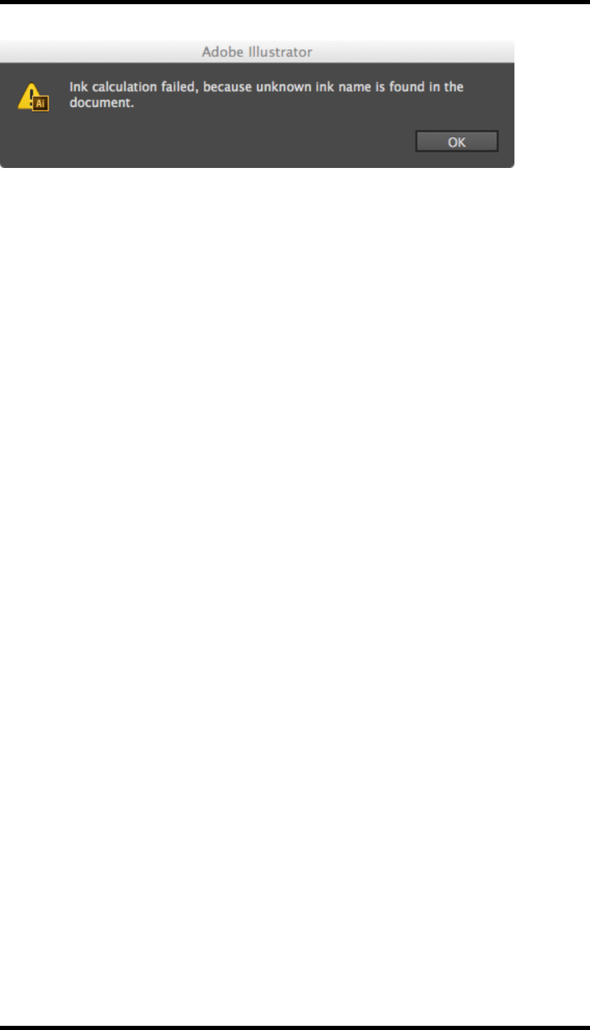
Note: The Ink Manager needs to be updated prior to generating the histogram. If there
are inks in the document that have not been added to the Ink Manager, the following
error message is displayed;
- 37 -
6. Ink Histogram
- 38 -
7. Link
7. Link
7.1. Overview
An Adobe Illustrator (AI) document can contain either embedded images or links to those images.
The latter methodology results in a smaller AI file, and allows the images to be updated inde-
pendently of the AI document, in their native application, the updated image is then automatically
viewable in AI.
The Link plug-in allows the operator to export embedded images to a location of their choice, repla-
cing the image with a link.
Images can be re-embedded using the standard AI tools.
Tools exist within the plug-in to export all the images in a document, or only images selected by the
operator.
Note: The document colour mode must be set to CMYK.
7.2. Operation
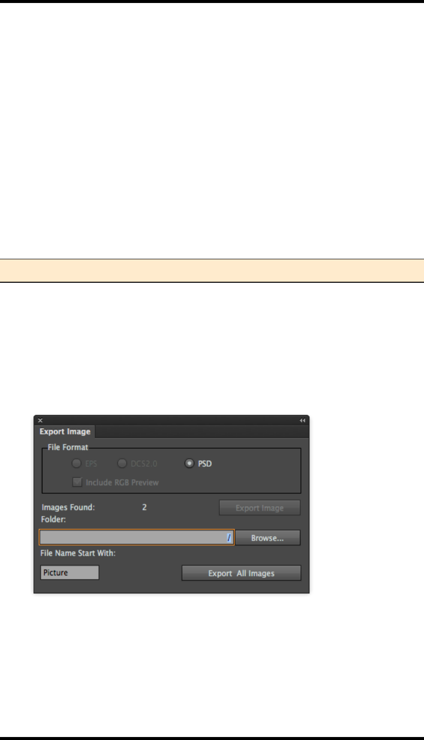
7.2.1 Export Images
1. Select Window > RealPro > Link or use the keyboard shortcut: Alt+Shift+Ctrl+\ to open
the Export Image dialogue box.
2. If there are multiple images selected, (or there are multiple images in the document), the
Export Image dialogue box is displayed as below:
3. If there is a single image selected, (or only a single image in the document), the Export Image
dialogue box is displayed as below:
- 39 -

7. Link
4. Choose the location for the file(s) and the file format.
The formats available will depend upon the format of the original image.
Some file types will give the option of producing an RGB preview, if this is required select the
Include RGB Preview option.
5. Select the prefix for the filenames by entering text in the ‘File name start with’ field.
The exported files will then be named: file name_number.
In the above example, this means “Picture_1.psd”, “Picture_2.psd”
6. Click on the appropriate Export button to save the images.
- 40 -
8. Search
8. Search
8.1. Overview
The Search plug-in provides an enhanced search function for Adobe Illustrator (AI). It provides a
method for locating and selecting objects using an operator defined set of conditions.
The search may be made up of multiple conditions and will find objects that match ALL, (default), or
ANY of those conditions.
8.2. Usage
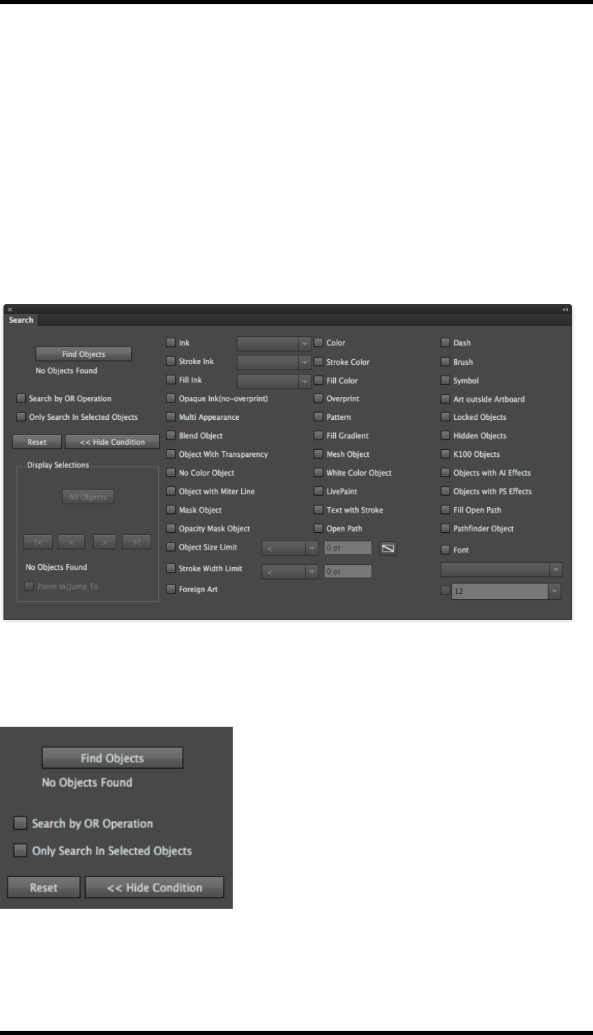
Select Window > RealPro > Search or use the shortcut:Alt+Ctrl+Z to open the Search tool.
The left hand side of the window contains controls to manage the search behaviour. The right-hand
side contains controls to select the condition(s) used for the search.
8.2.1 Search Controls
Find Objects
Clicking on this button executes the search.
- 41 -
8. Search
The number of objects found by the search is displayed beneath this button.
Search by OR operation
The default behaviour of the search is to find objects that match ALL the search conditions. Select-
ing this option will allow the search to find objects that match ANY of those conditions.
Only Search In Selected Objects
Selecting this option will limit the search to objects currently selected in the AI document.
Reset
Clicking on the Reset button will clear all the search conditions and reset the window to its default
state.
<< Hide Condition / Show Condition
Clicking on this button will toggle between showing and hiding the search conditions.
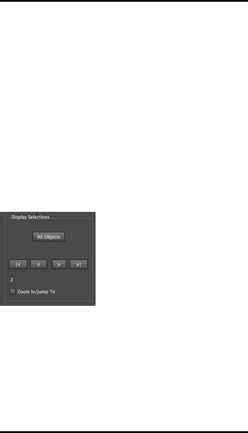
Display Selections
These controls are made available to the operator once objects that match the search conditions
have been found, and allow the operator to navigate between and select individual objects.
The number of the selected object is also displayed.
8.2.2 All Objects
Clicking on this button will select all objects found by the search.
|<
Clicking on this button will select the first object found by the search.
<
Clicking on this button will select the previous object found by the search
>
Clicking on this button will select the next object found by the search.
- 42 -
8. Search
>|
Clicking on this button will select the last object found by the search
Zoom In /Jump To
Selecting this option will cause the display to zoom into the selected object.
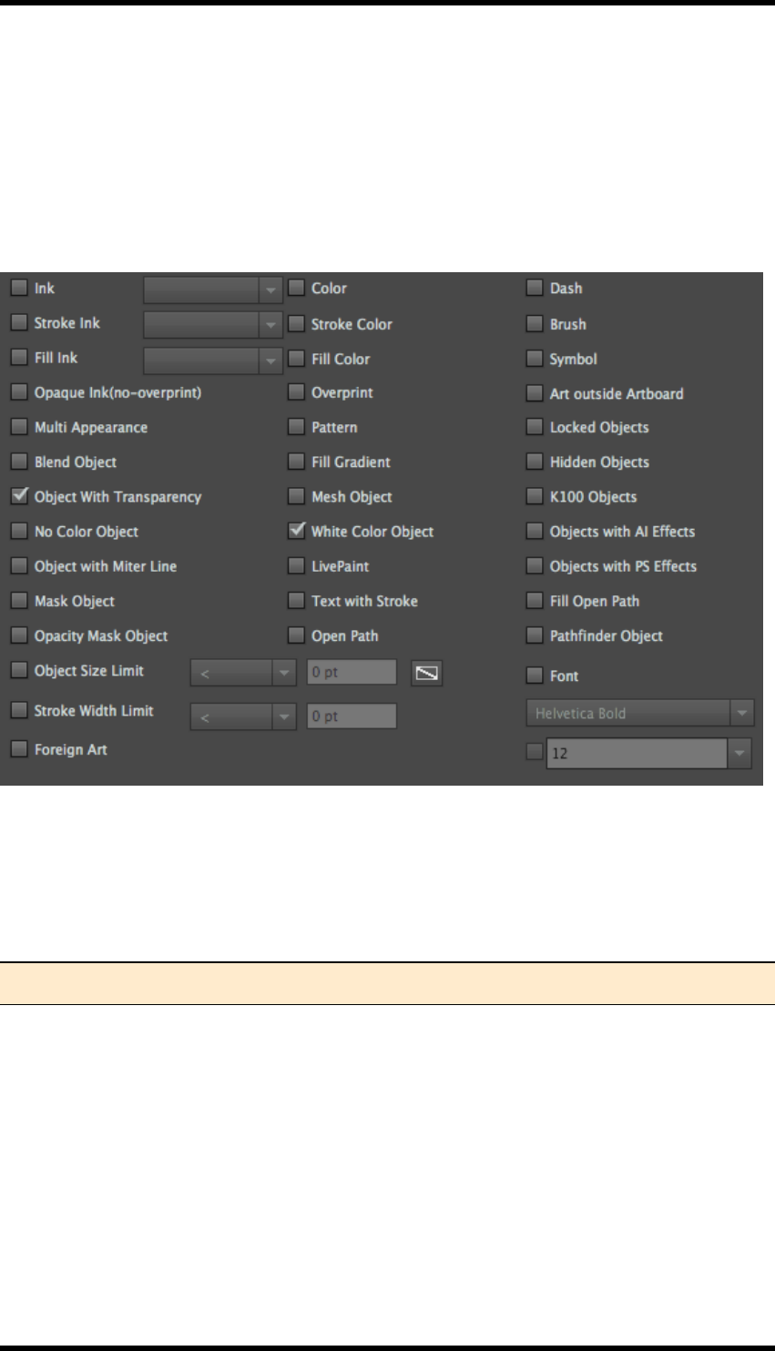
8.2.3 Search Conditions
The use of the majority of these conditions is self-explanatory; however all are listed below for com-
pleteness.
Ink
Fill or stroke with the specified ink. Select the ink from the pull down menu.
Note: The Ink Manager must be updated before any inks are available for selection.
Stroke Ink
Stroke line with the specified ink.
Fill Ink
Fill with the specified inks.
Colour
Fill or stroke with the specified colour. To select a colour, select Color then click on the selection
box.
- 43 -

8. Search
Choose Registration,Color,InkMix Color or AIColor.
Select Registration to search for objects that are made up from 100% of all inks in the document.
To search for objects of a particular colour, select Color, a Color Picker is displayed
The color picker can be used to select the colour, or by clicking on Color Swatches, a colour can be
selected from the swatches.
- 44 -

8. Search
Click on Color Models to display the Color Picker
Select InkMix to search for a colour created using the InkMix functionality.
Select AIColor to search for objects that have the same colour as the currently selected object. (If
the currently selected object has fill & no stroke, the fill colour will be selected in all cases. If there is
a stroke & no fill, then the stroke colour will be selected in all cases).
Stroke Colour
Stroke line with the specified colour.
Fill Colour
Fill with the specified colour.
Opaque Ink (no-overprint)
Fill or stroke without trapping.
Overprint
Fill or strokes with trapping.
Multi Appearance
Objects with multiple strokes or fills that equal or exceed 2.
Pattern
Objects with pattern styles.
- 45 -

8. Search
Blend Object
Blended objects.
Fill Gradient
Objects with gradient fills.
Object with Transparency
Objects with transparency.
Mesh Object
Mesh object.
No Colour Object
Any object with no fill or no stroke value or colour. If a sub-element of an object qualifies as a no col-
our object, then the whole object will be selected and displayed.
White Colour Object
Any object with at least one appearance specified as white qualifies as a white object. Definition of
white colour: 1) C0M0Y0K0; 2) any specified colour percentage is 0%; 3) K percentage in gray mode
is 0%; 4) c0m0y0k0 in Swatch (print colour in attributes). Note: 100% Specified white colour is not
included.
Object with Miter Line
Objects with miter line effect.
Masked Object
Objects with mask.
Text with Stroke
Text with strokes applied.
Opacity Mask Object
Objects with opacity masks.
Open Path
Object with open paths.
Object Size Limit
Minimum width of the object bounding box should be in accordance with the specified criteria. This
option can be used to search for isolated points: choose “less than any value” or “equal to 0”, or “less
than or equal to any value” or “equal to or exceed 0” to search objects whose Bounding Box meet
W=0 and H=0.
- 46 -

8. Search
Stroke Width Limit:
The width of line of the object should be in accordance with the specified criteria.
Live Paint
Objects with the Live Paint effect.
Fill Open Path
Fill open path without stroke.
Dash
Dash can be found by searching dash in AI or setting all dashes as 0.
Brush
Objects with brush applied.
Symbol
Symbol objects.
Object outside Artboard
Objects, some parts or the whole part of which are outside the artboard.
Locked Objects
Locked objects in AI layers
Hidden Objects
Hidden objects in AI layers.
K100 Object
Objects which include K100% colour. The definition of K100: 1) K100% is shown in the colour panel
in gray mode; 2) K100% is shown in the colour panel in CMYK mode; 3) K100% is shown in the
swatch colour panel of AI. The colour's attribute must be print colour.
Objects with AI Effects
Objects with Special Effect of Adobe Illustrator in the Special Effect menu of AI applied.
Objects with PS Effects
Objects with Special Effect of Adobe Photoshop in the Special Effect menu of AI applied.
Pathfinder Objects
Objects with Pathfinder applied but do not spread.
- 47 -

8. Search
Text Font:
Objects with specified text type and text size can be found by only searching text type or searching
both text type and text size.
Foreign Art
Foreign art in the current file can be found.
8.3. Limitations
1. If the line width of a stroked object is blank, then this line cannot be found.
2. An empty colour cannot be dragged into the AI Colour Swatches.
3. Hidden objects cannot be searched for in combination with another search condition.
4. Locked object: There are two search modes: Edit Envelope and Edit Contents, in locked
Envelope objects which both keep consistent to locking in the layer panel.
5. Regarding objects with opacity set, only objects with 100% opacity are identified as K100
objects.
6. An object is identified as K100 object, if its K100% effect is created by the overprinting of sev-
eral appearances whose opacities are all less than 100%.
7. Objects that have two consecutive white colour or K100% stop dots are identified as white
colour objects or K100 objects.
8. The check box of text size will be highlighted only if text objects are chosen.
- 48 -

9. Tool
9. Tool
9.1. Overview
The Tool plug-in contains a number of utilities that support RealPro Toolkit’s main features and
enhance Adobe Illustrator (AI) tools.
Selection Tools
Selects objects but does not allow either editing or movement of those objects.
RP Gradient Tool
Graphical tool to adjust gradient parameters.
Line Pathfinder
Used to crop a closed path object using an open path.
Path Editing Tools
These tools enhance the existing AI tools for editing paths and are of use when editing paths cre-
ated by the automatic trap functions..
lRetrace
lSplit
lDistort
lIntersect
lJoin Path
Expand Text Width
Tool to modify the width of text.
Node Optimization
Used to reduce the number of path nodes associated with an object. Reducing nodes can sig-
nificantly reduce process times.
Foreign Art to Grey
Objects that originate from other applications may not be recognised by AI. These are classified as
Non-Native by AI, this tool converts them to grey-scale images.
Bitmap Outline
Converts bitmaps to vector graphics.
RP Guide Tool
Creates guide lines for use with the following tools.
- 49 -
9. Tool
Guide Line
Guide line management tool.
RP Align
Object alignment tools.
RP Clip
Object clipping tools.
9.2. Selection Tools
9.2.1 Area Selection Tool
This tool works in the same way as the AI Selection Tool except that when this tool is used, selec-
ted objects cannot be moved or edited. This eliminates the possibility of accidental changes being
made by the operator.
The tool is accessed by expanding, (click & hold), the AI Selection Tool.
9.2.2 Area Direct Selection Tool
This tool works in the same way as the AI Direct Selection Tool except that when this tool is used,
selected objects cannot be moved or edited. This eliminates the possibility of accidental changes
being made by the operator.
The tool is accessed by expanding, (click and hold), the AI Direct Selection Tool.
9.3. RP Gradient Tool
This tool provides similar functionality to the AI gradient editing tools.
The tool is accessed by expanding, (click and hold), the AI Gradient Tool.
9.3.1 Usage
Select the gradient object to be modified.
The tool is shown as below:
- 50 -
9. Tool
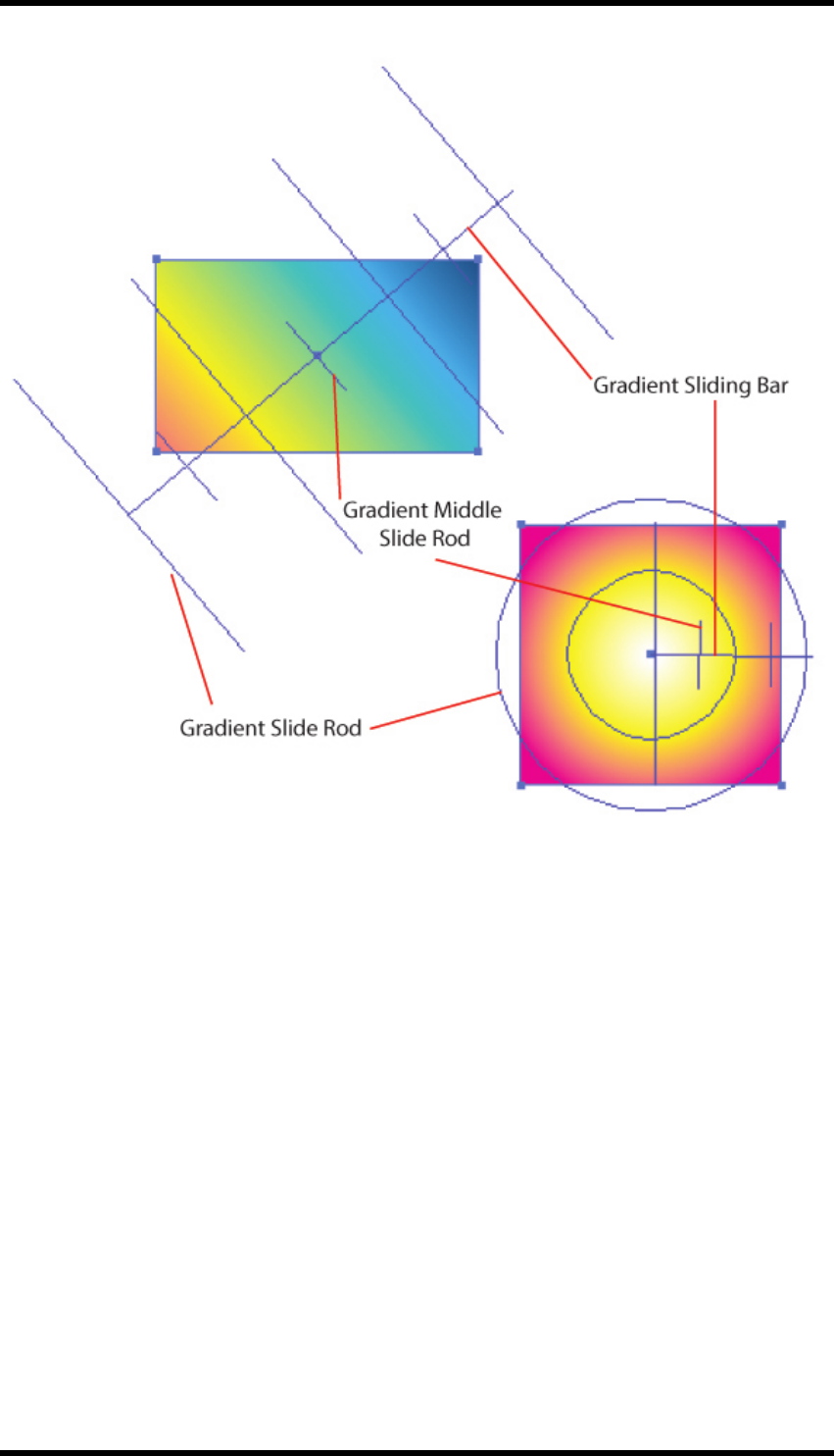
The tool is made up from a number of elements: shown in the diagram above.
Gradient Sliding Bar: Equivalent to the AI Gradient Annotator
Gradient slide rod: These are shown at the start and end points of the gradient colour stops
Gradient middle slide rod: These are shown at the mid points of the gradient colour stops
Adjustment
The gradient sliding bar can be adjusted by selecting the bar, (click anywhere on the bar), and then
while holding the Option (Mac) or Alt (PC) keys down, click on the bar and drag the bar to the new
position using the mouse. Clicking on an end point will allow rotation and adjustment of the length of
the bar.
- 51 -
9. Tool
The gradient slide rods can be adjusted by selecting the rod, (click anywhere on the rod), and then
while holding the Option (Mac) or Alt (PC) key down, click anywhere on the selected rod and drag
the rod to the new position using the mouse.
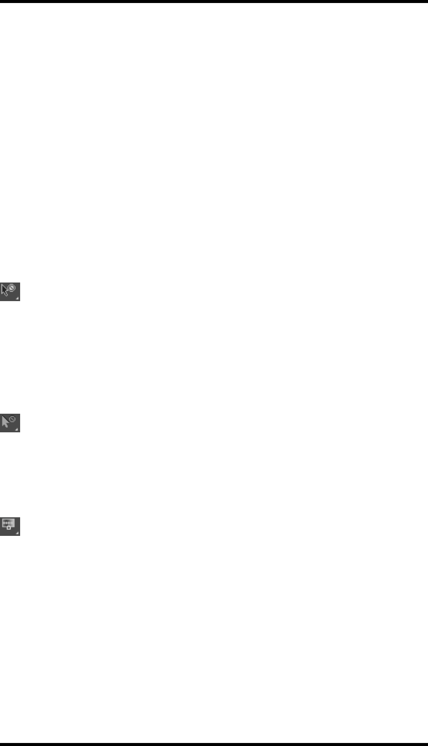
When the Option (Mac) or Alt (PC) key is held down, the cursor will change as it is moved over the
gradient controls. This indicates how the selected object will be moved.
Colour Select State Cursor Move State
Gradient Sliding Bar
Gradient Sliding Bar Endpoint
Gradient Slide Rod
Gradient Middle Slide Rod
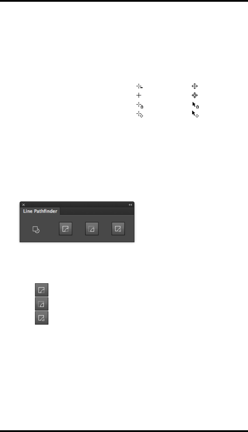
9.4. Line Pathfinder
This tool set allows the operator to crop a closed path object using an open path, creating multiple
objects. This is particularly useful when making edits to cutter guides and trap areas.
9.4.1 Usage
1. Either select Window > RealPro-Tool > Line Pathfinder or use the Keyboard shortcut:
Shift + Ctrl + Q to open the Line Pathfinder Tool.
2. Select the object to be cropped, and the path defining the crop.
3. Click on the required crop option from the Line Pathfinder tool:
lKeep Biggest – Deletes the smallest object created after the crop.
lKeep Smallest – Deletes the largest object created after the crop.
lKeep Both – Both objects are retained after the crop.
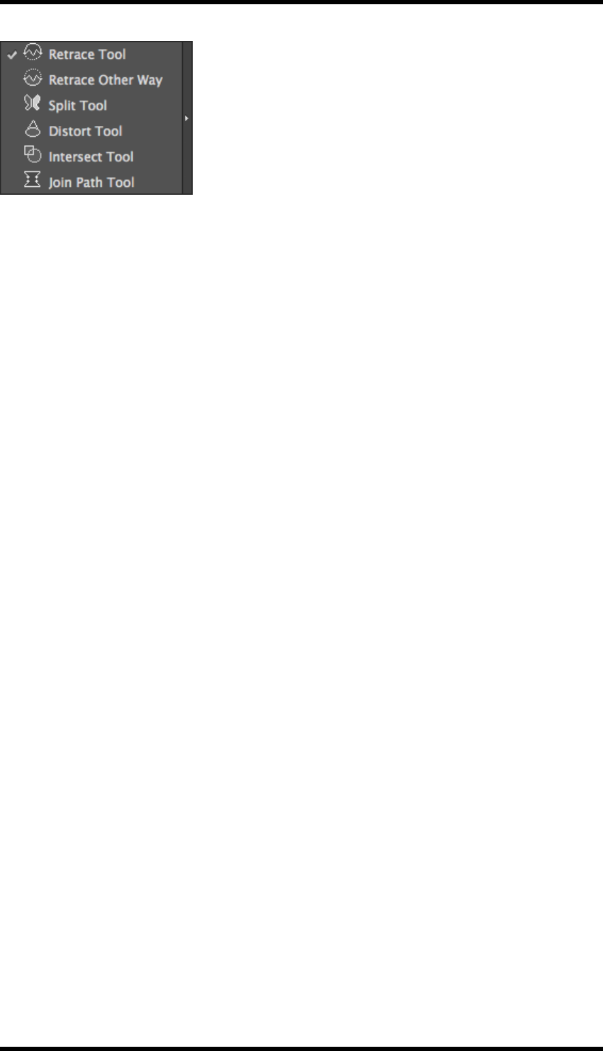
9.5. Path Editing Tools
The Path Editing tools provide additional functionality to the AI toolset, giving the operator faster
methods to modify documents.
The tools can be found by expanding (click and hold) the Retrace Tool.
- 52 -
9. Tool
9.5.1 Retrace Tool
This tool allows an existing closed path object to be clipped by an open path.
Usage
1. Create a path that describes how the closed path object should be clipped. (The end points
MUST touch the closed path).
2. Select the Retrace Tool.
3. Press the Return key on the keyboard.
The larger section of the object is retained with the new path. The smaller section is deleted.
9.5.2 Retrace Other Way
This tool works in the same way as the Retrace Tool described above, except that the smaller sec-
tion of the closed path object is retained and the larger section deleted.
9.5.3 Split Tool
This tool works in the same way as the Retrace Tool described above, except that both sections of
the closed path object are retained as separate objects. This can be useful, for example, when con-
structing artwork that bridges the closure point between two panels of a folded carton.
9.5.4 Distort Tool
This tool allows the operator to ‘distort’ a path.
Usage
1. Select the Distort Tool.
2. Define the start and end points of the distortion by clicking on the path.
3. Define the mid-point of the distortion by clicking on the path at a point between the start and
end points created above.
4. Click and drag the mid- point anchor to achieve the required distortion.
5. Press the Return key on the keyboard.
The distorted path is applied.
- 53 -
9. Tool
9.5.5 Intersect Tool
The Intersect Tool is used to divide intersecting closed paths into several open paths.
Usage
1. Select a number of overlapping closed path objects.
2. Select the Intersect Tool.
3. Press the Return key on the keyboard.
A number of open path objects are created. The open part of each path being defined by the
straight line between the intersection points.
9.5.6 Join Path Tool
The Join Path Tool is used to connect one or more open paths creating a single closed path.
The closed path will be generated by connecting the nearest endpoints of each path.
Usage
1. Select the open paths to be joined.
2. Select the Join Path Tool.
3. Press the Return key on the keyboard.
The ‘new’ closed path object will be created.
9.6. Expand Text Width
Sometimes thin strokes of text may be broken or even lost during printing, especially in either flexo-
graphic or gravure printing. Additionally, if the gap between strokes of text is too small, the stroke
might be run into another. Both of these problems can be overcome using the Expand Text Width
tool functionality.
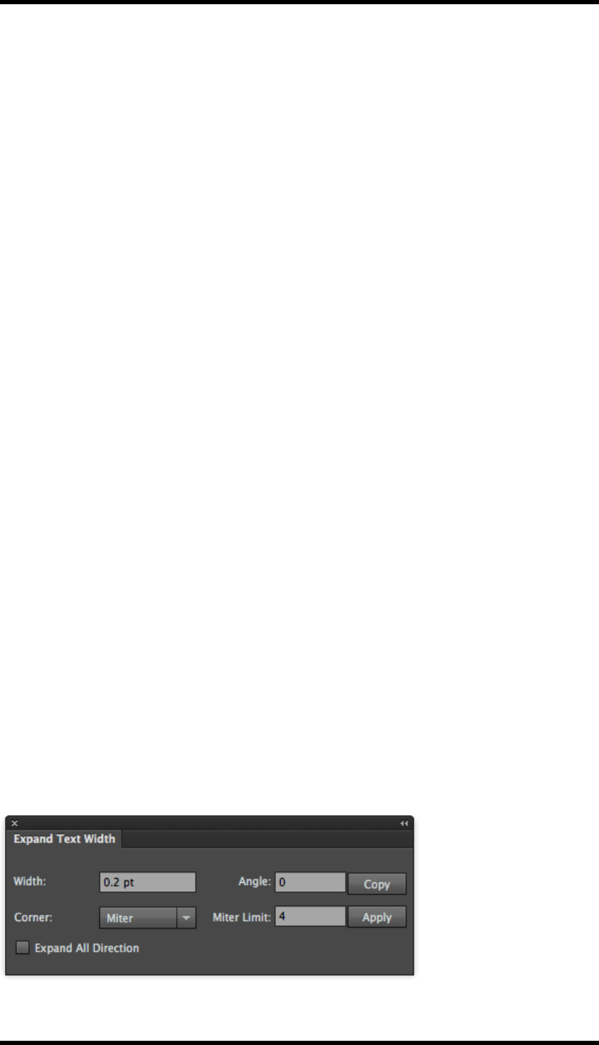
9.6.1 Usage
Select Window > RealPro >Tool > Expand Text Width to open the Expand Text Width dialogue
box:
- 54 -

9. Tool
Parameters
Width: Defines the amount of expansion of the text, setting a negative value will reduce the size of
the text.
Angle: Sets the expansion direction. (Only applies to outline fonts).
Corner: Sets the corner style of the text..
(When the corner style is set to miter, the miter limit can be set in the adjacent field, if this limit is
exceeded the corner style is set to bevel).
Apply: Expands the text creating outline objects
Copy: As Apply except that a copy is made of the text prior to the expansion.
Expand All directions: If selected, the text will expand in all directions. If de-selected, the text will
expand horizontally, or in the direction set by the Angle parameter.
The tool can also be used to modify the inner areas of the text only, see below
Use the Direct Selection Tool to select the appropriate area.
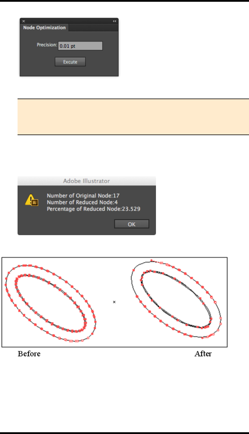
9.7. Node Optimisation
The Node Optimization tool can be used to remove unnecessary path nodes from an object without
affecting the original path appearance.
This tool is useful to optimize the paths of trapping area made by the trapping function.
9.7.1 Usage
1. Select the path to be modified.
2. Select Window > RealPro >Tool > Node Optimisation to open the Node Optimisation
Tool.
The Node Optimization dialogue box will be displayed.
- 55 -
9. Tool
3. Enter the required optimization precision level.
Note: The larger the precision value is, the more nodes will be removed from the
path. However, with high values the optimised path may be significantly altered.
Reduction of the precision value should then be made to achieve an acceptable
result.
4. Click OK to execute node optimization.
After optimisation, a report will be displayed. This indicates the number of original nodes, the
number of nodes removed, and the percentage of nodes removed.
9.7.2 Example
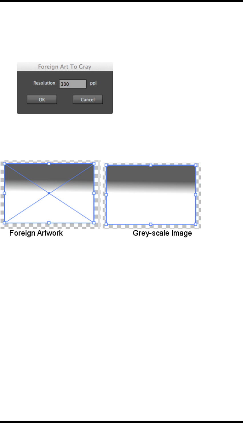
9.8. Foreign Art To Gray
The purpose of this tool is to convert object identified as ‘Non-Native’ by AI to grey-scale. These are
typically objects that may originate from Microsoft programs..
- 56 -
9. Tool
9.8.1 Usage
1. Select Window > RealPro > Tool > Foreign Art To Gray, to open the Foreign Art to Gray
tool.
The Foreign Art To Gray dialogue box will be displayed:
2. Set resolution in the dialogue box.
3. Click OK and the foreign art in the current AI document will be converted into gray-scale
images.
Foreign Artwork Grey-scale Image
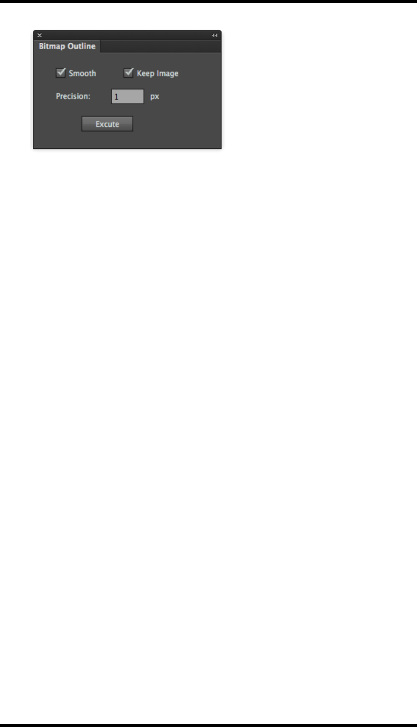
9.9. Bitmap Outline
This tool allows the operator to convert bitmap artwork to vector graphics.
9.9.1 Usage
1. Select the embedded bitmap to be converted.
2. Select Windows > RealPro > Tool > Bitmap Outline to open the Bitmap Outline tool.
The bitmap outline set dialogue box will be displayed as shown below:
- 57 -
9. Tool
3. Set the Precision factor as required, the lower the value, the nearer to the original bitmap the
result will be, the higher the value, the smoother the result.
The jagged edge of the bitmap will be converted to a smooth scalable vector outline.
9.10. RP Guide Tool
This tool allows the operator to create guide lines that can be used, in conjunction with the RP Align
and RP Clip tools to align objects accurately within the artwork.
The RP guide lines can also be converted to AI guides.
9.10.1 Usage
1. Select the RP Guide Tool from the AI toolbar.
The cursor will change to a + icon.
2. Move the cursor to the point where the guide lines are required, and click once.
Horizontal and vertical guides are drawn, intersecting at the cursor position.
3. Moving the cursor and clicking again will reposition the guides.
4. The guide lines can be hidden by deselecting Show Pack Guide from the RP Align side pull-
down menu.
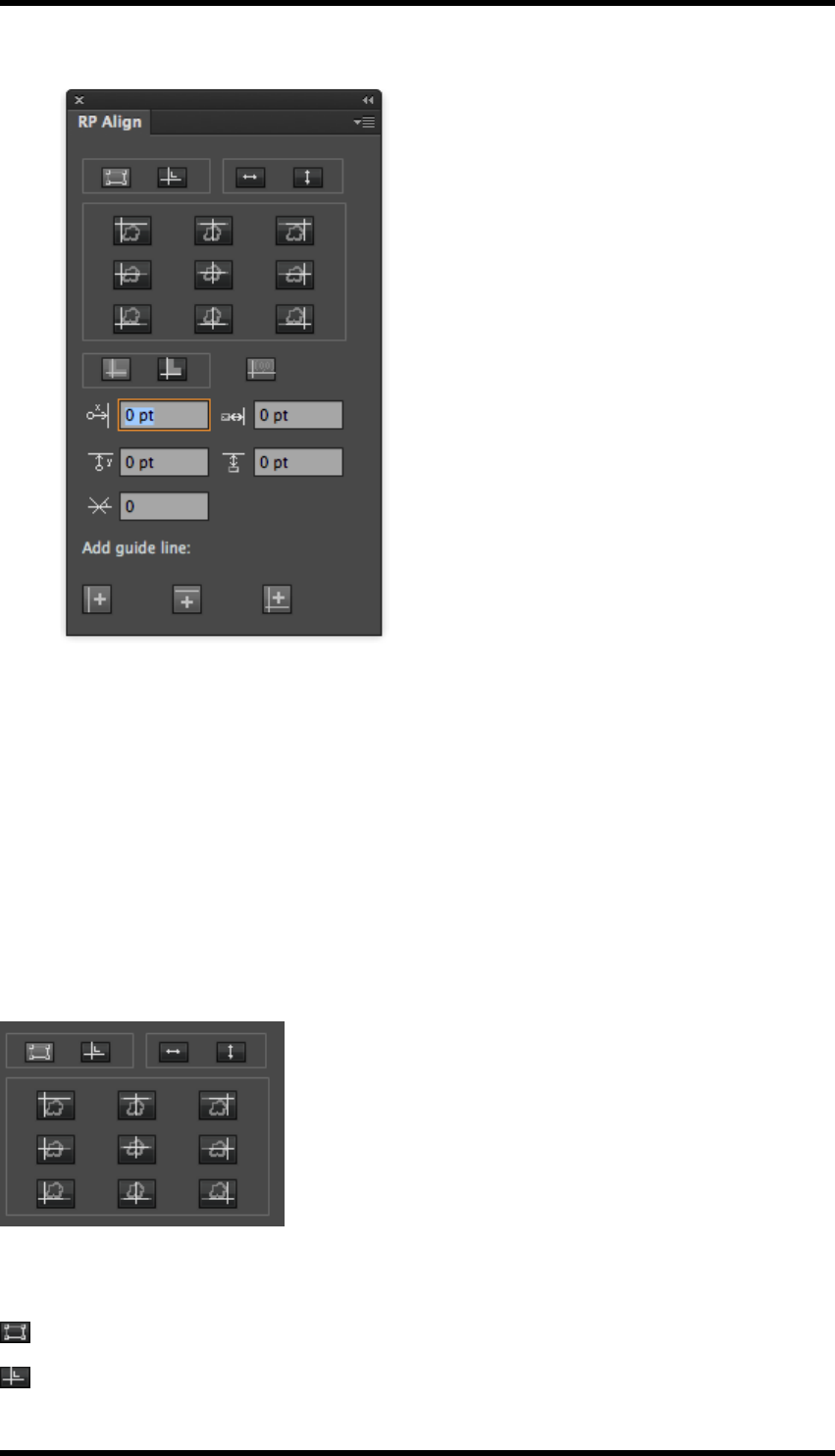
9.11. RP Align
The RP Align tool supports the accurate alignment of objects to the RP Guide lines described
above. Guides can also be aligned to objects using this tool. RP Guide lines can also be converted
to AI guides.
9.11.1 Usage
1. Select Window > RealPro > Tool > RP Align, or double-click on the RP Guide Tool from
the AI tool bar to open the RP align Tool.
- 58 -
9. Tool
The RP Align Interface is displayed.
Side pull-down menu controls
Show Options – Displays/hides the lower options panel of the RP Align interface.
Show Pack Guide – Displays/hides the RP Guides
Set X Line as vertical guide line – Converts the vertical RP Guide line to a vertical AI guide.
Set Y Line as horizontal guide line – Converts the horizontal RP Guide line to a horizontal AI
guide.
Set XY lines as guide lines - Converts both RP Guide lines to AI guides.
Functions & Alignment Controls
As the functions described below are enabled/disabled the alignment controls available to the oper-
ator will change or become enabled/disabled.
Displays controls to align objects to the RP guide.
Displays controls to align the RP guide to objects
- 59 -
9. Tool
Enables/disables horizontal alignment.
Enables/disables vertical alignment.
Alignment Controls
Clicking on one of these controls will perform the appropriate alignment, dependant upon the func-
tion(s) selected.
Additional Options
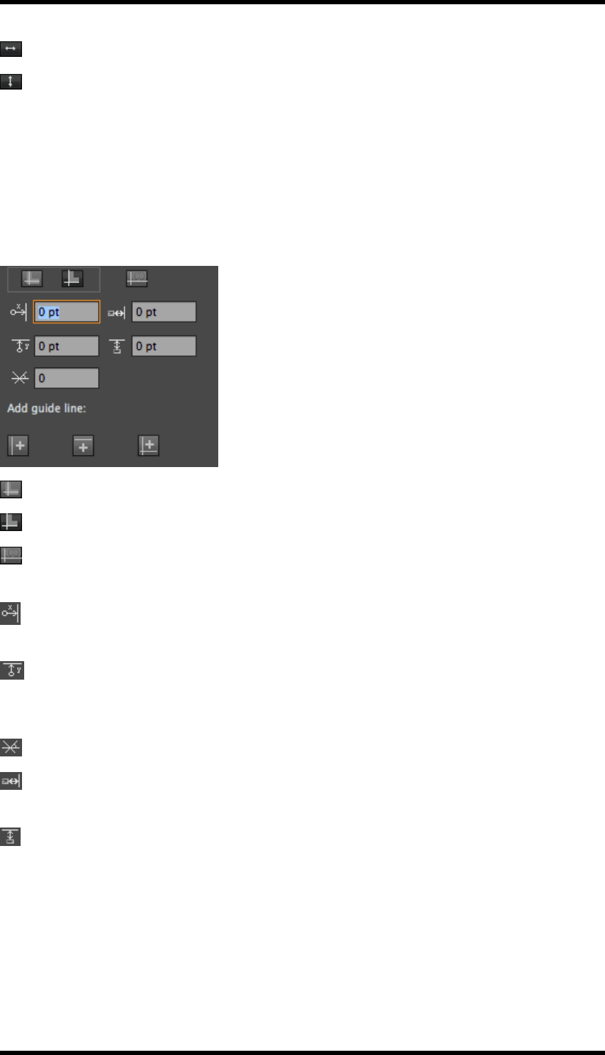
These are displayed by enabling the Show Options option from the side pull-down menu.
Art Bounds- Aligns to the border line of the object.
Visual Bounds – Aligns to the visible border of the object
Align Ruler Origin – Sets the current position of the RP Guide to be the origin. This is used in
the controls described below.
Vertical guide position – Used to position the vertical guide relative to the ruler origin position.
(Positive values will move the guide to the right; negative values will move the guide to the left).
Horizontal guide position - Used to position the horizontal guide relative to the ruler origin
position. (Positive values will move the guide upwards; negative values will move the guide, down-
wards).
Rotation Angle – Sets the angle of the guides. (Values are between -45 and +45 degrees).
Horizontal Offset – Sets the horizontal offset between the object and the guide to be applied
when alignment is performed.
Vertical Offset – Sets the vertical offset between the object and the guide to be applied when
alignment is performed.
Add Guide line: These options are also available from the side pull-down menu.
Set X Line as vertical guide line – Converts the vertical RP Guide line to a vertical AI guide.
- 60 -

9. Tool
Set Y Line as horizontal guide line – Converts the horizontal RP Guide line to a horizontal AI
guide.
Set XY lines as guide lines - Converts both RP Guide lines to AI guides.
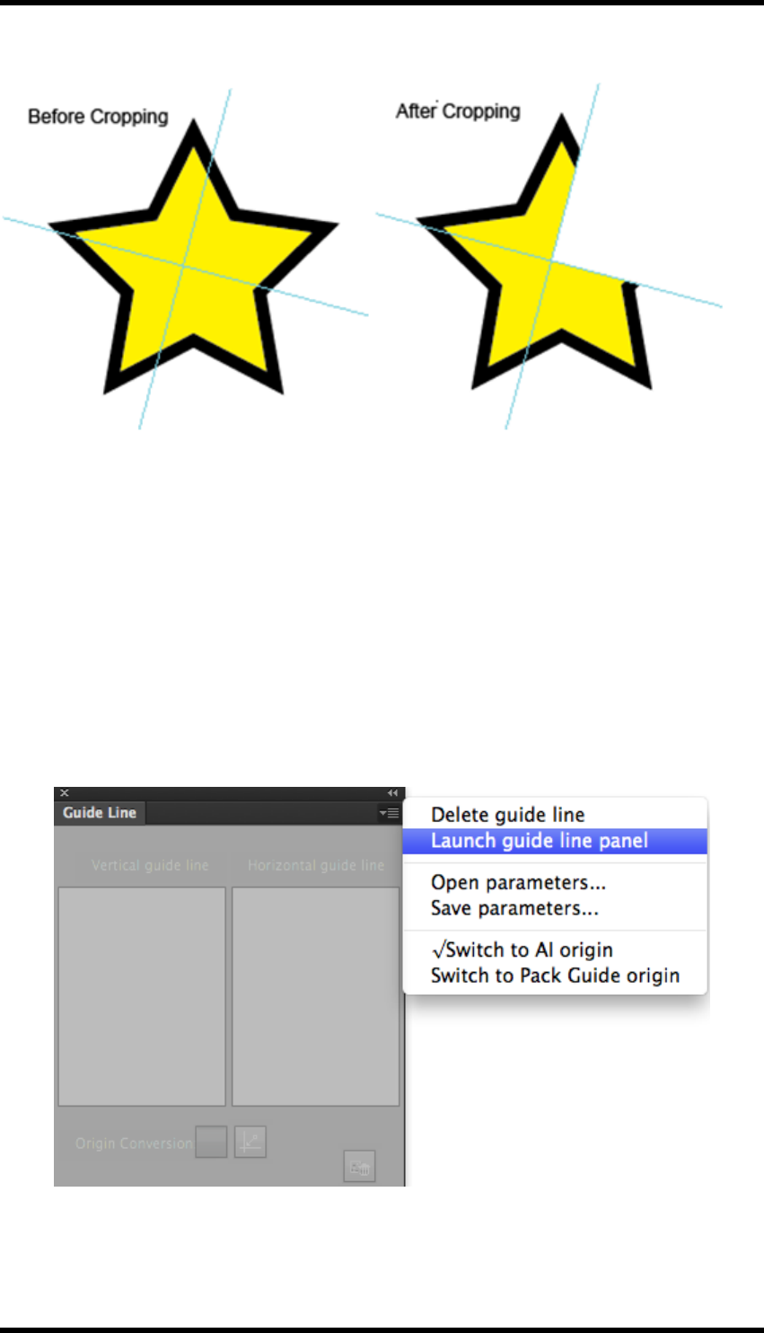
9.12. RP Clip
This tool allows the user to clip objects based on the four quadrants produced when the RP guide is
positioned over that object.
9.12.1 Usage
1. Select the object that is to be clipped.
2. Position the RP Guide over the object, effectively splitting the object into four quadrants.
3. Select Window > RealPro > Tool > RP Clip to open the RP Clip Tool.
The RP Clip interface is displayed.
4. Click on the icon that represents the quadrant that is to be cropped.
5. Click on the Clip button .
The object will be clipped as appropriate.
9.12.2 Example
The illustration below shows the result of clipping the upper right quadrant of the object.
- 61 -
9. Tool
9.13. Guide Line
The guide line tool allows the user to accurately position and to delete the AI guide lines.
The guide lines may have been created from RP Guides, or may be the standard AI guides.
Guides can only be moved or deleted if the AI Lock Guides function is disabled.
Sets of guide lines can be exported from the application for later use.
9.13.1 Usage
1. Select Window > RealPro > Tool > Guide Line to open the Guide Line Tool.
The Guide Line interface is displayed.
2. From the side pull-down menu select Launch guide line panel.
The interface will then show information relating to the AI guide(s). If any guides have been
- 62 -
9. Tool
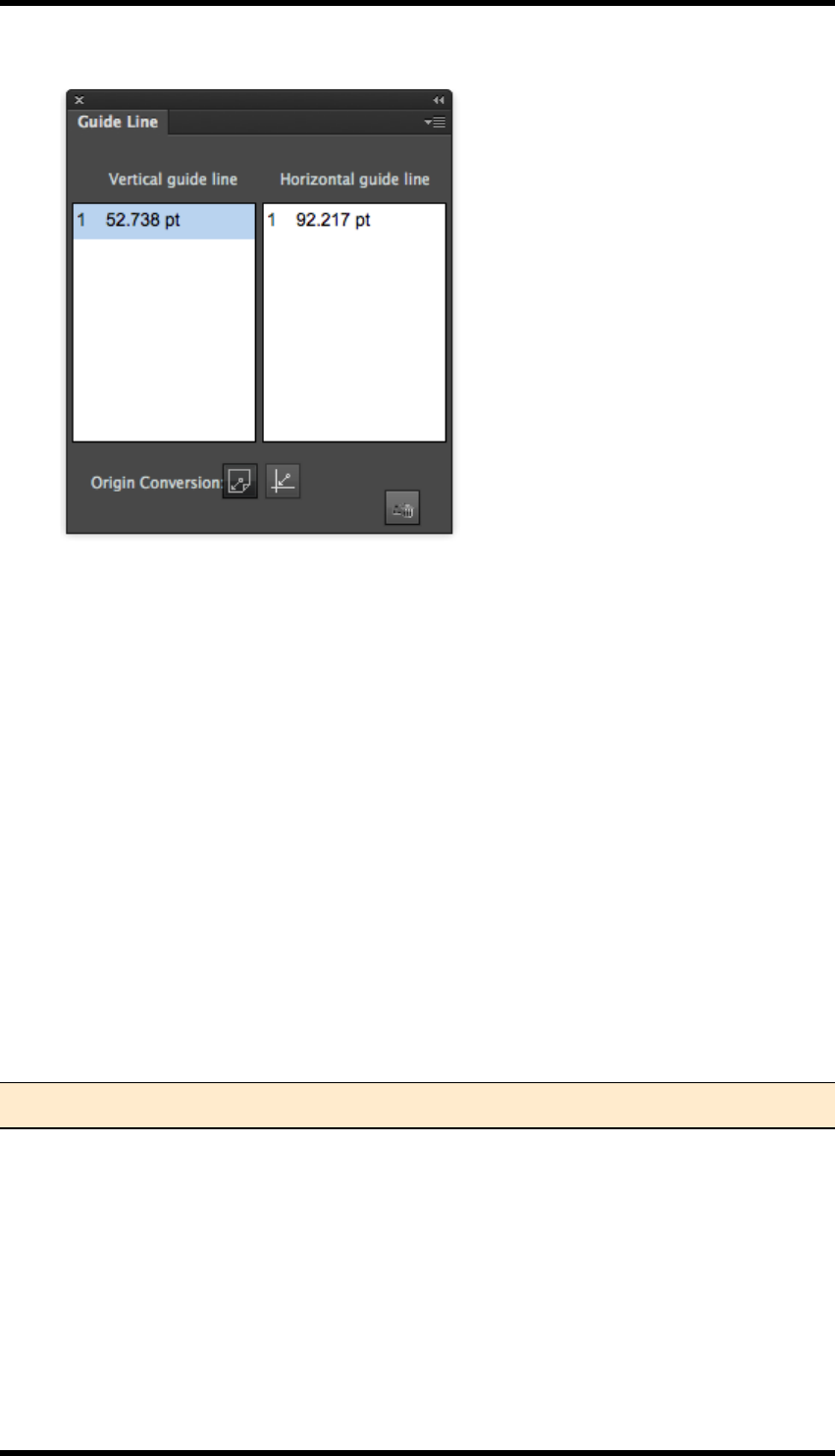
converted from RP Guides, then this will happen automatically.
By selecting the entry for a guide line, its position can be modified by over typing the values in the
fields, or removed by clicking Delete.
The value in the position field is relative to either the AI origin or the position of the RP Guide. (If
available). Switching between the two origins is achieved by clicking on the Origin Conversion but-
tons, or from the side pull-down menu options.
Guides can be saved as parameter sets:
1. From the side pull-down menu, select Save Parameters…
A navigation dialogue box will be displayed.
2. Navigate to the required location and save the parameters as a Guide Line Set (.fpg) file.
To use a previously saved Guide Line Set:
1. From the side pull-down menu, select Open Parameters…
2. Navigate to the required file and click Open.
Note: Any existing guides will be replaced by those defined in the imported set.
- 63 -

10. Eye
10. Eye
10.1. Overview
The Eye plug-in contains two elements, a Preview function which allows the operator to see an
accurate representation of the document when printed, and a tool which the operator can use to Nav-
igate around the document.
The Preview tool has a number of useful options which aid the operator in determining whether to
document is suitable for printing or not:
lControls to display some or all of the inks.
lShowing area where the dot percentage is below or above operator determined ranges.
lDisplaying areas where the total ink coverage is above an operator defined level.
lFile comparison, allowing the operator to easily detect change between versions of doc-
uments.
lAbility to turn on or off the trap data for display.
lNormal, positive and negative preview modes.
lZoom controls allowing zoom factor of up to 100000 %.
lEye dropper tool
lMeasurement tool
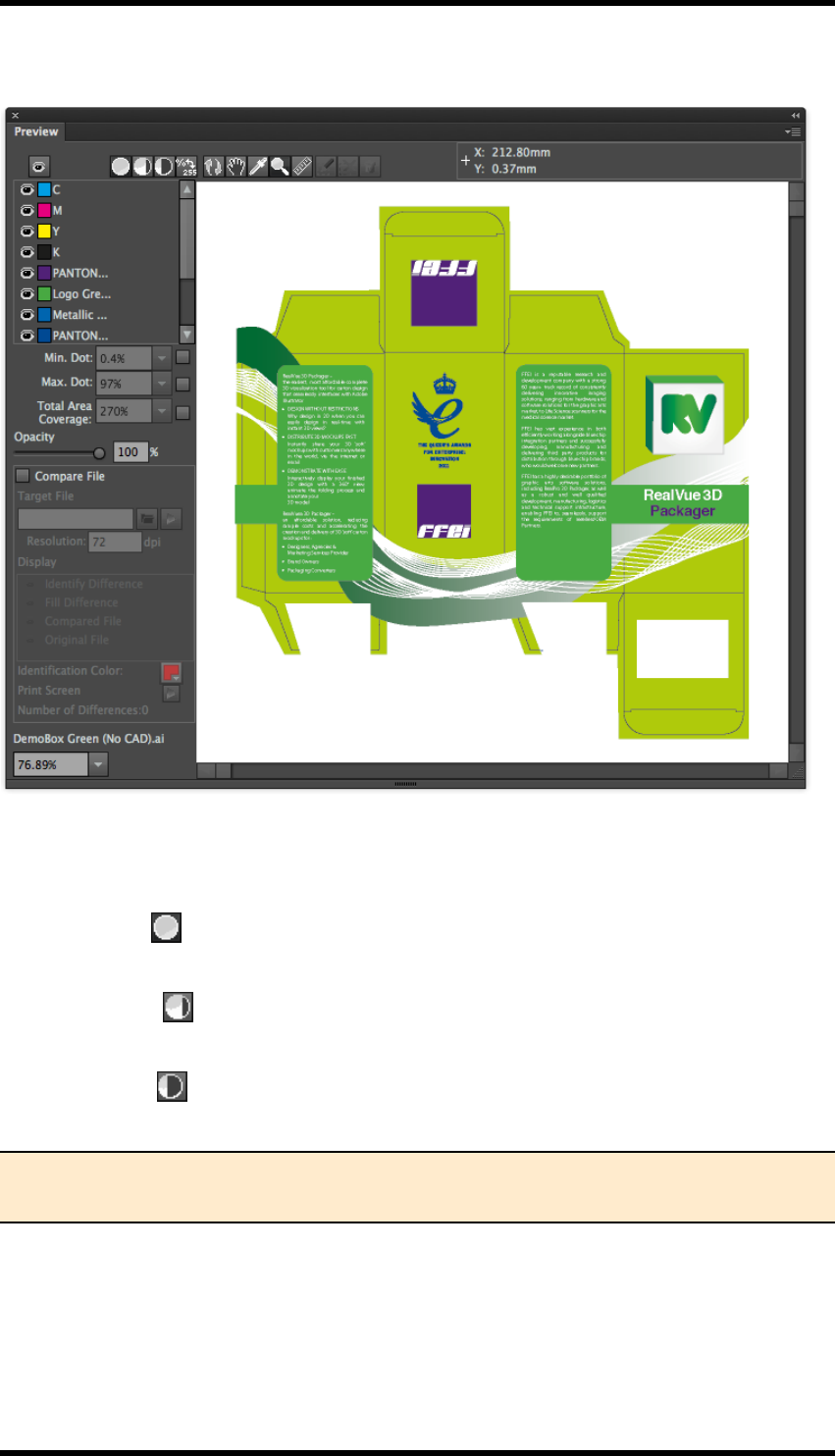
10.2. Preview
Select Window > RealPro > Eye > Preview to open the preview window.
When the Preview window is opened for the first time, no data is displayed. The operator must first
either click on the Update Preview button , or select Update Preview from the side pull-down
menu.
- 64 -
10. Eye
10.2.1 GUI
Toolbar Controls
Preview Mode
Normal Preview
Displays the selected separations. The separations are selected from the ink panel.
Negative Preview
Displays a single separation as a negative image. The separation is selected from the ink panel.
Positive Preview
Displays a single separation as a positive image. The separation is selected from the ink panel.
Note: If multiple inks are displayed before selecting Negative or Positive preview modes,
the first selected ink in the ink list will be displayed.
When switching back to Normal preview mode, only the ink displayed in Negative or Positive mode
will be selected. The operator should then select the remaining inks required.
- 65 -
10. Eye
Ink density display selector
Determines how ink densities are shown, toggles between numeric values & percentages.
Update Preview
Refreshes the display. Document edits made in AI are NOT automatically reflected in the preview
window.
Hand Tool
When selected, the cursor changes to a ‘hand’. Clicking and dragging, allows the image to be
moved within the preview window.
Eye Dropper Tool
When selected, left-click on a single point on the image to display the ink density values at that
point in the ink panel.
Note: The way in which the ink density is displayed, is dependant upon the ‘Ink density
display selector described above.
Zoom Tool
When selected, the cursor will change to a magnifying glass with a +, a single mouse click will
zoom into the image, centring about the cursor position.
Magnification factors are: 0.5, 1, 2, 4, 8, 16, 24, 32, 64, 100.
Holding down the Option key (MacOS) or Alt key (Windows) will cause the cursor to change to a
magnifying glass with a -, a single mouse click will then zoom out.
Alternatively the zoom tool can be used to draw a bounding box to surround the area to be mag-
nified. Hold down the left-hand mouse button and drag across the area to be enlarged.
The magnification factor can also be set using the control at the bottom left of the preview window.
Measure Tool
When selected, the cursor changes to a +. Holding down the left-hand mouse button allows the oper-
ator to draw a straight line between two points.
The following information is then displayed in the toolbar:
X: ‘X’ co-ordinate of the line start point
Y: ‘Y’ co-ordinate of the line start point
W: Relative X co-ordinate of the line end point
H: Relative Y co-ordinate of the line end point
D: Distance between start and end points
- 66 -

10. Eye
Angle: Angle between the start and end points measured relative to the X axis.
When the mouse is released, the line is no longer displayed, but the values remain in the toolbar
until a new line is drawn or a different tool selected.
Contrast Area Tools (Used when comparing two files)
Draw Contrast Area
Delete Contrast Area
Delete Contrast Result
Options Panel
Ink Selection
Clicking on the ‘eye’ icon next to the ink swatch and name will select/deselect the individual ink for
display. There is a global select/deselect button above the ink selection panel.
If the Eye dropper tool is selected, the ink density will be displayed next to the ink name in this
panel.
Minimum Dot
To enable this function, select the check box at the right of the control.
The display will then only show areas where any single ink dot percentage is equal to or less than
the value displayed in the pull-down menu.
The values can be selected from the pull-down menu or entered manually.
Maximum Dot
To enable this function, select the check box at the right of the control.
The display will then only show areas where any single ink dot percentage is equal to or greater than
the value displayed in the pull-down menu.
The values can be selected from the pull-down menu or entered manually.
Total Area Coverage
To enable this function, select the check box at the right of the control.
The display will then only show areas where the total ink coverage is either equal to or greater than
the value displayed in the pull-down menu.
The values can be selected from the pull-down menu or entered manually.
- 67 -

10. Eye
Opacity
The opacity control allows the operator to vary the opacity of the inks displayed. This can be used to
highlight trapping issues.
The slider control can be used to set the opacity, or a value entered into the field.
Compare File
This function can be used to identify differences between different versions of the same file. The cur-
rently open document is compared with one that has already been created.
The Compare File function is enabled by selecting the Compare Files check-box.
Target File
The name of file to be compared with the currently open document can be manually entered in the
Target File field, or the operator can browse to the file by clicking on the ‘folder’ icon.
When the file has been identified, click on the ‘Compare File’ icon to compare the files.
The default behaviour is to compare the whole document, but use of the Draw Contrast Area, Delete
Contrast Area and Delete Contrast Result tools in the Preview toolbar allow the operator to refine
the selection used.
2.1.3.2 Draw Contrast Area
Used to draw a bounding box which limits the area to be compared. (Only available if the Compare
File function has not been done).
Delete Contrast Area
Deletes the current Contrast Area. (Only available if the Compare File function has not been done).
Delete Contrast Result
Removes any highlighting of compared areas, allowing the contrast area to be deleted or a new area
defined.
Resolution
The resolution used by the system to compare the files should be selected. Range is from 72 dpi to
9999 dpi. The higher the resolution, the greater the detail that can be compared, but the longer the
process will take.
Display options
During file comparison the operator can choose the content in the preview window:
Identify Difference – Each different area is identified with a unique number and shown using a 2 pt
line boundary.
Fill Differences – All pixels that are different are highlighted.
- 68 -

10. Eye
Compared File – Displays the document selected as the target file.
Original File – Displays the current AI document.
Note: Only the target OR the current document can be displayed at any one time.
2.1.3.7 Identification Colour
Differences between the documents are highlighted in the Preview window in the colour selected as
the Identification Colour. (Double-click on the colour swatch to change).
Print Screen
Clicking on the ‘Print Screen’ icon will generate an Adobe PDF file containing a screen-shot of the
Preview display.
Other information
The number of different areas between the current AI document and the target file is displayed.
2.1.4 Information Window
Displays the name of the currently open document
2.1.5 Side Pull-Down Menu Controls
This section describes the usage of any options not previously documented.
Show Options
When enabled, the preview window will display all the ink data and the controls in the options panel.
When disabled, the preview window only shows the ink selection and magnification tools and the
information window.
Show Trapping Layers
If trapping layers exist in the document they can be viewed or hidden using this control.
Show Ruler
Displays or hides rulers at the left and top of the preview window.
Eye Preference
Controls whether dot percentages are ROUNDED up to the nearest full value when using the eye
dropper tool, or if EXACT values, (to two decimal places), are to be shown.
Calculate Ink Area
Selecting this option will generate a text file summarising the amount of each ink to be used in order
to print the document.
- 69 -

10. Eye
Ignore Small Difference
Outline Preview
When selected, the Preview window will display only paths and compound paths from the AI doc-
ument.
When in outline preview mode the standard preview controls are disabled or hidden. Path editing
tools, (as described in Chapter 7 of this document) are made available and can be used to modify
the document outlines.
Ink Match
The Ink Match functionality allows the operator to map an ink used in the original document to a dif-
ferent ink used in the compared document. This prevents the systemfrom reporting differences just
caused by colour changes.
- 70 -
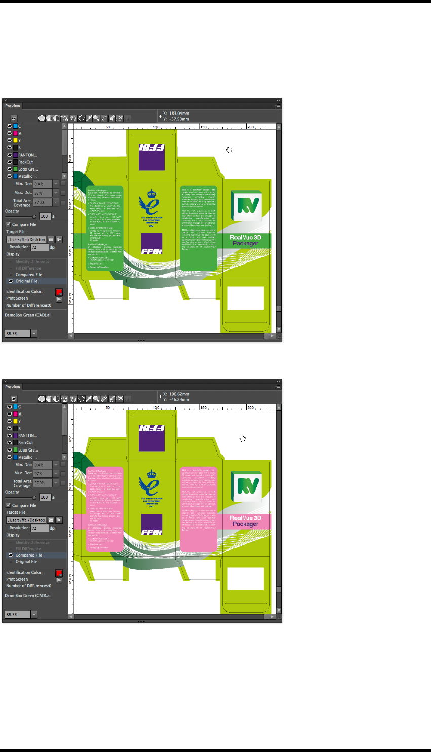
10. Eye
Ink Match Example:
Consider the case where the only difference between two documents is colour usage.
Original Document.
Compared Document:
Without using Ink Matchwhen the compare function is used, the result is shown below:
- 71 -
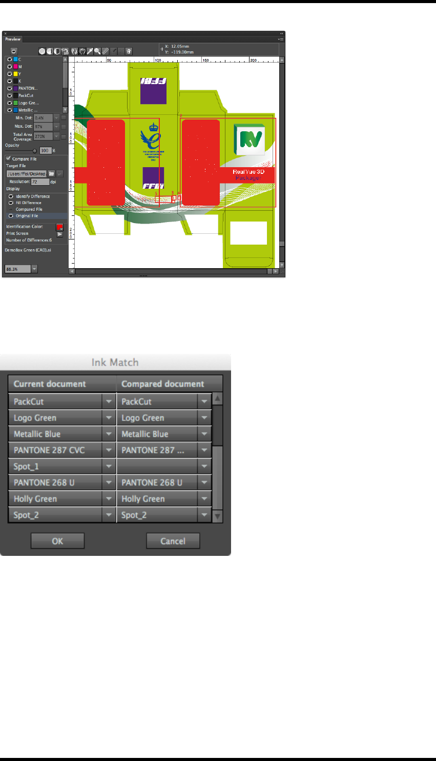
10. Eye
To prevent the system reporting the colour differences, the ink "Spot_1" in the original document
needs to be mapped to the ink "Pink" in the second.
Select InkMatch from the side pull-down menu. The Ink Match palette is displayed.
Spot_1 has no equivalent ink in the compared document.
Map Spot_1 to Pink by selecting from the list of inks in the compared document. (see below)
- 72 -
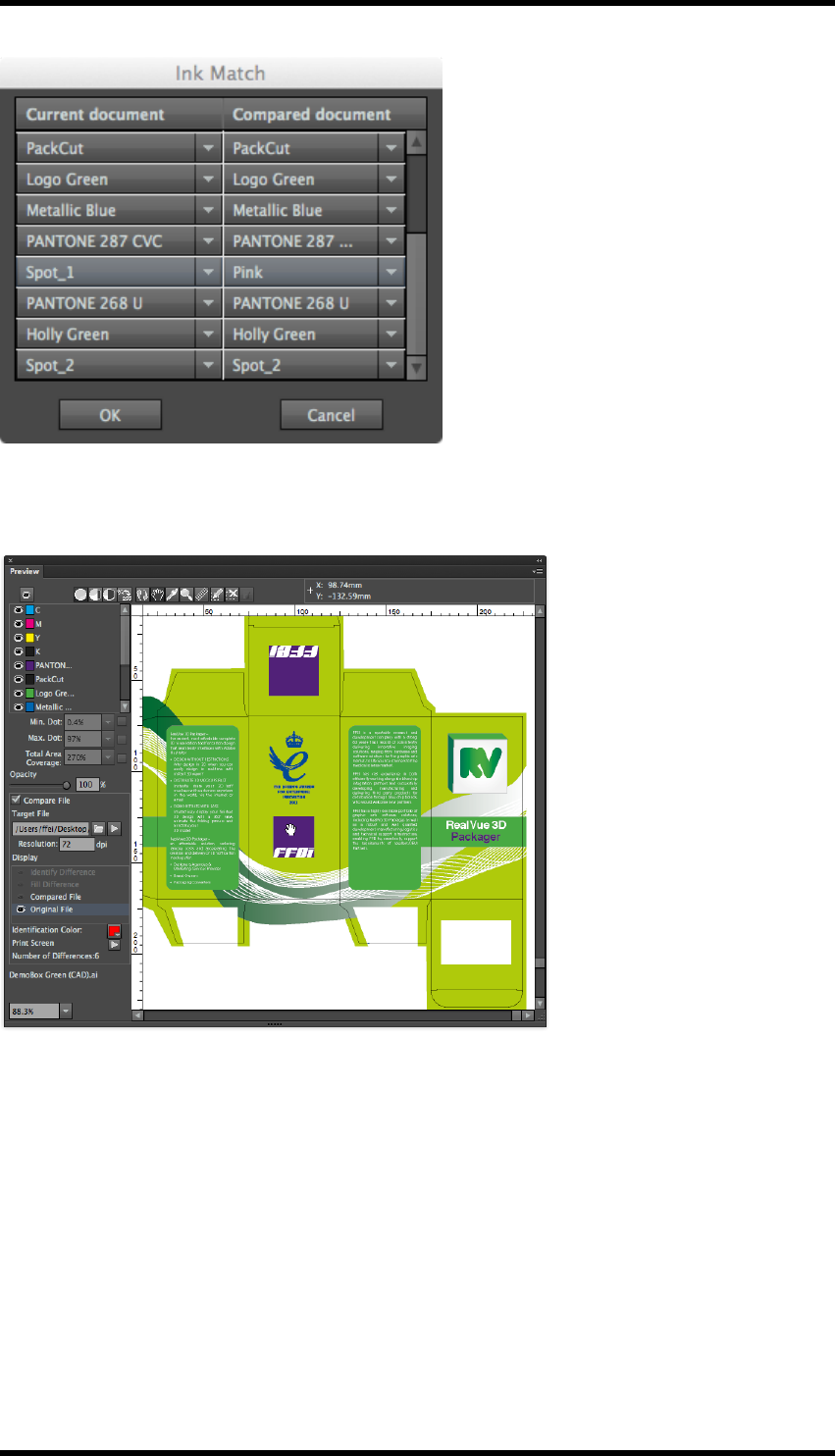
10. Eye
Click on OK to apply the match.
Comparing the two documents now delivers the following result.
10.3. Navigator
The navigator tool provides the operator with a simple method of displaying different parts of the AI
document in the preview window.
- 73 -
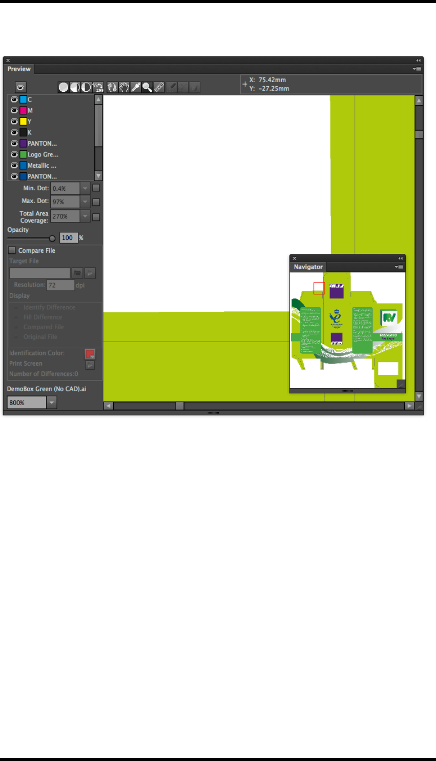
10. Eye
10.3.1 GUI
10.3.2 Usage
To display the navigator window select Window > RealPro > Eye > Navigator
The navigator displays a red bounding box representing the area of the document currently dis-
played within the preview window.
By clicking, (or clicking and dragging), in the navigator window, the operator can move the red bound-
ing box and so change the part of the document displayed in the preview window.
The Navigator tool can show either the whole AI document or just the artboard dependant upon the
setting available in the side pull-down menu.
10.4. Limitations
1. If there are more than 27 spot colours shown in the AI colour panel, the preview window will
not display
2. The Preview window will not display objects on non-printable or hidden layers
3. Images in DCS1.0 format cannot be displayed
- 74 -

10. Eye
4. The compare file functionality can only be used with AI, PDF or EPS files
- 75 -

11. Trap
11. Trap
11.1. Overview
The Trap plug-in offers four major functions:
lAutomatic Trapping:
The parameters used by the trap engine are defined in user created ‘Trap Tickets’. Tickets
can be stored within the application or exported to an external file.
Traps can be applied to selected objects or to all objects in the document.
The process creates ‘Colour Pairs’ and ‘Trap Edges’ who’s trapping characteristics can be
independently modified.
lInteractive Trapping.
Traps are applied in a defined area to a selected object. The parameters are defined at the
time the trapping is performed
lRich Black.
Applies a specific amount of one ink to a dark colour, usually Black..
lWhite Underprint.
Creates a ‘white’ background beneath selected, or all, objects. Typically used when printing
on a metal or transparent substrate.
The data generated by the trapping process is placed in new layers in the AI document allowing
straight forward viewing and editing. (Each run of the automatic trapping routine creates a new
layer).
Trapping uses information about the inks in the document in order to generate the correct result.
Because of this it is important that the Ink Manager is updated prior to carrying out any of the trap-
ping functions.
11.2. Automatic Trapping
11.2.1 Usage
Create or modify a Trap Ticket.
Select the objects in the document to be trapped.
‘Run’ the trapping engine
Check the Trap Colour Pairs produced and modify if required.
11.2.2 Trap Ticket
The trap ticket contains the parameters used by the trapping tool when the Automatic Trapping func-
tion is used. Multiple tickets may be created and stored within the application. They can also be
exported for use on other systems, or to be stored centrally.
- 76 -
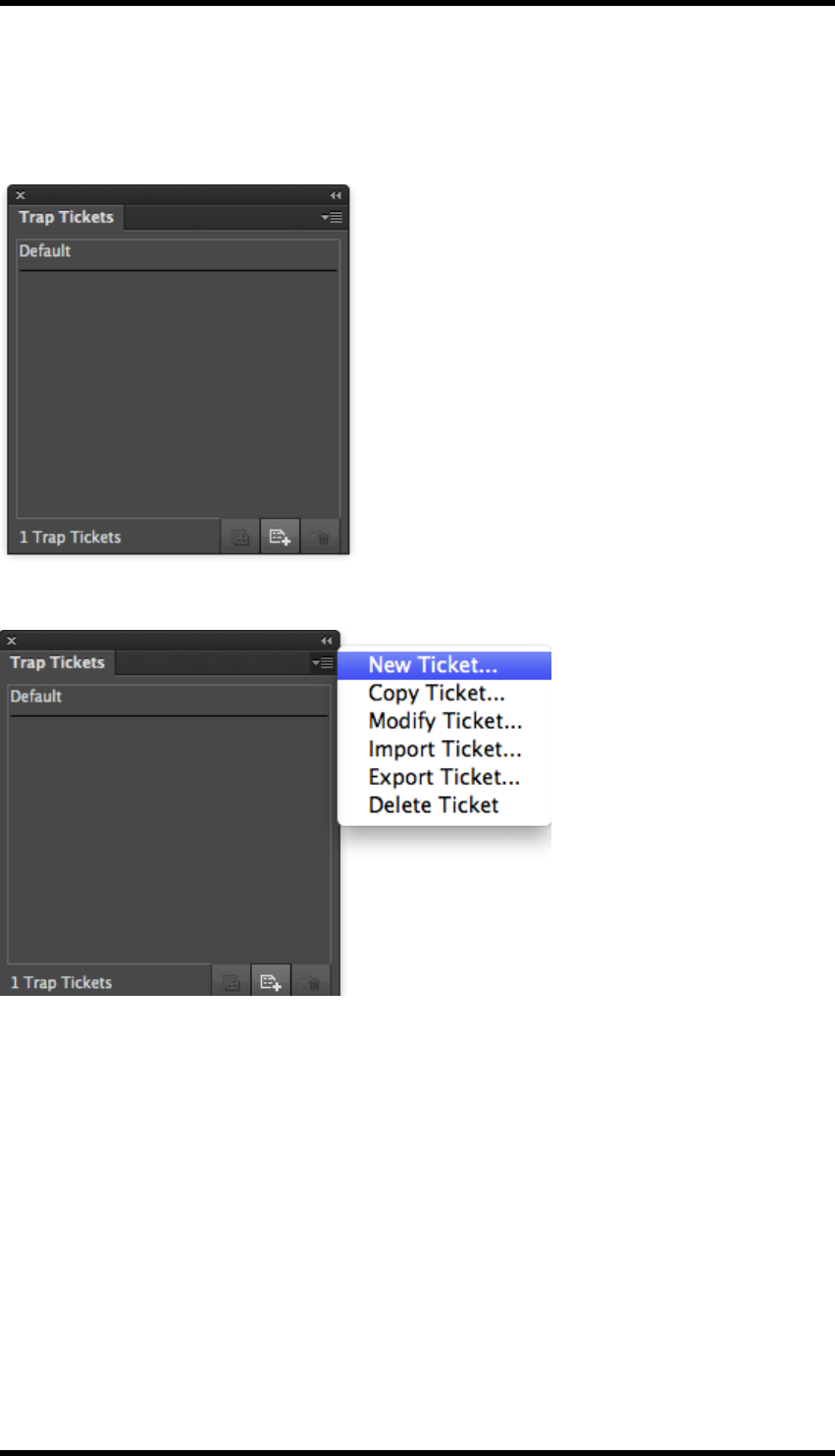
11. Trap
Usage
To display the Trap Ticket widow either select Window > RealPro > Trap > Trap Ticket or use
the keyboard shortcut: Shift+Ctrl+U.
The side pull-down menu provides controls for managing the tickets
The ‘Default’ ticket can be modified, but cannot be deleted.
lNew Ticket…
Creates a new ticket using system default settings
lCopy Ticket…
Creates a copy of the selected ticket
lModify Ticket…
Allows the selected ticket to be edited.
lImport Ticket…
Imports a previously exported ticket.
- 77 -
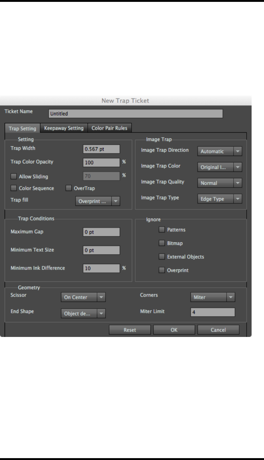
11. Trap
lExport Ticket…
Exports trap ticket data to an external file.
lDelete Ticket
Deletes the selected ticket.(Default ticket can not be deleted).
Trap Ticket Parameters
The trap ticket parameters can be set when creating a new ticket or modifying an existing ticket.
Ticket Name
Sets the name of the ticket, default for new tickets is ‘Untitled’.
Trap Setting
Trap settings set the parameters of normal trapping.
Trap Width
Use this parameter to set the width of the trapping area that will be generated
- 78 -
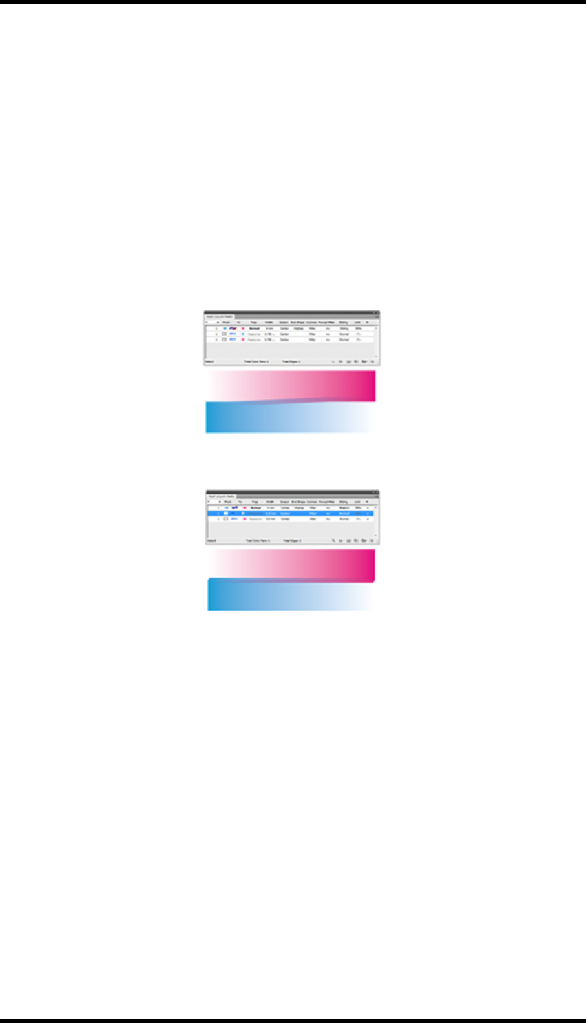
11. Trap
Trap Colour Opacity
Use this parameter to set the colour depth of the trapping area generated by two objects. The default
parameter is 100%. At this setting the trapping area colour is at its darkest which may cause this
trapping area to be more visible. Reducing the parameter value will reduce the strength of the trap-
ping area colour.
Allow Sliding
Select this option to implement a sliding gradient trap. The trapping engine adjusts (slides) the trap
position from spreading the lighter colour into the darker one by straddling the centre line between
the two. A sliding trap prevents abrupt shifts in the trap element, for example along a gradient edge,
behind a vignette.
Sliding Trap
Bilateral 50%
Use the % option in sliding trap to set the point at which the trap changes direction, to ensure a
smooth transition. A setting of 100% will force a sharp change of trapping direction, 0% will force a
constant centre line trap.
Colour Sequence
When enabled the trap direction will be consistent with the set colour sequence in the ink man-
agement box. The trap rule is that the colour with the smaller colour sequence number enters the
one with the larger colour sequence number.
For example: If we are given three colours: C, M and Y. We arrange two different colour sequences
using the ink management box, then there will be two different results after the colour sequence trap
is executed.
- 79 -
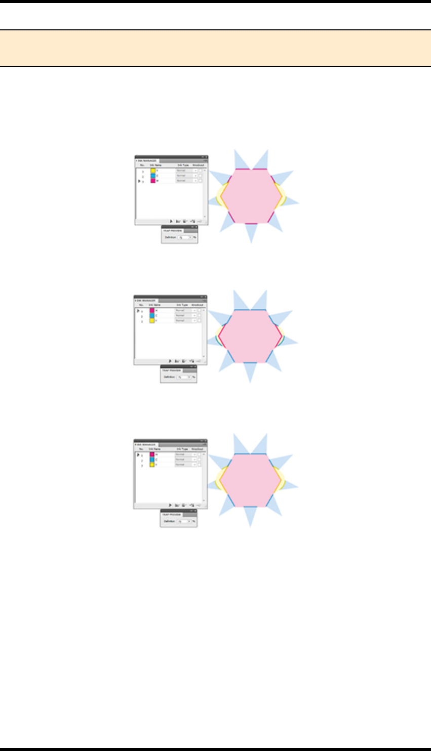
11. Trap
Note: Darken and Darken Image trap should only be used with Adobe PDF Print Engine
RIPs that offer live transparency support.
The basic rule for trapping is that lighter inks enter darker ones. By setting this control the definition
of which ink is darker than the other is defined by the order of the inks in the Ink Manager. In which
case the rule becomes: The ink with the lower ink sequence number enters the ink with the higher
sequence number.
Light to Dark Colour sequence trap on
Dark to Light Colour Sequence Trap on
Colour Sequence Trap off
When Colour sequence is switched off the trapping will not necessarily follow the ink sequence
defined in the Ink Manager.
Trap Fill
This setting determines the attributes applied to the trap objects.
lOverprint Fill
Trap will have an overprint attribute - Trap opacity is controlled by changing the colour of the
fill.
- 80 -

11. Trap
lDarken
The trap object will use the transparency setting ‘darken’. Darken selects the base or blend
colour—whichever is darker—as the resulting colour. Areas lighter than the blend colour are
replaced. Areas darker than the blend colour do not change. Opacity is controlled by trans-
parency.
lDarken Image trap
Any image trap area will have a darken transparency setting; remaining objects will be set to
overprint.
lWhite knockout
Trap is filled with white and set to knockout. - Used for print processes where the colours will
bleed and mix creating different pigment, such as screen printing on cans.
Image Trap Direction
Sets the direction of image traps
lAutomatic:
Trap automatically determines and generates the direction from light to dark in accordance
with the trapping rules.
lTrap Image to Artwork:
Forces the trapping direction to expand from the images to the artwork.
lTrap Artwork to Image:
Forces the trapping direction to expand from the artwork to the images.
Image Trap Colour
Set the colour type of image trap
lOriginal Image data
Original image data uses (if possible) data in the image which is hidden by clipping mask.
This creates a much more natural trap. If the image is not clipped the Image expansion is
used instead.
lImage Expansion
Image expansion will expand the image by replicating the pixels at the edge of the image,
thus allowing data to be created that would otherwise be unavailable.
Image Trap Quality
Image trapping has to process the image content in order to create a trap. This processing takes
time. In some cases when the document is complex it can not only take a long time but use sig-
nificant amount of memory. For this reason the trap quality can be adjusted to avoid shortfall in com-
puter resources.
- 81 -

11. Trap
lCoarse – Lowest quality
lNormal
lFine – Highest quality
Image Trap Type
This setting determines the source of data for the image trap.
lEdge Type:
Extract the colour from the pixels of the image edge to pad.
lInside Type:
Extract the colour from the pixels inside of the image (excluding the edge) to pad.
Maximum Gap
Occasionally two colours next to each other are designed in such a way that a small gap is left
between them. In this case the default trapping behaviour may cause effects that are not desired.
RealPro Toolkit can ‘fill’ these gaps with an adjoining colour, thus avoiding unwanted trap effects.
The Parameter setting range is 0 pt. to 1 pt. If the distance (gap) between the two objects is smaller
than this parameter value, then the gap will be filled. If the gap width is bigger that the defined value,
then it will not fill and normal trapping will take place.
Example 1:
Original artwork has a small gap between graphics.
Result of trapping without a maximum gap value
set.
Yellow ‘gap’ has been trapped to the magenta and to
the cyan.
- 82 -
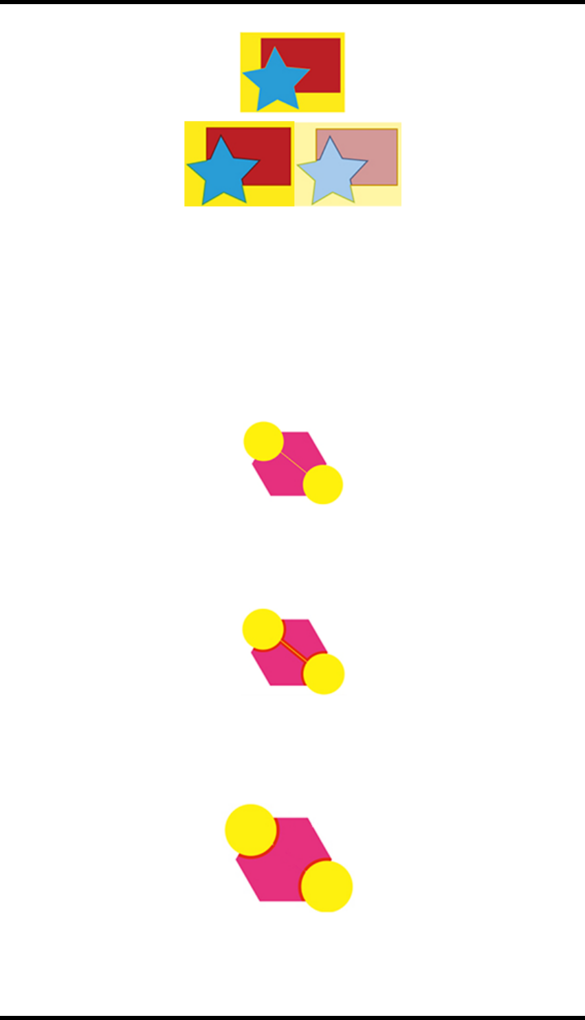
11. Trap
Result of trapping with maximum gap set.
Gap has been filled with cyan and traps to the
magenta.
Example 2:
Original object
A fine line, (gap), exists between the two yellow col-
our areas
Result of trapping without a maximum gap value
set.
A trap has been created each side of yellow line.
- 83 -

11. Trap
Result of trapping with maximum gap set.
The yellow line has been filled by the adjacent colour
and no trap generated.
Minimum Text size
If the font size is greater than this parameter, then it will meet the conditions for trapping and will gen-
erate a new trap; if not, then no trap will be created.
Minimum Ink Difference
This parameter will have an impact on whether or not two adjacent objects will trap. If the two
objects do not have an ink in common, then a trap will be generated.
If the two objects do have common Inks, two of those common inks must have a difference greater
than this value before a trap is created. Additionally, in the first object one ink must be darker than in
the second object, and one ink must be lighter.
Ignore
Use this option to set the objects to not be involved in trapping.
lPatterns: Use this option to control whether or not to ignore pattern objects of AI. If unse-
lected, patterns will be involved in trapping. If selected, the pattern objects will be ignored.
lBitmap: Use this option to control whether or not to ignore bitmap objects. If unselected, bit-
maps will be involved in trapping. If selected, the bitmap objects will be ignored.
lExternal Objects: Use this option to control whether or not to ignore external objects of AI. If
unselected, external objects will be involved in trapping. If selected, the external objects will
be ignored.
lOverprint: Use this option to control whether or not to ignore overprint. If unselected, over-
print will be involved in trapping. If selected, the overprint will be ignored.
Scissor
This parameter is used to set the end position of the trapping area, to prevent the trapping area going
over the border of a trapped object and creating a significant change to the trap area. There are two
options:
lOn Edge: The trapping area ends at the edges of the object being trapping into.
- 84 -

11. Trap
lOn Centre: The trapping area ends at the centre between the trapping object and object
being trapped into.
No Trapping On Edge On Centre
End Shape
This parameter is used to set the contour shape of the trapping area entering into another object.
Three are three options:
lSquare: Generate a right-angle endpoint
lRound: Generate a rounded end point.
lObject dependant: Based on the light-coloured object to extend. (See below)
The original file before trapping
- 85 -

11. Trap
The trapping effect of “Square” End Shape
The trapping effect of “Object dependant” End Shape
Corners
This parameter is used to set the corner-point shape of the trapping area.
lMitre: Use this option to change the corner to a mitred (pointed) tip
lRound: Use this option to change to a rounded corner
- 86 -

11. Trap
lBevelled: Use this option to change to a bevelled corner
Mitre Limit: (Only available if Corners setting is Mitre)
To prevent unsightly traps, where the length of the trap is disproportionate to the width, it is possible
to limit the size of a mitre corners, and replace with a bevelled corner.
A bevelled corner will be applied if the length of the trap is greater than the width of the trap mul-
tiplied by the Mitre Limit value.
Where the length of the trap is equal to, or less than, the width of the trap multiplied by the Mitre
Limit value, a mitred corner is used.
Keepaway Settings
Keepaway Width
This parameter is used to set the width of inward contraction of light colour from the outside to the
inside of the dark object.
Minimum Text Size
If the font size is greater than this parameter, it will meet the conditions for trapping, and will gen-
erate a new trap; if not, then no trap will be created.
Scissor
This parameter is used to set the termination position of the trapping area, to prevent the trapping
area going over the border of a trapped object and creating a significant change to the trap area.
lOn Edge: The trapping area ends at the edges of the object being trapping into.
lOn Centre: The trapping area ends at the centre between the trapping object and object
being trapped into.
Ignore
Use this option to set the objects not involved in keepaway trapping.
lPatterns: Use this option to control whether or not to ignore pattern objects of AI. If unse-
lected, patterns will be involved in trapping. If selected, the pattern objects will be ignored.
lGradients & Images: Use this option to control whether or not to ignore gradients & images.
If unselected, gradients & images will be involved in trapping. If selected, gradients & images
will be ignored.
lExternal Objects: Use this option to control whether or not to ignore external objects of AI. If
unselected, external objects will be involved in trapping. If selected, the external objects will
be ignored.
lLuminance: After selecting this option, any colour containing two or more inks will be
trapped. The differences in brightness between these inks will not be considered.
- 87 -

11. Trap
Colour Pair Rules
Colour Pair Rules can be defined to override the standard parameters when creating traps between
specific colours or object types.
If a number of Colour Pair Rules are created, then the top rule in the dialogue box is given priority
over those below. If a pair of objects meet the criteria for a number of rules, then the settings of the
uppermost one will be applied.
New
Use this button to create a new colour pair rule.
Modify
Use this button to modify the selected colour pair rules.
Remove
Use this button to delete the selected colour pair rules
Move Up
Use this button to raise the priority level of the selected colour pair. One click will cause the selec-
ted colour pair to move up one level.
Move Down
Use this button to reduce the priority level of the selected colour rule. One click will cause the selec-
ted colour rule to move down one level.
New Colour Pair Rule
This dialogue box contains the description of the colour pairs. The colour specified under the “From”
heading will expand into the colour specified under the “To” heading.
- 88 -
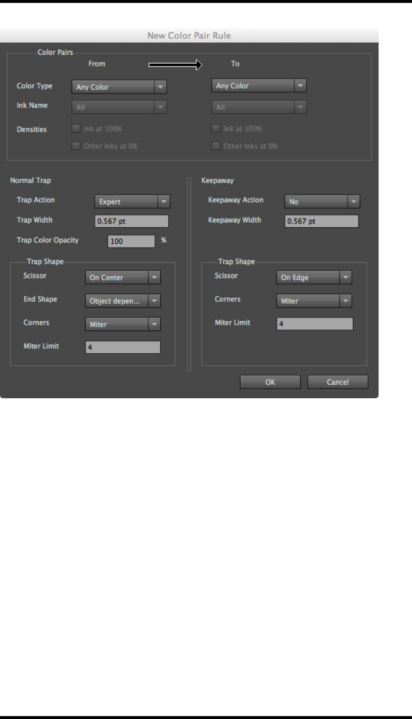
11. Trap
Colour Type
Any Colour: All colours which are used in the document.
Process Colour: The colours used in the document that are composed with CMYK inks.
Spot Colour: Pantone, DIC, Toyo and custom spot colour in the document.
Image: Any continuous tone or raster images.
Gradient: Any objects with gradient effect in the document.
Empty Background: The empty objects in the document will implement keepaway trapping.
Registration Colour: Objects composed of all inks used in the job.
Opaque Ink: The object that contains at least one opaque ink.
Ink Name
When the selected ink type is spot ink, then the ink name option will be activated. This colour rule
only can take effect on the specified colour, not all default colours.
- 89 -

11. Trap
Densities
When the selected ink type is process ink or spot ink, then the densities option will be activated.
Ink at 100%
If this option is selected, then the current colour pair rules only can take effect on an object that has
an ink percentage of 100%; if this option is not selected, then the current colour pair rules will affect
objects of any ink percentage.
Other Inks at 0%
If this option is selected, then the current colour pair rules only can take effect on an object without
other inks; if this option is not selected, then the current colour pair rules also can work on an object
with other inks.
Trap Action
Expert
Allow the system to decide whether or not to implement trapping for the colour pairs defined.
Force
Trapping will always take place between the colour pairs defined.
No
No trapping between the colours defined will take place.
11.2.3 Trap Colour Pairs
The Trap Colour Pairs window is displayed immediately after automatic trapping has been carried
out. It can also be opened by selecting Window > RealPro > Trap > Colour Pairs
- 90 -
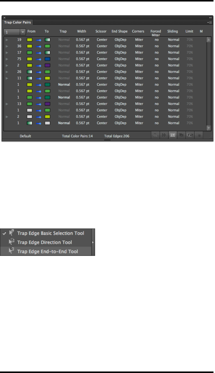
11. Trap
General
The window lists all the generated trap edges, grouping them into colour pairs. The parameters for
each edge can be modified. The parameters can also be modified at a colour pair level, affecting all
the edges in that colour pair group. When there are multiple edges with the same colour pair, a tri-
angular icon is displayed to the left of the pair. Click on the icon to expand the list to show all trap
edge data. (Click on the icon again to collapse the list).
Tools
Three Trap Edge tools exist in the AI toolbar.
lTrap Edge Basic Selection Tool: Selects a single trap edge.
lTrap Edge Direction Tool: Sets the direction of the trap.
lTrap Edge End-to-End Tool: Selects all trap areas between two points on an object.
Selecting Trap Results
Each time the automatic trapping routine is run, a new set of trap data is created. The results from
individual runs can be shown, or the results from All runs displayed by selecting from the pull-down
menu.
- 91 -
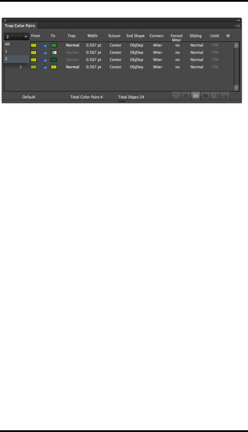
11. Trap
From + To
These columns graphically illustrate the colours that make up the colour pair, the arrow between
them shows the trap direction.
The arrow indicates: single direction trap, bi directional trap, sliding trap or suspected trap.
Trap Type
Three types; normal, keepaway or composite. The system displays the type of trap used. However,
when the colour being entered by the trap is made up from multiple inks, the user can choose to
keep the ink with the lowest luminance value by selecting Composite.
The remaining parameters associated with the colour pairs are described earlier in this chapter.
M
This column is used to indicate whether or not a parameter has been changed:
Blank: No modification
* A parameter has been modified but the trap has not been updated.
o A parameter has been modified and the trap has been updated.
Examining the trap data
Select either the Colour Pair or the Trap Edge.
Click on the Zoom In button. The display will then zoom in to the required edge(s).
Click on the Next Trap Edge button to navigate to the next edge.
Trap Edge Colour
Click on this button to set the colour that the trap edge is displayed in. This is the colour used by the
system to identify the edge and has no effect on the trap data itself.
Changing Trap Direction
Select either the Colour Pair or the Trap Edge.
- 92 -

11. Trap
Click on the Switch Colour Pair button. This will swap the colours in the from / to columns and will
update the trap data immediately.
Using the Trap Edge Direction Tool will also change the trap direction. (When selected, draw a line
across the trap area in the direction that the trap is required).
Updating Trap Data
When a trap parameter has been modified, the trap should be updated by clicking on the Update
Trap button.
Removing Traps
Select either the Colour Pair or the Trap Edge.
Click the Delete button, a confirmation screen is displayed, select Yes, the selected traps are
removed.
Side Pull-Down Menu Options
Save Colour Pairs
Colour pair information can be saved in the AI document by enabling Save Colour Pairs. If this is not
enabled, the trap layer is saved, but can not be modified using this tool. (Only the latest colour pair
information is saved).
Show Details …
This option is only enabled if a colour pair or trap edge is selected.
Clicking on this option opens the Colour Pair Details dialogue box which displays the details of the
trap. For a normal trap the Opacity of the trap area can be set. In the case of a keepaway trap, the
Keep parameter sets the colour to be kept.
(The Colour Pair Details dialogue box can also be displayed by double clicking on a colour pair or
edge from the Trap colour Pair window).
Show Suspected Colour Pairs
Colour pairs that don’t meet the trap conditions are classified as suspected colour pairs. Selecting
the option Show Suspected Colour Pairs lists those pairs after the normal pairs, showing a trap
width of 0. If the operator wants these colour pairs to trap, select the pair and modify the trap para-
meters as required.
Hide Unselected Colour Pairs
Clicking on the option causes the Trap Colour Pair window to display only selected colour pair or
trap edge information.
Show All Edges
Clicking on this option will enable the display of ALL trap edge information.
- 93 -
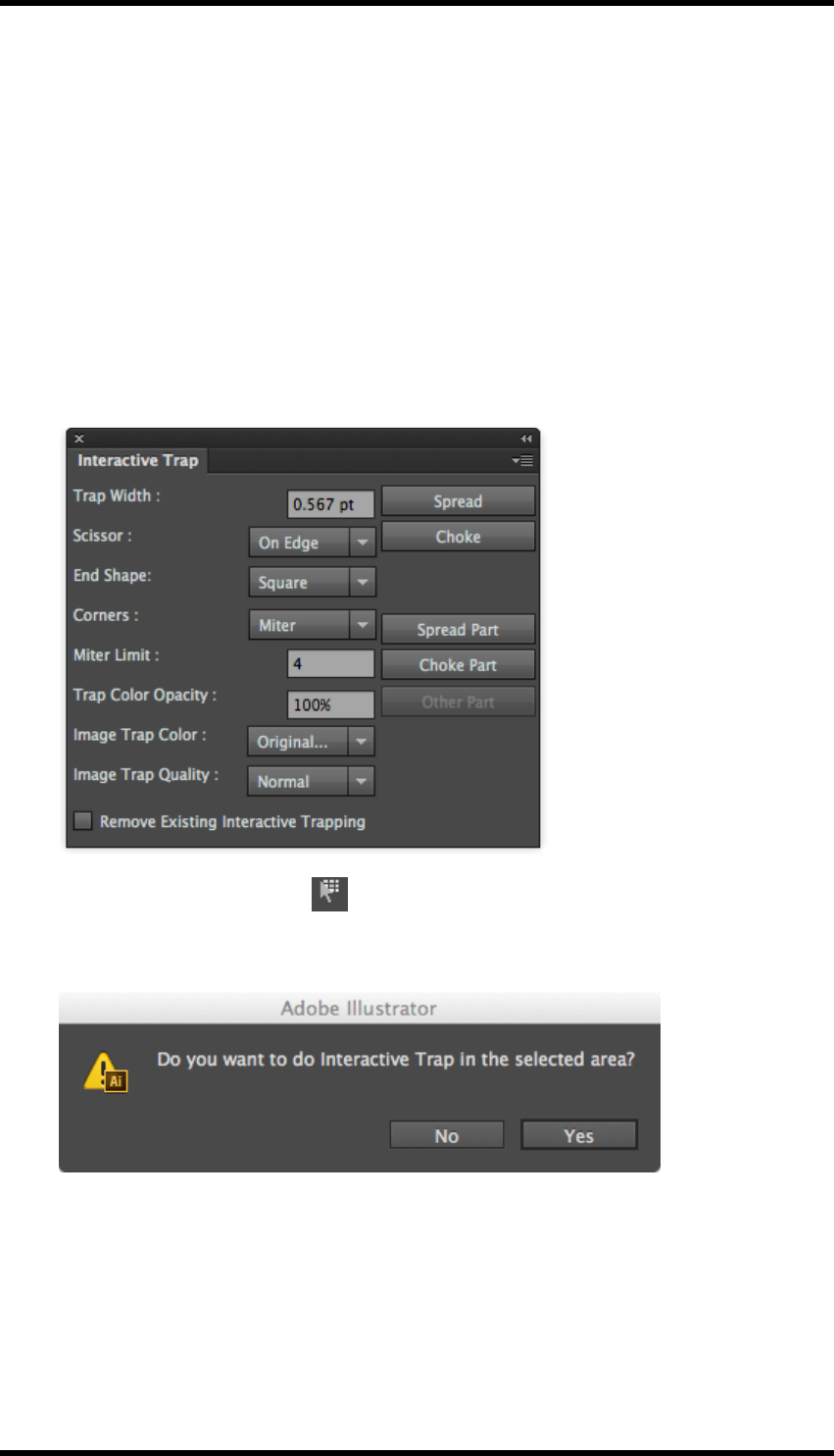
11. Trap
11.3. Interactive Trapping
11.3.1 Overview
Interactive trapping allows the operator to select which objects trap and set parameters for those
traps.
11.3.2 Usage
1. To start interactive trapping, click on the Interactive Trap Tool on the AI toolbar.
The Interactive Trap dialogue box will be displayed. (This dialogue box can be displayed at
any time by selecting
Window > RealPro > Trap > Interactive Trap).
2. With the Interactive Trap Tool selected, draw a bounding box to select all the objects to
be affected by the trap.
The following confirmation box is displayed:
3. Click Yes
4. Now select the single object that should trap to the others previously selected.
5. From the Interactive Trap dialogue box set the trapping parameters and select either Spread
or Choke as required.
This will create the trap in a new AI layer named Interactive Trap-x, where x is the number of
- 94 -
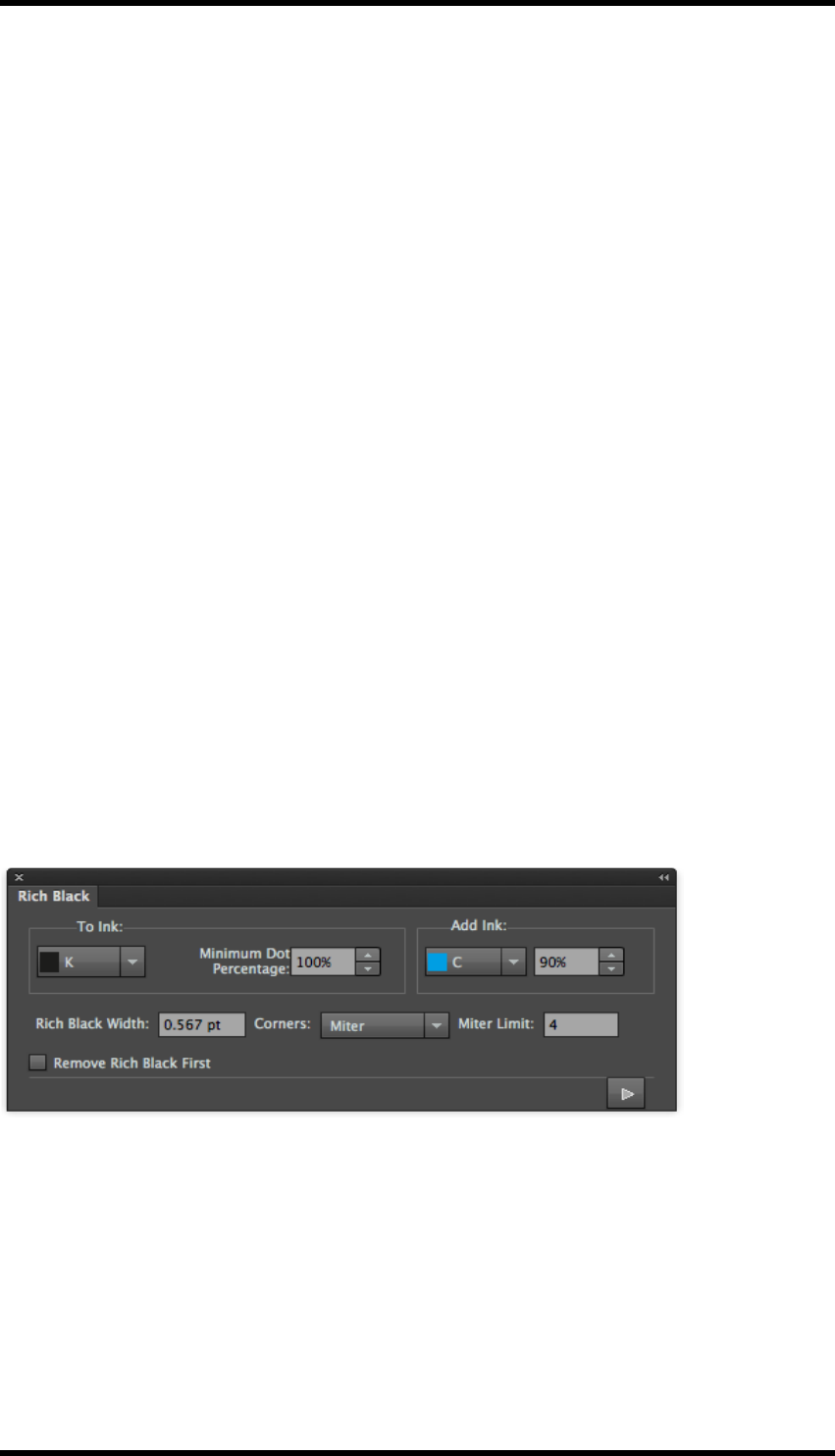
11. Trap
the Interactive trap run. (If required the trap area can be removed by deleting the layer).
6. If only a part of the object is to be trapped, click on the Spread Part or Choke Part button, the
cursor will change to a scissor icon. Click on the start point of the edge to be trapped, and
then on the end point. An X will be displayed at either end. The trap will then only be created
between those points.
7. It is possible that the operation described above will result in the wrong part of an object
being trapped, In this case click on Other Part, the previously non-trapped part of the object
edge will then have trapping applied, the original trap area being removed.
8. Remove Existing Interactive Trapping.
9. If you wish to delete previously created interactive trapping data, then this option should be
selected.
11.4. Rich Black
11.4.1 Overview
The Rich Black functionality adds a specified percentage of one ink to another. This is normally
used to create a ‘rich black’ by adding a dark ink to the black, but can be used to add any ink to any
other.
11.4.2 Usage
Select the object(s) which require the Rich Black functionality applied.
Select Window > RealPro > Trap > Rich Black
Parameters
To Ink
The ink to which the additional ink will be added.
Minimum dot percentage
If the dot percentage of the To Ink is less than this value, no ink will be added.
- 95 -

11. Trap
Add Ink
The ink and dot percentage of that ink that will be added
Rich Black Width
This parameter sets whether or not the ink spreads or chokes at the object edge and the width of
that spread/choke. A positive value creates a spread; a negative value creates a choke.
Corners
See earlier definition in this chapter.
Miter Limit
See earlier definition in this chapter.
Remove Rich Black First
If selected, any existing Rich Black trapping areas are removed prior to execution.
Click the Apply button.
A Rich Black-x layer is created for the data, where x is the number of the Rich Black operation.
11.5. White Underprint
11.5.1 Overview
The white underprint function allows one ink to underprint an object or object. Typical usage would
be to lay down an area of white ink when printing on a metallic or transparent substrate.
11.5.2 Usage
Select the objects which require the underprint to be applied.
Select Window > RealPro > Trap > White Underprint
- 96 -
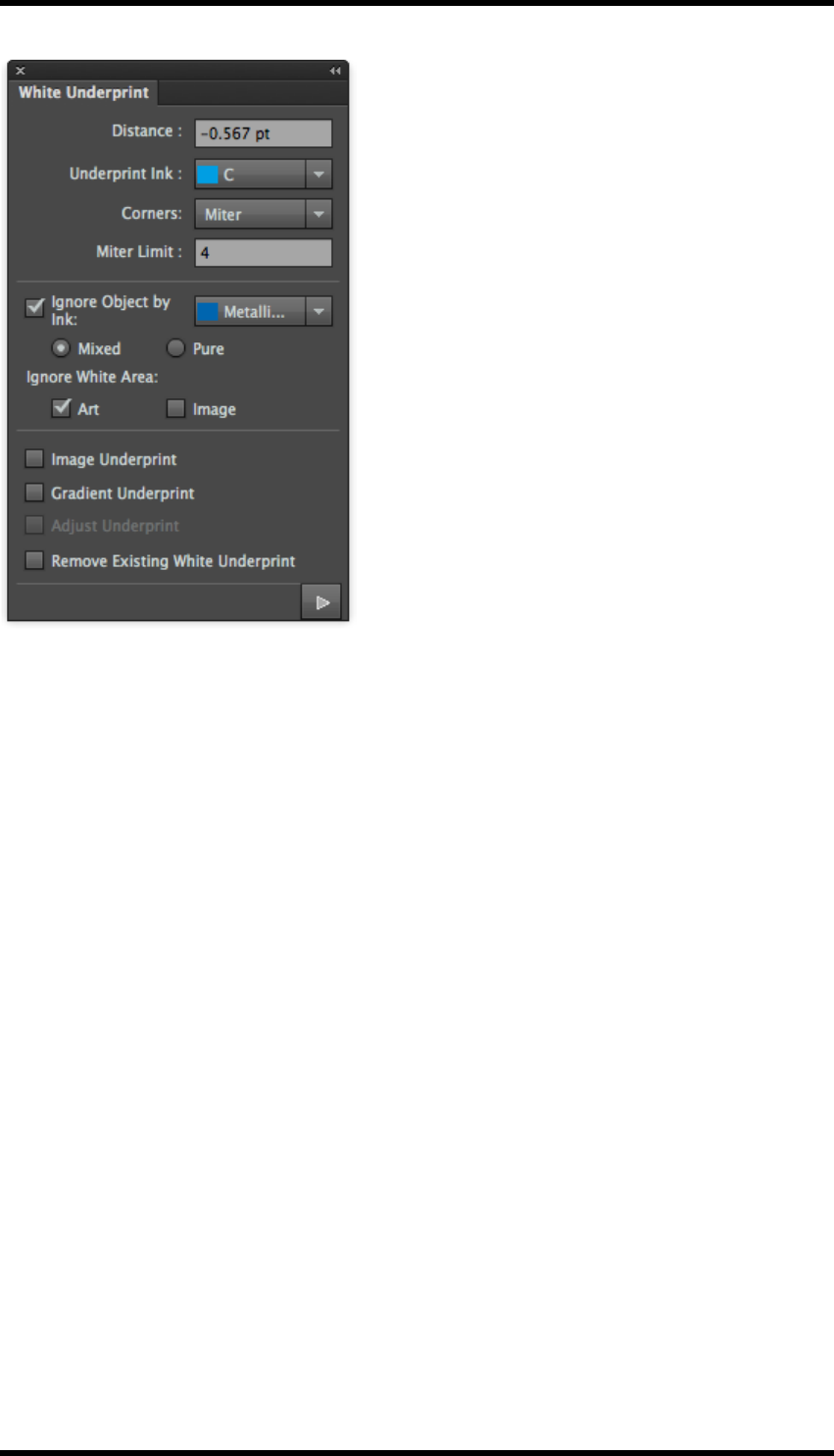
11. Trap
Parameters
Distance
This parameter sets whether or not the ink spreads or chokes at the object edge and the width of
that spread/choke. A positive value creates a spread; a negative value creates a choke.
Underprint Ink
Selects the underprinting ink.
Corners
See earlier definition in this chapter.
Miter Limit
See earlier definition in this chapter.
Ignore Object By Ink
Selects an ink where the white underprint function will not be applied.
Mixed
Do not apply to objects that contain the selected ink.
Pure
Do not apply to objects which only contain the selected ink.
- 97 -

11. Trap
Ignore White Area
These settings will cause the white underprint function to ignore areas where CMYK values are all
0.
Art
This setting will cause the white underprint function to ignore areas in artwork.
Image
This setting will cause the white underprint function to ignore areas in images.
Gradient Underprint
If selected, this option will cause the underprint to be generated as a gradient.
Image Underprint
When selected, the underprint associated with an image, will be generated as an image. The original
opacity effect of images with Alpha channel and Opacity Mask will be preserved.
Adjust Underprint
Adjust Underprint is used to create an “on-centre” effect between the underprint edge and white
objects.
Remove Existing White Underprint
If selected, any previously created white underprint areas are deleted.
Click the Apply button.
A White Underprint-x layer is created for the data, where x is the number of the White Underprint
operation.
11.6. Viewing the Trap Area
11.6.1 Trap Preview
This tool allows the operator to change the opacity of the non-trap layers in the AI document such
that the traps can be clearly seen.
To select the trap preview:
View >Trap Preview
An opacity control is displayed allowing the opacity of the non-trap layers to be changed for viewing
purposes.
- 98 -
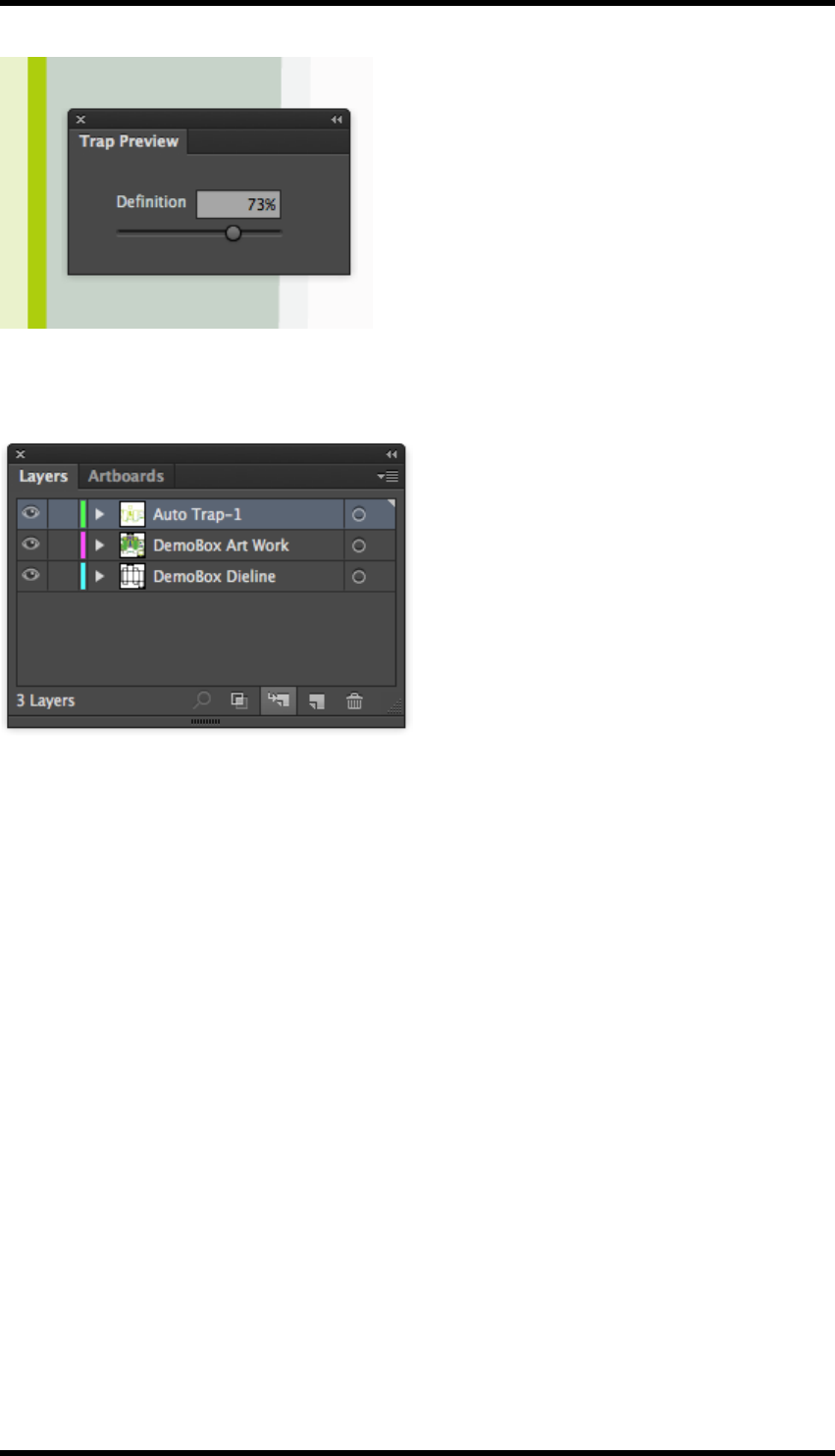
11. Trap
11.6.2 Using the AI Layer controls
The trap areas can be viewed in isolation by deselecting the other layers in the AI document.
11.7. Limitations
1. Keepaway operation is only available for an object on a white background. If the object is on
any other light colour background this operation cannot be implemented.
2. AI colour list can’t have more than 18 spot colours, if more than 18 colours exist, trapping will
not take place.
3. If the current file is RGB format, then it cannot be trapped.
4. Before using the Rich Black and White Underprint, it is necessary to execute the Update Ink
function for the current file.
5. The varnish inks and structural inks will not participate in the trapping operation.
6. After selecting the Allow Sliding option, the gradient object will not participate in the border
connection operation.
7. If any fonts originate from an AI version prior to CS3, they will need updating prior to trapping.
- 99 -

11. Trap
8. When the line-width is smaller than 0.005 pt, the trapping will have an abnormal effect,
because this kind of line will be deformed in AI.
- 100 -

12. Nest
12. Nest
12.1. Background
Following trapping, ink conversion and other preliminary pre-press processes, the package design
needs to be step & repeated in a layout to ensure efficient printing. A manual step & repeat process
is prone to errors because it is quite difficult to control the distances between the different package
shapes, apply the correct bleed and control other parameters that can create problems in post-press
when die-cutting and finishing the package.
When manually step & repeating a design in Adobe Illustrator (AI), it is necessary to copy the
object, add the station number to each object, and modify the overlapping parts. This is not only
very time-consuming and labour intensive, but the station number of each object cannot be guar-
anteed and the overlapping areas may be inconsistent.
Using Nest enables efficient step & repeating of objects to save paper and streamline the printing
process. You also can set station numbers and use Nest to find objects with overlapping areas. To
fix layout and step & repeat problems, you simply modify the parameters in Nest.
12.1.1 Terminology
In this guide, standard terms will be used to describe the components of step & repeat in order to
avoid confusion.
Box Structure – This term describes the CAD or AI file that contains the package
creasing and cutting information.
Box Artwork – This term describes the AI file that contains the package design and
artwork.
Artwork/Structure – This term describes an AI file that contains a single instance of
both the Box Artwork and the CAD box structure.
Layout Structure – This term describes a completed layout with no associated Box
Artwork (e.g. an existing cutter guide).
12.2. Overview
In this chapter we will be looking at the following:
Step & Repeat with Chart
Users can set a series of step & repeat parameters such as spacing, orientation etc. Saved para-
meter sets allow operators to create step & repeat layouts with the same parameters or predefined
logical formulae quickly and efficiently.
Settings and Formulae in Step and Repeat with Chart
Using formula is a good way to automate and standardise the step and repeat process.
- 101 -

12. Nest
Step & Repeat with CAD Layout
Use this tool to apply new Box Artworks on to existing Layout Structure. DXF and CFF2 format files
are supported. With this tool, the position of graphics is adjusted automatically which significantly
improves the efficiency of the step & repeat work.
Interactive Step & Repeat
This step & repeat method provides an object-oriented way of creating step & repeat layouts with
irregular boxes or boxes of different shapes.
Reverse CAD
This is used for flipping the CAD structure so that artwork printed on reverse of substrates can be
correctly aligned. This is common in label printing.
Align to margin
This is a useful tool for aligning stations or layouts in a step & repeat.
CAD
With this tool, the user identifies the structural elements by converting them to a special RealPro
CAD layer.
If existing files already use spot colours to specify structure lines (for example, from other applic-
ations) the user can set these as rules in a CAD ticket.
The Check CAD Breakpoint function is used to detect discontinuities in CAD structural elements.
Plate and Sheet Setup
With this tool, users can set the plate and sheet parameters such as size, relative position, etc.
There is a choice of preview modes: Show Linked File, Show Low Resolution Image or Show Bound-
ing Box.
Adding Station Numbers to the One-up file
This allows station or instance numbers to be added to the One-up units used in step and repeat lay-
outs.
Controlling Bleed and Overlap
Nest provides ‘Bleed Interspace’, ‘Bleed Outerspace’ mode, and a ‘Bleed All’ mode.
The “Adjust Overlap” function helps operators modify the overlap areas between different boxes eas-
ily.
RP Selection Tool
This tool allows users to select objects when editing or updating step and repeat layouts. It is avail-
able in the AI toolbar.
- 102 -
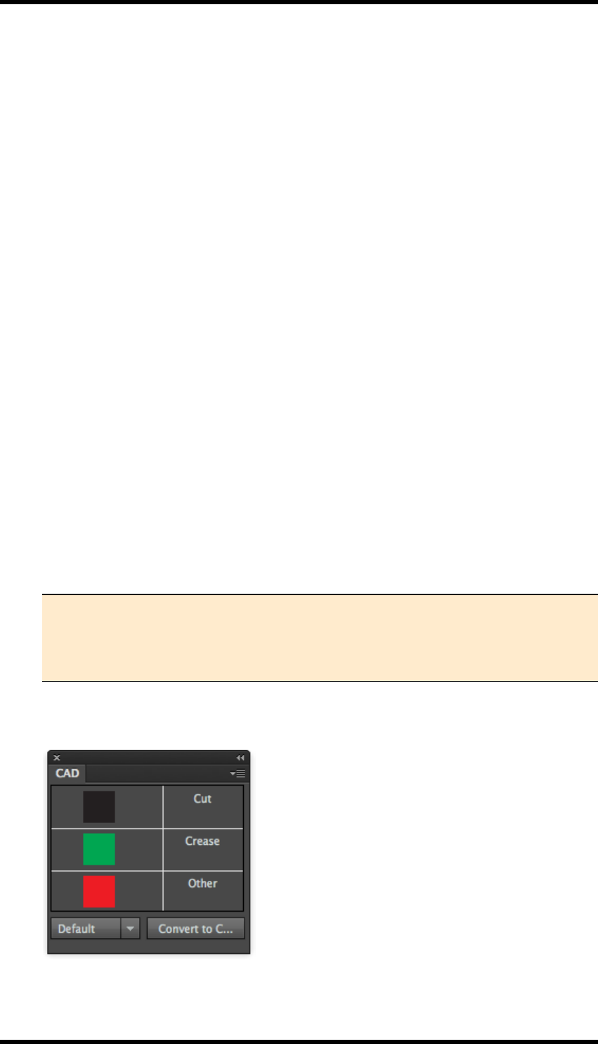
12. Nest
Anchor Tool
This tool allows users to adjust the distance between two stations in a step & repeat layout.
12.3. Step & Repeat With Chart
The Structure / Artwork unit must first be prepared for Step and Repeat with Chart
1. CAD layer is checked and combined with Artwork.
2. Media, trim and bleed for the unit are specified.
3. The Station number place-holder is added.
4. The final Structure / Artwork file is saved.
The Step and Repeat layout is created.
1. The paper and plate is defined.
2. The Structure / Artwork unit(s) are imported.
3. The units are step and repeated in the required layout.
4. Bleed and Overlap issues are resolved.
12.3.1 Preparing the Structure/Artwork Unit for Step & Repeat
1. Open the box structure file.
DXF format is supported by AI. RealPro Toolkit also provides support for CFF2 format.
2. Select Window > RealPro > Basic Function > Trim Box & Media Box.
The palette used for adding a trim box and media box to the CAD file is displayed.
Note : Trim and Media Box provides an easy method to set the PDF page boxes
for trim and media. These will be useful later when aligning units in the step and
repeat process. For more details on this function see the chapter on Basic Func-
tions.
3. Select Window > RealPro > Nest > CAD > CAD.
The CAD palette is displayed.
- 103 -
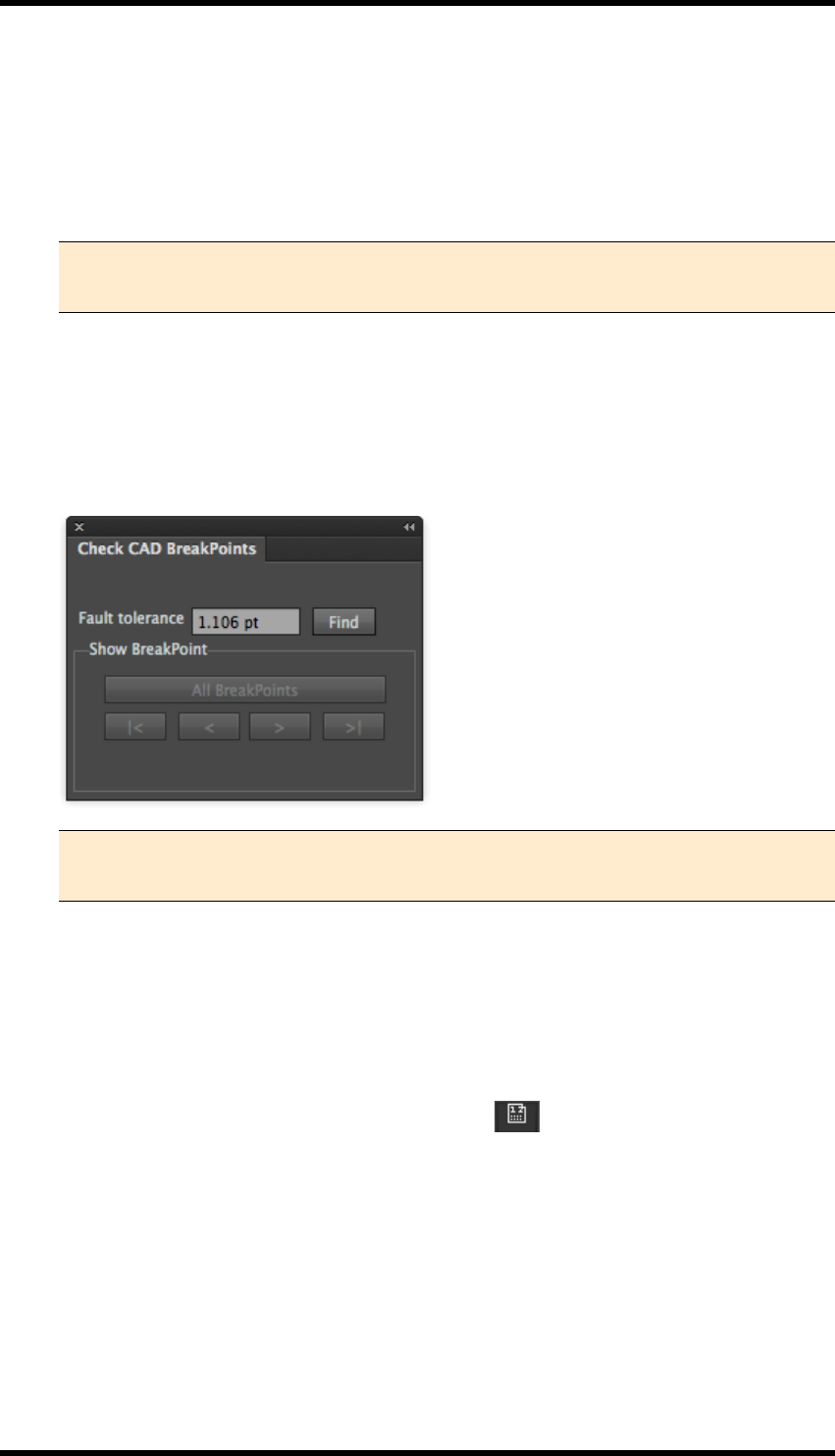
12. Nest
4. Select structural elements within the CAD file and the relevant element type from the CAD
palette (Cut, Crease or Other). Click the Convert to CAD button from the CAD panel.
The selected element from CAD file is converted to specified Nest CAD structural line type.
These are placed in a (locked) Nest CAD layer in the AI file. They remain visible in the AI lay-
out and will be drawn in the colour scheme of the CAD panel (e.g. Crease lines displayed in
green).
Note: CFF2 files do not need to be manually converted to CAD because this
format is automatically converted by RealPro Toolkit when it is opened.
The drop down list in the CAD palette contains any saved CAD Tickets. These allow the
user to specify rules for mapping named spot colours to specific structural line types, so that
CAD layers will be automatically identified. See 14.13
5. Select Window > RealPro> Nest > CAD > Check CAD Breakpoints.
The CAD Breakpoint palette is displayed.
Note: If the cutter has been used with RealVue 3D Packager then breakpoints are
automatically fixed.
6. Set the Fault tolerance value, and then click the Find button.
Potential discontinuities in the CAD design are highlighted in turn. Use the standard AI tools
to modify these into closed paths as required.
7. Import the Box Artwork and align it to the centre of the current CAD structure file.
8. From the AI Toolbar, select the Station Number tool .
The cursor will alter when this tool is in use. Click this tool where on the Artwork / Structure
you wish the station number to appear. This place holder position will be displayed as N.
When this Artwork/Structure is used in a Step & Repeat layout, this place-holder will be
replaced by the station (step) number.
9. Save this Artwork/Structure file for use in the Step & Repeat.
- 104 -
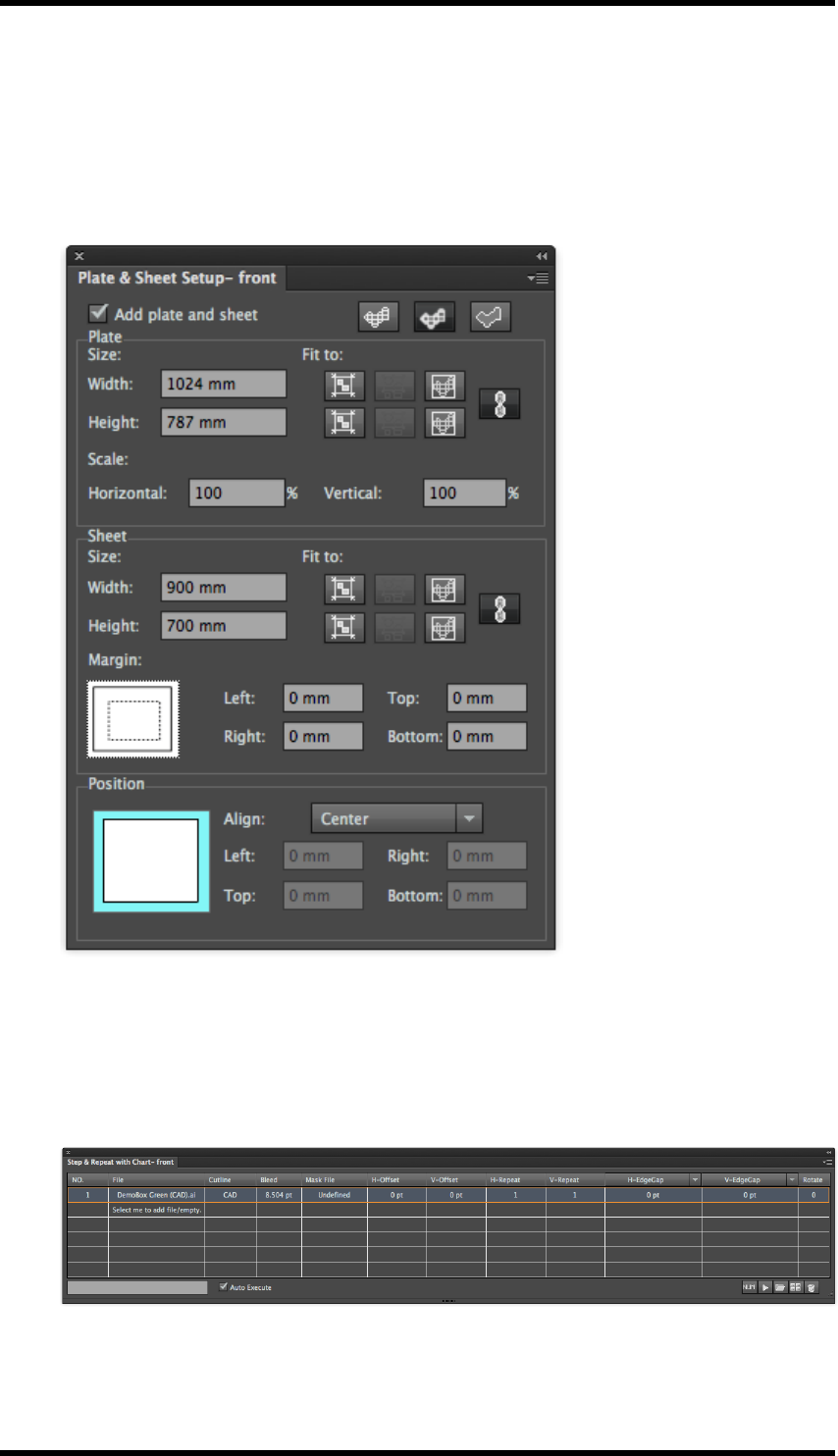
12. Nest
12.3.2 Step & Repeat
1. Create a new empty document.
2. Select Window > RealPro > Nest >Plate and Sheet Setup.
The Plate and Sheet Setup palette is displayed:
3. Add the printing plate and sheet sizes. In case of a digital press set this as the media and
printable area.
4. Select Window > RealPro > Nest > Step & Repeat with Chart.
a. Click Add File or Add Empty at the right bottom of this panel, and then browse to the file
you want to Step and repeat.
- 105 -
12. Nest
Note: Alternatively, One-up files can be imported into the Graphic Manager. These
will then appear in a drop-down list under ‘File’ in this
Files in the list may be duplicated (or replaced) by selecting a file in the list and holding down
the Alt key whilst dragging to a new position. The original parameters will be used when
duplicating file, and the parameters of the file being replaced will be used while replacing file.
b. Select Cutline pull-down list. Choose the parameter within the unit file, which will be used to
define the limits of the Cutline: CAD, CAD Bounding Box, Artboard or Bounding box. The
default value is CAD.
c. Set the bleed parameters using Bleed.
A Mask File maybe used optionally for complex bleed / artwork clipping.
d. Set the origin position of the unit file using H-Offset and V-Offset.
A number or formula can be input. (See below for details and examples)
e. Set the number or formula for the H-Repeat and V-Repeat.
f. Set the horizontal gap to H-EdgeGap, H-CenterGap or H-StructureGap.
A number or formula can be input. (See below for details and examples)
g. Set the vertical gap to V-EdgeGap, V-CenterGap or V-StructureGap,
A number or formula can be input. (See below for details and examples)
h. Set the orientation in “Rotate”.
After the Step and Repeat with Chart parameters have been set press the Execute button to
see the generated layout.
Note: The Execute button does not have to be used if the Auto Execute option is
checked.
Note : After the basic Step and repeat layout has been created the user should check
bleed and overlap: See 14.7 and 14.8
12.4. Settings and Formulae in Step and Repeat
For examples of standard parameter sets for Step and Repeat with Chart, see the
appendix at the end of this chapter.
The variables that can be used in Formulae are as follows:
Variable Description
PW Plate width
- 106 -
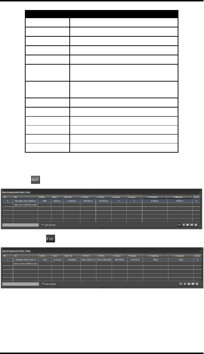
12. Nest
Variable Description
PH Plate height
SW Sheet width
SH Sheet height
MW Margin width
MH Margin height
OW[N] One-up width of No.[N] file (defined by Bounding
Box)
OH[N] One-up height of No.[N] file (defined by Bounding
Box)
OB[N] Bleed width of No.[N] one-up file
C[N] Column number of No.[N] one-up file
R[N] Row number of No.[N] one-up file
CGW[N] Centre gap width of No.[N] one-up file
CGH[N] Centre gap height of No.[N] one-up file
N Sequence number of step & repeat one-up file
F(x) / Num modes
To help when working with formulae, there is a view mode button; this switches between displaying
number values
…and entered formula .
Formulae can be entered irrespective of the display mode.
H and V-Repeat
This is the number of times the unit is repeated horizontally and vertically. Enter vertical and hori-
zontal repeats either numerically or use a formula.
Example formulae
- 107 -
12. Nest
Parameter Formula Description of formulae Notes
H-Repeat SW/CGW[1] Sheet Width divided by Centre Gap
Width of No.[1] one-up file
These formula will cal-
culate how many one-
up repeats will fit on
the sheet.
V-Repeat SH/CGH[1] Sheet Width divided by Centre Gap
Width of No.[1]one-up file.
Rotate
Sets the rotation angle of a single up item. This is normally set according to the grain direction
required for the carton or the direction required for label applicator.
H and V-Gap
Set the vertical and horizontal spacing between the one-up files in the layout. Numbers or formulae
can be used.
The horizontal gap can be specified as H-EdgeGap, H-CenterGap or H-OutlineGap
The vertical gap can be specified as V-EdgeGap, V-CenterGap or V-OutlineGap
Edge gap: The distance between the bounding box of the cutlines of two adjacent one-up units.
(Best for labels)
Centre Gap: The distance between the centres of two adjacent one-up units.
(Best for aligning art centre to guides for slitting.)
Outline Gap: The (minimum) distance between the cutlines of two adjacent one-up units.
(Best for nesting cartons)
Example
Parameter Formula Description of formulae Notes
Outline gap OB[1] Bleed width of No.[1] one-up file)
This will link the gap
setting to the bleed
width set in the bleed
control panel.
H and V Offset
Set the position of the initial one-up unit. Numbers or formulae can be used.
Examples
Parameter Formula Description of formulae
H-Offset: (SW-(CGW[1]*C[1])-(OW[1]-CGW[1]))/2
Sheet width - (Centre gap width x
No of columns) - (One up width -
Centre gap width) / 2
V-Offset (SH-(CGH[1]*R[1])-(OH[1]-CGH[1]))/2
Sheet height - (Centre gap height x
No of rows) - (One up height -
Centre gap height) / 2
- 108 -
12. Nest
The formula above will centre the step & repeat within the sheet. It will take into account the offset
for the nested item (longest edge to edge vertical or horizontal measurement) and the bounding box
of the full CAD (furthest point to furthest point).
Mask Files
A mask file is used to control custom clipping of artwork and allows multiple bleed distances to be
defined in a single file. A mask file must contain a single closed path. Often a structural designer will
define the bleed mask within a DXF file.
Select a One-up file in the file list. Select Add Mask from the side pull down menu, and browse to
the required mask file.
The mask can now be selected from the Mask pull down menu of the chosen One-up in the file list.
Mask files can also be deleted using Delete Mask File from the side pull down menu.
Adding Second File
The Step and Repeat with Chart interface can support stepping multiple objects. In cases where a
CFF2 or DXF file is imported through the step and repeat with CAD layout and converted to chart,
then each CAD station will be listed as a separate item.
Menu controls
Add File - Loads a new file into graphic manager.
This is also available by pressing the Add File button on the palette:
Add Empty - Creates a dummy page with definable bounding box which can later be replaced.
This is also available by pressing the Add Empty button on the palette
Delete - Deletes the selected Step and Repeat.
This is also available by pressing the Delete button on the palette
Execute - Refreshes the preview when changes have been made.
This is also available by pressing the Execute button on the palette
Add Mask file - Allows operator to select a supported file format with a single closed path.
Delete Mask file - Removes the existing mask file
Preview - Enables and disables the Auto Execute check box.
Show file path - Shows the full path to the selected linked file
Release to Step and Repeat with Chart - Converts the dynamic step and repeat into CAD sta-
tions which allows for versioned artwork to be placed into the layout.
Release to Interactive Step and Repeat - Converts the layout for use with interactive step and
repeat tools which can provide additional functions like "stagger".
- 109 -
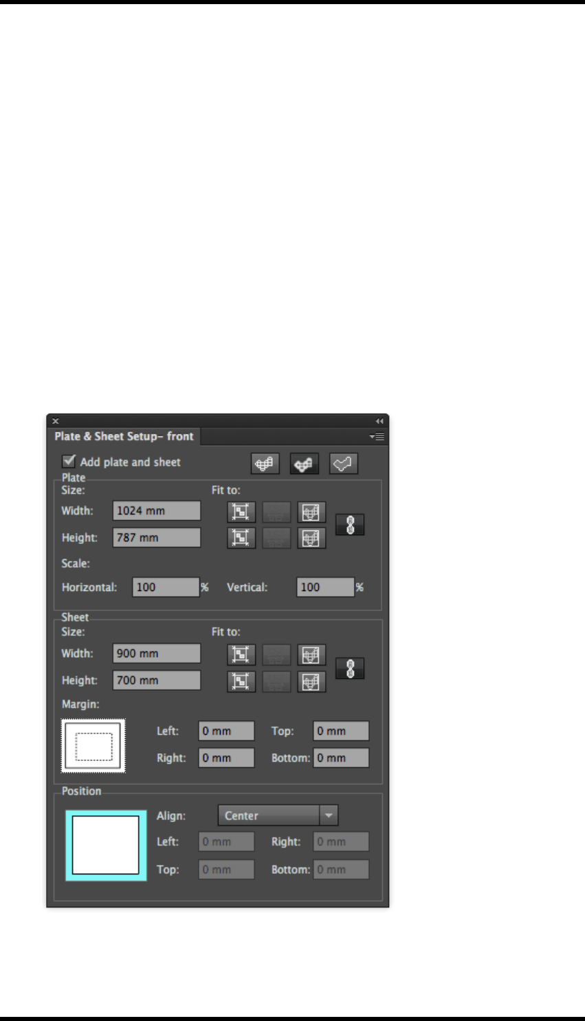
12. Nest
Same with Graphic Manager – files can optionally be ‘consumed’ as they are added to a layout, to
make it easier to select the correct files remaining:
when enabled:- graphics will be removed from the Graphic Manager list as they are added to a lay-
out
when disabled:- all graphics will remain in Graphic Manager.
12.5. Step and Repeat with CAD Layout
Use this tool to apply new Box Artworks on to existing Layout Structure. DXF and CFF2 format files
are supported. With this tool, the position of graphics is adjusted automatically which significantly
improves the efficiency of the step & repeat work.
1. Create a new empty document.
2. Select Window > RealPro > Nest > Plate and Sheet Setup panel.
The Plate and Sheet Setup palette is displayed:
3. Add the printing plate and sheet sizes. In case of a digital press set this as the media and
printable area.
- 110 -

12. Nest
4. Select Window > RealPro > Step and Repeat > Step and Repeat with CAD Layout.
The Step And Repeat with CAD Layout palette will be displayed
5. Click the Add CAD button and browse to the desired CAD file.
Supported file formats include DXF and CFF2.
If choosing DXF file format, the user needs to set the scale, unit, and the CAD ticket in the
DXF options dialog:
Note: The ‘units’ chosen must match those used within the CAD file if it is to be
imported at the correct size.
- 111 -
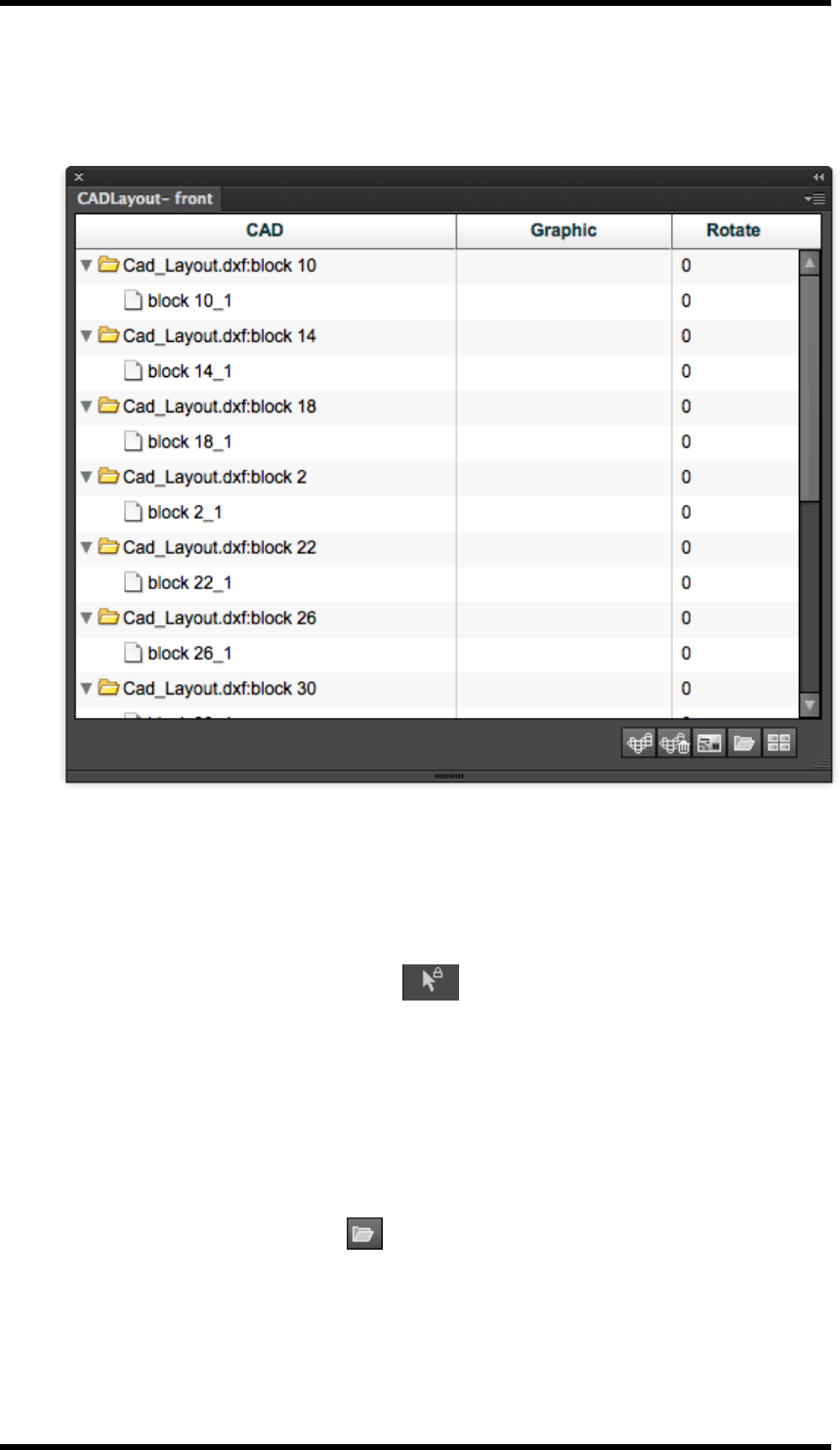
12. Nest
After the Structural layout file has been imported, the AI preview will display the Layout Struc-
ture and the CAD Layout palette will list the unpopulated Structural units. (In the example
below, the Graphic column is blank)
6. Add either a Box Artwork or an Empty file:
To add a Box Artwork file(s):
a. Select the unit in the structural layout where you wish to place the Box Artwork. This
can be selected either from the CAD Layout Palette or directly from the AI preview by
using the RP Pack Selection Tool from the AI Toolbar.
To select multiple units use:
Shift + Click (RP Pack Selection Tool)
Command + Click (from within the CAD Layout Palette)
Which ever method is used, the selected units will appear highlighted in the CAD list.
b. Click the Select File button and then browse to the desired artwork file.
c. Alternatively, files imported to the Graphic Manager will appear in a drop-down menu
in the Graphic column of the CAD Layout palette and can be selected directly from
- 112 -
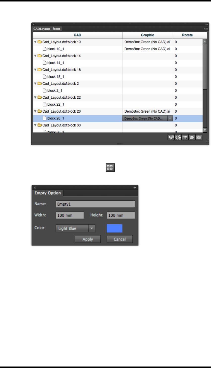
12. Nest
here.
To add a new Empty file:
a. Click the Select New Empty button .
The Empty Option dialog box will appear
b. Enter the name, the width and height of the Empty file.
c. Select the preview colour for how the empty file will appear in the AI layout.
As well as the colours from the Color pull down menu, it is possible to specify pre-
view colour for the empty file, by choosing Other.
7. Set the orientation of the box to fit the added artwork file to the CAD file. Use Rotate to
choose from 0, 90°, 180° or 270° from the drop-down options or type in any required value dir-
ectly.
To Delete a file:
1. Select the box artwork file that is to be deleted from the list.
- 113 -

12. Nest
2. Click the Delete button .
To Replace a file:
1. Choose the box artwork file that is to be replaced from the graphic list.
2. Click the Select New option.
3. Browse to the replacement file.
4. If an empty file is chosen, then the empty files dialog will appear. The parameters of an
empty file will need to be reset.
The result will be shown in the interface.
Note : After the basic Step and repeat layout has been created the user should
check bleed and overlap: See 14.7 and 14.8)
12.6. Interactive Step and Repeat
1. Create a new empty document.
2. Select Window > RealPro > Nest >Plate and Sheet Setup panel.
- 114 -
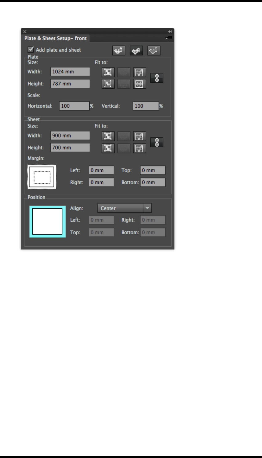
12. Nest
The Plate and Sheet Setup palette is displayed:
Add the printing plate and sheet sizes. In case of a digital press set this as the media and printable
area.
1. In AI menu bar, select Window > RealPro > Nest > Step & Repeat > Interactive Step &
Repeat
The Interactive Step and Repeat palette is displayed.
- 115 -
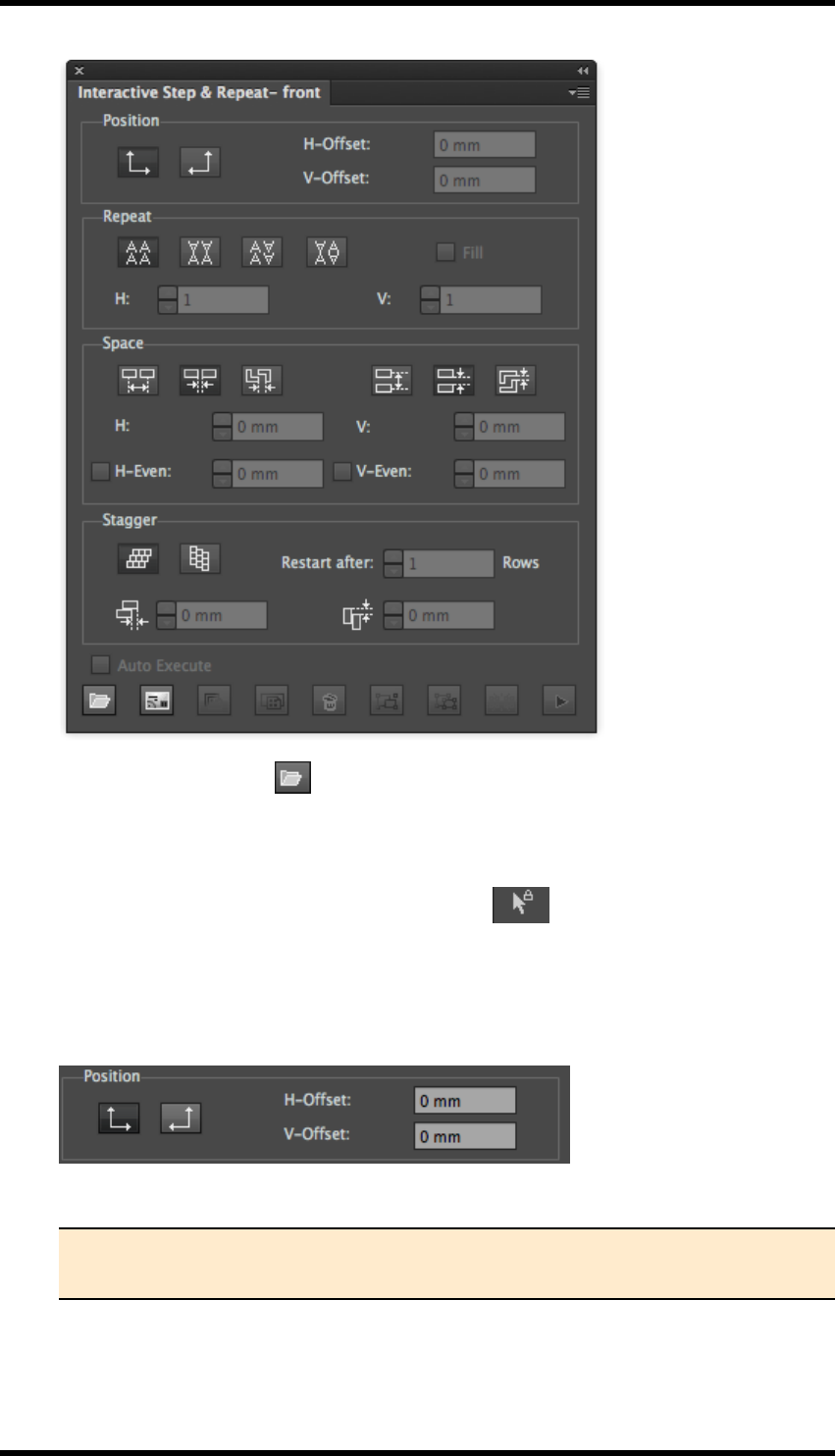
12. Nest
2. Using the Add File button , add the artwork file.
3. Make sure that Ink Manager inks are updated.
4. Select the artwork with the RP Pack Selection Tool from the AI Toolbar.
Once the Artwork is selected, the settings in the Interactive Step and Repeat palette become
available.
1. Set the Position as bottom left or bottom right hand corner as required.
5. Set the start of the step & repeat using the H-offset & V-Offset.
Tip: If you require a centred step and repeat it may be easier to use the Align to
Margin tool after the step & repeat has been achieved (see 14.9 below)
6. Select a repeat geometry in Repeat. This allows automatic reversal of alternate rows and
columns.
- 116 -
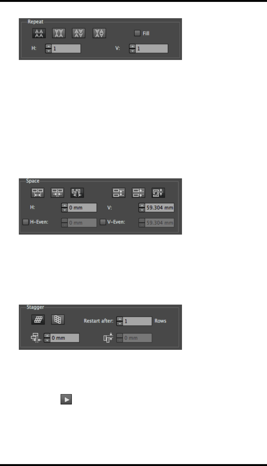
12. Nest
7. Set the numbers of lines and rows. If Fill is selected, the software will automatically cal-
culate the number of step & repeat lines and rows.
8. Set line and row spacing.
This can be set as:
Centre space - Measurement from centre of each 1up file.
Edge space - Sets the gap between edges of bounding box
Structural space - Sets minimum gap between cutter guides.
H-Even and V-Even allows different spacing to be applied on alternate rows or columns.
9. Set the Stagger to apply to lines or rows.
Stagger is often used when cutter guides need to be offset to create the most efficient use of
media. This is particularly important on sheet-fed cartons and labels. But also in preparing
beds of short run digital POS work.
Stagger is also used in narrow web label printing to create a stronger waste matrix and there-
fore less risk of web breakage during a press run.
10. Set the stagger Restart after 'n' rows.
11. Set the stagger offset value (Setting a value of “0” is effectively No Stagger).
12. Press Execute to finish step and repeat the process.
13. Apply bleed, station number, bleed and overlap and any other functions to the current file
(see 14.7 -14.8)
- 117 -
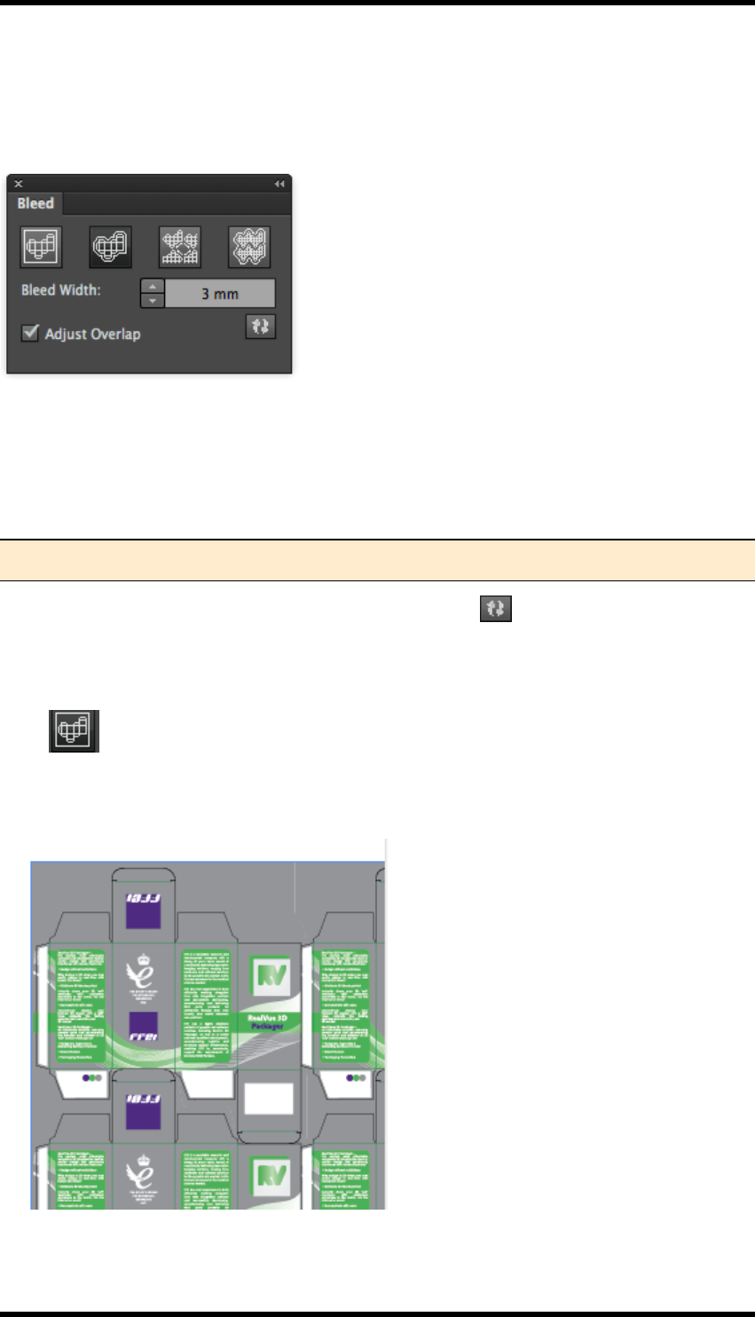
12. Nest
12.7. Bleed
Select Window > RealPro > Nest > Bleed.
The Bleed palette is displayed.
Bleed Width This controls the width of bleed that will be applied beyond the cutter guide. This
should be larger than the maximum expected mis-registration when printing and converting.
Adjust Overlap When selected the bleed is adjusted to prevent bleed from adjacent one-up units
overlapping; instead the bleed will abut at the midpoint between the two.
Note: For more control of overlapping areas see Adjust Overlap palette (Section 14.8)
After choosing the appropriate settings press the refresh button to see the effect in the AI pre-
view.
Bleed Modes
None
No bleed width is applied to the layout – the entire bleed is taken from the one-up Artwork or step
and repeat parameters (if applicable).
- 118 -
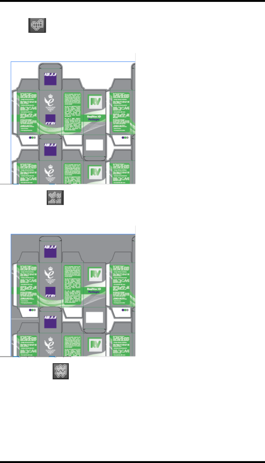
12. Nest
Bleed All
The specified bleed width is applied to each Artwork unit in the layout:
Bleed Interspace
The specified bleed distance is applied only where Artwork units are adjacent to each other:
Bleed Outerspace
The specified bleed distance is applied globally except where Artwork units are adjacent to each
other:
- 119 -
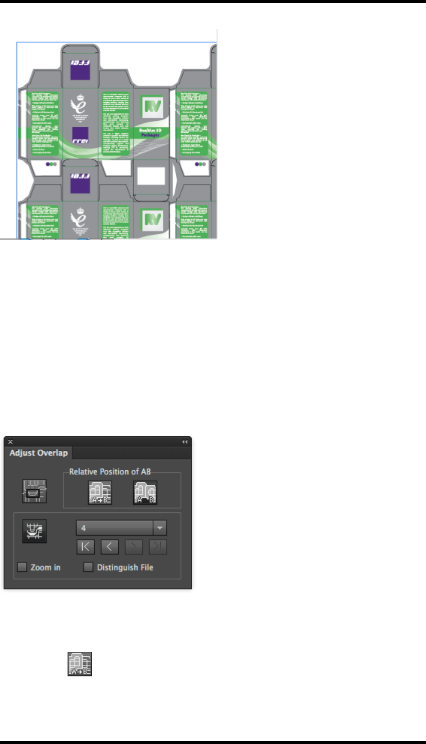
12. Nest
12.8. Adjust Overlap
This tool enables the user to identify areas where two adjacent Box Artworks overlap each other and
control how they interface.
When to use
The Adjust Overlap in the Bleed palette will always set overlapping bleed areas to abut at the mid-
point between the two cut lines. If this is not the desired result, the user should disable the Adjust
Overlap in the Bleed palette and instead use the Adjust Overlap tool.
Go to Window > RealPro > Nest > Adjust Overlap.
The Adjust Overlap palette will be displayed:
12.8.1 Relative Position of AB
Where two objects occupy the same space, the user is offered two modes:
1. A on top of B
In this mode, the bleed from one file is drawn at the expense of the second.
- 120 -
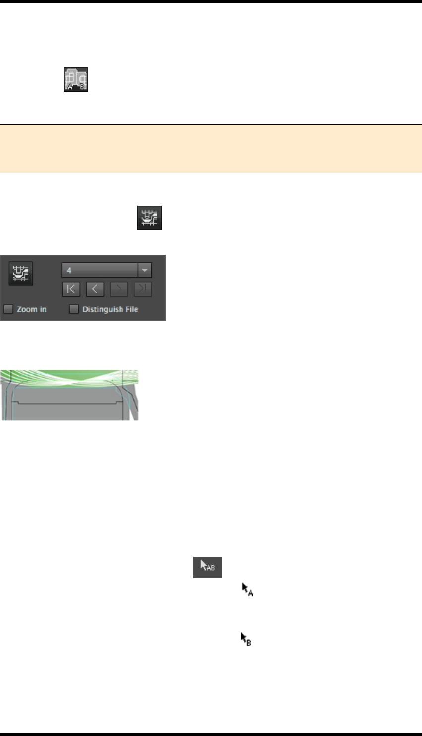
12. Nest
The user must use the AB Box selection tool available from the AI toolbar to specify which item is
on top and which underneath. (see below 14.8.2)
2. Mid split AB
The two objects abut at boundary halfway between the bleed areas.
Note: The Mid Split A|B mode is the same as offered in the Adjust Overlap in the Bleed
palette. It is also available here for when the user wishes to specify a mix of different
modes in the same Layout.
12.8.2 Search Overlap Area
Click the Search Overlap button to detect and classify the overlapping areas, and to show the
number of overlaps detected:
You can select the number or use the selection button to select the corresponding overlap area, and
zoom to the area by selecting Zoom in:
12.8.3 AB Box Selection Tool
If the A on top of B relative position mode is being used, the user must be able to specify which of
the files is A (on top) and which is B (below).
Pre-requisites:
The Relative Position of AB setting of the Adjust Overlap palette must be set to A on top of B.
The Adjust Overlap checkbox option of the Bleed palette must NOT be selected
1. From the AI Toolbar select the AB tool .
The Cursor will change whilst the tool is selected .
2. Click the file which is to be A (on top)
The Cursor will change whilst the tool is selected .
On this second selection, the overlap setting will be applied.
3. Then click the file which will be B.
The overlap of bleed will be modified according to the overlap mode setting (A over B or A|B).
- 121 -
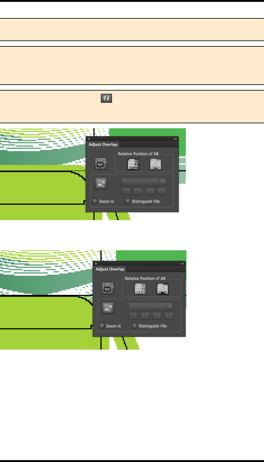
12. Nest
Note: All the overlaps for one-up units of same ‘category’ will be modified by this action.
It is possible to set different overlap modes for, say, horizontal and vertical alignment.
Note: Using this tool will resolve (remove) overlapping areas. After it has been used
once on a category, there are no overlapping areas to select. Therefore attempting to edit
overlap after it has been applied will probably not be successful and the user should
‘reset’ overlap by refreshing from the Bleed panel.
Note: Pressing the refresh button on the Bleed palette will reset the bleed, removing
any manual overlap settings. Therefore it is important to make sure that any bleed set-
tings are made before the adjust overlap is used.
Mid split AB The AB tool is used to click the two files in sequence. The result is that the bleed is
clipped.
12.8.4 Distinguish File
The Distinguish File option is available from the pull down side menu options of the Adjust Over-
lap palette. This is can be used when there is more than one box file in the layout.
If Distinguish File is selected, boxes on different files with the same CAD structure lines will be
grouped into different categories for the purposes of specifying overlap.
If Distinguish File is not selected, the boxes will be grouped into the same category, and overlap
will be applied globally.
- 122 -
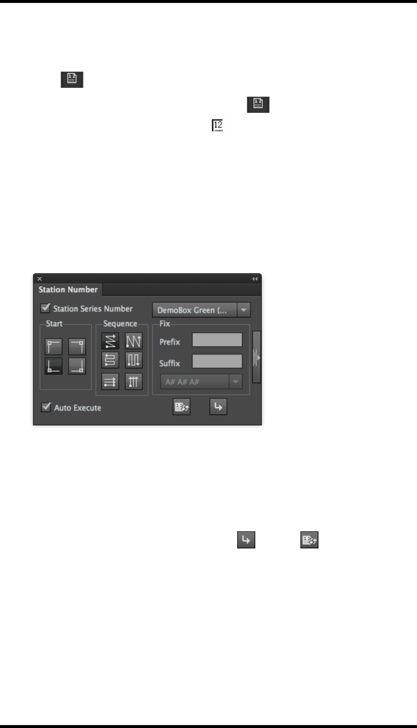
12. Nest
12.9. Station Numbers
Station number positions are defined in the one-up files using the Station Number tool available from
the AI Toolbar :
1. From the AI Toolbar, select the Station Number tool .
The cursor will alter when this tool is in use:
2. Click this toolx on the Artwork / Structure where you wish the station number to appear. This
place holder position will be displayed as N.
When the one-up file is step and repeated the Station Number palette controls how the station num-
bers are assigned and flowed through the one-up units within the layout.
1. Select Window > RealPro > Nest > Station Number.
The Station Number palette is displayed.
2. Select the one-up unit from the drop down menu, and set the Start and Sequence.
The palette allows you to display a thumbnail of the One-up unit to aid in identification of the
correct file.
3. If required add Prefix / suffix.
4. Use the Auto Execute option or the manual Apply or Update buttons to apply the
settings or changes.
12.9.1 Station Number Settings
Start - Set the start point for the numbering sequence. The options are; top left, top right, bottom left
or bottom right.
Sequence - Set the progression of the station numbering sequence.
Fix - Optionally add a Prefix or Suffix to the station number.
- 123 -
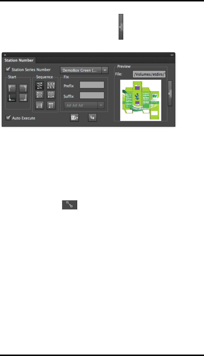
12. Nest
Preview Thumbnail - Press the expand / collapse button to show / hide a thumbnail preview and
path of the one-up unit.
This is particularly useful if there is more than one source file on the layout.
12.10. Anchor Tool
This tool allows rows or columns to be positioned relative to specific points on a CAD.
Prerequisite
The step and repeat layout has been created with either the Step & Repeat with Chart or Interactive
Step & Repeat functions
1. Select the Anchor Tool from the AI Toolbar.
The cursor will change to a cross-hair whilst the tool is selected.
2. Click a point in the guideline of any one-up file within the layout in the line or row that you
want to move.
3. Drag the mouse to a point in the guideline of any one-up file with layout in the next line or row.
A dialog window will display the relative position of these two points as Width and Height.
4. Type the desired values of Width and Height and press OK.
The job will be modified.
The parameters for Step and Repeat with Chart or Interactive Step and Repeat will also
- 124 -
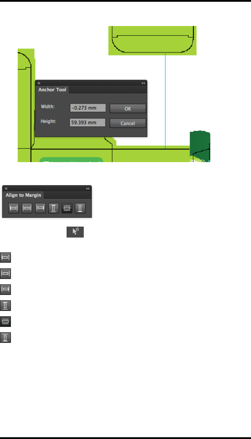
12. Nest
reflect the modification.
12.11. Align to Margin
Use the RP Selection tool to select the object of the current job, and choose from the dif-
ferent alignments to change the alignment of the stepped object relative to the margin.
: Align the selected objects and the margin by their left edges.
: Centre the selected objects horizontally between the margins.
: Align the selected objects and the margin by their right edges.
: Align the selected objects and the margin by their top edges.
: Centre the selected objects vertically between the margins.
: Align the selected objects and the margin by their bottom edges.
12.12. Reverse CAD
Reverse CAD is used for flipping the CAD structure so that artwork, which will be printed on reverse
of substrate, can be aligned.
These functions are all available from the AI menu bar Window > RealPro > Nest > Reverse
CAD >…
- 125 -
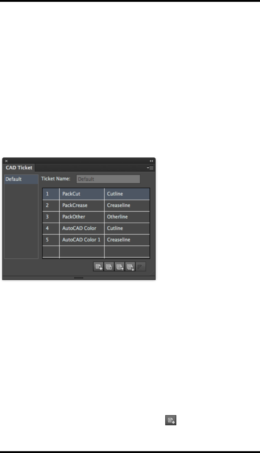
12. Nest
Reverse One-up
Reverse the RealPro CAD structure line of one-up file in the right or left direction.
Reverse With Sheet
Horizontally reverses the CAD with the sheet on the plate so that the position of the sheet on the
plate remains the same.
Reverse with Plate
Horizontally reverses the CAD with the plate.
12.13. CAD Ticket
Select Window > RealPro > Nest > CAD Ticket.
The CAD Ticket palette is displayed:
Ticket List
Lists all current CAD tickets.
Ticket Name
Displays and modifies the name of the current CAD ticket.
Ticket Contents
The converted line’s ink name or colour name is listed on the left side, while the target line’s ink
name or colour name is listed on the right side. The user can choose to use Cutline, Creaseline,
other lines or no conversion. If the user chooses no conversion, objects with the corresponding ink
or colour will not be converted.
New CAD Ticket - Creates a new CAD ticket.
This is also available by pressing the New button on the palette
- 126 -
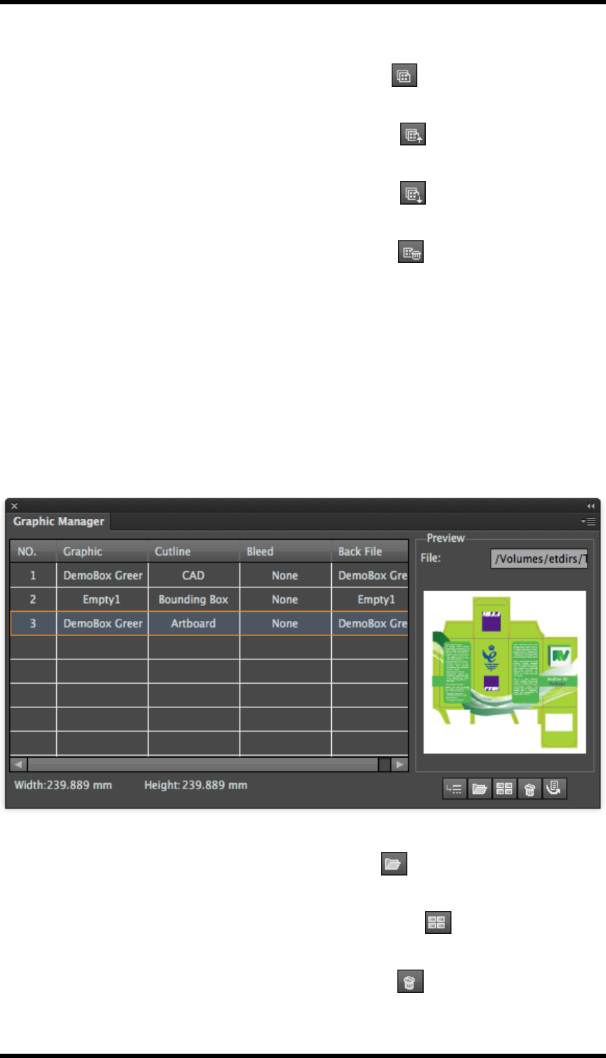
12. Nest
Copy - Creates a copy of CAD Ticket under a new name.
This is also available by pressing the Copy button on the palette
Import - Imports a CAD ticket from another RealPro Toolkit install or backup
This is also available by pressing the Import button on the palette
Export - Exports a CAD ticket to another RealPro Toolkit install or backup
This is also available by pressing the Export button on the palette
Delete - Removes a CAD ticket from the list.
This is also available by pressing the Delete button on the palette
12.14. The Graphic Manager
One-up files can be added to the Graphic Manager and then added to nests without having to
browse for them directly from within the individual Nesting tools. From here, it is possible to see the
(media box) size and thumbnail images of the files. It is also possible to define the CAD data, (Cut
lines, Crease lines, etc) using the Graphic Manager, removing the need to pre-define the data in the
one-up file.
Go to Window > RealPro > Nest > Graphic Manager.
The Graphic Manager palette is displayed:
Add File - adds new files to the file list.
This is also available by pressing the Add button on the palette .
Add Empty - adds a place-holder file to the list.
This is also available by pressing the Add Empty button on the palette
Delete – deletes the selected file from the list.
This is also available by pressing the Delete button on the palette .
- 127 -

12. Nest
Import File - places the selected file directly into the current layout.
This is also available by pressing the Import button on the palette .
CADSetting - allows definition of CADlines from spot colour data in the one-up file .
This function can be used instead of defining the CAD data in the one up file before import.
CADSetting Example:
Select a one up file that has no CAD data, (Cutline defined as Artboard), then click on
CADSetting.
Select the ink that is used to define the CAD data and choose the type of CAD data.
- 128 -
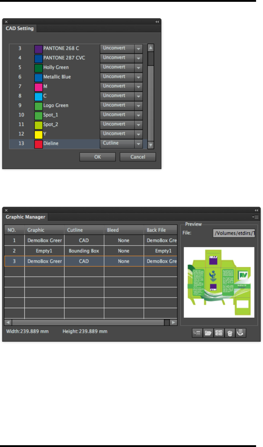
12. Nest
Click on OK.
The CADdata can then be selected to define the cutline.
- 129 -
12. Nest
12.15. Appendix : Examples of Step and Repeat For-
mula
12.15.1 Formula for Sheet Fed Labels and Cartons
Parameter Setting or formula Notes
Bleed 3 mm or None
H-Repeat SW/CGW[1] Auto-fill the sheet width and height
V-Repeat SH/CGH[1]
H-Offset (SW-(CGW[1]*C[1])-(OW[1]-CGW[1]))
/2
Centres the Step and Repeat on the
sheet
V-Offset (SH-(CGH[1]*R[1])-(OH[1]-CGH[1]))/2
H-OutlineGap OB[1] Use the One-up Bleed as the Gap dis-
tance
V-OutlineGap OB[1]
Rotate 0 or 90 [cartons]
90 or 270 [Labels]
12.15.2 Formula for Narrow Web Flexo V1
Labels are stepped and evenly spaced across the web and around cylinder repeat
Parameter Setting or formula
H-Repeat SW/OW[1]
V-Repeat SH/OH[1]
H-Offset ((SW-(OW[1]*C[1]))/C[1])/2
V-Offset ((SH-(OH[1]*R[1]))/R[1])/2
H-Edge Gap (SW-(OW[1]*C[1]))/C[1]
V-Edge Gap (SH-(OH[1]*R[1]))/R[1]
Rotate 90 or 270 [Labels]
12.15.3 Formula for narrow web Flexo V2
This will distribute labels across the web by doubling the bleed value. The stepped labels will be
centred on the web
Parameter Setting or formula
H-Repeat SW/OW[1]
V-Repeat SH/OH[1]
H-Offset ((SW-(OW[1]*C[1]))/C[1])/2
V-Offset ((SH-(OH[1]*R[1]))/R[1])/2
H-Edge Gap OB[1]*2
- 130 -

12. Nest
Parameter Setting or formula
V-Edge Gap (SH-(OH[1]*R[1]))/R[1]
Rotate 90 or 270 [Labels]
12.15.4 Formula for Narrow Web Flexo V3
Same as V2 formula but Labels are left aligned 20 mm from web edge.
Parameter Setting or formula
H-Repeat SW/OW[1]
V-Repeat SH/OH[1]
H-Offset 20 mm
V-Offset ((SH-(OH[1]*R[1]))/R[1])/2
H-Edge Gap OB[1]*2
V-Edge Gap (SH-(OH[1]*R[1]))/R[1]
Rotate 90 or 270 [Labels]
Same as V2 formula but Labels are left aligned 20 mm from web edge (not centred on the web).
- 131 -

13. Mark
13. Mark
13.1. Background
Mark is used to add printer marks to a plate.. "Mark" solves the potential problems caused by non-
standard marks and is significantly more efficient than manually creating marks in Adobe Illustrator
(AI).
"Mark" allows you to configure and add print registration marks of different types, trim marks, solid
and graduated ink colour patches and text marks to a trim box, media box, sheet, plate, One-up file,
or CAD bounding box as well as the artboard. Additionally you can save the marks parameters as
an individual file that can be used in other documents.
13.2. Overview
"Mark" specifically contains eight types of marks:
lCentre mark: printing marks for registration
lCorner mark: printing marks for registration
lTrim mark: for marking cut lines
lEllipse mark: for making round solid ink patches
lRectangle mark: for making rectangular solid ink patches
lGradation mark: for making ink patches with graduated tint values
lImage mark: users can import custom marks as image marks
lText mark: for adding smart or custom text as marks
13.3. GUI Description
Select Window > RealPro > Mark > Marks to launch the mark interface.
- 132 -
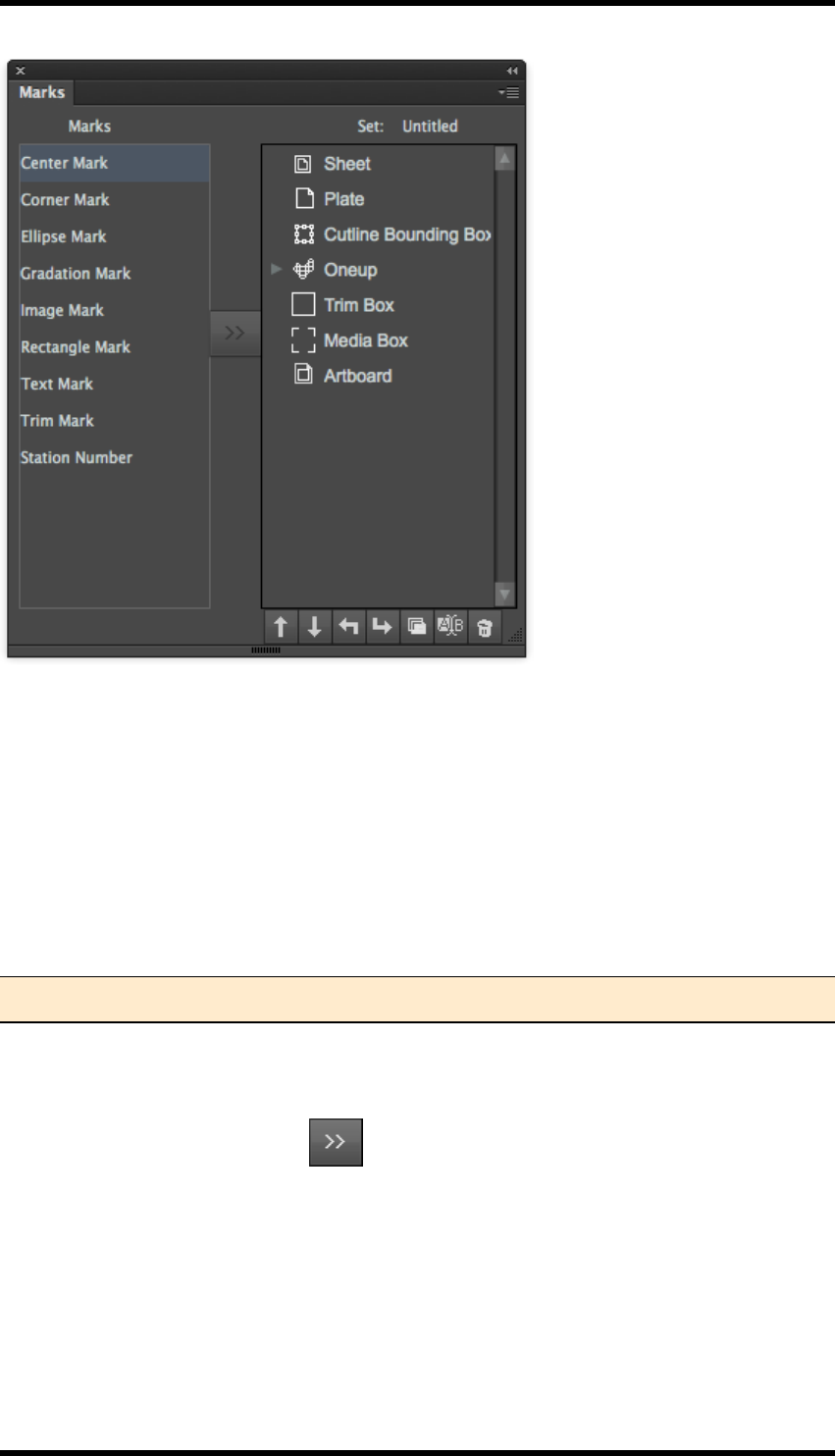
13. Mark
The main Marks palette allows marks to be added, edited and managed. Parameter sets of marks
can be saved and recalled for use within the AI file.
13.4. Adding a Mark
13.4.1 Prerequisites
Depending on the type and position of mark being placed, the trim, media box or plate and sheet set-
up must be predefined.
The Ink manager must be updated in order for marks colours to be processed correctly.
Note: Failure to update the Ink Manager may prevent marks from being displayed at all.
Procedure
1. From the main Marks window, select an item (e.g. sheet) and then select a mark type (e.g.
graduation) and then click the button.
The setting window for the chosen mark type will be displayed.
- 133 -
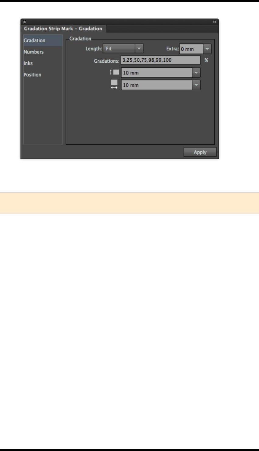
13. Mark
2. Configure the marks setting as required and press the Apply button.
The configured marks will appear in the AI file.
Note: The mark settings window can be accessed again by double-clicking on a mark
from the main marks window.
13.5. Configuring Marks Settings
13.5.1 Ink Settings
The Mark control panel will include settings for Inks. This will control how inks are used to define the
mark. The specific settings displayed will depend upon the mark type.
13.5.2 Ink Setting for Register and Trim marks
These are the ink settings that apply to centre marks, corner marks and trim marks.
The following example will use the Corner Mark to describe the process.
- 134 -
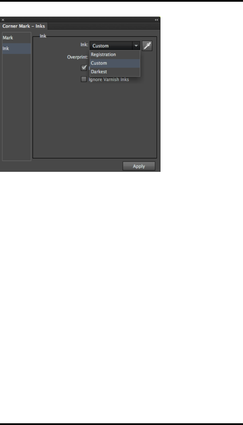
13. Mark
13.5.3 Ink
Registration: The mark will be reproduced using every ink in the file.
Custom: The mark will use a single colour defined by the following process:
1. Choose the Custom Option.
The eye-dropper icon will become available.
2. Click on the eye-dropper icon to display the “Select inks” window.
You are now able to select Inks by “Name or by “Number” from the drop-down menu.
The Number option means that the marks use an ink with the sequence number defined in
the Ink Manager.
For example, if the No.3 ink is specified, when the No.3 ink in the Ink Manger is converted
from C to Y, the ink used in mark will change to Y. If the No.3 ink is deleted, the mark will
have no ink assigned to it.
Darkest: The mark will use the single darkest ink resident in the file.
K ink is the darkest ink in the current file in example below
Ignore Varnish Inks: Any inks marked as Varnish inks will not be used to construct the mark.
13.5.4 Overprint
This control will change the overprint characteristic of the mark i.e.overprint and knockout.
- 135 -
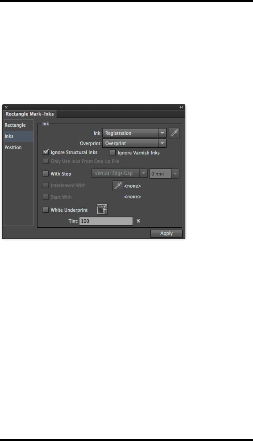
13. Mark
13.5.5 Ignore Inks
Ignore Structural Inks: Inks set in the Ink manager as “Structural” are not used in the mark.
Ignore Varnish Inks: Inks set in the Ink manager as “Varnish” are not used in the mark.
13.5.6 Ink Settings for Solid Ink Patches and (single colour) Image
Marks
These are the ink settings that apply to rectangle marks, ellipse marks and image marks with only
one ink. The following example will use the Rectangle Mark to explain the process.
13.5.7 Ink
Set Ink type (Registration, Custom or Darkest), the overprinting behaviour and whether to varnish or
structural inks should be included or ignored.
For further information see these settings in “11.5.1 Ink Setting for Register and Trim marks”
13.5.8 With Step
With this control deselected all the inks in the mark will be printed on top of each other in the same
location.
With this option enabled the location of the mark will be stepped for each ink so that all inks are vis-
ible in the final result. Select the stepping direction and the step distance:
Horizontal Centre Gap
Horizontal Edge Gap
Vertical Centre Gap
Vertical Edge Gap
- 136 -

13. Mark
The value entered in the text field will be applied to the rectangle mark according to the parameter
selected. Examples 1, 2, 3 and 4 show the effect of Horizontal Centre Gap, Horizontal Edge Gap
Vertical Centre Gap and Vertical Edge Gap respectively.
The step value supports formula mode using the following variables:
PW: Plate width
PH: Plate height
SW: Sheet width
SH: Sheet height
MW: Margin width
MH: Margin height
OW[N]: Step & Repeat Guideline-Bounding Box width of No.[N] one-up file
OH[N]: Step & Repeat Guideline-Bounding Box height of No.[N] one-up file
OB[N]: Bleed width of No.[N] one-up file
C[N]: Column number of No.[N] one-up file
R[N]: Row number of No.[N] one-up file
CGW[N]: Centre gap width of No.[N] one-up file
CGW[N]: Centre gap width of No.[N] one-up file
CGH[N]: Centre gap height of No.[N] one-up file
N: Sequence number of step & repeat one-up file.
Interleaved with:
When selecting this option, choose one interleave ink to use in the marking process. This function
will only be available after choosing the “with Step” option. The interleave ink can be chosen by
name or by number.
- 137 -
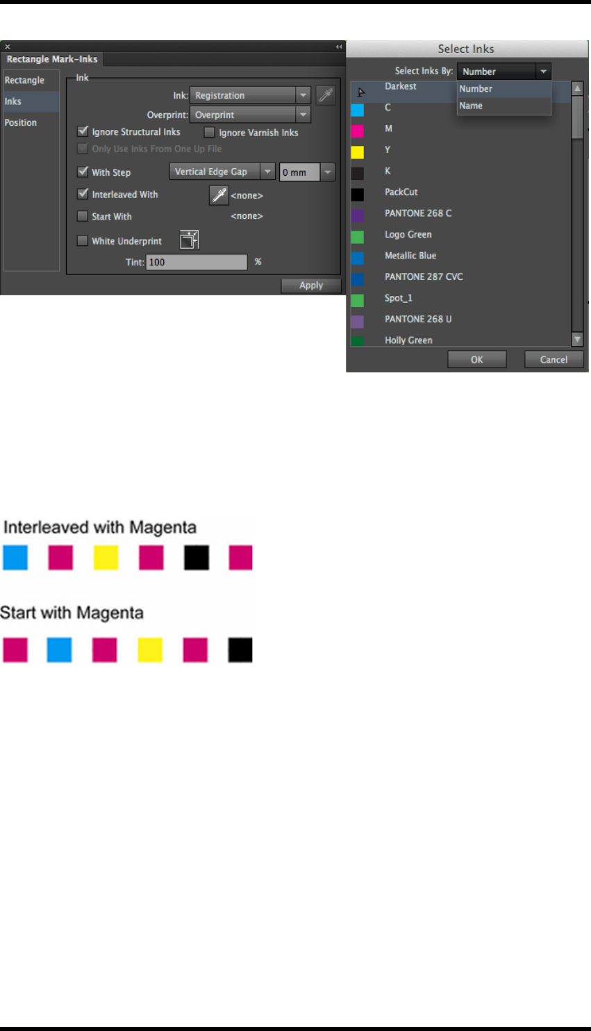
13. Mark
Start with:
This option allows the user to choose whether or not to use the interleave ink as the starting ink for
marking. This function will only be available after choosing the “Interleaved with” option.
As shown below, the top image shows the effect of the mark interleaved with Magenta. The bottom
image shows the effect of the mark started with Magenta.
13.5.9 White Underprint
This allows a white ink to be generated to Underprint the marks. The procedure is as follows:
1. Select the White Underprint option.
The Settings icon button will become available.
2. Click the setting icon button.
The White Underprint Setting dialogue box will be displayed.
3. Click “Select Ink…”
The dialogue box will appear for you to choose the ink you want to use.
The selected ink will display on the interface.
4. Direction: choose to expand (spread) or reduce (choke) the white Underprint area.
- 138 -
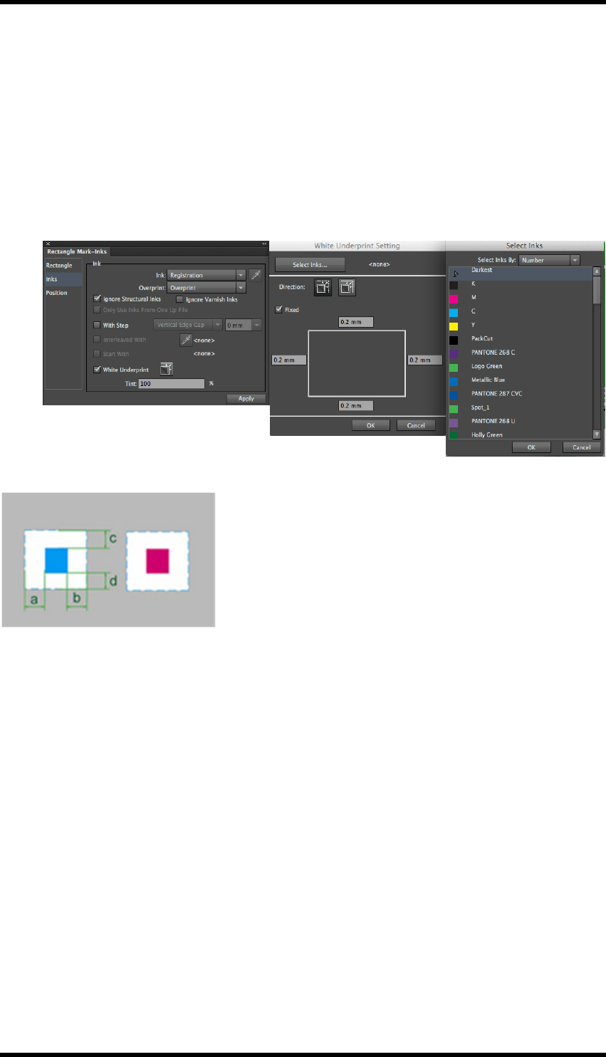
13. Mark
Select the ”Expand” button. According to the edge space values entered, the white underprint
created will be enlarged based on the current mark shape.
Select the ”Reduce” button. According to the edge spaces values entered, the created white
underprint will be decreased based on the current mark shape.
The “Fixed” option sets the four edge spaces of the mark white underprint to be the same.
Image below shows the enlarge effect of the white underprint.
5. Press the Apply button to see the effects of the changes.
13.5.10 Ink Setting for multi-coloured Image Marks
This ink setting type applies to image marks with multi-colours.
- 139 -

13. Mark
The following examples use a marks file consisting of 3 circles.
Circle 1 is filled with M ink.
Circle 2 is filled with Y ink.
Circle 3 is filled with C ink.
Map Inks:
The inks used in the mark file are mapped to the inks in the AI file.
In the example below, the marks are drawn using the first three inks as defined by the Ink Manager,
- 140 -
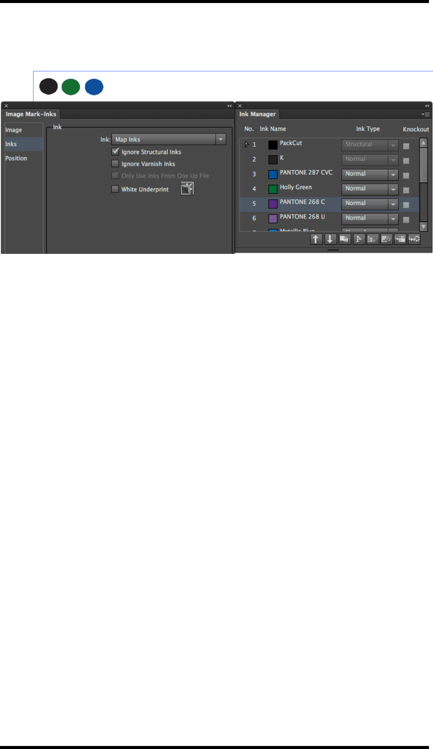
13. Mark
Changing the order of the inks in the Ink Manager will then change the mapping to the marks, see
below: (Structural inks ignored).
- 141 -
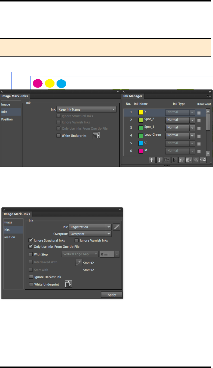
13. Mark
Keep Ink Name:
Use the ink with the same name to fill the added image mark.
NOTE: If there are some inks of the image mark file that do not exist in the current
AIfile, the objects using those inks in the image mark file will not be drawn.
As shown below, the three circles of the image mark file are individually filled with M, Y &C ink.
13.5.11 Ink Setting for single colour Image Mark
This ink setting type applies to image marks with multi-colours.
- 142 -
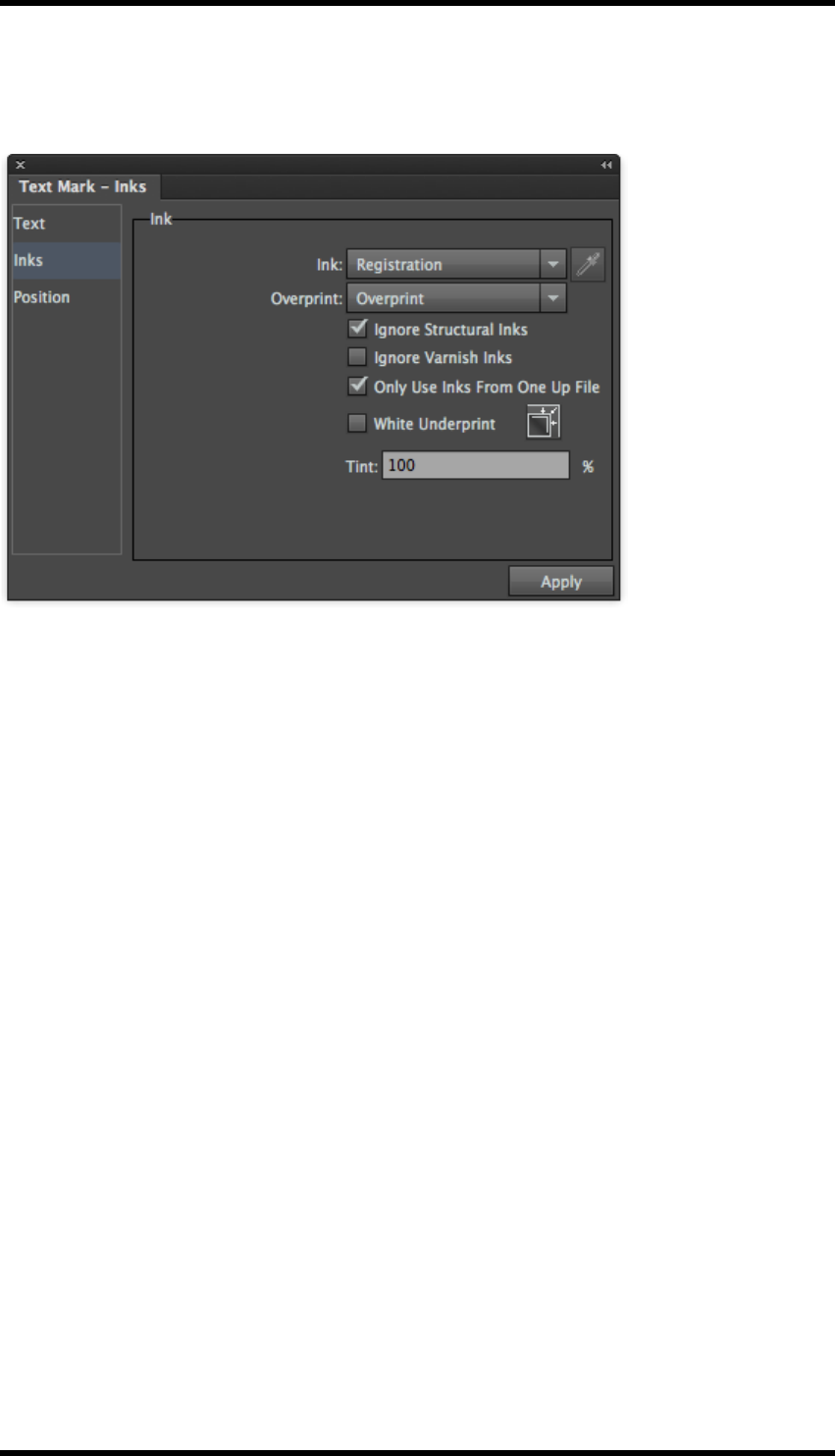
13. Mark
13.5.12 Ink Setting for Text Marks
These ink settings apply to text marks.
1. Set Ink type (Registration, Custom or Darkest), the Overprinting behaviour and whether to
Varnish or Structural inks should be ignored or included.
For further information see these settings in “11.5.1 Ink Setting for Register and Trim marks”
2. Set White Underprint if required.
For more information, consult the same section in 11.5.2 Ink Settings for Solid Ink Patches
and (single colour) Image Marks
13.5.13 Ink Setting for Graduation Marks
These ink settings apply to graduation marks
- 143 -
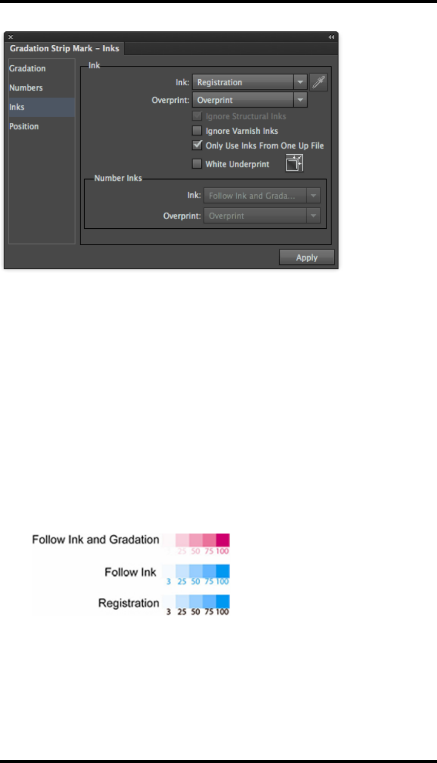
13. Mark
1. Set Ink type (Registration, Custom or Darkest), the Overprinting behaviour and whether to
Varnish or Structural inks should be ignored or included.
For further information see these settings in “11.5.1 Ink Setting for Register and Trim marks”
2. Number Inks Setting
This controls how numbers (% values) are drawn in Graduation mark There are three options.
1. Follow Ink and Gradation: The ink colour and dot percentage of the text are same as
for the patches.
2. Follow Ink: The ink colour of the text is same as for the patches, but the dot per-
centage of the text is 100%.
3. Registration: the text uses the registration colour.
3. Overprint type: This control will change the overprint characteristic of the mark i.e. overprint
or knockout.
4. For more information, consult the same section in 11.5.2 Ink Settings for Solid Ink Patches
and (single colour) Image Marks
- 144 -

13. Mark
13.5.14 Ink Setting: Only use inks from One-Up
This ink setting type is applicable to Image Marks, Rectangle Marks, Text Marks and Trim marks.
When this control is selected, the Marks for the One Up file will use only inks from the One Up file’s
ink list, not to the complete layout file’s ink list.
13.6. Setting Mark Position
This type of position setting applies to rectangle marks, ellipse marks, gradation marks, text marks
and image marks.
NOTE: When added to a sheet or plate, Centre, Corner and Trim marks are positioned
automatically to all the one-up files in the layout and the position controls are not
required.
Positioning marks on the Target Objects
As shown below, the Position dialogue box contains two boxed areas:
The red box represents the nine reference locator points of the mark’s Bounding Box,
The blue image represents the nine reference locator points of the marked object’s Bounding Box.
Users can use the mouse to select and drag the red box to align the reference point of the mark’s
bounding box to any reference point of the marked object’s bounding box controlling the mark and
object’s position.
Offset
After setting the basic position relationship between the mark and the marked object, users can use
the Offset to set the exact position. The image below shows the effect after setting vertical offset
and horizontal offset, here h represents the vertical offset, and w represents the horizontal offset.
- 145 -
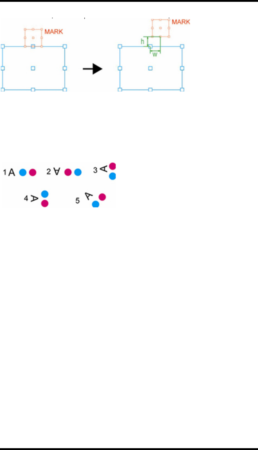
13. Mark
Users can also use formulae to set the offset value. For a list of the variables and their meaning
please see the section 11.5.2 ‘Ink Settings for Solid Ink Patches and (single colour) Image Marks’.
Orientation
Use the Orientation function to set the orientation of the mark. There are five options to choose
from:
1. Keep the mark in position without moving.
2. Rotate the mark 180 degree clockwise.
3. Rotate the mark 90 degrees counter-clockwise .
4. Rotate the mark in a 90 degrees clockwise
5. Custom allows any rotation angle to be applied to a mark.
After choosing this option, the angle setting input box will become available.
13.6.1 Do Not Adjust Mark
When “Do Not Adjust Mark” is disabled, if marks overlap a one up file’s bleed area, the overlapping
part of the mark will be clipped.
- 146 -

13. Mark
When “Do Not Adjust Mark” is enabled, any overlapping part won’t be clipped.
13.7. Mark Specific Settings
13.7.1 Centre Marks
There are three predefined styles of corner marks. Users can also use imported files as custom
centre marks.
1. Choose the desired mark and enter the geometric parameters of the selected mark style in
the corresponding dialogue box (see below).
2. Click the “Apply” button.
The specified marks are drawn at the corresponding position in the layout.
1. Crosshair
- 147 -
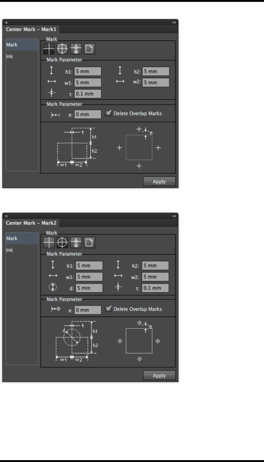
13. Mark
2. Registration target
3. Web
- 148 -
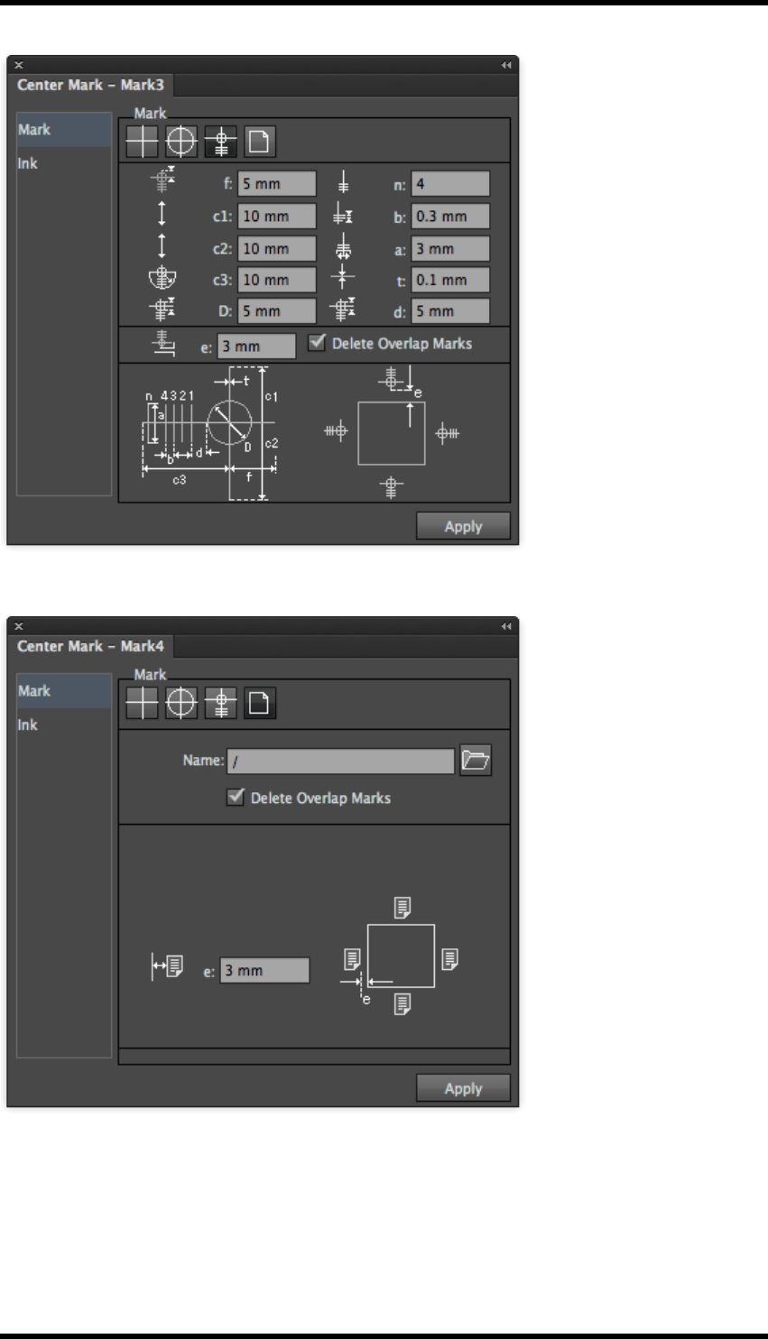
13. Mark
4. Custom
13.8. Corner Marks
There are four predefined styles of corner marks. Users can also use imported files as custom
corner marks.
- 149 -
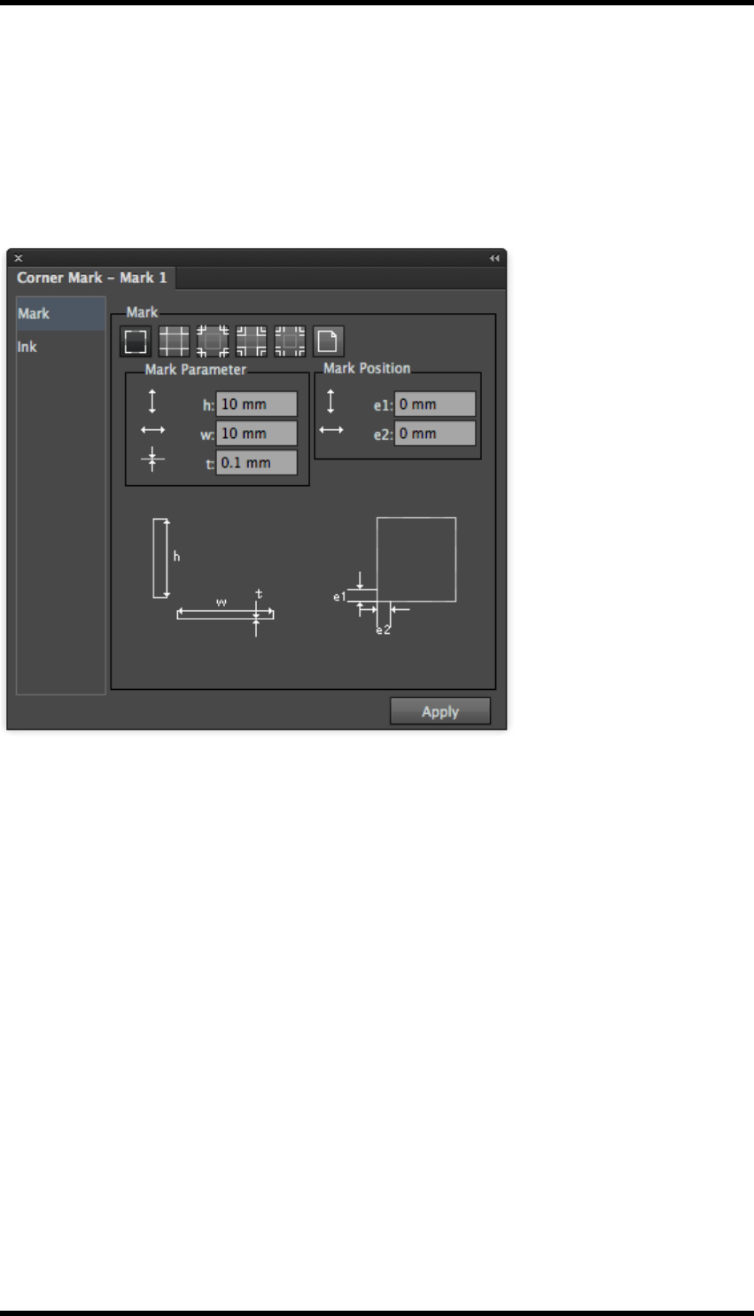
13. Mark
1. Choose the desired mark and enter the geometric parameters of the selected mark style in
the corresponding dialogue box (see below).
2. Click the “Apply” button.
The specified marks are drawn at the corresponding position in the layout.
Sheet Marks (Mark 1)
- 150 -
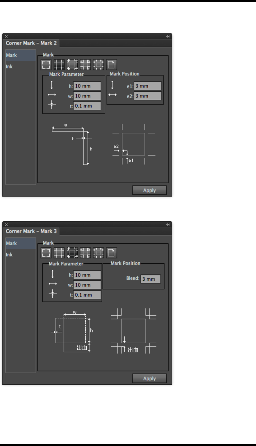
13. Mark
Trim Marks (Mark 2)
Trim and Bleed Marks (Mark 3)
- 151 -
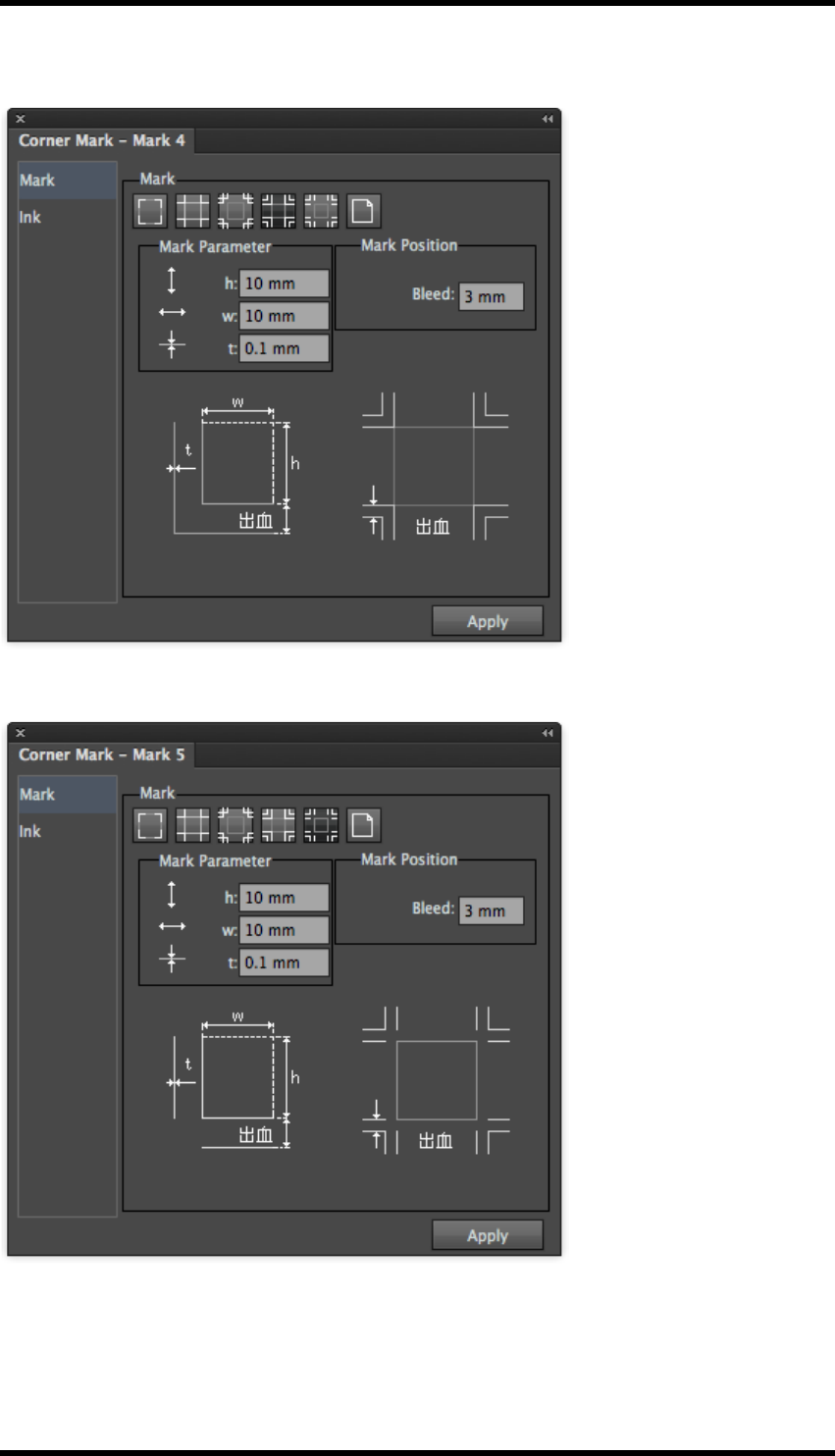
13. Mark
Trim and Bleed Marks (Mark 4)
Trim and Bleed Marks (Mark 5)
- 152 -
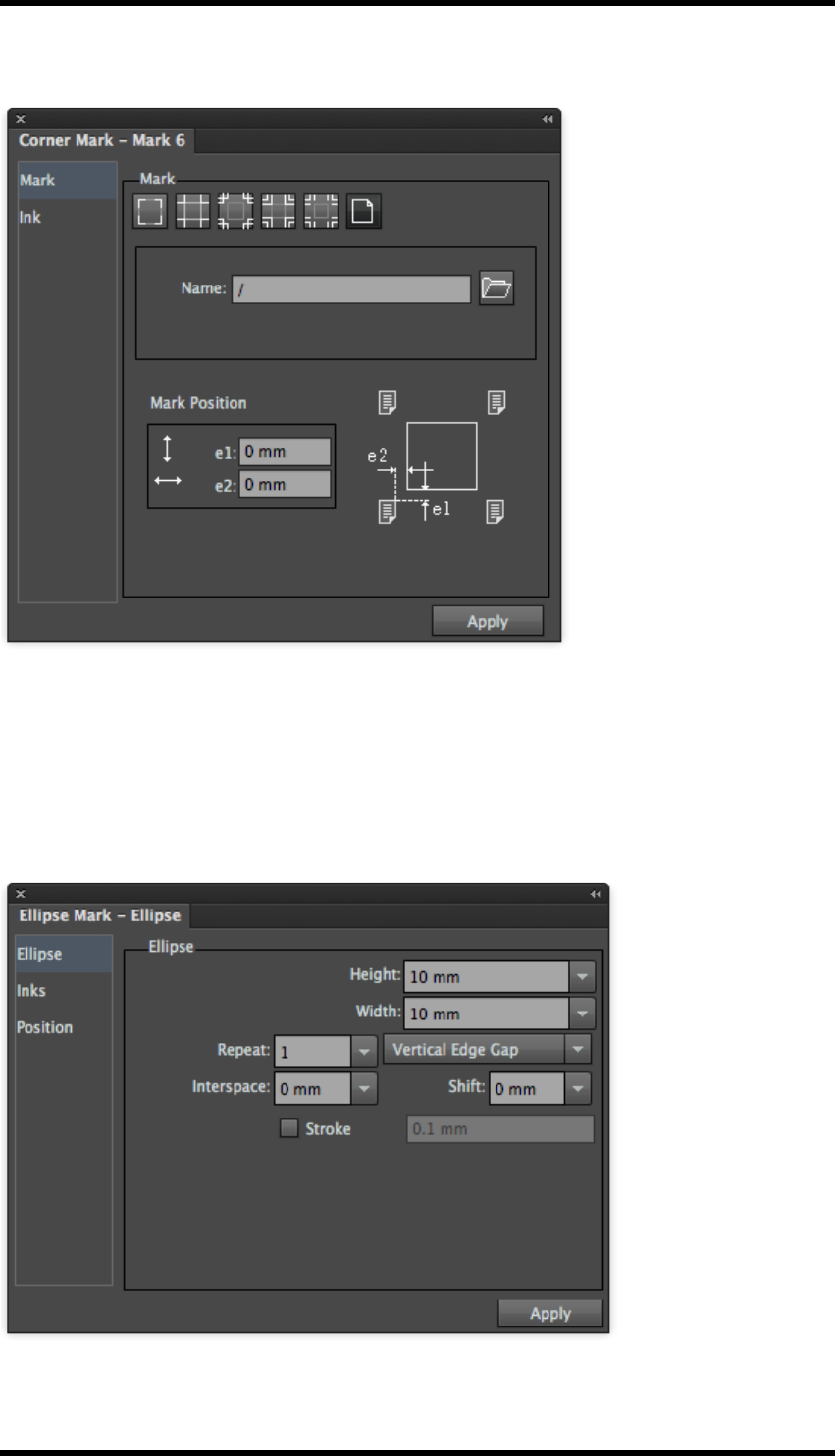
13. Mark
Custom Mark (Mark 6)
13.9. Ellipse Marks
Width and Height in this tool palette refers to the parameters shown in the screen-shot below.
Users can use a formula to set the width and height of the mark. For more information using for-
mulae, please see “With Step” in section 11.5.2 Ink Settings for Solid Ink Patches and (single col-
our) Image Marks.
- 153 -

13. Mark
Repeat:
sets the number of ellipse marks vertically or horizontally; users can use a formula to set the value.
Interspace:
This sets the edge gap between the two repeated ellipse marks. Users can set the value with a for-
mula; positive and negative values can be used for the two interspace directions respectively.
Tint
This sets the dot percentage of the ellipse mark.
Stroke: sets the ellipse marks to unfilled circles with an adjustable line-width. The "Fill and "Stroke"
effects can be seen in the example below"
13.10. Graduation Marks
13.10.1 Defining Patches
This panel allows the user to define the dot percentage and patches to be included in the gradation
mark.
- 154 -
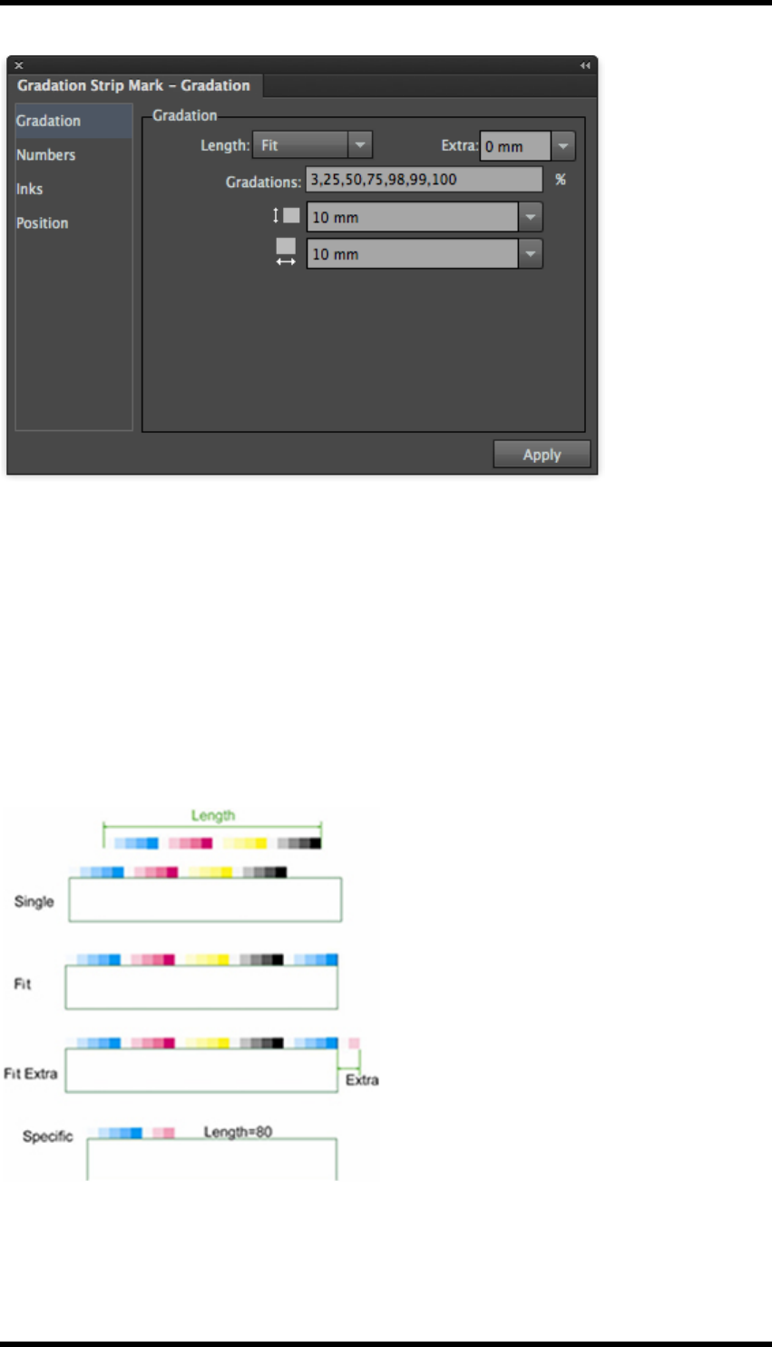
13. Mark
Length: sets the overall length of the graduation bar; there are three options:
Fit - Repeats the graduation sequence through each colour until the length fits the
object the mark is assigned to. Extra (only available only when the ‘fit‘option is used).
The Extra value extends the length of the graduation bar beyond the length of the
object it is assigned to. The extension behaviour also depends on the position control.
Single - Repeats the sequence for each colour once only.
Special - Repeats the sequence of graduations for each colour to a defined length. If
the length is shorter than a single repeat, the mark is clipped.
- 155 -

13. Mark
Graduations
The required patches are entered as dot % values. This will repeat with each colour defined in the
‘Inks’ tab (e.g. registration, custom or darkest mark). The sequence is the same as the order defined
in the Ink Manager.
See examples below for how these can be used.
Patch Size
Define the height and width of a single graduation patch.
13.10.2 Inks
Registration - Uses all colours in the job
Darkest - Use the darkest mark ink from the Ink Manager
Custom - Selection of a custom ink from a list
Overprint
Overprint or knockout other page elements where the mark is placed.
Ignore Structural and Varnish Ink
Ignores special ink types defined in Ink Manager i.e. structured or varnish.
White Underprint
Places a white spot colour under the mark. The spot and halo are selected via the additional "White
Underprint" control panel.
Number Inks
Follow Ink - Creates numbers in 100 % value of the patch ink colour.
Follow Ink and Graduation - Creates Numbers using the colour and tint value of the patch
Registration - Prints numbers using all colours.
Overprint - Defines overprint for numbers independently from the patches.
- 156 -
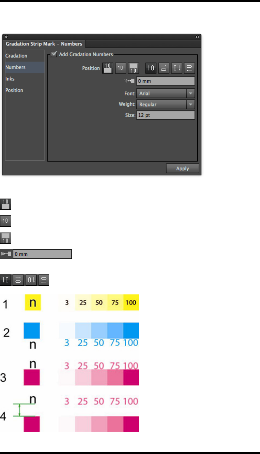
13. Mark
13.10.3 Numbers
There are three ways to set the location relationship between the number and the colour bar.
Number is placed above colour patch
The number is placed centrally on the colour patch
The number is placed below the colour patch
Use this control to adjust how far numbers are placed above or below
the colour bar.
Use these controls to set the number orientation.
- 157 -
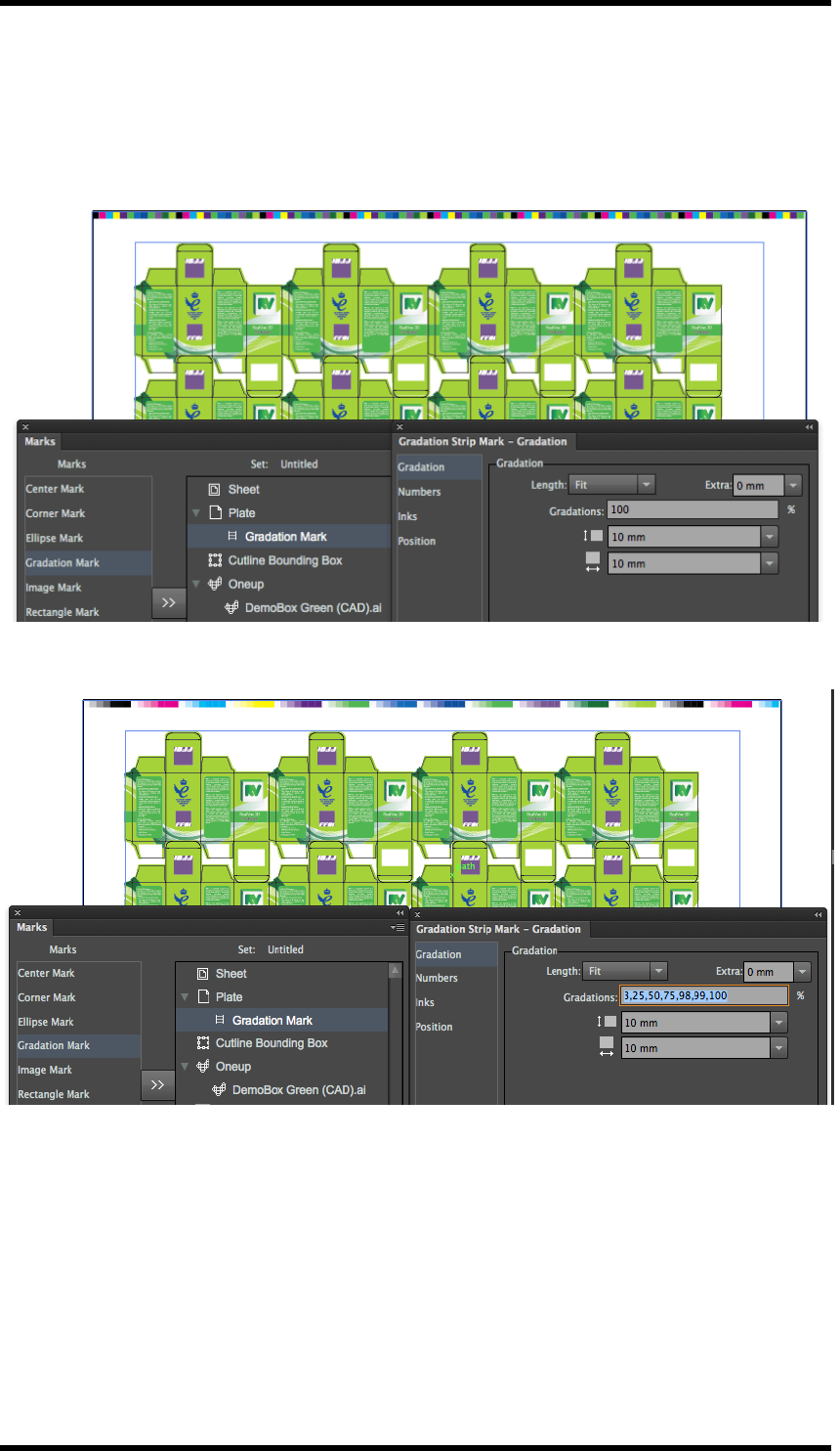
13. Mark
13.10.4 Examples of Graduation Marks
The examples below show different output from the graduation mark.
100% patch only
Defined Steps
- 158 -
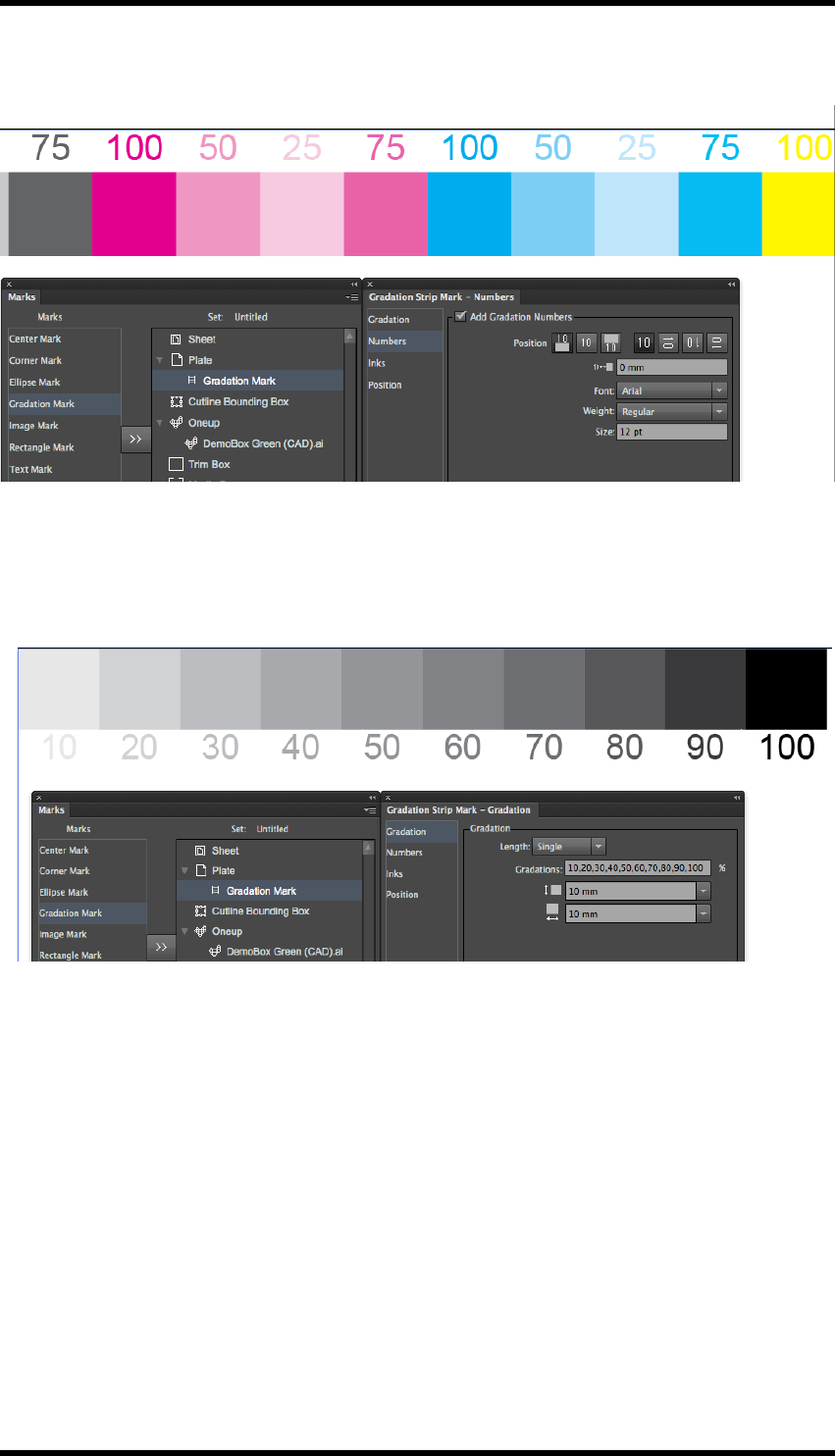
13. Mark
Dot gain 25, 50, 75, 100 with tint value numbers
Density Bar
The Diagram below shows an example of a density bar created using custom ink settings and a
large number of tints.
13.11. Image Marks
Image Mark allows an image to be imported and used as a custom mark. The image can be col-
ourised and used in very similar way to the Ellipse or Rectangular mark.
This provides flexibility to provide a very wide range of marks for different applications.
Examples of image mark applications
lBarcodes
lPre-rendered charts
lMeasurements
lSlur targets
lMinimum line width
- 159 -
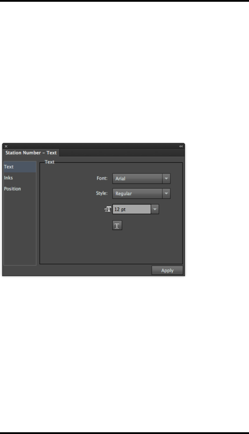
13. Mark
lCustom registration targets
lImage Marks
lRectangle Marks
lTrim Marks
lText Marks
13.12. Station Number
The Station Number mark allows a station index to be applied to the layout, without the need to
apply it to the one-up file previously.
It can only be applied to the Oneup file as selected in the Marks GUI.
13.12.1 Station Number Mark Controls
Text:Allows the text for the mark to be formatted.
Inks:Allows selection of the colour(s) to be used to define the mark, including a control to underprint
a white background.
- 160 -
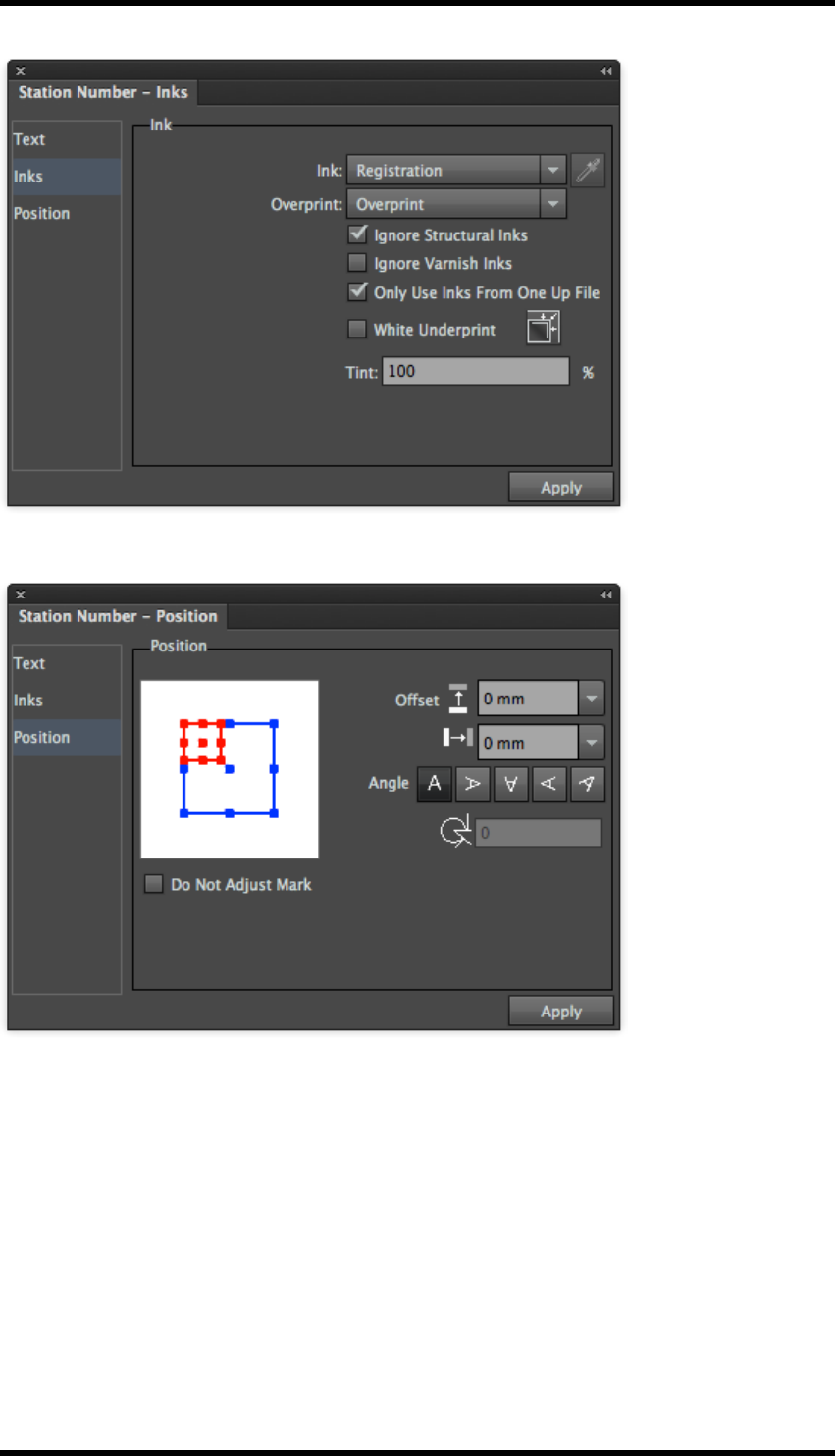
13. Mark
Position. Controls to allow the accurate positioning and rotation of the mark.
- 161 -

13. Mark
13.13. Mark Management
Turn
In the side pull-down menu of Marks, select the Turn command.
This option will flip all marks along the horizontal axis.
Tumble
In the side pull-down menu of Marks, select the Tumble command.
This option will flip all marks along the vertical axis.
Delete
1. Choose one or more marks from the mark list.
2. Go to the side pull-down menu of the Marks palette and choose Delete.
The selected marks will be deleted.
Convert to Objects
1. Choose one or more marks from the mark list.
2. Go to the side pull-down menu of the Marks palette, and select Convert to Objects.
The selected marks will be converted to normal AI objects.
- 162 -

13. Mark
After applying this command, the marks that have been converted to objects are removed from the
mark list, and can NOT be modified through the mark options dialogue box.
Options
1. Choose a mark from the mark list.
2. Go to the side pull-down menu of the Marks palette, and select Options.
The mark parameters dialogue box will be displayed, which can be used to edit the mark set-
tings. You can also open the mark parameters dialogue box by double-clicking a mark in the
mark list.
Change Mark Names
1. Choose a mark from the mark list.
2. Go to the side pull-down menu of the Marks palette, and select Change mark names.
The name of the chosen mark can be edited.
New Folder
Users can add new folders to manage the marks. The folders can then be expanded and collapsed.
This is useful to help organise and manage large numbers of marks.
13.14. Marks Parameters Set
New
Choosing the New command from the side pull-down menu of the Marks palette,
A warning box will appear asking whether to save the present marks.
a. Click OK.
All marks in the current document will be saved to a parameter file with a suffix – fms and
then removed from the working file.
b. Click No.
All marks added will be deleted and not saved.
c. Click Cancel.
The operation is cancelled: the working file remains unchanged.
Save As…
Choose Save as… from the side pull-down menu of the Marks palette.
The marks settings in the current document will be saved as a parameter file with a suffix .fms.
- 163 -

13. Mark
Open…
Choose the Open… command from the side pull-down menu of the Marks palette.
The settings of the parameter set will be applied to the he marks in the current document.
The name of the parameters set will be shown on the Marks palette.
Load…
1. Choose the Load… command from the side pull-down menu of the Marks palette.
A file browser window will be displayed.
2. Browse to and select an existing .fms saved parameter set.
The marks of the parameter file will be added based on the parameters of the document marks.
Recently opened parameters sets
The names of the recently opened files or loaded parameters sets will display at the bottom of the
Marks palette side pull down menu.
Choose a parameters set to apply these settings to the marks of the current document.
- 164 -

14. Basic Functions
14. Basic Functions
14.1. Background
RealPro Toolkit includes a number of general tools and functions that are not specific to a particular
process, but are required by a number of different functions. These generic tools are described in
this section.
14.2. Overview
The functions described in this chapter are:
Pack Selection Tool
This is used to select objects created by RealPro Toolkit (e.g. placed 1-up files, stepped and
repeated objects, CAD layers and Marks). The tool allows these objects to moved and edited even
though they are in locked layers.
Output PDF
This is the preferred method of saving a PDF as it performs some checks to ensure a master file
has been saved, Sheet and Plate set-up are correct and that any Adobe Illustrator editing inform-
ation is removed. Any requested media scaling is applied to the PDF exported in this way.
Trim and Media box
This function provides a quick interactive method of drawing a trim box and media box.
These page boxes are honoured by Nesting and PDF output.
14.3. Pack Selection Tool
1. Select the Pack Selection Tool from the AI toolbar .
The tools cursor icon will be displayed, when this tool is in use.
2. Use the Pack Selection Tool to select an object created by RealPro Toolkit. These objects
include placed 1-up files, stepped and repeated objects, CAD layers and Marks. The tool
allows these objects to be moved and edited even though they are in locked layers.
3. Press and hold the mouse button to drag the CAD object(s).
Note: The Pack Selection Tool orientation controls can only be used if the Pack Selec-
tion Tool was used to select the object of the CAD layout or when transforming the
object into a CAD object. In other situations the tool is unavailable.
14.3.1 Objects with registration marks
Note: The Pack Selection Tool can be used to move an object with register or trim
marks, but cannot move the centre marks, corner marks or trim marks independently of
- 165 -
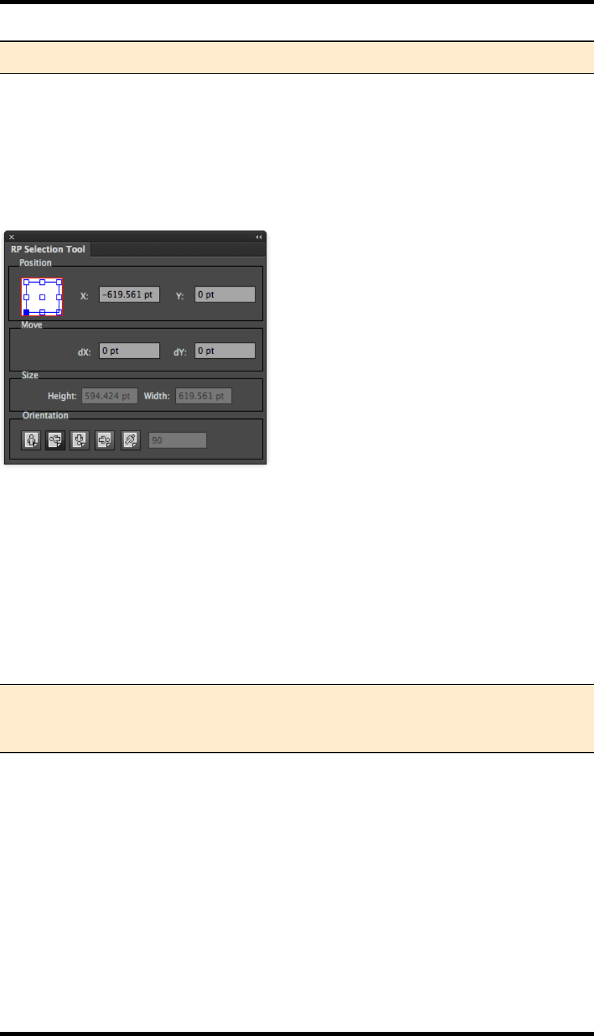
14. Basic Functions
that object.
14.3.2 RP Selection Tool
You also can use the RP Selection Tool to change the properties of the imposed object. Access this
from the file pull-down menu.
Select RealPro > Basic Function > RP Selection Tool.
The RP Selection Tool dialogue box is displayed:
The RP Selection Tool dialogue box will display the changed properties. Alternatively you can enter
new properties for the CAD object directly into the RP Selection Tool dialogue box.
Position
The nine points on the reference point locator in the RP Selection Tool correspond to the positions
on the bounding box of the selected object.
The X, Y position coordinates are given with reference to this position. With an object selected, the
user can enter position values directly into these fields to reposition the object.
Note: The selection of the reference point in the object composition will affect the X, Y
coordinate values and the centre of rotation. As an object is rotated the reference point
will move relative to the object
Move
dX: Enter a value to reposition the selected object horizontally.
dY: Enter a value to reposition the selected object vertically.
To use move, type a value (positive or negative) into the dX or dY fields and press the enter key.
The object will be moved accordingly, the values of X or Y will be updated to the new position and
the dX or dY value will return to zero.
Size
Width: The width of the bounding box of the selected object.
- 166 -
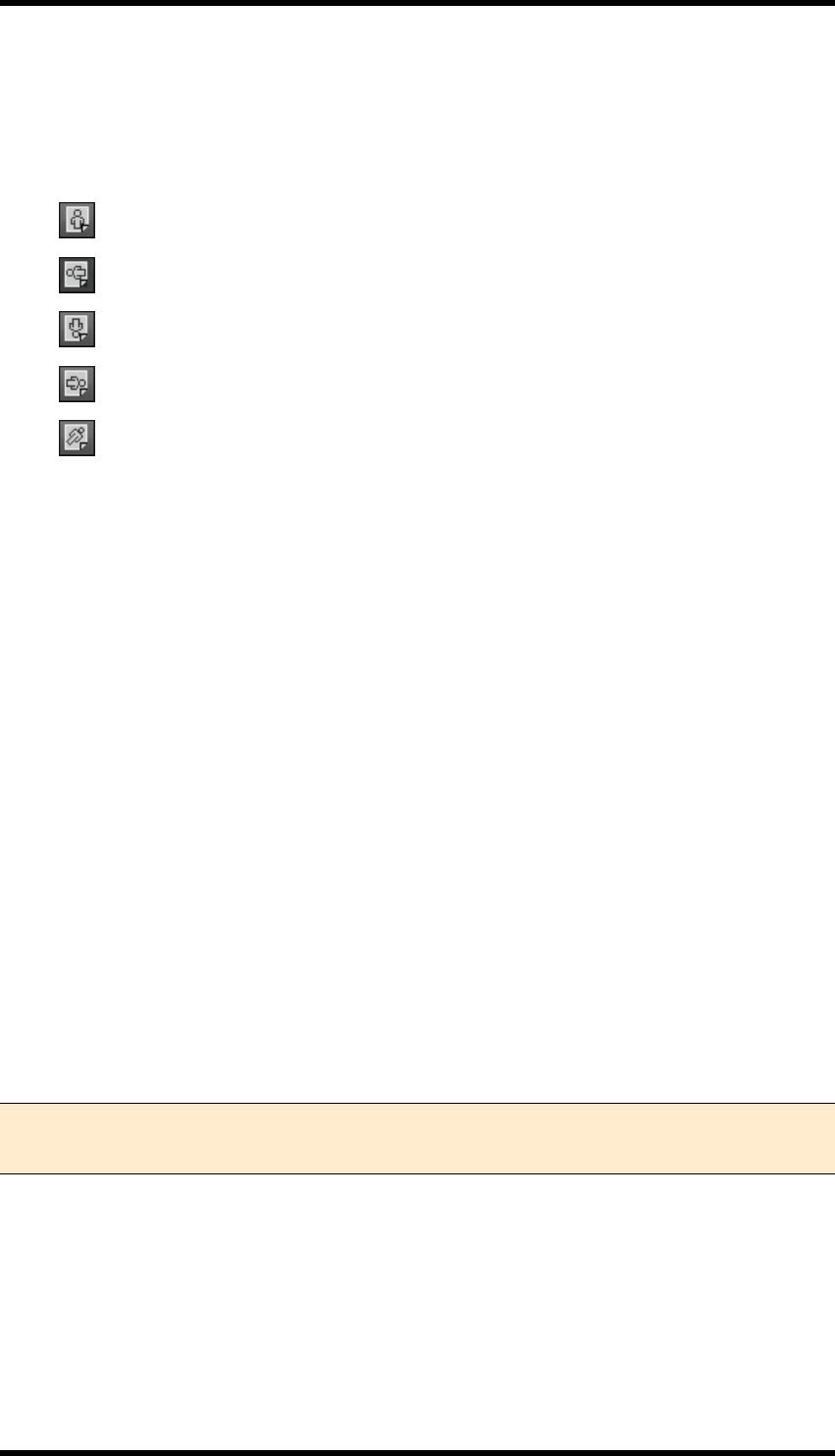
14. Basic Functions
Height: The height of the bounding box of the selected object.
Orientation
There are five orientation buttons:
Maintain the object in the original orientation
Rotates the object 270 degree clockwise
Rotates the object 180 degree clockwise
Rotates the object 90 degree clockwise
Allows a custom angle to be entered
Rotate: The reference point (on the objects bounding box) is used as the centre of rotation. This ref-
erence point remains relative to the sheet not the object so as the object is rotated, the reference
point may move relative to the object (unless the reference point is set to the object centre).
14.4. Output PDF
The Output PDF function performs some checks to ensure a master file has been saved, Sheet and
Plate set-up are correct. Any Adobe Illustrator editing information is removed.
1. Open the job or layout that you want to output to PDF.
2. In the file pull-down menu, select RealPro > Basic Function > Output PDF.
3. Select directory path, then click Save.
14.4.1 Scaling and media when exporting PDF
Any horizontal or vertical scaling specified in the plate and sheet set-up will be applied when using
Output PDF.
For example, if you set the size of the printing plate as 1000 mm x 1000 mm, the vertical direction is
90 %, the horizontal distortion is 100 %, and then the PDF file you export will be 900 mm x 1000
mm.
Note: When the imposition is exported as a PDF, the printing plate dimension will be set
as the media box and the paper dimension will be set as the trim box.
14.4.2 Checks and warnings when exporting PDF
If Output PDF is unsuccessful, the message window will display “Failed to Output PDF file!”.
If changes were made to the file, or the file has been updated but not saved before attempting PDF
export, then the message window will appear and warn you to save the file.
- 167 -
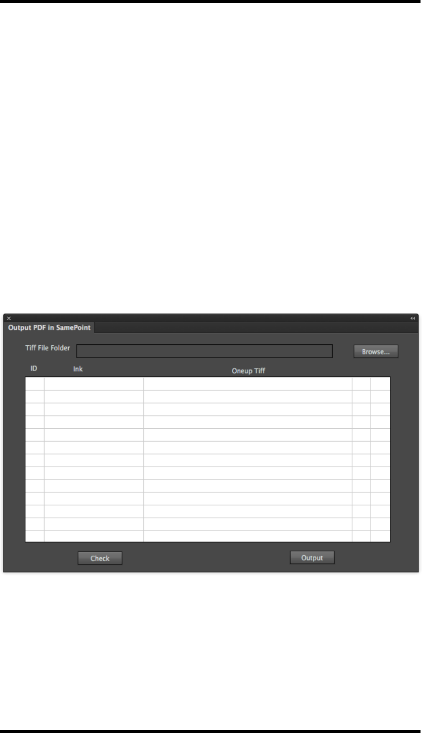
14. Basic Functions
If the size of the printing plate is larger than the artboard, a message will appear to notify you to
change the size of the artboard or the printing plate.
If the size of media box is larger than the artboard, a message will appear to notify you to change the
size of the artboard or the media box.
14.5. Output PDFin SamePoint
This function creates a PDF of the nested document, but replaces the one-up object with data made
up from 1-bit TIFFfiles produced from a RIP. This ensures dot for dot consistency across all
objects.
14.5.1 Usage
The one-up file(s) must be RIP'ed to produce a series of 1 bit TIFF files.
Create a nested documenent using the RealPro Toolkit Nest functions and the original one-up file
(s).
Select Window > RealPro >Basic Functions >Output PDFin SamePoint...the following pal-
lete is displayed:
Click on the Browse... button and use the browser to navigate to, and select, the folder containing
the 1-bit TIFF files.
Click on Check. Toolkit will then attempt to match the inks in the nested file to the appropriate 1-bit
TIFF.
- 168 -
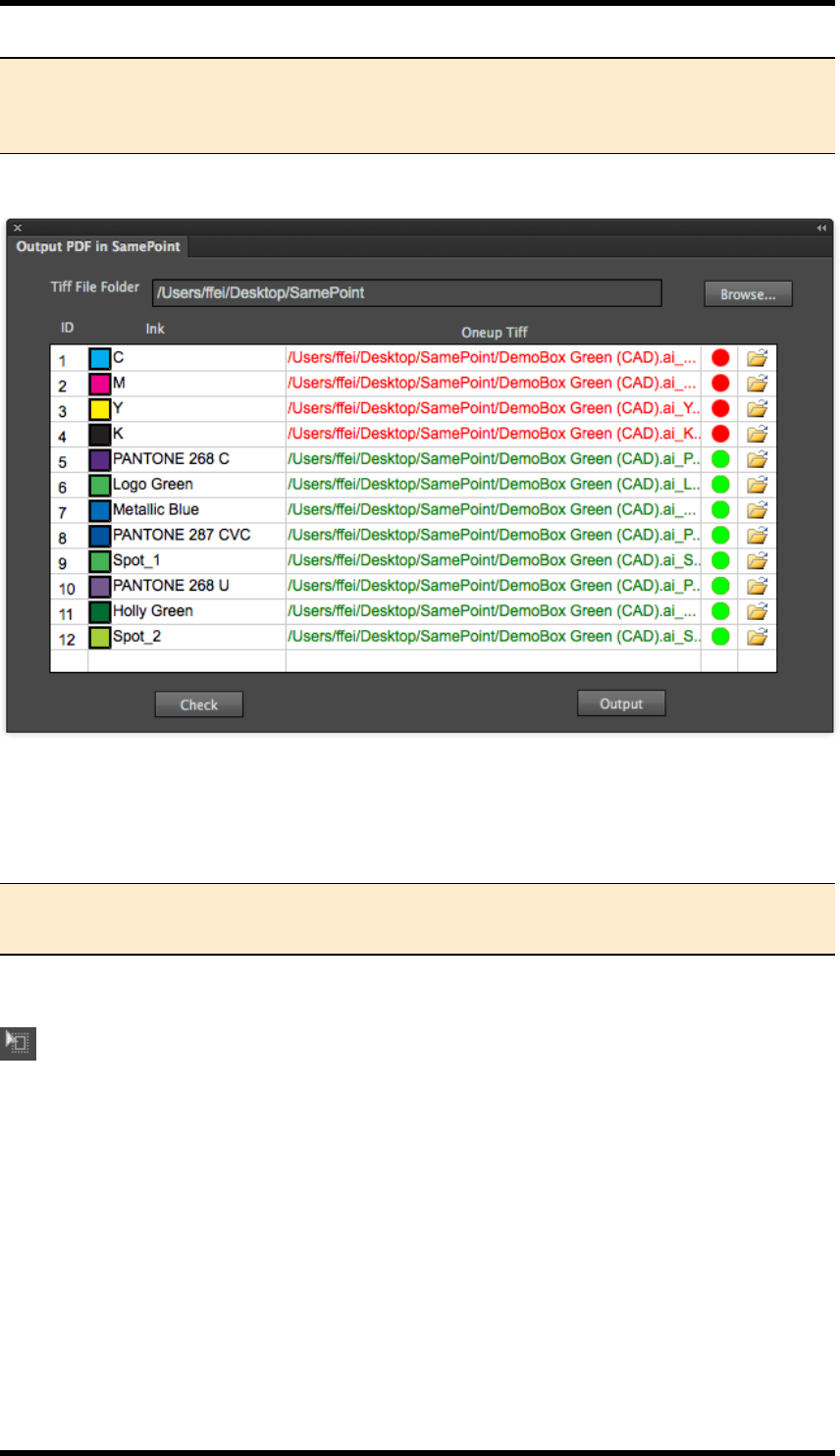
14. Basic Functions
Note:Toolkit is looking for files with a naming convention of:<one-up filename>_<ink
name>.tif, if the file is found, it is shown in green, otherwise it is shown in red. Names
for the process inks are "C", "M", "Y" &"K".
If there are any entries in red, as above, the paths to the files should be resolved by clicking on the
appropriate folder icon and navigating to the required file.
Once all paths have been resolved, click on Output to generate the PDF file.
Note:It is NOT possible to use Output PDFin SamePoint using the 8-bit TIFFfiles gen-
erated from the RealPro Toolkit TIFFMaker function.
14.6. Trim and Media box
This function provides a quick interactive method of drawing a trim box and media box. These page
boxes are honoured by nesting and PDF output.
The size of the Output PDF from Nest will be that of the media box added:
For example, the user adds a trim box & media box in the AI document.
trim box is 200 mm x 200 mm
media box is 205 mm x 205 mm
- 169 -
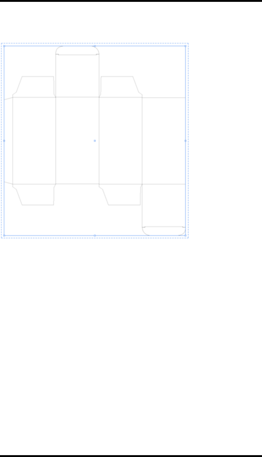
14. Basic Functions
Then the size of PDF file will be 205 mm x 205 mm which is the same as that of media box (See the
following figure).
Add Trim Box & Media Box
Use this to add the trim box and media box to the current job.
Hide Trim Box & Media Box
Use this to hide the added trim box and media box of the current job.
Size of Trim Box
Set the size of trim box. The pull-down menu contains a series of default sizes.
Width and Height
Custom width and height values can be entered in the text fields. The range is from 0 pt to 16383 pt.
Orientation
Set the orientation to be horizontal and vertical.
Fit to
Choose to fit the trim box to the AI artboard, all artwork in the layout, selected objects, to CAD or to
the crop area of layout.
- 170 -

14. Basic Functions
Media Box
Controls the gap between the media box and the trim box by setting the top, bottom, left and right
margins. The set range is from 0 pt to 9000 pt. Click the link icon to make the four margin values
equal.
Media Box Fit to
You can choose to automatically fit the media box to:
lAll artwork in the layout
lSelected objects
lCAD
lCrop area of layout
- 171 -

15. Variable Manager
15. Variable Manager
15.1. Background
The variable manager allows the user to create and manage variables for use in the Marks or Nest-
ing functions.
Variables are contained in Groups Groups can be either Global, saved on the system and applying
to all documents, or Local,saved with the current document only.
15.2. Usage
Select Window >RealPro >Basic Function >Variable Manager, the following dialogue box is
displayed:
Create a new group
Select whether the group will be Global or Local
Click on the New Group button.
Name the new group by entering the name in the Variable Set field then press the Enter (Return)
key.
Create a new variable
Enter the variable name into the Variable name field and press the Enter key. The name will then be
prefixed with "g_" if it is a global variable or "l_" in the case of a local variable.
Enter the required formula into the formula field, then press the Enter key.
The example below illustrates how variables can be used in conjunction with the Mark function.
- 172 -
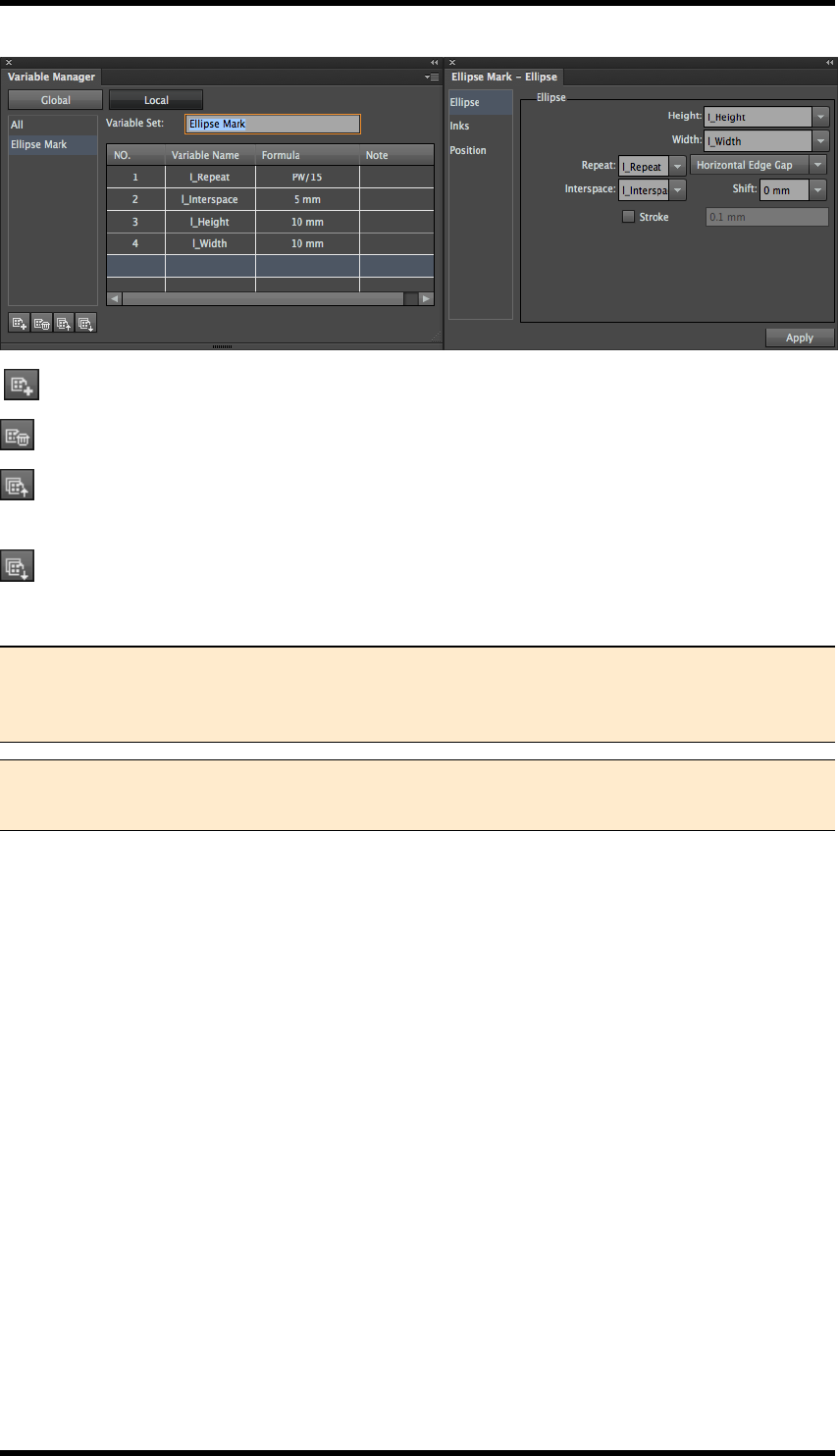
15. Variable Manager
New Group: Create a new variable group.
Delete Group: Deletes the selected group.
Import:Import a previously exported collection of variables. If the same variable name already
exists the user is prompted whether to overwrite or not.
Export:Export the groups of variables for use in another system or for archive purposes.
Selecting All from the list of groups will display all variables.
Note: If a variable that is in use, by Mark or Nest, is deleted, a warning is given to the
user and the value will revert to the formula specified by the variable instead of the vari-
able name.
Note:If a variable that is in use, by Mark or Nest, is changed, the values will be updated
accordingly.
- 173 -

16. Tiff Maker
16. Tiff Maker
16.1. Background
The RealPro Toolkit TIFF Maker function is used to export the selected graphic area to TIFF format.
This is often required when connecting to the next process in the workflow. TIFF Maker has the fol-
lowing advantages over using the Rasterize function in Adobe Illustrator (AI):
lThe exported TIFF file can contain spot inks that are included in the AI file. Optionally com-
posite (multichannel) or separated (grey-scale) TIFF files can be generated.
lIndividual inks can be included or excluded from the TIFF export. This reduces the time in
exporting and post-processing.
lThe area to be exported can be defined by the art board, crop area or trim box. In addition,
users can add bleed settings.
lTIFF Maker can be configured to construct meaningful file names automatically.
lDifferent levels of anti-aliasing can be applied to the exported TIFF.
lThe exported TIFF files can be rotated and mirrored.
lSupport of electric engraving "Fast forward" control files to enable electrical engraving
machine to automatically skip the blank areas during engraving so as to reduce production
time.
16.2. Overview
In this chapter we will look at:
Basic Output from Tiff Maker
The basic steps of using Tiff Maker.
Tiff Maker Settings
The settings of Tiff maker in more detail.
File Naming Rules
Tiff Maker can be configured to construct meaningful file names automatically.
Noise
The RealPro Noise effect filter can be used to add noise to Tiffs to reduce rendering artefacts in
downstream processes.
- 174 -

16. Tiff Maker
16.3. Basic output from TIFF Maker
1. Open the AI file that is to be used by TIFF Maker.
2. Use one of the following options to Update the Ink Manager
lOption 1
Select Window >RealPro >Ink >Ink Manager menu to open the Ink Manager Dia-
logue box.
Click the Update Ink List button to update the inks information of the current AI file.
lOption 2
Select Window >RealPro >Ink >Update Ink Manager menu to update the inks
information.
Note:It is recommended that Option 1 is used, as the ink manager allows the inks
information to be checked.
3. Select Window >RealPro >Tiff > Tiff Maker.
The TIFF Maker dialog box will open.
4. Set various parameters of TIFF Maker (See TIFF Maker Settings for more details).
5. Click Output to export the TIFF.
The progress will be displayed during TIFF output process, followed by a confirmation mes-
sage on completion.
- 175 -
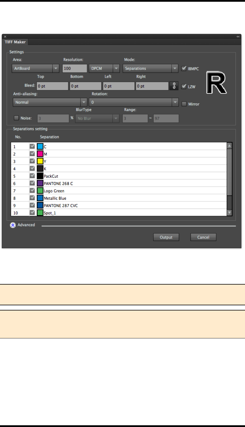
16. Tiff Maker
16.4. TIFF Maker Settings
Output Area
Output Area area has four options, ArtBoard, Media boxes, Crop Area, and plate.
Note: Where there are several artboards, TIFF Maker will only output the contents of cur-
rently selected artboard.
Note: The Media box and Crop area functions may only be used if the RealPro Toolkit
"Mark" plug-in is installed. The Plate option may only be used if the "Nest" plug-in is
installed.
Resolution
Enter the required resolution as either lines per cm (DPCM) or lines per inch (DPI).
Higher resolutions will take longer to export.
Mode
Separations:
- 176 -
16. Tiff Maker
Separations output: Each ink separation will be output as a separate grey-scale, (8 bit), TIFF file.
Composite
Asingle multi-channel TIFF file will be created containing all the separation information.
IBMPC
Select this option to create TIFFs in PCByte order. Clear this to create TIFFs in MacByte order. Spe-
cifically for Macs using non-Intel CPUs.
Bleed
Users can optionally set bleed values: The size of final exported TIFF file is increased by these mar-
gins entered. The units used are the same as those of the AI system.
LZW
Select this option to apply LZW compression to the output files.
Anti-aliasing
Anti-aliasing reduces jagged-edges when vector objects are converted to TIFF bitmap file. Four
options are available: "None ", "Normal", "Medium" and "High".
Note: The default setting of anti-aliasing is “Normal”. Choosing the "High" option will
increase the amount of time it takes to export the file.
None Normal Medium High
Rotation and Mirror
The output can be rotated and / or mirrored. The letter "R" is displayed in the dialog box to show a
preview the effects of the transform.
Note: If the output Tiff file is to be used in a Hell engraving machine, mirror the file
before output.
- 177 -
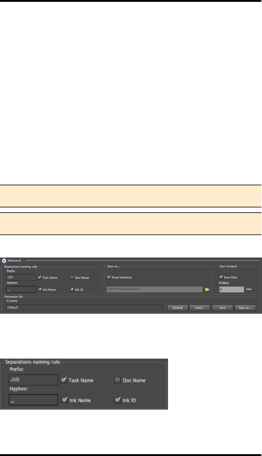
16. Tiff Maker
Noise settings
When you add or create smooth vignettes in a file, it is common for “stripes” to appear when the file
is either rendered or rasterised. A way to prevent these artefacts is to add a small amount of noise
Noise
Select this option to add noise to the output and enter a value, for the amount of noise required, in
the adjacent field.
Blur Type
Select the Blur filter required, options are No Blur,Gauss Blur (Gaussian Blur) or Average Blur.
Range
Select the density range to which the noise filter should be applied.
Separations setting
Select the inks to be included in the output by ticking the relevant items from the list of separations.
Note 1. The inks displayed in the separations area is in accordance with those in ink
manager.
Note 2. If any of the inks have been modified, it is necessary to update the ink manager
before TIFF output, to ensure the accuracy of TIFF output.
16.5. Advanced Settings
File Naming Rules
Tiff Maker can be configured to construct meaningful file names automatically using the following
parameters:
Prefix: allows the user to set a custom file name prefix, (Task Name) or use the current document
name, (Doc Name), as the prefix.
- 178 -
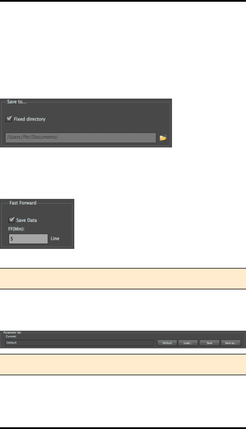
16. Tiff Maker
Ink Name and / or Ink ID: The user can set the name of the ink and /or the ink sequence number as
shown in the Ink Manager to be added to the output file names. These two options can be used indi-
vidually or in combination. (Only available when outputting in Separations mode).
The Hyphen field allows the user to specify which character(s) is used to separate the different ele-
ments of the file name.
Save to
The user can select the location where the TIFFfiles will be stored.
Fast Forward
The "fast forward files" can be saved as SVS format files, which can be read by engraving
machines. When the blank area is larger than setting value,(blank lines), the engraving machine will
move fast forward, so as to save engraving time.
FF MinSets the minimum number of blank lines.
Note: Only in colour separation output process, it can output fast forward files. Each col-
our separation plate can be respectively saved as a SVS file.
Parameter Set
The parameters of output TIFF files can be saved as a preference file for repeated use. They can
also be transferred to another system.
Note: The saved parameters file can be loaded across PC\Mac platform and language ver-
sion.
16.6. Limitations
1. Before using Tiff Maker, make sure that you update the inks information in the Ink Manager.
- 179 -

16. Tiff Maker
2. The Tiff Maker outputs standard 8-bits [.tiff] format file that theoretically can be used in
engraving machines which support 8-bits Tiff file. However, only the MDC and Hell engrav-
ing machines have been tested; other brands of engraving machines haven’t been sys-
temically tested.
3. During the actual engraving production, the [.svs] format file generated can be identified by
the Heliodisk system of Hell engraving machines.
4. The default anti-aliasing setting is “Normal”. If the small text in the output Tiff file has not
achieved the requirement, users can set the anti-aliasing parameter to “Medium” before out-
put.
5. There is no limitation in size and complexity of the file to be output, other than the capabilities
of the platform on which the software is running.
6. Tiff Maker is a CPU intensive process. Performance (output speed) will also be impacted by
the number of files open in AI.
- 180 -

17. E-Connector
17. E-Connector
17.1. Background
E-Connector is used to output RealPro Nest layout files to engraving machines by creating either
composite or separated TIFF files of the final layout file. The format required will, of course, vary
from system to system. RealPro E-Connector has some additional support for some specific
engraving systems.
RealPro E-Connector has many advantages:
1. Compatibility with engraving equipment: E-Connector can directly output step & repeat lay-
out files to engravers (Hell, OHIO, MDC, etc.) without switching between different nesting
work stations.
2. Consistency: It can generate engraving files with a operation, the resolution of all the one-up
files in the layout will be exactly the same.
3. Integrated with nesting: It allows output from step & repeat with multi spot colour channels,
users do not need to repeat the step & repeat operation.
17.2. E-Connector Overview
There are two main methods of using E-Connector; the creation of a composite (single) file or of sep-
arations (multiple) files. The choice depends upon the devices for which the output is made.
E-Connector also has additional support for specific engravers; as well as ensuring the correct
format, this optionally allows the creation of control files for the engraver devices.
The possible steps are best described in overview by the following diagram:
- 181 -
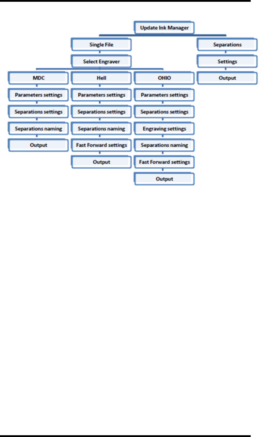
17. E-Connector
In this Chapter we will explore:
lComposite Output
lSeparations Output
lParameters Panels
lTask
lSettings
lSeparations
lAdvanced settings
lEngraver Specific Parameters
17.3. Composite Output File Procedure
Prerequisites: The required step & repeat layout file is open and the Ink Manager has been updated.
1. Select Window > RealPro >TIFF > E-Connector to display the E-Connector dialogue box.
The E-Connector dialogue will be displayed (see below).
2. In the Settings panel, select Composite from the Mode pull down menu.
- 182 -
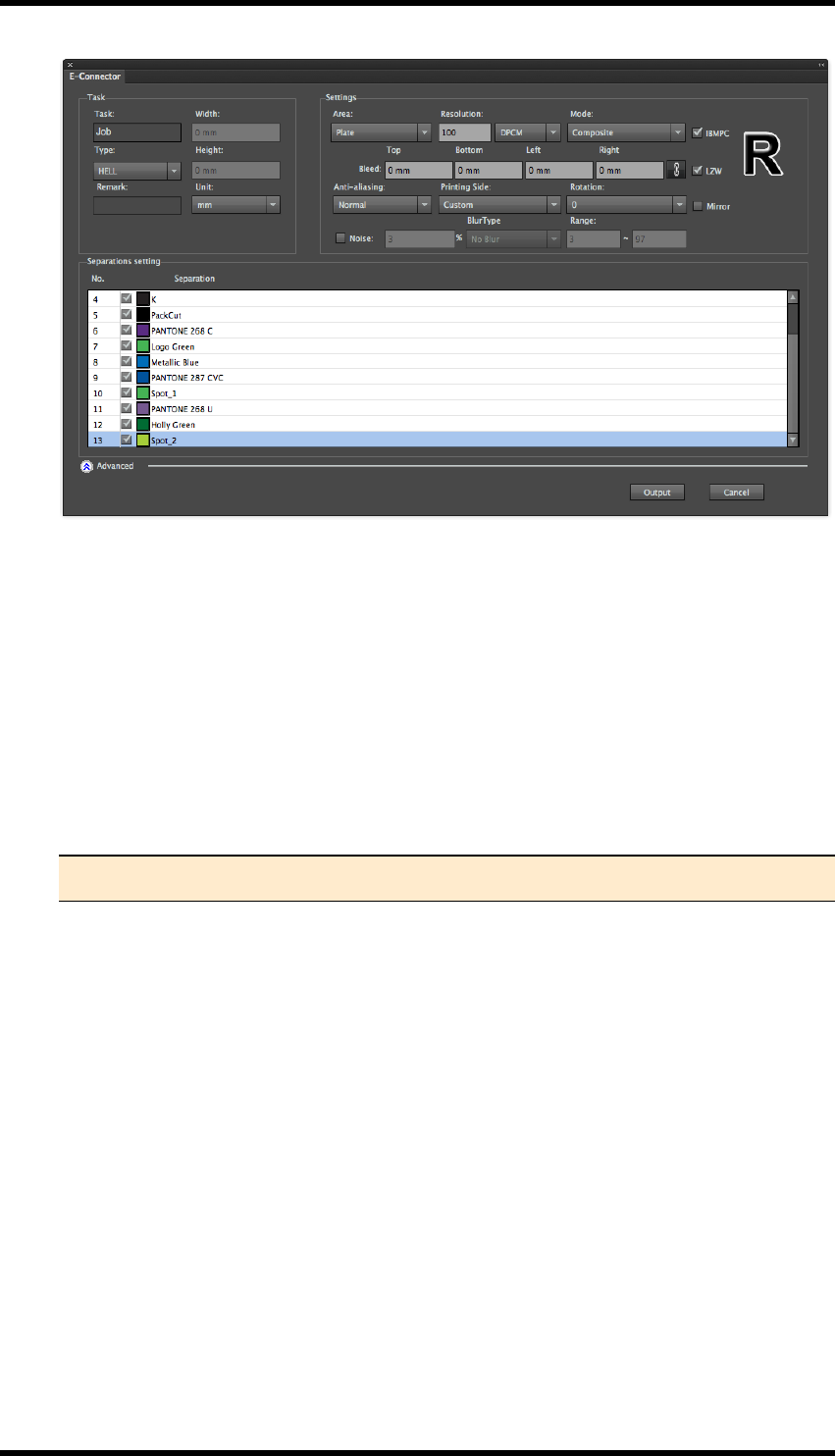
17. E-Connector
3. Set the required out parameters such as:
Separations to be included (check or uncheck the required separations in the Separations
Settings)
lArea to be exported
lResolution
lOutput geometry
lAnti-aliasing (optional)
lBleed (optional)
lNoise filters (optional)
Note: These parameters will be discussed in more detail below.
4. Click Output.
The user is able to configure and output path.
The file(s) will begin to export with a confirmation when they have successfully completed.
17.4. Output Separations Procedure
Prerequisites: The required step & repeat layout file is open and the Ink Manager has been updated.
1. Select Window > RealPro >TIFF > E-Connector to display the E-Connector dialogue box.
The E-Connector dialogue box will be displayed:
- 183 -
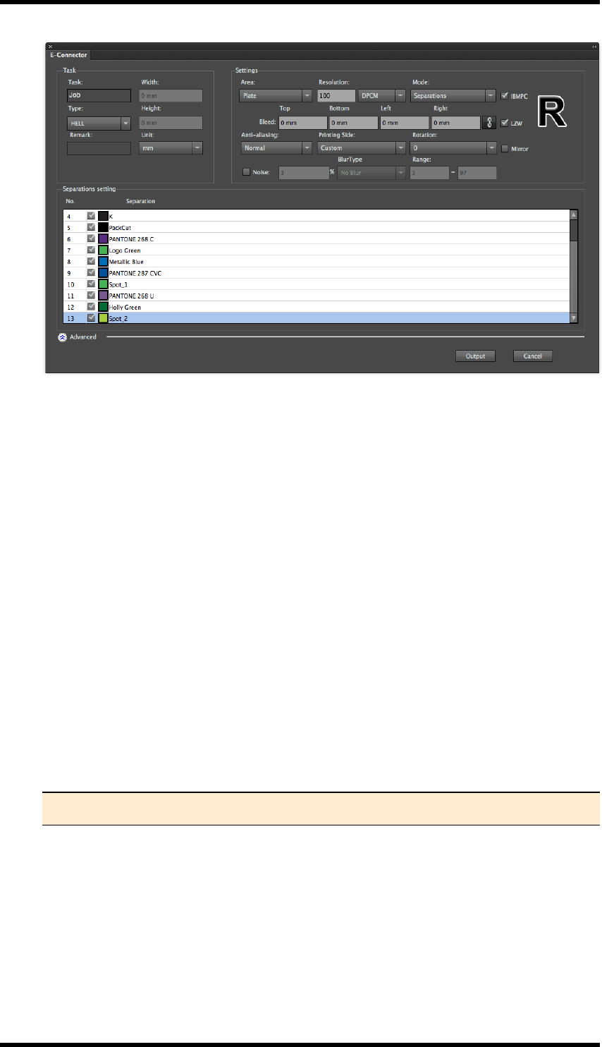
17. E-Connector
2. In the Settings panel, select Separations from the Mode pull down menu.
Some additional options are only available when Separations is selected.
3. In the Task panel, select the required Engraver Type: the available options are MDC, Hell or
OHIO.
Some settings will be automatically set or become available depending upon which option is
chosen.
4. Set any required parameters such as:
lSeparations to be included (check or uncheck the required separations in the Separ-
ations Settings
lArea to be exported
lResolution
lOutput geometry
lAnti-aliasing (optional)
lBleed (optional)
lNoise filters (optional)
Note: These parameters will be discussed in more detail below.
5. If OHIO engraver is selected, engraving parameters of screen ruling & angle, etc. can be set
(See 14.7 Separation Settings)
6. Set separations naming rules.
7. Fast forward settings will be activated if either OHIO or Hell engraver is chosen.
8. If output files need to be saved to fixed document path, select Fixed directory.
- 184 -
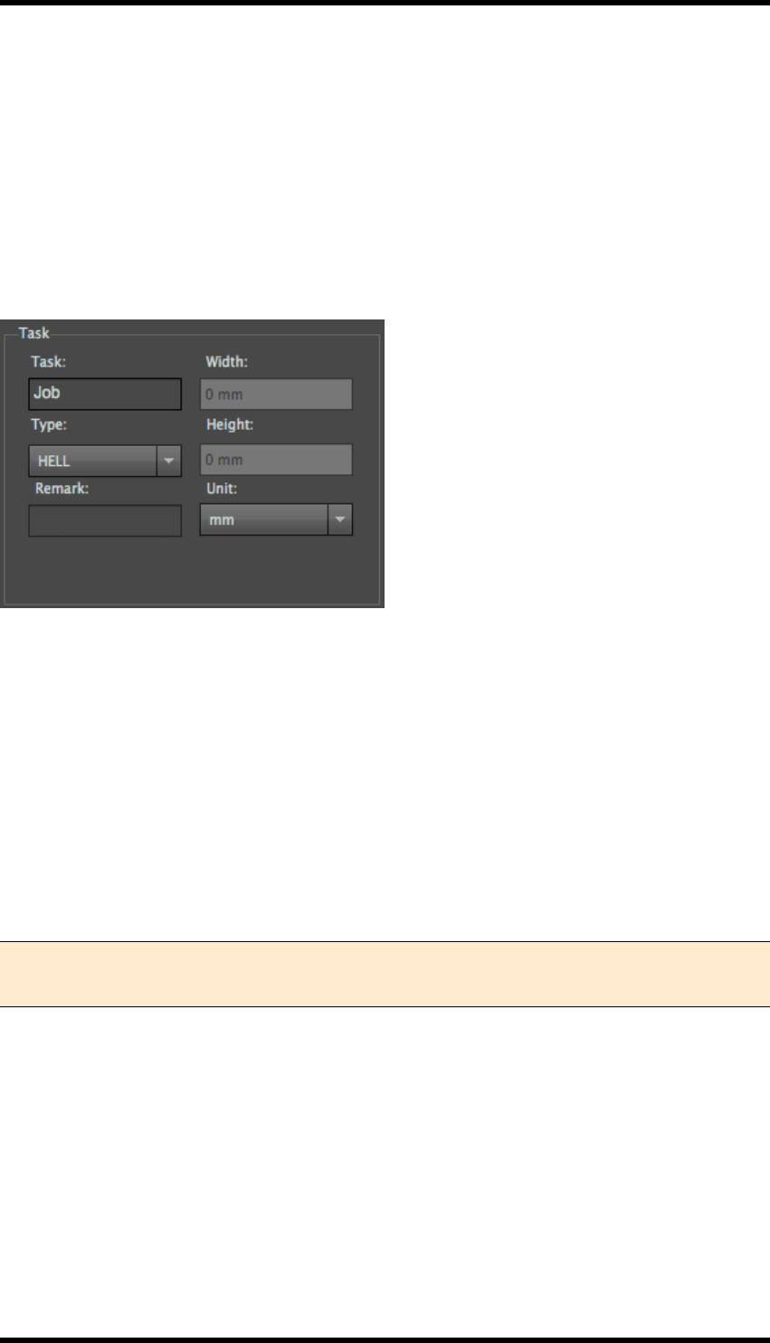
17. E-Connector
9. Click Output.
The user is able to configure and output path.
The file(s) will begin to export with a confirmation when they have successfully completed.
17.5. Parameter Panels
17.5.1 Task
Task
Set the name of the current file to be output.
Engraver
Use to set the engraver type: there are three options (OHIO, Hell & MDC). The format of the output
files will be set in accordance with the chosen engraver type. For example, [.img] format file will be
output if OHIO is selected while [.tiff] file format will be output when Hell or MDC is chosen.
Cylinder size (only available for OHIO types)
The width and height parameters are used to set the size of the cylinder.
Width: Width of the cylinder
Height: Diameter of the cylinder.
Note: The cylinder size setting can only be effective when OHIO is selected. The width
and height information will be written into the [.elo] format file for engraver to read.
Remark
Use to record the memo info on the output file.
Unit
The parameter is used to control the unit of the cylinder size.
- 185 -
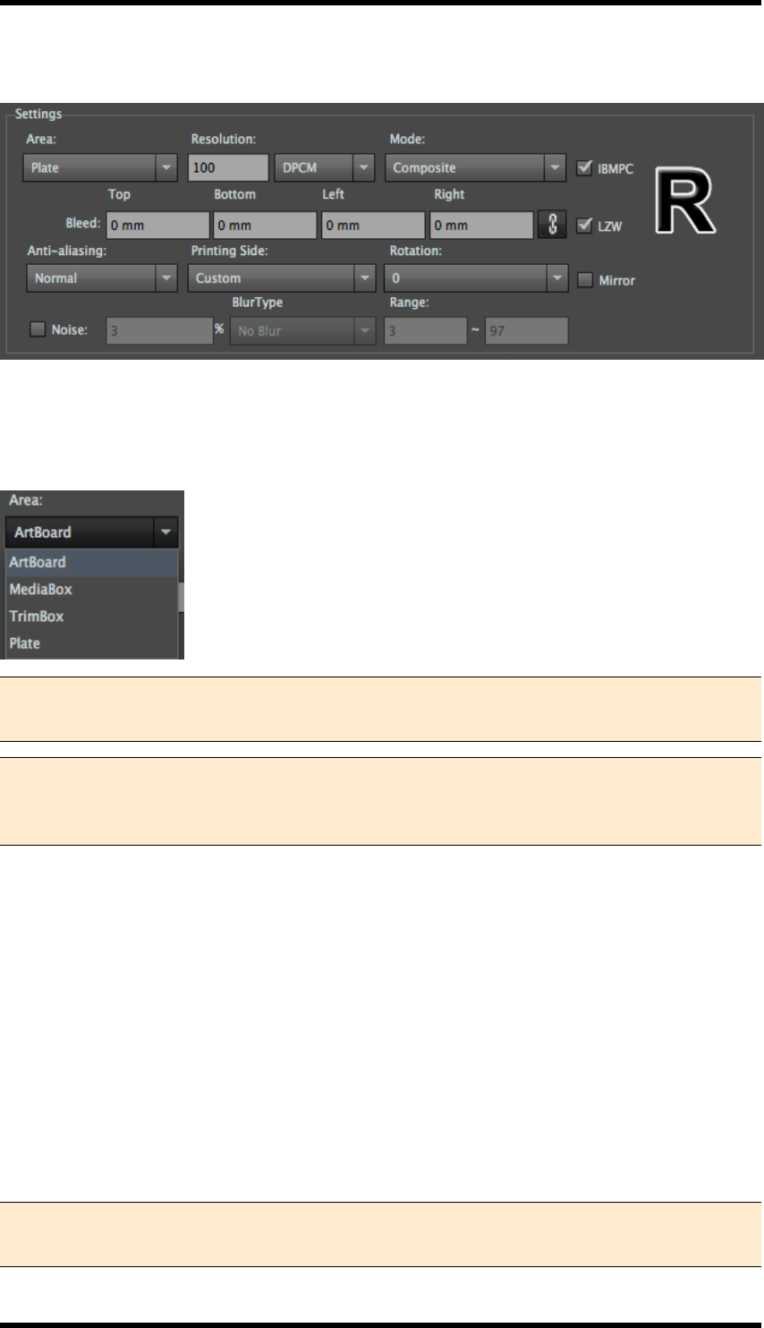
17. E-Connector
17.6. Settings
Area
Selecting export area has four options see below: Users can export the target area by selecting the
appropriate option.
Note 1: In circumstances where there are several artboards, TIFF Maker will only output
the contents of currently selected artboard.
Note 2: The Media Box and Crop area functions can only be used after the RealPro Mark
plug-in has been purchased and Plate can only be used after the ”Nest” function has
been purchased.
Resolution
Users can input relevant resolution values according to precision requirement. Higher resolution
needs higher analysis requirement, so it’ll cause longer export time. There are two kinds of unit,
respectively LPC and DPI.
Output Mode
Single file output: a single Tiff file contains all the ink separations information will be exported when
Single File is selected. The spot ink in the AI file will be output into a new corresponding spot ink
channel. Separations output: Each determined output colour will be output into a gray TIFF file.
Every separation is optional whether to be output or not in both of these two modes by checking on
the box in front of the ink list.
Note 1: Ink name, quantity, sequence displayed in colour separation is in accordance
with those in ink manager.
- 186 -
17. E-Connector
Note 2: If ink has been revised by current operation, it is necessary to update the ink of
ink manager before output, to insure the completeness and accuracy of output.
Anti-aliasing
Anti-aliasing reduces jagged-edges when vector objects are converted to TIFF bitmap file Four
options are available: "None ", "Normal", "Medium" and "High".
Note: The default setting of anti-aliasing is “Normal”. Choosing the "High" option will
increase the amount of time it takes to export the file.
None Normal Medium High
None Normal Medium High Contrast diagram of each anti-aliasing degree
IBMPC
Select the IBMPC check box to create TIFFs in PCByte order. Clear the check box to create TIFFs
in MACByte order. Specifically for Macs using non-Intel CPUs.
Note:Specific to the MAC with CPU of non-Intel series.
Compression
Exported TIFF file can be executed by LZW compression processing.
Back\Surface
This parameter is used to adjust the rotation and mirror operation of the file automatically according
to the selected engraver characteristics. There are three options in the pull down menu: Custom,
Back and Surface.
Custom, Rotation and Mirror parameters are entered manually.
Back\Surface: Rotation and Mirror of the file will be automatically set according to the selected
engraver characteristics.
- 187 -
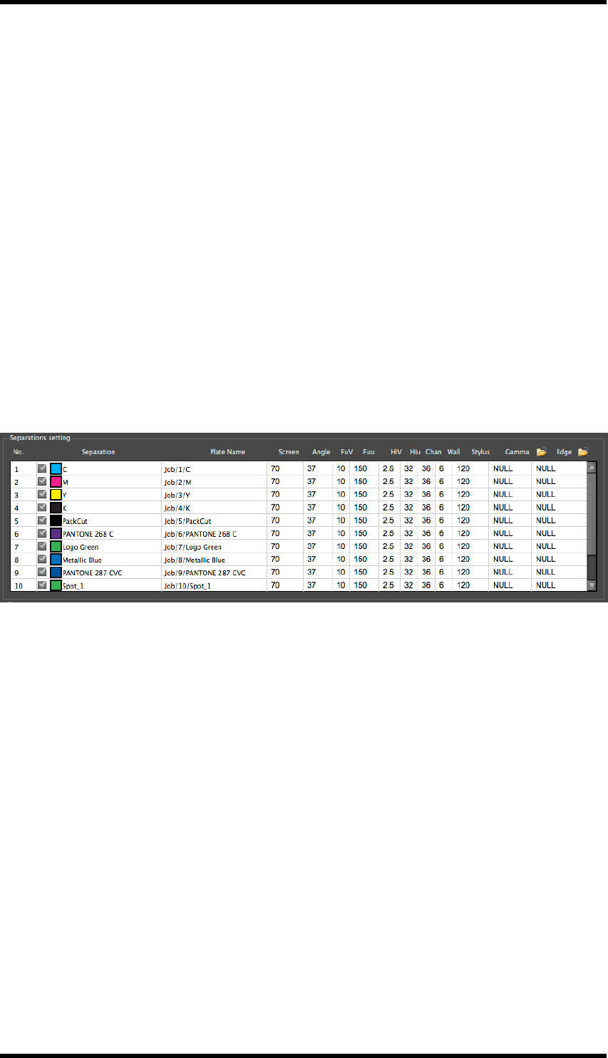
17. E-Connector
Rotation
The output contents can be rotated. Four angles are available: 0°, 90°, 180°& 270°.
Mirror
The output contents can be turn into mirror image. The letter “R” appearance is used for reference.
Bleed
After setting related type of export area, users can set bleeding value according to needs. The size
of final export TIFF file is depended by the enlarged one after bleeding. The unit of bleeding is con-
sistent with that of AI system. Bleed value can be set to the top, bottom, left and right margins of the
file.
17.7. Separations setting
Other than controlling which separations are to be output, other parameter settings only are effective
when engraver of OHIO is selected. All the other parameters will be written in an [.elo] format drive
file for engraving.
Separation
In the separations list, users can select inks that are to be output by selecting / clearing the appro-
priate check boxes.
Plate Name
Use to set the name of the current separation plate. The default plate name will be: Task Name/Se-
paration Number/Separation Ink Name.
Screen
Use to set screen ruling value of the current separation. E-Connector now supports screen ruling
value of 55, 60, 65, 70, 80, 90 and 100.
Angle
Use to set the screen angle of the current separation. Different angles can be selected for different
screen ruling value.
- 188 -
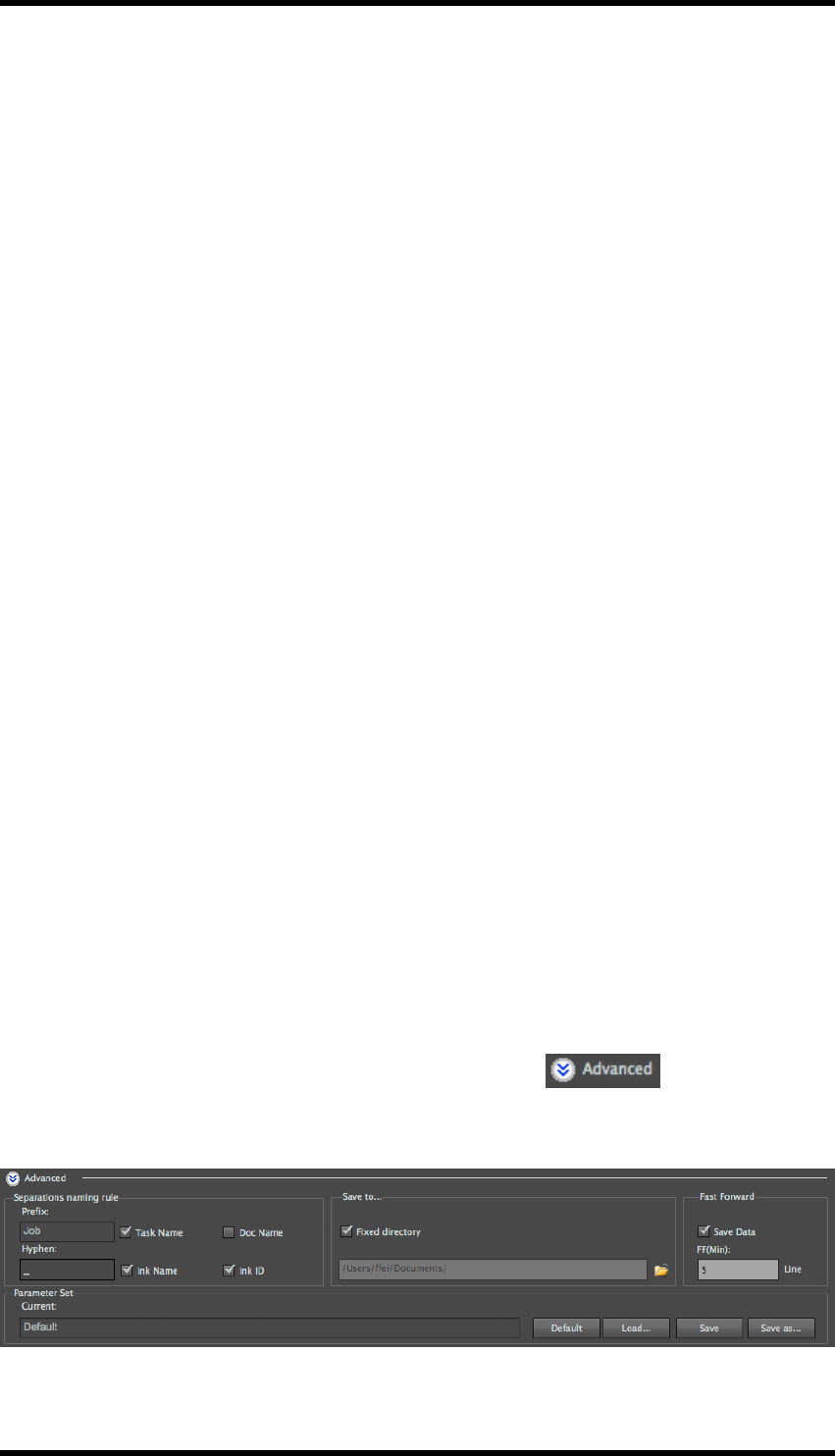
17. E-Connector
FullCell V
Use to set the engraving voltage of the shadow. Default value is 10 V.
FullCell u
Use to set the width of engraving cell of the shadow.
HiLite V
Use to set the engraving voltage of the highlight. Default value is 10 V.
HiLite u
Use to set the width of engraving cell of the highlight.
Channel
Use to set the width of the engraving cell channel.
Wall
The width value of the cell wall, which is automatically calculated by the program.
Stylus
Use to set the stylus of the engraver.
Gamma
Use to select Gamma data files for engraving. Click on <Select Gamma Data…> to select the
folder in which Gamma data files are stored. All Gamma files in the folder will be loaded.
Edge
Use to select edge enhancement data file for engraving. Click on <Select Edge Data…> to select
the folder in which edge enhancement data files are stored. All edge enhancement files in the folder
will be loaded.
17.8. Advanced Settings
From the E-Connector Main Window, press the Advanced button to access the
advanced settings: from here you can configure file naming rules, a fixed directory in which to save
into,
- 189 -

17. E-Connector
17.8.1 Separations naming rule
The output separation file names can be set by adding prefix name, ink name, ink ID and other
information, etc.
The naming rule is : <Prefix+Hyphen+Suffix>.
Note:Only in colour separations output process users can set naming rules. And sym-
bols like \ / : * ? ” < > | cannot be used.
Prefix
Set the prefix of the output separation file name. Users can choose the name of current task or doc-
ument as the prefix or enter a custom prefix.
Hyphen
Set the connector character used between prefix and suffix.
Suffix
Users can choose to use Ink Name, Ink ID or both as a suffix.
17.8.2 Using a Fixed Directory
The Advanced settings must be displayed.
1. Select the Use Fixed Directory check-box.
2. Set desired file path, either by typing in to the text entry field or by using the browse button
When the job is saved, the job is Output, the Save as dialogue box is suppressed, and the
TIFF files are written directly to the specified folder.
17.8.3 Fast Forward
This is a control file which can be passed to OHIO or Hell engravers: When a blank area in the file is
larger than that specified by the FF(Min.) value, the engraving machine will move ‘fast forward’, so
as to reduce engraving time.
- 190 -
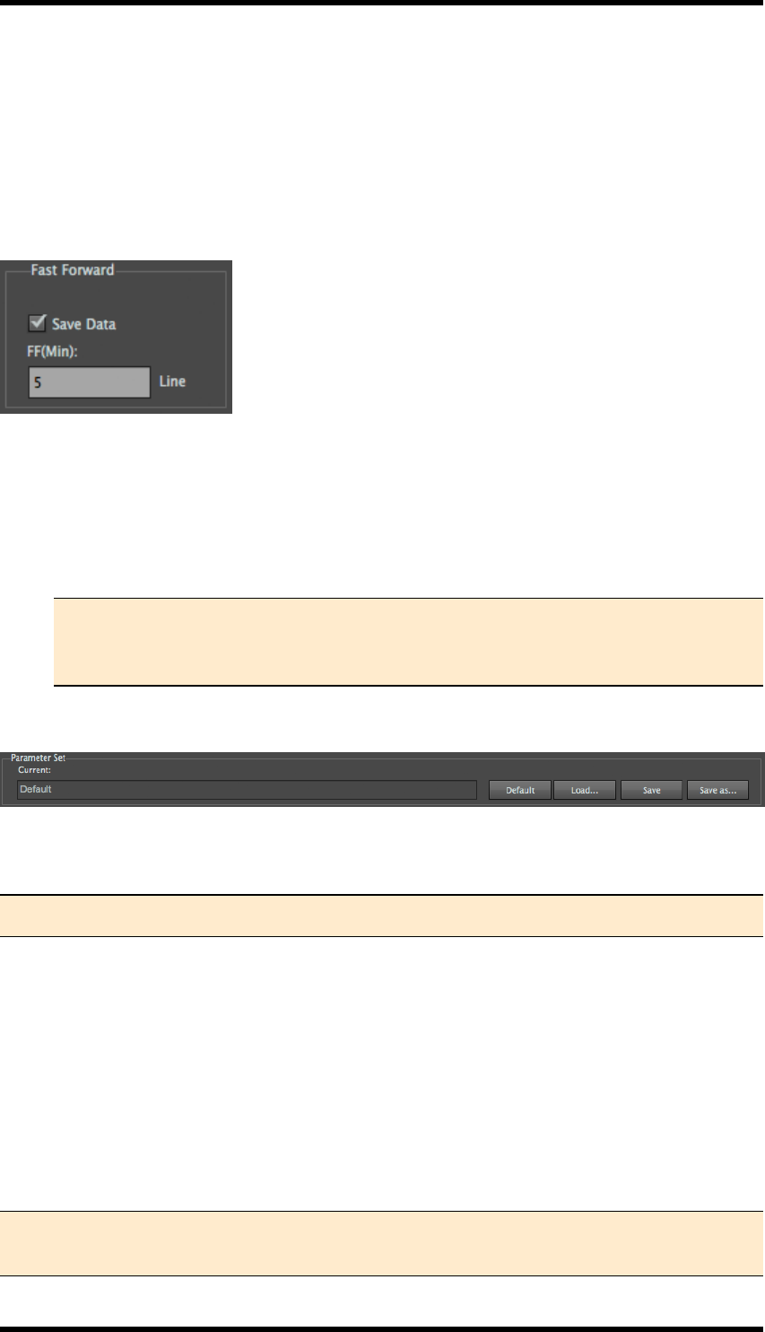
17. E-Connector
Prerequisite:
For the Fast Forward Controls to be available:
The Mode must be set to Separations.
The engraver Type must be set to either OHIO or Hell.
The Advanced settings must be displayed.
1. Select the Save Data check-box.
2. Set the FF(Min) value to the desired minimum of lines.
When the job is saved the "fast forward" data will be saved in the format correct for the spe-
cified engraver.
Note:A data file in the format [*.fa] will be generated for OHIO engravers and a
data file in the format [*.svs] will be generated for Hell engravers.
This function does not support MDC engravers.
17.9. Parameter Set
Parameter Set Parameter set data of output settings can be preserved as general parameters, facil-
itating convenient access.
Note:The parameter set file can save all setting data except separation setting.
Default
Click the Default button to use system default output settings.
Load…
Click the Load... button to load a previously saved parameter set file.
Save
Click this button to save current settings to the parameter set file.
Note:The saved parameters file can be loaded across PC\Mac platform and language ver-
sion.
- 191 -

17. E-Connector
Save as…
Click this button to save current settings to as new parameter set file.
17.10. Limitations
lBefore using Tiff Maker, please make sure that you update the inks information in the Ink
Manager.
lE-Connector is a CPU intensive process. Performance (output speed) will also be impacted
by the number of files open in AI.
- 192 -
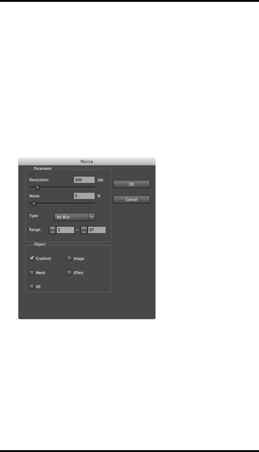
18. Effects
18. Effects
18.1. Noise
When you add or create smooth vignettes in a file, it is common for “stripes” to appear when the file
is either rendered or rasterised. A way to prevent these artefacts is to add a small amount of noise.
To add noise to a file using the RealPro Noise filter effect:
1. Open the required AI file.
2. Select the object you want to work with.
3. In the AI menu bar select Effect > RealPro > Noise.
The Noise dialogue box will be displayed.
4. Set the parameters:
Resolution: set the degree of coarseness of Noise added.
If accessed from either Tiff Maker or E-Connector, the resolution is set by the output res-
olution.
Noise: set the degree of the noise added.
Type: Select from No Blur, Gauss Blur or Average Blur.
A blur filter can optionally be added to the noise to remove high frequency artefacts.
Range: Only the area in the range can be added noise.
- 193 -
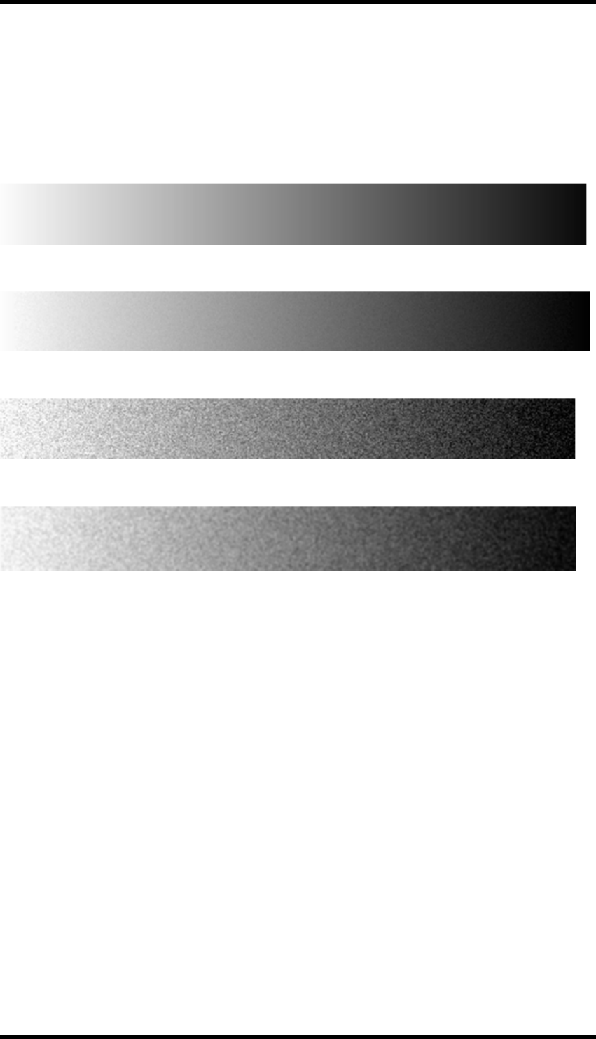
18. Effects
Object: From the Noise Tool you can add noise to specified objects (containing Group).
If accessed from Tiff Maker or E-Connector, the object type setting is not available and the
noise will be applied globally to the file.
5. Click OK to apply the settings.
Examples
no noise
3% noise – No Blur
20% Noise – No Blur
20% Noise + Blur
18.2. Curves
It is possible to adjust the points throughout an image's tonal range. This is similar to the tool avail-
able in Adobe Photoshop.
1. Open the required AI file.
2. Select the image to be adjusted.
- 194 -
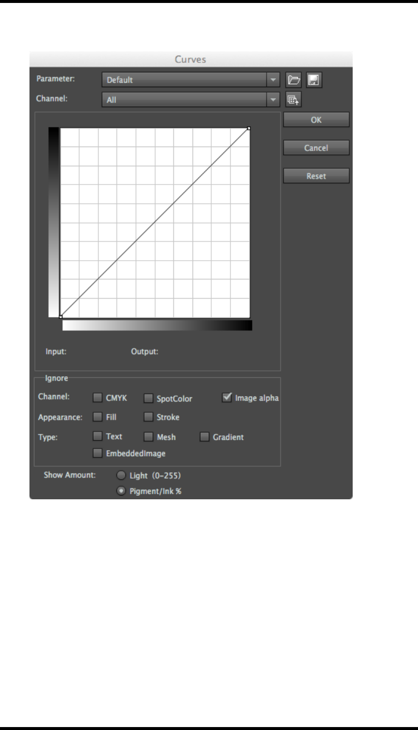
18. Effects
3. In the AI menu bar select Effect > RealPro > Curves.
The Curves dialogue box will be displayed.
- 195 -
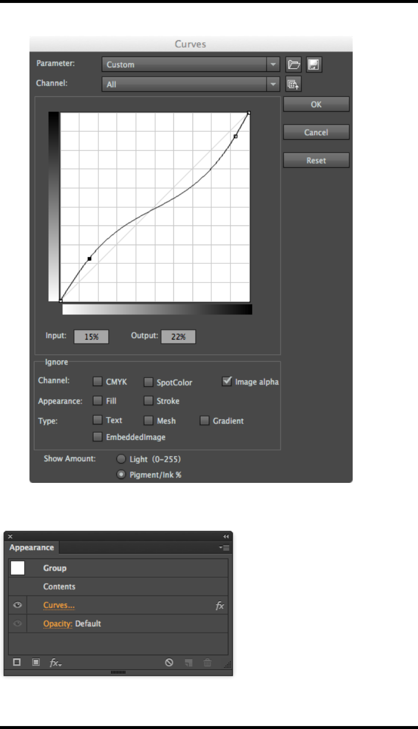
18. Effects
4. Adjust the curve as required, by clicking and dragging on the curve.
5. Click on OK when the required adjustments have been made.
The adjustment curves can be deleted by removing them from the image's appearance settings.
- 196 -

19. Seamless
19. Seamless
19.1. Background
RealPro Seamless allows users to repeat a unit element across the media in such a way that the
pattern will repeat continuously in the final printed result. The user can control the angle, spacing
and stagger offset of how the unit pattern is repeated.
The user can choose to create seamless patterns that repeat horizontally, vertically or in both dir-
ections.
19.2. Overview
There are several parameters which affect the way in which a unit may be repeated seamlessly on
the media.
There are some parameters the user has little or no control over:
e.g. the size of the unit design, the repeat distance of the media (e.g.
cylinder diameter).
There are some parameters the user is able to control:
e.g. the angle, horizontal and vertical spacing and stagger offset.
Calculating how the unit may be arranged to produce a seamless repeat is complex, and it might be
that no solution is possible that exactly fits a given set of parameters. More often there are a number
of possible solutions that work if these input parameters are allowed to vary slightly.
Using RealPro Seamless, the user can input these criteria, specifying which are fixed and which are
allowed vary. Seamless then suggests a ranked list of solutions for the user to choose from.
There are two ways of working to create a Seamless nesting:
1. Use a fixed sheet size and allow the parameters to vary.
2. Use fixed parameters and allow the sheet size to vary.
19.3. Seamless Nesting on a Fixed Sheet Size
1. To start the Seamless function open an AI file containing the image unit and select Window
> RealPro > Seamless.
The Seamless palette will be displayed.
- 197 -
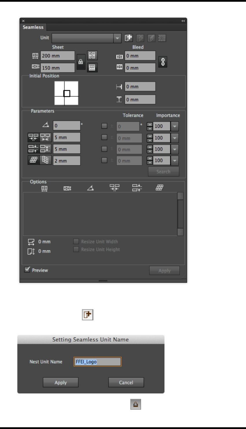
19. Seamless
2. Use the normal AI tools to select the required image unit.
3. Click the Add icon button to add the selected unit.
The dialogue box appears for you to name the unit.
4. Set the Sheet width and height and lock them .
- 198 -

19. Seamless
5. Then choose the seamless type:
H-Seamless, V-Seamless or both.
These options control the direction(s) in which the seamless behaviour will be applied.
6. Set the parameters for Angle, Vertical Spacing, Horizontal Spacing and Stagger, and
the corresponding Tolerance and Importance parameters.
7. Click the Search button.
A list of possible solutions will be displayed in the Options panel. The values of the para-
meters used for each solution are listed here also.. If there are no solutions displayed it is
because there are no solutions possible for the requested parameters. You will need to adjust
your parameters or tolerances.
- 199 -
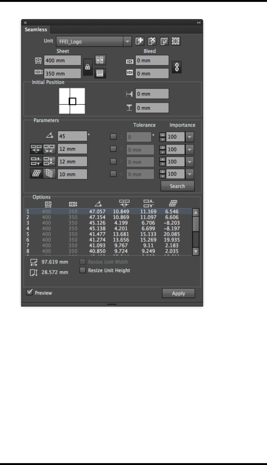
19. Seamless
8. Choose the option from the generated list that best meets your criteria and click the Apply
button.
The seamless nesting is generated in a new layer.
All but the current selected solution are removed from the list of Options.
The original artwork layer is set to be not-visible.
- 200 -
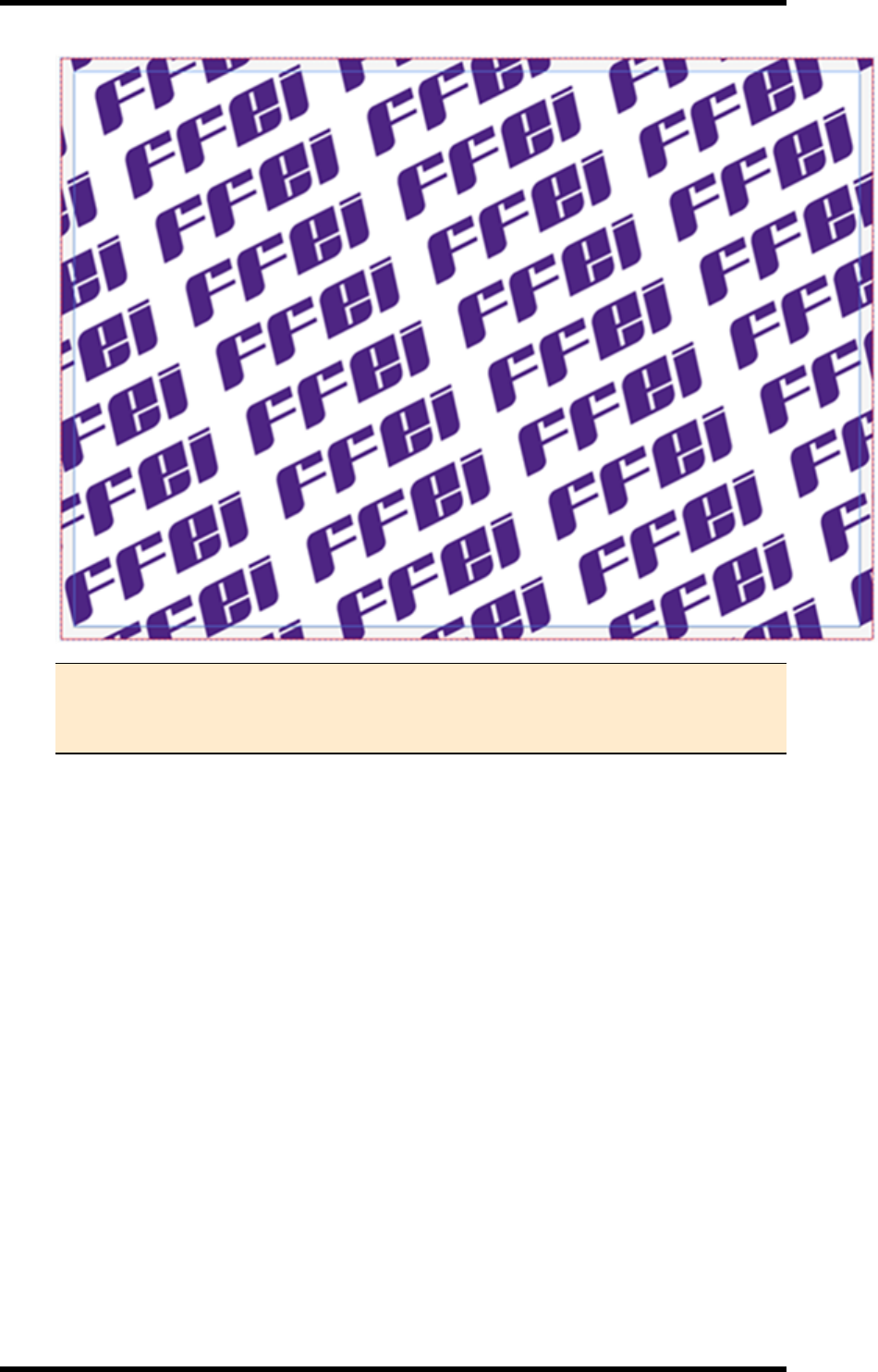
19. Seamless
Note: As all but the applied solution are removed from the list, if the user wishes
to try another solution, the search button has to be used to re-generate the list of
options.
19.3.1 Resizing the unit image
Normally, the horizontal and vertical spacing between the Image Units can be varied by the soft-
ware when it is attempting to create a Seamless solution. If the spacing is critical, the user can set a
tolerance of zero, but this greatly restricts the chances of getting an acceptable Seamless solution.
Sometimes the Image Unit size itself can be adjusted (for example, if it contains a white back-
ground). In these situations the user can use the Resize Unit controls to adjust the Image Unit size
to accommodate a specific inter-unit spacing.
- 201 -

19. Seamless
Procedure
1. Generate a set of Seamless options (i.e. follow steps 1-7 above).
2. Choose the option from the generated list that best meets your criteria.
The Resize Unit Width and / or Resize Unit Height options will become available (depending
upon whether H-Seamless or V-Seamless options were selected respectively).
3. Choose the required option(s) to Resize Unit Width / Height.
The corresponding parameters (vertical / horizontal gaps) in the generated Options list will
become greyed out.
The Resize Preview option will become available.
Note: It is not always necessary to use the Resize Preview. The user can simply
apply the chosen changes. The software will automatically clip the Image Unit in
order to maintain the desired unit separation. Using the Resize Preview is a good
way to assess (and if necessary modify) this behaviour before creating the Seam-
less nest.
4. Select the Resize Preview option.
The Image Unit will be displayed along with its bounding box.
- 202 -
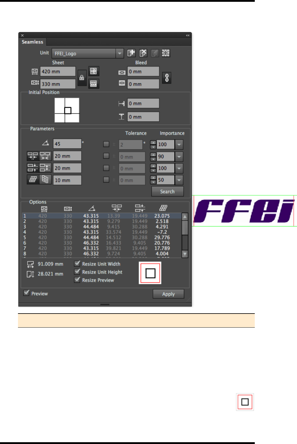
19. Seamless
Example of the Resize Preview
Note: The Width and Height of the Unit Image is displayed below the Options list.
The red box demarks the edited bounding box.
The green box demarks the artwork.
In the example above the bounding box is now clipping the artwork (probably unacceptably)
and so the artwork will require manual resizing.
By default the Bounding Box is adjusted (made larger or smaller) by placing the image unit in
the centrally. This can be controlled by moving the black square within the red square
at the bottom of the Seamless palette.
- 203 -

19. Seamless
The Bounding box can be returned to its original dimensions by using the Reset Bounding
Box button .
5. When you are happy with the clipping of the Image Unit, press Apply.
The seamless nesting is generated in a new layer.
The gap widths in the Options list will be set to the requested parameter and left greyed out.
Note: Resize Unit Width and Height options are only available before a seamless
document is created (before the Apply button is pressed). If these options are
greyed out, press the Search button to regenerate the nesting options.
19.4. Seamless Nesting with Fixed Parameters
1. To start the Seamless function open an AI file containing the image unit and choose Window
>RealPro > Seamless.
The Seamless palette will be displayed.
2. Use the normal AI tools to select the required image unit.
3. Click the Add icon button to add and name the selected unit.
4. Set the Sheet width and height and lock them.
5. Then choose the seamless type: H-Seamless, V-Seamless or both. These
options control the direction(s) in which the seamless behaviour will be applied.
6. Set the parameters for Angle, Vertical Space, Horizontal Space and Stagger, and the cor-
responding Tolerance and Importance parameters.
7. Use the lock button to lock these parameters .
When the Parameters are locked, the media settings will become unlocked (and vice-versa).
8. Click the Search button.
9. A list of possible solutions will be displayed in the Options panel.
The height and width of the sheet dimensions are listed for the solution in the options panel.
If there are no solutions displayed it is because there are no solutions possible for the reques-
ted parameters.
10. Choose the option from the generated list that best meets your criteria and click the Apply
button.
The seamless nesting is generated in a new layer.
- 204 -
19. Seamless
19.5. Using the Unit Edit
The Edit button allows the Image Unit to be edited from within a Seamless nested file.
1. Open the seamless nesting file.
2. Click the Edit button to edit the unit.
3. Click the Apply button to generate the result.
19.6. Using Unit Replace
1. Create a new seamless layout as previously described.
2. At the stage of adding the image unit, add multiple files.
3. In this way after the seamless layout has been created for the 1st unit, the other units can be
substituted using the same parameters.
19.7. Seamless Nesting Parameters
Unit: Displays the name of current unit and can be used to switch between units.
Add: Adds the selected unit.
Delete: Deletes the current unit.
Edit: Click to switch to the edit mode. In this mode the image unit can be edited. Click again to
exit from the edit mode.
Reset Bounding Box: The unit pattern will change after resizing its width or height. This item
helps to revert to the original state.
Width: Width of sheet
Height: Height of sheet
H-Seamless: Horizontal seamless nesting.
V-Seamless: Vertical seamless nesting.
Select both H-Seamless and V-Seamless for seamless nesting in both directions.
H-Bleed: Increase the horizontal bleed.
V-Bleed: Increase the vertical bleed.
- 205 -
19. Seamless
Initial Position: Relative coordinate position of the first unit in the left bottom corner of the
generated seamless document.
H-Offset: Relative horizontal coordinate of the first unit in the left bottom corner of the generated
seamless document.
V-Offset: Relative vertical coordinate of the first unit in the left bottom corner of the generated
seamless document. Parameters: Include angle, space, stagger, etc.
Angle: Rotation angle of unit.
Horizontal spacing can be defined by the user as either:
H-Edge Space: the gap between two adjacent units or
H-Centre Space: the spacing between the centre points of two adjacent units.
Vertical Spacing can be defined by the user as either:
V-Edge Space: the gap between two adjacent units or
V-Centre Space: the spacing between the centre points of two adjacent units.
Units can be offset either horizontally or vertically using:
H-Stagger
V-Stagger
As it is unlikely that there will be a solution that exactly matches the requested settings of angle,
spacing etc. the user is able to set tolerances and weightings of importance against each para-
meter.
Tolerance: Set the acceptable range from the set points of each parameter. The smaller the value
is, the closer to the parameters setting, but higher risk of getting no options generated .
Importance: Add a weighting of the relative importance for each setting. This can influence which
solutions are listed in the generated options and the order in which they are generated.
Search: Click the Search button to generate options based on entered parameters.
Options: Displays the generated options (max. 16).
Unit Width: Width of the current unit.
Unit Height: Height of the current unit.
Resize Unit Width and Height: This item helps to satisfy the V-Edge Space and H-Edge
- 206 -

19. Seamless
Resize Preview: Adjust and preview the effect of unit edit by moving the inner block to the loc-
ations of the outer block: upper left, upper middle, upper right, middle left, middle, right middle, left
down, middle down and right down.
Apply: Generate a seamless document based on the selected option by clicking the Apply button.
19.8. Limitations
1. There is no option information when sheet size is bigger than maximum size of AI drawing
board.
2. A maximum of 16 options can be displayed.
- 207 -

20. Warp
20. Warp
20.1. Background
Warp is used to apply the correct pre-distortion to graphics to compensate for the deformation inher-
ent in the production and conversion process.
For example, a yogurt pot is usually formed by being pressed out from a flat printed sheet of plastic.
We use the warp tool to create the anamorphic distortion the artwork requires in order to appear cor-
rect and without distortion on the final product.
The operator enters distortion parameters based on data from production. In bespoke container
cases a grid is often printed to test the anamorphic distortion.
20.2. Overview
The Warp tool provides an effective means of pre-distorting artwork so that the image can appear
correct after a conversion process. There are three main types of warp in RealPro Toolkit.
1. Conic Warp – Applies the required geometry when projecting a flat artwork on to a curved
conical shape. Examples include bottle neck labels, labels for plastic tubs, paper cups, roll
sleeve fast food cones.
2. Circular Warp – Creates artwork pre-distortion for circular profile or cylindrical objects
which will be formed though methods including extrusion, moulding or thermoplastic.
Examples include two-piece metal food cans, Direct printed yogurt pots and other ‘normally’
dairy food containers, moulded metal closures for drinks.
3. Complex Warp – Many items created through moulding or extrusion methods will not
always be circular. Example oval dairy tubs and fish cans. This means that the method of cal-
culating is more complex and the length of straight and radius edges must be entered.
The Warp tools are available from Window > RealPro > Warp
20.3. Circular Warp
Select Circular Grid. (This is displayed by default when the tool is first launched).
The Circular Warp controls are displayed:
- 208 -
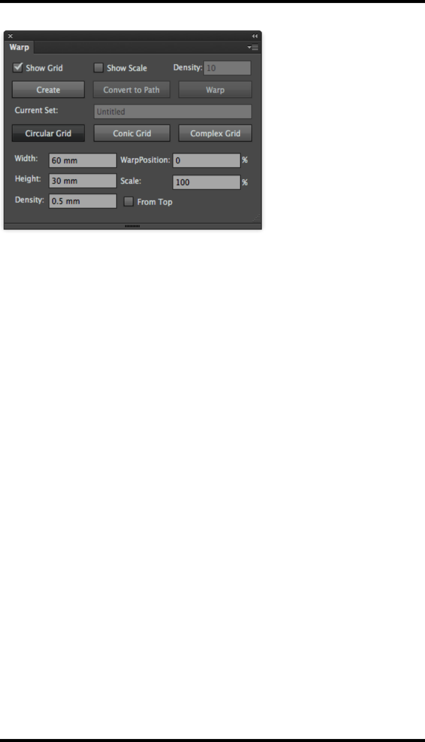
20. Warp
The parameters entered directly control the size of the rectangular grid of the undistorted artwork.
The circular grid on which the distorted artwork is place is derived form these:
Width – Controls width of undistorted artwork grid.
This is the same as the circumference of the circular grid at the height of the red Baseline. (i.e. if
Baseline is set at 0, this will be the circumference of the centre circle).
Height – Controls height of undistorted artwork grid.
This is the same as the height of the circular grid if no Scale is set to 0%
Density - Controls the spacing of the grid-lines.
Higher density will give smoother distortion, but take longer to compute.
Baseline at - Controls the position of where the warp will start:
lBaseline set to 0% - Width will be the same as the cylinder diameter
lIncreasing the value will decrease the centre circle.
lBaseline set to 100% will have no centre (i.e. a cone).
Scale –Controls the scaling factor of the warped area outside the centre circle. This can be less or
greater than 100% depending on the conversion process.
Baseline from top – controls the direction the warp is applied (for example, the direction of extru-
sion).
After setting these parameters, click Create to generate the source grid and destination gird.
The Circular Warp parameters in the example above will give the following rectangle and circular
grids:
- 209 -
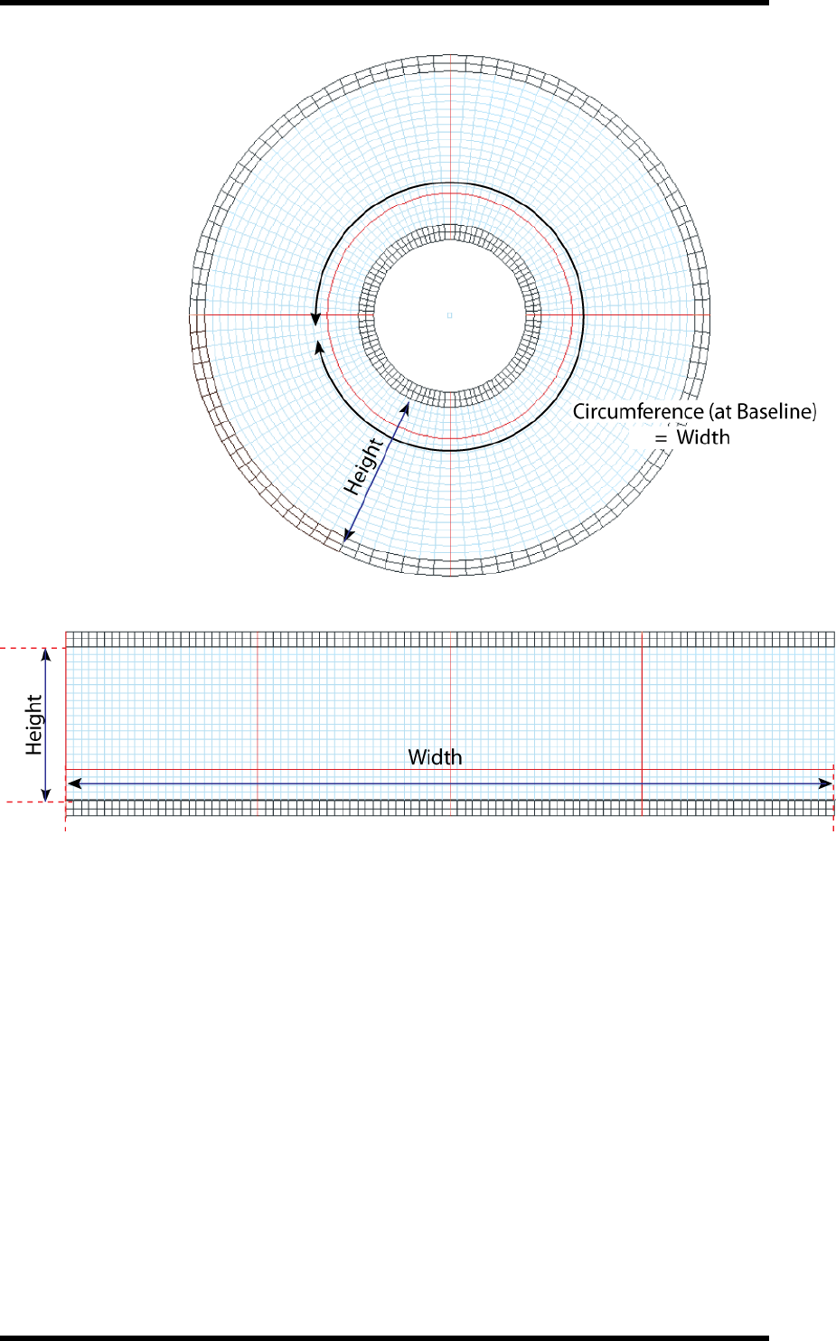
20. Warp
To use:
1. Select the object that is to be warped and drag it into the correct position on the source grid
(rectangle grid).
2. Click the Warp button.
The result is generated on the Circular output grid.
20.4. Conic Warp
Select Conic Grid
The Conic Warp controls are displayed:
- 210 -

20. Warp
Type in the parameters for the input Rectangle Grid size and the output Conic Grid.
Rectangle Grid
Density - Controls the spacing of the grid-lines.
Higher density will give smoother distortion, but take longer to compute.
Width - Controls width of undistorted artwork grid.
This is normally the same as the circumference of the minimum diameter (depending
upon the manufacturing process).
Height - Controls height of undistorted artwork grid.
This is the same as the height of the circular grid if no Scale is set to 0%
Conic Grid
Height - Set the Height of the Rectangle and the Conic grids to be the same value
unless any vertical scaling is required.
Max. Diameter – See diagram
Min. Diameter - See diagram
Baseline from top – controls the direction the warp is applied (for example for a bottle neck sleeve
or for a paper cup).
- 211 -
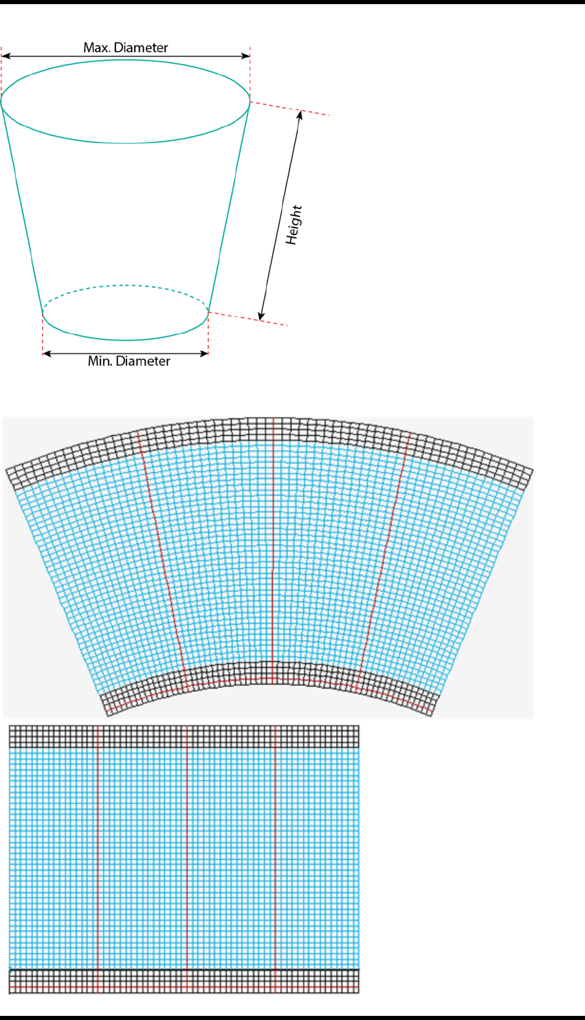
20. Warp
After setting these parameters, click Create to generate the source grid and destination gird.
Source Grid
Destination Grid
- 212 -
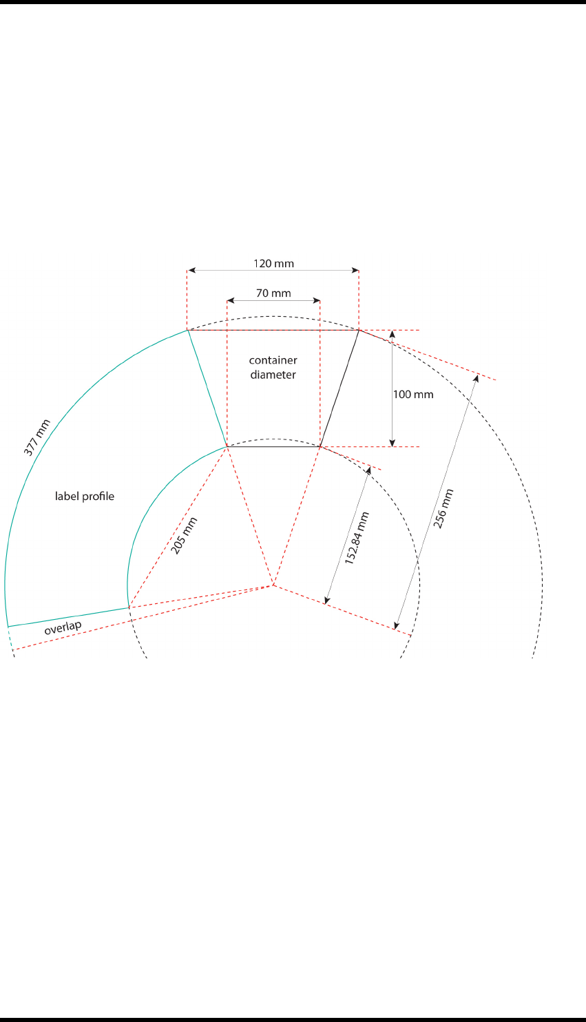
20. Warp
To use:
1. Select the object that is to be warped and drag it into the correct position on the source grid
(rectangle grid).
2. Click the Warp button.
The result is generated on the Conic output grid.
Basic process for calculating profile of a cone.
Below is a worked example for calculating conical labels using projection.
Height =100 mm
Max Diameter = 120 mm
Min Diameter = 70 mm
Base Circumference = 377 mm
Top Circumference = 226 mm
Arc Radius = 256 mm
Arc Circumference = 1605 mm
Arc Angle = 360 x (377 / 1605) = 84.6°
AI warp bounding box for undistorted artwork = 205 mm x 100 mm
AI warp tool arc distort = (377/1605) x 2 = 46° bend
- 213 -
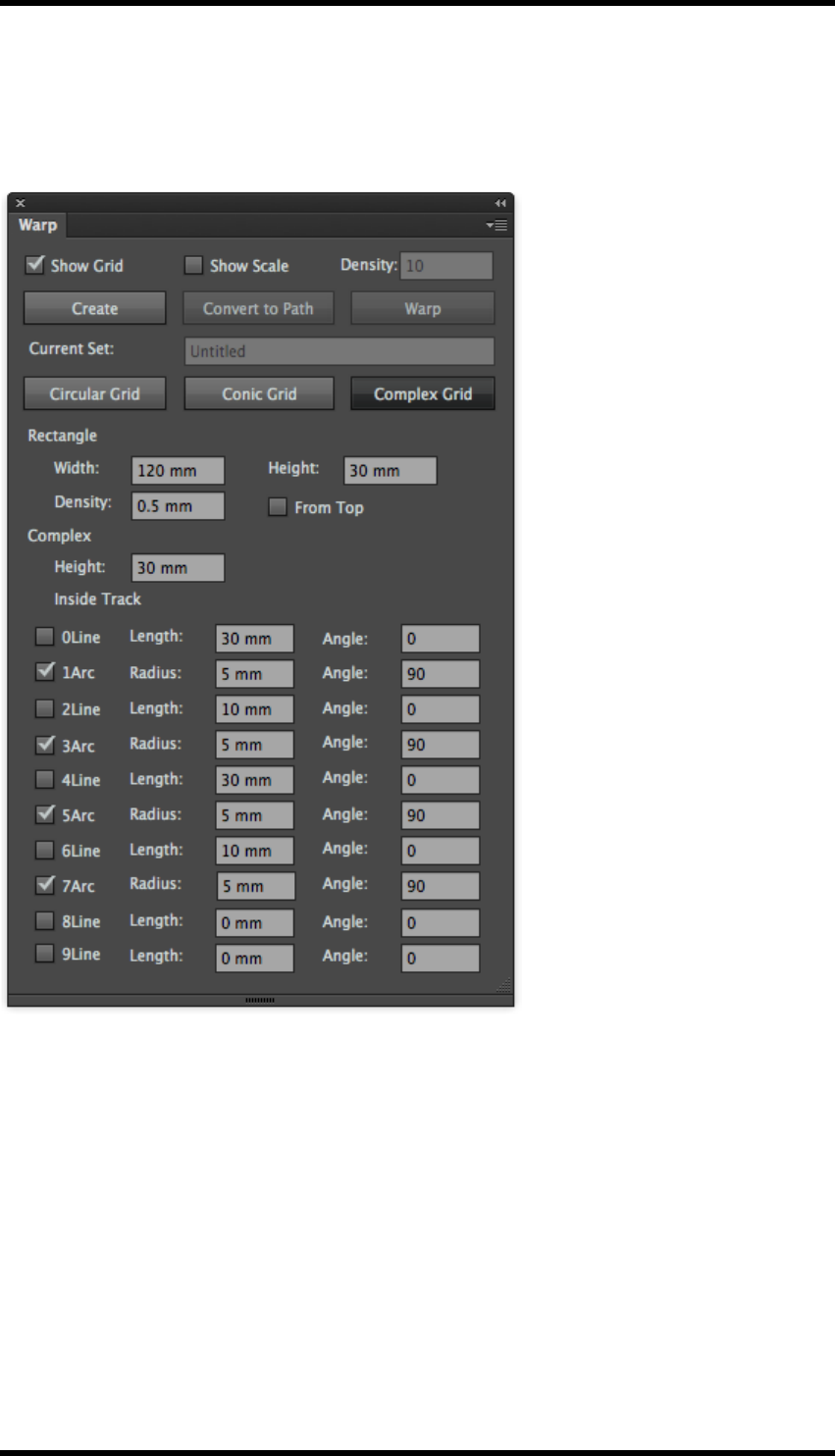
20. Warp
20.5. Complex Warp
Select Complex Grid.
The Complex Warp controls are displayed.
Rectangle Grid
Width - set the width of source grid area
Height - set the height of source grid area
Density - set the width and height of a single cell from source grid
Inside track parameter
Height - set the height of destination grid area
Length - set the length of straight part
Angle - set the tilt angle of straight part
- 214 -
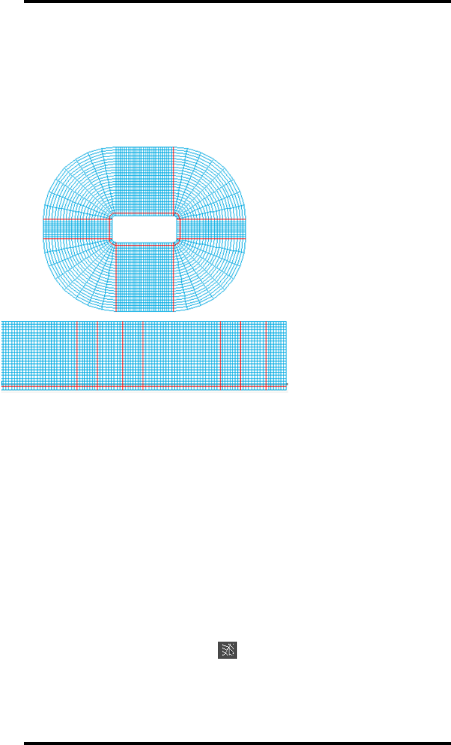
20. Warp
Arc Radius - set the minimum radius of rounded corner part
Angle - set the central angle of rounded corner part
Baseline from top – controls the direction the warp is applied (for example, the direction of extru-
sion).
After setting these parameters, click Create to generate the source grid and destination gird.
Destination Grid
Source Grid
To use:
1. Select the object that is to be warped and drag it into the correct position on the source grid
(rectangle grid).
2. Click the Warp button.
The result is generated on the output grid.
20.5.1 Adjust Grid
There are two ways to adjust a grid:
lManual adjustment
lNumeric adjustment (for accuracy)
Manual adjustment
1. In the AI tool bar, click the Adjust Grid tool.
2. Use new cursor to select the grid points that have to be moved.
- 215 -
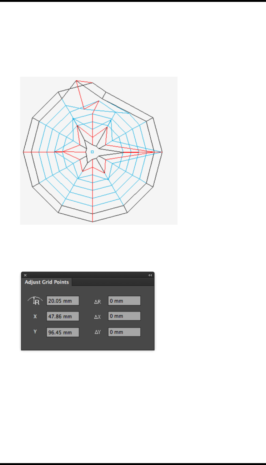
20. Warp
If you need to move one point at the time, click on an unselected point and drag it to the
desired location.
Several points can be moved by clicking and dragging the cursor to create a rectangle that
surrounds the required points, or use shift + click to select multiple points. Then, click on
one of the selected points and drag in the required direction.
Numerical adjustment
1. Adjust Grid is available from Window > RealPro > Warp > Adjust Grid
The Adjust Grid Points palette is displayed.
R- set the distance between centre of circle and the point
X- set the X-position of the point
Y- set the Y-position of the point
ΔR - set the distance of move in the direction of radius
ΔX - set the distance of move in the direction of horizontal axis
ΔY - set the distance of move in the direction of vertical axis
- 216 -

20. Warp
2. In the AI tool bar, click the Adjust Grid Tool button.
3. Select a point by clicking on an unselected point or clicking and dragging a rectangle that cov-
ers those points.
4. When the parameters above have been entered the adjustment is set.
20.5.2 Standard Grid
Standard Grid is used to create a circular grid.
1. Standard Grid is available from Window > RealPro > Warp > Circular Standard Grid.
The dialogue box of Circular standard Grid will be appear.
: set the X-position for centre of circle
: set the Y-position for centre of circle
:set the distance between inner arc and centre of circle
: set the distance between outer are and centre of circle
2. Click OK to confirm settings.
A standard grid will be created.
- 217 -

20. Warp
- 218 -

21. Shortcut keys
21. Shortcut keys
21.1. Shortcut Keys
Shortcut keys can be used to open some interfaces or functions of RealPro Toolkit plug-ins. The
pre-set shortcut key combinations can be changed by the user so that the user can get access to
functions of plug-ins quickly and efficiently.
21.1.1 How to change shortcut keys
The user can change shortcut keys by clicking “Keyboard Shortcuts” under the “Edit” menu in AI.
Then select “Shortcut keys-Menu-Window-RealPro” in the main menu. Shortcut keys in other pan-
els can be changed by selecting “Shortcut keys—Menu—Other panels”.
1. Choose Edit > Keyboard Shortcuts.
2. Choose "Illustrator Defaults" from the Set menu.
3. Choose "Menu Commands" from the menu above the shortcuts display.
4. Choose "Window" from the list of menu commands.
5. Choose "RealPro" from the list of Window items.
6. To change a shortcut, click the appropriate shortcut in the shortcut column and type the new
shortcut.
Note: If you enter a shortcut that has already been assigned to another command,
a alert is displayed at the bottom of the dialogue box. Either click Undo to undo
the change, or click Go To to go to the other command and assign it a new short-
cut.
7. To save the changes, click OK.
The New Key Set dialogue box will be displayed.
8. Enter a name for the new set of shortcuts and click OK.
- 219 -

21. Shortcut keys
21.1.2 Default Shortcuts:
Some of the useful default shortcuts are lsted below:
Name of
Plug-in
Description of Func-
tions Shortcut Keys (Mac) Shortcut keys (PC)
Eye Open Eye Option + Command + V Alt + Ctrl + V
Zoom in Option + Command + = Alt + Ctrl + =
Zoom out Option + Command + - Alt + Ctrl + -
Tool Line PathFinder Shift + Command + Q Shift + Cntrl + Q
Keep the larger object Shift + Command + 1 Shift + Ctrl + 1
Keep the smaller
object Shift + Command + 2 Shift + Ctrl + 2
Keep all objects Shift + Command + 5 Shift + Ctrl + 5
Basic
Functions Output PDF Option + Shift + Com-
mand + [ Alt + Shift + Ctrl + [
- 220 -

21. Shortcut keys
Name of
Plug-in
Description of Func-
tions Shortcut Keys (Mac) Shortcut keys (PC)
Trim Box and Media
box
Option + Shift + Com-
mand x Alt + Shift + Ctrl + X
Export
Images Export All Images Option + Shift + Com-
mand + \ Alt + Shift + Ctrl + \
Search Open Search Option + Command + Z Alt + Ctrl + Z
Ink Man-
ager Open Ink Manager Option + Command + A Alt + Ctrl + A
Update ink List Option + Command + U Alt + Ctrl + U
Open Image Channel
Convert
Option + Shift + Com-
mand + ] Alt + Shift + Ctrl + ]
Trap Open Trap Ticket Dia-
log Shift + Command + U Shift + Ctrl + U
Open Auto-Trap Dia-
log Option + Command + F Alt + Ctrl + F
Execute Trap Option + Command + G Alt + Ctrl + G
Nest Open CAD Dialog Option + Shift + Com-
mand + Z Alt + Shift + Ctrl + Z
Open Sheet &Plate
Dialog
Option + Shift + Com-
mand + P Alt + Shift + Ctrl + P
Open Step and Repeat
with Chart
Option + Shift + Com-
mand + N Alt + Shift + Ctrl + N
Trim box and media
box
Option + Shift + Com-
mand + X Alt + Shift + Ctrl + X
Open Bleed and Over-
lap Dialog
Option + Shift + Com-
mand + G Alt + Shift + Ctrl + G
Open Station Number
dialog
Option + Shift + Com-
mand + V Alt + Shift + Ctrl + V
Open Step and repeat
with CAD Dialog
Option + Shift + Com-
mand + A Alt + Shift + Ctrl + A
Align to Margin Option + Shift + Com-
mand + L Alt + Shift + Ctrl + L
Overlap Adjust Option + Shift + Com-
mand + R Alt + Shift + Ctrl + R
Check CAD Break-
points
Option + Shift + Com-
mand + Q Alt + Shift + Ctrl + Q
- 221 -
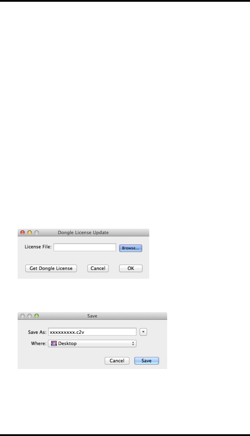
22. Updating the License key
22. Updating the License key
The License key can be updates as follows:
1. Find the License Update application
On a Mac:
Applications/Adobe Illustrator CS6/Plug-ins/FFEI RealPro/RealPro Toolkit License Update
Tool
or
Applications/Adobe Illustrator CC/Plug-ins/FFEI RealPro/RealPro Toolkit License Update
Tool
On a PC:
Program Files\Adobe\Adobe Illustrator CS6 (64 Bit)\Plug-ins\FFEI RealPro\RealPro Toolkit
License Update Tool.exe
or
Program Files\Adobe\Adobe Illustrator CC (64 Bit)\Plug-ins\FFEI RealPro\RealPro Toolkit
License Update Tool.exe
2. Double-click the file.
The Dongle License Update dialogue will be displayed.
3. Click "Get Dongle License".
A file will be created and a Save dialogue will be displayed.
4. Select a location in which the file can be saved.
5. Send this file to your vendor.
- 222 -

22. Updating the License key
6. If a new licence is granted, a *.v2c file will be returned.
7. Save the file on to the computer and start the Licence Update program.
8. Click "Browse" and search for the new *.v2c file.
9. Click OK. (Wait for confirmation that the dongle has been updated).
10. Restart Adobe Illustrator, and if you can see the RealPro Toolkit menu and can use it suc-
cessfully, your dongle has been successfully updated.
- 223 -
