NetLink_NL CSRCV_OI294B.36_USER Net Link CSRCV User Manual
User Manual: NetLink CSRCV User Manual AlarmHow.net Library
Open the PDF directly: View PDF ![]() .
.
Page Count: 20
1
© NAPCO 2004
Installing, Programming and
Using the NAPCO NetLink™
NL-CSRCV Software
NAPCO NetLink
NL-CSRCV v.1.0
Central Station Receiver Application
User’s Guide
OI294B 7/04
R
333 Bayview Avenue
Amityville, New York 11701
For Sales and Repairs, (800) 645-9445
For Technical Service, (800) 645-9440
© NAPCO 2004
s
)

2
NetLink™ Receiver System Overview .........................................................................3
NetLink™ Receiver Application System Requirements ...............................................3
Quick Start Checklist ...................................................................................................4
Set "Classic Mode" in Windows™ ............................................................................... 4
Turn off Hyper-Threading on the Dell 2400/4400 PC's ...................................................4
Getting Started--Installation and Adding Users ...........................................................5
Add a New Account .....................................................................................................7
Configure the NetLink™ Server ..................................................................................9
Configure the Automation Host Output .....................................................................10
Using the NetLink™ Receiver Application ................................................................. 11
Viewing Archived Events ...........................................................................................12
Database Maintenance ............................................................................................. 14
Server Check In Times .............................................................................................. 15
Appendix A ................................................................................................................16
Appendix B ................................................................................................................17
Glossary .................................................................................................................... 18
Warranty ....................................................................................................................20
Table of Contents
The model names are referenced in this manual as follows:
•The model name "NL-CSRCV" will be referenced as the NAPCO NetLink™ Receiver Application, which consists
of two modules:
1. The NetLink™ Server (receives check-in and event data from NAPCO control panels).
2. The NetLink™ User Interface (interprets and displays the event data).
•The model name "NL-MOD" will be referenced as the NL-MOD or the NetLink™ Module.
•The model name "NL-ULBD" will be referenced as the NL-ULBD.
•The model name "NL-MODCONFIG" will be referenced as the NL-MODCONFIG.
Terminology Used in this Manual

3
The NAPCO NetLink™ Receiver Application (NL-CSRCV) is a PC based software program that
is designed to act as a remote monitoring receiver or as a remote monitoring system. In place of
receiving alarm data through a telephone line, the NetLink™ Receiver Application receives data
sent through a TCP/IP network encrypted with AES 128 bit encryption. The NetLink™ Receiver
Application can supervise each control panel, receive alarms, maintain accounts and provide a
means of displaying alarms, status and event history. The NetLink™ Receiver Application can also
take the place of the automation system or work in tandem with one.
The software consists of two parts, a NetLink™ Server for receiving the check-in and event data
from a NAPCO alarm panel and the NetLink™ User Interface, for interpreting and displaying the
event data. After the initial setup, central station operators must first start the NetLink™ Server
program (which runs in the background) and then open the NetLink™ User Interface to begin re-
ceiving alarm data.
For each alarm control panel, a device called a "NetLink™ Module" (NL-MOD) connects the con-
trol panel to a TCP/IP based (Intranet or Internet) network, allowing data (using 128bit AES encryp-
tion) to be sent to the NetLink™ Receiver Application software. One NL-MOD is used for each
account, connecting a single panel to that network. Although an automation system could man-
age individual areas of a control panel as separate Accounts, the NetLink™ Receiver Application
detects each NL-MOD as a separate Account and not areas of a panel.
Note: It is required that "Classic Mode" is set in Windows® XP Professional before installing the
NetLink™ Receiver Application software. In addition, the NetLink™ Receiver Application soft-
ware requires the use of a dedicated computer only. To set "Classic Mode", see page 4.
NetLink™ Receiver System Overview
Windows is a registered trademark of the Microsoft Corporation.
Microsoft Data Access Components (MDAC) contains products and resources owned by the Microsoft Corporation.
Other products, product names and services described in this manual are for identification purposes only and may be trademarks of their respective companies.
•Windows® XP Professional installed on a dedicated PC.
•Intel® Pentium® 4 (2GHz processor or faster) with at least 512 MB RAM.
•Hard drive space 20GB or higher.
•Not supported: Hyper-Threading technology (see page 4), Dual Processors and
Windows® XP Themes.
•"Classic Mode" must be set in Windows XP Professional before installation.
•NAPCO Tested and certified using a Dell™ Dimension™ Series 2400 and 4400 PC.
Note: Installations with other PC's could vary and are at installer's risk.
•Network Card requirements: 100 BaseT Ethernet.
NetLink™ Receiver Application System Requirements

4
OPENING STEPS (SERVER CONFIGURATION)
❒ 1. INSTALL THE NETLINK™ RECEIVER APPLICATION SOFTWARE INTO THE
COMPUTER (see page 5)
❒ 2. ADD USERS (see page 5)
❒ 3. ADD ACCOUNTS (see page 7)
❒ 4. CONFIGURE THE SERVER (see page 9)
❒ 5. CONFIGURE THE AUTOMATION HOST OUTPUT (see page 10)
Quick Start Checklist
(Required) Set "Classic Mode" in Windows™
In Windows XP® Professional:
1. Click Start, Control Panel, Taskbar and Start Menu.
2. Click the Start Menu tab and select Classic Start Menu.
3. Click OK to save your selection.
It is recommended that you restart your computer before proceeding.
Turn off Hyper-Threading on the Dell 2400/4400 PC's
A feature of certain Pentium 4 chips, Hyper-Threading
must be deactivated before proceeding:
1. Click the Start button.
2. Click Shut Down, Restart. Wait for the computer to
turn off completely.
Note: If your computer locks (blue screen), press and
hold the power button for 10 seconds to turn the com-
puter off.
3. Restart the computer.
4. In your default browser, access www.dell.com and
press the <F2> key. The System Setup screen
opens.
5. Press the down arrow key on the keyboard to highlight
CPU Information.
6. Press <Enter>. A small box with CPU information ap-
pears.
7. Press the down arrow key to highlight Hyper-
Threading.
8. Press the <+> key until Disable appears to the right of
Hyper-Threading.
9. Press <Enter>. The small box with CPU information
closes.
10. Press the <Esc> key. A small box with Exit options
appears.
11. Press the down arrow key to highlight Save Changes
and Exit.
12. Press <Enter>. The computer will restart normally.

5
1. First run the NetLink Server and then run the
NetLink Application, by double-clicking on their
respective shortcut icons, found on the Windows®
desktop. The NAPCO NetLink Log On window
opens, displaying the default Administrative User
Name "Default".
There is no password assigned to this default user,
therefore press the Enter key to allow access to the
program. The Main NetLink™ Receiver
Application screen appears.
Installing the NetLink™ Receiver Software
Running the NetLink™ Receiver Application
System Requirements:
•Windows® XP Professional installed on a dedicated PC.
•Intel® Pentium® 4 (2GHz processor or faster) with at
least 512 MB RAM.
•Hard drive space 20GB or higher.
•Not supported: Hyper-Threading technology, Dual
Processors and Windows® XP Themes.
•NAPCO Tested and certified using a Dell™
Dimension™ Series 2400 PC (required). Note:
Installations with other PC's could vary and are at
installer's risk.
•Network Card requirements: 100 BaseT Ethernet.
Note: Close all applications before installing software.
1. Place the NetLink™ Receiver Software version 1.0 CD
into the CD-ROM drive. The InstallShield Wizard will
automatically begin the installation process.
2. If the Wizard installation process does not
automatically begin, click Start, Run and type the
following: D:\Program\English\setup.exe, where D is
the drive letter associated with the CD-ROM.
3. Two shortcut files are placed on your desktop:
NetLink Server and NetLink Application. These
shortcuts will be used to start the NetLink™ Receiver
Application, as described below.
Getting Started--Installation and Adding Users
Next, you must add users (operators) to allow access
to the NetLink™ Receiver Application screens.
IMPORTANT: Rename and modify the password for
the default Administrative User Name "Default".
This will maintain security within the system,
removing any possibility of unauthorized access to
the system configuration screens located in the Tools
menu.
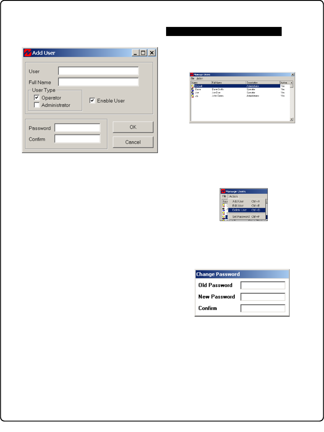
1. From the Tools Menu, click Manage Users. The
Manage Users screen opens:
2. From the Action menu, click Add User.
The Add User dialog opens:
Adding Users to the NetLink™ Receiver Application
6
Adding Users (cont'd)
3. The areas of the Add User screen are as follows:
User Name: Type a "user name" to represent a
central station operator in the User field.
Full Name: Type the full name of the user,
identifying the actual person.
User Type: There are two user types: Administrator
and Operator. Only one type can be selected for
each user.
Administrator: Enables access to Administrator
functions (Tools menu, Manage Users, Options,
and Database Maintenance).
Operator: Disables access to Administrator
Functions (default setting).
Enable User: Check to enable and uncheck to
disable existing users. When unchecked, user
information (User type, password, etc.) remains
within the system but is disabled, thus denying the
user the ability to log on to the system. Default
setting is enabled (checked).
Password: A password is required for each user,
with a minimum length of 4 characters. Type in a
password for the operator, to be used when logging
in to the system. Re-type the same password to
confirm.
4. When finished, click OK to save or click Cancel to
discard information.
Edit User. If you wish to change existing information
about a User, from the Action menu, click Edit User
to open the Edit User dialog. Double-click on the
user you wish to edit.
Delete User. To delete a User, highlight the user
you wish to delete. From the Action menu, click
Delete User to remove the User from the system.
Note: At least one administrative user must always
be active within the system. Any attempt to remove
the only remaining administrative user will result in a
warning dialog denying the deletion request.
Set Password. This option is used to change the
password of an existing user. To set a password
required to access a user profile, click Set Password
from the Action menu, and the Change Password
dialog opens:
To add a new password, the old password must be
provided as an added level of security. Type the new
password in the New Password field, and re-enter
the new password in the Confirm field. Press the
Enter key on your keyboard to save.
Additional User Options
7
Adding a New Account
After adding new Users, new Accounts must be added
to the system. Each Account is perceived by the Net-
Link™ Receiver Application software as a single control
panel and not as an "area" programmed within a burglar
alarm system.
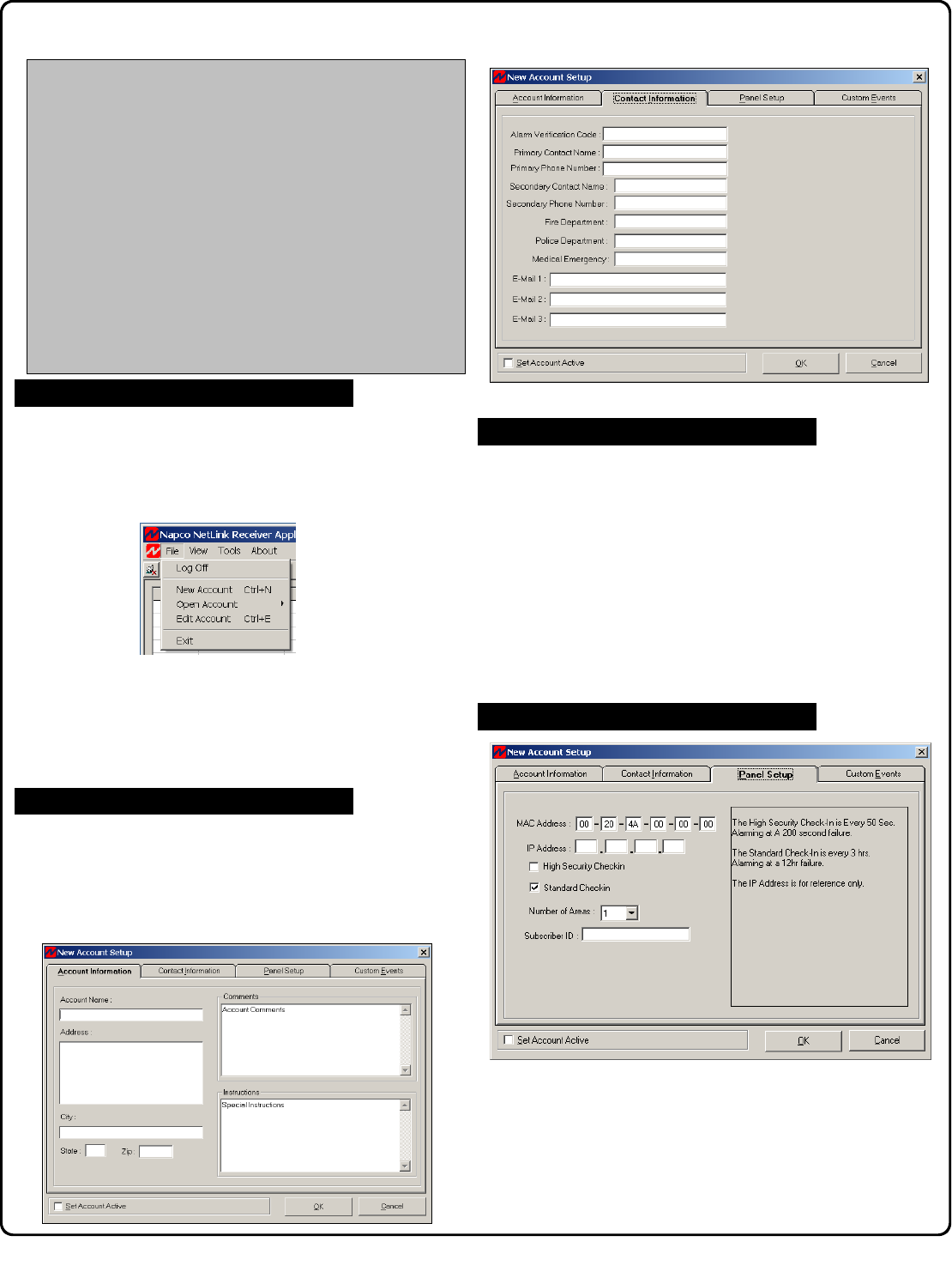
To add a new Account, click File, New Account or
press the New Account button on the toolbar (you can
also press Control + N on your keyboard). The New
Account Setup screen, Account Information tab ap-
pears:
Add a New Account
In the fields below, add the Account name and address.
Comments and Instructions fields are provided for any
special instructions or comments regarding this Account.
These two fields will appear in the Event Response
Screen.
Click the Contact Information tab to enter telephone num-
bers and other communication information used during an
alarm or other events (see screen above).
All this information will appear in the Event Response
screen.
Click the Panel Setup tab to configure network information.
In order for a network link to be firmly established, the in-
formation provided in this window must correspond to in-
formation programmed into the NL-MOD. Since the NL-
MOD is a device installed at the control panel, this network
information must be provided by the installer of the NL-
MOD. The fields within this window are as follows:
Adding Contact Information
Adding Panel Setup Information
Adding Account Information
Minimum Required Information for Reporting:
•Account Name
•Primary Phone Number
•MAC Address
•Subscriber ID
•Set Account Active
Press Control + N on your keyboard so that the New Ac-
count Setup screen appears. In the Account Information
tab, enter the Account Name. In the Contact Information
tab, enter the Primary Phone Number. In the Panel
Setup tab, enter the Subscriber ID, and enter the MAC Ad-
dress from the NL-MOD. Check the Set Account Active
check box to place the Account on-line. If unchecked, the
NetLink™ Server will not receive alarms from this Account.
Default is disabled.
8
Add a New Account (Cont'd)
MAC Address: Specifies the physical address of the net-
work interface within each NL-MOD device. This informa-
tion is located on the NL-MOD housing and is unique to
each device. Note: The Account cannot be enabled with-
out a valid MAC Address.
IP Address: Enter the Internet Protocol address assigned
to and programmed into the NL-MOD located at the control
panel. Note: This field is for reference only.
High Security/Standard Check-In: The NL-MOD will
"check-in" with the NetLink™ Server at a specified time
interval, verifying the existence and integrity of the commu-
nication link. Note: The NL-MOD settings must agree
with the settings configured here otherwise incorrect re-
porting will result.
Two check boxes are provided as follows:
High Security Check-In: Select to program a check-in
time interval that conforms to the UL Line Security
standards (Note: Not evaluated by UL). Currently
the standards require a check-in at the NetLink™ Re-
ceiver Application of 200 seconds.
Standard Security Check-In: Select to program a
check-in time interval of 12 hours.
Number of Areas: This is a reference-only field for the
number of areas in the control panel.
Subscriber ID: (Required field). While this is a required
field, it is mostly used by Central Stations. If your facility
does not require this field, it is suggested to use the last 4
digits of the MAC Address.
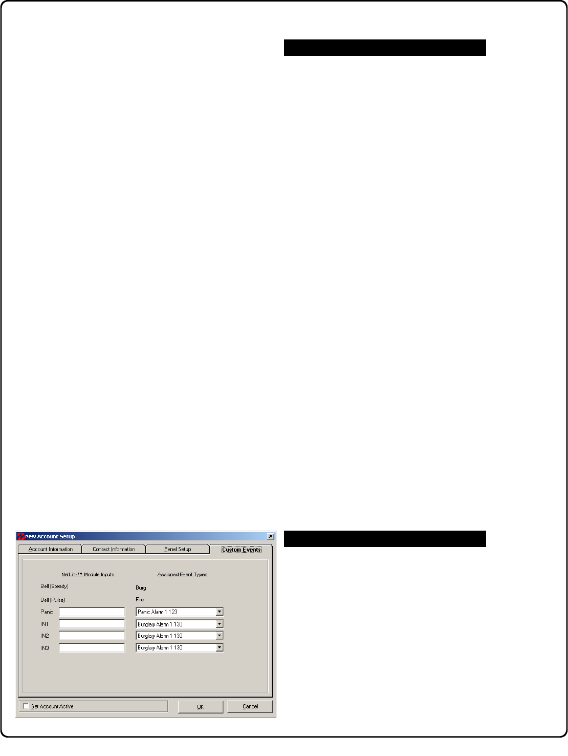
Click the Custom Events tab. In general, Custom
Events are used to map outputs from certain NAPCO
control panels to NL-MOD inputs. Adding Custom
Events to the NetLink™ Receiver Application applies to
any control panel that does not allow "Report to TCP/IP
Receiver" through a high speed serial output (the Local
Download jack (JP2) on the panel), namely these
NAPCO control panels:
•GEM-P1632
•GEM-P816
•GEM-P800
•GEM-P801
Outputs from the control panels listed above are wired
into the terminal strip of the NL-MOD device. In the
Custom Events screen, enter the NL-MOD input de-
scriptions in their specified fields, which selects their
corresponding Point ID codes if the default event types
are not suitable. Note: See WI1242 and WI1243 for
more information.
Check the Set Account Active check box to place the Ac-
count on-line. If unchecked, the NetLink™ Server will not
receive alarms. Default is disabled.
When complete, click OK to save your work. To re-
open an existing Account, click File, Open Account or
press the Open Existing Account button on the Net-
Link™ Receiver Application toolbar. To edit an existing
Account, click File, Edit Account or press the Edit Ac-
tive Account button on the toolbar (you can also press
Control + E on your keyboard). To log off of an open Ac-
count, click File, Log Off. To exit the NetLink™ Receiver
Application, click File, Exit.
Note: If this is not a first time installation, the NetLink™
Server Database will detect new Accounts and automati-
cally update its settings.
At this point in the Quick Start checklist (see page 4), all of
the basic functionality is configured and ready for use.
•NetLink™ Receiver Application software has been
installed.
•Users have been added and their access levels
properly set (see page 5)
•Accounts have been added and set to active (see
page 7)
Now it is time to configure the NetLink™ Server.
Custom Events
Summary
9
NetLink™ Server Setup
The NetLink™ Server is a separate program that runs in
the background, always standing ready to receive check-in
and event data sent from an alarm panel.
Run the NetLink™ Server program by double-clicking
on its shortcut icon found on the Windows® desktop.
You can also start the NetLink™ Server through the Start
button (Start, Programs, Napco NetLink menu). The
NetLink™ Server icon will appear in the Windows® task-
bar system tray to indicate it is running.
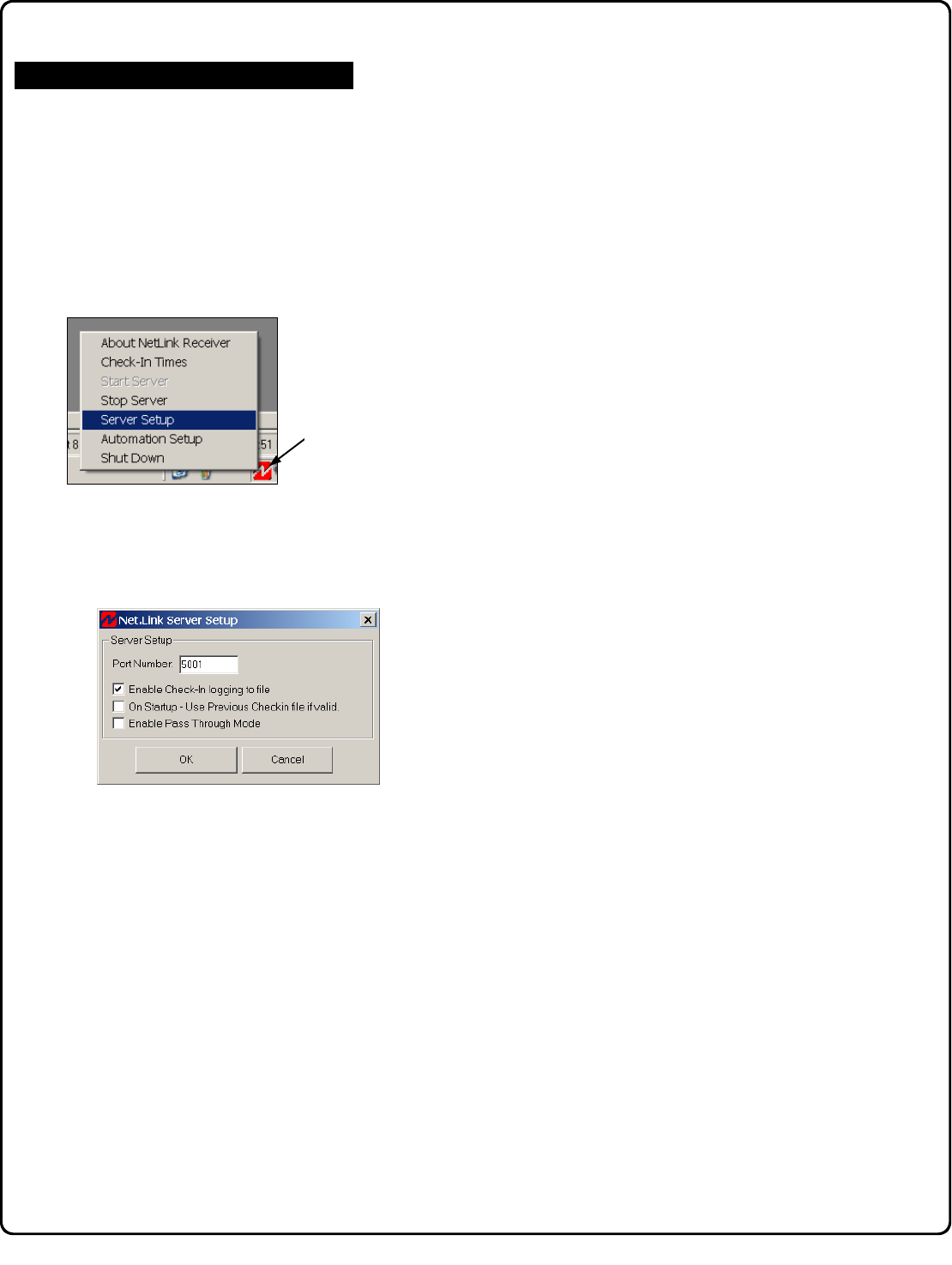
To setup the server, right mouse-click the NetLink™
Server icon located in the Windows system taskbar. Click
Server Setup and the NetLink™ Server Setup window
opens:
This small but important window allows the specification of
the Port Number and if Check-In events should or should
not be logged to a file:
Port Number: A port is basically a channel through
which data is sent within a unique network (address).
Each application program, including the NetLink™ Re-
ceiver Application program, has a unique port number
associated with it, and this number is specified in this
screen. It is recommended to leave the port number set to
its default of 5001. The NL-MOD IP address and port
number are programmed using the NL-MODCONFIG soft-
ware, matching the same information within the NetLink™
Receiver Application software. Note: The default port
number is generally permitted, but if in question, be sure to
verify with your network administrator.
Enable Check-In logging to file: To ensure that commu-
nication exists between the NL-MOD and the NetLink™
Receiver Application, the NL-MOD will send a signal to
"Check In" with the NetLink™ Receiver Application at
Configure the NetLink™ Server
timed intervals. Check this selection to enable (and un-
check to disable) the logging of these check-in events to
a text file, located (by default) in:
C:\Program Files\Napco Security Group\NetLink Re-
ceiver Application\Log Data.
On Startup - Use Previous Checkin File: To ensure
that check-in events are performed at regular intervals
and are not missed, this option (if checked) allows previ-
ously saved check-in log data to be used to determine
the next required check-in time event.
The Check-in Times screen (see page 15) records the
"last" check-in time, and calculates the "next" check-in
time (by simply adding the "duration" time to the "last"
check-in time). If "On Startup" is checked and the Net-
Link™ Server is "Shut Down" and re-started, the "next"
check-in time will be reset to the current time plus the
"duration" time (for only those Accounts currently
checked-in). This ensures that although the NetLink™
Server was shut down, the Server can resume where it
left off.
Enable Pass Through Mode: Check Enable Pass
Through Mode to allow the system to pass all Events to
the Automation Host system without operator intervention.
Checking this selection suppresses the Event Queue and
Event Response screens from displaying. Note: All
events will still be logged and the Event Log History screen
will function normally.
Make your selections and click OK to save the settings.
To setup the server,
right-click the NetLink™
Server icon in the sys-
tem taskbar.

10
signal being sent to the host computer (every 30
seconds). The "Heart Beat" can not be turned off and
expects an ACK (h06) to be sent back acknowledging
the "Heart Beat" signal. If an ACK is not received from
either the "Heart Beat" or an Event, the system will
resend the transmission 2 additional times (at which
point an error is displayed and the system will try to re-
establish communications until automation type is set to
NONE or communications have been re-established).
Contact ID Protocol Description
Example: Account 1234 sends in a duress alarm with
group number 01, and zone code 001, the
receiver number 01 and line number 1 will send
this signal as follows:
5011s181234E12101001[DC4]
UDP Network Setup
In the Network Setup section, enter the IP address of
the Automation Host computer in the field labeled
Remote Host IP. In addition, the Port Number of the
Automation Host computer must be entered.
Please note that the UDP Network protocol does not
support the "Heart Beat" feature of the Serial
communications. Furthermore, the UDP Network
protocol also does not expect a response of any kind to
the data it has sent.
Warning: The network Port Number must not be set
to the same Port as the NetLink™ Server.
Both - ComPort and UDP Network
Both the ComPort Setup and Network Setup sections
are utilized when this selection is selected.
Receiver Section
The Receiver section of this screen is used to
configure the emulation of the server to emulate a
receiver supporting Receiver Number and Line Card
Number. Both of these fields are numeric only.
Currently only the Sur-Gard SG-SLR (Single Line
Receiver) Contact ID protocol is used for host
communication.
This section covers the options for sending events to the
Automation Host computer system.
To setup the Automation Host output, right mouse-click the
NetLink™ Server icon located in your Windows system
tray. Click Automation Setup and the Automation Setup
window opens:
This screen displays three basic methods in which events
can be sent to the Automation Host computer. Use the
Output Mode drop-down box to select one of the three
methods:
•None
•ComPort Only (via RS232 communications)
•UDP Network Only (via TCP/IP)
•Both - ComPort and UDP Network
None
If None is selected, then no events will be sent to the
Automation Host.
ComPort Only and ComPort Setup
The ComPort Setup section, although dependent on
the Automation Host's requirements, will normally not
need to be changed from its default settings. Set the
ComPort Number to the local ComPort number of the
NetLink™ Receiver Application computer itself (not the
number on the Automation host computer). Using the
appropriate drop-down lists, select the Baud Rate (300-
115200), Data Bits (4-8), Stop Bits (1-2), Parity (odd
or even) and Flow Control (None, Hardware or Xon /
Xoff) for the Automation Host computer.
The Sur-Gard SG-SLR (Single Line Receiver) Contact
ID protocol is used for host communication. Only the
"ComPort Only" selection supports a "Heart Beat"
Automation Setup Options
Configure the Automation Host Output
DATA DESCRIPTION
5 Protocol number
RR Receiver number
L Line number
s Space
18 Contact-ID format identifier
AAAA Four digit account codes
Q Qualifier,
E = New event or opening, r = New restore or closing
P = Previous event
XYZ Class code and event code
GG Group number
CCC Zone codes or user ID
[DC4] Terminator, 14 Hex
5RRLs18AAAAQXYZGGCCC[DC4]
11
Using the Main User Interface
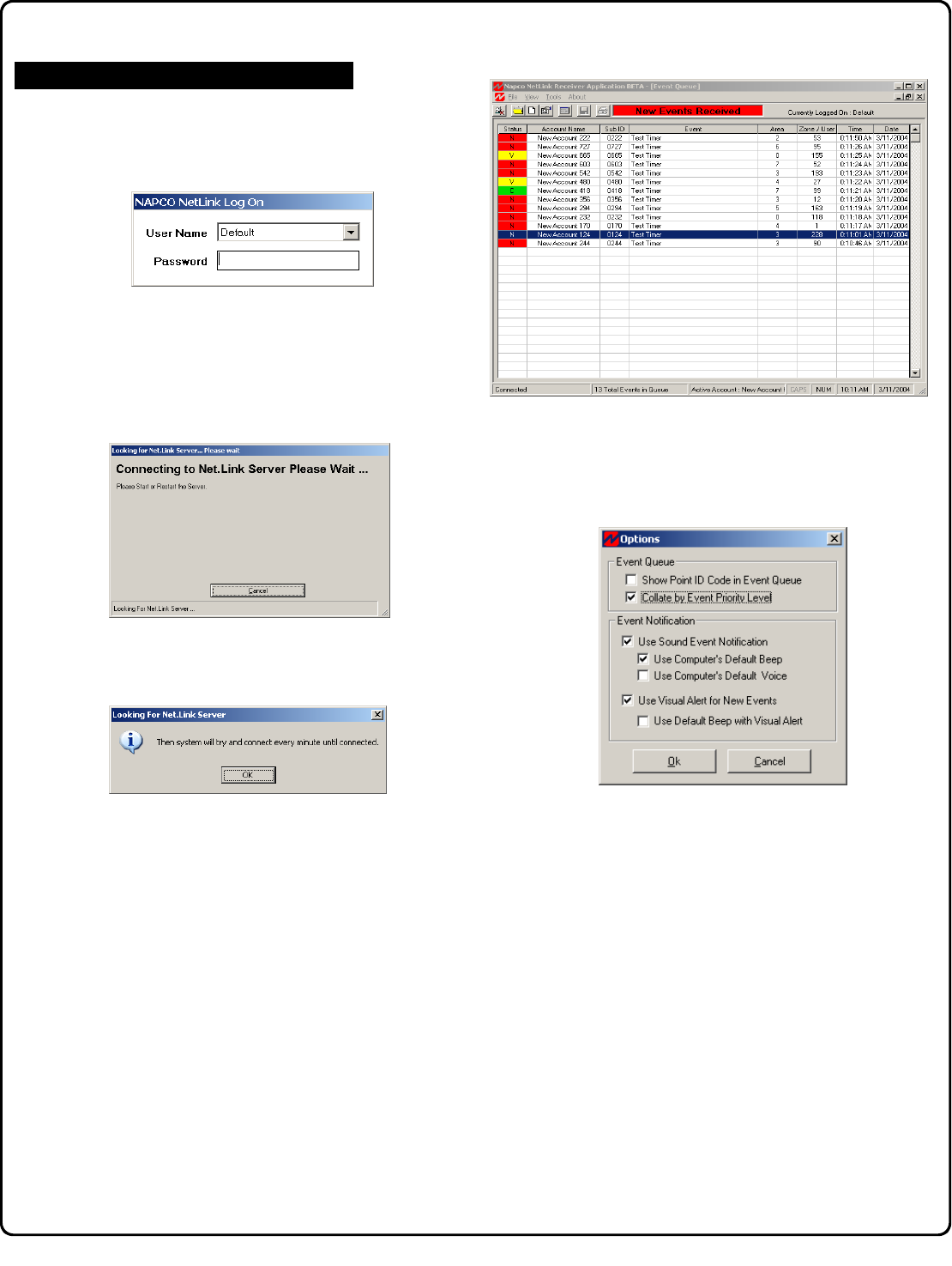
Before starting the NetLink™ Receiver Application, be
sure the NetLink™ Server is running. When the NetLink™
Receiver Application is first started, a logon screen appears.
You must first Log On to the system before the system can
be used.
Select your user log-on name from the User Name drop
down list, and enter your password in the field provided. If
you are unable to log on, see your system administrator for
assistance. If the NetLink server is not running or is
delayed, the following warning popup appears, indicating the
system is attempting to connect to the NetLink Server once
every second:
If Cancel is clicked, the system will attempt to connect to the
NetLink server once every minute, and the following warning
popup appears:
If a connection is made quickly, this warning popup will not
appear, and only a "Connected" message will appear in the
lower left corner of the Event Queue window status bar (see
image below).
Event Queue
When the NetLink™ Receiver Application is opened for the
first time, an empty grid appears. This grid is the Event
Queue, and as events are received they are added to the
list, displaying the most recent incoming events. The Event
Queue screen is full size when the NetLink™ Receiver
Application is first started, and can be minimized (or made
floating) by the Windows® control box located in the upper
right hand corner of the window. An example of the Event
Queue grid is displayed below.
When an event is delivered into the system, the Event
Queue, if closed, will automatically open and an alert
warning will sound. If you close the Event Queue, it can
always be re-opened by clicking View, Event Queue (or by
pressing F5).
Options
Event Queue defaults can be changed with the Options
dialog, found on the Tools menu (click Tools, Options). The
Options dialog specifies several Event Queue and Event
Notification options, as follows:
Show Point ID Code in Event Queue
Check to add a new column in the Event Queue screen
named Point ID, displaying a standardized coding
convention for alarms.
Collate by Event Priority Level
By default, Events are sorted first by time of occurrence,
most recent times at the top, then by their Event Priority
Level (giving important events preference). In the
Options dialog, check Collate by Event Priority Level to
reverse this arrangement, thus sorting Events first by their
Event Priority Level (giving important events preference)
and then by time of occurrence (most recent times at the
top). Note: This option must be selected for UL Line
Security (not evaluated by UL).
Event Notification
Check Use Sound Event Notification to enable a sound
to be played when Events are received. This sound can
be assigned to a default beep or a default voice, by
selecting one of the two following options:
Using the NetLink™ Receiver Application
(continued)
12
•Use Computer's Default Beep: Check to enable the
sound to be selected via the Sounds Properties
dialog, found in the Windows® Control Panel (Start,
Settings, Control Panel, Sounds). The default beep
event can be customized, as desired, via this
Windows® Sounds Properties dialog.
•Use Computer's Default Voice: Check to enable the
sound to be selected via the Speech Properties
dialog, found in the Windows® Control Panel (Start,
Settings, Control Panel, Speech). The default voice
can be customized, as desired, via this Windows®
Speech Properties dialog.
Use Visual Alert for New Events
Check to enable a "New Events Received" message in
the button bar area when Events are received. The
message will continue to appear until a key is pressed or
the mouse is moved. Check Use Default Beep with
Visual Alert to allow the default Beep to sound along
with this visual alert.
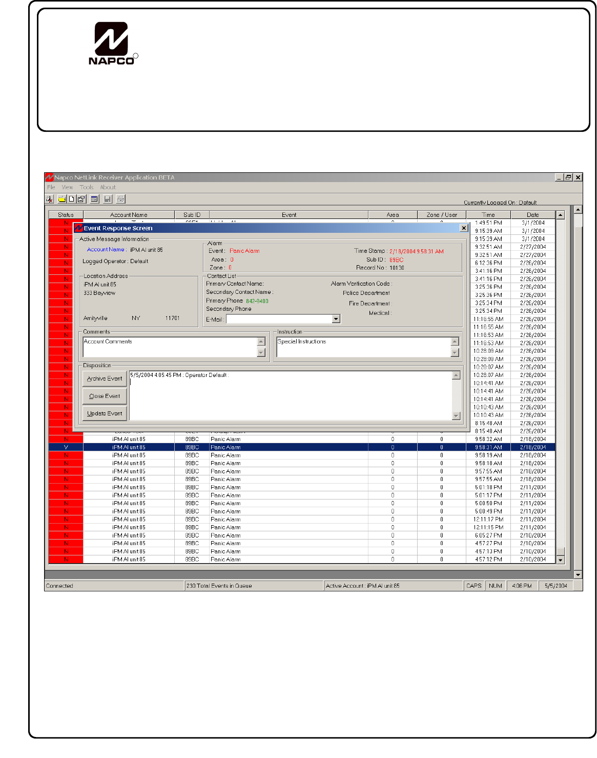
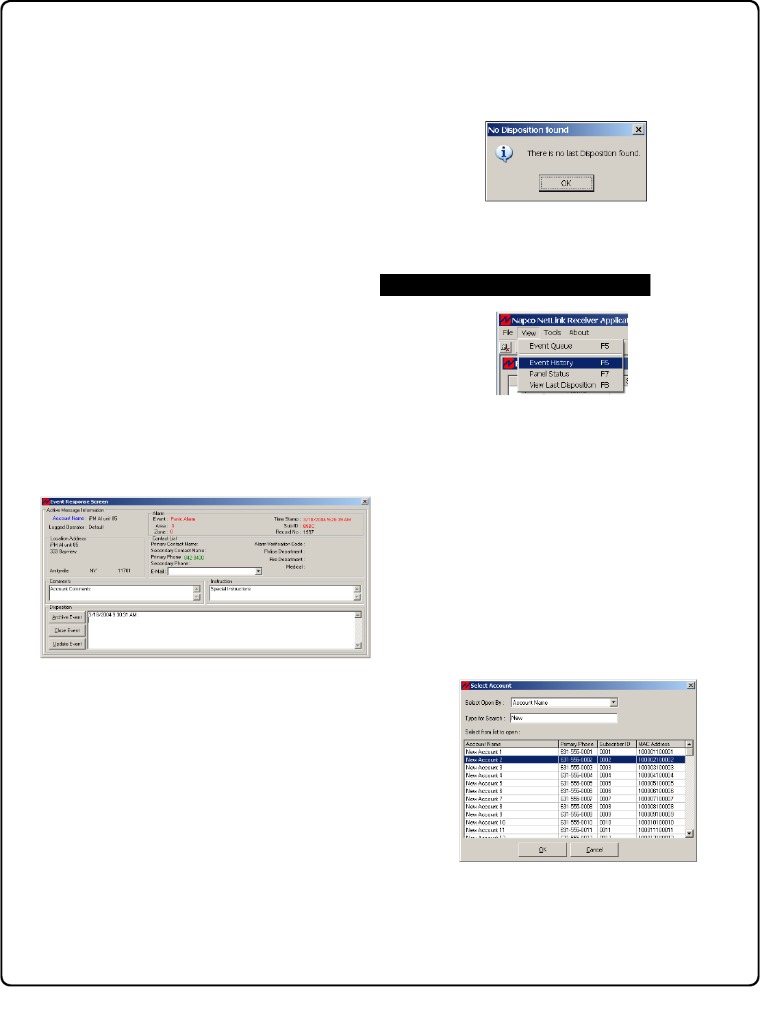
Responding to Events
Double-click an event (in the Event Queue) to open the
Event Response Screen, which displays detailed
information about the event, including the location address,
the type of event, alarm details, contact lists and special
comments and instructions. Type a description of the
response taken in the Disposition field (up to 256
characters allowed) which is saved when the Event
Response Screen is closed or reloaded.
All New and Viewed events are displayed in the Event
Queue. A New event is one not opened (and to which no
response has been made) and an Viewed event exists
when an operator opens but does not yet archive the
event. When an event is opened for the first time, the
Status column in the Event Queue changes from
"N" (New) to "V" (Viewed) for that event.
Press Update Event after adding information to the
Disposition field that you wish to save, such as actions
taken. Note: New information is saved if either (1) the
window is closed by clicking the "X" button in the upper-
right corner of the window, or (2) if the Update Event
button is clicked.
Press Close Event to close the Event window (without
archiving the Event). The Event will remain in the Event
Queue, and no changes can be made to it.
Press Archive Event when no further action is required.
When archived, the event is removed from the Event
Queue and sent to the database. Warning: Once
archived, the event cannot be modified further. If an
event is archived and you wish to immediately re-view the
event, click View, View Last Disposition (or press F8) and
the Event Response Screen will reappear. If no
disposition exists, the No Disposition Found popup
appears:
You can also view an archived event, by opening the
Event Log History screen (see below).
The Event Log History screen is used to view archived
events for a single Account. To access the Event History
screen, click View, Event History (you can also use the
short cut key (F6) or press the Show Event Log of the
Open Account button on the toolbar).
Before viewing the Account history, the Account whose
history you wish to view must be the "active" Account. An
Account becomes the active Account when (1) an event in
that Account has been viewed with the Event Response
Screen, or (2) open the Account by clicking File, Open
Account or pressing the Open Existing Account button
on the NetLink™ Receiver Application toolbar.
If the Account whose history you wish to view is not
currently active, then the Select Account screen will open
(below).
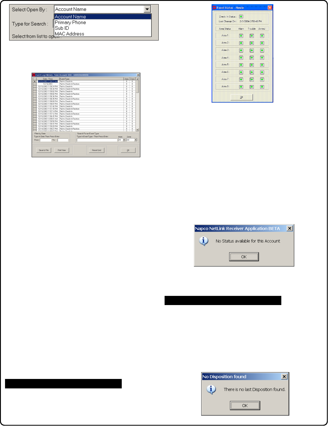
The Select Account screen enables you to search
through the Accounts currently available. Accounts can be
listed by Account Name, Primary Phone, Subscriber ID or
by MAC Address by selecting the category from the Select
Open By drop down list. Press Enter key on keyboard
after search criteria is entered.
Viewing Archived Events
13
When search results are found in the Select Account
screen, double-click on the desired Account to select.
Then the Event Log History screen will appear.
Although the events can be scrolled, the events listed in the
Event Log History screen can also be filtered by date,
thus making it easier to find a particular event. In the Filter
by Date area, type in a range of dates (or just the month
and date), starting with the From field, and ending with the
To field. Press the Enter key on your keyboard to remove
all events from the list not within the range specified.
Examples of date format are "4/20" or 7/16/2003".
To further assist in finding a particular event, you can also
search for Events by Event Type. Type a specific Event
Type in the Type in Event Type field. The event Area
and Zone can also be specified with their respective drop
down lists. Press the Enter key on your keyboard to
remove all events from the list not within the Type, Area
and Zone conditions specified.
To view the latest archived event, click the Reset Grid
button. You can also save the Event Log History list to a
text file by pressing the Save to File button. The Save
As… window will open, allowing the file to be renamed and
saved in the usual manner. The file saved will be a CSV
formatted text file. Press the Print View button to print, in
a table format, the current list of events.
To view the action taken within the archived event, double-
click the event (or click to highlight the event, and click
OK). The archived Event Log History screen opens,
allowing you to view past events and their complete
resolution with all Account information included. Note:
Archived events may not be modified,
To view the status of the control panel within the active
Account, click View, Panel Status, and the Panel Status
screen will appear.
The Panel Status screen indicates various attributes,
including Check In Status, Area Status (for areas 1-8) as to
Alarm, Armed and Trouble. A green icon indicates all is
OK. A red icon indicates the area specified is in alarm, is
armed or is in trouble. The darkest icon indicates the area
specified is inactive or does not exist.
The active Account can only provide a status of the control
panel for NL-MOD installations if: (a) the control panel is
set up to report to the TCP/IP receiver through a high
speed serial output (such as the Local Download jack
(JP2) on the control panel) and (b) the NL MOD is enabled
for High Security Checkin (see New Account Setup
window, Panel Setup tab on page 8). If the active
Account is unable to provide a status of the control panel,
the following popup will appear:
In addition, the above popup will also appear for new
control panel installations that have not yet sent any status
packets.
A disposition is a text description of the response taken for
an event. The Disposition field is saved when the Event
Response Screen is closed or reloaded. To view the last
written disposition at any time, simply click View, View Last
Disposition (or press F8) and the disposition in the Event
Response Screen will reappear.
If no disposition exists, the No Disposition Found popup
appears:
View Last Disposition
View Panel Status
14
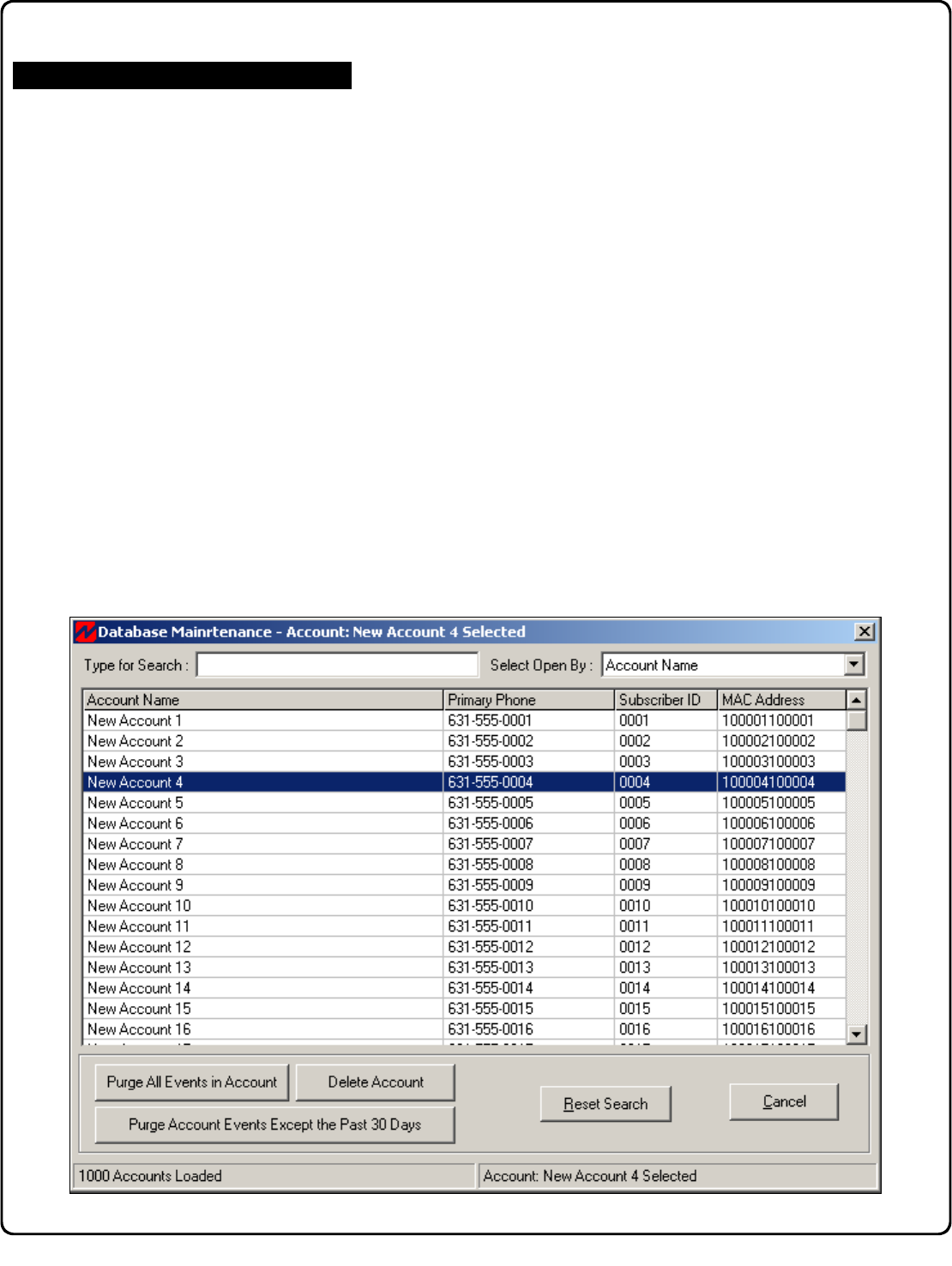
The Database Maintenance screen manages the Event
History database. To open the screen, click Tools,
Database Maintenance.
The Database Maintenance screen lists all Accounts, and
four buttons are used to remove older data from the
database, as follows:
•Purge Account Events - All events (except those
received/archived within the previous 30 days) will be
deleted.
•Purge All Accounts Events - All events in all
Accounts will be deleted.
•Delete Account - Deletes all highlighted Accounts.
Database Maintenance
Database Maintenance
15
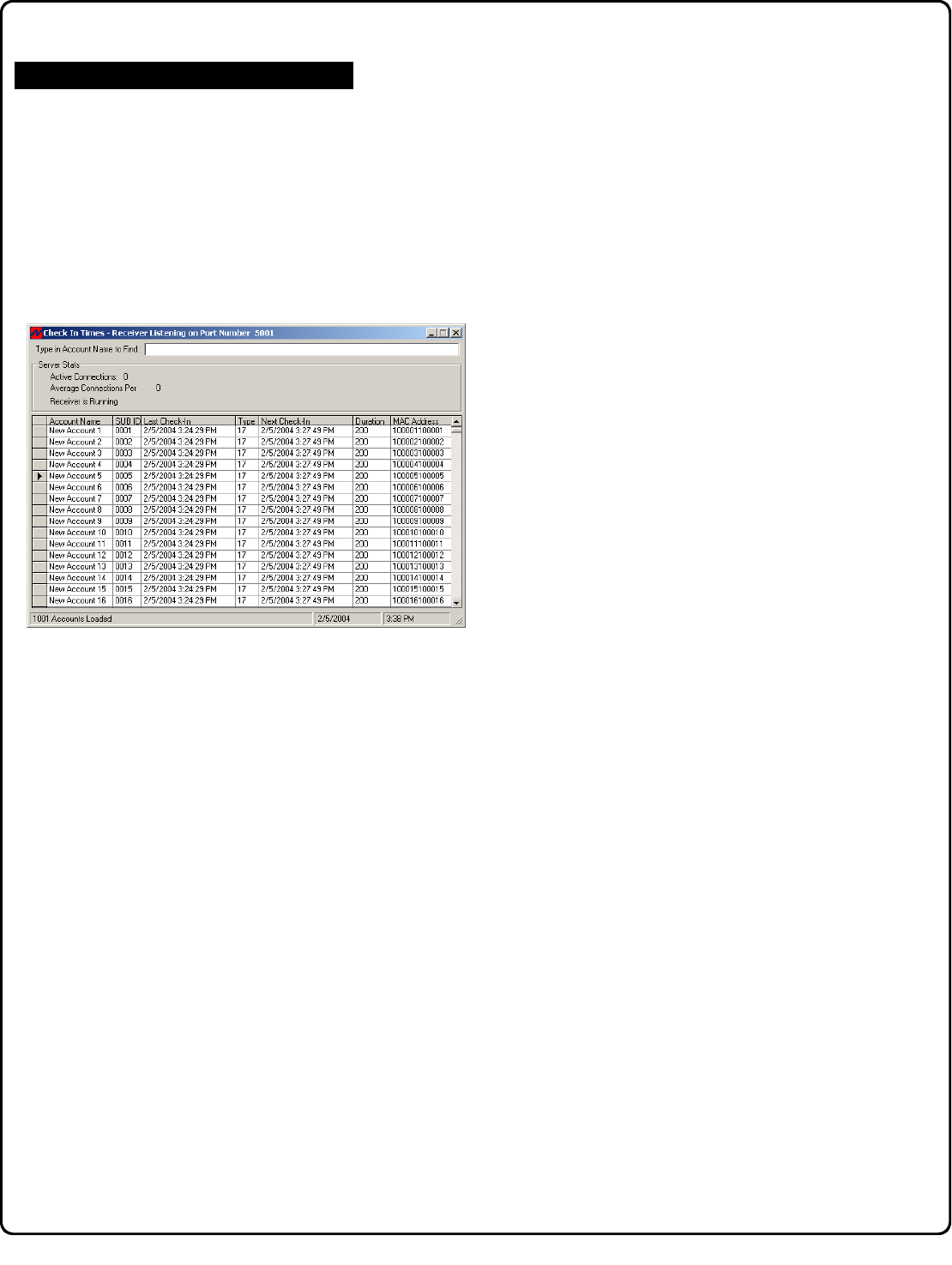
Check In Times
To ensure that communication exists between the control
panels and the NetLink™ Receiver Application, the panel
will send a signal to "Check In" with the NetLink™
Receiver Application at timed intervals.
The Check In Times screen will display all of the active
Accounts and their respective Check In times, all in real
time. You can search the Accounts by their Account
Name.
See page 9 "Enable Check-In logging to file" and "On
Startup - Use Previous Checkin File" for more
information with regard to the check-in events and logging.
Server Check In Times
16
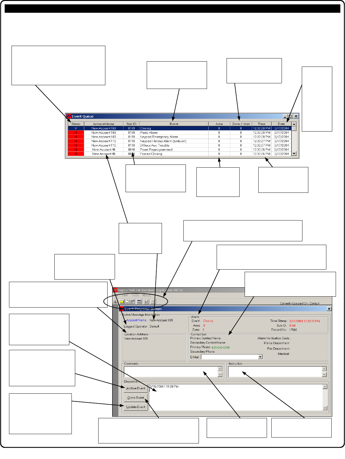
This is the main program User Interface (also referenced as the NetLink™ Application). The Operator interacts with
the two screens--the Event Queue and the Event Response Screen.
NetLink™ Receiver Application "Main Screen" - Field and Button Definitions Appendix A
Account Name
Indicates the name
of the active ac-
count initially listed
in the Event Queue.
Logged Operator
Indicates the User Name of
the operator to which the
event was directed.
Disposition
Type a description of the
response taken to the Event
in this field. The text will be
saved when archived.
Archive Event
Click this button to permanently
save into the database the text
typed into the Disposition field,
and to close the Event Re-
sponse Screen.
Update Event
Click this button to temporarily
save into memory the text
typed into the Disposition
field, and close the Event
Response Screen. Comments
Indicates special remarks for
the Account.
Instructions
Indicates special directions
for the Account.
Alarm
Indicates detailed information regarding the event,
including its internal record number, Sub ID, Zone,
Area, and Event Type.
Contact List
Indicates contact names, telephone num-
bers, email, verification codes, and local fire,
police and medical contact information.
Location Address
Indicates the physical location of the protected
premises, including the name of the business,
street address of the premises, city, etc.
NetLink™ Receiver Application Quick Access Buttons
NetLink™ Receiver Application Main Menu
Described on page 17.
Status
Indicates a description assigned to each
Event received. "N" indicates a New event,
and "V" indicates an Viewed event. "C" indi-
cates the event is closed and cannot be modi-
fied. A "R" indicates the event is a restoration
of a previously displayed alarm.
Time
Indicates the time the
event was received.
Date
Indicates the
month/day/
year the
event was
received by
the NetLink™
Receiver
Application
software.
Zone/User
Indicates the Zone of the
system that triggered the
event.
Event
Indicates the event descrip-
tion.
Sub ID
Identifies the ID used by the
subscriber to the Central
Station service.
Area
Indicates the Area
of the system that
triggered the event.
Close Event
Press Close Event to close the Event window
(without archiving the Event). The Event will remain in
the Event Queue, and no changes will be made to it.
17
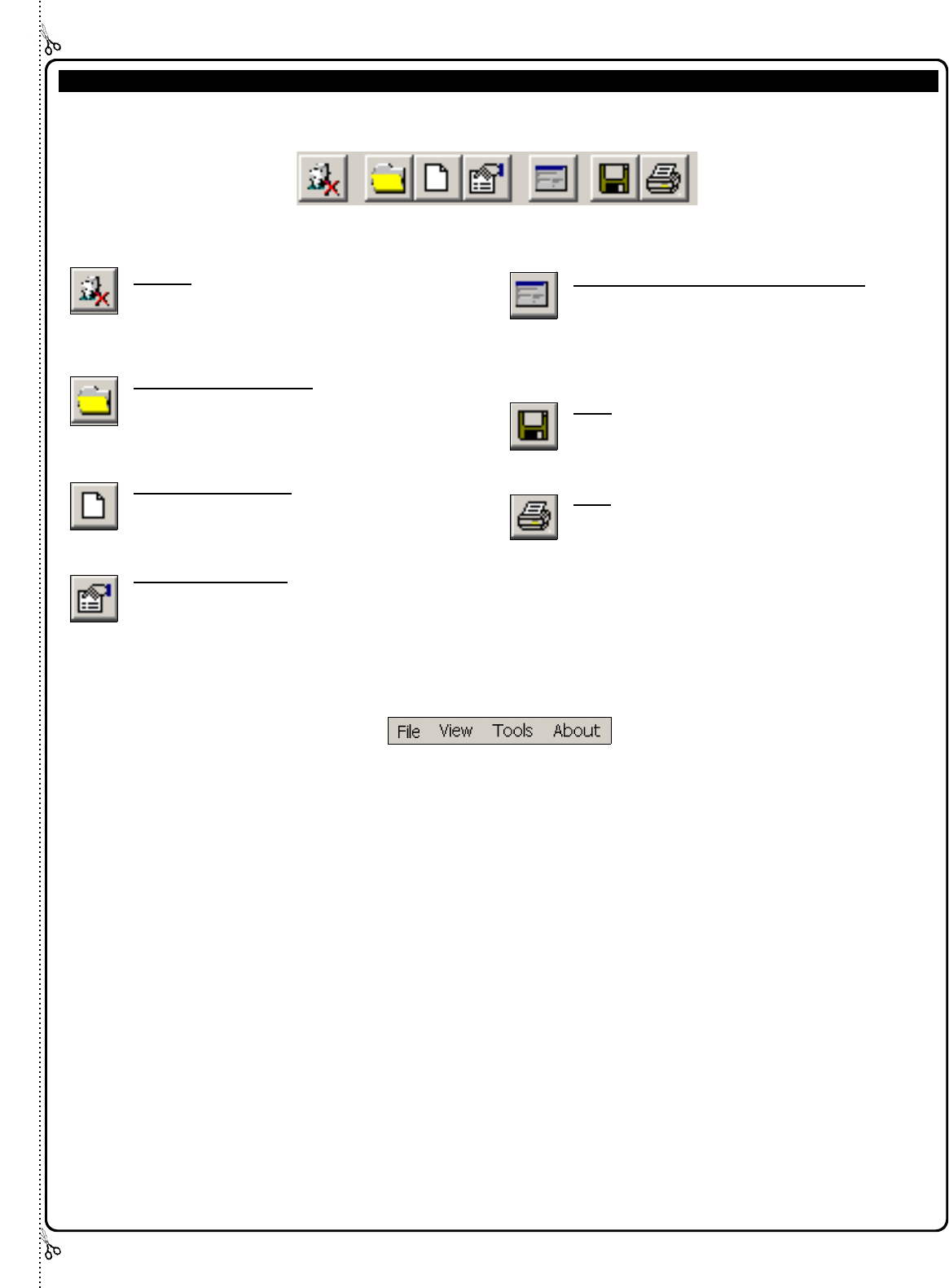
NetLink™ Receiver Application Quick Access Buttons and Main Menu Appendix B
Log Off - Logs the current operator off the
system.
Open Existing Account - Opens an existing
account. An account represents a
monitored premises, such as a building or a
home.
Create New Account - Creates new account.
For adding new accounts to the system, see
page 7.
Edit Active Account - Click this button to edit
existing account information, such as
primary and secondary contact information,
local police and fire department telephone
numbers, etc.
Show Event Log of the Open Account - When
an existing account is open, press this
button to view all Event Logs, listing all
events transmitted to the NetLink™ Receiver
Application by the control panel.
Save - Saves the newly created account into
the database.
Print - Prints the current view of the Event Log.
NetLink™ Receiver Application Quick Access Buttons
The NetLink™ Receiver Application toolbar (above) contains the Quick Access buttons. It may be helpful to open each
screen on your computer as you read. From left to right, they are as follows:
NetLink™ Receiver Application Main Menu
Menu System and Short Cut keys
The sub-menus within the NetLink™ Receiver Application Main
Menu bar can be activated by clicking the mouse or via short
cut keys. For example, to open the New Account Screen,
you can use your mouse to select File, new Account or you
can use its short cut (hold down the Ctrl button and press N).
Main NetLink™ Receiver Application Screen:
File Menu (Alt + F) Short Cut Key
Log Off (None)
New Account CTRL + N
Open Account (None)
Edit Account CTRL + E
Exit (None)
View Menu (Alt + V)
Event Queue F5
Event History F6
Panel Status F7
View Last Disposition F8
Tools (Alt + T)
(For Administrative Users Only)
Manage Users (None)
Options (None)
Database Maintenance (None)
Manage Users Screen
File Menu (Alt + F) Short Cut Key
Exit (None)
Action Menu (Alt + A) Short Cut Key
(For Administrative Users Only)
Add User CTRL + A
Edit User CTRL + E
Delete User CTRL + D
Set Password CTRL + P
NetLink™ Server
(Right Mouse-Click the NetLink™ Server icon in the taskbar)
About NetLink™ Receiver
Check-In Times
Start Server
Stop Server
Server Setup
Automation Setup
Shut Down

18
Account Name = A unique name assigned to an Account when added.
Active Account = An Account becomes the active Account when (1) an event in that Account has been
viewed with the Event Response Screen, or (2) open the Account by clicking File, Open Account or
pressing the Open Existing Account button on the NetLink™ Receiver Application toolbar.
Automation Host = A computer that receives Event data
Event Priority Order = When events are received, they are sorted in the Event Queue so as to allow the
operator to respond to events in the following order:
GUI = Acronym for Graphical User Interface.
NRA = Acronym for NetLink™ Receiver Application.
Priority Order = See Event Priority Order
Server = A computer that provides some service for other computers or devices connected to it via a network.
Refers to the NetLink™ Server.
Subscriber ID = An identification number signifying an Account assigned by the remote monitoring receiver.
TCP/IP = Transmission Control Protocol over Internet Protocol. The de facto standard Ethernet protocols.
Telephone Number = Entry into
UDP = User Datagram Protocol. Is a standard internet protocol which provides simple datagram services,
and like TCP, is layered on top of IP.
Glossary
1. Fire Alarm 6. Fire-Alarm Supervision
2. Hold-up or Panic Alarm 7. Burglar-Alarm Supervision
3. Burglar Alarm 8. Industrial Supervision where a danger will not result
4. Industrial Supervision where a danger can result 9. Other Supervisory services
5. Watchman Tour

19
Notes

20
NAPCO SECURITY SYSTEMS, INC. (NAPCO) war-
rants its products to be free from manufacturing defects
in materials and workmanship for thirty-six months fol-
lowing the date of manufacture. NAPCO will, within said
period, at its option, repair or replace any product failing
to operate correctly without charge to the original pur-
chaser or user.
This warranty shall not apply to any equipment, or any
part thereof, which has been repaired by others, improp-
erly installed, improperly used, abused, altered, dam-
aged, subjected to acts of God, or on which any serial
numbers have been altered, defaced or removed. Seller
will not be responsible for any dismantling or reinstalla-
tion charges.
THERE ARE NO WARRANTIES, EXPRESS OR IM-
PLIED, WHICH EXTEND BEYOND THE DESCRIP-
TION ON THE FACE HEREOF. THERE IS NO EX-
PRESS OR IMPLIED WARRANTY OF MERCHANT-
ABILITY OR A WARRANTY OF FITNESS FOR A PAR-
TICULAR PURPOSE. ADDITIONALLY, THIS WAR-
RANTY IS IN LIEU OF ALL OTHER OBLIGATIONS OR
LIABILITIES ON THE PART OF NAPCO.
Any action for breach of warranty, including but not lim-
ited to any implied warranty of merchantability, must be
brought within the six months following the end of the
warranty period.
IN NO CASE SHALL NAPCO BE LIABLE TO ANYONE
FOR ANY CONSEQUENTIAL OR INCIDENTAL DAM-
AGES FOR BREACH OF THIS OR ANY OTHER WAR-
RANTY, EXPRESS OR IMPLIED, EVEN IF THE LOSS
OR DAMAGE IS CAUSED BY THE SELLER'S OWN
NEGLIGENCE OR FAULT.
In case of defect, contact the security professional who
installed and maintains your security system. In order to
exercise the warranty, the product must be returned by
the security professional, shipping costs prepaid and
insured to NAPCO. After repair or replacement, NAPCO
assumes the cost of returning products under warranty.
NAPCO shall have no obligation under this warranty, or
otherwise, if the product has been repaired by others,
improperly installed, improperly used, abused, altered,
damaged, subjected to accident, nuisance, flood, fire or
acts of God, or on which any serial numbers have been
altered, defaced or removed. NAPCO will not be re-
sponsible for any dismantling, reassembly or reinstalla-
tion charges.
This warranty contains the entire warranty. It is the sole
warranty and any prior agreements or representations,
whether oral or written, are either merged herein or are
expressly cancelled. NAPCO neither assumes, nor au-
thorizes any other person purporting to act on its behalf
to modify, to change, or to assume for it, any other war-
ranty or liability concerning its products.
In no event shall NAPCO be liable for an amount in ex-
cess of NAPCO's original selling price of the product, for
any loss or damage, whether direct, indirect, incidental,
consequential, or otherwise arising out of any failure of
the product. Seller's warranty, as hereinabove set forth,
shall not be enlarged, diminished or affected by and no
obligation or liability shall arise or grow out of Seller's
rendering of technical advice or service in connection
with Buyer's order of the goods furnished hereunder.
NAPCO RECOMMENDS THAT THE ENTIRE SYSTEM
BE COMPLETELY TESTED WEEKLY.
Warning: Despite frequent testing, and due to, but not
limited to, any or all of the following; criminal tampering,
electrical or communications disruption, it is possible for
the system to fail to perform as expected. NAPCO does
not represent that the product/system may not be com-
promised or circumvented; or that the product or system
will prevent any personal injury or property loss by bur-
glary, robbery, fire or otherwise; nor that the product or
system will in all cases provide adequate warning or
protection. A properly installed and maintained alarm
may only reduce risk of burglary, robbery, fire or other-
wise but it is not insurance or a guarantee that these
events will not occur. CONSEQUENTLY, SELLER
SHALL HAVE NO LIABILITY FOR ANY PERSONAL
INJURY, PROPERTY DAMAGE, OR OTHER LOSS
BASED ON A CLAIM THE PRODUCT FAILED TO
GIVE WARNING. Therefore, the installer should in turn
advise the consumer to take any and all precautions for
his or her safety including, but not limited to, fleeing the
premises and calling police or fire department, in order
to mitigate the possibilities of harm and/or damage.
NAPCO is not an insurer of either the property or safety
of the user's family or employees, and limits its liability
for any loss or damage including incidental or conse-
quential damages to NAPCO's original selling price of
the product regardless of the cause of such loss or dam-
age.
Some states do not allow limitations on how long an im-
plied warranty lasts or do not allow the exclusion or limi-
tation of incidental or consequential damages, or differ-
entiate in their treatment of limitations of liability for ordi-
nary or gross negligence, so the above limitations or ex-
clusions may not apply to you. This Warranty gives you
specific legal rights and you may also have other rights
which vary from state to state.
NAPCO LIMITED WARRANTY
