Netborder SS7 To VoIP Gateway User Manual Ftp://ftp.sangoma.com/nsg/Netborder Vo IP Media V1.0.14
User Manual: ftp://ftp.sangoma.com/nsg/Netborder-SS7-VoIP-Media-Gateway-User-Manual-v1.0.14 manual pdf
Open the PDF directly: View PDF ![]() .
.
Page Count: 317 [warning: Documents this large are best viewed by clicking the View PDF Link!]

v1.14
1
Netborder SS7 to VoIP
Gateway
User Manual
[Type the abstract of the document here. The abstract is typically a short
summary of the contents of the document. Type the abstract of the document
here. The abstract is typically a short summary of the contents of the document.]

v1.14
2
Date: Dec 28 2012: Version: 1.14
Document Revision
Date
Description of Changes
1.14
Dec 28 2012
Profile Panel Support, On the fly config.
1.12
Nov 08 2012
Theory section and minor updates
1.11
Sep 23 2012
Quickstart section 5, Layout change
1.10
Sep 14 2012
Added MG Status, VLAN auto startup on eth config
1.09
Sep 12 2012
Updated network setup overview, snmp and monitoring
1.08
Sep 11 2012
Updated channel map, added more background info
1.07
Sep 09 2012
Added T38_Fax option in Media Gateway profile.
1.06
Sep 05 2012
Added rtpip on megaco profile
1.05
Aug 31 2012
Cosmetic Changes A.O, Added Megaco Overivew, VLAN routes, Reload
1.04
Aug 23 2012
USB CLI, Static Routes, Alarms, Improved instructions
1.03
Aug 22 2012
Pinout label
1.02
Aug 22 2012
VLAN, Factory Reset, Static Routes, Eth Options, usb console, DC PSU
info
1.01
Aug 19 2012
Added extra diagrams, Media, SIP, Relay, Dialplan, Update, Cables,
Appendix
1.00
Aug 2012
Initial revision of the document.
Conventions
This font indicates screen menus and parameters.
<> indicates keyboard keys (<Enter>, <q>, <s>).
NOTE
Notes inform the user of additional but essential information or features.
CAUTION
Cautions inform the user of potential damage, malfunction, or disruption
to equipment, software, or environment.
Sangoma Technologies provides technical support for this product.
Tech-support e-mail: support@sangoma.com

v1.14
3
This page is intentionally blank.

v1.14
4
Sangoma
Netborder SS7 to VoIP GW User Manual

v1.14
5
Contents
Sangoma............................................................................................................................................... 4
Netborder SS7 to VoIP GW User Manual ............................................................................................. 4
1 Product Overview .......................................................................................................................... 10
1.1 Features / Advantages ........................................................................................................... 10
1.1.1 Any to Any Signaling and Media Gateway ...................................................................... 11
1.2 TDM T1/E1 Interfaces ............................................................................................................ 12
1.3 Ethernet Network Interfaces .................................................................................................. 12
1.4 VoIP Protocols ....................................................................................................................... 12
1.4.1 SIP .................................................................................................................................. 12
1.4.2 Megaco/H.248 & MGCP .................................................................................................. 12
1.4.3 H.323 ............................................................................................................................... 13
1.5 TDM Protocols ....................................................................................................................... 13
1.5.1 SS7 ................................................................................................................................. 13
1.5.2 ISDN ................................................................................................................................ 14
1.6 Call Routing ........................................................................................................................... 14
1.7 Media Processing & Transcoding .......................................................................................... 14
1.8 Echo Cancellation & VQE ...................................................................................................... 15
1.9 DTMF Detection and Generation ........................................................................................... 15
1.10 Management and Configuration ......................................................................................... 15
1.11 Monitoring ........................................................................................................................... 15
1.12 Accounting .......................................................................................................................... 15
1.13 Shipping Options ................................................................................................................ 16
1.14 Support and Professional Services ..................................................................................... 16
2 NSG Product Information .............................................................................................................. 17
2.1 NetBorder SS7 to VoIP Gateway Appliance .......................................................................... 17
2.1.1 Hardware Specifications .................................................................................................. 17
2.2 NSG Shipping Box Contents .................................................................................................. 18
2.2.1 What is included in the box ............................................................................................. 18
2.2.2 What is not included ........................................................................................................ 18
2.2.3 Front Panel ...................................................................................................................... 19
2.2.4 Rear Panel 1U ................................................................................................................. 20
2.2.5 Front Panel 2u ................................................................................................................. 21
2.2.6 Rear Panel 2U ................................................................................................................. 22
2.3 NSG T1/E1 Port Identification ................................................................................................ 23
2.3.1 Cable Pinouts: T1/E1 ...................................................................................................... 24
2.4 NSG Appliance Default Configuration .................................................................................... 26
3 User Interface ............................................................................................................................... 27
3.1 WebGUI ................................................................................................................................. 27
3.1.1 WebGUI Structure ........................................................................................................... 28
3.2 Console Structure .................................................................................................................. 31
3.2.1 Connect via SSH ............................................................................................................. 31

v1.14
6
3.2.2 Connect via USB Serial ................................................................................................... 32
3.2.3 Bash Shell ....................................................................................................................... 33
3.2.4 Gateway CLI – nsg_cli .................................................................................................... 34
3.3 Shell/CLI from GUI ................................................................................................................. 35
4 Usage Scenarios ........................................................................................................................... 36
4.1 Signaling Gateway: M2UA .................................................................................................... 36
4.2 Megaco/H.248 Media Gateway: MG + SG ............................................................................. 36
4.2.1 Megaco Quick Configuration ........................................................................................... 37
4.3 SIP/H323 to SS7 ISUP .......................................................................................................... 38
4.3.1 H323 to SS7 ISUP Quick Start Guide ............................................................................. 39
4.4 Any to Any Signaling and Media Gateway ............................................................................. 40
5 First Boot/Initial Setup ................................................................................................................... 41
5.1 Power Connection.................................................................................................................. 41
5.1.1 PSU Connection .............................................................................................................. 41
5.1.2 DC PSU Connection ........................................................................................................ 42
5.2 Establishing Initial WebGUI Connection ................................................................................ 43
5.3 Change Password.................................................................................................................. 44
5.4 Console SSH Configuration ................................................................................................... 45
5.5 Self Test ................................................................................................................................. 47
5.5.1 Running Self-Test ............................................................................................................ 47
5.6 NSG License .......................................................................................................................... 49
6 Network Configuration................................................................................................................... 51
6.1 Physical Network Interface Configuration .............................................................................. 53
6.2 Appliance Network Interfaces ................................................................................................ 54
6.3 Selecting Default Route ......................................................................................................... 54
6.4 Network Section ..................................................................................................................... 55
6.5 Interface Section .................................................................................................................... 56
6.5.1 Network Role ................................................................................................................... 56
6.5.2 Types .............................................................................................................................. 57
6.5.3 Ethernet Options ............................................................................................................. 58
6.6 Virtual IP’s .............................................................................................................................. 59
6.7 IP Troubleshooting ................................................................................................................. 59
6.8 Static Routes ......................................................................................................................... 60
6.8.1 Routing Table Status ....................................................................................................... 62
6.9 VLAN ..................................................................................................................................... 63
6.9.1 VLAN Configuration ......................................................................................................... 64
6.9.2 VLAN Routes................................................................................................................... 65
6.9.3 Additional VLAN .............................................................................................................. 66
6.9.4 vconfig help ..................................................................................................................... 66
6.9.5 VLAN Status .................................................................................................................... 67
6.10 Date & Time Service Config ............................................................................................... 69
7 Initial Gateway Configuration ........................................................................................................ 71
7.1 Global Gateway Configuration ............................................................................................... 72

v1.14
7
8 Megaco/H.248 Media Gateway Configuration ............................................................................... 74
8.1 Overview ................................................................................................................................ 74
8.1.1 Terminations.................................................................................................................... 74
8.1.2 Contexts .......................................................................................................................... 74
8.2 Commands ............................................................................................................................ 75
8.2.1 Sent from controller to gateway ....................................................................................... 75
8.2.2 Sent from gateway to controller ....................................................................................... 75
8.3 Packages ............................................................................................................................... 76
8.4 Create MG Profile .................................................................................................................. 77
8.5 Create MG Peer Profile .......................................................................................................... 80
8.6 TDM Termination for Media Gateway .................................................................................... 82
8.6.1 Identify ............................................................................................................................. 83
8.6.2 Edit T1/E1 Config ............................................................................................................ 84
8.7 Span Link Type ...................................................................................................................... 87
8.8 Signaling Gateway Overview ................................................................................................. 88
8.8.1 MTP1/2 Link Configuration .............................................................................................. 89
8.8.2 M2UA Interface ............................................................................................................... 91
8.8.3 M2UA Cluster Creation ................................................................................................... 92
8.8.4 M2UA Cluster Peers ........................................................................................................ 93
8.8.5 SCTP Interface ................................................................................................................ 95
8.8.6 Binding all components ................................................................................................... 96
8.8.7 Mixed Mode Configuration .............................................................................................. 97
8.8.8 Bind Megaco to TDM ....................................................................................................... 98
8.8.9 TDM Termination Complete .......................................................................................... 101
9 SS7 ISUP .................................................................................................................................... 102
9.1 TDM SS7 Configuration Page .............................................................................................. 104
9.2 Port Identification ................................................................................................................. 105
9.3 Edit T1/E1 Config ................................................................................................................. 106
9.3.1 Standard T1/E1 Parameters .......................................................................................... 106
9.3.2 Advanced T1/E1 Parameters ........................................................................................ 108
9.4 Span Link Type .................................................................................................................... 109
9.5 SS7 Network Overview ........................................................................................................ 110
9.5.1 Links .............................................................................................................................. 111
9.5.2 Linksets ......................................................................................................................... 111
9.5.3 Routes ........................................................................................................................... 111
9.6 MTP2 Link Configuration ..................................................................................................... 112
9.7 MTP3 Linkset Configuration ................................................................................................. 115
9.8 MTP3 SS7 Route ................................................................................................................. 118
9.9 ISUP Interface Configuration ............................................................................................... 120
9.10 ISUP CIC Channel Mapping ............................................................................................. 124
10 Relay: SS7 .............................................................................................................................. 130
10.1 Relay Configuration .......................................................................................................... 131
10.1.1 Configuring the master gateway .................................................................................... 132

v1.14
8
10.1.2 Configuring the slave gateway ...................................................................................... 136
10.1.3 Configuring the slave TDM configurations from the master gateway ............................ 140
11 Media Transcoding Configuration ........................................................................................... 142
11.1 Media Hardware ............................................................................................................... 143
12 Applying Configuration ............................................................................................................ 144
13 Dialplan ................................................................................................................................... 146
13.1 Dialplan Reload/Apply ...................................................................................................... 147
13.2 PSTN to SIP Dialplan ....................................................................................................... 148
13.3 PSTN to H323 Dialplan..................................................................................................... 149
13.4 SIP/H323 to PSTN Dialplan .............................................................................................. 150
13.5 Dialplan Syntax ................................................................................................................. 151
13.5.1 Context .......................................................................................................................... 152
13.5.2 Extensions ..................................................................................................................... 153
13.5.3 Conditions ..................................................................................................................... 154
13.5.4 Multiple Conditions (Logical AND) ................................................................................. 155
13.5.5 Multiple Conditions (Logical OR, XOR) ......................................................................... 156
13.5.6 Complex Condition/Action Rules ................................................................................... 159
13.5.7 Variables ....................................................................................................................... 161
14 Backup Restore System .......................................................................................................... 163
14.1 Restore a System ............................................................................................................. 164
14.2 Restore to a new System .................................................................................................. 165
15 Factory Reset & Reboot .......................................................................................................... 166
15.1 Factory Reset ................................................................................................................... 166
15.2 Appliance Soft Reboot ...................................................................................................... 166
15.3 Appliance Shutdown ......................................................................................................... 166
16 Upgrade .................................................................................................................................. 167
16.1 WebUI System Update ..................................................................................................... 167
16.2 Console SSH Update ....................................................................................................... 168
17 Operations............................................................................................................................... 169
17.1 Starting the Gateway ........................................................................................................ 169
17.2 Profile Panel ..................................................................................................................... 171
17.3 Gateway Status ................................................................................................................ 173
17.3.1 Megaco/M2UA TDM ...................................................................................................... 173
17.4 Megaco Status .................................................................................................................. 178
17.5 Gateway Logs ................................................................................................................... 179
17.5.1 Gateway Log Download ................................................................................................ 180
17.6 Advanced Logs ................................................................................................................. 181
17.7 Packet Capture ................................................................................................................. 181
17.7.1 Ethernet Capture Filter Options ..................................................................................... 183
18 Monitoring & Management ...................................................................................................... 184
18.1 SNMP ............................................................................................................................... 184
18.2 SNMP Configuration ......................................................................................................... 185
18.3 SNMP Test ....................................................................................................................... 186

v1.14
9
19 Troubleshooting ...................................................................................................................... 188
19.1 Physical Layer .................................................................................................................. 189
19.1.1 NSG TDM Driver related commands ............................................................................. 190
19.1.2 T1/E1 Port Status .......................................................................................................... 191
19.1.3 T1/E1 Port Debugging ................................................................................................... 191
19.2 TDM Signaling Link Debugging ........................................................................................ 195
20 Appendix ................................................................................................................................. 197
20.1 Redundant DC PSU ......................................................................................................... 197
20.1.1 DC PSU Cables ............................................................................................................. 198
20.1.2 Hot-swap procedures .................................................................................................... 199
20.1.3 Trouble Shooting ........................................................................................................... 200
21 Theory ..................................................................................................................................... 201
v1.14
10
1 Product Overview
The NetBorder SS7 to VoIP Gateway is Sangoma’s Carrier Class TDM to SIP VoIP Gateway product.
For short, it is often referred to as NSG.
1.1 Features / Advantages
Any to any switching gateway.
o Ability to run all endpoints/protocols on single software image and appliance
o SS7, Sigtran, SIP, H.323, Megaco Media Gateway, Signaling Gateway
o Flexible dial plan to route from any endpoint to any endpoint
Scalable and very high density
o Up to 32 E1 per appliance appliance
o Can scale up to 288 E1s in relay mode where multiple systems act as one
o Transcoding available on all channels
Extensive VoIP Signaling
o SIP, H.323, Megaco/H.248
Full featured SS7/Sigtran Signaling
o SS7 ISUP Signaling with several national variants
o ITU, ANSI, Bellcore, France, UK, China, India and Russia
o Sigtran, M3UA, M2UA & Sigtran signaling gateway
ISDN signaling
o Q.931, QSIG,
Faxing and Media Support
o Pass-through
o T.38
Wide range of narrowband and wideband codecs supported
For any-to-any codec transcoding
o G.711, G.729, AMR
Robust implementation with distribution
Profile Panel, on the fly configuration with no service interruption.
v1.14
11
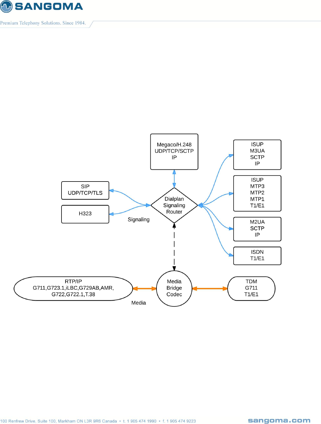
1.1.1 Any to Any Signaling and Media Gateway
Route any signaling traffic from eny signaling endpoint.
All protocols and signalling suppored from single gateway image.
o Ability to change from Megaco GW to SIP gateway via config change.
Route media with transcoding/dtmf/T.38 to/from end media endpoint.
NOTE:
Limitations exist when running specific signaling combinations at same time.
o Eg: M2UA SG cannot run at the same time as ISUP+MTP3+MTP2
o Some codes such as AMR will reduce session capacity.
o No reduction of capacity for G711, G729, iLBC

v1.14
12
1.2 TDM T1/E1 Interfaces
Electrical G.703.6/G.704 balanced
Minimum 4 T1/E1
Maximum 32 T1/E1 (960 ds0/sessions) per appliance
Transcoding supported on all channels
Extend capacity over 960 ports via ISUP relay feature and multiple appliances.
1.3 Ethernet Network Interfaces
Two Gigabit network interfaces
1.4 VoIP Protocols
1.4.1 SIP
SIP V2 / RFC 3261 RFC 3261 Session Initiate Protocol
RFC 2976 SIP INFO Method
RFC 3398 ISUP-SIP Mapping
RFC 3515 Refer Method
RFC 2327 Session Description Protocol
RFC 3581 An Extension to the Session Initiation Protocol (SIP) for Symmetric Response
Routing
RFC 3892 Referred-By Mechanism
RFC 3891 "Replaces" Header
RFC 3551: RTP/AVP
RFC 3515: REFER
RFC 2617: HTTP Digest Authentication
SDP Bypass
NSG exports all SS7 parameters via SIP custom X headers.
1.4.2 Megaco/H.248 & MGCP
MEGACO Protocol Version 1.0, Internet RFC3525
H.248.1 Version 1 Implementors’ Guide, 13 April, 2006
H.248 Sub-series Implementors’ Guide, 13 April, 2006
ITU-T recommendation H.248.1 Version 3 (09/2005): “Gateway control protocol”
SDP : Session Description Protocol, Internet RFC 2327 & RFC 4566

v1.14
13
H.248.2 – Fax etal Package
H.248.14 – Inactivity Timer Package
Augmented BNF for Syntax Specifications: ABNF, Internet RFC 2324
DTMF support
o RFC 2833/4733 - "RTP Payload for DTMF Digits, Telephony Tones and Telephony
Signals"
o In-band DTMF detection/generation
1.4.3 H.323
Call Handling
H.225.0 : Call signaling protocols and media stream packetization for packet-based multimedia
communication systems
H.245 : Control protocol for multimedia communication
H.235, H.450, H.460
DTMF support
RFC 2833/4733 - "RTP Payload for DTMF Digits, Telephony Tones and Telephony Signals"
In-band DTMF detection/generation
1.5 TDM Protocols
1.5.1 SS7
ISUP, MTP3, MTP2, MTP1, M3UA (RFC 3332), M2UA (RFC 3331), Relay
Variants
o ITU, ANSI, Bellcore, UK, China, France Spirou, India and Russian
MTP2
o ITU 88 & 92, ANSI 88 & 92, Peoples Republic of China
MTP3
o ITU 88 & 92 & ETSI, ANSI 88 & 92, 96 & Telcordia (including ANSI MTP3-B), China
ISUP
o ITU 88, 92 & 97, 2000, Telcordia 97, ANSI 88, 92, 95 and ETSI v2,v3
o SPIROU, China, UK, Russia, India
SCTP (RFC 2960)

v1.14
14
1.5.2 ISDN
CCITT 88, User & Network Side PRI/BRI
AT&T 4ESS User Side - PRI, Network Side - PRI
5ESS User Side - PRI/BRI, Network Side - PRI/BRI
DMS-100 User & Network Side - PRI/BRI
ETSI User & Network Side - PRI/BRI
Australian Telecom User Side - PRI/BRI and Network Side - PRI
National ISDN-1 User Side - BRI
NTT User & Network Side - PRI/BRI
National ISDN-2 User & Network Side - PRI
Q.SIG (PRI)
LAPD & TEI Management
1.6 Call Routing
Configurable and extendable XML-based dial plan and routing rules XML Dialplan can be used to
create complex routing scenarios between SIP and TDM.
Call routing based on any call parameter present in a SIP or SS7 IAM message.
Deep integration with signaling stacks
Ability to use external applications to build complex routing logic*
1.7 Media Processing & Transcoding
Wide range of codecs supported for any to any codec negotiation.
G.711
G.723.1
G.726
iLBC
G.729AB
GSM
G.722
AMR
G.722.1

v1.14
15
1.8 Echo Cancellation & VQE
Telco grade hardware based echo canceling and Voice processing
G.168-2002 with 128ms tail
Noise cancellation
DTMF Removal
DTMF Detection
FAX Detection
Automatic Gain Control
1.9 DTMF Detection and Generation
Sangoma NSG gateway supports multiple DTMF internetworking scenarios.
RFC 2833 Tone Relay
In-band
SIP INFO
Hardware and software DTMF detection and generation
1.10 Management and Configuration
Sangoma NSG configuration, operation and troubleshooting are designed to be flexible.
Web GUI
Profile Sync, on the fly configuration without service interruption.
Command line interface via ssh and usb to serial
Call detail records in XML format
Detailed logs with user configurable file size and auto rotation
1.11 Monitoring
SNMP v1, 2, 3
RTCP
1.12 Accounting
Radius
v1.14
16
1.13 Shipping Options
SKU
DESCRIPTION
SS7-NSG-AP04
Up to 4 E1/T1, ISUP to SIP, codec support, 4 signaling links, up to 12 point codes
SS7-NSG-AP08
Up to 8 E1/T1, ISUP to SIP, codec support, 8 signaling links, up to 12 point codes
SS7-NSG-AP16
Up to 16 E1/T1, ISUP to SIP, codec support, 16 signaling links, up to 12 point codes
SS7-NSG-AP32
Up to 32 E1/T1, ISUP to SIP, codec support, 32 signaling links, up to 12 point codes
1.14 Support and Professional Services
Sangoma Engineers are here to support your success. Whether you need technical support and
software maintenance, training, consultation and installation services, Sangoma can help you. Please
contact your Sales representative for more information.
v1.14
17
2 NSG Product Information
2.1 NetBorder SS7 to VoIP Gateway Appliance
Fully integrated Industrial grade telco appliance running a customized OS, Netborder SS7 to VoIP
application and TDM interfaces configured and installed by Sangoma.
NSG Appliance provides a full-featured, carrier-class VoIP deployment while leveraging the flexibility
and cost effectiveness of standard computing platforms.
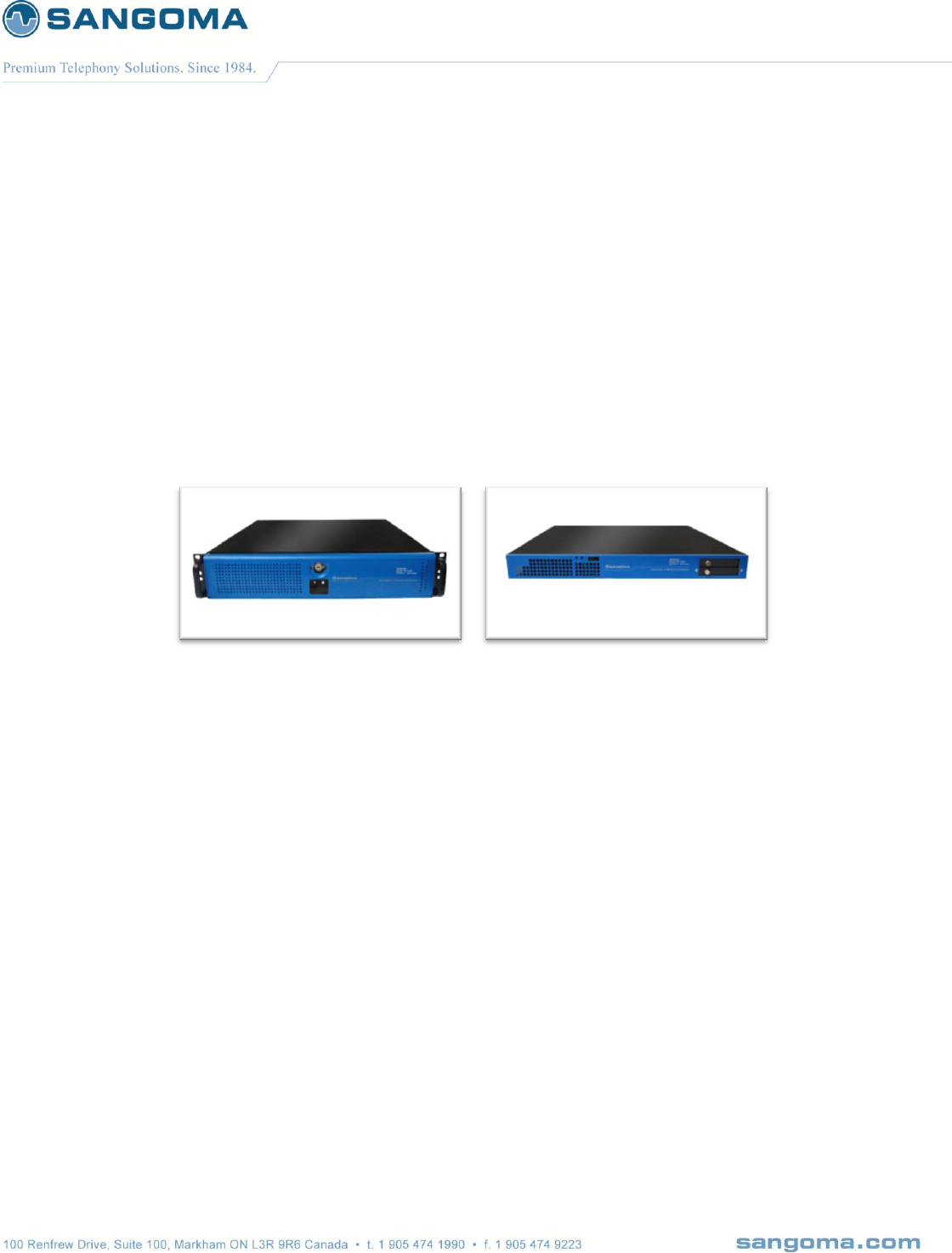
2.1.1 Hardware Specifications
Industrial grade telecom appliance
Size: 1U and 2U - 19'' Rackmount
Min Capacity: 4 T1/E1 (1U)
Max Capacity: 32 T1/E1 (2U)
Power: AC, DC, Redundant
AC Power Supply (Single)
o
DC Power Supply (Redundant)
o The Input Current for -48VDC, is 12.0A (RMS).
o With Inrush Current of 20.0A MAX.
Depth: 20''
Weight: 36lb
Full Spec on Sangoma Site

v1.14
18
2.2 NSG Shipping Box Contents
The first three tasks for installing and operating the Netborder SS7 to VOIP Gateway are
Unpack
Inspect
Power up.
Carefully inspect the NSG Appliance for any damage that might have occurred in shipment.
If damage is suspected, file a claim immediately with the carrier, keep the original packaging for
damage verification and/or returning the unit, and contact Sangoma Customer Service.
2.2.1 What is included in the box
Netborder SS7 to VoIP Appliance
o Appliance can be 1U or 2U depending on model ordered
Power Cable
o AC cable in case of AC PSU (black cable)
o DC cable in case of DC PSU (RED & Black cable)
Mounting Brackets
Quickstart user guide
2.2.2 What is not included
Appliance Rails
Appliance Rails can be purchased separately from Sangoma.
Please contact Sales for more information.
v1.14
19
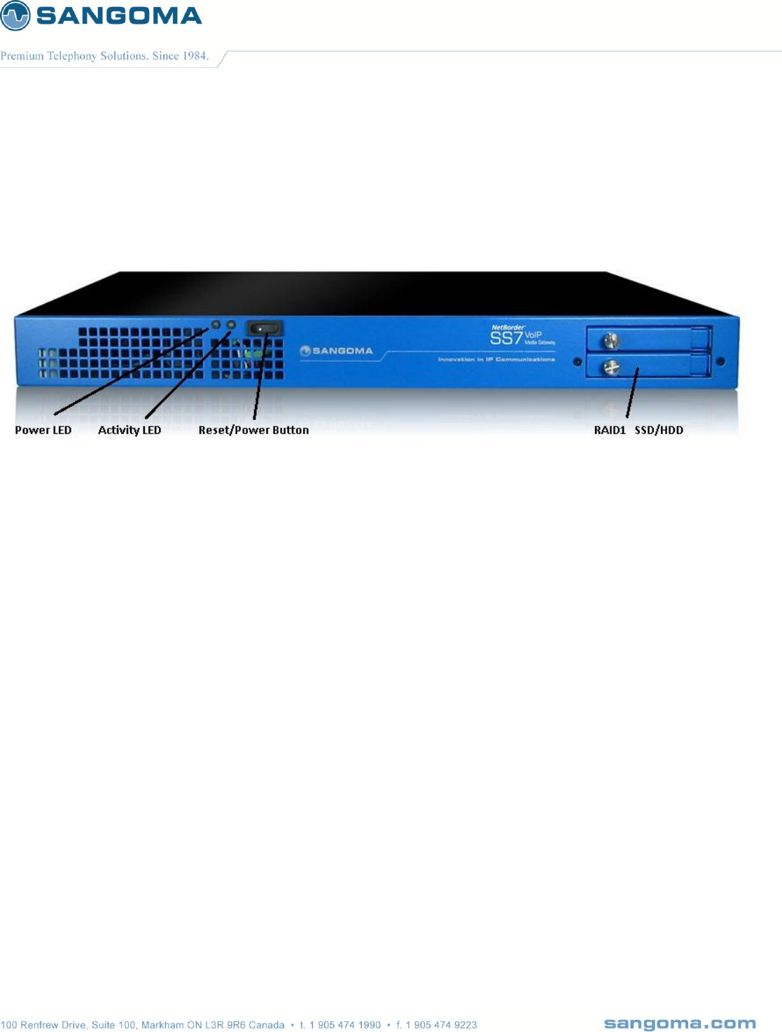
2.2.3 Front Panel
Front Panel Reset/Power button is used for:
o Factory Reset
Press 1 time per second until system beeps and reboots (approx.: 10sec).
A beep will sound to indicate that system has completed factory reset
before system reboots.
o Soft Reboot
Press 1 time every 3 seconds until system reboots. (approx.: 6sec)
There will be no beep on reboot.
o Power on/off
Hold for 10 seconds
o Nothing will happen if pressed once
To avoid accidental restart.
Caution: From NSG SW release 5.0
o Refer to Factory Reset section.
USB Ports can be used for Serial Console
o Refer to Serial Console section.
RAID1 SSD
o The RAID1 is NOT Hot Plug
o NSG appliances use industrial grade SSD
o One must power down the machine in order to change SSD/HDD
o Contact Sangoma Support for part replacement.
v1.14
20
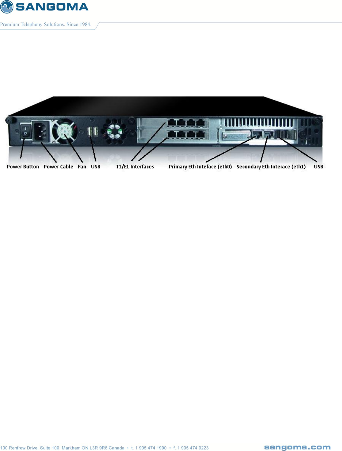
2.2.4 Rear Panel 1U
Power button
o Used to turn off the power supply
o Not for Factory Reset
USB Ports can be used for Serial Console
o Refer to Serial Console section.
PSTN T1/E1 Interfaces
o RJ45 Connections
Primary Eth Interface (eth0): Gig Ethernet Port
o This adapter must be plugged into the LAN
o SIP Signaling and RTP Media will flow through this device.
o WebUI identifies this device as "eth0"
Secondary Eth Interface (eth1): Gig Ethernet Port
o This adapter is optional
o It can be used for Monitoring and Statistics
o WebUI identifies this device as "eth1"
USB Ports
o Used for Serial Console
o Can be used re-flash the appliance
o Future use: active/standby redundancy*
v1.14
21
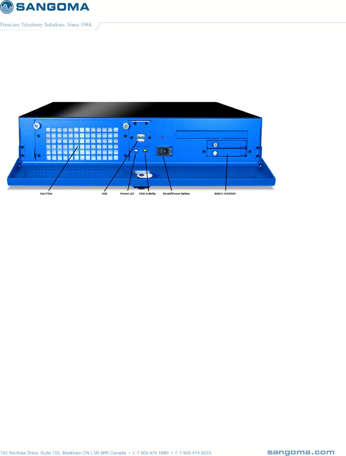
2.2.5 Front Panel 2u
Fan Filter
USB
o Used for Serial CLI
o Refer to the Serial CLI Section
Power LED
HDD Activity LED
Front Panel Reset/Power button is used for:
o Factory Reset
Press 1 time per second until system beeps and reboots (approx.: 10sec).
A beep will sound to indicate that system has completed factory reset
before system reboots.
o Soft Reboot
Press 1 time every 3 seconds until system reboots. (approx.: 6sec)
There will be no beep on reboot.
o Power on/off
Hold for 10 seconds
o Nothing will happen if pressed once
To avoid accidental restart.
Caution: From NSG SW release 5.0
o Refer to Factory Reset section.
RAID1 SSD
o The RAID1 is NOT Hot Plug
o NSG appliances use industrial grade SSD
o One must power down the machine in order to change SSD/HDD
o Contact Sangoma Support for part replacement.
v1.14
22
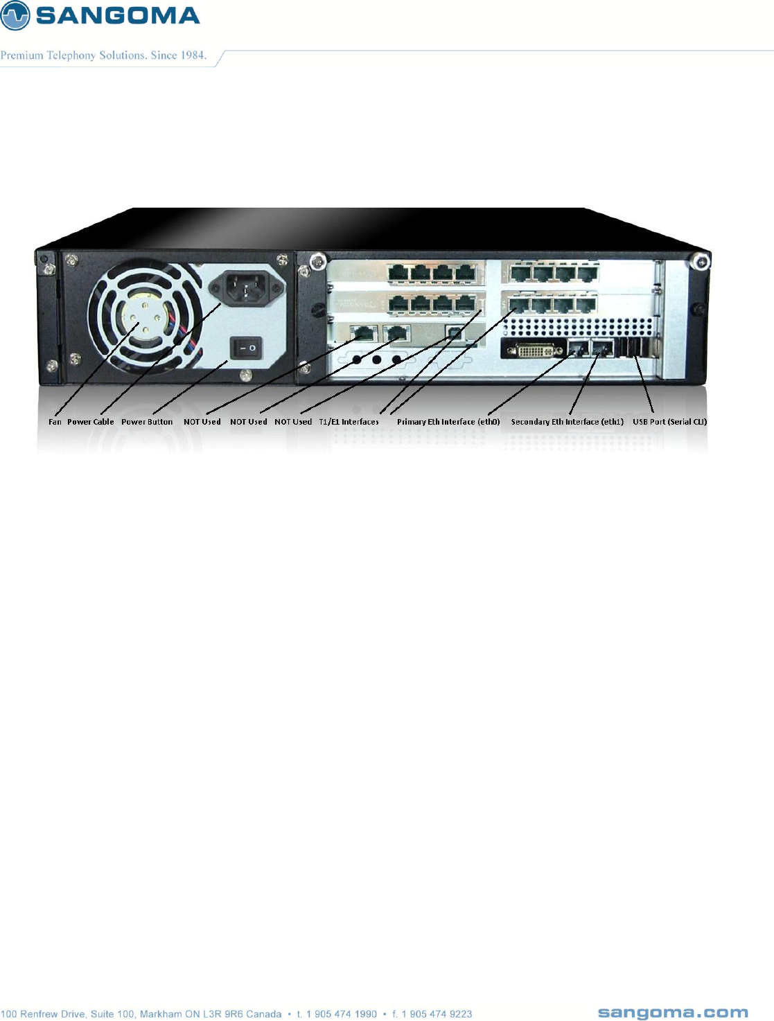
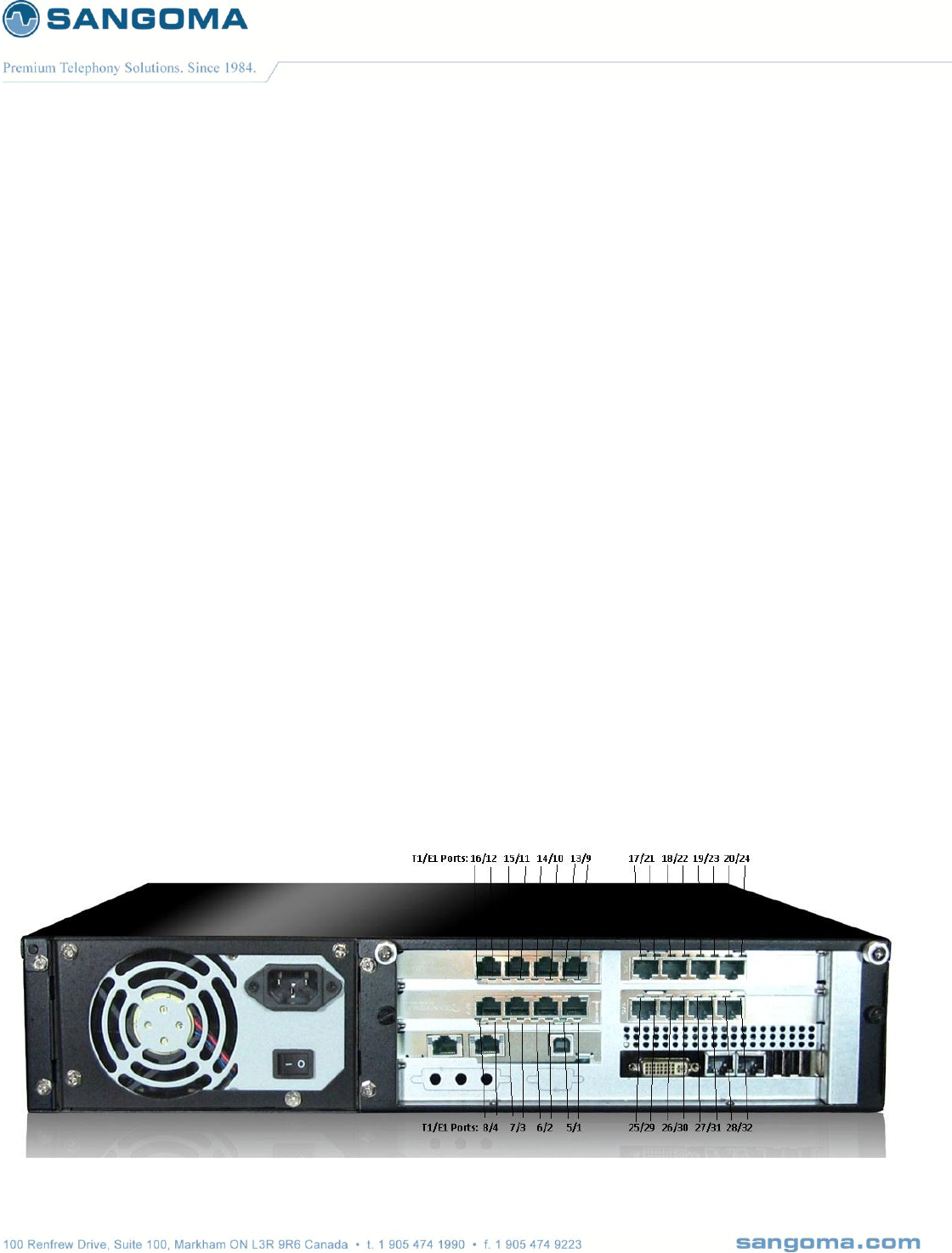
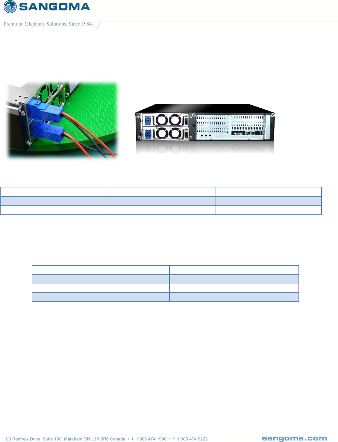
2.2.6 Rear Panel 2U
2.2.6.1 Rear Panel Description
Fan
Internal Power supply
o Default AC, non-redundant
o Option: DC or AC Redundant
Power Button
o Used to turn off the machine
o Not used for Factory Reset.
Unused 2x Gig Ethernet Port
o Not used at this time. Should NOT be plugged into the LAN.
Primary Eth Interface (eth0): Gig Ethernet Port
o This adapter must be plugged into the LAN
o SIP Signaling and RTP Media will flow through this device.
o WebUI identifies this device as "eth0"
Secondary Eth Interface (eth1): Gig Ethernet Port
o This adapter is optional
o It can be used for Monitoring and Statistics
o WebUI identifies this device as "eth1"
USB Ports
o Used for Serial Console
o Can be used re-flash the appliance
o Future use: active/standby redundancy*
v1.14
23
2.3 NSG T1/E1 Port Identification
Sangoma T1/E1 Interface boards come with two types of RJ45 Connections
Low density Interface Boards
o Single Port Interface Board
o Dual Port Interface Board
o Quad Ports Interface Board
o RJ 45 Connector
Each RJ45 Connector connects to a single T1/E1 line.
o Cable Type
Standard Cat5/Cat6 straight cable.
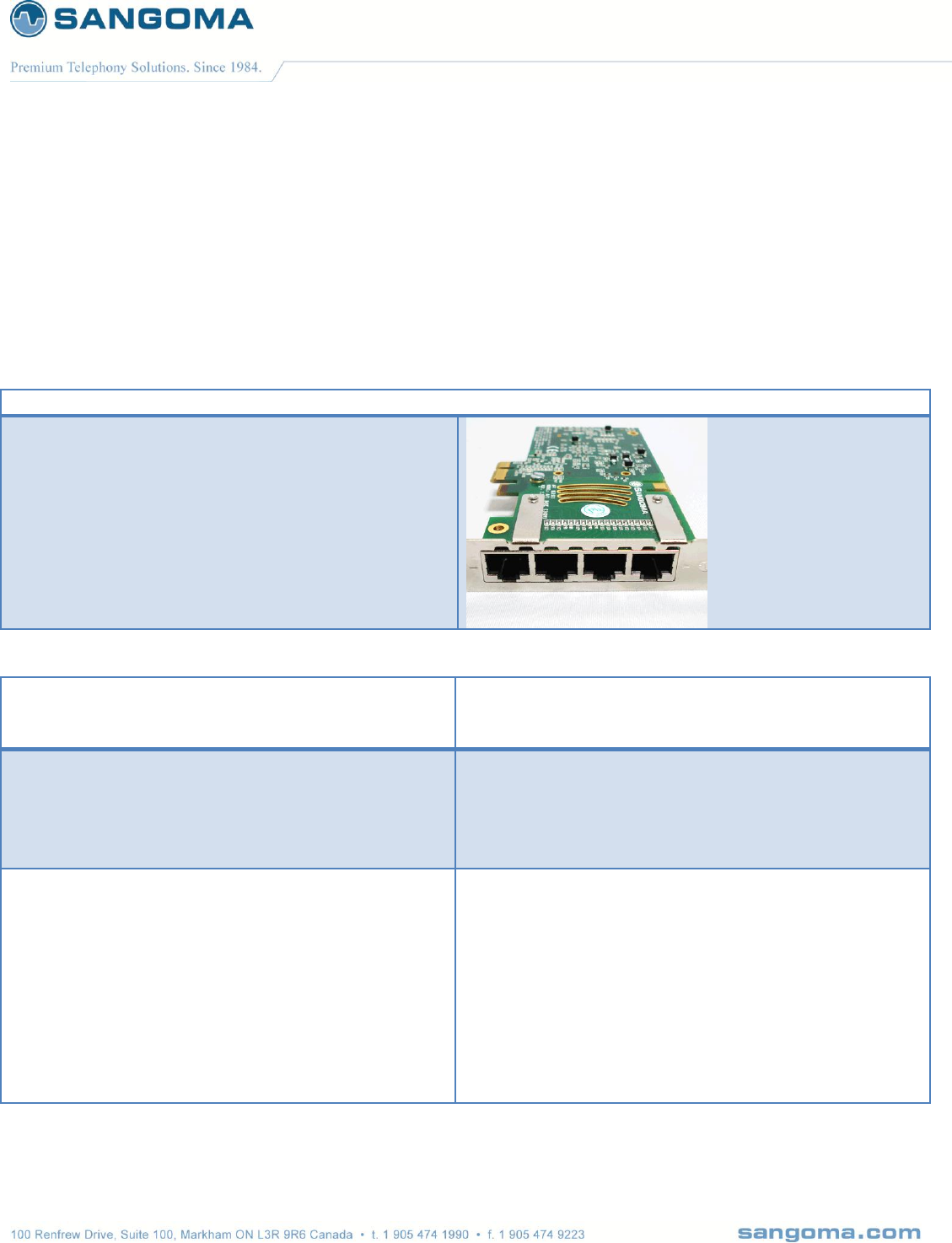
High density Interface Boards
o Eight Port Interface Board
o RJ45 Connector
Each RJ45 Connector connects to two (2) T1/E1 lines.
o Cable Type
A special Y cable is needed to connect 2 T1/E1 lines into a single RJ45 port.
If a standard Cat5/6 cable is used, only lower ports of the 8 port interface board
will be used/connected.
Board Type Identification
o The number of LED on the T1/E1 Interface boards indicates the number of T1/E1 ports
supported.
o In case of 8 port T1/E1 board, there will be 2 LED per T1/E1 port.
v1.14
24
2.3.1 Cable Pinouts: T1/E1
NSG Appliance utilizes Sangoma TDM T1/E1 digital board adapters.
A101DE – 1-port E1/T1 board
A102DE – 2-port E1/T1 board
A104DE – 4-port E1/T1 board
A108DE – 8-port E1/T1 board*
Eight Port Board Information
The A108D board has dual purpose RJ45
connector, as it provides access to two T1/E1
ports from a single RJ45 Female connector.
NOTE
There are two LED per RJ45 connector.
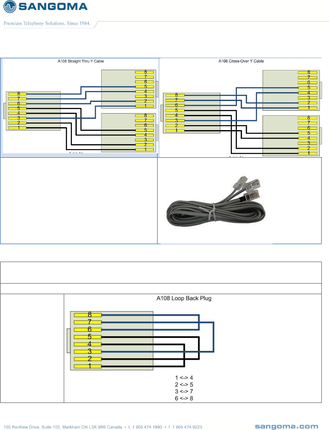
Eight Port Board
Straight Cable
Eight Port Board
Cross Over – Back-to-Back Cable
Y Cable for A108 connects 2 separate
T1/E1 (straight).
This is to connect the A108 board RJ45 ports to
Telco Lines.
Y Cable for A108 connects 2 separate
T1/E1 (cross).
This is to connect the A108 against another T1/E1
card in back to back mode.
A = port N; B = port N + 4
1 <-> 1A [Rx ring]
2 <-> 2A [Rx tip]
3 <-> 1B
4 <-> 4A [Tx ring]
5 <-> 5A [Tx tip]
6 <-> 2B
7 <-> 4B
8 <-> 5B
A = port N; B = port N + 4
1 <-> 4A
2 <-> 5A
3 <-> 4B
4 <-> 1A
5 <-> 2A
6 <-> 5B
7 <-> 1B
8 <-> 2B
v1.14
25
T1/E1 "Portsplitter" Cable
T1/E1 Split Cable for the Eight Port Board
Standard | ROHS: Yes | Length: 6'
SKU: CABL-630
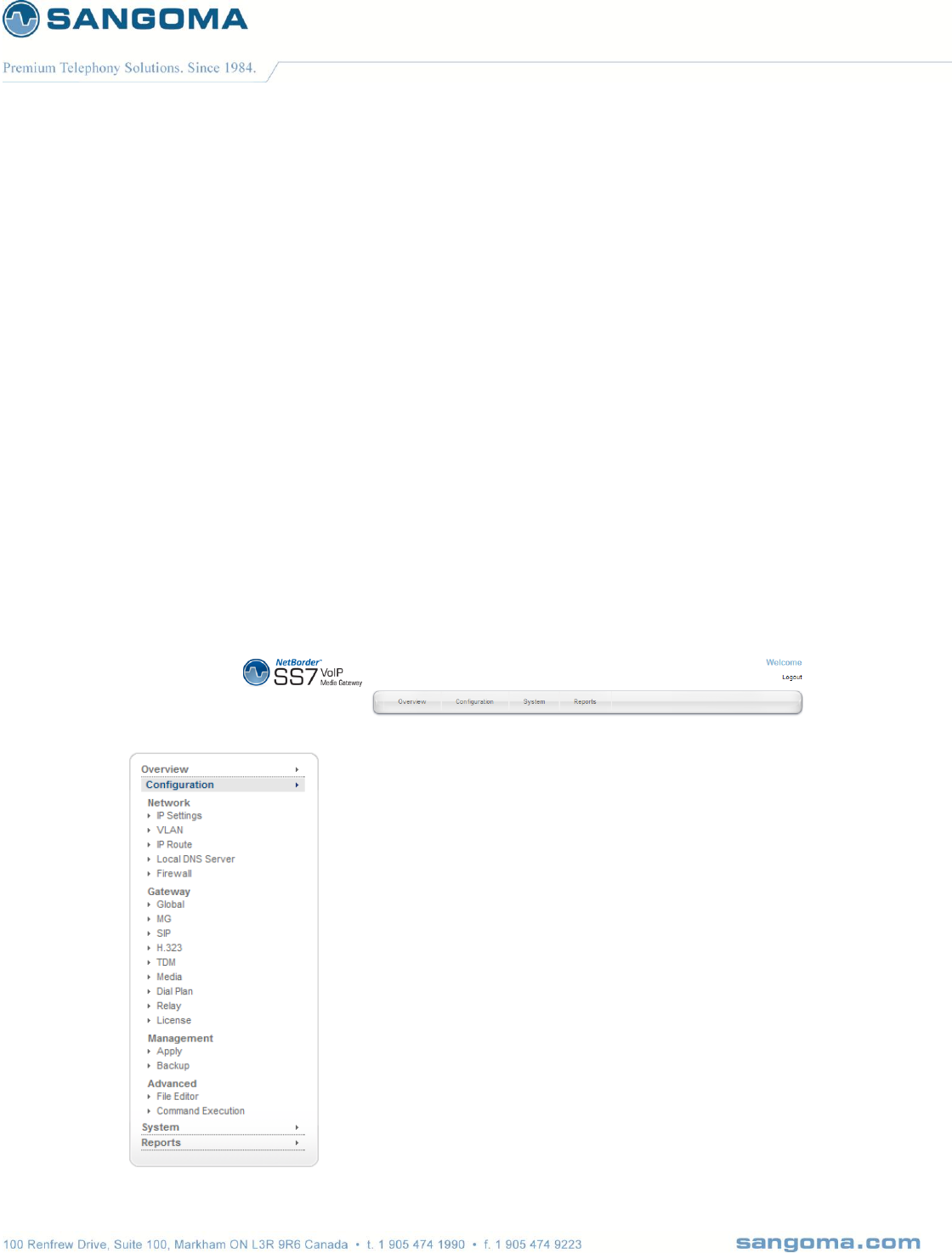
A108D Loop Back Cable
This is to connect an A108 port in loopback mode
1 <-> 4
2 <-> 5
3 <-> 7
4 <-> 1
5 <-> 2
6 <-> 8
7 <-> 3
8 <-> 6

v1.14
26
2.4 NSG Appliance Default Configuration
By default the NSG appliance gets shipped with following configuration.
Static IP 192.168.168.2 / 255.255.255.0
Static IP Port eth0 (Primary Ethernet Interface Port)
WebUI URL http://192.168.168.2:81
Username root
Password sangoma
v1.14
27
3 User Interface
Netborder SS7 to VoIP media gateway provides the user with two interfaces
WebGUI
o Web GUI is preferred for almost all operations
o Configuration, Operations, Statistics, Reports
Console via ssh or usb-serial
o For power users familiar with Linux operating system, ssh or usb-serial console
provides advanced and flexible interface for troubleshooting and automation.
3.1 WebGUI
WebGUI resides on the port 81
Interface provides two identical menus for easy access to all options
o Top Horizontal Menu
o Side Vertical Menu

v1.14
28
3.1.1 WebGUI Structure
3.1.1.1 Overview
Control Panel
o Used to control the global gateway operations: start, stop, restart
Profile Panel
o Used to Sync configuration on the fly without Restarting full gateway.
o Allows configuration of the gateway without service interruption.
o Supported from NSG Version v5.0.1
TDM Status
o Provides full overview of gateway utilization and states
SIP Status
o Provides full SIP statistics, call count
MG Status
o Megaco detail call status report per Profile
VLAN Status
o Provides full VLAN statistics, VLAN ID, IP, Netmask for each VLAN.
3.1.1.2 Configuration
Network
o Allows network configuration such as IP, Static IP Routes, VLAN, DNS and Firewall
Gateway
o Core product configuration
o Provides configuration of all Signaling and Media Protocols
SIP, RTP,H.323, Media Processing, Megaco(MG), SS7/Sigtran (TDM)
o Routing Logic / Dialplan
XML based dialplan
Management
o Apply
Write all configurations changed and set in Gateway section.
o Backup
Backup all system configurations into a zip file.
Recover a system from a backup file
Advanced
o File Editor
Allows custom file editing for custom configuration
Troubleshooting
o Command Execution
Instead of logging into a shell
Execute any system command via the WebGUI.

v1.14
29
3.1.1.3 System
Settings
o Date
Set date time and sync to time server
o Password
Change password
o Shutdown
Shutdown or reboot a system
o Update
Software and patch update system
Resources
o Processes
List of currently running process
o Services
List of all available services
SSH service start/stop
Hardware
o Self-Test
Allow for system software and hw components test.
o Firmware Update
Allows for firmware updates
Sangoma TDM boards
Sangoma Media processing boards
Help
o About
Shows system version and version of all important packages.
o PBX Integration
Help documentation
3.1.1.4 Reports
Dashboard
o Overview
Overview of network interfaces
Network
o Network Report
Long term usage charts for each network device
o Protocol Capture
PCAP packet capture with filter support for any network interface
System
o Gateway Logs
Specific gateway logs used to quickly trouble shoot gateway issues
Allows for log download
o Advanced Logs
Full system wide logs with filters

v1.14
30
o Hardware Report
Full hardware overview and description
HDD, Memory and system usage
Device enumeration
o Resource Report
Long term statistics

v1.14
31
3.2 Console Structure
Console access via ssh
Console access via usb-serial
Shell Commands via WebUI – Command Execution
Gateway CLI Commands via WebUI – Command Execution
Operating system is Linux based. Therefore Linux expertise is mandatory.
WARNING
o Working in shell is very powerful and flexible, but also dangerous
o A system can be corrupted, formatted, erased if user makes a mistake.
3.2.1 Connect via SSH
Use default SSH clients on any desktop
Windows – putty
Linux – native ssh
On login prompt
Username: root
Password: <your custom password>
v1.14
32
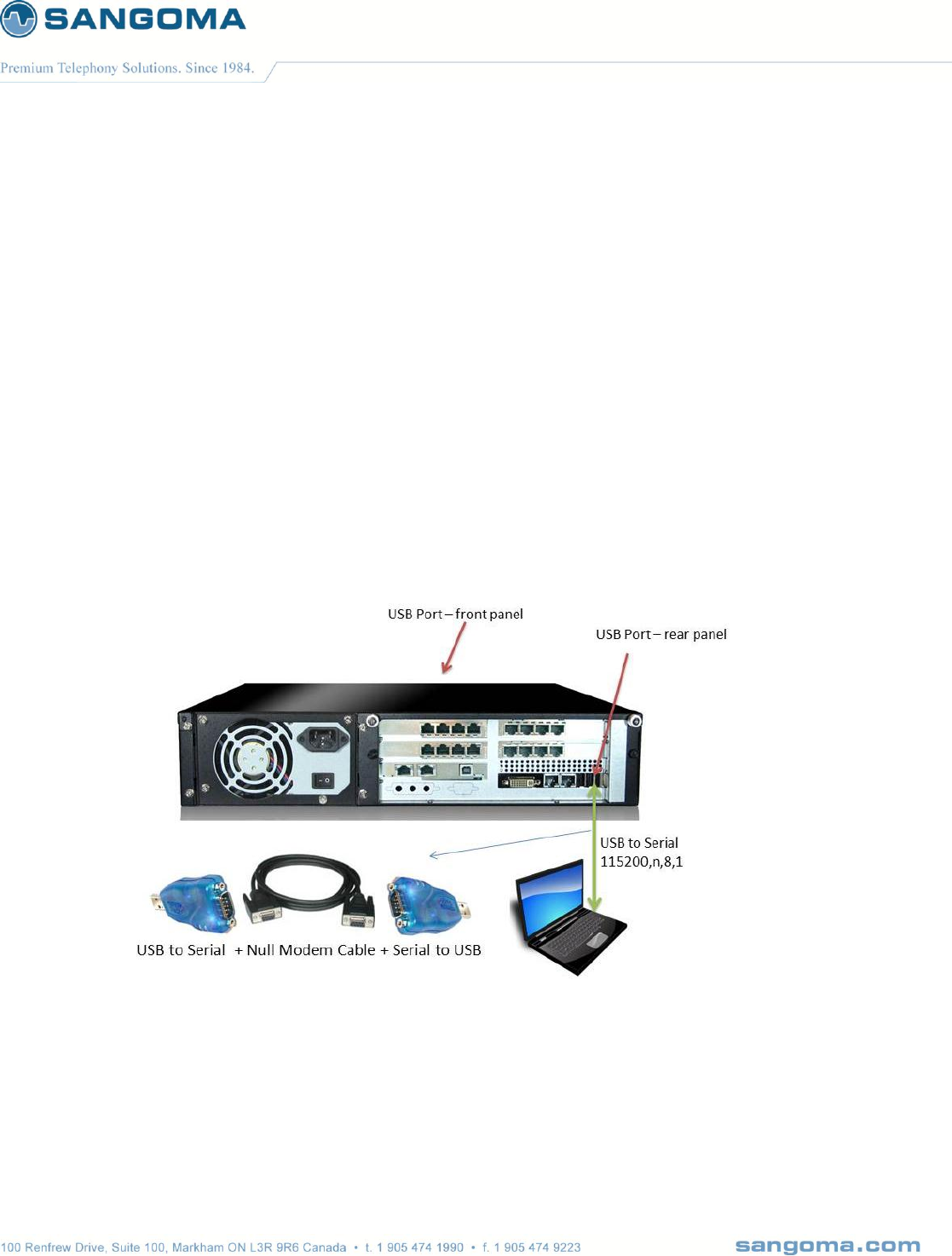
3.2.2 Connect via USB Serial
usb to serial cable
o One must use usb to serial cable + null modem cable
o If Laptop does not have a serial port then use two usb to serial cables plus null modem
cable per diagram below.
Connect to any usb port on NSG appliance
o All NSG appliances have usb port on rear panel
o 2U NSG appliances have usb port in front panel as well.
Configure Terminal Client on Laptop
o Windows HyperTerminal
o Linux – mincomm
Serial Settings
o 115200, N, 8, 1 vt100
Press enter a few times until a login prompt appears.
o Login via: username: root, password: <your personal password>

v1.14
33
3.2.3 Bash Shell
Once successfully logged into the system, either via ssh or usb serial, user will be offered a bash
prompt.
NSG system is based on Linux
The initial console after login will be a bash shell
3.2.3.1 System Commands
System commands are based on Linux operating systems.
Listed here are some most useful debugging commands.
tcpdump
o Provides network capture to a pcap file
o Can be analyzed using wireshark on Desktop or Laptop.
ethtool
o Provides detail network interface information, like Ethernet link status.
o Run: ethtool <enter> for all the options
o Eg: ethtool eth0 - show Ethernet status
Ifconfig
o Network interface statistics tool
o Shows error counters on Ethernet and TDM interfaces.
o Notice the error and overrun counters on wanpipe w1g1 interfaces.
wanpipemon
o Sangoma TDM troubleshooting tool
o T1/E1 alarms
wanpipemon –i w1g1 –c Ta
nsg_cli
o Provides Gateway low level CLI
Refer to the appendix for all System Commands

v1.14
34
3.2.4 Gateway CLI – nsg_cli
First log into the System Console (bash)
Once on bash prompt run
o nsg_cli
NOTE
The NSG gateway must be running and started in Control Pannel.
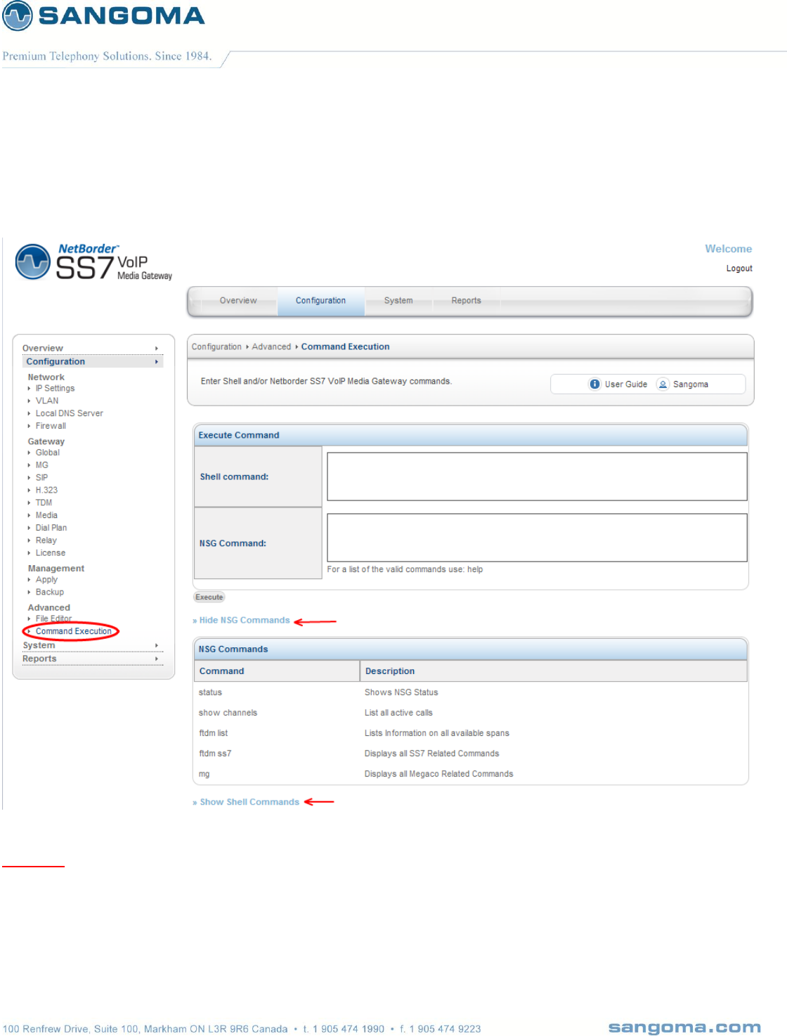
Command
Description
status
Shows NSG Status
show channels
List all active calls
ftdm list
Lists Information on all available spans
ftdm ss7
Displays all SS7 Related Commands
mg
Displays all Megaco Related Commands
log [debug|error|crit]
Set log level to debug loglevel critical
v1.14
35
3.3 Shell/CLI from GUI
Select Command Execution from side/top Configuration Menu
Specify a shell or CLI command. Refer to guide below.
Warning
Do not run shell commands that run indefinitely. Such as “ping <ip>”. In such case the webgui will
get stuck forever executing the command. In such case, user must login via CLI and kill the process.
In case of ping command one can limit number of pings to perform. eg: ping –c 10 <ip>
v1.14
36
4 Usage Scenarios
4.1 Signaling Gateway: M2UA
Pass through signaling from TDM to IP
o MTP2 -> M2UA
Pass through signaling from IP to TDM
o M2UA -> MTP2
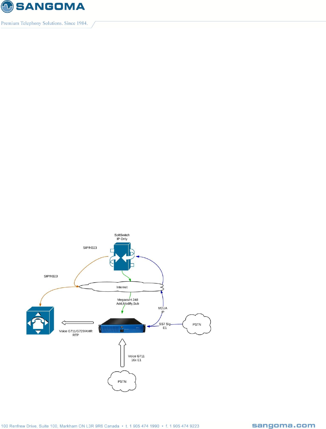
4.2 Megaco/H.248 Media Gateway: MG + SG
Third part Softswitch/MGC controlling Netborder SS7 Media Gateway
using Megaco/H.248 protocol.
o Bridge RTP media to TDM Voice 64kb G.711 channels
o Bridge TDM Voice 64kb G.711 channels to RTP media ports
Media specific functions
o Transcoding
o DTMF
o T.38 Faxing

v1.14
37
4.2.1 Megaco Quick Configuration
In order to configure the system for Megaco Operation
Perform the First Boot/Initial Setup
o Section 5
o Connect and Power up the system
o Change password
Perform the Network Connection
o Section 6
o Setup IP, VLAN and Routes
Perform Megaco Configuration
o Section 8
o Create Megaco Profile
Configuration -> MG Menu
o Setup TDM interfaces and bind to Megaco Profile
Configuration -> TDM Menu
o Create Sigtran M2UA Gateway (optional)
Configuration -> TDM Menu
Perform Media Transcoding Configuration
o Section 11
o Specify supported codecs.
Apply configuration
o Section 12
Start Gateway
o Initial Start
o Section 17
Configure additional MG profiles and Spans
o On the fly configuration
o Section 18
v1.14
38
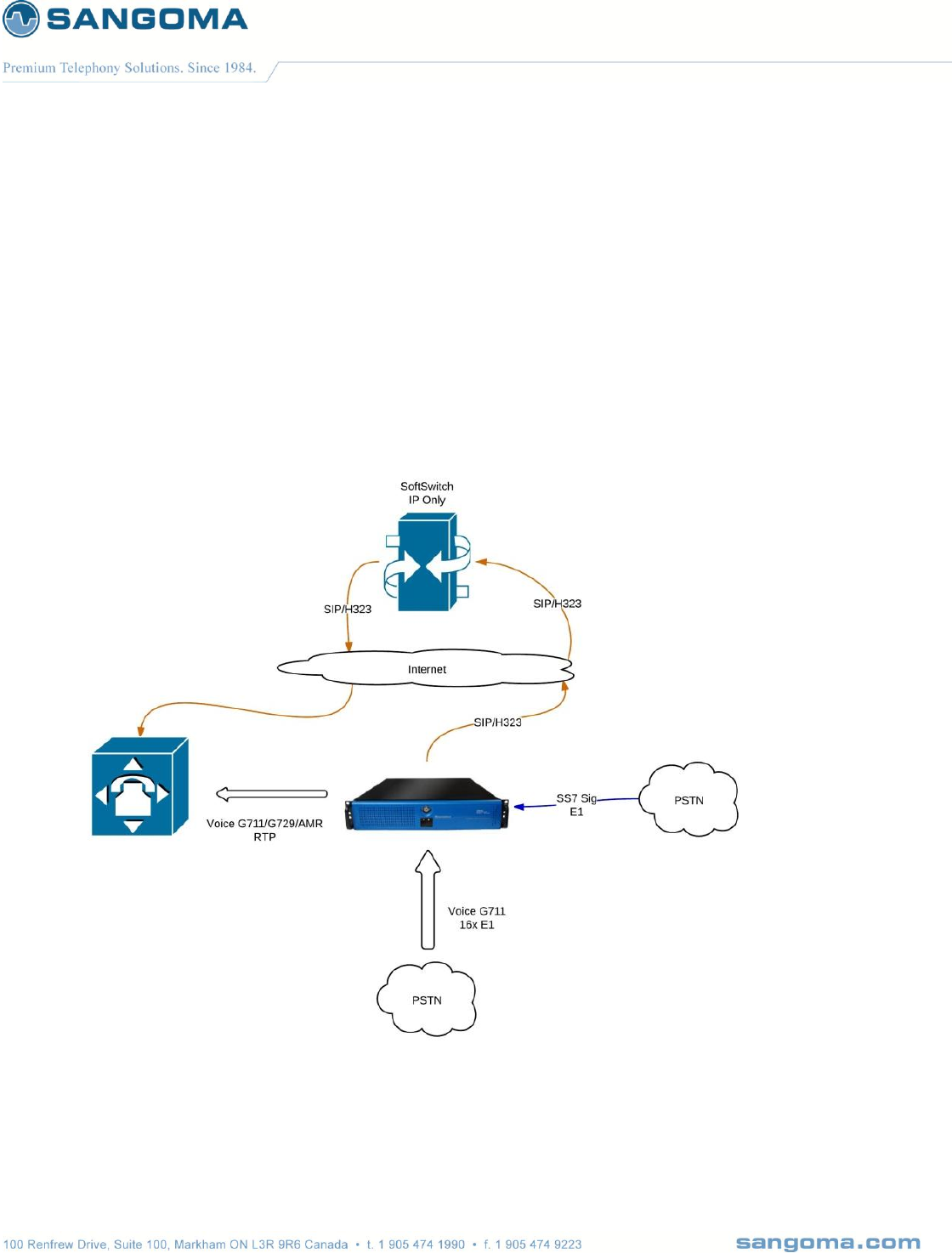
4.3 SIP/H323 to SS7 ISUP
Bridge signaling sessions from H.323 to SS7 ISUP
o Bridge RTP media to TDM Voice 64kb G.711 channels
Bridge signaling session from SS7 ISUP to H.323
o Bridge TDM Voice 64kb G.711 channels to RTP media ports
Media specific functions
o Transcoding
o DTMF
o T.38 Faxing

v1.14
39
4.3.1 H323 to SS7 ISUP Quick Start Guide
In order to configure the system for Megaco Operation
Perform the First Boot/Initial Setup
o Section 5
o Connect and Power up the system
o Change password
Perform the Network Connection
o Section 6
o Setup IP, VLAN and Routes
Perform Initial Gateway Configuration
o Section 7
Perform SS7 ISUP Configuration
o Section 9
o Create SS7 ISUP Profile
Configuration -> TDM Menu
o Setup TDM interfaces and bind to SS7 ISUP Profile
Configuration -> TDM Menu
Perform Media Transcoding Configuration
o Section 11
o Specify supported codecs.
Apply configuration
o Section 12
Dial Plan
o Section 13
Start Gateway
o Section 17

v1.14
40
4.4 Any to Any Signaling and Media Gateway
Route any signaling traffic from eny signaling endpoint simultaneously.
Ability to run all protocols together at the same time.
Route media with transcoding/dtmf/T.38 to/from end media endpoint.

v1.14
41
5 First Boot/Initial Setup
Unpack the NSG shipping box
Connect the NSG appliance to a power source
Connect the NSG appliance to LAN
Connect to NSG appliance via Laptop Browser
Provision the Appliance
o Change Password
o Change Hostname & IP
o Date Time
o Self Test
Initial Provision Done
Next step is to configure the Gateway.
o Please refer to usage scenarios in section 5.
5.1 Power Connection
Sangoma NSG comes with three types of power supplies
AC PSU
o AC Single PSU (Default)
o AC Dual-Redundant PSU
DC PSU
o DC Dual-Redundant PSU
5.1.1 PSU Connection
Standard 110V or 220V, 50-60Hz connection.
Optional Dual-Redundant AC 110V or 220V, 50-60Hz connection.
Optional Dual-Redundant DC -48V
v1.14
42
5.1.2 DC PSU Connection
Connecting cables to a power supply depends on the remote power source.
Power Source Type
Black Wire
Red Wire
If power source -48V
-48V
0V (Ground)
If power source +48V
0V (Ground)
+48V
The PSU has voltage reverse protection.
If the red and black wires are connected the wrong way, the system will not power up. But
there will be no damage to the PSU or the system.
VOLTAGE
DC -36V ~ -72V
INPUT CURRENT:
12.0A (RMS). FOR -48 VDC
INRUSH CURRENT
20A (Max)
DC OUTPUT
400W (Max)
v1.14
43
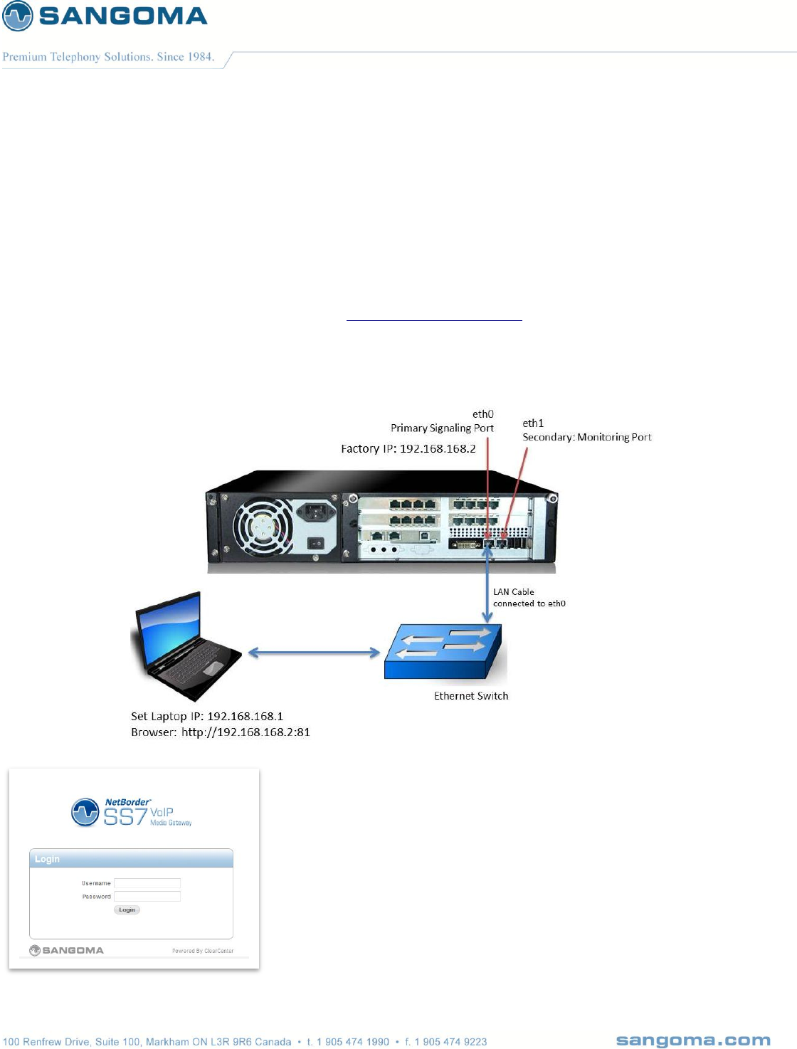
5.2 Establishing Initial WebGUI Connection
NSG factory settings are not very useful, as the Primary Ethernet port:eth0 is set to a static IP
address. Proceed to connect to the NSG Appliance via Laptop’s web browser.
Connect the Primary Signaling Port: eth0 to a LAN Switch
Connect Laptop to LAN Switch
Configure Laptop to IP address: 192.168.168.1/24
Using Laptop web browser go to URL: http://192.168.168.2:81
Login via
o Username: root, Password: sangoma
v1.14
44
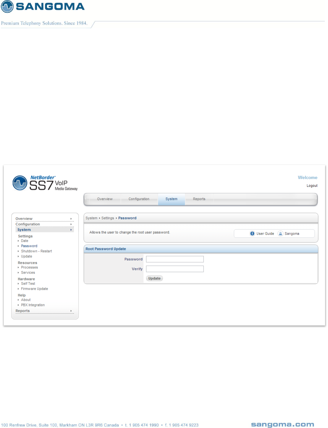
5.3 Change Password
After successful Login, please proceed to change the default password.
Sangoma NSG appliance comes with default password.
For security reasons please change the password.
Select Password page from side/top System menu
Enter your new password
Press update to save

v1.14
45
5.4 Console SSH Configuration
By default NSG systems come with SSH enabled.
To configure ssh service
Select Services from side/top System Menu
Enable or disable Secure Shell service

v1.14
46
Service
Description
Status
Samba/Windows NetBIOS
Windows NetBIOS server
Not used / Not required
MySQL
MySQL database
Not used / Not required
Samba/Windows Server
Windows File server
Not used / Not required
Time Server
Network Time Protocol
Should be configured and
enabled.
Note: There must be internet
access to reach the NTP
service.
Web Server
web/httpd server
Not used / Not required
Gateway Service
NSG VoIP to SS7 gateway
Do not configure it here
Use Control Panel
Logging Services
Syslog, logging service
Should be configured and
enabled.
Samba/Windows Winband
Not used/ Not required
Secure Shell
SSH server
Should be configured and
enabled.
System Scheduler/Cron
System scheduler
Should be configured and
enabled
System Watch
System watch
Should be configured and
enabled
v1.14
47
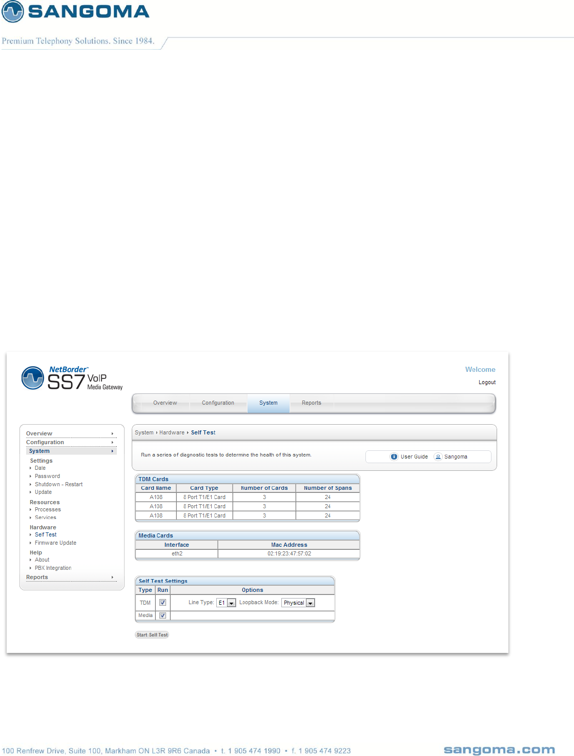
5.5 Self Test
Self-Test page must be run on initial installation or on any hardware upgrade. It will run a battery of
tests on Sangoma TDM and Transcoding hardware.
5.5.1 Running Self-Test
Select Self Test from side/top System Menu
If in North America select T1
If not in North America select E1
Select Media Transcoding Hardware if present.
Click Start Self-Test
o Refer to warning section below

v1.14
48
WARNING:
All services during the Self-Test will be stopped.
The existing configuration will be restored after Self Test.
Do not run Self-Test in production!
Only run Self-Test during on initial setup or during a maintenance window.
The Self-Test can be used to detect:
Defective TDM hardware
Defective Media Transcoding hardware
Miss-configured system device drivers
PCI Interrupt errors
Motherboard System issues
v1.14
49
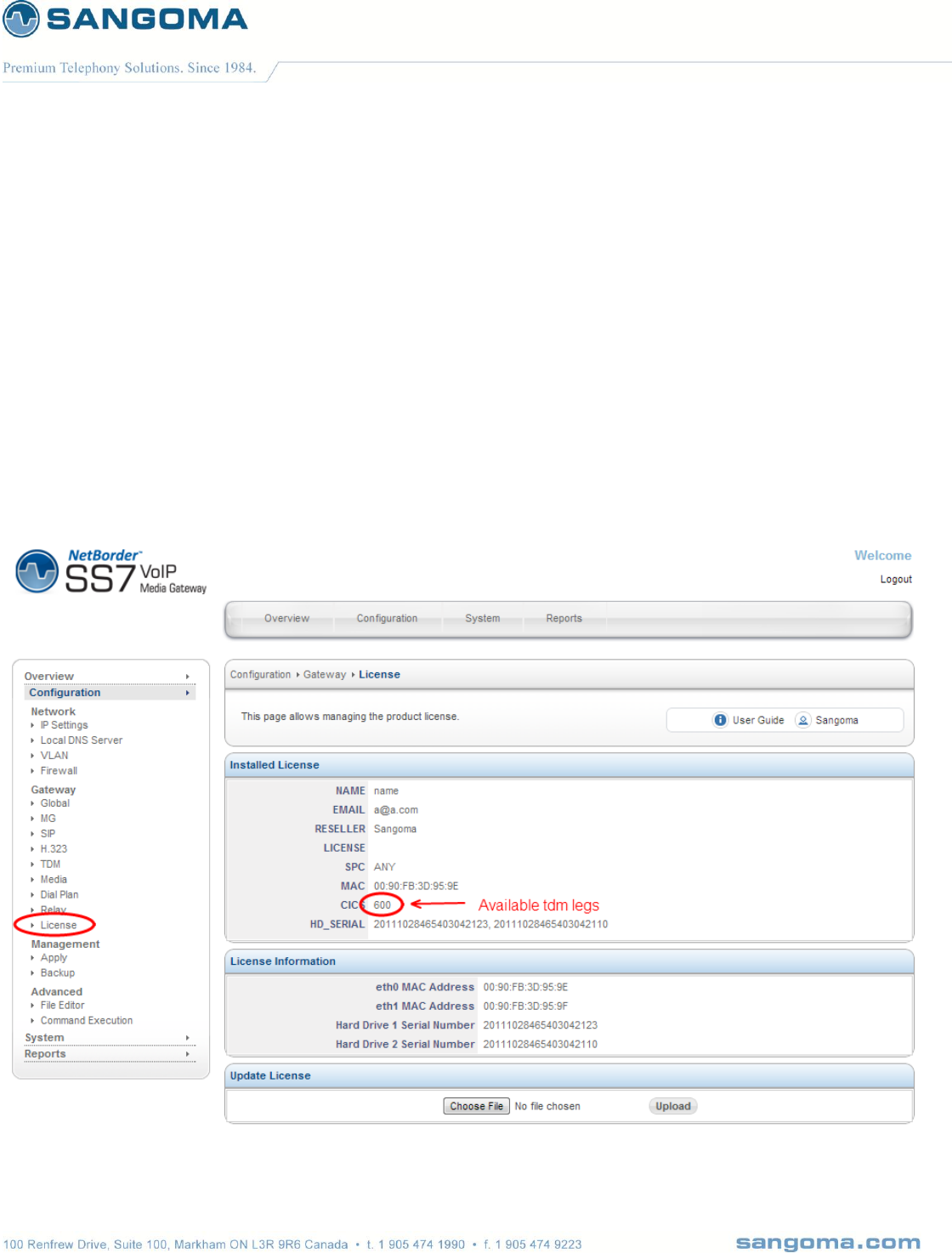
5.6 NSG License
Each NSG appliance comes with pre-installed license.
In case of upgrades, of expansions please contact Sangoma Sales.
To update NSG license
Select License from side/top Configuration Menu
Obtain NSG License from Sangoma Support
Upload the License into the NSG Gateway via the Upload Button
The License page offers the detailed license overview.

v1.14
50
License Variables
Description
Name
Customer Name
Email
Customer Email
Reseller
Reseller Name
License
NA
SPC
SPC stands for: self point code
It’s used to bind a specific set of point codes to the license.
ANY: is a special value which allows use of an SPC value.
MAC
System’s MAC address.
License code checks the MAC address and confirmes if
MAC is correct. One can check vs License Information
section.
CICS
Number of TDM channels allowed by the license.
From example above CICs = 600
For RTP to TDM calls: License allows 600 calls
For TDM to TDM calls: License allows 300 calls

v1.14
51
6 Network Configuration
Network configuration section only applies to Physical Network Interfaces: eth0 and eth1. It does not
apply to VLAN IP and route configuration.
Network Setup
Physical network interfaces: eth0, eth1 are configured in the section
Configuration-> Settings-> IP Settings.
This section can only be used to modify/configure IP, Host, DNS information for Physical
Network interfaces eth0 and eth1.
Default Route/Gateway
To configure a system default route through the IP Settings section, the appropriate interface
role type to use is “External”. The External interfaces get associated to the default system
route.
CAUTION:
o There can only be ONE External network interface.
o There can only be ONE system default route.
Static Routes
Static routes that apply to physical network interfaces eth0, eth1 should be configured in
Configuration-> Network -> IP Route section.
CAUTION:
o Do not try to configure VLAN routes in this section. .
o route configuration files are only meant to be used for eth0,eth1 interfaces.

v1.14
52
Media Ethernet Interface: Transcoding
NSG comes with optional, media/codec transcoding hardware. The media transcoding
hardware network interface is: eth2. The media transcoding network interface comes
preconfigured with a 10.x.x.x ip address.
Configuration of the eth2 device should be performed in Configuration->Settings->Media.
CAUTION:
One should take this into account when assigning IP addresses to eth0,eth1 or VLAN
interfaces. Confirm that ip address range set does not conflict with eth2 media transcoding
network interface.
VLAN Config IP & Routes
VLAN’s can be configured in section Configuration-> VLAN
VLAN can be configured on top of eth0 and eth1 network interface only.
All VLAN related configuration such as IP address, VLAN ID and VLAN routes must be
configured in VLAN configuration section only.
CAUTION:
o Do not use Static IP Route section to create a VLAN routes.
o Static IP Route section is only for physical interfaces eth0 and eth1.
VLAN Default Route
If a system default route needs to be configured via VLAN interface.
Configure the system default route in Configuration-> VLAN section.
Refer to the VLAN section below.
CAUTION:
o Make sure that all physical network interfaces in IP Settings section are configured for
role “LAN”. No physical network interface eth0, eth1 should be configured for role
“External”. This would result in multiple system default routes.
v1.14
53
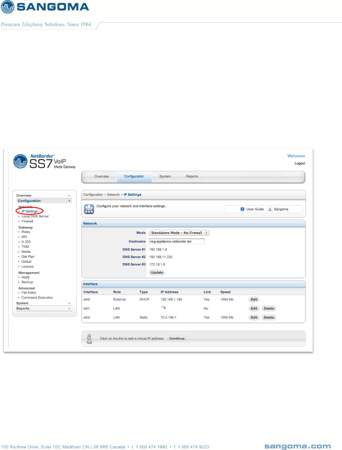
6.1 Physical Network Interface Configuration
By default the NSG appliance pre-configured with 192.168.168.2/24 address on Primary Port (eth0).
The IP address can be changed based as follows
Select IP Settings from side/top Configuration menu
Specify Firewall Mode and Hostname
Select Edit under eth0 and eth1 device and configure
NOTE
eth2 device is a Sangoma Transcoding device and should be modified.
eth2 device is configured in Configuration -> Media section of the GUI will configure this
device.

v1.14
54
6.2 Appliance Network Interfaces
eth0
o Primary Signaling Port
o By default provisioned as static 192.168.168.2
o By default allows access to ssh and management http
eth1
o Secondary Signaling or Management Port
o By default provisioned as static no IP address
o By default allows access to ssh and management http
eth2
o Sangoma transcoding DSP board
o Provisioned using Media page. Do not modify in this section.
6.3 Selecting Default Route
NSG appliance should have a single default route.
The default route is used to access Internet.
To configure a default route on eth0
Set the eth0 interface mode to External.
Refer to section below.

v1.14
55
6.4 Network Section
Variable Name
Input Options
Description
Mode
Standalone – No Firewall
Firewall Disabled
Standalone
Firewall Enabled
Warning:
All active service ports must be explicitly enabled
Hostname
String
A hostname is the full name of your system. If you have your
own domain, you can use a hostname like nsg.example.com
Alternatively, you can also make one up: gateway.lan, mail.lan.
The hostname does require at least one period (.)
Name/DNS Servers
Domain Name or IP address
eg. 8.8.8.8
On DHCP and DSL/PPPoE connections, the DNS servers will be
configured automatically for your IP Settings. In these two types
of connections there is no reason to set your DNS servers.
Users with static IP addresses should use the DNS servers
provided by your Internet Service Provider (ISP). If you are using
Multi-WAN, please review the documentation on the topic of
DNS servers.
v1.14
56
6.5 Interface Section
6.5.1 Network Role
When configuring a network interface, the first thing you need to consider is the network role in IP
Settings. Will this network card be used to connect to the Internet, for a local network, for a network
with just server systems? The following network roles in IP Settings are supported in NSG and are
described in further detail in the next sections:
External - network interface with direct or indirect access to the Internet
LAN - local area network
Hot LAN - local area network for untrusted systems
DMZ - de-militarized zone for a public network

v1.14
57
Option
Description
External
Network interface with direct or indirect access to the Internet
External interface is used as the system default route.
WARNING:
You should have only ONE external network interface.
Usually eth0 is the external interface
LAN
Connection to your local network
Usually eth1 is the LAN interface
Hot LAN
Hot LAN (or “Hotspot Mode”) allows you to create a separate LAN network for
untrusted systems. Typically, a Hot LAN is used for:
Servers open to the Internet (web server, mail server)
Guest networks
Wireless networks
A Hot LAN is able to access the Internet, but is not able to access any systems on
a LAN. As an example, a Hot LAN can be configured in an office meeting room
used by non-employees. Users in the meeting room could access the Internet and
each other, but not the LAN used by company employees.
DMZ
In NSG, a DMZ interface is for managing a block of public Internet IP addresses.
If you do not have a block of public IP addresses, then use the Hot LAN role of
your IP Settings. A typical DMZ setup looks like:
WAN: An IP addresses for connecting to the Internet
LAN: A private network on 192.168.x.x
DMZ: A block of Internet IPs (e.g from 216.138.245.17 to
216.138.245.31)
NSG GUI has a DMZ firewall configuration page to manage firewall policies on
the DMZ network.
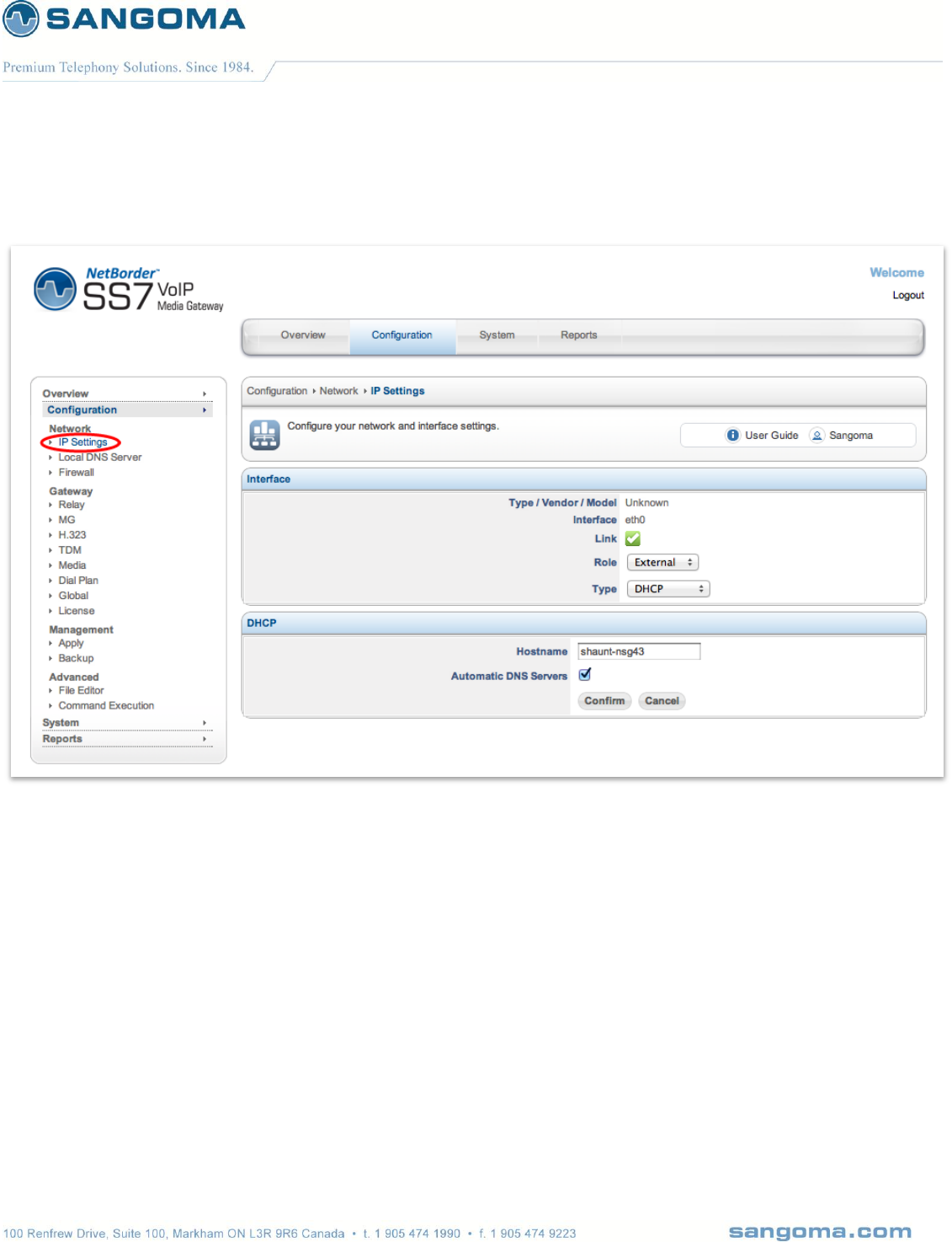
6.5.2 Types
Option
Description
DHCP
For most cable and Ethernet networks, DHCP is used to connect to the Internet.
In addition, your system will have the DNS servers automatically configured by
your ISP when the Automatic DNS Servers checkbox is set.
Static
If you have a static IP, you will need to set the following parameters:
IP
Netmask (e.g. 255.255.255.0)
Gateway (typically ends in 1 or 254)
Ethernet Options (able to force 100MB or 1000mb)
PPPoE DSL
For PPPoE DSL connections, you will need the username and password provided
by your ISP. In addition, your system will have the DNS servers automatically
configured by your ISP when the Automatic DNS Servers checkbox is set.
v1.14
58
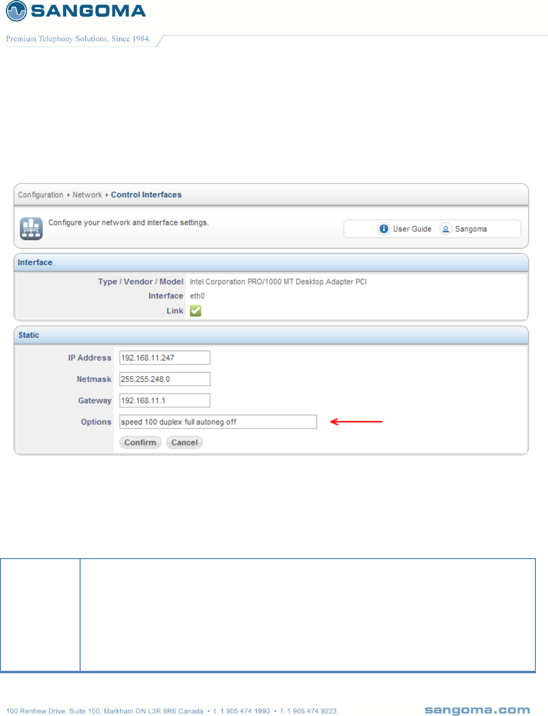
6.5.3 Ethernet Options
Setting custom Ethernet options such as disabling auto negotiation is done as part of the IP Settings.
Select IP Settings from side/top Configuration Menu
Specify Options field in order to add special configuration to this interface.
Options are any device-specific options supported by ethtool.
In above example the Ethernet device is set for 100Mb with negotiation disabled.
Options
[ speed 10|100|1000|2500|10000 ]
[ duplex half|full ]
[ port tp|aui|bnc|mii|fibre ]
[ autoneg on|off ]
[ advertise %%x ]
[ phyad %%d ]
[ xcvr internal|external ]
[ wol p|u|m|b|a|g|s|d... ]
[ sopass %%x:%%x:%%x:%%x:%%x:%%x ]
[ msglvl %%d ]

v1.14
59
6.6 Virtual IP’s
NSG supports virtual IPs. To add a virtual IP address, click on the link to configure a virtual IP
address and add specify the IP Address and Netmask. You will also need to create advanced firewall
rules if the virtual IP is on the Internet.
6.7 IP Troubleshooting
In most installs, the network cards and IP settings will work straight out of the box. However, getting
the network up the first time can be an exercise in frustration in some circumstances. Issues include;
Network card compatibility
Invalid networks settings (username, password, default gateway)
Cable/DSL modems that cache network card hardware information
v1.14
60
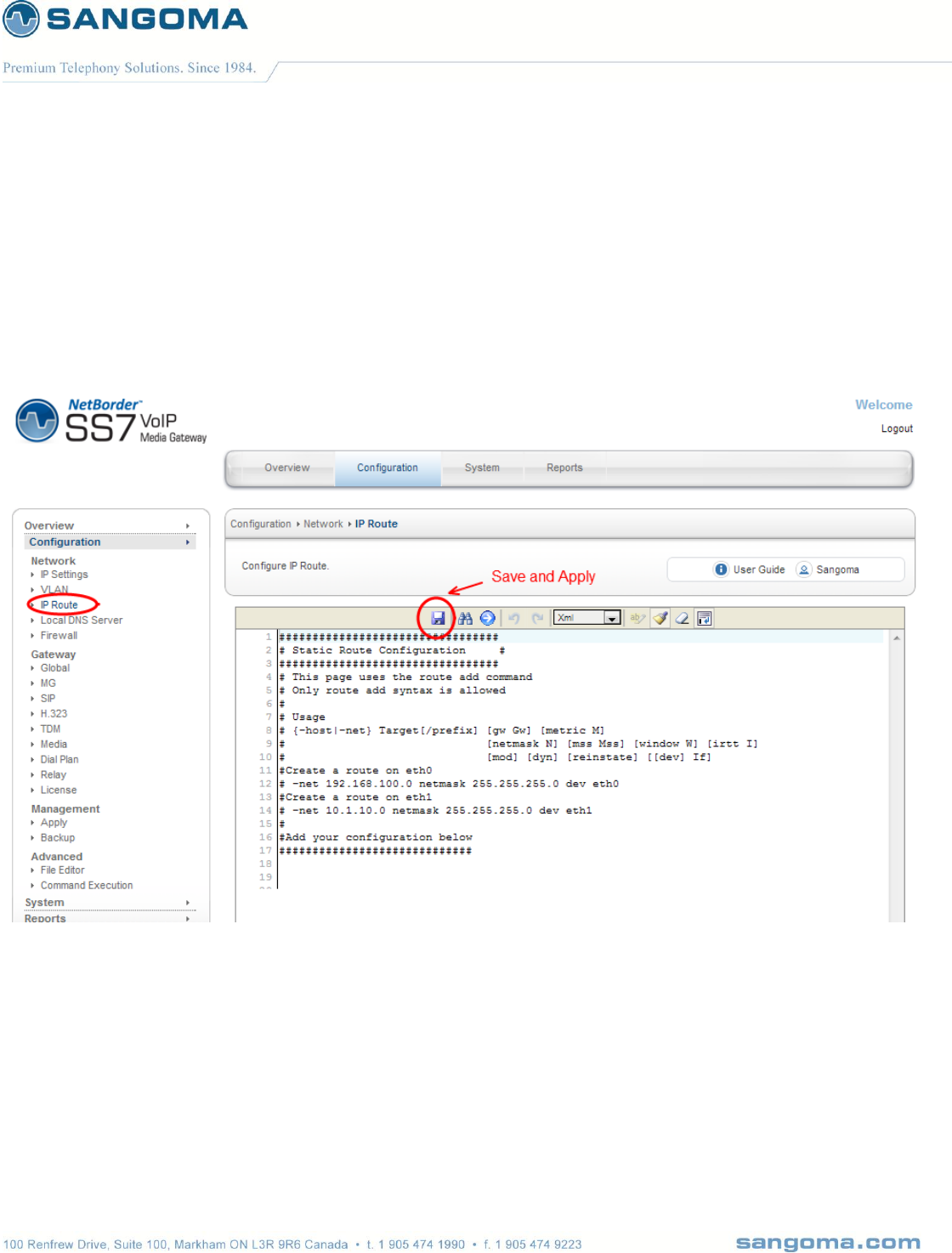
6.8 Static Routes
In some cases a static route must be defined for a specific network interface: eth0 or eth1.
The static route support is done via File Editor
Select IP Route from side/top Configuration Menu
Add a custom route command
Save and Apply
NOTE
The IP Route section only allows route add command syntax

v1.14
61
Route File Name
Description
Usage
Use to create static routes for Primary Signaling Ethernet Port:eth0
Usage:
{-host|-net} Target[/prefix] [gw Gw] [metric M]
[netmask N] [mss Mss] [window W] [irtt I]
[mod] [dyn] [reinstate] [[dev] If]
Example:
#Route a class C network 10.133.20.0 via gw IP
-net 10.133.20.0 netmask 255.255.255.0 gw 10.132.30.1
#Route a class B network 10.133.0.0 via gw IP
-net 10.133.0.0 netmask 255.255.0.0 gw 10.132.30.1
#Route a class B network 10.133.0.0 via device eth0
-net 10.133.0.0 netmask 255.255.0.0 dev eth0
v1.14
62
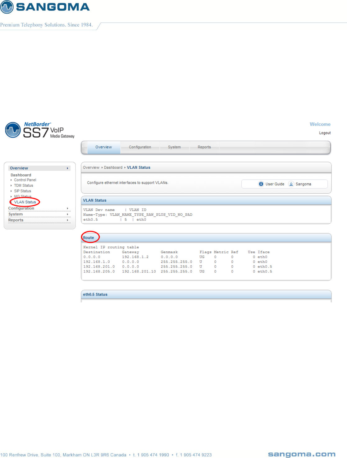
6.8.1 Routing Table Status
Select VLAN Status from side/top Overview Menu
Second table shows full system routing table.

v1.14
63
6.9 VLAN
Virtual local area network, virtual LAN or VLAN is a concept of partitioning a physical network, so that
distinct broadcast domains are created. NSG mark’s packets through tagging, so that a single
interconnect (trunk) may be used to transport data for various VLANs.
A VLAN has the same attributes as a physical local area network (LAN), but it allows for end stations
to be grouped together more easily even if not on the same network switch. VLAN membership can
be configured through software instead of physically relocating devices or connections. Most
enterprise-level networks today use the concept of virtual LANs(VLAN). Without VLANs, a switch
considers all interfaces on the switch to be in the same broadcast domain.

v1.14
64
6.9.1 VLAN Configuration
Currently NSG only supports VLAN configuration via GUI
Select VLAN from side/top Configuration Menu
Copy in the VLAN configuration script below into the file editor
Save
o On save the VLAN configuration will be applied
o Proceed to VLAN Status confirm VLAN configuration.
NOTE
The VLAN network interfaces are created over physical network interface. Make sure that the
physical network interface eth0 or eth1 are configured in IP Settings, before attempting to
configure VLAN on top of them eth0 or eth1.
The Save/Apply post processing will display VLAN configuration status.

v1.14
65
Example of sample script that could be copied into the VLAN config startup script:
#Create a VLAN device on eth0 interface with VLAN ID of 5
vconfig add eth0 5
#configure VLAN device with IP/Net mask
ifconfig eth0.5 192.168.1.100 netmask 255.255.255.0 broadcast 192.168.1.255 up
#configure a default route within a vlan
route add –net 192.168.1.0/24 gw 192.168.1.1
#if system default route needs to go through VLAN
#Note that there can only be ONE system default route.
#Make sure all interfaces in IP Settings are set to LAN (not External)
route add default gw 192.168.1.1 eth0.5
In the example above, a single VLAN was created
on top of the Primary Signaling Ethernet Port:eth0 with
VLAN ID=5 and
IP =192.168.1.100/24.
.
6.9.2 VLAN Routes
An optional route can be created to point to a gateway within a VLAN network.
NOTE
Only routes related to VLAN interfaces are allowed in the VLAN configuration section.
CAUTION
If a system default route needs to go through a VLAN
Confirm that IP Settings interfaces are all set to LAN role.
As there can be only ONE system default route.

v1.14
66
6.9.3 Additional VLAN
If more VLAN’s are needed, proceed to repeat the above steps for all VLANs.
When Save button is pressed
The VLAN configuration will be applied
The script above will be executed line by line.
Status window will pop up with VLAN config status. If one of the lines fails, the pop up will
report it.
Proceed to Overview -> VLAN status below to confirm VLAN and Route configuration
6.9.4 vconfig help
# vconfig
Expecting argc to be 3-5, inclusive. Was: 1
Usage: add [interface-name] [vlan_id]
rem [vlan-name]
set_flag [interface-name] [flag-num] [0 | 1]
set_egress_map [vlan-name] [skb_priority] [vlan_qos]
set_ingress_map [vlan-name] [skb_priority] [vlan_qos]
set_name_type [name-type]
* The [interface-name] is the name of the ethernet card that hosts
the VLAN you are talking about.
* The vlan_id is the identifier (0-4095) of the VLAN you are operating on.
* skb_priority is the priority in the socket buffer (sk_buff).
* vlan_qos is the 3 bit priority in the VLAN header
* name-type: VLAN_PLUS_VID (vlan0005), VLAN_PLUS_VID_NO_PAD (vlan5),
DEV_PLUS_VID (eth0.0005), DEV_PLUS_VID_NO_PAD (eth0.5)
* bind-type: PER_DEVICE # Allows vlan 5 on eth0 and eth1 to be unique.
PER_KERNEL # Forces vlan 5 to be unique across all devices.
* FLAGS: 1 REORDER_HDR When this is set, the VLAN device will move the
ethernet header around to make it look exactly like a real
ethernet device. This may help programs such as DHCPd which
read the raw ethernet packet and make assumptions about the
location of bytes. If you don't need it, don't turn it on, because
there will be at least a small performance degradation. Default
is OFF.
v1.14
67
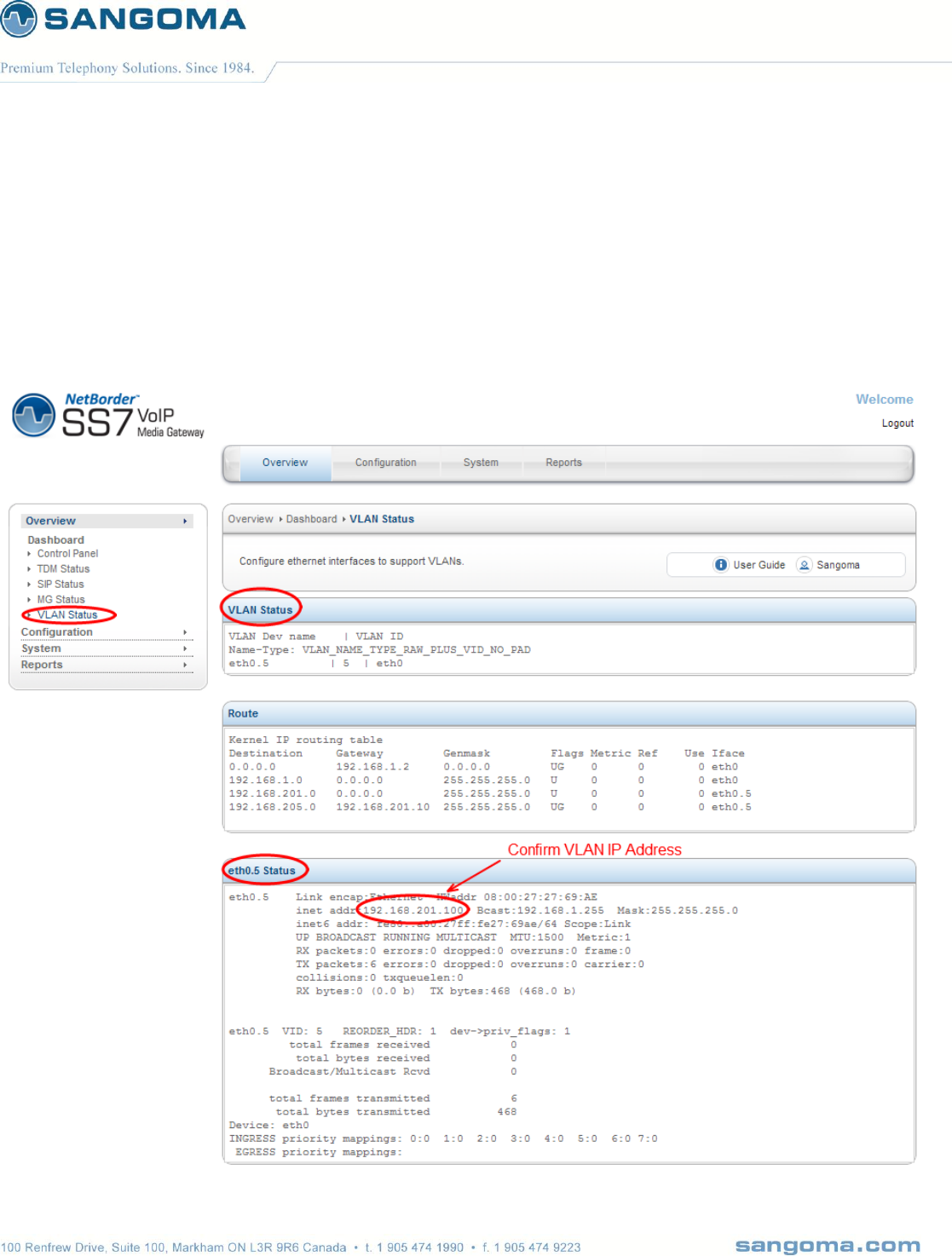
6.9.5 VLAN Status
Select VLAN Status from side/top Overview Menu
This page shows
o All configured VLANs
o System Routing table
o Individual VLAN configuration
o Individual VLAN IP information

v1.14
68
NOTE
Confirm that VLAN Interface contains the correct IP address.
If the IP address is not set, the VLAN configuration has not been set properly.
v1.14
69
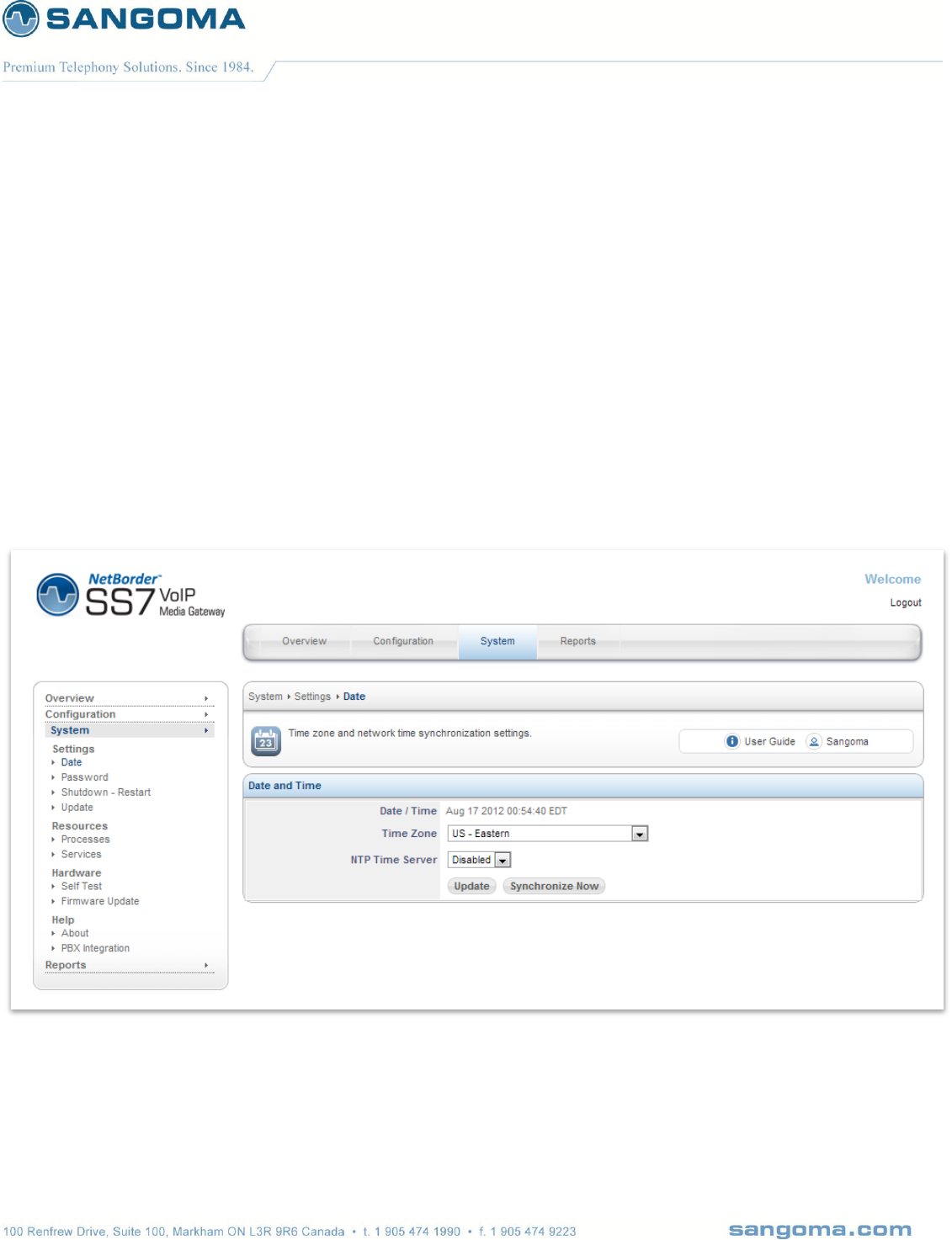
6.10 Date & Time Service Config
The Date/Time configuration tool allows you to:
Select your time zone
Synchronize your clock with network time servers
Enable/disable a local time server for your network
Note that you need to configure your IP address and default route in order to be able to use a default
time server that is located on the internet.
To configure
Select Date from side/top System menu
Refer below to all available options.

v1.14
70
Option
Description
Date/Time
The system date, time and time zone information is displayed for informational
purposes. Please make sure it is accurate since it is not unusual to have
computer clocks improperly set on a new installation.
Time Zone
It is important to have the correct time zone configured on your system. Some
software (notably, mail server software) depends on this information for proper
time handling.
NTP Time Server
An NTP Time Server is built into NSG.
Time
Synchronization
Hitting the Synchronize Now button will synchronize the system's clock with
network time servers.

v1.14
71
7 Initial Gateway Configuration
NSG by default contains following VoIP/TDM Sections
Global Gateway Config
o Configured in Global gateway section.
o Used to configure SIP, H323, RTP, RADIUS options.
SIP/RTP
o Configured in Global Gateway section
o SIP profile is always started
MG
o Configured in MG gateway section
o MG Termination ID’s are mapped to TDM channels in TDM gateway section.
o For full MG configuration one must configure MG and TDM sections.
H323
o Single H323 profile, configured in H323 gateway section
o H323 profile is started only if H323 gateway section is saved.
SS7
o Configured in TDM gateway section
o ISUP Termination
o M2UA Signaling Gateway
Media/Transcoding
o Configured in Media gateway section
o Enable and select hw codec support
o Note: HW transcoding is an optional feature.
Dialplan
o Used for SIP to TDM and H323 to TDM mode
o Note: Dialplan is not used in MG/Megaco/H.248 mode.
Apply
o All configuration files are saved to disk at this step.
o Above configuration sections only save information in local database.
o NSG Gateway can be started in Control Panel after this step
o TDM Status can be used to monitor Gateway Status.
v1.14
72
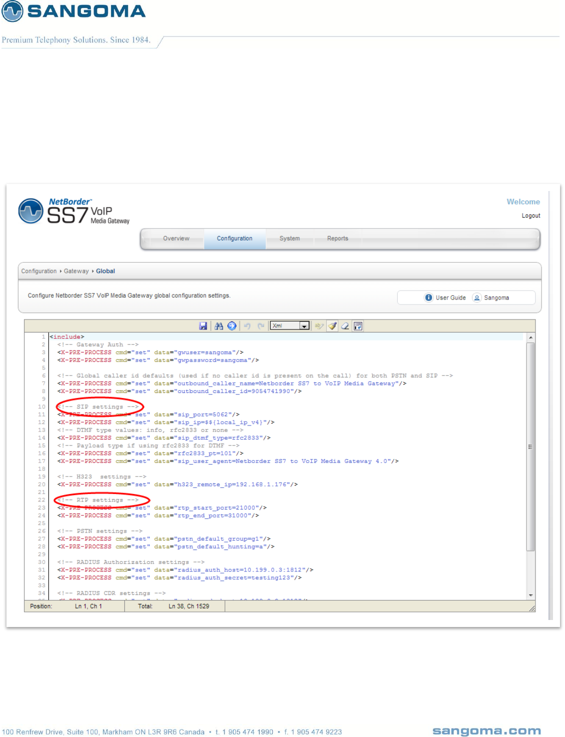
7.1 Global Gateway Configuration
Select Global from side/top Configuration Menu
Change a SIP global variable and Click on Save (Disk Icon)
Proceed to Control Panel and Restart the VoIP Gateway.

v1.14
73
Field Name
Possible
Values
Default Value
Description
gwuser
Any string
Sangoma
NSG SIP incoming registration authentication user
name.
gwpassword
Any string
Sangoma
NSG SIP incoming registration authentication
password
outbound_caller_name
Any string
Netborder SS7
to VoIP Media
Gateway
Global caller id name defaults (used if no caller id
name is present on the call) for both PSTN and
SIP
outbound_caller_id
Any digits
9054741990
Global caller id defaults (used if no caller id is
present on the call) for both PSTN and SIP
sip_port
Any port number
5062
SIP service local port number.
sip_ip
Any ip address
System IP
SIP service, local IP address. By default a local
system eth0 address is taken as default ip
address.
sip_dtmf_type
rfc2833
info
none
rfc2833
rfc2833
- DTMF passed via RTP oob message
info
- DTMF passed via SIP INFO message
none
- DTMF passed via inband media
rfc2833_pt
Any number
101
rfc2833 rtp payload type override. Ability to set
the RTP payload type for rfc2833. Use d edge
cases where remote equipment is not per spec.
sip_user_agent
Any string
Netborder SS7
to VoIP Media
Gateway 4.0
SIP INVITE user agent name string.
rtp_start_port
Any port
21000
RTP port starting range value. NSG will pick RTP
ports for each call within this range.
rtp_end_port
Any port
31000
RTP port stop range value. NSG will pick RTP
ports for each call within this range
pstn_default_group
g1,g2,g3,g4 ….
g1
Default pstn dial group number, in case the group
is not specified in the dial string.
radius_auth_host
Any ip address:port
10.199.0.3:1812
Location of the Radius server, that will be used to
authenticate incoming calls.
radius_auth_secret
Any string
testing123
Password of the remote Radius server.
radius_cdr_host
Any ip address:port
10.199.0.3:1812
Location of the Radius server, that will be used to
keep track of billing via CDRs.
radius_auth_secret
Any string
testing123
Password of the remote Radius server.

v1.14
74
8 Megaco/H.248 Media Gateway Configuration
8.1 Overview
H.248 or Megaco or Gateway Control Protocol is a recommendation from ITU which defines protocols
that are used between elements of a physically decomposed multimedia gateway. It is an
implementation of the Media Gateway Control Protocol Architecture (RFC 2805). H.248 is also called
Megaco or in IETF domain. It is now known as Gateway Control Protocol.
H.248/Megaco is standard protocol for controlling the elements of a physically decomposed
multimedia gateway, which enables separation of call control from media conversion. H.248/Megaco
is a master/slave protocol used to separate the call control logic from the media processing logic in a
gateway.
The H.248/Megaco model describes a connection model that contains the logical entities, or objects,
within the Media Gateways (MGs) that can be controlled by the Media Gateway Controller. The main
entities are Contexts and Terminations.
8.1.1 Terminations
These source or sink one or more media streams or control streams. Terminations may be
physical or ephemeral.
Physical Terminations represent physical entities that have a semi-permanent existence. For
example, a Termination representing ports on the gateway, such as TDM channel or DS0
might exist for as long as it is provisioned in the gateway. Ephemeral Terminations represent
Connections or data flows, such as RTP streams, or MP3 streams, and usually exist only for
the duration of their use in a particular Context.
Terminations have properties, such as the maximum size of a jitter buffer, which can be
inspected and modified by the MGC. A termination is given a name, or Termination ID, by the
MG.
8.1.2 Contexts
These are star connections created by associating multiple terminations. A Context is a logical
entity on an MG that is an association between a collection of Terminations. A NULL context
contains all non-associated terminations. A Context is a logical entity on an MG that is an
association between a collection of Terminations. A ContextID identifies a Context.

v1.14
75
The normal, "active" context might have a physical termination (say, one DS0 in a DS3) and
one ephemeral one (the RTP stream connecting the gateway to the network). Contexts are
created and released by the MG under command of the MGC. A context is created by adding
the first termination, and it is released by removing (subtracting) the last termination.
A termination may have more than one stream, and therefore a context may be a multistream
context. Audio, video, and data streams may exist in a context among several terminations.
8.2 Commands
The commands defined by megaco are very simple, since they can be heavily extended using
packages.
8.2.1 Sent from controller to gateway
Add
Used to add a termination to a context
Modify
Used to modify an existing termination
Substract:
Used to remove a termination from a context
Move:
used to move a termination to another context (call-waiting is achieved by moving it to the
NULL context, which keeps it opened).
AuditValue
Returns the current values of properties, signals and statistics
AuditCapabilities:
Returns metadata on the current termination (the possible values for all elements)
8.2.2 Sent from gateway to controller
Notify
Carries an event defined in one of the packages [P1]
ServiceChange:
Notifies the controller that the gateway is going out of service / back in service. [P1]

v1.14
76
A MEGACO-configured NSG starts by sending a Service Change command to its MGC. When an
MGC accepts the NSG registration, the session can start. Subsequently, the NSG responds to MGC
commands. Event notifications are sent only if the MGC requests them specifically.
8.3 Packages
Additional features are provided in packages, which define additional properties, events and signals
that are included in the descriptors used in the protocol’s commands. Packages follow an inheritance
model similar to object oriented programming, with some of those defined as “to be extended only”
providing only an indicative structure for proprietary implementation.
Some properties are read-only and others are read-write, for more information refer to H.248.1
Appendix E.
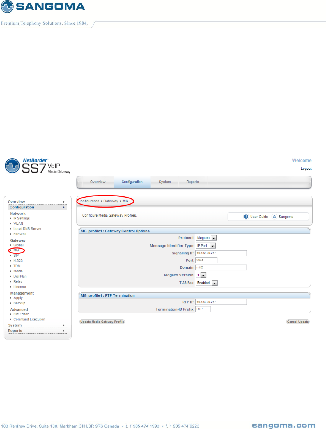
v1.14
77
8.4 Create MG Profile
Media gateway profile will contains all the required configuration parameters to bring up the Media
gateway stack.
Select MG from the side/top Configuration menu
Select Add New Profile
o Use default profile name, or specify one
Select Create Media Gateway Profile
Configure the MG Profile based on information received from our provider.
Select Update Media Gateway Profile to save

v1.14
78
Followings are the fields, that need to be configured.
Field Name
Possible
values
Default
Values
Description
Protocol
MEGACO
MGCP
MEGACO
Type of protocol Media Gateway is going to use.
NOTE: Currently Media Gateway supports only
MEGACO
Message Type
Identifier
IP-PORT
IP
DOMAIN
IP-PORT
Media gateway message identifier (MID) type
field will be used to build the message identifier
field which Media Gateway will use in all the
originating messages.
For example:
If MID type is IP-PORT then Message identifier
format will be
“[IP-Address]:Port”
If MID type is DOMAIN then message identifier
format will “<Domain>”. Refer to Domain
section below.
If MID type is IP then message identifier format
will
“[IP-Address]”
Note: IP-Address, Port and Domain values will be
as defined above.
Signaling IP
any ipv4 addr
NA
Media Gateway, Megaco, source IP address.
Port
1 - 65000
NA
Media Gateway source Port.
Domain
(a string value)
NA
Media Gateway domain name.
Used as MID Type, when MID Type is set to
DOMAIN. Ignored if MID Type is not Domain.
Default to system domain name.
Megaco Version
1
2
3
1
Megaco protocol version which Media Gateway
will use while communicating with Media
Gateway Controller
T.38 Fax
Enable/Disable
Enable
If enable MG will configure to detect and send
CNG/CED Fax notify events to MGC. This will
prompt MGC to modify the RTP stream to T.38.
If disable MG will not notify MGC about
CNG/CED, thus disabling T.38 faxing. Fax will go

v1.14
79
through as G711 stream.
RTP IP
any ipv4 addr
Same as Signaling
IP.
Megaco RTP source IP address.
By default it should be set to SIgnaling IP
address, this way both signaling and media
originate from single IP address.
In VLAN scenarios it’s possible to use separate
IP addresses for Signaling and RTP.
Termination-ID Prefix
any number
starting from 1
NA
RTP termination id prefix which Media Gateway
will use while allocating RTP terminations.
This variable is used as a name of RTP
termination. Eg: RTP/1, RTP/2 …
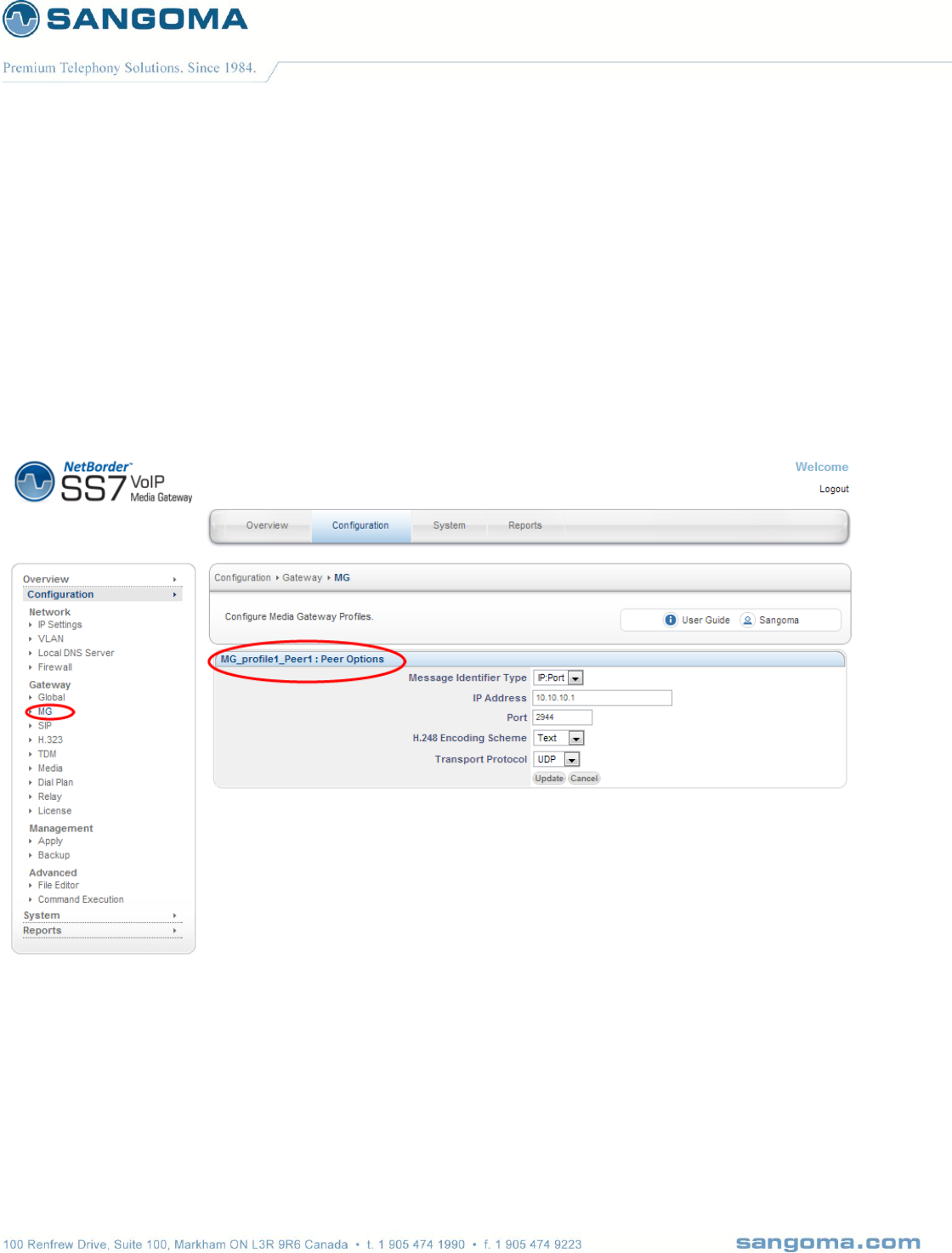
v1.14
80
8.5 Create MG Peer Profile
Each Media gateway profile will associate with one or multiple peers.
NOTE: As of now NSG supports only “one peer per MG profile”.
Select Add Peer in MG Section
Fill in the peer information
Select Update to Save
Followings are the fields which need to be configured.

v1.14
81
Field Name
Possible
values
Default
Values
Description
Message Identifier
Type
IP-PORT
IP
IP-PORT
Media gateway Controller message identifier
(MID) type field will be used by Media Gateway
to identify the peer.
Message identifier value will be built based on
MID type field.
For example:
If MID type is IP-PORT then Message identifier
format will be
“[IP-Address]:Port”
If MID type is IP then message identifier format
will
“[IP-Address]”
Note: IP-Address and Port values will be as
defined above.
IP Address
NA
NA
Media Gateway Controller IP address.
Port
NA
2944
Media Gateway Controller Port number
Default: 2944
H.248 Encoding
Scheme
TEXT
BINARY
TEXT
Encoding scheme of MEGACO protocol which
will be used by Media Gateway while
encoding/decoding the H.248 messages.
Transport Protocol
UDP
TCP
SCTP
UDP
Media Gateway will use the transport type field
to decide which transport to use for
transmitting/receiving MEGACO messages.
NOTE: currently we are supporting only
UDP/TCP.
Once the Media Peer is configured the Megaco configuration section is complete.
Proceed to TDM Termination for Media Gateway
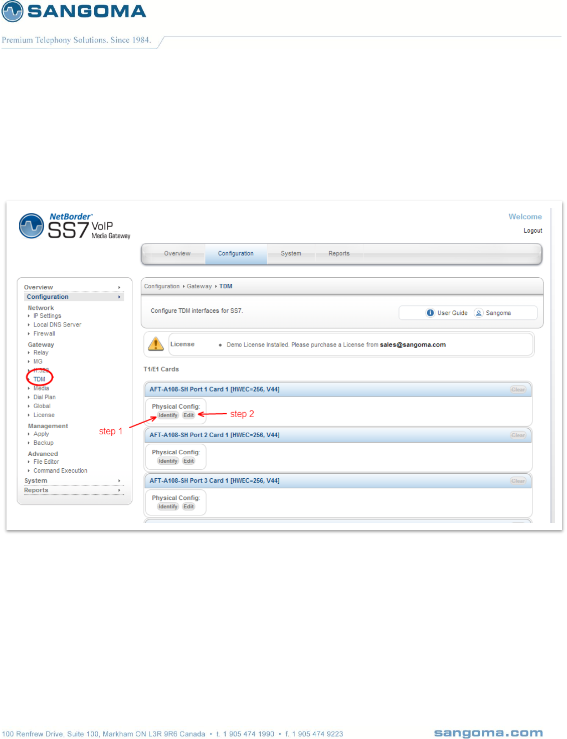
v1.14
82
8.6 TDM Termination for Media Gateway
Select TDM from side/top Configuration menu
The TDM section will display all installed TDM Spans/Ports.

v1.14
83
8.6.1 Identify
In order to determine which physical T1/E1 port is: Port 1 Card 1
Select Identify button for Port 1 Card 1
The LED light will start flashing on a rear RJ45 T1/E1 port: rear panel.
Look at the rear panel of the appliance and plug in RJ45 cable to the blinking RJ45 T1/E1 port.
Once the Port 1 Card 1 is identified, the subsequent ports for that board are labeled.
Or alternatively keep using the Identify feature for each port.
NOTE
Identify picture of the device is always set to A108D – 8 T1/E1 card. The LED will always bling
port 1. The image is not meant to reflect the real hardware image, nor real port location. User
should always view the rear panel for the flashing LED.
All Sangoma TDM T1/E1 cards Port 1 is closest to the PCI slot.
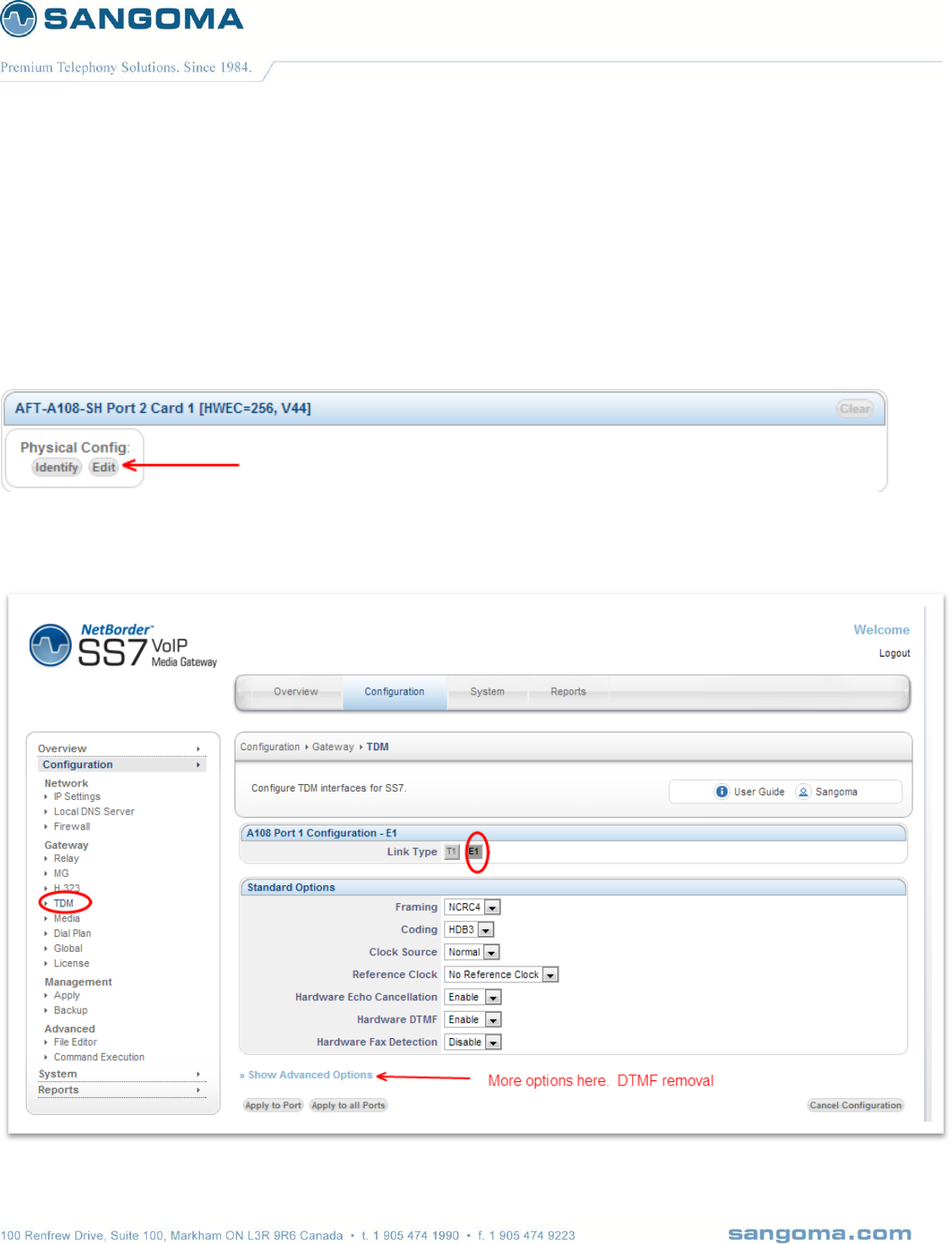
v1.14
84
8.6.2 Edit T1/E1 Config
Once the port has been identified and plugged into the T1/E1 network.
Select Edit button for Port 1 Card 1 to configure the physical T1/E1 parameters.
Select the port configuration type: T1 or E1
o T1: North American Market and Japan
o E1: Europe and the world
Fill in Physical Configuration T1 or E1 parameters
o Fill in the T1/E1 parameters based on the provider provision document.
8.6.2.1
Standard T1/E1 Parameters

v1.14
85
In case advanced parameters are not necessary proceed
Apply to Port
o Applies the configuration for a single T1/E1 port
o (The one that is currently being edited)
Apply to all Ports
o Apply to all T1/E1 ports on a board.
o Bulk config feature
o (This feature saves time as T1/E1 ports are usually provisioned the same)
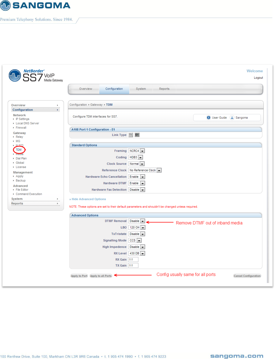
v1.14
86
8.6.2.2 Advanced T1/E1 Parameters
NOTE
After T1/E1 configuration, the NSG wizard will request Link Type Configuration.
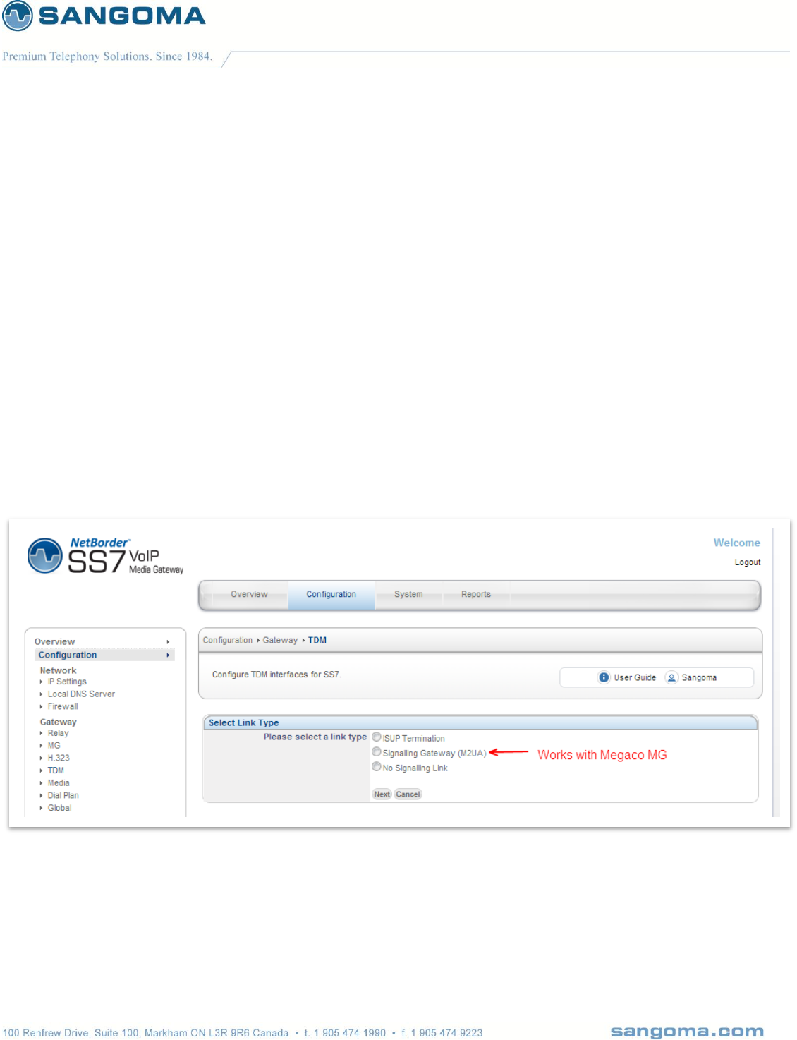
v1.14
87
8.7 Span Link Type
When configuring TDM Terminations for Megaco Media Gateway there are two possibilities
Voice Mode
o All TDM channels are used for Voice 64kbs G.711
o Example: All channels 1-31 on an E1 line are used for voice
o Link Type = Voice Only
Mix Mode
o Voice 64kbs G.711 channels and SS7 signaling channels.
o Example: Channel 16 is used for SS7 signaling, 1-15,17-31 are used for voice.
o Link Type = Signaling Gateway (M2UA)
If configuring for Voice Mode select No Signaling Link
If configuring for Mixed Mode select Signaling Gateway (M2UA)
NOTE
The rest of this section will continue to document the Signaling Gateway (M2UA) option.
Next page will introduce the Signaling Gateway Overview, followed by the next config section in the
WebGUI.
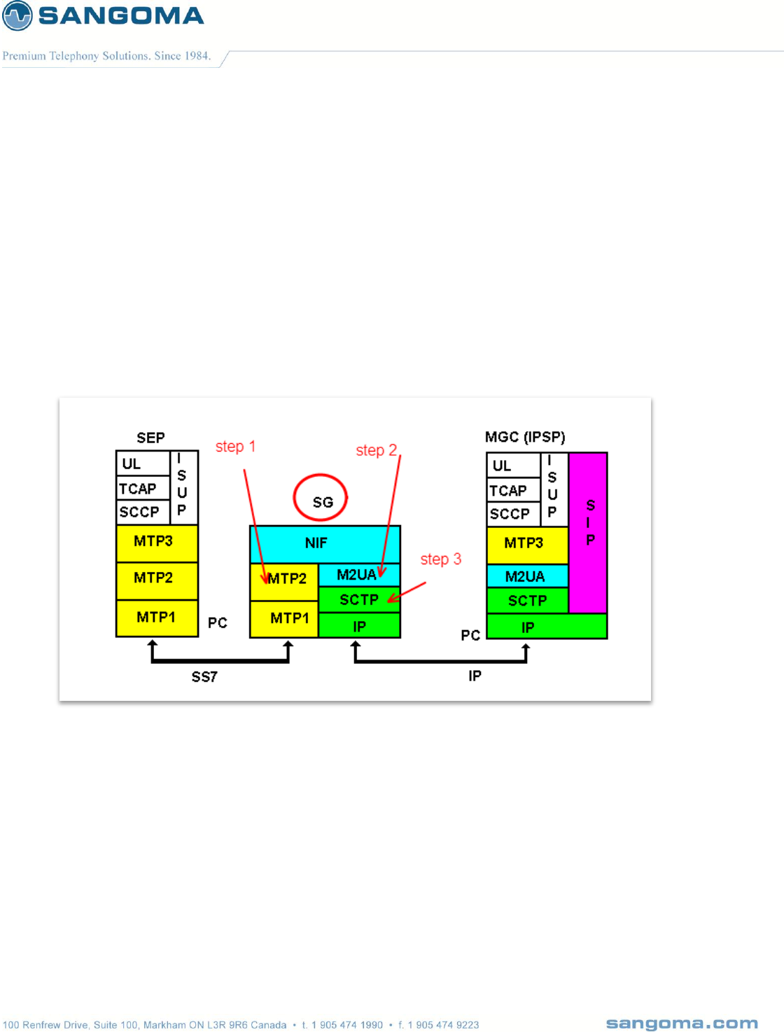
v1.14
88
8.8 Signaling Gateway Overview
NSG supports Signaling Gateway operation mode.
In Signaling gateway mode, NSG will bridge T1/E1 SS7 signaling link to IP and pass it transparently
to the MGC/Softswitch, via M2UA protocol. Looking at the diagram below, NSG Signaling Gateway
will configure:
MTP1 & MTP2 protocols over the TDM port
M2UA/SCTP protocol over IP network
NIF (Network interworking function) to bridge the two
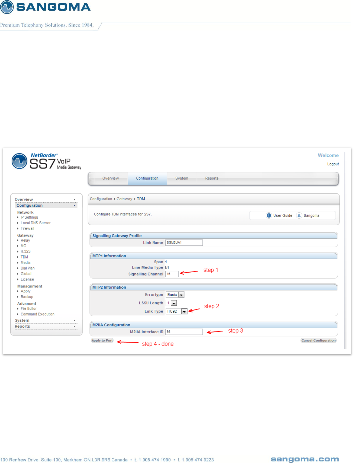
v1.14
89
8.8.1 MTP1/2 Link Configuration
Specify MTP1/2 information based on provider provision document
Step1: Identify which channel on T1/E1 line will carry signaling
Step2: Specify MTP2 signaling information based on provision document
Step3: Specify M2UA Interface ID based on provision document
Apply to Port to save configuration

v1.14
90
Field Name
Possible
Values
Default Value
Description
Link Name
NA
NA
M2UA Profile name
Span
NA
NA
Span number which is going to associated with this
M2UA profile.
Line Media
Type
E1/T1
E1
Media type
Signaling
channel
NA
NA
Signaling channel of the span which will carry the
M2UA signaling messages.
ErrorType
Basic/PCR
Basic
MTP2 error type.
LSSU length
1/2
1
LSSU length
Link Type
ITU92
ITU88
ANSI96
ANSI92
ANSI88
ETSI
ITU92
SS7 link variant.
M2UA Interface
ID
NA
NA
M2UA Interface identifier which will map to this
particular signaling span/channel and uniquely identify
the link between M2UA SG and MGC.
NOTE
Next section in WebUI will relate to M2UA configuration. Before we proceed however, the M2UA
interface architecture will be introduced in order to provide a big picture to the user.

v1.14
91
8.8.2 M2UA Interface
This section provides in-depth overview on how the M2UA interface is constructed. It should help the
user better understand the WebUI configuration objects for M2UA protocol.
WebUI for M2UA contains 3 sections: Cluster, Peer and SCTP
SCTP interfaces are standalone objects on which a peer bind to (regardless of its cluster).
o 1 SCTP binds to 1 or more peers
o 1 peer binds to 1 SCTP
o Thus SCTP are shared across all peers
o SCTP cannot be deleted if used by any peer (even from another cluster).
o Deleting a peer or a cluster does not delete SCTP.
Peers are bound to cluster.
o 1 peer binds to 1 cluster
o 1 cluster binds to 1 or more peer
o Deleting a cluster will delete peers.
Cluster are bound to MTP2 through M2UA binding and nif interface
o 1 cluster binds to 1 or many MTP2 (through M2UA->NIF relationship)
o 1 MTP2 binds to 1 cluster through NIF interface binding
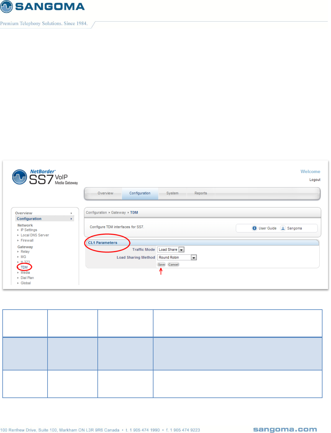
v1.14
92
8.8.3 M2UA Cluster Creation
M2UA Cluster is a group of peers to which M2UA SG will communicate
Select Create Cluster
Leave the Cluster values default unless the provider specifies otherwise.
Select Save to Continue
Field Name
Possible
Values
Default Value
Description
Traffic Mode
Load Share
Override
Broadcast
Load Share
This parameter defines the mode in which this
Cluster is supposed to work.
Load Sharing
Method
Round Robin
Link Specified
Customer
Specified
Round Robin
This parameter defines the load share
algorithm which is used to distribute the traffic
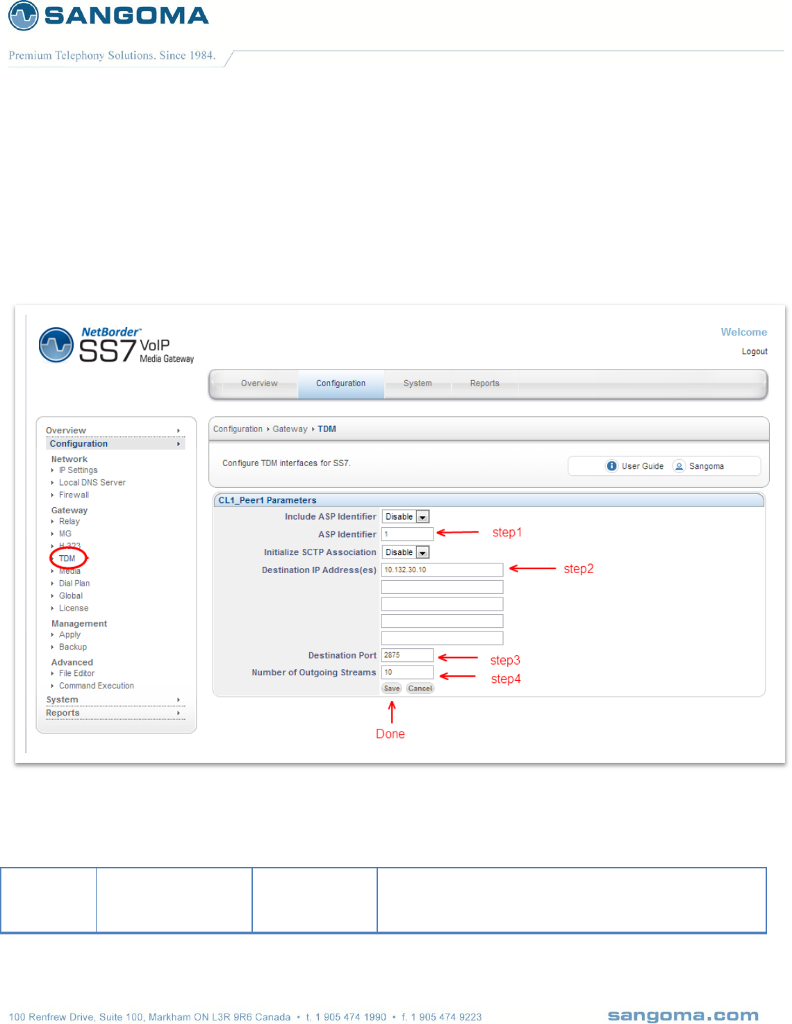
v1.14
93
8.8.4 M2UA Cluster Peers
M2UA Peers will be configured under the M2UA clusters
Select Add under Cluster Peers Profile
Select Create Cluster Peer Profile
Specify the Cluster Peer parameters based on provider provision document
Field
Name
Possible Values
Default Value
Description

v1.14
94
Include
ASP
Identifier
Disable
Enable
Disable
Flag used to indicate whether include the
ASP ID in the ASP UP message
ASP
Identifier
NA
NA
ASP identifier for this ASP node.
Set to 1 in case ASP is Disabled
Initialize
SCTP
Association
Disable
Enable
Disable
Flag used to indicate if M2UA SG has to start SCTP
association or not.
If Disable means M2UA SG will wait for SCTP association
request from MGC.
If Enable that means M2UA SG will initiate the SCTP
association request towards MGC.
Destination
IP
Address(es)
NA
NA
Destination IP address
Destination
port
NA
2904
Destination ASP Port
Default M2UA ASP port: 2904
Number of
Outgoing
Streams
NA
10
Number of outgoing streams supported by this association.
Default 10
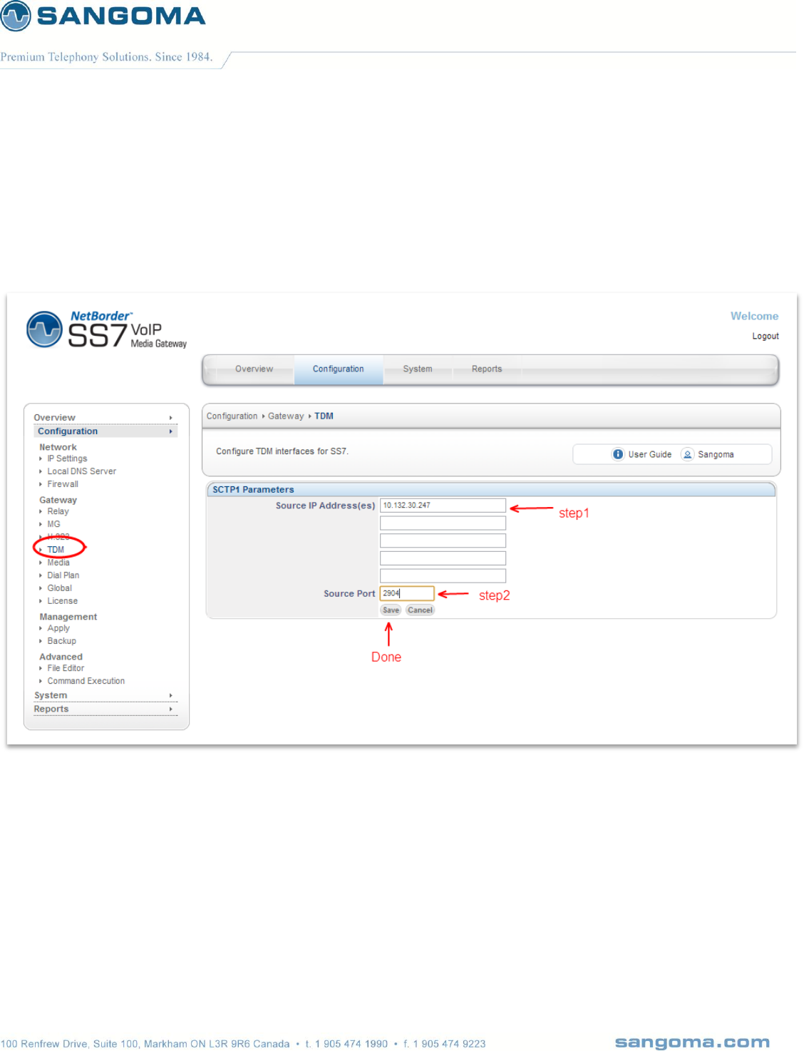
v1.14
95
8.8.5 SCTP Interface
Select Add SCTP Interface
Select Create SCTP Interface
Specify SCTP Information based on provider provision document
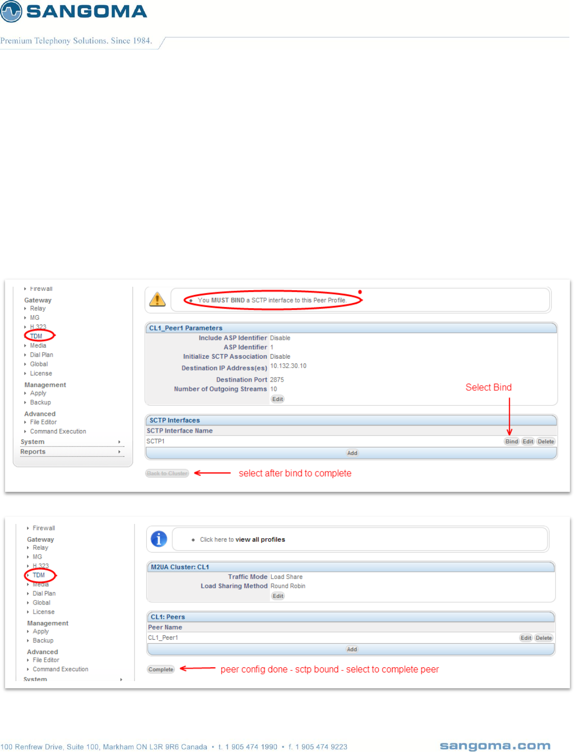
v1.14
96
8.8.6 Binding all components
All components have been created
o M2UA Cluster
o M2UA Peer
o SCTP Interface
Next step is to Bind / Connect them together
o SCTP interface into M2UA Peer
o M2UA peer into M2UA Cluster
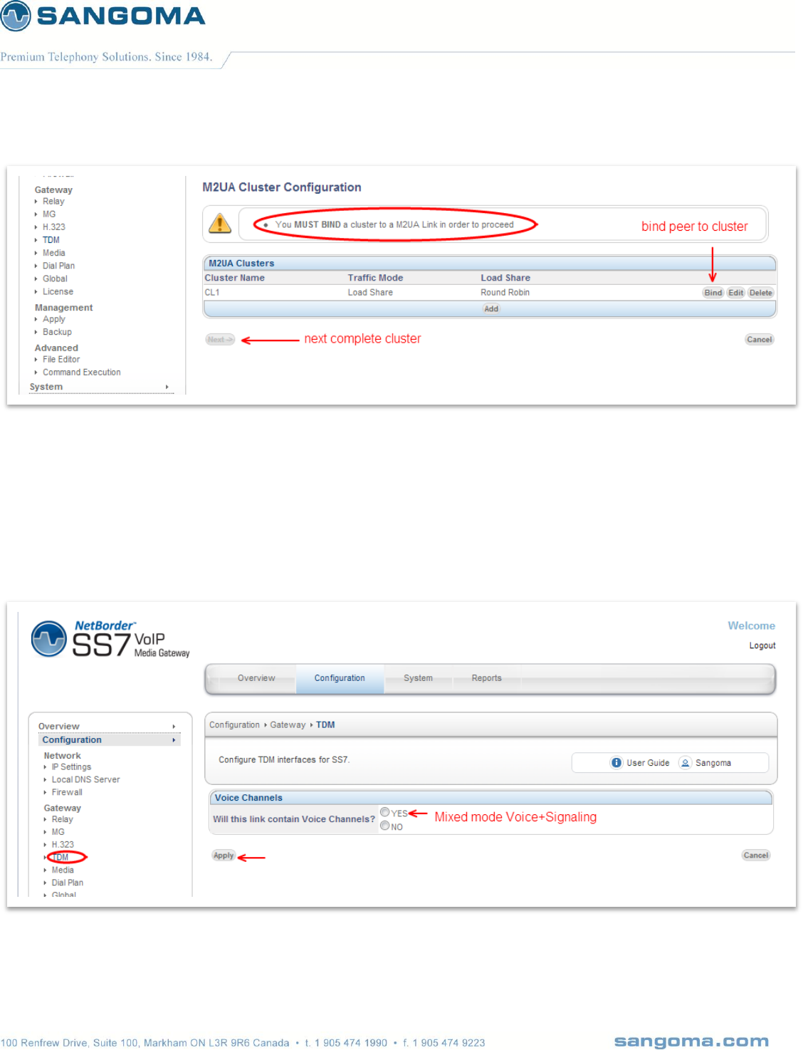
v1.14
97
8.8.7 Mixed Mode Configuration
Signaling is bridged by M2UA to the MGC/Soft switch
Voice is controlled by Megaco/H.248
Specify that Voice is part of this TDM Span
NOTE
Rest of this section will document the Mixed Mode Configuration
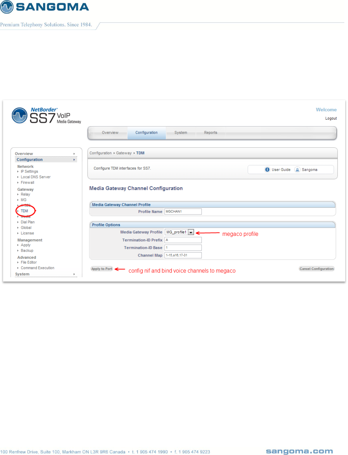
v1.14
98
8.8.8 Bind Megaco to TDM
The last step of the configuration is to bind the TDM voice channels to Megaco Profile.

v1.14
99
Field
Name
Possible Values
Default Value
Description
Media
Gateway
Profile
List of Gateways
First in the List
Select Megaco Profile that will be used to control the TDM
channels for this span.
Termination
ID Prefix
NA
NA
Usually a letter A-Z. This prefix is defined by MGC.
Please refer to MGC configuration.
Termination
ID Base
NA
NA
Usually a number starting from 1. This value is defined by
MGC. Please refer to MGC configuration.
Channel
Map
NA
NA
List of channels to be controlled by Megaco
Example: 1-15,s16,17-31
Channels 1-15 and 17-31 are used for Voice and should be
controlled by Megaco
Channel 16 (prefixed by letters) indicates that channel 16
carries signaling channel. Megaco will ignore this channel
as it’s not voice.
Prefix Letters to signaling channel:
s: megaco id not used, id mapped to signaling channel
g: megaco id is used, id mapped to next available
voice channel.
The bind between megaco and TDM would be as follows
Channel Map: 1—31 (no signaling channel)
A1: channel 1
A2: channel 2
…
A16: channel 16
…
A30: channel 30
A31; channel 31

v1.14
100
Channel Map: 1-15,s16,17-31 (signaling on ch 16)
A1: channel 1
A2: channel 2
…
A15: channel 15
…
A16: not used – A16 points to signaling channel 16
A17: channel 17
A18: channel 18
…
A31: channel 31
Channel Map: 1-15,g16,17-31 (signaling on ch 16)
A1: channel 1
A2: channel 2
A15: channel 15
A16: channel 17 - A16 is used and it points to ch 17.
A17: channel 18
…
A30: channel 31
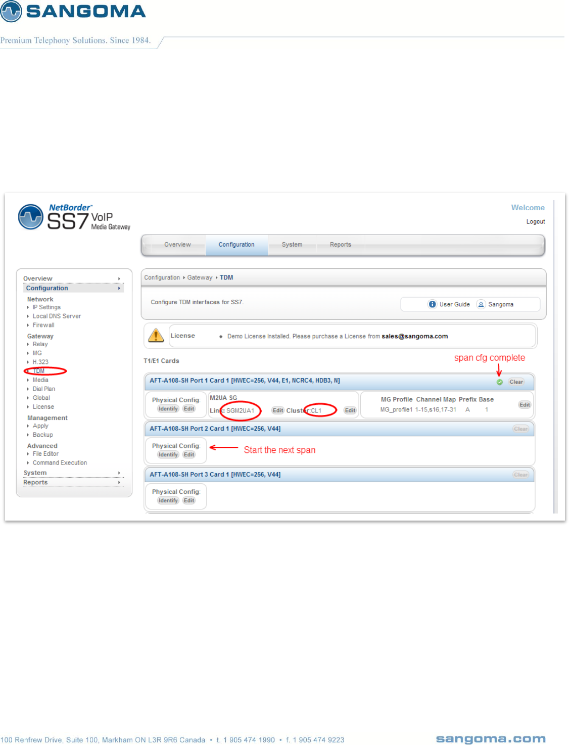
v1.14
101
8.8.9 TDM Termination Complete
A span has been configured and bound to a Megaco Profile.
Configuration for this span is done
o Confirmed in WebUI by a green checkmark.
Next step is to repeat the process for the rest of the spans.
In typical configurations there is one or two spans (T1/E1 ports) that contain signaling
channels. The rest of the spans are usually voice only.
In voice only config, there is no Signaling Gateway configuration.
o The configuration jumps directly to “Bind TDM to Megaco” section of the WebUI.
NOTE
The changes made in the Configuration section of the WebUI are only stored one the scratch disk.
User MUST proceed to Apply page in the Management Section to save new configuration.

v1.14
102
9 SS7 ISUP
SS7 is a signaling protocol, it is used to carry call control information such as call start, call progress,
call hangup etc. The SS7 call control information is used to control arbitrary number of voice
channels that are carried using T1/E1 spans.
In a typical SS7 setup the telco will provide you with SS7 information that will be used to map T1/E1
physical spans and channels into SS7 call control information.
The NSG TDM SS7 configuration page has been designed as bottom up SS7 configuration approach.
1. Identify T1/E1 spans on your system
2. For each T1/E1 span on your system:
a. Determine which T1/E1 spans will carry SS7 Link channels
b. T1/E1 Span can either carry an
i. SS7 Link in one of its channels or
ii. All T1/E1 channels can be used to carry voice.
c. Configure T1/E1 physical configuration parameters
d. Identify if T1/E1 span carries SS7 link or is Voice Only
e. If T1/E1 span has an SS7 link associate with it:
i. Create a new SS7 Link
ii. Next step is to bind the new SS7 Link to an SS7 Linkset.
iii. If an SS7 Link set does not exist, Create a new SS7 Link Set
iv. Then bind the SS7 Link to an existing or new SS7 Link Set
v. Next step is to bind the SS7 Linkset into an SS7 Route.
vi. If an SS7 Route does not exist, Create a new SS7 Route
vii. Then bind the SS7 Linkset to an existing or new SS7 Route
viii. Next step is to bind the SS7 Route into an SS7 ISUP Interface
ix. If an SS7 ISUP Interface does not exist, Create a new SS7 ISUP Interface
x. Then bind the SS7 Route to an existing or new SS7 ISUP Interface
f. The Last step is to assign CIC values to each physical T1/E1 timeslot in the span.
Whether the Span carries only voice or it contains the SS7 Link, each timeslot must be
associated with a SS7 CIC value.
This way when an incoming SS7 Call Start message arrives with an arbitrary CIC value.
The NSG system can open the appropriate physical voice channel associated with the
CIC value.

v1.14
103
3. Once all T1/E1 spans are configured you need to Apply the configuration files.
Note that this step does not start the NSG gateway. It just writes the appropriate configuration
files.
4. Proceed to the Control Panel to start the NSG SS7 to VoIP Gateway.
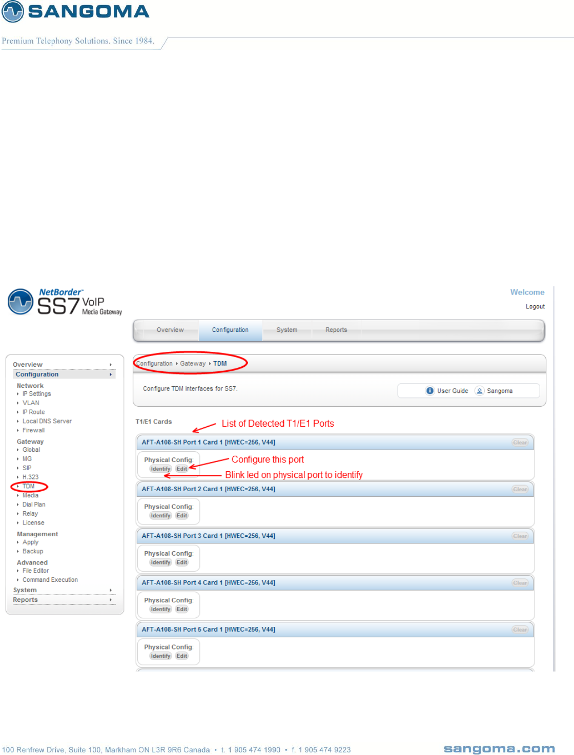
v1.14
104
9.1 TDM SS7 Configuration Page
Select TDM from side/top Configuration menu
The TDM section will display all installed TDM Spans/Ports.
The TDM Configuration page will display to the user every T1/E1 card detected by NSG.
Each card is logically separated into ports, which initially displays the firmware version and the Echo
Cancellation security chip ID. If the echo cancellation security chip ID is 0, then the card installed
does not have echo cancellation. If there is a alert image next to the firmware version, that means the
firmware on the system is out of date, and must be updated in order to have the most up to date and
efficient firmware running.
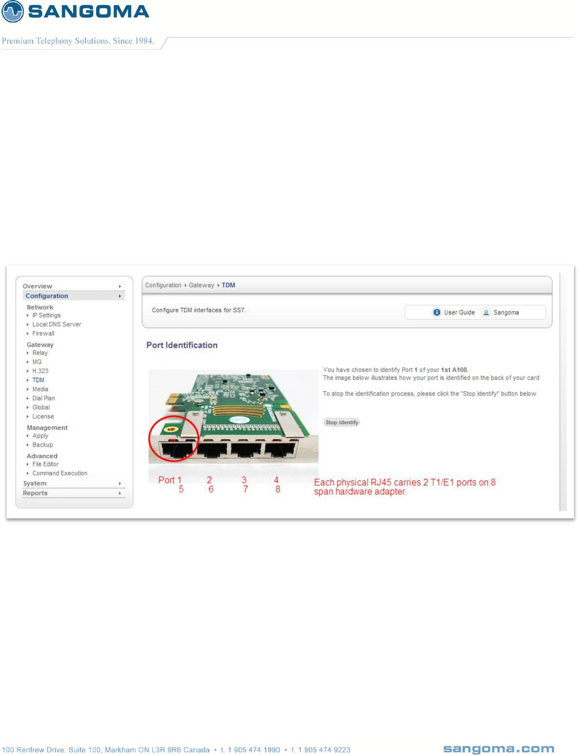
v1.14
105
9.2 Port Identification
In order to determine which physical T1/E1 port is: Port 1 Card 1
Select Identify button for Port 1 Card 1
The LED light will start flashing on a rear RJ45 T1/E1 port: rear panel.
Look at the rear panel of the appliance and plug in RJ45 cable to the blinking RJ45 T1/E1 port.
Once the Port 1 Card 1 is identified, the subsequent ports for that board are labeled.
Or alternatively keep using the Identify feature for each port.
NOTE
Identify picture of the device is always set to A108D – 8 T1/E1 card. The LED will always bling
port 1. The image is not meant to reflect the real hardware image, nor real port location. User
should always view the rear panel for the flashing LED.
All Sangoma TDM T1/E1 cards Port 1 is closest to the PCI slot.
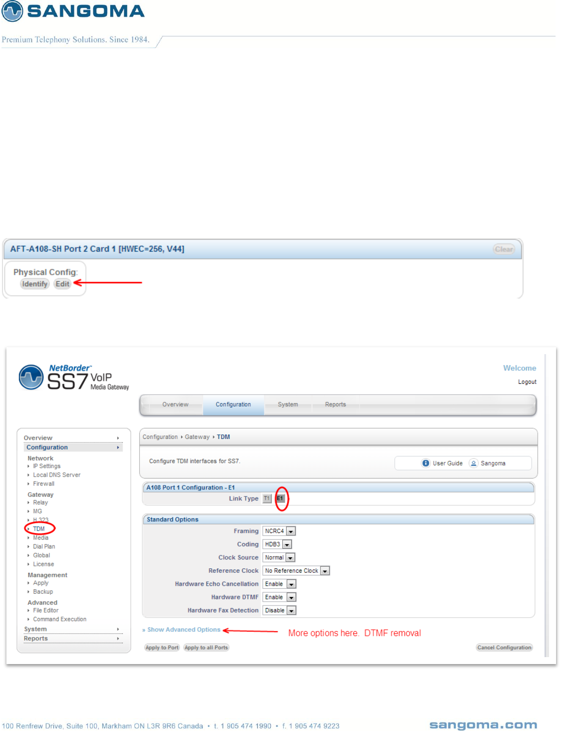
v1.14
106
9.3 Edit T1/E1 Config
Once the port has been identified and plugged into the T1/E1 network.
Select Edit button for Port 1 Card 1 to configure the physical T1/E1 parameters.
Select the port configuration type: T1 or E1
o T1: North American Market and Japan
o E1: Europe and the world
Fill in Physical Configuration T1 or E1 parameters
o Fill in the T1/E1 parameters based on the provider provision document.
9.3.1 Standard T1/E1 Parameters

v1.14
107
In case advanced parameters are not necessary proceed
Apply to Port
o Applies the configuration for a single T1/E1 port
o (The one that is currently being edited)
Apply to all Ports
o Apply to all T1/E1 ports on a board.
o Bulk config feature
o (This feature saves time as T1/E1 ports are usually provisioned the same)

v1.14
108
9.3.2 Advanced T1/E1 Parameters
NOTE
After T1/E1 configuration, the NSG wizard will request Link Type Configuration.
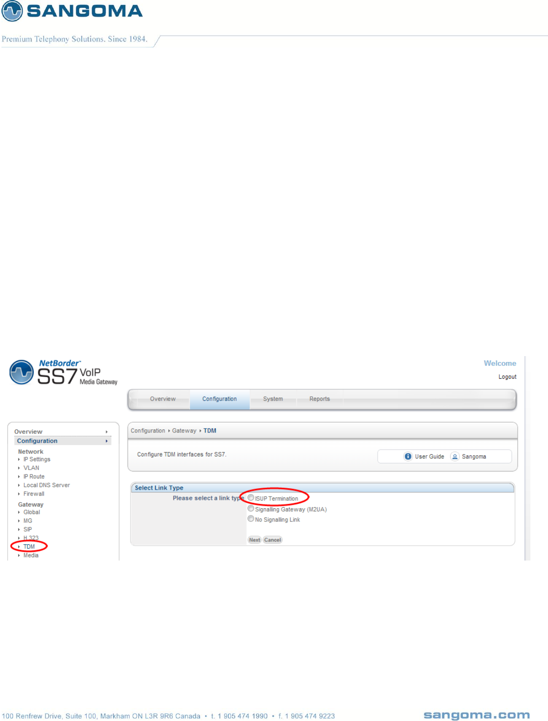
v1.14
109
9.4 Span Link Type
When configuring TDM Terminations for Megaco Media Gateway there are two possibilities
Voice Mode
o All TDM channels are used for Voice 64kbs G.711
o Example: All channels 1-31 on an E1 line are used for voice
o Link Type = Voice Only
Mix Mode
o Voice 64kbs G.711 channels and SS7 signaling channels.
o Example: Channel 16 is used for SS7 signaling, 1-15,17-31 are used for voice.
o Link Type = ISUP Termination
If configuring for Voice Mode select No Signaling Link
If configuring for Mixed Mode select ISUP Termination
NOTE
The rest of this section will continue to document the ISUP Termination option.
In case of Voice Mode – the GUI will skip the ISUP configuration and proceed directly to
Channel Map Section below.

v1.14
110
9.5 SS7 Network Overview

v1.14
111
9.5.1 Links
physical signaling links between the TX board and the adjacent signaling points. One link
configuration must be performed for each physical signaling link. The attributes of a link
include the point code of the adjacent signaling point, protocol variant employed on the link
(ITU-T or ANSI), point code length, maximum packet length, various timer values, membership
in a linkset, and others.
9.5.2 Linksets
are groups of from one to 16 links that directly connect two signaling points. Although a linkset
usually contains all parallel signaling links between 2 SPs, it is possible to define parallel link
sets. Each signaling link defined is assigned membership in exactly one link set.
9.5.3 Routes
specify the destination signaling points (or sub-networks (clusters) when route masks are
employed) that are accessible from the target node. Each route is assigned a direction - up or
down. One up route is required for the actual point code assigned to the signaling point being
configured and for each point code that is to be emulated. Up routes are used to identify
incoming messages that are to be routed up to the applications/user parts. One down route is
required for each remote signaling point/network/cluster that is to be accessible from the SP
being configured.
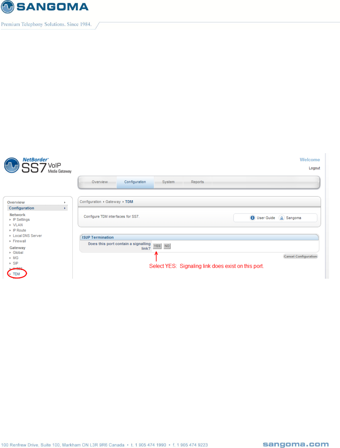
v1.14
112
9.6 MTP2 Link Configuration
Proceed to configure the SS7 ISUP link that exists on a DS0 timeslot of a T1/E1 port.
The information required for the SS7 Link configuration must be provided by the Telco.
Next screen will confirm if the T1/E1 port contains a signaling link.
Please select YES if the SS7 signaling link exists on current T1/E1 port.
By selecting NO this T1/E1 port would not contain a signaling link, but the voice channels
would still be controlled by the ISUP signaling. Thus channel mapping would still apply.

v1.14
113
The following screen will configure the MTP1 and MTP2 protocol configuration of the SS7 Link.
CAUTION
The SLC configuration value MUST be unique for each SS7 Link, in case all SS7 Links belong
to same Link Set.
Click on Apply to Port button to proceed to next configuration section

v1.14
114
Field
Name
Possible
Values
Default
Value
Description
Link
Name
Any String
Link1
Name to identify the SS7 Link. By default the GUI will select a unique
name.
However it is sometimes useful to specify a SS7 Link name that
relates to the remote destination.
Span
This is readonly information field. Provides the user with span
number information.
Line
Media
Type
This is readonly information field. Provide the user with T1/E1 link
type that has previously been configured.
Signaling
Channel
Single Digit 1-31
User must specify the DS0 location of the SS7 signaling channel. The
timeslot number relates to physical DS0 channel.
Valid options are
E1: 1 to 31
T1: 1 to 24
A usual location of a SS7 signaling channel is 1 or 16.
Error
Type
Basic
PCR
Basic
MTP2 error correction type
Two forms of error correction are defined for an SS7 signaling link at
MTP2: the basic method and the PCR method.
Default: Basic
The basic method is generally applied to configurations in which the
one-way propagation delay is less than 40 ms,
Optional: PCR
PCR is applied on intercontinental signaling links in which the one-
way propagation delay is greater than 40 ms and on all signaling links
established via satellite.
The maximum supported signaling link loop (round trip) delay is 670
ms (the time between the sending of a message signal unit [MSU] and
the reception of the acknowledgment for this MSU in undisturbed
operation).
LSSU
Length
1 or 2
1
1- or 2-byte link status signal unit (LSSU) format
Link
Type
ITU92
ITU88
ANSI96
ANSI92
ANSI88
ETSI
ITU92
MTP2 protocol supports different variants
Outside North America
ITU and ETSI standards are used
In North America
ANSI standards are used.

v1.14
115
MTP3
Priority
Digit
0
Default traffic priority for this link.
Switch
Type
ITU00
ITU97
ITU92
ITU88
ETSI V2
ETSI V3
UK
RUSSIA
INDIA
ANSI92
ANSI95
ITU00
MTP3 protocol supports different variants
Outside North America
ITU and ETSI standards are used
In North America
ANSI standards are used.
Sub
Service
Filed
(SSF)
National
International
Spare
Reserved
National
Please confirm with your provider which value to use.
Signaling
Link
Selection
Code
(SLC)
Digit 0-X
0
SLC can normally be set to 0 by default.
Except when there are multiple SS7 Links in a Link Set. In such case
SLC must be unique for each SS7 Link.
In such case
For each SS7 Link in a LinkSet increment the value of SLC by
one.
9.7 MTP3 Linkset Configuration
A number of links can be grouped into a linkset that connects to an adjacent point. Each signaling link
is provided with a unique code called a signaling link code (SLC). Traffic is load-shared across this
linkset. The signaling links within a linkset also provide a redundant transport mechanism. Therefore
the more links there are to a linkset the higher the transport bandwidth is and the higher the
redundancy.
Linkset configuration on NSG GUI is based on Linkset profiles. It is designed so that multiple SS7
signaling links can use the same SS7 Linkset Profile. The term used when attaching links to linksets
in NSG is BIND. You have to bind a link to a linkset in order to proceed.
NOTE
If no Linkset profile exists, user will be directed to the Linkset profile creation page.
If Linkset profile already exists, user will be directed to Link profile list page. Where user will be
able create a Linkset profile or edit existing Linkset profile.
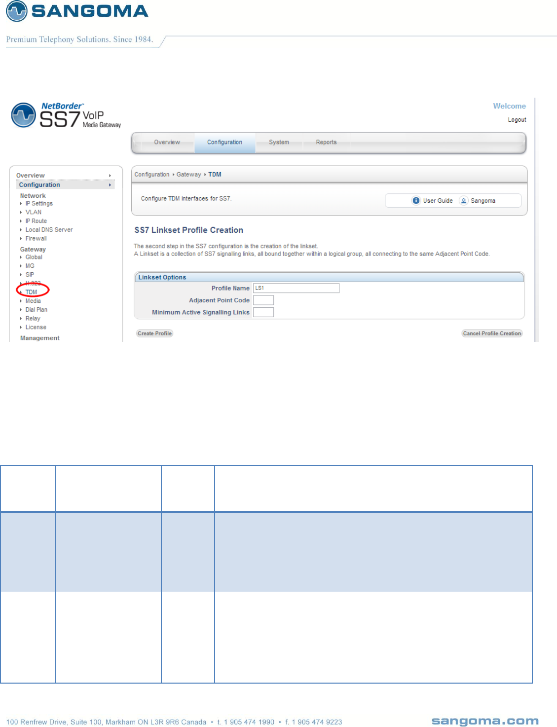
v1.14
116
Click on Create Profile once the configuration is completed.
NOTE
On very fist Linkset profile, the Link will automatically be BINDED to the Linkset.
Field
Name
Possible Values
Default
Value
Description
Profile
Name
Any String
LS1
Name to identify the SS7 Linkset. By default the GUI will select a
unique name.
However it is sometimes useful to specify a SS7 Linkset name that
relates to the remote destination.
Adjacent
Point
Code
If ITU
integer: 1 to X
If ANSI
three integers
separated by dash
Point-code is an SS7 address for an element in the SS7 network.
The Adjacent point is the SS7 equipment which the signaling links
terminate on. This equipment will also have a unique point code. This
equipment may be either STP equipment or SSP equipment
depending on type of interconnect

v1.14
117
If ITU
Single integer number: eg 500
If ANSI
Three integers separated by dash: eg 100-200-400
Please refer to your Telco provider for this information.
Minimum
Active
Signaling
Links
Integer 1-X
A Linkset can contain number of SS7 Links.
This field defines how data should be distributed across links in a
linkset.
For Round Robin – make the value equal number of links in a linkset
This mode will use all links equally. Recommended
For Active Standby –make the value 1 or
less than total number of links.
This mode will use the first link until it gets saturated.
And only use another link if necessary
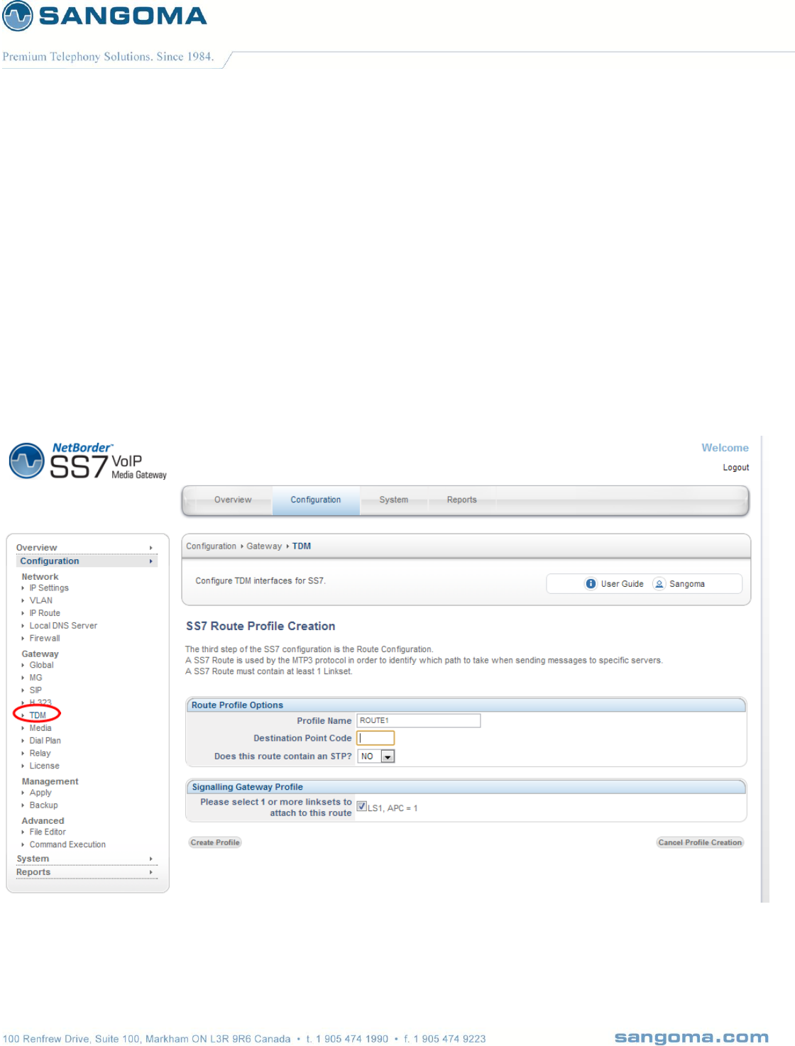
v1.14
118
9.8 MTP3 SS7 Route
Route is a collection of linksets to reach a particular destination. A linkset can belong to more than
one route. Service Provider personnel statically maintain signaling endpoint routing tables. The
routing table identifies the links, linksets, primary routes, and alternate routes for each DPC. All links
in the linkset share the traffic load equally.
After a successful Linkset configuration, NSG GUI will present a user with Route Configuration
screen.
If no Route profiles exist, user will be presented with Route create page.
If a Route profile already exists, user will be presented with Route profile list. Where user will
be able to either create new Route or edit existing Route profile.
NOTE
If a new linkset needs to be attached to a route, the user must edit the route, then add the new
linkset to that route.

v1.14
119
The user will only need to edit a route if a new linkset is created on the system. If no new
linksets are created, the user will proceed directly to the channel map and CIC map
configuration
Field
Name
Possible Values
Default
Value
Description
Profile
Name
Any String
ROUTE1
Name to identify the SS7 Route. By default the GUI will select a
unique name.
However it is sometimes useful to specify a SS7 Route name that
relates to the remote destination.
Destination
Point Code
If ITU
integer: 1 to X
If ANSI
three integers
separated by dash
Point-code is an SS7 address for an element in the SS7 network.
The Destination Point of the SS7 network defines the switching
equipment within the PSTN network which terminates the TDM
interfaces of this interconnect. This point is also allocated a unique
point-code within the SS7 network. If the adjacent point is a SSP or
MSC interconnect the destination point will be the same as the
adjacent point.
Eg:
A-Link = APC differs from DPC
F-Link = APC is equal to DPC
If ITU (outside North America)
Single integer number: eg 500
Default link type – F link
If ANSI (North America)
Three integers separated by dash: eg 100-200-400
Default link type – A link
Please refer to your Telco provider for this information.
Does route
contain
STP?
Yes or No
No
Signaling
Gateway
Profile List
List of existing Linksets that can be bound to a Route profile. There
has to be at least a single Linkset bound to a route.
In theory there can be a number of Linkset profiles bound a a single
route.

v1.14
120
9.9 ISUP Interface Configuration
ISUP connects, manages, and disconnects all voice and data calls in the PSTN. ISUP sets up and
tears down the circuits used to connect PSTN voice and data subscribers.. ISUP is used in cellular or
mobile networks for trunking connections.
ISUP information is transferred in MTP3 messages similar to the other L4 protocols. The ISUP
section covers the following topics:
ISUP ServicesBasic and Supplementary
End-to-end SignalingPass-along and SCCP
Call Setup and Teardown
ISUP Message Format
ISUP Call Control Messages
Like the linkset configuration and route configuration profiles, the ISUP Interface configuration is also
configured as profiles. It is setup so that 1 SS7 route can be attached to 1 ISUP Interface.
After a successful Route configuration, NSG GUI will present a user with Route Configuration screen.
If no ISUP profiles exist, user will be presented with ISUP create page.
If an ISUP profile already exists, user will be presented with ISUP profile list. Where user will
be able to either create new ISUP Interface Profile or edit existing ISUP Interface profile.
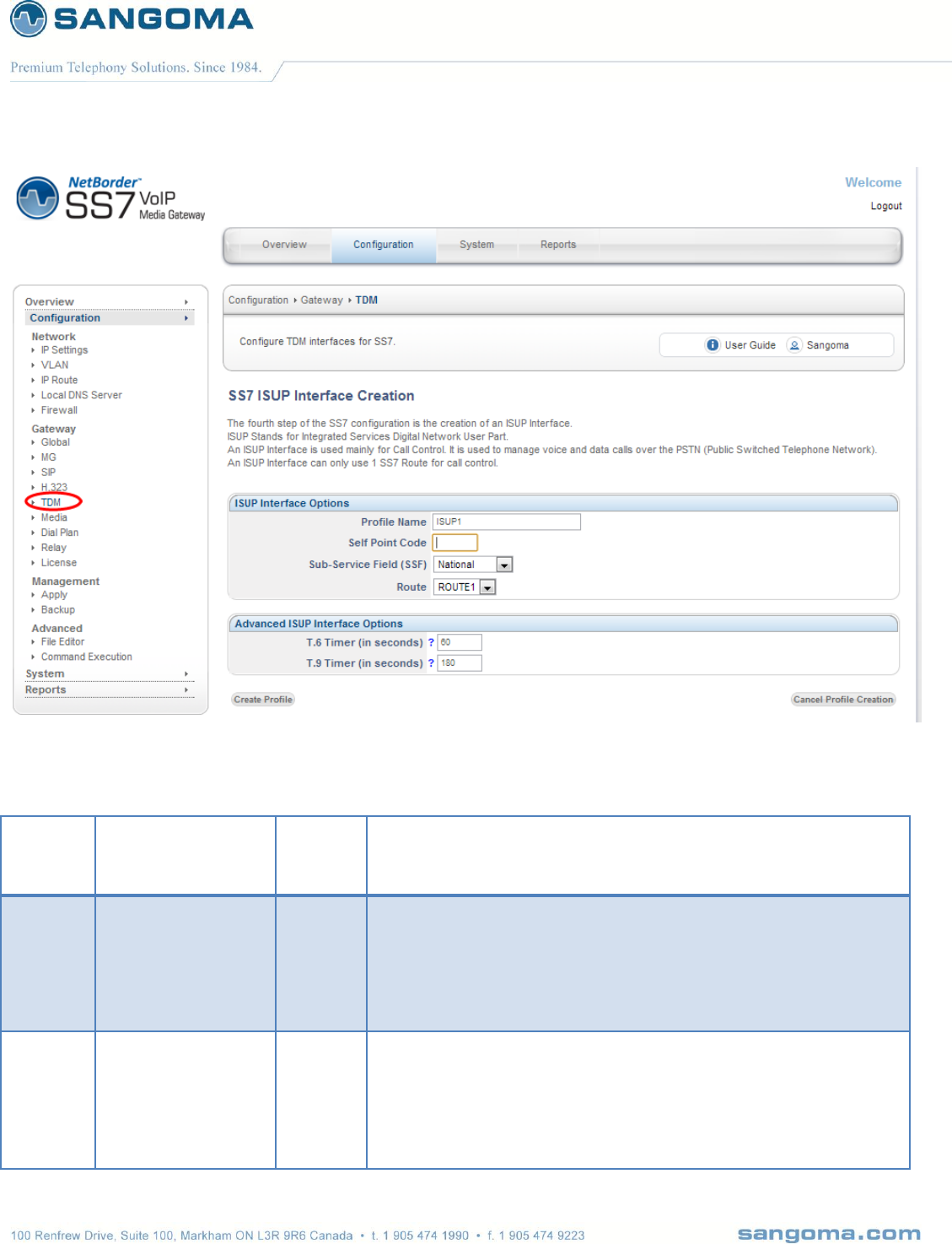
v1.14
121
Field
Name
Possible Values
Default
Value
Description
Profile
Name
Any String
ISUP1
Name to identify the SS7 ISUP Interface profile. By default the GUI
will select a unique name.
However it is sometimes useful to specify a SS7 ISUP Interface
name that relates to the remote destination.
Self
Point
Code
If ITU
integer: 1 to X
If ANSI
three integers
separated by dash
Point-code is an SS7 address for an element in the SS7 network.
The Self Point Code /Originating Point describes the equipment that is
interconnecting into the SS7 network. The originating point will be
provided with a unique point-code by the network provider allowing for
identification of this point with in the SS7 network.

v1.14
122
Sefl Point Code is the address of the NSG SS7 Gateway in the SS7
network.
If ITU (outside North America)
Single integer number: eg 500
If ANSI (North America)
Three integers separated by dash: eg 100-200-400
Please refer to your Telco provider for this information.
Sub
Service
Field
SSF
National
International
Spare
Reserved
National
Please confirm with your provider which value to use.
Route
List of existing Route profiles that can be bound to a Route profile.
There has to be a single Route bound to an ISUP Interface profile.
ISUP
Timer
Spec Value (s)
(ITU Q.764)
Default Value (s)
Timer Name
XML Tag for
Manual Control
T1
15-60
15
isup.t1
isup_interface
T2
180
180
isup.t2
isup_interface
T3
120
120
isup.t3
isup_interface
T4
300-900
300
isup.t4
isup_interface
T5
300-900
300
isup.t5
isup_interface
T6
60-120
60
isup.t6
isup_interface
T7
20-30
20
isup.t7
isup_interface
T8
10-15
10
isup.t8
isup_interface
T9
90-180
180
isup.t9
isup_interface
T10
4-6
4
isup.t10
isup_interface
T12
15-60 (ITU)
4-15(ANSI)
150
isup.t12
isup_interface
T13
300-900
300
isup.t13
isup_interface
T14
15-60
15
isup.t14
isup_interface
T15
300-900
300
isup.t15
isup_interface
T16
15-60
15
isup.t16
isup_interface
T17
300-900
300
isup.t17
isup_interface
T27
240
240
isup.t27
isup_interface
T31
360
360
isup.t31
isup_interface

v1.14
123
T33
12-15
12
isup.t33
isup_interface
T34
2-4
4
isup.t34
isup_interface
T35
15-20
15
isup.t35
isup_interface
T36
10-15
12
isup.t36
isup_interface
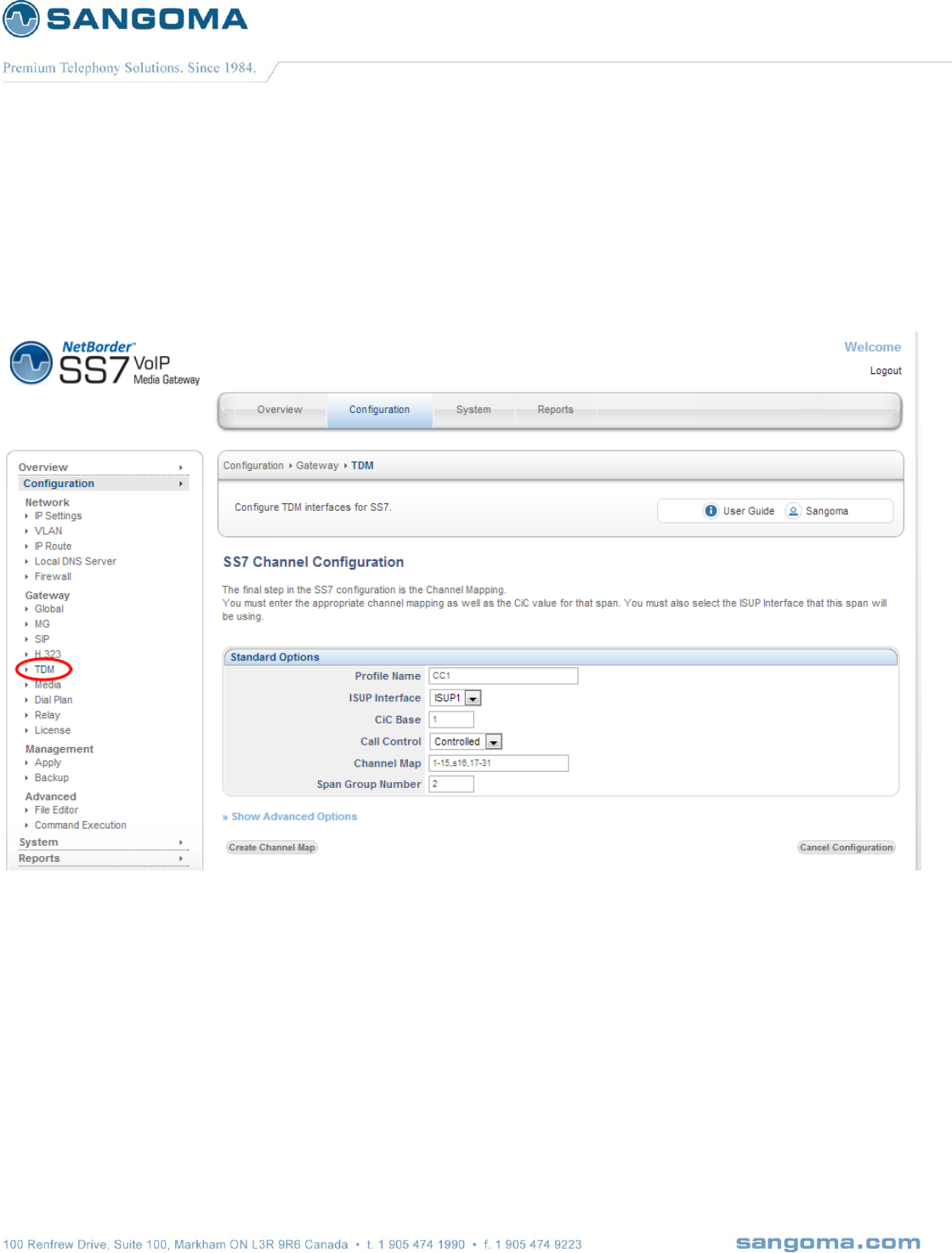
v1.14
124
9.10 ISUP CIC Channel Mapping
The last step of the configuration is to bind the TDM voice channels to ISUP Profile and map ISUP
CIC’s to the TDM timeslots.

v1.14
125
Field
Name
Possible Values
Default
Value
Description
Profile
Name
Any String
CC1
Name to identify the SS7 Call Control profile. By default the GUI will
select a unique name.
However it is sometimes useful to specify a SS7 ISUP Interface
name that relates to the remote destination.
ISUP
Interface
List of existing ISUP
Interface profiles
Current
Profile
ISUP Interface points to the list of currently defined ISUP Interface
profiles.
Each ISUP profile defines its own Self-Point-Code/Origination Code.
With multiple ISUP profiles, one can configure a system with multiple
Self-Point-Codes.
Selected ISUP Interface Profile will be used to control the physical
TDM T1/E1 DS0 channels.
CIC Base
Integer 1 to Any
1
Start of the ISUP CIC numbers. ISUP CIC numbers are logical
representations of the physical DS0 channels. The mapping between
CIC and DS0 channels is one to one.
This information is provided by the Telco.
CAUTION
Improper mapping between CIC and Physical T1/E1 DS0 can
result in one way or no audio. Even though the call completes
successfully on SS7 signaling.
Call
Control
Controlled
Controlling
Bothway
Incoming
Outgoing
Controlled
Refer to Telco information.
Channel
Map
List of channels to be controlled by ISUP Interface
Example: 1-15,s16,17-31
Channels 1-15 and 17-31 are used for Voice and should be controlled
by ISUP Interface
Channel 16 (prefixed by letters) indicates that channel 16 carries
signaling channel. ISUP Interface will ignore this channel as it’s not
voice.

v1.14
126
Prefix Letters to signaling channel:
s: ISUP CIC id not used, id mapped to signaling channel
g: ISUP CIC id is used, id mapped to next available
voice channel.
The bind between ISUP and TDM would be as follows
Channel Map: 1—31 (no signaling channel)
CIC 1: channel 1
CIC 2: channel 2
…
CIC 16: channel 16
…
CIC 30: channel 30
CIC 31; channel 31
Channel Map: 1-15,s16,17-31 (signaling on ch 16)
CIC 1: channel 1
CIC 2: channel 2
…
CIC 15: channel 15
…
CIC 16: not used – A16 points to signaling channel 16
CIC 17: channel 17
CIC 18: channel 18
…
CC 31: channel 31
Channel Map: 1-15,g16,17-31 (signaling on ch 16)
CIC 1: channel 1
CIC 2: channel 2
CIC 15: channel 15
CIC 16: channel 17 - A16 is used and it points to ch 17.
CIC 17: channel 18
…
CIC 30: channel 31
Span
Group
Number
Integer
1
Default group number used to dial out over a trunk group.
Usually the group number will correspond to the trunk group.
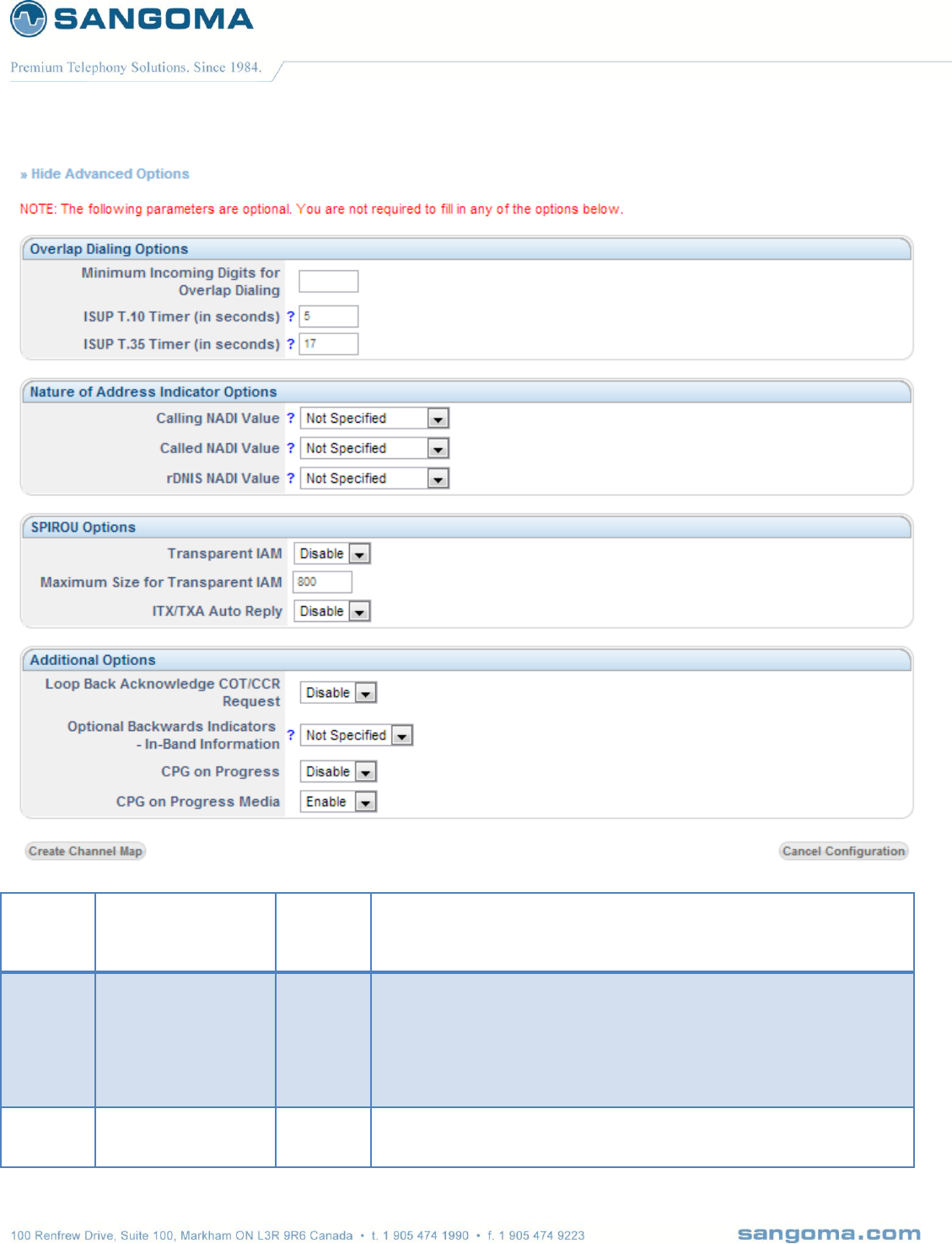
v1.14
127
Field
Name
Possible Values
Default
Value
Description
Minimum
Incoming
Overlap
Dialing
Integer
Enables overlap dialing in ISUP.
ISUP
Interface
List of existing ISUP
Interface profiles
Current
Profile
ISUP Interface points to the list of currently defined ISUP Interface
profiles.

v1.14
128
Each ISUP profile defines its own Self-Point-Code/Origination Code.
With multiple ISUP profiles, one can configure a system with multiple
Self-Point-Codes.
Selected ISUP Interface Profile will be used to control the physical
TDM T1/E1 DS0 channels.
CIC Base
Integer 1 to Any
1
Start of the ISUP CIC numbers. ISUP CIC numbers are logical
representations of the physical DS0 channels. The mapping between
CIC and DS0 channels is one to one.
This information is provided by the Telco.
CAUTION
Improper mapping between CIC and Physical T1/E1 DS0 can
result in one way or no audio. Even though the call completes
successfully on SS7 signaling.
Call
Control
Controlled
Controlling
Bothway
Incoming
Outgoing
Controlled
Refer to Telco information.
Channel
Map
List of channels to be controlled by ISUP Interface
Example: 1-15,s16,17-31
Channels 1-15 and 17-31 are used for Voice and should be controlled
by ISUP Interface
Channel 16 (prefixed by letters) indicates that channel 16 carries
signaling channel. ISUP Interface will ignore this channel as it’s not
voice.
Prefix Letters to signaling channel:
s: ISUP CIC id not used, id mapped to signaling channel
g: ISUP CIC id is used, id mapped to next available
voice channel.
The bind between ISUP and TDM would be as follows
Channel Map: 1—31 (no signaling channel)
CIC 1: channel 1
CIC 2: channel 2
…
CIC 16: channel 16
…
CIC 30: channel 30
CIC 31; channel 31

v1.14
129
Channel Map: 1-15,s16,17-31 (signaling on ch 16)
CIC 1: channel 1
CIC 2: channel 2
…
CIC 15: channel 15
…
CIC 16: not used – A16 points to signaling channel 16
CIC 17: channel 17
CIC 18: channel 18
…
CC 31: channel 31
Channel Map: 1-15,g16,17-31 (signaling on ch 16)
CIC 1: channel 1
CIC 2: channel 2
CIC 15: channel 15
CIC 16: channel 17 - A16 is used and it points to ch 17.
CIC 17: channel 18
…
CIC 30: channel 31
Span
Group
Number
Integer
1
Default group number used to dial out over a trunk group.
Usually the group number will correspond to the trunk group.

v1.14
130
10 Relay: SS7
NSG SS7 relay enables a single NSG gateway (master) to control multiple NSG gateways (slaves)
with as little as 1 signaling link connected to the master.
You can have up to 8 slave machines that are controlled by a single master gateway. Signaling
messages (MTP2 traffic) are passed over the IP network to the slave machines.
Having to configure up to 8 machines individually would be a tedious task from an operations
perspective. In order to simplify the configuration process of this distributed system, the relay option
enables the Master gateway to configure all the slaves machine from its web UI and pushing the
configurations to the slave gateways over SSH.
This following section will guide you through the configuration of the Relay mode to enable remote
control of the Slave gateways.

v1.14
131
10.1 Relay Configuration
To access the Relay: SS7 configuration section
1. Select Relay from side/top Configuration Menu
Select NO if you do not want to enable Relay mode in your installation and proceed to the
next section to resume SS7 configuration.
Select YES to activate the relay Mode
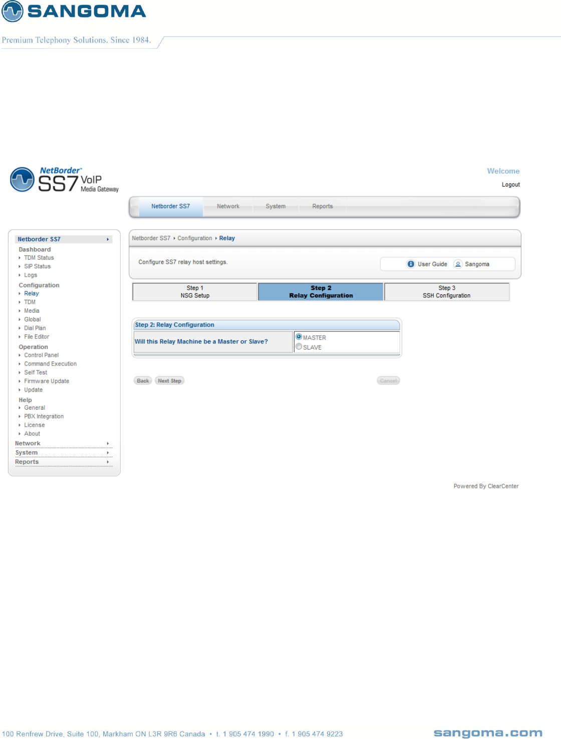
v1.14
132
10.1.1 Configuring the master gateway
We will start by configuring the master machine first.
Select the Master option in step 2 and click "Next Step" to continue.
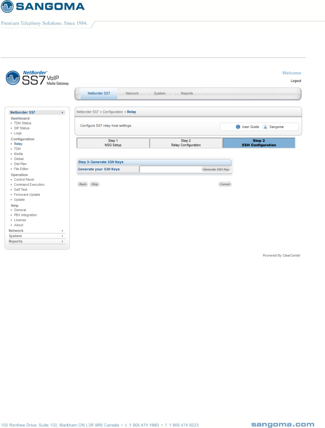
v1.14
133
In Step 3, you will generate an SSH key and download the public key that will be uploaded to all the
slave gateways. This key will enable a secure SSH connection between the master and the slave
machines to push the configurations.
The Relay Master will listen for incoming relay traffic on port 5000.
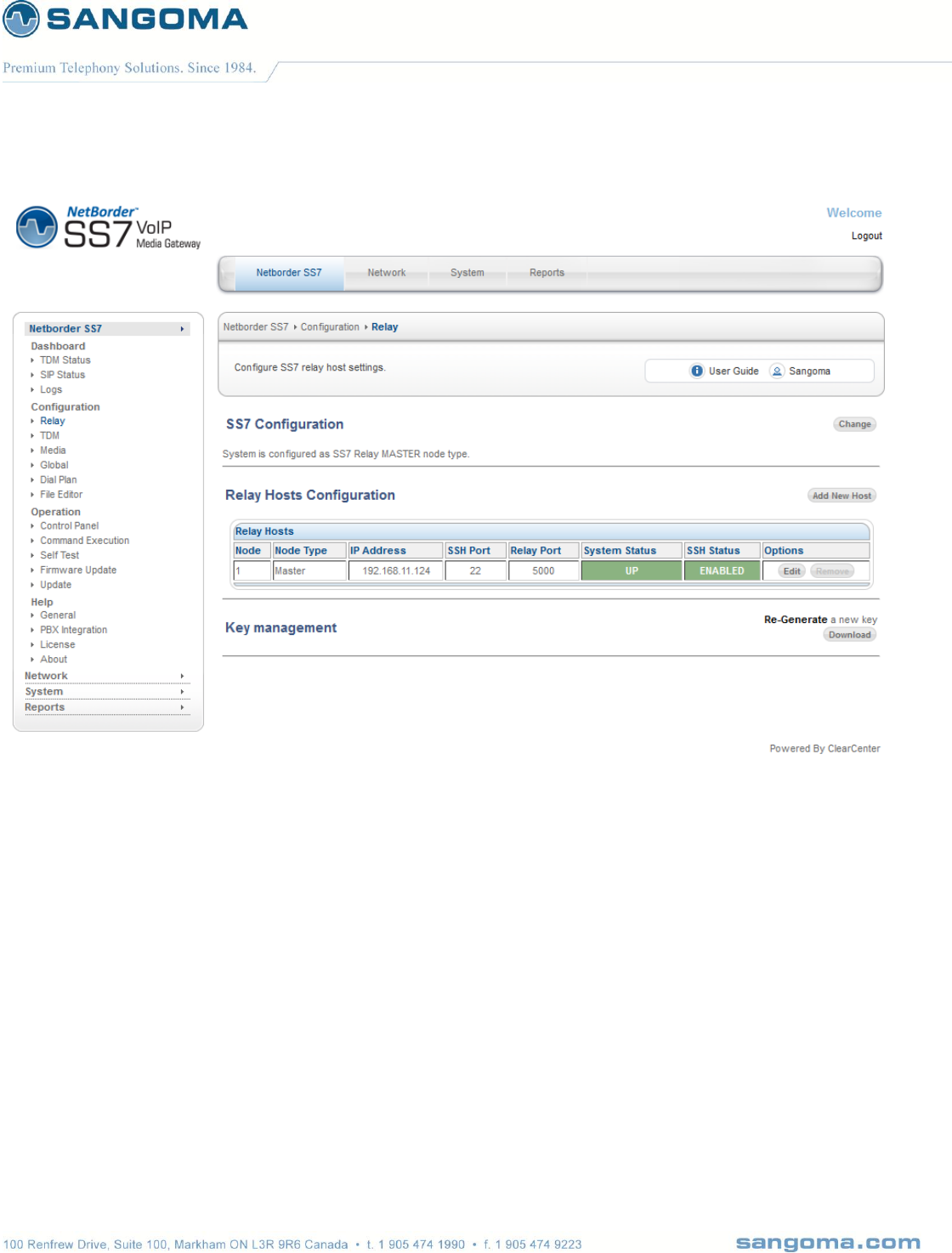
v1.14
134
Once the SSH key has been generated you will need to click on the "Add New Host" button to add 1
or more slave gateways to the relay configuration.
The listening relay port for all subsequent slave instances will increase by 1 port. Slave on node 2 will
listen on port 5001, Slave on node 3 will listen on port 5002, etc...
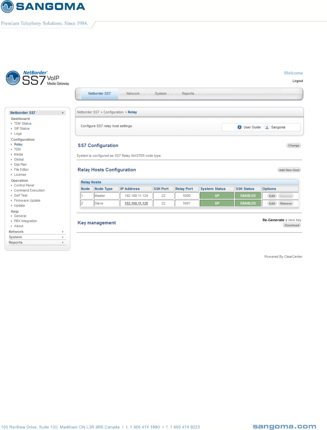
v1.14
135
Once you have configured all your slave hosts, you can now configure your slave machine(s)

v1.14
136
10.1.2 Configuring the slave gateway
To access the Relay: SS7 configuration section
1. Select Relay from side/top Configuration Menu
Select YES in step 1 to enable Relay mode.
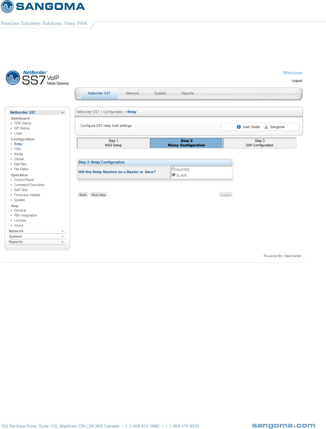
v1.14
137
Select the SLAVE option in step 2 and click "Next Step" to continue.
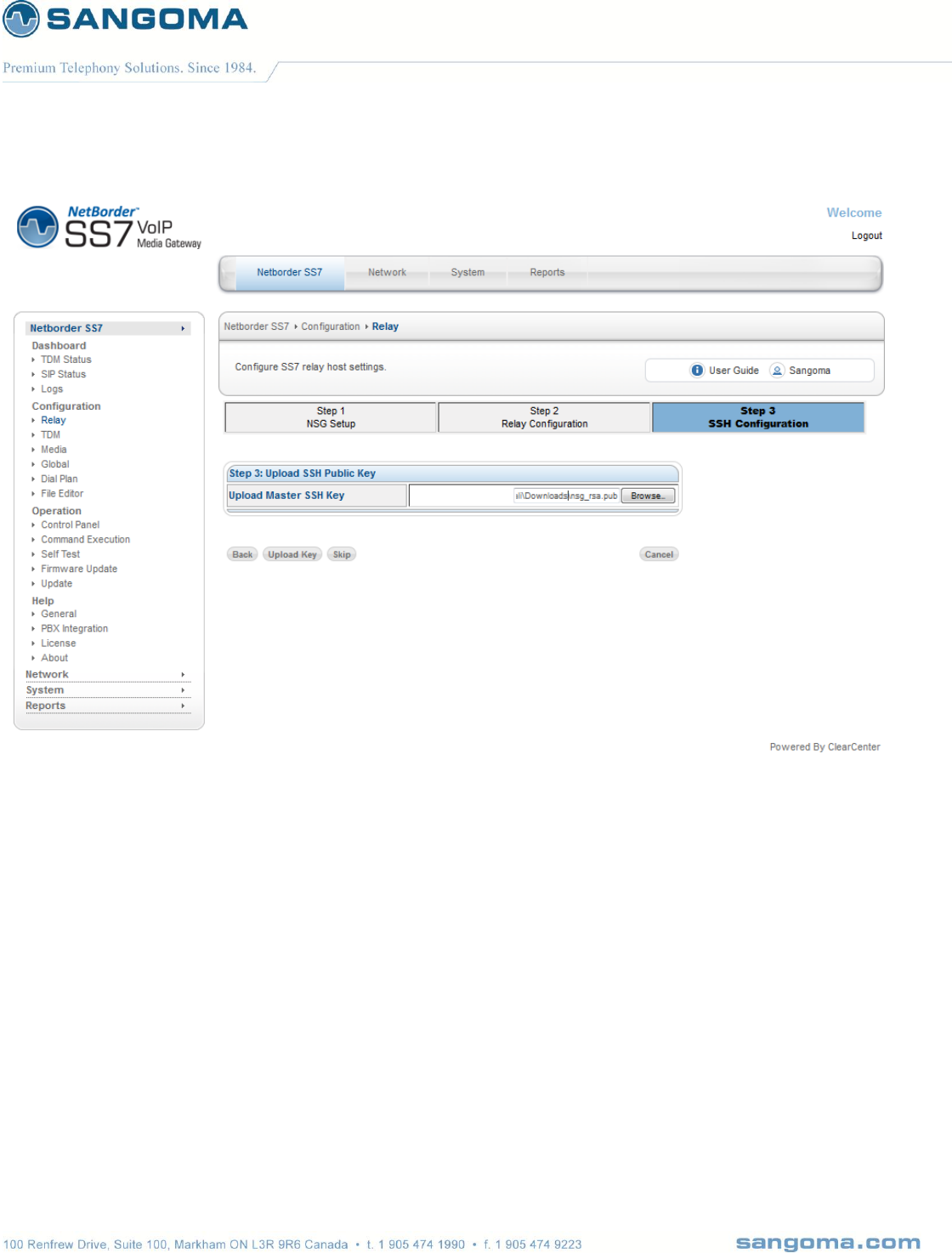
v1.14
138
Upload the public key that you downloaded and saved when you configured the master gateway
earlier.

v1.14
139
Once the key has been uploaded, the SSH link will have been enabled.
Repeat these steps for all the slave machines and return to the master WebUI when you are
finished.
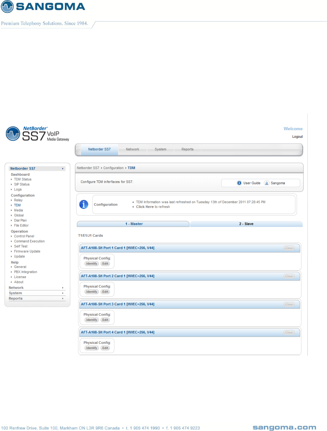
v1.14
140
10.1.3 Configuring the slave TDM configurations from the master gateway
Open the master WebUI in your browser.
1. Select TDM from side/top Configuration Menu
The TDM configuration is presented in a tabbed pane, each tab represents a machine to configure.
Select the Slave tab to configure the slave gateway.
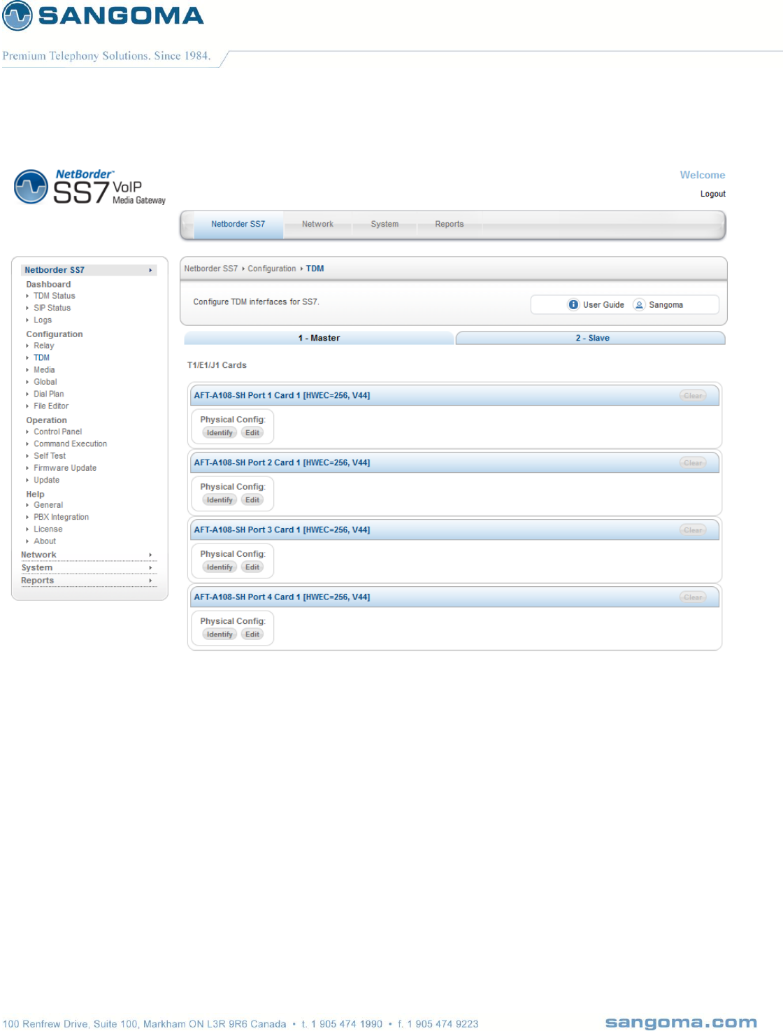
v1.14
141
Once you have completed configuring the master and slave(s) TDM configurations, you will click on
the "Generate config" button that will push the configuration to each slave over a secure SSH
connection. All this is done from the convenience of the master server's WebUIgateway’s web gui,
removing the need to log on to each slave server's WebUIgateway’s individually.
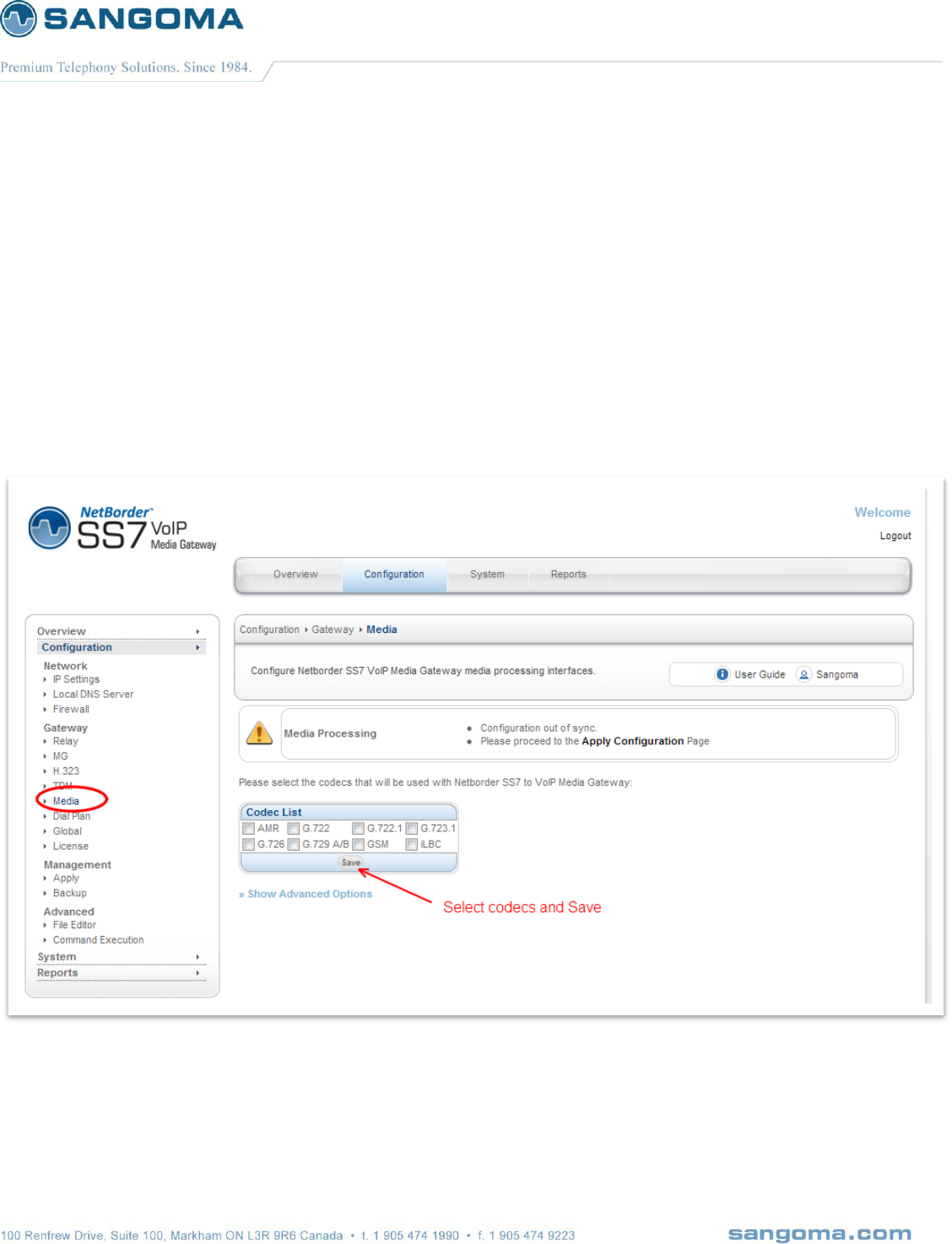
v1.14
142
11 Media Transcoding Configuration
NSG will enable ALL Media Codec’s by default. There is no extra configuration needed.
Use this configuration page in case you want to limit which codecs should be enabled, or disable
media codec support.
To access NSG Media Transcoding Configuration
Select Media from side/top Configuration Menu
Select any or all supported/listed codecs
Once done press Save
NOTE
At this point the codec selection is over. One can proceed to Media hardware discovery in the
Advanced Options of the Media page.
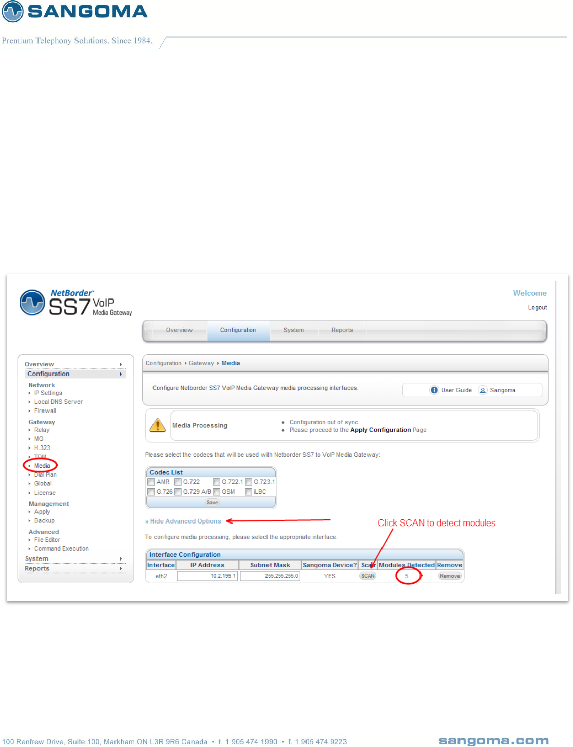
v1.14
143
11.1 Media Hardware
Once Codec selection has been made, proceed to Advanced Options section of the Media page.
Select SCAN
o This step will auto-detect all NSG transcoding resources
Confirm that GUI detected exact number of transcoding resources as installed.
User has an option of changing the assigned Local IP address of the Media device.
NOTE
At this point the Media configuration is complete.
Proceed to the next section, or
If finished all gateway configuration, proceed to Apply to generate configs.
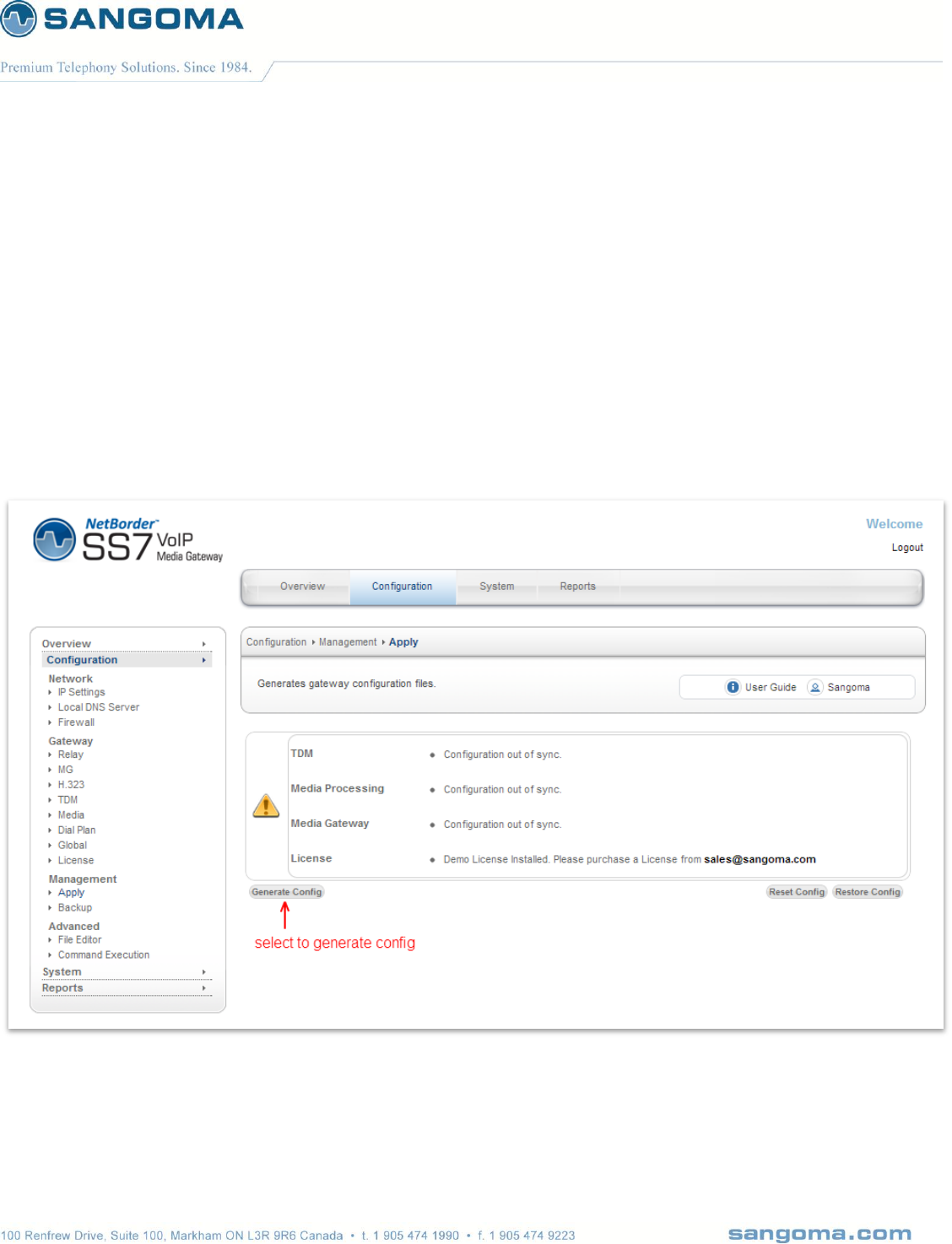
v1.14
144
12 Applying Configuration
The changes made in the Configuration section of the WebUI are only stored one the scratch disk.
User MUST proceed to Apply page in the Management Section to save new configuration.
Select Apply from side/top Configuration Menu
Visually confirm the warnings
o License warning need to be resolved with Sales
Select Generate Config to apply the configuration to file/disk.
o Generate Config will generate all necessary NSG SS7 VoIP Gateway configuration files
needed to successful start the NSG gateway.
CAUTION:
The generate config option will not be offered in case NSG gateway is started. Confirm that
NSG is fully stopped in Control Panel before Applying configuration.

v1.14
145
NOTE
After configuring the NSG endpoint/protocol configuration, proceed to Dialplan to configure the
routing rules.
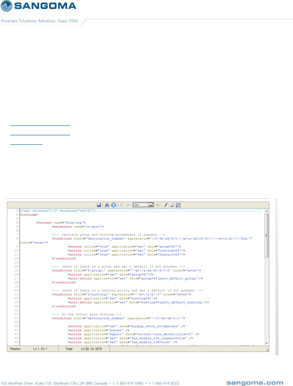
v1.14
146
13 Dialplan
When a call is received in the NetBorder SS7 Gateway, from SIP,H232 or SS7 the dialplan is fetched
to retrieve the route information to find the outgoing call location.
Note: Dialplan is not used in MG/Megaco/H.248 mode: MGC performs the routing.
PSTN to SIP Dialplan
SIP to PSTN Dialplan
References
To access Dialplan configuration section
Select Dialplan from side/top Configuration Menu
Change a variable and Click on Save (Disk Icon)
Proceed to Control Panel and Restart the VoIP Gateway.

v1.14
147
Dialplan is pre-configured for
SIP to TDM and TDM to SIP Bridging.
Section "from-sip" routes calls from SIP to PSTN/SS7
Section "from-pstn" routes calls from PSTN/SS7 to SIP.
H.323 to TDM and TDM to H.323 Bridging
Section “from-h323” routes calls from H.323 to PSTN
13.1 Dialplan Reload/Apply
Note that Dialplan can be modified in real time without the need to restart the gateway.
Once you Save the Dialplan, you will be prompted to Reload the gateway which will apply the
changes without any service interrupt. All the currently established calls will not be affected. Only the
newly established calls will start using the new dialplan rules.

v1.14
148
13.2 PSTN to SIP Dialplan
By default NSG is setup to send an call to a SIP IP address. The remote SIP address must be
configured in Configuration -> Global section.
<context name="from-pstn-to-sip">
<extension name="to-sip">
<!-- handle the case where there might not be destination number at all -->
<condition field="destination_number" expression="^(.{1,})$" break="never">
<action application="set" data="destnumber=$1"/>
<anti-action application="set" data="destnumber=unknown"/>
</condition>
<!-- Dial to the gateway user (it may ring multiple registrations, first answer wins) -->
<condition field="destination_number" expression="^(.*)$">
<action application="set" data="hangup_after_bridge=yes" />
<action application="set" data="tone_detect_hits=1" />
<action application="export" data="fax_enable_t38_request=true" />
<action application="export" data="fax_enable_t38=true" />
<action application="tone_detect" data="faxdisable 1100 r +5000 disable_ec 1"/>
<action application="export" data="execute_on_answer=tone_detect fax_disable_ec 2100 r +5000
t38_gateway 'self nocng'" />
<action application="set" data="sip_contact_user_replacement=${destnumber}"/>
<action application="set" data="hangup_after_bridge=yes"/>
<action application="bridge" data="sofia/internal/${destnumber}@${sip_dest_ip}:${sip_dest_port}"/>
<action application="hangup" data="${originate_disposition}"/>
</condition>
</extension>
</context>

v1.14
149
13.3 PSTN to H323 Dialplan
By default NSG is setup to send a call to an H323 IP address. The remote H323 address must be
configured in Configuration -> Global section.
<context name="from-pstn-to-h323">
<extension name="to-h323">
<!-- handle the case where there might not be destination number at all -->
<condition field="destination_number" expression="^(.{1,})$" break="never">
<action application="set" data="destnumber=$1"/>
<anti-action application="set" data="destnumber=unknown"/>
</condition>
<!-- Dial to the gateway user (it may ring multiple registrations, first answer wins) -->
<condition field="destination_number" expression="^(.*)$">
<action application="set" data="hangup_after_bridge=yes" />
<action application="set" data="tone_detect_hits=1" />
<action application="export" data="fax_enable_t38_request=true" />
<action application="export" data="fax_enable_t38=true" />
<action application="tone_detect" data="faxdisable 1100 r +5000 disable_ec 1"/>
<action application="export" data="execute_on_answer=tone_detect fax_disable_ec 2100 r +5000
t38_gateway 'self nocng'" />
<action application="set" data="sip_contact_user_replacement=${destnumber}"/>
<action application="set" data="hangup_after_bridge=yes"/>
<action application="bridge" data="opal/h323:${destination_number}@${h323_remote_ip}"/>
<action application="hangup" data="${originate_disposition}"/>
</condition>
</extension>
</context>
</include>

v1.14
150
13.4 SIP/H323 to PSTN Dialplan
Note that both SIP and H323 profiles share the same “from-sip” context name name. The from-sip
context will pass all calls to TDM interfaces.
<?xml version="1.0" encoding="utf-8"?>
<include>
<context name="from-sip">
<extension name="to-pstn">
<!-- retrieve group and hunting parameters if present -->
<condition field="destination_number" expression="([0-9a-zA-Z]+)(-g=[a-zA-Z0-9]+)?(-h=[a|A])?(-fax)?"
break="never">
<action inline="true" application="set" data="group=$2"/>
<action inline="true" application="set" data="hunting=$3"/>
<action inline="true" application="set" data="faxcall=$4"/>
</condition>
<!-- check if there is a group and set a default if not present -->
<condition field="${group}" expression="^-g=([a-zA-Z0-9]+)$" break="never">
<action application="set" data="group=$1"/>
<anti-action application="set" data="group=$${pstn_default_group}"/>
</condition>
<!-- check if there is a hunting policy and set a default if not present -->
<condition field="${hunting}" expression="^-h=([a|A])$" break="never">
<action application="set" data="hunting=$1"/>
<anti-action application="set" data="hunting=${pstn_default_hunting}"/>
</condition>
<!-- Do the actual pstn dialing -->
<condition field="destination_number" expression="^([0-9a-zA-Z]+)">
<action application="set" data="hangup_after_bridge=yes" />
<action application="answer" />
<action application="export" data="nolocal:tone_detect_hits=1" />
<action application="set" data="fax_enable_t38_request=true" />
<action application="set" data="fax_enable_t38=true" />
<action application="export" data="nolocal:execute_on_answer_1=tone_detect fax_disable_ec
2100 r +5000 disable_ec 1" />
<action application="export" data="nolocal:execute_on_answer_2=t38_gateway peer
ced_preamble" />
<action application="set" data="hangup_after_bridge=yes"/>
<action application="bridge" data="freetdm/${group}/${hunting}/$1"/>
<action application="hangup" data="${originate_disposition}"/>
</condition>
</extension>
</context>

v1.14
151
13.5 Dialplan Syntax
There are several elements used to build an XML dialplan. In general, the dialplan groups logically
similar functions and calling activities into a 'context'. Within a context are extensions, each with
'condition' rules and associated 'actions' to perform when the condition rules match.
The following is a sample dialplan to illustrate these concepts. We have left out the XML "wrapper" to
help make the basic concepts more clear:
<context name="example">
<extension name="500">
<condition field="destination_number" expression="^500$">
<action application="bridge" data="user/500"/>
</condition>
</extension>
<extension name="501">
<condition field="destination_number" expression="^501$">
<action application="bridge" data="user/501"/>
<action application="answer"/>
<action application="sleep" data="1000"/>
<action application="bridge" data="loopback/app=voicemail:default ${domain_name} ${dialed_extension}"/>
</condition>
</extension>
</context>
Each rule is processed in order until you reach the action tag which tells NSG what action to perform.
You are not limited to only one condition or action tag for a given extension.
In our above example, a call to extension 501 rings the extensions. If the user does not answer, the
second action answers the call, and following actions delay for 1000 milliseconds (which is 1 second)
and connect the call to the voicemail system.

v1.14
152
13.5.1 Context
Contexts are a logical grouping of extensions. You may have multiple extensions contained within a
single context.
The context tag has a required parameter of 'name'. There is one reserved name, any, which
matches any context. The name is used by incoming call handlers (like the [Sofia] SIP driver) to
select the dialplan that runs when it needs to route a call. There is often more than one context in a
dialplan.
A fully qualified context definition is shown below. Typically you'll not need all the trimmings, but they
are shown here for completeness.
<?xml version="1.0"?>
<document type="freeswitch/xml">
<section name="dialplan" description="Regex/XML Dialplan">
<!-- the default context is a safe start -->
<context name="default">
<!-- one or more extension tags -->
</context>
<!-- more optional contexts -->
</section>
</document>

v1.14
153
13.5.2 Extensions
Extensions are destinations for a call. This is the meat of NSG routing dialed numbers. They are
given a name and contain a group of conditions, that if met, will execute certain actions.
A 'name' parameter is required: It must be a unique name assigned to an extension for identification
and later use.
For example:
<extension name="Your extension name here">
<condition(s)...
<action(s) .../>
</condition>
</extension>
NOTE: Typically when an extension is matched in your dialplan, the corresponding actions are
performed and dialplan processing stops. An optional continue parameter allows your dialplan to
continue running.
<extension name="500" continue="true">

v1.14
154
13.5.3 Conditions
Dialplan conditions are typically used to match a destination number to an extension. They have,
however, much more power than may appear on the surface.
NSG has a set of built-in variables used for testing. In this example, the built-in
variable destination_number is compared against the regular expression ^500$.
This comparison is 'true' if <destination_number> is set to 500.
<extension name="500">
<condition field="destination_number" expression="^500$">
<action application="bridge" data="user/500"/>
</condition>
</extension>
Each condition is parsed with the Perl Compatible Regular Expression library. (go here for PCRE
syntax information).
If a regular expression contains any terms wrapped in parentheses, and the expression matches, the
variables $1,$2..$N will be set to the matching contents within the parenthesis, and may be used in
subsequent action tags within this extension's block.
For example, this simple expression matches a four digit extension number, and captures the last two
digits into $1.
<condition field="destination_number" expression="^\d\d(\d\d)$">
<action application="bridge" data="sofia/internal/$1@example.com"/>
</condition>
A destination number of 3425 would set $1 to 25 and then bridge the call to the phone
at 25@example.com

v1.14
155
13.5.4 Multiple Conditions (Logical AND)
You can emulate the logical AND operation available in many programming languages using multiple
conditions. When you place more than one condition in an extension, all conditions must match
before the actions will be executed. For example, this block will only execute the actions if the
destination number is 500 AND it is Sunday.
<condition field="destination_number" expression="^500$"/>
<condition wday="1">
action(s)...
</condition>
Keep in mind that you must observe correct XML syntax when using this structure. Be sure to close
all conditions except the last one with />. The last condition contains the final actions to be run, and is
closed on the line after the last action.
By default, if any condition is false, NSG will move on to the anti-actions or the next extension without
even evaluating any more conditions.

v1.14
156
13.5.5 Multiple Conditions (Logical OR, XOR)
It is possible to emulate the logical OR operation available in many programming languages, using
multiple conditions. In this situation, if one of the conditions matches, the actions are executed.
For example, this block executes its actions if the destination number is 501 OR the destination
number is 502.
<condition field="destination_number" expression="^501|502$">
action(s)...
</condition>
This method works well if your OR condition is for the same field. However, if you need to use two or
more different fields then use the new regex syntax
<extension name="Regex OR example 1" continue="true">
<condition regex="any">
<!-- If either of these is true then the subsequent actions are added to execute list -->
<regex field="caller_id_name" expression="Some User"/>
<regex field="caller_id_number" expression="^1001$"/>
<action application="log" data="INFO At least one of the conditions matched!"/>
<!-- If *none* of the regexes is true then the anti-actions are added to the execute list -->
<anti-action application="log" data="WARNING None of the conditions matched!"/>
</condition>
</extension>
Using this method it becomes easier to match the caller's name OR caller ID number and execute
actions whether either is true.
A slightly more advanced use of this method is demonstrated here:
<extension name="Regex OR example 2" continue="true">
<condition regex="any" break="never">
<regex field="caller_id_name" expression="^Michael\s*S?\s*Collins"/>
<regex field="caller_id_number" expression="^1001|3757|2816$"/>
<action application="set" data="calling_user=mercutioviz" inline="true"/>
<anti-action application="set" data="calling_user=loser" inline="true"/>
</condition>
<condition>
<action application="answer"/>

v1.14
157
<action application="sleep" data="500"/>
<action application="playback" data="ivr/ivr-welcome_to_freeswitch.wav"/>
<action application="sleep" data="500"/>
</condition>
<condition field="${calling_user}" expression="^loser$">
<action application="playback" data="ivr/ivr-dude_you_suck.wav"/>
<anti-action application="playback" data="ivr/ivr-dude_you_rock.wav"/>
</condition>
</extension>
<extension name="Regex XOR example 3" continue="true">
<condition regex="xor">
<!-- If only one of these is true then the subsequent actions are added to execute list -->
<regex field="caller_id_name" expression="Some User"/>
<regex field="caller_id_number" expression="^1001$"/>
<action application="log" data="INFO Only one of the conditions matched!"/>
<!-- If *none* of the regexes is true then the anti-actions are added to the execute list -->
<anti-action application="log" data="WARNING None of the conditions matched!"/>
</condition>
</extension>
Basically, for this new syntax you can have a condition to have a "regex" attr instead of "field" and
"expression" etc. When there is a "regex" attr, that means you plan to have one or more <regex> tags
that are similar to the condition tag itself that it has field and expression in it.
The value of the "regex" attr is either "all" or "any" or "xor indicating if all expressions must match or
just any expression or only one must match(xor) . If it's set to "any" it will stop testing the regex tags
as soon as it finds one match, if it is set to "all", it will stop as soon as it finds one failure.
From there it will behave like a normal condition tag either executing the actions or anti-actions and
breaking based on the "break" attr.
The basic difference here is once there is a "regex" attr, the <regex> tags parsed for "all" or "any"
take the place of the single "field" and "condition"
NOTE: Also, if any captures are done in the "expression" attrs of a <regex> tag, only the data from
the newest capture encountered will be considered in the $n expansion or FIELD_DATA creation. In
addition, you can set DP_REGEX_MATCH_1 .. DP_REGEX_MATCH_N to preserve captures into
arrays.
<extension name="Inbound_external">

v1.14
158
<condition regex="any">
<regex field="${sip_from_host}" expression="domainA"/>
<regex field="${sip_from_uri}" expression="1234567890@domainB"/>
<regex field="${sip_from_uri}" expression="user@domainC"/>
<regex field="caller_id_name" expression="^(John Smith)$"/>
<regex field="caller_id_number" expression="^(55512341)|(55512342)|(55512343)$"/>
<action application="set" data="domain_name=domainZ"/>
<action application="transfer" data="${destination_number} XML domainZ"/>
</condition>
</extension>
This is another example to show that all regex conditions must be true, then the action will get
executed; otherwise, the anti-action will. This is the same logic as follows:
IF (cond1 AND cond2 AND cond3) THEN
do actions
ELSE
do other actions
ENDIF
Basically, the <condition regex="all"> tells the parser, "Hey, execute the <action>'s only if all regexes
PASS, otherwise execute any <anti-action>'s".
<condition regex="all">
<regex field="${sip_gateway}" expression="^${default_provider}$"/>
<regex field="${emergency_call}" expression="^true$"/>
<regex field="${db(select/emergency/autoanswer)}" expression="^1$"/>
<!-- the following actions get executed if all regexes PASS -->
<action application="set" data="call_timeout=60"/>
<action application="set" data="effective_caller_id_name=${regex(${caller_id_name}|^Emerg(_.*)$|Auto%1)}"/>
<action application="set" data="autoanswered=true"/>
<action application="bridge" data="user/1000@${domain_name},sofia/gateway/1006_7217/${mobile_number}"/>
<!-- the following anti-actions are executed if any of the regexes FAIL -->
<anti-action application="set" data="effective_caller_id_name=${regex(${caller_id_name}|^Emerg(_.*)$|NotAuto%1)}"/>
<anti-action application="set" data="call_timeout=30"/>
<anti-action application="set" data="autoanswered=false"/>

v1.14
159
<anti-action application="bridge" data="user/1000@${domain_name},sofia/gateway/1006_7217/${mobile_number}"/>
</condition>
13.5.6 Complex Condition/Action Rules
Here is a more complex example, performing time-based routing for a support organization. The user
dials extension 1100. The actual support extension is 1105 and is staffed every day from 8am to
10pm, except Friday, when it is staffed between 8am and 1pm. At all other times, calls to 1100 are
sent to the support after-hours mailbox.
<extension name="Time-of-day-tod">
<!--if this is false, FreeSWITCH skips to the next *extension*.-->
<condition field="destination_number" expression="^1100$" break="on-false"/>
<!--Don't bother evaluating the next condition set if this is true.-->
<condition wday="6" hour="8-12" break="on-true"> <!--Fri, 8am-12:59pm-->
<action application="transfer" data="1105 XML default"/>
</condition>
<condition wday="1-5" hour="8-21" break="on-true"> <!--Sunday-Thursday, 8am-9:59pm-->
<action application="transfer" data="1105 XML default"/>
</condition>
<condition> <!--this is a catch all, sending the call to voicemail at all other times. -->
<action application="voicemail" data="default ${domain} 1105"/>
</condition>
</extension>
In this example, we use the break=never parameter to cause the first condition to 'fall-through' to the
next condition no matter if the first condition is true or false. This is useful to set certain flags as part

v1.14
160
of extension processing. This example sets the variable begins_with_one if the destination number
begins with 1.
<extension name="break-demo">
<!-- because break=never is set, even when the destination does not begin
with 1, we skip the action and keep going -->
<condition field="destination_number" expression="^1(\d+)$" break="never">
<action application="set" data="begins_with_one=true"/>
</condition>
<condition field="destination_number" expression="^(\d+)$">
...other actions that may query begins_with_one...
</condition>
</extension>

v1.14
161
13.5.7 Variables
Condition statements can match against channel variables, or against an array of built in variables.
13.5.7.1 Built-In Variables
The following variables, called 'caller profile fields', can be accessed from condition statements
directly:
context Why can we use the context as a field? Give us examples of usages please.
rdnis Redirected Number, the directory number to which the call was last presented.
destination_number Called Number, the number this call is trying to reach (within a given context)
dialplan Name of the dialplan module that are used, the name is provided by each dialplan module. Example: XML
caller_id_name Name of the caller (provided by the User Agent that has called us).
caller_id_number Directory Number of the party who called (caller) -- can be masked (hidden)
ani Automatic Number Identification, the number of the calling party (caller) -- cannot be masked
aniii The type of device placing the call ANI2
uuid Unique identifier of the current call? (looks like a GUID)
source Name of the FreeSWITCH module that received the call (e.g. PortAudio)
chan_name Name of the current channel (Example: PortAudio/1234). Give us examples when this one can be used.
network_addr IP address of the signaling source for a VoIP call.
year Calendar year, 0-9999
yday Day of year, 1-366
mon Month, 1-12 (Jan = 1, etc.)
mday Day of month, 1-31
week Week of year, 1-53
mweek Week of month, 1-6
wday Day of week, 1-7 (Sun = 1, Mon = 2, etc.) or "sun", "mon", "tue", etc.
hour Hour, 0-23
minute Minute (of the hour), 0-59
minute-of-day Minute of the day, (1-1440) (midnight = 1, 1am = 60, noon = 720, etc.)
time-of-day Time range formatted: hh:mm[:ss]-hh:mm[:ss] (seconds optional) Example: "08:00-17:00"
date-time Date/time range formatted: YYYY-MM-DD hh:mm[:ss]~YYYY-MM-DD hh:mm[:ss] (seconds optional, note
tilde between dates) Example: 2010-10-01 00:00:01~2010-10-15 23:59:59

v1.14
162
For example:
<condition field="network_addr" expression="^192\.168\.1\.1$"/> <!-- network address=192.168.1.1 >
<condition mon="2"> <!-- month=February -->
13.5.7.2
Caller Profile Fields vs. Channel Variables
One thing that may seem confusing is the distinction between a caller profile field (the built-in variables)
and a channel variable.
Caller profile fields are accessed like this:
<condition field="destination_number" attributes...>
While channel variables are accessed like this:
<condition field="${sip_has_crypto}" attributes...>
Please take note of the ${variable_name} syntax. Channel variables may also be used in action
statements. In addition, API functions can be called from inside a condition statement to provide
dynamic data.
For example, you can use the cond API:
<condition field="${cond(${my_var} > 12 ? YES : NO)}" expression="^YES$">
<action application="log" data="INFO ${my_var} is indeed greater than 12"/>
</condition>
This example tests ${my_var}. If it is more than 12, "YES" is returned. Otherwise "NO" is returned.
The condition tests the results for "YES" and logs the resulting message to the NSG log.
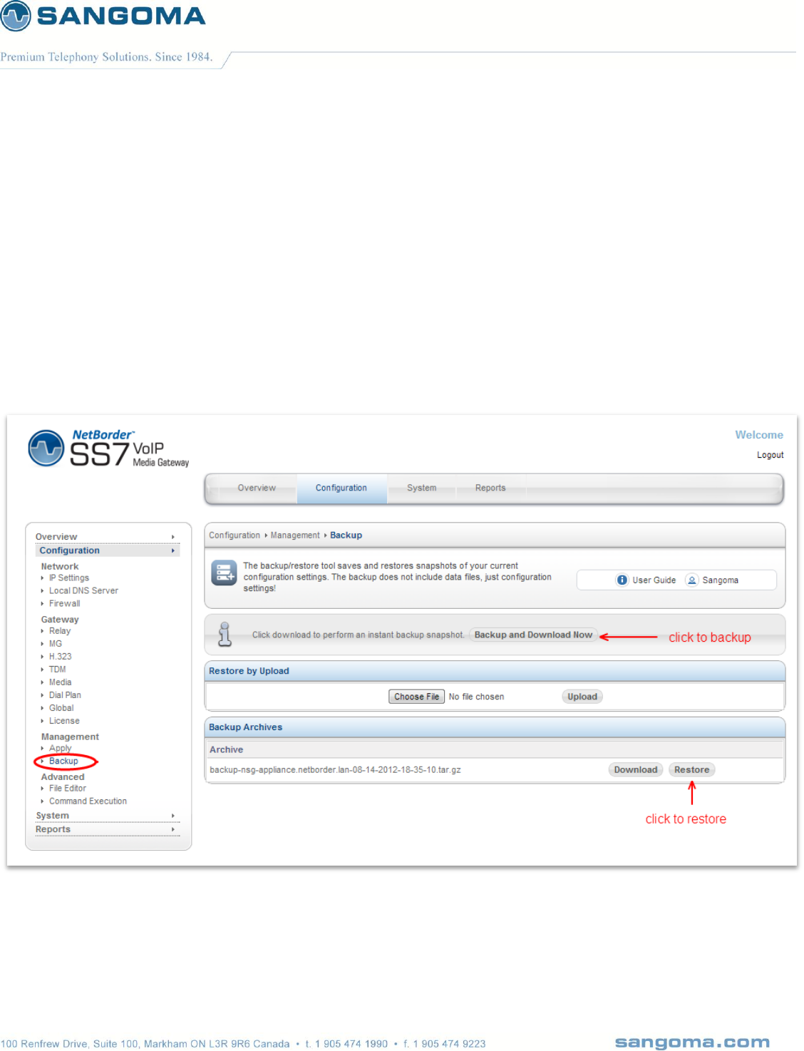
v1.14
163
14 Backup Restore System
Appliance configuration can be backed up to a zipped file.
Appliance can be restored from a same file.
Select Backup from side/top Configuration Menu
Click on Backup and Download Now
o Note that a backup will be offered for download as well as stored locally on the system.
o Note the Backup Archive shows previous backups that can be used to restore the
system.

v1.14
164
14.1 Restore a System
The default scenario for system Restore is to
recover an existing system from factory reset, or
to recover to another system, due to system failure
CAUTION
After a system has been restored via WebGUI a reboot is mandatory.
After a reboot
Confirm the VLAN configuration -> Overview -> VLAN Status
Confirm the IP route configuration -> Overview -> VLAN Status (Routing Rules)
Confirm Gateway is status in Overview -> Control Pannel
Confirm Gateway status in Overview -> TDM Status

v1.14
165
14.2 Restore to a new System
It is possible to back-up a working system, and restore the configuration to another target system,
with the intent of quickly provisioning a new target system.
However as backup will duplicate the current system, this is only useful in the case where original
system failed and is being replaced.
Restore has not been designed to provision new systems.
The amount work necessary to change a restored new system to operation is equivalent to starting
from scratch.
If using restores to provision a new system:
License
The license is going to be invalid on a new system. Thus user must update the system with
correct license after the restore from the backup.
IP Settings
IP settings are going to be duplicated and most likely invalid if the original system is still
functioning. Thus user must go into the IP Settings section and update the local IP settings.
VLAN
VLAN IP settings are going to be duplicated and most likely invalid if the original system is still
functioning. Thus user must go into the VLAN Settings section and update to new values.
Megaco/SIP/H323
All IP settings will most likely have to change.
TDM Spans
Target system must have identical T1/E1 spans installed as the source system. If TDM
installation is not identical there could be port mismatches or configuration errors, which will
cause the system to fail.
If provisioning from backing is the goal then user would have to edit the backup files manually to
update above settings before restoring to a target system.
This is not recommended and requires expert level understanding of the backup files and manual
configuration files. Which defeats the purpose of the WebGUI.
NOTE
Sangoma has a product roadmap plan for mass system provisioning.
If this is of interest please contact Sales.

v1.14
166
15 Factory Reset & Reboot
15.1 Factory Reset
Find a power button in front of the NSG Appliance
Press the power button repeatedly fast (every 1 sec) for 10 sec.
On factory reset trigger
o You will hear a loud high frequency beep for 10 seconds indicating that factory reset
has been successful.
o The system will be restored to factory settings and the system will reboot.
CAUTION
If you do not hear the factory reset sound and system reboots, you have triggered a soft reboot
sequence.
o Once system comes back up, re-try the factory reset sequence.
15.2 Appliance Soft Reboot
Find a power button in front of the NSG Server
Press the power button three times with more than 2sec delay in between..
o Press power button
o Count to 3 (3 sec)
o Press power button
o Count to 3 (3 sec)
o Press power button
When there were 3 power button presses within 10sec and 3sec apart, the NSG System will
do a soft reboot.
NOTE
A soft reboot can be triggered via WebGUI or USB CLI
WebGUI -> System -> Shutdown.
USB CLI -> reboot command
15.3 Appliance Shutdown
Find a power button in front of the NSG Appliance
Press the power button and hold it until machine shutdown.
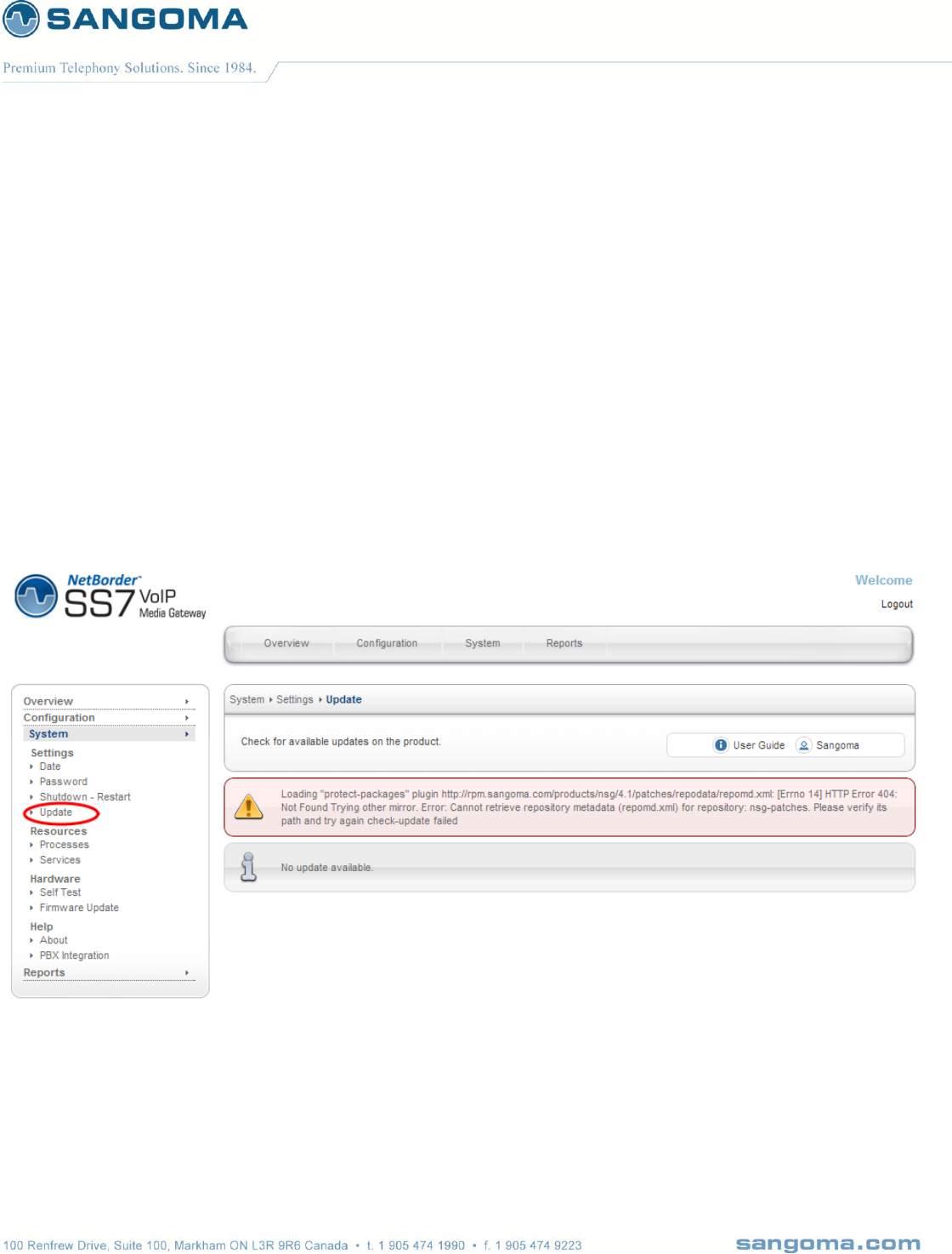
v1.14
167
16 Upgrade
User has three choices when upgrading NSG system.
Centralized Push Upgrade from NOC
WebUI Update Page
16.1 WebUI System Update
Select Update from side/top System Menu
Review available packages for upgrade.
Proceed with the upgrade process

v1.14
168
16.2 Console SSH Update
NSG product uses Linux RPM as part of its package management system.
Download new NSG RPM version
Stop NSG services
o User the GUI Control Panel
o Alternatively run:
services nsg stop
services nsg-webui stop
Install new package
o rpm –Uvh nsg-4.3.1.rpm
Restart NSG services
o Use the GUI Control Panel
o Alternatively run:
services nsg-webui start
services nsg start
NOTE
Using NSG console to upgrade the system is very powerful, as the process can be scripted
and centralized. This way all NSG appliances in the files can be upgraded from a single
upgrade machine in the NOC.
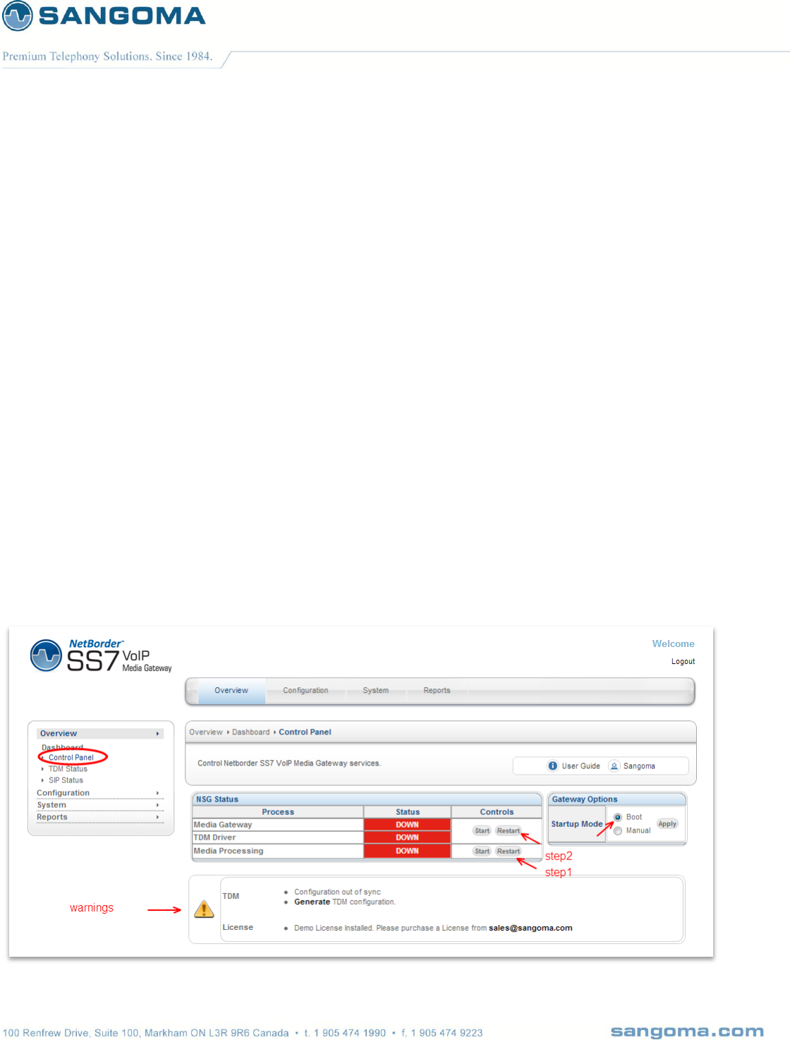
v1.14
169
17 Operations
17.1 Starting the Gateway
After successful initial configuration, the NSG gateway needs to be started. The Control Panel is
used to start, stop, restart the complete NSG gateway. One can also control on the fly configuration
in the Profile Panel once the gateway has been started.
Select Control Panel from side/top Overview Menu
Confirm that warnings are clear
Start the Media Processing First
o Media Processing will start the Transcoding resources.
o Note that Media Processing is optional
Start the Media Gateway Second.
o Media Gatway will start
o TDM Hardware Spans (T1/E1 ports)
o Netborder SS7 to VoIP Gateway Software
Confirm that the boot button is selected.
o This will confirm that gateway starts on reboot.
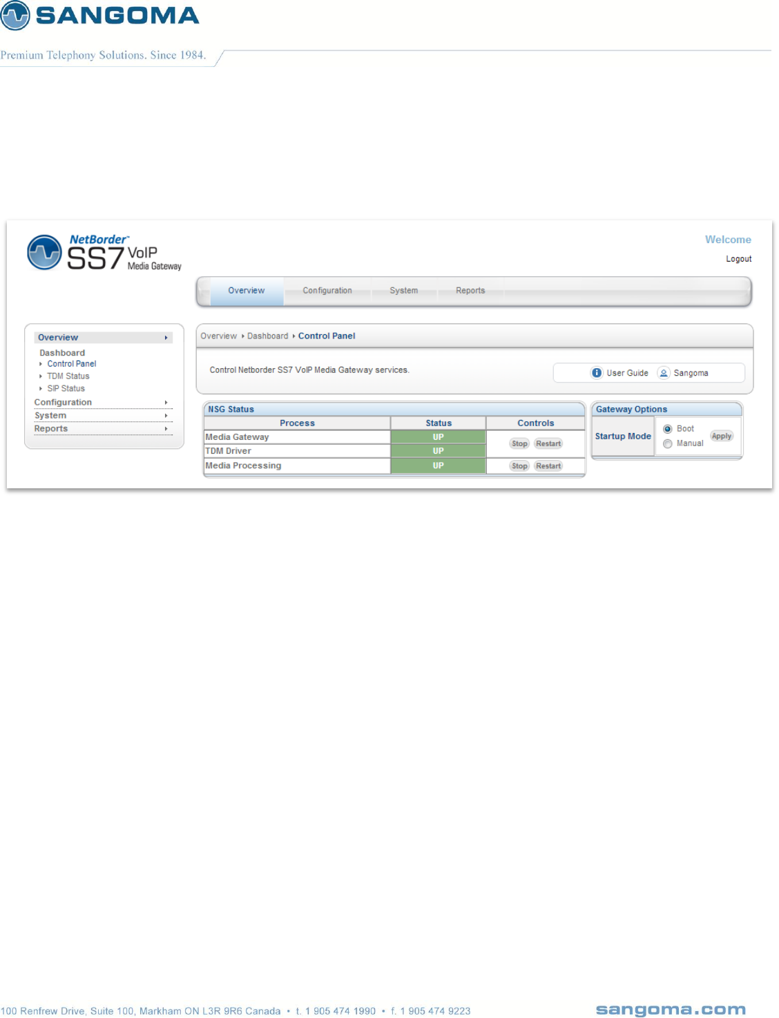
v1.14
170
When the Gateway starts successfully the green status bar will appear.
System is now running.
NOTE
Before attempting to pass traffic through the gateway, proceed to TDM Status to check the
state of the NSG gateway. There is no point of attempting calls while the status of the
gateway protocol is down.
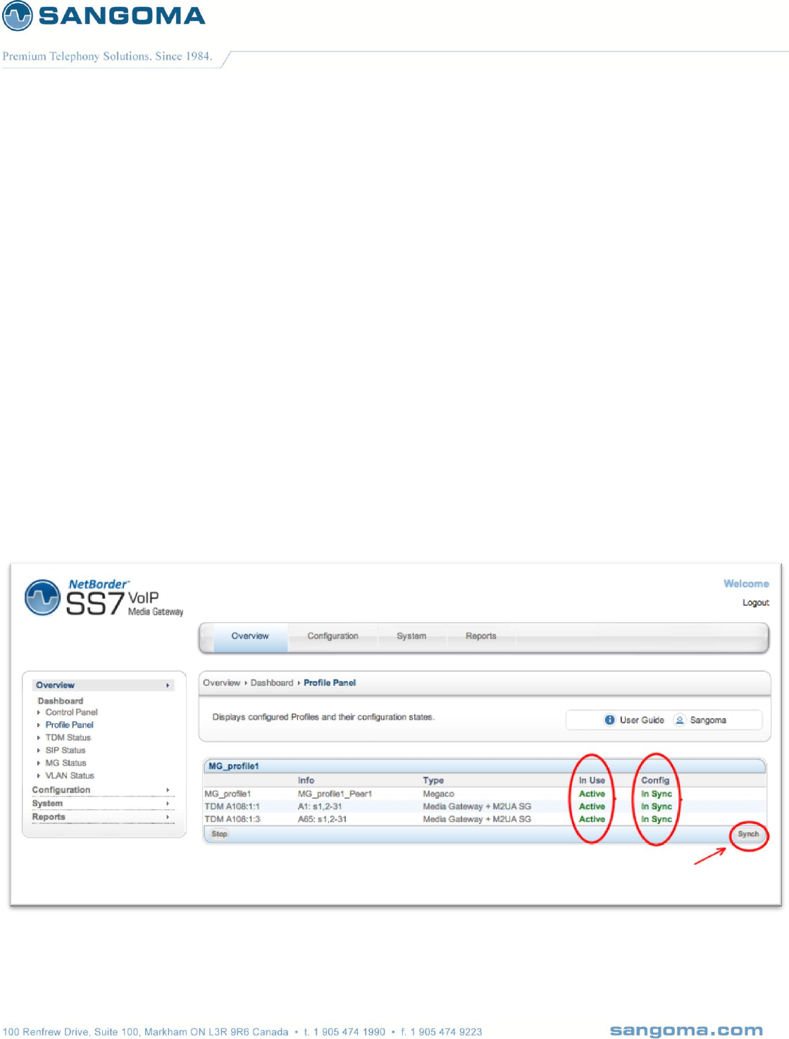
v1.14
171
17.2 Profile Panel
Profile Panel is used for on the fly configuration without disrupting gateway service.
The NSG Gateway has to be started in order to use the Profile Panel.
While the NSG Gateway is running, one can
Add a new TDM Voice span to existing MG Profile
Add a new TDM Voice + M2UA SG span to existing MG Profile
Add a new MG Profile and new TDM Spans and M2UA SG
Each MG Profile is grouped with the TDM Spans associated with it.
Sync/Stop actions will only affect the selected MG Profile and Spans that are not in Sync.
Adjacent MG Profiles will not be affected.
Configuration
Select Profile Panel from side/top Overview Menu
Select Sync Button to apply and start new configuration.

v1.14
172
Column
Description
In Use
Indicates whether the profile is currently running in NSG Gateway
Config
Indicates whether the profile configuration in database is in sync with what is currently
running in the gateway.
Sync Button
Configure and Start any profile that is In Active or out of Sync.
Sync operation WILL NOT disrupt service of TDM Spans that are in sync.
Sync operation WILL Restart the MG (Megaco) profile in order to update termination
ids.
Stop Button
Used to stop the whole MG Profile and associated TDM Spans.
Note
This feature is part of NSG 5.0.1 release and is only supported for MG Profiles.
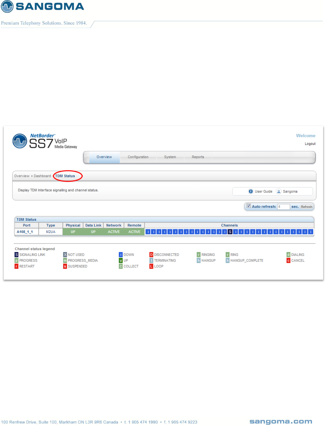
v1.14
173
17.3 Gateway Status
17.3.1 Megaco/M2UA TDM
The TDM Stats page displays the unified status of all NSG components
Select TDM Stats from side/top Overview Menu
v1.14
174
Field Name
Description
Port
Physical Port number. Identifies the hardware resource and T1/E1 port number.
The T1/E1 port number relates to the T1/E1 board.
Type
Signaling Type
In this example we see: M2UA
Physical
Physical T1/E1 layer status.
Hover the mouse over the Physical status section (green) to display detailed T1/E1 alarms and
status.
Data Link
MTP2 Link Layer status.
Hover the mouse over the UP and a popup will display detailed MTP2 status
Network
M2UA Link Layer status
Hover the mouse over the UP and a popup will display detailed M2UA status
Remote
Remote MGC Megaco Peer status.
This indicates that MG is connected to the MGC Megaco profile.
Hover the mouse over the UP and a popup will display detailed Megaco Peer status
Channels
If Megaco link state is IN-SERVICE
Channel is blue - down
If Megaco link state is OUT-OF-SERVICE
Channel is red – down
If channel is in use
Channel is green – up
Hover the mouse over each channel for more detailed data.
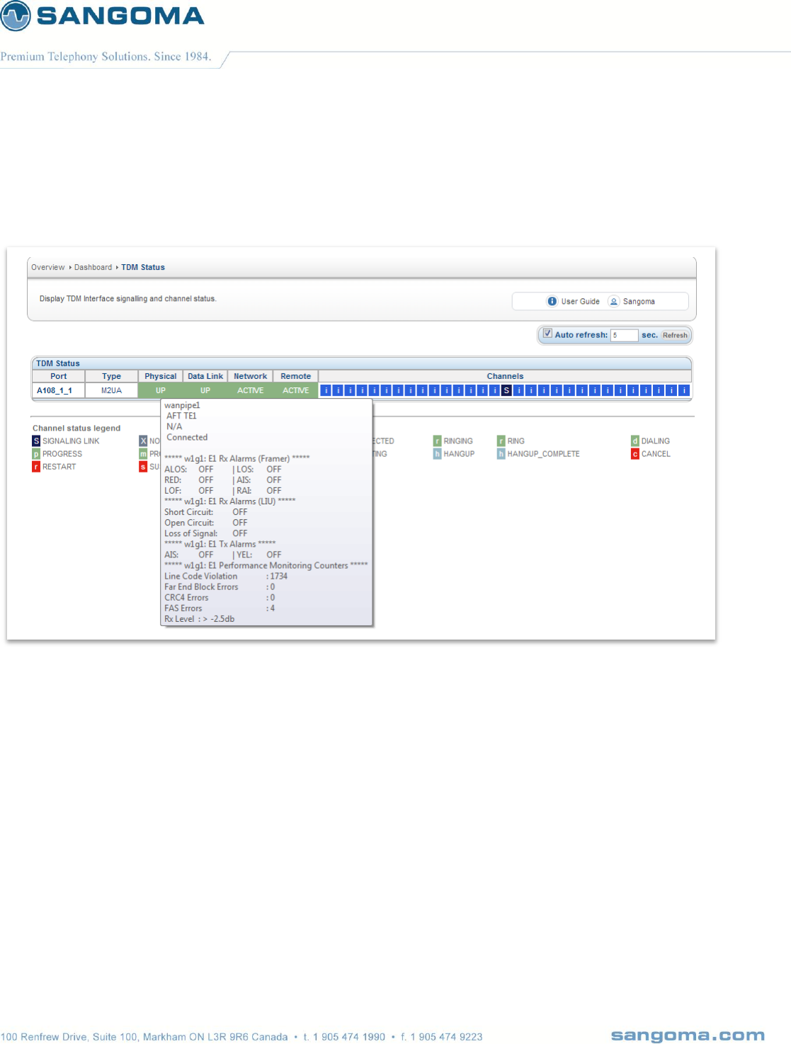
v1.14
175
17.3.1.1 Physical T1/E1 Alarms
Hover the mouse over Physical Status Section.
For detailed information about Alarms refer to Troubleshooting Section 18.
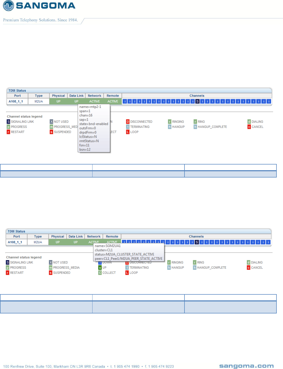
v1.14
176
17.3.1.2 Data Link MTP2 Alarms
Hover the mouse over Data Link Section.
state
bnd-enable
MTP2 is connected
bnd-disable
MTP2 is disconnected
17.3.1.3 Network M2UA Alarms
Hover the mouse over Network Section.
status
M2UA_CLUSTER_STATE_ACTIVE
Local state is connected.
peer
M2UA_PEER_STATE_ACTIVE
Remote MGC M2PA is in sync with
local M2UA connection
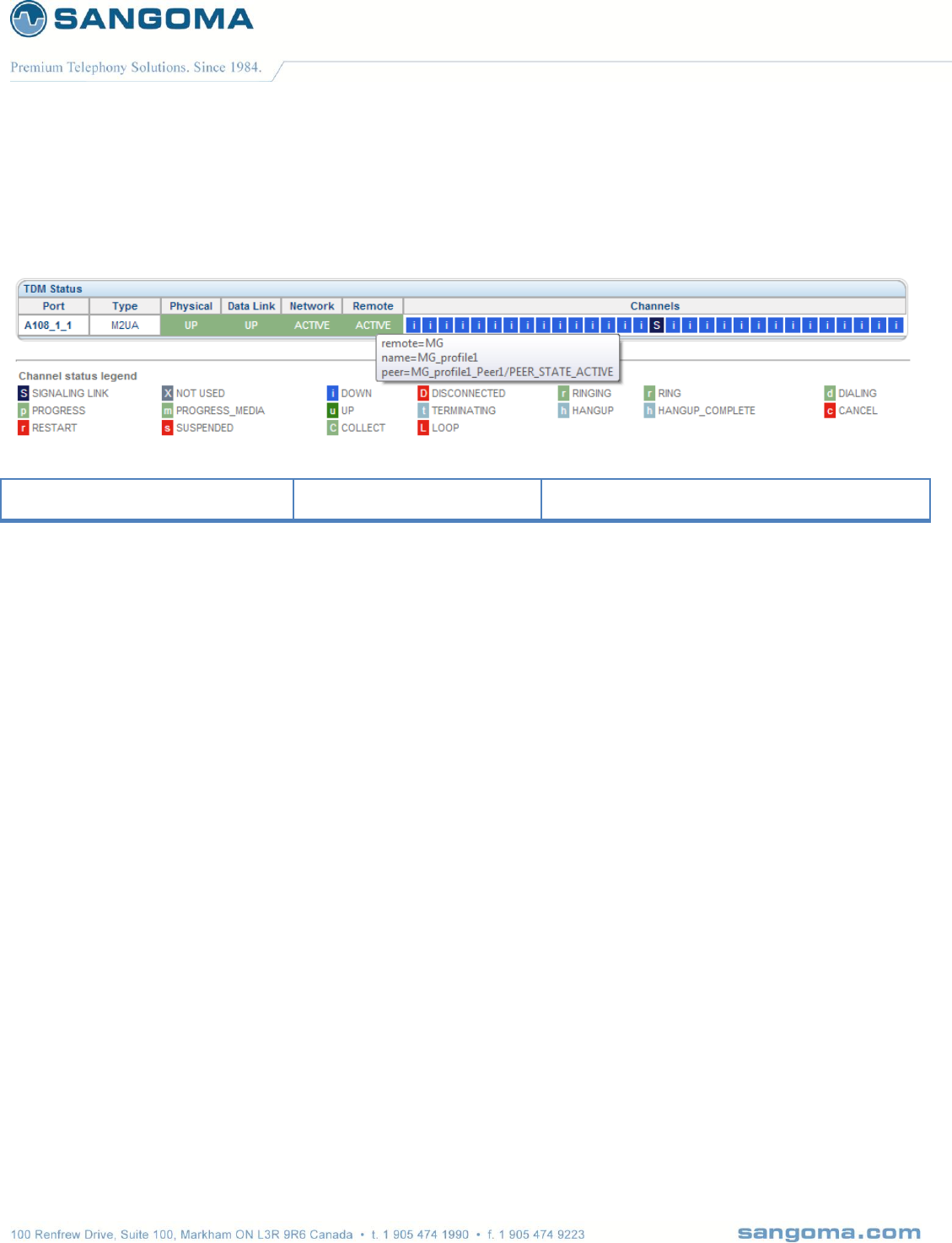
v1.14
177
17.3.1.4 Remote Megaco Alarms
Hover the mouse over Remote Section
peer
PEER_STATE_ACTIVE
Remote MGC Megaco protocol is in sync with
local Megaco profile.
NOTE
For more information on how to debug each section please refer to the Troubleshooting section.
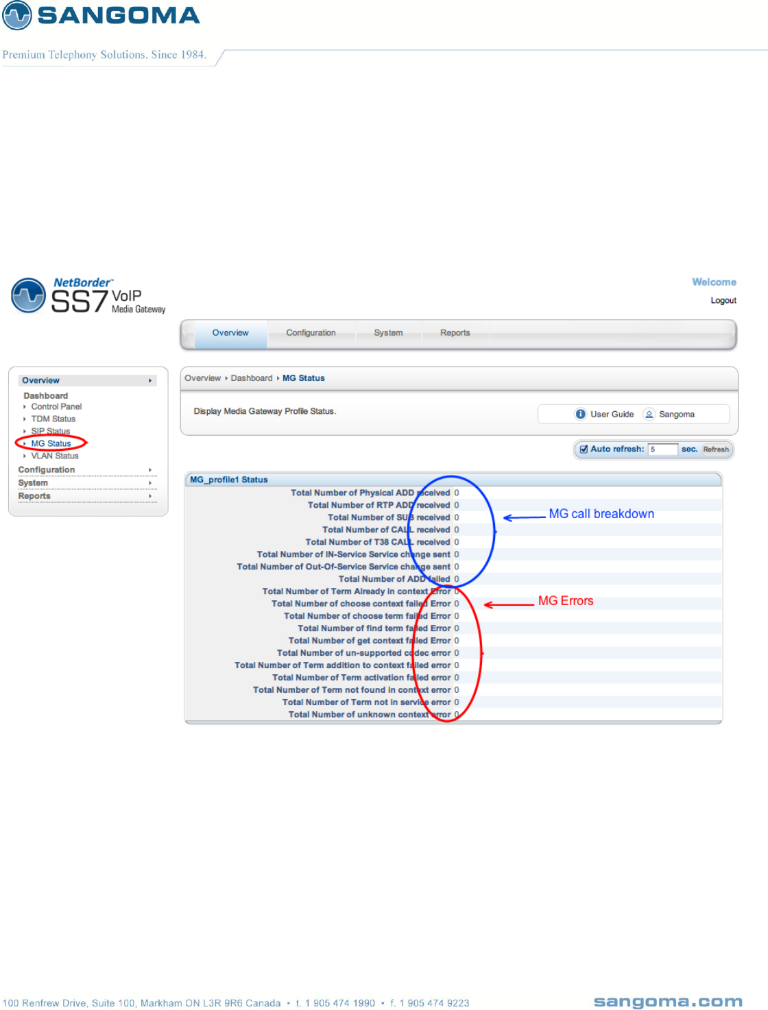
v1.14
178
17.4 Megaco Status
Megaco Status page provides detailed Megaco call statistics per Megaco Profile.
Select MG Status from side/top Overview Menu

v1.14
179
Reports
17.5 Gateway Logs
Select Gateway Logs from side/top Reports Menu
NOTE
All error events will be displayed in RED for easy identification.

v1.14
180
Log
Description
Driver
TDM device driver log.
All errors will be identified in RED
This log will show
TDM Driver startup sequence
TDM T1/E1 connection/disconnection
TDM Driver general errors
System errors
OS Errors
Gateway
SS7 to VoIP Gateway log
All errors will be identified in RED
This log will show
Gateway startup sequence
Gateway startup errors
Gateway run time errors and warnings
Media
Media Transcoding log
All errors will be identified in RED
This log will show
Media Transcoding server startup sequence
Media startup errors
Media transcoding run time errors and warnings
17.5.1 Gateway Log Download
When working with Sangoma support, you will be asked to download and submit the NSG logs.
Select Download Logs Button
Save the zipped file to your computer
Send the zipped debug package to Sangoma Support
Download Logs contains
All Gateway, Driver and Transcoding log files
Full Gateway configuration

v1.14
181
17.6 Advanced Logs
Detailed historical logs can be found in Advanced Logs Section. This page can be used to determine
historical alarm, events and errors.
Select Advanced Logs from side/top Reports Menu
Files
Description
messages
Displays kernel and driver level
messages. Including all T1/E1 status
changes or error messages.
Filter
Description
E1
All E1 messages
E1.*con
All E1 connected & disconnected
messages
: ON
All T1/E1 Alarms ON events
: OFF
All T1/E1 Alarms OFF events
Error
All Error messages
wanpipe
All T1/E1 driver messages
nsg/sangomagw.log
Display all NSG gateway logs.
Filter
Description
ERR
All Error Messages
WARN
All Warning Messages
sngtc_server.log
Displays all Media Transcoding logs
Filter
Description
ERR
All Error Messages
WARN
All Warning Messages
17.7 Packet Capture
The packet capture page captures network traffic from Ethernet interface, TDM interface or both.
Select Packet Capture from side/top Reports Menu
Filter
o Default filter will capture all packets on the Ethernet device
Select Capture to start capturing
Wait…
Select Stop Capture when Capture done
Download Link with capture pcap file is ready for download.
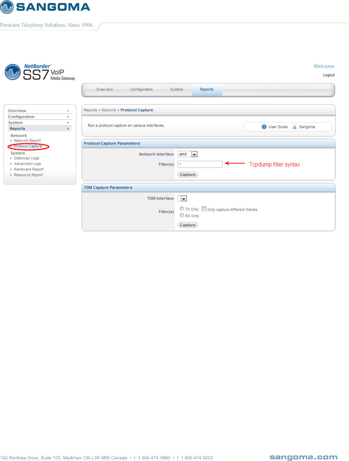
v1.14
182

v1.14
183
17.7.1 Ethernet Capture Filter Options
host <ip>
True if either the IPv4/v6 source or destination of the packet
is host.
dst host <ip>
True if the IPv4/v6 destination field of the packet is host,
which may be either an address or a name
src host <ip>
True if the IPv4/v6 source field of the packet is host.
net <ip>
True if either the IPv4/v6 source or destination address of
the packet has a network number of net.
port <port>
True if either the source or destination port of the packet is
port.
dst port <port>
True if the packet is ip/tcp, ip/udp, ip6/tcp or ip6/udp and
has a destination port value of port.
src port <port>
True if the packet has a source port value of port.
vlan <vlan_id>
True if the packet is an IEEE 802.1Q VLAN packet. If
[vlan_id] is specified, only true if the packet has the
specified vlan_id.
For example:
vlan 100 && vlan 200
filters on VLAN 200 encapsulated within VLAN 100, and
vlan && vlan 300 && ip
filters IPv4 protocols encapsulated in VLAN 300
encapsulated within any higher order VLAN.
tcp, udp, icmp
True if protocol matches
not <port> | not <ip>
Exclude a port/ip/protocol out of the trace
NOTE
Please refer to tcpdump documentation for more info.

v1.14
184
18 Monitoring & Management
NSG Currently offers number of monitoring and management options
SNMP
Web GUI Status
SSH CLI (Scripting)
18.1 SNMP
Simple Network Management Protocol (SNMP) is an "Internet-standard protocol for managing
devices on IP networks." Devices that typically support SNMP include routers, switches, servers,
workstations, printers, modem racks, and more." It is used mostly in network management systems to
monitor network-attached devices for conditions that warrant administrative attention. SNMP is a
component of the Internet Protocol Suite as defined by the Internet Engineering Task Force (IETF). It
consists of a set of standards for network management, including an application layer protocol, a
database schema, and a set of data objects
NSG provides SNMP support version 1, 2, 3
o Note that SNMP version 1,2 are mutually exclusive to version 3.
SNMP Version3 requires user authentication, and is more secure than versions 1 & 2.
By default NSG comes pre-configured with SNMP version 1 & 2 enabled.
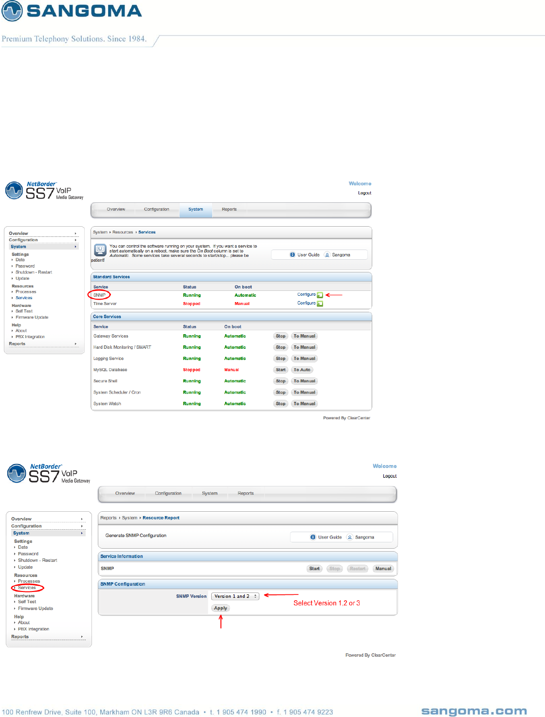
v1.14
185
18.2 SNMP Configuration
To configure SNMP proceed to System -> Services from the side/top System menu.
Select SNMP service Configure Button
NOTE: Before configuring SNMP service, the SNMP service must be stopped.

v1.14
186
Select SNMP Version 1&2 or 3
SNMP Version 3 requires user authentication
o Please specify a username and password
Click Apply to save.
18.3 SNMP Test
In order to confirm NSG responds to SNMP requests, one can use number of standard snmp client
tools to obtain system information.
snmpwalk -c public -v 1 <nsg ip address or dns name>
or
snmpwalk -c public -v2c <nsg ip address or dns name>
This should show some basic information about the system including:
SNMPv2-MIB::sysDescr.0 = STRING: Linux nsg-nc-43.sangoma.local 2.6.39-4.sng2 #1 SMP Wed Dec 21 17:26:48 EST
2011 i686
SNMPv2-MIB::sysObjectID.0 = OID: NET-SNMP-MIB::netSnmpAgentOIDs.10
DISMAN-EVENT-MIB::sysUpTimeInstance = Timeticks: (176243) 0:29:22.43
SNMPv2-MIB::sysContact.0 = STRING: Root <root@localhost> (configure /etc/snmp/snmp.local.conf)
SNMPv2-MIB::sysName.0 = STRING: nsg-nc-43.sangoma.local
SNMPv2-MIB::sysLocation.0 = STRING: Unknown (edit /etc/snmp/snmpd.conf)
SNMPv2-MIB::sysORLastChange.0 = Timeticks: (0) 0:00:00.00
SNMPv2-MIB::sysORID.1 = OID: SNMPv2-MIB::snmpMIB
SNMPv2-MIB::sysORID.2 = OID: TCP-MIB::tcpMIB
SNMPv2-MIB::sysORID.3 = OID: IP-MIB::ip
SNMPv2-MIB::sysORID.4 = OID: UDP-MIB::udpMIB
SNMPv2-MIB::sysORID.5 = OID: SNMP-VIEW-BASED-ACM-MIB::vacmBasicGroup
SNMPv2-MIB::sysORID.6 = OID: SNMP-FRAMEWORK-MIB::snmpFrameworkMIBCompliance
SNMPv2-MIB::sysORID.7 = OID: SNMP-MPD-MIB::snmpMPDCompliance
SNMPv2-MIB::sysORID.8 = OID: SNMP-USER-BASED-SM-MIB::usmMIBCompliance
…
IF-MIB::ifDescr.2 = STRING: eth0 (Primary Ethernet Port)
IF-MIB::ifDescr.3 = STRING: eth1 (Secondary Ethernet Port)

v1.14
187
IF-MIB::ifDescr.4 = STRING: eth2 (Media Transcoding Port)
IF-MIB::ifDescr.6 = STRING: eth1.1302 (VLAN)
IF-MIB::ifDescr.7 = STRING: eth1.1301 (VLAN)
IF-MIB::ifDescr.8 = STRING: eth1.1300 (VLAN)
IF-MIB::ifDescr.11 = STRING: w1g1 (T1/E1 TDM Port)
To determine the T1/E1 or Ethernet State
IF-MIB::ifAdminStatus.1 = INTEGER: up(1)
IF-MIB::ifAdminStatus.2 = INTEGER: up(1)
IF-MIB::ifAdminStatus.3 = INTEGER: up(1)
IF-MIB::ifAdminStatus.4 = INTEGER: up(1)
IF-MIB::ifAdminStatus.6 = INTEGER: up(1)
IF-MIB::ifAdminStatus.7 = INTEGER: up(1)
IF-MIB::ifAdminStatus.8 = INTEGER: up(1)
IF-MIB::ifAdminStatus.11 = INTEGER: up(1)
IF-MIB::ifOperStatus.1 = INTEGER: up(1)
IF-MIB::ifOperStatus.2 = INTEGER: up(1) (Primary port eth0 status – In this example eth0 link is up)
IF-MIB::ifOperStatus.3 = INTEGER: down(2)
IF-MIB::ifOperStatus.4 = INTEGER: up(1)
IF-MIB::ifOperStatus.6 = INTEGER: down(2)
IF-MIB::ifOperStatus.7 = INTEGER: down(2)
IF-MIB::ifOperStatus.8 = INTEGER: down(2)
IF-MIB::ifOperStatus.11 = INTEGER: down(2) (T1/E1 TDM Port Status – In this example T1/E1link is down, in alarm)
Note that all TDM interfaces/spans have the following nomenclature: “w<SPAN>g<CHAN>”
w1g1 translates to SPAN 1
w2g1 translates to SPAN 2
w31g1 translates to SPAN 31
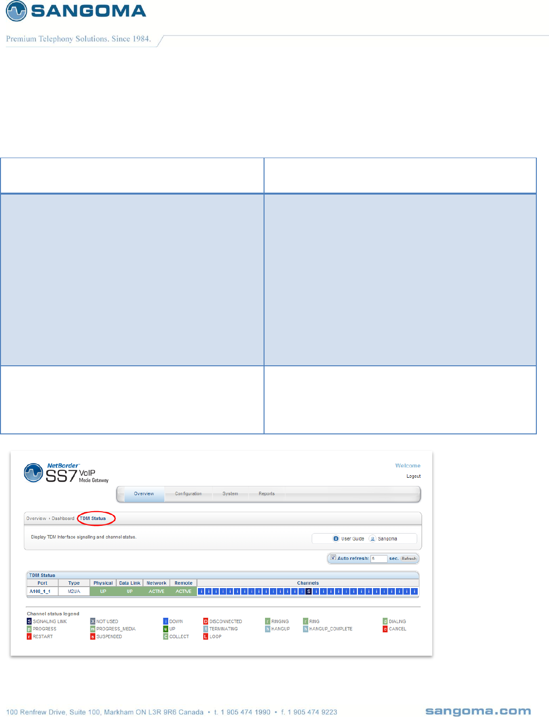
v1.14
188
19 Troubleshooting
In any network troubleshooting it is best to start from the bottom.
Physical Layer:
T1/E1 Ports
T1/E1 Alarms and Statistics
Command to read T1/E1 Alarms
wanpipemon -i w1g1 -c Ta
Data Link and Network Layers: ISUP Termination
MTP2 Link
MTP3 Link
ISUP Link
Trace/Capture TDM Signaling channel
From GUI: Reports -> Packet Capture
Open pcap file in Wireshark
From SSH
wanpipemon -i w1g1 -c trd #hdlc decoded
wanpipemon -i w1g1 -c tr #raw
wanpipemon options
o -rx rx only
o -tx tx only
o -diff different frames only
Data and Network Link Layers: Megaco MG + SG
SCTP
M2UA
M3UA
Megaco
Trace/Capture Ethernet Port
From GUI: Reports -> Packet Capture
Open pcap file in Wireshark
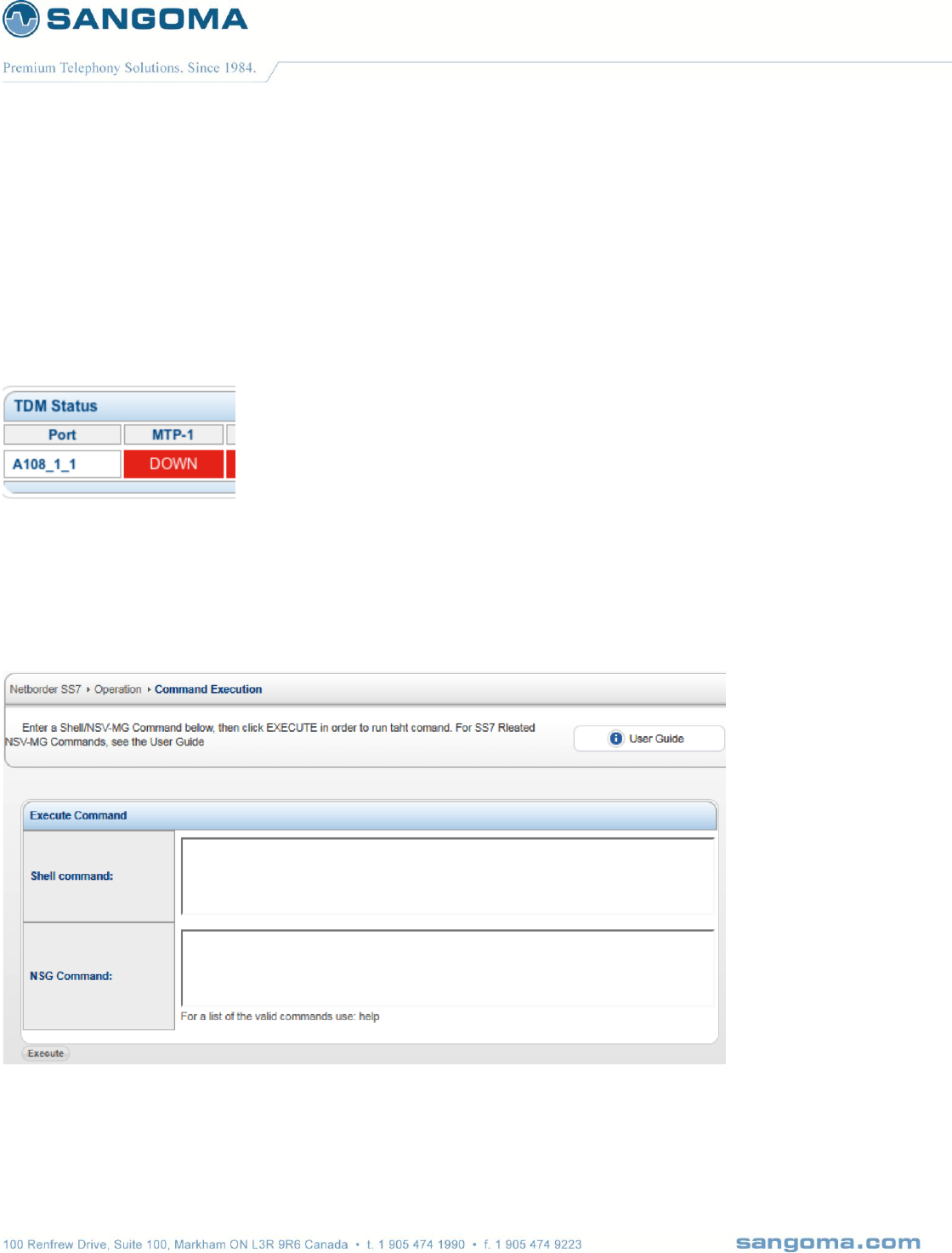
v1.14
189
19.1 Physical Layer
The first step in troubleshooting any connectivity issue is troubleshooting the physical layer.
Identifying whether a user has a physical layer issue is by using the TDM Status page and checking
the MTP-1/M2UA column.
If the column is listed as "DOWN" for that particular port, proceed with troubleshooting the physical
layer.
When physical layer is down, all layers above the physical layer will also be in a "DOWN" or
"TRYING" state.
In order to start troubleshooting, the user must proceed to the "Command Execution" page, which is
located under the "Configuration" menu.
The best way to troubleshoot physical layer issues is through the shell command option. Below is a
list of commands that can be run within the shell command section to help diagnose issues:

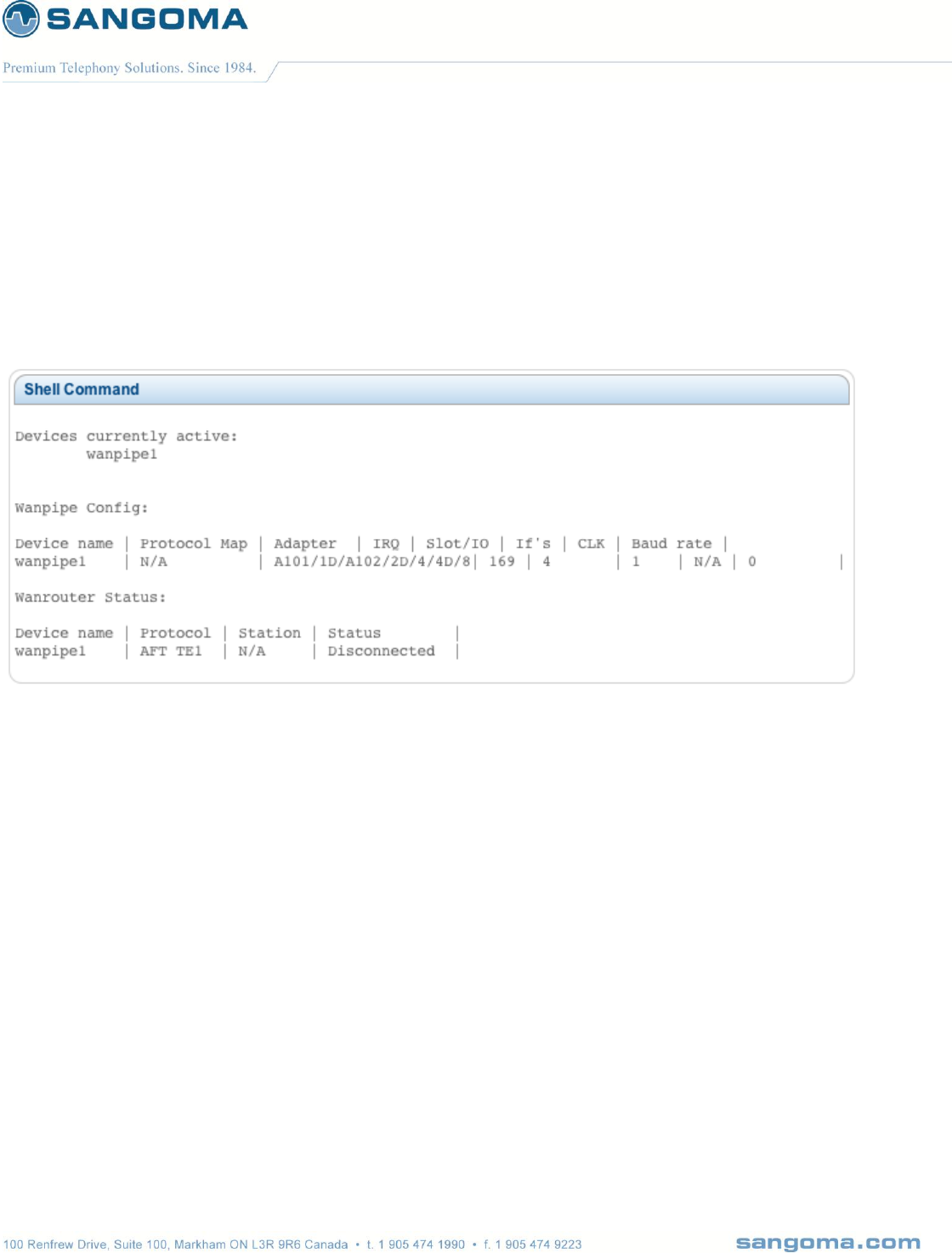
v1.14
191
19.1.2 T1/E1 Port Status
The first step in debugging physical layer issues would be to check whether wanrouter status reports
the line "Connected" or "Disconnected". To do this, within the "Shell Command" textbox, enter the
command "wanrouter status". It will return a result like the one below:
-> wanrouter status
All the devices running on a NSG system will be listed as a "wanpipe" device. In this example,
"wanpipe1" is being reported as "Disconnected", which tells us that the physical layer is in fact in a
"DOWN" state.
19.1.3 T1/E1 Port Debugging
The next step would be to check where the issue lies.
To do this, the user would need to run the command
wanpipemon -i wXg1 -c Ta
(where X stands for the wanpipe number).
In this example, "wanpipe1" is in a disconnected state, therefore the interface name would be "w1g1".
The command returns an output similar to the one below:
-> wanpipemon -i w1g1 -c Ta
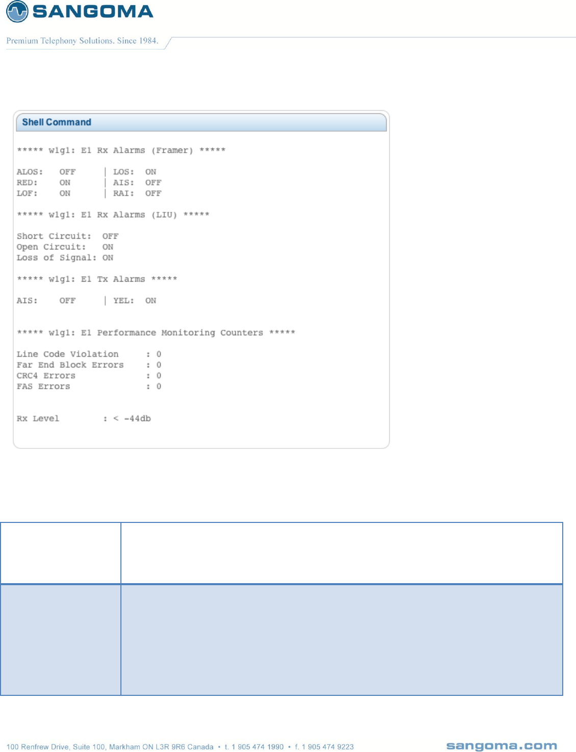
v1.14
192
Check for Short or
Open Circuit
Possibly a bad cable
Try another cable
Possibly a bad T1/E1 port on NSG
Unplug the E1 from NSG and run NSG self-test to confirm
Check Rx Level
if equal to -44db
No Cable
Circuit disconnected on Telco side
No power on the line
If lower than -2.5db (-10db-20db)
Cable problem, bad cable, short
Low signal strength
If equal to -2.5db
E1 signal strength is perfect
v1.14
193
Check Alarms
RED
Indicates the device is in alarm
LOF
(Loss of Framing).
Raised after four consecutive frames with FAS error.
If RAI and AIS alarms are not indicated, verify that you have selected the
proper line framing (i.e T1: ESF, D4, E1:CRC4, NCRC4..etc)
LOS
(Loss Of frame Signal)
AIS
(Alarm Indication Signal): typically know as a BLUE Alarm. all-ones signal
transmission to the receiving equipment to indicate that an upstream
repeater (telco equipment) is in alarm, due to upstream transmission fault,
either from another repeater or from the telco itself.
If ONLY AIS:ON then contact your telco with this information
(RAI:ON can also be a possibility in this case as well)
Example call diagram of the scenario:
Sangoma card <---------------repeater <--------------Telco
RAI
(Remote Alarm Indication): Indicates that the Far end (typically the Telco) is
in RED alarm state and sending that message over the line.
If ONLY RAI:ON then Telco is down, or TX wire in T1/E1 cable is damaged.
You will also get this alarm, and only this alarm, if your framing is incorrect.
This setting can be changed in the TDM Section.
Short
Circuit
The wires in your cable connected to the port are crossed. If you see this
alarm, check the pinouts for the cable you are using.
You may also be plugging in the wrong form of cable (straight-through, or
cross-over)
Open
Circuit
No line plugged into the port. Make sure that your connector is plugged in
and the wiring is making a good connection.
If this alarm is on, you will also Rx Level='-36'->'-44'.
Loss of
Signal
Cabling issue. Check the health of the cable plugged into the port, as well
as its connection to the port it is plugged into.
You will also see the Rx Level either very low, or in a disconnected state: -
v1.14
194
36 -> -44. It is typical to have this alarm triggers in combination with 'Open
Circuit' if there is an issue with the physical connection
YEL
When the equipment enters a Red-Alarm state, it returns a Yellow-Alarm
back up the line of the received OOF.
A typical scenario would be mis-configuration during the Sangoma card
configuration (i.e selected CRC4 vs NCRC4). In this type of scenario also
LOF and RED alarms will be triggered.
Line Code
Violation
This occurs upon a bipolar violation
Far End
Block
Errors
is reported by the upstream end of the PHY (the wire between you and the
switch) on the out-of-band management channel.
This means the other end of the line received bad data from you. Possible
reason are: line noise, corroded wires..etc.
Also, check line Framing (E1: CRC4 vs NCRC4)
CRC4
Errors
This occurs when the CRC polynomial calculation performed before
transmission does not match the CRC calculation done upon reception.
FAS Errors
(Frame alignment signal error). One or more incorrect bits in the alignment
word
Check Clock
Note that NSG will not come out of Alarm state if there is NO clock on the T1/E1 line.
If NSG configured for NORMAL (slave) clock
Re configure to MASTER clock
If E1 comes UP
Then there is NO clock on the line !!!
Contact the Telco

v1.14
195
19.2 TDM Signaling Link Debugging
If GUI TDM Status -> Data Link (MTP2) – is DOWN
Proceed to GUI -> Reporting -> Packet Capture
Check for Rx signaling
packets.
Proceed to GUI -> Reporting -> Packet Capture
Trace RX only packets on TDM T1/E1 port that contains a signaling link
eg: w1g1 – port 1
eg: w2g1 – port 2
Select RX Only
Start Trace
Wait a minute
Stop Trace
Download and open in Wireshark
Check for RX FISSU and LSSU
If NO RX packets at all
Then there is no signaling traffic on the T1/E1 timeslot
There is probably only idle pattern
Telco needs to turn on the MTP2 Link
OR
There is NO MTP2 link on this E1 timeslot
Check for Tx signaling
packets
Proceed to GUI -> Reporting -> Packet Capture
Trace RX only packets on TDM T1/E1 port that contains a signaling link
eg: w1g1 – port 1
eg: w2g1 – port 2
Select TX Only
Start Trace
Wait a minute
Stop Trace
Download and open in Wireshark
Check for TX FISSU and LSSU
If NO TX packets at all
Then MTP2 link might not be activated
If in M2UA bridge mode, the M2UA must be active.
Only when M2UA becomes active will the MTP2 link be activated.
Caution: TX trace will only capture different FISU and LSSU due to hw optimization.
Capture all Signaling
traffic and open in
Wireshark
Proceed to GUI -> Reporting -> Packet Capture
Trace Different only packets on TDM T1/E1 port that contains a signaling link
eg: w1g1 – port 1

v1.14
196
eg: w2g1 – port 2
Select Different only packets
Start Trace
Wait a minute
Stop Trace
Download and open in Wireshark
MTP2
Check for LSSU size mismatch
ISUP
Check for wrong OPC/SPC, APC, DPC
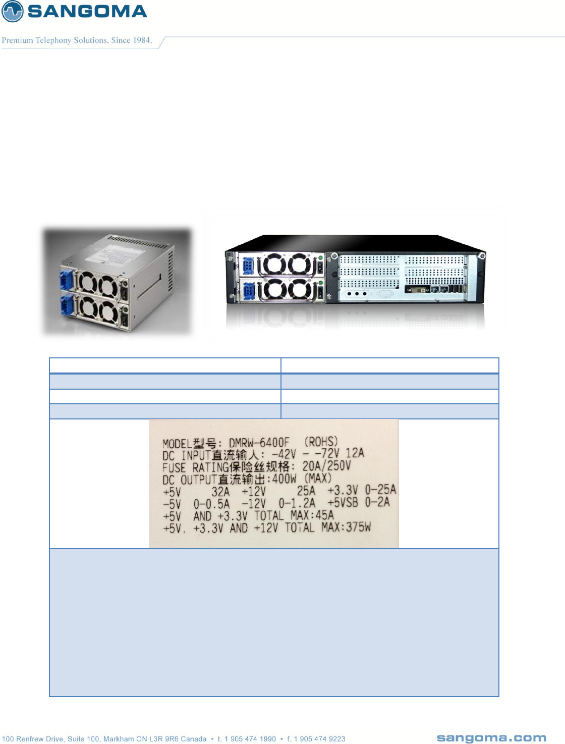
v1.14
197
20 Appendix
20.1 Redundant DC PSU
Sangoma NSG appliances come with redundant DC power supply.
VOLTAGE
DC -36V ~ -72V
INPUT CURRENT:
12.0A (RMS). FOR -48 VDC
INRUSH CURRENT
20A (Max)
DC OUTPUT
400W (Max)
TEMPERATURE RANGE : OPERATING 100C --- 400C
HUMIDITY:OPERATING:20%-95%, NON-OPERATING:10%-95%
REMARKS:85% IS NORMAL CONDITION AND 95% IS WITH SPECIAL COATING
PROCESS
HOLD UP TIME: 1.6 ms MINIMUM AT FULL LOAD & NOMINAL INPUT VOLTAGE
DIELECTRIC WITHSTAND: INPUT / OUTPUT 1500 VAC FOR 1 SECOND
INPUT TO FRAME GROUND 1500 VAC FOR 1 SECOND
EFFICIENCY: 65% TYPICAL, AT FULL LOAD
POWER GOOD SIGNAL: ON DELAY 100 ms TO 500 ms, OFF DELAY 1 ms
OVER LOAD PROTECTION: 130 ± 20%.
OVER VOLTAGE PROTECTION: +5V → 5.5V ~ 7.0V, + 3.3V → 4.0V ~ 4.5V
SHORT CIRCUIT:+5V,+12V,+3.3V

v1.14
198
EMI NOISE FILTER: FCC CLASS A, CISPR22 CLASS A
SAFETY: UL 1950, CSA 22.2 NO/ 950, TÜV IEC 950
REMOTE ON / OFF CONTROL
THE UNIT SHALL ACCEPT A LOGIC OPEN COLLECTOR LEVEL WHICH WILL
DISABLE / ENABLE ALL THE OUTPUT VOLTAGE (EXCLUDE +5V STANDBY), AS
LOGIC LEVEL IS LOW, OUTPUTS VOLTAGE WERE ENABLE, AS LOGIC LEVEL IS
HIGH, OUTPUTS VOLTAGE WERE DISABED
COOLING : TWO 40 mm DC FANS (MODULE)
AC INLET IN EACH MODULE
20.1.1 DC PSU Cables
Connecting cables to a power supply depends on the remote power source.
Power Source Type
Black Wire
Red Wire
If power source -48V
-48V
0V (Ground)
If power source +48V
0V (Ground)
+48V
The PSU has voltage reverse protection.
If the red and black wires are connected the wrong way, the system will not power up. But
there will be no damage to the PSU or the system.

v1.14
199
20.1.2 Hot-swap procedures
Please refer to the following when either power module is defective.
Locate the defective power module by examining the individual LED (if LED is distinguished, it
indicates the power module is defective).
*** WARNING
please perform the following step carefully; otherwise, it may cause the whole system
shutdown.
*** WARNING
Please do not remove the defective power module until you have worn gloves to keep from
been burned. This is due to the cover of the power module is used as heat sink for cooling.
Usually, its temperature is around 50-60 degree Celsius under full load condition.
Loose the screws of power module bracket.
Plug out the defective power module.
*** WARNING
please put aside the power module to wait for cooling down. Keep other people from toughing
it until it is cooled.
Replace a new / GOOD power module. Insert the power module into the power system till to
the end.
Check the LED of the power module, which should be in GREEN.
Check the warning LED indicating the status of total power system, which should be in
GREEN.
Tighten the screws of the power module.
If you want to test this new power module and simulate the defective situation, please refer to
Section 1.7 Installation & Testing.
Remarks: If the DC fan of the power module fails, you have to replace the power module.
Please follow the Hot-Swap Procedures for replacement.

v1.14
200
20.1.3 Trouble Shooting
If you have followed these instructions correctly, it should function normally.
Some common symptoms are, the system doesn’t work, buzzer alarms, shutdown after running a
very short period,… etc. If so, please check the following steps to verify and correct it.
Check all connection (if pinouts is correct, if any connection loosed, if the direction is
incorrect,… etc.).
Check if any short-circuit or defective peripherals by plugging out the power connector from
each peripheral, one at a time. Shall the system functions again, you have solved the problem.
Once you hear the buzzer sound or see the warning LED in RED, please check,
If the loading is under the minimum or over the maximum load of each channel.
If the power source is well connected and supplied. Shall the above condition is happened,
please disconnect the power source and wait for 2-3 minutes to release the protection status;
then test it again.
If buzzer keeps alarming or LED indicates the power module failure, please locate which
power module is defective. Perform hot-swap procedures (ref. to Sec. 1.8 Hot-Swap
Procedures). Return the defective power module back to your vendor for RMA procedure.
If you cannot fix the problem, please contact your vendor for supporting.
Note:
* The description stated herein is subject to change without prior notice.
* All brand names and trademarks are the property of their respective owners.

v1.14
201
21 Theory
v1.14
202
v1.14
203
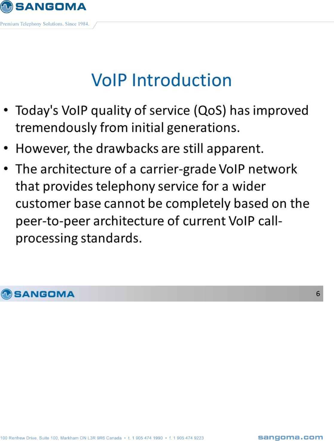
v1.14
204
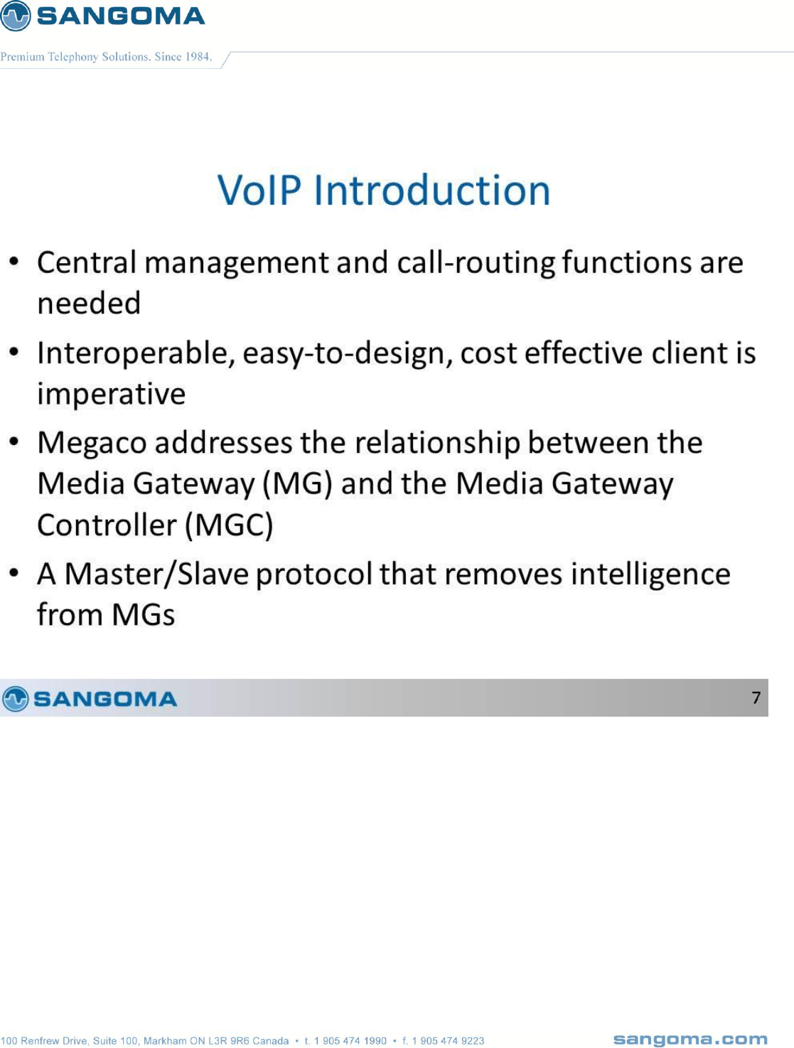
v1.14
205

v1.14
206
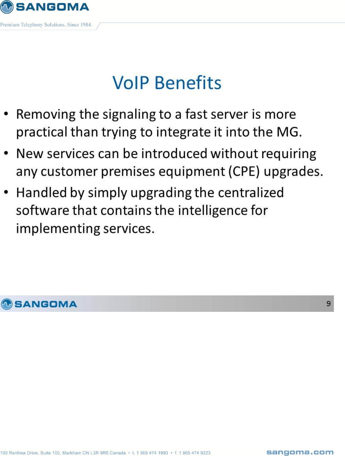
v1.14
207

v1.14
208

v1.14
209

v1.14
210
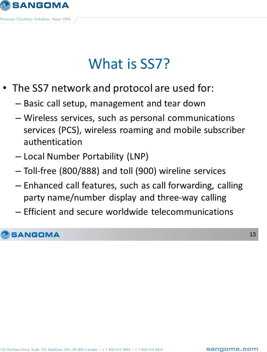
v1.14
211
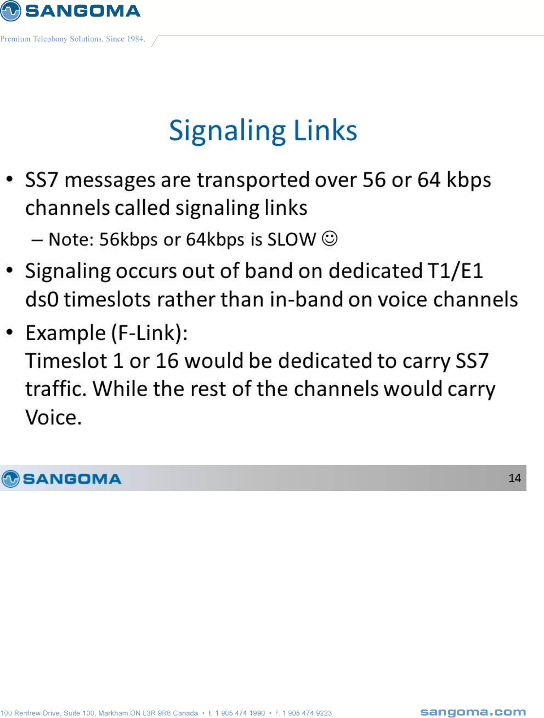
v1.14
212
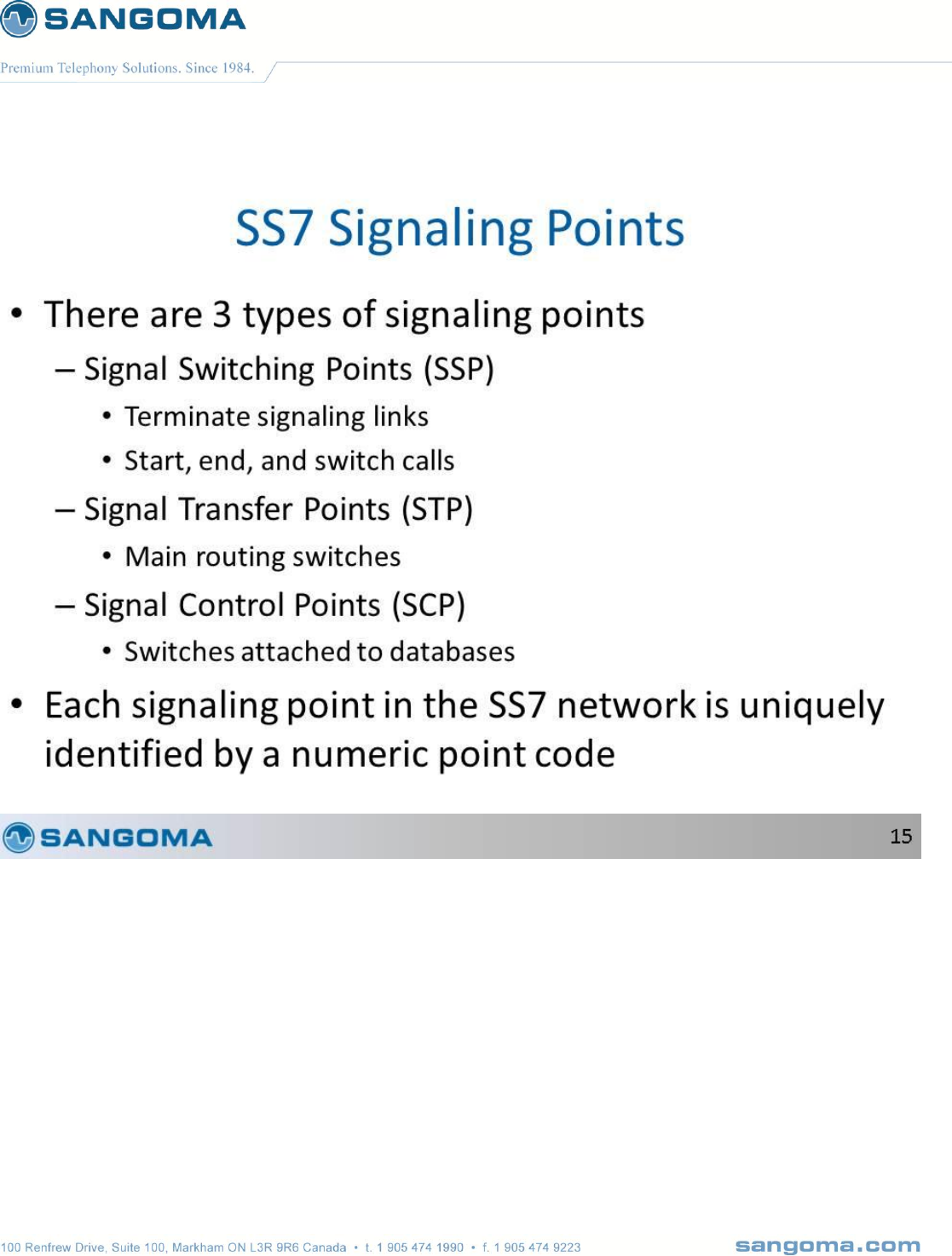
v1.14
213
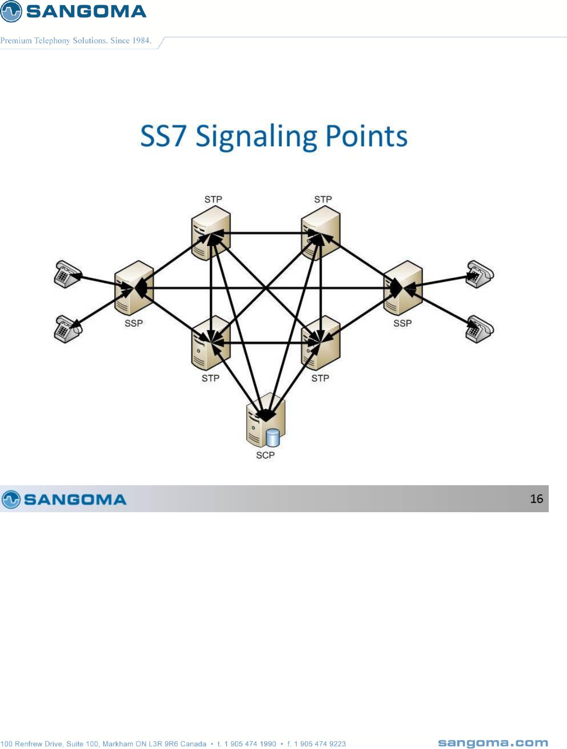
v1.14
214

v1.14
215

v1.14
216
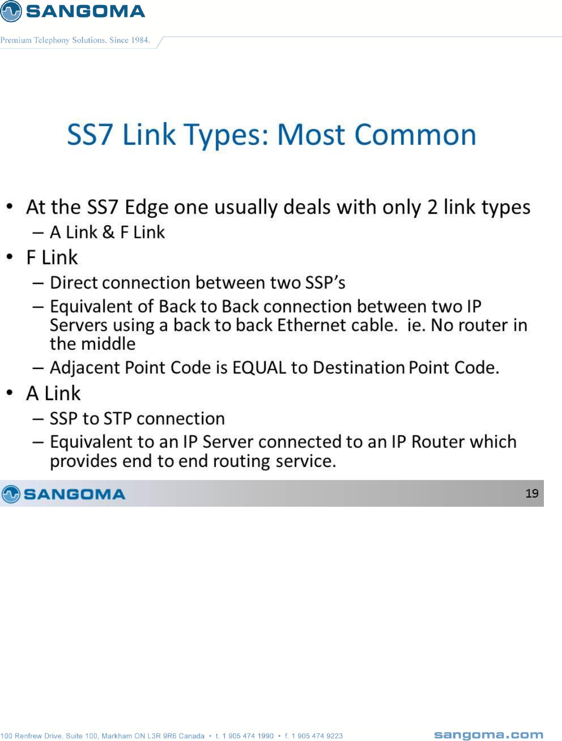
v1.14
217
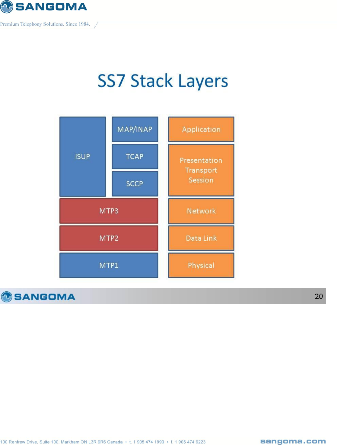
v1.14
218
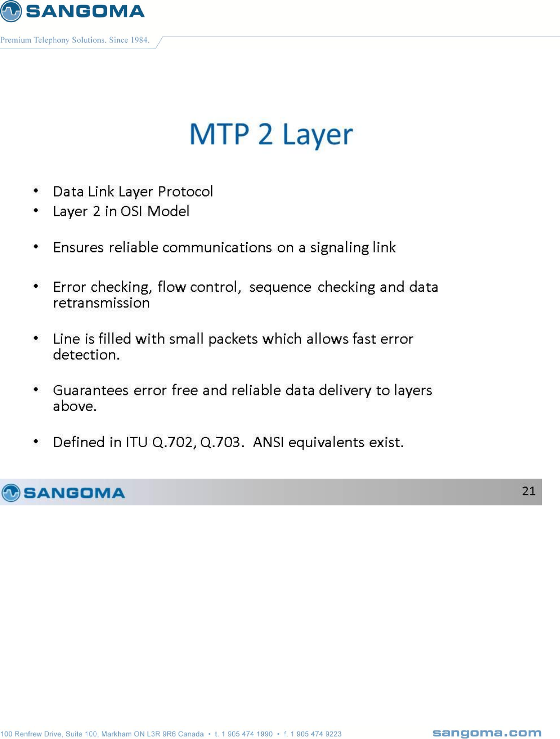
v1.14
219
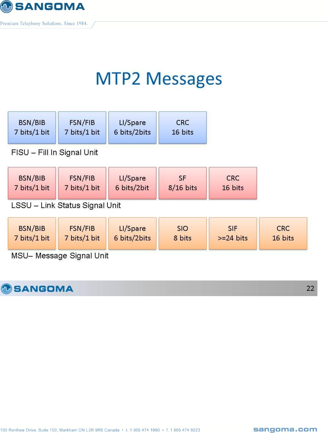
v1.14
220
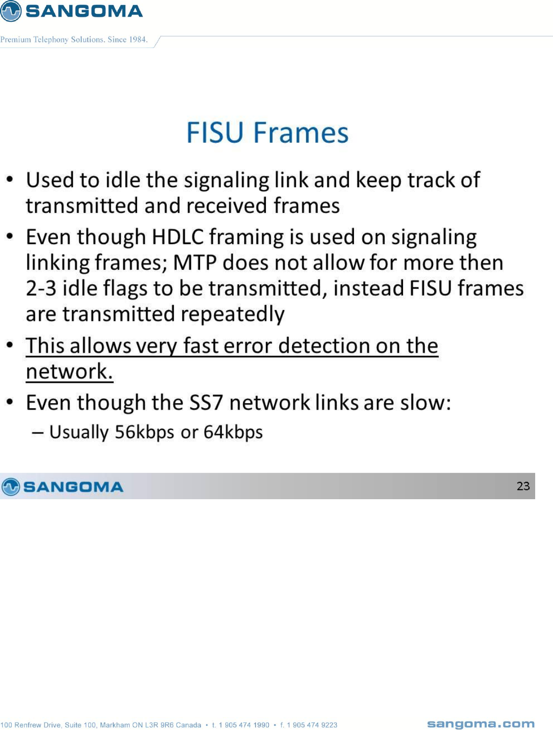
v1.14
221
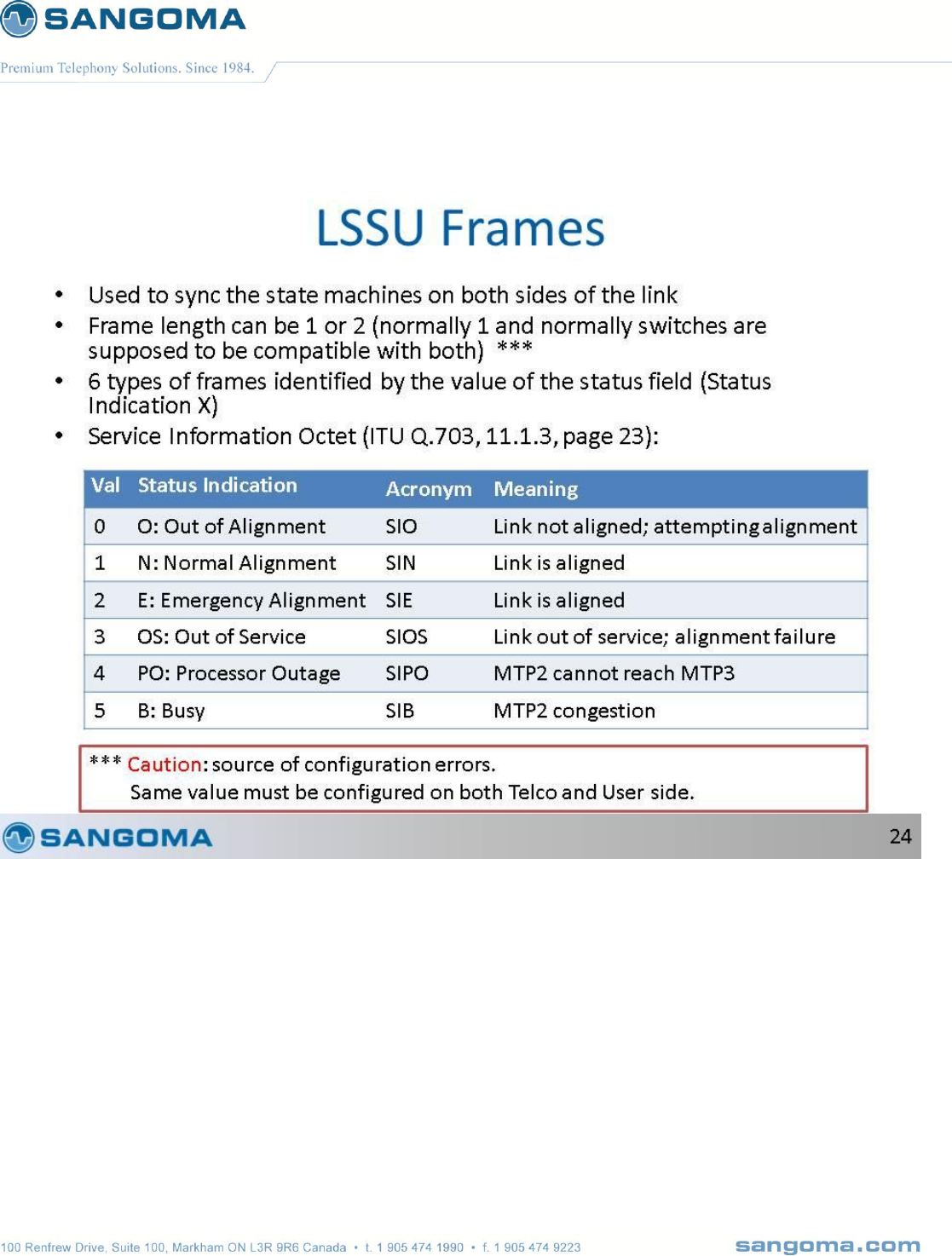
v1.14
222

v1.14
223
v1.14
224

v1.14
225
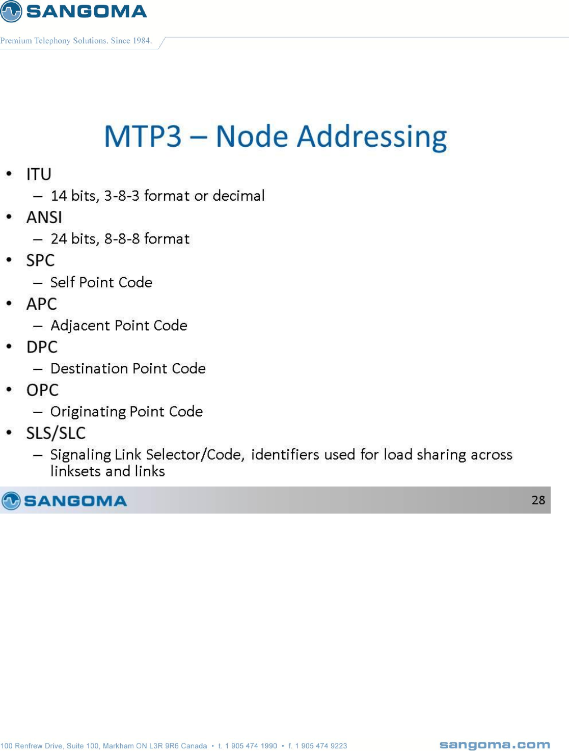
v1.14
226
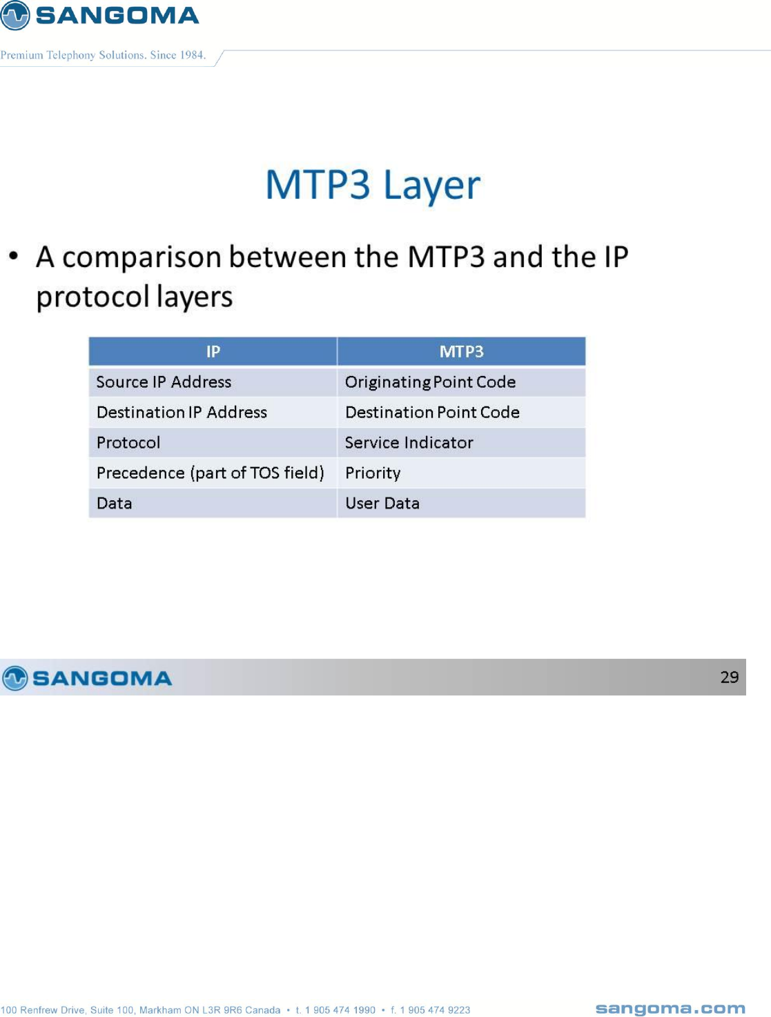
v1.14
227
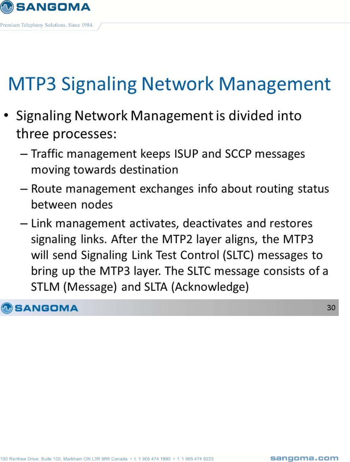
v1.14
228
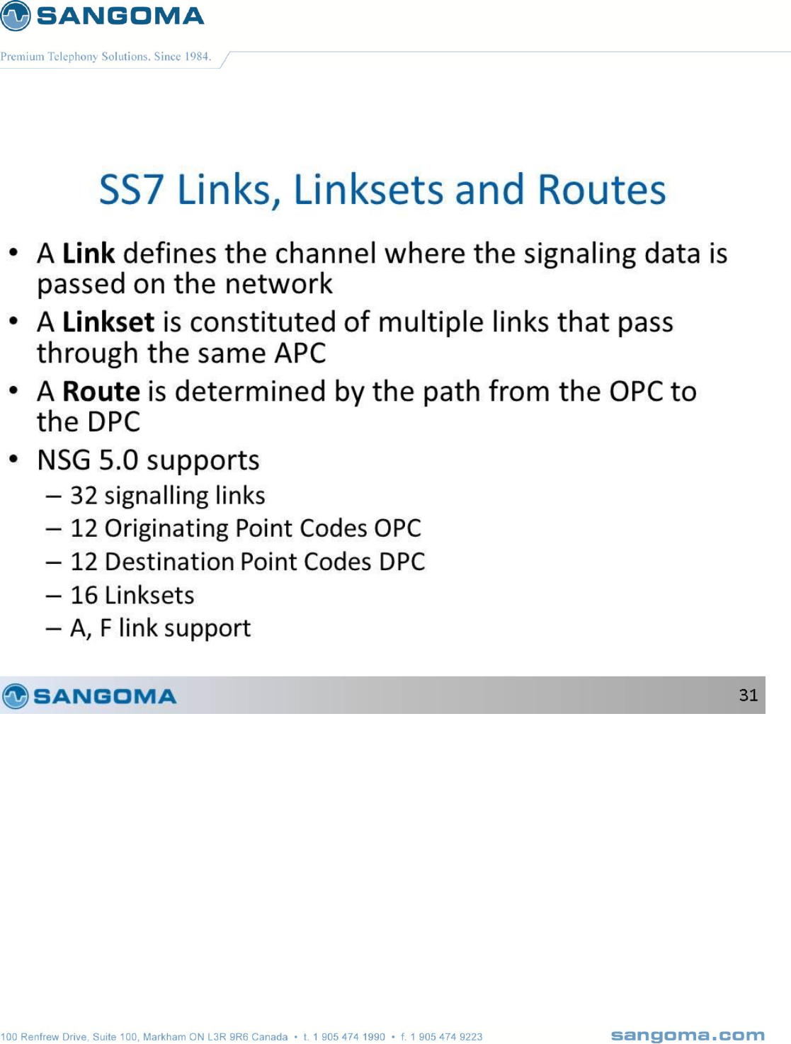
v1.14
229
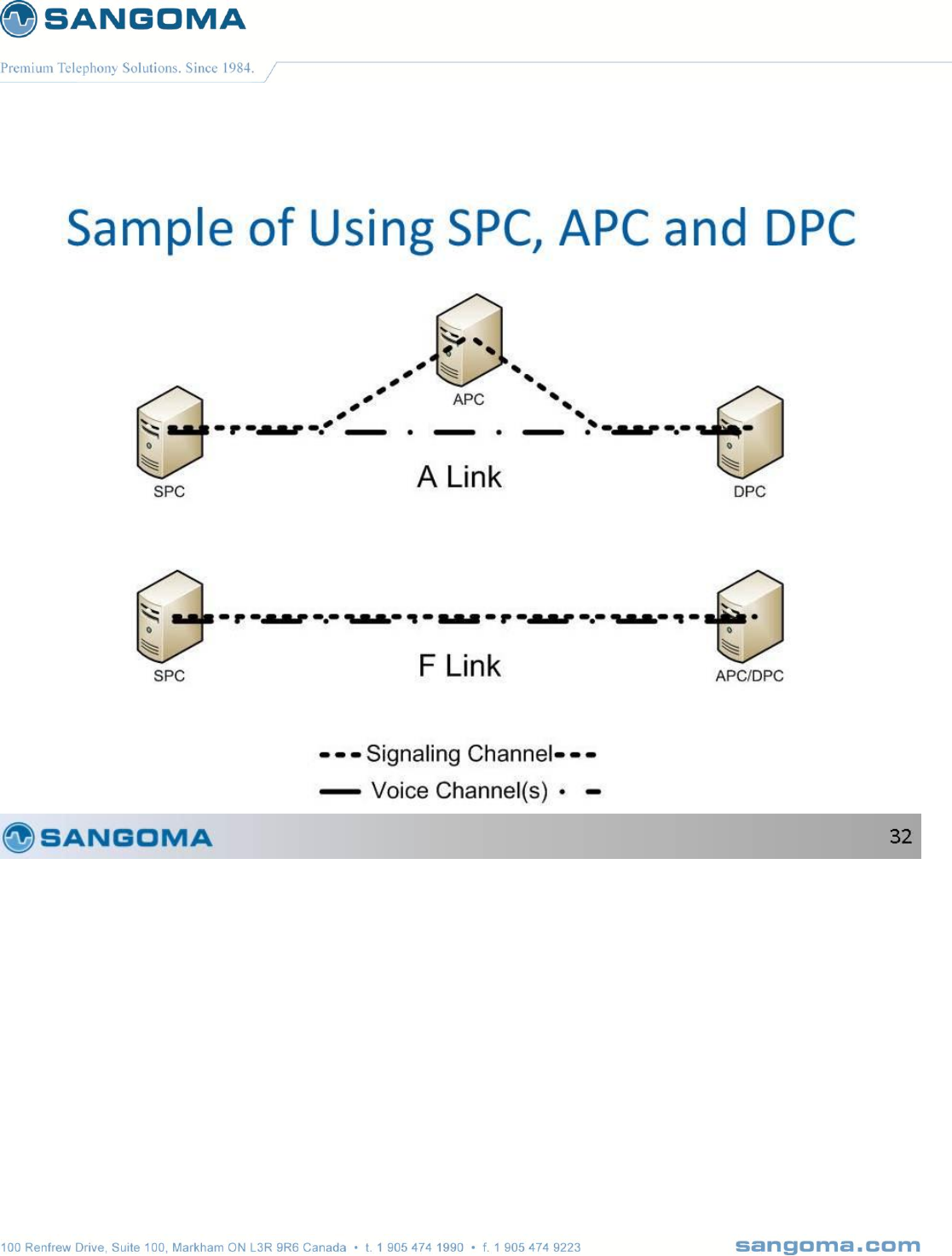
v1.14
230
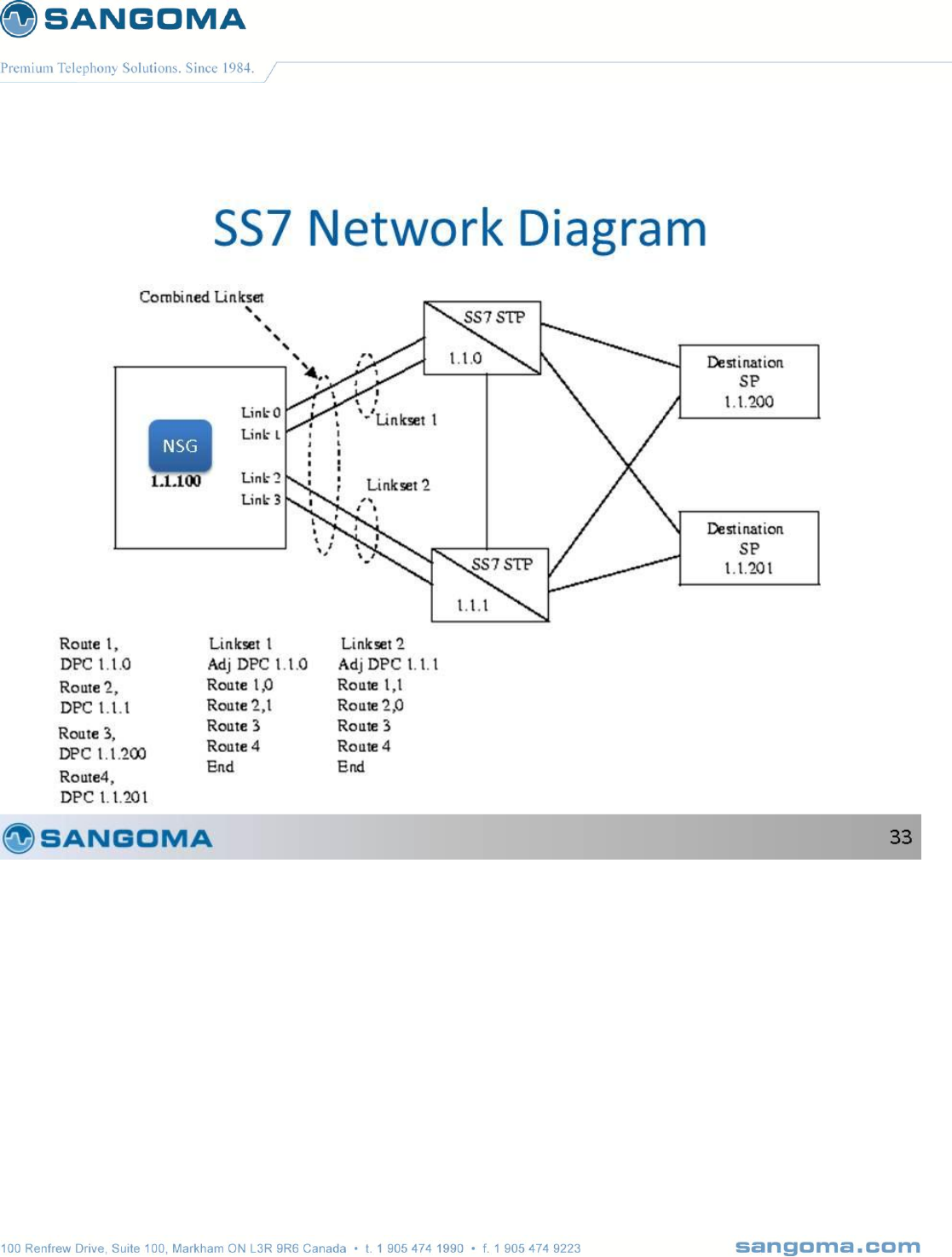
v1.14
231
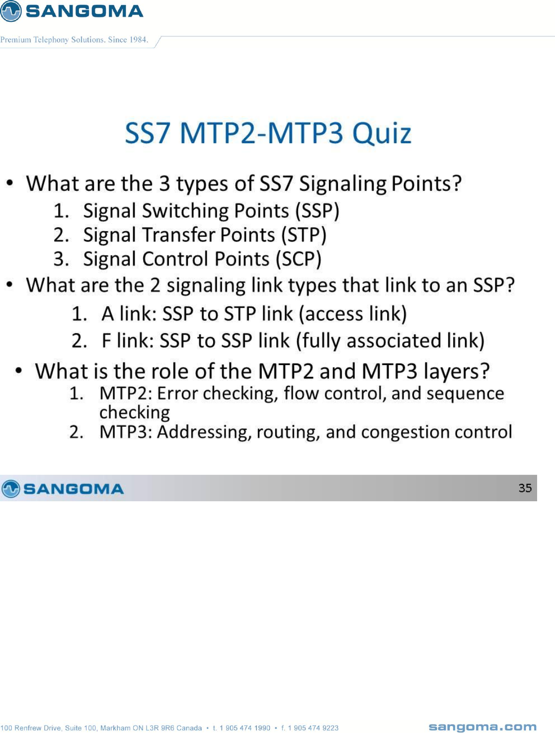
v1.14
232
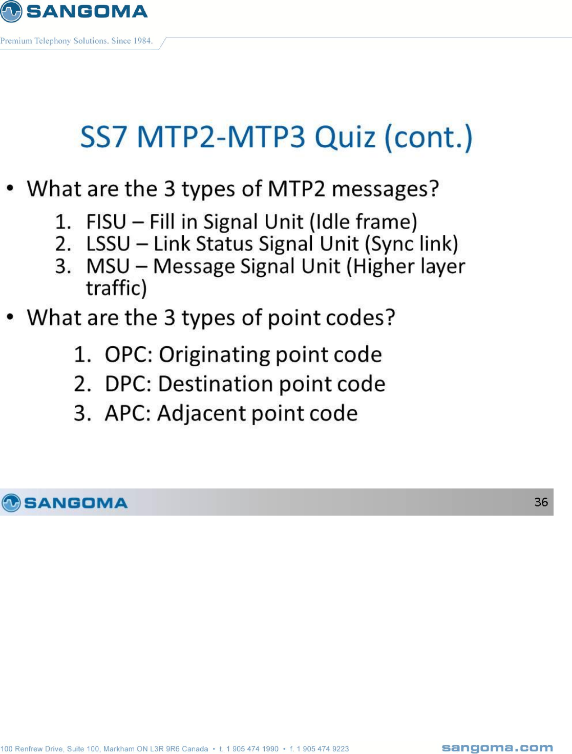
v1.14
233
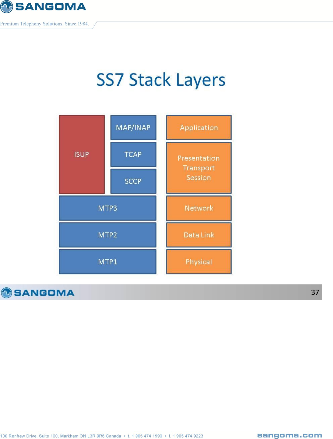
v1.14
234

v1.14
235
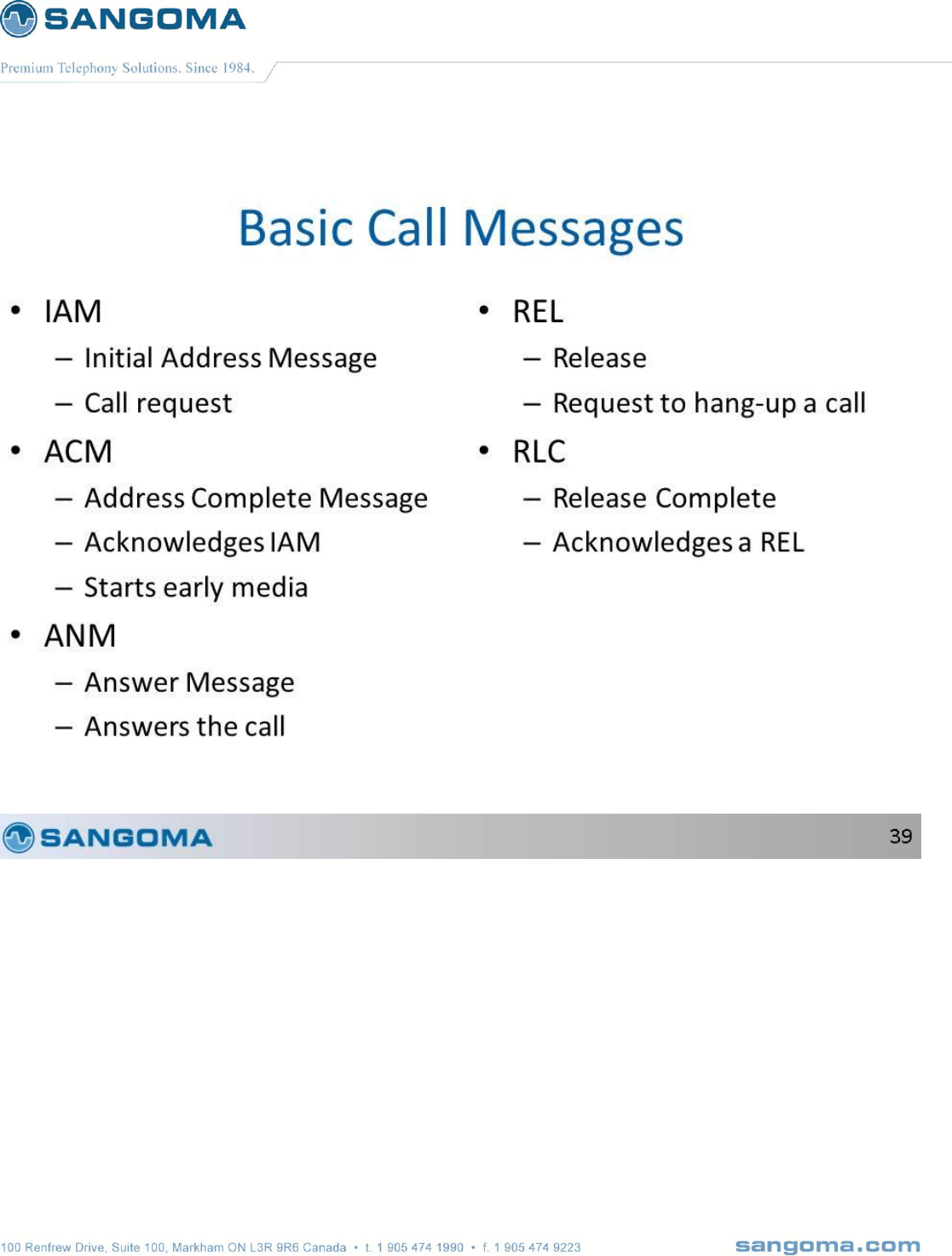
v1.14
236
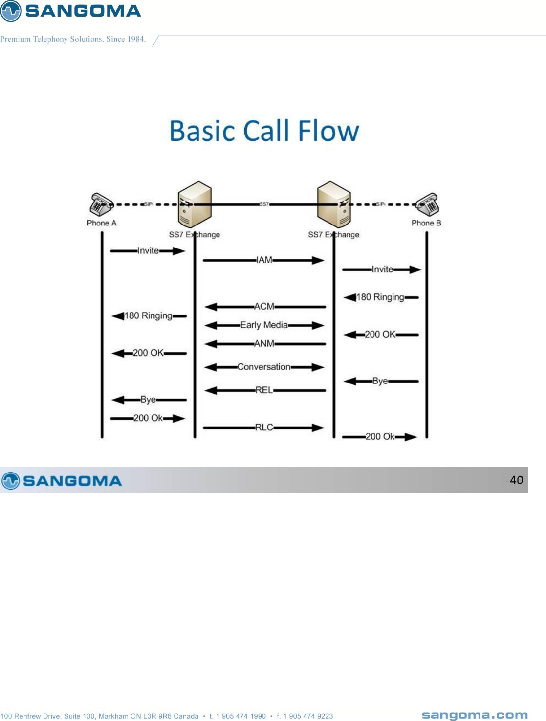
v1.14
237
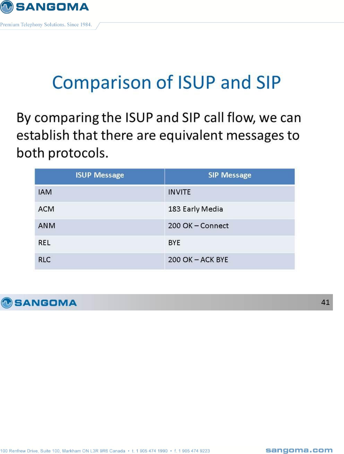
v1.14
238
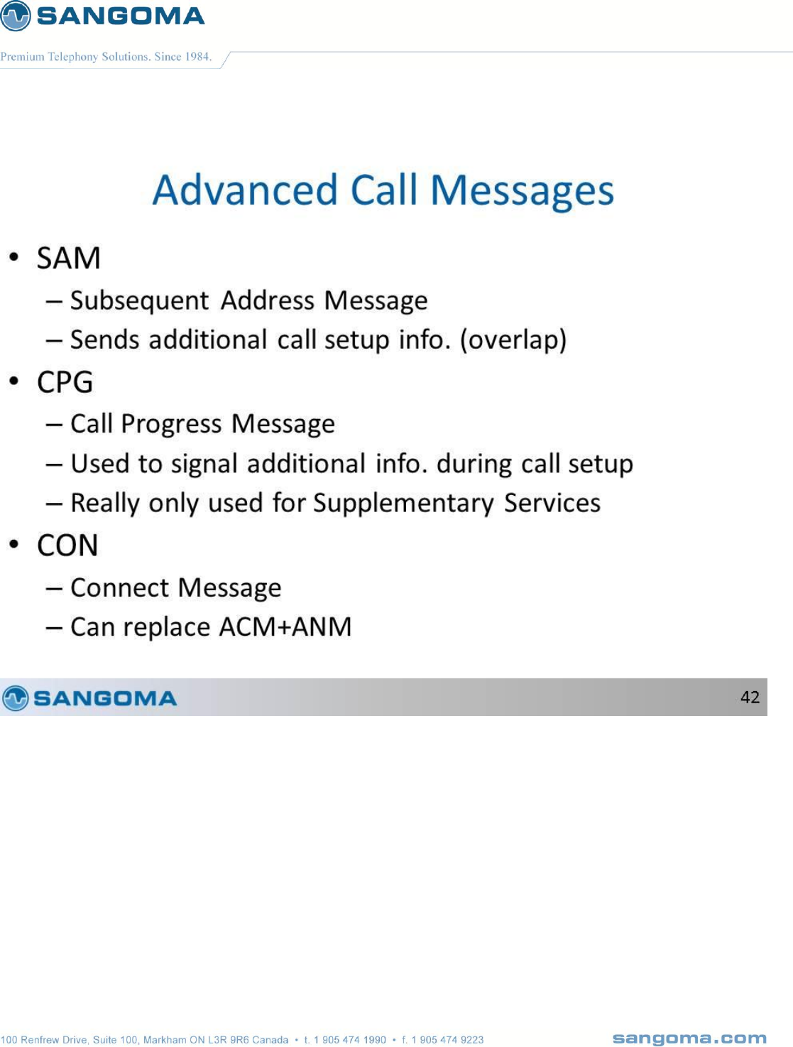
v1.14
239
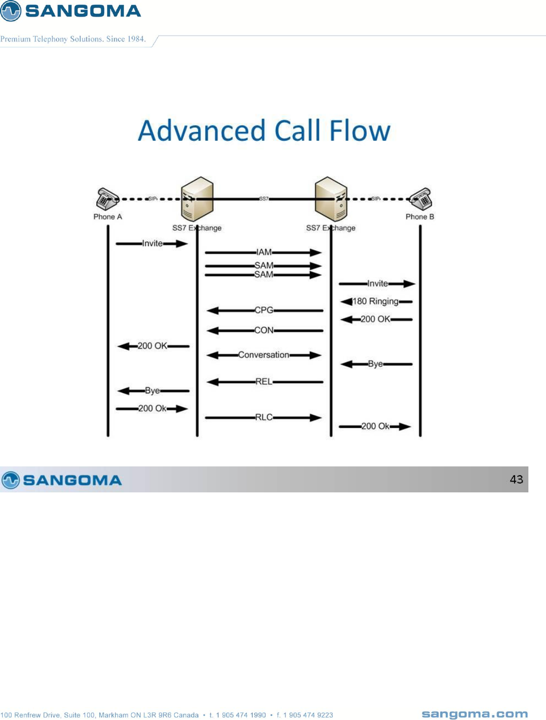
v1.14
240

v1.14
241
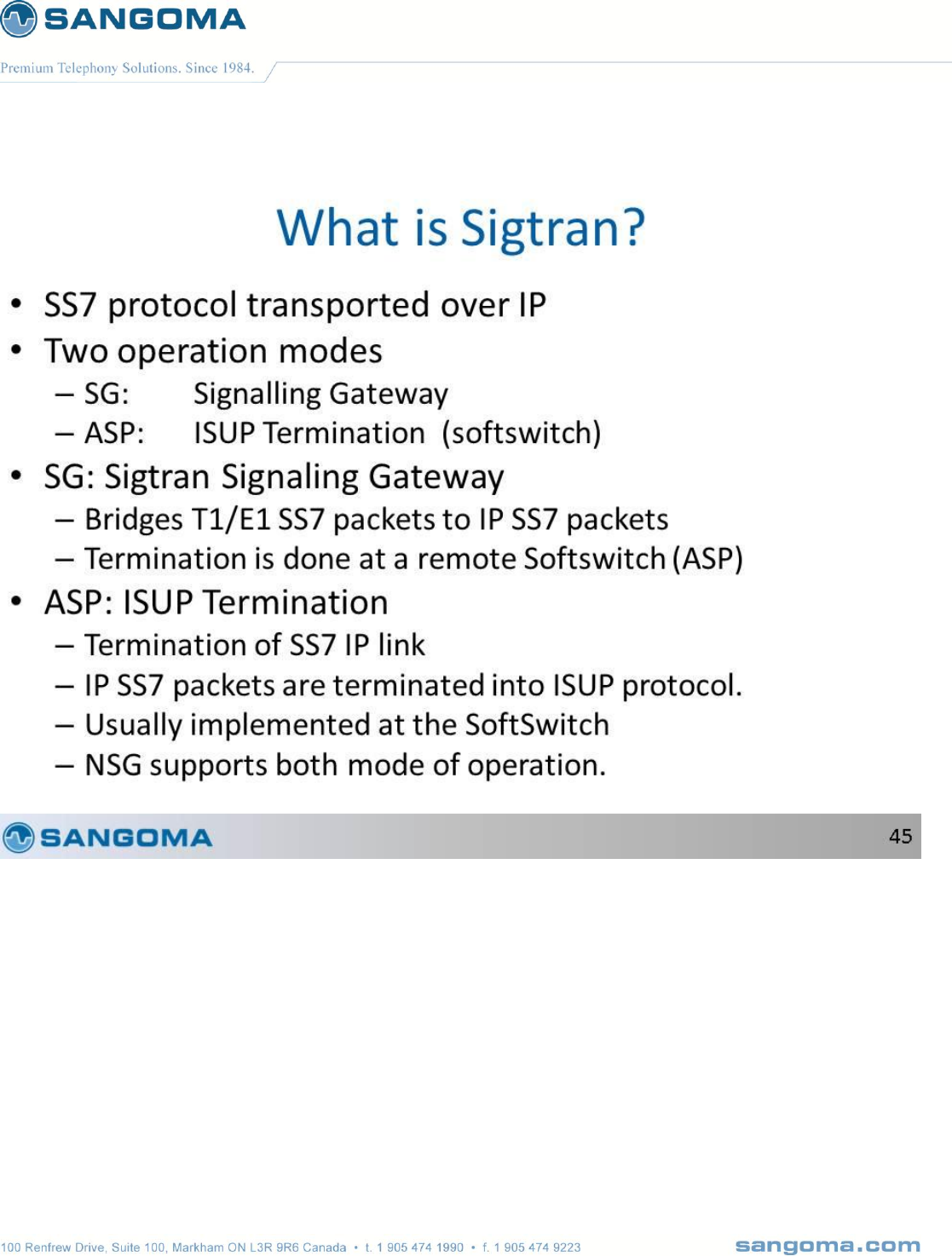
v1.14
242
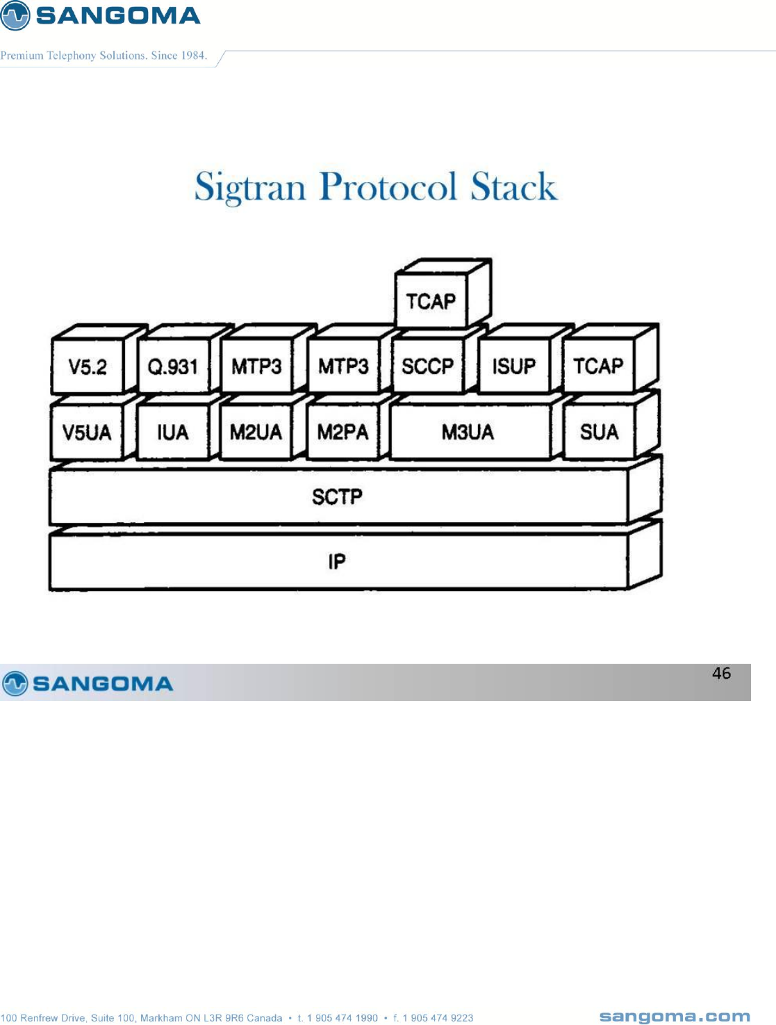
v1.14
243
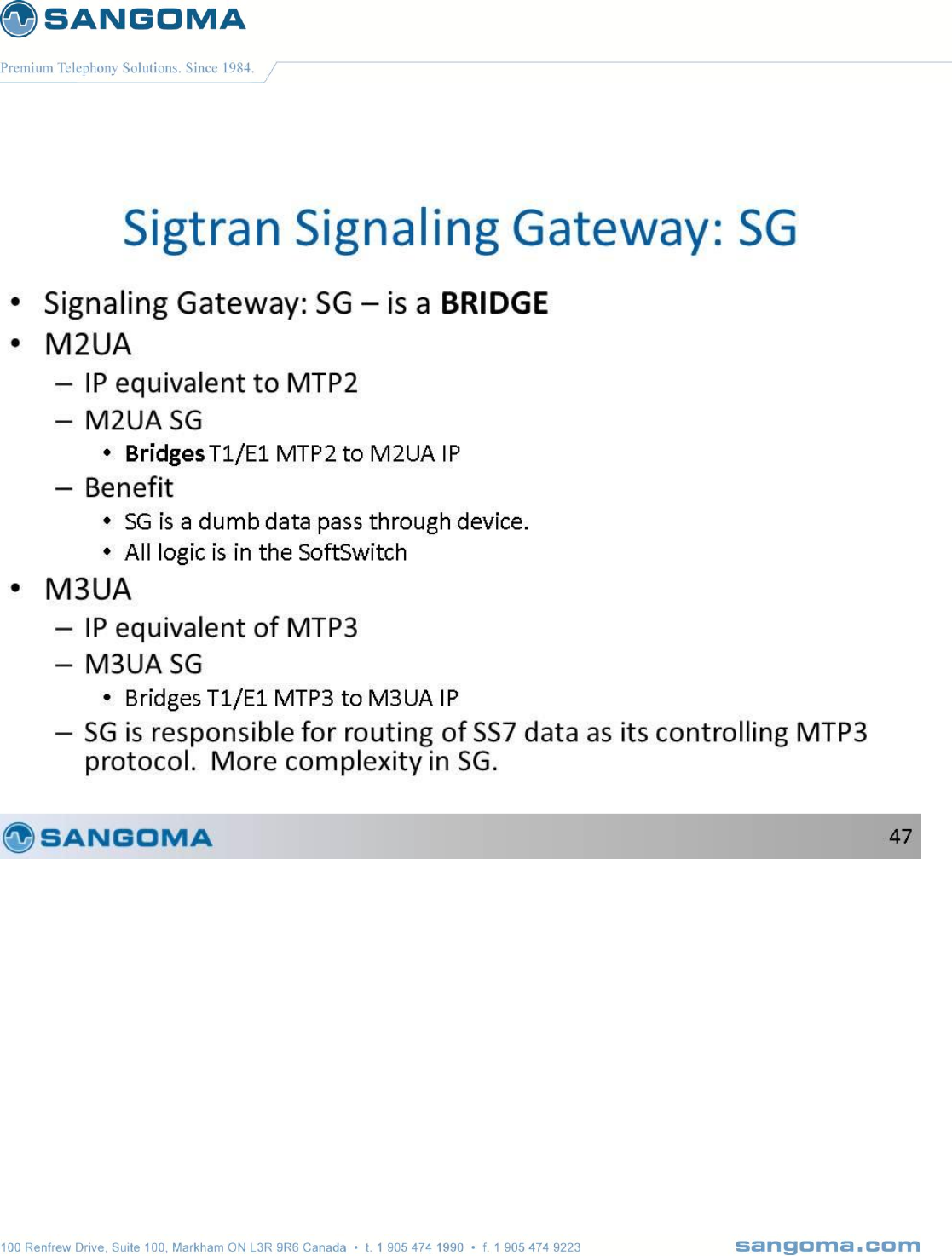
v1.14
244
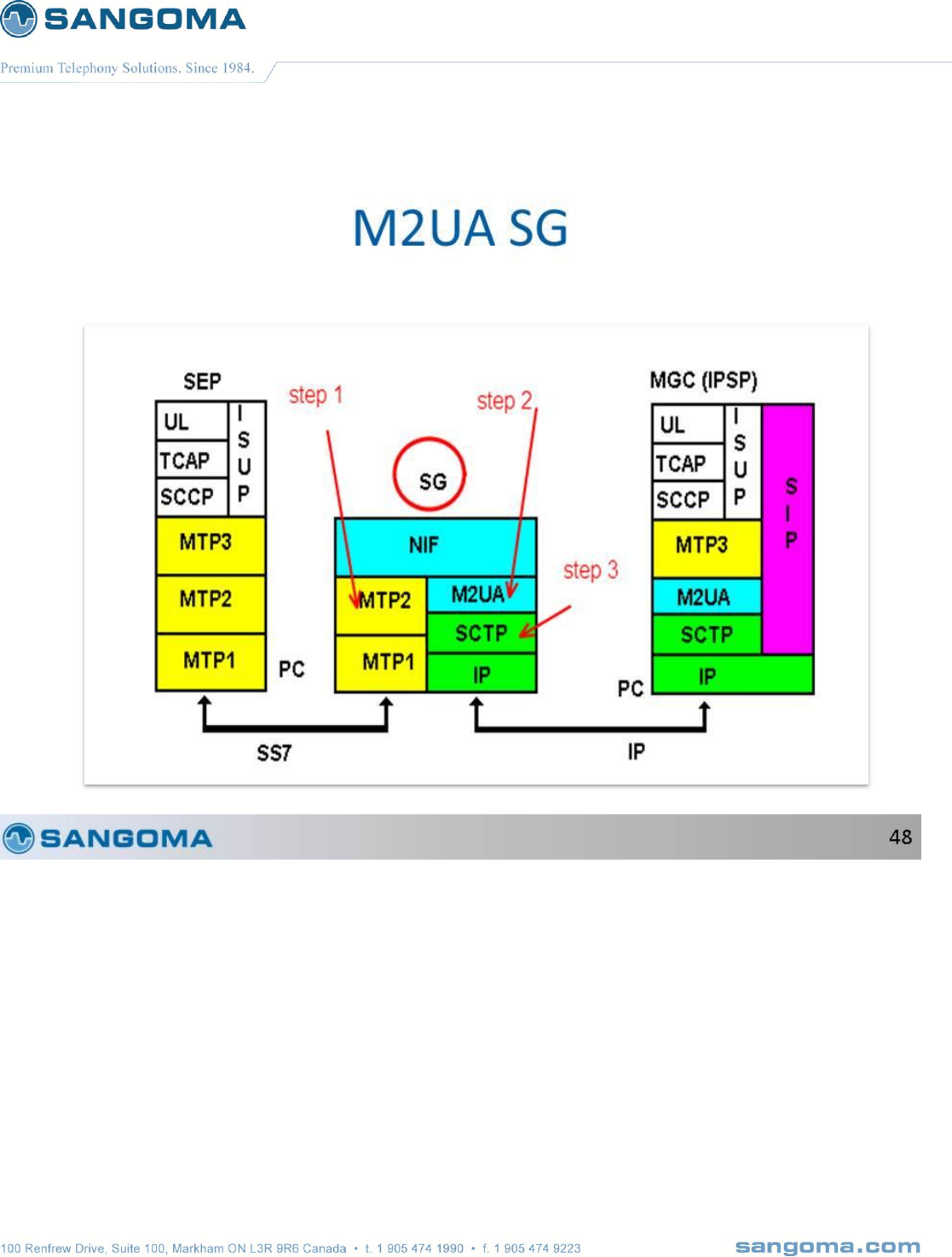
v1.14
245
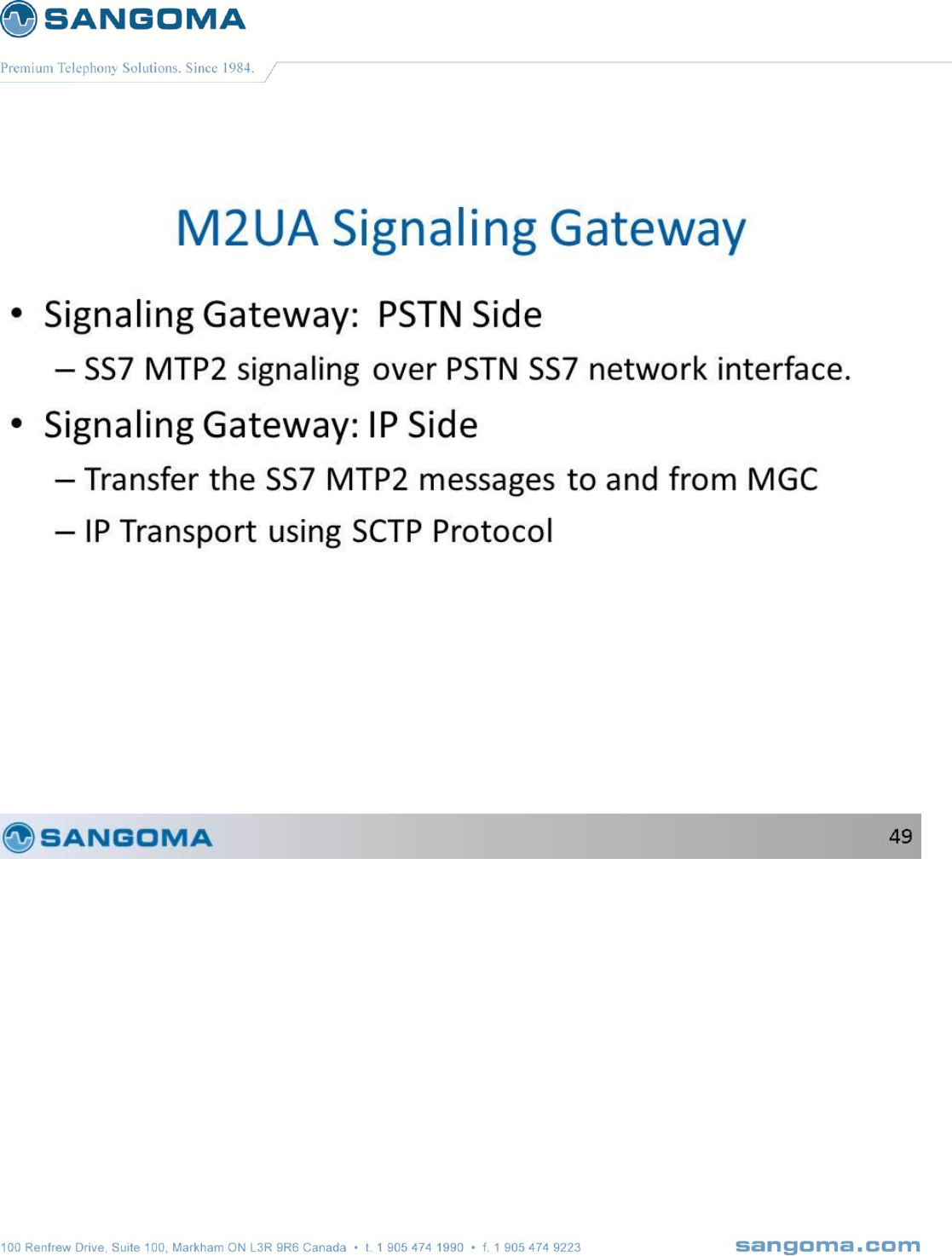
v1.14
246
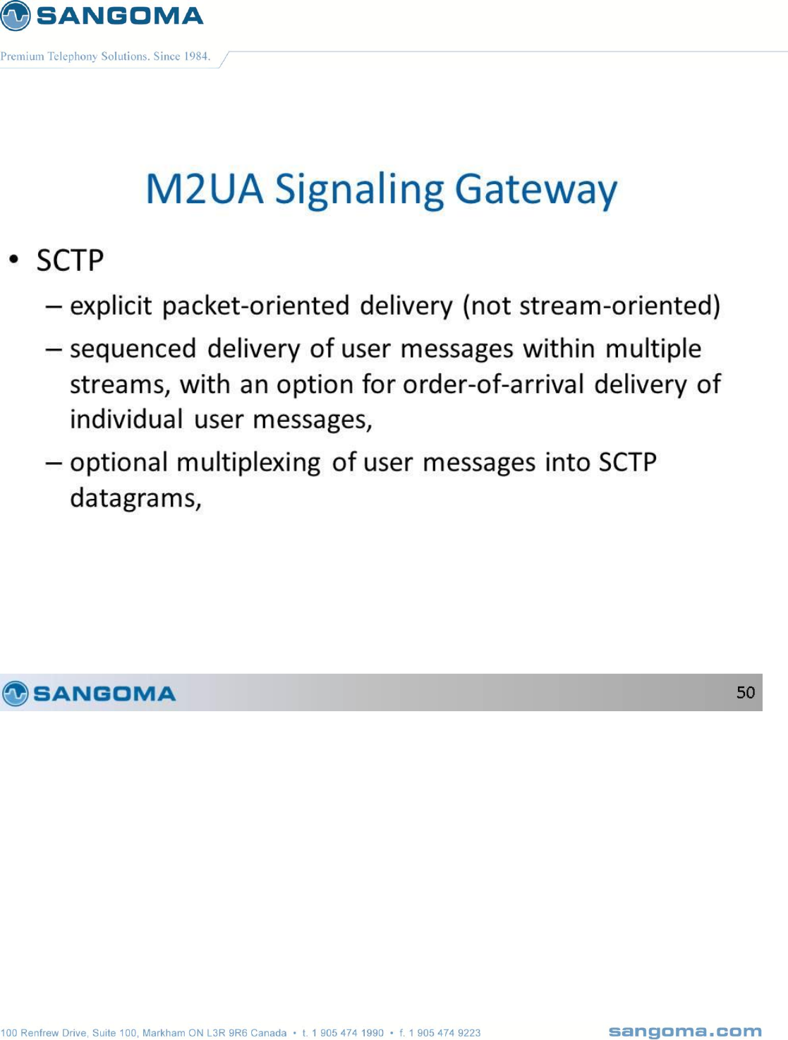
v1.14
247
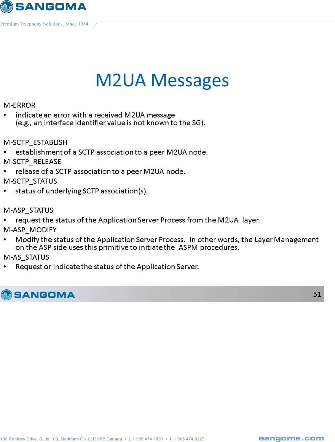
v1.14
248
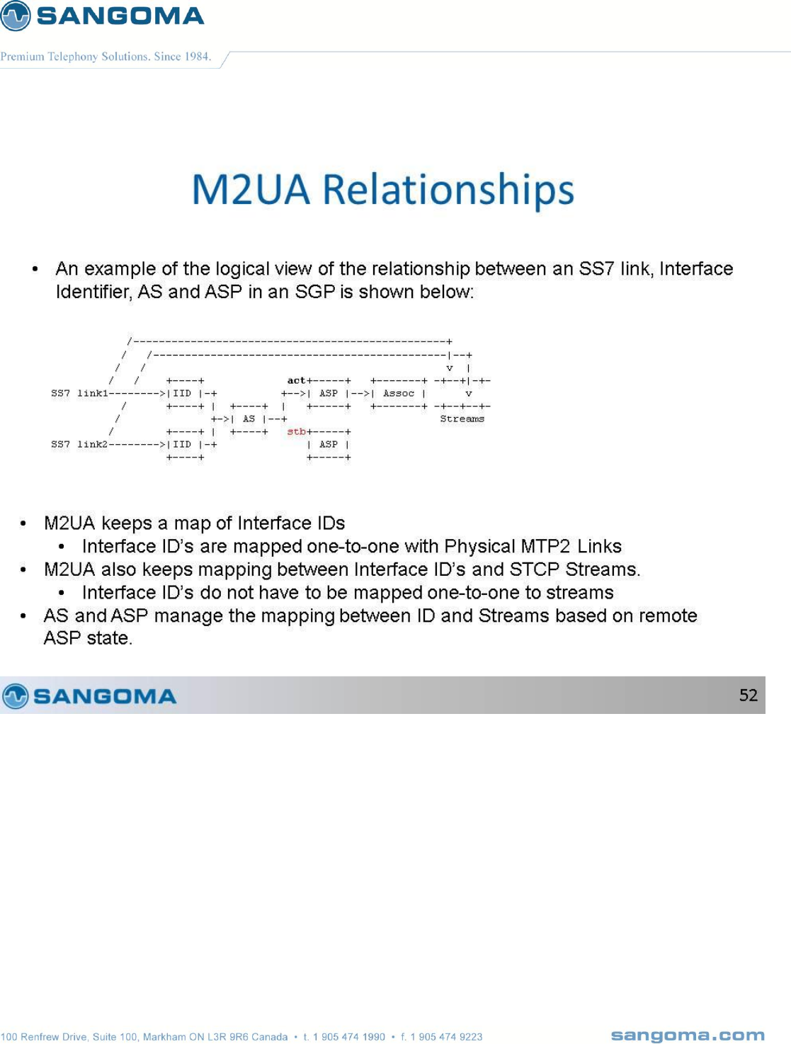
v1.14
249

v1.14
250
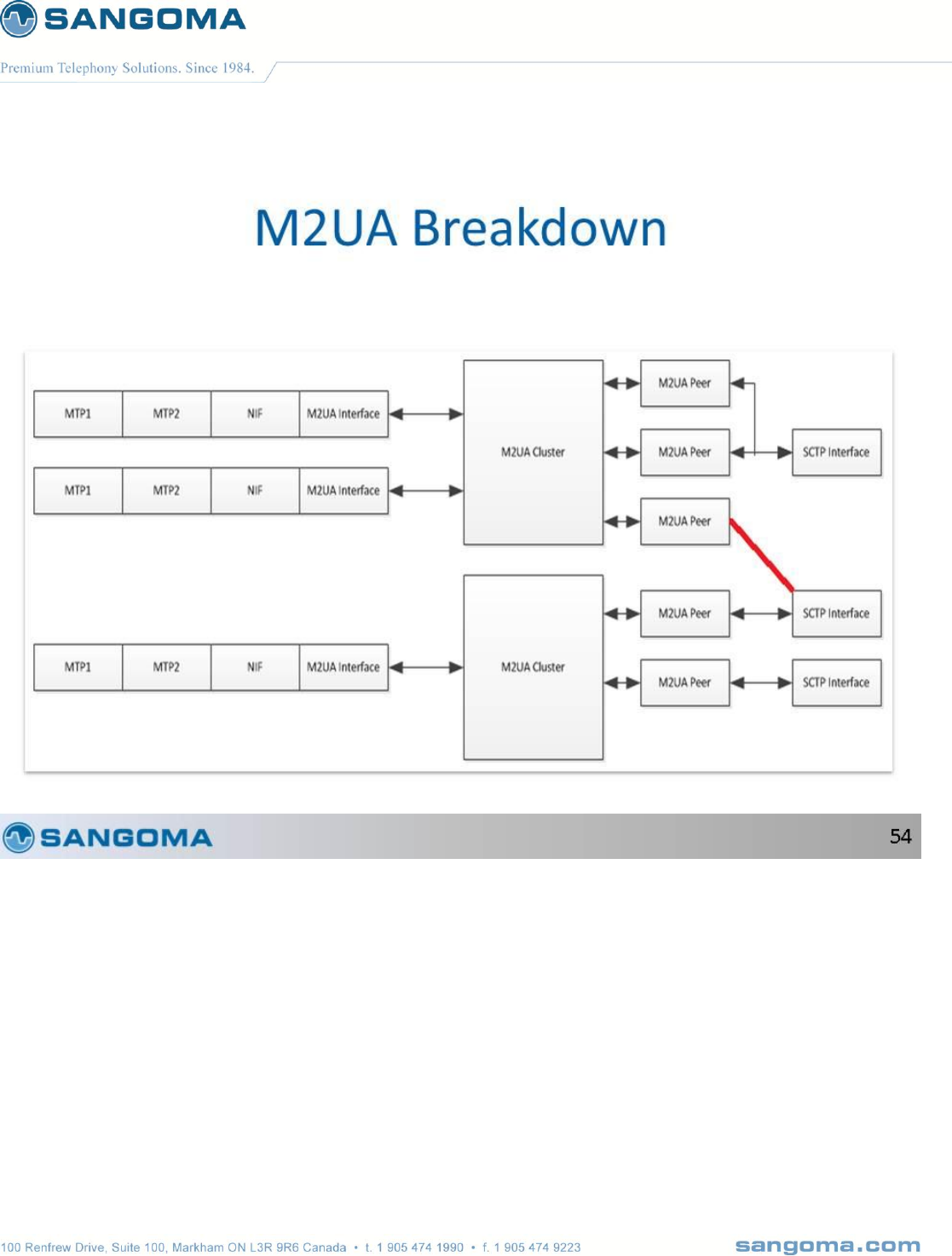
v1.14
251
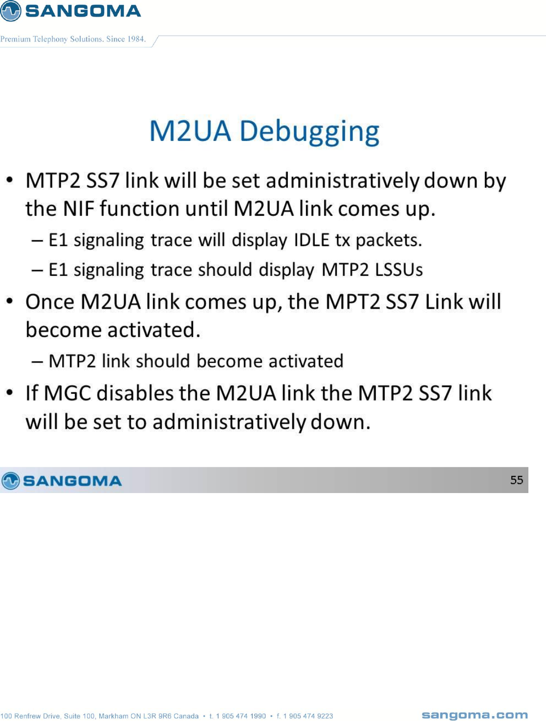
v1.14
252

v1.14
253
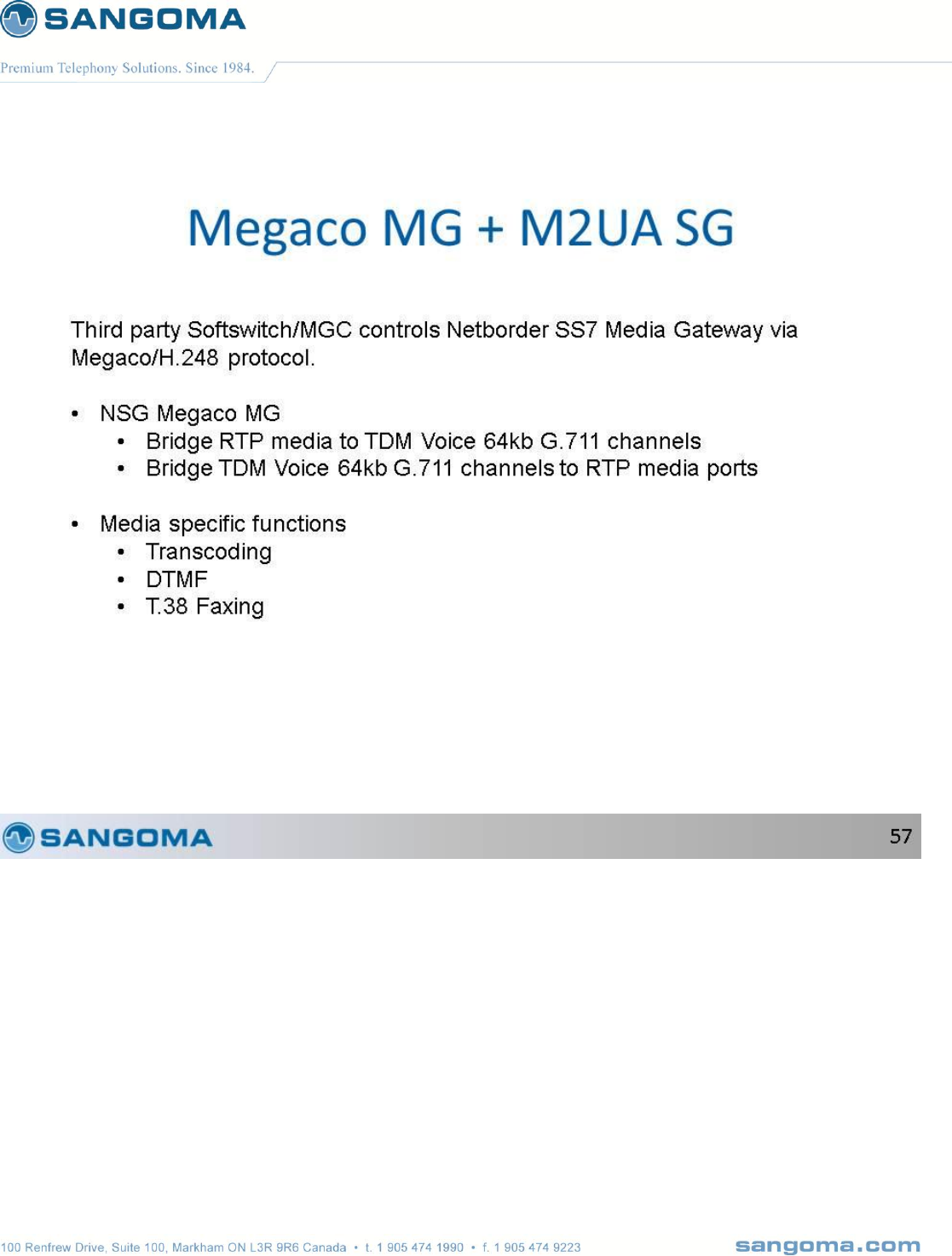
v1.14
254

v1.14
255
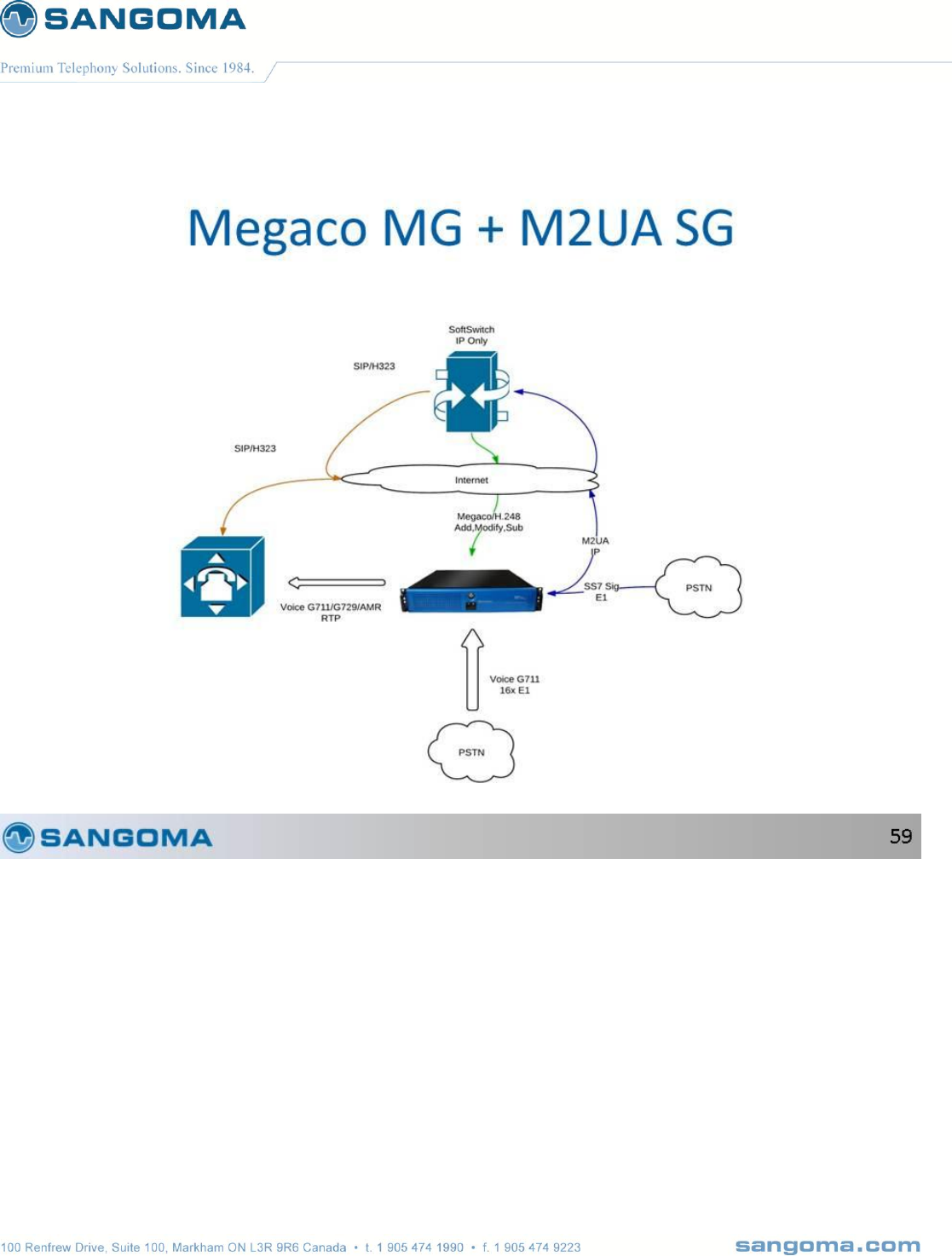
v1.14
256

v1.14
257
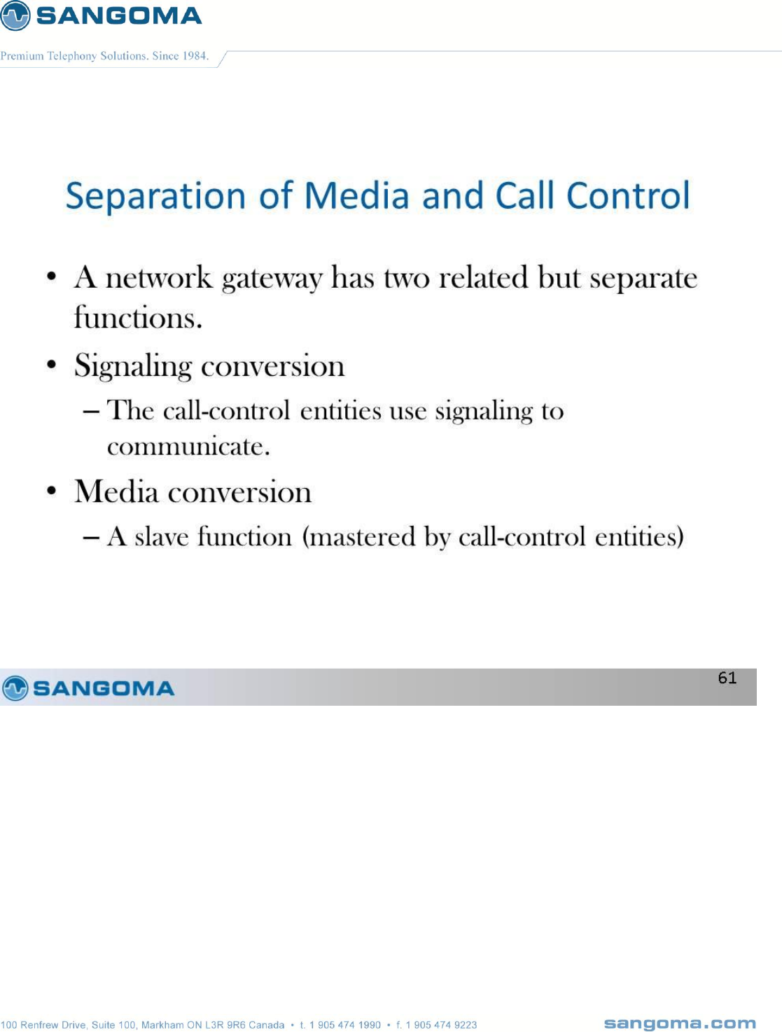
v1.14
258
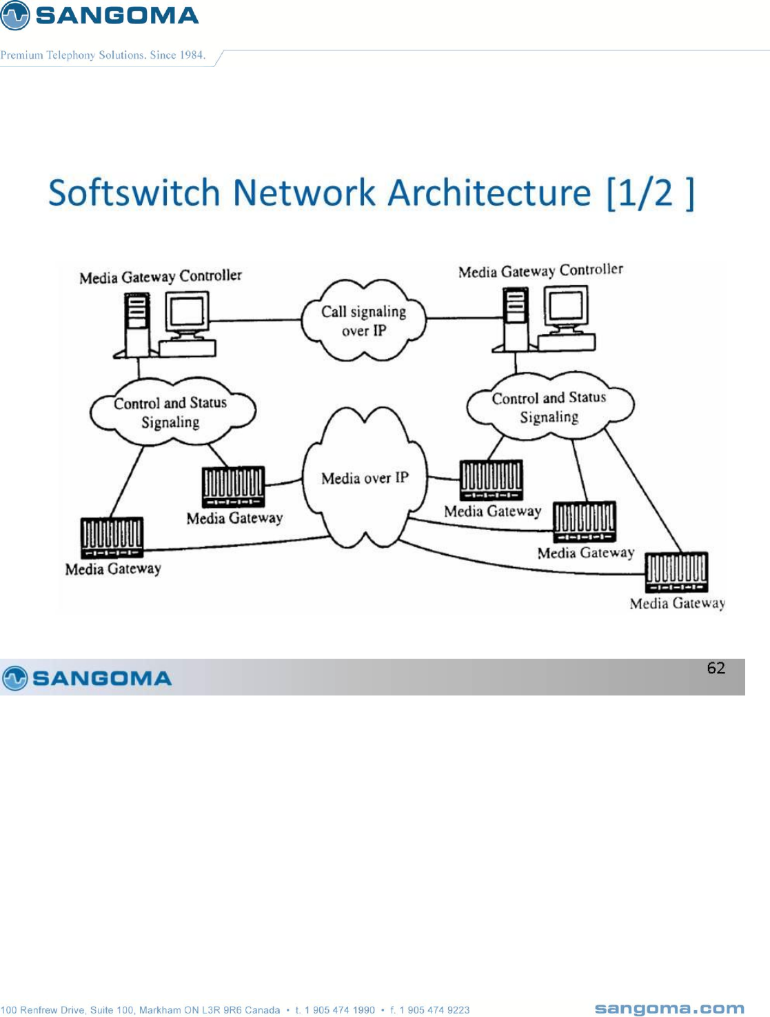
v1.14
259
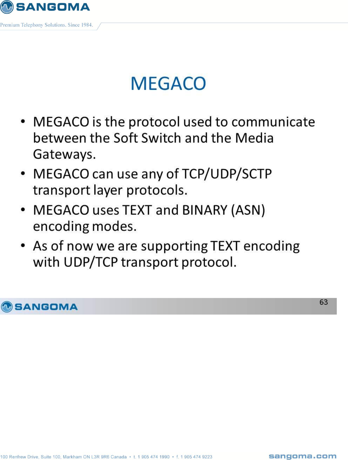
v1.14
260
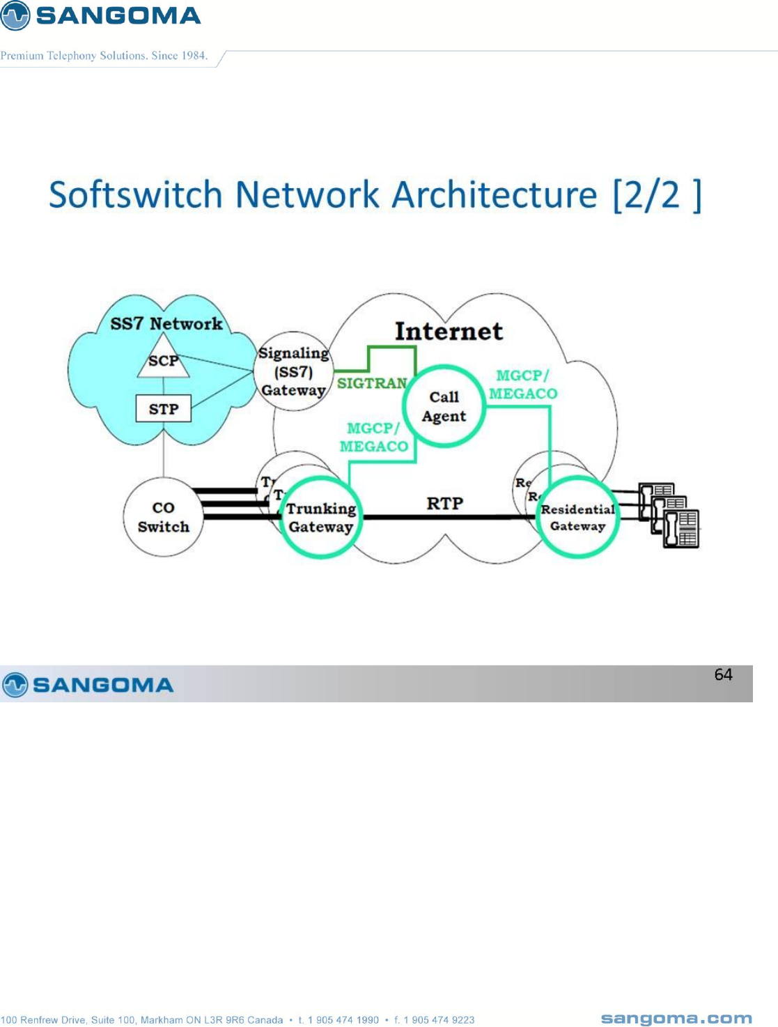
v1.14
261
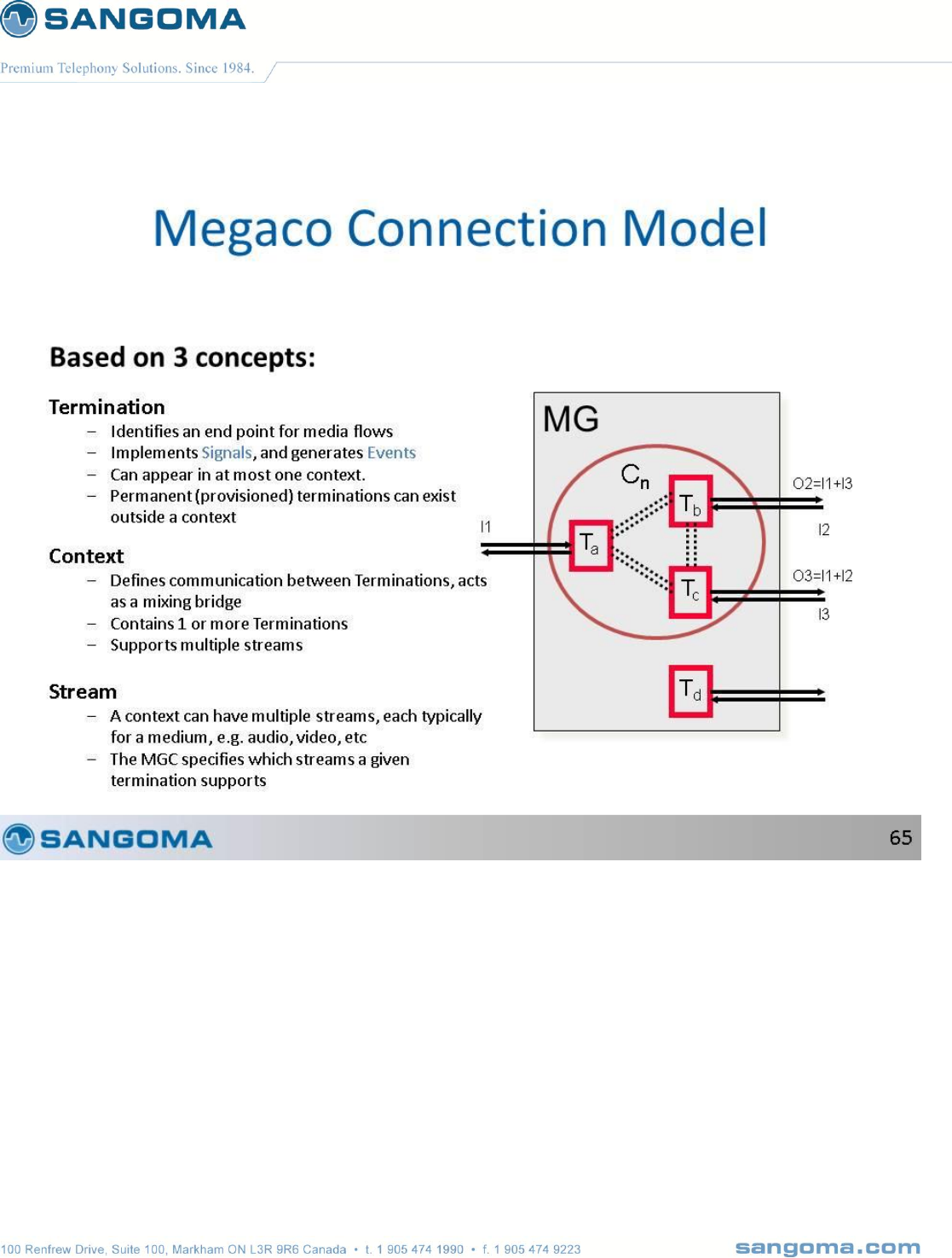
v1.14
262
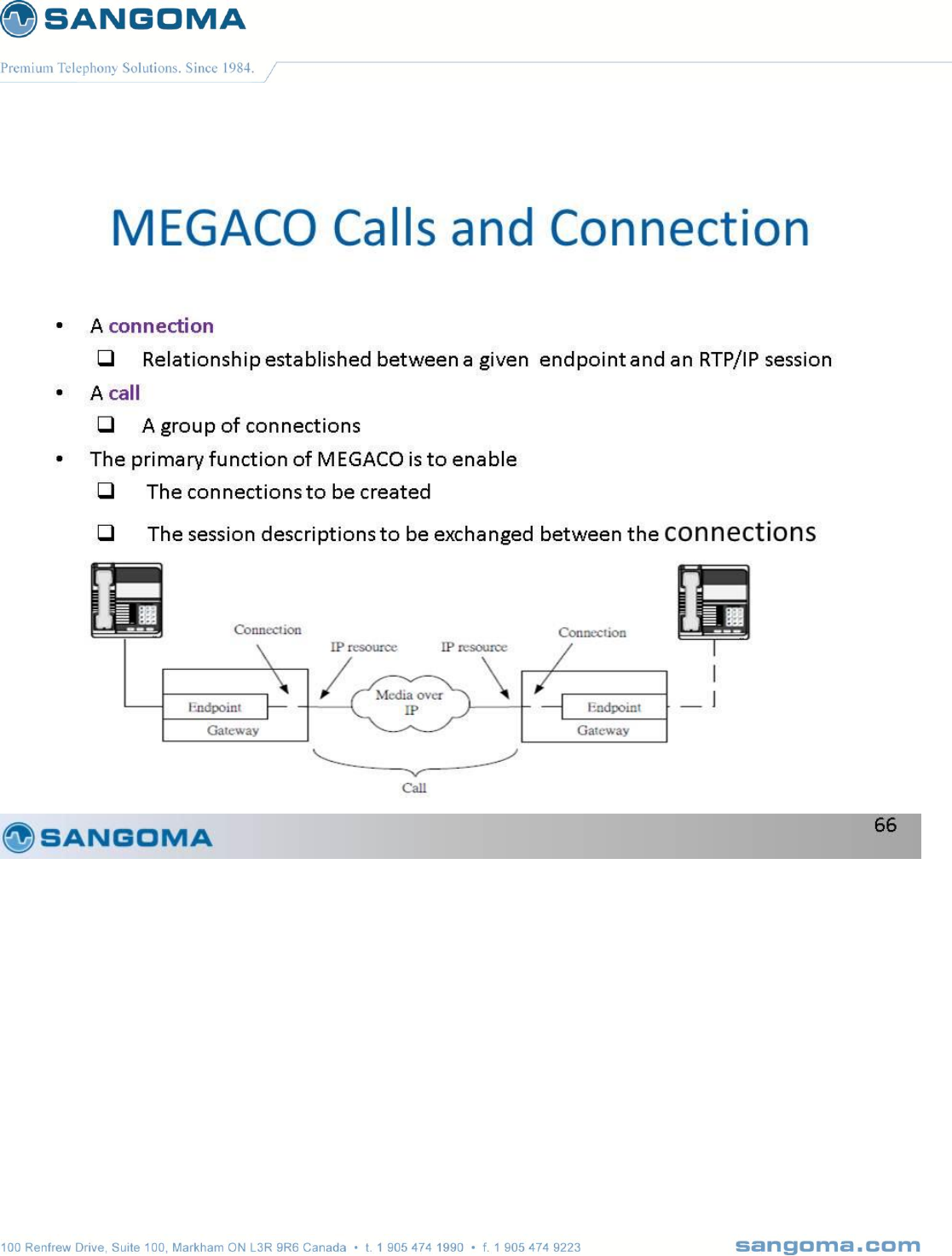
v1.14
263
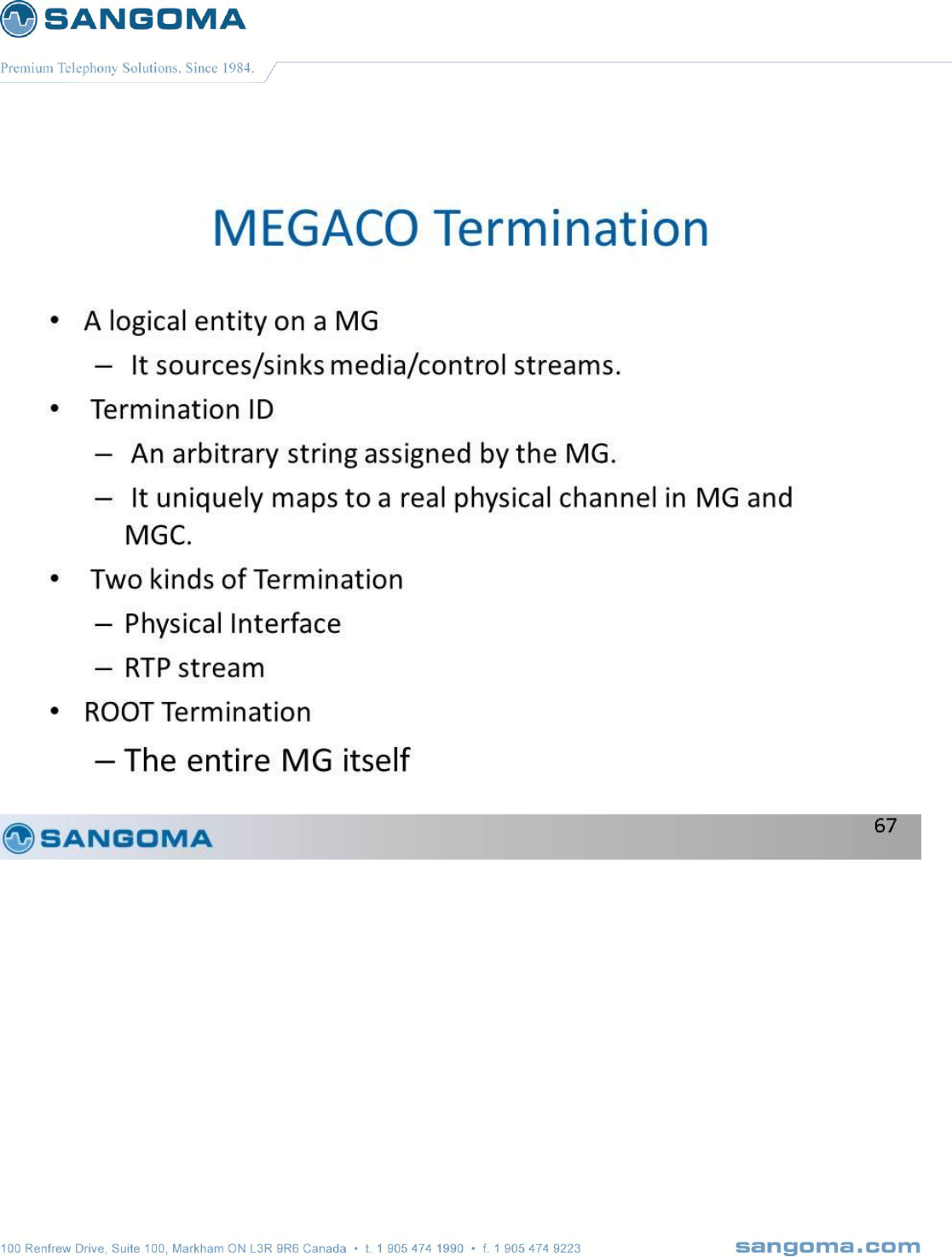
v1.14
264

v1.14
265
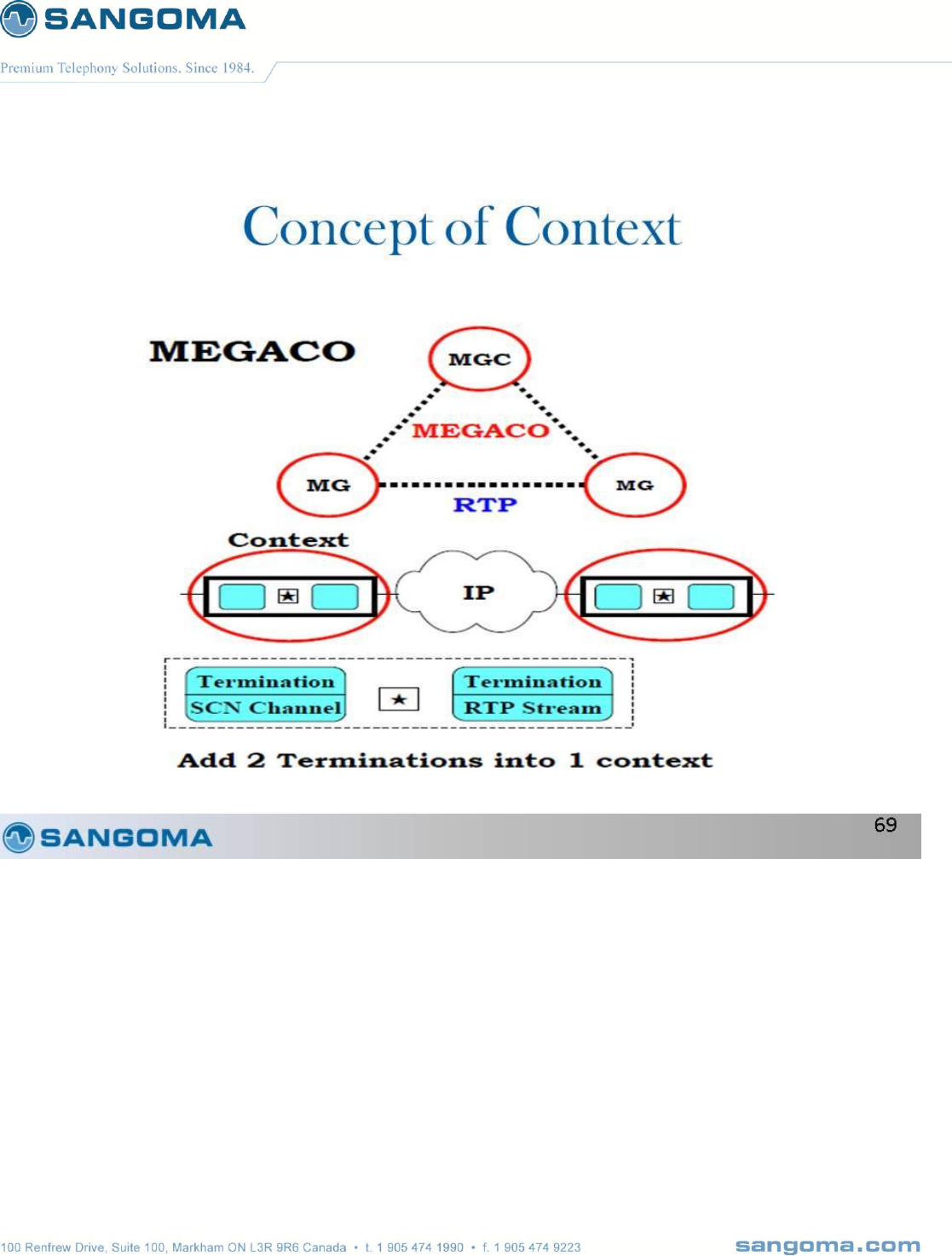
v1.14
266
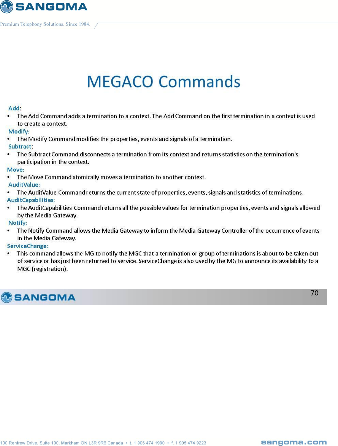
v1.14
267
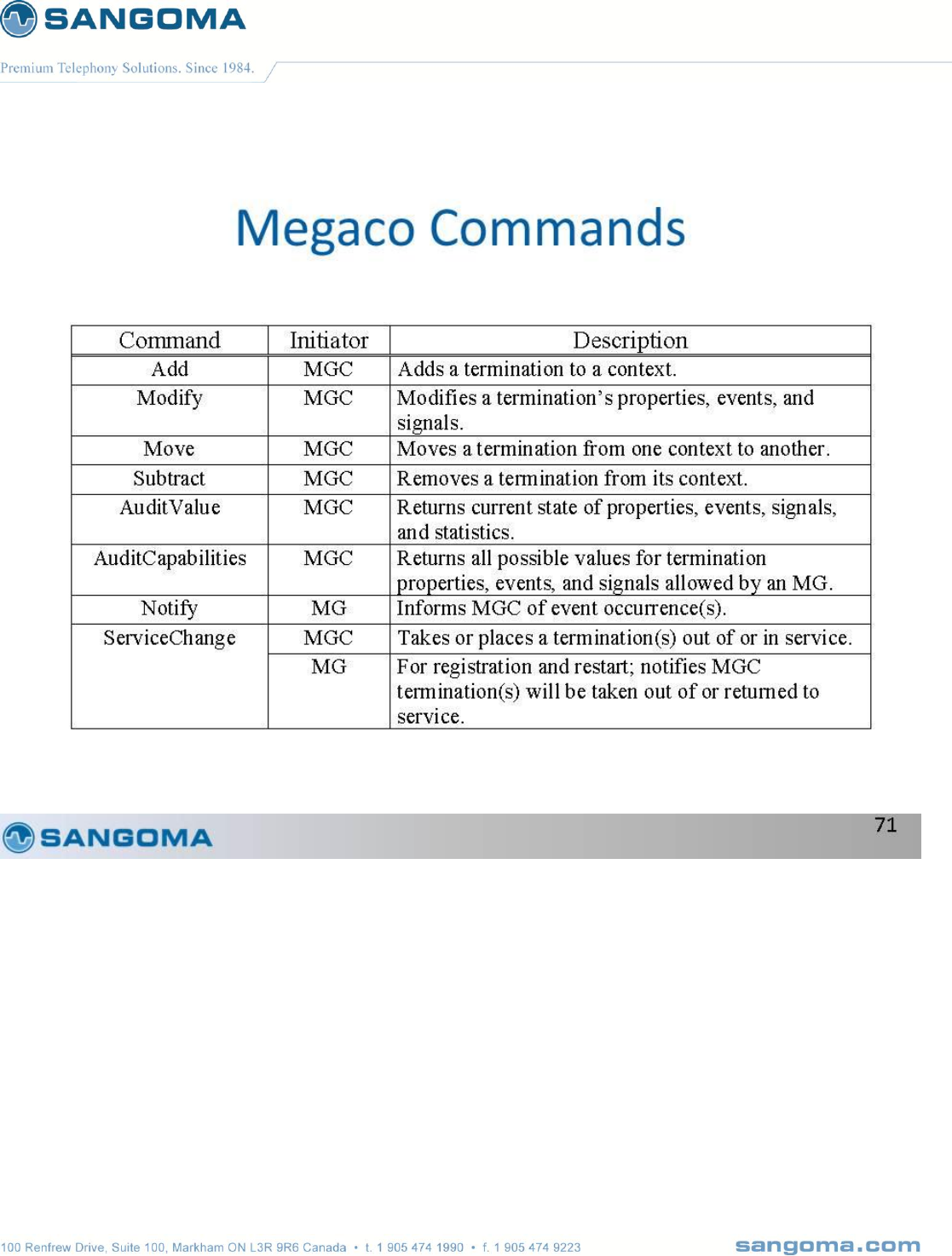
v1.14
268
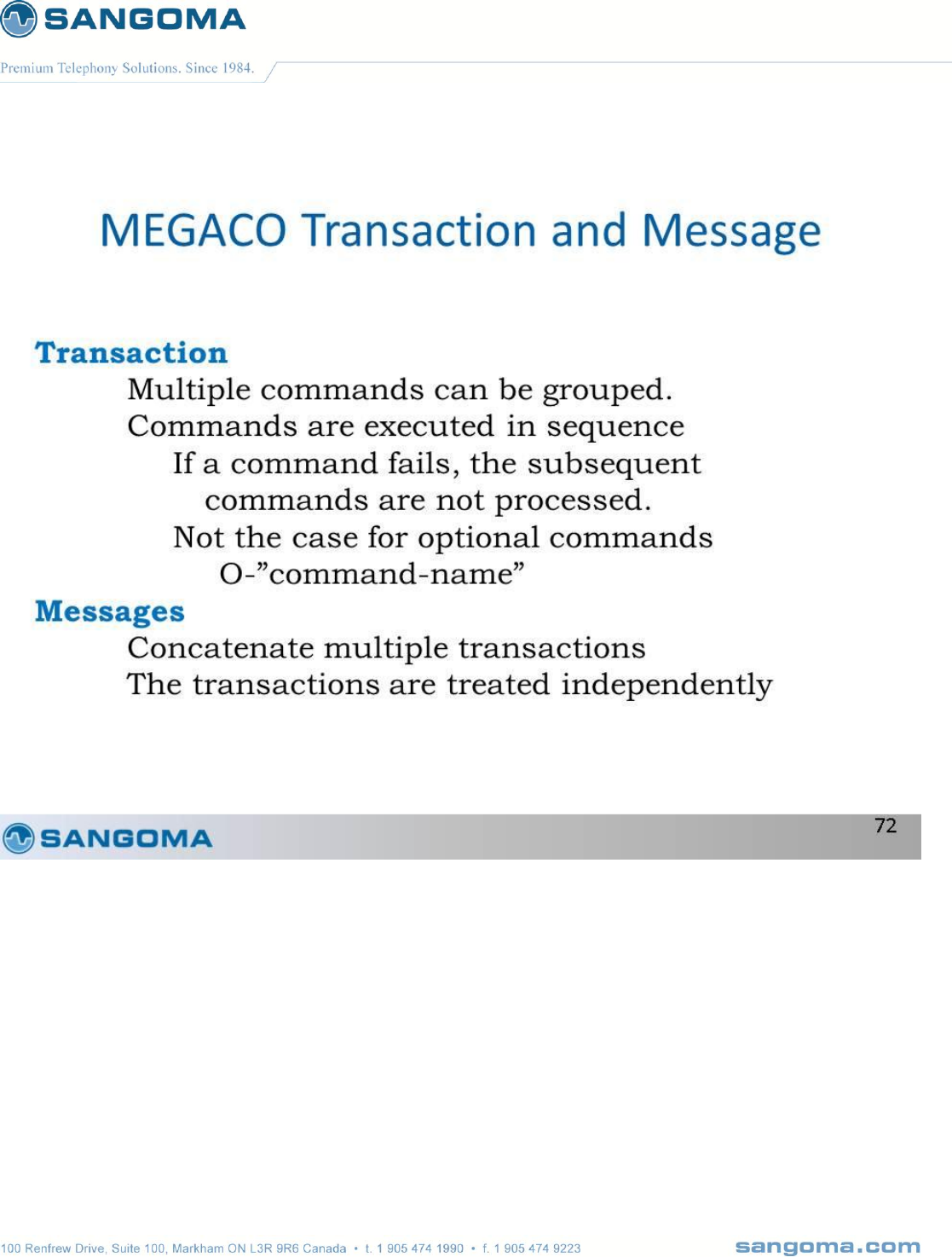
v1.14
269
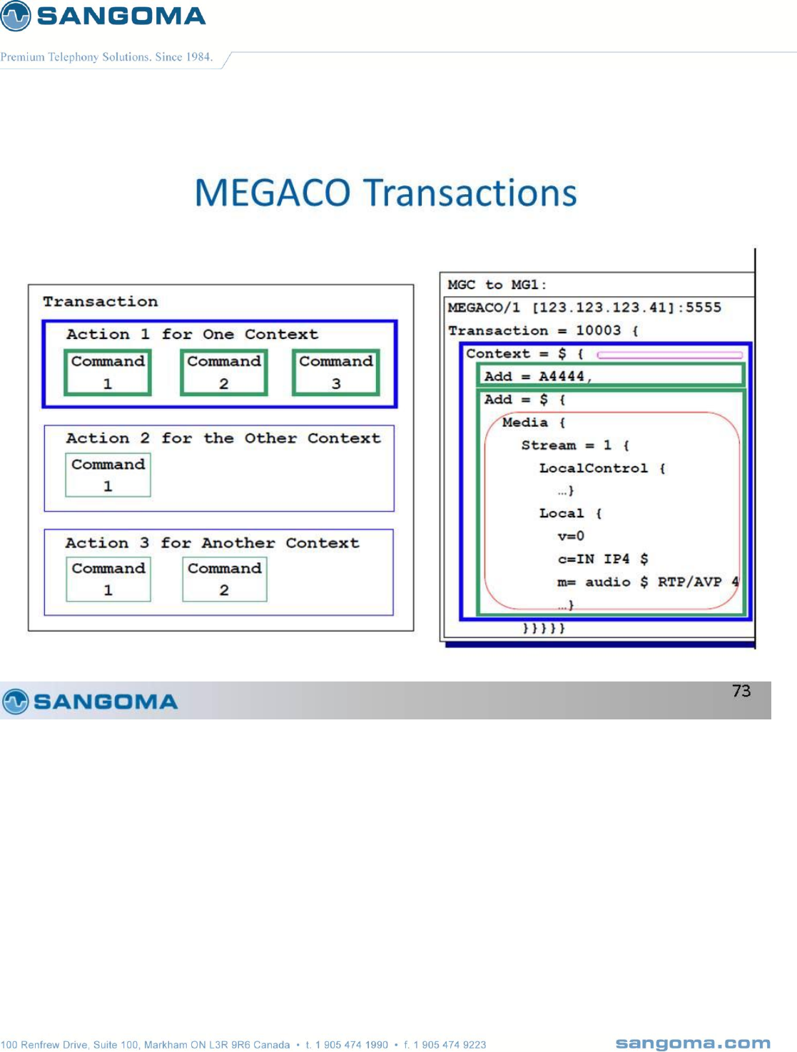
v1.14
270
v1.14
271
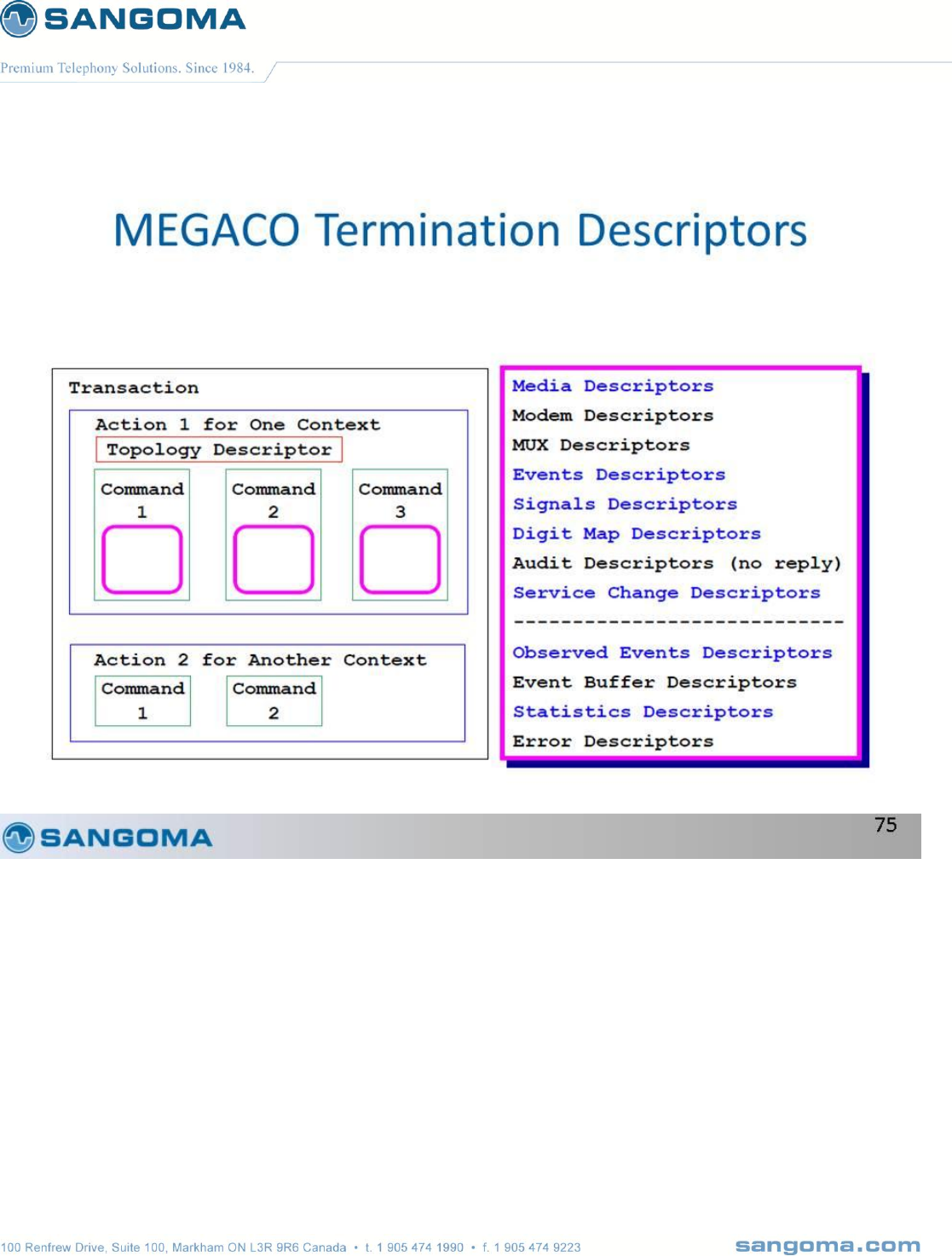
v1.14
272

v1.14
273
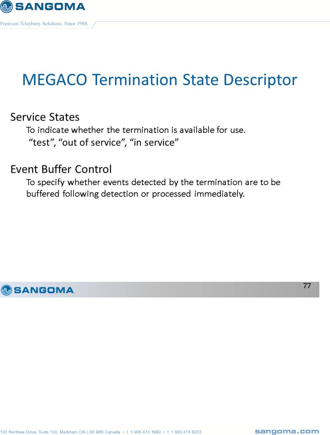
v1.14
274
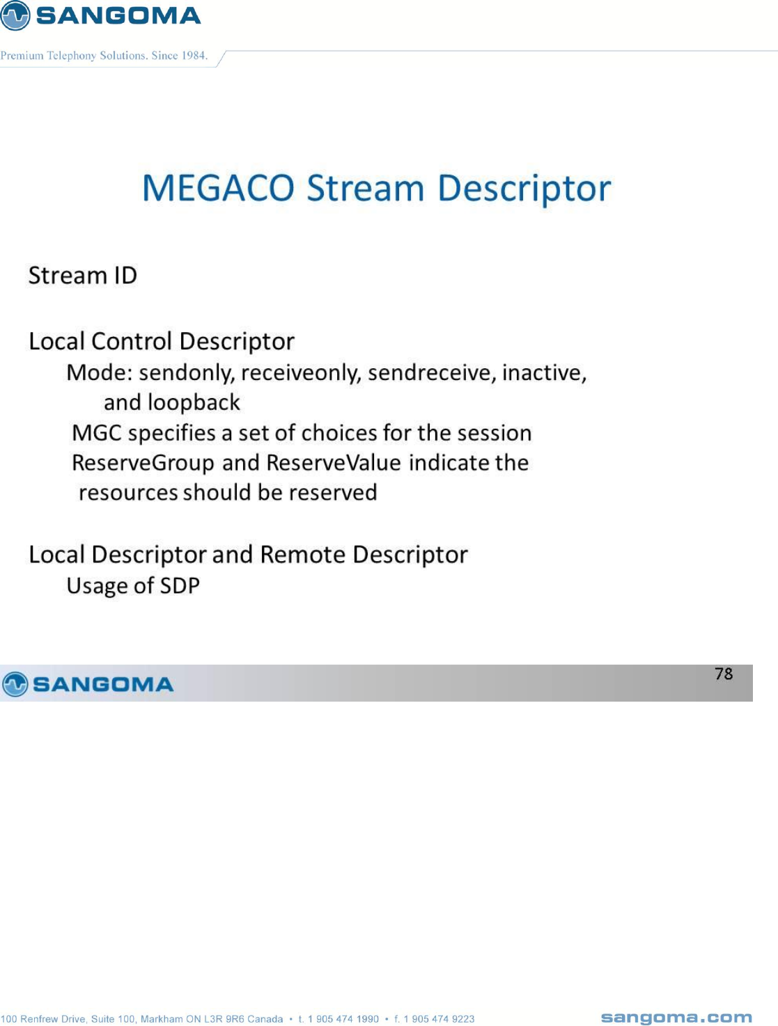
v1.14
275
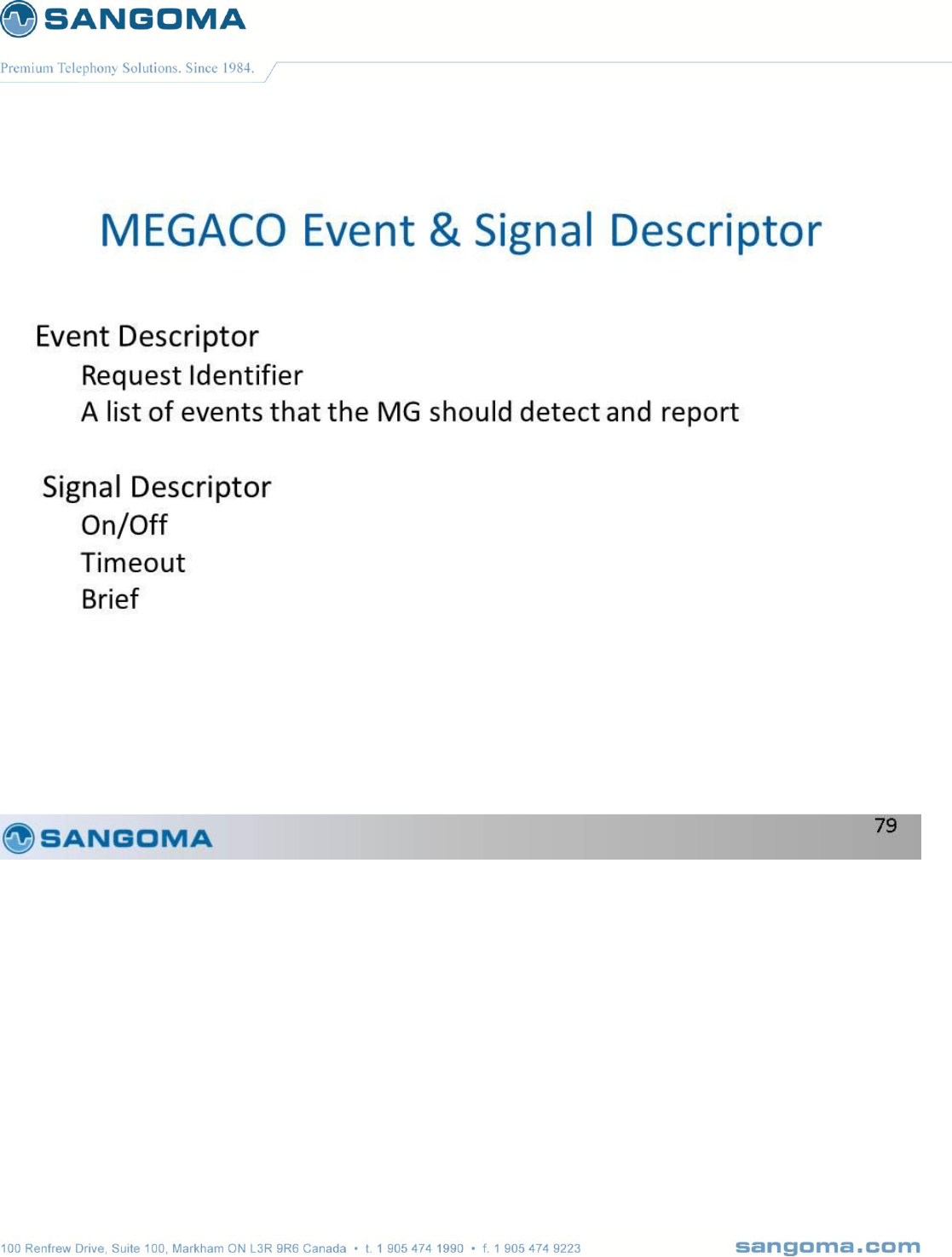
v1.14
276
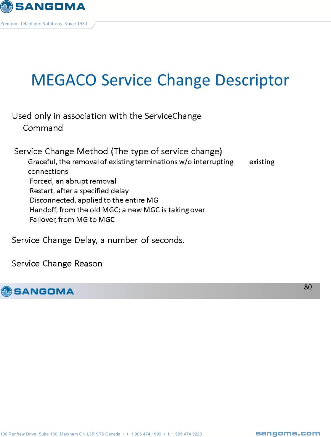
v1.14
277

v1.14
278
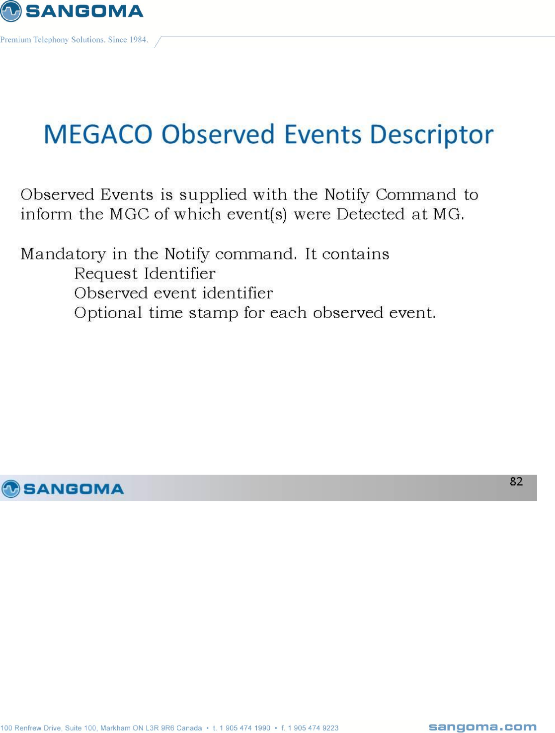
v1.14
279
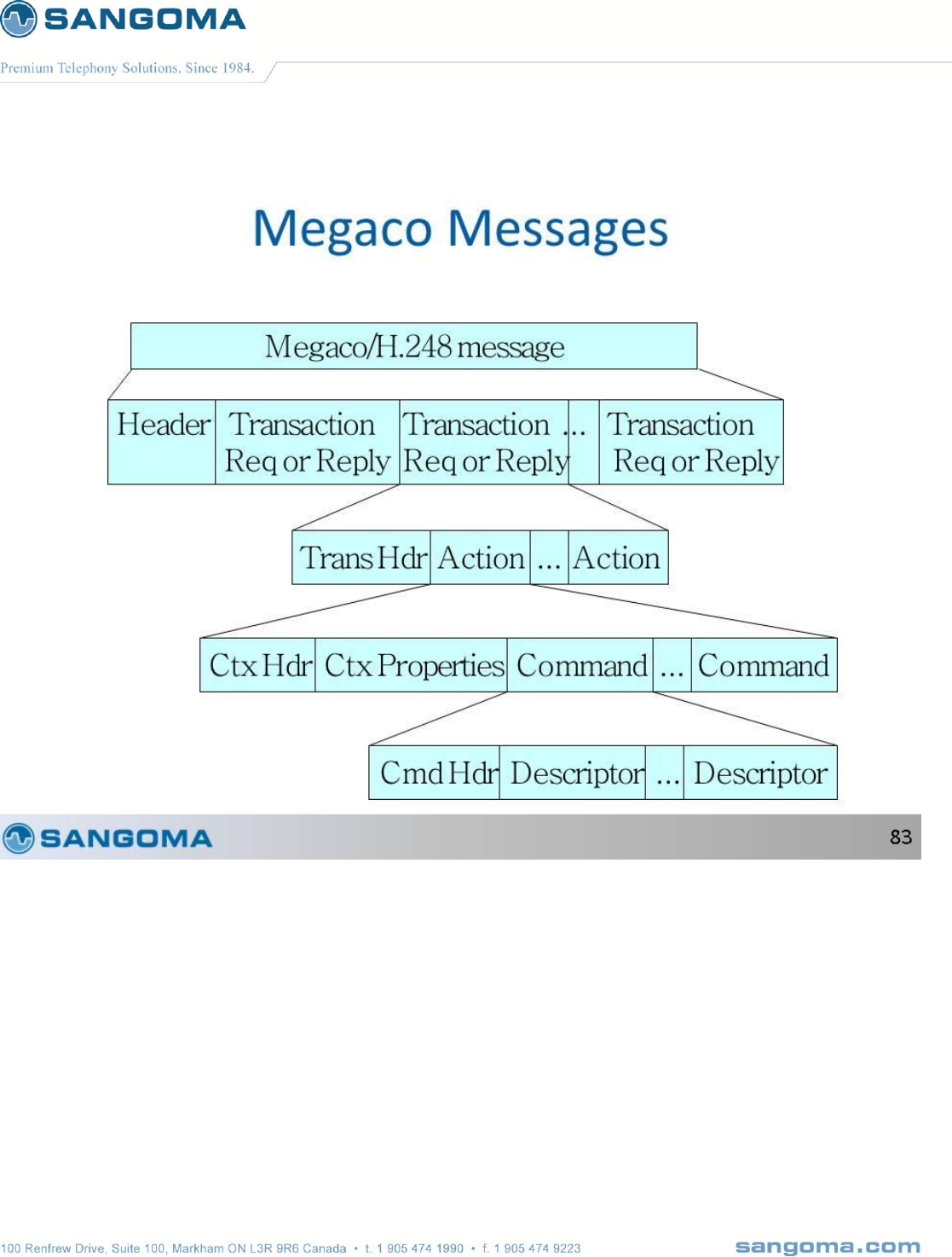
v1.14
280
v1.14
281
v1.14
282
v1.14
283
v1.14
284
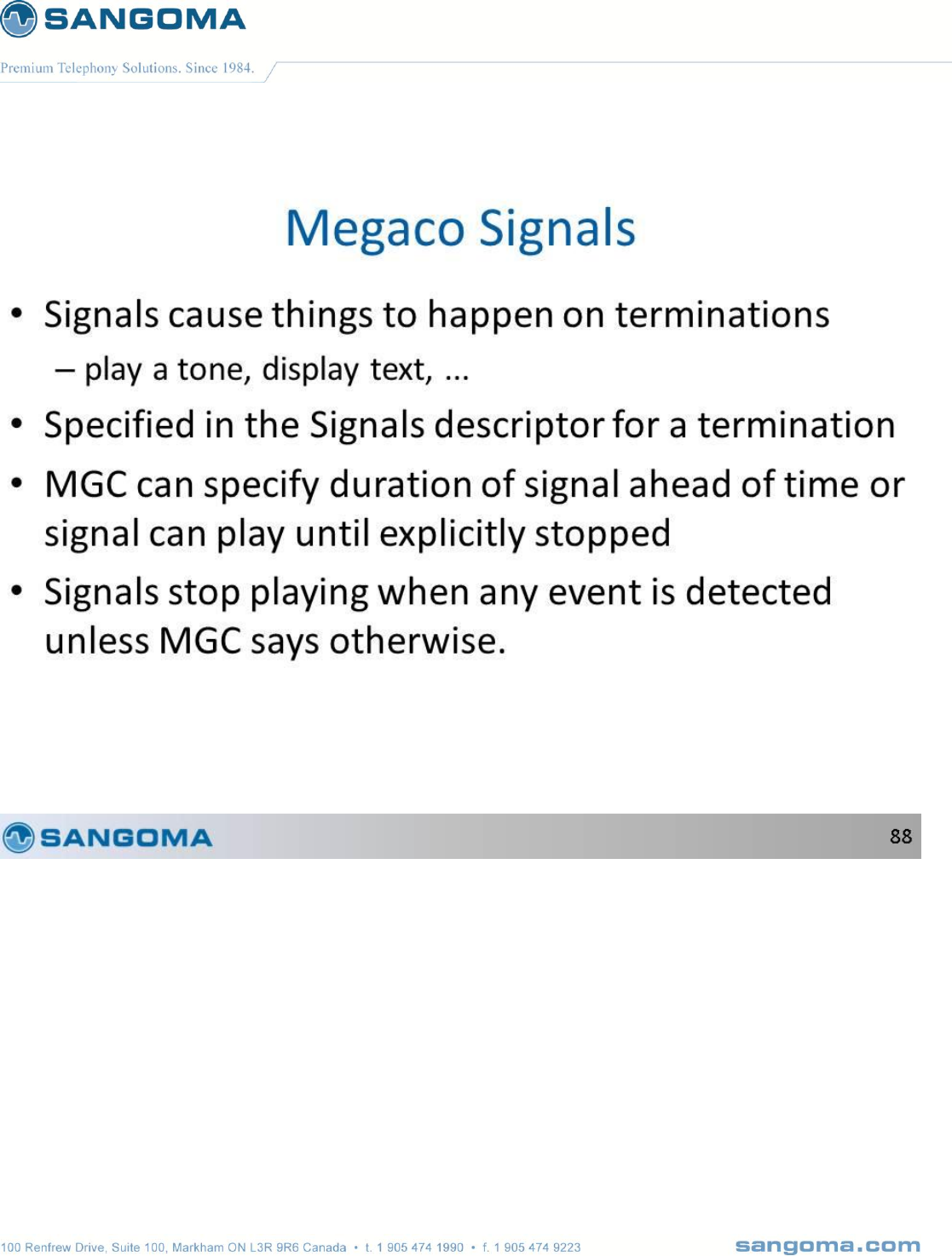
v1.14
285
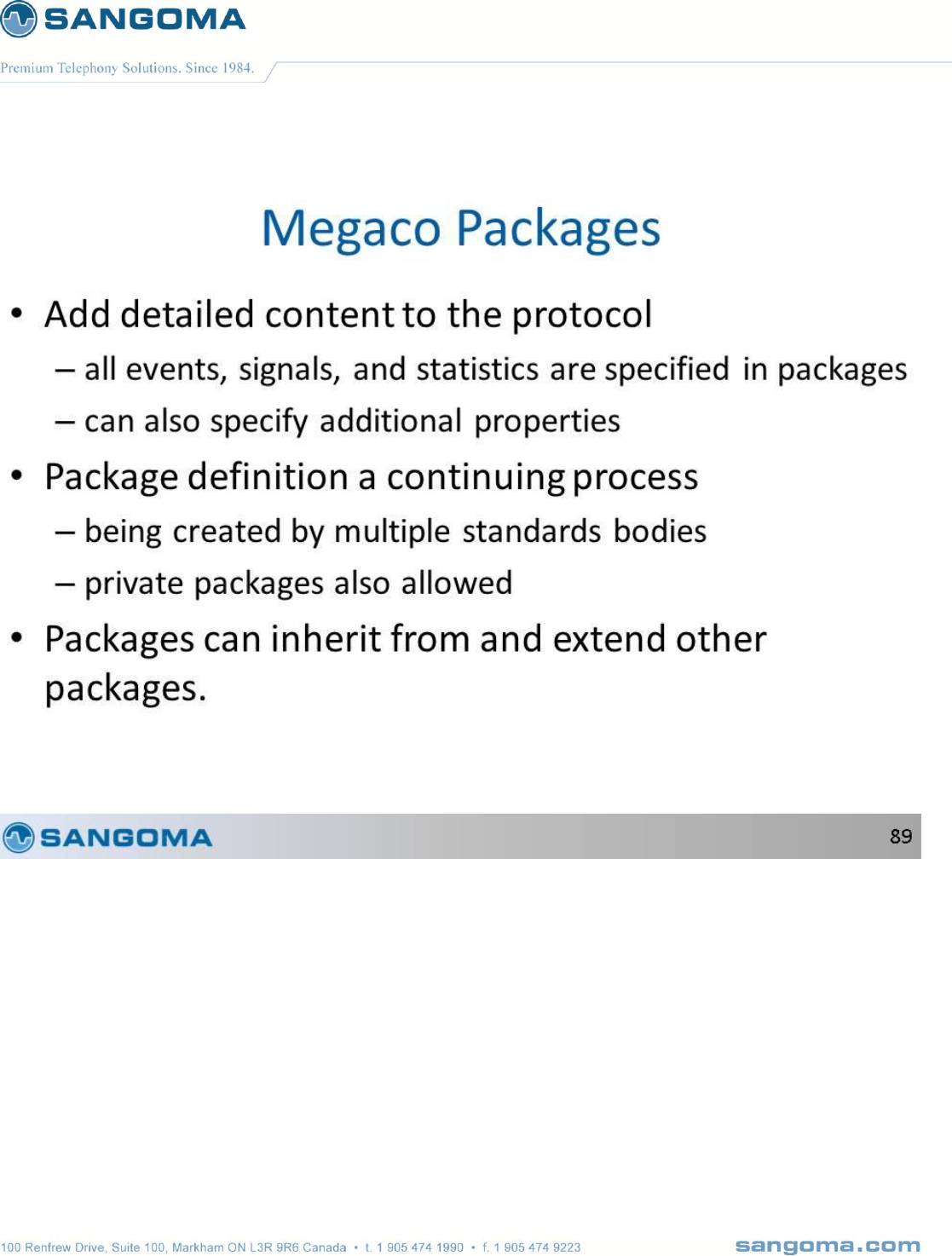
v1.14
286
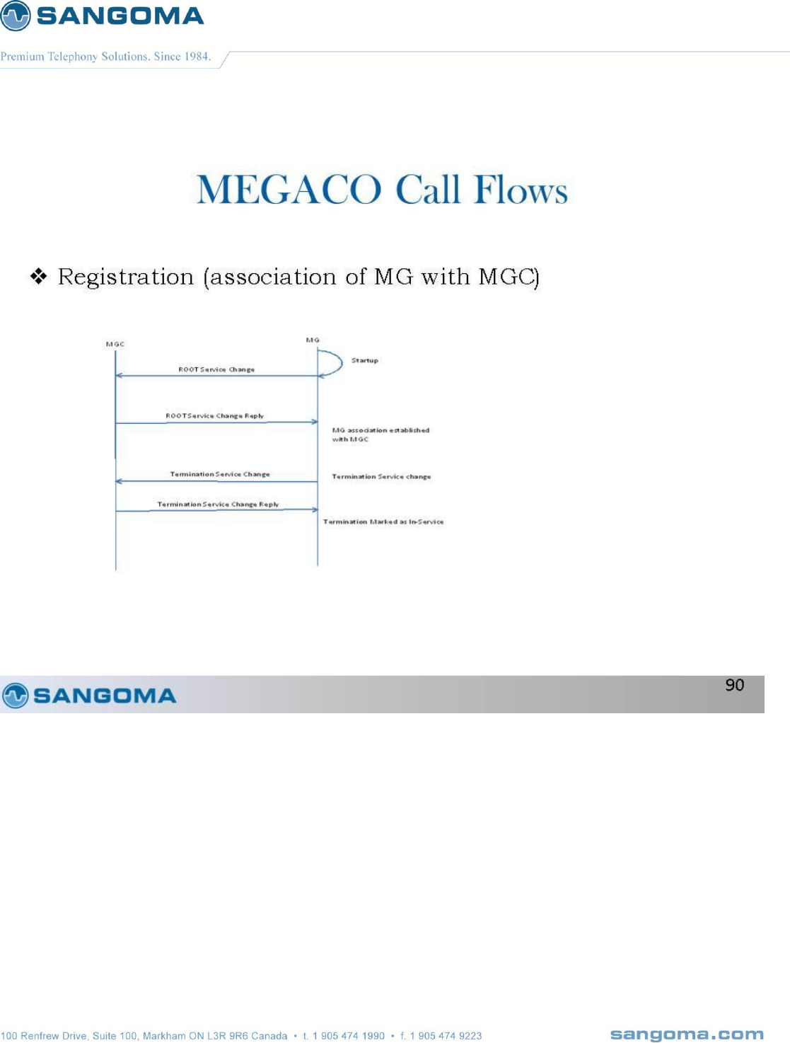
v1.14
287
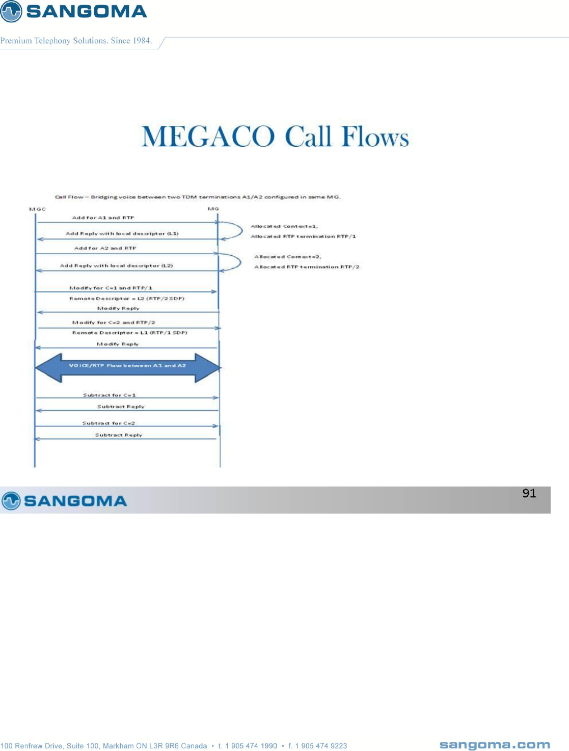
v1.14
288
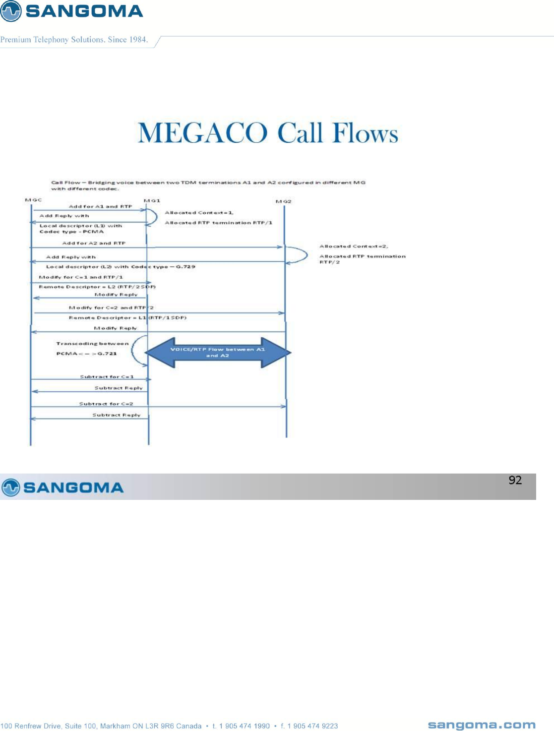
v1.14
289

v1.14
290
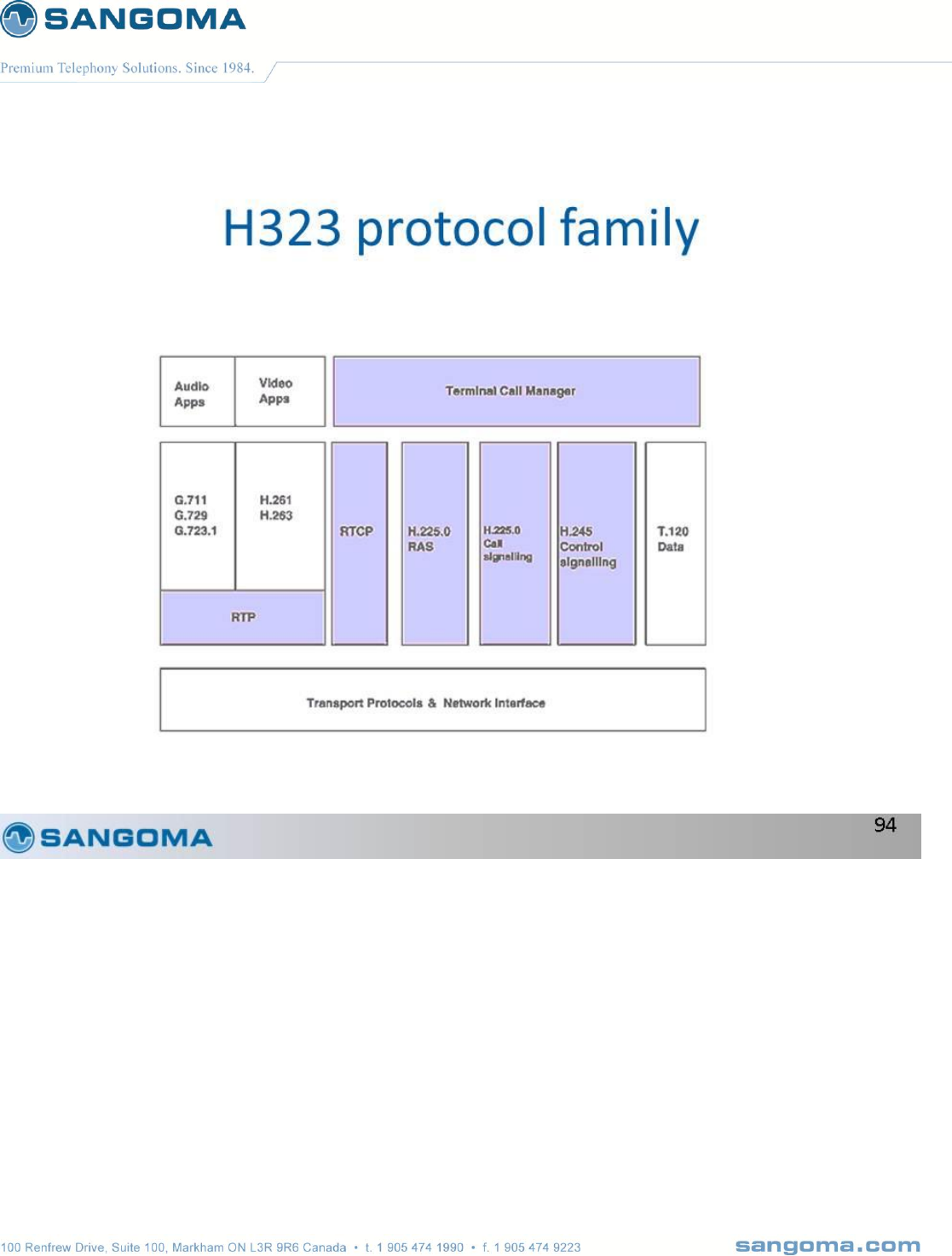
v1.14
291
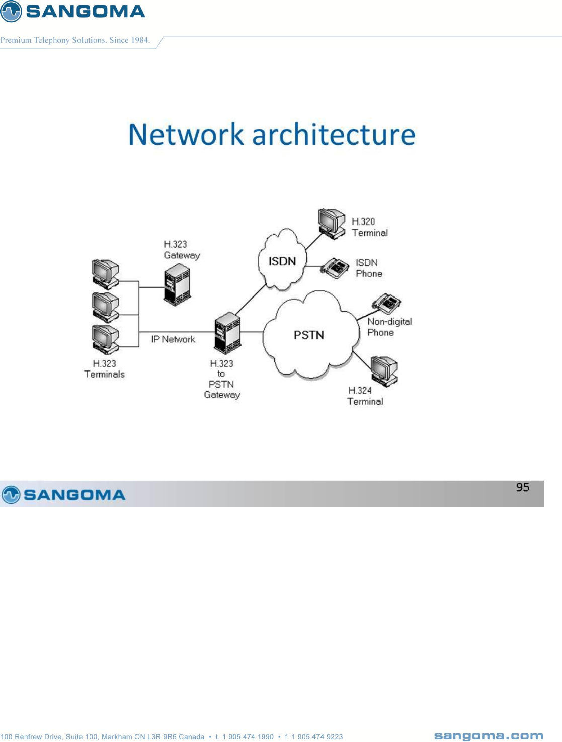
v1.14
292

v1.14
293
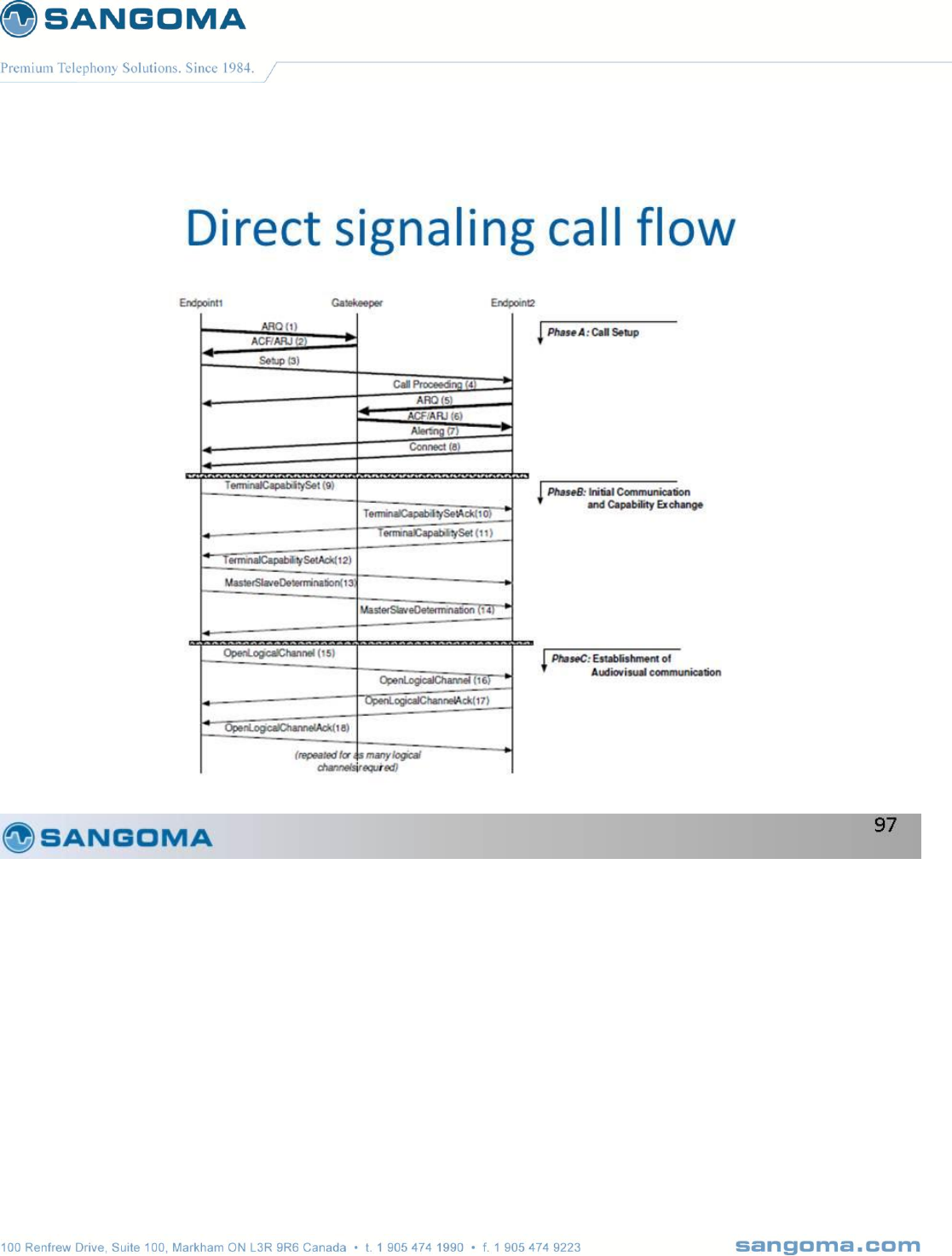
v1.14
294
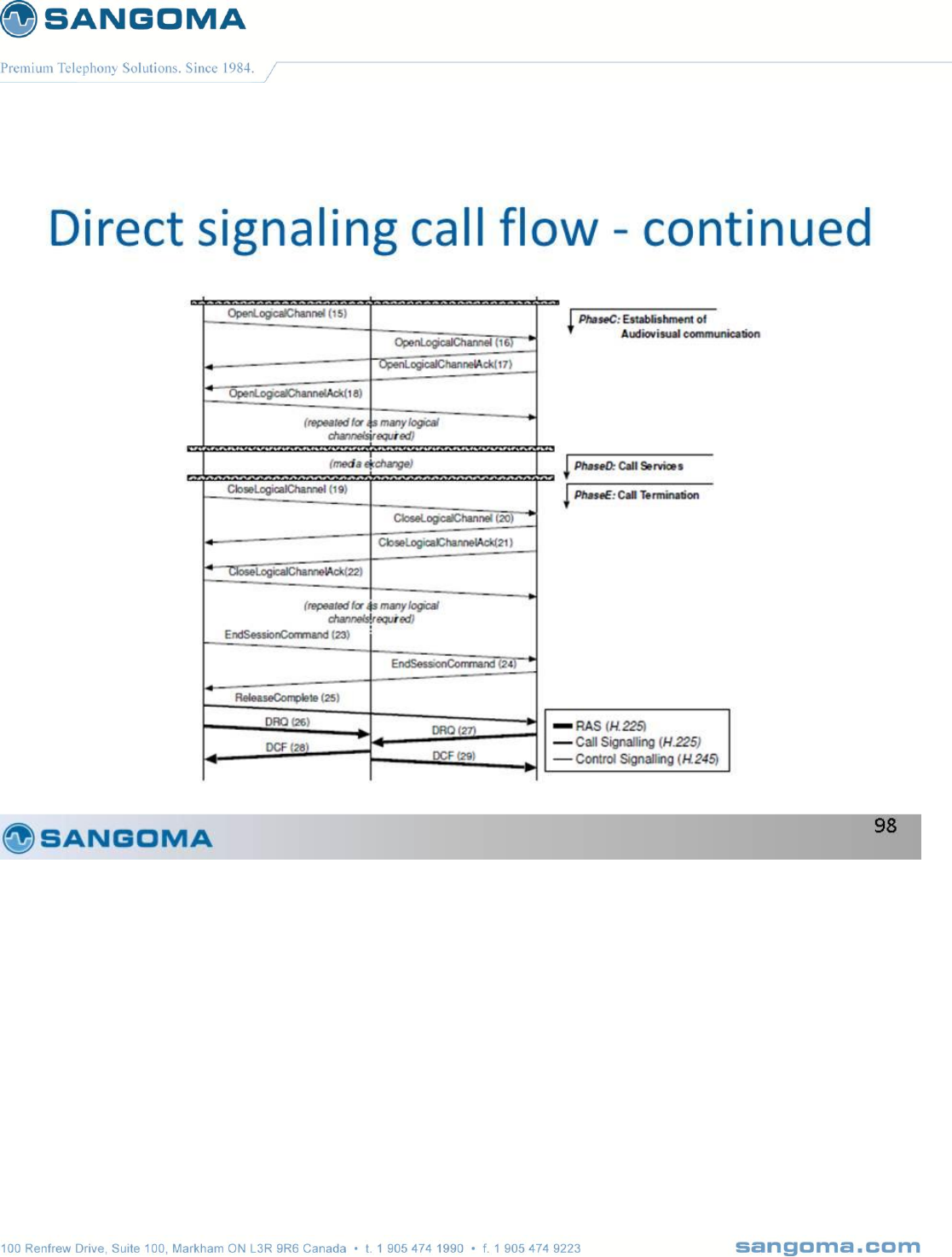
v1.14
295
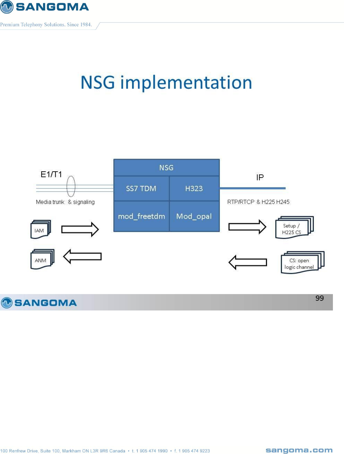
v1.14
296
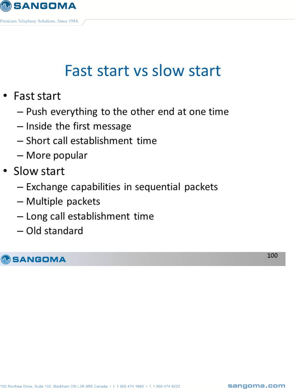
v1.14
297
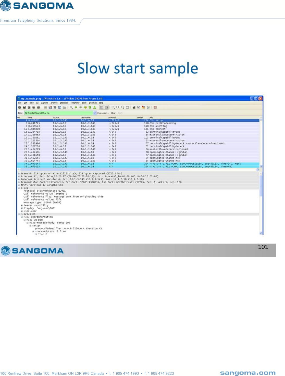
v1.14
298

v1.14
299
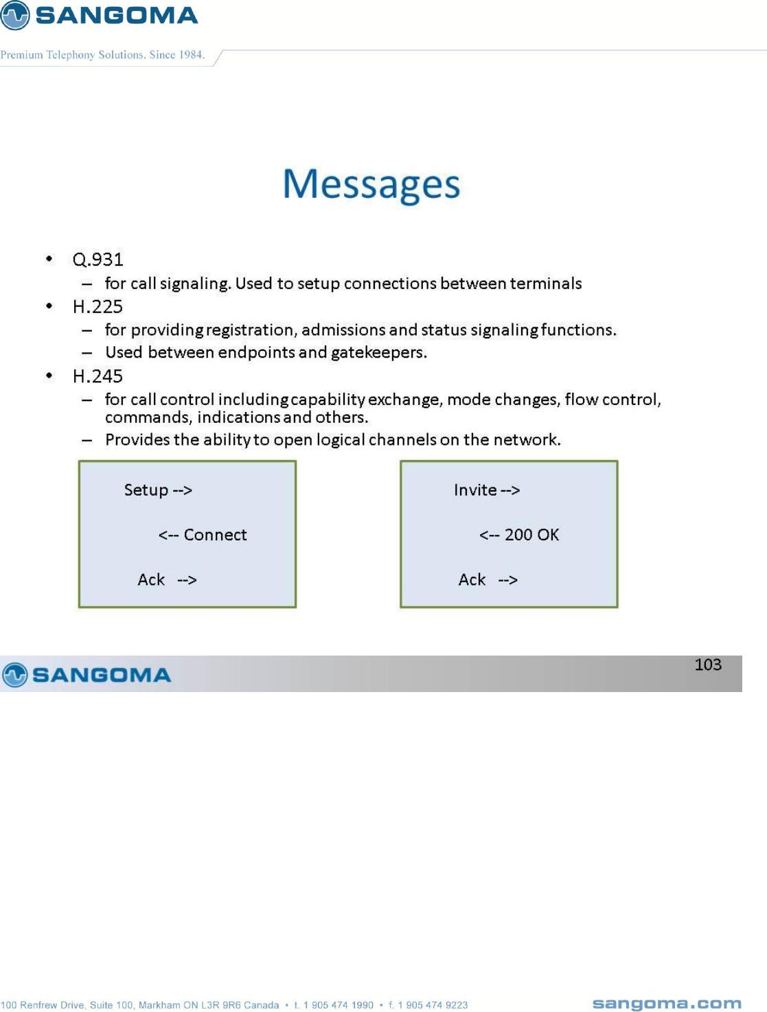
v1.14
300
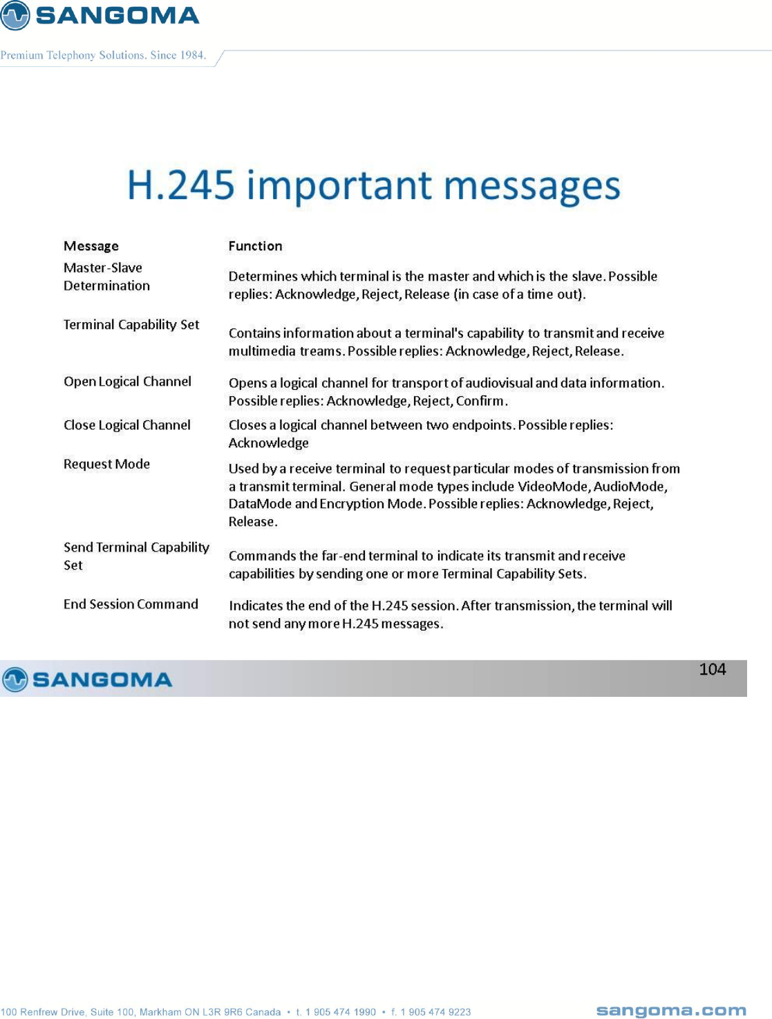
v1.14
301

v1.14
302
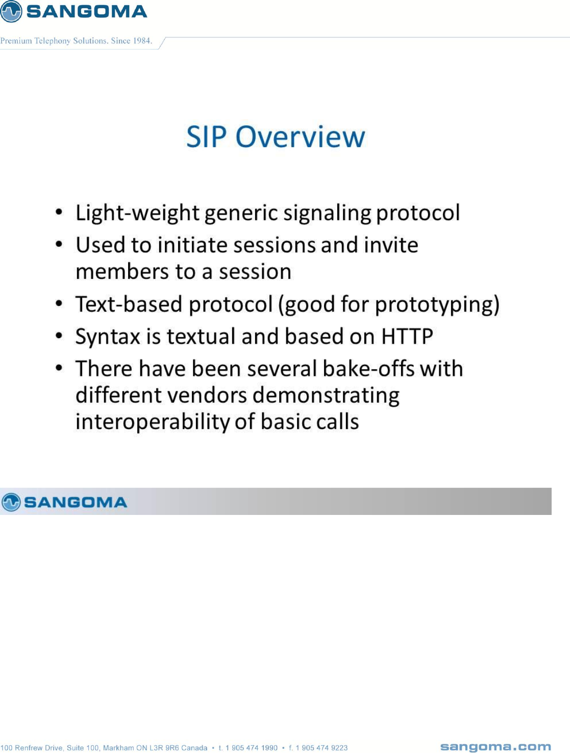
v1.14
303
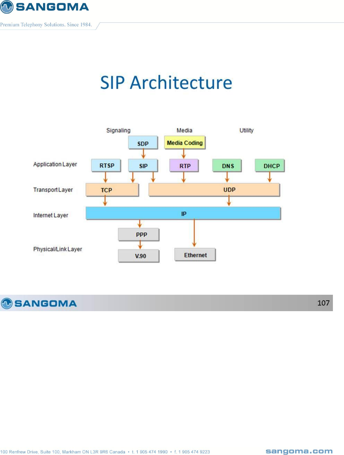
v1.14
304
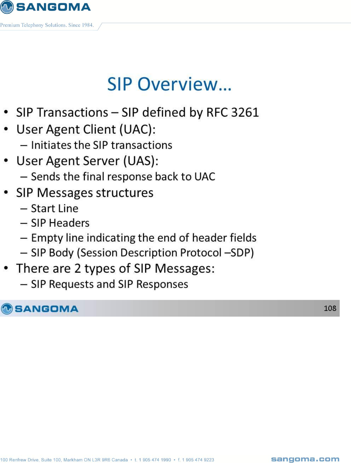
v1.14
305
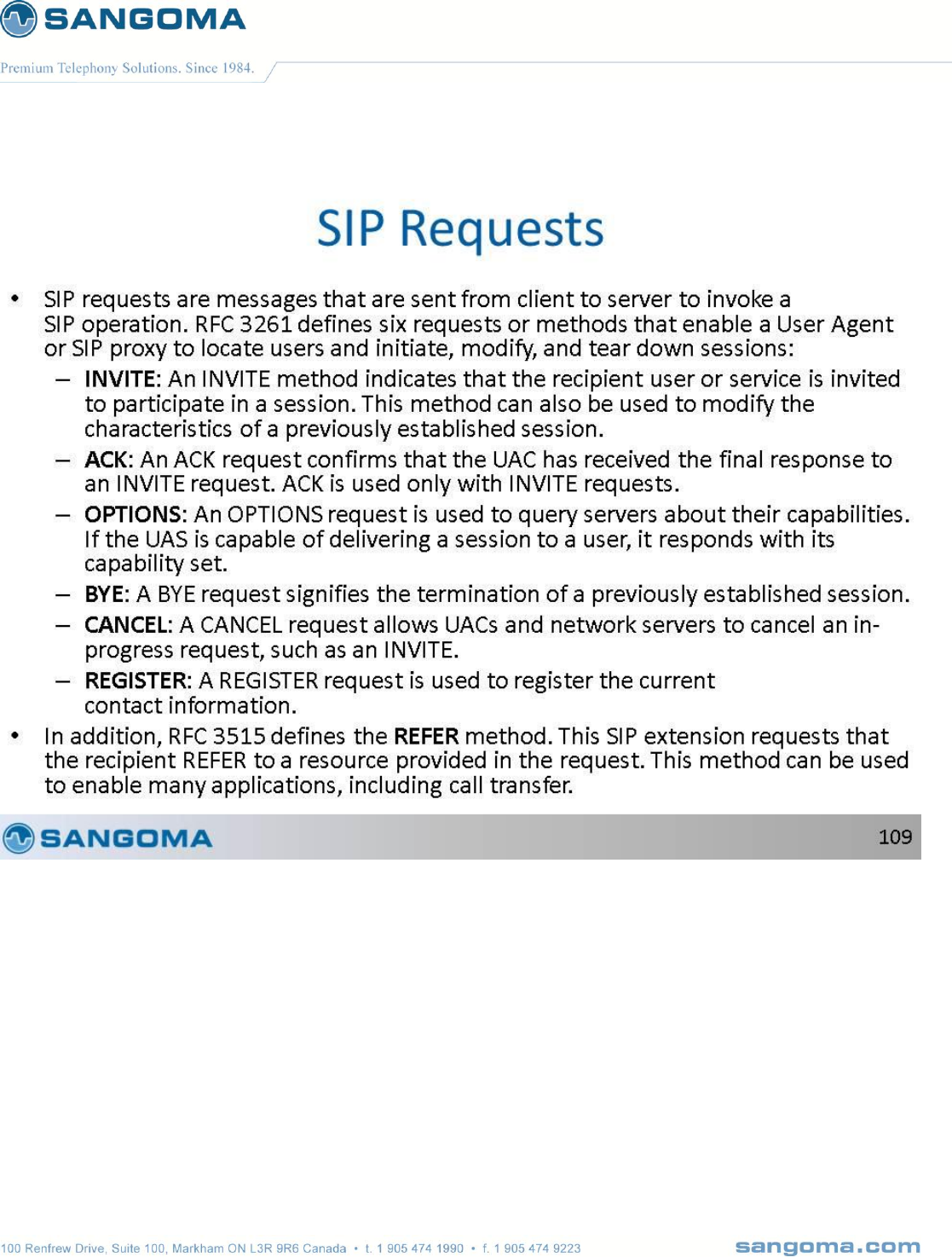
v1.14
306
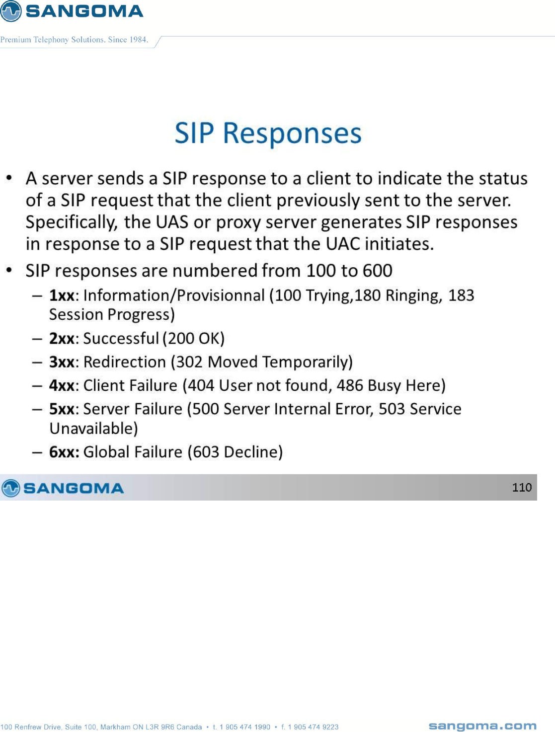
v1.14
307
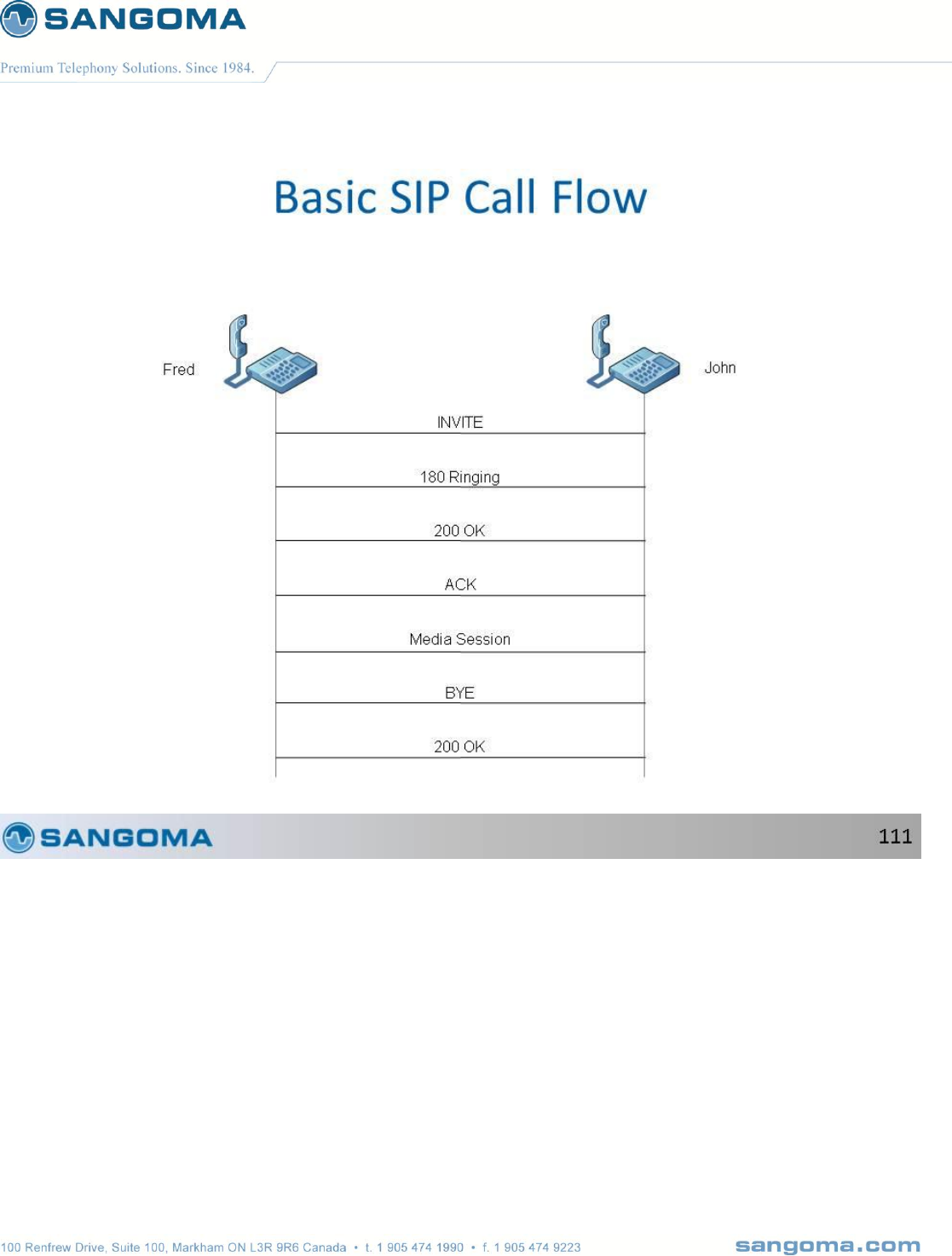
v1.14
308
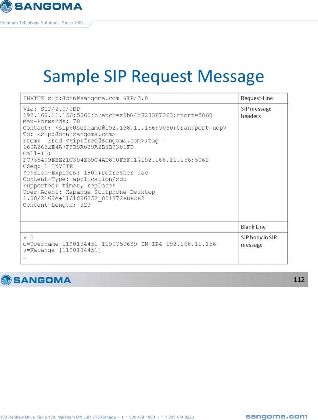
v1.14
309
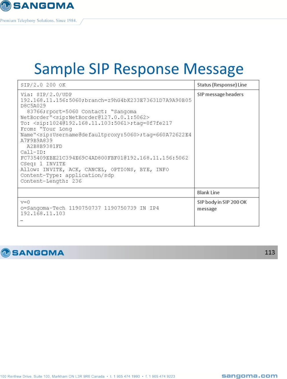
v1.14
310

v1.14
311

v1.14
312
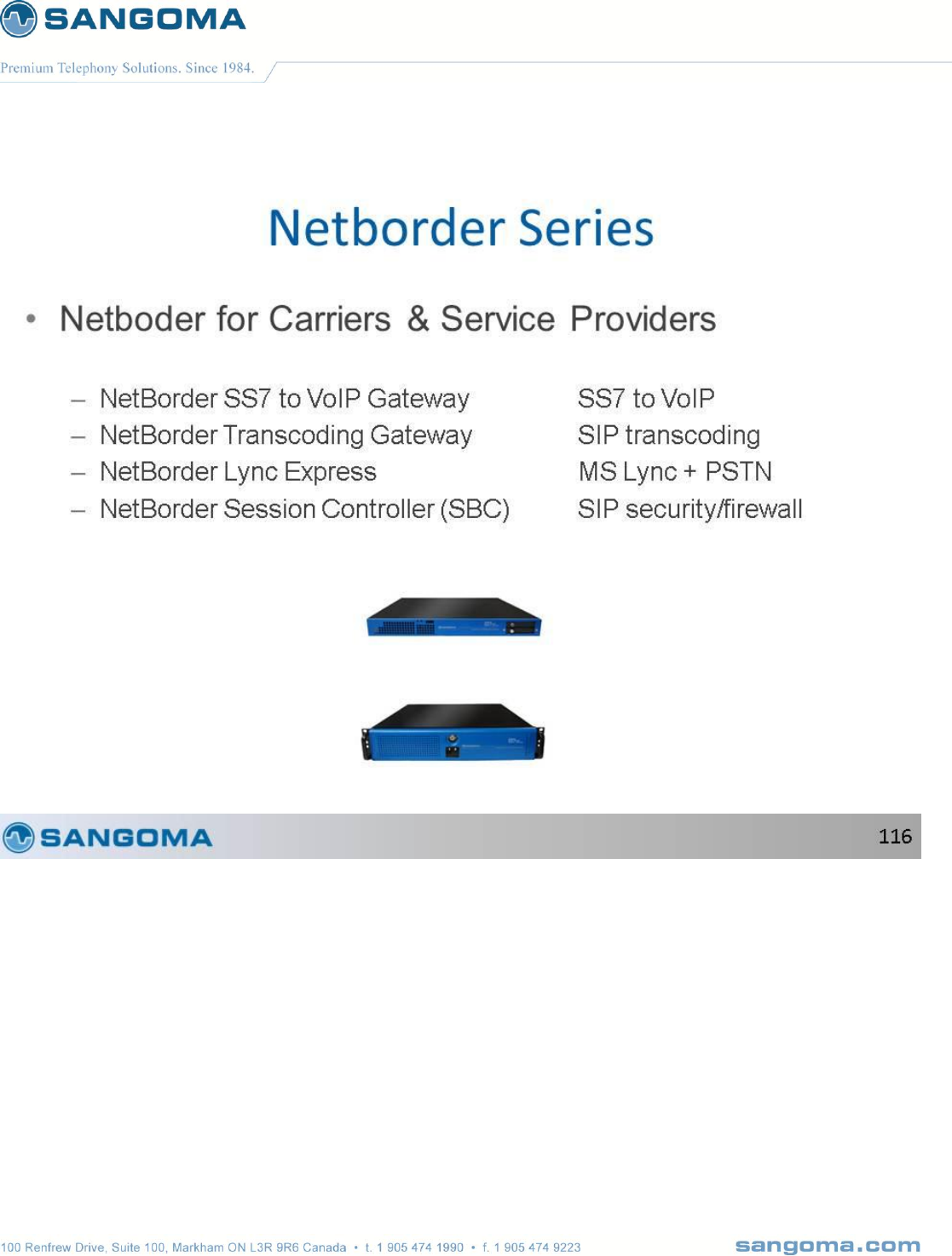
v1.14
313
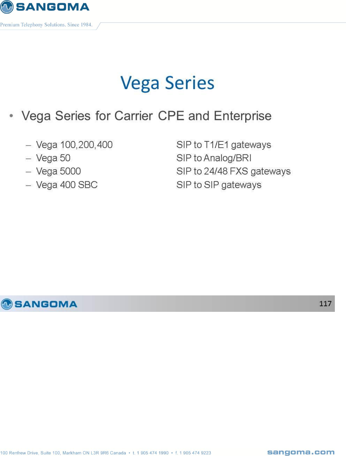
v1.14
314
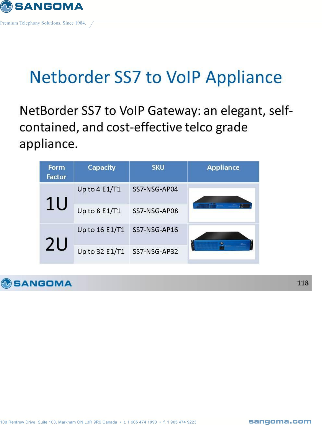
v1.14
315
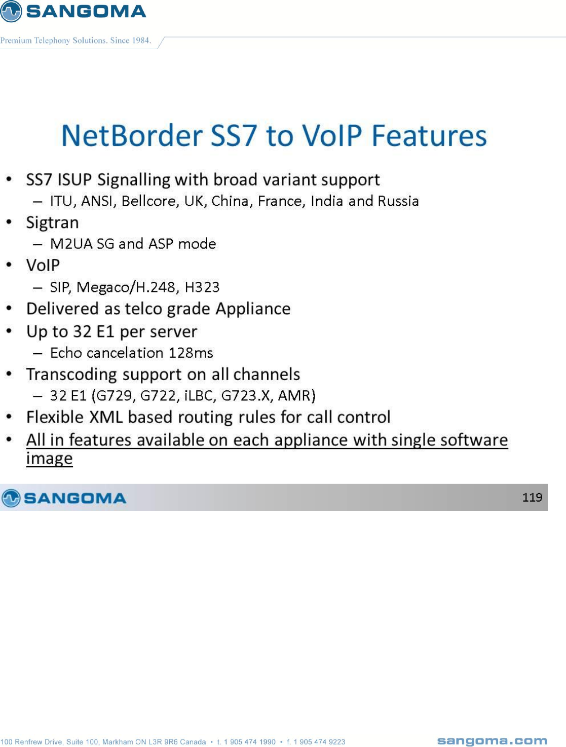
v1.14
316
v1.14
317
