CompTIA Network+™ Study Guide Network Plus
User Manual:
Open the PDF directly: View PDF ![]() .
.
Page Count: 960 [warning: Documents this large are best viewed by clicking the View PDF Link!]
- Cover������������
- Title Page�����������������
- Copyright
- Contents���������������
- Introduction
- Assessment Test
- Chapter 1 Introduction to Networks�����������������������������������������
- First Things First: What’s a Network?��������������������������������������������
- Physical Network Topologies����������������������������������
- Topology Selection, Backbones, and Segments��������������������������������������������������
- Summary��������������
- Exam Essentials����������������������
- Written Labs�������������������
- Review Questions�����������������������
- Chapter 2 The Open Systems Interconnection Specifications����������������������������������������������������������������
- Internetworking Models�����������������������������
- The OSI Reference Model������������������������������
- The Application Layer����������������������������
- The Presentation Layer�����������������������������
- The Session Layer������������������������
- The Transport Layer��������������������������
- The Network Layer������������������������
- The Data Link Layer��������������������������
- The Physical Layer�������������������������
- Introduction to Encapsulation������������������������������������
- Modulation Techniques����������������������������
- Summary��������������
- Exam Essentials����������������������
- Written Lab������������������
- Review Questions�����������������������
- Chapter 3 Networking Topologies, Connectors, and Wiring Standards������������������������������������������������������������������������
- Physical Media���������������������
- Cable Properties�����������������������
- Wiring Standards�����������������������
- Installing Wiring Distributions��������������������������������������
- Summary��������������
- Exam Essentials����������������������
- Written Lab������������������
- Review Questions�����������������������
- Chapter 4 The Current Ethernet Specifications����������������������������������������������������
- Network Basics���������������������
- Ethernet Basics����������������������
- Collision Domain�����������������������
- Broadcast Domain�����������������������
- CSMA/CD��������������
- Broadband/Baseband�������������������������
- Bit Rates vs Baud Rate�����������������������������
- Wavelength�����������������
- Sampling -Size���������������������
- Half- and Full-Duplex Ethernet�������������������������������������
- Ethernet at the Data Link Layer��������������������������������������
- Ethernet at the Physical Layer�������������������������������������
- Ethernet over Other Standards (IEEE 1905.1-2013)�������������������������������������������������������
- Summary��������������
- Exam Essentials����������������������
- Written Lab������������������
- Review Questions�����������������������
- Chapter 5 Networking Devices�����������������������������������
- Common Network Connectivity Devices������������������������������������������
- Network Interface Card�����������������������������
- Hub����������
- Bridge�������������
- Switch�������������
- Router�������������
- Firewall���������������
- IDS/IPS��������������
- HIDS�����������
- Access Point�������������������
- Dynamic Host Configuration Protocol Server�������������������������������������������������
- Other Specialized Devices��������������������������������
- Multilayer Switch������������������������
- Load Balancer��������������������
- Domain Name Service Server���������������������������������
- Proxy Server�������������������
- Encryption Devices�������������������������
- Analog Modem�������������������
- Packet Shaper��������������������
- VPN Concentrator�����������������������
- Planning and Implementing a Basic SOHO Network Using Network Segmentation��������������������������������������������������������������������������������
- Summary��������������
- Exam Essentials����������������������
- Written Lab������������������
- Review Questions�����������������������
- Common Network Connectivity Devices������������������������������������������
- Chapter 6 Introduction to the Internet Protocol������������������������������������������������������
- Introducing TCP/IP�������������������������
- A Brief History of TCP/IP��������������������������������
- TCP/IP and the DoD Model�������������������������������
- The Process/Application Layer Protocols����������������������������������������������
- The Host-to-Host Layer Protocols���������������������������������������
- The Internet Layer Protocols�����������������������������������
- Data Encapsulation�������������������������
- Summary��������������
- Exam Essentials����������������������
- Written Lab������������������
- Review Questions�����������������������
- Introducing TCP/IP�������������������������
- Chapter 7 IP Addressing������������������������������
- IP Terminology���������������������
- The Hierarchical IP Addressing Scheme��������������������������������������������
- IPv4 Address Types�������������������������
- Internet Protocol Version 6 (IPv6)�����������������������������������������
- Why Do We Need IPv6?���������������������������
- The Benefits of and Uses for IPv6����������������������������������������
- IPv6 Addressing and Expressions��������������������������������������
- Shortened Expression���������������������������
- Address Types��������������������
- Special Addresses������������������������
- Stateless Autoconfiguration (EUI-64)�������������������������������������������
- DHCPv6 (Stateful)������������������������
- Migrating to IPv6������������������������
- Summary��������������
- Exam Essentials����������������������
- Written Lab������������������
- Review Questions�����������������������
- Chapter 8 IP Subnetting, Troubleshooting IP, and Introduction to NAT���������������������������������������������������������������������������
- Subnetting Basics������������������������
- Troubleshooting IP Addressing������������������������������������
- Introduction to Network Address Translation (NAT)��������������������������������������������������������
- Summary��������������
- Exam Essentials����������������������
- Written Labs�������������������
- Review Questions�����������������������
- Chapter 9 Introduction to IP Routing�������������������������������������������
- Routing Basics���������������������
- The IP Routing Process�����������������������������
- Testing Your IP Routing Understanding��������������������������������������������
- Static and Dynamic Routing���������������������������������
- Summary��������������
- Exam Essentials����������������������
- Written Lab������������������
- Review Questions�����������������������
- Chapter 10 Routing Protocols�����������������������������������
- Routing Protocol Basics������������������������������
- Distance Vector Routing Protocols����������������������������������������
- Link State Routing Protocols�����������������������������������
- High Availability������������������������
- IPv6 Routing Protocols�����������������������������
- Summary��������������
- Exam Essentials����������������������
- Written Lab������������������
- Review Questions�����������������������
- Chapter 11 Switching and Virtual LANs��������������������������������������������
- Networking Before Layer 2 Switching������������������������������������������
- Switching Services�������������������������
- Spanning Tree Protocol�����������������������������
- Virtual LANs�������������������
- VLAN Trunking Protocol�����������������������������
- Two Additional Advanced Features of Switches���������������������������������������������������
- Summary��������������
- Exam Essentials����������������������
- Written Lab������������������
- Review Questions�����������������������
- Chapter 12 Wireless Networking�������������������������������������
- Introduction to Wireless Technology������������������������������������������
- The 802.11 Standards���������������������������
- Comparing 802.11 Standards���������������������������������
- Wireless Network Components����������������������������������
- Installing a Wireless Network������������������������������������
- Ad Hoc Mode: Independent Basic Service Set�������������������������������������������������
- Infrastructure Mode: Basic Service Set���������������������������������������������
- Wireless Controllers���������������������������
- Mobile Hot Spots�����������������������
- Signal Degradation�������������������������
- Other Network Infrastructure Implementations���������������������������������������������������
- Installing and Configuring WLAN Hardware�����������������������������������������������
- Site Survey������������������
- Wireless Security������������������������
- Wireless Threats�����������������������
- Open Access������������������
- Service Set Identifiers, Wired Equivalent Privacy, and Media Access Control Address Authentication���������������������������������������������������������������������������������������������������������
- Remote Authentication Dial-In User Service (802.1x)����������������������������������������������������������
- Temporal Key Integrity Protocol��������������������������������������
- Wi-Fi Protected Access or WPA2 Pre-Shared Key����������������������������������������������������
- Summary��������������
- Exam Essentials����������������������
- Written Lab������������������
- Review Questions�����������������������
- Chapter 13 Authentication and Access Control���������������������������������������������������
- Security Filtering�������������������������
- Managing User Account and Password Security��������������������������������������������������
- User-Authentication Methods����������������������������������
- Public Key Infrastructure (PKI)��������������������������������������
- Kerberos���������������
- Authentication, Authorization, and Accounting (AAA)����������������������������������������������������������
- Web Services�������������������
- Unified Voice Services�����������������������������
- Network Controllers��������������������������
- Network Access Control (NAC)�����������������������������������
- Challenge Handshake Authentication Protocol (CHAP)���������������������������������������������������������
- MS-CHAP��������������
- Extensible Authentication Protocol (EAP)�����������������������������������������������
- Hashes�������������
- Network Access Control�����������������������������
- Summary��������������
- Exam Essentials����������������������
- Written Lab������������������
- Review Questions�����������������������
- Chapter 14 Network Threats and Mitigation������������������������������������������������
- Recognizing Security Threats�����������������������������������
- Vulnerabilities����������������������
- Unnecessary Running Services�����������������������������������
- Open Ports�����������������
- Unpatched/Legacy Systems�������������������������������
- Unencrypted Channels���������������������������
- Clear-Text Credentials�����������������������������
- TEMPEST/RF Emanation���������������������������
- Malicious Users����������������������
- Buffer Overflow����������������������
- Wireless Threats�����������������������
- Attackers and Their Tools��������������������������������
- Misconfiguration Issues������������������������������
- Social Engineering (Phishing)������������������������������������
- Understanding Mitigation Techniques������������������������������������������
- Policies and Procedures������������������������������
- Anti-malware software����������������������������
- Summary��������������
- Exam Essentials����������������������
- Written Lab������������������
- Review Questions�����������������������
- Chapter 15 Physical Security and Risk��������������������������������������������
- Using Hardware and Software Security Devices���������������������������������������������������
- Defining Firewalls�������������������������
- Firewall Technologies����������������������������
- Firewalls at the Application Layer vs the Network Layer��������������������������������������������������������������
- Scanning Services and Other Firewall Features����������������������������������������������������
- Intrusion Detection and Prevention Systems�������������������������������������������������
- VPN Concentrators������������������������
- Understanding Problems Affecting Device Security�������������������������������������������������������
- Summary��������������
- Exam Essentials����������������������
- Written Lab������������������
- Review Questions�����������������������
- Chapter 16 Wide Area Networks������������������������������������
- What’s a WAN?��������������������
- T-Series Connections���������������������������
- Transmission Media�������������������������
- Broadband Services�������������������������
- Wireless WAN Technologies��������������������������������
- WAN Protocols��������������������
- WAN Troubleshooting��������������������������
- Summary��������������
- Exam Essentials����������������������
- Written Lab������������������
- Review Questions�����������������������
- Chapter 17 Troubleshooting Tools���������������������������������������
- Protocol Analyzers�������������������������
- Throughput Testers�������������������������
- Connectivity Software����������������������������
- Using Traceroute�����������������������
- Using ipconfig and ifconfig����������������������������������
- Using the ping Utility�����������������������������
- Using the Address Resolution Protocol��������������������������������������������
- Using the nslookup Utility���������������������������������
- Resolving Names with the Hosts Table�������������������������������������������
- Using the Mtr Command (pathping)���������������������������������������
- Using the route Command������������������������������
- Using the nbtstat Utility��������������������������������
- Using the netstat Utility��������������������������������
- Using the File Transfer Protocol���������������������������������������
- Using the Telnet Utility�������������������������������
- Summary��������������
- Exam Essentials����������������������
- Written Lab������������������
- Review Questions�����������������������
- Chapter 18 Software and Hardware Tools���������������������������������������������
- Understanding Network Scanners�������������������������������������
- Baseline���������������
- Network Monitoring and Logging�������������������������������������
- Identifying Hardware Tools���������������������������������
- Cable Testers��������������������
- Protocol Analyzer������������������������
- Certifiers�����������������
- Time-Domain Reflectometer��������������������������������
- Optical Time-Domain Reflectometer����������������������������������������
- Multimeter�����������������
- Toner Probe������������������
- Butt Set���������������
- Punch-Down Tool����������������������
- Cable Stripper/Snips���������������������������
- Voltage Event Recorder (Power)�������������������������������������
- Environmental Monitors�����������������������������
- Summary��������������
- Exam Essentials����������������������
- Written Lab������������������
- Review Questions�����������������������
- Chapter 19 Network Troubleshooting�����������������������������������������
- Narrowing Down the Problem���������������������������������
- Did You Check the Super Simple Stuff?��������������������������������������������
- Is Hardware or Software Causing the Problem?���������������������������������������������������
- Is It a Workstation or a Server Problem?�����������������������������������������������
- Which Segments of the Network Are Affected?��������������������������������������������������
- Is It Bad Cabling?�������������������������
- Troubleshooting Steps����������������������������
- Step 1: Identify the Problem�����������������������������������
- Step 2: Establish a Theory of Probable Cause���������������������������������������������������
- Step 3: Test the Theory to Determine Cause�������������������������������������������������
- Step 4: Establish a Plan of Action to Resolve the Problem and Identify Potential Effects�����������������������������������������������������������������������������������������������
- Step 5: Implement the Solution or Escalate as Necessary��������������������������������������������������������������
- Step 6: Verify Full System Functionality, and If Applicable, Implement Preventative Measures���������������������������������������������������������������������������������������������������
- Step 7: Document Findings, Actions, and Outcomes�������������������������������������������������������
- Troubleshooting Tips���������������������������
- Don’t Overlook the Small Stuff�������������������������������������
- Prioritize Your Problems�������������������������������
- Check the Software Configuration���������������������������������������
- Don’t Overlook Physical Conditions�����������������������������������������
- Don’t Overlook Cable Problems������������������������������������
- Check for Viruses������������������������
- Summary��������������
- Exam Essentials����������������������
- Written Lab������������������
- Review Questions�����������������������
- Narrowing Down the Problem���������������������������������
- Chapter 20 Management, Monitoring, and Optimization����������������������������������������������������������
- Managing Network Documentation�������������������������������������
- Network Monitoring�������������������������
- Baselines����������������
- On-Boarding and Off-Boarding of Mobile Devices�����������������������������������������������������
- NAC����������
- Policies, Procedures, and Regulations��������������������������������������������
- Safety Practices�����������������������
- Implementing Network Segmentation����������������������������������������
- Network Optimization���������������������������
- Reasons to Optimize Your Network’s Performance�����������������������������������������������������
- How to Optimize Performance����������������������������������
- Unified Communications�����������������������������
- Traffic Shaping����������������������
- Load Balancing���������������������
- High Availability������������������������
- Caching Engines����������������������
- Fault Tolerance����������������������
- Archives/Backups�����������������������
- Common Address Redundancy Protocol�����������������������������������������
- Virtual Networking�������������������������
- Locating and Installing Equipment����������������������������������������
- Change Management Procedures�����������������������������������
- Summary��������������
- Exam Essentials����������������������
- Written Lab������������������
- Review Questions�����������������������
- Appendix A Answers to the Written Labs���������������������������������������������
- Chapter 1����������������
- Chapter 2����������������
- Chapter 3����������������
- Chapter 4����������������
- Chapter 5����������������
- Chapter 6����������������
- Chapter 7����������������
- Chapter 8����������������
- Chapter 9����������������
- Chapter 10�����������������
- Chapter 11�����������������
- Chapter 12�����������������
- Chapter 13�����������������
- Chapter 14�����������������
- Chapter 15�����������������
- Chapter 16�����������������
- Chapter 17�����������������
- Chapter 18�����������������
- Chapter 19�����������������
- Chapter 20�����������������
- Appendix B Answers to Review Questions���������������������������������������������
- Chapter 1����������������
- Chapter 2����������������
- Chapter 3����������������
- Chapter 4����������������
- Chapter 5����������������
- Chapter 6����������������
- Chapter 7����������������
- Chapter 8����������������
- Chapter 9����������������
- Chapter 10�����������������
- Chapter 11�����������������
- Chapter 12�����������������
- Chapter 13�����������������
- Chapter 14�����������������
- Chapter 15�����������������
- Chapter 16�����������������
- Chapter 17�����������������
- Chapter 18�����������������
- Chapter 19�����������������
- Chapter 20�����������������
- Appendix C Subnetting Class A������������������������������������
- Subnetting Practice Examples: Class A Addresses������������������������������������������������������
- Subnetting in Your Head: Class A Addresses�������������������������������������������������
- Written Lab 1��������������������
- Written Lab 2��������������������
- Answers to Written Lab 1�������������������������������
- Answers to Written Lab 2�������������������������������
- Index
- EULA

f rst.indd 07/17/2017 Page i

f rs_247.indd 04/07/2015 Page iii
CompTIA Network+™
Study Guide
Third Edition
Todd L ammle
f rs_247.indd 04/07/2015 Page iv
Senior Acquistions Editor: Kenyon Brown
Development Editor: Kim Wimpsett
Technical Editors: Quentin Doctor and Troy McMillan
Production Editor: Christine O’Connor
Copy Editor: Judy Flynn
Editorial Manager: Mary Beth Wakefield
Production Manager: Kathleen Wisor
Associate Publisher: Jim Minatel
Media Supervising Producer: Richard Graves
Book Designers: Judy Fung and Bill Gibson
Proofreader: Jennifer Bennett, Word One New York
Indexer: Robert Swanson
Project Coordinator, Cover: Brent Savage
Cover Designer: Wiley
Cover Image: Wiley
Copyright © 2015 by John Wiley & Sons, Inc., Indianapolis, Indiana
Published simultaneously in Canada
ISBN: 978-1-119-02124-7
ISBN: 978-1-119-02126-1 (ebk.)
ISBN: 978-1-119-02125-4 (ebk.)
No part of this publication may be reproduced, stored in a retrieval system or transmitted in any form or by
any means, electronic, mechanical, photocopying, recording, scanning or otherwise, except as permitted under
Sections 107 or 108 of the 1976 United States Copyright Act, without either the prior written permission of the
Publisher, or authorization through payment of the appropriate per-copy fee to the Copyright Clearance Center,
222 Rosewood Drive, Danvers, MA 01923, (978) 750-8400, fax (978) 646-8600. Requests to the Publisher
for permission should be addressed to the Permissions Department, John Wiley & Sons, Inc., 111 River Street,
Hoboken, NJ 07030, (201) 748-6011, fax (201) 748-6008, or online at http://www.wiley.com/go/permissions.
Limit of Liability/Disclaimer of Warranty: The publisher and the author make no representations or warranties
with respect to the accuracy or completeness of the contents of this work and specifically disclaim all warran-
ties, including without limitation warranties of fitness for a particular purpose. No warranty may be created or
extended by sales or promotional materials. The advice and strategies contained herein may not be suitable for
every situation. This work is sold with the understanding that the publisher is not engaged in rendering legal,
accounting, or other professional services. If professional assistance is required, the services of a competent
professional person should be sought. Neither the publisher nor the author shall be liable for damages arising
herefrom. The fact that an organization or Web site is referred to in this work as a citation and/or a potential
source of further information does not mean that the author or the publisher endorses the information the
organization or Web site may provide or recommendations it may make. Further, readers should be aware that
Internet Web sites listed in this work may have changed or disappeared between when this work was written and
when it is read.
For general information on our other products and services or to obtain technical support, please contact our
Customer Care Department within the U.S. at (877) 762-2974, outside the U.S. at (317) 572-3993 or fax (317)
572-4002.
Wiley publishes in a variety of print and electronic formats and by print-on-demand. Some material included
with standard print versions of this book may not be included in e-books or in print-on-demand. If this book
refers to media such as a CD or DVD that is not included in the version you purchased, you may download
this material at
http://booksupport.wiley.com
. For more information about Wiley products, visit
www.wiley.com
.
Library of Congress Control Number: 2014958356
TRADEMARKS: Wiley, the Wiley logo, and the Sybex logo are trademarks or registered trademarks of John
Wiley & Sons, Inc. and/or its affiliates, in the United States and other countries, and may not be used without
written permission. CompTIA Network+ is a trademark of CompTIA Properties, LLC. All other trademarks are
the property of their respective owners. John Wiley & Sons, Inc. is not associated with any product or vendor
mentioned in this book.
10 9 8 7 6 5 4 3 2 1
Acknowledgments
Kim Wimpsett was the development editor of this, the newest book in the Sybex CompTIA
series. Thank you, Kim, for working so hard on this book with me.
Kenyon Brown is my new acquisitions editor for this book. Thank you, Kenyon, for
making this book a reality!
In addition, Christine O’Connor was an excellent production editor, and she worked
really hard to get the book done as quickly as possible, without missing the small mistakes
that are so easy to overlook. I am always very pleased when I hear that she will be working
with me on a new project. Judy Flynn was my copy editor, and she was patient, helpful,
and detailed yet worked extremely hard to get this book on the shelf as quickly as possible,
and for that I thank her tremendously.
Quentin Docter reviewed each topic in this guide, scrutinizing the material until we
both agreed it was veri ably solid. Thank you, Quentin!
Troy McMillian literally hashed and rehashed each topic in this guide with me at all
hours of the day and night. Thank you, Troy, yet again!
About the Author
Todd Lammle, CompTIA Network+, CCSI, CCNA/CCNP, is the authority on network
certi cation and internetworking. He is a world-renowned author, speaker, trainer, and
consultant. Todd has over 25 years of experience working with LANs, WANs, and large
licensed and unlicensed wireless networks. He’s president and CEO of GlobalNet Training
and Consulting, Inc., a network-integration and training rm based in Boulder, Colorado;
Dallas, Texas; and San Francisco, California. You can reach Todd through his forum at
www.lammle.com/networkplus
.
f rs_247.indd 04/07/2015 Page ix
Contents at a Glance
Introduction xxix
Assessment Test xli
Chapter
1 Introduction to Networks 1
Chapter
2 The Open Systems Interconnection Specifications 27
Chapter
3 Networking Topologies, Connectors, and Wiring Standards 55
Chapter
4 The Current Ethernet Specifications 91
Chapter
5 Networking Devices 127
Chapter
6 Introduction to the Internet Protocol 171
Chapter
7 IP Addressing 205
Chapter
8 IP Subnetting, Troubleshooting IP, and Introduction to NAT 233
Chapter
9 Introduction to IP Routing 277
Chapter
10 Routing Protocols 297
Chapter
11 Switching and Virtual LANs 333
Chapter
12 Wireless Networking 377
Chapter
13 Authentication and Access Control 429
Chapter
14 Network Threats and Mitigation 469
Chapter
15 Physical Security and Risk 525
Chapter
16 Wide Area Networks 573
Chapter
17 Troubleshooting Tools 615
Chapter
18 Software and Hardware Tools 671
Chapter
19 Network Troubleshooting 711
Chapter
20 Management, Monitoring, and Optimization 755
Appendix
A Answers to the Written Labs 813
Appendix
B Answers to Review Questions 827
Appendix
C Subnetting Class A 857
Index 865
ftoc.indd 04/06/2015 Page xi
Contents
Introduction xxix
Assessment Test xli
Chapter
1 Introduction to Networks 1
First Things First: What’s a Network? 2
The Local Area Network 3
Common Network Components 5
Wide Area Network 8
Network Architecture: Peer-to-Peer or Client-Server? 10
Physical Network Topologies 12
Bus Topology 12
Star Topology 13
Ring Topology 14
Mesh Topology 15
Point-to-Point Topology 16
Point-to-Multipoint Topology 17
Hybrid Topology 18
Topology Selection, Backbones, and Segments 19
Selecting the Right Topology 19
The Network Backbone 20
Network Segments 20
Summary 21
Exam Essentials 22
Written Labs 22
Review Questions 23
Chapter
2 The Open Systems Interconnection Specifications 27
Internetworking Models 28
The Layered Approach 29
Advantages of Reference Models 29
The OSI Reference Model 30
The Application Layer 32
The Presentation Layer 33
The Session Layer 33
The Transport Layer 33
The Network Layer 40
The Data Link Layer 43
The Physical Layer 45
xii
Contents
ftoc.indd 04/06/2015 Page xii
Introduction to Encapsulation 46
Modulation Techniques 47
Summary 47
Exam Essentials 48
Written Lab 49
Review Questions 50
Chapter
3 Networking Topologies, Connectors, and Wiring
Standards 55
Physical Media 57
Coaxial Cable 58
Twisted-Pai r Cable 60
Fiber-Optic Cable 64
Media Converters 69
Serial Cables 71
Cable Properties 73
Transmission Speeds 74
Distance 74
Duplex 74
Noise Immunity (Security, EMI) 74
Frequency 75
Wiring Standards 75
568A vs 568B 76
Straight-Through Cable 78
Crossover Cable 78
Rolled/Rollover Cable 80
T1 Crossover Cable 81
Installing Wiring Distributions 82
Summary 85
Exam Essentials 85
Written Lab 86
Review Questions 87
Chapter
4 The Current Ethernet Specifications 91
Network Basics 93
Ethernet Basics 95
Collision Domain 95
Broadcast Domain 96
CSMA/CD 96
Broadband/Baseband 98
Bit Rates vs Baud Rate 98
Wavelength 98
Sampling -Size 99
Contents
xiii
ftoc.indd 04/06/2015 Page xiii
Half- and Full-Duplex Ethernet 99
Ethernet at the Data Link Layer 101
Binary to Decimal and Hexadecimal Conversion 102
Ethernet Addressing 105
Ethernet Frames 106
Ethernet at the Physical Layer 108
Ethernet over Other Standards (IEEE 1905.1-2013) 114
Ethernet over Power Line 114
Ethernet over HDMI 116
Summary 117
Exam Essentials 117
Written Lab 117
Review Questions 123
Chapter
5 Networking Devices 127
Common Network Connectivity Devices 129
Network Interface Card 130
Hub 131
Bridge 132
Switch 132
Router 133
Firewall 137
IDS/IPS 138
HIDS 138
Access Point 138
Dynamic Host Configuration Protocol Server 139
Other Specialized Devices 144
Multilayer Switch 144
Load Balancer 145
Domain Name Service Server 145
Proxy Server 150
Encryption Devices 151
Analog Modem 152
Packet Shaper 153
VPN Concentrator 153
Planning and Implementing a Basic SOHO Network
Using Network Segmentation 154
Determining Requirements 154
Switches and Bridges at the Data Link Layer 161
Hubs at the Physical Layer 162
Environmental Considerations 163
Summary 164
Exam Essentials 164
xiv
Contents
ftoc.indd 04/06/2015 Page xiv
Written Lab 165
Review Questions 166
Chapter
6 Introduction to the Internet Protocol 171
Introducing TCP/IP 173
A Brief History of TCP/IP 173
TCP/IP and the DoD Model 174
The Process/Application Layer Protocols 176
The Host-to-Host Layer Protocols 184
The Internet Layer Protocols 189
Data Encapsulation 194
Summary 198
Exam Essentials 198
Written Lab 198
Review Questions 200
Chapter
7 IP Addressing 205
IP Terminology 206
The Hierarchical IP Addressing Scheme 207
Network Addressing 208
Private IP Addresses (RFC 1918) 212
IPv4 Address Types 214
Layer 2 Broadcasts 214
Layer 3 Broadcasts 215
Unicast Address 215
Multicast Address (Class D) 215
Internet Protocol Version 6 (IPv6) 216
Why Do We Need IPv6? 216
The Benefits of and Uses for IPv6 217
IPv6 Addressing and Expressions 218
Shortened Expression 219
Address Types 219
Special Addresses 220
Stateless Autoconfiguration (EUI-64) 221
DHCPv6 (Stateful) 223
Migrating to IPv6 223
Summary 225
Exam Essentials 226
Written Lab 227
Written Lab 7.1 227
Written Lab 7.2 227
Written Lab 7.3 228
Review Questions 229
Contents
xv
ftoc.indd 04/06/2015 Page xv
Chapter
8 IP Subnetting, Troubleshooting IP, and
Introduction to NAT 233
Subnetting Basics 234
How to Create Subnets 235
Subnet Masks 236
Classless Inter-Domain Routing (CIDR) 237
Subnetting Class C Addresses 239
Subnetting Class B Addresses 249
Troubleshooting IP Addressing 256
Determining IP Address Problems 259
Introduction to Network Address Translation (NAT) 264
Types of Network Address Translation 265
NAT Names 266
How NAT Works 267
Summary 268
Exam Essentials 269
Written Labs 269
Review Questions 271
Chapter
9 Introduction to IP Routing 277
Routing Basics 278
The IP Routing Process 281
Testing Your IP Routing Understanding 287
Static and Dynamic Routing 288
Summary 291
Exam Essentials 292
Written Lab 292
Review Questions 293
Chapter
10 Routing Protocols 297
Routing Protocol Basics 299
Administrative Distances 300
Classes of Routing Protocols 302
Distance Vector Routing Protocols 303
Routing Information Protocol (RIP) 305
RIP Version 2 (RIPv2) 305
VLSM and Discontiguous Networks 306
EIGRP 309
Border Gateway Protocol (BGP) 311
Link State Routing Protocols 313
Open Shortest Path First (OSPF) 314
Intermediate System-to-Intermediate System (IS-IS) 316
xvi
Contents
ftoc.indd 04/06/2015 Page xvi
High Availability 317
Hot Standby Router Protocol (HSRP) 319
Virtual Router Redundancy Protocol 324
IPv6 Routing Protocols 324
RIPng 325
EIGRPv6 325
OSPFv3 325
Summary 326
Exam Essentials 326
Written Lab 327
Review Questions 328
Chapter
11 Switching and Virtual LANs 333
Networking Before Layer 2 Switching 335
Switching Services 338
Limitations of Layer 2 Switching 339
Bridging vs LAN Switching 340
Three Switch Functions at Layer 2 340
Spanning Tree Protocol 346
Spanning Tree Port States 347
STP Convergence 347
Rapid Spanning Tree Protocol 802.1w 348
Virtual LANs 349
VLAN Basics 350
Quality of Service 353
VLAN Memberships 354
Static VLANs 354
Dynamic VLANs 355
Identifying VLANs 355
VLAN Identification Methods 357
VLAN Trunking Protocol 359
VTP Modes of Operation 360
Do We Really Need to Put an IP Address on a Switch? 361
Port Security 363
Port Bonding 364
Two Additional Advanced Features
of Switches 366
Power over Ethernet (802.3af, 802.3at) 366
Port Mirroring/Spanning (SPAN/RSPAN) 368
Summary 370
Exam Essentials 370
Written Lab 371
Review Questions 372
Contents
xvii
ftoc.indd 04/06/2015 Page xvii
Chapter
12 Wireless Networking 377
Introduction to Wireless Technology 380
The 802.11 Standards 383
2.4GHz (802.11b) 384
2.4GHz (802.11g) 385
5GHz (802.11a) 386
5GHz (802.11h) 387
2.4GHz/5GHz (802.11n) 388
5GHz (802.11ac) 389
Comparing 802.11 Standards 389
Range Comparisons 390
Wireless Network Components 391
Wireless Access Points 391
Wireless Network Interface Card 392
Wireless Antennas 393
Installing a Wireless Network 395
Ad Hoc Mode: Independent Basic Service Set 395
Infrastructure Mode: Basic Service Set 396
Wireless Controllers 398
Mobile Hot Spots 399
Signal Degradation 400
Other Network Infrastructure Implementations 401
Installing and Configuring WLAN Hardware 402
Site Survey 408
Wireless Security 412
Wireless Threats 412
Open Access 416
Service Set Identifiers, Wired Equivalent Privacy, and
Media Access Control Address Authentication 416
Remote Authentication Dial-In User Service (802.1x) 417
Temporal Key Integrity Protocol 418
Wi-Fi Protected Access or WPA2 Pre-Shared Key 419
Summary 422
Exam Essentials 423
Written Lab 423
Review Questions 425
Chapter
13 Authentication and Access Control 429
Security Filtering 431
Access Control Lists 432
Tunneling 434
Encryption 440
Remote Access 445
xviii
Contents
ftoc.indd 04/06/2015 Page xviii
Managing User Account and Password Security 447
Managing User Accounts 448
Managing Passwords 450
Single Sign-On 454
Multifactor Authentication 455
User-Authentication Methods 455
Public Key Infrastructure (PKI) 455
Kerberos 456
Authentication, Authorization, and Accounting (AAA) 458
Web Services 459
Unified Voice Services 460
Network Controllers 460
Network Access Control (NAC) 460
Challenge Handshake Authentication Protocol (CHAP) 460
MS-CHAP 461
Extensible Authentication Protocol (EAP) 462
Hashes 462
Network Access Control 462
Summary 464
Exam Essentials 464
Written Lab 465
Review Questions 466
Chapter
14 Network Threats and Mitigation 469
Recognizing Security Threats 473
Denial of Service 474
Distributed DoS (DDoS) 475
Authentication Issues 483
Viruses 484
Zero Day Attacks 487
Insider Threat/Malicious Employee 487
Vulnerabilities 488
Unnecessary Running Services 488
Open Ports 488
Unpatched/Legacy Systems 488
Unencrypted Channels 488
Clear-Text Credentials 488
TEMPEST/RF Emanation 489
Malicious Users 489
Buffer Overflow 490
Wireless Threats 490
Attackers and Their Tools 493
Misconfiguration Issues 497
Contents
xix
ftoc.indd 04/06/2015 Page xix
Social Engineering (Phishing) 498
Understanding Mitigation Techniques 499
Active Detection 500
Passive Detection 500
Proactive Defense 500
Basic Forensic Concepts 501
Policies and Procedures 503
Security Policies 504
Security Training 509
Patches and Upgrades 510
Firmware Updates 512
Driver Updates 512
Upgrading vs Downgrading 513
Anti-malware software 514
Host-based 514
Cloud/Server-based 514
Configuration Backups 515
Updating Antivirus Components 515
Fixing an Infected Computer 518
Summary 518
Exam Essentials 518
Written Lab 519
Review Questions 520
Chapter
15 Physical Security and Risk 525
Using Hardware and Software Security Devices 527
Defining Firewalls 529
Network-Based Firewalls 530
Host-Based Firewalls 530
Firewall Technologies 530
Access Control Lists 531
Port Security 533
Demilitarized Zone 534
Protocol Switching 534
Dynamic Packet Filtering 537
Proxy Services 538
Firewalls at the Application Layer vs
the Network Layer 540
Stateful vs Stateless Network Layer Firewalls 541
Application Layer Firewalls 542
Scanning Services and Other Firewall Features 542
Content Filtering 544
Signature Identification 544
xx
Contents
ftoc.indd 04/06/2015 Page xx
Context Awareness 544
Virtual Wire vs Routed 545
Zones 545
Intrusion Detection and Prevention Systems 547
Network-Based IDS 549
Host-Based IDS 551
Vulnerability Scanners 551
VPN Concentrators 552
Understanding Problems Affecting Device Security 553
Physical Security 554
Logical Security Configurations 558
Risk-Related Concepts 560
Summary 566
Exam Essentials 566
Written Lab 567
Review Questions 569
Chapter
16 Wide Area Networks 573
What’s a WAN? 577
Defining WAN Terms 577
The Public Switched Telephone Network 579
WAN Connection Types 580
Bandwidth or Speed 581
T-Series Connections 582
The T1 Connection 583
The T3 Connection 584
Transmission Media 584
Wired Connections 585
Wavelength Division Multiplexing 585
Passive Optical Network 586
Wireless Technologies 586
Broadband Services 588
DSL Technology and XDSL 589
Cable Modem 591
Wireless WAN Technologies 593
Cellular WAN 593
WAN Protocols 595
Integrated Services Digital Network 595
Frame Relay Technology 596
Point-to-Point Protocol 599
Asynchronous Transfer Mode 602
MPLS 603
Contents
xxi
ftoc.indd 04/06/2015 Page xxi
WAN Troubleshooting 603
Loss of Internet Connectivity 603
Interface Errors/Monitoring 604
Split Horizon 607
DNS Issues 608
Router Configurations 608
Company Security Policy 609
Summary 609
Exam Essentials 609
Written Lab 610
Review Questions 611
Chapter
17 Troubleshooting Tools 615
Protocol Analyzers 616
Throughput Testers 618
Connectivity Software 619
Using Traceroute 620
Using ipconfig and ifconfig 622
Using the ipconfig Utility 622
Using the ifconfig Utility 626
Using the ping Utility 627
Using the Address Resolution Protocol 630
The Windows ARP Table 630
Using the arp Utility 631
Using the nslookup Utility 634
Resolving Names with the Hosts Table 636
Using the Mtr Command (pathping) 637
Using the route Command 638
Using the route Command Options 639
Some Examples of the route Command 641
Using the nbtstat Utility 641
The –a Switch 642
The –A Switch 644
The –c Switch 644
The –n Switch 645
The –r Switch 645
The –R Switch 646
The –S Switch 646
The –s Switch 647
Using the netstat Utility 647
The –a Switch 650
The –e Switch 651
xxii
Contents
ftoc.indd 04/06/2015 Page xxii
The –r Switch 652
The –s Switch 652
The –p Switch 652
The –n Switch 654
Using the File Transfer Protocol 655
Starting FTP and Logging In to an FTP Server 656
Downloading Files 658
Uploading Files 660
Using the Telnet Utility 660
How to Enable Telnet in Windows 661
Don’t Use Telnet, Use Secure Shell 662
Summary 662
Exam Essentials 663
Written Lab 663
Review Questions 665
Chapter
18 Software and Hardware Tools 671
Understanding Network Scanners 673
Packet Sniffers/Network Monitors 673
Intrusion Detection and Prevention Software 675
Port Scanners 677
Wi-Fi Analyzer 680
Baseline 681
Network Monitoring and Logging 683
Network Monitoring 683
SNMP 684
Syslog 685
SIEM 687
Utilization 690
Identifying Hardware Tools 691
Cable Testers 692
Protocol Analyzer 695
Certifiers 696
Time-Domain Reflectometer 696
Optical Time-Domain Reflectometer 697
Multimeter 698
Toner Probe 698
Butt Set 700
Punch-Down Tool 701
Cable Stripper/Snips 702
Voltage Event Recorder (Power) 702
Environmental Monitors 703
Contents
xxiii
ftoc.indd 04/06/2015 Page xxiii
Summary 704
Exam Essentials 704
Written Lab 705
Review Questions 706
Chapter
19 Network Troubleshooting 711
Narrowing Down the Problem 715
Did You Check the Super Simple Stuff? 716
Is Hardware or Software Causing the Problem? 720
Is It a Workstation or a Server Problem? 721
Which Segments of the Network Are Affected? 721
Is It Bad Cabling? 722
Troubleshooting Steps 729
Step 1: Identify the Problem 729
Step 2: Establish a Theory of Probable Cause 733
Step 3: Test the Theory to Determine Cause 737
Step 4: Establish a Plan of Action to Resolve the Problem
and Identify Potential Effects 740
Step 5: Implement the Solution or Escalate
as Necessary 741
Step 6: Verify Full System Functionality, and If Applicable,
Implement Preventative Measures 744
Step 7: Document Findings, Actions, and Outcomes 745
Troubleshooting Tips 746
Don’t Overlook the Small Stuff 746
Prioritize Your Problems 746
Check the Software Configuration 747
Don’t Overlook Physical Conditions 747
Don’t Overlook Cable Problems 748
Check for Viruses 748
Summary 749
Exam Essentials 749
Written Lab 750
Review Questions 751
Chapter
20 Management, Monitoring, and Optimization 755
Managing Network Documentation 761
Using SNMP 761
Schematics and Diagrams 762
Network Monitoring 771
Baselines 771
On-Boarding and Off-Boarding of Mobile Devices 771
xxiv
Contents
ftoc.indd 04/06/2015 Page xxiv
NAC 772
Policies, Procedures, and Regulations 772
Safety Practices 775
Implementing Network Segmentation 780
Network Optimization 783
Reasons to Optimize Your Network’s Performance 783
How to Optimize Performance 786
Unified Communications 788
Traffic Shaping 788
Load Balancing 789
High Availability 789
Caching Engines 789
Fault Tolerance 790
Archives/Backups 790
Common Address Redundancy Protocol 791
Virtual Networking 791
Locating and Installing Equipment 797
Change Management Procedures 803
Summary 805
Exam Essentials 806
Written Lab 807
Review Questions 808
Appendix
A Answers to the Written Labs 813
Chapter 1 814
Chapter 2 814
Chapter 3 815
Chapter 4 815
Chapter 5 818
Chapter 6 818
Chapter 7 819
Written Lab 7.1 819
Written Lab 7.2 820
Written Lab 7.3 820
Chapter 8 820
Chapter 9 821
Chapter 10 821
Chapter 11 822
Chapter 12 822
Chapter 13 823
Chapter 14 823
Chapter 15 824
Chapter 16 824
Contents
xxv
ftoc.indd 04/06/2015 Page xxv
Chapter 17 825
Chapter 18 825
Chapter 19 825
Chapter 20 826
Appendix
B Answers to Review Questions 827
Chapter 1 828
Chapter 2 829
Chapter 3 830
Chapter 4 832
Chapter 5 833
Chapter 6 834
Chapter 7 835
Chapter 8 837
Chapter 9 839
Chapter 10 840
Chapter 11 842
Chapter 12 843
Chapter 13 845
Chapter 14 846
Chapter 15 848
Chapter 16 849
Chapter 17 851
Chapter 18 852
Chapter 19 853
Chapter 20 855
Appendix
C Subnetting Class A 857
Subnetting Practice Examples: Class A Addresses 858
Practice Example #1A: 255.255.0.0 (/16) 859
Practice Example #2A: 255.255.240.0 (/20) 859
Practice Example #3A: 255.255.255.192 (/26) 860
Subnetting in Your Head: Class A Addresses 861
Written Lab 1 861
Written Lab 2 862
Answers to Written Lab 1 863
Answers to Written Lab 2 864
Index 865
ast.indd 04/01/2015 Page xxvii
Becoming a CompTIA Certified
IT Professional Is Easy
It’s also the best way to reach greater
professional opportunities and rewards.
Why Get CompTIA Certified?
Growing Demand
Labor estimates predict
some technology fields
will experience growth
of over 20% by the year
2020.* CompTIA cer-
tification qualifies the
skills required to join
this workforce.
Higher Salaries
IT professionals with
certifications on their
resume command better
jobs, earn higher salaries
and have more doors
open to new multi-
industry opportunities.
Verified Strengths
Of hiring managers, 91%
indicate CompTIA certifica-
tions are valuable in validat-
ing IT expertise, making
certification the best way
to demonstrate your com-
petency and knowledge to
employers.**
Universal Skills
CompTIA certifications are
vendor neutral—which means
that certified professionals
can proficiently work with an
extensive variety of hardware
and software found in most
organizations.
Learn more about what the exam
covers by reviewing the following:
■ Exam objectives for key study
points.
■ Sample questions for a general
overview of what to expect
on the exam and examples of
question format.
■ Visit online forums, like Linke-
dIn, to see what other IT pro-
fessionals say about CompTIA
exams.
Purchase a voucher at a Pearson VUE
testing center or at CompTIAstore.com.
■ Register for your exam at a Pearson
VUE testing center: Visit pearson-
vue.com/CompTIA to find the clos-
est testing center to you.
■ Schedule the exam online. You will
be required to enter your voucher
number or provide payment informa-
tion at registration.
■ Take your certification exam.
Congratulations on your CompTIA
certification!
■ Make sure to add your certification
to your resume.
■ Check out the CompTIA Certifica-
tion Roadmap to plan your next
career move.
Learn More: Certification.CompTIA.org/networkplus
* Source: CompTIA 9th Annual Information Security Trends study: 500 U.S. IT and Business Executives Responsible for Security
** Source: CompTIA Employer Perceptions of IT Training and Certification
*** Source: 2013 IT Skills and Salary Report by CompTIA Authorized Partner © 2014 CompTIA Properties, LLC, used under license
by CompTIA Certifications, LLC. All rights reserved. All certification programs and education related to such programs are oper-
ated exclusively by CompTIA Certifications, LLC. CompTIA is a registered trademark of CompTIA Properties, LLC in the U.S. and
internationally. Other brands and company names mentioned herein may be trademarks or service marks of CompTIA Properties,
LLC or of their respective owners. Reproduction or dissemination prohibited without written consent of CompTIA Properties, LLC.
Printed in the U.S. 01085-Sep2014

ast.indd 04/01/2015 Page xxix
Introduction
If you’re like most of us in the networking community, you probably have one or more
network certi cations. If that’s you, you’re very wise in choosing a CompTIA Network+
(N10-006) certi cation to proudly add to your repertoire because that achievement will
make you all the more valuable as an employee. In these challenging economic times, keep-
ing ahead of the competition—even standing out among your present colleagues—could
make a big difference in whether you gain a promotion or possibly keep your job instead of
being the one who gets laid off! Or maybe this is your rst attempt at certi cation because
you’ve decided to venture into a new career in information technology (IT). You’ve realized
that getting into the IT sector is a good way to go because as the information age marches
on, the demand for knowledgeable professionals in this dynamic eld will only intensify
dramatically.
Either way, certi cation is one of the best things you can do for your career if you are
working in, or want to break into, the networking profession because it proves that you
know what you’re talking about regarding the subjects in which you’re certi ed. It also
powerfully endorses you as a professional in a way that’s very similar to a physician being
board certi ed in a certain area of expertise.
In this book, you’ll nd out what the Network+ exam is all about because each chapter
covers a part of the exam. I’ve included some great review questions at the end of each
chapter to help crystallize the information you learned and solidly prepare you to ace
the exam.
A really cool thing about working in IT is that it’s constantly evolving, so there are
always new things to learn and fresh challenges to master. Once you obtain your Network+
certi cation and discover that you’re interested in taking it further by getting into more
complex networking (and making more money), the Cisco CCNA certi cation is de nitely
your next step; you can get the skinny on that and even more in-depth certi cations on my
blog at
www.lammle.com
.
For Network+ training with Todd Lammle, both instructor-led and online,
please see
www.lammle.com/networkplus
.
What Is the Network+ Certification?
Network+ is a certi cation developed by the Computing Technology Industry Association
(CompTIA) that exists to provide resources and education for the computer and technology
community. This is the same body that developed the A+ exam for PC technicians.
xxx
Introduction
ast.indd 04/01/2015 Page xxx
Way back in 1995, members of the organization got together to develop a new certi ca-
tion that tests skills for IT. To ensure industry-wide support, it was sponsored by many past
and present IT industry leaders like these:
■ Compaq Computers
■ Digital Equipment Corporation (a part of Compaq)
■ IBM
■ Lotus
■ Microsoft
■ Novell
■ TSS
■ U.S. Robotics
■ US West
■ Wave Technologies
The Network+ exam was designed to test the skills of network technicians with 18
to 24 months of experience in the eld. It tests areas of networking technologies such as
the de nition of a protocol, the Open Systems Interconnection (OSI) model and its lay-
ers, and the concepts of network design and implementation—the minimum knowledge
required for working on a network and some integral prerequisites for network design and
implementation.
Why Become Network+ Certified?
Because CompTIA is a well-respected developer of vendor-neutral industry certi cations,
becoming Network+ certi ed proves you’re competent in the speci c areas covered by the
Network+ objectives.
Three major bene ts are associated with becoming Network+ certi ed:
Proof of Professional Achievement Networking professionals are pretty competitive when
it comes to collecting more certi cations than their peers. And because the Network+ cer-
ti cation broadly covers the entire eld of networking, technicians want this certi cation a
lot more than just Microsoft certi cations—Network+ is a lot more prestigious and valu-
able. Because it’s rare to gain something that’s worth a lot with little effort, I’ll be honest—
preparing for the Network+ exam isn’t exactly a lazy day at the beach. (However, beaches
do happen to be really high on my personal list of great places to study!) And people in IT
know that it isn’t all that easy to pass the Network+ exam, so they’ll de nitely respect you
more and know that you’ve achieved a certain level of expertise about vendor-independent,
networking-related subjects.
Opportunity for Advancement We all like to get ahead in our careers—advancement
results in more responsibility and prestige, and it usually means a fatter paycheck, greater
opportunities, and added options. In the IT sector, a great way to make sure all that good
stuff happens is by earning a lot of technology certi cations, including Network+.

Introduction
xxxi
ast.indd 04/01/2015 Page xxxi
Fulfillment of Training Requirements Network+, because of its wide-reaching industry
support, is recognized as a baseline of networking information. Some companies actually
specify the possession of a Network+ certi cation as a job requirement before they’ll even
consider hiring you, or it may be speci ed as a goal to be met before your next review.
Customer Confidence As companies discover the CompTIA advantage, they will undoubt-
edly require quali ed staff to achieve these certi cations. Many companies outsource their
work to consulting rms with experience working with security. Firms that have certi ed
staff have a de nite advantage over rms that don’t.
How to Become Network+ Certified
As this book goes to press, Pearson VUE is the sole Network+ exam providers. The follow-
ing is the necessary contact information and exam-speci c details for registering. Exam
pricing might vary by country or by CompTIA membership.
Vendor Website Phone Number
Pearson VUE
www.pearsonvue.com/comptia
US and Canada: 877-551-PLUS
(7587)
When you schedule the exam, you’ll receive instructions regarding appointment and can-
cellation procedures, ID requirements, and information about the testing center location. In
addition, you’ll receive a registration and payment con rmation letter. Exams can be sched-
uled up to six weeks out or as late as the next day (or, in some cases, even the same day).
Exam prices and codes may vary based on the country in which the exam
is administered. For detailed pricing and exam registration procedures,
refer to CompTIA’s website at
www.comptia.org
.
After you’ve successfully passed your Network+ exam, CompTIA will award you a
certi cation. Within four to six weeks of passing the exam, you’ll receive your of cial
CompTIA Network+ certi cate and ID card. (If you don’t receive these within eight weeks
of taking the test, contact CompTIA directly using the information found in your registra-
tion packet.)
Tips for Taking the Network+ Exam
Here are some general tips for taking your exam successfully:
■ Bring two forms of ID with you. One must be a photo ID, such as a driver’s license. The
other can be a major credit card or a passport. Both forms must include a signature.
xxxii
Introduction
ast.indd 04/01/2015 Page xxxii
■ Arrive early at the exam center so you can relax and review your study materials, par-
ticularly tables and lists of exam-related information. After you are ready to enter the
testing room, you will need to leave everything outside; you won’t be able to bring any
materials into the testing area.
■ Read the questions carefully. Don’t be tempted to jump to an early conclusion. Make
sure you know exactly what each question is asking.
■ Don’t leave any unanswered questions. Unanswered questions are scored against you.
There will be questions with multiple correct responses. When there is more than
one correct answer, a message at the bottom of the screen will prompt you to either
“choose two” or “choose all that apply.” Be sure to read the messages displayed to
know how many correct answers you must choose.
■ When answering multiple-choice questions you’re not sure about, use a process of elim-
ination to get rid of the obviously incorrect answers first. Doing so will improve your
odds if you need to make an educated guess.
■ On form-based tests (nonadaptive), because the hard questions will take the most time,
save them for last. You can move forward and backward through the exam.
■ For the latest pricing on the exams and updates to the registration procedures, visit
CompTIA’s website at
www.comptia.org
.
Who Should Read This Book?
You—if want to pass the Network+ exam, and pass it con dently! This book is chock full
of the exact information you need and directly maps to Network+ exam objectives, so if
you use it to study for the exam, your odds of passing shoot way up.
And in addition to including every bit of knowledge you need to learn to pass the exam,
I’ve included some really great tips and solid wisdom to equip you even further to success-
fully work in the real IT world.
What Does This Book Cover?
This book covers everything you need to know to pass the CompTIA Network+ exam.
But in addition to studying the book, it’s a good idea to practice on an actual network if
you can.
Here’s a list of the 20 chapters in this book:
Chapter 1, “Introduction to Networks” This chapter includes an introduction to what a
network is and an overview of the most common physical network topologies you’ll nd in
today’s networks.
Chapter 2, “The Open Systems Interconnection Specifications” This chapter covers the
OSI model, what it is, what happens at each of its layers, and how each layer works.
Introduction
xxxiii
ast.indd 04/01/2015 Page xxxiii
Chapter 3, “Networking Topologies, Connectors, and Wiring Standards” This chapter
covers the various networking media and topologies, plus the cable types and properties
used in today’s networks.
Chapter 4, “The Current Ethernet Specifications” This chapter covers how a basic
Ethernet LAN works, and describes and categorizes the different Ethernet speci cations.
Chapter 5, “Networking Devices” It’s important for you to understand all the various
devices used in today’s networks, and this chapter will describe how hubs, routers, and
switches and some other devices work within a network.
Chapter 6, “Introduction to the Internet Protocol” This is your introduction to the all-
important IP protocol stack.
Chapter 7, “IP Addressing” This chapter will take up from where Chapter 6 left off and
move into IP addressing. It also contains information about public versus private addressing
and DHCP.
Chapter 8, “IP Subnetting, Troubleshooting IP, and Introduction to NAT” Beginning
where Chapter 7 ends, we’ll be tackling IP subnetting in this one. But no worries here—I’ve
worked hard to make this not-so-popular-yet-vital topic as painless as possible.
Chapter 9, “Introduction to IP Routing” This is an introduction to routing that basi-
cally covers what routers do and how they do it. This chapter, along with Chapter 10 and
Chapter 11, cover routing and switching in much more detail than what is necessary to
meet the CompTIA Network+ objectives because this knowledge is so critical to grasp
when working with today’s networks.
Chapter 10, “Routing Protocols” This chapter goes into detail describing the protocols
that run on routers and that update routing tables to create a working map of the network.
Chapter 11, “Switching and Virtual LANs” This chapter covers Layer 2 switching, the
Spanning Tree Protocol (STP), and virtual LANs. I went deeper than needed for the exam
with the routing chapters, and I’ll cover switching and virtual LANs (which are also vital in
today’s corporate networks) more thoroughly as well.
Chapter 12, “Wireless Networking” Because wireless is so important for both home and
business networks today, this chapter is loaded with all the information you need to be
successful at wireless networking at home and work.
Chapter 13, “Authentication and Access Control” This is the rst of three security
chapters. There are tons of exam objectives about network security that are so important
that I took three chapters to cover all of them. In this chapter, I’ll introduce security, secu-
rity ltering, tunneling, and user authentication.
Chapter 14, “Network Threats and Mitigation” This is probably the most fun of the three
security chapters because I’ll tell you all about security threats and how to stop them. The
only way to get good at network security is to implement it, and this chapter shows you how.
xxxiv
Introduction
ast.indd 04/01/2015 Page xxxiv
Chapter 15, “Physical Security and Risk” This chapter’s focus is on explaining basic re-
walls, security devices, and device security.
Chapter 16, “Wide Area Networks” In this chapter, you get to learn all about things like
Frame Relay, E1/T1, DSL, cable modems, and more. All of the CompTIA Network+ WAN
objectives are covered in this chapter.
Chapter 17, “Troubleshooting Tools” This is also a fun chapter because, again, you can
follow along and run all the commands yourself. And I repeat, it’s a really good idea to run
through all the commands in this chapter!
Chapter 18, “Software and Hardware Tools” This chapter introduces you to the network
tools you will use to help you run your networks. Both software and hardware tools will be
discussed.
Chapter 19, “Network Troubleshooting” In almost every chapter, I discuss how to verify
and x problems, but this chapter will really get into the nuts and bolts of detailed network
troubleshooting and documentation.
Chapter 20, “Management, Monitoring, and Optimization” This last chapter will
provide con guration-management documentation, and covers wiring, logical diagrams,
baselines, policies, and regulations.
What’s Included in the Book
I’ve included several study tools throughout the book:
Assessment Test At the end of this introduction is an assessment test that you can use to
check your readiness for the exam. Take this test before you start reading the book; it will
help you determine the areas you might need to brush up on. The answers to the assessment
test questions appear on a separate page after the last question of the test. Each answer
includes an explanation and a note telling you the chapter in which the material appears.
Objective Map and Opening List of Objectives On the inside front cover of this book is a
detailed exam objective map showing you where each of the exam objectives is covered in
this book. In addition, each chapter opens with a list of the exam objectives it covers. Use
these to see exactly where each of the exam topics is covered.
Exam Essentials Each chapter, just after the summary, includes a number of exam essen-
tials. These are the key topics you should take from the chapter in terms of areas to focus
on when preparing for the exam.
Written Lab Each chapter includes a written lab. These are short exercises that map to the
exam objectives. Answers to these can be found in Appendix A.
Chapter Review Questions To test your knowledge as you progress through the book,
there are review questions at the end of each chapter. As you nish each chapter, answer the
review questions and then check your answers—the correct answers and explanations are
in Appendix B. You can go back to reread the section that deals with each question you got
wrong to ensure that you answer correctly the next time you’re tested on the material.

Introduction
xxxv
ast.indd 04/01/2015 Page xxxv
Interactive Online Learning Environment and Test Bank
The interactive online learning environment that accompanies CompTIA Network+ Study
Guide: Exam N10-006, Third Edition provides a test bank with study tools to help you
prepare for the certi cation exam—and increase your chances of passing it the rst time!
The test bank includes the following tools:
Sample Tests All of the questions in this book are provided, including the assessment
test, which you’ll nd at the end of this introduction, and the chapter tests that include the
review questions at the end of each chapter. In addition, there are two practice exams. Use
these questions to test your knowledge of the study guide material. The online test bank
runs on multiple devices.
Flashcards Questions are provided in digital ashcard format (a question followed by a
single correct answer). You can use the ashcards to reinforce your learning and provide
last-minute test prep before the exam.
Other Study Tools A glossary of key terms from this book and their de nitions are avail-
able as a fully searchable PDF.
Go to
http://sybextestbanks.wiley.com
to register and gain access to
this interactive online learning environment and test bank with study tools.
How to Use This Book
If you want a solid foundation for the serious effort of preparing for the Network+ exam,
then look no further because I’ve spent countless hours putting together this book with the
sole intention of helping you pass it!
This book is loaded with valuable information, and you will get the most out of your
study time if you understand how I put the book together. Here’s a list that describes how
to approach studying:
1. Take the assessment test immediately following this introduction. (The answers are at
the end of the test, but no peeking!) It’s okay if you don’t know any of the answers—
that’s what this book is for. Carefully read over the explanations for any question you
get wrong, and make note of the chapters where that material is covered.
2. Study each chapter carefully, making sure you fully understand the information and
the exam objectives listed at the beginning of each one. Again, pay extra-close atten-
tion to any chapter that includes material covered in questions you missed on the
assessment test.
3. Complete the written lab at the end of each chapter. Do not skip these written exercises
because they directly map to the CompTIA objectives and what you’ve got to have
nailed down to meet them.

xxxvi
Introduction
ast.indd 04/01/2015 Page xxxvi
4. Answer all the review questions related to each chapter. Specifically note any questions
that confuse you, and study the corresponding sections of the book again. And don’t
just skim these questions—make sure you understand each answer completely.
5. Try your hand at the practice exams. In addition, check out
www.lammle.com
for more
CompTIA Network+ exam prep questions. The questions found on my site will be
updated at least monthly, maybe weekly, or even daily. Before you take your test, be
sure to visit my website for questions, videos, audios, and other useful information.
6. Test yourself using all the electronic flashcards. This is a brand-new and updated flash-
card program to help you prepare for the latest CompTIA Network+ exam, and it is a
really great study tool.
I tell you no lies—learning every bit of the material in this book is going to require
applying yourself with a good measure of discipline. So try to set aside the same time
period every day to study, and select a comfortable and quiet place to do so. If you work
hard, you will be surprised at how quickly you learn this material.
If you follow the steps listed here and study with the review questions, practice exams,
electronic ashcards, and all the written labs, you would almost have to try to fail the
CompTIA Network+ exam. However, studying for the Network+ exam is like training for a
marathon—if you don’t go for a good run every day, you’re not likely to nish very well.
This book covers everything about CompTIA Network+. For up-to-date
information about Todd Lammle CompTIA boot camps, audio training,
and training videos, please see
www.lammle.com
and/or
www.lammle.com/
networkplus.
Exam Objectives
Speaking of objectives, you’re probably pretty curious about those, right? CompTIA asked
groups of IT professionals to ll out a survey rating the skills they felt were important in
their jobs, and the results were grouped into objectives for the exam and divided into ve
domains.
This table gives you the extent by percentage that each domain is represented on the
actual examination.
Domain % of Examination
1.0 Network Architecture 22%
2.0 Network Operations 20%

Introduction
xxxvii
ast.indd 04/01/2015 Page xxxvii
Domain % of Examination
3.0 Network Security 18%
4.0 Troubleshooting 24%
5.0 Industry Standards, Practices, and Network Theory 16%
Total 10 0%
Exam objectives are subject to change at any time without prior notice and
at CompTIA’s sole discretion. Please visit CompTIA’s website (
www.comp-
tia.org
) for the most current listing of exam objectives.
N10-006 Exam Objectives
Objective Chapter
1.0 Network architecture
1.1 Explain the functions and applications of various network devices 5, 15
1.2 Compare and contrast the use of networking services and applications 13
1.3 Install and configure the following networking services/applications 5, 8
1.4 Explain the characteristics and benefits of various WAN technologies 16
1.5 Install and properly terminate various cable types and connectors using
appropriate tools
3, 18
1.6 Differentiate between common network topologies 1
1.7 Differentiate between network infrastructure implementations 12, 16, 20
1.8 Given a scenario, implement and configure the appropriate addressing
schema
4, 7, 8
1.9 Explain the basics of routing concepts and protocols 9, 10

xxxviii
Introduction
ast.indd 04/01/2015 Page xxxviii
Objective Chapter
1.10 Identify the basics elements of unified communication technologies 20
1.11 Compare and contrast technologies that support cloud and virtualization 20
1.12 Given a set of requirements, implement a basic network 5
2.0 Network operations
2.1 Given a scenario, use appropriate monitoring tools 18
2.2 Given a scenario, analyze metrics and reports from monitoring and
tracking performance tools
16, 18
2.3 Given a scenario, use appropriate resources to support configuration
management
20
2.4 Explain the importance of implementing network segmentation 15, 20
2.5 Given a scenario, install and apply patches and updates 14
2.6 Given a scenario, configure a switch using proper features 11
2.7 Install and configure wireless LAN infrastructure and implement the
appropriate technologies in support of wireless capable devices
12
3.0 Network security
3.1 Compare and contrast risk-related concepts 15
3.2 Compare and contrast common network vulnerabilities and threats 6, 14
3.3 Given a scenario, implement network hardening techniques 6, 11, 12,
13, 14
3.4 Compare and contrast physical security controls 15
3.5 Given a scenario, install and configure a basic firewall 15
3.6 Explain the purpose of various network access control models 13
3.7 Summarize basic forensic concepts 14

Introduction
xxxix
ast.indd 04/01/2015 Page xxxix
Objective Chapter
4.0 Troubleshooting
4.1 Given a scenario, implement the following network troubleshooting
methodology
19
4.2 Given a scenario, analyze and interpret the output of troubleshooting tools 17, 18
4.3 Given a scenario, troubleshoot and resolve common wireless issues 12, 19
4.4 Given a scenario, troubleshoot and resolve common copper cable issues 19
4.5 Given a scenario, troubleshoot and resolve common fiber cable issues 19
4.6 Given a scenario, troubleshoot and resolve common network issues 19
4.7 Given a scenario, troubleshoot and resolve common security issues 14
4.8 Given a scenario, troubleshoot and resolve common WAN issues 3, 16
5.0 Industry standards, practices, and network theory
5.1 Analyze a scenario and determine the corresponding OSI layer 2
5.2 Explain the basics of network theory and concepts 2, 4, 6
5.3 Given a scenario, deploy the appropriate wireless standard 12
5.4 Given a scenario, deploy the appropriate wired connectivity standard 3, 4
5.5 Given a scenario, implement the appropriate policies or procedures 20
5.6 Summarize safety practices 20
5.7 Given a scenario, install and configure equipment in the appropriate
location using best practices
20
5.8 Explain the basics of change management procedures 20
5.9 Compare and contrast the following ports and protocols 6
5.10 Given a scenario, configure and apply the appropriate ports and protocols 6, 13


Assessment Test
xli
ast.indd 04/01/2015 Page xli ast.indd 04/01/2015 Page xli
Assessment Test
1. What is the basic purpose of a local area network (LAN)?
A. To interconnect networks in several different buildings
B. To connect one or more computers together so they can share resources
C. To interconnect two to 10 routers
D. To make routers unnecessary
2. You need a topology that is easy to troubleshoot and scalable. Which would you use?
A. Bus
B. Star
C. Mesh
D. Ring
3. IP resides at which layer of the OSI model?
A. Application
B. Data Link
C. Network
D. Physical
4. Layer 2 of the OSI model is named .
A. Application layer
B. Network layer
C. Transport layer
D. Data Link layer
5. Which RG rating of coax is used for cable modems?
A. RG-59
B. RG-58
C. RG-6
D. RG-8
6. Which UTP wiring uses four twisted wire pairs (eight wires) and is rated for 250MHz?
A. Category 3 UTP
B. Category 5 STP
C. Category 5 UTP
D. Category 6 UTP
xlii
Assessment Test
ast.indd 04/01/2015 Page xlii
7. If you are running half-duplex Internet, which of the following is true? (Choose all
that apply.)
A. Your digital signal cannot transmit and receive data at the same time.
B. Hosts use the CSMA/CD protocol to prevent collisions.
C. The physical connection consists of one wire pair.
D. None of the above.
8. You need to connect a hub to a switch. You don’t like this idea because you know that it
will create congestion. What type of cable do you need to use to connect the hub to the
switch?
A. EtherIP
B. Crossover
C. Straight-through
D. Cable Sense, Multiple Access
9. Your boss asks you why you just put in a requisition to buy a bunch of switches. He said he
just bought you a bunch of hubs five years ago! Why did you buy the switches?
A. Because each switch port is its own collision domain.
B. The cable connecting devices to the hub wore out, and switches were cheaper than
new cable.
C. There were too many broadcast domains, and a switch breaks up broadcast domains
by default.
D. The hubs kept repeating signals but quit recognizing frames and data structures.
10. Which device would connect network segments together, creating separate collision
domains for each segment but only a single broadcast domain?
A. Hub
B. Router
C. Switch
D. Modem
11. Most Application layer protocols use only UDP or TCP at the Transport layer. Which of the
following could use both?
A. TCP
B. Microsoft Word
C. Telnet
D. DNS
12. HTTP, FTP, and Telnet work at which layer of the OSI model?
A. Application
B. Presentation
C. Session
D. Transport
Assessment Test
xliii
ast.indd 04/01/2015 Page xliii
13. IPv6 uses multiple types of addresses. Which of the following would describe an anycast
address used by an IPv6 host?
A. Communications are routed to the most distant host that shares the same address.
B. Packets are delivered to all interfaces identified by the address. This is also called one-
to-many addressing.
C. This address identifies multiple interfaces, and the anycast packet is only delivered to
one address. This address can also be called one-to-one-of-many.
D. Anycast is a type of broadcast.
14. Which of the following IP addresses are not allowed on the Internet? (Choose all
that apply.)
A. 11.255.255.1
B. 10.1.1.1
C. 172.33.255.0
D. 192.168.0.1
15. What is the subnetwork address for a host with the IP address 200.10.5.168/28?
A. 200.10.5.156
B. 200.10.5.132
C. 200.10.5.160
D. 200.10.5.0
E. 200.10.5.255
16. If you wanted to verify the local IP stack on your computer, what would you do?
A. Ping 127.0.0.0
B. Ping 127.0.0.1
C. Telnet 1.0.0.127
D. Ping 169.5.3.10
E. Telnet 255.255.255.255
17. The OSI model uses an encapsulation method to describe the data as it is encapsulated at
each layer. What is the encapsulation named at the Data Link layer?
A. Bits
B. Packets
C. Frames
D. Data
E. Segments
18. Where does a Data Link layer frame have to carry a Network layer packet if the packet is
destined for a remote network?
A. Router
B. Physical medium
xliv
Assessment Test
ast.indd 04/01/2015 Page xliv
C. Switch
D. Another host
19. Which of the following are not distance vector routing protocols? (Choose all that apply.)
A. OSPF
B. RIP
C. RIPv2
D. IS-IS
20. Which of the following uses both distance vector and link state properties?
A. IGRP
B. OSPF
C. RIPv1
D. EIGRP
E. IS-IS
21. You need to break up broadcast domains in a Layer 2 switched network. What strategy will
you use?
A. Implement a loop-avoidance scheme.
B. Create a flatter network structure using switches.
C. Create a VLAN.
D. Disable the spanning tree on individual ports.
22. Why do most switches run the Spanning Tree Protocol by default?
A. It monitors how the network is functioning.
B. It stops data from forwarding until all devices are updated.
C. It prevents switching loops.
D. It manages the VLAN database.
3. Which of the following describes MIMO correctly?
A. A protocol that requires acknowledgment of each and every frame
B. A data-transmission technique in which several frames are sent by several antennae
over several paths and are then recombined by another set of antennae
C. A modulation technique that allows more than one data rate
D. A technique that packs smaller packets into a single unit, which improves throughput
24. Which two practices help secure your wireless access points from unauthorized access?
(Choose all that apply.)
A. Assigning a private IP address to the AP
B. Changing the default SSID value
C. Configuring a new administrator password
Assessment Test
xlv
ast.indd 04/01/2015 Page xlv
D. Changing the mixed-mode setting to single mode
E. Configuring traffic filtering
25. IPSec is defined at what layer of the OSI model?
A. Network
B. Physical
C. Layer 4
D. Layer 7
26. You want your users to log in and authenticate before they can get onto your network.
Which of the following services would you use?
A. RADIUS
B. DNS
C. Virtual Network Computing
D. Remote Desktop Protocol
27. Someone calls you and asks for your bank account number because the bank is having
problems with your account. You give them this information and later find out that you
were scammed. What type of attack is this?
A. Phishing
B. Calling scam
C. Analog scam
D. Trust-exploration attack
E. Man-in-the-middle attack
F. Rogue access point
28. Which of the following are types of denial of service attacks? (Choose all that apply.)
A. Ping of Death
B. Stacheldraht
C. SYN flood
D. Virus FloodSyn
29. You want to stop a hacker in their tracks. Which of the following devices are proactive in
providing this service?
A. Access control list (ACL)
B. Content filtering
C. Security zones
D. Intrusion prevention system (IPS)
E. Network Address Translation
F. Virtual LANs

xlvi
Assessment Test
ast.indd 04/01/2015 Page xlvi
30. You connected your company to the Internet, and security is a concern. What should
you install?
A. Higher-quality cables
B. Firewall
C. DNS
D. Switches
31. Which of the following are WAN protocols or technologies? (Choose all that apply.)
A. ATM
B. ISDN
C. MPLS
D. RIP
32. The rate at which the Frame Relay switch agrees to transfer data is referred to as
.
A. BE
B. FECN
C. CIR
D. BECN
33. Which two
arp
utility switches perform the same function?
A.
–g
B.
–Z
C.
–d
D.
–a
E.
-h
F.
-b
34. You need to purge and reload the remote NetBIOS name table cache. Which
nbtstat
utility
switch will you use?
A.
–r
B.
–R
C.
/r
D.
/R
E.
-a
F.
-A
35. Which tool is used to attach ends to network cables?
A. Punch-down tool
B. Crimper
C. VLAN tool
Assessment Test
xlvii
ast.indd 04/01/2015 Page xlvii
D. Strippers
E. ARP tool
36. You are using a TDR. Which of the following actions can you do with this device? (Choose
all that apply.)
A. Estimate cable lengths
B. Find splice and connector locations and their associated loss amounts
C. Display unused services
D. Define cable-impedance characteristics
37. Which of the following are considered cabling issues? (Choose all that apply.)
A. Crosstalk
B. Shorts
C. Open impedance mismatch
D. DNS configurations
38. You have just tested your theory of a problem to determine the cause. Based on the stan-
dard troubleshooting model, what is your next step?
A. Question the obvious.
B. Establish a theory of probable cause.
C. Establish a plan of action to resolve the problem and identify potential effects.
D. Verify full system functionality, and if applicable, implement preventative measures.
39. Which network performance optimization technique can delay packets that meet certain
criteria to guarantee usable bandwidth for other applications?
A. Traffic shaping
B. Jitter control
C. Logical network mapping
D. Load balancing
E. Access lists
40. You need to optimize network traffic by spreading it across multiple connections. Which
strategy should be used?
A. Load balancing
B. Traffic shaping
C. Adding VLANs
D. A 1Gbps connection
E. Following the regulations
xlviii
Answers to Assessment Test
ast.indd 04/01/2015 Page xlviii
Answers to Assessment Test
1. B. LANs generally have a geographic scope of a single building or smaller. They can be
simple (two hosts) to complex (with thousands of hosts). See Chapter 1 for more informa-
tion.
2. B. Star topologies are the easiest to troubleshoot and can easily scale to large sizes. See
Chapter 1 for more information.
3. C. IP is a Network layer protocol. Internet Explorer is an example of an Application layer
protocol, Ethernet is an example of a Data Link layer protocol, and T1 can be considered a
Physical layer protocol. See Chapter 2 for more information.
4. D. Layer 2 of the OSI model is the Data Link layer, which provides the physical transmis-
sion of the data and handles error noti cation, network topology, and ow control. See
Chapter 2 for more information.
5. C. Cable modems use RG-6 coax cables. See Chapter 3 for more information.
6. D. To get the high data-transfer speed, like 1Gbps, you need to use a wire standard that is
highly rated, such as Category 5e or Category 6. See Chapter 3 for more information.
7. A, B, C. With half duplex, you are using one wire pair with a digital signal either transmit-
ting or receiving (but not both at once). Carrier Sense Multiple Access with Collision Detec-
tion (CSMA/CD) helps packets that are transmitted simultaneously from different hosts
share bandwidth evenly. See Chapter 4 for more information.
8. B. To connect two switches together or a hub to a switch, you need a crossover cable. See
Chapter 4 for more information.
9. A. For the most part, switches are not cheap; however, one of the biggest bene ts of using
switches instead of hubs in your internetwork is that each switch port is actually its own
collision domain. A hub creates one large collision domain. Switches still can’t break up
broadcast domains (do you know which devices do?). Hubs do not recognize frames and
data structures but switches do. See Chapter 5 for more information.
10. C A. switch creates separate collision domains for each port but does not break up broad-
cast domains by default. See Chapter 5 for more information.
11. D. DNS uses TCP for zone exchanges between servers and UDP when a client is trying to
resolve a hostname to an IP address. See Chapter 6 for more information.
12. A. HTTP, FTP, and Telnet use TCP at the Transport layer; however, they are all Applica-
tion layer protocols, so the Application layer is the best answer for this question. See Chap-
ter 6 for more information.
13. C. Anycast is a new type of communication that replaces broadcasts in IPv4. Anycast
addresses identify multiple interfaces, which is the same as multicast; however, the big
difference is that the anycast packet is delivered to only one address: the rst one it nds
Answers to Assessment Test
xlix
ast.indd 04/01/2015 Page xlix
de ned in terms of routing distance. This address can also be called one-to-one-of-many.
See Chapter 7 for more information.
14. B, D. The addresses in the ranges 10.0.0.0 through 10.255.255.255 and 172.16.0.0
through 172.31.255.255 as well as 192.168.0.0 through 192.168.255.255 are all consid-
ered private, based on RFC 1918. Use of these addresses on the Internet is prohibited so
that they can be used simultaneously in different administrative domains without concern
for con ict. See Chapter 7 for more detail on IP addressing and information on private IP
addresses.
15. C. This is a pretty simple question. A /28 is 255.255.255.240, which means that our block
size is 16 in the fourth octet. 0, 16, 32, 48, 64, 80, 96, 112, 128, 144, 160, 176, and so on.
The host is in the subnet 160. See Chapter 8 for more information.
16. B. To test the local stack on your host, ping the loopback interface of 127.0.0.1. See Chap-
ter 8 for more information.
17. C. The Data Link layer is responsible for encapsulating IP packets into frames and for pro-
viding logical network addresses. See Chapter 9 for more information.
18. A. Packets speci cally have to be carried to a router in order to be routed through a net-
work. See Chapter 9 for more information.
19. A, D. RIP and RIPv2 are distance vector routing protocols. OSPF and IS-IS are link state.
See Chapter 10 for more information.
20. D. EIGRP is called a hybrid routing protocol because it uses the characteristics of both
distance vector and link state routing protocols. However, EIGRP can only be run on Cisco
routers and is not vendor neutral. The new CompTIA objectives mention BGP as a hybrid
routing protocol. See Chapter 10 for more information.
21. C. Virtual LANs break up broadcast domains in Layer 2 switched internetworks. See
Chapter 11 for more information.
22. C. The Spanning Tree Protocol (STP) was designed to stop Layer 2 loops. All enterprise
model switches have STP by default. See Chapter 11 for more information.
23. B. Part of the 802.11n wireless standard, MIMO sends multiple frames by several anten-
nae over several paths; they are then recombined by another set of antennae to optimize
throughput and multipath resistance. This is called spatial multiplexing. See Chapter 12 for
more information.
24. B, C. At a minimum, you need to change the default SSID value on each AP and con gure
new usernames and passwords on the AP. See Chapter 12 for more information.
25. A. IPSec works at the Network layer of the OSI model (Layer 3) and secures all applica-
tions that operate above it (Layer 4 and above). Additionally, because it was designed by the
IETF and designed to work with IPv4 and IPv6, it has broad industry
support and is quickly becoming the standard for VPNs on the Internet. See Chapter 13 for
more information.
l
Answers to Assessment Test
ast.indd 04/01/2015 Page l
26. A. RADIUS combines user authentication and authorization into one pro le. See Chapter
13 for more information.
27. A. Social engineering, or phishing, refers to the act of attempting to illegally obtain sensi-
tive information by pretending to be a credible source. Phishing usually takes one of two
forms: an email or a phone call. See Chapter 14 for more information.
28. A, B, C A. denial of service (DoS) attack prevents users from accessing the system. All of
the options are possible denial of service attacks except Virus FloodSyn. See Chapter 14 for
more information.
29. D. Changing network con gurations, terminating sessions, and deceiving the attacker are
all actions that can be taken by an intrusion prevention system (IPS) device. These are all
proactive approaches to security. See Chapter 15 for more information.
30. B. Firewalls help provide perimeter network security by allowing or denying connections
and types of traf c in or out of the network. See Chapter 15 for more information.
31. A, B, C. Routing Information Protocol (RIP) is not a WAN protocol but a routing protocol
used in local area connections. See Chapter 16 for more information.
32. C. The committed information rate (CIR) is the rate, in bits per second, at which the Frame
Relay switch agrees to transfer data. See Chapter 16 for more information.
33. A, D. The
arp
utility’s
–a
and
–g
switches perform the same function. They both show the
current ARP cache. See Chapter 17 for more information.
34. B. To purge and reload the remote NetBIOS name cache, you must use
nbtstat –R
.
Remember that the R must be uppercase, and it will not work correctly without the hyphen
before it. See Chapter 17 for more information.
35. B A. wire crimper or crimper is used to attach ends onto different types of network cables.
See Chapter 18 for more information.
36. A, B, D. Due to sensitivity to any variation and impedance to cabling, options A, B, and D
are all reasons you’d use a TDR. See Chapter 18 for more information.
37. A, B, C. Because most of today’s networks still consist of large amounts of copper cable,
they can continue to suffer from the physical issues (the options are not a complete list) that
have plagued all networks since the very beginning of networking. See Chapter 19 for more
information.
38. C. You have just tested your theory of a problem to determine the cause. Based on the stan-
dard troubleshooting model, the next step would be to establish a plan of action to resolve
the problem and identify potential effects. See Chapter 19 for more information.
39. A. Traf c shaping, also known as packet shaping, is another form of bandwidth optimiza-
tion. See Chapter 20 for more information.
40. A. Load balancing refers to a technique used to spread work out to multiple computers, net-
work links, or other devices. You can load-balance work on servers by clustering servers so
that multiple machines all provide the same service. See Chapter 20 for more information.

c01.indd 04/02/2015 Page 1
Chapter
1
Introduction to
Networks
THE FOLLOWING COMPTIA NETWORK+
EXAM OBJECTIVES ARE COVERED IN THIS
CHAPTER:
✓ 1.6 Differentiate between common network topologies
■ Mesh
■ Partial
■ Full
■ Bus
■ Ring
■ Star
■ Hybrid
■ Point-to-point
■ Point-to-multipoint
■ Client-server
■ Peer-to-peer
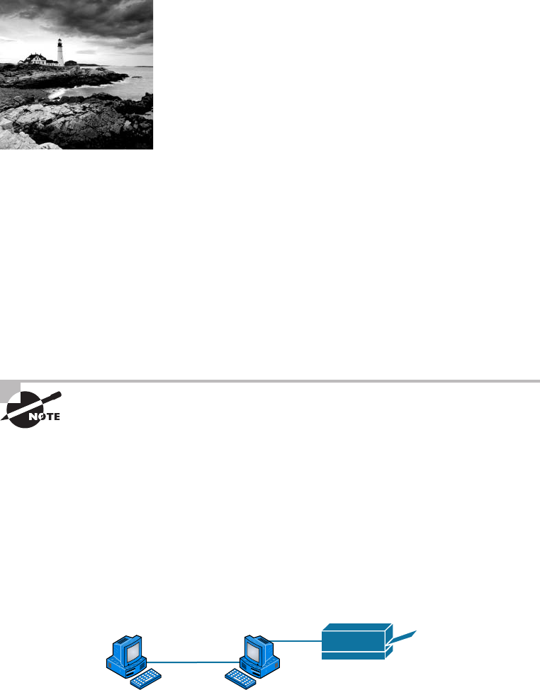
c01.indd 04/02/2015 Page 2
You’d have to work pretty hard these days to nd someone
who would argue when we say that our computers have
become invaluable to us personally and professionally. Our
society has become highly dependent on the resources they offer and on sharing them with
each other. The ability to communicate with others—whether they’re in the same building
or in some faraway land—completely hinges on our capacity to create and maintain solid,
dependable networks.
And those vitally important networks come in all shapes and sizes—ranging from small
and simple to humongous and super complicated. But whatever their avor, they all need
to be maintained properly, and to do that well, you have to understand networking basics.
The various types of devices and technologies that are used to create networks, as well as
how they work together, is what this book is about, and I’ll go through this critical infor-
mation one step at a time with you. Understanding all of this will not only equip you with
a rock-solid base to build on as you gain IT knowledge and grow in your career, it will also
arm you with what you’ll need to ace the Network+ certi cation exam!
To find up-to-the-minute updates for this chapter, please see
www.lammle
.com/forum
or the book’s website at
http://sybextestbanks.wiley.com/.
First Things First: What’s a Network?
The dictionary de nes the word network as “a group or system of interconnected people or
things.” Similarly, in the computer world, the term network means two or more connected
computers that can share resources such as data and applications, of ce machines, an
Internet connection, or some combination of these, as shown in Figure 1.1.
FIGURE 1.1 A basic network
Host Host
Printer
Figure 1.1 shows a really basic network made up of only two host computers connected;
they share resources such as les and even a printer hooked up to one of the hosts. These two
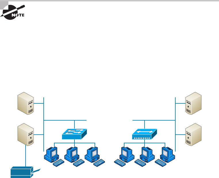
First Things First: What’s a Network?
3
c01.indd 04/02/2015 Page 3
hosts “talk” to each other using a computer language called binary code, which consists of
lots of 1s and 0s in a speci c order that describes exactly what they want to “say.”
Next, I’m going to tell you about local area networks, how they work, and even how we
can connect LANs together. Then, later in this chapter, I’ll describe how to connect remote
LANs together through something known as a wide area network.
The Local Area Network
Just as the name implies, a local area network (LAN) is usually restricted to spanning a
particular geographic location such as an of ce building, a single department within a cor-
porate of ce, or even a home of ce.
Back in the day, you couldn’t put more than 30 workstations on a LAN, and you had
to cope with strict limitations on how far those machines could actually be from each
other. Because of technological advances, all that’s changed now, and we’re not nearly as
restricted in regard to both a LAN’s size and the distance a LAN can span. Even so, it’s still
best to split a big LAN into smaller logical zones known as workgroups to make adminis-
tration easier.
The meaning of the term workgroup in this context is slightly different than
when the term is used in contrast to domains. In that context, a workgroup
is a set of devices with no security association with one another (whereas
in a domain they do have that association). In this context, we simply mean
they physically are in the same network segment.
In a typical business environment, it’s a good idea to arrange your LAN’s workgroups
along department divisions; for instance, you would create a workgroup for Accounting,
another one for Sales, and maybe another for Marketing—you get the idea. Figure 1.2
shows two separate LANS, each as its own workgroup.
FIGURE 1.2 Two separate LANs (workgroups)
Servers Servers
Switch Hub
SalesMarketing
Printer
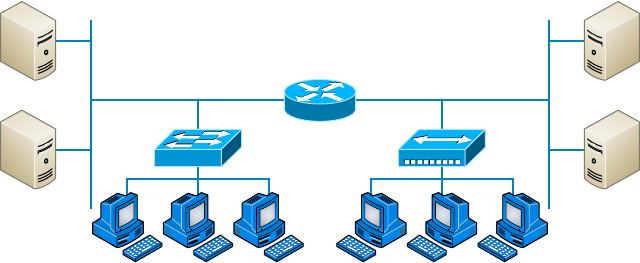
4
Chapter 1 ■ Introduction to Networks
c01.indd 04/02/2015 Page 4
First, don’t stress about the devices labeled hub and switch—these are just connectiv-
ity devices that allow hosts to physically connect to resources on an LAN. Trust me; I’ll
describe them to you in much more detail in Chapter 5, “Networking Devices.”
Anyway, back to the gure. Notice that there’s a Marketing workgroup and a Sales
workgroup. These are LANs in their most basic form. Any device that connects to the
Marketing LAN can access the resources of the Marketing LAN—in this case, the servers
and printer.
There are two problems with this:
■ You must be physically connected to a workgroup’s LAN to get the resources from it.
■ You can’t get from one LAN to the other LAN and use its server data and printing
resources remotely.
This is a typical network issue that’s easily resolved by using a cool device called a
router to connect the two LANs, as shown in Figure 1.3.
FIGURE 1.3 A router connects LANs
Servers Servers
Sales
Router
Marketing
Nice—problem solved! Even though you can use routers for more than just connecting
LANs, the router shown in Figure 1.3 is a great solution because the host computers from
the Sales LAN can get to the resources (server data and printers) of the Marketing LAN,
and vice versa.
Now, you might be thinking that we really don’t need the router—that we could
just physically connect the two workgroups with a type of cable that would allow the
Marketing and Sales workgroups to hook up somehow. Well, we could do that, but if we
did, we would have only one big, cumbersome workgroup instead of separate workgroups
for Marketing and Sales, and that kind of arrangement just isn’t practical for today’s
networks.
This is because with smaller, individual-yet-connected groups, the users on each LAN
enjoy much faster response times when accessing resources, and administrative tasks are a

First Things First: What’s a Network?
5
c01.indd 04/02/2015 Page 5
lot easier, too. Larger workgroups run more slowly because there’s a legion of hosts within
them that are all trying to get to the same resources simultaneously. So the router shown in
Figure 1.3, which separates the workgroups while still allowing access between them, is a
really great solution!
Don’t focus too much on the network connectivity devices like the hubs,
routers, and switches I’ve mentioned so far in this chapter yet. We’ll thor-
oughly cover them all later, in Chapter 5. Right now, I really want you to
prioritize your understanding of the concepts that I’m presenting here, so at
this point, all you need to know is that hubs and switches are devices that
connect other devices together and routers connect networks together.
So let me de ne the other terms I’ve used so far: workstations, servers, and hosts.
Common Network Components
There are a lot of different machines, devices, and media that make up our networks. Let’s
talk about three of the most common:
■ Workstations
■ Servers
■ Hosts
Workstations
Workstations are often seriously powerful computers that run more than one central
processing unit (CPU) and whose resources are available to other users on the network to
access when needed. With this much power, you might think I am describing a server—not
quite because there is an important difference between these devices that I’ll cover in the
next section. Workstations are often employed as systems that end users use on a daily
basis. Don’t confuse workstations with client machines, which can be workstations but not
always. People often use the terms workstation and client interchangeably. In colloquial
terms, this isn’t a big deal; we all do it. But technically speaking, they are different. A client
machine is any device on the network that can ask for access to resources like a printer or
other hosts from a server or powerful workstation.
The terms workstation, client, and host can sometimes be used inter-
changeably. Computers have become more and more powerful and the
terms have become somewhat fuzzy because hosts can be clients, work-
stations, servers, and more! The term host is used to describe pretty much
anything that takes an IP address.

6
Chapter 1 ■ Introduction to Networks
c01.indd 04/02/2015 Page 6
Servers
Servers are also powerful computers. They get their name because they truly are “at the
service” of the network and run specialized software known as the network operating
system to maintain and control the network.
In a good design that optimizes the network’s performance, servers are highly special-
ized and are there to handle one important labor-intensive job. This is not to say that a
single server can’t do many jobs, but more often than not, you’ll get better performance if
you dedicate a server to a single task. Here’s a list of common dedicated servers:
File Server Stores and dispenses les
Mail Server The network’s post of ce; handles email functions
Print Server Manages printers on the network
Web Server Manages web-based activities by running Hypertext Transfer Protocol
(HTTP) for storing web content and accessing web pages
Fax Server The “memo maker” that sends and receives paperless faxes over the network
Application Server Manages network applications
Telephony Server Handles the call center and call routing and can be thought of as a
sophisticated network answering machine
Proxy Server Handles tasks in the place of other machines on the network, particularly
an Internet connection.
See how the name of each kind of server indicates what it actually does—
how it serves the network? This is an excellent way to remember them.
As I said, servers are usually dedicated to doing one speci c important thing within the
network. Not always though—sometimes they have more than one job. But whether servers
are designated for one job or are network multitaskers, they can maintain the network’s
data integrity by backing up the network’s software and providing redundant hardware (for
fault tolerance). And no matter what, they all serve a number of client machines.
Back in Figure 1.2, I showed you an example of two really simple LAN networks. I want to
make sure you know that servers must have considerably superior CPUs, hard-drive space, and
memory—a lot more than a simple client’s capacity—because they serve many client machines
and provide any resources they require. Because they’re so important, you should always put
your servers in a very secure area. My company’s servers are in a locked server room because
not only are they really pricey workhorses, they also store huge amounts of important and
sensitive company data, so they need to be kept safe from any unauthorized access.
In Figure 1.4, you can see a network populated with both workstations and servers. Also
notice that the hosts can access the servers across the network, which is pretty much the
general idea of having a network in the rst place!
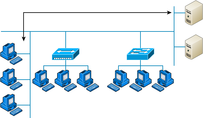
First Things First: What’s a Network?
7
c01.indd 04/02/2015 Page 7
FIGURE 1.4 A network populated with servers and workstations
Servers
Servers
Secure Server
Room
Hub Switch
Marketing
Hosts
Sales
You probably picked up on the fact that there are more workstations here than serv-
ers, right? Think of why that is. If you answered that it’s because one server can provide
resources to what can sometimes be a huge number of individual users at the same time but
workstations don’t, you nailed it!
Hosts
This can be kind of confusing because when people refer to hosts, they really can be
referring to almost any type of networking devices—including workstations and servers.
But if you dig a bit deeper, you’ll nd that usually this term comes up when people are
talking about resources and jobs that have to do with Transmission Control Protocol/
Internet Protocol (TCP/IP). The scope of possible machines and devices is so broad
because, in TCP/IP-speak, host means any network device with an IP address. Yes,
you’ll hear IT professionals throw this term around pretty loosely; for the Network+
exam, stick to the de nition being network devices, including workstations and servers,
with IP addresses.
Here’s a bit of background: The name host harkens back to the Jurassic period of net-
working when those dinosaurs known as mainframes were the only intelligent devices
able to roam the network. These were called hosts whether they had TCP/IP functionality
or not. In that bygone age, everything else in the network-scape was referred to as dumb
terminals because only mainframes—hosts—were given IP addresses. Another fossilized
term from way back then is gateways, which was used to talk about any Layer 3 machines
like routers. We still use these terms today, but they’ve evolved a bit to refer to the many

8
Chapter 1 ■ Introduction to Networks
c01.indd 04/02/2015 Page 8
intelligent devices populating our present-day networks, each of which has an IP address.
This is exactly the reason you hear host used so broadly.
Wide Area Network
There are legions of people who, if asked to de ne a wide area network (WAN), just
couldn’t do it. Yet most of them use the big dog of all WANs—the Internet—every day!
With that in mind, you can imagine that WAN networks are what we use to span large
geographic areas and truly go the distance. Like the Internet, WANs usually employ both
routers and public links, so that’s generally the criteria used to de ne them.
WANs are so important that I have dedicated an entire chapter to them:
Chapter 16, “Wide Area Networks.”
Here’s a list of some of the important ways that WANs are different from LANs:
■ WANs usually need a router port or ports.
■ WANs span larger geographic areas and/or can link disparate locations.
■ WANs are usually slower.
■ We can choose when and how long we connect to a WAN. A LAN is all or nothing—
our workstation is either connected permanently to it or not at all, although most of us
have dedicated WAN links now.
■ WANs can utilize either private or public data transport media such as phone lines.
We get the word Internet from the term internetwork. An internetwork is a type of LAN
and/or WAN that connects a bunch of networks, or intranets. In an internetwork, hosts
still use hardware addresses to communicate with other hosts on the LAN. However, they
use logical addresses (IP addresses) to communicate with hosts on a different LAN (other
side of the router).
And routers are the devices that make this possible. Each connection into a router is a
different logical network. Figure 1.5 demonstrates how routers are employed to create an
internetwork and how they enable our LANs to access WAN resources.
The Internet is a prime example of what’s known as a distributed WAN—an inter-
network that’s made up of a lot of interconnected computers located in a lot of differ-
ent places. There’s another kind of WAN, referred to as centralized, that’s composed of
a main, centrally located computer or location that remote computers and devices can
connect to. A good example is remote of ces that connect to a main corporate of ce, as
shown in Figure 1.5.
MPLS
Multiprotocol Label Switching (MPLS) will be de ned clearly in Chapter 16, but for the
objectives of the CompTIA Network+ exam, this chapter will de ne the actual layout of
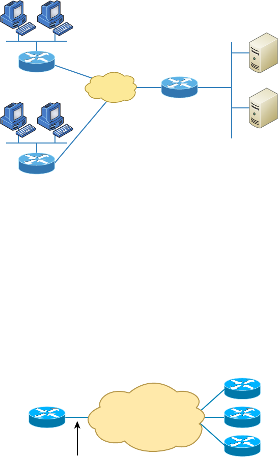
First Things First: What’s a Network?
9
c01.indd 04/02/2015 Page 9
what is one of the most popular WAN protocols in use today. MPLS has become one of
the most innovative and exible networking technologies on the market, and has some key
advantages over other WAN technologies:
■ Physical layout flexibility
■ Prioritizing of data
■ Redundancy in case of link failure
■ One-to-many connection
MPLS is a switching mechanism that imposes labels (numbers) to data and then uses
those labels to forward data when it arrives at the MPLS network, as shown in Figure 1.6.
FIGURE 1.6 Multiprotocol Label Switching layout
Corporate Office
Each router assigns labels to data when
the data heads toward the MPLS cloud.
Branch Offices
MPLS Network
Logical Connections
between Sites
The labels are assigned on the edge of the MPLS network, and forwarding inside the
MPLS network (cloud) is done solely based on labels through virtual links instead of
FIGURE 1.5 An internetwork
Servers
Internet
Corp
Branch1
Branch2
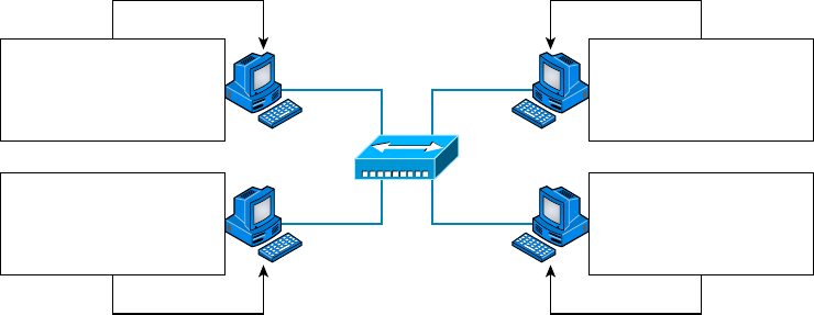
10
Chapter 1 ■ Introduction to Networks
c01.indd 04/02/2015 Page 10
physical links. Prioritizing data is a huge advantage; for example, voice data could have pri-
ority over basic data based on the labels. And since there are multiple paths for the data to
be forwarded through the MPLS cloud, there’s even some redundancy provided as well.
Network Architecture: Peer-to-Peer or Client-Server?
We’ve developed networking as a way to share resources and information, and how that’s
achieved directly maps to the particular architecture of the network operating system soft-
ware. There are two main network types you need to know about: peer-to-peer and client-
server. And by the way, it’s really tough to tell the difference just by looking at a diagram or
even by checking out live video of the network humming along. But the differences between
peer-to-peer and client-server architectures are pretty major. They’re not just physical;
they’re logical differences. You’ll see what I mean in a bit.
Peer-to-Peer Networks
Computers connected together in peer-to-peer networks do not have any central, or
special, authority—they’re all peers, meaning that when it comes to authority, they’re all
equals. The authority lies with the computer that has the desired resource being requested
from it to perform a security check for proper access rights.
It also means that the computers coexisting in a peer-to-peer network can be client
machines that access resources and server machines and provide them to other comput-
ers. This actually works pretty well as long as there isn’t a huge number of users on the
network, if each user backs things up locally, and if your network doesn’t require much
security.
If your network is running Windows, Mac, or Unix in a local LAN workgroup, you
have a peer-to-peer network. Figure 1.7 gives you a snapshot of a typical peer-to-peer net-
work. Keep in mind that peer-to-peer networks de nitely present security-oriented chal-
lenges; for instance, just backing up company data can get pretty sketchy!
FIGURE 1.7 A peer-to-peer network
Millie Pluto
Mickey Hub Louie
Users Password Access
Mickey !Tails? Full
Pluto $NoKats Read
Louie ^Wet#! Read
Users Password Access
Millie #Shorts? Read
Pluto &LittleTail! Full
Louie ^Wet#! Full
Users Password Access
Millie #Shorts? Read
Pluto &LittleTail! Full
Mickey &&Boss!@ Full
Users Password Access
Millie #Shorts? Read
Mickey My!Ears? Read
Louie ^Wet#! Full
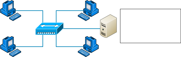
First Things First: What’s a Network?
11
c01.indd 04/02/2015 Page 11
Since it should be clear by now that peer-to-peer networks aren’t all sunshine, backing
up all your critical data may be tough, but it’s vital! Haven’t all of us forgotten where we’ve
put an important le? And then there’s that glaring security issue to tangle with. Because
security is not centrally governed, each and every user has to remember and maintain a list
of users and passwords on each and every machine. Worse, some of those all-important
passwords for the same users change on different machines—even for accessing different
resources. What a mess!
Client-Server Networks
Client-server networks are pretty much the polar opposite of peer-to-peer networks
because in them, a single server uses a network operating system for managing the
whole network. Here’s how it works: A client machine’s request for a resource goes to
the main server, which responds by handling security and directing the client to the
desired resource. This happens instead of the request going directly to the machine with
the desired resource, which has some serious advantages. First, because the network is
much better organized and doesn’t depend on users remembering where needed resources
are, it’s a whole lot easier to nd the les you need because everything is stored in one
spot—on that special server. Your security also gets a lot tighter because all usernames
and passwords are on that speci c server, which is never ever used as a workstation.
You even gain scalability—client-server networks can have legions of workstations on
them. And surprisingly, with all those demands, the network’s performance is actually
optimized—nice!
Check out Figure 1.8, which shows a client-server network with a server that has a data-
base of access rights, user accounts, and passwords.
FIGURE 1.8 A client-server network
Millie Pluto
Mickey Hub Louie Server
Users Password Access
Millie #Shorts? Read
Pluto &LittleTail! Full
Louie ^Wet#! Full
Mickey --Earls? Write
Many of today’s networks are hopefully a healthy blend of peer-to-peer and client-
server architectures, with carefully speci ed servers that permit the simultaneous sharing
of resources from devices running workstation operating systems. Even though the sup-
porting machines can’t handle as many inbound connections at a time, they still run the
server service reasonably well. And if this type of mixed environment is designed well, most
networks bene t greatly by having the capacity to take advantage of the positive aspects of
both worlds.
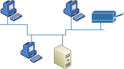
12
Chapter 1 ■ Introduction to Networks
c01.indd 04/02/2015 Page 12
Physical Network Topologies
Just as a topographical map is a type of map that shows the shape of the terrain, the physi-
cal topology of a network is also a type of map. It de nes the speci c characteristics of a
network, such as where all the workstations and other devices are located and the precise
arrangement of all the physical media such as cables. On the other hand, the logical topolo-
gies we covered earlier, delineate exactly how data moves through the network. Now, even
though these two topologies are usually a lot alike, a particular network can actually have
physical and logical topologies that are very different. Basically, what you want to remem-
ber is that a network’s physical topology gives you the lay of the land and the logical topol-
ogy shows how a digital signal or data navigates through that layout.
Here’s a list of the topologies you’re most likely to run into these days:
■ Bus
■ Star
■ Ring
■ Mesh
■ Point-to-point
■ Point-to-multipoint
■ Hybrid
Bus Topology
This type of topology is the most basic one of the bunch, and it really does sort of resemble
a bus, but more like one that’s been in a wreck! Anyway, the bus topology consists of two
distinct and terminated ends, with each of its computers connecting to one unbroken cable
running its entire length. Back in the day, we used to attach computers to that main cable
with wire taps, but this didn’t work all that well so we began using drop cables in their
place. If we were dealing with 10Base2 Ethernet, we would slip a “T” into the main cable
anywhere we wanted to connect a device to it instead of using drop cables.
Figure 1.9 depicts what a typical bus network’s physical topology looks like.
FIGURE 1.9 A typical bus network’s physical topology
Laser Printer
Server S1
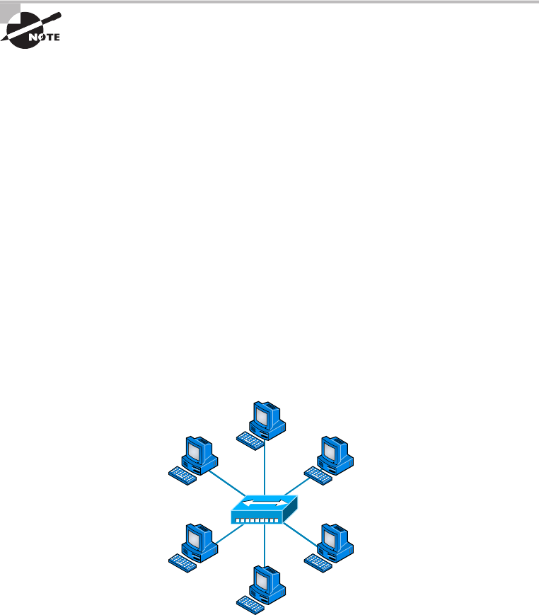
Physical Network Topologies
13
c01.indd 04/02/2015 Page 13
Even though all the computers on this kind of network see all the data owing through
the cable, only the one computer, which the data is speci cally addressed to, actually gets
the data. Some of the bene ts of using a bus topology are that it’s easy to install and it’s
not very expensive, partly because it doesn’t require as much cable as the other types of
physical topologies. But it also has some drawbacks: For instance, it’s hard to troubleshoot,
change, or move, and it really doesn’t offer much in the way of fault tolerance because
everything is connected to that single cable. This means that any fault in the cable would
basically brings the whole network down!
By the way, fault tolerance is the capability of a computer or a network
system to respond to a condition automatically, often resolving it, which
reduces the impact on the system. If fault-tolerance measures have been
implemented correctly on a network, it’s highly unlikely that any of that
network’s users will know that a problem ever existed at all.
Star Topology
A star topology’s computers are connected to a central point with their own individual
cables or wireless connections. You’ll often nd that central spot inhabited by a device like
a hub, a switch, or an access point.
Star topology offers a lot of advantages over bus topology, making it more widely used
even though it obviously requires more physical media. One of its best features is that
because each computer or network segment is connected to the central device individu-
ally, if the cable fails, it only brings down the machine or network segment related to the
point of failure. This makes the network much more fault tolerant as well as a lot easier
to troubleshoot. Another great thing about a star topology is that it’s a lot more scal-
able—all you have to do if you want to add to it is run a new cable and connect to the
machine at the core of the star. In Figure 1.10, you’ll nd a great example of a typical
star topology.
FIGURE 1.10 Typical star topology with a hub
Hub
14
Chapter 1 ■ Introduction to Networks
c01.indd 04/02/2015 Page 14
Although it is called a star topology, it also looks a lot like a bike wheel with spokes
connecting to the hub in the middle of the wheel and extending outward to connect to the
rim. And just as with that bike wheel, it’s the hub device at the center of a star topology
network that can give you the most grief if something goes wrong with it. If that central
hub happens to fail, down comes the whole network, so it’s a very good thing hubs don’t
fail often!
Just as it is with pretty much everything, a star topology has its pros and cons. But the
good news far outweighs the bad, which is why people often opt for star topology. And
here’s a list of bene ts you gain by going with it:
■ New stations can be added easily and quickly.
■ A single cable failure won’t bring down the entire network.
■ It’s relatively easy to troubleshoot.
And here are the disadvantages to using a star topology:
■ The total installation cost can be higher because of the larger number of cables, even
though prices are becoming more competitive.
■ It has a single point of failure—the hub or other central device.
There are two more sophisticated implementations of a star topology. The rst is called
a point-to-point link, where you have not only the device in the center of the spoke acting
as a hub but also on the other end, which extends the network. This is still a star-wired
topology, but as I’m sure you can imagine, it gives you a lot more scalability!
Another re ned version is the wireless version, but to understand this variety well,
you’ve got to have a solid grasp of all the capabilities and features of any devices populating
the wireless star topology. No worries, though—I’ll be covering wireless access points later
on in Chapter 12, “Wireless Networking.” For now, it’s good enough for you to know that
access points are pretty much just wireless hubs or switches that behave like their wired
counterparts. Basically, they create a point-by-point connection to endpoints and other
wireless access points.
Ring Topology
In this type of topology, each computer is directly connected to other computers within the
same network. Looking at Figure 1.11, you can see that the network’s data ows from com-
puter to computer back to the source, with the network’s primary cable forming a ring. The
problem is, the ring topology has a lot in common with the bus topology because if you
want to add to the network, you have no choice but to break the cable ring, which is likely
to bring down the entire network!
This is one big reason that ring topology isn’t very popular—you just won’t run into it a
lot as I did in the 1980s and early 1990s. It’s also pricey because you need several cables to
connect each computer, it’s really hard to recon gure, and as you’ve probably guessed, it’s
not fault-tolerant.
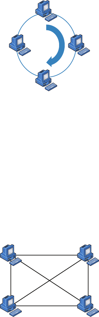
Physical Network Topologies
15
c01.indd 04/02/2015 Page 15
FIGURE 1.11 A typical ring topology
But even with all that being said, if you work at an ISP, you may still nd a physical ring
topology in use for a technology called SONET or some other WAN technology. However,
you just won’t nd any LANs in physical rings anymore.
Mesh Topology
In this type of topology, you’ll nd that there’s a path from every machine to every other
one in the network. That’s a lot of connections—in fact, the mesh topology wins the prize
for “most physical connections per device”! You won’t nd it used in LANs very often, if
ever, these days, but you will nd a modi ed version of it known as a hybrid mesh used in
a restrained manner on WANs, including the Internet.
Often, hybrid mesh topology networks will have quite a few connections between cer-
tain places to create redundancy (backup). And other types of topologies can sometimes
be found in the mix, too, which is another reason it’s dubbed hybrid. Just remember that it
isn’t a full-on mesh topology if there isn’t a connection between all devices in the network.
And understand that it’s fairly complicated. Figure 1.12 gives you a great picture of just
how much only four connections can complicate things!
FIGURE 1.12 A typical mesh topology

16
Chapter 1 ■ Introduction to Networks
c01.indd 04/02/2015 Page 16
You can clearly see that everything gets more and more complex as both the wiring and
the connections multiply. For each n locations or hosts, you end up with n(n–1)/2 connec-
tions. This means that in a network consisting of only four computers, you have 4(4–1)/2,
or 6 connections. And if that little network grows to, say, a population of 10 computers,
you’ll then have a whopping 45 connections to cope with! That’s a huge amount of over-
head, so only small networks can really use this topology and manage it well. On the bright
side, you get a really nice level of fault tolerance, but mesh still isn’t used in corporate
LANs anymore because they were so complicated to manage.
A full mesh physical topology is least likely to have a collision, which
happens when the data from two hosts trying to communicate simultane-
ously “collides” and gets lost.
This is also the reason you’ll usually nd the hybrid version in today’s WANs. In fact,
the mesh topology is actually pretty rare now, but it’s still used because of the robust fault
tolerance it offers. Because you have a multitude of connections, if one goes on the blink,
computers and other network devices can simply switch to one of the many redundant con-
nections that are up and running. And clearly, all that cabling in the mesh topology makes
it a very pricey implementation. Plus, you can make your network management much less
insane than it is with mesh by using what’s known as a partial mesh topology solution
instead, so why not go that way? You may lose a little fault tolerance, but if you go the par-
tial mesh route, you still get to use the same technology between all the network’s devices.
Just remember that with partial mesh, not all devices will be interconnected, so it’s very
important to choose the one’s that will be very wisely.
Point-to-Point Topology
As its name implies, in a point-to-point topology you have a direct connection between two
routers or switches, giving you one communication path. The routers in a point-to-point
topology can either be linked by a serial cable, making it a physical network. If they’re
located far apart and connected only via a circuit within a Frame Relay or MPLS network,
it’s a logical network instead.
Figure 1.13 illustrates a typical T1, or WAN, point-to-point connection.
What you see here is a lightning bolt and a couple of round things with a bunch of arrows
projecting from them, right? Well, the two round things radiating arrows represent our net-
work’s two routers, and that lightning bolt represents a WAN link. These symbols are industry
standard, and I’ll be using them throughout this book, so it’s a good idea to get used to them!
Okay—so part two of the diagram shows two computers connected by a cable—a
point-to-point link. By the way, this should remind you of something we just went over.
Remember peer-to-peer networks? Good! I hope you also remember that a big drawback
to peer-to-peer network sharing is that it’s not very scalable. With this in mind, you prob-
ably won’t be all that surprised that even if both machines have a wireless point-to-point
connection, this network still won’t be very scalable.
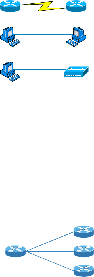
Physical Network Topologies
17
c01.indd 04/02/2015 Page 17
FIGURE 1.13 Three point-to-point connections
Serial Connection, Like a T1 between Routers
Direct Ethernet or Wireless
Cable Direct to Hub or Switch
Hub
You’ll usually nd point-to-point networks within many of today’s WANs, and as you
can see in part three of Figure 1.13, a link from a computer to a hub or switch is also a
valid point-to-point connection. A common version of this setup consists of a direct wire-
less link between two wireless bridges that’s used to connect computers in two different
buildings together.
Point-to-Multipoint Topology
Again as the name suggests, a point-to-multipoint topology consists of a succession of
connections between an interface on one router and multiple destination routers—one
point of connection to multiple points of connection. Each of the routers and every one
of their interfaces involved in the point-to-multipoint connection are part of the same
network.
Figure 1.14 shows a WAN and demonstrates a point-to-multipoint network. You can
clearly see a single, corporate router connecting to multiple branches.
FIGURE 1.14 A point-to-multipoint network, example 1
Corporate Office
Branch Offices
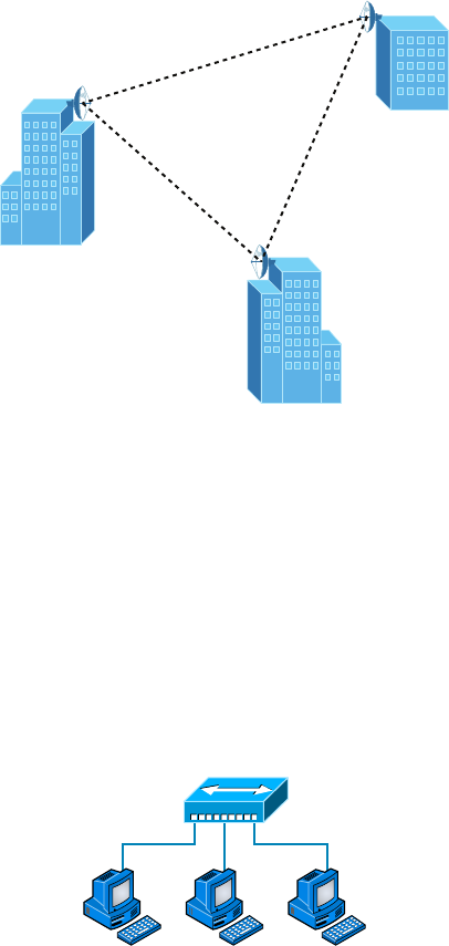
18
Chapter 1 ■ Introduction to Networks
c01.indd 04/02/2015 Page 18
Figure 1.15 shows another prime example of a point-to-multipoint network: a college or
corporate campus.
FIGURE 1.15 A point-to-multipoint network, example 2
Hybrid Topology
I know I just talked about hybrid network topology in the section about mesh topology, but
I didn’t give you a mental picture of it in the form of a gure. I also want to point out that
hybrid topology means just that—a combination of two or more types of physical or logi-
cal network topologies working together within the same network.
Figure 1.16 depicts a simple hybrid network topology; it shows a LAN switch or hub in a
star topology con guration that connects to its hosts via bus topology.
FIGURE 1.16 A simple hybrid network
Hub
Physical Star, Logical Bus

Topology Selection, Backbones, and Segments
19
c01.indd 04/02/2015 Page 19
Topology Selection, Backbones, and
Segments
Now that you’re familiar with many different types of network topologies, you’re ready for
some tips on selecting the right one for your particular network. You also need to know
about backbones and segments, which I’ll cover in the very last part of this chapter.
They’re Just Cables, Right?
Wrong! Regardless of the type of network you build, you need to start thinking about
quality at the bottom and work up.
Think of it as if you were at an electronics store buying the cables for your home theater
system. You’ve already spent a bunch of time and money getting the right components
to meet your needs. Because you’ve probably parted with a hefty chunk of change, you
might be tempted to cut corners, but why would you stop now and connect all your high-
quality devices together with the cable equivalent of twine? No, you’re smarter than
that–you know that picking out the exact cables that will maximize the sound and picture
quality of your specifi c components can also protect them!
It’s the same thing when you’re faced with selecting the physical media for a specifi c net-
work. You just don’t want to cut corners here because this is the backbone of the network
and you defi nitely don’t want to be faced with going through the costly pain of replacing
this infrastructure once its been installed. Doing that will cost you a lot more than taking
the time to wisely choose the right cables and spending the money it takes to get them
in the fi rst place. The network downtime alone can cost a company a bundle! Another
reason for choosing the network’s physical media well is that it’s going to be there for a
good fi ve to 10 years. This means two things: It better be solid quality, and it better be
scalable because that network is going to grow and change over the years.
Selecting the Right Topology
As you now know, not only do you have a buffet of network topologies to choose from, but
each one also has pros and cons to implementing it. But it really comes down to that well-
known adage “Ask the right questions.” First, how much cash do you have? How much
fault tolerance and security do you really need? Also, is this network likely to grow like a
weed—will you need to quickly and easily recon gure it often? In other words, how scal-
able does your network need to be?
20
Chapter 1 ■ Introduction to Networks
c01.indd 04/02/2015 Page 20
For instance, if your challenge is to design a nice, cost-effective solution that involves only
a few computers in a room, getting a wireless access point and some wireless network cards
is de nitely your best way to go because you won’t need to part with the cash for a bunch
of cabling and it’s super easy to set up. Alternatively, if you’re faced with coming up with a
solid design for a growing company’s already-large network, you’re probably good to go with
using a wired star topology because it will nicely allow for future changes. Remember, a star
topology really shines when it comes to making additions to the network, moving things
around, and making any kind of changes happen quickly, ef ciently, and cost effectively.
If, say, you’re hired to design a network for an ISP that needs to be up and running 99.9
percent of the time with no more than eight hours a year allowed downtime, well, you
need Godzilla-strength fault tolerance. Do you remember which topology gives that up the
best? (Hint: Internet.) Your primo solution is to go with either a hybrid or a partial mesh
topology. Remember that partial mesh leaves you with a subset of n(n–1)/2 connections to
maintain—a number that could very well blow a big hole in your maintenance budget!
Here’s a list of things to keep in mind when you’re faced with coming up with the right
topology for the right network:
■ Cost
■ Ease of installation
■ Ease of maintenance
■ Fault-tolerance requirement
■ Security requirement
The Network Backbone
Today’s networks can get pretty complicated, so we need to have a standard way of
communicating with each other intelligibly about exactly which part of the network we’re
referencing. This is the reason we divide networks into different parts called backbones and
segments.
Figure 1.17 illustrates a network and shows which part is the backbone and which parts
are segments.
You can see that the network backbone is actually kind of like our own. It’s what all the
network segments and servers connect to and what gives the network its structure. As you
can imagine, being such an important nerve center, the backbone must use some kind of
seriously fast, robust technology—often Gigabit Ethernet. And to optimize network per-
formance—it’s speed and ef ciency—it follows that you would want to connect all of the
network’s servers and segments directly to the network’s backbone.
Network Segments
When we refer to a segment, we can mean any small section of the network that may be
connected to, but isn’t actually a piece of, the backbone. The network’s workstations and
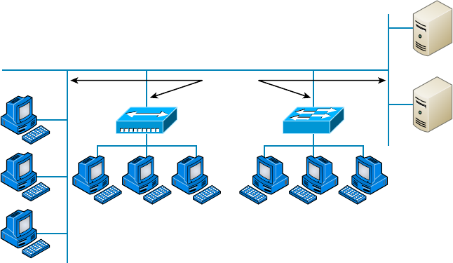
Summary
21
c01.indd 04/02/2015 Page 21
servers organized into segments connect to the network backbone, which is the common
connecting point for all segments; you can see this by taking another look at Figure 1.17,
which displays four segments.
FIGURE 1.17 Backbone and segments on a network
Servers
MarketingSales
Segments
Backbone
Summary
This chapter created a solid foundation for you to build your networking knowledge on as
you go through this book.
In it, you learned what, exactly, a network is, and you got an introduction to some of the
components involved in building one—routers, switches, and hubs—as well as the jobs they
do in a network.
You also learned that having the components required to build a network isn’t all you
need. Understanding the various types of network connection methods, like peer-to-peer
and client-server, is also vital.
Further, you learned about the various types of logical and physical network topolo-
gies and the features and drawbacks of each. I wrapped up the chapter with a short
discussion about network backbones and segments and equipped you with the right ques-
tions to ask yourself to ensure that you come up with the right network topology for your
networking needs.
22
Chapter 1 ■ Introduction to Networks
c01.indd 04/02/2015 Page 22
Exam Essentials
Know your network topologies. Know the names and descriptions of the topologies. Be
aware of the difference between physical networks (what humans see) and logical networks
(what the equipment “sees”).
Know the advantages and disadvantages of the topologies. It is important to know what
each topology brings to the table. Knowing the various characteristics of each topology
comes in handy during troubleshooting.
Understand the terms LAN and WA N. You need to understand when you would use
a LAN and when you would use a WAN. A LAN is used to connect a group of hosts
together, and a WAN is used to connect various LANs together.
Written Labs
You can nd the answers in Appendix A.
1. What are the three basic LAN topologies?
2. What common WAN topology often results in multiple connections to a single site (leading
to a high degree of fault tolerance) and has one-to-many connections?
3. What is the term for a device that shares its resources with other network devices?
4. What network model draws a clear distinction between devices that share their resources
and devices that do not?
5. Which network topology or connection type can be implemented with only two
endpoints?
6. What device is generally implemented as a star topology?
7. What does MPLS stand for?
8. What does WAN stand for?
9. Will a computer that shares no resources most likely be connected to the backbone or to
asegment?
10. Which LAN topology is characterized by all devices being daisy-chained together with the
devices at each end being connected to only one other device?
Review Questions
23
c01.indd 04/02/2015 Page 23
Review Questions
You can nd the answers to the review questions in Appendix B.
1. You need a network that provides centralized authentication for your users. Which of the
following logical topologies should you use?
A. VLANs
B. Peer-to-peer
C. Client-server
D. Mesh
2. You need a topology that is scalable to use in your network. Which of the following will
you install?
A. Bus
B. Ring
C. Star
D. Mesh
3. Which of the following physical topologies has the most connections and is the least popu-
lar for LANs?
A. Bus
B. Start
C. Ring
D. Mesh
4. In a physical star topology, what happens when a workstation loses its physical connection
to another device?
A. The ring is broken, so no devices can communicate.
B. Only that workstation loses its ability to communicate.
C. That workstation and the device it’s connected to lose communication with the rest of
the network.
D. No devices can communicate because there are now two unterminated network segments.
5. Which type of WAN technology uses labels, which enables priority of voice though
the network?
A. VPN
B. T1
C. MPLS
24
Chapter 1 ■ Introduction to Networks
c01.indd 04/02/2015 Page 24
D. LAN
E. Bus
6. What is a logical grouping of network users and resources called?
A. WAN
B. LAN
C. MPLS
D. Host
7. Which of the following is a concern when using peer-to-peer networks?
A. Where to place the server
B. Whose computer is least busy and can act as the server
C. The security associated with such a network
D. Having enough peers to support creating such a network
8. Which of the following is an example of when a point-to-multipoint network is called for?
A. When a centralized office needs to communicate with many branch offices
B. When a full mesh of WAN links is in place
C. When multiple offices are daisy-chained to one another in a line
D. When there are only two nodes in the network to be connected
9. Which of the following is an example of a LAN?
A. Ten buildings interconnected by Ethernet connections over fiber-optic cabling
B. Ten routers interconnected by Frame Relay circuits
C. Two routers interconnected with a T1 circuit
D. A computer connected to another computer so they can share resources
10. Which of the following is a disadvantage of the star topology?
A. When a single port on the central concentrating device fails, the entire network loses
connectivity.
B. When the central concentrating device experiences a complete failure, all attached
devices lose connectivity to the rest of the network.
C. In a star topology, a more expensive type of host must be used compared to the host
used when implementing a physical bus.
D. It is more difficult to add stations and troubleshoot than with other topologies.
11. What is a difference between a LAN and a WAN?
A. WANs require a router.
B. WANs cover larger geographical areas.
C. WANs can utilize either private or public data transport.
D. All of the above.
Review Questions
25
c01.indd 04/02/2015 Page 25
12. Which of the following provides the most physical layout flexibility in a very large,
geographically dispersed enterprise network?
A. Bus topology
B. LAN switch
C. Star topology
D. MPLS cloud network
13. In what type of network are all computers considered equal and do not share any central
authority?
A. Peer-to-peer
B. Client-server
C. Physical topology
D. None of the above
14. What advantage does the client-server architecture have over peer-to-peer?
A. Easier maintenance
B. Greater organization
C. Tighter security
D. All of the above
15. Which of the following is an example of a hybrid network?
A. Ethernet switch
B. Ring topology
C. Bus topology
D. Star topology
16. You have a network with multiple LANs and want to keep them separate but still con-
nect them together so they can all get to the Internet. Which of the following is the best
solution?
A. Use static IP addresses.
B. Add more hubs.
C. Implement more switches.
D. Install a router.
17. Which type of topology has the greatest number of physical connections?
A. Point-to-multipoint
B. Star
C. Point-to-point
D. Mesh
26
Chapter 1 ■ Introduction to Networks
c01.indd 04/02/2015 Page 26
18. What type of topology gives you a direct connection between two routers so that there is
one communication path?
A. Point-to-point
B. Star
C. Bus
D. Straight
19. Which network topology is a combination of two or more types of physical or two or more
types of logical topologies?
A. Point-to-multipoint
B. Hybrid
C. Bus
D. Star
20. When designing a network and deciding which type of network topology to use, which
item(s) should be considered? (Select all that apply.)
A. Cost
B. Ease of installation
C. Ease of maintenance
D. Fault-tolerance requirements

c02.indd 04/02/2015 Page 27
Chapter
2
The Open Systems
Interconnection
Specifications
THE FOLLOWING COMPTIA NETWORK+
EXAM OBJECTIVES ARE COVERED IN THIS
CHAPTER:
✓ 5.0 Industry standards, practices, and network theory
✓ 5.1 Analyze a scenario and determine the corresponding
OSI layer
■ Layer 1 – Physical
■ Layer 2 – Data link
■ Layer 3 – Network
■ Layer 4 – Transport
■ Layer 5 – Session
■ Layer 6 – Presentation
■ Layer 7 – Application
✓ 5.2 Explain the basics of network theory and concepts
■ Encapsulation/de-encapsulation
■ Modulation techniques
■ Multiplexing
■ De-multiplexing
■ Analog and digital techniques
■ TDM

c02.indd 04/02/2015 Page 28
In this chapter, we’re going to analyze the Open Systems
Interconnection (OSI) model. I’ll thoroughly describe each
part to you in detail because it’s imperative for you to grasp
the OSI model’s key concepts. Once solidly equipped with this vital foundation, you’ll be
set to move on and build your own, personal storehouse of networking knowledge.
The OSI model has seven hierarchical layers that were developed to enable different
networks to communicate reliably between disparate systems.
Because this book is centering upon all things Network+, it’s crucial for you to under-
stand the OSI model as CompTIA sees it, so I’ll present each of its seven layers in that light.
I’ll also provide you with an introduction to encapsulation, which is the process of
encoding data as it goes down the OSI stack. I’ll nish this chapter by covering important
modulation techniques.
To find up-to-the-minute updates for this chapter, please see
www.lammle
.com/forum
or the book’s website at
http://sybextestbanks.wiley.com/
Internetworking Models
In the very rst networks, the computers involved could communicate only with other
computers made by the same manufacturer. For example, companies ran either a complete
DECnet solution or an IBM solution—not both together. In the late 1970s, the Open Systems
Interconnection (OSI) reference model was created by the International Organization for
Standardization (ISO) to break through this barrier.
The OSI model was meant to help vendors create interoperable network devices and
software in the form of protocols, or standards, so that different vendors’ networks could
become compatible and work together. Like world peace, it’ll probably never happen
completely, but it’s still a great goal.
The OSI model is the primary architectural model for networks. It describes how data
and network information are communicated from an application on one computer through
the network media to an application on another computer. The OSI reference model breaks
this approach into layers.
Let’s move on and explore this layered approach as well as how you can utilize its key
concepts to troubleshoot internetworks.
Internetworking Models
29
c02.indd 04/02/2015 Page 29
The Layered Approach
Basically, a reference model is a conceptual blueprint of how communications should take
place. It addresses all the processes required for effective communication and divides these
processes into logical groupings called layers. When a communication system is designed in
this manner, it’s known as layered architecture.
Think of it like this: Say you and some friends want to start a company. One of the rst things
you’ll do is sit down and think through what tasks must be done, who will do them, the order
in which they will be done, and how they relate to each other. Ultimately, you might group these
tasks into departments. Let’s say you decide to have a customer service department, an inventory
department, and a shipping department. Each of your departments has its own unique tasks,
keeping its staff members busy and requiring them to focus only on their own duties.
In this scenario, I’m using departments as a metaphor for the layers in a communica-
tion system. For things to run smoothly, the staff of each department has to trust and rely
heavily on the others to do their jobs and competently handle their unique responsibilities.
During your planning sessions, you’ll probably take notes, recording the entire process to
facilitate later discussions about standards of operation that will serve as your business
blueprint or reference model.
Once your business is launched, each department leader will need to develop practical
methods to implement their assigned tasks using the speci c part of the business model’s
blueprint that relates to their branch. These practical methods, or protocols, must be com-
piled into a standard operating procedures manual and followed closely. The procedures
in your manual will have been included for different reasons and have varying degrees of
importance and implementation. If you form a partnership or acquire another company, it
will be crucial for its business protocols to either match or be compatible with yours.
Similarly, software developers can use a reference model to understand computer
communication processes and see exactly what must be accomplished on any one layer and
how. In other words, if I need to develop a protocol for a certain layer, I only need to focus
on that speci c layer’s functions. I don’t need to be concerned with those of any other layer
because different protocols will be in place to meet the different layer’s needs. The technical
term for this idea is binding. The communication processes that are related to each other
are bound, or grouped together, at a particular layer.
Advantages of Reference Models
The OSI model is hierarchical, and I’d like to point out that the same bene cial characteristics
can actually apply to any layered model. Understand that the central purpose of the OSI, and
all networking models, is to allow different vendors’ networks to interoperate smoothly.
This short list depicts some of the most important advantages we gain by using the OSI
layered model:
■ The OSI model divides network communication processes into smaller and simpler
components, thus aiding component development, design, and troubleshooting.
■ It allows multiple-vendor development through the standardization of network components.

30
Chapter 2 ■ The Open Systems Interconnection Specifications
c02.indd 04/02/2015 Page 30
■ It encourages industry standardization by defining the specific functions that occur at
each layer of the model.
■ It allows various types of network hardware and software to communicate.
■ It prevents changes in one layer from affecting other layers, facilitating development,
and making application programming much easier.
The OSI Reference Model
One of the greatest functions of the OSI speci cations is to assist in data transfer between
disparate hosts regardless if they’re Unix-Windows-or Mac-based.
But keep in mind that the OSI model isn’t a physical model; it’s a conceptual and
comprehensive yet uid set of guidelines, which application developers utilize to create and
implement applications that run on a network. It also provides a framework for creating
and implementing networking standards, devices, and internetworking schemes. The OSI
model has seven layers:
■ Application (Layer 7)
■ Presentation (Layer 6)
■ Session (Layer 5)
■ Transport (Layer 4)
■ Network (Layer 3)
■ Data Link (Layer 2)
■ Physical (Layer 1)
Figure 2.1 summarizes the functions that occur at each layer of the OSI model. With this
in mind, you’re ready to delve into what takes place at each layer in detail.
FIGURE 2.1 Layer functions
Application
Presentation
Session
Transport
Network
Data Link
Physical
• File, print, message, database, and application services
• Data encryption, compression, and translation services
• Dialog control
• End-to-end connection
• Routing
• Framing
• Physical topology
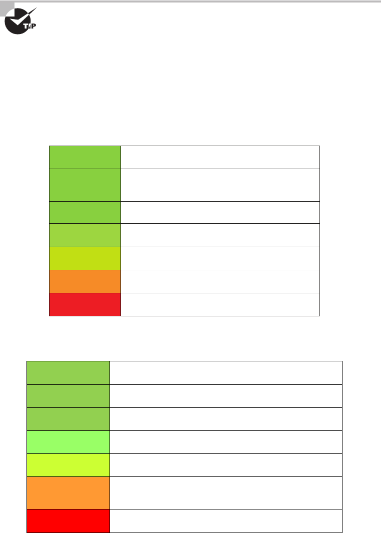
The OSI Reference Model
31
c02.indd 04/02/2015 Page 31
Some people like to use the mnemonic Please Do Not Throw Sausage Pizza
Away to remember the seven layers (starting at Layer 1 and moving up to
Layer 7). I didn’t make that up!
The OSI’s seven layers are divided into two groups. The top three layers de ne the rules
of how the applications working within host machines communicate with each other as
well as with end users. The bottom four layers de ne how the actual data is transmitted
from end to end. Figure 2.2 shows the top three layers and their functions, and Figure 2.3
shows the four lower layers and their functions.
FIGURE 2.2 The upper layers
Application
Presentation
Session
Transport
Network
Data Link
Physical
• Provides a user interface
• Keeps different applications’
data separate
• Presents data
• Handles processing such as encryption
FIGURE 2.3 The lower layers
Application
Presentation
Session
Transport
Network
Data Link
Physical
• Provides reliable or unreliable delivery
• Performs error correction before retransmit
• Moves bits between devices
• Specifies voltage, wire speed, and pin-out of cables
• Combines packets into bytes and bytes into frames
• Provides access to media using MAC address
• Performs error detection, not correction
• Provides logical addressing, which routers use for path
determination
32
Chapter 2 ■ The Open Systems Interconnection Specifications
c02.indd 04/02/2015 Page 32
Looking at Figure 2.2, it’s clear that actual users interface with the computer at the
Application layer. It’s also apparent that the upper layers are responsible for applica-
tions communicating between hosts. Remember that none of the upper layers “know”
anything about networking or network addresses. That’s the responsibility of the four
bottom layers.
Figure 2.3 illustrates that the four bottom layers define how data is transferred
through physical media, switches, and routers. These bottom layers also deter-
mine how to rebuild a data stream from a transmitting host to a destination host’s
application.
Okay—so let’s start at the Application layer and work our way down the stack.
The Application Layer
The Application layer of the OSI model marks the spot where users actually communicate
or interact with the computer. Technically, users communicate with the network stack
through application processes, interfaces, or APIs that connect the application in use to
the operating system of the computer. The Application layer chooses and determines the
availability of communicating partners along with the resources necessary to make their
required connections. It coordinates partnering applications and forms a consensus on
procedures for controlling data integrity and error recovery. The Application layer comes
into play only when it’s apparent that access to the network will be needed soon. Take
the case of Internet Explorer (IE). You could uninstall every trace of networking compo-
nents from a system, such as TCP/IP, the network card, and so on, and you could still use
IE to view a local HTML document without a problem. But things would de nitely get
messy if you tried to do something like view an HTML document that had to be retrieved
using HTTP or nab a le with FTP or TFTP because IE responds to requests like those
by attempting to access the Application layer. So what’s happening is that the Application
layer acts as an interface between the application program—which isn’t part of the lay-
ered structure—and the next layer down by providing ways for the application to send
information down through the protocol stack. In other words, IE doesn’t reside within
the Application layer—it interfaces with Application layer protocols when it needs to deal
with remote resources.
The Application layer is also responsible for identifying and establishing the availability
of the intended communication partner and determining whether suf cient resources for
the requested communication exist.
These tasks are important because computer applications sometimes require more
than just desktop resources. Often, they unite communicating components from more
than one network application. Prime examples are le transfers and email as well as
enabling remote access, network-management activities, and client-server processes
like printing and information location. Many network applications provide services
for communication over enterprise networks, but for present and future internetwork-
ing, the need is fast developing to reach beyond the limitations of current physical
networking.

The OSI Reference Model
33
c02.indd 04/02/2015 Page 33
It’s important to remember that the Application layer acts as an interface
between application programs. For instance, Microsoft Word doesn’t
reside at the Application layer, it interfaces with the Application layer
protocols. Later in Chapter 6, “Introduction to the Internet Protocol,” I’ll
tell you all about key programs or processes that actually do reside at the
Application layer, like FTP and TFTP.
The Presentation Layer
The Presentation layer gets its name from its purpose: it presents data to the Application
layer and is responsible for data translation and code formatting.
A successful data-transfer technique is to adapt the data into a standard format before
transmission. Computers are con gured to receive this generically formatted data and then
convert it back into its native format for reading—for example, from EBCDIC to ASCII.
By providing translation services, the Presentation layer ensures that the data transferred
from one system’s Application layer can be read and understood by the Application layer on
another’s.
The OSI has protocol standards that de ne how standard data should be formatted.
Tasks like data compression, decompression, encryption, and decryption are all associ-
ated with this layer. Some Presentation layer standards are even involved in multimedia
operations.
The Session Layer
The Session layer is responsible for setting up, managing, and then tearing down ses-
sions between Presentation layer entities. This layer also provides dialog control between
devices, or nodes. It coordinates communication between systems and serves to organize
their communication by offering three different modes: simplex, half duplex, and full
duplex. To sum up, the Session layer basically keeps applications’ data separate from other
applications’ data.
The Transport Layer
The Transport layer segments and reassembles data into a data stream. Services located in
the Transport layer handle data from upper-layer applications and unite it onto the same
data stream. They provide end-to-end data transport services and can establish a logical
connection between the sending host and destination host on an internetwork.
The Transport layer is responsible for providing the mechanisms for multiplexing
upper-layer applications, establishing virtual connections, and tearing down virtual
circuits. It also hides the many and sundry details of any network-dependent information
from the higher layers facilitating data transfer.

34
Chapter 2 ■ The Open Systems Interconnection Specifications
c02.indd 04/02/2015 Page 34
We’ll cover Transmission Control Protocol (TCP) and User Datagram Protocol (UDP)
thoroughly in Chapter 6, but if you’re already familiar with them, you know that they both
work at the Transport layer. You also know that TCP is a reliable service and UDP is not.
These two protocols give application developers more options because they have a choice
between them when they’re working with TCP/IP protocols.
The term reliable networking relates to the Transport layer and means that
acknowledgments, sequencing, and flow control will be used.
The Transport layer can be connectionless or connection-oriented, but it’s especially
important for you to really understand the connection-oriented portion of the Transport
layer. So let’s take some time to delve into the connection-oriented (reliable) protocol of the
Transport layer now.
Connection-Oriented Communication
Before a transmitting host starts to send segments down the model, the sender’s TCP process
contacts the destination’s TCP process to establish a connection. The resulting creation is
known as a virtual circuit. This type of communication is called connection-oriented. During
this initial handshake, the two TCP processes also agree on the amount of information that
will be sent in either direction before the respective recipient’s TCP sends back an acknowl-
edgment. With everything agreed on in advance, the path is paved for reliable communication
to take place.
Figure 2.4 depicts a typical reliable session taking place between sending and receiving
systems. Both of the hosts’ application programs begin by notifying their individual operating
systems that a connection is about to be initiated. The two operating systems communicate by
sending messages over the network con rming that the transfer is approved and that both sides
are ready for it to take place. After all of this required synchronization occurs, a connection is
fully established and the data transfer begins. This virtual circuit setup is called overhead.
FIGURE 2.4 Establishing a connection-oriented session
Sender SYN
SYN/ACK
ACK
Connection established
Data transfer
(Send bytes of segments)
Receiver

The OSI Reference Model
35
c02.indd 04/02/2015 Page 35
While the information is being transferred between hosts, the two machines periodically
check in with each other, communicating through their protocol software to ensure that all
is going well and that data is being received properly.
Let me sum up the steps in the connection-oriented session—the three-way handshake—
pictured in Figure 2.4:
1. The first “connection agreement” segment is a request for synchronization.
2. The next segments acknowledge the request and establishes connection parameters—
the rules—between hosts. These segments request that the receiver’s sequencing is
synchronized here as well so that a bidirectional connection is formed.
3. The final segment is also an acknowledgment. It notifies the destination host that the
connection agreement has been accepted and that the connection has been established.
Data transfer can now begin.
I know I went into a lot of detail about this connection setup, and I did that
so you would have a really clear picture of how it works. You can refer to
this entire process as “the three-way handshake” I already mentioned,
known as SYN, SYN/ACK, ACK or synchronize, synchronize-acknowledg-
ment, acknowledgment.
That sounds pretty simple, but things don’t always ow so well. Sometimes congestion
can occur during a transfer because a high-speed computer is generating data traf c a lot
faster than the network can handle transferring it. A bunch of computers simultaneously
sending datagrams through a single gateway or to a destination can also clog things up.
In the latter case, a gateway or destination can become congested even though no single
source caused the problem. Either way, the problem is like a freeway bottleneck—too much
traf c for too small a capacity. It’s not usually one car that’s the problem; it’s that there are
just too many cars on that particular route.
Flow Control
Data integrity is ensured at the Transport layer by maintaining ow control and by allowing
users to request reliable data transport between systems. Flow control provides a means for the
receiver to govern the amount of data sent by the sender. It prevents a sending host on one side
of the connection from over owing the buffers in the receiving host—an event that can result
in lost data. Reliable data transport employs a connection-oriented communications session
between systems, and the protocols involved ensure that the following will be achieved:
1. The segments delivered are acknowledged back to the sender upon their reception.
2. Any segments not acknowledged are retransmitted.
3. Segments are sequenced back into their proper order upon arrival at their destination.
4. A manageable data flow is maintained in order to avoid congestion, overloading, and
data loss.
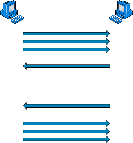
36
Chapter 2 ■ The Open Systems Interconnection Specifications
c02.indd 04/02/2015 Page 36
Okay, so what happens when a machine receives a ood of datagrams too quickly for it
to process? It stores them in a memory section called a buffer. But this buffering tactic can
only solve the problem if the datagrams are part of a small burst. If not, and the datagram
deluge continues, a device’s memory will eventually be exhausted, its ood capacity will be
exceeded, and it will react by discarding any additional datagrams that arrive like a dam
spilling over!
This sounds pretty bad, and it would be if it weren’t for the transport function network
ood-control systems that actually work really well. But how? Well, instead of just dump-
ing resources and allowing data to be lost, the transport can issue a “not ready” indicator
to the sender, or source, of the ood, as shown in Figure 2.5. This mechanism works kind
of like a stoplight, signaling the sending device to stop transmitting segment traf c to its
overwhelmed peer. After the peer machine’s receiver processes the segments abounding
in its memory reservoir (its buffer), it sends out a “ready” transport indicator. When the
machine waiting to transmit the rest of its datagrams receives this “go” indictor, it resumes
its transmission.
FIGURE 2.5 Transmitting segments with flow control
Sender
Transmit
Transmit
Receiver
Buffer full
Not ready –
STOP!
Segments
processed
GO!
During fundamental, reliable, connection-oriented data transfer, datagrams are deliv-
ered to the receiving host in exactly the same sequence they’re transmitted. So if any data
segments are lost, duplicated, or damaged along the way, a failure notice is transmitted.

The OSI Reference Model
37
c02.indd 04/02/2015 Page 37
This error is corrected by making sure the receiving host acknowledges it has received each
and every data segment, and in the correct order.
To summarize, a service is considered connection-oriented if it has the following
characteristics:
■ A virtual circuit is set up (such as a three-way handshake).
■ It uses sequencing.
■ It uses acknowledgments.
■ It uses flow control.
Windowing
Ideally, data throughput happens quickly and efficiently. And as you can imagine, it
would be slow if the transmitting machine had to wait for an acknowledgment after
sending each segment. But because time is available after the sender transmits the
data segment and before it finishes processing acknowledgments from the receiv-
ing machine, the sender uses the break as an opportunity to transmit more data.
The quantity of data segments (measured in bytes) that the transmitting machine is
allowedto send without receiving an acknowledgment is represented by something
called a window.
Windows are used to control the amount of outstanding, unacknowledged
data segments.
It’s important to understand that the size of the window controls how much informa-
tion is transferred from one end to the other. Although some protocols quantify infor-
mation by observing the number of packets, TCP/IP measures it by counting the number
of bytes.
Figure 2.6 illustrates two window sizes—one set to 1 and one set to 3. In this simpli ed
example, both the sending and receiving machines are workstations.
When you’ve con gured a window size of 1, the sending machine waits for an acknowl-
edgment for each data segment it transmits before transmitting another. If you’ve con g-
ured a window size of 3, the sending machine is allowed to transmit three data segments
before an acknowledgment is received. In reality, the window size actually delimits the
amount of bytes that can be sent at a time.
If a receiving host fails to receive all the segments that it should acknowl-
edge, the host can improve the communication session by decreasing the
window size.
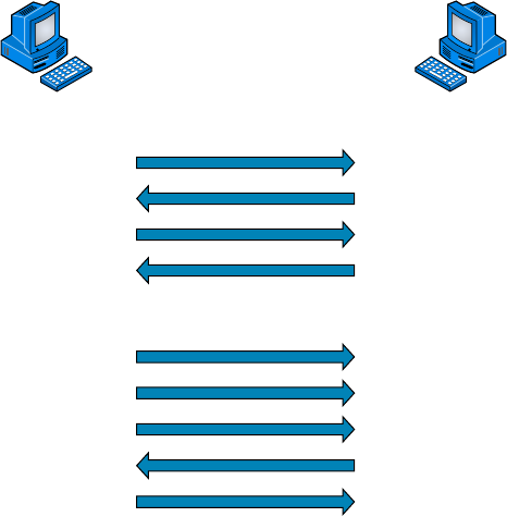
38
Chapter 2 ■ The Open Systems Interconnection Specifications
c02.indd 04/02/2015 Page 38
FIGURE 2.6 Windowing
Sender
Send 1
Send 1
Send 2
Send 2
Send 3
Send 4
Receive 1
Window size of 1
Window size of 3
Receive 2
ACK 1
ACK 2
ACK 4
Receiver
Acknowledgments
Reliable data delivery ensures the integrity of a data stream being sent from one machine
to the other through a fully functional data link. It guarantees that the data won’t be dupli-
cated or lost. This is achieved through something called positive acknowledgment with
retransmission—a technique that requires a receiving machine to communicate with the
transmitting source by sending an acknowledgment message back to the sender when it
receives data. The sender documents each segment it sends and waits for this acknowledg-
ment before sending the next segment. When it sends a segment, the transmitting machine
starts a timer and retransmits if it expires before an acknowledgment is returned from the
receiving end.
In Figure 2.7, the sending machine transmits segments 1, 2, and 3. The receiving node
acknowledges it has received them by requesting segment 4. When it receives the acknowl-
edgment, the sender then transmits segments 4, 5, and 6. If segment 5 doesn’t make it to the
destination, the receiving node acknowledges that event with a request for the segment to
be resent. The sending machine will then resend the lost segment and wait for an acknowl-
edgment, which it must receive in order to move on to the transmission of segment 7.
The Transport layer doesn’t need to use a connection-oriented service. That choice is up
to the application developer. It’s safe to say that if you’re connection-oriented, meaning that
you’ve created a virtual circuit, you’re using TCP. If you aren’t setting up a virtual circuit,
then you’re using UDP and are considered connectionless.
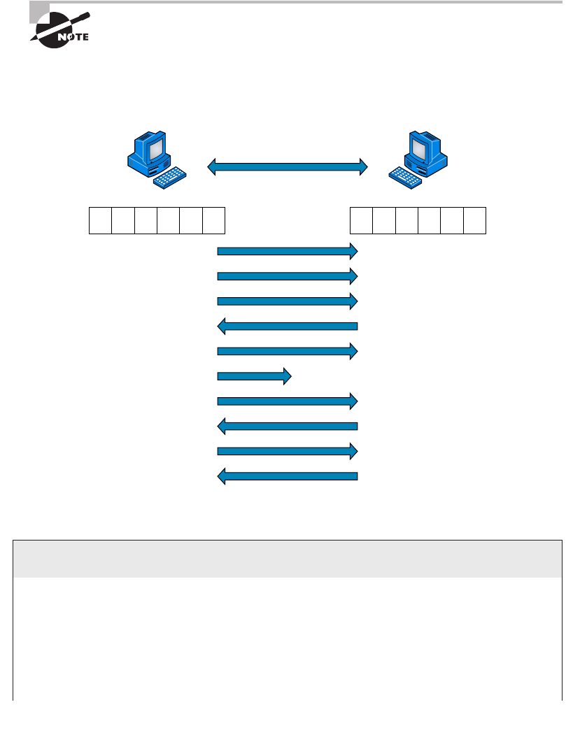
The OSI Reference Model
39
c02.indd 04/02/2015 Page 39
Transport Control Protocol (TCP) and User Datagram Protocol (UDP) are
protocols that work at the Transport layer and will be covered in detail in
Chapter 6.
FIGURE 2.7 Transport layer reliable delivery
Sender
Send 1
Send 2
Send 3
Send 4
Send 5
Send 5
Send 6
ACK 4
ACK 5
ACK 7
Connection lost!
Receiver
123456 123456
Devices Used in an Internetwork
The following network devices operate at all seven layers of the OSI model:
■ Network management stations (NMSs)
■ Web and application servers
■ Gateways (not default gateways)
■ Network hosts
continues

40
Chapter 2 ■ The Open Systems Interconnection Specifications
c02.indd 04/02/2015 Page 40
Several devices operate primarily at the Physical layer of the OSI model. These devices
manipulate mainly the physical aspects of a network data stream—things like voltages,
signal direction, and signal strength. The following four devices are the most popular and
will be detailed in Chapter 5, “Networking Devices”:
■ Network Interface Cards (NICs)
■ Transceivers
■ Repeaters
■ Hubs
The Network Layer
The Network layer manages logical device addressing, tracks the location of devices on the
network, and determines the best way to move data. This means that the Network layer
must transport traf c between devices that aren’t locally attached. Routers are Layer 3
devices that are speci ed at the Network layer and provide the routing services within an
internetwork.
It happens like this: First, when a packet is received on a router interface, the destina-
tion IP address is checked. If the packet isn’t destined for that particular router, the router
looks up the destination network address in the routing table. Once the router chooses an
exit interface, the packet is sent to that interface to be framed and sent out on the local
network. If the router can’t nd an entry for the packet’s destination network in the routing
table, the router drops the packet.
Two types of packets are used at the Network layer:
Data Packets These are used to transport user data through the internetwork. Protocols
used to support data traf c are called routed protocols. Two examples of routed protocols
are Internet Protocol (IP) and Internet Protocol version 6 (IPv6), which you’ll learn all
about coming up in Chapter 7, “IP Addressing.”
Route-Update Packets These are used to update neighboring routers about the networks
connected to all routers within the internetwork. Protocols that send route-update packets
are called routing protocols, and some common ones are Routing Information Protocol
(RIP), RIPv2, Enhanced Interior Gateway Routing Protocol (EIGRP), and Open Shortest
Path First (OSPF). Route-update packets are used to help build and maintain routing tables
on each router.
Figure 2.8 pictures a routing table. The routing table used by a router includes the
following information:
continued
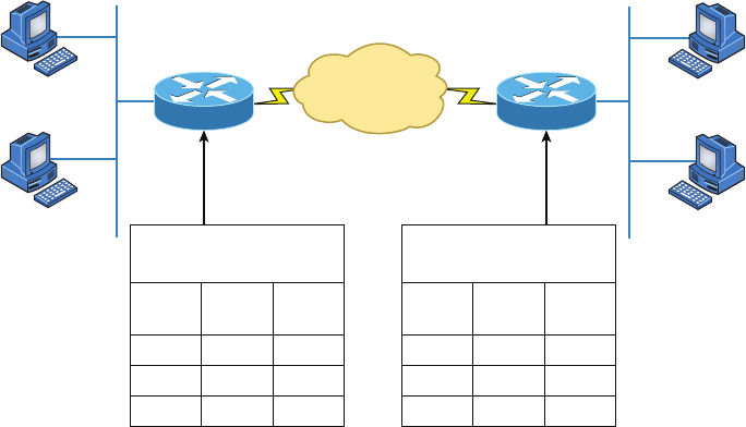
The OSI Reference Model
41
c02.indd 04/02/2015 Page 41
FIGURE 2.8 Routing table used in a router
1.0
1.1
1.3 3.3
3.0
3.1
3.2
Routing table
NET
1
2
3
E0
S0
S0
0
0
1
INT Metric
2.1 2.2
S0 S0
E0 E0
1.2
Routing table
NET
1
2
3
S0
S0
E0
1
0
0
INT Metric
Network Addresses These are protocol-speci c network addresses. A router must main-
tain a routing table for individual routing protocols because each routing protocol keeps
track of a network that includes different addressing schemes, like IP and IPv6. Think of
it as a street sign in each of the different languages spoken by the residents who live on a
particular street. If there were American, Spanish, and French folks on a street named Cat,
the sign would read Cat/Gato/Chat.
Interface This is the exit interface a packet will take when destined for a speci c network.
Metric This value equals the distance to the remote network. Different routing protocols
use different ways of computing this distance. I’ll cover routing protocols in Chapter 9,
“Introduction to IP Routing.” For now, just know that some routing protocols, namely RIP,
use something called a hop count—the number of routers a packet passes through en route
to a remote network. Other routing protocols alternatively use bandwidth, delay of the line,
and even something known as a tick count, which equals 1/18 of a second, to make routing
decisions.
Routers break up broadcast domains, which means that by default, broadcasts aren’t
forwarded through a router. This is a good thing because it reduces traf c on the network.
Routers also break up collision domains, but this can be accomplished using Layer 2 (Data
Link layer) switches as well.
42
Chapter 2 ■ The Open Systems Interconnection Specifications
c02.indd 04/02/2015 Page 42
Broadcast and collision domains will be covered in detail in Chapter 5. For
now, just remember that routers break up broadcast domains and switches
break up collision domains.
Because each interface in a router represents a separate network, it must be assigned
unique network identi cation numbers, and each host on the network connected to that
router must use the same network number. Figure 2.9 demonstrates how a router works
within an internetwork.
FIGURE 2.9 A router in an internetwork
FastEthernet0/0
FastEthernet0/1
Serial0
Each router interface is a broadcast domain.
Routers break up broadcast domains by
default and provide WAN services.
Internet
WAN Services
Here are some key points about routers that you really should commit to memory:
■ Routers, by default, won’t forward any broadcast or multicast packets.
■ Routers use the logical address in a Network layer header to determine the next-hop
router to forward the packet to.
■ Routers can use access lists, created by an administrator, to control security on the
types of packets that are allowed to enter or exit an interface.
■ Routers can provide Layer 2 bridging functions if needed and can simultaneously route
through the same interface.
■ Layer 3 devices (routers, in this case) provide connections between virtual LANs
(VLANs).
■ Routers can provide quality of service (QoS) for specific types of network traffic.
A router can also be referred to as a Layer 3 switch. These terms are
interchangeable.

The OSI Reference Model
43
c02.indd 04/02/2015 Page 43
The Data Link Layer
The Data Link layer provides the physical transmission of the data and handles error noti-
cation, network topology, and ow control. This means the Data Link layer ensures that
messages are delivered to the proper device on a LAN using hardware (MAC) addresses
and translates messages from the Network layer into bits for the Physical layer to transmit.
The Data Link layer formats the message into pieces, each called a data frame, and adds
a customized header containing the destination and source hardware address. This added
information forms a sort of capsule that surrounds the original message in much the same
way that engines, navigational devices, and other tools were attached to the lunar modules
of the Apollo project. These various pieces of equipment were useful only during certain
stages of ight and were stripped off the module and discarded when their designated stage
was complete. This is a great analogy for data traveling through networks because it works
very similarly.
It’s important for you to understand that routers, which work at the Network layer,
don’t care about where a particular host is located. They’re only concerned about where
networks are located and the best way to reach them—including remote ones. Routers are
totally obsessive when it comes to networks, and in this instance, obsession is a good thing!
The Data Link layer is responsible for the unique identi cation of each device that resides
on a local network.
For a host to send packets to individual hosts on a local network as well as transmit pack-
ets between routers, the Data Link layer uses hardware addressing. Each time a packet is
sent between routers, it’s framed with control information at the Data Link layer. However,
that information is stripped off at the receiving router, and only the original packet is left
completely intact. This framing of the packet continues for each hop until the packet is
nally delivered to the correct receiving host. It’s important to understand that the packet
itself is never altered along the route; it’s only encapsulated with the type of control informa-
tion required for it to be properly passed on to the different media types.
Figure 2.10 shows the Data Link layer with the Ethernet and Institute of Electrical and
Electronics Engineers (IEEE) speci cations. When you check it out, notice that the IEEE
802.2 standard is not only used in conjunction with the other IEEE standards, it also adds
functionality to those standards.
FIGURE 2.10 Data Link layer
802.5 802.3 802.2
Logical Link Control (LLC)
Media Access Control (MAC)

44
Chapter 2 ■ The Open Systems Interconnection Specifications
c02.indd 04/02/2015 Page 44
The IEEE Ethernet Data Link layer has two sublayers:
Media Access Control (MAC) De nes how packets are placed on the media. Contention media
access is “ rst come, rst served” access, where everyone shares the same bandwidth—hence the
name. Physical addressing is de ned here, as are logical topologies. What’s a logical topology?
It’s the signal path through a physical topology. Line discipline, error noti cation (not correc-
tion), ordered delivery of frames, and optional ow control can also be used at this sublayer.
Logical Link Control (LLC) Responsible for identifying Network layer protocols and then
encapsulating them, an LLC header tells the Data Link layer what to do with a packet once
a frame is received. It works like this: A host receives a frame and looks in the LLC header
to nd out where the packet is destined—say, the IP protocol at the Network layer. The
LLC can also provide ow control and sequencing of control bits.
Project 802
One of the major components of the Data Link layer is the result of the IEEE’s 802
subcommittees and their work on standards for local area and metropolitan area
networks (LANs/MANs). The committee met in February 1980, so they used the 80 from
1980 and the 2 from the second month to create the name Project 802. The designation
for an 802 standard always includes a dot (.) followed by either a single or a double digit.
These numeric digits specify particular categories within the 802 standard. These stan-
dards are listed in the following table.
Standard Topic
802.1 LAN/MAN Management (and Media Access Control Bridges)
802.2 Logical Link Control
802.3 CSMA/CD (Ethernet)
802.4 Token Passing Bus
802.5 Token Passing Ring
802.6 Distributed Queue Dual Bus (DQDB) Metropolitan Area Network (MAN)
802.7 Broadband Local Area Networks
802.8 Fiber-Optic LANs and MANs
802.9 Isochronous LANs

The OSI Reference Model
45
c02.indd 04/02/2015 Page 45
802.10 LAN/MAN Security
802.11 Wireless LAN
802.12 Demand Priority Access Method
802.15 Wireless Personal Area Network
802.16 Wireless Metropolitan Area Network (also called WiMAX)
802.17 Resilient Packet Ring
802.18 LAN/MAN Standards Committee
From this list in the sidebar, “Project 802”, you just need to remember that
802.3 calls out anything having to do with Ethernet and 802.11 is anything
wireless.
The Physical Layer
Finally, we’re hitting bottom. Well, not in a bad way—we’ve now arrived at the Physical layer,
which does two important things: it sends bits and receives bits. Bits come only in values of
1 or 0—a Morse code with numerical values. The Physical layer communicates directly with
the various types of actual communication media. Different kinds of media represent these bit
values in different ways. Some use audio tones, and others employ state transitions—changes
in voltage from high to low and low to high. Speci c protocols are needed for each type of
media to describe the proper bit patterns to be used, how data is encoded into media signals,
and the various qualities of the physical media’s attachment interface.
The Physical layer speci es the electrical, mechanical, procedural, and functional
requirements for activating, maintaining, and deactivating a physical link between end
systems. This layer is also where you identify the interface between the data terminal
equipment (DTE) and the data communication equipment (DCE). (Some older phone
company employees still call DCE data circuit-terminating equipment.) The DCE is usually
located at the customer whereas the DTE is the attached device. The services available to
the DTE are most often accessed via the DCE device, which is a modem or channel service
unit/data service unit (CSU/DSU).
The Physical layer’s connectors and different physical topologies are de ned by the
standards, allowing disparate systems to communicate.
Finally, the Physical layer speci es the layout of the transmission media, otherwise
known as its topology. A physical topology describes the way the cabling is physically laid
out, as opposed to the logical topology that we just talked about in “The Data Link Layer”
section. The various physical topologies include Bus, Star, Ring, and Mesh, and were
described in Chapter 1, “Introduction to Networks.”
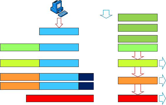
46
Chapter 2 ■ The Open Systems Interconnection Specifications
c02.indd 04/02/2015 Page 46
Introduction to Encapsulation
When a host transmits data across a network to another device, the data goes through
encapsulation: It’s wrapped with protocol information at each layer of the OSI model. Each
layer communicates only with its peer layer on the receiving device.
To communicate and exchange information, each layer uses Protocol Data Units
(PDUs). These hold the control information attached to the data at each layer of the model.
They’re usually attached to the header in front of the data eld but can also be in the
trailer, or end, of it.
At a transmitting device, the data-encapsulation method works like this:
1. User information is converted to data for transmission on the network.
2. Data is converted to segments, and a reliable connection is set up between the trans-
mitting and receiving hosts.
3. Segments are converted to packets or datagrams, and a logical address is placed in
the header so each packet can be routed through an internetwork. A packet carries a
segment of data.
4. Packets or datagrams are converted to frames for transmission on the local network.
Hardware (Ethernet) addresses are used to uniquely identify hosts on a local network
segment. Frames carry packets.
5. Frames are converted to bits, and a digital encoding and clocking scheme is used.
Figure 2.11 shows how user data is encapsulated at a transmitting host.
FIGURE 2.11 Data encapsulation
Upper-Layer Data
Upper-Layer Data Segment
PDU
Packet
Frame
Bits
TCP Header
IP Header
LLC Header
MAC Header
Segment
Packet
Packet
0101110101001000010
FCS
FCS
Application
Presentation
Session
Transport
Network
Data Link
Physical
Summary
47
c02.indd 04/02/2015 Page 47
After you learn more foundational material about networking in the next few chapters,
I’ll come back to the encapsulation method and discuss it in a lot more detail in Chapter 6.
Modulation Techniques
In networks, modulation is the process of varying one or more properties of a waveform,
called the carrier signal, with a signal that typically contains information to be transmitted.
Modulation of a waveform transforms a baseband (Ethernet or wireless) message signal
into a passband signal (a passband [a band-pass ltered signal] is the range of frequencies
or wavelengths that can pass through a lter without being attenuated). In current net-
works, modulation takes a digital or analog signal and puts it in another signal that can be
physically transmitted.
A modulator is a device that performs modulation of a signal and a demodulator is a
device that performs demodulation, the inverse of modulation. We typically just call these
modems (from modulator–demodulator), which can perform both operations.
The purpose of digital modulation is to transfer a digital bit stream over an analog
bandpass channel. (A good example would be data transmitting over the public switched
telephone network, where a bandpass lter limits the frequency range to 300–3400Hz, or
over a limited radio frequency band.) The purpose of an analog modulation is to transfer
an analog baseband (or lowpass) signal (for example, an audio signal, wireless network, or
TV signal) over an analog bandpass channel at a different frequency.
Analog and digital modulation use something called frequency-division multiplexing
(FDM), where several low-pass information signals are transferred simultaneously over
the same shared physical network, using separate passband channels (several different
frequencies).
The digital baseband modulation methods found in our Ethernet networks, and also
known as line coding, are used to transfer a digital bit stream over a baseband channel.
Baseband means that the signal being modulated used the complete available bandwidth.
Time-division multiplexing (TDM) is a method of transmitting and receiving many
independent signals over a common signal path by means of synchronized network devices
at each end of the transmission line so that each signal appears on the line only a fraction
of time in an alternating pattern. The receiving end demultiplexes the signal back to its
original form.
Summary
You’re now armed with a ton of fundamental information. You’re set to build on it and are
well on your way to certi cation.
Let’s take a minute to go over what you’ve learned in this chapter. We started by
discussing internetworking models and the advantages of having them. I then discussed the
48
Chapter 2 ■ The Open Systems Interconnection Specifications
c02.indd 04/02/2015 Page 48
OSI model—the seven-layer model used to help application developers design applications
that can run on any type of system or network. Each layer has its special jobs and select
responsibilities within the model to ensure that solid, effective communications do, in fact,
occur. I provided you with complete details of each layer and discussed how you need to
view the speci cations of the OSI model.
I also discussed the encapsulation method used in networking. Encapsulation is a highly
important concept to understand, and I’ll continue to discuss it throughout this book.
This chapter nished with a brief introduction to modulation of digital and
analogsignals.
Exam Essentials
Remember the OSI layers. You absolutely must remember and understand the seven
layers of the OSI model as well as what function each layer provides. The Application,
Presentation, and Session layers are upper layers and are responsible for communicating
from a user interface to an application. The Transport layer provides segmentation, sequenc-
ing, and virtual circuits. The Network layer provides logical network addressing and routing
through an internetwork. The Data Link layer provides framing and placing of data on the
network medium. The Physical layer is responsible for taking 1s and 0s and encoding them
into a digital signal for transmission on the network segment.
Know the sublayers of the Data Link layer. In addition to the OSI layers, knowing the
only layer that has sublayers and the functions of those sublayers is extremely important.
The Data Link layer has two sublayers: LLC and MAC. The LLC sublayer is respon-
sible primarily for the multiplexing of Network layer protocols. The MAC sublayer is
responsible for physical addressing and determining the appropriate time to place data on
the network.
Know the devices that operate at each layer of the OSI model. Hubs and repeaters see
only bits, making them Layer 1 devices. Because all networking devices have physical
connectivity to the network, they all operate at Layer 1, but hubs and repeaters operate
only at this layer, whereas other devices work in higher layers. Nevertheless, we generally
consider that a device operates at the highest layer it supports; that layer’s functionality
is the main reason we implement the device on the network. For example, switches and
bridges are considered Layer 2 devices because they understand and make decisions based
on Layer 2 addresses. Routers are Layer 3 devices for a similar reason; they deal with
Layer 3 addresses. Networking devices, such as workstations that run applications, are
said to operate at the Application layer (or you may hear that they operate at all layers)
because they must include Application layer protocols that offer services to networked
applications.
Written Lab
49
c02.indd 04/02/2015 Page 49
Written Lab
You can nd the answers in Appendix A.
1. Which layer chooses and determines the availability of communicating partners along with
the resources necessary to make the connection, coordinates partnering applications, and
forms a consensus on procedures for controlling data integrity and error recovery?
2. Which layer is responsible for converting frames from the Data Link layer into electrical
signals?
3. At which layer is routing implemented, enabling connections and path selection between
two end systems?
4. Which layer defines how data is formatted, presented, encoded, and converted?
5. Which layer is responsible for creating, managing, and terminating sessions
between applications?
6. Which layer manages the transmission of data across a physical link and is primarily
concerned with physical addressing and the ordered delivery of frames?
7. Which layer is used for reliable communication between end nodes over the network and
provides mechanisms for establishing, maintaining, and terminating virtual circuits as well
as controlling the flow of information?
8. Which layer provides logical addressing that routers use for path determination?
9. Which layer specifies voltage, wire speed, and connector pin-outs and moves bits
betweendevices?
10. Which layer combines bits into bytes and bytes into frames and uses MAC addressing?
50
Chapter 2 ■ The Open Systems Interconnection Specifications
c02.indd 04/02/2015 Page 50
Review Questions
You can nd the answers in Appendix B.
1. Host 1 sent a SYN packet to Host 2. What will Host 2 send in response?
A. ACK
B. NAK
C. SYN/ACK
D. SYN/NAK
E. SYN
2. TCP and UDP reside at which layer of the OSI model?
A. 1
B. 2
C. 3
D. 4
3. Which layer of the OSI model provides a user interface in the form of an entry point for
programs to access the network infrastructure?
A. Application
B. Transport
C. Network
D. Physical
4. You are connected to a server on the Internet and you click a link on the server and receive
a time-out message. What layer could be the source of this message?
A. Application
B. Transport
C. Network
D. Physical
5. Which layer of the OSI model is responsible for code and character-set conversion as well as
recognizing data formats?
A. Application
B. Presentation
C. Session
D. Network
6. At which layers of the OSI model do bridges, hubs, and routers primarily operate, respectively?
A. Physical, Physical, Data Link
B. Data Link, Data Link, Network
Review Questions
51
c02.indd 04/02/2015 Page 51
C. Data Link, Physical, Network
D. Physical, Data Link, Network
7. Which layer of the OSI model is responsible for converting data into signals appropriate for
the transmission medium?
A. Application
B. Network
C. Data Link
D. Physical
8. A receiving host has failed to receive all the segments that it should acknowledge. What can
the host do to improve the reliability of this communication session?
A. Send a different source port number.
B. Restart the virtual circuit.
C. Decrease the sequence number.
D. Decrease the window size.
9. Which Layer 1 devices can be used to enlarge the area covered by a single LAN segment?
(Choose two.)
A. Firewall
B. NIC
C. Hub
D. Repeater
E. RJ-45 transceiver
10. Segmentation of a data stream happens at which layer of the OSI model?
A. Physical
B. Data Link
C. Network
D. Transport
11. When data is encapsulated, which is the correct order?
A. Data, frame, packet, segment, bits
B. Segment, data, packet, frame, bits
C. Data, segment, packet, frame, bits
D. Data, segment, frame, packet, bits
12. What are two purposes for segmentation with a bridge? (Choose two.)
A. To add more broadcast domains
B. To create more collision domains
C. To add more bandwidth for users
D. To allow more broadcasts for users
52
Chapter 2 ■ The Open Systems Interconnection Specifications
c02.indd 04/02/2015 Page 52
13. Acknowledgments, sequencing, and flow control are characteristic of which OSI layer?
A. Layer 2
B. Layer 3
C. Layer 4
D. Layer 7
14. Which of the following is true regarding sequencing and acknowledgments? (Choose all
that apply.)
A. The segments delivered are acknowledged back to the sender upon their reception.
B. If a segment is not received, the virtual circuit must be restarted from the beginning at
a slower transmit interval.
C. Any segments not acknowledged are retransmitted.
D. Segments are sequenced back into their proper order upon arrival at their destination.
E. All segments are retransmitted on time slot intervals.
15. What is the purpose of flow control?
A. To ensure that data is retransmitted if an acknowledgment is not received
B. To reassemble segments in the correct order at the destination device
C. To provide a means for the receiver to govern the amount of data sent by the sender
D. To regulate the size of each segment
16. At which layer of the OSI model would you find IP?
A. Transport
B. Network
C. Data Link
D. Physical
17. Of the following, which is the highest layer in the OSI model?
A. Transport
B. Session
C. Network
D. Presentation
18. Routers perform routing at which OSI layer?
A. Physical
B. Data Link
C. Network
D. Transport
E. Application
Review Questions
53
c02.indd 04/02/2015 Page 53
19. Which of the following mnemonic devices can you use to remember the first letter of the
name of each layer of the OSI model in the proper order?
A. All People Seem To Need Processed Data.
B. Always Should People Never Threaten Dog Police.
C. Please Do Not Throw Sausage Pizza Away.
D. All Day People Should Try New Professions.
20. Which IEEE standard specifies the protocol for CSMA/CD?
A. 802.2
B. 802.3
C. 802.5
D. 802.11

c03.indd 04/06/2015 Page 55
Chapter
3
Networking
Topologies,
Connectors, and
Wiring Standards
THE FOLLOWING COMPTIA NETWORK+
EXAM OBJECTIVES ARE COVERED IN THIS
CHAPTER:
✓ 1.0 Network architecture
✓ 1.5 Install and properly terminate various cable types
and connectors using appropriate tools
■ Copper connectors
■ RJ-11
■ RJ-45
■ RJ-48C
■ DB-9/RS-232
■ DB-25
■ UTP coupler
■ BNC coupler
■ BNC
■ F-connector
■ 110 block
■ 66 block
■ Copper cables
■ Shielded vs unshielded
■ CAT3, CAT5, CAT5e, CAT6, CAT6a

c03.indd 04/06/2015 Page 56
■ PVC vs plenum
■ RG-59
■ RG-6
■ Straight-through vs crossover vs rollover
■ Fiber connectors
■ ST
■ SC
■ LC
■ MTRJ
■ FC
■ Fiber coupler
■ Fiber cables
■ Single mode
■ Multimode
■ APC vs UPC
■ Media converters
■ Single mode fiber Ethernet
■ Multimode fiber Ethernet
■ Fiber coaxial
■ Single mode multimode fiber
✓ 4.8 Given a scenario, troubleshoot and resolve common
WAN issues
■ Customer premise equipment
■ Smart jack/NIU
■ Demarc
■ CSU/DSU
✓ 5.0 Industry standards, practices, and network theory
✓ 5.4 Given a scenario, deploy the appropriate wired
connectivity standard
■ Wiring standards
■ EIA/TIA 568A/568B

c03.indd 04/06/2015 Page 57
The idea of connecting a bunch of computers together
hasn’t changed a whole lot since the mid-1980s, but how we
go about doing that certainly has. Like everything else, the
technologies and devices we create our networks with have evolved dramatically and
will continue to do so in order to keep up with the ever-quickening pace of life and the
way we do business.
When you connect computers together to form a network, you want error-free, blazingly
fast communication, right? Although “error-free” and reality don’t exactly walk hand in
hand, keeping lapses in communication to a minimum and making that communication hap-
pen really fast is de nitely possible. But it isn’t easy, and understanding the types of media
and network topologies used in networking today will go far in equipping you to reach these
goals. So will being really knowledgeable about the array of components and devices used to
control network traf c.
All of these networking ingredients are going to be the focus of this chapter. In it, I’ll
cover different types of networking media, discuss common topologies and devices, and
compare the features that they all bring into designing a solid network that’s as problem
free and turbo charged as possible.
To find up-to-the-minute updates for this chapter, please see
www. lammle
.com/networkplus
or the book’s website at
http://sybextestbanks
.wiley.com/
.
Physical Media
A lot of us rely on wireless networking methods that work using technologies like radio
frequency and infrared, but even wireless depends on a physical media backbone in
place somewhere. And the majority of installed LANs today communicate via some
kind of cabling, so let’s take a look at the three types of popular cables used in modern
networking designs:
■ Coaxial
■ Twisted-pai r
■ Fiber optic
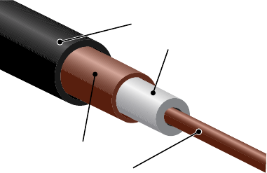
58
Chapter 3 ■ Networking Topologies, Connectors, and Wiring Standards
c03.indd 04/06/2015 Page 58
Coaxial Cable
Coaxial cable, referred to as coax, contains a center conductor made of copper that’s
surrounded by a plastic jacket with a braided shield over it. A plastic such as polyvinyl
chloride (PVC) or uoroethylenepropylene (FEP, commonly known as Te on) covers
this metal shield. The Te on-type covering is frequently referred to as a plenum-rated
coating, and it’s de nitely expensive but often mandated by local or municipal re code
when cable is hidden in walls and ceilings. Plenum rating applies to all types of cabling and
is an approved replacement for all other compositions of cable sheathing and insulation like
PVC-based assemblies.
The difference between plenum and non-plenum cable comes down to how each is
constructed and where you can use it. Many large multistory buildings are designed to
circulate air through the spaces between the ceiling of one story and the oor of the next;
this space between oors is referred to as the plenum. And it just happens to be a perfect
spot to run all the cables that connect the legions of computers that live in the building.
Unless there’s a re—if that happens, the non-plenum cable becomes a serious hazard
because its insulation gives off poisonous smoke that gets circulated throughout the whole
building. Plus, non-plenum cables can actually become “wicks” for the re, helping it
quickly spread from room to room and oor to oor—yikes!
Because it’s a great goal to prevent towering infernos, the National Fire Protection
Association (NFPA) demands that cables run within the plenum have been tested and
guaranteed as safe. They must be re retardant and create little or no smoke and poisonous
gas when burned. This means you absolutely can’t use a non-plenum-type cable in the
plenum, but it doesn’t mean you can’t use it in other places where it’s safe. And because it’s
a lot cheaper, you de nitely want to use it where you can.
Thin Ethernet, also referred to as thinnet or 10Base2, is a thin coaxial cable. It is
basically the same as thick coaxial cable except it’s only about 5 mm, or 2/10" diameter
coaxial cable. Thin Ethernet coaxial cable is Radio Grade 58, or just RG-58. Figure 3.1
shows an example of thinnet. This connector resembles the coaxial connector used for
cable TV, which is called an F connector.
FIGURE 3.1 A stripped-back thinnet cable
Plastic Jacket
Dielectric Insulator
Center Core
Metallic Shield
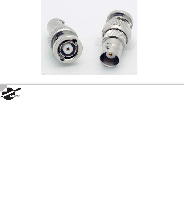
Physical Media
59
c03.indd 04/06/2015 Page 59
Oh, by the way, if you use thinnet cable, you’ve got to use BNC connectors to attach
stations to the network, as shown in Figure 3.2, and you have to use 50 ohm terminating
resistors at each end of the cable in order to achieve the proper performance.
FIGURE 3.2 Male and female BNC connectors
You don’t have to know much about most coax cable types in networks
anymore, especially the thinnet and thicknet types of coaxial cable. Thicknet
was known as RG-8, was about 1/2” in diameter, also requiring 50 ohm ter-
minating resistors on each end of the cable. Nowadays, we use 75 ohm coax
for cable TV; using coax in the Ethernet LAN world is pretty much a thing of
the past, but we do use them for high-bandwidth runs in our data centers.
RG-6, or CATV coax, is used in our broadband world.
You can attach a BNC connector to the cable with a crimper that looks like a weird pair of
pliers and has a die to crimp the connector. A simple squeeze crimps the connector to the cable.
You can also use a screw-on connector, but I avoid doing that because it’s not very reliable.
You can use a BNC coupler to connect two male connectors together or two female
connectors together.
Table 3.1 lists some speci cations for the different types of coaxial cable, but understand
that we use only RG-59 and RG-6 in today’s world.
TABLE 3.1 Coaxial cable specifications
RG rating Popular name
Ethernet
implementation Type of cable
RG-58 U N/A None Solid copper
RG-58 A/U Thinnet 10Base2 Stranded copper

60
Chapter 3 ■ Networking Topologies, Connectors, and Wiring Standards
c03.indd 04/06/2015 Page 60
RG rating Popular name
Ethernet
implementation Type of cable
RG-8 Thicknet 10Base5 Solid copper
RG-59 Cable television
Low cost, short distance
N/A Solid copper
RG-6 Cable television, cable modems
Longer distances than RG-59;
some power implementations
N/A Solid copper
RG-62 ARCnet (obsolete) N/A Solid/stranded
An advantage of using coax cable is the braided shielding that provides
resistance to electronic pollution like electromagnetic interference (EMI),
radio frequency interference (RFI), and other types of stray electronic
signals that can make their way onto a network cable and cause communi-
cation problems.
Twisted-Pair Cable
Twisted-pair cable consists of multiple individually insulated wires that are twisted
together in pairs. Sometimes a metallic shield is placed around them, hence the name
shielded twisted-pair (STP). Cable without outer shielding is called unshielded
twisted-pair (UTP), and it’s used in twisted-pair Ethernet (10BaseT, 100BaseTX,
1000BaseTX) networks.
Ethernet Cable Descriptions
Ethernet cable types are described using a code that follows this format: N<Signaling>X.
The N refers to the signaling rate in megabits per second. <Signaling> stands for the
signaling type—either baseband or broadband—and the X is a unique identi er for a
speci c Ethernet cabling scheme.
Here’s a common example: 100BaseX. The 100 tells us that the transmission speed is
100Mb, or 100 megabits. The X value can mean several different things, for example, a
T is short for twisted-pair. This is the standard for running 100-megabit Ethernet over two
pairs (four wires) of Category 5, 5e, or 6 UTP.
So why are the wires in this cable type twisted? Because when electromagnetic sig-
nals are conducted on copper wires in close proximity—like inside a cable—it causes
TABLE 3.1 Coaxial cable specifications (continued)

Physical Media
61
c03.indd 04/06/2015 Page 61
interference called crosstalk. Twisting two wires together as a pair minimizes interference
and even protects against interference from outside sources. This cable type is the most
common today for the following reasons:
■ It’s cheaper than other types of cabling.
■ It’s easy to work with.
■ It allows transmission rates that were impossible 10 years ago.
UTP cable is rated in these categories:
Category 1 Two twisted wire pairs (four wires). It’s the oldest type and is only
voice grade—it isn’t rated for data communication. People refer to it as plain old
telephone service (POTS). Before 1983, this was the standard cable used throughout
the North American telephone system. POTS cable still exists in parts of the Public
Switched Telephone Network (PSTN) and supports signals limited to the 1MHz
frequency range.
Category is often shortened to Cat. Today, any cable installed should be
a minimum of Cat 5e because some cable is now certified to carry band-
width signals of 350MHz or beyond. This allows unshielded twisted-pair
cables to exceed speeds of 1Gbps—fast enough to carry broadcast-quality
video over a network.
Category 2 Four twisted wire pairs (eight wires). It handles up to 4Mbps, with a
frequency limitation of 10MHz, and is now obsolete.
Category 3 Four twisted wire pairs (eight wires) with three twists per foot. This type can
handle transmissions up to 16MHz. It was popular in the mid-1980s for up to 10Mbps
Ethernet, but it’s now limited to telecommunication equipment and, again, is obsolete for
networks.
Category 4 Four twisted wire pairs (eight wires), rated for 20MHz; also obsolete.
Category 5 Four twisted wire pairs (eight wires), rated for 100MHz. But why use
Cat 5 when you can use Cat 5e for the same price? I am not sure you can even buy
plain Cat 5 anymore!
Category 5e (Enhanced) Four twisted wire pairs (eight wires), rated for 100MHz but
capable of handling the disturbance on each pair that’s caused by transmitting on all four
pairs at the same time—a feature that’s needed for Gigabit Ethernet. Any category below
5e shouldn’t be used in today’s network environments.
Figure 3.3 shows a basic Cat 5e cable with the four wire pairs twisted to reduce
crosstalk.
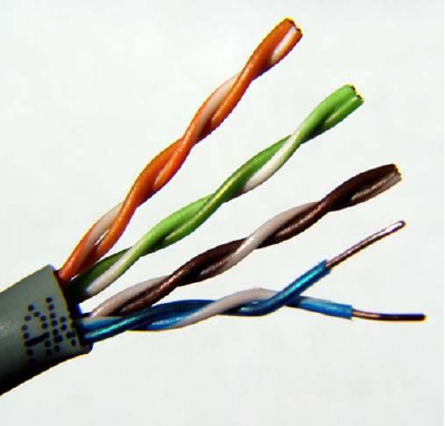
62
Chapter 3 ■ Networking Topologies, Connectors, and Wiring Standards
c03.indd 04/06/2015 Page 62
FIGURE 3.3 Cat 5e UTP cable
Category 6 Four twisted wire pairs (eight wires), rated for 250MHz. Cat 6 became
a standard back in June 2002. You would usually use it as riser cable to connect
oors together. If you’re installing a new network in a new building, there’s no
reason to use anything but Category 6 UTP cabling as well as running ber runs
between oors.
Category 6a (Augmented) Basic Category 6 cable has a reduced maximum length when
used for 10GBaseT; however, Category 6a cable, or Augmented Category 6, is character-
ized to 500MHz and has improved crosstalk characteristics, which allows 10GBaseT to be
run for up to 100 meters. The most important point is a performance difference between
Electronic Industries Alliance and Telecommunication Industry Association (EIA/TIA)
component speci cations for the NEXT (near-end crosstalk) transmission parameter.
Running at a frequency of 500MHz, an ISO/IEC Cat 6a connector provides double the
power (3db) of a Cat 6A connector that conforms with the EIA/TIA speci cation. Note
that 3dB equals a 100 percent increase of a near-end crosstalk noise reduction. This is our
future cable indeed!
Connecting UTP
BNC connectors won’t t very well on UTP cable, so you need to use a registered jack (RJ)
connector, which you’re familiar with because most telephones connect with them. The
connector used with UTP cable is called RJ-11 for phones that use four wires; RJ-45 has
four pairs (eight wires), as shown in Figure 3.4.
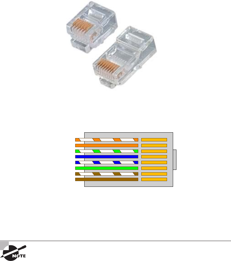
Physical Media
63
c03.indd 04/06/2015 Page 63
FIGURE 3.4 RJ-11 and RJ-45 connectors
RJ-11
RJ-45
Figure 3.5 shows the pin-outs used in a typical RJ-45 connector. Looking from the
bottom of the connector, pin 1 would be on the left.
FIGURE 3.5 The pin-outs in an RJ-45 Connector, T568B standard
Orange/White
Brown/White
Brown
Green/White
Green
Blue/White
Blue
Orange
Most of the time, UTP uses RJ connectors, and you use a crimper to attach them to a
cable, just as you would with BNC connectors. The only difference is that the die that holds
the connector is a different shape. Higher-quality crimping tools have interchangeable dies
for both types of cables. We don’t use RJ-11 for local area networks (LANs), but we do use
them for our home Digital Subscriber Line (DSL) connections.
RJ-11 uses two wire pairs, and RJ-45 uses four wire pairs.
There’s one other type of copper connector called the RJ-48c, which looks exactly like
an RJ-45 connector. This plug is very similar to the RJ-45 in that it has four wire pairs, but
they are wired differently and used for different circumstances.

64
Chapter 3 ■ Networking Topologies, Connectors, and Wiring Standards
c03.indd 04/06/2015 Page 64
RJ-45 is mainly used in LANs with short distances (typically up to 100 meters), where
the RJ-48c wiring type would be used with a T1 connection, which is a long-distance wide
area network (WAN). In addition, to protect the signal in an RJ-48c, the wires are typically
shielded, whereas the RJ-45 uses unshielded wiring.
Category 5e Cabling Tips
If you want data rates faster than 10Mbps over UTP, ensure that all components are
rated to deliver this and be really careful when handling all components. If you yank
on Cat 5e cable, it will stretch the number of twists inside the jacket, rendering the
Cat 5e label on the outside of the cable invalid. Also, be certain to connect and test all
four pairs of wire. Although today’s wiring usually uses only two pairs (four wires), the
standard for Gigabit Ethernet over UTP requires that all four pairs (eight wires) be in
good condition.
Also be aware that a true Cat 5e cabling system uses rated components from end to end,
patch cables from workstation to wall panel, cable from wall panel to patch panel, and
patch cables from patch panel to hub. So if any components are missing, or if the lengths
don’t match the Category 5e specifi cation, you just don’t have a Category 5e cabling
installation. And certify that the entire installation is Category 5e compliant. I’ve got
to warn you that doing this requires some pretty pricey test equipment to make the
appropriate measurements!
Fiber-Optic Cable
Because ber-optic cable transmits digital signals using light impulses rather than
electricity, it’s immune to EMI and RFI. Anyone who’s seen a network’s UTP cable
run down an elevator shaft would de nitely appreciate this ber feature. Fiber cable
allows light impulses to be carried on either a glass or a plastic core. Glass can carry
the signal a greater distance, but plastic costs less. Whichever the type of core, it’s
surrounded by a glass or plastic cladding with a different refraction index that re ects
the light back into the core. Around this is a layer of exible plastic buffer that can be
wrapped in an armor coating that’s usually Kevlar, which is then sheathed in PVC
or plenum.
The cable itself comes in either single-mode ber (SMF) or multimode ber (MMF);
the difference between them is in the number of light rays (the number of signals) they can
carry. Multimode ber is most often used for shorter-distance applications and single-mode
ber for spanning longer distances.
Although ber-optic cable may sound like the solution to many problems, it has its pros
and cons just like the other cable types.
Physical Media
65
c03.indd 04/06/2015 Page 65
Here are the pros:
■ It’s completely immune to EMI and RFI.
■ It can transmit up to 40 kilometers (about 25 miles).
And here are the cons:
■ It’s difficult to install.
■ It’s more expensive than twisted-pair.
■ Troubleshooting equipment is more expensive than twisted-pair test equipment.
■ It’s harder to troubleshoot.
Single-Mode Fiber
Single-mode ber-optic cable (SMF) is a very high-speed, long-distance media that
consists of a single strand—sometimes two strands—of glass ber that carries the signals.
Light-emitting diodes (LEDs) and laser are the light sources used with SMF. The light
source is transmitted from end to end and pulsed to create communication. This is the type
of ber cable employed to span really long distances because it can transmit data 50 times
further than multimode ber at a faster rate.
Clearly, because the transmission media is glass, the installation of SMF can be a bit
tricky. Yes, there are outer layers protecting the glass core, but the cable still shouldn’t be
crimped or pinched around any tight corners.
Multimode Fiber
Multimode ber-optic cable (MMF) also uses light to communicate a signal, but with
it, the light is dispersed on numerous paths as it travels through the core and is re ected
back. A special material called cladding is used to line the core and focus the light
back onto it. MMF provides high bandwidth at high speeds over medium distances
(up to about 3,000 feet), but beyond that it can be really inconsistent. This is why
MMF is most often used within a smaller area of one building; SMF can be used
between buildings.
MMF is available in glass or in a plastic version that makes installation a lot easier and
increases the installation’s exibility.
APC vs UPC
The choice between angle-polished connectors (APCs) and ultra-polished connectors
(UPCs) can make a pretty big difference on how your network will perform.
The ultra-polished connector looks like what you’d expect to nd in a ber-optic end.
The cut is perfectly straight, as shown in Figure 3.6.

66
Chapter 3 ■ Networking Topologies, Connectors, and Wiring Standards
c03.indd 04/06/2015 Page 66
FIGURE 3.6 UPC typical fiber connector end
UPC polish
Light is reflected back down to the core.
Return loss = 55dB
(Adequate for most applications)
The angle-polished connector looks like Figure 3.7. Notice the perfectly cut angle, which
seems odd, but there is a reason for this and it’s a good one!
FIGURE 3.7 The superior APC fiber connector
8° angled polish
Light is reflected into the cladding.
Return loss = –65dB
(0.0001% of power reflected back)
(Ideal for video and single-fiber applications)
Unlike the UPC, where the light is re ected back down to the core of the ber cable,
which causes a loss of db called a return loss because the angled connector causes the light
to re ect back into the cladding—the thick sides of the glass instead of the core. But the
APC doesn’t cause nearly as much db loss when using this type of connector. Very cool
design indeed!
Fiber-Optic Connectors
A whole bunch of different types of connectors are available to use with ber-optic cables,
but the two most popular are the straight tip (ST) and subscriber (or square) connector
(SC). The ST ber-optic connector (developed by AT&T) is one of the most widely used
ber-optic connectors; it uses a BNC attachment mechanism similar to thinnet’s that makes
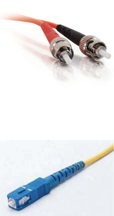
Physical Media
67
c03.indd 04/06/2015 Page 67
connections and disconnections fairly frustration free. In fact, this is the feature that makes
this connector so popular. Figure 3.8 shows an example of an ST connector. Notice the
BNC attachment mechanism.
FIGURE 3.8 An example of an ST connector
The SC connector is another type of ber-optic connector. As you can see in Figure 3.9,
SC connectors are latched—a mechanism holds the connector in securely and prevents it
from falling out.
FIGURE 3.9 A sample SC connector
SC connectors work with both single-mode and multimode optical bers and will last
for around 1,000 matings. They’re being used more now but still aren’t nearly as popular
as ST connectors for LAN connections.
Another type of connector I want to mention before moving on to the SFF connector is
the FC connector, or eld assembly connector, also called the ferrule connector, which isn’t

68
Chapter 3 ■ Networking Topologies, Connectors, and Wiring Standards
c03.indd 04/06/2015 Page 68
very popular. It’s still used in telecommunications and measurement equipment with
single-mode lasers, but the SC is a way more popular ber end. The only reason I mention
it here is because it is an exam objective; other than that you probably won’t ever see it in
production. These look identical to ST connectors.
You can also get a ber coupler in order to connect an ST to an SC connector, for
example, but you will lose a lot of your power (db) if you do so.
Small Form Factor Fiber-Optic Connectors
Another cool ber-optic connector is the small form factor (SFF) connector, which
allows more ber-optic terminations in the same amount of space than its standard-
sized counterparts. The two most popular versions are the mechanical transfer registered
jack (MT-RJ or MTRJ), designed by AMP, and the Local Connector (LC), designed
by Lucent.
Should I Use Copper or Fiber?
If your data runs are measured in miles, fi ber optic is your cable of choice because copper
just can’t give you more than about 1,500 feet without electronics regenerating the signal.
The standards limit UTP to a pathetic 328 feet.
Another good reason to opt for fi ber is if you require high security because it doesn’t
create a readable magnetic fi eld. Although fi ber-optic technology was initially super
expensive and nasty to work with, it’s now commonly used for Gigabit or 10GB Internet
backbones.
Ethernet running at 10Mbps over fi ber-optic cable to the desktop is designated 10BaseFL;
the 100Mbps version of this implementation is 100BaseFX. The L in the 10Mbps version
stands for link. Other designations are B for backbone and P for passive.
The MT-RJ ber-optic connector was the rst small form factor ber-optic connector to
be widely used, and it’s only one-third the size of the SC and ST connectors it most often
replaces. It offers these bene ts:
■ Small size
■ TX and RX strands in one connector
■ Keyed for single polarity
■ Pre-terminated ends that require no polishing or epoxy
■ Easy to use
Figure 3.10 shows an example of an MT-RJ ber-optic connector.
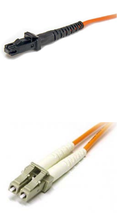
Physical Media
69
c03.indd 04/06/2015 Page 69
FIGURE 3.10 A sample MT-RJ fiber-optic connector
LC is a newer style of SFF ber-optic connector that’s pulling ahead of the MT-RJ. It’s
especially popular for use with Fibre-Channel adapters (FCs) and is a standard used for fast
storage area networks and Gigabit Ethernet adapters. Figure 3.11 depicts an example of the
LC connector.
FIGURE 3.11 A sample LC fiber-optic connector
It has similar advantages to MT-RJ and other SFF-type connectors but it’s easier to
terminate. It uses a ceramic insert just as standard-sized ber-optic connectors do.
Media Converters
Sometimes, you’ll need to convert from one media type to another. Maybe you need to go
from one mode of ber to another mode, or in an even more extreme case, you need to go
from ber to Ethernet. If you’re faced with situations like these, you’ll need to be familiar
with some of the more common media converters:
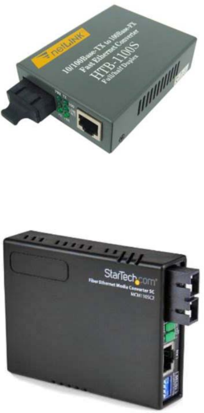
70
Chapter 3 ■ Networking Topologies, Connectors, and Wiring Standards
c03.indd 04/06/2015 Page 70
Single-Mode Fiber to Ethernet These devices accept a ber connector and an Ethernet
connector and convert the signal from Ethernet and single-mode ber (see Figure 3.12).
FIGURE 3.12 Single-mode fiber to Ethernet
Multimode Fiber to Ethernet These devices accept a ber connector and an Ethernet
connector and convert the signal from Ethernet and multi-mode ber (see Figure 3.13).
FIGURE 3.13 Multimode fiber to Ethernet
Fiber to Coaxial These devices accept a ber connector and a coaxial connector and
convert digital signals from optical to coax (see Figure 3.14).
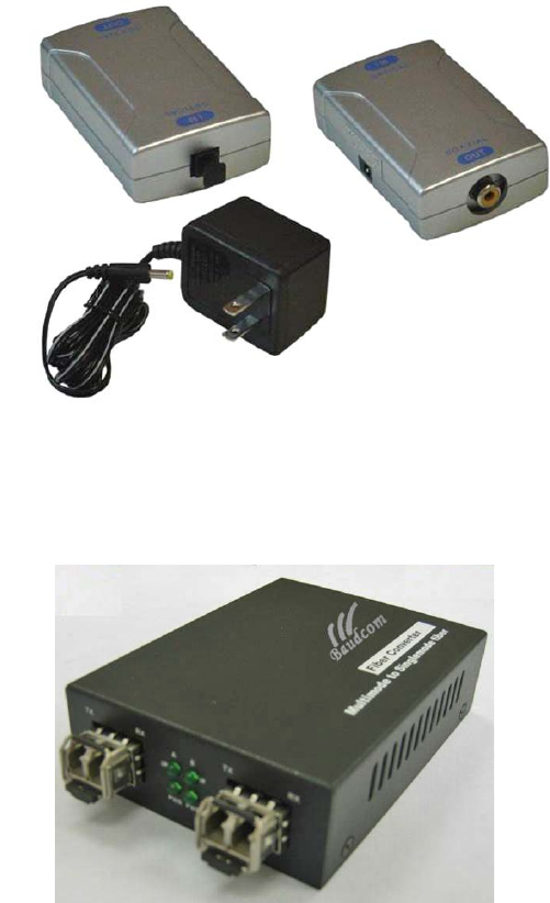
Physical Media
71
c03.indd 04/06/2015 Page 71
FIGURE 3.14 Fiber to coaxial
Front
Back
Single-Mode to Multimode Fiber These devices accept a single-mode ber connector and
a multimode ber connector and convert the signals between the two (see Figure 3.15).
FIGURE 3.15 Single-mode to multimode fiber
Serial Cables
Except for multimode ber, all the cable varieties I’ve talked about so far are considered
serial cable types. In network communications, serial means that one bit after another is
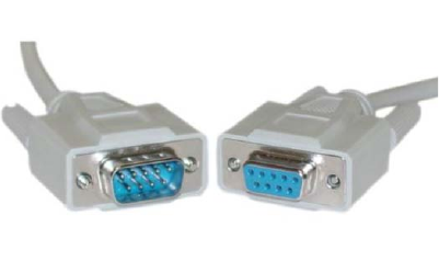
72
Chapter 3 ■ Networking Topologies, Connectors, and Wiring Standards
c03.indd 04/06/2015 Page 72
sent out onto the wire or ber and interpreted by a network card or other type of interface
on the other end.
Each 1 or 0 is read separately and then combined with others to form data. This is very
different from parallel communication where bits are sent in groups and have to be read
together to make sense of the message they represent. A good example of a parallel cable is
an old printer cable—which has been replaced by USB, as I’ll get to in a minute.
RS-232
Recommended Standard 232 (RS-232) was a cable standard commonly used for serial data
signals connecting the DTE and the DCE, such as a computer’s serial port to an external
modem.
Figure 3.16 shows an example of one of the many types of RS-232 cables. These cables
normally connect to a connector on the device called a DB-9.
FIGURE 3.16 An RS-232 cable end
Because laptops don’t even come with these types of connectors anymore, they’ve pretty
much been replaced by things like USB, Thunderbolt, and FireWire.
DB-25
Now here’s a connector that has been around for a while! The D series of connectors was
invented by ITT Cannon in 1952, and the D was followed by A, B, C, D, or E, which
described the shell size, then the numbers of pins or sockets. DB-25 tells us we have
25 pins in a “B” size shell. RS-232 devices usually used the DB-25 connector, but today
we don’t use RS-232 or DB-25, and we rarely use a DB-9, which used to be used for Cisco
console cables, but has mostly been replaced by USB.
Universal Serial Bus
Universal Serial Bus (USB) is now the built-in serial bus du jour of most motherboards.
You usually get a maximum of 4 external USB interfaces, but add-on adapters can take that
up to as many as 16 serial interfaces. USB can actually connect a maximum of 127 external
devices, and it’s a much more exible peripheral bus than either serial or parallel.
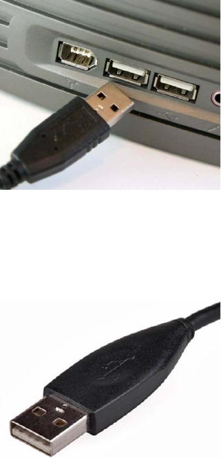
Cable Properties
73
c03.indd 04/06/2015 Page 73
We use USB to connect printers, scanners, and a host of other input devices like
keyboards, joysticks, and mice. When connecting USB peripherals, you’ve got to connect
them either directly to one of the USB ports on the PC or to a USB hub that is connected to
one of those USB ports. You can get a picture of this in Figure 3.17.
FIGURE 3.17 A USB port
Hubs can be chained together to provide multiple USB connections, but even though you
can connect up to 127 devices, it’s really not practical to go there. Each device has a USB
plug, as shown in Figure 3.18.
FIGURE 3.18 A USB plug
Cable Properties
The reason we use so many different types of cables in a network is that each type has
its own set of properties that speci cally make it the best to use for a particular area or
purpose. Different types vary in transmission speeds, distance, duplex, noise immunity,
and frequency, and I’ll cover each of these next.
74
Chapter 3 ■ Networking Topologies, Connectors, and Wiring Standards
c03.indd 04/06/2015 Page 74
Transmission Speeds
Based on the type of cable or ber you choose and the network that it’s installed in,
network administrators can control the speed of a network to meet the network’s
traf c demands. Admins usually permit, or would like to have, transmission speeds of
up to 10Gbps or higher on the core areas of their networks that connect various network
segments. In the distribution and access areas, where users connect to switches, it’s
typically 100Mbps per connection, but transmission speeds are creeping up because the
traf c demand is getting higher.
Distance
Deciding factors used in choosing what cable type to use often come down to the topology
of a network and the distance between its components. Some network technologies can run
much further than others without communication errors, but all network communication
technologies are prone to attenuation—the degradation of a signal due to the medium itself
and the distance signals have to travel. Some cable types suffer from attenuation more
than others. For instance, any network using twisted-pair cable should have a maximum
segment length of only 328 feet (100 meters).
Duplex
All communications are either half duplex or full duplex. The difference is whether the
communicating devices can “talk” and “listen” at the same time.
During half-duplex communication, a device can either send communication or receive
communication, but not both at the same time. Think walkie-talkie—when you press the
button on the walkie-talkie, you turn the speaker off and you can’t hear anything the other
side is saying.
In full-duplex communication, both devices can send and receive communication at
the same time. This means that the effective throughput is doubled and communication
is much more ef cient. Full duplex is typical in most of today’s switched networks.
I’ll discuss both full and half duplex in more detail in Chapter 4, “The Current
Ethernet Speci cations.”
Noise Immunity (Security, EMI)
Any time electrons are pushed through two wires next to each other a magnetic current is
created. And we can create a current in the wires. This is good because without magnetic
ux we wouldn’t be using computers—the power that surges through them is a result of it.
The bad news is that it also creates two communications issues.
First, because the wire is creating a current based on the 1s and 0s coursing through
it, with the right tools in hand, people can read the message in the wire without

Wiring Standards
75
c03.indd 04/06/2015 Page 75
cutting it or even removing the insulation. You’ve heard of this—it’s called tapping the
wire, and it’s clearly a valid security concern. In ancient history, high-security installa-
tions like the Pentagon actually encased communication wires in lead shielding to
prevent them from being tapped. STP wires make tapping a little harder, but not
hard enough.
The best way to solve the magnetic- ux problem caused by electricity is to not use
these wires at all. As I said, ber-optic cables carry the signal as light on a glass or a
really pure plastic strand, and light is not susceptible to magnetic ux, making ber
optics a whole lot harder to tap. It’s still not impossible—you can do it at the equipment
level, but you have to actually cut and then repair the cable to do that, which isn’t likely
to go unnoticed.
The second magnetic- ux issue comes from the outside in instead of from the inside
out. Because wires can take on additional current if they’re near any source of magnetism,
you’ve got to be really careful where you run your cables. You can avoid EMI by keep-
ing copper cables away from all powerful magnetic sources like electric motors, speakers,
ampli ers, uorescent light ballasts, and so on. Just keep them away from anything that
can generate a magnetic eld!
Frequency
Each cable type has a speci ed maximum frequency that gives you the transmission
bandwidth it can handle. Cat 5e cable is tested to 100MHz maximum frequency
and can run 1Gbps signals for relatively short distances. That’s maxing it out, but
it’s still good for connecting desktop hosts at high speeds. On the other hand, Cat 6
is a 250MHz cable that can handle 1Gbps data ow all day long with ease. Cat 6
has a lot more twists and thicker cables, so it’s best used when connecting oors of
a building.
Although a signal is measured as bandwidth, the capacity to carry the sig-
nal in a cable is measured as frequency.
Wiring Standards
Ethernet cabling is an important thing to understand, especially if you’re planning to work
on any type of LAN. There are different types of wiring standards available:
■ 568A
■ 568B
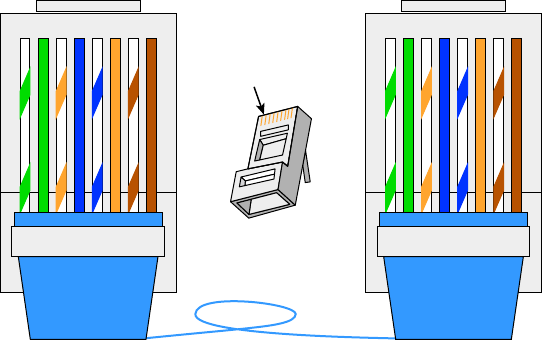
76
Chapter 3 ■ Networking Topologies, Connectors, and Wiring Standards
c03.indd 04/06/2015 Page 76
■ Straight-through
■ Crossover
■ Rolled/rollover
We will look into each one of these, and then I’ll end this discussion with some examples
for you.
568A vs 568B
If you look inside a network cable, you’ll nd four pairs of wires twisted together to
prevent crosstalk; they’re also twisted like this to help prevent EMI and tapping. The same
pins have to be used on the same colors throughout a network to receive and transmit,
but how do you decide which color wire goes with which pin? The good news is that you
don’t have to decide—at least not completely.
Two wiring standards have surfaced that have been agreed on by over 60 vendors,
including AT&T, 3Com, and Cisco, although there isn’t 100 percent agreement. In other
words, over the years, some network jacks have been pinned with the 568A standard and
some have used the 568B standard, which can cause a bit of confusion if you don’t know
what you’re looking at in your network.
568A By looking at Figure 3.19, you can see that the green pair is used for pins 1 and 2
but the orange pair is split to pins 3 and 6, separated by the blue pair.
FIGURE 3.19 568A wired standard
12345678
gGo OBBR Clip is pointed
away from you.
bbr
12345678
gGo OBBRbbr
T-568A
RJ-45 Plug
Pin 1
T-568A
568B Now take a look at Figure 3.20. The orange pair is pins 1 and 2 and the green pair
is pins 3 and 6, again separated by the blue pair.
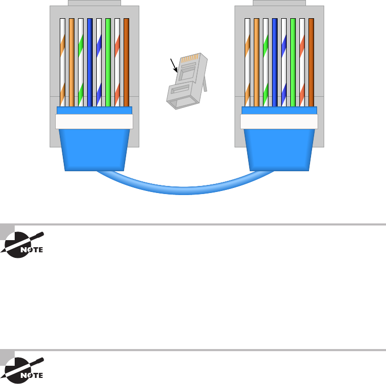
Wiring Standards
77
c03.indd 04/06/2015 Page 77
FIGURE 3.20 568B wired standard
12345678
Clip is pointed
away from you.
RJ-45 Plug
Pin 1
T-568B
oOg GBBRbbr
12345678
T-568B
oOg GBBRbbr
Note that the only difference between T568A and T568B is that pairs 2
and 3 (orange and green) are swapped. Also, you can use a UTP coupler in
order to connect two RJ-45 connectors together to lengthen a cable or in
order to make a straight-through cable into a crossover, and vice versa.
If you’re thinking, “What’s the difference, and why does it matter?” the answer is the
position of four wires on one side of the cable—that’s it! There are eight wires in each UTP
cable; pins 4, 5, 7, and 8 aren’t used in either standard.
If you’re installing new cabling to each cubicle and/or office, you need to
make sure to connect all eight pins—and use Cat 5e or Cat 6. Voice over IP
(VoIP) uses all eight pins, and it’s really common to have voice and data on
the same wire at the same time in today’s networks.
This only leaves the wire pairs to connect to pins 1, 2, 3, and 6 for data. Remember,
if we connect the green-white, green, orange-white, and orange wires to pins 1, 2, 3,
and 6, respectively, on both sides of the cable, we’re using the 568A standard and
creating the kind of straight-through cable that’s regularly implemented as a regular
patch cable for most networks. On the other hand, if we switch from pin 1 to pin 3 and
from pin 2 to pin 6 on one side only, we’ve created a crossover cable for most networks.
Let’s take a look.
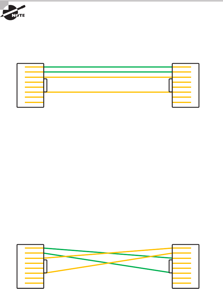
78
Chapter 3 ■ Networking Topologies, Connectors, and Wiring Standards
c03.indd 04/06/2015 Page 78
Straight-Through Cable
The straight-through cable is used to connect a host to a switch or hub or a router to a
switch or hub.
No worries—I’ll tell you all about devices like switches, hubs, and routers
in detail in Chapter 5, “Networking Devices.”
Four wires are used in straight-through cable to connect 10/100 Ethernet devices.
It’s really pretty simple to do this; Figure 3.21 depicts the four wires used in a straight-
through Ethernet cable.
FIGURE 3.21 Straight-through Ethernet cable
1
2
3
4
5
6
7
8
1
2
3
4
5
6
7
8
Notice that only pins 1, 2, 3, and 6 are used. Connect 1 to 1, 2 to 2, 3 to 3, and 6 to 6 and
you’ll be up and networking in no time. Just remember that this would be a 10/100 Ethernet-
only cable, so it wouldn’t work with 1000Mbps Ethernet, voice, Token Ring, ISDN, and so on.
Crossover Cable
The same four wires are used in this cable, and just as with the straight-through cable, you sim-
ply connect the different pins together. Crossover cables can be used to connect these devices:
■ Switch to switch
■ Hub to hub
■ Host to host
■ Hub to switch
■ Router direct to host
Take a look at Figure 3.22, which demonstrates how each of the four wires are used in a
crossover Ethernet cable.
FIGURE 3.22 Crossover Ethernet cable
1
2
3
4
5
6
7
8
1
2
3
4
5
6
7
8

Wiring Standards
79
c03.indd 04/06/2015 Page 79
Okay—did you notice that instead of connecting 1 to 1, 2 to 2, and so on, we connected
pins 1 to 3 and 2 to 6 on each side of the cable? A crossover cable is typically used to
connect two switches together, but it can also be used to test communications between
two workstations directly, bypassing the switch.
A crossover cable is used only in Ethernet UTP installations. You can connect two
workstation NICs or a workstation and a server NIC directly with it.
If you are trying to match the straight-through and crossover cables with the 568A and
568B standard, here is how it would look:
568A+568A = straight-through
568B+568B = straight-through
568A+568B = crossover
You’re going to find out a lot more about how important it is to label
basically everything. But for now, make sure to label a crossover cable as
what it is so that no one tries to use it as a workstation patch cable. If they
do that, the workstation won’t be able to communicate with the hub and
the rest of the network!
It’s really cool that you can carry a crossover cable with you in your tool bag along with
your laptop—then, if you want to ensure that a server’s NIC is functioning correctly, you
can just connect your laptop directly to the server’s NIC using your handy crossover cable.
You should be able to log in to the server if both NICs are con gured correctly.
Use a cable tester to make sure that what you’re dealing with is in fact a crossover cable.
The tester can also tell you if there’s a problem with the cable. Figure 3.23 shows an
inexpensive cable tester for UTP.
FIGURE 3.23 An inexpensive cable tester
This cost-effective little tool will tell you beyond a shadow of a doubt if you have a
straight-through or crossover cable—or even if there’s a problem with the cable.
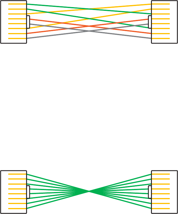
80
Chapter 3 ■ Networking Topologies, Connectors, and Wiring Standards
c03.indd 04/06/2015 Page 80
UTP Gigabit Wiring (1000BaseT)
In the previous examples of 10BaseT and 100BaseT UTP wiring, only two wire pairs were
used, but that’s just not good enough for Gigabit UTP transmission.
1000BaseT UTP wiring (Figure 3.24) requires four wire pairs and uses more advanced
electronics so that each and every pair in the cable can transmit simultaneously. Even so,
gigabit wiring is almost identical to my earlier 10/100 example, except that we’ll use the
other two pairs in the cable.
FIGURE 3.24 UTP gigabit crossover Ethernet cable
1
2
3
4
5
6
7
8
1
2
3
4
5
6
7
8
For a straight-through cable it’s still 1 to 1, 2 to 2, and so on up to pin 8. And in creat-
ing the gigabit crossover cable, you’d still cross 1 to 3 and 2 to 6, but you would add 4 to
7 and 5 to 8—pretty straightforward!
Rolled/Rollover Cable
Although rolled cable isn’t used to connect any Ethernet connections together, you can use
a rolled Ethernet cable to connect a host EIA-TIA 232 interface to a router console serial
communication (COM) port.
If you have a Cisco router or switch, you would use this cable to connect your PC,
Mac, or a device like an iPad to the Cisco hardware. Eight wires are used in this
cable to connect serial devices, although not all eight are used to send information,
just as in Ethernet networking. Figure 2.14 shows the eight wires used in a
rolled cable.
FIGURE 3.25 Rolled Ethernet cable
1
2
3
4
5
6
7
8
1
2
3
4
5
6
7
8
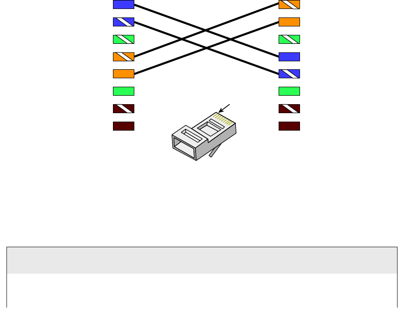
Wiring Standards
81
c03.indd 04/06/2015 Page 81
These are probably the easiest cables to make because you just cut the end off on one
side of a straight-through cable, turn it over, and put it back on—with a new connector,
of course!
T1 Crossover Cable
In Chapter 15 you’ll be introduced to a device called the CSU/DSU. This device may be
your connection to the Internet for the enterprise. The type of cable you use to connect to
this device from your router depends on the interface types that are available on the router.
The router may connect with several types of serial cables if a T1 connection is not built
into it. If a T1 connection is built into the router, you will use an Ethernet cable. Figure
3.26 shows a T1 crossover cable connected to a T568B connection.
FIGURE 3.26 A T1 crossover cable
1
T1 crossover cable T568B
2
3
4
5
6
7
8
1
2
3
4
5
6
7
8
Pin 1
RJ-45 Plug
In rare instances you may have the need to run a cable between two CSU/DSUs. In that
case you would need a T1 crossover cable. A T1 cable uses T568B pairs 1 and 2, so to
connect two T1 CSU/DSU devices back-to-back requires a crossover cable that swaps these
pairs. Speci cally, pins 1, 2, 4, and 5 are connected to 4, 5, 1, and 2, respectively.
Test Your Cable Understanding
You’ve taken a look at the various RJ-45 UTP cables. With that in mind, what cable is used
between the switches in the following image?
continues
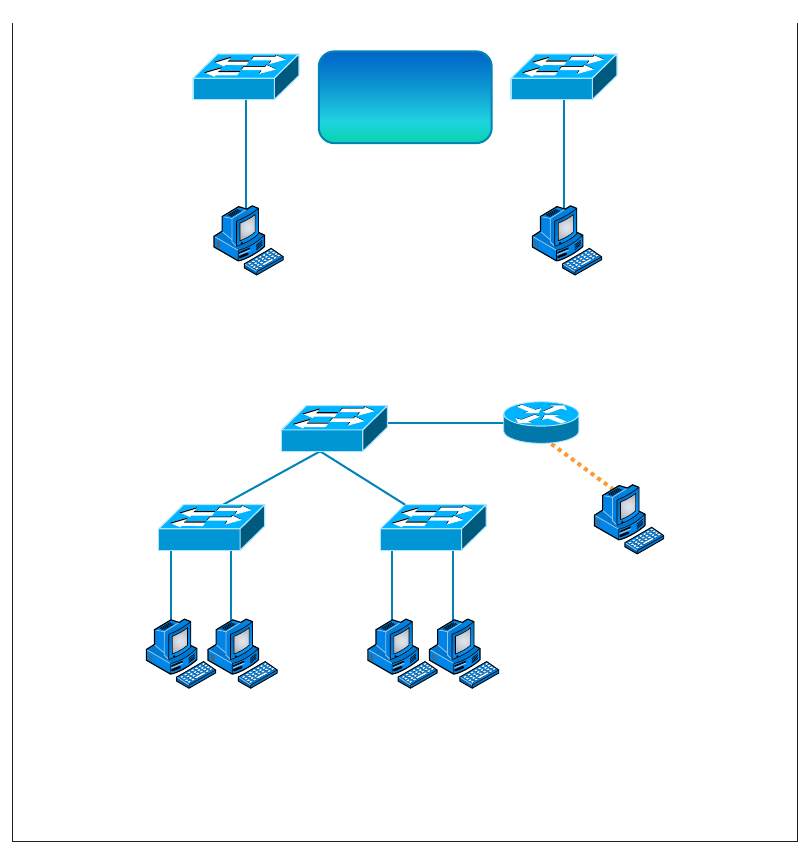
82
Chapter 3 ■ Networking Topologies, Connectors, and Wiring Standards
c03.indd 04/06/2015 Page 82
Switch Switch
?
For host A to ping host B, you need a crossover cable to connect the two switches
together. But what types of cables are used in the network shown in the
following image?
Router
Console
In the second example, there are a variety of cables in use. For the connection between
the switches, we’d clearly use a crossover cable like the one you saw in the earlier
example. The trouble is, here we have a console connection that uses a rolled cable. Plus,
the connection from the router to the switch is a straight-through cable, which is also
what’s running between the hosts to the switches.
Installing Wiring Distributions
By now, you’re probably getting the idea that there are a lot more components in the
average computer networks than meets the eye, right? If this isn’t exactly a news
bulletin to you, then you either already are, or have been, involved in the initial
continued
Installing Wiring Distributions
83
c03.indd 04/06/2015 Page 83
installation of a network. If the latter describes you, you probably will be, or already
are, involved in the purchase and installation of the components that will connect
the computers throughout your organization’s building. And it may also be up to
you to verify that all of the network components have been installed properly and
tested. So, let’s go over each of these components and the process of verifying their
proper installation.
MDF/IDF
The main distribution frame (MDF) is a wiring point that’s generally used as a reference
point for telephone lines. It’s also considered the WAN termination point. It’s installed in
the building as part of the prewiring, and the internal lines are connected to it. After that,
all that’s left is to connect the external (telephone company) lines to the other side to
complete the circuit. Often, another wire frame called an intermediate distribution frame
(IDF) is located in an equipment or telecommunications room. It’s connected to the MDF
and is used to provide greater exibility for the distribution of all the communications lines
to the building. It’s typically a sturdy metal rack designed to hold the bulk of cables coming
from all over the building!
25 Pair
A 25-pair cable consists of 25 individual pairs of wires all inside one common insulating
jacket. It’s not generally used for data cabling, just for telephone cabling, and especially
for backbone and cross-connect cables because it reduces the cable clutter signi cantly.
This type of cable is often referred to as a feeder cable because it supplies signal to many
connected pairs.
66 Block
If you know what a 66 block is, you’re either really old or work in an old building
since they came out in 1962 and can really only be used for old analog telephone
connections. This uses the 25-pair cable I just mentioned and is a standard termination
block containing 50 rows, which created an industry standard for easy termination
of voice cabling
110 Block
A newer type of wiring distribution point called a 110 block has replaced most
telephone wire installations and is also used for computer networking. On one side,
wires are punched down; the other side has RJ-11 (for phone) or RJ-45 (for network)
connections.
You’ll nd 110 blocks in sizes from 25 to more than 500 wire pairs, and some
are capable of carrying 1Gpbs connections when used with Category 6 cables. The

84
Chapter 3 ■ Networking Topologies, Connectors, and Wiring Standards
c03.indd 04/06/2015 Page 84
hitch is that using Cat 6 with the 110 block is really dif cult because of the size of the
Cat 6 wiring. Figure 3.27 shows a 110 block and describes each section used in the
110 block.
FIGURE 3.27 A 110 block
Rugged, high-impact,
flame-retardant
polycarbonate.
Termination strips
on the base are
notched and
divided into 5-pair
increments.
Connecting blocks
are color-coded.
Color laser-printable
labels are available.
Ideal for use in cross-connect
and consolidation point
applications.
Demarc/Demarc Extension
The demarc (short for demarcation) is the last point of responsibility for the service
provider. It’s often at the MDF in your building connection, especially if your building
is large, but it’s usually just an RJ-45 jack that your channel service unit/data service
unit (CSU/DSU) connects from your router to wide area network (WAN) connections. I’ll
thoroughly cover CSU/DSUs in Chapter 16, “Wide Area Networks”.
When troubleshooting, network admins often test for connectivity on both sides of the
demarc to determine if the problem is internal or external. The length of copper or ber
that begins after the demarc but still doesn’t reach all the way up to your of ce is referred
to as a demarc extension.
Smart Jack
A smart jack, also called a network interface device (NID) or network interface unit (NIU),
is owned by the PSTN and is a special network interface that’s often used between the
service provider’s network and the internal network. You can’t physically test to an actual
demarc because it’s just an RJ-45 jack, but the service provider may install an NID that has
power and can be looped for testing purposes.
The smart-jack device may also provide for code and protocol conversion, making
the signal from the service provider usable by the devices on the internal network like
the CSU/DSU.

Exam Essentials
85
c03.indd 04/06/2015 Page 85
Above and Beyond the Network+!
If you have a Cisco router that is having a problem—such as a serial WAN connection
issue—and you’re using a serial port on your router to connect to a port on a CSU/DSU,
type this at the enabled Cisco router console or Telnet port:
config t
int s0/0
loopback
At this point, your interface will come up and look like it is working. That is, of course, if
your connection from the router to the CSU/DSU is working properly. If not, you have a
local problem.
Summary
I know getting through this chapter probably wasn’t the most fun you’ve had recently. But
understanding all those types of wires and cabling, along with their unique capacities, their
associated standards, and the right connectors to use with them plus where to place them,
is integral to having a solid, foundational understanding of the things that make a great
network run quickly and reliably.
It’s critical for you to grasp the basics of networking. Having the facts about how a
good network is designed and implemented and what goes into that process will make
you an effective and ef cient technician—and maybe, some day, a highly paid system
administrator.
Exam Essentials
Understand the various types of cables used in today’s networks. Coaxial (other than for
cable modems) is rarely used, but twisted-pair and ber-optic cable are very common in
today’s networks.
Understand the various types of ends that are used on each type of cable. Coax uses
BNC; twisted-pair uses RJ-11 for voice and RJ-45 for data; and ber uses various ends,
depending on its use.
Describe the various types of media converters that are available. These include single-
mode ber to Ethernet, multimode ber to Ethernet, ber to coaxial, and single-mode to
multimode ber.

86
Chapter 3 ■ Networking Topologies, Connectors, and Wiring Standards
c03.indd 04/06/2015 Page 86
Understand what a 568A to 568A cable is. A 568A to 568A cable is also known as an
Ethernet straight-through cable and is used to connect hosts to switches, for example.
Understand what a 568A to 568B cable is. A 568A to 568B cable is also known as an
Ethernet crossover cable and is used to connect switches to switches, for example.
Define the function of a T1 crossover cable. In rare instances, you may have the need to
run a cable between two CSU/DSUs. In that case, you will need a T1 crossover cable. A
T1 cable uses T568B pairs 1 and 2, so to connect two T1 CSU/DSU devices back-to-back
requires a crossover cable that swaps these pairs. Speci cally, pins 1, 2, 4, and 5 are
connected to 4, 5, 1, and 2, respectively.
Written Lab
You can nd the answers in Appendix A.
1. Which UTP wiring uses four twisted wire pairs (eight wires) and is rated for 250MHz?
2. The point at which the operational control or ownership changes from your company
to a service provider is referred to as .
3. Which type of cable will you use to connect two switches to each other?
4. Which RG rating of coax is used for cable modems?
5. Which UTP uses four twisted wire pairs (eight wires), is rated for 100MHz, and is capable of
handling the disturbance on each pair caused by transmitting on all four pairs at the same time?
6. You want to connect a host to a switch port. What type of Ethernet cable will you use?
7. In what instance would you use T1 crossover cable?
8. 568A uses which pins to make a connection?
9. A crossover uses which pins to make a connection?
10. What are two advantages of fiber-optic cabling?
Review Questions
87
c03.indd 04/06/2015 Page 87
Review Questions
You can nd the answers to the review questions in Appendix B.
1. Why would a network administrator use plenum-rated cable during an installation?
(Choose two.)
A. Low combustion temperature
B. High combustion temperature
C. Reduces toxic gas released during a fire
D. Is not susceptible to any interference
2. Which of the following Ethernet unshielded twisted-pair cabling types are
commonly used?
A. 10BaseT
B. 100BaseTX
C. 1000BaseTX
D. All of the above
3. In which of the following categories is UTP cable not rated?
A. Category 2
B. Category 3
C. Category 5e
D. Category 8
4. What type of connector does UTP cable typically use?
A. BNC
B. ST
C. RJ-45
D. SC
5. Which of the following provides the longest cable run distance?
A. Single-mode fiber
B. Multimode fiber
C. Category 3 UTP
D. Coax
6. You need to crimp on a connector using an RJ-45 connector. Which pin-out configuration
would you use to connect a host into a switch?
A. UTP
B. Straight-through

88
Chapter 3 ■ Networking Topologies, Connectors, and Wiring Standards
c03.indd 04/06/2015 Page 88
C. Crossover
D. Rolled
7. Fiber-optic cable is immune to electromagnetic interference (EMI) and radio frequency
interference (RFI) because it .
A. Transmits analog signals using electricity
B. Transmits analog signals using light impulses
C. Transmits digital signals using light impulses
D. Transmits digital signals using electricity
8. What type of cable transmits lights from end to end?
A. Coax
B. Fiber-optic
C. UTP
D. Category 2
9. What is the main difference between single-mode fiber (SMF) and multimode
fiber (MMF)?
A. Electrical signals
B. Number of light rays
C. Number of digital signals
D. Signal-mode can be run a shorter distance
10. What type of cable should be used if you need to make a cable run longer
than 100 meters?
A. Category 5e
B. Category 6
C. Fiber-optic
D. Coaxial
11. Which of the following are fiber-optic connectors? (Select three.)
A. BNC
B. ST
C. RJ-11
D. SC
E. LC
F. RJ-45
12. You need to connect two devices on a network and they need to send voice traffic. Which of
the following cable will you use?
A. Cat 3
B. Cat 5

Review Questions
89
c03.indd 04/06/2015 Page 89
C. Cat 8
D. Rolled
13. How many hosts on a half-duplex segment can talk at one time?
A. 0
B. 1
C. 2
D. Unlimited
14. On which type of cable does EMI have the least effect?
A. Coax
B. Fiber-optic
C. UTP
D. STP
15. How many devices can be connected to a full-duplex segment?
A. 0
B. 1
C. 2
D. 4
16. How many wires are used in a 100Mbps UTP transmission?
A. 2
B. 4
C. 6
D. 8
17. A crossover cable is used to connect all of the following except .
A. Switch to switch
B. Host to host
C. Hub to switch
D. Host to switch
18. How is a T1 crossover cable wired?
A. Pins 1, 2, 4, and 5 are connected to 4, 5, 1, and 2.
B. Pins 2, 3, 4, and 5 are connected to 4, 5, 1, and 2.
C. Pins 1, 2, 4, and 5 are connected to 3, 4, 5, and 6.
D. Pins 4, 5, 6, and 7 are connected to 4, 5, 1, and 2.
19. The purpose of the demarcation point is to separate the customer from whom?
A. The branch office
B. Headquarters
90
Chapter 3 ■ Networking Topologies, Connectors, and Wiring Standards
c03.indd 04/06/2015 Page 90
C. The data center
D. The service provider
20. You need to make a 568B cable for a Fast Ethernet link. How many pairs will you use?
A. 1
B. 2
C. 3
D. 4

c04.indd 04/02/2015 Page 91
Chapter
4
The Current Ethernet
Specifications
THE FOLLOWING COMPTIA NETWORK+
EXAM OBJECTIVES ARE COVERED IN THIS
CHAPTER:
✓ 1.0 Network architecture
✓ 1.8 Given a scenario, implement and configure the
appropriate addressing schema
■ MAC addressing
✓ 5.0 Industry standards, practices, and network theory
✓ 5.2 Explain the basics of network theory and concepts
■ Numbering systems
■ Binary
■ Hexadecimal
■ Octal
■ Broadband/baseband
■ Bit rates vs baud rate
■ Sampling size
■ CSMA/CD and CSMA/CA
■ Carrier detect/sense
■ Wavelength
■ Collision

c04.indd 04/02/2015 Page 92
✓ 5.4 Given a scenario, deploy the appropriate wired con-
nectivity standard
■ Ethernet standards
■ 10BaseT
■ 100BaseT
■ 1000BaseT
■ 1000BaseTX
■ 10GBaseT
■ 100BaseFX
■ 10Base2
■ 10GBaseSR
■ 10GBaseER
■ 10GBaseSW
■ IEEE 1901-2013
■ Ethernet over HDMI
■ Ethernet over power line

c04.indd 04/02/2015 Page 93
Before we dive into the complex worlds of networking devices,
the TCP/IP and DoD models, IP addressing, subnetting, and
routing in the upcoming chapters, you have to understand the
big picture of LANs and learn the answer to these key questions: How is Ethernet used in
today’s networks? What are Media Access Control (MAC) addresses, and how are these
identi ers utilized in networking?
This chapter will answer those questions and more. I’ll not only discuss the basics of
Ethernet and the way MAC addresses are used on an Ethernet LAN, I’ll also cover the
protocols used with Ethernet at the Data Link layer. You’ll also learn about the various
Ethernet speci cations.
So now, let’s get started with the fundamentals of connecting two hosts together.
To find up-to-the-minute updates for this chapter, please see
www.
lammle.com/networkplus
or the book’s website at
www.sybextestbanks
.wiley.com
.
Network Basics
Networks and networking have grown exponentially over the last 20 years—
understandably so. They’ve had to evolve at light speed just to keep up with huge increases
in basic mission-critical user needs ranging from sharing data and printers to more
advanced demands like videoconferencing. Unless everyone who needs to share network
resources is located in the same of ce area (an increasingly uncommon situation), the
challenge is to connect the sometimes large number of relevant networks together so all
users can share the networks’ wealth.
Let’s take a look at how communication happens on a basic local area network
(LAN), which I started to discuss in Chapter 1, “Introduction to Networks.” Starting
with Figure 4.1, you get a picture of a basic LAN network that’s connected together
using an Ethernet connection to a hub. This network is actually one collision domain
and one broadcast domain, but don’t stress if you have no idea what this means—
I’m going to talk about both collision and broadcast domains in depth in Chapter 5,
“Networking Devices.”
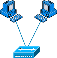
94
Chapter 4 ■ The Current Ethernet Specifications
c04.indd 04/02/2015 Page 94
FIGURE 4.1 The basic network
Bob Sally
Hub
Okay, about Figure 4.1; how would you say the PC named Bob communicates with
the PC named Sally? Well, they’re both on the same LAN connected with a multiport
repeater (a hub). So does Bob just send out a data message, “Hey Sally, you there?” or
does Bob use Sally’s IP address and put things more like, “Hey 192.168.0.3, are you
there?” I hope you picked the IP address option, but even if you did, the news is still
bad—both answers are wrong! Why? Because Bob is actually going to use Sally’s MAC
address (known as a hardware address), which is burned right into the network card of
Sally’s PC, to get a hold of her.
This is all good, but how does Bob get Sally’s MAC address when Bob knows only
Sally’s name and doesn’t even have her IP address? Bob is going to start by using name
resolution (hostname-to-IP-address resolution), something that’s usually accomplished
using Domain Name Service (DNS). And note that if these two hosts are on the same LAN,
Bob can just broadcast to Sally asking her for the information (no DNS needed)—welcome
to Microsoft Windows!
Here’s the output from a network analyzer depicting a simple name-resolution process
from Bob to Sally:
Time Source Destination Protocol Info
53.892794 192.168.0.2 192.168.0.255 NBNS Name query NB SALLY<00>
As I already mentioned, because the two hosts are on a local LAN, Windows (Bob) will
broadcast to resolve the name Sally (the destination 192.168.0.255 is a broadcast address).
Let’s take a look at the rest of the information:
EthernetII,Src:192.168.0.2(00:14:22:be:18:3b),Dst:Broadcast(ff:ff:ff:ff:ff:ff
)
This output shows that Bob knows his own MAC address and source IP address, but
not Sally’s IP address or MAC address. So, Bob sends a broadcast address of all Fs for the
MAC address (a Data Link layer broadcast) and an IP LAN broadcast of 192.168.0.255.
Again, no worries—you’re going to learn all about broadcasts in Chapter 6, “Introduction
to the Internet Protocol.”
Ethernet Basics
95
c04.indd 04/02/2015 Page 95
Before the name is resolved, the rst thing Bob has to do is broadcast on the LAN to
get Sally’s MAC address so he can communicate to her PC and resolve her name to an
IP address:
Time Source Destination Protocol Info
5.153054 192.168.0.2 Broadcast ARP Who has 192.168.0.3? Tell 192.168.0.2
Next, check out Sally’s response:
Time Source Destination Protocol Info
5.153403 192.168.0.3 192.168.0.2 ARP 192.168.0.3 is at 00:0b:db:99:d3:5e
5.53.89317 192.168.0.3 192.168.0.2 NBNS Name query response NB
192.168.0.3
Okay, sweet—Bob now has both Sally’s IP address and her MAC address
(00:0b:db:99:de:5e). These are both listed as the source address at this point because this
information was sent from Sally back to Bob. So, nally, Bob has all the goods he needs to
communicate with Sally. And just so you know, I’m also going to tell you all about Address
Resolution Protocol (ARP) and show you exactly how Sally’s IP address was resolved to a
MAC address a little later, in Chapter 6.
Importantly, I want you to understand that Sally still had to go through the same resolution
processes to communicate back to Bob—sounds crazy, huh? Consider this welcome to IPv4
and basic networking with Windows—and we haven’t even added a router yet!
Ethernet Basics
Ethernet is a contention media-access method that allows all hosts on a network
to share the same bandwidth of a link. Ethernet is popular because it’s readily
scalable, meaning that it’s comparatively easy to integrate new technologies, such
as Fast Ethernet and Gigabit Ethernet, into an existing network infrastructure. It’s
also relatively simple to implement in the rst place, and with it, troubleshooting is
reasonably straightforward.
Ethernet uses both Data Link and Physical layer speci cations, and this part of the
chapter will give you both the Data Link layer and Physical layer information you need to
effectively implement, troubleshoot, and maintain an Ethernet network.
In the following sections, I’ll also cover some basic terms used in networking with
Ethernet technologies. Let’s start with collision domains.
Collision Domain
The term collision domain is an Ethernet term that refers to a particular network
scenario wherein one device sends a packet out on a network segment and thereby
forces every other device on that same physical network segment to pay attention to
it. This is bad because if two devices on one physical segment transmit at the same
96
Chapter 4 ■ The Current Ethernet Specifications
c04.indd 04/02/2015 Page 96
time, a collision event—a situation where each device’s digital signals interfere with
another on the wire—occurs and forces the devices to retransmit later. Collisions have a
dramatically negative effect on network performance, so they’re de nitely something we
want to avoid!
The situation I just described is typically found in a hub environment where each host
segment connects to a hub that represents only one collision domain and one broadcast
domain. This begs the question, What’s a broadcast domain?
Broadcast Domain
Here’s that answer: A broadcast domain refers to the set of all devices on a network
segment that hear all the broadcasts sent on that segment.
Even though a broadcast domain is typically a boundary delimited by physical media
like switches and repeaters, it can also reference a logical division of a network segment
where all hosts can reach each other via a Data Link layer (hardware address) broadcast.
That’s the basic story, but rest assured, I’ll be delving deeper into the skinny on collision
and broadcast domains a bit later, in Chapter 5.
CSMA/CD
Ethernet networking uses Carrier Sense Multiple Access with Collision Detection (CSMA/
CD), a media access control method that helps devices share the bandwidth evenly
without having two devices transmit at the same time on the network medium. CSMA/
CD was created to overcome the problem of those collisions that occur when packets
are transmitted simultaneously from different hosts. And trust me—good collision
management is crucial because when a host transmits in a CSMA/CD network, all the
other hosts on the network receive and examine that transmission. Only bridges, switches,
and routers, but not hubs, can effectively prevent a transmission from propagating
throughout the entire network.
So, how does the CSMA/CD protocol work? Let’s start by taking a look at Figure 4.2,
where a collision has occurred in the network.
When a host wants to transmit over the network, it rst checks for the presence of a
digital signal on the wire. If all is clear, meaning that no other host is transmitting, the
host will then proceed with its transmission. But it doesn’t stop there. The transmitting
host constantly monitors the wire to make sure no other hosts begin transmitting. If
the host detects another signal on the wire, it sends out an extended jam signal that
causes all hosts on the segment to stop sending data (think busy signal). The hosts
respond to that jam signal by waiting a while before attempting to transmit again.
Backoff algorithms, represented by the clocks counting down on either side of the
jammed devices, determine when the colliding stations can retransmit. If collisions keep
occurring after 15 tries, the hosts attempting to transmit will then time out. Pretty clean!
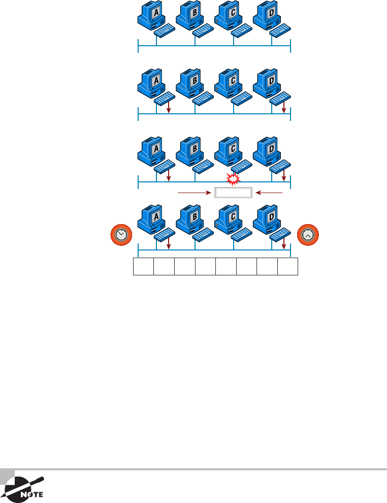
Ethernet Basics
97
c04.indd 04/02/2015 Page 97
FIGURE 4.2 CSMA/CD
Jam Jam Jam Jam Jam Jam Jam Jam
Carrier Sense Multiple
Access with Collision
Detection (CSMA/CD)
Collision
When a collision occurs on an Ethernet LAN, the following things happen:
■ A jam signal informs all devices that a collision occurred.
■ The collision invokes a random backoff algorithm.
■ Each device on the Ethernet segment stops transmitting for a short time until the
timers expire.
■ All hosts have equal priority to transmit after the timers have expired.
And following are the effects of having a CSMA/CD network that has sustained
heavy collisions:
■ Delay
■ Low throughput
■ Congestion
Backoff on an 802.3 network is the retransmission delay that’s enforced
when a collision occurs. When a collision occurs, a host will resume
transmission after the forced time delay has expired. After this backoff
delay period has expired, all stations have equal priority to transmit data.
98
Chapter 4 ■ The Current Ethernet Specifications
c04.indd 04/02/2015 Page 98
Broadband/Baseband
We have two ways to send analog and digital signals down a wire: broadband and
baseband.
We hear the term broadband a lot these days because that is pretty much what everyone
uses at home. It allows us to have both our analog voice and digital data carried on the
same network cable or physical medium. Broadband allows us to send multiple frequencies
of different signals down the same wire at the same time (called frequency-division multi-
plexing), and to send both analog and digital signals.
Baseband is what all LANs use. This is where all the bandwidth of the physical media is
used by only one signal. For example, Ethernet uses only one digital signal at a time, and
requires all the available bandwidth. If multiple signals are sent from different hosts at the
same time, we get collisions; same with wireless, except that uses only analog signaling.
Bit Rates vs Baud Rate
Bit rate is a measure of the number of data bits (0s and 1s) transmitted in one second in
either a digital or analog signal. A gure of 56,000 bits per second (bps) means 56,000 0s
or 1s can be transmitted in one second, which we simply refer to as bps.
In the 1970s and 1980s, we used the term baud rate a lot, but that was replaced by
bps because it was more accurate. Baud was a term of measurement named after a French
engineer, Jean-Maurice-Emile Baudot, because he used it to measure the speed of telegraph
transmissions.
One baud is one electronic state change per second—for example, from 0.2 volts to 3
volts or from binary 0 to 1. However, since a single state change can involve more than a
single bit of data, the bps unit of measurement has replaced it as a more accurate de nition
of how much data you’re transmitting or receiving.
Wavelength
Has anyone every told you that they were on the same wavelength as you? That means
they thought you were basically thinking the same way they were. The same is true of the
inverse—if they say, “you’re not on the same wavelength.” With electromagnetic radiation,
radio waves, light waves, or even infrared (heat) waves make characteristic patterns as they
travel through space. Some patterns can be the same, and some can be different, as shown
in Figure 4.3.
Each wave pattern has a certain shape and length. The distance between peaks (high
points) is called wavelength. If two wavelengths are different, we would say they’re not on
the same wavelength and that is the way we tell different kinds of electromagnetic energy
apart. We can use this to our advantage in electronics by sending traf c on different wave-
lengths at the same time.
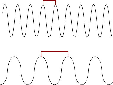
Ethernet Basics
99
c04.indd 04/02/2015 Page 99
In the following sections, I’m going to cover Ethernet in detail at both the Data Link
layer (Layer 2) and the Physical layer (Layer 1).
FIGURE 4.3 Shorter and longer wavelengths
Shorter Wavelength
Longer Wavelength
Sampling -Size
At its core, computers work one step at a time by turning a succession of switches on or off
at very high speed. In order for a computer to convert analog audio signals to digital signals
in a discrete step, the analog waveform is mathematically described as a succession of dis-
crete amplitude values.
When converting to analog, the computer captures a series of samples in speci ed sizes,
which we’ll call the sampling size. Each data stream sample contains items like dynamic
range, frequency content, and more.
The measured amplitude level in each sample is quantized by being given a value of the
nearest measured increment. A computer will reproduce these values and play them back in
the same order and at the same rate at which they were captured, producing a copy of the
original waveform. This is called the sample rate or sample size. The number of bits trans-
mitted per second is called the bit rate.
Half- and Full-Duplex Ethernet
Just so you know, half-duplex Ethernet is de ned in the original 802.3 Ethernet
speci cation. Basically, when you run half duplex, you’re using only one wire pair with a
digital signal either transmitting or receiving. This really isn’t all that different from full
duplex because you can both transmit and receive—you just don’t get to do that at the same
time running half duplex as you can if you’re running full duplex.

100
Chapter 4 ■ The Current Ethernet Specifications
c04.indd 04/02/2015 Page 100
Here’s how it works: If a host hears a digital signal, it uses the CSMA/CD protocol to
help prevent collisions and to permit retransmitting if a collision does occur. Half-duplex
Ethernet—typically 10BaseT—is only about 30 to 40 percent ef cient because a large
10BaseT network will usually provide only 3Mbps to 4Mbps at most. Although it’s true
that 100Mbps Ethernet can and sometimes does run half duplex, it’s just not very common
to nd that happening anymore.
In contrast, full-duplex Ethernet uses two pairs of wires at the same time instead
of one measly wire pair like half duplex employs. Plus, full duplex uses a point-to-
point connection between the transmitter of the sending device and the receiver of
the receiving device (in most cases the switch). This means that with full-duplex
data transfer, you not only get faster data-transfer speeds, but you also get collision
prevention too—sweet!
You don’t need to worry about collisions because now it’s like a freeway with multiple
lanes instead of the single-lane road provided by half duplex. Full-duplex Ethernet is
supposed to offer 100 percent ef ciency in both directions—for example, you can get
20Mbps with a 10Mbps Ethernet running full duplex or 200Mbps for Fast Ethernet. But
this rate is something known as an aggregate rate, which translates as “you’re supposed to
get” 100 percent ef ciency. No guarantees, in networking as in life.
Full-duplex Ethernet can be used in many situations; here are some examples:
■ With a connection from a switch to a host
■ With a connection from a switch to a switch
■ With a connection from a host to a host using a crossover cable
You can run full duplex with just about any device except a hub.
You may be wondering: If it’s capable of all that speed, why wouldn’t it deliver? Well,
when a full-duplex Ethernet port is powered on, it rst connects to the remote end and
then negotiates with the other end of the Fast Ethernet link. This is called an auto-detect
mechanism. This mechanism rst decides on the exchange capability, which means it
checks to see if it can run at 10, 100, or even 1000Mbps. It then checks to see if it can run
full duplex, and if it can’t, it will run half duplex instead.
Hosts usually auto-detect both the Mbps and the duplex type available (the default
setting), but you can manually set both the speed and duplex type on the Network Interface
Card (NIC), as shown in the following screen shot.
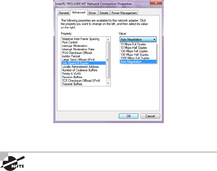
Ethernet at the Data Link Layer
101
c04.indd 04/02/2015 Page 101
Today, it’s pretty rare to go into a NIC con guration on a host and change these set-
tings, but this example demonstratess that you can do that if you want.
Remember that half-duplex Ethernet shares a collision domain and
provides a lower effective throughput than full-duplex Ethernet, which
typically has a private collision domain and a higher effective throughput.
Lastly, remember these important points:
■ There are no collisions in full-duplex mode.
■ A dedicated switch port is required for each full-duplex host.
■ The host network card and the switch port must be capable of operating in full-duplex
mode.
Now let’s take a look at how Ethernet works at the Data Link layer.
Ethernet at the Data Link Layer
Ethernet at the Data Link layer is responsible for Ethernet addressing, commonly referred
to as hardware addressing or MAC addressing. Ethernet is also responsible for framing

102
Chapter 4 ■ The Current Ethernet Specifications
c04.indd 04/02/2015 Page 102
packets received from the Network layer and preparing them for transmission on the local
network through the Ethernet contention media-access method known as CSMA/CD.
Ethernet MAC addresses are made up of hexadecimal addresses. So before I discuss
MAC addresses, let’s start by talking about binary, decimal, and hexadecimal addresses
and how to convert one to another.
Binary to Decimal and Hexadecimal Conversion
Understanding the differences between binary, decimal, and hexadecimal numbers and
how to convert one format into the other is very important before we move on to discussing
the TCP/IP protocol stack and IP addressing in Chapters 6 and 7.
So let’s get started with binary numbering. It’s pretty simple, really. Each digit used is
limited to being either a 1 (one) or a 0 (zero), and each digit is called 1 bit (short for binary
digit). Typically, you count either 4 or 8 bits together, with these being referred to as a
nibble and a byte, respectively.
What’s interesting about binary numbering is the value represented in a decimal
format—the typical decimal format being the base-10 number scheme that we’ve all used
since kindergarten. The binary numbers are placed in a value spot, starting at the right and
moving left, with each spot having double the value of the previous spot.
Table 4.1 shows the decimal values of each bit location in a nibble and a byte.
Remember, a nibble is four bits and a byte is eight bits. In network addressing, we often
refer to a byte as an octet or octal addressing. Mathematically, octal addressing actually
refers to base 8, which is completely different from the base 10 we are familiar with. So,
technically speaking we are using the term incorrectly, but it’s the common usage anyway.
When we get to the subnetting chapter, you’ll see that I’ll use byte and octet interchange-
ably when discussing IP addressing.
TABLE 4.1 Binary values
Nibble values Byte values
8 4 2 1 128 64 32 16 8 4 2 1
What all this means is that if a one digit (1) is placed in a value spot, then the nibble or
byte takes on that decimal value and adds it to any other value spots that have a 1. And
if a zero (0) is placed in a bit spot, you don’t count that value.
Let me clarify things for you—if we have a 1 placed in each spot of our nibble, we then
add up 8 + 4 + 2 + 1 to give us a maximum value of 15. Another example for our nibble
values is 1010, which means that the 8 bit and the 2 bit are turned on and equal a decimal
value of 10. If we have a nibble binary value of 0110, then our decimal value is 6 because
the 4 and 2 bits are turned on.

Ethernet at the Data Link Layer
103
c04.indd 04/02/2015 Page 103
But the byte values can add up to a value that’s signi cantly higher than 15. This
is how—if we count every bit as a one (1), then the byte binary value looks like this
(remember, 8 bits equal a byte):
11111111
We then count up every bit spot because each is turned on. It looks like this, which
demonstrates the maximum value of a byte:
128 + 64 + 32 + 16 + 8 + 4 + 2 + 1 = 255
A binary number can equal plenty of other decimal values. Let’s work through a
few examples:
10010110
Which bits are on? The 128, 16, 4, and 2 bits are on, so we’ll just add them up:
128 + 16 + 4 + 2 = 150.
01101100
Which bits are on? The 64, 32, 8, and 4 bits are on, so we add them up: 64 + 32 +
8 + 4 = 108.
11101000
Which bits are on? The 128, 64, 32, and 8 bits are on, so we add the values: 128 + 64 +
32 + 8 = 232.
You should memorize Table 4.2 before braving the IP sections in Chapter 6 and Chapter
7 since this lists all available subnet masks.
TABLE 4.2 Binary-to-decimal memorization chart
Binary value Decimal value
10000000 128
11000000 192
11100000 224
11110000 240
1111100 0 248
11111100 252
11111110 254
11111111 255

104
Chapter 4 ■ The Current Ethernet Specifications
c04.indd 04/02/2015 Page 104
Hexadecimal addressing is completely different than binary or decimal—it’s converted
by reading nibbles, not bytes. By using a nibble, we can convert these bits to hex pretty
simply. First, understand that the hexadecimal addressing scheme uses only the numbers 0
through 9. And because the numbers 10, 11, 12, and so on can’t be used (because they are
two-digit numbers), the letters A, B, C, D, E, and F are used to represent 10, 11, 12, 13, 14,
and 15, respectively.
Table 4.3 shows both the binary value and the decimal value for each hexadecimal digit.
TABLE 4.3 Hex-to-binary-to-decimal chart
Hexadecimal value Binary value Decimal value
0 0000 0
1 0001 1
200102
300113
401004
501015
601106
7 0111 7
8 1000 8
910019
A101010
B101111
C110012
D110113
E 1110 14
F 1111 15
Did you notice that the rst 10 hexadecimal digits (0–9) are the same values as the
decimal values? If not, look again. This handy fact makes those values super easy to convert.

Ethernet at the Data Link Layer
105
c04.indd 04/02/2015 Page 105
So suppose you have something like this: 0x6A. (Some manufacturers put 0x in front of
characters so you know that they’re a hex value, while others just give you an h. It doesn’t
have any other special meaning.) What are the binary and decimal values? To correctly
answer that question, all you have to remember is that each hex character is one nibble and
two hex characters together make a byte. To gure out the binary value, rst put the hex
characters into two nibbles and then put them together into a byte. 6 = 0110 and A (which
is 10 in hex) = 1010, so the complete byte is 01101010.
To convert from binary to hex, just take the byte and break it into nibbles.
Here’s how you do that: Say you have the binary number 01010101. First, break it into
nibbles—0101 and 0101—with the value of each nibble being 5 because the 1 and 4 bits
are on. This makes the hex answer 0x55. And in decimal format, the binary number is
01010101, which converts to 64 + 16 + 4 + 1 = 85.
Okay, now try another binary number:
11001100
Our answer is 1100 = 12 and 1100 = 12 (therefore, it’s converted to CC in hex). The
decimal conversion answer is 128 + 64 + 8 + 4 = 204.
One more example, and then we need to get working on the Physical layer. Suppose
we’re given the following binary number:
10110101
The hex answer is 0xB5 because 1011 converts to B and 0101 converts to 5 in hex value.
The decimal equivalent is 128 + 32 + 16 + 4 + 1 = 181.
See the written lab at the end of this chapter for more practice with binary/
hex/decimal conversion.
Ethernet Addressing
Now that you’ve got binary-to-decimal and hexadecimal address conversion down, we can
get into how Ethernet addressing works. It uses the Media Access Control (MAC) address
burned into each and every Ethernet NIC. The MAC, or hardware, address is a 48-bit
(6-byte) address written in a hexadecimal format.
Figure 4.4 shows the 48-bit MAC addresses and how the bits are divided.
The organizationally unique identi er (OUI) is assigned by the Institute of Electrical
and Electronics Engineers (IEEE) to an organization. It’s composed of 24 bits, or 3 bytes.
The organization, in turn, assigns a globally administered address (24 bits, or 3 bytes)
that is unique to each and every adapter it manufactures. Look closely at the gure. The
Individual/Group (I/G) address bit is used to signify if the destination MAC address
is a unicast or a multicast/broadcast Layer 2 address. If the bit is set to 0, then it is an
Individual MAC address and is a unicast address. If the bit is set to 1, it is a Group address
and is a multicast/broadcast address.
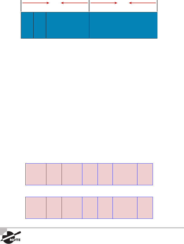
106
Chapter 4 ■ The Current Ethernet Specifications
c04.indd 04/02/2015 Page 106
FIGURE 4.4 Ethernet addressing using MAC addresses
24 bits
4647
I/G L/G Vendor Assigned
Organizationally Unique
Identifier (OUI)
(Assigned by IEEE)
24 bits
The next bit is the Local/Global bit (L/G). This bit is used to tell if the MAC address is
the burned-in-address (BIA) or a MAC address that has been changed locally. You’ll see
this happen when we get to IPv6 addressing. The low-order 24 bits of an Ethernet address
represent a locally administered or manufacturer-assigned code. This portion commonly
starts with 24 0s for the rst card made and continues in order until there are 24 1s for the
last (16,777,216th) card made. You’ll nd that many manufacturers use these same six hex
digits as the last six characters of their serial number on the same card.
Ethernet Frames
The Data Link layer is responsible for combining bits into bytes and bytes into frames.
Frames are used at the Data Link layer to encapsulate packets handed down from the
Network layer for transmission on a type of physical media access.
The function of Ethernet stations is to pass data frames between each other using a
group of bits known as a MAC frame format. This provides error detection from a cyclic
redundancy check (CRC). But remember—this is error detection, not error correction. The
802.3 frames and Ethernet frame are shown in Figure 4.5.
FIGURE 4.5 802.3 and Ethernet frame formats
Ethernet_II
802.3_Ethernet
Preamble
7
Preamble
7
SOF
1
SOF
1
Destination
6
Destination
6
Source
6
Source
6
Type
2
Length
2
Data and Pad
46 – 1500
Data and Pad
46 – 1500
FCS
4
FCS
4
Encapsulating a frame within a different type of frame is called tunneling.

Ethernet at the Data Link Layer
107
c04.indd 04/02/2015 Page 107
The following information regarding frame headings and the various
types of Ethernet frames are beyond the scope of the CompTIA Network+
objectives. Throughout the rest of this book, I’ll show you screen shots from
a network analyzer. It’s always good to understand what you are looking at,
so I put this information in to help you understand a frame structure.
Following are the details of the different elds in the 802.3 and Ethernet frame types:
Preamble An alternating 1,0 pattern provides a 5MHz clock at the start of each packet,
which allows the receiving devices to lock the incoming bit stream.
Start of Frame Delimiter (SOF)/Synch The preamble is seven octets, and the start of a
frame (SOF) is one octet (synch). The SOF is 10101011, where the last pair of 1s allows the
receiver to come into the alternating 1,0 pattern somewhere in the middle and still synch up
and detect the beginning of the data.
Destination Address (DA) This transmits a 48-bit value using the least signi cant bit
(LSB) rst. The DA is used by receiving stations to determine whether an incoming packet
is addressed to a particular host and can be an individual address or a broadcast or
multicast MAC address. Remember that a broadcast is all 1s (or Fs in hex) and is sent to
all devices, but a multicast is sent only to a similar subset of hosts on a network.
Source Address (SA) The SA is a 48-bit MAC address used to identify the transmitting
device, and it uses the LSB rst. Broadcast and multicast address formats are illegal within
the SA eld.
Length or Type 802.3 uses a Length eld, but the Ethernet frame uses a Type eld
to identify the Network layer protocol. 802.3 by itself cannot identify the upper-layer
routed protocol and must be used with a proprietary LAN protocol—Internetwork Packet
Exchange (IPX), for example.
Data This is a packet sent down to the Data Link layer from the Network layer. The size
can vary from 64 to 1500 bytes.
Frame Check Sequence (FCS) FCS is a eld that is at the end of the frame and is used to
store the CRC.
Okay—let’s take a minute to look at some frames caught on our trusty network
analyzer. You can see that the following frame has only three elds: Destination, Source,
and Type, displayed as Protocol Type on this analyzer:
Destination: 00:60:f5:00:1f:27
Source: 00:60:f5:00:1f:2c
Protocol Type: 08-00 IP
This is an Ethernet_II frame. Notice that the Type eld is IP, or 08-00 (mostly just
referred to as 0x800) in hexadecimal.
The next frame has the same elds, so it must be an Ethernet_II frame, too:
Destination: ff:ff:ff:ff:ff:ff Ethernet Broadcast
Source: 02:07:01:22:de:a4
Protocol Type: 08-00 IP

108
Chapter 4 ■ The Current Ethernet Specifications
c04.indd 04/02/2015 Page 108
Did you notice that this frame was a broadcast? You can tell because the destination
hardware address is all 1s in binary, or all Fs in hexadecimal.
Let’s take a look at one more Ethernet_II frame. You can see that the Ethernet frame is
the same Ethernet_II frame we use with the IPv4 routed protocol. The difference is that the
Type eld has 0x86dd when we are carrying IPv6 data, and when we have IPv4 data, we
use 0x0800 in the Protocol eld:
Destination: IPv6-Neighbor-Discovery_00:01:00:03 (33:33:00:01:00:03)
Source: Aopen_3e:7f:dd (00:01:80:3e:7f:dd)
Type: IPv6 (0x86dd)
This is the beauty of the Ethernet_II frame. Because of the Protocol eld, we can run
any Network layer routed protocol and it will carry the data because it can identify that
particular Network layer protocol!
Ethernet at the Physical Layer
Ethernet was rst implemented by a group called DIX (Digital, Intel, and Xerox). They
created and implemented the rst Ethernet LAN speci cation, which the IEEE used to
create the IEEE 802.3 Committee. This was a 10Mbps network that ran on coax, then on
twisted-pair, and nally on ber physical media.
The IEEE extended the 802.3 Committee to two new committees known as 802.3u
(Fast Ethernet), 802.3ab (Gigabit Ethernet on Category 5+), and then nally to 802.3ae
(10Gbps over ber and coax).
Figure 4.6 shows the IEEE 802.3 and original Ethernet Physical layer speci cations.
FIGURE 4.6 Ethernet Physical layer specifications
Data Link
(MAC Layer)
Physical
802.3
Ethernet
10Base2
10Base5
10BaseT
10BaseF
100BaseTX
100BaseFX
100BaseT4
When designing your LAN, it’s really important to understand the different types of
Ethernet media available to you. Sure, it would be great to run Gigabit Ethernet to each
desktop and 10Gbps between switches, as well as to servers. Although this is just starting
to happen, justifying the cost of that network today for most companies would be a
pretty hard sell. But if you mix and match the different types of Ethernet media methods
currently available instead, you can come up with a cost-effective network solution that
works great!
The Electronic Industries Association and the newer Telecommunications Industry
Alliance (EIA/TIA) together form the standards body that creates the Physical layer
speci cations for Ethernet. The EIA/TIA speci es that Ethernet use a registered jack (RJ)
Ethernet at the Physical Layer
109
c04.indd 04/02/2015 Page 109
connector on unshielded twisted-pair (UTP) cabling (RJ-45). However, the industry is
calling this just an 8-pin modular connector.
Each Ethernet cable type that is speci ed by the EIA/TIA has something known
as inherent attenuation, which is de ned as the loss of signal strength as it travels the
length of a cable and is measured in decibels (dB). The cabling used in corporate and
home markets is measured in categories. A higher-quality cable will have a higher-rated
category and lower attenuation. For example, Category 5 is better than Category 3 because
Category 5 cables have more wire twists per foot and therefore less crosstalk. Crosstalk is
the unwanted signal interference from adjacent pairs in the cable.
Here are the original IEEE 802.3 standards:
10Base2 This is also known as thinnet and can support up to 30 workstations on a single
segment. It uses 10Mbps of baseband technology, coax up to 185 meters in length, and a
physical and logical bus with Attachment Unit Interface (AUI) connectors. The 10 means
10Mbps, and Base means baseband technology—a signaling method for communication
on the network—and the 2 means almost 200 meters. 10Base2 Ethernet cards use BNC
(British Naval Connector, Bayonet Neill-Concelman, or Bayonet Nut Connector) and
T-connectors to connect to a network.
10Base5 Also known as thicknet, 10Base5 uses a physical and logical bus with AUI con-
nectors, 10Mbps baseband technology, and coax up to 500 meters in length. You can go up
to 2,500 meters with repeaters and 1,024 users for all segments.
10BaseT This is 10Mbps using Category 3 UTP wiring. Unlike on 10Base2 and 10Base5
networks, each device must connect into a hub or switch, and you can have only one host
per segment or wire. It uses an RJ-45 connector (8-pin modular connector) with a physical
star topology and a logical bus.
Each of the 802.3 standards de nes an AUI, which allows a one-bit-at-a-time
transfer to the Physical layer from the Data Link media-access method. This allows
the MAC address to remain constant but means the Physical layer can support both
existing and new technologies. The original AUI interface was a 15-pin connector,
which allowed a transceiver (transmitter/receiver) that provided a 15-pin-to-twisted-
pair conversion.
There’s an issue, though—the AUI interface can’t support 100Mbps Ethernet because
of the high frequencies involved. So basically, 100BaseT needed a new interface, and
the 802.3u speci cations created one called the Media Independent Interface (MII) that
provides 100Mbps throughput. The MII uses a nibble, which you of course remember is
de ned as 4 bits. Gigabit Ethernet uses a Gigabit Media Independent Interface (GMII) and
transmits 8 bits at a time.
802.3u (Fast Ethernet) is compatible with 802.3 Ethernet because they share the same
physical characteristics. Fast Ethernet and Ethernet use the same maximum transmission
unit (MTU) and the same MAC mechanisms, and they both preserve the frame format
that is used by 10BaseT Ethernet. Basically, Fast Ethernet is just based on an extension to
the IEEE 802.3 speci cation, and because of that, it offers us a speed increase of 10 times
10BaseT.
Here are the expanded IEEE Ethernet 802.3 standards, starting with Fast Ethernet:

110
Chapter 4 ■ The Current Ethernet Specifications
c04.indd 04/02/2015 Page 110
100BaseTX (IEEE 802.3u) 100BaseTX, most commonly known as Fast Ethernet, uses
EIA/TIA Category 5 or 5e or 6 and UTP two-pair wiring. It allows for one user per seg-
ment up to 100 meters long (328 feet), and uses an RJ-45 connector with a physical star
topology and a logical bus.
100BaseT and 100BaseTX: What’s the difference? 100BaseT is the name
of a group of standards for Fast Ethernet that include 100BaseTX. Also
included are 100BaseT4 and 100BaseT2.The same can be said about
1000BaseT and 1000BaseX.
100BaseFX (IEEE 802.3u) Uses 62.5/125-micron multimode ber cabling up to 412
meters long and point-to-point topology. It uses ST and SC connectors, which are media-
interface connectors.
Ethernet’s implementation over fiber can sometimes be referred to as
100BaseTF even though this isn’t an actual standard. It just means that Eth-
ernet technologies are being run over fiber cable.
1000BaseCX (IEEE 802.3z) Copper twisted-pair called twinax (a balanced coaxial pair)
that can run only up to 25 meters and uses a special 9-pin connector known as the High-
Speed Serial Data Connector (HSSDC).
1000BaseT (IEEE 802.3ab) Category 5, four-pair UTP wiring, and up to 100 meters long
(328 feet).
1000BaseTX Category 5, two-pair UTP wiring up to 100 meters long (328 feet). Not
used, and has been replaced by Category 6 cabling.
1000BaseSX (IEEE 802.3z) The implementation of Gigabit Ethernet runs over multimode
ber-optic cable instead of copper twisted-pair cable and uses short wavelength laser.
Multimode ber (MMF), using 62.5- and 50-micron core, utilizes an 850 nanometer (nm)
laser and can go up to 220 meters with 62.5-micron; 550 meters with 50-micron.
1000BaseLX (IEEE 802.3z) Single-mode ber that uses a 9-micron core, 1,300 nm laser,
and can go from 3 km up to 10 km.
10GBaseT 10GBaseT is a standard created by the IEEE 802.3an committee to provide
10Gbps connections over conventional UTP cables (Category 5e, 6, or 7 cables). 10GBaseT
allows the conventional RJ-45 used for Ethernet LANs. It can support signal transmission
at the full 100-meter distance speci ed for LAN wiring. If you need to implement a 10Gbps
link, this is the most economical way to go!
10GBaseSR An implementation of 10 Gigabit Ethernet that uses short-wavelength lasers
at 850 nm over multimode ber. It has a maximum transmission distance of between 2 and
300 meters (990 feet), depending on the size and quality of the ber.
10GBaseLR An implementation of 10 Gigabit Ethernet that uses long-wavelength lasers at
1,310 nm over single-mode ber. It also has a maximum transmission distance between 2
meters and 10 km, or 6 miles, depending on the size and quality of the ber.

Ethernet at the Physical Layer
111
c04.indd 04/02/2015 Page 111
10GBaseER An implementation of 10 Gigabit Ethernet running over single-mode ber
that uses extra-long-wavelength lasers at 1,550 nm. It has the longest transmission dis-
tances possible of all the 10 Gigabit technologies: anywhere from 2 meters up to 40 km,
again depending on the size and quality of the ber used.
10GBaseSW 10GBaseSW, as de ned by IEEE 802.3ae, is a mode of 10GBaseS for MMF
with an 850 nm laser transceiver and a bandwidth of 10Gbps. It can support up to 300
meters of cable length. This media type is designed to connect to SONET equipment.
10GBase-LW 10GBaseLW is a mode of 10GBaseL supporting a link length of 10 km on
standard single-mode ber (SMF) (G.652). This media type is also designed to connect to
SONET equipment.
10GBaseEW 10GBaseEW is a mode of 10GBaseE supporting a link length of up to 40 km
on SMF based on G.652 using optical-wavelength 1,550 nm. This is another media type
designed to connect to SONET equipment.
If you want to implement a network medium that is not susceptible to
electromagnetic interference (EMI), fiber-optic cable provides a more secure,
long-distance cable that is not susceptible to EMI at high speeds like UTP is.
Table 4.4 summarizes the cable types.
TABLE 4.4 Common Ethernet cable types
Ethernet
name Cable type
Maximum
speed
Maximum
transmission
distance Notes
10Base5 Coax 10Mbps 500 meters per
segment
Also called thicknet,
this cable type uses
vampire taps to con-
nect devices to cable.
10Base2 Coax 10Mbps 185 meters per
segment
Also called thinnet, a
very popular imple-
mentation of Ethernet
over coax.
10BaseT UTP 10Mbps 100 meters per
segment
One of the most popu-
lar network cabling
schemes.
100BaseTX UTP, STP 100Mbps 100 meters per
segment
Two pairs of Category
5 UTP.

112
Chapter 4 ■ The Current Ethernet Specifications
c04.indd 04/02/2015 Page 112
Ethernet
name Cable type
Maximum
speed
Maximum
transmission
distance Notes
10BaseFL Fiber 10Mbps Varies (ranges
from 500 meters
to 2,000 meters)
Ethernet over fiber
optics to the desktop.
100BaseFX MMF 100Mbps 2,000 meters 100Mbps Ethernet
over fiber optics.
1000BaseT UTP 1000Mbps 100 meters Four pairs of Category
5e or higher.
1000BaseTX UTP 1000Mbps 100 meters Two pairs of Category
5e or higher.
1000BaseSX MMF 1000Mbps 550 meters Uses SC fiber con-
nectors. Max length
depends on fiber size.
1000BaseCX Balanced,
shielded
copper
1000Mbps 25 meters Uses a special con-
nector, the HSSDC.
1000BaseLX MMF and
SMF
1000Mbps 550 meters mul-
timode/2,000
meters single
mode
Uses longer wave-
length laser than
1000BaseSX. Uses SC
and LC connectors.
10GBaseT UTP 10Gbps 100 meters Connects to the net-
work like a Fast Ether-
net link using UTP.
10GBaseSR MMF 10Gbps 300 meters 850 nm laser. Max
length depends on
fiber size and quality.
10GBaseLR SMF 10Gbps 10 kilometers 1,310 nm laser. Max
length depends on
fiber size and quality.
10GBaseER SMF 10Gbps 40 kilometers 1,550 nm laser. Max
length depends on
fiber size and quality.
TABLE 4.4 Common Ethernet cable types (continued)

Ethernet at the Physical Layer
113
c04.indd 04/02/2015 Page 113
Ethernet
name Cable type
Maximum
speed
Maximum
transmission
distance Notes
10GBaseSW MMF 10Gbps 300 meters 850 nm laser trans-
ceiver.
10GBaseLW SMF 10Gbps 10 kilometers Typically used with
SONET.
10GBaseEW SMF 10Gbps 40 kilometers 1,550 nm optical
wavelength.
An advantage of 100BaseFX over 100BaseTX is longer cable runs, but
100BaseTX is easier to install.
I know there’s a lot of information to remember about the various Ethernet and ber
types used in today’s networks, but for the CompTIA Network+ exam, you really need to
know them. Trust me, I haven’t inundated you with unnecessary information!
Deploy the Appropriate Wired Connectivity Standard
You have been tasked with installing wiring to handle the new networking technologies
of 1000Mbps to the desktop and Voice over IP (VoIP), with 10Gbps between the access
switches and the core switches. What cabling do you consider installing in order to
accomplish this in a cost-effective manner?
First, you need to verify your distances. Since this will not include any wireless stations,
you need to double-check the distances to each station and make sure the phone is within
100 meters (or closer) for connectivity to your access switches.
Once you have your distances verifi ed at 100 meters or less, you can use UTP wiring
to the stations and phones and possibly even connect the stations into the back of the
phones. Most phones have switches included, so this means you only need to run one
Category 5e or better 1000BaseT four-pair cable to each cubicle or offi ce.
For your connections from your access switches to your core switches, you can use
10GbaseT if your runs are 100 meters or less, or you can use 10GbaseSR, which allows
runs up to 300 meters using multimode fi ber.
114
Chapter 4 ■ The Current Ethernet Specifications
c04.indd 04/02/2015 Page 114
Ethernet over Other Standards (IEEE
1905.1-2013)
IEEE 1905.1-2013 is an IEEE standard that de nes a convergent digital home network for
both wireless and wireline technologies. Some the technologies include IEEE 802.11 (Wi-
Fi), IEEE 1901 (HomePlug, HD-PLC) powerline networking, IEEE 802.3 Ethernet, and
Multimedia over Coax (MoCA). The 2905.1-2013 was published in April 2013. The IEEE
1905.1 Standard Working Group is sponsored by the IEEE Power Line Communication
Standards Committee (PLCSC). The idea behind the 1905.1 technology standards is simple
setup, con guration, and operation of home networking devices using both wired and wire-
less technologies. This will take advantage of the performance, coverage, and mobility ben-
e ts of multiple interfaces (Ethernet, Wi-Fi, Powerline, and MoCA), which enables better
coverage and throughput in every room for both wireless and xed devices.
■ Ethernet over Power Line
■ Ethernet over HDMI
Ethernet over Power Line
In February 2011, the IEEE nally published a standard for Broadband over Power Line
(BPL) called IEEE 1901, also referred to as Power Line Communication (PLC), or even
Power Line Digital Subscriber Line (PDSL). Although this technology has been available
for decades in theory, without an IEEE standard it was just not adopted as an alternative to
other high-speed media.
However, it is highly likely that this technology will really start to see some traction,
especially from the power companies who will be able to gather data from every device in
your house and speci cally tell you how much power is being used by your refrigerator,
washers and dryers, and especially your computer and televisions, among all the other
devices plugged into a wall power outlet.
In the future, BPL will allow you to just plug a computer into a wall power socket and
have more than 500Mbps for up to 1,500 meters.
Near my home in Boulder, Colorado, Xcel Energy is using BPL in combination with
radio links for its SmartGridCity pilot project, which will send data from power meters,
hot water heaters, thermostats, and more.
An example of an adaptor is shown in Figure 4.7.
This technology can be used to deliver Internet access to the home as well. For a
computer (or any other device), you would simply need to plug a BPL modem into
any outlet in an equipped building to have high-speed Internet access. The basic BPL
installation is shown in Figure 4.8.
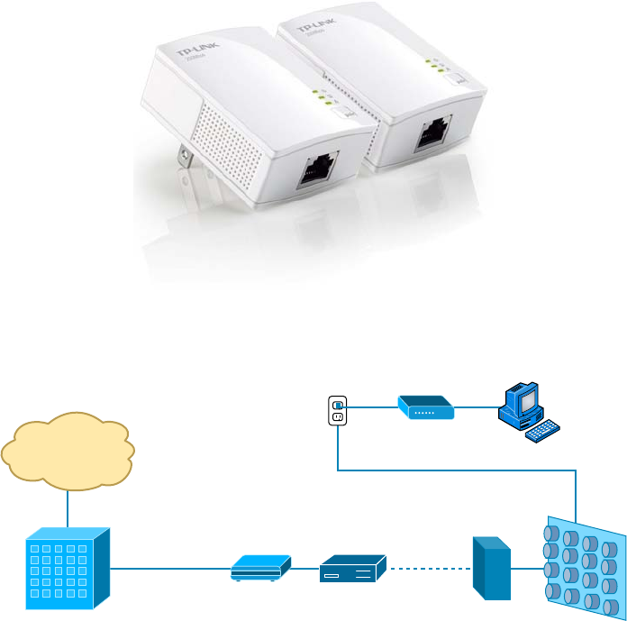
Ethernet over Other Standards (IEEE 1905.1-2013)
115
c04.indd 04/02/2015 Page 115
FIGURE 4.7 Powerline adapter sets
FIGURE 4.8 Basic BPL installation
Basic BPL Installation
Internet
Broadband
Service BPL
Gateway
Coaxial
Cable
BPL
Coupler Meter Bank
Existing Electrical Wiring
BPL Modem
ISP
Router
After the gateway is connected through the coupler to the meter bank for the building,
any electrical outlet can be used with the BPL modem to receive the ISP connection to the
Internet. Challenges that still exist include:
■ The fact that power lines are typically noisy.
■ The frequency at which the information is transmitted is used by shortwave and the
unshielded power lines can act as antennas, thereby interfering with shortwave com-
munications.
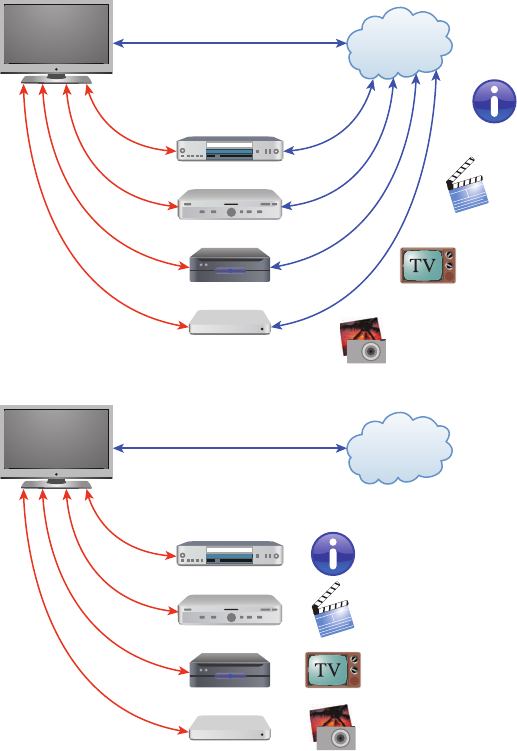
116
Chapter 4 ■ The Current Ethernet Specifications
c04.indd 04/02/2015 Page 116
Ethernet over HDMI
HDMI Ethernet Channel technology consolidates video, audio, and data streams into a
single HDMI cable, combining the signal quality of HDMI connectivity with the power
and exibility of home entertainment networking.
Figure 4.9 shows how a possible home entertainment network will look before and after
Ethernet over HDMI is implemented.
FIGURE 4.9 Ethernet over HDMI
Internet
HDMI
Before
HDMI Ethernet
Channel
With
HDMI Ethernet
Channel
HDMI
HDMI
HDMI
Internet
HDMI
HDMI
HDMI
HDMI
Written Lab
117
c04.indd 04/02/2015 Page 117
It incorporates a dedicated data channel into the HDMI link, enabling high-speed,
bi-directional networking at up to 100Mbps.
Armed with the basics covered in the chapter, you’re equipped to go to the next level and
put Ethernet to work using various network devices. But to ensure that you’re really ready,
read the summary, go over the exam essentials, and do the written lab and review questions
for this chapter!
Summary
In this chapter, you learned the fundamentals of Ethernet networking, how hosts communi-
cate on a network, and how CSMA/CD works in an Ethernet half-duplex network.
I also showed you the differences between half- and full-duplex modes.
I nished the chapter with a description of the common Ethernet cable types used in
today’s networks. And by the way, you’d be wise to study that section really well!
Exam Essentials
Understand basic Ethernet communication. Know how hosts use hardware addresses to
communicate on an Ethernet LAN.
Understand Ethernet addressing. Know the hexadecimal addressing scheme used to create
an Ethernet address.
Understand binary, decimal, and hexadecimal addressing. Know the different addressing
types, and also use the written lab to practice your conversions.
Written Lab
In this section, you will write in the answers to the following conversion tables. You can
nd the answers in Appendix A.
1. Convert from decimal IP address to binary format.
Complete the following table to express 192.168.10.15 in binary format.

118
Chapter 4 ■ The Current Ethernet Specifications
c04.indd 04/02/2015 Page 118
128 64 32 16 8421Binary
Complete the following table to express 172.16.20.55 in binary format.
128 64 32 16 8421Binary

Written Lab
119
c04.indd 04/02/2015 Page 119
Complete the following table to express 10.11.12.99 in binary format.
128 64 32 16 8421Binary
2. Convert the following from binary format to decimal IP address.
Complete the following table to express 11001100.00110011.10101010.01010101 in
decimal IP address format.
128 64 32 16 8421Binary

120
Chapter 4 ■ The Current Ethernet Specifications
c04.indd 04/02/2015 Page 120
Complete the following table to express 11000110.11010011.00111001.11010001 in
decimal IP address format.
128 64 32 16 8421Binary
Complete the following table to express 10000100.11010010.10111000.10100110 in
decimal IP address format.
128 64 32 16 8421Binary

Written Lab
121
c04.indd 04/02/2015 Page 121
3. Convert the following from binary format to hexadecimal.
Complete the following table to express 11011000.00011011.00111101.01110110 in
hexadecimal.
128 64 32 16 8 4 2 1 Hexadecimal
Complete the following table to express 11001010.11110101.10000011.11101011 in
hexadecimal.
128 64 32 16 8421Hexadecimal

122
Chapter 4 ■ The Current Ethernet Specifications
c04.indd 04/02/2015 Page 122
Complete the following table to express 10000100.11010010.01000011.10110011 in
hexadecimal.
128 64 32 16 8421Hexadecimal
Review Questions
123
c04.indd 04/02/2015 Page 123
Review Questions
You can nd the answers to the review questions in Appendix B.
1. On an Ethernet switched network, what address does one host computer use to communi-
cate with another?
A. IP address
B. MAC address
C. Street address
D. HUB address
2. Which of the following can run full duplex and achieve 200Mbps with Cat 5e cable?
A. 100BaseF
B. 100BaseTX
C. 1000BaseF
D. 1000BaseT
3. How many devices in a collision domain have to listen when a single host talks?
A. 2
B. 3
C. 1
D. All
4. If you are using a cable medium called 10Base2, what does this mean?
A. That you are running Ethernet over HDMI
B. That you are running Ethernet over fiber
C. That you are running Ethernet over thicknet
D. That you are bundling multiple connections
E. That you are really old and using thinnet coax for your LAN medium
5. What network access control method helps devices share the bandwidth evenly without
having two devices transmit at the same time on the network medium?
A. TCP/IP
B. CSMA/CD
C. HTTPS
D. TFTP
6. What is the maximum distance of 10GBaseSR?
A. 100 meters (328 feet)
B. 302 meters (990 feet)
C. 305 meters (1000 feet)
D. 1,593 km (6 miles)
124
Chapter 4 ■ The Current Ethernet Specifications
c04.indd 04/02/2015 Page 124
7. How many wire pairs are used with half duplex?
A. 2
B. 1
C. 4
D. None of the above
8. How many wire pairs are used with 100BaseT full duplex?
A. 2
B. 1
C. 4
D. A or C
9. What is the maximum distance of 10GBaseLR?
A. 1 mile
B. 3 miles
C. 6 miles
D. 25 miles
10. What is the effective total throughput increase with a full-duplex connection?
A. None
B. Twice as much
C. Four times as much
D. Ten times as much
11. What device can you not use full-duplex communication with?
A. Host
B. Hub
C. Switch
D. Router
12. What is the decimal equivalent of this binary number: 11000000.10101000.00110000.1111
0000?
A. 192.168.48.192
B. 192.168.48.240
C. 192.168.64.224
D. 192.168.32.248
13. Which IEEE standard is used for Ethernet over Power Lines?
A. 802.3p
B. 1901
C. 802.16
D. 1918
Review Questions
125
c04.indd 04/02/2015 Page 125
14. How is the decimal value 10 represented in binary?
A. 1000
B. 1001
C. 1010
D. 1011
15. What is the decimal value for the binary number 11101000?
A. 128
B. 194
C. 224
D. 232
16. What is the decimal number 10 in hexadecimal?
A. 9
B. A
C. C
D. B
17. How many bits is a MAC address?
A. 16
B. 32
C. 48
D. 64
18. What is the maximum distance of 1000BaseT?
A. 100 meters (328 feet)
B. 128 meters (420 feet)
C. 1000 meters (3280 feet)
D. 1,024 meters (3360 feet)
19. What is the purpose of the Frame Check Sequence (FCS) in an Ethernet frame?
A. Error correction
B. Error detection
C. Error recovery
D. Creating errors
20. What does the Base mean in 100BaseTX?
A. Broadband
B. 100Mbps
C. Baseband
D. Twisted-pair at 100Mbps

c05.indd 03/23/2015 Page 127
Chapter
5
Networking Devices
THE FOLLOWING COMPTIA NETWORK+
EXAM OBJECTIVES ARE COVERED IN THIS
CHAPTER:
✓ 1.1 Explain the functions and applications of various
network devices
■ Router
■ Switch
■ Multilayer switch
■ Firewall
■ HIDS
■ IDS/IPS
■ Access point (wireless/wired)
■ Content filter
■ Load balancer
■ Hub
■ Analog modem
■ Packet shaper
■ VPN concentrator
✓ 1.3 Install and configure the following networking
services/applications
■ DHCP
■ Static vs dynamic IP addressing
■ Reservations
■ Scopes
■ Leases
■ Options (DNS servers, suffixes)
■ IP helper/DHCP relay

c05.indd 03/23/2015 Page 128
■ DNS
■ DNS servers
■ DNS records (A, MX, AAAA, CNAME, PTR)
■ Dynamic DNS
■ Proxy/reverse proxy
✓ 1.12 Given a set of requirements, implement a basic
network
■ List of requirements
■ Device types/requirements
■ Environment limitations
■ Equipment limitations
■ Compatibility requirements
■ Wired/wireless considerations
■ Security considerations

c05.indd 03/23/2015 Page 129
In this chapter, I’ll tell you all about the networking devices
I’ve introduced so far. I’ll go into much greater detail about
each device, and yes—I’m going to present even more of them
to you! Because all the components that you’ll learn about shortly are typically found in
today’s networks and internetworks, it’s very important that you be familiar with them.
We’ll start by covering the more common network devices that you would be most likely
to come across and then move on to discuss some of the more specialized devices that you
may or may not always nd running in a network.
I’ll nish the chapter by using examples to discuss how routers, hubs, and switches work
within internetworks today.
To find up-to-the-minute updates for this chapter, please see
www.lammle.
com/networkplus
or the book’s website at
www.sybextestbanks.wiley.com
.
Common Network Connectivity Devices
By now, you should be fairly savvy regarding the various types of network media and
connections, so it’s time to learn about some of the devices they hook up to that are
commonly found on today’s networks.
First, I’ll de ne the basic terms; then, later in this chapter, I’ll show you how these
devices actually work within a network. At that time, I’ll give you more detailed
descriptions of these devices and the terminology associated with them.
Because these devices connect network entities, they’re known as connectivity devices.
Here’s a list of the devices I’ll be covering in this chapter:
■ Network interface card (NIC)
■ Hub
■ Bridge
■ Basic switch
■ Basic router
■ Basic firewall
■ IDS/IPS/HIDS
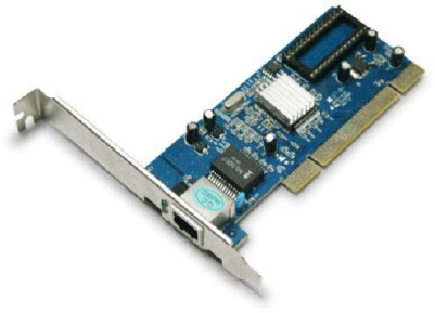
130
Chapter 5 ■ Networking Devices
c05.indd 03/23/2015 Page 130
■ Access point
■ Dynamic Host Configuration Protocol (DHCP) server
■ Other specialized devices
Network Interface Card
Those of you who aren’t familiar with NICs probably want to be, at this point, so here
goes: a network interface card (NIC) is installed in your computer to connect, or interface,
your computer to the network. It provides the physical, electrical, and electronic connec-
tions to the network media.
A NIC either is an expansion card or is built right into the computer’s motherboard.
Today, almost all NICs are built into the computer motherboard providing 10, 100, and
1000 Mbits/sec, but there was a time when all NICs were expansion cards that plugged
into motherboard expansion slots. In some notebook computers, NIC adapters can be
connected to the USB port or through a PC card slot.
Figure 5.1 shows a typical 100Mbps Ethernet NIC.
FIGURE 5.1 Network interface card
Nowadays, most PCs and laptops of all types come with an Ethernet and Wireless
connector built into the motherboard, so you usually don’t need a separate card. It’s rare
to nd a laptop today without a built-in wireless network card, but you can buy external
wireless cards for desktops and laptops if you’ve got legacy equipment that needs them.
NICs today usually have one, two, or more LEDs; one, usually green, is called a link-light
indicating that an Ethernet connection has been established with the device on the other
end of the cable, and, which ickers when traf c is being passed back or forth. The other,
or others, usually indicate the speed of the connection: 10, 100, or 1000 Mbit/sec. There’s
no universal standard for NIC LEDs, so check the manual to familiarize yourself with what
the ones you are working with indicate. But it’s not always that cut and dry—that blinking
LED can mean the NIC is receiving a proper signal from the hub or switch, but it can also
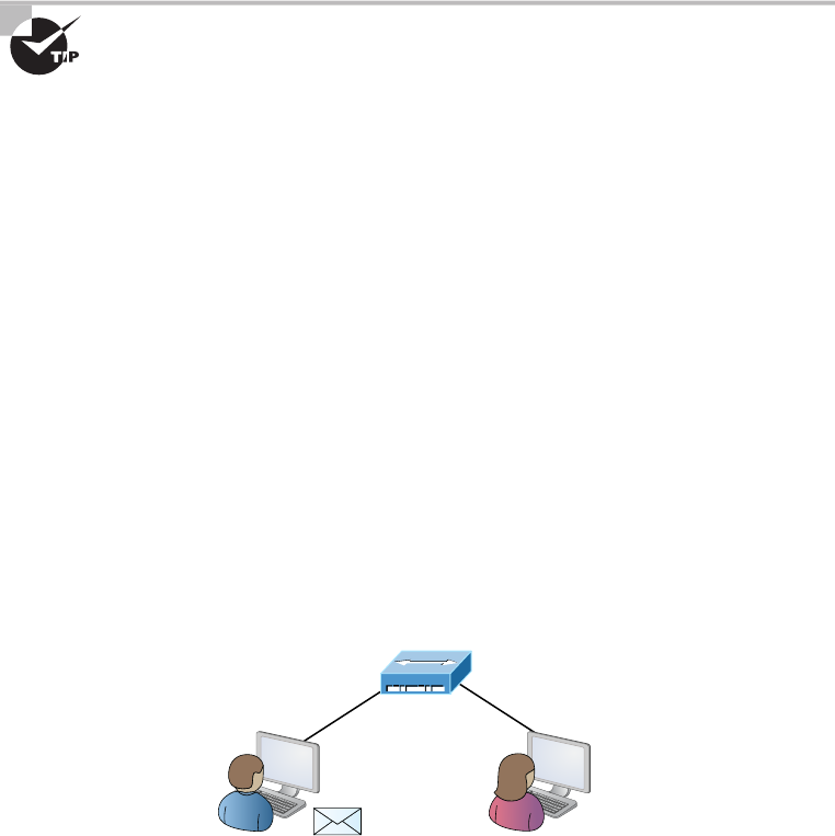
Common Network Connectivity Devices
131
c05.indd 03/23/2015 Page 131
indicate connectivity to and detection of a carrier on a segment. Another possibility is that
it’s found connectivity with a router or other end device using a crossover cable.
The other LED is the aptly named Activity LED, and it tends to icker constantly. That
activity indicates the intermittent transmission and reception of frames arriving at the
network or leaving it.
The first LED you should verify is the Link LED because if it’s not
illuminated, the Activity LED simply cannot illuminate.
Hub
As you learned earlier, a hub is the device that connects all the segments of the network
together in a star topology Ethernet network. Each device in the network connects directly
to the hub through a single cable and is used to connect multiple devices without segmenting
a network. Any transmission received on one port will be sent out all the other ports in the
hub, including the receiving pair for the transmitting device, so that Carrier Sense Multiple
Access with Collision Detection (CSMA/CD) on the transmitter can monitor for collisions.
So, basically, this means that if one station sends a broadcast, all the others will receive
it; yet based on the addressing found in the frame, only the intended recipient will actu-
ally listen and process it. This arrangement simulates the physical bus that the CSMA/CD
standard was based on, and it’s why we call the use of a hub in an Ethernet environment a
physical star/logical bus topology.
Figure 5.2 depicts a typical hub as you might nd it employed within a small network.
Since there are only two users there isn’t a problem in using a hub here: however, if there
were 20 users, everyone would see Bob’s request to send a packet to Mary. Most of the
time, hubs really aren’t recommended for corporate networks because of their limitations.
FIGURE 5.2 A typical hub
Hub
SallyBob HEY SALLY?
It’s important to note that hubs are nothing more than glori ed repeaters that are
incapable of recognizing frames and data structures—the reason they act with such a lack
of intelligence. A broadcast sent out by any device on the hub will be propagated to all
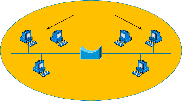
132
Chapter 5 ■ Networking Devices
c05.indd 03/23/2015 Page 132
devices connected to it. And just as in a physical bus topology con guration, any two or
more of those connected devices have the potential of causing a collision with each other,
which means that this hardware device will create a LAN with the most network traf c
collisions. Hubs are not suggested for use in today’s corporate network for this reason.
Bridge
A bridge—speci cally, a transparent bridge—is a network device that connects two similar
network segments together. Its primary function is to keep traf c separated on either side
of the bridge, breaking up collision domains, as pictured in Figure 5.3.
FIGURE 5.3 Bridges break up collision domains
Collision Domains
Bridge
One Broadcast Domain
What we can see here is that traf c is allowed to pass through the bridge only if the
transmission is intended for a station on the opposite side. The main reasons you would
place a bridge in your network would be to connect two segments together or to divide a
busy network into two segments.
Bridges are software based; so, interestingly, you can think of a switch as a hardware-
based, multiport bridge. In fact, the terms bridge and switch are often used interchangeably
because the two devices used basically the same bridging technologies. The past tense is
there for a reason—you’d be hard-pressed to buy a bridge today.
Switch
Switches connect multiple segments of a network together much like hubs do, but with
three signi cant differences—a switch recognizes frames and pays attention to the source
and destination MAC address of the incoming frame as well as the port on which it was
received. A switch makes each of its ports a unique, singular collision domain. Hubs don’t
do those things. They simply send anything they receive on one port out to all the others.
Common Network Connectivity Devices
133
c05.indd 03/23/2015 Page 133
So, if a switch determines that a frame’s nal destination happens to be on a segment
that’s connected via a different port than the one on which the frame was received, the
switch will only forward the frame out from the speci c port on which its destination is
located. If the switch can’t gure out the location of the frame’s destination, it will ood
the frame out every port except the one on which the frame port was received.
Figure 5.4 shows a typical low-cost Ethernet switch. It looks a lot like a hub. However,
switches can come in very large, expensive sizes. Switches that can perform the basic
switching process and do not allow you to con gure more advanced features—like add-
ing an IP address for telnetting to the device or adding VLANs—are called unmanaged
switches. Others, like Cisco switches that do allow an IP address to be con gured for
management with such applications as SNMP and do allow special ports to be con gured
(as in VoIP), are called managed switches.
FIGURE 5.4 Typical Ethernet switch
That’s as far as we’re going with switches right now. I’ll bring them up later on in this
chapter and cover them in much greater detail in Chapter 11, “Switching and Virtual
LANs.” For now, you can think of a switch as a faster, smarter bridge that has more ports.
Switches are Layer 2 devices, which means they segment the network
with MAC addresses. If you see the term Layer 3 switch that means you are
talking about a router, not a Layer 2 switch. The terms router and Layer 3
switch are interchangeable.
Router
A router is a network device used to connect many, sometimes disparate, network segments
together, combining them into what we call an internetwork. A well-con gured router
can make intelligent decisions about the best way to get network data to its destination. It
gathers the information it needs to make these decisions based on a network’s particular
performance data.
Figure 5.5 shows a small of ce, home of ce (SOHO) router that provides wired and
wireless access for hosts and connects them to the Internet without any necessary con-
guration. But know that I certainly don’t recommend leaving a router with the default
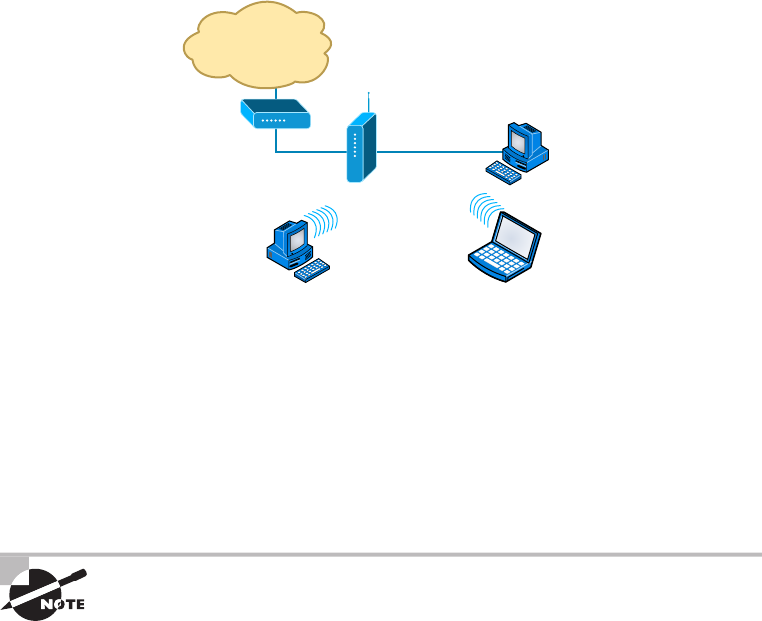
134
Chapter 5 ■ Networking Devices
c05.indd 03/23/2015 Page 134
con guration! No worries, though—I’ll go over the con guration process with you in
Chapter 10, “Routing Protocols.”
FIGURE 5.5 Router connected to the Internet, providing access for hosts
Internet
Wireless
Router
Computer
Equipped with
Network Adaptor
DSL/Cable
Modem
Computer
Equipped with
Wireless Adaptor
Notebook
Equipped with
Wireless Adaptor
Routers can be multifaceted devices that behave like computers unto themselves with
their own complex operating systems—for example, Cisco’s IOS. You can even think of
them as CPUs that are totally dedicated to the process of routing packets. And due to
their complexity and exibility, you can con gure them to actually perform the functions
of other types of network devices (like rewalls, for example) by simply implementing a
speci c feature within the router’s software.
Routers can have many different names: Layer 3 switch and multilayer
switch are the most common, besides the name router, of course. Remem-
ber, if you hear just the word switch, that means a Layer 2 device. Routers,
Layer 3 switches, and multilayer switches are all Layer 3 devices.
Interface Configurations
When con guring interfaces on a router or switch, unless you’re doing complex con gura-
tions such as connecting up a Voice over IP (VoIP) network, the interface con gurations are
pretty straightforward.
There is a major difference between a router interface and a switch interface con gura-
tion, however. On a switch, you do not add an IP address since they only read to Layer 2,
and most of the time, you never even need to con gure a switch interface. First, they are
enabled by default, and second, they are very good at auto-detecting the speed, duplex, and
in newer switches, even the Ethernet cable type (crossover or straight-through). A router is
Common Network Connectivity Devices
135
c05.indd 03/23/2015 Page 135
much different and an IP address is expected on each interface; they are not enabled
by default, and a good Layer 3 network design must be considered before installing
a router.
Let’s start by taking a look at a basic Cisco switch con guration. First, notice by the
output shown that there is no con guration on the interfaces, yet you can plug this switch
into your network and it would work. This is because all ports are enabled and there are
some very basic con gurations that allow the switch to run without any con guration—
they can be considered plug-and-play in a small or home network:
Switch#sh running-config
[output cut]
!
interface FastEthernet0/1
!
interface FastEthernet0/2
!
interface FastEthernet0/3
!
interface FastEthernet0/4
!
interface FastEthernet0/5
!
interface FastEthernet0/6
!
interface FastEthernet0/7
!
interface FastEthernet0/8
!
Let’s take a look at a con guration of a simple switch interface. First, we’ll notice the
duplex options:
Switch(config-if)#duplex ?
auto Enable AUTO duplex configuration
full Force full duplex operation
half Force half-duplex operation
All switch ports are set to duplex auto by default, and usually you can just leave this
con guration alone. However, be aware that if your network interface card is set to half
duplex and the switch port is con gured for full duplex, the port will receive errors and
you’ll eventually get a call from the user. This is why it is advised to just leave the defaults
on your hosts and switch ports, but it is a troubleshooting spot to check when a problem is
reported from a single user.
136
Chapter 5 ■ Networking Devices
c05.indd 03/23/2015 Page 136
The next con guration and/or troubleshooting spot you may need to consider is the
speed of the port:
Switch(config-if)#speed ?
10 Force 10 Mbps operation
100 Force 100 Mbps operation
auto Enable AUTO speed configuration
Again, this is set to auto, but you may want to force the port to be 100 and full duplex.
Typically, the NIC will run this without a problem and you’ll be sure you’re getting the
most bang for your buck on your switch port.
Let’s take a look at a router interface. We’re pretty much going to con gure (or not
con gure) the same parameters. However, you should be very aware that a router interface
and a switch interface perform different functions. A router interface will break up colli-
sion domains just as a switch interface does, but the purpose of a router interface is to create
and maintain broadcast domains and connectivity of WAN services. Basic Layer 2 switches
cannot provide these services. As I mentioned, you must have a Layer 3 design before you
can implement a router, meaning you must have your subnet design laid out on your network
diagram and your IP addressing scheme must be completely understood. You cannot start
con guring router interfaces randomly; there must be a design and it needs to be correct.
Unlike switches, router interfaces do not just work when you plug them into the net-
work—they must be con gured and enabled. All ports are shut down by default, and why
shouldn’t they be? Unless you have a network design and understand IP addressing, what
good is a router to your network?
Let’s take a look:
Router(config-if)#duplex ?
auto Enable AUTO duplex configuration
full Force full duplex operation
half Force half-duplex operation
Router(config-if)#speed ?
10 Force 10 Mbps operation
100 Force 100 Mbps operation
auto Enable AUTO speed configuration
Router(config-if)#ip address ?
A.B.C.D IP address
dhcp IP Address negotiated via DHCP
pool IP Address autoconfigured from a local DHCP pool
First, we can see that the basics are there, duplex and speed, but also, to make a router
interface useful at all we must add an IP address. Notice that the options allow you to
con gure a speci c IP address or allow the interface to receive the address from a
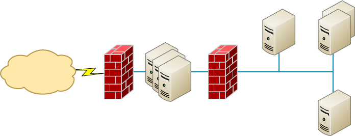
Common Network Connectivity Devices
137
c05.indd 03/23/2015 Page 137
DHCP server. You would only use this option if you had an IP address reservation for the
router interface on your DHCP server since having your router get a random IP address
from a DHCP server would be hard to manage. Let’s nish the basics:
Router(config-if)#ip address 1.1.1.1 255.0.0.0
Router(config-if)#no shutdown
Router(config-if)#
*Oct 5 17:26:46.522: %LINK-3-UPDOWN: Interface FastEthernet0/0,
changed state to up
*Oct 5 17:26:47.522: %LINEPROTO-5-UPDOWN: Line protocol on
Interface FastEthernet0/0, changed state to up
The interface can now be connected to a Layer 2 switch and the hosts connected to the
same broadcast domain must set their default gateway address to 1.1.1.1, and voilà, they
can now send packets to the router.
Firewall
So what, exactly, is a rewall? Basically, rewalls are your network’s security guards, and
to be real, they’re probably the most important thing to implement on your network. That’s
because today’s networks are almost always connected to the Internet—a situation that makes
security crucial! A rewall protects your LAN resources from invaders that prowl the Internet
for unprotected networks while simultaneously preventing all or some of your LAN’s comput-
ers from accessing certain services on the Internet. You can employ them to lter packets based
on rules that you or the network administrator create and con gure to strictly delimit the type
of information allowed to ow in and out of the network’s Internet connection.
A rewall can be either a stand-alone “black box” or a software implementation placed
on a server or router. Either way, the rewall will have at least two network connections:
one to the Internet (known as the public side) and one to the network (known as the private
side). Sometimes, there is a second rewall, as shown in Figure 5.6. This rewall is used to
connect servers and equipment that can be considered both public and private (like web and
email servers). This intermediary network is known as a demilitarized zone (DMZ).
FIGURE 5.6 Example of firewalls with a DMZ
Internet
Firewall DMZ Firewall
Internal Network

138
Chapter 5 ■ Networking Devices
c05.indd 03/23/2015 Page 138
Firewalls are the rst line of defense for an Internet-connected network. Without
them in place, any network that’s connected to the Internet is essentially wide open to
anyone with a little technical savvy who seeks to exploit LAN resources and/or access
your network’s sensitive information.
IDS/IPS
Intrusion detection systems (IDSs) and intrusion prevention systems (IPSs) are very
important in today’s networks. They are network security appliances that monitor
networks and packets for malicious activity. An IDS is considered monitor mode and
just records and tells you about problems, whereas an IPS can work in real time to stop
threats as they occur.
The main difference between them is that an IPS works inline to actively prevent
and block intrusions that are detected based on the rules you set up. IPSs can send an
alarm, create correlation rules and remediation, drop malicious packets, provide malware
protection, and reset the connection of offending source hosts.
HIDS
In a host-based IDS (HIDS), software runs on one computer to detect abnormalities on
that system alone by monitoring applications, system logs, and event logs—not by directly
monitoring network traf c.
Systems like these are typically implemented on servers because they’re a bear to manage
if spread across several client computers on a network. Plus, if the IDS database is on the
local computer and its data becomes compromised by an attack, the IDS data could be
corrupted, too.
Other types of IDSs are protocol based (PIDS), which monitor traffic for
one protocol on one server, and application protocol based (APIDS),
which monitor traffic for a group of servers running the same application
(such as SQL).
Access Point
I’ll be covering access points (APs) in depth in Chapter 12, but I’ll introduce them here.
Understand that an AP is just a hub that accepts wireless clients via an analog wireless
signal.
It’s no secret that wireless is the key to all networks in the world today, and they will
be even more prevalent in the future when all our home appliances have IP addresses and
communicate wirelessly to our networks, for example. The ease of communicating on a
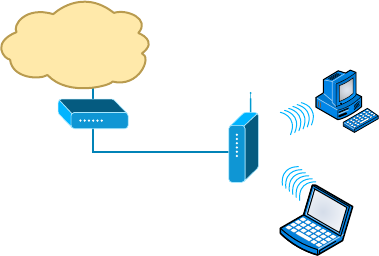
Common Network Connectivity Devices
139
c05.indd 03/23/2015 Page 139
network using an AP instead of having to use an Ethernet cable has changed our
world forever.
Figure 5.7 shows how an AP would look in a small network, such as a home.
FIGURE 5.7 Example of an AP in a network
Internet
Wireless
Router
DSL/Cable
Modem
The wireless client modulates a digital signal to an analog signal, which the AP can
read and demodulate back to a digital signal. The AP creates one collision domain and
can only run half duplex, which is why you can describe an AP as being like a hub.
However, even though there are some standards that provide some full-duplex-type
connectivity, a wireless host will never achieve the same type of throughput, security,
and consistency that a wired Ethernet network would, but does that matter? Like rock ’n’
roll, wireless is here to stay.
Dynamic Host Configuration Protocol Server
Even though I’m going to get into the ner points of DHCP soon, in Chapter 6,
“Introduction to the Internet Protocol,” I want to give you some basic insight into this
server service here.
In essence, DHCP servers assign IP addresses to hosts. This protocol gives us
a much easier way to administer—by automatically providing IP information—than
the alternative and tedious method known as static IP addressing, where we have to
address each host manually. It works well in any network environment, from tiny
to huge, and allows all types of hardware to be employed as a DHCP server,
including routers.
It works like this: A DHCP server receives a request for IP information from a DHCP
client using a broadcast (as Chapter 6 will show you in detail). The only hitch is that if
the DHCP server isn’t on the same segment as the DHCP client, the broadcast won’t be
received by the server because by default, routers won’t forward broadcasts, as shown
in Figure 5.8.
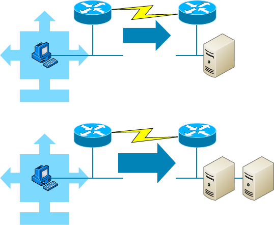
140
Chapter 5 ■ Networking Devices
c05.indd 03/23/2015 Page 140
FIGURE 5.8 DHCP client sends broadcasts looking for a DHCP server
Client
Server
Single-Server Example
Broadcast
A
E0
E0
B
Unicast
Client
Server Server
Multiple-Server Example
Broadcast
AB
Directed
Broadcast
In Figure 5.8, Router A is con gured with the IP helper address command on interface
E0 of the router. Whenever interface E0 receives a broadcast request, Router A will forward
those requests as a unicast (meaning instead of a broadcast, the packet now has the
destination IP address of the DHCP server).
So, as shown in the gure, you can con gure Router A to forward these requests and
even use multiple DHCP servers for redundancy, if needed. This works because the router
has been con gured to forward the request to a single server using a unicast or by sending
the request to multiple servers via a directed broadcast.
Personally, most of the time I use a Windows server to act as the DHCP server for my
entire internetwork and have my routers forward client requests. It is possible to have a
DHCP server on every network segment, but that is not necessary because of the routers’
forwarding ability.
Figure 5.9 shows a picture of a Windows server with something called scope options.
Scope Options provide IP con guration for hosts on a speci c subnet. Below the Scope
Options, you’ll nd Server Options, which provide IP information for all scopes con gured
on the server. If I had just one Domain Name Service (DNS) server for the entire network,
I’d con gure the Server Options with my DNS server information; that DNS server
information would then show up automatically in all scopes con gured on my server.
So, what exactly does a DHCP client ask for, and what does a DHCP server provide? Is
it just an IP address, a mask, and a default gateway? No, it is much more than that. Let’s
take a look at a DHCP client request on an analyzer. Figure 5.10 shows the options that the
client is requesting from the DHCP server.
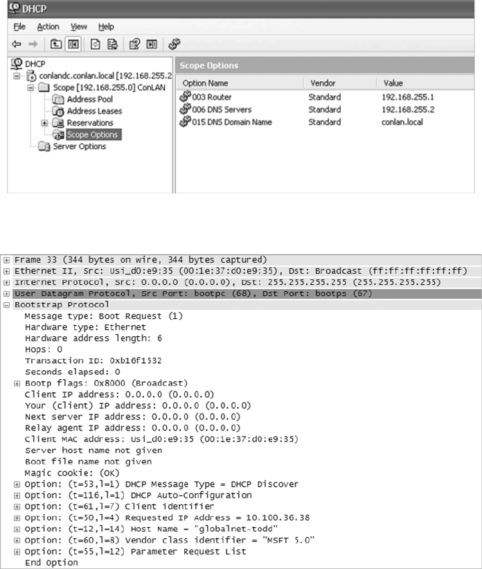
Common Network Connectivity Devices
141
c05.indd 03/23/2015 Page 141
FIGURE 5.9 A Windows DHCP server’s Scope Options
FIGURE 5.10 DHCP client request to a DHCP server
First, you can see that the DHCP service runs on top of the BootP protocol (port 68)
and that the DHCP client is looking for a BootP server (port 67). The client IP address
is 0.0.0.0, and the client doesn’t know the DHCP server address either because this is a
broadcast to 255.255.255.255 (the Data Link layer broadcast shows FF:FF:FF:FF:FF:FF).
Basically, all the DHCP client knows for sure is its own MAC address. The client is
“requesting” a certain IP address because this is the IP address it received from the server
the last time it requested an IP address.
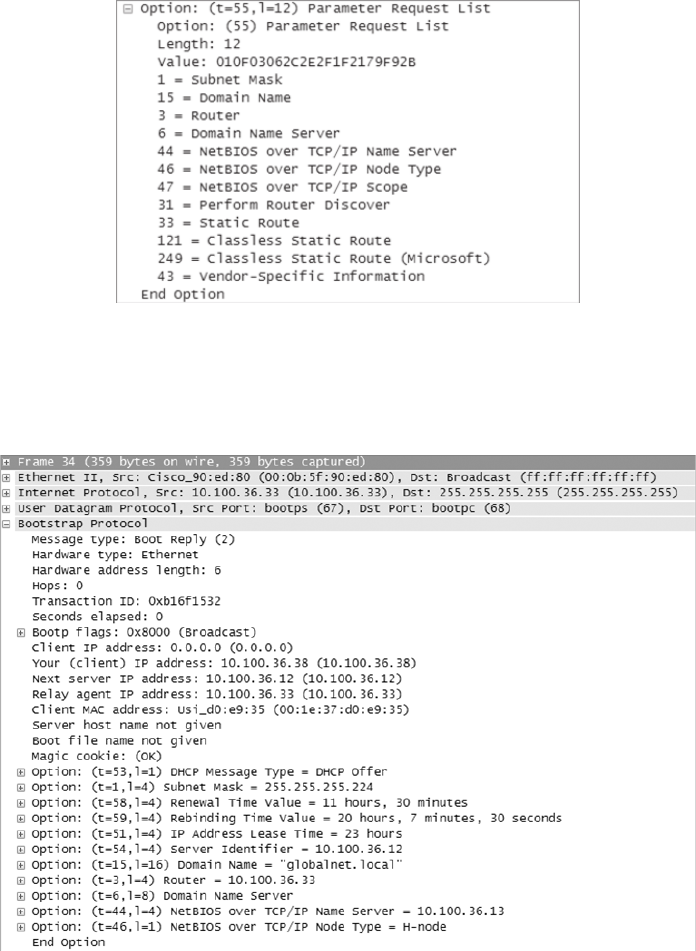
142
Chapter 5 ■ Networking Devices
c05.indd 03/23/2015 Page 142
The DHCP client Parameter Request List option shown at the end of Figure 5.10 has
been expanded and is shown in Figure 5.11. Notice all the parameter information that can
be sent to a DHCP client from the server.
FIGURE 5.11 DHCP client parameter request list
That is quite a request list! The DHCP server will respond with the options that it has
con gured and available to provide to a DHCP client. Let’s take a look and see what the
server responds with. Figure 5.12 shows the DHCP server response.
FIGURE 5.12 DHCP server response
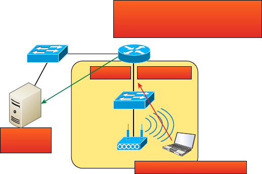
Common Network Connectivity Devices
143
c05.indd 03/23/2015 Page 143
The client is going to get the IP address that it asked for (10.100.36.38), a subnet mask
of 255.255.255.224, a lease time of 23 hours (the amount of time before the IP address
and other DHCP information expires on the client), the IP address of the DHCP server, the
default gateway (router), the DNS server IP address (it gets two), the domain name used by
DNS, and some NetBIOS information (used by Windows for name resolution).
The lease time is important and can even be used to tell you if you have a DHCP prob-
lem or, more speci cally, that the DHCP server is no longer handing out IP addresses to
hosts. If hosts start failing to get onto the network one at a time as they try to get a new IP
address as their lease time expires, you need to check your server settings.
Here is another example of a possible DHCP problem: You arrive at work after a week-
end and nd that some hosts were left on and some were shut down. The hosts that were
left running and not shut down are still working, but the hosts that were shut down and
were restarted on Monday morning do not get a new IP address. This is a good indication
that you need to head over to your DHCP server and take a look at what is going on.
A DHCP server can also be con gured with a reservation list so that a host always
receives the same IP address. You would use this reservation list for routers or servers if
they were not statically assigned. However, you can use reservation lists for any host on
your network as well.
DHCP Relay
If you need to provide addresses from a DHCP server to hosts that aren’t on the same
LAN as the DHCP server, you can con gure your router interface to relay or forward
the DHCP client requests, as shown in Figure 5.13. If we don’t provide this service,
our router would receive the DHCP client broadcast, promptly discard it, and the
remote host would never receive an address—unless we added a DHCP server on every
broadcast domain! Let’s take a look at how we would typically con gure DHCP service
in today’s networks.
FIGURE 5.13 Configuring a DHCP relay
I hear the port 67 request on int fa0/0!
I’ll forward this broadcast as a unicast to
10.10.10.254 ASAP!
DHCP Server
10.10.10.254
Int F0/0
DHCP Client broadcast request
192.168.10.1
Sales
Admin
144
Chapter 5 ■ Networking Devices
c05.indd 03/23/2015 Page 144
So we know that because the hosts off the router don’t have access to a DHCP server,
the router will simply drop their client request broadcast messages by default. To solve
this problem, we can con gure the F0/0 interface of the router to accept the DHCP client
requests and forward them to the DHCP server like this:
Router#config t
Router(config)#interface fa0/0
Router(config-if)#ip helper-address 10.10.10.254
Now I know that was a pretty simple example, and there are de nitely other ways to
con gure the relay, but rest assured that I’ve covered the objectives for you. Also, I want
you to know that
ip helper-address
forwards more than just DHCP client requests, so be
sure to research this command before you implement it!
Other Specialized Devices
In addition to the network connectivity devices I’ve discussed with you, there are several
devices that, while they may not be directly connected to a network, do actively participate
in moving network data. Here’s a list of them:
■ Multilayer switch
■ Load balancer
■ DNS server
■ Proxy server
■ Encryption devices
■ Content filter
■ Analog modem
■ Packet shaper
■ VPN concentrator
Multilayer Switch
A multilayer switch (MLS) is a computer networking device that switches on Open Systems
Interconnection (OSI) Layer 2 like an ordinary network switch but provides routing. A
24-port MLS gives you the best of both worlds. It operates at Layer 3 (routing) while still
providing 24 collision domains, which a router could not do.
The major difference between the packet-switching operation of a router and that of
a Layer 3 or multilayer switch lies in the physical implementation. In routers, packet
switching takes place using a microprocessor, whereas a Layer 3 switch handles this by
using application-speci c integrated circuit (ASIC) hardware. I’d show you a picture of a
Other Specialized Devices
145
c05.indd 03/23/2015 Page 145
Layer 3 switch, but they look just like regular Layer 2 switches and you already know what
those look like. The differences are the hardware inside and the operating system.
Load Balancer
Your average router just sends incoming packets to their speci ed, correlative IP address on
the network, but a load balancer can actually send incoming packets to multiple machines
hidden behind one IP address—cool, right?
Today’s load-balancing routers follow various rules to determine speci cally how they
will route network traf c. Depending on your needs, you can set rules based on the least
load, fault tolerance, the fastest response times, or just dividing up (balancing) outbound
requests for smooth network operations.
In fact, the fault tolerance, or redundancy, as well as the scalability so vital to large
networking environments and e-commerce are some of the great bene ts we gain using
load balancers.
Think about this scenario: Say you have a website where people are placing orders for
the stuff you’ve got for sale. Obviously, the orders placed vary in size and the rate at which
they come in varies; you de nitely wouldn’t want your servers becoming so overloaded that
they hose up and crash your site, causing you to lose lots of money, now would you? That’s
where balancing the load of traf c between a group of servers comes to the rescue, because
even if one of them freezes, your customers will still be able to access your site and
place orders.
Domain Name Service Server
A Domain Name Service (DNS) server is one of the most important servers in your
network and on the Internet as well. Why? Because without a DNS server, you would have
to type
http://206.123.114.186
instead of simply entering
www.lammle.com
. So it follows
that you can pretty much think of the DNS system as the phone book of the Internet.
A hostname is typically the name of a device that has a speci c IP address; on the
Internet, it is part of what is known as a fully quali ed domain name (FQDN). An FQDN
consists of a hostname and a domain name.
The process of nding the IP address for any given hostname is known as name
resolution, and it can be performed in several ways: a HOSTS le (meaning you statically
type in all names and IP addresses on each and every host), a request broadcast on the
local network (Microsoft’s favorite—why ask a server when you can just broadcast,
right?), DNS, and Microsoft’s Windows Internet Naming Service (WINS). DNS is the
most popular today and is the resolution method you really need to know.
On the Internet, domains are arranged in a hierarchical tree structure. The following list
includes some of the top-level domains currently in use:
.com A commercial organization. Most companies end up as part of this domain.
.edu An educational establishment, such as a university.
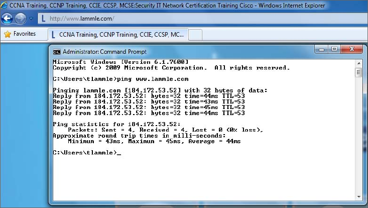
146
Chapter 5 ■ Networking Devices
c05.indd 03/23/2015 Page 146
.gov A branch of the US government.
.in t An international organization, such as NATO or the United Nations.
.mil A branch of the US military.
.net A network organization.
.org A nonpro t organization.
Your local ISP is probably a member of the
.net
domain, and your company is prob-
ably part of the
.com
domain. The
.gov
and
.mil
domains are reserved strictly for use by
the government and the military within the United States. In other parts of the world, the
nal part of a domain name represents the country in which the server is located (
.ca
for
Canada,
.jp
for Japan,
.uk
for Great Britain, and
.ru
for Russia, for example). Well over
130 countries are represented on the Internet.
The
.com
domain is by far the largest, followed by the
.edu
domain. Some new domain
names are becoming popular, however, because of the increasing number of domain-name
requests. These include
.firm
for businesses and companies,
.store
for businesses selling
goods rather than services,
.arts
for cultural and entertainment organizations, and
.info
for informational services. The domains
.cc
,
.biz
,
.travel
, and
.post
are also in use on the
Internet.
Figure 5.14 shows how, when you type in a domain name, the DNS server resolves it,
allowing the host to send the HTTP packets to the server.
FIGURE 5.14 DNS resolution example
This DOS screen shows how the DNS server can resolve the human name to the IP address
of the
Lammle.com
server when I ping the server by the name instead of the IP address.
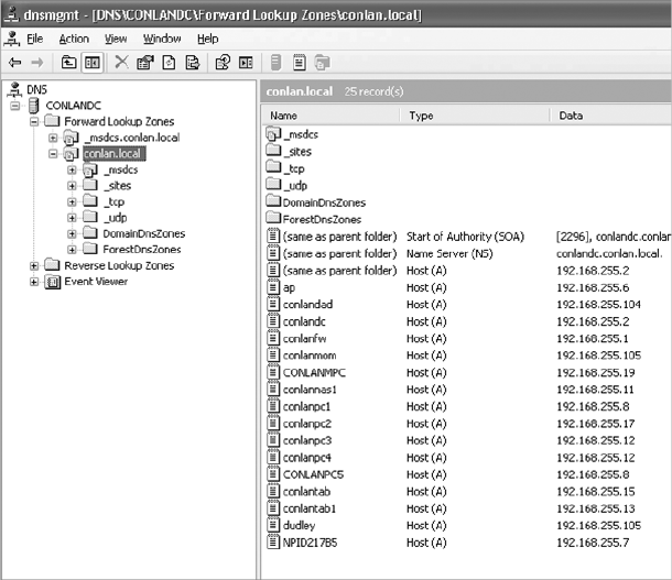
Other Specialized Devices
147
c05.indd 03/23/2015 Page 147
It should be easy to imagine how hard life would be without DNS translating human names
to IP addresses, routing your packet through the Internet or internetwork to get to your serv-
ers. Figure 5.15 gives you an example of a Windows server con gured as a DNS server.
To complete unquali ed Domain Name System (DNS) names that will be used to search
and submit DNS queries at the client for resolution, you must have a list of DNS suf xes that
can be appended to these DNS names. For DHCP clients, this can be set by assigning the DNS
domain name option (option 15) and providing a single DNS suf x for the client to append
and use in searches. For example, if you just wanted to
ping
todd
instead of
ping todd
.lammle.com
, you can con gure the DHCP server option 15 to provide the suf x for you.
FIGURE 5.15 A Windows DNS server
Now the hosts can receive the IP address of this DNS server, and then this server will
resolve hostnames to correct IP addresses. This is a mission-critical service in today’s
networks, don’t you think? As shown in Figure 5.15, if I ping from a host to
conlanpc1
,
the host will send the name-resolution request to the DNS server and translate this name
to IP address 192.168.255.8.
Host (A) is called an A record and is what gives you the IP address of a domain or host.
In IPv6, it’s called a quad-A or AAAA record. In Figure 5.15, you can see that each name
has an A record, which is associated to an IP address. So, A records resolve hostnames to IP
addresses, but what happens if you know the IP address and want to know the hostname?
There is a record for this, too! It’s called the pointer record (PTR).
148
Chapter 5 ■ Networking Devices
c05.indd 03/23/2015 Page 148
Other typical records found on DNS servers are mail exchanger (MX) records, which
are used to translate mail records. The MX record points to the mail exchanger for a par-
ticular host. DNS is structured so that you can actually specify several mail exchangers for
one host. This feature provides a higher probability that email will arrive at its intended
destination. The mail exchangers are listed in order in the record, with a priority code that
indicates the order in which they should be accessed by other mail-delivery systems.
If the rst-priority mail exchanger doesn’t respond in a given amount of time, the mail-
delivery system tries the second one, and so on. Here are some sample mail-exchange records:
hostname.company.com. IN MX 10 mail.company.com.
hostname.company.com. IN MX 20 mail2.company.com.
hostname.company.com. IN MX 30 mail3.company.com.
In this example, if the rst mail exchanger,
mail.company.com
, does not respond, the
second one,
mail2.company.com
, is tried, and so on.
Another important record type on a DNS is the canonical name (CNAME) record. This
is also commonly known as the alias record and allows hosts to have more than one name.
For example, suppose your web server has the hostname
www
and you want that machine
to also have the name
ftp
so that users can use FTP to access a different portion of the le
system as an FTP root. You can accomplish this with a CNAME record. Given that you
already have an address record established for the hostname
www
, a CNAME record that
adds
ftp
as a hostname would look something like this:
www.company.com. IN A 204.176.47.2
ftp.company.com. IN CNAME www.company.com.
When you put all these record types together in a zone le, or DNS table, it might look
like this:
mail.company.com. IN A 204.176.47.9
mail2.company.com. IN A 204.176.47.21
mail3.company.com. IN A 204.176.47.89
yourhost.company.com. IN MX 10 mail.company.com.
yourhost.company.com. IN MX 20 mail2.company.com.
yourhost.company.com. IN MX 30 mail3.company.com.
www.company.com. IN A 204.176.47.2
ftp.company.com. IN CNAME www.company.com.
Finally two other record types you should know about include AAA (for authentication
servers such as RADIUS or TACACS+) and PTR or pointer records. PTR records are an IP
address to name mapping rather than a name to IP address mapping. They reside in what
is called a reverse lookup zone (or table) in the server and are used when an IP address is
known but not a name.
Let’s take a look a tad deeper for a minute into how resolution takes place between a
host and a DNS server. Figure 5.16 shows a DNS query from my host to
www.lammle.com
from a browser.
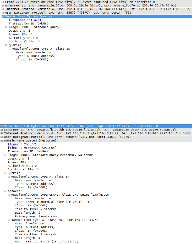
Other Specialized Devices
149
c05.indd 03/23/2015 Page 149
FIGURE 5.16 A DNS query to
www.lammle.com
This gure shows that DNS uses User Datagram Protocol (UDP) at the Transport layer
(it uses Transport Control Protocol [TCP] if it is updating its phone book pages—we call
these zone updates), and this query is asking destination port 53 (the DNS service) on host
192.168.133.2 who the heck
www.lammle.com
is.
Let’s take a look at the server’s response. Figure 5.17 shows the DNS answer to our
query for
www.lammle.com
.
FIGURE 5.17 The DNS answer to our query
Port 53 answered from server 192.168.133.147 with a CNAME and an A record with
the IP address of 184.172.53.52. My host can now go to that server requesting HTTP pages
using the IP address.
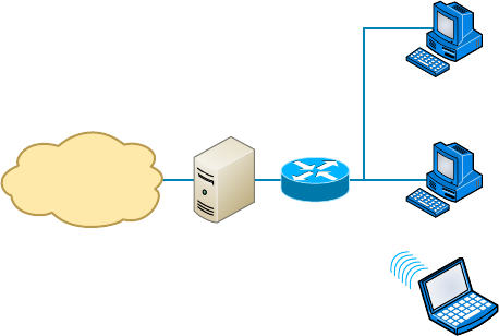
150
Chapter 5 ■ Networking Devices
c05.indd 03/23/2015 Page 150
Dynamic DNS
At one time all DNS records had to be manually entered into the DNS server and edited
manually when changes occurred. Today DNS is dynamic and works in concert with the
DHCP function. Hosts register their names with the DNS sever as they receive their IP
address con guration from the DHCP server. Some older operating systems are not capable
of self-registration (such as Windows NT), but the DHCP server can even be con gured to
perform registration on behalf of these clients with the DNS server.
This doesn’t mean that manual records cannot be created if desired. In fact, some of
the record types we have discussed can only be created manually. These include MX and
CNAME records.
Proxy Server
A proxy server is basically a type of server that handles its client-machine requests by
forwarding them on to other servers while allowing granular control over the traf c
between the local LAN and the Internet. When it receives a request, the proxy will then
connect to the speci c server that can ful ll the request for the client that wants it.
Sometimes the proxy modi es the client’s request or a server’s response to it—or
even handles the client’s request itself. It will actually cache, or “remember,” the
speci c server that would have normally been contacted for the request in case it’s
needed another time. This behavior really speeds up the network’s function, thereby
optimizing its performance. However, proxy servers can also limit the availability of the
types of sites that users on a LAN have access to, which is a bene t for an administrator
of the network if users are constantly connected to non-work sites and using all the
WAN bandwidth.
Figure 5.18 shows where a proxy server would be typically found in a small-to-medium-
size network.
FIGURE 5.18 A proxy server
Proxy
Server
LAN
PC
Second
PC or Printer
Wireless
Connection
Router
Switch
Internet
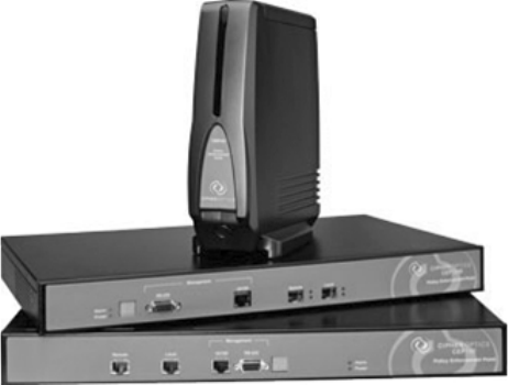
Other Specialized Devices
151
c05.indd 03/23/2015 Page 151
There are two main types of proxy servers you’ll typically nd working in present-day
networks:
Caching Proxy Server A caching proxy server speeds up the network’s service requests by
recovering information from a client’s or clients’ earlier request. Caching proxies keep local
copies of the resources requested often, which really helps minimize the upstream use of
bandwidth. These servers can greatly enhance network performance.
Web Proxy Server A web proxy server is usually used to create a web cache. You experi-
ence this when you Google a site you’ve visited before. The web proxy “remembers” you,
and the site not only loads faster, it sometimes even recalls your personal information by
automatically lling in your username—or even your billing/shipping information when you
place another order.
I want to mention one more thing before we move on from proxies, and this is reverse
proxies. Unlike a forward proxy, a reverse proxy takes requests from the Internet and
forwards them to servers in an internal network, whereas the forward proxy we discussed
in this section takes client requests and sends them to the Internet.
Encryption Devices
Although a number of the devices we have discussed earlier can perform encryption services,
there are dedicated appliances that can perform encryption as well. The advantage of using
these devices is that they normally provide more choice of encryption methods and stronger
encryption options. They also of oad the process from other devices like routers and servers,
which is a good thing since the encryption /decryption process is very processer intensive and
interferes with other functions that those routers and servers might be performing.
Sometimes these devices are called encryption gateways. They can either sit in line
with a server or a local network, encrypting and decrypting all traf c, or function as
an application server, encrypting any le sent to them within a network. Examples of
encryption appliances are shown in Figure 5.19.
FIGURE 5.19 Encryption appliance
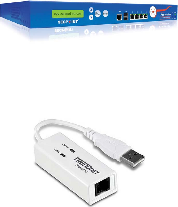
152
Chapter 5 ■ Networking Devices
c05.indd 03/23/2015 Page 152
While an encryption appliance is dedicated to encryption, a content ltering appliance
scans the content of what goes through it and lters out speci c content or content types.
Dedicating a device to this process of oads the work from servers or routers that could do
this but at a cost of greatly slowing the devices. Also, there is usually more functionality
and granular control available with a dedicated appliance.
Email is a good example of what you might run through one of these devices before
the email is delivered to lter out spam and objectionable content. Another example of the
use of a content lter might be to block websites based on the content of the web pages
rather than on the basis of the URL or IP address. An example of a dedicated content/URL
ltering appliance from SecPoint is shown in Figure 5.20.
FIGURE 5.20 Content filtering appliance
Analog Modem
A modem (modulator-demodulator) is a device that modulates an analog carrier signal to
encode digital information and demodulates the signal to decode the transmitted informa-
tion. I gave you an example of this when I explained APs earlier in the chapter because an
AP modulates and demodulates a signal just like a modem. Figure 5.21 shows a current
analog modem that can be used in today’s networks, albeit with slow throughput.
FIGURE 5.21 Analog modem
The goal is to produce a signal that can be transmitted easily and decoded to reproduce
the original digital data. These signals are transmitted over telephone lines and
demodulated by another modem at the receiver side in order to read the digital data.
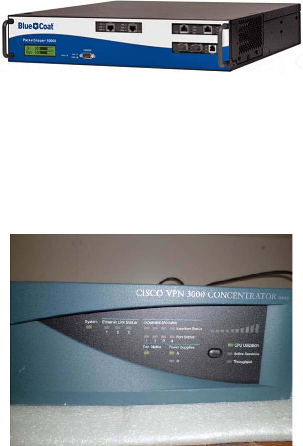
Other Specialized Devices
153
c05.indd 03/23/2015 Page 153
Packet Shaper
Packet shaping (also known as traf c shaping, it’s a form of rate limiting) is an internet-
working traf c management technique that delays some or all packets to bring them into
compliance with your or your company’s traf c pro le. Figure 5.22 shows a dedicated
packet shaper appliance from Blue Coat.
FIGURE 5.22 Packet shaper
This pro le is used to optimize or guarantee performance, improve latency, and/or increase
usable bandwidth for some kinds of packets by delaying other kinds, decided on by you.
VPN Concentrator
A VPN concentrator is a device that accepts multiple VPN connections from remote
locations. Although this function can be performed by a router or server, as with the
encryption gateways and content ltering devices discussed earlier, the same performance
bene ts can be derived from dedicating a device to this. Moreover, additional functionality
usually comes with these devices, one of which is shown in Figure 5.23.
FIGURE 5.23 VPN concentrator

154
Chapter 5 ■ Networking Devices
c05.indd 03/23/2015 Page 154
Planning and Implementing a Basic
SOHO Network Using Network
Segmentation
It’s likely that at some point you’ll have to break up one large network into a bunch of
smaller ones because user response will have dwindled to a slow crawl as the network
grew and grew. With all that growth, your LAN’s traf c congestion will have reached
epic proportions.
Determining Requirements
When implementing a SOHO network, the rst thing to be done is to identify the require-
ments of the network and the constraints around which you must operate. This should
drive your design and device choices. An example set of requirements and constraints might
be as follows:
■ A small number of computers are needed.
■ There is a high need for Internet access.
■ Resources need to be shared.
■ Wired hosts and wireless hosts will need to communicate with each other.
■ Security is very important.
With these constraints in mind, you might nd that you’ll need more than just a
switch and some Cat 5e cabling for this project. There is a need for a router, an AP, and
a rewall in this case. In addition, you need to think about compatibility between
equipment and the types and brands of equipment to buy as well as environmental
issues or limitations.
Wireless and security constraints are covered in Chapter 12 and Chapter
15, respectively. Chapter 12 is “Wireless Networking” and Chapter 15 is
“Physical and Hardware Security.”
One of the most important considerations you must take very seriously when building
a basic network is LAN traf c congestion, which can be lessened with network segmenta-
tion and is directly related to device types and compatibility requirements as well as
equipment limitations. Let’s look at how to use the segmentation devices I have de ned so
far in this chapter.
Here’s a list of some of the nasty things that commonly cause LAN traf c congestion:
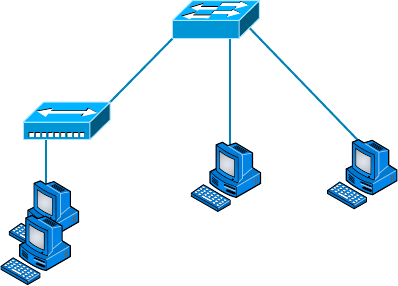
Planning and Implementing a Basic SOHO Network Using Network Segmentation
155
c05.indd 03/23/2015 Page 155
■ Too many hosts in a broadcast domain
■ Broadcast storms
■ Multicasting
■ Low bandwidth
■ Adding hubs for connectivity to the network
The answer to xing a huge but slow network is to break it up into a number of
smaller networks—something called network segmentation. You do this by using
devices like routers and switches, which are sometimes still referred to as bridges because
switches still use bridging technologies. Figure 5.24 displays a network that’s been
segmented with a switch so each network segment connected to the switch is now a
separate collision domain. But make note of the fact that this network is actually still
one broadcast domain—the set of all devices on a network segment that hear all the
broadcasts sent on that segment.
FIGURE 5.24 A switch can replace the hub, breaking up collision domains.
Switch
Hub
And keep in mind that the hub used in Figure 5.24 just extended the one collision
domain from the switch port.
Routers are used to connect networks together and route packets of data from one
network to another. (Cisco has become the de facto standard for routers because of its
high-quality router products, great selection, and fantastic service.) Routers, by default,
break up a broadcast domain. Figure 5.25 shows a router in our little network that creates
an internetwork and breaks up broadcast domains.
The network in Figure 5.25 is pretty cool. Each host is connected to its own collision
domain, and the router has created two broadcast domains. And don’t forget that the
router provides connections to WAN services as well. The router uses something called a
serial interface for WAN connections: speci cally, a V.35 physical interface.
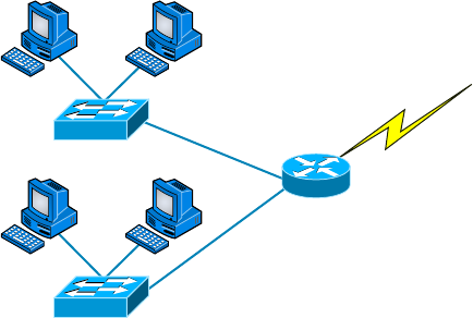
156
Chapter 5 ■ Networking Devices
c05.indd 03/23/2015 Page 156
FIGURE 5.25 Routers create an internetwork.
Switch
Serial 0
Switch
Breaking up a broadcast domain is important because when a host or server sends a net-
work broadcast, every device on the network must read and process that broadcast—unless
you’ve got a router. When the router’s interface receives this broadcast, it can respond by
basically saying, “Thanks, but no thanks,” and discard the broadcast without forwarding
it on to other networks. Even though routers are known for breaking up broadcast domains
by default, it’s important to remember that they break up collision domains as well.
There are two advantages of using routers in your network:
■ They don’t forward broadcasts by default.
■ They can filter the network based on Layer 3 (network layer) information (such as an
IP address).
Four router functions in your network can be listed as follows:
■ Packet switching
■ Packet filtering
■ Internetwork communication
■ Path selection
Remember that routers are really switches; they’re actually what we call Layer 3
switches. Unlike Layer 2 switches, which forward or lter frames, routers (Layer 3
switches) use logical addressing and provide what is called packet switching. Routers can
also provide packet ltering by using access lists, and when routers connect two or more
networks together and use logical addressing (IP or IPv6), this is called an internetwork.
Last, routers use a routing table (map of the internetwork) to make path selections and to
forward packets to remote networks.
Conversely, switches aren’t used to create internetworks (they do not break up broadcast
domains by default); they’re employed to add functionality to a network LAN. The main

Planning and Implementing a Basic SOHO Network Using Network Segmentation
157
c05.indd 03/23/2015 Page 157
purpose of a switch is to make a LAN work better—to optimize its performance—provid-
ing more bandwidth for the LAN’s users. And switches don’t forward packets to other
networks as routers do. Instead, they only “switch” frames from one port to another within
the switched network. Okay, you may be thinking, “Wait a minute, what are frames and
packets?” I’ll tell you all about them later in this chapter, I promise.
By default, switches break up collision domains, as mentioned in Chapter 4, “The
Current Ethernet Speci cations.” This is an Ethernet term used to describe a network
scenario wherein one particular device sends a packet on a network segment, forcing every
other device on that same segment to pay attention to it. At the same time, a different
device tries to transmit, leading to a collision, after which both devices must retransmit,
one at a time. Not very ef cient! This situation is typically found in a hub environment
where each host segment connects to a hub that represents only one collision domain and
only one broadcast domain. By contrast, each and every port on a switch represents its own
collision domain.
Switches create separate collision domains but a single broadcast domain.
Routers provide a separate broadcast domain for each interface.
The term bridging was introduced before routers and hubs were implemented, so it’s
pretty common to hear people referring to bridges as switches. That’s because bridges and
switches basically do the same thing—break up collision domains on a LAN (in reality,
you cannot buy a physical bridge these days, only LAN switches, but these switches use
bridging technologies.)
So this means a switch is basically just a multiple-port bridge with more brainpower,
right? Well, pretty much, but there are differences. Switches do provide this function,
but they do so with greatly enhanced management ability and features. Plus, most of
the time, bridges only had two or four ports. Yes, you could get your hands on a bridge
with up to 16 ports, but that’s nothing compared to the hundreds available on
some switches.
You would use a bridge in a network to reduce collisions within broadcast
domains and to increase the number of collision domains in your network.
Doing this provides more bandwidth for users. And keep in mind that
using hubs in your network can contribute to congestion on your Ethernet
network. As always, plan your network design carefully!
Figure 5.26 shows how a network would look with all these internetwork devices in
place. Remember that the router will not only break up broadcast domains for every LAN
interface but also break up collision domains.
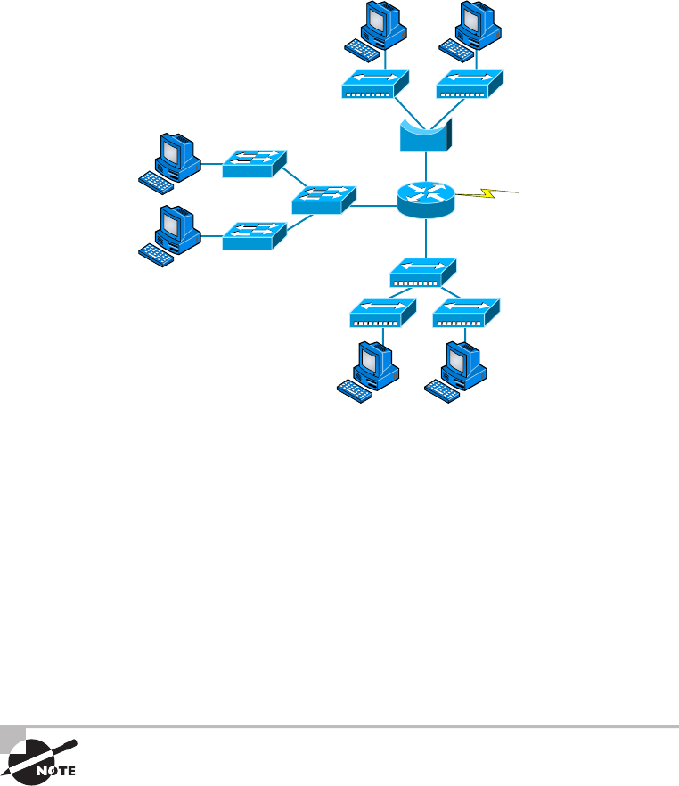
158
Chapter 5 ■ Networking Devices
c05.indd 03/23/2015 Page 158
FIGURE 5.26 Internetworking devices
Switch
Bridge
Router
When you look at Figure 5.26, do you see the router at center stage and see how it
connects each physical network together? We have to use this layout because of the older
technologies involved—bridges and hubs.
On the top internetwork in Figure 5.26, you’ll notice that a bridge is used to connect
the hubs to a router. The bridge breaks up collision domains, but all the hosts connected to
both hubs are still crammed into the same broadcast domain. Also, the bridge creates only
two collision domains, so each device connected to a hub is in the same collision domain
as every other device connected to that same hub. This is actually pretty lame, but it’s still
better than having one collision domain for all hosts.
Notice something else: The three hubs at the bottom that are connected also connect
to the router, creating one collision domain and one broadcast domain. This makes the
bridged network look much better indeed.
Although bridges/switches are used to segment networks, they will not
isolate broadcast or multicast packets.
The best network connected to the router is the LAN switch network on the left. Why?
Because each port on that switch breaks up collision domains. But it’s not all good—all
devices are still in the same broadcast domain. Do you remember why this can be a really
bad thing? Because all devices must listen to all broadcasts transmitted, that’s why.
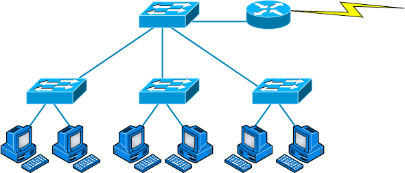
Planning and Implementing a Basic SOHO Network Using Network Segmentation
159
c05.indd 03/23/2015 Page 159
And if your broadcast domains are too large, the users have less bandwidth and are
required to process more broadcasts, and network response time will slow to a level that
could cause of ce riots.
Once we have only switches in our network, things change a lot. Figure 5.27 shows the
network that is typically found today.
FIGURE 5.27 Switched networks creating an internetwork
Router
Here I’ve placed the LAN switches at the center of the network world so the router is
connecting only logical networks together. If I implement this kind of setup, I’ve created
virtual LANs (VLANs), something I’m going to tell you about in Chapter 11. So don’t
stress. But it is really important to understand that even though you have a switched
network, you still need a router to provide your inter-VLAN communication, or internet-
working. Don’t forget that.
Obviously, the best network is one that’s correctly con gured to meet the business
requirements of the company it serves. LAN switches with routers, correctly placed
in the network, are the best network design. This book will help you understand
the basics of routers and switches so you can make tight, informed decisions on a
case-by-case basis.
Let’s go back to Figure 5.26 again. Looking at the gure, how many collision domains
and broadcast domains are in this internetwork? I hope you answered nine collision
domains and three broadcast domains.
The broadcast domains are de nitely the easiest to see because only routers break up
broadcast domains by default. And because there are three connections, that gives you
three broadcast domains. But do you see the nine collision domains? Just in case that’s a
no, I’ll explain. The all-hub network is one collision domain; the bridge network equals
three collision domains. Add in the switch network of ve collision domains—one for each
switch port—and you’ve got a total of nine.
Now, in Figure 5.27, each port on the switch is a separate collision domain and each
VLAN is a separate broadcast domain. But you still need a router for routing between
VLANs. How many collision domains do you see here? I’m counting 10—remember that
connections between the switches are considered a collision domain.
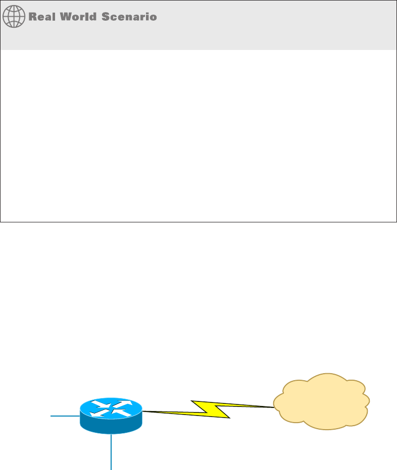
160
Chapter 5 ■ Networking Devices
c05.indd 03/23/2015 Page 160
Should I Replace All My Hubs with Switches?
You’re a network administrator at a large company in San Jose. The boss comes to you
and says that he got your requisition to buy a switch and is not sure about approving the
expense; do you really need it?
Well, if you can, sure—why not? Switches really add a lot of functionality to a network that
hubs just don’t have. But most of us don’t have an unlimited budget. Hubs still can create a
nice network—that is, of course, if you design and implement the network correctly.
Let’s say that you have 40 users plugged into four hubs, 10 users each. At this point, the hubs
are all connected together so that you have one large collision domain and one large broad-
cast domain. If you can afford to buy just one switch and plug each hub into a switch port, as
well as plug the servers into the switch, then you now have four collision domains and one
broadcast domain. Not great; but for the price of one switch, your network is a much better
thing. So, go ahead! Put that requisition in to buy all new switches. What do you have to lose?
So now that you’ve gotten an introduction to internetworking and the various devices
that live in an internetwork, it’s time to head into internetworking models.
As I mentioned earlier, routers break up broadcast domains, which means that by
default, broadcasts aren’t forwarded through a router. Do you remember why this is a good
thing? Routers break up collision domains, but you can also do that using Layer 2 (Data
Link layer) switches. Because each interface in a router represents a separate network, it
must be assigned unique network identi cation numbers, and each host on the network
connected to that router must use the same network number. Figure 5.28 shows how a
router works in an internetwork.
FIGURE 5.28 A router in an internetwork
FastEthernet0/0
FastEthernet0/1
Serial0 Internet
WAN Services
Here are some points about routers that you should commit to memory:
■ Routers, by default, will not forward any broadcast or multicast packets.
■ Routers use the logical address in a Network layer header to determine the next hop
router to forward the packet to.
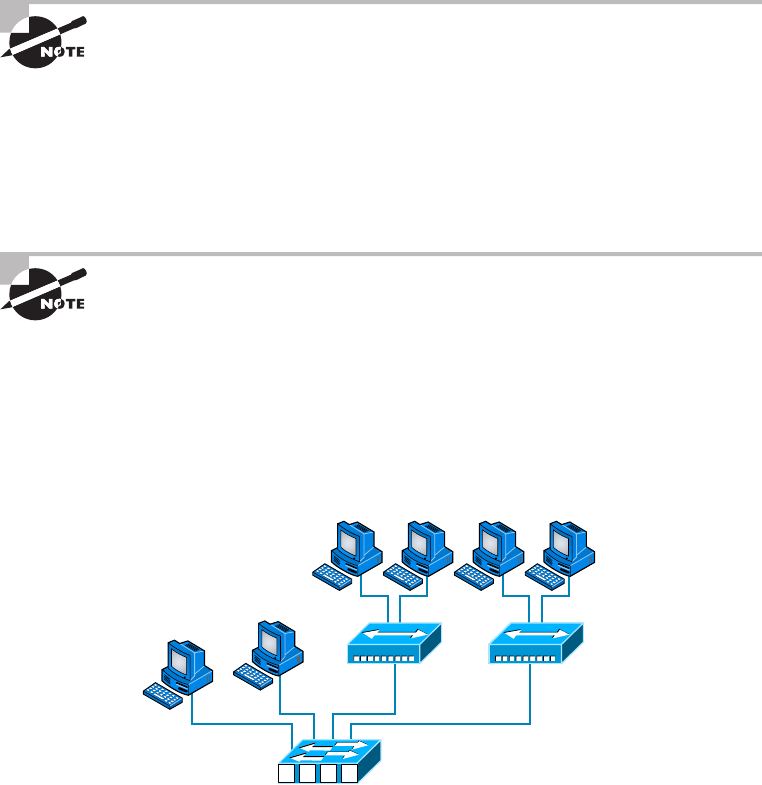
Planning and Implementing a Basic SOHO Network Using Network Segmentation
161
c05.indd 03/23/2015 Page 161
■ Routers can use access lists, created by an administrator, to control security on the
types of packets that are allowed to enter or exit an interface.
■ Routers can provide Layer 2 bridging functions if needed and can simultaneously route
through the same interface.
■ Layer 3 devices (routers, in this case) provide connections between virtual LANs
(VLANs).
■ Routers can provide quality of service (QoS) for specific types of network traffic.
Switching and VLANs are covered in Chapter 11.
Switches and Bridges at the Data Link Layer
Layer 2 switching is considered hardware-based bridging because it uses specialized hard-
ware called an application-speci c integrated circuit (ASIC). ASICs can run up to gigabit
speeds with very low latency rates.
Latency is the time measured from when a frame enters a port to when it
exits.
Bridges and switches read each frame as it passes through the network. The Layer 2
device then puts the source hardware address in a lter table and keeps track of which port
the frame was received on. This information (logged in the bridge’s or switch’s lter table)
is what helps the machine determine the location of the speci c sending device. Figure 5.29
shows a switch in an internetwork.
FIGURE 5.29 A switch in an internetwork
Each segment has its own collision domain.
All segments are in the same broadcast domain.
1234
162
Chapter 5 ■ Networking Devices
c05.indd 03/23/2015 Page 162
The real-estate business is all about location, location, location, and it’s the same way
for both Layer 2 and Layer 3 devices. Although both need to be able to negotiate the
network, it’s crucial to remember that they’re concerned with very different parts of it.
Primarily, Layer 3 machines (such as routers) need to locate speci c networks, whereas
Layer 2 machines (switches and bridges) need to eventually locate speci c devices. So,
networks are to routers as individual devices are to switches and bridges. And routing
tables that “map” the internetwork are for routers as lter tables that “map” individual
devices are for switches and bridges.
After a lter table is built on the Layer 2 device, it will forward frames only to the
segment where the destination hardware address is located. If the destination device is on
the same segment as the frame, the Layer 2 device will block the frame from going to any
other segments. If the destination is on a different segment, the frame can be transmitted
only to that segment. This is called transparent bridging.
When a switch interface receives a frame with a destination hardware address that isn’t
found in the device’s lter table, it will forward the frame to all connected segments. If the
unknown device that was sent the “mystery frame” replies to this forwarding action, the
switch updates its lter table regarding that device’s location. But in the event that the
destination address of the transmitting frame is a broadcast address, the switch will
forward all broadcasts to every connected segment by default.
All devices that the broadcast is forwarded to are considered to be in the same broadcast
domain. This can be a problem; Layer 2 devices propagate Layer 2 broadcast storms that
choke performance, and the only way to stop a broadcast storm from propagating through
an internetwork is with a Layer 3 device—a router.
The biggest bene t of using switches instead of hubs in your internetwork is that each
switch port is actually its own collision domain. (Conversely, a hub creates one large
collision domain.) But even armed with a switch, you still can’t break up broadcast
domains. Neither switches nor bridges will do that. They’ll typically simply forward
all broadcasts instead.
Another bene t of LAN switching over hub-centered implementations is that each device
on every segment plugged into a switch can transmit simultaneously—at least they can as
long as there is only one host on each port and a hub isn’t plugged into a switch port. As
you might have guessed, hubs allow only one device per network segment to communicate
at a time.
Hubs at the Physical Layer
As you know, a hub is really a multiple-port repeater. A repeater receives a digital
signal, reampli es or regenerates that signal, and then forwards the digital signal
out all active ports without looking at any data. An active hub does the same thing. Any
digital signal received from a segment on a hub port is regenerated or reampli ed and
transmitted out all ports on the hub. This means all devices plugged into a hub are in the
same collision domain as well as in the same broadcast domain. Figure 5.30 shows a hub
in a network.
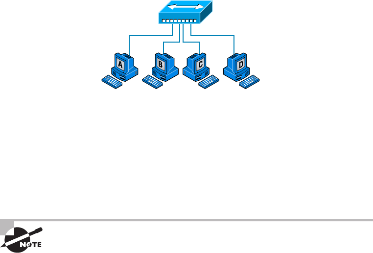
Planning and Implementing a Basic SOHO Network Using Network Segmentation
163
c05.indd 03/23/2015 Page 163
FIGURE 5.30 A hub in a network
All devices are in the same collision domain.
All devices are in the same broadcast domain.
Devices share the same bandwidth.
Hubs, like repeaters, don’t examine any of the traf c as it enters and is then transmitted
out to the other parts of the physical media. Every device connected to the hub, or hubs, must
listen if a device transmits. A physical star network—where the hub is a central device and
cables extend in all directions out from it—is the type of topology a hub creates. Visually,
the design really does resemble a star, whereas Ethernet networks run a logical bus topology,
meaning that the signal has to run through the network from end to end.
Hubs and repeaters can be used to enlarge the area covered by a single
LAN segment, although I do not recommend this. LAN switches and/or
wireless APs are affordable for almost every situation.
Environmental Considerations
All of the equipment discussed in this chapter—switches, routers, hubs, and so on—require
proper environmental conditions to operate correctly. These devices have the same needs as
any computing device. These environmental concerns can be categorized thusly:
Tempe ratu re Like any device with a CPU, infrastructure devices such as routers, switches,
and specialty appliances must have a cool area to operate. When temperatures rise, servers
start rebooting and appliance CPUs start overworking as well. The room(s) where these
devices are located should be provided with heavy-duty HVAC systems and ample ventila-
tion. It may even be advisable to dedicate a suite for this purpose and put the entire system
on a UPS with a backup generator in the case of a loss of power.
Humidity The air around these systems can be neither too damp nor too dry; it must be
“just right.” If it is too dry, static electricity will build up in the air, making the situation
ripe for damaging a system. It takes very little static electricity to fry some electrical
components. If it is too damp, connections start corroding and shorts begin to occur.
A humidifying system should be used to maintain the level above 50 percent. The air
conditioning should keep it within acceptable levels on the upper end.
164
Chapter 5 ■ Networking Devices
c05.indd 03/23/2015 Page 164
Summary
Whew, this chapter covered quite a bit of information. You learned the difference between a
router, a switch (bridge), and a hub and when to use each one. I also covered some devices that
you might nd in a network today, but not as often, such as VPN concentrators and content lters.
The information I discussed about DNS and DHCP is critical to your success on the
Network+ objectives, and I highly suggest that you reread those sections. I covered how
both the DNS and DHCP services work on a network.
In addition to the most common devices, I discussed the specialized network devices
mentioned in the Network+ objectives. I nished the chapter by discussing collision and
broadcast domains in detail as well as how you would use a router, switch, and hub in your
networks today.
All of the information in this chapter is fundamental, and you must understand it before
moving on to the other chapters in this book.
Exam Essentials
Understand how DHCP works and its purpose. Dynamic Host Con guration Protocol
(DHCP) provides IP con guration information to hosts. It is important to know how a
DHCP client requests information from a server, how a server receives this information,
and also how the server responds to the client and with what type of information.
Understand how DNS works and its purpose. Domain Name Service (DNS) is used to
resolve human names to IP addresses. Understanding how DNS resolves these names is
critical, as is understanding how a DNS query is sent and how a DNS server responds.
Understand the difference between a hub, a switch (bridge), and a router. A hub just
connects network segments together. A switch/bridge segments the network using MAC
addresses, and a router segments the network using logical addressing (IP and IPv6).
Switches break up collision domains, and routers break up broadcast domains by default.
Remember the different names for a router. A router is a Layer 3 hardware device, but it
can also be called a Layer 3 switch or a multilayer switch.
Remember the various devices used on networks today and when you would use each one
and how. Understand the differences and how each device works: routers, switches, hubs,
DNS servers, and DHCP servers.
Identify the purpose, benefits, and characteristics of using a proxy service. A proxy server keeps
a LAN somewhat separated from the Internet. Doing so increases security and ltering control,
and has the tendency to speed up Internet access through caching of recently used web pages.
Describe the proper use of network segmentation when planning and implementing a basic
SOHO network. Understand and apply the concepts of proper network segmentation
when planning the use of various devices in the design of a SOHO network.

Written Lab
165
c05.indd 03/23/2015 Page 165
Describe the benefits of using dedicated appliances for certain services. Using appliances
to of oad functions such as encryption, content ltering, and VPN concentration can
decrease the workload of other systems and add functionality that may be present in these
dedicated devices.
Identify the environmental requirements of infrastructure devices. A cool temperature,
ample ventilation, and the proper humidity level are all key to maintaining the operation of
devices like routers, switches, and appliances.
Written Lab
Complete the table by lling in the appropriate layer of the OSI or hub, switch, or router
device. You can nd the answers in Appendix A.
Description Device or OSI layer
This device sends and receives information about the Network layer.
This layer creates a virtual circuit before transmitting between
two end stations.
A Layer 3 switch or multilayer switch.
This device uses hardware addresses to filter a network.
Ethernet is defined at these layers.
This layer supports flow control and sequencing.
This device can measure the distance to a remote network.
Logical addressing is used at this layer.
Hardware addresses are defined at this layer.
This device creates one big collision domain and one large broadcast
domain.
This device creates many smaller collision domains, but the network
is still one large broadcast domain.
This device can never run full duplex.
This device breaks up collision domains and broadcast domains.

166
Chapter 5 ■ Networking Devices
c05.indd 03/23/2015 Page 166
Review Questions
You can nd the answers in Appendix B.
1. Which of the following is not a term used when making SOHO Internet connections?
A. Hub
B. Repeater
C. NIC
D. Switch
2. What advantage does a switch have over a hub?
A. It discards frames.
B. Transmissions received on one port will be sent out all the other ports.
C. It recognizes frame boundaries and destination MAC addresses of incoming frames.
D. Any two or more devices the switch connects are capable of causing a collision with
each other.
3. Which device is used to segment a network?
A. Hub
B. Switch
C. Repeater
D. All of the above
4. What is the primary function of a bridge?
A. Breaks up collision domains
B. Allows a NIC or other networking device to connect to a different type of media than
it was designed for
C. Allows mobile users to connect to a wired network wirelessly
D. None of the above
5. A network device that is used to connect multiple devices together without segmenting a
network is a .
A. Hub
B. Wireless access point
C. Switch
D. Router
6. Which of the following is among the benefits of a switch?
A. Protects LAN resources from attackers on the Internet
B. Provides extra bandwidth
C. Reduces throughput
D. Allows access to all computers on a LAN
Review Questions
167
c05.indd 03/23/2015 Page 167
7. Which of the following devices can work at both Layers 2 and 3 of the OSI model?
A. Hub
B. Switch
C. Multilayer switch
D. Bridge
8. What is an advantage of using DHCP in a network environment?
A. More difficult administration of the network
B. Static IP addressing
C. Can send an operating system for the PC to boot from
D. Assigns IP address to hosts
9. What is a benefit of a multilayer switch (MLS) over a Layer 2 switch?
A. Less bandwidth
B. Routing functions
C. Fewer features
D. Fewer ports
10. Which device should be used if you need to send incoming packets to one or more machines
that are hidden behind a single IP address?
A. Switch
B. Load balancer
C. Hub
D. Repeater
11. What role does the A record in a Domain Name Service (DNS) server have in your network?
A. Translates human name to IP address
B. Translates IP address to human name
C. Enables printing, copying, and faxing from one device
D. Controls network packets to optimize performance
12. Which device does not aid in network segmentation?
A. Router
B. Switch
C. Hub
D. Bridge
13. What is the most common use for a web proxy?
A. Web cache
B. Increases throughput
C. DHCP services
D. Supports user authentication
168
Chapter 5 ■ Networking Devices
c05.indd 03/23/2015 Page 168
14. Which is not an advantage of network segmentation?
A. Reduced congestion
B. Improved security
C. Containing network problems
D. Preventing broadcast storms
15. Users arrive at the office after a weekend and the hosts that were shut down over the
weekend are restarted but cannot access the LAN or Internet. Hosts that were not shut
down are working fine. Where can the problem be?
A. The DNS server
B. The DHCP server
C. The proxy server
D. The firewall
16. You need a device that can prevent your users from accessing certain websites. Which
device should you install?
A. Firewall
B. IDS
C. IPS
D. Proxy server
17. Which device creates separate collision domains and a single broadcast domain?
A. Hub
B. Router
C. Switch
D. Modem
18. Which of the following is not an advantage of using appliances to offload services like
encryption and content filtering?
A. Less expensive
B. Takes load off other devices
C. Additional functionality
D. Better performance
19. Which type of server in your network uses pointer and A records?
A. NAT translation server
B. IPS/IDS server
C. DNS server
D. Proxy server
Review Questions
169
c05.indd 03/23/2015 Page 169
20. Users on your network are saturating your bandwidth because they are using too many
non-work-related sites. What device would limit the availability of the types of sites that
users on a LAN have access to while providing granular control over the traffic between the
local LAN and the Internet?
A. Switch
B. DHCP server
C. DNS server
D. Proxy server

c06.indd 04/02/2015 Page 171
Chapter
6
Introduction to the
Internet Protocol
THE FOLLOWING COMPTIA NETWORK+
EXAM OBJECTIVES ARE COVERED IN THIS
CHAPTER:
✓ 5.2 Explain the basics of network theory and concepts
■ TCP/IP suite
■ ICMP
■ UDP
■ TCP
✓ 5.9 Compare and contrast the following ports and
protocols
■ 80 HTTP
■ 443 HTTPS
■ 137-139 Netbios
■ 110 POP
■ 143 IMAP
■ 25 SMTP
■ 5060/5061 SIP
■ 2427/2727 MGCP
■ 5004/5005 RTP
■ 1720 H.323
■ TCP
■ Connection-oriented
■ UDP
■ Connectionless

c06.indd 04/02/2015 Page 172
✓ 5.10 Given a scenario, configure and apply the appropriate
ports and protocols
■ 20,21 FTP
■ 161 SNMP
■ 22 SSH
■ 23 Telnet
■ 53 DNS
■ 67,68 DHCP
■ 69 TFTP
■ 445 SMB
■ 3389 RDP
✓ 3.0 Network security
✓ 3.2 Compare and contrast common network
vulnerabilities and threats
■ Vulnerabilities
■ Unsecure protocols
■ TELNET
■ HTTP
■ SLIP
■ FTP
■ TFTP
■ SNMPv1 and SNMPv2
✓ 3.3 Given a scenario, implement network hardening
techniques
■ Use secure protocols
■ SSH
■ SNMPv3
■ TLS/SSL
■ SFTP
■ HTTPS

c06.indd 04/02/2015 Page 173
The Transmission Control Protocol/Internet Protocol
(TCP/IP) suite was created by the Department of Defense
(DoD) to ensure and preserve data integrity as well as to
maintain communications in the event of catastrophic war.
So it follows that if designed and implemented correctly, a TCP/IP network can truly be
a solid, dependable, and resilient network solution. In this chapter, I’ll cover the protocols
of TCP/IP.
I’ll begin by covering the DoD’s version of TCP/IP and then compare this version and
its protocols with the OSI reference model discussed in Chapter 2, “The Open Systems
Interconnection Speci cations.”
After going over the various protocols found at each layer of the DoD model, I’ll nish
the chapter by adding more detail to the explanation of data encapsulation that I started in
Chapter 2.
To find up-to-the-minute updates for this chapter, please see
www.lammle
.com/networkplus
or the book’s website at
www.sybextestbanks.wiley.com
.
Introducing TCP/IP
Because TCP/IP is so central to working with the Internet and intranets, it’s essential for
you to understand it in detail. I’ll begin by giving you some background on TCP/IP and
how it came about, and then move on to describe the important technical goals de ned
by the original designers. After that, you’ll nd out how TCP/IP compares to a theoretical
model—the Open Systems Interconnection (OSI) model.
A Brief History of TCP/IP
The very rst Request for Comments (RFC) was published in April 1969, which paved the
way for today’s Internet and its protocols. Each of these protocols is speci ed in the multi-
tude of RFCs, which are observed, maintained, sanctioned, led, and stored by the Internet
Engineering Task Force (IETF).
TCP rst came on the scene in 1974. In 1978, it was divided into two distinct protocols,
TCP and IP, and nally documented into an RFC in 1980. Then, in 1983, TCP/IP replaced
the Network Control Protocol (NCP) and was authorized as the of cial means of data
transport for anything connecting to ARPAnet. ARPAnet was the Internet’s ancestor,

174
Chapter 6 ■ Introduction to the Internet Protocol
c06.indd 04/02/2015 Page 174
created by ARPA, the DoD’s Advanced Research Projects Agency, again, way back in
1969 in reaction to the Soviet’s launching of Sputnik. ARPA was soon redubbed DARPA,
and it was divided into ARPAnet and MILNET (also in 1983); both were nally dissolved
in1990.
But contrary to what you might think, most of the development work on TCP/IP hap-
pened at UC Berkeley in Northern California, where a group of scientists were simultane-
ously working on the Berkeley version of Unix, which soon became known as the BSD,
or the Berkeley Software Distribution series of Unix versions. Of course, because TCP/
IP worked so well, it was packaged into subsequent releases of BSD Unix and offered to
other universities and institutions if they bought the distribution tape. Basically, BSD Unix
bundled with TCP/IP began as shareware in the world of academia and, as a result, became
the basis of the huge success and exponential growth of today’s Internet as well as smaller,
private, and corporate intranets.
As usual, what may have started as a small group of TCP/IP a cionados evolved, and as
it did, the US government created a program to test any new published standards and make
sure they passed certain criteria. This was to protect TCP/IP’s integrity and to ensure that
no developer changed anything too dramatically or added any proprietary features. It’s this
very quality—this open-systems approach to the TCP/IP family of protocols—that pretty
much sealed its popularity because it guarantees a solid connection between myriad
hardware and software platforms with no strings attached.
TCP/IP and the DoD Model
The DoD model is basically a condensed version of the OSI model; it’s composed of four,
instead of seven, layers:
■ Process/Application layer
■ Host-to-Host layer
■ Internet layer
■ Network Access layer
Figure 6.1 shows a comparison of the DoD model and the OSI reference model. As you
can see, the two are similar in concept, but each has a different number of layers with
different names.
When the different protocols in the IP stack are discussed, two layers of
the OSI and DoD models are interchangeable. In other words, the Internet
layer and the Network layer describe the same thing, as do the Host-to-
Host layer and the Transport layer. The other two layers of the DoD model,
Process/Application and Network Access, are composed of multiple layers
of the OSI model.
A vast array of protocols operate at the DoD model’s Process/Application layer to inte-
grate the various activities and duties spanning the focus of the OSI’s corresponding top
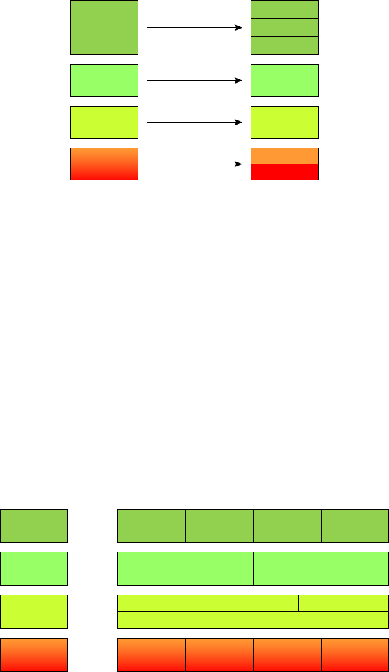
Introducing TCP/IP
175
c06.indd 04/02/2015 Page 175
three layers (Application, Presentation, and Session). We’ll be looking closely at those pro-
tocols in the next part of this chapter. The Process/Application layer de nes protocols for
node-to-node application communication and also controls user-interface speci cations.
FIGURE 6.1 The DoD and OSI models
DoD Model
Process/
Application
Host-to-Host
Internet
Network
Access
OSI Model
Application
Presentation
Session
Transport
Network
Data Link
Physical
The Host-to-Host layer parallels the functions of the OSI’s Transport layer, de ning
protocols for setting up the level of transmission service for applications. It tackles issues
such as creating reliable end-to-end communication and ensuring the error-free delivery of
data. It handles packet sequencing and maintains data integrity.
The Internet layer corresponds to the OSI’s Network layer, designating the protocols
relating to the logical transmission of packets over the entire network. It takes care of the
logical addressing of hosts by giving them an IP address, and it handles the routing of
packets among multiple networks.
At the bottom of the DoD model, the Network Access layer monitors the data exchange
between the host and the network. The equivalent of the Data Link and Physical layers
of the OSI model, the Network Access layer oversees hardware addressing and de nes
protocols for the physical transmission of data.
The DoD and OSI models are alike in design and concept, and have similar functions in
similar layers. Figure 6.2 shows the TCP/IP protocol suite and how its protocols relate to
the DoD model layers.
FIGURE 6.2 The TCP/IP protocol suite
DoD Model
Process/
Application
Host-to-Host
Internet
Network
Access
TCP UDP
Ethernet Fast
Ethernet
Gigabit
Ethernet
Wireless
/802.11
Telnet FTP LPD SNMP
TFTP SMTP NFS X Window
ICMP ARP
IP
RARP
176
Chapter 6 ■ Introduction to the Internet Protocol
c06.indd 04/02/2015 Page 176
We’ll now look at the different protocols in more detail, starting with the Process/
Application layer protocols.
The Process/Application Layer Protocols
In the following sections, I’ll describe the different applications and services typically used
in IP networks and list their associated port numbers as well, which are discussed in detail
in this chapter.
Telnet (23)
Telnet is the chameleon of protocols—its specialty is terminal emulation. It allows a user
on a remote client machine, called the Telnet client, to access the resources of another
machine, the Telnet server. Telnet achieves this by pulling a fast one on the Telnet server
and making the client machine appear as though it were a terminal directly attached to
the local network. This projection is actually a software shell—a virtual terminal that can
interact with the chosen remote host.
These emulated terminals are of the text-mode type and can execute re ned procedures
such as displaying menus that give users the opportunity to choose options and access the
applications on the duped server. Users begin a Telnet session by running the Telnet client
software and then logging into the Telnet server.
Telnet offers no security or encryption and is replaced by Secure Shell (SSH) when
security across the remote-con guration session is needed or desired.
File Transfer Protocol (20, 21)
File Transfer Protocol (FTP) is the protocol that actually lets you transfer les across an IP
network, and it can accomplish this between any two machines that are using it. But FTP
isn’t just a protocol; it’s also a program. Operating as a protocol, FTP is used by applica-
tions. As a program, it’s employed by users to perform le tasks by hand. FTP also allows
for access to both directories and les and can accomplish certain types of directory opera-
tions, such as relocating les into different directories.
Accessing a host through FTP is only the rst step, though. Users must then be subjected
to an authentication login that’s probably secured with passwords and usernames imple-
mented by system administrators to restrict access. You can get around this somewhat by
adopting the username anonymous—although what you’ll gain access to will be limited.
Even when employed by users manually as a program, FTP’s functions are limited to
listing and manipulating directories, typing le contents, and copying les between hosts.
It can’t execute remote les as programs. The problem with FTP is that all data is sent in
clear text, just as with Telnet. If you need to make sure your FTP transfers are secure, then
you’ll use SFTP.
Secure File Transfer Protocol (22)
Secure File Transfer Protocol (SFTP) is used when you need to transfer les over an
encrypted connection. It uses an SSH session (more on this later), which encrypts the
connection, and SSH uses port 22, hence the port 22 for SFTP. Apart from the secure

Introducing TCP/IP
177
c06.indd 04/02/2015 Page 177
part, it’s used just as FTP is—for transferring les between computers on an IP network,
such as the Internet.
Trivial File Transfer Protocol (69)
Trivial File Transfer Protocol (TFTP) is the stripped-down, stock version of FTP, but it’s
the protocol of choice if you know exactly what you want and where to nd it—plus it’s
easy to use, and it’s fast, too! It doesn’t give you the abundance of functions that FTP does
though. TFTP has no directory-browsing abilities; it can do nothing but send and receive
les. This compact little protocol also skimps in the data department, sending much smaller
blocks of data than FTP, and there’s no authentication as with FTP, so it’s insecure. Few
sites support it because of the inherent security risks.
When Should You Use FTP?
The folks at your San Francisco offi ce need a 50MB fi le emailed to them right away. What
do you do? Most email servers would reject the email because they have size limits. Even
if there’s no size limit on the server, it would still take a while to send this big fi le. FTP to
the rescue! However, most ISPs don’t allow fi les larger then 10MB to be emailed, so FTP
is an option you should consider if you need to send and receive.
If you need to give someone a large fi le or you need to get a large fi le from someone, FTP
is a nice choice. Smaller fi les (less than 10MB) can be sent via email if you have the band-
width (who doesn’t these days?), even if they’re compressed. To use FTP, you’ll need to
set up an FTP server on the Internet so that the fi les can be shared.
Besides, FTP is faster than email, which is another reason to use FTP for sending or
receiving large fi les. In addition, because it uses TCP and is connection-oriented, if the
session dies, FTP can sometimes start up where it left off. Try that with your email client!
Simple Mail Transfer Protocol (25)
Simple Mail Transfer Protocol (SMTP), answering our ubiquitous call to email, uses a
spooled, or queued, method of mail delivery. Once a message has been sent to a destina-
tion, the message is spooled to a device—usually a disk. The server software at the desti-
nation posts a vigil, regularly checking the queue for messages. When it detects them, it
proceeds to deliver them to their destination. SMTP is used to send mail; POP3 is used to
receive mail.
Post Office Protocol (110)
Post Of ce Protocol (POP) gives us a storage facility for incoming mail, and the latest
version is called POP3 (sound familiar?). Basically, how this protocol works is when a
client device connects to a POP3 server, messages addressed to that client are released for
178
Chapter 6 ■ Introduction to the Internet Protocol
c06.indd 04/02/2015 Page 178
downloading. It doesn’t allow messages to be downloaded selectively, but once they are, the
client-server interaction ends and you can delete and tweak your messages locally at will. A
newer standard, IMAP, is being used more and more in place of POP3. Why?
Internet Message Access Protocol, Version 4 (143)
Because Internet Message Access Protocol (IMAP) makes it so you get control
over how you download your mail, with it, you also gain some much-needed security.
It lets you peek at the message header or download just a part of a message—you can
now just nibble at the bait instead of swallowing it whole and then choking on the hook
hidden inside!
With it, you can choose to store messages on the email server hierarchically and link to
documents and user groups, too. IMAP even gives you search commands to use to hunt for
messages based on their subject, header, or content. As you can imagine, it has some serious
authentication features—it actually supports the Kerberos authentication scheme that MIT
developed. And yes, IMAP4 is the current version.
Remote Desktop Protocol (3389)
Remote Desktop Protocol (RDP) is a proprietary protocol developed by Microsoft. It
allows you to connect to another computer and run programs. RDP operates somewhat like
Telnet, except instead of getting a command-line prompt as you do with Telnet, you get the
actual graphical user interface (GUI) of the remote computer. Clients exist for most ver-
sions of Windows, and Macs now come with a preinstalled RDP client.
Microsoft currently calls its of cial RDP server software Remote Desktop Services; it
was called Terminal Services for a while. Microsoft’s of cial client software is currently
referred to as Remote Desktop Connection, which was called Terminal Services Client in
the past.
RDP is an excellent tool for remote clients, allowing them to connect to their work com-
puter from home, for example, and get their email or perform work on other applications
without running or installing any of the software on their home computer.
Transport Layer Security/Secure Sockets Layer (995/465)
Both Transport Layer Security (TLS) and its forerunner, Secure Sockets Layer (SSL), are
cryptographic protocols that come in really handy for enabling secure online data-transfer
activities like browsing the Web, instant messaging, Internet faxing, and so on. They’re so
similar that it’s not within the scope of this book to detail the differences between them.
They both use X.509 certi cates and asymmetric cryptography to authenticate to the host
they are communicating with and to exchange a key. This key is then used to encrypt data
owing between the hosts. This allows for data/message con dentiality, message integrity,
and message authentication.
Even though I listed TLS/SSL as using port 995 and 465, which is true if you’re using
Gmail, TLS/SSL isn’t tied down to any certain ports and can use various different ones.
SIP (VoIP) (5060/5061)
Session Initiation Protocol (SIP) is a hugely popular signaling protocol used to construct
and deconstruct multimedia communication sessions for many things like voice and video

Introducing TCP/IP
179
c06.indd 04/02/2015 Page 179
calls, videoconferencing, streaming multimedia distribution, instant messaging, presence
information, and online games over the Internet.
RTP (VoIP) (5004/5005)
Real-time Transport Protocol (RTP) describes a packet-formatting standard for deliver-
ing audio and video over the Internet. Although initially designed as a multicast protocol,
it’s now used for unicast applications, too. It’s commonly employed for streaming media,
videoconferencing, and push-to-talk systems—all things that make it a de facto standard in
Voice over IP (VoIP) industries.
MGCP (Multimedia) (2427/2727)
Media Gateway Control Protocol (MGCP) is a standard protocol for handling the
signaling and session management needed during a multimedia conference.
The protocol de nes a means of communication between a media gateway, which
converts data from the format required for a circuit-switched network to that required
for a packet-switched network, and the media gateway controller.
MGCP can be used to set up, maintain, and terminate calls between multiple endpoints.
H.323 (Video) (1720)
H.323 is a protocol that provides a standard for video on an IP network that de nes
how real-time audio, video, and data information is transmitted. This standard provides
signaling, multimedia, and bandwidth control mechanisms. H.323 uses the RTP standard
for communication.
Simple Network Management Protocol (161)
Simple Network Management Protocol (SNMP) collects and manipulates valuable
network information. It gathers data by polling the devices on the network from a
management station at xed or random intervals, requiring them to disclose certain
information. When all is well, SNMP receives something called a baseline—a report
delimiting the operational traits of a healthy network. This protocol can also stand as a
watchdog over the network, quickly notifying managers of any sudden turn of events. The
network watchdogs are called agents, and when aberrations occur, agents send an alert
called a trap to the management station. In addition, SNMP can help simplify the process
of setting up a network as well as the administration of your entire internetwork.
SNMP Versions 1, 2, and 3
SNMP versions 1 and 2 are pretty much obsolete. This doesn’t mean you won’t see them in
a network at some time, but v1 is super old and, well, outdated. SNMPv2 provided improve-
ments, especially in performance. But one of the best additions was what was called GET-
BULK, which allowed a host to retrieve a large amount of data at once. However, v2 never
really caught on in the networking world. SNMPv3 is now the standard and uses both TCP
and UDP, unlike v1, which used only UDP. Version 3 added even more security and mes-
sage integrity, authentication, and encryption. So, be careful when running SNMPv1 and v2
because they are susceptible to a packet sniffer reading the data.

180
Chapter 6 ■ Introduction to the Internet Protocol
c06.indd 04/02/2015 Page 180
Secure Shell (22)
Secure Shell (SSH) protocol sets up a secure Telnet session over a standard TCP/IP
connection and is employed for doing things like logging into other systems, running
programs on remote systems, and moving les from one system to another. And it does all
of this while maintaining a nice, strong, encrypted connection. You can think of it as the
new-generation protocol that’s now used in place of
rsh
and
rlogin
—even Telnet.
Hypertext Transfer Protocol (80)
All those snappy websites comprising a mélange of graphics, text, links, and so on—
the Hypertext Transfer Protocol (HTTP) is making it all possible. It’s used to manage
communications between web browsers and web servers, and opens the right resource
when you click a link, wherever that resource may actually reside.
Hypertext Transfer Protocol Secure (443)
Hypertext Transfer Protocol Secure (HTTPS) is a secure version of HTTP that arms you
with a whole bunch of security tools for keeping transactions between a web browser and
a server secure. It’s what your browser needs to ll out forms, sign in, authenticate, and
encrypt an HTTP message when you make a reservation or buy something online.
Both SSH (port 22) and HTTPS (port 443) are used to encrypt packets over
your intranet and the Internet.
Network Time Protocol (123)
Kudos to Professor David Mills of the University of Delaware for coming up with this
handy protocol that’s used to synchronize the clocks on our computers to one standard
time source (typically, an atomic clock). Network Time Protocol (NTP) works in
conjunction with other synchronization utilities to ensure that all computers on a given
network agree on the time. This may sound pretty simple, but it’s very important because
so many of the transactions done today are time- and date-stamped. Think about your
precious databases, for one. It can mess up a server pretty badly if it’s out of sync with
the machines connected to it, even by mere seconds (think crash!). You can’t have a trans-
action entered by a machine at, say, 1:50 a.m. when the server records that transaction as
having occurred at 1:45 a.m. So basically, NTP works to prevent “back to the future sans
DeLorean” from bringing down the network—very important indeed!
Lightweight Directory Access Protocol (389)
If you’re the system administrator of any decent-sized network, odds are you have a type
of directory in place that keeps track of all your network resources, such as devices and
users. But how do you access those directories? Through the Lightweight Directory Access
Introducing TCP/IP
181
c06.indd 04/02/2015 Page 181
Protocol (LDAP), that’s how. This protocol standardizes how you access directories, and
its rst and second inceptions are described in RFCs 1487 and 1777, respectively. There
were a few glitches in those two earlier versions, so a third version—the one most com-
monly used today—was created to address those issues and is described in RFC 3377.
Internet Group Management Protocol
Internet Group Management Protocol (IGMP) is the TCP/IP protocol used for manag-
ing IP multicast sessions. It accomplishes this by sending out unique IGMP messages over
the network to reveal the multicast-group landscape and to nd out which hosts belong to
which multicast group. The host machines in an IP network also use IGMP messages to
become members of a group and to quit the group, too. IGMP messages come in seriously
handy for tracking group memberships as well as active multicast streams.
IGMP works at the Network layer and doesn’t use port numbers, same as our next
one: SLIP.
Serial Line IP
Serial Line IP (SLIP) is a protocol created with the IP protocol stack and designed to work
over serial ports and modem connections. It’s also completely outdated, so I’m not sure why
it’s listed on the exam objectives. In the 1970s through the early 1990s, we used SLIP with
our modem con gurations. It was not compatible with DHCP, so everything was statically
con gured and assigned.
SLIP has been completely replaced by the Point-to-Point Protocol (PPP), which is better
engineered, has more features, and does not require a static IP address con guration.
NetBIOS (137–139)
Network Basic Input/Output System works only in the upper layers of the OSI model and
allows for an interface on separate computers to communicate over a network.
It was rst created in the early 1980s to work on an IBM LAN and was proprietary.
Microsoft and Novel both created a NetBIOS implementation to allows their hosts to
communicate to their servers, but Microsoft’s version became the de facto version.
Server Message Block (445)
Server Message Block (SMB) is used for sharing access to les and printers and other com-
munications between hosts on a Microsoft Windows network.
SMB can run on UDP port 137 and 138, and TCP port 137 and 139 using NetBIOS.
Domain Name Service (53)
Domain Name Service (DNS) resolves hostnames—speci cally, Internet names, such as
www.lammle.com
—to their corresponding IP addresses.
You don’t have to use DNS; you can just type in the IP address of any device you want
to communicate with. An IP address identi es hosts on a network and the Internet as
well. However, DNS was designed to make our lives easier. Think about this: What would

182
Chapter 6 ■ Introduction to the Internet Protocol
c06.indd 04/02/2015 Page 182
happen if you wanted to move your web page to a different service provider? The IP address
would change, and no one would know what the new one was. DNS allows you to use a
domain name to specify an IP address. You can change the IP address as often as you want
and no one will know the difference.
DNS is used to resolve a fully quali ed domain name (FQDN)—for example,
www.lammle.com
or
todd.lammle.com
—to an IP address. An FQDN, or DNS namespace, is
a hierarchy that can logically locate a system based on its domain identi er.
If you want to resolve the name todd, you must either type in the FQDN of
todd.lammle.com
or have a device, such as a PC or router, add the suf x for you. For
example, on a Cisco router, you can use the command
ip domain-name lammle.com
to
append each request with the
lammle.com
domain. If you don’t do that, you’ll have to type
in the FQDN to get DNS to resolve the name.
An important thing to remember about DNS is that if you can ping a device
with an IP address but can’t use its FQDN, you might have some type of
DNS configuration failure.
Dynamic Host Configuration Protocol/Bootstrap Protocol (67/68)
Dynamic Host Con guration Protocol (DHCP) assigns IP addresses to hosts with informa-
tion provided by a server. It allows easier administration and works well in small to even
very large network environments. Many types of hardware can be used as a DHCP server,
including routers.
DHCP differs from Bootstrap Protocol (BootP) in that BootP assigns an IP address to
a host but the host’s hardware address must be entered manually in a BootP table. You
can think of DHCP as a dynamic BootP. But remember that BootP is also used to send an
operating system that a host can boot from. DHCP can’t do that.
Please also read the section on DHCP and DNS in Chapter 5, “Network-
ing Devices,” if you have not done so; both figure largely in the exam
objectives.
But there is a lot of information a DHCP server can provide to a host when the host is
requesting an IP address from the DHCP server. Here’s a partial list of the information a
DHCP server can provide:
■ IP address
■ Subnet mask
■ Domain name
■ Default gateway (routers)
■ DNS
■ Windows Internet Naming Service (WINS) information
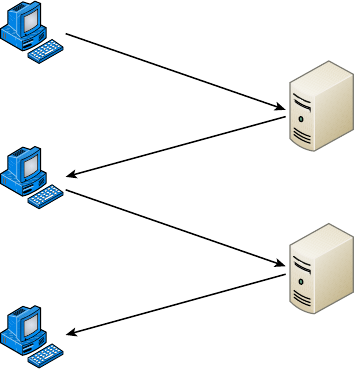
Introducing TCP/IP
183
c06.indd 04/02/2015 Page 183
A DHCP server can give even more information than this, but the items in the list are
the most common.
A client that sends out a DHCP Discover message in order to receive an IP address
sends out a broadcast at both Layer 2 and Layer 3. The Layer 2 broadcast is all Fs in hex,
which looks like this: FF:FF:FF:FF:FF:FF. The Layer 3 broadcast is 255.255.255.255,
which means all networks and all hosts. DHCP is connectionless, which means it uses User
Datagram Protocol (UDP) at the Transport layer, also known as the Host-to-Host layer,
which we’ll talk about next.
In case you don’t believe me, here’s an example of output from my trusty analyzer:
Ethernet II,Src:192.168.0.3(00:0b:db:99:d3:5e),Dst:Broadcast(ff:ff:ff:ff:ff:ff)
Internet Protocol,Src:0.0.0.0(0.0.0.0),Dst:255.255.255.255(255.255.255.255).
The Data Link and Network layers are both sending out “all hands” broadcasts saying,
“Help—I don’t know my IP address!”
Figure 6.3 shows the process of a client-server relationship using a DHCP connection.
FIGURE 6.3 DHCP client four-step process
ClientBroadcast
DHCP Discover
ServerUnicast
DHCP Offer
ClientBroadcast
DHCP Request
ServerUnicast
DHCP Acknowledgment
The following is the four-step process a client takes to receive an IP address from a
DHCP server:
1. The DHCP client broadcasts a DHCP Discover message looking for a DHCP server
(port 67).
2. The DHCP server that received the DHCP Discover message sends a unicast DHCP
Offer message back to the host.
3. The client then broadcasts to the server a DHCP Request message asking for the
offered IP address and possibly other information.
4. The server finalizes the exchange with a unicast DHCP Acknowledgment message.
184
Chapter 6 ■ Introduction to the Internet Protocol
c06.indd 04/02/2015 Page 184
What happens if you have a few hosts connected together with a switch or hub and
you don’t have a DHCP server? You can add IP information by hand (this is called static
IP addressing), or Windows provides what is called Automatic Private IP Addressing
(APIPA), a feature of later Windows operating systems. With APIPA, clients can automati-
cally self-con gure an IP address and subnet mask (basic IP information that hosts use to
communicate, which is covered in detail in Chapter 7, “IP Addressing,” and Chapter 8,
“IP Subnetting, Troubleshooting IP, and Introduction to NAT”) when a DHCP server isn’t
available. The IP address range for APIPA is 169.254.0.1 through 169.254.255.254. The
client also con gures itself with a default Class B subnet mask of 255.255.0.0. If you have a
DHCP server and your host is using this IP address, this means your DHCP client on your
host is not working or the server is down or can’t be reached because of a network issue.
Now, let’s take a look at the Transport layer, or what the DoD calls the Host-to-Host layer.
The Host-to-Host Layer Protocols
The main purpose of the Host-to-Host layer is to shield the upper-layer applications from
the complexities of the network. This layer says to the upper layer, “Just give me your data
stream, with any instructions, and I’ll begin the process of getting your information ready
to send.”
The following sections describe the two protocols at this layer:
■ Transmission Control Protocol (TCP)
■ User Datagram Protocol (UDP)
In addition, we’ll look at some of the key host-to-host protocol concepts as well as the
port numbers.
Transmission Control Protocol
Transmission Control Protocol (TCP) takes large blocks of information from an appli-
cation and breaks them into segments. It numbers and sequences each segment so that
the destination’s TCP process can put the segments back into the order the application
intended. After these segments are sent, TCP (on the transmitting host) waits for an
acknowledgment from the receiving end’s TCP process, retransmitting those segments that
aren’t acknowledged.
Remember that in a reliable transport operation, a device that wants to transmit sets
up a connection-oriented communication with a remote device by creating a session. The
transmitting device rst establishes a connection-oriented session with its peer system; that
session is called a call setup or a three-way handshake. Data is then transferred, and when
the transfer is complete, a call termination takes place to tear down the virtual circuit.
TCP is a full-duplex, connection-oriented, reliable, and accurate protocol, but establish-
ing all these terms and conditions, in addition to error checking, is no small task. TCP is
very complicated and, not surprisingly, costly in terms of network overhead. And because
today’s networks are much more reliable than those of yore, this added reliability is often
unnecessary.
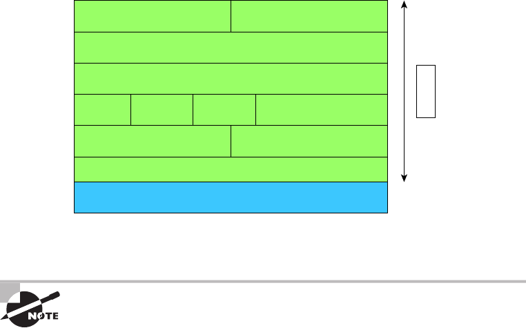
Introducing TCP/IP
185
c06.indd 04/02/2015 Page 185
Because the upper layers just send a data stream to the protocols in the Transport lay-
ers, I’ll demonstrate how TCP segments a data stream and prepares it for the Internet layer.
When the Internet layer receives the data stream, it routes the segments as packets through
an internetwork. The segments are handed to the receiving host’s Host-to-Host layer
protocol, which rebuilds the data stream to hand to the upper-layer protocols.
Figure 6.4 shows the TCP segment format. The gure shows the different elds within
the TCP header.
FIGURE 6.4 TCP segment format
24 Bytes
Bit 0
Source Port (16)
Sequence Number (32)
Acknowledgment Number (32)
Header
Length (4)
Reserved
(6)
Checksum (16) Urgent (16)
Options (0 or 32 if any)
Data (varies)
Code
Bits (6) Window (16)
Destination Port (16)
Bit 15 Bit 16 Bit 31
The TCP header is 20 bytes long, or up to 24 bytes with options.
For more detailed information regarding the TCP header, which is beyond
the scope of the CompTIA Network+ exam objectives, please see my book
CCNA: Cisco Certified Network Associate Study Guide (Sybex, 2013).
User Datagram Protocol
If you were to compare User Datagram Protocol (UDP) with TCP, the former is basically
the scaled-down economy model that’s sometimes referred to as a thin protocol. Like a
thin person on a park bench, a thin protocol doesn’t take up a lot of room—or in this case,
much bandwidth on a network.
UDP doesn’t offer all the bells and whistles of TCP either, but it does do a fabulous job
of transporting information that doesn’t require reliable delivery—and it does so using far
fewer network resources.
There are some situations in which it would de nitely be wise for developers to opt for
UDP rather than TCP. Remember the watchdog SNMP up there at the Process/Application
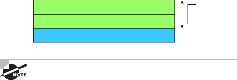
186
Chapter 6 ■ Introduction to the Internet Protocol
c06.indd 04/02/2015 Page 186
layer? SNMP monitors the network, sending intermittent messages and a fairly steady ow of
status updates and alerts, especially when running on a large network. The cost in overhead
to establish, maintain, and close a TCP connection for each one of those little messages would
reduce what would be an otherwise healthy, ef cient network to a dammed-up bog in no time!
Another circumstance calling for UDP over TCP is when reliability is already handled
at the Process/Application layer. DNS handles its own reliability issues, making the use of
TCP both impractical and redundant. But ultimately, it’s up to the application developer to
decide whether to use UDP or TCP, not the user who wants to transfer data faster.
UDP does not sequence the segments and doesn’t care in which order the segments arrive
at the destination. But after that, UDP sends the segments off and forgets about them. It
doesn’t follow through, check up on them, or even allow for an acknowledgment of safe
arrival—complete abandonment. Because of this, it’s referred to as an unreliable protocol.
This doesn’t mean that UDP is ineffective, only that it doesn’t handle issues of reliability.
Because UDP assumes that the application will use its own reliability method, it doesn’t use
any. This gives an application developer a choice when running the IP stack: TCP for reli-
ability or UDP for faster transfers.
Further, UDP doesn’t create a virtual circuit, nor does it contact the destination before
delivering information to it. Because of this, it’s also considered a connectionless protocol.
Figure 6.5 clearly illustrates UDP’s markedly low overhead as compared to TCP’s
hungry usage. Look at the gure carefully—can you see that UDP doesn’t use windowing
or provide for acknowledgments in the UDP header?
FIGURE 6.5 UDP segment
6 Bytes
Bit 0
Source Port (16)
Length (16) Checksum (16)
Data
Destination Port (16)
Bit 15 Bit 16 Bit 31
For more detailed information regarding the UDP header, which is beyond
the scope of the CompTIA Network+ exam objectives, please see my book
CCNA: Cisco Certified Network Associate Study Guide (Sybex, 2013).
Key Concepts of Host-to-Host Protocols
Now that you’ve seen both a connection-oriented (TCP) and connectionless (UDP) protocol
in action, it would be good to summarize the two here. Table 6.1 highlights some of the key
concepts that you should keep in mind regarding these two protocols. You should memo-
rize this table.

Introducing TCP/IP
187
c06.indd 04/02/2015 Page 187
TABLE 6.1 Key features of TCP and UDP
TCP UDP
Sequenced Unsequenced
Reliable Unreliable
Connection-oriented Connectionless
Virtual circuit No virtual circuit
High overhead Low overhead
Acknowledgments No acknowledgment
Windowing flow control No windowing or flow control
A telephone analogy could really help you understand how TCP works. Most of us
know that before you speak to someone on a phone, you must rst establish a connec-
tion with that person—wherever they are. This is like a virtual circuit with TCP. If you
were giving someone important information during your conversation, you might say,
“You know?” or ask, “Did you get that?” Saying something like this is a lot like a TCP
acknowledgment—it’s designed to get your veri cation. From time to time (especially on
cell phones), people also ask, “Are you still there?” They end their conversations with
a “Goodbye” of some kind, putting closure on the phone call. TCP also performs these
types of functions.
Alternatively, using UDP is like sending a postcard. To do that, you don’t need to con-
tact the other party rst. You simply write your message, address the postcard, and mail
it. This is analogous to UDP’s connectionless orientation. Because the message on the
postcard is probably not a matter of life or death, you don’t need an acknowledgment of its
receipt. Similarly, UDP doesn’t involve acknowledgments.
Port Numbers
TCP and UDP must use port numbers to communicate with the upper layers because
they’re what keep track of different simultaneous conversations originated by or accepted
by the local host. Originating source port numbers are dynamically assigned by the source
host and will usually have a value of 1024 or higher. Ports 1023 and below are de ned in
RFC 3232, which discusses what are called well-known port numbers.
Virtual circuits that don’t use an application with a well-known port number are
assigned port numbers randomly from a speci c range instead. These port numbers identify
the source and destination application or process in the TCP segment.
Figure 6.6 illustrates how both TCP and UDP use port numbers.
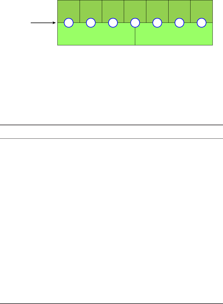
188
Chapter 6 ■ Introduction to the Internet Protocol
c06.indd 04/02/2015 Page 188
FIGURE 6.6 Port numbers for TCP and UDP
Transport
Layer TCP
TelnetFTP Doom DNS TFTP POP3 News
UDP
Port Numbers
Application
Layer
21 23 666 53 69 110 119
You just need to remember that numbers below 1024 are considered well-known port
numbers and are de ned in RFC 3232. Numbers 1024 and above are used by the upper
layers to set up sessions with other hosts and by TCP as source and destination identi ers
in the TCP segment.
Table 6.2 gives you a list of the typical applications used in the TCP/IP suite, their well-
known port numbers, and the Transport layer protocols used by each application or process.
It’s important that you study and memorize this table for the CompTIA Network+ exam.
TABLE 6.2 Key protocols that use TCP and UDP
TCP UDP
Telnet 23 SNMPv1/2 161
SMTP 25 TFTP 69
HTTP 80 DNS 53
FTP 20, 21
SFTP 22
BOOTPS/DHCP 67,68
DNS 53
HTTPS 443
SSH 22
SMB 445
POP3 110
NTP 123
IMAP4 143
RDP 3389
SNMPv3 161
Introducing TCP/IP
189
c06.indd 04/02/2015 Page 189
Notice that DNS uses both TCP and UDP. Whether it opts for one or the other depends
on what it’s trying to do. Even though it’s not the only application that can use both proto-
cols, it’s certainly one that you should remember in your studies.
The Internet Layer Protocols
In the DoD model, there are two main reasons for the Internet layer’s existence: routing
and providing a single network interface to the upper layers.
None of the other upper- or lower-layer protocols have any functions relating to
routing—that complex and important task belongs entirely to the Internet layer. The
Internet layer’s second duty is to provide a single network interface to the upper-layer
protocols. Without this layer, application programmers would need to write what are
called hooks into every one of their applications for each different Network Access
protocol. This would not only be a pain in the neck, it would also lead to different
versions of each application—one for Ethernet, another one for Token Ring, and so on.
To prevent this, IP provides one single network interface for the upper-layer protocols.
That accomplished, it’s then the job of IP and the various Network Access protocols to
get along and work together.
All network roads don’t lead to Rome—they lead to IP. And all the other protocols
at this layer, as well as all those at the upper layers, use it. Never forget that. All paths
through the DoD model go through IP. The following sections describe the protocols at the
Internet layer:
■ Internet Protocol (IP)
■ Internet Control Message Protocol (ICMP)
■ Address Resolution Protocol (ARP)
■ Reverse Address Resolution Protocol (RARP)
Internet Protocol
Internet Protocol (IP) is essentially the Internet layer. The other protocols found here
merely exist to support it. IP holds the big picture and could be said to “see all” in that it’s
aware of all the interconnected networks. It can do this because all the machines on the
network have a software, or logical, address called an IP address, which I’ll cover more
thoroughly in the next chapter.
IP looks at each packet’s destination address. Then, using a routing table, it decides
where a packet is to be sent next, choosing the best path. The protocols of the Network
Access layer at the bottom of the DoD model don’t possess IP’s enlightened scope of the
entire network; they deal only with physical links (local networks).
Identifying devices on networks requires answering these two questions: Which network
is it on? And what is its ID on that network? The answer to the rst question is the software
address, or logical address (the correct street). The answer to the second question is the
hardware address (the correct mailbox). All hosts on a network have a logical ID called an IP
address. This is the software, or logical, address and contains valuable encoded information,
greatly simplifying the complex task of routing. (IP is discussed in RFC 791.)
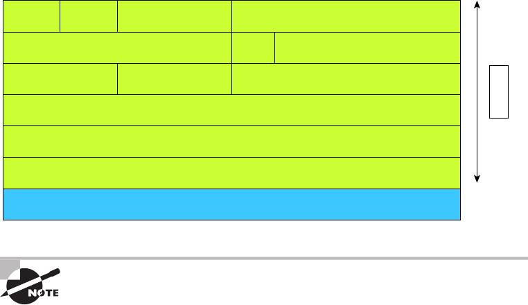
190
Chapter 6 ■ Introduction to the Internet Protocol
c06.indd 04/02/2015 Page 190
IP receives segments from the Host-to-Host layer and fragments them into packets
if necessary. IP then reassembles packets back into segments on the receiving side. Each
packet is assigned the IP address of the sender and of the recipient. Each router (Layer 3
device) that receives a packet makes routing decisions based on the packet’s destination
IP address.
Figure 6.7 shows an IP header. This will give you an idea of what IP has to go through
every time user data is sent from the upper layers to a remote network.
FIGURE 6.7 IP header
20 Bytes
Bit 0
Header
Length (4)
Version
(4)
Priority and
Type of Service (8)
Identification (16) Fragmented Offset (13)
Flags
(3)
Time to Live (8) Protocol (8) Header Checksum (16)
Destination IP Address (32)
Options (0 or 32 if any)
Data (varies if any)
Source IP Address (32)
Total Length (16)
Bit 15 Bit 16 Bit 31
For more detailed information regarding the IP header, which is beyond
the scope of the CompTIA Network+ exam objectives, please see my
book CCNA: Cisco Certified Network Associate Study Guide,
(Sybex, 2013).
Internet Control Message Protocol
Internet Control Message Protocol (ICMP) works at the Network layer and is used
by IP for many different services. ICMP is a management protocol and messaging service
provider for IP. Its messages are carried as IP packets.
ICMP packets have the following characteristics:
■ They can provide hosts with information about network problems.
■ They are encapsulated within IP datagrams.
The following are some common events and messages that ICMP relates to, and the two
most popular programs that use ICMP:
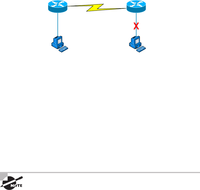
Introducing TCP/IP
191
c06.indd 04/02/2015 Page 191
Destination Unreachable If a router can’t send an IP datagram any further, it uses ICMP
to send a message back to the sender, advising it of the situation. For example, take a look
at Figure 6.8, which shows that the Ethernet interface of the Lab B router is down.
FIGURE 6.8 ICMP error message is sent to the sending host from the remote router
e0 on Lab B is down. Host A is trying to communicate to Host B. What happens?
Lab A
e0
Host A Host B
icmp e0
Lab B
When Host A Sends a packet destined for Host B, the Lab B router will send an ICMP
Destination Unreachable message back to the sending device (directly to Host A, in this
example).
Buffer Full If a router’s memory buffer for receiving incoming datagrams is full, it will
use ICMP to send out this message until the congestion abates.
Hops Each IP datagram is allotted a certain number of routers, called hops, to pass
through. If a datagram reaches its limit of hops before arriving at its destination, the last
router to receive it deletes it. The executioner router then uses ICMP to send an obituary
message, informing the sending machine of the demise of its datagram.
Ping Ping uses ICMP echo request and reply messages to check the physical and logical
connectivity of machines on an internetwork.
Traceroute Traceroute uses IP packet Time-to-Live time-outs to discover the path a
packet takes as it traverses an internetwork.
Both Ping and Traceroute (also just called Trace, and Microsoft Windows
uses tracert) allow you to verify address configurations in your internetwork.
Address Resolution Protocol
Address Resolution Protocol (ARP) nds the hardware address of a host from a known IP
address. Here’s how it works: When IP has a datagram to send, it must inform a Network
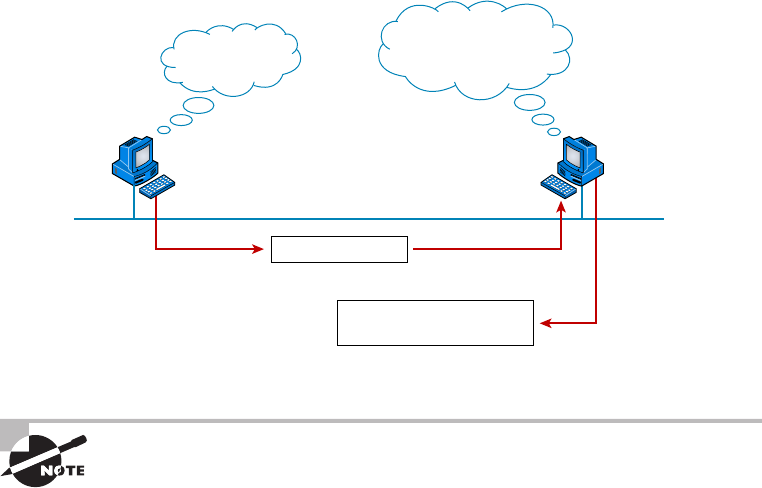
192
Chapter 6 ■ Introduction to the Internet Protocol
c06.indd 04/02/2015 Page 192
Access protocol, such as Ethernet or Token Ring, of the destination’s hardware address on
the local network. (It has already been informed by upper-layer protocols of the destina-
tion’s IP address.) If IP doesn’t nd the destination host’s hardware address in the ARP
cache, it uses ARP to nd this information.
As IP’s detective, ARP interrogates the local network by sending out a broadcast asking the
machine with the speci ed IP address to reply with its hardware address. So basically, ARP
translates the software (IP) address into a hardware address—for example, the destination
machine’s Ethernet address. Figure 6.9 shows how an ARP broadcast looks to a local network.
FIGURE 6.9 Local ARP broadcast
IP: 10.1.1.2 = ???
10.1.1.1
I need the Ethernet
address of 10.1.1.2.
I heard that broadcast.
The message is for me.
Here is my Ethernet address.
10.1.1.2
IP: 10.1.1.2
Ethernet: 45:23:79:85:77:34
ARP resolves IP addresses to Ethernet (MAC) addresses.
The following trace shows an ARP broadcast—notice that the destination hardware
address is unknown and is all 0s in the ARP header. In the Ethernet header, a destination
of all Fs in hex (all 1s in binary), a hardware-address broadcast, is used to make sure all
devices on the local link receive the ARP request:
Flags: 0x00
Status: 0x00
Packet Length: 64
Timestamp: 09:17:29.574000 12/06/03
Ethernet Header
Destination: FF:FF:FF:FF:FF:FF Ethernet Broadcast
Source: 00:A0:24:48:60:A5
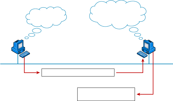
Introducing TCP/IP
193
c06.indd 04/02/2015 Page 193
Protocol Type: 0x0806
IP ARP
ARP - Address Resolution Protocol
Hardware: 1 Ethernet
(10Mb)
Protocol: 0x0800
IP
Hardware Address Length: 6
Protocol Address Length: 4
Operation: 1
ARP Request
Sender Hardware Address: 00:A0:24:48:60:A5
Sender Internet Address: 172.16.10.3
Target Hardware Address: 00:00:00:00:00:00
(ignored)
Target Internet Address: 172.16.10.10
Extra bytes (Padding):
................ 0A 0A 0A 0A 0A 0A 0A 0A 0A 0A 0A 0A 0A
0A 0A 0A 0A 0A
Frame Check Sequence: 0x00000000
Reverse Address Resolution Protocol
When an IP machine happens to be a diskless machine, it has no way of initially knowing
its IP address. But it does know its MAC address. Reverse Address Resolution Protocol
(RARP) discovers the identity of the IP address for diskless machines by sending out a
packet that includes its MAC address and a request for the IP address assigned to that
MAC address. A designated machine, called a RARP server, responds with the answer,
and the identity crisis is over. RARP uses the information it does know about the machine’s
MAC address to learn its IP address and complete the machine’s ID portrait.
Figure 6.10 shows a diskless workstation asking for its IP address with a RARP broadcast.
FIGURE 6.10 RARP broadcast example
Ethernet: 45:23:79:85:77:34 IP = ??
What’s my IP
address?
I heard that broadcast.
Your IP address
is 192.168.10.3.
Ethernet: 45:23:79:85:77:34
IP: 192.168.10.3

194
Chapter 6 ■ Introduction to the Internet Protocol
c06.indd 04/02/2015 Page 194
Data Encapsulation
I started to discuss data encapsulation in Chapter 2, but I could only provide an overview
at that point in the book because you needed to have a rm understanding of how ports
work in a virtual circuit. With the last ve chapters of foundational material under your
belt, you’re ready to get more into the details of encapsulation.
When a host transmits data across a network to another device, the data goes through
encapsulation: It’s wrapped with protocol information at each layer of the OSI model. Each
layer communicates only with its peer layer on the receiving device.
To communicate and exchange information, each layer uses Protocol Data Units
(PDUs). These hold the control information attached to the data at each layer of the model.
They’re usually attached to the header in front of the data eld but can also be in the
trailer, or end, of it.
Each PDU attaches to the data by encapsulating it at each layer of the OSI model, and
each has a speci c name depending on the information provided in each header. This
PDU information is read only by the peer layer on the receiving device. After it’s read, it’s
stripped off, and the data is then handed to the next layer up.
Figure 6.11 shows the PDUs and how they attach control information to each layer. This
gure demonstrates how the upper-layer user data is converted for transmission on the
network. The data stream is then handed down to the Transport layer, which sets up
a virtual circuit to the receiving device by sending over a synch packet. Next, the data
stream is broken up into smaller pieces, and a Transport layer header (a PDU) is created
and attached to the header of the data eld; now the piece of data is called a segment. Each
segment is sequenced so the data stream can be put back together on the receiving side
exactly as it was transmitted.
FIGURE 6.11 Data encapsulation
Upper-Layer Data
Upper-Layer Data Segment
PDU
Packet
Frame
Bits
TCP Header
IP Header
LLC Header
MAC Header
Segment
Packet
Packet
0101110101001000010
FCS
FCS
Application
Presentation
Session
Transport
Network
Data Link
Physical
Data Encapsulation
195
c06.indd 04/02/2015 Page 195
Each segment is then handed to the Network layer for network addressing and
routing through the internetwork. Logical addressing (for example, IP) is used to get
each segment to the correct network. The Network layer protocol adds a control header
to the segment handed down from the Transport layer, and what we have now is called
a packet or datagram. Remember that the Transport and Network layers work together
to rebuild a data stream on a receiving host, but it’s not part of their work to place their
PDUs on a local network segment—which is the only way to get the information to a
router or host.
It’s the Data Link layer that’s responsible for taking packets from the Network
layer and placing them on the network medium (cable or wireless). The Data Link
layer encapsulates each packet in a frame, and the frame’s header carries the hardware
address of the source and destination hosts. If the destination device is on a remote
network, then the frame is sent to a router to be routed through an internetwork. Once
it gets to the destination network, a new frame is used to get the packet to the
destination host.
To put this frame on the network, it must rst be put into a digital signal. Because a
frame is really a logical group of 1s and 0s, the Physical layer is responsible for encoding
these digits into a digital signal, which is read by devices on the same local network. The
receiving devices will synchronize on the digital signal and extract (decode) the 1s and 0s
from the digital signal. At this point, the devices build the frames, run a cyclic redundancy
check (CRC), and then check their answer against the answer in the frame’s Frame Check
Sequence (FCS) eld. If it matches, the packet is pulled from the frame and what’s left of
the frame is discarded. This process is called de-encapsulation. The packet is handed to the
Network layer, where the address is checked. If the address matches, the segment is pulled
from the packet and what’s left of the packet is discarded. The segment is processed at
the Transport layer, which rebuilds the data stream and acknowledges to the transmitting
station that it received each piece. It then happily hands the data stream to the upper-layer
application.
In summary, at a transmitting device, the data-encapsulation method works
like this:
1. User information is converted to data for transmission on the network.
2. Data is converted to segments, and a reliable connection is set up between the
transmitting and receiving hosts.
3. Segments are converted to packets or datagrams, and a logical address is placed in the
header so each packet can be routed through an internetwork.
4. Packets or datagrams are converted to frames for transmission on the local network.
Hardware (Ethernet) addresses are used to uniquely identify hosts on a local network
segment.
5. Frames are converted to bits, and a digital encoding and clocking scheme
is used.
To explain this in more detail using the layer addressing, I’ll use Figure 6.12.
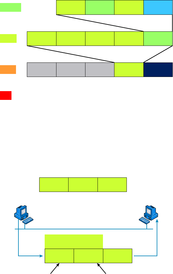
196
Chapter 6 ■ Introduction to the Internet Protocol
c06.indd 04/02/2015 Page 196
FIGURE 6.12 PDU and layer addressing
Source
Port
Segment
Packet
Frame
Bits
Source
IP
Destination
MAC
1011011100011110000
Source
MAC Packet FCSEther-Field
Destination
IP Protocol Segment
Destination
Port …
…
Data
Remember that a data stream is handed down from the upper layer to the Transport
layer. As technicians, we really don’t care who the data stream comes from because that’s
a programmer’s problem. Our job is to rebuild the data stream reliably and hand it to the
upper layers on the receiving device.
Before we go further in our discussion of Figure 6.12, let’s review port numbers and
make sure you understand them. The Transport layer uses port numbers to de ne both the
virtual circuit and the upper-layer process, as you can see from Figure 6.13.
FIGURE 6.13 Port numbers at the Transport layer
Source
Port
Host A Host Z
Destination
Port
SP
Defines virtual circuit Defines upper-layer
process or application
1028 23
DP
…
…
Data Encapsulation
197
c06.indd 04/02/2015 Page 197
The Transport layer takes the data stream, makes segments out of it, and establishes a
reliable session by creating a virtual circuit. It then sequences (numbers) each segment and
uses acknowledgments and ow control. If you’re using TCP, the virtual circuit is de ned
by the source port number. Remember, the host just makes this up starting at port number
1024 (0 through 1023 are reserved for well-known port numbers). The destination port
number de nes the upper-layer process (application) that the data stream is handed to when
the data stream is reliably rebuilt on the receiving host.
Now that you understand port numbers and how they’re used at the Transport layer,
let’s go back to Figure 6.12. Once the Transport layer header information is added to the
piece of data, it becomes a segment and is handed down to the Network layer along with
the destination IP address. (The destination IP address was handed down from the upper
layers to the Transport layer with the data stream, and it was discovered through a name
resolution method at the upper layers—probably DNS.)
The Network layer adds a header, and adds the logical addressing (IP addresses), to the
front of each segment. Once the header is added to the segment, the PDU is called a packet.
The packet has a protocol eld that describes where the segment came from (either UDP
or TCP) so it can hand the segment to the correct protocol at the Transport layer when it
reaches the receiving host.
The Network layer is responsible for nding the destination hardware address that
dictates where the packet should be sent on the local network. It does this by using ARP.
IP at the Network layer looks at the destination IP address and compares that address to its
own source IP address and subnet mask. If it turns out to be a local network request, the
hardware address of the local host is requested via an ARP request. If the packet is destined
for a remote host, IP will get the IP address of the default gateway from its con guration
information, then ARP for the hardware address of the default gateway (router) instead.
The packet, along with the destination hardware address of either the local host or
default gateway, is then handed down to the Data Link layer. The Data Link layer will add
a header to the front of the packet, and the piece of data then becomes a frame. (We call it
a frame because both a header and a trailer are added to the packet, which makes the data
resemble bookends or a frame, if you will.) This is shown in Figure 6.12. The frame uses
an Ether-Type eld to describe which protocol the packet came from at the Network layer.
Now a CRC is run on the frame, and the answer to the CRC is placed in the FCS eld
found in the trailer of the frame.
The frame is now ready to be handed down, one bit at a time, to the Physical layer,
which will use bit-timing rules to encode the data into a digital signal. Every device on the
network segment will synchronize with the clock, extract the 1s and 0s from the digital
signal, and build a frame. After the frame is rebuilt, a CRC is run to make sure the frame is
okay. If everything turns out to be good, the hosts will check the destination address to see
if the frame is for them.
If all this is making your eyes cross and your brain freeze, don’t freak—things will
become much clearer as we go through the book—really! Soon, I’ll be going over exactly
how data is encapsulated and routed through an internetwork in even more detail, in an
easy-to-understand, step-by-step manner, in Chapter 9, “Introduction to IP Routing.”
198
Chapter 6 ■ Introduction to the Internet Protocol
c06.indd 04/02/2015 Page 198
Summary
Protocols, protocols everywhere—so many different reasons for them, and so many jobs
they do for us! And sometimes they even work in conjunction with each other. This can
seem like way too much information, but no worries—as you become familiar with the
various layers and their functions, I promise it will soon become clear that this hierarchical
structure is a seriously tight, robust networking foundation.
Similarly, as you understand the TCP/IP big picture, the reason why all those protocols
exist and are necessary will also become much easier to understand. They’re really like a
team that works jointly, from layer to layer, to make our TCP/IP networks the wonderful,
great tools they are.
Exam Essentials
Remember the Process/Application layer protocols. Telnet is a terminal-emulation program
that allows you to log into a remote host and run programs. File Transfer Protocol (FTP) is a
connection-oriented service that allows you to transfer les. Trivial FTP (TFTP) is a connec-
tionless le transfer program. Simple Mail Transfer Protocol (SMTP) is a sendmail program.
Remember the Host-to-Host layer protocols. Transmission Control Protocol (TCP) is a
connection-oriented protocol that provides reliable network service by using acknowledg-
ments and ow control. User Datagram Protocol (UDP) is a connectionless protocol that
provides low overhead and is considered unreliable.
Remember the Internet layer protocols. Internet Protocol (IP) is a connectionless protocol that
provides logical network addressing and routing through an internetwork. Address Resolution
Protocol (ARP) nds a hardware address from a known IP address. Internet Control Message
Protocol (ICMP) provides diagnostics and Destination Unreachable messages.
Remember the difference between connection-oriented and connectionless network
services. Connection-oriented services use acknowledgments and ow control to cre-
ate a reliable session. More overhead is used than in a connectionless network service.
Connectionless services are used to send data with no acknowledgments or ow control.
This is considered unreliable.
Written Lab
Provide the answers to the following questions. You can nd the answers in Appendix A.
1. What would an ARP destination MAC address appear as?
2. Name the protocol that uses both TCP ports 20 and 21.
Written Lab
199
c06.indd 04/02/2015 Page 199
3. What Transport layer protocol does a DNS server use?
4. Which protocol dynamically reports errors to source hosts by using IP directly to build packets?
5. What could cause a server that you can ping not to provide the particular TCP/IP service,
such as FTP, HTTP, and so on, that you expect it to offer?
6. What is the well-known port number for RPC?
7. Which ports does the protocol MGCP use?
8. What protocol is at the heart of the
ping
and
tracert
commands in a Windows operating
system?
9. Which destination Transport layer protocol and port number does a TFTP client use to
transfer files over the network?
10. What well-known port numbers do SMTP, POP3, RDP, and IMAP4 servers use?
200
Chapter 6 ■ Introduction to the Internet Protocol
c06.indd 04/02/2015 Page 200
Review Questions
You can nd the answers to the review questions in Appendix B.
1. The OSI model has seven layers and the DoD has four. At which layer does SMTP work in
both models?
A. Network
B. Transport
C. Session
D. Application
E. Internet
2. You need to have secure communications using HTTPS. What port number is used by default?
A. 69
B. 23
C. 21
D. 443
3. You want to implement a mechanism that automates the IP configuration, including IP
address, subnet mask, default gateway, and DNS information. Which protocol will you use
to accomplish this?
A. SMTP
B. SNMP
C. DHCP
D. ARP
4. What protocol is used to find the hardware address of a local device?
A. RARP
B. ARP
C. IP
D. ICMP
E. BootP
5. You need to log in to a Unix server across a network that is not secure. Which
of the following protocols will allow you to remotely administrate this server
securely?
A. Telnet
B. SSH
C. SFTP
D. HTTP
Review Questions
201
c06.indd 04/02/2015 Page 201
6. If you can ping by IP address but not by hostname, or FQDN, which of the following port
numbers is related to the server process that is involved?
A. 21
B. 23
C. 53
D. 69
E. 80
7. Which of the following describe the DHCP Discover message? (Choose two.)
A. It uses FF:FF:FF:FF:FF:FF as a Layer 2 broadcast.
B. It uses UDP as the Transport layer protocol.
C. It uses TCP as the Transport layer protocol.
D. It does not use a Layer 2 destination address.
8. What Layer 4 protocol is used for a Telnet connection, and what is the default port
number?
A. IP, 6
B. TCP, 21
C. UDP, 23
D. ICMP, 21
E. TCP, 23
9. Which statements are true regarding ICMP packets? (Choose two.)
A. They acknowledge receipt of a TCP segment.
B. They guarantee datagram delivery.
C. They can provide hosts with information about network problems.
D. They are encapsulated within IP datagrams.
E. They are encapsulated within UDP datagrams.
10. Which of the following services use TCP? (Choose three.)
A. DHCP
B. SMTP
C. SNMP
D. FTP
E. HTTP
F. TFTP
11. Which of the following services use UDP? (Choose three.)
A. DHCP
B. SMTP
202
Chapter 6 ■ Introduction to the Internet Protocol
c06.indd 04/02/2015 Page 202
C. SNMP
D. FTP
E. HTTP
F. TFTP
12. Which of the following TCP/IP protocols are used at the Application layer of the OSI
model? (Choose three.)
A. IP
B. TCP
C. Telnet
D. FTP
E. TFTP
13. Which of the following protocols is used by email servers to exchange messages with one
another?
A. POP3
B. IMAP
C. SMTP
D. HTTP
14. You need to have a connection to run applications that are installed on only your desktop
computer at your office. Which protocol will provide a GUI interface to your work computer?
A. Telnet
B. FTP
C. RDP
D. IMAP
E. SMTP
15. Which of the following protocols can use TCP and UDP, permits authentication and secure
polling of network devices, and allows for automated alerts and reports on network devices?
A. DNS
B. SNMP
C. SMTP
D. TCP
16. You need to transfer files between two hosts. Which two protocols can you use?
(Choose two.)
A. SNMP
B. SCP
C. RIP
D. NTP
E. FTP
Review Questions
203
c06.indd 04/02/2015 Page 203
17. What layer in the IP stack is equivalent to the Transport layer of the OSI model?
A. Application
B. Host-to-Host
C. Internet
D. Network Access
18. You need to make sure that the time is consistent across all your network devices. What
protocol do you need to run on your network?
A. FTP
B. SCP
C. NTP
E. RTP
19. Which of the following allows a server to distinguish among different simultaneous
requests from the same host?
A. They use different port numbers.
B. A NAT server changes the IP address for subsequent requests.
C. A server is unable to accept multiple simultaneous sessions from the same host. One
session must end before another can begin.
D. The MAC address for each one is unique.
20. Which of the following uses both TCP and UDP?
A. FTP
B. SMTP
C. Telnet
D. DNS

c07.indd 04/02/2015 Page 205
Chapter
7
IP Addressing
THE FOLLOWING COMPTIA NETWORK+
EXAM OBJECTIVES ARE COVERED IN THIS
CHAPTER:
✓ 1.8 Given a scenario, implement and configure the
appropriate addressing schema
■ IPv6
■ Auto-configuration
■ EUI 64
■ DHCP6
■ Link local
■ Address structure
■ Address compression
■ Tunneling 6to4, 4to6
■ Teredo, miredo
■ IPv4
■ Address structure
■ Subnetting
■ APIPA
■ Classful A, B, C, D
■ Classless
■ Private vs public
■ NAT/PAT
■ MAC addressing
■ Multicast
■ Unicast
■ Broadcast
■ Broadcast domains vs collision domains

c07.indd 04/02/2015 Page 206
One of the most important topics in any discussion of TCP/IP
is IP addressing. An IP address is a numeric identi er assigned
to each machine on an IP network. It designates the speci c
location of a device on the network.
An IP address is a logical address, not a hardware address—the latter is hard-coded on a
network interface card (NIC) and used for nding hosts on a local network. IP addressing
was designed to allow hosts on one network to communicate with a host on a different
network regardless of the type of LANs the hosts are participating in.
Before we get into the more complicated aspects of IP addressing, you need to under-
stand some of the basics. First I’m going to explain some of the fundamentals of IP address-
ing and its terminology. Then you’ll learn about the hierarchical IP addressing scheme and
private IP addresses.
I’ll de ne unicast, multicast, and broadcast addresses and then nish the chapter with a
discussion on IPv6. And I promise to make it all as painless as possible.
The reason that we would even discuss IPv6 (besides to cover the objectives, of course)
is because of the lack of IPv4 addresses available for use in future networks, which we need
to keep our corporate and private networks and even the Internet running. Basically, we’re
running out of addresses for all our new hosts! IPv6 will x this for us.
To find up-to-the-minute updates for this chapter, please see
www.lammle
.com/networkplus
or the book’s website at
www.sybextestbanks.wiley.com
.
IP Terminology
Throughout this chapter, you’ll learn several important terms vital to your understanding
of the Internet Protocol. Here are a few to get you started:
Bit A bit is one binary digit, either a 1 or a 0.
Byte A byte is 7 or 8 bits, depending on whether parity is used. For the rest of this
chapter, always assume a byte is 8 bits.
Octet An octet, made up of 8 bits, is just an ordinary 8-bit binary number. In this
chapter, the terms byte and octet are completely interchangeable, and they are typically
displayed in decimal up to 255.
Network Address This is the designation used in routing to send packets to a remote
network—for example, 10.0.0.0, 172.16.0.0, and 192.168.10.0.

The Hierarchical IP Addressing Scheme
207
c07.indd 04/02/2015 Page 207
IP Address A logical address used to de ne a single host; however, IP addresses can be
used to reference many or all hosts as well. If you see something written as just IP, it is
referring to IPv4. IPv6 will always be written as IPv6.
Broadcast Address The broadcast address is used by applications and hosts to send
information to all hosts on a network. Examples include 255.255.255.255, which desig-
nates all networks and all hosts; 172.16.255.255, which speci es all subnets and hosts on
network 172.16.0.0; and 10.255.255.255, which broadcasts to all subnets and hosts on
network 10.0.0.0.
You will find the terms subnet mask and slash notation (for example, /24)
used a few times in this chapter. These terms will be fully defined and used
in Chapter 8, “IP Subnetting, Troubleshooting IP, and Introduction to NAT.”
The Hierarchical IP Addressing Scheme
An IP address consists of 32 bits of information. These bits are divided into four sections,
referred to as octets or bytes, and four octets sum up to 32 bits (8 × 4 = 32). You can depict
an IP address using one of three methods:
■ Dotted-decimal, as in 172.16.30.56
■ Binary, as in 10101100.00010000.00011110.00111000
■ Hexadecimal, as in AC.10.1E.38
Each of these examples validly represents the same IP address. Hexadecimal is used
with IPv6, and IP addressing uses dotted-decimal or binary, but you still might nd an
IP address stored in hexadecimal in some programs. The Windows XP Registry is a good
example of a program that stores a machine’s IP address in hex.
The 32-bit IP address is known as a structured, or hierarchical, address as opposed to
a at, or nonhierarchical, address. Although either type of addressing scheme can be used,
hierarchical addressing has been chosen for a very important reason. The major advan-
tage of this scheme is that it can handle a large number of addresses, namely, 4.3 billion
(a 32-bit address space with two possible values for each position—either 0 or 1—gives
you 232, or 4,294,967,296). The disadvantage of the at-addressing scheme, and the rea-
son it’s not used for IP addressing, relates to routing. If every address were unique, all
routers on the Internet would need to store the address of each and every machine on the
Internet. This would make ef cient routing impossible, even if only a fraction of all possible
addresses were used.
The solution to this problem is to use a two- or three-level hierarchical addressing
scheme that is structured by network and host or by network, subnet, and host.
This two- or three-level scheme is comparable to a telephone number. The rst section,
the area code, designates a very large area. The second section, the pre x, narrows the
scope to a local calling area. The nal segment, the customer number, zooms in on the spe-
ci c connection. IP addresses use the same type of layered structure. Rather than all 32 bits

208
Chapter 7 ■ IP Addressing
c07.indd 04/02/2015 Page 208
being treated as a unique identi er, as in at addressing, a part of the address is designated
as the network address and the other part is designated as either the subnet and host or just
the host address.
Next, I’m going to cover IP network addressing and the different classes of addresses
used for our networks.
Network Addressing
The network address—also called the network number—uniquely identi es each network.
Every machine on the same network shares that network address as part of its IP address.
In the IP address 172.16.30.56, for example, 172.16 is the network address (and in just a
minute I’ll show you how this is true).
The host address is assigned to, and uniquely identi es, each machine on a network.
This part of the address must be unique because it identi es a particular machine—an
individual—as opposed to a network, which is a group. So in the sample IP address
172.16.30.56, the 30.56 is the host address.
The designers of the Internet decided to create classes of networks based on network
size. For the small number of networks possessing a very large number of hosts, they
created the rank Class A network. At the other extreme is the Class C network, which is
reserved for the numerous networks with a small number of hosts. The class distinction for
networks between very large and very small is predictably the Class B network.
Subdividing an IP address into a network and host address is determined by the class
designation of your network. Figure 7.1 summarizes the classes of networks—a subject I’ll
explain in much greater detail throughout this chapter.
FIGURE 7.1 Summary of the three classes of networks
8 bits
Class A: Network
Network
Network
Multicast
Research
Network Network
Network
Host Host
Host Host
Host
Host
Class B:
Class C:
Class D:
Class E:
8 bits 8 bits 8 bits
To ensure ef cient routing, Internet designers de ned a mandate for the leading-bits
section of the address for each different network class. For example, since a router knows
that a Class A network address always starts with a 0, the router might be able to speed
a packet on its way after reading only the rst bit of its address. This is where the address

The Hierarchical IP Addressing Scheme
209
c07.indd 04/02/2015 Page 209
schemes de ne the difference between a Class A, a Class B, and a Class C address. Coming
up, I’ll discuss the differences between these three classes followed by a discussion of the
Class D and Class E addresses. For now, know that Classes A, B, and C are the only ranges
that are used to address hosts in our networks.
Class A Addresses
In a Class A network address, the rst byte is assigned to the network address, and the
three remaining bytes are used for the host addresses. The Class A format is as follows:
network.host.host.host
For example, in the IP address 49.22.102.70, the 49 is the network address and
22.102.70 is the host address. Every machine on this particular network would begin with
the distinctive network address of 49.
Class A network addresses are 1 byte long, with the rst bit of that byte reserved and
the 7 remaining bits available for manipulation, or addressing. As a result, the theoretical
maximum number of Class A networks that can be created is 128. Why? Well, each of the
7 bit positions can be either a 0 or a 1 and 27 gives you 128.
The designers of the IP address scheme said that the rst bit of the rst byte in a Class A
network address must always be off, or 0. This means a Class A address must be between 0
and 127 in the rst byte, inclusive.
Consider the following network address:
0xxxxxxx
If we turn the other 7 bits all off and then turn them all on, we’ll nd the Class A range
of network addresses:
00000000 = 0
01111111 = 127
So, a Class A network is de ned in the rst octet between 0 and 127, and it can’t be less
or more.
To complicate matters further, the network address of all 0s (0000 0000) is reserved to
designate the default route (see Table 7.1). Additionally, the address 127, which is reserved
for diagnostics, can’t be used either, which means that you can really only use the numbers
1 to 126 to designate Class A network addresses. This means the actual number of usable
Class A network addresses is 128 minus 2, or 126.
TABLE 7.1 Reserved IP addresses
Address Function
Network address of all 0s Interpreted to mean “this network or segment.”
Network address of all 1s Interpreted to mean “all networks.”

210
Chapter 7 ■ IP Addressing
c07.indd 04/02/2015 Page 210
Address Function
Network 127.0.0.1 Reserved for loopback tests. Designates the local host
and allows that host to send a test packet to itself without
generating network traffic.
Host address of all 0s Interpreted to mean “network address” or any host on
specified network.
Host address of all 1s Interpreted to mean “all hosts” on the specified network;
for example, 126.255.255.255 means “all hosts” on
network 126 (Class A address).
Entire IP address set to all 0s Used by Cisco routers to designate the default route.
Could also mean “any network.”
Entire IP address set to all 1s
(same as 255.255.255.255)
Broadcast to all hosts on the current network; sometimes
called an “all 1s broadcast” or limited broadcast.
Each Class A address has 3 bytes (24 bit positions) for the host address of a machine.
This means there are 224—or 16,777,216—unique combinations and, therefore, pre-
cisely that many potential unique host addresses for each Class A network. Because host
addresses with the two patterns of all 0s and all 1s are reserved, the actual maximum
usable number of hosts for a Class A network is 224 minus 2, which equals 16,777,214.
Either way, you can see that’s a seriously huge number of hosts to have on a network
segment!
Here’s an example of how to gure out the valid host IDs in a Class A network address:
■ All host bits off is the network address: 10.0.0.0.
■ All host bits on is the broadcast address: 10.255.255.255.
The valid hosts are the numbers in between the network address and the broadcast
address: 10.0.0.1 through 10.255.255.254. Notice that 0s and 255s can be valid host IDs.
All you need to remember when trying to nd valid host addresses is that the host bits can’t
ever be all turned off or all turned on at the same time.
Class B Addresses
In a Class B network address, the rst 2 bytes are assigned to the network address and the
remaining 2 bytes are used for host addresses. The format is as follows:
network.network.host.host
For example, in the IP address 172.16.30.56, the network address is 172.16 and the host
address is 30.56.
With a network address being 2 bytes (8 bits each), we’re left with 216 unique combina-
tions. But the Internet designers decided that all Class B network addresses should start
TABLE 7.1 Reserved IP addresses (continued)
The Hierarchical IP Addressing Scheme
211
c07.indd 04/02/2015 Page 211
with the binary digit 1, then 0. This leaves 14 bit positions available to manipulate, so in
reality, we get 16,384 (that is, 214) unique Class B network addresses.
In a Class B network, the RFCs state that the rst bit of the rst byte must always be
turned on but the second bit must always be turned off. If we turn the other 6 bits all off
and then all on, we will nd the range for a Class B network:
10000000 = 128
10111111 = 191
As you can see, a Class B network is de ned when the rst byte is con gured from 128
to 191.
A Class B address uses 2 bytes for host addresses. This is 216 minus the two reserved
patterns (all 0s and all 1s), for a total of 65,534 possible host addresses for each Class B
network.
Here’s an example of how to nd the valid hosts in a Class B network:
■ All host bits turned off is the network address: 172.16.0.0.
■ All host bits turned on is the broadcast address: 172.16.255.255.
The valid hosts would be the numbers in between the network address and the broadcast
address: 172.16.0.1 through 172.16.255.254.
Class C Addresses
The rst 3 bytes of a Class C network address are dedicated to the network portion of the
address, with only 1 measly byte remaining for the host address. Here’s the format:
network.network.network.host
Using the example IP address 192.168.100.102, the network address is 192.168.100 and
the host address is 102.
In a Class C network address, the rst three bit positions are always the binary 110. The
calculation is as follows: 3 bytes, or 24 bits, minus 3 reserved positions leaves 21 positions.
Hence, there are 221, or 2,097,152, possible Class C networks.
For Class C networks, the RFCs de ne the rst 2 bits of the rst octet as always turned
on, but the third bit can never be on. Following the same process as the previous classes,
convert from binary to decimal to nd the range. Here’s the range for a Class C network:
11000000 = 192
11011111 = 223
So, if you see an IP address with a range from 192 up to 223, you’ll know it’s a Class C
IP address.
Each unique Class C network has 1 byte to use for host addresses. This gets us to 28, or
256, minus the two reserved patterns of all 0s and all 1s for a total of 254 available host
addresses for each Class C network.
Here’s an example of how to nd a valid host ID in a Class C network:
■ All host bits turned off is the network ID: 192.168.100.0.
■ All host bits turned on is the broadcast address: 192.168.100.255.
The valid hosts would be the numbers in between the network address and the broadcast
address: 192.168.100.1 through 192.168.100.254.

212
Chapter 7 ■ IP Addressing
c07.indd 04/02/2015 Page 212
Class D and E Addresses
Addresses with the rst octet of 224 to 255 are reserved for Class D and E networks. Class
D (224–239) is used for multicast addresses and Class E (240–255) for scienti c purposes.
But they’re really beyond the scope of this book, so I’m not going to go into detail about
them here. But you do need to know that the multicast range is from 224.0.0.0 through
239.255.255.255.
Special Purposes of Network Addresses
Some IP addresses are reserved for special purposes, so network administrators can’t ever
assign them to hosts. Table 7.1 listed the members of this exclusive little club and the
reasons why they’re included in it.
Private IP Addresses (RFC 1918)
The people who created the IP addressing scheme also created what we call private IP
addresses. These addresses can be used on a private network, but they’re not routable
through the Internet. This is designed for the purpose of creating a measure of much-
needed security, but it also conveniently saves valuable IP address space.
If every host on every network had to have real routable IP addresses, we would have
run out of available IP addresses to hand out years ago. But by using private IP addresses,
ISPs, corporations, and home users need only a relatively tiny group of bona de IP
addresses to connect their networks to the Internet. This is economical because they can
use private IP addresses on their inside networks and get along just ne.
To accomplish this task, the ISP and the corporation—the end users, no matter who they
are—need to use something called Network Address Translation (NAT), which basically
takes a private IP address and converts it for use on the Internet. NAT provides security in
that these IP addresses cannot be seen by external users. External users will only be able
to see the public IP address to which the private IP address has been mapped. Moreover,
multiple devices in the same private network can use the same, real IP address to transmit
out onto the Internet. Doing things this way saves megatons of address space—a very good
thing for us all!
Table 7.2 lists the reserved private addresses.
TABLE 7.2 Reserved IP address space
Address class Reserved address space
Class A 10.0.0.0 through 10.255.255.255
Class B 172.16.0.0 through 172.31.255.255
Class C 192.168.0.0 through 192.168.255.255

The Hierarchical IP Addressing Scheme
213
c07.indd 04/02/2015 Page 213
So, What Private IP Address Should I Use?
That’s a really great question: Should you use Class A, Class B, or even Class C private
addressing when setting up your network? Let’s take Acme Corporation in San Francisco
as an example. This company is moving into a new building and needs a whole new net-
work (what a treat this is!). It has 14 departments, with about 70 users in each. You could
probably squeeze three or four Class C addresses to use, or maybe you could use a Class
B, or even a Class A just for fun.
The rule of thumb in the consulting world is, when you’re setting up a corporate net-
work—regardless of how small it is—you should use a Class A network address because
it gives you the most fl exibility and growth options. For example, if you used the 10.0.0.0
network address with a /24 mask, then you’d have 65,536 networks, each with 254 hosts.
Lots of room for growth with that network! You would then subnet this network address
space using Classless Internet Domain Routing (CIDR), which provides only the needed
amount of hosts to each department or building without wasting IP addresses.
(A /24 tells you that a subnet mask has 24 bits out of 32 bits turned on for subnetting a
network. This will be covered, as well as CIDR, in more detail in Chapter 8.)
But if you’re setting up a home network, you’d opt for a Class C address because it is the
easiest for people to understand and confi gure. Using the default Class C mask gives you
one network with 254 hosts—plenty for a home network.
With the Acme Corporation, a nice 10.1.x.0 with a /24 mask (the x is the subnet for each
department) makes this easy to design, install, and troubleshoot.
APIPA
I discussed this in Chapter 6, “Introduction to the Internet Protocol,” but it is worth
repeating here. What happens if you have a few hosts connected together with a switch or
hub and you don’t have a DHCP server? You can add static IP information to a host or you
can let Windows provides what is called Automatic Private IP Addressing (APIPA). I don’t
recommend this, but APIPA is a “feature,” so you do need to remember it, hence mention-
ing it two chapters in a row!
With APIPA, clients can automatically self-con gure an IP address and subnet mask,
which is the minimum information needed for hosts to communicate when a DHCP server
isn’t available. In this way, it could be thought of as a DHCP failover scheme. If all of the
hosts set themselves with an APIPA address, they could communicate with one another
but unfortunately not with any addresses that were statically con gured, such as default
gateways!
214
Chapter 7 ■ IP Addressing
c07.indd 04/02/2015 Page 214
The IP address range for APIPA is 169.254.0.1 through 169.254.255.254. The client also
con gures itself with a default Class B subnet mask of 255.255.0.0.
However, when you’re in your corporate network and you’re running a DHCP server,
and your host displays that it is using this IP address range, this means that either your
DHCP client on the host is not working or the DHCP server is down or can’t be reached
because of a network issue. For example, if you plug a DHCP client into a port that is
disabled, the host will receive an APIPA address. I don’t know anyone who has seen a host
in the APIPA address range and been happy about it!
IPv4 Address Types
Most people use broadcast as a generic term, and most of the time, we understand what
they mean. But not always. For example, you might say, “The host broadcasted through
a router to a DHCP server,” but, well, it’s pretty unlikely that this would ever really hap-
pen. What you probably mean—using the correct technical jargon—is, “The DHCP cli-
ent broadcasted for an IP address; a router then forwarded this as a unicast packet to the
DHCP server.” Oh, and remember that with IPv4, broadcasts are pretty important, but
with IPv6, there aren’t any broadcasts sent at all—as you’ll see in a bit!
Okay, I’ve referred to broadcast addresses throughout earlier chapters, and even showed
you some examples of various IP addresses. But I really haven’t gone into the different
terms and uses associated with them yet, and it’s about time I did. So here are the four IPv4
address types that I’d like to de ne for you:
Layer 2 Broadcasts These are sent to all nodes on a LAN.
Broadcasts (Layer 3) These are sent to all nodes on the network.
Unicast This is an address for a single interface, and these are used to send packets to a
single destination host.
Multicast These are packets sent from a single source and transmitted to many devices on
different networks. Referred to as one-to-many.
Layer 2 Broadcasts
First, understand that Layer 2 broadcasts are also known as hardware broadcasts—they
only go out on a LAN, and they don’t go past the LAN boundary (router).
The typical hardware address is 6 bytes (48 bits) and looks something like 0c.43.
a4.f3.12.c2. The broadcast would be all 1s in binary, which would be all Fs in hexadeci-
mal, as in FF.FF.FF.FF.FF.FF.
IPv4 Address Types
215
c07.indd 04/02/2015 Page 215
Layer 3 Broadcasts
Then there are the plain old broadcast addresses at Layer 3. Broadcast messages are meant
to reach all hosts on a broadcast domain. These are the network broadcasts that have all
host bits on.
Here’s an example that you’re already familiar with: The network address of 172.16.0.0
would have a broadcast address of 172.16.255.255—all host bits on. Broadcasts can also
be “any network and all hosts,” as indicated by 255.255.255.255.
A good example of a broadcast message is an Address Resolution Protocol (ARP)
request. When a host has a packet, it knows the logical address (IP) of the destination. To
get the packet to the destination, the host needs to forward the packet to a default gate-
way if the destination resides on a different IP network. If the destination is on the local
network, the source will forward the packet directly to the destination. Because the source
doesn’t have the MAC address to which it needs to forward the frame, it sends out a broad-
cast, something that every device in the local broadcast domain will listen to. This broad-
cast says, in essence, “If you are the owner of IP address 192.168.2.3, please forward your
MAC address to me,” with the source giving the appropriate information.
Unicast Address
A unicast address is assigned to a single interface, and this term is used in both IPv4 and
IPv6 to describe your host interface IP address.
Multicast Address (Class D)
Multicast is a different beast entirely. At rst glance, it appears to be a hybrid of uni-
cast and broadcast communication, but that isn’t quite the case. Multicast does allow
point-to-multipoint communication, which is similar to broadcasts, but it happens in a
different manner. The crux of multicast is that it enables multiple recipients to receive
messages without ooding the messages to all hosts on a broadcast domain. However,
this is not the default behavior—it’s what we can do with multicasting if it’s con gured
correctly!
Multicast works by sending messages or data to IP multicast group addresses. Routers
then forward copies (unlike broadcasts, which are not forwarded) of the packet out every
interface that has hosts subscribed to a particular group address. This is where multicast
differs from broadcast messages—with multicast communication, copies of packets, in
theory, are sent only to subscribed hosts. When I say in theory, this means that the hosts
will receive, for example, a multicast packet destined for 224.0.0.10 (this is an EIGRP
packet and only a router running the EIGRP protocol will read these). All hosts on the
broadcast LAN (Ethernet is a broadcast multi-access LAN technology) will pick up the
frame, read the destination address, and immediately discard the frame, unless they are in
the multicast group. This saves PC processing, not LAN bandwidth. Multicasting can cause
severe LAN congestion, in some instances, if not implemented carefully.
216
Chapter 7 ■ IP Addressing
c07.indd 04/02/2015 Page 216
There are several different groups that users or applications can subscribe to. The range
of multicast addresses starts with 224.0.0.0 and goes through 239.255.255.255. As you
can see, this range of addresses falls within IP Class D address space based on classful IP
assignment.
Internet Protocol Version 6 (IPv6)
People refer to IPv6 as “the next-generation Internet protocol,” and it was originally
created as the answer to IPv4’s inevitable, looming address-exhaustion crisis. Though
you’ve probably heard a thing or two about IPv6 already, it has been improved even further
in the quest to bring us the exibility, ef ciency, capability, and optimized functionality
that can truly meet our ever-increasing needs. The capacity of its predecessor, IPv4, pales in
comparison—and that’s the reason it will eventually fade into history completely.
The IPv6 header and address structure has been completely overhauled, and many of the
features that were basically just afterthoughts and addendums in IPv4 are now included as
full-blown standards in IPv6. It’s well equipped, poised, and ready to manage the mind-
blowing demands of the Internet to come.
Why Do We Need IPv6?
Well, the short answer is because we need to communicate and our current system isn’t
really cutting it anymore—kind of like how the Pony Express couldn’t compete with
airmail. Just look at how much time and effort we’ve invested in coming up with slick new
ways to conserve bandwidth and IP addresses.
It’s reality, the number of people and devices that connect to networks increases each
and every day. That’s not a bad thing at all—we’re nding new and exciting ways to com-
municate with more people all the time, something that’s become integral to our culture
today. In fact, it’s now pretty much a basic human need. But the forecast isn’t exactly blue
skies and sunshine because, as I alluded to in this chapter’s introduction, IPv4, upon which
our ability to communicate is presently dependent, is going to run out of addresses for us to
use. IPv4 has only about 4.3 billion addresses available—in theory—and we know that we
don’t even get to use all of those. There really are only about 250 million addresses that can
be assigned to devices. Sure, the use of Classless Inter-Domain Routing (CIDR) and NAT
has helped to extend the inevitable dearth of addresses, but the truth is we will run out of
them, and it’s going to happen within a few years. China is barely online, and we know
a huge population of people and corporations there surely want to be. There are a lot of
reports that give us all kinds of numbers, but all you really need to think about to convince
yourself that I’m not just being an alarmist is the fact that there are about 7.2 billion people
in the world today, and it’s estimated that just over 10 percent of that population is con-
nected to the Internet—wow! IPv6 to the rescue!
That statistic is basically screaming at us the ugly truth that, based on IPv4’s capac-
ity, every person can’t have a single computer with an IP address—let alone all the other
devices we use with them. I have more than one computer, and it’s pretty likely you do, too.
Internet Protocol Version 6 (IPv6)
217
c07.indd 04/02/2015 Page 217
And I’m not even including in the mix phones, laptops, game consoles, fax machines, rout-
ers, switches, and a mother lode of other devices we use every day! So I think I’ve made
it pretty clear that we’ve got to do something before we run out of addresses and lose the
ability to connect with each other as we know it. And that “something” just happens to be
implementing IPv6.
The Benefits of and Uses for IPv6
What’s so fabulous about IPv6? Is it really the answer to our coming dilemma? Is it really
worth it to upgrade from IPv4? All good questions—you may even think of a few more. Of
course, there’s going to be that group of people with the time-tested and well-known “resis-
tance-to-change syndrome,” but don’t listen to them. If we had done that years ago, we’d
still be waiting weeks, even months for our mail to arrive via horseback. Instead, just know
that the answer is a resounding YES! Not only does IPv6 give us lots of addresses
(3.4 × 1038 = de nitely enough), but there are many other features built into this version
that make it well worth the cost, time, and effort required to migrate to it.
Today’s networks, as well as the Internet, have a ton of unforeseen requirements that
simply were not considerations when IPv4 was created. We’ve tried to compensate with a
collection of add-ons that can actually make implementing them more dif cult than man-
dating them by a standard. By default, IPv6 has improved upon and included many of those
features as standard and mandatory. One of these sweet new standards is IPSec—a feature
that provides end-to-end security, and that I’ll cover in Chapter 13, “Authentication and
Access Control.” Another little beauty is known as mobility, and as its name suggests, it
allows a device to roam from one network to another without dropping connections.
But it’s the ef ciency features that are really going to rock the house! For starters, the
header in an IPv6 packet has half the elds, and they are aligned to 64 bits, which gives
us some seriously souped-up processing speed—compared to IPv4, lookups happen at
light speed. Most of the information that used to be bound into the IPv4 header was taken
out, and now you can choose to put it, or parts of it, back into the header in the form of
optional extension headers that follow the basic header elds.
And of course there’s that whole new universe of addresses (3.4 × 1038) we talked about
already. But where did we get them? Did that Criss Angel Mindfreak dude just show up
and, blammo, they all materialized? The obvious answer is no, but that huge proliferation
of addresses had to come from somewhere, right? Well, it just so happens that IPv6 gives us
a substantially larger address space, meaning the address is a whole lot bigger—four times
bigger, as a matter of fact! An IPv6 address is actually 128 bits in length, and no worries—
I’m going to break down the address piece by piece and show you exactly what it looks like
coming up in the next section, “IPv6 Addressing and Expressions.” For now, let me just say
that all that additional room permits more levels of hierarchy inside the address space and
a more exible address architecture. It also makes routing much more ef cient and scalable
because the addresses can be aggregated a lot more effectively. And IPv6 also allows
multiple addresses for hosts and networks. Plus, the new version of IP now includes an
expanded use of multicast communication (one device sending to many hosts or to a select
group), which will also join in to boost ef ciency on networks because communications
will be more speci c.

218
Chapter 7 ■ IP Addressing
c07.indd 04/02/2015 Page 218
IPv4 uses broadcasts very proli cally, causing a bunch of problems, the worst of which
is of course the dreaded broadcast storm—an uncontrolled deluge of forwarded broadcast
traf c that can bring an entire network to its knees and devour every last bit of bandwidth.
Another nasty thing about broadcast traf c is that it interrupts each and every device on
the network. When a broadcast is sent out, every machine has to stop what it’s doing and
analyze the traf c, whether the broadcast is meant for it or not.
But smile, everyone: There is no such thing as a broadcast in IPv6 because it uses
multicast traf c instead. And there are two other types of communication as well: unicast,
which is the same as it is in IPv4, and a new type called anycast. Anycast communication
allows the same address to be placed on more than one device so that when traf c is sent
to one device addressed in this way, it is routed to the nearest host that shares the same
address. This is just the beginning—we’ll get more into the various types of communication
later in this chapter in the section “Address Types.”
IPv6 Addressing and Expressions
Just as understanding how IP addresses are structured and used is critical with IPv4
addressing, it’s also vital when it comes to IPv6. You’ve already read about the fact that at
128 bits, an IPv6 address is much larger than an IPv4 address. Because of this, as well as
because of the new ways the addresses can be used, you’ve probably guessed that IPv6 will
be more complicated to manage. But no worries! As I said, I’ll break it down into the basics
and show you what the address looks like, how you can write it, and what many of its
common uses are. It’s going to be a little weird at rst, but before you know it, you’ll have
it nailed.
So let’s take a look at Figure 7.2, which has a sample IPv6 address broken down
into sections.
FIGURE 7.2 IPv6 address example
SubnetGlobalPrefix Interface ID
2001:0db8:3c4d:0012:0000:0000:1234:56ab
As you can now see, the address is truly much larger—but what else is different? Well,
rst, notice that it has eight groups of numbers instead of four, and also that those groups
are separated by colons instead of periods. And hey, wait a second…there are letters in that
address! Yep, the address is expressed in hexadecimal just like a MAC address is, so you
could say this address has eight 16-bit hexadecimal colon-delimited blocks. That’s already
quite a mouthful, and you probably haven’t even tried to say the address out loud yet.
One other thing I want to point out is for when you set up your test network to play
with IPv6, because I know you’re going to want to do that. When you use a web browser
to make an HTTP connection to an IPv6 device, you have to type the address into the
browser with brackets around the literal address. Why? Well, a colon is already being used
by the browser for specifying a port number. So basically, if you don’t enclose the address
in brackets, the browser will have no way to identify the information.
Internet Protocol Version 6 (IPv6)
219
c07.indd 04/02/2015 Page 219
Here’s an example of how this looks:
http://[2001:0db8:3c4d:0012:0000:0000:1234:56ab]/default.html
Now obviously, if you could, you would rather use names to specify a destination (like
www.lammle.com
); but even though it’s de nitely going to be a pain in the rear, you just
have to accept the fact that sometimes you have to bite the bullet and type in the address
number. It should be pretty clear that DNS is going to become extremely important when
implementing IPv6.
Shortened Expression
The good news is, there are a few tricks to help rescue you when you’re writing these mon-
ster addresses. For one thing, you can actually leave out parts of the address to abbreviate
it, but to get away with doing that you have to follow a couple of rules. First, you can drop
any leading zeros in each of the individual blocks. After you do that, the sample address
from earlier would then look like this:
2001:db8:3c4d:12:0:0:1234:56ab
That’s a de nite improvement—at least you don’t have to write all of those extra zeros!
But what about whole blocks that don’t have anything in them except zeros? Well, you can
kind of lose those, too—at least some of them. Again referring to our sample address, you
can remove the two blocks of zeros by replacing them with double colons, like this:
2001:db8:3c4d:12::1234:56ab
Cool—you replaced the blocks of all zeros with double colons. The rule you have to
follow to get away with this is that you can only replace one contiguous block of zeros in
an address. So if my address has four blocks of zeros and each of them is separated, I don’t
get to replace them all. Check out this example:
2001:0000:0000:0012:0000:0000:1234:56ab
And just know that you can’t do this:
2001::12::1234:56ab
Instead, this is the best that you can do:
2001::12:0:0:1234:56ab
The reason why this example is your best shot is that if you remove two sets of zeros,
the device looking at the address will have no way of knowing where the zeros go back
in. Basically, the router would look at the incorrect address and say, “Well, do I place two
blocks into the rst set of double colons and two into the second set, or do I place three
blocks into the rst set and one block into the second set?” And on and on it would go
because the information the router needs just isn’t there.
Address Types
We’re all familiar with IPv4’s unicast, broadcast, and multicast addresses, which basically
de ne who or at least how many other devices we’re talking to. But as I mentioned, IPv6
220
Chapter 7 ■ IP Addressing
c07.indd 04/02/2015 Page 220
adds to that trio and introduces the anycast address type. Broadcasts, as we know them,
have been eliminated in IPv6 because of their cumbersome inef ciency.
Since a single interface can have multiple types of IPv6 addresses assigned for various
purposes, let’s nd out what each of these types of IPv6 addresses are and the communica-
tion methods of each:
Unicast Packets addressed to a unicast address are delivered to a single interface, same as
in IPv4. For load balancing, multiple interfaces can use the same address.
Global Unicast Addresses These are your typical publicly routable addresses, and they’re
used the same way globally unique addresses are in IPv4.
Link-Local Addresses These are like the APIPA addresses in IPv4 in that they’re not
meant to be routed and are unique for each link (LAN). Think of them as a handy tool that
gives you the ability to throw a temporary LAN together for meetings or for creating
a small LAN that’s not going to be routed but still needs to share and access les and
services locally. However, link-local is used on every LAN that connects to a router
interface(s) as well.
Unique Local Addresses These addresses are also intended for nonrouting purposes,
but they are nearly globally unique, so it’s unlikely you’ll ever have one of them over-
lap with any other address. Unique local addresses were designed to replace site-local
addresses, so they basically do almost exactly what IPv4 private addresses do—allow com-
munication throughout a site while being routable to multiple local networks. The
difference between link-local and unique local is that unique local can be routed within
your organization or company.
Multicast Again, as in IPv4, packets addressed to a multicast address are delivered to all
interfaces identi ed by the multicast address. Sometimes people call them one-to-many
addresses. It’s really easy to spot multicast addresses in IPv6 because they always start
with FF.
Anycast Like multicast addresses, an anycast address identi es multiple interfaces, but
there’s a big difference: The anycast packet is delivered to only one address—actually, to
the rst IPv6 address it nds de ned in terms of routing distance. And again, this address
is special because you can apply a single address to more than one interface. You could
call them one-to-one-of-many addresses, but just saying anycast is a lot easier. This is also
referred to as one-to-nearest addressing.
You’re probably wondering if there are any special, reserved addresses in IPv6 because
you know they’re there in IPv4. Well, there are—plenty of them! Let’s go over them now.
Special Addresses
I’m going to list some of the addresses and address ranges that you should de nitely make
a point to remember because you’ll eventually use them. They’re all special or reserved for
speci c use, but unlike IPv4, IPv6 gives us a galaxy of addresses, so reserving a few here
and there doesn’t hurt a thing.

Internet Protocol Version 6 (IPv6)
221
c07.indd 04/02/2015 Page 221
TABLE 7.3 Special IPv6 addresses
Address Meaning
0:0:0:0:0:0:0:0 Equals ::. This is the equivalent of IPv4’s 0.0.0.0 and is typically
the source address of a host before the host receives an IP
address when you’re using DHCP-driven stateful configuration.
0:0:0:0:0:0:0:1 Equals ::1. The equivalent of 127.0.0.1 in IPv4.
0:0:0:0:0:0:192.168.100.1 This is how an IPv4 address would be written in a mixed IPv6/
IPv4 network environment.
2000::/3 The global unicast address range allocated for Internet access.
FC00::/7 The unique local unicast range.
FE80::/10 The link-local unicast range.
FF00::/8 The multicast range.
3FFF:FFFF::/32 Reserved for examples and documentation.
2001:0DB8::/32 Also reserved for examples and documentation.
2002::/16 Used with 6to4 tunneling, which is an IPv4-to-IPv6 transition
system. The structure allows IPv6 packets to be transmitted over
an IPv4 network without the need to configure explicit tunnels.
Stateless Autoconfiguration (EUI-64)
Autocon guration is an especially useful solution because it allows devices on a network
to address themselves with a link-local unicast address as well as with a global unicast
address. This process happens through rst learning the pre x information from the router
and then appending the device’s own interface address as the interface ID. But where does
it get that interface ID? Well, you know every device on an Ethernet network has a physi-
cal MAC address, which is exactly what’s used for the interface ID. But since the interface
ID in an IPv6 address is 64 bits in length and a MAC address is only 48 bits, where do the
extra 16 bits come from? The MAC address is padded in the middle with the extra bits—
it’s padded with FFFE.
For example, let’s say I have a device with a MAC address that looks like this:
0060:d673:1987. After it’s been padded, it would look like this: 0260:d6FF:FE73:1987.
Figure 7.3 illustrates what an EUI-64 address looks like.
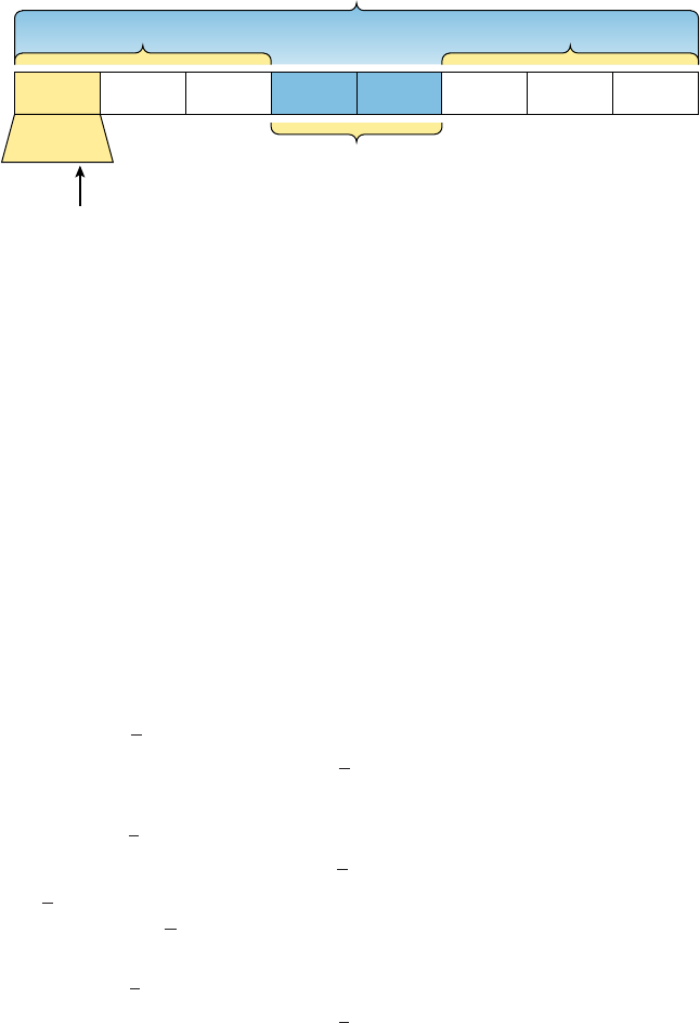
222
Chapter 7 ■ IP Addressing
c07.indd 04/02/2015 Page 222
FIGURE 7.3 EUI-64 interface ID assignment
OUI
The 7th Bit (U/L)
000000X0
Unique Address
16-Bit Interface ID
10 = Universally Unique
00 = Locally Unique
FF FE
Insert 16 bits
So where did that 2 in the beginning of the address come from? Another good question.
You see that part of the process of padding, called modi ed EUI-64 format, changes the
Universal/Local (U/L) bit to specify if the address is locally unique or globally unique. And
the bit that gets changed is the 7th bit in the address.
The reason for modifying the U/L bit is that, when using manually assigned addresses on
an interface, it means you can simply assign the address 2001:db8:1:9::1/64 instead of the
much longer 2001:db8:1:9:0200::1/64. Also, if you are going to manually assign link-local
addresses, you can assign the short address fe80::1 instead of the long fe80::0200:0:0:1
or fe80:0:0:0:0200::1. So, even though at rst glance it seems the IETF made this harder
for you to simply understand IPv6 addressing by ipping the 7th bit, in reality this made
addressing much simpler. Also, since most people don’t typically override the burned-in
address, the U/L bit is by default a 0, which means that you’ll see this inverted to a 1 most
of the time. But because you’re studying the exam objectives, you’ll need to look at invert-
ing it both ways.
Here are a few examples:
■ MAC address 0090:2716:fd0f
■ IPv6 EUI-64 address: 2001:0db8:0:1:0290:27ff:fe16:fd0f
That one was easy! Too easy for the exam objectives, so let’s do another:
■ MAC address aa12:bcbc:1234
■ IPv6 EUI-64 address: 2001:0db8:0:1:a812:bcff:febc:1234
10101010 represents the rst 8 bits of the MAC address (aa), which when inverting the
7th bit becomes 10101000. The answer becomes a8. I can’t tell you how important this is
for you to understand, so bear with me and work through a couple more!
■ MAC address 0c0c:dede:1234
■ IPv6 EUI-64 address: 2001:0db8:0:1:0e0c:deff:fede:1234

Internet Protocol Version 6 (IPv6)
223
c07.indd 04/02/2015 Page 223
0c is 00001100 in the rst 8 bits of the MAC address, which then becomes 00001110
when ipping the 7th bit. The answer is then 0e. Let’s practice one more:
■ MAC address 0b34:ba12:1234
■ IPv6 EUI-64 address: 2001:0db8:0:1:0934:baff:fe12:1234
0b in binary is 00001011, the rst 8 bits of the MAC address, which then becomes
00001001. The answer is 09.
Pay extra-special attention to this EUI-64 address assignment and be able
to convert the 7th bit based on the EUI-64 rules! Written Lab 14.3 will help
you practice this.
DHCPv6 (Stateful)
DHCPv6 works pretty much the same way DHCP does in v4, with the obvious differ-
ence that it supports IPv6’s new addressing scheme. And it might come as a surprise, but
there are a couple of other options that DHCP still provides for us that autocon guration
doesn’t. And no, I’m not kidding—in autocon guration, there’s absolutely no mention of
DNS servers, domain names, or many of the other options that DHCP has always gener-
ously provided for us via IPv4. This is a big reason that the odds favor DHCP’s continued
use in IPv6 into the future at least partially—maybe even most of the time!
This means that you’re de nitely going to need another server around to supply and
dispense all the additional, required information—maybe to even manage the address
assignment, if needed!
Migrating to IPv6
We certainly have talked a lot about how IPv6 works and how we can con gure it to work
on our networks, but what is doing that going to cost us? And how much work is it really
going to take? Good questions for sure, but the answers to them won’t be the same for every-
one. This is because how much you are going to end up having to pony up is highly depen-
dent upon what you’ve got going on already in terms of your infrastructure. Obviously,
if you’ve been making your really old routers and switches “last” and therefore have to
upgrade every one of them so that they’re IPv6 compliant, that could very well turn out to
be a good-sized chunk of change! Oh, and that sum doesn’t even include server and com-
puter operating systems (OSs) and the blood, sweat, and maybe even tears spent on making
all your applications compliant. So, my friend, it could cost you quite a bit! The good news
is that unless you’ve really let things go, many OSs and network devices have been IPv6
compliant for a few years—we just haven’t been using all their features until now.
Then there’s that other question about the amount of work and time. Straight up—this
one could still be pretty intense. No matter what, it’s going to take you some time to get all
224
Chapter 7 ■ IP Addressing
c07.indd 04/02/2015 Page 224
of your systems moved over and make sure that things are working correctly. And if you’re
talking about a huge network with tons of devices, well, it could take a really long time!
But don’t panic—that’s why migration strategies have been created, to allow for a gradual
integration. I’m going to show you three of the primary transition strategies available to
us. The rst is called dual stacking, which allows a device to have both the IPv4 and IPv6
protocol stacks running so it’s capable of continuing on with its existing communications
and simultaneously running newer IPv6 communications as they’re implemented. The next
strategy is the 6to4 tunneling approach; this is your choice if you have an all-IPv6 network
that must communicate over an IPv4 network to reach another IPv6 network. I’ll surprise
you with the third one just for fun!
Dual Stacking
This is the most common type of migration strategy because, well, it’s the easiest on us—
it allows our devices to communicate using either IPv4 or IPv6. Dual stacking lets you
upgrade your devices and applications on the network one at a time. As more and more
hosts and devices on the network are upgraded, more of your communication will happen
over IPv6, and after you’ve arrived—everything’s running on IPv6 and you get to remove
all the old IPv4 protocol stacks you no longer need.
6to4 Tunneling
6to4 tunneling is really useful for carrying IPv6 packets over a network that’s still running
IPv4. It’s quite possible that you’ll have IPv6 subnets or other portions of your network that
are all IPv6, and those networks will have to communicate with each other. Not so com-
plicated, but when you consider that you might nd this happening over a WAN or some
other network that you don’t control, well, that could be a bit ugly. So what do we do about
this if we don’t control the whole tamale? Create a tunnel that will carry the IPv6 traf c for
us across the IPv4 network, that’s what.
The whole idea of tunneling isn’t a dif cult concept, and creating tunnels really isn’t
as hard as you might think. All it really comes down to is snatching the IPv6 packet that’s
happily traveling across the network and sticking an IPv4 header onto the front of it. Kind
of like catch and release shing, except for the sh doesn’t get something plastered on its
face before being thrown back into the stream.
To get a picture of this, take a look at Figure 7.4.
Nice—but to make this happen, we’re going to need a couple of dual-stacked routers,
which I just demonstrated for you, so you should be good to go. Now we have to add a
little con guration to place a tunnel between those routers. Tunnels are pretty simple—we
just have to tell each router where the tunnel begins and where we want it to end up. The
opposite of this would be a 4to6 tunnel, which is rare to nd because this means your
whole business network is IPv4 (okay, this sounds normal so far) but you’re traversing an
IPv6-only Internet to get to another IPv4 network. Not so common at the time of
this writing.
One important note here—if the IPv4 network that you’re traversing in this 6to4 situa-
tion has a NAT translation point, it would absolutely break the tunnel encapsulation we’ve
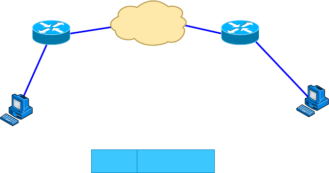
Summary
225
c07.indd 04/02/2015 Page 225
just created! Over the years, NAT has been upgraded a lot so that it can handle speci c
protocols and dynamic connections, and without one of these upgrades, NAT likes to
demolish most connections. And since this transition strategy isn’t present in most NAT
implementations, that means trouble.
FIGURE 7.4 A 6to4 tunnel
IPv4 Network
IPv4
IPv6 packet encapsulated in an IPv4 packet
IPv6 Packet
Dual Stack
Router1
IPv6 Host
and Network
IPv4: 192.168.30.1
IPv6: 2001:db8:1:1::1
IPv4: 192.168.40.1
IPv6: 2001:db8:2:2::1
IPv6 Host
and Network
Dual Stack
Router2
But there is a way around this little problem, and it’s called Teredo, which allows all
your tunnel traf c to be placed in UDP packets. NAT doesn’t blast away at UDP packets,
so they won’t get broken as other protocol packets do. So with Teredo in place and your
packets disguised under their UDP cloak, the packets will easily slip by NAT alive and well!
Miredo is a tunneling technique used on native IPv6 Linux and BSD Unix machines to
communicate on the IPv4 Internet directly without a dual-stack router or 6to4 tunnel. This
is rarely used.
Summary
In this chapter, I covered the very basics of both IPv4 and IPv6 and how they work in an
internetwork (remember that if the word IP is used alone, it is referring to just IPv4). As
you now know by reading this chapter, even when discussing and con guring the basics,
there is a lot to understand—and we just scratched the surface. But trust me when I say
this—you now know more than you’ll need to meet the Network+ objectives.
I discussed in detail the difference between each class of address and how to nd a
network address, broadcast address, and valid host range.
I explained why we need IPv6 and the bene ts associated with it. I followed that up by
covering addressing with IPv6 as well as how to use the shortened expressions. And during
226
Chapter 7 ■ IP Addressing
c07.indd 04/02/2015 Page 226
the discussion on addressing with IPv6, I showed you the different address types, plus the
special addresses reserved in IPv6.
The next chapter is very important, but it’s one that some people nd rather challenging,
so take a break and get ready for a really fun but long chapter on IP subnetting. I promise
not to torture you too much!
Exam Essentials
Remember the Class A range. The IP range for a Class A network is 1 through 126. This
provides 8 bits of network addressing and 24 bits of host addressing by default.
Remember the Class B range. The IP range for a Class B network is 128 through 191.
Class B addressing provides 16 bits of network addressing and 16 bits of host addressing
by default.
Remember the Class C range. The IP range for a Class C network is 192 through 223.
Class C addressing provides 24 bits of network addressing and 8 bits of host addressing by
default.
Remember the Private IP ranges. The Class A private address range is 10.0.0.0 through
10.255.255.255.
The Class B private address range is 172.16.0.0 through 172.31.255.255.
The Class C private address range is 192.168.0.0 through 192.168.255.255.
Remember the APIPA range. The IP address range for APIPA is 169.254.0.1 through
169.254.255.254. The client also con gures itself with a default Class B subnet mask of
255.255.0.0.
Understand why we need IPv6. Without IPv6, the world would soon be depleted of IP
addresses.
Understand link-local. Link-local addresses are like an IPv4 APIPA IP address, but it can’t
be routed at all, not even in your organization.
Understand unique local. This, like link-local, is like a private IP address in IPv4 and can-
not be routed to the Internet. However, the difference between link-local and unique local
is that unique local can be routed within your organization or company.
Remember IPv6 addressing. IPv6 addressing is not like IPv4 addressing. IPv6 addressing
has much more address space and the address is 128 bits long, represented in hexadecimal,
unlike an IPv4 address, which is only 32 bits long and represented in decimals.
Understand and be able to read a EUI-64 address with the 7th bit inverted. Hosts can use
autocon guration to obtain an IPv6 address, and one of the ways is through what is called
EUI-64. This takes the unique MAC address of a host and inserts FF:FE in the middle of
Written Lab
227
c07.indd 04/02/2015 Page 227
the address to change a 48-bit MAC address to a 64-bit interface ID. In addition to insert-
ing the 16 bits into the interface ID, the 7th bit of the rst byte is inverted, typically from a
0 to a 1. Practice this with Written Lab 7.3.
Written Lab
You can nd the answers in Appendix A.
Written Lab 7.1
Provide the answers to the following questions:
1. What is the valid range used for a Class C private IP address?
2. Name some of the benefits of IPv6 over IPv4.
3. What is the term for the autoconfiguration technology responsible for addresses that start
with 169.254?
4. What defines a unicast address?
5. What defines a multicast address?
6. What is the name for a 48-bit (6-byte) numerical address physically assigned to a network
interface, such as a NIC?
7. What gives IPv6 the ability to reference more addresses than IPv4?
8. What is the private address range for class B networks?
9. What is the Class C range of values for the first octet in decimal and in binary?
10. What is the 127.0.0.1 address used for?
Written Lab 7.2
In this lab, write the answers to the following IPv6 questions:
1. Which type of packet is addressed and delivered to only a single interface?
2. Which type of address is used just like a regular public routable address in IPv4?
3. Which type of address is not meant to be routed?
4. Which type of address is not meant to be routed to the Internet but is still globally unique?
5. Which type of address is meant to be delivered to multiple interfaces?
228
Chapter 7 ■ IP Addressing
c07.indd 04/02/2015 Page 228
6. Which type of address identifies multiple interfaces, but packets are delivered only to the
first address it finds?
7. Which addressing type is also referred to as one-to-nearest?
8. IPv4 had a loopback address of 127.0.0.1. What is the IPv6 loopback address?
9. What does a link-local address always start with?
10. What does a unique local unicast range start with?
Written Lab 7.3
In this lab, you will practice inverting the 7th bit of a EUI-64 address. Use the pre x
2001:db8:1:1/64 for each address.
1. Convert the following MAC address into a EUI-64 address: 0b0c:abcd:1234
2. Convert the following MAC address into a EUI-64 address: 060c:32f1:a4d2
3. Convert the following MAC address into a EUI-64 address: 10bc:abcd:1234
4. Convert the following MAC address into a EUI-64 address: 0d01:3a2f:1234
5. Convert the following MAC address into a EUI-64 address: 0a0c.abac.caba
Review Questions
229
c07.indd 04/02/2015 Page 229
Review Questions
You can nd the answers to the review questions in Appendix B.
1. Which of the following addresses is not allowed on the Internet?
A. 191.192.168.1
B. 191.168.169.254
C. 172.32.255.0
D. 172.31.12.251
2. A host automatically configured with an address from which of the following ranges indi-
cates an inability to contact a DHCP server?
A. 169.254.0.x with a mask of 255.255.255.0
B. 169.254.x.x with a mask of 255.255.0.0
C. 169.254.x.x with a mask of 255.255.255.0
D. 169.255.x.x with a mask of 255.255.0.0
3. Which statement regarding private IP addresses is most accurate?
A. Private addresses cannot be used in intranets that require routing.
B. Private addresses must be assigned by a registrar or ISP.
C. A remote host across the Internet cannot ping your host if it has a private address.
D. Private addresses can only be used by a single administrative domain.
4. Which of the following is a valid Class A address?
A. 191.10.0.1
B. 127.10.0.1
C. 128.10.0.1
D. 126.10.0.1
5. Which of the following is a valid Class B address?
A. 10.1.1.1
B. 126.1.1.1
C. 129.1.1.1
D. 192.168.1.1
6. Which of the following describes a broadcast address?
A. All network bits are on (1s).
B. All host bits are on (1s).
C. All network bits are off (0s).
D. All host bits are off (0s).
230
Chapter 7 ■ IP Addressing
c07.indd 04/02/2015 Page 230
7. Which of the following is a Layer 2 broadcast?
A. FF.FF.FF.EE.EE.EE
B. FF.FF.FF.FF.FF.FF
C. 255.255.255.255
D. 255.0.0.0
8. In a Class C IP address, how long is the network address?
A. 8 bits
B. 16 bits
C. 24 bits
D. 32 bits
9. Which of the following is true when describing a unicast address?
A. Packets addressed to a unicast address are delivered to a single interface.
B. These are your typical publicly routable addresses, just like regular publicly routable
addresses in IPv4.
C. These are like private addresses in IPv4 in that they are not meant to be routed.
D. These addresses are meant for nonrouting purposes, but they are almost globally
unique so it is unlikely they will have an address overlap.
10. A host is rebooted and you view the IP address that it was assigned. The address is
169.123.13.34. Which of the following happened?
A. The host received an APIPA address.
B. The host received a multicast address.
C. The host received a public address.
D. The host received a private address.
11. An IPv4 address uses 32 bits. How many bits is an IPv6 address?
A. 64
B. 128
C. 192
D. 255
12. Which of the following is true when describing a multicast address?
A. Packets addressed to a unicast address from a multicast address are delivered to a
single interface.
B. Packets are delivered to all interfaces identified by the address. This is also called a
one-to-many address.
C. It identifies multiple interfaces and is delivered to only one address. This address can
also be called one-to-one-of-many.
D. These addresses are meant for nonrouting purposes, but they are almost globally
unique so it is unlikely they will have an address overlap.
Review Questions
231
c07.indd 04/02/2015 Page 231
13. Which of the following is true when describing an anycast address?
A. Packets addressed to a unicast address from an anycast address are delivered to a single
interface.
B. Packets are delivered to all interfaces identified by the address. This is also called a
one-to-many address.
C. This address identifies multiple interfaces, and the anycast packet is delivered to only
one address; the closest one. This address can also be called one-to-nearest.
D. These addresses are meant for nonrouting purposes, but they are almost globally
unique so it is unlikely they will have an address overlap.
14. You want to ping the loopback address of your local host. Which two addresses could you
type? (Choose two.)
A.
ping 127.0.0.1
B.
ping 0.0.0.0
C.
ping ::1
D.
trace 0.0.::1
15. What two statements about IPv6 addresses are true?
A. Leading zeros are required.
B. Two colons (::) are used to represent successive hexadecimal fields of zeros.
C. Two colons (::) are used to separate fields.
D. A single interface will have multiple IPv6 addresses of different types.
16. What two statements about IPv4 and IPv6 addresses are true? (Choose two.)
A. An IPv6 address is 32 bits long, represented in hexadecimal.
B. An IPv6 address is 128 bits long, represented in decimal.
C. An IPv4 address is 32 bits long, represented in decimal.
D. An IPv6 address is 128 bits long, represented in hexadecimal.
17. Which of the following is a Class C network address?
A. 10.10.10.0
B. 127.0.0.1
C. 128.0.0.0
D. 192.255.254.0
18. Which of the following are private IP addresses? (Choose two.)
A. 12.0.0.1
B. 168.172.19.39
C. 172.20.14.36
D. 172.33.194.30
E. 192.168.24.43
232
Chapter 7 ■ IP Addressing
c07.indd 04/02/2015 Page 232
19. IPv6 unicast routing is running on the Corp router. Which of the following addresses
would be used as the EUI-64 address?
Corp#sh int f0/0
FastEthernet0/0 is up, line protocol is up
Hardware is AmdFE, address is 000d.bd3b.0d80 (bia 000d.bd3b.0d80)
[output cut]
A. FF02::3c3d:0d:bdff:fe3b:0d80
B. FE80::3c3d:2d:bdff:fe3b:0d80
C. FE80::3c3d:0d:bdff:fe3b:0d80
D. FE80::3c3d:2d:ffbd:3bfe:0d80
20. Which of the following is an invalid IP address for a host?
A. 10.0.0.1
B. 128.0.0.1
C. 224.0.0.1
D. 172.0.0.1

c08.indd 03/23/2015 Page 233
Chapter
8
IP Subnetting,
Troubleshooting IP,
and Introduction
to NAT
THE FOLLOWING COMPTIA NETWORK+
EXAM OBJECTIVES ARE COVERED IN THIS
CHAPTER:
✓ 1.3 Install and configure the following networking ser-
vices/applications
■ NAT
■ PAT
■ SNAT
■ DNAT
■ Port forwarding
✓ 1.8 Given a scenario, implement and configure the appro-
priate addressing sc hema
■ IPv4
■ Subnetting
■ NAT/PAT

c08.indd 03/23/2015 Page 234
This chapter’s focus will really zoom in on IP addressing to
ensure that you have it nailed down tight. This is an integral
aspect of networking, and it’s important to your success on
the exams and as a professional, too!
We’ll start with subnetting an IP network. You’re going to have to really apply yourself
because it takes time and practice in order to do subnetting correctly and quickly. So be
patient and do whatever it takes to get this stuff dialed in. This chapter truly is important—
possibly the most important chapter in this book for you to understand. Make it
part of you!
I’ll thoroughly cover IP subnetting from the very beginning. I know this might sound
weird to you, but I think you’ll be much better off if you can try to forget everything
you’ve learned about subnetting before reading this chapter—especially if you’ve been to a
Microsoft class!
I’ll also take you through IP address troubleshooting and walk you through each of the
steps recommended when you’re faced with troubleshooting an IP network. Finally, I’ll
nish up with an introduction to Network Address Translation (NAT)—there are various
types of NAT, and you need to know when you would use each one.
So get psyched—you’re about to go for quite a ride! This chapter will truly help you
understand IP addressing and networking, so don’t get discouraged or give up. If you
stick with it, I promise that one day you’ll look back on this and be really glad you
decided to stay the course. It’s one of those things that after you understand it, you’ll
laugh at that time, way back when, when you thought this was hard. So, are you ready
now? Let’s go!
To find up-to-the-minute updates for this chapter, please see
www.lammle.
com/networkplus
or the book’s website at
www.sybextestbanks.wiley.com
.
Subnetting Basics
In Chapter 7, “IP Addressing,” you learned how to de ne and nd the valid host ranges
used in a Class A, Class B, or Class C network address by turning the host bits all off and
then all on. This is very good, but here’s the catch: You were de ning only one network.
What would happen if you wanted to take one network address and create six networks
Subnetting Basics
235
c08.indd 03/23/2015 Page 235
from it? You would have to do something called subnetting, because that’s what allows you
to take one larger network and break it into a bunch of smaller networks.
There are loads of reasons in favor of subnetting, including the following bene ts:
Reduced Network Traffic We all appreciate less traf c of any kind. With networks, it’s
no different. Without trusty routers, packet traf c could grind the entire network down to
a near standstill. With routers, most traf c will stay on the local network; only packets
destined for other networks will pass through the router. Routers create broadcast
domains. The more broadcast domains you create, the smaller the broadcast domains and
the less network traf c on each network segment.
Optimized Network Performance This is the very cool reward you get when you reduce
network traf c!
Simplified Management It’s easier to identify and isolate network problems in a group of
smaller connected networks than within one gigantic network.
Facilitated Spanning of Large Geographical Distances Because WAN links are consider-
ably slower and more expensive than LAN links, a single large network that spans long
distances can create problems in every area previously listed. Connecting multiple smaller
networks makes the system more ef cient.
Next, we’re going to move on to subnetting a network address. This is the good
part—ready?
How to Create Subnets
To create subnetworks, you take bits from the host portion of the IP address and reserve
them to de ne the subnet address. This means fewer bits for hosts, so the more subnets, the
fewer bits are left available for de ning hosts.
Soon, I’ll show you how to create subnets, starting with Class C addresses. But before
you actually implement subnetting, you really need to determine your current requirements
as well as plan for future conditions.
Follow these steps—they’re your recipe for solid design:
1. Determine the number of required network IDs:
■ One for each subnet
■ One for each wide area network (WAN) connection
2. Determine the number of required host IDs per subnet:
■ One for each TCP/IP host
■ One for each router interface
3. Based on the previous requirements, create the following:
■ One subnet mask for your entire network
■ A unique subnet ID for each physical segment
■ A range of host IDs for each subnet

236
Chapter 8 ■ IP Subnetting, Troubleshooting IP, and Introduction to NAT
c08.indd 03/23/2015 Page 236
Understanding the Powers of 2
By the way, powers of 2 are really important to memorize for use with IP subnetting. To
review powers of 2, remember that when you see a number with another number to its
upper right (an exponent), this means you should multiply the number by itself as many
times as the upper number specifi es. For example, 23 is 2 × 2 × 2, which equals 8. Here’s a
list of powers of 2 that you should commit to memory:
21 = 2
22 = 4
23 = 8
24 = 16
25 = 32
26 = 64
27 = 128
28 = 256
29 = 512
210 = 1,024
211 = 2,048
212 = 4,096
213 = 8,192
214 = 16,384
If you hate math, don’t get stressed out about knowing all these exponents—it’s helpful to
know them, but it’s not absolutely necessary. Here’s a little trick, because you’re working
with 2s: Each successive power of 2 is double the previous one.
For example, all you have to do to remember the value of 29 is to fi rst know that 28 = 256.
Why? Because when you double 2 to the eighth power (256), you get 29 (or 512). To deter-
mine the value of 210, simply start at 28 = 256, and then double it twice.
You can go the other way as well. If you needed to know what 26 is, for example, you just cut
256 in half two times: once to reach 27 and then one more time to reach 26. Not bad, right?
Subnet Masks
For the subnet address scheme to work, every machine on the network must know which
part of the host address will be used as the subnet address. This is accomplished by assign-
ing a subnet mask to each machine. A subnet mask is a 32-bit value that allows the recipi-
ent of IP packets to distinguish the network ID portion of the IP address from the host ID
portion of the IP address.

Subnetting Basics
237
c08.indd 03/23/2015 Page 237
The network administrator creates a 32-bit subnet mask composed of 1s and 0s.
The 1s in the subnet mask represent the positions that refer to the network, or
subnet, addresses.
Not all networks need subnets, meaning they use the default subnet mask. This is basi-
cally the same as saying that a network doesn’t have a subnet address. Table 8.1 shows
the default subnet masks for Classes A, B, and C. These default masks cannot and do not
change. In other words, you can’t make a Class B subnet mask read 255.0.0.0. If you try,
the host will read that address as invalid and usually won’t even let you type it in. For a
Class A network, you can’t change the rst byte in a subnet mask; it must read 255.0.0.0 at
a minimum. Similarly, you cannot assign 255.255.255.255, because this is all 1s—a broad-
cast address. A Class B address must start with 255.255.0.0, and a Class C has to start
with 255.255.255.0. Check out Table 8.1.
TABLE 8.1 Default subnet mask
Class Format Default subnet mask
Anetwork.host.host.host 255.0.0.0
Bnetwork.network.host.host 255.255.0.0
Cnetwork.network.network.host 255.255.255.0
Classless Inter-Domain Routing (CIDR)
Another term you need to know is Classless Inter-Domain Routing (CIDR). It’s basically
the method that Internet service providers (ISPs) use to allocate a number of addresses to a
company or a home connection. They provide addresses in a certain block size; I’ll be going
into that in greater detail later in this chapter.
When you receive a block of addresses from an ISP, what you get will look something
like this: 192.168.10.32/28. This is telling you what your subnet mask is. The slash nota-
tion (/) means how many bits are turned on (1s). Obviously, the maximum could only be
/32 because a byte is 8 bits and there are 4 bytes in an IP address: 4 × 8 = 32. But keep in
mind that the largest subnet mask available (regardless of the class of address) can only be a
/30 because you have to keep at least 2 bits for host bits.
Take, for example, a Class A default subnet mask, which is 255.0.0.0. This means that
the rst byte of the subnet mask is all ones (1s), or 11111111. When referring to a slash
notation, you need to count all the 1s bits to gure out your mask. The 255.0.0.0 is consid-
ered a /8 because it has 8 bits that are 1s—that is, 8 bits that are turned on.
A Class B default mask would be 255.255.0.0, which is a /16 because 16 bits are (1s):
11111111.11111111.00000000.00000000.
Table 8.2 offers a listing of every available subnet mask and its equivalent CIDR slash
notation.

238
Chapter 8 ■ IP Subnetting, Troubleshooting IP, and Introduction to NAT
c08.indd 03/23/2015 Page 238
TABLE 8.2 CIDR values
Subnet Mask CIDR Value
255.0.0.0 /8
255.128.0.0 /9
255.192.0.0 /10
255.224.0.0 /11
255.240.0.0 /12
255.248.0.0 /13
255.252.0.0 /14
255.254.0.0 /15
255.255.0.0 /16
255.255.128.0 /17
255.255.192.0 /18
255.255.224.0 /19
255.255.240.0 /20
255.255.248.0 /21
255.255.252.0 /22
255.255.254.0 /23
255.255.255.0 /24
255.255.255.128 /25
255.255.255.192 /26
255.255.255.224 /27
255.255.255.240 /28
255.255.255.248 /29
255.255.255.252 /30

Subnetting Basics
239
c08.indd 03/23/2015 Page 239
Make a note to self that the /8 through /15 can be used only with Class A network
addresses; /16 through /23 can be used by Class A and B network addresses; /24 through
/30 can be used by Class A, B, and C network addresses. This is a big reason why most
companies use Class A network addresses. By being allowed the use of all subnet masks,
they gain the valuable bene t of maximum exibility for their network design.
Subnetting Class C Addresses
There are many different ways to subnet a network. The right way is the way that
works best for you. In a Class C address, only 8 bits are available for de ning the hosts.
Remember that subnet bits start at the left and go to the right, without skipping bits. This
means that the only Class C subnet masks can be those listed here:
Binary Decimal CIDR
00000000 0 /24
10000000 128 /25
11000000 192 /26
11100000 224 /27
11110000 240 /28
11111000 248 /29
11111100 252 /30
We can’t use a /31 or /32 because, remember, we have to leave at least 2 host bits for
assigning IP addresses to hosts.
Get ready for something special. I’m going to teach you an alternate method of subnet-
ting that makes it a whole lot easier to subnet larger numbers in no time. And trust me, you
really do need to be able to subnet fast!
Subnetting a Class C Address: The Fast Way!
When you’ve chosen a possible subnet mask for your network and need to determine the
number of subnets, valid hosts, and broadcast addresses of a subnet that the mask provides,
all you need to do is answer ve simple questions:
■ How many subnets does the chosen subnet mask produce?
■ How many valid hosts per subnet are available?
■ What are the valid subnets?
■ What’s the broadcast address of each subnet?
■ What are the valid hosts in each subnet?
240
Chapter 8 ■ IP Subnetting, Troubleshooting IP, and Introduction to NAT
c08.indd 03/23/2015 Page 240
At this point, it’s important that you both understand and have memorized your powers
of 2. Please refer to the sidebar “Understanding the Powers of 2” earlier in this chapter if
you need some help. Here’s how you get the answers to those ve big questions:
■ How many subnets? 2x = number of subnets. x is the number of masked bits, or the 1s.
For example, in 11000000, the number of 1s gives us 22 subnets. In this example, there
are 4 subnets.
■ How many hosts per subnet? 2y – 2 = number of hosts per subnet. y is the number of
unmasked bits, or the 0s. For example, in 11000000, the number of 0s gives us 26 – 2
hosts. In this example, there are 62 hosts per subnet. You need to subtract 2 for the
subnet address and the broadcast address, which are not valid hosts.
■ What are the valid subnets? 256 – subnet mask = block size, or increment number. An
example would be 256 – 192 = 64. The block size of a 192 mask is always 64. Start
counting at zero in blocks of 64 until you reach the subnet mask value, and these are
your subnets. 0, 64, 128, 192. Easy, huh?
■ What’s the broadcast address for each subnet? Now here’s the really easy part.
Because we counted our subnets in the last section as 0, 64, 128, and 192, the broad-
cast address is always the number right before the next subnet. For example, the 0
subnet has a broadcast address of 63 because the next subnet is 64. The 64 subnet has
a broadcast address of 127 because the next subnet is 128. And so on. And remember,
the broadcast of the last subnet is always 255.
■ What are the valid hosts? Valid hosts are the numbers between the subnets, omitting
all the 0s and all the 1s. For example, if 64 is the subnet number and 127 is the broad-
cast address, then 65–126 is the valid host range—it’s always the numbers between the
subnet address and the broadcast address.
I know this can truly seem confusing. But it really isn’t as hard as it seems to be at rst—
just hang in there! Why not try a few and see for yourself?
Subnetting Practice Examples: Class C Addresses
Here’s your opportunity to practice subnetting Class C addresses using the method I just
described. Exciting, isn’t it? We’re going to start with the rst Class C subnet mask and
work through every subnet that we can using a Class C address. When we’re done, I’ll show
you how easy this is with Class A and B networks too!
Practice Example #1C: 255.255.255.128 (/25)
Because 128 is 10000000 in binary, there is only 1 bit for subnetting, and there are 7 bits
for hosts. We’re going to subnet the Class C network address 192.168.10.0.
192.168.10.0 = Network address
255.255.255.128 = Subnet mask
Now, let’s answer the big ve:
■ How many subnets? Because 128 is 1 bit on (10000000), the answer is 21 = 2.
■ How many hosts per subnet? We have 7 host bits off (10000000), so the equation
is 27 – 2 = 126 hosts.
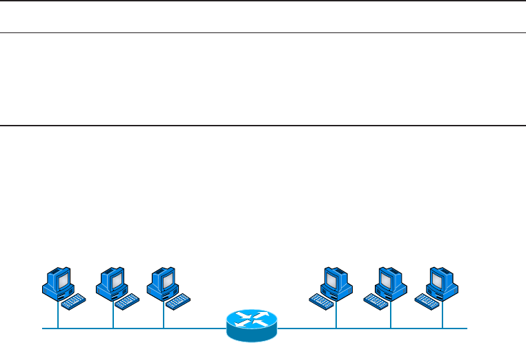
Subnetting Basics
241
c08.indd 03/23/2015 Page 241
■ What are the valid subnets? 256 – 128 = 128. Remember, we’ll start at zero and
count in our block size, so our subnets are 0, 128.
■ What’s the broadcast address for each subnet? The number right before the value
of the next subnet is all host bits turned on and equals the broadcast address. For
the 0 subnet, the next subnet is 128, so the broadcast of the 0 subnet is 127.
■ What are the valid hosts? These are the numbers between the subnet and broad-
cast address. The easiest way to find the hosts is to write out the subnet address
and the broadcast address. This way, the valid hosts are obvious. The following
table shows the 0 and 128 subnets, the valid host ranges of each, and the broadcast
address of both subnets:
Subnet 0128
First host 1 129
Last host 126 254
Broadcast 127 255
Before moving on to the next example, take a look at Figure 8.1. Okay, looking at a
Class C /25, it’s pretty clear there are two subnets. But so what—why is this signi cant?
Well actually, it’s not, but that’s not the right question. What you really want to know is
what you would do with this information!
FIGURE 8.1 Implementing a Class C /25 logical network
.1 .129
.2 .3 .4 .130 .131 .132
192.168.10.128192.168.10.0
Router#showiproute
[outputcut]
C192.168.10.0isdirectlyconnectedtoEthernet0.
C192.168.10.128isdirectlyconnectedtoEthernet1.
The key to understanding subnetting is to understand the very reason you need to do it.
And I’m going to demonstrate this by going through the process of building a physical net-
work—and let’s add a router. (We now have an internetwork, as I truly hope you already
know!) Because we added that router, in order for the hosts on our internetwork to com-
municate, they must now have a logical network addressing scheme. We could use IPv6,
but IPv4 is still the most popular, and it also just happens to be what we’re studying at the
moment, so that’s what we’re going with.

242
Chapter 8 ■ IP Subnetting, Troubleshooting IP, and Introduction to NAT
c08.indd 03/23/2015 Page 242
Now take a look back at Figure 8.1. By the way, the output you see below the diagram
is the routing table of the router, which was displayed by executing the
show ip route
command on the router. There are two physical networks, so we’re going to implement a
logical addressing scheme that allows for two logical networks. As always, it’s a really good
idea to look ahead and consider any likely growth scenarios—both short and long term,
but for this example, a /25 will do the trick.
Practice Example #2C: 255.255.255.192 (/26)
In this second example, we’re going to subnet the network address 192.168.10.0 using the
subnet mask 255.255.255.192.
192.168.10.0 = Network address
255.255.255.192 = Subnet mask
It’s time to answer the big ve:
■ How many subnets? Because 192 is 2 bits on (11000000), the answer is 22 = 4
subnets.
■ How many hosts per subnet? We have 6 host bits off (11000000), so the equation
is 26 – 2 = 62 hosts.
■ What are the valid subnets? 256 – 192 = 64. Remember, we start at zero and count
in our block size, so our subnets are 0, 64, 128, and 192.
■ What’s the broadcast address for each subnet? The number right before
the value of the next subnet is all host bits turned on and equals the broadcast
address. For the 0 subnet, the next subnet is 64, so the broadcast address for the
0 subnet is 63.
■ What are the valid hosts? These are the numbers between the subnet and broad-
cast address. The easiest way to find the hosts is to write out the subnet address
and the broadcast address. This way, the valid hosts are obvious. The following
table shows the 0, 64, 128, and 192 subnets, the valid host ranges of each, and the
broadcast address of each subnet:
The subnets (do this first) 064 128 192
Our first host (perform host addressing last) 1 65 129 193
Our last host 62 126 190 254
The broadcast address (do this second) 63 127 191 255
Again, before getting into the next example, you can see that we can now subnet a /26.
And what are you going to do with this fascinating information? Implement it! We’ll use
Figure 8.2 to practice a /26 network implementation.
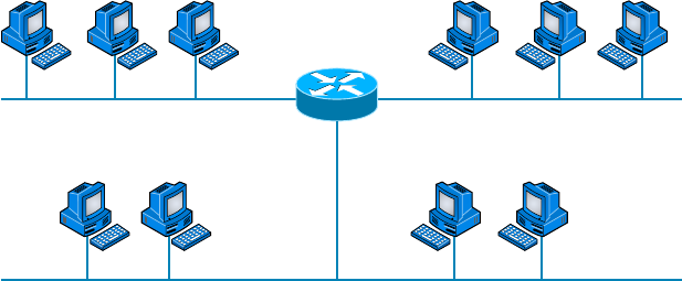
Subnetting Basics
243
c08.indd 03/23/2015 Page 243
FIGURE 8.2 Implementing a Class C /26 logical network
.65
.1
.129
.66 .67 .68 .130 .131 .132
192.168.10.128
192.168.10.0
192.168.10.64
.2 .3 .4 .5
Router#showiproute
[outputcut]
C192.168.10.0isdirectlyconnectedtoEthernet0
C192.168.10.64isdirectlyconnectedtoEthernet1
C192.168.10.128isdirectlyconnectedtoEthernet2
The /26 mask provides four subnetworks, and we need a subnet for each router
interface. With this mask, in this example, we actually have room to add another
router interface.
Practice Example #3C: 255.255.255.224 (/27)
This time, we’ll subnet the network address 192.168.10.0 and subnet mask
255.255.255.224.
192.168.10.0 = Network address
255.255.255.224 = Subnet mask
■ How many subnets? 224 is 11100000, so our equation is 23 = 8.
■ How many hosts? 25 – 2 = 30.
■ What are the valid subnets? 256 – 224 = 32. We just start at zero and count to
the subnet mask value in blocks (increments) of 32: 0, 32, 64, 96, 128, 160, 192,
and 224.
■ What’s the broadcast address for each subnet (always the number right before the
next subnet)?
■ What are the valid hosts (the numbers between the subnet number and the broad-
cast address)?
To answer the last two questions, rst just write out the subnets, and then write out the
broadcast addresses—the number right before the next subnet. Last, ll in the host addresses.
The following table gives you all the subnets for the 255.255.255.224 Class C subnet mask:

244
Chapter 8 ■ IP Subnetting, Troubleshooting IP, and Introduction to NAT
c08.indd 03/23/2015 Page 244
The subnet address 0 32 64 96 128 160 192 224
The first valid host 1 33 65 97 129 161 193 225
The last valid host 30 62 94 126 158 190 222 254
The broadcast address 31 63 95 127 159 191 223 255
Practice Example #4C: 255.255.255.240 (/28)
Let’s practice on another one:
192.168.10.0 = Network address
255.255.255.240 = Subnet mask
■ Subnets? 240 is 11110000 in binary. 24 = 16.
■ Hosts? 4 host bits, or 24 – 2 = 14.
■ Valid subnets? 256 – 240 = 16. 0, 16, 32, 48, 64, 80, 96, 112, 128, 144, 160, 176,
192, 208, 224, 240.
■ Broadcast address for each subnet?
■ Valid hosts?
To answer the last two questions, check out the following table. It gives you the subnets,
valid hosts, and broadcast addresses for each subnet. First, nd the address of each subnet
using the block size (increment). Second, nd the broadcast address of each subnet incre-
ment (it’s always the number right before the next valid subnet); then, just ll in the host
addresses. The following table shows the available subnets, hosts, and broadcast addresses
provided by a Class C network 255.255.255.240 mask:
Subnet 016 32 48 64 80 96 112 128 144 160 176 192 208 224 240
First host 1 17 33 49 65 81 97 113 129 145 161 177 193 209 225 241
Last host 14 30 46 62 78 94 110 126 142 158 174 190 206 222 238 254
Broadcast 15 31 47 63 79 95 111 127 143 159 175 191 207 223 239 255
Practice Example #5C: 255.255.255.248 (/29)
Let’s keep practicing:
192.168.10.0 = Network address
255.255.255.248 = Subnet mask
■ Subnets? 248 in binary = 11111000. 25 = 32.
■ Hosts? 23 – 2 = 6.

Subnetting Basics
245
c08.indd 03/23/2015 Page 245
■ Valid subnets? 256 – 248 = 8, start at zero: 0, 8, 16, 24, 32, 40, 48, 56, 64, 72,
80, 88, 96, 104, 112, 120, 128, 136, 144, 152, 160, 168, 176, 184, 192, 200, 208,
216, 224, 232, 240, and 248.
■ Broadcast address for each subnet?
■ Valid hosts?
Take a look at the following table. It shows some of the subnets ( rst four and last four
only), valid hosts, and broadcast addresses for the Class C 255.255.255.248 mask:
Subnet 0 8 16 24 … 224 232 240 248
First host 1 9 17 25 … 225 233 241 249
Last host 6 14 22 30 … 230 238 246 254
Broadcast 7 15 23 31 … 231 239 247 255
Practice Example #6C: 255.255.255.252 (/30)
I know, I know—but just one more:
192.168.10.0 = Network address
255.255.255.252 = Subnet mask
■ Subnets? 64.
■ Hosts? 2.
■ Valid subnets? 0, 4, 8, 12, and so on, all the way to 252.
■ Broadcast address for each subnet (always the number right before the next
subnet)?
■ Valid hosts (the numbers between the subnet number and the broadcast
address)?
The following table shows you the subnet, valid host, and broadcast address of the rst
four and last four subnets in the 255.255.255.252 Class C subnet:
Subnet 0 4 8 12 … 240 244 248 252
First host 1 5 9 13 … 241 245 249 253
Last host 2 6 10 14 … 242 246 250 254
Broadcast 3 7 11 15 … 243 247 251 255

246
Chapter 8 ■ IP Subnetting, Troubleshooting IP, and Introduction to NAT
c08.indd 03/23/2015 Page 246
Subnetting in Your Head: Class C Addresses
It really is possible to subnet in your head by looking at a valid IP address and subnet
mask. This is extremely important for IP addressing and troubleshooting. Even if you don’t
believe me that you can subnet in your head, I’ll show you how. And it’s not all that hard
either—take the following example: What is the subnet, broadcast address, and valid host
range that this host IP address is a part of?
192.168.10.33 = Host address
255.255.255.224 = Subnet mask
Should We Really Use This Mask That Provides Only Two Hosts?
Imagine you are the network administrator for Acme Corporation in San Francisco, with
dozens of WAN links connecting to your corporate offi ce. Right now your network is a
classful network, which means that the same subnet mask is on each host and router
interface. You’ve read about classless routing where you can have different size masks,
but you don’t know what to use on your point-to-point WAN links. Is 255.255.255.252 (/30)
a helpful mask in this situation?
Yes, this is a very helpful mask in wide area networks.
If you use the 255.255.255.0 mask, then each network will have 254 hosts, but you only
use two addresses with a WAN link! That is a waste of 252 hosts per subnet. If you use
the 255.255.255.252 mask, then each subnet has only 2 hosts, and you don’t waste pre-
cious addresses.
First, determine the subnet and broadcast address of this IP address. You can do this
by answering question 3 of the big ve questions: 256 – 224 = 32. Start at zero: 0, 32,
64. The address of 33 falls between the two subnets of 32 and 64 and must be part of the
192.168.10.32 subnet. The next subnet is 64, so the broadcast address of the 32 subnet is
63. (Remember that the broadcast address of a subnet is always the number right before the
next subnet.) The valid host range is 33–62 (the numbers between the subnet and broadcast
address). I told you this is easy!
Okay, let’s try another one. What is the subnet, broadcast address, and valid host range
that this host IP address is a part of?
192.168.10.33 = Host address
255.255.255.240 = Subnet mask
256 – 240 = 16. Start at zero and count till you pass the valid host in the problem:
0, 16, 32, 48. Bingo—the host address is between the 32 and 48 subnets. The subnet is
Subnetting Basics
247
c08.indd 03/23/2015 Page 247
192.168.10.32, and the broadcast address is 47 (the next subnet is 48). The valid host range
is 33–46 (the numbers between the subnet number and the broadcast address).
We need to do more, just to make sure you have this down.
You have a host address of 192.168.10.174 with a mask of 255.255.255.240. What is the
subnet, broadcast address, and valid host range that this host IP address is a part of?
The mask is 240, so we need our block size: 256 – 240 = 16. Just keep adding 16 until
we pass the host address of 174, starting at zero, of course: 0, 16, 32, 48, 64, 80, 96, 112,
128, 144, 160, 176. The host address of 174 is between 160 and 176, so the subnet is 160.
The broadcast address is 175; the valid host range is 161–174. That was a tough one.
Let’s do one more just for fun. This is the easiest one of all Class C subnetting:
192.168.10.17 = Host address
255.255.255.252 = Subnet mask
What subnet and broadcast address is this IP address a part of? 256 – 252 = 4. Start at
zero (always start at zero unless told otherwise), 0, 4, 8, 12, 16, 20, and so on. You’ve got
it! The host address is between the 16 and 20 subnets. The subnet is 192.168.10.16, and the
broadcast address is 19. The valid host range is 17–18.
Now that you’re all over Class C subnetting, let’s move on to Class B subnetting. But
before we do, let’s do a quick review.
So What Do You Know Now?
Here’s where you can really apply what you’ve learned so far and begin committing it all to
memory. This is a very cool section that I’ve been using in my classes for years. It will really
help you nail down subnetting!
When you see a subnet mask or slash notation (CIDR), you should know the following
when working with Class C networks.
/25
What do you know about a /25?
■ 128 mask
■ 1 bit on and 7 bits off (10000000)
■ Block size of 128
■ 2 subnets, each with 126 hosts
/26
And what do you know about a /26?
■ 192 mask
■ 2 bits on and 6 bits off (11000000)
■ Block size of 64
■ 4 subnets, each with 62 hosts
248
Chapter 8 ■ IP Subnetting, Troubleshooting IP, and Introduction to NAT
c08.indd 03/23/2015 Page 248
/27
What about a /27?
■ 224 mask
■ 3 bits on and 5 bits off (11100000)
■ Block size of 32
■ 8 subnets, each with 30 hosts
/28
And what about a /28?
■ 240 mask
■ 4 bits on and 4 bits off
■ Block size of 16
■ 16 subnets, each with 14 hosts
/29
What do you know about a /29?
■ 248 mask
■ 5 bits on and 3 bits off
■ Block size of 8
■ 32 subnets, each with 6 hosts
/30
And last, what about a /30?
■ 252 mask
■ 6 bits on and 2 bits off
■ Block size of 4
■ 64 subnets, each with 2 hosts
Regardless of whether you have a Class A, Class B, or Class C address, the /30 mask
will provide you with only two hosts, ever. This mask is suited almost exclusively for use on
point-to-point links.
If you can memorize this “So What Do You Know Now?” section, you’ll be much
better off in your day-to-day job and in your studies. Try saying it out loud, which helps
you memorize things—yes, your signi cant other and/or coworkers will think you’ve lost
it, but they probably already do if you’re in the networking eld. And if you’re not yet in
the networking eld but are studying all this to break into it, you might as well have people
start thinking you’re a little “different” now because they will eventually anyway.
It’s also helpful to write these on some type of ashcards and have people test your skill.
You’d be amazed at how fast you can get subnetting down if you memorize block sizes as
well as this “So What Do You Know Now?” section.

Subnetting Basics
249
c08.indd 03/23/2015 Page 249
Subnetting Class B Addresses
Before we dive into this, let’s look at all the possible Class B subnet masks. Notice that we
have a lot more possible subnet masks than we do with a Class C network address:
255.255.0.0 (/16)
255.255.128.0 (/17)
255.255.192.0 (/18)
255.255.224.0 (/19)
255.255.240.0 (/20)
255.255.248.0 (/21)
255.255.252.0 (/22)
255.255.254.0 (/23)
255.255.255.0 (/24)
255.255.255.128 (/25)
255.255.255.192 (/26)
255.255.255.224 (/27)
255.255.255.240 (/28)
255.255.255.248 (/29)
255.255.255.252 (/30)
We know the Class B network address has 16 bits available for host addressing. This
means we can use up to 14 bits for subnetting (because we have to leave at least 2 bits for
host addressing). Using a /16 means you are not subnetting with Class B, but it is a mask
you can use.
By the way, do you notice anything interesting about that list of subnet
values—a pattern, maybe? Ah-ha! That’s exactly why I had you memorize
the binary-to-decimal numbers at the beginning of this section. Because
subnet mask bits start on the left and move to the right and bits can’t
be skipped, the numbers are always the same regardless of the class of
address. Memorize this pattern.
The process of subnetting a Class B network is pretty much the same as it is for a Class
C, except that you have more host bits and you start in the third octet.
Use the same subnet numbers for the third octet with Class B that you used for the
fourth octet with Class C, but add a 0 to the network portion and a 255 to the broadcast
section in the fourth octet. The following table shows you an example host range of two
subnets used in a Class B 240 (/20) subnet mask:

250
Chapter 8 ■ IP Subnetting, Troubleshooting IP, and Introduction to NAT
c08.indd 03/23/2015 Page 250
First subnet Second Subnet
16.0 32.0
31.255 47.255
Notice that these are the same numbers we used in the fourth octet with a /28 mask,
but we moved them to the third octet and added a .0 and .255 at the end. Just add the valid
hosts between the numbers, and you’re set!
Subnetting Practice Examples: Class B Addresses
This section will give you an opportunity to practice subnetting Class B addresses. Again,
I have to mention that this is the same as subnetting with Class C, except we start in the
third octet—with the exact same numbers!
Practice Example #1B: 255.255.128.0 (/17)
Let’s take a look at our rst example:
172.16.0.0 = Network address
255.255.128.0 = Subnet mask
■ Subnets? 21 = 2 (same as Class C).
■ Hosts? 215 – 2 = 32,766 (7 bits in the third octet, and 8 in the fourth).
■ Valid subnets? 256 – 128 = 128. 0, 128. Remember that subnetting in Class B
starts in the third octet, so the subnet numbers are really 0.0 and 128.0, as shown
in the next table. These are the exact numbers we used with Class C; we use them
in the third octet and add a 0 in the fourth octet for the network address.
■ Broadcast address for each subnet?
The following table shows the two subnets available, the valid host range, and the
broadcast address of each:
Subnet 0.0 128.0
First host 0.1 128.1
Last host 127.254 255.254
Broadcast 127.255 255.255
Notice that we just added the fourth octet’s lowest and highest values and came up with
the answers. And again, it’s done exactly the same way as for a Class C subnet. We just
use the same numbers in the third octet and added 0 and 255 in the fourth octet—pretty

Subnetting Basics
251
c08.indd 03/23/2015 Page 251
simple, huh? I really can’t say this enough: It’s not hard. The numbers never change. We
just use them in different octets!
Practice Example #2B: 255.255.192.0 (/18)
Let’s take a look at a second example with Class B.
172.16.0.0 = Network address
255.255.192.0 = Subnet mask
■ Subnets? 22 = 4.
■ Hosts? 214 – 2 = 16,382 (6 bits in the third octet, and 8 in the fourth).
■ Valid subnets? 256 – 192 = 64. 0, 64, 128, 192. Remember that we’re in the third
octet, so the subnet numbers are really 0.0, 64.0, 128.0, and 192.0, as shown in
the next table.
■ Broadcast address for each subnet?
■ Valid hosts?
The following table shows the four subnets available, the valid host range, and the
broadcast address of each:
Subnet 0.0 64.0 128.0 192.0
First host 0.1 64.1 128.1 192.1
Last host 63.254 127.254 191.254 255.254
Broadcast 63.255 127.255 191.255 255.255
Again, it’s pretty much the same as it is for a Class C subnet—we just added 0 and 255
in the fourth octet for each subnet in the third octet.
Practice Example #3B: 255.255.240.0 (/20)
Let’s take a look:
172.16.0.0 = Network address
255.255.240.0 = Subnet mask
■ Subnets? 24 = 16.
■ Hosts? 212 – 2 = 4094.
■ Valid subnets? 256 – 240 = 0, 16, 32, 48, and so on, up to 240. Notice that these
are the same numbers as a Class C 240 mask—we just put them in the third octet
and add a 0 and 255 in the fourth octet.
■ Broadcast address for each subnet?
■ Valid hosts?

252
Chapter 8 ■ IP Subnetting, Troubleshooting IP, and Introduction to NAT
c08.indd 03/23/2015 Page 252
The following table shows the rst four subnets, valid hosts, and broadcast addresses in
a Class B 255.255.240.0 mask:
Subnet 0.0 16.0 32.0 48.0
First host 0.1 16.1 32.1 48.1
Last host 15.254 31.254 47.254 63.254
Broadcast 15.255 31.255 47.255 63.255
Practice Example #4B: 255.255.254.0 (/23)
Let’s take a look:
172.16.0.0 = Network address
255.255.254.0 = Subnet mask
■ Subnets? 27 = 128.
■ Hosts? 29 – 2 = 510.
■ Valid subnets? 256 – 254 = 0, 2, 4, 6, 8, and so on, up to 254.
■ Broadcast address for each subnet?
■ Valid hosts?
The following table shows the rst ve subnets, valid hosts, and broadcast addresses in a
Class B 255.255.254.0 mask:
Subnet 0.0 2.0 4.0 6.0 8.0
First host 0.1 2.1 4.1 6.1 8.1
Last host 1.254 3.254 5.254 7.254 9.254
Broadcast 1.255 3.255 5.255 7.255 9.255
Practice Example #5B: 255.255.255.0 (/24)
Contrary to popular belief, 255.255.255.0 used with a Class B network address is not
called a Class B network with a Class C subnet mask. It’s amazing how many people see
this mask used in a Class B network and think it’s a Class C subnet mask. This is a Class
B subnet mask with 8 bits of subnetting—it’s considerably different from a Class C mask.
Subnetting this address is fairly simple:

Subnetting Basics
253
c08.indd 03/23/2015 Page 253
172.16.0.0 = Network address
255.255.255.0 = Subnet mask
■ Subnets? 28 = 256.
■ Hosts? 28 – 2 = 254.
■ Valid subnets? 256 – 255 = 1. 0, 1, 2, 3, and so on, all the way to 255.
■ Broadcast address for each subnet?
■ Valid hosts?
The following table shows the rst four and last two subnets, the valid hosts, and the
broadcast addresses in a Class B 255.255.255.0 mask:
Subnet 0.0 1.0 2.0 3.0 ... 254.0 255.0
First host 0.1 1.1 2.1 3.1 ... 254.1 255.1
Last host 0.254 1.254 2.254 3.254 ... 254.254 255.254
Broadcast 0.255 1.255 2.255 3.255 ... 254.255 255.255
Practice Example #6B: 255.255.255.128 (/25)
This is one of the hardest subnet masks you can play with. And worse, it actually is a really
good subnet to use in production because it creates over 500 subnets with a whopping 126
hosts for each subnet—a nice mixture. So, don’t skip over it!
172.16.0.0 = Network address
255.255.255.128 = Subnet mask
■ Subnets? 29 = 512.
■ Hosts? 27 – 2 = 126.
■ Valid subnets? Now for the tricky part. 256 – 255 = 1. 0, 1, 2, 3, and so on for
the third octet. But you can’t forget the one subnet bit used in the fourth octet.
Remember when I showed you how to figure one subnet bit with a Class C mask?
You figure this out the same way. (Now you know why I showed you the 1-bit sub-
net mask in the Class C section—to make this part easier.) You actually get two
subnets for each third octet value, hence the 512 subnets. For example, if the third
octet is showing subnet 3, the two subnets would actually be 3.0 and 3.128.
■ Broadcast address for each subnet?
■ Valid hosts?
The following table shows how you can create subnets, valid hosts, and broadcast
addresses using the Class B 255.255.255.128 subnet mask (the rst eight subnets are
shown, and then the last two subnets):

254
Chapter 8 ■ IP Subnetting, Troubleshooting IP, and Introduction to NAT
c08.indd 03/23/2015 Page 254
Subnet 0.0 0.128 1.0 1.128 2.0 2.128 3.0 3.128 ... 255.0 255.128
First host 0.1 0.129 1.1 1.129 2.1 2.129 3.1 3.129 ... 255.1 255.129
Last host 0.126 0.254 1.126 1.254 2.126 2.254 3.126 3.254 ... 255.126 255.254
Broadcast 0.127 0.255 1.127 1.255 2.127 2.255 3.127 3.255 ... 255.127 255.255
Practice Example #7B: 255.255.255.192 (/26)
Now, this is where Class B subnetting gets easy. Because the third octet has a 255 in the
mask section, whatever number is listed in the third octet is a subnet number. However,
now that we have a subnet number in the fourth octet, we can subnet this octet just as we
did with Class C subnetting. Let’s try it:
172.16.0.0 = Network address
255.255.255.192 = Subnet mask
■ Subnets? 210 = 1024.
■ Hosts? 26 – 2 = 62.
■ Valid subnets? 256 – 192 = 64. The subnets are shown in the following table. Do
these numbers look familiar?
■ Broadcast address for each subnet?
■ Valid hosts?
The following table shows the rst eight subnet ranges, valid hosts, and broadcast
addresses:
Subnet 0.0 0.64 0.128 0.192 1.0 1.64 1.128 1.192
First host 0.1 0.65 0.129 0.193 1.1 1.65 1.129 1.193
Last host 0.62 0.126 0.190 0.254 1.62 1.126 1.190 1.254
Broadcast 0.63 0.127 0.191 0.255 1.63 1.127 1.191 1.255
Notice that for each subnet value in the third octet, you get subnets 0, 64, 128, and 192
in the fourth octet.
Practice Example #8B: 255.255.255.224 (/27)
This is done the same way as the preceding subnet mask, except that we have more subnets
and fewer hosts per subnet available.

Subnetting Basics
255
c08.indd 03/23/2015 Page 255
172.16.0.0 = Network address
255.255.255.224 = Subnet mask
■ Subnets? 211 = 2048.
■ Hosts? 25 – 2 = 30.
■ Valid subnets? 256 – 224 = 32. 0, 32, 64, 96, 128, 160, 192, 224.
■ Broadcast address for each subnet?
■ Valid hosts?
The following table shows the rst eight subnets:
Subnet 0.0 0.32 0.64 0.96 0.128 0.160 0.192 0.224
First host 0.1 0.33 0.65 0.97 0.129 0.161 0.193 0.225
Last host 0.30 0.62 0.94 0.126 0.158 0.190 0.222 0.254
Broadcast 0.31 0.63 0.95 0.127 0.159 0.191 0.223 0.255
This next table shows the last eight subnets:
Subnet 255.0 255.32 255.64 255.96 255.128 255.160 255.192 255.224
First host 255.1 255.33 255.65 255.97 255.129 255.161 255.193 255.225
Last host 255.30 255.62 255.94 255.126 255.158 255.190 255.222 255.254
Broadcast 255.31 255.63 255.95 255.127 255.159 255.191 255.223 255.255
Subnetting in Your Head: Class B Addresses
Are you nuts? Subnet Class B addresses in our heads? It’s actually easier than writing it
out—I’m not kidding! Let me show you the steps:
1. What subnet and broadcast address is the IP address 172.16.10.33 255.255.255.224
(/27) a member of?
The interesting octet is the fourth octet. 256 – 224 = 32. 32 + 32 = 64. Bingo: 33 is
between 32 and 64. However, remember that the third octet is considered part of the
subnet, so the answer is the 10.32 subnet. The broadcast is 10.63 because 10.64 is the
next subnet. That was a pretty easy one.
2. What subnet and broadcast address is the IP address 172.16.66.10 255.255.192.0 (/18)
a member of?

256
Chapter 8 ■ IP Subnetting, Troubleshooting IP, and Introduction to NAT
c08.indd 03/23/2015 Page 256
The interesting octet is the third octet instead of the fourth octet. 256 – 192 = 64.
0, 64, 128. The subnet is 172.16.64.0. The broadcast must be 172.16.127.255 because
128.0 is the next subnet.
Notice in the last example I started counting at zero. This is called ip sub-
net-zero. It is a command that if executed on a router, allows us to use the
zero subnet as our first subnet. This may or may not be enabled on your
router. If it is not enabled, then you cannot start counting subnets at zero.
Most routers, if not all routers these days, support ip subnet-zero.
3. What subnet and broadcast address is the IP address 172.16.50.10 255.255.224.0 (/19)
a member of?
256 – 224 = 0, 32, 64 (remember, we always start counting at zero). The subnet is
172.16.32.0, and the broadcast must be 172.16.63.255 because 64.0 is the next subnet.
4. What subnet and broadcast address is the IP address 172.16.46.255 255.255.240.0
(/20) a member of?
256 – 240 = 16. The third octet is interesting to us. 0, 16, 32, 48. This subnet address
must be in the 172.16.32.0 subnet, and the broadcast must be 172.16.47.255 because
48.0 is the next subnet. So, yes, 172.16.46.255 is a valid host.
5. What subnet and broadcast address is the IP address 172.16.45.14 255.255.255.252
(/30) a member of?
Where is the interesting octet? 256 – 252 = 0, 4, 8, 12, 16 (in the fourth octet). The
subnet is 172.16.45.12, with a broadcast of 172.16.45.15 because the next subnet is
172.16.45.16.
6. What is the subnet and broadcast address of the host 172.16.88.255/20?
What is a /20? If you can’t answer this, you can’t answer this question, can you? A
/20 is 255.255.240.0, which gives us a block size of 16 in the third octet, and because
no subnet bits are on in the fourth octet, the answer is always 0 and 255 in the fourth
octet. 0, 16, 32, 48, 64, 80, 96. Bingo: 88 is between 80 and 96, so the subnet is 80.0
and the broadcast address is 95.255.
7. A router receives a packet on an interface with a destination address of
172.16.46.191/26. What will the router do with this packet?
Discard it. Do you know why? 172.16.46.196⁄26 is a 255.255.255.192 mask, which
gives us a block size of 64. Our subnets are then 0, 64, 128, 192. 191 is the broadcast
address of the 128 subnet, so a router, by default, will discard any broadcast packets.
Troubleshooting IP Addressing
Troubleshooting IP addressing is obviously an important skill because running into trouble
somewhere along the way is pretty much a sure thing, and it’s going to happen to you.
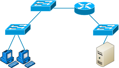
Troubleshooting IP Addressing
257
c08.indd 03/23/2015 Page 257
No—I’m not a pessimist; I’m just keeping it real. Because of this nasty fact, it will be great
when you can save the day because you can both gure out (diagnose) the problem and x
it on an IP network whether you’re at work or at home!
Let’s use Figure 8.3 as an example of your basic IP trouble—poor Sally can’t log in to
the Windows server. Do you deal with this by calling the Microsoft team to tell them their
server is a pile of junk and causing all your problems? Tempting, but probably not such a
great idea—let’s rst double-check our network instead. Check out Figure 8.3.
FIGURE 8.3 Basic IP troubleshooting
E0
172.16.10.1
Sally
172.16.10.2
Server
172.16.20.2
Let’s get started by going over the basic troubleshooting steps. They’re pretty simple, but
important nonetheless. Pretend you’re at Sally’s host and she’s complaining that she can’t
communicate to a server that just happens to be on a remote network:
1. Open a command prompt window on Sally’s host, and ping 127.0.0.1.
C:\>ping 127.0.0.1
Pinging 127.0.0.1 with 32 bytes of data:
Reply from 127.0.0.1: bytes=32 time<1ms TTL=128
Reply from 127.0.0.1: bytes=32 time<1ms TTL=128
Reply from 127.0.0.1: bytes=32 time<1ms TTL=128
Reply from 127.0.0.1: bytes=32 time<1ms TTL=128
Ping statistics for 127.0.0.1:
Packets: Sent = 4, Received = 4, Lost = 0 (0% loss),
Approximate round trip times in milli-seconds:
Minimum = 0ms, Maximum = 0ms, Average = 0ms
This is the diagnostic, or loopback, address, and if you get a successful ping, your IP
stack is considered to be initialized. If it fails, then you have an IP stack failure and
need to reinstall TCP/IP on the host.

258
Chapter 8 ■ IP Subnetting, Troubleshooting IP, and Introduction to NAT
c08.indd 03/23/2015 Page 258
If you ping the loopback address and receive an “unable to contact IP
driver, error code 2” message, you need to reinstall the TCP/IP protocol
suite on the host.
2. Now, from the same command prompt window, ping the IP address of the local host.
C:\>ping 172.16.10.2
Pinging 172.16.10.2 with 32 bytes of data:
Reply from 172.16.10.2: bytes=32 time<1ms TTL=128
Reply from 172.16.10.2: bytes=32 time<1ms TTL=128
Reply from 172.16.10.2: bytes=32 time<1ms TTL=128
Reply from 172.16.10.2: bytes=32 time<1ms TTL=128
Ping statistics for 172.16.10.2:
Packets: Sent = 4, Received = 4, Lost = 0 (0% loss),
Approximate round trip times in milli-seconds:
Minimum = 0ms, Maximum = 0ms, Average = 0ms
If that’s successful, your Network Interface Card (NIC) is functioning. If it fails, there
is a problem with the NIC. Success here doesn’t mean that a cable is plugged into the
NIC, only that the IP protocol stack on the host can communicate to the NIC (via the
LAN driver).
3. From the command prompt window, ping the default gateway (router).
C:\>ping 172.16.10.1
Pinging 172.16.10.1 with 32 bytes of data:
Reply from 172.16.10.1: bytes=32 time<1ms TTL=128
Reply from 172.16.10.1: bytes=32 time<1ms TTL=128
Reply from 172.16.10.1: bytes=32 time<1ms TTL=128
Reply from 172.16.10.1: bytes=32 time<1ms TTL=128
Ping statistics for 172.16.10.1:
Packets: Sent = 4, Received = 4, Lost = 0 (0% loss),
Approximate round trip times in milli-seconds:
Minimum = 0ms, Maximum = 0ms, Average = 0ms
If the ping works, it means that the NIC is plugged into the network and can commu-
nicate on the local network. If it fails, you have a local physical network problem that
could be anywhere from the NIC to the router.
4. If steps 1 through 3 were successful, try to ping the remote server.
C:\>ping 172.16.20.2
Pinging 172.16.20.2 with 32 bytes of data:
Reply from 172.16.20.2: bytes=32 time<1ms TTL=128
Reply from 172.16.20.2: bytes=32 time<1ms TTL=128
Reply from 172.16.20.2: bytes=32 time<1ms TTL=128
Reply from 172.16.20.2: bytes=32 time<1ms TTL=128
Troubleshooting IP Addressing
259
c08.indd 03/23/2015 Page 259
Ping statistics for 172.16.20.2:
Packets: Sent = 4, Received = 4, Lost = 0 (0% loss),
Approximate round trip times in milli-seconds:
Minimum = 0ms, Maximum = 0ms, Average = 0ms
If that works, then you know that you have IP communication between the local host
and the remote server. You also know that the remote physical network is working.
If the user still can’t communicate with the server after steps 1 through 4 are successful,
you probably have some type of name resolution problem and need to check your Domain
Name System (DNS) settings. But if the ping to the remote server fails, then you know you
have some type of remote physical network problem and need to go to the server and work
through steps 1 through 3 until you nd the snag.
Before we move on to determining IP address problems and how to x them, I just want
to mention some basic yet handy DOS commands that you can use to help troubleshoot
your network from both a PC and a Cisco router (the commands might do the same thing,
but they are implemented differently):
Packet InterNet Groper (
ping
) Uses an Internet Control Message Protocol (ICMP) echo
request and replies to test if a host IP stack is initialized and alive on the network.
traceroute
Displays the list of routers on a path to a network destination by using Time-
to-Live (TTL) time-outs and ICMP error messages. This command will work on a router,
MAC, or Linux box but not from a Windows command prompt.
tracert
Same command as
traceroute
, but it’s a Microsoft Windows command and will
not work on other devices, like a Cisco router or Unix box.
arp -a
Displays IP-to-MAC-address mappings on a Windows PC.
ipconfig /all
Used only from a DOS prompt. Shows you the PC network con guration.
Once you’ve gone through all these steps and used the appropriate DOS commands, if
necessary, what do you do if you nd a problem? How do you go about xing an IP address
con guration error? That’s exactly what you’re going to learn about next—how to deter-
mine speci c IP address problems and what you can do to x them.
Determining IP Address Problems
It’s common for a host, router, or other network device to be con gured with the wrong IP
address, subnet mask, or default gateway. Because this happens way too often, I’m going to
teach you how to both determine and x IP address con guration errors.
Once you’ve worked through the four basic steps of troubleshooting and determined
there’s a problem, you obviously then need to nd and x it. It really helps to draw out the
network and IP addressing scheme. If it’s already done, consider yourself lucky and go buy
a lottery ticket because although it should be done, it rarely is. And if it is, it’s usually out-
dated or inaccurate anyway. Typically it is not done, and you’ll probably just have to bite
the bullet and start from scratch.
Once you have your network accurately drawn out, including the IP addressing scheme,
you need to verify each host’s IP address, mask, and default gateway address to determine

260
Chapter 8 ■ IP Subnetting, Troubleshooting IP, and Introduction to NAT
c08.indd 03/23/2015 Page 260
the problem. (I’m assuming that you don’t have a physical problem or that if you did,
you’ve already xed it.)
Let’s check out the example illustrated in Figure 8.4. A user in the sales department calls
and tells you that she can’t get to ServerA in the marketing department. You ask her if she
can get to ServerB in the marketing department, but she doesn’t know because she doesn’t
have rights to log on to that server. What do you do?
FIGURE 8.4 IP address problem 1
Sales Marketing
F0/0 192.168.1.62
S0/0
F0/0 192.168.1.95
192.168.1.97/27
Lab_A Lab_B
192.168.1.33
Defaultgateway:
192.168.1.62
ServerB
192.168.1.65
Defaultgateway:
192.168.1.95
ServerA
192.168.1.66
Defaultgateway:
192.168.1.95
S0/0
DCE
192.168.1.100/27
You ask the client to go through the four troubleshooting steps that you learned about
in the preceding section. Steps 1 through 3 work, but step 4 fails. By looking at the gure,
can you determine the problem? Look for clues in the network drawing. First, the WAN
link between the Lab_A router and the Lab_B router shows the mask as a /27. You should
already know that this mask is 255.255.255.224 and then determine that all networks
are using this mask. The network address is 192.168.1.0. What are our valid subnets and
hosts? 256 – 224 = 32, so this makes our subnets 0, 32, 64, 96, 128, and so on. So, by
looking at the gure, you can see that subnet 32 is being used by the sales department, the
WAN link is using subnet 96, and the marketing department is using subnet 64.
Now you have to determine what the valid host ranges are for each subnet. From what
you learned at the beginning of this chapter, you should now be able to easily determine
the subnet address, broadcast addresses, and valid host ranges. The valid hosts for the Sales
LAN are 33 through 62—the broadcast address is 63 because the next subnet is 64, right?
For the Marketing LAN, the valid hosts are 65 through 94 (broadcast 95), and for the
WAN link, 97 through 126 (broadcast 127). By looking at the gure, you can determine
that the default gateway on the Lab_B router is incorrect. That address is the broadcast
address of the 64 subnet, so there’s no way it could be a valid host.
Did you get all that? Maybe we should try another one, just to make sure. Figure 8.5
shows a network problem. A user in the Sales LAN can’t get to ServerB. You have the user
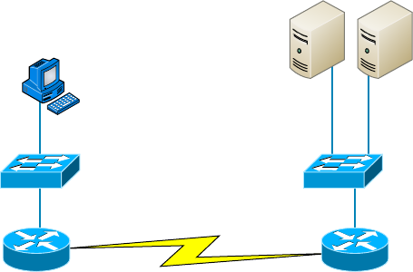
Troubleshooting IP Addressing
261
c08.indd 03/23/2015 Page 261
run through the four basic troubleshooting steps and nd that the host can
communicate to the local network but not to the remote network. Find and de ne the
IP addressing problem.
FIGURE 8.5 IP address problem 2
Sales Marketing
F0/0 192.168.1.30
S0/0
F0/0 192.168.1.81
192.168.1.41/29
Lab_A Lab_B
S0/0
DCE
192.168.1.25
Defaultgateway:
192.168.1.30
ServerA
192.168.1.86
Defaultgateway:
192.168.1.81
ServerB
192.168.1.87
Defaultgateway:
192.168.1.81
192.168.1.46/29
If you use the same steps used to solve the last problem, you can see rst that the WAN
link again provides the subnet mask to use— /29, or 255.255.255.248. You need to deter-
mine what the valid subnets, broadcast addresses, and valid host ranges are to solve this
problem.
The 248 mask is a block size of 8 (256 – 248 = 8), so the subnets both start and incre-
ment in multiples of 8. By looking at the gure, you see that the Sales LAN is in the 24
subnet, the WAN is in the 40 subnet, and the Marketing LAN is in the 80 subnet. Can you
see the problem yet? The valid host range for the Sales LAN is 25–30, and the con gura-
tion appears correct. The valid host range for the WAN link is 41–46, and this also appears
correct. The valid host range for the 80 subnet is 81–86, with a broadcast address of 87
because the next subnet is 88. Server B has been con gured with the broadcast address of
the subnet.
Now that you can gure out miscon gured IP addresses on hosts, what do you do if a
host doesn’t have an IP address and you need to assign one? What you need to do is look at
other hosts on the LAN and gure out the network, mask, and default gateway. Let’s take a
look at a couple of examples of how to nd and apply valid IP addresses to hosts.
You need to assign a server and router IP addresses on a LAN. The subnet assigned
on that segment is 192.168.20.24/29, and the router needs to be assigned the rst usable
address and the server the last valid host ID. What are the IP address, mask, and default
gateway assigned to the server?
To answer this, you must know that a /29 is a 255.255.255.248 mask, which provides
a block size of 8. The subnet is known as 24, the next subnet in a block of 8 is 32, so the
broadcast address of the 24 subnet is 31, which makes the valid host range 25–30:
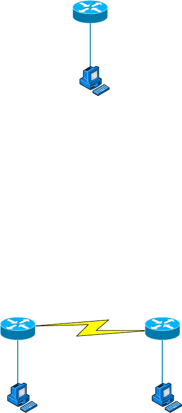
262
Chapter 8 ■ IP Subnetting, Troubleshooting IP, and Introduction to NAT
c08.indd 03/23/2015 Page 262
Server IP address: 192.168.20.30
Server mask: 255.255.255.248
Default gateway: 192.168.20.25 (router’s IP address)
As another example, let’s take a look at Figure 8.6 and solve this problem.
FIGURE 8.6 Find the valid host
RouterA
HostA
E0:192.168.10.33/27
Look at the router’s IP address on Ethernet0. What IP address, subnet mask, and valid
host range could be assigned to the host?
The IP address of the router’s Ethernet0 is 192.168.10.33/27. As you already know, a /27
is a 224 mask with a block size of 32. The router’s interface is in the 32 subnet. The next
subnet is 64, so that makes the broadcast address of the 32 subnet 63 and the valid host
range 33–62:
Host IP address: 192.168.10.34–62 (any address in the range except for 33, which is
assigned to the router)
Mask: 255.255.255.224
Default gateway: 192.168.10.33
Figure 8.7 shows two routers with Ethernet con gurations already assigned. What are
the host addresses and subnet masks of hosts A and B?
FIGURE 8.7 Find the valid host #2
RouterA
HostA
E0:192.168.10.65/26
RouterB
HostB
E0:192.168.10.33/28
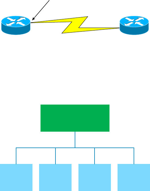
Troubleshooting IP Addressing
263
c08.indd 03/23/2015 Page 263
RouterA has an IP address of 192.168.10.65/26 and RouterB has an IP address
of 192.168.10.33/28. What are the host con gurations? RouterA Ethernet0 is in the
192.168.10.64 subnet, and RouterB Ethernet0 is in the 192.168.10.32 network:
HostA IP address: 192.168.10.66–126
HostA mask: 255.255.255.192
HostA default gateway: 192.168.10.65
HostB IP address: 192.168.10.34–46
HostB mask: 255.255.255.240
HostB default gateway: 192.168.10.33
Just a couple more examples, and then this section is history. Hang in there!
Figure 8.8 shows two routers; you need to con gure the S0⁄0 interface on RouterA. The
network assigned to the serial link is 172.16.16.0/22. What IP address can be assigned?
FIGURE 8.8 Find the valid host address #3
S0/0
S0/0
172.16.16.0/22
RouterA RouterB
First, you must know that a /22 CIDR is 255.255.252.0, which makes a block size of 4
in the third octet. Because 16 is listed, the available range is 16.1 through 19.254; so, for
example, the IP address S0⁄0 could be 172.16.18.255 because that’s within the range.
Okay, last one! You have one Class C network ID, and you need to provide one usable
subnet per city while allowing enough usable host addresses for each city speci ed in
Figure 8.9. What is your mask?
FIGURE 8.9 Find the valid subnet mask
Corporate
7Users
LA
15 Users
SF
13 Users
NY
7 Users
Chicago
15 Users
264
Chapter 8 ■ IP Subnetting, Troubleshooting IP, and Introduction to NAT
c08.indd 03/23/2015 Page 264
Actually, this is probably the easiest thing you’ve done all day! I count 5 subnets
needed, and the Chicago of ce needs 16 users (always look for the network that needs
the most hosts). What block size is needed for the Chicago of ce? 32. (Remember, you
cannot use a block size of 16 because you always have to subtract 2!) What mask
provides you with a block size of 32? 224. Bingo! This provides 8 subnets, each
with 30 hosts.
Introduction to Network Address
Translation (NAT)
Similar to Classless Inter-Domain Routing (CIDR), the original intention for NAT was to
slow the depletion of available IP address space by allowing many private IP addresses to be
represented by some smaller number of public IP addresses.
Since then, it’s been discovered that NAT is also a useful tool for network migrations
and mergers, server load sharing, and creating “virtual servers.” So in this section, I’m
going to describe the basics of NAT functionality and the terminology common to NAT.
At times, NAT really decreases the overwhelming amount of public IP addresses
required in your networking environment. And NAT comes in very handy when two com-
panies that have duplicate internal addressing schemes merge. NAT is also great to have
around when an organization changes its ISP and the networking manager doesn’t want the
hassle of changing the internal address scheme.
Here’s a list of situations when it’s best to have NAT on your side:
■ You need to connect to the Internet and your hosts don’t have globally unique IP
addresses.
■ You change to a new ISP that requires you to renumber your network.
■ You need to merge two intranets with duplicate addresses.
You typically use NAT on a border router. For an illustration of this, see Figure 8.10,
where NAT would be con gured on the Corporate router.
Now you may be thinking, “NAT’s totally cool. It’s the grooviest, greatest network gad-
get, and I just gotta have it.” Well, hang on a minute. There are truly some serious snags
related to NAT use. Oh, don’t get me wrong: It really can save you sometimes, but there’s
a dark side you need to know about too. For a visual of the pros and cons linked to using
NAT, check out Table 8.3.
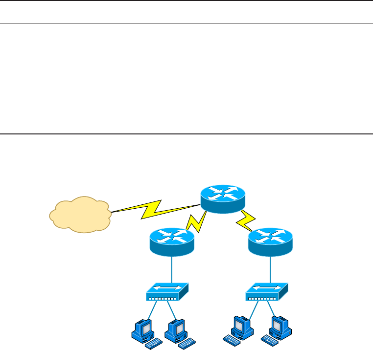
Introduction to Network Address Translation (NAT)
265
c08.indd 03/23/2015 Page 265
TABLE 8.3 Advantages and disadvantages of implementing NAT
Advantages Disadvantages
Conserves legally registered addresses. Translation introduces switching path delays.
Reduces address overlap occurrences. Loss of end-to-end IP traceability.
Increases flexibility when connecting to
the Internet.
Certain applications will not function with
NAT enabled.
Eliminates address renumbering as the
network changes.
FIGURE 8.10 Where to configure NAT
Internet
Corporate
Engineering Sales
Types of Network Address Translation
In this section, I’m going to go over the three types of NAT with you:
Static NAT (SNAT) This type of NAT is designed to allow one-to-one mapping between
local and global addresses. Keep in mind that the static version requires you to have one
real Internet IP address for every host on your network.

266
Chapter 8 ■ IP Subnetting, Troubleshooting IP, and Introduction to NAT
c08.indd 03/23/2015 Page 266
Dynamic NAT (DNAT) This version gives you the ability to map an unregistered IP
address to a registered IP address from a pool of registered IP addresses. You don’t have to
statically con gure your router to map an inside-to-an-outside-address as you would using
static NAT, but you do have to have enough real, bona- de IP addresses for everyone who’s
going to be sending packets to and receiving them from the Internet.
Overloading This is the most popular type of NAT con guration. Understand that over-
loading really is a form of dynamic NAT that maps multiple unregistered IP addresses to
a single registered IP address—many-to-one—by using different ports. Now, why is this
so special? Well, because it’s also known as Port Address Translation (PAT). And by using
PAT (NAT Overload), you get to have thousands of users connect to the Internet using only
one real global IP address—pretty slick, yeah? Seriously, NAT Overload is the real reason
we haven’t run out of valid IP address on the Internet. Really—I’m not joking.
NAT Names
The names we use to describe the addresses used with NAT are pretty simple. Addresses
used after NAT translations are called global addresses. These are usually the public
addresses used on the Internet, but remember, you don’t need public addresses if you aren’t
going on the Internet.
Local addresses are the ones we use before NAT translation. So, the inside local address
is actually the private address of the sending host that’s trying to get to the Internet, while
the outside local address is the address of the destination host. The latter is usually a public
address (web address, mail server, and so on) and is how the packet begins its journey.
After translation, the inside local address is then called the inside global address, and the
outside global address then becomes the name of the destination host. Check out Table 8.4,
which lists all this terminology, for a clear picture of the various names used with NAT.
TABLE 8.4 NAT terms
Name Meaning
Inside local Name of the inside source address before translation
Outside local Name of the destination host before translation
Inside global Name of the inside host after translation
Outside global Name of the outside destination host after translation
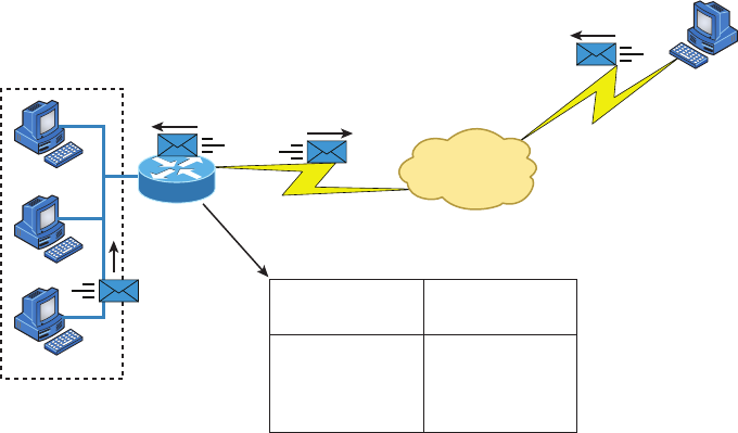
Introduction to Network Address Translation (NAT)
267
c08.indd 03/23/2015 Page 267
How NAT Works
Now it’s time to look at how this whole NAT thing works. I’m going to start by using
Figure 8.11 to describe the basic translation of NAT.
In the example shown in Figure 8.11, host 10.1.1.1 sends an outbound packet to the
border router con gured with NAT. The router identi es the IP address as an inside local
IP address destined for an outside network, translates the address, and documents the
translation in the NAT table.
The packet is sent to the outside interface with the new translated source address. The
external host returns the packet to the destination host, and the NAT router translates the
inside global IP address back to the inside local IP address using the NAT table. This is as
simple as it gets.
FIGURE 8.11 Basic NAT translation
Internet
NAT Table
Inside
10.1.1.3
10.1.1.2
10.1.1.1
SA
10.1.1.1
Inside Local IP
Addresses
10.1.1.3
10.1.1.2
10.1.1.1
170.168.2.4
170.168.2.3
170.168.2.2
Inside Global IP
Addresses
DA
10.1.1.1
SA
170.168.2.2
DA
170.168.2.2
Host B
63.41.7.3
Let’s take a look at a more complex con guration using overloading, or what is also
referred to as PAT. I’ll use Figure 8.12 to demonstrate how PAT works.
With overloading, all inside hosts get translated to one single IP address, hence the term
overloading. Again, the reason we have not run out of available IP addresses on the Internet
is because of overloading (PAT).
Take a look at the NAT table in Figure 8.12 again. In addition to the inside local IP
address and outside global IP address, we now have port numbers. These port numbers
help the router identify which host should receive the return traf c.
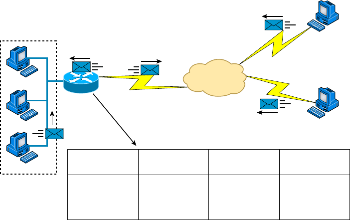
268
Chapter 8 ■ IP Subnetting, Troubleshooting IP, and Introduction to NAT
c08.indd 03/23/2015 Page 268
FIGURE 8.12 NAT overloading example (PAT)
Internet
NAT Table
Inside
10.1.1.3
10.1.1.2
10.1.1.1
SA
10.1.1.1
Protocol
10.1.1.1
TCP
TCP
TCP
10.1.1.3:1492
10.1.1.2:1723
10.1.1.1:1024
Inside Local IP
Addresses: Port
Inside Global IP
Addresses: Port
170.168.2.2:1492
170.168.2.2:1723
170.168.2.2:1024
63.41.7.3:23
63.41.7.3:23
63.40.7.3:23
Outside Global IP
Addresses: Port
DA
10.1.1.1 SA
170.168.2.2
DA
170.168.2.2
DA
170.168.2.2
Host B
63.41.7.3
Host C
63.40.7.3
Port numbers are used at the Transport layer to identify the local host in this example. If
we had to use IP addresses to identify the source hosts, that would be called static NAT, and
we would run out of addresses. PAT allows us to use the Transport layer to identify the hosts,
which in turn allows us to use (theoretically) up to 65,000 hosts with one real IP address.
One last thing: we’ve been discussing translating IP addresses using some type of network
address translation. However, using a router or rewall, you can also perform port forward-
ing, which is translating the port number of a packet to a new destination. The destination
may be a predetermined network port (using any IP protocol, but typically TCP or UDP ports)
on a host within a private network behind a NAT router. Based on the received port number,
a remote host can communicate to servers behind the NAT gateway to the local network.
You’re done, the diva has sung, the chicken has crossed the road…whew! Take a good
break, and then come back and go through the written labs and review questions.
Summary
Did you read Chapter 7 and this chapter and understand everything on the rst pass? If so,
that is fantastic—congratulations! The thing is, you probably got lost a couple of times—
and as I told you, that’s what usually happens, so don’t stress. Don’t feel bad if you have to
read each chapter more than once, or even 10 times, before you’re truly good to go.
This chapter provided you with an important understanding of IP subnetting. After
reading this chapter, you should be able to subnet IP addresses in your head.
Written Labs
269
c08.indd 03/23/2015 Page 269
You should also understand the basic troubleshooting methods. You must remember the
four steps you take when trying to narrow down exactly where a network/IP addressing
problem is and then know how to proceed systematically in order to x it. In addition, you
should be able to nd valid IP addresses and subnet masks by looking at a network diagram.
I nished this chapter with an introduction to Network Address Translation. I discussed
the difference between static and dynamic NAT and NAT overloading.
Exam Essentials
Remember the steps to subnet in your head. Understand how IP addressing and subnet-
ting work. First, determine your block size by using the 256-subnet mask math. Then,
count your subnets and determine the broadcast address of each subnet—it is always the
number right before the next subnet. Your valid hosts are the numbers between the subnet
address and the broadcast address.
Understand the various block sizes. This is an important part of understanding IP
addressing and subnetting. The valid block sizes are always 4, 8, 16, 32, 64, 128, and so
on. You can determine your block size by using the 256-subnet mask math.
Remember the four diagnostic steps. The four simple steps for troubleshooting are ping
the loopback address, ping the NIC, ping the default gateway, and ping the remote device.
You must be able to find and fix an IP addressing problem. Once you go through the four
troubleshooting steps, you should be able to determine the IP addressing problem by draw-
ing out the network and nding the valid and invalid hosts addressed in your network.
Understand basic NAT terminology. You want to know the difference between inside
local and inside global. Inside local is before translation, and inside global is after transla-
tion. Inside global is de ned as a registered address that represents an inside host to an
outside network. You should also understand PAT and how it works by using different port
numbers to map multiple private IP addresses to a single registered IP address.
Written Labs
You can nd the answers to the written labs in Appendix A.
Write the subnet, broadcast address, and valid host range for question 1 through
question 6:
1. 192.168.100.25/30
2. 192.168.100.37/28
3. 192.168.100.66/27
270
Chapter 8 ■ IP Subnetting, Troubleshooting IP, and Introduction to NAT
c08.indd 03/23/2015 Page 270
4. 192.168.100.17/29
5. 192.168.100.99/26
6. 192.168.100.99/25
7. You have a Class B network and need 29 subnets. What is your mask?
8. What is the broadcast address of 192.168.192.10/29?
9. How many hosts are available with a Class C /29 mask?
10. What is the subnet for host ID 172.16.3.65/23?
Review Questions
271
c08.indd 03/23/2015 Page 271
Review Questions
You can nd the answers to the review questions in Appendix B.
1. What is the maximum number of IP addresses that can be assigned to hosts on a local
subnet that uses the 255.255.255.224 subnet mask?
A. 14
B. 15
C. 16
D. 30
E. 31
F. 62
2. You have a Class A host of 10.0.0.110/25. It needs to communicate to a host with an IP
address of 10.0.0.210/25. Which of the following devices do you need to use in order for
these hosts to communicate?
A. A Layer 2 switch
B. Router
C. DNS server
D. Hub
3. What is the subnetwork address for a host with the IP address 200.10.5.68/28?
A. 200.10.5.56
B. 200.10.5.32
C. 200.10.5.64
D. 200.10.5.0
4. The network address of 172.16.0.0/19 provides how many subnets and hosts?
A. 7 subnets, 30 hosts each
B. 7 subnets, 2,046 hosts each
C. 7 subnets, 8,190 hosts each
D. 8 subnets, 30 hosts each
E. 8 subnets, 2,046 hosts each
F. 8 subnets, 8,190 hosts each
5. You receive a call from a user who is complaining that they cannot get on the Internet. You
have them verify their IP address, mask, and default gateway. The IP address is 10.0.37.144,
with a subnet mask of 255.255.254.0. The default gateway is 10.0.38.1. What is the prob-
lem?
A. Incorrect DNS server address
B. Invalid subnet mask
272
Chapter 8 ■ IP Subnetting, Troubleshooting IP, and Introduction to NAT
c08.indd 03/23/2015 Page 272
C. Incorrect gateway IP
D. IP address and mask not compatible
6. If a host on a network has the address 172.16.45.14/30, what is the subnetwork this host
belongs to?
A. 172.16.45.0
B. 172.16.45.4
C. 172.16.45.8
D. 172.16.45.12
E. 172.16.45.16
7. On a network, which mask should you use on point-to-point WAN links in order to reduce
the waste of IP addresses?
A. /27
B. /28
C. /29
D. /30
E. /31
8. On which of the following devices are you most likely to be able to implement NAT?
A. Hub
B. Ethernet switch
C. Router
D. Bridge
9. You have an interface on a router with the IP address of 192.168.192.10/29. Including the
router interface, how many hosts can have IP addresses on the LAN attached to the router
interface?
A. 6
B. 8
C. 30
D. 62
E. 126
10. When configuring the IP settings on a computer on one subnet to ensure that it can commu-
nicate with a computer on another subnet, which of the following is desirable?
A. Configure the computer with the same default gateway as the other computer.
B. Configure the computer with the same subnet mask as the other computer.
C. Configure the computer with a default gateway that matches the IP address of the
interface of the router that is attached to the same subnet as the computer.
D. Configure the computer with a subnet mask that matches the IP address of the router’s
interface that is attached to the same subnet as the computer.

Review Questions
273
c08.indd 03/23/2015 Page 273
11. You have an interface on a router with the IP address of 192.168.192.10/29. What is the
broadcast address the hosts will use on this LAN?
A. 192.168.192.15
B. 192.168.192.31
C. 192.168.192.63
D. 192.168.192.127
E. 192.168.192.255
12. What is the highest usable address on the 172.16.1.0/24 network?
A. 172.16.1.255
B. 172.16.1.254
C. 172.16.1.253
D. 172.16.1.23
13. A network administrator is connecting two hosts directly through their Ethernet interfaces,
as shown in the illustration. Ping attempts between the hosts are unsuccessful. What can be
done to provide connectivity between the hosts? (Choose two.)
Straight-ThroughCable
IPAddress:192.168.1.20
Mask:255.255.255.240
IPAddress:192.168.1.201
Mask:255.255.255.240
A. A crossover cable should be used in place of the straight-through cable.
B. A rollover cable should be used in place of the straight-though cable.
C. The subnet masks should be set to 255.255.255.192.
D. A default gateway needs to be set on each host.
E. The subnet masks should be set to 255.255.255.0.
14. If an Ethernet port on a router was assigned an IP address of 172.16.112.1/25, what would
be the subnet address of this host?
A. 172.16.112.0
B. 172.16.0.0
C. 172.16.96.0
D. 172.16.255.0
E. 172.16.128.0
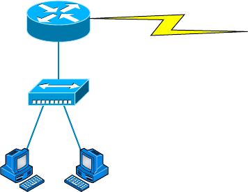
274
Chapter 8 ■ IP Subnetting, Troubleshooting IP, and Introduction to NAT
c08.indd 03/23/2015 Page 274
15. Using the following illustration, what would be the IP address of E0 if you were using the
eighth subnet? The network ID is 192.168.10.0/28, and you need to use the last available IP
address in the range. The 0 subnet should not be considered valid for this question.
Router
E0
S0
A. 192.168.10.142
B. 192.168.10.66
C. 192.168.100.254
D. 192.168.10.143
E. 192.168.10.126
16. Using the illustration in question 15, what would be the IP address of E0 if you were
using the first subnet? The network ID is 192.168.10.0/28, and you need to use the last
available IP address in the range. Again, the zero subnet should not be considered valid for
this question.
A. 192.168.10.24
B. 192.168.10.62
C. 192.168.10.30
D. 192.168.10.127
17. If you are forced to replace a router that has failed to the point that you are unable to access
its current configuration to aid in setting up interface addresses on the new router, which of
the following can you reference for assistance?
A. The default-gateway settings on computers from each subnet that the old router inter-
connected.
B. The router’s configuration that was periodically cached on the DHCP server.
C. The router’s configuration that was periodically cached on the DNS server.
D. The new router will auto-configure itself with the correct settings.
Review Questions
275
c08.indd 03/23/2015 Page 275
18. You have a network with a subnet of 172.16.17.0/22. Which of the following is a valid
host address?
A. 172.16.17.1 255.255.255.252
B. 172.16.0.1 255.255.240.0
C. 172.16.20.1 255.255.254.0
D. 172.16.16.1 255.255.255.240
E. 172.16.18.255 255.255.252.0
F. 172.16.0.1 255.255.255.0
19. Your router has the following IP address on Ethernet0: 172.16.2.1/23. Which of the follow-
ing can be valid host IDs on the LAN interface attached to the router? (Choose two.)
A. 172.16.0.5
B. 172.16.1.100
C. 172.16.1.198
D. 172.16.2.255
E. 172.16.3.0
F. 172.16.3.255
20. You have one IP address provided from your ISP with a /30 mask. However, you have
300 users that need to access the Internet. What technology will you use to implement a
solution?
A. PAT
B. VPN
C. DNS
D. LANs

c09.indd 04/02/2015 Page 277
Chapter
9
Introduction to IP
Routing
THE FOLLOWING COMPTIA NETWORK+
EXAM OBJECTIVES ARE COVERED IN THIS
CHAPTER:
✓ 1.9 Explain the basics of routing concepts and protocols
■ Loopback interface
■ Routing loops
■ Routing tables
■ Static vs dynamic routes
■ Default route
■ Distance vector routing protocols
■ RIP v2
■ Hybrid routing protocols
■ BGP
■ Link state routing protocols
■ OSPF
■ IS-IS

c09.indd 04/02/2015 Page 278
IP routing is the process of moving packets from one network
to another network using routers. The IP routing process is a
super-important subject to understand because it pertains to
all routers and con gurations that use IP.
Before you read this chapter, you need to understand the difference between a routing
protocol and a routed protocol. A routing protocol is a tool used by routers to dynami-
cally nd all the networks in the internetwork as well as to ensure that all routers have the
same routing table. Basically, a routing protocol determines the path of a packet through
an internetwork. Examples of routing protocols are Routing Information Protocol (RIP),
Routing Information Protocol version 2 (RIPv2), Enhanced Interior Gateway Routing
Protocol (EIGRP), and Open Shortest Path First (OSPF).
Once all routers know about all networks, a routed protocol can be used to send user
data (packets) through the established internetwork. Routed protocols are assigned to an
interface and determine the method of packet delivery. Examples of routed protocols are
Internet Protocol (IP) and Internet Protocol version 6 (IPv6).
In this chapter, I’m going to describe IP routing with routers. I will explain, in a step-by-
step fashion, the IP routing process. I will also explain static and dynamic routing on a con-
ceptual level, with more details about dynamic routing in Chapter 10, “Routing Protocols.”
To find up-to-the-minute updates for this chapter, please see
www.lammle
.com/networkplus
or the book’s website at
www.sybextestbanks.wiley.com.
Routing Basics
Once you create an internetwork by connecting your wide area networks (WANs) and local
area networks (LANs) to a router, you need to con gure logical network addresses, such
as IP addresses, to all hosts on the internetwork so that they can communicate via routers
across that internetwork.
In IT, routing essentially refers to the process of taking a packet from one device and
sending it through the network to another device on a different network. Routers don’t
really care about hosts—they care only about networks and the best path to each network.
The logical network address of the destination host is used to get packets to a network
through a routed network, and then the hardware address of the host is used to deliver the
packet from a router to the correct destination host.
If your network has no routers, then it should be apparent that, well, you are not
routing. But if you do have them, they’re there to route traf c to all the networks in your
Routing Basics
279
c09.indd 04/02/2015 Page 279
internetwork. To be capable of routing packets, a router must know at least the following
information:
■ Destination network address
■ Neighbor routers from which it can learn about remote networks
■ Possible routes to all remote networks
■ The best route to each remote network
■ How to maintain and verify routing information
The router learns about remote networks from neighbor routers or from an administrator.
The router then builds a routing table (a map of the internetwork) that describes how to nd
the remote networks. If a network is directly connected, then the router already knows how
to get to it.
If a network isn’t directly connected to the router, the router must use one of two ways
to learn how to get to it. One way is called static routing, which can be a ton of work
because it requires someone to hand-type all network locations into the routing table. The
other way is dynamic routing.
In dynamic routing, a protocol on one router communicates with the same protocol run-
ning on neighbor routers. The routers then update each other about all the networks they
know about and place this information into the routing table. If a change occurs in the
network, the dynamic routing protocols automatically inform all routers about the event. If
static routing is used, the administrator is responsible for updating all changes by hand into
all routers. Understandably, in a large network, it’s common to nd that a combination of
both dynamic and static routing is being used.
Before we jump into the IP routing process, let’s take a look at a simple example that
demonstrates how a router uses the routing table to route packets out of an interface. We’ll
be going into a more detailed study of this process in a minute.
Figure 9.1 shows a simple two-router network. Lab_A has one serial interface and three
LAN interfaces.
FIGURE 9.1 A simple routing example
S0/0
10.10.40.1/24
Fa0/1
10.10.20.1/24
Lab_A
Fa0/2
10.10.30.1/24
Fa0/0
10.10.10.1/24

280
Chapter 9 ■ Introduction to IP Routing
c09.indd 04/02/2015 Page 280
Looking at Figure 9.1, can you gure out which interface Lab_A will use to forward an
IP datagram to a host with an IP address of 10.10.10.10?
By using the Cisco IOS command
show ip route
, we can see the routing table (map of
the internetwork) that router Lab_A will use to make all forwarding decisions:
Router_A#show ip route
[output cut]
Gateway of last resort is not set
C 10.10.10.0/24 is directly connected, FastEthernet0/0
C 10.10.20.0/24 is directly connected, FastEthernet0/1
C 10.10.30.0/24 is directly connected, FastEthernet0/2
C 10.10.40.0/24 is directly connected, Serial 0/0
The
C
in the routing table output means that the networks listed are “directly con-
nected,” and until we add a routing protocol—something like RIP, EIGRP, and so on—to
the routers in our internetwork, or use static routes, we’ll have only directly connected net-
works in our routing table.
So, let’s get back to the original question: By looking at the gure and the output of the
routing table, can you tell what Lab_A will do with a received packet that has a destination
IP address of 10.10.10.10? If you answered, “The router will packet-switch the packet to
interface FastEthernet 0/0, and this interface will then frame the packet and send it out on
the network segment,” you’re right.
Just because we can, let’s look at a different example. Based on the output of the next
routing table, which interface will a packet with a destination address of 10.10.10.14 be
forwarded from?
Router_A#sh ip route
[output cut]
Gateway of last resort is not set
C 10.10.10.16/28 is directly connected, FastEthernet0/0
C 10.10.10.8/29 is directly connected, FastEthernet0/1
C 10.10.10.4/30 is directly connected, FastEthernet0/2
C 10.10.10.0/30 is directly connected, Serial 0/0
First, you can see that the network is subnetted and that each interface has a differ-
ent mask. And I have to tell you, you positively can’t answer this question if you can’t
subnet—no way! Here’s the answer: 10.10.10.14 would be a host in the 10.10.10.8/29
subnet connected to the FastEthernet 0/1 interface. Don’t freak if this one left you star-
ing vacantly. Instead, if you’re struggling, go back and reread Chapter 8, “IP Subnetting,
Troubleshooting IP, and Introduction to NAT,” until you get it. This should then make per-
fect sense to you.
When the routing tables of all routers in the network are complete
(because they include information about all the networks in the internet-
work), they are considered converged, or in a steady state. This is covered
in more detail in Chapter 10.
Now, let’s get into this process in more detail.

The IP Routing Process
281
c09.indd 04/02/2015 Page 281
The IP Routing Process
The IP routing process is actually pretty simple, and it doesn’t change, regardless of the size
of your network. I’m going to use Figure 9.2 to give you a picture of this step-by-step process.
The question I’m asking is this: What happens when Host_A wants to communicate with
Host_B on a different network? I’ll go through how to answer that question by breaking
down the process with headings to make it easier to understand. First, check out Figure 9.2.
FIGURE 9.2 IP routing example using two hosts and one router
172.16.20.2172.16.10.2
Host_A Host_B
E0
172.16.10.1
E1
172.16.20.1
Lab_A
Here you can see that a user on Host_A pings Host_B’s IP address. Routing doesn’t get
any simpler than this, but it still involves a lot of steps. Let’s work through them.
A packet is created on the host:
1. Internet Control Message Protocol (ICMP) creates an echo request payload (which
is just the alphabet in the data field).
2. ICMP hands that payload to IP, which then creates a packet. At a minimum, this
packet contains an IP source address, an IP destination address, and a Protocol
field with 01h. (Remember that Cisco likes to use 0x in front of hex characters, so
this could look like 0x01.) All of that tells the receiving host whom it should hand
the payload to when the destination is reached. In this example, it’s ICMP.
The packet is forwarded:
3. After the packet is created, IP determines whether the destination IP address is on
the local network or a remote one.
4. Because IP has discovered that this is a remote request, the packet needs to be sent
to the default gateway so the packet can be routed to the correct remote network.
The Registry in Windows is parsed to find the configured default gateway.
5. The default gateway of host 172.16.10.2 (Host_A) is configured to 172.16.10.1.
For this packet to be sent to the default gateway, the hardware address of the rout-
er’s interface Ethernet 0 (configured with the IP address of 172.16.10.1) must be
known. Why? So the packet can be handed down to the Data Link layer, framed,
and sent to the router’s interface that’s connected to the 172.16.10.0 network.
Because hosts only communicate via hardware addresses on the local LAN, it’s
important to recognize that for Host_A to communicate to Host_B, it has to send

282
Chapter 9 ■ Introduction to IP Routing
c09.indd 04/02/2015 Page 282
packets to the Media Access Control (MAC) address of the default gateway on the
local network.
MAC addresses are always local on the LAN and never go through and
past a router.
6. The Address Resolution Protocol (ARP) cache of the host is checked to see whether
the IP address of the default gateway has already been resolved to a hardware
address. If it has, the packet is then free to be handed to the Data Link layer
for framing. (The hardware-destination address is also handed down with that
packet.) To view the ARP cache on your host, use the following command:
C:\>
arp -a
Interface: 172.16.10.2 --- 0x3
Internet Address Physical Address Type
172.16.10.1 00-15-05-06-31-b0 dynamic
If the hardware address isn’t already in the ARP cache of the host, an ARP
broadcast is sent out onto the local network to search for the hardware address
of 172.16.10.1. The router responds to that request and provides the hardware
address of Ethernet 0, and the host caches this address.
7. After the packet and destination hardware address have been handed to the Data
Link layer, the LAN driver is used to provide media access via the type of LAN
being used (in this example, it’s Ethernet). A frame is then generated, encapsulating
the packet with control information. Within that frame are the hardware-desti-
nation and source addresses plus, in this case, an Ether-Type field that describes
the Network layer protocol that handed the packet to the Data Link layer—in this
instance, IP. At the end of the frame is something called a Frame Check Sequence
(FCS) field that houses the result of the cyclic redundancy check (CRC). The frame
would look something like what I’ve detailed in Figure 9.3. It contains Host_A’s
hardware (MAC) address and the hardware-destination address of the default
gateway. It does not include the remote host’s MAC address—remember that
because it’s important!
FIGURE 9.3 Frame used from Host_A to the Lab_A router when Host_B is pinged
Packet
DestinationMAC
(router’sE0MACaddress)
SourceMAC
(Host_AMACaddress)
Ether-Type
field
FCS
(CRC)
The IP Routing Process
283
c09.indd 04/02/2015 Page 283
8. When the frame is completed, it’s handed down to the Physical layer to be placed
onto the physical medium one bit at a time. In this example, the physical medium
is twisted-pair wire.
The router receives the packet:
9. Every device within the collision domain receives these bits and builds the frame.
They each run a CRC and check the answer in the FCS field. If the answers don’t
match, the frame is discarded. But if the CRC matches, then the hardware-desti-
nation address is checked to see if it matches, too (in this example, it’s the router’s
interface, Ethernet 0). If it’s a match, then the Ether-Type field is checked to find
the protocol used at the Network layer.
10. The packet is pulled from the frame, and what is left of the frame is discarded. The
packet is then handed to the protocol listed in the Ether-Type field—it’s given to IP.
The router routes the packet:
11. IP receives the packet and checks the IP destination address. Because the packet’s
destination address doesn’t match any of the addresses configured on the receiving
router’s interfaces, the router will look up the destination IP network address in its
routing table.
12. The routing table must have an entry for the network 172.16.20.0 or the packet
will be discarded immediately and an ICMP message will be sent back to the origi-
nating device with a Destination Unreachable message.
13. If the router does find an entry for the destination network in its table, the packet
is switched to the exit interface—in this example, interface Ethernet 1. The follow-
ing output displays the Lab_A router’s routing table. The
C
means “directly con-
nected.” No routing protocols are needed in this network because all networks (all
two of them) are directly connected:
Lab_A>
sh ip route
Codes:C - connected,S - static,I - IGRP,R - RIP,M - mobile,B –
BGP, D - EIGRP,EX - EIGRP external,O - OSPF,IA - OSPF inter
area, N1 - OSPF NSSA external type 1, N2 - OSPF NSSA external
type 2, E1 - OSPF external type 1, E2 - OSPF external type 2,
E – EGP,i - IS-IS, L1 - IS-IS level-1, L2 - IS-IS level-2, ia
- IS-IS intearea * - candidate default, U - per-user static
route, o – ODR P - periodic downloaded static route
Gateway of last resort is not set
172.16.0.0/24 is subnetted, 2 subnets
C 172.16.10.0 is directly connected, Ethernet0
C 172.16.20.0 is directly connected, Ethernet1
284
Chapter 9 ■ Introduction to IP Routing
c09.indd 04/02/2015 Page 284
14. The router packet-switches the packet to the Ethernet 1 buffer.
15. Now that the packet is in the Ethernet 1 buffer, IP needs to know the hardware
address of the destination host and first checks the ARP cache. If the hardware
address of Host_B has already been resolved and is in the router’s ARP cache, then
the packet and the hardware address are handed down to the Data Link layer to be
framed. Let’s take a look at the ARP cache on the Lab_A router by using the
show
ip arp
command:
Lab_A#
sh ip arp
Protocol Address Age(min) Hardware Addr Type Interface
Internet 172.16.20.1 - 00d0.58ad.05f4 ARPA Ethernet1
Internet 172.16.20.2 3 0030.9492.a5dd ARPA Ethernet1
Internet 172.16.10.1 - 0015.0506.31b0 ARPA Ethernet0
Internet 172.16.10.2 12 0030.9492.a4ac ARPA Ethernet0
The dash (-) means that this is the physical interface on the router. From this
output, we can see that the router knows the 172.16.10.2 (Host_A) and
172.16.20.2 (Host_B) hardware addresses. Cisco routers will keep an entry in the
ARP table for 4 hours. But if the hardware address hasn’t already been resolved,
the router then sends an ARP request out E1 looking for the hardware address
of 172.16.20.2. Host_B responds with its hardware address, and the packet and
hardware-destination address are both sent to the Data Link layer for framing.
16. The Data Link layer creates a frame with the destination and source hardware
address, Ether-Type field, and FCS field at the end. The frame is handed to the
Physical layer to be sent out on the physical medium one bit at a time.
Finally, the remote host receives the packet:
17. Host_B receives the frame and immediately runs a CRC. If the result matches
what’s in the FCS field, the hardware-destination address is then checked. If the
host finds a match, the Ether-Type field is then checked to determine the protocol
that the packet should be handed to at the Network layer—IP, in this example.
18. At the Network layer, IP receives the packet and checks the IP destination address.
Because there’s finally a match made, the Protocol field is checked to find out
whom the payload should be given to.
19. The payload is handed to ICMP, which understands that this is an echo request.
ICMP responds to this by immediately discarding the packet and generating a new
payload as an echo reply.
The destination host becomes a source host:
20. A packet is created, including the source and destination IP addresses, Protocol
field, and payload. The destination device is now Host_A.
21. IP checks to see whether the destination IP address is a device on the local LAN or
on a remote network. Because the destination device is on a remote network, the
packet needs to be sent to the default gateway.

The IP Routing Process
285
c09.indd 04/02/2015 Page 285
22. The default gateway IP address is found in the Registry of the Windows device,
and the ARP cache is checked to see whether the hardware address has already
been resolved from an IP address.
23. After the hardware address of the default gateway is found, the packet and desti-
nation hardware addresses are handed down to the Data Link layer for framing.
24. The Data Link layer frames the packet of information and includes the following
in the header:
■ The destination and source hardware addresses
■ The Ether-Type field with 0x0800 (IP) in it
■ The FCS field with the CRC result in tow
25. The frame is now handed down to the Physical layer to be sent out over the net-
work medium one bit at a time.
Time for the router to route another packet:
26. The router’s Ethernet 1 interface receives the bits and builds a frame. The CRC is
run, and the FCS field is checked to make sure the answers match.
27. When the CRC is found to be okay, the hardware-destination address is checked.
Because the router’s interface is a match, the packet is pulled from the frame, and
the Ether-Type field is checked to see which protocol at the Network layer the
packet should be delivered to.
28. The protocol is determined to be IP, so it gets the packet. IP runs a CRC check on
the IP header first and then checks the destination IP address.
IP does not run a complete CRC the way the Data Link layer does—it only
checks the header for errors.
Because the IP destination address doesn’t match any of the router’s interfaces, the
routing table is checked to see whether it has a route to 172.16.10.0. If it doesn’t
have a route over to the destination network, the packet will be discarded imme-
diately. (This is the source point of confusion for a lot of administrators—when a
ping fails, most people think the packet never reached the destination host. But as
we see here, that’s not always the case. All it takes is just one of the remote rout-
ers to be lacking a route back to the originating host’s network and—poof!—the
packet is dropped on the return trip, not on its way to the host.)
Just a quick note to mention that when (if) the packet is lost on the way
back to the originating host, you will typically see a Request Timed Out
message because it is an unknown error. If the error occurs because of a
known issue, such as a route that is not in the routing table on the way to
the destination device, you will see a Destination Unreachable message.
This should help you determine if the problem occurred on the way to the
destination or on the way back.
286
Chapter 9 ■ Introduction to IP Routing
c09.indd 04/02/2015 Page 286
29. In this case, the router does know how to get to network 172.16.10.0—the exit
interface is Ethernet 0—so the packet is switched to interface Ethernet 0.
30. The router checks the ARP cache to determine whether the hardware address for
172.16.10.2 has already been resolved.
31. Because the hardware address to 172.16.10.2 is already cached from the originat-
ing trip to Host_B, the hardware address and packet are handed to the Data Link
layer.
32. The Data Link layer builds a frame with the destination and source hardware
addresses and then puts IP in the Ether-Type field. A CRC is run on the frame, and
the result is placed in the FCS field.
33. The frame is then handed to the Physical layer to be sent out onto the local
network one bit at a time.
The original source host, now the destination host, receives the reply packet:
34. The destination host receives the frame, runs a CRC, checks the hardware
destination address, and looks in the Ether-Type field to find out whom to hand
the packet to.
35. IP is the designated receiver, and after the packet is handed to IP at the Network
layer, IP checks the Protocol field for further direction. IP finds instructions to give
the payload to ICMP, and ICMP determines the packet to be an ICMP echo reply.
36. ICMP acknowledges that it has received the reply by sending an exclamation point
(!) to the user interface. ICMP then attempts to send four more echo requests to the
destination host.
You’ve just been introduced to “Todd’s 36 easy steps to understanding IP routing.” The
key point to understand here is that if you had a much larger network, the process would
be the same. In a really big internetwork, the packet just goes through more hops before it
nds the destination host.
It’s super important to remember that when Host_A sends a packet to Host_B, the des-
tination hardware address used is the default gateway’s Ethernet interface. Why? Because
frames can’t be placed on remote networks—only local networks. So packets destined for
remote networks must go through the default gateway.
Let’s take a look at Host_A’s ARP cache now by using the
arp -a
command from the
DOS prompt:
C:\ >arp -a
Interface: 172.16.10.2 --- 0x3
Internet Address Physical Address Type
172.16.10.1 00-15-05-06-31-b0 dynamic
172.16.20.1 00-15-05-06-31-b0 dynamic
Did you notice that the hardware (MAC) address that Host_A uses to get to Host_B is
the Lab_A E0 interface?
Testing Your IP Routing Understanding
287
c09.indd 04/02/2015 Page 287
Hardware addresses are always local, and they never pass a router’s interface.
Understanding this process is as important to internetworking as breathing air is to you, so
carve this into your memory!
Testing Your IP Routing Understanding
I want to make sure you understand IP routing because it’s really that important. So, I’m
going to use this section to test your understanding of the IP routing process by having you
look at a couple of gures and answer some very basic IP routing questions.
Figure 9.4 shows a LAN connected to RouterA, which is, in turn, connected via a WAN
link to RouterB. RouterB has a LAN connected with an HTTP server attached. Take a look.
FIGURE 9.4 IP routing example 1
RouterA RouterB
S0/0
S0/0
Fa0/0
HostA
Fa0/0
HTTPServer
The critical information you need to glean from this gure is exactly how IP routing will
occur in this example. Okay—we’ll cheat a bit. I’ll give you the answer, but then you should
go back over the gure and see if you can answer example 2 without looking at
my answers:
1. The destination address of a frame, from HostA, will be the MAC address of the Fa0/0
interface of the RouterA router.
2. The destination address of a packet will be the IP address of the network interface card
(NIC) of the HTTP server.
3. The destination port number in the segment header will have a value of 80.
That example was a pretty simple one, and it was also very to the point. One thing to
remember is that if multiple hosts are communicating to the server using HTTP, they must
all use a different source port number. That is how the server keeps the data separated at
the Transport layer.
Let’s mix it up a little and add another internetworking device into the network and
then see if you can nd the answers. Figure 9.5 shows a network with only one router but
two switches.
288
Chapter 9 ■ Introduction to IP Routing
c09.indd 04/02/2015 Page 288
FIGURE 9.5 IP routing example 2
RouterA
HostA
HTTPS Server
Fa0/1
Fa0/0
What you want to understand about the IP routing process here is what happens when
HostA sends data to the HTTPS server:
1. The destination address of a frame from HostA will be the MAC address of the Fa0/0
interface of the RouterA router.
2. The destination address of a packet will be the IP address of the NIC of the
HTTPS server.
3. The destination port number in the segment header will have a value of 443.
Notice that neither switch was used as either a default gateway or another destination.
That’s because switches have nothing to do with routing. I wonder how many of you chose
the switch as the default gateway (destination) MAC address for HostA. If you did, don’t
feel bad—just take another look with that fact in mind. It’s very important to remember
that the destination MAC address will always be the router’s interface—if your packets are
destined for outside the LAN, as they were in these last two examples.
Static and Dynamic Routing
How does a router send packets to remote networks when the only way it can send them
is by looking at the routing table to nd out how to get to the remote networks? And what
happens when a router receives a packet for a network that isn’t listed in the routing table?
It doesn’t send a broadcast looking for the remote network—the router just discards the
packet.
There are several ways to con gure the routing tables to include all the networks so that
packets will be forwarded. Understand that what’s best for one network isn’t necessarily
what’s best for another. Knowing about and being able to recognize the different types of
Static and Dynamic Routing
289
c09.indd 04/02/2015 Page 289
routing will really help you come up with the best solution for your speci c environment
and business requirements.
Looking at Figure 9.6, we can see that we can con gure a router either with static or
dynamic routing. If we choose static routing, then we have to go to each router and type in
each network and the path that IP will use to send packets. However, static routing does
not scale well in large networks, but dynamic routing does because network routes are
automatically added to the routing table via the routing protocol.
FIGURE 9.6 Routing options
Routing
Static
Routing
Dynamic
Routing
Dynamic routing protocols break up into many different categories or types of proto-
cols, as shown in Figure 9.7. The rst split in the dynamic protocol branch is the division of
interior gateway protocols (IGPs) and exterior gateway protocols (EGPs). We are going to
talk about each protocol and category in the next few sections, but for now the difference
between IGP and EGP is interior or exterior routing of an autonomous system (AS).
FIGURE 9.7 Dynamic routing options
IGPs
Dynamic
Routing
EGPs
Protocol:
BGP
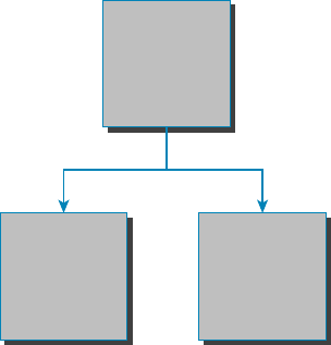
290
Chapter 9 ■ Introduction to IP Routing
c09.indd 04/02/2015 Page 290
An autonomous system is a collection of networks or subnets that are in the same
administrative domain. This is another way of saying an administrative domain is within
your company’s network, and you control or administer all the subnets that are within it.
You control and set the policy for what happens in the network or autonomous system. I
hope you can now see that an IGP operates and routes within an AS, and an EGP works
outside or between more than one AS.
The most popular protocol for an EGP is Border Gateway Protocol (BGP), which is typi-
cally used by ISPs or really large corporations. As an administrator of a small to medium-
size network, you’ll probably never use BGP. (BGP will be discussed in Chapter 10.)
Now that we have that out of the way, let’s talk about all the great things that dynamic
routing protocols do for us. The thing that comes to mind rst is the amount of time and
energy we save con guring routers. We won’t have to go to every single router and de ne
for it, with a static route, what and where every destination network is. If that was the only
way to con gure routing, there would probably be a lot fewer of us interested in doing this
for a living. Thankfully, we have routing protocols that do much of the work for us. We
still have to know what the routing protocols are going to do and how they will do it, but
the protocols will take care of most of the updating and sending information to each other.
That is the end of the EGP branch of the tree, but the IGP branch continues to split out
as we go down further. Looking at Figure 9.8, with the IGP split, you can see that there are
two primary categories: distance vector (DV) and link state (LS) routing protocols.
FIGURE 9.8 DV and LS routing protocols
IGP
DistantVector
Protocols:
RIPv1&2,
IGRP
LinkState
Protocols:
OSPF,IS-IS
No worries—I’m going to discuss all of these types of protocols in the next chap-
ters. But in the distance vector category, for example, we have RIP and Interior Gateway
Routing Protocol (IGRP). Under the link state category are the nonproprietary OSPF and
Intermediate System-to-Intermediate System (IS-IS) that were designed to work in larger
internetworks.
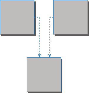
Summary
291
c09.indd 04/02/2015 Page 291
Now, in Figure 9.9, you can see from the diagram that there is a third category: the
hybrid protocol category.
FIGURE 9.9 Hybrid routing
Distant Vector
Protocols:
RIPv1 & 2,
IGRP
Link State
Protocols:
OSPF, IS-IS
Hybrid
EIGRP and
BGP
The only protocol under this category is EIGRP. It is Cisco proprietary and uses the
features of both DV and LS. The Network+ objectives list BGP as a hybrid routing protocol
as well because it can work on internal networks as well as external, but it’s really an EGP;
just keep this in mind.
Now that we have a handle on IP routing, let’s move on to Chapter 10 and discuss the
IGP routing protocols introduced in this chapter.
Summary
This chapter covered the IP routing process in detail. It’s extremely important that you
really understand the basics we covered in this chapter because everything that’s done on a
router typically will have some type of IP routing con gured and running.
You learned in this chapter how IP routing uses frames to transport packets between
routers and to the destination host. Understanding the process of how packets and frames
traverse a network is critical to your fundamental understanding of IP routing.
After I covered the basics of IP routing, I went through some examples to test your
understanding and to emphasize the importance of the IP routing fundamentals that
you need. I nished the chapter with an introduction to static and dynamic routing, and
explained IGP and EGP as well as the difference between distance vector and link state
routing protocols. In the next chapter, we’ll continue with dynamic routing by discussing
the various dynamic routing protocols.

292
Chapter 9 ■ Introduction to IP Routing
c09.indd 04/02/2015 Page 292
Exam Essentials
Understand the basic IP routing process. You need to remember that the frame changes
at each hop but that the packet is never changed or manipulated in any way until it reaches
the destination device.
Understand that MAC addresses are always local. A MAC (hardware) address will only
be used on a local LAN. It will never pass a router’s interface.
Understand that a frame carries a packet to only two places. A frame uses MAC (hard-
ware) addresses to send a packet on a LAN. The frame will take the packet to either a host
on the LAN or a router’s interface if the packet is destined for a remote network.
Remember the difference between static and dynamic routing. Static routing is where
you, as the administrator, by hand, add every route into every routing table on every router
on the network. This is as much work as it sounds like, which is why we use dynamic rout-
ing protocols that do the work for us. Of course, we’ll discuss dynamic routing protocols
more in the next chapter, but the main job of a routing protocol is to update routing tables.
Written Lab
You can nd the answers in Appendix A. Write the answers to the following questions:
1. True/False: RIPv2 is a hybrid routing protocol.
2. True/False: RIPv1 is a link state routing protocol.
3. True/False: EIGRP is a nonproprietary routing protocol.
4. An is a collection of networks or subnets that are in the same administra-
tive domain.
5. You need a routing protocol that can be run in a very large network with routers from
multiple vendors. What routing protocol would be your best choice?
6. Which type of routing are you performing if you have to go to each router and type in each
network and the path that IP will use to send packets?
7. You are trying to reach a server on another subnet. What will be the destination hardware
address of a frame sent from your host?
8. You are trying to reach a server on another subnet. What will be the destination IP address
of a packet sent from your host?
9. A server has received a frame from your remote host. What will be the source hardware
address of the frame?
Review Questions
293
c09.indd 04/02/2015 Page 293
10. A server has received a packet from your remote host. What will be the destination IP
address of the packet?
Review Questions
You can nd the answers to the review questions in Appendix B.
1. Which is not a routing protocol?
A. RIP
B. RIPv2
C. RIPv3
D. EIGRP
2. Which of these best describes dynamic routing?
A. All network addresses must be hand-typed into the routing table.
B. Only a portion of the network address must be hand-typed into the routing table.
C. Routing tables are updated automatically when changes occur in the network.
D. A and B.
3. Which is true regarding dynamic routing?
A. Static routes are best in large networks and thus better to use than dynamic routing
protocols.
B. Static routes are automatically added to the routing table but dynamic routes must be
added by hand.
C. You must use a DNS and WINS server when configuring dynamic routing.
D. Dynamic routes are automatically added to the routing table.
4. Which of the following is true for MAC addresses?
A. MAC addresses are never local on the LAN and always pass through a router.
B. MAC addresses are always local on the LAN and never go through or past a router.
C. MAC addresses will always be the IP address of Fa0/0 interface.
D. None of the above.
5. What is it called when protocols update their forwarding tables after changes have
occurred?
A. Name resolution
B. Routing
C. Convergence
D. ARP resolution
6. What command would be used to view the ARP cache on your host?
294
Chapter 9 ■ Introduction to IP Routing
c09.indd 04/02/2015 Page 294
A.
C:\ >show ip route
B.
C:\ >show ip arp
C.
C:\ >show protocols
D.
C:\ >arp -a
7. What happens when a router receives a packet for a network that isn’t listed in the
routing table?
A. It forwards the packet to the next available router.
B. It holds the packet until the address is updated in the routing table.
C. The router will use RIP to inform the host that it can’t send the packet.
D. None of the above.
8. Which of the following is not a distance vector protocol?
A. RIPv1
B. RIPv2
C. OSPF
D. IGRP
9. Which two of the following are link state protocols?
A. RIPv1
B. RIPv2
C. OSPF
D. IS-IS
E. IGRP
10. Which of the following is a hybrid routing protocol?
A. RIPv2
B. EIGRP
C. IS-IS
D. IGRP
11. What does the acronym IGRP stand for?
A. Interior Gateway Routing Protocol
B. Inside Gateway Redundancy Protocol
C. Interior Group Reliability Protocol
D. Interior Gateway Redundancy Protocol
12. What EGP protocol is used on the Internet?
A. GGP
B. EGP
C. BGP
Review Questions
295
c09.indd 04/02/2015 Page 295
D. IGP
13. What are the two categories of IGP protocols?
A. Link state
B. Static
C. Distance vector
D. EGP
14. What two pieces of information does a router require to make a routing decision?
(Choose two.)
A. Destination network (address)
B. Destination MAC address
C. Application layer protocol
D. Neighbor router
15. Where does a frame have to carry a packet if it is destined for a remote network?
A. Default gateway
B. Neighbor host
C. Switch
D. Hub
16. Where along the IP routing process does a packet get changed?
A. Router
B. Host A
C. Destination device
D. Host B
17. When all routers in a network agree about the path from one point to another, the network
is said to be what?
A. Dynamic
B. Static
C. Secure
D. Converged
18. What type of request must a client send if it does not know the destination MAC address?
A. ARP broadcast
B. Multicast
C. ICMP redirect
D. Reverse ARP
19. You need to perform maintenance on a router in your corporate office. It is important that
the network does not go down. What can you do to accomplish your goal?
296
Chapter 9 ■ Introduction to IP Routing
c09.indd 04/02/2015 Page 296
A. Configure BGP on the router.
B. Implement NAT on the router.
C. Configure on the router a static route that temporarily reroutes traffic through
another office.
D. Implement convergence on the router.
20. When are you most likely to see a Request Timed Out message?
A. When an unknown error has occurred
B. When you have used the
arp -a
command incorrectly
C. When a known error has occurred
D. When you are using a hybrid routing protocol

c10.indd 04/02/2015 Page 297
Chapter
10
Routing Protocols
THE FOLLOWING COMPTIA NETWORK+
EXAM OBJECTIVES ARE COVERED IN THIS
CHAPTER:
✓ 1.9 Explain the basics of routing concepts and protocols
■ Loopback interface
■ Routing loops
■ Routing tables
■ Static vs dynamic routes
■ Default route
■ Distance vector routing protocols
■ RIPv2
■ Hybrid routing protocols
■ BGP
■ Link state routing protocols
■ OSPF
■ IS-IS
■ Interior vs exterior gateway routing protocols
■ Autonomous system numbers
■ Route redistribution
■ High availability
■ VRRP
■ Virtual IP
■ HSRP
■ Route aggregation
■ Routing metrics

c10.indd 04/02/2015 Page 298
■ Hop counts
■ MTU, bandwidth
■ Costs
■ Latency
■ Administrative distance
■ SPB

c10.indd 04/02/2015 Page 299
Routing protocols are critical to a network’s design. This
chapter focuses on dynamic routing protocols. Dynamic rout-
ing protocols run only on routers that use them in order to
discover networks and update their routing tables. Using dynamic routing is easier on you,
the system administrator, than using the labor-intensive, manually achieved, static routing
method, but it’ll cost you in terms of router CPU processes and bandwidth on the network
links.
The source of the increased bandwidth usage and CPU cycles is the operation of the
dynamic routing protocol itself. A router running a dynamic routing protocol shares
routing information with its neighboring routers, and it requires additional CPU cycles and
additional bandwidth to accomplish that.
In this chapter, I’ll give you all the basic information you need to know about routing
protocols so you can choose the correct one for each network you work on or design.
To find up-to-the-minute updates for this chapter, please see
www.lammle
.com/networkplus
or the book’s website at
www.sybextestbanks.wiley
.com
.
Routing Protocol Basics
Because getting a solid visual can really help people learn, I’ll get you started by combining
the last few gures used in Chapter 9, “Introduction to IP Routing.” This way, you can get
the big picture and really understand how routing works. Figure 10.1 shows the complete
routing tree that I broke up piece by piece at the end of Chapter 9.
As I touched on in Chapter 9, two types of routing protocols are used in internetworks:
interior gateway protocols (IGPs) and exterior gateway protocols (EGPs). IGPs are used to
exchange routing information with routers in the same autonomous system (AS). An AS is
a collection of networks under a common administrative domain, which simply means that
all routers sharing the same routing table information are in the same AS. EGPs are used to
communicate between multiple ASs. A nice example of an EGP would be Border Gateway
Protocol (BGP).
There are a few key points about routing protocols that I think it would be a good idea
to talk over before getting deeper into the speci cs of each one. First on the list is some-
thing known as an administrative distance.
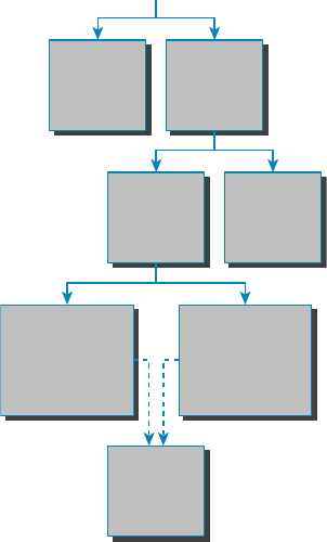
300
Chapter 10 ■ Routing Protocols
c10.indd 04/02/2015 Page 300
FIGURE 10.1 Routing flow tree
Routing
Static
Routing
IGP EGP
Protocols:
BGP
Distance
Vector
Protocols:
RIPv1 & 2, IGRP
Link
State
Protocols:
OSPF, IS-IS
Hybrid
Protocols:
EIGRP/BGP
Dynamic
Routing
Administrative Distances
The administrative distance (AD) is used to rate the trustworthiness of routing informa-
tion received on one router from its neighboring router. An AD is an integer from 0 to 255,
where 0 equals the most trusted route and 255 the least. A value of 255 essentially means,
“No traf c is allowed to be passed via this route.”
If a router receives two updates listing the same remote network, the rst thing the
router checks is the AD. If one of the advertised routes has a lower AD than the other, the
route with the lower AD is the one that will get placed in the routing table.
If both advertised routes to the same network have the same AD, then routing protocol
metrics like hop count or the amount of bandwidth on the lines will be used to nd the best
path to the remote network. And as it was with the AD, the advertised route with the low-
est metric will be placed in the routing table. But if both advertised routes have the same
AD as well as the same metrics, then the routing protocol will load-balance to the remote
network. To perform load balancing, a router will send packets down each link to test for
the best one.

Routing Protocol Basics
301
c10.indd 04/02/2015 Page 301
Why Not Just Turn On All Routing Protocols?
Many customers have hired me because all their employees were complaining about the
slow, intermittent network that had a lot of latency. Many times, I have found that the
administrators did not truly understand routing protocols and just enabled them all on
every router.
This may sound laughable, but it is true. When an administrator tried to disable a rout-
ing protocol, such as the Routing Information Protocol (RIP), they would receive a call
that part of the network was not working. First, understand that because of default ADs,
although every routing protocol was enabled, only the Enhanced Interior Gateway Rout-
ing Protocol (EIGRP) would show up in most of the routing tables. This meant that Open
Shortest Path First (OSPF), Intermediate System-to-Intermediate System (IS-IS), and RIP
would be running in the background but just using up bandwidth and CPU processes,
slowing the routers almost to a crawl.
Disabling all the routing protocols except EGIRP (this would only work on an all-Cisco
router network) improved the network at least 30 percent. In addition, fi nding the rout-
ers that were confi gured only for RIP and enabling EIGRP solved the calls from users
complaining that the network was down when RIP was disabled on the network. Last, I
replaced the core routers with better routers with more memory, enabling faster, more
effi cient routing and raising the network response time to a total of 50 percent.
Table 10.1 shows the default ADs that a router uses to decide which route to take to a
remote network.
TABLE 10.1 Default administrative distances
Route source Default AD
Connected interface 0
Static route 1
External BGP 20
Internal EIGRP 90
IGRP 100

302
Chapter 10 ■ Routing Protocols
c10.indd 04/02/2015 Page 302
Route source Default AD
OSPF 110
ISIS 115
RIP 120
External EIGRP 170
Internal BGP 200
Unknown 255 (this route will never be used)
Understand that if a network is directly connected, the router will always use the inter-
face connected to that network. Also good to know is that if you con gure a static route,
the router will believe that route to be the preferred one over any other routes it learns
about dynamically. You can change the ADs of static routes, but by default, they have an
AD of 1. That’s only one place above zero, so you can see why a static route’s default AD
will always be considered the best by the router.
This means that if you have a static route, a RIP-advertised route, and an EIGRP-
advertised route listing the same network, then by default, the router will always use the
static route unless you change the AD of the static route.
Classes of Routing Protocols
The three classes of routing protocols introduced in Chapter 9, and shown in Figure 10.1,
are as follows:
Distance Vector The distance vector protocols nd the best path to a remote network
by judging—you guessed it—distance. Each time a packet goes through a router, it equals
something we call a hop, and the route with the fewest hops to the destination network will
be chosen as the best path to it. The vector indicates the direction to the remote network.
RIP, RIPv2, and Interior Gateway Routing Protocol (IGRP) are distance vector routing
protocols. These protocols send the entire routing table to all directly connected neighbors.
Link State Using link state protocols, also called shortest path rst protocols, the rout-
ers each create three separate tables. One of these tables keeps track of directly attached
TABLE 10.1 Default administrative distances (continued)
Distance Vector Routing Protocols
303
c10.indd 04/02/2015 Page 303
neighbors, one determines the topology of the entire internetwork, and one is used as
the actual routing table. Link state routers know more about the internetwork than any
distance vector routing protocol. OSPF and IS-IS are IP routing protocols that are com-
pletely link state. Link state protocols send updates containing the state of their own links
to all other routers on the network.
Hybrid A hybrid protocol uses aspects of both distance vector and link state, and
formerly, EIGRP was the only one you needed to understand to meet the Network+
objectives. But now, BGP is also listed as a hybrid routing protocol because of its capabil-
ity to work as an EGP and be used in supersized internetworks internally. When deployed
in this way, it’s called internal BGP, or iBGP, but understand that it’s still most commonly
utilized as an EGP.
I also want you to understand that there’s no one set way of con guring routing proto-
cols for use in every situation because this really needs to be done on a case-by-case basis.
Even though all of this might seem a little intimidating, if you understand how each of the
different routing protocols works, I promise you’ll be capable of making good, solid deci-
sions that will truly meet the individual needs of any business!
Distance Vector Routing Protocols
Okay, the distance vector routing algorithm passes its complete routing table contents to
neighboring routers, which then combine the received routing table entries with their own
routing tables to complete and update their individual routing tables. This is called routing
by rumor because a router receiving an update from a neighbor router believes the informa-
tion about remote networks without verifying for itself if the news is actually correct.
It’s possible to have a network that has multiple links to the same remote network, and
if that’s the case, the AD of each received update is checked rst. As I said, if the AD is the
same, the protocol will then have to use other metrics to determine the best path to use to
get to that remote network.
Distance vector uses only hop count to determine the best path to a network. If a router
nds more than one link with the same hop count to the same remote network, it will auto-
matically perform what’s known as round-robin load balancing.
It’s important to understand what a distance vector routing protocol does when it starts
up. In Figure 10.2, the four routers start off with only their directly connected networks in
their routing table. After a distance vector routing protocol is started on each router, the
routing tables are then updated with all route information gathered from neighbor routers.
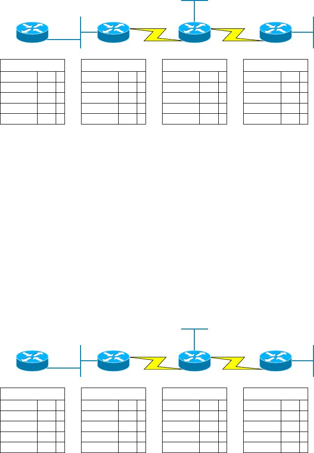
304
Chapter 10 ■ Routing Protocols
c10.indd 04/02/2015 Page 304
FIGURE 10.2 The internetwork with distance vector routing
Routing Table
172.16.10.0 F0/0 0
Routing Table
172.16.10.0 E0 0
Routing Table
172.16.20.0 S0 0
Routing Table
172.16.40.0 S0 0
172.16.20.0 S0 0 172.16.30.0 E0 0
172.16.40.0 S1 0
172.16.50.0 E0 0
172.16.10.0
F0/0
E0
E0
E0
2501A
S0
S0 S0
2501B 2501C
S1
172.16.20.0
172.16.30.0
172.16.40.0 172.16.50.0
2621A
As you can see in Figure 10.2, each router only has the directly connected networks in
its routing table. Also notice that their hop count is zero in every case. Each router sends its
complete routing table, which includes the network number, exit interface, and hop count
to the network, out to each active interface.
Now, in Figure 10.3, the routing tables are complete because they include informa-
tion about all the networks in the internetwork. They are considered converged. The hop
count for every directly connected network remains zero, but notice that the hop count is
incremented by one each time the path completely passes through a router. So, for router
2621A, the path to the 172.16.10.0 network still has a hop count of zero, but the hop count
for the path to network 172.16.20.0 is one. The hop count to networks 172.16.30.0 and
172.16.40.0 increases to two, and so on. Usually, data transmission will cease while routers
are converging—a good reason in favor of fast convergence time! In fact, one of the main
problems with RIP is its slow convergence time.
FIGURE 10.3 Converged routing tables
Routing Table
172.16.10.0 F0/0 0
172.16.20.0 F0/0 1
Routing Table
172.16.10.0 E0 0
Routing Table
172.16.20.0 S0 0
Routing Table
172.16.40.0 S0 0
172.16.20.0 S0 0 172.16.30.0 E0 0
172.16.40.0 S1 0
172.16.50.0 E0 0
172.16.30.0 F0/0 2 172.16.30.0 S0 1 172.16.10.0 S0 2
172.16.10.0 S0 1172.16.40.0 F0/0 2 172.16.40.0 S0 1 172.16.20.0 S0 1
172.16.50.0 S1 1172.16.50.0 F0/0 3 172.16.50.0 S0 2 172.16.30.0 S0 1
172.16.10.0
F0/0
E0
E0
E0
2501A
S0
S0 S0
2501B 2501C
S1
172.16.20.0
172.16.30.0
172.16.40.0 172.16.50.0
2621A

Distance Vector Routing Protocols
305
c10.indd 04/02/2015 Page 305
As you can see in Figure 10.3, once all the routers have converged, the routing table in
each router keeps information about three important things:
■ The remote network number
■ The interface that the router will use to send packets to reach that particular network
■ The hop count, or metric, to the network
Remember! Routing convergence time is the time required by protocols to
update their forwarding tables after changes have occurred.
Let’s start discussing dynamic routing protocols with one of the oldest routing protocols
that is still in existence today.
Routing Information Protocol (RIP)
RIP is a true distance vector routing protocol. It sends the complete routing table out to all
active interfaces every 30 seconds. RIP uses only one thing to determine the best way to a
remote network—the hop count. And because it has a maximum allowable hop count of
15 by default, a hop count of 16 would be deemed unreachable. This means that although
RIP works fairly well in small networks, it’s pretty inef cient on large networks with slow
WAN links or on networks populated with a large number of routers. Worse, this dinosaur
of a protocol has a bad history of creating routing loops, which were somewhat kept in
check by using things like maximum hop count. This is the reason why RIP only permits
going through15 routers before it will judge that route to be invalid. If all that isn’t nasty
enough for you, RIP also happens to be glacially slow at converging, which can easily cause
latency in your network!
RIP version 1 uses only classful routing, which means that all devices in the network
must use the same subnet mask for each speci c address class. This is because RIP version
1 doesn’t send updates with subnet mask information in tow. RIP version 2 provides some-
thing called pre x routing and does send subnet mask information with the route updates.
Doing this is called classless routing.
RIP Version 2 (RIPv2)
Let’s spend a couple of minutes discussing RIPv2 before we move into the advanced dis-
tance vector (also referred to as hybrid), Cisco-proprietary routing protocol EIGRP.
RIP version 2 is mostly the same as RIP version 1. Both RIPv1 and RIPv2 are distance
vector protocols, which means that each router running RIP sends its complete routing
tables out to all active interfaces at periodic time intervals. Also, the timers and loop-
avoidance schemes are the same in both RIP versions. Both RIPv1 and RIPv2 are

306
Chapter 10 ■ Routing Protocols
c10.indd 04/02/2015 Page 306
con gured with classful addressing (but RIPv2 is considered classless because subnet
information is sent with each route update), and both have the same AD (120).
But there are some important differences that make RIPv2 more scalable than RIPv1.
And I’ve got to add a word of advice here before we move on: I’m de nitely not advocating
using RIP of either version in your network. But because RIP is an open standard, you can
use RIP with any brand of router. You can also use OSPF because OSPF is an open stan-
dard as well.
Table 10.2 discusses the differences between RIPv1 and RIPv2.
TABLE 10.2 RIPv1 vs RIPv2
RIPv1 RIPv2
Distance vector Distance vector
Maximum hop count of 15 Maximum hop count of 15
Classful Classless
Broadcast based Uses multicast 224.0.0.9
No support for VLSM Supports VLSM networks
No authentication Allows for MD5 authentication
No support for discontiguous networks Supports discontiguous networks (covered in
the next section)
RIPv2, unlike RIPv1, is a classless routing protocol (even though it is con gured as
classful, like RIPv1), which means that it sends subnet mask information along with the
route updates. By sending the subnet mask information with the updates, RIPv2 can
support Variable Length Subnet Masks (VLSMs), which are described in the next section;
in addition, network boundaries are summarized.
VLSM and Discontiguous Networks
VLSMs allows classless routing, meaning that the routing protocol sends subnet-mask
information with the route updates. The reason it’s good to do this is to save address space.
If we didn’t use a routing protocol that supports VLSMs, then every router interface, every
node (PC, printer, server, and so on), would have to use the same subnet mask.
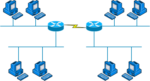
Distance Vector Routing Protocols
307
c10.indd 04/02/2015 Page 307
As the name suggests, with VLSMs we can have different subnet masks for different
router interfaces. Check out Figure 10.4 to see an example of why classful network designs
are inef cient.
FIGURE 10.4 Typical classful network
.1
.49
.2 .3 .18
.66 .67
.19
.17
.50 .65
(6 Hosts) (10 Hosts)
(25 Hosts) (12 Hosts)
(2 Hosts)
192.168.10.48/28
192.168.10.32/28
192.168.10.0/28 192.168.10.16/28
192.168.10.64/28
.34 .35
.33
Looking at this gure, you’ll notice that we have two routers, each with two LANs and
connected together with a WAN serial link. In a typical classful network design example
(RIP or RIPv2 routing protocol), you could subnet a network like this:
192.168.10.0 = Network
255.255.255.240 (/28) = Mask
Our subnets would be (you know this part, right?) 0, 16, 32, 48, 64, 80, and so on. This
allows us to assign 16 subnets to our internetwork. But how many hosts would be available
on each network? Well, as you probably know by now, each subnet provides only 14 hosts.
This means that with a /28 mask, each LAN can support 14 valid hosts—one LAN requires
25 addresses, so a /28 mask doesn’t provide enough addresses for the hosts in that LAN!
Moreover, the point-to-point WAN link also would consume 14 addresses when only 2 are
required. It’s too bad we can’t just nick some valid hosts from that WAN link and give them
to our LANs.
All hosts and router interfaces have the same subnet mask—again, this is called classful
routing. And if we want this network to be more ef cient, we de nitely need to add differ-
ent masks to each router interface.
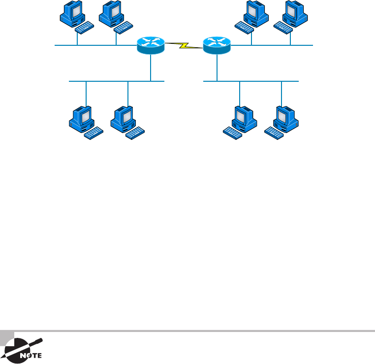
308
Chapter 10 ■ Routing Protocols
c10.indd 04/02/2015 Page 308
But there’s still another problem—the link between the two routers will never use more
than two valid hosts! This wastes valuable IP address space, and it’s the big reason I’m talk-
ing to you about VLSM networking.
Now let’s take Figure 10.4 and use a classless design, which will become the new net-
work shown in Figure 10.5. In the previous example, we wasted address space—one LAN
didn’t have enough addresses because every router interface and host used the same subnet
mask. Not so good.
FIGURE 10.5 Classless network design
s
.1
.73
.2 .3 .45
.66 .67
.35
.33
.74 .49
(6 Hosts) (10 Hosts)
(25 Hosts) (12 Hosts)
(2 Hosts)
192.168.10.72/30
192.168.10.64/29
192.168.10.0/27 192.168.10.32/28
192.168.10.48/28
.66 .67
.65
What would be good is to provide only the needed number of hosts on each router inter-
face, meaning VLSMs. Remember that if a “classful routed network” requires that all sub-
net masks be the same length, then it follows that a “classless routed network” would allow
us to use Variable Length Subnet Masks (VLSMs).
So, if we use a /30 on our WAN links and a /27, /28, and /29 on our LANs, we’ll get 2
hosts per WAN interface and 30, 14, and 6 hosts per LAN interface—nice! This makes a
huge difference—not only can we get just the right number of hosts on each LAN, we still
have room to add more WANs and LANs using this same network.
Remember, in order to implement a VLSM design on your network, you need to have a
routing protocol that sends subnet-mask information with the route updates. This would be
RIPv2, EIGRP, or OSPF. RIPv1 and IGRP will not work in classless networks and are con-
sidered classful routing protocols.
By using a VLSM design, you do not necessarily make your network run
better, but you can save a lot of IP addresses.
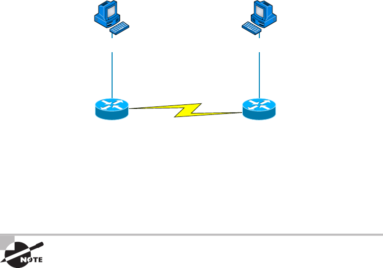
Distance Vector Routing Protocols
309
c10.indd 04/02/2015 Page 309
Now, what’s a discontiguous network? It’s one that has two or more subnetworks of a
classful network connected together by different classful networks. Figure 10.6 displays a
typical discontiguous network.
FIGURE 10.6 A discontiguous network
172.16.10.1/24
Host_BHost_A
S0/0
10.3.1.1/24
10.3.1.0/24
S0/0
10.3.1.2/24
172.16.10.0/24 172.16.20.0/24
E0
172.16.20.1/24
Lab_A Lab_B
E0
172.16.10.2/24 172.16.20.2/24
The subnets 172.16.10.0 and 172.16.20.0 are connected together with a 10.3.1.0
network. By default, each router thinks it has the only 172.16.0.0 classful network.
It’s important to understand that discontiguous networks just won’t work with RIPv1 at
all. They don’t work by default on RIPv2 or EIGRP either, but discontiguous networks do
work on OSPF networks by default because OSPF does not auto-summarize like RIPv2
and EIGRP.
Route aggregation is essentially combining multiple subnets into one
larger subnet, and it’s also known as supernetting. You would implement
this type of route summarization if you required more efficient routing
tables in large networks.
EIGRP
EIGRP is a classless, enhanced distance vector protocol that possesses a real edge over
another older Cisco proprietary protocol, IGRP. That’s basically why it’s called Enhanced
IGRP.
EIGRP uses the concept of an autonomous system to describe the set of contiguous rout-
ers that run the same routing protocol and share routing information. But unlike IGRP,
EIGRP includes the subnet mask in its route updates. And as you now know, the advertise-
ment of subnet information allows us to use VLSMs when designing our networks.
EIGRP is referred to as a hybrid routing protocol because it has characteristics of
both distance vector and link state protocols. For example, EIGRP doesn’t send link state
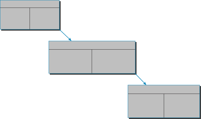
310
Chapter 10 ■ Routing Protocols
c10.indd 04/02/2015 Page 310
packets as OSPF does; instead, it sends traditional distance vector updates containing infor-
mation about networks, plus the cost of reaching them from the perspective of the advertis-
ing router. But EIGRP has link state characteristics as well—it synchronizes routing tables
between neighbors at startup and then sends speci c updates only when topology changes
occur. This makes EIGRP suitable for very large networks.
There are a number of powerful features that make EIGRP a real standout from RIP,
RIPv2, and other protocols. The main ones are listed here:
■ Support for IP and IPv6 (and some other useless routed protocols) via protocol-depen-
dent modules
■ Considered classless (same as RIPv2 and OSPF)
■ Support for VLSM/Classless Inter-Domain Routing (CIDR)
■ Support for summaries and discontiguous networks
■ Efficient neighbor discovery
■ Communication via Reliable Transport Protocol (RTP)
■ Best path selection via Diffusing Update Algorithm (DUAL)
Another great feature of EIGRP is that it’s simple to con gure and turn on like a
distance vector protocol, but it keeps track of more information than a distance vector does.
It creates and maintains additional tables instead of just one table as distance vector routing
protocols do. To determine the best path to each network, EIGRP uses bandwidth and delay
of the line as well as send reliability, load, and the MTU information between routers, but it
only uses bandwidth and delay by default.
These tables are called the neighbor table, topology table, and routing table, as shown in
Figure 10.7.
FIGURE 10.7 EIGRP tables
Neighbor Table–IP
Topology Table–IP
Routing Table–IP
Destination 1 Successor
Destination 1
Destination 1
Successor
Feasible Successor
Next Hop
Router
Interface

Distance Vector Routing Protocols
311
c10.indd 04/02/2015 Page 311
Neighbor Table Each router keeps state information about adjacent neighbors. When
a newly discovered neighbor is learned on a router interface, the address and interface of
that neighbor are recorded, and the information is held in the neighbor table and stored in
RAM. Sequence numbers are used to match acknowledgments with update packets. The
last sequence number received from the neighbor is recorded so that out-of-order packets
can be detected.
Topology Table The topology table is populated by the neighbor table, and the best path
to each remote network is found by running Diffusing Update Algorithm (DUAL). The
topology table contains all destinations advertised by neighboring routers, holding each
destination address and a list of neighbors that have advertised the destination. For each
neighbor, the advertised metric, which comes only from the neighbor’s routing table, is
recorded. If the neighbor is advertising this destination, it must be using the route to for-
ward packets.
Feasible Successor (Backup Routes) A feasible successor is a path whose reported
distance is less than the feasible (best) distance, and it is considered a backup route.
EIGRP will keep up to six feasible successors in the topology table. Only the one with
the best metric (the successor) is copied and placed in the routing table.
Successor (Routes in a Routing Table) A successor route (think successful!) is the best
route to a remote network. A successor route is used by EIGRP to forward traf c to a
destination and is stored in the routing table. It is backed up by a feasible successor route
that is stored in the topology table—if one is available.
By using the feasible distance and having feasible successors in the topology table as
backup links, EIGRP allows the network to converge instantly and updates to any neighbor
only consist of traf c sent from EIGRP. All of these things make for a very fast, scalable,
fault-tolerant routing protocol.
Route redistribution is the term used for translating from one routing
protocol into another. An example would be where you have an old router
running RIP but you have an EIGRP network. You can run route redistribu-
tion on one router to translate the RIP routes into EIGRP.
Border Gateway Protocol (BGP)
In a way, you can think of Border Gateway Protocol (BGP) as the heavyweight of routing
protocols. This is an external routing protocol (used between autonomous systems, unlike
RIP or OSPF, which are internal routing protocols) that uses a sophisticated algorithm
to determine the best route. In fact, it just happens to be the core routing protocol of the
Internet. And it’s not exactly breaking news that the Internet has become a vital resource in
so many organizations, is it? No—but this growing dependence has resulted in redundant
connections to many different ISPs.
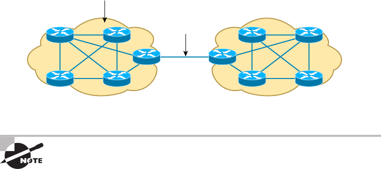
312
Chapter 10 ■ Routing Protocols
c10.indd 04/02/2015 Page 312
Even though BGP is an EGP by default, it can be used within an AS, which is one of the
reasons the objectives are calling this a hybrid routing protocol. Another reason they call it
a hybrid is because it’s often known as a path vector protocol instead of a distance vector
like RIP.
This is where BGP comes in. The sheer onslaught of multiple connections would totally
overwhelm other routing protocols like OSPF, which I am going to talk about in the next
section. BGP is essentially an alternative to using default routes for controlling path selec-
tions. Default routes are con gured on routers to control packets that have a destination IP
address that is not found in the routing table. Please see CCNA: Cisco Certi ed Network
Associate Study Guide (Sybex, 2011) for more information on static and default routing.
Because the Internet’s growth rate shows no signs of slowing, ISPs use BGP for its ability
to make classless routing and summarization possible. These capabilities help to keep rout-
ing tables smaller and more ef cient at the ISP core.
BGP is used for IGPs to communicate ASs together in larger networks, if needed, as
shown in Figure 10.8.
FIGURE 10.8 Border Gateway Protocol (BGP)
IGPs: RIP, IGRP, EIGRP, OSPF
EGP: BGP
Autonomous System 1 Autonomous System 2
An autonomous system is a collection of networks under a common
administrative domain. IGPs operate within an autonomous system, and
EGPs connect different autonomous systems together.
So yes, very large private IP networks can make use of BGP. Let’s say you wanted to join
a number of large OSPF networks together. Because OSPF just couldn’t scale up enough
to handle such a huge load, you would go with BGP instead to connect the ASs together.
Another situation in which BGP would come in really handy would be if you wanted to
multi-home a network for better redundancy, either to a multiple access point of a single
ISP or to multiple ISPs.
Internal routing protocols are employed to advertise all available networks, including
the metric necessary to get to each of them. BGP is a personal favorite of mine because its
routers exchange path vectors that give you detailed information on the BGP AS numbers,
Link State Routing Protocols
313
c10.indd 04/02/2015 Page 313
hop by hop (called an AS path), required to reach a speci c destination network. Also good
to know is that BGP doesn’t broadcast its entire routing table like RIP does; it updates a
lot more like OSPF, which is a huge advantage. Also, the routing table with BGP is called a
Routing Information Base (RIB).
And BGP also tells you about any/all networks reachable at the end of the path. These
factors are the biggest differences you need to remember about BGP. Unlike IGPs that
simply tell you how to get to a speci c network, BGP gives you the big picture on exactly
what’s involved in getting to an AS, including the networks located in that AS itself.
And there’s more to that “BGP big picture”—this protocol carries information like the
network pre xes found in the AS and includes the IP address needed to get to the next AS
(the next-hop attribute). It even gives you the history on how the networks at the end of the
path were introduced into BGP in the rst place, known as the origin code attribute.
All of these traits are what makes BGP so useful for constructing a graph of loop-free
autonomous systems, for identifying routing policies, and for enabling us to create and
enforce restrictions on routing behavior based upon the AS path—sweet!
Link State Routing Protocols
Link state protocols also fall into the classless category of routing protocols, and they
work within packet-switched networks. OSPF and IS-IS are two examples of link state
routing protocols.
Remember, for a protocol to be a classless routing protocol, the subnet-mask informa-
tion must be carried with the routing update. This enables every router to identify the best
route to each and every network, even those that don’t use class-de ned default subnet
masks (i.e., 8, 16, or 24 bits), such as VLSM networks. All neighbor routers know the
cost of the network route that’s being advertised. One of the biggest differences between
link state and distance vector protocols is that link state protocols learn and maintain
much more information about the internetwork than distance vector routing protocols do.
Distance vector routing protocols only maintain routing tables with the destination routes
and vector costs (like hop counts) in them. Link state routing protocols maintain two
additional tables with more detailed information, with the rst of these being the neighbor
table. The neighbor table is maintained through the use of hello packets that are exchanged
by all routers to determine which other routers are available to exchange routing data with.
All routers that can share routing data are stored in the neighbor table.
The second table maintained is the topology table, which is built and sustained through
the use of link state advertisements or packets (LSAs or LSPs). In the topology table, you’ll
nd a listing for every destination network plus every neighbor (route) through which it can
be reached. Essentially, it’s a map of the entire internetwork.
Once all of that raw data is shared and each one of the routers has the data in its topol-
ogy table, the routing protocol runs the Shortest Path First (SPF) algorithm to compare it
all and determine the best paths to each of the destination networks.

314
Chapter 10 ■ Routing Protocols
c10.indd 04/02/2015 Page 314
Open Shortest Path First (OSPF)
Open Shortest Path First (OSPF) is an open-standard routing protocol that’s been imple-
mented by a wide variety of network vendors, including Cisco. OSPF works by using the
Dijkstra algorithm. First, a shortest-path tree is constructed, and then the routing table is
populated with the resulting best paths. OSPF converges quickly (although not as fast as
EIGRP), and it supports multiple, equal-cost routes to the same destination. Like EIGRP, it
supports both IP and IPv6 routed protocols, but OSPF must maintain a separate database
and routing table for each, meaning you’re basically running two routing protocols if you
are using IP and IPv6 with OSPF.
OSPF provides the following features:
■ Consists of areas and autonomous systems
■ Minimizes routing update traffic
■ Allows scalability
■ Supports VLSM/CIDR
■ Has unlimited hop count
■ Allows multivendor deployment (open standard)
■ Uses a loopback (logical) interface to keep the network stable
OSPF is the rst link state routing protocol that most people are introduced to, so it’s
good to see how it compares to more traditional distance vector protocols like RIPv2 and
RIPv1. Table 10.3 gives you a comparison of these three protocols.
TABLE 10.3 OSPF and RIP comparison
Characteristic OSPF RIPv2 RIPv1
Type of protocol Link state Distance vector Distance vector
Classless support Yes Yes No
VLSM support Yes Yes No
Auto-summarization No Yes Yes
Manual summarization Yes No No
Discontiguous support Yes Yes No

Link State Routing Protocols
315
c10.indd 04/02/2015 Page 315
Characteristic OSPF RIPv2 RIPv1
Route propagation Multicast on change Periodic multicast Periodic broadcast
Path metric Bandwidth Hops Hops
Hop-count limit None 15 15
Convergence Fast Slow Slow
Peer authentication Yes Yes No
Hierarchical network Yes (using areas) No (flat only) No (flat only)
Updates Event triggered Route table updates
time intervals
Route table
updates
Route computation Dijkstra Bellman-Ford Bellman-Ford
OSPF has many features beyond the few I’ve listed in Table 10.3, and all of them con-
tribute to a fast, scalable, and robust protocol that can be actively deployed in thousands
of production networks. One of OSPF’s most noteworthy features is that after a network
change, such as when a link changes to up or down, OSPF converges with serious speed! In
fact, it’s the fastest of any of the interior routing protocols we’ll be covering. Just to make
sure you’re clear, convergence refers to when all routers have been successfully updated
with the change.
OSPF is supposed to be designed in a hierarchical fashion, which basically means that
you can separate the larger internetwork into smaller internetworks called areas. This is
de nitely the best design for OSPF.
The following are reasons you really want to create OSPF in a hierarchical design:
■ To decrease routing overhead
■ To speed up convergence
■ To confine network instability to single areas of the network
Pretty sweet bene ts! But you have to earn them—OSPF is more elaborate and dif cult
to con gure in this manner.
Figure 10.9 shows a typical OSPF simple design. Notice how each router connects to the
backbone—called area 0, or the backbone area. OSPF must have an area 0, and all other
areas should connect to this area. Routers that connect other areas to the backbone area
within an AS are called area border routers (ABRs). Still, at least one interface of the ABR
must be in area 0.
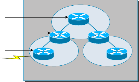
316
Chapter 10 ■ Routing Protocols
c10.indd 04/02/2015 Page 316
FIGURE 10.9 OSPF design example
Backbone Router
Area 0
Area 1 Area 2
Autonomous System
Area Border
Router (ABR)
Autonomous System
Border Router (ASBR)
OSPF runs inside an autonomous system, but it can also connect multiple autonomous
systems together. The router that connects these ASs is called an autonomous system
border router (ASBR). Typically, in today’s networks, BGP is used to connect between ASs,
not OSPF.
Ideally, you would create other areas of networks to help keep route updates to a mini-
mum and to keep problems from propagating throughout the network. But that’s beyond
the scope of this chapter. Just make note of it for your future networking studies.
Intermediate System-to-Intermediate System (IS-IS)
IS-IS is an IGP, meaning that it’s intended for use within an administrative domain or net-
work, not for routing between ASs. That would be a job that an EGP (such as BGP, which
we just covered) would handle instead.
IS-IS is a link state routing protocol, meaning it operates by reliably ooding topology
information throughout a network of routers. Each router then independently builds a pic-
ture of the network’s topology, just as they do with OSPF. Packets or datagrams are
forwarded based on the best topological path through the network to the destination.
Figure 10.10 shows an IS-IS network and the terminology used with IS-IS.
Here are the de nitions for the terms used in the IS-IS network shown in Figure 10.10:
L1 Level 1 intermediate systems route within an area. When the destination is outside an
area, they route toward a Level 2 system.
L2 Level 2 intermediate systems route between areas and toward other ASs.
The similarity between IS-IS and OSPF is that both employ the Dijkstra algorithm to
discover the shortest path through the network to a destination network. The difference
between IS-IS and OSPF is that IS-IS uses Connectionless Network Service (CLNS) to pro-
vide connectionless delivery of data packets between routers, and it also doesn’t require an
area 0 like OSPF does. OSPF uses IP to communicate between routers instead.
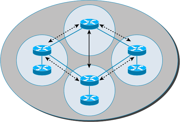
High Availability
317
c10.indd 04/02/2015 Page 317
FIGURE 10.10 IS-IS network terminology
Area 13
AS 1200
Area 12Area 10
Area 11
L2
L1
L1
L1
L1/L2
L1/L2
L1/L2
An advantage to having CLNS around is that it can easily send information about mul-
tiple routed protocols (IP and IPv6), and as I already mentioned, OSPF must maintain a
completely different routing database for IP and IPv6, respectively, for it to be able to send
updates for both protocols.
IS-IS supports the most important characteristics of OSPF and EIGRP because it sup-
ports VLSM and also because it converges quickly. Each of these three protocols has advan-
tages and disadvantages, but it’s these two shared features that make any of them scalable
and appropriate for supporting the large-scale networks of today.
One last thing—even though it’s not as common, IS-IS, although comparable to OSPF, is
actually preferred by ISPs because of its ability to run IP and IPv6 without creating a sepa-
rate database for each protocol as OSPF does. That single feature makes it more ef cient in
very large networks.
High Availability
First hop redundancy protocols (FHRPs) work by giving you a way to con gure more than
one physical router to appear as if they were only a single logical one. This makes client
con guration and communication easier because you can simply con gure a single default
gateway and the host machine can use its standard protocols to communicate. First hop is
a reference to the default router being the rst router, or rst router hop, through which a
packet must pass.
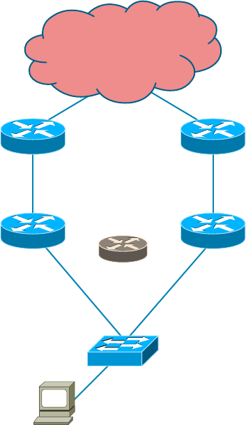
318
Chapter 10 ■ Routing Protocols
c10.indd 04/02/2015 Page 318
So how does a redundancy protocol accomplish this? The protocols I’m going to
describe to you do this basically by presenting a virtual router to all of the clients. The vir-
tual router has its own IP and MAC addresses. The virtual IP address is the address that’s
con gured on each of the host machines as the default gateway. The virtual MAC address
is the address that will be returned when an ARP request is sent by a host. The hosts don’t
know or care which physical router is actually forwarding the traf c, as you can see in
Figure 10.11.
FIGURE 10.11 FHRPs use a virtual router with a virtual IP address and virtual MAC
address.
Fa0/1Fa0/1
Fa0/0
10.0.0.1 10.0.0.2
IP: 10.0.0.100
Gateway: 10.0.0.10
Virtual Router
10.0.0.10
Fa0/0
It’s the responsibility of the redundancy protocol to decide which physical router will
actively forward traf c and which one will be placed in standby in case the active router
fails. Even if the active router fails, the transition to the standby router will be transparent
to the hosts because the virtual router, identi ed by the virtual IP and MAC addresses, is

High Availability
319
c10.indd 04/02/2015 Page 319
now used by the standby router. The hosts never change default gateway information, so
traf c keeps owing.
Fault-tolerant solutions provide continued operation in the event of a
device failure, and load-balancing solutions distribute the workload over
multiple devices.
Next we’ll explore these two important redundancy protocols:
Hot Standby Router Protocol (HSRP) This is by far Cisco’s favorite protocol ever! Don’t
buy just one router; buy up to eight routers to provide the same service, and keep seven as
backup in case of failure! HSRP is a Cisco proprietary protocol that provides a redundant
gateway for hosts on a local subnet, but this isn’t a load-balanced solution. HSRP allows
you to con gure two or more routers into a standby group that shares an IP address and
MAC address and provides a default gateway. When the IP and MAC addresses are inde-
pendent from the routers’ physical addresses (on a virtual interface, not tied to a speci c
interface), they can swap control of an address if the current forwarding and active router
fails. But there is actually a way you can sort of achieve load balancing with HSRP—by
using multiple VLANs and designating a speci c router for one VLAN, then an alternate
router as active for VLAN via trunking.
Virtual Router Redundancy Protocol (VRRP) This also provides a redundant—but again,
not load-balanced—gateway for hosts on a local subnet. It’s an open standard protocol
that functions almost identically to HSRP. I’ll comb through the ne differences that exist
between these protocols.
Hot Standby Router Protocol (HSRP)
Again, HSRP is a Cisco proprietary protocol that can be run on most, but not all, of
Cisco’s router and multilayer switch models. It de nes a standby group, and each standby
group that you de ne includes the following routers:
■ Active router
■ Standby router
■ Virtual router
■ Any othser routers that maybe attached to the subnet
The problem with HSRP is that with it, only one router is active and two or more
routers just sit there in standby mode and won’t be used unless a failure occurs—not very
cost effective or ef cient! Figure 10.12 shows how only one router is used at a time in an
HSRP group.
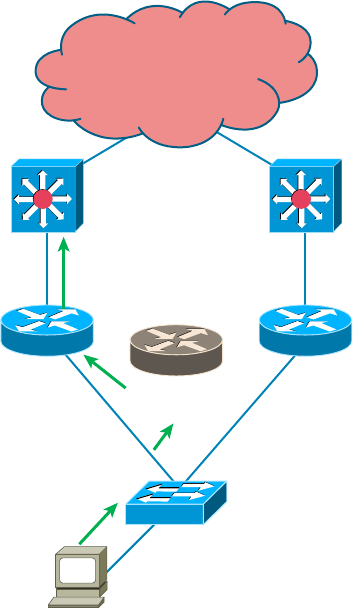
320
Chapter 10 ■ Routing Protocols
c10.indd 04/02/2015 Page 320
FIGURE 10.12 HSRP active and standby routers
Fa0/1Fa0/1
Fa0/0
10.0.0.1
Active
10.0.0.2
Standby
IP: 10.0.0.100
Gateway: 10.0.0.10
Virtual Router
10.0.0.10
Fa0/0
The standby group will always have at least two routers participating in it. The primary
players in the group are the one active router and one standby router that communicate to
each other using multicast Hello messages. The Hello messages provide all of the required
communication for the routers. The Hellos contain the information required to accomplish
the election that determines the active and standby router positions. They also hold the key
to the failover process. If the standby router stops receiving hello packets from the active
router, it then takes over the active router role, as shown in Figure 10.13.
As soon as the active router stops responding to hellos, the standby router automatically
becomes the active router and starts responding to host requests.
Virtual MAC Address
A virtual router in an HSRP group has a virtual IP address and a virtual MAC address.
So where does that virtual MAC come from? The virtual IP address isn’t that hard to
gure out; it just has to be a unique IP address on the same subnet as the hosts de ned in
the con guration. But MAC addresses are a little different, right? Or are they? The answer
is yes—sort of. With HSRP, you create a totally new, made-up MAC address in addition to
the IP address.
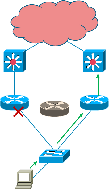
High Availability
321
c10.indd 04/02/2015 Page 321
FIGURE 10.13 Example of HSRP active and standby routers swapping interfaces
Fa0/1Fa0/1
Fa0/0
10.0.0.1
Standby
10.0.0.2
Active
IP: 10.0.0.100
Gateway: 10.0.0.10
Virtual Router
10.0.0.10
Fa0/0
The HSRP MAC address has only one variable piece in it. The rst 24 bits still identify
the vendor who manufactured the device (the organizationally unique identi er, or OUI).
The next 16 bits in the address tells us that the MAC address is a well-known HSRP MAC
address. Finally, the last 8 bits of the address are the hexadecimal representation of the
HSRP group number.
Let me clarify all this with an example of what an HSRP MAC address would look like:
0000.0c07.ac0a
■ The first 24 bits (0000.0c) are the vendor ID of the address; in the case of HSRP being
a Cisco protocol, the ID is assigned to Cisco.
■ The next 16 bits (07.ac) are the well-known HSRP ID. This part of the address was
assigned by Cisco in the protocol, so it’s always easy to recognize that this address is
for use with HSRP.
■ The last 8 bits (0a) are the only variable bits and represent the HSRP group number
that you assign. In this case, the group number is 10 and converted to hexadecimal
when placed in the MAC address, where it becomes the 0a that you see.
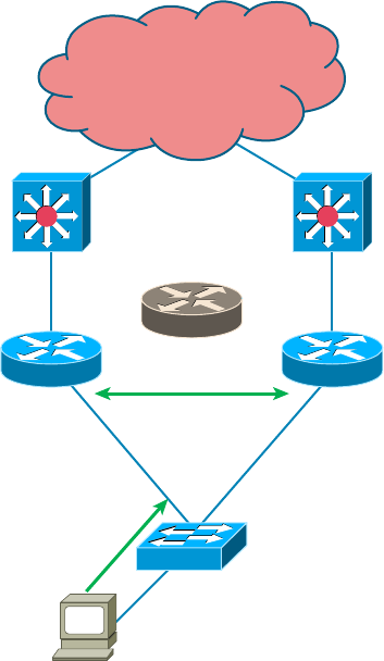
322
Chapter 10 ■ Routing Protocols
c10.indd 04/02/2015 Page 322
You can see this MAC address added to the ARP cache of every router in the HSRP
group. There will be the translation from the IP address to the MAC address as well as the
interface on which it’s located.
HSRP Timers
Before we get deeper into the roles that each of the routers can have in an HSRP group, I
want to de ne the HSRP timers. The timers are very important to HSRP function because
they ensure communication between the routers, and if something goes wrong, they allow
the standby router to take over. The HSRP timers include hello, hold, active, and standby.
Hello Timer The hello timer is the de ned interval during which each of the routers send
out Hello messages. Their default interval is 3 seconds, and they identify the state that each
router is in. This is important because the particular state determines the speci c role of
each router and, as a result, the actions each will take within the group. Figure 10.14 shows
the Hello messages being sent, and the router uses the hello timer to keep network traf c
owing in case of a failure.
FIGURE 10.14 HSRP Hellos
Fa0/1
Hello?
Fa0/1
Fa0/0
10.0.0.1
Active
10.0.0.2
Standby
IP: 10.0.0.100
Gateway: 10.0.0.10
Virtual Router
10.0.0.10
Fa0/0

High Availability
323
c10.indd 04/02/2015 Page 323
This timer can be changed, and people used to avoid doing so because it was thought that
lowering the hello value would place an unnecessary load on the routers. That isn’t true
with most of the routers today; in fact, you can con gure the timers in milliseconds, mean-
ing the failover time can be in milliseconds! Still, keep in mind that increasing the value
will make the standby router wait longer before taking over for the active router when it
fails or can’t communicate.
Hold Timer The hold timer speci es the interval the standby router uses to determine
whether the active router is of ine or out of communication. By default, the hold timer is
10 seconds, roughly three times the default for the hello timer. If one timer is changed for
some reason, I recommend using this multiplier to adjust the other timers too. By setting
the hold timer at three times the hello timer, you ensure that the standby router doesn’t take
over the active role every time there’s a short break in communication.
Active Timer The active timer monitors the state of the active router. The timer resets
each time a router in the standby group receives a Hello packet from the active router. This
timer expires based on the hold time value that’s set in the corresponding eld of the HSRP
hello message.
Standby Timer The standby timer is used to monitor the state of the standby router. The
timer resets anytime a router in the standby group receives a hello packet from the standby
router and expires based on the hold time value that’s set in the respective hello packet.
Large Enterprise Network Outages with FHRPs
Years ago when HSRP was all the rage, and before VRRP and GLBP, enterprises used
hundreds of HSRP groups. With the hello timer set to 3 seconds and a hold time of 10 sec-
onds, these timers worked just fi ne and we had great redundancy with our core routers.
However, as we’ve seen in the last few years, and will certainly see in the future, 10 sec-
onds is now a lifetime! Some of my customers have been complaining with the failover
time and loss of connectivity to their virtual server farms.
So lately I’ve been changing the timers to well below the defaults. Cisco had changed the
timers so you could use sub-second times for failover. Because these are multicast pack-
ets, the overhead that is seen on a current high-speed network is almost nothing.
The hello timer is typically set to 200 msec and the hold time is 700 msec. The command
is as follows:
(config-if)#Standby 1 timers msec 200 msec 700
This almost ensures that not even a single packet is lost when there is an outage.
324
Chapter 10 ■ Routing Protocols
c10.indd 04/02/2015 Page 324
Virtual Router Redundancy Protocol
Like HSRP, Virtual Router Redundancy Protocol (VRRP) allows a group of routers to
form a single virtual router. In an HSRP or VRRP group, one router is elected to handle
all requests sent to the virtual IP address. With HSRP, this is the active router. An HSRP
group has only one active router, at least one standby router, and many listening routers. A
VRRP group has one master router and one or more backup routers, and is the open stan-
dard implementation of HSRP.
Comparing VRRP and HSRP
The LAN workstations are con gured with the address of the virtual router as their default
gateway, just as they are with HSRP, but VRRP differs from HSRP in these important
ways:
■ VRRP is an IEEE standard (RFC 2338) for router redundancy; HSRP is a Cisco
proprietary protocol.
■ The virtual router that represents a group of routers is known as a VRRP group.
■ The active router is referred to as the master virtual router.
■ The master virtual router may have the same IP address as the virtual router group.
■ Multiple routers can function as backup routers.
■ VRRP is supported on Ethernet, Fast Ethernet, and Gigabit Ethernet interfaces as
well as on Multiprotocol Label Switching (MPLS), virtual private networks (VPNs),
and VLANs.
VRRP Redundancy Characteristics
VRRP has some unique features:
■ VRRP provides redundancy for the real IP address of a router or for a virtual IP
address shared among the VRRP group members.
■ If a real IP address is used, the router with that address becomes the master.
■ If a virtual IP address is used, the master is the router with the highest priority.
■ A VRRP group has one master router and one or more backup routers.
■ The master router uses VRRP messages to inform group members of its status.
■ VRRP allows load sharing across more than one virtual router.
Now let’s take a look at some IPv6 routing protocols.
IPv6 Routing Protocols
Most of the routing protocols we’ve already discussed have been upgraded for use in IPv6
networks. Also, many of the functions and con gurations that we’ve already learned will
be used in almost the same way as they’re used now. Knowing that broadcasts have been
IPv6 Routing Protocols
325
c10.indd 04/02/2015 Page 325
eliminated in IPv6, it follows that any protocols that use entirely broadcast traf c will go
the way of the dodo—but unlike the dodo, it’ll be good to say goodbye to these bandwidth-
hogging, performance-annihilating little gremlins!
The routing protocols that we’ll still use in version 6 got a new name and a facelift. Let’s
talk about a few of them now.
First on the list is RIPng (next generation). Those of you who have been in IT for a while
know that RIP has worked very well for us on smaller networks, which happens to be the
reason it didn’t get whacked and will still be around in IPv6. And we still have EIGRPv6
because it already had protocol-dependent modules and all we had to do was add a new
one to it for the IPv6 protocol. Rounding out our group of protocol survivors is OSPFv3—
that’s not a typo; it really is version 3. OSPF for IPv4 was actually version 2, so when it got
its upgrade to IPv6, it became OSPFv3.
RIPng
To be honest, the primary features of RIPng are the same as they were with RIPv2. It is still
a distance vector protocol, has a max hop count of 15, and still has the same loop avoid-
ance mechanisms as well as using UDP port 521.
And it still uses multicast to send its updates, too, but in IPv6, it uses FF02::9 for the
transport address. This is actually kind of cool because in RIPv2, the multicast address was
224.0.0.9, so the address still has a 9 at the end in the new IPv6 multicast range. In fact,
most routing protocols got to keep a little bit of their IPv4 identities like that.
But of course there are differences in the new version or it wouldn’t be a new version,
would it? We know that routers keep the next-hop addresses of their neighbor routers
for every destination network in their routing table. The difference is that with RIPng,
the router keeps track of this next-hop address using the link-local address, not a global
address. So just remember that RIPng will pretty much work the same way as with IPv4.
EIGRPv6
As with RIPng, EIGRPv6 works much the same as its IPv4 predecessor does—most of the
features that EIGRP provided before EIGRPv6 will still be available.
EIGRPv6 is still an advanced distance vector protocol that has some link state features.
The neighbor-discovery process using hellos still happens, and it still provides reliable com-
munication with a reliable transport protocol that gives us loop-free fast convergence using
DUAL.
Hello packets and updates are sent using multicast transmission, and as with RIPng,
EIGRPv6’s multicast address stayed almost the same. In IPv4 it was 224.0.0.10; in IPv6,
it’s FF02::A (A = 10 in hexadecimal notation).
Last to check out in our group is what OSPF looks like in the IPv6 routing protocol.
OSPFv3
The new version of OSPF continues the trend of the routing protocols having many simi-
larities with their IPv4 versions.

326
Chapter 10 ■ Routing Protocols
c10.indd 04/02/2015 Page 326
The foundation of OSPF remains the same—it is still a link state routing protocol that
divides an entire internetwork or autonomous system into areas, making a hierarchy.
Adjacencies (neighbor routers running OSPF) and next-hop attributes now use link-
local addresses, and OSPFv3 still uses multicast traf c to send its updates and acknowl-
edgments, with the addresses FF02::5 for OSPF routers and FF02::6 for OSPF-designated
routers, which provide topological updates (route information) to other routers. These new
addresses are the replacements for 224.0.0.5 and 224.0.0.6, respectively, which were used
in OSPFv2.
With all this routing information behind you, it’s time to go through some review ques-
tions and then move on to learning all about switching in the next chapter.
Shortest Path Bridging (SPB), specified in the IEEE 802.1aq standard, is a
computer networking technology intended to simplify the creation and
configuration of networks and replace the older 802.1d/802.1w protocols,
while enabling multipath routing
Summary
This chapter covered the basic routing protocols that you may nd on a network today.
Probably the most common routing protocols you’ll run into are RIP, OSPF, and EIGRP.
I covered RIP, RIPv2, the differences between the two RIP protocols, EIGRP, and BGP
in the section on distance vector protocols.
I nished by discussing OSPF and IS-IS and when you would possibly see each one in
a network.
Exam Essentials
Remember the differences between RIPv1 and RIPv2. RIPv1 sends broadcasts every 30
seconds and has an AD of 120. RIPv2 sends multicasts (224.0.0.9) every 30 seconds and
also has an AD of 120. RIPv2 sends subnet mask information with the route updates,
which allows it to support classless networks and discontiguous networks. RIPv2 also sup-
ports authentication between routers, and RIPv1 does not.
Compare OSPF and RIPv1. OSPF is a link state protocol that supports VLSM and class-
less routing; RIPv1 is a distance vector protocol that does not support VLSM and supports
only classful routing.

Written Lab
327
c10.indd 04/02/2015 Page 327
Written Lab
You can nd the answers in Appendix A.
1. The default administrative distance of RIP is .
2. The default administrative distance of EIGRP is .
3. The default administrative distance of RIPv2 is .
4. What is the default administrative distance of a static route?
5. What is the version or name of RIP that is used with IPv6?
6. What is the version or name of OSPF that is used with IPv6?
7. What is the version or name of EIGRP that is used with IPv6?
8. When would you use BGP?
9. When could you use EIGRP?
10. Is BGP considered link state or DV?
328
Chapter 10 ■ Routing Protocols
c10.indd 04/02/2015 Page 328
Review Questions
You can nd the answers to the review questions in Appendix B.
1. Which of the following protocols support VLSM, summarization, and discontiguous
networking? (Choose three.)
A. RIPv1
B. IGRP
C. EIGRP
D. OSPF
E. BGP
F. RIPv2
2. Which of the following are considered distance vector routing protocols? (Choose two.)
A. OSPF
B. RIP
C. RIPv2
D. IS-IS
3. Which of the following are considered link state routing protocols? (Choose two.)
A. OSPF
B. RIP
C. RIPv2
D. IS-IS
4. Which of the following is considered a hybrid routing protocol? (Choose two.)
A. OSPF
B. BGP
C. RIPv2
D. IS-IS
E. EIGRP
5. Why would you want to use a dynamic routing protocol instead of using static routes?
A. There is less overhead on the router.
B. Dynamic routing is more secure.
C. Dynamic routing scales to larger networks.
D. The network runs faster.
6. Which of the following is a vendor-specific FHRP protocol?
A. STP
B. OSPF
Review Questions
329
c10.indd 04/02/2015 Page 329
C. RIPv1
D. EIGRP
E. IS-IS
F. HSRP
7. RIP has a long convergence time and users have been complaining of response time when a
router goes down and RIP has to reconverge. Which can you implement to improve conver-
gence time on the network?
A. Replace RIP with static routes.
B. Update RIP to RIPv2.
C. Update RIP to OSPF using link state.
D. Replace RIP with BGP as an exterior gateway protocol.
8. What is the administrative distance of OSPF?
A. 90
B. 100
C. 110
D. 120
9. Which of the following protocols will advertise routed IPv6 networks?
A. RIP
B. RIPng
C. OSPFv2
D. EIGRPv3
10. What is the difference between static and dynamic routing?
A. You use static routing in large, scalable networks.
B. Dynamic routing is used by a DNS server.
C. Dynamic routes are added automatically.
D. Static routes are added automatically.
11. Which routing protocol has a maximum hop count of 15?
A. RIPv1
B. IGRP
C. EIGRP
D. OSPF
12. Which of the following describes routing convergence time?
A. The time it takes for your VPN to connect
B. The time required by protocols to update their forwarding tables after changes have
occurred
330
Chapter 10 ■ Routing Protocols
c10.indd 04/02/2015 Page 330
C. The time required for IDS to detect an attack
D. The time required by switches to update their link status and go into forwarding state
13. What routing protocol is typically used to connect ASs on the Internet?
A. IGRP
B. RIPv2
C. BGP
D. OSPF
14. RIPv2 sends out its routing table every 30 seconds just like RIPv1, but it does so more effi-
ciently. What type of transmission does RIPv2 use to accomplish this task?
A. Broadcasts
B. Multicasts
C. Telecast
D. None of the above
15. Which routing protocols have an administrative distance of 120? (Choose two.)
A. RIPv1
B. RIPv2
C. EIGRP
D. OSPF
16. Which of the following routing protocols uses AS-Path as one of the methods to build the
routing tables?
A. OSPF
B. IS-IS
C. BGP
D. RIP
E. EIGRP
17. Which IPv6 routing protocol uses UDP port 521?
A. RIPng
B. EIGRPv6
C. OSPFv3
D. IS-IS
18. What EIGRP information is held in RAM and maintained through the usage of hello and
update packets? (Select all that apply.)
A. DUAL table
B. Neighbor table
C. Topology table
D. Successor route
Review Questions
331
c10.indd 04/02/2015 Page 331
19. Which is true regarding EIGRP successor routes?
A. Successor routes are saved in the neighbor table.
B. Successor routes are stored in the DUAL table.
C. Successor routes are used only if the primary route fails.
D. A successor route is used by EIGRP to forward traffic to a destination.
20. Which of the following uses only hop count as a metric to find the best path to a remote
network?
A. RIP
B. EIGRP
C. OSPF
D. BGP

c11.indd 04/02/2015 Page 333
Chapter
11
Switching and Virtual
LANs
THE FOLLOWING COMPTIA NETWORK+
EXAM OBJECTIVES ARE COVERED IN THIS
CHAPTER:
✓ 2.6 Given a scenario, configure a switch using proper
features
■ VLAN
■ Native VLAN/Default VLAN
■ VTP
■ Spanning tree (802.1d)/rapid spanning tree (802.1w)
■ Flooding
■ Forwarding/blocking
■ Filtering
■ Interface configuration
■ Trunking /802.1q
■ Tag vs untag VLANs
■ Port bonding (LACP)
■ Port mirroring (local vs remote)
■ Speed and duplexing
■ IP address assignment
■ VLAN assignment
■ Default gateway
■ PoE and PoE+ (802.3af, 802.3at)
■ Switch management
■ User/passwords
■ AAA configuration
■ Console
■ Virtual terminals

c11.indd 04/02/2015 Page 334
■ In-band/Out-of-band management
■ Managed vs unmanaged
✓ 3.3 Given a scenario, implement network hardening
techniques
■ Network-based
■ Switch port security
■ MAC address filtering
■ DHCP snooping
■ ARP inspection
■ VLAN assignments
■ Network segmentation

c11.indd 04/02/2015 Page 335
Layer 2 switching is the process of using the hardware
addresses of devices on a LAN to segment a network. Because
you’ve got the basic ideas down, I’m now going to focus on the
more in-depth particulars of Layer 2 switching and how it works.
You already know that switching breaks up large collision domains into smaller ones
and that a collision domain is a network segment with two or more devices sharing the
same bandwidth. A hub network is a typical example of this type of technology. But
because each port on a switch is actually its own collision domain, you can create a much
better Ethernet LAN network by simply replacing your hubs with switches!
Switches truly have changed the way networks are designed and implemented. If a pure
switched design is properly implemented, it will result in a clean, cost-effective, and resil-
ient internetwork. In this chapter, we’ll survey and compare how networks were designed
before and after switching technologies were introduced.
Routing protocols like RIP, which you learned about in Chapter 10, employ processes for
preventing network loops from occurring at the Network layer. This is all good, but if you
have redundant physical links between your switches, routing protocols won’t do a thing
to stop loops from occurring at the Data Link layer. That’s exactly the reason Spanning
Tree Protocol was developed—to put a stop to loops taking place within a Layer 2 switched
network. The essentials of this vital protocol, as well as how it works within a switched
network, are some of the important subjects that we’ll cover thoroughly in this chapter.
And to nish up this chapter, you’re going to learn exactly what a VLAN is and how
VLAN memberships are used in a switched network as well as how trunking is used to
send information from all VLANs across a single link. Good stuff!
To find up-to-the-minute updates for this chapter, please see
www.lammle
.com/networkplus
or the book’s website at
www.sybextestbanks.wiley
.com
.
Networking Before Layer 2 Switching
Because knowing the history of something really helps with understanding why things are
the way they are today, I’m going to go back in time a bit and talk about the condition of
networks before switches and the part switches have played in the evolution of corporate
LANs by helping to segment them. For a visual of how a typical network design looked
before LAN switching, check out the network in Figure 11.1.
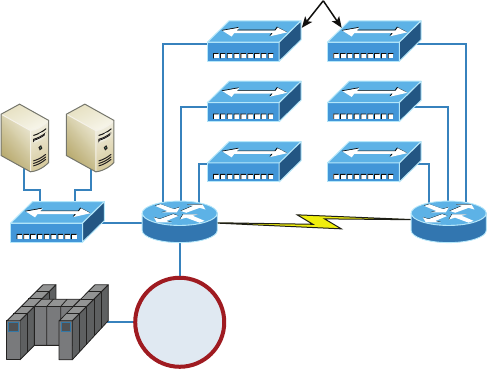
336
Chapter 11 ■ Switching and Virtual LANs
c11.indd 04/02/2015 Page 336
FIGURE 11.1 A network before switching
Hubs
Server Farm
Corporate
Token Ring
Remote Branch
The design in Figure 11.1 was called a collapsed backbone because all the hosts involved
had to go to the corporate backbone in order to reach any network services—both LAN
and mainframe.
Going back even further, before networks like the one shown in Figure 11.1 had physi-
cal segmentation devices such as routers and hubs, there was the mainframe network. This
type of network comprised mainframe controllers made by IBM, Honeywell, Sperry, DEC,
and so on, and dumb terminals that connected into the controller(s). Any remote sites were
connected to the mainframe with bridges.
And then the PC began its rise to stardom, and the mainframe was connected to an
Ethernet or Token Ring LAN where the servers were installed. These servers were usually
OS/2 or LAN Manager because this was “pre-NT.” Each oor of a building ran either coax
or twisted-pair wiring to the corporate backbone, which was then connected to a router.
PCs ran an emulating software program that allowed them to connect to mainframe
services, giving those PCs the ability to access services from the mainframe and LAN
simultaneously. Eventually, the PC became robust enough to allow application developers
to port applications more effectively than they ever could before—an advance that mark-
edly reduced networking prices and enabled businesses to grow at a much faster rate.
Moving forward to when Novell rose to popularity in the late 1980s and early 1990s,
OS/2 and LAN Manager servers were by and large replaced with NetWare servers. This
made the Ethernet network even more popular because that’s what Novell 3.x servers used
to communicate with client-server software.
So basically, that’s the story about how the network in Figure 11.1 came into being.
But soon a big problem arose with this con guration. As the corporate backbone grew
and grew, network services became slower and slower. A big reason for this was that at
the same time this huge burst in growth was taking place, LAN services began to require
even faster response times. This resulted in networks becoming totally saturated and
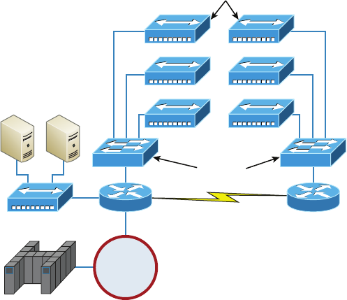
Networking Before Layer 2 Switching
337
c11.indd 04/02/2015 Page 337
overwhelmed. Everyone was dumping the dumb terminals used to access mainframe ser-
vices in favor of those slick new PCs so they could more easily connect to the corporate
backbone and network services.
And all this was taking place before the Internet’s momentous popularity, so everyone
in the company needed to access the corporate network’s own, internal services. Without
the Internet, all network services were internal, meaning that they were exclusive to the
company network. As you can imagine, this situation created a screaming need to segment
that single, humongous, and now plodding corporate network, which was connected
together with sluggish old routers.
How was this issue addressed? Well, at rst, Cisco responded by simply creating faster
routers (no doubt about that), but still more segmentation was needed, especially on the
Ethernet LANs. The invention of Fast Ethernet was a very good and helpful thing, yet
it too fell short of solving that network segmentation need. But devices called bridges
did provide relief, and they were rst used in the networking environment to break up
collision domains.
Sounds good, but only so much—bridges were sorely limited by the number of ports and
other network services they could provide, and that’s when Layer 2 switches came to the
rescue. These switches saved the day by breaking up collision domains on each and every
port—like a bridge—but switches could provide hundreds of ports! This early, switched
LAN looked like the network pictured in Figure 11.2.
FIGURE 11.2 The first switched LAN
Hubs
Switches
Server Farm
Corporate
Token Ring
Remote Branch
As you can see here, each hub was placed into a switch port—an innovation that vastly
improved the network. So now, instead of each building being crammed into the same
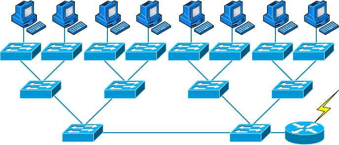
338
Chapter 11 ■ Switching and Virtual LANs
c11.indd 04/02/2015 Page 338
collision domain, each hub became its own separate collision domain. Yet still, as is too
often the case, there was a catch—switch ports were still very new and, therefore, super
expensive. Because switches were so cost prohibitive, simply adding a switch into each oor
of the building just wasn’t going to happen—at least, not yet. But thanks to whomever you
choose to thank for these things, the switch price tag has dropped dramatically; now, hav-
ing every one of your users plugged into a switch port is a really good solution, and cost
effective, too!
So there it is—if you’re going to create a network design and implement it, including
switching services is a must.
A typical, contemporary, and complete switched network design/implementation would
look something like Figure 11.3.
FIGURE 11.3 The typical switched network design
“But wait—there’s still a router in there!” you say. Yes, it’s not a mirage—there is a
router in there. But its job has changed quite a bit. Instead of performing physical segmen-
tation, it now creates and handles logical segmentation. Those logical segments are called
VLANs, and no worries, I promise to explain them thoroughly throughout the rest of this
chapter.
Switching Services
Bridges use software to create and manage a lter table, but switches use application-
speci c integrated circuits (ASICs) to accomplish this. Even so, it’s still okay to think of
a Layer 2 switch as a multiport bridge because their basic reason for being is the same: to
break up collision domains.
Layer 2 switches and bridges are faster than routers because they don’t take up time
looking at the Network layer header information. Instead, they look at the frame’s hard-
ware addresses before deciding to forward, ood, or drop the frame.
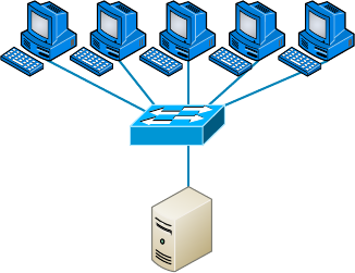
Switching Services
339
c11.indd 04/02/2015 Page 339
Switches create private, dedicated collision domains and provide independent bandwidth
on each port, unlike hubs. Figure 11.4 shows ve hosts connected to a switch—all running
100Mbps full duplex to the server. Unlike with a hub, each host has full-duplex, 100Mbps
of dedicated communication to the server.
FIGURE 11.4 Switches create private domains.
Server
100Mbps Full-Duplex Links
Layer 2 switching provides the following bene ts:
■ Hardware-based bridging (ASIC)
■ Wire speed
■ Low latency
■ Low cost
What makes Layer 2 switching so ef cient is that no modi cation to the data packet
takes place. The device reads only the frame encapsulating the packet, which makes the
switching process considerably faster and less error prone than routing processes.
And if you use Layer 2 switching for both workgroup connectivity and network
segmentation (breaking up collision domains), you can create a atter network design with
more network segments than you can with traditional routed networks.
Plus, Layer 2 switching increases bandwidth for each user because, again, each connec-
tion (interface) into the switch is its own collision domain. This feature makes it possible
for you to connect multiple devices to each interface—very cool.
Coming up, we’ll dive deeper into the Layer 2 switching technology.
Limitations of Layer 2 Switching
Because people usually toss Layer 2 switching into the same category as bridged networks,
we also tend to think it has the same hang-ups and issues that bridged networks do.
Keep in mind that bridges are good and helpful things if we design the network correctly,
340
Chapter 11 ■ Switching and Virtual LANs
c11.indd 04/02/2015 Page 340
keeping our devices’ features as well as their limitations in mind. To end up with a solid
design that includes bridges, there are two really important things to consider:
■ You absolutely have to break up the collision domains properly.
■ A well-oiled, functional bridged network is one whose users spend 80 percent of their
time on the local segment.
So, bridged networks break up collision domains, but remember, that network is
really still just one big broadcast domain. Neither Layer 2 switches nor bridges break up
broadcast domains by default—something that not only limits your network’s size and
growth potential but can also reduce its overall performance!
Broadcasts and multicasts, along with the slow convergence time of spanning trees, can
give you some major grief as your network grows. These are the big reasons Layer 2 switches
and bridges just can’t completely replace routers (Layer 3 devices) in the internetwork.
Bridging vs LAN Switching
It’s true—Layer 2 switches really are pretty much just bridges that give us a lot more ports.
But the comparison doesn’t end there. Here’s a list of some signi cant differences and
similarities between bridges and switches that you need to keep in mind:
■ Bridges are software based, whereas switches are hardware based because they use
ASIC chips to help make filtering decisions.
■ A switch can be viewed as a multiport bridge.
■ There can be only one spanning-tree instance per bridge, whereas switches can have
many. (I’m going to tell you all about spanning trees in a bit.)
■ Switches have a higher number of ports than most bridges.
■ Both bridges and switches forward Layer 2 broadcasts.
■ Bridges and switches learn MAC addresses by examining the source address of each
frame received.
■ Both bridges and switches make forwarding decisions based on Layer 2 addresses.
Three Switch Functions at Layer 2
There are three distinct functions of Layer 2 switching—you need to know these! They are
as follows:
■ Address learning
■ Forward/filter decisions
■ Loop avoidance
The next three sections cover these functions in detail.
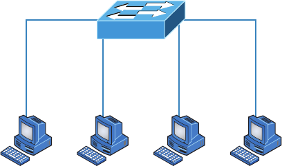
Switching Services
341
c11.indd 04/02/2015 Page 341
Address Learning
Layer 2 switches and bridges are capable of address learning; that is, they remember the
source hardware address of each frame received on an interface and enter this information
into a MAC database known as a forward/ lter table. But rst things rst—when a switch
is initially powered on, the MAC forward/ lter table is empty, as shown in Figure 11.5.
FIGURE 11.5 Empty forward/filter table on a switch
Host A
E0/1 E0/2
E0/3E0/0
Host B Host C Host D
MAC Forward/Filter Table
E0/0:
E0/1:
E0/2:
E0/3:
When a device transmits and an interface receives a frame, the switch places the frame’s
source address in the MAC forward/ lter table, which allows it to remember the interface
on which the sending device is located. The switch then has no choice but to ood the net-
work with this frame out of every port except the source port because it has no idea where
the destination device is actually located.
If a device answers this ooded frame and sends a frame back, then the switch will
take the source address from that frame and place that MAC address in its database as
well, thereby associating the newly discovered address with the interface that received the
frame. Because the switch now has both of the relevant MAC addresses in its ltering table,
the two devices can make a point-to-point connection. The switch doesn’t need to ood
the frame as it did the rst time because now the frames can and will be forwarded only
between the two devices recorded in the table. This is exactly the thing that makes Layer 2
switches better than hubs, because in a hub network, all frames are forwarded out all ports
every time—no matter what. This is because hubs just aren’t equipped to collect, store, and
draw upon data in a table as a switch is. Figure 11.6 shows the processes involved in build-
ing a MAC database.
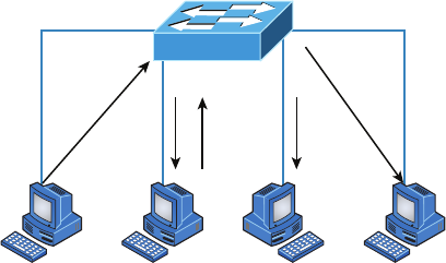
342
Chapter 11 ■ Switching and Virtual LANs
c11.indd 04/02/2015 Page 342
FIGURE 11.6 How switches learn hosts’ locations
Host A
E0/1
3
Step 1
334
E0/2
E0/3E0/0
Host B Host C Host D
MAC Forward/Filter Table
E0/0: 0000.8c01.000A Step 2
E0/1: 0000.8c01.000B Step 4
E0/2:
E0/3:
In this gure, you can see four hosts attached to a switch. When the switch is powered
on, it has nothing in its MAC address forward/ lter table (just as in Figure 11.5). But when
the hosts start communicating, the switch places the source hardware address of each
frame in the table along with the port that the frame’s address corresponds to.
Let me give you a step-by-step example of how a forward/ lter table becomes populated:
1. Host A sends a frame to Host B. Host A’s MAC address is 0000.8c01.000A, and Host
B’s MAC address is 0000.8c01.000B.
2. The switch receives the frame on the E0/0 interface and places the source address in the
MAC address table, associating it with the port it came in on.
3. Because the destination address is not in the MAC database, the frame is forwarded
(flooded) out all interfaces—except the source port.
4. Host B receives the frame and responds to Host A. The switch receives this frame on
interface E0/1 and places the source hardware address in the MAC database, associat-
ing it with the port it came in on.
5. Host A and Host B can now make a point-to-point connection, and only the two devices
will receive the frames. Hosts C and D will not see the frames, nor are their MAC
addresses found in the database because they haven’t yet sent a frame to the switch.
Oh, by the way, it’s important to know that if Host A and Host B don’t communicate to
the switch again within a certain amount of time, the switch will ush their entries from
the database to keep it as current as possible.
Forward/Filter Decisions
When a frame arrives at a switch interface, the destination hardware address is compared
to the forward/ lter MAC database and the switch makes a forward/ lter decision. In
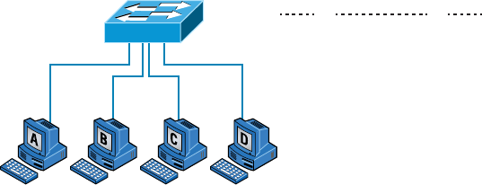
Switching Services
343
c11.indd 04/02/2015 Page 343
other words, if the destination hardware address is known (listed in the database), the
frame is only sent out the speci ed exit interface. The switch will not transmit the frame
out any interface except the destination interface. Not transmitting the frame preserves
bandwidth on the other network segments and is called frame ltering.
But as I mentioned earlier, if the destination hardware address isn’t listed in the MAC
database, then the frame is ooded out all active interfaces except the interface on which
the frame was received. If a device answers the ooded frame, the MAC database is
updated with the device’s location—its particular interface.
So by default, if a host or server sends a broadcast on the LAN, the switch will ood the
frame out all active ports except the source port. Remember, the switch creates smaller
collision domains, but it’s still one large broadcast domain by default.
In Figure 11.7, you can see Host A sending a data frame to Host D. What will the switch
do when it receives the frame from Host A?
FIGURE 11.7 Forward/filter table
Fa0/3 Fa0/4 Fa0/5 Fa0/6
VLAN Mac Address Ports
1 0005.dccb.d74b Fa0/4
1 000a.f467.9e80 Fa0/5
1 000a.f467.9e8b Fa0/6
Switch#sh mac address-table
If you answered that because Host A’s MAC address is not in the forward/ lter table,
the switch will add the source address and port to the MAC address table and then forward
the frame to Host D, you’re halfway there. If you also came back with, “If Host D’s MAC
address was not in the forward/ lter table, the switch would have ooded the frame out all
ports except for port Fa0/3,” then congratulations—you nailed it!
Let’s take a look at the output of a
show mac address-table
command as seen from a
Cisco Catalyst switch (the MAC address table works pretty much exactly the same on all
brands of switches):
Switch#sh
mac address-table
Vlan Mac Address Type Ports
---- -------------- ------- -----
1 0005.dccb.d74b DYNAMIC Fa0/1
1 000a.f467.9e80 DYNAMIC Fa0/3
1 000a.f467.9e8b DYNAMIC Fa0/4
1 000a.f467.9e8c DYNAMIC Fa0/3
1 0010.7b7f.c2b0 DYNAMIC Fa0/3
344
Chapter 11 ■ Switching and Virtual LANs
c11.indd 04/02/2015 Page 344
1 0030.80dc.460b DYNAMIC Fa0/3
1 0030.9492.a5dd DYNAMIC Fa0/1
1 00d0.58ad.05f4 DYNAMIC Fa0/1
Now suppose the preceding switch received a frame with the following MAC addresses:
Source MAC: 0005.dccb.d74b
Destination MAC: 000a.f467.9e8c
How will the switch handle this frame? The right answer is that the destination MAC
address will be found in the MAC address table and the frame will be forwarded out
Fa0/3 only. Remember that if the destination MAC address is not found in the forward/
lter table, it will forward the frame out all ports of the switch looking for the destination
device.
Now that you can see the MAC address table and how switches add hosts’ addresses to
the forward lter table, how do you stop switching loops if you have multiple links between
switches? Let’s talk about this possible problem in more detail.
Loop Avoidance
Redundant links between switches can be a wise thing to implement because they help
prevent complete network failures in the event that one link stops working.
But it seems like there’s always a downside—even though redundant links can be
extremely helpful, they often cause more problems than they solve. This is because frames
can be ooded down all redundant links simultaneously, creating network loops as well as
other evils. Here are a few of the problems you can be faced with:
■ If no loop avoidance schemes are put in place, the switches will flood broadcasts
endlessly throughout the internetwork. This is sometimes referred to as a broadcast
storm. (In real life, it’s often referred to in less-polite ways that we’re not permitted to
repeat in print!) Figure 11.8 illustrates how a broadcast can be propagated throughout
the network. Pay special attention to how a frame is continually being flooded through
the internetwork’s physical network media. One way to test the loop avoidance opera-
tions of your switch network is to plug one end of a cable into one port and the other
end of the same cable into another port. If loop avoidance is not operational, this
should cause a big broadcast storm!
■ What you see in Figure 11.8 is that a device can receive multiple copies of the same
frame because that frame can arrive from different segments at the same time. Figure
11.9 demonstrates how a whole bunch of frames can arrive from multiple segments
simultaneously. The server in the figure sends a unicast frame to another device
connected to Segment 1. Because it’s a unicast frame, Switch A receives and forwards
the frame, and Switch B provides the same service—it forwards the unicast. This is bad
because it means that the destination device on Segment 1 receives that unicast frame
twice, causing additional overhead on the network.
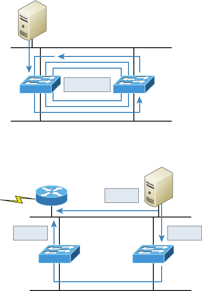
Switching Services
345
c11.indd 04/02/2015 Page 345
FIGURE 11.8 Broadcast storm
Switch A Switch B
Segment 1
Segment 2
Broadcast
FIGURE 11.9 Multiple frame copies
Switch B Switch A
Router C
Segment 1
Segment 2
Unicast
Unicast
Unicast
■ You may have thought of this one: The MAC address filter table could be totally con-
fused about the device’s location because the switch can receive the frame from more
than one link. Worse, the bewildered switch could get so caught up in constantly
updating the MAC filter table with source hardware address locations that it might fail
to forward a frame! This is called thrashing the MAC table.
■ One of the nastiest things that can happen is having multiple loops propagating
throughout a network. This means you end up with loops occurring within other
loops, and if a broadcast storm happened at the same time, the network wouldn’t be
able to perform frame switching at all—it’s toast!
All of these problems spell disaster (or something like it) and are decidedly ugly situa-
tions that just must be avoided or at least xed somehow. That’s where the Spanning Tree
Protocol comes into the game. It was developed to solve each and every one of the problems
I just told you about.
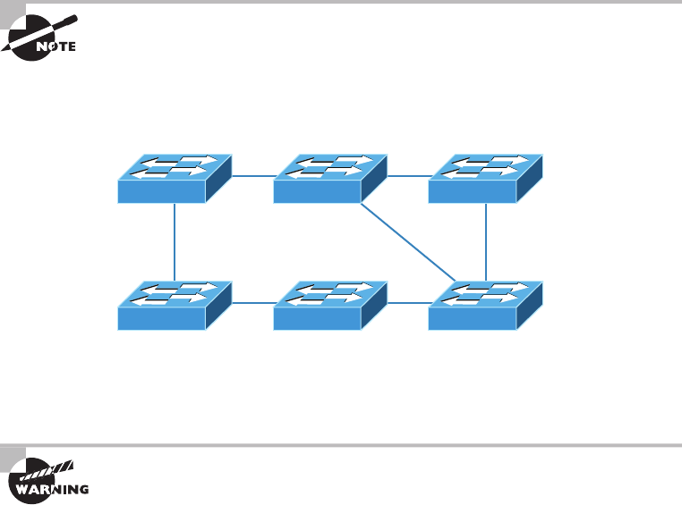
346
Chapter 11 ■ Switching and Virtual LANs
c11.indd 04/02/2015 Page 346
Spanning Tree Protocol
Once upon a time, a company called Digital Equipment Corporation (DEC) was pur-
chased and renamed Compaq. But before that happened, DEC created the original version
of Spanning Tree Protocol (STP). The IEEE later created its own version of STP called
802.1D. Yet again, it’s not all clear skies—by default, most switches run the IEEE 802.1D
version of STP, which isn’t compatible with the DEC version. The good news is that there is
a new industry standard called 802.1w, which is faster but not enabled by default on
any switches.
To begin with, STP’s main task is to stop network loops from occurring on your Layer 2
network (bridges or switches). It achieves this feat by vigilantly monitoring the network to
nd all links and making sure that no loops occur by shutting down any redundant ones.
STP uses the spanning-tree algorithm (STA) to rst create a topology database and then
search out and destroy redundant links. With STP running, frames will be forwarded only
on the premium, STP-picked links. Switches transmit Bridge Protocol Data Units (BPDUs)
out all ports so that all links between switches can be found.
STP is a Layer 2 protocol that is used to maintain a loop-free switched
network.
STP is necessary in networks such as the one shown in Figure 11.10.
FIGURE 11.10 A switched network with switching loops
In Figure 11.10, you see a switched network with a redundant topology (switching
loops). Without some type of Layer 2 mechanism to stop network loops, we would fall vic-
tim to the problems I discussed previously: broadcast storms and multiple frame copies.
Understand that the network in Figure 11.10 would actually sort of work,
albeit extremely slowly. This clearly demonstrates the danger of switching
loops. And to make matters worse, it can be super hard to find this
problem once it starts!

Spanning Tree Protocol
347
c11.indd 04/02/2015 Page 347
Spanning Tree Port States
The ports on a bridge or switch running STP can transition through ve different states:
Blocking A blocked port won’t forward frames; it just listens to BPDUs and will drop all
other frames. The purpose of the blocking state is to prevent the use of looped paths. All
ports are in a blocking state by default when the switch is powered up.
Listening The port listens to BPDUs to make sure no loops occur on the network before
passing data frames. A port in listening state prepares to forward data frames without
populating the MAC address table.
Learning The switch port listens to BPDUs and learns all the paths in the switched net-
work. A port in learning state populates the MAC address table but doesn’t forward data
frames. Forward delay is the time it takes to transition a port from listening to learning
mode. It’s set to 15 seconds by default.
Forwarding The port sends and receives all data frames on the bridged port. If the port is
still a designated or root port at the end of the learning state, it enters the forwarding state.
Disabled A port in the disabled state (administratively) does not participate in the frame
forwarding or STP. A port in the disabled state is virtually nonoperational.
Switches populate the MAC address table in learning and forwarding
modes only.
Switch ports are usually in either the blocking or forwarding state. A forwarding port
is one that has been determined to have the lowest (best) cost to the root bridge. But when
and if the network experiences a topology change because of a failed link or when some-
one adds a new switch into the mix, you’ll nd the ports on a switch in the listening and
learning states.
As I mentioned, blocking ports is a strategy for preventing network loops. Once a switch
determines the best path to the root bridge, all other redundant ports will be in blocking
mode. Blocked ports can still receive BPDUs—they just don’t send out any frames.
If a switch determines that a blocked port should now be the designated, or root, port,
say because of a topology change, the portwill respond by going into listening mode and
check all the BPDUs it receives to ensure that it won’t create a loop once the port goes back
into forwarding mode.
STP Convergence
Convergence is what happens when all the ports on bridges and switches have transitioned
to either forwarding or blocking modes. During this phase, no data will be forwarded until
the convergence event is complete. Plus, before data can begin being forwarded again, all
devices must be updated. Yes—you read that right: When STP is converging, all host data
stops transmitting! So if you want to remain on speaking terms with your network’s users
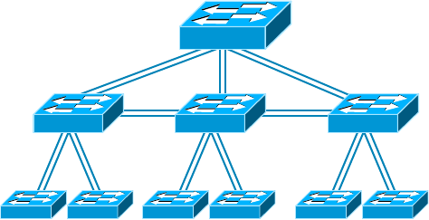
348
Chapter 11 ■ Switching and Virtual LANs
c11.indd 04/02/2015 Page 348
(or remain employed for any length of time), you positively must make sure that
your switched network is physically designed really well so that STP can converge quickly
and painlessly.
Figure 11.11 demonstrates a really great way to design and implement your switched
network so that STP converges ef ciently.
FIGURE 11.11 An optimal hierarchical switch design
STP Root
Bridge Priority 4096
Bridge Priority 8192
Create core switch as STP root for fastest STP convergence
6500
3560
2960 2960
3560
2960 2960
3560
2960 2960
Convergence is truly important because it ensures that all devices are in either the for-
warding mode or the blocking mode. But as I’ve drilled into you, it does cost you some
time. It usually takes 50 seconds to go from blocking to forwarding mode, and I don’t rec-
ommend changing the default STP timers. (You can adjust those timers if you really have
to.) By creating your physical switch design in a hierarchical manner, as shown in Figure
11.11, you can make your core switch the STP root. This makes everyone happy because it
makes STP convergence happen fast.
Because the typical spanning-tree topology’s time to convergence from blocking to for-
warding on a switch port is 50 seconds, it can create time-out problems on your servers or
hosts—like when you reboot them. To address this hitch, you can disable spanning tree on
individual ports.
Rapid Spanning Tree Protocol 802.1w
How would you like to have a good STP con guration running on your switched network
(regardless of the brand of switches) but instead of taking 50 seconds to converge, the
switched network can converge in about 5 seconds, or maybe even less. How does that
sound? Absolutely—yes, we want this! Well then, welcome to the world of Rapid Spanning
Tree Protocol (RSTP).
RSTP was not designed to be a “brand -new” protocol but more of an evolution of the
802.1d standard, with faster convergence time when a topology change occurs. Backward
compatibility was a must when 802.1w was created.
Virtual LANs
349
c11.indd 04/02/2015 Page 349
The 802.1w is de ned in these different port states (compared to 802.1d):
■ Disabled = Discarding
■ Blocking = Discarding
■ Listening = Discarding
■ Learning = Learning
■ Forwarding = Forwarding
To verify the spanning-tree type running on your Cisco switch, use the following command:
S1#sh spanning-tree
VLAN0001
Spanning tree enabled protocol ieee
Root ID Priority 32769
Address 000d.29bd.4b80
Cost 3012
Port 56 (Port-channel1)
Hello Time 2 sec Max Age 20 sec Forward Delay 15 sec
Bridge ID Priority 49153 (priority 49152 sys-id-ext 1)
Address 001b.2b55.7500
Hello Time 2 sec Max Age 20 sec Forward Delay 15 sec
Aging Time 15
Uplinkfast enabled
Interface Role Sts Cost Prio.Nbr Type
---------------- ---- --- --------- -------- ----------
Fa0/3 Desg FWD 3100 128.3 Edge Shr
Fa0/4 Desg FWD 3019 128.4 Edge P2p
Fa0/8 Desg FWD 3019 128.8 P2p
Po1 Root FWD 3012 128.56 P2p
Since the type output shows
Spanning tree enabled protocol ieee
, we know we are
running the 802.1d protocol. If the output shows RSTP, then you know your switch is run-
ning the 802.1w protocol.
Virtual LANs
I know I keep telling you this, but I’ve got to be sure you never forget it, so here I go one
last time: By default, switches break up collision domains and routers break up broadcast
domains. Okay, I feel better! Now we can move on.
In contrast to the networks of yesterday, which were based on collapsed backbones,
today’s network design is characterized by a atter architecture—thanks to switches.
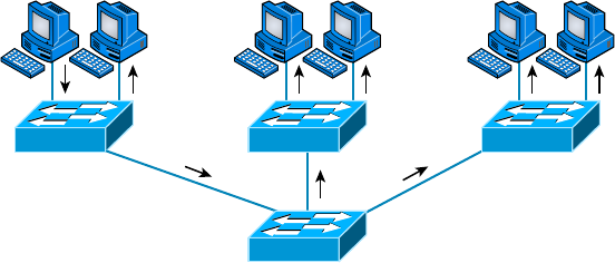
350
Chapter 11 ■ Switching and Virtual LANs
c11.indd 04/02/2015 Page 350
So now what? How do we break up broadcast domains in a pure switched internetwork?
By creating a virtual local area network (VLAN), that’s how!
A VLAN is a logical grouping of network users and resources connected to administra-
tively de ned ports on a switch. When you create VLANs, you gain the ability to create
smaller broadcast domains within a Layer 2 switched internetwork by assigning the vari-
ous ports on the switch to different subnetworks. A VLAN is treated like its own subnet or
broadcast domain, meaning that frames broadcasted onto the network are only switched
between the ports logically grouped within the same VLAN.
So, does this mean we no longer need routers? Maybe yes, maybe no—it really depends
on what your speci c goals and needs are. By default, hosts in a speci c VLAN can’t com-
municate with hosts that are members of another VLAN, so if you want inter-VLAN
communication, the answer is yes, you still need a router.
VLAN Basics
Figure 11.12 shows how Layer 2 switched networks are typically designed—as at net-
works. With this con guration, every broadcast packet transmitted is seen by every device
on the network regardless of whether the device needs to receive that data or not.
FIGURE 11.12 Flat network structure
Host A Host D
By default, routers allow broadcasts to occur only within the originating network,
whereas switches forward broadcasts to all segments. Oh, and by the way, the reason it’s
called a at network is because it’s one broadcast domain, not because the actual design is
physically at. In Figure 11.12, you can see Host A sending out a broadcast and all ports
on all switches forwarding it—all except the port that originally received it.
Now check out Figure 11.13. It pictures a switched network and shows Host A sending
a frame with Host D as its destination. What’s important to get out of this gure is that the
frame is forwarded only out of the port where Host D is located. This is a huge improve-
ment over the old hub networks, unless having one collision domain by default is what you
really want. (I’m guessing not!)
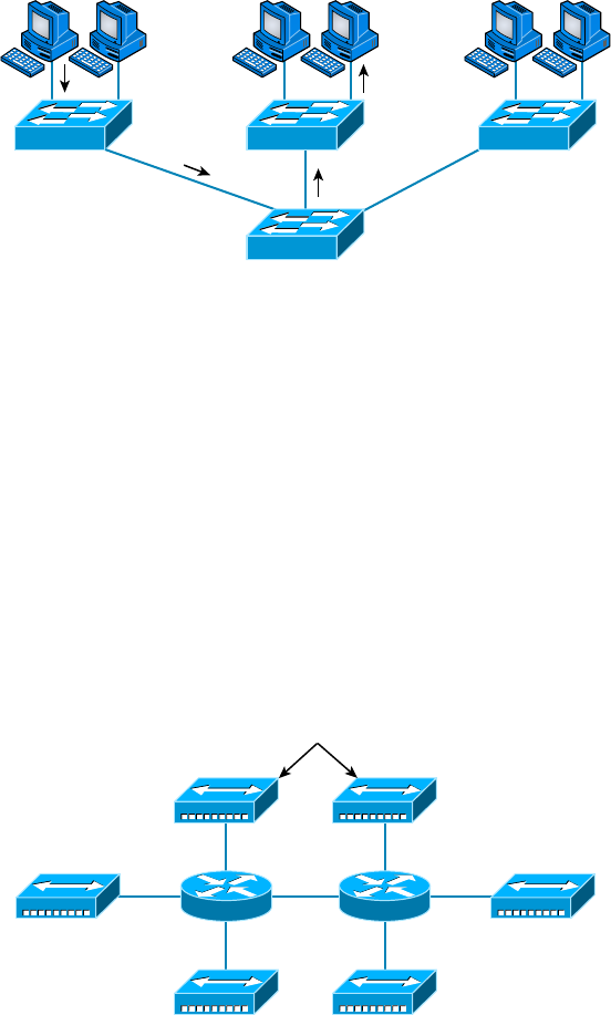
Virtual LANs
351
c11.indd 04/02/2015 Page 351
FIGURE 11.13 The benefit of a switched network
Host A Host D
Okay, you already know that the coolest bene t you gain by having a Layer 2 switched
network is that it creates an individual collision domain segment for each device plugged
into each port on the switch. But as is often the case, new advances bring new challenges
with them. One of the biggest is that the greater the number of users and devices, the more
broadcasts and packets each switch must handle.
And of course, the all-important issue of security and its demands also must be consid-
ered—while simultaneously becoming more complicated! VLANs present a security chal-
lenge because by default, within the typical Layer 2 switched internetwork, all users can see
all devices. And you can’t stop devices from broadcasting, plus you can’t stop users from
trying to respond to broadcasts. This means your security options are dismally limited to
placing passwords on your servers and other devices.
To understand how a VLAN looks to a switch, it’s helpful to begin by rst looking at a
traditional network. Figure 11.14 shows how a network used to be created using hubs to
connect physical LANs to a router.
FIGURE 11.14 Physical LANs connected to a router
Hubs
Engineering
Shipping
Finance Management
Marketing
Sales
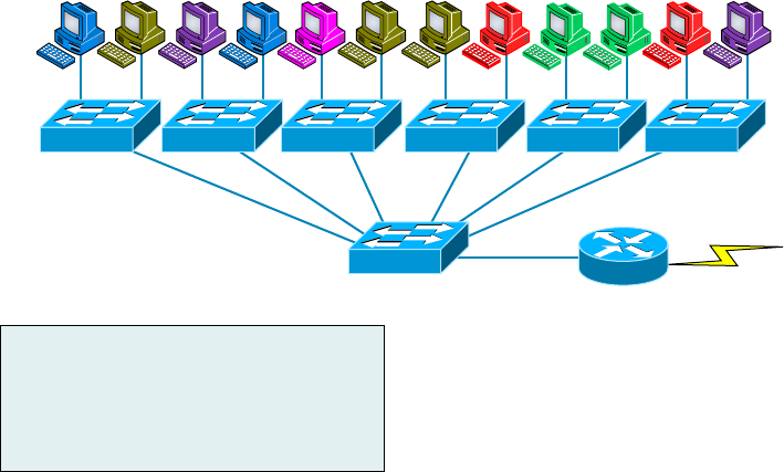
352
Chapter 11 ■ Switching and Virtual LANs
c11.indd 04/02/2015 Page 352
Here you can see that each network is attached with a hub port to the router (each seg-
ment also has its own logical network number, even though this isn’t obvious looking at
the gure). Each host attached to a particular physical network has to match that network’s
logical network number in order to be able to communicate on the internetwork. Notice
that each department has its own LAN, so if we needed to add new users to, let’s say, Sales,
we would just plug them into the Sales LAN and they would automatically be part of the
Sales collision and broadcast domain. This design actually did work well for many years.
But there was one major aw: What happens if the hub for Sales is full and we need to
add another user to the Sales LAN? Or, what do we do if there’s no more physical space for
a new employee where the Sales team is located? Hmmm, well, let’s say there just happens
to be plenty of room over in the Finance section of the building. That new Sales team mem-
ber will just have to sit on the same side of the building as the Finance people, and we’ll just
plug the poor soul into the hub for Finance. Simple, right?
So wrong! Doing this obviously makes the new user part of the Finance LAN, which is
very bad for many reasons. First and foremost, we now have a major security issue. Because
the new Sales employee is a member of the Finance broadcast domain, the newbie can see
all the same servers and access all network services that the Finance folks can. Second, for
this user to access the Sales network services they need to get their job done, they would
have to go through the router to log in to the Sales server—not exactly ef cient.
Now, let’s look at what a switch accomplishes for us. Figure 11.15 demonstrates how
switches come to the rescue by removing the physical boundary to solve our problem. It
also shows how six VLANs (numbered 2 through 7) are used to create a broadcast domain
for each department. Each switch port is then administratively assigned a VLAN member-
ship, depending on the host and which broadcast domain it’s placed in.
FIGURE 11.15 Switches removing the physical boundary
VLAN2 VLAN3 VLAN4 VLAN2 VLAN7 VLAN3 VLAN3 VLAN6 VLAN5 VLAN5 VLAN6 VLAN4
Providesinter-VLAN
communicationand
WANservices
Marketing
Shipping
Engineering
Finance
Management
Sales
VLAN2
VLAN3
VLAN4
VLAN5
VLAN6
VLAN7
172.16.20.0/24
172.16.30.0/24
172.16.40.0/24
172.16.50.0/24
172.16.60.0/24
172.16.70.0/24
Virtual LANs
353
c11.indd 04/02/2015 Page 353
So now if we needed to add another user to the Sales VLAN (VLAN 7), we could just
assign the port to VLAN 7 regardless of where the new Sales team member is physically
located—nice! This illustrates one of the sweetest advantages to designing your network
with VLANs over the old collapsed backbone design. Now, cleanly and simply, each host
that needs to be in the Sales VLAN is merely assigned to VLAN 7.
Notice that I started assigning VLANs with VLAN number 2. The number is irrelevant,
but you might be wondering what happened to VLAN 1. Well, that VLAN is an admin-
istrative VLAN, and even though it can be used for a workgroup, Cisco recommends that
you use it for administrative purposes only. You can’t delete or change the name of VLAN
1, and by default, all ports on a switch are members of VLAN 1 until you actually do
change them.
Now, because each VLAN is considered a broadcast domain, it’s got to also have its
own subnet number (refer again to Figure 11.15). And if you’re also using IPv6, then each
VLAN must also be assigned its own IPv6 network number. So you don’t get confused, just
keep thinking of VLANs as separate subnets or networks.
Let’s get back to that “because of switches, we don’t need routers anymore” misconcep-
tion. When looking at Figure 11.15, you can see that there are seven VLANs, or broadcast
domains, counting VLAN 1 (not shown in the gure). The hosts within each VLAN can
communicate with each other but not with anything in a different VLAN because the hosts
in any given VLAN “think” that they’re actually in a collapsed backbone, illustrated in
Figure 11.14.
So what handy little device do you think we need to enable the hosts in Figure 11.15
to communicate to a host or hosts on a different VLAN? You guessed it—a router! Those
hosts absolutely need to go through a router, or some other Layer 3 device, just as they
do when they’re con gured for internetwork communication (as shown in Figure 11.14).
It works the same way it would if we were trying to connect different physical networks.
Communication between VLANs must go through a Layer 3 device. So don’t expect mass
router extinction anytime soon!
Quality of Service
Before we dive in further into VLANs, I want to make sure that you have a fundamental
understanding of QoS and why it is important. Chapter 20, “Management, Monitoring,
and Optimization,” will provide more detail on QoS.
Quality of service (QoS) refers to the way the resources are controlled so that the qual-
ity of services is maintained. It’s basically the ability to provide a different priority for one
or more types of traf c over other levels; priority is applied to different applications, data
ows, or users so that they can be guaranteed a certain performance level.
QoS methods focus on one of ve problems that can affect data as it traverses
network cable:
■ Delay
■ Dropped packets
■ Error
■ Jitter
■ Out-of-order delivery

354
Chapter 11 ■ Switching and Virtual LANs
c11.indd 04/02/2015 Page 354
QoS can ensure that applications with a required bit rate receive the necessary band-
width to work properly. Clearly, on networks with excess bandwidth, this is not a factor,
but the more limited your bandwidth is, the more important a concept like this becomes.
To provide inter-VLAN communication (communication between VLANs),
you need to use a router or a Layer 3 switch.
VLAN Memberships
Most of the time, VLANs are created by a system administrator who proceeds to assign
switch ports to each one. VLANs of this type are known as static VLANs. If you don’t
mind doing a little more work when you begin this process, assign all the host devices’
hardware addresses into a database so your switches can be con gured to assign VLANs
dynamically anytime you plug a host into a switch. I hate saying things like “obviously,”
but obviously, this type of VLAN is known as a dynamic VLAN. I’ll be covering both
static and dynamic VLANs next.
Static VLANs
Creating static VLANs is the most common way to create a VLAN, and one of the reasons
for that is because static VLANs are the most secure. This security stems from the fact that
any switch port you’ve assigned a VLAN association to will always maintain it unless you
change the port assignment manually.
Static VLAN con guration is pretty easy to set up and supervise, and it works really
well in a networking environment where any user movement within the network needs to
be controlled. It can be helpful to use network management software to con gure the ports,
but you don’t have to use it if you don’t want to.
In Figure 11.15, each switch port was con gured manually with a VLAN membership
based on which VLAN the host needed to be a member of—remember, the device’s actual
physical location doesn’t matter one bit as long as the VLAN assignments are correctly
con gured. Which broadcast domain your hosts become members of is purely up to you.
And again, remember that each host also has to have the correct IP address information.
For instance, you must con gure each host in VLAN 2 into the 172.16.20.0/24 network
for them to become members of that VLAN. It’s also a good idea to keep in mind that if
you plug a host into a switch, you have to verify the VLAN membership of that port. If the
membership is different than what’s needed for that host, the host won’t be able to gain
access to the network services that it needs, such as a workgroup server.
Static access ports are either manually assigned to a VLAN or assigned
through a RADIUS server for use with IEEE 802.1x.
Virtual LANs
355
c11.indd 04/02/2015 Page 355
Dynamic VLANs
On the other hand, a dynamic VLAN determines a host’s VLAN assignment automatically.
Using intelligent management software, you can base VLAN assignments on hardware
(MAC) addresses, protocols, or even applications that work to create dynamic VLANs.
For example, let’s say MAC addresses have been entered into a centralized VLAN man-
agement application and you hook up a new host. If you attach it to an unassigned switch
port, the VLAN management database can look up the hardware address and both assign
and con gure the switch port into the correct VLAN. Needless to say, this makes manage-
ment and con guration much easier because if a user moves, the switch will simply assign
them to the correct VLAN automatically. But here again, there’s a catch—initially, you’ve
got to do a lot more work setting up the database. It can be very worthwhile though!
And here’s some more good news: You can use the VLAN Management Policy Server
(VMPS) service to set up a database of MAC addresses to be used for the dynamic address-
ing of your VLANs. The VMPS database automatically maps MAC addresses to VLANs.
Identifying VLANs
Know that switch ports are Layer 2–only interfaces that are associated with a physical port. A
switch port can belong to only one VLAN if it is an access port or all VLANs if it is a trunk
port, as I’ll explain in a minute. You can manually con gure a port as an access or trunk port,
or you can let the Dynamic Trunking Protocol (DTP) operate on a per-port basis to set the
switch port mode. DTP does this by negotiating with the port on the other end of the link.
Switches are de nitely pretty busy devices. As frames are switched throughout the net-
work, they’ve got to be able to keep track of all the different port types plus understand
what to do with them depending on the hardware address. And remember—frames are
handled differently according to the type of link they’re traversing.
There are two different types of links in a switched environment: access ports and
trunk ports.
Access Ports
An access port belongs to and carries the traf c of only one VLAN. Anything arriving on
an access port is simply assumed to belong to the VLAN assigned to the port. Any device
attached to an access link is unaware of a VLAN membership—the device just assumes it’s
part of the same broadcast domain, but it doesn’t have the big picture, so it doesn’t
understand the physical network topology at all.
Another good thing to know is that switches remove any VLAN information from the
frame before it’s forwarded out to an access-link device. Remember that access-link devices
can’t communicate with devices outside their VLAN unless the packet is routed. And you
can only create a switch port to be either an access port or a trunk port—not both. So
you’ve got to choose one or the other, and know that if you make it an access port, that
port can be assigned to one VLAN only.

356
Chapter 11 ■ Switching and Virtual LANs
c11.indd 04/02/2015 Page 356
Voice Access Ports
Not to confuse you, but all that I just said about the fact that an access port can be
assigned to only one VLAN is really only sort of true. Nowadays, most switches will allow
you to add a second VLAN to an access port on a switch port for your voice traf c; it’s
called the voice VLAN. The voice VLAN used to be called the auxiliary VLAN, which
allowed it to be overlaid on top of the data VLAN, enabling both types of traf c through
the same port. Even though this is technically considered to be a different type of link, it’s
still just an access port that can be con gured for both data and voice VLANs. This allows
you to connect both a phone and a PC device to one switch port but still have each device
in a separate VLAN. If you are con guring voice VLANs, you’ll want to con gure Quality
of Service (QoS) on the switch ports to provide a higher precedence to voice traf c over
data traf c to improve sound quality.
Suppose you plug a host into a switch port and users are unable to access
any server resources. The two typical reasons this happens is because the
port is configured in the wrong VLAN membership or STP has shut down
the port because STP thought there was possibly a loop.
Trunk Ports
Believe it or not, the term trunk port was inspired by the telephone system trunks that
carry multiple telephone conversations at a time. So it follows that trunk ports can similarly
carry multiple VLANs at a time.
A trunk link is a 100Mbps or 1000Mbps point-to-point link between two switches,
between a switch and router, or even between a switch and server, and it carries the traf c
of multiple VLANs—from 1 to 4,094 VLANs at a time.
Trunking can be a real advantage because with it, you get to make a single port part of a
whole bunch of different VLANs at the same time. This is a great feature because you can
actually set ports up to have a server in two separate broadcast domains simultaneously
so your users won’t have to cross a Layer 3 device (router) to log in and access it. Another
bene t of trunking comes into play when you’re connecting switches. Information from
multiple VLANs can be carried across trunk links, but by default, if the links between your
switches aren’t trunked, only information from the con gured VLAN will be switched
across that link.
Check out Figure 11.16. It shows how the different links are used in a switched network.
All hosts connected to the switches can communicate to all ports in their VLAN because of
the trunk link between them. Remember, if we used an access link between the switches,
this would allow only one VLAN to communicate between switches. As you can see, these
hosts are using access links to connect to the switch, so they’re communicating in one
VLAN only. That means that without a router, no host can communicate outside its own
VLAN, but the hosts can send data over trunked links to hosts on another switch con g-
ured in their same VLAN.
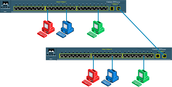
Virtual LANs
357
c11.indd 04/02/2015 Page 357
FIGURE 11.16 Access and trunk links in a switched network
TrunkLink
RedVLAN
RedVLAN
GreenVLAN
GreenVLAN
BlueVLAN
BlueVLAN
VLANscanspanacrossmultipleswitches
byusingtrunklinks,whichcarrytraffic
formultipleVLANs.
It’s nally time to tell you about the VLAN identi cation methods.
VLAN Identification Methods
VLAN identi cation is what switches use to keep track of all those frames as they’re tra-
versing a switch fabric. All of our hosts connect together via a switch fabric in our switched
network topology. It’s how switches identify which frames belong to which VLANs, and
there’s more than one trunking method: ISL and 802.1q.
Inter-Switch Link (ISL)
Inter-Switch Link (ISL) is a way of explicitly tagging VLAN information onto an Ethernet
frame. This tagging information allows VLANs to be multiplexed over a trunk link
through an external encapsulation method (ISL), which allows the switch to identify the
VLAN membership of a frame over the trunked link.
By running ISL, you can interconnect multiple switches and still maintain
VLAN information as traf c travels between switches on trunk links. ISL functions
at Layer 2 by encapsulating a data frame with a new header and cyclic redundancy
check (CRC).
Of note is that this is proprietary to Cisco switches, and it’s used for Fast Ethernet and
Gigabit Ethernet links only. ISL routing is pretty versatile and can be used on a switch
port, on router interfaces, and on server interface cards to trunk a server.
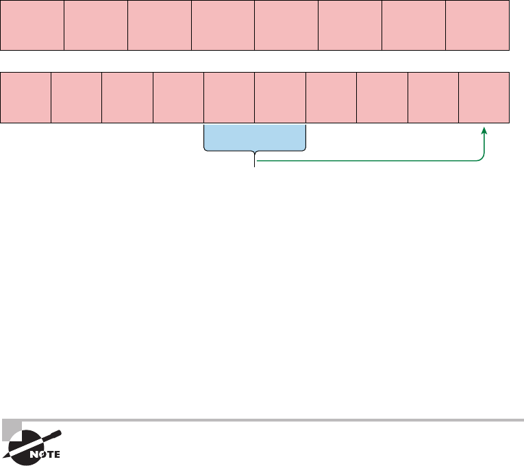
358
Chapter 11 ■ Switching and Virtual LANs
c11.indd 04/02/2015 Page 358
IEEE 802.1q
Created by the IEEE as a standard method of frame tagging, IEEE 802.1q works by inserting
a eld into the frame to identify the VLAN. This, one of the aspects of 802.1q that makes it
your only option if you want to trunk between a Cisco switched link and another brand of
switch. In a mixed environment, you’ve just got to use 802.1q for the trunk to work!
Unlike ISL, which encapsulates the frame with control information, 802.1q inserts an
802.1q eld along with tag control information, as shown in Figure 11.17.
FIGURE 11.17 IEEE 802.1q encapsulation with and without the 802.1q tag
CRC must be recalculated
802.1q Field
inserted
Preamble
(7-bytes)
Preamble
(7-bytes)
Start
Frame
Delimiter
(1-byte)
Start
Frame
Delimiter
(1-byte)
Destination
MAC Address
(6-bytes)
Destination
MAC Address
(6-bytes)
Source MAC
Address
(6-bytes)
Source MAC
Address
(6-bytes)
Type/Length
(2-bytes)
Length/Type
(2-bytes)
Type/Length
= 802.1Q Tag
Type
(2-bytes)
Tag Control
Information
Packet
(0 – n bytes)
Packet
(0 – n bytes)
Pad
(0 – p bytes)
Pad
(0 – p bytes)
Frame Check
Sequence
(4-bytes)
Frame Check
Sequence
(4-bytes)
3 bits = User Priority Field
1 bit = Canonical Format Identifier (CFI)
12 bits – VLAN Identifier (VLAN ID)
To meet the exam objectives, it’s really the 12-bit VLAN ID that matters, so keep
your focus on it. This eld identi es the VLAN and can be 2^12 minus 2 for the 0 and
4,095 reserved VLANs, which means an 802.1q tagged frame can carry information for
4,094 VLANs.
It works like this: You rst designate each port that’s going to be a trunk with 802.1q
encapsulation. The other ports must be assigned a speci c VLAN ID in order for them to
communicate. VLAN 1 is the default native VLAN, and when using 802.1q, all traf c for
a native VLAN is untagged. The ports that populate the same trunk create a group with
this native VLAN, and each port gets tagged with an identi cation number re ecting that
membership. Again the default is VLAN 1. The native VLAN allows the trunks to accept
information that was received without any VLAN identi cation or frame tag.
The basic purpose of ISL and 802.1q frame-tagging methods is to provide
inter-switch VLAN communication. Remember that any ISL or 802.1q frame
tagging is removed if a frame is forwarded out an access link—tagging is
used internally and across trunk links only!
VLAN Trunking Protocol
359
c11.indd 04/02/2015 Page 359
VLAN Trunking Protocol
The basic goals of VLAN Trunking Protocol (VTP) are to manage all con gured VLANs
across a switched internetwork and to maintain consistency throughout that network. VTP
allows you to add, delete, and rename VLANs—and information about those actions is
then propagated to all other switches in the VTP domain.
Here’s a list of some of the cool features VTP has to offer:
■ Consistent VLAN configuration across all switches in the network
■ Accurate tracking and monitoring of VLANs
■ Dynamic reporting of added VLANs to all switches in the VTP domain
■ Adding VLANs using plug-and-play
Very nice, but before you can get VTP to manage your VLANs across the network,
you have to create a VTP server (really, you don’t need to even do that since all switches
default to VTP server mode, but just make sure you have a server). All servers that need to
share VLAN information must use the same domain name, and a switch can be in only one
domain at a time. So basically, this means that a switch can share VTP domain informa-
tion with other switches only if they’re con gured into the same VTP domain. You can use
a VTP domain if you have more than one switch connected in a network, but if you’ve got
all your switches in only one VLAN, you just don’t need to use VTP. Do keep in mind that
VTP information is sent between switches only via a trunk port.
Switches advertise VTP management domain information as well as a con guration
revision number and all known VLANs with any speci c parameters. But there’s also
something called VTP transparent mode. In it, you can con gure switches to forward VTP
information through trunk ports but not to accept information updates or update their
VTP databases.
If you’ve got sneaky users adding switches to your VTP domain behind your
back, you can include passwords, but don’t forget—every switch must be set up with
the same password. And as you can imagine, this little snag can be a real hassle
administratively!
Switches detect any added VLANs within a VTP advertisement and then prepare to send
information on their trunk ports with the newly de ned VLAN in tow. Updates are sent
out as revision numbers that consist of summary advertisements. Anytime a switch sees
a higher revision number, it knows the information it’s getting is more current, so it will
overwrite the existing VLAN database with the latest information.
You should know these requirements for VTP to communicate VLAN information
between switches:
■ The VTP management domain name of both switches must be set the same.
■ One of the switches has to be configured as a VTP server.
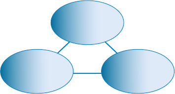
360
Chapter 11 ■ Switching and Virtual LANs
c11.indd 04/02/2015 Page 360
■ Set a VTP password if used.
■ No router is necessary and a router is not a requirement.
Now that you’ve got that down, we’re going to delve deeper into the world of VTP with
VTP modes.
VTP Modes of Operation
Figure 11.18 shows you all three different modes of operation within a VTP domain:
FIGURE 11.18 VTP modes
Server
TransparentClient
ServerConfiguration:SavedinNVRAM
TransparentConfiguration:SavedinNVRAMClientConfiguration:NotSavedinNVRAM
Server This is the default mode for all Catalyst switches. You need at least one server
in your VTP domain to propagate VLAN information throughout that domain. Also
important is that the switch must be in server mode for you to be able to create, add,
and delete VLANs in a VTP domain. VLAN information has to be changed in server
mode, and any change made to VLANs on a switch in server mode will be advertised
to the entire VTP domain. In VTP server mode, VLAN con gurations are saved in
NVRAM on the switch.
Client In client mode, switches receive information from VTP servers, but they also
receive and forward updates, so in this way they behave like VTP servers. The difference is
that they can’t create, change, or delete VLANs. Plus, none of the ports on a client switch
can be added to a new VLAN before the VTP server noti es the client switch of the new
VLAN and the VLAN exists in the client’s VLAN database. Also good to know is that
VLAN information sent from a VTP server isn’t stored in NVRAM, which is important
because it means that if the switch is reset or reloaded, the VLAN information will be
deleted. Here’s a hint: If you want a switch to become a server, rst make it a client so it
receives all the correct VLAN information, then change it to a server—so much easier!
Transparent Switches in transparent mode don’t participate in the VTP domain or share
its VLAN database, but they’ll still forward VTP advertisements through any con gured
trunk links. An admin on a transparent switch can create, modify, and delete VLANs
because they keep their own database—one they keep secret from the other switches.
VLAN Trunking Protocol
361
c11.indd 04/02/2015 Page 361
Despite being kept in NVRAM memory, the VLAN database in transparent mode is actu-
ally only locally signi cant. The whole purpose of transparent mode is to allow remote
switches to receive the VLAN database from a VTP-server-con gured switch through a
switch that is not participating in the same VLAN assignments.
Do We Really Need to Put an IP Address on a Switch?
The answer is absolutely not! Switches have all ports enabled and ready to rock. Take
the switch out of the box, plug it in, and the switch starts learning MAC addresses in the
CAM. But since the switches are providing Layer 2 services, why do we need an IP address?
Because you still need an IP address for in-band management, which is used with your vir-
tual terminals, that’s why. Telnet, SSH, SNMP, and so on all require IP addresses to com-
municate with the switch, in-band, through the network. And remember, since all ports
are enabled by default, you need to shut down unused ports or assign them to an unused
VLAN. Con guring a switch out-of-band means you’re not going through the network to
con gure the device; you’re actually using a port, such as a console port, to con gure the
switch instead. Most of the time, you’ll use the console port upon starting up the switch.
After that, all the management will be completed in-band.
So now you know that the switch needs a management IP address for in-band manage-
ment purposes, but exactly where do you want to place it? Conveniently, there’s something
predictably called the management VLAN interface, and that’s clearly your target. It’s a
routed interface found on every switch, and it’s referred to as interface VLAN 1. Good to
know that this management interface can be changed, and all manufacturers recommend
changing it to a different management interface for security purposes.
Yes, you can buy switches that are unmanaged, but you would never ever want to do
that for an enterprise network! The only environment in which doing that would make
sense is in a home network, but that’s about it. Anything you get for an of ce or larger net-
work absolutely must be a managed switch!
With all that in mind, let’s get down to con guring a switch now.
We’ll begin our con guration by connecting into the switch via the console and setting
the administrative functions. At this point, we’ll also assign an IP address to each switch,
but as I said, doing that isn’t really necessary to make our network function. The only rea-
son we’re going to do that is so we can manage/administer it remotely—in-band—via a pro-
tocol like telnet. Let’s use a simple IP scheme like 192.168.10.16/28. And by the way, this
mask should be familiar to you. Let’s check out the following output:
Switch>enable
Switch#config t
Switch(config)#hostname S1
S1(config)#enable secret todd
S1(config)#int f0/15
S1(config-if)#description 1st connection to S3
S1(config-if)#int f0/16
S1(config-if)#description 2nd connection to S3
362
Chapter 11 ■ Switching and Virtual LANs
c11.indd 04/02/2015 Page 362
S1(config-if)#speed 1000
S1(config-if)#duplex full
S1(config-if)#line console 0
S1(config-line)#password console
S1(config-line)#login
S1(config-line)#line vty 0 15
S1(config-line)#password telnet
S1(config-line)#login
S1(config-line)#int vlan 1
S1(config-if)#ip address 192.168.10.17 255.255.255.240
S1(config-if)#no shut
S1(config-if)#exit
S1(config)#ip default-gateway 192.168.10.30
S1(config)#banner motd #this is my S1 switch#
S1(config)#exit
S1#copy run start
Destination filename [startup-config]? [enter]
Building configuration...
[OK]
S1#
In this output, the rst thing to notice is that there aren’t any IP addresses con gured on
the switch’s physical interfaces. Since all ports on a switch are enabled by default, there’s
not really a whole lot to con gure. But look again—I con gured the speed and duplex of
the switch to gigabit, full-on port 16. Most of the time you would just leave these as auto-
detect, and I actually recommend doing that. My next step is to set the console password
for out-of-band management and then the VTY (Telnet) password for in-band manage-
ment. The next task is to set the default gateway of the switch and banner. So you don’t get
confused, I want to clarify that the default gateway is used to send management (in-band)
traf c to a remote network so you can manage the switch remotely. Understand this is
not the default gateway for the hosts—the default gateway would be the router interface
address assigned to each VLAN.
The IP address is con gured under a logical interface, called a management domain or
VLAN. You can use default VLAN 1 to manage a switched network just as we’re doing
here, or you can be smart and opt to use a different VLAN for management.
The preceding con guration demonstrates how to con gure the switch for local
management, meaning that the passwords to log in to the switch are right there in the
switch’s con guration. You can also con gure switches and routers to store their usernames
and passwords remotely for ease of con guration using a AAA server. Doing this allows
you to change the passwords at one device without having to telnet into each device sepa-
rately to change passwords.
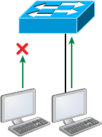
VLAN Trunking Protocol
363
c11.indd 04/02/2015 Page 363
To get this done, use the following command:
S1(config)#aaa authentication login default
This tells the switch to use AAA when Telnet or SSH is used for in-band management.
This next command tells the switch to use the AAA server if someone is trying to access the
console of the switch:
S1(config)#aaa authentication login console
So remember, no IP addresses on physical switch interfaces, no routing protocols there
either, and so on. We’re performing Layer 2 switching at this point, not routing!
Port Security
Clearly, it’s a bad idea to have your switches available for anyone to just plug into and play
around with. Security is a big deal—even more of a concern regarding wireless security, so
why wouldn’t we demand switch security as much, if not more?
But just how do we actually prevent someone from simply plugging a host into one of
our switch ports—or worse, adding a hub, switch, or access point into the Ethernet jack
in their of ce? By default, MAC addresses dynamically appear in your MAC forward/ lter
database, but the good news is that you can stop bad guys in their tracks by using
port security!
Figure 11.19 pictures two hosts connected to the single switch port Fa0/3 via either a
hub or access point (AP).
FIGURE 11.19 Port security on a switch port restricts port access by MAC address
NO! Okay!
AB
Fa0/3
Port Fa0/3 is con gured to observe and allow only certain MAC addresses to associate
with the speci c port, so in this example, Host A is denied access, but Host B is allowed to
associate with the port.
By using port security, you can limit the number of MAC addresses that can be assigned
dynamically to a port, set static MAC addresses, and—here’s my favorite part—set penal-
ties for users who abuse your policy! Personally, I like to have the port shut down when the
security policy is violated. Making abusers bring me a memo from their boss explaining
why they violated the security policy brings with it a certain poetic justice, which is nice.
364
Chapter 11 ■ Switching and Virtual LANs
c11.indd 04/02/2015 Page 364
And I’ll also require something like that before I’ll enable their port again. Things like this
really seem to help people remember to behave!
DHCP Snooping
A rogue DHCP server (one not under your control that is giving out incompatible IP
addresses) can be an annoyance that causes users to be unable to connect to network
resources, or it may play a part in several types of attacks. In either case, DHCP snooping
is a switch feature that can help to prevent your devices from communicating with illegiti-
mate DHCP servers.
When enabled, DHCP snooping allows responses to client requests from only DHCP
servers located on trusted switch ports (which you de ne). When only ports where com-
pany DHCP servers are located are con gured to be trusted, rogue DHCP servers will be
unable to respond to client requests.
The protection doesn’t stop there, however. The switch will also, over time, develop an
IP address to MAC address table called the bindings table, derived from “snooping “ on
DHCP traf c to and from the legitimate DHCP server. The bindings table will alert the
switch to any packets that have mappings that do not match the table. These frames will be
dropped. The bindings table is also used with ARP inspection, which makes the con gura-
tion of DHCP snooping a prerequisite of ARP inspection.
ARP Inspection
Many man-in-the-middle attacks are made possible by the attacker polluting the ARP
cache of the two victims such that their cache maps each other’s IP addresses to the MAC
address of the attacker, thus allowing the attacker to receive all traf c in the conversation.
Dynamic ARP inspection (DAI) is a feature that, when con gured, uses the DHCP
snooping database of IP address to MAC address mappings to verify the MAC address
mappings of each frame going through the switch. In this way, any frames with incorrect or
altered mappings are dropped by the switch, thus breaking any attacks depending on these
bogus mappings. Because it uses the DHCP snooping database, the con guration of DHCP
snooping is a prerequisite to enabling DAI.
Port Bonding
Know that almost all Ethernet networks today will typically have multiple links between
switches because this kind of design provides redundancy and resiliency. On a physical
design that includes multiple links between switches, STP will do its job and put a port
or ports into blocking mode. In addition to that, routing protocols like OSPF and EIGRP
could see all these redundant links as individual ones, depending on the con guration,
which can mean an increase in routing overhead.
We can gain the bene ts from multiple links between switches by using port channel-
ing. EtherChannel is a port channel technology that was originally developed by Cisco as
a switch-to-switch technique for grouping several Fast Ethernet or Gigabit Ethernet ports
into one logical channel.
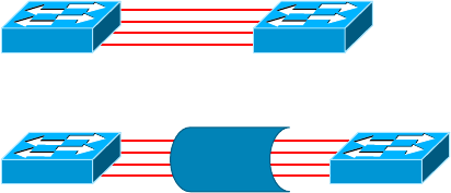
VLAN Trunking Protocol
365
c11.indd 04/02/2015 Page 365
Also important to note is that once your port channel is up and working, Layer 2 STP
and Layer 3 routing protocols will treat those bundled links as a single one, which would
stop STP from performing blocking. An additional nice result is that because the rout-
ing protocols now only see this as a single link, a single adjacency across the link can be
formed—elegant!
Figure 11.20 shows how a network would look if we had four connections between
switches, before and after con guring port channels.
FIGURE 11.20 Before and after port channels
Now as usual, there’s the Cisco version and the IEEE version of port channel negotia-
tion protocols to choose from, and you can take your pick. Cisco’s version is called Port
Aggregation Protocol (PAgP), and the IEEE 802.3ad standard is called Link Aggregation
Control Protocol (LACP). Both versions work equally well, but the way you con gure each
is slightly different. Keep in mind that both PAgP and LACP are negotiation protocols and
that EtherChannel can actually be statically con gured without PAgP or LACP. Still, it’s
better to use one of these protocols to help with compatibility issues as well as to manage
link additions and failures between two switches.
Cisco EtherChannel allows us to bundle up to eight active ports between switches. The
links must have the same speed, duplex setting, and VLAN con guration—in other words
you can’t mix interface types and con gurations into the same bundle.
Here are a few things to remember:
Port Channeling/Bonding Refers to combining two to eight Fast Ethernet or Gigabit
Ethernet ports together between two switches into one aggregated logical link to achieve
more bandwidth and resiliency.
EtherChannel Cisco’s proprietary term for port channeling.
PAgP This is a Cisco proprietary port channel negotiation protocol that aids in the auto-
matic creation of EtherChannel links. All links in the bundle must match the same param-
eters (speed, duplex, VLAN info), and when PAgP identi es matched links, it groups the
links into an EtherChannel. This is then added to STP as a single bridge port. At this point,
PAgP’s job is to send packets every 30 seconds to manage the link for consistency, any link
additions and modi cations, and failures.
LACP (802.3ad) This has the exact same purpose as PAgP, but it’s nonproprietary, so it
can work between multi-vendor networks.

366
Chapter 11 ■ Switching and Virtual LANs
c11.indd 04/02/2015 Page 366
Two Additional Advanced Features
of Switches
Switches really expand our exibility when we’re designing our networks. The features that
we need to cover for the CompTIA Network+ objectives are as follows:
■ Power over Ethernet (PoE)
■ Port mirroring/spanning (local vs remote)
Power over Ethernet (802.3af, 802.3at)
Power over Ethernet (PoE and PoE+) technology describes a system for transmitting electri-
cal power, along with data, to remote devices over standard twisted-pair cable in an Ethernet
network. This technology is useful for powering IP telephones (Voice over IP, or VoIP), wire-
less LAN access points, network cameras, remote network switches, embedded computers,
and other appliances—situations where it would be inconvenient, expensive, and possibly not
even feasible to supply power separately. One reason for this is that the main wiring usually
must be done by quali ed and/or licensed electricians for legal and/or insurance mandates.
The IEEE has created a standard for PoE called 802.3af, and for PoE+ it’s referred to
as 802.3at. This standard describes precisely how a powered device is detected and also
de nes two methods of delivering Power over Ethernet to a given powered device. Keep in
mind that PoE+ standard, 802.3at, delivers more power than 802.3af, which is compatible
with Gigabit Ethernet with four-wire pairs at 30w.
This process happens one of two ways: either by receiving the power from an Ethernet
port on a switch (or other capable device) or via a power injector. And you can’t use both
approaches to get the job done. And this can lead to serious trouble, so be sure before
connecting!
PoE
It would be rare for me not to design a network around PoE. Most of my consulting work
is wireless networking, including large outdoor wireless networks. When I design the net-
work, I order equipment based on the amount of power needed to run it, knowing I’ll have
only a few electrical outlets, or even no outlets if all my equipment is outside. This means
that all my switches must run PoE to my access points and wireless bridges and must do
this for long distances.
For me to accomplish this, I need to order the more expensive, large-scale enterprise
switches. If you have devices that need PoE but do not have long-distance connections,
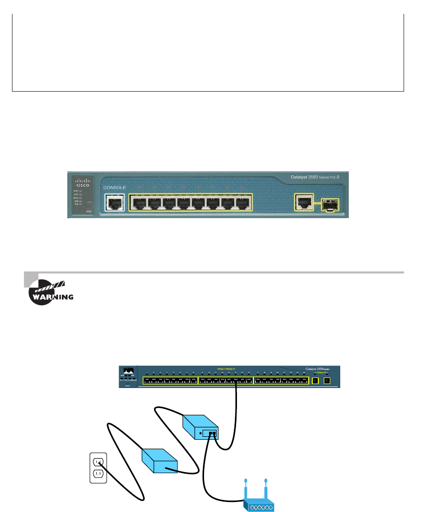
Two Additional Advanced Features of Switches
367
c11.indd 04/02/2015 Page 367
you can use lower-end switches, but you must verify that they provide the right amount
of power. There was a customer who called me because their network access points were
going up and down. The bottom line is that they had purchased less-expensive switches
and there was not enough power to run the equipment. They ended up buying all new
switches. So, before you buy a PoE switch, verify that the switch provides the right power
for your environment.
Figure 11.121 shows an example of a switch that provides PoE to any
PoE-capable device.
FIGURE 11.21 Switched Ethernet ports can provide power to devices.
As I just said, if you don’t have a switch with PoE, then you can use a power injector.
Figure 11.22 shows a picture of a typical power injector physically installed in a network.
Use caution when using an external power injector! Take the time to make
sure the power injector provides the voltage level for which your device
was manufactured.
FIGURE 11.22 An external power injector used for PoE
Network Resource
Power Injector
Access Port or Bridge
Universal
Power Supply
Power Cord
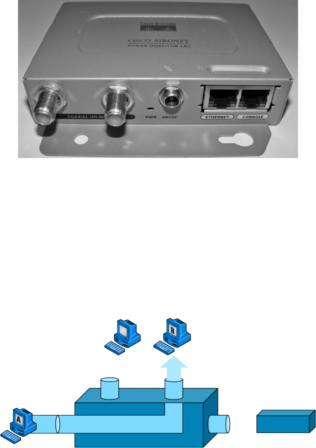
368
Chapter 11 ■ Switching and Virtual LANs
c11.indd 04/02/2015 Page 368
Because most higher-end switches provide PoE, we don’t need to worry about injectors, but
if you are adding a wireless bridge into an existing network that has switches without PoE, you
need to add a power injector. Figure 11.23 shows a power injector used for a wireless bridge.
FIGURE 11.23 Wireless bridge power injector
Now, let’s discuss how we would troubleshoot a network that has a switch in the LAN
instead of a hub.
Port Mirroring/Spanning (SPAN/RSPAN)
Port mirroring, also called Switch Port Analyzer (SPAN) and Remote SPAN, allows you to
sniff traf c on a network when using a switch. In Figure 11.24, you can see how a typical
switch will read the forward/ lter table and only send traf c out the destination port (this
is the whole idea of using a switch, so this is good!).
FIGURE 11.24 Switches send frames out the destination port only
Sniffer
Switch
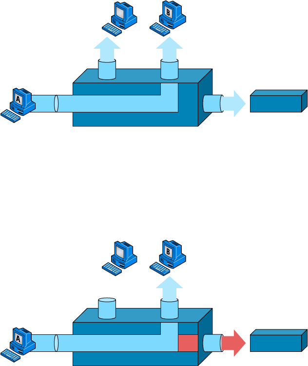
Two Additional Advanced Features of Switches
369
c11.indd 04/02/2015 Page 369
All good, but a problem with this arises when you need to sniff traf c on the network.
Figure 11.24 illustrates this issue; the sniffer isn’t seeing data coming from Host A to Host
B. To solve this little snag, you can temporarily place a hub between Host A and Host B, as
demonstrated in Figure 11.25.
FIGURE 11.25 Place a hub between two hosts to troubleshoot
Sniffer
Hub
This method will allow you to see the frames sent from Host A to Host B. The bad
news, however, is that by doing this, you’ll bring down the network temporarily.
The port-mirroring option allows you to place a port in span mode so that every frame
from Host A is captured by both Host B and the sniffer, as shown in Figure 11.26.
This would also be a helpful option to take advantage of if you were connecting an IDS or
IPS to the switch as well.
FIGURE 11.26 Port spanning/mirroring
Sniffer
Switch
Be careful when using port mirroring because it can cause a lot of overhead on the
switch and possibly crash your network. Because of this, it’s a really good idea to use this
feature at strategic times, and only for short periods if possible.

370
Chapter 11 ■ Switching and Virtual LANs
c11.indd 04/02/2015 Page 370
The last thing I want you to bear in mind is that RSPAN extends SPAN by
enabling remote monitoring of multiple switches across your network.
The traffic for each RSPAN session is carried over a user-specified RSPAN
VLAN, which is dedicated for a specific RSPAN session in all participating
switches.
Summary
In this chapter, I talked about the differences between switches and bridges and how they
both work at Layer 2 and create a MAC address forward/ lter table in order to make deci-
sions about whether to forward or ood a frame.
I also discussed problems that can occur if you have multiple links between bridges
(switches) and how to solve these problems by using the Spanning Tree Protocol (STP).
This chapter also introduced you to the world of virtual LANs and described how
switches can use them. We talked about how VLANs break up broadcast domains in a
switched internetwork—a very important, necessary thing because Layer 2 switches only
break up collision domains and, by default, all switches make up one large broadcast
domain. I also described access links and went over how trunked VLANs work across a
Fast Ethernet link.
Trunking is a crucial technology to understand well when you’re dealing with a network
populated by multiple switches that are running several VLANs.
Exam Essentials
Remember the three switch functions. Address learning, forward/ lter decisions, and
loop avoidance are the functions of a switch.
Understand the main purpose of the Spanning Tree Protocol in a switched LAN. The
main purpose of STP is to prevent switching loops in a network with redundant
switched paths.
Remember the states of STP. The purpose of the blocking state is to prevent the use of
looped paths. A port in the listening state prepares to forward data frames without popu-
lating the MAC address table. A port in the learning state populates the MAC address table
but doesn’t forward data frames. A port in the forwarding state sends and receives all data
frames on the bridged port. Last, a port in the disabled state is virtually nonoperational.
Remember to check a switch port’s VLAN assignment when plugging in a new host. If
you plug a new host into a switch, then you must verify the VLAN membership of
Written Lab
371
c11.indd 04/02/2015 Page 371
that port. If the membership is different than what is needed for that host, the host will not
be able to reach the needed network services, such as a workgroup server.
Understand what PoE provides. Power over Ethernet was created to provide power to
devices that are connected to a switch port but that are not in a place that has a power
outlet—for example, an access point in a ceiling.
Written Lab
You can nd the answers in Appendix A. Write the answers to the following questions:
1. VLANs break up ________ domains in a Layer 2 switched network.
2. Switches, by default, only break up ________ domains.
3. What does trunking provide?
4. You need to power a device such as an access point or IP phone. What protocol can provide
power to these devices over an Ethernet cable?
5. You plug a host into a switch port and the host receives an IP address but the user can’t get
to the services it needs. What is probably the problem?
6. If a destination MAC address is not in the forward/filter table, what will the switch do with
the frame?
7. What are the three switch functions at Layer 2?
8. If a frame is received on a switch port and the source MAC address is not in the forward/
filter table, what will the switch do?
9. What is used at Layer 2 to prevent switching loops?
10. You need to implement a separate network for contractors and guests working at your
office. Which technology should you implement?
372
Chapter 11 ■ Switching and Virtual LANs
c11.indd 04/02/2015 Page 372
Review Questions
You can nd the answers in Appendix B.
1. You want to improve network performance by increasing the bandwidth available to hosts
and limiting the size of the broadcast domains. Which of the following options will achieve
this goal?
A. Managed hubs
B. Bridges
C. Switches
D. Switches configured with VLANs
2. The types of ports that can be found on a switch are___________________ and
___________________. (Choose two.)
A. VLAN Trunk Protocol
B. Access
C. 802.1Q
D. Trunk
3. Which switching technology reduces the size of a broadcast domain?
A. ISL
B. 802.1Q
C. VLANs
D. STP
4. Which of the following are IEEE versions of STP? (Choose two.)
A. 802.1x
B. VLANs
C. 802.1d
D. 802.11
E. 802.1w
5. You connect a host to a switch port, but the new host cannot log into the server that is
plugged into the same switch. What could the problem be? (Choose two.)
A. The router is not configured for the new host.
B. The STP configuration on the switch is not updated for the new host.
C. The host has an invalid MAC address.
D. The switch port the host is connected to is not configured to the correct VLAN
membership.
E. STP shut down the port.
Review Questions
373
c11.indd 04/02/2015 Page 373
6. Which of the following are benefits of VLANs? (Choose three.)
A. They increase the size of collision domains.
B. They allow logical grouping of users by function.
C. They can enhance network security.
D. They increase the size of broadcast domains while decreasing the number of collision
domains.
E. They simplify switch administration.
F. They increase the number of broadcast domains while decreasing the size of the broad-
cast domains.
7. Which of the following is a Layer 2 protocol used to maintain a loop-free network?
A. VTP
B. STP
C. RIP
D. CDP
8. What is the result of segmenting a network with a bridge (switch)? (Choose two.)
A. It increases the number of collision domains.
B. It decreases the number of collision domains.
C. It increases the number of broadcast domains.
D. It decreases the number of broadcast domains.
E. It makes smaller collision domains.
F. It makes larger collision domains.
9. You connect your host to a switch that is running network analyses software. However, you
are not seeing any packets from the server. What do you need to implement on the switch to
see all the packet information?
A. VLANs
B. STP
C. Port mirroring
D. Authentication
10. Which of the following features of a switch will allow two switches to pass VLAN network
information?
A. PoE
B. VLANs
C. Trunking
D. STP
374
Chapter 11 ■ Switching and Virtual LANs
c11.indd 04/02/2015 Page 374
11. What are the distinct functions of Layer 2 switching that increase available bandwidth on
the network? (Choose three.)
A. Address learning
B. Routing
C. Forwarding and filtering
D. Creating network loops
E. Loop avoidance
F. IP addressing
12. Which of the following statements is true?
A. A switch creates a single collision domain and a single broadcast domain. A router
creates a single collision domain.
B. A switch creates separate collision domains but one broadcast domain. A router
provides a separate broadcast domain.
C. A switch creates a single collision domain and separate broadcast domains. A router
provides a separate broadcast domain as well.
D. A switch creates separate collision domains and separate broadcast domains. A router
provides separate collision domains.
13. What does a switch do when a frame is received on an interface and the destination hard-
ware address is unknown or not in the filter table?
A. Forwards the switch to the first available link
B. Drops the frame
C. With the exception of the source port, floods the network with the frame looking for
the device
D. Sends back a message to the originating station asking for a name resolution
14. If a switch receives a frame and the source MAC address is not in the MAC address table
but the destination address is, what will the switch do with the frame?
A. Discard it and send an error message back to the originating host
B. Flood the network with the frame
C. Add the source address and port to the MAC address table and forward the frame out
the destination port
D. Add the destination to the MAC address table and then forward the frame
15. When would you configure VTP on a switch?
A. When you have hubs connected in your network
B. When you have redundant links between switches
C. When you have multiple hosts in multiple VLANs and you want to share all the data
between hosts without a router
D. When you have multiple switches with multiple VLANs and you want to share the
VLAN database from one switch to all the others
Review Questions
375
c11.indd 04/02/2015 Page 375
16. When is STP said to be converged on the root bridge? (Choose two.)
A. When all ports are in the forwarding state
B. When all ports are in the blocking state
C. When all ports are in the listening state
D. When all ports are in the learning state
17. In which two states is the MAC address table populated with addresses? (Choose two.)
A. Blocking
B. Listening
C. Learning
D. Forwarding
18. You have multiple departments all connected to switches, with crossover cables connect-
ing the switches together. However, response time on the network is still very slow even
though you have upgraded from hubs to switches. What technology should you implement
to improve response time on the networks?
A. STP
B. VLANs
C. Convergence
D. OSPF
19. If you are configuring voice VLANs, which of the following should you configure on the
switch ports to provide a higher precedence to voice traffic over data traffic to improve
sound quality?
A. Access VLANs
B. VTP
C. QoS
D. STP
20. What is a disadvantage of using port spanning?
A. It breaks up broadcast domains on all ports.
B. It can create overhead on the switch.
C. It makes the switch one large collision domain.
D. It makes the switch fast between only two ports instead of all ports.

c12.indd 04/0½ 015 Page 377
Chapter
12
Wireless Networking
THE FOLLOWING COMPTIA NETWORK+
EXAM OBJECTIVES ARE COVERED IN THIS
CHAPTER:
✓ 1.7 Differentiate between network infrastructure
implementations
■ WLAN
■ Hotspot
■ PAN
■ Bluetooth
■ IR
■ NFC (near field communication)
✓ 2.7 Install and configure wireless LAN infrastructure and
implement the appropriate technologies in support of
wireless capable devices
■ Small office/home office wireless router
■ Wireless access points
■ Device density
■ Roaming
■ Wireless controllers
■ VLAN pooling
■ LWAPP
■ Wireless bridge
■ Site surveys
■ Heat maps
■ Frequencies
■ 2.4 Ghz
■ 5.0 Ghz

c12.indd 04/0½ 015 Page 378
■ Channels
■ Goodput
■ Connection types
■ o 802.11a-ht
■ o 802.11g-ht
■ Antenna placement
■ Antenna types
■ Omnidirectional
■ Unidirectional
■ MIMO/MUMIMO
■ Signal strength
■ Coverage
■ Differences between device antennas
■ SSID broadcast
■ Topologies
■ Adhoc
■ Mesh
■ Infrastructure
■ Mobile devices
■ Cell phones
■ Laptops
■ Tablet s
■ Gaming devices
■ Media devices
✓ 3.3 Given a scenario, implement network hardening tech-
niques
■ Wireless security
■ WEP
■ WPA/WPA2
■ Enterprise
■ Personal
■ TKIP/AES

c12.indd 04/0½ 015 Page 379
■ 802.1x
■ TLS/TTLS
■ MAC filtering
✓ 4.3 Given a scenario, troubleshoot and resolve common
wireless issues
■ Open networks
■ Rogue access point
■ MIMO
■ AP placement
■ AP configurations
■ LWAPP
■ Thin vs thick
✓ 5.3 Given a scenario, deploy the appropriate wireless
standard
■ 802.11a
■ 802.11b
■ 802.11g
■ 802.11n
■ 802.11ac

c12.indd 04/0½ 015 Page 380
While you’re sipping coffee at a café or hanging out in an
airport until they nally x the plane you’re waiting to board,
you are no longer limited to just reading actual papers and
magazines. Now, you have the option to connect to the local wireless network and catch up
on your emails, blog, do a little gaming—maybe even get some work done! It’s come to the
point that many of us wouldn’t even think of checking into a hotel that doesn’t offer this
important little amenity. So clearly, those of us already in or wishing to enter the IT eld
better have our chops down regarding wireless network components and their associated
installation factors, right? (Answer: a resounding YES!)
With that established, here’s a great starting point. If you want to understand the basic
wireless LANs (WLANs) most commonly used today, just think 10BaseT Ethernet with
hubs. What this means is that our WLANs typically run half-duplex communication—
everyone is sharing the same bandwidth, and only one user is communicating at a time.
This isn’t necessarily bad; it’s just not good enough. Because most people rely upon wire-
less networks today, it’s critical that they evolve faster than greased lightning to keep up
with our rapidly escalating needs. The good news is that this is actually happening—and it
even works securely!
The goal in this chapter is to introduce you to wireless networks and the technologies in
use today. I’ll also cover the various components used, the IEEE 802.11 standards, wireless
installation, and of course, wireless security.
To find up-to-the-minute updates for this chapter, please see
www.lammle.
com/networkplus
or the book’s website at
www.sybextestbanks.wiley.com
.
Introduction to Wireless Technology
Transmitting a signal using the typical 802.11 speci cations works a lot like it does with a
basic Ethernet hub: They’re both two-way forms of communication, and they both use the
same frequency to both transmit and receive, often referred to as half duplex as mentioned
in the chapter introduction. Wireless LANs (WLANs) use radio frequencies (RFs) that are
radiated into the air from an antenna that creates radio waves. These waves can be absorbed,
refracted, or re ected by walls, water, and metal surfaces, resulting in low signal strength. So
because of this innate vulnerability to surrounding environmental factors, it’s pretty appar-
ent that wireless will never offer us the same robustness as a wired network can, but that still
doesn’t mean we’re not going to run wireless. Believe me, we de nitely will!
We can increase the transmitting power and we’d be able to gain a greater transmitting
distance, but doing so can create some nasty distortion, so it has to be done carefully.

Introduction to Wireless Technology
381
c12.indd 04/0½ 015 Page 381
By using higher frequencies, we can attain higher data rates, but this is, unfortunately, at
the cost of decreased transmitting distances. And if we use lower frequencies, we get to
transmit greater distances but at lower data rates. This should make it pretty clear to you
that understanding all the various types of WLANs you can implement is imperative to
creating the LAN solution that best meets the speci c requirements of the unique situation
you’re dealing with.
Also important to note is the fact that the 802.11 speci cations were developed so that
there would be no licensing required in most countries—to ensure the user the freedom to
install and operate without any licensing or operating fees. This means that any manufac-
turer can create wireless networking products and sell them at a local computer store or
wherever. It also means that all our computers should be able to communicate wirelessly
without con guring much, if anything at all.
Various agencies have been around for a very long time to help govern the use of wireless
devices, frequencies, standards, and how the frequency spectrums are used. Table 12.1 shows
the current agencies that help create, maintain, and even enforce wireless standards worldwide.
TABLE 12.1 Wireless agencies and standards
Agency Purpose Website
Institute of Electrical and
Electronics Engineers (IEEE)
Creates and maintains opera-
tional standards
www.ieee.org
Federal Communications
Commission (FCC)
Regulates the use of wireless
devices in the US
www.fcc.gov
European Telecommunications
Standards Institute (ETSi)
Chartered to produce common
standards in Europe
www.etsi.org
Wi-Fi Alliance Promotes and tests for WLAN
interoperability
www.wi-fi.com
WLAN Association (WLANA) Educates and raises consumer
awareness regarding WLANs
www.wlana.org
Because WLANs transmit over radio frequencies, they’re regulated by the same types
of laws used to govern things like AM/FM radios. In the United States, it’s the Federal
Communications Commission (FCC) that regulates the use of wireless LAN devices, and
the Institute of Electrical and Electronics Engineers (IEEE) takes it from there and creates
standards based on what frequencies the FCC releases for public use.
The FCC has released three unlicensed bands for public use: 900MHz, 2.4GHz, and
5GHz. The 900MHz and 2.4GHz bands are referred to as the Industrial, Scienti c,
and Medical (ISM) bands, and the 5GHz band is known as the Unlicensed National
Information Infrastructure (UNII) band. Figure 12.1 shows where the unlicensed bands sit
within the RF spectrum.
So it follows that if you opt to deploy wireless in a range outside of the three public
bands shown in Figure 12.1, you need to get a speci c license from the FCC to do so.
382
Chapter 12 ■ Wireless Networking
c12.indd 04/0½ 015 Page 382
Once the FCC opened the three frequency ranges for public use, many manufacturers were
able to start offering myriad products that ooded the market, with 802.11b/g/n being the
most widely used wireless network found today.
Figure 12.2 shows the WLAN history that is important to us. Although wireless trans-
missions date back many, many years, the type we really care about is wireless as related to
WLANs starting in the 1990s. Use of the ISM band started in early 1990, and it’s deployed
today in multiple environments, including outdoor links, mesh networks, of ce buildings,
healthcare facilities, warehouses, and homes.
FIGURE 12.1 Unlicensed frequencies
Cellular
(840 Mhz)
Visible
LightAM Broadcasts
FM Broadcasts Infrared
Wireless
LAN
900 Mhz
Band
2.4 Ghz
Band
5 Ghz
Band
X-raysSonar
(extremely low)
FIGURE 12.2 Wireless LAN history
860Kbps
Proprietary Standards-Based
1 and 2Mbps 11Mbps 54Mbps
900 MHz
Speed
Radio
Network
2.4 GHz
1992
IEEE 802.11 Drafting
Begins
802.11
Ratified
802.11a,b
Ratified
802.11g
Ratified
802.11n
Draft 2.0
1997 1999 2003 2007
5 GHz
802.11ac was released in December 2013, and although it isn’t shown in Figure 12.2,
it will be the newest, hottest 802.11 standard in the next few years. I’ll discuss 802.11ac
in detail throughout this chapter.
The Wi-Fi Alliance grants certi cation for interoperability among 802.11 products
offered by various vendors. This certi cation provides a sort of comfort zone for the users
purchasing the many types of products, although in my personal experience, it’s just a
whole lot easier if you buy all your access points from the same manufacturer.
In the current US WLAN market, there are several accepted operational standards and
drafts created and maintained by the IEEE. We’ll now take a look at these standards and
then talk about how the most commonly used standards work.

The 802.11 Standards
383
c12.indd 04/0½ 015 Page 383
The 802.11 Standards
Taking off from what you learned in Chapter 1, “Introduction to Networks,” wireless
networking has its own 802 standards group—remember, Ethernet’s committee is 802.3.
Wireless starts with 802.11, and there are various other up-and-coming standard groups as
well, like 802.11ac. And even cellular networks are becoming huge players in our wireless
experience. But for now, we’re going to concentrate on the 802.11 standards committee and
subcommittees.
IEEE 802.11 was the rst, original standardized WLAN at 1Mbps and 2Mbps. It runs
in the 2.4GHz radio frequency. It was rati ed in 1997, although we didn’t see many prod-
ucts pop up until around 1999 when 802.11b was introduced. All the committees listed
in Table 12.2 made amendments to the original 802.11 standard except for 802.11f and
802.11t, which produced stand-alone documents.
TABLE 12.2 802.11 committees and subcommittees
Committee Purpose
IEEE 802.11a 54Mbps, 5GHz standard
IEEE 802.11ac
IEEE 802.11b
1Gbps, 5GHz standard
Enhancements to 802.11 to support 5.5Mbps and 11Mbps
IEEE 802.11c Bridge operation procedures; included in the IEEE 802.1d standard
IEEE 802.11d International roaming extensions
IEEE 802.11e Quality of service
IEEE 802.11f Inter-Access Point Protocol
IEEE 802.11g 54Mbps, 2.4GHz standard (backward compatible with 802.11b)
IEEE 802.11h Dynamic Frequency Selection (DFS) and Transmit Power Control (TPC)
at 5GHz
IEEE 802.11i Enhanced security
IEEE 802.11j Extensions for Japan and US public safety
IEEE 802.11k Radio resource measurement enhancements
IEEE 802.11m Maintenance of the standard; odds and ends

384
Chapter 12 ■ Wireless Networking
c12.indd 04/0½ 015 Page 384
Committee Purpose
IEEE 802.11n Higher throughput improvements using multiple-input, multiple-output
(MIMO) antennas
IEEE 802.11p Wireless Access for the Vehicular Environment (WAVE)
IEEE 802.11r Fast roaming
IEEE 802.11s ESS Extended Service Set Mesh Networking
IEEE 802.11t Wireless Performance Prediction (WPP)
IEEE 802.11u Internetworking with non-802 networks (cellular, for example)
IEEE 802.11v Wireless network management
IEEE 802.11w Protected management frames
IEEE 802.11y 3650–3700 operation in the US
One type of wireless networking that doesn’t get a whole lot of attention
is infrared wireless. Infrared wireless uses the same basic transmission
method as many television remote controls—that’s right, infrared technol-
ogy. Infrared is used primarily for short-distance, point-to-point commu-
nications, like those between a peripheral and a PC, with the most widely
used for peripherals being the IrDA standard.
Now let’s discuss some important speci cs of the most popular 802.11 WLANs.
2.4GHz (802.11b)
First on the menu is the 802.11b standard. It was the most widely deployed wireless stan-
dard, and it operates in the 2.4GHz unlicensed radio band that delivers a maximum data
rate of 11Mbps. The 802.11b standard has been widely adopted by both vendors and
customers who found that its 11Mbps data rate worked pretty well for most applica-
tions. But now that 802.11b has a big brother (802.11g), no one goes out and just buys an
802.11b card or access point anymore—why would you buy a 10Mbps Ethernet card when
you can score a 10/100 Ethernet card for the same price?
An interesting thing about all 802.11 WLAN products is that they have the ability
to data-rate-shift while moving. This allows the person operating at 11Mbps to shift to
TABLE 12.2 802.11 committees and subcommittees (continued)
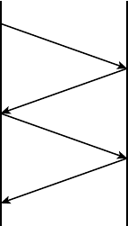
The 802.11 Standards
385
c12.indd 04/0½ 015 Page 385
5.5Mbps, then 2Mbps, and nally still communicate farthest from the access point at
1Mbps. And furthermore, this rate shifting happens without losing the connection and
with no interaction from the user. Rate shifting also occurs on a transmission-by-transmis-
sion basis. This is important because it means that the access point can support multiple
clients at varying speeds depending upon the location of each client.
The problem with all 802.11b communication lies in how the Data Link layer is dealt
with. In order to solve problems in the RF spectrum, a type of Ethernet collision detection
was created called Carrier Sense Multiple Access with Collision Avoidance (CSMA/CA).
CSMA/CA also has an optional implementation called a Request to Send, Clear to
Send (RTS/CTS) because of the way that hosts must communicate with the access point
(AP). For every packet sent, an RTS/CTS and acknowledgment must be received, and
because of this rather cumbersome process, it’s kind of hard to believe it all actually works
when you use this!
To get a clear picture of this, check out Figure 12.3.
FIGURE 12.3 802.11b CSMA/CA
Source
RTS
CTS
Data
Ack
Destination
2.4GHz (802.11g)
The 802.11g standard was rati ed in June 2003 and is backward compatible to 802.11b.
The 802.11g standard delivers the same 54Mbps maximum data rate as you’ll nd in the
802.11a range but runs in the 2.4GHz range—the same as 802.11b.
Because 802.11b/g operates in the same 2.4GHz unlicensed band, migrating to 802.11g
is an affordable choice for organizations with existing 802.11b wireless infrastructures.
Just keep in mind that 802.11b products can’t be “software upgraded” to 802.11g. This
limitation is because 802.11g radios use a different chipset in order to deliver the higher
data rate.
But still, much like Ethernet and Fast Ethernet, 802.11g products can be commingled
with 802.11b products in the same network. Yet, for example, and completely unlike
Ethernet, if you have four users running 802.11g cards and one user starts using an
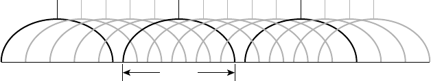
386
Chapter 12 ■ Wireless Networking
c12.indd 04/0½ 015 Page 386
802.11b card, everyone connected to the same access point is then forced to run the
802.11b CSMA/CA method—an ugly fact that really makes throughput suffer badly. So to
optimize performance, it’s recommended that you disable the 802.11b-only modes on all
your access points.
To explain this further, 802.11b uses a modulation technique called Direct Sequence
Spread Spectrum (DSSS) that’s just not as robust as the Orthogonal Frequency Division
Multiplexing (OFDM) modulation used by both 802.11g and 802.11a. 802.11g cli-
ents using OFDM enjoy much better performance at the same ranges as 802.11b clients
do, but—and remember this—when 802.11g clients are operating at the 802.11b rates
(11Mbps, 5.5Mbps, 2Mbps, and 1Mbps), they’re actually using the same modulation
802.11b uses.
So, regarding the throughput of different WLAN standards, you know that 802.11b
has a top throughput of 11Mbps, and 802.11g has a top throughput of 54Mbp. But with
that said, do you really think we’re actually getting that type of throughput? The answer is
absolutely not! This is because in reality, about 70% or more of the RF bandwidth is used
for management of the wireless network itself! The actual bandwidth the user experiences
using an application is called goodput, even though you won’t hear this term used a lot.
Just remember that goodput refers to the actual data throughput, not the theoretical num-
ber that the standards describe.
Figure 12.4 shows the 14 different channels (each 22MHz wide) that the FCC released
in the 2.4GHz range.
FIGURE 12.4 ISM 2.4GHz channels
Channels
2.402GHz 2.483GHz
16112345 78910 121314
22MHz
In the United States, only 11 channels are con gurable, with channels 1, 6, and 11 being
non-overlapping. This allows you to have three access points in the same area without expe-
riencing interference. You must be aware of the channels when installing APs in a large envi-
ronment so you do not overlap channels. Make sure that each channel is not overlapping the
same channel number! If you con gure one AP with channel 1, then the next AP would be
con gured in channel 11, the channel farthest from that con gured on the rst AP.
5GHz (802.11a)
The IEEE rati ed the 802.11a standard in 1999, but the rst 802.11a products didn’t begin
appearing on the market until late 2001—and boy, were they pricey! The 802.11a standard
delivers a maximum data rate of 54Mbps with 12 non-overlapping frequency channels.
Figure 12.5 shows the UNII bands.

The 802.11 Standards
387
c12.indd 04/0½ 015 Page 387
FIGURE 12.5 UNII 5GHz band has 12 non-overlapping channels (US)
Lower Band
5.15–5.25
Indoor
5.15
5.180
36
5.200
40
5.220
44
5.240
48
5.260
52
5.280
56
5.300
60
5.320
64
5.745
149
5.765
153
5.785
157
5.805
5.825
161
Channel Center
Frequencies
Operating
Channels
Middle Band
5.25–5.35
Indoor and Outdoor
Upper Band
5.725–5.825
Outdoor
Operating in the 5GHz radio band, 802.11a is also immune to interference from devices
that operate in the 2.4GHz band, like microwave ovens, cordless phones, and Bluetooth
devices. 802.11a isn’t backward compatible with 802.11b because they are different fre-
quencies, so you don’t get to just “upgrade” part of your network and expect everything to
work together in perfect harmony. But no worries—there are plenty of dual-radio devices
that will work in both types of networks. A de nite plus for 802.11a is that it can work in
the same physical environment without interference from 802.11b users.
Similar to the 802.11b radios, all 802.11a products also have the ability to data-rate-
shift while moving. The 802.11a products allow the person operating at 54Mbps to shift to
48Mbps, 36Mbps, 24Mbps, 18Mbps, 12Mbps, and 9Mbps, and nally, still communicate
farthest from the AP at 6Mbps.
There’s also an extension to the 802.11a speci cation called 802.11h, which is
described next.
5GHz (802.11h)
The FCC added 11 new channels in February 2004, and in 2008, we were nally able to
begin using these channels based on manufacturers’ releases of more 802.11a 5GHz prod-
ucts. This means that we gained access to up to 23 non-overlapping channels! And there
are even two new features to the 5GHz radio that are part of the 802.11h speci cation:
Dynamic Frequency Selection (DFS) and Transmit Power Control (TPC).
Dynamic Frequency Selection (DFS) This cool feature continuously monitors a device’s
operating range for any radar signals that are allowed to operate in portions of the 5GHz
band as well as 802.11a before transmitting. If DFS discovers any radar signals, it’ll either
abandon the occupied channel or mark it as unavailable to prevent interference from occur-
ring on the WLAN.
Transmit Power Control (TPC) Even though it’s been employed by the mobile phone
industry for a long time, this technology has some handy new uses. You can set the client
machine’s adapter and the access point’s transmit power to cover various size ranges—a fea-
ture that’s useful for many reasons. For one, setting the access point’s transmit power to 5mW
reduces cell range, which works great if you’ve got a compact area with high-density usage.
Further advantages include the fact that TPC enables the client and the access point to
communicate with less power. This means the client machine can ne-tune its transmit power

388
Chapter 12 ■ Wireless Networking
c12.indd 04/0½ 015 Page 388
dynamically so it uses just enough energy to preserve its connection to the access point and
conserve its battery power plus reduce interference on the neighboring WLAN cells—sweet!
2.4GHz/5GHz (802.11n)
802.11n builds on previous 802.11 standards by adding multiple-input, multiple-output
(MIMO), which employs multiple transmitters and receiver antennas to increase data
throughput. 802.11n can have up to eight antennas, but most of today’s access points use
four. These are sometimes referred to as smart antennas, and if you did have four of them,
two would be used for transmitting simultaneously with the other two receiving simulta-
neously. This setup would allow for much higher data rates than 802.11a/b/g. In fact, the
marketing people claim it will provide about 250Mbps, but personally, I’ve never really
seen that level of throughput. Even if what they’re saying is true, exactly how would that
help if all you’ve got is a 1Mbps or even 20Mbps cable or DSL connection to the Internet?
802.11n allows for communication at both the 2.4GHz and 5GHz frequen-
cies by using channel bonding.
Unlike 802.11a and 802.11g, which are locked into using the 5.0GHz and 2.4GHz
spectrums, respectively, with 802.11n you can control which of the spectrums (or both)
that you want to allow in your WLAN! Listed next are some additional components of
802.11n that give people reason to say 802.11n has greater reliability and predictability:
40MHz Channels 802.11g and 802.11a use 20MHz channels, and tones on the sides of
each channel are not used to protect the main carrier, which means that 11Mbps are unused
or wasted. 802.11n aggregates two carriers to double the speed from 54Mbps to 108Mbps.
Add the 11Mbps that we gain from not wasting the side tones and we have 119Mbps.
MAC Efficiency 802.11 protocols require acknowledgment of each and every frame.
802.11n can pass many packets before an acknowledgment is required, which saves you on
overhead. This is called block acknowledgment.
So What Is Wi-Fi?
You may have seen products that are 802.11 compliant with a small sticker on them that
says “Wi-Fi.” You might be able to guess that this rather odd phrase stands for Wireless
Fidelity, but you may not know what its implications are. Simply put, that sticker indicates
that the product in question has passed certifi cation testing for 802.11 interoperability by
the Wi-Fi Alliance. This nonprofi t group was formed to ensure that all 802.11a/b/g/n wire-
less devices would communicate seamlessly. So, Wi-Fi is a good thing.
Comparing 802.11 Standards
389
c12.indd 04/0½ 015 Page 389
Multiple-Input, Multiple-Output (MIMO) Several frames are sent by several antennae
over several paths and are then recombined by another set of antennae to optimize through-
put and multipath resistance. This is called spatial multiplexing.
5GHz (802.11ac)
802.11ac is a Wi-Fi standard that works in the 5GHz range and delivers up to 1Gigabit
throughput that was approved by the 802.11 standards committee in January 2014. Still,
just as it is with 802.11n, you won’t nd that the speeds described in the standard actually
line up with the marketing material.
For example, for a single link, which is basically one host to AP, the best throughput
you can hope to get would be 500Mbps, which is fantastic if it actually happens! But unless
you have a Gigabit Internet connection, 802.11ac won’t really help so much. To be fair, in
a small network, or if you’re transferring les in your internal WLAN or to your internal
network, this new speci cation could actually be useful.
At this point, you’re probably wondering how these people can claim to achieve these
theoretical rates, right? That’s an excellent question! They get these values by increasing the
RF band usage from 20MHz wide channels with 802.11a/b/g to 40MHz with 802.11n and
up to 160MHz wide channels with 802.11ac. But again, for typical commercial 802.11ac
products, 80MHz would be a lot more realistic. The problem with this scenario centers
on the fact that if any interference is found in the 80MHz wide channel, it drops down to
40MHz wide channels. Worse, if interference is still found at that level, it will drop even
further down to 20MHz wide channels.
In addition to the wider channels, we can also get more MIMO spatial streams than
we can with 802.11n—up to eight where 802.11n only supported four. Furthermore,
and optionally, a downlink of multi-user MIMO (MU-MIMO) supports up to four
clients and, most important, a modulation of QAM-256 compared to QAM-64
with 802.11a/g.
The last thing I want to point out is the fact that 802.11n had added elds in the wireless
frame to identify 802.11a and 802.11g as high throughput (HT), whereas 802.11ac adds
four elds to identify the frames as very high throughput (VHT).
Comparing 802.11 Standards
Before I move on to wireless installations, take a look at Figure 12.6, which lists, for each
of the IEEE standards in use today, the year of rati cation as well as the frequency, number
of non-overlapping channels, physical layer transmission technique, and data rates.
I mentioned earlier that 802.11b runs DSSS, whereas 802.11g and 802.11a both run the
OFDM modulation technique (802.11ac runs up to OFDM 256-QAM).
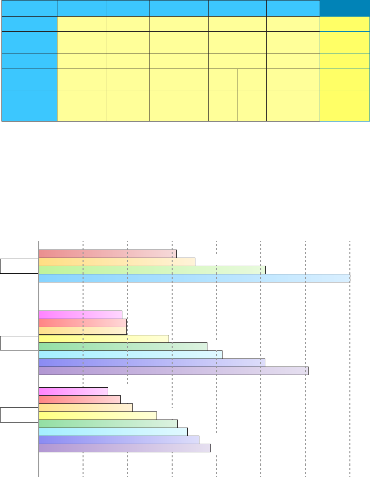
390
Chapter 12 ■ Wireless Networking
c12.indd 04/0½ 015 Page 390
FIGURE 12.6 Standards for spectrums and speeds
802.11
1997
2.4GHz
3
1, 2 1, 2, 5.5,
11
6, 9, 12, 18, 24,
36, 48, 54
1, 2,
5.5, 11 100+ 1000+
6, 9,
12,
5.5, 11
33Up to 23 Varies Varies
OFDM
2.4GHz 2.4GHz 2.4GHz–5GHz5GHz 5GHz
1999 1999 2003 2010 2013Ratified
No. of Channels
Transmission IR, FHSS,
DSSS
DSSS, CCK,
OFDM
DSSS OFDM OFDMDSSS
Data Rates
(Mbps)
Frequency
Band
802.11b 802.11a 802.11g 802.11n 802.11ac
Range Comparisons
Now let’s take a look at Figure 12.7, which delimits the range comparisons of each 802.11
standard and shows these different ranges using an indoor open-of ce environment as a
factor. (We’ll be using default power settings.)
FIGURE 12.7 Range comparisons of 802.11 standards
802.11b
11Mbps
54Mbps
50 ft. 100 ft. 200 ft. 300 ft.150 ft. 250 ft. 350 ft.
48Mbps
36Mbps
36Mbps
24Mbps
18Mbps
12Mbps
12Mbps
9Mbps 6Mbps
2Mbps 1Mbps
802.11g
802.11a
5.5Mbps
18Mbps
54Mbps
48Mbps
24Mbps
9Mbps
6Mbps
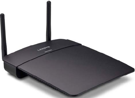
Wireless Network Components
391
c12.indd 04/0½ 015 Page 391
You can see that to get the full 54Mbps bene t of both 802.11a and 802.11g, you need
to be between 50 feet and 100 feet (maximum) away, which will likely be even less if there
happens to be any obstructions between the client and the access point. 802.11n gives more
distance than all three standards shown in the gure (up to twice the distance), and under-
stand that 802.11ac just won’t give you more distance than 802.11n.
Wireless Network Components
Though it might not seem this way to you right now, wireless networks are less complex
than their wired cousins because they require fewer components. To make a wireless net-
work work properly, all you really need are two main devices: a wireless access point and
a wireless NIC, the latter of which is typically built into your laptop. This also makes it a
lot easier to install a wireless network because, basically, you just need an understanding of
these two components in order to do so.
Wireless Access Points
You’ll nd a central component—like a hub or switch—in the vast majority of wired net-
works that serves to connect hosts together and allow them to communicate with each
other. It’s the same idea with wireless networks. They also have a component that connects
all wireless devices together, only that device is known as a wireless access point (WAP),
or just AP. Wireless access points have at least one antenna (typically two for better recep-
tion—a solution called diversity, and up to eight to support 802.11ac) and an Ethernet port
to connect them to a wired network. Figure 12.8 shows an example of a typical wireless
access point.
FIGURE 12.8 A wireless access point
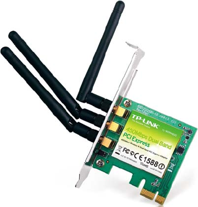
392
Chapter 12 ■ Wireless Networking
c12.indd 04/0½ 015 Page 392
You can even think of an AP as a bridge between the wireless clients and the wired net-
work. In fact, an AP can be used as a wireless bridge (depending on the settings) to bridge
two wired network segments together.
In addition to the stand-alone AP, there is another type of AP that includes a built-
in router, which you can use to connect both wired and wireless clients to the Internet
(the most popular home brand being Linksys, a division of Cisco). In summation, an AP
can operate as a repeater, bridge (switch), or router, depending on its hardware and its
implementation.
These devices are usually known as (surprise) wireless routers. They’re usually employed
as Network Address Translation (NAT) servers by using the one ISP-provided global IP
address to multiplex numerous local IP addresses that are generally doled out to inside
clients by the wireless router from a pool within the 192.168.x.x range.
Wireless Network Interface Card
Every host that wants to connect to a wireless network needs a wireless Network Interface
Card (NIC) to do so. Basically, a wireless NIC does the same job as a traditional NIC, but
instead of having a socket to plug some cable into, the wireless NIC has a radio antenna.
In addition to the different types of wireless networking (I’ll talk about those in a minute),
wireless NICs (like other NICs) can differ in the type of connection they use to connect to
the host computer.
Figure 12.9 shows an example of a wireless NIC.
FIGURE 12.9 A wireless NIC

Wireless Network Components
393
c12.indd 04/0½ 015 Page 393
The wireless card shown in Figure 12.9 is used in a desktop PC. There are various
options for laptops as well. All new laptops have wireless cards built into the motherboard.
These days, it’s pretty rare to use an external wireless client card because
all laptops come with them built in, and desktops can be ordered with
them too. But it’s good to know that you can still buy the client card shown
in Figure 12.9. Typically, you would use cards like the one shown in the
figure for areas of poor reception because they can have a better range—
depending on the antenna you use, or because you want to upgrade the
built-in card to 802.11n/ac.
Wireless Antennas
Wireless antennas act as both transmitters and receivers. There are two broad classes of
antennas on the market today: Omni directional (or point-to-multipoint) and directional,
or Yagi (point-to-point). Yagi antennas usually provide greater range than Omni antennas
of equivalent gain. Why? Because Yagis focus all their power in a single direction, whereas
Omnis must disperse the same amount of power in all directions at the same time. A down-
side to using a directional antenna is that you’ve got to be much more precise when aligning
communication points. This is why a Yagi is really only a good choice for point-to-point
bridging of access points. It’s also why most APs use Omnis, because often, clients and
other APs could be located in any direction at any given moment.
To get a picture of this, think of the antenna on your car. Yes, it’s a non-networking
example, but it’s still a good one because it clari es the fact that your car’s particular
orientation doesn’t affect the signal reception of whatever radio station you happen to be
listening to. Well, most of the time, anyway. If you’re in the boonies, you’re out of range—
something that also applies to the networking version of Omnis.
The television aerials that some of us are old enough to remember rotating into a speci c
direction for a certain channel are examples of Yagi antennas. (How many of you labeled
your set-top antenna dial for the actual TV stations you could receive?) Believe it or not,
they still look the same to this day!
Both Omnis and Yagis are rated according to their signal gain with respect to an actual
or theoretical laboratory reference antenna. These ratings are relative indicators of the
corresponding production antenna’s range. Range is also affected by the bit rate of the
underlying technology, with higher bit rates extending shorter distances. Remember, a Yagi
will always have a longer range than an equivalently rated Omni, but as I said, the straight-
line Yagi will be very limited in its coverage area.
Both antennas are also rated in units of decibel isotropic (dBi) or decibel dipole (dBd),
based on the type of reference antenna (isotropic or dipole) of equivalent frequency that
was initially used to rate the production antenna. A positive value for either unit of measure
represents a gain in signal strength with respect to the reference antenna. Merriam-Webster
de nes isotropic as “exhibiting properties (as velocity of light transmission) with the same

394
Chapter 12 ■ Wireless Networking
c12.indd 04/0½ 015 Page 394
values when measured along axes in all directions.” Isotropic antennas are not able to be
produced in reality, but their properties can be engineered from antenna theory for refer-
ence purposes.
As a practical example, I’m going to use the Cisco Systems series of Aironet access point
(indoor) and bridge (outdoor) antennas. Table 12.3 describes the effect that gain ratings
and attempted bit rates have on range limitations.
TABLE 12.3 Wireless antenna types and ranges
Model Gain
Indoor range
at 1Mbps
Indoor range
at 11Mbps
Outdoor range
at 2Mbps
Outdoor range
at 11Mbps
AIR-ANT2410Y-R 10dBi 800ft 230ft Not specified Not specified
AIR-ANT1728 5.2dBi 497ft 142ft Not specified Not specified
AIR-ANT4941 2.2dBi 350ft 130ft Not specified Not specified
AIR-ANT2506 5.2dBi Not specified Not specified 5,000ft 1,580ft
AIR-ANT24120 12dBi Not specified Not specified 24,288ft 7,392ft
It’s pretty much a given that antennas operating with frequencies below 1GHz are
measured in dBd while those operating above 1GHz are measured in dBi. But because
this rule doesn’t always work de nitively, sometimes we have to compare the strength of
one antenna measured in dBd with another measured in numerically equivalent dBi in
order to determine which one is stronger. This is exactly why it’s important to know that
a particular numerical magnitude of dBd is more powerful than the same numerical mag-
nitude of dBi.
I know this sounds pretty complicated, but because the relationship between these two
values is linear, it really makes the conversion a lot easier than you might think. Here’s how
it works: At the same operating frequency, a dipole antenna has about 2.2dB gain over a
0dBi theoretical isotropic antenna, which means you can easily convert from dBd to dBi by
adding 2.2 to the dBd rating. Conversely, subtract 2.2 from the dBi rating and you get the
equivalent dBd rating.
Armed with what you’ve learned about the difference between Omni and Yagi antennas
and the difference between dBd and dBi gain ratings, you should be able to compare the
relative range of transmission of one antenna with respect to another based on a combina-
tion of these characteristics. For example, the following four antenna ratings are given in
relative order from greatest to least range:
■ 7dBd Yagi (equivalent to a 9.2dBi Yagi)
■ 7dBi Yagi (longer range than 7dBi Omni)

Installing a Wireless Network
395
c12.indd 04/0½ 015 Page 395
■ 4.8dBd Omni (equivalent to a 7dBi Omni)
■ 4.8dBi Omni (equivalent to a 2.6dBd Omni)
If you’re having an intermittent problem with hosts connecting to the wire-
less network and varying signal strengthens at different locations, check
your antennae location in the office or warehouse to make sure you’re get-
ting the best coverage possible.
So now that you understand the basic components involved in a wireless network, it’s
time to use what you learned about the standards we use in our everyday home and corpo-
rate wireless networks and the different ways that they’re actually installed.
Installing a Wireless Network
Let’s say you just bought a wireless AP for your laptop to use to connect to the Internet.
What’s next? Well, that all depends on the type of installation you want to create with your
new toys. First, it’s important you understand where to place the AP. For example, you
don’t want to place the AP on or near a metal ling cabinet or other obstructions. Once
you decide on the AP’s placement, you can con gure your wireless network.
There are two main installation types, ad hoc and infrastructure mode, and each 802.11
wireless network device can be installed in one of these two modes, also called service sets.
Ad Hoc Mode: Independent Basic Service Set
This is the easiest way to install wireless 802.11 devices. In this mode, the wireless NICs
(or other devices) can communicate directly without the need for an AP. A good example of
this is two laptops with wireless NICs installed. If both cards were set up to operate in ad
hoc mode, they could connect and transfer les as long as the other network settings, like
protocols, were set up to enable this as well. We’ll also call this an independent basic
service set (IBSS), which is created as soon as two wireless devices communicate.
To set up a basic ad hoc wireless network, all you need are two wireless NICs and two
computers. First (assuming they aren’t built in), install the cards into the computers accord-
ing to the manufacturer’s directions. During the software installation, you’ll be asked if you
want to set up the NIC in ad hoc mode or infrastructure mode. For an ad hoc network, you
would obviously go with the ad hoc mode setting. Once that’s done, all you’ve got to do is
bring the computers within range (90m–100m) of each other, and voilà—they’ll “see” each
other and be able to connect to each other.
Figure 12.10 shows an example of an ad hoc wireless network. (Note the absence of an
access point.)
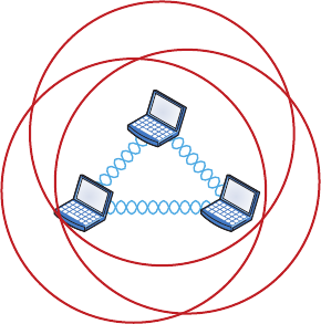
396
Chapter 12 ■ Wireless Networking
c12.indd 04/0½ 015 Page 396
FIGURE 12.10 A wireless network in ad hoc mode
An ad hoc network would not scale well and really is not recommended due to
collision and organization issues. With the low costs of APs, this type of network is just
not needed today.
Infrastructure Mode: Basic Service Set
The most common use of wireless networking equipment is to give us the wireless equiva-
lent of a wired network. To do this, all 802.11 wireless equipment has the ability to operate
in what’s known as infrastructure mode, also referred to as a basic service set (BSS), which
is provided by an AP. The term basic service area (BSA) is also used at times to de ne the
area managed by the AP, but BSS is the most common term used to de ne the cell area.
In infrastructure mode, NICs communicate only with an access point instead of directly
with each other as they do when they’re in ad hoc mode. All communication between hosts,
plus with any wired portion of the network, must go through the access point. A really
important fact to remember is that in this mode, wireless clients actually appear to the rest
of the network as though they were standard, wired hosts.
Figure 12.11 shows a typical infrastructure mode wireless network. Pay special attention
to the access point and the fact that it’s also connected to the wired network. This connec-
tion from the access point to the wired network is called the distribution system (DS) and
is referred to as wireless bridging.
When you con gure a client to operate in wireless infrastructure mode, you need to
understand a couple of basic wireless concepts—namely, SSID and security. The service
set identi er (SSID) refers to the unique 32-character identi er that represents a particular
wireless network and de nes the basic service set. Oh, and by the way, a lot of people use
the terms SSID and BSS interchangeably, so don’t let that confuse you! All devices involved
in a particular wireless network must be con gured with the same SSID.
Good to know is that if you set all your access points to the same SSID, mobile wireless
clients can roam around freely within the same network. Doing this creates an extended
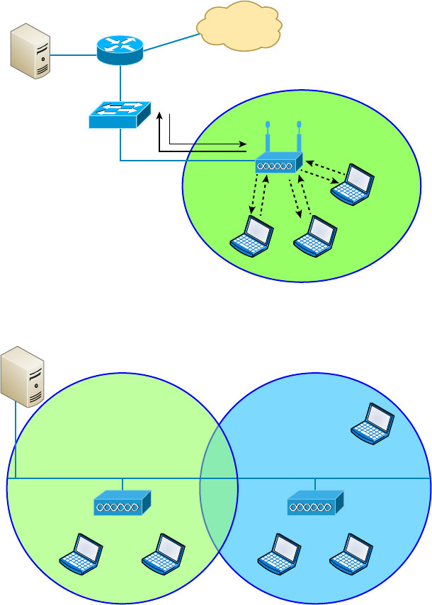
Installing a Wireless Network
397
c12.indd 04/0½ 015 Page 397
service set (ESS) and provides more coverage than a single access point. Figure 12.12 shows
two APs con gured with the same SSID in an of ce, thereby creating the ESS network.
FIGURE 12.11 A wireless network in infrastructure mode
Internet
DS*
Access Point
Wireless Clients
*DS = Distribution System
FIGURE 12.12 Extended service set (ESS)
“Wireless Cell”
Channel 1
LAN Backbone
SSID Sales SSID Sales
Overlapping
20%
Wireless Clients Wireless Clients
Channel 6
“Wireless Cell”
For users to be able to roam throughout the wireless network—from AP to AP without
losing their connection to the network—all APs must overlap by 10 percent of their signal
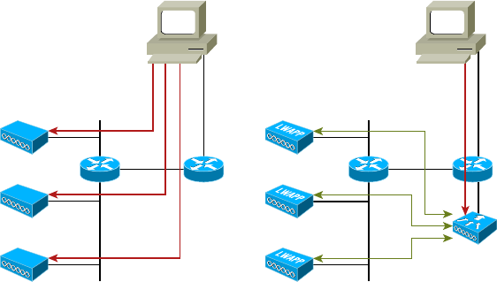
398
Chapter 12 ■ Wireless Networking
c12.indd 04/0½ 015 Page 398
or more. To make this happen, be sure the channels on each AP are set differently. And
remember, in an 802.11b/g network, there are only three non-overlapping channels (1, 6,
11), so careful design is super important here!
Wireless Controllers
You’d be hard pressed to nd an enterprise WLAN that doesn’t use wireless controllers.
In fact, every wireless enterprise manufacturer has a controller to manage the APs in
the network.
By looking at Figure 12.13, you can see the difference between what we call stand-alone
APs and the controller solution. In a stand-alone solution, all the APs have a full operating
system loaded and running, and each must be managed separately.
FIGURE 12.13 Stand-alone and controller-based wireless networks
stand-alone Solution Controller-Based Solution
Administrator
Configure
WLAN
Controller
Configure
Administrator
In the controller-based system, the APs are what we refer to as lightweight, meaning
they do not have a full operating system running on them. The controller and AP split
duties—a solution known as split MAC. APs running with a controller are referred to as
lightweight, but also you’ll hear the term thin AP, whereas you’ll hear the term thick when
referring to APs that run a full OS.
Take another look at Figure 12.13. You can also see that the administrator isn’t manag-
ing each AP independently when using the WLAN controller solution. Instead, the admin-
istrator con gures the controller, which in turn pushes out the con guration needed for
each AP. Controllers allow us to design and implement larger enterprise wireless networks
with less time and tedium, which is very important in today’s world!
One feature that also gives controllers the ability to provide a great solution is when
you’re dealing with a location that’s overloaded with clients because it utilizes VLAN
pooling, or virtual LAN pooling. This is very cool because it allows you to partition a
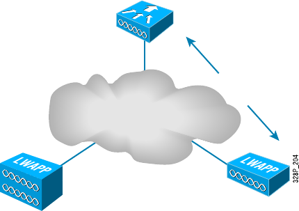
Installing a Wireless Network
399
c12.indd 04/0½ 015 Page 399
single large wireless broadcast domain into multiple VLANs and then either statically or
randomly assign clients into a pool of VLANs. So, all clients get to keep the same SSID
and stay connected to the wireless network, even when they roam. They’re just in different
broadcast domains.
In order for split MAC to work in a wireless controller network, the APs and controller
run a protocol to enable them to communicate. The proprietary protocol that Cisco used
was called Lightweight Access Point Protocol (LWAPP), and it’s pictured in Figure 12.14.
FIGURE 12.14 LWAPP
WLAN
Controller
LWAPP
Keep in mind that LWAPP isn’t used too much these days, but a newer, more secure
protocol called Control and Provisioning of Wireless Access Points (CAPWAP), which also
happens to be nonproprietary, has replaced it to become the standard that most controller
manufactures use today.
Mobile Hot Spots
Let’s say you’re in a location that doesn’t have an AP installed, or they want to charge
you for access, and you want to connect your laptop, tablet, or even play a game. What
can you do?
You’ve got a couple of options, but they all include the cellular network as an infrastruc-
ture. Not to be an ad for AT&T, but Figure 12.15 shows a mobile hot spot device that con-
nects your laptop, tablet, media devices, or even a gaming device to the Internet at decent
speeds. Pretty much all cellular vendors sell a version of these hot spots now.
But let’s say you don’t want to carry yet another device around with you and you just
want to use your phone instead. Figure 12.16 shows how I turned my iPhone into an AP for
my laptop. First I went to Settings and then chose Personal Hotspot. If that option doesn’t
show up for you, just give a quick shout to your carrier and have it enabled.
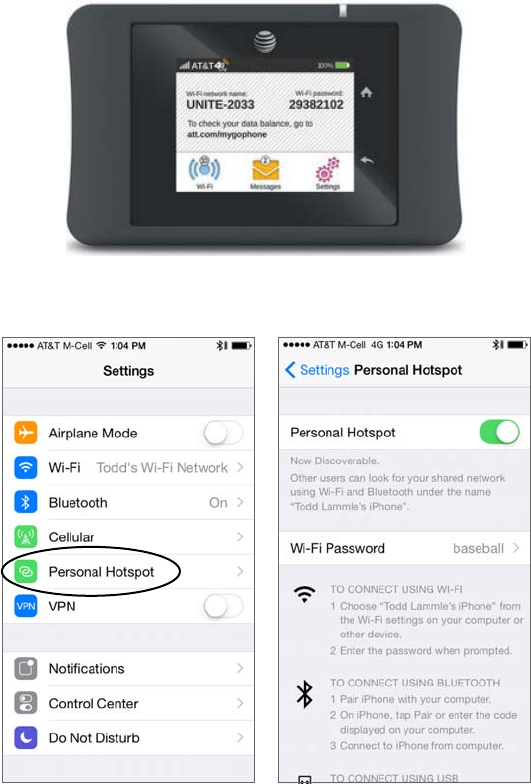
400
Chapter 12 ■ Wireless Networking
c12.indd 04/0½ 015 Page 400
FIGURE 12.15 Mobile hot spot
FIGURE 12.16 iPhone hot spot
I pay very little to AT&T for my AP capability, but I still have to pay for my usage, so
I use it only when I’m someplace like an airport and I want security without paying for
access to their Internet wireless. Airport wireless hot spots are notoriously slow anyway,
and you’d be dead in the water if you intend to use this type of wireless networking for
something like gaming, which requires a ton of bandwidth!
Signal Degradation
Something that’s really important to consider when installing a wireless network is
signal degradation. Because the 802.11 wireless protocols use radio frequencies, the sig-
nal strength varies according to many factors. The weaker the signal, the less reliable the
Installing a Wireless Network
401
c12.indd 04/0½ 015 Page 401
network connection will be and so the less usable as well. (Think dropped calls!) There are
several key factors that affect signal strength:
Distance This one is de nitely on the obvious side—the farther away from the WAP you
get, the weaker the signal you get. Most APs have a very limited maximum range that
equals less than 100 meters for most systems. You can extend this range to some degree
using ampli ers or repeaters, or even by using different antennas.
Walls and Other Barriers Also easy to imagine is the fact that the more walls and other
of ce barriers a wireless signal has to pass through, the more attenuated (reduced) the
signal becomes. Also, the thicker the wall, the more it interrupts the signal. So in an indoor
of ce area with lots of walls, the range of your wireless network could be as low as 25 feet!
You really have to be careful where you place your APs!
Protocols Used This one isn’t so apparent, but it certainly is a factor that affects, and can
even determine, the range of a wireless LAN. The various wireless 802.11 protocols have
different maximum ranges. As discussed earlier, and illustrated in Figure 12.7, the maxi-
mum effective range varies quite a bit depending on the 802.11 protocol used. For example,
if you have a client running the 802.11g protocol but it connects to an AP running only the
802.11b protocol, you’ll only get a throughput of 11Mbps to the client.
Interference The nal factor that affects wireless performance is outside interference.
Because 802.11 wireless protocols operate in the 900MHz, 2.4GHz, and 5GHz ranges,
interference can come from many sources. These include wireless devices like Bluetooth,
cordless telephones, cell phones, other wireless LANs, and any other device that transmits a
radio frequency (RF) near the frequency bands that 802.11 protocols use. Even microwave
ovens—a huge adversary of 802.11b and 802.11g—can be serious culprits!
Other Network Infrastructure Implementations
We’ve discussed the hot spot’s wireless LANs (WLANs) created by installing APs, but there
are other technologies like personal area networks (PANs), which create wireless infra-
structures, too. By far, the best known is the ever-popular Bluetooth, but there are other
wireless technologies we can use as well, and we’ll take some time to explore these soon.
For now, it’s back to Bluetooth, which happens to have a fantastic history behind it!
The technology was actually named after a fabled 10th century Viking king, Harald I
(Harald “Blatand” Gormsson), who was faced with the challenge of dealing with many
disparate tribes; he needed to communicate with them all and they needed to get along
with each other. Blatand, who it’s said got his unique nickname due to sporting an unfor-
tunately prominent blue tooth, was having a really tough time getting this to happen. The
Viking king was a famously great diplomat possessing a wonderful way with words, and
he effectively and nonviolently united ancient Norway and Denmark into a single territory
via his powerful communication skills. Incidentally, Blatand just happens to translate into
Bluetooth in English.
Fast forward to modern times and a Scandinavian company called Ericsson and a
highly gifted, technological innovator, Jim Kardach. As one of the founders of Bluetooth,
Kardach’s challenge was a decent, modern-day analogy of the ancient Viking king’s—he
was faced with making disparate phones, computers, and other devices communicate
and cooperate effectively. To answer the challenge, Kardach came up with an elegant,
402
Chapter 12 ■ Wireless Networking
c12.indd 04/0½ 015 Page 402
technological wireless solution to make all these disparate devices communicate and play
well with each other. To come up with an equally cool name for the brilliant innovation,
he did some research, discovered the legend of the ancient Viking king, and codenamed
the new technology Bluetooth. It stuck! Now all that was left was to create a super slick
logo for it. Today’s Bluetooth icon is actually the legendary king’s initials in ancient Viking
runes merged together—how cool is that?
Bluetooth operates in the 2.4GHz range, so while it can cause some interference with
802.11b/g, it’s really low power. Plus, the electronics in our WLANs are much better today than
they were in the past, so it really isn’t much of an issue anymore, and so at last, modern wireless
communication works nicely for us today, making our technological lives so much easier!
To delve a little deeper into wireless technologies, the idea of PANs is to allow personal
items such as keyboards, mouse, and phones to communicate to our PC/laptop/display/TV
wirelessly instead of having to use any wires at all—over short distances of up to 30 feet,
of course. This idea of the wireless of ce hasn’t quite come to fruition completely yet, but
you have to admit that Bluetooth really has helped us out tremendously in our of ces and
especially in our cars!
There are two other network infrastructure implementations in the PAN area: infrared
(IR) and near- eld communication (NFC).
Like Bluetooth, IR has some history behind it, but the technology’s idea only goes back
to about 1800 because that’s when it was rst said that the energy from the sun radiates
to Earth in infrared. We can use IR to communicate short range with our devices, like
Bluetooth-enabled ones, but it isn’t really as popular as Bluetooth to use within network
infrastructures. Unlike Wi-Fi and Bluetooth, the infrared wireless signals cannot penetrate
walls and only work line-of-sight. Last, the rates are super slow and most transfers are only
115kbps—up to 4Mbps on a really good day!
The last implementation I want to cover is called near- eld communication (NFC). For
NFC to work, the actual antenna must be smaller than the wavelength on both the trans-
mitter and receiver. For instance, if you look at a 2.4GHz or 5GHz antenna, they are the
exact length of one wavelength for that speci c frequency. With NFC, the antenna is about
one-quarter the size of the wavelength, which means that the antenna can create either an
electric eld or a magnetic eld but not an electromagnet eld.
NFC can be used for wireless communication between devices like smartphones and/or
tablets, but you need to be near the device transmitting the RF to pick up the signal—really
close. A solid example would be when you’re swiping your phone over a QR code.
Installing and Configuring WLAN Hardware
As I said earlier, installing 802.11 equipment is actually fairly simple—remember that there
are really only two main types of components in 802.11 networks: APs and NICs. Wireless
NIC installation is just like installing any other network card, but nowadays most, if not
all, laptops have wireless cards preinstalled, and that’s as easy as it gets! And just as with
connecting an Ethernet card to a LAN switch, you need the wireless network card to con-
nect to an access point.
The AP installation can be fairly simple as well. Take it out of the box, connect the
antenna(e) if necessary, connect the power, and then place the AP where it can reach the
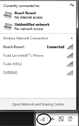
Installing a Wireless Network
403
c12.indd 04/0½ 015 Page 403
highest number of clients. This last part is probably the trickiest, but it really just involves a
little common sense and maybe a bit of trial and error. Knowing that walls obstruct the
signal means that putting the AP out in the open—even indoors—works better. And you
also know it should be placed away from sources of RF interference, so putting it next to
the microwave or phone system is probably a really bad idea, too. Near a metal ling cabi-
net is also not so good. So just experiment and move your AP around to nd the spot that
gives you the best signal strength for all the clients that need to use it.
Now that you have the hardware installed, it’s time to con gure it, right? Let’s get started.
No worries—con guring your AP and NIC to work together isn’t as tricky as it sounds.
Most wireless equipment is designed to work almost without con guration, so by default,
you can pretty much turn things on and start working. The only things you need to con-
gure are customization settings (name, network address, and so on) and security settings,
and even these aren’t required. But because I do highly recommend con guring them, I’ll
take you through that now.
NIC Configuration
Windows XP, Windows Vista, Windows 7/8, and Windows Server 2003/2008/2012 include
software to automatically con gure a wireless connection, and they do so automatically
when you install a wireless NIC—assuming that somehow you have a Windows machine
without a wireless NIC installed on the motherboard. And if you have one without a NIC
installed, your Windows machine is really old!
Con guring a Windows 7 client is pretty simple, but what do you if you can’t get it to
actually work afterward? If this happens to you, searching for the solution could eat up a seri-
ous amount of your time! Following these steps could save you from that frustrating quest:
1. To find a wireless network, open Control Panel and choose Network And Internet,
Network And Sharing Center, and finally, Connect To A Network. If all is well, you’ll
get a screen similar to this one.

404
Chapter 12 ■ Wireless Networking
c12.indd 04/0½ 015 Page 404
What I just described was actually the long way to get to that goal. There’s a shortcut:
just go to the lower-right corner of your screen and click the signal
strength bars with the yellow caution sign that I circled in the screen shot to get the
same results!
2. Double-click the network you want to join, and click Connect Anyway, even if it’s an
unsecured network. You’ll then see a screen showing that it’s trying to connect.
3. If you’re using security, the AP will ask you for your credentials.
4. Check your TCP/IP settings to find out if you’re not really connected to the Internet
and troubleshoot from there.
AP Configuration
Once you’ve successfully con gured your workstation(s), it’s time to move on and con gure
the AP. There are literally hundreds of different APs out there, and of course, each uses
a different method to con gure its internal software. The good news is that for the most
part, they all follow the same general patterns:
1. First of all, out of the box, the AP should come configured with an IP address that’s
usually something similar to 192.168.1.1. But check the documentation that comes
with the AP to be sure. You can just take the AP out of its box, plug it into a power
outlet, and connect it to your network, but in order to manage the AP, you’ve got to
configure its IP address scheme to match your network’s.
2. You should receive a DHCP address from the AP when you connect, but if you don’t
get one, start by configuring a workstation on the wired network with an IP address
(192.168.1.2 or similar) and subnet mask on the same subnet as the AP’s. You
should then be able to connect to the AP to begin the configuration process. Usually,
you do this via a web browser or with a manufacturer-supplied configuration
program.
3. Once you have successfully connected to the AP, you then get to configure its
parameters.
Following are the minimum parameters common to APs that you should con gure for
your AP to work properly. (Remember, typically, an AP works right out of the box, but
it is unsecure too!)
Installing a Wireless Network
405
c12.indd 04/0½ 015 Page 405
SSID As I talked about earlier, this is the name of the wireless network that your AP
will advertise. If this new AP is to be part of an existing wireless network, it needs to be
con gured with the same SSID as the existing network. In a network with only one AP,
you can think of the SSID as the “name” of the AP.
AP IP Addresses Remember, even though most APs come precon gured with an IP
address, it may not be one that matches the wired network’s IP addressing scheme. So
it follows that you should con gure the AP’s IP addresses (including the address, subnet
mask, and default gateway addresses) to match the wired network you want it connected
to. An AP does not need an IP address to work in your network. The IP address of the
AP is used only to manage the AP.
Operating Mode (Access Point or Bridging) Access points can operate in one of two
main modes: Access Point mode or Bridging mode. Access Point mode allows the AP
to operate as a traditional access point to allow a wireless client transparent access to a
wired network. Alternatively, two APs set to Bridging mode provide a wireless bridge
between two wired network segments.
Password Every access point has some kind of default password that’s used to access
the AP’s con guration. For security reasons, it’s a good idea to change this as soon as
you can to connect to and con gure the AP.
Wireless Channel 802.11 wireless networks can operate on different channels to avoid
interference. Most wireless APs come set to work on a particular channel from the factory,
and you can change it if other networks in the area are using that channel, but be aware
that no particular channel is any more secure than another. Wireless stations do not use a
channel number as a taker when seeking a connection. They only pay attention to SSIDs!
WEP/WPA Although it isn’t a requirement per se, I de nitely recommend enabling
security right from the start as soon as you turn on the AP. Commercial APs typically
come con gured as an open network so that it’s easy to log in, whereas enterprise APs
come uncon gured and don’t work until they are con gured. WEP and Wi-Fi Protected
Access (WPA) allow data to be encrypted before it’s sent over the wireless connection,
and all con guring entails is to enable it and pick a key to be used for the connections.
Simple, easy-to-con gure security is certainly worth your time!
So here’s what you do: First, you’ll be asked to enter one or more human-readable
passphrases called shared keys—secret passwords that won’t ever be sent over the
wire. After entering each one, you’ll generally click a button to initiate a one-way hash
to produce a WEP key of a size related to the number of bits of WEP encryption you
want. Entering the same passphrase on a wireless client causes the hash (not the pass-
phrase) to be sent from the wireless client to the AP during a connection attempt. Most
con guration utilities allow you to create multiple keys in case you want to grant some-
one temporary access to the network, but you still want to keep the primary passphrase
a secret. You can just delete the key you enabled to permit temporary access after you
don’t need it anymore without affecting access by any primary LAN participants.
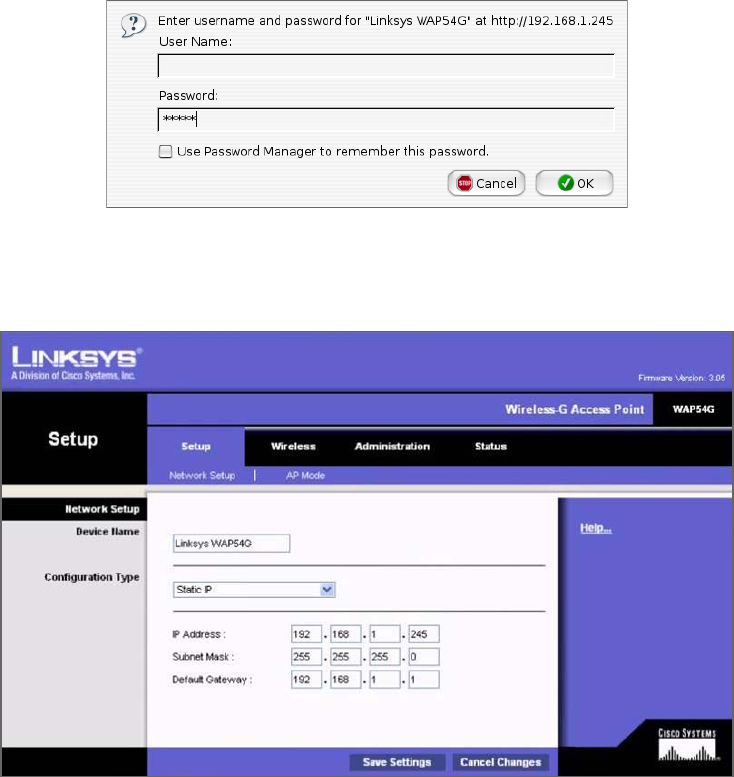
406
Chapter 12 ■ Wireless Networking
c12.indd 04/0½ 015 Page 406
Here’s an example of connecting to a Linksys access point (not a Linksys wireless router,
which is a different device):
1. The first screen shows that I’ve connected using HTTP to configure the device. The
IP address of the Linksys AP is 192.168.1.245. If it was a Linksys wireless router
instead—the typical home DSL/cable modem wireless connection device around
today—than the address would be 192.168.1.1.
2. As you can see, there’s no username required, and the password is just admin. Again,
be sure not to leave this login configuration as the default! Once I click OK, I get taken
to a screen where I can change my IP address:
3. It isn’t vital for an AP to have an IP address, but it comes in handy for management
purposes. You can change the IP address as well as the device name from this screen if
you want to. I clicked the Wireless tab on top and this screen appeared:
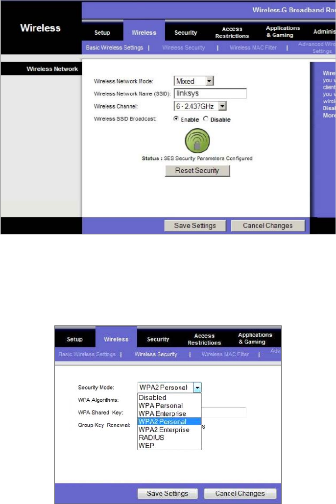
Installing a Wireless Network
407
c12.indd 04/0½ 015 Page 407
4. From here, you can set the device to run b/g, only g, or even Mixed mode, which happens
to be the default. You can also change the SSID from Linksys to another name, and I highly
recommend doing this. The AP channel can also be changed, and you can turn off the AP
beacons as well, which is also recommended, but understand that if you do this, you’ll have
to set the new SSID name in each of your clients! Last thing—you can see that by default,
there’s no encryption. Click the Wireless Security tab, and you’ll get this screen:
5. From the pull-down menu, it’s clear that security is set to Disabled by default, but no
worries, you get to choose from various wireless security options if you want to.
408
Chapter 12 ■ Wireless Networking
c12.indd 04/0½ 015 Page 408
I’ll talk more about security after I hammer on about site surveys for a bit—they really
are that important!
Site Survey
I want to be sure you’re completely clear about where I stand regarding site surveys. They
are absolutely and vitally imperative to bringing a premium-quality—even just a reasonably
viable—WLAN into this world! You should carry out a predeployment survey and a
postdeployment survey, but keep in mind that your predeployment survey isn’t actually
your rst step to begin this key process.
So, because you positively must know how to formulate and implement a solid site sur-
vey, I’m going to walk you through executing the three major steps to doing that effectively.
And just to be really thorough, I’m also going to cover some issues commonly encountered
as we progress through these steps.
Information Gathering This is actually your rst step, and during this stage, you must
determine three key factors:
■ The scope of the network, including all applications that will be used, data types that
will be present, and how sensitive these data types are to delay.
■ The areas that must be covered and the expected capacity at each location.
■ The types of wireless devices that will need to be supported, such as, for example,
laptops, iPads/iPhones, IP phones, and barcode readers.
During this phase, a key goal of mine would be to create a coverage model that maps to all
areas that need coverage, along with those that don’t, and have my client sign off in agreement
to this document before I do anything else. You definitely want to do this, too—just trust me!
Predeployment Site Survey In this phase, I use live APs to verify the optimal distances
between their prospective locations. I base this placement on the expected speed at the edge
of the cell, the anticipated number of devices, and other information gathered in step 1.
Usually, after I get one AP positioned, I’ll place the next one based on the distance from the
rst, with special consideration given to any sources of interference I’ve found.
Postdeployment Site Survey I utilize the postdeployment survey phase to con rm and
verify that the original design and placements are happily humming along, problem free,
when all stations are using the network. This pretty much never happens, so at this point,
it’s likely changes will need to be made—sometimes, signi cant ones—in order to optimize
the performance of a WLAN operating under full capacity.
Providing Capacity
Now here’s a big issue that frequently rears its ugly head: providing enough capacity in
areas where many wireless stations will be competing for the airwaves. Remember that
stations share access to the RF environment with all other stations in the BSS, as well as
with the AP, so really, the only way to increase capacity is by increasing the number of APs
in an area requiring serious density.
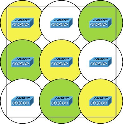
Site Survey
409
c12.indd 04/0½ 015 Page 409
This can get complicated, but basically, it comes down to placing APs on non-overlap-
ping channels while still sharing the same SSID. Take a look at Figure 12.17 for an example
of this scenario.
FIGURE 12.17 Basic coverage
In Figure 12.17, nine APs have been con gured in the same area using the three, non-
overlapping channels in the 2.4GHz frequency (1, 6, and 11). Each shade represents a
different channel. Even though the APs on the same channel have been positioned far
enough away from one another so that they don’t overlap much and/or cause interference,
surprisingly, it’s actually better if there is some overlap. But bear in mind that the channels
should be used in a way that no APs on the same channel overlap in a detrimental way.
Another thing I want to point out that’s not so ideal about this arrangement is that all the
APs would have to run at full power. This isn’t a good way to go because it doesn’t give you
much fault tolerance at all!
So, we’ve got two problems with our design: lack of overlap and lack of fault tolerance.
To address both issues, you need more APs using 802.11a, b, and g, which would get you
more channels and provide better throughput, as shown in Figure 12.18.
A key bene t to this design is it would also gain the critical ability to run the APs at less
than full power. This allows the controller to strategically boost the power of speci c APs
in the event of an AP outage in a given area.
When you know exactly the type of applications and activity a WLAN will need to sup-
port, you can then determine the data rate that must be attained in a particular area. Since
received signal strength indicator (RSSI), signal-to-noise ratio (SNR), and data rate are
correlated, the required data rate will tell you what the required RSSI or SNR should be as
seen at the AP from the stations. Keep in mind that stations located at the edge of the cell
will automatically drop the data rate and that the data rate will increase as a station moves
toward the AP.
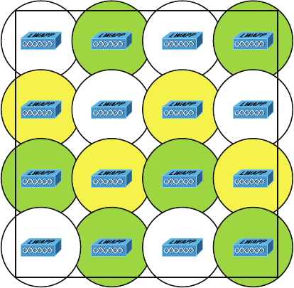
410
Chapter 12 ■ Wireless Networking
c12.indd 04/0½ 015 Page 410
FIGURE 12.18 Enterprise design
Multiple Floors
Another special challenge is a multistory building where WLANs are located on all oors.
In these conditions, you’ve got to think about channel usage in a three-dimensional way,
and you’ll have to play nicely with the other WLANs’ administrators to make this work!
Facing this scenario, your channel spacing should be deployed, as shown in Figure 12.19.
To prevent bleed from one oor to another, use semi-directional or patch antennas to
control radiation patterns.
Location-Based WLAN
When using a location device such as the Cisco 2710, your restrictions get even tighter. The
additional requirements for the location device to operate properly are as follows:
■ APs should be placed at the edge even when they’re not needed there for normal cover-
age purposes so that devices at the edge can be located.
■ The density of APs must be higher. Each AP should be 50 to 70 feet apart—much
closer than is normally required.
■ Some APs will need to be set in monitor or scanner mode so that they won’t transmit
and interfere with other APs.
All of this means that the nal placement will be denser and a bit more symmetrical
than usual.
Site Survey Tools
As I touched upon at the beginning of our site survey section, there are some highly
specialized, very cool site survey tools that can majorly help you achieve your goals. The
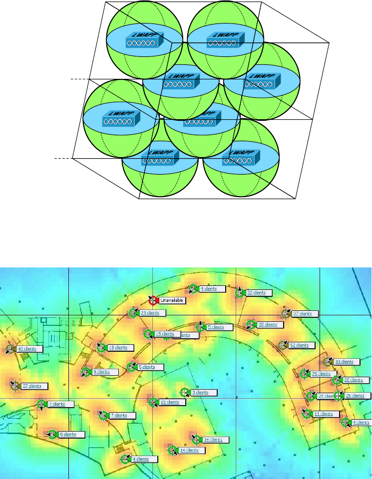
Site Survey
411
c12.indd 04/0½ 015 Page 411
AirMagnet Survey and Ekahau Site Survey tools make it possible to do a client walk-
through with the unit running and you can click each location on the map.
FIGURE 12.19 A multifloor installation
Channel 1 Channel 11
2nd Floor
1st Floor
Channel 1 Channel 6
Channel 6 Channel 1
Channel 1 Channel 11
These tools will gather RSSI and SNR from each AP in the range, and at the end of your
tour, global heat map coverage will be magically displayed, as shown in Figure 12.20.
FIGURE 12.20 A heat map of a building
412
Chapter 12 ■ Wireless Networking
c12.indd 04/0½ 015 Page 412
Wireless Security
So, wireless security is basically nonexistent on access points and clients. The original
802.11 committee just didn’t imagine that wireless hosts would one day outnumber
bounded media hosts, but that’s actually where we’re headed now. Also, unfortunately, just
as with the IPv4 routed protocol, engineers and scientists didn’t include security standards
that are robust enough to work in a corporate environment. So we’re left with proprietary
solution add-ons to aid us in our quest to create a secure wireless network. And no—I’m
not sitting here bashing the standards committees, because the security problems we’re
experiencing were also created by the US government because of export issues with its own
security standards. Our world is a complicated place, so it follows that our security
solutions would have to be as well.
Wireless Threats
Protection of data and the authentication processes are certainly key threats, but there are
other wireless security perils lurking out there as well. We’ll dive deeper into the processes
and procedures designed to mitigate these dangers in Chapter 14, but l want to brie y dis-
cuss them here.
Rogue APs
First, there’s the evil we call rogue APs. These are APs that have been connected to your
wired infrastructure without your knowledge. The rogue may have been placed there by
a determined hacker who snuck into your facility and put it in an out-of-the-way loca-
tion or, more innocently, by an employee who just wants wireless access and doesn’t get
just how dangerous doing this is. Either way, it’s just like placing an open Ethernet port
out in the parking lot with a sign that says “Corporate LAN access here—no password
required!”
Clearly, the worst type of rogue AP is the one some hacker has cleverly slipped into
your network. It’s particularly nasty because the bad guy probably didn’t do it to simply
gain access to your network. Nope—the hacker likely did it to entice your wireless clients
to disastrously associate with their rogue AP instead! This ugly trick is achieved by plac-
ing their AP on a different channel from your legitimate APs and then setting its SSID
in accordance with your SSID. Wireless clients identify the network by the SSID, not the
MAC address of the AP or the IP address of the AP, so jamming the channel that your AP
is on will cause your stations to roam to the bad guy’s AP instead. With the proper DHCP
software installed on the AP, the hacker can issue the client an address, and once that’s
been done, the bad guy has basically “kidnapped” your client over to their network and can
freely perform a peer-to-peer attack. Believe it or not, this can all be achieved from a laptop
while Mr. Hacker simply sits in your parking lot, because there are many types of AP soft-
ware that will run on a laptop—yikes!
Wireless Security
413
c12.indd 04/0½ 015 Page 413
Mitigation
But you’re not helpless—one way to keep rogue APs out of the wireless network is to
employ a wireless LAN controller (WLC) to manage your APs. This is a nice mitiga-
tion technique because APs and controllers communicate using Lightweight Access Point
Protocol (LWAPP) or the newer CAPWAP, and it just so happens that one of the message
types they share is called Radio Resource Management (RRM). Basically, your APs moni-
tor all channels by momentarily switching from their con gured channel and by collecting
packets to check for rogue activity. If an AP is detected that isn’t usually managed by the
controller, it’s classi ed as a rogue, and if a wireless control system is in use, that rogue can
be plotted on a oor plan and located. Another great bene t to this mitigation approach
is that it enables your APs to also prevent workstations from associating with the newly
exposed rogue.
Ad Hoc Networks
As you already know, ad hoc networks are created peer to peer or directly between stations
and not through an AP. This can be a dangerous con guration because there’s no corporate
security in place, and since these networks are often created by unsophisticated users, you
end up with the scenario I just described that’s primed for, and wide open to, a peer-to-
peer attack. Even uglier, if the laptop happens to connect to the corporate LAN through an
Ethernet connection at the same time the ad hoc network is created, the two connections
could be bridged by a hacker to gain them access straight up into the wired LAN itself!
Mitigation
When you’ve got a Cisco Uni ed Wireless Network (CUWN) in operation, ad hoc net-
works can be identi ed over the air by the kind of frames they send, which are different
from those belonging to an infrastructure network. When these frames are identi ed, the
CUWN can prevent harmful intrusions by sending out something known as deauthentica-
tion frames to keep your stations from associating via ad hoc mode.
Denial of Service
Not all attacks are aimed at the goal of stealing information. Sometimes the hacker just
wants to cause some major network grief, like jamming the frequency where your WLAN
lives to cause a complete interruption of service until you manage to ferret out the jamming
signal and disable it. This type of assault is known as a denial of service (DoS) attack.
Mitigation
And this is how we deal with them. First, if someone is jamming the frequency, there isn’t
much, if anything, you can do. However, many DoS, man-in-the-middle, and penetration
attacks operate by deauthenticating, or disassociating, stations from their networks. Some
DoS attacks take the form of simply ooding the wireless network with probe requests
or association frames, which effectively makes the overwhelmed network unavailable for
normal transmissions. These types of management frames are sent unauthenticated and
414
Chapter 12 ■ Wireless Networking
c12.indd 04/0½ 015 Page 414
unencrypted. Since deauthentication and disassociation frames are classi ed as manage-
ment frames, the Management Frame Protection (MFP) mechanism can be used to prevent
the deluge. There are two types of MFP you can use, referred to as infrastructure and
client. Let’s take a look at each of them now.
Infrastructure Mode
This sweet strategy doesn’t require con guration on the station—only the AP. Controllers
generate a speci c signature for each WLAN, which is added to each management frame it
sends, and any attempt to alter this is detected by the MIC in the frame. Therefore, when
an AP receives a management frame from an unknown SSID, it reports the event to the
controller and an alarm is generated.
When an AP receives an MFP protected frame from an unknown SSID, it queries the
controller for the key. If the BSSID isn’t recognized by the controller, it will return an
“unknown BSSID” message, which causes the AP to drop the frame.
Client Mode
Often rogue APs attempt to impersonate the company AP. With client MFP, all manage-
ment frames between the AP and the station are protected because clients can detect and
drop spoofed or invalid management frames.
Passive Attacks
So far, the attacks I’ve talked about are in a category referred to as active attacks because
in deploying them, the hacker is interacting with stations, the AP, and the network in real
time. But beware—there are other ways into the fort!
Passive attacks are most often used to gather information to be used in an active attack
a hacker is planning to execute later, and they usually involve wireless snif ng. During a
passive attack, the hacker captures large amounts of raw frames to analyze online with
snif ng software used to discover a key and decrypt it “on the y.” Or the data will be ana-
lyzed of ine, which simply means the bad guy will take the data away and analyze it later.
Mitigation
In addition to the tools already described, you can use an intrusion detection system (IDS)
or an intrusion protection system (IPS) to guard against passive attacks:
IDS An intrusion detection system (IDS) is used to detect several types of malicious
behaviors that can compromise the security and trust of your system. These malicious
behaviors include network attacks against vulnerable services; data-driven attacks on
applications; host-based attacks like privilege escalation; unauthorized logins; access to
sensitive les; and malware like viruses, Trojan horses, and worms.
IPS An intrusion prevention system (IPS) is a computer security device that monitors
network and/or system activities for malicious or unwanted behavior and can react, in real
time, to block or prevent those activities. For example, a network-based IPS will operate
inline to monitor all network traf c for malicious code or attacks. When either is detected,
it can drop the offending packets while still allowing all other traf c to pass.

Wireless Security
415
c12.indd 04/0½ 015 Page 415
Which approach you’ll opt to go with depends on the size of your wireless network
and how tight your security needs to be. The goal of a security mechanism is to provide
three features:
■ Confidentiality of the data
■ Data integrity
■ An assured identification process
And when faced with decisions about security, you need to consider these three things:
■ The safety of the authentication process
■ The strength of the encryption mechanism
■ Its ability to protect the integrity of the data
War Driving
It’s a fact—wireless networks are pretty much everywhere these days. You can get your
hands on a wireless access point for less than $100.00, and they’re fl ying off the shelves.
You can fi nd APs in public places like shopping malls, coffee shops, airports, and hotels,
and in some cities, you can just hang out in a downtown area and zero in on a veritable
menu of APs operating in almost every nearby business.
Predictably, this proliferation of APs has led to a new hobby for those with enough skill:
It’s called war driving. Not for the technologically challenged, war driving involves driv-
ing around in a car with a laptop, a wireless NIC, and a high-gain antenna, trying to locate
open APs. If one with high-speed Internet access is found, it’s like hitting the jackpot.
People do this aided by various software programs and Global Positioning Systems
(GPSs) to make their game even easier. But it’s not always innocent—war drivers can be
a serious security threat because they can potentially access anything on your wireless
LAN as well as anything it’s attached to! Even though they’re not a sinister threat most of
the time, realize that in the very least, they’re consuming precious resources from your
network. So, if you happen to notice unusually slow-moving vehicles outside your home
or business—especially those with computer equipment inside—know that you’re the
potential target of a war driver.
A good place to start discussing Wi-Fi security is by talking about the basic security
that was incorporated into the original 802.11 standards and why those standards are
still way too imsy and incomplete to help us create a secure wireless network relevant to
today’s challenges.

416
Chapter 12 ■ Wireless Networking
c12.indd 04/0½ 015 Page 416
Open Access
All Wi-Fi Certi ed small-of ce, home-of ce (SOHO) wireless LAN products are
shipped in “open-access” mode, with their security features turned off. Although
open access or no security may be appropriate and acceptable for public hot spots
such as coffee shops, college campuses, and maybe airports, it’s de nitely not an option
for an enterprise organization, and it’s probably not even adequate for your private
home network.
With what I’ve told you so far, I’m sure you agree that security needs to be enabled on
wireless devices during their installation in enterprise environments. Yet surprisingly, many
companies actually don’t enable any WLAN security features. Obviously, the companies
that do this are exposing their networks to tremendous risk.
The reason that the products are shipped with open access is so that any person who
knows absolutely nothing about computers can just buy an access point, plug it into their
cable or DSL modem, and voilà—they’re up and running. It’s marketing, plain and simple,
and simplicity sells.
Service Set Identifiers, Wired Equivalent Privacy, and
Media Access Control Address Authentication
What the original designers of 802.11 did to create basic security was to include the use of
SSIDs, open or shared-key authentication, static WEP, and optional Media Access Control
(MAC) authentication/MAC ltering. Sounds like a lot, but none of these really offer any
type of serious security solution—all they may be close to adequate for is use on a common
home network. But we’ll go over them anyway.
An SSID is a common network name for the devices in a WLAN system that create the
wireless LAN. An SSID prevents access by any client device that doesn’t have the SSID. The
thing is, by default, an access point broadcasts its SSID in its beacon many times a second.
And even if SSID broadcasting is turned off, a bad guy can discover the SSID by monitor-
ing the network and just waiting for a client response to the access point. Why? Because,
believe it or not, that information, as regulated in the original 802.11 speci cations, must
be sent in the clear—how secure!
If you cannot see an AP when trying to perform a site survey, verify that
the AP has SSID beaconing enabled.
Two types of authentication were speci ed by the IEEE 802.11 committee: open and
shared-key authentication. Open authentication involves little more than supplying the cor-
rect SSID—but it’s the most common method in use today. With shared-key authentication,
the access point sends the client device a challenge-text packet that the client must then
encrypt with the correct WEP key and return to the access point. Without the correct key,
authentication will fail and the client won’t be allowed to associate with the access point.
But shared-key authentication is still not considered secure because all an intruder has to do

Wireless Security
417
c12.indd 04/0½ 015 Page 417
to get around this is detect both the clear-text challenge and the same challenge encrypted
with a WEP key and then decipher the WEP key. Surprise—shared key isn’t used in today’s
WLANs because of clear-text challenge.
With open authentication, even if a client can complete authentication and associate
with an access point, the use of WEP prevents the client from sending and receiving data
from the access point unless the client has the correct WEP key. A WEP key is composed
of either 40 or 128 bits, and in its basic form, it’s usually statically de ned by the network
administrator on the access point and all clients that communicate with that access point.
When static WEP keys are used, a network administrator must perform the time-consum-
ing task of entering the same keys on every device in the WLAN. Obviously, we now have
xes for this because tackling this would be administratively impossible in today’s huge
corporate wireless networks!
Last, client MAC addresses can be statically typed into each access point, allowing
MAC ltering, and any frames that show up to the AP without a known MAC address in
the lter table will be denied access. Sounds good, but of course all MAC layer informa-
tion must be sent in the clear—anyone equipped with a free wireless sniffer can just read
the client packets sent to the access point and spoof their MAC address. If you have a
small number of wireless clients and you don’t want to deploy an encryption-based access
method, MAC address lters may be suf cient.
If you cannot connect to an AP and you’ve verified that your DHCP configu-
ration and WEP key are correct, check the MAC address filtering on the AP.
WEP can actually work if administered correctly. But basic static WEP keys are no
longer a viable option in today’s corporate networks without some of the proprietary xes
that run on top of WEP.
So, what should you use today? The answer lies in the size of your wireless network and
how tight your security needs to be. Let’s discuss this further now.
Remote Authentication Dial-In User Service (802.1x)
Remote Authentication Dial-In User Service (RADIUS) is a networking protocol that
offers us several security bene ts: authorization, centralized access, and accounting
supervision regarding the users and/or computers that connect to and access our net-
works’ services. Once RADIUS has authenticated the user, it allows us to specify the
type of rights a user or workstation has, plus control what it, or they, can do within the
network. It also creates a record of all access attempts and actions. The provision of
authentication, authorization, and accounting is called AAA, which is pronounced just
like the automobile insurance company, “triple A,” and it’s part of the IEEE 802.1x secu-
rity standard.
RADIUS has risen to stardom because of its AAA features and is often employed by
ISPs, web servers, wireless networks, and APs, as well as network ports—basically, by
anybody who wants or needs a AAA server. And these servers are only becoming more
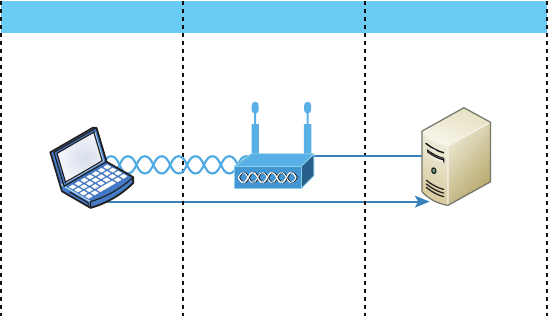
418
Chapter 12 ■ Wireless Networking
c12.indd 04/0½ 015 Page 418
critically important in large corporate environments, and that’s because they offer security
for wireless networks. From the Linksys security screen shown earlier, you can see that
RADIUS is an available option. If you choose it, you’ll be asked for the IP address of the
RADIUS server so the AP can send authentication packets.
Figure 12.21 shows how the AP becomes an authenticator when you choose the
RADIUS authentication method.
FIGURE 12.21 RADIUS authentication server
Operates on a client
Supplicant
802.11 Network Enterprise Edge Enterprise Network
Authenticator Authentication Server
802.1x Traffic Only
Access point
acts as authenticator
EAP plug-in goes
In RADIUS server
Now, packets must pass through the AP until the user and/or host gets authenticated by
the RADIUS server.
Temporal Key Integrity Protocol
Put up a fence, and it’s only a matter of time until bad guys nd a way over, around,
and through it. And true to form, they indeed found ways to get through WEP’s
defenses, leaving our Wi-Fi networks vulnerable—stripped of their Data Link layer
security! So someone had to come to the rescue. In this case, it happened to be the IEEE
802.11i task group and the Wi-Fi Alliance, joining forces for the cause. They came
up with a solution called Temporal Key Integrity Protocol (TKIP). The Wi-Fi Alliance
unveiled it back in late 2002 and introduced it as Wi-Fi Protected Access (WPA). This
little beauty even saved us lots of money because TKIP—say this like “tee kip”—didn’t
make us upgrade all our legacy hardware equipment in order to use it. Then, in the
summer of 2004, the IEEE put its seal of approval on the nal version and added
even more defensive muscle with goodies like 802.1x and AES-CCMP (AES-Counter
Mode CBC-MAC Protocol) upon publishing IEEE 802.11i-2004. The Wi-Fi Alliance
responded positively by embracing the now-complete speci cation and dubbing it
WPA2 for marketing purposes.
Wireless Security
419
c12.indd 04/0½ 015 Page 419
A big reason that TKIP doesn’t require buying new hardware to run is because it really
just kind of wraps around the preexisting WEP encryption key (which was way too short),
and upgrades it a whole lot to much more impenetrable 128-bit encryption. Another reason
for TKIP’s innate compatibility is that both its encryption mechanism and the RC4 algo-
rithm used to power and de ne WEP, respectively, remained the same.
But there are still signi cant differences that help make it the seriously tough shield it
is, one of them being that it actually changes each packet’s key. Let me explain: Packet
keys are made up of three things: a base key, the transmitting device’s MAC address, and
the packet’s serial number. It’s an elegant design because, although it doesn’t place a ton
of stress on workstations and APs, it serves up some truly formidable cryptographic force.
Here’s how it works: Remember the packet serial number part of the transmission key?
Well, it’s not just your average serial number; it’s special—very special.
TKIP-governed transmission ensures that each packet gets its very own 48-bit serial
number, which is augmented with a sequence number whenever a new packet gets sent
out, and not only serves as part of the key but also acts as the initialization vector. And the
good news doesn’t end there—because each packet is now uniquely identi ed, the collision
attacks that used to happen using WEP are also history. Plus, the fact that part of the pack-
et’s serial number is also the initialization vector prevents something called replay attacks.
It takes an ice age for a 48-bit value to repeat, so replaying packets from some past wireless
connection is just not going to happen; those “recycled” packets won’t be in sequence, but
they will be identi ed, thus preventing the attack.
Now for what may be the truly coolest thing about TKIP keys: the base key. Because
each base key that TKIP creates is unique, no one can recycle a commonly known key over
and over again to gain access to a formerly vulnerable WEP wireless LAN. This is because
TKIP throws the base key into the mix when it assembles each packet’s unique key, mean-
ing that even if a device has connected to a particular access point a bunch of times, it
won’t be permitted access again unless it has a completely new key granting it permission.
Even the base key itself is a fusion of something called nonces—an assortment of ran-
dom numbers gleaned from the workstation, the access point, and each of these devices’
MAC addresses, so this should also be referred to as a session secret. So basically, if you’ve
got IEEE 802.1x authentication working for you, rest assured that a session secret abso-
lutely will be transmitted securely to each machine every time it initiates a connection to
the wireless LAN by the authentication server—unless you’re using pre-shared keys, that
is, because if you happen to be using them, that important session secret always remains
the same. Using TKIP with pre-shared keys is kind of like closing an automatically locking
security door but not enabling its security settings and alarm—anyone who knows where
the secret latch is can get right in!
Wi-Fi Protected Access or WPA2 Pre-Shared Key
These are both essentially another form of basic security that’s really just an add-on to the
speci cations. Even though you can totally lock the vault, as I mentioned in the previous

420
Chapter 12 ■ Wireless Networking
c12.indd 04/0½ 015 Page 420
section, WPA/WPA2 Pre-Shared Key (PSK) is a better form of wireless security than any
other basic wireless security method I’ve talked about so far. And note that I did say basic!
But if you are using only MAC address lters and/or WEP, and you nd that interlopers
are still using your network and dragging down the performance, adding this layer of
security should help tremendously since it’s a better form of access control than either of
those measures.
Wi-Fi Protected Access (WPA) is a standard developed by the Wi-Fi Alliance, for-
merly known as the Wireless Ethernet Compatibility Alliance (WECA). WPA provides
a standard for authentication and encryption of WLANs that’s intended to solve known
security problems. The standard takes into account the well-publicized AirSnort and
man-in-the-middle WLAN attacks. So of course we use WPA2 to help us with today’s
security issues.
The PSK veri es users via a password or identifying code (also called a passphrase) on
both the client machine and the access point. A client gains access to the network only if its
password matches the access point’s password. The PSK also provides keying material that
TKIP or Advanced Encryption Standard (AES) uses to generate an encryption key for each
packet of transmitted data.
Although more secure than static WEP, PSK still has a lot in common with static
WEP in that the PSK is stored on the client station and can be compromised if the client
station is lost or stolen (even though nding this key isn’t all that easy to do). It’s a de -
nite recommendation to use a strong PSK passphrase that includes a mixture of letters,
numbers, and nonalphanumeric characters. With WPA, it’s still actually possible
to specify the use of dynamic encryption keys that change each time a client establishes
a connection.
The benefit of WPA over a static WEP key is that WPA can change dynami-
cally while the system is used.
WPA is a step toward the IEEE 802.11i standard and uses many of the same compo-
nents, with the exception of encryption—802.11i (WPA2) uses AES-CCMP encryption.
The IEEE 802.11i standard replaced WEP with a speci c mode of AES known as the
CCMP, as mentioned earlier. This allows AES-CCMP to provide both data con dentiality
(encryption) and data integrity.
The highest level of wireless encryption you can run is WPA2-AES.
The following screen shows that if you choose WPA2 Personal on the Linksys AP, you
can then enter your passphrase—it’s really called WPA2 Pre-Shared Key, but whatever.
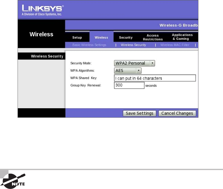
Wireless Security
421
c12.indd 04/0½ 015 Page 421
You have a choice of TKIP or AES as the encryption, and by the way, you can choose up
to a 64-character key—pretty tight!
WPA’s mechanisms are designed to be implementable by current hardware vendors,
meaning that users should be able to implement WPA on their systems with only a rm-
ware/software modi cation.
The IEEE 802.11i standard has been sanctioned by WPA and is called WPA
version 2.
Certificates and PKI
WPA2 can use the Extensible Authentication Protocol (EAP) method for authentication.
EAP isn’t a single method but a framework that enhances the existing 802.1x framework.
The EAP framework describes a basic set of actions that will take place, and each EAP
type differs in the speci cs of how it operates within the framework. These variables
include things like whether they use passwords or certi cates as well as the ultimate
level of security provided. Some of the EAP methods require that certi cates be used as
the credential during authentication. This means that to implement those methods, you
must have a Public Key Infrastructure (PKI) in your network. A PKI requires a certi cate
server that issues certi cates to your users and/or devices. These certi cates, which con-
sist of a public/private key pair, must be securely installed on the devices and renewed at
regular intervals.

422
Chapter 12 ■ Wireless Networking
c12.indd 04/0½ 015 Page 422
In symmetric encryption, the two encryption keys are the same, just as they are with
WEP keys, but in asymmetric encryption, the key used to encrypt is different from the key
used to decrypt. In PKI, asymmetric keys are used, and the keys are called a public/private
key pair. Certi cates are binding regulations of a public/private key pair generated by a
certi cate server to a user or computer. As long as two parties trust the same certi cate
source, called the trusted certi cate authority (CA), they can trust the certi cate they’re
presented with for authentication. These keys can also be used for encryption and as
digital signatures.
Despite the other uses of public/private keys, our focus here is the use of the certi cates
as a form of authentication. And as a means of identifying the device or the user, this
is considered the highest form of authentication when compared to names and passwords.
What all this means is that as long as the AP or controller and the station or user trust
the CA that issued the certi cates, the certi cate is trusted as a means of identi cation
as well.
EAP-TLS
EAP Transport Layer Security (EAP-TLS) is the most secure method, but it’s also the most
dif cult to con gure and maintain. To use EAP-TLS, you must install a certi cate on both
the authentication server and the client. An authentication server pair of keys and a client
pair of keys need to be generated rst, signed using a PKI, and installed on the devices. On
the station side, the keys can be issued for the machine itself and/or for the user.
In the authentication stage, the station, along with the authentication server (RADIUS,
etc.), exchange certi cates and identify each other. Mutual authentication is a solid
bene cial feature, which ensures that the station it’s communicating with is the proper
authentication server. After this process is completed, random session keys are created for
encryption.
Tunneled Transport Layer Security (TTLS) provides authentication as
strong as EAP-TLS, but it doesn’t require each user to be issued a certifi-
cate. Instead, only the servers are issued certificates.
Summary
Like rock ’n’ roll, wireless technologies are here to stay. And for those of us who have come
to depend on wireless technologies, it’s actually pretty hard to imagine a world without
wireless networks—what did we do before cell phones?
So we began this chapter by exploring the essentials and fundamentals of how wire-
less networks function. Springing off that foundation, I then introduced you to the basics
of wireless radio frequencies (RFs) and the IEEE standards. We discussed 802.11 from its
inception through its evolution to current and near-future standards, and talked about the
subcommittees who create these standards.
Written Lab
423
c12.indd 04/0½ 015 Page 423
All of this led into a discussion of wireless security—or rather, nonsecurity for the most
part—which we went over in detail.
We nished the chapter by bringing you up to speed on TKIP and WPA/WPA2 security
solutions—important tools used to protect the wireless LANs of today.
Exam Essentials
Understand the IEEE 802.11a specification. 802.11a runs in the 5GHz spectrum, and if
you use the 802.11h extensions, you have 23 non-overlapping channels. 802.11a can run up
to 54Mbps, but only if you are less than 50 feet from an access point.
Understand the IEEE 802.11b specification. IEEE 802.11b runs in the 2.4GHz range and
has three non-overlapping channels. It can handle long distances but with a maximum data
rate of up to 11Mpbs.
Understand the IEEE 802.11g specification. IEEE 802.11g is 802.11b’s big brother and
runs in the same 2.4GHz range, but it has a higher data rate of 54Mbps if you are less than
100 feet from an access point.
Remember the wireless LAN modulation techniques. Direct Sequence Spread Spectrum
(DSSS) is the most widely used modulation technique, but it has speeds only to 11Mbps.
Frequency Hopping Spread Spectrum (FHSS), although it is used in wireless devices like
Bluetooth, isn’t the technique of choice for either vendors or the 802.11 working group. To
get the higher speeds needed in today’s WLANs, we use Orthogonal Frequency Division
Multiplexing (OFDM) in 802.11g/a/n and ac networks.
Understand how WPA works in a WLAN. Wi-Fi Protected Access (WPA) is the security
of choice in today’s home and corporate networks. It provides both authentication and
encryption (either TKIP or AES); the latest version is WPA2.
Written Lab
You can nd the answers in Appendix A. Write the answers to the following questions
about wireless networking:
1. What is the maximum data rate of IEEE 802.11b?
2. What is the maximum data rate of IEEE 802.11g?
3. What is the maximum data rate of IEEE 802.11a?
4. What is the frequency range of IEEE 802.11b?
5. What is the frequency range of IEEE 802.11g?
424
Chapter 12 ■ Wireless Networking
c12.indd 04/0½ 015 Page 424
6. What is the frequency range of IEEE 802.11a?
7. What is the possible bandwidth of 802.11ac?
8. Why would we use WPA instead of basic WEP?
9. Which IEEE committee has been sanctioned by WPA and is called WPA2?
10. The IEEE 802.11b/g basic standard has how many non-overlapping channels?
Review Questions
425
c12.indd 04/0½ 015 Page 425
Review Questions
You can nd the answers to the review questions in Appendix B.
1. You need to install wireless Internet access in an open warehouse environment. After
installing the equipment, the technician notices varying signal strengths throughout the
warehouse. How do you make sure there is full coverage?
A. Turn on broadcast key rotation.
B. Change the encryption method used on all the APs.
C. Change the antenna placement.
D. Use channel bonding.
E. Use channel shaping.
2. Which of the following uses a certificate on both the server and client to provide the best
wireless security with 802.1x (but is hardest to implement)?
A. AES
B. TTLS
C. TLS
D. TKIP
3. What is the frequency range of the IEEE 802.11g standard?
A. 2.4Gbps
B. 5Gbps
C. 2.4GHz
D. 5GHz
4. Which devices can interfere with the operation of a wireless network because they operate
on similar frequencies? (Choose two.)
A. Copier
B. Microwave oven
C. Toaster
D. Cordless phone
E. IP phone
F. AM radio
5. Which wireless standard allows you to channel-bond to increase bandwidth and uses both
the 2.4GHz and 5GHz frequencies?
A. 802.11b
B. 802.11g
C. 802.11a
426
Chapter 12 ■ Wireless Networking
c12.indd 04/0½ 015 Page 426
D. 802.11n
E. 802.11ac
6. Which of the following is considered a PAN?
A. AES
B. BSS
C. SSID
D. Bluetooth
7. How many non-overlapping channels are available with 802.11a?
A. 3
B. 12
C. 23
D. 40
8. What is the maximum data rate for the 802.11a standard?
A. 6Mbps
B. 11Mbps
C. 22Mbps
D. 54Mbps
9. You need to install wireless on multiple floors of a large building and maintenance area.
What is your first concern before installing the APs?
A. Authentication
B. Encryption
C. Channel overlap
D. AP configuration
10. What is the maximum data rate for the 802.11b standard?
A. 6Mbps
B. 11Mbps
C. 22Mbps
D. 54Mbps
11. You connect a new host to your company’s wireless network. The host is set to receive a
DHCP address and the WPA2 key is entered correctly. However, the host cannot connect to
the network. What can the problem be?
A. DNS is not configured on the host.
B. MAC filtering is enabled on the AP.
Review Questions
427
c12.indd 04/0½ 015 Page 427
C. The network has run out of wireless connections.
D. The host is enabled to run 802.11b and 802.11g.
12. Which is the highest encryption that WPA2 can use?
A. AES-CCMP
B. PPK via IV
C. PSK
D. TKIP/MIC
13. Which additional configuration step is necessary in order to connect to an access point that
has SSID broadcasting disabled?
A. Set the SSID value in the client software to public.
B. Configure open authentication on the AP and the client.
C. Set the SSID value on the client to the SSID configured on the AP.
D. Configure MAC address filtering to permit the client to connect to the AP.
14. Which spread-spectrum technology does the 802.11b standard define for operation?
A. IR
B. DSSS
C. FHSS
D. DSSS and FHSS
E. IR, FHSS, and DSSS
15. Which wireless LAN design ensures that a mobile wireless client will not lose connectivity
when moving from one access point to another?
A. Using adapters and access points manufactured by the same company
B. Overlapping the wireless cell coverage by at least 10 percent
C. Configuring all access points to use the same channel
D. Utilizing MAC address filtering to allow the client MAC address to authenticate with
the surrounding APs
16. You have installed a point-to-point connection using wireless bridges and Omni directional
antennas between two buildings. The throughput is low. What can you do to improve
the link?
A. Replace the bridges with APs.
B. Replace the Omni directional antennas with Yagis.
C. Configure 802.11a on the links.
D. Install amps to boost the signal.
428
Chapter 12 ■ Wireless Networking
c12.indd 04/0½ 015 Page 428
17. What does extended service set (ESS) ID mean?
A. That you have more than one access point, and they are in the same SSID connected by
a distribution system
B. That you have more than one access point, and they are in separate SSIDs connected
by a distribution system
C. That you have multiple access points, but they are placed physically in different
buildings
D. That you have multiple access points, but one is a repeater access point
18. What is one reason that WPA encryption is preferred over WEP?
A. A WPA key is longer and requires more special characters than the WEP key.
B. The access point and the client are manually configured with different WPA key
values.
C. WPA key values remain the same until the client configuration is changed.
D. The values of WPA keys can change dynamically while the system is used.
19. How wide are the channels used in 802.11n in order to gain the large bandwidth that the
specification provides?
A. 22MHz
B. 20MHz
C. 40MHz
D. 100MHz
20. 802.11n uses MIMO. How does this optimize throughput to gain the high-speed advantage
that 802.11n provides?
A. By specifying an acknowledgment of each and every frame, 802.11n provides better
overhead.
B. Several frames are sent by several antennae over several paths and are then recombined
by another set of antennae.
C. One frame at a time is sent, but faster than in 802.11g because multiple antennas are
used (multiple-in, multiple-out).
D. MIMO packs smaller packets into a single unit, which improves throughput.

c13.indd 04/02/2015 Page 429
Chapter
13
Authentication and
Access Control
THE FOLLOWING COMPTIA NETWORK+
EXAM OBJECTIVES ARE COVERED IN THIS
CHAPTER:
✓ 3.3 Given a scenario, implement network hardening
techniques
■ Switch port security
■ MAC address filtering
■ Use secure protocols
■ TLS/SSL
■ Access lists
■ IP filtering
■ Port filtering
■ User authentication
■ CHAP/MSCHAP
■ EAP
■ Kerberos
■ Multifactor authentication
■ Two-factor authentication
■ Single sign-on
✓ 5.10 Given a scenario, configure and apply the appropriate
ports and protocols
■ 3389 RDP
■ 22 SSH

c13.indd 04/02/2015 Page 430
✓ 1.2 Compare and contrast the use of networking services
and applications
■ VPN
■ Site to site/host to site/host to host
■ Protocols
■ IPsec
■ GRE
■ SSL VPN
■ PTP/PPTP
■ TACACS/RADIUS
■ RAS
■ Web services
■ Unified voice services
■ Network controllers
✓ 3.6 Explain the purpose of various network access control
models
■ 802.1x
■ Posture assessment
■ Guest network
■ Persistent vs non-persistent agents
■ Quarantine network
■ Edge vs access control

c13.indd 04/02/2015 Page 431
So far, you’ve learned a lot about networking standards and
related technologies and even how to make computers and
devices communicate so you can get a network up and
running. But there’s more—because network security is absolutely critical, I’m going to
equip you with the knowledge you need to keep your network safe from intruders.
Yes, communication and accessing the information you need is all good, but knowing
exactly who it is at the other end of the connection is vital. This means you need ways to
con rm that the person or computer at the other end of the connection is really supposed
to be accessing the resource it’s trying to, and even whether the resources or entities that
you’re contacting are really who and what they appear to be. Seriously, if you don’t have
network security rmly in place, you’re ying dangerously blind—you could be inadver-
tently exposing critical data to people who have no right to see that information and may
even intend to exploit it in a big way! So, in this chapter, we’ll focus on some very impor-
tant pieces of the security puzzle; two of the rst things on our list are security ltering and
user authentication.
To find up-to-the-minute updates for this chapter, please see
www.lammle
.com/networkplus
or the book’s website at
www.sybextestbanks.wiley.com
.
Security Filtering
How do we know who’s really at the other end of our connections? The answer to that may
seem simple enough because the computer or person on the other end has to identify him/
her/itself, right? Wrong! That’s just not good enough because people—especially hackers—
lie, so it’s totally naïve to assume that the person or computer on the other end of the line is
who they’re claiming to be. Sad but true: Hackers use the many tools out there today with
the precise goal of convincing us they’re someone else, and way too many of us have been,
or know of someone who has been, a victim of identity theft thanks to bad guys with the
right spoo ng software in hand.
This means it’s imperative to control who or what can get into our network by identify-
ing the speci c computers and individuals who have the right to gain access to it and its
resources. But how do we do this? Well, for starters, I’m going to cover some basic ways to
safely allow the computers you want to have access into your network plus ways to keep
out the ones you don’t.
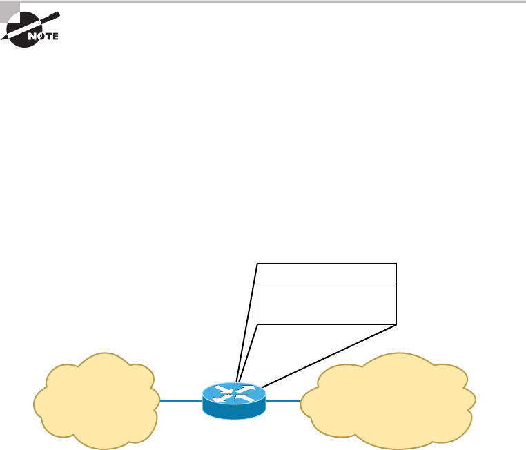
432
Chapter 13 ■ Authentication and Access Control
c13.indd 04/02/2015 Page 432
The rst line of defense is something called security ltering, which broadly refers to
ways to let people securely access your resources. This process is twofold and includes
ensuring that only authorized computers get to enter your network and making sure data
you’re sending back and forth between networks is secured so it can’t be intercepted and
translated by bad guys.
Access Control Lists
It’s rare to nd a network around these days that isn’t connected to the Internet. The
Internet is clearly a public internetwork that anyone can connect to, but your company’s
or personal network is, and should de nitely be, a private one. The catch here is that every
time you connect to the Internet (where everyone is welcome) from a private network,
you’re instantly vulnerable to security break-ins. This is where something we call a rewall
comes into play. Firewalls are basically tools that you can implement to prevent any
unauthorized users roaming around on public networks from gaining access to your
private network.
I’ll be covering the different types of firewalls, plus give you the skinny on
exactly how they work, in Chapter 15, “Physical Security and Risk.” For
now, understand that firewalls can be either stand-alone devices or com-
bined with another hardware device like a server or a router. And although
firewalls can use a lot of various technologies to restrict information flow,
their primary weapon is known as an access control list (ACL).
Access control lists (ACLs) typically reside on routers to determine which packets are
allowed to route through them based on the requesting device’s source or destination
Internet Protocol (IP) address. Oh, and just so you know, ACLs have been around for
decades and have other uses apart from rewalls.
Figure 13.1 demonstrates how ACLs prevent users on Network B from accessing
Network A.
FIGURE 13.1 Two networks with an ACL-enabled router
Network A
“Private” Network
Network B
“Public” Network
Router
A can access B.
B can access if a secure
authenticated
connection is detected.
Security Filtering
433
c13.indd 04/02/2015 Page 433
Okay, what we see here is that users in Network A can pass through the router into
Network B. This means that an IP spoo ng attack, when someone pretends to have a
network address on the inside of a rewall to gain network access, can still happen if a user
in Network B pretends to be located in Network A. We’ll go over things like IP spoo ng
more thoroughly in Chapter 14, “Network Threats and Mitigation,” but for now, let’s get
back to ACLs.
You can create a wide array of ACLs, from the very simple to the highly complex,
depending on exactly what you want to have them do for you. One example is
placing separate inbound and outbound ACLs on a router to ensure that the data
that’s leaving your network comes from a different source than the data that’s coming
into it.
When con guring ACLs between the Internet and your private network to mitigate
security problems, it’s a good idea to include these four conditions:
■ Deny any addresses from your internal networks.
■ Deny any local host addresses (127.0.0.0/8).
■ Deny any reserved private addresses.
■ Deny any addresses in the IP multicast address range (224.0.0.0/4).
None of these addresses should ever be allowed to enter your internetwork.
Interestingly enough, because of the way in which in-public IP addresses are issued, with
some research you can create a lter that blocks a country, state, or even locale based on
IP addresses!
Most of the time, it’s wise to con gure ACLs so that they’ll allow or deny access based
on the IP address of the source or destination device. If your network is running a proto-
col other than Transmission Control Protocol/Internet Protocol (TCP/IP), you can lter
traf c based on a Media Access Control (MAC), or hardware, address instead of an IP
address. You can still use a MAC address–based ACL if you’re running TCP/IP, but keep
in mind that it’s a lot easier to deal with IP addresses than MAC addresses. Another point
to remember is that even though most rewalls and routers will allow you to create both
IP-based and MAC-based ACLs, doing so can create an exceptionally ugly situation where
access is denied when it really shouldn’t be.
Port Filtering
ACLs can also be used to lter based on port numbers as well as IP addresses. In fact, most
rewalls default to allowing only the open ports that you specify. This is another
version of the implicit deny (anything not allowed speci cally is denied).
When managing a rewall, it’s important to know the port numbers of all traf c that
needs to be allowed through it. This means that for some of your applications, you will
need to read and learn the port numbers being used.
This also explains why it’s a big deal to know the port numbers of security protocols like
SSL and IPSec. Successful rewall management involves being aware of and allowing only
the ports to keep things running.
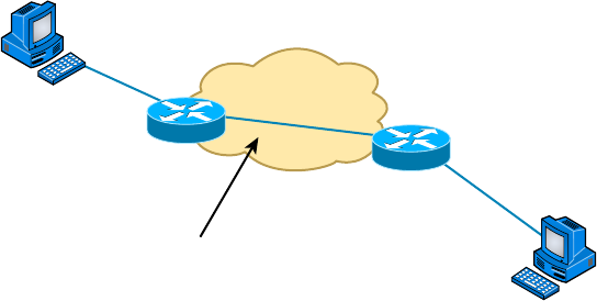
434
Chapter 13 ■ Authentication and Access Control
c13.indd 04/02/2015 Page 434
Tunneling
Just thinking about the huge amount of sensitive data bouncing all over the Internet 24/7
makes me want to scream the word security! It’s seriously clear that we need it almost as much
as air. Worse, most of that data is sent out over the Internet without any encryption or secu-
rity, but at least not the really sensitive stuff, which should be sent via one of several different
security protocols available today—phew. These vital protocols are really sets of conditions or
rules that de ne how a secure connection is maintained when we send sensitive data through
an unsecure medium like the Internet or a wireless connection. Before talking about the secu-
rity protocols that the Network+ exam is likely to quiz you on, I’d like to de ne a few terms.
The rst is a concept called tunneling, which basically means encapsulating one protocol
within another to ensure that a transmission is secure. Here’s an example: The lion’s share
of us use IP, known as a payload protocol, which can be encapsulated within a delivery
protocol like Internet Protocol Security (IPSec). If you took a look at these packets individ-
ually, you would see that they’re encrypted. If you look at the process as a whole, it appears
that a point-to-point tunnel is created on the Internet, as Figure 13.2 illustrates. (Make a
note to yourself that usually the tunneled protocol is running at a higher layer in the OSI
model than the payload protocol, but not always.)
FIGURE 13.2 A tunnel through the Internet
Internet
Single Private Path or Tunnel
through the Internet
The Network+ exam will test your understanding of the following tunneling protocols:
■ Virtual Private Network (VPN)
■ Secure Sockets Layer (SSL)
■ Secure Sockets Layer Virtual Private Network (SSL VPN)
■ Layer 2 Tunneling Protocol (L2TP)
■ Point-to-Point Tunneling Protocol (PPTP)
■ Generic Routing Encapsulation (GRE)
■ Internet Protocol Security (IPSec)
■ ISAKMP
Let’s dig in and take a detailed look at each one now.
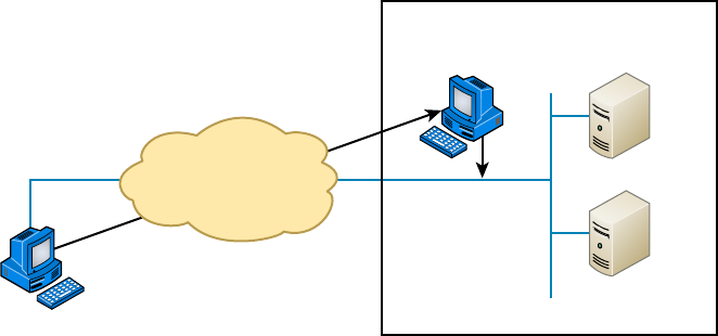
Security Filtering
435
c13.indd 04/02/2015 Page 435
Virtual Private Network
No worries—VPNs aren’t really that hard to understand. A VPN ts somewhere
between a LAN and WAN, and many times may seem just like a WAN link because
your computer, on one LAN, connects to a different, remote LAN and uses its resources
remotely. The key difference with VPNs is a big one—security! So the de nition of con-
necting a LAN (or VLAN) to a WAN may sound the same, but a VPN is much more.
Here’s the difference: A typical WAN connects two or more remote LANs together using
someone else’s network—like, say, your Internet service provider’s (ISP’s)—and a router.
Your local host and router see these networks as remote networks and not as local net-
works or local resources. This would be a WAN in its most general de nition. A VPN actu-
ally makes your local host part of the remote network by using the WAN link that connects
you to the remote LAN. The VPN will make your host appear as though it’s actually local
on the remote network! This means that we now have access to the remote LAN’s resources
and that access is very secure.
This may sound a lot like the VLAN de nition I just used in Chapter 11, “Switching
and Virtual LANs,” and really, the concept is the same: “Take my host and make it appear
local to the remote resources.” Just remember that for networks that are physically local,
using VLANs is a good solution, but for networks that are physically remote—those that
span a WAN—we’d opt for using VPNs instead.
For a simple VPN example, let’s use my home of ce in Boulder, Colorado. Here, I have
my personal host, but I want it to appear as if it’s on a LAN in my corporate of ce in
Dallas, Texas, so I can get to my remote servers. VPN is the solution I use for this because I
need the security it provides.
Figure 13.3 shows this example of my host using a VPN connection from Boulder to
Dallas, which allows me to access the remote network services and servers as if my host is
right there on the same VLAN as my servers.
FIGURE 13.3 Example of using a VPN network
Internet
VPN
My Host in
Colorado
Secure Server Room
Now my host appears
local to the servers.
Secure VLAN at
Dallas Corporate Office
Servers
Why is this so important? If you answered, “Because my servers in Dallas are secure,
and only the hosts on the same VLAN are allowed to connect to them and use their
436
Chapter 13 ■ Authentication and Access Control
c13.indd 04/02/2015 Page 436
resources,” you nailed it! A VPN allows me to connect to these resources by locally attach-
ing to the VLAN through a VPN across the WAN. The other option is to open up my
network and servers to everyone on the Internet or another WAN service, in which case my
security goes poof! So you can see that it’s a very good thing I have a VPN.
Types of VPNs are named based on the kind of role they play in a real-world business
situation. There are three different categories of VPNs:
Host-to-Site (Remote-Access) VPNs Remote-access VPNs allow remote users like tele-
commuters to securely access the corporate network wherever and whenever they need to.
It is typical that users can connect to the Internet but not to the of ce via their VPN client
because they don’t have the correct VPN address and password. This is the most common
problem and one you should always check rst.
Host-to-Host VPN A host-to-host VPN is somewhat like a site-to-site in concept except
that the endpoints of the tunnel are two individual hosts. In this case all traf c is protected
from the time it leaves the NIC on one host until it reaches the NIC of the other host.
Site-to-Site VPNs Site-to-site VPNs, or intranet VPNs, allow a company to con-
nect its remote sites to the corporate backbone securely over a public medium like the
Internet instead of requiring more expensive wide area network (WAN) connections like
Frame Relay. This is probably the best solution for connecting a remote of ce to a main
company of ce.
Extranet VPNs Extranet VPNs allow an organization’s suppliers, partners, and custom-
ers to be connected to the corporate network in a limited way for business-to-business
(B2B) communications.
SSL and SSL VPN
Next on the list is Secure Sockets Layer (SSL). This security protocol was developed
by Netscape to work with its browser. It’s based on Rivest, Shamir, and Adleman
(RSA) public-key encryption and used to enable secure Session layer connections over
the Internet between a web browser and a web server. SSL is service independent,
meaning a lot of different network applications can be secured with it—a famous one
being the ubiquitous HTTP Secure (HTTPS) protocol. As time marched on, SSL was
merged with other Transport layer security protocols to form a new protocol called
Transport Layer Security (TLS). The latest version of Transport Layer Security (TLS
2.0) provides a number of enhancements over earlier versions. The following are the
most noteworthy:
■ Several improvements in the operation of a central component, the MD5-SHA-1 hash-
ing function. Hashing functions are used to ensure that the data is not changed or
altered (also known as maintaining data integrity).
■ More flexibility in the choice of hashing and encryption algorithms on the part of the
client and the server.
■ Enhanced support for the Advanced Encryption Standard (AES).
Figure 13.4 shows the SSL connection process.
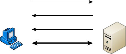
Security Filtering
437
c13.indd 04/02/2015 Page 437
FIGURE 13.4 The SSL connection process
Connection Request
Secure Connection Needed
Security Capabilities
SSL Session Established
ServerPC
SSL VPN is really the process of using SSL to create a virtual private network (VPN). A
VPN is a secured connection between two systems that would otherwise have to connect
to each other through a non-secured network. Here’s what I mean: Even though I’d never
really let this happen, let’s just say I could connect to the servers in my corporate of ce
through the Internet like, snap! You know by now that this would be a very bad thing
because the Internet is far from secure, right? But if I connected to those servers using a
VPN with a tunneling protocol instead, anything I send from my PC to my corporate of ce
would be locked up nice and securely.
Plus, VPNs also come in handy for data that’s being sent within a private network
that you probably wouldn’t want everyone on that network to be able to see. Maybe you
want a few speci c computers on the intranet to be able to communicate with each other
securely—like, say, the computers used by your top nance people. You wouldn’t neces-
sarily want that data just sent off in the clear to be viewed by the of ce gossip, now would
you? No way. So, you can put those nance folks on a VPN that’s just like having them on
their own little private, secure subnetwork. Plus, what’s even cooler about this setup is that
the members of your intranet’s VPN can still communicate with everyone else whenever
they want; they just won’t be doing that securely—nice solution!
L2TP
Next, we have the Layer 2 Tunneling Protocol (L2TP), which was created by the Internet
Engineering Task Force (IETF). It comes in handy for supporting non-TCP/IP protocols
in VPNs over the Internet. L2TP is actually a combination of Microsoft’s Point-to-Point
Tunneling Protocol (PPTP) and Cisco’s Layer 2 Forwarding (L2F) technologies. A nice L2TP
feature is that, because it works way down there at the Data Link layer (Layer 2) of the
OSI model, it can support tons of protocols beyond just TCP/IP—a couple of biggies being
Internetwork Packet Exchange (IPX) and AppleTalk. It’s a really great tool to implement if
you happen to have two non-TCP/IP networks that need to be connected via the Internet.
PPTP
I just mentioned Point-to-Point Tunneling Protocol (PPTP), and even though I said it was
Microsoft’s PPTP, this security protocol was really developed jointly by Microsoft, Lucent
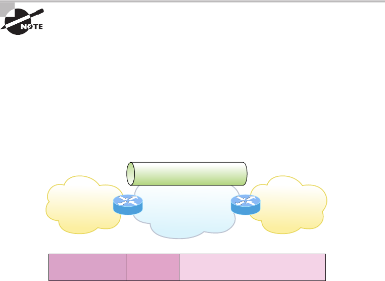
438
Chapter 13 ■ Authentication and Access Control
c13.indd 04/02/2015 Page 438
Technologies, 3COM, and a few other companies. Oh, and it’s not actually sanctioned by
the IETF, but that doesn’t mean it doesn’t work. PPTP acts by combining an unsecured
Point-to-Point Protocol (PPP) session with a secured session using the Generic Routing
Encapsulation (GRE) protocol.
Because PPTP uses two different protocols, it actually opens up two different network
sessions: so be warned, PPTP can give you some grief when passing through a router. This
is a big reason you won’t nd it around much nowadays. Another reason it’s going the way
of the dinosaurs is that it originally gained popularity because it was the rst VPN protocol
to be supported by Microsoft’s dial-up networking services, and not too many of us depend
on dial-up to get to the Internet anymore. As if these aren’t reasons enough for PPTP’s
impending extinction, it’s also not that secure. In fact, as you’d probably expect from a
rst-generation security protocol, it’s now really vulnerable to spoo ng attacks, which is
why it’s pretty much been replaced by L2TP and IPSec.
PPTP is a VPN protocol that runs over port 1723 and allows encryption to
be done at the Application (data) level. It is important to remember for the
CompTIA Network+ objectives that PPTP is a protocol that allows secure
access to a VPN.
GRE
Generic Routing Encapsulation (GRE) is a tunneling protocol that can encapsulate many
protocols inside IP tunnels. Some examples would be routing protocols such as EIGRP and
OSFP and the routed protocol IPv6. Figure 13.5 shows GRE.
FIGURE 13.5 GRE encapsulation
IP VPN
Site
IP VPN
Site
GRE Tunnel
(Carrier Protocol)
IP Network
(Transportation Protocol)
(Passenger Protocol) (Passenger Protocol)
Passenger (IP) Packet
Transport
IP Header
GRE
Header
A GRE tunnel interface supports a header for each of the following:
■ A passenger protocol or encapsulated protocols like IP or IPv6, which is the protocol
being encapsulated by GRE
■ GRE protocol
■ A Transport delivery protocol, typically IP
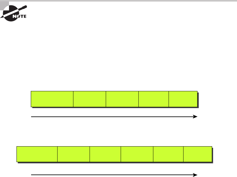
Security Filtering
439
c13.indd 04/02/2015 Page 439
GRE tunnels have the following characteristics:
■ GRE uses a protocol-type field in the GRE header so any Layer 3 protocol can be used
through the tunnel.
■ GRE is stateless and has no flow control.
■ GRE offers no security.
■ GRE creates additional overhead for tunneled packets—at least 24 bytes.
IPSec
On the other hand, IP Security (IPSec) was designed by the IETF for providing authenti-
cation and encryption over the Internet. It works at the Network layer of the OSI model
(Layer 3) and secures all applications that operate in the layers above it. Because it’s sanc-
tioned by the IETF and designed to work with IPv4 and IPv6, it’s got a huge amount of
industry support, so it’s the standard for VPNs on the Internet today.
The two major protocols you’ll nd working in IPSec are Authentication Header (AH)
and Encapsulating Security Payload (ESP). AH serves up authentication services only—no
encryption—but ESP provides both authentication and encryption abilities. Both of these
protocols can be used with either mode discussed in the following paragraphs.
The AH protocol within IPSec isn’t compatible with networks running Net-
work Address Translation (NAT).
IPSec works in two modes: transport mode and tunneling mode. Transport mode creates
a secure tunnel between two devices end to end. This means that regardless of how many
foreign networks (including the Internet) the packet traverses, it is protected. The data is
protected by authentication and/or encryption. Figure 13.6 illustrates a TCP/IP packet and
a TCP/IP packet in transport mode using AH. ESP can also be used with transport mode.
FIGURE 13.6 TCP/IP packet in IPSec transport mode with AH
Standard TCP/IP Packet
Data Flow
Authenticated by AH
Data Flow
TCP/IP Packet with AH in Transport Mode
TCP/IP Payload TCP Header Destination
IP Address
Source
IP Address IP Header
TCP/IP Payload TCP Header Destination
IP Address
AH Header Source
IP Address IP Header
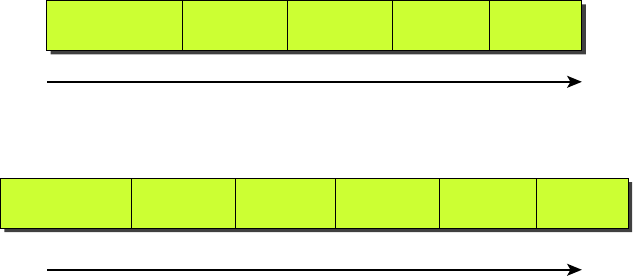
440
Chapter 13 ■ Authentication and Access Control
c13.indd 04/02/2015 Page 440
On the other hand, in tunnel mode, the tunnel is created between two endpoints, such as
two routers or two gateway servers, protecting all traf c that goes through the tunnel. It is
commonly used between two of ces to protect all traf c going between the of ces regard-
less of the source and destination. Figure 13.7 rst shows a TCP/IP packet and then depicts
one using ESP in tunnel mode. AH can also be used with tunnel mode.
FIGURE 13.7 TCP/IP packet in IPSec tunnel mode with ESP
Standard TCP/IP Packet
Data Flow
Authenticated by AH
Data Flow
TCP/IP Packet with ESP in Tunneling Mode
TCP/IP Payload TCP Header Destination
IP Address
Source
IP Address IP Header
TCP/IP Payload
(Encrypted)
TCP Header
(Encrypted)
Destination
IP Address
ESP Header Source
IP Address IP Header
You can see here that when data is tunneled in this way, hackers can’t even see what
transport protocol you’re using, let alone decipher the data you’re transmitting.
ISAKMP
Internet Security Association and Key Management Protocol (ISAKMP) de nes proce-
dures and packet formats to establish, negotiate, modify, and delete security associations
(SAs). SAs contain information required to execute security services, such as header authen-
tication and payload encapsulation. ISAKMP’s real value is its ability to provide a frame-
work for safely transferring key and authentication data independent of the key generation
technique, encryption algorithm, and authentication mechanism. ISAKMP is integrated
into another security mechanism we have already discussed, IPSec.
Encryption
Sometimes, like it or not, sending out corporate nancial and other types of sensitive data
over the Internet just can’t be avoided. This is why being able to hide or encode that data
with encryption technologies is so vital for shielding it from the prying eyes of a company’s
competitors, identity thieves—anyone who wants to take a look. Without encryption, our
sensitive les and information are essentially being paraded on full display as the data
courses over the Internet.

Security Filtering
441
c13.indd 04/02/2015 Page 441
Encryption works by running the data (which when encoded is represented as numbers)
through a special encryption formula called a key that the designated sending and receiving
devices both “know.” When encrypted data arrives at its speci ed destination, the receiving
device uses that key to decode the data back into its original form.
Back in 1979, the National Security Agency (NSA) classi ed encryption tools and
their associated formulas as munitions, and the NSA has overseen their regulation
ever since. The dangerous possibility that hostile nations, terrorists, and criminals may
use encrypted communications to plan crimes and go undetected is the compelling
reason for doing so. It’s also the reason that we’re only allowed to export weak
encryption methods.
This brings up an important question: Exactly how do we measure an encryption algo-
rithm’s strength? One way to do that is to measure its bit strength. Until 1998, only soft-
ware with 40-bit strength or less could be exported, but today, the bar has been raised to
64-bit strength. And by the way, exporting any software with a key length greater than
64 bits is subject to review by the Export Administration Regulations (EAR) required by
the US Department of Commerce’s Bureau of Industry and Security. This doesn’t include
exporting to every country because some—like most of those in Western Europe plus
Canada, Australia, and Japan—are countries we trust with the technology. But if you hap-
pen to be curious or just want to be really careful, check out the current regulations at
www.
bis.doc.gov/index.php/regulations#ear
. Remember, these regulations aren’t there to
make life a hassle; they’re in place to protect us. The greater the number of bits that are
encrypted, the tougher it is to crack the code.
Clearly, the security of monetary transfers is extremely important. The
NSA does allow US banks to use more secure encryption methods for this
reason and to ensure that they communicate very securely with their over-
seas branches, customers, and affiliates.
Encrypting passwords being sent from a workstation to a server at login is the most
basic need for internal networks, and it’s done automatically by most network operating
systems today. But legacy utilities like File Transfer Protocol (FTP) and Telnet don’t have
the ability to encrypt passwords. Most email systems also give users the option to encrypt
individual (or all) email messages, and third-party software packages like Pretty Good
Privacy (PGP) are used by email systems that don’t come with encryption abilities of their
own. And you already know how critical encryption is for data transmission over VPNs.
Last but not least, encryption capability is clearly very important for e-commerce transac-
tions, online banking, and investing.
I mentioned this earlier, but I didn’t tell you exactly what it is: An encryption key is
essentially a random string of characters that is used in conjunction with the encryption
algorithm. The algorithm is the same for all transactions, but the key is unique to each
transaction. Encryption keys come in two avors: public and private. I’m going to tell you
how each one is used next.
442
Chapter 13 ■ Authentication and Access Control
c13.indd 04/02/2015 Page 442
Symmetrical Encryption Keys
Using symmetrical key encryption, both the sender and receiver have the same key and use
it to encrypt and decrypt all messages. The downside of this technique is that it becomes
hard to maintain the security of the key. When the keys at each end are different, it is called
asymmetrical or public key. We’ll talk about that right after we discuss some encryption
standards.
The Data Encryption Standard (DES)
Kudos go to IBM for coming up with one of the most widely used standards: Data Encryption
Standard (DES). It was made a standard back in 1977 by the US government. If you want, you
can look it up in the Federal Information Processing Standards Publication 46-2 (FIPS 46-2).
Basically, DES uses lookup and table functions, and it actually works much faster than
more complex systems. It uses 56-bit keys. RSA Data Systems once issued a challenge to
see if anyone could break the key. A group of Internet users worked together to attempt the
task, with each member dealing with a portion of the 72 quadrillion possible combinations.
They succeeded and cracked the key in June 1997, after searching only 18 quadrillion keys.
Their prize? Knowing they had succeeded when they read a plain-text message that said,
“Strong cryptography makes the world a safer place.”
Back in the day, DES was a great security standard, but its 56-bit key length has proved
to be too short. As I said, the key was rst cracked in June 1997. A year later, one was
cracked in just 56 hours, and in January 1999, a DES key was broken in a blazing 22 hours
and 15 minutes! Not exactly secure, right? We de nitely needed something stronger.
Triple Data Encryption Standard (3DES)
That’s when Triple Data Encryption Standard (3DES, also referred to as TDES) came into
its glory. Originally developed in the late 1970s, it became the recommended method of
implementing DES encryption in 1999. As its name implies, 3DES is essentially three DES
encryption methods combined into one.
So 3DES encrypts three times, and it allows us to use one, two, or three separate keys.
Clearly, going with only one key is the most unsecure, and opting to use all three keys gives
you the highest level of security. Three-key TDES has a key length of 168 bits (56 times 3),
but due to a complex type of attack known as meet-in-the-middle, it really provides only 112
bits of security. It gets worse farther down the food chain—even though the two-key version
has a key size of 112 bits, it actually arms you with only 80 bits of effective security.
Another problem with 3DES is that it’s slow. No one likes that, so the National Institute
of Standards and Technology (NIST) believes that 3DES will be an effective encryption
standard only until sometime around 2030. Even now, it’s being phased out in favor of
faster methods like AES.
The Advanced Encryption Standard (AES)
The Advanced Encryption Standard (AES, also known as Rijndael) has been the “of cial”
encryption standard in the United States since 2002. It speci es key lengths of 128, 192,
or 256 bits.
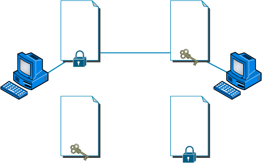
Security Filtering
443
c13.indd 04/02/2015 Page 443
The United States government has determined that 128-bit security is adequate for
things like secure transactions and all materials deemed Secret, but all Top Secret informa-
tion must be encoded using 192- or 256-bit keys.
The good news is that the AES standard has proven amazingly dif cult to crack.
Those who try use a popular method involving something known as a side channel
attack. This means that instead of going after the cipher directly, they attempt to gather
the information they want from the physical implementation of a security system.
Hackers attempt to use power consumption, electromagnetic leaks, or timing informa-
tion (like the number of processor cycles taken to complete the encryption process)
to give them critical clues about how to break the AES system. Although it’s true that
attacks like these are possible to pull off, they’re not really practical to clinch over
the Internet.
Public Key Encryption
Public key encryption uses the Dif e-Hellman algorithm, which employs a public key and
a private key to encrypt and decrypt data. It works like this: The sending machine’s public
key is used to encrypt a message that is decrypted by the receiving machine with its private
key. It’s a one-way communication, but if the receiver wants to send a return message, it
does so via the same process. If the original sender doesn’t have a public key, the message
can still be sent with a digital certi cate that’s often called a digital ID, which veri es the
sender of the message.
Figure 13.8 shows public-key-encrypted communication between User X and User Y.
FIGURE 13.8 Public-key encryption
Y&Z!8:”
>)(hb&
gf%^dc
yH98Y
Don’t
forget
the
chocolate!
>_<l)(+
<&n_(^
utrfytr
&(%pG
UDOPJ
milk
bread
eggs
cat food
User YUser X
Original Message
Decrypted Using
User Y’s Private Key
Original Message
Encrypted Using
User Y’s Public Key
Reply Message
Encrypted Using
User X’s Public Key
Reply Message
Decrypted Using
User X’s Private Key
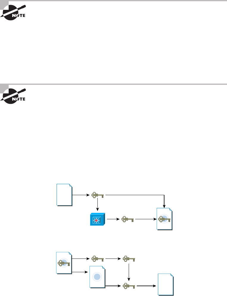
444
Chapter 13 ■ Authentication and Access Control
c13.indd 04/02/2015 Page 444
Here’s a cool factoid for you—Diffie-Hellman refers to all public-key algo-
rithms. Whitfield Diffie and Martin Hellman from the Stanford Research
Institute invented public-key encryption. They introduced the dual-key con-
cept in their 1976 paper “New Directions in Cryptography.”
RSA Data Security
Rivest, Shamir, and Adleman (RSA) encryption is a public-key algorithm named after the
three scientists from MIT who created it. They formed a commercial company in 1977 to
develop asymmetric keys and nailed several US patents. Their encryption software is used
today in electronic commerce protocols.
For more information about RSA Data Security, go to
www.rsa.com
.
Pretty Good Privacy (PGP)
In the early 1990s, Phil Zimmerman (also from MIT) wrote most of the code for this freely
available version of public-key encryption designed to encrypt data for email transmission.
Zimmerman basically compared email to postcards, because anyone can read email
messages traversing the Internet just as they can postcards traveling through the postal
service. By contrast, he compared an encrypted message to a letter mailed inside an enve-
lope. Figure 13.9 shows the PGP encryption system.
FIGURE 13.9 The PGP encryption system
Encryption
Process
Document
Encrypted with
Session Key
Key Store Encrypted with
Public Key
Encrypted
Session Key
Decryption
Process
Encrypted
Message
Clphertext Document
Session Key to
Decrypt Clphertext
Recipient’s
Private Key
Clphertext + Encrypted
Session Key
In Figure 13.9, the document is encrypted with a session key, which is then encrypted
with the public key of the recipient. Then the ciphertext and the encrypted session key are
Security Filtering
445
c13.indd 04/02/2015 Page 445
sent to the recipient. Since the recipient is the only person with the matching private key,
only they can decrypt the session key and then use it to decrypt the document.
Zimmerman distributed the software for personal use only, and as the name implies, it’s
really pretty good security.
RSA Data Security and the US federal government both had a problem with
Zimmerman’s product—the RSA complained about patent infringement, and the govern-
ment actually decided to prosecute Zimmerman for exporting munitions-grade software.
The government eventually dropped the charges, and now a licensing fee is paid to RSA, so
today, PGP and other public-key-related products are readily available.
Don’t let the name fool you! PGP is a highly secure encryption standard.
Remote Access
Think of remote access as a telecommuting tool because it’s used by companies to allow
employees to connect to the internal network and access resources that aren’t in the of ce.
Remote access is great for users who work from home or travel frequently, but clearly, to a stalk-
ing hacker, using an unsecured remote-access connection is like stealing candy from a baby.
Using remote access requires a server con gured to accept incoming calls and also
requires remote-access software to be installed on the client. Microsoft Windows operating
systems, since Windows 95, have had remote-access client software built in, and there are
many third-party remote-access clients available as well. Several different methods exist to
create remote-access connections.
RAS
Remote Access Services (RAS) is not a protocol but refers to the combination of hardware
and software required to make a remote-access connection. The term was popularized by
Microsoft when the company began referring to its Windows NT–based remote-access
tools by this name. Users would dial in via a modem, be authenticated by the server, and
then be asked for their username and password just as if they were on the local network.
Once logged in, users had access to data on the internal network just as if they were logged
in locally. Figure 13.10 gives you an idea of what this would look like.
FIGURE 13.10 A typical remote-access connection between a remote user and a server
Remote
Access Server
Remote
Resources
Remote
Access Client
446
Chapter 13 ■ Authentication and Access Control
c13.indd 04/02/2015 Page 446
RAS itself was not secure; but there are options within RAS to include a secure pro-
tocol for tunneling, such as PPTP, and for authentication, such as Microsoft Challenge
Handshake Authentication Protocol (MS-CHAP) and Extensible Authentication Protocol
(EAP). RAS is versatile because it supports several other network protocols in addition
to TCP/IP.
RDP
Remote Desktop Protocol (RDP) allows users to connect to a computer running
Microsoft’s Remote Desktop Services, but a remote computer must have the right kind of
client software installed for this to happen. Most Windows-based operating systems include
an RDP client, and so do most other major operating systems, like Linux, Solaris, and Mac
OS X. Microsoft’s RDP client software is called either Remote Desktop Connection (RDC)
or Terminal Services Client (TSC). Microsoft began calling all terminal services products
Remote Desktop with Windows Server 2008 R2.
After establishing a connection, the user sees a terminal window that’s basically a
precon gured window that looks like a Windows or other operating system’s desktop.
From there, the user on the client computer can access applications and les available to
them by using the remote desktop.
The most current version of RDP is RDP 8.1, released in Windows 7 SP1 and Server
2008 R2 SP1. When logged in using RDP, clients are able to access local les and printers
from the remote desktop just as if they were logged into the network. RDP offers 128-bit
encryption using the RC4 encryption algorithm and also offers TLS 1.0 support.
PPP (PTP)
Point-to-Point Protocol (PPP) is a Layer 2 protocol that provides authentication, encryp-
tion, and compression services to clients logging in remotely. ISPs use PPP a lot to authen-
ticate clients dialing in with a modem or a DSL or cable modem. Many network servers
that provide remote-access services (such as RAS) can also use PPP as an authentication
protocol.
PPPoE
Point-to-Point Protocol over Ethernet (PPPoE) is an extension of PPP. Its purpose is to
encapsulate PPP frames within Ethernet frames.
The need for PPPoE was born out of the need to deal with the massive increase in high-
speed Internet connections. Service providers offering customers high-speed access using
Asymmetric Digital Subscriber Line (ADSL) or cable modems needed a way to offer the
authentication and encryption services of PPP. A Remote Authentication Dial In User
Service (RADIUS) server—something I’ll get into a bit later in this chapter—is commonly
used to manage PPPoE connections.
PPPoE works in two stages: discovery and session. In the discovery phase, the MAC
addresses of each of the connection’s endpoints are given to each other so that a secure
PPP connection can be made. During this phase, a session ID is also created that’s used to
facilitate further data transmission during the session. When the MAC addresses of each
Managing User Account and Password Security
447
c13.indd 04/02/2015 Page 447
endpoint are known to each other, a point-to-point connection is created; the session stage
begins at this time.
ICA
Independent Computing Architecture (ICA) is a protocol designed by Citrix Systems to
provide communication between servers and clients. The most common application that
uses ICA is Citrix’s WinFrame, which administrators can use to set up Windows applica-
tions on a Windows-based server and then allow clients with virtually any operating system
to access those applications. Client computers running Linux, Unix, or Mac OSs can access
Windows-based applications with the help of WinFrame, giving network administrators all
kinds of exibility with client operating systems. But again, there’s a downside—connec-
tions like these tend to be slow because of the huge amount of translation that’s required to
enable the client and server to communicate with each other properly.
SSH
Secure Shell is a network protocol that is designed as an alternative to command-based
utilities such as Telnet that transmit requests and responses in clear text. It creates a secure
channel between the devices and provides con dentiality and integrity of the data transmis-
sion. It uses public-key cryptography to authenticate the remote computer and allow the
remote computer to authenticate the user, if necessary.
This public key is placed on any computer that must allow access to the owner of a
matching private key (the owner keeps the private key in secret). The private key is never
transferred through the network during authentication.
Managing User Account and Password
Security
A whole bunch of authentication schemes are used today, and although it’s important to
know about these different schemes and how they work, all that knowledge doesn’t equal
power if your network’s users aren’t schooled on how to manage their account names and
passwords correctly. This is because if bad guys get their hands on usernames and pass-
words, it gives them a way to get into your network. Worse, if a hacker gains the adminis-
trator account name and password for your network, it doesn’t matter what authentication
protocol or server you’re using—that hacker isn’t just going to get in, they’re going to get
in armed with the escalated rights that type of account allows, meaning they can do some
serious damage.
With that in mind, let’s get into some solid ways to manage user accounts and passwords
and follow that up by talking about the key authentication methods in use today.
Usernames and passwords are vital to network security because their whole purpose
is to control initial access to it. Even if the system administrator assigns individuals their
448
Chapter 13 ■ Authentication and Access Control
c13.indd 04/02/2015 Page 448
usernames and passwords, users can and often do change them, so you need to make sure
your network’s users know the difference between a good password and a bad one, and
how to keep their passwords safe from theft.
I’ll cover the important security issues related to user account and password manage-
ment. Moreover, in the following sections, I’ll discuss more secure methods of authentica-
tion (two-factor and multifactor authentication) and a widely used concept in the Enterprise
networks: single sign-on.
Managing User Accounts
So, your rst step in managing access to network resources is through user accounts
and the rights you assign to the network resources. System administrators usually maintain
user accounts on a daily basis, doing things like renaming accounts and setting the num-
ber of simultaneous connections. You can also specify where users can log in, how often,
and when; plus, you can adjust how often their passwords expire and delimit when their
accounts expire as well.
Disabling Accounts
This is important, so remember it—when a user leaves the organization, you have these
three options:
■ Leave the account in place.
■ Delete the account.
■ Disable the account.
The rst option is not so good because if you just leave the account in place, anyone
(including the user to whom it belonged) can still log in as that user if they know the pass-
word. This is clearly very bad security, but deleting the account presents its own set of
problems. If you delete an account and then create a new one, the numeric ID associated
with that user (UID in Unix, SID in Windows Server) will be lost, and it’s through this
magic number that passwords and rights to network resources are associated with the user
account. This can be a good thing—but if you create a new user account with the same
name as the one you deleted, the identi cation number of the new account will be different
from the old one, so none of its settings will be there for the new account.
This means that disabling an account until you’ve made a decision about what should
happen to it is your best bet because you’ll probably just want to rename the account when
someone new is hired. When you disable an account, it still exists, but no one can use it to
log in. Another good time to disable an account is when someone leaves for an extended
period, like taking maternity/paternity leave or other medical leaves or going on sabbatical.
Because it’s really common for companies today to have contract and temporary employ-
ees, you need to know how to manage temporary accounts that will be used for only a
short time and then disabled.
Managing these temporary accounts is easy—you just set the account to expire on the
employee’s expected last day of work.

Managing User Account and Password Security
449
c13.indd 04/02/2015 Page 449
Setting Up Anonymous Accounts
Anonymous accounts allow only extremely limited access for a large number of users who
all log in with the same username—for instance, anonymous or guest. These logins are
frequently used to access FTP les; you gain access when you log in with the username
anonymous and enter your email address as the password.
Sometimes people don’t use their real email addresses. If you really want
to know where a user is located on the Internet, use third-party software to
verify IP addresses and Internet domain names.
It’s obviously a very bad idea to use anonymous accounts for regular network access—
you just can’t track them. All Windows Server products from Windows NT on come with
the anonymous account Guest disabled, and it’s usually a good thing to leave it that way.
When you want to enable that account, like at a public kiosk, make sure you carefully man-
age what it is able to access by implementing strict group policies.
Some web servers create an Internet user account to allow anonymous access to the web-
site through which a user is allowed to access the web server over the network. The pass-
word is always blank, and you never see a request to log in to the server because it’s done
automatically. Without this kind of account, no one would be able to access your
web pages.
Do not rename the Internet user account or set a password because if you
do so, the general public won’t be able to view your website. If you want to
secure documents, use a separate secure HTTP or Windows server.
Limiting Connections
There is a good reason to limit how many times a user can connect to the network. Users
should normally be logged in to the network for one instance because they can only be in
one place at a time. So if your system is telling you that someone is logged in from more
than one place, it’s probably because someone else is using their account. By limiting simul-
taneous connections to one, only a single user at a single workstation can gain access to the
network using a speci c user account. But there are times that some users need to log in
multiple times to use certain applications or perform certain tasks, and you can allow that
speci c user to have multiple concurrent connections.
You may also want to limit the speci c location from which a user logs in because most
of the time, your users will be logging on to the network only from their own workstations.
This makes sense, but this rule isn’t usually enforced because sometimes users move around
without taking their computers with them, or they log in at someone else’s station to get
their jobs done. So unless you require super tight security, imposing this rule can really
complicate your job because it requires a lot of administration. Windows Server products
can limit which station(s) a user is allowed to log in from, but they don’t do so by default.
450
Chapter 13 ■ Authentication and Access Control
c13.indd 04/02/2015 Page 450
A Windows feature that is enabled by default is not allowing average users to log in at the
server console because they shouldn’t be working directly on a server. They can do some
serious damage accidentally!
Renaming the Maintenance Account
Network operating systems automatically give the network maintenance (or administra-
tion) account a default name. On Windows servers, it’s (surprise) Administrator, and in
Unix it’s root. So it should be crystal clear that if you don’t change this account name, bad
guys already have half the information they need to break into your network. The only
thing they’re missing is the password—yikes!
By all means, rename that account to something cool and creative that you’ll remember
but that would be really hard for someone to guess—and don’t write it on a Post-it and
stick it to the server. Here’s a “do not use” list of names:
■ Admin
■ Administrator
■ Analyst
■ Audit
■ Comptroller
■ Controller
■ Manager
■ Root
■ Super
■ Superuser
■ Supervisor
■ Wizard
■ Any variation on the above
Managing Passwords
Like any other aspect of network security, passwords must be managed, and doing that
involves ensuring that all passwords for user accounts follow security guidelines so bad
guys can’t easily guess or crack them. You’ve also got to implement certain features of your
network operating system to prevent unauthorized access.
Basically, a strong password is some combination of alphanumeric and special charac-
ters that’s easy for you to remember but really hard for someone else to guess. Like server
account names, they should never be written down on anything that is then put into your
desk or stuck onto your computer. Unfortunately, this guideline is only followed in a per-
fect world. Users invariably try to make things easy on themselves by choosing passwords
that are so simple to guess that someone would have to be seriously mentally challenged not
to be able to. Let’s look at some characteristics of strong passwords.

Managing User Account and Password Security
451
c13.indd 04/02/2015 Page 451
Minimum Length
Strong passwords should be at least 8 characters (the more, the merrier), but they shouldn’t
be any longer than 15 characters to make them easier to remember. You absolutely must
specify a minimum length for passwords because a short password is easily cracked—
after all, there are only so many combinations of three characters, right? The upper limit
depends on the capabilities of your operating system and the ability of your users to
remember complex passwords. Here’s what I call “The Weak List” for passwords—never
use them!
■ The word password (not kidding—people actually do this!)
■ Proper names
■ Your pet’s name
■ Your spouse’s name
■ Your children’s names
■ Any word in the dictionary
■ A license plate number
■ Birth dates
■ Anniversary dates
■ Your username
■ The word server
■ Any text or label on the PC or monitor
■ Your company’s name
■ Your occupation
■ Your favorite color
■ Any of the above with a leading number
■ Any of the above with a trailing number
■ Any of the above spelled backward
Security Audits
A great way to begin a basic security audit to get a feel for any potential threats to your
network is to simply take a walk through the company’s halls and offi ces. I’ve done this a
lot, and it always pays off because invariably I happen upon some new and different way
that people are trying to “beat the system” regarding security. This doesn’t necessarily
indicate that a given user is trying to cause damage on purpose; it’s just that following
the rules can be a little inconvenient—especially when it comes to adhering to strict pass-
continues

452
Chapter 13 ■ Authentication and Access Control
c13.indd 04/02/2015 Page 452
word policies. Your average user just doesn’t get how important their role is in maintain-
ing the security of the network (maybe even their job security as well) by sticking to the
network’s security policy, so you have to make sure they do.
Think about it. If you can easily discover user passwords just by taking a little tour of
the premises, so can a bad guy, and once someone has a username and a password, it’s
pretty easy to hack into resources. I wasn’t kidding about people slapping sticky notes
with their usernames and/or passwords right on their monitors—this happens a lot more
than you would think. Some users, thinking they’re actually being really careful, glue
them to the back of their keyboards instead, but you don’t have to be James Bond to think
about looking there either, right? People wouldn’t think of leaving their cars unlocked with
the windows down and the keys in the ignition, but that’s exactly what they’re doing by
leaving sensitive info anywhere on or near their workstations.
Even though it might not make you Mr. or Ms. Popularity when you search workspaces
or even inside desks for notes with interesting or odd words written on them, do it any-
way. People will try to hide these goodies anywhere. Or sometimes, not so much. I kid
you not—I had a user who actually wrote his password on the border of his monitor with
a Sharpie, and when his password expired, he just crossed it off and wrote the new one
underneath it. Sheer genius! But my personal favorite was when I glanced at this one
guy’s keyboard and noticed that some of the letter keys had numbers written on them.
All you had to do was follow the numbers that (surprise!) led straight to his password. Oh
sure—he’d followed policy to the, ahem, letter by choosing random letters and numbers,
but a lot of good that did—he had to draw himself a little map in plain sight on his key-
board to remember the password.
So, like it or not, you have to walk your beat to fi nd out if users are managing their
accounts properly. If you fi nd someone doing things the right way, praise them for it
openly. If not, it’s time for more training—or maybe worse, termination.
There are more, but you get the idea, and these really are the most commonly used
brainless passwords.
Using Characters to Make a Strong Password
The good news is that solid passwords don’t have to be in ancient Mayan to be hard to
crack. They just need to include a combination of numbers, letters, and special characters—
that’s it. Special characters aren’t letters or numbers but symbols like $ % ^ # @). Here’s an
example of a strong password: tqbf4#jotld. Looks like gibberish, but remember that famous
sentence, “The quick brown fox jumped over the lazy dog”? Well, this particular password
uses the rst letter of each word in that sentence with a 4# thrown in the middle of it.
Sweet—solid and easy to remember. You can do this with favorite quotes, song lyrics, and
so on, with a couple of numbers and symbols stuck in the middle. Just make sure you don’t
sing the song or quote Shakespeare every time you log in!
continued

Managing User Account and Password Security
453
c13.indd 04/02/2015 Page 453
If you want to test the strength of passwords to make sure they’re nice and tight, you
can use auditing tools like crack programs that try to guess passwords. Clearly, if that
program has a really tough time or even fails to crack the password, you have a good one.
By the way, don’t just use a regular word preceded by or ending with a special character
because good crack programs strip off the leading and trailing characters during decryption
attempts.
Password-Management Features
All network operating systems include built-in features for managing passwords to help
ensure that your system remains secure and that passwords cannot be easily hacked with
crack programs. These features usually include automatic account lockouts and password
expiration.
Automatic Account Lockouts
Hackers, and even people who forget their passwords, usually try to log in by guessing
passwords. This is why most network operating systems will lock you out after a few
unsuccessful attempts. Some will even disable the account. Once that happens, the user
won’t be able to log in to that account even if they enter the correct password. This feature
prevents a potential hacker from running an automated script to crack account passwords
by continuously attempting to log in using different character combinations.
When an account is on lockdown, guards—I mean, network staff—will have to unlock
the account if the network operating system doesn’t unlock it after a preset period. In any
high-security network, it’s a good idea to require an administrator to manually unlock
every locked account instead of setting the network operating system to do it automatically.
This way, the administrator will be sure to know about any possible security breaches.
Be careful not to lock yourself out. With many network operating sys-
tems, only administrators can reset passwords, so if you happen to be the
administrator and you lock yourself out, only another administrator can
unlock your account. Embarrassing, yes, but what if you’re the only admin-
istrator? You’re in trouble then, because even though many network oper-
ating system vendors do have solutions to this humiliating little problem,
the cost of those solutions isn’t going to be cheap!
It’s good to know that Windows-based servers allow you to configure
accounts to be locked out after a number of bad login attempts, but the
default Administrator account is exempt from this happening. This might
sound convenient for you, but it’s actually a security risk. You should defi-
nitely rename this account, and it’s also a good idea not to use it for day-
to-day administration. Create a new administrator account (with a different
name, of course), and use it for administrative purposes instead.

454
Chapter 13 ■ Authentication and Access Control
c13.indd 04/02/2015 Page 454
Password Expiration and Password Histories
Unlike a good wine, even really good passwords don’t age well over time; they just become
more likely to be cracked. This is why it’s good to set passwords so that they expire after
a speci c amount of time. Most organizations set up passwords to expire every 30 to 45
days, after which the network’s users all must reset their passwords either immediately or
during a preset grace period. The grace period is usually limited to a speci c number of
login attempts, or it may allow a couple of days.
By default, each network operating system delimits a specific password-
expiration period that bad guys usually know about. So make sure you
reset that time period to something other than the default, in accordance
with your security policy.
Older network operating systems allowed users to reset their passwords back to their
original form after using an intermediary password for a while, but today’s network oper-
ating systems prevent this by employing password histories that consist of a record of the
past several passwords used by a speci c user. This record prevents users from using any
password that’s stored in the password history. If they try, the password will fail, and the
operating system will then request a password change. What this means to you, the system
administrator, is that if your security policy dictates that passwords be reset every two
weeks, you should make sure your password history can hold at least 20 passwords. This
would prevent a user from reusing a password until the password is at least 10 months old
(two changes per month). They’ll forget that password by then!
By the way, your more experienced users know about this history feature, and because
coming up with a really tight password takes a little thought, when savvy users create ones
they really like, they may have a hard time letting go. Maybe they just want to avoid the
hassle of creating a tight new password and remembering it, so they’ll try to nd ways to
get out of doing that by getting around the password-history feature. For instance, I knew
one guy who actually admitted that he just changed his password as many times as it took
to defeat the history log and then changed it one last time to his beloved, original pass-
word—all of which took him only about ve minutes to accomplish.
You can force users to change their passwords to ones that are unique because the latest
operating systems require unique passwords and can, depending on the network operating
system, store more than 20 passwords. This feature makes it a whole lot harder to revert
to any previous passwords. But it’s still possible for users to beat the system, so don’t rely
completely on it.
Single Sign-On
In today’s modern enterprises, users can be overwhelmed by the number of points in the
network where they may be challenged to identify themselves. Most users have to log onto
the domain to have network access at all, and then there may be company websites that
require an authentication process to access databases, SharePoint sites, secured drives, per-
sonal folders, and on and on!
User-Authentication Methods
455
c13.indd 04/02/2015 Page 455
When users must remember multiple passwords, as the number increases, they begin
to resort to unsafe security practices such as writing passwords on sticky notes, hiding
passwords in their drawers, and even sharing them with coworkers. All of these practices
undermine the security of the network.
Single sign-on addresses this problem. With single sign-on, when the user logs into the
domain, the domain controller issues them an access token. This access token contains a
list of all the resources (which can include folders, drives, websites, databases, and so on) to
which they should have access. As a result, anytime the user accesses a resource, the token
is veri ed behind the scenes, and the users never needs to provide another password!
Multifactor Authentication
Multifactor authentication is designed to add an additional level of security to the authenti-
cation process by verifying more than one characteristic of a user before allowing access to
a resource. Users can be identi ed in one of three ways:
■ By something they know (password)
■ By something they are (retinas, fingerprint, facial recognition)
■ By something they possess (smart card)
Two-factor authentication is when two of the above factors are being tested, while
multifactor is when more than two of the above factors are being tested. An example of
two-factor authentication would be requiring both a smart card and a PIN to log onto the
network. The possession of either by itself would not be suf cient to authenticate. This pro-
tects against the loss and theft of the card as well as the loss of the password. An example
of multifactor would be when three items are required, such as a smart card, a PIN, and a
username and password.
This process can get as involved as the security requires. In an extremely high-security
situation, you might require a smart card, a password, a retina scan, and a ngerprint scan.
The trade-off to all the increased security is an inconvenient authentication process for the
user and the high cost of biometric authentication devices.
User-Authentication Methods
There are a number of authentication systems in use today, but I’m going to focus on the
ones you’re likely to be confronted with on the Network+ exam.
Public Key Infrastructure (PKI)
Public Key Infrastructure (PKI) is a system that links users to public keys and veri es a
user’s identity by using a certi cate authority (CA). Think of a CA as an online notary
public—an organization that’s responsible for validating user IDs and issuing unique
identi ers to con rmed individuals to certify that their identity can really be trusted.
Figure13.11 shows how the CA process works in relation to two users.
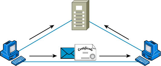
456
Chapter 13 ■ Authentication and Access Control
c13.indd 04/02/2015 Page 456
FIGURE 13.11 The certificate authority process
Certificate Authority
Message Certificate
Jeff can verify that the
message with the
certificate from Mike is
valid if he trusts the CA.
Mike Jeff
PKI allows people to communicate with each other with con dence that they’re talking
to whom they think they are talking to. It is used to establish con dentiality and to ensure
message integrity without knowing anything about the other party prior to the conversa-
tion. It’s also used to verify the digital signature of a private key’s owner.
Public-key encryption operates through asymmetric cryptography, meaning that a differ-
ent key is used to encrypt and decrypt the message, respectively. Symmetric cryptography uses
the same key to encrypt and decrypt, so it’s a lot less secure. Here’s how it works: If I sent you
a message using PKI, I’d use your public key to encrypt the message. When you received the
message, you would use your private key, which is theoretically the only thing that can be used
to decrypt the message back into something readable by humans. If a digital signature was
required, you would sign the document with your private key, and anyone with access to your
public key would be able to verify that the signature was truly yours. So clearly, you should be
the only one who has access to your private key. Figure 13.12 illustrates what I just described.
This type of authentication is used a lot in websites that perform transactions. You’ve
probably experienced shopping online and having an error message pop up notifying you that
a certain site’s certi cate or key has expired and asking if you want to proceed with the trans-
action. If you do, it’s time to rethink things—you’re probably way too trusting. Just say no!
Kerberos
Kerberos, created at MIT, isn’t just a protocol, it’s an entire security system that estab-
lishes a user’s identity when they rst log on to a system that’s running it. It employs strong
encryption for all transactions and communication, and it’s readily available. The source
code for Kerberos can be freely downloaded from lots of places on the Internet.
Kerberos works by issuing tickets to users who log in, kind of like going to an amusement
park—as long as you have your ticket to ride, you’re good to go. Even though the tickets
expire quickly, they’re automatically refreshed as long as you remain logged in. Because of
this refresh feature, all systems participating in a Kerberos domain must have synchronized
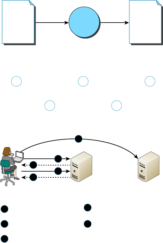
User-Authentication Methods
457
c13.indd 04/02/2015 Page 457
clocks. This synchronicity is a bit complicated to set up, although in Microsoft servers and
Domains the process is automatic, requiring only access to a recognized time server (which
Microsoft also operates). The real negative hits happen if you have only one Kerberos
authentication server—if it goes down, no one can log in to the network. So when running
Kerberos, having redundant servers is clearly vital. You should also know that because all
users’ secret keys are stored in one centralized database, if that’s compromised, you have a
security tsunami on your hands. Luckily these keys are stored in an encrypted state. Figure
13.13 shows Kerberos in action.
FIGURE 13.12 PKI in action
1 3
Public Key Encryption at Work
This message
is for Jenny…
Joe creates a
message for
Jenny.
Joe uses
Jenny’s public
key to encrypt
the message.
The data gets
sent across
the wire.
Jenny uses her
private key to
decrypt the
message.
Jenny can read
the message.
This message
is for Jenny…
ehyeosy
Ayg9us3
el48vye
2 4
5
FIGURE 13.13 The Kerberos authentication process
5
1
3
2
4
Request for ticket granting ticket
(TGT)
Application ticket returned by ticket-
granting service
Request for service
(authenticated with application ticket)
TGT returned by authentication
service
Request for application ticket
(authenticated with TGT)
5
1
3
2
4
Client Authentication Server Application Server

458
Chapter 13 ■ Authentication and Access Control
c13.indd 04/02/2015 Page 458
Authentication, Authorization, and Accounting (AAA)
In computer security speak, AAA (triple A, like the auto club) refers to authentication,
authorization, and accounting. AAAA is a more robust version that adds auditing into the
mix. AAA and AAAA aren’t really protocols; instead, they’re systematized, conceptual
models for managing network security through one central location. Two common imple-
mentations of AAA are RADIUS and TACACS+.
RADIUS
Although its name implies it, the Remote Authentication Dial In User Service (RADIUS)
is not a dial-up server. Like pretty much everything else, it originated that way, but it’s
evolved into more of a veri cation service. Today, RADIUS is an authentication and
accounting service that’s used for verifying users over various types of links, including dial-
up. Many ISPs use a RADIUS server to store the usernames and passwords of their clients
in a central spot through which connections are con gured to pass authentication requests.
RADIUS servers are client-server-based authentication and encryption services maintaining
user pro les in a central database.
RADIUS is also used in rewalls. Purposed this way, when a user wants to access a par-
ticular TCP/IP port, they must provide a username and a password. The rewall then con-
tacts the RADIUS server to verify the credentials given. If the veri cation is successful, the
user is granted access to that port.
RADIUS is an authentication server that allows for domain-level authenti-
cation on both wired and wireless networks.
TACACS+
The Terminal Access Controller Access-Control System Plus (TACACS+) protocol is also
a AAA method and an alternative to RADIUS. Like RADIUS, it is capable of performing
authentication on behalf of multiple wireless APs, RAS servers, or even LAN switches that
are 802.1x capable. Based on its name, you would think it’s an extension of the TACACS
protocol (and in some ways it is), but the two de nitely are not compatible.
Here are two major differences between TACACS+ and RADIUS:
■ RADIUS combines user authentication and authorization into one profile, but
TACACS+ separates the two.
■ TACACS+ utilizes the connection-based TCP protocol, but RADIUS uses UDP
instead.
Even though both are commonly used today, because of these two reasons TACACS+ is
considered more stable and secure than RADIUS.
Figure 13.14 shows how TACACS+ works.
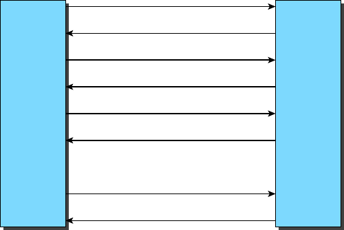
User-Authentication Methods
459
c13.indd 04/02/2015 Page 459
FIGURE 13.14 TACACS+ login and logout sequence
Authentication
Login Request
Reply Success
Authorization Request
Reply Success
Reply Success
Reply Success
TACACS+
Client
TACACS+
Server
Accounting Stop
Logout Request
Accounting Start
Just to clarify things, in the IT world, accounting has nothing to do with money. Here’s
what I mean: When a TACACS+ session is closed, the information in the following list is
logged, or accounted for. This isn’t a complete list; it’s just meant to give you an idea of the
type of accounting information that TACACS+ gathers:
■ Connection start time and stop time
■ The number of bytes sent and received by the user
■ The number of packets sent and received by the user
■ The reason for the disconnection
The only time the accounting feature has anything to do with money is if your service
provider is charging you based on the amount of time you’ve spent logged in or for the
amount of data sent and received.
Web Services
Secure connections to web services can be con gured using several variations of HTTP,
which is unsecured. The following protocols can be used:
■ Hypertext Transfer Protocol Secure (HTTPS) protects HTTP traffic by layering it on
top of SSL/TLS. It requires a certificate on the server.
■ Secure Hypertext Transfer Protocol (S-HTTP) is a little-used alternative to the HTTPS.
While HTTPS wraps the entire communication within SSL, S-HTTP only encrypts the
served page data and the submitted data like POST fields. It leaves the initiation of the
protocol unchanged.
460
Chapter 13 ■ Authentication and Access Control
c13.indd 04/02/2015 Page 460
Unified Voice Services
Uni ed voice services, or uni ed communications, is a term that describes combining traf c
formerly con ned to the phone network with IP data traf c and video traf c. It takes voice and
video information and encapsulates it within IP packets to be transmitted on the data network.
VoIP and video streaming are two examples of this. In both cases, incoming data is con-
sumed in real time as it is received, thus placing a premium on performance. To ensure this,
QoS mechanisms must be utilized to give these traf c types priority over traf c that’s less
sensitive to latency.
Speci cally, uni ed voice can also mean the integration of voice with other messaging
systems such as IM, presence, and email services. It will include voice mail as well.
Network Controllers
There are several meanings for the term network controller, but in most cases it refers to
a Network Interface Card, or NIC. Newer cards are available that can support both LAN
and SAN traf c at the same time. Moreover, these devices usually of oad the processing
usually placed on the CPU. Special models also perform their own encryption, thus easing
the workload further on the CPU.
In other cases you may see this term used to describe a device that controls admission
or access to a network. A good example of this is a system that goes beyond simple authen-
tication and ensures that systems are safe and secure before they are allowed to access the
network (Network Admission Control). In the next section, you’ll be introduced to another
such system called 802.1x.
Network Access Control (NAC)
Network Access Control (NAC) is a method of securing network hosts before they’re
allowed to access the network. The most common implications for NAC are in wireless
networking, where nodes are often added to and removed from the network freely. One of
the most common forms of NAC is IEEE 802.1x.
Even the Institute of Electrical and Electronics Engineers (IEEE) recognizes the potential
security holes in wireless networking, so it came up with the IEEE 802.1x standard as a way
to authenticate wireless users. 802.1x is an open framework that’s designed to support multiple
authentication schemes. Before a client, called a supplicant in 802.1x-speak, can communicate
on a wireless network, it asks the access point, or authenticator, for permission to join and
then provides its credentials. The access point passes those credentials to a centralized authen-
tication server that sends back an accept message to the access point if the authentication is
accepted. Only then will the access point allow a user to connect to the wireless network.
Challenge Handshake Authentication Protocol (CHAP)
The Challenge Handshake Authentication Protocol (CHAP) is a secure authentication proto-
col because with CHAP, the username and password never cross the wire. Instead, both the
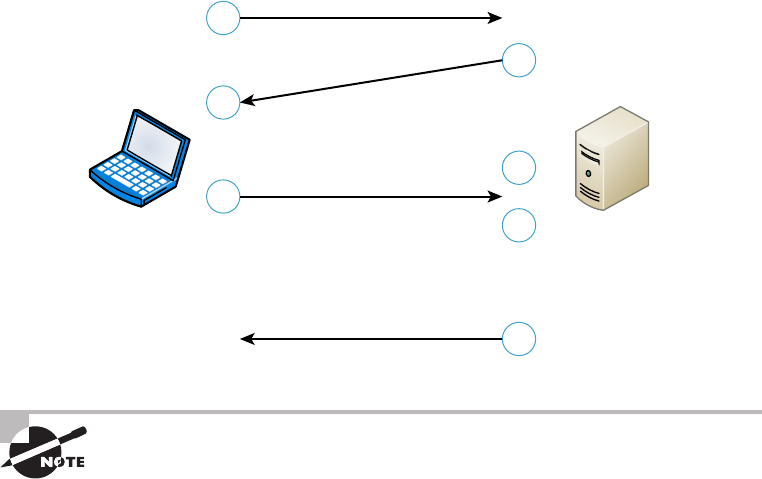
User-Authentication Methods
461
c13.indd 04/02/2015 Page 461
client and server are con gured with the same text phrase that’s known as a shared secret.
When a client sends out an authentication request, the server responds by sending a random
value called a nonce plus an ID value back to the client. The client takes these two strings,
sequences them with the shared secret, and then generates a one-way hash value using the
Message-DIGEST 5 (MD5) encryption algorithm. This hash value is transmitted back to the
server, which performs the same algorithm using the same values and shared secret. The server
basically compares the hash value that it’s received from the client with the hash value it has
calculated, and if they match, the client gets to be authenticated. I know this sounds pretty
complicated, so let me give you a visual demonstration of how CHAP works in Figure 13.15.
FIGURE 13.15 CHAP authentication process
1
3
2
4
6
5
7
Logon Request
Challenge
Encrypts Value
Encrypts Value
Response
ServerClient
Authorize or Fail
Compare
Encrypted
Results
CHAP has replaced the older Password Authentication Protocol (PAP)
because PAP sends usernames and passwords in clear text and CHAP
doesnot.
MS-CHAP
Microsoft has its own variation of CHAP known as Microsoft Challenge Handshake
Authentication Protocol (MS-CHAP). It works basically the same way as CHAP, except
that unlike CHAP, which requires the shared secret to be stored locally in clear text,
MS-CHAP encrypts the secret locally. And whereas CHAP provides authentication of the
client by the server only, MS-CHAP version 2 is capable of mutual authentication so that
the client can be sure the server is legitimate as well. Also, the encryption method used
to generate the one-way hash in MS-CHAP is DES. Finally, and predictably, MS-CHAP
doesn’t work on Linux or other platforms—it’s a Windows proprietary protocol.
462
Chapter 13 ■ Authentication and Access Control
c13.indd 04/02/2015 Page 462
Extensible Authentication Protocol (EAP)
Extensible Authentication Protocol (EAP) is an extension to PPP that provides a host of
additional authentication methods for remote-access clients. Some examples include smart
cards, certi cates, Kerberos, and biometric schemes like retinal scans and ngerprint and
voice recognition. Although EAP itself doesn’t allow for mutual authentication, enhanced
forms of the protocol do. For example, EAP-TLS and EAP-TTLS, a tunneled version of EAP-
TLS, create a secure tunnel through which password-based versions like EAP-MD5 can run.
Hashes
Hashing is a cryptographic process that uses an algorithm to derive a value from a set of
clear text to verify that the information came from where it says and that it has not changed.
Therefore, we say hashes are used to provide data integrity and origin authentication. Two
of the most well-known hashing algorithms are discussed in the following sections.
MD5
The MD5 message-digest algorithm was designed by Ron Rivest, and while it has been
shown to have some aws that cause many to prefer SHA (described in the next section),
those aws are not considered fatal and it is still widely used to ensure the integrity of
transmission. As is the case with most hashing processes, the hash is created from the clear
text and then sent along with the clear-tax message. At the other end, a second hash of the
clear-text data is created using the same algorithm, and if the two hashes match, the data is
deemed to be unchanged.
SHA
Secure Hash Algorithm is a family of algorithm versions, much like MD5 having multiple
versions on its way to becoming MD5. It is published by the National Institute of Standards
and Technology (NIST) as a US Federal Information Processing Standard (FIPS). It oper-
ates as any hash does and is considered to be superior to MD5.
Network Access Control
Network access control systems that control access to devices based on their security set-
tings include Cisco’s Network Admission Control (NAC) and Microsoft’s Network Policy
and Access Services (NPAS). These systems examine the state of a computer’s operating sys-
tem updates and anti-malware updates before allowing access, and in some cases can even
remediate the devices prior to permitting access. In the following sections, key components
of network access control systems are covered.
Posture Assessment
When devices attempt to access the network, the devices are examined closely, which is
called a posture assessment. The following items can be checked:
User-Authentication Methods
463
c13.indd 04/02/2015 Page 463
■ Anti-malware updates
■ Operating system updates
■ Windows Registry settings
When the assessment is complete and is positive, admission is granted. If problems are
found, admission may be denied and the user noti ed that action must be taken, or the
device may be directed to a remediation server that can install missing updates or quaran-
tine the device if necessary.
Guest Network
When a device is attempting to connect to a network using a form of network access
control, the device is rst placed in a guest network until a posture assessment is per-
formed. Until it is either approved or remediated, it will remain in the guest network. The
guest network will not allow access to the balance of the network to prevent the device
from introducing issues to the network.
Persistent vs Nonpersistent Agents
Network access control systems can be deployed using either persistent or nonpersistent agents
on the devices. A persistent agent is one that is installed on a NAC client and starts when the
operating system loads. This agent provides functionality that may not be present in the nonper-
sistent agent, such as system-wide noti cations and alerts, and auto and manual remediation.
A non-persistent agent is one that is used to assess the device only during the one-time
check-in at login, usually through a captive web portal. The persistent or dissolvable agent
is removed from the device when the authentication web page is closed. It can be used to
support the assessment of endpoints not owned by the organization and as such can help to
make a Bring Your Own Device (BYOD) policy possible.
Quarantine Network
When a guest machine is found to be out of compliance with the security posture required
by a NAC system, the device is placed in a quarantine network, which prevents the device
from exposing the rest of the network to the security risks that have been identi ed by the
posture assessment. It will remain in this quarantine network until it is able to pass the
assessment.
In cases where the NAC system supports remediation, the device may be connected to a
remediation server that can make the required changes or updates to the system. Once the
remediation is complete and the device is able to pass the assessment, it is then allowed to
proceed on to the protected network.
Edge vs Access Control
While controlling access to the network at the edge or boundary of the network (typically
using rewalls) is certainly a proven method of protecting a network, it is somewhat of a
blunt instrument of access control. Certainly the use of certain protocols and services can
464
Chapter 13 ■ Authentication and Access Control
c13.indd 04/02/2015 Page 464
be prevented and rewalls can even be granular enough to single out IP addresses and sub-
nets, but at some point more sophisticated means of control are indicated.
Access controls that are applied where the resource resides often can be much more
granular and can be more easily placed under the control of the resource owner. It is also
less likely that mistakes in the application of access control lists on the resource will cause
the type of widespread access problems that mistakes in ACLs on rewalls may have.
In today’s network, there is a place for both access and edge control. Understanding the
role that each can play and properly utilizing them can result in a layered approach to net-
work security.
Summary
In this chapter, you learned about the two most basic security concerns: security ltering
and user authentication. First, we talked about how to allow remote computers to join your
network and how to specify the way traf c leaves your network using access control lists.
Then, you learned about various tunneling and encryption protocols like SSL, VPN, L2TP,
PPTP, and IPSec.
Moving on, we examined several of the ways used today to remotely access networks,
including RAS, RDP, PPP, PPPoE, and ICA.
We wrapped things up by discussing solid user-account and password-management
policies and why those policies are essential to maintaining tight security on your net-
work. Finally, you learned about authentication methods like PKI, Kerberos, RADIUS,
TACACS+, 802.1x, CHAP, MS-CHAP, and EAP—good stuff!
Exam Essentials
Know two ways you can filter traffic using an access control list. Access control lists can
lter traf c by IP address or MAC address.
Know which protocols can be used for tunneling and encryption of data. Tunneling and
encryption protocols include SSL, VPN, L2TP, PPTP, GRE, and IPSec.
Know which services allow you to remotely access computers across a network. RAS,
RDP, PPP, PPPoE, and ICA are remote-access services and protocols.
Know different user-authentication protocols used on networks. User-authentication
protocols and systems include PKI, Kerberos, RADIUS, TACACS+, 802.1x, CHAP,
MS-CHAP, and EAP.
Understand the operation of Network Access Control systems such as Cisco Network
Admission Control. When devices attempt to access the network, the devices are
Written Lab
465
c13.indd 04/02/2015 Page 465
examined closely, which is called a posture assessment. When the assessment is complete
and is positive, admission is granted.
Written Lab
In this section, write the answers to the following authentication and access-control ques-
tions. You can nd the answers in Appendix A.
1. What are two possible items checked during a posture assessment?
2. Which type of agent is one that is installed on a NAC client and starts when the operating
system loads?
3. Which encryption protocol or standard allows you to create a private network on an
intranet?
4. Which user-authentication method uses a public key and private key pair?
5. In an authentication system that uses private and public keys, who should have access to the
private key?
6. Which authentication method relies on tickets to grant access to resources?
7. In computer security, what does AAA stand for?
8. Which network access security method is commonly used in wireless networks?
9. Which user-authentication method is available only in an all-Windows environment?
10. Which user-authentication method utilizes the TCP protocol?
466
Chapter 13 ■ Authentication and Access Control
c13.indd 04/02/2015 Page 466
Review Questions
You can nd the answers to the review questions in Appendix B.
1. Non-persistent or dissolvable NAC agents may help to make what possible?
A. BYOD initiative
B. Edge control
C. Unified voice services
D. Host-based IDS
2. What is the main difference between a private network and a public network?
A. In a private network, everyone has access; in a public network, only authorized users
have access.
B. There is no difference, in both a private and public network, only authorized users have
access.
C. In a private network, only authorized users have access; in a public network, everyone
that is connected has access.
D. In a private network, everyone has access; in a public network, only the first 100
people have access.
3. You have a remote user who can connect to the Internet but not to the office via their VPN
client. After determining the problem, which should be your next step?
A. Have the client reboot their host.
B. Make sure the user has the correct VPN address and password.
C. Have the client reinstall their VPN software.
D. Reboot the router at the corporate office.
4. Which IP address should you deny into your internetwork?
A. 126.10.10.0/8
B. 168.0.0.0/8
C. 128.0.0.0/8
D. 127.0.0.0/8
5. Which of the following is a tunneling protocol?
A. Layer 2 Tunneling Protocol (L2TP)
B. Internet Protocol Security (IPSec)
C. Secure Sockets Layer (SSL)
D. All of the above
6. Which tunneling protocol is based on RSA public-key encryption?
A. SSL
B. L2TP
C. IPSec
D. SSL VPN
Review Questions
467
c13.indd 04/02/2015 Page 467
7. What is the minimum number of characters you should use when creating a secure password?
A. 6
B. 7
C. 8
D. 15
8. Which layer of the OSI model does IPSec operate in?
A. Physical
B. Network
C. Transport
D. Application
9. Which protocol works in both the transport mode and tunneling mode?
A. SSL
B. L2TP
C. PPTP
D. IPSec
10. Companies that want to ensure that their data is secure during transit should use which of
the following?
A. Firewalls
B. Encryption
C. Data accounting
D. Routing table
11. Which network utilities do not have the ability to encrypt passwords? (Select two.)
A. FTP
B. SSH
C. Telnet
D. SCP
12. To encode or read an encrypted message, what tool is necessary?
A. Routing table
B. Internet access
C. Encryption key
D. Email address
13. Which of the following is not an enhancement provided by TLS version 2.0?
A. Improvements in the operation of the MD5-SHA-1 hashing function
B. Enhanced support for the Advanced Encryption Standard (AES)
C. Expansion of the use of TLS to VPNs
D. More flexibility in the choice of hashing and encryption algorithm
468
Chapter 13 ■ Authentication and Access Control
c13.indd 04/02/2015 Page 468
14. Which of the following is not a type of public-key encryption?
A. Diffie-Hellman algorithm
B. RSA Data Security
C. Pretty Good Privacy (PGP)
D. DES
15. Which of the following VPN protocols runs over port 1723, allows encryption to be done at
the data level, and allows secure access?
A. RAS
B. Radius
C. PPPoE
D. PPTP
16. At which stage of PPPoE are the MAC addresses of each of the endpoints of the connection
given to each other so that a PPP connection can be made?
A. Session
B. Discovery
C. Transport
D. Final
17. When utilizing multifactor authentication, which of the following is an example of verifying
something you are?
A. Smart card
B. Password
C. Fingerprint
D. Certificate
18. Which of the following authentication methods allows for domain authentication on both
wired and wireless networks?
A. RADIUS
B. CHAP
C. PKI
D. RDP
19. Which user-client-server authentication software system combines user authentication and
authorization into one central database and maintains user profiles?
A. RADIUS
B. TACACS+
C. Kerberos
D. PKI
20. Which of the following is not a Network Access Control method?
A. CHAP
B. 802.1x
C. EAP
D. ICA

c14.indd 04/02/2015 Page 469
Chapter
14
Network Threats and
Mitigation
THE FOLLOWING COMPTIA NETWORK+
EXAM OBJECTIVES ARE COVERED IN
THIS CHAPTER:
✓ 2.5 Given a scenario, install and apply patches and
updates
■ OS updates
■ Firmware updates
■ Driver updates
■ Feature changes/updates
■ Major vs minor updates
■ Vulnerability patches
■ Upgrading vs downgrading
■ Configuration backup
✓ 3.2 Compare and contrast common network
vulnerabilities and threats
■ Attacks/threats
■ Denial of service
■ Distributed DoS
■ Botnet
■ Traffic spike
■ Coordinated attack
■ Reflective/amplified
■ DNS
■ NTP
■ Smurfing

c14.indd 04/02/2015 Page 470
■ Friendly/unintentional DoS
■ Physical attack
■ Permanent DoS
■ ARP cache poisoning
■ Packet/protocol abuse
■ Spoofing
■ Wireless
■ Evil twin
■ Rogue AP
■ War driving
■ War chalking
■ Bluejackng
■ Bluesnarfing
■ WPA/WEP/WPS attacks
■ Brute force
■ Session hijacking
■ Social engineering
■ Man-in-the-middle
■ VLAN hopping
■ Compromised system
■ Effect of malware on the network
■ Insider threat/malicious employee
■ Zero day attacks
■ Vulnerabilities
■ Unnecessary running services
■ Open ports
■ Unpatched/legacy systems
■ Unencrypted channels
■ Clear text credentials
■ TEMPEST/RF emanation

c14.indd 04/02/2015 Page 471
✓ 3.3 Given a scenario, implement network hardening
techniques
■ Anti-malware software:
■ Host-based
■ Cloud/server-based
■ Security policies
■ Disable unneeded network services
■ Wireless security
■ WEP
■ WPA/WPA2
✓ 3.7 Summarize basic forensic concepts
■ First responder
■ Secure the area
■ Escalate when necessary
■ Document the scene
■ eDiscovery
■ Evidence/data collection
■ Chain of custody
■ Data transport
■ Forensics report
■ Legal hold
✓ 4.7 Given a scenario, troubleshoot and resolve common
security issues
■ Misconfigured firewall
■ Misconfigured ACLs/applications
■ Malware
■ Denial of service
■ Open/closed ports
■ ICMP related issues
■ Ping of death
■ Unreachable default gateway

c14.indd 04/02/2015 Page 472
■ Unpatched firmware/OSs
■ Malicious users
■ Trusted
■ Untrusted users
■ Packet sniffing
■ Authentication issues
■ TACACS/RADIUS misconfigurations
■ Default passwords/settings
■ Improper access/backdoor access
■ ARP issues
■ Banner grabbing/OUI
■ Domain/local group configurations
■ Jamming
✓ 5.5 Given a scenario, implement the appropriate
policies or procedures
■ Security policies
■ Consent monitoring

c14.indd 04/02/2015 Page 473
It’s true…you’re not paranoid if they really are out to get
you. Although “they” probably aren’t after you personally;
your network—no matter the size—is seriously vulnerable,
so it’s wise to be very concerned about keeping it secure. Unfortunately, it’s also true
that no matter how secure you think your network is, it’s a good bet that there are still
some very real threats out there that could breach its security and totally cripple your
infrastructure!
I’m not trying to scare you; it’s just that networks, by their very nature, are not secure
environments. Think about it—the whole point of a having a network is to make resources
available to people who aren’t at the same physical location as the network’s resources.
Because of this, it follows that you’ve got to open access to those resources to users you
may not be able to identify. One network administrator I know referred to a server running
a much-maligned network operating system as “a perfectly secure server until you install
the NIC.” You can see the dilemma here, right?
Okay, with all this doom and gloom, what’s a network administrator to do? Well,
the rst line of defense is to know about the types of threats out there because you can’t
do anything to protect yourself from something you don’t know about. But once you
understand the threats, you can then begin to design defenses to combat bad guys lurking
in the depths of cyberspace just waiting for an opportunity to strike.
I’m going to introduce you to some of the more common security threats and teach
you about the ways to mitigate them. I’ll be honest—the information I’ll be giving you in
this chapter is de nitely not exhaustive. Securing computers and networks is a huge task and
there are literally hundreds of books on this subject alone. If you want to learn more about
security on a much deeper level (and get another powerful certi cation in the
process), get your hands on the CompTIA Security+ Deluxe Study Guide by Emmett
Dulaney (Sybex,2014).
To find up-to-the-minute updates for this chapter, please see
www.lammle.com/
networkplus
or the book’s website at
www.sybextestbanks.wiley.com
.
Recognizing Security Threats
I’m not trying to freak you out, but I’m not exaggerating the dangers to your network
security either. Here’s an example: Recently, I hooked up a friend’s computer to a high-
speed network connection from his phone company. He had antivirus software but no
personal rewall in place yet, and before I could get that rewall set up (which usually
takes about 10 minutes), 15 virus alerts popped up!
474
Chapter 14 ■ Network Threats and Mitigation
c14.indd 04/02/2015 Page 474
Although viruses are common threats that we hear about all the time, there are
manyother nasty things out there as well. Bad guys who create threats to a network gen-
erally have one of two purposes in mind: destruction or reconnaissance. They’re seek-
ing to destroy data or deny access, and maybe even nick information that you de nitely
don’t want them to have. Some types of attacks can accomplish both, but they’re usually
combinations of simpler forms. In the following sections, we’ll look at several common
approaches that bad guys use to breach the security of our precious networks.
Denial of Service
A denial of service (DoS) attack does exactly what it sounds like it would do—it prevents
users from accessing the network and/or its resources. Today, DoS attacks are commonly
launched against a major company’s intranet and especially its websites. “Joe the Hacker”
(formerly a plumber) thinks that if he can make a mess of, say, Microsoft’s or Amazon’s web-
site, he’s done that company some serious damage. And you know what? He’s right!
Even though DoS attacks are nasty, strangely, hackers don’t respect other hackers who
execute them because they’re really easy to deploy. It’s true—even a pesky little 10-year-old
can execute one and bring you to your knees. (That’s just wrong!) This means that “real”
bad guys have no respect for someone who uses DoS attacks, and they usually employ much
more sophisticated methods of wreaking havoc on you instead. I guess it comes down to
that “honor among thieves” thing. Still, know that even though a DoS-type attack won’t
gain the guilty party any esteemed status among “real” hackers, it’s still not exactly a day
at the beach to deal with.
Worse, DoS attacks come in a variety of avors. Let’s talk about some of them now.
The Ping of Death
Ping is primarily used to see whether a computer is responding to IP requests. Usually,
when you ping a remote host, what you’re really doing is sending four normal-sized Internet
Control Message Protocol (ICMP) packets to the remote host to see if it’s available. But
during a Ping of Death attack, a humongous ICMP packet is sent to the remote host victim,
totally ooding the victim’s buffer and causing the system to reboot or helplessly hang
there, drowning. It’s good to know that patches are available for most operating systems to
prevent a Ping of Death attack from working.
Unreachable Gateway
An attacker can make a host’s default gateway unreachable; the end game is to get the host
to change their gateway address to that of one controlled by the attacker to accomplish a
man-in-the-middle attack.
1. First, the attacker takes control of a secondary gateway available to the host, shown as
G1 in Figure 14.1.
2. The attacker, acting as the destination host, sends a TCP open packet to the acting
source host.
3. While a reply is in transit from the source host to the destination host through gateway
G2, the attacker, spoofing as G2, sends an ICMP route redirect message to the source host.
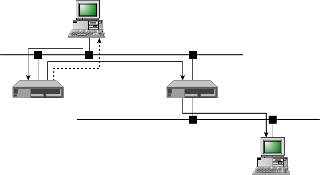
Recognizing Security Threats
475
c14.indd 04/02/2015 Page 475
FIGURE 14.1 Unreachable gateway
Data
Redirect Data
Data
G1 G2
NET2
NET1
Destination
Host
Source
Host
4. The source host will accept the route change control message as valid and thus change
its routing table to route all traffic bound for the destination host through gateway G1.
5. Now the attacker, acting as a man-in-the-middle host, will quietly read/modify and
forward all traffic bound for the destination host to gateway G2.
Distributed DoS (DDoS)
Denial of service attacks can be made more effective if they can be ampli ed by recruiting
helpers in the attack process. In the following sections, some terms and concepts that apply
to a distributed denial of service attack are explained.
Botnet
A botnet is a group of programs connected on the Internet for the purpose of performing
a task in a coordinated manner. Some botnets, such as those created to maintain control
of Internet Relay Chat (IRC) channels are legal, while others are illegally created to foist
a DDoS. An attacker can recruit and build a botnet to help amplify a DoS attack, as illus-
trated in Figure 14.2.
The steps in the process of building a botnet are as follows:
1. A botnet operator sends out viruses or worms whose payloads are malicious applica-
tions, the bots, infecting ordinary users’ computers.
2. The bots on the infected PCs log into a server called a command and control (C&C)
server under the control of the attacker.
3. At the appropriate time, the attacker, through the C&C server, sends a command to all bots
to attack the victim at the same time, thereby significantly amplifying the effect of the attack.
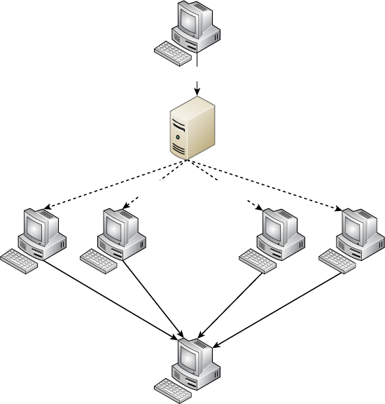
476
Chapter 14 ■ Network Threats and Mitigation
c14.indd 04/02/2015 Page 476
FIGURE 14.2 Botnet
Bot Bot Bot Bot
Victim
•••••• •••
Attacker
Command and Control
Server
Traffic Spike
One of the hallmarks of a DDoS attack is a major spike in traf c in the network as bots
that have been recruited mount the attack. For this reason, any major spike in traf c should
be regarded with suspicion. A network intrusion detection system (IDS) can recognize these
traf c spikes and may be able to prevent them from growing larger or in some cases prevent
the traf c in the rst place.
Some smaller organizations that cannot afford some of the more pricy intrusion preven-
tion systems (IPSs) or IDSs make use of features present on their load balancers. Many of
these products include DDoS mitigation features such as the TCP SYN cookie option. It
allows the load balancer to react when the number of SYN requests reaches a certain point.
At that point, the device will start dropping requests when the SYN queue is full.
Coordinated Attack
Another unmistakable feature of a DDoS attack is the presence of a coordinated attack.
As shown in Figure 14.2 and as just described in the section “Botnet,” to properly amplify
the attack the bots must attack the victim at the same time. The coordination of the bots is
Recognizing Security Threats
477
c14.indd 04/02/2015 Page 477
orchestrated by the command and control server depicted in Figure 14.2. If all the bots can
be instructed to attack at precisely the same second, the attack becomes much more danger-
ous to the victim.
Friendly/Unintentional DoS
An unintentional DoS attack (also referred to as attack from “friendly re”) is one that is
not caused by malicious individuals but rather is a spike in activity to a website or resource
that overpowers its ability to respond. In many cases, it is the result of a relatively unknown
URL suddenly being shared in a larger medium such as a popular TV or news show. For
example, when Michael Jackson died, the amount of Twitter and Google traf c spiked so
much that at rst it was though that an automated attack was under way.
Physical Attack
Physical attacks are those that cause hardware damage to a device. These attacks can be
mitigated, but not eliminated, by preventing physical access to the device. Router, switches,
rewalls, servers, and other infrastructure devices should be locked away and protected by
strong access controls. Otherwise, you may be confronted with a permanent DoS, covered
in the next section.
Permanent DoS
A permanent DoS attack is one in which the device is damaged and must be replaced. It
requires physical access to the device, or does it? Actually, it doesn’t! An attack called a
phlashing denial of service ( PDOS) attacks the rmware located in many systems. Using tools
that fuzz (introduce errors) the rmware, attackers cause the device to be unusable. Another
approach is to introduce a rmware image containing a Trojan or other types of malware.
Smurf
Smurfs are happy little blue creatures that like to sing and dance, but a Smurf attack is far
more nefarious. It’s a version of a DoS attack that oods its victim with spoofed broadcast
ping messages. I’ll talk about spoo ng in more detail later; for now, understand that it basi-
cally involves stealing someone else’s IP address.
Here’s how it works: The bad guy spoofs the intended victim’s IP address and then sends
a large number of pings (IP echo requests) to IP broadcast addresses. The receiving router
responds by delivering the broadcast to all hosts in the subnet, and all the hosts respond
with an IP echo reply—all of them at the same time. On a network with hundreds of hosts,
this results in major network gridlock because all the machines are kept busy responding
to each echo request. The situation is even worse if the routers have not been con gured to
keep these types of broadcasts con ned to the local subnet (which thankfully they are by
default!). Figure 14.3 shows a Smurf attack in progress.
Fortunately, Smurf attacks aren’t very common anymore because most routers are
con gured in a way that prevents them from forwarding broadcast packets to other net-
works. Plus, it’s really easy to con gure routers and hosts so they won’t respond to ping
requests directed toward broadcast addresses.
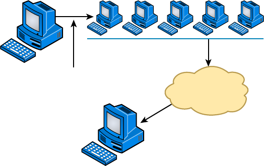
478
Chapter 14 ■ Network Threats and Mitigation
c14.indd 04/02/2015 Page 478
FIGURE 14.3 Smurf attack in progress
Internet
Attacker Attacker sends ICMP broadcast
to network with false IP address.
Network overloads victim
with ICMP response.
Victim
SYN Flood
A SYN ood is also a DoS attack that inundates the receiving machine with lots of packets
that cause the victim to waste resources by holding connections open. In normal com-
munications, a workstation that wants to open a Transmission Control Protocol/Internet
Protocol (TCP/IP) communication with a server sends a TCP/IP packet with the SYN ag
set to 1. The server automatically responds to the request, indicating that it’s ready to start
communicating with a SYN-ACK. In the SYN ood, the attacker sends a SYN, the vic-
tim sends back a SYN-ACK, and the attacker leaves the victim waiting for the nal ACK.
While the server is waiting for the response, a small part of memory is reserved for it. As
the SYNs continue to arrive, memory is gradually consumed.
Figure 14.4 shows an example of a simple DoS/SYN ood attack.
You can see that the preyed-upon machine can’t respond to any other requests
because its buffers are already overloaded, and it therefore rejects all packets requesting
connections, even valid ones, which is the idea behind the attack. The good news is that
patches to help guard against this type of attack are available for the various network
operating systems today.
Stacheldraht
This is actually a mélange of techniques that translates from the German word for barbed
wire. It basically incorporates TFN and adds a dash of encryption to the mix. The night-
mare begins with a huge invasion at the root level, followed with a DoS attack nale.
Reflective/Amplified Attacks
Re ected or ampli ed attacks increase the effectiveness of a DoS attack. Two of the more
effective of these type of attacks involve leveraging two functions that almost all networks
use, DNS and NTP. In the next two sections these attacks are described.
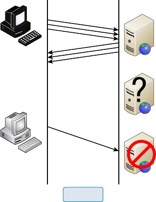
Recognizing Security Threats
479
c14.indd 04/02/2015 Page 479
FIGURE 14.4 A simple DoS/SYN flood attack
Attacker sends
multiple SYN
requests to a
web server.
Valid user sends
SYN request.
Web server sends
SYN-ACK replies.
Web Server
Web Server
Web Server
Web server waits to
complete three-way
handshake.
Web server is
unavailable.
SYN Flood
DNS
A DNS ampli cation attack is a form of re ection attack in that the attacker delivers traf c
to the victim by re ecting it off a third party. Re ection conceals the source of the attack.
It relies on the exploitation of publicly accessible open DNS servers to deluge victims with
DNS response traf c.
The attacker sends a small DNS message using the victim’s IP address as the source to
an open resolver. The type of request used returns all known information about the DNS
zone, which allows for the maximum level of response ampli cation directed to the victim’s
server. The attack is magni ed by recruiting a botnet to send the small messages to a large
list of open resolvers (DNS servers). The response from the DNS server overwhelms the vic-
tim, as shown in Figure 14.5.
NTP
While NTP refection attacks use the same process of recruiting bots to aid the attack,
the attacks are not re ected off DNS servers; they are instead re ected off Network Time
Protocol (NTP) servers. These servers are used to maintain time synchronization between
devices in a network.
The attacker (and his bots) sends a small spoofed 8-byte UDP packet to vulnerable NTP
servers that requests a large amount of data (megabytes worth of traf c) be sent to the
DDoS’s target IP address. The attackers use the
monlist
command, a remote command in
older versions of NTP, that sends the requester a list of the last 600 hosts who have con-
nected to that server. This attack can be prevented by using at least NTP version 4.2.7
(which was released in 2010).
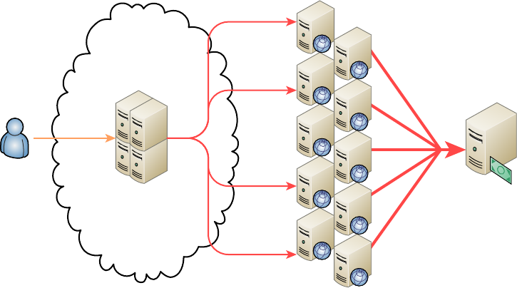
480
Chapter 14 ■ Network Threats and Mitigation
c14.indd 04/02/2015 Page 480
FIGURE 14.5 DNS amplification attack
Attacker
Attacker-Controlled
Botnet
Small Spoofed
DNS Request Amplified DNS Response
from Open Resolver
Victim’s
E-commerce
Server
ARP Cache Poisoning
ARP cache poisoning is usually a part of a man-in-the middle attack. The ARP cache
contains IP address to MAC address mappings that a device has learned through the ARP
process. One of the ways this cache can be poisoned is by pinging a device with a spoofed
IP address. In this way, an attacker can force the victim to insert an incorrect IP address
to MAC address mapping into its ARP cache. If the attacker can accomplish this with
two computers having a conversation, they can effectively be placed in the middle of the
transmission. After the ARP cache is poisoned on both machines, they will be sending data
packets to the attacker, all they while thinking they are sending them to the other member
of the conversation.
Packet/Protocol Abuse
After an attacker has broken into the system, attained access, and escalated their privileges,
it is important for them to maintain their authority on the system so they can access it at a
later time. They could put an operating system backdoor on the target, but in some cases
the rewall on the victim may not allow outgoing TCP connections.
One of the ways in which a hacker can get traf c through a rewall that would typi-
cally not be allowed is by concealing one protocol within another, which is a form of tun-
neling. TCP can be encapsulated into either DNS or ICMP, thereby bypassing the rewall
restrictions.
An example of this is using a program called Iodine to encapsulate IP traf c in DNS
packets. Once the DNS packets reach the local DNS server, they are forwarded to a second
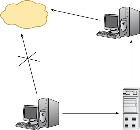
Recognizing Security Threats
481
c14.indd 04/02/2015 Page 481
machine running Iodine that de-encapsulates the packets and sends them on to the hacker.
The DNS traf c is allowed by the rewall and is able to reach the client. In this way, the
attacker is able to communicate with the victim machine. This process is illustrated in
Figure 14.6.
FIGURE 14.6 IP4 packets tunneled in DNS
Server Running Iodine
Server Running Iodine
Local DNS Server
DNS Traffic
(Encapsulated)
DNS Traffic
(Encapsulated)
Internet
IPv4 Traffic
Blocked
Spoofing
IP spoo ng is the process of changing a source IP address so that one computer appears
to be a different computer. It’s usually done to get traf c through a rewall that would
normally not be allowed. It may also be used to access a server to which the hacker would
normally be disallowed access by their IP address.
While IP spoo ng may be the most well-known type of spoo ng, it is not the only type
used by hackers. The following forms of this subterfuge also exist:
■ ARP spoofing (discussed earlier in the section “ARP Cache Poisoning”).
■ Referrer spoofing, in which the referrer header of an HTTP packet is changed to reflect
an allowed referral page, which some sites require for access.
■ Email spoofing, in which the “from” field is changed to hide the true origin of an
email. In most cases this is to conceal the identity of an email spammer.
482
Chapter 14 ■ Network Threats and Mitigation
c14.indd 04/02/2015 Page 482
Brute Force
A brute force attack is a form of password cracking. The attacker attempts every possible
combination of numbers and letters that could be in a password. Theoretically, given
enough time and processing power, any password can be cracked. When long, complex
passwords are used, however, it can take years.
Setting an account lockout policy is the simplest mitigation technique to defeat brute
force attacks. With such a policy applied, the account becomes locked after a set number of
failed attempts.
Session Hijacking
Session hijacking attacks attempt to take over a user’s session with a secure server after the
user has been authenticated. This can be done in the following ways:
Session Fixation The attacker sets the session ID ahead of time by sending a link to the
victim with the ID preset. When the user connects, the attacker waits for the authentica-
tion to complete and takes over the session by disconnecting the user and using the ID to
reconnect.
Session Sidejacking The attacker uses a sniffer to steal a session cookie from the user.
Alternately, if the attacker has physical access to the user’s machine, they can steal the
session key from memory.
Cross-Site Scripting The attacker uses the user’s computer to run code on the site
that may allow him to obtain the cookie. The attacker does this by putting malware on the
user’s computer; the malware runs the code on the site after the user authenticates
to thesite.
VLAN Hopping
VLANs, or virtual LANs, are Layer 2 subdivisions of the ports in a single switch. A VLAN
may also span multiple switches. By segregating devices into VLANs, access control lists
(ACLs) can be used in a router to control access between VLANs in the same way it is done
between real LANs. When VLANs span switches, the connection between the switches is
called a trunk link, and it carries the traf c of multiple VLANs. Trunk links are also used
for the connection from the switch to the router.
A VLAN hopping attack results in traf c from one VLAN being sent to the wrong
VLAN. Normally, this is prevented by the trunking protocol placing a VLAN tag in the
packet to identify the VLAN to which the traf c belongs. The attacker can circumvent this
by a process called double tagging, which is placing a fake VLAN tag into the packet along
with the real tag. When the frame goes through multiple switches, the real tag is taken off
by the rst switch, leaving the fake tag. When the frame reaches the second switch, the fake
tag is read and the frame is sent to the VLAN to which the hacker intended the frame to go.
This process is shown in Figure 14.7.
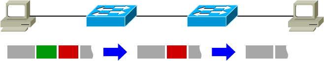
Recognizing Security Threats
483
c14.indd 04/02/2015 Page 483
FIGURE 14.7 VLAN hopping
S1 S2
EthEth V1 V10 Eth V10
Attacker Access
VLAN: 1
Access
VLAN: 10 Victim
802.1Q
Trunk
Authentication Issues
Since the process of authenticating a user or a device forms the basis for securing most
resources, authentication issues can lead to improper access, stolen data, and a whole host of
other problems. In the following sections, we’ll look at some common authentication issues.
TACACS/RADIUS Misconfiguration
Terminal Access Controller Access Control System Plus (TACACS+) and Remote Access
Dial-In User Service (RADIUS) are both examples of Authentication, Authorization, and
Accounting (AAA) servers that verify the identity of, grant access to, and track the actions
of users. Miscon guration of these devices can result in an inability of users and devices to
connect to the access devices that are clients of the AAA server (switches, WAPs, dial-up
servers, VPN servers). Some of the most common mistakes that result in this situation
prevent communication between the AAA server and the AAA client. When this
happens, check the following:
■ Verify the port numbers. Even if standard port numbers for these services have been
selected, that doesn’t mean the product you are using uses those port numbers. Make
sure the client and server are using the correct port numbers.
■ Check to see if there is a mismatch in the pre-shared key between the client and the server.
When the problem is an issue between the supplicant (user or device requesting access)
and the authenticating server (switch, WAP, dial-up server), check the following:
■ Verify that the AAA method configured on the supplicant lists the appropriate
RADIUS or TACACs+ server group.
■ Verify that the authentication port number matches the configured port number.
■ Verify that the user is configured on the AAA server (user account).
Default Passwords/Settings
All network devices are con gured with default administrator accounts and their default
passwords. These accounts should be disabled and renamed if possible. At the very least,
the passwords for these accounts should be changed from the default because they are well
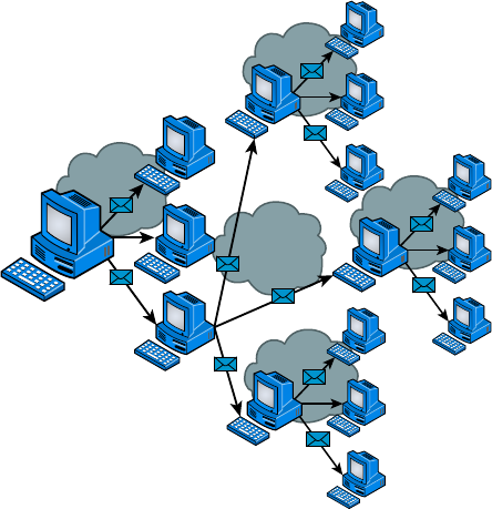
484
Chapter 14 ■ Network Threats and Mitigation
c14.indd 04/02/2015 Page 484
known, available in documentation that comes with the product, and also widely available
on the Internet.
Viruses
Viruses with catchy names like Chernobyl, Michelangelo, Melissa, I Love You, and Love
Bug are probably the best-known threats to your computer’s security because they get a lot
of media coverage as they proliferate and cause tons of damage to legions of people. In their
simplest form, viruses are basically little programs that cause a variety of very bad things
to happen on your computer, ranging from merely annoying to totally devastating. They
can display a message, delete les, or even send huge amounts of meaningless data over
a network to block legitimate messages. A key trait of viruses is that they can’t replicate
themselves to other computers or systems without a user doing something like opening an
executable attachment in an email to propagate them. Figure 14.8 shows how fast a virus
can spread through an email system.
FIGURE 14.8 An email virus spreading rapidly
Virus
Virus
Virus
Virus
Virus
There are several different kinds of viruses, but the most popular ones are le viruses,
macro (data le) viruses, and boot-sector viruses. Each type differs slightly in the way
it works and how it infects your system. Predictably, many viruses attack popular appli-
cations like Microsoft Word, Excel, and PowerPoint because those programs are easy
to use so it’s easy to create a virus for them. Unlike with DoS attacks, writing a unique

Recognizing Security Threats
485
c14.indd 04/02/2015 Page 485
virus is considered a programming challenge, so the scoundrel who’s able to come up
with it not only gains respect from the hacking community but also gets to bask in the
glow of the media frenzy that results from their creation and relish their 15 minutes of
fame. This is also a big reason viruses are becoming more and more complex and harder
to eliminate.
Effect of Malware on the Network
Malicious software (or malware) is a term that describes any software that harms a com-
puter, deletes data, or takes actions the user did not authorize. There is a wide array of
malware types, including ones you have probably heard of, like viruses. Some types of mal-
ware require the assistance of a user to spread, while others do not.
A worm is a type of malware that can spread without the assistance of the user. A worm
is a small program that, like a virus, is used to deliver a payload. One way to help miti-
gate the effects of worms is to place limits on sharing, writing, and executing programs.
However, the real solution is to deploy antivirus and anti-malware software to all devices in
the network. This software is designed to identify viruses, Trojans, and worms and delete
them, or at least quarantine them until they can be removed.
File Viruses
A le virus attacks executable application and system program les like those with le-
names ending in
.com
,
.exe
, and
.dll
. These viruses do their damage by replacing some or
all of the target program’s code with their own. Only when the compromised le is
executed can the virus do its dirty work. First, it loads itself into memory and waits to
infect other executables, propagating its destructive effects throughout a system or net-
work. A couple of well-known le viruses are Jerusalem and Nimda, the latter of which is
actually an Internet worm that infects common Windows les and other les with lename
extensions like
.html
,
.htm
, and
.asp
.
Don’t fall into the trap of thinking that just because you have a Mac, you
don’t need to worry about viruses. It’s a common misconception that Mac
operating systems are immune to viruses, but they’re not. Today’s Macs
are really BSD Unix machines with a couple of proprietary programs run-
ning on top that provide users with a slick interface. And although it’s true
that more sophisticated programming skills are required to write viruses
for Mac, BSD Unix, and Linux operating systems than for DOS-based
operating systems like Windows, all operating systems are vulnerable
to attacks. True, it’s a lot easier for a bad guy to write malicious code for
Windows machines, but the real reason few programmers spend their time
creating viruses for Sun workstations and Macs is that there aren’t nearly
as many people using them. On the other hand, Windows machines are
everywhere, so viruses written for them will clearly infect multitudes, giv-
ing bad guys who want to infect as many computers as possible a lot more
bang for their evil programming buck!
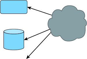
486
Chapter 14 ■ Network Threats and Mitigation
c14.indd 04/02/2015 Page 486
Macro Viruses
A macro is basically a script of commonly enacted commands used to automatically carry
out tasks without requiring a user to initiate them. Some popular programs even give you
the option of creating your own, personal scripts to perform tasks you do repeatedly in a
single step instead of having to enter the individual commands one by one.
Similar to this, a macro virus uses something known as the Visual Basic macro-scripting
language to perform nasty things in data les created with programs like those in the
Microsoft Of ce Suite. Because macros are so easy to write, they’re really common and
usually fairly harmless, but they can be super annoying! People frequently nd them infect-
ing the les they’re working on in Microsoft Word and PowerPoint. Suddenly you can’t save
the le even though the Save function is working, or you can’t open a new document, only
a template. As I said, these viruses won’t crash your system, but they can ruin your day.
Cap and Cap A are examples of macro viruses.
Boot-Sector Viruses
Boot-sector viruses work their way into the master boot record that’s essentially the
ground-zero sector on your hard disk where applications aren’t supposed to live. When
a computer boots up, it checks this area to nd a pointer for its operating system. Boot-
sector viruses overwrite your boot sector, making it appear as if there’s no pointer to your
operating system. You know you’ve got this type of virus when you power up the computer
and get a Missing Operating System or Hard Disk Not Found error message. Monkey B,
Michelangelo, Stoned, and Stealth Boot are a few examples of boot-sector viruses.
Multipartite Viruses
A multipartite virus is one that affects both the boot sector and les on your computer,
making such a virus particularly dangerous and exasperatingly dif cult to remove. Figure
14.9 gives you an idea of how a multipartite virus works. You can see that it is attacking
the boot sector, memory, and the disk at once.
FIGURE 14.9 Multipartite virus
Memory
Boot Sector
Disk Files
Multipartite
Virus
Anthrax and Tequila are both multipartite viruses. These viruses are so nasty that you
might end up reformatting your computer if you get one. Although the Anthrax virus was

Recognizing Security Threats
487
c14.indd 04/02/2015 Page 487
more of a hoax then a real virus; what is really interesting about the Tequila virus is that it
does nothing until the next reboot—it was no hoax!
Although many software companies can handle these, the best way to save your
computer from a complete overhaul is to make sure you do not get a virus in the rst place
by using a good virus scan program as well as Windows Defender.
Most of the viruses in one of these categories infect your system through
something known as a Trojan horse. Troy was successfully invaded by
troops hidden inside a giant horse; a Trojan virus hides within other
programs and is launched when the program it’s lurking in starts up.
Often viruses come as attachments to emails with double filename exten-
sions to hide the true extension.
DMSETUP.EXE
and
LOVE-LETTER-FOR-YOU.
TXT.VBS
are examples of viruses. Displaying filename extensions for
known file types can help spot naming tricks like these, but they make up
only a short list of the viruses out there. For a more complete inventory,
see your antivirus software manufacturer’s website.
Zero Day Attacks
Antivirus software uses de nition les that identify known malware. These les must be
updated frequently, but the update process can usually be automated so that it requires no
help from the user. If a new virus is created that has not yet been identi ed in the list, you
will not be protected until the virus de nition is added and the new de nition le is down-
loaded. This condition is known as a zero day attack because it is the rst day the virus has
been released and therefore no known x exists. This term may also be applied to an oper-
ating system bug that has not been corrected.
Insider Threat/Malicious Employee
It is often said that an organization has the most to fear from its own employees. They have
already completed two phases of the hacking process, that is, discovery and penetration.
They are already inside your network and probably have learned quite a bit about the net-
work just doing their job.
The rst step to mitigating damage that may be caused by disgruntled or malicious
employees is to adhere to the principle of least privilege. This concept prescribes that users
should be given access only to resources required to do their job.
Another principle that should be followed is called separation of duties. It calls for
breaking up sensitive operations into two parts and having different users perform each
part. This means there would have to be collusion between the two to take advantage of the
process, which is not likely to occur.
Finally, all network access should be taken from a user who has been terminated before
they have a chance to access the network.
488
Chapter 14 ■ Network Threats and Mitigation
c14.indd 04/02/2015 Page 488
Vulnerabilities
While malware certainly presents an ongoing danger to your network, it is not the only
concern of the security professional. In the following sections, I’ll cover some other issues.
Unnecessary Running Services
Services that are not required to be running on a system should be disabled. Running
services present an additional attack surface to the hacker. Once they identify the
running services on a machine, they will research all the vulnerabilities presented by that
service and attempt to use it to compromise the target.
Open Ports
In the same way that unnecessary services present attack options, so do open ports.
Software port numbers are used to identify protocols and services, and serve as a
connection point to the service on a target machine. Ports scanners can be used to identify
the ports that are open on all machines in a network. An open port means the device is
listening on that port number and is willing to make a connection using that port. Unused
ports should be shut down.
Unpatched/Legacy Systems
Systems that use older or legacy operating systems and applications may lack the security
required in today’s networks. These devices may require special protection, such as placing
them in a secure VLAN or installing host-based IPS systems.
Even modern operating systems and applications will be insecure if they are not
maintained by applying updates and security patches as they are released. A formal, and
preferably automated, process should be set up to ensure that this maintenance
is ongoing.
Unencrypted Channels
If it isn’t clear to you by now, in any situation where sensitive data is being transmitted,
attention should be given to the type of channel across which the data is traveling. When
no other method is available, IPSec is a network layer protocol suite that can be used to
provide end-to-end protection of any data that resides above the network layer.
Clear-Text Credentials
Many protocols provide the ability to control access through authentication. However,
while some protect the con dentiality of the process by hiding the credentials as they are
Vulnerabilities
489
c14.indd 04/02/2015 Page 489
exchanged, others do not. For example, Telnet (a protocol used for remote command-line
management of devices) transmits credentials in clear text; Secure Shell (SSH) does not.
Another example is Password Authentication Protocol (PAP), one of two authentication
options offered when a PPP connection is being set up. PAP transmits credentials in clear
text, while Challenge Authentication Protocol (CHAP), the other option, uses a process
that never sends the credential across the network. You should never use a protocol that
transmits credentials in clear text.
TEMPEST/RF Emanation
Spying on information systems can also be accomplished by capturing and analyzing leak-
ing emanations of things like radio or electrical signals, sounds, and vibrations. TEMPEST
is a National Security Agency speci cation and NATO certi cation that addresses methods
of spying used and how to protect against them. Distance, shielding, ltering, and masking
are used to protect equipment from spying. The TEMPEST standards are used to describe
the level of protection a system is certi ed to provide.
Malicious Users
Damaging activity on your network can come from both inside and outside the network.
In the following sections, we’ll look at the two types of malicious users you will encounter
and an operation often performed in the execution of their mayhem.
Trusted Users
While we would like to think that all of our own people can be trusted, that’s often not the
case. Even your “trusted” users can go to the dark side with the proper motivation. The
following are among the motives that can turn a trusted user into a malicious user:
■ Perceived slight by the company
■ Jealousy of other employees
■ Monetary reward
The real danger presented by a trusted employee who turns malicious is that the
employee is already inside your network and probably knows quite a bit about it. This is
the reason for following the principle of least privilege, which prescribes that users be given
access only to resources required to do their job.
Untrusted Users
While it may take untrusted users or users outside your network a bit longer to make their
way into your network, once they get there they will probably have a signi cantly higher
level of skill than a disgruntled employee has. Discovering and penetrating your network
from outside takes some skill. The best mitigation for these attacks is a combination of
perimeter defense (keep them out) and strong access control at the point of resource access
(prevent access to devices holding information). A multilayer approach works best.
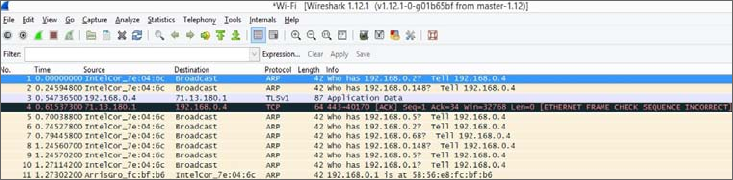
490
Chapter 14 ■ Network Threats and Mitigation
c14.indd 04/02/2015 Page 490
Packet Sniffing
One of the basic tools a hacker will possess is a protocol analyzer or packer sniffer. These
devices capture raw packets off the network for analysis. Normally, a device will only pro-
cess packets that are destined for itself, but this software places the network interface of the
hacker’s device in promiscuous mode, which means it captures all packets on the network.
This software can also be used legitimately to examine your network traf c for things
that should not be there. Figure 14.10 shows an example of the output from the packet ana-
lyzer Wireshark. In the output, it can be seen that packet 4 failed a Frame Check Sequence,
which would require it to be sent again. While the list of packets captured is displayed, you
can click on any packet and examine it in detail. If the data is in clear text, you will be able
to read it.
FIGURE 14.10 Wireshark
Buffer Overflow
When programs execute, they write commands into memory or to a buffer. Well-written
programs allow a certain location and/or amount of memory space for these commands to
execute. If a hacker is able to inject a command that over ows the amount of memory allo-
cated and the command is able to execute with the proper security privileges, the hacker
could execute commands that would not normally be allowed. They may be able to take
control of the machine and create havoc.
A number of well-known exploits, such as the Code Red worm, employed buffer over-
ows to create their mayhem. The way to prevent buffer over ows is to include input vali-
dation into programs to mitigate the possibility of them occurring.
Wireless Threats
The proliferation of wireless communication has introduced a number of security challenges
that are unique to the wireless environment. Some of these threats even take advantage
of the security measures that have been created to protect wireless networks and hosts.
Wireless threats such as WEP and WPA cracking (discussed in the following sections)
remind us that network attackers never stop evolving their methods and that constant review
and adaptation of security measures are required to maintain security in the network.
Vulnerabilities
491
c14.indd 04/02/2015 Page 491
War Driving
War driving is one of the oldest wireless threats and perhaps one of the easiest to discour-
age (although you can’t defeat it if the hacker is determined). The attacker simply drives
around with a high-powered antenna connected to a wireless laptop scanning for net-
works. The networks will be listed by network name (SSID) in the wireless client software,
and depending on the software, the channel and security measures in use will also be
displayed.
If the network is not secured, the attacker can connect to it. This is not just a matter of
stealing bandwidth for Internet access. Once connected, the attacker may be able to
proceed on into your wired network as well. They can then attempt other attacks, such as
port scanning and peer-to-peer attacks. The point is that they have completed the rst step
in the hacking process, which is penetration.
War driving cannot be entirely prevented, but you can make it harder for an attacker.
One of the simplest things you can do is limit the transmission power on the access point
(AP) such that the signal does not go any further than required! Additionally, if you set the
access point to not broadcast the SSID, the name of the network will not appear in the
display when they scan for networks. This means that to connect, they will have to know
the SSID and create a wireless pro le specifying it.
If an attacker is determined, however, they can learn the SSID by using a wireless
protocol analyzer or sniffer to capture the raw packets. This is something you cannot pre-
vent without turning off the AP. When you set the AP to not broadcast the SSID, it will
remove the SSID from packets called beacons (these are the packets that populate the dis-
play when you scan for networks), but it will still be present in many other packet types.
In most cases, hiding the SSID will be suf cient because if an attacker doesn’t see your
network when scanning, they probably won’t be motivated to use the sniffer.
War Chalking
War chalking is really just an extension of war driving. The hacker simply writes the SSID
and security employed on the sidewalk or wall somewhere near your facility, sort of like
advertising “here’s a wireless network” to anyone who recognizes that code. Most of this
type of activity has moved online where websites have sprung up that allow hackers to post
and share these networks on maps indicating their location.
WEP Cracking
Wired Equivalent Privacy (WEP) is a security protocol created in the early years of 802.11
development that was designed to both authenticate users and encrypt the wireless data
they transmitted. It uses the RC4 algorithm in the encryption process. Soon after its
adoption as a security measure, it was discovered that due to a weakness in the way the
algorithm was employed, programs that became widely available on the Internet could be
used to crack the WEP key. Once the key was known, it could be used to decrypt the data.
Because of this, WEP is no longer considered to be a suf cient security mechanism in any
situation where the data is sensitive.
492
Chapter 14 ■ Network Threats and Mitigation
c14.indd 04/02/2015 Page 492
WPA/WPA2 Cracking
After WEP cracking became an issue, the manufacturers of wireless equipment were faced
with a problem. The IEEE was working on creating a new security standard (which became
known as 802.11i) but were moving at their usual deliberate pace. In the meantime, compa-
nies were not deploying wireless networks because of security concerns. The Wi-Fi Alliance
created a temporary solution called Wi-Fi Protected Access (WPA) that was an improve-
ment on WEP.
Soon after WPA was rolled out, it was discovered that it also could be cracked. Cracking
WPA required more effort than cracking WEP, and it required what is called a diction-
ary le (a le of words that could possibly be used as a password). It also required that the
passphrase or password be a word in the dictionary. Finally, it required capturing a large
number of wireless frames, and the cracking process took a lot of time. Keep in mind that
this type of attack is effective on any password-based system, including Wi-Fi Protected
Access 2 (WPA2) when it uses passwords.
But the point is that if the hackers had good reason to believe they were capturing valu-
able data, it could be done. Therefore, WPA is not considered good security unless it is
employed as WPA2, which is based in the secure 802.11i architecture.
WPS Attacks
Wi-Fi Protected Setup (WPS, originally Wi-Fi Simple Con g) is a network security stan-
dard that attempts to allow users to easily secure a wireless home network. It works by
enabling the user to add a device to the network without typing credentials; all the user
needs to do is push the WPS button located on many home wireless access points.
When this function is enabled, which it is by default on many systems, it is possible for
a hacker to perform a brute force attack on the password, and then later the network pre-
shared key for WPA or WPA2. Users should disable this feature if the device allows this
change.
Rogue Access Points
Rogue access points are access points that you do not control and manage. There are two
types: those that are connected to your wired infrastructure and those that are not. The
ones that are connected to your wired network present a danger to your wired and wireless
network. They may be placed there by your own users without your knowledge, or they
may purposefully be put there by a hacker. In either case, they allow access to your wired
network. Wireless intrusion prevention system (IPS) devices are usually used to locate them
and to alert administrators of their presence.
Rogue access points that are not connected to your wired infrastructure are usually used
as part of a hijacking attack, which is discussed in the next section.
Evil Twin
An evil twin is an AP that is not under your control but is used to perform a hijacking
attack. A hijacking attack is one in which the hacker connects one or more of your users’
computers to their network for the purpose of a peer-to-peer attack.
Vulnerabilities
493
c14.indd 04/02/2015 Page 493
The attack begins with the introduction of an access point that is under the hacker’s
control. This access point will be set to use the same network name or SSID your network
uses, and it will be set to require no authentication (creating what is called an open net-
work). Moreover, this access point will be set to use a different channel than the access
point under your control.
To understand how the attack works, you must understand how wireless stations
(laptops, PDAs, and so on) choose an access point with which to connect. It is done by
SSID and not by channel. The hacker will “jam” the channel on which your access point is
transmitting. When a station gets disconnected from an access point, it scans the area for
another access point with the same SSID. The stations will nd the hacker’s access point
and will connect to it.
Once the station is connected to the hacker’s access point, it will receive an IP address
from a DHCP server running on the access point and the user will now be located on
the same network as the hacker. At this point, the hacker is free to commence a
peer-to-peer attack.
Bluejackng
Bluejacking is an attack aimed at Bluetooth connections. It sends unsolicited messages to
the devices. These messages are typically in the form of a vCard that contains the message
in the name eld. While these attacks are annoying, they are not serious when compared to
the attack in the next section, which is also a Bluetooth attack.
Bluesnarfing
Bluesnar ng is unauthorized access of a Bluetooth-enabled device. These attacks allow
access to the data on the device and make use of the pairing function used to connect two
devices to transfer data between them. Users should be advised to disable the function that
makes their device “discoverable” and enable it manually only when a connection needs
to be made.
Attackers and Their Tools
The old adage “Never talk to strangers” applies here because you can’t spot a hacker by
looking at one. That quiet 15-year-old kid next door or the head of the PTA could secretly
be a criminal hacker (or cracker, in nerd-speak)—you just never know. But instead of living
your life being suspicious of everyone you meet, it’s much better to understand the ways
and strategies bad guys use to in ltrate your defenses.
The interaction between a hacker and a network administrator can be anything from
a harmless game of cat and mouse to a terrorist attack on national security. Either way,
there’s someone out there trying to break into or crash your system, and it’s up to you to
track and prevent the attacks.
Network attacks executed by an actual hacker are called directed attacks. For instance,
a bad guy can use the WinNuke utility, which I’ll describe soon, to generate a packet and
send it to a speci c machine. On the other hand, viruses aren’t usually directed attacks—
instead they’re just blindly copied from user to user.

494
Chapter 14 ■ Network Threats and Mitigation
c14.indd 04/02/2015 Page 494
I’ll start by telling you about some common network attacks and then move on to cover
the techniques used to prevent them from happening to you.
Do We Really Need Firewalls?
Believe it or not, the honor system used to apply to the Internet, and it pretty much
worked, so fi rewalls just weren’t needed. Now, nothing could be further from the truth!
Today, multitudes of companies have their entire corporate intranets connected to the
Internet; plus, a legion of e-commerce sites like eBay and Amazon transfer seriously
sensitive personal and fi nancial data over the Internet. Corporate espionage and identity
theft are currently the fastest-growing crimes worldwide—evil deeds pulled off by bad
guys lurking on the Net. So, we all need to practice “Safe Net,” and one popular way to
do that is by implementing fi rewalls on our networks.
Application-Layer Attacks
Application-layer attacks usually zero in on well-known holes in software that’s running
on our servers. Favorite targets include FTP, sendmail, and HTTP because the permissions
level granted to these accounts is often privileged. This means that bad guys who break in
not only gain access to your network but also get the added bonus of having privileged
status while they’re in there—yikes!
ActiveX Attacks
A fairly new form of attack makes its way to your computer through ActiveX and Java
programs (applets). These are miniature programs that run on a web server or that you
download to your local machine. Most ActiveX and Java applets are safe, but some con-
tain viruses or snoop or spyware programs. Snoop or spyware programs allow a hacker to
look at everything on your hard drive from a remote location without you knowing about
it, which is really bad, so be sure you properly con gure the on-access component of your
antivirus software to check and clean for these types of attacks.
Autorooters
You can think of autorooters as a kind of hacker automaton. Hackers use something called
a rootkit to probe, scan, and then capture data on a strategically positioned computer that’s
poised to give them “eyes” into entire systems automatically. This is clearly very bad for
you and your data. Note that this is typically how a cracker can attack a Mac or Unix box.
Backdoors
Backdoors are simply paths leading into a computer or network. From simple invasions to
elaborate Trojan horses, villains can use their previously placed inroads into a speci c host
Vulnerabilities
495
c14.indd 04/02/2015 Page 495
or a network whenever they want to. That is, unless you can detect them and stop them in
their tracks.
Network Reconnaissance
Before breaking into a network, bad guys gather all the information they can about it
because the more they know about the network, the better they can compromise it. This is
called network reconnaissance. Hackers accomplish their objectives through methods
like port scans, Domain Name Service (DNS) queries, and ping sweeps—even social
engineering, or phishing, which I’ll cover in a bit.
Packet Sniffers
A packet sniffer is a software tool that can be incredibly effective in troubleshooting a
problematic network, but it can also be a hacker’s friend. Here’s how it works: A network
adapter card is set to promiscuous mode so it will send all packets snagged from the
network’s Physical layer through to a special application to be viewed and sorted out. A
packet sniffer can nick some highly valuable, sensitive data, including, but not limited to,
passwords and usernames, making such a tool a prize among identity thieves.
Port Scanners
Port scanners are programs that ping every port on the target to identify which ports are
open. It does this by pinging the IP address of the target with the port number appended
after a colon. If an answer is received, the port is open. Open ports can lead to services the
hacker can potentially exploit.
FTP Bounce
This attack is a variation of the port scan in that the attacker uses the
FTP PORT
command
to request access to ports indirectly by using the victim machine as a middleman for the
request. This cloaks the identity of the device performing the port scan.
Port-Redirection Attacks
A port-redirection attack requires a host machine the hacker has broken into and uses to
redirect traf c that normally wouldn’t be allowed passage through a rewall. The attacker
gains access to a trusted computer that is outside the rewall and installs software on the
machine. They then redirect traf c bound for a particular port on the trusted yet now com-
promised host to their machine.
Trust-Exploitation Attacks
Trust-exploitation attacks happen when someone exploits a trust relationship in your net-
work. The attacker gains control of a host that is outside the rewall yet is trusted by hosts
that are inside the rewall. Once compromised, the host outside the rewall can be used as
a platform to exploit the fact it is trusted by those inside the rewall.
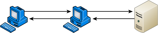
496
Chapter 14 ■ Network Threats and Mitigation
c14.indd 04/02/2015 Page 496
Man-in-the-Middle Attacks
Interception! But it’s not a football, it’s a bunch of your network’s packets—your precious
data. A man-in-the-middle attack happens when someone intercepts packets intended for
one computer and reads the data. A common guilty party could be someone working for
your very own ISP using a packet sniffer and augmenting it with routing and transport
protocols. Rogue ATM machines and even credit-card swipers are tools that are also increas-
ingly used for this type of attack. Figure 14.11 shows a man-in-the-middle attack.
FIGURE 14.11 Man-in-the-middle attack
Client ServerMan in the Middle
Improper Access/Backdoor Access
A backdoor is a piece of software installed by a hacker that allows them to return later and
connect to the computer without going through the normal authentication process. Some
commercial applications inadvertently include backdoors because programmers forget to
remove them before release to market. In many cases, the program is listening on a speci c
port, and when attempting to connect to that port, the attacker is allowed to connect with-
out authentication. An example is Back Ori ce 2000 (BO2K), an application-level Trojan
horse used to give an attacker backdoor network access.
ARP Issues
ARP cache poisoning, usually a part of a man-in-the middle attack, was discussed earlier in
the section “ARP Cache Poisoning.”
Banner Grabbing/OUI
Banners are messages that are con gured on some devices (routers, switches, servers) and
appear under certain conditions, such as when someone is presented with a login screen or
upon making a connection or when an error is encountered. These messages can impart
information that can be used during the discovery phase of the hacking process. It may
reveal the operating system or the version of rmware.
Banner grabbing is the process of connecting to the device using protocols such as
Telnet, SMTP or HTTP and then generating an error displaying the banner. Once the hacker
discovers this information, they can research weaknesses in the system. For this reason, any
service not in use should be disabled to eliminate it as a source of connection.
Vulnerabilities
497
c14.indd 04/02/2015 Page 497
Domain/Local Group Configurations
In cases where computers are part of a domain, the domain member computers will have
both domain accounts and local accounts. Local accounts are thus only effective on the
local machine and cannot be used to access the domain.
However, there are default local accounts that exist on these computers that can be used
to log on locally to the computer, thereby circumventing the domain login process. It’s dan-
gerous to leave some of these enabled, such as the local administrator account. While they
cannot be deleted, it is possible to rename them and/or disable them.
Jamming
Jamming is the process of sending out radio waves on the frequency used by a wireless
network. It will have the effect of disassociating (disconnecting) all of the stations from the
AP, at least while the jam signal is still there. When used for that purpose, jamming could
be considered a DoS attack.
However, it is usually part of an evil twin attack, when the hacker is attempting to get
your wireless stations to connect to their access point. They will set their AP to the same
SSID as your wireless network but in a different channel (frequency). When they jam the
real frequency, it causes the stations to seek another frequency with the same SSID, and
they will nd the hacker’s AP all too willing to allow their association.
Misconfiguration Issues
In many cases, security issues arise due to our own mistakes, rather than the efforts of
hackers. In the following sections, we’ll take a look at (and in some cases review) some of
the most common miscon guration errors and omissions.
Misconfigured Firewall
If the access control lists are miscon gured on a rewall, the damage will fall into one of
three categories:
■ Traffic is allowed that shouldn’t be allowed
■ Traffic that should be allowed is blocked
■ No traffic is allowed at all
The rst two problems are a matter of specifying the wrong traf c type in a permit or
deny rule. Because in many cases the traf c type is speci ed in terms of a port number, it is
critical to know the port numbers of the traf c you are dealing with.
The last problem can be either a simple omission or a complete misunderstanding of how
ACLs work. At the end of every ACL is an implied rule that blocks all traf c that has not
been allowed by earlier rules in the rule set. This means that all ACLs should have a rule at
the end that allows all traf c that should be allowed. An ACL with no permit statements
will block all traf c.
498
Chapter 14 ■ Network Threats and Mitigation
c14.indd 04/02/2015 Page 498
Misconfigured ACLs/Applications
Miscon gured applications can also cause issues. Web applications that do not perform
proper input validation can allow for attacks such as buffer over ows. They can also in
some cases allow for commands to be executed on the web server. For this reason, web-
based applications should undergo strict code review and fuzz testing, and you should
ensure that all input is validated before it is accepted by the application.
Open/Closed Ports
As discussed in the section on miscon guration of rewalls, destination services and appli-
cations are speci ed in a packet in terms of a port number. When a device is open to receiv-
ing a connection to a service or application, it is said to be listening on that port. Therefore,
closing or disabling a port eliminates the possibility of a malicious user connecting to that
port and leveraging any weakness that may be known to be present with that service.
It is a standard device hardening practice to close any ports not required for the proper
functioning of a device based on its role in the network. For example, a DNS server should
have no other ports open but port 53, which is used to service DNS.
Unpatched Firmware/OSs
The best defense against the majority of malware types and attack modes is to keep current
on all updates. This includes operating system patches, rmware updates, and application
updates. Many devices that fall prey to malware and attacks do so needlessly because a
patch existed that would have prevented the attack. A formal update system should be in
place to ensure that no updates fall through the cracks.
Social Engineering (Phishing)
Hackers are more sophisticated today than they were 10 years ago, but then again, so are
network administrators. Because most of today’s sys admins have secured their networks
well enough to make it pretty tough for an outsider to gain access, hackers decided to try
an easier route to gain information: they just asked the network’s users for it.
Social engineering, or phishing, refers to the act of attempting to illegally obtain sensi-
tive information by pretending to be a credible source. Common phishing tactics include
sending emails, making phone calls, or even starting up a conversation in person.
Some email phishing scams have made the news. In one case, bad guys sent out a mass
email that was all dressed up to appear as though the message actually came from a real
bank. The email said that the bank had an issue with one of its servers, so it now required
you to con rm your user-account information to verify that none of your data was lost.
All you needed to do was click the link provided in the email, enter your information, and
snap—your identity went poof! If you possess a working brain and someone you didn’t know
phoned and asked for your bank-account number, you certainly wouldn’t give it to them,
right? No way—but the same request, coming in the form of a really legitimate-looking email,
seems more believable for some reason. This has become a popular phishing tool, notoriously
used to separate people from anything from a few bucks to their entire identity. Be careful!
Understanding Mitigation Techniques
499
c14.indd 04/02/2015 Page 499
Oh, and speaking of phone calls…let’s say you get a call to your desk at work from
“Joe” in IT. He says he’s noticed some unusual activity on your network account and wants
to check it out, but for security purposes, he needs your permission rst. So he proceeds to
con rm your login, and then he tells you he needs to enter your password into the network
tracker. He asks, “What’s your password?” To protect yourself from this one, all you need
to do is con rm his information and verify it with your IT department before you give him
any of your data. You know by now that just because “Joe” knows your login doesn’t mean
he’s on the up-and-up; even if “Joe” hangs up on you, you should still report the call to IT.
How did Joe get your login and telephone number? Remember network reconnaissance?
First, because company phone directories are often on the Web, getting your phone number
was easy. Even if it isn’t published, maybe Joe did some earlier phishing by calling one of
your coworkers and, pretending to be a colleague at another site, asking for your phone
number. But what about the username? On most networks, your username is the same as
your email address because that makes things easier for your sys admin. This means that
knowing that information is probably just a good guess on the attacker’s part. Maybe Joe
the Hacker has gotten an email from someone at your company and knows what your
email format is, and he may have some other information to help him gure out your
network login. And even if the number on your caller ID when Joe called was an internal
phone number, it doesn’t mean a thing—remember IP spoo ng? Well, you can do that with
phone numbers too.
The golden rule is don’t ever give any of your information or anyone else’s to anyone
you’re not absolutely sure should have it. And if they are someone who should have it, they
probably already do, and they shouldn’t be contacting you for it!
Understanding Mitigation Techniques
To be honest, I’m not going to go into detail about how to mitigate each and every one of
the security threats I just talked about, not only because that would be outside the scope of
this book, but also because the methods I am going to teach you will truly protect you from
being attacked in general. You’ll learn enough tricks to make all but the most determined
bad guys give up on you and search for easier prey. Basically, think of this as a section on
how to practice “Safe Net.”
Safe networking techniques fall into three major categories: policies and procedures,
training, and patches and upgrades. But before we go there, let’s cover some of those
general defense techniques I just referred to.
Okay— rst know that there are three main ways to detect an intruder and defend your-
self against one:
■ Active detection, which involves constantly scanning the network for possible break-ins
■ Passive detection, which involves logging all network events to a file
■ Proactive defense methods, which involve using tools to shore up your network walls
against attack
500
Chapter 14 ■ Network Threats and Mitigation
c14.indd 04/02/2015 Page 500
Active Detection
Active detection is analogous to a security guard walking the premises, rattling doors to
make sure they’re locked, and checking for intruders and any unusual activity. Similarly,
there’s special network software that searches for hackers attempting known attack meth-
ods and scans for the kind of suspicious activity and weird network traf c that hackers
leave behind as they travel over the network. Some sophisticated active systems go a step
further and take action by doing things like shutting down the communications sessions a
bad guy is using as well as emailing or paging you. Some security packages will even go as
far as trying to cripple the computer from which the hacker is attacking! Cisco’s NetRanger,
Memco’s Session Wall, and Snort are all forms of active intrusion-detection software.
Passive Detection
Using video cameras is a good example of using a passive intrusion-detection system. Their
counterparts in networking are les that log events that occur on the network. Tripwire
for Unix systems is one of the earliest programs of this variety. It identi es changes in les
using checksums. Changes in les indicate that someone has accessed them. Passive detec-
tion systems work by examining les and data and then calculating the checksums for each.
The checksums are stored in a log le so that if the sys admin notices that a security breach
has occurred on the network, they can access the log les to nd clues about it.
Proactive Defense
A proactive defense is something you do or implement to ensure that your network is
impenetrable. You can accomplish a lot through solid research and vigilant maintenance—
you absolutely must stay current regarding any known security holes relevant to your type
of network and the devices that populate it. You can also use tools like the unfortunately
dubbed Security Administrator Tool for Analyzing Networks (SATAN) to nd the holes in
your security walls and plug them with software patches.
Clearly, before you can patch a hole, you’ve got to know it’s there, right? This is why I
said it’s so important to stay current. Even better, stay a step ahead of bad guys by know-
ing your enemy’s strategies because the war against attackers is ever evolving—as soon as
one hole is patched, bad guys will search for and nd another vulnerability to exploit. And
because patches usually take some time to develop, you can lose your shirt to a hacker in
the interim. This is a big reason I’m saying it’s a better idea for you to know thy enemy than
to rely on patches and the like.
Incident Response
Often when an attack or security breach occurs in the network, valuable time and informa-
tion are lost in the critical rst minutes and hours after the incident occurs. In some cases,
evidence is inadvertently destroyed, making prosecution of the offending party impossible.
In other cases, attacks that could have been interrupted and prevented before damage
occurs are allowed to continue.

Understanding Mitigation Techniques
501
c14.indd 04/02/2015 Page 501
An incident response policy is designed to prevent this by establishing in advance the
procedures that should be followed when an attack occurs. It may categorize incidents in
such a way that certain event types (such as an active port scan) may require a response
(such as disabling certain services) within 10 minutes while other events (such as an attempt
to access a le without proper credentials) may only require a notation and follow-up in the
next few days. The point is to establish these rules ahead of time to ensure that events are
handled in a way that minimizes damage and preserves evidence.
There is a host of great shareware and freeware available on the Internet
today, including Windows Defender, Spybot Search & Destroy, and Ad-
Aware as well as Windows Update.
Basic Forensic Concepts
When security incidents occur in a network, a proper response is key, especially in the early
stages. Computer forensics principles must be applied. These principles are speci c to the
nature of digital devices and the environment in which security incidents occur. From a
high level, the steps in incident response are as follows:
1. Detect the incident.
2. Respond to the incident.
3. Report the incident to the appropriate personnel.
4. Recover from the incident.
5. Remediate all components affected by the incident to ensure that all traces of the
incident have been removed.
6. Review the incident, and document all findings.
In the following sections, we’ll take a look at some of the salient details of these six steps.
First Responder
The rst responder is responsible for securing the crime scene and protecting the evidence
from corruption. This requires addressing the evidence in the order of volatility. Some types
of data may be fragile and therefore need to be collected before other types. For example, a
Polaroid photo (not a digital photo) should be taken of anything showing on the computer
screen since that could go away at any time if the system goes off.
Secure the Area
The area should be sealed off to prevent anyone from touching or tampering with anything.
Access to the crime scene should be tightly controlled and limited only to individuals who
are vital to the investigation. As part of the documentation process, make sure to note any-
one who has access to the crime scene. Once a crime scene is contaminated, there is no way
to restore it to the original condition.
502
Chapter 14 ■ Network Threats and Mitigation
c14.indd 04/02/2015 Page 502
Escalate When Necessary
In any case where the rst responder is not trained in forensics, the issue should be esca-
lated to other personnel. In some cases it may involve calling the police, but be aware that
when you do that you may lose control of the crime scene because they will take over the
investigation. All users should be trained in basic crime scene concepts, such as don’t turn
the machine off and don’t touch anything.
Document the Scene
Everything about the crime scene should be recorded and documented. Polaroid pictures
should be taken to show the positon of everything in the scene. Diagrams can be drawn
to indicate positioning as well. Interviews of witnesses and rst responders should be con-
ducted as soon as possible because memory of details fades quickly.
eDiscovery
In the United States, discovery is the exchange of evidence by both sides in a lawsuit.
eDiscovery is simply the application of this principle to electronic documents, such as
emails, chat records, and other electronic forms of data. When this data is identi ed as
potentially relevant to a case, it is placed on legal hold. Then it is gathered using digital
forensic procedures to prevent its contamination as evidence.
Evidence/Data Collection
When you’re collecting evidence, the order of volatility is critical. Collecting it in the fol-
lowing order ensures that investigators get evidence from the components that are most
volatile rst. The order of volatility is as follows:
1. Memory contents
2. Swap files
3. Network processes
4. System processes
5. File system information
6. Raw disk blocks
You should create a bit-level copy of the system image and isolate the system from the
network when you do this. Keep two copies of this image, one to be stored as an accurate
backup copy of the evidence and the other to use to examine the image. You should create
message digests (hashes) of the images to ensure that you can later prove that the images
have not been tampered with.
Chain of Custody
Chain of custody records document who controlled the evidence, who secured the evidence,
and who obtained the evidence. To successfully prosecute a suspect, a proper chain of
custody must be preserved and the evidence must be collected following prede ned proce-
dures in accordance with all laws and regulations. Proper chain of custody ensures that all
evidence is admissible in court.

Policies and Procedures
503
c14.indd 04/02/2015 Page 503
Data Transport
When the data or evidence is being transported in any way, the process must be recorded
and documented in detail. All physical evidence must be tagged, and the evidence tags
must document the mode and means of transportation, a complete description of the evi-
dence (including quality), who received the evidence, and who had access to the evidence.
Any transmission of evidence should include a hash so the integrity of the evidence can be
maintained.
Forensics Report
A forensic report should be created based on the ndings. While evidence is being exam-
ined, any characteristics, such as time stamps and identi cation properties, should be
determined and documented. Once the evidence has been fully analyzed using scienti c
methods, the full incident should be reconstructed and documented.
Legal Hold
During the eDiscovery process, evidence that is deemed to be possibly relevant will be
placed on legal hold. This process may be initiated by a notice or communication from legal
counsel to an organization. It requires suspension of normal processing of the data, such as
backup tape recycling, archiving media, and using other forms of document and informa-
tion storage and management.
Policies and Procedures
Every company should have written policies to effectively enable security on their computer
networks. The policies should have the approval of the highest-ranking security or IT
of cer within the company, and they should address all aspects of the company network.
Procedures should also be in place to determine the appropriate course of action if there is
a security breach. And all network administrators absolutely need to be thoroughly trained
on all policies and procedures—no weak links.
All of this might sound a bit militaristic in nature, but it’s truly necessary. Speaking of
the military, though, the US Department of Defense (DoD) has some really good standards;
it wouldn’t hurt to keep them in mind when you’re setting up the security policies for your
own network.
You can find the evaluation criteria for the DoD computer standards at
www.niap-ccevs.org/cc-scheme/
. In the past, this was known as the
Rainbow Series
www.securecomputing.com/WBT/wbt-61/csec0001_r/
module3/3mandatory.sb.html
because of the color of the books, but that’s been replaced by the much
less colorful Common Criteria Evaluation and Validation Scheme (CCEVS).

504
Chapter 14 ■ Network Threats and Mitigation
c14.indd 04/02/2015 Page 504
Security Policies
So what, exactly, is a security policy? Ideally, it should precisely de ne how security is to
be implemented within an organization and include physical security, document security,
and network security. Plus, you have to make sure these forms of security are implemented
completely and solidly because if they aren’t, your security policy will be a lot like a block
of Swiss cheese—some areas are covered, but others are full of holes.
Before a network can be truly secure, the network support staff should post the part
of the security policy that applies to employee conduct on bulletin boards. It should, for
example, forbid posting any company and/or employee information that’s not absolutely
necessary—like, believe it or not, sticking Post-its with usernames and passwords on
computer screens. Really clean desks, audits, and recording email communications and, in
some cases, phone calls should also be requirements. And don’t forget to also post the
consequences of not complying with the security policy.
Security Audit
Let me take a minute to explain all this a little more, beginning with security audits. A
security audit is a thorough examination of your network that includes testing all its com-
ponents to make sure everything is secure. You can do this internally, but you can also con-
tract an audit with a third party if you want the level of security to be certi ed. A valid and
veri ed consultant’s audit is a good follow-up to an internal audit. One reason for
having your network’s security certi ed like this is that government agencies usually
require it before they’ll grant you contract work, especially if that work is considered
Con dential, Secret, or Top Secret.
Clean-Desk Policy
That clean-desk policy doesn’t mean just “get rid of the crumbs from your last snack.” It
means requiring that all potentially important documents like books, schematics, con den-
tial letters, notes to self, and so on aren’t left out in the open when someone’s away from
their desk. Instead, they’re locked away, securely out of sight. And make sure it’s clear that
this rule applies to users’ PC desktops too. Policies like this apply to of ces, laboratories,
and workbenches as well as desks, and it’s really important for employees who share work-
spaces and/or workstations.
It’s super easy to nick something off someone’s desk or screen. Because most security
problems involve people on the inside, implementing and enforcing a clean-desk policy is a
simple way to guard against security breaches.
The International Computer Security Association (ICSA,
www.icsa.net
)
reports that as many as 80 percent of all network break-ins occur from
within the company and are carried out by employees, so protecting your
data with a firewall is just the beginning of establishing network security.
It might sound really nitpicky, but for a clean-desk policy to be effective, users have to
clean up their desks every time they walk away from them—without exception. The day

Policies and Procedures
505
c14.indd 04/02/2015 Page 505
someone doesn’t will be the very day some prospective tenant is being shown the building’s
layout and a sensitive document suddenly disappears. You should make sure workstations
are locked to desks and do random spot checks once in a while to help enforce the policy.
For obvious reasons, before company picnics and parties and before “bring your child to
work day” are good times to do this.
The ICSA is a vendor-neutral organization that certifies the functionality
of security products as well as makes recommendations on security
in general.
Recording Equipment
Recording equipment—such as tape recorders, cell phones, and small memory devices like
USB ash memory keychains—can contain sensitive, con dential information, so a good
security policy should prohibit their unauthorized presence and use.
Just walk into almost any large technology company and you’ll be immediately con-
fronted with signs. A really common one is a camera with a circle surrounding it and a
slash through the center of the circle. Read the text below the sign and you’ll be informed
that you can’t bring any recording devices onto the premises.
Here’s a good example. The NSA has updated its policy to include prohibiting Furby
dolls on government premises because they have reasonably sophisticated computers inside
them, complete with a digital recording device. The doll repeats what it hears at a certain
interval of time, which is either cute or creepy but pretty much harmless—maybe even
protective—in a children’s daycare center. Not so much at the NSA, though—no recording
conversations there. Maybe, at least in some locations, it’s not such a good idea for your
company either.
Other Common Security Policies
So you get the idea—security policies can cover literally hundreds of items. Here are some
common ones:
Notification Security policies aren’t much good if no one knows about them, right? So
make sure you give users a copy of the security policy when you give them their usernames
and passwords. It’s also a good idea to have computers display a summarized version of
the policy when any user attempts to connect. Here’s an example: “Unauthorized access is
prohibited and will be prosecuted to the fullest extent of the law.” Remember—your goal is
to close loopholes. One hacker actually argued that because a computer didn’t tell him oth-
erwise, anyone was free to connect to and use the system!
Equipment Access Disable all unused network ports so that any nonemployees who hap-
pen to be in the building can’t connect a laptop to an unused port and gain access to the
network. And don’t forget to place all network equipment under lock and key.
Wiring Your network’s wires should never run along the oor where they can be easily
accessed (or tripped over, getting you sued). Routers, switches, and concentrators should
506
Chapter 14 ■ Network Threats and Mitigation
c14.indd 04/02/2015 Page 506
live in locked closets or rooms, with access to those rooms controlled by anything ranging
from a good lock to a biometric access system, depending on the level of security your spe-
ci c network and data require.
Door Locks/Swipe Mechanisms Be sure that only authorized people know the combina-
tion to the cipher lock on your data-center doors or that only the appropriate people have
badges that allow access to the data center. Change lock combinations often, and never ever
leave server room doors open or unlocked.
Badges Require everyone to wear an ID badge, including contractors and visitors, and
assign appropriate access levels to everyone.
Tracking Require badge access to all entrances to buildings and internal computer rooms.
Track and record all entry to and exits from these rooms.
Passwords Reset passwords at least every month. Train everyone on how to create
strong passwords. Set BIOS passwords on every client and server computer to prevent
BIOS changes.
Monitor Viewing Place computer monitors strategically so that visitors or people look-
ing through windows can’t see them, and make sure unauthorized users/persons can’t see
security-guard stations and server monitors. Use monitor privacy screens if necessary.
Accounts Each user should have their own, unique user account, and employees should
never share user accounts. Even temporary employees should have their own account.
Otherwise, you won’t be able to isolate a security breach.
Testing Review and audit your network security at least once a year.
Background Checks Do background checks on all network support staff. This may
include calling their previous employers, verifying their college degrees, requiring a drug
test, and checking for a criminal background.
Firewalls Use a rewall to protect all Internet connections, and use the appropriate prox-
ies and dynamic-packet- ltering equipment to control access to the network. Your rewall
should provide as much security as your company requires and your budget allows.
Intrusion Detection Use intrusion detection and logging software to discover security
breaches, and be sure you’re logging the events you want to monitor.
Cameras Cameras should cover all entrances to the building and the entire parking lot. Be
sure that cameras are in weather-proof and tamper-proof housings, and review the output
at a security-monitoring of ce. Record everything on extended-length tape recorders.
Mail Servers Provide each person with their own email mailbox, and attach an individual
network account to each mailbox. If several people need to access a mailbox, don’t give all
of them the password to a single network account. Instead, assign individual privileges to
each person’s network account so you can track activity down to a single person, even with
a generic address like
info@mycompany.com
.
DMZ Use a demilitarized zone (DMZ) for all publicly viewable servers, including web
servers, FTP servers, and email relay servers. Figure 14.12 shows a common DMZ setup.
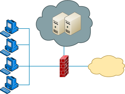
Policies and Procedures
507
c14.indd 04/02/2015 Page 507
FIGURE 14.12 A common DMZ configuration
Internet
Private
Network
Firewall
Web Servers
DMZ
It is not advisable to put a DMZ outside the firewall because any servers outside your fire-
wall defeat the whole purpose of having one. However, it is possible that you may see a
DMZ outside the firewall in some networks.
Mail Relay Mail servers relay to other email servers by design. When the email server
relays from any server that requests it, it is called open relay. Hackers use this feature to
forward spam. Modern email systems allow you to control which servers your email server
will relay for, which helps to prevent this.
Patches Make sure the latest security updates are installed after being properly tested on a
nonproduction computer.
Backups Store backup tape cartridges securely, not on a shelf or table within reach of
someone working at the server. Lock tapes in a waterproof, reproof safe, and keep at least
some of your backups off site.
Modems Do not ever allow desktop modems because they can be used to get to the
Internet without your knowledge. Restrict modem access to approved server-based
modem pools.
Guards If you need security guards, they shouldn’t patrol the same station all the time. As
people become familiar with an environment and situation, they tend to become less obser-
vant about that environment, so rotating guards to keep their concentration at the highest
possible level makes a lot of sense. Clearly, guards are people who need breaks to ensure
alertness, but make sure that all patrol areas are covered during shift changes, rotations,
and breaks. Guards should also receive periodic training and testing to make sure they can
recognize a threat and take appropriate action.

508
Chapter 14 ■ Network Threats and Mitigation
c14.indd 04/02/2015 Page 508
Believe it or not, covering all these bases still won’t guarantee that your
network or facility is secure. All of this is really just a starting point that’s
meant to point you in the right direction.
Breaking Policy
You know that for your policy to be effective it’s got to be enforced consistently and
completely. Nobody is so special that they don’t have to adhere to it. And people have to
understand the consequences of breaking policy too. Your network users need to have a
clearly written document, called a security policy, that fully identi es and explains what’s
expected of them and what they can and can’t do. Plus, people must be made completely
aware of the consequences of breaking the rules, and penalties have to match the severity of
the offense and be carried out quickly, if not immediately, to be effective.
Let’s take a minute and talk about those penalties. As far back as the mid-1980s, employees
were immediately terminated for major technology policy infractions. For example, one guy
from a large computer company immediately got his pink slip when pornography was found
on his computer’s hard drive. The situation was handled decisively—his manager informed
him that he was being immediately terminated and that he had one hour to vacate the prem-
ises. A security guard stood watch while he cleaned out his desk to make sure the employee
touched only personal items—no computer equipment, including storage media—and when he
had nished gathering his personal things, the guard then escorted him from the building.
Downloading and installing software from the Internet to your PC at work is not as
major (depending on where you work), but from the things we’ve been over so far, you
know that doing that can compromise security. Beta products, new software, and patches
need to be tested by the IT department before anyone can use them, period! Here’s an exam-
ple: After an employee installed the untested beta release of a web browser and rebooted
their PC, the production Windows NT server at a national telephone company crashed. The
resulting action was to revoke that employee’s Internet FTP privileges for three months.
Implement the appropriate policies or procedures
You operate a mid size network for Acme Inc. Recently a security breach was discovered,
in that a rogue access point was discovered in the network. While the original fear was
that it was installed as an evil twin, further investigation revealed it was placed there by an
employee so his department could have wireless access. It has now been removed. What
two actions do you need to take and what security policy document do you need to access?
Answer:
Remind/inform the employee of the security policy prohibiting this activity and discipline
the employee. This will require access to Acceptable Use policy, specifi cally the one that
the employee signed when hired.

Policies and Procedures
509
c14.indd 04/02/2015 Page 509
To prevent this in the future, you should schedule a training session for employees that
reinforces the rules contained in the acceptable use policy and explains the motivation
behind each.
The Exit Interview
Sometimes, the importance of an employee’s position and the amount of knowledge they
have about the company and its systems justi es requiring an exit interview when they’re
terminated. It’s done to minimize the risk of that employee being disgruntled and to
attempt to ensure that they’re leaving under the most favorable circumstances possible. The
interview can include the IT manager, a human resources representative, a sys admin, and
sometimes even security personnel.
When an employee leaves the company—whether they’re quitting to move on to another
job or being terminated—all company property needs to be turned in and logged. This
includes things like company cell phones, pagers, toolkits, keys, badges, security tokens,
models, and, obviously, all company documents.
And clearly, IT needs to disable all accounts immediately, including those for network
access and voicemail, and remaining employees should be informed that the employee is
leaving at this time. This is especially important when that employee has access to sensitive
documents because even if they’re leaving under favorable conditions, they could still log
in and copy data to take with them for their own use. For instance, salespeople can easily
hurt a company by taking client information with them, and it has happened—a salesper-
son accessed their former company’s voicemail system and stole sales leads. So it’s not just
the obviously disgruntled ex–network administrator who could demolish your website after
leaving that you need to be concerned about.
Security Procedures
A security procedure de nes how to respond to any security event that happens on your
network. Here’s a short list of items you might include:
■ What to do when someone has locked themselves out of their account
■ How to properly install or remove software on servers
■ What to do if files on the servers suddenly appear to be “missing” or altered
■ How to respond when a network computer has a virus
■ Actions to take if it appears that a hacker has broken into the network
■ Actions to take if there is a physical emergency such as a fire or flood
Security Training
This brings us to the human element of network security. It’s true that most of your users
want to do the right thing to protect the company—and their jobs—from the prying eyes of
hackers, but the problem is that people don’t always know the right thing to do. That’s why
510
Chapter 14 ■ Network Threats and Mitigation
c14.indd 04/02/2015 Page 510
training is so vital. It can include classroom sessions and/or web-based training, but experi-
ence has shown me that actual classroom-based instruction works the best. It’s also a good
idea to have separate training classes for IT personnel and end users.
End-User Training
End-user training is pretty easy—it can take just an hour or so to bring employees up
to speed. The “keep it short and simple” rule applies here or you’ll just end up with nap
time. This is a great time to include detailed security protocol training. But if you see eyes
beginning to glaze over or hear anyone snoring, you might want to make security proto-
col training a separate session because, as I said, it’s really important to the effectiveness
of your security policy for everyone to know about and understand it. You can even use
a year-end bonus or something else cool as a motivational reward for the employees who
complete their training and test well on it.
And you have to back up your training by providing your end users with hard-copy,
printed reference manuals in case they forget something (which they will). Include things
like the following items:
■ Recommended policies for creating safe passwords
■ The number to call if they’ve locked themselves out of their accounts
■ What to do if they think someone is phishing for information
■ What to do if they think their computer has a virus
Clearly, new employees to the company or division should be required to go through train-
ing, but requiring that everybody attend refresher courses is also a good idea. And don’t hesitate
to call a meeting if new threats arise or any sudden changes occur to keep everyone up-to-date.
Administrator Training
Obviously, training sessions for your IT personnel have to be a lot more in depth because
they’ll be the ones who set up and con gure policies, and they’ll also be the rst responders
to any security emergency.
It’s important to cover every aspect of your security policy with these people. And be sure
they understand the correct ways to escalate issues in case of an emergency. Reacting to a
security emergency is pretty stressful, and you don’t want your administrators to panic or
feel isolated if one occurs. Making sure they know where their lifelines are and how to reach
them quickly if they need backup will relieve a lot of pressure when something nasty happens.
Patches and Upgrades
The operating systems and applications we use today are really just gigantic collections of
computer code. Windows Vista has about 50 million lines of code, and Windows XP has
35 to 40 million lines of code, whereas they shaved down Windows 7 to 40 million lines
of code, Windows 8 is rumored to be between 50 and 80 million lines of code. And if you
look at the subsystems within Windows, you’ll nd that there are more than 50 depen-
dency layers—processes that depend on other processes. Experts who work on developing
Windows say that it typically takes someone about ve years to fully learn two or three
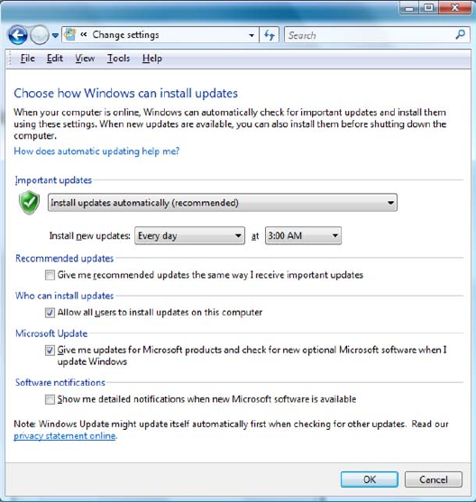
Policies and Procedures
511
c14.indd 04/02/2015 Page 511
of these layers. So it’s pretty easy to imagine that with that much code being created by a
couple of thousand different people, sometimes a few things get mixed up—and that’s the
reason there always seems to be a few holes, glitches, and bugs to x.
The good news is, as operating systems and applications are released, their developers
have a chance to catch and repair the problems they uncover. In addition, as hackers nd and
take advantage of vulnerabilities, software developers work to plug those holes. The repairs
are usually released to the public as patches or hot xes. To address large-scale issues or add
major features and components to a program, companies release complete upgrades instead.
Here’s where we get into the software side of security, which includes things like apply-
ing patches, hot xes, and upgrades, plus how to choose and install the right third-party
software to protect yourself against viruses.
Ensuring that your software is up-to-date is one of the best ways to protect against bad
guys exploiting the security holes on your network.
Automatic Updates through Windows Update
It’s really easy to get updates for Windows-based operating systems from Windows
via Windows Update—a utility that’s usually automatically installed when you install
Windows. If you need to get more information, go to
www.microsoft.com
.
To ensure that Windows Update is enabled, open your System Properties dialog (right-
click My Computer and then choose Properties). You will see a screen similar to the one
shown in Figure 14.13.
FIGURE 14.13 Automating Windows Update
512
Chapter 14 ■ Network Threats and Mitigation
c14.indd 04/02/2015 Page 512
If you have Windows Update installed, it will periodically scan your system for the
version of Windows components you already have installed and compare them to the most
current versions available from Microsoft. If your software is out-of-date, a Windows
Update dialog box will appear, asking if you want to install the software updates. If you
click Continue, the installation will proceed in the background; you’ll still be able to work
in the foreground without skipping a beat.
Downloading Patches and Hotfixes
If you don’t have automatic updates set up, you can download patches and hot xes manu-
ally. A hot x is just like a patch that updates software, but this term is reserved for a solu-
tion to potentially serious issues that could compromise your network and hosts. When
a company like Microsoft has created a whole bunch of patches, hot xes, and upgrades,
it will put them together in a larger bundle called a service pack. For instance, you can
download Windows 7 Service Pack 1 (SP1) or Windows Server 2008 Pack 2 (SP2), which
will update lots of components and address security, performance, and stability issues all
at the same time. For the latest service pack for your Windows-based operating system or
application, visit
support.microsoft.com
.
But let’s say you think you have a smaller, speci c issue and you only want to down-
load a patch for that particular problem. Maybe you’re dealing with an issue with IPSec
and you want to know about creating IPSec security lters in Windows XP. After sur ng
Microsoft’s support site, you come across article KB914841 (
support.microsoft.com/
default.aspx?kbid=914841
). (KB stands for Knowledge Base, and it’s one way Microsoft
organizes its support documents.) This article will give you background information as well
as allow you to download hot xes for the operating system you’re running.
Firmware Updates
While keeping operating system and application patches up-to-date gets most of the atten-
tion, there are devices on your network that may require rmware updates from time to
time. Firmware is a form of program code and related data that are stored in persistent
memory of some sort, such as non-volatile RAM (NVRAM).
In many cases rmware updates are designed to increase the functionality of a device.
In other cases it may correct a bug or aw in the system. Firmware updates are much more
infrequent than other types of updates, so it’s easy to forget about them. You should always
agree to be contacted by manufacturers regarding these updates because they are not as
widely publicized as other types of updates.
Updating rmware is a process sometimes called ashing in which the old rmware
instructions are overwritten by the new ones. You should carefully follow the process
described in the manufacturer’s documentation because failure to do so can lead to the
device being made useless (sometimes called bricking the device).
Driver Updates
Drivers are les that allow a peripheral or component to talk to the hardware layer of the
hosting device. In most cases, the drivers you need for a device will already be present in

Policies and Procedures
513
c14.indd 04/02/2015 Page 513
the drive cache that is installed with the operating system, but in some cases, especially
with new devices, this will not be the case. In those instances, you will have to allow
the system to locate the driver le from the CD that came with the device, or in extreme
instances, you may have to search for it on the Internet. You should always start your
search on the website of the manufacturer. Drivers found elsewhere may be problematic
and in some case may introduce malware.
Drivers also need to be updated from time to time. If you have computers set to receive
updates automatically, updated drivers can be among the items you select to receive. Not
all devices can bene t from automatic updating, and you may be required to check manu-
ally from time to time for driver updates for other devices, such as printers, scanners,
and cameras.
Upgrading vs Downgrading
Whenever a new version of an operating system or application is released, it usually gener-
ates a debate over whether the upgrade should be implemented. This is because experience
has taught many IT technicians that there are often problems with a new release that they
would prefer to avoid until someone else locates and corrects them.
Waiting until “all the bugs are ironed out” in an upgraded release is probably not a bad
idea unless the upgrade addresses a security issue. In those cases the risk of an issue is prob-
ably worth taking to close the security hole.
In some cases it may be necessary to reverse or downgrade a system to the old version
if the new version causes substantial issues in the production environment. You can save
yourself a lot of grief and possible downtime in the production environment by testing all
new versions of applications, operating systems, and rmware before deploying them.
Applying Your Knowledge
In your new position at ABB Tech Inc., one of your responsibilities is to maintain all
software and fi rmware updates for the Sales department, which contains the following
devices:
■ 38 Windows 8.1 desktop systems
■ 4 Red Hat Linux servers
■ 1 Cisco 3550 switch
■ 2 HP printers
■ 1 Windows Server 2012 R2
Your latest assignment is to develop a plan for maintaining the updates on all of these
machines. Complete the following table to provide the data required to create the plan.
Research your answers using the websites of the vendors listed. You can check your
answer at the end of the chapter.

514
Chapter 14 ■ Network Threats and Mitigation
c14.indd 04/02/2015 Page 514
Device
Update types (OS,
firmware, driver)
Most efficient
method Schedule
Windows 8.1 OS, driver WSUS Weekly
Red Hat Linux OS, driver Individual
application
As notified by errata advisories
through the Red Hat Customer Portal
Cisco 3550 Firmware Individual
application
As notified by subscribing to field
advisories and security emails from
Cisco
HP printers Driver Individual
application
As notified by subscribing to HP
Windows
Server 2012 R2
OS, driver WSUS Weekly
Anti-malware software
Of all the update types that need to be maintained, anti-malware updates are the most critical
to the organization. You must maintain updates to the malware de nitions as well the updates
to the malware engine itself. When choosing an anti-malware solution there are two approaches,
host-based (also called premises based) and cloud based. In this section we will examine both.
Host-based
Host or premises based antimalware is a solution that you install and run inside your net-
work. It has the advantage of giving you total control over the process but also requires
you to stay on top of updates. It also requires the deployment of some hardware to hold the
engine and the de nition les.
Cloud/Server-based
Cloud antivirus products run not on local computers but in the cloud, creating a smaller
footprint on the client and utilizing processing power in the cloud. They have the following
advantages:
■ They allow access to the latest malware data within minutes of the cloud antivirus
service learning about it.
■ They eliminate the need to continually update your antivirus.

Anti-malware software
515
c14.indd 04/02/2015 Page 515
■ The client is small, and it requires little processing power.
■ Cloud antivirus products have the following disadvantages:
■ There is a client-to-cloud relationship, which means they cannot run in the background.
■ They may scan only the core Windows files for viruses and not the whole computer.
■ They are highly dependent on an Internet connection.
Should I install host base or cloud/server based anti-malware for my
network?
You manage a very enterprise network and need to keep a close eye on the most com-
mon attacks today: malware. You should install a Next Generation IPS device, but you
don’t have the money for that type of equipment and training on the new equipment. You
need something that will stop zero-day attacks if possible and don’t want to add much
processing or even more software on the hosts in the network then you already have. You
don’t want to install any new hardware, if possible, to get this done. With all this in mind,
cloud/server based anti-malware is your answer! They allow access to the latest malware
data within minutes of the cloud antivirus service learning about it and you don’t need to
install any new hardware at your location, you just need a good, solid internet connection.
Configuration Backups
We create device con gurations over time that can be quite complicated, and in some cases
where multiple technicians have played a role, no single person has a complete understand-
ing of the con guration. For this reason, con gurations should be backed up.
Con gurations may sometimes exist as text les, such as in a router or switch. Other
times, such as with a Microsoft server, you will back up what is called the system state.
This backs up only the con guration of the server and not the data. In this case, a system
state backup and a data backup should be performed. It is also possible to back up the
entire computer, which would include both data sets.
Considering the time it takes to set up a new device, install the operating system, and
recon gure it to replace a defective device, it makes great sense to keep backups of con gu-
rations so that if a device fails, you can quickly reimage a new machine and simply apply
the system state to it or apply the con guration le (in the case of routers and switches).
Updating Antivirus Components
A typical antivirus program consists of two components:
■ The definition files
■ The engine

516
Chapter 14 ■ Network Threats and Mitigation
c14.indd 04/02/2015 Page 516
The de nition les list the various viruses, their types, and their footprints and tell you
how to remove them. More than 100 new viruses are found in the wild each month, so it’s
easy to see that an antivirus program would be totally useless if it didn’t keep up with all
those emerging viruses.
The engine accesses the de nition les (or database), runs virus scans, cleans the les,
and noti es the appropriate people and accounts. Eventually, viruses become so sophis-
ticated that a new engine, or even a whole new technology, is required to combat them
effectively.
Heuristic scanning is a technology that allows an antivirus program to
search for a virus even if there’s no definition for it yet. The engine looks
for suspicious activity of the kind that usually indicates the presence of a
virus. But use such a tool with caution—if it’s turned on, this scanning tech-
nique can mistake harmless or even necessary code for suspicious code,
and that can give you some major grief.
For your antivirus program to work for you, you have to upgrade, update, and scan in a
speci c order:
1. Upgrade the antivirus engine.
2. Update the definition files.
3. Create an antivirus emergency boot disk.
4. Configure and run a full on-demand scan.
5. Schedule monthly full on-demand scans.
6. Configure and activate on-access scans.
7. Make a new antivirus emergency boot disk monthly.
8. Get the latest update when fighting a virus outbreak.
9. Repeat all steps when you get a new engine.
I’m going to cover only the steps in this list that map to objectives of the Network+
exam, but looking into the others won’t hurt and will give you some worthwhile
knowledge.
Upgrading an Antivirus Engine
An antivirus engine is the core program that runs the scanning process, and virus de ni-
tions are keyed to an engine version number. For example, a 3.x engine won’t work with
4.x de nition les. When the manufacturer releases a new engine, consider both the cost to
upgrade and how much you’ll bene t before buying it.
Before installing new or upgraded software, back up your entire computer
system, including all your data.

Anti-malware software
517
c14.indd 04/02/2015 Page 517
Updating Definition Files
I recommend that you update your list of known viruses—called the virus de nition les—
no less than weekly. You can do this manually or automatically through the manufacturer’s
website, and you can use a staging server within your company to download and distribute
the updates or set up each computer to download updates individually.
Scanning for Viruses
An antivirus scan is the process that an antivirus program deploys to examine a computer
suspected of having a virus, identify the virus, and then get rid of it. There are three types
of antivirus scans, and to really make sure your system is clean, you should use a combina-
tion of the types I’m covering in this section:
On-Demand Scan An on-demand scan is a virus scan initiated by you or an administra-
tor that searches a le, a directory, a drive, or an entire computer but only checks the les
you’re currently accessing. I recommend doing this at least monthly, but you’ll also want to
do an on-demand scan when the following occurs:
■ You first install the antivirus software
■ You upgrade the antivirus software engine
■ You suspect a virus outbreak
Before you initiate an on-demand scan, be sure you have the latest virus
definitions.
On-Access Scan An on-access scan runs in the background when you open a le or use a
program in situations like these:
■ Inserting a floppy disk or thumb drive
■ Downloading a file with FTP
■ Receiving email messages and attachments
■ Viewing a web page
This kind of scan slows down the processing speed of other programs, but it’s worth the
inconvenience.
Emergency Scan During an emergency scan, only the operating system and the antivirus
program are running. You initiate one of these scans when a virus has totally invaded your
system and taken control of the machine. In this situation, insert your antivirus emergency
boot disk and boot the infected computer from it. Then, scan and clean the entire com-
puter. If you don’t have your boot disk, go to another, uninfected machine and create one
from it. Another possibility is to use an emergency scan website like
housecall.trendmi-
cro.com
, which allows you to scan your computer via high-speed Internet access without
using an emergency disk.

518
Chapter 14 ■ Network Threats and Mitigation
c14.indd 04/02/2015 Page 518
Fixing an Infected Computer
So what do you do if you know you have a virus? First, you want to make sure to scan all
potentially affected hard disks plus any external disks that could be infected. Establish a
cleaning station, and quarantine the infected area. You’ll have a really hard time doing this
if anyone continues to use the computer while it is infected, so make sure all users in the
infected area stop using their computers.
Then, remove all external memory devices from all disk drives and perform a scan and
clean at the cleaning station. Update the virus de nitions of any computers that are still
operational. For the ones that aren’t, or the ones that are still working but are infected,
boot to an antivirus emergency boot disk. After you’ve done that, run a full scan and clean
the entire system on all computers in the of ce space. With luck, you will be done before
your users return from lunch.
It’s frustrating, but a lot of programs won’t install unless you disable the
on-access portion of your antivirus software. Clearly, this is dangerous if
the program has a virus. If you want to be really safe, do an on-demand
scan of the software before installing it. If things are all good, go ahead
and disable on-access scanning during installation, and then reactivate it
when the installation is complete.
Summary
Whew—this was a long chapter with a lot of good information in it. We talked about the
dark side of computer networking: bad guys and the threats and attacks they use to victim-
ize our systems and networks. You learned a lot about tactics like denial of service attacks,
viruses, worms, social engineering, and other devious methods that hackers use. After that,
you learned about ways to mitigate these threats and protect yourself by establishing poli-
cies and procedures, providing training, and ensuring that all your software is up-to-date.
You also learned what to do about the ubiquitous problem of viruses. It’s a lot to remem-
ber, I know, but believe me, you’ll be really glad you’re armed with this knowledge because
unfortunately, you’ll probably deal with these threats sooner or later.
Exam Essentials
Recognize vulnerabilities that may exist in your network. These vulnerabilities include
unnecessary running services, open ports, unpatched systems, unencrypted channels, and
the transmission of clear-text authentication credentials.

Written Lab
519
c14.indd 04/02/2015 Page 519
Know what types of threats can adversely affect your network. Threats include denial
of service attacks, viruses, worms, rogue access points, phishing, and various other attack
methods employed by hackers.
Understand how attackers attempt to get information about your network. Attackers
have various methods they can use to gather information. Some of the most common recon-
naissance tools are packet sniffers and social engineering.
Know how to keep your systems automatically updated. Programs such as Windows
Update can keep your operating systems current, which will reduce opportunities for
attackers to exploit your computers and network.
Know where to go to find downloadable software updates. Check the manufacturer’s
website for the most current security information, patches, and updates.
Understand and implement proper forensic concepts. This includes following the six steps
in the incident response process.
Written Lab
Write the answers to the following questions. You can nd the answers in Appendix A.
1. A is a group of computers connected on the Internet for the purpose of per-
forming a task in a coordinated manner
2. How often should you update your virus definitions in your antivirus software?
3. What type of attack injects a command that overflows the amount of memory allocated
and executes commands that would not normally be allowed?
4. attacks are those that increase the effectiveness of a DoS attack?
5. What kind of tool could a hacker use to intercept traffic on your network?
6. What type of virus uses Microsoft’s Visual Basic scripting language?
7. What is it called when someone intercepts traffic on your network that’s intended for a dif-
ferent destination computer?
8. If someone installed a wireless router on your network without your knowledge, the WAP
would be called .
9. What software application can automatically ensure that your Windows-based computers
have the most current security patches?
10. The two different types of virus scans are .
520
Chapter 14 ■ Network Threats and Mitigation
c14.indd 04/02/2015 Page 520
Review Questions
You can nd the answers to the review questions in Appendix B.
1. Which of the following is a type of denial of service attack?
A. Ping of death
B. Stacheldraht
C. SYN flood
D. All of the above
2. In which attack does the attacker set the session ID ahead of time by sending a link to the
victim with the ID preset?
A. Session fixation
B. Cross-site scripting
C. Session sidejacking
D. Session seeding
3. Which type of virus impacts files with the filename extensions
.com
,
.exe
, and
.dll
?
A. File viruses
B. SYN flood
C. Smurf
D. Tribe Flood Network
4. In which type of attack does the attacker scan for networks using a high-powered antenna
connected to a wireless laptop?
A. War driving
B. Evil twin
C. WEP cracking
D. WPA cracking
5. Monkey B, Michelangelo, Stoned, and Stealth Boot are examples of which type of virus?
A. IP spoofing
B. Multipartite
C. Macro
D. Boot sector
6. Which type of virus affects both the boot sector and files on a computer?
A. Mulipartite
B. Macro
C. Tribe Flood Network 2000 (TFN2K)
D. Smurf
Review Questions
521
c14.indd 04/02/2015 Page 521
7. What is the main difference between a worm and a virus?
A. Worms require user action for replication; viruses do not.
B. Viruses do not require user intervention for replication, whereas worms do.
C. Worms can replicate without user intervention; viruses cannot.
D. None of the above.
8. What kind of attack involves the hacker attempting all combinations of characters for a
password to gain access?
A. Packet sniffers
B. Brute force attack
C. Worm
D. Backdoor
9. What type of security threat allows an attacker to learn your password through the use of
an email or phone call?
A. Phishing
B. Trust-exploration attack
C. Man-in-the-middle attack
D. Rogue access point
10. Which type of policy should be implemented to secure important company documents and
materials when employees leave their workstations?
A. Clean housekeeping
B. Clean desk
C. Security audit
D. Proactive defense
11. If you implement a set of policies and procedures that define corporate information as con-
fidential and then train employees on these procedures, what type of attack can you
prevent?
A. DoS
B. Man-in-the-middle attacks
C. Smurf
D. Social engineering
12. What type of wireless frame populates the display when someone is scanning for wireless
networks?
A. Probe response
B. Beacon
C. SSID
D. Discovery
522
Chapter 14 ■ Network Threats and Mitigation
c14.indd 04/02/2015 Page 522
13. What defines the appropriate response to a security event on a network?
A. Implementing security procedures
B. Installing a new router
C. Turning off the network
D. Implementing an HR policy for dress code
14. Which of the following security mechanisms has been compromised?
A. WEP
B. 802.11i
C. WPA2 Enterprise
D. RADIUS
15. What process allows you to update your Windows-based operating system?
A. Technet
B. Windows Update
C. Text message
D. Hotfix
16. Why is it important to keep your system patched and up to date?
A. To completely stop your need for security
B. To increase the functionality of your applications
C. To fix system vulnerabilities
D. To make Windows completely safe and worry free
17. Who is responsible for securing a crime scene and protecting the evidence from corruption?
A. First responder
B. CIO
C. Police
D. User
18. Which type of scanning allows an antivirus program to search for a virus even if there is no
definition for it?
A. Update scan
B. Signature-file scan
C. Database scan
D. Heuristic scan
Review Questions
523
c14.indd 04/02/2015 Page 523
19. What type of files need to be updated in order for your antivirus program to have the latest
information about attacks and viruses?
A. Definition files
B. Email files
C. DOC (
.doc
) files
D. EXE (
.exe
) files
20. What type of scan can be done by an antivirus program?
A. Emergency
B. In-demand
C. On-access
D. All of the above

c15.indd 03/23/2015 Page 525
Chapter
15
Physical Security
and Risk
THE FOLLOWING COMPTIA NETWORK+
EXAM OBJECTIVES ARE COVERED IN THIS
CHAPTER:
✓ 1.1 Explain the functions and applications of various
network devices
■ IDS/IPS
✓ 2.4 Explain the importance of implementing network
segmentation
■ Honeypot/honeynet
✓ 3.1 Compare and contrast risk-related concepts
■ Disaster recovery
■ Business continuity
■ Battery backups/UPS
■ First responders
■ Data breach
■ End user awareness and training
■ Single point of failure
■ Critical nodes
■ Critical assets
■ Redundancy
■ Adherence to standards and policies
■ Vulnerability scanning
■ Penetration testing
✓ 3.4 Compare and contrast physical security controls
■ Mantraps
■ Network closets

c15.indd 03/23/2015 Page 526
■ Video monitoring
■ IP cameras/CCTVs
■ Door access controls
■ Proximity readers/key fob
■ Biometrics
■ Keypad/cypher locks
■ Security guard
✓ 3.5 Given a scenario, install and configure a basic firewall
■ Types of firewalls
■ Host-based
■ Network-based
■ Software vs hardware
■ Application aware/context aware
■ Small office/home office firewall
■ Stateful vs stateless inspection
■ UTM
■ Settings/techniques
■ ACL
■ Virtual wire vs routed
■ DMZ
■ Implicit deny
■ Block/allow
■ Outbound traffic
■ Inbound traffic
■ Firewall placement
■ Internal/external

c15.indd 03/23/2015 Page 527
Finding a corporate network that isn’t connected to the
Internet would be pretty tough these days. Being connected
allows for a huge increase in productivity, and not having an
online presence is akin to sheer oblivion in today’s business environment. But as is often
the case, advantages, even big ones, have a downside to them, and being hooked up to the
Internet is no exception. Connecting our private networks to a huge public one exposes us
to some really major security risks, so we absolutely have to protect our networks from the
very real threats of intrusion, corporate espionage, data and identity theft, and exploita-
tion in general. To succeed, we need to make sure our networks have one or more security
devices to control any traf c coming into and owing out from them. We need things like
rewalls and intrusion detection and/or prevention systems as much as we need any other
form of security in our businesses and daily lives today—period.
These vital security methods are going to be the focus of this chapter. In it, I’ll be cover-
ing the ins and outs of the protective networking measures and devices designed to shield
and secure our network traf c, zooming in on the all-important rewalls because they’re
a ubiquitous and critical line of defense against the exploits of the all-too-common hackers
who seek to compromise our corporate and personal network security.
I’ll end this important chapter by going over the speci c issues that can and do affect
device security on your network. I’ll discuss things you can do physically and logically to
implement tight security, right down to choosing the best protocols to use for safe commu-
nication to the outside world.
To find up-to-the-minute updates for this chapter, please see
www.lammle
.com/networkplus
or the book’s website at
www.sybextestbanks.wiley
.com
.
Using Hardware and Software Security
Devices
This heading may be a little misleading because it makes it sound like I’m going to discuss
the differences between hardware and software security devices. But I’m not, because
even though many rewalls and routers that contain proxy and/or rewall services brand
themselves as hardware or software solutions, the fact is, most of these devices are really a
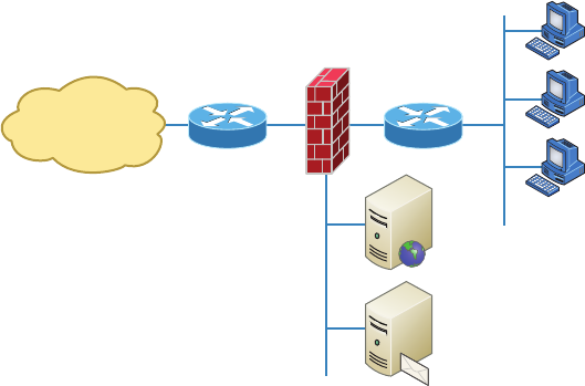
528
Chapter 15 ■ Physical Security and Risk
c15.indd 03/23/2015 Page 528
combination of the two. For instance, there’s software embedded within a hardware ROM
chip to make the software harder to attack, but it still actually functions as software. So
instead of focusing on the type of device, it makes a lot more sense to delve into exactly
what it is that a device does and how it does it.
In medium to large enterprise networks, strategies for security usually include some
combination of internal and perimeter routers plus rewall devices. Internal routers provide
added security by screening traf c to the more vulnerable parts of a corporate network
through a wide array of strategic access lists. You can see where each of these devices is
found within a typical network in Figure 15.1.
FIGURE 15.1 A typical secured network
Internet
Untrusted
Network
DMZ
Web
Server
Email
Server
Perimeter
(Premises)
Router
Firewall Internal
(Local Network)
Router
Corporate
(Trusted)
Network
I’ll use the terms trusted network and untrusted network throughout this chapter, so it’s
important that you can see where they are found in a typical secured network. The demili-
tarized zone (DMZ) can be global (real) Internet addresses or private addresses, depend-
ing on how you con gure your rewall, but this is typically where you’ll nd the HTTP,
Domain Name Service (DNS), email, and other Internet-type corporate servers. The DMZ
is used to create a security zone that allows public traf c but the traf c is isolated from the
company private network.
Instead of having routers, we can also use virtual local area networks (VLANs) with
switches on the inside trusted network. Multilayer switches containing their own security
features can sometimes replace internal (LAN) routers to provide higher performance in
VLAN architectures.
Next, I’ll show you how these devices go about directing traf c between your private
network that only authorized users have access to and the public network part of the net-
work that everyone connects to.

Defining Firewalls
529
c15.indd 03/23/2015 Page 529
Defining Firewalls
Firewalls are usually a combination of hardware and software. The hardware part is usu-
ally a router, but it can also be a computer or a dedicated piece of hardware called a black
box that has two Network Interface Cards (NICs) in it. One of the NICs connects to the
public side, and the other one connects to the private side. The software part is con gured
to control how the rewall actually works to protect your network by scrutinizing each
incoming and outgoing packet and rejecting any suspicious ones.
Firewalls generally allow only packets that pass speci c security restrictions to get
through; they can also permit, deny, encrypt, decrypt, and proxy all traf c that ows
through, either between the public and private parts of a network or between different
security domains, or zones, on a private network. The system administrator decides on and
sets up the rules a rewall follows when deciding to forward data packets or reject them.
Just so you know, a Network+ certified system administrator rarely has the
sophisticated knowledge required to design, install, and manage a firewall.
The information I’m imparting to you here will give you the tools you need
to understand the basic ways firewalls work and to help you to work effec-
tively in an environment where a firewall is already installed.
Firewalls can be placed on top of an existing operating system or be self-contained.
Conversely, black-box systems are proprietary and have external controls that aren’t con-
trolled by the operating system itself. If you opt to use a general-purpose server operating
system to run your rewall, you can do that with Unix and Windows because both support
third-party rewall products.
For networks with multiple Windows-based computers, firewalls should
be installed on a router that connects the private network to the Internet
or to a Windows server like Windows Server 2008 or newer rather than on
clients like Windows 7 or 8.
Clearly, if your rewalls aren’t con gured properly, they’re not going to do you much
good. Most of them are con gured as default-deny, meaning that the only network con-
nections allowed are the ones that have been speci ed to be permitted. A pro cient system
administrator has to do this, and trust me, with the multitude of applications and ports
involved in internal-external network communication, it’s not all that easy! To make life
easier, some people resort to trusting the default-allow option, where all traf c is allowed
to pass through unless it’s been speci cally blocked. But doing this isn’t exactly tight
because it makes inadvertent network connections and security breaches much more likely
to happen. Even though it might ease a little administrative pain, I don’t recommend going
with this method—ever.

530
Chapter 15 ■ Physical Security and Risk
c15.indd 03/23/2015 Page 530
Network-Based Firewalls
A network-based rewall is what companies use to protect their private network from
public networks. The de ning characteristic of this type of rewall is that it’s designed to
protect an entire network of computers instead of just one system, and it’s usually a combi-
nation of hardware and software.
As you can imagine, protecting an entire network of computers from malicious attacks
is quite the challenge. Most of the rewall features that I’m going to cover in this chapter
are designed with this goal in mind, although the technology is certainly applicable to host-
based rewalls too.
In many small office, home office (SOHO) networks, a firewall with some-
what less sophistication may be used. While not providing all of the func-
tionality of an enterprise firewall, these devices, may be easier to configure
and can still be deployed safely.
Host-Based Firewalls
In contrast to a network-based rewall, a host-based rewall is implemented on a single
machine, so it protects only that one machine. This type of rewall is usually a software
implementation because you don’t need any additional hardware in your personal computer
to run it. All current Windows client operating systems come with Windows Firewall,
which is a great example of a host-based solution.
If you hear someone say that host-based software solutions just aren’t as secure as a
separate hardware-based solution, they’re pretty much right. This is because if you’re run-
ning a dedicated black-box rewall and someone manages to hack in and disable it, your
best-case scenario is a blown black box and a ruined rewall. Believe it or not, even if that
happens, all the data on your internal network may still be safe if the bad guy wasn’t able
to get past everything. But if they were able to get all the way in, you could have some ugly
consequences to deal with; if the hacker makes it through the often relatively imsy soft-
ware rewall running on your local computer, they could not only view and/or nick your
les but also trash your entire system—yikes!
Still, it all comes down to how much security you really require. Unless you’re the direc-
tor of the CIA or something, you probably don’t need to go the extra mile and shell out for
a dedicated black box if all you want to do is protect your personal computer from some-
one who’s trying to hack their way in through your high-speed Internet connection.
Firewall Technologies
There’s a whole bunch of rewall technologies, and they all differ in the way that they
restrict information ow. Things like access control lists and dynamic packet ltering are
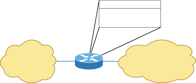
Firewall Technologies
531
c15.indd 03/23/2015 Page 531
often used as rewalls in their own right, or they can be implemented along with proxies,
DMZs, and other rewall technologies to build a serious, formidable system fortress.
Access Control Lists
The rst line of defense for any network that’s connected to the Internet is what we call
access control lists (ACLs). These reside on your routers and determine by IP addresses
which machines are allowed to use those routers and in what direction. ACLs have been
around for decades and have some other really cool uses apart from being used as rewalls.
Figure 15.2 gives you a great demonstration of how ACLs can work to prevent users on
Network B from accessing Network A. Network A, however, hosts from Network B and
can access Network A if a secure authenticated connection is used.
FIGURE 15.2 Two networks with an ACL-enabled router
Network A
“Public” Network
Network B
“Private” Network
Router
A can access B.
B can access A if
secure authenticated
connection is detected.
An important thing to note here is that data from users in Network A can still pass
through the router into Network B. This means that a hacker executing an IP spoo ng
attack that makes it appear as though they’re an IP address originating from inside the re-
wall can still gain access to Network B by pretending to be a valid user in Network A.
ACLs are essentially lists of conditions that categorize packets, so you can imagine
how helpful they can be in helping you gain control over the network’s traf c. One of the
most common and easiest-to-understand ways that ACLs are used is for ltering unwanted
packets when you’re implementing security policies. You can set up the ACLs to make very
speci c decisions about regulating traf c patterns so that they’ll allow only certain hosts
to access web resources on the Internet while restricting others. With a solid combination
of ACLs, network managers can arm themselves like Rambo and powerfully enforce pretty
much any security policy they need to.
Chapter 14 discussed some of the security threats that ACLs can help mitigate:
■ IP address spoofing, inbound
■ IP address spoofing, outbound
■ Denial of service (DoS) TCP SYN attacks
■ DoS Smurf attacks
532
Chapter 15 ■ Physical Security and Risk
c15.indd 03/23/2015 Page 532
The following techniques can be used to mitigate these security threats:
■ Using TCP intercept to address DoS TCP SYN attacks
■ Filtering ICMP messages, inbound
■ Filtering ICMP messages, outbound
■ Filtering Traceroute
You can even employ ACLs for situations that don’t necessarily involve blocking pack-
ets—like using them to control which networks will or won’t be advertised by dynamic
routing protocols. The way you con gure your ACL to do that is the same; you just apply it
to a routing protocol instead of an interface. The only other difference here is that an ACL
applied to a protocol is referred to as a distribution list, and it doesn’t stop routing adver-
tisements, it just controls their content. You can also use ACLs to categorize and queue
packets for applications that require quality of service (QoS) and for controlling the types
of traf c that can activate a pricey backup link.
So, how do you go about creating an ACL? Well, it’s really a lot like programming a
series of
if-then
statements: If a given condition is met, then a speci c action happens; but
if that explicit condition isn’t met, nothing happens except that the next statement in the
list is evaluated. Access-list statements are basically packet lters that packets are compared
against, categorized by, and then acted on accordingly as directed. Once your list is built, it
can be applied to either inbound or outbound traf c on any interface, causing the router to
analyze every packet crossing that interface in the speci ed direction and take the appropri-
ate action.
There are a few important rules by which packets are processed when being compared
with an ACL:
■ They’re always compared with each line of the ACL in sequential order, always
beginning with the first line, then proceeding to line 2, then line 3, and so on.
■ They’ll be compared with subsequent lines of the list until a match is made. Once the
packet matches the condition on a line of the ACL, the packet is acted upon and no
further comparisons take place.
■ There is an implicit “deny” at the end of each ACL that says that if a packet doesn’t
match the condition on any of the lines in the ACL, it will be discarded.
Each of these rules has some powerful implications for ltering IP packets with ACLs,
which is why creating effective ACLs truly takes some practice!
There are two main types of ACLs:
Standard ACLs These use only the source IP address in an IP packet as the condition test,
so all decisions regarding a packet will be based on the source IP address. This means that
standard ACLs basically permit or deny an entire suite of protocols without distinguishing
between any of the myriad types of IP traf c like web, Telnet, UDP, and so on.
Firewall Technologies
533
c15.indd 03/23/2015 Page 533
Extended ACLs Extended ACLs go the distance and evaluate lots of the other elds
in the Layer 3 and 4 headers of an IP packet. They can evaluate source and destination
IP addresses, the protocol eld in the Network layer header, and the port number at the
Transport layer header. This gives extended ACLs the ability to enforce highly speci c
network traf c control conditions.
Once you create an ACL, it doesn’t do much of anything until you apply it. Yes, it’s there
on the router, but it’s inactive until you tell that router what to do with it. To use an ACL as
a packet lter, you’ve got to apply it to the interface on the router exactly where you want
the traf c ltered, and you’ve also got to specify the traf c’s direction—inbound or out-
bound. This is because you probably want different controls in place for traf c leaving your
network that’s destined for the Internet than you want for traf c coming into your network
from the Internet. Here’s the difference:
Inbound ACLs When an ACL is applied to inbound packets on an interface, those packets
are processed through the ACL before being routed to the outbound interface. Any packets
that are denied won’t be routed because they’ll be discarded before the routing process is
completed.
Outbound ACLs When an ACL is applied to outbound packets on an interface, those
packets are routed to the outbound interface and then processed through the ACL before
being queued.
Creating ACLs is great, but don’t forget to apply them to an interface or they’re not
going to lter traf c. With that in mind, here’s a list of rules to live by when con guring
ACLs on interfaces from the Internet into your production network:
■ Deny any addresses from your internal networks.
■ Deny any local host addresses (127.0.0.0/8).
■ Deny any reserved private addresses.
■ Deny any addresses in the IP multicast address range (224.0.0.0/4).
These addresses should never, ever be allowed to enter your internetwork.
Port Security
While rewalls can be used to protect access to the network at Layer 3 (IP addresses), there
are cases where security needs to be maintained between users within the network. This
can be done by implementing port security on the switches in the network. When you do
this, you are enforcing security at Layer 2 (MAC addresses).
This can be used in several ways. First, you can use port security to de ne a set of MAC
addresses that are allowed to access a port where a sensitive device is located. Another use
is to set unused ports to only be available to a precon gured set of MAC addresses. The
534
Chapter 15 ■ Physical Security and Risk
c15.indd 03/23/2015 Page 534
second example could help to prevent unauthorized persons from plugging into a wall out-
let (connected to a secured switch port) and accessing the network.
Demilitarized Zone
Most rewalls in use today implement something called a demilitarized zone (DMZ),
which, as its name implies, is a network segment that isn’t public or local but halfway
between the two. People outside your network primarily access your web servers, File
Transfer Protocol (FTP) servers, and mail relay servers, and because bad guys tend to go
after these servers rst, it’s a good idea to place them in the DMZ.
A standard DMZ setup typically (but not always) has two or three network cards in the
rewall computer. The rst goes to the Internet, the second one goes to the network seg-
ment where the commonly targeted servers exist (the servers I recommended be placed in
the DMZ), and the third connects to your intranet. As you can see in Figure 15.3, the email
server, the FTP server, and web server are all in the DMZ, so all critical servers live inside
the rewall.
Understand that it is very possible to have a DMZ outside the rewall. Figure 15.3
shows an example of having the DMZ inside the rewall. Both options are available when
building your intranets.
If you set things up like this, hackers who break into servers in the DMZ will only
get to see public information—meaning your entire corporate network won’t be compro-
mised. Understand that email messages are still fairly vulnerable, but only the relay server
can be accessed because all messages are stored and viewed on email servers inside the
network.
It is important to understand and remember that you need to administer your DMZ.
This is not a device you buy at the store and just connect, turn on, and forget—you need to
permit and deny the ports you want. If your company uses custom port numbers, you need
to verify that the DMZ is allowing these ports through your server. This is easy to do
by telnetting to the DMZ server using the custom port number. If the server responds,
you’re good!
Protocol Switching
Protocol switching protects data on the inside of a rewall, and because Transmission
Control Protocol/Internet Protocol (TCP/IP) is what the Internet runs on, most external
attacks take direct aim at this protocol stack. In days gone by, protocol switching used to
be pretty popular, but not so much anymore due to the greatly intensi ed power of rewall
technology and the fact that TCP/IP is now the protocol of choice for all network commu-
nications. But if you did want to implement protocol switching, here are the two best ways
to do it:
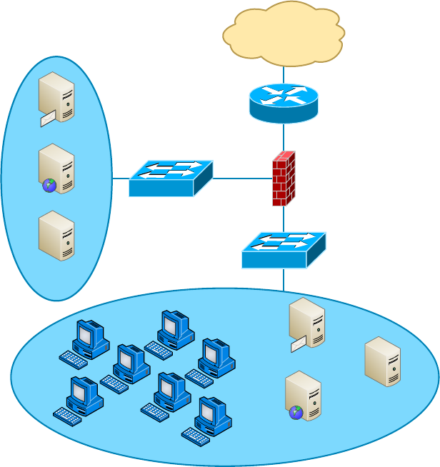
Firewall Technologies
535
c15.indd 03/23/2015 Page 535
■ Use a protocol other than TCP/IP on the internal network inside the firewall. IP-based
attacks aimed at your development server just can’t work if you use Internetwork
Packet Exchange (IPX) on the internal-network side of a router, which gives you an
automatic firewall.
■ Use TCP/IP on the internal network and use a different protocol like IPX in a dead
zone between the internal network and the Internet. Basically, you’ll have things set
up to switch from IP to IPX in that dead zone and switch back to IP again once inside
your network (IPv6 would work in this example as well, but IPX is a good example
because no one would expect it).
FIGURE 15.3 A firewall with a DMZ
Internet
Router
Switch
Email Server
Web Server
FTP Server Switch
Protected
Intranet
Email Server
File & Print Server
Internal Database
& Web Server
Firewall
DMZ

536
Chapter 15 ■ Physical Security and Risk
c15.indd 03/23/2015 Page 536
Applying Your Knowledge
Your new role with ABB Tech Inc. requires you to manage the fi rewall leading into the
Sales department. Your predecessor confi gured the following rule set on the fi rewall.
Source Destination Port Protocol Action
192.168.2.0/24 192.168.10.0/24 23 TCP Drop
192.168.2.1/24 ANY 23 TCP Allow
192.168.10.0/24 192.168.3.0/24 FTP UDP Allow
All All All All Allow
The following issues have been identifi ed with the functioning of the fi rewall.
■ Joe Smith, an IT tech with an IP address of 192.168.2.1, should be able to use Telnet to
any devices in the network, but he cannot use it with any devices.
■ All users in the Marketing department, which uses the 192.168.10.0 subnet, should be
able to use FTP to upload images to a server at 192.168.3.10 but cannot do so.
Your assignment is to correct the rule list. The corrected list is at the end of the chapter.
Source Destination Port Protocol Action
192.168.2.1/24 ANY 23 TCP Allow
192.168.2.0/24 192.168.10.0/24 23 TCP Drop
192.168.10.0/24 192.168.3.0/24 FTP TCP Allow
All All All All Allow
Note: The rule designed to allow Joe at 192.168.2.1 should be moved to the top of the list.
As it is now positioned, the fi rst rule will match his address as well and prevent him from
using Telnet to any devices. The rule designed to allow users in the Marketing depart-
ment, which uses the 192.168.10.0 subnet, to use FTP to upload images to a server at
192.168.3.10 is set with an incorrect protocol type. FTP uses TCP and not UDP, so chang-
ing that in the rule set will solve that issue.
Figure 15.4 demonstrates both of these strategies. Focus on the dead zone between two
of the routers, and also notice that the only protocol on the inside of either router is IPX.
This means that any TCP/IP packets coming in from the Internet can’t pass through into
the local network because of the difference in protocols used by each network.
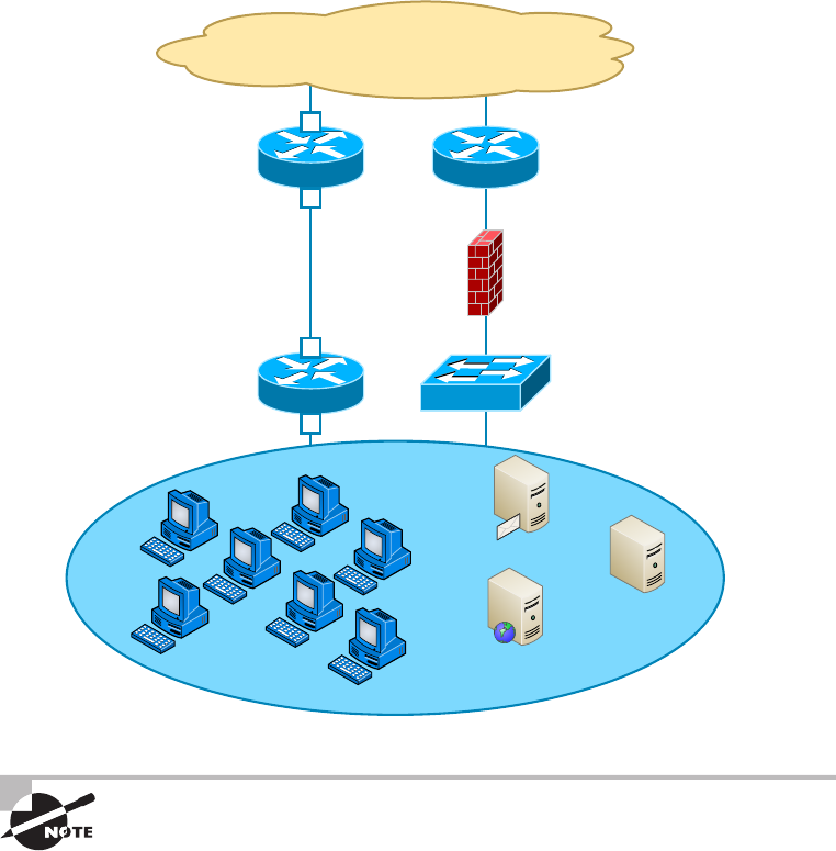
Firewall Technologies
537
c15.indd 03/23/2015 Page 537
FIGURE 15.4 Protocol switching with and without a dead zone
Router
Switch
Firewall
Router
Router
Internet
Protected
Intranet
Email Server
File & Print Server
Internal Database
& Web Server
TCP/IP Only
TCP/IP
TCP/IP Only
IPX/SPX Only
Dead Zone
IPX/SPX Only
IPX/SPX Only
Protocol switching occurs
inside the firewall. The first
NIC understands TCP/IP only.
The second NIC understands
IPX/SPX only.
IPX/SPX
TCP/IP Both
TCP/IP Only
TCP/IP Only
Both of these methods protect only the Internal network. You still need a
firewall to guard against attacks on your network’s access point and proto-
col-switching device.
Dynamic Packet Filtering
Packet ltering refers to the ability of a router or a rewall to discard packets that don’t meet
the right criteria. Firewalls use dynamic packet ltering to ensure that the packets they for-
ward match sessions initiated on their private side by something called a dynamic state list or
state table, which keeps track of all communication sessions between stations from inside and
outside the rewall. This list changes dynamically as sessions are added and deleted.
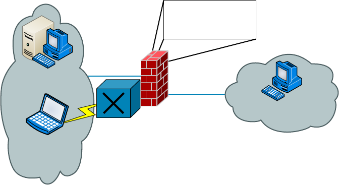
538
Chapter 15 ■ Physical Security and Risk
c15.indd 03/23/2015 Page 538
So with dynamic packet ltering, only packets for valid and current sessions are allowed
to pass. Anyone trying to play back a communication session—for instance, a login to gain
access—won’t be able to do that if your rewall is using dynamic packet ltering with a
dynamic state list because the data they send isn’t part of a currently valid session. The re-
wall will respond to an event like this by dropping all packets that don’t correspond to a cur-
rent session via the information in the dynamic state list. Let me clarify this: Say a computer
in Network A requests a Telnet session with a server in Network B. The rewall in between
the two keeps a log of the communication packets that are sent each way, and only packets
that belong to the current session will be allowed back into Network A through that rewall.
Figure 15.5 depicts a failed attempt to in ltrate a network protected with a dynamic
state list. Can you see that the hacker attempts to insert a packet into the communica-
tion stream but can’t because they don’t have the correct packet number? This is because
the rewall was waiting for a speci c order of packets and the hacker’s packet is out of
sequence.
FIGURE 15.5 A hacker denied by a dynamic state list
Server sending
packet #1239
Session between A & B:
Last packet #1238
Next packet #1239
State List
Hacker attempts
to get in using
packet #1211
Hacker is denied access because the
state list says the firewall should expect
packet #1239 next, but instead it is
receiving #1211, so it rejects the packet.
Client expecting
packet #1239
Firewall
Proxy Services
Firewalls can also implement something called proxy services, which actually makes them
proxy servers, or proxies for short. Proxies act on behalf of the whole network to com-
pletely separate packets from internal hosts and external hosts. Let’s say an internal client
sends a request to an external host on the Internet. That request will get to the proxy server
rst, where it will be examined, broken down, and handled by an application that will cre-
ate a new packet requesting information from the external server. Figure 15.6 demonstrates
this process. Make a note to self that this exchange occurs between applications at the
Application layer of the OSI model.
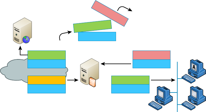
Firewall Technologies
539
c15.indd 03/23/2015 Page 539
FIGURE 15.6 A packet going to a proxy
From Proxy
Data
From A
Data
From Proxy
Data
From Proxy
From A
Data
From Server
Data
HTTP
Proxy Server
Internet
Web Server
Discarded
A proxy receives a request from a client and makes
the request on behalf of the client. This example
shows an HTTP proxy server.
Proxies make good rewalls because they dissect the entire packet so that each section of
it can be scrutinized for invalid data at each and every layer of the OSI model; proxies look
at everything from information in the packet header to the actual contents of the message.
They can even examine attachments for viruses. As if all that isn’t cool enough, proxies can
also search messages for keywords that can indicate the source of a packet. That last little
goodie is vital because you can use this type of searching to prevent sensitive information
from escaping your organization along with the outbound data stream. If your sensitive
documents contain a header or footer that includes something like MyCompanyName
Con dential, you can set up your proxy server software to search for it. The only downside
is that all that analysis will de nitely degrade overall performance because it requires a lot
more time than just checking state lists.
There are many types of proxy servers:
IP Proxy An IP proxy hides the IP addresses of all the devices on the internal network by
exchanging its IP address for the address of any requesting station. This is good because
you de nitely don’t want a hacker to know any IP addresses speci c to your internal net-
work, right? Even Internet web servers won’t be able to determine the speci c IP address
from which they receive a request because any and all communications appear to have orig-
inated from the proxy server—nice! These proxies are sometimes called Network Address
Translation (NAT) proxies.
Web (HTTP) Proxy Web proxies, also called HTTP proxies, handle HTTP requests on
behalf of the sending workstation. When these are implemented correctly, a client’s web
browser asks a web server on the Internet for a web page using an HTTP request. Because
the browser is con gured to make HTTP requests using an HTTP proxy, the browser sends
the request to the proxy server. The proxy server changes the From address of the HTTP
request to its own network address and sends it to the Internet web server. The response to

540
Chapter 15 ■ Physical Security and Risk
c15.indd 03/23/2015 Page 540
the HTTP request goes directly to the proxy (because it replaced the sender’s address with
its own). The proxy server then replaces its address with the address of the original sender,
and the response is delivered to the original sender.
The most popular implementation of a web proxy is a proxy cache server. This server
receives an HTTP request from a web browser and then makes the request on behalf of the
sending workstation. When the requested page is returned, the proxy server caches a copy
of the page locally. The next time someone requests the same web page or Internet informa-
tion, the page can be delivered from the local cache instead of the proxy server having to
formulate a new request to the web server on the Internet. This speeds up web sur ng for
commonly accessed pages. Web proxies can also increase network security by ltering out
content that is considered insecure, such as executables, scripts, or viruses.
FTP Proxy FTP proxies handle the uploading and downloading of les from a server on
behalf of a workstation. An FTP proxy operates in a fashion similar to a web proxy. As
with web proxies, FTP proxies can lter out undesirable content (viruses and the like).
SMTP proxy SMTP proxies handle Internet email. Here, the actual contents of the packet
and mail can be automatically searched. Any packets or messages that contain material that
is not considered secure can be blocked. Many SMTP proxies allow network virus protec-
tion software to scan inbound mail.
Not every firewall falls into a simple category. Although firewalls are used
to typically work in one arena, today’s firewalls offer multiple solutions
within one box or software program. Firewalls that perform more than one
type of filtering service are sometimes referred to as hybrid firewalls.
Firewalls at the Application Layer vs
the Network Layer
By now, you know all about the OSI model and that the Application layer is at the top of
the heap and the Network layer is third up from the bottom. And as a rule of thumb, the
higher you get in the OSI model, the more complex the interactions become. This rule holds
true for discussions of rewalls that work at the Application layer versus those that work at
the Network layer.
The rst rewalls that were developed functioned solely at the Network layer, and the
earliest of these were known as packet- lter rewalls. I covered packet ltering a bit earlier
in this chapter; as a refresher, all it means is that the rewall looks at an incoming packet
and applies it against the set of rules in the ACL(s). If the packet passes, it gets sent on. If
not, the packet is dropped.
This type of ltering is pretty basic because all the rewall considers is the individual
packet. All that matters are the source and destination addresses, protocol, and port
number. The rewall doesn’t care whether that packet is stand-alone or part of another

Firewalls at the Application Layer vs the Network Layer
541
c15.indd 03/23/2015 Page 541
data stream. This process works fairly well for common protocols such as TCP and User
Datagram Protocol (UDP), which communicate on prede ned port numbers. People gener-
ally refer to two types of Network layer rewalls: stateful and stateless.
Stateful vs Stateless Network Layer Firewalls
As I said in the last section, a basic packet lter doesn’t care about whether the packet it
is examining is stand-alone or part of a bigger message stream. That type of packet lter
is said to be stateless, in that it does not monitor the status of the connections passing
through it. Again, these work pretty well, but the rewall has no idea whether a packet is
legitimate or possibly a rogue packet trying to sneak by. These types of rewalls tended to
be susceptible to various DoS attacks and IP spoo ng.
The one big advantage that a stateless rewall has over its stateful counterparts is that
it uses less memory. Today, stateless rewalls are best used on an internal network where
security threats are lower and there are few restrictions.
In contrast to a stateless rewall, a stateful rewall is one that keeps track of the various
data streams passing through it. If a packet that is a part of an established connection hits
the rewall, it’s passed through. New packets are subjected to the rules as speci ed in the
ACL. These types of rewalls are better at preventing network attacks that look to exploit
existing connections, or DoS attacks.
A stateful rewall works by using the TCP three-way handshake. First, the client sends
a packet with the SYN bit set to the rewall. The rewall interprets this as a new connec-
tion and passes the request to the appropriate service provider on the internal network.
Next, the service responds with a packet that has both the SYN and ACK bits set. Finally,
the client responds with a packet with only the ACK bit set. At that point, the connection
is considered established and the rewall will only allow packets in that have the same con-
nection identi cation. The established connection is logged in the state table.
If there is no data on the connection for a speci ed period of time, the connection will
time out in the state table. Any new communication will need to be reestablished based on
the ACL rules.
Stateful rewalls tend to be a bit slower at establishing connections than stateless ones
because there is more to do. After the connection is established, though, stateful rewalls
are usually faster because they just have to check the state table for the connection instead
of comparing the packet against all the relevant ACLs. This is done via stateful packet
inspection. Most stateful rewalls can also keep track of connections using connectionless
protocols such as UDP.
In a common DoS attack, the SYN flood, the attacker attempts to overload
a firewall by spamming it with inordinate numbers of SYN requests. The
firewall by default will keep sending SYN/ACKs back, thereby preventing
it from responding to legitimate connection requests. An additional prob-
lem for the firewall is that it maintains memory space for every SYN/ACK
it sends out and the attacker never answers with a final ACK, so memory
gets used up. Many of today’s firewalls can circumvent this problem by
not responding to multiple SYN requests from the same host.

542
Chapter 15 ■ Physical Security and Risk
c15.indd 03/23/2015 Page 542
Firewall Challenges
You were just given a fi rewall for your network and that fi rewall was appropriated from a
different part of your company. You want to make sure hackers can’t get in through that
fi rewall on random ports. Fortunately for you, the fi rewall is default deny, so you don’t have
too many worries. You open up the ports for legitimate traffi c, such as 80 for HTTP, 161 for
Simple Network Management Protocol (SNMP), 21 for FTP, and so on. But users complain
that they are unable to download fi les from the extranet using FTP. What happened?
FTP does work on port 21, but it also establishes connections on arbitrary high-number ports
to complete its work. If those ports are not opened, FTP won’t work. This is where a stateful
fi rewall is handy. When FTP goes to open the new port number, the fi rewall will see that the
data intended for the new port is part of the existing FTP connection and let the data pass
through. Yet another reason why stateful fi rewalls are so much better than stateless ones!
Application Layer Firewalls
Although stateful rewalls are more powerful and secure than stateless ones, Application
layer rewalls are even better. They work by inspecting more than just data in the IP
header: They read data at the Application layer. In other words, they will know whether
a packet is FTP, SNMP, HTTP, or whatever Application layer protocol it is. The one
major drawback is speed. Because these devices have to read more information than their
Network layer counterparts, they do tend to be a bit slower. It’s generally not enough that
you’ll notice, though, unless you have the reaction time of Superman.
One nice feature of Application layer rewalls is that they let you set proxy rules for
multiple applications on the same rewall. As a proxy, the rewall processes all data
between the two endpoints and drops all packets that are suspicious. In theory, a rogue
packet will never reach the system on your internal network. Application layer rewalls
also handle complex protocols such as H.323, which is used for Voice over IP (VoIP), much
better than their Network layer counterparts.
Scanning Services and Other Firewall
Features
Most rewalls are capable of performing scanning services, which means that they scan
different types of incoming traf c in an effort to detect problems. For example, re-
walls can scan incoming HTTP traf c to look for viruses or spyware, or they can scan
email looking for spam. You can often set scanning rules that will prevent users from

Scanning Services and Other Firewall Features
543
c15.indd 03/23/2015 Page 543
downloading les over a certain size. On Cisco routers, scanning is administered by the
Content Security and Control Security Services Module (CSC-SSM). Two categories of con-
tent are typically scanned: mail and web.
Table 15.1 shows some key default scanning settings within CSC-SSM.
TABLE 15.1 Default scanning settings
Category Protocol Function
Mail SMTP and POP3 Scans all scannable files in an email
Mail SMTP and POP3 Rejects all messages larger than 15MB
Mail SMTP Rejects messages addressed to more than
100 recipients
Mail SMTP Cleans emails or attachments containing
malware, and attaches a notification that the
malware was deleted
Web HTTP Scans all file downloads
Web HTTP Scans web mail sites for AOL, MSN, Google, and Yahoo!
Web FTP Scans all file transfers
Web HTTP and FTP Skips scanning of files larger than 50MB; can also enable
deferred scanning
Web HTTP and FTP Cleans files in which malware is detected; deletes files
that cannot be cleaned
The defaults give you a pretty good level of protection, but there may be instances where
you want to change settings. For example, if you are concerned about bandwidth, then you
can limit the size of les transferred via FTP or HTTP. If mail storage is an issue, then you
can set the rewall to reject mail larger than 10MB.
Keep in mind, though, that by changing some settings, you are increasing your security
risk. If you offer deferred scanning for large les, it will allow you to begin viewing the
data without a prolonged wait while the entire body of information is scanned. However,
the unscanned portion of information can introduce a security risk.
If you are having problems with large file transfers timing out on your
network, it’s possible that it’s partially caused by the firewall scanning the
files immediately. Offering deferred scanning can help fix the problem, but
you also need to weigh the additional security risk.
544
Chapter 15 ■ Physical Security and Risk
c15.indd 03/23/2015 Page 544
Content Filtering
Content ltering is very closely related to scanning services, and on Cisco routers it’s also
provided by the CSC-SSM. Speci cally, content ltering means blocking data based on the
content of the data rather than the source of the data. Most commonly, this is used to lter
email and website access.
The reasons for using content ltering seem pretty obvious. Most companies have a
zero-tolerance policy against hateful material or pornography. If a user on a company net-
work uses that network to spread hate mail or porn, the company could be liable for dam-
ages in a lawsuit if they didn’t take measures to prevent such actions. It’s not only a moral
issue, it’s a legal issue, too.
Content ltering is also important in places like schools. It’s doubtful that parents want
their kids to be able to stumble upon a porn site in the school library while researching
a school project. Content ltering can block that site from being accessed so the problem
never occurs. You can also nd several parental-control software packages for home use
that employ content ltering.
There are several ways to lter content; here are some of the more common categories used:
■ Attachment (blocking attachments of a certain type, such as EXE files)
■ Bayesian
■ Content-encoding
■ Email headers
■ Language
■ Phrases
■ Proximity of words to each other
■ URLs
Nearly all ltering methods use a combination of lters to protect users from improper
content.
Signature Identification
Firewalls can also stop attacks and problems through a process called signature identi ca-
tion. Viruses that are known will have a signature, which is a particular pattern of data,
within them. Firewalls (and antivirus programs) can use signatures to identify a virus and
remove it. The same holds true for other software bugs, such as worms and spyware.
Numerous network attacks have signatures as well. For example, if your router starts
getting hit by large numbers of SYN requests, you may be at the beginning of a SYN ood
attack. The inundation of SYN traf c is a signature of a SYN ood.
Context Awareness
A rewall that is “context aware” is one that can take into consideration the context in
which traf c is arriving at the rewall. It can detect different applications, users, and

Scanning Services and Other Firewall Features
545
c15.indd 03/23/2015 Page 545
devices—not just IP addresses. Because of this more sophisticated approach, it lets adminis-
trators track how applications are used across a range of devices. For example, it may track
and/or prevent the posting or sharing of videos on Facebook using an iPhone, PC, or other
device. It also enables companies to enforce policies, like not allowing a speci c group of
employees to access games on iPads.
Virtual Wire vs Routed
Firewalls can control communications between segments by controlling traf c between
Layer 3 segments (routed approach) or by a process called virtual wire. In this approach,
the rewall is connected between a trusted and untrusted section of a network, as shown
in Figure 15.7. To the devices connected to the rewall (in this gure a switch and router) it
appears that only a single “wire” is connected between them.
FIGURE 15.7 Virtual wire
Trusted
and
Protected
Network
Trusted Untrusted Internet or Other
Untrusted External
Network
Virtual wire rewall interfaces do not need IP addresses. Security zones are de ned on
the physical interfaces of the virtual wire pair. Virtual wire does neither routing nor switch-
ing; it examines the traf c ow to perform deep packet inspection and enforces the rewall
policy.
Zones
A zone is an individual area of the network that has been con gured with a speci c trust
level. Firewalls are ideal devices to regulate the ow of traf c between zones. If you look
back at Figure 15.3, this provides a good example of how zone levels could work. The
Internet would be a zone with no trust or a low level of trust. The DMZ, located between
the Internet and the internal network, could have a medium level of trust. The computers
on the intranet would all be within a high trust zone. The higher the trust level, the less
scrutiny you place on data coming from a computer in that zone.
Another way to look at zones is to understand how Internet Explorer deals with them.
Figure 15.8 shows you what the Internet Options Security tab looks like. On this tab, you
can see that there are four zones for which you can con gure security levels: Internet, Local
Intranet, Trusted Sites, and Restricted Sites. There are three default security levels for the
Internet: High, Medium, and Low. Don’t get this confused with the trust levels I talked
about in the previous paragraph—they are basically opposites. If the security level is set to
High, it means you have low trust.
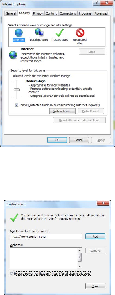
546
Chapter 15 ■ Physical Security and Risk
c15.indd 03/23/2015 Page 546
FIGURE 15.8 Internet Options Security tab
A good way to ensure some security through your browser is to set the security level
to Medium-High or High and leave it there. If there are sites that you download from fre-
quently and that you trust, then you can put those sites into the Trusted Sites zone. Click
Trusted Sites and then click the Sites button to get to the screen shown in Figure 15.9.
FIGURE 15.9 Adding a trusted site
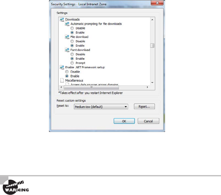
Intrusion Detection and Prevention Systems
547
c15.indd 03/23/2015 Page 547
Finally, you can customize the security level of any of the zones by clicking the Custom
Level button near the bottom of the Internet Options window. This will take you to a
screen similar to the one shown in Figure 15.10.
FIGURE 15.10 Custom security settings
Within the custom settings, you can specify behavior for .NET framework components,
ActiveX controls and plug-ins, downloads, scripting, user authentication, and several other
options. Most of the options have choices to disable, enable, or prompt you if you want to
continue with the operation.
Although Internet Explorer security options can help protect your computer,
do not think of them as a replacement for a firewall. The best security sys-
tems are multifaceted. You should have a firewall solution in place and then
augment that with solid security measures on your local computer as well.
Intrusion Detection and Prevention
Systems
If someone has broken into your network, how would you know? I mean, it’s not like you’re
going to nd broken windows or the door left wide open, right? Although it’s true that you
won’t be dusting for prints, bad guys who break into networks still leave clues behind that
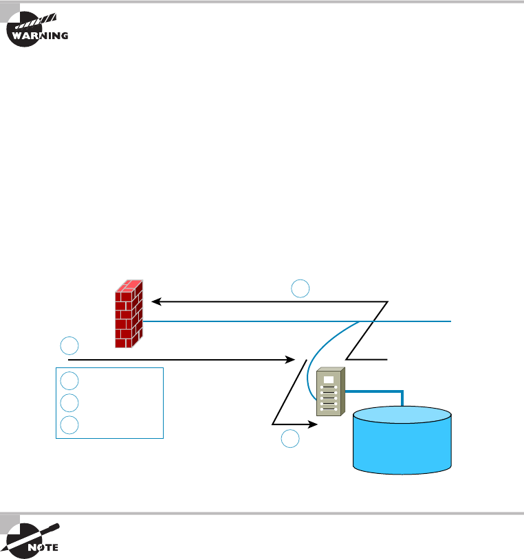
548
Chapter 15 ■ Physical Security and Risk
c15.indd 03/23/2015 Page 548
can help you sleuth out their identities as well as how they gained access. A great tool for
doing network detective work is known as an intrusion detection system (IDS).
Firewalls are designed to block nasty traf c from entering your network, but an IDS is
more of an auditing tool: It keeps track of all activity on your network so you can see if
someone has been trespassing. Because the technology behind IDSs is fairly new, people are
busy developing ways to combine IDS technology with existing rewalls.
An intrusion detection system does not replace a firewall on your network!
There are two ways IDSs can detect attacks or intrusions. The rst is based on the sig-
nature of an intrusion, often referred to as a misuse-detection IDS (MD-IDS), and it works
by looking for ngerprints. That’s right—I said ngerprints, which in this case means
strange or abusive use of the network. The IDS sends up an alarm only if it recognizes
the ngerprints typical of attackers. The second approach looks for anomalies in network
activity, or an anomaly-detection IDS (AD-IDS). An AD-IDS basically watches for any-
thing out of the ordinary; if it discovers ngerprints where there shouldn’t be any, it will
send out an alert. And a really cool feature is that it’s known as a smart system because it
learns on the go by keeping track of and building a history of network activity for norms to
which you can compare unusual activity. Most IDSs today are a combination of two types
of detection systems. Figure 15.11 shows an MD-IDS in action.
FIGURE 15.11 An MD-IDS system in action
1
1
2
2
3
3
Firewall
Attack underway
IDS analysis
Response
Network
Looks for misuse
or known attack
signatures IDS Attack Signature
&
Misuse Database
An intrusion detection system cannot detect attacks within encrypted traffic.
An IDS is a system made up of several components, including one or more sensors to
detect events, a console to control and con gure the sensors and monitor events, and a
database that records the events. These three elements can all be on the same device, or
they can be implemented on multiple devices.
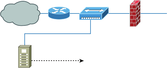
Intrusion Detection and Prevention Systems
549
c15.indd 03/23/2015 Page 549
The two most common types of IDS implementations are network based and host based.
Network-Based IDS
By far the most common implementation of a detection system is a network-based IDS
(NIDS), where the IDS is a separate device attached to the network via a machine like a
switch or directly via a tap. Some IDSs are even capable of attaching to the network both
outside and inside the rewall; this gives you the best security because you can see what
is happening out in the wild and really nail exactly what’s getting through your defenses.
Figure 15.12 gives you an example of a typical IDS setup can look like.
When your IDS detects an intrusion, it will respond to it either passively or actively.
Passive responses are the easiest to con gure and include the following:
Logging All activity to the intrusion is logged. The information gathered can be used to
foil future attacks of the same type. Intrusions should always be logged.
Notification When an attack occurs, an IDS can send an alert to one or more administrators.
Shunning I’m not kidding about this one—you can sometimes just ignore the attack
because it’s possible it won’t affect your network. For instance, if someone launches an
attack designed to cripple a Microsoft Exchange email server at a network that’s running
Lotus Notes, you’re all good, so why waste time doing anything about it? I would recom-
mend recording the event though.
FIGURE 15.12 An IDS connected to the network
Internet
Hub or Tap
Connection
Firewall
Secured
Management Channel
IDS
Active responses mean taking immediate action. When an IDS moves to prevent an
attack, it’s often called a reactive system or an intrusion protection system (IPS). Here are
three common active responses:
Changing Network Configuration Let’s say an attack comes in on port 21. Your IDS can
close the port either temporarily or permanently. The downside is that if the IDS closes
ports, legitimate traf c can’t get through either, but it will de nitely stop the attack. Figure
15.13 shows an example of closing port 80 (HTTP) for 60 seconds.
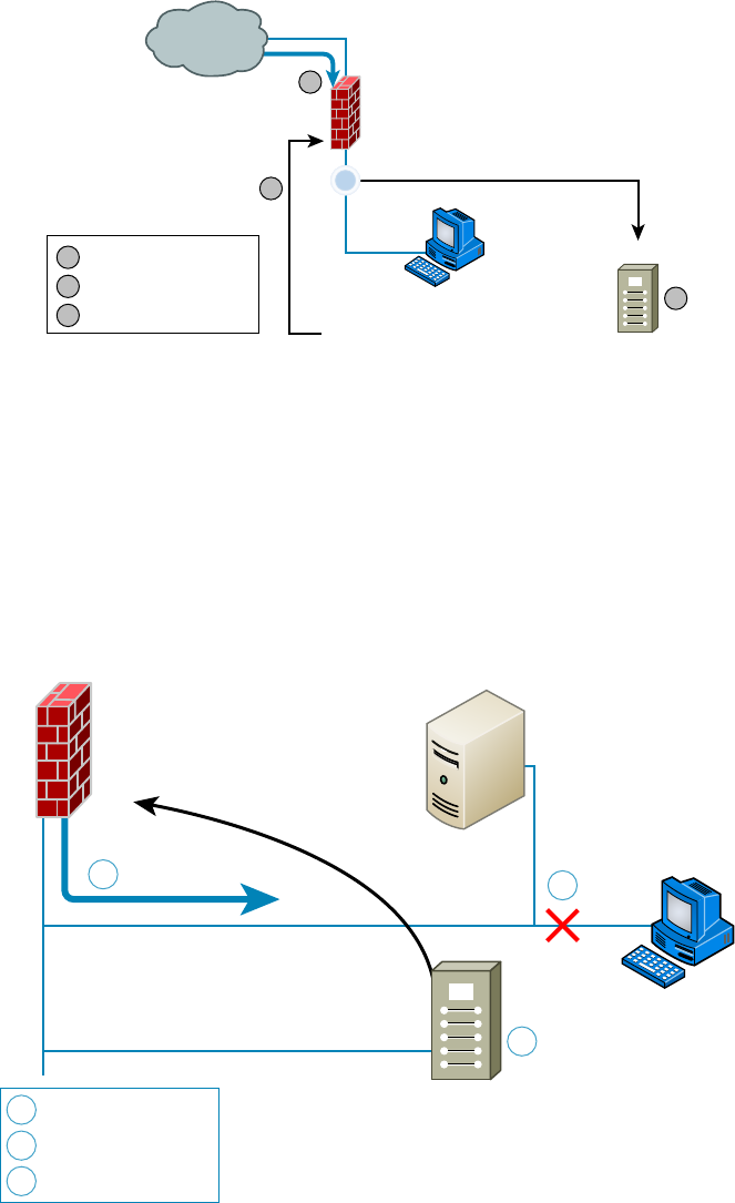
550
Chapter 15 ■ Physical Security and Risk
c15.indd 03/23/2015 Page 550
FIGURE 15.13 Shutting down port 80 for 60 seconds to stop an attack
Firewall
Port 80 Attack
Sensor
Alert Detected
IDS Command (Close 80, 60 Seconds)
Client
3
2
1
1
2
3
Attack occurs
IDS analysis/responses
Port 80 closed
Internet
Terminating Sessions When the IDS detects an attack, it can force all sessions to close
and restart, which will affect and delay legitimate traf c, too, but not for long.
Deceiving the Attacker This one’s the most fun because it tricks the bad guy into thinking
their attack is really working when it’s not. The system logs information, trying to pinpoint
who’s behind the attack and which methods they’re using. This response requires some-
thing called a honeypot, typically a server or group of servers (called honeynets) or maybe
even access points, to which the hacker is directed; it’s intended to keep their interest long
enough to gather enough information to identify them and their attack method so you can
prevent another attack in the future. Figure 15.14 demonstrates this.
FIGURE 15.14 Deceiving an attacker with a honeypot
1
2
3
3
Attack occurs
1 Network Attack
Analysis/response
2 Alert Detected
Reroute network traffic
IDS
Client
Firewall
Honeypot

Intrusion Detection and Prevention Systems
551
c15.indd 03/23/2015 Page 551
I am not endorsing using honeypots, just explaining the concept and how
they work.
Host-Based IDS
In a host-based IDS (HIDS), software runs on one computer to detect abnormalities on
that system alone by monitoring applications, system logs, and event logs—not by directly
monitoring network traf c.
Systems like these are typically implemented on servers because they’re a bear to manage if
spread across several client computers on a network. Plus, if the IDS database is on the local
computer and its data becomes compromised by an attack, the IDS data could be corrupted too.
Other types of IDSs are protocol based (PIDS), which monitor traffic for
one protocol on one server; application protocol based (APIDS), which
monitor traffic for a group of servers running the same application (such as
SQL); and hybrid IDS, which combine one or more IDS technologies.
Vulnerability Scanners
One of the most effective ways to determine if security holes exist in the network is to think
like an attacker and attack your own network. In that case, why not use the same tools
that the hacker might use to identify your weaknesses? For example, if I wanted to verify
the proper application of some ACls to a rewall, I could do so with scanning services sup-
plied by a vulnerability scanner. In the following sections, I’ll cover two of the most widely
known and effective programs that can be used for this purpose.
Nessus
Nessus is a propriety vulnerability scanning program that requires a license to use commer-
cially yet is the single most popular scanning program in use. It normally is executed from
the command line because it can thus be included in batch les that can automate its opera-
tion on a schedule. Its output can be reported in a variety of formats, including plain text,
HTML, and XML.
It operates by performing a port scan and then follows up with more speci c tests and scans
based on the ports open. It can identify a wide array of weaknesses, including the following:
■ Unsecured access to sensitive data on a system
■ Misconfigurations like open mail relay and missing patches
■ Password issues such as the use of default passwords, common passwords, and blank
passwords on system accounts
It can also perform an active attack such as denial of service or a dictionary attack.
552
Chapter 15 ■ Physical Security and Risk
c15.indd 03/23/2015 Page 552
NMAP
Network Mapper (NMAP) was originally intended to simply identify devices on the net-
work for the purpose of creating a network diagram. Its functionality has evolved, how-
ever, and now it can also do the following:
■ Perform port scanning
■ Identify versions of network services in operation on the network
■ Identify operating systems
It can be used from the command line as with Nessus, but it also can be used with web-
based interfaces to be controlled remotely.
Unified Threat Management (UTM)
Uni ed threat management (UTM) devices perform multiple security functions within the
same appliance:
■ Network firewalling
■ Network intrusion prevention
■ Gateway antivirus
■ Gateway anti-spam
■ VPN
■ Content filtering
■ Load balancing
■ Data leak prevention
■ On-appliance reporting
While the advantage of uni ed security lies in the fact that administering multiple
systems is no longer necessary, some feel that a single point of failure is created and
creating multiple layers of devices is a more secure approach.
VPN Concentrators
A VPN concentrator is a device that creates remote access for virtual private networks
(VPNs) either for users logging in remotely or for a large site-to-site VPN. In contrast to
standard remote-access connections, remote-access VPNs often allow higher data through-
put and provide encryption. Cisco produces VPN concentrators that support anywhere
from 100 users up to 10,000 simultaneous remote-access connections.
Encryption for a remote-access VPN through a concentrator is usually handled by
Internet Protocol Security (IPSec) or by Secure Sockets Layer (SSL), and user authentication
can be achieved via Microsoft’s Active Directory; Kerberos; Remote Authentication Dial In
User Service (RADIUS); Rivest, Shamir, and Adleman (RSA); and digital certi cates. Many
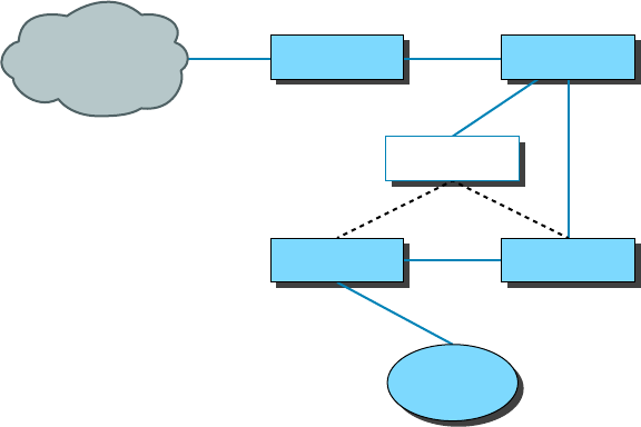
Understanding Problems Affecting Device Security
553
c15.indd 03/23/2015 Page 553
VPN concentrators also have a built-in authentication server and allow ACLs to be imple-
mented through them. In Figure 15.15, you can see where VPN concentrators are usually
placed within a network setup.
The dotted line indicates that you can opt to run your remote-access clients through the
rewall before they’re granted internal access, or you can just let the concentrator handle
the security.
FIGURE 15.15 VPN concentrator in a network
Internet Internet Router External Switch
VPN Concentrator
Firewall
Corporate
Network
Internal Switch
Understanding Problems Affecting
Device Security
Throughout this whole chapter, I’ve been going on and on about the myriad devices we
use to secure traf c coming into our networks and devices and the things we depend on to
detect and prevent attacks on them. It’s an important subject and one that you must solidly
understand in order to be effective in networking. Knowing how to implement a tight secu-
rity program requires working knowledge of these devices, but it doesn’t end there because
there’s always more you can know.
There happen to be a few more really signi cant and valuable concepts you should have
a good grasp of when setting up and managing the security on your network. So that’s the
direction in which we’re going to head for the remainder of this chapter—we’ll cover key
issues you need to be aware of, including physical security and corresponding logical secu-
rity structures, restricting access, and the types of protocols you should and should not use
on your network.

554
Chapter 15 ■ Physical Security and Risk
c15.indd 03/23/2015 Page 554
Physical Security
Over the years, I’ve visited lots of different companies, large and small, public and private,
and analyzed, advised, troubleshot, designed, and implemented their networks. Without
fail, the system administrators I’ve met along the way have been really eager to tell me
all about the security systems they have in place. “Look at this awesome rewall setup!”
“Check out the cool Group Policy structure we have!” “Watch how quickly our fault toler-
ance springs into action!” They’re very proud, and rightly so, of what they’ve worked so
hard to set up, because doing that isn’t easy.
But interestingly, one of the things few people brag about is physical security—like it’s
some kind of afterthought. Maybe the server room has a locked door, maybe it doesn’t.
Maybe the badges that open that door are owned by the right people, or maybe they aren’t. I
guess that on a subconscious level, we tend to inherently trust the people working within the
walls and focus our fears, suspicions, and ammo on mysterious outside forces that we’re sure
are incessantly trying to break in, steal data, or totally murder our networks. Some of the
sharpest, most talented, and savvy system administrators I’ve ever met still have a tendency
to neglect inside security and fail to reasonably monitor things going on within the building.
And there are some seriously vital things to nail down on the inside. For instance, does
it really matter if your network has a secured subnet for the servers, with its own dedicated
internal rewall? De nitely—I’ve actually found servers in racks like sitting ducks in a
hallway right across from the lunch room. When I pointed out the fact that this was not
so good, I was assured that it was only temporary until the server room construction was
complete. I don’t know about you, but for some reason, that didn’t cut it and didn’t make
me feel anywhere near okay with the situation. At another company, I found the door to
the server room propped open because otherwise “it got too hot in there.” Because that
toasty server room didn’t exactly have a guard posted, anyone could just walk in and do
whatever; the backup tapes were clearly marked and sitting there on a shelf—yikes! And
don’t even get me started about the heat. The bottom line is that if your system is not physi-
cally secured, you’re basically sending out an open invitation to a Pandora’s box of prob-
lems without even realizing it.
Beware the Big Gulp
Several years ago when I was teaching a networking class, one of my best students issued
me a challenge. He was proud of the security confi guration on his server computer in the
classroom and went so far as to tell me there was no way I could get to or damage any fi les
on his system. He was really sure about that. Well, it just so happens I like a good challenge.
The students went off to lunch, and I stayed behind to work on a few things. While they
were gone, I got out my handy Partition Magic diskette (I said this was a while ago) and
popped it into his system. One reset button push later, I was in business. I wiped out the
partitions on his hard drive and shut down the system.
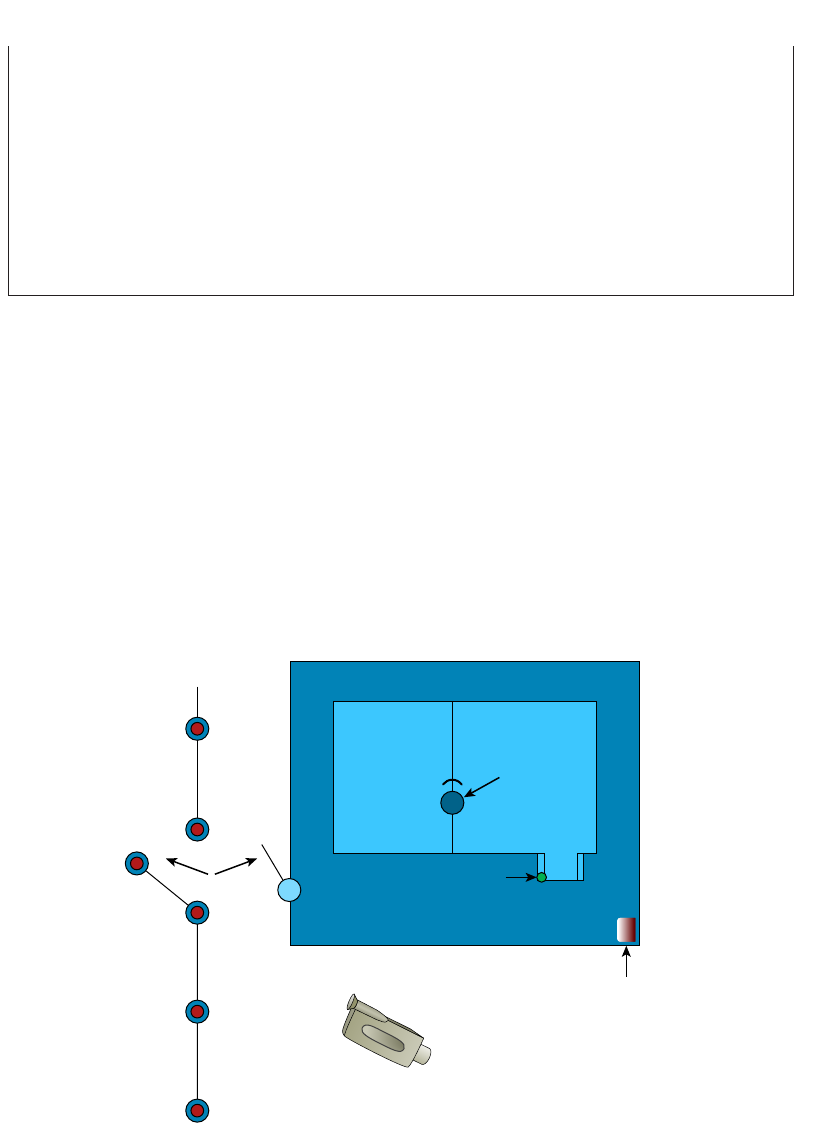
Understanding Problems Affecting Device Security
555
c15.indd 03/23/2015 Page 555
When he came back from lunch, he looked a bit confused. He clearly remembered leaving
his computer on, and upon booting up and playing around for a minute, he realized that
his hard drive was gone. At fi rst, he was more than a little angry at me for doing that, but
then I asked him to give me a chance to prove a point—an important one. That is, when
someone has access to your computer, they can do whatever they want. Yes, they might
not be able to read your fi les (although I could have done that too), but they can still do
a lot of damage. My tool of destruction was a partitioning program, but going back to
that “servers out in the open across from the lunch room” situation, all it would take is a
spilled soft drink to cause mass destruction. In any case, the data clearly was not safe, so
physical security needs to be a top priority.
Physical Barriers
Your rst objective is to keep people from physically getting to your equipment. Clearly,
end users need to be able to get to their workstations, but only authorized personnel should
be anywhere near your servers. The best way to do this is to have a dedicated, two-stage,
air-conditioned server room with really secure doors and locks. Even better, your data cen-
ter should have more than one form of physical security—preferably three. We call that a
multiple barrier system. For instance, you could have a perimeter security system control-
ling access to the building as your rst line of defense. The second would be a secured door
to the computer room, and the third would be another security door to the server room
itself. This is illustrated in Figure 15.16.
FIGURE 15.16 A three-layer security model
Fence
Perimeter
Security
Motion Detector
Door Sensor
Video Camera
Computer Center
Building
Locked Door
Combination
Lock
Computer
Room
556
Chapter 15 ■ Physical Security and Risk
c15.indd 03/23/2015 Page 556
Security Zones
Your network probably has different security zones. Let’s say your servers are in one zone
and the clients are in another. Maybe your engineering department has its own zone.
So why not have the same zones for physical access to the computers? Many companies
today use RFID badges to control where employees are allowed to go inside the building.
You may need a safety clearance and/or certi cation before you can go in the room where
the pilot production machine lives. People should be cleared and certi ed before they’re
allowed in the server room as well.
Mantraps
A mantrap is a series of two doors with a small room between them. The user is authenti-
cated at the rst door and then allowed into the room. At that point, additional veri ca-
tion will occur (such as a guard visually identifying the person) and then they are allowed
through the second door. These doors are typically used only in very high-security situa-
tions. They can help prevent tailgating. A mantrap design is shown in Figure 15.17.
Network Closets
While much of the network equipment should be locked securely in the server room, there
are frequently cases where it is also stored in a smaller location or closets. If that is the case,
these locations should be locked as securely as the server room, and access to them should
be controlled through mechanisms such as cipher doors or proximity locks.
Video Monitoring
In many high-security scenarios it may be advisable to visually monitor the area 24 hours a
day. When this is the case, it will make sense to deploy video monitoring. We’ll look at two
options, IP cameras and CCTV systems.
IP Cameras IP video systems are a good example of the bene ts of networking applica-
tions. These systems can be used for both surveillance of the facility and for facilitating
collaboration.
CCTVs While an IP camera is a type of digital video camera commonly employed for
surveillance, analog closed circuit television (CCTV) cameras are unable to send their
images across IP networks. CCTV cameras record directly to a medium such as video tape
or hard drive. It is possible to convert the signal to digital in cases where you need to send it
across an IP network.
Door Access Controls
While mantraps may justify their cost in some high-security scenarios, not all situations
require them. Door controls should be used to prevent physical access to important infra-
structure devices such as routers, switches, rewalls, and servers. Door control systems are
covered in the following sections.
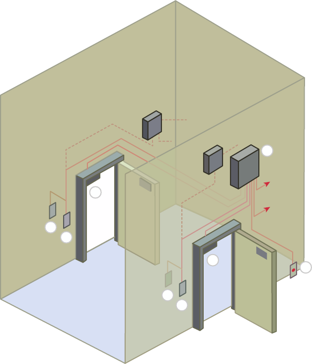
Understanding Problems Affecting Device Security
557
c15.indd 03/23/2015 Page 557
FIGURE 15.17 Mantrap
C
C
C
C
D
A
B
B
Proximity Readers/Key Fob
Proximity readers are door controls that read a card from a short distance and are used
to control access to sensitive rooms. These devices can also provide a log of all entries and
exits. Usually, a card contains the user information required to authenticate and authorize
the user to enter the room.
A key fob, on the other hand, is a type of security token: a small hardware device with
built-in authentication mechanisms. The mechanisms in the key fob control access to net-
work services and information. An advantage of a key fob is that it can support multifactor
authentication.
558
Chapter 15 ■ Physical Security and Risk
c15.indd 03/23/2015 Page 558
For example, a user may have a personal identi cation number (PIN), which authenti-
cates them as a device’s owner; after the user correctly enters their PIN, the device displays
a number that allows them to log on to the network
Biometrics
Biometric systems are designed to operate using characteristic and behavioral factors.
While knowledge factors (password, PIN) are the most common authentication factors
used, characteristic factors represent something that you are ( ngerprint, iris scan) while
behavioral factors represent something that you do (signature analysis).
Multifactor authentication is achieved by combining authentication factors. When two
knowledge factors are combined, such as a retina scan (characteristic factor) and a pass-
word (knowledge factor), dual-factor authentication is required. When three factors are
combined, such as a retina scan (characteristic factor), a password (knowledge factor), and
signature analysis (behavioral factor), then multifactor authentication is in effect.
One of the issues with biometrics is the occurrence of false positives and false negatives.
A false positive is when a user that should not be allowed access is indeed allowed access.
A false negative, on the other hand, is when an authorized individual is denied passage by
mistake.
Keypad/Cypher Locks
Cypher locks that use a keypad require a user to know the key code. This devices can also
come with additional security features. The lock can be combined with a set time for open-
ing the door as well as a battery standby system. Three types of alarm systems are avail-
able. A burglar alarm interface is available to indicate when the door is breached. An error
alarm can reveal someone who tries to guess the code. Finally, a hostage alarm can be trig-
gered to indicate that entry was made under duress.
Security Guard
In cases where judgment may be required to control entry, a security guard may be advis-
able. While the cost is generally higher than with an automated system, there are advan-
tages to this. This offers the most exibility in reacting to whatever occurs. One of the keys
to success when using guards is to ensure that they are trained with a response to every
conceivable eventuality. Finally, the biggest advantage is that guards can use discriminating
judgment in a situation, which an automated system cannot.
Logical Security Configurations
Now that you have your physical network locked down tight, it’s time to review the
security con guration of your network. The same concepts that apply to physical security
apply here, too. First, you want to ensure that your network has an outside barrier and/or
a perimeter defense. This is usually achieved by having a solid rewall, and it’s best to have
an IDS or IPS of some sort as well. Figure 15.18 shows what this might look like.
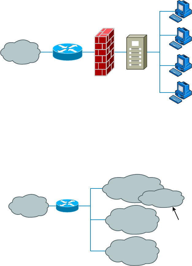
Understanding Problems Affecting Device Security
559
c15.indd 03/23/2015 Page 559
FIGURE 15.18 Network perimeter defense
Local Network
Firewall
IDS
Internet
Router
That may be enough for your network, but maybe not. Let’s say that your network
serves several distinct departments at your company. The admin, production, and sales
groups all have their own unique needs. What you can now do is divide up your internal
network into smaller administrative zones by creating VLANs and using a DMZ. Maybe
your network would logically look like the one shown in Figure 15.19.
FIGURE 15.19 Network divided into security zones
Router
Internet
Accounting
Network
Private
Network
Administration Network
Zone 1
Production Network
Zone 2
Sales Network
Zone 3
Finally, your network might be similar to the one shown in Figure 15.19 but just
larger. Maybe traf c is heavy and you need to break up physical segments. Perhaps differ-
ent groups are in different buildings or on different oors of a building and you want to
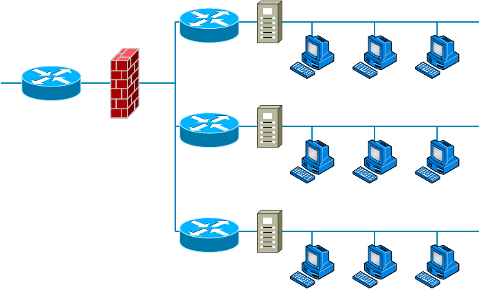
560
Chapter 15 ■ Physical Security and Risk
c15.indd 03/23/2015 Page 560
effectively segment them. There could be any number of reasons for you to “physically”
separate your network into different groups, effectively partitioning your network by using
multiple routers, as shown in Figure 15.20.
FIGURE 15.20 Using routers to divide a network into security zones
Firewall
Border
Router
Zone 3
Router
IDS
Zone 2
Router
IDS
Zone 1
Router
IDS
PCs
Risk-Related Concepts
All organizations should identify and analyze the risks they face. This is called risk
management. In the following sections, you’ll nd a survey of topics that all relate in some
way to identifying risks and mitigating them.
Disaster Recovery
A disaster is an emergency that goes beyond the normal response of resources. The causes
of disasters are categorized into three main areas according to origin:
■ Technological disasters (device failures)
■ Manmade disasters (arson, terrorism, sabotage)
■ Natural disasters (hurricanes, floods, earthquakes)
The severity of nancial and reputational damage to an organization is largely deter-
mined by the amount of time it takes the organization to recover from the disaster. A
Understanding Problems Affecting Device Security
561
c15.indd 03/23/2015 Page 561
properly designed disaster recovery plan (DRP) minimizes the effect of a disaster. The DRP
is implemented when the emergency occurs and includes the steps to restore functions and
systems so the organization can resume normal operations. The goal of DRP is to minimize
or prevent property damage and prevent loss of life.
Business Continuity
One of the parts of a DRP is a plan to keep the business operational while the organization
recovers from the disaster, known as a business continuity plan (BCP). Continuity planning
deals with identifying the impact of any disaster and ensuring that a viable recovery plan
for each function and system is implemented. By prioritizing each process and its support-
ing technologies, the company can ensure that mission-critical systems are recovered rst
and systems that are considered luxuries can be recovered as time allows.
One document that should be created to drive this prioritization is the business impact
analysis. In this document, the impact each system has on the ability of the organization to
stay operational is determined. The results list the critical and necessary business functions,
their resource dependencies, and their level of criticality to the overall organization.
Battery Backups/UPS
One risk that all organizations should prepare for is the loss of power. All infrastructure
systems should be connected to uninterruptible power supplies (UPSs). These devices can
immediately supply power from a battery backup when a loss of power is detected. You
should keep in mind, however, that these devices are not designed as a long-term solution.
They are designed to provide power long enough for you to either shut the system down
gracefully or turn on a power generator. In scenarios where long-term backup power is
called for, a gas-powered generator should be installed.
First Responders
A rst responder is the rst person to discover a data breach or other security incident.
First responders are covered in the section “Basic Forensic Concepts” in Chapter 14.
Data Breach
A data breach is a risk that the organization should always be prepared to address.
Procedures for responding to data breaches and other security incidents are covered in the
section “Incident Response” in Chapter 14.
End User Awareness and Training
One of the issues related to the risk involved in security incidents and disasters over which
the company has some control is the amount of preparation spent on training users.
Regardless of whether the incident is as small as the mistaken deletion of a key docu-
ment or as large as a re destroying the entire building, users should be trained in how to
respond to every eventuality.
562
Chapter 15 ■ Physical Security and Risk
c15.indd 03/23/2015 Page 562
Moreover, it would be even better if recovery teams were created to address the stages
of disaster recovery. The following teams should be assembled and trained before a disaster
occurs:
■ Damage assessment team
■ Legal team
■ Media relations team
■ Recovery team
■ Relocation team
■ Restoration team
■ Salvage team
■ Security team
Each team should rehearse its response to various scenarios. One exercise that seems to
work well is called a tabletop exercise. A tabletop exercise is an informal brainstorming
session that encourages participation from business leaders and other key employees. In a
tabletop exercise, the participants agree to a particular disaster scenario upon which they
will focus.
Single Point of Failure
One concept that makes any IT technician nervous is the existence of a single point of
failure anywhere in the network. During the process of creating the BCP, all single points
of failure should be identi ed. The process begins as described in the following sections,
with the identi cation of critical assets and nodes, and is followed by providing redundancy
where indicated.
Critical Nodes
Critical nodes are individual systems or groups of systems without which the organization
cannot operate. The process of identifying these system should begin with prioritization of
the business processes that each supports. Once this has been done, it is simple to identify
the servers and other systems that are required to allow that process to continue to func-
tion. If this investigation reveals a system that is critical and a single point of failure, action
should be taken to provide some form of redundancy to the node.
Critical Asset
While critical nodes need to be identi ed and provided with additional support to prepare
for disasters and smaller issues, some critical business processes depend on access to assets
such as data that may reside in a database or in connections to vendors and partners.
These assets also need to be identi ed and an action plan developed that recognizes their
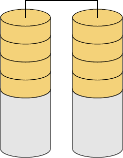
Understanding Problems Affecting Device Security
563
c15.indd 03/23/2015 Page 563
importance. In almost all cases, the solution is some form of redundancy, as covered in the
next section.
Redundancy
Redundancy occurs when an organization has a secondary component, system, or device
that takes over when the primary unit fails. Redundancy can be implemented in many
forms. The organization should assess any systems that have been identi ed as critical to
determine if it is cost effective to implement redundant systems. Redundant systems include
redundant servers, redundant routers, redundant internal hardware, and even redundant
backbones.
One form of fault tolerance that can be provided to a system is Redundant Array of
Independent Disks (RAID). This technology allows for automatic recovery from a hard
drive failure (within certain limits based on the exact form of RAID) in a system. The
major forms of RAID are as follows:
RAID-0 Also called disk striping, this method writes the data across multiple drives.
While it improves performance, it does not provide fault tolerance. RAID-0 is depicted in
Figure 15.21.
FIGURE 15.21 RAID-0
A1
A3
A5
A7
Disk 0
RAID-0
A2
A4
A6
A8
Disk 1
RAID-1 Also called disk mirroring, RAID-1 uses two disks and writes a copy of the
data to both disks, providing fault tolerance in the case of a single drive failure. RAID-1 is
depicted in Figure 15.22.
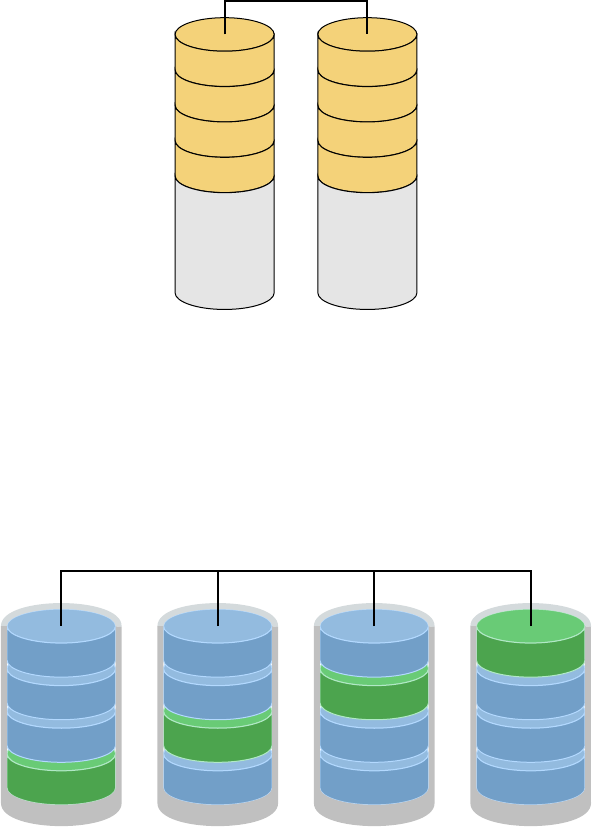
564
Chapter 15 ■ Physical Security and Risk
c15.indd 03/23/2015 Page 564
FIGURE 15.22 RAID-1
A1
A2
A3
A4
A1
A2
A3
A4
Disk 0
RAID-1
Disk 1
RAID-5 Requiring at least three drives, this method writes the data across all drives
like striping, and then parity information is also written across all drives. With hardware
RAID-5, the spare drives that replace the failed drives are usually hot swappable, meaning
they can be replaced on the server while it is running. RAID-5 is depicted in Figure 15.23
FIGURE 15.23 RAID-5
block 1a
block 1b
block 1c
parity
disk 1
block 2a
block 2b
parity
block 2c
disk 2
block 3a
parity
block 3b
block 3c
disk 3
parity
block 4a
block 4b
block 4c
disk 4
RAID-5
Parity across Disks
Adherence to Standards and Policies
Policies and standard are created to communicate to employees the behavior expected from
them in various situations. This includes polices related to business continuity and disaster
recovery. Security policies and procedures are covered in detail in Chapter 14.
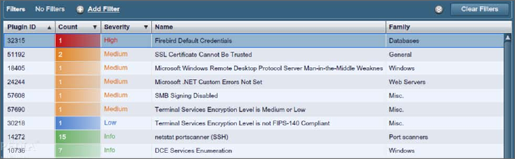
Understanding Problems Affecting Device Security
565
c15.indd 03/23/2015 Page 565
Vulnerability Scanning
Part of the security policy of an organization should address the type and frequency of vul-
nerability scans. These scans are designed to identify any security vulnerabilities that exist.
A vulnerability scanner can probe for a variety of security weaknesses, including mis-
con gurations, out-of-date software, missing patches, and open ports. One of the most
widely used is Nessus, a proprietary vulnerability scanner developed by Tenable Network
Security. A partial screenshot is shown in Figure 15.24. In the output, the issues found on a
host are rated, and issues with the highest severity are at the top by default.
FIGURE 15.24 Nessus
Penetration Testing
A penetration test is designed to simulate an attack on a system, network, or application.
Its value lies in its potential to discover security holes that may have gone unnoticed. It
differs from vulnerability testing in that it attempts to exploit vulnerabilities rather than
simply identify them.
Strategies for penetration testing are based on the testing objectives as de ned by the
organization:
Blind Test The testing team is provided with limited knowledge of the network systems
and devices using publicly available information. The organization’s security team knows
that an attack is coming. This test requires more effort by the testing team.
Double-Blind Test This test is like a blind test except the organization’s security team
does not know that an attack is coming. This test usually requires equal effort for both the
testing team and the organization’s security team.
Target Test Both the testing team and the organization’s security team are given maxi-
mum information about the network and the type of test that will occur. This is the easiest
test to complete, but it will not provide a full picture of the organization’s security.
566
Chapter 15 ■ Physical Security and Risk
c15.indd 03/23/2015 Page 566
Summary
In this chapter, you learned a lot about physical and hardware security. We dove into this
increasingly important subject by looking at one of the most useful network protection
devices around: rewalls. You found out the differences between network-based and host-
based rewalls, and then learned the speci c ways that rewalls work to protect our data
and networks by using access control lists (ACLs). You also learned about other key rewall
topics, like demilitarized zones (DMZs), protocol switching, packet ltering, and proxy
services. I talked about how rewalls can operate at the Network layer or the Application
layer of the OSI model. For those operating at the Network level, there are stateful rewalls
that keep track of the established connections passing through them and stateless rewalls
that don’t. Firewalls also provide services like scanning, signature identi cation, content
ltering, and breaking your network up into security zones.
We then moved on and discussed two other vital hardware devices: intrusion detection
and prevention systems and VPN concentrators. You learned that IDS devices can be net-
work or host based, just like rewalls, but unlike rewalls, which block traf c based on
speci c rules, IDS and IPS systems allow traf c in and then initiate a reaction if any prob-
lems are detected. I also talked about something called an IPS, which is an IDS that can
generate an active response when an intrusion is detected. We then covered VPN concentra-
tors, which are speci cally designed to allow several hundred—even several thousand—
users to remotely access your network either through a secure connection or by setting up a
virtual secure network between two locations.
Finally, you discovered some often-overlooked aspects of physical security that can seri-
ously affect your network. You now know that beyond a doubt, if people can get to your
hardware, they can do damage to your infrastructure, intentionally or not.
Exam Essentials
Understand and utilize network segmentation. This includes segmentation at Layer 2 and
3, and includes the proper location of devices such as IPS, IDS, honeypots, and honey nets.
Understand the difference between a network-based firewall and a host-based firewall. A
network-based rewall is a hardware device on the network or on a router that protects a
group of computers. A host-based rewall is software installed on one individual machine,
and it protects only that machine.
Compare and contrast risk-related concepts. Understand how to identify and prioritize
key systems and business functions. Create standards and policies to ensure the continued
operation of these functions to support business continuity and disaster recovery.
Understand how a firewall determines which traffic can pass through it. Firewalls use
access control lists (ACLs), which are sets of rules, to determine which traf c is allowed to
pass through.
Written Lab
567
c15.indd 03/23/2015 Page 567
Describe and apply proper physical security controls. This includes door access controls,
biometric systems, and the use of cameras and security guards.
Remember where a DMZ can be placed. A demilitarized zone (DMZ) can be located out-
side a rewall, connected directly to the Internet. However, it can also be placed after the
rewall inside your network. You need to remember that it can be placed in either location.
Understand what a proxy server is and what types of proxying are common. A proxy
server is a computer that makes and ful lls requests on behalf of another computer. Many
rewalls can act as proxies. Common proxy services include IP proxy, web proxy, FTP
proxy, and mail (SMTP) proxy.
Know on which levels of the OSI model various security devices operate. Firewalls work
at the Application layer or the Network layer. Port security on switches operates at the
Data Link layer.
Understand the difference between stateful and stateless firewalls. A stateful rewall
keeps track of the established connections passing through it. When another packet is
received that’s part of an existing connection (part of a current state), the packet is passed
without checking the ACLs. A stateless rewall examines each packet individually and
does not track existing states. This makes it a bit slower and more susceptible to network
attacks.
Know what types of services firewalls can provide. Most rewalls provide scanning
services, content ltering, signature identi cation, and the ability to segregate network
segments into separate security zones.
Know the difference between an IDS and an IPS. An intrusion detection system (IDS)
monitors network traf c, looking for signs of an intrusion. Intrusions are detected by
matching activity versus known signatures within the IDS’s database. If an intrusion is
detected, a passive response such as logging or notifying a network administrator is exe-
cuted. An intrusion prevention system (IPS) is like an IDS, but with two key differences.
First, it learns what is “normal” on the network and can react to abnormalities even if
they’re not part of the signature database. Second, it can issue an active response such as
shutting down a port, resetting connections, or attempting to lull the attacker into a trap.
Written Lab
In this section, write the answers to the following security questions. You can nd the
answers in Appendix A.
1. Which type of firewall interface does not use IP addresses?
2. Which type of firewall keeps track of existing connections passing through it?
3. If you wanted to ensure that your firewall could block inflammatory email, which
type of service would you look for?

568
Chapter 15 ■ Physical Security and Risk
c15.indd 03/23/2015 Page 568
4. The main security issue with UTM devices is that they constitute a
5. If you wanted to allow remote access to 500 users, which type of device is recommended?
6. If data from one of your subnets should be restricted from entering another subnet, the
subnets should be configured as different .
7. A series of two doors with a small room between them is called a ?
8. How does an ACL treat any traffic type by default?
9. What is a group of servers used to lure attackers called?
10. Logging, notification, and shunning are what types of reactions from what type of
security device?

Review Questions
569
c15.indd 03/23/2015 Page 569
Review Questions
You can nd the answers to the review questions in Appendix B.
1. In general, firewalls work by .
A. Rejecting all packets regardless of security restrictions
B. Forwarding all packets regardless of security restrictions
C. Allowing only packets that pass security restrictions to be forwarded
D. None of the above
2. Which if the following devices can read an entry card from a distance?
A. Biometric reader
B. Proximity reader
C. Mantrap
D. Key fob
3. What is the main difference between a network-based firewall and a host-based firewall?
A. A network-based firewall protects the Internet from attacks.
B. A network-based firewall protects a network, not just a single host.
C. A network-based firewall protects the network wires.
D. A network-based firewall protects a CD from data loss.
4. Which of the following minimizes the effect of a disaster and includes the steps necessary to
resume normal operation?
A. SLA
B. BIA
C. DRP
D. ARP
5. Which of the following items cannot be identified by the Nessus program?
A. Default password use
B. Incorrect IP addresses
C. Unsecured data
D. Missing security patches
6. What is the benefit of using a firewall?
A. Protects external users
B. Protects external hardware
C. Protects LAN resources
D. Protects hardware from failure

570
Chapter 15 ■ Physical Security and Risk
c15.indd 03/23/2015 Page 570
7. IDSs can identify attackers by their .
A. Port number
B. Signature
C. Timing
D. IV
8. Which of the following is also called disk striping?
A. RAID-0
B. RAID-1
C. RAID-3
D. RAID-5
9. Which is not a type of access control list (ACL)?
A. Standard
B. Extended
C. Referred
D. Outbound
10. What is it called when the firewall ignores an attack?
A. Logging
B. Shunning
C. Notification
D. False negative
11. What is the function of a DMZ?
A. To separate a security zone for an IPS and IDS server
B. To create a security zone for VPN terminations
C. To create a security zone that allows public traffic but is isolated from the private
inside network
D. To create a security zone that allows private traffic but is isolated from the public
network
12. Which of the following are types of services that firewalls can provide?
A. Content filtering
B. Segregate network segments
C. Signature identification
D. Scanning services
E. All of the above

Review Questions
571
c15.indd 03/23/2015 Page 571
13. In which type of test is the testing team provided with limited knowledge of the network
systems and devices using publicly available information?
A. Blind test
B. Double-blind test
C. Target test
D. Open test
14. Which of the following is a vulnerability scanner?
A. Network Monitor
B. Nessus
C. Traceroute
D. Tripwire
15. Which of the following is not a function of NMAP?
A. Perform port scanning
B. Identify operating systems
C. Collect passwords
D. Identify versions of network services in operation on the network
16. Changing network configurations, terminating sessions, and deceiving the attacker are
actions that can be taken from what type of security device?
A. Access control list (ACL)
B. Content filtering
C. Security zones
D. Intrusion prevention system (IPS)
17. act on behalf of the whole network to completely separate packets from
internal hosts and external hosts.
A. Honeypots
B. IDSs
C. IPSs
D. Proxies
18. Which of the following cannot be identified by Nessus?
A. Unsecured access to sensitive data on a system
B. IP address conflicts
C. Misconfigurations like open mail relay
D. Password issues

572
Chapter 15 ■ Physical Security and Risk
c15.indd 03/23/2015 Page 572
19. A firewall keeps track of the established connections passing through it.
A. Hardware
B. Software
C. Stateful
D. Network
20. A(n) learns what is “normal” on the network and can react to abnormalities
even if they’re not part of the signature database.
A. IDS
B. Firewall
C. IPS
D. VPN concentrator

c16.indd 04/02/2015 Page 573
Chapter
16
Wide Area Networks
THE FOLLOWING COMPTIA NETWORK+
EXAM OBJECTIVES ARE COVERED
IN THIS CHAPTER:
✓ 1.4 Explain the characteristics and benefits of various
WAN technologies
■ Fiber
■ SONET
■ DWDM
■ CWDM
■ Frame relay
■ Satellite
■ Broadband cable
■ DSL/ADSL
■ ISDN
■ ATM
■ PPP/Multilink PPP
■ MPLS
■ GSM/CDMA
■ LTE/4G
■ HSPA+
■ 3G
■ Edge
■ Dialup
■ WiMAX
■ Metro-Ethernet
■ Leased lines

c16.indd 04/02/2015 Page 574
■ T-1
■ T-3
■ E-1
■ E-3
■ OC3
■ OC12
■ Circuit switch vs packet switch
✓ 1.7 Differentiate between network infrastructure
implementations
■ WAN
■ MAN
■ LAN
✓ 4.8 Given a scenario, troubleshoot and resolve common
WAN issues
■ Loss of internet connectivity
■ Interface errors
■ Split horizon
■ DNS issues
■ Interference
■ Router configurations
■ Customer premise equipment
■ Smart jack/NIU
■ Demarc
■ Loopback
■ CSU/DSU
■ Copper line drivers/repeaters
■ Company security policy
■ Throttling
■ Blocking
■ Fair access policy/utilization limits
■ Satellite issues
■ Latency

c16.indd 04/02/2015 Page 575
✓ 2.2 Given a scenario, analyze metrics and reports from
monitoring and tracking
■ Link status
■ Interface monitoring
■ Errors
■ Utilization
■ Discards
■ Packet drops
■ Interface resets
■ Speed and duplex

c16.indd 04/02/2015 Page 576
We have wide area networks (WANs) and local area networks
(LANs), but what’s really the key difference between the two?
Clearly there’s the distance factor, but these days, wireless
LANs can cover respectable turf. Is it a bandwidth thing? Not so much—some seriously big
pipes can be had for a price in many places, so what is it that actually sets the two apart?
One of the main ways a WAN differs from a LAN is that you usually own your LAN
infrastructure, whereas WAN infrastructure is typically leased from a service provider
instead. To be honest, modern technologies actually blur this de nition a bit, but it still
ts neatly into the context of CompTIA’s Network+ exam objectives. Anyway, I’ve already
talked about the data link that you usually own (Ethernet), so it’s time to explore the kind
you usually don’t own—the type most often leased from a service provider.
You’ve probably heard of T-series connections, which are leased line connections that
reserve or dedicate lines to provide paths between network segments. In addition to these,
we’ll survey broadband services, including the array of Digital Subscriber Line (DSL) and
cable modem connectivity that most of us use to connect to the Internet from home. We’ll
even check out a more modern home-based option known as a passive optical network,
which essentially means running ber to a speci c site.
Cellular technologies have evolved over the years, and more and more people are
opting to use them for connecting to the Internet. For this reason, we’ll talk about HSPA+,
WiMAX, and LTE, and discuss the evolution of 1G, 2G, 3G, and 4G.
We’ll also spend some time looking into the different kinds of WAN connectivity
achieved through other kinds of links and over different transmission media. WAN tech-
nologies run the gamut from short-range Bluetooth to the serious, long-distance coverage
available via satellite transmissions. I’ll also focus on key WAN protocols, which are basi-
cally sets of rules that establish exactly how long-distance communication and connectivity
should occur. We’ll even review some not-so-modern technologies like Integrated Services
Digital Network (ISDN), Frame Relay, and Asynchronous Transfer Mode (ATM), and talk
about the legacy phone-company network and some of its terminology, too. I’ll guide you
through everything you’ll need to know about different speed links—including T1s and
E1s, SONET ber links, and the plain old telephone service (POTS) lines that connect us
to the Public Switched Telephone Network (PSTN). With all of these subjects nailed down,
you’ll be well equipped with the knowledge you’ll need to con dently meet the CompTIA
Network+ objectives!
For up-to-the-minute updates for this chapter, please see
www.lammle.com/
networkplus
or the book’s website at
www.sybextestbanks.wiley.com
.
What’s a WAN?
577
c16.indd 04/02/2015 Page 577
What’s a WAN?
As local area networks grew and developed, it became increasingly necessary to be able to
connect their resources together over long distances. We initially met these challenges via the
phone company network—the Public Switched Telephone Network (PSTN)—and the rst
successful network able to establish voice communications over disparate locations was born.
Few of us remember back to a world without phone service, which made PSTN an
obvious solution. It was already a fully operational, circuit-switching network, enabling
every phone call to establish a unique circuit from one endpoint (phone) to another through
a path of switches. So, instead of reinventing the wheel to design LANs, early network
planners used packet switching as their communications-delivery method. As you can
imagine, wiring these packet-switched networks to enable communication over vast locales
wasn’t exactly something we could get done quickly, so even wide area networks (WANs)
used the existing phone company network back in the day! But all solutions aren’t created
equally, and this one just wasn’t so great due to its hefty price tag and because it imposed
some ugly data transfer limitations on very networks it served.
So that’s the history for you, but know that it’s not a thing of the past—yet. Today’s
WANs are communication networks that cover broad geographic areas, and they still
frequently use phone companies (service providers) in concert with their circuit-switched
networks to connect LANs together. Competition can be a great motivator, and with the
Internet entering the scene, giving us an alternative way to connect LANs, we bene t tre-
mendously from the resulting reduction in the cost of our connectivity. These new connec-
tion options, along with their related protocols and technologies, can greatly reduce the
cost of a WAN’s infrastructure, and lowered transport costs are a huge relief for network
administrators and designers alike!
An important fact to lock into memory is that WAN protocols and technologies all
occupy at least two of the OSI model’s lower three layers—the Physical layer, Data Link
layer, and sometimes the Network layer as well. Coming up, we’ll examine the various
types of connections, technologies, topologies, and devices used with WANs as well as how
to create WAN connections using different transmission media such as air (wireless), space
(satellite), and both copper and glass ber for wired connections. But before we go there,
you’ll need to know some basic WAN terms.
Defining WAN Terms
Before you run out and order a WAN service type from a provider, you really need to
understand the following terms that service providers typically use:
Customer Premises Equipment (CPE) Customer premises equipment (CPE) is equipment
that’s owned by the service provider but located on the subscriber’s (your) property.
CSU/DSU Channel service unit/data service unit (CSU/DSU) is a Layer 1 device that
connects the serial ports on your router to the provider’s network and connects directly to
the demarcation point (demarc) or location. These devices can be external, as shown in

578
Chapter 16 ■ Wide Area Networks
c16.indd 04/02/2015 Page 578
Figure 16.1, or they can be internal cards on the router. The CSU/DSU provides clocking of
the line to the CPE—in this case, your router—and provides other important options, like
voltage regulation.
FIGURE 16.1 A typical wide area network
Provider
Network
Local Loop
ISP can perform a loopback test from CO to NIU.
CO
Smart
Jack/NIU CPE
CSU/DSU
Demarc
Smart Jack/NIU As you can see, there’s a smart jack, or network interface unit (NIU),
installed between the demarcation location and the CSU/DSU at the customer premises
equipment (CPE) location. But why is it there and what does it do? For starters, a smart
jack can provide signal conversion by converting codes and protocols (e.g., framing
types) into something the customer equipment requires. Plus, the NIU can buffer and/or
regenerate the signal to compensate for signal degradation from line transmission. This is
very similar to what a repeater does.
But there’s more. Smart jacks also typically provide diagnostic capabilities to the ISP, some-
thing a demarcation location just can’t. A very common and vital capability gained via a
smartjack is the ability to perform a loopback test, where the signal from the provider is
transmitted back to the provider’s location. Doing this allows the ISP to test the line from
the central office, without the need to have test equipment or a technician at the customer
site. Of course, this loopback test will bring down the line, but then again, they wouldn’t
need to perform the test if you didn’t call in a problem in the first place!
Demarcation Point Just so you’re clear, a demarc is the precise spot where the service
provider’s or local exchange carrier’s responsibility ends and the CPE begins. It’s generally
a device in a telecommunications closet owned and installed by the telecommunications
company (telco). It’s your responsibility to cable—a task called extended demark—from
this box to the CPE, which is usually a connection to a CSU/DSU or ISDN interface.
Copper Line Drivers/Repeaters A copper line driver or repeater allows for a demarc
extension length of up to 5,000 feet from the telephone company’s demarc. These can be
used to connect equipment across a campus, between oors of a high-rise of ce building,
even between of ce buildings with underground cable connections.
What’s a WAN?
579
c16.indd 04/02/2015 Page 579
Local Loop A cable consisting of a pair of copper wires called the local loop connects the
demarc to the closest switching of ce, known as a central of ce (CO).
Central Office (CO) A phone company building that connects the customer’s network to
the provider’s switching network. It’s also good to know that a CO is sometimes referred to
as a point of presence (POP).
Toll Network The toll network is a trunk line inside a WAN provider’s network. This
network is a collection of switches and facilities owned by the ISP.
With all this said, let’s take another look at Figure 16.1, which uses all these items to
describe a typical WAN connection.
You would nd the typical WAN (as shown in Figure 16.1) when you order a T1 or
Frame Relay circuit. De nitely familiarize yourself with these terms because they’re crucial
to understanding WAN technologies.
The Public Switched Telephone Network
As I mentioned at bit earlier, the portion of the PSTN that runs from your house to the
rest of the world is known as plain old telephone service (POTS), and it’s a popular
method for connecting remote users to a local network due to simplicity, low cost, and easy
installation. Connecting to PSTN via ISDN, DSL, a cable modem, or even your cellular
service is becoming increasingly popular.
Two key concepts to keep in mind about PSTN are public and switched. Public basically
means that, for a fee, anyone can lease the use of the network without being required to
run any cabling. Switched explains how the phone system works. Even though one or more
wires are actually connected to your home and/or of ce, all of them aren’t always online or
being used. Any dormant wires are still available to you in their of ine state so you can get
online and join the network whenever you want. Think of it as like a standing reservation,
and your phone number is used as an ID to access it. Because you initiate the connection
by dialing a certain phone number, it’s easy to imagine how technically impractical, if not
impossible, it would be for this method to work if every phone number stayed connected all
the time. If connections stayed active 24/7, the resulting backbone cabling requirements and
problems would be insurmountable.
Take, for instance, the US and worldwide telephone systems. The actual numbering
sequence varies in other countries, but the concept is identical. The phone company runs
the local loop from the demarc to the CO. All the pairs from all the local loop cables
within a small regional area come together at a central point a lot like a patch panel in a
LAN based on unshielded twisted-pair (UTP) cable.
This centralized point has a piece of equipment attached called a switch, which opens a
communications session when it’s initiated by a user who’s dialed the phone number of the
receiver and keeps it open until the “conversation” ends and the session is closed. On one
side of the switch is the neighborhood wiring, and on the other side are lines that connect
to either another switch or a local set of wiring.
To make this concept really clear, picture the following scenario: When you want to
make a call, you pick up the phone, which completes a circuit, and in most cases that gives
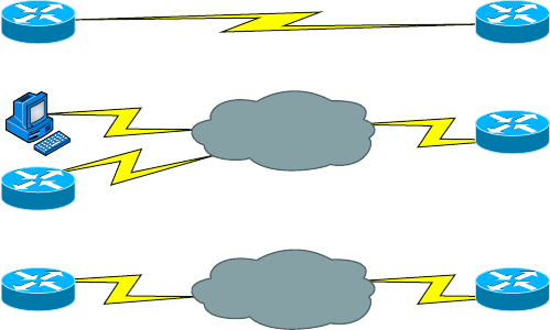
580
Chapter 16 ■ Wide Area Networks
c16.indd 04/02/2015 Page 580
you a dial tone. The tone is the switch’s way of saying, “I’m ready.” When you don’t get
that dial tone, it means that either there’s a break in the equipment chain or the switch is
too busy processing other requests. In many areas of the world, you hear a fast on-and-off
tone (somewhat like a fast busy signal) after giving a command string (phone number) to
the local switch. This means that the other switches that the local switch is attempting to
communicate with are too busy at that time.
Recently, this tone thing has been replaced with a voice recording saying something
like, “We’re sorry. All circuits are busy. Please try your call later.” Sometimes you even get
offered the shady-sounding “For only 99 cents, you can interrupt this call” added to the
message. This happens frequently on holidays or during natural disasters because the local
area’s phone company uses only the minimum number of wires, called trunk lines, required
to handle the norms of usage capacity plus a few auxiliary lines for peak usage. They keep
equipment to a minimum because wiring and switches are really expensive; it’s essentially
a trade-off between providing 100 percent uptime and keeping the costs of leasing the
connection from the phone company reasonably affordable.
WAN Connection Types
With all that in mind, it’s time to go over the various types of WAN connections you’ll nd
on the market today. Figure 16.2 shows the different WAN connection types that can be
used to connect your LANs together.
FIGURE 16.2 WAN connection types
Dedicated
Synchronous Serial
Asynchronous Serial, ISDN
Telephone
Company
Synchronous Serial
Service
Provider
Circuit-Switched
Packet-Switched
Let’s talk about the different WAN connection types you see pictured here:
Dedicated (Leased) Lines These are usually referred to as point-to-point or dedicated
connections. A dedicated leased line is a preestablished WAN communications path that
goes from the CPE through the DCE switch and then over to the CPE of the remote site.
The CPE enables DTE networks to communicate at any time with no cumbersome setup
What’s a WAN?
581
c16.indd 04/02/2015 Page 581
procedures to muddle through before transmitting data. When you’ve got plenty of cash,
this is the way to go because it uses synchronous serial lines up to 45Mbps. High-Level
Data Link Control (HDLC) and Point-to-Point Protocol (PPP) encapsulations are frequently
used on leased lines.
Circuit Switching When you hear the term circuit switching, think phone call. The big
advantage is cost—you only pay for the time you actually use. No data can transfer before
an end-to-end connection is established. Circuit switching uses dial-up modems or ISDN
and is used for low-bandwidth data transfers. I know what you’re thinking: “Modems?
Did he say modems? Aren’t those only in museums now?” After all, with all the wireless
technologies available, who uses modems these days? Believe it or not, some people still
use ISDN. It’s still viable, and there are many places on Earth where you de nitely need a
modem to get connected. Also, circuit switching can actually be used in some of the newer
WAN technologies as well.
Packet Switching This WAN switching method allows you to share bandwidth with other
companies to save money. Packet switching can be thought of as a network that’s designed
to look like a leased line yet charges you more like circuit switching does. But less isn’t
always more—there’s de nitely a downside, and if you need to transfer data constantly, just
forget about this option. Instead, get yourself a leased line. Packet switching will only work
for you if your data transfers are the bursty type, not continuous. Frame Relay and the
super-old X.25 are packet-switching technologies with speeds that can range from 56Kbps
up to T3 (45Mbps).
LANs use packet switching technology. The source and destination addresses in the
packet header guide the network as it moves the packet closer and closer to the destination
in the same way the post of ce takes an addressed letter and keeps it moving incremen-
tally closer to its destination. This approach avoids the necessity of establishing an actual
contiguous electrical circuit from one end to the other—the method phone companies use
to facilitate a phone call in their circuit-switched networks.
Most WAN connections work on the phone company’s circuit-switched network
where the point-to-point nature of most connections eliminates the need for addressing
because there’s only one possible destination between endpoints. But you still need a
proper addressing scheme within your LAN to ensure that data packets reach their
correct destinations.
Bandwidth or Speed
Satisfying the need for speed involves moving large volumes of data, voice, and video
loaded packets across vast distances to communicate. Companies’ volume requirements
have grown right along with their appetites for ever bigger, faster connections. Speed,
typically made possible with more bandwidth, is measured in bits per second or multiples
of bits per second, such as kilobits (thousands of bits) per second.
And no surprise here—the winner of the “Slowest WAN Connection” prize is the
much-maligned dial-on-demand dial-up connection. Modern dial-up modems typically

582
Chapter 16 ■ Wide Area Networks
c16.indd 04/02/2015 Page 582
have a maximum theoretical transfer speed of 56Kbps, although in most cases 40Kbps to
50Kbps is the norm. Factors such as phone-line noise as well as the quality of the modem
itself play a large part in determining connection speeds. Modems are required to modu-
late/demodulate the signal, which means translating the analog signal our ears hear into
a digital stream for transfer across a digital network. Some connections may be as slow as
20Kbps in extremely “noisy” environments like hotel rooms where phone lines are shared
with an abundant number of extensions.
Megabyte (MB) and gigabyte (GB) usually refer to the amount of storage capacity
available, whereas bandwidth and speed refer to units that measure how much data (bits)
can be sent per second. In the networking world, speed is essentially the measurement of
how fast the data ows (Hz) and also refers to how fast data ows within memory systems.
Sometimes the terms bandwidth and speed are used interchangeably.
T-Series Connections
The basic, entry-level in bandwidth or speed for leased lines that provide synchronous
connections between sites is known as the T1. It serves up 24 Digital Signal 0 (DS0)
64Kbps channels in the United States, Japan, and South Korea. There’s a slightly bigger/
faster version with 32 DS0 channels that’s available in Europe and called the E1 or E
carrier line.
T1s use Digital Signal 1 (DS1) bit patterns to transmit packets; DS1 has to do with the
service to be sent over a T1—originally, 24 digitized voice channels. The terms T1 and DS1
have become synonymous and include a bunch of different services from voice to data to
clear-channel pipes. The line speed is always consistent at 1.544Mbps (millions of bits per
second), but the payload can vary greatly. For trivia lovers, T1 came from the carrier letter
or part number assigned by AT&T to the technology.
But That Doesn’t Add Up!
Twenty-four of these channels are a composite of 1.536Mbps, not 1.544Mbps! Why is there
a difference? The reason is that after a byte (8 bits) of data is sent from each channel
(24 × 8 = 192 bits), there is an extra bit used for synchronizing called a frame bit. Hence,
193 bits are sent, and this increase of 1 bit per 192 causes the speed to increase to
1.544Mbps.
T-series connections are digital connections that you can lease from the telephone
company. They can use copper pairs like regular phone lines, or they can be brought in as
part of a backbone, which is also called a trunk line. At this point, T-series connections
use time-division multiplexing, or TDM, to divide the bandwidth into channels of equal
bit rate.
T-Series Connections
583
c16.indd 04/02/2015 Page 583
T-series connection types are denoted by the letter T followed by a number. Each
connection type differs in its speed and in the signal used to multiplex the channels.
Table 16.1 lists some of the T-series connections and their maximum data rates. The
most commonly used T-series lines are T1 and T3.
TABLE 16.1 T-series connections
Connection Maximum speed
T1 1.544Mbps
T1C 3.152Mbps
T2 6.312Mbps
T3 44.736Mbps
T4 274.176Mbps
The T1 Connection
So a T1 is a 1.544Mbps digital connection that’s typically carried over two pairs of copper
wires. This 1.544 Mbps connection uses DS1 and aggregates 24 discrete, 64Kbps channels
that use DS0, which refers to the time slots within a channel. Each channel can carry either
voice or data. In the POTS world, T1 lines are used to convert and bundle analog phone
conversations over great distances due to the better quality of a digital signal and the use
of a great deal less wiring than would be needed if each pair carried only one call. This
splitting into independent channels also allows a company to combine voice and data over
one T1 connection or to use the T1 as if it were an unchannelized 1.544Mbps pipe. You
can also order a fractional T1 (FT1) circuit that’s delivered on a T1 but doesn’t allow the
use of all 24 channels.
The European version of the T1 is the E1, which operates at 2.048Mbps and uses 32
64Kbps channels (32 DS0s). It was designed later, based on T1s, and is a little bigger. You’ll
also nd the J1, which is the Japanese version of the T1 and operates at 1.544Mbps, just
like the T1.
What’s a Good Speed for a Business?
Many of you who happen to be in charge of setting up your company’s Internet
connection may think that a T1 is defi nitely what you should go with. Unfortunately, T1
connections to the Internet can be really pricey. If you’re in the business of selling Internet
continues

584
Chapter 16 ■ Wide Area Networks
c16.indd 04/02/2015 Page 584
connections as an ISP is, you can justify spending the big bucks on large bandwidth
pipes. Another example of when it would make sense for you to opt for a T1 is if you have
loads of users on your network—at least 50 or more.
But even if you’ve got bunches of users on your network, it could be worth it to check out
alternative solutions that offer similar speeds at lower costs, like DSL or a cable modem.
You can always use a virtual private network (VPN) if you need the security. And there are
inexpensive wireless connection options out there as well that provide good bandwidth.
Do your research before you buy!
The T3 Connection
A T3 line works similarly to a T1 connection but carries a whopping 44.736Mbps. This
is equivalent to 28 T1 circuits and a whopping 672 DS0 channels! It uses a signal known
as Digital Signal 3 (DS3) that’s de nitely not the same as DS1, which is generally delivered
over ber-optic cable. Many local ISPs have T3 connections to their next-tier ISPs. Other
entities that often opt for T3 are large multinational companies because they need the
capacity to send voice and data between their major regional of ces. And don’t forget that
the reason the math doesn’t quite work out is because of those frame bits!
As it goes with the T1, the T3’s European counterpart is the E3, which operates at
34.368Mbps. The Japanese Digital Hierarchy speci es the J3 circuit, which operates at
32.064Mbps.
This Doesn’t Add Up Again!
Why does an E1 have more capacity than a T1 but a T3 has more capacity than an E3?
E and T lines are incremented differently. A T1 is 28 T1s, while an E3 is only 16 E1s.
Transmission Media
Another aspect of WAN technologies that can have a big effect on the speed, bandwidth, and
the volume of data that can be transferred is the type of transmission media. Wireless trans-
missions use air as transmission media. This not only creates a bit of a challenge concerning
security, it also presents us with signal degradation—the further the signal has to travel from
the original source, the weaker it gets. A solution to this last snag comes to us via microwave
repeaters, which retransmit signals through the air and bolster them. This approach is a lot
more ef cient because it can preserve signal strength over much greater distances.
The most far-reaching technology uses the air and even empty space to send electromag-
netic signals to satellites from which they are then resent to distant geographic locations.
continued

Transmission Media
585
c16.indd 04/02/2015 Page 585
Wired Connections
Back on Earth, wired connections use either copper wire or glass ber to carry bits as
voltages or light pulses, respectively. That attenuation issue I just talked about under wire-
less technology, where the signal gradually weakens over distances, also relates to copper
wire transmissions and limits the length of wire you can use. Fiber offers a lot more band-
width and it’s a lot less susceptible to noise, but it also costs a lot more to buy and install!
In the United States, the standard for synchronous data transmission on optical ber is
called Synchronous Optical Network (SONET). The international equivalent of SONET is
Synchronous Digital Hierarchy (SDH). SONET de nes a base data rate, or throughput, of
51.84Mbps, and multiples of this rate are known as optical carrier (OC) levels, like OC-3,
OC-12, and so on. Table 16.2 depicts common OC levels and their associated data rates.
TABLE 16.2 Common optical carrier levels (OC-x)
Level Data rate
OC-1 51.84Mbps
OC-3 155.52Mbps
OC-12 622.08Mbps
OC-48 2.488Gbps
OC-192 9.953Gbps
Regardless of the media used to carry WAN traf c, the growing volume of voice and
video traversing data networks has led to new traf c problems. Regular data traf c can
arrive out of order and be reassembled back into its original order on the receiving end, but
voice and video data require real-time delivery to be intelligible. Clearly, this makes regu-
lar data a lot less vulnerable to congestion or busy traf c conditions that can delay voice
and video communications and totally mess them up. The explosion in the popularity and
amount of multimedia being sent over data networks is a big reason the never-ending quest
for greater bandwidth and speed to avoid traf c jams on WAN links is so vital today.
Wavelength Division Multiplexing
Wavelength Division Multiplexing (WDM) is a technology that multiplexes several optical
carriers on a single optical ber by using different wavelengths. Remember, ber-optic
signals are light, so using different wavelengths of the light spectrum is somewhat like using
different frequencies in a radio wave.
Dense Wavelength Division Multiplexing (DWDM) multiplexes within a speci c band
(1550 nm), allowing for the use of erbium-doped ber ampli ers (EDFAs) that boost the signal.
586
Chapter 16 ■ Wide Area Networks
c16.indd 04/02/2015 Page 586
This allows for upgrading the bit rate of a single strand line by simply replacing equipment
at either end of the line. The system consists of the following:
■ DWDM terminal multiplexer
■ Intermediate line repeater (every 80–100 km)
■ Intermediate terminal multiplexer (remote amplification site)
■ DWDM terminal de-multiplexer
Coarse Wavelength Division Multiplexing (CWDM) uses larger chunks of the light
spectrum, and is de ned by wavelengths, whereas DWDM is de ned by frequencies and ts
40-plus channels into the same frequency range used by just 2 CWDM channels. So why use
CWDM at all then? Because CWDM can match the basic capabilities of DWDM at a lower
capacity at a signi cant discount! This allows ISPs to help customers in a Metropolitan Area
Network (MAN) physical location where ber is still too pricey to implement.
Passive Optical Network
Passive Optical Network (PON), also called ber to the premises, is a new option for
connecting homes and business to the Internet. It is point-to-multipoint technology with a
single ber strand used for multiple premises (typically 16–28). Unpowered optical splitters
are used in the process and are the reason for using the term passive.
The system consists of an optical line termination (OLT) at the telco’s of ce and a
number of optical network units (ONUs) near end users. These systems typically have
downlink speeds of 155Mbps to 655Mbps and uplink bursts to 155Mbps.
Wireless Technologies
Now let’s get back to that distance issue. You know that different technologies offer
different distance ranges and that optical ber carries signals much further than copper
cabling can. You also know that ber comes with a much higher price tag to match its
higher capacity and that it’s much harder to install.
By now, most of us know what Bluetooth is—a type of wireless technology that’s only
used for short-distance wireless transmissions. Bluetooth is actually a wireless protocol that
creates personal area networks (PANs). It utilizes short-range communications technology
enabling data transmission between xed and/or mobile devices. Most of us have mobile
phones and those who have smartphones can even get their email, news, directions to
where they’re headed, and the best Italian restaurant, and once there, they can tell friends
where to meet them and post it all on social media in real time. But it’s already illegal to
talk on your cell while driving in some US states and, as time goes on, likely more, if not
all. Even using a wireless headset while driving can get you in trouble in some places. Those
headsets, along with wireless keyboards and mice, all use Bluetooth technology.
Bluetooth uses a radio technology called Frequency Hopping Spread Spectrum that
chops up the data being sent and transmits chunks of it through the air on up to 75
Transmission Media
587
c16.indd 04/02/2015 Page 587
different frequencies in the 2.4GHz range. The transmitter and receiver change frequencies
or channels in a prearranged pattern. Getting all of our wireless toys to play nicely with
each other and synch up can be a hassle initially, but meeting that need is exactly what the
people who created Bluetooth intended to do—develop a single digital wireless protocol,
capable of connecting multiple devices and overcoming problems arising from trying to
synchronize them. Bluetooth achieves this goal and even allows us to synch our cars with
our phones to chat away legally while driving again!
Microwave radio relay is a technology for transmitting digital and sometimes even
analog signals between two locations on a line-of-sight radio path through the atmosphere.
During microwave radio relay, radio waves are transmitted between the two locations
with directional antennas that form a xed radio connection between them. A really
long connected series of links can form line-of-sight transcontinental communication
systems. Now, if this sounds familiar, it should—if you didn’t skip Chapter 12, “Wireless
Networking,” that is! Anyway, although having a dedicated microwave connection is still
common because it allows you to purchase your own frequency range from the FCC to
ensure that you don’t get any interference, a much less costly installation is the wireless
802.11 speci cation, which provides us with long-distance solutions and a healthy amount
of bandwidth to boot.
A communications satellite (comsat) is an arti cial satellite stationed in space for
telecommunications purposes. Modern communications satellites use a variety of orbits.
Here’s a list of them:
■ Geostationary orbits
■ Molniya orbits (molniya means lightening in Russian), named after a series of commu-
nications satellites from Russia
■ Low-polar and non-polar Earth orbits from which the satellite can first boost
communications signals and then send them back to earth
There are other elliptical orbits too, but I’m not going to go into them in this book
because you’re not reading this to help you get your FCC license. Instead, you want
to pass the CompTia Network+ exam, and to do that, you do need to understand
point-to-multipoint services and how communications satellites provide microwave
radio relay technology, as shown in Figure 16.3.
This technology is also used for mobile applications like GPS communications to ships,
vehicles, planes, and handheld terminals as well as for fun stuff like watching football on
satellite HDTV and radio broadcasting. These all require capabilities that are impractical
or impossible to use with other technologies like cable.
So yeah, this satellite thing is pretty awesome, but of course it comes with a few
problems too. First of all, it’s expensive, and although it isn’t necessarily slow, there’s a
lot of latency because of the time it takes to get from your terminal to the satellite to the
provider and back. This is totally understandable since you’re transmitting about 20,000
miles or more and once you get a good TCP stream—something like an FTP download—
speeds can really get moving. Still, for bursty traf c, like email messages, you’ll probably
encounter enough latency to drive you batty enough to head straight back to a modem!
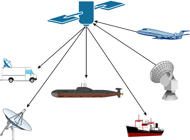
588
Chapter 16 ■ Wide Area Networks
c16.indd 04/02/2015 Page 588
FIGURE 16.3 An example of a satellite point-to-multipoint
Transportable
Terminal
Surfaced Submarine
Terminal
Ship
Terminal
Fixed
Terminal
Aircraft
Terminal
Semi-Fixed
Terminal
Broadband Services
Before I get into telling you all about the WAN protocols required to meet the CompTIA
objectives, I’ve got to talk about cable modems and DSL as solutions for connecting to
WANs. I think brie ng you on them will really help you understand the practical differ-
ences between DSL and cable-modem networking, and they just happen to be CompTIA
objectives as well!
Dedicated broadband services include transmissions over media in a broad range of
frequencies. The various forms of Digital Subscriber Line (DSL) services are broadband
in the sense that digital information is sent over a high-bandwidth channel above the
baseband voice channel on a single pair of wires. Ethernet digital signals sent over a cable
modem from your local cable television service provider compete with DSL service.
Although it’s true that DSL and cable Internet services do indeed have a lot in com-
mon, they still have some basic, essential differences that are really important for you to
understand:
Speed Most people would tell you that cable is faster than DSL Internet, but they
wouldn’t be right because cable doesn’t always win the race in the real world.
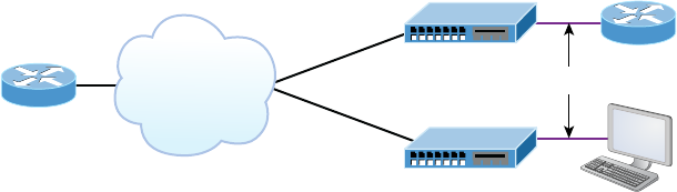
Broadband Services
589
c16.indd 04/02/2015 Page 589
Security DSL and cable are based upon different network-security models, and until
recently, cable has been the reputed loser in this contest. But now it’s pretty much a toss-up,
with both offering adequate security to meets the needs of most users. And when I say
adequate, I don’t mean anywhere near great—there are still some very real security issues
relating to both alternatives, no matter what your ISP says!
Popularity Cable Internet is de nitely “best in show” in the United States, but DSL is
beginning to catch up.
Customer Satisfaction Here, the reverse is true—in the United States, DSL is top dog.
Still, do you really know anyone who’s satis ed with their ISP?
Figure 16.4 shows how a connection can terminate from modems to either a PC directly
or to a router. The two devices that lie between the router and the cloud and between
the computer and the cloud represent the cable or DSL modem. Typically, your router
would run Dynamic Host Con guration Protocol (DHCP) on that interface as well as
Point-to-Point Protocol over Ethernet (PPPoE), which we discussed back in Chapter 13,
“Authentication and Access Control.”
FIGURE 16.4 Broadband access using cable or DSL
Underlying
network is
transparent
to the user.
Cable or DSL
Cable or DSL
Always-on Voice, Video, and Data Services
Ethernet
Both DSL and cable high-speed Internet services are available to millions of
residential and business consumers worldwide, but in some areas, only one and some-
times neither service is available. Surprisingly, some of the differences between DSL and
cable modem have nothing to do with the actual technologies—it comes down to the
individual ISP. All other things being equal, issues like cost, reliability, and quality of
customer support for both installation and maintenance really do vary signi cantly from
one provider to the next.
DSL Technology and xDSL
DSL is not a complete end-to-end solution. It is really a physical layer transmission
technology like dial-up, cable, or wireless. DSL connections are deployed in the last mile of
a local telephone network or local loop. The term last mile has been used quite a bit in the
last few years with broadband-type connections. It basically means the same thing as local
loop, and de nes the physical connection from the customer to the rst aggregation device
of the provider network.

590
Chapter 16 ■ Wide Area Networks
c16.indd 04/02/2015 Page 590
A DSL connection is set up between a pair of modems on either end of a copper wire
that is between the CPE and the digital subscriber line access multiplexer (DSLAM). A
DSLAM is the device located at the provider’s CO that concentrates connections from
multiple DSL subscribers.
xDSL is really a family of technologies that have become popular for data transmission
over phone lines because xDSL uses regular PSTN phone wires to transmit digital signals
and is extremely inexpensive compared with other digital communications methods.
The x in xDSL represents the various letters that refer to different DSL avors. xDSLs
use high-frequency signals, whereas regular phone calls use low-frequency signals over the
same lines.
Communicating via xDSL requires an interface to a PC. All xDSL con gurations require
a DSL modem called an endpoint and a Network Interface Card (NIC) in your computer.
The NIC can be connected directly to the DSL modem using a straight-through Ethernet
UTP patch cord with standard RJ-45 connectors on each end. But if there are other con-
necting devices between the computer and the cable modem, you’ll need either a special
switchable port or an Ethernet crossover cable for things to work out well.
So Are These Really Modems?
Actually, neither ISDN nor cable modems are actually modems in the sense that no
analog-to-digital signal modulation is occurring. But the industry calls them modems
anyway!
A nice feature of xDSL implementations is that they cost tens of dollars instead of the
hundreds, sometimes up to the thousands, you would have to pony up for a dedicated, digi-
tal point-to-point link like a T1. These cost-effective implementations include the following:
High Bit-Rate Digital Subscriber Line (HDSL) HDSL was the rst DSL technology to use
a higher-frequency spectrum of copper twisted-pair cables. HDSL was developed in the
United States as a better technology for high-speed, synchronous circuits. It was typically
used to interconnect local-exchange carrier systems and to carry high-speed corporate data
links and voice channels using T1 lines.
Symmetric Digital Subscriber Line (SDSL) Symmetric (meaning same rate in both direc-
tions) digital subscriber line (SDSL) provides T1/E1 type speeds symmetrically for both
uploading and downloading data, but doesn’t allow low-frequency phone calls on the
same line as asymmetric digital subscriber line (ADSL) does. How much it will set you
back ranges between the cost of ADSL and T1s. This option is typically used by small to
medium-sized businesses that don’t require the higher performance of a leased line for
connecting to a server.
Very High Bit-Rate Digital Subscriber Line (VDSL) VDSL, or very high bit-rate DSL
(VHDSL), provides faster data transmission over single, at, untwisted or twisted pairs
Broadband Services
591
c16.indd 04/02/2015 Page 591
of copper wires. This capacity for blazingly fast speeds mean that VDSL is capable of
supporting high-bandwidth applications like HDTV and telephone services like the ever
popular Voice over IP (VoIP) as well as general Internet access over a single connection.
VDSL is deployed over existing wiring used for POTS and lower-speed DSL connections.
Second-generation VDSL2 systems utilize bandwidths of up to 30MHz to provide data
rates exceeding 100Mbps simultaneously in both the upstream and downstream directions.
The maximum available bit rate is achieved at a range of about 300 meters with the signal
performance degrading as the loop attenuation increases.
Asymmetric digital subscriber line (ADSL) Asymmetric (meaning different upload and
download speed) DSL has become the most popular xDSL because it focuses on providing
reasonably fast upstream transmission speeds (768Kbps) and very fast downstream trans-
mission speeds of up to 9Mbps (ADSL2+ can get up to 20Mbps). This makes downloading
graphics, audio, video, and data les from any remote computer a snap! The majority of
web traf c is downstream. The best part is that ADSL works on a single phone line with-
out losing voice call capability. This is accomplished with something called a splitter that
enables the use of multiple frequencies on your POTS line.
Cable Modem
Cable is a great cost-effective connection for a small of ce or home of ce (SOHO)—yes,
there is an acronym for everything. Even in larger organizations, cable, or even DSL, can
be great to have around as a backup link.
Here are a few cable network terms:
Headend This is where all cable signals are received, processed, and formatted. The
signals are then transmitted over the distribution network from the headend.
Distribution Network These are relatively small service areas that usually range in size
from 100 to 2,000 customers. They’re typically composed of a mixed, ber-coaxial, or
hybrid ber-coaxial (HFC) architecture, with optical ber substituting for the distribu-
tion network’s trunk portion. The ber forms both the connection from the headend
and an optical node that changes light to radio frequency (RF) signals that are then
distributed through a coaxial cable throughout the speci c service area—that is, your
home or of ce.
Data over Cable Service Interface Specifications (DOCSIS) This speci cation provides
the interface requirements for a data-over-cable system, including that of high-speed data
transfer to an existing cable TV system. All cable modems and similar devices have to
measure up to this standard.
Figure 16.5 shows where you would be likely to nd the various types of networks and
how the terms I just listed would be used in a network diagram. The area on the right
where coaxial cable is in use is the distribution network, and the box labeled Node is the
optical node where light is converted to RF signals for use on the coaxial cable.
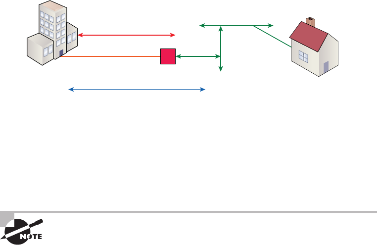
592
Chapter 16 ■ Wide Area Networks
c16.indd 04/02/2015 Page 592
FIGURE 16.5 Cable network
HFC
Fiber Node
Headend
DOCSIS Standard
Coaxial Cable Serving Area
The problem with this is that ISPs often use a ber-optic network that extends from the
cable operator’s master headend—sometimes even to regional headends—out to a neighbor-
hood’s hubsite and nally arrives at a ber-optic node that services anywhere from 25 to
2,000 or more homes. I’m really not picking on cable, but here’s another issue: If you have
cable, open your PC’s command prompt, type
ipconfig
, and check out your subnet mask.
It’s probably a /20 or /21 Class B address—yikes! You already know that translates to either
4,094 or 2,046 hosts per cable network connection—de nitely not good.
When I say cable, I really mean using coax (coaxial) cable for transmission.
Community antenna television (CATV) is now used as a means to offer
cost-effective broadcasting to subscribers. Cable is able to provide voice
and data, plus analog and digital video, without requiring your
whole paycheck!
Your average cable connection gives you a maximum download speed of 20Mbps
(theoretically, some providers sell this up to 50Mbps). And remember—you have to share
that bandwidth with all the other subscribers. As if that weren’t enough, there are other
things like overloaded web servers and plain old network congestion that factor into
the mix as well. But your email-checking neighbors really aren’t making that much of a
difference. So who or what is? Well, if you’re an online gamer, you will likely notice a bit
more lag during peak periods, which could be a matter of virtual life and death. And if
somebody in your neighborhood is uploading a large amount of data, like, say, an entire
collection of pirated Star Wars movies, it could de nitely max out the entire connection
and bring everyone’s browser to crawl speed or worse.
Cable-modem access may or may not be faster or easier to install than DSL, and your
mileage will vary, depending on where you live plus a variety of other factors. But it’s usually
more available and a tad less pricey, making it a winner by a nose. But no worries, if cable
access isn’t available in your neighborhood, DSL is okay—anything is better than dial-up!
Metro Ethernet
Metropolitan-area Ethernet is a metropolitan area network (MAN) that’s based on
Ethernet standards and can connect a customer to a larger network and the Internet.
Wireless WAN Technologies
593
c16.indd 04/02/2015 Page 593
If available, businesses can use Metro Ethernet to connect their of ces together, which
presents another very cost-effective connection option. MPLS-based Metro Ethernet
networks use MPLS in the ISP by providing an Ethernet or ber cable to the customer as a
connection. From the customer, it leaves the Ethernet cable, jumps onto MPLS, and then
Ethernet again on the remote side. This is a smart and thrifty solution that’s very popular
if you can get it in your area.
Wireless WAN Technologies
At one time, it was taken as gospel that wireless technologies, especially WAN technolo-
gies, could never be completely acceptable, especially when compared to terrestrial tech-
nologies. Today, that given is being challenged with a number of new technologies that can
provide acceptable Internet and even multimedia performance without a landline. In the
following sections, we’ll look at some of the cellular WAN technologies and see how far
we’ve really come in this regard.
Cellular WAN
Cellular technologies have evolved since their introduction in the late 1970s. Terms like
1G ( rst generation) 2G, 3G, and 4G are often used to describe signi cant advances in
the technology. First I’ll rst give you a quick overview of the major developments, and
then we’ll look more closely at a couple of the newer technologies, speci cally what these
technologies bring to the table and what they may promise for the future.
First generation cellular (1G) was a voice-only analog network. The second generation
(2G) marked the switch to digital, which allowed voice and, for the rst time, simple data,
such as a text message. Fourth generation (4G) is still the most widely used globally at this
writing, but things change quickly. 4G allows high-speed voice and data, even Internet.
This is the type of network supporting most of your smartphones.
GSM, or Global System for Mobile Communications, is a standard developed by the
European Telecommunications Standards Institute (ETSI). It delineates protocols for
2G digital cellular networks, which are used by mobile phones, and it’s the default global
standard for mobile communications and enjoys over 90 percent market share. 2G is
available in over 219 countries and territories worldwide.
The GSM standard was created to replace rst generation (1G) analog cellular networks
and originally described a digital, circuit-switched network optimized for full duplex voice
telephony. It evolved to include data communications, at rst via circuit-switched transport,
then through packet data transport via General Packet Radio Services (GPRS) and EDGE,
alternately via Enhanced Data rates for GSM Evolution (EGPRS).
Code division multiple access (CDMA) is a channel access method that’s used by various
radio communication technologies. CDMA offers multiple access, where several transmit-
ters can send information simultaneously over a single communication channel, allowing
594
Chapter 16 ■ Wide Area Networks
c16.indd 04/02/2015 Page 594
several users to share a band of frequencies. To make this work without a bunch of
interference between users, CDMA relies upon spread-spectrum technology and a special
coding scheme in which each transmitter is assigned a unique code.
Fourth generation (4G) is actually still an emerging technology that has two variants,
LTE and WiMAX. An organization called the Third Generation Partnership Project 2
(3GPP2) has set speci c requirements that must be met for a system to call itself 4G.
At this point in time, LTE and WiMAX meet these requirements.
The goal of 4G is to provide data rates way beyond what’s typically available today.
Even so, uplinks from the mobile device to the tower will always be much slower, and
actual performance in the real world still isn’t always so hot. I’ll provide a few gures
to clarify all this, but just know that 4G systems really should still be backward com-
patible with 3G systems most of the time to fully achieve the performance goals that
4G was created to meet. Oh, and obviously, the device itself has got to be 4G capable to
start with!
HSPA+
Evolved High Speed Packet Access (HSPA+) is really considered a 3.5 generation tech-
nology. It does include an optional all-IP architecture, which is one of 4G’s require-
ments, and it actually has greatly improved data rates over its HSPA forerunner.
Because HSPA+ uses an all-IP architecture, it has the potential to evolve into a true 4G
technology someday. It has downlink speeds of 3Mbps to 4Mbps and uplink speeds of
1Mbps to 2Mbps.
WiMAX
World Wide Interoperability for Microwave Access (WiMax) is considered a true
4G technology, and it’s based on the IEEE 802.16 standard. It supports both xed,
tower-to-tower applications and mobile applications. It was originally designed as a
last-mile technology to deliver Internet to areas where implementing landlines wasn’t
possible as an alternative to DSL and cable.
But it has its challenges too—WiMAX just isn’t compatible with 2G and 3G technolo-
gies, and it’s pricey and requires lots of power. Worse, it also lags behind LTE in speed with
downlink speeds of 5Mbps to 6Mbps and uplink speeds of 2Mbps to 3Mbps.
LTE
This brings us to Long Term Evolution (LTE), which is de nitely the most promising of
all emerging 4G technologies. It uses an all-IP-based core, it offers the highest data rates,
and it’s compatible with 3G and WiMAX! And it happens to have the best indoor cover-
age while maintaining high data rates all the way to the edge of a coverage cell. If that
isn’t enough for you, it also accommodates more devices in a given area and still performs
really well by maintaining data rates of 7Mbps to 12Mbps on the downlink and 3Mbps to
5Mbps on the uplink.
WAN Protocols
595
c16.indd 04/02/2015 Page 595
WAN Protocols
We’ll be focusing on these six technologies in the following sections:
■ ISDN
■ Frame Relay
■ PPP
■ ATM
■ MPLS
Integrated Services Digital Network
ISDN is a digital, point-to-point WAN technology capable of maximum transmission
speeds of about 2Mbps (Primary Rate Interface [PRI]), although speeds of 128 Kbps
(Basic Rate Interface [BRI]) are more the reality within a SOHO environment.
Because it’s capable of much higher data rates at a relatively low cost, ISDN is becoming
a viable remote-user connection method—especially for those who work out of their
homes. ISDN uses the same UTP wiring as POTS, yet it can transmit data at much higher
speeds. But that’s where the similarity ends. The main thing that makes ISDN different
from a regular POTS line is how it utilizes the copper wiring. Instead of carrying an analog
voice signal, it carries digital signals, which also happens to be the key behind several more
vital differences.
First, a computer connects to the 128Kbps ISDN line via an ISDN terminal adapter
(TA) that’s often incorrectly referred to as an ISDN modem. An ISDN TA is not a modem
because it doesn’t convert a digital signal from the computer to an analog signal on the sub-
scriber line—ISDN signals are digital on the subscriber line. A TA is technically an ISDN-
compatible device that has one or more non-ISDN ports for devices like computer serial
interfaces and RJ-11 analog phones, which work to give these non-ISDN devices access to
the ISDN network.
Second, an ISDN line has two types of channels. The data is carried on special Bearer
channels, or B channels, each of which can carry 64Kbps of data. A BRI ISDN line has
2 B channels, and a PRI has 23 64Kbps channels. One channel can be used for a voice call
while the other can be used for data transmissions, and it’s all made possible by time-divi-
sion multiplexing (TDM) on one pair of copper wires.
The other type of channel in ISDN is also multiplexed onto only one copper pair. It’s
used for call setup and link management and is known as the signaling channel, D channel,
or Delta channel. This channel has only 16Kbps of bandwidth in BRI and 64Kbps in PRI.
To maximize throughput, the two B channels are often combined into one data con-
nection for a total bandwidth of 128Kbps. This is known as Bandwidth on Demand
Interoperability Group (BONDING) or inverse multiplexing.
596
Chapter 16 ■ Wide Area Networks
c16.indd 04/02/2015 Page 596
But this still leaves the D channel free for signaling purposes. In rare cases, you may see
user data, such as credit-card veri cation, on the D channel. This was introduced as an
additional feature of ISDN, but it hasn’t really caught on.
Some of the main advantages of ISDN are as follows:
■ A fast connection.
■ It offers higher bandwidth than POTS. BONDING yields 128Kbps bandwidth.
■ There is no conversion from digital to analog.
ISDN has the following disadvantages:
■ It’s more expensive than POTS.
■ Specialized equipment is required both at the phone company and at the remote
computer.
■ ISDN equipment isn’t compatible to connect to every other type of equipment
out there.
■ Why use ISDN if you can get DSL or cable?
■ It’s just a plain outdated technology
Remember that ISDN is a type of dial-up connection that must be initiated.
So, you now know that ISDN is another form of high-speed Internet access that
delivers digital services (on 64Kbps channels) over conditioned telephone copper pairs.
As I mentioned earlier, the device you must hook up to your computer to access ISDN
services is properly known as an ISDN terminal adapter, which doesn’t change from
digital to analog like a modem does. It’s only capable of changing between digital
transmission formats.
The box itself is about the size of a modem and happens to look pretty similar to one.
And also like DSL modems, it has a phone jack and an Ethernet jack. You connect a phone
cord from the phone jack to the wall jack where your ISDN services are being delivered,
and then you connect an Ethernet cable from your PC to the ISDN TA’s Ethernet jack.
Older, less-capable TAs used an Electronic Industries Association/Telecommunications
Industry Alliance (EIA/TIA) 232 serial port for PC connectivity. It’s exactly these
similarities that cause people to confuse ISDN TAs with standard modems.
Frame Relay Technology
Frame Relay is a WAN technology in which variable-length packets are transmitted by
switching. Packet switching involves breaking messages into chunks at the sending device.
Each packet can be sent over any number of routes on its way to its destination. The
packets are then reassembled in the correct order at the receiving device. Because they are
packet-switched and the exact path is unknown, we use a cloud when creating diagrams to
illustrate how data travels throughout this type of service.
From everything you’ve learned so far, just telling you that Frame Relay is a packet-
switched technology should make you immediately realize a couple of things about it:
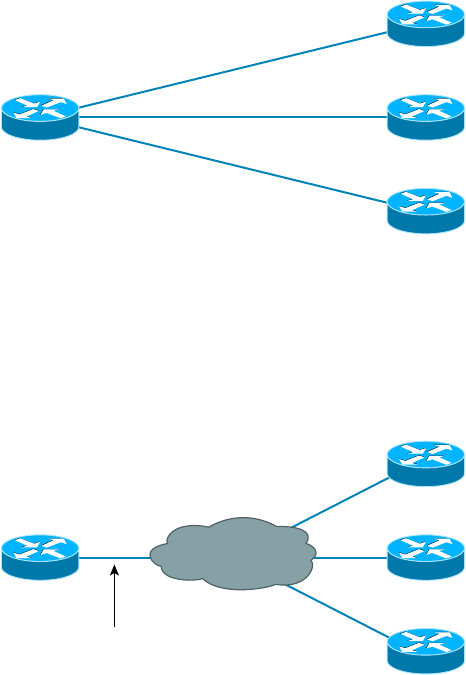
WAN Protocols
597
c16.indd 04/02/2015 Page 597
■ Frame Relay doesn’t work like a point-to-point leased line (although it can be made to
look and act like one).
■ Frame Relay is usually less expensive than leased lines are, but there are some sacrifices
to make to get that savings.
So, why would you even consider using Frame Relay? Take a look at Figure 16.6 to get
an idea of what a network looked like before Frame Relay.
FIGURE 16.6 Before Frame Relay
Dedicated/Leased Lines
to Each Location
$$$
Now check out Figure 16.7. You can see that there’s now only one connection between
the corporate router and the Frame Relay switch. That saves some major cash.
FIGURE 16.7 After Frame Relay
Statistically multiplexing
multiple logical circuits over a
single physical connection
Frame Relay
Let’s say you need to add seven remote sites to the corporate of ce and you have only
one free serial port on your router. Frame Relay to the rescue! Of course, I should probably
mention that you now also have one single point of failure, which is not so good. But Frame
Relay is used to save money, not to make a network more resilient.
598
Chapter 16 ■ Wide Area Networks
c16.indd 04/02/2015 Page 598
Coming up, I’m going to cover the Frame Relay technology information you need to
know about when studying for the CompTIA Network+ exam.
Committed Information Rate
Frame Relay allows for a packet-switched network to be provided to many different
customers at the same time. This is really good because it spreads out the cost of the
switches among lots of customers. But remember, Frame Relay is based on the assumption
that all customers won’t need to transmit data constantly—or even all at the same time.
Frame Relay works by providing a portion of dedicated bandwidth to each user, and it
also allows the user to exceed their guaranteed bandwidth if resources on the telco network
happen to be available. So basically, Frame Relay providers allow customers to buy a lower
amount of bandwidth than they really use. There are two separate bandwidth speci cations
with Frame Relay:
Access Rate The maximum speed at which the Frame Relay interface can transmit.
Committed Information Rate (CIR) The maximum bandwidth of data guaranteed to
be delivered. In reality, it’s the average amount that the service provider will allow you to
transmit, based upon what you purchased.
If these two values are the same, the Frame Relay connection is pretty much just like
a leased line. But they can actually be set to different values. Here’s an example: Let’s say
that you buy an access rate of T1 (1.544Mbps) and a CIR of 256Kbps. By doing this, you’re
guaranteed that the rst 256Kbps of traf c you send will be delivered. Anything beyond
that is called a burst—a transmission that exceeds your guaranteed 256Kbps rate and can
total any amount up to the T1 access rate, if that amount is permitted in your contract.
If your combined committed burst, which is the basis for your CIR, and excess burst sizes,
known as the maximum burst rate (MBR), exceed the access rate, you can pretty much
say goodbye to your additional traf c because it will most likely be dropped! Whether
this happens or not basically comes down to the subscription level offered by a particular
service provider.
In a perfect world, this always works beautifully—but remember that little word
guarantee—as in guaranteed rate, of 256Kbps to be exact? This means any burst of data
you send that exceeds your guaranteed 256Kbps rate will be delivered on something called
a “best effort” delivery basis. Or maybe not—if your telco’s equipment doesn’t have the
capacity to deliver it at the time you transmitted, then your frames will be discarded and
the DTE will be noti ed. Timing is everything—you can scream data out at six times
your guaranteed rate of 256Kbps (T1) only if your telco has the capacity available on its
equipment at that moment!
Virtual Circuits
Frame Relay operates using virtual circuits as opposed to the actual circuits that leased
lines use. These virtual circuits are what link together the thousands of devices connected
to the provider’s “cloud.” Frame Relay provides a virtual circuit between your two DTE
devices, making them appear to be connected via a circuit when in reality they’re dumping

WAN Protocols
599
c16.indd 04/02/2015 Page 599
their frames into a large, shared infrastructure. You never see the complexity of what’s
actually happening inside the cloud because you only have a virtual circuit.
And on top of all that, there are two types of virtual circuits—permanent and switched.
Permanent virtual circuits (PVCs) are by far the most common type in use today. What
permanent means here is that the telco creates the mappings inside its gear and as long as
you pay the bill, they’ll remain “permanently” in place.
Switched virtual circuits (SVCs) are more like phone calls. The virtual circuit is
established when data needs to be transmitted, and it’s taken down when the data
transfer is complete.
I have never seen a Frame Relay service using SVCs offered by a telco in
North America. It’s used mainly in private Frame Relay networks.
Data Link Connection Identifiers
Frame Relay PVCs are identi ed to DTE end devices by Data Link Connection Identi ers
(DLCIs). A Frame Relay service provider typically assigns DLCI values, which are used
on Frame Relay interfaces to distinguish between different virtual circuits. Because many
virtual circuits can be terminated on one multipoint Frame Relay interface, many DLCIs
are often af liated with it.
Let me explain. Suppose you have a central HQ with three branch of ces. If you were
to connect each branch of ce to HQ using a T1, you would need three serial interfaces
on your router at HQ, one for each T1. Simple, right? Well, suppose you use Frame Relay
PVCs instead. You could have a T1 at each branch connected to a service provider and only
a single T1 at HQ. There would be three PVCs on the single T1 at HQ, one going to each
branch. And even though you’d have only a single interface and a single CSU/DSU, the
three PVCs would function as three separate circuits. Remember what I said about saving
money? How much for two additional T1 interfaces and a pair of CSU/DSUs? Answer:
A lot! So, why not go ahead and ask for a percentage of the savings in your bonus?
Point-to-Point Protocol
Point-to-Point Protocol (PPP) is a Data Link layer protocol that can be used over either
asynchronous serial (dial-up) or synchronous serial (ISDN) media. It relies on Link Control
Protocol (LCP) to build and maintain data-link connections. Network Control Protocol
(NCP) enables multiple Network layer protocols (routed protocols) to be used on a
point-to-point connection.
Because HDLC is the default serial encapsulation on Cisco serial links and it works
great, why in the world would you choose to use PPP? Well, the basic purpose of PPP is to
transport Layer 3 packets across a Data Link layer point-to-point link, and it’s nonpropri-
etary. So unless you have all Cisco routers, you need PPP on your serial interfaces because
the HDLC encapsulation is Cisco proprietary, remember? Plus, since PPP can encapsulate

600
Chapter 16 ■ Wide Area Networks
c16.indd 04/02/2015 Page 600
several Layer 3 routed protocols and provide authentication, dynamic addressing, and
callback, PPP could actually be the best encapsulation solution for you over HDLC anyway.
Figure 16.8 shows the PPP stack compared to the OSI reference model.
FIGURE 16.8 Point-to-Point Protocol stack
OSI Layer
3
2
1
Upper-Layer Protocols
(such as IP and IPv6)
Link Control Protocol (LCP)
High-Level Data Link Control (HDLC)
Physical Layer
(such as EIA/TIA-232, V.24, V.35, ISDN)
Network Control Protocol (NCP)
(specific to each Network layer protocol)
PPP contains four main components:
EIA/TIA-232-C, V.24, V.35, and ISDN A Physical layer international standard for serial
communication.
HDLC A method for encapsulating datagrams over serial links.
LCP A method of establishing, con guring, maintaining, and terminating the
point-to-point connection. It also provides features such as authentication. I’ll give
you a complete list of these features coming up soon in the next section.
NCP A method of establishing and con guring different Network layer protocols for
transport across the PPP link. NCP is designed to allow the simultaneous use of multiple
Network layer protocols. Two examples of protocols here are Internet Protocol Control
Protocol (IPCP) and Cisco Discovery Protocol Control Protocol (CDPCP).
Burn it into your mind that the PPP protocol stack is speci ed at the Physical and Data
Link layers only. NCP is used to allow communication of multiple Network layer protocols
by identifying and encapsulating the protocols across a PPP data link.
Next, we’ll cover the options for LCP and PPP session establishment.
Link Control Protocol (LCP) Configuration Options
Link Control Protocol (LCP) offers different PPP encapsulation options, including the
following:
Authentication This option tells the calling side of the link to send information that can
identify the user. The two methods for this task are PAP and CHAP.
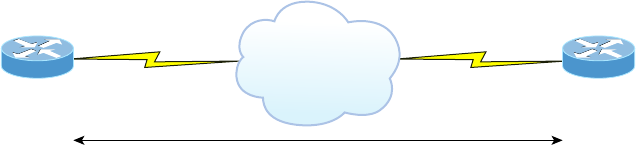
WAN Protocols
601
c16.indd 04/02/2015 Page 601
Compression This is used to increase the throughput of PPP connections by compressing
the data or payload prior to transmission. PPP decompresses the data frame on the
receiving end.
Error Detection PPP uses Quality and Magic Number options to ensure a reliable,
loop-free data link.
Multilink The multilink option makes several separate physical paths appear to be one
logical path at Layer 3. This means that the two T1s running multilink PPP would show up
as a single 3Mbps path to a Layer 3 routing protocol.
PPP Callback On a dial-up connection, PPP can be con gured to call back after successful
authentication. PPP callback can be a very good thing because it allows us to keep track of
usage based upon access charges for accounting records and a bunch of other reasons. With
callback enabled, a calling router (client) will contact a remote router (server) and authen-
ticate. Predictably, both routers have to be con gured for the callback feature for this to
work. Once authentication is completed, the remote router will terminate the connection
and then reinitiate a connection to the calling router.
PPP Session Establishment
When PPP connections are started, the links go through three phases of session establish-
ment, as shown in Figure 16.9:
FIGURE 16.9 PPP session establishment
PPP
PPP Session Establishment
1. Link-establishment phase
2. Authentication phase (optional)
3. Network layer protocol phase
Link-Establishment Phase LCP packets are sent by each PPP device to con gure and test
the link. These packets contain a eld called Con guration Option that allows each device
to see the size of the data, the compression, and authentication. If no Con guration Option
eld is present, then the default con gurations will be used.
Authentication Phase If required, either CHAP or PAP can be used to authenticate a link.
Authentication takes place before Network layer protocol information is read, and it’s also
possible that link-quality determination will occur simultaneously.
Network Layer Protocol Phase PPP uses the Network Control Protocol (NCP) to allow
multiple Network layer protocols to be encapsulated and sent over a PPP data link.

602
Chapter 16 ■ Wide Area Networks
c16.indd 04/02/2015 Page 602
Each Network layer protocol (e.g., IP, IPv6, which are routed protocols) establishes a
service with NCP.
PPP Authentication Methods
There are two methods of authentication that can be used with PPP links:
Password Authentication Protocol (PAP) Password Authentication Protocol (PAP) is the
less secure of the two methods. Passwords are sent in clear text and PAP is performed only
upon the initial link establishment. When the PPP link is rst established, the remote node
sends the username and password back to the originating target router until authentication
is acknowledged. Not exactly Fort Knox!
Challenge Handshake Authentication Protocol (CHAP) The Challenge Handshake
Authentication Protocol (CHAP) is used at the initial startup of a link and at periodic
checkups on the link to ensure that the router is still communicating with the same host.
After PPP nishes its initial link-establishment phase, the local router sends a challenge
request to the remote device. The remote device sends a value calculated using a one-way
hash function called MD5. The local router checks this hash value to make sure it matches.
If the values don’t match, the link is immediately terminated.
CHAP authenticates at the beginning of the session and periodically
throughout the session.
Asynchronous Transfer Mode
Asynchronous Transfer Mode (ATM), not to be confused with automated teller machines,
rst emerged in the early 1990s. ATM was designed to be a high-speed communications
protocol that doesn’t depend on any speci c LAN topology. It uses a high-speed cell-
switching technology that can handle data as well as real-time voice and video. The ATM
protocol breaks up transmitted data into 53-byte cells. A cell is analogous to a packet or
frame, except that an ATM cell is always xed in length and is relatively small and fast,
whereas a frame’s length can vary.
ATM is designed to switch these small cells through an ATM network very quickly.
It does this by setting up a virtual connection between the source and destination nodes;
the cells may go through multiple switching points before ultimately arriving at their nal
destination. The cells may also arrive out of order, so the receiving system may have to
reassemble and correctly order the arriving cells. ATM, like Frame Relay, is a connection-
oriented service, in contrast to most Data Link protocols, which are best-efforts delivery
services and do not require virtual circuits to be established before transmitting user data.
Data rates are scalable and start as low as 1.5Mbps, with speeds of 25Mbps, 51Mbps,
100Mbps, 155Mbps, and higher. The common speeds of ATM networks today are
51.84Mbps and 155.52Mbps; both of them can be used over either copper or ber-optic
cabling. You can also get ATM with a speed of 622.08Mbps, but that is currently used
WAN Troubleshooting
603
c16.indd 04/02/2015 Page 603
exclusively over ber-optic cable. ATM supports very high speeds because it’s designed to
be routed by hardware rather than software, which makes faster processing speeds possible.
Fiber-based service-provider ATM networks are running today at data rates of 10Gbps,
and they’re becoming more and more common. These fast speeds make real-time payloads
like voice and video travel with data on an ATM network and arrive without too much
delay, or latency. The small size of the payload, compared to the size of each cell’s header,
makes ATM less ef cient than other WAN technologies. In other words, ATM networks
are fast, but they get bad gas mileage.
MPLS
MultiProtocol Label Switching (MPLS) is a data-carrying mechanism that emulates some
properties of a circuit-switched network over a packet-switched network. So MPLS is a
actually a switching mechanism that imposes labels (numbers) to packets and then uses
them to forward packets. The labels are assigned on the edge of the MPLS network, and
forwarding inside the MPLS network is carried out solely based on the labels. The labels
usually correspond to a path to Layer 3 destination addresses, which is on par with IP
destination-based routing. MPLS was designed to support the forwarding of protocols
other than TCP/IP. Because of this, label switching within the network is achieved the same
way irrespective of the Layer 3 protocol. In larger networks, the result of MPLS labeling is
that only the edge routers perform a routing lookup. All the core routers forward packets
based on the labels, which makes forwarding the packets through the service provider net-
work faster. This is a big reason most companies have replaced their Frame Relay networks
with MPLS service today. Last, you can use Ethernet with MPLS to connect a WAN, and
this is called Ethernet over MPLS, or EoMPLS.
WAN Troubleshooting
Troubleshooting WANs can be tough at times because you don’t control and own the
physical lines. You de nitely do receive the trouble tickets and stressful emails, but you’re
relying on someone else to do their job, and you have limited visibility in a lot of areas.
However, that doesn’t mean you’re powerless, but it does mean that you’ve got to narrow
the problem down to make sure you’re working on the correct issue.
Loss of Internet Connectivity
The most common trouble ticket you’ll receive is someone complaining about not being
able to connect to the Internet. This issue can be caused by the WAN link dropping the
CSU/DSU or internal wiring, but most of the time, it’s due to an ISP issue. This doesn’t
mean you don’t need to check your local physical WAN connections though. A better
approach is to double check all your power to all devices, including the smart jack, and
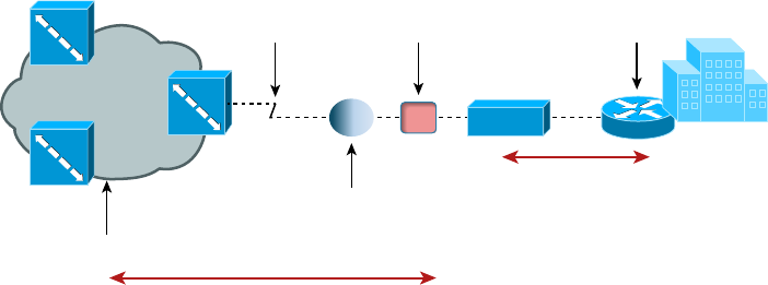
604
Chapter 16 ■ Wide Area Networks
c16.indd 04/02/2015 Page 604
run a loopback test from the router to the CSU/DSU to verify that speci c links come up
locally. Figure 16.10 shows the different spots you would typically need to check out.
FIGURE 16.10 WAN troubleshooting spots
Provider
Network
Local Loop
ISP can perform a loopback test from CO to NIU.
CO
Smart
Jack/NIU CPE
CSU/DSU
Demarc
You can perform a loopback test from
your router to the CSU/DSU.
One more thing—if you have either a copper line driver or repeaters in your WAN link,
you’ve got to be sure to check those connections too!
Interface Errors/Monitoring
There are a couple of key interfaces you need to check when verifying your WAN. If you
have cable or DSL, you’ll need to check into interface errors on the LAN port connecting
to your router rst. Let’s take a look at an example to clarify how to use this information
for interface monitoring to scrutinize errors, utilization, discards, packet drops, interface
resets, and duplex issues:
Router#sh int fa0/0
FastEthernet0/0 is up, line protocol is up
[output cut]
Full-duplex, 100Mb/s, 100BaseTX/FX
ARP type: ARPA, ARP Timeout 04:00:00
Last input 00:00:05, output 00:00:01, output hang never
Last clearing of "show interface" counters never
Input queue: 0/75/0/0 (size/max/drops/flushes); Total output drops: 0
Queueing strategy: fifo
Output queue: 0/40 (size/max)
5 minute input rate 0 bits/sec, 0 packets/sec
5 minute output rate 0 bits/sec, 0 packets/sec
1325 packets input, 157823 bytes
Received 1157 broadcasts (0 IP multicasts)
0 runts, 0 giants, 0 throttles
WAN Troubleshooting
605
c16.indd 04/02/2015 Page 605
0 input errors, 0 CRC, 0 frame, 0 overrun, 0 ignored
0 watchdog
0 input packets with dribble condition detected
2294 packets output, 244630 bytes, 0 underruns
0 output errors, 0 collisions, 3 interface resets
347 unknown protocol drops
0 babbles, 0 late collision, 0 deferred
4 lost carrier, 0 no carrier
0 output buffer failures, 0 output buffers swapped out
Link Status The rst thing we’ll check when there is a trouble ticket or our network man-
agement tools alert us of a link error is the link status. This is the rst line in the output as
shown. This would be the same on serial links as is it on Ethernet links.
Router#sh int fa0/0
FastEthernet0/0 is up, line protocol is up
The first
up
listed is carrier detect. If this shows down, then you have a physical layer prob-
lem locally and you need to get to that port stat and check the cable and port. The second
statistic, which is
protocol
is up
in this example, is keepalives from the remote end. If you
see
up/down
, then you know your local end is good but you’re not getting a digital signal
from the remote end.
You’ve got to be able to analyze interface statistics to nd problems there if they exist, so
let’s pick out the important factors relevant to meeting that challenge effectively now:
Speed and Duplex Settings Make a mental note that the most common cause of interface
errors is a mismatched duplex mode between two ends of an Ethernet link. This is why it’s
so vital to verify that the switch and its hosts—PCs, router interfaces, cable modems, and
so on—all have the same speed setting. If they don’t, they just won’t connect. And if they
have mismatched duplex settings, you’ll receive a legion of errors, which cause nasty perfor-
mance issues, intermittent connectivity, and sometimes even a total loss of communication!
A common strategy is to use autonegotiation for speed and duplex, and it’s enabled by
default. But if this fails for some reason, you’ll have to set the con guration manually like this:
Router(config)#int gi0/1
Router(config-if)#speed ?
10 Force 10 Mbps operation
100 Force 100 Mbps operation
1000 Force 1000 Mbps operation
auto Enable AUTO speed configuration
Router(config-if)#speed 1000
Router(config-if)#duplex ?
auto Enable AUTO duplex configuration
full Force full duplex operation
606
Chapter 16 ■ Wide Area Networks
c16.indd 04/02/2015 Page 606
half Force half-duplex operation
Router(config-if)#duplex full
If you have a duplex mismatch, a telling sign is that the late collision counter
will increment.
Input Queue Drops If the input queue drops counter increments, this tells you that more
traf c is being delivered to the router than it can process. If this value is consistently high,
try to determine exactly when these counters are increasing and how the events relate to
CPU usage. Know that you’ll see the ignored and throttle counters increment as well.
Output Queue Drops This counter indicates that packets were dropped due to interface
congestion, leading to lost data and queuing delays. When this occurs, applications like
VoIP will experience performance issues. If you observe this constantly incrementing,
consider QoS as the culprit.
Input Errors Input errors often indicate high-level errors such as CRCs. This can point to
cabling problems, hardware issues, or duplex mismatches.
Output Errors This issue equals the total number of frames that the port tried to transmit
when an issue such as a collision occurred.
These errors can also be caused by interference of the line itself, which means you’ll have to
call the ISP to sort them out.
On serial interface, start by checking out the physical connection to your router. Are
you receiving clocking? This comes from the CSU/DSU. Check out the output to see how
to do that:
Router>sh controllers s0/0
Interface Serial0/0
Hardware is PowerQUICC MPC860
DTE V.35 TX and RX clocks detected.
Okay, we’ve veri ed we’re receiving clocking, so let’s move on to look at the what the
interface is telling us:
Router#sh int s0/0
Serial0/0 is up, line protocol is down
Hardware is PowerQUICC Serial
Description: Connection to CR1
Internet address is 192.168.11.1/24
MTU 1500 bytes, BW 1000 Kbit, DLY 20000 usec,
reliability 255/255, txload 1/255, rxload 1/255
Encapsulation PPP, LCP Closed, loopback not set
Keepalive set (10 sec)
CRC checking enabled
Last input never, output never, output hang never
Last clearing of "show interface" counters 00:02:58
WAN Troubleshooting
607
c16.indd 04/02/2015 Page 607
Input queue: 0/75/0/0 (size/max/drops/flushes); Total output drops: 0
Queueing strategy: fifo
Output queue: 0/40 (size/max)
5 minute input rate 0 bits/sec, 0 packets/sec
5 minute output rate 0 bits/sec, 0 packets/sec
0 packets input, 0 bytes, 0 no buffer
Received 0 broadcasts, 0 runts, 0 giants, 0 throttles
1565789 input errors, 0 CRC, 0 frame, 0 overrun, 0 ignored, 0 abort
0 packets output, 0 bytes, 0 underruns
0 output errors, 0 collisions, 2 interface resets
0 output buffer failures, 0 output buffers swapped out
0 carrier transitions
DCD=up DSR=up DTR=up RTS=up CTS=up
BR1#
See that? We can see a problem with this interface right there in the rst line output.
The Serial0/0 is up, but the line protocol is down, which tells us that our local router
interface connecting to the CSU/DSU is working, but we’re still not seeing the remote
router. Once in a while this indicates a remote router problem, but it’s usually an ISP issue.
So again, it means you’ve got to call into the ISP if you’re getting this error. And look at all
those input errors! This is screaming that you’ve got a troubled line—probably some type
of interference, which needs to be reported.
Split Horizon
Split horizon issues usually happen when using Frame Relay in an environment where you
have multiple PVCs coming into a single serial WAN interface. This con guration makes the
routing protocol think that it’s receiving routes on the same interface that they were being
sent out of, which in this case would result in the routes being dropped. A great way to solve
this problem is to create subinterfaces (logical interfaces) on the serial interface to make the
routing protocol believe there are multiple interfaces—one for each subnet—so the routing
advertisement will be received. The con guration would go from looking like this:
interface Serial0/0
ip address 10.1.12.1 255.255.255.0
no ip directed-broadcast
encapsulation frame-relay
to looking like this:
interface Serial0/0
no ip address (notice there is no IP address on the physical interface!)
no ip directed-broadcast
encapsulation frame-relay
608
Chapter 16 ■ Wide Area Networks
c16.indd 04/02/2015 Page 608
!
interface Serial0/0.102 point-to-point
ip address 10.1.12.1 255.255.255.0
no ip directed-broadcast
frame-relay interface-dlci 102
!
interface Serial0/0.103 point-to-point
ip address 10.1.13.1 255.255.255.0
no ip directed-broadcast
frame-relay interface-dlci 103
!
DNS Issues
Another issue that could make it appear as if the Internet connectivity has gone down
completely involves DNS. If users cannot resolve names, it seems like everything is broken
to them. The rst step to solving a DNS issue is to understand exactly how your DNS is
set up on your speci c network. Do you have a local DNS server or are you using the ISP’s
DNS server? If you can ping a site, such as 74.125.228.50, but can’t ping
www.google.com
from an internal host, you know you’re dealing with a DNS resolution issue. Start by
verifying the local DNS server, if you use one, and if that checks out, call the ISP.
Router Configurations
Router con gurations can also be the culprit when WAN services just aren’t working right.
All you need is an admin that enters some routing protocol information incorrectly and
your access to the Internet goes poof! So your rst step is always to verify your default
route to the ISP when troubleshooting the routers that connect you to the Internet.
By using the command
show ip route
on a router, we can see the routing table—a map
of the internetwork that the router uses to make its forwarding decisions:
Router#sh ip route
Codes: L - local, C - connected, S - static,
[output cut]
10.0.0.0/8 is variably subnetted, 6 subnets, 4 masks
C 10.0.0.0/8 is directly connected, FastEthernet0/3
L 10.0.0.1/32 is directly connected, FastEthernet0/3
C 10.10.0.0/16 is directly connected, FastEthernet0/2
L 10.10.0.1/32 is directly connected, FastEthernet0/2
C 10.10.10.0/24 is directly connected, FastEthernet0/1
L 10.10.10.1/32 is directly connected, FastEthernet0/1
S* 0.0.0.0/0 is directly connected, FastEthernet0/0
Exam Essentials
609
c16.indd 04/02/2015 Page 609
Verify the default route, which is the one that starts with an S*. If this route points to
the wrong next hop or wrong exit interface, you’re going to have some serious problems!
Company Security Policy
Another common culprit that can often cause WAN-related problems is the company
security policy. For example, if there’s a rewall blocking ports, say, on applications that
need to get to the Internet, it mimics a WAN issue when the root of the problem is actually
bad con guration on your rewall(s)!
Another common source of trouble tickets have to do with slow response time, which
again can make it look as though it’s the WAN link that’s having issues. But again, it’s
possible that it’s the security policy that’s throttling bandwidth on certain applications.
I can’t tell you how typical this is these days! Many company policies block certain sites,
demanding that you provide URL ltering to them, especially social media or streaming
news feeds. People often refer to these security-oriented limitations as fair access policies or
utilization limits, which are forced upon certain activities for several reasons but most often
to preserve bandwidth.
Summary
In this chapter, you learned about the important issues involved in providing WAN
connectivity between geographically separated network locations as well as about the
different kinds of WAN connections, including point-to-point connections, circuit-switched
service provider networks, and packet-switched service provider networks.
You also became aware of the impacts different transmission media and different
distance parameters have on WAN connections. In addition, you learned about the choices
for leased-line connections along with broadband technologies like xDSL and cable
modems.
You studied the different WAN protocols and technologies used in connecting today’s
high-speed WANs, including ISDN, Frame Relay, ATM, and MPLS, and were equipped
with helpful strategies to troubleshoot and solve common WAN connection issues.
Exam Essentials
Be able to differentiate the kinds of WAN technologies. You must be able to identify the
speeds and capacities of the different remote-access and WAN technologies as well as the
media over which they are implemented.
Identify the basic characteristics of various Internet access technologies. These include
DSL, broadband cable, POTS, and ber to the premises (PON). It is important to know the
610
Chapter 16 ■ Wide Area Networks
c16.indd 04/02/2015 Page 610
differentiating features of these access technologies. Know their advantages and disadvan-
tages so you can identify the best use of each.
Be knowledgeable about the differences between circuit-switched and packet-switched
technologies, and know which protocols use either. Frame Relay is a packet-switched
technology, and ISDN is a circuit-switched digital solution. ATM is considered to be a cell-
switched technology because it incorporates a 53-byte cell. Both MPLS and ATM are con-
sidered connection-oriented technologies because the connection is set up rst.
Be clear about the differences involving speed and distance between different media and
between different WAN protocols. The use of both wireless and ber is growing, and
their standards are facilitating faster speeds and coverage of greater distances.
Be able to differentiate cellular WAN technologies like HSPA+, WiMAX, and LTE. HSPA+
is considered 3.5G, while LTE and WiMAX are considered true 4G.
Be able to differentiate between the different WAN protocols and technologies, their
relative costs and speeds, and the types of implementations for which each would serve as
a best solution. ISDN is rarely used nowadays in its BRI con guration except for small
home or of ce solutions. Frame Relay is relatively inexpensive, but service providers have
overbooked their Frame Relay clouds, resulting in poor performance. ATM is fast but
inef cient, and MPLS is fast and more ef cient but complicated to administer.
Written Lab
You can nd the answers in Appendix A.
1. What is the greatest advantage of PSTN (POTS)?
2. Which technology uses the term HFC?
3. You have one serial port on your router but need to connect many remote sites. What WAN
protocol could you consider as an option?
4. What is the maximum speed for T1?
5. What does the acronym DSL stand for?
6. Which WAN technologies are considered packet-switching networks?
7. Which cellular technologies are considered 4G?
8. Which WAN technology is considered a cell-switching network?
9. What are the different flavors of xDSL?
10. What is another name for PON?
Review Questions
611
c16.indd 04/02/2015 Page 611
Review Questions
You can nd the answers to the review questions in Appendix B.
1. Which of the following is not a WAN protocol or technology?
A. ATM
B. ISDN
C. MPLS
D. RIP
2. What OSI model layers do WAN protocols operate in?
A. Layer 6, Layer 4, Layer 2
B. Transport, Data Link, Network
C. Physical, Data Link, Network
D. Application, Data Link, Network
3. If you have a device in a telecommunications closet owned and installed by the telecom-
munications company (telco) and it’s your responsibility to cable from this box to the CPE,
which term should you use to refer to the device?
A. Customer premises equipment
B. Demarcation point
C. Toll network
D. Central office
4. You have an E1. How many DS0s are used in this point-to-point connection?
A. 24
B. 25
C. 30
D. 32
5. Where does the local exchange carrier responsibility end and your responsibility begin on a
WAN link?
A. POP
B. Central office
C. Demarc
D. Smart jack
612
Chapter 16 ■ Wide Area Networks
c16.indd 04/02/2015 Page 612
6. You have a small office/home office environment. What WAN technology would most
likely be used?
A. T1
B. T3
C. Frame Relay
D. Cable modem
7. Which type of communication has a line speed of 1.544Mbps (millions of bits per second)?
A. T3
B. T1C
C. T1
D. T4
8. Which cellular WAN technology has the best data rate?
A. HSPA
B. HSPA+
C. LTE
D. WiMAX
9. Which is not a common optical carrier level (OC-x)?
A. OC-1
B. OC-4
C. OC-12
D. OC-192
10. Which wireless protocol utilizes a short-range communications technology facilitating data
transmission from fixed and/or mobile devices, creating wireless personal area networks
(PANs)?
A. Bluetooth
B. Microwave radio relay
C. Comsat
D. Point-to-multipoint
11. What does the x in xDSL represent?
A. Wire type
B. Transmission speed
C. DSL type
D. Download speed
12. Which is not a type of xDSL?
A. ADSL
B. HDSL
Review Questions
613
c16.indd 04/02/2015 Page 613
C. SONET
D. SDSL
13. What does the acronym DOCSIS stand for?
A. Data over cable service interface spectrum
B. Data over cable systems Internet specification
C. Data over cable service Internet specification
D. Data over cable service interface specification
14. What is the bandwidth for OC-12?
A. 1.544Mbps
B. 45Mbps
C. 622Mbps
D. 1000Mbps
15. Which WAN protocol utilizes cell-switching technology?
A. Frame Relay
B. ISDN
C. ATM
D. RIP
16. Which WAN protocol utilizes packet-switched technology?
A. Frame Relay
B. ISDN
C. ATM
D. RIP
17. What is the CIR in Frame Relay?
A. Virtual circuit that is established when data needs to be transmitted
B. Maximum speed at which the Frame Relay interface can transmit
C. Rate at which the Frame Relay switch guarantees to transfer data
D. Rate at which the Frame Relay switch agrees to receive data
18. You are having DSL Internet connection issues and time-outs. You check the interface on
your router and notice a lot of input errors. What could the problem be?
A. CSU/DSU
B. Demarc
C. Duplex configuration
D. Clocking is down
19. Which WAN has a transfer rate of 44.7Mbps?
A. T1
B. T3
614
Chapter 16 ■ Wide Area Networks
c16.indd 04/02/2015 Page 614
C. E1
D. E3
20. How does DWDM put multiple transmissions on a single strand?
A. Different frequencies
B. Different polarizations
C. Different wavelengths
D. Different time slots

c17.indd 04/03/2015 Page 615
Chapter
17
Troubleshooting Tools
THE FOLLOWING COMPTIA NETWORK+
EXAM OBJECTIVES ARE COVERED IN
THIS CHAPTER:
✓ 4.2 Given a scenario, analyze and interpret the output of
troubleshooting tools
■ Command line tools
■ ipconfig
■ netstat
■ ifconfig
■ ping/ping6/ping -6
■ tracert/tracert -6/traceroute6/traceroute -6
■ nbtstat
■ nslookup
■ arp
■ mac address lookup table
■ pathping

c17.indd 04/03/2015 Page 616
Most of us are running Transmission Control Protocol/Internet
Protocol (TCP/IP) version 4 on our networks these days, so
we absolutely need a way to test IP connectivity. But we also
need to be able to test and verify IPv6 networks. The reason for
this is that even though Microsoft makes the majority of client
platforms, a lot of the commands used to test IP connectivity
are really platform independent, and most of the platforms can
now use both IPv4 and IPv6. Even so, keep in mind that the
Network+ exam focuses on the basic concepts of the function
and use of the TCP/IP utilities that come with Windows.
You can use several utilities, both command line and GUI, to verify TCP/IP function on
Windows workstations, and most of them are listed in the chapter objectives. But there are
a few others that I’m going to discuss with you because they’re really important for anyone
working in the networking eld to know about. Here’s a list of them:
■
Traceroute
(
tracert
in Microsoft)
■
ipconfig
/
winipcfg
(
ifconfig
in Unix)
■
ping
■
arp
■
nslookup
(
dig
in Unix)
■
Mtr
(
pathping
)
■
route
■
nbtstat
■
netstat
■
ftp
■
telnet
And by the way, it’s very important that you don’t just blow through the output that
I’ve supplied for each command. Instead, pay serious attention to it because to meet the
Network+ objectives, you’ll be required to correctly identify each command’s output.
So, let’s cut right to the chase and take a look at some of these commands and their
output. Oh, and do try and have fun with it!
To find up-to-the-minute updates for this chapter, please see
www.lammle.
com/networkplus
or the book’s website at
www.sybextestbanks.wiley.com
.
Protocol Analyzers
Protocol analyzers, also called sniffers or network monitors, are used to capture packets
in their raw format as they cross the network. Windows desktop operating systems before
Windows Vista came with a built-in protocol analyzer called Network Monitor, but that is
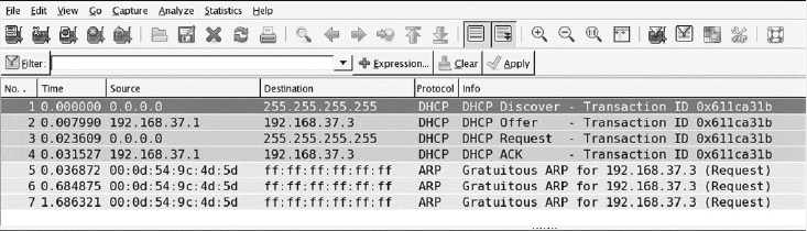
Protocol Analyzers
617
c17.indd 04/03/2015 Page 617
no longer the case, although you can download one for free that will work with the newer
operating systems.
The Network Monitor tool that comes with these operating systems will capture only
packets that are sourced from or destined to the computer on which the tool is running.
Commercial sniffers like Wireshark and OmniPeek can capture any packets because they
set the NIC to operate in promiscuous mode, which means the NIC processes all packets
that it sees.
Protocol analyzers can be used to determine the type of traf c that you have in your
network, and depending on the product and the bells and whistles contained therein, you
may be able to sort the results based on port numbers, protocols, and so on. Another use of
a sniffer is to examine the traf c that should be occurring on the network when something
is not working to aid in troubleshooting. These devices can capture and display all packets
involved in the connection setup, including, for example, request and response headers to a
web server.
For example, earlier in the book we discussed the operation of DHCP, and you learned
that there are a series of four packet types that must occur for a DHCP client to receive an
IP con guration from the server. As a review, those packets are as follows:
■ DHCP Discover
■ DHCP Offer
■ DHCP Request
■ DHCP ACK
If you turned on the analyzer and then executed the
ipconfig/release
and
ipconfig/
renew
commands on the client (more on those commands later in this chapter), you should
see these four packets in the analyzer’s capture le. The packets would be interspersed with
the hundreds and perhaps thousands of other packet types that would be captured, but by
using the display ltering options in the software, you can easily segregate out the DHCP
traf c. An example of the DHCP process, as seen in a capture, is shown in Figure 17.1.
FIGURE 17.1 DHCP capture
If all you saw in the capture were the DHCDISCOVER packets with no DHCPOFFER
packets, you could reasonably assert that the DHCP server is not receiving the DHCP-
DISCOVER packets (perhaps it is located in another broadcast domain or perhaps it is
not on). Additionally, you could examine elds in the DHCPOFFER packets that may tell
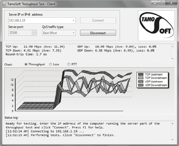
618
Chapter 17 ■ Troubleshooting Tools
c17.indd 04/03/2015 Page 618
you that the DHCP server is out of addresses. The point is that the tool can be used to
troubleshoot the issue.
Throughput Testers
Users of a network often complain about the speed of the network. Network “speed” is in
some ways a personal perception because some people have more patience than others. To
determine when a network slowdown is real as opposed to perceived, you need to actually
measure the throughput. That’s what throughput testers are used for.
These devices, typically software based, work much like a protocol analyzer in that they
measure the traf c seen on the network and can also classify the types of traf c that are
eating up your bandwidth (which is probably what you really need to know). Figure 17.2
shows one version of this software by TamoSoft.
FIGURE 17.2 Throughput
This software is installed on a server and also on a client. In the gure the software is
measuring traf c between the client and a server. It shows the throughput for traf c in
real time and in this shot is breaking that traf c up by unicast (TCP) and broadcast (UDP)
types and by direction.
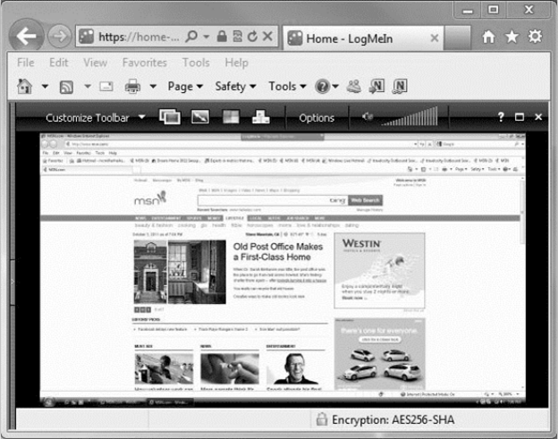
Connectivity Software
619
c17.indd 04/03/2015 Page 619
Earlier in this book, I discussed the importance of baselines, and this is another area
where they are important. Network throughput gures mean little without a baseline with
which comparisons can be made. How do you know what is abnormal when you don’t
know what normal is? Baselines should be taken when the network is operating well, but
they should also be taken when the traf c load is normal.
Connectivity Software
There are times when you need to make a remote connection to a machine to perform
troubleshooting but you are miles away. Connectivity software is designed to allow you
to make a connection to the machine, see the desktop, and perform any action you could
perform if you were sitting in front of it.
Microsoft has made what it calls Remote Desktop software available for free with
Windows products since Windows NT. When this software is installed (installed by default
in later versions) on both source and destination computers, a remote desktop connection
can be made.
Commercial tools are also available that (of course) claim to have more functionality,
and they probably do have a few extra bells and whistles. These include LogMeIn.com,
GoToMyPC, and others. Figure 17.3 shows the session window for a LogMeIn.com session.
FIGURE 17.3 LogMeIn
620
Chapter 17 ■ Troubleshooting Tools
c17.indd 04/03/2015 Page 620
The advantages of these connectivity tools are obvious. With these tools, you can do
anything you need to on the machine as long as you can connect. They also allow you to
see what a user is actually doing when they encounter a problem rather than having to rely
on what they tell you they are doing. You can even show a user what they are doing wrong.
Most of these tools allow for chat sessions and for either end of the connection to take
control of the machine. You can also transfer les to them if required (maybe a DLL got
deleted, for example).
Using Traceroute
For starters, let’s pose these questions: Where do all those packets really go when we send
them over the Internet? And, how do all the packets actually get to their destinations? Well,
we can use the TCP/IP
traceroute
(
tracert
with Windows) command-line utility to help
us answer both questions because its output will show us every router interface a TCP/IP
packet passes through on the way to its destination.
Traceroute
(
trace
for short) displays the path a packet takes to get to a remote device
in all its glory by using something we call IP packet Time-to-Live (TTL) time-outs, and
Internet Control Message Protocol (ICMP) error messages. And it’s also a handy tool for
troubleshooting an internetwork because we can use it to gure out which router along a
path through that internetwork happens to be causing a network failure when a certain
destination machine or network is, or suddenly becomes, unreachable.
To use
tracert
, at a Windows command prompt, type
tracert
, a space, and the
Domain Name Service (DNS) name or IP address of the host machine to which you want
to nd the route. The
tracert
utility will respond with a list of all the DNS names and IP
addresses of the routers that the packet is passing through on its way. Plus,
tracert
uses
TTL to indicate the time it takes for each attempt.
Following is the
tracert
output from my workstation in Boulder, Colorado, to my
Lammle.com
server in Dallas, Texas:
C:\Users\tlammle>tracert www.lammle.com
Tracing route to lammle.com [206.123.114.186]
over a maximum of 30 hops:
1 1 ms <1 ms <1 ms dslmodem.domain.actdsltmp [192.168.0.1]
2 53 ms 52 ms 52 ms hlrn-dsl-gw36-228.hlrn.qwest.net
[207.225.112.228]
3 52 ms 53 ms 52 ms hlrn-agw1.inet.qwest.net [71.217.189.25]
4 75 ms 75 ms 74 ms dal-core-01.inet.qwest.net [67.14.2.53]
5 76 ms 76 ms 76 ms dap-brdr-01.inet.qwest.net [205.171.225.49]
6 76 ms 76 ms 76 ms 205.171.1.110

Using Traceroute
621
c17.indd 04/03/2015 Page 621
7 75 ms 76 ms 106 ms xe-0-0-0.er2.dfw2.us.above.net [64.125.26.206]
8 76 ms 76 ms 76 ms 209.249.122.74.available.above.net
[209.249.122.74]
9 76 ms 76 ms 76 ms 65.99.248.250
10 76 ms 76 ms 76 ms pageuppro.pageuppro.com [206.123.114.186]
Trace complete.
Were you able to see that the packet bounces through several routers before arriving
at its destination? Good! This utility is useful if you are having problems reaching a web
server on the Internet and you want to know if a wide area network (WAN) link is down
or if the server just isn’t responding. What this means to you is that, basically, wherever the
trace stops is a great place to start troubleshooting. No worries here, though—the previous
output shows that every router is up and responding. Last, notice in the output the
ms
.
This is the latency of each hop, meaning the delay.
Tracert
(or
traceroute
) is a great
troubleshooting tool you can use to nd out where your network bottlenecks are.
If you use
traceroute
or
tracert
and receive an asterisk, this indicates that the attempt
to reach that router took longer than the default time-out value. This is very good to know
because it can mean that either the router is extremely busy or that a particular link is slow.
Another reason for getting an asterisk could be that the administrator has disabled ICMP
on the router that the packet is trying to hop through.
Why would someone want to do that? For security reasons, that’s why. It happens to be
a typical strategic move done on the routers that interface to the ISP to conceal their actual
location so bad guys can’t hack into them and therefore into your internetwork. It’s a good
idea, and I highly recommend doing it.
If you are running
traceroute
and see repeating addresses and TTL
time-outs, you probably have a routing loop.
In addition to
traceroute
and
tracert
, you can use
pathping
, which is a lot like
traceroute
:
C:\Users\Todd Lammle>pathping lammle.com
Tracing route to lammle.com [184.172.53.52]
over a maximum of 30 hops:
0 WIN-Q14VTD8DH0G.localdomain [192.168.133.147]
1 192.168.133.2
2 * * *
Computing statistics for 25 seconds...
Source to Here This Node/Link
Hop RTT Lost/Sent = Pct Lost/Sent = Pct Address
0 WIN-Q14VTD8DH0G.localdomain [192.168.133.147]
0/ 100 = 0% |
1 0ms 0/ 100 = 0% 0/ 100 = 0% 192.168.133.2

622
Chapter 17 ■ Troubleshooting Tools
c17.indd 04/03/2015 Page 622
Trace complete.
C:\Users\Todd Lammle>
This provides a nice feedback at the end of the output.
In addition to
traceroute
and
tracert
, which show the path of an IPv4
packet, you can use
tracert -6
for a Windows trace,
traceroute6
for
MAC and Unix, and
traceroute -6
for Cisco routers to trace an IPv6
packet through an internetwork.
Using ipconfig and ifconfig
The utilities known as
ipconfig
(in Windows) and
ifconfig
(in Unix/Linux/Mac) will
display the current con guration of TCP/IP on a given workstation—including the current
IP address, DNS con guration, Windows Internet Naming Service (WINS) con guration,
and default gateway. In the following sections, I will show you how to use both.
Using the ipconfig Utility
With the new Mac, Windows Vista, Windows 7 and 8, and Windows Server 2008/2012
operating systems you can now see the IPv6 con guration because IPv6 is enabled
by default. The output of the
ipconfig
command provides the basic routed protocol
information on your machine. From a DOS prompt, type
ipconfig
, and you’ll see
something like this:
C:\Users\tlammle>ipconfig
Windows IP Configuration
Ethernet adapter Local Area Connection:
Connection-specific DNS Suffix . : domain.actdsltmp
Link-local IPv6 Address . . . . . : fe80::2836:c43e:274b:f08c%11
IPv4 Address. . . . . . . . . . . : 192.168.0.6
Subnet Mask . . . . . . . . . . . : 255.255.255.0
Default Gateway . . . . . . . . . : 192.168.0.1
Wireless LAN adapter Wireless Network Connection:
Connection-specific DNS Suffix . : qwest.net
Link-local IPv6 Address . . . . . : fe80::20e7:7fb8:8a00:832b%10
IPv4 Address. . . . . . . . . . . : 10.0.1.198
Subnet Mask . . . . . . . . . . . : 255.255.255.0
Using ipconfig and ifconfig
623
c17.indd 04/03/2015 Page 623
Default Gateway . . . . . . . . . : fe80::21b:63ff:fef3:3694%10
10.0.1.1
Tunnel adapter Local Area Connection* 6:
Media State . . . . . . . . . . . : Media disconnected
Connection-specific DNS Suffix . :
Tunnel adapter Local Area Connection* 7:
Media State . . . . . . . . . . . : Media disconnected
Connection-specific DNS Suffix . :
[output cut for brevity]
Wow, there sure are a lot of options in this output compared to the output for earlier
versions of Windows! First, what’s up with all these interfaces showing? I only have two—
one Ethernet and one wireless. You can see that my Ethernet adapter shows up rst, and it
has an IP address, a mask, and a default gateway plus an IPv6 address and a DNS suf x.
The next con gured interface is the wireless local area network (LAN) adapter, which has
an IP address, a mask, a default gateway, an IPv6 address, and the IPv6 default gateway as
well. This IPv6 default gateway address is simply my router advertising that it runs IPv6
and saying, “I am the way out of the local LAN!”
The next adapters are disconnected because they are logical interfaces and I’m not using
them—my machine actually shows eight, but I cut the output because it provides no new
information. They’re automatically inserted because IPv6 is installed and running on my
machine, and these adapters allow me to run IPv6 over an IPv4-only network.
But just in case the
ipconfig
command doesn’t provide enough information for you, try
the
ipconfig /all
command—talk about details. Here’s the beginning of that output:
C:\Users\tlammle>ipconfig /all
Windows IP Configuration
Host Name . . . . . . . . . . . . : globalnet-todd
Primary Dns Suffix . . . . . . . : globalnet.local
Node Type . . . . . . . . . . . . : Hybrid
IP Routing Enabled. . . . . . . . : No
WINS Proxy Enabled. . . . . . . . : No
DNS Suffix Search List. . . . . . : globalnet.local
domain.actdsltmp
qwest.net
Ethernet adapter Local Area Connection:
Connection-specific DNS Suffix . : domain.actdsltmp
Description . . . . . . . . . . . : Intel(R) 82566MM Gigabit
Network Connection
Physical Address. . . . . . . . . : 00-1E-37-D0-E9-35
624
Chapter 17 ■ Troubleshooting Tools
c17.indd 04/03/2015 Page 624
DHCP Enabled. . . . . . . . . . . : Yes
Autoconfiguration Enabled . . . . : Yes
Link-local IPv6 Address . . . . . : fe80::2836:c43e:274b:f08c%11(Preferred)
IPv4 Address. . . . . . . . . . . : 192.168.0.6(Preferred)
Subnet Mask . . . . . . . . . . . : 255.255.255.0
Lease Obtained. . . . . . . . . . : Monday, October 20, 2008 9:08:36 AM
Lease Expires . . . . . . . . . . : Tuesday, October 21, 2008 9:08:39 AM
Default Gateway . . . . . . . . . : 192.168.0.1
DHCP Server . . . . . . . . . . . : 192.168.0.1
DNS Servers . . . . . . . . . . . : 192.168.0.1
205.171.3.65
NetBIOS over Tcpip. . . . . . . . : Enabled
Wireless LAN adapter Wireless Network Connection:
Connection-specific DNS Suffix . : qwest.net
Description . . . . . . . . . . . : Intel(R) Wireless WiFi Link 4965AGN
Physical Address. . . . . . . . . : 00-1F-3B-3F-4A-D9
DHCP Enabled. . . . . . . . . . . : Yes
Autoconfiguration Enabled . . . . : Yes
Link-local IPv6 Address . . . . . : fe80::20e7:7fb8:8a00:832b%10(Preferred)
IPv4 Address. . . . . . . . . . . : 10.0.1.198(Preferred)
Subnet Mask . . . . . . . . . . . : 255.255.255.0
Lease Obtained. . . . . . . . . . : Monday, October 20, 2008 10:43:53 AM
Lease Expires . . . . . . . . . . : Monday, October 20, 2008 2:43:53 PM
Default Gateway . . . . . . . . . : fe80::21b:63ff:fef3:3694%10
10.0.1.1
DHCP Server . . . . . . . . . . . : 10.0.1.1
DNS Servers . . . . . . . . . . . : 10.0.1.1
NetBIOS over Tcpip. . . . . . . . : Enabled
Tunnel adapter Local Area Connection* 6:
Media State . . . . . . . . . . . : Media disconnected
Connection-specific DNS Suffix . :
Description . . . . . . . . . . . : isatap.globalnet.local
Physical Address. . . . . . . . . : 00-00-00-00-00-00-00-E0
Using ipconfig and ifconfig
625
c17.indd 04/03/2015 Page 625
DHCP Enabled. . . . . . . . . . . : No
Autoconfiguration Enabled . . . . : Yes
Tunnel adapter Local Area Connection* 7:
Media State . . . . . . . . . . . : Media disconnected
Connection-specific DNS Suffix . :
Description . . . . . . . . . . . : isatap.{9572A79F-3A58-4E9B-
9BD0-8F6FF2F058FC}
Physical Address. . . . . . . . . : 00-00-00-00-00-00-00-E0
DHCP Enabled. . . . . . . . . . . : No
Autoconfiguration Enabled . . . . : Yes
[output cut]
As you can see, it’s more of the same—a whole lot more. The most important thing
I want you to notice is that I’ve received the hardware information about each interface,
including the Media Access Control (MAC) address. Also signi cant is that I can see the
Dynamic Host Con guration Protocol (DHCP) lease times and DNS addresses now.
But why stop here? There are two more valuable options you need to use with the
ipconfig
command. They are
/release
and
/renew
.
When you change networks, you need to get the IP address of that subnet and/or virtual
LAN (VLAN). Windows 7 and 8 work most of the time without doing anything, but some-
times I do have to renew the IP con guration when changing networks. But that’s easy—
just type
ipconfig /renew
from a command prompt, and if you’re connected to a DHCP
server that’s available, you’ll then magically receive an IP address.
Now, if it still doesn’t work, you’ll need to release and renew your TCP/IP settings. To
release your current DHCP TCP/IP information, you must elevate your command prompt
or you’ll get this warning:
C:\Users\tlammle>ipconfig /release
The requested operation requires elevation.
C:\Users\tlammle>
Should this happen to you, choose Start
➪
All Programs
➪
Accessories
➪
Command
Prompt, right-click, and choose Run As Administrator. (Of course, you’ll have to enter your
name and password to do this if you are using Windows 7 or 8. But we love Windows 7
and 8, right? Okay, maybe not always.) Figure 17.4 shows how I did this.
Once your command prompt has been duly elevated, you can use the
ipconfig
/release
command and then the
ipconfig /renew
command to get new TCP/IP informa-
tion for your host.
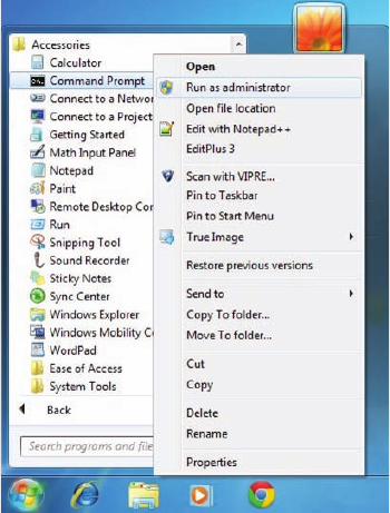
626
Chapter 17 ■ Troubleshooting Tools
c17.indd 04/03/2015 Page 626
FIGURE 17.4 Elevating your command prompt
Using the ifconfig Utility
There is a utility in Linux/Unix/Mac that will give you information similar to what
ipconfig
shows. It’s called
ifconfig
(short for interface con guration). Although
ipconfig
and
ifconfig
show similar information, there are major differences between
these two utilities. The
ipconfig
utility is mainly used to view the TCP/IP con guration
for a computer. You can use
ifconfig
to do the same thing, but
ifconfig
can also be used
to con gure a protocol or a particular network interface.
The general syntax of the
ifconfig
command is as follows:
ifconfig
interface [address [parameters]]
The
interface
parameter equals the Unix name of the interface, such as
eth0
. If the
optional
address
parameter is speci ed, the
ifconfig
command sets the IP address for
the interface to the address you’ve speci ed. When the
ifconfig
command is used by itself
with no parameters, all con gured interfaces will be reported on. But if only the interface
name is speci ed, you’ll get output that looks like this:
# ifconfig eth0
eth0 Link encap 10Mbps Ethernet HWaddr 00:00:C0:90:B3:42
inetaddr 172.16.0.2 Bcast 172.16.0.255 Mask 255.255.255.0 UP
Using the ping Utility
627
c17.indd 04/03/2015 Page 627
BROADCAST RUNNING MTU 1500 Metric 0
RX packets 3136 errors 217 dropped 7 overrun 26
TX packets 1752 errors 25 dropped 0 overrun 0
Looking at this, we can see that the
eth0
interface is a 10Mbps Ethernet interface.
The interface’s MAC and IP address information is displayed in this output as well. And,
although not shown in the output, the
ifconfig
tool can show you the DNS information
con gured on the host.
Using the ping Utility
ping
is the most basic TCP/IP utility, and it’s included with most TCP/IP stacks for most
platforms. Windows, again, is no exception. In most cases,
ping
is a command-line utility,
although there are many GUI implementations available. You use the
ping
utility for two
primary purposes:
■ To find out if a host is responding
■ To find out if you can reach a host
Here’s the syntax:
ping
hostname or IP address
If you ping any station that has an IP address, the ICMP that’s part of that particular
host’s TCP/IP stack will respond to the request. The ICMP test and response looks
something like this:
ping 204.153.163.2
Pinging 204.153.163.2 with 32 bytes of data:
Reply from 204.153.163.2: bytes=32 time<10ms TTL=128
Reply from 204.153.163.2: bytes=32 time=1ms TTL=128
Reply from 204.153.163.2: bytes=32 time<10ms TTL=128
Reply from 204.153.163.2: bytes=32 time<10ms TTL=128
Because I’ve received a reply from the destination station (204.153.163.2, in this case),
I know that I can reach the host and that it’s responding to basic IP requests. Don’t forget
that you can use name resolution and ping to a name, such as
ping www.sybex.com
, and
as long as that name can be resolved, you’re golden.
Most versions of
ping
work the same way, but there are some switches you can use to
specify certain information, like the number of packets to send, how big a packet to send,
and so on. And if you’re running the Windows command-line version of
ping
, just use the
/?
or
–?
switch to display a list of the available options like this:

628
Chapter 17 ■ Troubleshooting Tools
c17.indd 04/03/2015 Page 628
C:\Users\tlammle>ping /?
Usage: ping [-t] [-a] [-n count] [-l size] [-f] [-i TTL] [-v TOS]
[-r count] [-s count] [[-j host-list] | [-k host-list]]
[-w timeout] [-R] [-S srcaddr] [-4] [-6] target_name
The command will also output a table showing what each of the options does, presented
here in Table 17.1.
TABLE 17.1 Options for
ping
switches
Option Description
-t
Pings the specified host until stopped. To see statistics and continue,
press Ctrl+Break; to stop, press Ctrl+C.
-a
Resolves addresses to hostnames.
-n
count
Specifies the number of echo requests to send.
-l
size
Sends the buffer size.
-f
Sets the Don’t Fragment flag in the packet (IPv4 only).
-i
TTL
Specifies the time to live of the packet.
-v
TOS
Specifies the type of service (IPv4 only).
-r
count
Records the route for count hops (IPv4 only).
-s
count
Specifies the time stamp for count hops (IPv4 only).
-j
host-list
Uses a loose source route along the host-list (IPv4 only).
-k
host-list
Uses a strict source route along host-list (IPv4 only).
-w
timeout
Specifies the time-out to wait for each reply in milliseconds.
-R
Uses the routing header to test the reverse route also (IPv6 only).
-S
srcaddr
Specifies the source address to use.
-4
Forces using IPv4.
-6
Forces using IPv6.

Using the ping Utility
629
c17.indd 04/03/2015 Page 629
You can ping your local TCP/IP interface by typing
ping 127.0.0.1
or
ping
localhost
. Understand that both addresses represent the local interface.
Really, you can use any address in the 127.0.0.0 network range to provide a
loopback test.
As you can see, there’s a plethora of options you can use with the
ping
command from
a Windows DOS prompt. But I really want you to focus on a few from the previous output.
(I’m going to go over only a few of them, but you can get on your host machine and play
with all the options.)
The
-a
switch is very cool because if you have name resolution (such as a DNS server),
you can see the name of the destination host even if you only know its IP address. The
-n
switch sets the number of echo requests to send, where four is the default, and the
-w
switch allows you to adjust the timeout in milliseconds. The default
ping
timeout is 1
second (1000ms).
The
-6
is also nice if you want to ping an IPv6 host. By the way, unless you really love
typing 128-bit addresses, this is a wonderful example of how important name resolution is.
And then there’s
-t
, which keeps the ping running. Here’s an example of a ping to an
IPv6 address:
C:\Users\tlammle>ping -6 fe80::1063:16af:3f57:fff9
Pinging fe80::1063:16af:3f57:fff9 from fe80::1063:16af:3f57:fff9%25
with 32 bytes of data:
Reply from fe80::1063:16af:3f57:fff9: time<1ms
Reply from fe80::1063:16af:3f57:fff9: time<1ms
Reply from fe80::1063:16af:3f57:fff9: time<1ms
Reply from fe80::1063:16af:3f57:fff9: time<1ms
Ping statistics for fe80::1063:16af:3f57:fff9:
Packets: Sent = 4, Received = 4, Lost = 0 (0% loss),
Approximate round trip times in milli-seconds:
Minimum = 0ms, Maximum = 0ms, Average = 0ms
C:\Users\tlammle>
From a MAC you can use the
ping6
command. Here are the options:
$ ping6
usage: ping6 [-DdfHmnNoqrRtvwW] [-a addrtype] [-b bufsiz] [-B boundif]
[-c count][-g gateway] [-h hoplimit] [-I interface] [-i wait] [-l preload]
[-p pattern] [-S sourceaddr] [-s packetsize] [-z tclass]
[hops ...] host
630
Chapter 17 ■ Troubleshooting Tools
c17.indd 04/03/2015 Page 630
And if I want to have a continuous ping, I just use that
-t
option like this:
C:\Users\tlammle>ping -t 192.168.0.1
Pinging 192.168.0.1 with 32 bytes of data:
Reply from 192.168.0.1: bytes=32 time=7ms TTL=255
Reply from 192.168.0.1: bytes=32 time=1ms TTL=255
Reply from 192.168.0.1: bytes=32 time=1ms TTL=255
Reply from 192.168.0.1: bytes=32 time=1ms TTL=255
Reply from 192.168.0.1: bytes=32 time=1ms TTL=255
Reply from 192.168.0.1: bytes=32 time=1ms TTL=255
Ping statistics for 192.168.0.1:
Packets: Sent = 6, Received = 6, Lost = 0 (0% loss),
Approximate round trip times in milli-seconds:
Minimum = 1ms, Maximum = 7ms, Average = 2ms
Control-C
^C
C:\Users\tlammle>
This ping will just keep going and going like the Energizer Bunny until you press Ctrl+C.
And by the way, it’s an awesome tool for troubleshooting links.
Using the Address Resolution Protocol
The Address Resolution Protocol (ARP) is part of the TCP/IP protocol stack. It’s used to
translate TCP/IP addresses to MAC addresses using broadcasts. When a machine running
TCP/IP wants to know which machine on an Ethernet network is using a certain IP
address, it will send an ARP broadcast that says, in effect, “Hey…exactly who is IP address
xxx.xxx.xxx.xxx?” The machine that owns the speci c address will respond with its own
MAC address, supplying the answer. The machine that made the inquiry will respond by
adding the newly gained information to its own ARP table.
In addition to the normal usage, the ARP designation refers to a utility in Windows that
you can use to manipulate and view the local workstation’s ARP table.
The Windows ARP Table
The ARP table in Windows includes a list of TCP/IP addresses and their associated
physical (MAC) addresses. This table is cached in memory so that Windows doesn’t have
to perform ARP lookups for frequently accessed TCP/IP addresses like those of servers and
default gateways. Each entry contains an IP address and a MAC address plus a value for
TTL that determines how long each entry will remain in the ARP table.

Using the Address Resolution Protocol
631
c17.indd 04/03/2015 Page 631
Remember that the ARP table contains two kinds of entries:
■ Dynamic
■ Static
Dynamic ARP table entries are created whenever the Windows TCP/IP stack per-
forms an ARP lookup but the MAC address isn’t found in the ARP table. When the MAC
address of the requested IP address is nally found, or resolved, that information is then
added into the ARP table as a dynamic entry. Whenever a request to send a packet to the
host is sent to the Data Link layer, the ARP cache is checked rst before an ARP broadcast
is sent out. Remember, the ARP request is broadcast on the local segment—it does not go
through a router.
The ARP table is cleared of dynamic entries whose TTL has expired to
ensure that the entries are current.
Static ARP table entries serve the same function as dynamic entries but are made manu-
ally using the
arp
utility.
Using the arp Utility
You now know that ARP is a protocol included in the TCP/IP suite. You also understand
that ARP is used by IP to determine the MAC address of a device that exists on the same
subnet as the requesting device. When a TCP/IP device needs to forward a packet to a
device on the local subnet, it rst looks in its own table, called an ARP cache or mac
address lookup table, for an association between the known IP address of the destination
device on the local subnet and that same device’s MAC address. The cache is called that
because the contents are periodically weeded out.
If no association that includes the destination IP address can be found, the device will
then send out an ARP broadcast that includes its own MAC and IP information as well as
the IP address of the target device and a blank MAC address eld. Filling in that blank is
the object of the whole operation—it’s the unknown value that the source device is request-
ing to be returned to it in the form of an ARP reply. Windows includes a utility called
arp
that allows us to check out the operating system’s ARP cache. To view this, from a
Windows DOS prompt, use the
arp
command like this:
C:\Uses\tlammle>arp
Displays and modifies the IP-to-Physical address translation tables used
by address resolution protocol (ARP).
ARP -s inet_addr eth_addr [if_addr]
ARP -d inet_addr [if_addr]
ARP -a [inet_addr] [-N if_addr] [-v]

632
Chapter 17 ■ Troubleshooting Tools
c17.indd 04/03/2015 Page 632
Table 17.2 describes the various options that you can use with the
arp
command.
TABLE 17.2
arp
options
Option Description
-a
Displays current ARP entries by interrogating the current protocol data.
If
inet_addr
is specified, the IP and physical addresses for only the
specified computer are displayed. If more than one network interface
uses ARP, entries for each ARP table are displayed.
-g
Same as
-a
.
-v
Displays current ARP entries in verbose mode. All invalid entries and
entries on the loopback interface will be shown.
inet_addr
Specifies an Internet address.
-N
Displays the ARP entries for the network interface specified by
if_addr
.
-d
Deletes the host specified by
inet_addr
.
inet_addr
. May be wildcarded
with
*
to delete all hosts.
-s
Adds the host, and associates the Internet address
inet_addr
with the
physical address
eth_addr
. The physical address is given as six hexa-
decimal bytes separated by hyphens. The entry is permanent.
eth_addr
Specifies a physical address.
if_addr
If present, specifies the Internet address of the interface whose address
translation table should be modified. If not present, the first applicable
interface will be used.
Sheesh. Looking at that output really makes me wish we were all just running IPv6
because, as you already should know, IPv6 doesn’t need ARP as well as many other
annoying features and protocols required when running IPv4.
Of note, the Windows
arp
utility is primarily useful for resolving duplicate IP addresses.
For example, let’s say your workstation receives its IP address from a DHCP server but
it accidentally receives the same address that some other workstation gets. And so, when
you try to ping it, you get no response. Your workstation is basically confused—it’s trying
to determine the MAC address, and it can’t because two machines are reporting that they
have the same IP address. To solve this little snag, you can use the
arp
utility to view your
local ARP table and see which TCP/IP address is resolved to which MAC address.
To display the entire current ARP table, use the
arp
command with the
–a
switch like so
to show you the mac address lookup table:

Using the Address Resolution Protocol
633
c17.indd 04/03/2015 Page 633
C:\Users\tlammle>arp -a
Interface: 192.168.0.6 --- 0xb
Internet Address Physical Address Type
192.168.0.1 00-15-05-06-31-b0 dynamic
192.168.0.255 ff-ff-ff-ff-ff-ff static
224.0.0.22 01-00-5e-00-00-16 static
224.0.0.252 01-00-5e-00-00-fc static
239.255.255.250 01-00-5e-7f-ff-fa static
255.255.255.255 ff-ff-ff-ff-ff-ff static
Interface: 10.100.10.54 --- 0x10
Internet Address Physical Address Type
10.100.10.1 00-15-05-06-31-b0 dynamic
10.100.10.255 ff-ff-ff-ff-ff-ff static
224.0.0.22 01-00-5e-00-00-16 static
224.0.0.252 01-00-5e-00-00-fc static
239.255.255.250 01-00-5e-7f-ff-fa static
By the way, the
–g
switch will produce the same result.
Now, from this output, you can tell which MAC address is assigned to which IP address.
Then, for static assignments, you can tell which workstation has a speci c IP address and if
it’s indeed supposed to have that address by examining your network documentation—you
do have that record, right?
For DHCP-assigned addresses, you can begin to uncover problems stemming from
multiple DHCP scopes or servers doling out identical addresses and other common
con guration issues. And remember that under normal circumstances, you shouldn’t see
IP addresses in the ARP table for a given interface that aren’t members of the same IP
subnet as the interface.
If the machine has more than one network card (as may happen in
Windows servers and on laptops with both Ethernet and wireless cards),
each interface will be listed separately.
It’s good to know that in addition to displaying the ARP table, you can use the
arp
utility to manipulate the table itself. To add static entries to the ARP table, you use the
arp
command with the
–s
switch. These static entries will stay in the ARP table until
the machine is rebooted. A static entry essentially hardwires a speci c IP address to a

634
Chapter 17 ■ Troubleshooting Tools
c17.indd 04/03/2015 Page 634
speci c MAC address so that when a packet needs to be sent to that IP address, it will
automatically be sent to that MAC address. Here’s the syntax:
arp –
s [IP Address] [MAC Address]
Simply replace the
[IP Address]
and
[MAC Address]
sections with the appropriate
entries, like so:
arp –s 204.153.163.5 00–a0–c0–ab–c3–11
Now, take a look at your new ARP table by using the
arp –a
command. You should see
something like this:
Internet Address Physical Address Type
204.153.163.5 00–a0–c0–ab–c3–11 static
Finally, if you want to delete entries from the ARP table, you can either wait until the
dynamic entries time out or use the
–d
switch with the IP address of the static entry you’d
like to delete, like this:
arp –d 204.153.163.5
Doing so effectively deletes the entry from the ARP table in memory.
The
arp
utility doesn’t confirm successful additions or deletions
(use
arp -a
or
arp -g
for that), but it will give you an error message if
you use incorrect syntax.
Using the nslookup Utility
Whenever you’re con guring a server or a workstation to connect to the Internet, you’ve
got to start by con guring DNS if you want name resolution to happen (that is, if you want
to be able to type
www.sybex.com
instead of an IP address). When con guring DNS, it’s
a very good thing to be able to test what IP address DNS is returning to ensure that it’s
working properly. The
nslookup
utility allows you to query a name server and quickly
nd out which name resolves to which IP address.
The Unix
dig
(short for domain information groper) utility does the exact
same thing as
nslookup
. It’s primarily a command-line utility that allows
you to perform a single DNS lookup for a specific entity, but it can also be
employed in batch mode for a series of lookups. Detailed information on
this command is beyond the scope of this study guide, but you can find
more information on the Web by searching for “unix dig.”
The
nslookup
utility comes with Windows NT and later as well as most versions of
Unix and Linux, but not with Windows 95/98. You can run it from a Windows command
Using the nslookup Utility
635
c17.indd 04/03/2015 Page 635
prompt. At the command prompt, you can start the
nslookup
utility by typing
nslookup
and pressing Enter. When you’re inside this utility, the command prompt will change from
something similar to a
C:\>
sign to a shorter
>
sign. It will also display the name and IP
address of the default DNS server you will be querying (you can change it, if necessary).
Then you can start using
nslookup
. The following output gives you a sample of the display
after the
nslookup
command has been entered at the
C:\>
prompt.
C:\Users\tlammle>nslookup
Default Server: gnt-corpdc1.globalnet.local
Address: 10.100.36.12
>
The primary job of
nslookup
is to tell you the many different features of a particular
domain name, the names of the servers that serve it, and how they’re con gured. To get
that, just type in a domain name at the > prompt, and the
nslookup
utility will then return
this information:
> lammle.com
Server: dslmodem.domain.actdsltmp
Address: 192.168.0.1
Non-authoritative answer:
Name: lammle.com
Address: 206.123.114.186
What this tells you is that the server that returned the information is not responsible
(authoritative) for the zone information of the domain for which you requested an
address and that the name server for the domain
lammle.com
is located at the IP address
206.123.114.186.
You can also ask
nslookup
for other information by setting a different option within
nslookup
. Just type
set
option
at the
>
prompt and replace
option
with the actual option
you want to use—for example, use
>set type=mx
to determine the IP address of your email
server. If you can’t decide which one you want, use the question mark (
?
) at the greater
than sign (
>
) to see all available options.
If you type in
nslookup
and receive the reply:
NS request timed out.
timeout was 2 seconds.
***Can't find server name for address 206.123.114.186: Timed out
Default Server: UnKnown
Address: fec0:0:0:ffff::1
then you know your DNS servers are not answering. You need to get over to the DNS
server, stat!

636
Chapter 17 ■ Troubleshooting Tools
c17.indd 04/03/2015 Page 636
Resolving Names with the Hosts Table
The Hosts table is really a lot like DNS, except its entries are static for each and every
host and server. Within the Hosts table, you’ll nd a collection of hostnames that devices
reference for name-resolution purposes. And even though it works in both IPv4 and
IPv6 environments, it’s unlikely you will use it these days because the Hosts table is a
way-ancient relic left over from old Unix machines.
But just because it’s museum quality doesn’t mean you won’t run into it now and
then, which is the main reason I’m showing it to you. You can nd the Hosts table in
C:\Windows\System32\drivers\
etc
. Just double-click the le, and then choose to open
the le in Notepad or another text editor. Here’s the default information—it’s really
nothing more than an explanation of how to use it and the local hosts for both IP
and IPv6:
# Copyright (c) 1993-2006 Microsoft Corp.
#
# This is a sample HOSTS file used by Microsoft TCP/IP for Windows.
#
# This file contains the mappings of IP addresses to host names. Each
# entry should be kept on an individual line. The IP address should
# be placed in the first column followed by the corresponding host name.
# The IP address and the host name should be separated by at least one
# space.
#
# Additionally, comments (such as these) may be inserted on individual
# lines or following the machine name denoted by a '#' symbol.
#
# For example:
#
# 102.54.94.97 rhino.acme.com # source server
# 38.25.63.10 x.acme.com # x client host
127.0.0.1 localhost
::1 localhost
Any information entered to the right of a pound sign (
#
) in a Hosts file is
ignored, so you can use this space for comments.

Using the Mtr Command (pathping)
637
c17.indd 04/03/2015 Page 637
Because it’s a plain ASCII text le, you add the IP address under the local hosts and then
the name to which you want to resolve the IP address. It’s a pretty simple con guration,
and again, one I don’t recommend using because you have to type in the names of every
host on every machine in your network. DNS is de nitely the name resolution of choice for
networks today.
Do not get the Hosts table confused with the
hostname
command. The
hostname
command doesn’t do much but display the name of your host,
as shown here:
C:\Users\tlammle>
hostname
/?
Prints the name of the current host.
hostname
C:\Users\tlammle>
hostname
globalnet-todd
Using the Mtr Command (pathping)
Mtr
, or
My traceroute
, is a computer program that combines the functions of the
traceroute
and
ping
utilities in a single network diagnostic tool. It also adds round-trip
time and packet loss to the output—very cool.
Mtr
probes routers on the route path by limiting the number of hops individual packets
are allowed to traverse and listening to news of their termination. It will regularly repeat
this process (usually once per second) and keep track of the response times of the hops
along the path.
Mtr
is great if you have Linux or Unix, but by default, it’s not installed on Windows
devices. Third-party applications of
Mtr
are available to install on Windows, but Microsoft
did respond with its own version of
Mtr
—it’s called
pathping
and it provides the same
functions as
Mtr
. Here’s a look at the output and the options:
C:\Users\tlammle>pathping
Usage: pathping [-g host-list] [-h maximum_hops] [-i address] [-n]
[-p period] [-q num_queries] [-w timeout]
[-4] [-6] target_name
Table 17.3 lists the options of the Windows
pathping
command.

638
Chapter 17 ■ Troubleshooting Tools
c17.indd 04/03/2015 Page 638
TABLE 17.3
pathping
options
Option Description
-g
host-list
Uses a loose source route along the
host-list
.
-h
maximum_hops
Specifies the maximum number of hops to search for the target.
-i
address
Uses the specified source address.
-n
Does not resolve addresses to hostnames.
-p
period
Waits
period
milliseconds between pings.
-q
num_queries
Specifies the number of queries per hop.
-w
timeout
Waits
timeout
milliseconds for each reply.
-4
Forces using IPv4.
-6
Forces using IPv6.
The
Mtr
utility is basically the same as
traceroute
and
ping
, but it
does give you some additional output that can help you troubleshoot
your network.
Using the route Command
I went over static routing in Chapter 9, “Introduction to IP Routing,” so you know that
Windows devices like routers perform routing. Most of the time, it’s a good idea to leave
Windows alone, but it’s still good to know how to add and delete routes on your Windows
machines.
Probably the biggest reason for manipulating the routing table on a Windows server is
to create a rewall. For instance, let’s say we’re running an Application layer rewall on a
Windows server located between the demilitarized zone (DMZ) and the internal network.
This scenario would mean the routing that’s happening on the server or hosts located in the
DMZ wouldn’t be able to reach the internal network’s hosts and vice versa.
To circumvent this problem, we would need to employ both static and default routing
because Windows Vista, Windows 7/8, and Server 2008/2012 don’t support routing
protocols—running routing protocols on hosts and servers wouldn’t be a good solution
for today’s networks, and Microsoft knows that.
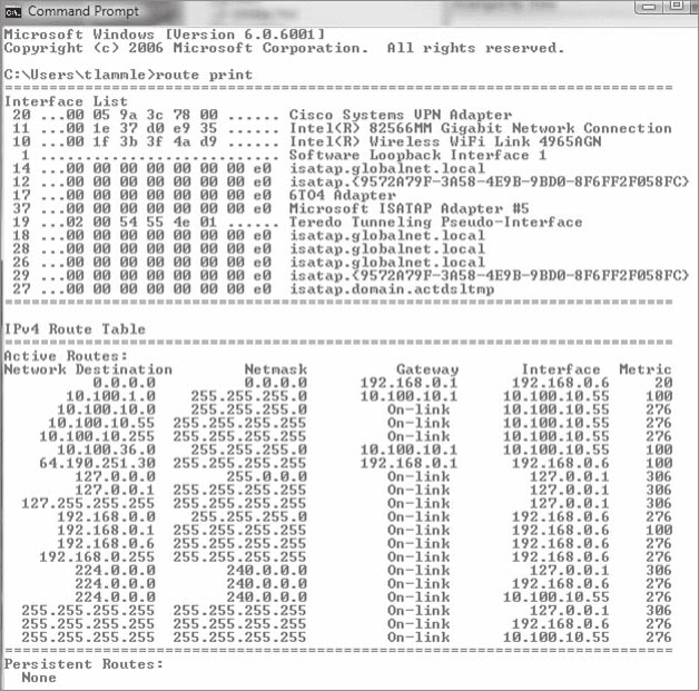
Using the route Command
639
c17.indd 04/03/2015 Page 639
To view the routing table on a Windows device, use the
route print
command, as
shown in Figure 17.5.
FIGURE 17.5
route print
output
In this output, you can see that each of the routes were added automatically when the
system booted up. (This is all based on the con guration of your IP stack.) To see all the
options available with the
route
command, type the
route
command and then press Enter.
To add a route to your routing table, use the following syntax:
route [-f] [-p] [
Command
[
Destination
] [mask
Netmask
] [
Gateway
] [metric
Metric
]] [if
Interface
]]
Using the route Command Options
Let’s start with the switches you can use:
-f
Using this command with any of the options like
add
,
change
, or
delete
will clear
the routing table of all entries that aren’t host routes (routes with the subnet mask

640
Chapter 17 ■ Troubleshooting Tools
c17.indd 04/03/2015 Page 640
255.255.255.255), the loopback network route(s) (routes with a destination of 127.0.0.0
and the subnet mask 255.0.0.0), and any multicast routes (those with a destination of
224.0.0.0 and the subnet mask 240.0.0.0).
-p
If you use this with the
add
command, the individual route will be added to the
Registry and then used to initialize the IP routing table whenever TCP/IP is started.
Important to remember is that by default, the routes you’ve statically added won’t remain
in the routing table the next time TCP/IP boots. And if you use
-p
with the
print
com-
mand, you’ll get shown a list of the persistent routes that are stored in the Registry loca-
tion of
HKEY_LOCAL_MACHINE\SYSTEM\CurrentControlSet\Services\Tcpip\Parameters\
PersistentRoutes
.
Now, let’s take a look at how and when you would use the
route
command. Table 17.4
shows the command options available and what they do when you are using the
route
command with them.
TABLE 17.4
route
command options
Command Purpose
add
Adds a route
change
Modifies an existing route
delete
Deletes a route(s)
print
Prints a route(s)
Here’s a description of some other tasks you can accomplish via the rest of the
command’s options:
destination
This will give you the network destination of a given route. If the host bits
of the network address are set to 0, it will be depicted with the destination’s IP network
address, an IP address for a speci c host route, or the default route of 0.0.0.0.
mask
netmask
This will provide you with the netmask—often referred to as the subnet
mask—that’s associated with the destination network. The default destination subnet mask
is 0.0.0.0, and typically you’ll see 255.255.255.255 representing a host route. It’s really
important to remember that the destination address can’t be more speci c than its corre-
sponding subnet mask. What I’m saying is that there absolutely can’t be a bit set to 1 in the
destination address if the equivalent bit in the subnet mask is a 0.
gateway
The gateway also depends on the network address and subnet mask, but it’s
even more speci c and delimits what’s called the next-hop IP address. For routes located
on a local subnet, the gateway address maps directly to a particular interface. If the
destination is on a remote network, the gateway IP address will direct packets to the
neighboring router.
Using the nbtstat Utility
641
c17.indd 04/03/2015 Page 641
metric
metric
Metric refers to the cost of a given route from the sending to the receiving
device, and it’s a value between 1 and 9999. Devices use this value to choose the best, or
most ef cient, routes among those in its routing table—the route with the lowest value
wins. This decision can also include factors like the number of hops and the speed, reliabil-
ity, and available bandwidth of the path being considered plus the various administrative
aspects associated with it.
if
interface
This tool depends on information from the gateway address and
determines the interface index for the speci c interface that needs to receive the data.
You can get a list of interfaces along with their relevant interface indexes by typing the
route print
command.
/?
Using this will allow you to view help at the command prompt.
Some Examples of the route Command
Even though the ner points of the
route
command demand that you use caution when
deploying some of the options, I’ll still list the basics of the
route
command because it can
be really useful. I highly recommend that you spend some time practicing them on a non-
production server, though—especially at rst.
■ To display the entire IP routing table, type
route print
.
■ To add a default route with the default gateway address 192.168.10.1, type
route
add 0.0.0.0 mask 0.0.0.0 192.168.10.1
.
■ To add a route to the destination 10.1.1.0 with the subnet mask 255.255.255.0 and
the next-hop address 10.2.2.2, type
route add 10.1.1..0 mask 255.255.255.0
10.2.2.2
.
■ If you want to, let’s say, add a persistent route to the destination 10.100.0.0 with
the subnet mask 255.255.0.0 and the next-hop address 10.2.0.1, type
route -p
add 10.100.0.0 mask 255.255.0.0 10.2.0.1
. If you want to delete the route to
the destination 10.100.0.0 with the subnet mask 255.255.0.0, enter
route delete
10.100.0.0 mask 255.255.0.0
.
■ And finally, if you want to change the next-hop address of a route with the destination
10.100.0.0 and the subnet mask 255.255.0.0 from 10.2.0.1 to 10.7.0.5, type
route
change 10.100.0.0 mask 255.255.0.0 10.7.0.5
.
Let’s move on to some other important Windows utilities.
Using the nbtstat Utility
Microsoft Windows uses an interface called Network Basic Input/Output System
(NetBIOS), which relates names with workstations and is an upper-layer interface that
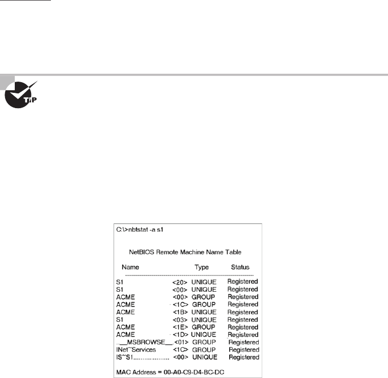
642
Chapter 17 ■ Troubleshooting Tools
c17.indd 04/03/2015 Page 642
requires a transport protocol—usually TCP/IP. But IPv6 can be used as well. Deploying the
nbtstat
utility will achieve these three important things:
■ Track NetBIOS over TCP/IP statistics
■ Show the details of incoming and outgoing NetBIOS over TCP/IP connections
■ Resolve NetBIOS names
Understand that because NetBIOS name resolution is primarily a Windows network
utility, the
nbtstat
command is available only in Windows-based operating systems.
To display a basic description of
nbtstat
and its associated options, type
nbtstat
at the
command line. Then, use these options to get a display of information about NetBIOS over
TCP/IP hosts. Here are some of the tools, or switches, you can use:
–a –A
–c –n
–r –R
–S –s
All
nbtstat
switches are case sensitive. Generally speaking, lowercase
switches deal with NetBIOS names of hosts, and the uppercase ones deal
with the TCP/IP addresses of hosts.
The –a Switch
Making use of the
–a
switch will get you a remote machine’s NetBIOS name table consisting
of a list of every NetBIOS name the machine from which you’ve deployed the switch knows
of. The
–a
switch produced the output from server S1 shown in Figure 17.6.
FIGURE 17.6 Sample output of the
nbtstat –a
command

Using the nbtstat Utility
643
c17.indd 04/03/2015 Page 643
So, using this switch arranges the NetBIOS name-table information in table form with
output in four columns. The Name column displays the NetBIOS name entry for the
remote host machine.
The next column gives you a unique two-digit hexadecimal identi er for the NetBIOS
name. This identi er represents the last byte of the NetBIOS name depicted in the Name
column, and it’s important because the same name could actually be used several times for
the same machine. Plus, it identi es the speci c service on the particular host that the name
is referencing. Table 17.5 and Table 17.6 list the hexadecimal identi ers for unique and
group hostnames.
TABLE 17.5 Last-byte identifiers for unique names
Hex ID Description
00 General name for the computer.
03 Messenger service ID used to send messages between a WINS server and a
workstation. This is the ID registered with a WINS server.
06 Remote Access Server (RAS) server service ID.
20 File-serving service ID.
21 RAS client.
53 DNS.
123 Network Time Protocol (NTP).
1B Domain master browser ID. A NetBIOS name with this ID indicates the domain
master browser.
1F Network Dynamic Data Exchange (NetDDE) service ID.
BE Network monitor agent ID.
BF Network monitor utility ID.
The Type column refers to (surprise) the type of NetBIOS name being referenced. Unique
NetBIOS names refer to individual hosts, and group names refer to logical groupings of
workstations—either domains or workgroups.
The Status column gives you information about the status of a host’s NetBIOS even if it
hasn’t been registered with the rest of the network.
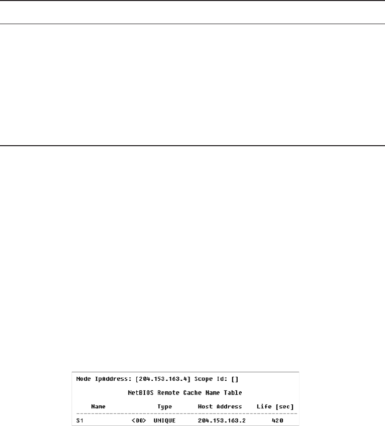
644
Chapter 17 ■ Troubleshooting Tools
c17.indd 04/03/2015 Page 644
TABLE 17.6 Last-byte identifiers for group names
Hex ID Description
01 Master browser for a domain to other master browsers.
20 Internet group name ID. This ID is registered with the WINS server to indicate
which computers are used for administrative purposes.
1C Domain group name ID.
1D Master browser name.
1E Normal group name.
The –A Switch
The
–A
switch works just like the
–a
switch and will give you the same output, but the
syntax of the command is different. Obviously, you use an uppercase
A
instead of a lower-
case one, and you also have to include the host’s IP address instead of its NetBIOS name.
To use it, type
nbtstat
followed by
–A
and nally the IP address of the speci c host whose
NetBIOS table you want to check out:
nbtstat –A 199.153.163.2
The –c Switch
Use the
–c
switch to display the local NetBIOS name cache on the workstation it’s running
on. Figure 17.7 shows sample output of the
nbtstat –c
command.
FIGURE 17.7 Sample output of the
nbtstat –c
command
Each entry in this display shows the NetBIOS name, the hex ID for the service that
was accessed, the type of NetBIOS name (unique or group), the IP address that the name
resolves to, and its life. The Life value shows how many seconds each entry will live in the
cache. When this time expires, the entry will be deleted.
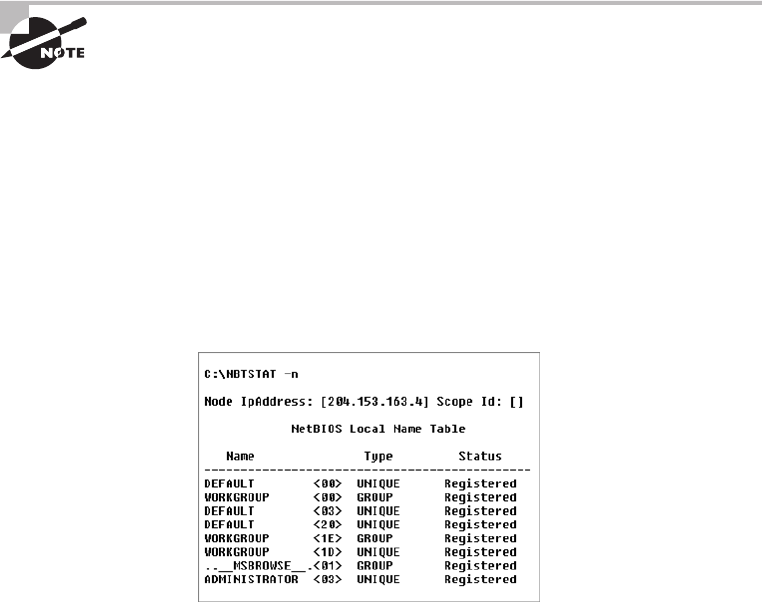
Using the nbtstat Utility
645
c17.indd 04/03/2015 Page 645
Sometimes, deploying
nbtstat
to display the cache will get you the
response “No names in the cache” because all entries in the cache have
expired. This is what happens if you don’t regularly access machines or
services with NetBIOS names.
The –n Switch
The
–n
switch will give you the local NetBIOS name table on a Windows device. Figure 17.8
shows output that’s similar to the output of the
–a
switch except for one important thing:
What you’re seeing is the NetBIOS name table for the machine you’re running the command
on instead of that of another host. Check it out.
FIGURE 17.8 Sample output of the
nbtstat –n
command
The –r Switch
This switch is probably the one you’ll use most often when you want to get a hold of
NetBIOS over TCP/IP (NBT) statistics because it tells you exactly how many NetBIOS
names have been resolved to TCP/IP addresses. Figure 17.9 shows sample output of the
nbtstat –r
command.
What you can see here is that the statistics are divided into two categories. First, there
are the NetBIOS names resolution and registration statistics. This is how many names have
been resolved or registered either by broadcasts on the local segment or via lookup from a
WINS name server.
Next you have the NetBIOS unique and group names and their associated hex IDs
that were resolved or registered. In Figure 17.9, you can see that there’s a distinct lack of
information regarding names resolved by a name server. What this means is that the output
is telling you that there’s no WINS server operating—instead, all NetBIOS names were
resolved by broadcast only.
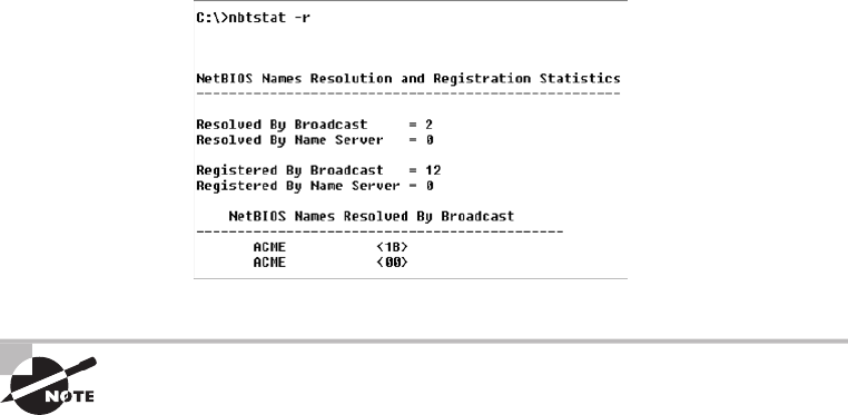
646
Chapter 17 ■ Troubleshooting Tools
c17.indd 04/03/2015 Page 646
FIGURE 17.9 Sample output of the
nbtstat –r
command
The
–r
switch comes in handy when you want to determine how a
workstation is resolving NetBIOS names and whether WINS is configured
correctly. If WINS isn’t configured correctly or it’s simply not being used,
the numbers in the Resolved By Name Server and Registered By Name
Server categories will always be zero.
The –R Switch
Unlike the
–a
and
–A
switches,
-r
and
-R
use the same letter but do not have anything
in common.
Here’s an example. Let’s say you have a bad name in the NetBIOS name cache but the
right name is in the LMHOSTS le instead. (The LMHOSTS le contains NetBIOS names
of stations and their associated IP addresses.) Because the cache is consulted before the
LMHOSTS le is, that bad address will remain in the cache until it expires.
This command is used when you want to purge the NetBIOS name table cache and
reload the LMHOSTS le into memory. You do that using the
nbtstat
command with the
–R
switch, like so:
nbtstat –R
You can practice this
nbtstat -R
command on your host to purge the NBT remote
cache table.
The –S Switch
Using the
-S
switch will display the NetBIOS sessions table that lists all NetBIOS sessions
to and from the host from which you issued the command. The
–S
switch displays both
workstation and server sessions but lists remote addresses by IP address only.
Figure 17.10 shows sample output of the
nbtstat –S
command.

Using the netstat Utility
647
c17.indd 04/03/2015 Page 647
FIGURE 17.10 Sample output of the
nbtstat –S
command
Here you can see the NetBIOS name being displayed along with its hex ID and the sta-
tus of each session. An entry in the In/Out column determines whether the connection has
been initiated from the computer on which you’re running
nbtstat
(outbound) or whether
another computer has initiated the connection (inbound). The numbers in the Input and
Output columns indicate in bytes the amount of data transferred between the stations.
The –s Switch
As with the
–A
and
–a
switches, the lowercase
–s
switch is similar to its uppercase sibling.
The
nbtstat –s
command produces the same output as
nbtstat –S
except that it will also
attempt to resolve remote-host IP addresses into hostnames. Figure 17.11 shows sample out-
put from the
nbtstat –s
command.
FIGURE 17.11 Sample output of the
nbtstat –s
command
Note the similarities between Figure 17.10 and Figure 17.11.
As with the
netstat
command, with the
nbtstat
command you can place
a number for an interval at the end to direct it to deploy once every so
many seconds until you press Ctrl+C.
Using the netstat Utility
Using
netstat
is a great way to check out the inbound and outbound TCP/IP connections
on your machine. You can also use it to view packet statistics like how many packets have
been sent and received, the number of errors, and so on.
648
Chapter 17 ■ Troubleshooting Tools
c17.indd 04/03/2015 Page 648
When used without any options,
netstat
produces output similar to the following,
which shows all the outbound TCP/IP connections. This utility is a great tool to use to
determine the status of outbound web connections. Take a look:
C:\Users\tlammle>netstat
Active Connections
Proto Local Address Foreign Address State
TCP 10.100.10.54:49545 gnt-exchange:epmap TIME_WAIT
TCP 10.100.10.54:49548 gnt-exchange:epmap TIME_WAIT
TCP 10.100.10.54:49551 gnt-exchange:1151 ESTABLISHED
TCP 10.100.10.54:49557 gnt-exchange:1026 ESTABLISHED
TCP 10.100.10.54:49590 gnt-exchange:epmap TIME_WAIT
TCP 127.0.0.1:49174 globalnet-todd:62514 ESTABLISHED
TCP 127.0.0.1:62514 globalnet-todd:49174 ESTABLISHED
TCP 192.168.0.6:2492 blugro2relay:2492 ESTABLISHED
TCP 192.168.0.6:2492 blugro3relay:2492 ESTABLISHED
TCP 192.168.0.6:49170 64.12.25.26:5190 ESTABLISHED
TCP 192.168.0.6:49171 oam-d05c:5190 ESTABLISHED
TCP 192.168.0.6:49473 205.128.92.124:http CLOSE_WAIT
TCP 192.168.0.6:49625 64-190-251-21:ftp ESTABLISHED
TCP 192.168.0.6:49628 210-11:http ESTABLISHED
TCP 192.168.0.6:49629 varp1:http ESTABLISHED
TCP 192.168.0.6:49630 varp1:http ESTABLISHED
TCP 192.168.0.6:49631 varp1:http ESTABLISHED
TCP 192.168.0.6:49632 varp1:http ESTABLISHED
TCP 192.168.0.6:49635 199.93.62.125:http ESTABLISHED
TCP 192.168.0.6:49636 m1:http ESTABLISHED
TCP 192.168.0.6:49638 spe:http ESTABLISHED
The Proto column lists the protocol being used. You can see that I’m connected to my
Exchange server and an FTP server and that I have some HTTP sessions open; by the way,
all of them use TCP at the Transport layer.
The Local Address column lists the source address and the source port (source socket).
The Foreign Address column lists the address of the destination machine (the hostname if
it’s been resolved). If the destination port is known, it will show up as the well-known port.
In the previous output, you see
http
instead of port 80 and
ftp
instead of port 21.
The State column indicates the status of each connection. This column shows statistics
only for TCP connections because User Datagram Protocol (UDP) establishes no virtual
circuit to the remote device. Usually, this column indicates
ESTABLISHED
when a TCP
connection between your computer and the destination computer has been established.
All sessions eventually time out and then close, and you can see that I have all of these
listed in my
netstat
output.

Using the netstat Utility
649
c17.indd 04/03/2015 Page 649
If the address of either your computer or the destination computer can
be found in the HOSTS file on your computer, the destination computer’s
name, rather than the IP address, will show up in either the Local Address
or Foreign Address column.
The output of the
netstat
utility depends on the switch. By using the
netstat /?
command, we can see the options available to us.
C:\Users\tlammle>netstat /?
All of the
netstat
switch options are listed in Table 17.7.
TABLE 17.7
netstat
options
Option Description
-a
Displays all connections and listening ports.
-b
Displays the executable involved in creating each connection or listening
port. In some cases, well-known executables host multiple independent
components, and in these cases the sequence of components involved in
creating the connection or listening port is displayed. In this case, the execut-
able name is in
[ ]
at the bottom; on top is the component it called, and so
forth, until TCP/IP was reached. Note that this option can be time consuming
and will fail unless you have sufficient permissions.
-e
Displays Ethernet statistics. This may be combined with the
-s
option.
-f
Displays fully qualified domain names (FQDNs) for foreign addresses.
-n
Displays addresses and port numbers in numerical form.
-o
Displays the owning process ID associated with each connection.
-p
proto
Shows connections for the protocol specified by
proto
;
proto
may be TCP,
UDP, TCPv6, or UDPv6. If used with the
-s
option to display per-protocol
statistics,
proto
may be IP, IPv6, ICMP, ICMPv6, TCP, TCPv6, UDP, or UDPv6.
-r
Displays the routing table.
-s
Displays per-protocol statistics. By default, statistics are shown for IP, IPv6,
ICMP, ICMPv6, TCP, TCPv6, UDP, and UDPv6; the
-p
option may be used to
specify a subset of the default.
-t
Displays the current connection offload state. Redisplays selected
statistics, pausing interval seconds between each display. Press Ctrl+C to
stop redisplaying statistics. If
-t
is omitted,
netstat
will print the current
configuration information once.

650
Chapter 17 ■ Troubleshooting Tools
c17.indd 04/03/2015 Page 650
Simply type
netstat
followed by a space and then the particular switch you want to use.
Some switches have options, but no matter what, the syntax is basically the same.
Note that with Unix-type switches, the hyphen absolutely must be
included. This is common in Microsoft operating systems for TCP/IP
utilities that originate from Unix systems. I’m not going to exhaustively go
over each and every switch, but make sure you practice all of these on your
own Windows machine.
The –a Switch
When you use the
–a
switch, the
netstat
utility displays all TCP/IP connections and
all UDP connections. Figure 17.12 shows sample output produced by the
netstat
–a
command.
FIGURE 17.12 Sample output of the
netstat –a
command
The last two entries in Figure 17.12 show that the protocol is UDP and give the
source-port nicknames nbname and nbdatagram. These are the well-known port numbers
of 137 and 138, respectively. These port numbers are commonly seen on networks that
broadcast the NetBIOS name of a workstation on the TCP/IP network. You can tell that
this is a broadcast because the destination address is listed as *:* (meaning “any address,
any port”).
The State column in Figure 17.12 has no entry for the UDP rows because
UDP is not a connection-oriented protocol and, therefore, has no
connection state.
The most common use for the
–a
switch is to check the status of a TCP/IP connection
that appears to be hung. You can determine if the connection is simply busy or is actually
hung and no longer responding.
Using the netstat Utility
651
c17.indd 04/03/2015 Page 651
The –e Switch
The
-e
switch displays a summary of all the packets that have been sent over the Network
Interface Card (NIC) as of that instant. The Received and Sent columns show packets
coming in as well as being sent:
C:\Users\tlammle>netstat -e
Interface Statistics
Received Sent
Bytes 7426841 7226953
Unicast packets 25784 35006
Non-unicast packets 1115 12548
Discards 0 0
Errors 0 71
Unknown protocols 0
You can use the
–e
switch to display the following categories of statistics:
Bytes The number of bytes transmitted or received since the computer was turned on.
This statistic is useful for nding out if data is actually being transmitted and received or
if the network interface isn’t doing anything at all.
Unicast Packets The number of packets sent from or received at this computer. To register
in one of these columns, the packet must be addressed directly from one computer to
another and the computer’s address must be in either the source or destination address
section of the packet.
Non-unicast Packets The number of packets that weren’t directly sent from one
workstation to another. For example, a broadcast packet is a non-unicast packet. The
number of non-unicast packets should be smaller than the number of unicast packets.
If the number of non-unicast packets is as high or higher than that of unicast packets, too
many broadcast packets are being sent over your network. De nitely nd the source of
these packets and make any necessary adjustments to optimize performance.
Discards The number of packets that were discarded by the NIC during either transmis-
sion or reception because they weren’t assembled correctly.
Errors The number of errors that occurred during transmission or reception. (These
numbers may indicate problems with the network card.)
Unknown Protocols The number of received packets that the Windows networking
stack couldn’t interpret. This statistic only shows up in the Received column because if
the computer sent them, they wouldn’t be unknown, right?
Unfortunately, statistics don’t mean much unless they can be colored with time
information. For example, if the Errors column shows 71 errors, is that a problem? It might
be if the computer has been on for only a few minutes. But 71 errors could be par for the
652
Chapter 17 ■ Troubleshooting Tools
c17.indd 04/03/2015 Page 652
course if the computer has been operating for several days. Unfortunately, the
netstat
utility doesn’t have a way of indicating how much time has elapsed for these statistics.
The –r Switch
You use the
–r
switch to display the current route table for a workstation so that you can
see exactly how TCP/IP information is being routed. This will give you the same output as
the
route print
command that we covered earlier in this chapter.
The –s Switch
Using the
–s
switch displays a variety of TCP, UDP, IP, and ICMP protocol statistics. But
be warned—the output you’ll get is really long, which may or may not be okay for you.
For this book, it’s way too long for me to insert. With that in mind, we can add another
modi er called the
-p
switch.
The –p Switch
Like the
–n
switch, the
–p
switch is a modi er that’s usually used with the
–s
switch to
specify which protocol statistics to list in the output (IP, TCP, UDP, or ICMP). For exam-
ple, if you want to view only ICMP statistics, you use the
–p
switch like so:
netstat –s –p ICMP
The
netstat
utility then displays the ICMP statistics instead of the entire gamut of TCP/
IP statistics that the
–s
switch will typically ood you with. For a different example, let’s
use the
-s
and
-p
switches to retrieve some IPv6 information:
C:\Users\tlammle>netstat -s -p IPV6
IPv6 Statistics
Packets Received = 1400
Received Header Errors = 0
Received Address Errors = 6
Datagrams Forwarded = 0
Unknown Protocols Received = 0
Received Packets Discarded = 451
Received Packets Delivered = 10441
Output Requests = 24349
Routing Discards = 0
Discarded Output Packets = 3575
Output Packet No Route = 41
Reassembly Required = 0
Using the netstat Utility
653
c17.indd 04/03/2015 Page 653
Reassembly Successful = 0
Reassembly Failures = 0
Datagrams Successfully Fragmented = 0
Datagrams Failing Fragmentation = 0
Fragments Created = 0
C:\Users\tlammle>
Nice! Gets right to the point. Now, let’s see the TCP connections my host has:
C:\Users\tlammle>netstat -s -p tcp
TCP Statistics for IPv4
Active Opens = 7832
Passive Opens = 833
Failed Connection Attempts = 1807
Reset Connections = 2428
Current Connections = 11
Segments Received = 1391678
Segments Sent = 1340994
Segments Retransmitted = 6246
Active Connections
Proto Local Address Foreign Address State
TCP 10.100.10.54:54737 gnt-exchange:1151 ESTABLISHED
TCP 10.100.10.54:54955 gnt-exchange:1026 ESTABLISHED
TCP 10.100.10.54:55218 gnt-exchange:epmap TIME_WAIT
TCP 127.0.0.1:2492 globalnet-todd:54840 ESTABLISHED
TCP 127.0.0.1:54516 globalnet-todd:62514 ESTABLISHED
TCP 127.0.0.1:54840 globalnet-todd:2492 ESTABLISHED
TCP 127.0.0.1:62514 globalnet-todd:54516 ESTABLISHED
TCP 192.168.0.6:2492 blugro2relay:2492 ESTABLISHED
TCP 192.168.0.6:2492 blugro3relay:2492 ESTABLISHED
TCP 192.168.0.6:54527 64.12.25.26:5190 ESTABLISHED
TCP 192.168.0.6:54531 oam-d05c:5190 ESTABLISHED
TCP 192.168.0.6:55163 207.123.44.123:http CLOSE_WAIT
C:\Users\tlammle>
This kind of ef ciency is exactly why it’s good you to use the
-p
modi er with
the
-s
switch.

654
Chapter 17 ■ Troubleshooting Tools
c17.indd 04/03/2015 Page 654
Because the Network+ exam doesn’t cover them, we won’t go into detail
about what all these statistics mean for most of these commands. You can
probably figure out most of them—for instance, Packets Received. For more
details, go to Microsoft’s support website at
www.support.microsoft.com
.
The –n Switch
The
-n
switch is a modi er for the other switches. When used with them, it reverses the
natural tendency of
netstat
to use names instead of network addresses. In other words,
when you use the
–n
switch, the output always displays network addresses instead of their
associated network names. Following is output from the
netstat
command used with the
netstat -n
command. It’s showing the same information but with IP addresses instead
of names:
C:\Users\tlammle>netstat
Active Connections
Proto Local Address Foreign Address State
TCP 10.100.10.54:54737 gnt-exchange:1151 ESTABLISHED
TCP 10.100.10.54:54955 gnt-exchange:1026 ESTABLISHED
TCP 127.0.0.1:2492 globalnet-todd:54840 ESTABLISHED
TCP 127.0.0.1:54516 globalnet-todd:62514 ESTABLISHED
TCP 127.0.0.1:54840 globalnet-todd:2492 ESTABLISHED
TCP 127.0.0.1:62514 globalnet-todd:54516 ESTABLISHED
TCP 192.168.0.6:2492 blugro2relay:2492 ESTABLISHED
TCP 192.168.0.6:2492 blugro3relay:2492 ESTABLISHED
TCP 192.168.0.6:54527 64.12.25.26:5190 ESTABLISHED
TCP 192.168.0.6:54531 oam-d05c:5190 ESTABLISHED
TCP 192.168.0.6:55163 207.123.44.123:http CLOSE_WAIT
C:\Users\tlammle>netstat -n
Active Connections
Proto Local Address Foreign Address State
TCP 10.100.10.54:54737 10.100.36.13:1151 ESTABLISHED
TCP 10.100.10.54:54955 10.100.36.13:1026 ESTABLISHED
TCP 127.0.0.1:2492 127.0.0.1:54840 ESTABLISHED
TCP 127.0.0.1:54516 127.0.0.1:62514 ESTABLISHED

Using the File Transfer Protocol
655
c17.indd 04/03/2015 Page 655
TCP 127.0.0.1:54840 127.0.0.1:2492 ESTABLISHED
TCP 127.0.0.1:62514 127.0.0.1:54516 ESTABLISHED
TCP 192.168.0.6:2492 65.55.239.100:2492 ESTABLISHED
TCP 192.168.0.6:2492 65.55.248.110:2492 ESTABLISHED
TCP 192.168.0.6:54527 64.12.25.26:5190 ESTABLISHED
TCP 192.168.0.6:54531 205.188.248.163:5190 ESTABLISHED
TCP 192.168.0.6:55163 207.123.44.123:80 CLOSE_WAIT
C:\Users\tlammle>
Uses for netstat
You might be saying to yourself, “Fine…I can use lots of cool switches with
netstat
,
but really, what for?” I’m always fi nding uses for
netstat
. For instance, once I found a
particularly nasty worm on my PC using
netstat
. I just happened to run
netstat
for
giggles one day and noticed a very large number of outbound connections to various
places on the Internet. My PC was sending out SYN packets to a large number of hosts
(an indication that my computer was involved—unknowingly—in a large-scale denial of
service attack). Upon further examination, I noticed that this activity would start shortly
after bootup.
I tried running
netstat
after bootup and noticed that the fi rst outbound connection was
to TCP port 6667, some Internet Relay Chat (IRC) server I’d never heard of—I didn’t even
have an IRC client on my machine at the time. The worm was particularly nasty to try to
get rid of while active, so I turned off port 6667 on my fi rewall. That prevented the initial
connection to the IRC server and, as I found out later, nicely prevented the worm from
getting its instructions from the IRC server. I was then able to simply remove it. I would’ve
never found out that this worm was working without
netstat
. Even my antivirus program
missed it.
Using the File Transfer Protocol
You already know that File Transfer Protocol (FTP) is a subset of TCP/IP and that FTP
is used for the transfer of les. In recent years, FTP has become a truly cross-platform
protocol for transferring les. Because Internet (and thus TCP/IP) use has skyrocketed,
almost every client and server platform has implemented FTP. Windows is no exception.
Its TCP/IP stack comes with a command-line
ftp
utility.

656
Chapter 17 ■ Troubleshooting Tools
c17.indd 04/03/2015 Page 656
To start the
ftp
utility, enter
ftp
at a command prompt. The result is an
ftp
command
prompt:
C:\Users\tlammle>ftp
ftp>
From this prompt, you can open a connection to an FTP server and upload and
download les as well as change the way FTP operates. To display a list of all the com-
mands you can use at the
ftp
command prompt, type
help
or
?
and press Enter. To get
help on a speci c command, type
help
, a space, and then the name of the command.
Here is some output from the
help
command:
ftp>help
Commands may be abbreviated. Commands are:
! delete literal prompt send
? debug ls put status
append dir mdelete pwd trace
ascii disconnect mdir quit type
bell get mget quote user
binary glob mkdir recv verbose
bye hash mls remotehelp
cd help mput rename
close lcd open rmdir
ftp>
In the following sections, I’ll give you an introduction to uploading and downloading
les because every network technician and administrator positively needs to know how to
do this. As they come up, I’ll go over the speci c commands necessary to perform those
two operations as well as any commands that relate to those processes. But rst, let’s look
at how to begin the process.
Third-party applications are available that provide a GUI interface for FTP,
which is easier to use than a command line.
Starting FTP and Logging In to an FTP Server
Of the two FTP le operations (download and upload), the ability to download les is
de nitely the more crucial for you to have down as a network technician or sys admin. The
reason it’s so important for you to master is that network and client operating system driv-
ers and patches are located on FTP servers all over the Internet.
Using the File Transfer Protocol
657
c17.indd 04/03/2015 Page 657
The rst steps in starting an FTP download session are to determine the address of the
FTP site and start the
ftp
utility. The FTP site typically has the same name as the website
except that the rst three characters are
ftp
instead of
www
. For example, Microsoft’s web-
site is
www.microsoft.com
. Its FTP site, on the other hand, is
ftp.microsoft.com
. We’ll use
my personal FTP site as an example for the rest of this section because it works, so I can
actually log in to it.
First, start the
ftp
utility as demonstrated earlier, and then follow these steps:
1. At the
ftp
command prompt, type
open
, a space, and the name of the FTP server,
like this:
C:\Users\tlammle>
ftp
ftp>
open ftp.lammle.com
Connected to ftp.lammle.com.
220---------- Welcome to Pure-FTPd [TLS] ----------
220-You are user number 1 of 50 allowed.
220-Local time is now 11:45. Server port: 21.
220-IPv6 connections are also welcome on this server.
220 You will be disconnected after 15 minutes of inactivity.
User (ftp.lammle.com:(none)):
enter
230 Anonymous user logged in
ftp>
As shown here, if the FTP server is available and running, you’ll receive a response
welcoming you to the server and asking you for a username. Right now, I just have
Anonymous as the username (enabled by default on the FTP server), which means that
anyone can log in to it. (By the way, don’t bother trying this on my server because I
disabled it for obvious reasons as soon as I nished writing this section.)
You can also start an FTP session by typing
ftp
, a space, and the address of the FTP
server (for example,
ftp ftp.globalnettraining.com
). This allows you to start the
ftp
utility and open a connection in one step. Here’s an example:
C:\Users\tlammle>
ftp ftp.globalnettraining.com
Connected to ftp.globalnettraining.com.
220 Microsoft FTP Service
User (ftp.globalnettraining.com:(none)):
todd
331 Password required for todd.
Password:
not shown when typed
230 User todd logged in.
ftp>
quit
2. Enter a valid username, and press Enter.
3. Enter your password, and press Enter. (The password won’t show up when you type it.)

658
Chapter 17 ■ Troubleshooting Tools
c17.indd 04/03/2015 Page 658
Most Internet web servers that allow just about anyone to download files
also allow the username anonymous, as I demonstrated. In addition to
anonymous, you can use the username ftp to gain access to a public FTP
server. They are both anonymous usernames. Remember that FTP (and
Unix) usernames are case sensitive.
All good, but if you want to access a private FTP server, as I’ll demonstrate in a minute,
you’ll need to use the username and password given to you by the site’s administrator. Oh,
and sometimes you can use your email address as a password when accessing a public FTP
server with a username like anonymous.
You don’t have to enter your entire email address to log in with the
anonymous username. Most of the time, FTP server software doesn’t
actually verify the actual email address, only that it is, in fact, an email
address. To do this, it checks for an @ sign and two words separated by
a period. You just need to enter a very short email address to bypass the
password (like
u@me.com
). This is especially helpful if you have a long
email address, and it’s a really good idea if you don’t want to get a ton of
junk email.
If you enter the wrong username and/or password, the server will tell you so by
displaying the following and leaving you at the
ftp
command prompt:
530 Login Incorrect
Login failed.
This means you’ve got to try again and must start the login process over. If you’re
successful, the FTP server will welcome you and drop you back at the
ftp
command
prompt. You’re now ready to start uploading or downloading les.
Downloading Files
After you log in to the FTP server, you’ll navigate to the directory that contains the les
you want. Thankfully, the FTP command-line interface is similar to the DOS command-
line interface. This is no surprise because DOS is based on Unix and FTP is a Unix utility.
Table 17.8 lists and describes the common navigation commands for FTP. (Remember that
these are also case sensitive.)
After you navigate to the directory and nd the le you want to download, it’s time to
set the parameters for the type of le. Files come in two types:
■ ASCII, which contains text
■ Binary, which is all other files
If you set
ftp
to the wrong type, the le you download will contain gibberish. So if
you’re in doubt, set
ftp
to download les as binary les. Check out Table 17.8.

Using the File Transfer Protocol
659
c17.indd 04/03/2015 Page 659
TABLE 17.8 Common FTP navigation commands
Command Description
Ls
Short for list. Displays a directory listing. Very similar to the
DIR
command in
MS-DOS.
Cd
Short for change directory. Works almost identically to the MS-DOS
CD
com-
mand. Use it to change to a different directory and navigate the server’s direc-
tory structure.
Pwd
Short for print working directory. Displays the current directory on the server. Use-
ful if you forget where you are when changing to several locations on the server.
Lcd
Short for local change directory. Displays and changes the current directory
on the local machine. Useful when you are downloading a file and aren’t in the
directory where you want to put the file.
To set the le type to ASCII, type
ascii
at the
ftp
command prompt.
ftp
will respond
by telling you that the le type has been set to A (ASCII):
ftp>ascii
Type set to A
To set the le type to binary, type
binary
at the
ftp
command prompt.
ftp
will respond
by telling you that the le type has been set to I (binary):
ftp>binary
Type set to I
To download the le, just use the
get
command like this:
ftp>get lammlepress.exe
200 PORT command successful.
150 Opening BINARY mode data connection for 'scrsav.exe'
(567018 bytes).
The le will start downloading to your hard drive. Unfortunately, with its default
settings, the
ftp
utility doesn’t give you any indication of the progress of the transfer. When
the le has downloaded, the
ftp
utility will display the following message and return you
to the
ftp
command prompt:
226 Transfer complete.
567018 bytes received in 116.27 seconds (4.88 Kbytes/sec)
You can download multiple files by using the
mget
command. Simply type
mget
, a space, and then something known as a wildcard that specifies
the files you want to get. For example, to download all the text files in a
directory, type
mget *.txt
.

660
Chapter 17 ■ Troubleshooting Tools
c17.indd 04/03/2015 Page 660
Uploading Files
To upload a le to an FTP server, you’ve got to have rights on that speci c server. These
rights are assigned on a directory-by-directory basis. To upload a le, log in and then
follow these steps:
1. At the
ftp
command prompt, type
lcd
to navigate to the directory on the local
machine where the file resides.
2. Type
cd
to navigate to the destination directory.
3. Set the file type to ASCII or binary.
4. Use the
put
command to upload the file.
The syntax of the
put
command looks like this:
ftp>put
local file destination file
Let’s say you want to upload a le called
1.txt
on the local server but you want it to be
called
my.txt
on the destination server. To accomplish that, use the following command:
ftp>put 1.txt my.txt
You’ll get the following response:
200 PORT command successful.
150 Opening BINARY mode data connection for collwin.zip
226 Transfer complete.
743622 bytes sent in 0.55 seconds (1352.04 Kbytes/sec)
You can upload multiple files using the
mput
command. Simply type
mput
,
a space, and then a wildcard that specifies the files. For example, to upload
all the text files in a directory, type
mput *.txt
.
When you’re nished with the
ftp
utility, just type
quit
to return to the command
prompt.
Using the Telnet Utility
Part of the TCP/IP protocol suite, Telnet is a virtual terminal protocol utility that allows
you to make connections to remote devices, gather information, and run programs. Telnet
was originally developed to open terminal sessions from remote Unix workstations to Unix
servers. Although it’s still used for that purpose, we now use it as a troubleshooting tool as
well. Figure 17.13 shows the basic Telnet interface as it’s being used to start a terminal
session on a remote Unix host.
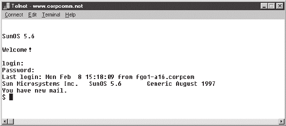
Using the Telnet Utility
661
c17.indd 04/03/2015 Page 661
FIGURE 17.13 The Telnet utility
In today’s Windows environments, Telnet is a basic command-line tool for testing
TCP connections. You can telnet to any TCP port to see if it’s responding—something
that’s especially useful when checking Simple Mail Transfer Protocol (SMTP) and HTTP
(web) ports.
As you learned back in Chapter 6, “Introduction to the Internet Protocol,” each upper-
layer service in a TCP stack has a number for its address. And by default, each network
service that uses a particular address will respond to a TCP request on that speci c port.
How to Enable Telnet in Windows
Because most people have Windows 7 or 8 operating systems running on their PCs these
days, it’s good to know that, by default, these operating systems install without Telnet
available. But there’s a way around that one—if you really must have a Telnet client enabled
in these operating systems, here’s how to do it:
1. Open Control Panel.
2. Select Programs And Features.
3. In the left column, select Turn Windows Features On Or Off (get ready for the annoy-
ing User Account Control [UAC] prompt, and then enter your name and password).
4. Select the Telnet check box (and any other obscure services you may want enabled),
and wait while Windows thinks for a while and then reboots.
Nice—now you can go to Start and then type
telnet
in the Start search box to get a
Telnet window to open for you. You can also open a DOS prompt and just type
telnet
from there. Here are the options that Windows provides with Telnet:
Microsoft Telnet> ?
Commands may be abbreviated. Supported commands are:
c - close close current connection

662
Chapter 17 ■ Troubleshooting Tools
c17.indd 04/03/2015 Page 662
d - display display operating parameters
o - open hostname [port] connect to hostname (default port 23).
q - quit exit telnet
set - set set options (type 'set ?' for a list)
sen - send send strings to server
st - status print status information
u - unset unset options (type 'unset ?' for a list)
?/h - help print help information
Now that we’ve nished talking about Telnet, my personal recommendation is that you
never use it again. What? Yes, you read that right, and here’s why.
Don’t Use Telnet, Use Secure Shell
What? I just told you how to use Telnet, and now I am telling you not to use it. That’s right,
don’t use Telnet! Telnet is totally insecure because it sends all data in crystal-clear text—
including your name and password. And I’m pretty sure you know that’s a really bad thing
these days. If Microsoft doesn’t even enable it on its latest OSs, then you know it really
must be insecure.
So if you shouldn’t use Telnet, what should you use instead? Secure Shell (SSH) is your
answer. It provides the same options as Telnet, plus a lot more; but most important, it
doesn’t send any data in clear text. The thing is, your servers, routers, and other devices
need to be enabled with SSH, and it’s not con gured by default on most devices.
Some con guration is usually necessary if you want things to work as they really should,
and yes, sometimes it’s a little painful to get everything running smoothly, but it’s all worth
it in the long run. Personally, I disable Telnet on all my routers and use SSH exclusively. No
lie—I never use Telnet anymore if I can help it. Even so, you should still understand Telnet
and get in some practice with it in case you do ever need it.
In my Sybex book Cisco CCNA Study Guide, I get into the skinny on how to
configure SSH on all Cisco devices and use an SSH client.
Summary
In this chapter, you learned about many of the utilities for using and troubleshooting
TCP/IP. These utilities include GUI tools like protocol analyzers, throughput testers, and
connectivity software like Remote Desktop, and they include command-line utilities like
tracert
,
ping
,
arp
,
netstat
,
nbtstat
,
ipconfig
,
ifconfig
, and
nslookup
.
You also learned how these utilities are used, including their various options and
switches and how they all affect the use of the utilities. Finally, you learned about how
these utilities work within the TCP/IP suite.
Written Lab
663
c17.indd 04/03/2015 Page 663
Exam Essentials
Describe some of the GUI tools available to assist in testing and troubleshooting. These
include protocol analyzers, throughput testers, and connectivity software. Understand each
product’s purpose and how to use it.
Know how to describe and use the troubleshooting information and statistics that
arp
,
nbtstat
, and
netstat
provide for you. The
arp
utility shows whether an IP address is
being resolved to your MAC address (or someone else’s, in case of con icts). The
netstat
utility produces TCP/IP statistics, and
nbtstat
produces NetBIOS over TCP/IP statistics.
Know how to diagnose a network by using TCP/IP’s troubleshooting commands. The
ping
command echoes back if a machine is alive and active on a network. The
tracert
command shows the path that the ping packets take from source to target. And
telnet
enables a user to participate in a remote text-based session.
Know what the
tracert
utility does. The
tracert
utility nds the route from your com-
puter to any computer on a network.
Know what the
ping
utility does.
ping
determines whether a particular IP host is
responding.
Know what the
ftp
utility does. The
ftp
utility allows you to reliably download and
upload les from and to an FTP server across the Internet.
Know what the
ipconfig
and
ifconfig
utilities do. The
ipconfig
utility displays TCP/
IP con guration information for Windows NT and later operating systems. The
ifconfig
utility performs a similar function in Unix environments, in addition to performing certain
interface-con guration tasks.
Know what the
nslookup
and
dig
utilities do. The
nslookup
and
dig
utilities allow you to
look up DNS resolution information.
Written Lab
You can nd the answers in Appendix A. Write the answers to the following questions
about command-line tools:
1. What command can you type from a command prompt to see the hops a packet takes to get
to a destination host?
2. What tool would you use to verify a complaint about a slow network?
3. You need your IP address, subnet mask, default gateway, and DNS information. What
command will you type from a Windows command prompt?
4. You need to log in as a dumb terminal to a server or Unix host and run programs. What
application will you use?
664
Chapter 17 ■ Troubleshooting Tools
c17.indd 04/03/2015 Page 664
5. You need to add a route to your Windows server’s routing table. What command will you
use?
6. You want to log in to a server and transfer files. What application will you use?
7. You need to check your name-resolution information on your host. What command will
you type from the command prompt?
8. You want to use
netstat
, but you want to see only the IP address, not the names of the
hosts. Which modifier will you use?
9. You want the IP configuration on a Unix host. What command will you type at the com-
mand prompt?
10. Which Windows command will show you the routing table of your host or server?
Review Questions
665
c17.indd 04/03/2015 Page 665
Review Questions
You will nd the answers to the review questions in Appendix B.
1. Which TCP/IP utility is most often used to test whether an IP host is up and functional?
A.
ftp
B.
telnet
C.
ping
D.
netstat
2. Which TCP/IP utility will produce the following result?
Interface: 199.102.30.152
Internet Address Physical Address Type
199.102.30.152 A0–ee–00–5b–0e–ac dynamic
A.
arp
B.
netstat
C.
tracert
D.
nbtstat
3. Which Windows utility can you use to connect to a machine 50 miles away to troubleshoot?
A. Remote Desktop
B.
netstat
C.
arp
D. Wireshark
4. Which TCP/IP utility might produce the following output?
Reply from 204.153.163.2: bytes=32 time=1ms TTL=128
Reply from 204.153.163.2: bytes=32 time=1ms TTL=128
Reply from 204.153.163.2: bytes=32 time=1ms TTL=128
Reply from 204.153.163.2: bytes=32 time<10ms TTL=128
A.
tracert
B.
ping
C.
WINS
D.
ipconfig
5. Which utility can you use to find the MAC and TCP/IP addresses of your Windows
workstation?
A.
ping
B.
ipconfig
C.
ipconfig /all
666
Chapter 17 ■ Troubleshooting Tools
c17.indd 04/03/2015 Page 666
D.
tracert
E.
telnet
6. Which
ping
commands will verify that your local TCP/IP interface is working? (Choose all
that apply.)
A.
ping 204.153.163.2
B.
ping 127.0.0.1
C.
ping localif
D.
ping localhost
E.
ping iphost
7. Which switch for the Windows
nbtstat
utility will display all NetBIOS name-resolution
statistics?
A.
–r
B.
/r
C.
–R
D.
/R
8. You need to find a NIC’s specific MAC address and IP address. Which command-line tool
can you use to find this information without physically going to the computer?
A.
ping
B.
nbtstat
C.
arp
D.
netstat
E.
ftp
9. Which
nbtstat
utility switch will purge and reload the remote NetBIOS name table cache?
A.
–r
B.
–R
C.
/r
D.
/R
10. Wireshark is an example of a ________________?
A. Throughput tester
B. Protocol analyzer
C. Remote connection tool
11. Which utility produces output similar to the following?
1 110 ms 96 ms 107 ms fgo1.corpcomm.net [209.74.93.10]
2 96 ms 126 ms 95 ms someone.corpcomm.net [209.74.93.1]
3 113 ms 119 ms 112 ms Serial5–1–1.GW2.MSP1.alter.net
[157.130.100.185]
Review Questions
667
c17.indd 04/03/2015 Page 667
4 133 ms 123 ms 126 ms 152.ATM3–0.XR2.CHI6.ALTER.NET
[146.188.209.126]
5 176 ms 133 ms 129 ms 290.ATM2–0.TR2.CHI4.ALTER.NET [146.188.209.10]
6 196 ms 184 ms 218 ms 106.ATM7–0.TR2.SCL1.ALTER.NET [146.188.136.162]
7 182 ms 187 ms 187 ms 298.ATM7–0.XR2.SJC1.ALTER.NET [146.188.146.61]
8 204 ms 176 ms 186 ms 192.ATM3–0–0.SAN–JOSE9– GW.ALTER.NET
[146.188.144.133]
9 202 ms 198 ms 212 ms atm3–0–622M.cr1.sjc.globalcenter.net
[206.57.16.17]
10 209 ms 202 ms 195 ms pos3–1–155M.br4.SJC.globalcenter.net
[206.132.150.98]
11 190 ms * 191 ms pos0–0–0–155M.hr3.SNV.globalcenter.net
[206.251.5.93]
12 195 ms 188 ms 188 ms pos4–1–0– 155M.hr2.SNV.globalcenter.net
[206.132.150.206]
13 198 ms 202 ms 197 ms www10.yahoo.com [204.71.200.75]
A.
arp
B.
tracert
C.
nbtstat
D.
netstat
12. You are the network administrator. A user calls you, complaining that the performance of
the intranet web server is sluggish. When you try to ping the server, it takes several seconds
for the server to respond. You suspect that the problem is related to a router that is seriously
overloaded. Which workstation utility could you use to find out which router is causing this
problem?
A.
netstat
B.
nbtstat
C.
tracert
D.
ping
E.
arp
13. Which
ipconfig
switch will display the most complete listing of IP configuration
information for a station?
A.
/all
B.
/renew
C.
/release
D.
/?
14. Which utility will display a list of all the routers that a packet passes through on the way to
an IP destination?
A.
netstat
B.
nbtstat
668
Chapter 17 ■ Troubleshooting Tools
c17.indd 04/03/2015 Page 668
C.
tracert
D.
ping
E.
arp
15. Which Windows TCP/IP utility could you use to find out whether a server is responding on
TCP port 21?
A.
tcp
B.
port
C.
ping
D.
nbtstat
E.
telnet
16. Which
arp
command can you use to display the currently cached ARP entries?
A.
arp
B.
arp –all
C.
arp /a
D.
ipconfig /arp
E.
arp /ipconfig
17. Which command-line tool would best be used to verify DNS functionality?
A.
netstat
B.
nbtstat
C.
dig
D.
icmp
E.
arp
18. Which of the following
arp
utility switches perform the same function? (Choose all
that apply.)
A.
–g
B.
–A
C.
–d
D.
–a
19. Which command would you use at a workstation prompt to see the DNS servers that are
configured to use? (Choose three.)
A.
arp
B.
nslookup
C.
netstat
D.
nbtstat
E.
ipconfig/all
F.
ifconfig
Review Questions
669
c17.indd 04/03/2015 Page 669
20. Which
nbtstat
switch displays a list of all the NetBIOS sessions currently active on the
local workstation?
A.
–a
B.
–r
C.
–s
D.
–I

c18.indd 04/01/2015 Page 671
Chapter
18
Software and
Hardware Tools
THE FOLLOWING COMPTIA NETWORK+
EXAM OBJECTIVES ARE COVERED IN
THIS CHAPTER:
✓ 1.5 Install and properly terminate various cable types and
connectors using appropriate tools
■ Tools
■ Cable crimpers
■ Punch down tool
■ Wire strippers
■ Snips
■ OTDR
■ Cable certifier
✓ 2.1 Given a scenario, use appropriate monitori ng tools
■ Packet/network analyzer
■ Interface monitoring tools
■ Port scanner
■ Top talkers/listeners
■ SNMP management software
■ Trap
■ Get
■ Walk
■ MIBS
■ Alerts
■ Email
■ SMS
■ Packet flow monitoring

c18.indd 04/01/2015 Page 672
■ SYSLOG
■ SIEM
■ Environmental monitoring tools
■ Temperature
■ Humidity
■ Power monitoring tools
■ Wireless survey tools
■ Wireless analyzers
✓ 2.2 Given a scenario, analyze metrics and reports from
monitoring and tracking performance tools
■ Baseline
■ Bottleneck
■ Log management
■ Graphing
■ Utilization
■ Bandwidth
■ Storage
■ Network device CPU
■ Network device memory
■ Wireless channel utilization
✓ 4.2 Given a scenario, analyze and interpret the output of
troubleshooting tools
■ Line testers
■ Certifiers
■ Multimeter
■ Cable tester
■ Light meter
■ Toner probe
■ Speed test sites
■ Looking glass sites
■ WiFi analyzer
■ Protocol analyzer

c18.indd 04/01/2015 Page 673
Specialized tasks require specialized tools, and installing
network components is no exception. We use some of these
tools, like network scanners, on an everyday basis, but most
of the hardware tools I’ll be covering in this chapter are used mainly in the telecommunica-
tions industry.
Still, in order to meet the CompTIA Network+ objectives, and also because you’re likely
to run across them in today’s networking environments, it’s very important that you’re
familiar with them.
For up-to-the-minute updates for this chapter, please see
www.lammle.com/
networkplus
or
www.sybextestbanks.wiley.com
.
Understanding Network Scanners
Network scanner has become a broad term often referring to a family of tools used to
analyze our networks, but the CompTIA Network+ objectives are much less vague. So with
regard to those critical objectives, know that network scanners refer to these three tools:
■ Packet sniffers
■ Intrusion detection system/intrusion prevention system (IDS/IPS) software
■ Port scanners
Packet Sniffers/Network Monitors
Unlike port scanners, packet sniffers actually look inside every packet on a network
segment. Packet sniffers come in many avors, and some of them, like Microsoft’s Network
Monitor (NetMon), are even free today. Even though NetMon comes in more complex
versions that are, well, not exactly free, the version that comes bundled with Windows
Server does allow you to analyze network communications traf c. The full version will
give you statistics on network utilization and packet traf c data as well as capture
individual frames for analysis. These abilities really mean that NetMon is both a packet
sniffer and a network analyzer, and it’s common for these to be combined and referred to
as one and the same.

674
Chapter 18 ■ Software and Hardware Tools
c18.indd 04/01/2015 Page 674
All good, but personally, I use Wireshark instead. It’s also free, and you can easily
download it from
www.wireshark.org
. A nice feature of Wireshark is that it runs from
Windows, OS X, Linux, and Unix platforms. It easily captures data on all my interfaces,
including my wireless and virtual private network (VPN) connections, and looks at all
traf c on the network segment. There are tons of packet sniffers available, and to get your
hands on most of them, you’ll have to pony up some cash. Sometimes they’re worth it,
though, because these higher-end products can even provide solutions to problems you nd
on your network—nice.
Anyway, free or not, the basic purpose of packet sniffers (or network analyzers) is to
collect and analyze each individual packet that is captured on a speci c network segment to
determine if problems like bottlenecks, retransmissions, and security breaches are happen-
ing. Packet sniffers are a must-have for every network administrator to troubleshoot and
nd problems or security holes in a network. For example, you may discover that users are
using an application on the network with usernames and passwords being sent unencrypted
over the network.
You can also use packet sniffers to see if there is too much traf c on a segment, to see
router or switch interfaces (referred to as interface monitoring), or even to see if a broadcast
storm has been created by a bad Network Interface Card (NIC). And remember—I do
mean on a network segment—you can’t use them to catch packets passing through routers.
These network analyzers can also show you top talkers and listeners on your network, and
provide packet ow monitoring.
Yes, they can help you nd a hacker stalking around in there, but you’d really have to be
looking closely and constantly to discover this. For that level of monitoring, you’d be better
off using a tool known as an IDS/IPS. It can really help you track and even defeat hackers.
(We’ll talk about IDS/IPS software in the next section.) The more expensive network
sniffers can help nd anomalies in your network, like a hack, and even alert you to these
problems. Figure 18.1 shows output from a packet sniffer. Notice that you can identify both
the IP addresses and the MAC addresses associated with any of the packets captured as
well as identify the protocol in use.
You can de nitely see that a packet sniffer can provide you with huge amounts of
information. This means you really need something to narrow things down and help you
to more readily nd the needle in the haystack that you’re looking for, right?
In this case, help comes in the form of some handy built-in lters that can be used to
gather information from just one speci c host or server; without them, you’d have to go
through possibly thousands of packets to nd the problem. For the packet I’ve highlighted,
you can see that there’s a probable User Datagram Protocol (UDP) checksum error. And by
the way, because UDP is connectionless, this is a pretty common error.
You should download and start working with a network sniffer right away.
As I mentioned, you can download Wireshark at
www.wireshark.org
for
free, so what are you waiting for? Go for it!
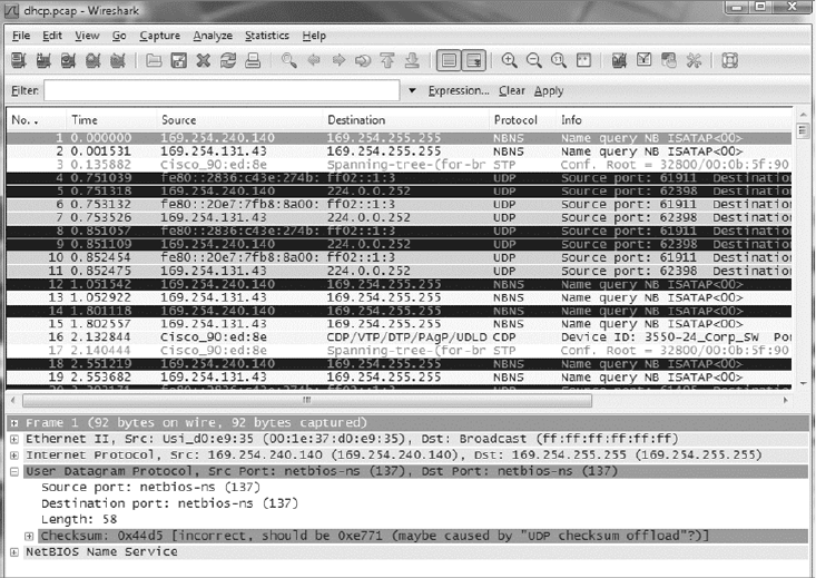
Understanding Network Scanners
675
c18.indd 04/01/2015 Page 675
FIGURE 18.1 Output from a packet sniffer
Now comes the fun stuff—let’s take a look at ways we can nd and stop hackers dead in
their tracks.
Intrusion Detection and Prevention Software
An IDS detects unwanted attempts to manipulate network systems and/or environments,
and an IPS is a computer-security device that monitors network and/or system activities for
any strange or malicious behavior. It can react in real time to prevent and even block nasty
activities. An IDS identi es, detects, and reports attempts of unauthorized access to the
network as well as any suspicious activity, and it’s the best software type for identifying an
attack. However, if you want to stop the attack in its tracks, you need to add an IPS device.
So, unlike IDSs, which can identify an attack and report it, an IPS can stop the attack by
shutting down ports or dropping certain types of packets.
A bunch of different IDS/IPS software packages are available on the market, and a lot of
them are free. Again, predictably, the best ones aren’t, and they can be a bit pricey. These
high-powered versions run on Linux or other proprietary hardware. But there are still
many IDS/IPS software applications available for Windows.
Snort is one of the most popular IDS/IPS software products around. It runs on both
Linux and Windows, and it’s a free, open-source platform, which happens to be a big
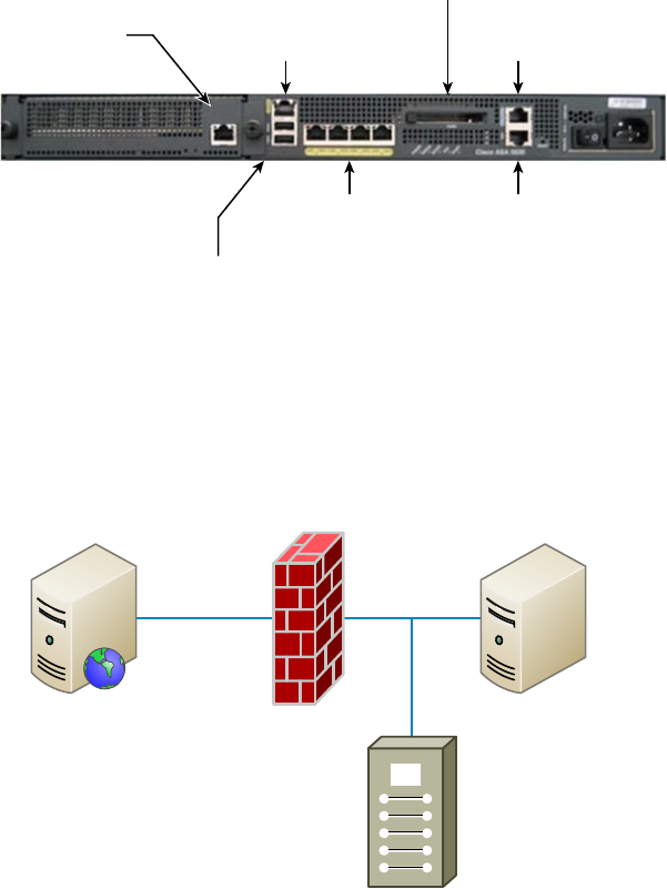
676
Chapter 18 ■ Software and Hardware Tools
c18.indd 04/01/2015 Page 676
reason for its popularity. But that’s not the only reason—just because it is free doesn’t
mean it doesn’t offer up some pretty cool features. On the other hand, if you’re dealing
with a large, corporate environment, you need some serious weaponry, and Cisco offers an
Adaptive Security Appliance (ASA) as an enterprise solution that’s powerful but de nitely
far from free. It’s worth it, though.
Figure 18.2 shows a picture of a Cisco ASA box I use in my security classes.
FIGURE 18.2 A Cisco ASA
Two USB 2.0 Ports
Four 10/100/1000
Copper Gigabit Ports
AUX Ports
Security Service Module
(SSM) Monitoring Port 10/100 Out-of-Band
Management Port
Console
Port
Compact Flash
Personally, I think the Cisco box is the best IDS/IPS box on the market today. Still,
Snort isn’t bad (check out Cisco’s new acquisition, SourceFire), so if cost is an issue, rest
assured you can use it, as well as several other tools, and be much better equipped than
you would be without them working on your network to help you keep it secure.
Figure 18.3 shows where you’d nd a typical IDS/IPS in a internetwork.
FIGURE 18.3 IDS/IPS placement in an internetwork
DMZ Internal Network
Web Server Firewall SQL Server
IDS/IPS

Understanding Network Scanners
677
c18.indd 04/01/2015 Page 677
To be honest, because of the device’s complexity and the many different physical
con gurations possible, this is a relatively simplistic view of an IDS/IPS working within
a network. The important thing I want you to pay attention to is the fact that you would
typically nd the IDS/IPS software positioned between your internal router and the rewall
to the outside network (Internet). If you’re using Snort, just add the software to a Linux
box, and connect this box between the rewall and the router. This area would typically
be your demilitarized zone (DMZ). The Basic Analysis and Security Engine (BASE)
displays and reports intrusions and attacks logged in the Snort database in a web browser
for convenient analysis.
Port Scanners
A port scanner is a software tool designed to search a host for open ports. Those of
us administering our networks use port scanners to ensure their security, but bad guys
use them to nd a network’s vulnerabilities and compromise them. To port scan means
to scan for TCP and UDP open ports on a single target host either to legitimately
connect to and use its services for business and/or personal reasons or to nd and
connect to those ports and subsequently attack the host and steal or manipulate it for
nefarious reasons.
In contrast, port sweeping means scanning multiple hosts on a network for a speci c
listening TCP or UDP port, like SQL. (SQL injection attacks are super common today.)
This just happens to be a favorite approach used by hackers when trying to invade your
network. They port sweep in a broad manner, and then, if they nd something—in this
case, SQL—they can port scan the particular host they’ve discovered with the desired
service available to exploit and get what they’re after. This is why it’s a really good idea
to turn off any unused services on your servers and routers and to run only the minimum
services required on every host machine in your network. Do yourself a big favor and make
sure this is in your security policy.
Remember that three-way handshake I discussed in Chapter 6, “Introduction to the
Internet Protocol”? Well, it just so happens that a SYN scan is the most popular form of
TCP scanning. Rather than use the operating system’s network functions, the port
scanner actually generates raw IP packets itself and monitors for responses. This scan type
is also known as half-open scanning because it never really opens a full TCP connection.
The port scanner generates a SYN packet, and if the targeted port is open, it will respond
with a SYN-ACK packet. The scanner host responds with an RST (reset) packet, closing the
connection before the handshake is completed.
Never use the tools I’m telling you about on computers belonging to any
businesses or government agencies without their permission. It’s against
the law in a big way, and they do monitor and prosecute! Know that I am
not exaggerating here, so please do yourself a favor and use the following
tools only to test your own network for vulnerabilities.
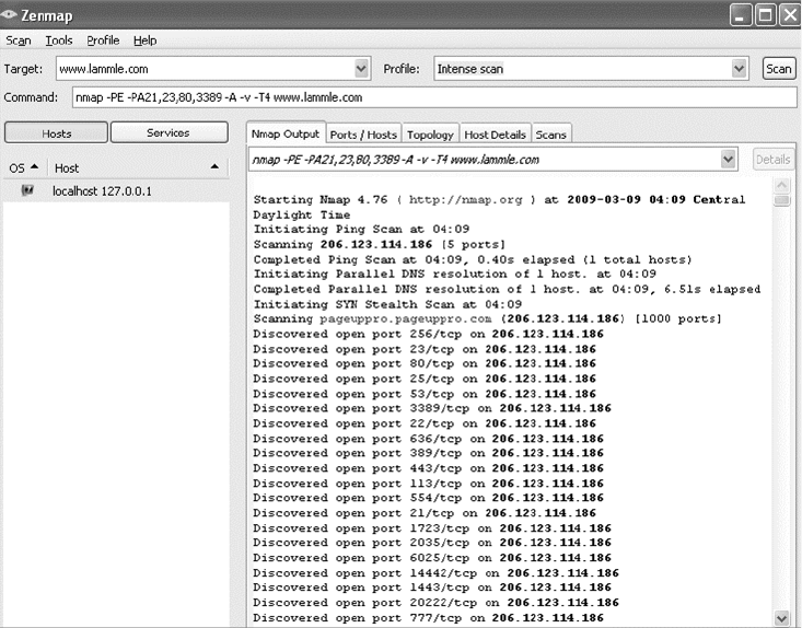
678
Chapter 18 ■ Software and Hardware Tools
c18.indd 04/01/2015 Page 678
Although a free program named Network Mapper (Nmap) can be used as a port
scanner, you can use it to do so much more. I give it two thumbs up and recommend that
you download Nmap (
http://nmap.org
) and play with this cool program.
Nmap, like Snort, is open source. But Nmap runs on all platforms and can provide
port-scanning ability, check all the open services running on each host, nd rewalls, and
even help tremendously with network management.
Figure 18.4 shows Nmap running on a Windows Vista platform, performing a Domain
Name Service (DNS) resolution, and then a port scan to the host being monitored (Zenmap
is the name of the GUI interface it uses). Pretty chill, right?
FIGURE 18.4 Nmap in action
Nmap is very exible, and again, I really encourage you to check it out. One of the
other nice features of Nmap is its documentation capacity. It comes with a complete set
of instructions and equips you with documentation to help you troubleshoot and map
your network.
Even though Nmap is pretty simple, there are even simpler tools out there—a whole lot
of them. Angry IP is a program I also use that provides both IP-scanning and port-scanning
abilities. It’s de nitely not as complex as Nmap, but because it’s extremely easy to use, you
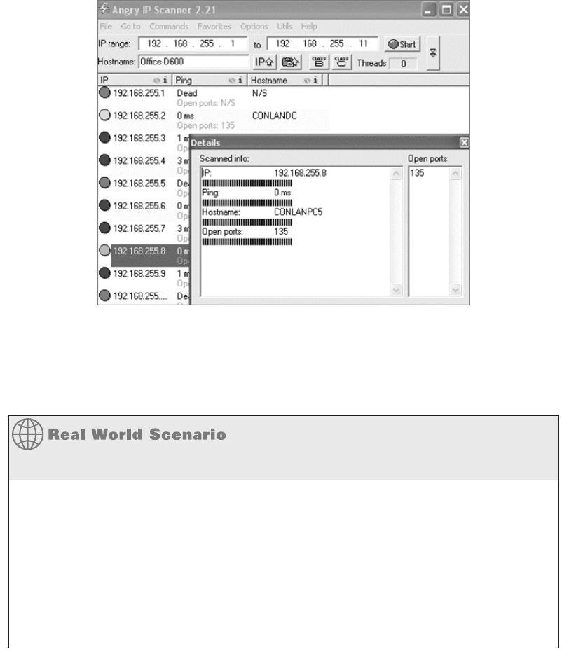
Understanding Network Scanners
679
c18.indd 04/01/2015 Page 679
might want to try out this free, open-source program as well. Figure 18.5 illustrates port
scanning with Angry IP.
FIGURE 18.5 Angry IP port scanning
You can see right away that this is a much simpler program than some of the other
snif ng and port mapping tools we’ve discussed, but simple doesn’t mean it isn’t powerful.
Angry IP slowed the PC I was scanning way down when I performed a full port scan on the
host using this program. Check it out at
http://angryip.org
.
Hacked and Blamed!
I’ve already mentioned that you shouldn’t port scan on hosts that are not yours, but you
need to be careful that someone else does not use your hosts or servers to port scan
someone else’s servers as well. A few years ago, I had a server at an ISP, and some
crackers had hacked into my server and were using it to port scan the Department of
Defense (DoD) servers. I received a letter from the DoD informing me of this issue. They
were very professional and even mentioned that it probably wasn’t me doing the port
scanning, but they said that if it happened again, they would prosecute me. They told
me that I was responsible for my server and that if I did not stop the attackers, I would
be liable.
continues

680
Chapter 18 ■ Software and Hardware Tools
c18.indd 04/01/2015 Page 680
I was terribly embarrassed, and I was a little freaked out, too! After looking at the server
logs, I realized that the crackers were from France and that they had been in my server
for three months. Instead of just locking down the ports and getting rid of the hackers,
I formatted the server. Why? Because crackers/hackers are notorious for creating many
backdoors once they are in a system, in case they get caught, so just locking them out
would not have solved the problem. If this happens to you, a reformat is typically what
you need to do. I also upgraded to the latest server operating system, which helped with
some of the security issues.
After you’ve downloaded all the software tools I just went over with you and practiced
honing your skills with them (only on your own network, right?), you’ll be ready to move
on and explore the hardware tools that you need to be familiar with to meet the CompTIA
Network+ objectives.
Wi-Fi Analyzer
A Wi-Fi analyzer, or wireless analyzer, is similar to the network analyzers that I’ve already
discussed but is used for snif ng wireless networks. Wi-Fi analyzers can nd the channels
in use, the amount of clients and bandwidth used, top talkers, and more. On wireless
LANs, one can capture traf c on a particular channel or on several channels when using
multiple adapters.
Wi-Fi analyzers identify networks by passively collecting packets and detecting standard
named networks, detecting (given time) hidden networks, and inferring the presence of
nonbeaconing networks via data traf c.
Figure 18.6 shows an output of a wireless analyzer.
In addition to using a wireless analyzer, to create a good wireless network, you need to
do a wireless survey of the oor or building where you are installing your network. To do
this, you need a wireless survey tool. Wireless survey tools help you design and deploy the
most accurate indoor and outdoor wireless LAN networks (802.11n/a/b/g/ac) correctly the
rst time and prevent costly rework and IT complaints.
You can collect real-world data by performing unique true end-user experience
measurements (wireless LAN throughput, data rates, retries, losses). You can also
minimize the (expensive) impact of RF interference sources on wireless 802.11n/a/b/g/
ac LAN performance by performing simultaneous wireless spectrum analysis in a single
walk-through.
In addition, you can certify the wireless network for any design/application require-
ments using customer-ready pass/fail assessment reports. Figure 18.7 shows an output of a
wireless survey tool.
continued
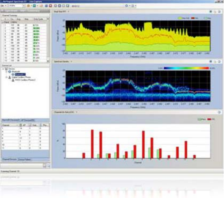
Baseline
681
c18.indd 04/01/2015 Page 681
FIGURE 18.6 Wireless analyzer
Baseline
High-quality documentation should include a baseline for network performance because
you and your client need to know what “normal” looks like in order to detect problems
before they develop into disasters. Don’t forget to verify that the network conforms
to all internal and external regulations and that you’ve developed and itemized solid
management procedures and security policies for future network administrators to refer
to and follow.
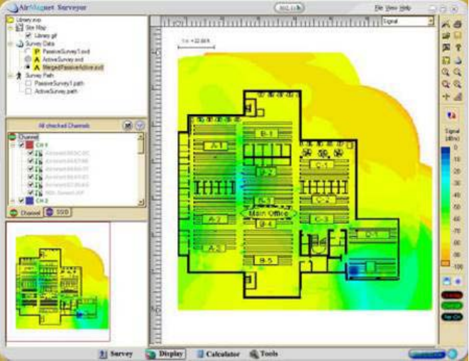
682
Chapter 18 ■ Software and Hardware Tools
c18.indd 04/01/2015 Page 682
FIGURE 18.7 Wireless survey tool
In networking, baseline can refer to the standard level of performance of a certain
device or to the normal operating capacity for your whole network. For instance, a speci c
server’s baseline describes norms for factors like how busy its processors are, how much of
the memory it uses, and how much data usually goes through the NIC at a given time.
A network baseline delimits the amount of bandwidth available and when. For networks
and networked devices, baselines include information about four key components:
■ Processor
■ Memory
■ Hard-disk (or other storage) subsystem
■ Wired/wireless utilization
After everything is up and running, it’s a good idea to establish performance baselines on
all vital devices and your network in general. To do this, measure things like network usage
at three different strategic times to get an accurate assessment. For instance, peak usage
usually happens around 8:00 a.m. Monday through Friday, or whenever most people log in
to the network in the morning. After hours or on weekends is often when usage is the lowest.
Knowing these values can help you troubleshoot bottlenecks or determine why certain system
resources are more limited than they should be. Knowing what your baseline is can even tell
you if someone’s complaints about the network running like a slug are really valid—nice!
Network Monitoring and Logging
683
c18.indd 04/01/2015 Page 683
It’s good to know that you can use network-monitoring software to establish baselines.
Even some server operating systems come with software to help with network monitoring,
which can help nd baselines, perform log management, and even do network graphing as
well so you can compare the logs and graphs at a later period of time on your network.
In my experience, it’s wise to re-baseline network performance at least once a year. And
always pinpoint new performance baselines after any major upgrade to your network’s
infrastructure.
Network Monitoring and Logging
There are a lot of ways to nd out what’s really going on within your network. Most
administrators opt to directly keep tabs on network performance by looking at important
factors like data rates and available bandwidth, using the many tools on the market
designed to help with that. Another good strategy for assessing a network’s health and
well-being is via the more indirect route of monitoring the logs that your server operating
systems keep. These can help you spot problems on your physical network as well as
services or applications that aren’t running properly and could eventually bring the network
or its resources down and make your users really unhappy.
Network Monitoring
Some key network-monitoring tools and diagnostic utilities around today are software
additions that run on an existing server operating system like Windows Server or Unix.
Others are stand-alone hardware devices that you plug into your network, but both are
basically the packet sniffers we talked about back in Chapter 14. Although it’s true that
hackers can and do use sniffers to capture network traf c and gather data for an attack, we
make good use of them too. And strange but true, being a bit of a hacker yourself can make
you a much better sys admin—knowing your enemies and their methods can help you nd
the same holes they would use for evil, and you can use that knowledge to plug security
holes and even optimize your network’s performance.
Packet sniffers allow you to examine network traf c down to details of individual
packets. You can put the packet’s header under the microscope: It contains vital informa-
tion about the protocol being used to encapsulate it, plus the source and destination IP
addresses. This is super-valuable information—if I’m seeing the speed of traf c on a speci c
segment grind to a crawl, one of rst the things I’ll look for is one IP address that’s spewing
tons of data. If that’s the case, it could mean that I’ve got a failing network adapter because
a common symptom of a dying NIC is to become extremely “chatty” by sending out broad-
cast packets and clogging things to the point that legitimate traf c can’t get through. It’s
like getting a deluge of junk mail and being forced to read every last bit of it; a broadcast
packet is technically addressed to everyone, meaning that all the other NICs on the segment
have to stop and read what’s in it—not so good.

684
Chapter 18 ■ Software and Hardware Tools
c18.indd 04/01/2015 Page 684
Good news—routers are, by default, configured to prevent broadcasts
from going from one segment to another. Most switches sold today
are also able to prevent broadcasts from spreading to multiple network
segments, but not by default.
When you hear people refer to things like load testing, connectivity testing, and
throughput testing, they’re really talking about network monitoring. You’ll also hear
network monitors referred to as protocol analyzers. Microsoft has a graphical utility called
Network Monitor that can be used to capture network traf c. The current version is 3.4,
and it’s supported by Windows Vista, Windows 7/8, Server 2003/2008/2012. You can
download it from Microsoft’s website, but for it to work, your network adapter must be
able to work in promiscuous mode (yes, you read that right!). Several third parties special-
ize in producing network monitors, such as, for example, Fluke Networks, which makes
some cool tools like the OptiView Network Analyzer.
SNMP
Although Simple Network Management Protocol (SNMP) certainly isn’t the oldest
protocol ever, it’s still pretty old, considering it was created way back in 1988 (RFC 1065)!
SNMP is an Application layer protocol that provides a message format for agents on
a variety of devices to communicate with network management stations (NMSs)—for
example, Cisco Prime or HP Openview. These agents send messages to the NMS station,
which then either reads or writes information in the database, stored on the NMS, that’s
called a Management Information Base (MIB).
The NMS periodically queries or polls the SNMP agent on a device to gather and
analyze statistics via GET messages. These messages can be sent to a console or alert you
via email or SMS. The command
snmpwalk
uses the SNMP GETNEXT request to query a
network for a tree of information.
End devices running SNMP agents would send an SNMP trap to the NMS if a problem
occurs. This is demonstrated in Figure 18.8.
FIGURE 18.8 SNMP GET and TRAP messages
GET
Reply
Gi0/1
NMS
Check interface status!
Router
Gi0/1
My interface Gi0/1 went down!
It’s the end of the world!
HELP!
NMS
Router
TRAP!
Network Monitoring and Logging
685
c18.indd 04/01/2015 Page 685
Admins can also use SNMP to provide some con guration to agents as well, called SET mes-
sages. In addition to polling to obtain statistics, SNMP can be used for analyzing information
and compiling the results in a report or even a graph. Thresholds can be used to trigger a noti -
cation process when exceeded. Graphing tools are used to monitor the CPU statistics of devices
like a core router. The CPU should be monitored continuously, and the NMS can graph the sta-
tistics. Noti cation will be sent when any threshold you’ve set has been exceeded.
SNMP has three versions, with version 1 being rarely, if ever, implemented today. Here’s
a summary of these three versions:
SNMPv1 Supports plaintext authentication with community strings and uses only UDP.
SNMPv2c Supports plaintext authentication with MD5 or SHA with no encryption but
provides GET BULK, which is a way to gather many types of information at once and mini-
mize the number of GET requests. It offers a more detailed error message reporting method,
but it’s not more secure than v1. It uses UDP even though it can be con gured to use TCP.
SNMPv3 Supports strong authentication with MD5 or SHA, providing con dentiality
(encryption) and data integrity of messages via DES or DES-256 encryption between agents
and managers. GET BULK is a supported feature of SNMPv3, and this version also uses TCP.
Syslog
Reading system messages from a switch’s or router’s internal buffer is the most popular and
ef cient method of seeing what’s going on with your network at a particular time. But the
best way is to log messages to a syslog server, which stores messages from you and can even
time-stamp and sequence them for you, and it’s easy to set up and con gure! Figure 18.9
shows a syslog server and client in action.
FIGURE 18.9 Syslog server and client
I want to look at the console messages
of the SF router from last night.
Syslog server
SF
Syslog allows you to display, sort, and even search messages, all of which makes it a
really great troubleshooting tool. The search feature is especially powerful because you
can use keywords and even severity levels. Plus, the server can email admins based on the
severity level of the message.
Network devices can be con gured to generate a syslog message and forward it to various
destinations. These four examples are popular ways to gather messages from Cisco devices:
■ Logging buffer (on by default)
■ Console line (on by default)

686
Chapter 18 ■ Software and Hardware Tools
c18.indd 04/01/2015 Page 686
■ Terminal lines (using the
terminal monitor
command)
■ Syslog server
As you already know, all system messages and debug output generated by the IOS go out
only the console port by default and are also logged in buffers in RAM. And you also know
that routers aren’t exactly shy about sending messages! To send message to the VTY lines,
use the
terminal monitor
command.
So, by default, we’d see something like this on our console line:
*Oct 21 17:33:50.565:%LINK-5-CHANGED:Interface FastEthernet0/0, changed
state to administratively down
*Oct 21 17:33:51.565:%LINEPROTO-5-UPDOWN:Line protocol on Interface
FastEthernet0/0, changed state to down
And the router would send a general version of the message to the syslog server that
would be formatted something like this:
Seq no:timestamp: %facility-severity-MNEMONIC:description
The system message format can be broken down in this way:
seq no
This stamp logs messages with a sequence number, but not by default. If you want
this output, you’ve got to con gure it.
timestamp
Date and time of the message or event.
facility
The facility to which the message refers.
severity
A single-digit code from 0 to 7 that indicates the severity of the message.
MNEMONIC
Text string that uniquely describes the message.
description
Text string containing detailed information about the event being reported.
The severity levels, from the most severe level to the least severe, are explained in Table 18.1.
Informational is the default and will result in all messages being sent to the buffers and console.
TABLE 18.1 Severity levels
Severity Level Explanation
Emergency (severity 0) System is unusable.
Alert (severity 1) Immediate action is needed.
Critical (severity 2) Critical condition.
Error (severity 3) Error condition.
Warning (severity 4) Warning condition.

Network Monitoring and Logging
687
c18.indd 04/01/2015 Page 687
Severity Level Explanation
Notification (severity 5) Normal but significant condition.
Information (severity 6) Normal information message.
Debugging (severity 7) Debugging message.
If you are studying for your CompTIA Network+ exam, you need to
memorize Table 18.1.
Understand that only emergency-level messages will be displayed if you’ve con gured
severity level 0. But if, for example, you opt for level 4 instead, level 0 through 4 will be
displayed, giving you emergency, alert, critical, error, and warning messages, too. Level 7
is the highest-level security option and displays everything, but be warned that going with
it could have a serious impact on the performance of your device. So always use debugging
commands carefully with an eye on the messages you really need to meet your speci c
business requirements!
SIEM
Security information and event management (SIEM) is a term for software products and
services combining security information management (SIM) and security event manage-
ment (SEM). SIEM technology provides real-time analysis of security alerts generated by
network hardware and applications. You can get this as a software solution or a hard-
ware appliance, and some businesses sell managed services using SIEM. Any one of these
solutions provides log security data and can generate reports for compliance purposes.
The acronyms SEM, SIM, and SIEM are used interchangeably; however, SEM is
typically used to describe the management that deals with real-time monitoring and
correlation of events, noti cations, and console views.
The term SIM is used to describe long-term storage, analysis, and reporting of log data.
Recently, vSIEM (voice security information and event management) was introduced to
provide voice data visibility.
SIEM can collect useful data about the following items:
■Data aggregation
■ Correlation
■Alerting
■ Dashboards

688
Chapter 18 ■ Software and Hardware Tools
c18.indd 04/01/2015 Page 688
■ Compliance
■ Retention
■ Forensic analysis
Speed Test Sites
Speed test sites are especially helpful for testing the bandwidth of your Internet connection.
I typically use Speakeasy’s Speed Test, but just search for speed tests, or DSL speed tests,
and you’ll get a whole host of speed test sites.
Figure 18.10 shows the speed test site that I use.
FIGURE 18.10 Speakeasy Speed Test
Looking Glass Sites
You can access a Looking Glass (LG) server remotely to view routing information. They
are servers on the Internet that run Looking Glass software that is available to the public.
The servers are essentially read-only portals to the router belonging to the organizations
running them. They are basically just providing a ping or traceroute from a remote
location for you.
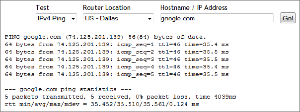
Network Monitoring and Logging
689
c18.indd 04/01/2015 Page 689
Figure 18.11 shows an output from a Looking Glass server.
FIGURE 18.11 Looking Glass site output
Server Logs
Windows Server 2003 and 2008 (and most other Windows operating systems) come with
a tool called Event Viewer that provides you with several logs containing vital information
about events happening on your computer. Other server operating systems have similar
logs, and many connectivity devices like routers and switches also have graphical logs that
gather statistics on what’s happening to them. These logs can go by various names, like
history logs, general logs, or server logs. Figure 18.12 shows an Event Viewer system log
display from a Windows Server 2003 machine.
On Windows servers, a minimum of three separate logs hold different types of
information:
Application Contains events triggered by applications or programs determined by their
programmers. Example applications include LiveUpdate, the Microsoft Of ce suite, and
SQL and Exchange servers.
Security Contains security events like valid or invalid logon attempts and potential
security problems.
System Contains events generated by Windows system components, including drivers and
services that started or failed to start.
The basic “Big Three” can give us lots of juicy information about who’s logging on,
who’s accessing the computer, and which services are running properly (or not). If you
want to nd out whether your Dynamic Host Con guration Protocol (DHCP) server
started up its DHCP service properly, just check out its system log. Because the com-
puter depicted in Figure 18.12 is con gured as a domain controller, its Event Viewer
serves up three more logs: Directory Service, DNS Server, and File Replication Service,
for a total of six.
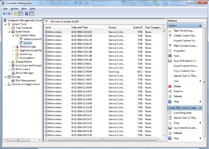
690
Chapter 18 ■ Software and Hardware Tools
c18.indd 04/01/2015 Page 690
FIGURE 18.12 Windows Event Viewer system log
Windows 2000 Server and Windows Server 2003 came with System Monitor—another
graphical tool used to create network baselines, provide performance logs, and identify
bottlenecks. Windows Server 2008 R2 offers an optional new monitoring and optimization
tool called System Center Operations Manager 2010.
Utilization
Wired and wireless analyzers can show you the bandwidth used on your network segments
or wireless area. There are tools to help you nd the stats on storage, network device CPU,
and device memory for your servers and hosts.
For example, if you have a MAC, you can use the built-in activity monitor, which
provides the CPU usage, memory statistics, energy used by the applications, disk usage,
and network bytes sent and received, as shown in Figure 18.13.
In addition to utilization information for your hosts, servers, networks, and so on, you
need information about the wireless channel utilization on your network. To get it, you
need to use a wireless analyzer, which I’ve already discussed.
The wireless analyzer in Figure 18.14 is showing channel utilization. Notice that three
channels—1, 6, and 11—are in use.
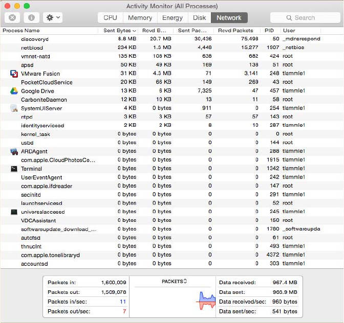
Identifying Hardware Tools
691
c18.indd 04/01/2015 Page 691
FIGURE 18.13 MAC’s Activity Monitor
Identifying Hardware Tools
A great example of when the hardware tools and testers I’m about to cover would come
in really handy is if you’re dealing with failed ber links between structures. As a system
administrator running a network with a server, routers, and switches, it’s entirely possible
you’ll never nd yourself in a situation that calls for these tools. But if you’re in network
design or a eld that requires installing cabling, then these hardware tools are going to be
really valuable to you. Unlike the software tools we just talked about, none of these goodies
are free, but they do come in a variety of avors that run the gamut from real bargains to
“You’re joking—how much?” Some of them can indeed free you of thousands of dollars!
Cable testers are the most widely used hardware tool in today’s LANs, so let’s start
with them.
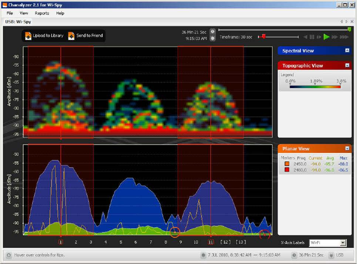
692
Chapter 18 ■ Software and Hardware Tools
c18.indd 04/01/2015 Page 692
FIGURE 18.14 Wireless channel utilization
Cable Testers
The best way to deal with a faulty cable installation is to avoid the problem in the rst
place by purchasing high-quality components and installing them carefully. Still, this isn’t
a perfect world—no matter how careful you are, problems are bound to arise anyway.
The tools that I’m going to cover can be used to test cables at the time of their installa-
tion and afterward, if and when you need to troubleshoot cabling problems. Cable-testing
tools can range from simple, inexpensive mechanical devices to elaborate electronic
testers that automatically supply you with a litany of test results in an easy-to-read pass/
fail format. Figure 18.15 shows an example of an inexpensive cable tester for twisted-pair
wiring testing.
This little box can verify the connection through the cable and tell you if the cable
is straight-through or crossover. It can also identify problems such as grounding issues.
Sometimes the problem is not a complete lack of connectivity. Sometimes performance is
slow, which can also be a cabling issue that a cable tester can identify. This tool is as cheap
as they come.
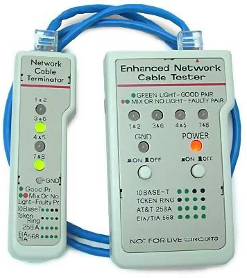
Identifying Hardware Tools
693
c18.indd 04/01/2015 Page 693
FIGURE 18.15 An inexpensive cable tester
Let’s focus on the types of tools available for both copper and ber-optic cable testing.
This is not to say that you need all of the tools listed here. In fact, I’ll try to steer you away
from certain types of tools. Sometimes you’ll get lucky and have the luxury of choosing
between high-tech and low-tech devices that perform roughly the same function. You
can choose which ones you prefer according to the requirements of your network, your
operational budget, even your temperament and time constraints. Some of the tools are
extremely complicated and require extensive training to use effectively, whereas others can
be used by pretty much anybody equipped with a functioning brain.
Other important considerations to keep in mind when selecting the types of tools you
need are based on the descriptions of cable tests given earlier in this chapter, the test results
required by the standards you’re using to certify your network, and the capabilities of the
people who will be doing the actual work. And don’t forget the potentially painful cost of
some of them.
Loopback Plug
A loopback test is a diagnostic procedure in which a signal is transmitted and returned
to the sending device after passing through all or a portion of a network or circuit. The
returned signal is compared with the transmitted signal to evaluate the integrity of the
equipment or transmission path. A computer needs a loopback plug that is inserted into a
port in order to perform a loopback test.
Loopback plugs are made for both Ethernet and ber applications. Figure 18.16 shows
an Ethernet loopback plug and Figure 18.17 shows a plug for ber applications.
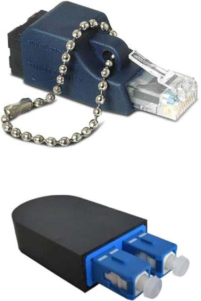
694
Chapter 18 ■ Software and Hardware Tools
c18.indd 04/01/2015 Page 694
FIGURE 18.16 Ethernet loopback plug
FIGURE 18.17 Fiber loopback plug
Wire-Map Testers
A wire-map tester is a device that transmits signals through each wire in a copper twisted-pair
cable to determine if it’s connected to the correct pin at the other end. Wire mapping is the most
basic test for twisted-pair cables because the eight separate wire connections involved in each
cable run are a common source of installation errors. Wire-map testers detect transposed wires,
opens (broken or unconnected wires), and shorts (wires or pins improperly connected to each
other). All of these problems can render a cable run completely inoperable.
Wire-map testing is nearly always included in multifunction cable testers, but sometimes
it’s just not worth spending serious cash on a comprehensive device. Dedicated wire-map
testers that run about two to three hundred bucks are relatively inexpensive options that
enable you to test your installation for the most common faults that occur during installa-
tions and afterward. If, say, you’re installing voice-grade cable, a simple wire-mapping test
is probably all that’s needed.
A wire-map tester essentially consists of a remote unit that you attach to the far end of a
connection and a battery-operated, handheld main unit that displays the results. Typically,

Identifying Hardware Tools
695
c18.indd 04/01/2015 Page 695
the tester displays various codes that indicate the speci c type of fault that it nds. You can
also purchase a tester with multiple remote units that are numbered so that one person can
test several connections without constantly traveling back and forth from one end of the
connections to the other to move the remote unit.
The one wiring fault that is not detectable by a dedicated wire-map tester
is something known as split pairs. This fault flies under the radar because
even though the pinouts are incorrect, the cable is still wired straight
through. To detect split pairs, you must use a device that tests the cable for
the near-end crosstalk that split pairs cause.
Continuity Testers
A continuity tester, or line tester, is an even simpler and less-expensive device than a
wire-map tester; it’s designed to check a copper cable connection for basic installation
problems like opens, shorts, and crossed pairs. It will set you back only a few dollars, but
such a device usually can’t detect the more complicated twisted-pair wiring faults. It’s still
a nice option for basic cable testing, especially for coaxial cables that have only two
conductors and so don’t easily confuse whoever is installing them.
Like a wire-map tester, a continuity tester consists of two separate units that you
connect to each end of the cable you want to test. Most of the time, the two units can snap
together for storage and easy testing of patch cables. But remember, a continuity tester
simply tests continuity, equivalent to data at one bit per minute (or slower), and cannot tell
you whether or not a cable will reliably pass Ethernet data at network speeds. For that, you
need a real cable tester that can test cables up to Gigabit speeds or higher.
Protocol Analyzer
A protocol analyzer is often confused with a packet sniffer because some products really
are both. Remember—a packet sniffer looks at all traf c on a network segment. On the
other hand, a protocol analyzer (surprise!) analyzes protocols. These tools come in both
software and hardware versions, but compared to the products I listed earlier in this chap-
ter, a network protocol analyzer is likely to give you more information and help than a
sniffer will. This is because a bona de protocol analyzer can actually help you troubleshoot
problems, whereas most sniffers just provide information for you to have a ball deciphering.
A network protocol analyzer can perform the following functions:
■ Help troubleshoot hard-to-solve problems
■ Help you detect and identify malicious software (malware)
■ Help gather information such as baseline traffic patterns and network-utilization metrics
■ Help you identify unused protocols so that you can remove them from the network
■ Provide a traffic generator for penetration testing
■ Possibly even work with an IDS

696
Chapter 18 ■ Software and Hardware Tools
c18.indd 04/01/2015 Page 696
And last, and perhaps most important for you, they can really help you learn about
networking in general. This means if you just want to nd out why a network device is
functioning in a certain way, you can use a protocol analyzer to sniff (there’s that word
again) the traf c and expose the data and protocols that pass along the wire.
Free Network Analyzers
I’ve found a whole bunch of network analyzers you can use for free at the following
location:
www.snapfiles.com/freeware/network/fwpacketsniffer.html
But understand that there’s no way I can verify the validity of this link after this book
is published. Again, the terms sniffer and analyzer are used to defi ne the same prod-
uct found at this link. Both Microsoft’s NetMon and Wireshark are called sniffers and
analyzers, and they both are—at least to some degree.
Certifiers
Certi cation testers—or certi ers—are used to determine whether your network meets
speci c International Organization for Standardization (ISO) or Telecommunication
Industry Association (TIA) standards (Cat 5e, Cat 6, or Cat 7). They are the only option
for you in this case. Also, if your network is wired with both copper and ber, you really
must use a certi cation tester.
Basically, a certi er is a combination cable tester and network analyzer, only better
because it comes with more options. This is wonderful because it makes your job easier
and makes you seem smarter to everyone around you—you’re only as good as your tools,
right? A good certi er will test the performance and response times of network resources
like web, le, email, and even DNS and Dynamic Host Con guration Protocol (DHCP)
servers. And, at the same time, it will certify your full Category 6 cable installation. After
it nishes all this, you can provide your boss with a detailed network test report complete
with dazzling, colorful graphics to make it simple to explain and understand—voilà! You’re
instantly the genius of the day.
To get these smarts, all you need is a lot of money. These products are not for the small
of ce, home of ce (SOHO) market because they cost literally thousands of dollars, starting
at about $5,000.
Time-Domain Reflectometer
A time-domain re ectometer (TDR) is a tool that nds and describes faults in metallic
cables like twisted wire pairs and coaxial cables. The equivalent device for optical ber is
an optical time-domain re ectometer (OTDR), which I’ll talk about in a minute.
Identifying Hardware Tools
697
c18.indd 04/01/2015 Page 697
A TDR works in the same basic way that radar does. It transmits a short rise time
pulse along the conductor, and if it turns out to be of a uniform impedance and properly
terminated, the entire transmitted pulse is absorbed in the far-end termination; no signal
is re ected back to the TDR. Any impedance interruptions will cause some of the incident
signal to be sent back toward the source, letting you know all is not well.
So basically, any increases in the impedance create a re ection that reinforces the
original pulse and decreases the impedance, thereby creating a re ection that opposes the
original pulse. The resulting re ected pulse that’s measured at the output/input to the TDR
is displayed or plotted in measures of time. And because the speed of signal propagation
is pretty consistent for a given type of transmission medium, the reading can also tell you
about the cable length.
Because of this sensitivity to any variation in impedance, you can use a TDR to verify
these things:
■ Speed and condition of the cable
■ How long it takes to send a signal down a cable and how long it takes to come back
■ Cable impedance characteristics
■ Splice and connector locations and their associated loss amounts
■ Estimated cable lengths
Now, let’s take a look at a device that tests ber-optic cables.
Optical Time-Domain Reflectometer
An optical time-domain re ectometer (OTDR) is an optoelectronic instrument used
to give you the skinny on optical bers, typically referred to as light meters. It works by
putting out a series of optical pulses into the speci c ber you want to test. From the same
end that sent these impulses, it collects and measures the light that is scattered and re ected
along the length of the ber. It then records the change in the amount of refraction at
various points. This is a lot like the way an electronic TDR measures re ections caused
by impedance changes in a cable that you’re testing. The strength of the return pulses is
incorporated into a measure of time, which also conveniently gives you the ber’s length.
We use OTDRs to give us the following information:
■ The fiber’s estimated length
■ Its overall attenuation, including splice and mated-connector losses
■ The location faults, such as breaks
Figure 18.18 shows the output from an OTDR testing a ber connection.
The spike shows where a splice in the ber is located, which has resulted in the signal
being degraded. This is a very typical output. As the signal attenuates, you see a gradual
but quick drop in decibels (db). Any connector will actually show a re ection, which, as
mentioned, shows up as a spike in the OTDR output. The connector then creates more
attenuation and loss of more db. The more splices, the less distance you can run with ber.

698
Chapter 18 ■ Software and Hardware Tools
c18.indd 04/01/2015 Page 698
FIGURE 18.18 Sample OTDR output
Attenuation
Connector Reflection
Splice Loss
Multimeter
A multimeter, or a multitester (also called a volt/ohm meter [VOM]), is a multitasking
electronic measuring instrument. Your average multimeter typically includes features like
the ability to measure voltage, current, and resistance. Multimeters come in analog and
digital versions, and they range from basic handheld devices useful for simple fault- nding
and eld-service work to more complex bench instruments that will give you measurements
with a very high degree of accuracy.
They can be used to troubleshoot electrical problems in a wide array of electrical devices
like batteries, motor controls, appliances, power supplies, and wiring systems. Figure 18.19
shows the multimeter that I use to help troubleshoot my networks.
Multimeters come in lots of avors with different ranges of features and prices.
Cheap ones cost less than 10 bucks, but the top-of-the-line models can set you back up to
5 thousand.
Toner Probe
A toner probe, also called a tone generator, is a simple copper cable tester that is simple to
use and can be used to trace a wire in a wall. It is a two-piece unit that’s basically a tone
generator and probe, sometimes called a “fox and hound” wire tracer. This type of device
consists of one part that you connect to a cable with a standard jack—or to an individual
wire with alligator clips that transmit a signal over the cable or wire—and another part
that’s a penlike probe that emits an audible tone when it touches the other end of the cable,
the wire, or even its insulating sheath.

Identifying Hardware Tools
699
c18.indd 04/01/2015 Page 699
FIGURE 18.19 A multimeter
Most often, you will use a toner probe to locate a speci c connection in a punch-down
block because (annoyingly) some installers run all the cables for a network to the central
punch-down block without labeling them. They (or you, if you’re unlucky enough) then
have to use a tone generator to identify which block is connected to which wall plate and
label the punch-down block accordingly. This tool can identify a particular cable at any
point between the two ends, and because the probe can detect the cable containing the
tone signal through its sheath, it can help you to locate one speci c cable out of a massive
cable-spaghetti bundle in a ceiling conduit or other type of raceway.
Just connect the tone generator to one end, and touch the probe to each cable in the
bundle until you hear the tone. Figure 18.20 shows a picture of my toner and the probe
I use to nd the tone on the other end of the cable.
Also, by testing the continuity of individual wires using alligator clips, you can use
a tone generator and probe to nd opens, shorts, and miswires. An open wire won’t
produce a tone at the other end, a short will produce a tone on two or more wires at the
other end, and an improperly connected wire will produce a tone on the wrong pin at
the other end.
Sound like fun to you? Well, not so much—it takes a really long time, and it’s super
tedious. Worse, the whole process is almost as prone to errors as the cable installation
itself. You have to either continually travel from one end of the cable to the other to move
the tone generator unit or use a partner to test each connection, keeping in close contact
using radios or some other means of communication to avoid confusion. So, considering
the time and effort involved, investing in a wire-map tester is just a much more practical
solution unless you’re numbingly bored or really easily amused.

700
Chapter 18 ■ Software and Hardware Tools
c18.indd 04/01/2015 Page 700
FIGURE 18.20 A toner probe
Butt Set
A butt set is essentially a portable telephone that allows you to test analog wet or dry lines
and is used to monitor those lines. The most common type, shown in Figure 18.21, can
both monitor and transmit.
FIGURE 18.21 A butt set
You see these all the time with telco guys up on the telephone poles. They use their butt
sets to connect to telephone lines, test them, and even make phone calls.
Another handy tool that will take the place of a butt set is a hound. This noncanine
device is nothing more than an inductively coupled ampli er with a small speaker in a
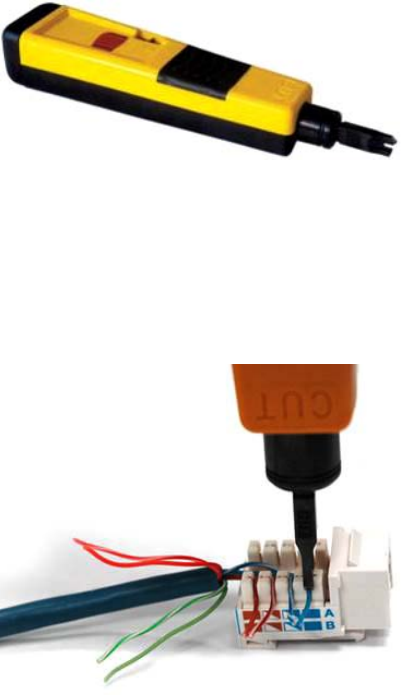
Identifying Hardware Tools
701
c18.indd 04/01/2015 Page 701
handheld tool. It’s used to monitor the audio on a given line to verify that you have the right
pair before connecting it and typically is used with a toner probe. It will also monitor for noise.
Punch-Down Tool
Most networks today are built using twisted-pair cable of some sort. This cable is usually
terminated in wiring closets using a tool known as a punch-down tool. It’s called that
because that’s exactly what the tool does—punch down the wire into some kind of insula-
tion displacement connector (IDC).
There are different types of punch-down tools. The most common is a punch down with
replaceable blades for the different types of connectors (either 66 or 110). Figure 18.22
shows an example of this type of punch-down tool.
FIGURE 18.22 An example of a punch-down tool
IDCs make contact by cutting through, or displacing, the insulation around a single
conductor inside a twisted-pair cable.
As shown in Figure 18.23, the punch-down tool pushes a conductor between the sides
of a V inside an IDC, in this example a keystone connector, allowing the small metal blade
inside the connector to make contact with the inner conductor deep inside the wire.
FIGURE 18.23 Using a punch-down tool on a small keystone connector
Now let’s take a look at how to put a cable end together.

702
Chapter 18 ■ Software and Hardware Tools
c18.indd 04/01/2015 Page 702
Cable Stripper/Snips
A wire crimper, often simply called a crimper, is a handy tool found in most network
technicians’ tool bags. Crimpers are primarily used for attaching ends onto different types
of network cables via a process known as—that’s right—crimping. Crimping involves using
your hands to apply a certain amount of force to press some kind of metal teeth into the inner
conductors of a cable. Before you can crimp a connector onto the end, you’ve got to strip the
cable with a type of cable stripper (or snip) and then properly put the wires into the connector.
Figure 18.24 shows what a cable stripper and snip looks like (this particular tool also
includes a crimper).
FIGURE 18.24 A combination cable stripper, crimper, and snippers
Often, network technicians will make patch cables with a crimper. They’ll take a small
piece of Category 5e unshielded twisted-pair (UTP), strip the cable, and crimp two RJ-45
ends onto it to create the cable. Snips will create the type of cable needed to connect a host
to a wall jack connection, for example. There are strippers and crimpers for the other types
of cable as well—even specialized crimpers for ber-optic ends.
Voltage Event Recorder (Power)
Alternating current (AC) is basically the food that PCs and other network devices require in
speci c amounts to function properly. In the United States, it’s normally 110 volts and changes
polarity 60 cycles a second (60 hertz). These values are referred to as line voltage. Any devia-
tion from these values can create some major problems for your PC or other electronics—like
death. While we’re on the subject, you should also know that when a telephone rings, the phone
company central of ce puts 140 VAC on the line to ring that bell; telephone lines are not always
the “low-voltage” devices we think they are. Do all phone systems do this, even PBX systems
within buildings? Are you willing to bet your life that they don’t? Didn’t think so.
This is why we have surge protectors. These little saviors use a special electronic circuit
that monitors the incoming voltage level and trips a circuit breaker when the voltage level
Identifying Hardware Tools
703
c18.indd 04/01/2015 Page 703
reaches critical mass, which is known as the overvoltage threshold. Even though having
a surge protector is de nitely better than nothing, they too can fall victim to overvoltage
events—I’m reminded of a friend whose home was struck by lightning during a thunder-
storm and he found his surge protectors literally melted into the carpet! But they’re still
cool because even though they’re really only somewhat protective, they are multiple-outlet
strips that give us a lot more places to plug in our stuff.
By contrast, a quality voltage event recorder can troubleshoot and even provide
preventative maintenance on your entire electrical system, whether it’s for a home or a huge
factory. Although they do big things, they’re typically small devices that just plug into a
wall and record, over time, the power quality of a given circuit. You would typically use a
voltage event recorder for the following applications:
Recording Voltage The voltage event recorder monitors and records the supply voltage
and checks whether the socket outlet is providing voltage within speci cations.
Measuring Distortion The device measures frequency and harmonics, and it checks
whether your uninterruptible power supply (UPS) system is functioning correctly.
Measuring Flicker It checks the switching loads on lighting systems.
Capturing Voltage Transients It can help you nd intermittent, momentary events that may be
affecting your equipment; the full waveform is captured with date, time stamp, and duration.
But you still have to do more to ensure the vitality of your electronic devices because
they’re very sensitive to temperature as well. This means you also need a way to monitor
the temperature of the place(s) where your equipment is stored.
Environmental Monitors
Environmental monitors are designed to monitor the temperature, humidity, power, and
air ow in an area or in a device. Temperature and humidity are both critical factors in the
health of computing equipment. High temperatures lead to CPU overheating, and shortly
thereafter, systems start rebooting.
High humidity cannot be tolerated because it leads to corrosion of electrical parts
followed by shorts and other failures. Low humidity sounds good on paper, but with it
comes static electricity buildup in the air, which can fry computer parts if it reaches them.
Both of these conditions should be monitored.
A temperature and humidity monitor can save you and your precious devices from
a total meltdown. By their very nature, networks often include lots of machines placed
close together in one or several location(s)—like server rooms. Clearly, these devices, all
humming along at once, generate quite a bit of heat.
Just like us, electronics need to “breathe,” and they’re also pretty sensitive to
becoming overheated, which is why you’ll often need a jacket in a chilly server room. It’s
also why we need to set up and use temperature-monitoring devices. Twenty years ago or
so, these devices didn’t send alerts or give off any kind of alarms; they were just little plas-
tic boxes that had pieces of round graph paper to graph temperature. The paper was good
for a month, and for that duration, it would just spin around in a circle. As the temperature
moved up or down, the pen attached to the temperature coil moved in or out, leaving a
704
Chapter 18 ■ Software and Hardware Tools
c18.indd 04/01/2015 Page 704
circle line around the paper. All of this allowed you to manually monitor the temperature
modulation in the server room over time. Although intended to “alert” you when and if
there were climate changes, it usually did so after the fact, and therefore, too late.
Today, these temperature/humidity systems can provide multiple sensors feeding data
to a single control point—nice. Now we can much more accurately track the temperature
in our server rooms dynamically in real time. The central control point is usually equipped
with HTTP software that can send alerts and provide alarms via a browser should your
server room experience a warming event.
Temperature/humidity monitors also come in a variety of avors. They vary in size and
cost and come in hardware and/or software varieties. The kind you need varies and is based
on the size of the room and the number of devices in it. You can even get one that will just
monitor your PC’s internal heat.
What else will indicate you have a temperature problem in your server room? When you
install new servers in a rack and you have network instability and other issues across all the
servers in the rack but the power resources and bandwidth have been tested, this would be
a good time to check your temperature monitor and verify that the servers are staying cool
enough. Another red ag when it comes to environmental issues is a problem that occurs
every day at the same time. This could be the time of day when the room temperature
reaches the problematic stage.
Summary
You need network tools, and you need to know how to use them. And as I said, you can get
your hands on many of them for free; so download them and use them as soon as possible
to get the experience you’ll need to pass the CompTIA Network+ exam.
This chapter covered network scanners, including packet sniffers, IDS and IPS software,
and port scanners. I also covered hardware tools, which are rarely free. The good news is
that you don’t need many of them yourself, but the company that owns all the equipment
de nitely does. Even though I’ve used all of the tools I talked about in this chapter, I don’t
own most of them personally—only the ones that are free or relatively inexpensive.
In the hardware tools section, I covered cable testers, analyzers, certi ers, TDR/OTDRs,
and other critical tools that help you test the cables and devices in your network, monitor
them, and keep them up and running smoothly.
Exam Essentials
Understand what network scanners are and how to use each one. Network scanners are
described as packet sniffers, IDS/IPS software, and port scanners. These devices can help
you both troubleshoot and x your network as well as nd and stop hackers in their tracks.
Written Lab
705
c18.indd 04/01/2015 Page 705
Remember the basic purpose of a packet sniffer. The basic purpose of packet sniffers or
network analyzers is to collect and analyze each individual packet that is captured on a
speci c network segment to determine if problems are happening.
Remember the main purpose of IDS/IPS software. The IDS detects unwanted attempts to
manipulate network systems and/or environment, and the IPS is a computer security device
that monitors network and/or system activities for malicious behavior and can react in real
time to stop attacks.
Understand what an OTDR is used for. An optical time-domain re ectometer (OTDR)
is an optoelectronic instrument used to test ber-optic cabling. You can learn the cable’s
estimated length and attenuation (loss in db) and the location of faults.
Understand the difference between cable testers and certifiers. Cable testers simply
tell you if the cable will function. Cable certi ers run much more sophisticated tests that
determine if the cable performs according to speci cations called for in the standard.
Understand the value of temperature and humidity monitors. These devices can monitor
environmental conditions and alert you if either the temperature or the humidity in a server
room or area falls below or rises above the prescribed range of safe values.
Written Lab
You can nd the answers in Appendix A. Answer the following questions about software
and hardware tools:
1. True/False: An IDS box can find and fix a problem as the attack occurs.
2. True/False: A TDR is used to test fiber connections.
3. True/False: An IDS box will report an attack but not fix it.
4. True/False: An OTDR is used to test fiber connections.
5. True/False: A network analyzer will see every packet on every segment of your network at
the same time.
6. What type of device determines if a cable meets standards specifications?
7. True/False: It is okay to scan the DoD network servers with a port scanner.
8. You need to monitor the temperature of your server room. What device should you use?
9. You want to monitor your UPS systems and make sure they are functioning correctly.
What device should you use?
10. What type of device is used to put an RJ-45 end on a Cat 5e cable?
706
Chapter 18 ■ Software and Hardware Tools
c18.indd 04/01/2015 Page 706
Review Questions
You can nd the answers to the review questions in Appendix B.
1. Which is a tool in the network scanner category? (Choose all that apply.)
A. Packet sniffers
B. IDS/IPS software
C. Port scanners
D. None of the above
2. What is the purpose of packet sniffers?
A. Discarding frames
B. Sending transmissions from one port to another port
C. Looking inside every packet on a network segment
D. Stopping malicious behavior on the network
3. You need to trace cables in multiple-pair wiring. What tool will you use?
A. Toner probe
B. IDS
C. Cable tester
D. Butt set
4. What tool would you use to both find a break in a fiber-optic connection and test the fiber
connectivity on the network?
A. Multimeter
B. OTDR
C. Butt set
D. Toner probe
5. You need to create a cable that will connect your host to a wall jack connection. Which of
the following will you use?
A. IDS/IPS
B. Snips
C. Coax cable strippers
D. Multimeter
6. Where is the IDS/IPS software typically placed within a network?
A. Between the internal router and the firewall connected to the ISP
B. Between the printer and the router connected to the ISP
Review Questions
707
c18.indd 04/01/2015 Page 707
C. Between the computer and the switch configured with VLANs
D. Between the firewall and the router connected to the email server
7. What is the purpose of a port scanner?
A. Scan UDP for closed ports
B. Sweep TCP for closed ports
C. Search the network host for open ports
D. None of the above
8. What is the purpose of wire-map testers?
A. Check copper cable for crossed pairs only
B. Analyze protocols in software
C. Help find unused protocols and remove them from the network
D. Detect transposed wires, opens, and shorts in twisted-pair cables
9. Which of the following can check the speed and condition of the signal on a cable, measure
the time it takes to send a signal down the wire and back, and find the exact location of
a break?
A. Multimeter
B. TDR
C. Tone generator
D. Event recorder
10. Which device should be used if you need to determine whether your network meets ISO or
TIA standards?
A. Angry IP
B. Certifiers
C. Nmap
D. Routing table
11. Which software tool is used to view network traffic at the frame level?
A. TDR
B. Multimeter
C. Port scanner
D. Packet sniffer
12. Which of the following options is not a function of a TDR?
A. Estimate cable lengths
B. Find splice and connector locations and their associated loss amounts
C. Display unused services
D. Determine cable-impedance characteristics
E. Send a signal down a cable and measure how long it takes to come back
708
Chapter 18 ■ Software and Hardware Tools
c18.indd 04/01/2015 Page 708
13. Which device would be used to measure voltage?
A. Multimeter
B. OTDR
C. Butt set
D. Toner probe
14. Which device would most likely be used to locate a specific connection in an unlabeled
punch-down block?
A. VOM
B. Certifier
C. TDR
D. Toner probe
15. Which tool would be used to connect wire between two punch-down block blades?
A. Punch-down tool
B. Crimper
C. Snips
D. Strippers
16. Which tool is used to attach an RJ-45 connector to a Cat 5 cable?
A. Punch-down tool
B. Crimper
C. Snips
D. Strippers
17. On which of the following would a technician use a punch-down tool?
A. RJ-45 connector
B. CSU/DSU
C. 110 block
D. Fiber ST connector
18. Which device monitors incoming voltage levels and overvoltage thresholds?
A. Repeater
B. Toner probe
C. VOM
D. Surge protector
19. Which of the following tools can test a port on a device?
A. Cable certifier
B. Loopback plug
Review Questions
709
c18.indd 04/01/2015 Page 709
C. Butt set
D. Toner probe
20. You install new switches in your server room and are now experiencing network instability
and other issues across all servers in the rack. Which device would be used to alert you of a
system overheating?
A. Voltage event recorder
B. Temperature monitor
C. Surge protector
D. Probe

c19.indd 04/01/2015 Page 711
Chapter
19
Network
Troubleshooting
THE FOLLOWING COMPTIA NETWORK+
EXAM OBJECTIVES ARE COVERED IN
THIS CHAPTER:
✓ 4.1 Given a scenario, implement the following network
troubleshooting methodology
■ Identify the problem
■ Gather information
■ Duplicate the problem, if possible
■ Question users
■ Identify symptoms
■ Determine if anything has changed
■ Approach multiple problems individually
■ Establish a theory of probable cause
■ Question the obvious
■ Consider multiple approaches
■ Top-to-bottom/bottom-to-top OSI model
■ Divide and conquer
■ Test the theory to determine cause
■ Once theory is confirmed, determine next steps to
resolve problem
■ If theory is not confirmed, re-establish new theory
or escalate
■ Establish a plan of action to resolve the problem and identify
potential effects
■ Implement the solution or escalate as necessary

c19.indd 04/01/2015 Page 712
■ Verify full system functionality and if applicable implement
preventative measures
■ Document findings, actions, and outcomes
✓ 4.3 Given a scenario, troubleshoot and resolve common
wireless issues
■ Signal loss
■ Interference
■ Overlapping channels
■ Mismatched channels
■ Signal-to-noise ratio
■ Device saturation
■ Bandwidth saturation
■ Untested updates
■ Wrong SSID
■ Power levels
■ Wrong antenna type
■ Incompatibilities
■ Wrong encryption
■ Bounce
■ Environmental factors
■ Concrete walls
■ Window film
■ Metal studs
■ Wireless standard related issues
■ Throughput
■ Frequency
■ Distance
■ Channels

c19.indd 04/01/2015 Page 713
✓ 4.4 Given a scenario, troubleshoot and resolve common
copper cable issues
■ Shorts
■ Opens
■ Incorrect termination (mismatched standards)
■ Straight-through
■ Crossover
■ Cross-talk
■ Near end
■ Far end
■ EMI/RFI
■ Distance limitations
■ Attenuation/Db loss
■ Bad connector
■ Bad wiring
■ Split pairs
■ Tx/Rx reverse
■ Cable placement
■ Bad SFP/GBIC - cable or transceiver
✓ 4.5 Given a scenario, troubleshoot and resolve common
fiber cable issues
■ Attenuation/Db loss
■ SFP/GBIC - cable mismatch
■ Bad SFP/GBIC - cable or transceiver
■ Wavelength mismatch
■ Fiber type mismatch
■ Dirty connectors
■ Connector mismatch
■ Bend radius limitations
■ Distance limitations

c19.indd 04/01/2015 Page 714
✓ 4.6 Given a scenario, troubleshoot and resolve common
network issues
■ Incorrect IP configuration/default gateway
■ Broadcast storms/switching loop
■ Duplicate IP
■ Speed and duplex mismatch
■ End-to-end connectivity
■ Incorrect VLAN assignment
■ Hardware failure
■ Misconfigured DHCP
■ Misconfigured DNS
■ Incorrect interface/interface misconfiguration
■ Cable placement
■ Interface errors
■ Simultaneous wired/wireless connections
■ Discovering neighboring devices/nodes
■ Power failure/power anomalies
■ MTU/MTU black hole
■ Missing IP routes
■ NIC teaming misconfiguration
■ Active-active vs active-passive
■ Multicast vs broadcast

c19.indd 04/01/2015 Page 715
There is no way around it. Troubleshooting computers and
networks is a combination of art and science, and the only
way to get really good at it is by doing it—a lot! So it’s
practice, practice, and practice with the basic yet vitally important skills you’ll attain in
this chapter. Of course, I’m going to cover all the troubleshooting topics you’ll need to sail
through the Network+ exam, but I’m also going to add some juicy bits of knowledge that
will really help you to tackle the task of troubleshooting successfully in the real world.
First, you’ll learn to check quickly for problems in the “super simple stuff” category,
and then we’ll move into a hearty discussion about a common troubleshooting model
that you can use like a checklist to go through and solve a surprising number of network
problems. We’ll nish the chapter with a good brie ng about some common troubleshoot-
ing resources, tools, tips, and tricks to keep up your sleeve and equip you even further.
I won’t be covering any new networking information in this chapter because you’ve gotten
all the foundational background material you need for troubleshooting in the previous
chapters. But no worries. I’ll go through each of the issues described in this chapter’s
objectives, one at a time, in detail, so that even if you’ve still got a bit of that previous
material to nail down yet, you’ll be good to get going and x some networks anyway.
To find up-to-the-minute updates for this chapter, please see
www.lammle.
com/networkplus
or the book’s website at
www.sybextestbanks.wiley.com
.
Narrowing Down the Problem
When initially faced with a network problem in its entirety, it’s easy to get totally
overwhelmed. That’s why it’s a great strategy to start by narrowing things down to the
source of the problem. To help you achieve that goal, it’s always wise to ask the right
questions. You can begin doing just that with this list of questions to ask yourself:
■ Did you check the super simple stuff (SSS)?
■ Is hardware or software causing the problem?
■ Is it a workstation or server problem?
■ Which segments of the network are affected?
■ Can you test the network from end to end to confirm connectivity?
■ Are there any cabling issues?
716
Chapter 19 ■ Network Troubleshooting
c19.indd 04/01/2015 Page 716
Did You Check the Super Simple Stuff?
Yes—it sounds like a snake’s hiss (appropriate for a problem, right?), but exactly what’s on
the SSS list that you should be checking rst, and why? Well, as the saying goes, “All things
being equal, the simplest explanation is probably the correct one,” so you probably won’t
be stunned and amazed when I tell you that I’ve had people call me in and act like the sky
is falling when all they needed to do was check to make sure their workstation was plugged
in or powered on. (I didn’t say “super simple stuff” for nothing!) Your SSS list really does
include things that are this obvious—sometimes so obvious no one thinks to check for
them. Even though anyone experienced in networking has their own favorite “DUH”
events to tell about, almost everyone can agree on a few things that should de nitely be on
the SSS list:
■ Check to ensure login procedures and rights.
■ Look for link lights and collision lights.
■ Check all power switches, cords, and adapters.
■ Look for user errors.
The Correct Login Procedure and Rights
You know by now that if you’ve set up everything correctly, your network’s users absolutely
have to follow the proper login procedure to the letter (or number, or symbol) in order to
successfully gain access to the network resources they’re after. If they don’t do that, they
will be denied access, and considering that there are truly tons of opportunities to blow
it, it’s a miracle, or at least very special, that anyone manages to log in to the network
correctly at all.
Think about it. First, a user must enter their username and password awlessly. Sounds
easy, but as they say, “in a perfect world. . .” In this one, people mess up, don’t realize it,
and freak out at you about the “broken network” or the imaginary IT demon that changed
their password on them while they went to lunch and now they can’t log in. (The latter
could be true—you may have done exactly that. If you did, just gently remind them about
that memo you sent about the upcoming password-change date and time that they must
have spaced about due to the tremendous demands on them.)
Anyway, it’s true. By far, the most common problem is bad typing—people acciden-
tally enter the wrong username or password, and they do that a lot. With some operat-
ing systems, a slight brush of the Caps Lock key is all it takes: The user’s username and
password are case sensitive, and suddenly, they’re trying to log in with what’s now all in
uppercase instead—oops.
Plus, if you happen to be running one of the shiny new operating systems around today,
you can also restrict the times and conditions under which users can log in, right? So, if
your user spent an unusual amount of time in the bathroom upon returning from lunch, or
if they got distracted and tried to log in from their BFF’s workstation instead of their own,
the network’s operating system would’ve rejected their login request even though they still
can type impressively well after two martinis.
Narrowing Down the Problem
717
c19.indd 04/01/2015 Page 717
And remember—you can also restrict how many times a user can log in to the network
simultaneously. If you’ve set that up, and your user tries to establish more connections than
you’ve allowed, access will again be denied. Just know that most of the time, if a user is
denied access to the network and/or its resources, they’re probably going to interpret that
as a network problem even though the network operating system is doing what it should.
Can the Problem Be Reproduced?
The fi rst question to ask anyone who reports a network or computer problem is, “Can
you show me what ‘not working’ looks like?” This is because if you can reproduce the
problem, you can identify when it happens, which may give you all the information you
need to determine the source of the problem and maybe even solve it in a snap.
The hardest problems to solve are those of the random variety that occur intermittently
and can’t be easily reproduced.
Let’s pause for a minute to outline the steps to take during any user-oriented network
problem-solving process:
1. Make sure the username and password is being entered correctly.
2. Check that Caps Lock key.
3. Try to log in yourself from another workstation, assuming that doing this doesn’t
violate the security policy. If it works, go back to the user-oriented login problems,
and go through them again.
4. If none of this solves the problem, check the network documentation to find out
whether any of the aforementioned kinds of restrictions are in place; if so, find out
whether the user has violated any of them.
Remember, if intruder detection is enabled on your network, a user will get
locked out of their account after a specific number of unsuccessful login
attempts. If this happens, either they’ll have to wait until a predetermined
time period has elapsed before their account will unlock and give them
another chance or you’ll have to go in and manually unlock it for them.
The Link and Collision Lights
The link light is that little light-emitting diode (LED) found on both the Network Interface
Card (NIC) and the switch. It’s typically green and labeled Link or some abbreviation of
that. If you’re running 100BaseT, a link light indicates that the NIC and switch are making
a logical (Data Link layer) connection. If the link lights are lit up on both the workstation’s

718
Chapter 19 ■ Network Troubleshooting
c19.indd 04/01/2015 Page 718
NIC and the switch port to which the workstation is connected, it’s usually safe to assume
that the workstation and switch are communicating just ne.
The link lights on some NICs don’t activate until the driver is loaded. So, if
the link light isn’t on when the system is first turned on, you’ll just have to
wait until the operating system loads the NIC driver. But don’t wait forever!
The collision light is also a small LED, but it’s typically amber in color, and it can
usually be found on both Ethernet NICs and hubs. When lit, it indicates that an Ethernet
collision has occurred. If you’ve got a busy Ethernet network on which collisions are
somewhat common, understand that this light is likely to blink occasionally; if it stays on
continuously, though, it could mean that there are way too many collisions happening for
legitimate network traf c to get through. Don’t assume this is really what’s happening
without rst checking that the NIC, or other network device, is working properly because
one or both could simply be malfunctioning.
Don’t confuse the collision light with the network-activity or network-traffic
light (which is usually green) because the latter just indicates that a
device is transmitting. This particular light should be blinking on and off
continually as the device transmits and receives data on the network.
The Power Switch
Clearly, to function properly, all computer and network components must be turned on and
powered up rst. Obvious, yes, but if I had a buck for each time I’ve heard, “My computer
is on, but my monitor is all dark,” I’d be rolling in money by now.
When this kind of thing happens, just keep your cool and politely ask, “Is the
monitor turned on?” After a little pause, the person calling for help will usually say,
“Ohhh. . .ummmm. . .thanks,” and then hang up ASAP. The reason I said to be nice is that,
embarrassing as it is, this, or something like it, will probably happen to you, too, eventually.
Most systems include a power indicator (a Power or PWR light). The power switch
typically has an On indicator, but the system or device could still be powerless if all the
relevant power cables aren’t actually plugged in—including the power strip.
Remember that every cable has two ends, and both must be plugged into
something. If you’re thinking something like, “Sheesh—a four-year-old
knows that,” you’re probably right. But again, I can’t count the times this
has turned out to be the root cause of a “major system failure.”
The best way to go about troubleshooting power problems is to start with the most
obvious device and work your way back to the power-service panel. There could be a

Narrowing Down the Problem
719
c19.indd 04/01/2015 Page 719
number of power issues between the device and the service panel, including a bad power
cable, bad outlet, bad electrical wire, tripped circuit breaker, or blown fuse, and any
of these things could be the actual cause of the problem that appears to be
device-death instead.
Operator Error
Or, the problem may be that you’ve got a user who simply doesn’t know how to be one.
Maybe you’re dealing with someone who doesn’t have the tiniest clue about the equipment
they’re using or about how to perform a certain task correctly—in other words, the
problem may be due to something known as operator error (OE). Here’s a short list of the
most common types of OEs and their associated acronyms:
■ Equipment exceeds operator capability (EEOC)
■ Problem exists between chair and keyboard (PEBCAK)
■ ID Ten T error (an ID10T)
A word of caution here, though—assuming that all your problems are user related can
quickly make an ID10T error out of you.
Although it can be really tempting to take the easy way out and blow things off,
remember that the network’s well-being and security are ultimately your responsibility. So,
before you jump to the operator-error conclusion, ask the user in question to reproduce the
problem in your presence, and pay close attention to what they do. Understand that doing
this can require a great deal of patience, but it’s worth your time and effort if you can
prevent someone who doesn’t know what they’re doing from causing serious harm to pricey
devices or leaving a gaping hole in your security. You might even save the help desk crew’s
sanity from the relentless calls of a user with the bad habit of ipping off the power switch
without following proper shutdown procedures. You just wouldn’t know they always do
that if you didn’t see it for yourself, right?
And what about nding out that that pesky user was, in fact, trained really badly by
someone and that they aren’t the only one? This is exactly the kind of thing that can turn
the best security policy to dust and leave your network and its resources as vulnerable to
attack as that goat in Jurassic Park.
The moral here is, always check out the problem thoroughly. If the problem and its
solution aren’t immediately clear to you, try the procedure yourself, or ask someone else at
another workstation to do so. Don’t just leave the issue unsettled or make the assumption
that it is user error or a chance abnormality because that’s exactly what the bad guys out
there are hoping you’ll do.
This is only a partial list of super simple stuff. No worries. Rest assured
you’ll come up with your own expanded version over time.

720
Chapter 19 ■ Network Troubleshooting
c19.indd 04/01/2015 Page 720
Is Hardware or Software Causing the Problem?
A hardware problem often rears its ugly head when some device in your computer skips a
beat and/or dies. This one’s pretty easy to discern because when you try to do something
requiring that particular piece of hardware, you can’t do it and instead get an error telling
you that you can’t do it. Even if your hard disk fails, you’ll probably get warning signs
before it actually kicks, like a Disk I/O error or something similar.
Other problems drop out of the sky and hit you like something from the wrong end of a
seagull. No warning at all—just splat! Components that were humming along ne a second
ago can and do suddenly fail, usually at the worst possible time, leaving you with a mess of
lost data, les, everything—you get the idea.
Solutions to hardware problems usually involve one of three things:
■ Changing hardware settings
■ Updating device drivers
■ Replacing dead hardware
If your hardware has truly failed, it’s time to get out your tools and start replacing
components. If this isn’t one of your skills, you can either send the device out for repair or
replace it. Your mantra here is “backup, backup, backup,” because in either case, a system
could be down for a while—anywhere from an hour to several days—so it’s always good to
keep backup hardware around. And I know everyone and your momma has told you this,
but here it is one more time: Back up all data, les, hard drive, everything, and do so on a
regular basis.
Software problems are muddier waters. Sometimes you’ll get General Protection Fault
messages, which indicate a Windows or Windows program (or other platform) error of
some type, and other times the program you’re working in will suddenly stop responding
and hang. At their worst, they’ll cause your machine to randomly lock up on you. When
this type of thing happens, I’d recommend visiting the manufacturer’s support website to
get software updates and patches or searching for the answer in a knowledge base.
Sometimes you get lucky and the ailing software will tell the truth by giving you a
precise message about the source of the problem. Messages saying the software is missing
a le or a le has become corrupt are great because you can usually get your problem xed
fast by providing that missing le or by reinstalling the software. Neither solution takes
very long, but the downside is that whatever you were doing before the program hosed will
probably be at least partially lost; so again, back up your stuff, and save your data often.
Please reread Chapter 17, “Troubleshooting Tools,” and Chapter 18,
“ Software and Hardware Tools,” and use the software and hardware tools
discussed in those two chapters to help you troubleshoot network problems.
It’s time for you to learn how to troubleshoot your workstations and servers.
Narrowing Down the Problem
721
c19.indd 04/01/2015 Page 721
Is It a Workstation or a Server Problem?
The rst thing you’ve got to determine when troubleshooting this kind of problem is
whether it’s only one person or a whole group that’s been affected. If the answer is only
one person (think, a single workstation), solving the issue will be pretty straightforward.
More than that, and your problem probably involves a chunk of the network, like a
segment. A clue that the source of your grief is the latter case is if there’s a whole bunch
of users complaining that they can’t discover neighboring devices/nodes.
So either way, what do you do about it? Well, if it’s the single-user situation, your rst
line of defense is to try to log in from another workstation within the same group of users.
If you can do that, the problem is de nitely the user’s workstation, so look for things like
cabling faults, a bad NIC, power issues, and OSs.
But if a whole department can’t access a speci c server, take a good, hard look at that
particular server, and start by checking all user connections to it. If everyone is logged in
correctly, the problem may have something to do with individual rights or permissions.
If no one can log in to that server, including you, the server probably has a communication
problem with the rest of the network. And if the server has totally crashed, either you’ll see
messages telling you all about it on the server’s monitor or you’ll nd its screen completely
blank—screaming indicators that the server is no longer running. And keep in mind that
these symptoms do vary among network operating systems.
Which Segments of the Network Are Affected?
Figuring this one out can be a little tough. If multiple segments are affected, you may be
dealing with a network-address con ict. If you’re running Transmission Control Protocol/
Internet Protocol (TCP/IP), remember that IP addresses must be unique across an entire
network. So, if two of your segments have the same static IP subnet addresses assigned,
you’ll end up with duplicate IP errors—an ugly situation that can be a real bear to
troubleshoot and can make it tough to nd the source of the problem.
If all of your network’s users are experiencing the problem, it could be a server everyone
accesses. Thank the powers that be if you nail it down to that because if not, other
network devices like your main router or hub may be down, making network transmissions
impossible and usually meaning a lot more work on your part to x.
Adding wide area network (WAN) connections to the mix can complicate matters
exponentially, and you don’t want to go there if you can avoid it, so start by nding out if
stations on both sides of a WAN link can communicate. If so, get the champagne—your
problem isn’t related to the WAN—woo hoo! But if those stations can’t communicate, it’s
not a happy thing: You’ve got to check everything between the sending station and the
receiving one, including the WAN hardware, to nd the culprit. The good news is that most
of the time, WAN devices have built-in diagnostics that tell you whether a WAN link is
working okay, which really helps you determine if the failure has something to do with the
WAN link itself or with the hardware involved instead.
722
Chapter 19 ■ Network Troubleshooting
c19.indd 04/01/2015 Page 722
Is It Bad Cabling?
Back to hooking up correctly. . .Once you’ve gured out whether your plight is related
to one workstation, a network segment, or the whole tamale (network), you must then
examine the relevant cabling. Are the cables properly connected to the correct port? More
than once, I’ve seen a Digital Subscriber Line (DSL) modem connection to the wall cabled
all wrong—it’s an easy mistake to make and an easy one to x.
And you know that nothing lasts forever, so check those patch cables running between
a workstation and a wall jack. Just because they don’t come with expiration dates written
on them doesn’t mean they don’t expire. They do go bad—especially if they get moved,
trampled, or tripped over a lot. (I did tell you that it’s a bad idea to run cabling across the
of ce oor, didn’t I?) Connection problems are the tell here—if you check the NIC and
there is no link light blinking, you may have a bad patch cable to blame.
It gets murkier if your cable in the walls or ceiling is toast or hasn’t been installed
correctly. Maybe you’ve got a user or two telling you the place is haunted because they
only have problems with their workstations after dark when the lights go on. Haunted?
No. . .some genius probably ran a network cable over a uorescent light, which is something
that just happens to produce lots of electromagnetic interference (EMI),
which can really mess up communications in that cable.
Next on your list is to check the medium dependent interface/medium dependent
interface-crossover (MDI/MDI-X) port setting on small, workgroup hubs and switches.
This is a potential source of trouble that’s often overlooked, but it’s important because this
port is the one that’s used to uplink to a switch on the network’s backbone.
First, understand that the port setting has to be set to either MDI or MDI-X depending
on the type of cable used for your hub-to-hub or switch-to-switch connection. For instance,
the crossover cables I talked about way back in Chapter 3, “Networking Topologies,
Connectors, and Wiring Standards,” require that the port be set to MDI, and a standard
network patch cable requires that the port be set to MDI-X. You can usually adjust the
setting via a regular switch or a dual inline package (DIP) switch, but to be sure, if you’re
still using hubs, check out the hub’s documentation. (You did keep that, right?)
Other Important Cable Issues You Need to Know About
They may be basic, but they’re still vital—an understanding of the physical issues that
can happen on a network when a user is connected via cable (usually Ethernet) is critical
information to have in your troubleshooting repertoire.
Because many of today’s networks still consist of large amounts of copper cable, they
suffer from the same physical issues that have plagued networking since the very beginning.
Newer technologies and protocols have helped to a degree, but they haven’t made these
issues a thing of the past yet. Some physical issues that still affect networks are listed and
de ned next:
Incorrect Termination/Bad Wiring/Bad Connector The rst things to check when
working on cabling are the cable connectors to make sure they haven’t gone bad.
After that, look to make sure the wiring is correct on both ends by physically checking
Narrowing Down the Problem
723
c19.indd 04/01/2015 Page 723
the cable pinouts. Important to remember is that if you have two switches, you need a
crossover cable where you cross pins 1 and 2 with 3 and 6. On the other hand, if you have
a PC going into a switch, you need a straight-through cable where pins 1 and 2 correspond-
ingly connect to pins 1 and 2 on each side—the same with 3 and 6. Finally, make sure the
termination pins on both ends are the correct type for the kind of cable you’re using.
Crosstalk Again, looking back to Chapter 3, remember that crosstalk is what happens
when there’s signal bleed between two adjacent wires that are carrying a current. Network
designers minimize crosstalk inside network cables by twisting the wire pairs together,
putting them at a 90-degree angle to each other. The tighter the wires are twisted, the less
crosstalk you have, and newer cables like Cat 6 cable really make a difference. But like
I said, not completely—crosstalk still exists and affects communications, especially in
high-speed networks.
Near-End/Far-End Crosstalk Near-end crosstalk is a speci c type of crosstalk
measurement that has to do with the EMI bled from a wire to adjoining wires where the
current originates. This particular point has the strongest potential to create crosstalk
issues because the crosstalk signal itself degrades as it moves down the wire. If you have
a problem with it, it’s probably going to show up in the rst part of the wire where it’s
connected to a switch or a NIC. Far-end crosstalk is the interference between two pairs of
a cable measured at the far end of the cable with respect to the interfering transmitter.
Attenuation/DB Loss/Distance Limitation As a signal moves through any medium,
the medium itself will degrade the signal—a phenomenon known as attenuation that’s
common in all kinds of networks. True, signals traversing ber-optic cable don’t attenu-
ate as fast as those on copper cable, but they still do eventually. You know that all copper
twisted-pair cables have a maximum segment distance of 100 meters before they’ll need
to be ampli ed, or repeated, by a hub or a switch, but single-mode ber-optic cables can
sometimes carry signals for miles before they begin to attenuate (degrade). If you need to
go big, use ber, not copper. Although there is attenuation/Db loss in ber, it can go much
further distances than copper cabling can before being affected by attenuation.
Collisions A network collision happens when two devices try to communicate on the
same physical segment at the same time. Collisions like this were a big problem in the early
Ethernet networks, and a tool known as Carrier Sense Multiple Access with Collision
Detection (CSMA/CD) was used to detect and respond to them in Ethernet_II. Nowadays,
we use switches in place of hubs because they can separate the network into multiple
collision domains, learn the Media Access Control (MAC) addresses of the devices attached
to them, create a type of permanent virtual circuit between all network devices, and
prevent collisions.
Shorts Basically, a short circuit, or short, happens when the current ows through a
different path within a circuit than it’s supposed to; in networks, they’re usually caused by
some type of physical fault in the cable. You can nd shorts with circuit-testing equipment,
but because sooner is better when it comes to getting a network back up and running,
replacing the ailing cable until it can be xed (if it can be) is your best option.
724
Chapter 19 ■ Network Troubleshooting
c19.indd 04/01/2015 Page 724
Open Impedance Mismatch (echo) Open impedance on cable-testing equipment tells you
that the cable or wires connect into another cable and there is an impedance mismatch.
When that happens, some of the signal will bounce back in the direction it came from,
degrading the strength of the signal, which ultimately causes the link to fail.
Interference/Cable Placement EMI and radio frequency interference (RFI) occur when
signals interfere with the normal operation of electronic circuits. Computers happen to be
really sensitive to sources of this, such as TV and radio transmitters, which create a speci c
radio frequency as part of their transmission process. Two other common culprits are
two-way radios and cellular phones.
Your only way around this is to use shielded network cables like shielded twisted-pair
(STP) and coaxial cable (rare today), or to run EMI/RFI-immune but pricey fiber-optic
cable throughout your entire network.
Split Pairs A split pair is a wiring error where two connections that are supposed to be
connected using the two wires of a twisted pair are instead connected using two wires from
different pairs. Such wiring causes errors in high-rate data lines. If you buy your cables
precut, you won’t have this problem.
Tx/Rx Reverse When connecting from a PC type device into a switch, for the PC use pins
1 and 2 to transmit and 3 and 6 for receiving a digital signal. This means that the pins must
be reversed on the switch, using pins 1 and 2 for receive and 3 and 6 for transmitting the
digital signal. If your connection isn’t working, check the cable end pinouts.
Fiber Cable Issues
Fiber is de nitely the best kind of wiring to use for long-distance runs because it has the
least attenuation at long distances compared to copper. The bad news is that it’s also the
hardest to troubleshoot. Here are some common ber issues to be aware of.
SFP/GBIC (Cable Mismatch) The small form-factor pluggable (SFP) is a compact,
hot-pluggable transceiver used for networking and other types of equipment. It interfaces
a network device motherboard for a switch, router, media converter, or similar device
to a ber-optic or copper networking cable. Due to its smaller size, SFP obsolesces the
formerly ubiquitous gigabit interface converter (GBIC), so SFP is sometimes referred to as a
mini-GBIC. Always make sure you have the right cable for each type of connector type
and that they are not mismatched.
Bad SFP/GBIC (Cable or Transceiver) If your link is down, verify that your cable or
transceiver hasn’t gone bad. I covered the pricey equipment you need to get this done in
Chapter 18. It can provide exact locations of exactly where the problem has originated.
Wavelength Mismatch One of the more confusing terms used regarding ber networks is
wavelength. Though it sounds very complicated and scienti c, it’s actually just the term used
to de ne what we think of as the color of light. Wavelength mismatch occurs when two differ-
ent ber transmitters at each end of the cable are using either a longer or shorter wavelength.
This means you’ve got to make sure your transmitters match on both ends of the cable.
Narrowing Down the Problem
725
c19.indd 04/01/2015 Page 725
Fiber Type Mismatch Fiber type mismatches, at each of the transceivers, can cause
wavelength issues, massive attenuation, and Db loss.
Dirty Connectors It’s important to verify your connectors to make sure no dirt or dust
has corrupted the cable end. You need to polish your cable ends with a soft cloth, but do
not look into the cable if the other end is transmitting—it could damage your eyes!
Connector Mismatch Just because it ts doesn’t mean it works. Make sure you have
precisely the right connectors for each type of cable end or transceiver.
Bend Radius Limitations Fiber, whether it is made of glass or plastic, can break. You need
to make sure you understand the bend radius limitations of each type of ber you purchase
and that you don’t exceed the speci cations when installing ber in your rack.
Distance Limitations The pros of ber are that it’s completely immune to EMI and RFI,
and that it can transmit up to 40 kilometers—about 25 miles! Add some repeater stations
and you can go between continents. But all ber types aren’t created equally. For example,
single mode can perform at much greater distances than multi-mode can. And again, make
sure you have the right cable for the distance you’ll require to run your ber!
Unbounded Media Issues (Wireless)
Now let’s say your problem-ridden user is telling you they only use a wireless connection.
Well, you can de nitely take crosstalk and shorts off the list of suspects, but don’t get
excited because with wireless, you’ve got a whole new bunch of possible Physical layer
problems to sort through.
Wireless networks are really convenient for the user but not so much for administrators.
They can require a lot more con guration, and understand that with wireless networks,
you don’t just get to substitute one set of challenges for another—you pretty much add all
those fresh new issues on top of the wired challenges you already have on your plate.
The following list includes some of those new wireless challenges:
Interference Because wireless networks rely on radio waves to transmit signals, they’re
more subject to interference, even from other wireless devices like Bluetooth keyboards,
mice, or cell phones that are all close in frequency ranges. Any of these—even microwave
ovens!—can cause signal bleed that can slow down or prevent wireless communications.
Factors like the distance between a client and a wireless access point (WAP) and the stuff
between the two can also affect signal strength and even intensify the interference from
other signals. So, careful placement of that WAP is a must.
Device Saturation/Bandwidth Saturation Clearly it’s important to design and imple-
ment your wireless network correctly. Be sure to understand the number of hosts that
will be connecting to each AP that you’ll be installing. If you have too much device
saturation on an AP, it will result in low available bandwidth. Just think about when
you’re in a hotel and how slow the wireless is. This is directly due to device/bandwidth
saturation for each AP. And more APs don’t always solve the problem—you need to
design correctly!
726
Chapter 19 ■ Network Troubleshooting
c19.indd 04/01/2015 Page 726
Simultaneous Wired/Wireless Connections It’s not unusual to nd that a laptop today
will have both a wired and wireless connection at the same time. Typically this doesn’t
create a problem, but don’t think you get more bandwidth or better results because of it.
It’s possible that the con gurations can cause a problem, although that’s rare today.
For instance, if each provides a DNS server with a different address, it can cause name
resolution issues, or even default gateway issues. Most of the time, it just causes confusion
in your laptop, which will make it work harder to determine the correct DNS or default
gateway address to use. And it’s possible for the laptop to give up and stop communicat-
ing completely! Because of this, you need to remind the user to turn off their wireless when
they take it into their of ce and connect it to their dock.
Configurations Mistakes in the con guration of the wireless access point or wireless
router or inconsistencies between the settings on the AP and the stations can also be
the source of problems. The following list describes some of the main sources of
con guration problems.
Incorrect Encryption You know that wireless networks can use encryption to secure
their communications and that different encryption avors are used for wireless
networks, like Wired Equivalent Privacy (WEP) and Wi-Fi Protected Access 2 (WPA2)
with Advanced Encryption Standard (AES). To ensure the tightest security, con gure
your wireless networks with the highest encryption protocol that both the WAP and the
clients can support. Oh, and make sure the AP and its clients are con gured with the
same type of encryption. This is why it’s a good idea to disable security before trouble-
shooting client problems, because if the client can connect once you’ve done that, you
know you’re dealing with a security con guration error.
Incorrect, Overlapping, or Mismatched Channels Wireless networks use many
different frequencies within the 2.4GHz or 5GHz band, and I’ll bet you didn’t know
that these frequencies are sometimes combined to provide greater bandwidth for
the user. You actually do know about this—has anyone heard of something called a
channel? Well, that’s exactly what a channel is, and it’s also the reason some radio
stations come in better than others—they have more bandwidth because their chan-
nel has more combined frequencies. You also know what happens when the AP and the
client aren’t quite matching up. Have you ever hit the scan button on your car’s radio
and only kind of gotten a station’s static-ridden broadcast? That’s because the AP (radio
station) and the client (your car’s radio) aren’t quite on the same channel. Most of the
time, wireless networks use channel 1, 6, or 11, and because clients auto-con gure
themselves to any channel the AP is broadcasting on, it’s not usually a con guration
issue unless someone has forced a client onto an incorrect channel. Also, be sure not to
use the same channel on APs within the same area. Overlapping channels cause your
signal-to-noise ratio to drop because you’ll get a ton of interference and signal loss!
Incorrect Frequency/Incompatibilities So, setting the channel sets the frequency or
frequencies that wireless devices will use. But some devices, such as an AP running
802.11g/n, allow you to tweak those settings and choose a speci c frequency such as
2.4GHz or 5GHz. As with any relationship, it works best if things are mutual. So if you
Narrowing Down the Problem
727
c19.indd 04/01/2015 Page 727
do this on one device, you’ve got to con gure the same setting on all the devices with
which you want to communicate, or they won’t—they’ll argue, and you don’t want that.
Incorrect-channel and frequency-setting problems on a client are rare, but if you have
multiple APs and they’re in close proximity, you need to make sure they’re on different
channels/frequencies to avoid potential interference problems.
ESSID Mismatch When a wireless device comes up, it scans for Service Set Identi ers
(SSIDs) in its immediate area. These can be Basic Service Set Identi ers (BSSIDs) that
identify an individual access point or Extended Service Set Identi ers (ESSIDs) that
identify a set of APs. In your own wireless LAN, you clearly want the devices to nd
the ESSID that you’re broadcasting, which isn’t usually a problem: Your broadcast is
closer than the neighbor’s, so it should be stronger—unless you’re in an of ce building
or apartment complex that has lots of different APs assigned to lots of different ESSIDs
because they belong to lots of different tenants in the building. This can de nitely give
you some grief because it’s possible that your neighbor’s ESSID broadcast is stronger
than yours, depending on where the clients are in the building. So if a user reports that
they’re connected to an AP but still can’t access the resources they need or authenticate
to the network, you should verify that they are, in fact, connected to your ESSID and
not your neighbor’s. This is very typical in an open security wireless network. You can
generally just look at the information tool tip on the wireless software icon to nd this
out. However, you can easily solve this problem today by making the of ce SSID the
preferred network in the client software.
Wireless Standard Mismatch As you found out in Chapter 12, “Wireless Networking,”
wireless networks have many standards that have evolved over time, like 802.11a,
802.11b, 802.11g, and 802.11n. Standards continue to develop that make wireless
networks even faster and more powerful. The catch is that some of these standards are
backward compatible and others aren’t. For instance, most devices you buy today can be
set to 802.11a/b/g/n, which means they can be used to communicate with other devices
of all four standards. So, make sure the standards on the AP match the standards on the
client, or that they’re at least backward compatible. It’s either that or tell all your users
to buy new cards for their machines. Be sure to understand the throughput, frequency,
distance capabilities, and available channels for each standard you use.
Untested Updates It’s really important to push updates to the APs in your wireless
network, but not before you test them. Just like waiting for an update from Microsoft or
Apple to become available for weeks or months before you update, you need to wait for
the OS or patch updates for your AP. Then, you need to test the updates thoroughly on
your bench before pushing them to your live network.
Distance/Signal Strength/Power Levels Location, location, location. You’ve got only two
worries with this one: Your clients are either not far enough away or they’re too far from
the AP. If your AP doesn’t seem to have enough power to provide a connectivity point for
your clients, you can move it closer to them, increase the distance that the AP can transmit
by changing the type of antenna it uses, or you can use multiple APs connected to the same
switch or set of switches to solve the problem. If the power level or signal is too strong, and
728
Chapter 19 ■ Network Troubleshooting
c19.indd 04/01/2015 Page 728
it reaches out into the parking area or farther out to other buildings and businesses, place
the AP as close as possible to the center of the area it’s providing service for. And don’t
forget to verify that you’ve got the latest security features in place to keep bad guys from
authenticating to and using your network.
Latency When wireless users complain that the network is slow (latency) or that they are
losing their connection to applications during a session, it is usually a capacity or distance
issue. Remember, 802.11 is a shared medium, and as more users connect, all user through-
put goes down. If this becomes a constant problem as opposed to the occasional issue where
20 guys with laptops gather for a meeting every six months in the conference room, it may
be time to consider placing a second AP in the area. When you do this, place the second
AP on a different non-overlapping channel from the rst and make sure the second AP
uses the same SSID as the rst. In the 2.4 GHz frequency (802.11b and 802.11g), the three
non-overlapping channels are 1, 6, and 11. Now the traf c can be divided between them and
users will get better performance. It is also worth noting that when clients move away from
the AP, the data rate drops until at some point it is insuf cient to maintain the connection.
Bounce For a wireless network spanning large geographical distances, you can install
repeaters and re ectors to bounce a signal and boost it to cover about a mile. This can
be a good thing, but if you don’t tightly control signal bounce, you could end up with a
much bigger network than you wanted. To determine exactly how far and wide the signal
will bounce, make sure you conduct a thorough wireless site survey. However, bounce
can also refer to multipath issues, where the signal re ects off objectives and arrives at
the client degraded because it is arriving out of phase. The solution is pretty simple. APs
use two antennas that both sample the signal and use the strongest signal, and ignore the
out-of-phase signal. However, 802.11n takes advantage of multipath and can combine the
out-of-phase signals to increase the distance hosts can be from the AP.
Incorrect Antenna or Switch Placement Most of the time, the best place to put an AP and/or
its antenna is as close to the center of your wireless network as possible. But you can position
some antennas a distance from the AP and connect to it with a cable—a method used for a
lot of the outdoor installations around today. If you want to use multiple APs, you’ve also got
to be a little more sophisticated about deciding where to put them all; you can use third-party
tools like the packet sniffers Wireshark and AirMagnet on a laptop to survey the site and
establish how far your APs are actually transmitting. You can also hire a consultant to do
this for you—there are many companies that specialize in assisting organizations with their
wireless networks and the placement of antennas and APs. This is important because poor
placement can lead to interference and poor performance, or even no performance at all.
Environmental Factors It’s vital to understand your environmental factors when designing
and deploying your wireless network. Do you have concrete walls, window lm, or metal
studs in the walls? All of these will cause a degradation of DB or power level and result in
connectivity issues. Again—plan your wireless network carefully!
Now that you know all about the possible physical network horrors that can befall you
on a typical network, it’s a good time for you to memorize the troubleshooting steps that
you’ve got to know to ace the CompTIA Network+ exam.

Troubleshooting Steps
729
c19.indd 04/01/2015 Page 729
Troubleshooting Steps
In the Network+ troubleshooting model, there are seven steps you’ve got to have dialed in:
1. Identify the problem.
2. Establish a theory of probable cause.
3. Test the theory to determine cause.
4. Establish a plan of action to resolve the problem and identify potential effects.
5. Implement the solution or escalate as necessary.
6. Verify full system functionality, and if applicable, implement preventative measures.
7. Document findings, actions, and outcomes.
To get things off to a running start, let’s assume that the user has called you yet again,
but now they’re almost in tears because they can’t connect to the server on the intranet and
they also can’t get to the Internet. (By the way, this happens a lot, so pay attention—it’s
only a matter of time before it happens to you!)
Absolutely, positively make sure you memorize this seven-step trouble-
shooting process in the right order when studying for the Network+ exam!
Step 1: Identify the Problem
Before you can solve the problem, you’ve got to gure out what it is, right? Again, asking
the right questions can get you far along this path and really help clarify the situation.
Identifying the problem involves steps that together constitute information gathering.
Gather Information by Questioning Users
A good way to start is by asking the user the following questions:
■ Exactly which part of the Internet can’t you access? A particular website? A certain
address? A type of website? None of it at all?
■ Can you use your web browser?
■ Is it possible to duplicate the problem?
■ If the hitch has to do with an internal server to the company, ask the user if they can
ping the server and talk them through doing that.
■ Ask the user to try to telnet or FTP to an internal server to verify local network
connectivity; if they don’t know how, talk them through it.
■ If there are multiple complaints of problems occurring, look for the big stuff first, then
isolate and approach each problem individually.
730
Chapter 19 ■ Network Troubleshooting
c19.indd 04/01/2015 Page 730
Here’s another really common trouble ticket that just happens to build on the last
scenario: Now let’s say you’ve got a user who’s called you at the help desk. By asking the
previous questions, you found out that this user can’t access the corporate intranet or
get out to any sites on the Internet. You also established that the user can use their web
browser to access the corporate FTP site, but only by IP address, not by the FTP server
name. This information tells you two important things: that you can rule out the host and
the web browser (application) as the source of the problem and that the physical network
is working.
Determine If Anything Has Changed
Moving right along, if you can reproduce the problem, your next step is to verify what has
changed and how. Drawing on your knowledge of networking, you ask yourself and your
user questions like these:
Were you ever able to do this? If not, then maybe it just isn’t something the hardware or
software is designed to do. You should then tell the user exactly that, as well as advise them
that they may need additional hardware or software to pull off what they’re trying do.
If so, when did you become unable to do it? If, once upon a time, the computer was
able to do the job and then suddenly could not, whatever conditions surrounded and were
involved in this turn of events become extremely important. You have a really good shot
at unearthing the root of the problem if you know what happened right before things
changed. Just know that there’s a high level of probability that the cause of the problem is
directly related to the conditions surrounding the change when it occurred.
Has anything changed since the last time you could do this? This question can lead you
right to the problem’s cause. Seriously—the thing that changed right before the problem
began happening is almost always what caused it. It’s so important that if you ask it and
your user tells you, “Nothing changed…it just happened,” you should rephrase the question
and say something like, “Did anyone add anything to your computer?” or “Are you doing
anything differently from the way you usually do it?”
Were any error messages displayed? These are basically arrows that point directly at the
problem’s origin; error messages are designed by programmers for the purpose of pointing
them to exactly what it is that isn’t working properly in computer systems. Sometimes error
messages are crystal clear, like Disk Full, or they can be cryptically annoying little puzzles
in and of themselves. If you pulled the short straw and got the latter variety, it’s probably
best to hit the software or hardware vendor’s support site, where you can usually score
a translation from the “programmerese” in which the error message is written into plain
English so you can get back to solving your riddle.
Are other people experiencing this problem? You’ve got to ask this one because the
answer will de nitely help you target the cause of the problem. First, try to duplicate the
problem from your own workstation because if you can’t, it’s likely that the issue is related

Troubleshooting Steps
731
c19.indd 04/01/2015 Page 731
to only one user or group of users—possibly their workstations. (A solid hint that this
is the case is if you’re being inundated with calls from a bunch of people from the same
workgroup.)
Is the problem always the same? It’s good to know that when problems crop up,
they’re almost always the same each time they occur. But their symptoms can change
slightly as the conditions surrounding them change. A related question would be, “If you
do x, does the problem get better or worse?” For example, ask a user, “If you use a differ-
ent le, does the problem get better or worse?” If the symptoms lighten up, it’s an indica-
tion that the problem is related to the original le that’s being used. It’s important to try to
duplicate the problem to nd the source of the issue as soon as possible!
Understand that these are just a few of the questions you can use to get to
the source of a problem.
Okay, so let’s get back to our sample scenario. So far, you’ve determined that the
problem is unique to one user, which tells you that the problem is speci c to this one host.
Con rming that is the fact that you haven’t received any other calls from other users on
the network.
And when watching the user attempt to reproduce the problem, you note that they’re
typing the address correctly. Plus, you’ve got an error message that leads you to believe that
the problem has something to with Domain Name Service (DNS) lookups on the user’s
host. Time to go deeper…
Identify Symptoms
I probably don’t need to tell you that computers and networks can be really ckle—they
can hum along ne for months, suddenly crash, and then continue to work ne again with-
out ever seizing in that way again. That’s why it’s so important to be able to reproduce the
problem and identify the affected area to narrow things down so you can cut to the chase
and x the issue fast. This really helps—when something isn’t working, try it again, and
write down exactly what is and is not happening.
Most users’ knee-jerk reaction is to straight up call the help desk the minute they have
a problem. This is not only annoying but also inef cient, because you’re going to ask them
exactly what they were doing when the problem occurred and most users have no idea what
they were doing with the computer at the time because they were focused on doing their
jobs instead. This is why if you train users to reproduce the problem and jot down some
notes about it before calling you, they’ll be much better prepared to give you the informa-
tion you need to start troubleshooting it and help them.
So with that, here we go. The problem you’ve identi ed results in coughing out an error
message to your user when they try to access the corporate intranet. It looks like this.
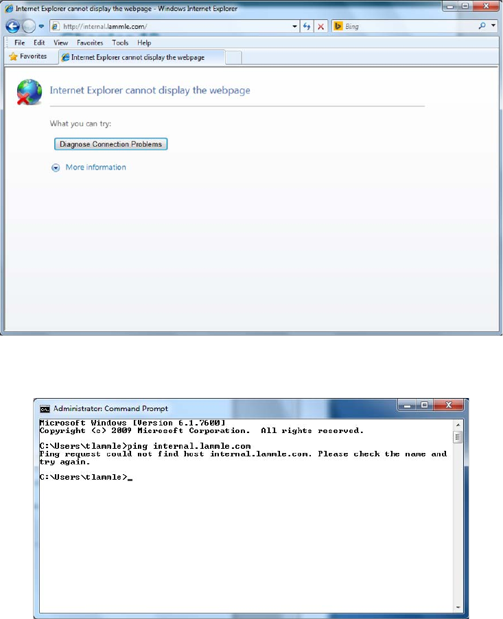
732
Chapter 19 ■ Network Troubleshooting
c19.indd 04/01/2015 Page 732
And when this user tries to ping the server using the server’s hierarchical web name, it
fails, too.
You’re going to respond by checking to see whether the server is up by pinging the server
by its IP address.
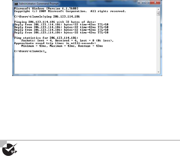
Troubleshooting Steps
733
c19.indd 04/01/2015 Page 733
Nice—that worked, so the server is up, but you could still have a server problem. Just
because you can ping a host, it doesn’t mean that host is 100 percent up and running, but
in this case, it’s a good start.
And you’re in luck because you’ve been able to re-create this problem from this user’s
host machine. By doing that, you now know that the URL name is not being resolved from
Internet Explorer, and you can’t ping it by the name either. But you can ping the server IP
address from your limping host, and when you try this same connection to the
internal.
lammle.com
server from another host nearby, it works ne, meaning the server is working
ne. So, you’ve succeeded in isolating the problem to this speci c host—yes!
It is a huge advantage if you can watch the user try to reproduce the
problem themselves because then you know for sure whether the user
is performing the operation correctly. It’s a really bad idea to assume the
user is typing in what they say they are.
Great—now you’ve nailed down the problem. This leads us to step 2.
Step 2: Establish a Theory of Probable Cause
After you observe the problem and identify the symptoms, next on the list is to establish its
most probable cause. (If you’re stressing about it now, don’t, because though you may feel
overwhelmed by all this. It truly does get a lot easier with time and experience.)
You must come up with at least one possible cause, even though it may not be completely
on the money. And you don’t always have to come up with it yourself. Someone else in
the group may have the answer. Also, don’t forget to check online sources and vendor
documentation.
734
Chapter 19 ■ Network Troubleshooting
c19.indd 04/01/2015 Page 734
Again, let’s get back to our scenario, in which you’ve determined the cause is probably
an improperly con gured DNS lookup on the workstation. The next thing to do is to
verify the con guration and probably recon gure DNS on the workstation; we’ll get to this
solution later, in step 4.
Understand that there are legions of problems that can occur on a network—and I’m
sorry to tell you this, but they’re typically not as simple as the example we’ve been using.
They can be, but I just don’t want you to expect them to be. Always consider the physical
aspects of a network, but look beyond them into the realm of logical factors like the DNS
lookup issue we’ve been using.
Question the Obvious
The probable causes that you’ve got to thoroughly understand to meet the Network+
objectives are as follows:
■ Port speed
■ Port duplex mismatch
■ Mismatched MTU
■ Incorrect virtual local area network (VLAN)
■ Incorrect IP address/duplicate IP address
■ Wrong gateway
■ Wrong DNS
■ Wrong subnet mask
■ Incorrect interface/interface misconfiguration
Let’s talk about these logical issues, which can cause an abundance of network
problems. Most of these happen because a device has been improperly con gured:
Port Speed Because networks have been evolving for many years, there are various levels
of speed and sophistication mixed into them—often within the same network. Most of
the newest NICs can be used at 10Mbps, 100Mbps, and 1000Mbps. Most switches can
support at least 10Mbps and 100Mbps, and an increasing number of switches can also
support 1,000Mbps. Plus, many switches can also autosense the speed of the NIC that’s
connected and use different speeds on various ports. As long as the switches are allowed to
autosense the port speed, it’s rare to have a problem develop that results in a complete lack
of communication. But if you decide to set the port speed manually, make positively sure to
set the same speed on both sides of a link.
Port Duplex Mismatch There are generally three duplex settings on each port of a
network switch: full, half, and auto. In order for two devices to connect effectively, the
duplex setting has to match on both sides of the connection. If one side of a connection is
set to full and the other is set to half, they’re mismatched. More elusively, if both sides are
set to auto but the devices are different, you can also end up with a mismatch because the
device on one side defaults to full and the other one defaults to half.

Troubleshooting Steps
735
c19.indd 04/01/2015 Page 735
Duplex mismatches can cause lots of network and interface errors, and even the lack of a
network connection. This is partially because setting the interfaces to full duplex disables
the CSMA/CD protocol. This is definitely not a problem in a network that has no hubs
(and therefore no shared segments in which there could be collisions), but it can make
things really ugly in a network where hubs are still being used. This means the settings you
choose are based on the type of devices you have populating your network. If you have all
switches and no hubs, feel free to set all interfaces to full duplex, but if you’ve got hubs in
the mix, you have shared networks, so you’re forced to keep the settings at half duplex.
With all new switches produced today, leaving the speed and duplex setting to auto (the
default on both switches and hosts) is the recommended way to go.
Mismatched MTU Ethernet LANs enforce what is called a maximum transmission unit
(MTU). This is the largest size packet that is allowed across a segment. In most cases, this
is 1,500 bytes. Left alone this is usually not a problem, but it is possible to set the MTU
on a router interface, which means it is possible for a mismatch to be present between
two router interfaces. This can cause problems with communications between the routers,
resulting in the link failing to pass traf c. To check the MTU on an interface, execute the
command
show interface
.
Incorrect VLAN Switches can have multiple VLANs each, and they can be connected
to other switches using trunk links. As you now know, VLANs are often used to repre-
sent departments or the occupations of a group of users. This makes the con gurations of
security policies and network access lists much easier to manage and control. On the other
hand, if a port is accidentally assigned to the wrong VLAN in a switch, it’s as if that client
was magically transported to another place in the network. If that happens, the security
policies that should apply to the client won’t anymore, and other policies will be applied to
the client that never should have been. The correct VLAN port assignment of a client is
as important as air; when I’m troubleshooting a single-host problem, this is the rst
place I look.
It’s pretty easy to tell if you have a port configured with a wrong VLAN
assignment. If this is the case, it won’t be long before you’ll get a call from
some user screaming something at you that makes the building shake, like,
“I can get to the Internet but I can’t get to the Sales server, and I’m about to
lose a huge sale. DO SOMETHING!” When you check the switch, you will
invariably see that this user’s port has a membership in another VLAN like
Marketing, which has no access to the Sales server.
Incorrect IP Address/Duplicate IP Address The most common addressing protocol in
use today is IPv4, which provides a unique IP address for each host on a network. Client
computers usually get their addresses from Dynamic Host Con guration Protocol (DHCP)
servers. But sometimes, especially in smaller networks, IP addresses for servers and router
interfaces are statically assigned by the network’s administrator. An incorrect or duplicate
IP address on a client will keep that client from being able to communicate and may even

736
Chapter 19 ■ Network Troubleshooting
c19.indd 04/01/2015 Page 736
cause a con ict with another client on the network, and a bad address on a server or router
interface can be disastrous and affect a multitude of users. This is exactly why you need to
be super careful to set up DHCP servers correctly and also when con guring the static IP
addresses assigned to servers and router interfaces.
Wrong Gateway A gateway, sometimes called a default gateway or an IP default
gateway, is a router interface’s address that’s con gured to forward traf c with a des-
tination IP address that’s not in the same subnet as the device itself. Let me clarify that
one for you: If a device compares where a packet wants to go with the network it’s
currently on and nds that the packet needs to go to a remote network, the device will
send that packet to the gateway to be forwarded to the remote network. Because every
device needs a valid gateway to obtain communication outside of its own network, it’s
going to require some careful planning when considering the gateway con guration of
devices in your network.
If you’re configuring a static IP address and default gateway, you need
to verify the router’s address. Not doing so is a really common “wrong
gateway” problem that I see all the time.
Wrong DNS DNS servers are used by networks and their clients to resolve a
computer’s hostname to its IP addresses and to enable clients to nd the server they
need to provide the resources they require, like a domain controller during the login
and authentication process. Most of the time, DNS addresses are automatically con g-
ured by a DHCP server, but sometimes these addresses are statically con gured instead.
Because lots of applications rely on hostname resolution, a botched DNS con guration
usually causes a computer’s network applications to fail just like the user’s applications
in our example scenario.
If you can ping a host using its IP address but not its name, you probably
have some type of name-resolution issue. It’s probably lurking somewhere
within a DNS configuration.
Wrong Subnet Mask When network devices look at an IP address con guration, they
see a combination of the IP address and the subnet mask. The device uses the subnet mask
to establish which part of the address represents the network address and which part
represents the host address. So clearly, a subnet mask that is con gured wrong has the same
nasty effect as a wrong IP address con guration does on communications. Again, a subnet
mask is generally con gured by the DHCP server; if you’re going to enter it manually, make
sure the subnet mask is tight or you’ll end up tangling with the fallout caused by the entire
address’s miscon guration.
Troubleshooting Steps
737
c19.indd 04/01/2015 Page 737
Incorrect Interface/Interface Misconfiguration If a host is plugged into a miscon gured
switch port, or if it’s plugged into the wrong switch port that’s con gured for the wrong
VLAN, the host won’t function correctly. Make sure the speed, duplex, and correct
Ethernet cable is used. Get any of that wrong and you’ll either get interface errors on the
host and switch port or, worse, things just won’t work at all!
With all that in mind, let’s move on with our troubleshooting steps.
Consider Multiple Approaches
There are two standard approaches that you can use to establish a theory of probable
cause. Let’s take a look at them next.
Top-to-Bottom/Bottom-to-Top OSI Model As its name implies, when you apply a
top-down approach to troubleshooting a networking problem, you start with the user
application and work your way down the layers of the OSI model. If a layer is not in good
working condition, you inspect the layer below it. When you know that the current layer
is not in working condition and youdiscover that a lower layer works, you can conclude
that the problem is within the layer above the lower working layer. Once you’ve determined
which layer is the lowest layer with problems, you can begin identifying the cause of them
from within that layer.
The bottom-up approach to troubleshooting a networking problem starts with the physical
components of the network and works its way up the layers of the OSI model. If you
conclude thatall the elements associated with a particular layer are in good working order,
move on to inspect theelements associated with the next layer up until the cause(s) of the
problem is/are identified. The downside to the bottom-up approach is that it requires you
to check every device, interface, and so on. In other words, regardless of the nature of the
problem, the bottom-up approach starts with an exhaustive check of all the elements of
each layer, starting with the physical layer and working its way up from there.
Divide and Conquer Unlike when opting for the top-down and bottom-up
troubleshooting strategies, the divide-and-conquer approach to network troubleshoot-
ing doesn’t always begin the investigation at a particular OSI layer. When using the
divide-and-conquer approach, you select a layer, test its health, and based on the results,
you can move up or down through the model from the layer you began scrutinizing.
Step 3: Test the Theory to Determine Cause
Once you’ve gathered information and established a plausible theory, you’ve got to
determine the next steps to resolve your problem. If you can’t con rm your theory during
this step, you must formulate a new theory or escalate the problem.
Let’s look into the matter by rst checking the IP con guration of the host that just
happens to include DNS information. You use the
ipconfig /all
command to show the IP
con guration. The
/all
switch will give you the DNS information you need.
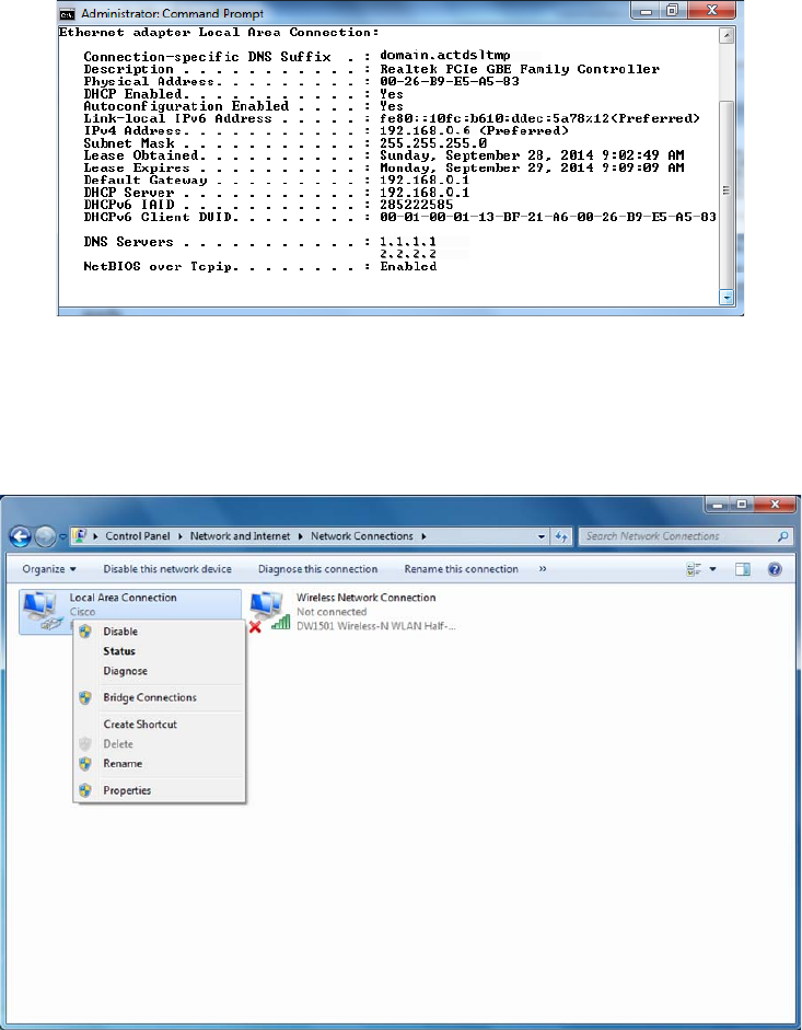
738
Chapter 19 ■ Network Troubleshooting
c19.indd 04/01/2015 Page 738
Check out the DNS entries: 1.1.1.1 and 2.2.2.2. Is this right? What are they supposed to
be? You can nd this out by checking the addresses on a working host, but let’s check the
settings on your troubled host’s adapter rst. Click Start, then Control Panel, then Network
And Sharing Center, and then Manage Network Connections on the left side of the screen,
which will take you to this screen.
Now, click the interface in question, and click Properties. You receive this screen.
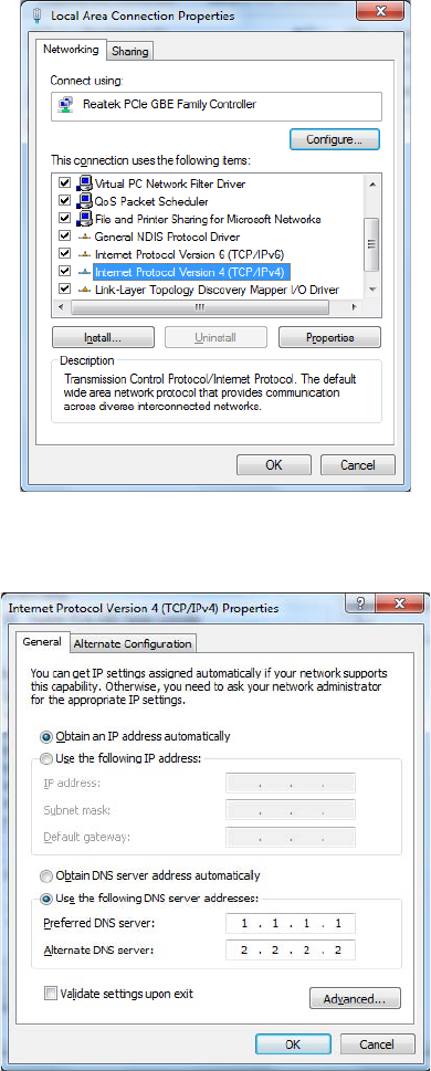
Troubleshooting Steps
739
c19.indd 04/01/2015 Page 739
From here, you highlight Internet Protocol Version 4, and click Properties (or just
double-click). From the next screen, do you see what may be causing the problem?
As I said, you’re using DHCP right? But DNS is statically con gured on this host.
Interesting enough, when you set a static DNS entry on an interface, it will override the
DHCP-provided DNS entry.
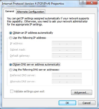
740
Chapter 19 ■ Network Troubleshooting
c19.indd 04/01/2015 Page 740
Step 4: Establish a Plan of Action to Resolve the Problem
and Identify Potential Effects
Now that you’ve identi ed some possible changes, you’ve got to follow through and test
your solution to see if you really solved the problem. In this case, you ask the user to try to
access the intranet server (because that’s what they called about). Basically, you just ask the
user to try doing whatever it was they couldn’t do when they called you in the rst place.
If it works—sweet—problem solved. If not, try the operation yourself.
Now you can test the proposed solution on the computer of the user who is still waiting
for a solution. To do that, you need to check the DNS con guration on your host. But rst,
let me point out something about the neglected user’s network. All hosts are using DHCP,
so it’s really weird that a single user is having a DNS resolution issue.
So, to x the problem and get your user back in the game, just click Obtain DNS Server
Address Automatically, and then click OK. Voilà!
Let’s take a look at the output of
ipconfig /all
and see if you received new DNS server
addresses.
All good; you did. And you can test the host by trying to use HTTP to connect to a web
page on the intranet server and even pinging by hostname. Congratulations on solving your
rst trouble ticket!
If things hadn’t worked out so well, you would go back to step 2, select a new possible
cause, and redo step 3. If this happens, keep track of what worked and what didn’t so you
don’t make the same mistakes twice.
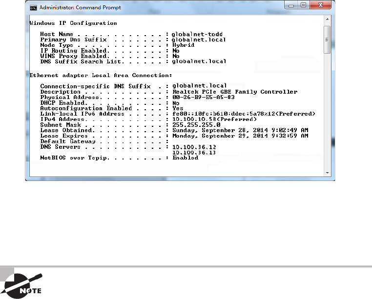
Troubleshooting Steps
741
c19.indd 04/01/2015 Page 741
It’s pretty much common sense that you should change settings like this only when you
fully understand the effect your changes will have, or when you’re asked to by someone
who does. The incorrect con guration of these settings will disable the normal operation of
your workstation, and, well, it seems that someone (the user, maybe?) did something they
shouldn’t have or you wouldn’t have had the pleasure of solving this problem.
You have to be super careful when changing settings and always check out
a troubled host’s network settings. Don’t just assume that because they’re
using DHCP, someone has screwed up the static configuration.
Step 5: Implement the Solution or Escalate
as Necessary
Although it’s true that CompTIA doesn’t expect you to x every single network problem
that could possibly happen in the universe, they actually do expect you to get pretty close
to determining exactly what the problem is. And if you can’t x it, you’ll be expected to
know how to escalate it and to whom. You are only as good as your resources—be they
your own skill set, a book like this one, other more reference-oriented technical books, the
Internet, or even a guru at a call center.
I know it seems like I talked to death physical and logical issues that cause problems in
a network, but trust me, with what I’ve taught you, you’re just getting started. There’s a
galaxy of networking evils that we have not even touched on because they’re far beyond the
objectives for Network+ certi cation and, therefore, the scope of this book. But out there in
the real world, you’ll get calls about them anyway, and because you’re not yet equipped to

742
Chapter 19 ■ Network Troubleshooting
c19.indd 04/01/2015 Page 742
handle them yourself, you need to escalate these nasties to a senior network engineer who
has the additional experience and knowledge required to resolve the problems.
Some of the calamities that you should escalate are as follows:
■ Switching loops
■ Missing routes
■ Routing loops
■ Routing problems
■ MTU black hole
■ Bad modules
■ Proxy Address Resolution Protocol (ARP)
■ Broadcast storms
■ NIC Teaming misconfiguration
■ Power failures/power anomalies
If you can’t implement a solution and instead have to escalate the problem,
there is no need for you to go on with steps 6 and 7 of the seven-step trou-
bleshooting model. You now need to meet with the emergency response
team to determine the next step.
And just as with other problems, you have to be able to identify these events because if
you can’t do that, how else will you know that you need to escalate them?
Switching Loops Today’s networks often connect switches with redundant links to
provide for fault tolerance and load balancing. Protocols such as Spanning Tree Protocol
(STP) prevent switching loops and simultaneously maintain fault tolerance. If STP fails,
it takes some expertise to recon gure and repair the network, so you just need to be
concerned with being able to identify the problem so you can escalate it. Remember, when
you hear users complaining that the network works ne for a while, then unexpectedly
goes down for about a minute, and then goes back to being ne, it’s de nitely an STP
convergence issue that’s pretty tough to nd and x. Escalate this problem ASAP!
Missing Routes Routers must have routes either con gured or learned to function. There
are a number of issues that can prevent a router from learning the routes that it needs. To
determine if a router has the route to the network in question, execute the
show ip route
command and view the routing table. This can save a lot of additional troubleshooting if
you can narrow the problem to a missing route.
Routing Loops Routing protocols are often used on networks to control traf c ef ciently
while preventing routing loops that happen when a routing protocol hasn’t been con g-
ured properly or network changes didn’t get the attention they deserved. Routing loops
Troubleshooting Steps
743
c19.indd 04/01/2015 Page 743
can also happen if you or the network admin blew the static con guration and created
con icting routes through the network. This evil event affects the traf c ow for all users,
and because it’s pretty complicated to x, again, it’s up, up, and away with this one. You
can expect routing loops to occur if your network is running old routing protocols like
Routing Information Protocol (RIP) and RIPv2. Just upgrading your routing protocol to
Enhanced Interior Gateway Routing Protocol (EIGRP), Open Shortest Path First (OSPF),
or Intermediate System-to-Intermediate System (IS-IS) will usually take care of the problem
once and for all. Anyway, escalate this problem to the router group—which hopefully is
soon to be you.
Routing Problems Routing packets through the many subnets of a large enterprise
while still maintaining security can be a tremendous challenge. A router’s con guration
can include all kinds of stuff like access lists, Network Address Translation (NAT), Port
Address Translation (PAT), and even authentication protocols like Remote Authentication
Dial In User Service (RADIUS) and Terminal Access Controller Access-Control System
(TACACS). Particularly diabolical, errant con guration changes can trigger a domino
effect that can derail traf c down the wrong path or even cause it to come to a grinding
halt and stop traversing the network completely. To identify routing problems, check to see
if someone has simply set a wrong default route on a router. This can easily create routing
loops. I see it all the time. These con gurations can be highly complex and speci c to a
particular device, so they need to be escalated to the top dogs—get the problem to the best
sys admin in the router group.
MTU Black Hole On a WAN connection, communication routes may fail if an interme-
diate network segment has an MTU that is smaller than the maximum packet size of the
communicating hosts—and if the router does not send an appropriate Internet Control
Message Protocol (ICMP) response to this condition. If ICMP traf c is allowed, the routers
will take care of this problem using ICMP messages. However, as ICMP traf c is increas-
ingly being blocked, this can create what is called a black hole. This will probably be an
issue you will escalate.
Bad Modules Some multilayer switches and routers have slots available to add new
features. The hardware that ts in these slots is called modules. These modules can host
ber connections, wireless connections, and other types as well. A common example
is the Cisco Small Form-Factor Pluggable (SFP) Gigabit Interface Ethernet Converter
(GBIC). This is an input-output device that plugs into an existing Gigabit Ethernet port
or slot, providing a variety of additional capabilities to the device hosting the slot or port.
Conversions can happen in all types of cables, from Ethernet to ber, for example. Like any
piece of hardware made by humans, the modules can fail. It is always worth checking if
there are no other reasons a link is not functioning.
Proxy ARP Address Resolution Protocol (ARP) is a service that resolves IP addresses
to MAC addresses. Proxy ARP is just wrong to use in today’s networks, but hosts and
routers still have it on by default. The idea of Proxy ARP was to solve the problem of a
744
Chapter 19 ■ Network Troubleshooting
c19.indd 04/01/2015 Page 744
host being able to have only one con gured default gateway. To allow redundancy, Proxy
ARP running on a router will respond to an ARP broadcast from a host that’s sending a
packet to a remote network—but the host doesn’t have a default gateway set. So the router
responds by being the proxy for the remote host, which in turn makes the local host think
the remote host is really local; as a result, the local host sends the packets to the router,
which then forwards the packets to the remote host. Most of the time, in today’s networks,
this does not work well, if at all. Disable Proxy ARP on your routers, and make sure you
have default gateways set on all your hosts. If you need router redundancy, there are much
better solutions available than Proxy ARP! This is another job for the routing group.
Broadcast Storms When a switch receives a broadcast, it will normally ood the
broadcast out all the ports except for the one the broadcast came in on. If STP fails
between switches or is disabled by an administrator, it’s possible that the traf c could
continue to be ooded repeatedly throughout the switch topology. When this happens,
the network can get so busy that normal traf c can’t traverse it—an event referred to as
a broadcast storm. As you can imagine, this is a particularly gruesome thing to have to
troubleshoot and x because you need to nd the one bad link that is causing the mess
while the network is probably still up and running—but at a heavily congested crawl.
Escalate ASAP to experts!
NIC Teaming Misconfiguration NIC Teaming, also known as load balancing/failover
(LBFO), allows multiple network interfaces to be placed into a team for the purposes of
bandwidth aggregation and/or traf c failover to prevent connectivity loss in the event of a
network component failure. The cards can be set to active-active state, where both cards
are load balancing, or active–passive, where one card is on standby in case the primary
card fails. Most of the time, the NIC team will use a multicast address to send and receive
data, but it can also use a broadcast address so all cards receive the data at the same time.
If these are not con gured correctly, either they will operate at a severely diminished
capacity or, worse, neither card will work at all!
Power Failure/Power Anomalies When you have power issues, whether it’s a full-blown
power outage or intermittent power surges, it can cause some serious issues with your
network devices. Your servers and core network devices require a fully functional
UPS system.
Step 6: Verify Full System Functionality, and If
Applicable, Implement Preventative Measures
A trap that any network technician can fall into is solving one problem and thinking it’s
all xed without stopping to consider the possible consequences of their solution. The cure
can be worse than the disease, and it’s possible that your solution falls into this category.
So before you fully implement the solution to a problem, make sure you totally understand
the rami cations of doing so—clearly, if it causes more problems than it xes, you should
toss it and nd a different solution that does no harm.

Troubleshooting Steps
745
c19.indd 04/01/2015 Page 745
Many people update a router’s operating system or firmware just because
a new version of code is released from the manufacturer. Do not do this
on your production routers—just say no! Always test any new code before
upgrading your production routers: Like a bad solution, sometimes the
new code provides new features but creates more problems, and the cons
outweigh the pros.
Step 7: Document Findings, Actions, and Outcomes
I can’t stress enough how vital network documentation is. Always document problems and
solutions so that you have the information at hand when a similar problem arises in the
future. With documented solutions to documented problems, you can assemble your own
database of information that you can use to troubleshoot other problems. Be sure to include
information like the following:
■ A description of the conditions surrounding the problem
■ The OS version, the software version, the type of computer, and the type of NIC
■ Whether you were able to reproduce the problem
■ The solutions you tried
■ The ultimate solution
Network Documentation
I don’t know how many times I’ve gone into a place and asked where their documenta-
tion was only to be met with a blank stare. I was recently at a small business that was
experiencing network problems. The fi rst question I asked was, “Do you have any kind
of network documentation?” I got the blank stare. So, we proceeded to search through
lots of receipts and other paperwork—anything we could fi nd to help us understand the
network layout and fi gure out exactly what was on the network. It turned out they had
recently bought a WAP, and it was having trouble connecting—something that would’ve
taken me fi ve minutes to fi x instead of searching through a mess for a couple hours!
Documentation doesn’t have to look like a sleek owner’s manual or anything—it can
consist of a simple three-ring binder with an up-to-date network map; receipts for
network equipment; a pocket for owner’s manuals; and a stack of loose-leaf paper to
record services, changes, network-addressing assignments, access lists, and so on.
Just this little bit of documentation can save lots of time and money and prevent grief,
especially in the critical fi rst few months of a new network install.
746
Chapter 19 ■ Network Troubleshooting
c19.indd 04/01/2015 Page 746
Troubleshooting Tips
Now that you’ve got the basics of network troubleshooting down pat, I’m going to go over
a few really handy troubleshooting tips for you to arm yourself with even further in the
quest to conquer the world’s networking evils.
Don’t Overlook the Small Stuff
The super simple stuff (SSS) I referred to at the beginning of this chapter should never be
overlooked—ever! Here’s a quick review: Just remember that problems are often caused by
little things like a bad power switch; a power switch in the wrong position; a card or port
that’s not working, indicated by a link light that’s not lit; or simply operator error (OE).
Even the most experienced system administrator has forgotten to turn on the power, left a
cable unplugged, or mistyped a username and password—not me, of course, but others. . .
And make sure that users get solid training for the systems they use. An ounce of prevention
is worth a pound of cure, and you’ll experience dramatically fewer ID10T errors this way.
Prioritize Your Problems
Being a network administrator or technician of even a fairly small network can keep you
hopping, and it’s pretty rare that you’ll get calls for help one at a time and never be inter-
rupted by more coming in. Closer to reality is receiving yet another call when you already
have three people waiting for service. So, you’ve got to prioritize.
You start this process by again asking some basic questions to determine the severity
of the problem being reported. Clearly, if the new call is about something little and you
already have a huge issue to deal with, you should put the new call on hold or get their info
and get back to them later. If you establish a good set of priorities, you’ll make much better
use of your time. Here’s an example of the rank you probably want to give to networking
problems, from highest priority to lowest:
■ Total network failure (affects everyone)
■ Partial network failure (affects small groups of users)
■ Small network failure (affects a small, single group of users)
■ Total workstation failure (single user can’t work at all)
■ Partial workstation failure (single user can’t do most tasks)
■ Minor issue (single user has problems that crop up now and then)
Mitigating circumstances can, of course, change the order of this list. For example, if the
president of the company can’t retrieve email, you’d take the express elevator to their of ce
as soon as you got the call, right? And even a minor issue can move up the ladder if it’s per-
sistent enough.
Don’t fall prey to thinking that simple problems are easier to deal with because even
though you may be able to bring up a crashed server in minutes, a user who doesn’t know

Troubleshooting Tips
747
c19.indd 04/01/2015 Page 747
how to make columns line up in Microsoft Word could take a chunk out of your day. You’d
want to put the latter problem toward the bottom of the list because of the time involved—
it’s a lot more ef cient to solve problems for a big group of people than to x this one user’s
problem immediately.
Some network administrators list all network-service requests on a chalkboard or a
whiteboard. They then prioritize them based on the previously discussed criteria. Some
larger companies have written support-call tracking software whose only function is to
track and prioritize all network and computer problems. Use whatever method makes you
comfortable, but prioritize your calls.
Check the Software Configuration
Often, network problems can be traced to software con guration, like our DNS con gura-
tion scenario; so when you’re checking for software problems, don’t forget to check types of
con gurations:
■ DNS configuration/misconfiguration
■ DHCP configuration/misconfiguration
■ WINS configuration
■ HOSTS file
■ The Registry
Software-con guration settings love to hide in places like these and can be notoriously
hard to nd (especially in the Registry).
Also, look for lines that have been commented out either intentionally or accidentally
in text-con guration les—another place for clues. A command such as
REM
or
REMARK
, or
asterisk or semicolon characters, indicates comment lines in a le.
In the HOSTS file, a pound sign (
#
) is used to indicate a comment line.
Don’t Overlook Physical Conditions
You want to make sure that from a network-design standpoint, the physical environment
for a server is optimized for placement, temperature, and humidity. When troubleshooting
an obscure network problem, don’t forget to check the physical conditions under which the
network device is operating. Check for problems like these:
■ Excessive heat
■ Excessive humidity (condensation)
■ Low humidity (leads to electrostatic discharge [ESD] problems)
■ EMI/RFI problems
■ ESD problems

748
Chapter 19 ■ Network Troubleshooting
c19.indd 04/01/2015 Page 748
■ Power problems
■ Unplugged cables
Don’t Overlook Cable Problems
Cables, generally speaking, work ne once they are installed properly. If the patch cable
isn’t the problem, use a cable tester (not a tone generator and locator) to nd the source of
the problem.
One of the easiest mistakes to make, especially if cables are not labeled, is to use a
crossover cable where a straight-through cable should be used or vice versa. In either case,
when you do this it causes TX RX reversal. What’s that? That’s when the transmit wire is
connected to Transmit and the receive wire to Receive. That sounds good, but it needs to
be Transmit to Receive. See more about straight through and crossover cables in Chapter 3,
“Networking Topologies, Connectors, and Wiring Standards.”
Wires that are moved can be prone to breaking or shorting, and a short can happen
when the wire conductor comes in contact with another conductive surface, changing the
path of the electrical signal. The signal will go someplace else instead of to the intended
recipient. You can use cable testers to test for many types of problems:
■ Broken cables
■ Incorrect connections
■ Interference levels
■ Total cable length (for length restrictions)
■ Cable shorts
■ Connector problems
■ Testing the cable at all possible data rates
As a matter of fact, cable testers are so sophisticated that they can even
indicate the exact location of a cable break, accurate to within 6 inches
or better.
Check for Viruses
People overlook scanning for viruses because they assume that the network’s virus-checking
software has already picked them off. But to be effective, the software must be kept up-to-
date, and updates are made available pretty much daily. You’ve got to run the virus-de ni-
tion update utility to keep the virus-de nition le current.
If you are having strange, unusual, irreproducible problems with a workstation, try
scanning it with an up-to-date virus-scan utility. You’d be surprised how many times
Exam Essentials
749
c19.indd 04/01/2015 Page 749
people have spent hours and hours troubleshooting a strange problem only to run a
virus-scan utility, nd and clean out one or more viruses, and have the problem disappear
like magic.
Summary
In this chapter, you learned about all things troubleshooting, and you now know how to
sleuth out and solve a lot of network problems. You learned to rst check all the SSS and
about how to approach problem resolution by eliminating what the problem is not. You
learned how to narrow the problem down to its basics and de ne it.
Next, you learned a systematic approach using a seven-step troubleshooting model to
troubleshoot most of the problems you’ll run into in networking. And you also learned
about some resources you can use to help you during the troubleshooting process. In
addition, you learned how important documentation is to the health of your network.
Finally, I gave you a bunch of cool tips to further equip you, tips about prioritizing
issues, checking for con guration issues, considering environmental factors—even hunting
down viruses. As you venture out into the real world, keep these tips in mind; along with
your own personal experience, they’ll really help make you an expert troubleshooter.
Exam Essentials
Know the seven troubleshooting steps, in order. The steps, in order, are as follows:
1. Identify the problem.
2. Establish a theory of probable cause.
3. Test the theory to determine cause.
4. Establish a plan of action to resolve the problem and identify potential effects.
5. Implement the solution or escalate as necessary.
6. Verify full system functionality, and if applicable, implement preventative
measures.
7. Document findings, actions, and outcomes.
Be able to identify a link light. A link light is the small, usually green LED on the back of
a network card. This LED is typically found next to the media connector on a NIC and is
usually labeled Link.
Understand how proper network use procedures can affect the operation of a network. If
a user is not following a network use procedure properly (for example, not logging in cor-
rectly), that user may report a problem where none exists. A good network troubleshooter
750
Chapter 19 ■ Network Troubleshooting
c19.indd 04/01/2015 Page 750
should know how to differentiate between a network hardware/software problem and a
“lack of user training” problem.
Know how to narrow down a problem to one specific area or cause. Most problems
can be traced to one speci c area or cause. You must be able to determine if a problem is
speci c to one user or a bunch of users, speci c to one computer or a bunch of computers,
and related to hardware or software. The answers to these questions will give you a very
speci c problem focus.
Know how to detect cabling-related problems. Generally speaking, most cabling-related
problems can be traced by plugging the suspect workstation into a known, working
network port. If the problem disappears (or at the very least changes signi cantly), it is
related to the cabling for that workstation.
Written Lab
In this section, write the answers to the following questions. You can nd the answers in
Appendix A.
1. What is step 3 of the seven-step troubleshooting model?
2. What is step 7 of the seven-step troubleshooting model?
3. How is crosstalk minimized in twisted-pair cabling?
4. If you plug a host into a switch port and the user cannot get to the server or other services
they need to access despite a working link light, what could the problem be?
5. What is it called when a cable has two wires of a twisted pair connected to two wires from
a different pair?
6. When a signal moves through any medium, the medium itself will degrade the signal.
What is this called?
7. What is step 4 of the seven-step troubleshooting model?
8. What is step 5 of the seven-step troubleshooting model?
9. What are some of the problems that, if determined, should be escalated?
10. What cable issues should you know and understand for network troubleshooting?
Review Questions
751
c19.indd 04/01/2015 Page 751
Review Questions
You can nd the answers to the review questions in Appendix B.
1. Which of the following are not steps in the Network+ troubleshooting model? (Choose all
that apply.)
A. Reboot the servers.
B. Identify the problem.
C. Test the theory to determine the cause.
D. Implement the solution or escalate as necessary.
E. Document findings, actions, and outcomes.
F. Reboot all the routers.
2. You have a user who cannot connect to the network. What is the first thing you could
check to determine the source of the problem?
A. Workstation configuration
B. Connectivity
C. Patch cable
D. Server configuration
3. When wireless users complain that they are losing their connection to applications during a
session, what is the source of the problem?
A. Incorrect SSID
B. Latency
C. Incorrect encryption
D. MAC address filter
4. Several users can’t log in to the server. Which action would help you to narrow the problem
down to the workstations, network, or server?
A. Run
tracert
from a workstation.
B. Check the server console for user connections.
C. Run
netstat
on all workstations.
D. Check the network diagnostics.
5. A user can’t log in to the network. She can’t even connect to the Internet over the LAN.
Other users in the same area aren’t experiencing any problems. You attempt to log in as
this user from your workstation with her username and password and don’t experience any
problems. However, you cannot log in with either her username or yours from her worksta-
tion. What is a likely cause of the problem?
A. Insufficient rights to access the server
B. A bad patch cable
752
Chapter 19 ■ Network Troubleshooting
c19.indd 04/01/2015 Page 752
C. Server down
D. Wrong username and password
6. A user is experiencing problems logging in to a Unix server. He can connect to the Internet
over the LAN. Other users in the same area aren’t experiencing any problems. You attempt
logging in as this user from your workstation with his username and password and don’t
experience any problems. However, you cannot log in with either his username or yours
from his workstation. What is a likely cause of the problem?
A. The Caps Lock key is pressed.
B. The network hub is malfunctioning.
C. You have a downed server.
D. You have a jabbering NIC.
7. You receive a call from a user who is having issues connecting to a new VPN. Which is the
first step you should take?
A. Find out what has changed.
B. Reboot the workstation.
C. Document the solution.
D. Identify the symptoms and potential causes.
8. A workstation presents an error message to a user. The message states that a duplicate
IP address has been detected on the network. After establishing what has changed in the
network, what should be the next step using the standard troubleshooting model?
A. Test the result.
B. Select the most probable cause.
C. Create an action plan.
D. Identify the results and effects of the solution.
9. You have gathered information on a network issue and determined the affected areas of the
network. What is your next step in resolving this issue?
A. You should implement the best solution for the issue.
B. You should test the best solution for the issue.
C. You should check to see if there have been any recent changes to this affected part of
the network.
D. You should consider any negative impact to the network that might be caused by a
solution.
10. A user calls you, reporting a problem logging in to the corporate intranet. You can access
the website without problems using the user’s username and password. At your request, the
user has tried logging in from other workstations but has been unsuccessful. What is the
most likely cause of the problem?
A. The user is logging in incorrectly.
B. The network is down.
Review Questions
753
c19.indd 04/01/2015 Page 753
C. The intranet server is locked up.
D. The server is not routing packets correctly to that user’s workstation.
11. You have just implemented a solution and you want to celebrate your success. But what
should you do next before you start your celebration?
A. Gather more information about the issue.
B. Document the issue and the solution that was implemented.
C. Test the solution and identify other effects it may have.
D. Escalate the issue.
12. You can ping the local router and web server that a local user is trying to reach, but you
cannot reach the web page that resides on that server. From step 2 of the troubleshooting
model, what is a possible problem that would lead to this situation?
A. Your network cable is unplugged.
B. There is a problem with your browser.
C. Your NIC has failed.
D. The web server is unplugged.
13. When troubleshooting an obscure network problem, what physical conditions should be
reviewed to make sure the network device is operating correctly? (Choose all that apply.)
A. Excessive heat
B. Low/excessive humidity
C. ESD problems
D. None of the above
14. Which of the following is not a basic physical issue that can occur on a network when a
user is connected via cable?
A. Crosstalk
B. Shorts
C. Open impedance mismatch
D. DNS configurations
15. You are troubleshooting a LAN switch and have identified the symptoms. What is the next
step you should take?
A. Escalate the issue.
B. Create an action plan.
C. Implement the solution.
D. Determine the scope of the problem.
754
Chapter 19 ■ Network Troubleshooting
c19.indd 04/01/2015 Page 754
16. A user calls you, complaining that he can’t access the corporate intranet web server. You try
the same address, and you receive a Host Not Found error. Several minutes later, another
user reports the same problem. You can still send email and transfer files to another server.
What is the most likely cause of the problem?
A. The hub is unplugged.
B. The server is not routing protocols to your workstation.
C. The user’s workstation is not connected to the network.
D. The web server is down.
17. You have implemented and tested a solution and identified any other effects the solution
may have. What is your next step?
A. Create an action plan.
B. Close the case and head home for the day.
C. Reboot the Windows server.
D. Document the solution.
18. Users are reporting that they can access the Internet but not the internal company website.
Which of the following is the most likely problem?
A. The DNS entry for the server is non-authoritative.
B. The intranet server is down.
C. The DNS address handed out by DHCP is incorrect.
D. The default gateway is incorrect.
19. Several users have complained about the server’s poor performance as of late. You know
that the memory installed in the server is sufficient. What could you check to determine
the source of the problem?
A. Server’s NIC link light
B. Protocol analyzer
C. Performance-monitoring tools
D. Server’s system log file
20. You lose power to your computer room and the switches in your network do not come
back up when everything is brought online. After you have identified the affected areas,
established the cause, and escalated this problem, what do you do next?
A. Start to implement a solution to get those users back online ASAP.
B. Create an action plan and solution.
C. Meet with the emergency response team to determine the next step.
D. Copy all the working routers’ configurations to the nonworking switches.

c20.indd 04/02/2015 Page 755
Chapter
20
Management,
Monitoring, and
Optimization
THE FOLLOWING COMPTIA NETWORK+
EXAM OBJECTIVES ARE COVERED IN THIS
CHAPTER:
✓ 2.3 Given a scenario, use appropriate resources to support
configuration management
■ Archives/backups
■ Baselines
■ On-boarding and off-boarding of mobile devices
■ NAC
■ Documentation
■ Network diagrams (logical/physical)
■ Asset management
■ IP address utilization
■ Vendor documentation
■ Internal operating procedures/policies/standards
✓ 1.10 Identify the basic elements of unified communication
technologies
■ VoIP
■ Video
■ Real-time services
■ Presence
■ Multicast vs unicast
■ QoS
■ DSCP
■ COS

c20.indd 04/02/2015 Page 756
■ Devices
■ UC servers
■ UC devices
■ UC gateways
✓ 1.11 Compare and contrast technologies that support
cloud and virtualization
■ Virtualization
■ Virtual switches
■ Virtual routers
■ Virtual firewall
■ Virtual vs physical NICs
■ Software defined networking
■ Storage area network
■ iSCSI
■ jumboframe
■ Fiber channel
■ Network attached storage
■ Cloud concepts
■ Public IaaS, SaaS, PaaS
■ Private IaaS, SaaS, PaaS
■ Hybrid IaaS, SaaS, PaaS
■ Community IaaS, SaaS, PaaS
✓ 1.7 Differentiate between network infrastructure
implementations
■ SCADA/ICS
■ ICS server
■ DCS/closed network
■ Remote terminal unit
■ Programmable logic controller

c20.indd 04/02/2015 Page 757
■ Medianets
■ VTC
■ ISDN
■ IP/SIP
✓ 2.4 Explain the importance of implementing network
segmentation
■ SCADA systems/Industrial control systems
■ Legacy systems
■ Separate private/public networks
■ Honeypot/honeynet
■ Testing lab
■ Load balancing
■ Performance optimization
■ Security
■ Compliance
✓ 5.5 Given a scenario, implement the appropriate policies
or procedures
■ Security policies
■ Consent to monitoring
■ Network policies
■ Acceptable use policy
■ Standard business documents
■ SLA
■ MOU
■ MLA
■ SOW
✓ 5.6 Summarize safety practices
■ Electrical safety
■ Grounding

c20.indd 04/02/2015 Page 758
■ ESD
■ Static
■ Installation safety
■ Lifting equipment
■ Rack installation
■ Placement
■ Tool safety
■ MSDS
■ Emergency procedures
■ Building layout
■ Fire escape plan
■ Safety/emergency exits
■ Fail open/fail close
■ Emergency alert system
■ Fire suppression systems
■ HVAC
✓ 5.7 Given a scenario, install and configure equipment in
the appropriate location using best practices
■ Intermediate distribution frame
■ Main distribution frame
■ Cable management
■ Patch panels
■ Power management
■ Power converters
■ Circuits
■ UPS
■ Inverters
■ Power redundancy
■ Device placement
■ Air flow

c20.indd 04/02/2015 Page 759
■ Cable trays
■ Rack systems
■ Server rail racks
■ Two-post racks
■ Four-post racks
■ Free-standing racks
■ Labeling
■ Port labeling
■ System labeling
■ Circuit labeling
■ Naming conventions
■ Patch panel labeling
■ Rack monitoring
■ Rack Security
✓ 5.8 Explain the basics of change management procedures
■ Document reason for a change
■ Change request
■ Configuration procedures
■ Rollback process
■ Potential impact
■ Notification
■ Approval process
■ Maintenance window
■ Authorized downtime
■ Notification of change
■ Documentation
■ Network configurations
■ Additions to network
■ Physical location changes

c20.indd 04/02/2015 Page 760
If you didn’t just skip to the end of this book, you’ve trekked
through enough material to know that without a doubt, the
task of designing, implementing, and maintaining a state-
of-the-art network doesn’t happen magically. Ending up with a great network requires
some really solid planning before you buy even one device for it. And planning includes
thoroughly analyzing your design for potential aws and optimizing con gurations
everywhere you can to maximize the network’s future throughput and performance. If you
blow it in this phase, trust me—you’ll pay dearly later in bottom-line costs and countless
hours consumed troubleshooting and putting out the res of faulty design.
Start planning by creating an outline that precisely delimits all goals and business
requirements for the network, and refer back to it often to ensure that you don’t deliver a
network that falls short of your client’s present needs or fails to offer the scalability to grow
with those needs. Drawing out your design and jotting down all the relevant information
really helps in spotting weaknesses and faults. If you have a team, make sure everyone on it
gets to examine the design and evaluate it, and keep that network plan up throughout the
installation phase. Hang on to it after implementation has been completed as well because
having it is like having the keys to the kingdom—it will enable you to ef ciently trouble-
shoot any issues that could arise after everything is in place and up and running.
High-quality documentation should include a baseline for network performance because
you and your client need to know what “normal” looks like in order to detect problems
before they develop into disasters. Don’t forget to verify that the network conforms to
all internal and external regulations and that you’ve developed and itemized solid man-
agement procedures and security policies for future network administrators to refer to
andfollow.
I’ll begin this chapter by going over the fundamentals of things like plans, diagrams,
baselines, rules, and regulations, and then move on to cover critical hardware and software
utilities you should have in your problem resolution arsenal, like packet sniffers, through-
put testers, connectivity packages, and even different types of event logs on your servers.
And because even the best designs usually need a little boost after they’ve been up and run-
ning for a while, I’ll wrap things up by telling you about some cool ways you can tweak
things to really jack up a network’s performance, optimize its data throughput, and, well,
keep it all humming along as ef ciently and smoothly as possible.
To find up-to-the-minute updates for this chapter, please see
www.lammle
.com/networkplus
or the book’s website at
www.sybextestbanks.wiley.com
.
Managing Network Documentation
761
c20.indd 04/02/2015 Page 761
Managing Network Documentation
I’ll admit it—creating network documentation is one of my least favorite tasks in network
administration. It just isn’t as exciting to me as learning about the coolest new technology
or tackling and solving a challenging problem. Part of it may be that I gure I know my
networks well enough—after all, I installed and con gured them, so if something comes
up, it should be easy to gure it out and x it, right? And most of the time I can do that,
but as networks get bigger and more complex, it gets harder and harder to remember it
all. Plus, it’s an integral part of the service I provide for my clients to have seriously solid
documentation in hand to refer to after I’ve left the scene and turned their network over to
them. So while I’ll admit that creating documentation isn’t something I get excited about, I
know from experience that having it around is critical when problems come up—for myself
and for my clients’ technicians and administrators, who may not have been part of the
installation process and simply aren’t familiar with the system.
Using SNMP
In Chapter 6, “Introduction to the Internet Protocol,” I introduced you to Simple Network
Management Protocol (SNMP), which is used to gather information from and send set-
tings to devices that are SNMP compatible. Make sure to thoroughly review the differences
between versions 1, 2, and 3 that we discussed there! Remember, I told you SNMP gathers
data by polling the devices on the network from a management station at xed or random
intervals, requiring them to disclose certain information. This is a big factor that really
helps to simplify the process of gathering information about your entire internetwork.
SNMP uses UDP to transfer messages back and forth between the management system
and the agents running on the managed devices. Inside the UDP packets (called datagrams)
are commands from the management system to the agent. These commands can be used
either to get information from the device about its state (
SNMP
GetRequest
) or to make a
change in the device’s con guration (
SetRequest
). If a
GetRequest
command has been sent,
the device will respond with an
SNMP
response. If there’s a piece of information that’s par-
ticularly interesting to an administrator about the device, the administrator can set some-
thing called a trap on the device.
So, no whining! Like it or not, we’re going to create some solid documentation. But
because I’m guessing that you really don’t want to redo it, it’s a very good idea to keep it
safe in at least three forms:
■ An electronic copy that you can easily modify after configuration changes
■ A hard copy in a binder of some sort, stored in an easily accessible location
■ A copy on an external drive to keep in a really safe place (even off site) in case some-
thing happens to the other two or the building or part of it burns to the ground
So why the hard copy? Well, what if the computer storing the electronic copy totally
crashes and burns at exactly the same time a major crisis develops? Good thing you have
762
Chapter 20 ■ Management, Monitoring, and Optimization
c20.indd 04/02/2015 Page 762
that paper documentation on hand for reference! Plus, sometimes you’ll be troubleshoot-
ing on the run—maybe literally, as in running down the hall to the disaster’s origin.
Having that binder containing key con guration information on board could save you a
lot of time and trouble, and it’s also handy for making notes to yourself as you trouble-
shoot. Also, depending on the size of the intranet and the amount of people staf ng the IT
department, it might be smart to have several hard copies. Just always make sure they’re
only checked out by staff who are cleared to have them and that they’re all returned to a
secure location at the end of each shift. You de nitely don’t want that information in the
wrong hands!
Now that I’ve hopefully convinced you that you absolutely must have tight documenta-
tion, let’s take a look into the different types you need on hand so you can learn how to
assemble them.
I’ll cover schematics and diagrams next, and discuss baselines and policies, procedures,
and regulations later when I cover network monitoring.
Schematics and Diagrams
Now reading network documentation doesn’t exactly compete with racing your friends
on jet skis, but it’s really not that bad. It’s better than eating canned spinach, and some-
times it’s actually interesting to check out schematics and diagrams—especially when they
describe innovative, elegant designs or when you’re hunting down clues needed to solve an
intricate problem with an elusive solution. I can’t tell you how many times, if something
isn’t working between point A and point B, a solid diagram of the network that precisely
describes exactly what exists between point A and point B has totally saved the day. Other
times these tools come in handy is when you need to extend your network and you want a
clear picture of how the expanded version will look and work. Will the new addition cause
one part of the network to become bogged down while another remains underutilized? You
get the idea.
Diagrams can be simple sketches created while brainstorming or troubleshooting on the
y. They can also be highly detailed, re ned illustrations created with some of the snappy
software packages around today, like Microsoft Visio, SmartDraw, and a host of computer-
aided design (CAD) programs. Some of the more complex varieties, especially CAD pro-
grams, are super pricey. But whatever tool you use to draw pictures about your networks,
they basically fall into these groups:
■ Wiring diagrams/schematics
■ Physical network diagrams
■ Logical network diagrams
■ Schematics and Diagrams
■ Asset Management
■ IP address Utilization
■ Vendor Documentation
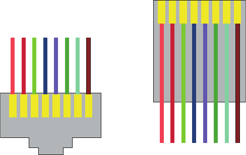
Managing Network Documentation
763
c20.indd 04/02/2015 Page 763
Wiring Schematics
Wireless is de nitely the wave of the future, but for now even the most extensive wireless
networks have a wired backbone they rely on to connect them to the rest of humanity.
That skeleton is made up of cabled physical media like coax, ber, and twisted pair.
Surprisingly, it is the latter—speci cally, unshielded twisted pair (UTP)—that screams
to be pictured in a diagram. You’ll see why in a minute. To help you follow me, let’s
review what we learned in Chapter 3, “Networking Topologies, Connectors, and Wiring
Standards.” We’ll start by checking out Figure 20.1 (a diagram!) that pictures the fact that
UTP cables use an RJ-45 connector (RJ stands for registered jack).
FIGURE 20.1 RJ-45 connector
123456
RJ-45 connector
as seen from the front
As see from the top
RJ-45 cable
78
12345678
What we see here is that pin 1 is on the left and pin 8 is on the right, so clearly, within
your UTP cable, you need to make sure the right wires get to the right pins. No worries
if you got your cables premade from the store, but making them yourself not only saves
you a bunch of money, it allows you to customize cable lengths, which is really important!
Table 20.1 matches the colors for the wire associated with each pin, based on the Electronic
Industries Association and the Telecommunications Industry Alliance (EIA/TIA) 568B wir-
ing standard.
Standard drop cables or patch cables have the pins in the same order on both con-
nectors. If you’re connecting a computer to another computer directly, you should
already know that you need a crossover cable that has one connector with ipped
wires. Speci cally, pins 1 and 3 and pins 2 and 6 get switched to ensure that the send
port from one computer’s Network Interface Card (NIC) gets attached to the receive
port on the other computer’s NIC. Crossover cables were also used to connect older
routers, switches, and hubs through their uplink ports. Figure 20.2 shows you what this
looks like.
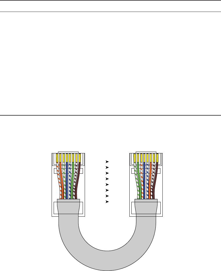
764
Chapter 20 ■ Management, Monitoring, and Optimization
c20.indd 04/02/2015 Page 764
TABLE 20.1 Standard EIA/TIA 568B wiring
Pin Color
1White/Orange
2Orange
3White/Green
4Blue
5White/Blue
6Green
7White/Brown
8Brown
FIGURE 20.2 Two ends of a crossover cable
1. Orange/White
2. Orange
3. Green/White
4. Blue
5. Blue/ White
6. Green
7. Brown/White
8. Brown
1. Green/White
2. Green
3. Orange/White
4. Blue
5. Blue/ White
6. Orange
7. Brown/White
8. Brown
12345678 12345678
1
2
3
4
5
6
7
8
3
6
1
4
5
2
7
8
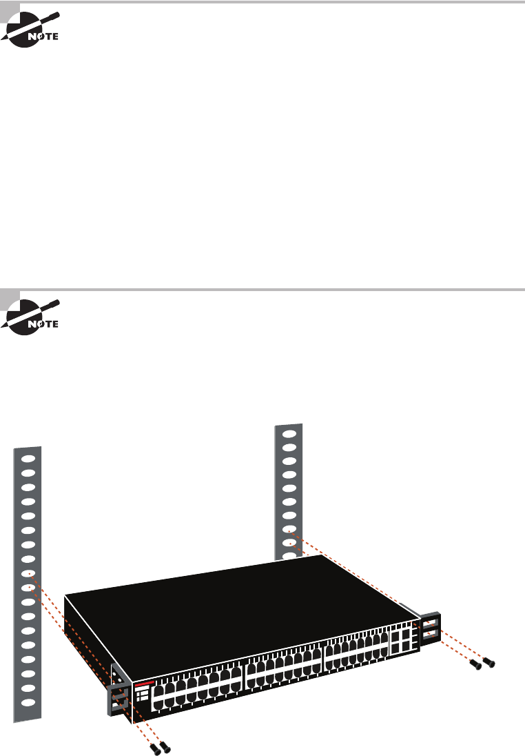
Managing Network Documentation
765
c20.indd 04/02/2015 Page 765
The crossover cable shown in Figure 20.2 is for connections up to
100BaseTX. If you are using 1000BaseT4, all four pairs of wires get crossed
at the opposite end, meaning pins 4 and 7 and pins 5 and 8 get crossed
as well. The Automatic MDI/MDI+ Configuration standard—an optional
feature of the 1000BaseT standard—makes the need for crossover cables
between gigabit-capable interfaces a thing of the past.
This is where having a diagram is golden. Let’s say you’re troubleshooting a network and
discover connectivity problems between two hosts. Because you’ve got the map, you know
the cable running between them is brand new and custom made. This should tell you to go
directly to that new cable because it’s likely it was poorly made and is therefore causing the
snag.
Another reason it’s so important to diagram all things wiring is that all wires have
to plug into something somewhere, and it’s really good to know what and where that is.
Whether it’s into a hub, a switch, a router, a workstation, or the wall, you positively need to
know the who, what, where, when, and how of the way the wiring is attached.
After adding a new cable segment on your network, you need to update
the wiring schematics.
For medium to large networks, devices like switches and routers are rack-mounted and
would look something like the switch in Figure 20.3.
FIGURE 20.3 Rack-mounted switches

766
Chapter 20 ■ Management, Monitoring, and Optimization
c20.indd 04/02/2015 Page 766
Knowing someone’s or something’s name is important because it helps us differentiate
between people and things—especially when communicating with each other. If you want
to be speci c, you can’t just say, “You know that router in the rack?” This is why coming
up with a good naming system for all the devices living in your racks will be invaluable for
ensuring that your wires don’t get crossed.
Okay, I know it probably seems like we’re edging over into OCD territory, but stay with
me here; in addition to labeling, well, everything so far, you should actually label both
ends of your cables, too. If something happens (earthquake, tsunami, temper tantrum, even
repairs) and more than one cable gets unplugged at the same time, it can get really messy
scrambling to reconnect them from memory—fast!
Physical Network Diagrams
A physical network diagram contains all the physical devices and connectivity paths on
your network and should accurately picture how your network physically ts together in
glorious detail. Again, I know it seems like overkill, but ideally, your network diagram
should list and map everything you would need to completely rebuild your network from
scratch if you had to. This is actually what this type of diagram is designed for. But there’s
still another physical network diagram variety that includes the rmware revision on all
the switches and access points in your network. Remember, besides having your physical
network accurately detailed, you must also clearly understand the connections, types of
hardware, and their rmware revisions. I’m going to say it again—you will be so happy you
have this documentation when troubleshooting! It will prevent much suffering and enable
you to x whatever the problem is so much faster!
Avoiding Confusion
Naming your network devices is no big deal, but for some reason, coming up with
systems for naming devices and numbering connections can really stress people out.
Let me ease the pain. Let’s say your network has two racks of switches, creatively named
Block A and Block B. (I know this sounds like a prison, but it’s just to keep things simple
for this example. In the real world, you can come up with whatever naming system works
for you.)
Anyway, I’m going to use the letters FETH for Fast Ethernet, and because each rack has
six switches, I’m going to number them 1 through 6. Because we read from left to right
in the West, it’s intuitive to number the ports on each switch that way, too, but again, do
what works best for you.
Having a solid naming system makes things so much more effi cient—even if it’s a bit
of a hassle to create. For instance, if you were the system administrator in this example
and suddenly all the computers connected to FETHB-3 couldn’t access any network
resources, you would have a pretty good idea of where to look fi rst, right?
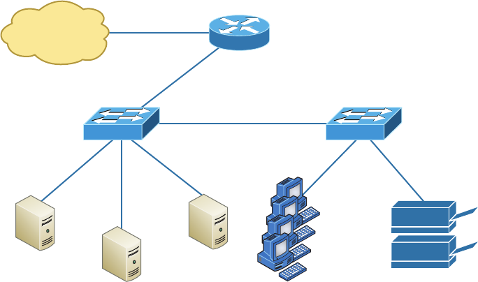
Managing Network Documentation
767
c20.indd 04/02/2015 Page 767
If you can’t diagram everything for some reason, at least make sure all network devices
are listed. As I said, physical network diagrams can run from simple, hand-drawn models
to insanely complex monsters created by software packages like SmartDraw, Visio, and
AutoCAD. Figure 20.4 shows a simple diagram that most of us could draw by hand.
FIGURE 20.4 Simple network physical diagram
Internet
Router
Switch 1
Server 1
(Login)
Server 2
(Files)
Server 3
(Mail)
19
Workstations
2 Printers
Switch 2
For the artistically impaired, or if you just want a ashier version, Figure 20.5 exhibits
a more complex physical diagram. This is an actual sample of what SmartDraw can do for
you, and you can get it at
www.smartdraw.com
. In addition, Microsoft Visio provides many,
possibly more of these same functions.
My last example, also courtesy of SmartDraw, includes diagrams of hardware racks, as
revealed in Figure 20.6.
Don’t throw anything at me, but I need to bring up one last thing: Never forget to
mirror any changes you make to your actual network in the network’s diagram. Think of it
like an updated snapshot. If you give the authorities your college buddy’s baby picture after
he goes missing, will that really help people recognize him as well as one taken just before
he disappeared? Because they don’t make age progression software for networks, it’s smart
to just keep things up to date.
Logical Network Diagrams
Physical diagrams depict how data physically ows from one area of your network to the
next, but a logical network diagram includes things like protocols, con gurations, address-
ing schemes, access lists, rewalls, types of applications, and so on—all things that apply
logically to your network. Figure 20.7 shows what a typical logical network diagram
lookslike.
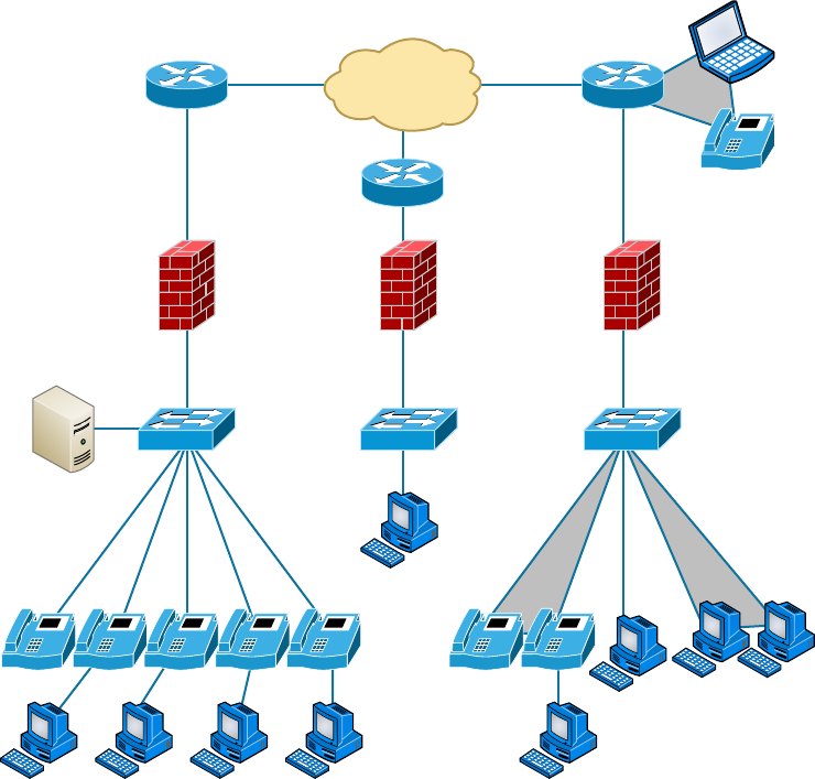
768
Chapter 20 ■ Management, Monitoring, and Optimization
c20.indd 04/02/2015 Page 768
FIGURE 20.5 Network diagram with firewalls from SmartDraw
Internet
Clients
IP
IP IP IP IP IPIP IP
Just as you mirror any physical changes you make to the physical network, like adding
devices or even just a cable, on your physical diagram, you map logical changes, such as
creating a new subnet, VLAN, or security zone on your logical network diagram. And it’s
equally vital that you keep this oh-so-important document up to date!
Asset Management
Asset management involves tracking all network assets like computers, routers, switches,
and hubs through their entire life cycles. Most organizations nd it bene cial to utilize
asset identi cation numbers to facilitate this process. The ISO has established standards
regarding asset management. The ISO 19770 family consists of four major parts:
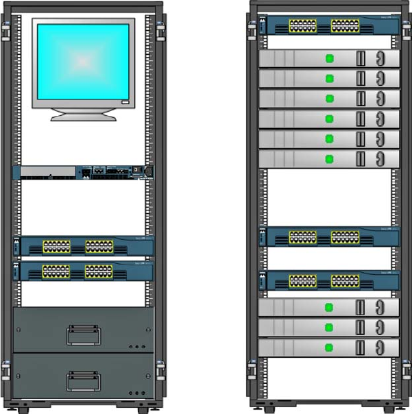
Managing Network Documentation
769
c20.indd 04/02/2015 Page 769
FIGURE 20.6 Hardware-rack diagram from SmartDraw
8U Rack Mount
Monitor
Cisco 2960 XL Switch
PC-1
PC-2
PC-3
PC-4
PC-5
PC-6
PC-7
PC-8
PC-9
Router 55.800.50.1
Rack Diagram Cisco 2900 XL Switch
Cisco 2900 XL Switch
VLAN1 Netware 5.1
55.811.50.20
VLAN1 RedHat 7.1
55.812.50.20
UPS
UPS
■ 19770-1 is a process-related standard that outlines best practices for IT asset manage-
ment in an organization.
■ 19770-2 is a standard for machine encapsulation (in the form of an XML file known
as a SWID tag) of inventory data—allowing users to easily identify what software is
deployed on a given device.
■ 19770-3 is a standard that provides a schema for machine encapsulation of entitle-
ments and rights associated with software licenses. The records (known as ENTs) will
describe all entitlements and rights attendant to a piece of software and the method for
measurement of license/entitlement consumption. This is still a draft.
■ 19770-4 allows for standardized reporting of utilization of resources. This is crucial
when considering complex datacenter license types and for the management of cloud-
based software and hardware (software as a service, or SaaS, and infrastructure as a
service, or IaaS). This is also still a draft.
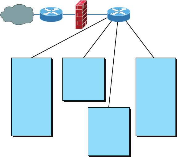
770
Chapter 20 ■ Management, Monitoring, and Optimization
c20.indd 04/02/2015 Page 770
FIGURE 20.7 Logical network diagram
Internet
R&D subnet
192.168.5.0/24
File Server IP:
192.168.5.10/24
Printer IPs:
192.168.5.20/24-
192.168.5.39
Workstation IPs:
192.168.5.50/24-
192.168.5.99
Web Server
www.example.com
192.168.3.10/24
Mail Server
mail.example.com
192.168.3.15/24
Server subnet
192.168.4.0/24
Server IPs:
192.168.4.10/24
192.168.4.11/24
192.168.4.12/24
192.168.4.13/24
Admin subnet
192.168.6.0/24
File Server IP:
192.168.6.10/24
Printer IPs:
192.168.6.20/24-
192.168.6.39
Workstation IPs:
192.168.6.50/24-
192.168.6.99
External Router Internal Router
Firewall
IP Address Utilization
Documenting the current IP addressing scheme can also be highly bene cial, especially
when changes are required. Not only is this really helpful to new technicians, it’s very use-
ful when identifying IP addressing issues that can lead to future problems. In many cases IP
addresses are con gured over a long period of time with no real thought or planning on the
macro level.
Current and correct documentation can help administrators identify discontiguous
networks (where subnets of a major network are separated by another major network) that
can cause routing protocol issues. Proper IP address design can also facilitate summariza-
tion, which makes routing tables smaller, speeding the routing process. None of these wise
design choices can be made without proper IP address documentation.
Vendor Documentation
Vendor agreements often have bene cial clauses that were negotiated during the purchase
process. Many also contain critical details concerning SLAs and deadlines for warranties.
These documents need to be organized and stored safety for future reference. Creating a
spreadsheet or some other form of tracking documentation that alerts you of upcoming
dates of interest can be a huge advantage!
Network Monitoring
771
c20.indd 04/02/2015 Page 771
Network Monitoring
Identifying performance issues within the network is only one of the reasons to perform
structured monitoring. Security issues also require constant monitoring. In the following
sections, we’ll look into both types of monitoring and cover some of the best practices and
guidelines for success.
Baselines
In networking, baseline often refers to the standard level of performance of a certain
device, or to the normal operating capacity for your whole network. For instance, a speci c
server’s baseline describes norms for factors like how busy its processors are, how much
memory it uses, and how much data usually goes through the NIC at a given time.
A network baseline delimits the amount of bandwidth available and when. For networks
and networked devices, baselines include information about four key components:
■ Processor
■ Memory
■ Hard-disk (or other storage) subsystem
■ Network adapter or subsystem
After everything is up and running, it’s a good idea to establish performance baselines
on all vital devices and for your network in general. To do this, measure things like net-
work usage at three different strategic times to get an accurate assessment. For instance,
peak usage usually happens around 8:00 a.m. Monday through Friday, or whenever most
people log in to the network in the morning. After hours or on weekends is often when
usage is the lowest. Knowing these values can help you troubleshoot bottlenecks or deter-
mine why certain system resources are more limited than they should be. Knowing what
your baseline is can even tell you if someone’s complaints about the network running like a
slug are really valid—nice!
It’s good to know that you can use network-monitoring software to establish baselines.
Even some server operating systems come with software to help with network monitoring,
which can help nd baselines as well.
In my experience, it’s wise to re-baseline network performance at least once a year. And
always pinpoint new performance baselines after any major upgrade to your network’s
infrastructure.
On-Boarding and Off-Boarding of Mobile Devices
Increasingly, users are doing work on their mobile devices that they once performed on
laptops and desktop computers. Moreover, they are demanding that they be able to use
their personal devices to work on the company network. This presents a huge security issue
for the IT department because they have to secure these devices while simultaneously exer-
cising much less control over them.
772
Chapter 20 ■ Management, Monitoring, and Optimization
c20.indd 04/02/2015 Page 772
The security team must have a way to prevent these personal devices from introduc-
ing malware and other security issues to the network. Bring Your Own Device (BYOD)
initiatives can be successful if implemented correctly. The key is to implement control over
these personal devices that leave the safety of your network and return later after poten-
tially being exposed to environments that are out of your control. One of the methods that
has been employed successfully to accomplish this goal is network access control (NAC),
covered in the next section.
NAC
Today’s network access control goes beyond simply authenticating users and devices before
they are allowed into the network. With the challenges presented by today’s mobile work-
force, it must go further. These services are called Network Admission Control in the Cisco
world and Network Access Protection in the Microsoft world, but the goals of these features
are the same: to examine all devices requesting network access for malware, missing security
updates, and any other security issues any device could potentially introduce to the network.
In some cases network access control goes beyond simply denying access to systems that
fail inspection. NAC can even redirect the failed system to a remediation server, which will
then apply patches and updates before allowing the device access to the network. These
systems can be especially helpful in supporting a BYOD initiative while still maintaining
the security of the network.
Policies, Procedures, and Regulations
It’s up to us, individually and corporately, to nail down exactly what solid guidelines there
should be for policies and procedures for network installation and operation. Some organi-
zations are bound by regulations that also affect how they conduct their business, and that
kind of thing clearly needs to be involved in their choices. But let me take a minute to make
sure you understand the difference between policies and procedures.
Policies govern how the network is con gured and operated as well as how people are
expected to behave on it. They’re in place to direct things like how users access resources
and which employees and groups get various types of network access and/or privileges.
Basically, policies give people guidelines as to what they are expected to do. Procedures are
precise descriptions of the appropriate steps to follow in a given situation, such as what to
do when an employee is terminated or what to do in the event of a natural disaster. They
often dictate precisely how to execute policies as well.
Of note, one of the most important aspects of any policy or procedure is that it’s given
high-level management support. This is because neither will be very effective if there aren’t
any consequences for not following the rules!
Policies
I talked extensively about security policies in Chapter 14, “Network Threats and
Mitigation,” so if you’re drawing a blank, you can go back there for details. Here’s a sum-
mary list of factors that most policies cover:
Security Policies These are policies applied to users to help maintain security in thenetwork:
Network Monitoring
773
c20.indd 04/02/2015 Page 773
■ Clean-desk policies: These policies are designed to prevent users from leaving
sensitive documents on unattended desks.
■ Network access (who, what, and how): These policies control which users
can access which portions of the network. They should be designed around job
responsibilities.
■ Acceptable-use policies: These policies should be as comprehensive as possible
and should outline every action that is allowed in addition to those that are not
allowed. They should also specify which devices are allowed, which websites are
allowed, and the proper use of company equipment.
■ Consent to monitoring: These policies are designed to constantly remind users that
their activities are subject to monitoring as they are using company equipment and
as such they should have no expectation of privacy.
Change Management These policies ensure a consistent approach to managing changes to
network con gurations:
■ Disposal of network equipment
■ Use of recording equipment
■ How passwords are managed (length and complexity required, and how often they
need to be changed)
■ Types of security hardware in place
■ How often to do backups and take other fault-tolerant measures
■ What to do with user accounts after an employee leaves the company
Procedures
These are the actions to be taken in speci c situations:
■ Disciplinary action to be taken if a policy is broken
■ What to do during an audit
■ How issues are reported to management
■ What to do when someone has locked themselves out of their account
■ How to properly install or remove software on servers
■ What to do if files on the servers suddenly appear to be “missing” or altered
■ How to respond when a network computer has a virus
■ Actions to take if it appears that a hacker has broken into the network
■ Actions to take if there is a physical emergency like a fire or flood
So you get the idea, right? For every policy on your network, there should be a credible
related procedure that clearly dictates the steps to take in order to ful ll it. And you know
that policies and procedures are as unique as the wide array of companies and organiza-
tions that create and employ them. But all this doesn’t mean you can’t borrow good ideas
and plans from others and tweak them a bit to meet your requirements.

774
Chapter 20 ■ Management, Monitoring, and Optimization
c20.indd 04/02/2015 Page 774
An example of a network access policy is a time-of-day restriction on
logging into the network.
Standard Business Documents
In the course of supporting mergers and acquisitions, and in providing support to depart-
ments within the organization, it’s always important to keep the details of agreements
in writing to reduce the risk of misunderstandings. In this section, I’ll discuss standard
documents that are used in these situations. You should be familiar with the purpose of the
following documents:
Statement of Work (SOW) This documents spells out all details concerning what work is
to be performed, deliverables, and the timeline a vendor must execute in performance of
speci ed work.
Memorandum of Understanding (MOU) This is an agreement between two or more
organizations that details a common line of action. It is often used in cases where parties
do not have a legal commitment or in situations where the parties cannot create a legally
enforceable agreement. In some cases, it is referred to as a letter of intent.
Master License Agreement (MLA) This is an agreement whereby one party is agreeing to
pay another party for the use of a piece of software for a period of time. These agreements,
as you would expect, are pretty common in the IT world.
Service-Level Agreement (SLA) This is an agreement that de nes the allowable time in
which in party must respond to issues on behalf of the other party. Most service contracts
are accompanied by an SLA, which often include security priorities, responsibilities, guar-
antees, and warranties.
Regulations
In contrast, regulations are rules imposed on your organization by an outside agency, like a
certifying board or a government entity, and they’re usually totally rigid and immutable. The
list of possible regulations that your company could be subjected to is so exhaustively long,
there’s no way I can include them all in this book. Different regulations exist for different types
of organizations, depending on whether they’re corporate, nonpro t, scienti c, educational,
legal, governmental, and so on, and they also vary by where the organization is located.
For instance, US governmental regulations vary by county and state, federal regula-
tions are piled on top of those, and many other countries have multiple regulatory bodies
as well. The Sarbanes-Oxley Act of 2002 (Sar-Ox) is an example of a regulation system
imposed on all publicly traded companies in the United States. Its main goal was to
ensure corporate responsibility and sound accounting practices, and although that may
not sound like it would have much of an effect on your IT department, it does, because
a lot of the provisions in this act target the retention and protection of data. Believe me,
something as innocent sounding as deleting old emails could get you in trouble—if any
of them could’ve remotely had a material impact on the company’s nancial disclosures,
Network Monitoring
775
c20.indd 04/02/2015 Page 775
deleting them could actually be breaking the law. All good to know, so be aware, and
becareful!
I’m not going to give you a laundry list of regulations to memorize here, but I will tell
you that IT regulations center around something known as the CIA triad:
■ Confidentiality: Only authorized users have access to the data.
■ Integrity: The data is accurate and complete.
■ Availability: Authorized users have access to the data when access is needed.
One of the most commonly applied regulations is the ISO/IEC 27002 standard for
information security, previously known as ISO 17799, renamed in 2007 and updated in
2013. It was developed by the International Organization for Standardization (ISO) and the
International Electrotechnical Commission (IEC), and it is based on British Standard (BS)
7799-1:1999.
The of cial title of ISO/IEC 27002 is Information technology - Security techniques
- Code of practice for information security controls. Although it’s beyond our scope to
get into the details of this standard, know that the following items are among the topics
itcovers:
■ Risk assessment
■ Security policy
■ Organization of information security
■ Asset management
■ Human-resources security
■ Physical and environmental security
■ Communications and operations management
■ Access control
■ Information systems acquisition, development, and maintenance
■ Information security incident management
■ Business-continuity management
■ Compliance
So, what do you take with you from this? Your mission is clear. Know the regulations
your company is expected to comply with, and make sure your IT policies and procedures
are totally in line with any regulations so it’s easy for you to comply with them. No sense
getting hauled off to jail because you didn’t archive an email, right?
Safety Practices
In the course of doing business, it’s the responsibility of the company to protect the safety
of its workers, customers, vendors, and business partners. In the following sections, some
of the issues that affect safety are considered, along with best practices and guidelines for
preventing injuries and damage to equipment.
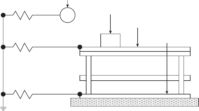
776
Chapter 20 ■ Management, Monitoring, and Optimization
c20.indd 04/02/2015 Page 776
Electrical Safety
IT personnel spend a great deal of time dealing with electrical devices. Therefore, electrical
safety should be stressed in all procedures. In this section, we’ll look at key issues involved
with electrical safety, relevant to preventing injuries and for preventing damage to com-
puter equipment.
Grounding Grounding is the electrical term for providing a path for an electrical charge
to follow to return to earth. To prevent injury to yourself when you are working with
equipment, you should ensure that you are grounded. To avoid damaging the equipment
with which you are working, it should also be grounded.
You can provide grounding to yourself or the equipment with either a grounding strap or
a grounding mat. Either of these should be plugged into the ground of an electrical outlet.
The way in which these devices are connected to ground is pictured in Figure 20.8.
FIGURE 20.8 Grounding methods
1 MΩ
1 MΩ
1 MΩ
Building floor
Personnel wrist strap
ESD-protective foam, trays, etc.
ESD-protective table mat
ESD-protective
floor or mat
ESD Electrostatic discharge (ESD) is the technical term for what happens whenever two
objects of dissimilar charge come in contact. ESD can be generated easily by walking across
a carpeted oor. While the amount of ESD generated doing that may shock you if you
touch a doorknob, it’s really not enough to harm you. However, even that small amount is
enough to seriously damage sensitive parts of computers.
This is exactly why we ground both ourselves and the equipment—to prevent ESD damage.
Always use mats and straps to prevent damage when working with computing equipment.
Static When ESD is created, it’s a form of static energy. Extremely dry conditions in the
area where computers are utilized make the problem of static electricity worse. This is
why the humidity of the area must be controlled so that it’s not too humid, which causes
Network Monitoring
777
c20.indd 04/02/2015 Page 777
corrosion of electrical connections, and not too dry, which causes static buildup and
potential for damage.
Installation Safety
While protecting yourself from electrical injury is very important, it’s not the only safety
issue you’ve got to take into consideration. Other types of injuries can also occur, ranging
from a simple pulled muscle to a more serious incident requiring a trip to the hospital. The
following issues related to installing equipment should also be taken into consideration.
Lifting Equipment Oftentimes when a piece of equipment is being installed, the time pres-
sures involved and the rush to “get ’er done” can lead to improper lifting. Always keep in
mind these safe lifting techniques:
■ Be careful to not twist when lifting. Keep the weight at the center of your body.
■ Keep objects as close to your body as possible and at waist level.
■ Lift with your legs, not your back. When you have to pick up something, bend at
the knees, not at the waist. You want to maintain the natural curve of the back
and spine when lifting.
■ Whenever possible, push instead of pull.
Rack Installation Even for a small business, it’s bad business to operate computing equip-
ment in a poor environment such as on a shelf. There is a reason so many devices come
“rack ready.” Racks not only make for a neat and clean server room or closet, but when
combined with proper cable management and environmental control, they provide an envi-
ronment that allows the devices to breathe and stay cool.
When installing racks, always follow the manufacturer’s directions and always use the
correct tools! Countless screws have been ruined using the wrong tool.
Server racks are measured in terms of rack units, usually written as RU or simply U. One
rack unit equals 1.75 inches (44.45mm) in height, with compliant equipment measured in
multiples of U. Network switches are generally 1U to 2U, servers can range from 1U to 4U,
and blade servers can be anywhere from 5U to 10U or more.
I’ll cover the types of racks you’re likely to encounter in more detail later in this chapter.
Placement The most important issue when placing devices is to ensure proper cooling and
protection from moisture. It’s a good idea to align the racks and install your equipment in
hot and cold aisles. The goal of a hot aisle/cold aisle con guration is to conserve energy and
lower cooling costs by managing air ow.
Hot aisle/cold aisle design involves lining up racks in alternating rows with cold air intakes
facing one way and hot air exhausts facing the other. The rows composed of rack fronts
are called cold aisles. Typically, cold aisles face air conditioner output ducts. The rows
the heated exhausts pour into are called hot aisles and face air conditioner return ducts.
Moreover, all of the racks and the equipment they hold should never be on the oor. There
should be a raised oor to provide protection against water.
Figure 20.9 pictures a solid arrangement:
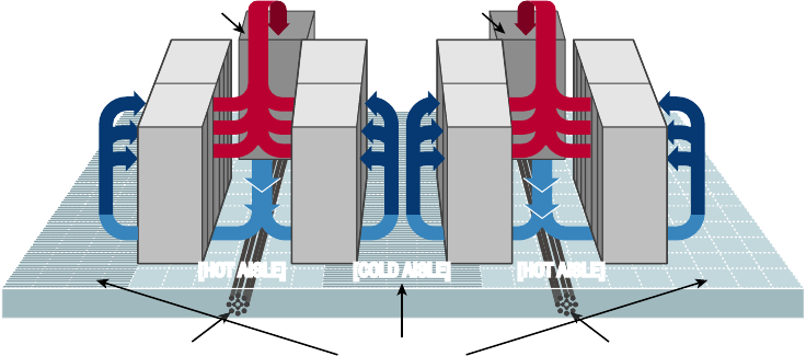
778
Chapter 20 ■ Management, Monitoring, and Optimization
c20.indd 04/02/2015 Page 778
FIGURE 20.9 Hot and cold aisles
Precision Air
Conditioning Unit
Precision Air
Conditioning Unit
Perforated TilesCable Management Cable Management
[RAISED FLOOR]
HOT AISLE/ COLD AISLE APPROACH
[HOT AISLE] [HOT AISLE][COLD AISLE]
[
RAISED FLOOR
]
Tool sa fety It’s worth mentioning again that the rst step on safely using tools is to make
sure you’re properly grounded. Besides practicing tool safety for your own welfare, you
should do so to protect the equipment. Here are some speci c guidelines to follow:
■ Avoid using pencils inside a computer. They can become a conductor and
causedamage.
■ Be sure that the tools you are using have not been magnetized. Magnetic fields can
be harmful to data stored on magnetic media.
■ When using compressed air to clean inside the computer, blow the air around the
components with a minimum distance of 4 inches (10 centimeters) from the nozzle.
■ Clean the contacts on components with isopropyl alcohol. Do not use rubbing alcohol.
■ Never use a standard vacuum cleaner inside a computer case. The plastic parts of
the vacuum cleaner can build up static electricity and discharge to the components.
Use only vacuums that are approved for electronic components.
MSDS In the course of installing, servicing, and repairing equipment, you’ll come in
contact with many different types of materials. Some are safer than others. You can get
all the information you need regarding the safe handling of materials by reviewing the
Materials Safety Data Sheet (MSDS).
Any type of chemical, equipment, or supply that has the potential to harm the environ-
ment or people has to have an MSDS associated with it. These are traditionally created
by the manufacturer and describe the boiling point, melting point, ash point, and poten-
tial health risks. You can obtain them from the manufacturer or from the Environmental
Protection Agency.
Network Monitoring
779
c20.indd 04/02/2015 Page 779
Emergency Procedures
Every organization should be prepared for emergencies of all types. If possible this plan-
ning should start with the design of the facility and its layout. In this section, I’ll go over
some of the components of a well-planned emergency system along with some guidelines
for maintaining safety on a day-to-day basis.
Building Layout Planning for emergences can start with the layout of the facility. Here are
some key considerations:
■ All walls should have a two-hour minimum fire rating.
■ Doors must resist forcible entry.
■ The location and type of fire suppression systems should be known.
■ Flooring in server rooms and wiring closets should be raised to help mitigate
flooding damage.
■ Separate AC units must be dedicated to the information processing facilities.
■ Backup and alternate power sources should exist.
Fire Escape Plan You should develop a plan that identi es the escape route in the event
of a re. You should create a facility map showing the escape route for each section of the
building, keeping in mind that it’s better to use multiple exits to move people out quickly.
These diagrams should be placed in all areas.
Safety/Emergency Exits All escape routes on the map should have the following
characteristics:
■ Clearly marked and well lit
■ Wide enough to accommodate the expected number of people
■ Clear of obstructions
Fail Open/Fail Close Door systems that have electronic locks may lose power during a
re. When they do, they may lock automatically (fail close) or unlock automatically (fail
open). While a fail close setting may enhance security during an electrical outage, you
should consider the effect it will have during an evacuation and take steps to ensure that
everyone can get out of the building when the time comes.
Emergency Alert System All facilities should be equipped with a system to alert all
employees when a re or any other type of emergency occurs. It might be advisable to
connect the facility to the Emergency Alert System (EAS), which is a national warning sys-
tem in the United States. One of the functions of this system is to alert the public of local
weather emergencies such as tornadoes and ash oods. EAS messages are transmitted
via AM and FM radio, broadcast television, cable television, and the Land Mobile Radio
Service as well as VHF, UHF, and FiOS (wireline video providers).
Fire-Suppression Systems While re extinguishers are important and should be placed
throughout a facility, when large numbers of computing devices are present, it is worth the
money to protect them with a re-suppression system. The following types of systemsexist:
780
Chapter 20 ■ Management, Monitoring, and Optimization
c20.indd 04/02/2015 Page 780
■ Wet pipe systems use water contained in pipes to extinguish the fire.
■ Dry pipe systems hold the water in a holding tank instead of in the pipes.
■ Preaction systems operate like a dry pipe system except that the sprinkler head
holds a thermal-fusible link that must melt before the water is released.
■ Deluge systems allow large amounts of water to be released into the room, which
obviously makes this not a good choice where computing equipment will be located.
■ Today, most companies use a fire-suppressant like Halon, which is known as a
“Clean Agent, an electrically non-conducting, volatile, or gaseous fire extinguisher
that does not leave a residue upon evaporation.” Leaving no residue means not ren-
dering inoperative expensive networking equipment like water can do if released in
a data center. It’s remarkably safe for human exposure, meaning that it won’t poi-
son living things, and will allow you to leave the area safely, returning only after
the fire department gives the all-clear.
HVAC
The heating and air-conditioning systems must support the massive amounts of computing
equipment deployed by most enterprises. Computing equipment and infrastructure devices
like routers and switches do not like the following conditions:
■ Heat. Excessive heat causes reboots and crashes.
■ High humidity. It causes corrosion problems with connections.
■ Low humidity. Dry conditions encourage static electricity, which can damage equipment.
Here are some important facts to know about temperature:
■ At 100 degrees, damage starts occurring to magnetic media. In fact, floppy disks are
the most susceptible.
■ At 175 degrees, damage starts occurring to computers and peripherals.
■ At 350 degrees, damage starts occurring to paper products.
Implementing Network Segmentation
Maintaining security in the network can be made easier by segmenting the network and
controlling access from one segment to another. Segmentation can be done at several layers
of the OSI model. The most extreme segmentation would be at Layer 1 if the networks are
actually physically separated from one another. In other cases, it may be suf cient to seg-
ment a network at Layer 2 or Layer 3. Coming up next, we’ll look at some systems that
require segmentation from other networks at one layer or another.
SCADA Systems/Industrial Control Systems
Industrial control system (ICS) is a general term that encompasses several types of control
systems used in industrial production. The most widespread is Supervisory Control and Data
Acquisition (SCADA). SCADA is a system operating with coded signals over communication
channels to provide control of remote equipment. It includes the following components:
Network Monitoring
781
c20.indd 04/02/2015 Page 781
■ Sensors, which typically have digital or analog I/O, and these signals are not in a form
that can be easily communicated over long distances
■ Remote terminal units (RTUs), which connect to the sensors and convert sensor data to
digital data (includes telemetry hardware)
■ Programmable logic controllers (PLCs), which connect to the sensors and convert
sensor data to digital data (does not include telemetry hardware)
■ Telemetry systems, which connect RTUs and PLCs to control centers and the
Enterprise
■ Human interface, which presents data to the operator
■ ICS server, also called a data acquisition server, which uses coded signals over commu-
nication channels to acquire information about the status of the remote equipment for
display or for recording functions
The distributed control system (DCS) network should be a closed network, meaning it
should be securely segregated from other networks. The Stuxnet virus hit the SCADA used
for the control and monitoring of industrial processes.
Medianets
Medianets are networks primarily devoted to VoIP and video data that often require seg-
mentation from the rest of the network at some layer. We implement segmentation for two
reasons: rst, to ensure the security of the data, and second, to ensure that the network
delivers the high performance and low latency required by these applications. One such
high-demand application is video teleconferencing (VTC), which I’ll cover next.
Video Teleconferencing (VTC)
IP video has ushered in a new age of remote collaboration. This has saved a great deal of
money on travel expenses and enabled more ef cient use of time. When you’re implement-
ing IP video systems, consider and plan for the following issues:
■ Expect a large increase in the need for bandwidth.
■ QoS will need to be configured to ensure performance.
■ Storage will need to be provisioned for the camera recordings.
■ Initial cost may be high.
There are two types of VTC systems. Let’s look at both:
ISDN The rst VTC systems were ISDN based. These systems were based on a standard
called H.320. While the bandwidth in each ISDN line is quite low by today’s standard
(128Kb per line), multiple lines could be combined or bonded.
IP/SIP VTC systems based on IP use a standard called H.323. Since these work on a
packet-switched network, you don’t need a direct ISDN link between the sites. Session
Initiation Protocol can also be used, and it operates over IP but lacks many of the struc-
tured call control functions that H.323 provides.
782
Chapter 20 ■ Management, Monitoring, and Optimization
c20.indd 04/02/2015 Page 782
Legacy Systems
Legacy systems are those that are older and incompatible with more modern systems and
equipment. They may also be less secure and no longer supported by the vendor. In some
cases, these legacy systems, especially with respect to industrial control systems, sometimes
use propriety protocols that prevent them from communicating on the IP-based network.
It’s a good idea to segment these systems to protect them from security issues they aren’t
equipped to handle or even just to allow them to function correctly.
Separate Private/Public Networks
Public IP addressing isn’t typically used in a modern network. Instead, private IP addresses
are used and Network Address Translation services are employed to convert traf c to a
public IP address when the traf c enters the Internet. While this is one of the strategies
used to conserve the public IP address space, it also served to segment the private network
from the public network (Internet). Hiding the actual IP address (private) of the hosts inside
the network makes it very dif cult to make an unsolicited connection to a system on the
inside of the network from the outside.
Honeypot/Honeynet
Another segmentation tactic is to create honeypots and honeynets. Honeypots are systems
strategically con gured to be attractive to hackers and to lure them into spending enough
time attacking them while information is gathered about the attack. In some cases, entire
networks called honeynets are attractively con gured for this purpose.
You need to make sure that either of these types of systems do not provide direct con-
nections to any important systems. Their ultimate purpose is to divert attention from valu-
able resources and to gather as much information about an attack as possible. A tarpit is
a type of honeypot designed to provide a very slow connection to the hacker so that the
attack takes enough time to be properly analyzed.
Testing Lab
Testing labs are used for many purposes. Sometimes they’re created as an environment for
developers to test applications. They may also be used to test operating system patches and
antivirus updates. These environments may even be virtual environments. Virtualization
works well for testing labs because it makes it easier to ensure that the virtual networks
have no physical connection to the rest of the network, providing necessary segmentation.
Security
One of the biggest reasons for implementing segmentation is for security purposes. At
Layer 1, this means complete physical separation. However, if you don’t want to go with
complete segmentation, you can also segment at Layer 2 on switches by implementing
VLANs and port security. This can prevent connections between systems that are con-
nected to the same switch. They can also be used to organize users into common networks
regardless of their physical location.
Network Optimization
783
c20.indd 04/02/2015 Page 783
If segmentation at Layer 3 is required, it’s achieved using access control lists on routers
to control access from one subnet to another or from one VLAN to another. Firewalls can
implement these types of access lists as well.
Compliance
Finally, network segmentation may be required to comply with an industry regulation. For
example, while it’s not strictly required, the Payment Card Industry Data Security Standard
(PCI DSS) strongly recommends that the credit card network should be segmented from the
regular network. If you choose not to do this, your entire network must be compliant with
all sections of the standard.
Network Optimization
Regardless of how well a network is functioning, you should never stop trying to optimize
its performance. This is especially true when latency-sensitive applications such as VoIP,
streaming video, and web conferencing are implemented. In the next several sections, I’ll
discuss some techniques you can use to ensure that these applications and services deliver
on their promise of increased functionality.
Reasons to Optimize Your Network’s Performance
So why do we have networks, anyway? I don’t mean this in a historical sense; I mean
pragmatically. The reason they’ve become such precious resources is that as our world has
become smaller and more connected, we need a way to keep in touch like never before.
Networks make accessing resources easy for people who can’t be in the same location as
the resources they need—including other people.
In essence, networks of all types are really complex tools we use to facilitate commu-
nication from afar and to allow lots of us to access the resources we need to keep up with
the demands imposed on us in today’s lightning-paced world. And use them we do—a lot!
And when we have many, many people trying to access one resource like a valuable le
server or a shared database, our systems can get as bogged down and clogged as a freeway
at rush hour. Just as road rage can result from driving on one of those not-so-expressways,
frustrated people can direct some serious hostility at you if the same thing happens when
they’re trying to get somewhere using a network that’s crawling along at snail speed.
This is why optimizing performance is in everyone’s best interest—it keeps you and you
network’s users happily humming along. Optimization includes things like splitting up
network segments, stopping unnecessary services on servers, of oading one server’s work
onto another, and upgrading outmoded hardware devices to newer, faster models. I’ll get
to exactly how to make all this happen coming up soon, but rst, I’m going to talk about
the theories behind performance optimization and even more about the reasons for making
sure performance is at its best.
784
Chapter 20 ■ Management, Monitoring, and Optimization
c20.indd 04/02/2015 Page 784
In a perfect world, there would be unlimited bandwidth, but in reality, you’re more
likely to nd Bigfoot. So, it’s helpful to have some great strategies up your sleeve.
If you look at what computers are used for today, there’s a huge difference between
the les we transfer now versus those transferred even three to ve years ago. Now we do
things like watch movies online without them stalling, and we can send huge email attach-
ments. Video teleconferencing is almost more common than Starbucks locations. The point
is that the les we transfer today are really large compared to what we sent back and forth
just a few years ago. And although bandwidth has increased to allow us to do what we do,
there are still limitations that cause network performance to suffer miserably. Let’s start
with a few reasons why you need to carefully manage whatever amount of precious band-
width you’ve got.
Latency Sensitivity
Most of us have clicked to open an application or clicked a web link only to have the
computer just sit there staring back at us, helplessly hanging. That sort of lag comes when
the resources needed to open the program or take us to the next page are not fully avail-
able. That kind of lag on a network is called latency—the time between when data is
requested and the moment it actually gets delivered. The more latency, the longer the delay
and the longer you have to stare blankly back at your computer screen, hoping something
happenssoon.
Latency affects some programs more than others. If you are sending an email, it may
be annoying to have to wait a few seconds for the email server to respond, but that type
of delay isn’t likely to cause physical harm to you or a loved one. Applications that are
adversely affected by latency are said to have high latency sensitivity. A common example
of this is online gaming. Although it may not mean actual life or death, playing certain
online games with signi cant delays can mean the untimely demise of your character—and
you won’t even know it. Worse, it can affect the entire experience for those playing with
you, which can get you booted from some game servers. On a much more serious level,
applications like remote surgery also have high latency sensitivity.
High-Bandwidth Applications
Many of the applications we now use over the network would have been totally unservice-
able in the past because of the high amount of bandwidth they consume. And even though
technology is constantly improving to give us more bandwidth, developers are in hot pur-
suit, developing new applications that gobble up that bandwidth as soon as it becomes—
even in advance of it becoming—available. A couple of good examples of high-bandwidth
applications are VoIP and video streaming:
VoIP Voice over Internet Protocol (VoIP) describes several technologies that work to
deliver voice communications over the Internet or other data networks. In many cases,
VoIP includes not only voice but video transmissions as well. VoIP allows us to send voice,
video, and data all over the same connection to another location. Its most common applica-
tion is video teleconferencing.
Network Optimization
785
c20.indd 04/02/2015 Page 785
Many companies are investing in VoIP systems to reduce travel costs. Ponying up for pricey
plane tickets, lodging, and rental cars adds up fast, so investing in a good VoIP system that
allows the company to have virtual conferences with people in another state or country
pays for itself in no time.
But sadly, VoIP installations can be stressed heavily by things like really low bandwidth,
latency issues, packet loss, jitter, security aws, and reliability concerns. And in some cases,
routing VoIP through rewalls and routers using address translation can prove pretty prob-
lematic as well.
Video Applications Watching real-time video on the Internet today is great if you have a
decent high-speed connection. You can watch the news, sports, movies, and pretty much
anything else that you watch on television. Although viewing digital media online is so
common that anyone born after the year 2000 won’t be able to remember a time when we
had to watch videos on anything other than a computer, again, this requires lots of band-
width. And excessive use can cause traf c problems even on the most robust networks!
Other Real-Time Services
While VOIP and video traf c certainly require the most attention with respect to perfor-
mance and latency, other real-time services are probably in use in your network. We’re going
to brie y look at presence, another example of real-time services you may not give a lot of
thought to, and then I’ll compare the use of unicast and multicast in real-time services.
Presence Presence is a function provided by many collaboration solutions that indicates the
availability of a user. It signals to other users whether a user is online, busy, in a meeting, and so
forth. If enabled across multiple communication tools, such as IM, phone, email, and videocon-
ferencing, it also can help determine the communication channel on which the user is currently
active and therefore which channel provides the best possibility of an immediate response.
Multicast vs Unicast Unicast transmissions represent a one-to-one conversation, that is,
data sent from a single device to another single device. On the other hand, Multicast is a
technology that sends information for a single source to multiple recipients and is far supe-
rior to using unicast transmission when it comes to video streaming and conferencing.
While unicast transmission creates a data connection and stream for each recipient, mul-
ticast uses the same stream for all recipients. This single stream is replicated as needed by
multicast routers and switches in the network. The stream is limited to branches of the net-
work topology that actually have subscribers to the stream. This greatly reduces the use of
bandwidth in the network.
Uptime
Uptime is the amount of time the system is up and accessible to your end users, so the more
uptime you have the better. And depending on how critical the nature of your business is,
you may need to provide four-nine or ve-nine uptime on your network—that’s a lot. Why
is this a lot? Because you write out four-nine as 99.99%, or better, you write out ve-nine
as 99.999%! Now that is some serious uptime!
786
Chapter 20 ■ Management, Monitoring, and Optimization
c20.indd 04/02/2015 Page 786
How to Optimize Performance
You now know that bandwidth is to networking as water is to life, and you’re one of the
lucky few if your network actually has an excess of it. Cursed is the downtrodden admin-
istrator who can’t seem to nd enough, and more fall into this category than the former.
At times, your very sanity may hinge upon ensuring that your users have enough available
bandwidth to get their jobs done on your network, and even if you’ve got a 1Gbps connec-
tion, it doesn’t mean all your users have that much bandwidth at their ngertips. What it
really means is that they get a piece of it, and they share the rest with other users and net-
work processes. Because it’s your job to make sure as much of that 1Gbps as possible is there
to use when needed, I’m going to discuss some really cool ways to make that happen for you.
Quality of Service
Quality of service (QoS) refers to the way the resources are controlled so that the quality
of services is maintained. It’s basically the ability to provide a different priority to one or
more types of traf c over other levels for different applications, data ows, or users so that
they can be guaranteed a certain performance level.
QoS methods focus on one of ve problems that can affect data as it traverses
networkcable:
Delay Data can run into congested lines or take a less-than-ideal route to the destination,
and delays like these can make some applications, such as VoIP, fail. This is the best rea-
son to implement QoS when real-time applications are in use in the network—to prioritize
delay-sensitive traf c.
Dropped Packets Some routers will drop packets if they receive a packet while their
buffers are full. If the receiving application is waiting for the packets but doesn’t get them,
it will usually request that the packets be retransmitted—another common cause of a
service(s) delay.
Error Packets can be corrupted in transit and arrive at the destination in an unacceptable
format, again requiring retransmission and resulting in delays.
Jitter Not every packet takes the same route to the destination, so some will be more
delayed than others if they travel through a slower or busier network connection. The
variation in packet delay is called jitter, and this can have a nastily negative impact on
programs that communicate in real time.
Out-of-Order Delivery Out-of-order delivery is also a result of packets taking different
paths through the network to their destinations. The application at the receiving end needs
to put them back together in the right order for the message to be completed, so if there are
signi cant delays or the packets are reassembled out of order, users will probably notice
degradation of an application’s quality.
QoS can ensure that applications with a required bit rate receive the necessary band-
width to work properly. Clearly, on networks with excess bandwidth, this is not a factor,
but the more limited your bandwidth is, the more important a concept like this becomes.

Network Optimization
787
c20.indd 04/02/2015 Page 787
DSCP
One of the methods that can be used for classifying and managing network traf c and pro-
viding quality of service (QoS) on modern IP networks is Differentiated Services Code Point
(DSCP), or DiffServ. DiffServ uses a 6-bit differentiated services code point (DSCP) in the 8-bit
Differentiated Services eld (DS eld) in the IP header for packet classi cation. This allows for
the creation of traf c classes that can be used to assign priorities to various traf c classes.
In theory, a network could have up to 64 different traf c classes using different DSCPs,
but most networks use the following traf c classi cations:
■ Default, which is typically best-effort traffic
■ Expedited Forwarding (EF), which is dedicated to low-loss, low-latency traffic
■ Assured Forwarding (AF), which gives assurance of delivery under prescribed conditions
■ Class Selector, which maintains backward compatibility with the IP Precedence field
(afield formerly used by the Type of Service, or TOS, function)
Class of Service (COS)
The second method of providing traf c classi cation and thus the ability to treat the classes
differently is a 3-bit eld called the Priority Code Point (PCP) within an Ethernet frame
header when VLAN tagged frames as de ned by IEEE 802.1Q are used.
This method is de ned in the IEEE 802.1p standard. It describes eight different classes
of service as expressed through the 3-bit PCP eld in an IEEE 802.1Q header added to the
frame. These classes are shown in Table 20.2.
TABLE 20.2 Eight levels of QoS
Level Description
0Best effort
1 Background
2 Standard (spare)
3 Excellent load (business-critical applications)
4 Controlled load (streaming media)
5 Voice and video (interactive voice and video, less than 100ms latency and jitter)
6 Layer 3 Network Control Reserved Traffic (less than 10ms latency and jitter)
7 Layer 2 Network Control Reserved Traffic (lowest latency and jitter)
788
Chapter 20 ■ Management, Monitoring, and Optimization
c20.indd 04/02/2015 Page 788
QoS levels are established per call, per session, or in advance of the session by an agree-
ment known as a service-level agreement (SLA).
Unified Communications
Increasingly, workers and the organizations for which they work are relying on new meth-
ods of communicating and working together. Uni ed communications (UC) is the integra-
tion of real-time communication services such as instant messaging with non-real-time
communication services such as uni ed messaging (integrated voicemail, email, SMS, and
fax). UC allows an individual to send a message on one medium and receive the same com-
munication on another medium.
UC systems are made of several components that make sending a message on one
medium and receiving the same communication on another medium possible. The follow-
ing may be part of a UC system:
UC Servers The UC server is the heart of the system. It provides call control mobility ser-
vices and administrative functions. It may be a standalone device or in some cases a module
that is added to a router.
UC Devices UC devices are the endpoints that may participate in uni ed communica-
tions. This includes computers, laptops, tablets, and smartphones.
UC Gateways UC gateways are used to tie together geographically dispersed locations
that may want to make use of UC facilities. They are used to connect the IP-based network
with the Public Switched Telephone Network (PSTN).
Traffic Shaping
Traf c shaping, or packet shaping, is another form of bandwidth optimization. It works by
delaying packets that meet a certain criteria to guarantee usable bandwidth for other appli-
cations. Traf c shaping is basically traf c triage—you’re really just delaying attention to
some traf c so other traf c gets A-listed through. Traf c shaping uses bandwidth throttling
to ensure that certain data streams don’t send too much data in a speci ed period of time as
well as rate limiting to control the rate at which traf c is sent.
Most often, traf c shaping is applied to devices at the edge of the network to control
the traf c entering the network, but it can also be deployed on devices within an internal
network. The devices that control it have what’s called a traf c contract that determines
which packets are allowed on the network and when. You can think of this kind of like
the stoplights on busy freeway on-ramps, where only so much traf c is allowed onto
the road at one time, based on prede ned rules. Even so, some traf c (like carpools and
emergency vehicles) is allowed on the road immediately. Delayed packets are stored in
the managing device’s rst-in, rst-out (FIFO) buffer until they’re allowed to proceed
per the conditions in the contract. If you’re the rst car at the light, this could happen
immediately. If not, you get to go after waiting brie y until the traf c in front of you is
released.

Network Optimization
789
c20.indd 04/02/2015 Page 789
Load Balancing
Load balancing refers to a technique used to spread work out to multiple computers, net-
work links, or other devices.
Using load balancing, you can provide an active/passive server cluster in which only one
server is active and handling requests. For example, your favorite Internet site might actu-
ally consist of 1 of 20 servers that all appear to be the same exact site because that site’s
owner wants to ensure that its users always experience quick access. You can accomplish
this on a network by installing multiple, redundant links to ensure that network traf c is
spread across several paths and to maximize the bandwidth on each link.
Think of this as like having two or more different freeways that will both get you to
your destination equally well—if one is really busy, just take the other one.
High Availability
High availability is a system-design protocol that guarantees a certain amount of opera-
tional uptime during a given period. The design attempts to minimize unplanned down-
time—the time users are unable to access resources. In almost all cases, high availability
is provided through the implementation of duplicate equipment (multiple servers, multiple
NICs, etc.). Organizations that serve critical functions obviously need this; after all, you
really don’t want to blaze your way to a hospital ER only to nd that they can’t treat you
because their network is down!
There’s a difference between planned downtime and unplanned downtime.
Planned downtime is good—it’s occasionally scheduled for system mainte-
nance and routine upgrades. Unplanned downtime is bad: It’s a lack of access
due to system failure, which is exactly the issue high-availability resolves.
One of the highest standards in uptime is the ability to provide the ve-nine availability I
mentioned earlier. This actually means the network is accessible 99.999% of the time—way
impressive! Think about this. In one non-leap year, there are 31,536,000 seconds. If you
are available 99.999% of the time, it means you can be down only 0.001% of the time, or a
total of 315.36 seconds, or 5 minutes and 15.36 seconds per year—wow!
There’s a difference between uptime and availability. Your servers may
be up but not accessible if a cable gets cut or something, and that outage
would definitely count against your availability time.
Caching Engines
A cache is a collection of data that duplicates key pieces of original data. Computers use
caches all the time to temporarily store information for faster access, and processors have
both internal and external caches available to them, which speeds up their response times.
790
Chapter 20 ■ Management, Monitoring, and Optimization
c20.indd 04/02/2015 Page 790
A caching engine is basically a database on a server that stores information people need
to access fast. The most popular implementation of this is with web servers and proxy serv-
ers, but caching engines are also used on internal networks to speed up access to things like
database services.
Fault Tolerance
Fault tolerance means that even if one component fails, you won’t lose access to the
resource it provides. To implement fault tolerance, you need to employ multiple devices or
connections that all provide a way to access the same resource(s).
A familiar form of fault tolerance is con guring an additional hard drive to be a mir-
ror image of another so that if either one fails, there’s still a copy of the data available to
you. In networking, fault tolerance means that you have multiple paths from one point to
another. What’s really cool is that fault-tolerant connections can be con gured to be avail-
able either on a standby basis only or all the time if you intend to use them used as part of a
load-balancing system.
Archives/Backups
While providing redundancy to hardware components is important, the data that resides
on the components must also be archived in case a device where the data is stored has to be
replaced. It could be a matter of replacing a hard drive on which the data cannot be saved
and restoring the data from tape backup. Or suppose RAID has been enabled in a system;
in that case, the loss of a single hard drive will not present an immediate loss of access to
the data (although a replacement of the bad drive will be required to recover from another
drive failure). RAID systems are covered in more detail in Chapter 15, “Physical Security
and Risk.”
With regard to the data backups, they must be created on a schedule and tested regu-
larly to ensure that a data restoration is successful. The three main data backup types are
full backups, differential backups, and incremental backups. But to understand them, you
must grasp the concept of archive bits. When a le is created or updated, the archive bit for
the le is enabled. If the archive bit is cleared, the le will not be archived during the next
backup. If the archive bit is enabled, the le will be archived during the next backup.
The end result is that each type of backup differs in the amount of time taken, the
amount of data backed up, whether unchanged data is backed up repeatedly, and the num-
ber of tapes required to restore the data. Keep these key facts in mind:
■ If you use a full back up once a week and differential backups the other days of the
week, to restore you will only need the last full backup tape and the last differential
tape. This is the fastest restore.
■ If you use a full back up once a week and incremental backups the other days of the
week, to restore you will need the last full backup tape and all of the incremental tapes.
This is the slowest restore.
A comparison of the three main backup types is shown in Figure 20.10.

Network Optimization
791
c20.indd 04/02/2015 Page 791
FIGURE 20.10 Backup types
Backup Type Data Backed Up Backup Time Restore Time Storage Space
Full backup
Incremental
backup
Only new/modified
files/folders Fast
FastModerate
Moderate
Moderate
Lowest
All data since
last full
Differential
backup
All data Slowest Fast
High
Common Address Redundancy Protocol
Common Address Redundancy Protocol (CARP) provides IP-based redundancy, allowing
a group of hosts on the same network segment (referred to as a redundancy group) to share
an IP address. One host is designated the master and the rest are backups. The master host
responds to any traf c or ARP requests directed toward it. Each host may belong to more
than one redundancy group at a time.
One of its most common uses is to provide redundancy for devices such as rewalls or
routers. The virtual IP address (this is another name for the shared group IP address) will
be shared by a group of routers or rewalls.
The client machines use the virtual IP address as their default gateway. In the event that
the master router suffers a failure or is taken of ine, the IP will move to one of the backup
routers and service will continue. Other protocols that use similar principles are Virtual
Router Redundancy Protocol and the Hot Standby Router Protocol.
Virtual Networking
Over the last few years, one of the most signi cant developments helping to increase the
ef cient use of computing resources—leading to an increase in network performance with-
out an increase in spending on hardware—has been the widespread adoption of virtualiza-
tion technology. You can’t read an industry publication without coming across the term
cloud computing within 45 seconds!
The concept of virtualization is quite simple. Instead of dedicating a physical piece of
hardware to every server, run multiple instances of the server operating system, each in its
own “virtual environment” on the same physical piece of equipment. This saves power,
maximizes the use of memory and CPU resources, and can even help to “hide” the physical
location of each virtual server.
Virtual computing solutions come from a number of vendors. The following are some of
the more popular currently:
■ VMware vSphere
■ Microsoft Hyper-V
■ Citrix XenServer
792
Chapter 20 ■ Management, Monitoring, and Optimization
c20.indd 04/02/2015 Page 792
All of these solutions work on the same basic concept but each has its own unique
features, and of course all claim to be the best solution. In the following sections, I will dis-
cuss the building blocks of virtualization rather than the speci c implementation from any
single vendor.
Onsite vs Offsite
Often you hear the terms public cloud and private cloud. Clouds can be thought of as vir-
tual computing environments where virtual servers and desktops live and can be accessed
by users. A private cloud is one in which this environment is provided to the enterprise by
a third party for a fee. This is a good solution for a company that has neither the expertise
nor the resources to manage their own cloud yet would like to take advantage of the ben-
e ts that cloud computing offers:
■ Increased performance
■ Increased fault tolerance
■ Constant availability
■ Access from anywhere
These types of clouds might be considered offsite or public. On the other hand, for the
organization that has the expertise and resources, a private or onsite solution might be bet-
ter and might be more secure. This approach will enjoy the same bene ts as a public cloud
and may offer more precise control and more options to the organization.
Virtual Networking Components
Virtualization can be deployed in several different ways to deliver cost-effective solutions to
different problems. Each of the following components can have its place in the solution:
Virtual Servers Virtual servers can perform all the same functions as physical servers but
can enjoy some signi cant advantages. By clustering a virtual server with other virtual serv-
ers located on different hosts, you can achieve fault tolerance in the case of a host failure.
Increased performance can also be derived from this approach.
The virtualization software can allow you to allocate CPU and memory resources to the
virtual machines (VMs) dynamically as needed to ensure that the maximum amount of
computing power is available to any single VM at any moment while not wasting any of
that power on an idle VM. In fact, in situations where VMs have been clustered, they may
even be suspended or powered down in times of low demand in the cluster.
Virtual Switches Virtual switches are software versions of a Layer 2 switch that can
be used to create virtual networks. They can be used for the same purposes as physical
switches. VLANs can be created, virtual servers can be connected to the switches, and
the virtual network can be managed, all while residing on the same physical box. These
switches can also span multiple hosts (the physical machines that house multiple virtual
servers, desktops, and switches are called hosts).
Distributed virtual switches are those switches that span multiple hosts, and they are what
link together the VMs that are located on different hosts yet are members of the same cluster.
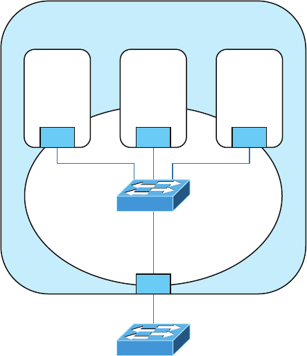
Network Optimization
793
c20.indd 04/02/2015 Page 793
Virtual vs Physical NICs Figure 20.11 shows the relationship between a physical server
and the virtual servers and virtual switches that it hosts. The virtual servers, called virtual
machines (VMs), have virtual network cards (vNICs) that connect to the virtual switch.
Keep in mind that all three of these components are software running on the same physi-
cal server. Then the virtual switch makes a software connection to the physical NIC on the
physical host, which makes a physical connection to the physical switch in the network.
FIGURE 20.11 Virtualization
Physical Server
Virtual
Machine
(VM)
Virtual
Network
Virtual Switch
(Software)
NIC: Network Interface Card
vNIC: Virtual NIC
Physical Switch (Hardware)
NIC
Virtual
Machine
(VM)
vNIC vNIC vNIC
Virtual
Machine
(VM)
It is interesting to note and important to be aware of the fact that the IP address of the
physical NIC in Figure 20.11 will actually be transmitting packets from multiple MAC
addresses since each of the virtual servers will have a unique virtual MAC address.
Virtual Routers In virtualized environments, virtual routers are typically implemented
as specialized software. They consist of individual routing and forwarding tables, each of
which could be considered a virtual router.
Virtual Firewall Virtual rewalls are also implemented as software in the virtualized
environment. Like their physical counterparts, they can be used to restrict traf c between
virtual subnets created by virtual routers.
Software-Defined Networking Software-de ned networking (SDN) is an approach to com-
puter networking that allows network administrators to manage network services through
abstraction of lower-level functionality. SDN architectures decouple network control and
794
Chapter 20 ■ Management, Monitoring, and Optimization
c20.indd 04/02/2015 Page 794
forwarding functions, enabling network control to become directly programmable and the
underlying infrastructure to be abstracted from applications and network services.
Virtual Desktops Using operating system images for desktop computers is not a new con-
cept. Delivering these desktop images to users from a virtual environment when they start
their computer is. This allows for the user desktop to require less computing power, espe-
cially if the applications are also delivered virtually and those applications are running in a
VM in the cloud rather than in the local desktop eating up local resources. Another bene t
of using virtual desktops is the ability to maintain a consistent user environment (same
desktop, applications, etc.), which can enhance user support.
Thin computing takes this a step further. In this case, all of the computing is taking place
on the server. A thin client is simply displaying the output from the operating system run-
ning in the cloud, and the keyboard is used to interact with that operating system in the
cloud. Does this sound like dumb terminals with a GUI to anyone yet? Back to the future
indeed! The thin client needs very little processing power for this job.
Virtual PBX Virtual PBX is an example of what is called software as a service (SaaS). A
hosting company manages the entire phone system for the company, freeing the organiza-
tion from the need to purchase and manage the physical equipment that would be required
otherwise to provide the same level of service. To the outside world, the company appears
to have a professional phone system while everything is actually being routed through the
hosting company’s system.
Network as a Service (NaaS) Now that you know what SaaS is you can probably guess
what NaaS is. You guessed it: a network hosted and managed by a third party on behalf of
the company. For many enterprises, it makes more sense to outsource the management of
the network to a third party when it is not cost effective to maintain a networking staff.
An example of this is the Cisco OpenStack cloud operating system, which is an open-source
platform that provides computers and storage.
Storage Area Network
Storage area networks (SANs) comprise high-capacity storage devices that are connected by
a high-speed private network (separate from the LAN) using a storage-speci c switch. This
storage information architecture addresses the collection of data, management of data, and
use of data. In this section, we’ll take a look at the protocols that can be used to access the
data and the client systems that can use those various protocols. We’ll also look at an alter-
native to a SAN, network-attached storage (NAS).
iSCSI Internet Small Computer System Interface (iSCSI) is an IP-based networking stor-
age standard method of encapsulating SCSI commands (which are used with storage area
networks) within IP packets. This allows the use of the same network for storage as is used
for the balance of the network. A comparison of a regular SAN that uses the Fibre-Channel
protocol, and one using iSCSI is shown in Figure 20.12. I’ll talk more about Fiber Channel
in the next section.
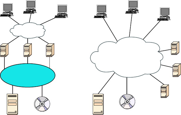
Network Optimization
795
c20.indd 04/02/2015 Page 795
FIGURE 20.12 Classic SAN vs iSCSI
Classic SAN iSCSI
Clients Database
Data IP Network
Servers
Storage
Storage
Fibre Channel
Network
Web
Server
File
Server
Database
Server
HTTP
File
Clients
Database
Data and Storage
IP Network
Storage Web
Server
File
Server
Database
Server
HTTP
File
Fiber Channel Fiber Channel, or FC, is a high-speed network technology (commonly run-
ning at 2-, 4-, 8-, and 16-gigabit per second rates) primarily used to connect computer data
storage. It operates on an optical network that is not compatible with the regular IP-based
data network. As you can see in Figure 20.12, this protocol runs on a private network that
connects the servers to the storage network.
Fibre-Channel over Ethernet (FCoE), on the other hand, encapsulates Fiber Channel
traf c within Ethernet frames much like iSCSI encapsulates SCSI commands in IP pack-
ets. However, unlike iSCSI, it does not use IP at all. It does allow this traf c on the IP
network.
Jumbo Frame Jumbo frames are Ethernet frames with more than 1,500 bytes of payload.
Jumbo frames or 9,000-byte payload frames have the potential to reduce overhead and
CPU cycles. In high-speed networks such as those typically used in a SAN, it may be advis-
able to enable jumbo frames to improve performance.
Network attached storage Network-attached storage (NAS) serves the same function as
SAN, but clients access the storage in a different way. In a NAS con guration, almost any
machine that can connect to the LAN (or is interconnected to the LAN through a WAN)
can use protocols such as NFS, CIFS, and HTTP to connect to the NAS and share les. In
a SAN con guration, only devices that can use the Fiber Channel SCSI network can access
the data, so it’s typically done though a server with this capability. A comparison of the
two systems is shown in Figure 20.13.
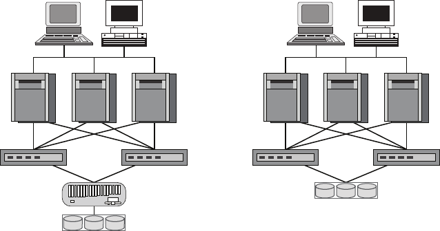
796
Chapter 20 ■ Management, Monitoring, and Optimization
c20.indd 04/02/2015 Page 796
FIGURE 20.13 NAS and SAN
Application
Networks
Application
& Database
Servers
Network-Attached Storage (NAS) Storage Area Network (SAN)
Custom File
Server
RAID Disk
Array
RAID Disk
Array
IP-Based
Ethernet
LAN
Fibre
Channel
SAN
Cloud Concepts
Cloud storage locates the data on a central server, but unlike an internal data center in
the LAN, the data is accessible from anywhere and in many cases from a variety of device
types. Moreover, cloud solutions typically provide fault tolerance and dynamic computer
resource (CPU, memory, network) provisioning.
Cloud deployments can differ in two ways:
■ The entity that manages the solution
■ The percentage of the total solution provided by the vendor
First, let’s look at the options relative to the entity that manages the solution:
■ Private cloud: This is a solution owned and managed by one company solely for that
company’s use.
■ Public cloud: This is a solution provided by a third party. It offloads the details to the
third party but gives up some control and can introduce security issues.
■ Hybrid cloud: This is some combination of private and public. For example, perhaps
you only use the facilities of the provider but still manage the data yourself.
■ Community cloud: This is a solution owned and managed by a group of organizations
that create the cloud for a common purpose.
There are several levels of service that can be made available through a cloud deployment:
■ Infrastructure as a service (IaaS). The vendor provides the hardware platform or data center,
and the company installs and manages its own operating systems and application systems.
■ Platform as a service (PaaS). The vendor provides the hardware platform or data center
and the software running on the platform.
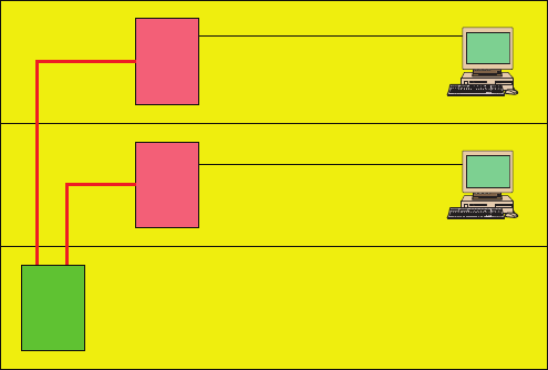
Network Optimization
797
c20.indd 04/02/2015 Page 797
■ Software as a service ( SaaS). The vendor provides the entire solution. This includes the
operating system, infrastructure software, and the application.
Locating and Installing Equipment
When infrastructure equipment is purchased and deployed, the ultimate success of the
deployment can depend on selecting the proper equipment, determining its proper location
in the facility, and installing it correctly. Let’s look at some common data center or server
room equipment and a few best practices for managing these facilities.
Main Distribution Frame
The main distribution frame connects equipment (inside plant) to cables and subscriber car-
rier equipment (outside plant). It also terminates cables that run to intermediate distribution
frames distributed throughout the facility.
Intermediate Distribution Frame
An intermediate distribution frame (IDF) serves as a distribution point for cables from the
main distribution frame (MDF) to individual cables connected to equipment in areas remote
from these frames. The relationship between the IDFs and the MDF is shown in Figure 20.14.
FIGURE 20.14 MDF and IDFs
Cat 5 UTP
Cat 5 UTP
Fiber Optic
Intermediate Distribution
Frame (IDF)
Intermediate Distribution
Frame (IDF)
Main Distribution Frame
(MDF)
Cable Management
While some parts of our network may be wireless, the lion’s share of the network will be
connected with cables. The cables come together in large numbers at distribution points
where managing them becomes important both to protect the integrity of the cables and to
prevent overheating of the infrastructure devices caused by masses of unruly cabling. The
points of congestion typically occur at the patch panels.
798
Chapter 20 ■ Management, Monitoring, and Optimization
c20.indd 04/02/2015 Page 798
Patch panels terminate cables from wall or data outlets. These masses of wires that
emerge from the wall in a room will probably feed to the patch panel in a cable tray, which
I’ll talk more about soon. The critical maintenance issues at the patch panel are to ensure
that cabling from the patch panel to the switch is neat, that the patch cables are as short as
possible without causing stress on the cables, and that the positioning of the cabling does
not impede air ow to the devices, which can cause overheating.
Power Management
Computing equipment of all types needs clean and constant power. Power uctuations of any
sort, especially complete outages and powerful surges, are a serious matter. In this section,
we’ll look at power issues and devices that can be implemented to avoid or mitigate them.
Power Converters Power conversion is the process of converting electric energy from one
form to another. This conversion could take several forms:
■ AC to DC
■ From one voltage level to another
■ From one frequency to another
Power converters are devices that make these conversions, and they typically are placed inline,
where the energy owing into one end is converted to another form when it exits the converter.
Circuits In situations where high availability is required, it may be advisable to provision
multiple power circuits to the facility. This is sometimes called A+B or A/B power. To provi-
sion for A+B power, you should utilize a pair of identically sized circuits (e.g., 2 × 20 amperes).
In the nal analysis, even these systems can fail you in some natural disasters and so you
should always also have power generators as well as a nal backup.
UPS All infrastructure systems and servers should be connected to an uninterruptible
power supply (UPS). As described in Chapter 15, a UPS can immediately supply power
from a battery backup when a loss of power is detected. They provide power long enough
for you to either shut the system down gracefully or turn on a power generator.
Inverters A power inverter is type of power converter that speci cally converts DC to AC.
It produces no power and must be connected to a DC source.
Power Redundancy While the facility itself needs redundant power circuits and backup
generators, a system can still fail if the power supply in the device fails. Mission-critical
devices should be equipped with redundant power supplies, which can mitigate this issue.
Device Placement
When locating equipment in a data center, server room, or wiring closet, the placement of
the equipment should take several issues into consideration.
Air Flow Air ow around the equipment is crucially important to keep devices running.
When hot air is not removed from the area and replaced with cooler air, the devices over-
heat and start doing things like rebooting unexpectedly. Even if the situation doesn’t reach
that point, the high heat will shorten the life of costly equipment.
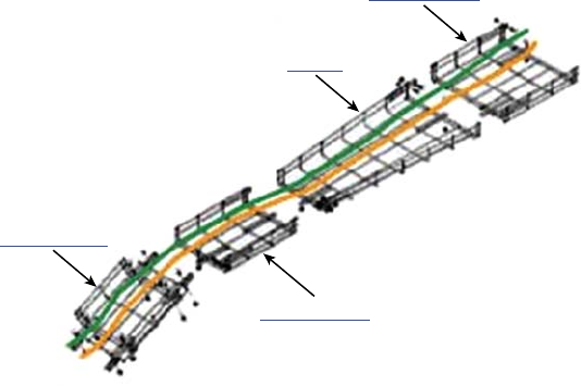
Network Optimization
799
c20.indd 04/02/2015 Page 799
One of the approaches that has been really successful is called hot/cold aisles. As explained
earlier in this chapter, hot aisle/cold aisle design involves lining up racks in alternating rows
with cold air intakes facing one way and hot air exhausts facing the other. The rows com-
posed of rack fronts are called cold aisles. Typically, cold aisles face air conditioner output
ducts. The rows the heated exhausts pour into are called hot aisles. They face air condi-
tioner return ducts. Moreover, all of the racks and the equipment they hold should never be
on the oor. There should be a raised oor to provide some protection against water.
Cable Trays Masses of unruly cables can block air ow and act as a heat blanket on
the equipment if the situation is bad enough. Cable trays are metal trays used to organize
the cabling neatly and keep it away from the areas where it can cause heat buildup. In
Figure20.15, some examples of cable tray components are shown. These are used to orga-
nize the cables and route them as needed.
FIGURE 20.15 Cable trays
Straight Section
Straight Section
Reducer
Cable Tray Drop
Rack Systems Rack systems are used to hold and arrange the servers, routers, switches,
rewalls, and other rack-ready equipment. Rack devices are advertised in terms of Us. U is
the standard unit of measure for designating the vertical usable space, or height of racks.
1U is equal to 1.75 inches. For example, a rack designated as 20U has 20 rack spaces for
equipment and has 35 (20 × 1.75) inches of vertical usable space. You should be familiar
with the following types of rack systems and components:
Server Rail Racks Server rail racks are used to hold servers in one of the types of racks
described next. They are designed to hold the server while allowing the server to be slid
out from the rack for maintenance.
Two-Post Racks A two-post rack is one in which only two posts run from the oor.
These posts may reach to the ceiling or they may not (freestanding). Several sizes of two-
post racks are shown in Figure 20.16.
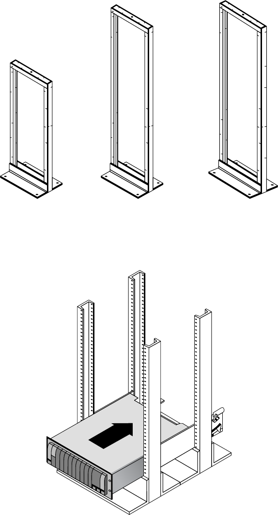
800
Chapter 20 ■ Management, Monitoring, and Optimization
c20.indd 04/02/2015 Page 800
FIGURE 20.16 Two-post racks
Four-Post Racks As you would expect, these racks have four rails and can be either
oor to ceiling or freestanding. One is shown in Figure 20.17.
FIGURE 20.17 Four-post rack

Network Optimization
801
c20.indd 04/02/2015 Page 801
Freestanding racks A freestanding rack is one that does not reach the ceiling and
stands on its own. A four-post freestanding rack is shown in Figure 20.18.
FIGURE 20.18 Freestanding rack
Applying Your Knowledge
You have been assigned the job of positioning the following pieces of equipment in the
network for maximum performance and security:
Firewall
Patch server
Main distribution frame (MDF)
Intermediate distribution frame (IDF)
Public web server
Using the following table, place these fi ve pieces of equipment in the correct position.
The answer is at the end of the chapter.

802
Chapter 20 ■ Management, Monitoring, and Optimization
c20.indd 04/02/2015 Page 802
Device Position
Firewall In the DMZ
Patch server Just after the Internet router
MDF In the server room or closet on each floor
IDF Inside the LAN
Public web server In the server room or closet that is connected to the service provider
ANSWER BELOW
Firewall Just after the Internet router
Patch server Inside the LAN
MDF In the server room or closet that is connected to the service provider
IDF In the server room or closet on each floor
Public web server In the DMZ
Labeling
In a data center, server room, or wiring closet, correct and updated labeling of ports, sys-
tems, circuits, and patch panels can prevent a lot of confusion and mistakes when con gu-
ration changes are made. Working with incorrect or incomplete (in some cases nonexistent)
labeling is somewhat like trying to locate a place with an incorrect or incomplete map. In
this section, we’ll touch on some of the items that should be correctly labeled.
Port Labeling Ports on switches, patch panels, and other systems should be properly
labeled, and the wall outlets to which they lead should match! You should arrive at an
agreement as to the naming convention to use so that all technicians are operating from the
same point of reference. They also should be updated in any case where changes are made
that dictate an update.
System Labeling Other systems that are installed in racks, such as servers, rewall appli-
ances, and redundant power supplies, should also be labeled with IP addresses and DNS
names that the devices possess.
Network Optimization
803
c20.indd 04/02/2015 Page 803
Circuit Labeling Circuits entering the facility should also be labeled. Label electrical
receptacles, circuit breaker panels, and power distribution units. Include circuit informa-
tion, voltage and amperage, the type of electrical receptacle, and where in the data center
the conduit terminates.
Naming Conventions A naming system or convention guides and organizes labeling and
ensures consistency. No matter what name or numbering system you use, be consistent.
Patch Panel Labeling The key issue when labeling patch panels is to ensure that they’re correct.
Also, you need to make sure that the wall outlet they’re connected to is the same. The American
National Standards Institute/Telecommunications Industry Association (ANSI/TIA) 606-B.1
Administration Standard for Telecommunications Infrastructure for identi cation and labeling
approved in April 2012 provides clear speci cations for labeling and administration best prac-
tices across all electrical and network systems premise classes, including large data centers.
Rack Monitoring
Racks should contain monitoring devices that can be operated remotely. These devices can
be used to monitor the following issues:
■ Temperature
■ Humidity
■ Physical security (open doors)
■ Smoke
■ Water leaks
■ Vibration
Rack Security
Rack devices should be secured from theft. There are several locking systems that can be
used to facilitate this. These locks are typically implemented in the doors on the front of a
rack cabinet:
■ Swing handle/wing knob locks with common key
■ Swing handle/wing knob locks with unique key
■ Swing handle with number and key lock
■ Electronic locks
■ Radio-frequency identification (RFID) card locks
Change Management Procedures
Throughout this chapter I’ve stressed that network operations need to occur in a controlled
and managed fashion. For this to occur, an organization must have a formal change man-
agement process in place. The purpose of this process is to ensure that all changes are
approved by the proper personnel and are implemented in a safe and logical manner. Let’s
look at some of the key items that should be included in these procedures.
804
Chapter 20 ■ Management, Monitoring, and Optimization
c20.indd 04/02/2015 Page 804
Document Reason for a Change
Clearly, every change should be made for a reason, and before the change is even discussed,
that reason should be documented. During all stages of the approval process (discussed
later), this information should be clearly communicated and attached to the change under
consideration.
Change Request
A change should start its life as a change request. This request will move through various
stages of the approval process and should include certain pieces of information that will
guide those tasked with approving or denying it.
Configuration Procedures
The exact steps required to implement the change and the exact devices involved should be
clearly detailed. Complete documentation should be produced and submitted with a formal
report to the change management board.
Rollback Process
Changes always carry a risk. Before any changes are implemented, plans for reversing the
changes and recovering from any adverse effects from the change should be identi ed.
Those making the changes should be completely briefed in these rollback procedures, and
they should exhibit a clear understanding of them prior to implementing the changes.
Potential Impact
While unexpected adverse effects of a change can’t always be anticipated, a good-faith
effort should be made to identity all possible systems that could be impacted by the change.
One of the bene ts of performing this exercise is that it can identify systems that may
need to be more closely monitored for their reaction to the change as the change is being
implemented.
Notification
When all systems and departments that may be impacted by the change are identi ed, sys-
tem owners and department heads should be noti ed of all changes that could potentially
affect them. One of the associated bene ts of this is that it creates additional monitors for
problems during the change process.
Approval Process
Requests for changes should be fully vetted by a cross section of users, IT personnel, man-
agement, and security experts. In many cases, it’s wise to form a change control board to
complete the following tasks:
■ Assure that changes made are approved, tested, documented, and implemented correctly.
■ Meet periodically to discuss change status accounting reports.
■ Maintain responsibility for assuring that changes made do not jeopardize the sound-
ness of the verification system.
Summary
805
c20.indd 04/02/2015 Page 805
Maintenance Window
A maintenance window is an amount of time a system will be down or unavailable dur-
ing the implementation of changes. Before this window of time is speci ed, all affected
systems should be examined with respect to their criticality in supporting mission-critical
operations. It may be that the time required to make the change may exceed the allowable
downtime a system can suffer during normal business hours, and the change may need to
be implemented during a weekend or in the evening.
Authorized Downtime
Once the time required to make the change has been compared to the maximum allowable
downtime a system can suffer and the optimum time for the change is identi ed, the autho-
rized downtime can be speci ed. This amounts to a nal decision on when the change will
be made.
Notification of Change
When the change has been successfully completed and a suf cient amount of time has
elapsed for issues to manifest themselves, all stakeholders should be noti ed that the
change is complete. At that time, these stakeholders (those possibly affected by the change)
can continue to monitor the situation for any residual problems.
Documentation
The job isn’t complete until the paperwork is complete. In this case, the following should be
updated to re ect the changed state of the network:
■ Network configurations
■ Additions to network
■ Physical location changes
Summary
In this chapter, I talked a lot about the documentation aspects of network administration. I
started off discussing physical diagrams and schematics, and moved on to the logical form as
well as con guration-management documentation. You learned about the importance of these
diagrams as well as the simple-to-complex forms they can take and the tools used to create
them—from pencil and paper to high-tech AutoCAD schematics. You also found out a great
deal about creating performance baselines. After that, I delved deep into a discussion of net-
work policies and procedures, and how regulations can affect how you manage your network.
Next, you learned about network monitoring and optimization, and how monitor-
ing your network can help you nd issues before they develop into major problems.
806
Chapter 20 ■ Management, Monitoring, and Optimization
c20.indd 04/02/2015 Page 806
Youlearned that server operating systems and intelligent network devices have built-in
graphical monitoring tools to help you troubleshoot your network.
We got into performance optimization and the many theories and strategies you can
apply to optimize performance on your network. All of them deal with controlling the traf-
c in some way and include methods like QoS, traf c shaping, load balancing, high avail-
ability, and the use of caching servers. We discussed how Common Address Redundancy
Protocol (CARP) can be used to increase availability of gateways and rewalls. You also
learned how important it is to ensure that you have plenty of bandwidth available for any
applications that vitally need it, like critical service operations, VoIP, and real-time multi-
media streaming.
Finally, we discussed cloud computing, or virtualization. We looked at its bene ts,
including increased performance and fault tolerance, increased availability, and the ability
to access cloud services from anywhere. You also learned about some of its major compo-
nents, such as virtual servers, virtual switches, virtual desktops, and an example of soft-
ware as a service (SaaS), virtual PBX.
Exam Essentials
Understand the difference between a physical network diagram and a logical network
diagram. A physical diagram shows all of the physical connections and devices, and
in many cases the cables or connections between the devices. It’s a very detail-oriented
view of the hardware on your network. A logical network diagram takes a higher-level
view, such as your subnets and which protocols those subnets use to communicate with
eachother.
Identify the elements of unified communications technology. This includes the proper
treatment of traf c types such as VOIP and video. You should also understand what UC
servers, devices, and gateways are. Finally, describe the methods used to provide QoS to
latency-sensitive traf c.
Understand the difference between policies, procedures, and regulations. A policy is cre-
ated to give users guidance as to what is acceptable behavior on the network. Policies also
help resolve problems before they begin by specifying who has access to what resources
and how con gurations should be managed. Procedures are steps to be taken when an
event occurs on the network, such as what to do when a user is red or how to respond to a
natural disaster. Regulations are imposed on your organization; you are required to follow
them, and if you don’t, you may be subject to punitive actions.
Know how your servers and network devices can help you monitor your network. Most
servers and network devices have monitoring tools built in that are capable of tracking data
and events on your network. These include graphical tools as well as log les.
Compare and contrast cloud technologies. Understand the differences between public
IaaS, SaaS, PaaS; private IaaS, SaaS, PaaS; hybrid IaaS, SaaS, PaaS; and community IaaS,
SaaS, PaaS. Also know the difference between a NAS and a SAN.

Written Lab
807
c20.indd 04/02/2015 Page 807
Understand several theories of performance optimization. There are several ways to man-
age traf c on your network to speed up access and in some cases guarantee available band-
width to applications. These include QoS, traf c shaping, load balancing, high availability,
and using caching servers.
Know some examples of bandwidth-intensive applications. Two examples of high-band-
width applications are Voice over IP (VoIP) and real-time video streaming.
Describe the major building blocks of virtualization. Understand how virtual serv-
ers, virtual switches, and virtual desktops are used to supply the infrastructure to deliver
cloud services. Differentiate onsite or private clouds from offsite or public cloud services.
Identify services that can be provided, such as network as a service (NaaS) and software as a
service(SaaS).
Summarize safety and environmental issues in the data center. Understand electrical
safety as it relates to both devices and humans. Understand the use of re suppression
systems. Describe proper emergency procedures.
Written Lab
You can nd the answers in Appendix A. In this section, write the answers to the following
management questions:
1. are systems that are configured to be attractive to hackers and to lure
them into spending time attacking them while information is gathered about the attack.
2. Which network-performance optimization technique uses a contract to determine which
data can get on to the network?
3. The lowest level of QoS is called .
4. is a type of power converter that specifically converts DC to AC.
5. Spreading network traffic across multiple connections is called .
6. A standard of normal network performance is called .
7. If you need to connect two PCs directly together using their network adapters, what type of
cable do you need?
8. What is another name for using virtualization to provide services?
9. List at least three major components of virtualization.
10. The steps you should take when, for example, a network user is fired are called
.
808
Chapter 20 ■ Management, Monitoring, and Optimization
c20.indd 04/02/2015 Page 808
Review Questions
You can nd the answers to the review questions in Appendix B.
1. UTP cables use which type of connector?
A. RJ-11
B. RJ-25
C. RJ-45
D. BCN
2. Which type of cable will have the pins in the same order on both connectors?
A. Crossover cable
B. Straight-through cable
C. Console cable
D. Telephone cable
3. Which pins are switched in a crossover cable?
A. 1 and 2, 3 and 4
B. 1 and 3, 2 and 6
C. 2 and 4, 5 and 7
D. 1 and 4, 5 and 8
4. UTP cable has specific colors for the wire associated with each pin. Based on the TIA/EIA
568B wiring standard, what is the correct color order, starting with pin 1?
A. White/Orange, Orange, Blue, White/Green, White/Blue, Green, White/Brown, Brown
B. Orange, White/Orange, White/Green, Blue, White/Blue, White/Brown, Brown, Green
C. White/Orange, Orange, White/Green, Blue, White/Blue, Green, White/Brown, Brown
D. White/Green, Green, White/Orange, Blue, White/Blue, Orange, White/Brown, Brown
5. What is the technical term for what happens when two objects of dissimilar charge come in
contact?
A. RFI
B. EMI
C. ESD
D. Crosstalk
6. Which of the following govern how the network is configured and operated as well as how
people are expected to behave on the network?
A. Baselines
B. Laws
C. Policies
D. Procedures
Review Questions
809
c20.indd 04/02/2015 Page 809
7. You have upgraded the firmware on your switches and access points. What documentation
do you need to update?
A. Baselines and configuration documentation
B. Physical network diagram
C. Logical network diagram
D. Wiring schematics
8. In an ICS, which of the following uses coded signals over communication channels to
acquire information about the status of the remote equipment?
A. ICS server
B. Telemetry system
C. Human interface
D. PLC
9. Load testing, connectivity testing, and throughput testing are all examples of what?
A. Load balancing
B. Network monitoring
C. Packet sniffing
D. Traffic shaping
10. What can provide different priority levels to different applications, data flows, or users to
help guarantee performance levels?
A. 1Gbps connection
B. Bandwidth
C. Uptime
D. Quality of service
11. Which of the following identifies steps to recover from adverse effects caused by a change?
A. Rollback process
B. Approvable process
C. Notification process
D. Impact assessment
12. After a change has been made, which of the following is not a document that needs to be
updated?
A. Network configurations
B. Additions to the network
C. Physical location changes
D. All of the above
810
Chapter 20 ■ Management, Monitoring, and Optimization
c20.indd 04/02/2015 Page 810
13. Which of the following provides increased availability to firewalls and gateways?
A. DHCP
B. CARP
C. SaaS
D. NaaS
14. You have added a new cable segment to your network. You need to make sure you docu-
ment this for troubleshooting purposes. What should you update?
A. The disaster recovery plan
B. The wiring schematics
C. The router connections document
D. The baseline document
15. What is the basic purpose of QoS? (Choose two.)
A. Block access to certain websites
B. Make your entire network run faster
C. Provide priority to one more types of traffic over others
D. Block access to web resources for just certain users or groups
E. Prioritize delay-sensitive traffic
16. Which network-performance optimization technique can delay packets that meet certain
criteria to guarantee usable bandwidth for other applications?
A. Traffic shaping
B. Jitter
C. Logical
D. Load balancing
17. Which of the following is neither a virtualization component nor a service made available
through virtualization?
A. Virtual servers
B. SaaS
C. CARP
D. Virtual switches
18. Which of the following are reasons to optimize network performance? (Choose all that
apply.)
A. Maximizing uptime
B. Minimizing latency
C. Using VoIP
D. Using video applications
E. None of the above
Review Questions
811
c20.indd 04/02/2015 Page 811
19. What term describes technologies that can deliver voice communications over the Internet?
A. Jitter
B. Uptime
C. Voice over Internet Protocol
D. None of the above
20. To optimize performance on your network, which of the following control traffic in some
way? (Choose all that apply.)
A. QoS
B. Traffic shaping
C. Load balancing
D. Caching services
E. None of the abov e

bapp01.indd 04/03/2015 Page 813
Answers to the
Written Labs
Appendix
A
814
Appendix A ■ Answers to the Written Labs
bapp01.indd 04/03/2015 Page 814
Chapter 1
1. Bus, ring, and star
2. Multiprotocol Label Switching (MPLS)
3. Server
4. Client-server
5. Point-to-point
6. Hub or switch
7. Multiprotocol Label Switching
8. Wide area network
9. A segment
10. Bus
Chapter 2
1. Application layer is responsible for nding the network resources broadcast from a
server and adding ow control and error control (if the application developer chooses).
2. The Physical layer takes frames from the Data Link layer and encodes the 1s and 0s
into a digital signal for transmission on the network medium.
3. The Network layer provides routing through an internetwork and logical addressing.
4. The Presentation layer makes sure that data is in a readable format for the
Application layer.
5. The Session layer sets up, maintains, and terminates sessions between applications.
6. Protocol Data Units (PDUs) at the Data Link layer are called frames. As soon as you
see the word frame in a question, you know the answer.
7. The Transport layer uses virtual circuits to create a reliable connection between
two hosts.
8. The Network layer provides logical addressing, typically IP addressing, and routing.
9. The Physical layer is responsible for the electrical and mechanical connections
between devices.
10. The Data Link layer is responsible for the framing of data packets.

Chapter 4
815
bapp01.indd 04/03/2015 Page 815
Chapter 3
1. Category 6
2. Demarcation point, or demarc
3. Crossover
4. RG-6
5. Category 5e
6. Straight-through
7. To connect two CSU/DSUs
8. 1, 2, 3, and 6
9. 1 to 3 and 2 to 6
10. It is completely immune to EMI and RFI and can transmit up to 40 kilometers
(about 25 miles).
Chapter 4
Decimal 128 64 32 16 8421Binary
1921100000011000000
1681010100010101000
10 0000101000001010
15 0000111100001111
Decimal 128 64 32 16 8421Binary
1721010110010101100
16 0001000000010000
20 0001010000010100
55 0011011100110111

816
Appendix A ■ Answers to the Written Labs
bapp01.indd 04/03/2015 Page 816
Decimal 128 64 32 16 8 4 2 1 Binary
10 0 0 0 0 1 0 1 0 00001010
11 0 0 0 0 1 0 1 1 00001011
12 0 0 0 0 1 1 0 0 00001100
99 0110001101100011
Binary 128 64 32 16 8421Decimal
1100110011001100204
001100110011001151
1010101010101010170
010101010101010185
Binary 128 64 32 16 8421Decimal
1100011011000110198
1101001111010011211
001110010011100157
1101000111010001209
Binary 128 64 32 16 8421Decimal
10000100 10000100132
1101001011010010210
1011100010111000184
1010011010100110166

Chapter 4
817
bapp01.indd 04/03/2015 Page 817
Binary 128 64 32 16 8421Hexadecimal
1101100011011000 D8
0001101100011011 1B
00111101 00111101 3D
0111011001110110 76
Binary 128 64 32 16 8421Hexadecimal
1100101011001010 CA
11110101 11110101 F5
10000011 10000011 83
1110101111101011 EB
Binary 128 64 32 16 8 4 2 1 Hexadecimal
10000100 1 0 000100 84
1101001011010010 D2
01000011 0 1 000011 43
1011001110110011 B3

818
Appendix A ■ Answers to the Written Labs
bapp01.indd 04/03/2015 Page 818
Chapter 5
Description Device or OSI layer
This device sends and receives information about the Net-
work layer.
Router
This layer creates a virtual circuit before transmitting
between two end stations.
Transpor t
A Layer 3 switch or multilayer switch. Router
This device uses hardware addresses to filter a network. Bridge or switch
Ethernet is defined at these layers. Data Link and Physical
This layer supports flow control and sequencing. Transport
This device can measure the distance to a remote network. Router
Logical addressing is used at this layer. Network
Hardware addresses are defined at this layer. Data Link (MAC sublayer)
This device creates one big collision domain and one large
broadcast domain.
Hub
This device creates many smaller collision domains, but the
network is still one large broadcast domain.
Switch or bridge
This device can never run full duplex. Hub
This device breaks up collision domains and broadcast
domains.
Router
Chapter 6
1. This would be a Layer 2 broadcast, or FF:FF:FF:FF:FF:FF.
2. FTP uses both TCP ports 20 and 21 for the data channel and the control channel,
respectively.
Chapter 7
819
bapp01.indd 04/03/2015 Page 819
3. Both TCP and UDP! A DNS server uses TCP port 53 for zone transfers and UDP port
53 for name resolutions. Notice that DNS uses both TCP and UDP. Whether it opts for
one or the other depends on what it’s trying to do.
4. ICMP uses IP directly to build error-reporting packets that are transmitted back to the
originating source host when issues arise during the delivery of data packets. ICMP is
also used during Ping and some Traceroute operations.
5. Quite simply, the service might not be running currently on that server. Another
possibility might be that a rewall between the client and the server has blocked the
protocol in question from passing.
6. RDP uses port 3389.
7. MGCP uses ports 2427 and 2727.
8. ICMP is the protocol that the
ping
and
tracert
commands rely on. If you’re hav-
ing trouble getting pings and traceroutes through a router, you might need to check if
ICMP is being allowed through.
9. TFTP servers respond to UDP messages sent to port 69.
10. SMTP uses TCP port 25, POP3 uses TCP port 110, RDP uses TCP port 3389, and
IMAP4 uses TCP port 143.
Chapter 7
Written Lab 7.1
1. The class C private range is 192.168.0.0 through 192.168.255.255.
2. IPv6 has the following characteristics, among others, that make it preferable to IPv4:
more available addresses, simpler header, options for authentication, and other security.
3. Automatic Private IP Addressing (APIPA) is the technology that results in hosts auto-
matically con guring themselves with addresses that begin with 169.254.
4. An IP address assigned to an interface
5. One-to-many address
6. A MAC address, sometimes called a hardware address or even a burned-in address
7. The fact that it has 128-bit (16-octet) addresses, compared to IPv4’s 32-bit (4-octet)
addresses
8. 172.16.0.0 through 172.31.255.255
9. 192–223, 110xxxxx
10. Loopback or diagnostics
820
Appendix A ■ Answers to the Written Labs
bapp01.indd 04/03/2015 Page 820
Written Lab 7.2
1. Unicast
2. Global unicast
3. Link-local
4. Unique local (used to be called site-local)
5. Multicast
6. Anycast
7. Anycast
8. ::1
9. FE80::/10
10. FC00:: /7
Written Lab 7.3
1. 2001:db8:1:1:090c:abff:fecd:1234
2. 2001:db8:1:1: 040c:32ff:fef1:a4d2
3. 2001:db8:1:1:12:abff:fecd:1234
4. 2001:db8:1:1:0f01:3aff:fe2f:1234
5. 2001:db8:1:1:080c:abff:feac:caba
Chapter 8
1. 192.168.100.25/30. A /30 is 255.255.255.252. The valid subnet is 192.168.100.24,
broadcast is 192.168.100.27, and valid hosts are 192.168.100.25 and 26.
2. 192.168.100.37/28. A /28 is 255.255.255.240. The fourth octet is a block size of 16.
Just count by 16s until you pass 37. 0, 16, 32, 48. The host is in the 32 subnet, with a
broadcast address of 47. Valid hosts are 33–46.
3. 192.168.100.66/27. A /27 is 255.255.255.224. The fourth octet is a block size of 32.
Count by 32s until you pass the host address of 66. 0, 32, 64. The host is in the 64 sub-
net, broadcast address of 95. The valid host range is 65–94.
4. 192.168.100.17/29. A /29 is 255.255.255.248. The fourth octet is a block size of 8. 0,
8, 16, 24. The host is in the 16 subnet, broadcast of 23. Valid hosts are 17–22.
5. 192.168.100.99/26. A /26 is 255.255.255.192. The fourth octet has a block size of 64.
0, 64, 128. The host is in the 64 subnet, broadcast of 127. Valid hosts are 65–126.
Chapter 10
821
bapp01.indd 04/03/2015 Page 821
6. 192.168.100.99/25. A /25 is 255.255.255.128. The fourth octet is a block size of 128.
0, 128. The host is in the 0 subnet, broadcast of 127. Valid hosts are 1–126.
7. A default Class B is 255.255.0.0. A Class B 255.255.255.0 mask is 256 subnets, each
with 254 hosts. We need fewer subnets. If we use 255.255.240.0, this provides 16
subnets. Let’s add one more subnet bit. 255.255.248.0. This is 5 bits of subnetting,
which provides 32 subnets. This is our best answer, a /21.
8. A /29 is 255.255.255.248. This is a block size of 8 in the fourth octet. 0, 8, 16. The
host is in the 8 subnet, and broadcast is 15.
9. A /29 is 255.255.255.248, which is 5 subnet bits and 3 host bits. This is only 6 hosts
per subnet.
10. A /23 is 255.255.254.0. The third octet is a block size of 2. 0, 2, 4. The host is in the
16.2.0 subnet; the broadcast address is 16.3.255.
Chapter 9
1. False. RIP and RIPv2 are both distance vector protocols.
2. False. RIP and RIPv2 are both distance vector protocols.
3. False. EIGRP is a Cisco-proprietary routing protocol.
4. Autonomous system
5. RIP does not work well in large networks, so OSPF would be the best answer, and
both RIP and OSPF are nonproprietary.
6. Static routing
7. The MAC address of your default gateway (router)
8. The IP address of the server
9. The MAC address of the router sending the frame to the server
10. The IP address of the server
Chapter 10
1. 120
2. 90
3. 120
4. 1
822
Appendix A ■ Answers to the Written Labs
bapp01.indd 04/03/2015 Page 822
5. RIPng (Next Generation). I wonder how many of you answered RIPv3.
6. OSPFv3
7. EIGR P v6
8. When you need to connect two autonomous systems (ASs) together
9. When all your routers are Cisco routers
10. Distance vector
Chapter 11
1. Broadcast
2. Collision
3. Trunking allows you to send information about many or all VLANs through the same
link. Access ports allow information about only one VLAN transmitted.
4. Power over Ethernet (PoE)
5. The VLAN port membership is set wrong.
6. Flood the frame out all ports except the port on which it was received.
7. Address learning, ltering, and loop avoidance
8. It will add the source MAC address to the forward/ lter table.
9. Spanning Tree Protocol (STP)
10. Create a VLAN for contractors and another VLAN for guests.
Chapter 12
1. 11Mbps
2. 54Mbps
3. 54Mbps
4. 2.4GHz
5. 2.4GHz
6. 5GHz
7. 1Gbps
Chapter 14
823
bapp01.indd 04/03/2015 Page 823
8. The values of WPA keys can change dynamically while the system is being used.
9. The IEEE 802.11i standard has been sanctioned by WPA and is called WPA version 2.
10. Three
Chapter 13
1. Anti-malware updates, operating system updates, or Windows Registry settings
2. Persistent
3. SSL VPN
4. PKI
5. Only the owner of the key
6. Kerberos
7. Authentication, Authorization, and Accounting
8. 802.1x
9. MS-CHAP
10. TACACS+
Chapter 14
1. Botnet
2. Once per week
3. Buffer over ow
4. Ampli ed or re ective
5. Packet sniffer
6. A macro virus
7. Man-i n-the -middle at tack
8. A rogue access point
9. Windows Update
10. On-demand and on-access virus scans
824
Appendix A ■ Answers to the Written Labs
bapp01.indd 04/03/2015 Page 824
Chapter 15
1. Virtual wire rewall interfaces
2. Stateful
3. Content ltering
4. Single point of failure
5. A VPN concentrator
6. Security zones
7. Mantrap
8. Deny
9. Honeynet
10. Passive reactions from an IDS
Chapter 16
1. It is readily available.
2. Cable. In a modern network, hybrid ber coaxial (HFC) is a telecommunications
industry term for a network that incorporates both optical ber and coaxial cable to
create a broadband network.
3. Frame Relay. Although Frame Relay is not available in many markets today, it is a
possible solution for the problem presented.
4. 1.544Mbps
5. Digital Subscriber Line
6. Frame Relay and X.25
7. LTE and WiMAX
8. ATM
9. HDSL, SDSL, VDSL, ADSL
10. Fiber to the premises
Chapter 19
825
bapp01.indd 04/03/2015 Page 825
Chapter 17
1.
traceroute
or
tracert
2. Throughput tester
3.
ipconfig /all
4. Telnet
5.
route
6. FTP
7.
nslookup
8.
-n
9.
ifconfig
10.
route print
Chapter 18
1. False
2. False
3. True
4. True
5. False. A typical network analyzer can see only one segment at a time.
6. Cable certi er
7. False. Unless you don’t mind prison.
8. A temperature monitor
9. A voltage event recorder
10. A cable stripper/crimper
Chapter 19
1. Test the theory to determine cause.
2. Document ndings, actions, and outcomes.
826
Appendix A ■ Answers to the Written Labs
bapp01.indd 04/03/2015 Page 826
3. Network designers minimize crosstalk inside network cables by twisting the wire pairs
together, putting them at a 90 degree angle to each other.
4. The port has the wrong VLAN assignment.
5. Split pairs
6. Attenuation
7. Establish a plan of action to resolve the problem and identify potential effects.
8. Implement the solution or escalate as necessary.
9. Switching loops, routing loops, routing problems, Proxy ARP, broadcast storms
10. Crosstalk, attenuation, collisions, shorts, open impedance mismatch, interference
Chapter 20
1. Honeypot
2. Traf c shaping
3. Best effort
4. Inverter
5. Load balancing
6. A baseline
7. Crossover
8. Cloud computing
9. Virtual servers, virtual switches, virtual desktops, software as a service (SaaS), and
network as a service (NaaS)
10. Procedures

bapp02.indd 04/01/2015 Page 827
Appendix
B
Answers to Review
Questions
828
Appendix B ■ Answers to Review Questions
bapp02.indd 04/01/2015 Page 828
Chapter 1
1. C. A client-server logical topology allows you to have a centralized database of users so
that authentication is provided in one place.
2. C. To install a physical topology that provides ease of scalability, use a star network.
This is a hub or switch device, and this is the most common LAN network today.
3. D. Only a mesh physical topology has point-to-point connections to every device, so it
has more connections and is not a popular LAN technology.
4. B. In a star topology, each workstation connects to a hub, switch, or similar central
device but not to other workstations. The benefit is that when connectivity to the
central device is lost, the rest of the network lives on.
5. C. Multiprotocol Label Switching has as many advantages as a LAN protocol. When
labels are used, voice can have priority over basic data, for example.
6. B. A logical grouping of hosts is called a LAN, and you typically group them by
connecting them to a hub or switch.
7. C. It is easy to relax about security in a peer-to-peer environment. Because of the
trouble it takes to standardize authentication, a piecemeal approach involving users’
personal preferences develops. There are no dedicated servers in a peer-to-peer
network, and such a network can be created with as few as two computers.
8. A. When a central office, such as headquarters, needs to communicate directly with its
branch offices but the branches do not require direct communication with one another,
the point-to-multipoint model is applicable. The other scenarios tend to indicate the
use of a point-to-point link between sites.
9. D. LANs generally have a geographic scope of a single building or smaller. They can
range from simple (two hosts) to complex (with thousands of hosts).
10. B. The only disadvantage mentioned is the fact that there is a single point of failure
in the network. However, this topology makes troubleshooting easier; if the entire
network fails, you know where to look first. The central device also ensures that the
loss of a single port and the addition of a new device to an available port do not disrupt
the network for other stations attached to such a device.
11. D. A typical WAN connects two or more remote LANs together using someone else’s
network (your ISP’s) and a router. Your local host and router see these networks as
remote networks and not as local networks or local resources. Routers use proprietary
serial connections for WANs.
12. D. Multiprotocol Label Switching provides logical links between sites, so branch
offices can be easily and quickly added.
13. A. In a peer-to-peer network, all computers are considered equal. It is up to the
computer that has the resource being requested to perform a security check for access
rights to its resources.
Chapter 2
829
bapp02.indd 04/01/2015 Page 829
14. D. In client-server networks, requests for resources go to a main server that responds
by handling security and directing the client to the resource it wants instead of the
request going directly to the machine with the desired resource (as in peer-to-peer).
15. A. The best answer to this question is an Ethernet switch, which uses a star physical
topology with a logical bus technology.
16. D. Routers are used to connect different networks together.
17. D. In the mesh topology, there is a path from every connection to every other one in
the network. A mesh topology is used mainly because of the robust fault tolerance it
offers—if one connection goes on the blink, computers and other network devices can
simply switch to one of the many redundant connections that are up and running.
18. A. As its name implies, in a point-to-point topology you have a direct connec-
tion between two routers, giving you one communication path. The routers in a
point-to-point topology can either be linked by a serial cable, making it a physi-
cal network, or be far away and only connected by a circuit within a Frame Relay
network, making it a logical network.
19. B. A hybrid topology is a combination of two or more types of physical or logical
network topologies working together within the same network.
20. A, B, C, D. Each topology has its own set of pros and cons regarding implementa-
tion, so it’s important to ask the right questions and consider cost, ease of installation,
maintenance, and fault tolerance.
Chapter 2
1. C. A connection-oriented session is set up using what is called a three-way handshake.
The transmitting host sends a SYN packet, the receiving host sends a SYN/ACK, and
the transmitting host replies with the last ACK packet. The session is now set up.
2. D. TCP and UDP are Transport layer protocols. The Transport layer is Layer 4 of the
OSI model.
3. A. The top layer of the OSI model gives applications access to the services that allow
network access.
4. A. If the remote server is busy or does not respond to your web browser request, this is
an Application layer problem.
5. B. The Presentation layer makes data “presentable” for the Application layer.
6. C. Bridges, like switches, are Data Link layer devices. Hubs, like repeaters, are Physical
layer devices. Routers are Network layer devices.
7. D. The Physical layer’s job is to convert data into impulses that are designed for the
wired or wireless medium being used on the attached segment.
830
Appendix B ■ Answers to Review Questions
bapp02.indd 04/01/2015 Page 830
8. D. A receiving host can control the transmitter by using flow control (TCP uses win-
dowing by default). By decreasing the window size, the receiving host can slow down
the transmitting host so the receiving host does not overflow its buffers.
9. C, D. Not that you really want to enlarge a single collision domain, but a hub
(multiport repeater) will provide this functionality for you.
10. D. The Transport layer receives large data streams from the upper layers and breaks
these up into smaller pieces called segments.
11. C. The encapsulation order is data, segment, packet, frame, bits.
12. B, C. Bridges and switches break up collision domains, which allows more bandwidth
for users.
13. C. A reliable Transport layer connection uses acknowledgments to make sure all data
is received reliably. A reliable connection is defined by the use of acknowledgments,
sequencing, and flow control, which is characteristic of the Transport layer (Layer 4).
14. A, C, D. When sequencing and acknowledgments are used, the segments delivered are
acknowledged back to the sender upon their reception. At this point, any segments not
acknowledged are retransmitted, and segments are sequenced back into their proper
order upon arrival at their destination.
15. C. Flow control allows the receiving device to control the pace of the transmitting
device so the receiving device’s buffer does not overflow.
16. B. IP is a Network layer protocol. TCP is an example of a Transport layer protocol,
Ethernet is an example of a Data Link layer protocol, and T1 can be considered a
Physical layer protocol.
17. D. The Presentation layer is the sixth layer of the model. Only the Application layer is
higher, but it is not listed. Session is Layer 5, Transport is Layer 4, and Network is Layer 3.
18. C. A router is specified at the Network layer and a router routes packets. Routers can
also be called Layer 3 switches.
19. C. The phrase “Please Do Not Throw Sausage Pizza Away” contains the first letters
of the layers in order, from Layer 1 through Layer 7. “All People Seem To Need Data
Processing” works from the top down. The other options have all the right letters, just
not in the right order.
20. B. The 802.3 standard, commonly associated with Ethernet, specifies the media-access
method used by Ethernet, which is known as Carrier Sense Multiple Access with
Collision Detection (CSMA/CD).
Chapter 3
1. B, C. Plenum-rated means that the cable’s coating doesn’t begin burning until a
much higher temperature of heat, doesn’t release as many toxic fumes as PVC when
it does burn, and is rated for use in air plenums that carry breathable air, usually as
nonenclosed fresh-air return pathways that share space with cabling.
Chapter 3
831
bapp02.indd 04/01/2015 Page 831
2. D. UTP is commonly used in twisted-pair Ethernet like 10BaseT, 100BaseTX,
1000BaseTX, and so on.
3. D. Unshielded twisted-pair has standards from Category 2 through 6 for use on
Ethernet networks. There is no Category 8 defined.
4. C. UTP usually connects with RJ-45. You use a crimper to attach an RJ connector to a
cable.
5. A. Single-mode fiber allows for the maximum cable run distances.
6. B. You would use a straight-through cable to connect a host to a switch, and the
typical pin-out is called 568A.
7. C. Fiber-optic cable transmits digital signals using light impulses rather than electric-
ity; therefore, it is immune to EMI and RFI.
8. B. Remember that fiber-optic cable transmits a digital signal using light impulses.
Light is carried on either a glass or a plastic core.
9. B. The difference between single-mode fibers and multimode fibers is in the number
of light rays (and thus the number of signals) they can carry. Generally speaking,
multimode fiber is used for shorter-distance applications and single-mode fiber for
longer distances.
10. C. Standards limit UTP to a mere 100 meters. Different fiber-optic types have different
maximum lengths, but fiber-optic is the only cable type that can extend well beyond
100 meters.
11. B, D, E. There are many different types of fiber-optic connectors. SC, ST, LC, and
MT-RJ are some of the more typical connectors in use today.
12. B. To connect two devices for voice on a vertical connect, the minimum cable you can
use is Category 5E.
13. B. In half-duplex communication, a device can either send communication or receive
communication, but it cannot do both at the same time.
14. B. Fiber-optic cable transmits only light (not electricity like UTP), so EMI has zero
effect on it.
15. C. Full-duplex communication requires a point-to-point configuration because the
collision-avoidance circuit is disabled.
16. B. Both wiring standards for UTP (568A and 568B) utilize only pins 1, 2, 3, and 6.
17. D. All devices that are pinned the same for transmit and receive require a crossover
cable to communicate directly.
18. A. A T1 cable uses T568B pairs 1 and 2, so to connect two T1 CSU/DSU devices
back to back requires a crossover cable that swaps these pairs. Specifically, pins 1, 2,
4, and 5 are connected to 4, 5, 1, and 2, respectively.
19. D. The demarcation point, or demarc, is the point at which the operational control or
ownership changes from your company to a service provider. This is often at the MDF
in relation to telephone connections and the CSU/DSU in regard to WAN connections.
20. B. A 568B is an RJ-45 wiring standard and this type of cable uses two pairs of wires.
832
Appendix B ■ Answers to Review Questions
bapp02.indd 04/01/2015 Page 832
Chapter 4
1. B. On an Ethernet network, the MAC address (hardware address) is used for one host
to communicate with another.
2. B. 100BaseTX uses CAT 5e and can run 200Mbps when using full duplex.
3. D. When one device sends a packet out on a network segment, all other devices on the
same physical network segment must wait and let it be transmitted.
4. E. 10Base2 was one of the very first Ethernet network physical mediums and is a
thinnet coax.
5. B. Carrier Sense Multiple Access with Collision Detection (CSMA/CD) helps packets
that are transmitted simultaneously from different hosts share bandwidth evenly.
6. B. A 10GBaseSR cable can have a maximum distance of 990 feet (302 meters).
7. B. With half duplex, you are using only one wire pair at a time, with a digital signal
either transmitting or receiving.
8. A. Full-duplex Ethernet uses two pairs of wires at the same time.
9. C. A 10GBaseLR implementation can go a distance of up to 6 miles.
10. B. Double up! You can get 20Mbps with a 10Mbps Ethernet running full duplex or
200Mbps for Fast Ethernet.
11. B. Full-duplex communication cannot be used with a hub because a hub is a half-
duplex single communication device. A host, switch, and router have the ability to
process traffic (frames), whereas a hub is a multiport repeater.
12. B. 11000000 is 192, 10101000 is 168, 00110000 is 48, and 11110000 is 240.
13. B. In February 2011, the IEEE finally published a standard for Broadband over Power
Line (BPL) called IEEE 1901; this is also referred to as Power Line Communication
(PLC) or even Power Line Digital Subscriber Line (PDSL).
14. C. Nibble values are 8 + 4 + 2 + 1, giving us a maximum value of 15. If we have a
decimal value of 10, that means the 8 bit and the 2 bit are turned on.
15. D. The 128, 64, 32, and 8 bits are on, so just add the values: 128 + 64 + 32 + 8 = 232.
16. B. The first 10 hexadecimal digits (0–9) are the same values as the decimal values.
We already know the binary value for the number 10 is 1010—in hex, the number 10
needs to be displayed as a single character. To display double-digit numbers as a single
character, we substitute letters. In our example, 10 is A.
17. C. A MAC, or hardware, address is a 48-bit (6-byte) address written in hexadecimal
format.
18. A. 100BaseT and 1000BaseT both have a maximum distance of 100 meters, or
328 feet.
19. B. The FCS can detect frames in the sequence by calculating the cyclic redundancy
check (CRC), which verifies that all the bits in the frame are unchanged.
Chapter 5
833
bapp02.indd 04/01/2015 Page 833
20. C. The 100 means 100Mbps. The Base means baseband, which refers to baseband
technology—a signaling method for communication on the network.
Chapter 5
1. C. NICs are the physical network connections for a computer but are not one of the
devices or mediums used to provide Internet access in a SOHO setting.
2. C. Like a hub, a switch connects multiple segments of a network together, with one
important difference. Whereas a hub sends out anything it receives on one port to all
the others, a switch recognizes frame boundaries and pays attention to the destination
MAC address of the incoming frame as well as the port on which it was received.
3. B. When we say segment, we mean to create multiple collision or broadcast domains.
Hubs don’t segment a network; they just connect network segments together. Repeaters
don’t segment the network; they repeat a signal and allow the distance covered to be
increased. So the only correct option is B, a switch.
4. A. The primary function of a bridge is to keep traffic separated on both sides of it,
breaking up collision domains.
5. A. Hubs create one collision domain and one broadcast domain.
6. B. By allowing full-duplex operation on each port, a switch provides extra bandwidth
to each port.
7. B. A switch is typically just a Layer 2 device segmenting the network by using MAC
addresses. However, some higher-end switches can provide Layer 3 services.
8. D. Remember that DHCP servers assign IP addresses to hosts. Thus, DHCP allows
easier administration than providing IP information to each host by hand (called static
IP addressing).
9. B. Multilayer switches (also called Layer 3 switches) don’t have any fewer features,
less bandwidth, or fewer ports than a normal switch; they just allow routing functions
between subnets.
10. B. A load balancer uses a little trickery and sends incoming packets to one or more
machines that are hidden behind a single IP address. Modern load-balancing routers
can use different rules to make decisions about where to route traffic, which can be
based on least load, fastest response times, or simply balancing requests.
11. A. DNS translates human names to IP addresses for routing your packet through
the Internet. Hosts can receive the IP address of this DNS server and then resolve
hostnames to IP addresses.
12. C. Routers, switches, and bridges are all devices that help break up big networks into
a number of smaller ones—also known as network segmentation. Hubs don’t segment
networks—they just connect network segments together.
834
Appendix B ■ Answers to Review Questions
bapp02.indd 04/01/2015 Page 834
13. A. Web cache, of course! Most proxy programs provide a means to deny access to
certain URLs in a blacklist, thus providing content filtering, usually in corporate
environments.
14. D. Options A, B, and C all aid in boosting network performance, so the only option
left is broadcast storms. Increased traffic will increase LAN congestion.
15. B. If the DHCP server has stopped functioning, it will not hand out IP addresses to
hosts that are restarted. However, the hosts that were not shut down still have an IP
addresses because the lease time has not expired.
16. D. A proxy server can be used to prevent external traffic from reaching your internal
network directly and can also be used to filter the sites to which your users are allowed
to connect.
17. C. Switches create separate collision domains but a single broadcast domain.
Remember that routers provide a separate broadcast domain for each interface.
18. A. Using appliances to offload functions such as encryption, content filtering, and VPN
concentration can decrease the workload of other systems and add functionality that
may be present in these dedicated devices.
19. C. A DNS server uses many types of records. An A record is a hostname to IP address
record, and a pointer record is an IP address to hostname record.
20. D. A proxy server can provide many functions. A proxy server can use a caching engine
so repeated access requests for web information would accelerate repeated access for
users, and they can also limit the availability of websites.
Chapter 6
1. D. SMTP resides at the Application layer of the OSI and DoD models.
2. D. HTTPS, or Secure HTTP, uses port 443 by default.
3. C. Dynamic Host Configuration Protocol (DHCP) is used to provide IP information to
hosts on your network. DHCP can provide a lot of information, but the most common
is IP address, subnet mask, default gateway, and DNS information.
4. B. Address Resolution Protocol (ARP) is used to find the hardware address from a
known IP address.
5. B. Secure Shell (SSH) allows you to remotely administer router, switches, and even
servers securely.
6. C. The problem is with DNS, which uses both TCP and UDP port 53.
7. A, B. A client that sends out a DHCP Discover message in order to receive an IP
address sends out a broadcast at both Layer 2 and Layer 3. The Layer 2 broadcast is
all Fs in hex, or FF:FF:FF:FF:FF:FF. The Layer 3 broadcast is 255.255.255.255, which
means all networks and all hosts. DHCP is connectionless, which means it uses User
Datagram Protocol (UDP) at the Transport layer, also called the Host-to-Host layer.
Chapter 7
835
bapp02.indd 04/01/2015 Page 835
8. E. Telnet uses TCP at the Transport layer with a default port number of 23.
9. C, D. Internet Control Message Protocol (ICMP) is used to send error messages
through the network, but ICMP does not work alone. Every segment or ICMP payload
must be encapsulated within an IP datagram (or packet).
10. B, D, E.
11. A, C, F. DHCP, SNMP, and TFTP use UDP. SMTP, FTP, and HTTP use TCP.
12. C, D, E. Telnet, File Transfer Protocol (FTP), and Trivial FTP (TFTP) are all
Application layer protocols. IP is a Network layer protocol. Transmission Control
Protocol (TCP) is a Transport layer protocol.
13. C. SMTP is used by a client to send mail to its server and by that server to send mail
to another server. POP3 and IMAP are used by clients to retrieve their mail from the
server that stores it until it is retrieved. HTTP is only used with web-based
mail services.
14. C. Remote Desktop Protocol (RDP) allows you to connect to a remote computer and
run programs, as Telnet does. However, the large advantage that RDP has over Telnet
is that RDP allows you to have a GUI interface connection.
15. B. Simple Network Management Protocol is typically implemented using version 3,
which allows for a connection-oriented service, authentication and secure polling of
network devices, and alerts and reports on network devices.
16. B, E. Secure Copy Protocol (SCP) and File Transfer Protocol (FTP) can be used to
transfer files between two systems.
17. B. The four layers of the IP stack (also called the DoD model) are Application/Process,
Host-to-Host, Internet, and Network Access. The Host-to-Host layer is equivalent to
the Transport layer of the OSI model.
18. C. Network Time Protocol will ensure a consistent time across network devices on
the network.
19. A. Through the use of port numbers, TCP and UDP can establish multiple sessions
between the same two hosts without creating any confusion. The sessions can be
between the same or different applications, such as multiple web-browsing sessions or
a web-browsing session and an FTP session.
20. D. DNS uses TCP for zone exchanges between servers and UDP when a client is trying
to resolve a hostname to an IP address.
Chapter 7
1. D. The addresses in the range 172.16.0.0 through 172.31.255.255 are all considered
private, based on RFC 1918. Use of these addresses on the Internet is prohibited so that
they can be used simultaneously in different administrative domains without concern
for conflict. Some experts in the industry believe these addresses are not routable,
which is not true.
836
Appendix B ■ Answers to Review Questions
bapp02.indd 04/01/2015 Page 836
2. B. APIPA uses the link-local private address range of 169.254.0.0 through
169.254.255.255 and a subnet mask of 255.255.0.0 (see RFC 3330). APIPA addresses
are used by DHCP clients that cannot contact a DHCP server and have no static
alternate configuration. These addresses are not Internet routable and cannot, by
default, be used across routers on an internetwork.
3. C. Private IP addresses are not routable over the Internet, as either source or
destination addresses. Because of that fact, any entity that wishes to use such addresses
internally can do so without causing conflicts with other entities and without asking
permission of any registrar or service provider. Despite not being allowed on the
Internet, private IP addresses are fully routable on private intranets.
4. D. The Class A range is 1 through 126 in the first octet/byte so only option D is a valid
Class A address.
5. C. The Class B range is 128 through 191 in the first octet/byte. Only option C is a
valid Class B address.
6. B. If you turned on all host bits (all of the host bits are 1s), this would be a broadcast
address for that network.
7. B. A Layer 2 broadcast is also referred to as a MAC address broadcast, which is in
hexadecimal and is FF.FF.FF.FF.FF.FF.
8. C. A default Class C subnet mask is 255.255.255.0, which means that the first three
octets, or first 24 bits, are the network number.
9. A. Packets addressed to a unicast address are delivered to a single interface. For load
balancing, multiple interfaces can use the same address.
10. C. I wonder how many of you picked APIPA address as your answer? An APIPA
address is 169.254.x.x. The host address in this question is a public address. Somewhat
of a tricky question if you did not read carefully.
11. B. An IPv6 address is 128 bits in size.
12. B. Packets addressed to a multicast address are delivered to all interfaces identified
by the multicast address, the same as in IPv4. A multicast address is also called a
one-to-many address. You can tell multicast addresses in IPv6 because they always
start with FF.
13. C. Anycast addresses identify multiple interfaces, which is the same as multicast;
however, the big difference is that the anycast packet is delivered to only one address:
the first one it finds defined in terms of routing distance. This address can also be
called one-to-one-of-many or one-to-nearest.
14. A, C. The loopback address with IPv4 is 127.0.0.1. With IPv6, that address is ::1.
15. B, D. In order to shorten the written length of an IPv6 address, successive fields of
zeros may be replaced by double colons. In trying to shorten the address further,
leading zeros may also be removed. Just as with IPv4, a single device’s interface can
have more than one address; with IPv6 there are more types of addresses and the
same rule applies. There can be link-local, global unicast, and multicast addresses all
assigned to the same interface.
Chapter 8
837
bapp02.indd 04/01/2015 Page 837
16. C, D. IPv4 addresses are 32 bits long and are represented in decimal format. IPv6
addresses are 128 bits long and represented in hexadecimal format.
17. D. Only option D is in the Class C range of 192 through 224. It might look wrong
because there is a 255 in the address, but this is not wrong—you can have a 255 in a
network address, just not in the first octet.
18. C, E. The Class A private address range is 10.0.0.0 through 10.255.255.255. The Class
B private address range is 172.16.0.0 through 172.31.255.255, and the Class C private
address range is 192.168.0.0 through 192.168.255.255.
19. B. This can be a hard question if you don’t remember to invert the 7th bit! Always look
for the 7th bit when studying for the exam. The EUI-64 autoconfiguration inserts an
FF:FE in the middle of the 48-bit MAC address to create a unique IPv6 address.
20. C. Option C is a multicast address and cannot be used to address hosts.
Chapter 8
1. D. A /27 (255.255.255.224) is 3 bits on and 5 bits off. This provides 8 subnets, each
with 30 hosts. Does it matter if this mask is used with a Class A, B, or C network
address? Not at all. The number of host bits would never change.
2. B. Don’t freak because this is a Class A. What is your subnet mask? 255.255.255.128.
Regardless of the class of address, this is a block size of 128 in the fourth octet. The
subnets are 0 and 128. The 0 subnet host range is 1–126, with a broadcast address of
127. The 128 subnet host range is 129–254, with a broadcast address of 255. You need
a router for these two hosts to communicate because they are in different subnets.
3. C. This is a pretty simple question. A /28 is 255.255.255.240, which means that our
block size is 16 in the fourth octet (0, 16, 32, 48, 64, 80, and so on). The host is in the
64 subnet.
4. F. A CIDR address of /19 is 255.255.224.0. This is a Class B address, so that is only 3
subnet bits, but it provides 13 host bits, or 8 subnets, each with 8,190 hosts.
5. C. The host ID of 10.0.37.144 with a 255.255.254.0 mask is in the 10.0.36.0 subnet
(yes, you need to be able to subnet in this exam!). Do not stress that this is a Class
A; what we care about is that the third octet has a block size of 2, so the next subnet
is 10.0.38.0, which makes the broadcast address 10.0.37.255. The default gateway
address of 10.0.38.1 is not in the same subnet as the host. Even though this is a Class
A address, you still should easily be able to subnet this because you look more at the
subnet mask and find your interesting octet, which is the third octet in this question.
256 – 254 = 2. Your block size is 2.
6. D. A /30, regardless of the class of address, has a 252 in the fourth octet. This means
we have a block size of 4 and our subnets are 0, 4, 8, 12, 16, and so on. Address 14 is
obviously in the 12 subnet.
838
Appendix B ■ Answers to Review Questions
bapp02.indd 04/01/2015 Page 838
7. D. A point-to-point link uses only two hosts. A /30, or 255.255.255.252, mask
provides two hosts per subnet.
8. C. Devices with Layer 3 awareness, such as routers and firewalls, are the only ones that
can manipulate the IP header in support of NAT.
9. A. A /29 (255.255.255.248), regardless of the class of address, has only 3 host bits.
Six hosts is the maximum number of hosts on this LAN, including the router interface.
10. C. A computer should be configured with an IP address that is unique throughout the
reachable internetwork. It should be configured with a subnet mask that matches those
of all other devices on its local subnet, but not necessarily one that matches the mask
used on any other subnet. It should also be configured with a default gateway that
matches its local router’s interface IP address.
11. A. A /29 (255.255.255.248) has a block size of 8 in the fourth octet. This means the
subnets are 0, 8, 16, 24, and so on. 10 is in the 8 subnet. The next subnet is 16, so 15
is the broadcast address.
12. B. A 24-bit mask, or prefix length, indicates that the entire fourth octet is used for host
identification. In a special case, such as this, it is simpler to visualize the all-zeros value
(172.16.1.0) and the all-ones value (172.16.1.255). The highest usable address, the last
one before the all-ones value, is 172.16.1.254.
13. A, E. First, if you have two hosts directly connected, as shown in the graphic, then you
need a crossover cable. A straight-through cable won’t work. Second, the hosts have
different masks, which puts them in different subnets. The easy solution is just to set
both masks to 255.255.255.0 (/24).
14. A. A /25 mask is 255.255.255.128. Used with a Class B network, the third and fourth
octets are used for subnetting with a total of 9 subnet bits: 8 bits in the third octet and
1 bit in the fourth octet. Because there is only 1 bit in the fourth octet, the bit is either
off or on—which is a value of 0 or 128. The host in the question is in the 0 subnet,
which has a broadcast address of 127 because 128 is the next subnet.
15. A. A /28 is a 255.255.255.240 mask. Let’s count to the ninth subnet (we need to find
the broadcast address of the eighth subnet, so we need to count to the ninth subnet).
We start at 16 (remember, the question stated that we will not use subnet 0, so we start
at 16, not 0): 16, 32, 48, 64, 80, 96, 112, 128, 144. The eighth subnet is 128, and the
next subnet is 144, so our broadcast address of the 128 subnet is 143. This makes the
host range 129–142. 142 is the last valid host.
16. C. A /28 is a 255.255.255.240 mask. The first subnet is 16 (remember that the question
stated not to use subnet 0), and the next subnet is 32, so our broadcast address is 31.
This makes our host range 17–30. 30 is the last valid host.
17. A. The best method here is to check the configuration of devices that were using the
old router as a gateway to the rest of the internetwork. Routers do not periodically
cache their configurations to servers of any sort. You might have copied the old router’s
configuration to a TFTP server or the like, but failing that, you will have to rebuild the
configuration from scratch, which might well be much more than interface addresses.
Chapter 9
839
bapp02.indd 04/01/2015 Page 839
Therefore, keeping a copy of the router’s current configuration somewhere other than
on the router is a wise choice. Routers don’t auto-configure themselves; we wouldn’t
want them to.
18. E. A Class B network ID with a /22 mask is 255.255.252.0, with a block size of 4 in
the third octet. The network address in the question is in subnet 172.16.16.0 with a
broadcast address of 172.16.19.255. Only option E has the correct subnet mask listed,
and 172.16.18.255 is a valid host.
19. D, E. The router’s IP address on the E0 interface is 172.16.2.1/23, which is a
255.255.254.0. This makes the third octet a block size of 2. The router’s interface is in
the 2.0 subnet, and the broadcast address is 3.255 because the next subnet is 4.0.
The valid host range is 2.1 through 3.254. The router is using the first valid host
address in the range.
20. A. Network Address Translation can allow up to 65,000 hosts to get onto the Internet
with one IP address by using Port Address Translation (PAT).
Chapter 9
1. C. Yep, you got it. RIP, RIPv2, and EIGRP are all examples of routing protocols.
2. C. In dynamic routing, routers update each other about all the networks they know
about and place this information into the routing table. This is possible because a
protocol on one router communicates with the same protocol running on neighbor
routers. If changes occur in the network, a dynamic routing protocol automatically
informs all routers about the event.
3. D. Dynamic routing scales well in large networks and routes are automatically
added into the routing table. Static routing is done by hand, one route at a time into
each router.
4. B. Media Access Control (MAC) addresses are always local on the LAN and never go
through and past a router.
5. C. Routing convergence is the time required by the routing protocols to update the
routing tables (forwarding tables) on all routers in the network.
6. D. The
arp -a
command will show the ARP cache on your host.
7. D. Hope you answered D! A router will not send a broadcast looking for the remote
network—the router will discard the packet.
8. C. RIPv1 and 2 and IGRP are all distance vector (DV) protocols. Routers using a DV
protocol send all or parts of their routing table in a routing-update message at a regular
interval to each of their neighbor routers.
9. C, D. Open Shortest Path First (OSPF) and Intermediate System-to-Intermediate
System (IS-IS) are link state (LS) routing protocols.
840
Appendix B ■ Answers to Review Questions
bapp02.indd 04/01/2015 Page 840
10. B. The only protocol you could select is Enhanced Interior Gateway Routing Protocol
(EIGRP). The Network+ objectives list BGP as a hybrid routing protocol; just keep
that in mind.
11. A. Interior Gateway Routing Protocol is a distance vector (DV) interior gateway
protocol.
12. C. Border Gateway Protocol (BGP) is the most popular choice for ISPs or really large
corporations.
13. A, C. Distance vector (DV) and link state (LS) are the two routing protocols to
remember.
14. A, D. A frame uses MAC addresses to send a packet on the LAN. The frame will take
the packet to either a host on the LAN or a router’s interface if the packet is destined
for a remote network.
15. A. I hope you said A! Packets specifically have to be carried to a router in order to be
routed through a network.
16. C. Remember that the frame changes at each hop but that the packet is never changed
in any way until it reaches the destination device.
17. D. When the routing tables are complete because they include information about all
networks in the internetwork, they are considered converged.
18. A. This is step 6 in the IP routing process. If the hardware address isn’t in the ARP
cache of the host, an ARP broadcast is sent out onto the local network to search for
the hardware address.
19. C. The best answer would be to reroute traffic using a temporary static route until the
maintenance is complete on the router.
20. A. You are most likely to see a Request Timed Out message when (if) a packet is lost
on the way back to the originating host for an unknown error. Remember, if the error
occurs because of a known issue, you are likely to see a Destination Unreachable
message.
Chapter 10
1. C, D, F. RIPv1 and IGRP are true distance vector routing protocols and can’t do much,
really—except build and maintain routing tables and use a lot of bandwidth! RIPv2,
EIGRP, and OSPF build and maintain routing tables, but they also provide classless
routing, which allows for VLSM, summarization, and discontiguous networking.
2. B, C. RIP and RIPv2 are distance vector routing protocols. OSPF and IS-IS are
link state.
3. A, D. RIP and RIPv2 are distance vector routing protocols. OSPF and IS-IS are
link state.
Chapter 10
841
bapp02.indd 04/01/2015 Page 841
4. B, E. RIP and RIPv2 are distance vector routing protocols. OSPF and IS-IS are link
state. EIGRP uses qualities from both distance vector and link state to create a hybrid
routing protocol. BGP can be used as an EGP and IGP, and the objectives consider BGP
a hybrid routing protocol.
5. C. Dynamic routing is typically used in today’s networks because it scales to larger
networks and takes less administrative work.
6. F. Hot Standby Router Protocol (HSRP) is Cisco’s FHRP. Cisco also created GLBP.
7. C. Static routes may be a good solution, but remember that they are not dynamic and if
a piece of equipment goes down, new routes to remote networks will not automatically
update, so OSPF is the best answer. It dynamically will update the routing tables with
faster convergence than RIP.
8. C. The administrative distance (AD) is a very important parameter in a routing
protocol. The lower the AD, the more trusted the route. If you have IGRP and OSPF
running, by default IGRP routes would be placed in the routing table because IGRP
has a lower AD of 100. OSPF has an AD of 110. RIPv1 and RIPv2 both have an AD
of 120, and EIGRP is the lowest at 90.
9. B. The routing protocols that have been upgraded to advertise IPv6 routes are RIPng,
OSPFv3, and EIGRPv6. IS-IS can advertise IPv6 routes as well, but no upgrade was
needed for IS-IS.
10. C. Dynamic routing protocols, like RIP, EIGRP and OSPF, automatically add route
updates to the routing table. Static routes must be added by hand.
11. A. The distance vector protocols RIPv1 and RIPv2 both have a maximum hop count
of 15 (remember, 16 is unreachable). IGRP and EIGRP have a hop count of 255, and
OSPF doesn’t have a maximum hop count.
12. B. Routing convergence time happens in many protocols, for many devices, but
routing convergence time is the time for all routers to update their routing tables
(forwarding tables).
13. C. BGP is used to connect autonomous systems together on the Internet because of its
ability to make classless routing and summarization possible. This helps to keep rout-
ing tables smaller and more efficient at the ISP core.
14. B. RIPv1 sends broadcasts every 30 seconds and has an AD of 120. RIPv2 sends
multicasts (224.0.0.9) every 30 seconds and also has an AD of 120. RIPv2 sends
subnet-mask information with the route updates, which allows it to support classless
networks and non-contiguous networks. RIPv2 also supports authentication between
routers; RIPv1 does not.
15. A, B. Both RIPv1 and RIPv2 have an AD of 120. EIGRP has an AD of 90 and OSPF
is 110.
16. C. Border Gateway Protocol (BGP) attributes include the IP address to get to the next
AS (the next-hop attribute) as well as an indication of how the networks at the end of
the path were introduced into BGP (the origin code attribute). The AS path information
842
Appendix B ■ Answers to Review Questions
bapp02.indd 04/01/2015 Page 842
is useful to construct a graph of loop-free autonomous systems and is used to identify
routing policies so that restrictions on routing behavior can be enforced based on the
AS path.
17. A. RIPng has many of the same features as RIPv2: It’s a distance vector protocol;
it has a max hop count of 15; and it uses split horizon, poison reverse, and other
loop-avoidance mechanisms. And it still uses multicast to send its updates, too, but in
IPv6, it uses FF02::9 for the transport address. For RIPv2, the multicast address was
224.0.0.9, so the address still has a 9 at the end in the new IPv6 multicast range.
18. B, C. EIGRP holds three tables in RAM: neighbor, topology, and routing. The
neighbor and topology tables are built and also maintained with the use of hello
packets.
19. D. A successor route (think “successful” rather than standby or backup) is used by
EIGRP to forward traffic to a destination and is stored in the routing table. It is backed
up by a feasible successor route that is stored in the topology table—if one is available.
Remember that all routes are in the topology table.
20. A. RIP and RIPv2 use only hop count as a metric, with a maximum of 15 hops, to find
the best path to a remote network.
Chapter 11
1. D. By creating and implementing VLANs in your switched network, you can break
up broadcast domains at Layer 2. For hosts on different VLANs to communicate, you
must have a router or Layer 3 switch.
2. B, D. Hosts are connected to a switch and are members of one VLAN. This is called an
access port. Trunk links connect between switches and pass information about
all VLANs.
3. C. Virtual LANs break up broadcast domains in Layer 2 switched internetworks.
4. C, E. Both 802.1d and 802.1w are IEEE STP versions, with 802.1w being the latest
and greatest version.
5. D, E. The best answers are that the VLAN membership for the port is configured
incorrectly and that STP shut down the port.
6. B, C, F. VLANs break up broadcast domains in a switched Layer 2 network, which
means smaller broadcast domains. They allow configuration by logical function
instead of physical location and can create some security if configured correctly.
7. B. The Spanning Tree Protocol is used to stop switching loops in a switched network
with redundant paths.
8. A, E. Bridges break up collision domains, which would increase the number of collision
domains in a network and also make smaller collision domains.
Chapter 12
843
bapp02.indd 04/01/2015 Page 843
9. C. In order to see all frames that pass through the switch and read the packets with a
network analyzer, you need to enable port mirroring on the port your diagnostic host
is plugged into.
10. C. Trunking allows switches to pass information about many or all VLANs configured
on the switches.
11. A, C, E. Layer 2 features include address learning, forwarding and filtering of the
network, and loop avoidance.
12. B. Switches break up collision domains, and routers break
13. C. With the exception of the source port, switches flood all frames that have an
unknown destination address. If a device answers the frame, the switch will update the
MAC address table to reflect the location of the device.
14. C. Because the source MAC address is not in the MAC address table, the switch will
add the source address and the port it is connected to into the MAC address table and
then forward the frame to the outgoing port.
15. D. Virtual Trunk Protocol (VTP) is a Cisco proprietary method of having a single
VLAN database advertised to all other switches in your network. This allows for ease
of VLAN management in a larger network. Option C is not a possible configuration,
by the way; I made that up.
16. A, B. The sequence of steps for STP convergence is, by default, disabled, blocking,
listening, learning, and forwarding. When all ports are in either the blocking or
forwarding state, STP is converged.
17. C, D. In the blocking and listening states, the MAC address table is not learning.
Only in the learning and forwarding states is the MAC address table learning MAC
addresses and populating the MAC address table.
18. B. Switches break up collision domains by default, but the network is still one large
broadcast domain. In order to break up broadcast domains in a Layer 2 switched
network, you need to create virtual LANs.
19. C. If you are configuring voice VLANs, you’ll want to configure Quality of Service
(QoS) on the switch ports to provide a higher precedence to voice traffic over data
traffic to improve quality of the line.
20. B. Be careful when using port mirroring/spanning on a switch because it can cause a
lot of overhead on the switch and possibly crash your network. It’s therefore a good
idea to use this feature at strategic times and only for short periods, if possible.
Chapter 12
1. C. It is imperative that a good site survey is completed before you install your wireless
network. Trying various types of antennas and their placements is the key to covering
the whole wireless area.
844
Appendix B ■ Answers to Review Questions
bapp02.indd 04/01/2015 Page 844
2. C. TLS provides really good wireless security, but it’s hard to implement because you
need to install a certificate on your server and also on all your clients. TTLS only uses
a server-side certificate.
3. C. The IEEE 802.11b and IEEE 802.11g both run in the 2.4GHz RF range.
4. B, D. If you are running 802.11b/g frequency, which most networks are, then you can
receive interference from microwave ovens and cordless phones.
5. D. 802.11n uses channel bonding of both the 2.4GHz range and the 5GHz range to get
increased bandwidth of over 100Mbps.
6. D. Bluetooth works wirelessly to connect our phones, keyboards, and so on in small
areas, also known a personal area networks (PANs).
7. B. The IEEE 802.11a standard provides up to 12 non-overlapping channels, or up to 23
if you add the 802.11h standard.
8. D. The IEEE 802.11a standard provides a maximum data rate of up to 54Mbps.
9. C. If you have a large area to cover with wireless, you need to be concerned with
channel overlap.
10. B. The IEEE 802.11b standard provides a maximum data rate of up to 11Mbps.
11. B. If everything is correctly configured on the host, then MAC filtering would stop
the host from connecting to the AP. If you try to connect and can’t, check the
AP’s settings.
12. A. The IEEE 802.11i standard replaced Wired Equivalent Privacy (WEP) with a
specific mode of the Advanced Encryption Standard (AES) known as the Counter
Mode Cipher Block Chaining-Message Authentication Code (CBC-MAC) protocol.
This allows AES-Counter Mode CBC-MAC Protocol (AES-CCMP) to provide both
data confidentiality (encryption) and data integrity.
13. C. If you disable SSID broadcasting, which you should, then you must configure the
SSID name on the clients that need to connect to the AP.
14. B. The IEEE 802.11b standard uses Direct Sequence Spread Spectrum (DSSS). If you
are running 802.11g, it uses Orthogonal Frequency Division Multiplexing (OFDM).
15. B. If you are running an extended service set (meaning more than one AP with the
same SSID), you need to overlap the cell coverage by 10 percent or more so clients will
not drop out while roaming.
16. B. You need to use directional antennas, like a Yagi, to get the best signal
between antennas.
17. A. Extended service set ID means that you have more than one access point, they all
are set to the same SSID, and they are all connected together in the same VLAN or
distribution system so users can roam.
18. D. WPA is cool because it is easy to configure and works great. Type in a passphrase
(assuming you’re using pre-shared key) and you’re done. Plus, you have great security
because the keys change dynamically.
Chapter 13
845
bapp02.indd 04/01/2015 Page 845
19. C. 802.11n uses two 20MHz wide channels to create a 40MHz wide channel, which
provides over 100Mbps wireless.
20. B. 802.11n MIMO sends multiple frames by several antennae over several paths. The
frames are then recombined by another set of antennae to optimize throughput and
multipath resistance. This is called spatial multiplexing.
Chapter 13
1. A. A non-persistent agent is one that is used to assess the device only during the
one-time check-in at login. It can be used to support the assessment of endpoints not
owned by the organization and as such can help to make a Bring Your Own Device
(BYOD) policy possible.
2. C. On a private network, only authorized users have access to the data, whereas in a
public network, everyone connected has access to the data.
3. B. After determining that the user has local network access, your next step would be to
verify the VPN address and password.
4. D. To have good security on your network, deny any addresses from your internal
networks, deny any local host addresses (127.0.0.0/8), deny any reserved private
addresses, and deny any addresses in the IP multicast address range (224.0.0.0/4).
5. D. Tunneling is encapsulating one protocol within another protocol to complete a
secure transmission. Options A, B, and C are all tunneling protocols you should be
aware of, as well as Secure Sockets Layer Virtual Private Network (SSL VPN) and
Point-to-Point Tunneling Protocol (PPTP).
6. A. SSL is based on RSA public-key encryption and is used to provide secure Session
layer connections over the Internet between a web browser and a web server.
7. C. The minimum length should be eight characters, and the maximum length should
be 15 characters. A strong password is a combination of alphanumeric and special
characters that is easy for you to remember but difficult for someone else to guess.
8. B. IPSec works at the Network layer of the OSI model (Layer 3) and secures all
applications that operate above it (Layer 4 and above). Additionally, because it was
designed by the IETF and designed to work with IPv4 and IPv6, it has broad industry
support and is quickly becoming the standard for VPNs on the Internet.
9. D. IPSec works in both transport mode and tunneling mode. In transport mode, a
secure IP connection between two hosts is created. Data is protected by authentication
or encryption (or both). Tunnel mode is used between network endpoints to protect all
data going through the tunnel.
10. B. Companies that want to ensure that their data is secure during transit should
encrypt their data before transmission. Encryption is the process that encodes and
decodes data.
846
Appendix B ■ Answers to Review Questions
bapp02.indd 04/01/2015 Page 846
11. A, C. Some older network utilities such as FTP and Telnet don’t have the ability to
encrypt passwords.
12. C. To encode a message and decode an encrypted message, you need the proper
encryption key or keys. The encryption key is the table or formula that defines which
character in the data translates to which encoded character.
13. C. TLS was available for use with VPNs in earlier versions prior to 2.0.
14. D. The Data Encryption Standard (DES) is not a type of public-key encryption.
15. D. PPTP is a VPN protocol that was created by Microsoft and uses port 1723 to
encrypt data at the Application level.
16. B. PPPoE has only two stages: discovery and session. In the discovery phase, the MAC
addresses of each of the endpoints of the connection are given to each other so that a
secure PPP connection can be made.
17. C. A fingerprint is an example of something you are. Other examples are retina scans
and facial recognition.
18. A. RADIUS servers provide both authentication and encryption services and can
combine these into one service. RADIUS can be used for allowing or denying both
wired and wireless access at the domain level.
19. A. RADIUS combines user authentication and authorization into one centralized
database and maintains user profiles.
20. D. Independent Computing Architecture (ICA) is a protocol designed by Citrix Systems
to provide communication between servers and clients. ICA is a remote-access method.
Chapter 14
1. D. A denial of service (DoS) attack prevents users from accessing the system. All of the
options are possible denial of service attacks.
2. A. Session fixation is an attack in which the attacker sets the session ID ahead of
time by sending a link to the victim with the ID preset. Then when the user connects,
the attacker waits for the authentication to complete and takes over the session by
disconnecting the user and using the ID to reconnect.
3. A. Options B, C, and D are all DoS attacks, so the only real answer is a file virus.
A file virus attacks executable application and system program files.
4. A. In war driving, the attacker simply drives around with a high-powered antenna
connected to a wireless laptop scanning for networks.
5. D. These are all examples of boot-sector viruses that get into the master boot record.
A boot-sector virus will overwrite the boot sector, thereby making it look as if there is
no pointer to your operating system. When you power up the computer, you will see a
Missing Operating System or Hard Disk Not Found error message.
Chapter 14
847
bapp02.indd 04/01/2015 Page 847
6. A. A multipartite virus is one that affects both the boot sector and files on your
computer.
7. C. A worm can actively replicate itself without user intervention, whereas a virus can
be activated and spread only if a user opens an application.
8. B. A brute force attack is a software-related attack that employs a program that is
running on a targeted network to log in to some type of shared network resource like
a server.
9. A. Social engineering, or phishing, refers to the act of attempting to illegally obtain
sensitive information by pretending to be a credible source. Phishing usually takes one
of two forms: an email or a phone call.
10. B. A clean-desk policy means that all important documents, such as books, schematics,
confidential letters, and the like, are removed from the desk (and locked away) when
employees leave their workstations.
11. D. It is important to train all employees by informing them that people may try to call
and email them to gather information to attack the company. This is called phishing or
social engineering.
12. B. When you set the AP to not broadcast the SSID, it will remove the SSID from
packets called beacons (these are the packets that populate the display when you scan
for networks) but it will still be present in many other packet types.
13. A. A security procedure defines the appropriate response to a security event on your
network.
14. A. Soon after WEP’s adoption as a security measure, it was discovered that due to
a weakness in the way the algorithm was employed, programs that became widely
available on the Internet could be used to crack the WEP key.
15. B. Windows Update is a utility that is typically automatically installed when you
install Windows. The update engine will periodically scan your system for the version
of Windows components you have installed and compare them to the most current
versions available from Microsoft. If your software is out-of-date, a Windows Update
dialog box will appear, asking if you want to install the software updates.
16. C. With so much code written for applications and operating systems, developers go
back after the initial release to fix any problems that are uncovered. These fixes are
released as hotfixes or patches.
17. A. The first responder is responsible for securing the crime scene and protecting the
evidence from corruption.
18. D. Heuristic scanning allows for this type of scanning. The engine looks for suspicious
activity that might indicate a virus.
19. A. Every week, you need to update your list of known viruses—called the virus
definition files. You can do this manually or automatically through the manufacturer’s
website. You can use a staging server within your company to download and then
distribute the updates, or you can set up each computer to download updates.
848
Appendix B ■ Answers to Review Questions
bapp02.indd 04/01/2015 Page 848
20. D. An antivirus program examines the computer suspected of being infected and
eradicates any viruses it finds using any of these methods.
Chapter 15
1. C. Firewalls work by allowing only packets that pass security restrictions to be
forwarded through the firewall. A firewall can also permit, deny, encrypt, decrypt,
and proxy all computer traffic that flows through it; this can be between a public and
private network or between different security domains (or zones) on a private network.
You, as the administrator, set up the rules by which a firewall decides to forward or
reject packets of data.
2. B. Proximity readers are door controls that read a card from a short distance and are
used to control access to sensitive rooms.
3. B. A network-based firewall is what companies use to protect their private network
from public networks. The defining characteristic of this type of firewall is that it’s
designed to protect an entire network of computers as opposed to just one system.
This is usually a combination of hardware and software. A host-based firewall is
implemented on one machine and is designed to protect that machine only. Most
often, this is implemented as software; no additional hardware is required in your
personal computer to run a host-based firewall.
4. C. A properly designed disaster recovery plan (DRP) minimizes the effect of a disaster
and includes the steps necessary to resume normal operation. The DRP is implemented
when the emergency occurs and includes the steps to restore functions and systems.
5. B. Nessus cannot identify incorrect IP addresses.
6. C. One of the benefits of using a firewall is that it helps protect LAN resources from
unwanted attacks.
7. B. An intrusion detection system (IDS) monitors network traffic, looking for signs of
an intrusion. Intrusions are detected by an attack signature.
8. A. RAID-0, also called disk striping, writes the data across multiple drives. While it
improves performance, it does not provide fault tolerance.
9. C. Standard, extended, and outbound are all types of ACL. Referred is not.
10. B. You can sometimes just ignore the attack because it’s possible it won’t affect your
network. This is called shunning.
11. C. A DMZ can be set up many different ways, but the best explanation is that the
DMZ is used to separate and secure your inside network from the Internet while still
allowing hosts on the Internet to access your servers.
12. E. Most firewalls provide content filtering, signature identification, and the ability
to segregate network segments into separate security zones. Most firewalls are also
Chapter 16
849
bapp02.indd 04/01/2015 Page 849
capable of performing scanning services, which means that they scan different types of
incoming traffic in an effort to detect problems.
13. A. In a blind test, the testing team is provided with limited knowledge of the network
systems and devices using publicly available information. The organization’s security
team knows that an attack is coming. This type of test requires more effort by the test-
ing team.
14. B. Nessus is a propriety vulnerability scanning program that requires a license for
commercial use, yet is the single most popular scanning program in use.
15. C. Nessus does not collect passwords.
16. D. Changing network configurations, terminating sessions, and deceiving the attacker
are all actions that can be taken by an IPS device.
17. D. Proxies act on behalf of the whole network to completely separate packets from
internal hosts and external hosts.
18. B. Nessus operates by performing a port scan and then follows up with more specific
tests, but it cannot identify IP address conflicts.
19. C. A stateful firewall keeps track of the established connections passing through it.
When another packet is received that’s part of an existing connection (part of a current
state), the packet is passed without checking the ACLs.
20. C. An intrusion prevention system (IPS) is like an IDS but with two key differences.
First, it learns what is “normal” on the network and can react to abnormalities even
if they’re not part of the signature database. Second, it can issue an active response
such as shutting down a port, resetting connections, or attempting to lull an attacker
into a trap.
Chapter 16
1. D. Routing Information Protocol (RIP) is not a WAN protocol but a routing protocol
used in internetworks.
2. C. These different protocols and technologies all occupy the lower three layers of the
OSI model: the Physical layer, the Data Link layer, and sometimes the Network layer.
Most WAN protocols work only at the Physical layer and Data Link layer.
3. B. The demarcation point is the precise spot where the service provider’s responsibility
ends and the CPE begins.
4. D. The European version of the T1 is the E1, which operates at 2.048Mbps and uses
30 64Kbps channels (30 DS0s), and two channels are used for D channels, which
makes 32 total DS0s.
850
Appendix B ■ Answers to Review Questions
bapp02.indd 04/01/2015 Page 850
5. C. The demarc is the precise spot where the service provider’s (local exchange carrier’s)
responsibility ends and the CPE begins. It’s generally a device in a telecommunications
closet owned and installed by the telecommunications company (telco).
6. D. Cable is a great cost-effective connection for a small office or home office (SOHO).
7. C. A T1 has a line speed of 1.544Mbps. This 1.544Mbps connection uses Digital
Signal 1 (DS1) and aggregates 24 discrete 64Kbps channels that use Digital Signal 0
(DS0). Other T-series connections have greater maximum connection speeds.
8. C. LTE is true 4G and has the best data rates.
9. B. OC-1, OC-3, OC-12, OC-48, and OC-192 are the normal service offerings. OC-1
has the lowest data rate at 51.84Mbps, and OC-192 is the highest at 9.953Gbps.
10. A. Bluetooth uses a radio technology called Frequency Hopping Spread Spectrum. It
chops up the data being sent and transmits chunks of it through the air on up to 75
different frequencies.
11. C. The x in xDSL represents the different letters that refer to the DSL flavors. xDSLs
use high-frequency signals, whereas regular phone calls use low-frequency signals over
the same lines.
12. C. ADSL, HDSL, SDSL, VDSL or VHDSL, and VDSL2 are all common xDSL
types. Synchronous Optical Network (SONET) is the standard for synchronous
data transmission on optical fiber.
13. D. DOCSIS stands for Data Over Cable Service Interface Specifications. All cable
modems and like devices have to measure up to this standard.
14. C. Optical carrier 12 has speeds up to 622Mbps.
15. C. ATM uses a high-speed cell-switching technology that can handle data as well as
real-time voice and video. The ATM protocol breaks up transmitted data into
53-byte cells.
16. A. Frame Relay is the frame WAN technology in which variable-length packets are
transmitted by switching.
17. C. The committed information rate (CIR) is the rate, in bits per second, at which the
Frame Relay switch guarantees to transfer data.
18. C. We’re thinking in terms of a DSL, so a CSU/DSU is not used, nor is a demarc.
If clocking was down, your Internet would be completely down. Input errors could
be indicative of a duplex issue.
19. B. A T3 line works similarly to a T1 connection but carries a whopping 44.736Mbps.
This is equivalent to 28 T1 circuits (or a total of 672 DS0 channels), and it uses a signal
known as Digital Signal 3 (DS3).
20. C. Wavelength Division Multiplexing (WDM) is a technology that multiplexes multiple
optical carriers on a single optical fiber by using different wavelengths.
Chapter 17
851
bapp02.indd 04/01/2015 Page 851
Chapter 17
1. C. The program Packet Internet Groper (
ping
) is used to find out if a host has the IP
stack initialized.
2. A. The
arp
utility is used to display the contents of the ARP cache, which tracks
the resolution of IP addresses to physical (MAC) addresses and will produce the
displayed output.
3. A. Microsoft has made what it calls Remote Desktop software available for free with
Windows products since Windows NT. When this software is installed (installed by
default in later versions) on both source and destination computers, a remote desktop
connection can be made.
4. B. The purpose of the
ping
utility is to test the communications channel between two
IP hosts as well as how long it takes the packets to get from one host to another.
5. C. The
ipconfig /all
utility will display the current configuration of TCP/IP on a
given workstation—including the current IP address, DNS configuration, WINS
configuration, and default gateway.
6. B, D. The address 127.0.0.1 is the special IP address designated for the local TCP/
IP interface. The hostname localhost is the hostname given to the local interface.
Therefore, pinging either the IP address or the hostname for the local interface will
tell you whether the local interface is working.
7. A. The command
nbtstat –r
displays all the name resolutions performed by the local
client as well as their associated IP addresses. The
–R
switch will reload the cache.
8. C. The
arp
utility will show you the resolved MAC to IP address of all hosts on your
network segment. Remember, this will work for only local hosts, not remote hosts.
9. B. To purge and reload the remote NetBIOS name cache, you must use
nbtstat
–R
. Remember that the
R
must be uppercase and that it will not work correctly without
the hyphen before it.
10. B. Commercial sniffers like Wireshark and OmniPeek can capture any packets because
they set the NIC to operate in promiscuous mode, which means the NIC processes all
packets that it sees.
11. B. The
tracert
utility will give you that output. The
tracert
command (or
trace
for
short) traces the route from the source IP host to the destination host.
12. C. The
tracert
utility will tell you which router is having the performance problem
and how long it takes to move between each host.
tracert
can be used to locate
problem areas in a network.
13. A. The
ipconfig /all
switch will display the most complete listing of TCP/IP
configuration information, also displaying the MAC address, DHCP lease times,
and the DNS addresses.
852
Appendix B ■ Answers to Review Questions
bapp02.indd 04/01/2015 Page 852
14. C. The
tracert
utility returns the names and addresses of all routers through which a
packet passes on its way to a destination host.
15. E. The
telnet
utility can be used to test if a particular IP host is responding on a
particular TCP port.
16. C. The
arp /a
command will display the current contents of the ARP cache on the
local workstation.
17. C.
dig
is an old Unix command that will show you DNS server information.
18. A, D. The
arp
utility’s
–a
and
–g
switches perform the same function. They both show
the current ARP cache.
19. B, E, F. The
nslookup
,
ipconfig
, and
ifconfig
commands will show you the DNS
servers that a computer is configured to use.
20. C. The command
nbtstat –s
will display pre-protocol statistics for IP, IPv6, ICMP,
ICMPv6, TCP, TCPv6, UDP, and UDPv6.
Chapter 18
1. A, B, C. Yup, all of the above. The CompTIA Network+ objectives cover all three in
regard to tools used to analyze today’s networks.
2. C. The basic purpose of packet sniffers or network analyzers is to collect and analyze
each individual packet that is captured on a specific network segment to determine
whether problems are happening. You can also use them to see if there is too much
traffic on a segment.
3. A. A toner probe sends a signal down a pair of wires so that the wires can be traced.
Typically, a butt set is used to find this signal, but toner probe is the best answer to
this question.
4. B. An optical time-domain reflectometer (OTDR) is an optoelectronic instrument
used to give you the skinny on optical fibers. It works by putting out a series of optical
pulses into the specific fiber you want to test and can tell you if a break in the fiber has
occurred and where.
5. B. To create a patch cable (568A) to connect your host to a jack in the wall, you need to
use a snip.
6. A. Remember that firewalls are the first line of defense for an Internet-connected
network. If a network was directly connected to the Internet without a firewall, an
attacker could theoretically gain direct access to the computers and servers on that net-
work with little effort. The IDS/IPS software is usually positioned between your inter-
nal router and the firewall to the outside network (Internet).
7. C. Hope you answered C! A port scanner is just a piece of software designed to search
a network for open hosts. Administrators of networks use port scanners to ensure
security and bad guys use them to compromise it.
Chapter 19
853
bapp02.indd 04/01/2015 Page 853
8. D. Wire-map testing is the most basic type of testing for twisted-pair cables. It detects
transposed wires, opens (broken or unconnected wires), and shorts (wires or pins
improperly connected to each other).
9. B. A time-domain reflectometer (TDR) is a tool that finds and describes faults in
metallic cables like twisted wire pairs and coaxial cables. The equivalent device for
optical fiber is an optical time-domain reflectometer (OTDR). A TDR can also check
the speed and condition of the signal on the cable.
10. B. A certifier is a combination cable tester and network analyzer, only better. It can
test the performance and response times of network resources and certify your full
Category 6 cable installation at the same time.
11. D. Unlike port scanners, packet sniffers actually look inside every packet on a network
segment at the frame level.
12. C. Due to sensitivity to any variation and impedance, options A, B, D, and E are all
reasons you’d use a TDR.
13. A. A multimeter, or a volt/ohm meter (VOM), is used to measure voltage, current, and
resistance.
14. D. Otherwise known as a “fox and hound” wire tracer, a toner probe would be useful
in this situation. A toner probe will emit an audible tone when it touches the other end
of the cable.
15. A. I hope you said A! A punch-down tool would be used if you needed to connect wire
to a punch-down block. Most networks today have wiring closets, and to terminate the
cables, you’re certain to need a punch-down tool.
16. B. A wire crimper, or crimper, is used for attaching ends onto different types of
network cables.
17. C. A punch-down tool is used to punch down an RJ-45 cable to an insulation
displacement connector, typically a 110 block.
18. D. An everyday surge protector monitors the incoming voltage level and trips a circuit
breaker when the voltage reaches a certain level, known as the overvoltage threshold.
19. B. A loopback test is a diagnostic procedure in which a signal is transmitted and
returned to the sending device after passing through all or a portion of a network or
circuit. A loopback plug makes this test possible.
20. B. Electronic devices are prone to overheating, which is why you should use a
temperature monitor.
Chapter 19
1. A, F. Rebooting servers and routers are not part of the troubleshooting model.
2. B. You need to check basic connectivity. The link light indicates that the network card
is making a basic-level connection to the rest of the network. It is a very easy item to
854
Appendix B ■ Answers to Review Questions
bapp02.indd 04/01/2015 Page 854
check, and if the link light is not lit, it is usually a very simple fix (like plugging in an
unplugged cable).
3. B. When wireless users complain that the network is slow (latency) or that they are
losing their connection to applications during a session, it is usually latency arising
from a capacity issue.
4. B. Although all of these are good tests for network connectivity, checking the
server console for user connections will tell you whether other users are able to log
into the server. If they can, the problem is most likely related to one of those users’
workstations. If they can’t, the problem is either the server or network connection.
This helps narrow down the problem.
5. B. Because of all the tests given and their results, you can narrow the problem down to
the network connectivity of that workstation. And because no other users in her area
are having the same problem, it can’t be the hub or server. You can log in as the user
from your workstation, so you know it isn’t a rights issue or username/password issue.
The only possible answer listed is a bad patch cable.
6. A. Because other users in the same area aren’t having a problem, it can’t be a downed
server, network hub, or jabbering NIC. And because both you and the user can’t log in,
more than likely it’s a problem specific to that workstation. The only one that would
affect your ability to log in from that station is the Caps Lock key being pressed. That
will cause the password to be in all uppercase (which most server operating systems
treat as a different password), and thus it will probably be rejected.
7. D. Since this is a new connection, you need to start by troubleshooting and identify the
symptoms and potential causes.
8. B. According to the Network+ troubleshooting model, the next step would be step 2,
establishing the most probable cause.
9. C. After determining the affected area, you need to find out if any changes have
taken place.
10. A. Because the user can’t log in correctly from any machine, more than likely he is
using the wrong procedure for logging in. Because no one else is having that problem
(including yourself), the problem must be related to that user.
11. C. After you have implemented a solution, you need to test if the solution works and
identify other effects it may have.
12. B. Because you cannot reach the web page that resides on the server, the problem is
most likely related to your browser.
13. A, B, C. From a design standpoint, the physical environment for a server should be
optimized for items such as placement, temperature, and humidity. When troubleshoot-
ing, don’t forget to check the physical conditions under which the network
device is operating. Check for problems such as those mentioned here as well as EMI/
RFI problems, power problems, and unplugged cables.
Chapter 20
855
bapp02.indd 04/01/2015 Page 855
14. D. Because most of today’s networks still consist of large amounts of copper cable,
networks can suffer from the physical issues that have plagued all networks since the
very beginning of networking (and the answers here are not a complete list). Newer
technologies and protocols have lessened these issues but have not resolved them
completely.
15. A. Once you have determined that the switch or the configuration of the switch is the
problem, you need to escalate the issue.
16. D. Because other people are experiencing the problem, most likely it is either network
or server related. Because you can transfer files to and from another server, it can’t be
the network. Thus, the problem is related to the web server.
17. D. After investigating the problem thoroughly and successfully testing and resolving an
issue, you need to document the solution.
18. B. Since users can get to the Internet, this means the DNS server is working and they
have the correct default gateway. The intranet server is probably down.
19. C. Performance-monitoring tools can give you an idea of how busy the server and the
rest of the network are. These tools use graphs to indicate how much traffic is going
through the server.
20. C. Once you escalate the problem, you are done with the seven-step model. Meet with
the escalation team to determine the next step.
Chapter 20
1. C. UTP cables use an RJ-45 connector. RJ-11 and RJ-25 are often used for terminating
telephone lines.
2. B. Straight-through cables, known as drop cables or patch cables, will have the pins in
the same order on both connectors.
3. B. On a crossover cable, one connector has flipped the wires. Specifically, pins 1 and 3
get switched, and pins 2 and 6 get switched.
4. C. If you are going to make your own UTP cables (drop/patch cables) to customize
length, you need to make sure that the right wires get to the right pins.
5. C. Electrostatic discharge (ESD) is the technical term for what happens when two
objects of dissimilar charge come in contact.
6. C. Policies govern how the network is configured and operated as well as how people
are expected to behave on the network, such as how users are able to access resources
and which types of employees get network access.
7. A. A physical network diagram contains all the physical devices and connectivity
paths on your network and should accurately picture how your network physically
856
Appendix B ■ Answers to Review Questions
bapp02.indd 04/01/2015 Page 856
fits together in detail. This document will also have the firmware revision on all the
switches and access points in your network.
8. A. An ICS server, also called a data acquisition server, uses coded signals over commu-
nication channels to acquire information about the status of the remote equipment for
display or for recording functions.
9. B. Network monitoring can have several names, including load testing, connectivity
testing, and throughput testing. You will also hear network monitors referred to as
protocol analyzers.
10. D. QoS provides different priority levels to different applications, data flows, or users
so that they can be guaranteed a certain performance level.
11. A. Those making the changes should be completely briefed in rollback procedures, and
they should exhibit a clear understanding of them prior to implementing the changes.
12. D. The job isn’t complete until the paperwork is complete. In this case, network
configurations, additions to the network, and physical location changes should be
updated to reflect the changed state of the network.
13. B. Common Address Redundancy Protocol (CARP) can be used to increase availability
of gateways and firewalls.
14. B. If you add a new cable segment to the network, you need to update the wiring
schematics document.
15. C, E. Quality of service (QoS) is basically the ability to provide different priority to one
or more types of traffic over other levels for different applications, data flows, or users
so that they can be guaranteed a certain performance level.
16. A. Traffic shaping, also known as packet shaping, is a form of bandwidth optimization.
It delays packets that meet a certain criteria to guarantee usable bandwidth for other
applications. Essentially, with traffic shaping, you’re delaying some traffic so other
traffic can get through. Traffic shaping uses bandwidth throttling to ensure that
certain data streams don’t send too much data in a specified period of time.
17. C. Common Address Redundancy Protocol (CARP) can be used to increase availability
of gateways and firewalls. It is not related to virtualization.
18. A, B, C, D. There are many bandwidth-intensive programs, like VoIP and video
streaming. These are just a few of the reasons it’s necessary to try to optimize network
performance.
19. C. Voice over Internet Protocol (VoIP) is a general term that describes several
technologies that are able to deliver voice communications over the Internet or other
data networks.
20. A, B, C, D. There are many theories and strategies you can apply to optimize perfor-
mance on your network. All of them deal with controlling the traffic in some way.
Strategies include QoS, traffic shaping, load balancing, high availability, and the use
of caching servers. You want to ensure that you have plenty of bandwidth available for
those applications that need it, such as critical service operations, VoIP, and real-time
multimedia streaming.

bapp03.indd 04/02/2015 Page 857
Appendix
C
Subnetting Class A

bapp03.indd 04/02/2015 Page 858 bapp03.indd 04/02/2015 Page 858
Class A subnetting is not performed any differently than
subnetting with Classes B and C, but there are 24 bits to
play with instead of the 16 in a Class B address and the 8 in
a Class C address.
Let’s start by listing all the Class A masks:
255.0.0.0 (/8)
255.128.0.0 (/9) 255.255.240.0 (/20)
255.192.0.0 (/10) 255.255.248.0 (/21)
255.224.0.0 (/11) 255.255.252.0 (/22)
255.240.0.0 (/12) 255.255.254.0 (/23)
255.248.0.0 (/13) 255.255.255.0 (/24)
255.252.0.0 (/14) 255.255.255.128 (/25)
255.254.0.0 (/15) 255.255.255.192 (/26)
255.255.0.0 (/16) 255.255.255.224 (/27)
255.255.128.0 (/17) 255.255.255.240 (/28)
255.255.192.0 (/18) 255.255.255.248 (/29)
255.255.224.0 (/19) 255.255.255.252 (/30)
That’s it. You must leave at least 2 bits for de ning hosts. And I hope you can see the
pattern by now. Remember, we’re going to do this the same way as a Class B or C subnet.
It’s just that, again, we simply have more host bits, and we use the same subnet numbers we
used with Class B and Class C, but we start using these numbers in the second octet.
Subnetting Practice Examples: Class A
Addresses
When you look at an IP address and a subnet mask, you must be able to distinguish the
bits used for subnets from the bits used for determining hosts. This is imperative. If you’re
still struggling with this concept, please reread Chapter 6, “Introduction to the Internet
Protocol.” It shows you how to determine the difference between the subnet and host bits
and should help clear things up.

Subnetting Practice Examples: Class A Addresses
859
bapp03.indd 04/02/2015 Page 859
Practice Example #1A: 255.255.0.0 (/16)
Class A addresses use a default mask of 255.0.0.0, which leaves 22 bits for subnetting since
you must leave 2 bits for host addressing. The 255.255.0.0 mask with a Class A address is
using 8 subnet bits.
■ Subnets? 28 = 256.
■ Hosts? 216 – 2 = 65,534.
■ Valid subnets? What is the interesting octet? 256 – 255 = 1. 0, 1, 2, 3, etc. (all in the
second octet). The subnets would be 10.0.0.0, 10.1.0.0, 10.2.0.0, 10.3.0.0, etc., up to
10.255.0.0.
■ Broadcast address for each subnet?
■ Valid hosts?
The following table shows the rst two and last two subnets, valid host range, and
broadcast addresses for the private Class A 10.0.0.0 network:
Subnet 10.0.0.0 10.1.0.0 …10.254.0.0 10.255.0.0
First host 10.0.0.1 10.1.0.1 … 10.254.0.1 10.255.0.1
Last host 10.0.255.254 10.1.255.254 … 10.254.255.254 10.255.255.254
Broadcast 10.0.255.255 10.1.255.255 … 10.254.255.255 10.255.255.255
Practice Example #2A: 255.255.240.0 (/20)
255.255.240.0 gives us 12 bits of subnetting and leaves us 12 bits for host addressing.
■ Subnets? 212 = 4096.
■ Hosts? 212 – 2 = 4094.
■ Valid subnets? What is your interesting octet? 256 – 240 = 16. The subnets in the
second octet are a block size of 1 and the subnets in the third octet are 0, 16, 32, etc.
■ Broadcast address for each subnet?
■ Valid hosts?
The following table shows some examples of the host ranges—the rst three and the last
subnets:

860
Appendix C ■ Subnetting Class A
bapp03.indd 04/02/2015 Page 860
Subnet 10.0.0.0 10.0.16.0 10.0.32.0 …10.255.240.0
First host 10.0.0.1 10.0.16.1 10.0.32.1 … 10.255.240.1
Last host 10.0.15.254 10.0.31.254 10.0.47.254 … 10.255.255.254
Broadcast 10.0.15.255 10.0.31.255 10.0.47.255 … 10.255.255.255
Practice Example #3A: 255.255.255.192 (/26)
Let’s do one more example using the second, third, and fourth octets for subnetting.
■ Subnets? 218 = 262,144.
■ Hosts? 26 – 2 = 62.
■ Valid subnets? In the second and third octet, the block size is 1, and in the fourth
octet, the block size is 64.
■ Broadcast address for each subnet?
■ Valid hosts?
The following table shows the rst four subnets and their valid hosts and broadcast
addresses in the Class A 255.255.255.192 mask:
Subnet 10.0.0.0 10.0.0.64 10.0.0.128 10.0.0.192
First host 10.0.0.1 10.0.0.65 10.0.0.129 10.0.0.193
Last host 10.0.0.62 10.0.0.126 10.0.0.190 10.0.0.254
Broadcast 10.0.0.63 10.0.0.127 10.0.0.191 10.0.0.255
The following table shows the last four subnets and their valid hosts and broadcast
addresses:
Subnet 10.255.255.0 10.255.255.64 10.255.255.128 10.255.255.192
First host 10.255.255.1 10.255.255.65 10.255.255.129 10.255.255.193
Last host 10.255.255.62 10.255.255.126 10.255.255.190 10.255.255.254
Broadcast 10.255.255.63 10.255.255.127 10.255.255.191 10.255.255.255

Written Lab 1
861
bapp03.indd 04/02/2015 Page 861bapp03.indd 04/02/2015 Page 861
Subnetting in Your Head: Class A
Addresses
This sounds hard, but as with Class C and Class B, the numbers are the same; we just start
in the second octet. What makes this easy? You only need to worry about the octet that
has the largest block size (typically called the interesting octet; one that is something other
than 0 or 255)—for example, 255.255.240.0 (/20) with a Class A network. The second
octet has a block size of 1, so any number listed in that octet is a subnet. The third octet is
a 240 mask, which means we have a block size of 16 in the third octet. If your host ID is
10.20.80.30, what is your subnet, broadcast address, and valid host range?
The subnet in the second octet is 20 with a block size of 1, but the third octet is in block
sizes of 16, so we’ll just count them out: 0, 16, 32, 48, 64, 80, 96 . . . violà! (By the way,
you can count by 16s by now, right?) This makes our subnet 10.20.80.0, with a broadcast
of 10.20.95.255 because the next subnet is 10.20.96.0. The valid host range is 10.20.80.1
through 10.20.95.254. And yes, no lie! You really can do this in your head if you just get
your block sizes nailed!
Okay, let’s practice on one more, just for fun!
Host IP: 10.1.3.65/23
First, you can’t answer this question if you don’t know what a /23 is. It’s 255.255.254.0.
The interesting octet here is the third one: 256 – 254 = 2. Our subnets in the third octet are
0, 2, 4, 6, etc. The host in this question is in subnet 2.0, and the next subnet is 4.0, so that
makes the broadcast address 3.255. And any address between 10.1.2.1 and 10.1.3.254 is
considered a valid host.
Written Lab 1
Given a Class A network and the net bits identi ed (CIDR), complete the following table to
identify the subnet mask and the number of host addresses possible for each mask.
Classful Address Subnet Mask Number of Hosts per Subnet (2x – 2)
/16
/17
/18
/19

862
Appendix C ■ Subnetting Class A
bapp03.indd 04/02/2015 Page 862
Classful Address Subnet Mask Number of Hosts per Subnet (2x – 2)
/20
/21
/22
/23
/24
/25
/26
/27
/28
/29
/30
Written Lab 2
Given the decimal IP address, write in the address class, number of subnet and host bits,
number of subnets, and number of hosts for each IP address.
Decimal IP Address
Address
Class
Number of
Subnet and
Host Bits
Number of
Subnets (2x) Number of Hosts (2x – 2)
10.25.66.154/23
172.31.254.12/24
192.168.20.123/28
63.24.89.21/18

Answers to Written Lab 1
863
bapp03.indd 04/02/2015 Page 863bapp03.indd 04/02/2015 Page 863
Decimal IP Address
Address
Class
Number of
Subnet and
Host Bits
Number of
Subnets (2x) Number of Hosts (2x – 2)
128.1.1.254/20
208.100.54.209/30
Answers to Written Lab 1
Classful Address Subnet Mask Number of Hosts per Subnet (2x – 2)
/16 255.255.0.0 65,534
/17 255.255.128.0 32,766
/18 255.255.192.0 16,382
/19 255.255.224.0 8,190
/20 255.255.240.0 4,094
/21 255.255.248.0 2,046
/22 255.255.252.0 1,022
/23 255.255.254.0 510
/24 255.255.255.0 254
/25 255.255.255.128 126
/26 255.255.255.192 62
/27 255.255.255.224 30
/28 255.255.255.240 14
/29 255.255.255.248 6
/30 255.255.255.252 2

864
Appendix C ■ Subnetting Class A
bapp03.indd 04/02/2015 Page 864
Answers to Written Lab 2
Decimal IP Address
Address
Class
Number of Subnet
and Host Bits
Number of
Subnets (2x)
Number of Hosts (2x
– 2)
10.25.66.154/23 A 15/9 32768 510
172.31.254.12/24 B 8/8 256 254
192.168.20.123/28 C 4/4 16 14
63.24.89.21/18 A 10/14 1,024 16,382
128.1.1.254/20 B 4/12 16 4094
208.100.54.209/30 C 6/2 64 2

bindex.indd 04/01/2015 Page 865
Index
Note to the reader: Throughout this index boldfaced page numbers indicate primary
discussions of a topic. Italicized page numbers indicate illustrations.
A
A records, 147, 149, 834
-a
switch
nbtstat
utility, 642–644
netstat
utility, 650
-A
switch,
nbtstat
utility,
644
AAA (authentication,
authorization,
accounting), 458–459
AAA records, 148
AAAA (authentication,
authorization,
accounting, audits), 458
AAAA records, 147
ABB Tech Inc., 513, 536
access control lists (ACLs)
described, 432–433,
531–533
misconfigured, 497
access controls, 463–464. See
also security filtering
access points (APs). See also
wireless access points
evil twin, 492–493
introduction, 138–139,
139
rogue, 412–413, 492
access ports, VLANs,
355–356
accounting, AAA, 458–459
accounts. See user account
management
ACK, SYN, SYN/ACK, 34,
34–35
acknowledgments, 38, 39
ACLs. See access control lists
Acme Corporation, 213,
246, 508
action plan, 740–741.
See also network
troubleshooting
active detection, 500
active timer, 323
ActiveX attacks, 494
Activity LED, 131
ad hoc mode: IBSS, 395–396,
396
ad hoc networks, 413
address learning, 341–342
Address Resolution Protocol.
See ARP
administrator training, 510
ADs (administrative
distances)
default, 301–302
described, 300–302
ADSL. See asymmetric digital
subscriber line
Advanced Encryption
Standard. See AES
Advanced Research Projects
Agency. See ARPA
AES (Advanced Encryption
Standard), 442–443
AES-CCMP (AES-Counter
Mode CBC-MAC
Protocol), 418, 420, 844
agents
nonpersistent, 463
persistent, 463
SNMP, 179
aggregate rate, 100
aggregation, route, 309
AirMagnet Survey, 411, 728
Aironet access point,
394, 394
alias record, 148. See also
CNAME records
amplified/reflected attacks,
478–479, 480
analog modems. See modems
angle-polished connectors.
See APCs
anonymous accounts, 176,
449, 658
antennas, wireless, 393–395,
394
Anthrax virus, 486–487
anti-malware software,
514–518
antivirus components,
515–518
anycast addresses, 218,
220, 836
APCs (angle-polished
connectors), 65–66, 66
APIDS. See application
protocol based IDS
APIPA (Automatic Private IP
Addressing)
described, 184, 213–214,
819
DHCP failover scheme,
213
IP address range, 184,
214, 226
link-local addresses, 220,
226, 836
Application layer
bindex.indd 04/01/2015 Page 866
866
application protocol based IDS (APIDS) – autonomous systems (ASs)
described, 32–33
firewalls, 540–542
functions, 30, 31
Process/Application layer,
174–175, 175
application protocol based
IDS (APIDS), 138
application servers, 6
Application-layer attacks, 494
application-specific integrated
circuits (ASICs), 144,
161, 338, 340
APs. See access points
archives, 790
ARP (Address Resolution
Protocol). See also RARP
broadcast
local ARP broadcast,
192
traceroute
, 192–193
DAI, 364
described, 191–193
show ip arp
, 284
using, 630–634
Windows ARP table,
630–631
arp -a
, 259, 282, 286, 293,
634, 839
ARP cache poisoning, 480
arp
utility, 631–634
ARPA (Advanced Research
Projects Agency), 174
ARPAnet, 173–174
ASBR. See autonomous
system border router
ASICs. See application-
specific integrated
circuits
ASs. See autonomous systems
asset management, 768–769
asymmetric cryptography,
178, 456
asymmetric digital subscriber
line (ADSL), 591
Asynchronous Transfer Mode
(ATM), 602–603
attacks. See network threats
and mitigation; specific
attacks
attenuation
defined, 74
inherent, 108
audits
AAAA, 458
security, 451–452, 503
authentication (user
authentication), 447–464.
See also security filtering
CHAP, 460–461, 461
EAP, 421–422, 462
EAP-TLS, 422, 462
exam essentials, 464–465
issues, 483–487
Kerberos, 178, 456–457,
457
methods, 455–464
MS-CHAP, 461
multifactor, 455
NAC, 460, 462
network controllers, 460
password management
automatic account
lockouts, 453
characters, 452–453
default passwords/
settings, 483–484
described, 450–455
expiration of
passwords, 454
minimum length,
451–452
overview, 447–448
password histories, 454
strong passwords,
452–453
PKI, 421–422, 455–456
posture assessment,
462–463
RADIUS, 148, 417–418,
418, 458
review questions,
466–468, 845–846
single sign-on, 454–455
summary, 464
TACACS+, 148, 458–459,
459
two-factor, 455
unified voice services, 460
user account management,
447–450
anonymous accounts,
176, 449, 658
disabling accounts, 447
limiting connections,
449–450
maintenance account,
renaming, 450
web services, 459
written lab, 465
authentication, authorization,
accounting (AAA),
458–459
authentication, authorization,
accounting, audits
(AAAA), 458
authorization, AAA,
458–459
autoconfiguration. See
EUI-64
auto-detect mechanism, 100
automatic account
lockouts, 453
Automatic Private IP
Addressing. See APIPA
autonomous system
border router (ASBR),
316, 316
autonomous systems (ASs)
BGP, 311, 312, 313, 841
defined, 29, 299, 312
EGPs, 312
EIGRP, 309

autorooters – brute force attack
867
bindex.indd 04/01/2015 Page 867
IGPs, 312
OSPF, 314, 316, 316
autorooters, 494
Availability, CIA triad, 775
B
backbones
collapsed, 336, 336, 349,
353
defined, 20, 21
backdoor access/improper
access, 496
backdoors, 494–495
background checks, 506
backups
configuration backups, 515
types, 790, 791
UPS/battery backups, 561
badges, 506
bandwidth
high bandwidth
DSL, 588
MMF, 65
WANs, 581–582
bandwidth (high-bandwidth)
applications
described, 784–785
examples of, 784, 807
HDTV, 587, 591
Real-time Transport
Protocol
described, 179
EIGRP, 310
port 5004/5005, 179
Session Initiation Protocol
described, 178–179
port 5060/5061, 178
VTC systems, 781
video streaming, 460, 784,
785, 807, 856
VoIP (Voice over Internet
Protocol)
delay problems, 786
described, 784–785
managed switches, 133
RTP, 179, 310
SIP, 178–179, 781
wired connectivity
standard, Real World
Scenario, 113
banner grabbing, 496
barriers, signal degradation
and, 401
baseband, 98
baselines, 681–683, 771
basic service area. See BSA
basic service set. See BSS
battery backups/UPS, 561
baud rates, 98
Baudot, Jean-Maurice-Emile,
98
Berkeley Software
Distribution. See BSD
BGP (Border Gateway
Protocol)
AD, default, 301, 302
autonomous systems, 311,
312, 313, 841
described, 311–313, 312
hybrid routing protocol,
312, 840, 841
Routing Information Base,
313
binary
binary code, 3
binary values, 102, 102
binary-to-decimal
memorization chart,
103, 103
hexadecimal-to-binary-to
decimal chart, 104,
104–105
binding, 29
biometric systems, 558
bit rates, 98
bits, 206
Blatand, 401
blind test, 565
blocking, STP port state, 347
Bluejacking, 493
Bluesnarfing, 493
Bluetooth, 401–402, 493,
586–587
BNC connectors, 59, 59
bonding, port, 364–365
boot-sector viruses, 486
Border Gateway Protocol.
See BGP
botnet, 475, 476
BPDUs (Bridge Protocol Data
Units), 346, 347
BPL. See Broadband over
Power Line
breaking policy, 508
bridge (outdoor) antennas,
394, 394
Bridge Protocol Data Units.
See BPDUs
bridges
Data Link layer, 161,
161–162
defined, 132, 132,
157, 337
switches versus, 340
transparent, 132, 162
Bring Your Own Device
(BYOD), 463, 772, 845
broadband, 98
Broadband over Power Line
(BPL), 114–115, 115
broadband services, 588–593.
See also WANs
broadcast address
defined, 207
Layer 2 broadcasts, 214
Layer 3 broadcasts, 215
broadcast domain, 96
broadcast storms, 345,
744, 834
brute force attack, 482

bindex.indd 04/01/2015 Page 868
868
BSA (basic service area) – CIDR (Classless Inter-Domain Routing)
BSA (basic service area), 396
BSD (Berkeley Software
Distribution) Unix, 174,
225, 485
BSS (basic service set),
396–398, 397. See
also SSIDs
Buffer Full, 36, 191
buffer overflow, 490
buffers, flow control and, 36
bus topology, 12, 12–13
business continuity, 561
business documents, network
monitoring, 774
butt set, 700, 700–701
BYOD. See Bring Your Own
Device
bytes (octets)
defined, 102, 206
octal addressing, 102
C
-c
switch,
nbtstat
utility, 644
cable management, 797–798
cable modem, 591–592, 592
cable strippers/snips, 702, 702
cable testers, 79, 79,
692–693, 693
cables. See also connectors;
Ethernet cables; wiring
standards
bad, 722
coaxial, 58–60
EMI/RFI resistance, 60
specifications, 59–60
thinnet cable, 58, 58,
109, 111
feeder, 83
fiber-optic cable, 64–69
APCs, 65–66, 66
connectors, 66–69
cons, 65
copper cable versus, 68
FC connector, 67–68
LC connector, 68, 69, 69
MMF, 64, 65
MT-RJ connector,
68–69, 69
pros, 65
SC connectors, 66, 67, 67
SFF connectors, 68–69,
69
SMF, 64, 65
UPCs, 65–66, 66
issues, 722–724
properties, 73–75
distance, 74
duplex communication,
74
frequency, 75
noise immunity, 74–75
transmission speeds, 74
Real World Scenario, 19
review questions, 87–90,
830–831
serial, 71–73
shielded twisted-pair, 60
test for understanding,
81, 82
25-pair, 83
twisted-pair, 60–64
types, 57
UTP
categories, 61–62
RJ connectors, 62–64
cache poisoning, ARP, 480
caching engines, 789–790
caching proxy server, 151
call setup. See three-way
handshake
cameras, 506
capacity provision, site
surveys, 408–409
CARP. See Common Address
Redundancy Protocol
Carrier Sense Multiple Access
with Collision Detection.
See CSMA/CD
categories, UTP cable, 61–62
Category 2, 61
Category 3, 61
Category 4, 61
Category 5, 61
Category 5e (enhanced),
61, 62, 64
Category 6, 62
Category 6a (augmented),
62
CCNA: Cisco Certified
Network Associate Study
Guide (Sybex, 2013),
185, 186, 190, 312, 662
cellular WAN, 593–594
central office (CO), 579
centralized WANs, 8, 9
certificates
PKI and, 421–422
X.509 certificates, 178
certifiers, 696
chain of custody, 502
Challenge Handshake
Authentication Protocol.
See CHAP
change management
procedures, 803–805
channel service unit/data
service units. See CSU/
DSUs
CHAP (Challenge Handshake
Authentication Protocol),
460–461, 461
characters, strong passwords,
452–453
CIA triad (Confidentiality,
Integrity, Availability),
775
CIDR (Classless Inter-Domain
Routing). See also
subnetting
bindex.indd 04/01/2015 Page 869
described, 237–239
NAT compared to, 264
CIR. See Committed
Information Rate
circuit labeling, 803
circuit switching, 580, 581
circuits, virtual, 34, 598–599.
See also connection-
oriented communication;
Frame Relay
Class A network addresses
described, 208, 209–210
reserved IP addresses,
209–210
when to use, 213
Class B network addresses
described, 208, 210–211
when to use, 213
Class C network addresses
described, 208, 211
when to use, 213
Class D network addresses
(multicast addresses),
208, 212, 215–216, 220
Class E network addresses,
208, 212
Class of Service (COS), 787,
787–788
classful routing, 305,
307–308, 326
Classless Inter-Domain
Routing. See CIDR
classless networks, 308, 326,
841
classless routing, 246, 305,
306, 308, 312, 313, 326,
840, 841
clean-desk policy, 504–505
clear-text credentials,
488–489
client mode
VTP, 360, 360–361
wireless security, 414
clients, 5
client-server networks, 11,
11–12
CLNS. See Connectionless
Network Service
clock synchronization,
NTP, 180
closed ports, 498
cloud storage, 796–797
cloud/server-based anti-
malware, 514–515
CNAME records, 148, 149,
150
CO. See central office
coaxial cables, 58–60
EMI/RFI resistance, 60
specifications, 59–60
thinnet cable, 58, 58, 109,
111
Code Red worm, 490
collapsed backbones, 336,
336, 349, 353
collision and link lights,
717–718
collision domain, 95–96
collision event, 96
.com (top-level domain), 145
Committed Information Rate
(CIR), 598
Common Address
Redundancy Protocol
(CARP), 791
communications satellite,
587, 588
community cloud, 796
compliance, network
segmentation, 783
Confidentiality, CIA triad,
775
configuration backups, 515
connection types, WAN, 580,
580–581
connectionless
IP, 198
services, 198
TFTP, 198
Transport layer, 34
UDP, 38, 186, 187,
198, 541
Connectionless Network
Service (CLNS), 316–317
connection-oriented
communication, 34,
34–35
connections, limiting,
449–450. See also user
account management
connectivity devices. See
network devices
connectivity software,
619– 620
connectors
APCs, 65–66, 66
BNC, 59, 59
DB-9, 72
DB-25, 72
F, 58
FC, 67–68
fiber-optic cables, 66–69
LC, 68, 69, 69
MT-RJ, 68–69, 69
110 block, 83–84, 84
review questions, 87–90,
830–831
RJ connectors, 62–64
RJ-11, 62–63, 63
RJ-45, 62–64, 63
RJ-48c, 63–64
RS-232, 72, 72
SC, 66, 67, 67
SFF, 68–69, 69
66 block, 83
UPCs, 65–66, 66
content filtering, 544
content filtering appliance,
152, 152
context awareness, firewalls,
544–545
continuity testers, 695
CIR – continuity testers
869

870
controllers – demarc extension
bindex.indd 04/01/2015 Page 870
controllers, wireless, 398,
398–399, 399
convergence, STP, 347–348,
348
conversions. See numbers
coordinated attack, 476–477
copper cable, fiber-optic
versus, 68. See also
fiber-optic cable
copper line drivers/repeaters,
578
COS. See Class of Service
coxial cable, fiber to coaxial
(media converter),
70–71, 71
CPE. See customer premises
equipment
crimper, 702, 702
critical assets, 562–563
critical nodes, 562
crossover cables
described, 78, 78–79
T1, 81, 81
cross-site scripting, 482
crosstalk
defined, 61
near-end, 62, 695, 723
cryptography
asymmetric, 178, 456
encryption
AES, 442–443
AES-CCMP, 418,
420, 844
content filtering
appliance, 152, 152
Data Encryption
Standard, 442
described, 440–445
devices, 151, 151–152
HTTPS, 180
PGP, 444, 444–445
public key encryption,
443, 443–445,
444
RSA, 444
SSH, 180
symmetrical encryption
keys, 442–443
Triple Data Encryption
Standard, 442
unencrypted channels,
488
hashes, 462
“New Directions in
Cryptography,” 444
SSL, 178
TKIP packet keys, 418–419
TLS, 178
CSMA/CD (Carrier Sense
Multiple Access with
Collision Detection)
described, 96–97, 97
802.3 standard, 44, 45
CSU/DSUs (channel service
unit/data service units),
577–578, 578
customer premises equipment
(CPE), 577
cypher locks/keypads, 558
D
DA. See Destination Address
DAI. See dynamic ARP
inspection
DARPA, 174
data breach, 561
data collection/evidence, 502
data communication
equipment (DCE), 45
data encapsulation. See
encapsulation
Data Encryption Standard
(DES), 442
data frames, 43
Data Link Connection
Identifiers (DLCIs), 599
Data Link layer
bridges, 161, 161–162
described, 43, 43–45
Ethernet, 101–108
binary-to-decimal
memorization
chart, 103, 103
frames, 106, 106–108
hexadecimal-to-binary-
to decimal chart,
104, 104–105
functions, 30, 31
Network Access layer,
175, 175
switches, 161, 161–162
data packets. See packets
data terminal equipment
(DTE), 45
data transport, 503
DB-9, 72
DB-25, 72
DCE. See data communication
equipment
DDoS (distributed DoS),
475–479
decimals
binary-to-decimal
memorization chart,
103, 103
hexadecimal-to-binary-to
decimal chart, 104,
104–105
dedicated (leased) lines, 580,
580–581
de-encapsulation, 195, 481.
See also encapsulation
default passwords/settings,
483–484
default routes, 312, 743
delivery protocol, 434
Demand Priority Access
Method, 45
demarc, 84
demarc extension, 84
demarcation point – DoD (Department of Defense)
871
bindex.indd 04/01/2015 Page 871
demarcation point, 578
demilitarized zone. See DMZ
demodulator, 47, 152. See
also modems
denial of service (DoS) attack,
413–414, 474–479
Dense Wavelength Division
Multiplexing (DWDM),
585–586
Department of Defense.
See DoD
DES. See Data Encryption
Standard
Destination Address
(DA), 107
Destination Unreachable,
191, 198, 283, 285, 840
detection, active/passive, 500
device placement, 798–802
DHCP (Dynamic Host
Configuration Protocol)
basic insights, 139–144
Bootstrap Protocol versus,
182
described, 182–184
DHCP client four-step
process, 183, 183–184
DHCP client parameter
request list, 142, 142
DHCP client request
to DHCP server,
140–141, 141
DHCP client sends
broadcasts looking
for DHCP server,
140, 140
DHCP relay, 143, 143–144
DHCP server response,
142, 142–143
DHCPv6, 223
failover scheme, APIPA
and, 213
information provision, list
of, 182–183
port 67/68, 182–184
scope options, Windows
DHCP server,
140, 141
SLIP, 181
snooping, 364
diagrams and schematics. See
network documentation
Differentiated Services Code
Points. See DSCPs
Diffie, Whitfield, 444
Diffie-Hellman algorithm,
443–444
Diffusing Update Algorithm
(DUAL), 310, 311, 325
Digital, Intel, Xerox. See DIX
Dijkstra algorithm, 314, 315,
316
Direct Sequence Spread
Spectrum. See DSSS
directed attacks, 493
directional antennas,
393–395, 394
disabled port, STP, 347
disabling accounts, 448
disaster recovery, 560–561
discontiguous networks,
306–309. See also
VLSMs
distance
cable property, 74
signal degradation
and, 401
distance vector (DV) routing
protocols
converged routing tables,
304, 304–305
defined, 302
described, 303–313
round-robin load
balancing, 303
routing flow tree,
299, 300
distributed DoS. See DDoS
Distributed Queue Dual Bus
(DQDB), 44
distributed WAN, 8
distribution system, 396, 397
DIX (Digital, Intel, Xerox),
108
DLCIs. See Data Link
Connection Identifiers
DMSETUP.EXE
, 487
DMZ (demilitarized zone),
137, 137, 506–507,
507, 534
DNAT. See dynamic NAT
DNS (Domain Name Service)
described, 145–150,
181–182
DNS answer to query,
149, 149
DNS query to www.
lammle.com,
148–149, 149
dynamic, 150
FQDNs, 145, 182, 649
issues, WANs, 608
name resolution, 145, 146,
146–149
port 53, 181
records
A records, 147
AAA records, 148
A records, 149, 834
AAAA records, 147
CNAME records, 148,
149, 150
MX records, 148
PTR records, 147, 148,
834
top-level domains,
145–146
Windows DNS server, 147,
147–148
DNS amplification attacks,
479, 480
DoD (Department of Defense)

872
DoD model – 802.3 frame format
bindex.indd 04/01/2015 Page 872
ARPA, 174
security standards, 503
TCP/IP, 173
DoD model
Host-to-Host layer
described, 175, 175
main purpose, 184
TCP, 173, 179,
184 –185, 185,
186–187, 187
TCP/IP protocol suite,
175, 175
UDP, 179, 185–187,
187
Internet layer
described, 175, 175
TCP/IP protocol suite,
175, 175
IP stack, 835
Network Access layer
described, 175, 175
TCP/IP protocol suite,
175, 175
OSI model versus,
174–175, 175
Process/Application layer
described, 174–175,
175
TCP/IP protocol suite,
175, 175
TCP/IP protocol suite
compared to,
175, 175
Domain Name Service.
See DNS
domain/local group
configurations, 497
domains, top-level, 145–146
door access controls, 556–558
door locks/swipe
mechanisms, 506
DoS. See denial of service
double-blind test, 565
downgrading, 513
DQDB. See Distributed
Queue Dual Bus
driver updates, 512–513
DSCPs (Differentiated
Services Code Points),
787
DSL technology, 589–591
DSSS (Direct Sequence
Spread Spectrum), 386,
390, 423, 844
DTE. See data terminal
equipment
DUAL. See Diffusing Update
Algorithm
dual stacking, 224
dumb terminals, 7
duplex
cable property, 74
full-duplex
communication, 33,
74
full-duplex Ethernet,
99–101
half-duplex
communication, 33,
74
half-duplex Ethernet,
99–101
DV. See distance vector
DWDM. See Dense
Wavelength Division
Multiplexing
dynamic ARP inspection
(DAI), 364
dynamic DNS, 150
Dynamic Host Configuration
Protocol. See DHCP
dynamic NAT (DNAT), 266
dynamic packet filtering,
537–538, 538
dynamic routing
defined, 279
described, 288–291, 289,
290, 291
routing flow tree, 299,
300
static versus, 292
dynamic VLANs, 355
E
-e
switch,
netstat
utility,
651–652
EAP (Extensible
Authentication Protocol),
421–422, 462
EAP-TLS (EAP Transport
Layer Security), 422, 462
edge control, 463–464
eDiscovery, 502
.edu (top-level domain), 145
EGPs (exterior gateway
protocols)
autonomous systems, 312
IGPs versus, 289
routing flow tree, 299,
300
EIA/TIA (Electronic
Industries Alliance and
Telecommunication
Industry Association),
108–109
568A wired standard, 76,
76–77
568B wired standard,
76–77, 77
NEXT (near-end
crosstalk)
transmission
parameter, 62
Physical layer
specifications,
108–109
8-pin modular connector, 109
802.1q, 358, 358, 787
802.3 frame format, 106,
106–108
802.3 standards – EtherChannel
873
bindex.indd 04/01/2015 Page 873
802.3 standards
described, 44, 45, 109
expanded, 109–111,
111–113
802.11 standards, 383–391
committees and
subcommittees,
383–384
comparing, 389–391, 390
802.11a, 383, 423
802.11ac, 382, 383, 389
802.11b (2.4GHz), 383,
383, 384–385, 423
802.11c, 383
802.11d, 383
802.11e, 383
802.11f, 383, 383
802.11g, 423
802.11g (2.4GHz), 383,
383, 385–386,
386, 423
802.11h (5GHz), 383,
387–388, 423, 844
802.11i, 383, 418, 420,
421, 492, 823, 844
802.11j, 383
802.11k, 383
802.11m, 383
802.11n (2.4GHz/5GHz),
384, 388–389, 428,
728, 844, 845
802.11p, 384
802.11r, 384
802.11s, 384
802.11t, 383, 384
802.11u, 384
802.11v, 384
802.11w, 384
802.11y, 384
range comparisons, 390
spectrums and
speeds, 390
802.16, 45
802 standards, 44–45
EIGRP (Enhanced Interior
Gateway Routing
Protocol)
AD, default, 301, 302
autonomous systems, 309
described, 309–311
DUAL, 310, 311, 325
feasible successor, 311,
842
features, 310
hybrid routing protocol,
309, 840, 841
IS-IS, 317
route-update packets, 40
RTP, 310
successor route, 311, 842
VLSM support, 308, 309,
840
EIGRPv6, 325, 841
Ekahau Site Survey, 411
electrical safety, 776–777
electromagnetic interference.
See EMI
Electronic Industries Alliance
and Telecommunication
Industry Association. See
EIA/TIA
emergency procedures,
779–780
EMI (electromagnetic
interference)
coaxial cable, 60
fiber-optic cable, 64
noise immunity, cables,
74–75
emulated terminals, 176, 198
encapsulation (data
encapsulation)
de-encapsulation, 195, 481
described, 194, 194–197
introduction, 46, 46–47
PDUs and, 46, 194, 194,
196
encryption
AES, 442–443
AES-CCMP, 418, 420,
844
content filtering appliance,
152, 152
Data Encryption Standard,
442
described, 440–445
devices, 151, 151–152
HTTPS, 180
PGP, 444, 444–445
public key encryption,
443, 443–445, 444
RSA, 444
SSH, 180
symmetrical encryption
keys, 442–443
Triple Data Encryption
Standard, 442
unencrypted channels, 488
end-user training, 510,
561–562
Enhanced Interior Gateway
Routing Protocol. See
EIGRP
environmental considerations,
networks, 163
environmental monitors,
703–704
equipment access, security
policy, 505
equipment location and
installation. See network
optimization
Ericsson company, 401
error messages
ICMP, 191, 259, 620
network troubleshooting,
730
ESS (extended service set),
396–397, 397
ESSIDs (Extended Service Set
Identifiers), 727
EtherChannel, 364, 365
874
Ethernet – exam essentials
bindex.indd 04/01/2015 Page 874
Ethernet, 91–125
basics, 95–101
baud rates, 98
bit rates, 98
broadcast domain, 96
collision domain, 95–96
CSMA/CD
described, 96–97, 97
802.3 standard, 44, 45
Data Link layer, 101–108
binary-to-decimal
memorization
chart, 103, 103
frames, 106, 106–108
hexadecimal-to-binary-
to decimal chart,
104, 104–105
defined, 95
DIX group, 108
exam essentials, 117
Fibre-Channel over
Ethernet, 795
full-duplex Ethernet,
99–101
half-duplex Ethernet,
99–101
IEEE 1905.1-2013,
114–117
Broadband over
Power Line,
114–115, 115
HDMI Ethernet
Channel
technology, 116,
116–117
media converters
multimode fiber to
Ethernet, 70, 70
single-mode fiber to
Ethernet, 70, 70
metropolitan-area,
592–593
network basics, 93–95
Physical layer, 108–113
802.3 standards, 44,
45, 109
802.3 standards,
expanded,
109–111, 111–113
specifications, 109
PoE (Power over Ethernet)
described, 366–368
Real World Scenario,
366–367
wireless bridge power
injector, 368, 368
PPPoE, 446–447
review questions,
123–125, 832–833
sampling size, 99
switch, 133
wavelengths, 98–99, 99
Ethernet addressing. See
MAC addresses
Ethernet cables, 60–62
10Base2 (thinnet), 58, 58,
109, 111
10Base5 (thicknet), 109,
111
10BaseFL, 68, 112
10BaseT, 109, 111
10GBaseER, 111, 112
10GBaseEW, 111, 113
10GBaseLR, 110, 112
10GBase-LW, 111, 113
10GBaseSR, 110, 112
10GBaseSW, 111, 113
10GBaseT, 110, 112
100BaseFX (IEEE
802.3u), 110, 112,
113
100BaseTX (IEEE
802.3u), 110, 111,
113
1000BaseCX (IEEE
802.3z), 110, 112
1000BaseLX (IEEE
802.3z), 110, 112
1000BaseSX (IEEE
802.3z), 110, 112
1000BaseT (IEEE
802.3ab), 80, 80, 110,
112
1000BaseTX, 110
Ethernet frames. See frames
Ethernet_II frame, 106,
106–108
ETSi. See European
Telecommunications
Standards Institute
EUI-64 (stateless
autoconfiguration)
described, 221–223
interface ID assignment,
221–222, 222
European
Telecommunications
Standards Institute
(ETSi), 381, 593
evidence/data collection, 502
evil twin, 492–493
Evolved High Speed Packet
Access (HSPA+), 594
exam essentials
authentication, 464–465
cables, connectors, 85–86
Ethernet, 117
hardware and software
tools, 704–705
IP addressing, 226–227
NAT, 269
network devices, 164–165
network monitoring,
806–807
network optimization,
806–807
network threats and
mitigation, 518–519
network troubleshooting,
749–750
networks, introduction, 22
OSI model, 48

exit interview – firmware updates
875
bindex.indd 04/01/2015 Page 875
physical security and risk,
566–567
protocols, 198
routing (IP routing), 292
routing protocols, 326
security filtering, 464–465
subnetting, 269
switches, 370–371
troubleshooting IP
addressing, 269
troubleshooting tools, 663
WANs, 609–610
wireless networks, 423
wiring standards, 85–86
exit interview, 509
expiration, password, 454
expressions, IPv6, 219
extended ACLs, 533
extended service set. See ESS
Extended Service Set
Identifiers. See ESSIDs
Extensible Authentication
Protocol. See EAP
exterior gateway protocols.
See EGPs
extranet VPNs, 436
F
F connector, 58
fault tolerance, 13, 790
fax servers, 6
FC (field assembly) connector,
67–68
FCC (Federal
Communications
Commission), 381,
381–382, 386, 387, 587
FCS. See Frame Check
Sequence
feasible successor, 311, 842
Federal Communications
Commission. See FCC
feeder cable, 83
FEP. See
fluoroethylenepropylene
ferrule connector, 67–68
FHRPs. See first hop
redundancy protocols
FHSS (Frequency Hopping
Spread Spectrum), 423,
586, 850
fiber cable issues, 724–725
Fiber Channel, 795
fiber to coaxial, 70–71, 71
fiber-optic cable
APCs, 65–66, 66
connectors, 66–69
cons, 65
copper cable versus, 68
described, 64–69
FC connector, 67–68
LC connector, 68, 69, 69
media converters, 69–71
fiber to coaxial, 70–71,
71
multimode fiber to
Ethernet, 70, 70
single-mode fiber to
Ethernet, 70, 70
single-mode to
multimode fiber,
71, 71
MMF, 64, 65
MT-RJ connector, 68–69,
69
pros, 65
SC connectors, 66,
67, 67
SFF connectors, 68–69, 69
SMF, 64, 65
UPCs, 65–66, 66
Fibre-Channel over Ethernet,
795
field assembly connector. See
FC connector
file servers, 6
File Transfer Protocol.
See FTP
file viruses, 485
filtering. See security filtering
firewalls, 529–547. See
also physical security
and risk
access control lists
described, 432–433,
531–533
misconfigured, 497
Application layer,
540–542
content filtering, 544
context awareness,
544–545
defining, 137, 529
described, 137–138
DMZ, 137, 137, 506–507,
507, 534
dynamic packet filtering,
537–538, 538
host-based, 530
misconfigured, 497
Network layer, 540–542
network-based, 530
port security, 533–534
private side, 137
protocol switching,
534–536, 537
proxy services, 538–540
public side, 137
Real World Scenario, 494,
536, 542
routed wire, 545
scanning services,
542–543, 543
signature identification,
544
technologies, 530–540
virtual, 793
virtual wire, 545, 545
zones, 545–547, 546, 547
firmware updates, 512

876
firmware/operating systems – hardware tools
bindex.indd 04/01/2015 Page 876
firmware/operating systems,
unpatched, 498
first hop redundancy
protocols (FHRPs),
317–318, 318, 323, 841.
See also HSRP
first responder, 501, 561
5GHz (802.11h), 383,
387–388, 423, 844
5GHz/2.4GHz (802.11n),
384, 388–389, 428, 728,
844, 845
568A wired standard, 76,
76–77
568B wired standard, 76–77,
77
flat network structure,
VLANs, 350, 350
flat-addressing scheme, 207
flow control, 35–37, 36
fluoroethylenepropylene
(FEP), 58
forensic concepts, 501–503
forensics report, 503
forward proxy, 151. See also
proxy servers
forward/filter decisions,
342–344
forward/filter table, 341,
341, 343
forwarding, STP port
state, 347
4to6 tunneling, 224
FQDNs (fully qualified
domain names), 145,
182, 649
Frame Check Sequence (FCS),
107, 195, 282, 490
Frame Relay, 596–599, 597
frames. See also tunneling
described, 106–108, 195
Destination Address, 107
802.3 frame format, 106,
106–108
Ethernet_II frame, 106,
106–108
IP routing process and,
281–287
Length field, 107
on network analyzer,
107–108
packets, 107
to host on LAN, 292
to router’s interface
(remote network),
292
preamble, 107
SOF/Synch, 107
Source Address, 107
tunneling, 106
Type field, 107
frequency, cable property, 75
friendly DoS, 477
FTP (File Transfer Protocol)
described, 176
port 20, 21, 176
SFTP, 176
TFTP, 177
troubleshooting with,
655–660
when to use, Real World
Scenario, 177
FTP bounce attack, 495
FTP proxies, 540
full-duplex communication,
33, 74
full-duplex Ethernet,
99–101
fully qualified domain names.
See FQDNs
G
gateways, older meaning, 7
Generic Routing
Encapsulation. See GRE
GETBULK, 179
global unicast addresses, 220,
221, 836
Gmail, 178
Gormsson, Harald
“Blatand,” 401
.gov (top-level domain), 146
GRE (Generic Routing
Encapsulation), 438,
438–439
guards, security, 507, 558
guest network, 462–463
H
H.323
Application layer firewalls,
542
described, 179
port 1720, 179
RTP standard, 179
VTC systems, 781
half-duplex communication,
33, 74
half-duplex Ethernet, 99–101
handshake, 34. See also
three-way handshake
Harald I (Harald “Blatand”
Gormsson), 401
hardware addressing. See
MAC addresses
hardware and software
security devices.
See physical security
and risk
hardware tools, 691–704. See
also software tools
butt set, 700, 700–701
cable strippers/snips, 702,
702
cable testers, 79, 79,
692–693, 693
certifiers, 696
continuity testers, 695
hashes – Host-to-Host layer
877
bindex.indd 04/01/2015 Page 877
environmental monitors,
703–704
exam essentials, 704–705
loopback plugs, 693, 694
multimeter, 698, 699
optical time-domain
reflectometer,
697, 698
protocol analyzers,
616– 618, 695–696
punch-down tool, 701,
701
review questions,
706–709, 852–853
time-domain
reflectometer,
696–697
toner probe, 698–699, 700
voltage event recorder
(power), 702–703
wire-map testers, 694–695
written lab, 705
hashes, 462
HDMI Ethernet Channel
technology, 116, 116–117
HDSL. See High Bit-Rate
Digital Subscriber Line
HDTV, 587, 591
header
IP, 190, 190
TCP, 185, 185
UDP, 186
Hellman, Martin, 444. See
also Diffie-Hellman
algorithm
hello timer, 322, 322–323
hexadecimal-to-binary-to
decimal chart, 104,
104–105
HIDS. See host-based IDS
hierarchical design, OSPF,
315–316, 316
hierarchical IP addressing
scheme, 207–214
high availability
described, 317–324, 789
first hop redundancy
protocols, 317–318,
318, 323, 841
HSRP
active and standby
routers, 319–320,
320
defined, 319
timers, 322, 322–323
virtual MAC address,
320–322
VRRP versus, 324
VRRP
defined, 319
described, 324
HSRP versus, 324
high bandwidth
DSL, 588
MMF, 65
High Bit-Rate Digital
Subscriber Line (HDSL),
590
high-bandwidth applications
described, 784–785
examples of, 784, 807
HDTV, 587, 591
network optimization,
784–785
Real-time Transport
Protocol
described, 179
EIGRP, 310
port 5004/5005, 179
Session Initiation Protocol
described, 178–179
port 5060/5061, 178
VTC systems, 781
video streaming, 460, 784,
785, 807, 856
VoIP (Voice over Internet
Protocol)
delay problems, 786
described, 784–785
managed switches, 133
RTP, 179, 310
SIP, 178–179, 781
wired connectivity
standard, Real World
Scenario, 113
histories, password, 454
hold timer, 323
honeynets, 550, 782
honeypots, 550, 550, 782
hopping, VLAN, 482, 483
hops
first hop redundancy
protocols (FHRPs),
317–318, 318,
323, 841
hop counts
AD, 300
RIP and, 41
ICMP, 191
host-based anti-malware, 514
host-based firewalls, 530
host-based IDS (HIDS), 138,
551
hosts, 7–8
HOSTS file, 145, 636, 649,
747
Hosts table, 636–637
Host-to-Host layer
described, 175, 175
main purpose, 184
TCP
described, 184–185
header, 185, 185
IP and, 173
key concepts, 186–187,
187
segment format, 185,
185
SNMP, 179
TCP/IP protocol suite,
175, 175
UDP

878
host-to-host VPNs – IGPs (interior gateway protocols)
bindex.indd 04/01/2015 Page 878
described, 185–186
key concepts, 186–187,
187
SNMP, 179
host-to-host VPNs, 436
host-to-site VPNs, 436
hot spots, mobile, 399–400,
400
Hot Standby Router Protocol.
See HSRP
hotfixes, 512, 847
HSPA+. See Evolved High
Speed Packet Access
HSRP (Hot Standby Router
Protocol)
active and standby routers,
319–320, 320
defined, 319
timers, 322, 322–323
virtual MAC address,
320–322
VRRP versus, 324
HTTP (Hypertext Transfer
Protocol)
described, 180
port 80, 180
HTTP proxies, 539–540
HTTPS (Hypertext Transfer
Protocol Secure)
described, 180
encryption, 180
port 443, 180
web services, 459
hubs
described, 131–132
as multiple-port repeaters,
162–163
Physical layer, 162–163,
163
switches compared to, 160
typical, 131
humidity, network planning
and, 163
HVAC, 780
hybrid cloud, 796
hybrid network topology, 15,
18, 18
hybrid routing protocols
BGP, 312, 840, 841
defined, 291, 291, 303
EIGRP, 309, 840, 841
routing flow tree, 299,
300
Hypertext Transfer Protocol.
See HTTP
Hypertext Transfer Protocol
Secure. See HTTPS
I
IaaS. See Infrastructure as a
service
IBSS (independent basic
service set), 395–396,
396
ICA (Independent Computing
Architecture), 447
ICMP (Internet Control
Message Protocol)
Buffer Full, 191
described, 190–191
Destination Unreachable,
191, 198, 283, 285,
840
error messages, 191, 259,
620
hops, 191
IP routing process and,
281–287
ping, 191, 259
traceroute
, 191, 259
ICS. See industrial control
systems
IDF (intermediate distribution
frame), 83, 797, 797
IDSs. See intrusion detection
systems
IEEE (Institute of Electrical
and Electronics
Engineers). See also
802.11 standards;
Ethernet cables
DIX group, 108
802.1q, 358, 358, 787
802.3 standards
described, 44, 45, 109
expanded, 109–111,
111–113
802.16, 45
802 standards, 44–45
Ethernet over other
standards (IEEE
1905.1-2013),
114–117
Broadband over
Power Line,
114–115, 115
HDMI Ethernet
Channel
technology, 116,
116–117
OUI, 105, 106
purpose, 381
IETF (Internet Engineering
Task Force)
IPSec, 439, 845
L2TP, 437
PPTP, 438
RFCs, 173
ifconfig
, 626–627
IGMP (Internet Group
Management Protocol)
described, 181
Network layer, 181
port numbers, 181
IGPs (interior gateway
protocols)
autonomous systems, 312
EGPs versus, 289
routing flow tree, 299,
300
bindex.indd 04/01/2015 Page 879
IGRP (Interior Gateway Routing Protocol) – IP addresses
879
IGRP (Interior Gateway
Routing Protocol),
290, 301
IMAP (Internet Message
Access Protocol)
described, 178
Kerberos authentication,
178
POP3, 178
port 143, 178
improper access/backdoor
access, 496
inbound ACLs, 533
incident response, 500–501
independent basic service set.
See IBSS
Independent Computing
Architecture. See ICA
industrial control systems
(ICS), 780–781
information gathering, site
surveys, 408
infrared (IR), 384, 402
Infrastructure as a service
(IaaS), 796
infrastructure mode: BSS,
396–398, 397
infrastructure mode
strategy (wireless
security), 414
inherent attenuation, 108
inside global address,
266, 266, 267, 267,
268, 269
inside local address, 266,
266, 267, 268, 269
insider threat/malicious
employee, 487
installation safety,
777–778
Institute of Electrical and
Electronics Engineers.
See IEEE
.int (top-level domain), 146
Integrated Services Digital
Network (ISDN),
595–596
Integrity, CIA triad, 775
Intel, DIX, 108
interface, Network layer
and, 41
interface configurations,
routers/switches, 134–137
interface errors/monitoring,
WANs, 604–607
interference, signal
degradation and, 401
interior gateway protocols.
See IGPs
Interior Gateway Routing
Protocol. See IGRP
intermediate distribution
frame. See IDF
Intermediate System-to-
Intermediate System. See
IS-IS
Internet
ARPAnet, 173–174
distributed WAN, 8
Internet Control Message
Protocol. See ICMP
Internet Engineering Task
Force. See IETF
Internet Group Management
Protocol. See IGMP
Internet layer
described, 175, 175
protocols in, 189–193
purpose, 189
TCP/IP protocol suite,
175, 175
Internet Message Access
Protocol. See IMAP
Internet Protocol. See IP
Internet Protocol version 4.
See IPv4
Internet Protocol version 6.
See IPv6
Internet Security Association
and Key Management
Protocol. See ISAKMP
Internet Small Computer
System Interface.
See iSCSI
internetwork, 8, 9, 133
internetworking devices,
157–158, 158
internetworking models,
28–30. See also OSI
model
Inter-Switch Link. See ISL
intrusion detection, 506
intrusion detection systems
(IDSs)
described, 138, 414,
547–548, 548
host-based IDS (HIDS),
138, 551
network-based, 549,
549–550, 550
software, 675–677
intrusion prevention systems
(IPSs)
described, 138, 414–415,
547–548
software, 675–677
IP (Internet Protocol). See
also protocols; TCP/IP
connectionless, 198
described, 189–190
header, 190, 190
RFC 791, 189
as routed protocol,
40, 278
TCP and, 173
IP address range, APIPA, 184,
214, 226
IP addresses. See also IP
addressing; private IP
addresses
defined, 207
reserved

880
IP addressing – Kerberos
bindex.indd 04/01/2015 Page 880
IPv6 addresses, 220, 221
network addresses,
209–210, 212
private IP addresses, 212
on switches, 361–363
IP addressing, 205–232. See
also subnetting
defined, 206
documentation, 770
exam essentials, 226–227
hierarchical IP addressing
scheme, 207–214
overview, 206
review questions,
229–232, 835–837
summary, 225–226
written labs, 227–228
IP addressing,
troubleshooting,
256–264
basic steps, 257–259
exam essentials, 269
example, 257
problem solving, 259–264
find valid host, 262,
262
find valid host #2, 262,
262–263
find valid host #3, 263,
263
find valid subnet mask,
263, 264
IP address problem 1,
260, 260
IP address problem 2,
260–261, 261
IP proxy, 539
IP routing. See routing
IP Security. See IPSec
IP stack, 835. See also DoD
model
IP subnetting. See subnetting
IP terminology, 206–207
ipconfig
, 622–626
ipconfig /all
, 259, 623,
737, 740, 851
iPhone hot spot, 399, 400
IPSec (IP Security)
described, 439, 439–440,
440
IETF, 439, 845
IPSs. See intrusion prevention
systems
IPv4 (Internet Protocol
version 4)
address types
described, 214–216
Layer 2 broadcasts, 214
Layer 3 broadcasts, 215
multicast addresses
(Class D network
addresses), 208,
212, 215–216
unicast address, 215
dual stacking, 224
4to6 tunneling, 224
migrating to IPv6,
223–226
IPv6 (Internet Protocol
version 6)
addresses, 218–221
special, 220, 221
types, 219–220
anycast addresses, 218,
220, 836
benefits, 217–218
described, 216–225
dual stacking, 224
global unicast addresses,
220, 221, 836
link-local addresses, 220,
226, 836
migrating to, 223–226
multicast addresses, 220
overview, 216
reasons for using, 216–217
as routed protocol, 40,
278
routing protocols,
324–326
shortened expressions, 219
6to4 tunneling, 224–225,
225
unicast addresses, 220
unique local addresses,
220
uses, 217–218
IR. See infrared
ISAKMP (Internet Security
Association and Key
Management Protocol),
440
iSCSI (Internet Small
Computer System
Interface), 794, 795
ISDN. See Integrated Services
Digital Network
IS-IS (Intermediate System-
to-Intermediate System)
AD, default, 302
CLNS, 316–317
described, 316–317
Dijkstra algorithm, 316
link state protocol, 303
network terminology,
316–317, 317
OSPF versus, 316–317
VLSM support, 317
ISL (Inter-Switch Link), 357
isochronous LANs, 44
J
jamming, 497
jumbo frames, 795
K
Kardach, Jim, 401–402
Kerberos, 178, 456–457, 457

bindex.indd 04/01/2015 Page 881
key fob/proximity readers – logical security configurations
881
key fob/proximity readers,
557–558
keypad/cypher locks, 558
L
L2TP (Layer 2 Tunneling
Protocol), 437
labeling, 802–803
LACP (Link Aggregation
Control Protocol), 365
LANs (local area networks).
See also Ethernet;
switches; VLANs
baseband, 98
described, 3, 3–5, 4
isochronous, 44
LAN/MAN Standards
Committee, 45
before Layer 2 switching,
335–338
Project 802, 44–45
routers compared to, 351
Token Ring, 78, 189, 192,
336, 336, 337
traffic congestion,
154–155
VTP
client mode, 360,
360–361
described, 359–365
features, 359
goals of, 359
modes of operation,
360, 360–361
requirements, 359–360
server mode, 360,
360–361
transparent mode, 360,
360–361
WANs compared to, 8, 22
latency sensitivity, 784
Layer 2 broadcasts, 214
Layer 2 switching. See
switches
Layer 2 Tunneling Protocol.
See L2TP
Layer 3 broadcasts, 215
Layer 3 switches (routers),
42, 134
layered architecture, 29
layers. See also OSI model
defined, 29
functions, 30
lower, 31, 31–32
mnemonic, 31
upper, 31, 31–32
LC (local connector) fiber-
optic connector, 68, 69,
69
LCP. See Link Control
Protocol
LDAP (Lightweight Directory
Access Protocol)
described, 180–181
port 389, 180
learning, STP port state, 347
leased lines. See dedicated
lines
LEDs, NIC, 130–131
legacy/unpatched systems,
488, 782
legal hold, 503
length, passwords, 451–452
Length field, Ethernet frames,
107
Lightweight Access Point
Protocol. See LWAPP
Lightweight Directory Access
Protocol. See LDAP
limiting connections,
449–450. See also user
account management
Link Aggregation Control
Protocol. See LACP
link and collision lights,
717–718
Link Control Protocol (LCP),
600–601
Link LED, 131
link state (LS) routing
protocols
defined, 302–303
described, 313
routing flow tree, 299,
300
shortest path first
protocols, 302
VLSM support, 313
link-local addresses, 220,
226, 836
listening, STP port
state, 347
LLC (Logical Link Control),
44
load balancing
described, 145, 789, 833
round-robin, 303
local area networks. See
LANs
local connector. See LC
local group/domain
configurations, 497
local loop, 579
Local/Global bit, 106
location-based WLANs, 410
lockouts, automatic account,
453
logging and network-
monitoring tools. See
software tools
Logical Link Control. See
LLC
logical network diagrams,
767–768, 768
logical network topologies,
12. See also network
topologies
logical security
configurations. See
physical security and risk

882
Long Term Evolution (LTE) – mobile devices
bindex.indd 04/01/2015 Page 882
Long Term Evolution (LTE),
594
looking glass sites,
688, 689
loop avoidance, 344–345,
345
loopback interface, 85
loopback plugs, 693, 694
LOVE-LETTER-FOR-YOU.TXT.
VBS
, 487
lower layers, 31, 31–32
LS. See link state
LTE. See Long Term
Evolution
LWAPP (Lightweight Access
Point Protocol), 399,
399, 413
M
MAC (Media Access
Control), 44
MAC addresses (Ethernet
addressing; hardware
addressing)
ARP, 192
described, 105–106, 106
EUI-64, 221–223
HSRP, 320–322
local, 292
RARP, 193
MAC authentication,
416– 417
macro viruses, 486
mail exchanger (MX) records,
148
mail relay, 507
mail servers, 6, 506
main distribution frame.
See MDF
mainframes, 7
maintenance account,
renaming, 450
malicious employee/insider
threat, 487
malicious users, 489
malware
anti-malware software,
514–518
defined, 485
managed switches, 133
management. See network
documentation
man-in-the-middle attacks,
364, 420, 496, 496
MANs (metropolitan area
networks). See also
WiMAX
DQDB, 44
LAN/MAN Standards
Committee, 45
metropolitan-area
Ethernet, 592–593
Project 802, 44–45
mantraps, 556, 557
masks. See subnet masks
Master License Agreement
(MLA), 774
MD5, 462
MDF (main distribution
frame), 83, 797, 797
mechanical transfer registered
jack. See MT-RJ
Media Access Control. See
MAC
media converters
described, 69–71
fiber to coaxial, 70–71, 71
multimode fiber to
Ethernet, 70, 70
single-mode fiber to
Ethernet, 70, 70
single-mode to multimode
fiber, 71, 71
media gateway, 179
Media Gateway Control
Protocol. See MGCP
media gateway controller, 179
media issues, unbounded,
725–728
medianets, 781
memberships, VLAN, 354
Memorandum of
Understanding (MOU),
774
mesh topology, 15, 15–16
metric, Network layer and,
41
metropolitan area networks.
See MANs
metropolitan-area Ethernet,
592–593
MGCP (Media Gateway
Control Protocol)
described, 179
port 2427/2727, 179
Michelangelo, 484, 486, 520
Microsoft
MS-CHAP, 461
RDP, 178
microwave radio relay, 587
.mil (top-level domain), 146
Mills, David, 180. See also
NTP
MILNET, 174
minimum length, passwords,
451–452
misconfiguration issues,
497–498. See also network
threats and mitigation
mitigation techniques. See
network threats and
mitigation
MLA. See Master License
Agreement
MLS. See multilayer switches
MMF. See multimode fiber
mnemonic, for layers, 31
mobile devices, on-boarding
and off-boarding,
771–772

mobile hot spots – NAT (Network Address Translation)
883
bindex.indd 04/01/2015 Page 883
mobile hot spots, 399–400,
400
MoCA. See Multimedia over
Coax
modems
cable, 591–592, 592
described, 152, 152
modulator–demodulator,
47, 152
modulation techniques, 47
WLANs
DSSS, 386, 390, 423,
844
FHSS, 423, 586, 850
OFDM, 386, 389, 390,
423, 844
modulator–demodulator,
47, 152
monitor viewing, 506
monitoring. See network
monitoring
monitors, environmental,
703–704
Monkey B, 486, 520
MOU. See Memorandum of
Understanding
MPLS (Multiprotocol Label
Switching), 8–10, 9, 603
MS-CHAP, 461
MT-RJ (mechanical transfer
registered jack)
fiber-optic connector,
68–69, 69
multicast, unicast versus, 785
multicast addresses (Class D
network addresses), 208,
212, 215–216, 220
multifactor authentication,
455
multilayer switches (MLS),
134, 144–145. See also
routers
multimedia
H.323
Application layer
firewalls, 542
described, 179
port 1720, 179
VTC systems, 781
MGCP
described, 179
port 2427/2727, 179
Presentation layer
standards, 33
real-time multimedia
streaming, 806, 856
SIP
described, 178–179
port 5060/5061, 178
VTC systems, 781
Multimedia over Coax
(MoCA), 114
multimeter, 698, 699
multimode fiber to Ethernet,
70, 70
multimode fiber-optic cable
(MMF), 64, 65
multipartite viruses, 486,
486–487
multiple barrier system, 555,
555
multiple floors, site surveys,
410
multiple-port repeaters,
162–163. See
also hubs
Multiprotocol Label
Switching. See MPLS
MX records. See mail
exchanger records
My traceroute
, 637–638
N
-n
switch
nbtstat
utility, 645
netstat
utility, 652–653
NaaS (Network as a Service),
794
NAC (Network Access
Control), 460, 462, 772
name resolution, DNS, 145,
146, 146–149. See
also DNS
names
maintenance account,
renaming, 450
NAT, 266, 266
routers, 134
naming conventions, 803
NAS. See network-attached
storage
NAT (Network Address
Translation)
advantages, 265
CIDR compared to, 264
described, 264–268
disadvantages, 265
DNAT, 266
exam essentials, 269
how it works, 267,
267–268, 268
inside global address,
266, 266, 267, 267,
268, 269
inside local address, 266,
266, 267, 268, 269
names, 266, 266
outside global address,
266, 266, 267, 268
outside local address,
266, 266
PAT (Port Address
Translation; NAT
overload)
defined, 266
example, 267–269, 268
NAT allowance: 65,000
hosts, 839
routing problems, 743
private IP addresses, 212
884
nbtstat utility – network documentation
bindex.indd 04/01/2015 Page 884
SNAT, 265, 268
types, 265–266
when to use, 264
where to configure, 265
nbtstat
utility, 641–647
NCP (Network Control
Protocol)
PPP and, 599, 600, 600,
601–602
TCP/IP and, 173
near-end crosstalk, 62, 695,
723
neighbor table, 310, 310–311,
313, 842
Nessus, 551
.net (top-level domain), 146
NetBIOS (Network Basic
Input/Output System)
described, 181
ports 137-139, 181
netstat
utility, 647–655
Network Access Control. See
NAC
Network Access layer
described, 175, 175
TCP/IP protocol suite,
175, 175
Network Address
Translation. See NAT
network addresses (network
number)
Class A network addresses
described, 208,
209–210
reserved IP addresses,
209–210
when to use, 213
Class B network addresses
described, 208,
210–211
when to use, 213
Class C network addresses
described, 208, 211
when to use, 213
defined, 206
described, 208–212
Network layer and, 41
reserved IP addresses,
209–210, 212
special purposes of,
209–210, 212
network analyzers
Ethernet frames, 107–108
purpose of, 674
Network as a Service. See
NaaS
Network Basic Input/Output
System. See NetBIOS
network closets, 556
Network Control Protocol.
See NCP
network controllers, 460
network devices, 127–169.
See also DHCP; DNS;
firewalls; routers;
switches; specific
network devices
bridges
Data Link layer, 161,
161–162
defined, 132, 132, 157
transparent, 132, 162
connectivity devices,
129–144
encryption devices,
151–152
content filtering
appliance, 152,
152
example, 151
exam essentials, 164–165
host-based IDS, 138
hubs
described, 131–132
as multiple-port
repeaters, 162–163
Physical layer, 162–163,
163
switches compared to,
160
typical, 131
list of, 39–40, 129–130,
144
load balancers, 145, 833
MLS, 144 –145
modems
described, 152, 152
modulator–demodulator,
47, 152
networks, planning and
implementing,
154–163
NICs
described, 130,
130–131
LEDs, 130–131
wireless, 392, 392–393,
403–404
in OSI model layers,
39–40
proxy servers
defined, 6, 150
described, 150–151
review questions, 166–169,
833–834
traffic shaping (packet
shaper), 78, 153, 153,
856
types of, 39–40, 129–130,
144
VPN concentrators, 153,
153, 552–553, 553,
834
written lab, 165
network documentation,
761–770
asset management,
768–769
exam essentials, 806–807
IP address utilization, 770
logical network diagrams,
767–768, 768
bindex.indd 04/01/2015 Page 885
physical network
diagrams, 766–767,
767
Real World Scenario, 745
review questions,
808–811, 855–856
SNMP, 761–762
summary, 805–806
as troubleshooting step,
745
vendor documentation,
770
wiring schematics,
763–766
network interface cards. See
NICs
network interface devices. See
smart jacks
network interface units. See
smart jacks
Network layer
data packets, 40
described, 40–42
firewalls, 540–542
functions, 30, 31
IGMP, 181
interface, 41
Internet layer, 175, 175
metric, 41
network addresses, 41
routers, 40–42
route-update packets, 40
Network Mapper. See NMAP
network monitoring,
771–783
baselines, 681–683, 771
emergency procedures,
779–780
exam essentials, 806–807
honeynets, 550, 782
honeypots, 550, 550, 782
HVAC, 780
industrial control systems,
780–781
legacy/unpatched systems,
782
medianets, 781
mobile devices,
on-boarding and off-
boarding, 771–772
NAC, 460, 462, 772
network segmentation,
780–783
network-monitoring tools
and logging, 683–691
packet sniffers/network
monitors, 179, 490,
495, 673–675
policies, 772–773
procedures, 773
regulations, 774–775
review questions, 808–
811, 855–856
safety practices, 775–780
standard business
documents, 774
summary, 805–806
Supervisory Control and
Data Acquisition,
780–781
testing labs, 782
video teleconferencing,
781
network optimization,
783–805. See also high
availability
archives, 790
backups
configuration backups,
515
types, 790, 791
UPS/battery backups,
561
caching engines, 789–790
change management
procedures, 803–805
Class of Service, 787,
787–788
device placement,
798–802
DSCPs, 787
equipment location and
installation, 797–803
exam essentials, 806–807
fault tolerance, 13, 790
high-bandwidth
applications, 784–785
labeling, 802–803
latency sensitivity, 784
load balancing
described, 145, 789,
833
round-robin, 303
multicast versus unicast,
785
presence, 785
QoS, 786–788
reasons for, 783–784
review questions,
808–811, 855–856
SANs, 794–795, 795, 796
summary, 805–806
traffic shaping (packet
shaper), 78, 153, 153,
788, 856
unified communications,
460, 788
virtual networking,
791–797
network reconnaissance, 495
network scanners
IDS/IPS software,
675–677
network analyzers,
107–108, 674
packet sniffers/network
monitors, 179, 490,
495, 673–675
port scanners, 495,
677–680
network segmentation. See
segmentation
network interface cards – network segmentation
885
886
network threats and mitigation – networks
bindex.indd 04/01/2015 Page 886
network threats and
mitigation, 469–523. See
also physical security and
risk; wireless security
ActiveX attacks, 494
anti-malware software,
514–518
Application-layer attacks,
494
ARP cache poisoning, 480
attacks, 493–498
authentication issues,
483–487
autorooters, 494
backdoors, 494–495
brute force attack, 482
DDoS (distributed DoS),
475–479
denial of service (DoS)
attack, 413– 414,
474–479
exam essentials, 518–519
exit interview, 509
forensic concepts, 501–503
insider threat/malicious
employee, 487
misconfiguration issues,
497–498
mitigation techniques,
499–503
packet/protocol abuse,
480–481, 481
patches, 488, 498, 507,
510–512
phishing, 498–499
recognizing threats,
473–487
review questions,
520–523, 846–848
security policies, 504–509
security procedures, 509
security training, 509–510
session hijacking, 482
spoofing, 481
summary, 518
upgrades, 510–512
viruses, 484, 484–487
VLAN hopping, 482, 483
vulnerabilities, 488–499
wireless threats, 490–493
written lab, 519
network topologies
logical network
topologies, 12
physical network
topologies
bus, 12, 12–13
hybrid, 15, 18, 18
mesh, 15, 15–16
partial mesh, 16
point-to-multipoint, 17,
17–18, 18
point-to-point, 16–17,
17
ring, 14–15, 15
star, 13, 13–14
selection of, 19–20
network troubleshooting,
711–754
exam essentials, 749–750
narrowing down problems
(list of questions),
715–728
bad cables, 722
cable issues, 722–724
fiber cable issues,
724–725
network segments, 721
software or hardware
problems, 721
super simple stuff,
716–720
workstation or server
problems, 721
review questions, 751–754,
853–855
steps, 729–745
action plan, 740–741
network documentation,
745
probable cause theory,
733–737
problem identification,
729–733
solution
implementation,
741–744
test theory to determine
cause, 737–739
verify full system
functionality;
implement
preventative
measures, 744–745
summary, 749
tips, 746–749
written lab, 750
network-attached storage
(NAS), 795, 796
network-based firewalls,
530
network-based IDS, 549,
549–550, 550
networks
ad hoc, 413
backbones, 20, 21
basics, Ethernet and,
93–95
classless, 308, 326, 841
client-server, 11, 11–12
collapsed backbones, 336,
336, 349, 353
defined, 2, 2–3
internetwork, 8, 9, 133
introduction, 1–26,
828–829
peer-to-peer
described, 10, 10–11
segments, 20–21, 21
networks, planning and
implementing,
154–163

bindex.indd 04/01/2015 Page 887
“New Directions in Cryptography” – OSI model
887
bridges at Data Link layer,
161, 161–162
environmental
considerations, 163
hubs at Physical layer,
162–163
humidity, 163
internetworking devices,
157–158, 158
LAN traffic congestion,
154–155
requirements, 154–161
segmentation, 154–155
switches at Data Link
layer, 161, 161–162
temperature, 163
“New Directions in
Cryptography” (Diffie
and Hellman), 444
NEXT (near-end crosstalk)
transmission parameter,
62
NFC (near field
communication), 402
nibble, 102, 102
NICs (network interface
cards)
described, 130–131, 131
LEDs, 130–131
virtual, 793
wireless, 392, 392–393,
403–404
NIDs. See smart jacks
NIUs. See smart jacks
NMAP (Network Mapper),
552
node-to-node application
communication, 175
nonpersistent agents, 463
notification, security policy,
505
nslookup
, 634–635
NTP (Network Time Protocol)
described, 180
port 123, 180
NTP reflection attacks, 479
numbers
binary values, 102, 102
binary-to-decimal
memorization chart,
103, 103
hexadecimal-to-binary-to
decimal chart, 104,
104–105
octal addressing, 102
written lab: binary,
decimal, hexdecimal
conversions, 117–122
O
octal addressing, 102
octets. See bytes
OFDM (Orthogonal
Frequency Division
Multiplexing), 386, 389,
390, 423, 844
off-boarding, mobile devices,
771–772
omni directional antennas
(point-to-multipoint),
393–395, 394
on-boarding, mobile devices,
771–772
100BaseFX (IEEE 802.3u),
110, 112, 113
100BaseTX (IEEE 802.3u),
110, 111, 113
110 block, 83–84, 84
1000BaseCX (IEEE 802.3z),
110, 112
1000BaseLX (IEEE 802.3z),
110, 112
1000BaseSX (IEEE 802.3z),
110, 112
1000BaseT (IEEE 802.3ab),
80, 80, 110, 112
1000BaseTX, 110
open access, wireless security,
416
open ports, 488, 498
Open Shortest Path First. See
OSPF
Open Systems
Interconnection reference
model. See OSI model
operating systems/firmware,
unpatched, 498
operator error, 719
optical carrier levels, 585,
585
optical time-domain
reflectometer (OTDR),
697, 698
optimization. See network
optimization
.org (top-level domain), 146
organizationally unique
identifier. See OUI
OSI model (Open Systems
Interconnection reference
model), 27–53. See also
Application layer; Data
Link layer; Network
layer; Physical layer;
Presentation layer;
Session layer; Transport
layer
advantages, 29–30
DoD model versus,
174–175, 175
exam essentials, 48
layered architecture, 29
layers
defined, 29
functions, 30
lower, 31, 31–32
mnemonic, 31
upper, 31, 31–32
network devices operating
in layers, 39–40

888
OSPF (Open Shortest Path First) – Physical layer
bindex.indd 04/01/2015 Page 888
reference models, 29–30
review questions, 50–53,
829–830
written lab, 49
OSPF (Open Shortest Path
First)
autonomous systems, 314,
316, 316
default AD, 302
described, 314–316
Dijkstra algorithm, 314,
315, 316
features, 314–315
hierarchical design,
315–316, 316
IS-IS versus, 316–317
link state protocol, 303
RIP (v1/v2) versus,
314–315, 314–315
route-update packets, 40
VLSM support, 308, 314,
314, 326, 840
OSPFv3, 325–326, 841
OTDR. See optical time-
domain reflectometer
OUI (organizationally unique
identifier), 105, 106, 321,
496
outbound ACLs, 533
outside global address, 266,
266, 267, 268
outside local address, 266, 266
overhead, 34
overloading. See PAT
P
-p
switch,
netstat
utility,
652–653
PaaS. See Platform as a
service
packet filtering, dynamic,
537–538, 538
Packet Internet Groper. See
ping
packet keys, TKIP, 418–419
packet shaper (traffic
shaping), 78, 153, 153,
788, 856
packet sniffers/network
monitors, 179, 490, 495,
673–675
packet switching, 580, 581
packet/protocol abuse, 480–
481, 481
packets. See also frames
defined, 40
IP routing process and,
281–287
Request Timed Out, 284,
840
sizes, 107
PAgP (Port Aggregation
Protocol), 365
PANs (personal area
networks)
Bluetooth, 401–402, 493,
586–587
defined, 45
infrared (IR) wireless,
384, 402
NFC, 402
partial mesh topology, 16
Partition Magic diskette,
554–555
passive attacks, wireless
security, 414– 415
passive detection, 500
Passive Optical Network
(PON), 586
password management
automatic account
lockouts, 453
characters, 452–453
default passwords/settings,
483–484
described, 450–455
expiration of passwords,
454
minimum length, 451–452
overview, 447–448
password histories, 454
strong passwords,
452–453
PAT (Port Address
Translation; NAT
overload)
defined, 266
example, 267–269, 268
NAT allowance: 65,000
hosts, 839
routing problems, 743
patch panel labeling, 803
patches, 488, 498, 507,
510–512
payload protocol, 434
PBX, virtual, 794
PDUs (Protocol Data Units)
encapsulation, 46, 194,
194, 196
peer-to-peer networks, 10,
10–11
penetration testing, 565
performance optimization.
See network optimization
permanent DoS, 477
persistent agents, 463
personal area networks. See
PANs
PGP (Pretty Good Privacy),
444, 444–445
phishing (social engineering),
498–499
physical attacks, 477
Physical layer
described, 45
EIA/TIA standards body,
108–109
Ethernet, 108–113
802.3 standards, 44,
45, 109
bindex.indd 04/01/2015 Page 889
802.3 standards,
expanded, 109–111,
111–113
specifications, 109
functions, 30, 31
hubs, 162–163, 163
Network Access layer,
175, 175
network devices at, 40
physical media. See cables;
connectors; media
converters
physical network diagrams,
766–767, 767
physical network topologies,
12–18. See also network
topologies
bus, 12, 12–13
hybrid, 15, 18, 18
mesh, 15, 15–16
partial mesh, 16
point-to-multipoint, 17,
17–18, 18
point-to-point, 16–17, 17
ring, 14–15, 15
star, 13, 13–14
physical security and risk,
525–572. See also
firewalls; network
threats and mitigation
administrator training,
510
end-user training, 510,
561–562
exam essentials,
566–567
intrusion detection
systems
described, 138, 414,
547–548, 548
host-based IDS (HIDS),
138, 551
network-based, 549,
549–550, 550
intrusion prevention
systems, 138, 414–
415, 547–548
logical security
configurations, 558–
560, 559, 560
physical barriers, 555, 555
physical security, 554–558
review questions, 569–
572, 848–849
risk-related concepts,
560–565
security devices, hardware
and software,
527–528
security zones, 556
summary, 566
VPN concentrators, 153,
153, 552–553, 553,
834
vulnerability scanners,
551–552, 565
written lab, 567–568
PIDS. See protocol-based IDS
ping
(Packet Internet Groper)
defined, 259
ICMP, 191, 259
troubleshooting IP
addressing, 257–259
using, 627–630
Ping of Death attack, 474
PKI (Public Key
Infrastructure), 421–
422, 455–456, 456
Platform as a service (PaaS),
796
PLC. See Power Line
Communication
plenum, 58
plenum-rated coating, 58
PoE (Power over Ethernet)
described, 366–368
Real World Scenario,
366–367
wireless bridge power
injector, 368, 368
pointer records (PTR), 147,
148, 834
point-to-multipoint. See omni
directional antennas
point-to-multipoint topology,
17, 17–18, 18
point-to-point. See Yagi
antennas
Point-to-Point Protocol. See
PPP
point-to-point topology,
16–17, 17
Point-to-Point Tunneling
Protocol. See PPTP
policies and procedures. See
network monitoring;
network threats and
mitigation
polyvinyl chloride (PVC), 58
PON. See Passive Optical
Network
POP3 (Post Office Protocol)
described, 177–178
IMAP, 178
port 110, 177
Port Aggregation Protocol.
See PAgP
port bonding, 364–365
port filtering, 433
port labeling, 802
port mirroring/spanning,
368–370
port numbers
described, 187–189
DHCP, port 67/68,
182–184
DNS, port 53, 181
FTP, port 20, 21, 176
H.323, port 1720, 179
HTTP, port 80, 180
HTTPS, port 443, 180
IGMP and, 181
physical media – port numbers
889
890
port scanners – protocols (TCP/IP protocols)
bindex.indd 04/01/2015 Page 890
IMAP, port 143, 178
LDAP, port 389, 180
MGCP, port 2427/2727,
179
NetBIOS, ports 137-139,
181
NTP, port 123, 180
POP3, port 110, 177
RDP, port 3389, 178
RTP, port 5004/5005, 179
SFTP, port 22, 176–177
SIP, port 5060/5061, 178
SLIP, 181
SMB, port 445, 181
SMTP, port 25, 177
SNMP, port 161, 179
SSH, port 22, 180
TCP, 187–188, 188
Telnet, port 23, 176
TFTP, port 69, 177
TLS, port 995/465, 178
at Transport layer, 196,
196–197
UDP, 187–188, 188
port scanners, 495, 677–680
port security
firewalls, 533–534
switches, 361–363
port states, STP, 347
port-redirection attacks, 495
ports
access ports, 355–356
closed, 498
open, 488, 498
trunk ports, 356, 357
voice access ports, 356
positive acknowledgment
with retransmission, 38
Post Office Protocol. See
POP3
postdeployment site surveys,
408
posture assessment,
462–463
POTS (plain old telephone
service), 61, 576, 579, 609
Power Line Communication
(PLC), 114–115, 115
power management, 798
Power over Ethernet. See PoE
power switch, proper
functioning, 718–719
powers of 2, 236
PPP (Point-to-Point
Protocol)
authentication modes, 602
described, 446
LCP configuration
options, 600–601
NCP and, 599, 600, 600,
601–602
session establishment, 601,
601–602
SLIP, 181
WANs, 599–602
PPPoE (PPP over Ethernet),
446–447
PPTP (Point-to-Point
Tunneling Protocol),
437– 438
preamble, Ethernet frames,
107
predeployment site surveys, 408
prefix routing, 305
presence, network
optimization, 785
Presentation layer
described, 33
functions, 30, 31
Process/Application layer,
174–175, 175
Pre-Shared Key (PSK), 420
Pretty Good Privacy. See PGP
preventative measures. See
network troubleshooting
print servers, 6
private cloud, 796
private IP addresses
APIPA
described, 184,
213–214, 819
DHCP failover scheme,
213
IP address range, 184,
214, 226
link-local addresses,
220, 226, 836
described, 212–213
NAT, 212
reserved IP addresses, 212
RFC 1918, 212, 835
selecting, Real World
Scenario, 213
private side, firewalls, 137
proactive defense, 500–501
probable cause theory,
733–737
problem identification,
729–733
procedures and policies. See
network monitoring;
network threats and
mitigation
Process/Application layer
described, 174–175, 175
protocols in, 176–189
TCP/IP protocol suite,
175, 175
Project 802, 44–45
protocol analyzers, 616–618,
695–696
Protocol field, 108
protocol switching, 534–536,
537
protocol-based IDS (PIDS), 138
protocol/packet abuse,
480–481, 481
protocols (TCP/IP protocols),
171–203. See also
routing protocols;
WAN protocols; specific
protocols

proximity readers/key fob – Real World Scenario
891
bindex.indd 04/01/2015 Page 891
exam essentials, 198
in Internet layer, 189–193
list, 175, 175
in Process/Application
layer, 176–189
review questions,
200–203, 834–835
usage
in TCP, 188, 188–189
in UDP, 188, 188–189
written lab, 198–199
proximity readers/key fob,
557–558
proxy servers
defined, 6, 150
described, 150–151
proxy services, 538–540, 539.
See also firewalls
PSK. See Pre-Shared Key
PSTN. See Public Switched
Telephone Network
PTR. See pointer records
public cloud, 796
public key encryption, 443,
443–445, 444
Public Key Infrastructure.
See PKI
public side, firewalls, 137
Public Switched Telephone
Network (PSTN), 576,
577, 579–580, 788
punch-down tool,
701, 701
PVC. See polyvinyl
chloride
Q
QoS (quality of service)
network optimization,
786–788
VLANs, 353–354
quad-A records, 147
quality of service. See QoS
quarantine network, 463
R
-r
switch
nbtstat
utility,
645–646
netstat
utility, 652
-R
switch,
nbtstat
utility,
646
rack monitoring, 803
rack security, 803
radio frequency interference.
See RFI
RADIUS (Remote
Authentication Dial
In User Service), 148,
417– 418, 418, 458
RADIUS/TACACS
misconfiguration, 483
RAID (Redundant Array of
Independent Disks), 563,
563–564, 564
Rapid Spanning Tree
Protocol. See RSTP
RARP (Reverse Address
Resolution Protocol)
broadcast example, 193,
193
described, 193
RAS. See Remote Access
Services
RDC. See Remote Desktop
Connection
RDP (Remote Desktop
Protocol)
described, 178, 446
port 3389, 178
Remote Desktop
Connection, 178, 446
Remote Desktop Services,
178, 446
Telnet compared to, 178
Terminal Services Client,
178, 446
Real World Scenario
Acme Corporation, 213,
246, 508
cables, 19
copper cable versus
fiber-optic, 68
device placement
for maximum
performance,
801–802
firewalls, 494, 536, 542
FTP usage, 177
hubs versus switches, 160
loopback interface, 85
netstat
utility, uses, 655
network documentation,
745
network outages, hello
timer, 323
physical security, Partition
Magic diskette,
554–555
PoE, 366–367
port scanning, 679–680
private IP address
selection, 213
routing protocols,
disabling, 301
security audits, 451–452
security policies/procedures,
implementing,
508–509
software and firmware
updates, 513–514
subnet mask, 246
switches versus hubs, 160
T1 connection, 583–584
war driving, 415
wired connectivity
standard, deployment,
113
892
real-time multimedia streaming – review questions
bindex.indd 04/01/2015 Page 892
real-time multimedia
streaming, 806, 856
Real-time Transport Protocol.
See RTP
real-time video streaming,
460, 784, 785, 807, 856.
See also VoIP
recording equipment,
security, 505
records, DNS
A records, 147
AAA records, 148
A records, 149, 834
AAAA records, 147
CNAME records, 148,
149, 150
MX records, 148
PTR records, 147, 148, 834
redistribution, route, 310
redundancy, 563, 563–564,
564
redundancy protocols
FHRPs, 317–318, 318,
323, 841
HSRP
active and standby
routers, 319–320,
320
defined, 319
timers, 322, 322–323
virtual MAC address,
320–322
VRRP versus, 324
VRRP
defined, 319
described, 324
HSRP versus, 324
Redundant Array of
Independent Disks. See
RAID
reference models, 29–30. See
also OSI model
reflected/amplified attacks,
478–479, 480
regulations. See network
monitoring
relay, DHCP, 143, 143–144.
See also DHCP
reliable delivery, 39
reliable networking, 34
remote access, 445–447
Remote Access Services
(RAS), 445, 445–446
Remote Authentication Dial
In User Service. See
RADIUS
Remote Desktop Connection
(RDC), 178, 446
Remote Desktop Protocol.
See RDP
Remote Desktop Services,
178, 446
remote Switch Port Analyzer.
See RSPAN
remote-access VPNs, 436
repeaters, 162–163, 578. See
also hubs
Request for Comments. See
RFCs
Request Timed Out,
284, 840
reserved IP addresses
IPv6 addresses, 220, 221
network addresses,
209–210, 212
private IP addresses, 212
Resilient Packet Ring, 45
resolution, DNS, 145, 146,
146–149. See also DNS
Reverse Address Resolution
Protocol. See RARP
reverse lookup zone, 148
reverse proxies, 151. See also
proxy servers
review questions
answers, 827–856
authentication, 466–468,
845–846
cables, connectors, 87–90,
830–831
documentation, network,
808–811, 855–856
Ethernet, 123–125, 832–
833
hardware tools, 706–709,
852–853
IP addressing, 229–232,
835–837
monitoring, network,
808–811, 855–856
network devices, 166 –169,
833–834
network threats and
mitigation, 520–523,
846–848
network troubleshooting,
751–754, 853–855
networks, introduction,
23–26, 828–829
optimization, network,
808–811, 855–856
OSI model, 50–53, 829–
830
physical security and risk,
569–572, 848–849
protocols, 200–203,
834–835
routing (IP routing),
293–296, 839–840
routing protocols,
328–331, 840–842
security filtering (access
control), 466–468,
845–846
software tools, 706–709,
852–853
subnetting, 271–275,
837–839
switches, 372–375,
842–843
troubleshooting tools,
665–669, 851–852
RF Emanation/TEMPEST – Routing Information Base (RIB)
893
bindex.indd 04/01/2015 Page 893
VLANs, 372–375,
842–843
WANs, 611– 614, 849–850
wireless networks,
425–428, 843–845
wiring standards, 87–90,
830–831
RF Emanation/TEMPEST,
489
RFC 791, 189
RFC 1065, 684
RFC 1487, 181
RFC 1777, 181
RFC 1918, 212, 835. See also
private IP addresses
RFC 2338, 324
RFC 3232, 187–188
RFC 3330, 836
RFC 3377, 181
RFCs (Request for
Comments)
Class B network, 211
Class C network, 211
history, 173
RFI (radio frequency
interference)
coaxial cable, 60
fiber-optic cable, 64
RG-6, 59, 60
RG-8, 60
RG-58, 58
RG-58 A/U, 59, 59
RG-58 U, 59
RG-59, 59, 60
RG-62, 60
RIB. See Routing Information
Base
Rijndael, 442. See also AES
ring
Resilient Packet Ring, 45
Token Passing Ring, 44
Token Ring, 78, 189, 192,
336, 336, 337
ring topology, 14–15, 15
RIPng, 325, 822, 841, 842
RIPv1 (Routing Information
Protocol)
AD, default, 302
described, 305
hop count, 41
OSPF versus, 314–315,
314–315
RIPv2 versus, 305–306,
306, 326
route-update packets, 40
RIPv2 (Routing Information
Protocol)
described, 305–306
OSPF versus, 314–315,
314–315
RIPv1 versus, 305–306,
306, 326
route-update packets, 40
VLSM support, 308, 840
risk. See physical security and
risk
Rivest, Shamir, and Adleman.
See RSA
RJ connectors, 62–64
RJ-11, 62–63, 63
RJ-45, 62–64, 63, 109
RJ-48c, 63–64
rlogin
, 180. See also SSH
rogue APs, 412–413, 492
rolled/rollover cable, 80,
80–81
round-robin load balancing,
303
route aggregation, 309
route
command, 638–641
route redistribution, 310
routed protocols, 40, 278.
See also IP; IPv6; routing
protocols
routed wire, firewalls, 545
routers
advantages, 156
ASBR, 316, 316
described, 133–134
functions, 156
important points, 160–161
interface configurations,
134–137
key points, 42
LANs compared to, 351
Layer 3 switches, 42, 134
multilayer switches (MLS),
134, 144–145
names for, 134
Network layer, 40–42
switches compared to,
156–157
typical setup, 134
virtual, 793
WAN troubleshooting,
608–609
routes, default, 312, 743
route-update packets, 40
routing (IP routing),
277–296
basics, 278–280
classful, 305, 307–308,
326
classless, 246, 305, 306,
308, 312, 313, 326,
840, 841
defined, 278
exam essentials, 292
prefix, 305
review questions,
293–296, 839–840
show ip route
, 242, 243,
280, 283, 608, 742
simple example, 279,
279–280
steps (36 steps), 281–287
summary, 291
testing understanding,
287, 287–288, 288
written lab, 292
Routing Information Base
(RIB), 313
bindex.indd 04/01/2015 Page 894
Routing Information
Protocol. See RIPv1;
RIPv2
routing protocols, 297–331
basics, 299–303
BGP
AD, default, 301, 302
autonomous systems,
311, 312, 313, 841
described, 311–313, 312
hybrid routing protocol,
312, 840, 841
Routing Information
Base, 313
classes of, 302–303
classful, 305, 307–308,
326
classless, 246, 305, 306,
308, 312, 313, 326,
840, 841
defined, 278
disabling, Real World
Scenario, 301
distance vector (DV)
defined, 302
routing flow tree, 299,
300
EGPs
autonomous systems,
312
IGPs versus, 289
routing flow tree, 299,
300
EIGRP
AD, default, 301, 302
autonomous systems,
309
described, 309–311
DUAL, 310, 311, 325
feasible successor, 311,
842
features, 310
hybrid routing protocol,
309, 840, 841
IS-IS, 317
route-update packets,
40
RTP, 310
successor route, 311,
842
VLSM support, 308,
309, 840
EIGRPv6, 325, 841
exam essentials, 326
first hop redundancy
protocols (FHRPs),
317–318, 318, 323,
841
HSRP
active and standby
routers, 319–320,
320
defined, 319
timers, 322, 322–323
virtual MAC address,
320–322
VRRP versus, 324
hybrid
BGP, 312, 840, 841
defined, 291, 291, 303
EIGRP, 309, 840, 841
routing flow tree, 299,
300
IGPs
autonomous systems,
312
EGPs versus, 289
routing flow tree, 299,
300
IPv6, 324–326
IS-IS
AD, default, 302
CLNS, 316–317
described, 316–317
Dijkstra algorithm, 316
link state protocol, 303
network terminology,
316–317, 317
OSPF versus, 316–317
VLSM support, 317
link state (LS)
defined, 302–303
routing flow tree, 299,
300
OSPF
autonomous systems,
314, 316, 316
default AD, 302
described, 314–316
Dijkstra algorithm,
314, 315, 316
features, 314–315
hierarchical design,
315–316, 316
IS-IS versus, 316–317
link state protocol, 303
RIP (v1/v2) versus,
314–315, 314–315
route-update packets,
40
VLSM support,
308, 314, 314,
326, 840
OSPFv3, 325–326, 841
overview, 299
review questions,
328–331, 840–842
RIPng, 325, 822, 841, 842
RIPv1
AD, default, 302
described, 305
hop count, 41
OSPF versus, 314–315,
314–315
RIPv2 versus,
305–306, 306, 326
route-update packets,
40
RIPv2
described, 305–306
OSPF versus, 314–315,
314–315
894
Routing Information Protocol – routing protocols

bindex.indd 04/01/2015 Page 895
RIPv1 versus, 305–306,
306, 326
route-update packets,
40
VLSM support, 308,
840
routing flow tree, 299,
300
summary, 326
VRRP
defined, 319
described, 324
HSRP versus, 324
written lab, 327
routing tables
converged, DV protocols,
304, 304–305
defined, 279
described, 40, 41, 310, 310
route-update packets, 40
RS-232 (Recommended
Standard 232), 72, 72
RSA (Rivest, Shamir, and
Adleman), 444
rsh
, 180. See also SSH
RSPAN (remote Switch Port
Analyzer), 368–370
RSTP (Rapid Spanning Tree
Protocol), 348–349
RTP (Real-time Transport
Protocol)
described, 179
EIGRP, 310
H.323, 179
port 5004/5005, 179
running services,
unnecessary, 488
S
-s
switch
nbtstat
utility, 647
netstat
utility, 652
-S
switch,
nbtstat
utility,
646–647
SA. See Source Address
SaaS. See Software as a
service
safety practices, 775–780
sampling size, 99
SANs (storage area
networks), 794–795,
795, 796
satellite, communications,
587, 588
SC connectors, 66, 67, 67
SCADA. See Supervisory
Control and Data
Acquisition
scanners, vulnerability,
551–552, 565
scanning services, 542–543,
543
schematics and diagrams.
See network
documentation
scope options, Windows
DHCP server, 140, 141
SDN. See software-defined
networking
SDSL. See Symmetric Digital
Subscriber Line
secure area, 501
Secure File Transfer Protocol.
See SFTP
Secure Hash Algorithm. See
SHA
Secure Shell. See SSH
Secure Sockets Layer.
See SSL
Secure-HTTPS, 459
security. See also network
threats and mitigation;
physical security and
risk; security filtering;
wireless security
audits, 451–452, 503
noise immunity, cables,
74–75
recording equipment, 505
security devices, hardware
and software. See
physical security and risk
security filtering (access
control), 431–447. See
also authentication;
encryption; tunneling
access control lists,
432–433
defined, 432
exam essentials, 464–465
port filtering, 433
PPPoE, 446–447
RAS, 445, 445–446
RDP
described, 178, 446
port 3389, 178
Remote Desktop
Connection, 178,
446
Remote Desktop
Services, 178, 446
Telnet compared to,
178
Terminal Services
Client, 178, 446
remote access, 445–447
review questions,
466–468, 845–846
summary, 464
written lab, 465
security guards, 507, 558
security information and
event management. See
SIEM
security policies. See network
threats and mitigation
security threats. See network
threats and mitigation
security training. See network
threats and mitigation
routing tables – security training
895
896
security zones – SNMP (Simple Network Management Protocol)
bindex.indd 04/01/2015 Page 896
security zones, 556
segmentation, network.
See also networks,
planning and
implementing
defined, 155
implementing, 780–783
LAN traffic congestion,
154–155
segments
described, 20–21, 21
TCP, 185, 185
UDP, 186, 186
serial, 71–72
serial cables, 71–73
server logs, 689–690, 690
Server Message Block. See
SMB
server mode, VTP, 360,
360–361
server problems, 721
server/cloud-based anti-
malware, 514–515
servers
described, 6–7
virtual, 792
service set identifiers. See
SSIDs
Service-Level Agreement
(SLA), 774
session establishment, PPP,
601, 601–602
session fixation, 482
session hijacking, 482
Session Initiation Protocol.
See SIP
Session layer
described, 33
functions, 30, 31
Process/Application layer,
174–175, 175
session sidejacking, 482
SFF (small form factor)
connectors, 68–69, 69
SFTP (Secure File Transfer
Protocol)
described, 176–177
port 22, 176–177
SSH, 176 –177
SHA (Secure Hash
Algorithm), 462
shielded twisted-pair cable,
60
shortened expressions, IPv6,
219
shortest path first protocols.
See link state routing
protocols
show ip arp
, 284
show ip route
, 242, 243,
280, 283, 608, 742
SIEM (security information
and event management),
687–688
signal degradation, 400–401
signature identification, 544
Simple Mail Transfer
Protocol. See SMTP
Simple Network Management
Protocol. See SNMP
simplex mode, 33
single point of failure, 562
single sign-on, 454–455
single-mode fiber to Ethernet,
70, 70
single-mode fiber-optic fiber
(SMF), 64, 65
single-mode to multimode
fiber, 71, 71
SIP (Session Initiation
Protocol)
described, 178–179
port 5060/5061, 178
VTC systems, 781
site surveys
AirMagnet Survey, 411,
728
described, 408–411
Ekahau Site Survey, 411
heatmap of building, 411
information gathering,
408
multifloor installation,
411
multiple floors, 410
postdeployment, 408
predeployment, 408
providing capacity,
408–409
tools, 410–411, 411
site-to-site VPNs, 436
6to4 tunneling, 224–225,
225
66 block, 83
SLA. See Service-Level
Agreement
SLIP (Serial Line IP)
described, 181
DHCP, 181
PPP, 181
small form factor connectors.
See SFF connectors
smart jacks (network
interface devices (NIDs);
network interface units
(NIUs)), 84, 578
SMB (Server Message Block)
described, 181
port 445, 181
SMF. See single-mode fiber
SMTP (Simple Mail Transfer
Protocol)
described, 177
port 25, 177
SMTP proxies, 540
smurf attacks, 477, 478
SNAT. See static NAT
SNMP (Simple Network
Management Protocol)
agents, 179
described, 179
GETBULK, 179
bindex.indd 04/01/2015 Page 897
network documentation,
761–762
packet sniffers, 179
port 161, 179
software tool, 684–685
TCP, 179
UDP, 179
versions, 179
snooping, DHCP, 364
social engineering. See
phishing
SOF. See Start of Frame
Delimiter
software and hardware
security devices. See
physical security and risk
Software as a service (SaaS),
797
software tools, 673–691. See
also hardware tools
baseline, 681–683, 771
exam essentials, 704–705
looking glass sites, 688,
689
network scanners
IDS/IPS software,
675–677
network analyzers,
107–108, 674
packet sniffers/network
monitors, 179,
490, 495, 673–675
port scanners, 495,
677–680
network-monitoring tools
and logging, 683–691
review questions, 706–
709, 852–853
SIEM, 687–688
SNMP, 684–685
speed test sites, 688, 688
Syslog, 685, 685–687,
686–687
Wi-Fi analyzer, 680, 681
wireless survey tools, 680,
682
written lab, 705
software-defined networking
(SDN), 793–794
software/hardware
problems. See network
troubleshooting
SOHO networks. See
networks, planning and
implementing
solution implementation. See
network troubleshooting
SONET (Synchronous
Optical Network), 585,
850
Source Address (SA), 107
Soviet Union, Sputnik, 174
SOW. See Statement of Work
SPAN (Switch Port Analyzer),
368–370
spanning, port mirroring,
368–370
Spanning Tree Protocol. See
STP
spanning-tree algorithm
(STA), 346
special IPv6 addresses, 220,
221
speed, WANs, 581–582
speed test sites, 688, 688
split horizon issues, 607–608
spoofing, 481
Sputnik, 174
square connectors. See SC
connectors
SSH (Secure Shell)
described, 180, 447
encryption, 180
port 22, 180
rlogin
, 180
rsh
, 180
SFTP, 176–177
Telnet, 176, 180, 662
SSIDs (Service Set Identifiers)
defined, 396
ESSIDs, 727
infrastructure mode: BSS,
396–398, 397
wireless security, 416– 417
SSL (Secure Sockets Layer),
436–437
SSL VPN, 437
ST (straight tip) connectors,
66–67, 67
STA. See spanning-tree
algorithm
Stacheldraht, 478
standard ACLs, 532
standard business documents,
774
standby timer, 323
star topology, 13, 13–14
Start of Frame Delimiter
(SOF)/Synch, 107
state transitions, 45
stateful, DHCPv6, 223
stateful Network layer
firewalls, 541
stateless autoconfiguration.
See EUI-64
stateless Network layer
firewalls, 541
Statement of Work (SOW),
774
static NAT (SNAT), 265, 268
static routing
defined, 279
described, 288–291, 289,
290, 291
dynamic versus, 292
routing flow tree, 299,
300
static VLANs, 354
Stealth Boot, 486, 520
Stoned, 486, 520
storage area networks. See
SANs
snooping – storage area networks
897
bindex.indd 04/01/2015 Page 898
STP (Spanning Tree Protocol)
convergence, 347–348,
348
described, 346–349
port states, 347
RSTP, 348–349
straight tip. See ST
connectors
straight-through cables, 78,
78
strong passwords, 452–453
subnet masks
CIDR values and, 237,
238, 239
Class B addresses, 249
Class C addresses, 239
default, Classes A, B, C,
237, 237
defined, 236
described, 236–237
example: find valid subnet
mask, 263, 264
Real World Scenario, 246
VLSMs
described, 306–309
discontiguous
networks,
306–309
EIGRPs, 308, 309, 840
IS-IS, 317
link state routing
protocols, 313
OSPF, 308, 314, 314,
326, 840
RIPv2, 308, 840
subnetting (IP subnetting)
basics, 234–256
benefits, 235
defined, 235
exam essentials, 269
powers of 2, 236
review questions, 271–275,
837–839
route aggregation, 309
subnets, how to create,
235
summary, 268–269
written labs, 269–270
subnetting Class B addresses,
249–256
overview, 249–250
practice examples
255.255.128.0 (/17),
250, 250–251
255.255.192.0 (/18),
251, 251
255.255.240.0 (/20),
251–252, 252
255.255.254.0 (/23),
252, 252
255.255.255.0 (/24),
252–253, 253
255.255.255.128 (/25),
253, 254
255.255.255.192 (/26),
254, 254
255.255.255.224 (/27),
254–255, 255
subnet masks, 249
subnetting in your head,
255–256
subnetting Class C addresses,
239–248
fast way, 239–240
practice examples
255.255.255.128 (/25),
240–242, 241,
242
255.255.255.192 (/26),
242–243, 243
255.255.255.224 (/27),
243, 244
255.255.255.240 (/28),
244, 244
255.255.255.248 (/29),
244–245, 245
255.255.255.252 (/30),
245, 245
“So what do you know
now?” section,
247–248
subnet masks, 239
subnetting in your head,
246–247
subscriber connectors. See SC
connectors
successor route, 311, 842
super simple stuff. See
network troubleshooting
Supervisory Control and Data
Acquisition (SCADA),
780–781
swipe mechanisms, 506
Switch Port Analyzer. See
SPAN
switches (for troubleshooting
tools). See
troubleshooting tools
switches (Layer 2 switching),
335–349
address learning,
341–342
application-specific
integrated circuits,
144, 161, 338, 340
benefits, 339
bridges versus, 340
Data Link layer, 161,
161–162
defined, 335
described, 132–133
Ethernet, 133
exam essentials, 370–371
forward/filter decisions,
342–344
functions of, 340
hubs compared to, 160
interface configurations,
134–137
898
STP (Spanning Tree Protocol) – switches (Layer 2 switching)

Symmetric Digital Subscriber Line (SDSL) – 10BaseFL
899
bindex.indd 04/01/2015 Page 899
IP addresses on, 361–363
Layer 3 (routers), 42, 134
limitations, 339–334
loop avoidance, 344–345,
345
managed, 133
multilayer switches (MLS),
134, 144–145
networking before,
335–338
overview, 335
PoE (Power over
Ethernet)
described, 366–368
Real World Scenario,
366–367
wireless bridge power
injector, 368, 368
port mirroring/spanning,
368–370
port security, 361–363
purpose, 157
review questions,
372–375, 842–843
routers compared to,
156–157
RSPAN (remote Switch
Port Analyzer),
368–370
SPAN (Switch Port
Analyzer), 368–370
summary, 370
virtual, 792
written lab, 371
Symmetric Digital Subscriber
Line (SDSL), 590
symmetrical encryption keys,
442–443
SYN, SYN/ACK, ACK, 34,
34–35
SYN flood, 478, 479
Synchronous Optical
Network. See SONET
Syslog, 685, 685–687,
686–687
system labeling, 802
T
T1 connection, 583
T1 crossover cables, 81, 81
T3 connection, 584
tables
neighbor table, 310,
310–311, 313, 842
routing tables
converged, DV
protocols, 304,
304–305
defined, 279
described, 40, 41, 310,
310
route-update packets,
40
topology table, 310,
310–311, 313, 842
TACACS+ (Terminal Access
Controller Access-
Control System Plus),
148, 458–459, 459
TACACS/RADIUS
misconfiguration, 483
tapping, 75, 76
target test, 565
TCP (Transmission Control
Protocol)
described, 184–185
header, 185, 185
IP and, 173
key concepts, 186–187,
187
port numbers, 187–188,
188
protocols that use TCP,
188, 188–189
segment format, 185, 185
SNMP, 179
UDP versus, 186–187, 187
TCP/IP (Transmission
Control Protocol/
Internet Protocol). See
also protocols
ARPAnet, 173–174
brief history, 173–174
BSD Unix, 174
DoD and, 173
open-systems approach,
174
University of California,
Berkeley, 174
TDM. See time-division
multiplexing
TDR. See time-domain
reflectometer
Teflon-type covering, 58
Telecommunication Industry
Association. See
EIA/TIA
telephony servers, 6
Telnet
described, 176
port 23, 176
RDP compared to, 178
SSH and, 176, 180, 662
terminal emulation, 176,
198
troubleshooting with,
660–662
temperature, network
planning and, 163
TEMPEST/RF Emanation,
489
Temporal Key Integrity
Protocol. See TKIP
10Base2 (thinnet), 58, 58,
109, 111
10Base5 (thicknet), 109, 111
10BaseFL, 68, 112
900
10BaseT – Trojan horses
bindex.indd 04/01/2015 Page 900
10BaseT, 109, 111
10GBaseER, 111, 112
10GBaseEW, 111, 113
10GBaseLR, 110, 112
10GBase-LW, 111, 113
10GBaseSR, 110, 112
10GBaseSW, 111, 113
10GBaseT, 110, 112
Tequila virus, 486–487
Terminal Access Controller
Access-Control System
Plus. See TACACS+
terminal emulation,
176, 198
Terminal Services Client
(TSC), 178, 446
test theory to determine
cause, 737–739
testers. See hardware tools
testing
labs, 782
penetration, 565
TFTP (Trivial File Transfer
Protocol)
connectionless, 198
described, 177
FTP, 177
port 69, 177
thicknet (10Base5), 109, 111
thinnet (10Base2), 58, 58,
109, 111
thrashing, 345
threats. See network threats
and mitigation
3DES. See Triple Data
Encryption Standard
three-way handshake
call setup, 184
described, 34, 34–35
throughput testers, 618–619
TIA/EIA. See EIA/TIA
time-division multiplexing
(TDM), 47
time-domain reflectometer
(TDR), 696–697
timers, HSRP, 322, 322–323
TKIP (Temporal Key
Integrity Protocol),
418– 419
TLS (Transport Layer
Security)
described, 178
port 995/465, 178
SSL, 178
Token Passing Bus, 44
Token Passing Ring, 44
Token Ring, 78, 189, 192,
336, 336, 337
toll network, 579
toner probe, 698–699, 700
top-level domains, 145–146
topologies. See network
topologies
topology table, 310, 310–311,
313, 842
traceroute
ARP broadcast, 192–193
defined, 259
ICMP, 191, 259
using, 620–622
tracert
, 191, 259
tracking, 506
traffic congestion, LAN,
154–155
traffic shaping (packet
shaper), 78, 153, 153,
788, 856
traffic spike, 476
training
administrator training,
510
end-user training, 510,
561–562
security training, 509–510
Transmission Control
Protocol. See TCP
Transmission Control
Protocol/ Internet
Protocol. See TCP/IP
transmission media, WANs,
584–588
transmission speeds, cable
property, 74
transparent bridging, 132,
162
transparent mode, VTP, 360,
360–361
Transport layer. See also
Host-to-Host layer
acknowledgments, 38, 39
connectionless, 34
connection-oriented
communication, 34,
34–35
described, 33–40
flow control, 35–37, 36
functions, 30, 31
Host-to-Host layer, 175,
175
port numbers at, 196,
196–197
reliable delivery, 39
reliable networking, 34
TLS
described, 178
port 995/465, 178
SSL, 178
Tunneled Transport Layer
Security (TTLS), 420,
462, 844
windowing, 37, 38
Transport Layer Security. See
TLS
Triple Data Encryption
Standard (3DES), 442
Trivial File Transfer Protocol.
See TFTP
Trojan horses, 414, 487, 494,
496

bindex.indd 04/01/2015 Page 901
troubleshooting. See
IP addressing,
troubleshooting; network
troubleshooting; WAN
troubleshooting
troubleshooting tools,
615–669. See also ARP
arp
utility, 631–634
connectivity software,
619– 620
exam essentials, 663
FTP, 655–660
Hosts table, 636–637
ifconfig
, 626–627
ipconfig
, 622–626
list, 616
My traceroute
, 637–638
nbtstat
utility, 641–647
netstat
utility, 647–655
nslookup
, 634–635
ping
(Packet Internet
Groper)
defined, 259
ICMP, 191, 259
troubleshooting IP
addressing,
257–259
using, 627–630
protocol analyzers,
616– 618
review questions, 665–
669, 851–852
route
command, 638–641
summary, 662
Telnet utility, 660–662
traceroute
ARP broadcast,
192–193
defined, 259
ICMP, 191, 259
using, 620–622
written lab, 663–664
trunk ports, 356, 357
trusted network, 528
trusted users, 489
trust-exploitation attacks,
495
TSC. See Terminal Services
Client
T-series connections,
582–584
TTLS. See Tunneled
Transport Layer Security
Tunneled Transport Layer
Security (TTLS), 420,
462, 844
tunneling
defined, 106
described, 433–440
4to6 tunneling, 224
GRE, 438, 438–439
IPSec
described, 439,
439–440, 440
IETF, 439, 845
ISAKMP, 440
L2TP, 437
PPTP, 437–438
6to4 tunneling, 224–225,
225
SSL VPN, 437
VPNs, 435, 435–437
25-pair cable, 83
twisted-pair cable, 60–64.
See also UTP cable
2.4GHz (802.11b), 383, 383,
384–385, 423
2.4GHz (802.11g), 383, 383,
385–386, 386, 423
2.4GHz/5GHz (802.11n),
384, 388–389, 428, 728,
844, 845
two-factor authentication,
455
Type field, Ethernet frames,
107
U
UDP (User Datagram
Protocol)
connectionless, 38, 186,
187, 198, 541
described, 185–186
header, 186
key concepts, 186–187,
187
port numbers, 187–188,
188
protocols that use UDP,
188, 188–189
segment, 186, 186
SNMP, 179
TCP versus, 186–187, 187
unreliable, 186, 187, 198
ultra-polished connectors. See
UPCs
unbounded media issues
(wireless), 725–728
unencrypted channels, 488
unicast, multicast versus, 785
unicast addresses
defined, 215, 220
global, 220, 221, 836
unified communications, 460,
788
unified threat management
(UTM), 552
unified voice services, 460
unintentional DoS, 477
unique local addresses, 220
Universal Serial Bus.
See USB
University of California,
Berkeley, 174. See also
BSD
Unix, BSD, 174, 225, 485
unlicensed frequencies,
wireless technologies,
381, 382
troubleshooting – unlicensed frequencies
901

902
unnecessary running services – VLANs (virtual LANs)
bindex.indd 04/01/2015 Page 902
unnecessary running services,
488
unpatched firmware/
operating systems, 498
unpatched/legacy systems,
488, 782
unreachable gateway,
474–475, 475
unreliable
connectionless services,
198
UDP, 186, 187, 198
unshielded twisted-pair. See
UTP
untrusted network, 528
untrusted users, 489
UPCs (ultra-polished
connectors), 65–66, 66
upgrades, 510–512
upper layers, 31, 31–32
UPS/battery backups, 561
uptime, 785
USB (Universal Serial Bus),
72–73, 73
user account management,
447–450
anonymous accounts, 176,
449, 658
disabling accounts, 447
limiting connections,
449–450
maintenance account,
renaming, 450
user authentication. See
authentication
User Datagram Protocol. See
UDP
username, anonymous, 176,
449, 658
UTM. See unified threat
management
UTP (unshielded
twisted-pair) cable
categories, 61–62
Category 2, 61
Category 3, 61
Category 4, 61
Category 5, 61
Category 5e (enhanced),
61, 62, 64
Category 6, 62
Category 6a
(augmented), 62
RJ connectors, 62–64
RJ-11, 62–63, 63
RJ-45, 62–64, 63
RJ-48c, 63–64
UTP Gigabit wiring
(1000BaseT), 80, 80
V
Variable Length Subnet
Masks. See VLSMs
vendor documentation, 770
verify full system
functionality, 744–745
Very High Bit-Rate Digital
Subscriber Line
(VHDSL), 590–591
video monitoring, 556
video streaming, 460, 784,
785, 807, 856. See also
VoIP
video teleconferencing (VTC),
781
virtual circuits, 34, 598–599.
See also connection-
oriented communication;
Frame Relay
virtual desktops, 794
virtual firewalls, 793
virtual LANs. See VLANs
virtual networking, 791–797
virtual NICs, 793
virtual PBX, 794
virtual private networks. See
VPNs
Virtual Router Redundancy
Protocol. See VRRP
virtual routers, 793
virtual servers, 792
virtual switches, 792
virtual wire, firewalls, 545,
545
virtualization, 793, 793
viruses
antivirus components,
515–518
described, 484, 484–487
VLAN hopping, 482, 483
VLAN Trunking Protocol
(VTP)
client mode, 360,
360–361
described, 359–365
features, 359
goals of, 359
modes of operation, 360,
360–361
requirements, 359–360
server mode, 360,
360–361
transparent mode, 360,
360–361
VLANs (virtual LANs),
349–365
access ports, 355–356
basics, 350–353
dynamic, 355
flat network structure,
350, 350
identification methods,
357–358
identifying, 355
ISL, 357
memberships, 354
QoS, 353–354

VLSMs (Variable Length Subnet Masks) – WANs (wide area networks)
903
bindex.indd 04/01/2015 Page 903
review questions,
372–375, 842–843
static, 354
trunk ports, 356, 357
voice access ports, 356
VLSMs (Variable Length
Subnet Masks)
described, 306–309
discontiguous networks,
306–309
EIGRPs, 308, 309, 840
IS-IS, 317
link state routing
protocols, 313
OSPF, 308, 314, 314, 326,
840
RIPv2, 308, 840
voice access ports, 356
VoIP (Voice over Internet
Protocol)
delay problems, 786
described, 784–785
managed switches, 133
Real-time Transport
Protocol
described, 179
EIGRP, 310
port 5004/5005, 179
Session Initiation Protocol
described, 178–179
port 5060/5061, 178
VTC systems, 781
wired connectivity
standard, Real World
Scenario, 113
voltage event recorder
(power), 702–703
VPN concentrators, 153, 153,
552–553, 553, 834
VPNs (virtual private
networks), 435, 435–437
VRRP (Virtual Router
Redundancy Protocol)
defined, 319
described, 324
HSRP versus, 324
VTC. See video
teleconferencing
VTP. See VLAN Trunking
Protocol
vulnerabilities. See network
threats and mitigation
vulnerability scanners,
551–552, 565
W
walls, signal degradation and,
401
WAN protocols
Asynchronous Transfer
Mode (ATM),
602–603
Frame Relay, 596–599,
597
ISDN, 595–596
MPLS, 8–10, 9, 603
PPP, 599–602
WAN troubleshooting
described, 603–609
DNS issues, 608
interface errors/
monitoring, 604–607
loss of Internet
connectivity, 603–604
router configurations,
608–609
split horizon issues,
607–608
WANs (wide area networks),
573–614. See also MPLS;
WAN protocols
bandwidth, 581–582
Bluetooth, 401–402, 493,
586–587
broadband services,
588–593
cable modem, 591–592,
592
cellular, 593–594
centralized, 8, 9
communications satellite,
587, 588
connection types, 580,
580–581
defined, 577
Dense Wavelength
Division Multiplexing,
585–586
distributed, 8
DSL technology, 589–591
exam essentials, 609–610
LANs compared to,
8, 22
microwave radio relay, 587
overview, 576
POTS, 61, 576, 579, 609
Public Switched Telephone
Network, 576, 577,
579–580, 788
review questions, 611–614,
849–850
speed, 581–582
summary, 609
terms, definitions for,
577–579
transmission media,
584–588
T-series connections,
582–584
Wavelength Division
Multiplexing,
585–586
WiMAX, 45, 594
wireless WAN
technologies, 593–594
written labs, 610
xDSL, 590–591, 850
bindex.indd 04/01/2015 Page 904
WAPs. See wireless access
points
war chalking, 491
war driving, 415, 491, 846
Wavelength Division
Multiplexing (WDM),
585–586
wavelengths, 98–99, 99
WDM. See Wavelength
Division Multiplexing
web proxies, 151, 539–540
web servers, 6
web services, 459
WEP (Wired Equivalent
Privacy), 416– 417
WEP cracking, 491
wide area networks. See
WANs
Wi-Fi, 388. See also 802.11
standards
Wi-Fi Alliance, 381, 382,
388, 418, 420, 492
Wi-Fi analyzer, 680, 681
Wi-Fi Protected Access. See
WPA
WiMAX (World Wide
Interoperability for
Microwave Access;
Wireless Metropolitan
Area Network), 45, 594
windowing, 37, 38
Windows ARP table,
630–631
Windows DHCP server, scope
options, 140, 141. See
also DHCP
Windows DNS server, 147,
147–148. See also DNS
Windows Event Viewer
system log, 690
Windows Update, 511,
511–512
WINS (Windows Internet
Naming Service), 145
wire crimper, 702, 702
Wired Equivalent Privacy. See
WEP
wireless access points (WAPs)
configuration, 404–407
described, 391, 391–392
wireless antennas, 393–395,
394
wireless bridge power
injector, 368, 368
wireless channel utilization,
692
wireless controllers, 398,
398–399, 399
wireless issues, unbounded
media issues, 725–728
Wireless Metropolitan Area
Network. See WiMAX
wireless networks, 377–
428. See also 802.11
standards; WLANs
agencies, 381
antennas, wireless,
393–395, 394
components, 391–395
controllers, wireless, 398,
398–399, 399
exam essentials, 423
installing, 395–408
ad hoc mode: IBSS,
395–396, 396
infrastructure mode:
BSS, 396–398,
397
introduction, 380–382
mobile hot spots,
399–400, 400
NICs, wireless, 392,
392–393, 403–404
overview, 380
PANs
Bluetooth, 401–402,
493
defined, 45
infrared (IR) wireless,
384, 402
NFC, 402
review questions,
425–428, 843–845
signal degradation,
400–401
summary, 422–423
unlicensed frequencies,
381, 382
WAPs, 391, 391–392
written lab, 423–424
wireless NICs, 392, 392–393,
403–404
wireless security, 412–422
ad hoc networks, 413
certificates, 421–422
client mode, 414
DoS, 413–414
EAP, 421–422
EAP-TLS, 422, 462
infrastructure mode
strategy, 414
intrusion detection
systems, 138, 414
intrusion prevention
systems, 138,
414– 415
MAC authentication,
416– 417
open access, 416
passive attacks, 414–415
PKI, 421–422
RADIUS, 148, 417–418,
418, 458
rogue APs, 412– 413
SSIDs, 416–417
threats, 490–493
TKIP, 418–419
war driving, 415,
491, 846
WEP, 416–417
WPA
described, 419–422
904
WAPs – wireless security
wireless survey tools – written labs
905
bindex.indd 04/01/2015 Page 905
802.11i standard, 383,
418, 420, 421, 492,
823, 844
Pre-Shared Key (PSK),
420
WPA2, 419–421
WPA2-AES, 420
WPA/WPA2 cracking,
492
wireless survey tools, 680,
682
wireless technologies, WANs,
586–587
wireless WAN technologies.
See WANs
wire-map testers, 694–695
Wireshark, 490, 617, 674,
696, 728, 851
wiring, security policy,
505–506
wiring distributions,
installing, 82–84
wiring schematics, 763–766
wiring standards, 75–82. See
also cables
crossover cables, 78,
78–79
exam essentials, 85–86
568A, 76, 76–77
568B, 76–77, 77
Real World Scenario, 113
review questions, 87–90,
830–831
rolled/rollover cable, 80,
80–81
straight-through cables,
78, 78
T1 crossover cables, 81, 81
UTP Gigabit wiring
(1000BaseT), 80, 80,
110, 112
written lab, 86
WLAN Association
(WLANA), 381
WLANs (wireless LANs). See
also wireless networks
APs configuration,
404–407
hardware, installing and
configuring, 402–403
history, 382, 382
location-based, 410
modulation techniques
DSSS, 386, 390, 423,
844
FHSS, 423, 586, 850
OFDM, 386, 389, 390,
423, 844
NIC configuration,
403–404
site surveys
AirMagnet Survey, 411,
728
described, 408–411
Ekahau Site Survey,
411
heatmap of building,
411
information gathering,
408
multifloor installation,
411
multiple floors, 410
postdeployment, 408
predeployment, 408
providing capacity,
408–409
tools, 410–411, 411
workgroups, 3
workstation problems, 721
workstations, 5
World Wide Interoperability
for Microwave Access.
See WiMAX
worms, 485, 490, 655, 847
WPA (Wi-Fi Protected
Access)
described, 419–422
802.11i standard, 383,
418, 420, 421, 492,
823, 844
Pre-Shared Key (PSK), 420
WPA2, 419–421
WPA2-AES, 420
WPA/WPA2 cracking, 492
WPS attacks, 492
written labs
answers, 813–826
authentication, 465
binary, decimal,
hexadecimal
conversions, 117–122
cables, connectors,
86–87
hardware and software
tools, 705
IP addressing, 227–228
network devices, 165
network documentation,
807
network monitoring, 807
network optimization,
807
network threats and
mitigation, 519
network troubleshooting,
750
networks, introduction, 22
OSI model, 49
physical security and risk,
567–568
protocols, 198–199
routing (IP routing), 292
routing protocols, 327
subnetting, 269–270
switches, 371
troubleshooting tools,
663–664
WANs, 610
wireless networks,
423–424
wiring standards, 86

906
X.509 certificates – zones
bindex.indd 04/01/2015 Page 906
X
X.509 certificates, 178
xDSL, 590–591, 850
Xerox, DIX, 108
Y
Yagi antennas (point-
to-point), 393–395,
394
Z
zero day attacks, 487, 515
Zimmerman, PHil, 444–445
zones, 545–547, 546, 547

badvert.indd 04/02/2015 Page 910
Register on Sybex.com to gain access to the free online interactive
learning environment and test bank to help you study for your
CompTIA certi cation.
The online test bank includes:
• Assessment Test to help you focus your study to speci c objectives
• Chapter Tests to reinforce what you learned
• Practice Exams to test your knowledge of the material
• Electronic Flashcards to reinforce your learning and provide last-minute
• test prep before the exam
• Searchable Glossary gives you instant access to the key terms you’ll need
to know for the exam
Go to
http://sybextestbanks.wiley.com
to register and gain access to this
comprehensive study tool package.
Free Online
Learning
Environment
