Involute Profile Of Non Circular Gears
User Manual: Non-Circular-Gears Igor's of metalworking and electrical manuals
Open the PDF directly: View PDF ![]() .
.
Page Count: 5
1
Involute Profile of Non-Circular Gears
Dr. Bálint Laczik Associate Professor
Institute of Mechanical Engineering, College of Dunaújváros, 2401 Dunaújváros, Hungary
e-mail: laczik@goliat.eik.bme.hu
Abstract: This paper presents an approach to calculate
the parameters of a family of noncircular gears. The
calculations of the general elliptical rolling curves are
based on complex algebraic methods. Two methods was
developed to calculate the contour curves of involute
profile. The first based on the virtual manufacturing in a
CAD system, while the second by determines the contour
curves analytically. These gears were manufactured by
wire EDM technology.
Keywords: non-circular, involute, elliptical gears,
Maple, EDM
1 Introduction
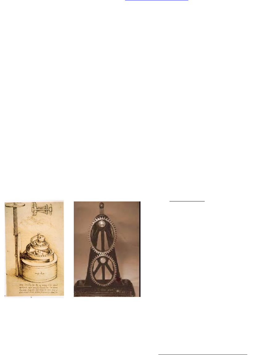
The earlier version of spatial non-circular gears
shown on a sketch made by Leonardo da Vinchi. In
the 17-18th century makes has more practical
applications of the non-circular gears in the
clockworks, musical instruments, mechanical
theatres and another automatic toys.
There are some well-known non-circular gear
models made by F. Reuleaux to study the
kinematics in the technical education in the
beginning years of 20th century. (Fig.1).
Figure 1
In the middle of 20th century the non-circular
gearing was used in electromechanical systems to
control and drive non-linear potentiometers. In spite
of the improvement of digital techniques, the
importance of non-circular gears are not decreased.
The profound summary and list of earlier references
of this discipline is found in book [1]. For a huge
lifework of Mr. F. L. Litvin [2] is a little-known
part. In this work all basic questions of this special
machinery elements are discussed exhaustively, but
the applied calculation, construction and
manufacturing methods are now anachronistic. In
the corresponding chapters of new books [3-4] of
the author summarise the most important
theoretical results of [2].
The articles [5], [6] reflect some issues of the new
constructions and manufacturing techniques. The
[7] demonstrate the practical basics of the
metrology of non-circular gears.
In this article a method is presented to calculate the
basic parameters of general elliptical gears. The
involute profile of teeth obtained by i.) virtual
manufacturing in a CAD system and ii.) complex
analytical method.
To formal derivation and numerical calculation we
carried on in the symbolical mathematical program
Maple® V. 7R.
2 General elliptical pitch curves
The polar equation of general elliptical curve is
(1)
where R is a set of real numbers1.
The curve ρk hase k ρkmax maximal values and k
ρkmin minimal values of its radius. The pitch curve
have 2k congruent part between ρkmax and ρkmin
values, that can be transformed to each other by
rotation and/or mirroring. The involute profile of
teeth’s can be obtained by well-known generating
(envelope) method.
The profiles of teeth curves located in the same
positions of the congruent parts of pitch curve are
identical, if the symmetric line of teeth of the basic
rack coincide with the polar vector ρk
corresponding φ = 0, and number of teeth is
zk = 2k.( ξ + ½) (ξ=…, 4, 5, …) (2)
The number of teeth in one congruent part of the
pitch curve is ξ + ½ (not integer!). If k1 = k2 the
always the same teeth’s of driven and driver wheel
1 In case k = 1 the pitch curve is a classical ellipse. The
rotation shaft coincides with one of its foci.
,...2,1=
k
:= ρk
p
k
− 1e
k
()cos kφR∈
kk e
p
,
2
are connected, while in case of k1 ≠ k2 the teeth
connecting with periodically identical position2. In
The mean transmission ratio of gears is ηmean =
k1/k2, and the ratio of actual relative angular
velocities is η = ρk1/ρk2.
In practice to calculate parameters of pitch curves
the origins k1, k2, ηmax and the distance of axes
„a” are given. The system of basic equations
(3)
is linearly depend on the formal parameter „A”.
Solution of system (3) is
= pk1
2aAηmax
+ + Aηmax 2ηmax A = pk2
2a
+ + Aηmax 2 (4)
= ek1
− + Aηmax
+ + Aηmax 2ηmax A = ek2
− + Aηmax
+ + Aηmax 2
Substitute the solution (4) in to equation (1) can be
the value of common modul of gears can be
obtained (5)
(5)
where k = k1 or k = k2. (If the gears are
manufactured with wire EDM technology, m can be
an arbitrary value different from the standardised
ones.)
The curvature radius of pitch curve is
:= K
æ
è
ç
ç
ç
ö
ø
÷
÷
÷
+ ρ2æ
è
ç
çö
ø
÷
÷
∂
∂
φρ
2
æ
è
ç
çö
ø
÷
÷
3
2
+ − ρ22æ
è
ç
çö
ø
÷
÷
∂
∂
φρ
2
ρæ
è
ç
ç
ç
ö
ø
÷
÷
÷
∂
∂2
φ2ρ
(6)
In the practice usually K > 0 and the pitch curve is
convex3.
3 Virtual manufacturing in CAD system
The basic rack cutter consist of two straight lines
that form a pressure angle α with respect to the real
2 This is in working practice unfavourable, but this is a
basic property of non-circular gears.
3 This is one advantage for generating technology with
CAD, but with the method presented in chapter 4 the case
K < 0 can be equally treated.
axes of complex co-ordinate system. The co-
ordinates of corner points of first teeth in the basic
rack are
))(.
4
(( 110
α
π
tanhIhmQ +−= (7.a)
))(.
4
(( 221
α
π
tanhIhmQ −−−= (7.b)
))(.
4
(( 222
α
π
tanhIhmQ −+−= (7.c)
))(.
4
(( 213
α
π
tanhIhmQ ++= (7.d)
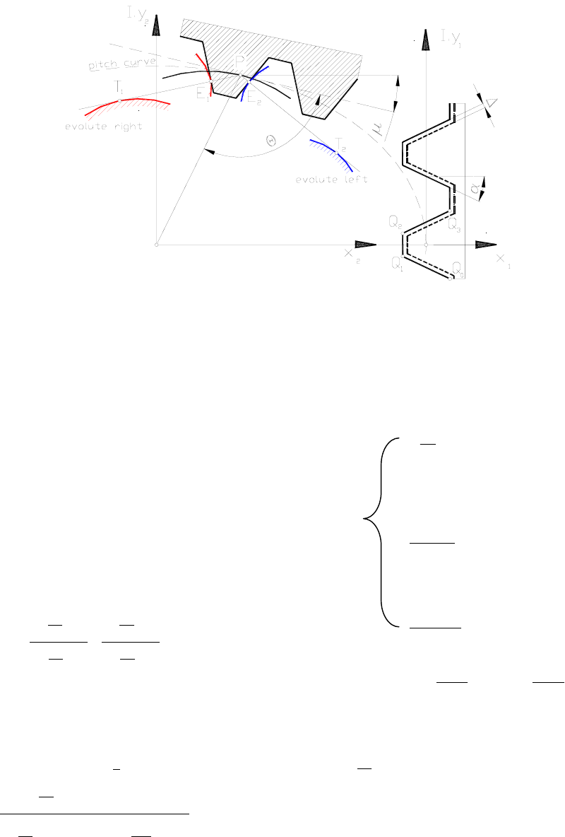
where I2 = -1, see Fig. 3. The pitch line of the cutter
is coinciding with the complex axe. The fillet
radiuses of standard tool are in this case neglected.
Complex co-ordinates of sth corner point in the rack
are
Qs := Qs-4 + I.m.π(8)
s = 4, 5, …, 4ζ – 1, where ζ = ξ + 1 is the total
number of teeth of basic rack.
The pitch line of the cutter rolls on the pitch curve
without slipping. Let the angular position of pitch
curve (1) φ = ψ. The pitch line of the tool is
actually the tangent of pitch curve (1). The complex
co-ordinates of the sth corner point of the tool are:
:= w +
æ
è
ç
ç
ç
ç
ç
ç
ç
ö
ø
÷
÷
÷
÷
÷
÷
÷
− QsId
ó
õ
ô
ô
ô
ô
ô
0
ψ
+ ρ2æ
è
ç
çö
ø
÷
÷
∂
∂
φρ
2
φe()Iµρe()Iψ
(9)
and the slope angle of the tangent line is
:= µ + + ψ
π
2θ (10)
The angle between radius vector and tangent line of
(1) is
(11)
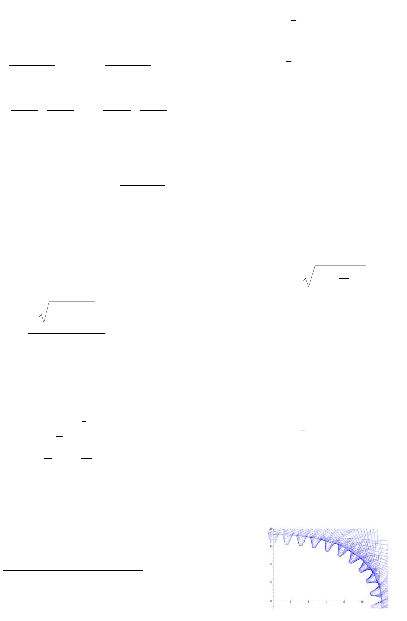
By evaluate the equations (1), (7-11) the complex
co-ordinates of corner points of tool rack can be
calculated. The first part of generated gear in case
of m = 0.4973, P = 8.56996, e = 0.231692, k =2
shown on Fig. 2.
Figure 2
:=θ
æ
è
ç
ç
ç
ç
ç
ö
ø
÷
÷
÷
÷
÷
arctan
ρ
∂
∂
φ
ρ
=
pk1 () − 1ek2
() + 1ek1 pk2
A
=
p
k1 () + 1ek2
() − 1ek1 pk2
ηmax
= +
pk1
− 1ek1
pk2
+ 1ek2
a = +
p
k1
+ 1ek1
p
k2
− 1ek2
a
:= m
d
ó
õ
ô
ô
ô
ô
ô
0
π
k
+ ρk
2æ
è
ç
çö
ø
÷
÷
∂
∂
φρk
2
φ
ξπ
3
In the CAD systems standard manipulation
commands like MOVE, ROTATE, SUBTRACT,
and MIRROR can be used to virtually manufacture
the gear. The movement of the tool object is
determined by equations (9-11). In every step the
tool object is subtracted from the workpiece object
which results the final contour curve of the gear.
Apply the appropriate mirroring and rotating
functions the complete contour curve can be
produced.
By manufacturing the gears with wire EDM cutting
technology, the offset value ∆ is very important an
depend on the used technology, look Fig. 3.
Figure 3
4 The basic curve and the involute
profile
The basic involute profile curves of the teeth are
determined by the enveloped figures of the profile
normal of the teeth of the rack. The normal lines
PT1 and PT2 coincide with the tangent line at the
contact point P of the pitch curve (Willis-Kennedy
Theorem).
The basic curves of the left and right profiles of the
teeth are different. The complex equation of normal
line parameterised by λ is
W = ρ.ei.φ + λ.ei.(φ + θ ± α)(12)
The differential equation of the enveloped curve
derived by
:= ()tan µ =
æ
è
ç
çö
ø
÷
÷
ℑ∂
∂
φW
æ
è
ç
çö
ø
÷
÷
ℜ∂
∂
φW
æ
è
ç
çö
ø
÷
÷
ℑ∂
∂
λW
æ
è
ç
çö
ø
÷
÷
ℜ∂
∂
λW(13)
where I and R symbolise the real and imaginary
part of partial derivatives of W. Solution of
equation (13) is
:= λ
æ
è
ç
ç
ç
ö
ø
÷
÷
÷
+
æ
è
ç
çö
ø
÷
÷
∂
∂
φρ
2
ρ2
æ
è
ç
çö
ø
÷
÷
3
2
()sin α
+ − 2æ
è
ç
çö
ø
÷
÷
∂
∂
φρ
2
ρ2()ρφ æ
è
ç
ç
ç
ö
ø
÷
÷
÷
∂
∂2
φ2()ρφ
(14)
Considering formula (6) it is evident that K =
r.sin(α).
The continuous function of the rack profile curve is
Q(u) see Fig, 4:
β
β
≤u
ua ,
.
β
π
−≤xa,
Q(u) =
χ
β
π
≤
−u
ua ,
).(
(15)
χ
≤− xb,
β
π
)2.( −ua
otherwise
where
a = h1 b = h2
)(
1
α
β
tan
h
=
)(
2
α
πγ
tan
h
+= (16)
expanded in to odd type of trigonometric series
)2cos())12sin((
2
)( 212
0juBujA
B
uQ j
j
j
å+−+= −(17)
The Fourier-coefficients are
4
ò
=
π
π
0
).sin().(
1duukuQAk
ò
=
π
π
0
).cos().(
1duukuQBk
(18)
Figure 4.
Based on equation (9) the point of rack profiles
curve at the angular position ψ and profile
parameter u determined by equation (19)
(19)
The involute points of teeth E1 and E2 are
intersections of the tool curve (19) and the normal
lines of teeth. The equation of normal lines is
)
2
.(
..
α
π
µ
ψ
ρ
±±
Λ+= I
Ieek (20)
Solving the equations (19) and (20) Λ and u
parameters can be calculated. Substitute Λ or u into
equation (19) or (20) the co-ordinates of involute
point can be determined.
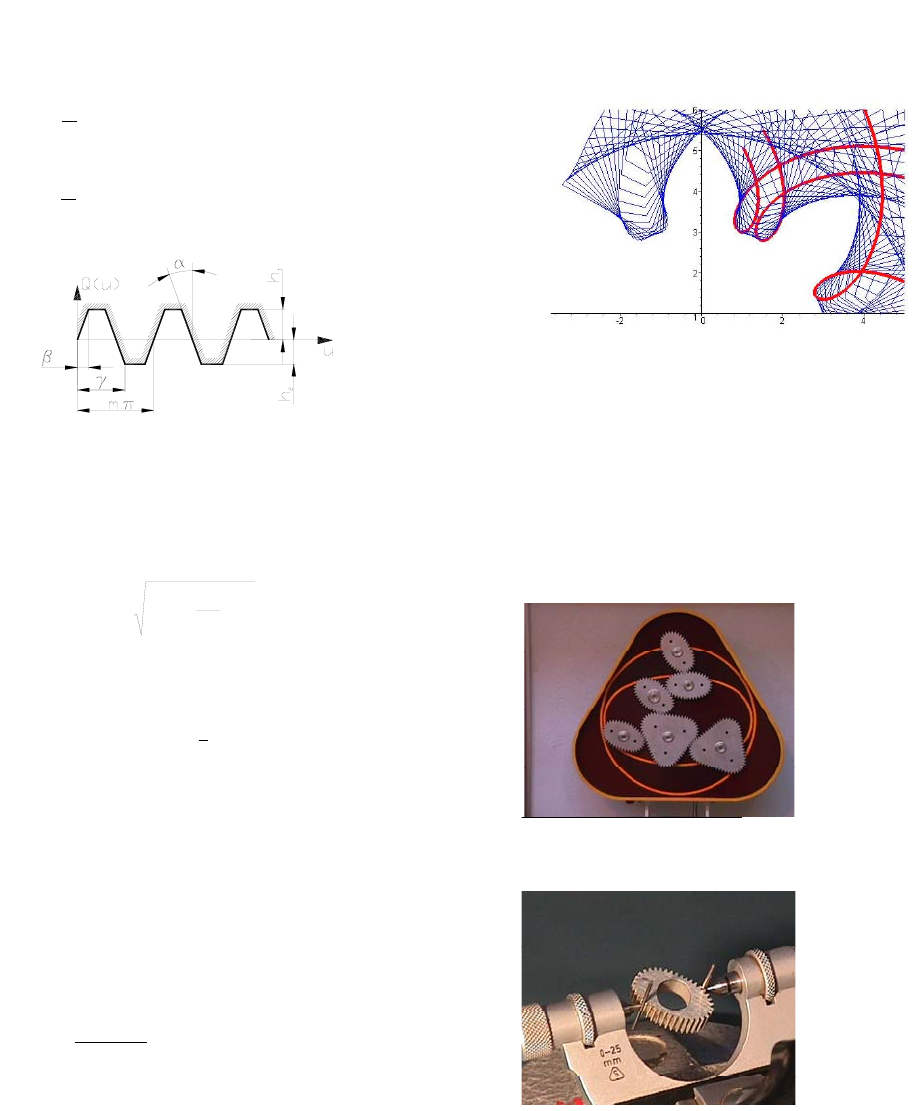
5 The undercutting line of the teeth
In case of the conventional involute gears the teeth
are undercutted if radius of pitch circle is smaller
than
2
min )sin(
α
m
r=(21)
In case of non-circular gears, the teeth are
undercutted if K < rmin. The approximate
undercutting curve can be calculated by the
sweeping path of corner point Q4s+1 and Q4s+2. The
limit point of undercutting is the intersection of
exact involute profiles and the sweeping path
curves of Q
4s+1 and Q4s+2 points The part of
undercutting line is shown in Figure 5.
Figure 5
6 Applications
From the practice of author some products are
shown in Fig. 6 which ware calculated with the
presented method. Usually the gears in the
industrial applications (flow measuring
equipment’s, printing machines and robots) have
modul cca. 0.4 – 3.5 mm
Figures 6
7 Summary
This paper present an approach that calculates the
parameters of a set of noncircular gears by general
elliptical rolling curve applying complex algebraic
methods. The complex formulas easy to use for
calculating the undercutting limit. To formal
derivation and numerical calculation ware carried in
the symbolical mathematical program Maple® V.
7R. To manufacture the gears by wire EDM
technology the final tool paths were generated in a
CAD system.
ψµ
ψ
ρϕρ
ϕ
ρ
II eedIuQw .).)((
0
2
2+
÷
ø
ö
ç
è
æ
∂
∂
+−= ò
5
References
1 Olsson, U.: Noncircular cylindrical gears,
Acta Polytechnica, Mech. Eng. Series
Stockholm (1953) X. 1-216
2 Ф.Л.Литвин: Некруглые зубчатые
колеса, изд. МАШГИЗ, Москва-
Ленинград, 1-203 (1956)
3 Ф.Л.Литвин: Теория зубчатых
зацеплений, изд. НАУКА, Москва-
Ленинград, 1-203 (1967)
4 F.L. Litvin: Gear Geometry and Applied
Theory, Prentice Hall, New York (1994)
5 Shinn-Liang Chang, Chung-Biau Tsay,
Long-Iong Wu: Mathematical model and
undercutting analysis of elliptical gears
generated by rack cutters, Mech. Mach.
Theory, Vol. 31. No. 7, pp. 879-891,
Elsevier Science Ltd., (1996)
6 W.C.Smith: The Math of Noncircular
Gearing, Gear Technology, pp. 18-21,
(2000. July/August)
7 B.Laczik - Z. Szaniszló: Measuring of
Gears with General (Non-Circular) Pitch
Curve, Proc. INES 2001, Helsinki (373-
376)
