CONTENTS Norbar 43217 User Manual
User Manual: Norbar 43217 User Manual
Open the PDF directly: View PDF ![]() .
.
Page Count: 28
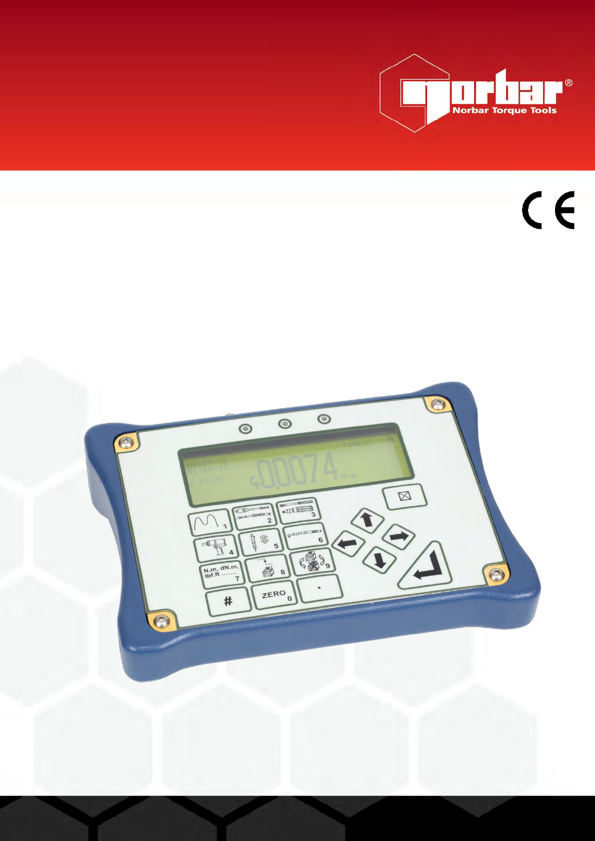
OPERATOR’S MANUAL
TORQUE TESTER LITE – HARSH ENVIRONMENT
(TTL-HE)
FOR USE WITH TTL-HE FITTED WITH VERSION 37712.305
SOFTWARE
Part Number 34298 | Issue 5 | Original Instructions (English)
© Norbar Torque Tools Ltd 2016
NORBAR TORQUE TOOLS LTD
Wildmere Road, Banbury,
Oxfordshire, OX16 3JU
UNITED KINGDOM
Tel + 44 (0)1295 270333
Email enquiry@norbar.com
NORBAR TORQUE TOOLS
45–47 Raglan Avenue, Edwardstown,
SA 5039
AUSTRALIA
Tel + 61 (0)8 8292 9777
Email enquiry@norbar.com.au
NORBAR TORQUE TOOLS INC
36400 Biltmore Place, Willoughby,
Ohio, 44094
USA
Tel + 1 866 667 2279
Email inquiry@norbar.us
NORBAR TORQUE TOOLS PTE LTD
194 Pandan Loop
#07-20 Pantech Business Hub
SINGAPORE 128383
Tel + 65 6841 1371
Email enquires@norbar.sg
NORBAR TORQUE TOOLS (SHANGHAI) LTD
E Building–5F, no. 1618 Yishan Road,
Minhang District, Shanghai
CHINA 201103
Tel + 86 21 6145 0368
Email sales@norbar.com.cn
NORBAR TORQUE TOOLS INDIA PVT. LTD
Plot No A-168, Khairne Industrial Area,
Thane Belapur Road, Mahape,
Navi Mumbai – 400 709
INDIA
Tel + 91 22 2778 8480
Email enquiry@norbar.in
www.norbar.com
1
CONTENTS
Introduction 2
Parts Included 2
Accessories 2
Features and Functions 3
Set Up 4
Preparation 4
Set Up for Use 5
Flow Diagrams 7
Measure 10
User Units 11
Using the Key Pad 11
Screen Layout 12
Modes of Measurement 14
Power Saving & Power Down 15
Limits 16
Transducer Interface 17
Transducer Leads Available 17
Specifications 17
PIN Connections 18
Connector Type 18
Ancillaries 18
PIN Connections 18
External Print / Reset 18
Analogue Output 19
Connector Type 19
Serial Port 20
Specifications 20
Pulse Count 20
Hyperterminal 21
Limits 21
PIN Connections 21
Data Output Example 21
Connector Type 21
Maintenance 22
TTL-HE Calibration 22
Transducer Calibration 22
Battery Replacement 22
Repair 23
Cleaning 23
Disposal (Recycling Considerations) 23
Specifications 23
Trouble Shooting 24
Error Messages 24
Problems 25
Glossary of Terms 25

2
INTRODUCTION
Torque Tester Lite – Harsh Environment (TTL-HE) is a portable torque measuring instrument designed for
use in harsh environments. The TTL-HE operating on battery power with one of the ‘HE’ range of
transducers connected, has an ingress protection rating of IP65/IP67. Typical operating environments are
where high humidity, water or salt water spray and dust may be an issue. Features include; 10 measurement
modes, 13 units of torque (with additional USER units feature), 12 pairs of limits and text displayed in 11
languages.
Part numbers covered by this manual: 43217 Torque Tester Lite – Harsh Environment TTL-HE
Parts Included
Description
Part Number
Quantity
Torque Tester Lite – Harsh Environment Instrument (TTL-HE).
43217
1
M4 x 10mm long neck strap screws.
25498
2
a.c. power adapter (not for use in harsh environments).
39254
1
Neck strap clip.
38881
2
Neck strap clip spacer.
38882
2
Neck strap.
38883
1
2.5mm Hex key.
24933
1
Operators Manual.
34298
1
Calibration Certificate.
-
1
TTL-HE carry case.
38879
1
Power Cord.
-
1
Accessories
Description
Part Number
TTL-HE to 6 way transducer lead, for Harsh Environment Transducers.
60245.200
TTL-HE to 6 way transducer lead, for standard SMART Transducers.
60250.200
Watertight instrument carry case.
60247
Various torque transducers for use in harsh environments.
Contact Norbar
3
FEATURES AND FUNCTIONS
For use in harsh environments and outdoor use where high humidity, water/salt water spray, dust may
be present.
Can be washed down with a light water jet.
The pictorial panel allows easy mode selection for the 6 modes of operation.
Additionally the 4 Peak modes can be configured for automatic reset.
13 Torque units, plus the ability to specify USER measurement units up to a maximum of 6 characters.
Automatically recognises any ‘SMART’ Norbar transducer.
Can also work with most mV/V transducers from Norbar or other manufacturers.
5 digit resolution for all Norbar transducers.
Operational from internal rechargeable battery or a.c. supply.
Fast battery charge in 3 hours 20 minutes.
There are 12 pairs of limits available.
Each limit has a target value and upper / lower tolerances.
The display shows LO / OK / HI with bright LED’s to signal AMBER / GREEN / RED for easy
confirmation. The limit status is also output on the ancillaries connector and serial port.
Pulse count feature in Impulse Tool mode & Clutch Tool mode.
User selectable frequency response for each mode of operation.
Password protection of all selectable features. The instrument can be issued to an operator with only
the required modes of operation and units of measurement enabled.
This feature can virtually eliminate operator induced errors.
Ancillaries connector with analogue output.
Serial Port for data output to a PC or printer.
Serial Port set up options include: sending time & date, limit status and continuous output.
4
SET UP
Preparation
NOTE: If the equipment is used in a manner not specified by the manufacturer, the protection
provided by the equipment may be impaired.
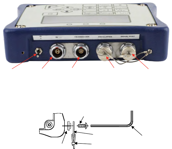
1. Assemble neck strap to TTL-HE as shown below if required.
2. Connect transducer to be used, plug transducer lead into TRANSDUCER connector.
3. To output data to an external device (PC or printer) connect to the SERIAL PORT connector.
4. If using with a control or shut-off system, plug into ANCILLARIES connector.
5. The TTL-HE can be powered from mains or battery. Mains power is intended for indoor use within a
light industrial environment and for re-charging the instruments internal battery pack. It is essential to
charge the internal battery for 200 minutes (3 hours & 20 minutes) before battery operation. To charge
the internal battery, connect the a.c. power adapter between the TTL-HE (9 V d.c. input) and a live a.c.
supply.
TIP: Insert 9 V d.c. connector into TTL-HE before applying a.c. mains to ensure correct charging.
TIP: If the power cord has no plug fitted, wire as follows:
BROWN-LIVE BLUE-NEUTRAL GREEN / YELLOW-EARTH
If in doubt consult a qualified electrician.
TIP: The display backlight is ON when connected to a.c. power.
The TTL-HE can be used whilst the battery is charging.
Recharging is independent of the on/off switch.
The battery can be charged continuously.
25498
38882
24933
38881
38883
FIGURE 1 – Back View
On/Off Switch
9 V d.c. input
Transducer
Connector
Ancillaries
Connector
Serial Port
Connector

5
Set Up For Use
Turn TTL-HE on and wait for LOGO.
The TTL-HE will either enter the measure screen or display ‘CONNECT TRANSDUCER’.
Press to obtain SET UP menu:
17. SET UP X
SOFTWARE # 37712.XXX
1. LIMITS
2. SETTINGS
3. RETURN TO MEASURE
TO CONFIRM
NOTE: The set up is password protected, the default password is 000000.
TIP: If password is lost, contact Norbar quoting the coded number in brackets on the password
menu.
TIP: When in a set up screen, after entering one option press the down arrow to enter the next.
When all entry’s have been made, press ‘’.
1. Limits
The user can set up to 12 target values that each have two settable LIMITS.
To set the limits the following are needed:
Parameter
Comment
Target Number
Select 1 to 12.
Units for limits
Select torque units (or specify USER units).
Target value
Torque value required.
Upper limit
The % allowed above target.
Lower limit
The % allowed below target.
Operate
OFF or Clockwise or Anticlockwise or Both directions.
Confirm limits
Limit values shown in % of the target value.
Select next TARGET to set up. Press when finished.
For more information see flow diagram on page 7.

6
2. Settings
Setting
Options (defaults)
Comment
LANGUAGE
ENGLISH (default), FRANCAIS,
DEUTSCH, ITALIANO, ESPAÑOL,
DANSK, NEDERLANDS, SUOMI,
NORSK, SVENSKA, PORTUGUES.
Set language of operation.
PASSWORD
Any 6 numeric characters
(default = ‘000000’).
Set Password.
DATE & TIME
Set date DD/MM/YY or MM/DD/YY.
24 hour clock with date.
MODE
FREQUENCY
100Hz to 2500Hz (defaults, see ‘MODES
OF MEASUREMENT’ section).
Select mode then select frequency from list.
OTHER FREQUENCY allows a custom value.
SERIAL PORT
See ‘SERIAL PORT’ section.
Select required options.
THRESHOLDS
FIRST PEAK SENSITIVITY =
LOW / MEDIUM / HIGH
(default = HIGH).
This is the amount by which the torque must
drop to register a first peak.
LOW must drop 10% of reading.
MEDIUM must drop 5% of reading.
HIGH must drop 2.5% of reading.
THRESHOLDS
AUTO RESET HOLD TIME =
1 (default) / 2 / 3 / 4 seconds.
The time allowed for automatic reset in ‘Click
& Cam’ mode.
THRESHOLDS
TRIGGER FROM =
0.5% to 99% of transducer capacity
(default = 1.8 %).
This is the point at which any memory mode
starts to work, all memory modes will
‘TRACK’ below this setting. This can help
overcome false results. Values entered below
0.5% will act as 0.5%.
THRESHOLDS
PEAK MEMORY RESET =
AUTO / MANUAL (default).
All Peak modes will reset the highest reading
automatically or manually.
UNITS
All units (default = all enabled).
Turn off unwanted torque units.
MODES
All modes (default = all enabled).
Turn off unwanted modes.
POWER DOWN
TIME
0 to 99 minutes (default = 10).
The time before power down starts.
Set to ‘0’ to disable.
PRINT SETTINGS
None.
All settings and limit settings can be printed.
No password is needed.
TIP: When or is shown on screen, this means more menu items are available.
For more information see flow diagram on page 9.
3. Return to Measure
This option allows the user to view the measurement screen.
For ‘SMART’ transducers the measure screen is automatically entered.
For ‘NON-SMART’ transducers the option to store transducer details is available.
For more information see flow diagram on pages 7 & 8.
7
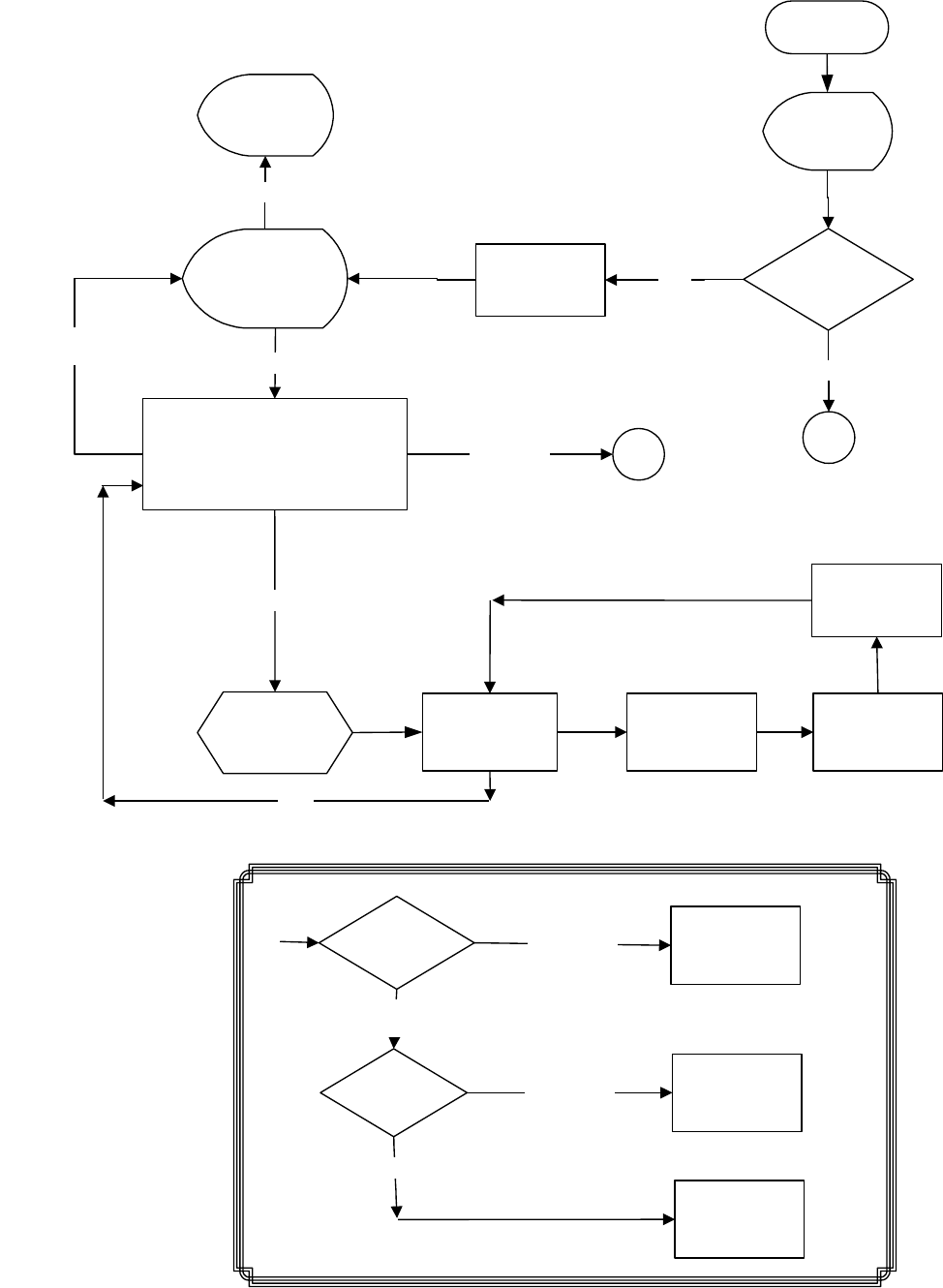
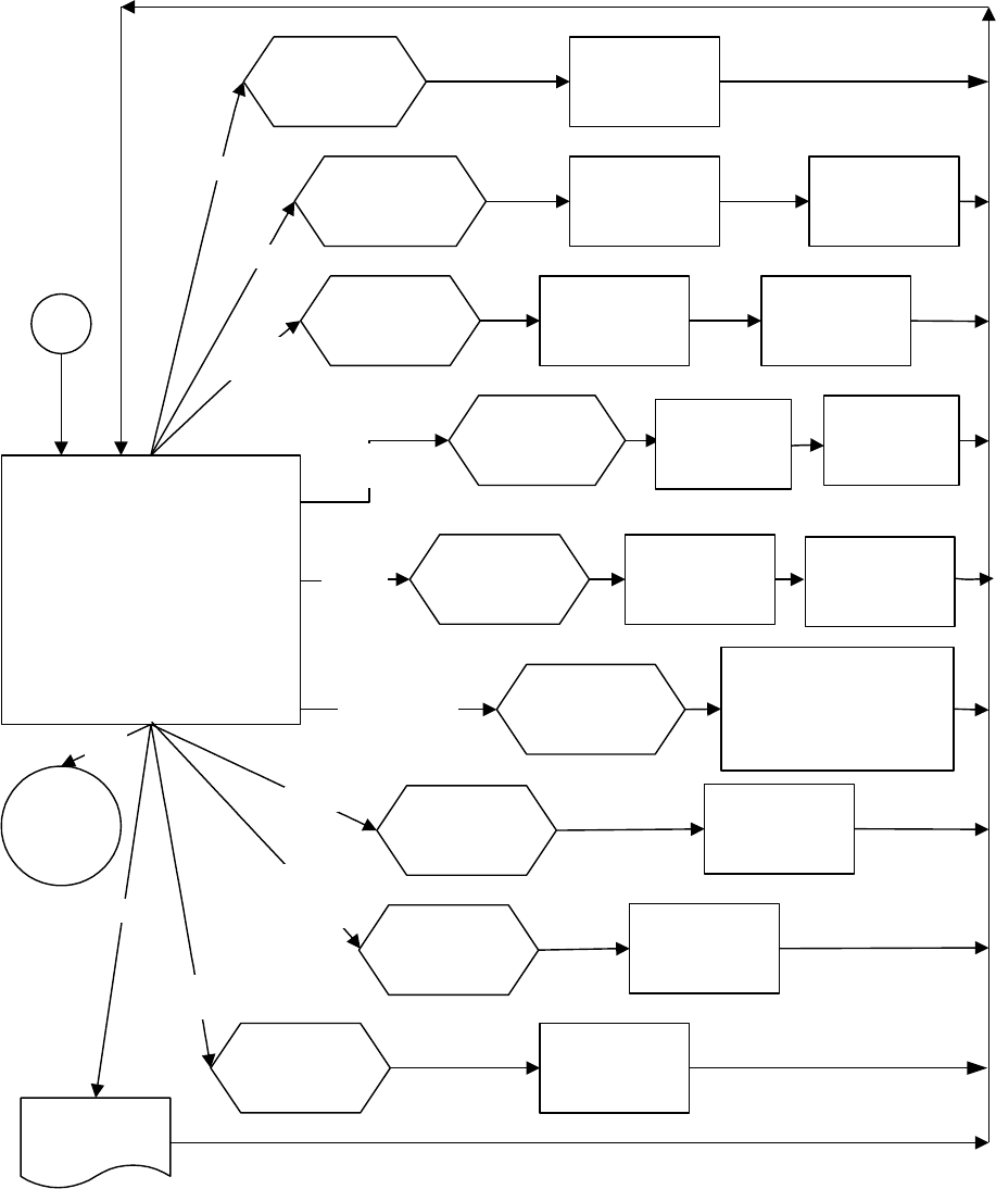
FLOW DIAGRAMS
All set up menus are numbered on the TTL-HE for ease of identification.
Menu Structure + Limits Flow Diagram
SWITCH ON
17. SET UP
SOFTWARE # XXXXX.XXX
1.LIMITS
2.SETTINGS
3.RETURN TO MEASURE
19. SELECT
UNITS
20. SET
TRANSDUCER
LIMITS
22. CONFIRM
LIMITS
B
27. ENTER
PASSWORD
28. RE-ENTER
PASSWORD
INCORRECT
PASSWORD
INCORRECT PASSWORD
CORRECT
PASSWORD
CORRECT
PASSWORD
PROCEED
PROCEED
ACCESS
DENIED
Password flow diagram
MEASURE
DISPLAY
LOGO
LIMITS
EXIT
SMART
TRANSDUCER ?
A
NO
SETTINGS
RETURN TO
MEASURE
PASSWORD 91. SELECT
TARGET
EXIT
DISPLAY
TRANSDUCER
DETAILS
#
YES
TRANSDUCER
DETAILS
SCREEN
Password Flow Diagram
8
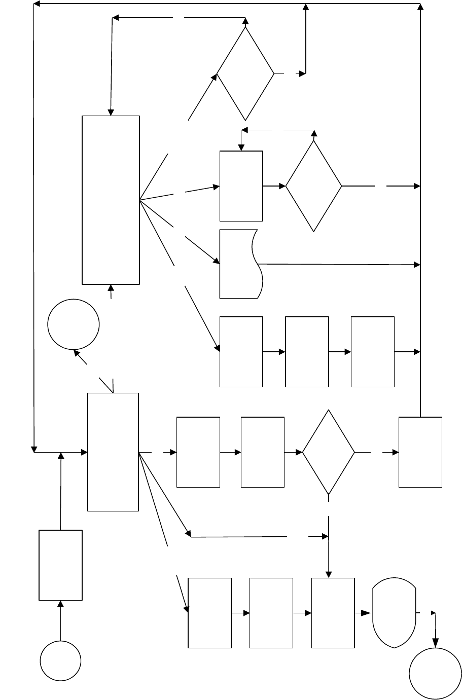
Measure Flow Diagram
Measure flow diagram
2. CONNECT
TRANSDUCER
MEASURE
5. TRANSDUCER
ADD TRANSDUCER
EDIT/PRINT/DELETE
USE SERIAL # : XXXXX
USED SAVED TRANSDUCER
15. SELECT
TRANSDUCER
6. EDIT/PRINT/DELETE TRANSDUCERS
EDIT
PRINT
DELETE
DELETE ALL
EDIT/PRINT/DELETE
PRINTING
TRANSDUCERS
PRINT
9. SELECT
TRANSDUCER
13.
TRANSDUCER
PARAMETERS
14.
TRANSDUCER
CALIBRATION
FIGURE
EDIT
10. SELECT
TRANSDUCER 12. DELETE ALL
TRANSDUCERS ?
YES
11. DELETE
TRANSDUCER ?
DELETE
YES
13.
TRANSDUCER
PARAMETERS
14.
CALIBRATION
FIGURE
7. SAVE
TRANSDUCER ?
8. SAVE WHERE
?
ADD
YES
DELETE
ALL
A
NO
MENU
17
MENU
17
EXIT
NO
NO
EXIT
TRANSDUCER
DETAILS
SCREEN
USE
SERIAL# 12345
USE
SAVED
16. SHOW
TRANSDUCER
9
Settings Flow Diagram
26. SET UP/SETTINGS
LANGUAGE
PASSWORD
DATE & TIME
MODE FREQUENCY
SERIAL PORT
THRESHOLDS
UNITS
MODE ENABLE/DISABLE
POWER DOWN TIME
PRINT SETTINGS
29. SET
LANGUAGE
LANGUAGE 31. ENTER
NEW
PASSWORD
33. SET
DATE
37. SET
FREQUENCY
39. SET
SERIAL PORT
41. SET THRESHOLDS
FIRST PEAK SENSITIVITY/
AUTO RESET HOLD TIME/
TRIGGER FROM/
PEAK MEMORY RESET
32. NEW
PASSWORD IS
PASSWORD
PASSWORD
PASSWORD
PASSWORD
PASSWORD
PASSWORD
PASSWORD 43. SET
TORQUE UNITS
PASSWORD 46. SET UP
MODES
PASSWORD
TIME &
DATE
UNITS
MODE
ENABLE/
DISABLED
PASSWORD
PRINT
PRINT
POWER
DOWN
B
48. SET POWER
DOWN TIME
35. SET
TIME
MENU
17
EXIT
THRESHOLDS
MODE
FREQUENCY
SERIAL
PORT
87. SELECT
MODE
86. TEST
OUTPUT

10
MEASURE
1. Set up the TTL-HE as described in the previous section.
2. Turn TTL-HE on.
3. If a ‘SMART’ transducer is connected, the TTL-HE automatically shows TD#1, the transducers capacity
and units. The transducer’s serial number and direction of linearization (if enabled) are also shown. The
instrument then displays the measurement screen.
TD#1
CAPACITY XXXXX N∙m
TRANSDUCER SERIAL # XXXXX
LINEARISED X
NOTE: If the word ‘LINEARISED’ and direction arrows appear on this screen then the TTL-HE is
using a second order polynomial to linearise the transducer.
4. If ‘Menu 2’ is shown, then either:
a) A ‘SMART’ transducer is not connected.
b) The transducer is ‘NON-SMART’.
For ‘NON-SMART’ transducers the transducer details can be saved in the TTL-HE for future use.
Transducer details can be edited, deleted or printed. The last transducer used will always be
retained for quick selection.
Follow ‘measure flow diagram’ in SET UP section & refer to TRANSDUCER INTERFACE section.
TIP: For entry of transducer data, see the ‘USER UNITS’ and ‘USING THE KEY PAD’ sections on
page 11.
5. The TRACK screen is now displayed. Exercise the transducer in required direction of use.
6. Press ‘ZERO’ to zero displayed reading.
TIP: The measurement display may not zero if outside +/-3% of transducer capacity. This may be
due to transducer overstrain. Return defective transducer to Norbar.
7. Select measurement mode required.
TIP: If any measurement mode does not memorise the measurement value, ensure that the
‘TRIGGER FROM’ setting is correct. See SETTING, SETUP/THESHOLDS menu. TRIGGER
FROM can be used to overcome erratic results being obtained.
8. Press to exit any measurement screen and go to SET UP.
11
N∙m, dN∙m,
lbf∙ft …….
7
User Units
This feature allows the USER to specify custom measurement units that are displayed after the
measurement value and printed on the serial port. Any mV/V transducer conforming to the specifications in
the TRANSDUCER INTERFACE section can be used. Typical examples could be load or pressure
transducers.
1) When ‘2. MEASURE’ is displayed, press ‘ TO CONFIRM’.
2) Select ’13. ADD TRANSDUCER’ and press ‘ TO CONFIRM’.
3) Enter ‘SERIAL #:’ and press ‘’. Enter ‘PART NUMBER: (if required) and press ‘’.
4) The user can choose the ‘UNITS OF CALIBRATION:’. Press whilst the display is showing ‘N∙m’, 6
underscores will be displayed (______). Now input the required ‘UNITS OF CALIBRATION’, for
example ‘kN’. Press ‘’ when input has finished.
5) Enter ‘RATED CAPACITY:’, press ‘ TO CONFIRM’.
TIP: The button will have no effect when in measure.
TIP: Only limits set up in the same USER units are available for selection when in measure.
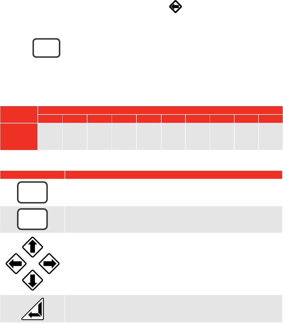
Using the Key Pad
Press and hold the required key until the desired character is displayed, then release.
Key
1
2
3
4
5
6
7
8
9
0
Character
1,
a, A,
b, B,
c, C
2,
d, D,
e, E,
f, F
3,
g, G,
h, H,
i, I
4,
j, J,
k, K,
l, L
5,
m, M,
n, N,
o, O
6,
p, P,
q, Q,
r, R
7,
s, S,
t, T,
u, U
8,
v, V,
w, W
9,
x, X,
y, Y,
z, Z
0
NOTE: The keys 0 – 9 are shortcuts for menu selection.
Key
Function
Entry of:
# % ( ) * , / : = \ _
Entry of:
. (full stop or decimal point) + -
a) Navigate menu options and choices.
b) Left arrow becomes delete when entering data.
c) Right arrow becomes space when entering data.
d) Down arrow moves on to next option in a set up menu.
e) Use left and right arrows for quick selection of torque units in measurement
screen.
Confirm change.
NOTE: If the change is not confirmed, it will not be made.
#
·
12
4
5
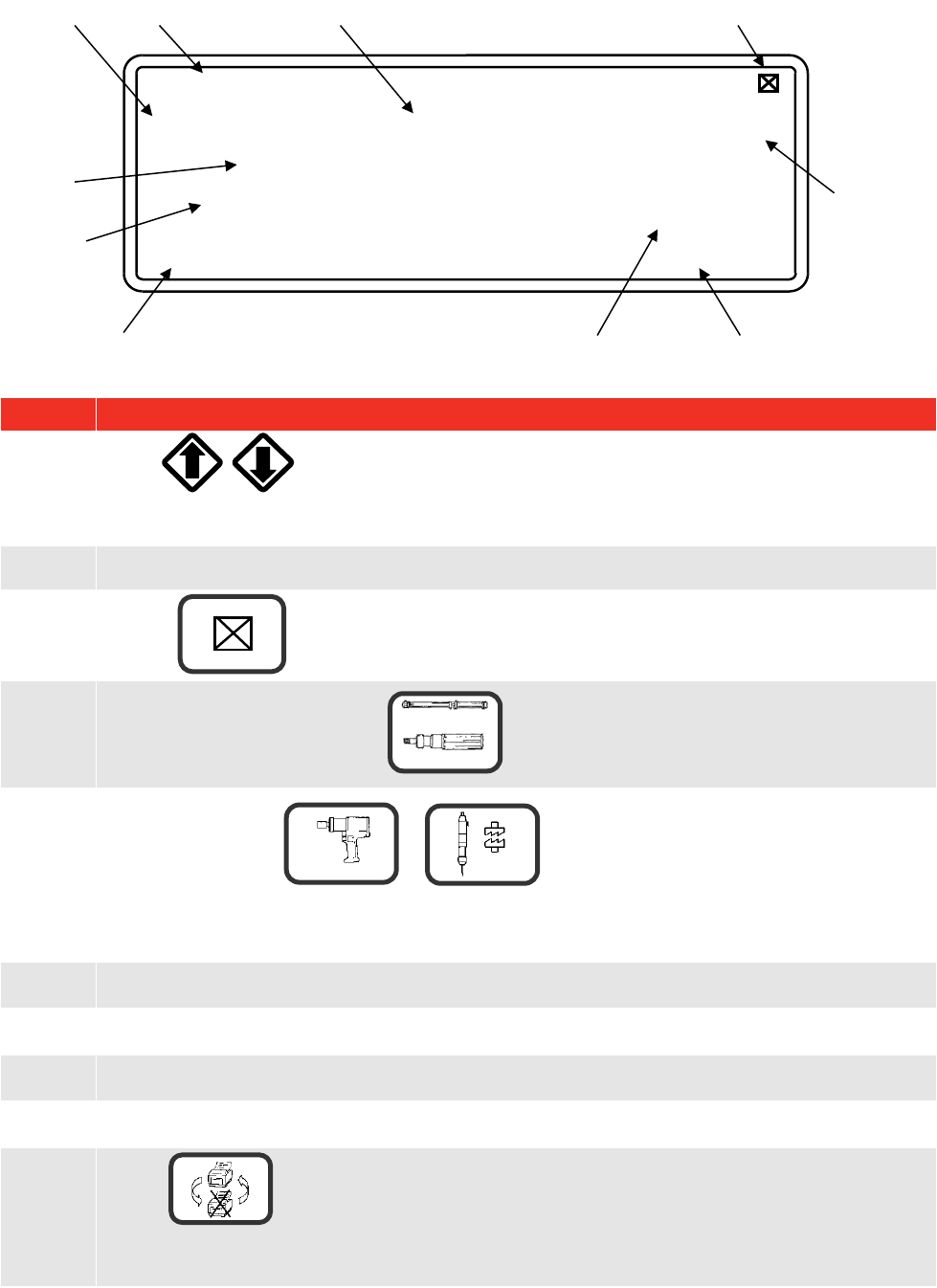
Screen Layout
Display
Instruction
A.
Press to select target value and associated limits to be used.
Time/Date shown if no targets set.
B.
Measurement reading.
C.
Press to exit.
D.
Indicates when to stop loading in CLICK & CAM measurement mode.
E.
Pulse count when in or measurement modes.
In ‘IMPULSE TOOL’ & ‘CLUTCH TOOL’ modes, a count is added every time the torque passes
above & below the ‘trigger from’ setting.
F.
Units of measurement
G.
Current ‘mode of measurement’ in use along with frequency response set for that mode.
H.
Limit indication (if enabled).
I.
Direction of measurement.
J.
Press to toggle between ‘ PRINT’ and ‘X PRINT’ on the display.
PRINT enables serial port, X PRINT disables serial port.
PRINT
IMPULSE TOOL (500 Hz)
TARGET 1=100 N∙m
_∏_#=0
STOP
G
D
C
B
A
E
J
N∙m
112.34
HI
F
I
H
9
3
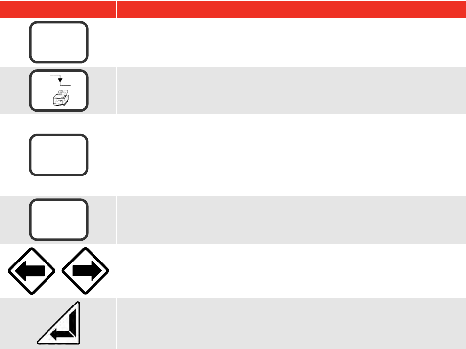
13
Key
Function
Selection of enabled torque units.
PRINT reading and RESET.
To view transducer details in track mode.
Shows: Serial #, Part Number, Units & Rated Capacity.
Clockwise & anticlockwise mV/V Calibration figures.
Angle option programmed (for use with Pro-Log instrument)
Clockwise & anticlockwise linearised values, where
T=a + bR + cR² (T is torque & R is Ratio in mV/V).
TRACK mode: - Zero transducer (It is recommended to check the zero when
returning from power down).
All other modes: - PRINT reading and RESET.
For selection of torque units.
PRINT reading and RESET.
TIP: To simplify operation disable all units of measurement not required. See SETTINGS, UNITS
ENABLE/DISABLE menu.
N∙m, dN∙m,
lbf∙ft …….
7
8
#
0
ZERO
14
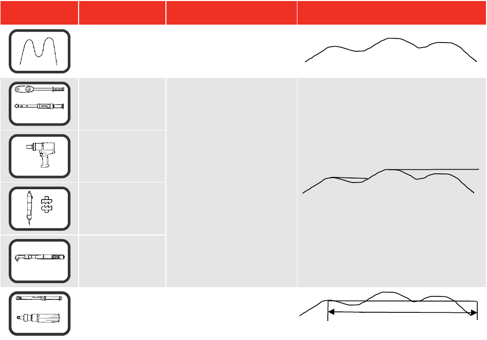
Modes of Measurement
Mode
Mode
(Frequency)
How it Works
Visual Representation
TRACK
(500 Hz)
Follows signal.
Dial & Electronic
(500 Hz)
Holds the highest reading
until RESET by the user.
[The highest reading can
be automatically reset if
AUTO is selected for
PEAK MEMORY RESET.
After the value returns to
zero, the memorised
reading is held for the
AUTO RESET HOLD
TIME, then resets].
Impulse Tool
(500 Hz)
Clutch Tool
(500 Hz)
Stall Tool
(500 Hz)
Click & Cam
(500 Hz)
Hold 1st peak for the
‘AUTO RESET HOLD
TIME’, then resets.
TIP: To simplify operation DISABLE all modes of measurement that are not required.
See SETTINGS, MODES ENABLE/DISABLE menu.
TIP: The peak reading can be set up to automatically reset by changing PEAK MEMORY RESET
from MANUAL to AUTO. See SETTINGS, THRESHOLDS
TIP: For slower operation of any AUTO RESET mode, change AUTO RESET HOLD TIME to 4
SECOND. See SETTINGS, THRESHOLDS menu.
TIP: In CLICK & CAM mode the serial port will only output for a genuine first peak.
Pressing enter or ZERO will not send an output.
TIP: If torque wrench readings are inconsistent in CLICK & CAM mode, change FIRST PEAK
SENSITIVITY in the SETTINGS, THRESHOLDS menu to be less sensitive i.e. MEDIUM or LOW.
This will compensate for torque wrench sensitivity.
4
5
6
3
AUTO RESET HOLD TIME
2

15
Power Saving & Power Down
Battery life can be greatly increased from a minimum of 14 hours by making use of power down. If no key is
pressed or measurement reading taken in the specified time, the TTL-HE will enter power down. The
following will be displayed:
SAVING POWER
PRESS ANY KEY TO CONTINUE
The following features should be noted:
The POWER DOWN TIME is set in the SETTINGS, POWER DOWN TIME.
For maximum battery life set POWER DOWN TIME to 1 minute.
To disable the power down feature set POWER DOWN TIME to 0 (zero).
The TTL-HE also enters power down when in a set up menu.
The analogue output will NOT work during power down.
TIP: Check the zero setting of the transducer on return from power down.
When the battery is low there is approximately 20 minutes of use left. In the measure screen a flashing
battery symbol will be seen in the top right hand corner of the display. In a SET UP menu, the following is
displayed:
WARNING #202
BATTERY LOW
PRESS X
When battery is flat the TTL-HE must be turned off or recharged. The following is displayed:
WARNING #201
BATTERY FLAT
SWITCH OFF AND RECHARGE BATTERY
NOTE: From a very flat battery it may take 1 minute of mains power before the display will turn on.

16
Limits
Limits can be selected In Measure by pressing or .
The target is shown at the top left of the screen and if no limits have been set, the TIME & DATE will be
shown. If limits are available but not selected, ‘↓↑LIMITS OFF’ will be shown.
The limit status is shown in 4 ways:
1. On the display showing LO / OK / HI next to the torque value (updated at 3 Hz).
2. On AMBER / GREEN / RED LED’s on front panel (updated at 208 Hz).
3. On the Serial Port LO / OK / HI is sent before torque value (updated with serial port).
4. On the Ancillaries LO / OK / HI logic outputs (updated at 208 Hz).
TIP: The Ancillaries are updated quickly to give a fast response to an external control system.
NOTE: This difference in update rate may lead to very small differences between the changeover
points.
The LED’s & logic outputs change precisely with increasing torque, and at 0.5% of transducer capacity below
the limit with decreasing torque. This eliminates the logic lines oscillating.
The status of the limits changes as follows:
Torque signal
Display
LED’s
Serial port
Ancillaries
Zero band. (<0.5% of
transducer capacity)
OFF
OFF
No output
No output
Under lower limit
LO
AMBER
LO
LO output
Within limits
OK
GREEN
OK
OK output
Above upper limit
HI
RED
HI
HI output
NOTE: For operation of limits in one direction only, the opposite direction will be shown as LO.
The limit operation is dependent on the measurement mode:
Measurement Mode
Limit Operation
Track
Limits follow the transducer input and are not held.
Dial & Electronic
Impulse tool
Clutch tool
Stall tool
For PEAK MEMORY RESET = MANUAL, Limits status is held until
PRINT / RESET is pressed.
For PEAK MEMORY RESET = AUTO, Limit status is held until after the
auto reset timer has operated.
Click & Cam
Limit status is held until after the auto reset timer has operated.
TIP: When TTL-HE is switched on, the target shown is the last one used.
TIP: The TTL-HE will automatically change torque units to those set by the limits.
TIP: Limits can be set up in USER units for operation with transducers programmed with the same
USER units.

17
TRANSDUCER INTERFACE
The Transducer interface has been designed for use with most four wire bridge strain gauge type
transducers.
When used with Norbar ‘SMART’ transducers the calibration data will be automatically known.
For ‘NON-SMART’ transducers up to 20 sets of transducer parameters can be stored in the TTL-HE for ease
of use.
TIP: Mark ‘NON-SMART’ transducers with their stored ‘T’ number for ease of identification.
TIP: Press '#' in track mode to show details of ‘SMART’ transducer in use.
TIP: If any of the transducer’s parameters are changed (i.e. re-calibration of mV/V value), the
transducer’s stored parameters must be edited prior to use. (‘NON-SMART’ only).
Norbar transducers with the following suffix are all suitable for use with the TTL-HE:
Suffix
Description
XXXXX.IND
‘SMART’ transducer calibrated in mV/V.
XXXXX.INDA
‘SMART’ transducer with integral angle encoder calibrated in mV/V.
XXXXX.LOG
‘SMART’ transducer calibrated with a TTL-HE in units of calibration.
A mV/V figure is also supplied.
XXXXX.LOGA
‘SMART’ transducer with integral angle encoder calibrated with a TTL-HE
in units of calibration. A mV/V figure is also supplied.
Transducer Leads Available
Part Number
Description
60245.200
TTL-HE to 6 way lead, for Harsh Environment Transducers.
60250.200
TTL-HE to 6 way lead, for standard SMART Transducers.
NOTE: The suffix after the part number indicates the length of the lead in cm, thus
XXXXX.200 = 2 metres. If Transducer leads are required of a non-standard length, the new
suffix must be added to the part number when ordering (to the nearest metre).
Specifications
Parameter
Minimum
Maximum
Bridge Resistance ().
350
1000
Millivolt / volt value (mV/V).
0.50 mV/V.
3.15 mV/V.
Zero balance.
+/- 3% of transducer
capacity (3 mV/V).
+/- 9% of transducer capacity
(1 mV/V).
Display Resolution.
4.5 Active digits.
5 Active digits.
Transducer capacity ranges.
0.010000
1,500,000
Torque units.
Dependent on transducer
capacity and mV/V value.
N∙m, dN∙m, cN∙m, lbf∙ft, lbf∙in,
ozf∙in, ft∙lb, in∙lb, in∙oz, kgf∙m,
kgf∙cm, gf∙m, gf∙cm.
User units.
None.
6 Characters.
Displayable overrange.
120% of transducer capacity.

18
PIN Connections
Pin No
Function
1
+ve transducer excitation.
2
-ve transducer excitation.
3
+ve transducer signal.
4
-ve transducer signal.
5
Serial clock (SMART memory).
6
Serial data (SMART memory).
Connector Type
Lemo® 6 way panel socket, size 1K. The mating part to this connector is a Lemo 6 way, size 1K free plug,
manufacturers part number FGG.1K.306.CLAC55Z.
TIP: If the display shows ‘SMART TD NOT INITALISED’ it is likely that:
a) The transducer lead may have a broken connection.
b) Your ‘SMART’ transducer may have lost its stored data, return to Norbar.
ANCILLARIES
The ancillaries connector contains an analogue signal output and a print / reset signal input.
PIN Connections
Pin No
Function
1
Digital +5 volts (maximum current 5 mA).
2
External PRINT / RESET input (Active High).
3
Analogue Out 0V reference (Do not connect to a noisy electrical ground).
4
Analogue Out 2.5V.
5
Analogue Out.
External Print / Reset
Pins 1 & 2 are intended for use as an external PRINT / RESET:-
The switch must remain active for at least 200 mS. Screened cable is recommended.
PIN 1
PIN 2
Momentary
Switch

19
Analogue Output
The analogue output is designed for connection to a control system. It is a true analogue value, so has a
very fast frequency response of above 10 kHz. The calibration of the analogue output is factory set and not
adjustable, it is not affected by the instrument calibration.
The output is PIN 5.
If the output is measured against PIN 4 (2.5V) the signal will swing positive for clockwise torque and negative
for anticlockwise torque.
If the output is measured against PIN 3 (0V) the signal will always be positive, with zero torque around 2.5V.
TIP: Some transducers (Norbar Annular type) will give a negative output change for a positive
torque. This is because they are designed to measure reaction torque.
The output voltage is a function of the mV/V value. The larger the mV/V value the larger the analogue output
voltage. At transducer full scale the analogue output voltage (in volts) is numerically equal to the mV/V value
divided by 2.
TIP: Find the mV/V value by pressing # in the track mode or from the transducer’s certificate.
Using 2.5V (PIN 4) as a reference:
Torque
Analogue output (PIN 5)
@ 1.0mV/V
@ 2.0 mV/V
@ 3.0 mV/V
- full scale of transducer
-0.5 V
-1.0 V
-1.5 V
Zero
0.0 V
0.0 V
0.0 V
+ full scale of transducer
+0.5 V
+1.0 V
+1.5 V
Using 0V (PIN 3) as a reference:
Torque
Analogue output (PIN 5)
@ 1.0mV/V
@ 2.0 mV/V
@ 3.0 mV/V
- Full scale of transducer
2.0 V
1.5 V
1.0 V
Zero
2.5 V
2.5 V
2.5 V
+ Full scale of transducer
3.0 V
3.5 V
4.0 V
TIP: The analogue output will not operate in power down mode. If using the analogue output
continuously then disable the power down feature by setting to 0 (zero).
The accuracy of the analogue output is +/- 2% of voltage reading. For a more accurate output value the
voltage can be externally scaled against the displayed torque.
Connector Type
Lemo® 5 way panel socket, size 1K. The mating part to this connector is a Lemo 5 way, size 1K free plug,
manufacturers part number FGG.1K.305.CLAC55Z.
Pin 5
Pin 4
Pin 3
5V
Output
2.5V
0V

20
SERIAL PORT
The serial port is for sending data to a PC or serial printer.
When the TTL-HE is measuring, data can be output on the serial interface automatically when the AUTO
RESET timer operates or when the 'PRINT / RESET' key is pressed. The data can include the measured
value, units of measurement and time/date. Output can also be requested externally via pin 2 (ancillaries
connector), see ancillaries section.
Specifications
Parameter
Options
Factory
Defaults
Comments
Parity
ODD, EVEN or OFF.
OFF
Baud rate
1200, 2400, 4800, 9600 or 19200.
9600
The data rate.
Data - Stop bits
8 – 2, 8 – 1, 7 – 2, 7 - 1.
8 - 2
First character
- or +/- or NONE.
-
If required by receiver.
Output Limits
YES or NO.
YES
Limit status sent before data.
Output units
YES or NO.
YES
Measurement units sent after data.
Output date & time
YES or NO.
NO
Date & Time sent after data.
Output line feed
YES or NO.
NO
Line feed sent after data.
Handshake
NONE, CTS or X-ON/OFF.
NONE
If required by receiver.
Line delay
0.00 to 9999 SECONDS.
0.50 Seconds
Time delay in data output.
Continuous output
YES or NO.
NO
Up to 22 readings per second in
track mode.
SET TO FACTORY DEFAULTS.
Maximum number of characters per line = 24.
Maximum number of requests in track mode = 4 per second (line delay set to 0).
Transmitted data voltage levels are between +5 to +9 volts and –5 to -9 volts.
Configured as DTE (Data Terminal Equipment) and conforms to RS-232-C specifications.
TIP: If the serial port is not communicating with other equipment try:
a) Check that all serial port parameters on the TTL-HE and the equipment receiving data
match.
b) Check that the baud rate is set to the same as the equipment receiving data.
c) Check that the connecting lead is wired correctly at both ends.
d) Check if equipment receiving data requires the units of measurement inhibited or a
leading character.
e) Select CONFIRM at the end of the serial port settings, the TTL-HE will keep sending a
‘TEST OUTPUT’ message to help fault finding.
TIP: If the serial output is being overwritten set ‘Output Line Feed’ to YES.
TIP: If the Serial data is being sent too quickly the printer may not keep up, so data is lost. To slow
down the TTL-HE output change the ‘Line delay’ function.
Pulse Count
When in IMPULSE TOOL or CLUTCH TOOL modes, the pulse count is output on the next line following the
measured value. The pulse count will be output as follows ‘_/\_#=XXXX’. XXXX represents the number of
pulses.

21
Hyperterminal
The standard HyperTerminal program found in Microsoft® Windows allows the user to view and store serial
output data. For more information see our web site www.norbar.com and select FAQ.
TIP: Downloading of data can be speeded up by changing the LINE DELAY to 0 SECONDS.
TIP: To regulate the CONTINUOUS OUTPUT, set LINE DELAY to required time period.
Limits
The serial port will output LO / OK / HI when the limits are being used.
Some software, including the Norbar ‘Torque Wrench Calibration Software’ (Part 37705.XXX), will not accept
LO / OK / HI characters.
To remove LO / OK / HI set OUTPUT LIMITS to ‘NO‘.
The following table gives all options for the FIRST CHARACTER & OUTPUT LIMITS settings:
First Character
Direction
Example with No Limits or
OUTPUT LIMITS = NO
Example with
OUTPUT LIMITS = YES
-
Clockwise
1.0335 N∙m
LO 1.0335 N∙m
Anti Clockwise
-1.0335 N∙m
LO -1.0335 N∙m
+/-
Clockwise
+1.0335 N∙m
LO +1.0335 N∙m
Anti Clockwise
-1.0335 N∙m
LO -1.0335 N∙m
NONE
Clockwise
1.0335 N∙m
LO 1.0335 N∙m
Anti Clockwise
1.0335 N∙m
LO 1.0335 N∙m
PIN Connections
Pin No
Function
1
CTS (clear to send).
2
Received data (to TTL-HE).
3
Transmitted data (from TTL-HE).
4
Signal ground 0V.
Data Output Example
Code: DP=Decimal Point. CR=Carriage Return. SP=Space.
TTL-HE with the serial port set to the factory defaults. Reading 1068.4 lbf∙ft (clockwise).
1
0
6
8
DP
4
SP
l
b
f
DP
f
t
CR
Connector Type
Lemo® 4 way panel socket, size 1K. The mating part to this connector is a Lemo 4 way,
size 1K free plug, manufacturers part number FGG.1K.304.CLAC55Z.
22
MAINTENANCE
TTL-HE Calibration
Your TTL-HE has been supplied with a certificate of calibration. To maintain the specified accuracy it is
recommended that the TTL-HE is recalibrated at least once per year. Re-calibration should be carried out at
Norbar or by a Norbar approved agent to ensure the instrument is functioning at maximum accuracy.
IMPORTANT: DO NOT REMOVE FRONT PANEL OR CASE; THERE ARE NO CALIBRATION
SETTINGS INSIDE.
Transducer Calibration
To maintain the specified accuracy it is recommended that transducers are recalibrated at least once per
year. Re-calibration and repair should be carried out at Norbar or by a Norbar approved agent.
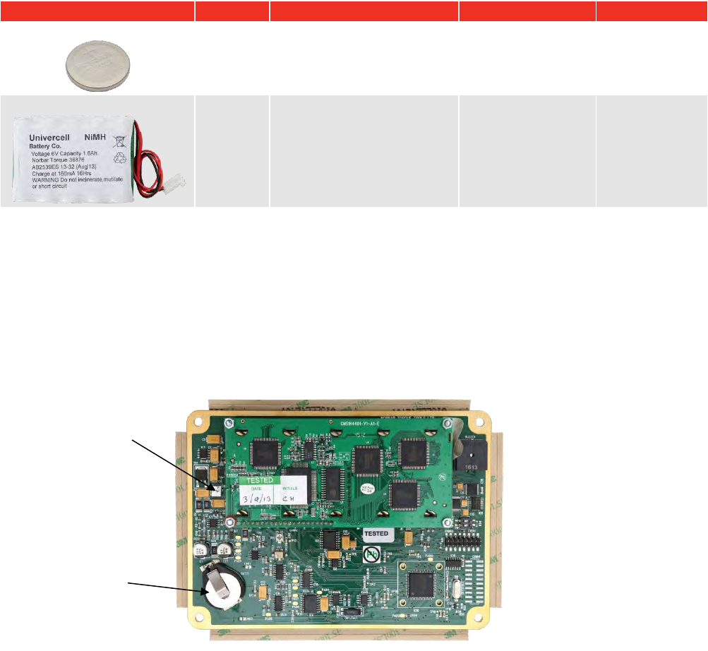
Battery Replacement
There are 2 batteries in the TTL-HE.
Description
Use
Reason for Replacement
Battery Markings
Part Number
Coin cell 3V
Time &
Date
Time & date fail.
CR2032
39202
Battery pack 6V NiMH
Powers
TTL-HE
TTL-HE has short battery
life.
38876
38876
TIP: Batteries should only be replaced by Norbar or a Norbar approved agent.
To replace battery(s):
1. Turn TTL-HE off.
2. Remove 4 front screws with 2.5mm HEX key.
3. Lift the top of the panel to show PCB.
4. Replace coin cell (marked BATT1 on PCB) and / or replace battery pack (marked CONN4 on PCB).
5. Fit panel without trapping any internal wires and refit 4 front screws.
FIGURE 2 – PBC (Inside TTL-HE)
BATT1
CONN4 connection
for battery pack,
the red wire should
be closest to the
edge of the PCB

23
Repair
Repair should be carried out at Norbar or by a Norbar approved agent, where all the facilities to ensure the
instrument is functioning at maximum accuracy are available.
NOTE: Only remove front panel for battery replacement; there are no other parts for user repair inside.
Cleaning
Do not use abrasives or solvent based cleaners.
Disposal (Recycling Considerations)
Component
Material
TTL-HE case.
Polyurethane.
Coin cell / Battery pack.
Dispose of used battery in a safe way.
Do not incinerate, mutilate or short circuit.
This symbol on the product indicates that it must not be disposed of in the
general waste. Please dispose of according to your local recycling laws and
regulations.
Contact your distributor or see the Norbar website (www.norbar.com) for further
recycling information.
For up to date disposal information, see our web site www.norbar.com.
SPECIFICATIONS
Input Voltage
Equivalent Torque
Accuracy
Calibration Uncertainty*
@0.5 mV
5% of full scale.
±0.1% of reading.
±0.13%
@1.0 mV
10% of full scale.
±0.05% of reading.
±0.08%
@2.0 to 18.9 mV
20% to 120% full scale.
±0.05% of reading.
±0.06%
*Using a coverage factor of k=2, to give a confidence level of approximately 95%.
Resolution: 5 digits for all Norbar transducers.
Display: 240 x 64 pixel dot matrix display.
With update rate of twice per second (2Hz).
Torque Unit Conversions: To ‘BS 350:2004 Conversion factors for units’.
Zero Suppression: TRACK None.
ALL OTHER MODES Suppressed from 0 to approximately 0.5% of
transducer calibration range.
Password: 000000 (default), must be 6 characters.
Time/Date: HH:MM:SS 24 Hour clock.
DD/MM/YY or MM/DD/YY date format.
Time/Date Compliance: To year 2062.
Units of Measurement: See TRANSDUCER INTERFACE section.
First Peak Sensitivity: 2.5%(High), 5%(Medium), or 10%(Low) of reading.
Auto Reset Hold Time: 1, 2, 3 or 4 seconds.
Frequency Response: 8th Order Butterworth low pass filter with a –3dB point settable from 100
to 2500 Hz.
Trigger from Setting: 0 to 99% of transducer capacity.
Operating Temperature Range: +5°C to +40°C.
Storage Temperature Range: -20°C to +70°C.
Maximum Operating Humidity: 85% Relative Humidity @30°C.

24
ac Power Adapter: 100 to 240 Volts a.c. at 50-60 Hz input.
9V, 300 mA D.C. output (pin 2 positive).
Power Down Time: 1 to 99 minutes (enter 0 to disable).
Power Consumption: 2.4 W - maximum.
Power Cable: 2 metres (6 ft 6 ins) long minimum.
Power Plug Fuse (if fitted): 1 Amp.
Battery Pack: 1600 mAh, 6.0 volt (5 cell) NiMH (Recharge time 200 minutes).
Coin Cell: Renata 190 mAh (CR2032FH).
Weight: 0.8 Kg (2.2 lb).
Dimensions: 45mm high x 200 mm wide x 145 mm deep.
Case Materials / Finish: Rigid polyurethane with fine texture acrylic paint finish.
Environment (Battery power): In conformance with EN 60529.
IP65 Dust-tight and protected against water jets.
IP67 Dust-tight and protected against the effects of temporary immersion
in water.
Environment (Mains power): Indoor use, within a light industrial environment.
Electromagnetic Compatibility: Designed to EN 61326 : 2013.
(EMC) Directive
Low Voltage Directive: Designed to EN 61010-1 : 2010.
(Mains power) To environmental conditions Pollution Degree 2
& Installation Category (Over voltage Category) II.
Also compliant with a Norbar transducer connected.
NOTE: Due to continuous improvement all specifications are subject to change without prior notice.
TROUBLE SHOOTING
Tips are located within the manual to help with troubleshooting.
Error Messages
Error messages are displayed to help the user, with audible warnings given when necessary.
Common error messages are:
Error #
Message
Comment
312
TRANSDUCER CAPACITY > 1,500,000
Wrong value entered.
313
TRANSDUCER CAPACITY < 0.01
Wrong value entered.
314
CALIBRATION FIGURE NOT 0.50 TO 3.15 MV/V
Wrong value entered.
316
NO TRANSDUCER TO EDIT / PRINT
No stored transducers.
317
DELETE A SAVED TRANSDUCER FIRST
All 20 locations full.
318
SET + LIMIT TOO HIGH
Wrong value entered.
319
SET - LIMIT TOO HIGH
Wrong value entered.
320
INCORRECT TARGET VALUE
Wrong value entered.
321
FREQUENCY NOT 100 Hz – 2500 Hz
Wrong value entered.
322
POWER DOWN TIME 0-99 MINUTES
Wrong value entered.
324
SMART TRANSDUCER NOT INITIALISED
Transducer’s stored data is blank.

Problems
Problem
Likely Solutions
No TTL-HE display.
Check on/off switch is ON.
Charge battery for at least 1 minute.
Battery will not charge.
Check display backlight is ON when charging.
Check a.c. power adaptor is ON (green LED on power adaptor will glow).
Check electrical power supply and fuse in plug (if fitted).
Displays Menu 82:
‘CLOCK NOT INITALISED’
The coin cell battery has failed. See MAINTENANCE section or return to
Norbar.
Overrange
Open circuit in transducer or transducer lead.
For more complex faults please contact Norbar distributor / manufacturer.
GLOSSARY OF TERMS
Word or Term
Meaning
a.c.
Alternating current.
Auto Reset Hold Time
The length of time a reading is displayed until automatically reset.
d.c.
Direct current.
First Peak Sensitivity
The amount by which the reading must fall from a peak for the display to be held.
Frequency Response
Frequency value below which signals are passed.
Hz
Hertz, unit of frequency.
LED
Light Emitting Diode.
Lemo
Reference for manufacturers of connector.
mA (milli amp)
One thousandth of an amp.
mAh (milli ampere hour)
Rate of charge/discharge of a battery.
mS (Millisecond)
One thousandth of a second (0.001 second).
mV (Millivolt)
One thousandth of a volt (0.001 volt).
mV/V (Millivolt per volt)
Ratio of millivolt output to voltage input.
NiMH
Nickel metal Hydride.
NON-SMART
Standard mV/V transducer (NON-INTELLIGENT).
PC
Personal Computer.
PCB
Printed Circuit Board.
Power Down Time
The length of time that the TTL-HE has not been used before the instrument goes
into power down mode.
Print / X Print
Print can be switched off to stop all serial port output.
Pulse Count
The number of torque pulses that have been applied to the TTL-HE in IMPULSE
TOOL or CLUTCH TOOL mode.
SMART
Serial Memory Automatic Recognition Transducer (INTELLIGENT).
SMART Transducer
A transducer that holds its own calibration data (INTELLIGENT).
Trigger From
Value at which the memory modes operate. Used to overcome erratic
applications of torque causing false results.
TTL-HE
Torque Tester Lite – Harsh Environment.
USER
Measurement units that can be specified by the user.
V d.c.
Voltage (direct current).
Zero Suppression
Value of torque that has to be achieved for the TTL-HE not to display zero.
25

OPERATOR’S MANUAL
TORQUE TOOL TESTER (TTT) SERIES 3
FOR USE WITH TTT’S FITTED WITH
VERSION 37712.305 SOFTWARE
Part Number 34308 | Issue 3 | Original Instructions (English)
© Norbar Torque Tools Ltd 2016
NORBAR TORQUE TOOLS LTD
Wildmere Road, Banbury,
Oxfordshire, OX16 3JU
UNITED KINGDOM
Tel + 44 (0)1295 270333
Email enquiry@norbar.com
NORBAR TORQUE TOOLS
45–47 Raglan Avenue, Edwardstown,
SA 5039
AUSTRALIA
Tel + 61 (0)8 8292 9777
Email enquiry@norbar.com.au
NORBAR TORQUE TOOLS INC
36400 Biltmore Place, Willoughby,
Ohio, 44094
USA
Tel + 1 866 667 2279
Email inquiry@norbar.us
NORBAR TORQUE TOOLS PTE LTD
194 Pandan Loop
#07-20 Pantech Business Hub
SINGAPORE 128383
Tel + 65 6841 1371
Email enquires@norbar.sg
NORBAR TORQUE TOOLS (SHANGHAI) LTD
E Building–5F, no. 1618 Yishan Road,
Minhang District, Shanghai
CHINA 201103
Tel + 86 21 6145 0368
Email sales@norbar.com.cn
NORBAR TORQUE TOOLS INDIA PVT. LTD
Plot No A-168, Khairne Industrial Area,
Thane Belapur Road, Mahape,
Navi Mumbai – 400 709
INDIA
Tel + 91 22 2778 8480
Email enquiry@norbar.in
www.norbar.com
