OBC User Manual Rev1
User Manual:
Open the PDF directly: View PDF ![]() .
.
Page Count: 33

USER MANUAL
Onboard Computer (OBC) Type II

ENDUROSAT
2
ONBOARD COMPUTER OBC TYPE II – USER MANUAL
1 Change Log........................................................................................................................ 4
2 Acronyms List ..................................................................................................................... 5
3 Description ......................................................................................................................... 6
4 Product Performance And Properties .................................................................................. 6
5 Electrical Characteristic ....................................................................................................... 7
6 Interface Diagram ............................................................................................................... 8
7 Communication Interfaces ................................................................................................ 10
7.1 CAN ..................................................................................................................................... 10
7.2 USART and UART ................................................................................................................ 11
7.3 SPI ....................................................................................................................................... 13
7.4 I2C........................................................................................................................................ 14
7.5 Six General Purpose Outputs ................................................................................................ 14
8 Attitude determination and control system ........................................................................ 14
8.1 Compass ............................................................................................................................. 14
8.2 Accelerometers .................................................................................................................... 15
8.3 Sun sensors ......................................................................................................................... 15
8.4 Temperature sensors ............................................................................................................ 15
8.5 Magnetorquers control ......................................................................................................... 15
9 OBC ProtoBoard Area ...................................................................................................... 16
9.1 USB interface ....................................................................................................................... 16
9.2 External PCB (Payload) ......................................................................................................... 17
9.3 Stripboard grid ..................................................................................................................... 18
9.4 Atomic Clock Ready ............................................................................................................. 19
9.5 SD Card Holder .................................................................................................................... 19
10 Connector pinout .............................................................................................................. 20
10.1 Connectors location ............................................................................................................. 20
10.2 H1 & H2 Stack Connector .................................................................................................... 21
10.3 PAN1, PAN2 and PAN3 ........................................................................................................ 23
10.4 PAN4, PAN5 and PAN6 ........................................................................................................ 23
10.5 JP2 ...................................................................................................................................... 24
10.6 JP14 .................................................................................................................................... 26
10.7 J1 ........................................................................................................................................ 26
10.8 JP15 .................................................................................................................................... 27
10.9 CN1 ..................................................................................................................................... 28
10.10 SD1 .................................................................................................................................. 28
10.11 P1 .................................................................................................................................... 29

ENDUROSAT
3
ONBOARD COMPUTER OBC TYPE II – USER MANUAL
11 Mechanical Characteristics ............................................................................................... 30
12 Assembling ....................................................................................................................... 31
13 Envinronmental And Mechanical Tests .............................................................................. 31
14 Included In The Shipment ................................................................................................. 31
15 Handling And Storage ....................................................................................................... 31
16 Warnings .......................................................................................................................... 32
ENDUROSAT
4
ONBOARD COMPUTER OBC TYPE II – USER MANUAL
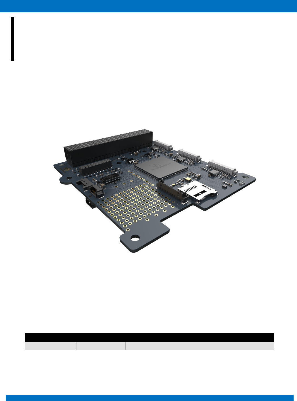
ONBOARD COMPUTER (OBC) TYPE II
USER MANUAL
This user manual is specially designed to detail the EnduroSat onboard computer (OBC) type II, functions
and features.
Please read carefully the manual before unpacking the OBC in order to ensure safe and proper use.
Figure 1 – Onboard computer (OBC) type II
1 CHANGE LOG
Date
Version
Note
20/06/2018
Rev 1
Initial document

ENDUROSAT
5
ONBOARD COMPUTER OBC TYPE II – USER MANUAL
2 ACRONYMS LIST
ASIC
Application Specific Integrated Circuit
CAN
Controller Area Network
COM-port
Communication Port
CSAC
Chip Scale Atomic Clock
ECSS
European Cooperation Space Standardization
ESA
European Space Agency
ESD
Electrostatic Discharge
GEVS
General Environmental Verification Standard.
GND
Ground
GPS
Global Positioning System
I2C
Inter-Integrated Circuit
OBC
Onboard Computer
PCB
Printed Circuit Board
PWM
Pulse Width Modulation
RAM
Random-Access Memory
RBF
Remove Before Flight
RF
Radio Frequency
SD card
Secure Digital Card
SPI
Serial Peripheral Interface
UART
Universal Asynchronous Receiver/Transmitter
UHF
Ultra-High Frequency
USART
Universal Synchronous Asynchronous Receiver Transmitter
USB
Universal Serial Bus

ENDUROSAT
6
ONBOARD COMPUTER OBC TYPE II – USER MANUAL
3 DESCRIPTION
The EnduroSat onboard computer type II is a low power consumption and high performance
computing platform for nanosatellites, fully compatible with the CubeSat standard. It is based on ARM
Cortex M4 with frequency rate up to 180MHz or optionally on ARM Cortex M7 processor with
frequency rate up to 216 MHz. It comes with integrated double redundancy sensors: 3-Axis
accelerometers and compass. PWM drivers for magnetorquers and inputs for sun sensors,
temperature sensors and gyroscope allow the implementation of the attitude determination and control
systems.
Customized interfaces and connectors allow high flexibility of the unit.
A Protoboard area on the PCB allows high customization ideal for test bed and fast prototyping. It is
possible to connect additional PCB through connectors and mounting holes and to integrate easily
additional sensors and chips such as atomic clocks, GPS receiver and so on.
4 PRODUCT PERFORMANCE AND PROPERTIES
• ARM Cortex M4/M7 processor;
• Frequency rate: up to 180 MHz for M4, up to 216 MHz for M7;
• 2MB Program Memory Size; 256kB RAM for M4, 2MB RAM for M7; 2048kB flash memory;
• MicroSD card slot;
• Integrated double redundancy sensors: 3-axis accelerometer and compass;
• 3x PWM drivers for magnetorquers;
• 6x analog inputs for sun sensor;
• 6x external temperature sensors can be connected;
• Three external gyroscope can be connected
• Interfaces: CAN, 2x USART, UART, 2x I2C, 2x SPI, USB (VCP);
• Real Time Clock
• Flexible frequency eco-mode;
• Weight: 58 g.
• 1Gbit Serial NOR Flash Memory
• 64Mbit Static RAM (Optional)
• Connector for antenna deployment
• ProtoBoard area for easy connection of payload and access to main power and communication
busses.

ENDUROSAT
7
ONBOARD COMPUTER OBC TYPE II – USER MANUAL
5 ELECTRICAL CHARACTERISTIC
1 - Current consumption is for one 3-Axis Accelerometer. The OBC has two identical sensors on the same location, but on opposite sides of the
PCB.
2 - Current consumption is for one 3-Axis Digital Compass. The OBC has two identical sensors on the same location, but on opposite sides of the
PCB
Parameter
Unit
Condition
Min
Typ
Max
Supply voltage
V
3
3.3
3.6
Supply current
mA
STM32F427 @185Mhz
104
123
mA
STM32F427 @120Mhz
58
72
mA
STM32F427 @60Mhz
30
38
mA
STM32F427 @16Mhz
13
27
µA
3-Axis Accelerometer – Normal Mode1
200
400
µA
3-Axis Accelerometer – Low Power Mode1
8
12
µA
3-Axis Accelerometer – Power Down Mode1
0.1
2
µA
3-Axis Digital Compass – Power Down Mode2
1
µA
3-Axis Digital Compass - Measurement Mode2
– Low Power Mode
40
3-Axis Digital Compass - Measurement Mode2
– High Resolution Mode
280
mA
Ext. 64M-bit Static RAM (Opt.), F = 18Mhz
45
55
mA
Ext. 64M-bit Static RAM (Opt.), F = 1Mhz
7.5
9
µA
Ext. 64M-bit Static RAM (Opt.), Stand-By
Mode
8
48
mA
Ext. 1Gbit NOR Flash Memory Operational
Mode @108Mhz
(fast-read extended I/O)
4
15
mA
Ext. 1Gbit NOR Flash Memory Operational
Mode @54Mhz
(fast-read extended I/O)
6
6
mA
Ext. 1Gbit NOR Flash Memory Operational
Mode @108Mhz (fast-read dual I/O)
18
mA
Ext. 1Gbit NOR Flash Memory Operational
Mode @108Mhz (Operating current (fast-
read quad I/O)
20
µA
Ext. 1Gbit NOR Flash Memory Operational
Mode Stand by Mode
200
Bi-directional PWM
Outputs
mA
@3.3V
3000
Operating
Temperature
°C
-30
85
Storage Temperature
°C
25
ENDUROSAT
8
ONBOARD COMPUTER OBC TYPE II – USER MANUAL
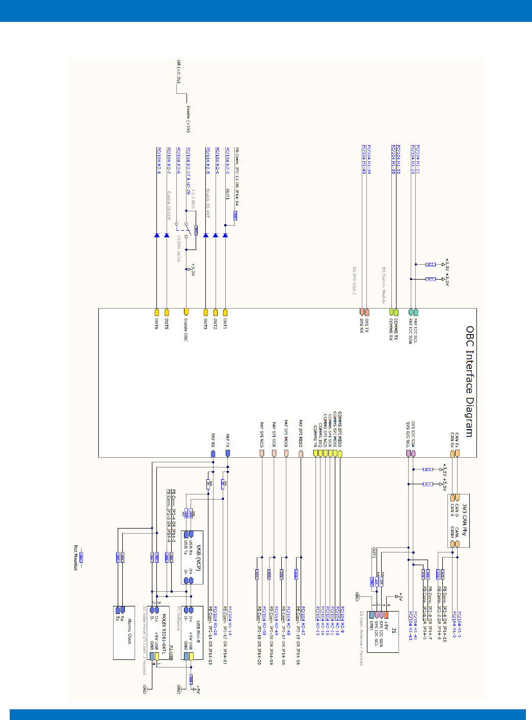
6 INTERFACE DIAGRAM
ENDUROSAT
9
ONBOARD COMPUTER OBC TYPE II – USER MANUAL
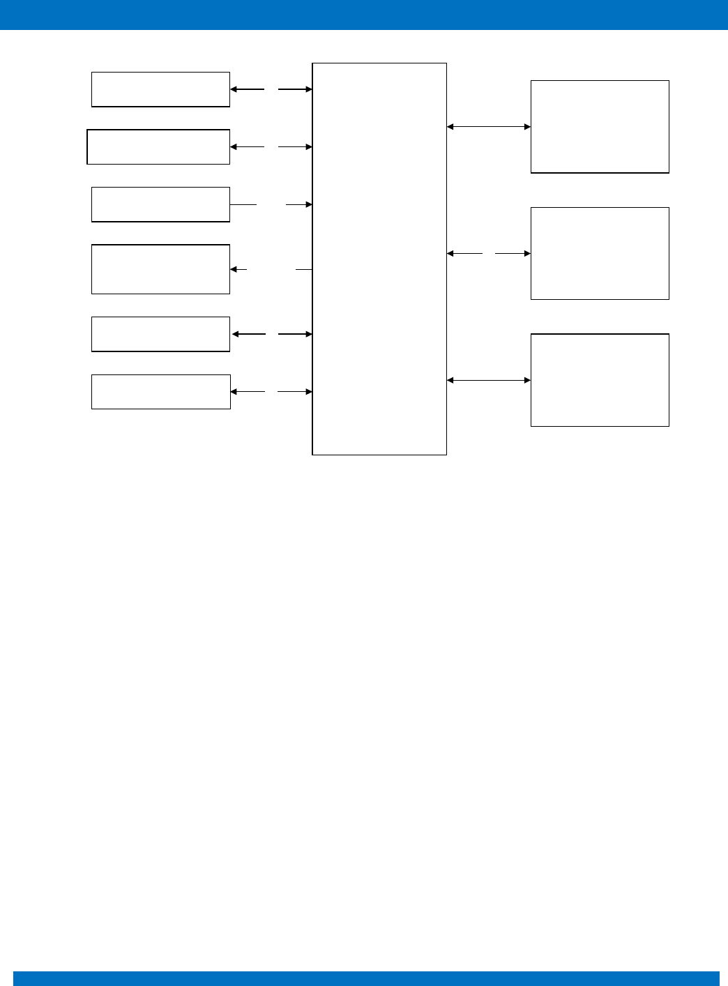
Figure 2 – OBC microcontroller periphery
MCU ARM
Cortex-M4/M7
Two 3-Axis
Accelerometer
Two 3-Axis Digital
Compass
64-Mbit Static RAM
(Opt.)
1-Gbit Flash Memory
SD Card Holder
Six Outputs for Sun
Sensors
Three H-Bridges
Outputs for
Magnetorquers
SPI
Analog
I2C
I2C
Six Outputs for
Temperature Sensors SPI
PWM/Direction
Three Outputs for
Gyroscopes SPI
ENDUROSAT
10
ONBOARD COMPUTER OBC TYPE II – USER MANUAL
7 COMMUNICATION INTERFACES
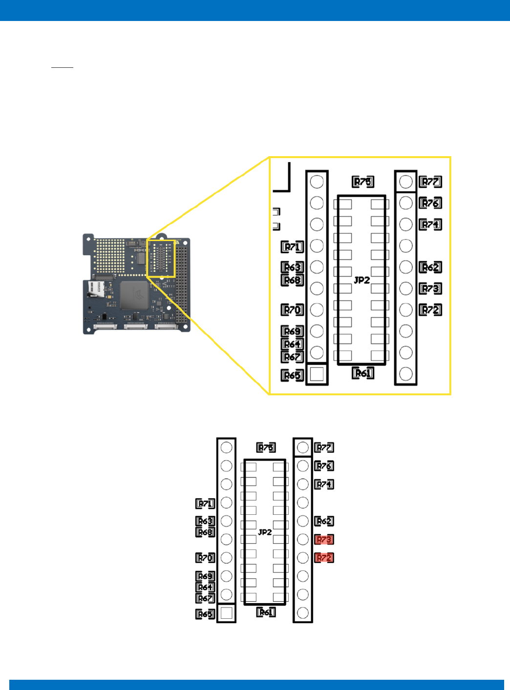
7.1 CAN
The EnduroSat On-board computer has a CAN bus interface using a 3.3-V CAN transceiver.
External modules can be connected throughout H1-1 and H1-3 of the PC/104 connector. Same
interface can be reached from the ProtoBoard area through JP2 and JP14 connectors (TLE-110-01-
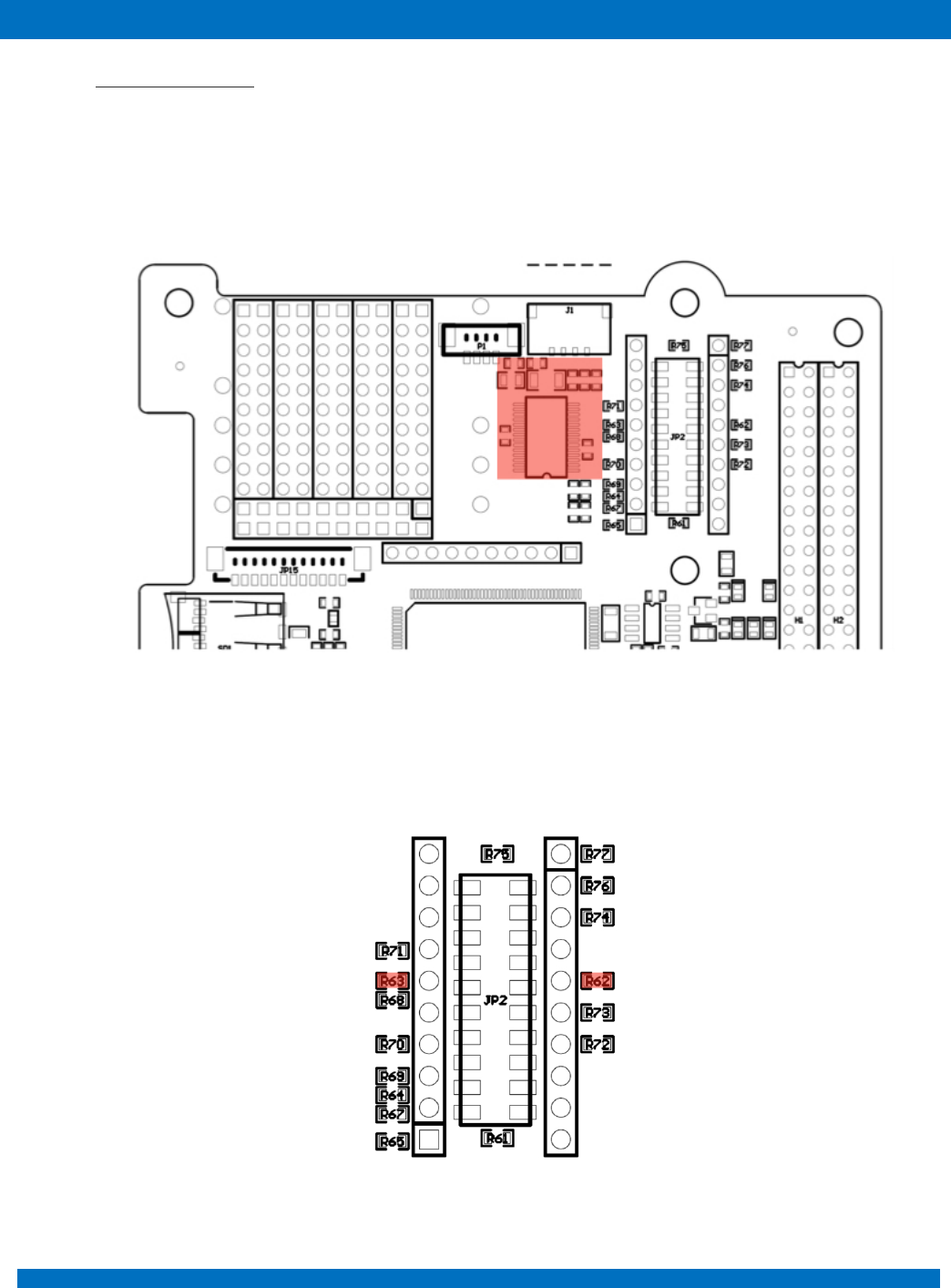
G-DV), for this purpose zero Ohm resistors R72 and R73 should be mounted as shown in Figure 4.
Figure 3 – Protoboard area customization
Figure 4
ENDUROSAT
11
ONBOARD COMPUTER OBC TYPE II – USER MANUAL
7.2 USART and UART
The EnduroSat onboard computer provides two USART and one UART interfaces.
The first USART interface (H1-33 and H1-35) is used by the UHF transceiver of the EnduroSat platform.
Second USART interface is left free for the payload (H1-19 and H1-20). If the USB peripheral is
mounted (Figure 5), this interface is used for UART to USB communication (Virtual COM Port).
Figure 5 – USB peripheral location
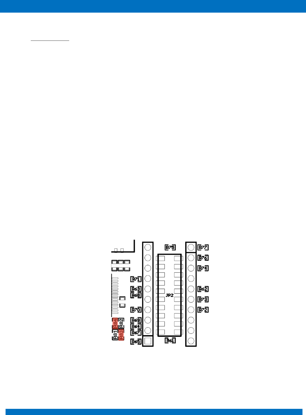
Mounting zero Ohm resistors on R62 and R63 gives access to this interface through the connectors
JP2 or JP14 on the ProtoBoard as shown in Figure 6.
Figure 6
ENDUROSAT
12
ONBOARD COMPUTER OBC TYPE II – USER MANUAL
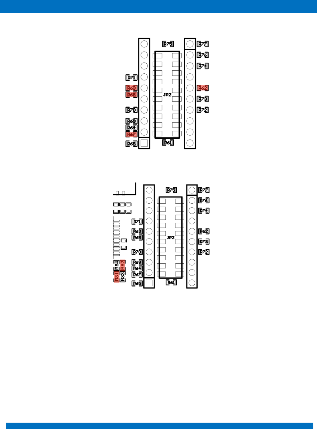
For USB (VCP) R62, R63, R67 & R68 as shown on figure 7
Figure 7
For USART on “P1-USB” R82, R81 as shown on figure 8.
Figure 8
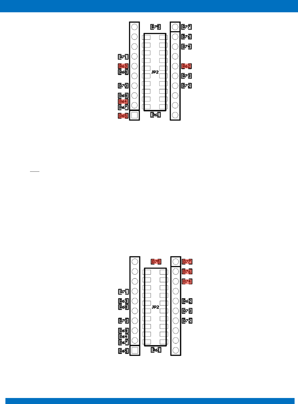
Moreover, the same interface can be used for communication with atomic clock if it is mounted on the
ProtoBoard area (Microsemi Quantum™ SA.45s CSAC). To realize the communication with the atomic
clock, zero ohm resistors – R62, R63, R64 and R65 have to be mounted as shown in Figure 9.
ENDUROSAT
13
ONBOARD COMPUTER OBC TYPE II – USER MANUAL
Figure 9
UART – is free for payload and it can be access through H1-39 / H1-40 (EnduroSat EPS Opt.).
7.3 SPI
Two 3.3V SPI interfaces are provided.
In the EnduroSat CubeSat platform the first SPI interface (H2-9, H2-10, H2-11, H2-15 and H2-16 of
the PC104 connector) is used for the EnduroSat S-Band transceiver.
The second SPI interface (H2-47, H2-48, H2-49 and H2-50 of the PC104 connector) can be used for
the payload or for generic user needs.
The second SPI interface also can be accessed through JP2 or JP14 of the ProtoBoard area mounting
zero Ohm resistors R74, R75, R76 and R77 as shown in Figure 10.
Figure 10
ENDUROSAT
14
ONBOARD COMPUTER OBC TYPE II – USER MANUAL
7.4 I2C
Two 3.3V I2C interfaces are provided.
First I2C interface (H1-41 and H1-43 of the PC104 connector) can be used as main interface among
all the subsystems of the satellite.
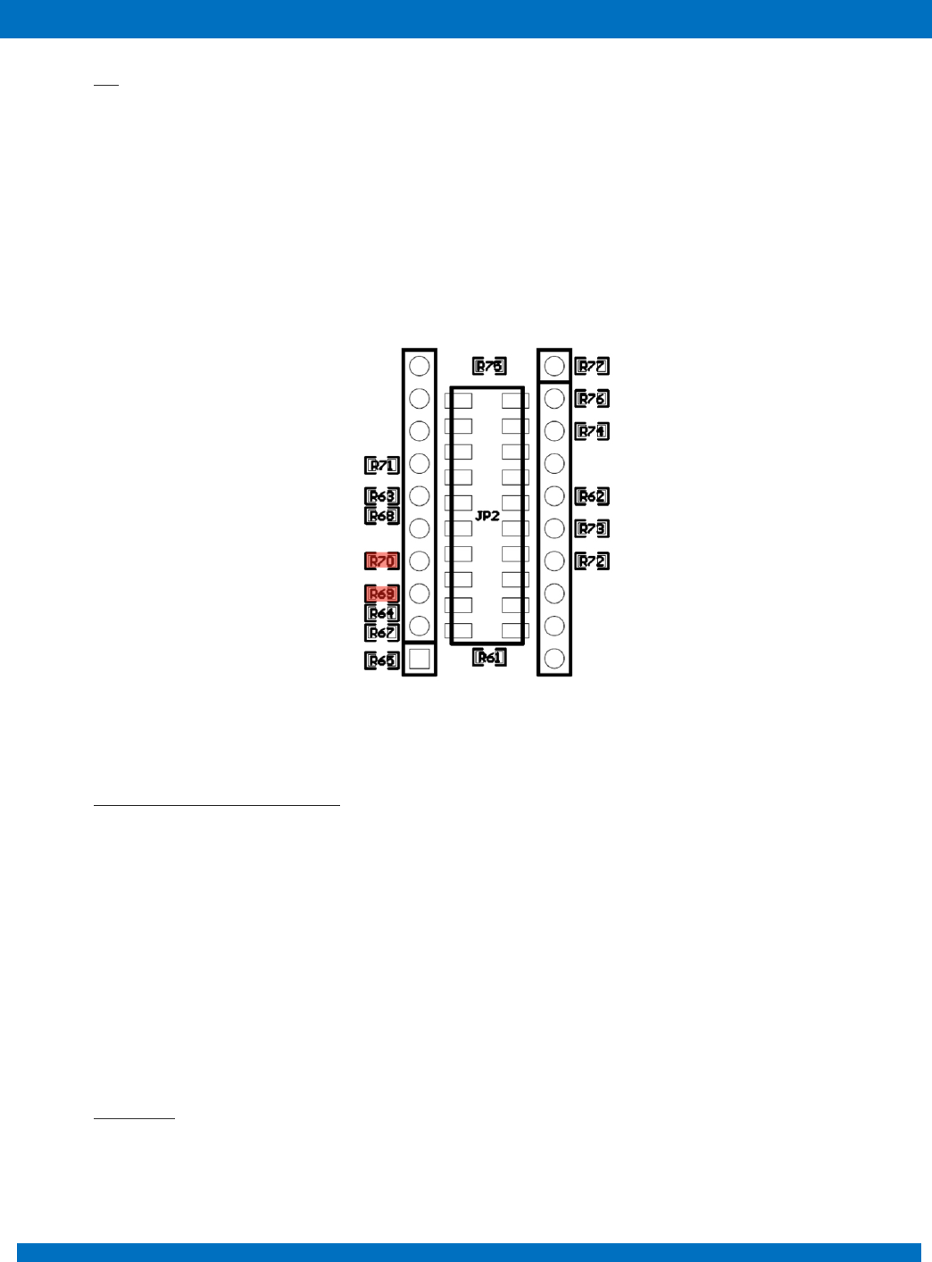
Second I2C interface (H1-21 and H1-23 of the PC104 connector) can be used for the payload and to
control the deployment of the EnduroSat UHF Antenna through the connector J1 located on the
ProtoBoard area. To realize the access through JP2 or JP14, zero Ohm resistors R69 and R70 and
have to be mounted (Figure 11).
Figure 11
7.5 Six General Purpose Outputs
The OBC Module has five general purpose outputs. Each output can be switched between 3.1V and
Ground. All outputs are protected with diodes. In this way other modules can control the same outputs
(there are 10k pull-down resistors on the EnduroSat EPS Type I Module). Diode OR gate can be
realized.
8 ATTITUDE DETERMINATION AND CONTROL SYSTEM
The EnduroSat Onboard computer comes with an embedded array of sensors for the attitude
determination and outputs for magnetorquers control.
8.1 Compass
Two 3-axis digital compass designed for low-field magnetic sensing with high-resolution are added to
the OBC periphery. Both sensors are located at the same place, but on opposite sides of the OBC.
The compass is based on magneto-resistive sensors plus an ASIC containing amplification, automatic

ENDUROSAT
15
ONBOARD COMPUTER OBC TYPE II – USER MANUAL
degaussing strap drivers, offset cancellation, and a 12-bit ADC that enables 1° to 2° compass heading
accuracy. Compass utilizes Anisotropic Magneto-resistive (AMR) technology that provides advantages
over other magnetic sensor technologies. These anisotropic, directional sensors feature
precision in-axis sensitivity and linearity. These sensors’ solid-state construction with very low cross-
axis sensitivity is designed to measure both the direction and the magnitude of Earth’s magnetic fields,
from milli-gauss to 8 gauss.
8.2 Accelerometers
Two high-performance ultra low-power 3-axis accelerometers are added to OBC periphery. Both of
them are placed at the same location but on opposite site of the PCB. Accelerometers has dynamic
user-selectable full-scales of ±2g/±4g/±8g and is capable of measuring accelerations with output data
rates from 0.5 Hz to 1 kHz
8.3 Sun sensors
Six analog inputs for sun sensors. At the current OBC design filters and amplification is optimized to
EnduroSat Solar Panels Sun Sensors.
8.4 Temperature sensors
Six external temperature sensors with SPI communication interface can be connected to the OBC.
8.5 Magnetorquers control
Three independent outputs for control the magnetorquers. The control of magnetorquers is realised
with H-Bridge with 3.3V and maximum output current of 3A.
Sensor
Parameter
Unit
Condition
Min
Typ
Max
Two 3-Axis
Digital
Compass
Measurement
Range
gauss
Full scale
-16
+16
Sensitivity
LSb/gauss
±4
6842
1370
±8
3421
±12
2281
±16
1711
Two 3-Axis
Accelerometer
Measurement
range
±2g/±4g/±8g
Output Data
Rate
Hz
0.5
1000
ENDUROSAT
16
ONBOARD COMPUTER OBC TYPE II – USER MANUAL
9 OBC PROTOBOARD AREA
9.1 USB interface
Additional USB interface can be provided on the ProtoBoard area. This interface gives accessibility to
an external device/PC (Master device) to communicate with the OBC Microcontroller (Slave device).
OBC USB interface is based on IC FT232RL - UART to USB interface (Virtual COM Port). Full driver
support can be found at http://www.ftdichip.com.
The EnduroSat On-Board Computer type II comes with electronic components for USB Interface
already mounted on it.
The USB interface can be accessed from PC/104 connector (Tx) H-19 and (Rx) H-20. Moreover, it can
be also accessed from 20pin headers “JP2” of the top side of the OBC through 11pin Rx/12pin Tx or
“JP14” from bottom side through 12pin Rx / 11pin Tx. To realize the access through “JP2” and “JP14”,
zero Ohm resistors R62, R63, R67 and R68 have to be mounted as shown in Figure 7.
Two types of connectors can be used to access the USB Interface: standard USB Mini B Connector
(USB1) or Molex 53398-0471 (P1). When EnduroSat Solar Panel with RBF and interface connector are
used in the platform, connection through it and the OBC Molex 53398-0471 can be realized with
EnduroSat 4 pin cable. In this way the OBC USB interface can be accessed with the external
EnduroSat USB adapter also when the CubeSat is fully assembled. Both USB connectors can be
connected to the ProtoBoard Connectors “JP2” (DM – pin3 / DP – pin4) and “JP14” (DM – pin4 / DP
– pin3) when zero Ohm resistors are mounted on R83 and R84 (Figure 12).
Figure 12
ENDUROSAT
17
ONBOARD COMPUTER OBC TYPE II – USER MANUAL
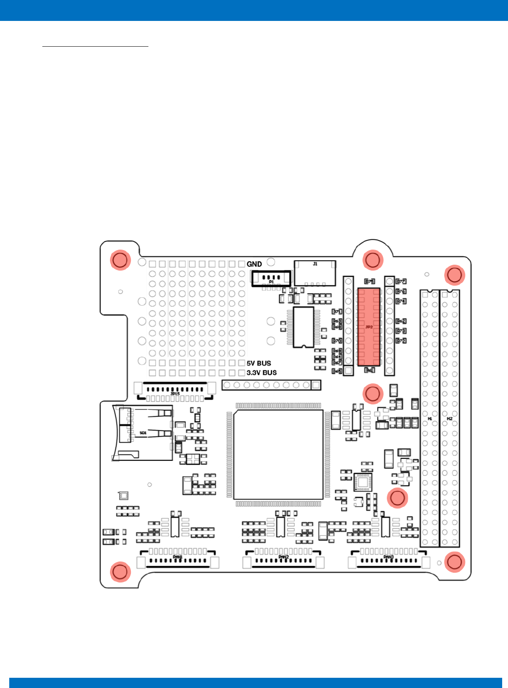
9.2 External PCB (Payload)
External PCB (Payload) can be connected to the connector located on the ProtoBoard Area. Additional
mounting holes аrе also provided. The ProtoBoard connector is the 20pin SAMTEC TLE-110-01-G-
DV. One is on the top side (JP2) of the OBC and the other on the bottom (JP14 -Not Mounted). This
allows to minimize the used space inside the satellite and easily access to different communication
interfaces and power supply. The interfaces on the ProtoBoard connectors should be chosen very
carefully, because they are shared between with main PC/104 connector. All pins of ProtoBoard
connectors are separated from the rest of the OBC when zero Ohm resistors are not mounted. Each
pin of the ProtoBoard connector has its own testing point located just next to it for research and
developing purposes. All test points are plated holes with pitch 0.1inch (2.54mm) and diameter of
0.060inch.
Figure 13 – External PCB
ENDUROSAT
18
ONBOARD COMPUTER OBC TYPE II – USER MANUAL
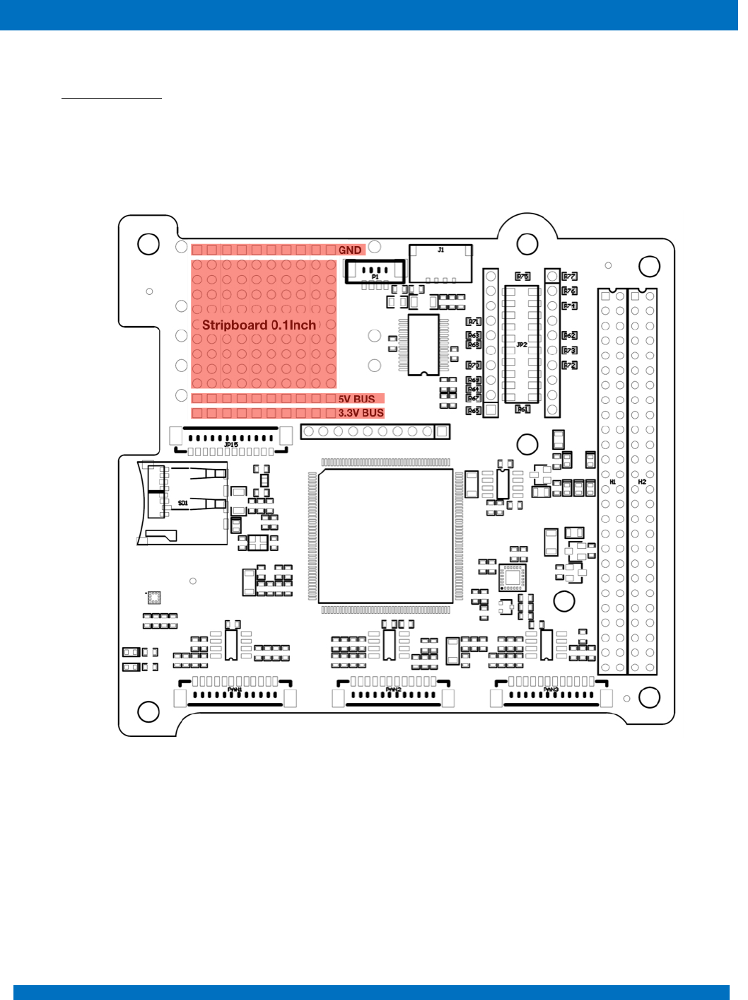
9.3 Stripboard grid
For developing and prototyping purposes an area of OBC is left as a stripboard grid with 11 holes on
16 strips. All holes are plated with grid spacing of 0.1inch(2.54mm) and diameter of 0.060inch. All holes
in the first strip are connected to the 5V BUS, in the second strip to 3.3V BUS and the last one to GND.
These power strips can be recognized by the square rings.
Figure 14
ENDUROSAT
19
ONBOARD COMPUTER OBC TYPE II – USER MANUAL
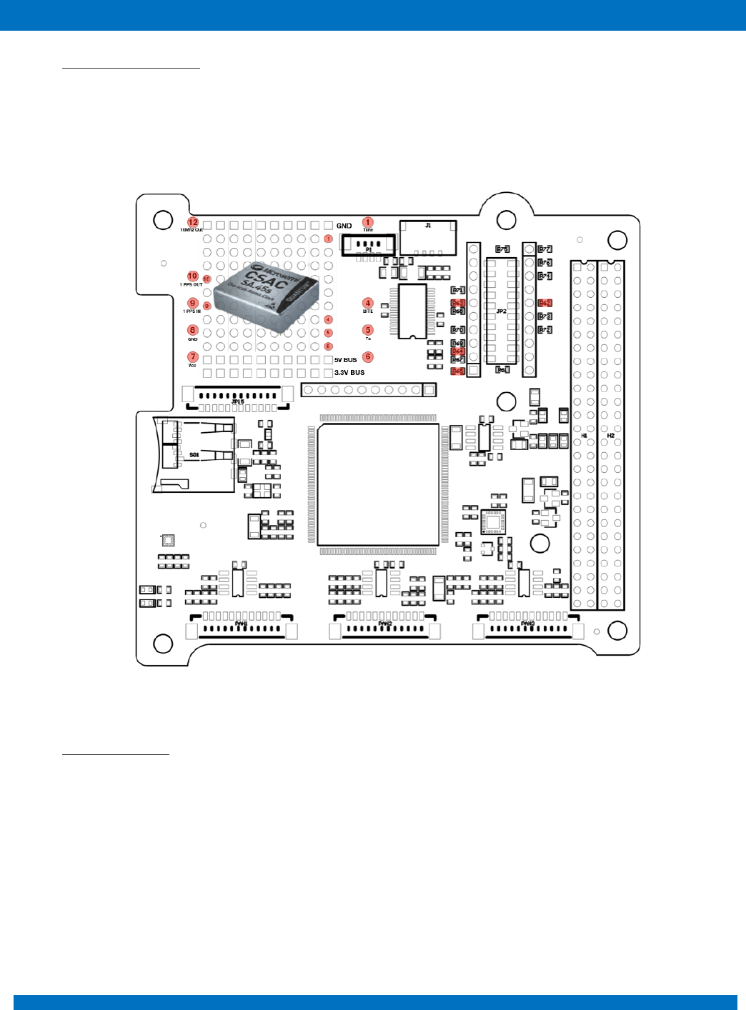
9.4 Atomic Clock Ready
On the protoboard area, there are mounting holes for Quantum™ SA.45s Chip Scale Atomic Clock
(CSAC) from Microsemi. UART interface can be connected through zero Ohm resistors. Access to
other pins of the atomic clock can be realized with plated holes next to each pin.
Figure 15
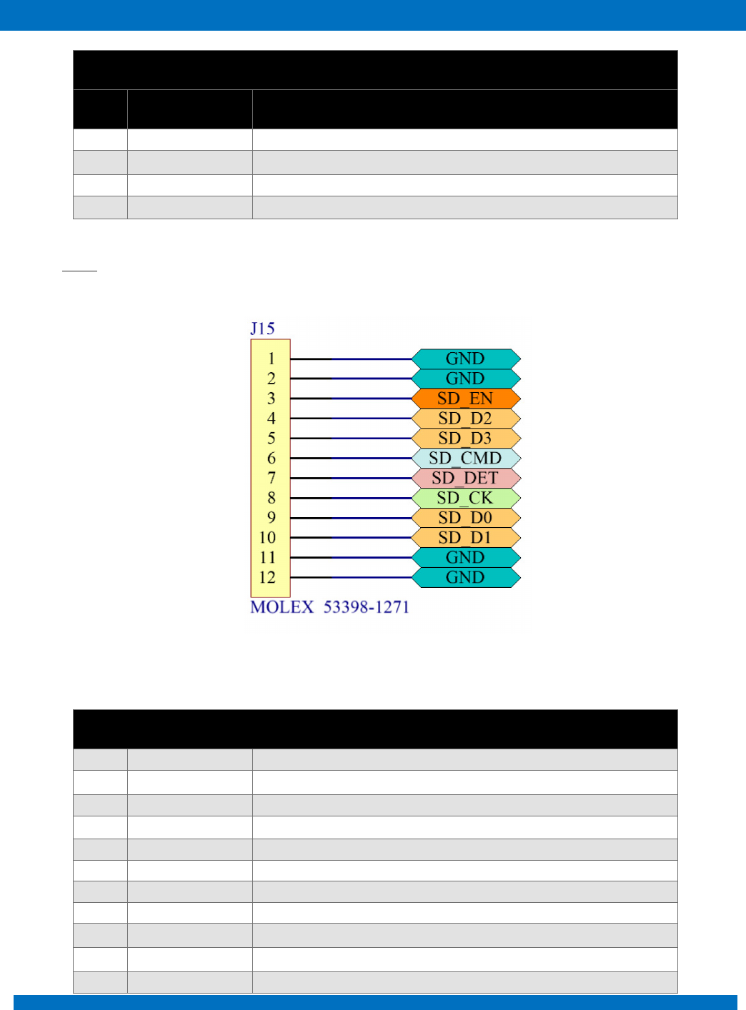
9.5 SD Card Holder
Direct access to SD Card holder is enable through 12pin connector JP15 – Molex 53398-1271. The
SD card is shared between high speed data payload and OBC to resend trough the RF communication
module.
ENDUROSAT
20
ONBOARD COMPUTER OBC TYPE II – USER MANUAL
10 CONNECTOR PINOUT
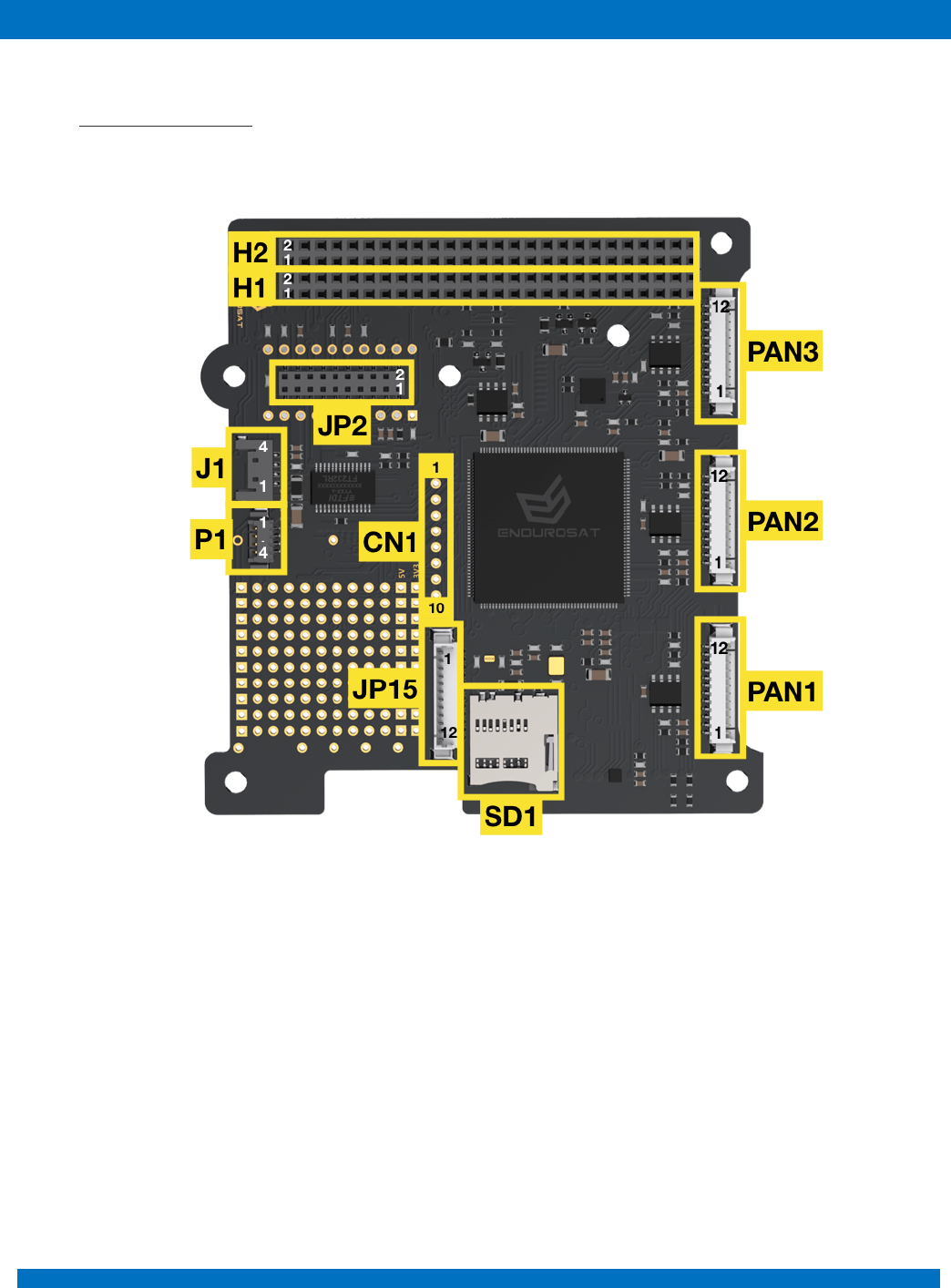
10.1 Connectors location
Figure 16 - OBC - top side - Connectors location
ENDUROSAT
21
ONBOARD COMPUTER OBC TYPE II – USER MANUAL
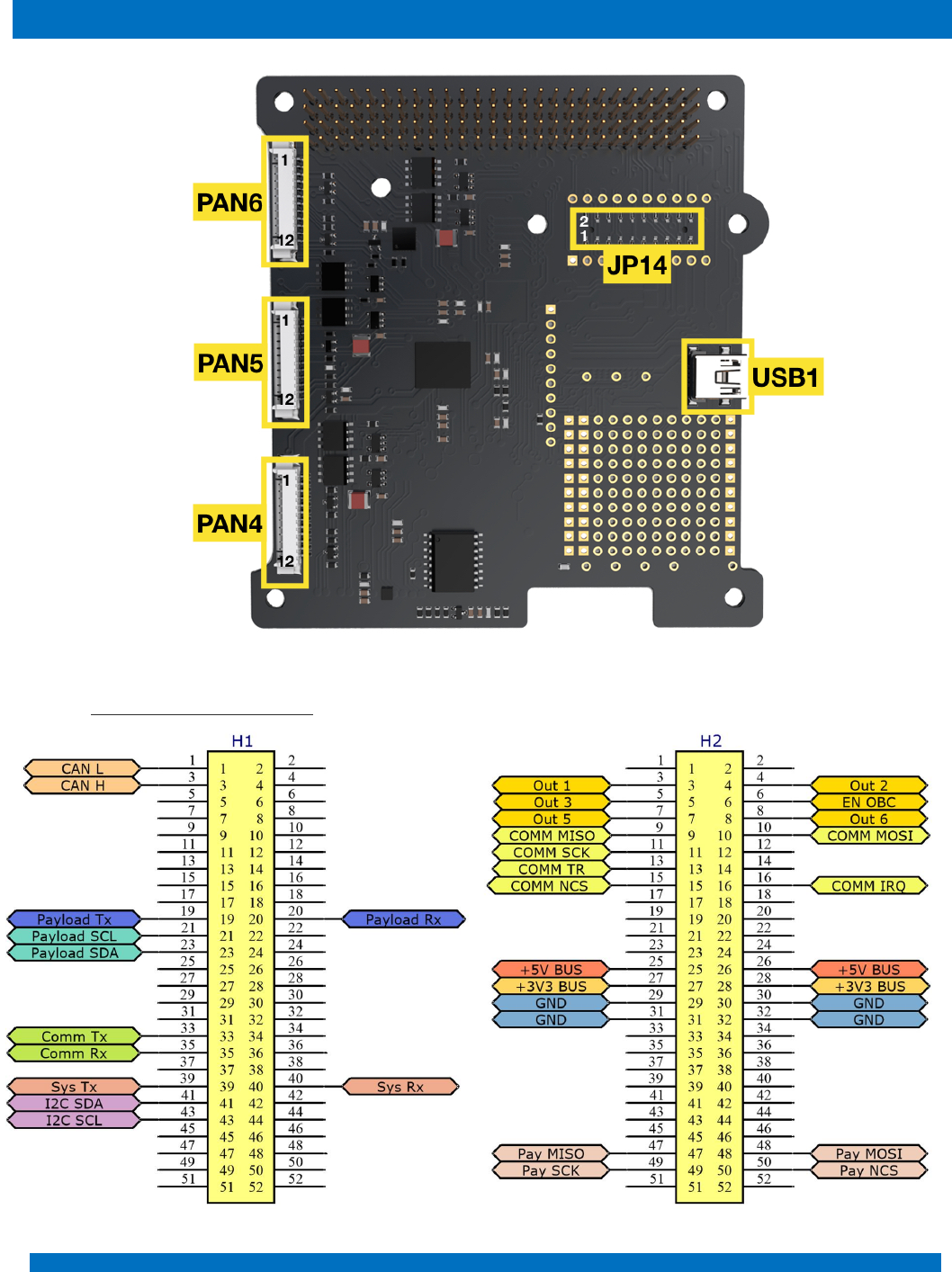
Figure 17 - OBC – bottom side - Connectors location
10.2 H1 & H2 Stack Connector

ENDUROSAT
22
ONBOARD COMPUTER OBC TYPE II – USER MANUAL
H1
Pin
Mnemonic
Description
H1-1
CANL
CAN communication Low (3.3V)
H1-3
CANH
CAN communication High (3.3V)
H1-19
PAY_TX
USART payload transmit data
H1-20
PAY_RX
USART payload receive data
H1-21
PAY_SCL
I2C for payload
H1-23
PAY_SDA
I2C for payload
H1-33
UHF RX
USART UHF module transmit data (optional EnduroSat EPS)
H1-35
UHF TX
USART UHF module receive data (optional EnduroSat EPS)
H1-39
SYS_TX
UART transmit data
H1-40
SYS_RX
UART receive data
H1-41
SYS_SDA
I2C between sub-systems
H1-43
SYS_SCL
I2C between sub-systems
H2
Pin
Mnemonic
Description
H2-3
OBC_OUT1
Universal Output 1
H2-4
OBC_OUT2
Universal Output 2
H2-5
OBC_OUT3
Universal Output 3
H2-6
EN_OBC
Enable OBC (to turn on the OBC)
H2-7
OBC_OUT5
Universal Output 5
H2-8
OBC_OUT6
Universal Output 6
H2-9
SPI MISO
SPI MISO
H2-10
SPI MOSI
SPI MOSI
H2-11
SPI SCK
SPI SCK
H2-13
SPI TR
SPI TR
H2-15
SPI CS
SPI CS
H2-16
SPI IRQ
SPI IRQ
H2-25
+5V
+5V BUS
H2-26
+5V
+5V BUS
H2-27
3V3
+3.3V BUS
H2-28
3V3
+3.3V BUS
H2-29
GND
Ground
H2-30
GND
Ground
H2-31
GND
Ground
H2-32
GND
Ground
ENDUROSAT
23
ONBOARD COMPUTER OBC TYPE II – USER MANUAL
H2-47
PAY_MISO
SPI Payload
H2-48
PAY_MOSI
SPI Payload
H2-49
PAY_SCK
SPI Payload
H2-50
PAY_NCS
SPI Payload
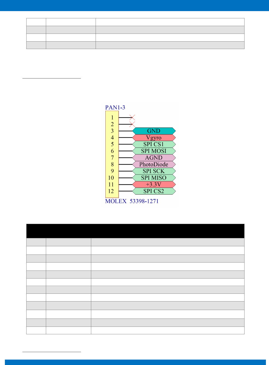
10.3 PAN1, PAN2 and PAN3
Picoblade 12 pins connectors PAN1, PAN2 and PAN3 are located on the top side of the OBC as
shown in Figure 16.
Pin
Mnemonic
Description
1
NC
Not connected
2
NC
Not connected
3
GND
Ground
4
Vgyro
Power for gyroscope
5
SPI CS1
SPI chip select for gyroscope
6
SPI MOSI
SPI (for gyroscope and temperature sensor)
7
AGND
Photodiode Analog Ground
8
PhotoDiode
Photodiode signal
9
SPI SCK
SPI (for gyroscope and temperature sensor)
10
SPI MISO
SPI (for gyroscope and temperature sensor)
11
+3.3V
+3.3V BUS power supply for sensors
12
SPI CS2
SPI chip select for temperature sensor
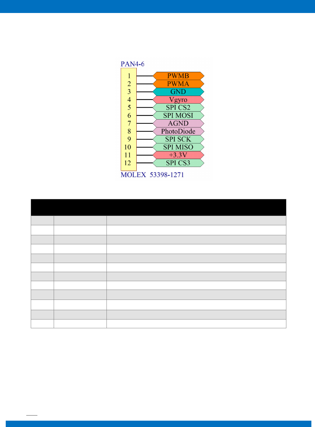
10.4 PAN4, PAN5 and PAN6
ENDUROSAT
24
ONBOARD COMPUTER OBC TYPE II – USER MANUAL
Picoblade 12 pins connectors PAN4, PAN5 and PAN6 are located on the bottom side of the OBC as
shown in Figure 17.
Pin
Mnemonic
Description
1
PWMB
PWM (in/out)
2
PWMA
PWM (out/in)
3
GND
Ground
4
Vgyro
Power for gyroscope
5
SPI CS1
SPI chip select for gyroscope
6
SPI MOSI
SPI (for gyroscope and temperature sensor)
7
AGND
Photodiode Analog Ground
8
PhotoDiode
Photodiode signal
9
SPI SCK
SPI (for gyroscope and temperature sensor)
10
SPI MISO
SPI (for gyroscope and temperature sensor)
11
+3.3V
+3.3V BUS power supply for sensors
12
SPI CS2
SPI chip select for temperature sensor
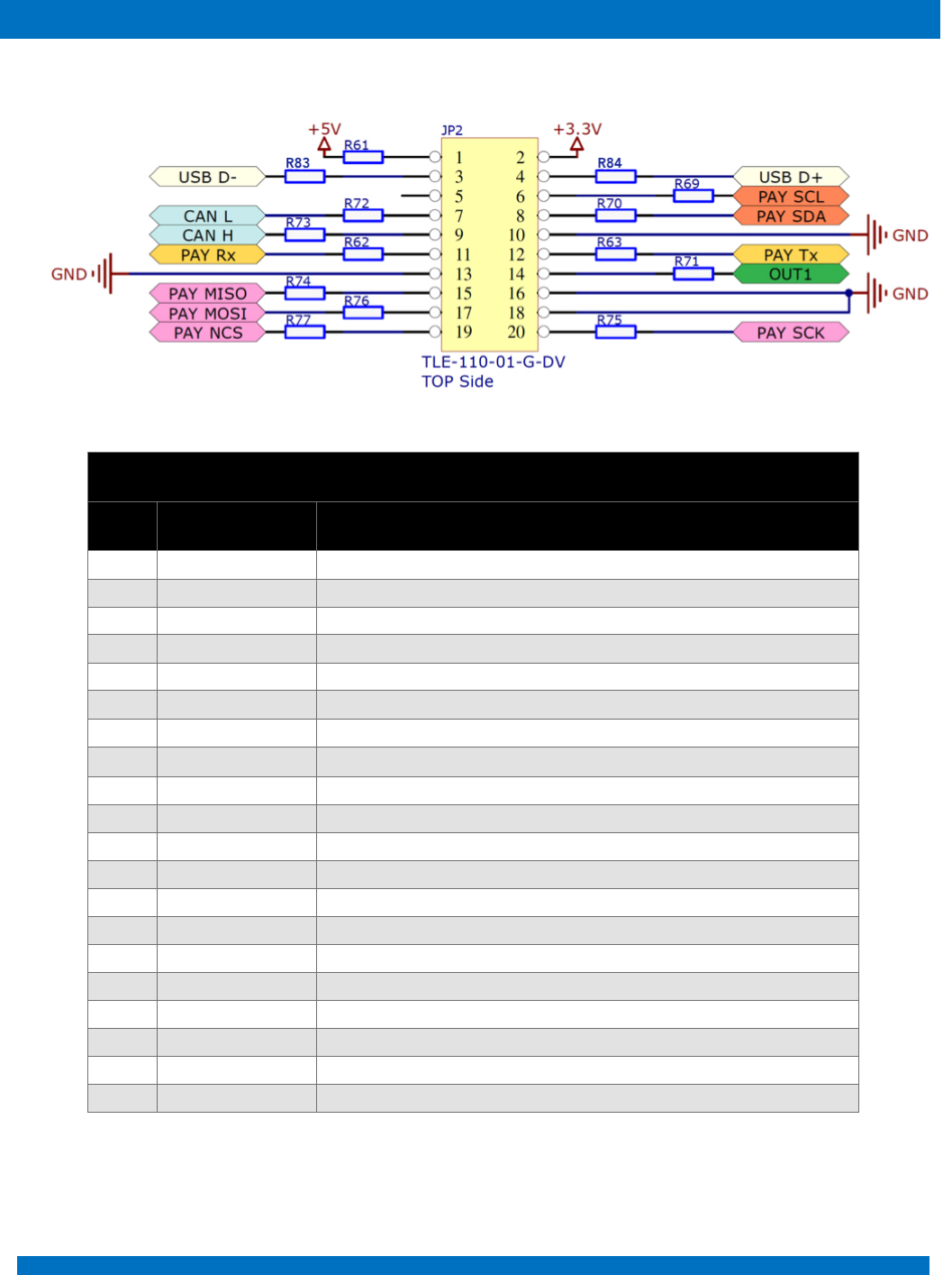
10.5 JP2
ENDUROSAT
25
ONBOARD COMPUTER OBC TYPE II – USER MANUAL
JP2
Pin
Mnemonic
Description
1
+5V
+5V BUS
2
+3.3V
+3.3V BUS
3
USB D-
USB data -
4
USB D+
USB data +
5
Not connected
6
PAY SCL
I2C payload
7
CAN L
CAN Low (3.3V)
8
PAY SDA
I2C payload
9
CAN H
CAN High (3.3V)
10
GND
Ground
11
PAY Rx
USART receive data
12
PAY Tx
USART transmit data
13
GND
Ground
14
OUT1
Universal output 1
15
PAY MISO
SPI payload
16
GND
Ground
17
PAY MOSI
SPI payload
18
GND
Ground
19
PAY NCS
SPI payload
20
PAY SCK
SPI payload
ENDUROSAT
26
ONBOARD COMPUTER OBC TYPE II – USER MANUAL
10.6 JP14
JP14
Pin
Mnemonic
Description
1
+3.3V
+3.3V BUS
2
+5V
+5V BUS
3
USB D+
USB data +
4
USB D-
USB data -
5
PAY SCL
I2C payload
6
Not connected
7
PAY SDA
I2C payload
8
CAN L
CAN Low (3.3V)
9
GND
Ground
10
CAN H
CAN High (3.3V)
11
PAY Tx
USART transmit data
12
PAY Rx
USART receive data
13
OUT1
Universal output 1
14
GND
Ground
15
GND
Ground
16
PAY MISO
SPI payload
17
GND
Ground
18
PAY MOSI
SPI payload
19
PAY SCK
SPI payload
20
PAYNCS
SPI payload
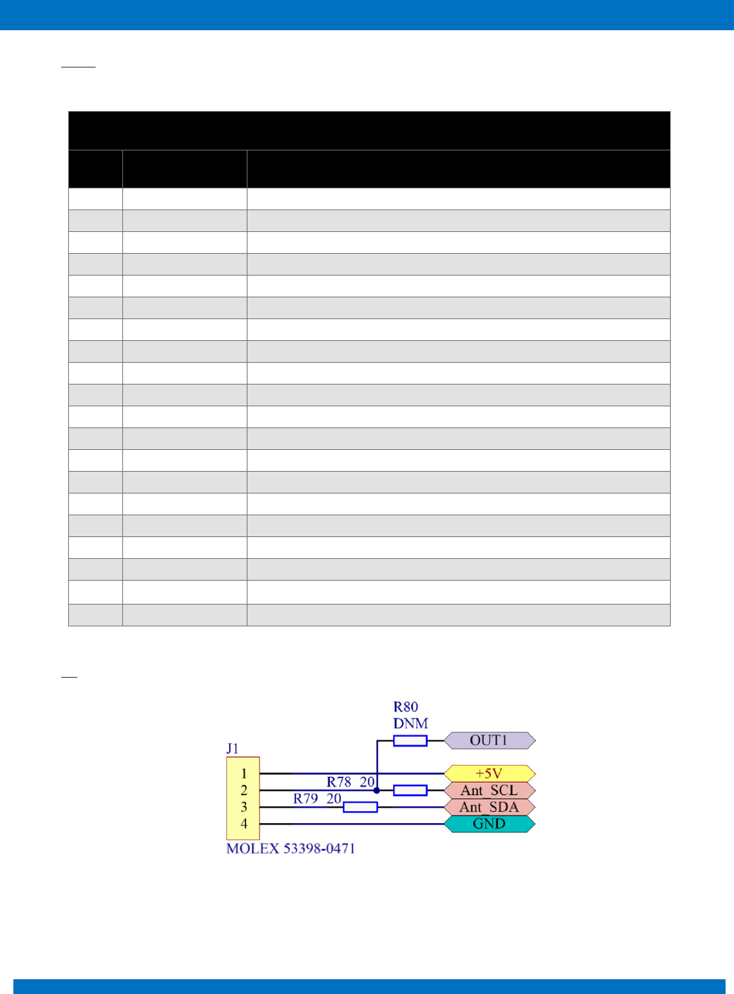
10.7 J1
Figure 18
ENDUROSAT
27
ONBOARD COMPUTER OBC TYPE II – USER MANUAL
J1
Pin
Mnemonic
Description
1
+5V
+5V BUS
2
Ant_SCL / OUT1
I2C UHF antenna / Universal output 1
3
Ant_SDA
I2C UHF antenna
4
GND
Ground
10.8 JP15
Pin
Mnemonic
Description
1
GND
Ground
2
GND
Ground
3
SD_EN
SD Enable
4
SD_D2
SD data 2
5
SD_D3
SD data 3
6
SD_CMD
SD command I/O
7
SD_DET
SD detect
8
SD_CK
SD clock
9
SD_D0
SD data 0
10
SD_D1
SD data 1
11
GND
Ground
ENDUROSAT
28
ONBOARD COMPUTER OBC TYPE II – USER MANUAL
12
GND
Ground
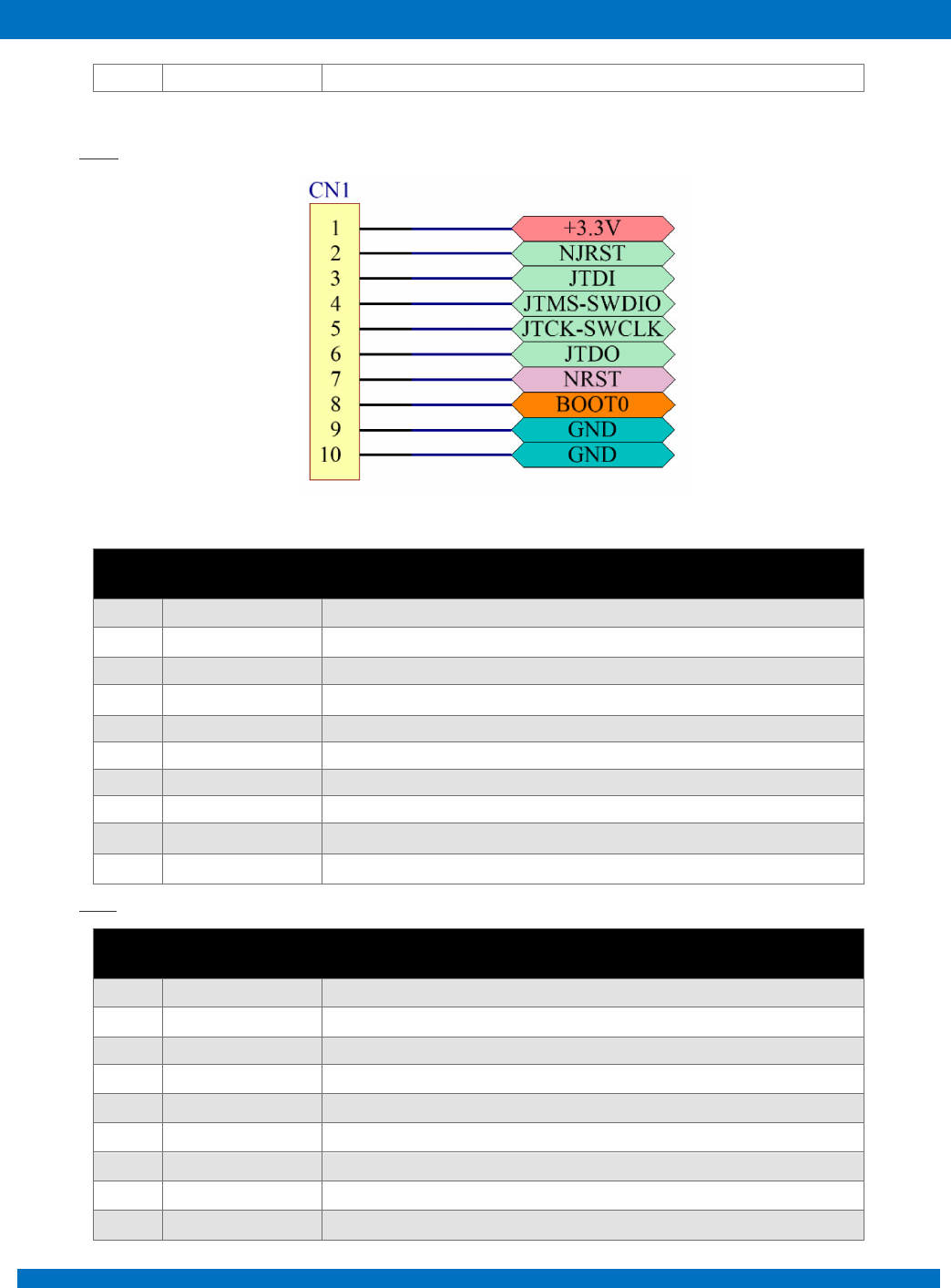
10.9 CN1
Pin
Mnemonic
Description
1
+3.3V
+3.3V BUS
2
NJRST
JTAG Test nReset
3
JTDI
JTAG Test Data Input
4
JTMS-SWDIO
JTAG Test Mode Selection / Serial Wire Data I/O
5
JTCK-SWCLK
JTAG Test Clock / Serial Wire Clock
6
JTDO
JTAG Test Data Output
7
NRST
External Reset
8
BOOT0
Boot Configuration
9
GND
Ground
10
GND
Ground
10.10 SD1
Pin
Signal
Description
1
Data2
Data signal 1
2
Data3
Data signal 2
3
CMD I/O
input and output command
4
GND
supply voltage negative
5
VDD
supply voltage positive
6
CLK
clock signal
7
GND
supply voltage negative
8
Data0
data signal 0
9
Data1
data signal 1
ENDUROSAT
29
ONBOARD COMPUTER OBC TYPE II – USER MANUAL
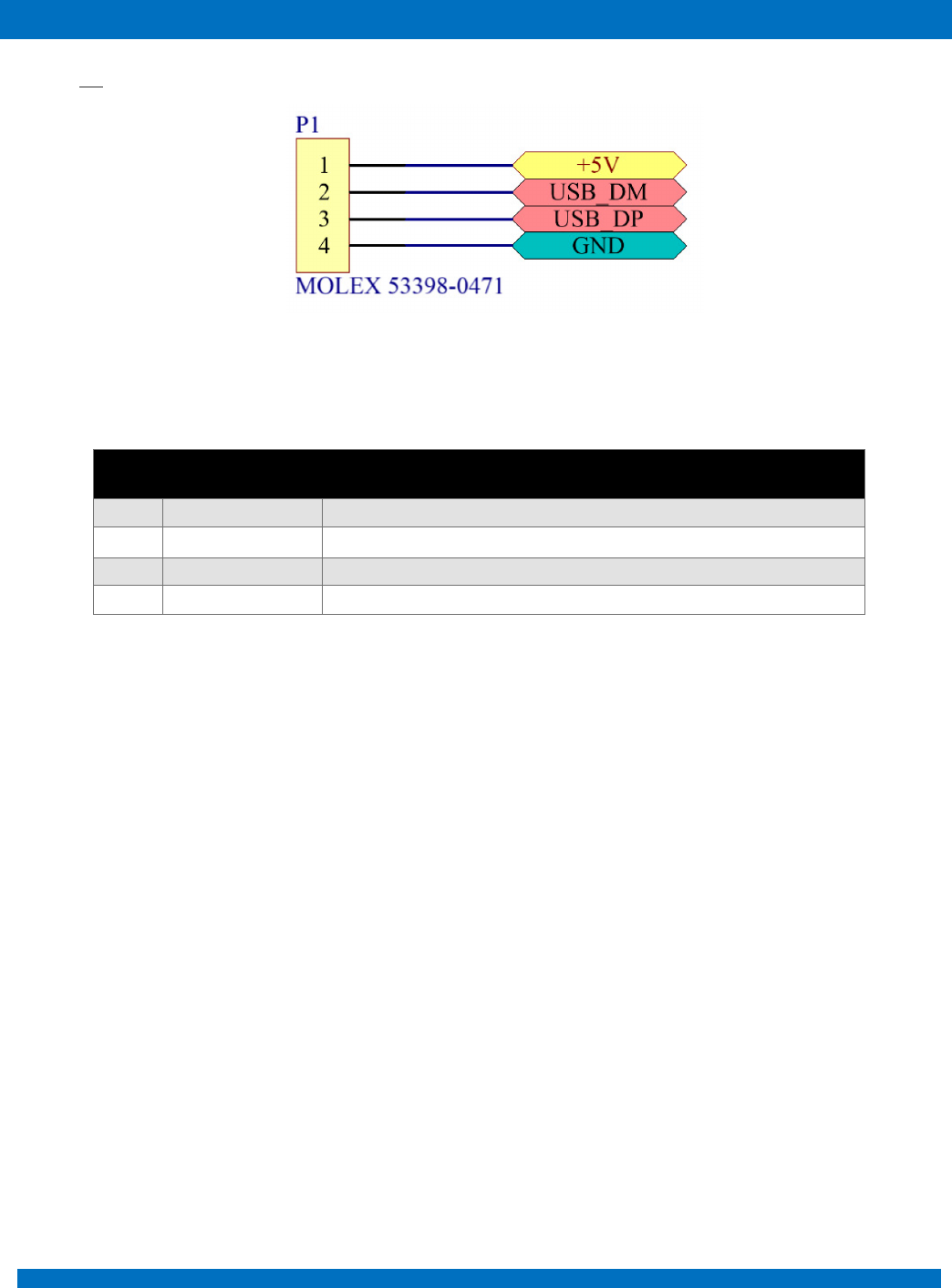
10.11 P1
Figure 19
Pin
Mnemonic
Description
1
+5V
+5V USB
2
USB_DM
USB data -
3
USB_DP
USB data +
4
GND
Ground
ENDUROSAT
30
ONBOARD COMPUTER OBC TYPE II – USER MANUAL
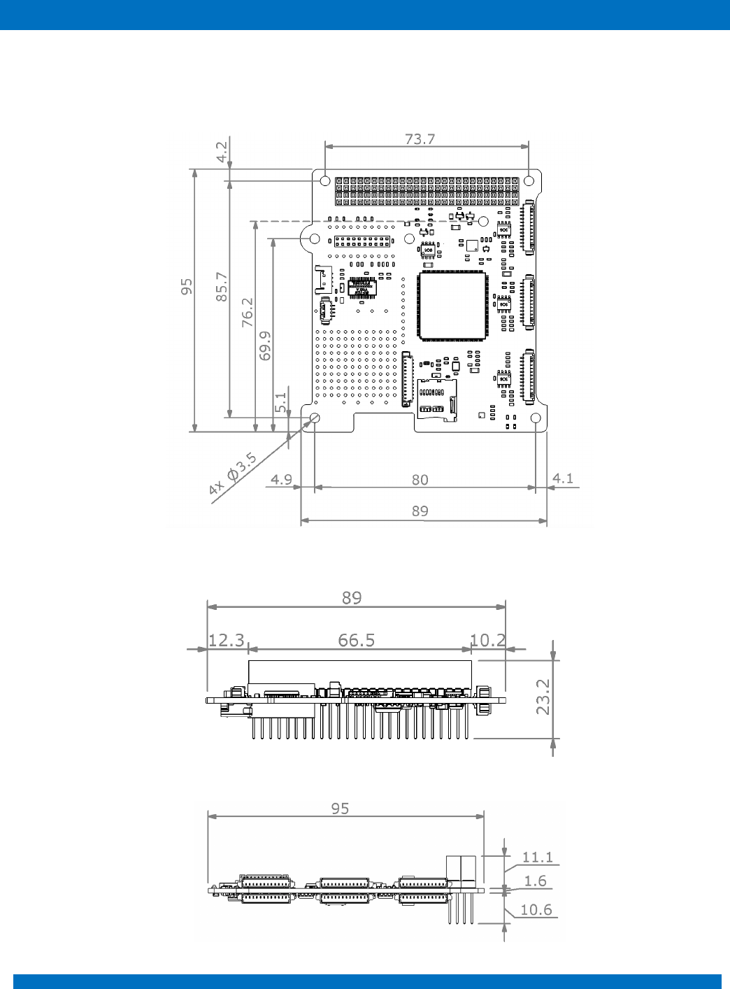
11 MECHANICAL CHARACTERISTICS
In the following paragraphs main dimensions of the Onboard Computer are shown. All dimensions
are in mm. STEP file can be provided upon request.
Figure 20 - OBC top view
Figure 21 - OBC side view
Figure 22 - OBC - side view

ENDUROSAT
31
ONBOARD COMPUTER OBC TYPE II – USER MANUAL
12 ASSEMBLING
Production process follows quality standard:
• PC-A-610E, class 3 (Acceptability of Electronic Assemblies)
• IPC-A-600 (Acceptability of printed boards)
• J-STD-001 (Requirements for Soldered Electrical and Electronic Assemblies)
• ISO 14644 (Cleanrooms and associated controlled environments)
• IEC 61340 (Electrostatics ESD: Protection of electronic devices from electrostatic phenomena)
Conformal coating:
• Outgassing requirements: NASA SP-R-0022A
• Thickness tolerance: NASA-STD-8793.
13 ENVINRONMENTAL AND MECHANICAL TESTS
A full campaign of tests at qualification level was performed on the onboard computer qualification
engineering model. Qualification tests level and duration follow the ESA standard ECSS-E-ST-10-03C
and GEVS: GSFC-STD-7000A. Test performed:
• Thermal Cycling
• Thermal Vacuum
• Random Vibration
• Sine Vibration
• Shock Test
Space qualification campaign link: https://www.endurosat.com/space-qualification/
14 INCLUDED IN THE SHIPMENT
EnduroSat provides along with the Onboard computer:
• USB drive with user manual
• JTAG programming cable
15 HANDLING AND STORAGE
Particular attention shall be paid to the avoidance of damage to the onboard computer during handling,
storage and preservation. The handling of the on board computer module should be performed in
compliance with the following instructions:
• Handle using PVC, latex, cotton (lint free) or nylon gloves.
ENDUROSAT
32
ONBOARD COMPUTER OBC TYPE II – USER MANUAL
• The environment where on board computer module will be handled shall meet the requirements
for a class 100,000 environment, free of contaminants such dust, oil, grease, fumes and smoke
from any source.
• Store in such a manner as to preclude stress and prevent damage.
• To prevent the deterioration, the power module must be stored in a controlled environment,
i.e. the temperature and humidity levels shall be maintained in the proper ranges:
o Ideal storage temperature range: 15ºC to 27ºC
o Ideal storage humidity range: 30% to 60% relative humidity (RH)
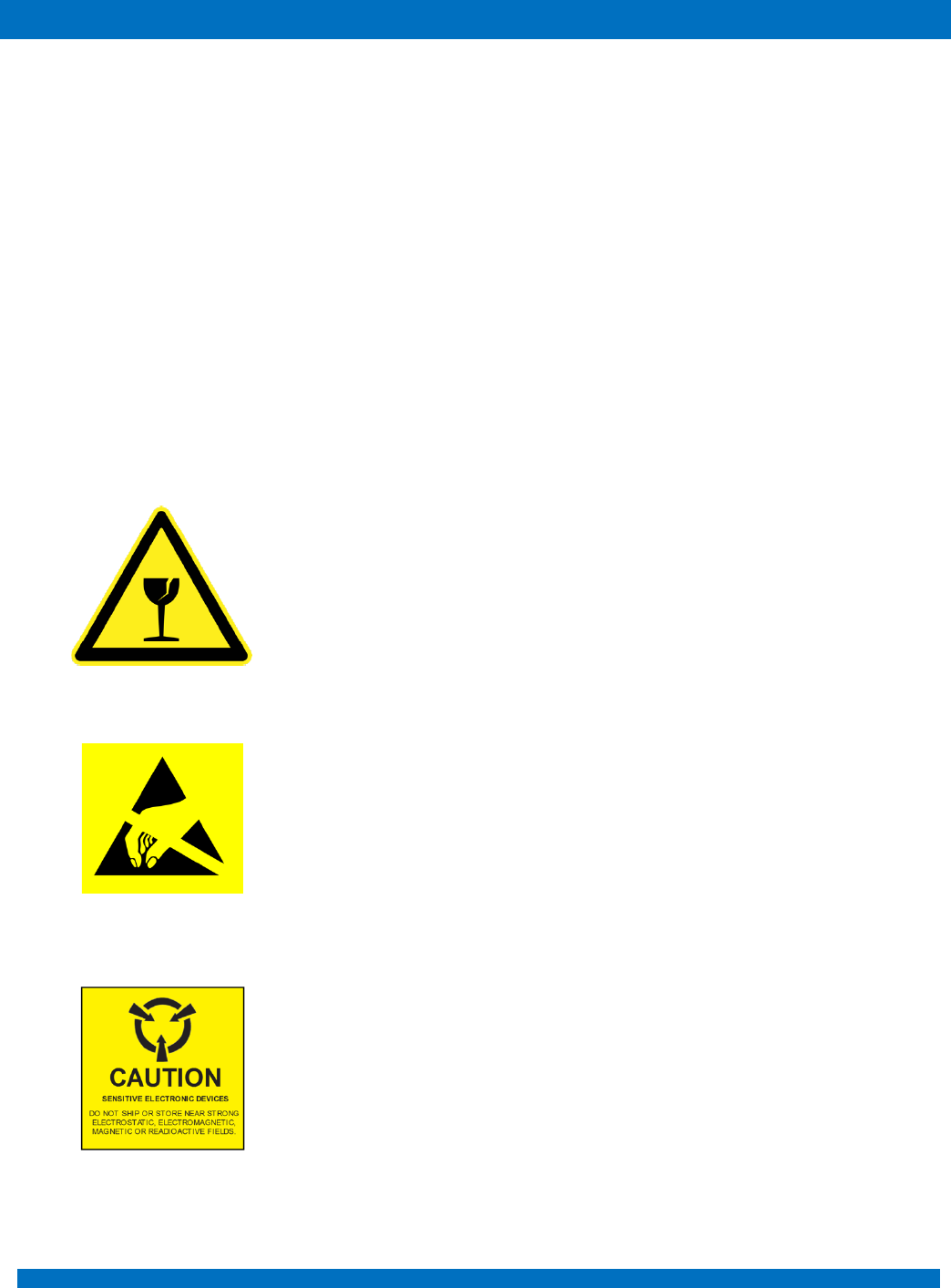
16 WARNINGS
This product uses very fragile components. Observe precautions
for Handling.
This product uses semiconductors that can be damaged by
electrostatic discharge (ESD). Observe precautions for Handling
Sensitive Electronic device. Do not ship or store near strong
electrostatic, electromagnetic, magnetic or radioactive fields.

ENDUROSAT
33
ONBOARD COMPUTER OBC TYPE II – USER MANUAL
