Ftp://mail.cjsoft.org/pub/Develop/Archi CAD/12 Rus/Addons/Objective 2.25/OBJECTi VEWin AC12/OBJECTi VE Manual OBJECTi
User Manual: ftp://mail.cjsoft.org/pub/Develop/ArchiCAD/12 rus/Addons/Objective 2.25/OBJECTiVEWinAC12/OBJECTiVE Manual
Open the PDF directly: View PDF ![]() .
.
Page Count: 50
3D Tools for ArchiCAD
Reference Manual
Copyright © Encina Ltd 2008
Profile
Rotate
Bend
Split
Encina Ltd
29 Fenshurst Gardens
Long Ashton
Bristol BS41 9AU
UK
Tel. +44 (0) 1275 840 103
E-mail: contact@encina.co.uk
Website: www.encina.co.uk
OBJECTiVE 2.23 Reference Manual
Copyright © 2008 by Encina, all rights reserved. Reproduction, paraphrasing or translation
without express prior written permission is strictly prohibited.
Compatibility
Version 2.23 is compatible with ArchiCAD 8 to 12. OBJECTiVE is available on both Mac and
Windows operating systems.
2
Contents
1 Introduction....................................................................................................4
1.1 About This Manual............................................................................................5
2Installation..................................................................................................... 6
2.1 Downloading OBJECTiVE................................................................................. 7
2.2 Installing OBJECTiVE on Mac OS X...................................................................7
2.3 Installing OBJECTiVE on Windows.....................................................................9
2.4 Registering OBJECTiVE.................................................................................. 10
3 User Interface.................................................................................................11
3.1 OBJECTiVE Tool Icon.....................................................................................12
3.2 OBJECTiVE Menu Items..................................................................................13
4Tools............................................................................................................ 14
4.1 Making Custom Profiles...................................................................................15
New Profile.............................................................................................15
Creating A Section Profile.........................................................................16
Creating An Elevation Profile.................................................................... 19
Creating A Lathed Profile......................................................................... 21
Extract Profile.........................................................................................23
Upgrade Object........................................................................................23
Change Profile........................................................................................ 24
Swap Object............................................................................................24
4.2 Rotating In 3D................................................................................................26
4.3 Splitting In 3D................................................................................................27
4.4 Bending In 3D................................................................................................ 29
4.5 Offsetting In 3D.............................................................................................. 30
4.6 Working With 3D Assemblies............................................................................31
New.......................................................................................................31
Update................................................................................................... 32
Detach....................................................................................................32
Go To Plan.............................................................................................32
Go To Model...........................................................................................33
Set Plan Home.........................................................................................33
Set Model Home.......................................................................................33
4.7 Aligning And Distributing Objects..................................................................... 34
4.8 Updating Objects.............................................................................................36
Repair Object.......................................................................................... 36
Remove Cuts............................................................................................36
Set Display Order.....................................................................................37
5OBJECTiVE Library.....................................................................................38
5.1 An Overview...................................................................................................39
5.2 The Regular Profile Object................................................................................ 39
5.3 Timber Objects................................................................................................42
5.4 Steel Objects...................................................................................................45
6Troubleshooting............................................................................................ 48
3
Section 1
Introduction
4
1.1 About This Manual
OBJECTiVE has been designed to greatly increase your ability to model in 3D in ArchiCAD,
but in a way which feels like a natural part of the environment. In every way we strive to
retain the natural look and feel of ArchiCAD.
Each tool and library part is described in detail in this manual. Refer to the Tutorial to see
some examples of OBJECTiVE in use. Also, refer to the troubleshooting section if something
entirely unexpected has happened.
We assume the reader has some knowledge of ArchiCAD, and suggest that new users also
refer to the ArchiCAD documentation.
5
Section 2
Installation
6
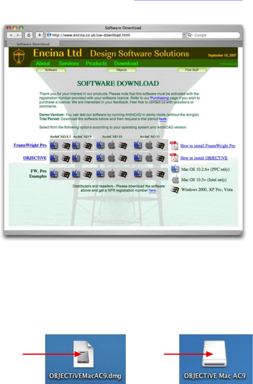
2.1 Downloading OBJECTiVE
The latest version of OBJECTiVE can be found at http://encina.co.uk/sw-download.html
Select the download which suits your computer platform (Mac or Windows) and ArchiCAD
version (Fig. 2.11).
Figure 2.11
Platform-specific installation instructions follow below.
2.2 Installing OBJECTiVE on Mac OS X
Your browser should automatically open the selected file when the download is complete. If
not, you should locate the downloaded file and open it by double-clicking on the icon (Fig.
2.21). The Mac OS will automatically mount a new volume on your computer which contains
the necessary installation files (Fig. 2.22).
Figure 2.21
Figure 2.22
Open the
downloaded file...
…and this
volume should
be mounted.
Make sure you have Quit from ArchiCAD before continuing with the installation.
7
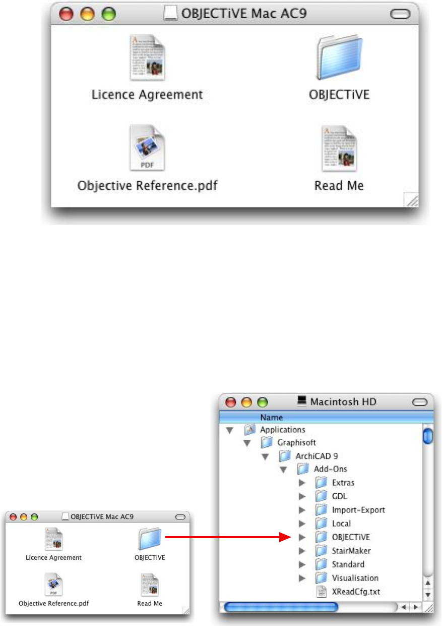
Double-click on the OBJECTiVE installation volume (Fig. 2.22) to view the contents. It
should contain the files shown in Figure 2.23.
Figure 2.23
Read the included License Agreement before installing the software, and refer to the ‘Read
Me’ file for late-breaking additions. To install OBJECTiVE:
1. Make sure ArchiCAD is not running (quit first if it is).
2. Drag the folder called "OBJECTiVE" into the "Add-Ons" folder in the ArchiCAD
application folder (Fig. 2.24). Copy the entire folder as shown because it contains
more files than the add-on alone.
3. Launch ArchiCAD again.
4. Refer to section 2.4 for registration instructions.
Figure 2.24
8
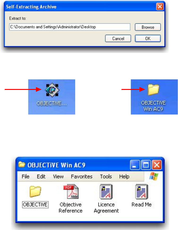
2.3 Installing OBJECTiVE on Windows
Your browser may automatically open the selected file when the download is complete. If
not, you should locate the downloaded file and open it by double-clicking on the icon (Fig.
2.32). You will first be prompted for the location of the installation folder - the desktop is an
easy option (Fig. 2.31).
Figure 2.31
You should see a new folder appear once the extraction process is complete (Fig. 2.33).
Figure 2.32
Figure 2.33
Open the
downloaded file...
…and it should
extract to create
this folder.
Make sure you have Quit from ArchiCAD before continuing with the installation. Open the
OBJECTiVE installation folder (Fig. 2.33) to view the contents. It should contain the files
shown in Figure 2.34.
Figure 2.34
Read the included License Agreement before installing the software, and refer to the ‘Read
Me’ file for late-breaking additions. To install OBJECTiVE:
1. Make sure ArchiCAD is not running (quit first if it is).
2. Drag the folder called "OBJECTiVE" into the "Add-Ons" folder in the ArchiCAD
application folder (Fig. 2.35). Copy the entire folder as shown because it contains
more files than the add-on alone.
3. Launch ArchiCAD again.
4. Refer to section 2.4 for registration instructions.
9
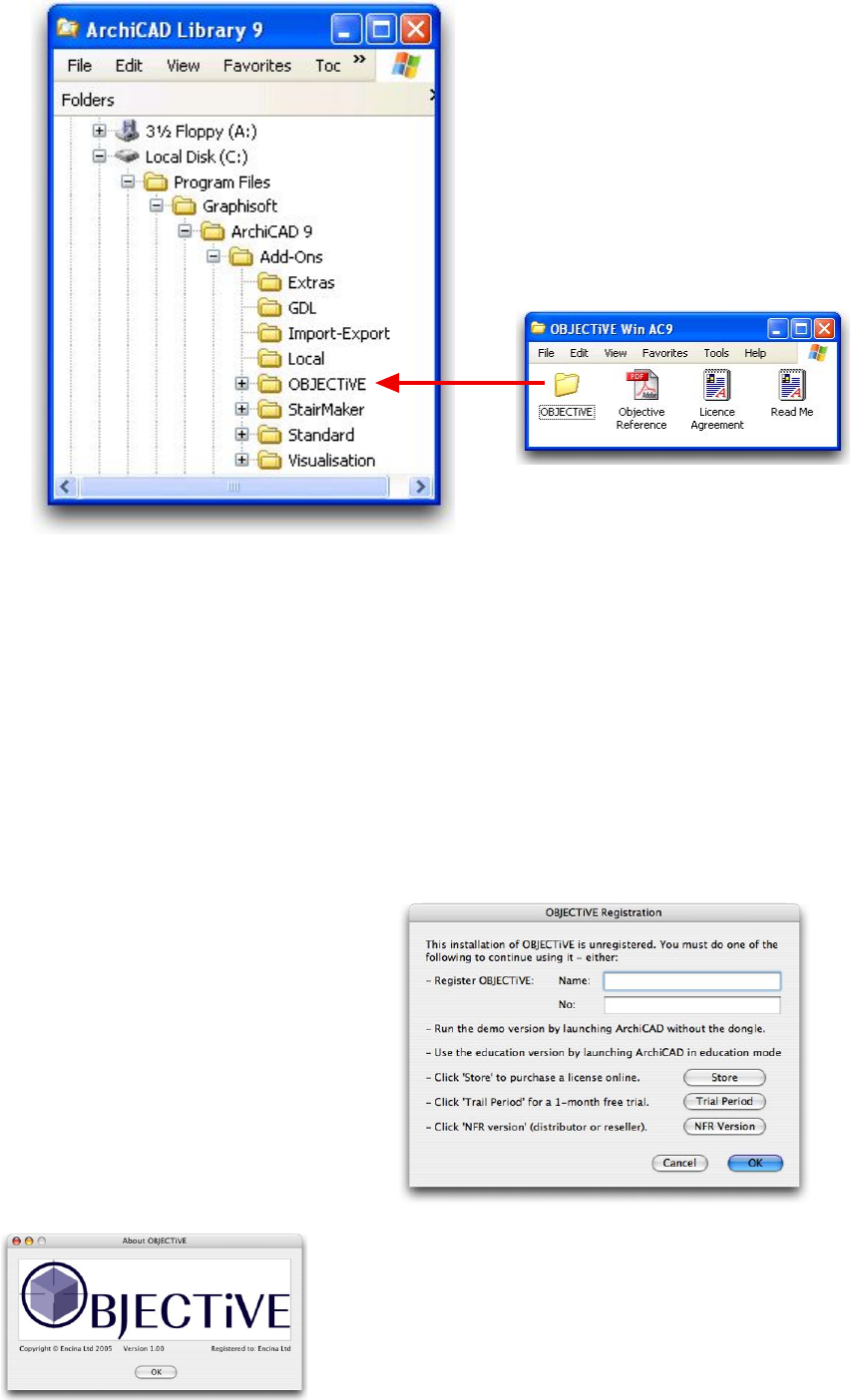
Figure 2.35
2.4 Registering OBJECTiVE
When ArchiCAD has restarted you should see a new menu named ‘OBJECTiVE’ (see section
3.2) and a new icon in the tool bar (see section 3.1). Refer to the ‘Troubleshooting’ section if
these items do not appear.
Timber and steel libraries are bundled with OBJECTiVE, and both are loaded by default
provided they remain in the ‘OBJECTiVE’ folder (in the ‘Add-Ons’ folder). The add-on
won’t ask for a registration code until you try to use one of its tools (a menu item from the
‘OBJECTiVE menu for example). A dialog box will appear with a prompt for your registered
name and code (Fig. 2.41).
If you have purchased a license for
OBJECTiVE, please enter your name
and code exactly as shown in your
registration information.
Alternatively, there are buttons to:
•Take you to an online store to
purchase a license
• Request a free 1 month trial
•Request a NFR license
Figure 2.42
Figure 2.41
The name of the registered user will be displayed in
the ‘About OBJECTiVE’ dialog (Fig. 2.42).
You can use the demo version by launching
ArchiCAD without the dongle, or use the education
version by launching ArchiCAD in education mode.
10
Section 3
User Interface
11
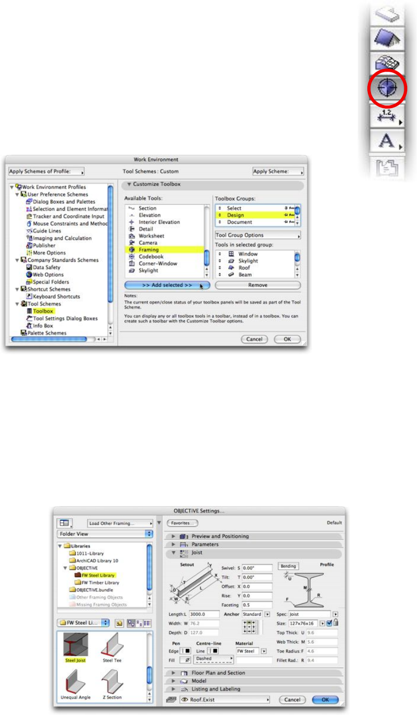
3.1 OBJECTiVE Tool Icon
OBJECTiVE provides a GDL library of commonly used objects, and you
can create your own using the profile tools or even the GDL editor built
into ArchiCAD. These objects are placed and edited using the OBJECTiVE
tool (Fig. 3.11), which works in the same way as the standard ArchiCAD
object tool.
ArchiCAD hides this tool by default when OBJECTiVE is first installed.
You can show it in the Toolbox settings in the Work Environment dialog
(Fig. 3.12 - from the menu ‘Options/Work Environment/Toolbox…).
Figure 3.12
Figure 3.11
Click once on the tool to begin placing the currently selected object. Double-click to select a
different object or to view/edit the object settings (Fig. 3.13). Refer to chapter 5 in this manual
and the ‘Object tool’ settings in the ArchiCAD manual for more information about the object
settings.
The OBJECTiVE Settings dialog is identical to the Object Settings dialog, with a custom
interface for all the objects. The appearance of this dialog varies across different versions of
ArchiCAD, but the functionality is essentially the same.
Figure 3.13
12
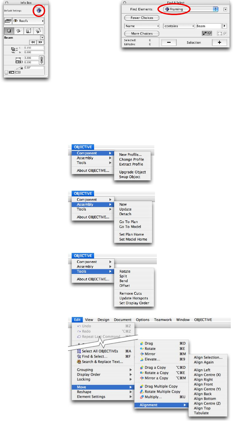
Anything drawn with the OBJECTiVE tool also displays relevant information in the standard
‘Info’ palette (Fig. 3.13), and can be selected from the ‘Find & Select’ dialog (Fig. 3.14).
Figure 3.13
Figure 3.14
3.2 OBJECTiVE Menu Items
Most of the tools provided by OBJECTiVE are accessed from the ‘OBJECTiVE’ menu (see
below). We recommend setting menu shortcut keys for commonly used tools (via the
‘Keyboard Shortcuts...’ section under the ‘Options/Work Environment’ menu).
Tools (Section 4.2 - 4.5)
Assemblies (Section 4.6)
Alignment (Section 4.7)
Components (Section 4.1)
13
Section 4
Tools
14
4.1 Making Custom Profiles
Menu Item Name
Component/New Profile
Description
Some components have irregular shapes that cannot be
described parametrically. This tool will convert a user-defined
shape into a OBJECTiVE object. The outline can be drawn with
any of the standard ArchiCAD tools for drawing polygons (fill,
slab, roof, etc.). If lines and arcs are used to define an outline
then the shape must be transformed into a polygon - you can
use ArchiCAD’s ‘Magic Wand’ tool to perform this operation
quickly. The shape may be drawn in either the Floor Plan or
any Section/Elevation window, and may contain holes.
Procedure
- Draw the section/elevation profile with the Fill or Slab tool.
- Select the shape you have drawn with the Arrow tool.
- Select ‘New Profile...’ from the ‘OBJECTiVE/Component’ menu.
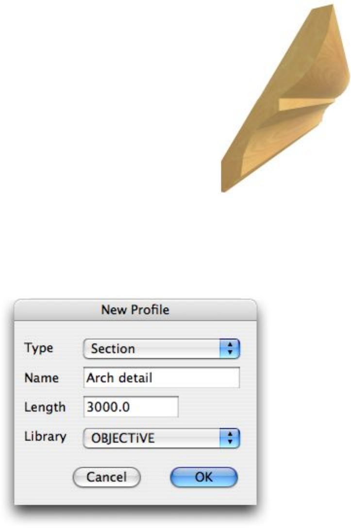
A dialog will appear prompting for the type, name, size, and target library (Fig 4.11).
Figure 4.11
The specified name becomes the name of the new OBJECTiVE component in the specified
library. The profile type may one of the following:
Elevation The profile becomes the elevation of the new component which can be stretched
or bent along its depth but not length or width (Fig 4.12).
Section The profile becomes the section of the component, which can be stretched or
bent along its length but not in depth or width (Fig 4.13).
Lathe The profile becomes the cross-section of the new object, revolved by a specified
angle around a central axis (Fig 4.14).
15
The library popup menu displays all the folders selected in the ArchiCAD Library Manager.
Note that some libraries can’t be used because the folder is either locked or embedded in an
archive file. We recommend creating a new library folder for every new project and using this
as the destination library for new profiles.
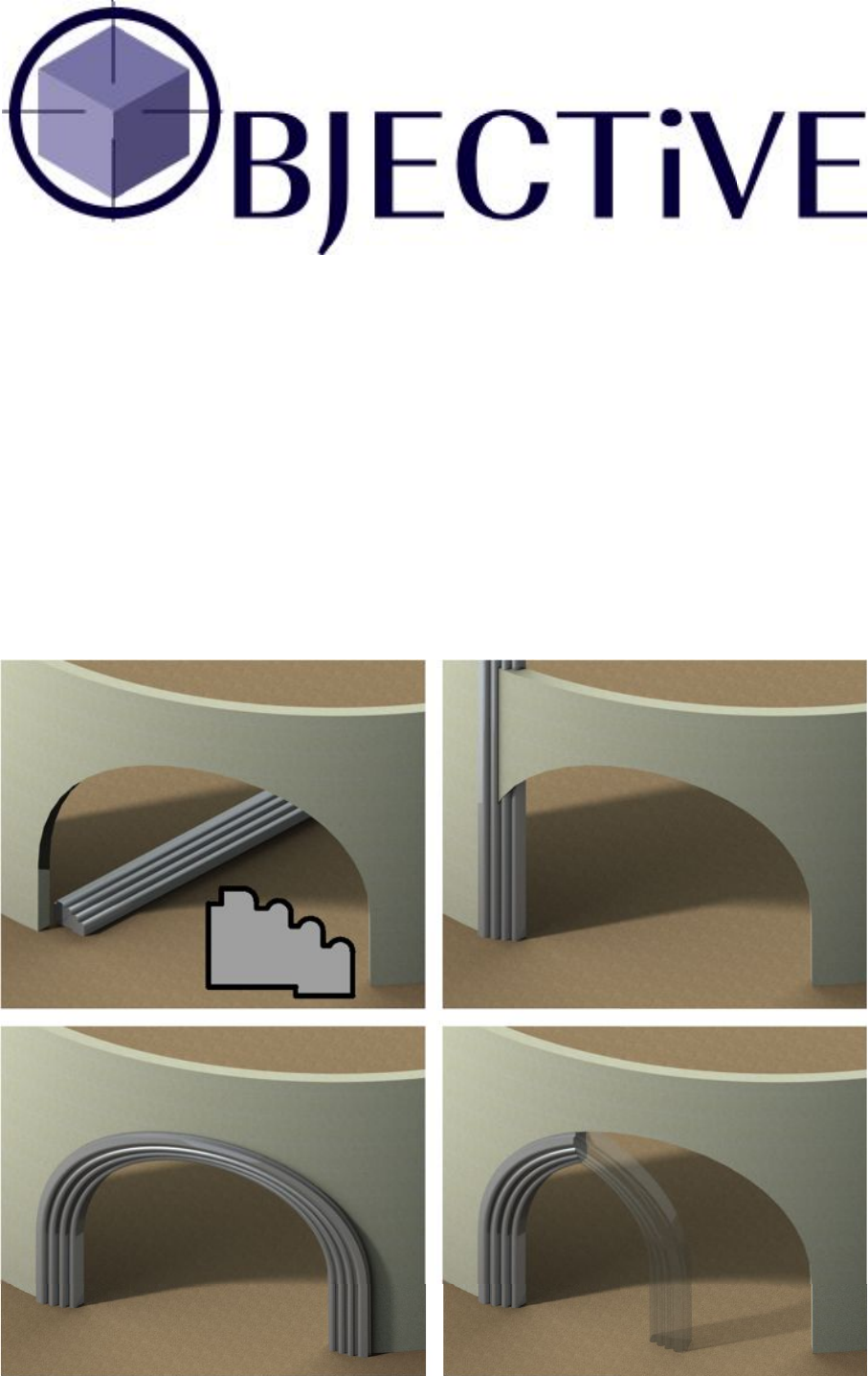
Creating A Section Profile
A section profile is an ArchiCAD object which can be stretched
to any length and bent to a curve in 3D.
To create a section profile, first draw the cross-section through
the profile using the standard ArchiCAD Fill tool. The shape can
have curves and holes. Then select the fill and pick ‘New
Profile…’ from the ‘OBJECTiVE/Component’ menu. In the
‘New Profile’ dialog (Fig. 4.11), set the type to ‘Section’ and
enter a name and length. Note that the length is only a default
setting - you can subsequently stretch it to any length you like.
Figure 4.12
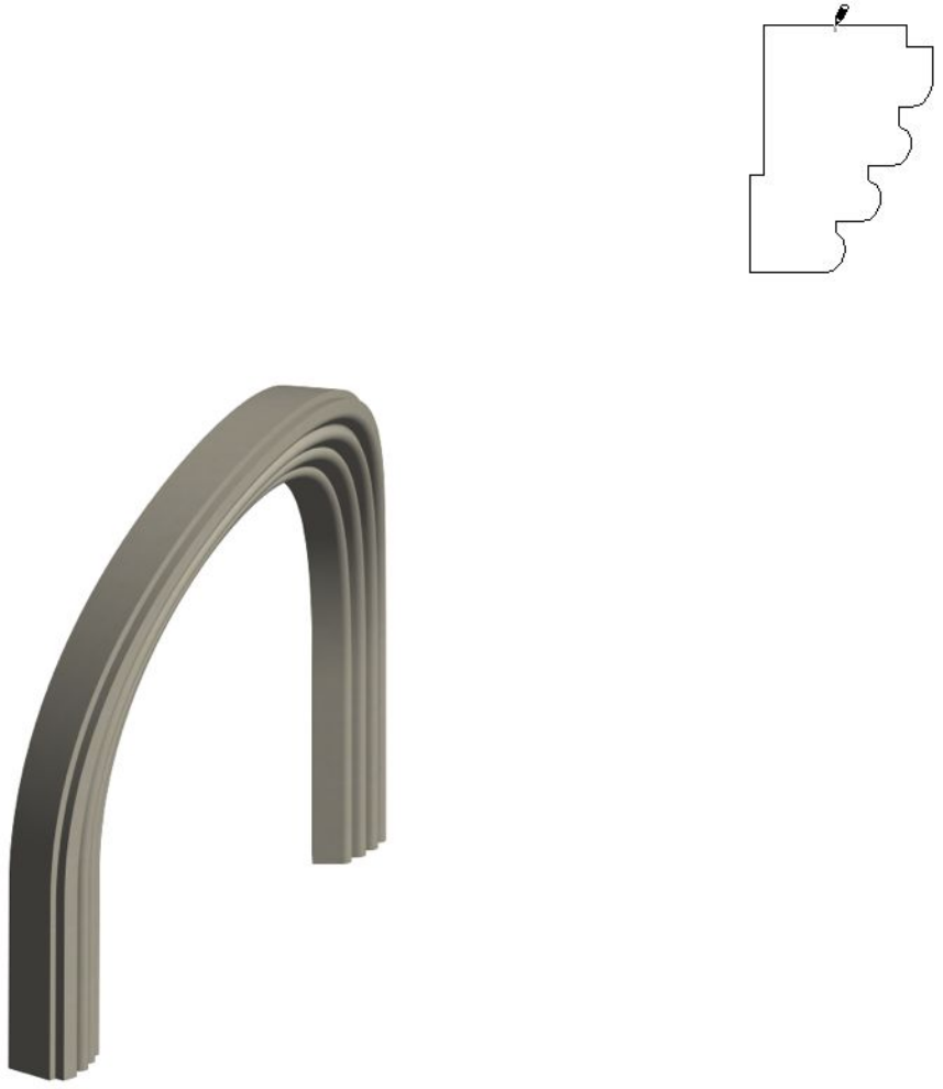
Click OK to continue. You will then be
prompted to click on an anchor point (Fig.
4.12), a fixed position which will keep your
profiles correctly positioned in 3D even if the
shape is subsequently changed. For example,
the profile of a skirting board would have an
anchor at the bottom corner adjacent to the
wall. Note that you can still cancel at this
point if you do not wish to create the profile,
either by pressing the Escape key or clicking
Cancel in the standard ArchiCAD ‘Control
Box’ palette.
A new profile object is then created in the
plan, superimposed on the original Fill. The
Fill is not deleted, but you do not need to keep
it either because the ‘Extract Profile’ tool can
retrieve it at any time.
Any profiles placed in a Section/Elevation
window will also simultaneously appear in the
Floor Plan. The new profile can be split,
rotated, bent, or added to assemblies.
Figure 4.13
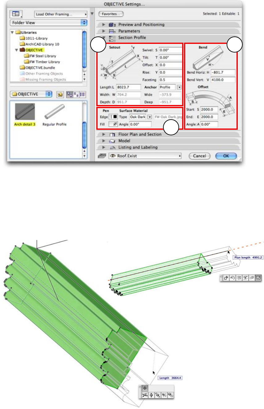
More profiles of the same shape can be placed using the OBJECTiVE tool (Section 3.1). The
settings for the profile also include a detailed user interface for specifying properties in
broadly 3 categories (Fig. 4.13):
1. Setout
2. Bending
3. 2D/3D appearance
16
2
1
3
Figure 4.14
1. Setout
The bounding size of the profile (length, width, depth) has the same meaning irrespective of
the object’s orientation in 3D. Only the length can be varied in a section profile, which can
also be edited in 2D or 3D using smart hotspots aligned to the profile anchor (Fig. 4.14). Note
that the plan length is displayed when stretching an inclined profile in the Floor Plan window.
Figure 4.15
Faceting controls the smoothness of curves in the profile and the bent object. The number is a
measure of the maximum distance a face can be from the true curve. A small value will be very
smooth, but produce many faces. Conversely, a large figure will have fewer faces (and render
faster), but may appear course or blocky.
17
The Anchor is a point in the profile cross-section which stays fixed when the profile shape
changes. Section profiles are also placed and stretched by the anchor, which has 3 possible
settings:
Standard Select the anchor from a 3 x 3 grid of standard snap points (identical to the
anchor selection for ArchiCAD columns or text)
Custom Enter 2 offsets from the bottom corner to specify the anchor position
Profile The point specified when the profile was created (default setting)
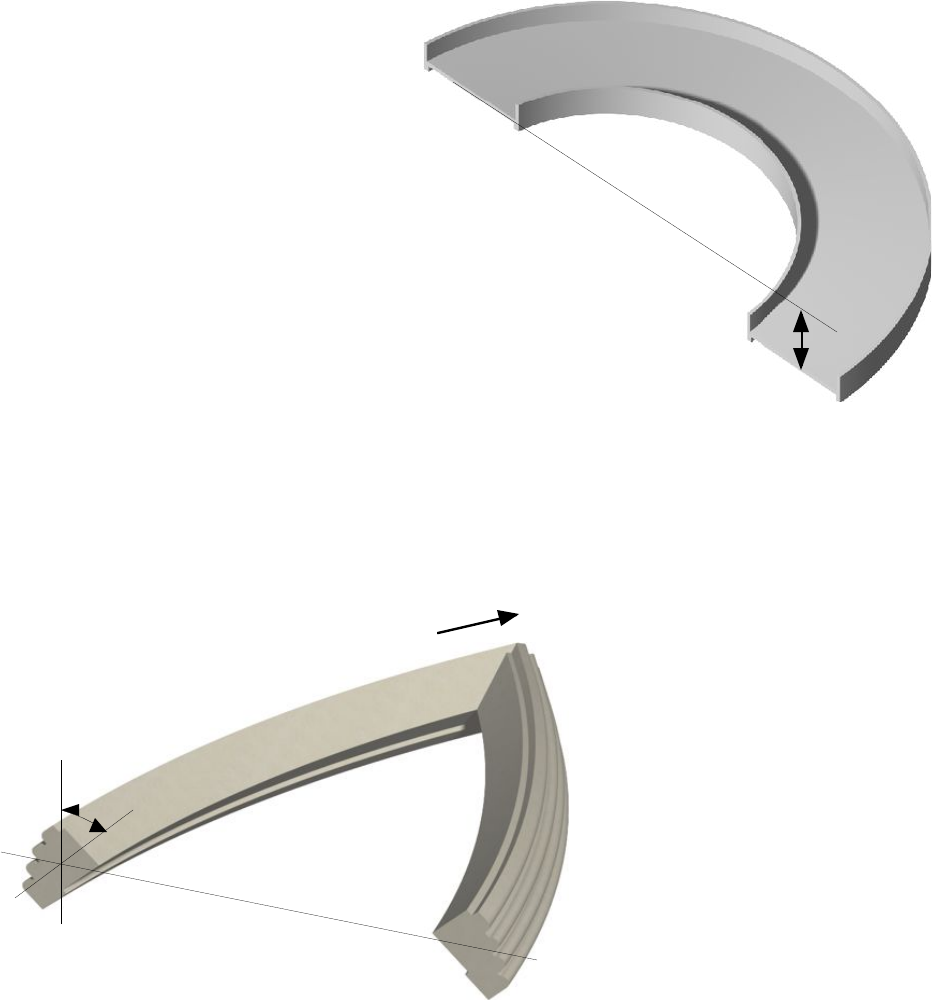
Rise and Offset adjust the end of the
profile in the Y and X axis. For
example, you might specify rise
when you are placing a profile on a
slope and know the overall height
but not the pitch.
This is a particularly useful setting
for curved profiles, for example a
curved carpark ramp (Fig. 4.15). The
profile can be bent to the ramp curve
and the Rise value set (or moved
with the Offset tool) to the floor-to-
floor height.
2. Bending
Rise
Figure 4.16
A section profile can be bent to a curve along its horizontal and/or vertical axis. The ramp in
Fig. 4.15 is bent in the horizontal axis for example. Profiles can still be freely cut and rotated
in 3D when curved, and hotspots are calculated around the surface for easy placement and
snapping.
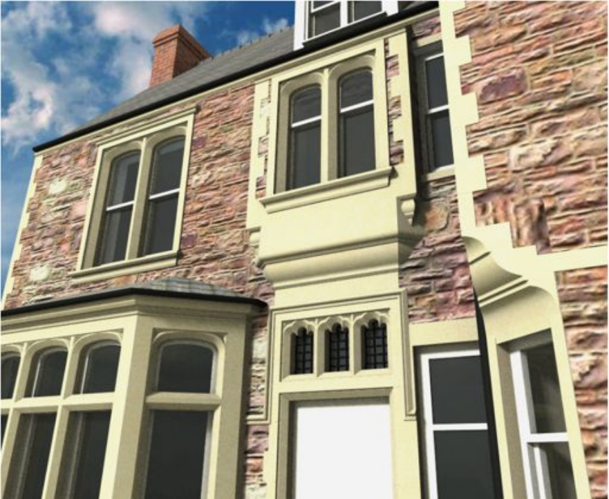
The profile ends can be extended at a
tangent to the curve for connections
with adjacent objects (the Start and
End values). In Fig. 4.13, the profile
ends have been extended to form the
columns either size of the curved
arch. And finally, the profile shape
can be skewed at any angle along the
curve with the Angle setting (Fig.
4.17)
End
Angle
Figure 4.17
18
3. Appearance
Pens can be selected for both the profile edges and fill. Set the fill pen to 0 to make the profile
transparent.
If you select a texture in the ‘Section Profile’ settings, OBJECTiVE will attempt to keep it
sensible aligned to the object even when rotated in 3D. This can be a preset timber grain or –
by selecting ‘Custom’ – you can enter the name of a texture image from the loaded library.
The texture direction can be fine-tuned with the adjacent ‘Angle’ setting.
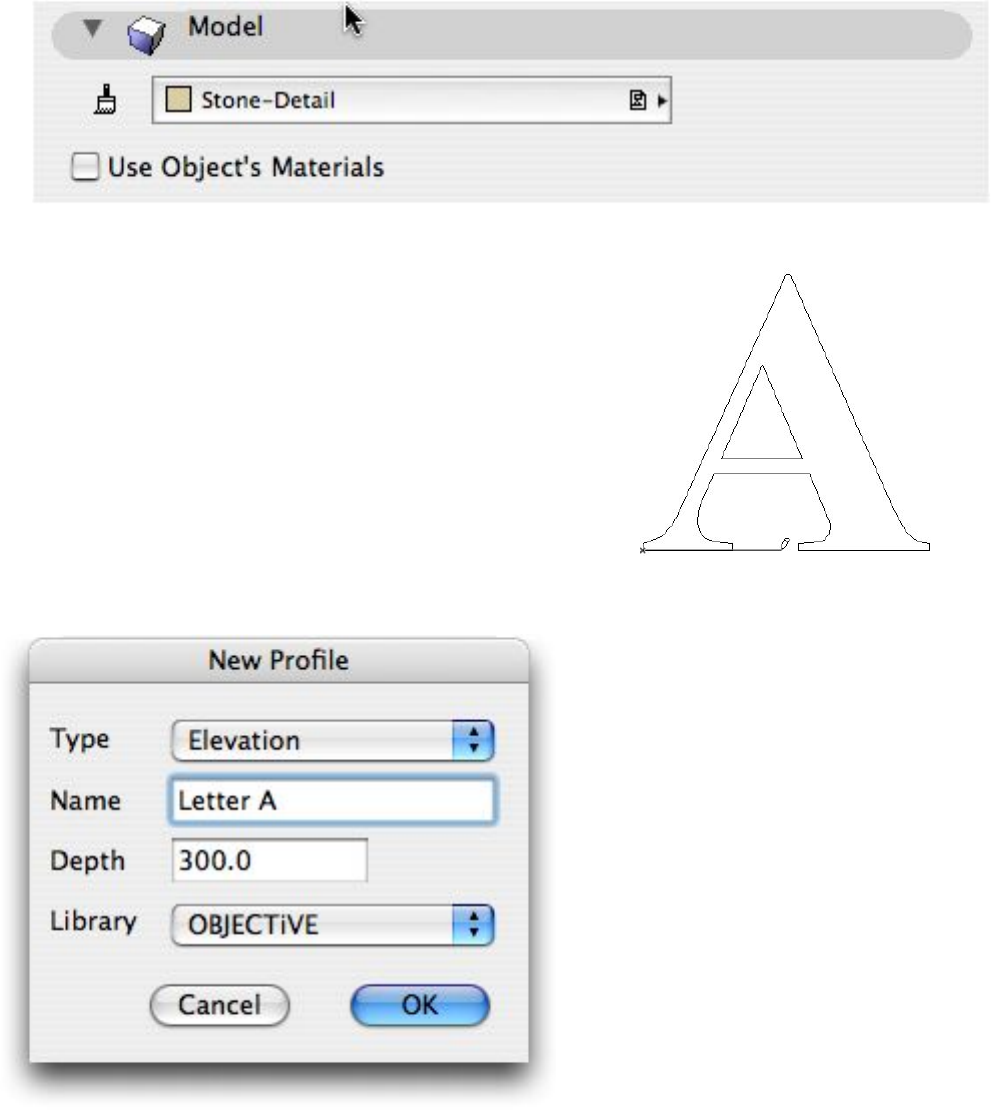
Any standard material can be applied using the ‘Model’ tab. Uncheck ‘Use Object’s
Materials’ and select the required material in the popup menu above (Fig. 4.18)
Figure 4.18
Creating An Elevation Profile
An elevation profile is an ArchiCAD object which can be
stretched to any depth and bent to a curve in one axis across
its face.
To create an elevation object, first draw an elevation view of
the profile using the standard ArchiCAD Fill tool. The shape
can have curves and holes. Then select the fill and pick ‘New
Profile…’ from the ‘OBJECTiVE/Component’ menu. In the
‘New Profile’ dialog (Fig. 4.19), set the type to ‘Elevation’
and enter a name and depth. Note that the depth is only a
default setting - you can subsequently stretch it to any depth
you like.
Figure 4.19
Click OK to continue. You will then
be prompted to draw a line across the
profile. The first point of the line is
the anchor point (Fig. 4.110), a fixed
position which will keep your
profiles correctly positioned in 3D
even if the shape is subsequently
changed. The second point defines the
plane along which the profile can be
bent. Refer to the bending section
below for an illustration.
Note that you can still cancel at this
point if you do not wish to create the
profile, either by pressing the Escape
key or clicking Cancel in the standard
ArchiCAD ‘Control Box’ palette.
Figure 4.110
19
A new profile object is then created in the
plan, superimposed on the original Fill. The
Fill is not deleted, but you do not need to
keep it either because the ‘Extract Profile’ tool
can retrieve it at any time.
Any profiles placed in a Section/Elevation
window will also simultaneously appear in
the Floor Plan. The new profile can be split,
rotated, bent, or added to assemblies.
More profiles of the same shape can be placed
using the OBJECTiVE tool (Section 3.1). The
settings for the profile also include a detailed
user interface for specifying properties in
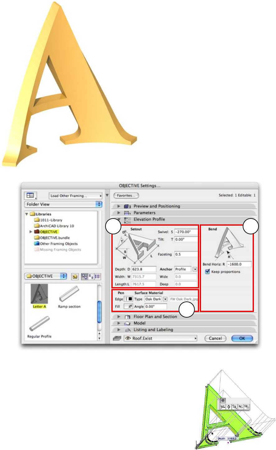
broadly 3 categories (Fig. 4.111):
1. Setout
2. Bending
3. 2D/3D appearance
2
1
3
Figure 4.111
1. Setout
The bounding size of the profile (length, width, depth) has the
same meaning irrespective of the object’s orientation in 3D.
Only the depth can be varied in an elevation profile, which can
also be edited in 3D using smart hotspots aligned to the profile
anchor. These hotspots are not available if the profile is bent.
Faceting and anchor point work in the same way as section
profiles above.
20
2. Bending
An elevation profile can be bent to a curve
across its face in the direction defined by the
user when it was created. Because the
profile can only be bent in one axis, it can
easily be done using a smart hotspot (Fig.
4.112).
Bending can occur in either direction. The
original profile length can be preserved along
the circumference of the curved face if Keep
Proportions is checked. Otherwise, the
profile will be stretched along the
circumference of the curve, maintaining a
constant length.
Profiles can still be freely cut and rotated in
3D when curved, and hotspots are
calculated around the surface for easy
placement and snapping.
3. Appearance
Settings to control 2D and 3D appearance
are identical to those for section profiles
above.
Creating A Lathed Profile
Figure 4.112
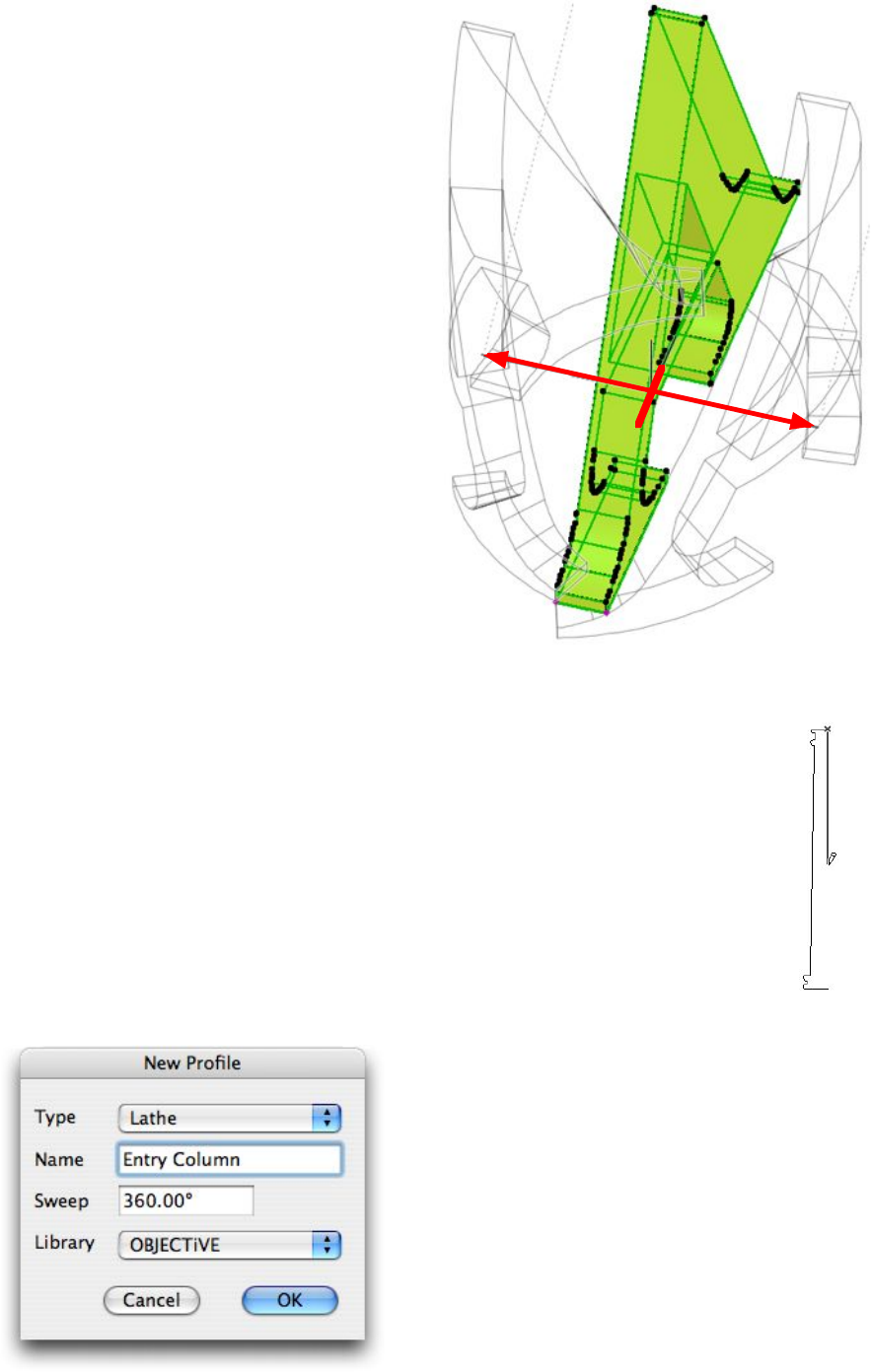
Click OK to continue. You will then be prompted
to draw the centre line of the object (Fig. 4.113),
about which the profile will be swept. The centre
line must not overlap any of the profile edges -
OBJECTiVE will warn you if this happens and
prompt you to change either the profile or the
centre line.
Note that you can still cancel at this point if you do
not wish to create the profile, either by pressing the
Escape key or clicking Cancel in the standard
ArchiCAD ‘Control Box’ palette.
Figure 4.114
Figure 4.113
An lathed profile is an ArchiCAD object with a user defined shape swept
around a central axis by a specified angle. The object is a fixed size, i.e. it
cannot be stretched.
To create a lathed object, first draw a half-section through the shape with the
standard ArchiCAD Fill or Polyline tool. The shape can have curves, but holes
will be ignored. Profiles drawn with the Polyline tool do not have to be closed.
Next, select the fill/polyline and pick ‘New Profile…’ from the
‘OBJECTiVE/Component’ menu. In the ‘New Profile’ dialog (Fig. 4.114), set
the type to ‘Lathe’ and enter a name and sweep angle. Note that the angle is
only a default setting - you can subsequently enter any angle you like.
21
A new lathed profile object is then created in the plan,
superimposed on the original Fill/Polyline. The
Fill/Polyline is not deleted, but you do not need to keep it
either because the ‘Extract Profile’ tool can retrieve it at
any time.
Any profiles placed in a Section/Elevation window will
also simultaneously appear in the Floor Plan. The new
profile can be split, rotated, bent, or added to assemblies.
More profiles of the same shape can be placed using the
OBJECTiVE tool (Section 3.1). The settings for the
profile also include a detailed user interface for specifying
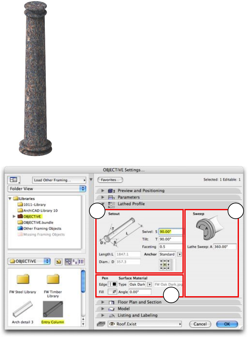
properties in broadly 3 categories (Fig. 4.115):
1. Setout
2. Sweep
3. 2D/3D appearance
2
1
3
Figure 4.115
1. Setout
The bounding size of the profile (length and diameter) has the same meaning irrespective of
the object’s orientation in 3D, but neither is editable. Faceting and anchor point work in the
same way as section profiles above.
2. Sweep
The profile can be swept around any angle - Fig. 4.116 illustrates an uplighter created from a
180° sweep.
22
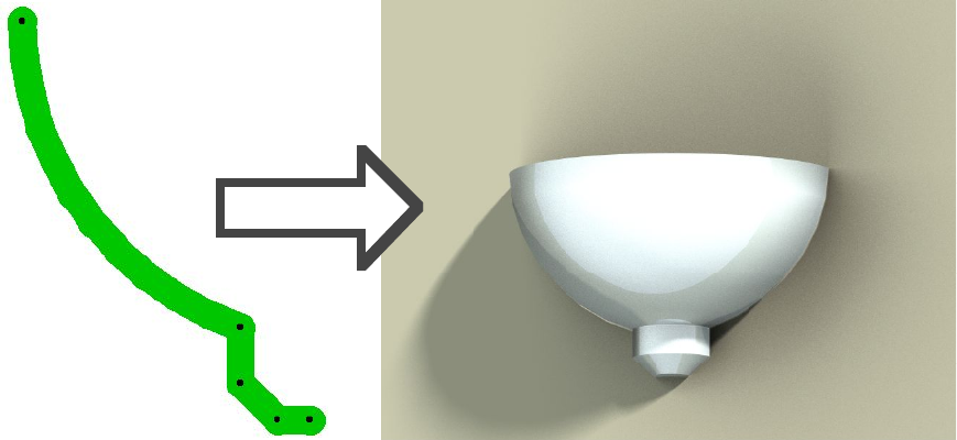
180°
Figure 4.116
Menu Item Name
Component/Extract Profile
Description
Profiles are created from shapes drawn with fills, slabs, polylines, etc. The profile can
subsequently be changed to any other selected shape with Change Profile (see below).
This tool will extract a fill or polyline from the selected profile so you can quickly edit and
update the shape without having to keep a copy of the element it was originally created from.
Procedure
- Select a section, elevation, or lathe profile.
- Select ‘Extract Profile’ from the ‘OBJECTiVE/Component’ menu.
- Click to place a fill/polyline with the profile shape.
Menu Item Name
Component/Upgrade Object
Description
The library parts provided with OBJECTiVE are constantly being developed and improved
over time. Most of these enhancements will automatically flow through to existing projects
when you upgrade, but your custom profile objects do not. This tool injects the
enhancements from the latest objects into a selected custom profile component.
Procedure
- Select an existing custom profile object in the Floor Plan.
- Select ‘Upgrade Object’ from the ‘OBJECTiVE/Component’ menu.
- Click ‘OK’ when asked to approve the upgrade.
23
Menu Item Name
Component/Change Profile
Description
A custom profile may have to be modified in response to design changes. It would be
inconvenient to have to create the profile from scratch and reposition each object in the
project model. This tool allows the user to update the profile of an existing custom profile,
automatically adjusting it wherever it is used in the model.
Procedure
- Draw the modified profile (in the Floor Plan or a Section/Elevation window).
- Select the profile and any instance of the component to be updated.
- Select ‘Change Profile’ from the ‘OBJECTiVE/Component’ menu.
- Click on the profile anchor point (and define the setout axis of elevations).
NOTE: An object’s hotspots have to be recalculated when its profile changes. Therefore,
make sure all affected objects are unlocked and on visible layers before using this tool. The
shape will change in any case, but the hotspots will be wrong if the update is restricted in any
way. Objects used on multiple storeys will automatically update without problems.
Menu Item Name
Component/Swap Object
Description
This tool can swap the type of one or more selected objects for another, transferring the
values of all matching parameters in the process. One useful application is updating projects
affected by renamed objects in new releases of ArchiCAD, e.g. “D1-10” to “D1-11”. The
settings of one object can be injected into another using standard ArchiCAD tools, but many
parameters remain with new settings (especially pens), requiring significant editing afterward.
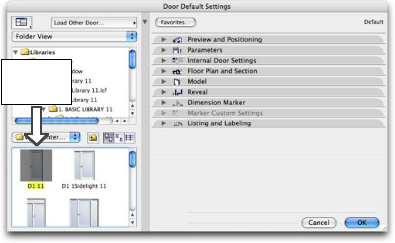
With OBJECTiVE, you can pick a replacement object, select the object(s) to be replaced, and
instantly transfer as much information as possible into the new objects.
Pick a
replacement
object here
This tool works for all object-based tools, including lamps, doors, and windows.
24
Procedure
- Pick a replacement in the Object, Lamp, Door, Window or OBJECTiVE tool settings.
- Select the object(s) to be replaced in the plan, section, or 3D window.
- Select ‘Swap Object’ from the ‘OBJECTiVE/Component’ menu.
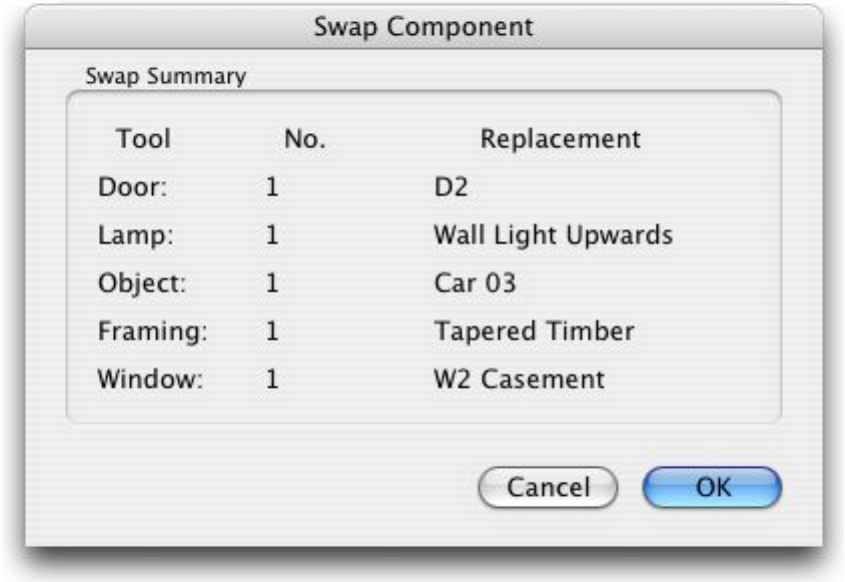
-Review the exchange(s) to be made and click ‘OK’ to proceed (Fig 4.117).
Figure 4.117
The ‘Swap’ dialog shows how many items are selected of each object type, e.g. the number of
selected doors, and the name of the replacement object (‘D2’ for doors in the example above).
25
4.2 Rotating In 3D
Menu Item Name
Tools/Rotate
Description
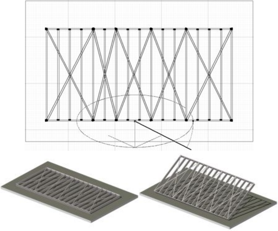
Have you ever wished you could simply tilt GDL objects to any pitch you like? Or wondered
why you can’t use the ArchiCAD’s ‘Rotate’ tool on 3D objects in section/elevation
windows? With OBJECTiVE, this is as simple as using the built-in (2D) rotate tool. All the
rotated objects can still be individually edited (including further rotations) and display
bounding hotspots for easy snapping. 3D GDL objects (not doors or windows) may be
rotated in the Floor Plan and Section/Elevation windows.
Procedure
- Select the object(s) to rotate.
- Select ‘Rotate’ from the ‘OBJECTiVE/Tools’ menu.
In Plan - Draw (or enter) a line to define the axis of rotation.
- Draw (or enter) an arc to define the rotation angle about the axis.
In Section - Draw (or enter) a line to define a reference axis.
- Draw (or enter) an arc to define the rotation angle from the reference axis.
The rotation axis and direction are fully illustrated during the operation, and the standard
ArchiCAD ‘Coordinates’ palette can be used to precisely enter the rotation axis and angle.
26
4.3 Splitting In 3D
Menu Item Name
Tools/Split
Description
OBJECTiVE can split GDL objects in 3D with the same simplicity as the standard ‘Split’
tool. As with rotation, all the split objects can still be individually edited (including further
splitting and/or rotation). Split objects can be sensibly stretched (see below), and hotspots are
placed on all cut edges to enable segments to be easily clipped together.
This tool may be used in the Floor Plan and Section/Elevation windows on any 3D GDL
object (not doors or windows). It is disabled when nothing is selected.
Procedure
- Select the object(s) to be split;
- Select ‘Split’ from the ‘OBJECTiVE/Tools’ menu;
- Draw the cut line (Figure 4.31);
- Click on either side of the line (offcuts on that side will remain selected);
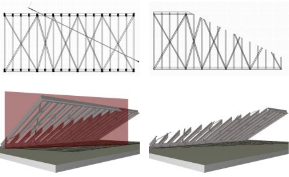
- OBJECTiVE splits the selected objects (Figure 4.32)
Fig. 4.31
Fig. 4.32
Some objects remain stretchable after cutting, and the angle of the cut(s) will remain constant
when resized (Figure 4.33). The hotspots will also update to suit the new length.
27
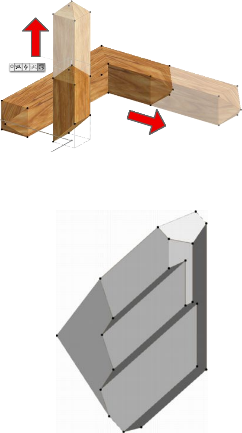
Fig. 4.33
Objects can be repeatedly rotated an cut to produce very complex shapes, but no new library
parts are ever created by these tools and every object remains fully and individually editable.
This is particularly useful when coupled with a custom section profile (Section 4.1) because
the ends can be repeatedly cut to form complex intersections with other objects.
28
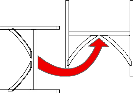
4.4 Bending In 3D
Menu Item Name
Tools/Bend
Description
GDL objects created with or designed for OBJECTiVE that have a constant cross-sectional
profile along their length (a “Section” profile type) can be bent to a curve in 2D or 3D. For
example, a steel beam could be bent to support a curved roof. Or a moulding could be bent to
the radius of a curved wall. Note that “Elevation” profile types are bent with a built-in smart
hotspot and cannot be bent with this tool.
Setting the extent of the curvature in either a horizontal or vertical plane can easily be done by
entering an offset in the object’s settings dialog. The bend tool allows this to be done visually
(and to snap to other elements in plan or elevation), and also simplifies bending an object in
both planes simultaneously.
Procedure
- Select the object(s) to be bent;
- Select ‘Bend’ from the ‘OBJECTiVE/Tools’ menu;
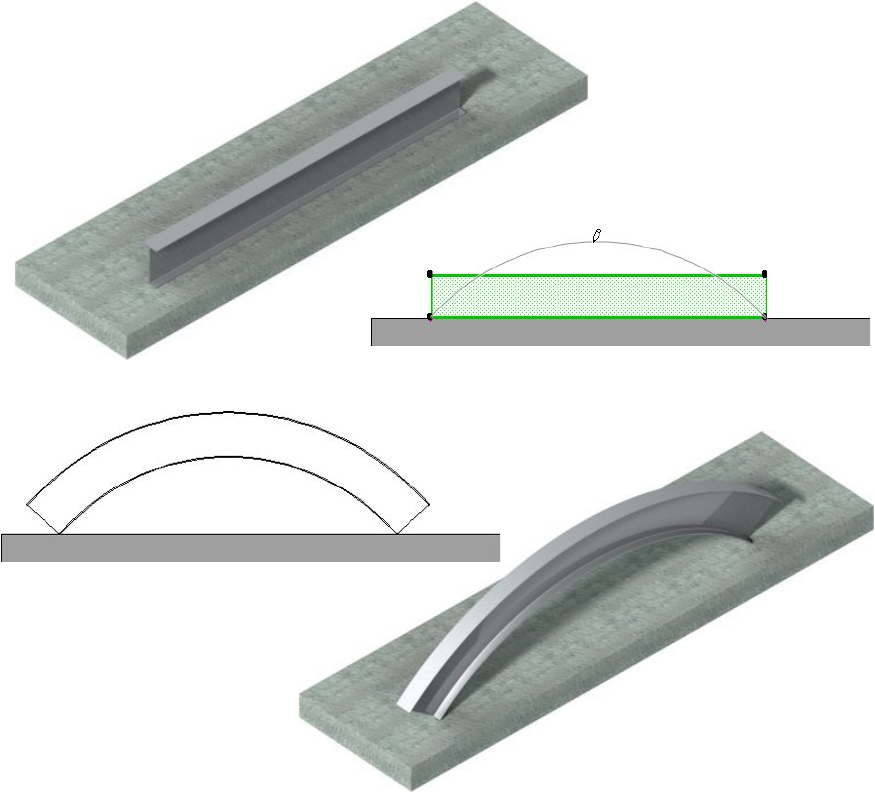
- Move the rubber-banded bending radius to the required position (Fig. 4.41);
Before…
After…
Figure 4.41
29
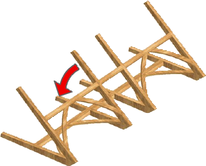
4.5 Offsetting In 3D
Menu Item Name
Tools/Offset
Description
Any object which can be bent to a curve with OBJECTiVE (see the previous section) can also
have one offset vertically or horizontally. A vertical offset is an easy way to set an object on
an incline when the overall rise is know but not an exact angle. This is particularly useful
when the object has been bent to a curve, as in a curved ramp or the handrail of a circular stair.
The offset tool allows the offset to be set visually in plan or section/elevation, and can
calculate offsets in both planes simultaneously if the object has been rotated in 3D.
Procedure
- Select the object(s) to be offset;
- Select ‘Offset’ from the ‘OBJECTiVE/Tools’ menu;
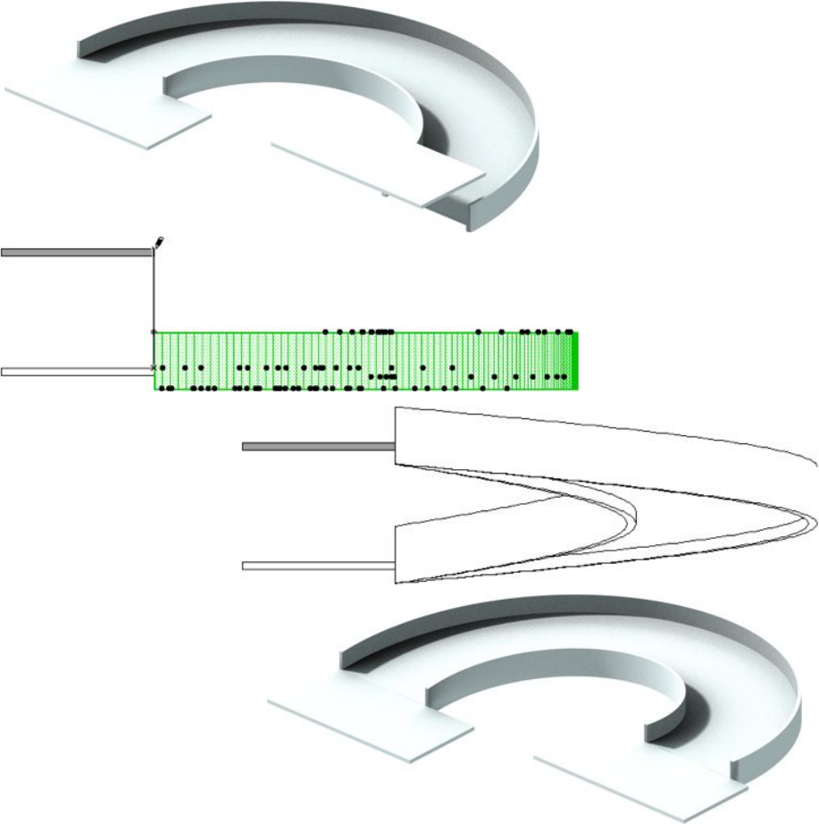
- Move the rubber-banded bending end to the required position (Fig. 4.51);
Before…
After…
Figure 4.51
30
4.6 Working With 3D Assemblies
Editing is often easier in plan, either because more tools work in the Plan view or because it is
difficult to get a suitable viewing angle on the target. Wouldn’t modelling be simpler if you
could temporarily transform an entire assembly into a flat, plan view, and then put it back
into the model when you had finished?
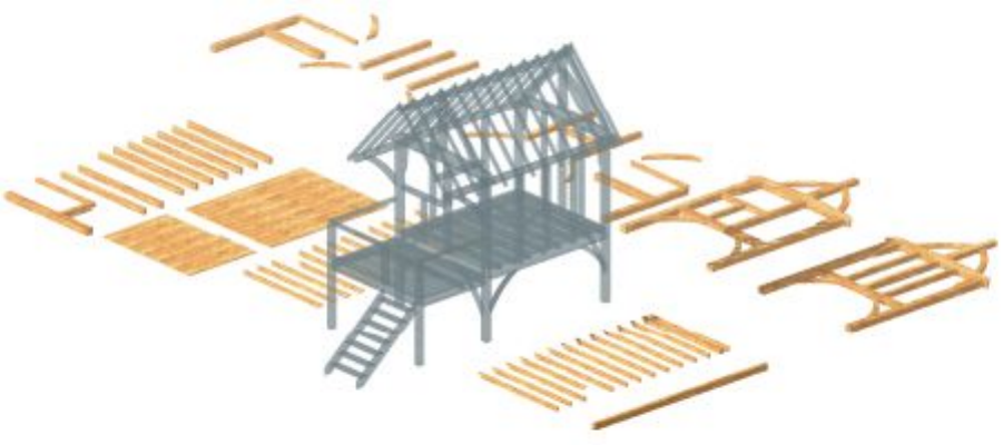
OBJECTiVE delivers this functionality with its Assembly tools. Any selection of objects can
be designated as an ‘Assembly’, which behaves just like a standard ArchiCAD group with an
added bonus - you can define and recall two working planes: One position for easy editing,
and another which fits with the building model. An entire building can be ‘flattened’ or
‘repackaged’ in one step! (Fig. 4.61)
Figure 4.61
Menu Item Name
Assembly/New
Description
This tool defines the members of a new assembly.
Procedure
• Select the objects to be members of the assembly;
• Select ‘New’ from the ‘OBJECTiVE/Assembly’ menu.
• Click to set an origin point for the assembly
All the selected objects will become a standard ArchiCAD ‘group’, including a special
‘Assembly’ object – placed at the origin – which holds the data about the assembly. The
Assembly object itself is not visible in 2D or 3D, but is selectable. Ensure that the Assembly
object is selected when moving or rotating objects (unless you want to move some objects
relative to the assembly origin). OBJECTiVE warns you if the origin moves and only some of
the objects go with it.
The plan and model home locations default to the position at which the assembly was first
created. Suspend groups if you wish to work on individual members of the assembly.
31
Menu Item Name
Assembly/Update
Description
Assemblies will be edited to suit design changes, possibly adding or removing components.
This tool allows you to change which objects are members of an assembly without losing any
of it’s information (e.g. the plan/model home positions). NOTE: No action is taken if you
haven’t selected an assembly.
Procedure
- Select all the objects to be in an assembly (including the Assembly Object).
- Select ‘Update’ from the ‘OBJECTiVE/Assembly’ menu.
Menu Item Name
Assembly/Detach
Description
It may be necessary to explode an assembly into its original components. This tool will delete
the assembly object and ungroup the members.
Procedure
- Select one or more members of the assembly to explode.
- Invoke the ‘Detach Assembly’ menu item.
Menu Item Name
Assembly/Go To Plan
Description
This tool will relocate an assembly to its plan ‘home’ position, typically used because it is
easier to edit in a plan view. The item is greyed out if nothing is selected. Multiple assemblies
can be sent simultaneously sent to their respective plan homes. It will also work correctly
even if only one item in an assembly is selected.
Procedure
- Select any part of one or more assemblies.
- Select ‘Go To Plan’ from the ‘OBJECTiVE/Assembly’ menu.
32
Menu Item Name
Assembly/Go To Model
Description
Essentially the same as ‘Go To Plan’ above, except that the assembly is sent to the model
‘home’ position.
Procedure
- Select one or more assemblies to put back into the model.
- Invoke the ‘Go To Model’ menu item.
Menu Item Name
Assembly/Set Plan Home
Description
The current assembly position is recorded as being the plan ‘home’ position. The assembly
will return to this position whenever you use ‘Go To Plan’.
Procedure
- Select any part of one or more assemblies.
- Select ‘Set Plan Home’ from the ‘OBJECTiVE/Assembly’ menu.
Menu Item Name
Assembly/Set Model Home
Description
The current assembly position is recorded as being the model ‘home’ position. The assembly
will return to this position whenever you use ‘Go To Model’.
Procedure
The steps are:
- Select any part of one or more assemblies.
- Select ‘Set Model Home’ from the ‘OBJECTiVE/Assembly’ menu.
33
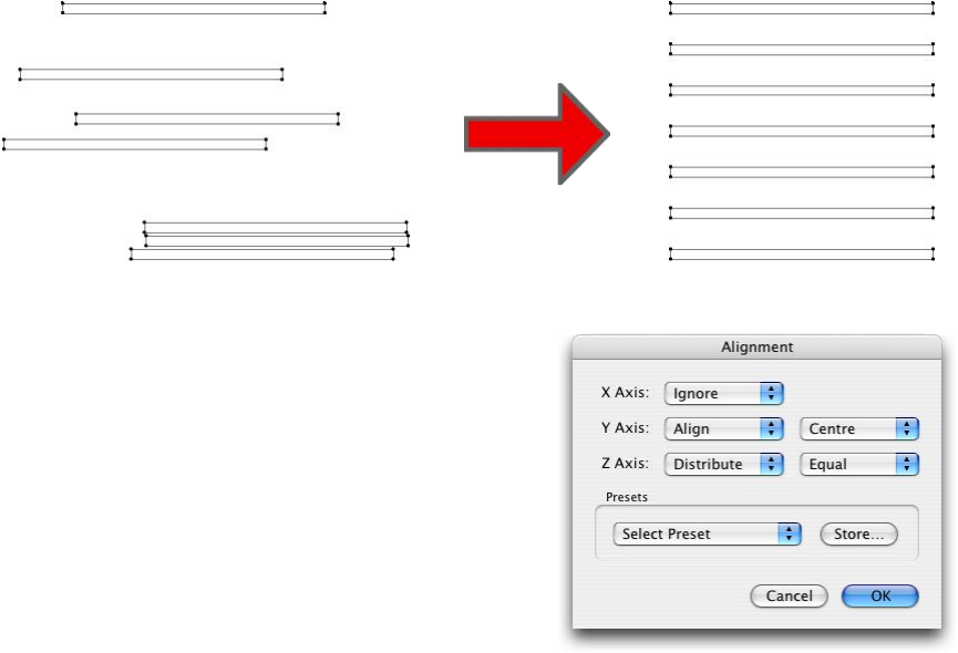
4.7 Aligning And Distributing Objects
Menu Item Name
Alignment/Align Selection…
Description
This tool can align or distribute a selection of objects in 2D or 3D as required (Fig. 4.71). This
includes all ArchiCAD 2D and 3D elements (including text, lines, etc.) and not just GDL
objects. Note that prior to ArchiCAD 10 the Alignment menu was found under the ‘Tools’
menu. From ArchiCAD 10 onward, the ‘Tools’ menu was removed, and the Alignment menu
is under ‘Edit/Move’ instead.
Fig. 4.71
The ‘Alignment’ dialog is displayed when this tool is
selected (Fig. 4.72). An alignment action can be
specified for each axis using the first popup menu:
Align: The selected objects will be aligned to the
specified reference line along the axis.
Distribute: The selected objects will be distributed
equally along the axis between their outermost bounds,
measured from a specified edge.
Ignore: No action will be taken along the axis.
Fig. 4.72
If ‘Align’ or ‘Distribute’ is selected, a second popup menu will appear for the axis to select a
reference for the alignment/distribution. For example, a selection can be aligned to the left,
right, or centre along the X axis. If you selected ‘Right’, the objects would be aligned to the
rightmost edge of the entire selection. Note that alignment in the Z axis is meaningless for
objects that have no 3D form, e.g. lines.
‘Distribute’ enables on additional option: ‘Equal’. This means that the selected objects will be
distributed to ensure the gap between then is equal. For example, to align text into a suitable
form for a table, you might choose ‘Align Left’ for the X Axis, and ‘Distribute Equal’ for the
Y Axis.
34
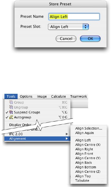
The alignment tool also provides 10 preset configurations
for commonly used operations, e.g. ‘Align Left’. These
are displayed in the Alignment menu and in the
Alignment dialog. You can store your own presets by
selecting the required alignment configuration and clicking
on the ‘Store’ button. This will display the ‘Store Preset’
dialog (Fig. 4.73), where you can specify the name and
slot for the stored configuration.
Fig. 4.73
Procedure
Fig. 4.74
- Select one or more objects.
-Select ‘Align Selection’ from the
‘Tools/Alignment’ menu (Fig 4.74).
- Specify whether to Align or Distribute along
each axis, and the reference line.
Menu Item Name
Alignment/Align Again
Description
This tool automatically repeats the previous alignment operation on the current selection.
Tip: Assign keypresses to both ‘Align’ and ‘Align Again’ to accelerate their use (using the
standard ArchiCAD Options/Work Environment dialog). Commonly used presets can also
benefit from this.
35
4.8 Updating Objects
Menu Item Name
Tools/Repair Object
Description
This tool will force a recalculation of a object’s bounds and hotspots. This may be necessary
if the object has either been edited without an installation of OBJECTiVE or imported from
an older version of ArchiCAD (e.g. from 7 to 8).
Procedure
- Select one or more objects.
- Select ‘Repair Object’ from the ‘OBJECTiVE/Tools’ menu.
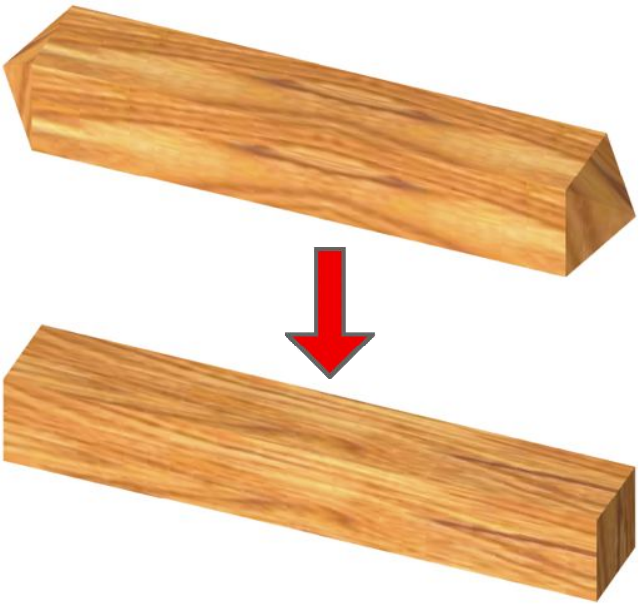
Menu Item Name
Tools/Remove Cuts
Description
This tool removes all cuts from the selected object(s), restoring the original shape (Fig. 4.81).
Procedure
- Select one or more objects.
- Select ‘Remove Cuts’ from the ‘OBJECTiVE/Tools’ menu.
Fig. 4.81
36
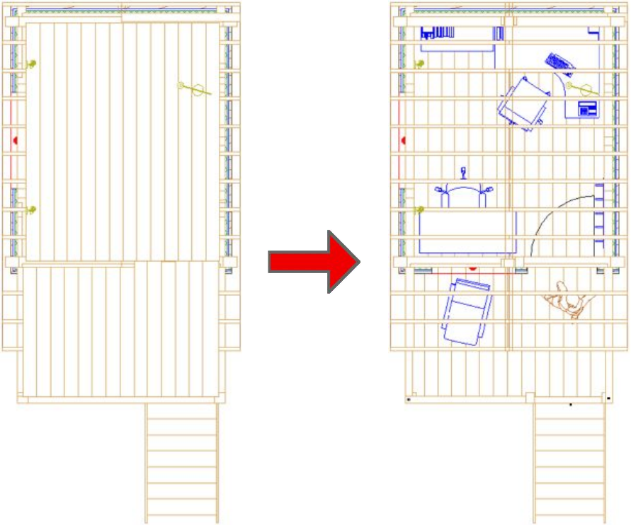
Menu Item Name
Tools/Set Display Order
Description
ArchiCAD does not display elements in the Floor Plan according to their relative height, e.g. a
lower wall may be drawn overlapping a higher wall. so the plan view can be hard to read
without manually reordering using “Send To Back”, “Move To Front”, etc. This tool reorders
everything in the floor plan according to their relative level, which means the 2D view will
closely resemble a view of the 3D model from above (Fig. 4.82).
This tool works with any ArchiCAD element with a 3D shape unless it is locked, on a
locked/hidden layer, or not in your workspace (for TeamWork).
Procedure
- Select ‘Set Display Order’ from the ‘OBJECTiVE/Tools’ menu.
Fig. 4.82
37
Section 5
OBJECTiVE Library
38
5.1 An Overview
OBJECTiVE provides a library of objects which are likely to be
required for architectural 3D modelling, including timber and steel
framing members, but can be fashioned into almost any shape using
OBJECTiVE’s toolset.
It is important to note that these objects are standard GDL and do not
require the add-on to be present for 2D or 3D visualisation. They can
also be edited without the add-on, but some of the smart features like
automatic hotspot generation will not be available. This means you
can safely archive or distribute your projects without fear of data loss.
These objects are placed and edited with the OBJECTiVE tool (Fig.
5.11) and work just like standard library parts. Click once on the tool
to begin placing the currently selected timber. Double-click to
view/edit the OBJECTiVE tool settings (Fig. 5.12). The OBJECTiVE
Settings dialog works in exactly the same way as the standard Object
Settings dialog, with the exception that only OBJECTiVE objects are
displayed.
Figure 5.11
There is one significant difference between the OBJECTiVE tool and the standard object tool
when placing objects in a Section/Elevation window. The standard object tool places an object
in a section window only - there is no change to the project model or any other views (as if it
was a 2D illustration only). However, when you place an object into a section with the
OBJECTiVE tool, it automatically places it in the project model so that all views are updated
(Plan/Section/3D). All objects placed this way will appear in the plane of the
section/elevation. This feature makes the section/elevation window as significant as the floor
plan or 3D window for constructing and editing the virtual model.
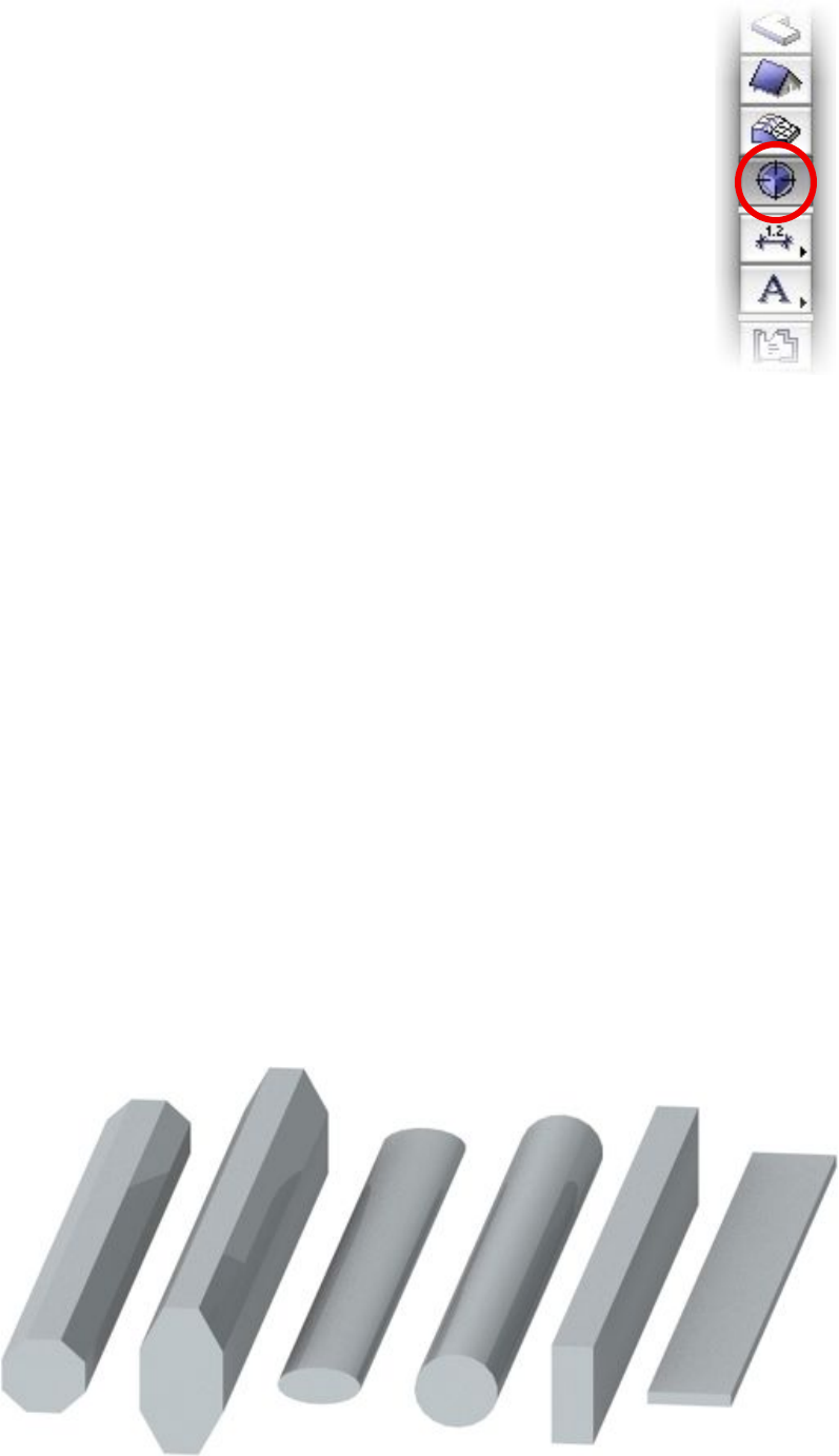
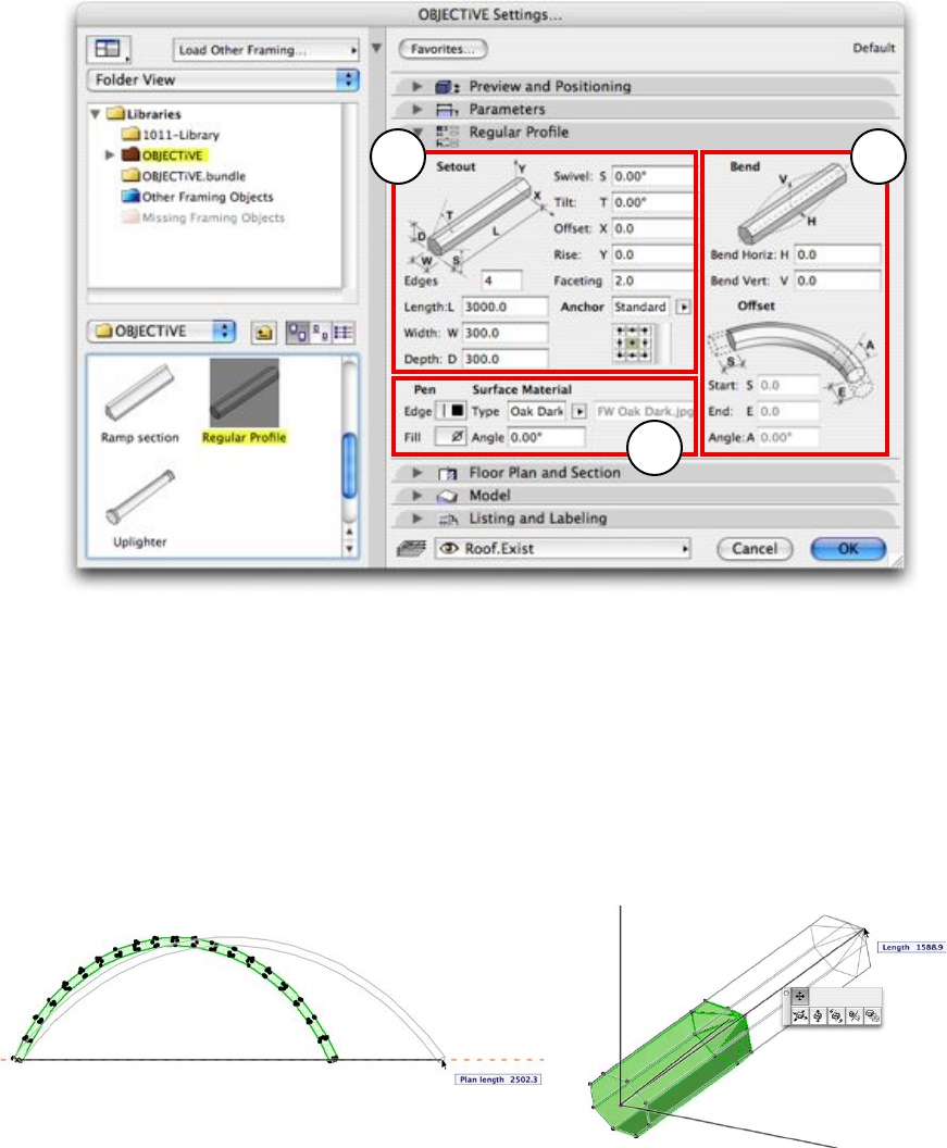
5.2 The Regular Profile Object
In addition to the timber and steel libraries, OBJECTiVE provides one generic object,
“Regular Profile” which will solve many common modelling requirements. As the name
implies, the object illustrates a 3D body with a regular cross-section, e.g. a regular polygon or
circle, which can rotated, cut, bent, or offset in 3D. It’s cross-sectional proportions can also
be distorted to any size, e.g. flattening a circle section to an ellipse. All the images in Fig. 5.21
are different instances of “Regular Profile”.
Figure 5.21
39
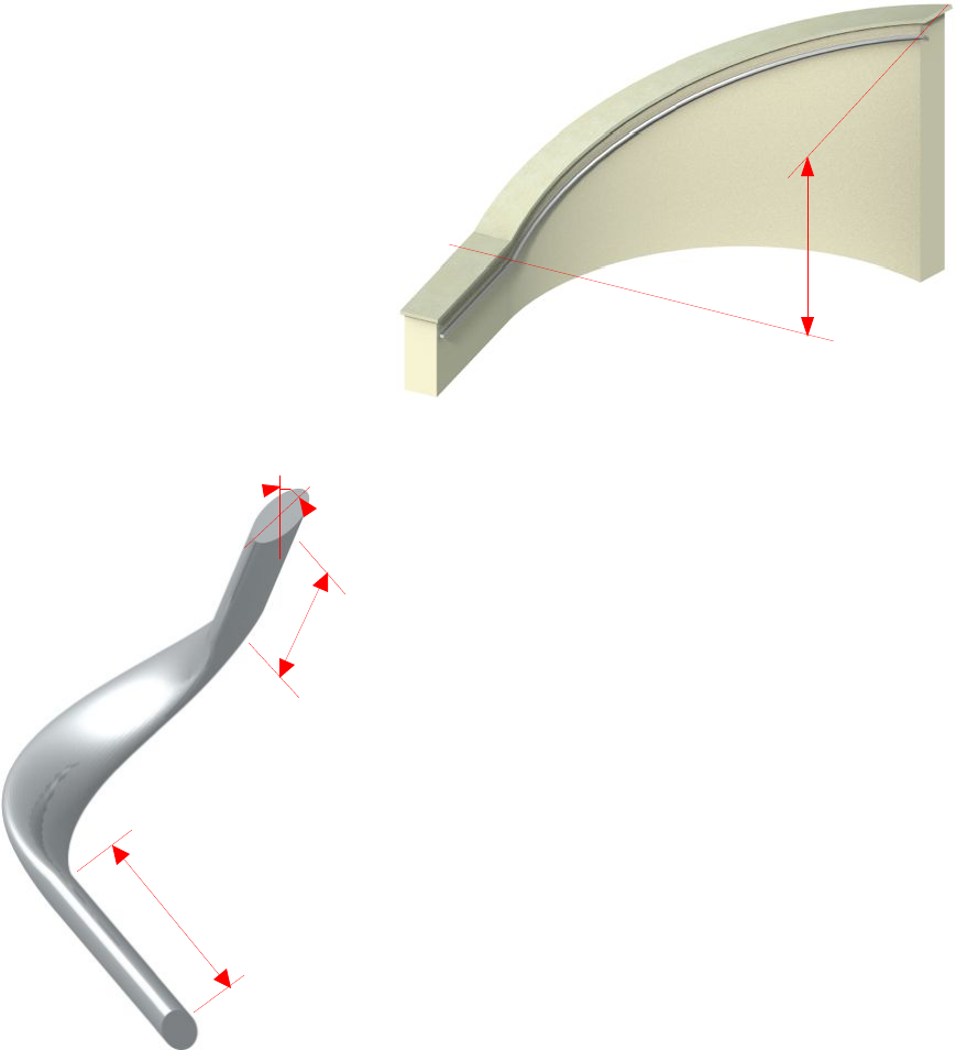
This object can serve a wide variety of purposes including handrailing, copings, fascias, and is
excellent as a SEO operator to slope the top or underside of curved walls or stairs. The
settings for the profile can be edited in a detailed user interface, broadly divided into 3
categories (Fig. 5.22):
1. Setout
2. Bending
3. 2D/3D appearance
2
1
3
Figure 5.22
1. Setout
The bounding size of the profile (length, width, depth) has the same meaning irrespective of
the object’s orientation in 3D. All 3 bounding sizes can be independently edited, i.e. the object
does not try to preserve its proportions, and length can also be edited in 2D or 3D using
smart hotspots aligned to the profile anchor (Fig. 5.23). Note that the plan length is displayed
when stretching an inclined profile in the Floor Plan window. The length remains stretchable
even if the profile is bent and/or split.
Figure 5.23
Faceting controls the smoothness of curves in the profile and the bent object. The number is a
measure of the maximum distance a face can be from the true curve. A small value will be very
smooth, but produce many faces. Conversely, a large figure will have fewer faces (and render
faster), but may appear course or blocky.
40
The Anchor is a point in the profile cross-section which stays fixed when the profile shape
changes, and has 2 options:
Standard Select the anchor from a 3 x 3 grid of standard snap points (identical to the
anchor selection for ArchiCAD columns or text)
Custom Enter 2 offsets from the bottom corner to specify the anchor position
Rise and Offset adjust the end of the
profile in the Y and X axis. For
example, you might specify rise
when you are applying the object to
a slope and know the overall height
but not the pitch.
This is a particularly useful setting
for curved shapes, for example a
handrail on a curved stair (Fig. 5.24).
The profile can be bent to the stair
curve and the Rise value set (or
moved with the Offset tool) to the
overall stair rise.
Rise
Figure 5.24
2. Bending
“Regular Profile” can be bent to a curve along its
horizontal and/or vertical axis. The handrail in Fig.
5.15 is bent in the horizontal axis for example.
Profiles can still be freely cut and rotated in 3D
when curved, and hotspots are calculated around
the surface for easy placement and snapping.
The profile ends can be extended at a tangent to the
curve for connections with adjacent objects (the
Start and End values), and the profile shape can be
skewed at any angle along the curve with the Angle
setting (Fig. 5.25)
3. Appearance
Pens can be selected for both the profile edges and
fill. Set the fill pen to 0 to make the profile
transparent.
Start
End
Angle
Figure 5.16
Figure 5.25
If you select a texture in the ‘Section Profile’ settings, OBJECTiVE will attempt to keep it
sensible aligned to the object even when rotated in 3D. This can be a preset timber grain or –
by selecting ‘Custom’ – you can enter the name of a texture image from the loaded library.
The texture direction can be fine-tuned with the adjacent ‘Angle’ setting.
Any standard material can be applied using the ‘Model’ tab. Uncheck ‘Use Object’s
Materials’ and select the required material in the popup menu above.
41
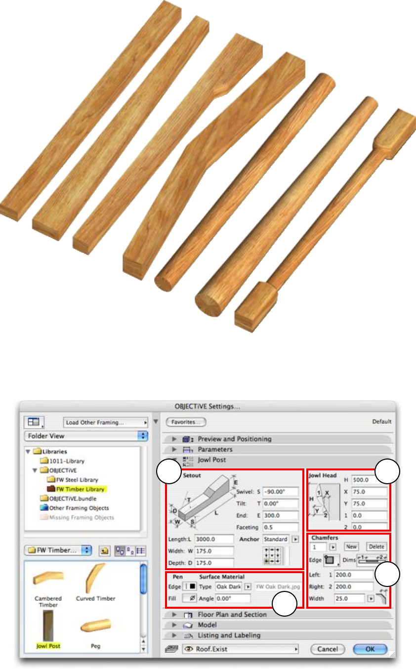
5.3 Timber Objects
Common Timber Settings
The interface for the timber library is divided into groups of settings which are common to
most timber objects, best illustrated by the ‘Jowl Post’ (Fig. 5.31).
2
1
4
3
Figure 5.31
42
The timber settings are broken down into four categories:
1. Setout
2. Shape-specific settings
3. Chamfers
4. 2D/3D appearance
1. Setout
The bounding size of the timber (length, width, depth) has
the same meaning irrespective of its orientation. All 3
bounding sizes can be independently edited, i.e. the object
does not try to preserve its proportions, and length can
also be edited in 3D using smart hotspots aligned to the
profile anchor (Fig. 5.14). Most timbers can also be
stretched in 2D depending on their orientation.
Faceting controls the smoothness of curves in the profile
and the bent object. The number is a measure of the
maximum distance a face can be from the true curve. A
small value will be very smooth, but produce many faces.
Conversely, a large figure will have fewer faces (and render
faster), but may appear course or blocky.
The Anchor is a point in the profile cross-section which
stays fixed when the profile shape changes, and has 2
options:
Standard Select the anchor from a 3 x 3 grid of standard
snap points (identical to the anchor selection
for ArchiCAD columns or text)
Custom Enter 2 offsets from the bottom corner to
specify the anchor position
Figure 5.32
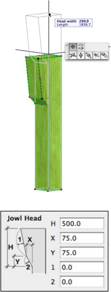
2. Shape-specific Settings
Most timber objects have unique shape
measurements. The setout of the jowl post, for
example, is shown to the right. Many of these
settings can be edited by dragging smart hotspots in
the 3D window, e.g. the curvature to the jowl.
The specification of each object is clearly illustrated
in the user interface and should need no additional
explanation.
43
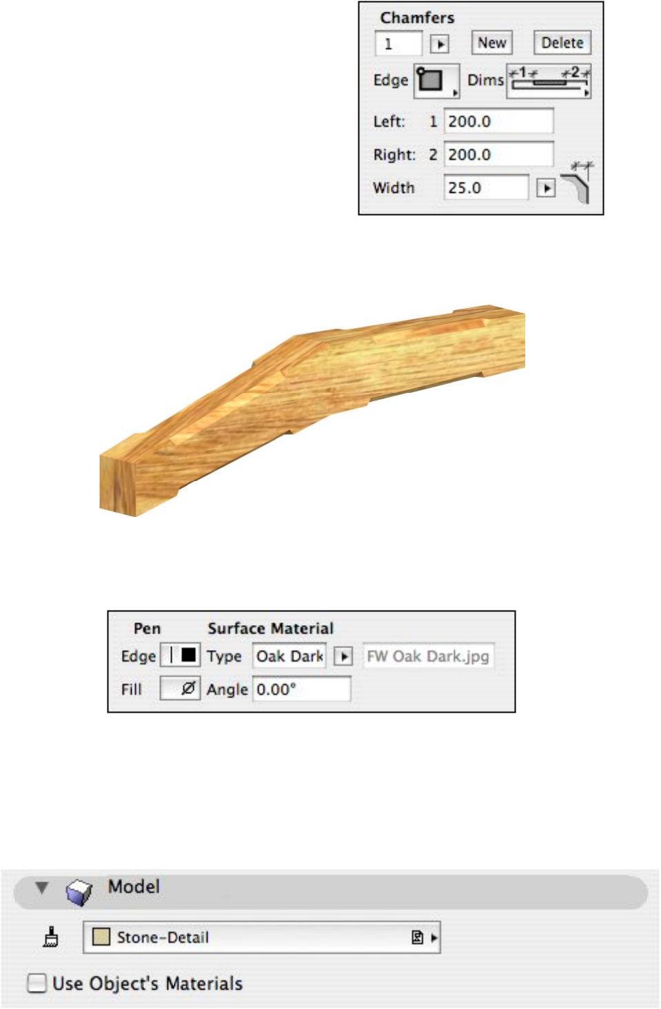
3. Chamfers
The following timber objects can have chamfers
specified to edges along their length: Cambered
Timber, Jowl Post, Rectilinear, and Tapered
Timber. Click ‘New’ to add a chamfer or Delete to
remove the active Chamfer. The active chamfer can
be selected from the popup menu in the top left
corner. Two popup menus below are used to
specify the edge to be chamfered (viewed from the
same orientation as the anchor) and the setout
method.
The two dimensions immediately below are applied according to the selected setout method,
which include: offset to start and length; offset to end and length; offset to centre and length;
and offsets to start and end. The last dimension specifies the chamfer width.
4. Appearance
Pens can be selected for both the timber edges and fill. Set the fill pen to 0 to make the timber
transparent.
If you select a texture under Surface Material, OBJECTiVE will attempt to keep it sensibly
aligned to the object even when rotated in 3D. This can be a preset timber grain or – by
selecting ‘Custom’ – you can enter the name of a texture image from the loaded library. The
texture direction can be fine-tuned with the adjacent ‘Angle’ setting.
Any standard material can be applied using the ‘Model’ tab. Uncheck ‘Use Object’s
Materials’ and select the required material in the popup menu above.
44
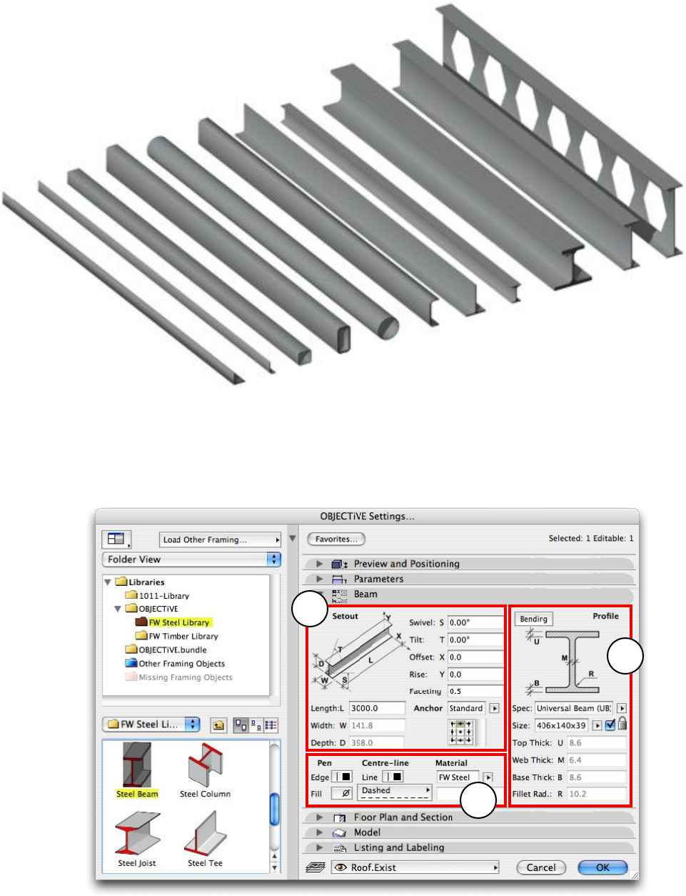
5.4 Steel Objects
Common Steel Settings
The interface for the steel library is divided into groups of settings which are common to most
steel objects, best illustrated by the ‘Steel Beam’ (Fig. 5.41).
2
1
3
Figure 5.41
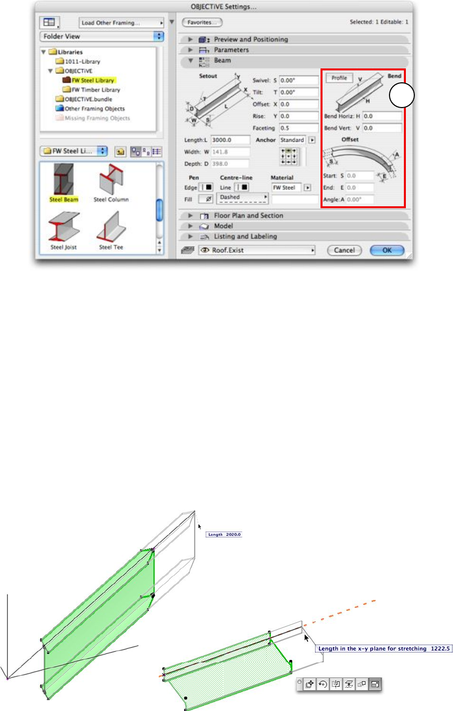
Clicking on the ‘Bending’ button swaps a panel showing bending settings for the steel Profile
settings (Fig. 5.42). Click ‘Profile’ to return to the Profile settings panel.
45
4
Figure 5.42
The steel settings are broken down into four categories:
1. Setout
2. Profile
3. 2D/3D appearance
4. Bending
1. Setout
The bounding size of the steel (length, width, depth) has the same meaning irrespective of its
orientation. All 3 bounding sizes can be independently edited, i.e. the object does not try to
preserve its proportions (unless you have locked the steel size to a specific standard - refer
to the Profile settings below), and length can always be edited in 3D using smart hotspots
aligned to the steel section anchor anchor (Fig. 5.14). Note that the plan length is displayed
when stretching an inclined profile in the Floor Plan window. The length remains stretchable
even if the profile is bent and/or split (Fig 5.43).
Figure 5.43
46
Faceting controls the smoothness of curves in the profile and bending along the steel length.
The number is a measure of the maximum distance a face can be from the true curve. A small
value will be very smooth, but produce many faces. Conversely, a large figure will have fewer
faces (and render faster), but may appear course or blocky.
The Anchor is a point in the profile cross-section which stays fixed when the profile shape
changes, and has 2 options:
Standard Select the anchor from a 3 x 3 grid of standard snap points (identical to the
anchor selection for ArchiCAD columns or text)
Custom Enter 2 offsets from the bottom corner to specify the anchor position
2. Profile
Each steel profile is clearly illustrated and needs little further explanation. Many support steel
specifications according to a variety of standards, accessed from the “Spec” popup menu. The
‘Size’ menu below is automatically populated with sizes from the selected standard. If the
adjacent checkbox is ticked (also illustrated with a ‘locked’ symbol), the sizes extracted from
the standard become locked and cannot be manually changed. Unlocking allows complete
freedom in sizing the steel.
Note that the ‘Bending’ button in the top, left-hand corner will switch this panel to the
Bending settings.
3. Appearance
Pens can be selected for both the steel edges, fill, and centreline. Any of these pens can be set
to 0 (transparent), allowing you to illustrate just the steel edges, or just the centrelines, or
both. There is also a pulldown menu for the centreline dash style.
‘Material’ can be the preset steel texture or – by selecting ‘Custom’ – you can enter the name
of a texture image from the loaded library. Any standard material can be applied using the
‘Model’ tab. Uncheck ‘Use Object’s Materials’ and select the required material in the popup
menu above.
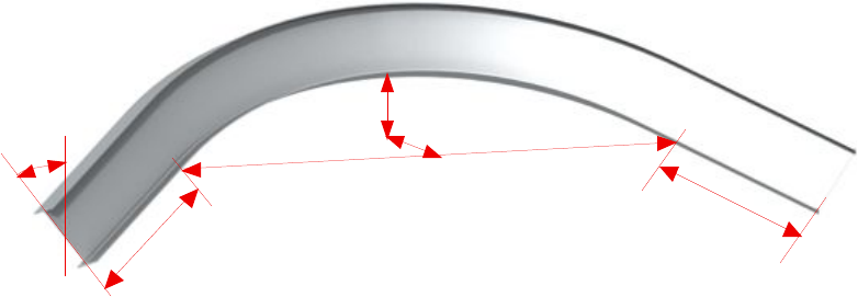
4. Bending
Most steel sections can be bent to a curve along its horizontal and/or vertical axis (the only
exception is the ‘Castellated Beam’). The steel can still be freely cut and rotated in 3D when
curved, and hotspots are calculated around the surface for easy placement and snapping.
The steel ends can be extended at a tangent to the curve for connections with adjacent objects
(the Start and End values). And finally, the profile shape can be skewed at any angle along the
curve with the Angle setting (Fig. 5.44)
The ‘Profile’ button in the top, left-hand corner will switch this panel to the Profile settings.
Length
Start
End
Bend up
& across
Angle
Figure 5.44
47
Section 6
Troubleshooting
48
6.1 The OBJECTiVE menu does not appear?
If the OBJECTiVE pulldown menu does not appear then the add-on has not been loaded.
This may be due to one of the following:
1. OBJECTiVE has been disabled in the Add-on Manager. Check the Add-on Manager to see
if OBJECTiVE is listed and enabled.
2. OBJECTiVE has not been installed correctly. Please check that the OBJECTiVE folder
containing the OBJECTiVE add-on has been placed in the Add-Ons folder in the
ArchiCAD application folder.
3. There are two different versions of OBJECTiVE installed at the same time. Make sure
there are no other copies of OBJECTiVE anywhere in your Add-Ons folder.
4. You are running the demo version with a full version of ArchiCAD. The OBJECTiVE
demo will only work with the ArchiCAD demo.
6.2 The OBJECTiVE tool isn’t in the toolbar?
From ArchiCAD 9, the user could choose which tools appear in the toolbar. The icons for
add-on tools are hidden by default, so you need to show it using the ‘Toolbox’ section in the
‘Work Environment’ dialog (under the ‘Options’ menu).
6.3 Dots appear instead of objects?
At least one library has not loaded, possibly the standard timber or steel libraries bundled
with OBJECTiVE. The standard libraries will be automatically loaded provided they remain
in the OBJECTiVE folder with the add-on. Otherwise, use the ArchiCAD Library Manager to
locate and load the required library.
6.4 The ‘Assembly’ GDL object displays nothing in 2D or 3D?
This is normal - the Assembly object is simply a marker for the anchor point of an assembly,
and stores data about the assembly. There is no need to place this object manually.
6.5 I can’t ‘Undo’ an update to a custom profile?
Updating the profile changes the library part definition, which cannot be reversed. You will be
warned of this prior to the application of the update.
6.6 Some timber hotspots are detached from the object after splitting?
Some objects are designed to be stretchable after splitting. ArchiCAD may not allow objects
to be stretched consistently without hotspots on the rectilinear bounds, so these are added to
stretchable objects.
6.7 The OBJECTiVE GDL objects are behaving strangely?
The objects may not work properly if the project has come from an older version of
ArchiCAD or someone has worked on it without the OBJECTiVE add-on. There can be many
different symptoms:
-The objects cannot be split or rotated correctly
- The objects can’t be edited with the OBJECTiVE tool
-Hotspots and labels are not placed correctly
To fix this problem, select all the timber and use the ‘Update Hotspots’ from the
‘OBJECTiVE/Tools’ menu. This has to be repeated for each storey containing timber. Be sure
all the relevant layers are visible and unlocked.
49
6.8 Some menu items are missing from the OBJECTiVE menu?
The menu settings in your work environment options may be set to exclude these items.
Check in the “Menu” section of the “Work Environment” dialog.
6.9 An object didn’t rotate or split properly
Badly written GDL objects may not integrate well with OBJECTiVE’s extensions. This
should rarely be a problem in practice because the constraints are simply good programming
practice.
For GDL authors, please avoid expressions which unpredictably modify the transformation
stack like “DEL TOP”. Also avoid abrupt changes in the execution flow, for example using
“END” in an external macro or script.
50
