OFE 324 OPEN FRY STATION SERVICE MANUAL
User Manual: OFE-324
Open the PDF directly: View PDF ![]() .
.
Page Count: 110 [warning: Documents this large are best viewed by clicking the View PDF Link!]

Henny Penny Model OFE/OFG-321,322,323,324
This manual should be retained in a convenient location for future reference.
A wiring diagram for this appliance is located on the inside of the right side panel.
Post in a prominent location, instructions to be followed in event user smells gas. This
information shall be obtained by consulting the local gas supplier.
FORYOURSAFETY
DO NOT STORE OR USE GASOLINE OR OTHER FLAMMABLE VAPORS
AND LIQUIDS IN THE VICINITY OF THIS OR ANY OTHER APPLIANCE.
Keep appliance area free and clear from combustibles.
Do not obstruct the flow of combustion and ventilation air. Adequate clearance must be left all
around appliance for sufficient air to the combustion chamber.
NOTE
The Model OFG/OGA-32X Fryer is equipped with a continuous pilot. But Fryer can not be
operated without electric power. Fryer will automatically return to normal operation when power
is restored.
WARNING: Improper installation, adjustment, alteration, service or maintenance can
cause property damage, injury or death. Read the installation, operating and maintenance
instructions thoroughly before installing or servicing this equipment.
FM01-650

Henny Penny
LIMITED WARRANTY FOR HENNY PENNY APPLIANCES
Subject to the following conditions, Henny Penny Corporation makes the following limited warranties to the
original purchaser only for Henny Penny appliances and replacement parts:
NEW EQUIPMENT: Any part of a new appliance, except lamps and fuses, which proves to be
defective in material or workmanship within two (2) years from date of original installation, will be
repaired or replaced without charge F.O.B. factory, Eaton, Ohio, or F.O.B. authorized distributor. To
validate this warranty, the registration card for the appliance must be mailed to Henny Penny within ten
(10) days after installation.
REPLACEMENT PARTS: Any appliance replacement part, except lamps and fuses, which proves to
be defective in material or workmanship within ninety (90) days from date of original installation will be
repaired or replaced without charge F.O.B. factory, Eaton, Ohio, or F.O.B. authorized distributor.
The warranty for new equipment and replacement parts covers only the repair or replacement of the defective
part and does not include any labor charges for the removal and installation of any parts, travel or other expenses
incidental to the repair or replacement of a part.
EXTENDED FRYPOT WARRANTY: Henny Penny will replace any frypot that fails due to manufacturing or
workmanship issues for a period of up to seven (7) years from date of manufacture. This warranty shall not cover
any frypot that fails due to any misuse or abuse, such as heating of the frypot without shortening.
0 TO 3 YEARS: During this time, any frypot that fails due to manufacturing or workmanship
issues will be replaced at no charge for parts, labor, or freight. Henny Penny will either install a
new frypot at no cost or provide a new or reconditioned replacement fryer at no cost.
3 TO 7 YEARS: During this time, any frypot that fails due to manufacturing or workmanship
issues will be replaced at no charge for the frypot only. Any freight charges and labor costs to
install the new frypot as well as the cost of any other parts replaced, such as insulation, thermal
sensors, high limits, fittings, and hardware, will be the responsibility of the owner.
Any claim must be represented to either Henny Penny or the distributor from whom the appliance was
purchased. No allowance will be granted for repairs made by anyone else without Henny Penny’s written
consent. If damage occurs during shipping, notify the sender at once so that a claim may be filed.
THE ABOVE LIMITED WARRANTY SETS FORTH THE SOLE REMEDY AGAINST HENNY PENNY
FOR ANY BREACH OF WARRANTY OR OTHER TERM. BUYER AGREES THAT NO OTHER REMEDY
(INCLUDING CLAIMS FOR ANY INCIDENTAL OR CONSQUENTIAL DAMAGES) SHALL BE
AVAILABLE.
The above limited warranty does not apply (a) to damage resulting from accident, alteration, misuse, or
abuse; (b) if the equipment’s serial number is removed or defaced; or (c) for lamps and fuses. THE ABOVE
LIMITED WARRANTY IS EXPRESSLY IN LIEU OF ALL OTHER WARRANTIES, EXPRESS OR
IMPLIED, INCLUDING MERCHANTABILITY AND FITNESS, AND ALL OTHER WARRANTIES ARE
EXCLUDED. HENNY PENNY NEITHER ASSUMES NOR AUTHORIZES ANY PERSON TO ASSUME
FOR IT ANY OTHER OBLIGATION OR LIABILITY.

Henny Penny Model OFE/OFG-321,322,323,324
TABLE OF CONTENTS
Section Page
Section 1. INTRODUCTION .....................................................................................................1-1
1-1 Introduction ...................................................................................................1-1
1-2 Model Variations...........................................................................................1-1
1-3 Features .........................................................................................................1-1
1-4 Safety.............................................................................................................1-1
1-5 Assistance......................................................................................................1-2
Section 2. INSTALLATION ......................................................................................................2-1
2-1 Introduction ...................................................................................................2-1
2-2 Unpacking......................................................................................................2-1
2-3 Selecting the Location ...................................................................................2-2
2-4 Leveling the Fry Station ................................................................................2-2
2-5 Ventilation of Fry Station..............................................................................2-2
2-6 Gas Supply.....................................................................................................2-3
2-7 Gas Leak Test ................................................................................................2-5
2-8 Gas Pressure Regulator .................................................................................2-6
2-9 Electrical Requirements OFE-320 Series......................................................2-6
2-10 Testing the Fry Station ..................................................................................2-7
2-11 Joining Instructions .......................................................................................2-7
Section 3. OPERATION.............................................................................................................3-1
3-1 Introduction ...................................................................................................3-1
3-2 Operating Controls ........................................................................................3-1
3-3 Filling or Adding Shortening.........................................................................3-5
3-4 Basic Operations and Procedures (6 Product Controls)................................3-5
3-5 Basic Operations and Procedures (Electro-Mechanical)...............................3-7
3-6 Basic Operations and Procedures (12 Product Controls/Auto-lift)...............3-9
3-7 Filtering of Shortening ..................................................................................3-12
3-8 Filter Pump Problems ....................................................................................3-14
3-9 Filter Pump Motor Protector .........................................................................3-14
3-10 Changing the Filter Envelope........................................................................3-15
3-11 Cleaning the Cookpots ..................................................................................3-16
3-12 Lighting and Shutdown of Burners ...............................................................3-19
3-13 Regular Maintenance.....................................................................................3-20
Section 4. PROGRAMMING ......................................................................................................4-1
4-1 Introduction ....................................................................................................4-1
4-2 Product Program Mode ..................................................................................4-1
4-3SpecialProgramMode...................................................................................4-4
Section 5. TROUBLESHOOTING..............................................................................................5-1
5-1 Introduction ....................................................................................................5-1
5-2 Troubleshooting .............................................................................................5-1
Section 6. MAINTENANCE........................................................................................................6-1
6-1 Introduction ....................................................................................................6-1
6-2 Maintenance Hints .........................................................................................6-1

Henny Penny Model OFE/OFG-321,322,323,324
TABLE OF CONTENTS
Section Page
Section 6. MAINTENANCE (Continued)
6-3 High Temperature Limit Control (Gas Units)................................................6-1
6-4 Complete Control Panel Replacement ...........................................................6-4
6-5 Power Switch..................................................................................................6-4
6-6 Temperature Probe Replacement ...................................................................6-5
6-7 Flame Sensor (Gas Units) ..............................................................................6-6
6-8 Pilot/Ignitor Assembly ...................................................................................6-7
6-9 Ignition Module..............................................................................................6-8
6-10 Transformer....................................................................................................6-8
6-11 I/O Power Supply Board Assembly ...............................................................6-9
6-12 Airflow Switch ...............................................................................................6-9
6-13 Speaker Assembly (Gas Units) ......................................................................6-10
6-14 Drain Microswitch .........................................................................................6-11
6-15 Filter Switch ...................................................................................................6-11
6-16 Gas Valve Assembly ......................................................................................6-12
6-17 Blower Motor Assembly ................................................................................6-14
6-18 Heating Elements (Electric Only) ..................................................................6-16
6-19 Heating Contactors (Electric Only)................................................................6-19
6-20 Speaker Assembly (Electric Units) ................................................................6-21
6-21 High Temperature Limit Control (Electric Units) .........................................6-21
Section 7. PARTS INFORMATION............................................................................................7-1
7-1 Introduction ....................................................................................................7-1
7-2 Genuine Parts .................................................................................................7-1
7-3 When Ordering Parts......................................................................................7-1
7-4 Prices ..............................................................................................................7-1
7-5 Delivery..........................................................................................................7-1
7-6 Warranty.........................................................................................................7-1
120V/60Hz/1Ph (OFG-32X Gas) Wiring Diagram........................................7-13
208-240V/60Hz/1Ph (Domestic-OFE-32X Electric) Wiring Diagram..........7-14
120V/50/60Hz/1Ph (OFG-322) Wiring Diagram...........................................7-15
230V/50Hz/1 Ph (OFG-321) Wiring Diagram...............................................7-16
208-240V/50-60 Hz/3Ph (OFE-321/2/3 Electric) Wiring Diagram...............7-17
120V/50-60Hz/1Ph (OFG-321) Wiring Diagram ..........................................7-18
380-415V/50-60Hz/3Ph (OFE-321/2/3) Wiring Diagram .............................7-19
120V/50-60Hz/1Ph (OGA-323) Wiring Diagram..........................................7-20
120V/50-60/1Ph (OGA-321) Wiring Diagram ..............................................7-21
380-480V/50-60Hz/3Ph (OFE-321/2/3) Wiring Diagram .............................7-22
230V/50Hz/1Ph (OFG-323) Wiring Diagram................................................7-23
120V/50-60Hz/1Ph (ODG-323) Wiring Diagram..........................................7-24
230V/50Hz/1Ph (OFG-322) Wiring Diagram................................................7-25
120V/50-60Hz/1Ph (OFG-323) Wiring Diagram ..........................................7-26
208-240V/50-60Hz/3Ph (OFE-321/2/3) Wiring Diagram .............................7-27
208-240V/50-60Hz/3Ph (OEA-321/2/3) Wiring Diagram.............................7-28
Distributors List - Domestic and International

Henny Penny Model OFE/OFG-321,322,323,324
SECTION 1. INTRODUCTION
1-1. INTRODUCTION. The Henny Penny Open Fry Station is a basic unit of food
equipment designed to cook foods better and easier. The
microcomputer based design helps make this possible. This
unit is used only in institutional and commercial food service
operations.
1-2. MODEL VARIATIONS This manual covers the following variations of the Henny
Penny Open Fry Station:
• Model OFG/OFE-323
• Model OFG/OFE-322
• Model OFG/OFE-321
• Model OFG/OFE-324
• Model OGA/OEA-323
• Model OGA/OEA-322
• Model OGA/OEA-321
1-3. FEATURES • Easily cleaned.
• 55 lb. (24.94 kg.) shortening capacity
• 2 Half size baskets per well (or full size baskets).
• Microcomputer control.
• Stainless steel construction.
• Manual reset high limit control.
• Self-diagnostic system built into controls.
• Built in filter (handles all 3 wells).
• Propane or Natural Gas; 85,000 BTU/pot (26.38 kW)
1-4. SAFETY The Henny Penny Fry Station has many safety features
incorporated. However, the only way to ensure safe
operation is to fully understand the proper installation,
operation, and maintenance procedures. The instructions in
this manual have been prepared to aid you in learning the
proper procedures. Where information is of particular
importance or is safety related, the words DANGER,
WARNING, CAUTION, or NOTE are used. Their usage is
described below:
The word DANGER indicates an imminent hazard
which will result in highly serious injury such as second
or third degree burns.
998 1-1
Henny Penny Model OFE/OFG-321,322,323,324
1-4. SAFETY
(Continued)
The word WARNING is used to alert you to a
procedure that if not performed properly, might cause
personal injury.
ThewordCAUTIONisusedtoalertyoutoaprocedure
that, if not performed properly, may damage the fry
station.
NOTE
The word NOTE is used to highlight especially
important information.
1-5. ASSISTANCE Should you require outside assistance, just call your local
independent distributor maintained by Henny Penny
Corporation.
In addition, feel free to contact our corporate headquarters in
Eaton,Ohio.Dial1-800-417-8405 tollfree,or
937-456-8405.
1-2 998

Henny Penny Model OFE/OFG-321,322,323,324
SECTION 2. INSTALLATION
2-1. INTRODUCTION This section provides the installation instructions for the
Henny Penny Fry Station.
NOTE
Installation of the unit should be preformed only by a
qualified service technician.
Do not puncture the unit with any objects such as drills
or screws as component damage or electrical shock
could result.
2-2. UNPACKING The Henny Penny Fry Station has been tested, inspected,
and expertly packed to ensure arrival at its destination in
the best possible condition. The unit is banded to a wooden
skid and then packed inside a heavy cardboard carton with
sufficient padding to withstand normal shipping treatment.
NOTE
Any shipping damage should be noted in the presence
of the delivery agent and signed prior to his or her
departure.
1. Carefully cut bands from cardboard carton.
2. Lift carton from fryer.
This manual should be retained in a convenient location
for future reference.
Wiring diagram for this appliance is located on the inside
of the Service and Operation Manual. Post in a prominent
location, instructions to be followed in event user smells gas.
This information shall be obtained by consulting the local gas
supplier.
998 2-1

Henny Penny Model OFE/OFG-321,322,323,324
2-3. SELECTING THE The proper location of the Fry Station is very important
LOCATION for operation, speed, and convenience. The location of the
fry station should allow clearances for servicing and proper
operation. Choose a location which will provide easy loading
and unloading without interfering with the final assembly of
food orders. Operators have found that frying from raw to
finish, and holding the product in warmers provides fast
continuous service. Keep in mind the best efficiency will be
obtained by a straight line operation, i.e. raw in one side and
finished out the other side. Order assembly can be moved
away with only a slight loss of efficiency.
NOTE
The fryer should be installed in such a way as to prevent
tipping or movement causing splashing of hot liquid
shortening. This may be accomplished by the location
the fry station is in, or by restraining ties.
The gas Model OFG-320 Series Fry Station is designed
for installation on combustible floors and adjacent to
combustible walls. Fry Station must be installed with a
minimum clearance from all combustible materials, 4
inches (10.16 cm) from side and 4 inches (10.16 cm)
from the back.
2-4. LEVELING THE FRY For proper operation, the fry station should be level from
STATION side to side and front to back. Using a level place on the
flat areas around the frypot collar, on the middle well, adjust
the casters until the unit is level.
2-5. VENTILATION OF FRY The fry station should be located with provision for venting
STATION into an adequate exhaust hood or ventilation system. This
is essential to permit efficient removal of the steam exhaust
and frying odors. Special precaution must be taken in
designing an exhaust canopy to avoid interference with the
operation of the fry station. We recommend you consult a
local ventilation or heating company to help in designing an
adequate system.
NOTE
Ventilation must conform to local, state, and national
codes. Consult your local fire department or building
authorities.
2-2 998

Henny Penny Model OFE/OFG-321,322,323,324
2-5. VENTILATION OF FRY
STATION (Continued)
When installing the gas fry station do not attach an exten-
sion to the gas flue exhaust stack. This may impair proper
operation of the burner, causing malfunctions and possible
negative back draft.
2-6. GAS SUPPLY The gas fry station is factory available for either natural or
propane gas. Check the data plate inside the front door of the
cabinet to determine the proper gas supply requirements.
Do not attempt to use any gas other than that specified on
the data plate. Incorrect gas supply could result in a fire or
explosion.
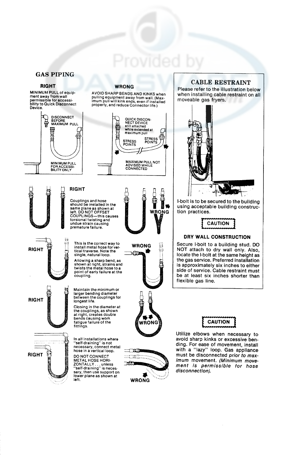
Please refer to the illustration on the following page for the
recommended hookup of the fry station to the main gas line
supply.
To avoid possible serious personal injury:
•Installation must conform with local, state, and national codes.
•Installation must conform with American National Standard
Z223.1-Latest Edition National Fuel Gas Code and the local
municipal building codes. In Canada, installation must be in
accordance with Standard CAN/CGA B 149.1 & Installation
Codes - Gas Burning Appliances and local codes.
•The fry station must be isolated from the gas supply piping
system by closing its individual manual shut off valve during
any pressure testing of the gas supply piping system at test
pressures equal to or less than 1/2 PSIG (3.45 KPA) (34.47
mbar).
998 2-3
Henny Penny Model OFE/OFG-321,322,323,324
2-4 998

Henny Penny Model OFE/OFG-321,322,323,324
2-6. GAS SUPPLY • A standard one inch, black steel pipe and malleable fit-
(Continued) tings should be used for gas service connections.
• Do not use cast iron fittings.
• Although one inch (2.54 cm) size pipe is recommended,
piping should be of adequate size and installed to provide a
supply of gas sufficient to meet the maximum demand
without undue loss of pressure between the meter and the
fry station. The pressure loss in the piping system should
not exceed 0.3 inch water column (.747 mbar).
• Do not adjust the vacuum pressure switch. It is factory set
for the most efficiency.
Provisions should be made for moving the fry station for
cleaning and servicing. This may be accomplished by:
1. Installing a manual gas shut off valve and a disconnect
union, or
2. Installing a heavy-duty design A.G.A. certified
connector. In order to be able to service this appliance,
which is provided with casters, a connector complying
with ANSI Z21.69 or CAN 1-6.l0m88 and a
quick-disconnect device, complying with ANSI Z21.41
or CAN 1-6.9m70, must be installed. It must also be
installed with restraining means to guard against
transmission of strain to the connector as specified in
the appliance manufacturer's instruction.
3. Refer to the cable restraint instructions, on preceding page,
on how and where to attach the restraining devices to
the wall and fryer.
2-7. GAS LEAK TEST NOTE
Upon initial installation, and after moving the unit, be
sure the gas dial cock on fry station gas valve is in the
OFF position. After the piping and fittings have been
installed, check for gas leaks. A simple checking
method is to turn on the gas and brush all connections
with a soap solution. If bubbles occur, it indicates
escaping gas. In this event, the piping connection must
be redone.
Never use a lighted match or open flame to test for gas
leaks. Escaping gas could cause an explosion resulting
in severe personal injury.
998 2-5

Henny Penny Model OFE/OFG-321,322,323,324
2-8. PRESSURE REGULATOR The gas pressure regulator on the automatic gas valve is
factory set as follows:
• Natural: 3.5 inches water column (8.7 mbar).
• Propane 10.0 inches water column (24.9 mbar).
2-9. ELECTRICAL
REQUIREMENTS
OFG-320 SERIES • 120 V, 50/60 Hz., 12 A, 1 PH
• 230 V, 50 Hz., 1 PH
The 120 V gas fry station requires a 3 wire grounded
(Earthed) service and is supplied with a grounded cord and
plug. Any 230 volt plug used on the 230 volt unit must
conform to all local, state, and national codes.
DO NOT DISCONNECT THE GROUND (EARTH)
PLUG. This fry station MUST be adequately and
safely grounded or electrical shock could result. Refer
to local electrical codes for correct grounding
(Earthing) procedures or in absence of local codes, with
the National Electrical Code, ANSO/NFPA No. 70
Latest Edition. Canadian models are supplied with a
terminal box, suitable for conduit connection. In
Canada, all electrical connections are to be made in
accordance with CSA C221, Canadian Electrical Code
Part 1, and/or local codes.
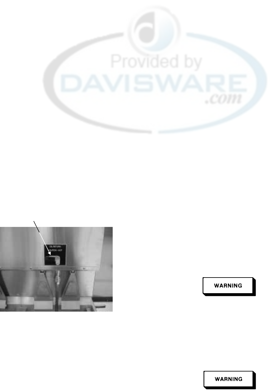
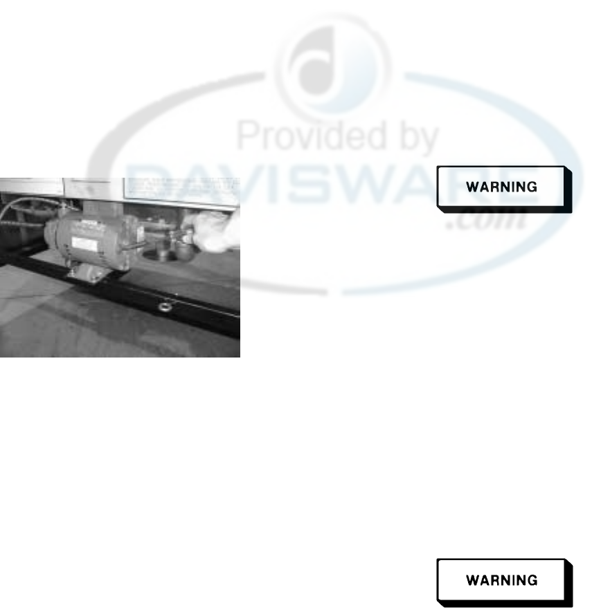
Servicing of the filter pump is done at the rear of the unit. If
service is required, disconnect the fry station from the
electrical power source. The fry station will have to be
pulled out from the wall to gain access to rear.
2-6 998

Henny Penny Model OFE/OFG-321,322,323,324
2-9. ELECTRICAL
REQUIREMENTS
OFE-320 SERIES Refer to the table below for supply wiring and fusing.
(Per Well)
Volts Phase Kw Amps
200-208 3 14.4 40
220/240 3 14.4 40
440-480 3 14.4 17
380-415 3 14.4 20
This fry station must be adequately and safely grounded.
Refer to local electrical codes for correct grounding pro-
cedures. If fry station is not adequately grounded, electrical
shock could result.
A separate disconnect switch with proper capacity fuses or
breakers must be installed at a convenient location between
the fry station and the power switch.
NOTE
CE units require a minimum wire size of 6mm to be wired
to the terminal block.
2-10 TESTING THE
FRY STATION Each Henny Penny Fry Station was completely checked and
tested prior to shipment. However, it is good practice to
check the unit again after installation.
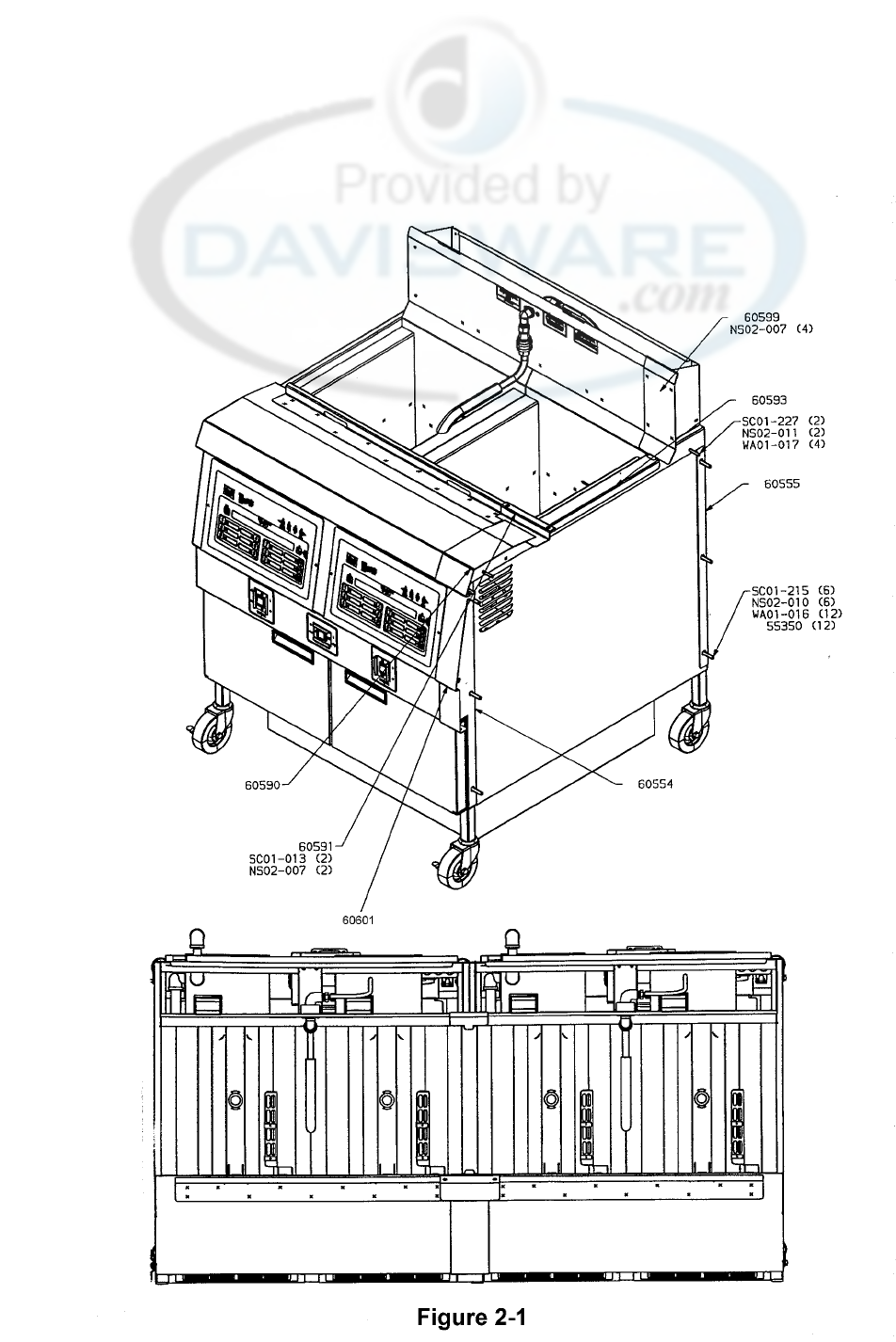
2-11 JOINING INSTRUCTIONS The following instructions are for joining two units together.
The instructions have part numbers in them. Please refer to
figure 2-1 on the following page to visually match the
numbers in the instructions to the illustration.
1. Remove all hardware from the sides of the two fryers.
2. Remove the right control panel assembly from the left
unit and the left control panel assembly from the right
unit.
499 2-7

Henny Penny Model OFE/OFG-321,322,323,324
2-11 JOINING INSTRUCTIONS
(Continued)
3. Move the two units side by side with minimal gap.
4. Remove the right front caster from the left unit and the
left rear caster from the right unit. Fasten both casters to
the rear of the unit with wire ties (EF02-041).
5. Position the two fryers by inserting bolts (SC01-227) thru
the holes in top cover and the pot sides. Use washer
(WA01-017) on both sides of the bolt when installing.
DO NOT TIGHTEN!
6. Position front spacer (60554) between the front of the two
fryers. Place bolt (SC01-215), backed by washers (55350
& WA01-016), thru three holes in the frame capturing the
spacer between the frames. Place washers ( 55350&
WA01-016) on bolt before installing nuts (NS02-010).
DO NOT TIGHTEN!
7. Repeat with rear spacer (60555).
8. Tighten all fasteners securely.
9. Place cover (60593) over gap between fryers.
10. Drill out dimples on rear shroud to 0.250 diameter holes.
11. Apply silicon around edge of unfinished side of rear
cover (60599). Install rear cover (60599) with #8 nuts
(NS02-007).
12. Apply silicon around edge of unfinished side of front
cover (60601). Install front cover (60601) using #8 self
drilling screws (SC03-005).
13. Apply silicon around edge of unfinished side of top cover
(60590) and basket rest cover ( 60591). Position top cover
(60590) on fryer top cover and install basket rest cover
( 60591) using #8 screws and nuts (Sc01-013 & Ns02-007).
14. Apply silicon to any gaps that may be left.
2-8 499
Henny Penny Model OFE/OFG-321,322,323,324
2-11 JOINING INSTRUCTIONS
( Continued)
400 2-9

Henny Penny Model OFE/OFG-321,322,323,324
SECTION 3. OPERATION
3-1. INTRODUCTION This section provides operating procedures for the Henny
Penny OFG/OFE-320 series open fryer with both 6 and 12
button timer controls. Sections 1, 2, and 3 should be read and
all instructions should be followed before operating the fryer.
3-2. OPERATING CONTROLS Figure 3-1 shows the function of the 12 button timer control,
and Figure 3-2, shows the function of the 6 timer control.
Fig. Item Description Function
No. No.
3-1 1 The Heat-On LED will light when the control calls for heat,
3-2 and the burners should come on and heat the shortening.
3-1 2 Digital Display The digital display is to show the shortening temperature,
3-2 the timer countdown in the frying cycle, and the selections in
the Program mode. The temperature of the shortening can be
shown by depressing the INFO button. If the
temperature exceeds 425°F (218°C), the display will read
"E-5", “FRYER TOO HOT”.
3-1 3 Wait LED Once the fryer is out of the Melt mode, the Wait LED will
3-2 light, signaling the operator that the shortening temperature is
NOT at the proper temperature for dropping product into the
cookpot.
3-1 4 Ready LED The Ready LED will light when the shortening temperature is
3-2 within 5°of the setpoint temperature, signaling the operator
that the shortening temperature is now at the proper
temperature for dropping product into the cookpot.
3-1 5 The INFO button can display the current shortening
3-2 temperature, the setpoint temperature, as well as cooking
performance. It will also show the amount of time left in
a hold mode. Also, in the program mode, it will step back
to the previous parameter.
3-1 6 & 7 The Up and Down buttons are used to adjust the value
3-2 of the currently displayed setting in the Program mode.
3-1 500

Henny Penny Model OFE/OFG-321,322,323,324
3-2. OPERATING CONTROLS
(Continued)
Fig. Item Description Function
No. No.
3-1 8 The PROG button is used access the program modes.
3-2 Also, once in the program mode, it is used to advance
to the next parameter.
3-1 9 Start/Stop Button The Start/Stop buttons are used to start and stop cooking
3-2 cycles. They will also de-activate the quality timer at the
end of a hold mode.
3-1 10 Menu Card The name of the food product associated with each Product
3-2 Window Selection button below. The menu card strip is located
Behind the decal.
3-1 11 Product Select The Product Select buttons are used to select which food
3-2 Buttons products are to be cooked. (On Auto-lift fryers, the 6 and 12
product buttons are basket lift buttons.)
500 3-2

Henny Penny Model OFE/OFG-321,322,323,324
1 2 3 4 5678
910 11 9
Figure. 3.1
3-3 400

Henny Penny Model OFE/OFG-321,322,323,324
1 234 5678
910 11 9
Figure. 3.2
400 3-4

Henny Penny Model OFE/OFG-321,322,323,324
3-3. FILLING OR It is recommended that a high quality frying shortening be
ADDING SHORTENING used in the OFG/OFE-320 fry stations. Some low grade
shortenings have a high moisture content causing foaming
and boiling over. The Henny Penny OFG-320 requires 55
pounds (24.94 kg) of shortening per cookpot. All cookpots
have two level indicators inscribed on the rear of the cookpot
wall. The top indicator shows when the heated shortening is
at the proper level. Cold shortening should be at the bottom
indicator, since the shortening will expand when heated.
Hot shortening must be maintained at the level indicator
on each cookpot, or fire could result. It is also
recommended to use gloves when in contact with hot
shortening. Shortening and all metal parts that are in
contact with the shortening are extremely hot and
severe burns could result.
Moving the fryer with hot shortening in the cookpots or
filter pan is not recommended. Hot shortening can
splash out and severe burns could result.
3-4. BASIC OPERATIONS The Henny Penny Open Fry Station has electronic controls
AND PROCEDURES for each cookpot. The following is brief description of the
(6 Product Controls) operating procedures for controls with 6 Product Buttons.
1. Be sure the drain valve is in the closed position.
2. Place basket support inside of cookpot.
3. Fill the cookpot with shortening.
When using solid shortening, it is recommended to melt
the shortening on an outside heating source before
placing it in the cookpots. The heating tubes of the gas
cookpot or the elements of the electric pot must be
completely submerged in shortening. Fire could result,
or damage to the cookpot could result.
3-5 500

Henny Penny Model OFE/OFG-321,322,323,324
3-4. BASIC OPERATIONS 4. Move power switch to the "ON" position. Unit will
AND PROCEDURES automatically go into the melt cycle. When the
(6 Product Controls) temperature reaches 230°F (110°C) the control will go
(Continued) into the heat cycle. The shortening will be heated until
the temperature setting is reached.
NOTE
The OFG-320 series fryer has several safety devices which
shuts down the gas supply when they are activated. The
above procedures should be followed to restart the cooker
and if the shut down is repeated, a qualified technician
should be notified.
NOTE
The melt cycle may be bypassed, if desired, by pressing
a Product button and holding it for five seconds.
Do not bypass the melt cycle unless enough shortening
has melted to completely cover all of the heating
tubes. If melt cycle is bypassed before all heating
tubes are covered, excessive smoking of the
shortening, or a fire will result.
5. Once out of the Melt cycle, the Wait LED will flash
until the setpoint temperature has been reached. Then
the Ready LED will light, and the selected product
will display on the left and right side of the display.
NOTE
The timing operation of the two sides of the control
is entirely independent. They may be set, started, or
stopped without affecting each other.
6. Thoroughly stir shortening to stabilize the temperature
throughout the cookpots.
7. Once the shortening temperature has stabilized at the
setpoint temperature, the operator can then lower the
basket with product into the cookpot.
Do not overload, or place product with extreme moisture
content into the basket. 12.5 lbs. (5.7 kgs.) is the maximum
amount of product per cookpot, (15 lbs. (6.75 kgs.)
maximum for Auto-lift fryers). Failure to follow these
directions can result in shortening overflowing the cookpot.
Serious burns or damage to the cookpot could result.
500 3-6

Henny Penny Model OFE/OFG-321,322,323,324
3-4. BASIC OPERATIONS 8. If the right basket was dropped into the shortening, then
AND PROCEDURES the right START/STOP button should be pressed. If the
(6 Product Controls) left basket was dropped, then the left START/STOP
(Continued) button should be pressed.
9. Once the START/STOP button has been pressed, the
timer on the appropriate side (right or left) will start
counting down.
10. At the end of the cook cycle a tone will sound the
Display will flash ‘DONE’. Press the START/STOP
button and lift the basket from the shortening.
11. The display will show which product it is ready to time
down. If a HOLD time was programmed, the controller
will automatically start the hold timer. The display will
alternately show the product selected and the quality
time remaining in minutes. If a different product is
selected during the hold cycle, the display will only
show the product selected. To view the hold time remaining,
push the INFO button.
11. At the end of the Hold mode, a tone will sound and the
display will flash “QUALITY” and the product it was
timing. Press and release the START/STOP button.
The display will show the product it is ready to start
timing for frying.
3-5. BASIC OPERATIONS
AND PROCEDURES
(Electro-Mechanical) The Henny Penny Open Fryer models OFE/OFG are avail-
able with electro-mechanical controls. The electro-
mechanical controls consist of one timer and one thermo-
stat per well.
1. Be sure the drain valve is in the closed position.
2. Place basket support inside of cookpot.
3. Fill the cookpot with shortening.
3-7 500

Henny Penny Model OFE/OFG-321,322,323,324
3-5. BASIC OPERATIONS
AND PROCEDURES
(Electro-Mechanical)
(Continued) When using solid shortening, it is recommended to melt
the shortening on an outside heating source before
placing it in the cookpots. The heating tubes of the gas
cookpot or the elements of the electric pot must be
completely submerged in shortening. Fire could result,
or damage to the cookpot could result.
4. Turn the POWER switch to the On position.
5. Determine the time and temperature settings according
to the type of product to be fried.
6. Set the thermostat to the desired temperature.
7. Set the TIMER dial, but do not turn on yet.
NOTE
Before placing the product into the basket, make certain
the shortening temperature is at the correct frying
temperature for the type of product. Also check that
the TEMPERATURE light is off.
8. Place the product into the basket. Lower the basket into
the shortening. Lift the basket slightly out of the
shortening and shake it, causing the pieces to separate.
Doing this will prevent white spots on the finished
product.
Do not overload, or place product with extreme
moisture content into the basket. 12.5 lbs. (5.7 kgs.) is
the maximum amount of product per cookpot, (15 lbs.
(6.75 kgs.) maximum for Auto-lift fryers). Failure to
follow these directions can result in shortening
overflowing the cookpot. Serious burns or damage to
the cookpot could result.
9. Turn the TIMER ON/OFF switch to ON.
10. At the end of the frying cycle (the TIMER reaches
zero), the TIMER buzzer will sound, and the Timer
light will go off.
500 3-8

Henny Penny Model OFE/OFG-321,322,323,324
3-5. BASIC OPERATIONS
AND PROCEDURES
(Electro-Mechanical)
(Continued) 11. Turn the TIMER switch to OFF. The TIMER will
automatically reset to the previously selected time
setting.
12. Lift the basket and hang it on the front of the frypot to
drain. Allow the product to drain for approximately 15
seconds before dumping the product onto a tray.
13. Place the product into a warming cabinet immediately.
14. Before frying the next load, allow time for the shorten-
ing to reheat. (Wait until the TEMPERATURE light
goes off.)
3-6. BASIC OPERATIONS
AND PROCEDURES
(12 Product Controls/Auto-lift) The Henny Penny Open Fryer models OFE/OFG are avail-
able with 12 product button controls. Also, models
OEA/OGA, are available with 12 button controls, equipped
with Auto-Lift features. The Auto-lift controls, allows the
baskets to be automatically lowered into the shortening, at the
beginning of the cook cycle, and raised from the shortening
at the end of the cycle.
1. Be sure the drain valve is in the closed position.
2. Fill the cookpot with shortening.
When using solid shortening, it is recommended to melt
the shortening on an outside heating source before
placing it in the cookpots. The heating tubes of the gas
cookpot or the elements of the electric pot must be
completely submerged in shortening. Fire could result,
or damage to the cookpot could result.
3-9 500

Henny Penny Model OFE/OFG-321,322,323,324
3-6. BASIC OPERATIONS
AND PROCEDURES
(12 Product Controls/Auto-lift)
( Continued) 3. Move power switch to the "ON" position. Unit will
automatically go into the melt cycle. When the
temperature reaches 250°F (121°C) the control will go
into the heat cycle. The shortening will be heated until
the temperature setting is reached.
NOTE
The OFG-320 series fryer has several safety devices
which shuts down the gas supply when they are
activated. The above procedures should be followed to
restart the cooker and if the shut down is repeated, a
qualified technician should be notified.
NOTE
The melt cycle may be bypassed, if desired, by pressing
Do not bypass the melt cycle unless enough shortening
has melted to completely cover all of the heating
tubes. If melt cycle is bypassed before all heating
tubes are covered, excessive smoking of the
shortening, or a fire will result.
4. Once out of the Melt cycle, the Wait LED will flash
until the setpoint temperature has been reached. Then
the Ready LED will illuminate.
NOTE
The timing operation of the two sides of the control
can be programmed entirely independent from each
other for 2 half baskets, or as one timer for a single full
sized basket which will set on both lifts. The default
setting from the factory is for two half sized baskets.
To change to a single full size basket setting, push and
hold the #1 product button while turning on the
“POWER” switch. To change back to the two basket
mode, push and hold the #2 product button while
turning on the “POWER” switch.
5. Thoroughly stir shortening to stabilize the temperature
throughout the cookpots.
500 3-10

Henny Penny Model OFE/OFG-321,322,323,324
3-6. BASIC OPERATIONS 6. Once the shortening temperature has stabilized at the
AND PROCEDURES setpoint temperature, the operator may now place the
(12 Product Controls/Auto-lift) baskets into the shortening, (or for Auto-lift fryers, lift
( Continued) basket ontothe hangers,). Place product into the basket.
Do not overload, or place product with extreme
moisture content into the basket. 12.5 lbs. (5.7 kgs.) is
the maximum amount of product per cookpot, (15 lbs.
(6.75 kgs.) maximum for Auto-lift fryers). Failure to
follow these directions can result in shortening
overflowing the cookpot. Serious burns or damage to
the cookpot could result.
7. If the right basket is to be lowered into the shortening,
then one of the right product buttons should be pressed.
If the left basket is to be lowered, then one of the left
product buttons should be pressed.
8. The timer on the appropriate side will start counting
down. (On Auto-lift fryers, the basket will
automatically lower into the shortening.)
9. At the end of the cook cycle, a tone will sound and the
display will show “DONE”. Lift the basket from the
shortening. (On Auto-lift fryers, the basket will
automatically raise out of the shortening.) To stop the
“DONE” beeper, either press the “TIMER” button, or
the product button.
NOTE
A different product can be selected during the first
minute of cooking.
10. The display will show which product it is ready to time
down. If a HOLD time was programmed, the controller
will automatically start the hold timer. The display will
alternately show the product selected and the hold
time remaining in minutes. If a different product is
selected during the hold cycle, the display will only
show the product selected.
3-11 500

Henny Penny Model OFE/OFG-321,322,323,324
3-6. BASIC OPERATIONS
AND PROCEDURES
(12 Product Controls/Auto-lift) 11. At the end of the Hold mode, a tone will sound and the
( Continued) display will flash “QUALITY” and the product it was
timing. Press and release the TIMER button.
NOTE
In the Cook mode, when "FILTER SUGGESTED,
shows in the display, the operator has the option to
filter at this time, or to continue cooking. But, if the
operator continues cooking, a Filter Lockout will occur
within the next cook cycle, or two.
When "FILTER LOCKOUT", then "YOU *MUST*
FILTER NOW........” shows in the display, the PROG
button is the only button that will function, until the unit is
filtered.
3-7. FILTERING Frying breaded food requires frequent filtering. Taste the
OF SHORTENING cold shortening every day for flavor. Watch the shortening
for foaming during the frying cycle. Discard the shortening
as soon as it shows sign of foaming. Clean the cookpot as
follows each time the shortening is changed or filtered.
1. Turn the main switch to the OFF position. Remove
and clean the fry basket in soap and water. Rinse
thoroughly.
NOTE
Best results are obtained when shortening is filtered at
the normal frying temperature.
2. Use a metal spatula to scrape any build up from the
sides of the cookpot. Do not scrape heating tubes
on the gas models, or heating elements on electric
models.
Position the filter pan properly, under the drain valve,
to prevent splashing of hot shortening. Severe burns
could result.
700 3-12
Henny Penny Model OFE/OFG-321,322,323,324
3-7. FILTERINGOF 3. Open door(s) under unit, and slowly turn drain
SHORTENING valve handle a half turn. Leave for a few minutes, then
(Continued) slowly, fully open drain valve. This prevents much
splashing of the hot shortening as it drains.
4. As the shortening drains from the cookpot, use brushes
to scrape and clean the sides of the cookpot and the
heat tubes or heating elements. If the drain fills with
breading, use straight white brush to push excess
breading into the drain pan.
5. When all of the shortening has drained, scrape or brush
the sides and the bottom of the cookpot.
6. Rinse the cookpot as follows:
Standard fryers
a. Close the drain valve.
b. Position return line over empty cookpot.
Figure 3-3 c. Move the pump switch to the pump position.
Filter Handle d. Fill the cookpot 1/3 full, then turn off pump.
Autolift fryers
a. Close the drain valve.
b. Turn filter handle to the on position. Figure 3-3.
c. Fill the cookpot 1/3 full.
d. Turn filter handle to the off position.
Use care when reaching across a cookpot of hot
shortening. Severe burns could result.
e. Wash down and scrub the sides of the frypot with
the brushes.
f. After the sides and bottom are cleaned, open the
drain valve.
If shortening flow is slow from faucet, use gloves
to tighten the filter union. This union will be hot, and
severe burns could result.
3-13 700

Henny Penny Model OFE/OFG-321,322,323,324
3-7. FILTERING OF 7. Pump all of the shortening out of the filter pan and
SHORTENING back into the cookpot.
(Continued)
8. When the pump is pumping air only, move the pump
switch from PUMP to OFF, or on autolift fryers, turn
filter handle to OFF.
9. Check the level of the shortening in the cookpot. Add
fresh shortening if necessary, until it reaches the top
level indicator line on the rear wall of the cookpot.
NOTE
About 10 to 12 filterings can be made with one filter
paper envelope, depending on:
• the quantity and type of product fried and filtered
• thetypeofbreadingused
• the amount of crumbs left inside the filter drain pan
When the filter screen assembly and filter paper become
clogged, and the pumping flow slows, clean
the screen assembly and change the filter envelope.
10. To continue cooking, move the main power switch
to the "ON" position, and shortening reheats.
3-8. FILTER PUMP PROBLEMS To help prevent filter pump problems:
1. Properly install paper envelope over the filter screens.
Fold the open end of the envelope, and clamp
With retaining clips so that crumbs cannot enter.
2. Pump shortening, until no shortening is coming from
nozzle.
3-9. FILTER PUMP MOTOR The filter pump motor is equipped with a manual reset but-
PROTECTOR ton in the event the motor's thermal protector actuates. This
reset button is located on the rear of the motor. Wait
approximately 5 minutes before attempting to reset this
protector device.
700 3-14
Henny Penny Model OFE/OFG-321,322,323,324
3-9. FILTER PUMP MOTOR
PROTECTOR
(Continued)
To prevent burns caused by splashing shortening, the
unit's filter pump switch must be in the OFF position
before resetting the filter pump motor's manual reset
protector device.
NOTE
The reset button will take some effort to reset. A
screwdriver could be used to press against the reset
button to aid in resetting the protector device.
3-10. CHANGING THE FILTER The filter envelope should be changed after 10-12 filterings
ENVELOPE or whenever it becomes clogged with crumbs. Proceed as
follows:
1. Move the main power switch to the OFF position.
2. Disconnect the filter union and remove the filter drain
pan from beneath the cookpot.
This unit maybe hot. Use protective gloves or cloth
to prevent burns. Also use care to prevent burns caused
by splashing of hot shortening.
3. Remove drain pan cover from drain pan and lift the
screen assembly from the drain pan.
4. Wipe the shortening and crumbs from the drain pan.
Clean the drain pan with soap and water. Thoroughly
rinse with hot water.
5. Unthread the suction standpipe from the screen
assembly.
6. Remove the crumb catcher and clean thoroughly with
soap and water. Rinse thoroughly with hot water.
7. Remove the filter clips and discard the filter envelope.
3-15 700

Henny Penny Model OFE/OFG-321,322,323,324
3-10. CHANGING THE FILTER 8. Clean the top and bottom filter screen with soap and
ENVELOPE (Continued) water. Rinse thoroughly with hot water.
Be sure that the filter screens, crumb catcher, filter clips
and the suction standpipe are thoroughly dry before
assembly of filter envelope or water will dissolve the
filter paper.
9. Assemble the top filter screen to the bottom filter
screen.
10. Slide the screen into a clean filter envelope.
11. Fold the corners in and then double fold the open end.
12. Clamp the envelope in place with the two filter
retaining clips.
13. Replace the crumb catcher screen on top of the filter
paper. Screw on the suction standpipe assembly.
14. Place complete filter screen assembly back into filter
drain pan, replace cover, and slide pan back into place
beneath the fryer.
15. Connect the filter union by hand. Do not use a wrench
to tighten.
16. The fryer is now ready to operate.
3-11. CLEANING After the initial installation of the fryer, as well as before
THE COOKPOTS every change of shortening, the cookpot should be
thoroughly cleaned as follows:
1. Turn the main power switch OFF.
The filter drain pan must be in position under the drain
valves to prevent splashing or spilling of hot liquids
which can cause serious burns.
400 3-16
Henny Penny Model OFE/OFG-321,322,323,324
3-11. CLEANING 2. If hot shortening is present in the cookpot, it must be
THE COOKPOTS drained by slowly opening the drain valve handle one
(Continued) half turn. Leave for a few minutes, then slowly open
the valve to full open position.
3. Close the drain valve. Discard the shortening in the
filter pan using the shortening shuttle. Then install the
filter drain under the fryer, leaving out the filter screen
assembly.
Moving the fry station, or drain pan, with hot
shortening in them is not recommended. Hot
shortening can splash out, and severe burns could
result.
4. Fill the cookpot to the level indicator with hot water.
Add 4 ounces (.12 l) of fryer cleaner to the water and
mix thoroughly. The fry basket can be placed inside the
cookpot for cleaning.
Always wear chemical splash goggles or face shield
and protective rubber gloves when cleaning the
cookpot as the cleaning solution is high in alkaline.
Avoid splashing or other contact of the solution with
your eyes or skins. Severe burns may result.
Carefully read the instructions on the cleaner. If
the solution comes in contact with your eyes rinse
thoroughly with cool water and see a physician
immediately.
5. Turn the main POWER switch to the POWER position
and set temperature to 200°F.
6. When the solution reaches 200°F, turn the main power
switch to the OFF position.
Watch cleaning solution constantly to make sure it does
NOT boil over, and do not spray the unit with water,
such as, with a garden hose. Failure to follow these
directions could cause component failure.
3-17 400

Henny Penny Model OFE/OFG-321,322,323,324
3-11. CLEANING 7. Let the cleaning solutions stand for 15 to 20 minutes
THE COOKPOTS with the power off.
(Continued) 8. Using the fryer brush (never use steel wool), scrub the
inside of the cookpot.
DO NOT use harsh abrasive cleaners, or cleaners
containing chlorine, bromine, iodine, or ammonia
chemicals on the stainless steel, as these will deteriorate
the stainless steel.
9. After cleaning, open the drain valve and drain cleaning
solution from the cookpot into the drain pan and
discard.
10. Replace the empty drain pan, close the drain valve, and
refill the cookpot with plain hot water to the proper
level.
11. Add approximately 8 ounces (.24 l) of distilled vinegar
and bring the solution back up to 200°F (93°C).
12. Using a clean brush, scrub the interior of the cookpot.
This will neutralize the alkaline left by the cleaning
compound.
13. Drain the vinegar rinse water and discard.
14. Rinse down the cookpot using clean, hot water.
15. Thoroughly dry the drain pan and the cookpot interior.
NOTE
Make sure the inside of the cookpot, the drain valve
opening, and all the parts that will come in contact with
new shortening are as dry as possible.
16. Replace the clean filter screen assembly in the drain
17. Refill the cookpot with fresh shortening.
400 3-18

Henny Penny Model OFE/OFG-321,322,323,324
3-12. LIGHTING AND 1. Turn the Power Switch to the OFF position.
SHUTDOWN OF THE
BURNERS 2. Rotate the gas valve knob clockwise to the OFF
position and wait at least five(5) minutes before
continuing to the next step.
3. Rotate gas valve counter clockwise to the ON position.
4. Place the Power Switch to the ON position.
5.The burner will light and operate in a melt cycle mode
until the shortening reaches a preset temperature.
6. Press the desired Product button after the display and
LED shows READY.
To Shutdown burner:
1 . Turn the Power Switch to the OFF position.
2. Rotate gas valve knob to the OFF position.
This fryer is equipped with a grounded cord and plug for
your protection against electrical shock, and should be
plugged into a 3 prong grounded receptacle. DO NOT cut or
remove the grounding prong.
Before servicing the fryer, the burner should be shut down
and the electrical supply removed from the unit. The fryer
should be unplugged or the wall circuit breaker turned off, or
electrical shock could result.
3-19 400

Henny Penny Model OFE/OFG-321,322,323,324
3-13. REGULAR MAINTENANCE As in all food service equipment, the Henny Penny Open
Fryer does require care and proper maintenance. The table
below provides a summary of scheduled maintenance proce-
dures to be performed by the operator.
Procedure Frequency
Filtering of shortening Daily (3-4 loads)
See section 3-5
Changing of shortening When shortening smokes,
foams up violently, or tastes
bad.
The shortening should be changed regularly With prolonged
use, the flashpoint of shortening is reduced and it tends to
foam up more, which could cause serious burns, personal
injury, fire and property damage.
Changing the filter envelope After 10-12 filterings, or
when envelope is clogged
with crumbs. See section 3-8
Cleaning the cookpot Every change of shortening.
See section 3-9
400 3-20

Henny Penny Model OFE/OFG-321,322,323,324
SECTION 4. PROGRAMMING
4-1. INTRODUCTION The controls are preset from the factory, but desired functions
can be programmed in the field. Press and hold the PROG
button for one second to access the Product Programming Mode.
By continuing to hold the PROG button for five seconds, you may
access Level 2 programming.
4-2. PRODUCT PROGRAM This mode allows the operator to change and set various
MODE parameters for each product.
1. Press and hold the PROG button for one second.
“PROG” will show in the display.
2. After 5 seconds, “ENTER CODE” will scroll through
the display.
3. Enter code 1,2,3. "SELECT PROG PRODUCT' now scrolls
across the display.
4. Press and release the desired Product button (1 thru 12, - 12
timer controls or, 1 thru 6, - 6 timer controls).
5. Press and release the PROG button. The present name of
that product will show in the display. Ex. “ NAME“FRIES”.
Change Product Names
a. Press and release the the Up or Down arrows and the first
letter, or digit, will start flashing.
b. Press and release the Up or Down arrows to change the
flashing letter.
c. To continue to the next letter, press the PROG button.
Then press the Up or Down buttons to change this letter.
6. Press and release the PROG button and "COOK TIME"
shows in the display along with the preset time in the right
side of the display. Press the Up or Down buttons to change
the time. The time will show in minutes and seconds. Press
and hold the buttons, and the time will jump by 5 second
increments to a maximum of 59:59.
4-1 400

Henny Penny Model OFE/OFG-321,322,323,324
4-2. PRODUCT PROGRAM 7. Press and release the PROG button a second time and
(Continued) "TEMP" shows in the display, along with the preset
temperature on the right side of the display. Press the Up or
Down button to change the temperature. Press and hold the
buttons and the temperature will jump by 5 degree
increments to a maximum of 390°F (200ºC), and a minimum
of 200°F (100ºC).
8. Press and release the PROG button a third time and
“COOK ID” shows in the display along with the product
ID. For example, “FF” would be the ID for french fries
And “NU” would be the ID for nuggets. Press the Up and
Down arrows to change the ID letters.
9. Press and release the PROG button a fourth time and
“LOAD COMP" shows in the display along with the
load compensation value on the right side of the
display. Press and release the Up and Down arrows to
change this value to a maximum of 20 and a minimum
of 0.
10. Press and release the PROG button a fifth time and
"LCOMP AVG" shows in the display along with the
load compensation average temperature on the right side
of the display. Press and release the Up and Down arrows
to change this value to a maximum of 50 degrees below
the setpoint temperature.
11. Press and release the PROG button a sixth time and
“ALARM – 1 AT 0:00” shows in the display. Press and
release the Up and Down arrows to set a time an alarm is
to sound. Ex : If a cook cycle was set at 3 minutes, and an
alarm was to go off after 30 seconds into the cook cycle,
“2:30” would be set in the display at this time. When the
timer counts down to 2:30 the alarm will sound.
NOTE
Up to 4 alarms can be programmed. After the first one is set,
the other alarms can be accessed by pressing the PROG
button again.
400 4-2

Henny Penny Model OFE/OFG-321,322,323,324
4-2. PRODUCT PROGRAM
(Continued) NOTE
On 12 button controls, additional prompts will show in the
display. These will be “NONE”, “SHAKE”, “STIR”,
“ADD”, or “PAUSE”. Use the “ UP” and “DOWN”
buttons to select the word to show in the display if an
alarm is programmed. If the “PAUSE” mode is selected,
on Auto-lift fryers, the basket will automatically raise out
of the shortening and timer will stop the countdown. The
TIMER button must be pressed to lower the basket
back into the shortening and resume the timer.
12. Press and release the PROG button until "QUALITY
TMR" shows in the display along with the preset holding
time on the right side of the display. Press and release the
Up and Down buttons to adjust the holding time.
NOTE
To exit the Program mode at any time, press and hold
PROG button for 2 seconds.
Filter Cycle Mode (Optional)
For "2,MIXED",or"3,GLOBAL" to appear in the
Product Program mode, the Filter Tracking must be enabled
in the Special Program Mode. (See section 4-3.)
13. Press the PROG button.
"2,MIXED"
a. "FILTER AFTER" shows in the display, along with
the preset number of cook cycles on the right side of
the display.
b. Press and release the Up and Down buttons until the
desired number of cook cycles between filters shows
in the display. For example, if 4 is set for a product, each
time that product is selected, it count 1/4, or 25%. Then
each time a product is selected, the percentages add up
until 100%, or more is reached. Then the display shows
"FILTER SUGGESTED".
"3,GLOBAL"
a. "FILTER INCL" shows in the display, along with "NO"
or "YES"
b. Press and release the Up and Down buttons to "YES" if
that product is to be included in the filter count, or "NO"
if is not.
4-3 400

Henny Penny Model OFE/OFG-321,322,323,324
4-3. SPECIAL PROGRAM The Special Program mode is used to set more detailed
MODE parameters listed below.
SP-1 • Degrees Fahrenheit or Celsius
SP-2 • Language: English, French, German,
Spanish and Portuguese.
SP-3 • System Initialization (Factory Presets)
SP-4 • Audio Volume
SP-5 • Audio Tone
SP-6 • Αudio Effect
SP-7 • Type of Shortening to be Melted - Liquid, Solid
SP-8 • Idle Mode
SP-9 • Filter Tracking
SP-10 • Product Buttons
SP-11 • Cooking Display
SP-12 • Quality Timer Display
SP-13 • Baskets - 1 or 2 (12 Product Controls Only)
SP-14 • Auto-lift Detection (12 Product Controls Only)
1. Press and hold the PROG button for 5 seconds until
"L-2" and "LEVEL 2", followed by, “SP PROG" and
“ENTER CODE shows in the display.
2. Enter code 1,2,3, and "SP- 1 ", "TEMP, UNITS" shows
in the display.
NOTE
If a bad code is entered, a tone will sound and "BAD
CODE" will show on the display. Wait a few seconds,
the control will revert back to the cook mode, and repeat
the above steps.
To exit from the Special Program mode at any time, press
and hold the PROG button for 2 seconds.
Degrees Fahrenheit or Celsius (SP-1)
a. Follow steps 1 and 2 above.
b. The display will flash "SP- 1" and "TEMP, UNITS", along
with "ºF" or "ºC" in the right side of the display. Press
the Up or Down buttons to toggle from"ºF" to "ºC", or
vice versa.
400 4-4

Henny Penny Model OFE/OFG-321,322,323,324
4-3 SPECIAL PROGRAM Language (SP-2)
MODE (Continued) a. Follow steps 1 and 2 above.
b. Press and release the PROG button. "SP-2" and
"LANGUAGE" will flash on the display, along with the
language type in the right side of the display (Ex:
" 1.ENGL")
c. To toggle to the desired language, press and release the Up
and Down buttons.
System Initialization (SP-3)
This step will reset the cook programs to factory settings.
a. Follow steps 1and 2 above.
b. Press and release the PROG button twice. "SP-3" and
"DO SYSTEM INIT" will flash on the display, along with
"INIT' on the right side of the display.
c. Press and hold the Down button. "INIT" will
show on the display, a tone will sound, and "IN 3”,
“IN 2”, “ IN 1” will flash on the right side of the display.
When "INIT" starts flashing on the left side of the display,
release the Up or Down button. When “ DONE” shows
on the display, the initialization is complete, and the
controls now have factory preset parameters.
Audio Volume (SP-4)
The volume of the speaker can be adjusted.
a. Follow steps 1 and 2 above.
b. Press the PROG button 3 times. "SP-4" and
"AUDIO VOLUME" will flash on the display, along
with the volume value on the right side of the display.
c. Press the Up and Down buttons to adjust the volume of
the speaker, 10 being the maximum value and 1 the
minimum.
Audio Tone (SP-5)
The tone of the speaker can be adjusted.
a. Follow steps 1 and 2 above.
b. Press the PROG button 4 times. "SP-5" and
"AUDIO TONE (HZ)" flashes on the display, along
with the tone value on the right side of the display.
c. Press the Up and Down buttons to adjust the tone of the
speaker, 2000 being the maximum, 50 being the
minimum.
4-5 400

Henny Penny Model OFE/OFG-321,322,323,324
4-3. SPECIAL PROGRAM
MODE (Continued)
Audio Effect (SP-6)
This setting lets you add an “audio effect”- i.e. a pulsed or
“warble” sound effect – to the beeps generated in the cook
mode.
a. Follow steps 1 and 2 above.
b. Press the PROG button 5 times. “SP-6” and “Audio
Effect” will show in the display, along with the effect
Value in the right of the display.
c. Press the Up and Down buttons to change the sound
effect of the tone. The numbers correspond as follows:
0 = Normal Tone
1 = Fast-Pulsed Tone
2 = Slow Pulsed Tone
3 = Warble Tone
Type of shortening to be melted - Liquid or Solid (SP-7)
The Melt cycle can be set to the type of shortening being
used.
a. Follow steps 1and 2 above.
b. Press and release the PROG button 6 times. "SP-7"
and "MELT CYCLE SELECT" will flash on the display,
along with "l=LIQ"or "2=SOLID" will show on the right
side of the display.
c. Press the Up or Down buttons to toggle from one type
to another.
The type of shortening being used in the cooker
determines the amount of heat applied during the Melt
cycle. If the controls are set to the Solid setting, less
heat is applied to the shortening, than if the controls
weresettoLiquid. Toomuchheatappliedtosolid
shortening will cause much smoking, and could cause a
fire. This setting should match the type of shortening
being used at the time.
1098 4-6

Henny Penny Model OFE/OFG-321,322,323,324
4-3. SPECIAL PROGRAM
MODE (Continued)
When using solid shortening, it is recommended to melt
some of the shortening on an outside heating source
before placing the shortening in the cookpots. The heat
exchange tubes must be completely surrounded by
liquid shortening. Fire or damage to the cookpot could
result.
Idle Mode (SP-8)
An Idle mode can be programmed to allow the shortening
temperature to drop to a lower temperature when not in
use. This will be a savings on the shortening and utilities.
a. Follow steps 1and 2 above.
b. Press and release the PROG button 7 times.
"SP-8" and "IDLE MODE ENABLED?"flashes in the
display, along with "NO" or "YES" on the right side of
the display.
c. Press and release the Up or Down buttons to toggle
fromNOtoYES,orviceversa.
d. With "YES" in the display, the Idle mode is enabled.
Press and release the PROG button. "SP-8A" and
"IDLE SETPT TEMP" shows in the display, along
with the preset temperature in the right side of the
display.
e. The setpoint, at which the temperature the shortening
will stay idle at, can be changed at this time by pressing
the Up or Down buttons.
f. Press and release the PROG button. "SP-8B" and
"AUTO-IDLE MINUTES" shows in the display, along
with the preset time on the right side of the display.
g. Press the Up and Down buttons to set the minutes the
cooker stays idle before the Auto-idle is enabled, 60
being the maximum, OFF the minimum. Ex: "30" in the
display means, if product in not cooked in that particular
cookpot for 30 minutes, the control will automatically
cool the shortening down to the idle setpoint temperature,
programmed above.
h. To use Product button number 6 (P6) as the Idle button
(P12 for 12 button controllers), press the PROG button.
"SP8C" and "USE P 6 FOR IDLE (12 for 12 button
controllers), shows in the display, along with "NO" or
"YES" on the right side of the display.
4-7 400

Henny Penny Model OFE/OFG-321,322,323,324
4-3. SPECIAL PROGRAM i. Press the Up or Down buttons to toggle from NO to
MODE (Continued) YES. If "YES" is in the display, then during a time of
low volume, the operator can press the P6 button
(or P12) to manually enter the Idle mode.
NOTE
Programming the Idle on Auto-lift fryers, disables the
basket lift function of the P12 button.
Filter Tracking Enabled (Sp-9 - 6 Product Controls)
The controls can be set to signal the operator when the
shortening needs filtering. The Filter Tracking must be
enabled to program the number of cook cycles between
filtering procedures. (See Filter Cycles section 4-2.)
a. Follow steps 1and 2 above.
b. Press and release the PROG button until "SP"
and "FILTER TRACKING ENABLED" flashes on the
display, along with "YES" or "NO" on the right side of
the display.
c. To enable the filter tracking, press either the Up or Down
buttons to toggle the display from "NO" to “YES”.
d. Press the PROG button and “SP-10A” will show in
the display followed by “SUGGEST FILTER AT …”
and a value between 75% and 100% on the right display.
Press and release the Up and Down arrows to change this
value.
e. Press the PROG button and “SP10B” will show in the
display followed by “FILTER LOCKOUT AT…” AND
a value between 100% and 200% in the right display.
Press and release the Up and Down arrows to change
this value.
f. Now, go back to the Product Program mode, to the
Filter Cycle, and program in the number of cook cycles
Filter Tracking Enabled (Sp-9 - 12 Product Controls)
The controls can be set to signal the operator when the
shortening needs filtering. The Filter Tracking must be
enabled to program the number of cook cycles between
filtering procedures. (See Filter Cycles section 4-2.)
a. Follow steps 1 and 2 above.
b. Press and release the PROG button until "SP-9"
and "FILTER TRACKING ENABLED" flashes on the
display, along with "1,OFF" on the right side of
the display.
500 4-8

Henny Penny Model OFE/OFG-321,322,323,324
4-3. SPECIAL PROGRAM c. To enable the filter tracking, press either the Up or Down
MODE (Continued) buttons to toggle the display from "1,OFF", to
"2,MIXED", or, "3,GLOBAL".
NOTE
The Mixed setting allows the operator to set different
amounts of cook cycles, between filters, for each
product. If the operator wants to have one setting for
all products, go to step g.
d. If "2,MIXED" is selected, press the PROG button and
“SP-9A” will show in the display followed by
“SUGGEST FILTER AT …” and a value between 75%
and 100% on the right display. Press and release the
Up and Down arrows to change this value.
e. Press the PROG button and “SP-9B” will show in the
display followed by “FILTER LOCKOUT AT…” and
a value between 100% and 200% in the right display.
Press and release the Up and Down arrows to change
this value.
f. Now, go back to the Product Program mode, to the
Filter Cycle, and program in the number of cook cycles
between filtering.
g. If "3,GLOBAL" is selected, "SP-9A" shows in the
display, and followed by "GLOBAL FILTER
CYCLES". The right side of the display will show a
digit, 1 to 99. Press the Up or Down buttons to set the
desired amount of cook cycles between filters.
NOTE
When the unit is on, the number of global cook cycles
remaining, before Filter Lockout occurs,
shows in the center of the display.
Ex: "-------- 5x ---------".
h. Now, go back to section 4-2 and enter the Program
mode. Press the PROG until "FILTER INCL" shows in
the display (step 13). Each product must be set to
"YES" to be included in the filter tracking.
4-9 500

Henny Penny Model OFE/OFG-321,322,323,324
4-3. SPECIAL PROGRAM Product Buttons (Sp-10)
MODE (Continued) This mode allows you set up the way the product buttons
are displayed in the cook mode.
a. Follow steps 1 and 2 above.
b. Press and release the PROG button until “SP-10” and
“PRODUCT BUTTONS” flashes in the display.
c. The first option, “1,COOK”, will display only the
product button that is selected. When nothing is
cooking, no product will be displayed. Products 1,2,and
3 will display on the left timer only, and products 4,5,
and 6 will display on the right timer only. (1 to 6 on the
left timer only, and 7 to 12, for 12 product controls)
d. The second option, “2,L+R” ("2,SELECT" for 12
product controls), will automatically display
the product button selected in both timer displays. The
TIMER buttons start the cook cycle.
e. (6 Product Controls Only) The third option, , “3,L/R”,
will make the operator determine which timer the
product selected goes to. If no timer switch is selected,
then the product selected will automatically display in
both timers. The TIMER buttons start the cook cycle.
Cooking Display (Sp-11)
This mode lets the operator set up the display during a
cook cycle.
a. Follow steps 1 and 2 above.
b. Press the PROG button until “SP-11” and “COOKING
DISPLAY” shows in the display.
c. The first option, “1,TIME”, will set the display to read
only the time remaining in the cook cycle during a
cook mode.
d. The second option, “2,TM+ID”, will set the display to
read both the time remaining in the cook cycle and also
the product ID.(ie. FF=French Fries)
e. The third option, “3,NM+TM”, will set the display to
alternate between showing the name of the product
being timed, and the time remaining in the cook cycle.
500 4-10

Henny Penny Model OFE/OFG-321,322,323,324
4-3. SPECIAL PROGRAM Quality Timer Display (SP-12)
MODE (Continued) This mode lets the operator set up the display during the
quality timer countdown.
a. Follow steps 1 and 2 above
b. Press the PROG button until “SP-12” and “QUALITY
TMR DISPLAY” shows in the display.
c. The first option, “1,NONE”, means that the display will
not show the quality time remaining after a cook cycle.
The only way to view the quality time remaining is to
push the INFO button.
c. The second option, “2,QT+ID”, will set the display to
constantly show the quality time remaining and the
product ID that the quality time is holding for after a
cook cycle.
d. The third option, “3,NM+QT”, will set the display to
alternate between the name of the product the timer is
ready to count down for, and the quality time remaining
for the product just cooked.
6 Product Controls Only
Enable 2 products Per Button (SP-13)
This mode is an option that will allow the operator to be
Able to program 2 product times on each button.
a. Follow steps 1 and 2 above.
b. Press the PROG button until “SP-13” an “ENABLE 2
PRODS PER BTN?” shows in the display. “YES” or
“NO” will show on the right side of the display.
c. Press and release the UP and DOWN arrows to toggle
between “YES and “NO”. If “NO” is displayed, only
one product may be programmed per each product
button. If “YES” is displayed, two products may be
programmed per each product button. They will be
displayed as “1A”,”1B”-“2A”,”2B” Etc.
12 Product Controls Only
Number of Baskets (SP-13)
This allows the operator to set the controls for use of 1
basket or 2.
a. Follows steps 1 and 2 above.
b. Press PROG until "SP-13" and "NUMBER OF
BASKETS" shows in the display.
c. Press the UP or DOWN buttons to toggle between
"1,BSKT", or "2,BSKT".
4-11 500

Henny Penny Model OFE/OFG-321,322,323,324
4-3. SPECIAL PROGRAM 12 Product Controls Only
MODE (Continued) Auto-lift Detection (SP-14)
a. Follows steps 1 and 2 above.
b. Press PROG until "SP-14" and "AUTOLIFT" shows in
the display.
c. Keep the controls set at "1,DETECT" for the controls
to automatically detect the autolift or not.
d. Press the Up or Down buttons to select "2,*OFF*", to
disable the auto-lift. This can be used to bypass the
auto-lift mechanism, if the auto-lift becomes disabled.
e. Press the Up or Down buttons to select "3,*ON*", to
force the auto-lift feature, if the controls are not
detecting the auto-lift.
4-4. DATA LOGGING, HEAT The Data Logging, Heat Control, Tech and Stat modes are
CONTROL, TECH MODE, advanced diagnostic and program modes, mainly for
AND STAT MODE Henny Penny use only. For more information on these
Modes, contact the Service Department at 1-800-417- 8405, or
937-456-8405.
500 4-12

Henny Penny Model OFE/OFG-321,322,323,324
SECTION 5. TROUBLESHOOTING
5-1. INTRODUCTION This section provides troubleshooting information
in the form of an easy-to-read table.
If a problem occurs during the first operation of a
new fryer, recheck the installation per Section 2 of
this manual.
Before troubleshooting, always recheck the
operating procedure per Section 3 of this manual.
5-2. TROUBLESHOOTING In the event of a control system failure, the digital
display will show an "Error Message." These
messages are coded: E4, E5, E6, E10, E15, E20,
E41, E46, and E92. A constant tone is heard when
an error code is displayed, and to silence this tone,
press any button.
DISPLAY CAUSE PANEL BOARD CORRECTION
E4 Control Board Turn switch to OFF position, then turn switch back to ON.
Overheating If display shows E4, the control board is getting too hot.
Check the louvers on each side of the unit for obstructions.
E5 Shortening Turn switch to OFF position, then turn switch back to ON.
Overheating If display shows E5, the heating circuits and temperature
probe should be checked.
E6-A Thermal Sensor Turn switch to OFF position, then turn switch back to ON.
Open If display shows E6 the thermal sensor should be checked.
To replace, refer to section 6-6.
E6-B Thermal Sensor Turn switch to OFF position, then turn switch back to ON.
Shorted If display shows E6 the thermal sensor should be checked.
To replace, refer to section 6-6.
E10 High Limit Reset the high limit by manually pushing up on the red
reset button. If high limit does not reset, high limit must be
replaced per section 6-3.
E15 Drain Switch Close drain, using the drain valve handle. If display still
Failure shows E-15, check the drain microswitch per section 6-14.
5-1 1098

Henny Penny Model OFE/OFG-321,322,323,324
5-2. TROUBLESHOOTING
(Continued)
DISPLAY CAUSE PANEL BOARD CORRECTION
E41, E46 Programming Turn switch to OFF, then back to ON. If display shows any
Failure of the error codes, try to reinitialize the control (Section
4-3). If error code persists, replace the control board per
section 6-4.
E-20 A Air Pressure Press the Timer button to try the ignition process again,
Switch Failure and if E-20 A persists check the air switch per section 6-12.
(stuck closed)
E-20 B Draft Fan or Press the Timer button to try the ignition process again,
Air Pressure and if E-20 B persists, check the air switch per section 6-12
Switch Failure or the blower motor per section 6-17.
(stuck open)
E-20 C Ignition Modules Press the timer button to try the ignition process again. If
Not Responding E-20 C persist, check the ignition module per section 6-9,
or the spark ignitor per section 6-8, or the I/O board per
section 6-11.
E-20 D Pilots Not Lit or Press the timer button to try the ignition process again. If
No Flame Sense E-20 D persist, check the ignition module per section 6-9,
or the I/O board per section 6-11, or the flame sensor per
section 6-7.
E-92 24 VAC Fuse 24 VAC fuse on I/O Board open. Check for shorted
On I/O Open component in 24 volt circuit. (I.E., Hi Limit, Drain Switch,
Air Switch).
1098 5-2

Henny Penny Model OFE/OFG-321,322,323,324
5-2. TROUBLESHOOTING
(Continued)
PROBLEM CAUSE POWER CORRECTION
With the switch in Open Circuit •Check to see if unit is plugged in.
the POWER position, •Check breaker or fuse at supply box.
fryer is completely •Check POWER switch per section 6-5.
inoperative. Replace if defective.
•Check voltage at wall receptacle.
•Check cord and plug.
Shortening will not Faulty Contactor •Check contactor per Section 6-19.
heat but lights are on. (elec. model)
Faulty Gas Valve •Check gas valve per Section 6-16.
(gas model)
Faulty Probe •Check probe per Section 6-6. “Error
message” E6.
Faulty High Limit •Check High Limit per Section 6-3 or 6-12.
“Error message” E10.
Faulty Drain Switch •Check drain switch per Section 6-14. “Error
Message E15)
Heating of Low or improper •Use a meter and check the receptacle
shortening too voltage (elec. unit) voltage against the data plate.
slow
Weak or burnt out •Check heating elements per Section 6-18.
elements (elec. model)
Wire(s) loose •Tighten
Burnt or charred •Replace wire and clean connectors.
wire connection
Faulty contactor •Check contactor per Section 6-19.
Supply line too small •Increase supply line size. Refer to
- low gas volume (gas installation instructions.
unit)
Improper ventilation •RefertoSection2-5.
system (gas unit)
5-3 0200

Henny Penny Model OFE/OFG-321,322,323,324
5-2. TROUBLESHOOTING
(Continued)
PROBLEM CAUSE POWER CORRECTION
Shortening overheating Check probe •Calibrate probe if ±10°F or °C off. If more
calibration than ±10°F or °C off, replace probe.
Check mercury con-
tactor for not opening.
(elec. unit)
Bad controller •Replace control board if heat indicator stays
on past ready temperature.
Foaming or boiling Water in shortening •At end of frying cycle, drain shortening and
over of shortening clean
Improper or bad •Use recommended shortening.
shortening
Improper filtering •Refer to the procedure covering filtering the
shortening.
Improper rinsing after •Cleanandrinsethefrypot.Thendry
thoroughly.
cleaning the fryer
Shortening will not Drain valve clogged •Open valve, force cleaning brush through
drain from frypot with crumbs drain
Drain valve will not •Replace cotter pins in valve coupling.
open by turning handle
Filter motor runs Pump clogged •Remove pump cover and clean.
but pumps shortening
slowly Filter line connection •Tighten al filter line connections.
loose.
Solidified shortening •Clear all filter lines of solidified shortening.
in lines
0200 5-4

Henny Penny Model OFE/OFG-321,322,323,324
5-2. TROUBLESHOOTING
(Continued)
PROBLEM CAUSE POWER CORRECTION
Filter switch on, Defective switch •Check/replace switch per Section 6-15.
motor does not run
Defective motor •Check/replace motor.
Motor thermal •Reset thermal switch per Section 3-7.
protector tripped
Motor hums but Clogged lines or •Remove and clean pump and lines.
will not pump pump
•Replace pump seal, rotor and rollers.
5-5 0200
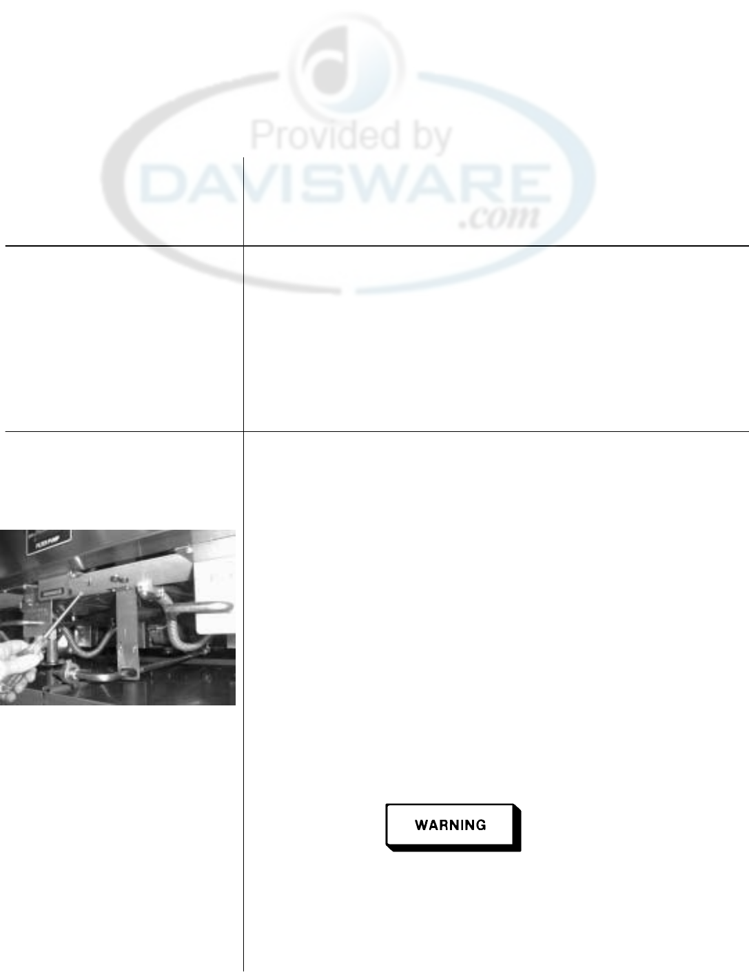
Henny Penny Model OFE/OFG-321,322,323,324
SECTION 6. MAINTENANCE
6-1. INTRODUCTION This section provides procedures for the check out and replacement
of the various parts used within the fryer. Before replacing any
parts, refer to the Troubleshooting section. It will aid you in
determining the cause of the malfunction.
6-2. MAINTENANCE HINTS 1. You may need to use a multimeter to check the electric
components.
2. When the manual refers to the circuit being closed, the
multimeter should read zero unless otherwise noted.
3. When the manual refers to the circuit being open, the
multimeter will read infinity.
6-3 HIGH TEMPERATURE
LIMIT CONTROL This high temperature control is a safety, manual reset control,
(Gas Units) which senses the temperature of the shortening. If the short-
ening temperature exceeds 425°F (218°C), this switch will open
and shut off heat to the cookpot. When the temperature of the
shortening drops to a safe operation limit, the control must be
manually reset by pressing the red reset button. The red reset
button is located under the control panel, in the front of the fryer.
This will allow heat to be supplied to the cookpot once again.
Checkout Before replacing a high temperature limit control, check to see
that its circuit is closed.
NOTE
The shortening temperature must be below 380°F
(193°C) to accurately perform this check.
1. Remove electrical power supplied to fryer.
Remove electrical power supplied to the fryer by
unplugging the unit, or by turning off the wall circuit
breaker or electrical shock could result.
2. Remove the control panel.
6-1 899
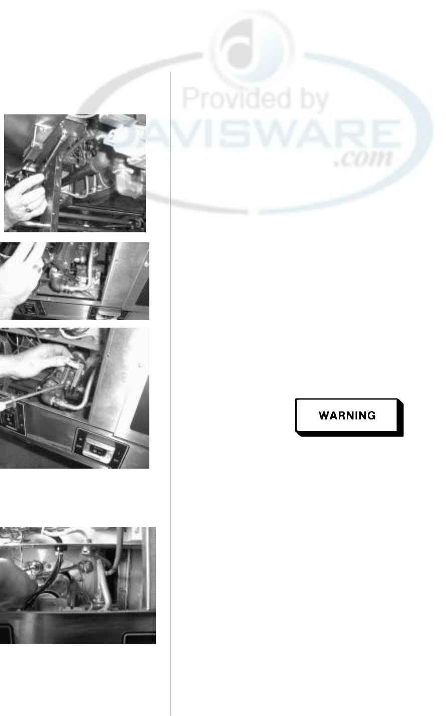
Henny Penny Model OFE/OFG-321,322,323,324
6-3 HIGH TEMPERATURE
LIMIT CONTROL
(Continued)
3. Remove the two nuts securing the high limit bracket to the unit
and pull the bracket from the unit.
4. Remove the two screws securing the high limit to the bracket,
and remove the high limit from the bracket.
5. Remove the two electrical wires from the high temperature
limit control.
6. Manually reset the control, then check for continuity between
the two terminals after resetting the control. If the circuit is
open, replace the control, then continue with this procedure.
(If the circuit is closed, the high limit is not defective. Re-
connect the two electrical wires.)
Remove electrical power supplied to the fryer by
unplugging the unit, or by turning off the wall circuit
breaker or electrical shock could result.
1. If the tube is broken or cracked, the control will open , shutting
off electrical power to the heat circuit. The control cannot be
reset,
and it will continuously click when pushed.
2. Drain the shortening from the cookpot and discard. A substance
in
the tube could contaminate the shortening.
3. Remove the control panel.
4. Loosen small inside screw nut on capillary tube.
899 6-2
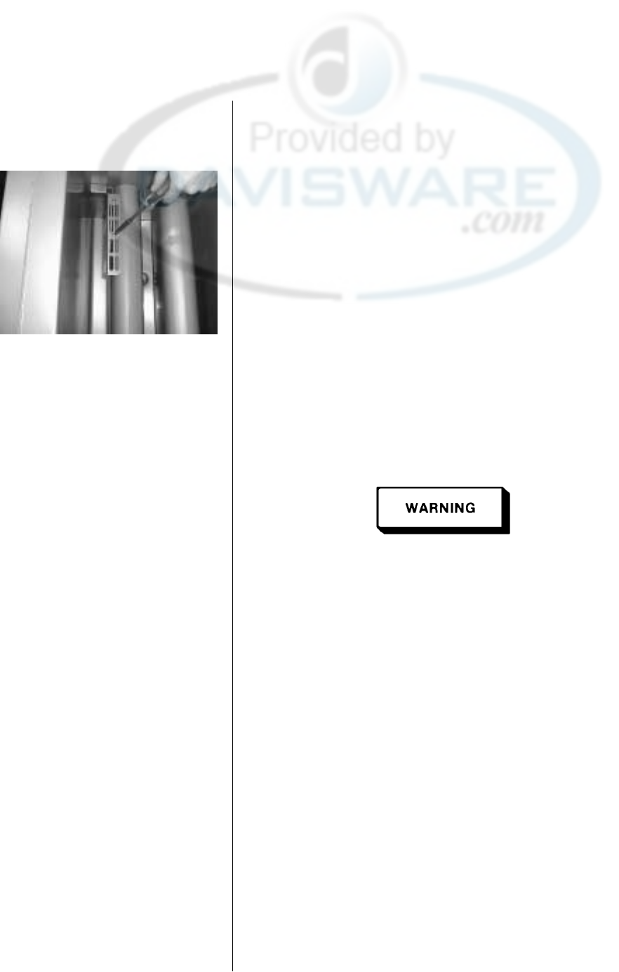
Henny Penny Model OFE/OFG-321,322,323,324
6-3 HIGH TEMPERATURE
LIMIT CONTROL
(Continued)
5. Remove the bracket from the heat tube covering the high limit
bulb.
6. Straighten the capillary tube behind the pot wall.
7. Pull the high limit bulb through the retainers on the heat tube.
8. Remove the larger outside nut that threads into the pot wall.
9. Remove the defective high limit from the control panel area.
10. Insert new high limit into bracket and replace wires.
11. Uncoil capillary line, starting at capillary tube, and insert
through cookpot wall.
To avoid electrical shock or other injury, the capillary line
must run under and away from all electrical power wires
and terminals. The tube must NEVER be in such position
where it could accidentally touch the electrical power
terminals.
12. Insert capillary line through brackets on heat tube, and then
pull back through pot wall until capillary bulb is secure in
brackets.
13. Pull excess capillary line from pot and tighten nut into
cookpot
wall.
14. With excess capillary line pulled out, tighten smaller nut.
15. Replace bracket on heat tube covering the high limit bulb.
16. Replace front panel.
17. Refill cookpot with shortening.
6-3 899
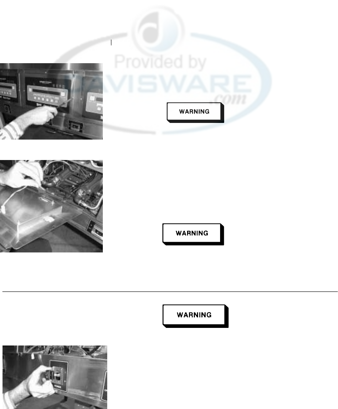
Henny Penny Model OFE/OFG-321,322,323,324
6-4. COMPLETE CONTROL
PANEL REPLACEMENT Should the control board become inoperative, follow these
instructions for replacing the board.
1. Remove electrical power supplied to the unit.
Place the power switch in the “OFF” position, and unplug
the power cord and/or turn the wall circuit breaker off or
electrical shock could result.
2. Remove the four screw securing the control panel and lift
out.
3. Unplug the wire connectors going to the control board.
4. Install new control panel in reverse order.
When plugging connectors onto new control panel, be sure
the
connectors are inserted onto all of the pins. Also, be sure
the connectors are not forced onto the pins backwards, or
damage to the board could result.
6-5. POWER SWITCH 1. Remove electrical power supplied to fryer.
Place the power switch in the off position, and remove
power to the fryer by unplugging the unit or turning off the
wall circuit breaker. Failure to do so could result in
electrical shock.
2. Remove control panel.
3. Label and remove the wires from the switch. With test
instrument check across the terminals of the switch with the
switch in the on position, then in the off position. With the
switch in the on position, the circuit should be closed. With
the switch in the off position, the circuit should be open. If
the switch checks defective, replace by continuing with this
procedure.
899 6-4
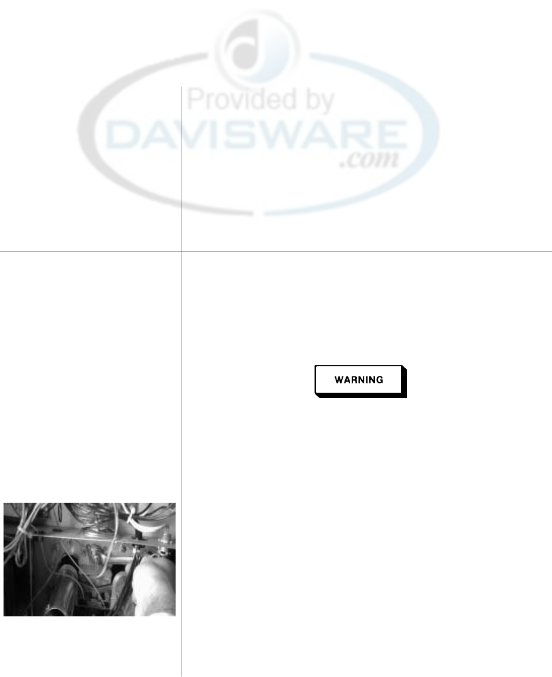
Henny Penny Model OFE/OFG-321,322,323,324
6-5. POWER SWITCH
(Continued) 4. With control panel removed, and the wires off the switch, push
in on tabs on the switch to remove from panel.
5. Replace with new switch, and reconnect wires to switch.
6. Replace the control panel.
6-6. TEMPERATURE PROBE
REPLACEMENT The Temperature Probe relays the actual shortening temperature to
the control board. If it becomes disabled, “E06” will show in the
display. Also, if the shortening temperature is out of calibration
more than 10°F or C°, the probe should be replaced as follows:
1. Remove electrical power supplied to the fryer.
Place the Power switch in the “OFF” position, and unplug the
power cord or turn the wall circuit breaker off or electrical
shock could result.
2. Drain the shortening from the cookpot.
3. Remove the control panel.
4. Using a ½ inch wrench, remove the nut on the compression
fitting.
5. Remove the probe from the cookpot, and disconnect wire
connector from the control panel.
6. Place the nut and new ferrule on the probe on the new probe
and insert the probe into the compression fitting until it extends
one (1) inch (2.54cm) into the cookpot.
7. Tighten hand tight and then a half turn with wrench.
6-5 899
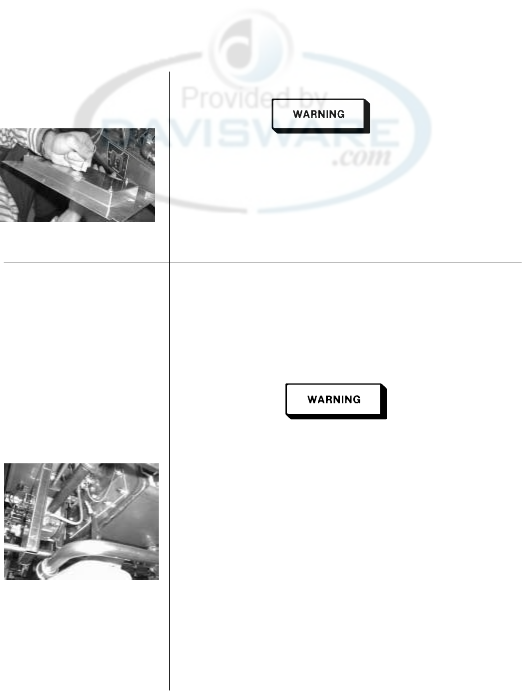
Henny Penny Model OFE/OFG-321,322,323,324
6-6. TEMPERATURE PROBE
REPLACEMENT
(Continued)
Excess force will damage probe.
8. Connect new probe to PC board and replace Control Panel.
9. Replace shortening.
10. Turn power “ON” and check out fryer.
6-7. FLAME SENSOR The flame sensor recognizes the pilot flame and allows gas to
(Gas Units) continue to the pilot. The flame sensor must send a minimum of
two (2) micro amps to the ignition module. The pilot flame should
be split in two by the flame sensor, causing the flame sensor to be
bright red in color.
1. Remove electrical power supplied to the unit.
Remove electrical power supplied to the unit by unplugging
the power cord, or by turning off the wall circuit breaker or
electrical shock could result.
2. To access flame sensor, open the filter doors in the front of the
unit. Follow the small gauge yellow wire running to the sensor
behind the pilot assembly.
3. Disconnect the flame sense wire from the flame sensor.
4. Using a pair of needle nosed pliers, pull the flame sensor out
of the pilot assembly bracket.
5. Insert new flame sensor and reconnect flame sensor wire.
6. Turn power “ON” and check fryer.
899 6-6
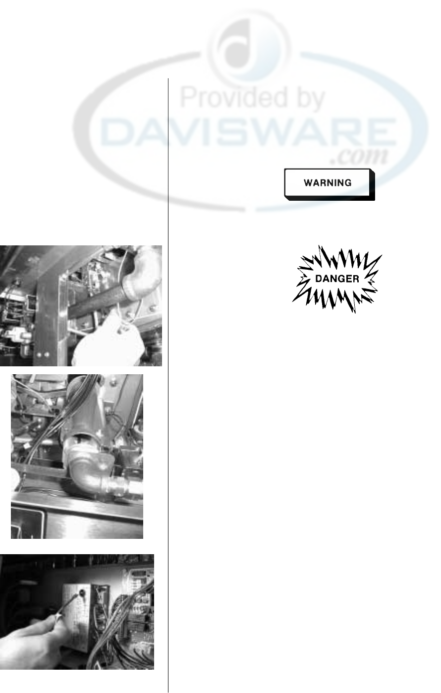
Henny Penny Model OFE/OFG-321,322,323,324
6-8. PILOT / IGNITOR
ASSEMBLY The Henny Penny Open Fryer (Gas) has electronic spark ignition
that lights a standing pilot. The gap between the spark electrode
and the pilot hood should be set at 1/8 of an inch.
1. Remove electrical power supplied to the unit.
Remove electrical power supplied to the unit by unplugging
the unit , or by turning off the wall circuit breaker, or electrical
shock could result.
To avoid injury or property damage, before starting this
procedure, move the power switch to the “OFF” position.
Disconnect the main circuit breaker at the circuit breaker
box, or unplug the power cord at the receptacle. Turn off
the main gas supply to the fryer and disconnect, and cap, the
the supply line to the fryer, or possible explosion could result.
2. Remove the control panel as discussed in section 6-4.
3. Disconnect the pilot gas line fitting at the pilot assembly with
a ½ inch wrench.
4. With a phillips screwdriver, remove the two screws securing
the pilot assembly to the mounting bracket.
5. Remove the flame sensor wire from the flame sensor.
6. Follow the wire from the spark ignitor back to the module, and
remove wire from module.
7. After removing assembly from unit, pull the flame sensor out
of the bracket as discussed in section 6-7. Insert flame sensor
into new pilot/ignitor assembly.
8. Reinstall the new pilot/ignitor assembly in reverse order. Be
extremely careful not to cross thread the pilot gas line fitting.
6-7 899
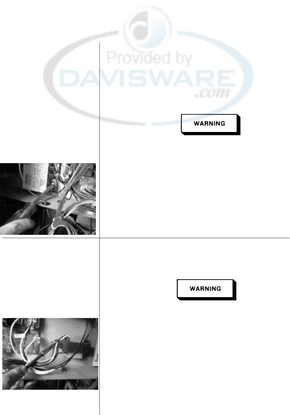
Henny Penny Model OFE/OFG-321,322,323,324
6-9. IGNITION MODULE During normal operation, the ignition modules send 24 volts to the
ignitors and gas valve. If a module does not sense a pilot flame, the
module starts the ignition process again. But, if a pilot light goes out
for longer that 10 seconds, or it goes out 3 times within 10 seconds,
the module keeps the 24 volts from reaching the gas valve. The
burners shut down.
1. Remove electrical power supplied to the unit.
Remove electrical power supplied to the unit by unplugging
the unit or by turning off the wall circuit breaker or electrical
shock could result.
2. Remove the control panel as discussed in section 6-4.
3. Label and remove the wires at module.
4. Using a 3/8 inch nut driver, remove the keps nuts securing the
module to the shroud.
5. Install new module in reverse order.
6-10. TRANSFORMER The transformer reduces voltage down (120V to 24V ) to
accommodate those components with low voltage.
1. Remove electrical power supplied to the unit.
Remove electrical power supplied to the unit by unplugging
the unit, or by turning off the wall circuit breaker, or electrical
shock could result.
2. Remove the control panel as discussed in section 6-4.
3. Squeeze on the wire connector at the I/O Board assembly to
disconnect the wires from the transformer.
4. Using a phillips screwdriver, remove the two screws securing the
transformer to the shroud.
5. Install the new transformer in reverse order.
600 6-8
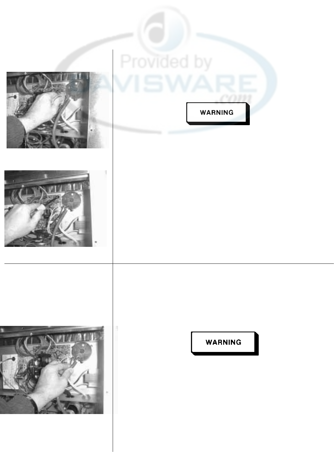
Henny Penny Model OFE/OFG-321,322,323,324
6-11. I/O POWER SUPPLY
BOARD ASSEMBLY The Input/Output Power Supply Board Assembly distributes
voltage to the various components in the fryer. The board also
receives information from components in the fryer.
1. Remove electrical power supplied to the unit.
Remove electrical power supplied to the fryer by unplugging
the unit, or by turning off the wall circuit breaker, or electrical
shock could result.
2. Remove the control panel as discussed in section 6-4.
3. Disconnect the wire assemblies from the board.
4. Using a nut driver or wrench, remove the four keps nuts
securing the board to the shroud.
5. Install the new I/O Board Assembly in reverse order.
6-12. AIRFLOW SWITCH The airflow switch senses the airflow from the induction blower. If
the airflow is reduced below a set amount, the switch will open and
the I/O board will cut power to the gas control valve, which will
shut the pilot flame off.
1. Remove electrical power supplied to the unit.
Remove electrical power supplied to the unit by unplugging the
unit, or by turning off the wall circuit breaker, or electrical
shock could result.
2. Remove the control panel as discussed in section 6-4.
3. Remove the air hose from the air switch.
4. Label and remove wires from air switch.
6-9 899
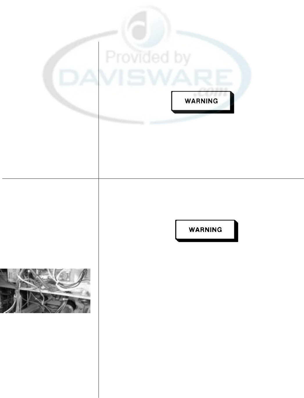
Henny Penny Model OFE/OFG-321,322,323,324
6-12. AIRFLOW SWITCH
(Continued) 5. Using a phillips screwdriver, remove the screws securing the
air switch to the shroud.
6. Install the new air switch in reverse order.
Do not tamper with, or disassemble this component. It is set
and sealed from the factory and is not to be adjusted.
6-13. SPEAKER ASSEMBLY The speaker assembly emits audible signals to let the operator
(Gas Units) know when cooking and hold times are finished.
1. Remove electrical power supplied to the unit.
Remove electrical power supplied to the unit by unplugging the
unit, or by turning off the wall circuit breaker, or electrical
shock could result.
2. Remove the control panel as discussed in section 6-4.
3. Using a phillips screwdriver, remove the four screws securing
the speaker to the shroud.
4. Install new speaker in reverse order. When plugging connector
into control board, be sure to align pins into connector
correctly.
899 6-10
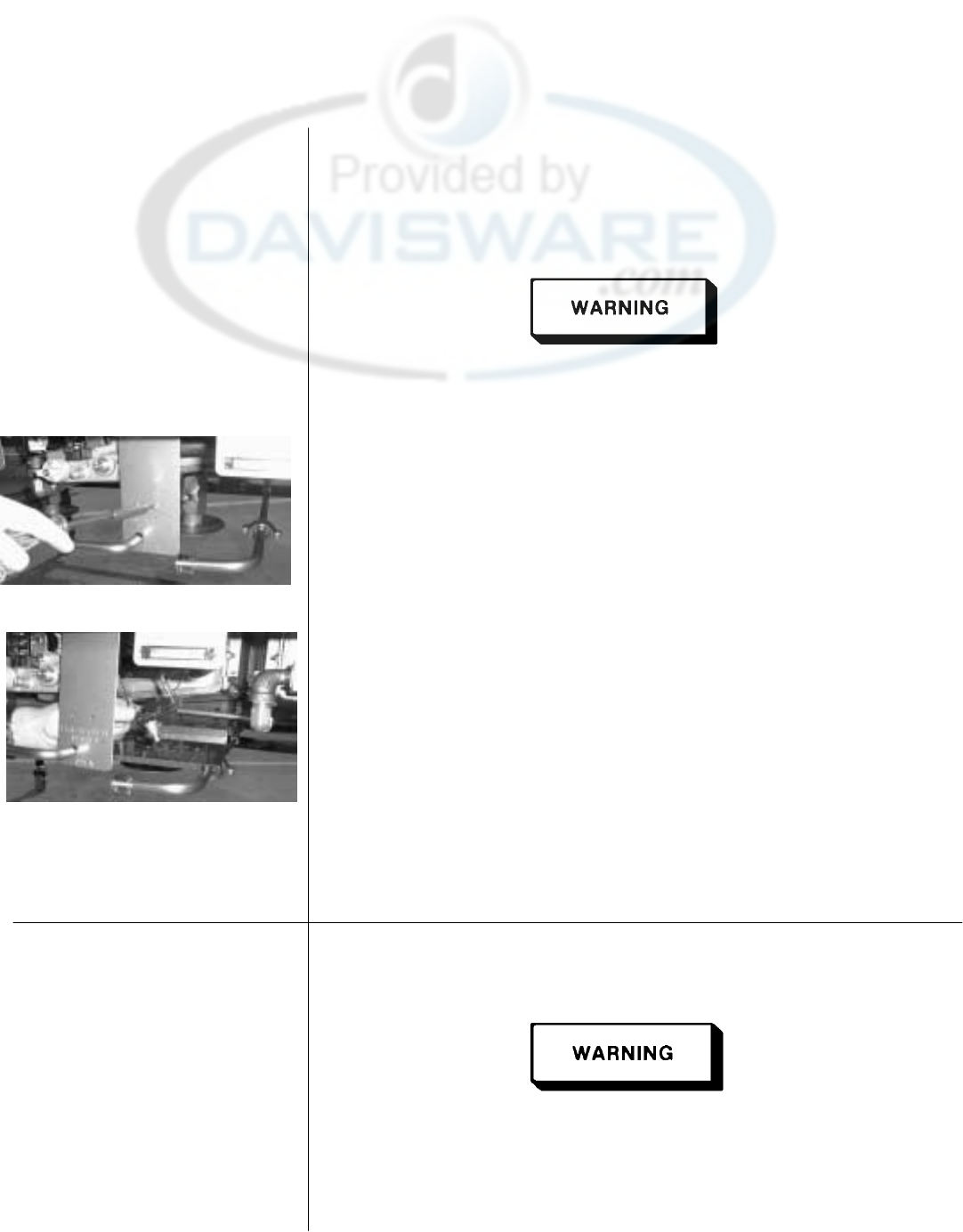
Henny Penny Model OFE/OFG-321,322,323,324
6-14. DRAIN MICROSWITCH Upon turning the drain handle, the drain microswitch should
“open”, cutting off the pilot flame. This will prevent the fryer
from heating while shortening is being drained from the cookpot.
1. Remove electrical power supplied to the unit.
Remove electrical power supplied to the unit by unplugging the
unit, or by turning off the wall circuit breaker, or electrical
shock could result.
2. The following check should be made to determine if the drain
microswitch is defective.
a. Remove the two screws securing the microswitch to the
drain rod valve bracket.
b. Remove wires from the switch.
c. Check for continuity across the two outside terminals of the
drain switch. If the circuit is open, the drain switch is
defective. The circuit should only be opened by pressing on
the actuator of the drain switch.
3. Replace switch in reverse order.
6-15. FILTER SWITCH
1. Remove electrical power supplied to the unit.
Remove electrical power supplied to the unit by unplugging the
unit, or by turning off the wall circuit breaker, or electrical
shock could result.
6-11 899
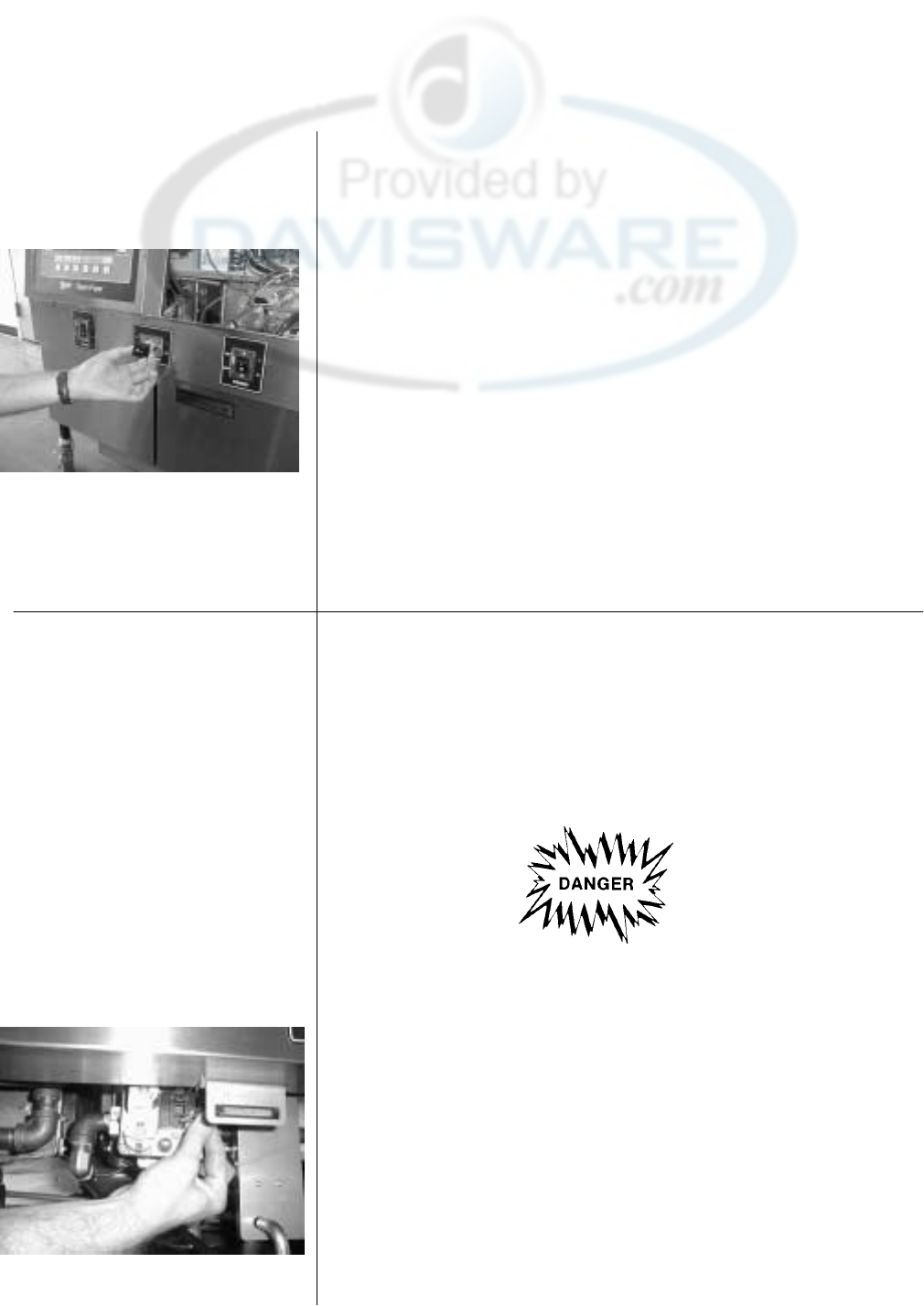
Henny Penny Model OFE/OFG-321,322,323,324
6-15. FILTER SWITCH
(Continued) 2. According to the amount of wells in the unit, remove the control
panel above the switch.
3. Label and remove the wires from the switch. With test
instrument check across the terminals of the switch with the
switch in the on position and then in the off position. With the
switch in the on position, the circuit should be closed. With the
switch in the off position, the circuit should be open. If the
switch checks defective, replace by continuing with this
procedure.
4. With wires removed from the switch, push in on tabs on the
switch and remove switch from the panel.
5. Push new switch into panel and reconnect wires.
6-16. GAS VALVE
ASSEMBLY The gas valve assembly controls the flow of gas to the pilot and the
main burner. The valve has two 24 volt coils, which are regulated
by the P and M terminals on the valve. The C terminal is the
common terminal. For gas flow to the pilot, 24 VAC must be
present between the P and C terminals. For gas flow to the main
burner, 24 VAC must be present between the M and C terminals.
To avoid injury or property damage, before starting this
procedure, move the POWER/PUMP switch to the “OFF”
position. Disconnect the main circuit breaker at the circuit
breaker box, or unplug the service cord at the receptacle.
Turn off the main gas supply to the fryer and disconnect and
cap the supply line to the fryer, or possible explosion could
result.
1. Remove control panel assembly.
2. Remove wires from gas valve.
899 6-12
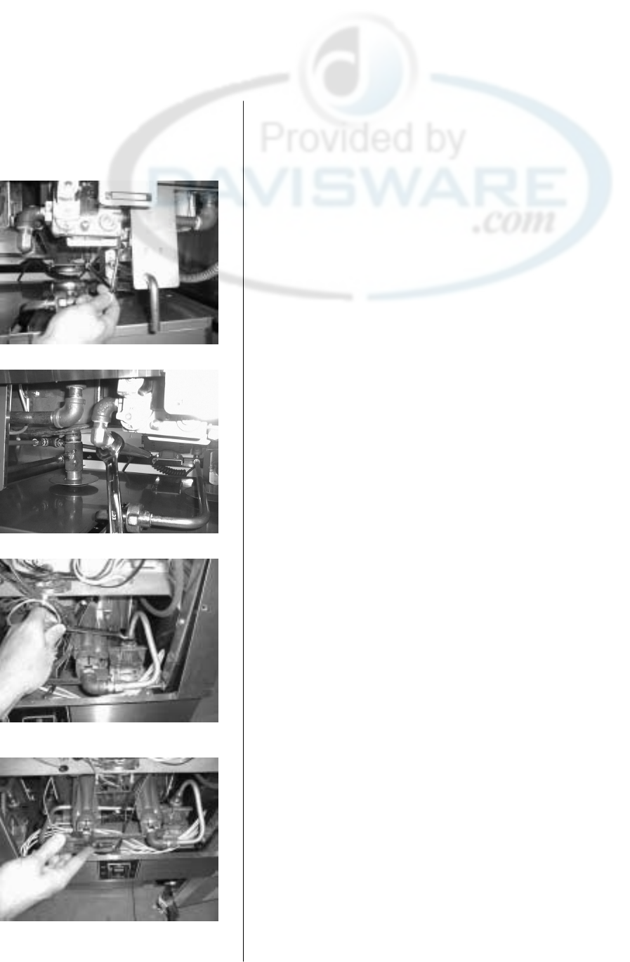
Henny Penny Model OFE/OFG-321,322,323,324
6-16. GAS VALVE
ASSEMBLY
(Continued)
3. Using a 7/16 wrench, remove the pilot line from the gas valve.
4. Using a 1 inch wrench, loosen the nut securing the main gas
inlet line to the gas valve.
5. Using 5/8 wrench, remove the two burner gas line fittings
at the black “T” located behind the control panel area.
6. Using a phillips screwdriver, remove the three screws securing
the gas valve bracket to the frame of the fryer behind the
control panel area.
6-13 899
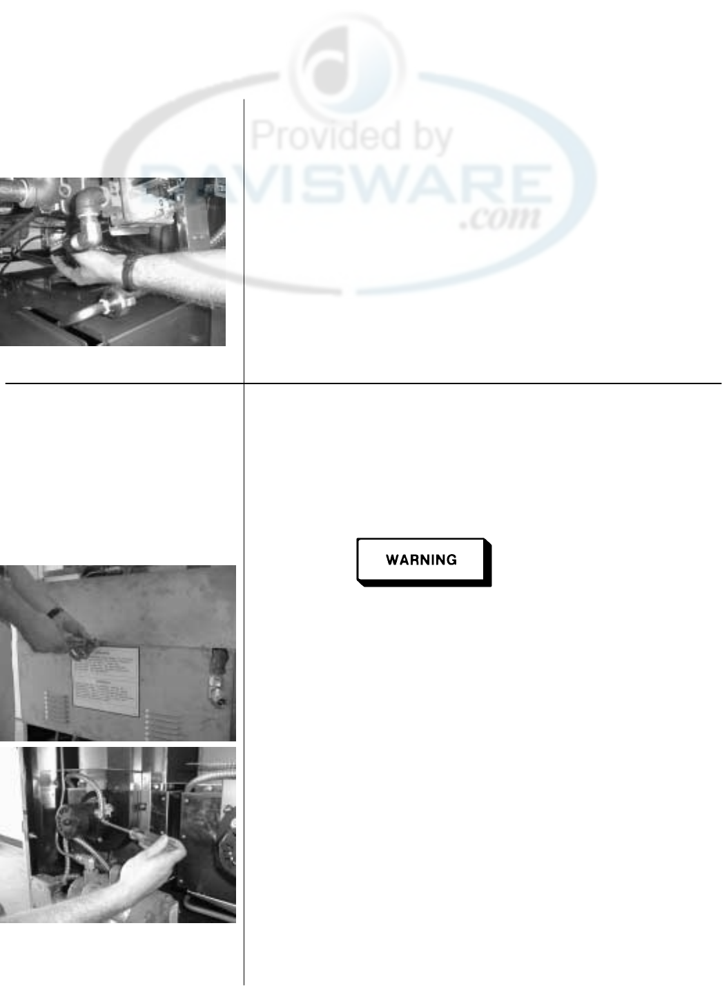
Henny Penny Model OFE/OFG-321,322,323,324
6-16. GAS VALVE
ASSEMBLY
(Continued)
7. With the bracket dropped down, remove the two screws behind
the bracket securing the gas valve to the bracket.
8. Install the new gas valve in reverse order.
6-17. BLOWER MOTOR
ASSEMBLY The blower motor assembly induces the draft for the burners. If the
blower motor fails, the air switch will fail to close, causing an
“E-20B” error code in the display.
1. Remove electrical power supplied to the unit.
Remove electrical power supplied to the unit by unplugging
the unit, or by turning off the wall circuit breaker, or electrical
shock could result.
2. Remove screws securing the two rear covers to the unit.
3. Remove the wire cover from the blower motor housing.
899 6-14
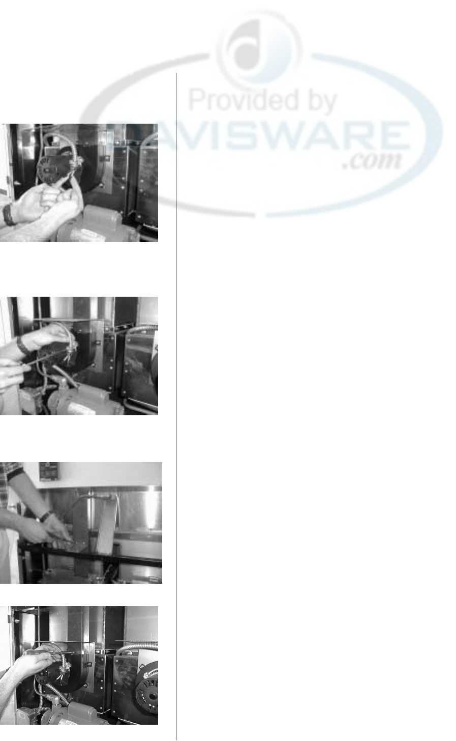
Henny Penny Model OFE/OFG-321,322,323,324
6-17. BLOWER MOTOR
ASSEMBLY
(Continued)
4. Remove wire nuts connecting blower motor wires to wires in
conduit.
5. Loosen conduit from blower motor.
6. Remove screws connecting flue to bracket in upper frame.
7. Remove screws connecting flue to blower.
6-15 899
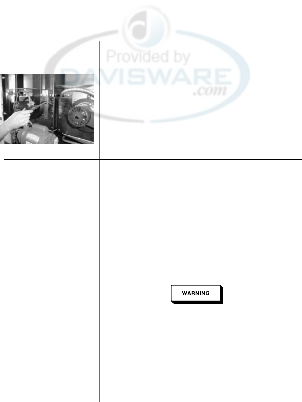
Henny Penny Model OFE/OFG-321,322,323,324
6-17. BLOWER MOTOR
ASSEMBLY
(Continued)
8. Using 3/8 inch nut driver, remove nuts securing blower to the
unit. Pull blower from unit.
9. Install new blower in reverse order.
6-18. HEATING ELEMENTS
(ELECTRIC ONLY)
NOTE
Heating elements are available for 208 and 230 voltage. Check
data plate to determine correct voltage.
Checkout If the shortenings temperature recovery is very slow or at a slower
rate than required, this may indicate defective heating element(s).
An ohmmeter will quickly indicate if the elements are shorted or
open.
1. Remove electrical power supplied to the cookpot to be worked
on.
Place power switch to the OFF position and unplug the power
cord or open the wall circuit breaker, for the cookpot to be worked
on. Be aware the other controls will have power, or electrical shock
could result.
2. Remove control panel per section 6-4.
899 6-16

Henny Penny Model OFE/OFG-321,322,323,324
6-18. HEATING ELEMENTS
(ELECTRIC ONLY)
Continued 3. Perform an ohm check on one element at a time, with wires
disconnected from element. If the resistance is not within
tolerance, replace the element.
Voltage Wattage Resistance Ohms (cold)
208 4800 9
230 4800 11
Replacement NOTE
Refer to figure 6-2
1. Drain the shortening from the cookpot.
2. Remove the High Limit bulb holder from the heating element
inside the cookpot.
3. Remove the heating element wires from the terminals by
removing the nuts and washers. Label each so it can be
replaced on the new element in the same position.
4. Remove the bolts from the five element spreaders. The
element spreaders will now pull off the elements.
5. Remove the brass nuts and washers which secure the ends of
the elements through the frypot wall.
6. Remove the heating elements from the frypot as a group by
lifting the far end and sliding them up and out toward the
rear of the cookpot.
NOTE
Always install new rubber O rings when installing heater
elements.
7. Install new heating elements with the new O rings, terminal
end first at approximately a 45°angle, slipping the terminals
through the front wall of the cookpot.
8. Replace the brass nuts and washers on the element terminals.
Tighten the brass nuts to 30 foot lbs. of torque.
6-17 899
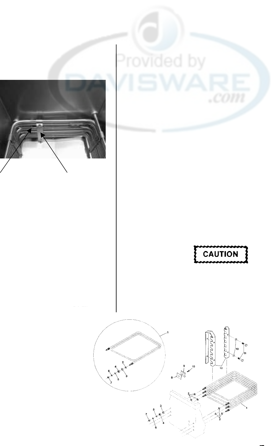
Henny Penny Model OFE/OFG-321,322,323,324
6-18. HEATING ELEMENTS
(ELECTRIC ONLY)
Continued 9. Evenly space the element spreaders on the sides of the
elements and reinstall bolts. Place the fifth spreader in the
front of the elements as to protect the probe. (Fig. 6-1)
10. Replace the high limit bulb holder on the top element, and
position the bulb between the top and second element
midway from side to side, and tighten screw that holds the
bulb in place.
11. Reconnect the wires to the appropriate terminal as labeled
when they were removed.
Probe Spreader
Fig. 6-1 12. Replace the front control panel.
13. Connect the power cord to the wall receptacle or close wall
circuit breaker.
Heating elements should never be energized without
shortening in the frypot, or damage to the elements could
result.
14. Replace the shortening in the frypot.
899 Fig. 6-2 6-18
Henny Penny Model OFE/OFG-321,322,323,324
6-19. HEATING
CONTACTORS
(ELECTRIC ONLY)
Each well of an electric fryer requires two switching contactors.
the first in line is the primary contactor and the second in line is
the heat contactor. When open, the primary contactor does not
allow power to flow to the heat contactor. When closed, the
primary supplies voltage to the heat contactor. When the heat
contactor is open, no voltage is supplied to the heating elements.
When the heat contactor closes, voltage is supplied to the heating
elements.
Checkout (Power Removed) 1. Remove electrical power supplied to the cookpot to be worked
on.
Place POWER switch to the OFF position, and unplug the
power cord or open the wall circuit breaker, or electrical shock
could result. Be aware that the other controls will still have
power.
2. Remove the control panel per section 6-4.
30 31 32 3. Perform a check on the contactor as follows:
Test Points Results
From30to34 opencircuit
From31to35 opencircuit
From32to36 opencircuit
From 33 to 37 ohm reading 1700
NOTE
Wires should be removed and labeled to obtain an accurate check
of contactors.
34 35 36
Mercury Contactor
6-19 899
33
37
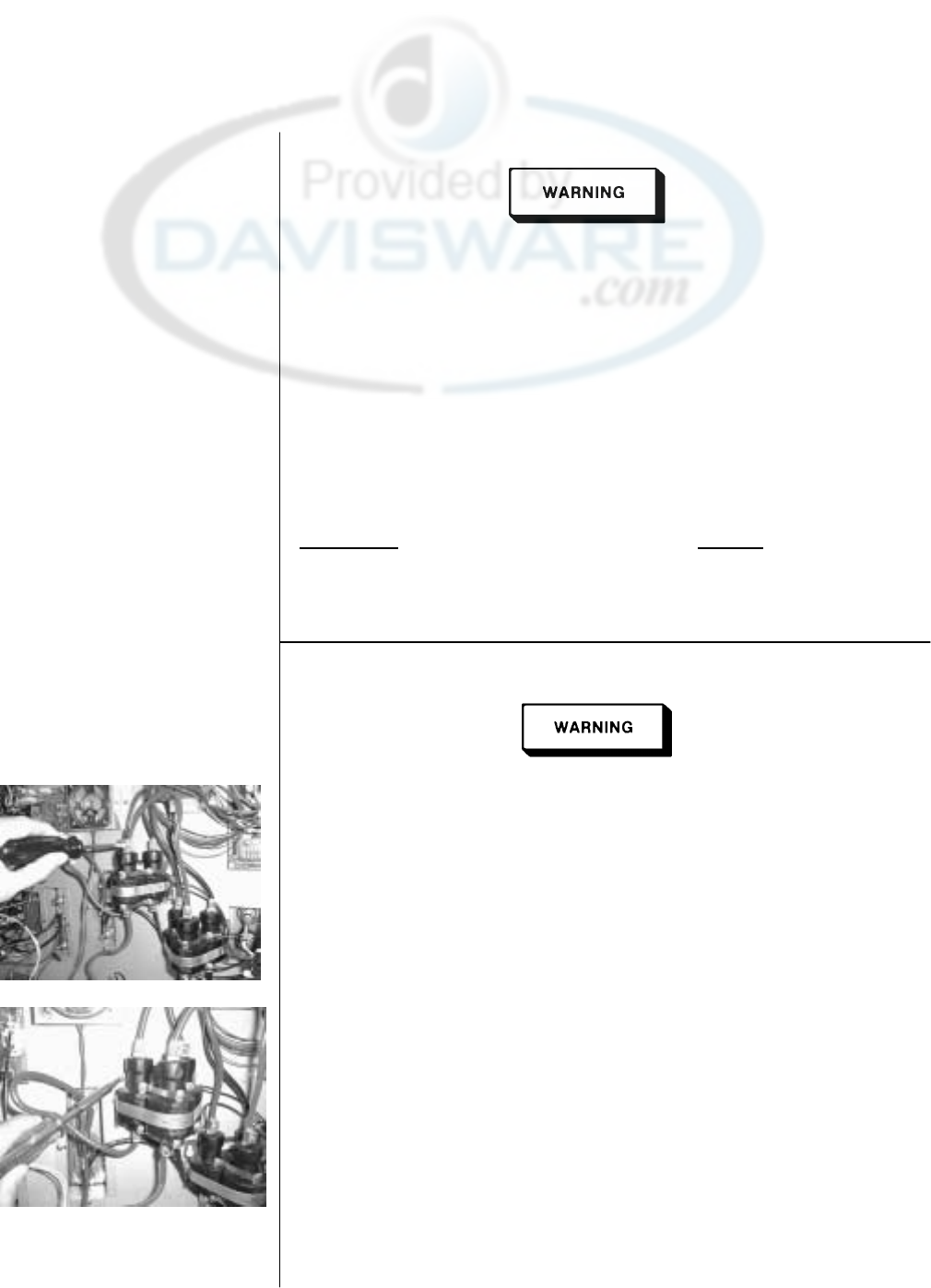
Henny Penny Model OFE/OFG-321,322,323,324
6-19. HEATING
CONTACTORS
(ELECTRIC ONLY)
(Continued)
The following checks are preformed with the wall circuit breaker
Checkout (power supplied) closed and the POWER switch in the ON position. Extreme
caution should be taken. Make connections before applying power,
take reading, and remove power before removing meter leads, or
electrical shock could result.
1. Re-apply power to unit and turn POWER switch “ON”.
2. Using illustrations from previous page, check voltage as
follows:
Test Points Results
From terminal 34 to 35 The voltage should read
From terminal 35 to 36 the same at each terminal
From terminal 34 to 36
Replacement If either contactor is defective it must be replaced as follows:
Remove electrical power supplied to the cookpot to be
worked on, by unplugging the power cord from the
receptacle or opening the wall circuit breaker, or electrical
shock could result. Be aware the other controls will have
power.
1. Remove only the wires directly connected to the contactor being
replaced. Label the wires for replacement.
2. Loosen the screws securing the contactor bracket to the shroud.
3. Remove the contactor from the bracket.
4. Reinstall in reverse order.
899 6-20
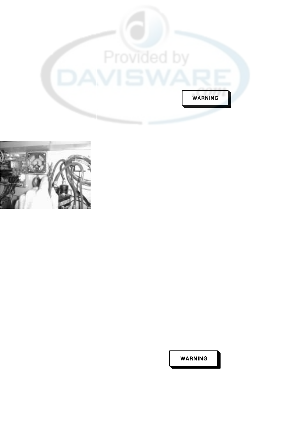
Henny Penny Model OFE/OFG-321,322,323,324
6-20. SPEAKER ASSEMBLY
(Electric Units) The speaker assembly emits audible signals to let the operator
know when cooking and hold times are finished.
1. Remove electrical power supplied to unit.
Remove electrical power supplied to the unit by unplugging the
unit, or by turning off the wall circuit breaker, or electrical
shock could result.
2. Remove control panel per section 6-4.
3. Follow the speaker wire and disconnect from control board.
4. Remove the screws securing the speaker bracket to the shroud.
5. Remove the speaker from the bracket.
6. Reinstall in reverse order.
6-21. HIGH TEMPERATURE
LIMIT CONTROL
(Electric Units) The electric units, model OFE-321/2/3/4, use the same high
temperature control limits as the gas units, OFG-321/2/3/4, but
the mounting of the capillary tube is different on the electric
units compared to the gas units.
Checkout Use the same procedure as in section 6-3.
Replacement
Before following these steps, place the POWER switch in the
OFF position, and unplug the power cord or open the wall
circuit breaker, or electrical shock could result. Be aware the
other controls will have power.
6-21 899
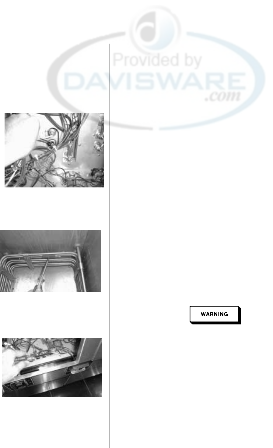
Henny Penny Model OFE/OFG-321,322,323,324
6-21. HIGH TEMPERATURE 1. Drain the shortening from the cookpot.
LIMIT CONTROL
(Electric Units)
(Continued) 2. Remove control panel per section 6-4.
3. Loosen small inside screw nut on capillary tube.
4. Remove capillary bulb from bulb holder inside the frypot.
5. Straighten the capillary tube.
6. Remove larger outside nut that threads into pot wall.
7. Remove the two screws that secure the high limit to the high
limit bracket.
8. Remove the defective control from the control panel area.
9. Insert new control and replace screws.
10. Uncoil capillary tube, starting at control, and insert through pot
fitting.
To avoid electric shock or other injury, the capillary line must
run under and away all electrical power wires and terminals.
The tube must never be in a position where it could accidentally
touch the electrical power terminals.
11. Carefully bend the capillary bulb and tube toward bulb holder
on heating elements.
12. Slip capillary bulb into bulb holder on heating elements.
Pull excess capillary line from pot and tighten nut into frypot
wall.
899 6-22

Henny Penny Model OFE/OFG-321,322,323,324
6-21. HIGH TEMPERATURE
LIMIT CONTROL
(Electric Units)
(Continued)
Be sure capillary bulb of high limit is located behind front edge
of heating elements. Capillary bulb and bulb holders should be
positioned as not to interfere with basket or when cleaning the
frypot wall, or damage to the capillary bulb could result.
13. With excess capillary line pulled out, tighten smaller nut hand
tight,then¼turnwithwrench.
14. Replace front panel.
15. Refill with shortening.
6-23 500

Henny Penny Model OFE/OFG-321,322,323,324
SECTION 7. PARTS INFORMATION
7-1. INTRODUCTION This section list the replaceable parts of the Henny Penny
OFE/OFG- 32x Open Fryers.
7-2. GENUINE PARTS Use only genuine Henny Penny parts in your fryer. Using a part of
lesser quality or substitute design may result in damage to the unit
or personal injury.
7-3. WHEN ORDERING
PARTS Once the parts that you want to order have been found in the parts
List, write down the following information:
Item Number 8
Part Number 31561 Example:
Description On/Off Switch
From the data plate, list the following information:
Product Number 01400
Serial Number 0001 Example:
Voltage 208
7-4. PRICESYourdistributorhasapricepartslistandwillbegladtoinform
you of the cost of your parts order.
7-5. DELIVERYCommonlyreplaceditemsarestockedbyyourdistributorandwill
be sent to you when your order is received. Other parts will be
ordered, by your distributor, from Henny Penny Corporation.
Normally, these will be sent to your distributor within three
working days.
7-6. WARRANTYAllreplacementparts(exceptlampsandfuses)arewarrantedfor
90 days against manufacturing defects and workmanship. If
damage occurs during shipping, notify the carrier at once so that
a claim may be properly filed. Refer to warranty in the front of this
manual for other rights and limitations.
999 7-1
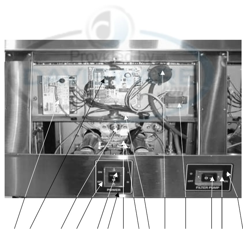
Henny Penny Model OFE/OFG-321,322,323,324
12 311 4135 67 8 9 1011 12
Item No. Part No. Description Qty. per Well
1 54924 Ignition Module – CE only 1
1 21347 Ignition Module 1
2 60430RB I/O Board Assy 1
3 55168 Probe Assy 1
4 43768 Power Switch Assy 1
4 52224 Covered Power Switch – CE 1
5 60266 Tee Style Pilot Assy (Gas Only) 1
6 60292 Pilot Flame sensor (Gas Only) 1
7 60206 Speaker Assy 1
8 60783 Vacuum Switch (Gas Only) 1
9 60207 120v to 24v Transformer (Gas Only) 1
10 43768 Filter Switch (One Per Unit) -
11 60844 Switch Guard – Power Switch 1
11 60844 Switch Guard – Filter Switch 1 (per unit)
12 60609 Decal – Filter Power Switch 1 (per unit)
13 60608 Decal – Main Power Switch 1
7-2 800
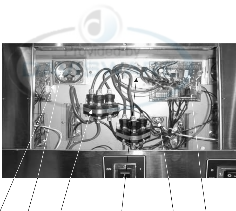
Henny Penny Model OFE/OFG-321,322,323,324
12 3 4 5 6
Item No. Part No. Description Qty. per Well
1 60781 Speaker Bracket Assy (Elec. Only) 1
2 60206 Speaker Assy 1
3 29510 24v Mercury Contactor (Elec. Only) 1
* 51795 24v Mechanical Contactor (Elec. Only) 1
4 60536 24v/230v Transformer Assy (Elec. Only) 1
5 55168 Probe Assy 1
6 60430RB I/O Board Assy 1
* 60838 Transformer 480V to 240V 1
* 60810 I/O to Control Cable – 3 Pin 1
* Not Shown
101 7-3
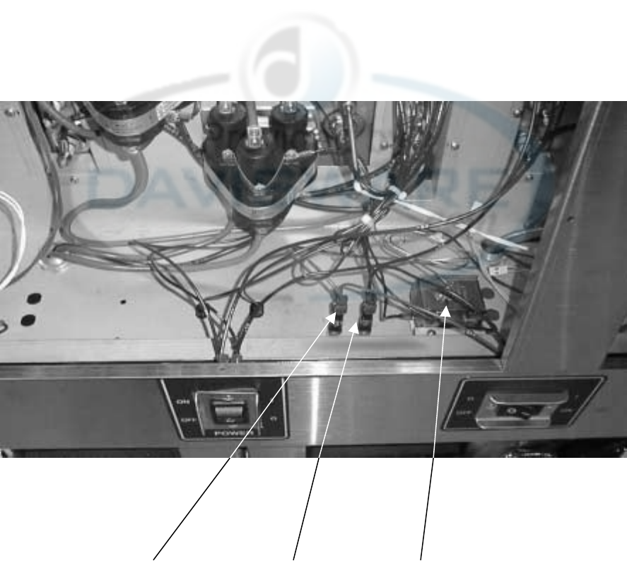
Henny Penny Model OFE/OFG-321,322,323,324
123
Item No. Part No. Description Qty. per Well
1 EF02-006 20A 250v Fuse Holder (Elec. Only) 2
1 EF02-104 20A 250v Fuse Holder (Elec. Only) - CE 2
2 EF02-007 15 Amp Fuse (Elec. Only) 2
2 EF02-105 15 Amp Fuse (Elec. Only) - CE 2
3 60241 425°High limit Assy 1
* 60838 Transformer – 480-240 Volt (480 Volt fryers) 1
* 60847 Transformer Mounting Bracket (480 Volt fryers) 1
* not shown
7-4 101
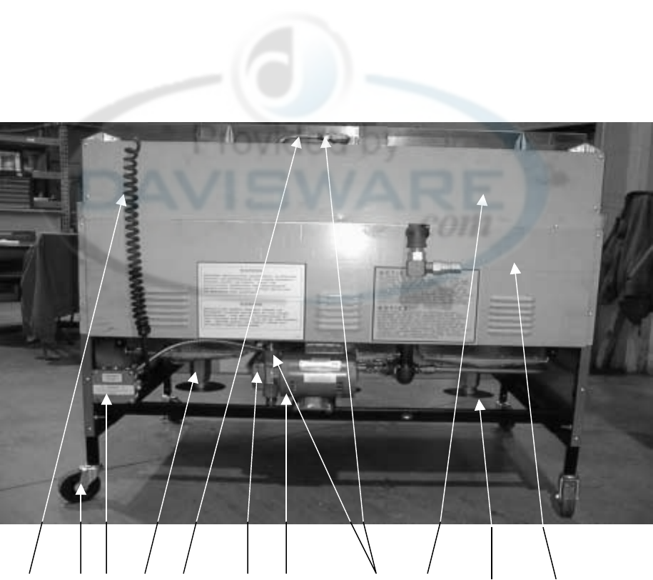
Henny Penny Model OFE/OFG-321,322,323,324
1 2 8 3 11 4 5 12 6 13 7
Item No. Part No. Description Qty. per Unit
1. 33353 120v Coiled Power Cord (Gas Only) 1
2. 60312 Caster 4in. w/o Brake 2
3. 55152 Drain Valve & Coupling Assy 1
4. 17437 Filter Pump 1
5. 46854 Filter Pump Motor, ½ hp. 1
6. 60368 Top Rear Cover (3 Well) 1
6. 60471 Top Rear Cover (2 Well) 1
7. 60369 Bottom Rear Cover (3 Well) 1
7. 60472 Bottom Rear Cover (2 Well) 1
8. ME50-021 Terminal Block – Gas 1
9* 18127 Terminal Block – Electric 12
10* 52078 Blower Motor Assy. (Gas Only) 1 per well
11. 60293 Tube-Oil Return Line 1
11. 60504 Tube-Oil Return Line–OFG-322 & 324 only 1
12. FP01-082 Connector – 3/8 tube to ½ NPT SS 2
13 60736 Drain Valve Extension – Electric 1 per well
13 60388 Drain Valve Extension – Gas 1 per well
* 60618 Gas Line-1/2” w/Double Swivel - 321 1
* 33501 Gas Line-3/4” w/Double Swivel – 322 1
* 33167 Gas Line-1” w/Double Swivel – 323 1
* Not Shown
101 7-5
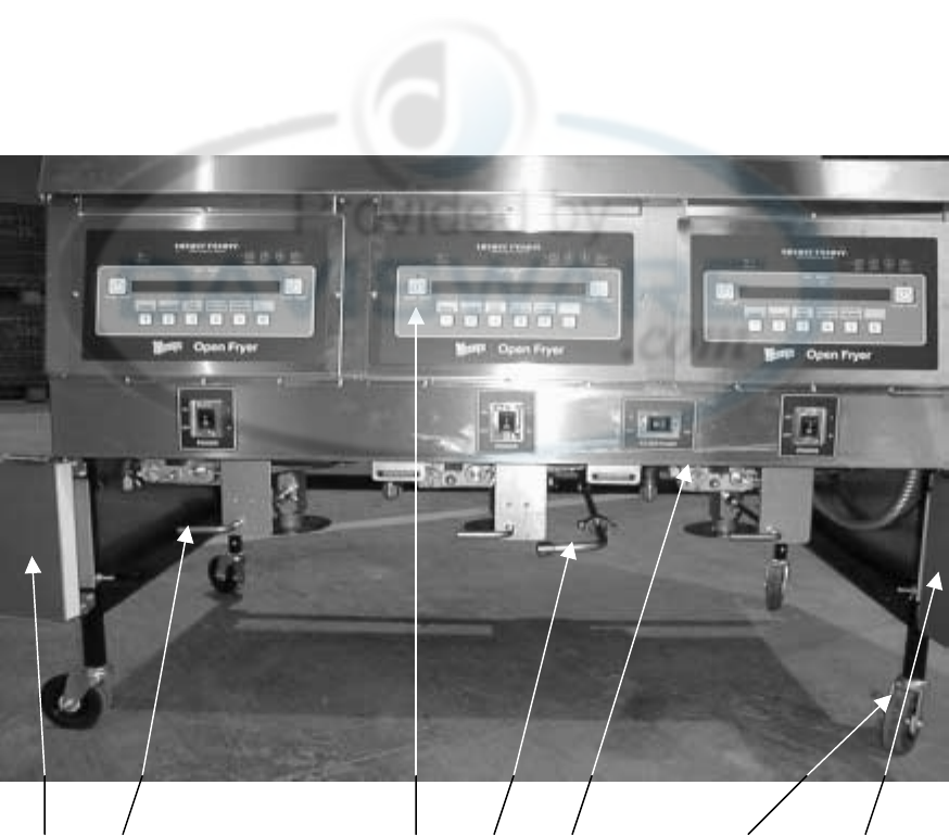
Henny Penny Model OFE/OFG-321,322,323,324
12 37 4 5 6
Item No. Part No. Description Qty. per Well
1. 60490 Left Door Assy (3 Well) 1
1. 60502 Left Door Assy (2 Well) 1
* 60542 Door Assy ( 1 Well ) 1
2. 18818 Drain Valve Extension Rod 1
3. 60603RB 6 Timer Control Board Assy 1
3. 60803BB 12 Timer Control Board Assy. 1
* 60682 Wendys Menu Card -
* 61724 CFA Menu Card -
* 59565 GM Menu Card -
* 59566 Blank Menu Card -
4. 52129 24v Natural Gas Valve 1
4 60632 24v Natural Gas Valve - CE 1
4. 60363 24v LP Gas Valve 1
4. 60633 24v LP Gas Valve – CE 1
5. 52064 4 Inch Swivel Caster W/ Brake 2
6. 60485 Right Door Assy (3 Well) 1
6. 60501 Right Door Assy (2 Well) 1
7. 60442 Filter to Pump Tube Assy. – Gas 323 & 322/324 1
* 14260 OFG Natural to LP Conv. Kit 1
* 14261 OFG LP to Natural Conv. Kit 1
* 18227 Drain Microswitch 1
* 60370 Drain Switch Cover 1
* 59224 Drain Switch Cover- CE 1
* Not Shown
7-6 101
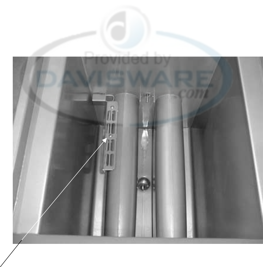
Henny Penny Model OFE/OFG-321,322,323,324
1
(Gas Models)
Item No. Part No. Description Qty. per Well
1. 60367 High Limit Guard 1
* 60120 OFG Fry Basket Support 1
* 33102 Half Size Fry Basket 2
* 59078 Third Size Fry Basket 3
* 33824 Full Size Fry Basket 1
* Not Shown
101 7-7
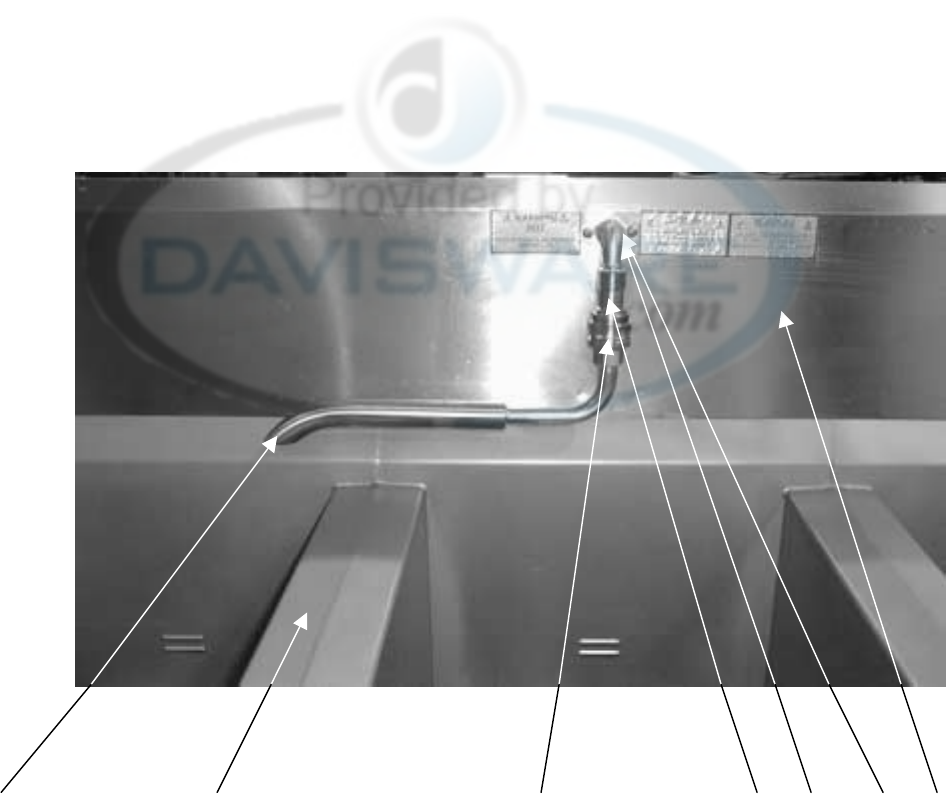
Henny Penny Model OFE/OFG-321,322,323,324
17 23456
Item No. Part No. Description Qty. per Unit
1. 45402 Return Faucet Only (without 17333) - 322, 323, & 324 1
1 60611 Return Faucet Assy. (with 17333)–321 & Auto-lift (1 per well) 1
2. 17333 Female Disconnect 1
3. 17334 Male Disconnect 1
4. FP01-087 Elbow, Male-3/8 in. 1
5* 50715 3/8 x 1 1/8 Nipple 1
6. 60441 Front Shroud Assy. (3 Well) 1
6. 60470 Front Shroud Assy. (2 Well) 1
7. 60686 Pot & Countertop Assy. – OFE-321 1
7. 60687 Pot & Countertop Assy. – OFE-322 1
7. 60688 Pot & Countertop Assy. – OFE-323 1
8. 60843 Frypot Cover 1 per well
* Not Shown
7-8 101
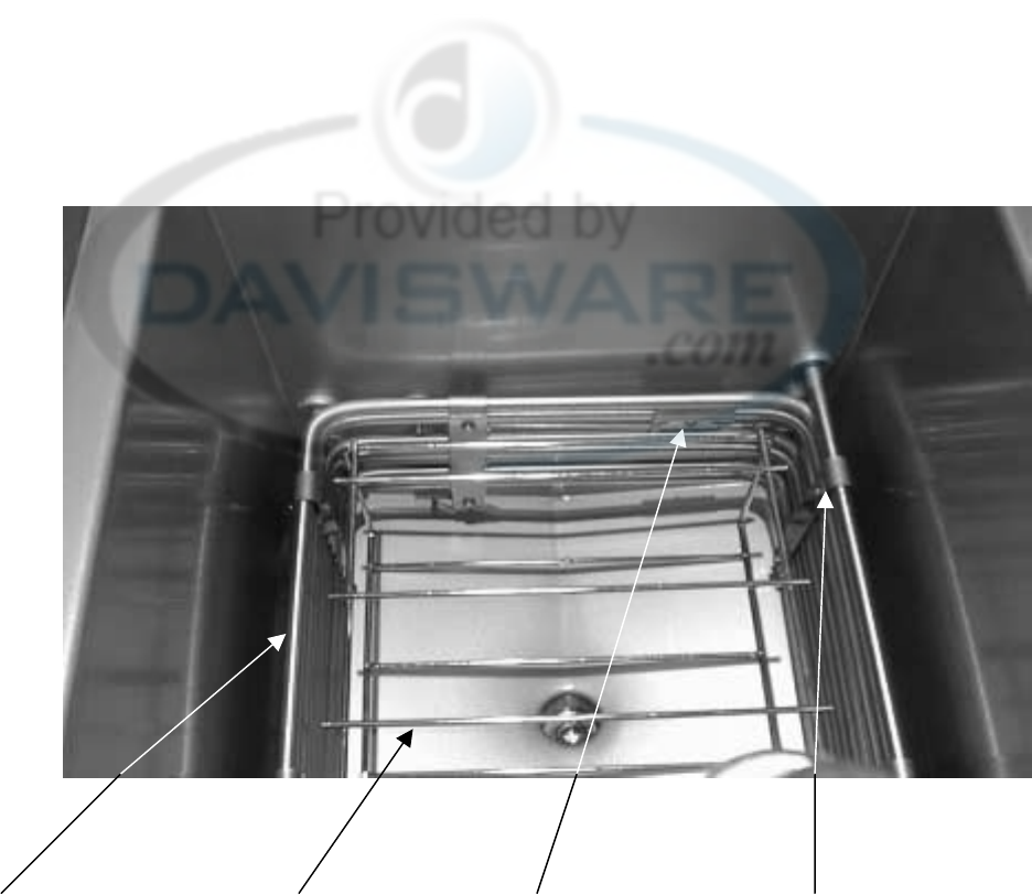
Henny Penny Model OFE/OFG-321,322,323,324
1234
(Electric Models)
Item No. Part No. Description Qty. per Well
1 60744-3 Heater – 230V 4800W 3
1 60744-4 Heater – 208V 4800W 3
1 60744-5 Heater – 480V 4800W 3
1 60744-2 Heater – 380V 4800W 3
1 60744-1 Heater – 460V 4800W 3
2 60747 OFE Fry Basket Support 1
3 18720 Hi Limit Rear Clamp 1
3 18248 Hi Limit Front Clamp 1
3 SC01-053 Clamp Screw #8-32x1/2 1
4 51931 Spreader Bar Assy 5
4 SC01-055 Spreader Screw #10-32x3/4 10
4 LW02-005 Lockwasher #10 Internal 10
101 7-9
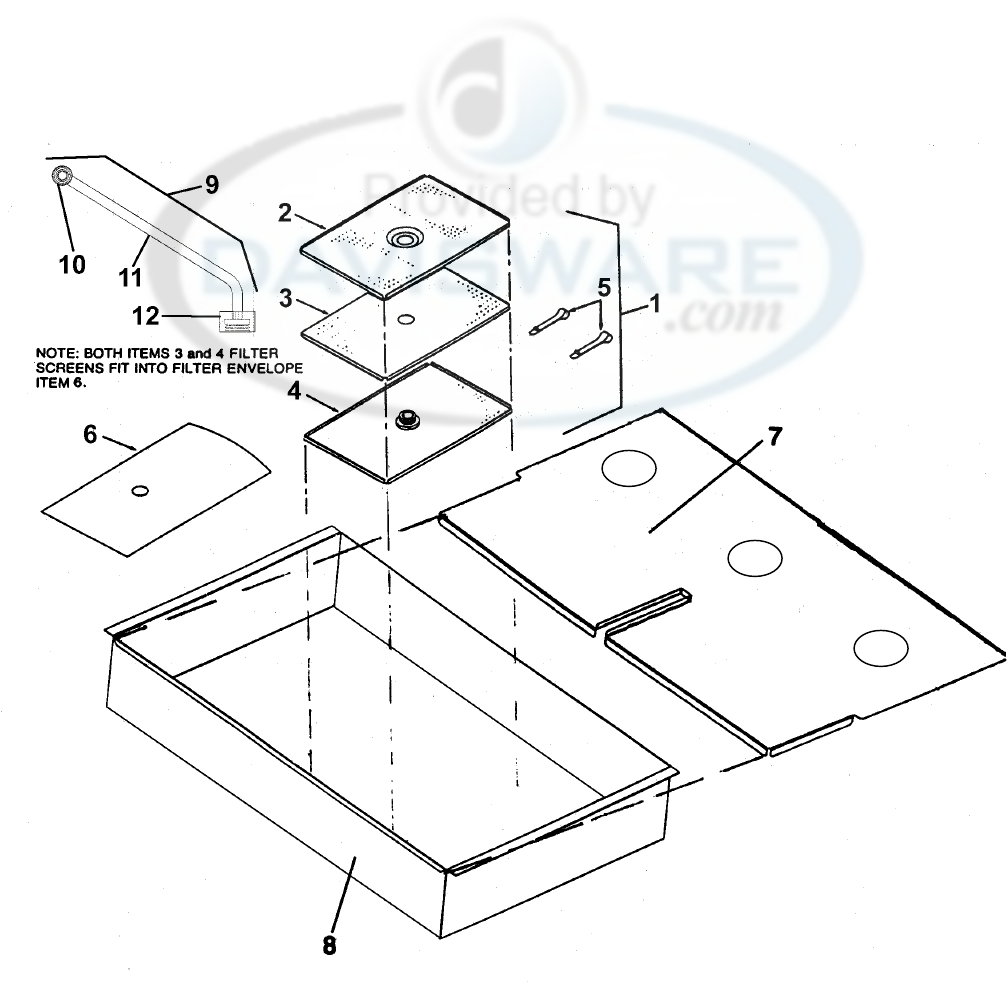
Henny Penny Model OFE/OFG-321,322,323,324
Item No. Part No. Description Qty. per Unit
1 17510 Screen Assembly, Filter 1
2 17501 Crumb Catcher 1
3 17502 Top Filter Screen 1
4 17503 Bottom Filter Screen 1
5 17505 Filter Envelope Clips 2
6 12102 Filter Envelope Paper (100 per Carton) 1
7 60512 Drain Pan Cover – 321 1
7 60460 Drain Pan Cover – 322 1
8 60510 Drain Pan – 321 1
8 60458 Drain Pan – 322 1
9 60378 Filter Standpipe Assembly 1
10 17430 Union – Female Fitting 1
11 60377 Standpipe Tube 1
12 17403 Nut – Filter 1
7-10 101

Henny Penny Model OFE/OFG-321,322,323,324
Main Gas Lines
OFG-321 OFG-322
OFG-323
OGA-323
Item No. Part No. Description Qty. per Unit
1 60621 Main Gas Line Assy 1
2 FP01-098 Elbow ¾ NPT x 90 Female Bi 3
3 FP02-032 Nipple – ¾ NPT x 17 in. Lg. Bi 1
4 FP02-033 Nipple – ¾ NPT x 4 in. Lg. Bi 2
5 FP01-097 Tee ¾ NPT Female Pip Bi 1
6 FP01-089 Bushing-Reducing 3/4M to 1/2F Bl 1
7 16335 Male Connector 37 Flare 5
8 FP01-093 Elbow 1 in. NPT x 90 Female Bi 3
9 FP01-094 Nipple 1 in. NPT x 3 ½ Lg. Bi 2
10 FP02-031 Nipple 1 in. NPT x 16 in Lg. Bi 1
11 FP01-085 Bushing-Reducing 1M to 1/2F Bl 3
12 FP01-092 Cross Tee 1 in. NPT Female Bi 1
13 FP02-034 Nipple 1 in. NPT x 9 in. Lg. Bi 1
101 7-11

Henny Penny Model OFE/OFG-321,322,323,324
AUTO-LIFT PARTS LIST
Part Quantity
Number Description 321 322 323
TS22-012 Transformer 1 2 3
60241 High Limit - 425º F 1 2 3
60206 Speaker Assembly 1 2 3
29510 Mercury Contactor - Electic Units 246
30614 Transformer - 208/240V-Pri, 24V Sec. - Electic Units 123
EF02-006 Fuse Holder - Electic Units 246
EF02-007 Fuse - 15 amp - Electic Units 246
50703 Full Size Basket 1 2 3
50704 1/2 Size Basket 2 4 6
50716 Actuator-Auto-lift-24V (motor) 1 2 3
50719 Basket Hanger Assembly 2 4 6
50750 Filter Valve-Oil Return 1 2 3
60796RB GM 12 Button Control-321 1 - -
60797RB GM 12 Button Control-322 - 2 -
60798RB GM 12 Button Control-323 - - 3
60430RB I/O PCB W/ Power Supply 1 2 3
50290 Basket Lift PCB Assembly 1 2 3
50764 Microswitch-Rigid Lever 1 2 3
60292 Pilot Flame Sensor - Gas Units 123
21347 Ignition Module - Gas Units 123
60363 Gas Valve Assembly - 24V-LP- Gas Units 123
60397 Gas Valve Assembly - 24V-Nat. - Gas Units 123
60783 Vacuum Switch - Gas Units 123
43768 Power Switch 1 2 3
52224 Covered Power Switch – CE 1 2 3
52078 Blower Motor Assembly - Gas Units 123
55168 Probe Assembly 1 2 3
46854 Filter Pump Motor - 1/2 Horse 1 1 1
61562 Menu Card – Auto-lift 2 4 6
59721 Return Valve Handle 1 2 3
50814 Frypot Cover – Auto-lift 1 2 3
101 7-11

Henny Penny Model OFE/OFG-321,322,323,324
OFG/OFE ELECTRO MECHANICAL PARTS LIST
PART NUMBER DESCRIPTION
60816 Adjustable Relay Base
60817 Adjustable Time Delay Relay
60818 24VAC Coil Relay
60765 24V Dual Face Timer
18412 Thermostat Assy
60814 E/M Bulb Mounting Clip
35916 Transformer 120V to 24V (Gas)
60536 Transformer 24V/230V (Electric)
60792 Indicator Light – 24 V
7-12 101
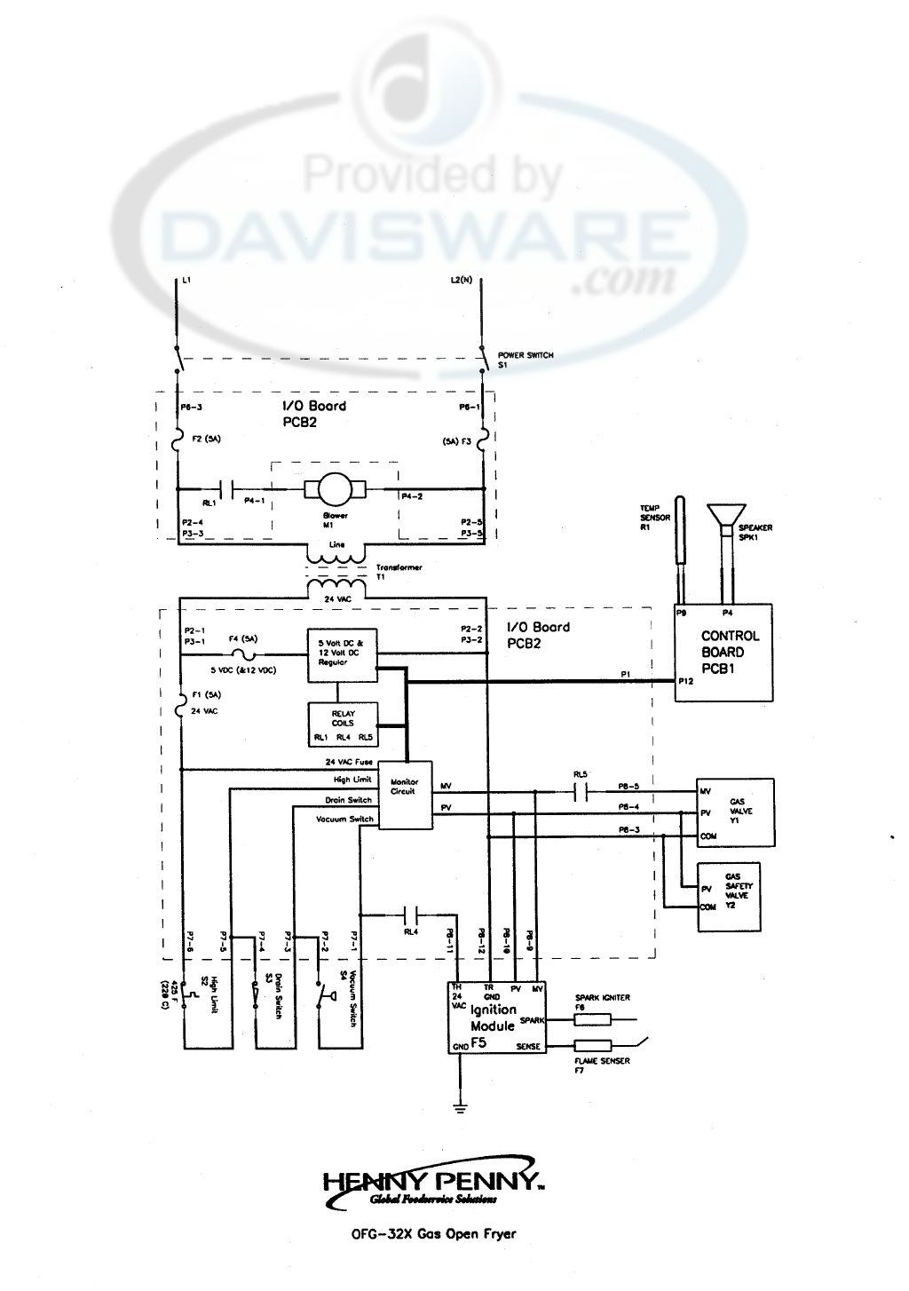
Henny Penny Model OFE/OFG-321,322,323,324
120 Volt
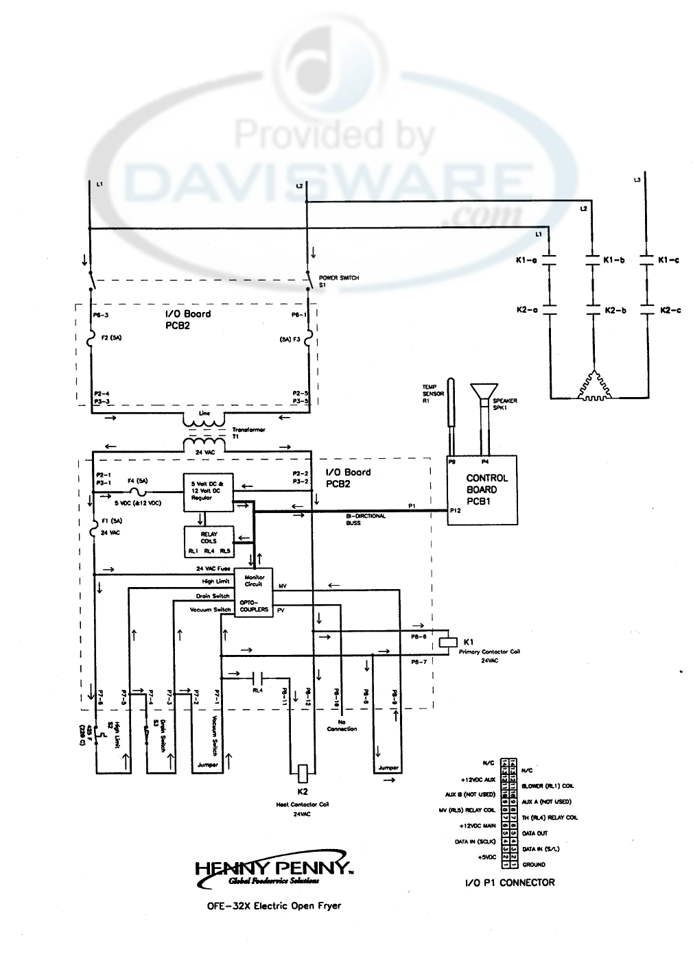
Henny Penny Model OFE/OFG-321,322,323,324
208/240 Volt (Domestic)
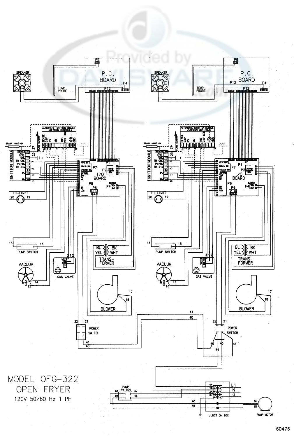
Henny Penny Model OFE/OFG-321,322,323,324
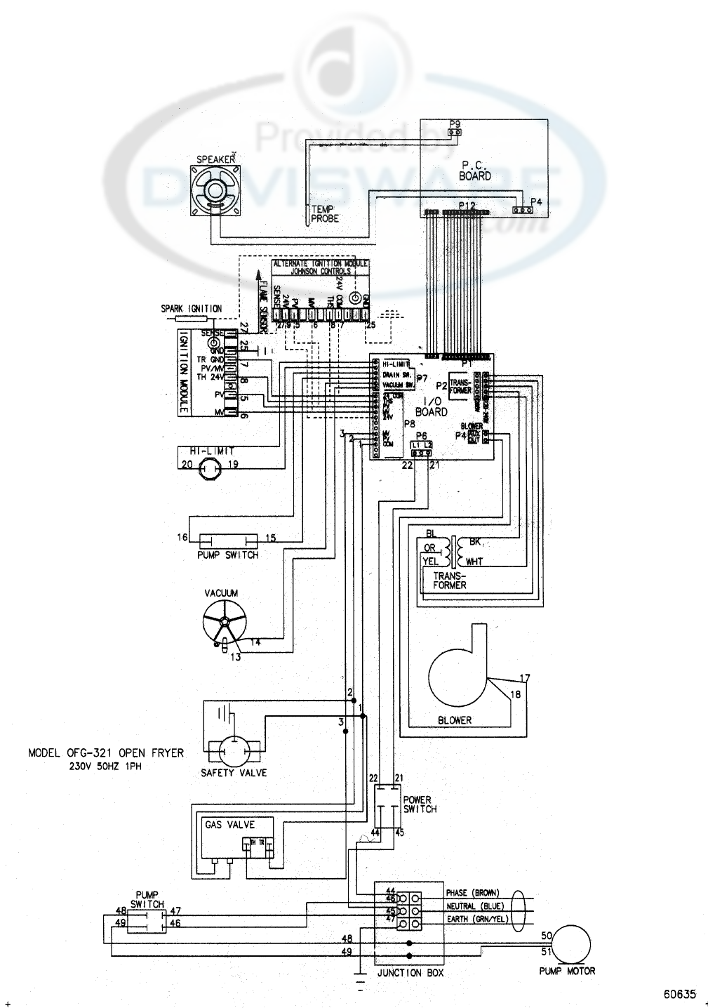
Henny Penny Model OFE/OFG-321,322,323,324
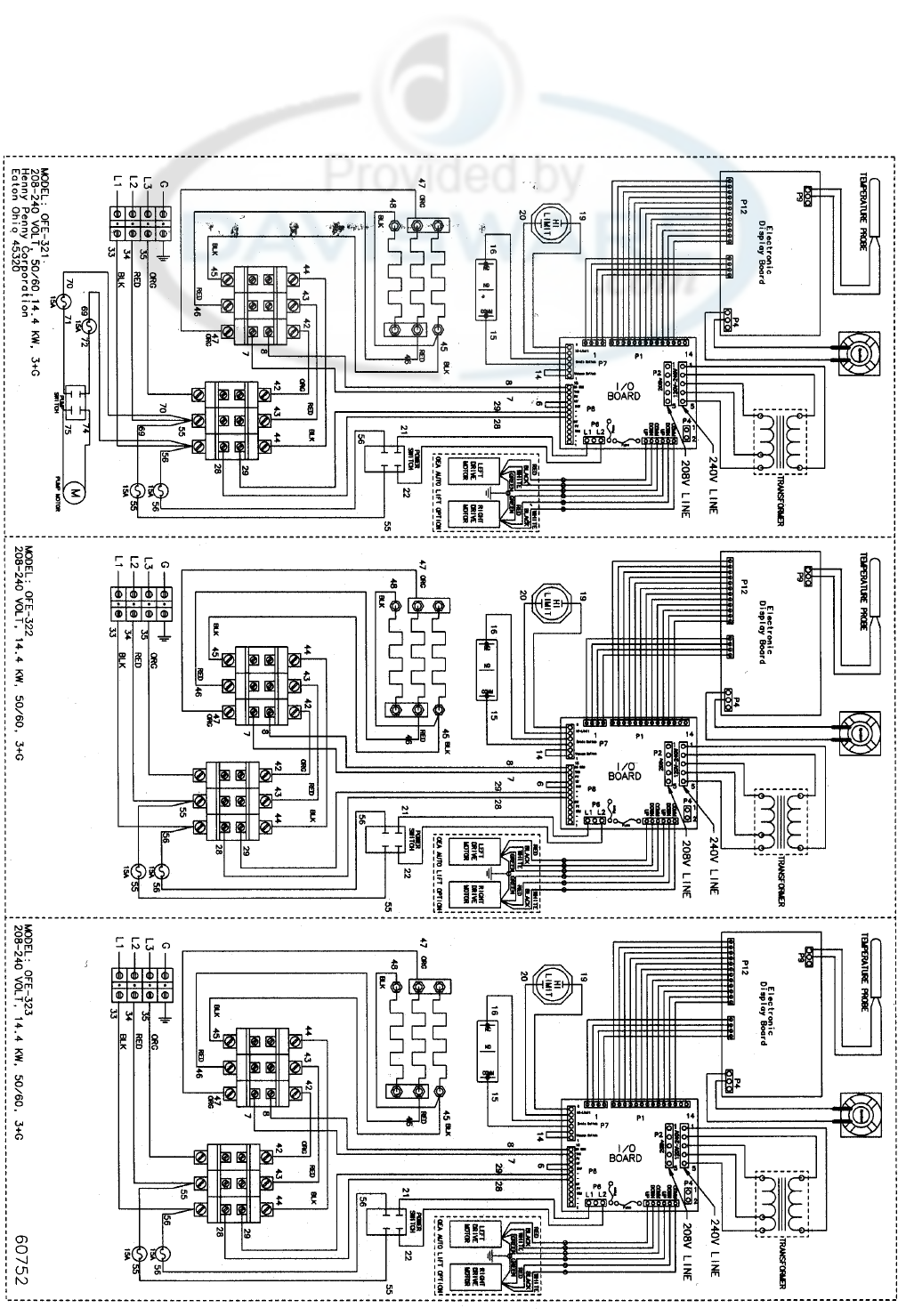
Henny Penny Model OFE/OFG-321,322,323,324
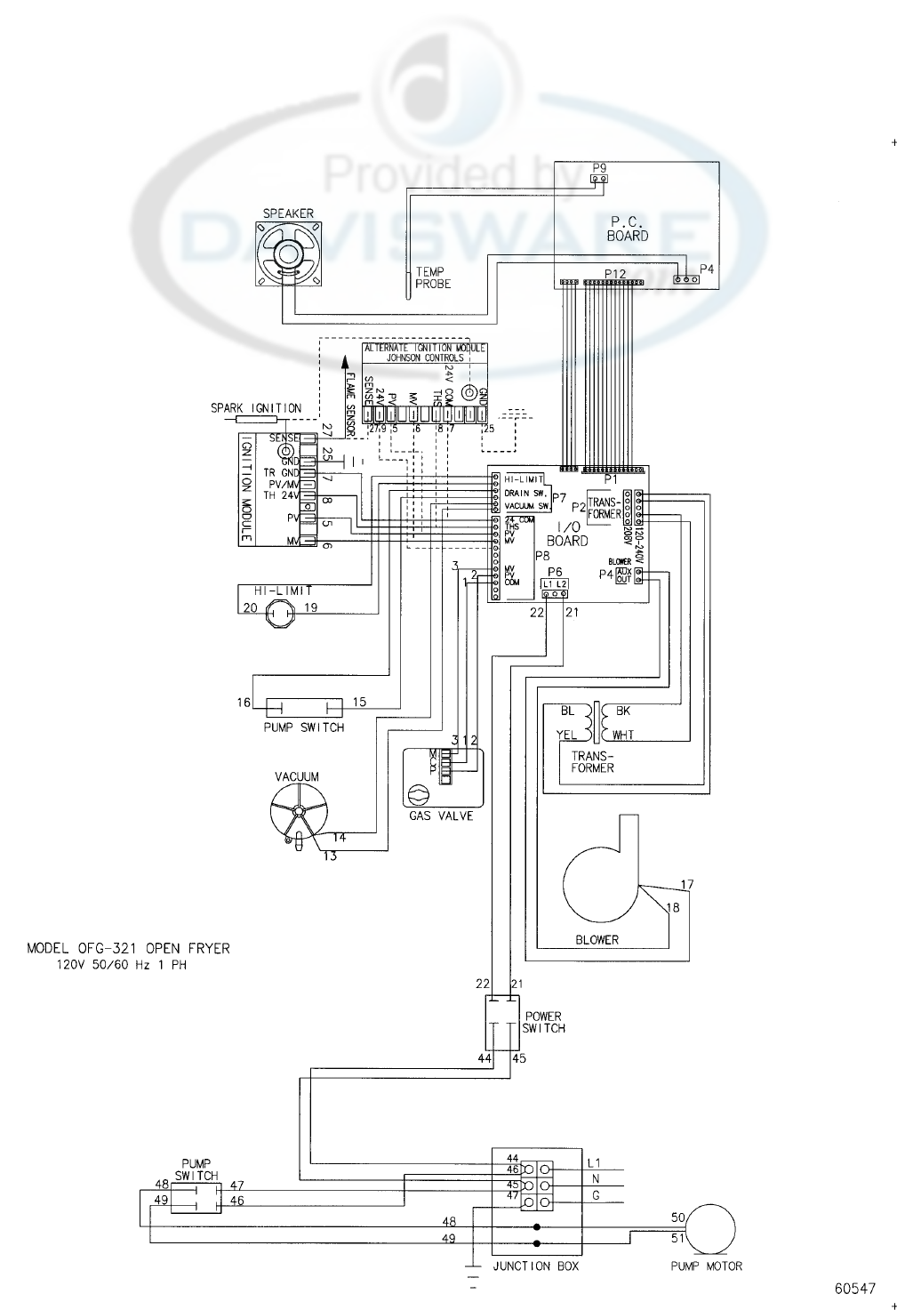
Henny Penny Model OFE/OFG-321,322,323,324
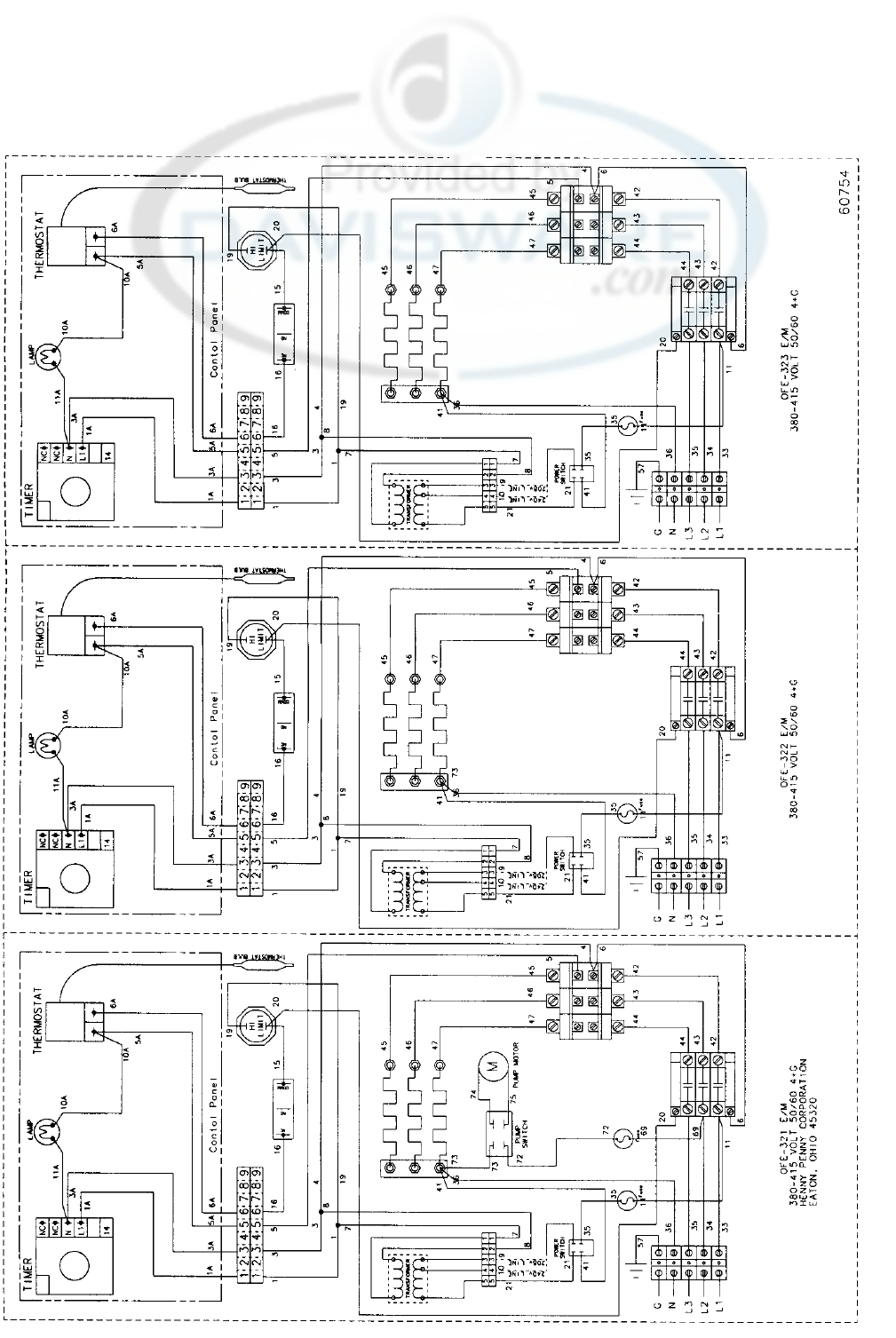
Henny Penny Model OFE/OFG-321,322,323,324
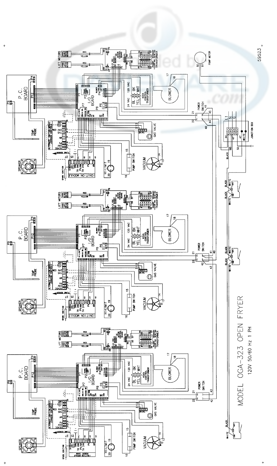
Henny Penny Model OFE/OFG-321,322,323,324
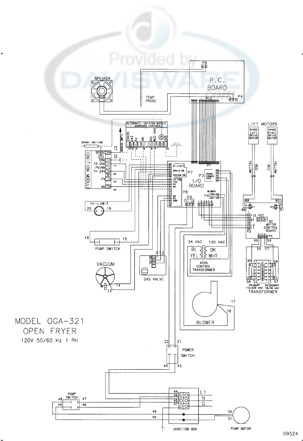
Henny Penny Model OFE/OFG-321,322,323,324
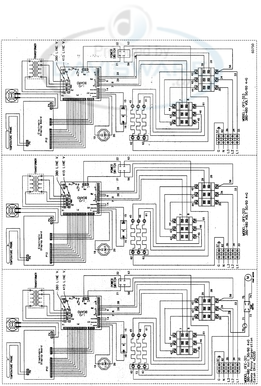
Henny Penny Model OFE/OFG-321,322,323,324
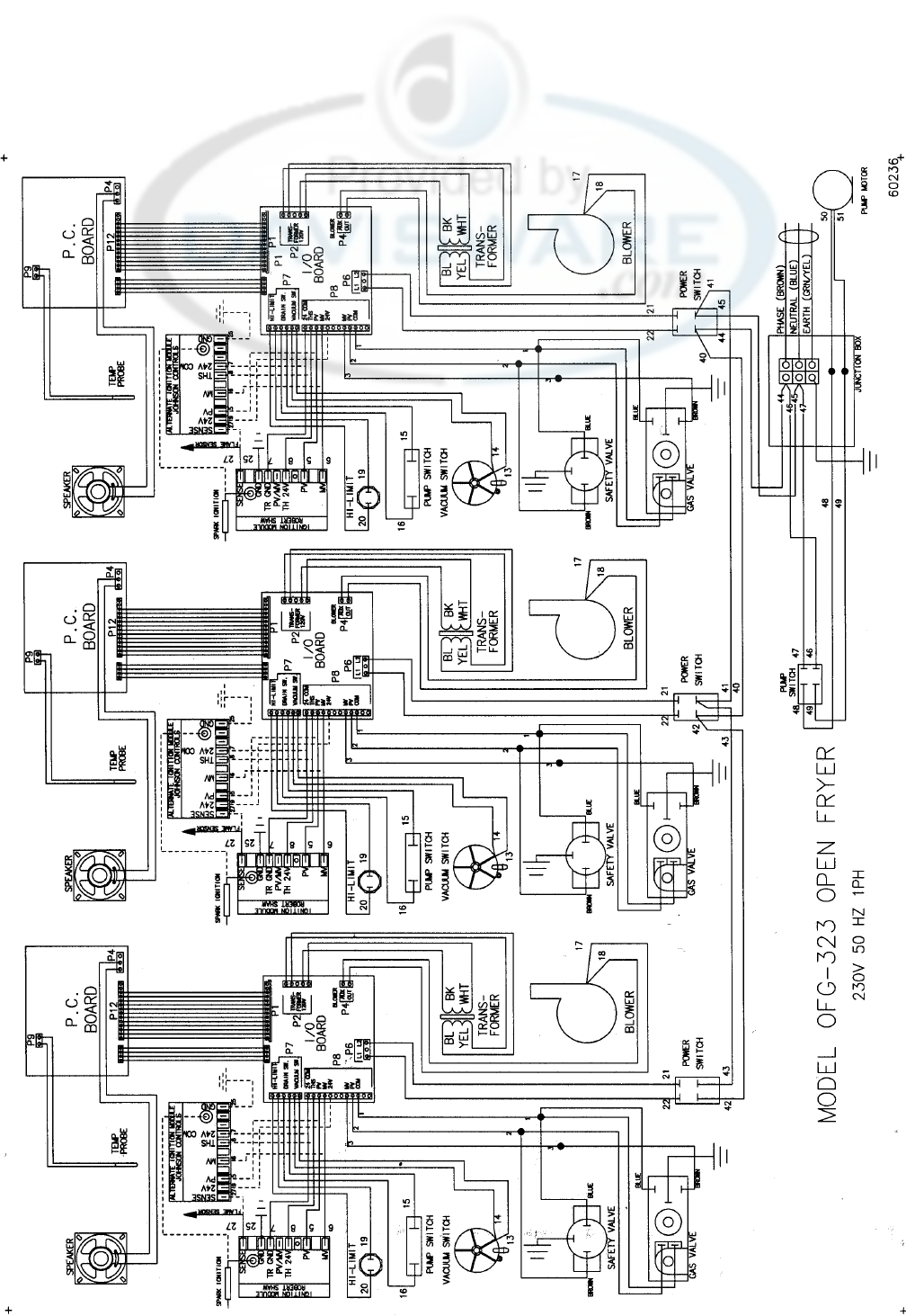
Henny Penny Model OFE/OFG-321,322,323,324
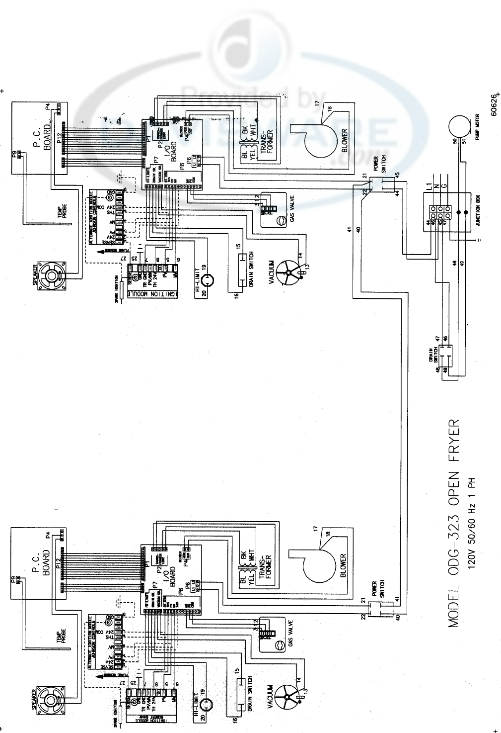
Henny Penny Model OFE/OFG-321,322,323,324
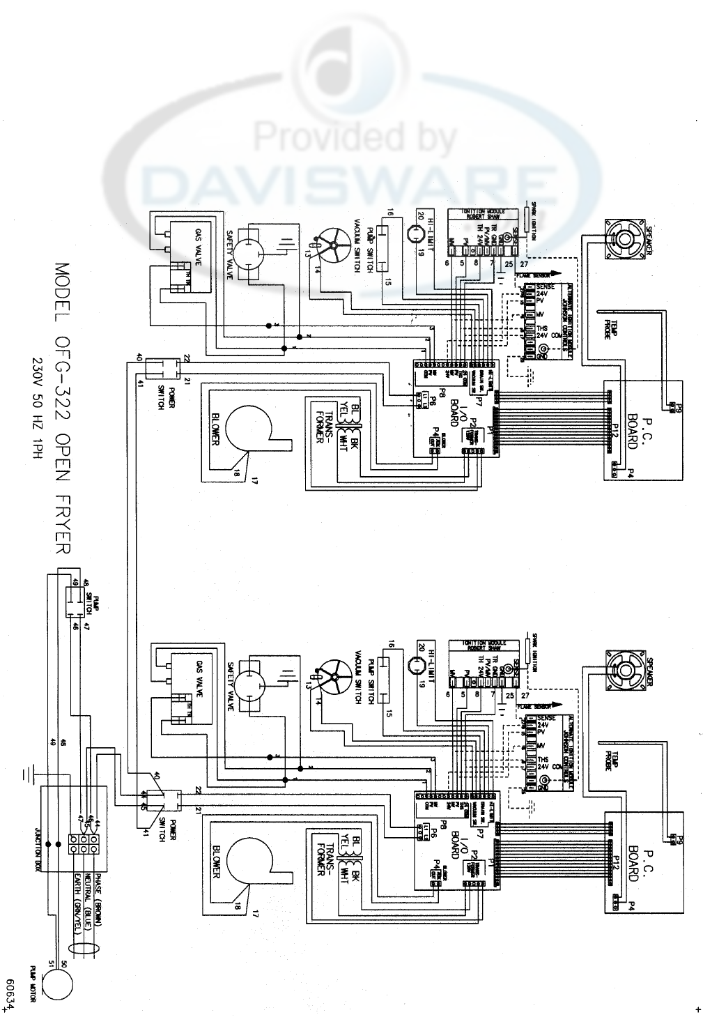
Henny Penny Model OFE/OFG-321,322,323,324
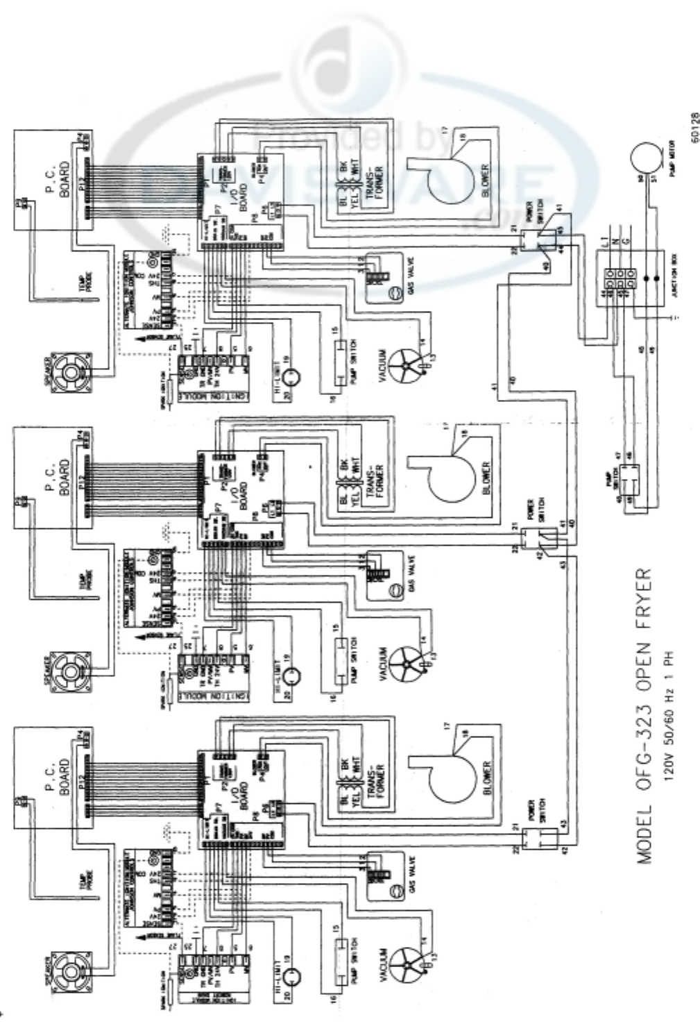
Henny Penny Model OFE/OFG-321,322,323,324
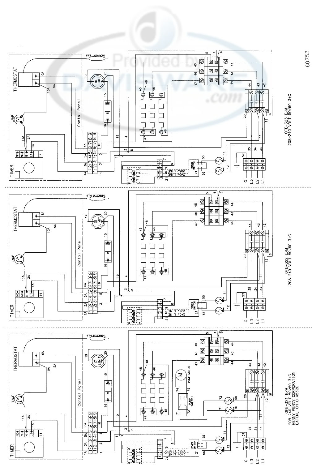
Henny Penny Model OFE/OFG-321,322,323,324
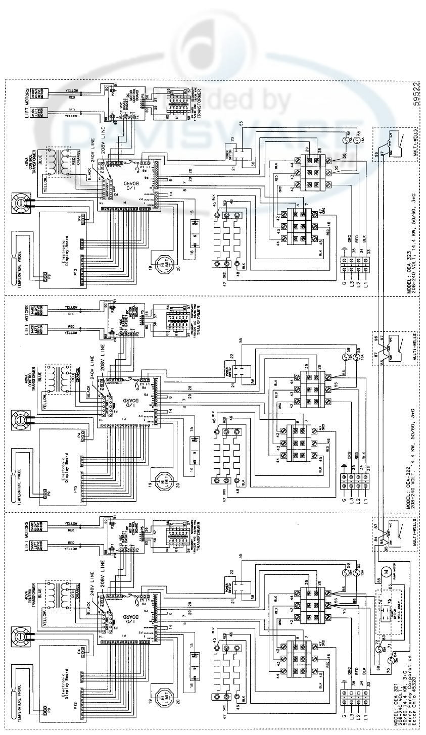
Henny Penny Model OFE/OFG-321,322,323,324


1. General Services
100 Hicks Ave.
Medford, MA 02155
(800) 233-1033
2. Art Cole Associates
Golden Street
Industrial Park
Meriden, CT 06450
(203) 237-7177
3. Globe-Monte Metro, Inc.
47-02 Metropolitan Avenue
Ridgewood, NY 11385
(718) 786-5760
4. Guertin Dist. Inc.
5 Technology Drive
East Syracuse, NY 13057-9713
(315) 437-4928
(800) 468-6336
5. Kreiser Distributing Co.
13800 Lincoln Highway
N. Huntington, PA 16652
(724) 863-3360
6. AFS Equipment Company
9130-X Red Branch Road
Columbia, MD 21045
(410) 964-3770
(800) 969-3770
7. HP Sales & Service Co.
200 Rittenhouse Circle, 4-East
Bristol, PA 19007
(215) 785-3250
NJ Watts (800) 477-4379
8. Astro Food Equipment
7901 Old Rockside Rd.)
Independence, OH 44131
(216) 619-8821
(800) 367-4237
9. Carlisle Food Systems, Inc.
11020 Lakeridge Pkwy.
Ashland, VA 23005
(804) 550-2169
10. Price-Davis, Inc.
Route 1, Highway 27
Iron Station, NC 28080
(509) 928-8815
(704) 732-2236
(800) 456-1014
11. Big A Distributors, Inc.
P.O. Box 1283
Forest Park, GA 30051
(404) 366-6510
(800) 222-0298
12. W.H. Reynolds
Distributors, Inc.
4817 Westshore Blvd.
Tampa, FL 33609
(813) 873-2402
Miami-(954) 845-0841
Jacksonville-(904) 781-9054
FL Watts (800) 282-2733
13. Ber-Vel Distributing Co. Inc.
P.O. Box 9943
Birmingham, AL 35220
(205) 681-1855
For Sales or Service Please Contact
The Nearest Henny Penny Distributor
14. Barnett Supply
2089 York Ave.
Memphis, TN 38104
(901) 278-0440
Nashville, TN
(615) 242-6451
Scotsman Supply
516 5th Ave., South
Nashville, TN 37203
(615) 242-6451
15. St. Clair Supply Company
231 East Main Street
Eaton, OH 45320
(937) 456-5500
(800) 762-2968
16. Dine Equipment Co.
3110 Preston Hwy.
P.O. Box 34038 zip 40232
Louisville, KY 40213
(502) 637-3232
FAX (502) 637-5177
17. United Marketing Assoc.
11877 Belden Court
Livonia, MI 48150
(734) 261-5380
18. T&H Distributors
1235 Parkview
Green Bay, WI 54304
(920) 339-9838
19. Food Service Solutions, Inc.
1682 Barclay Blvd.
Buffalo Grove, IL 60089
(847) 459-8040
(847) 459-7942
20. MEC
2511 Cassens Dr.
Fenton, MO 63026-2547
(636) 343-0664
(800) 397-1515
21. Delta Supply Co., Inc.
3315 W. Roosevelt Rd.
Little Rock, AR 72204
(501) 664-4326
22. Dixie Supply
490 Julianne St.
Bldg. A-2
Jackson, MS 39201
(601) 354-3025
23. Beaullieu Refrigeration Inc.
200 North Luke St.
Lafayette, LA 70506
(337) 235-9755
24. S.L.E. Corporation
1110 Avenue H East
Arlington, TX 76011
(817) 640-7999
25. Brooks Industries
4420 S.W. 29th St.
Oklahoma City, OK 73119
(405) 685-7200
26. B & D Dist.
19915 W. 161st St.
Suite D
Olathe, KS 66062
(913) 768-8588
FAX 913-768-8855
27. PHT Systems
1801 Highway 8
Suite 120
New Brighton, MN 55112
(651) 639-0368
28. Mid-Nebraska Restaurant
Supply Co.
1415 S. Webb Road
Grand Island, NE 68802
(308) 384-5780
29. Robert G. Wood & Co.
2080 W. Cornell Ave.
Englewood, CO 80110
(303) 761-0500
(800) 358-3061
30. Open Territory
31. CPE-USALCO
1310 West Drivers Way
Tempe, AZ 85284
(480) 496-6995
32. National Equipment Corp.
242 West-3680 South
Salt Lake City, UT 84115
(800) 266-5824
(800) 955-9202
33. The Nicewonger Co.
19219 West Valley Hwy
Suite M103
Kent, WA 98032
(800) 426-5972
(425) 656-0907 FAX
34. Tri-State Market Supply
11115 E. Montgomery, Suite A
Spokane, WA 99206
(509) 928-8815
(877) 828-4268
36. Western Pacific
Distributors, Inc.
19422 Cabot Boulevard
Haywood, CA 94545
(510) 732-0100
37. Don Walters Company
2121 S. Susan Street
Suite A
Santa Ana, CA 92704
(714) 979-5863
38. Troyer Foods, Inc.
17141 State Route 4
Goshen, IN 46526
(219) 533-0302
39. Tri-City HP, Inc.
527 West Fourth St.
Davenport, IA 52801
(319) 322-5382
40. Certified Commercial Service &
Equipment (CCSE)
6031-A Industrial Heights Drive
Knoxville, TN 37909
(865)-546-8778
41. Gower Distributors, Inc.
P.O. Box 4804
Box 216K Rt. -4
Victoria, TX 77903
(361) 573-9777
42. Top-Line Distributors
1501 College Ave.
Houston, TX 77585
(713) 946-6008
43. DSL Inc., Canada
14520 128th Ave.
Edmonton, Alberta
Canada T5L3H6
(403) 452-7580
(Alberta, British Columbia,
Manitoba, Saskatchewan,
Yukon, & N.W. Territories)
44. Taylor Freezers, Inc.
52 Armthorpe Rd.
Brampton, Ontario
Canada L6T5M4
(905) 790-2211
(Ontario, Montreal, and
Maritime Provinces)
45. Bazinet Taylor Ltee.
4750 Rue Bourg
Ville St. Laurent
Quebec, Canada H5T 1J2
(514) 735-3627
(Quebec only)
If Further Assistance Is Needed Please Contact: Henny Penny Corporation
1219 U. S. Route 35 West
Eaton, Ohio 45320
1-800-417-8417
Fax 1-800-417-8402
Revised 4-01


U.S. Headquarters
Henny Penny Corporation
1219 U.S. Route 35 West
Eaton, OH 45320 USA
Telephone: 937-456-8417
Fax: 937-456-1860
Representative Office
1 . Henny Penny Corporation
Representative Office
Parc dEntreprises de
IEsplanade
2bis Rue Paul Henri Speak
Saint Thibault des Vignes
77462 Lagny sur Mame Cedex,
France
Telephone: 33 (1) 60075600
Fax: 33 (1) 60071489
U.S. Export Centers
2. Feco International Company
20 North San Mateo Drive,
Suite 9
San Mateo, CA 94401 USA
Telephone: 415-348-3499
Fax: 415-348-3575
3. Caribbean Islands & Central
America (excluding Puerto Rico)
Total Equipment Suppliers
9550 NW 41
st
St.
Miami, FL 33178
Telephone: 305-718-9550
Fax: 305-718-9505
Algeria
4. SOMAB
Y1 Rue Mahmoud Boudjatit
(Oasis) Ager, Algeria
Tel: 213-21-23-3051/3052
Fax: 213-21-23-3161
Argentina
5. Oditec S.A.
Augstin Alvarez 2128
1602 Florida
Buenos Aires, Argentina
Telephone: (541) 796-0820
Fax: (541) 796-2009
6. Australia
J.L. Lennard Pty. Ltd.
937-941 Victoria Rd.
West Ryde NSW 2114
Sydney, Australia
Telephone: 617-3272-4744
Fax: 617-3272-4799
Bahrain
7. Mohammed Jalal Catering
Old Palace Road
P.O. Box 1335
Manama, State of Bahrain
Telephone: 973-53-45-39
Fax: 973 53-14-78
Bangladesh
8. Puffin International Ltd.
3691B Elephant Rd.
Swarankika Plaza
4th Floor-Dhaka 1205
Dhaka, Bangladesh
Telephone: 8802-863117
Fax: 880-2-867563
Belgium
9. Engelen-Heere N.V.
Industrialpark Terbekehof
Fotografielaan 14
B-2610 Antwerpen (Wilrijk)
Telephone: 323-825-5577
Fax: 323-825-3702
Henny Penny International Distributor Network
Brazil
10. Pesin Equipment Food Service
R. Olavo Bilac 188/198
Sao Caetano Do Sul - SP
Brazil
Telephone:55-11-7690-1470
Fax: 55-11-7690-1466
Bulgaria
11. E.C.E. - CAIX
23A Rue Oborichte
Sofia 1604, Bulgaria
Telephone: 19-359-2-946-1479
Fax: 19-359-2-946-1669
Chile
12. IMAHE
Manuel Montt 1154 Providencia
Santiago, Chile
Tel: 562-341-4953/5707
Fax: 562-274-8567
China
13. Bonny Foodservice Products
Flat C, 8/F, Yeung Yiu Chung
Industrial Bldg., No. 20
Wang Hoi Rd.
Kowloon Bay, Kowloon Hong Kong
Telephone: 852-796-5616
Fax: 852-799-8490
Colombia
14. Industrial Taylor Ltda.
Transversal 93, Numero 64-24
Apartado Aereo 95075
Bogota D.E., Colombia
Telephone: 57 (1) 4340016
Fax: 571-223-2642
Crotia
15. New Rok
Opatija M. Tita 15
51410 Opatija, Crotia
Telephohe: 385-51-701-251
Fax: 385-51-701-251
Cyprus
16. AMF Chistofides Ltd.
104A Prodromos Str.
P.O. Box 25100
Nicosia, Cyprus
Telephone: 357-2-454-380
Fax: 357-2-454-088
Czech Republic
17. Citus
Argentinska 20
CZ 4170 00 Pragues 7
CZECH REPUBLIC
Telephone: 420-2-667-10-561
Fax: 420-2-667-10-557
Denmark
18. Inter-Gastro A.S.
Midtager 18
2605 Brondby
Denmark DK2605
Telephone: 45-43292000
Fax: 45-43292001
Ecuador
19. Equindeca Cia. Ltda.
Hotel El Conquistador
Gran Colombia 6-65
Cuenca, Ecuador
Telephone: 593-7-831788
Fax: 593-7-843221
Egypt
20. Con Trade Centre
3A Ramsis Street
Maaroof Building #83 & #62
Cairo, Egypt
Telephone: 20 (2) 770642/762551
Fax: 20 (2) 756258
Estonia
21. Sisustaja As
Tihniku 5
11625 Tallinn, Estonia
Telephone: 372-6502300
Fax: 372-6502301
Finland
22. Monilaite Oy
P.O. Box 27
Salpakuja 6
SF-01200 Vantaa, Finland
Telephone: 358-9-877-0100
Fax: 358-9-877-01099
France
23. Diffusion International de
Materiel (DIM)
Parc dactivite Clemenceau
Chemin du Chateau dEau
B.P. 4009
59704 Marcq-En-Baroeuil
Cedex, France
Telephone: (33) 20890000
Fax: (33) 20727355
Germany
24. Sesjak KG
Wullener Feld 9a
D-58454 Witten
Germany
Telephone: 49-2302-697077
Fax: 49-2302-698451
Ghana
25. DRT Ghana
E6619 Ablade Road
Kanda Estate
P.O. Box C2074
Accra-Cantonments, Ghana
Telephone: 233-2123-3949
Fax: 233-2123-1380
Greece
26. Domestica S.A.
65 Stournara Str.
Athens 10432, Greece
Telephone: 30-15-24-30-14/15
Fax: 30-15-22-91-58
Guam
27. Pacific Technical Service, Inc.
New Commercial Building
#979 Rt. 16, Suite B-3
Barrigada, Guam 96913
Telephone: 6710632-5000
Fax: 671-632-3333
Holland
28. Englelen-Heere B.V.
Straatveg 85, Postbus 35020
3005 DA Rotterdam, Holland
Telephone: 311-042-23077
Fax: 311-042-23435
Hong Kong
29. Bonny Foodservice Products
Flat C, 8/F, Yeung Yiu Chung
Industrial Building #20
Wang Hoi Road
Kowloon Bay, Kowloon,
Hong Kong
Telephone: 852-796-5616
Fax: 852-799-8490
Hungary
30. Hotex Service
H-2094 Nagykovacsi
Kossith Lajos u. 1.
Hungary
Telephone: 36-263-56653/89463
Fax: 36-26389463
Iceland
31. A. Karlsson H. F.
Brautarholti 28
105 Reykjavik, PO Box 167
Iceland
Telephone: 354-560-0900
Fax: 354-560-0901
India
32. AISHWARYA
Trust Complex, 10 OVG Rd
Basavanagudi
Bangalore 560004, India
Telephone: 91-80-667-7576
Fax: 91-80-667-7576
Intl. Refrigeration Corp
7 Netaji Subhash Marg
Darya Ganj
New Delhi 110002, India
Telephone: 91-11-3275651
Fax: 91-11-6221827
Indonesia
33. P.T. Gema
JL. Raya Bloulevard Raya
Block IOA 2 No. 27
Kelapa Gading Permai
Jakarta 14240, Indonesia
Telephone: 62-21-4532077
62-21-4508910
Fax: 62-21-4532586/4530777
Ireland
34. Martin Food Equipment Ltd.
Gaskin Business Park
Coes Road
Dundalk, Louth County
Ireland
Telephone: 353-42-30366
Fax: 353-42-30370
Italy
35. Allegra SRL
Corso Matteotti, 5 - 10121
Torino, Italy
Telephone: 39-011-540264
Fax: 39-011-533779
Japan
36. Toei Kogyo Co. Ltd.
4F, Nissay Nishi-Gotanda
Building 24-5
Nishi-Gatanda 7-Chome
Shinagawa-ku, Tokyo 141-0031
Japan
Telephone: 813-3779-1081
Fax: 813-3779-1638
Jordan
37. Awar Trading Est
PO Box 962227
Amman 11196, Jordan
Telephone: 962-6-55-19-610
Fax: 962-6-55-19-605
Korea
38. Ohjin Corporation
3rd Floor, Hee Jung Building
1635-0 Seocho-dong
Seocho-ku
C.P.O. Box 3252
Seoul 137-070, Korea
Telephone: 82-2-5850441
Fax: 82-2-5874197
Kuwait
39. Mabrook Hotel Supplies Co.
PO Box 43832 Hawalli
32053 Kuwait
Telephone: 965-481-8242
965-483-01648
Fax: 965-483-4314
Revised 5/01

Lebanon
40. Pro Kitchen
Cahlfoun Building
Kaslik - Main Road
PO Box 1066 Jounieh
Lebanon
Telephone: 961-9-635-077
Fax: 961-9-635-059
Lithuania
41. Master Group Baltic Master
Dariaus Ir Girena 175
2038 Vilnius, Lithuania
Telephone: 3702-306-528/529
Fax: 3702-306-533
Malaysia
42. SCC Corp. Sdn. Bhd.
19-21 Jalan Hujan
Taman Overseas Union
58200 Kuala Lumpur,
Malaysia
Telephone: 60-3-77828384
Fax: 60-3-77818561
Malta
43. C & H Bartoli Ltd.
232 The Strand
Gzira Gzros, Malta
Telephone: 356-342-584
Fax: 356-342-569
Mauritius Island
44. (Mauritius, Reunion Island,
Seychelles)
Hassam Moussa Rawat
10 Bourbon Street
P.O. Box 492
Port Louis, Mauritius Island
Telephone: 160 (230) 2080024
Fax: 160-230-2080147
Mexico
45. Central Mexico Metro Mexico City
Cavimex S.A. de C.V.
Revillagigedo No. 61 Col Centro
Mexico, D.F. 06070
Mexico
Telephone: 525-521-4200
Fax: 525-510-2791
Pacific
Micro Herros De Occidente,
S.A. de C.V.
Av. Juan Palamar y Arias
#83 Col. Jardines Vallarta
Zapopan, Jalisco, Mexico
C.P.45020
Telephone: 52-3-629-54-05
Fax: 52-3-673-29-43
Southeast
Equipo Para El Mercado
S.A. de C.V
Calle 55 No. 501-B por 60 y 62
Merida, Yucatan,
Mexico C.P. 97000
Telephone: 52-99-236500
Fax: 52-99-286649
Morocco
46. Electra
Boulevard AHL Loghlam
BP 25698
Sidi Bernoussi - Ain-Sebaa
Casablanca Morocco
Telephone: 212-22-753-531
Fax: 212-22-753-554
New Zealand
47. Taylor Equipment Limited
4 Ponuz Place
Mt. Wellington
Auckland, New Zealand
Telephone: 64 (9) 5733377
Fax: 64 (9) 5730841
Norway
48. Grillfagmannen A.S.
Ostensjoveien 44
N-0667 Oslo 6, Norway
Telephone: 47 (2) 651410
Fax: 47 (2) 720017
Oman
49. Mohsin Haider Darwish LLC
P.O. Box 880
Ruwi, Code 112
SULTANATE OF OMAN
Telephone: 968-703411
Fax: (968) 789927
Pakistan
50. The Equipment Company
Ground Floor, Dadabhoy Centre
Sharea Faisai, Karachi 75530
Pakistan
Telephone: 922-1-778-1778/2778
Fax: 922-1-587-0456/778-2777
Peru
51. Importadora Tecnica
Comercial C.R. Ltda.
Jr. Marcos de Aramburu #595
Lima 17, Peru
Telephone: 51-1-226-2124
Fax: 51-1-275-2689
Philippines
52. HKR Equipment Corp.
2nd Floor, THC Bldg.
2176 Primo Rivera St.
La Paz, Makati City, Philippines
Telephone: 632-899-4511
Fax: 632-899-4541
Poland
53. I. F. E.
Rydygiera 12
01 793 Warsaw, Poland
Telephone: 48-3912-3373
42-22-663-4820/4069
Fax: 48-3912-3373
Portugal
54. Restaurotel
AV Da Republica
83 C 1050
243 Lisboa
Portugal
Telephone: 351 7967116/7/8/9
FAX: 351 7933982
Puerto Rico
55. Progressive Sales and Service
PO Box 10876
Caparra Heights Station
San Juan, Puerto Rico 00922-
0876
Telephone: 787-782-7474
Fax: 787-793-6479
Qatar
56. Tristar Group
C.R. No. 6778
P.O. Box 4746
Doha, Qatar
Telephone: 974-4664433
Fax: 974-4365365
Romania
57. Delta Technologies Romani S.A.
Sector 6, 20 Constructorilor Blvd.
Bloc 20 A, sc. B 7th Floor
Apt. 64
Bucharest, D599 Romania
Telephone: 401-220-4261
Fax: 401-220-3990
US Address:
115 Main St.
Mishawaka, In. 46544
Telephone: 219-256-3783
Fax: 219-256-7130
Saudi Arabia
58. Commercial Center
Development & Economy
P.O. Box 1210
Jeddah 21431, Saudi Arabia
Telephone: 966 (2) 629-1857
Fax: 966 (2) 629-1860
Senegal
59. Breading Systems Co.
C/ Ripoche,14
35007 Las Palmas
Spain
Telephone: 34-9-28-22-43-86
Fax: 34-9-28-27-56-90
Singapore
60. Simplex Pte. Ltd.
Block 1, Lorong 8
Toa Payoh Industrial Park 01-1383
Singapore 319053
Telephone: 65-251-6241
Fax: 65-253-8814
Shopfit (S) Pte. Ltd.
Blk 623 Aljunied Industrial Complex
Unit 02-09
Singapore 389835
Telephone: 65-7410911
Fax: 65-7438911
South Africa
61. Foodserv CC
PO Box 55269
Northlands 2116,
Republic of South Africa
Telephone: 27 (11) 616-5183,
Fax: 27 (11) 616-8287
Spain
62. Adisa
Tuset, 8-10
08006 Barcelona, Spain
Telephone: 34-93-415-0018
Fax: 34-93-218-1782
Sri Lanka
63. Sperrys Commercial Equipment
1014 Parliament Road
Etul Kotte
Kotte/Colombo, Sri Lanka
Telephone:941-873-0561
Fax: 941-863-8361
Suriname
64. Tessco N.V.
Oude Charlesburgweg #47
Paramaribo Suriname
Telephone: 597-473366/477388
Fax: 597-473366
Sweden
65. Eurospice AB
Box 5050
Hejargatan 6
632 29 Eskilstuna, Sweden
Telephone: 46 (16) 125600
Fax: 46 (16) 131390
Switzerland
66. Stuppen Fast Food GmbH
Oberneuhofstrasse 8
CH-6340 Baar, Switzerland
Telephone: 41-41-761-5052
Fax: 41-41 761-7210
Syria
67. Lahham Trading & Contracting
Hamra Str. Omyad Building
P.O. Box 2960
Damascus Syria
Telephone: 963-11-331-2251
Fax: 963-11-331-2252
Taiwan
68. Feco Corporation
420, 11 F Keelung Rd.
Sec. 1 Postal Code 110
Taipei, Taiwan
Republic of China
Telephone:886-2-2758-2288
Fax: 886 (2) 2758-2297
Thailand
69. Fieco Company Ltd.
43/524-526 Amarinnivej 1
Anusaovari Laksi
Phaholoyothin Road
Bangkok 10220
Thailand
Telephone: 66-2-521-3824/3878
Fax: 66-2-552-0833
Tunisia
70. Semci
16, Rue Aziz Taj
1101 Tunis RP, Tunisia
Telephone: 216 -133-1501
Fax: 216-133-0698
Turkey
71. Klimatek
Inonu Caddesi, Opera Palas 73/5
80090 Gumussuyu
Istanbul, Turkey
Telephone: 90-212-245-1812
90-212-293-7892
Fax: 90-212-293-3903
United Arab Emirates
72. Habtoor International
P.O. Box 55332
Dubai, United Arab Emirates
Telephone: 971-4-272-1212
Fax: 971-4-272-2255
United Kingdom
73. Servequip Products Ltd.
214 Purley Way
GB-Croyden CRO 4XG, England
Telephone: 44-208-6868855
Fax: 44-208-6817509
Uruguay
74. Tecnoland S.A.
Dr. José Scorsería 2740
CP 11300 Montevideo, Uruguay
Telephone: 598-2-7105900
Fax: 598-2-7105900
Venezuela
75. Prefer, C.A.
Avenida Presidente Medina
Edificio Prefer, Local No. 44
Entre Calles Chile y Progreso
urb. Los Acacias
Caracas 1040, Venezuela
Telephone: 58-212-633-6933/2801
Fax: 58-212-632-6711
Vietnam
76. Cao Sinh Pte
Block 1, Lorong 8
Toa Payoh Industrial
Estate #01-1383
Singapore 319053
Telephone: 65-2516241
Fax: 84-2538814
Yemen
77. Mukiriani Sanaa
PO Box 8150 Sanaa
Yemen
Telephone: 967-1-230-675
Fax: 967-1-230-929
Revised 4/01
