OLD Build Instructions
User Manual:
Open the PDF directly: View PDF ![]() .
.
Page Count: 56
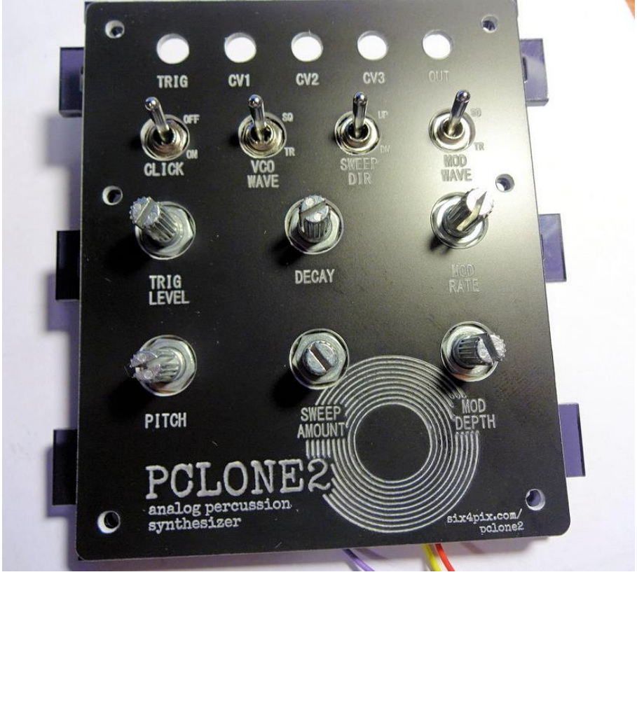
Welcome to the PCLONE2 build instructions!
I’ll assume you’ve done some soldering before and skip the basics,
however if you do need some tips or reminders on soldering technique,
please check out my page here. As kits go, this is moderate in complexity,
especially the panel wiring. You should give yourself at least 4-5 hours to
make the kit and go slowly and carefully – it is much easier to avoid a
mistake than fix it afterwards…
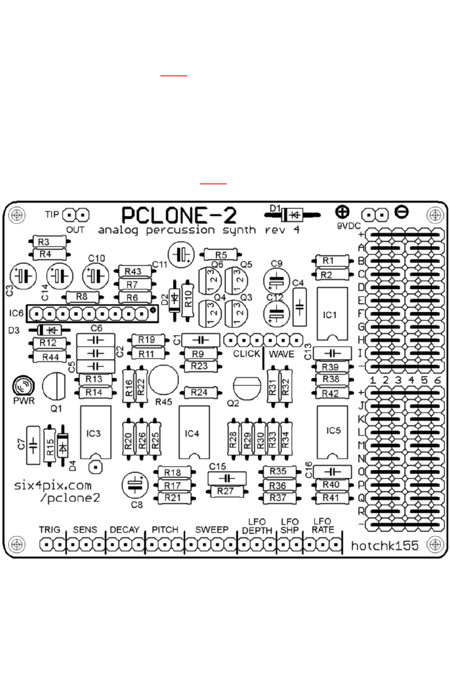
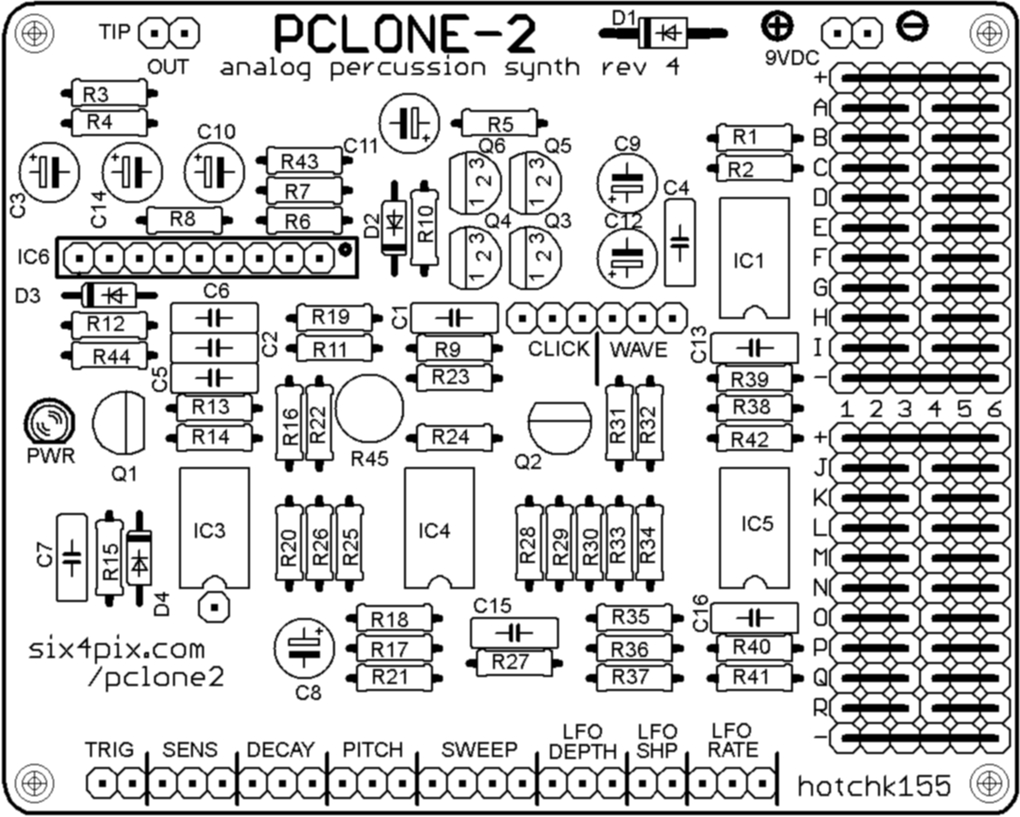
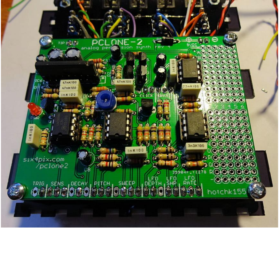
Here is an image of the PCB layout which can be useful to refer to as you
work, especially if you accidentally put a component in the wrong place,
covering up the designator (Click here for a bigger version)
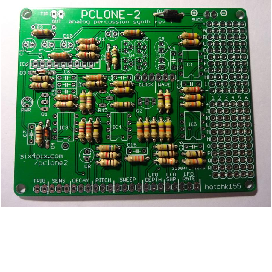
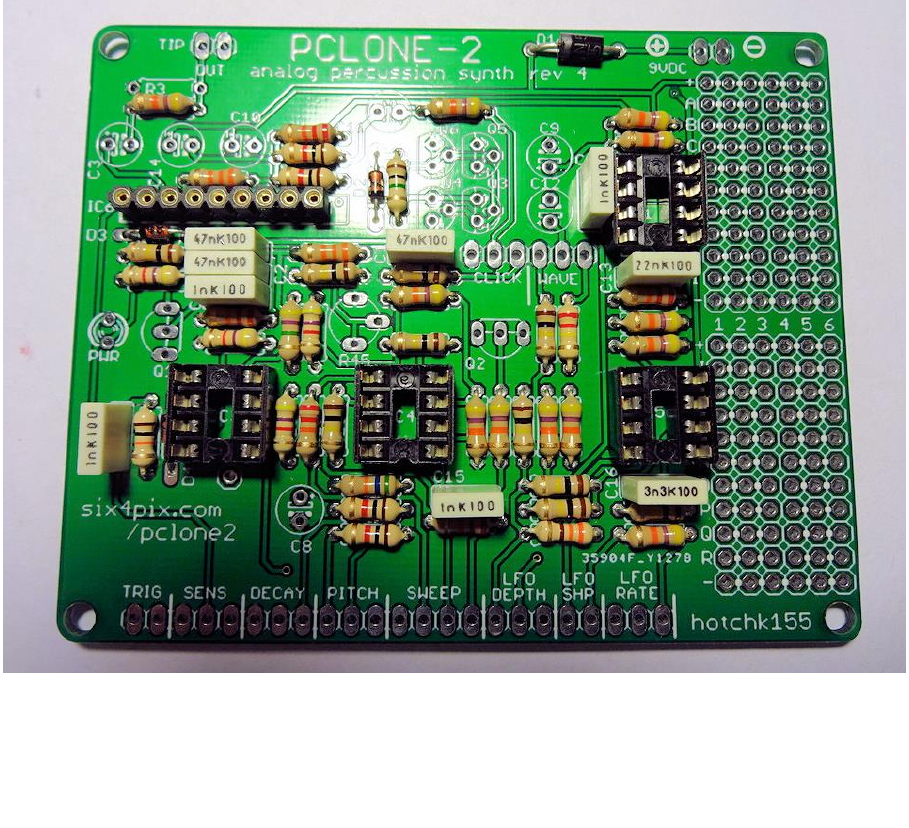
OK, Let’s begin by soldering the resistors. The different resistors can be
identified by their coloured stripes, which are listed below. When reading
the resistor codes you can ignore the silver or gold “tolerance band”.
The body of the resistor may be a tan or blue colour depending on the type
(carbon or metal film). The body colour doesn’t matter, so don’t worry if the
colour does not match the photo.

• R37 – 330 Ohm (ORANGE-ORANGE-BROWN)
• R6, R7, R17, R21 – 1k (BROWN-BLACK-RED)
• R14, R20, R22, R44 – 4k7 (YELLOW-VIOLET-RED)
• R15 – 10k (BROWN-BLACK-ORANGE)
• R13, R26, R27, R39, R43 – 22k (RED-RED-ORANGE)
• R8, R19 – 33k (ORANGE-ORANGE-ORANGE)
• R1, R2, R4, R5, R23, R28, R29, R33, R34, R38, R41, R42 – 47k
(YELLOW-VIOLET-ORANGE)
• R18 – 56k (GREEN-BLUE-ORANGE)
• R9, R11, R12, R24, R25, R30, R31, R35, R36, R40 – 100k
(BROWN-BLACK-YELLOW)
• R32 – 220k (RED-RED-YELLOW)
• R10 – 1M (BROWN-BLACK-GREEN)
• R16 – 4M7 (YELLOW-VIOLET-GREEN)
Note: The space for R3 is not populated. The kit does contain spare
resistors and some extras of certain useful values for mods, so don’t be
confused if there seem to be too many of a particular value, and don’t throw
away the leftovers!
Now let’s fit the diodes, remembering that they need to be soldered the
correct way around (and don’t heat them for too long when soldering)
• D2, D3 and D4 are small signal diodes with a small orange glass
body with a black stripe. Make sure the black stripe lines up with
the stripe marked on the circuit board symbol.
• D1 is a larger rectifier diode with a black body and silver stripe.
Make sure the stripe matches up with the one printed on the
board.
Your board should now look something like this
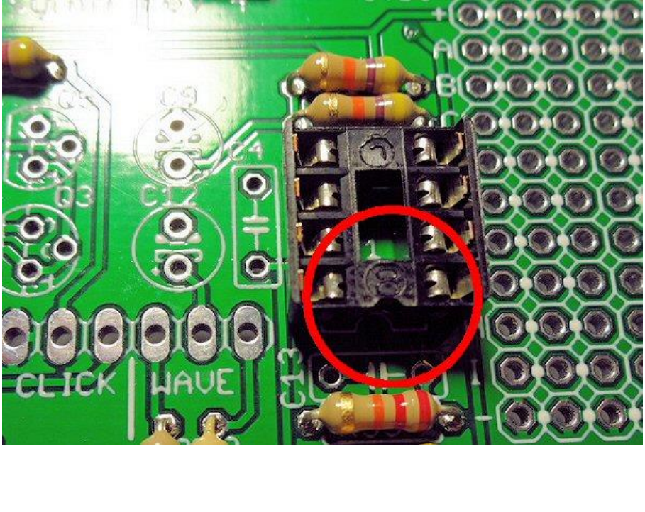
Now lets solder the four, 8-pin IC sockets and the 9-pin header strip.
Take care to align the notch on the end of the 8 pin sockets with the
marking on the board. In this layout the notch is towards the bottom of the
board for each socket.
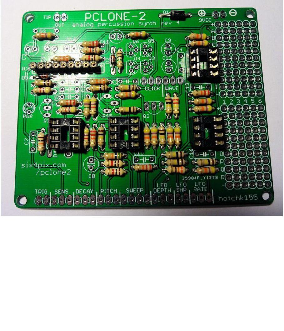
With all the sockets in place the board should be looking like this
The next step is to insert the nine polyester box capacitors.
• C1, C2, C6 – 47nF (Marked “47n”)
• C13 – 22nF (Marked “22n”)
• C16 – 3.3nF (Marked “3n3”)
• C4, C5, C7, C15 – 1nF (Marked “1n”)
The markings will contain other codes (e.g. “47nK100”), but check they
start with the indicated value (e.g. “47n”)
Now insert the trimmer potentiometer, R45. This is pretty tight to insert into
the PCB and may need a bit of waggling – be careful not to damage the
legs.
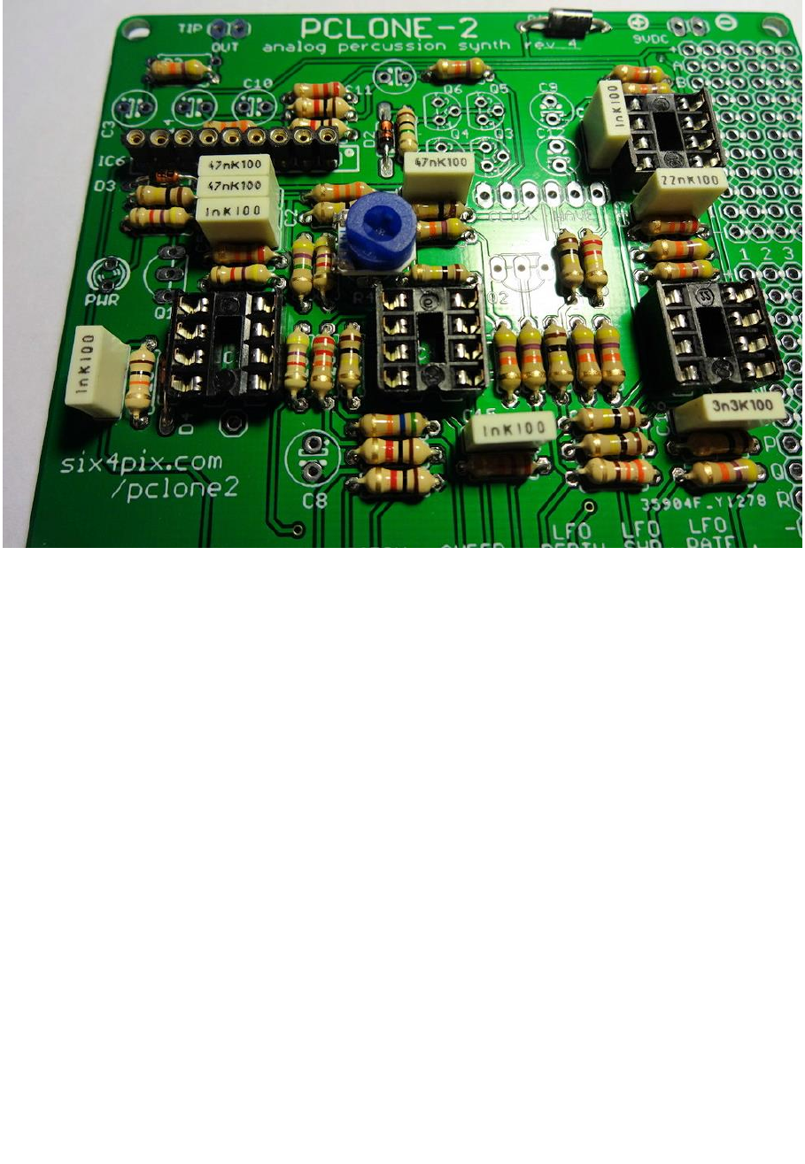
Solder the LED. It is important that this goes the right way round; you’ll see
that the marking on the board shows a “flat” side next to one of the legs
(beside the “PWR” label). The LED has a matching “flat” (marking the
negative terminal, which also has a shorter leg). Line the flats up when
inserting the LED and don’t heat for too long when soldering.
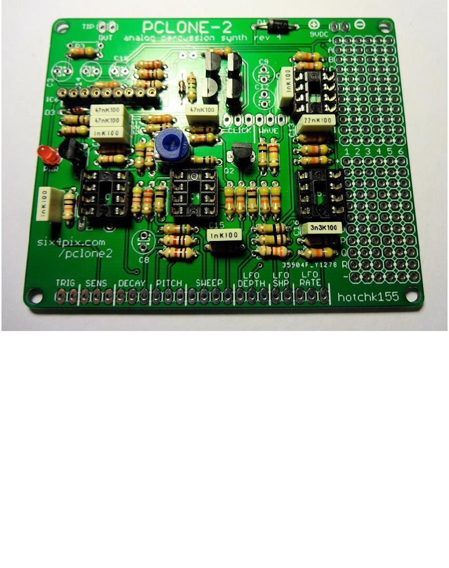
Now for transistors. There are three types of transistor in the kit
• Q1, Q2 – 2SC945P NPN (Marked “945P” or “C945”)
• Q3, Q4 – 2N3906 PNP
• Q5, Q6 – 2N3904 NPN
It is very important not to mix them up (or you might let the magic smoke
out of them as soon as you apply power!). There is an extra 2N3904 in the
kit – hang on to it to use for mods…
When you solder them, make sure the “D” shape of the case lines up with
the D shaped marking on the board – you need to bend or splay the legs a
little to get them into the holes on the board. When soldered, the transistors
should sit above the board by a few millimetres.
Almost there! Now add the electrolytic capacitors. These need to go in the
right way round. The symbols on the circuit board show a tiny little (+) sign
next to one hole. Put the longer leg of the capacitor through the hole. The
capacitor body will also have a white stripe to mark the negative terminal
(aligned with the shorter leg)
As with the box capacitors they are easy to mix up, so pay special attention
to the markings
• C3, C11, C12 – 1uF/50V electrolytic capacitor
• C8 – 2.2uF/50V electrolytic capacitor
• C9 – 10uF/16V electrolytic capacitor
• C10, C14 – 100uF/16V electrolytic capacitor
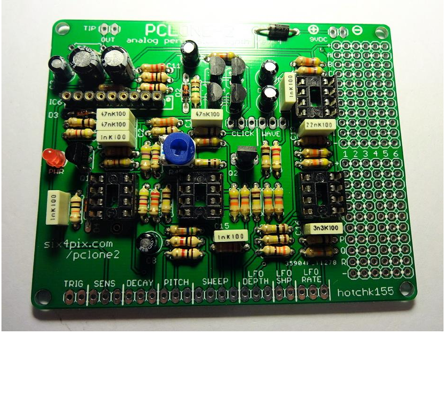
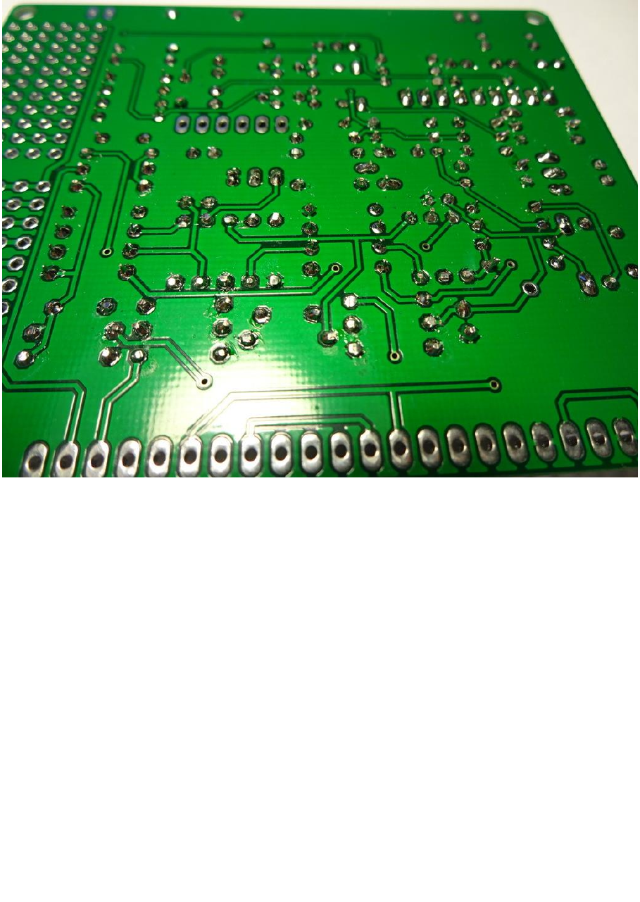
Make sure you trim back the excess component legs on the underside of
the board, since the back of the board will be mounted close to the metal
bodies of the potentiometers.
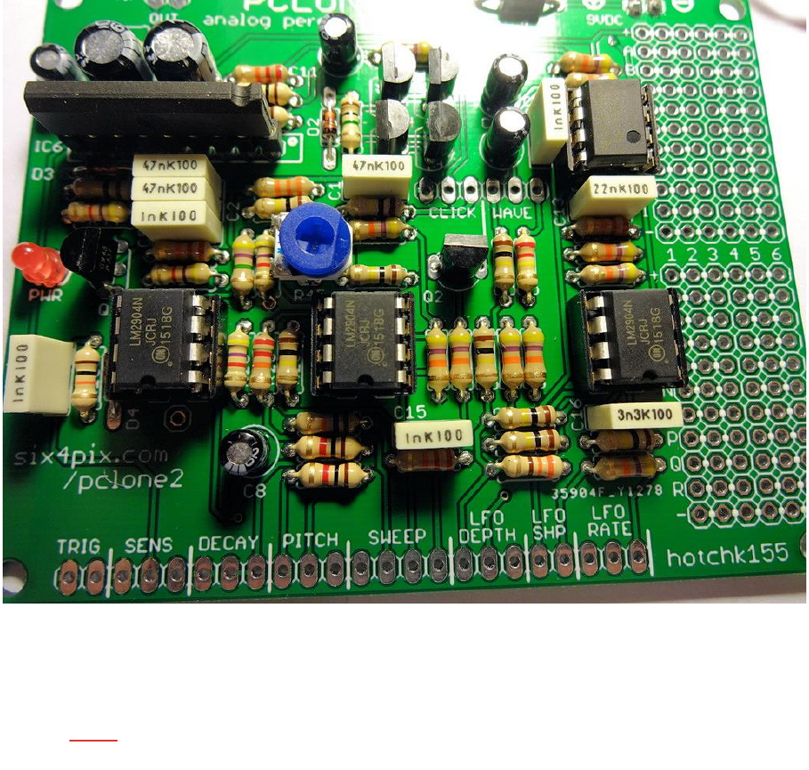
Now lets insert the ICs.
• IC1 – RC4558 op-amp DIP8
• IC3, IC4, IC5 – LM2904 op-amp DIP8
• IC6 BA6110 – op amp SIL9
For IC1, IC3, IC4, IC5, make sure that the notch or dimple on the body of
the chip matches the notch shown in the symbol on the board (which
should also match the notch on the socket). The location for each notch is
toward the bottom edge of the board.
For IC6, there is a notch along the top of the chip. This should be towards
the right (There is a dot marked on the board). A firm push is needed to
insert IC6 but take special care not to bend of break any legs – These are
old chips (no longer manufactured) and your chip may have been
recovered from other equipment, so the legs can be a bit more fragile than
the other ICs.
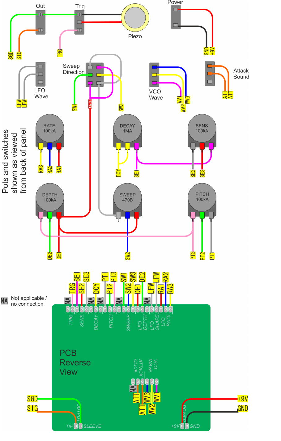

The wiring is actually pretty complicated and easy to get wrong, so if
possible I would recommend that you stick to using the same colours for
the wires as I did, and which I describe in these instructions.
However, if you are just using the wire supplied with the kit you might run
out of a particular colour (as they are supplied in equal lengths). You can
substitute in another without any problems – the wires are all the same type
– but be careful not to mix them up.
Be careful with the length of each wire – you want to keep them short
enough so they all fit in the case when it is put together (it is very easy to
end up with such a bulk of wires that they wont fit!) but also you want to
make sure the wires are long enough to allow you to get the PCB out of the
case for troubleshooting and modding. You want them all to have the same
amount of “slack” so you don’t end up with one wire shorter than the others
stopping you being able to move the board.
Honestly this is the hardest part of the build, so go carefully and
slowly and double check everything as you go!
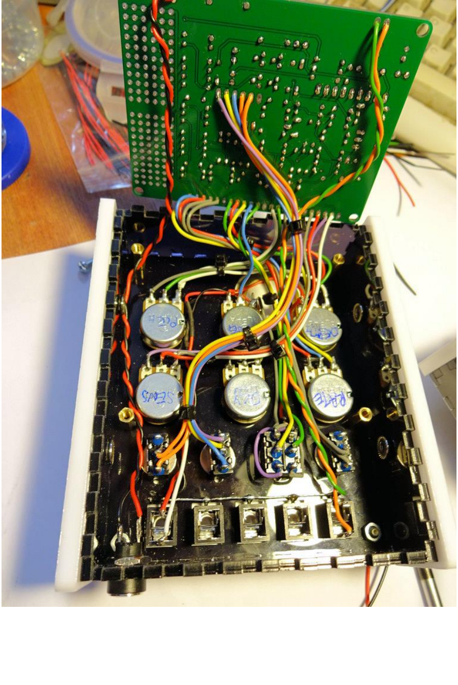
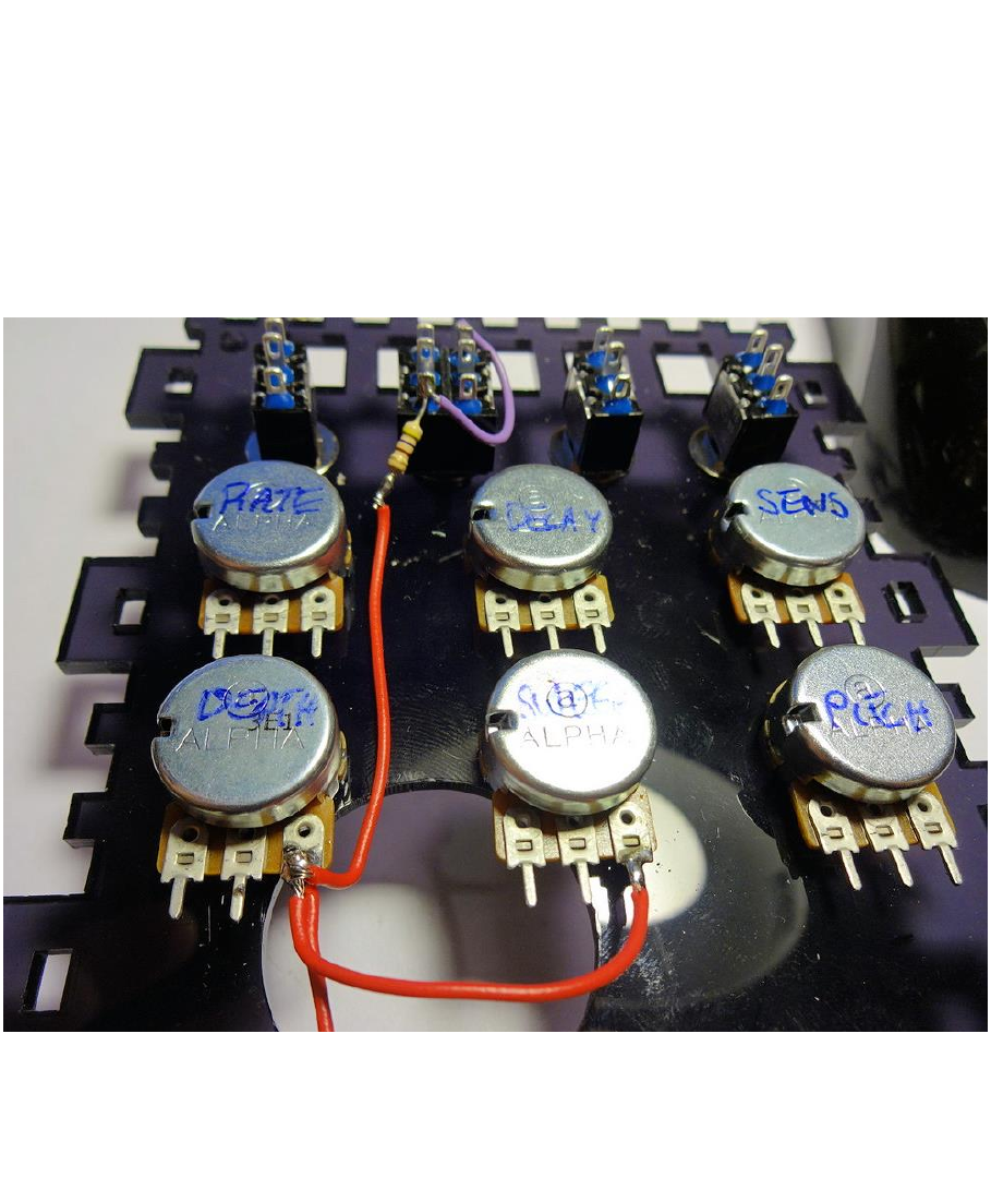
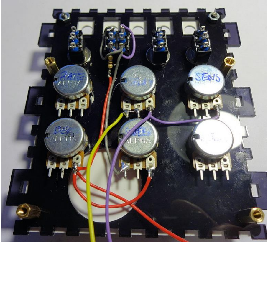
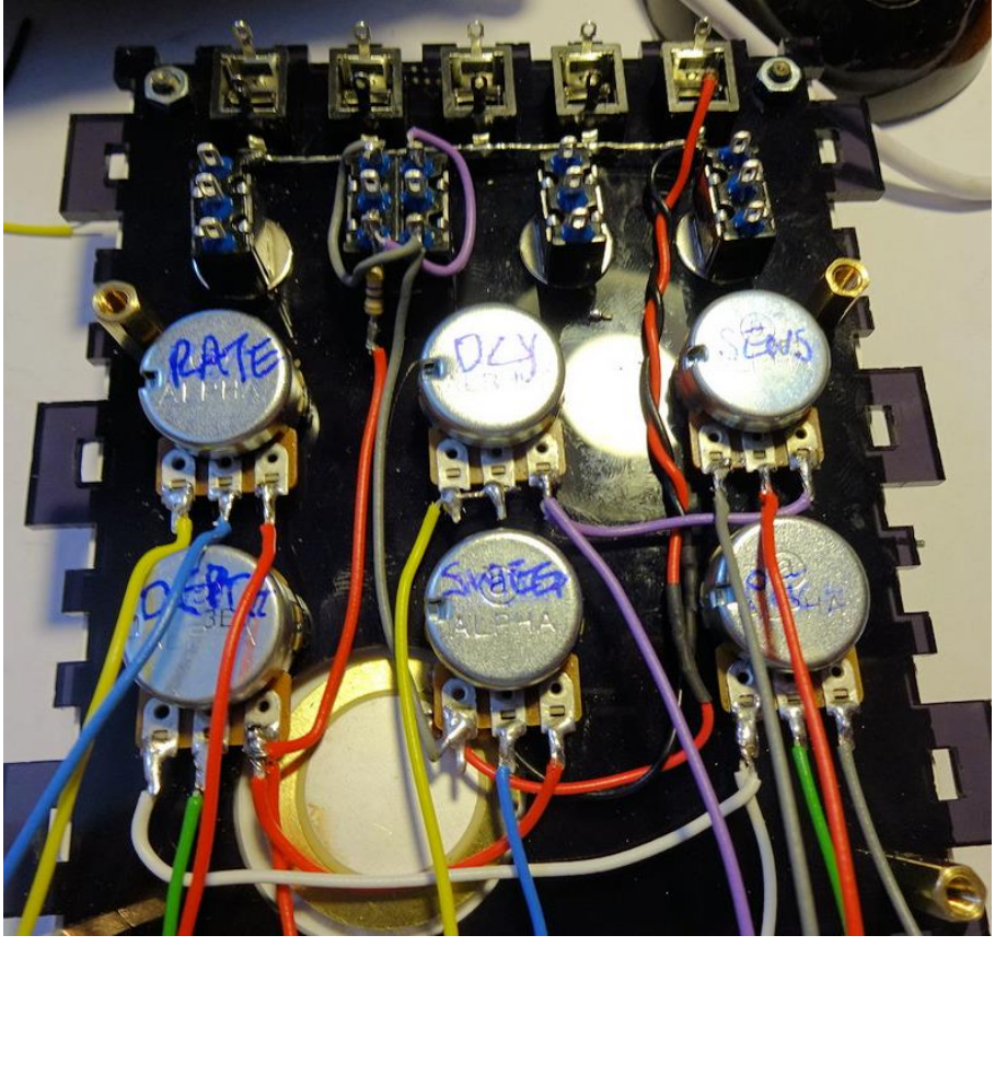
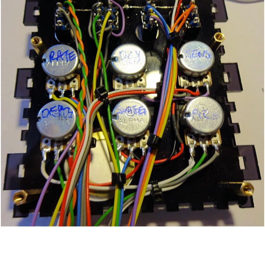
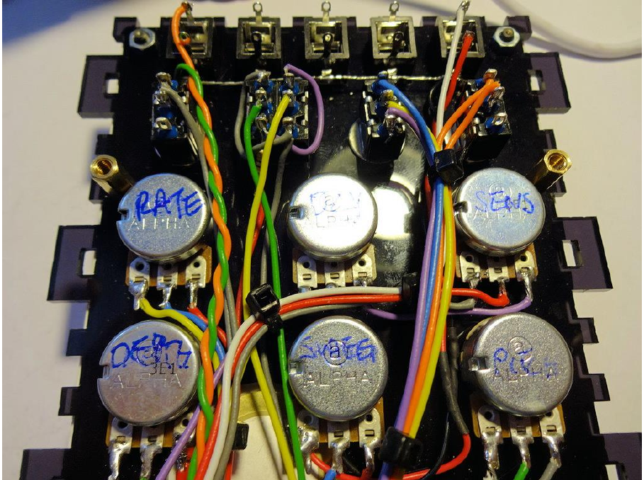
Here is a picture showing what we are aiming for (don’t worry, the steps are
all described below…). Basically we want to be able to access the PCB
when the wires are attached, but we also want to keep the wiring as un-
bulky as we can.
So lets get started, fetch the acrylic front case panel and remove the
protective film from both sides. Get the six potentiometers – I recommend
labelling the back of each one with a marker pen or sticker
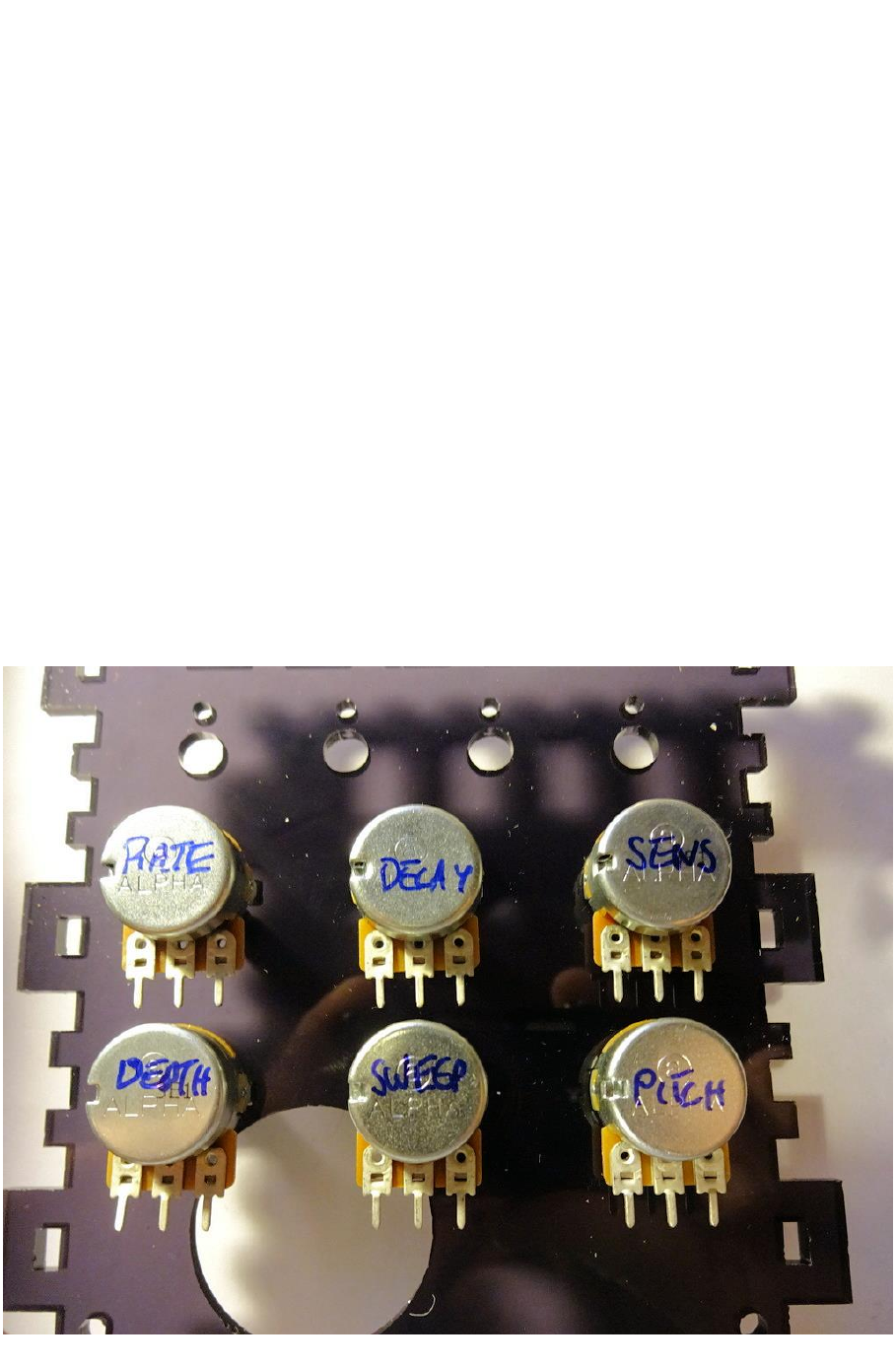
There are three types of potentiometer, so check the marking on the front
of each. In the order as viewed from back of panel the potentiometers are
• A100K – Rate
• A1M – Decay
• A100K – Sensitivity
• A100K – Depth
• B470 – Sweep
• A100K – Pitch
DO NOT break off the locating tabs from the potentiometers (as you
might have done in other kits). There are holes cut for the tabs in the panel
and they will stop the pots moving around when the knobs are turned.
Remove the nut and washer from each one and insert them into the panel
as shown below (check the location of the large round hole in the panel
matches the photo). Replace the washer and tighten the nut. Double check
all your pots are in the right place and the panel is the right way round (it
will be MUCH harder to correct it later!)
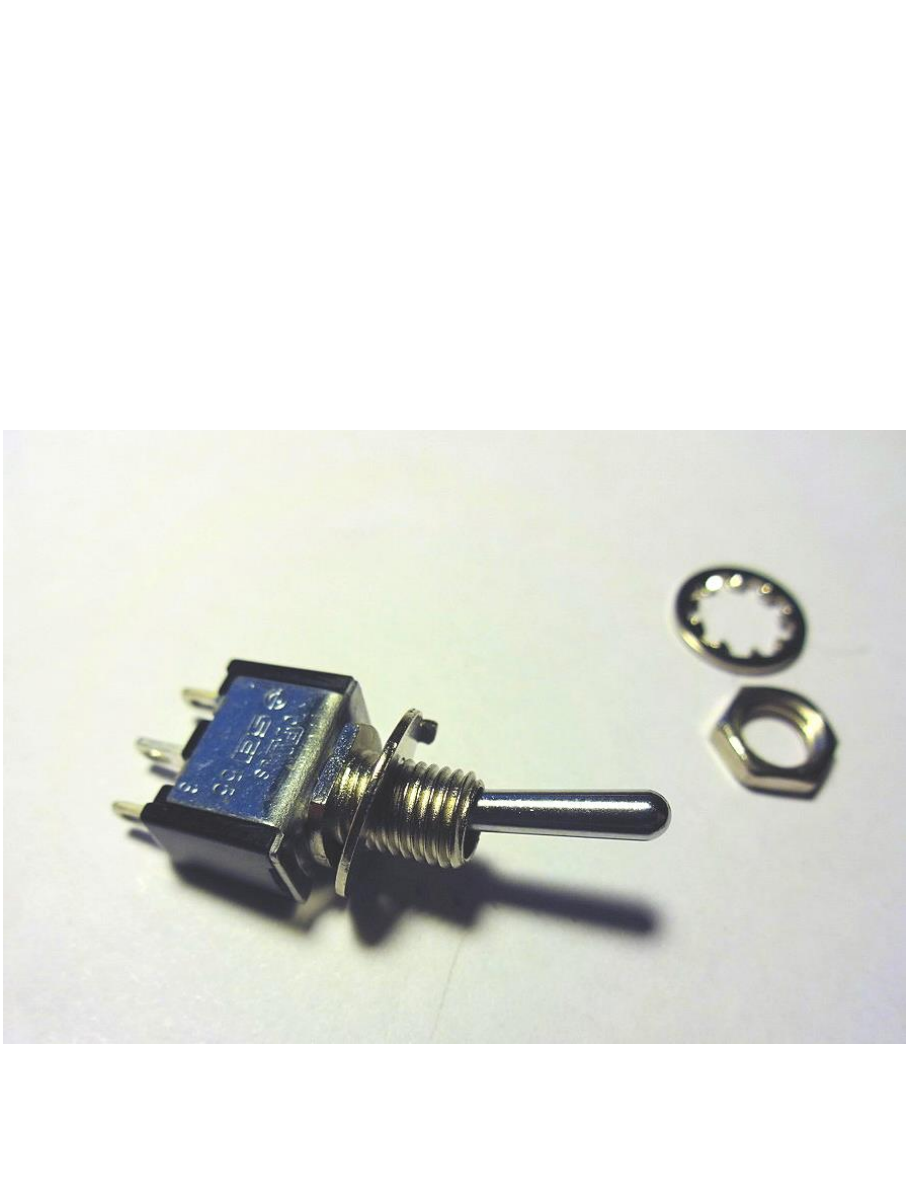
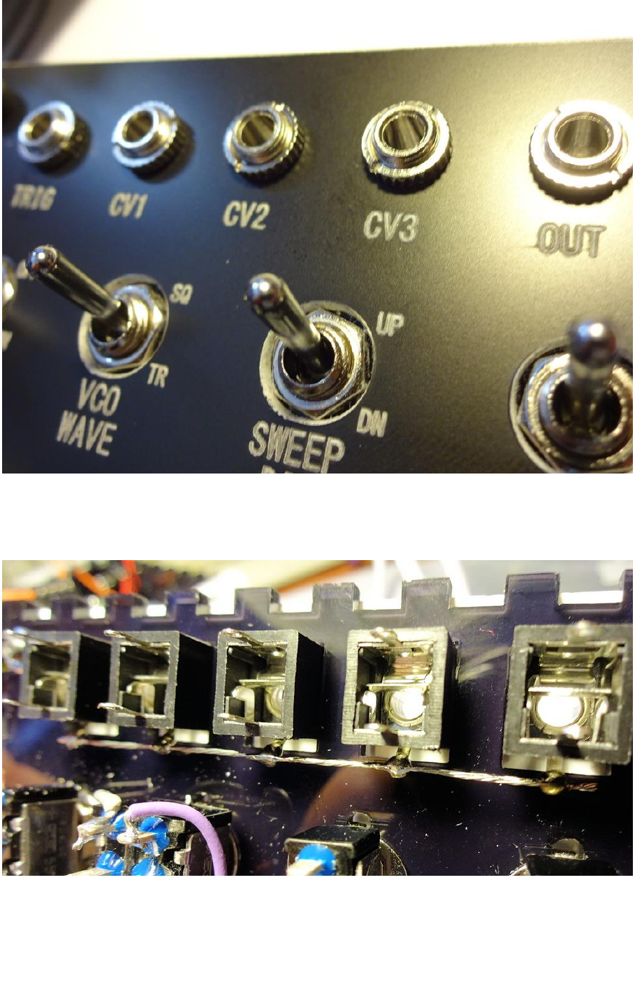
Now add the four switches. They are inserted into the read of the panel in
order:
• MOD WAVE – SPDT (Three pins)
• SWEEP DIR – DPDT (Six pins)
• VCO WAVE – SPDT (Three pins)
• CLICK – SPDT (Three pins)
Remove the nuts and washer and turn the locating plate around so the tab
faces forwards. When the switch is in place the tab should align with the
small hole cut in the panel. I use a single nut to fix the switch in place and
discard the grip washer.
One of the switches is a double-pole (DPDT) switch with six terminals. This
is placed second from the left as shown in the photo below. All the other
switches are identical single pole (SPDT) switches.
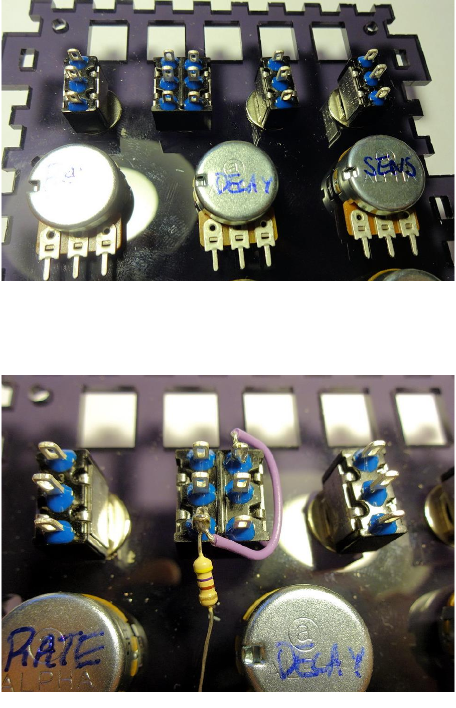
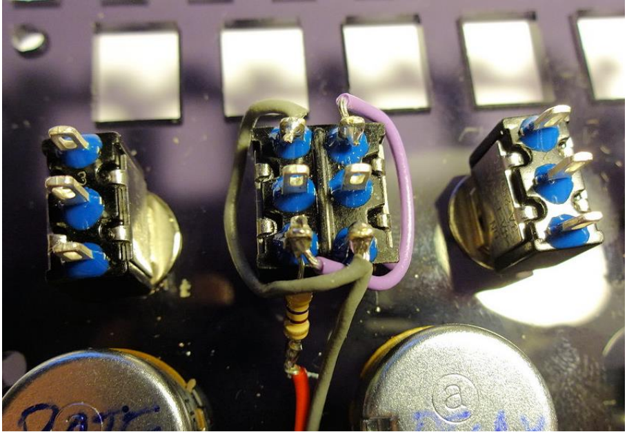
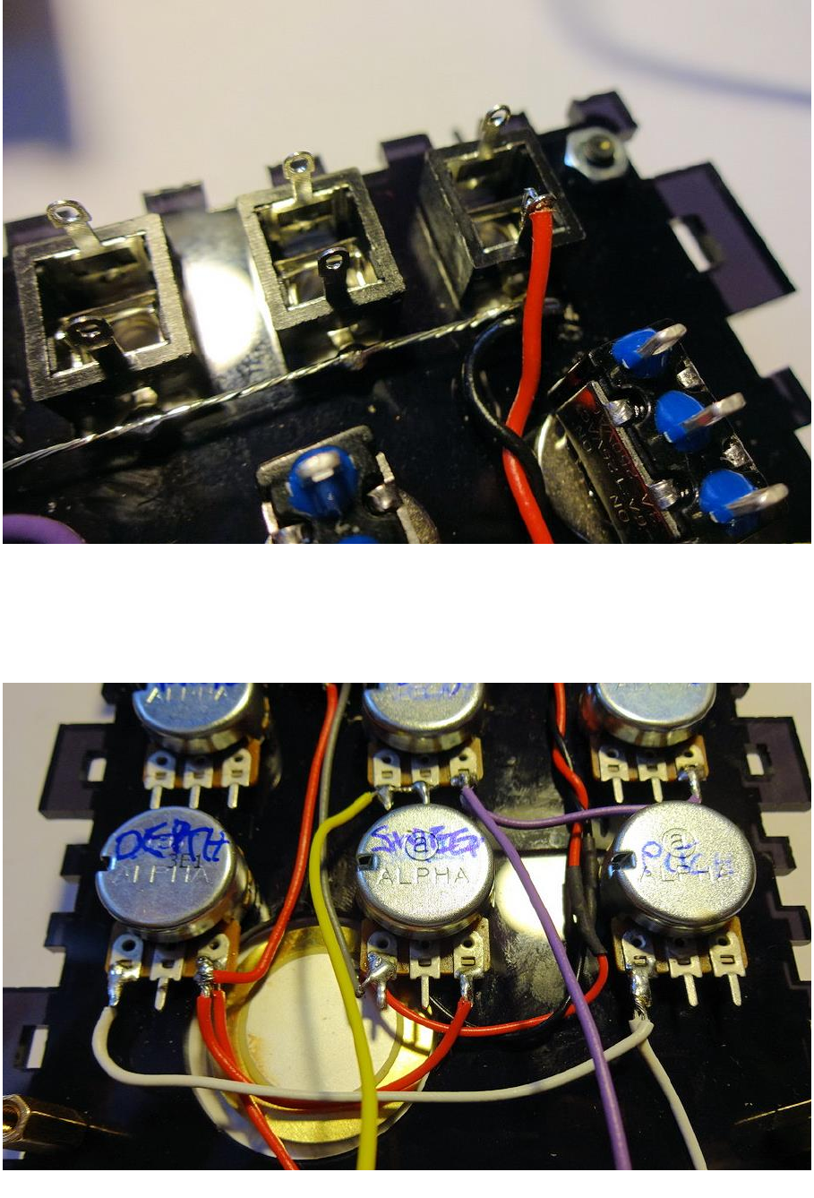
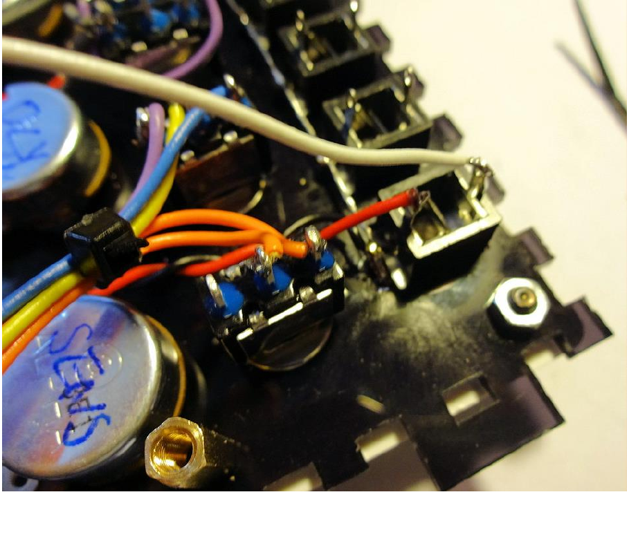
Take about 5cm of purple wire and solder it between the bottom left and
top right pins of the DPDT switch as shown below. Solder one end of a 470
ohm resistor (YELLOW-VIOLET-BROWN) to the same bottom left pin as
shown. Solder the resistor close to the switch.
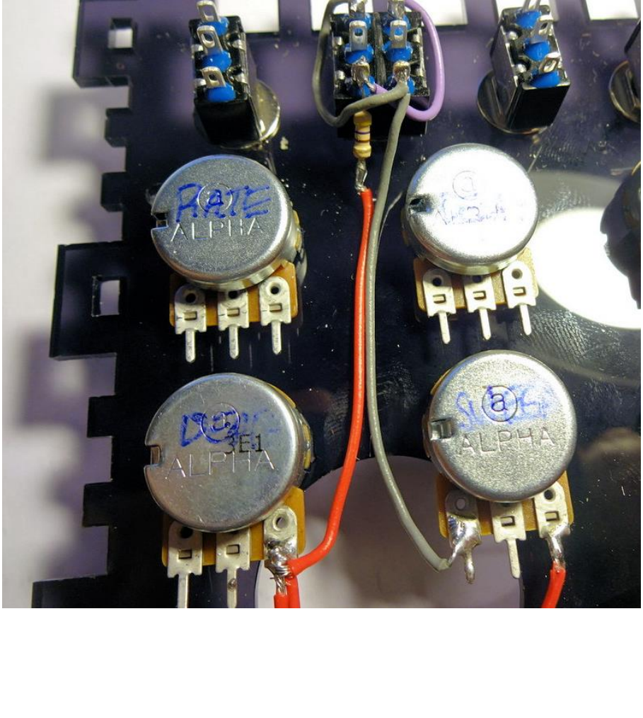
Use red wire to connect
• The other end of the 470 ohm resistor to the right hand tab of the
DEPTH pot (~7cm of wire)
• The right hand tab of the DEPTH pot to the right hand tab of the
SWEEP pot (~5cm of wire)
• Another wire connected at one end to the right hand tab of the
DEPTH pot (~10cm of wire)
Use 5cm of grey wire connect the top left pin of the DPDT switch to the
bottom right, then connect these to the left tab of the SWEEP pot using
about 7cm of grey wire.
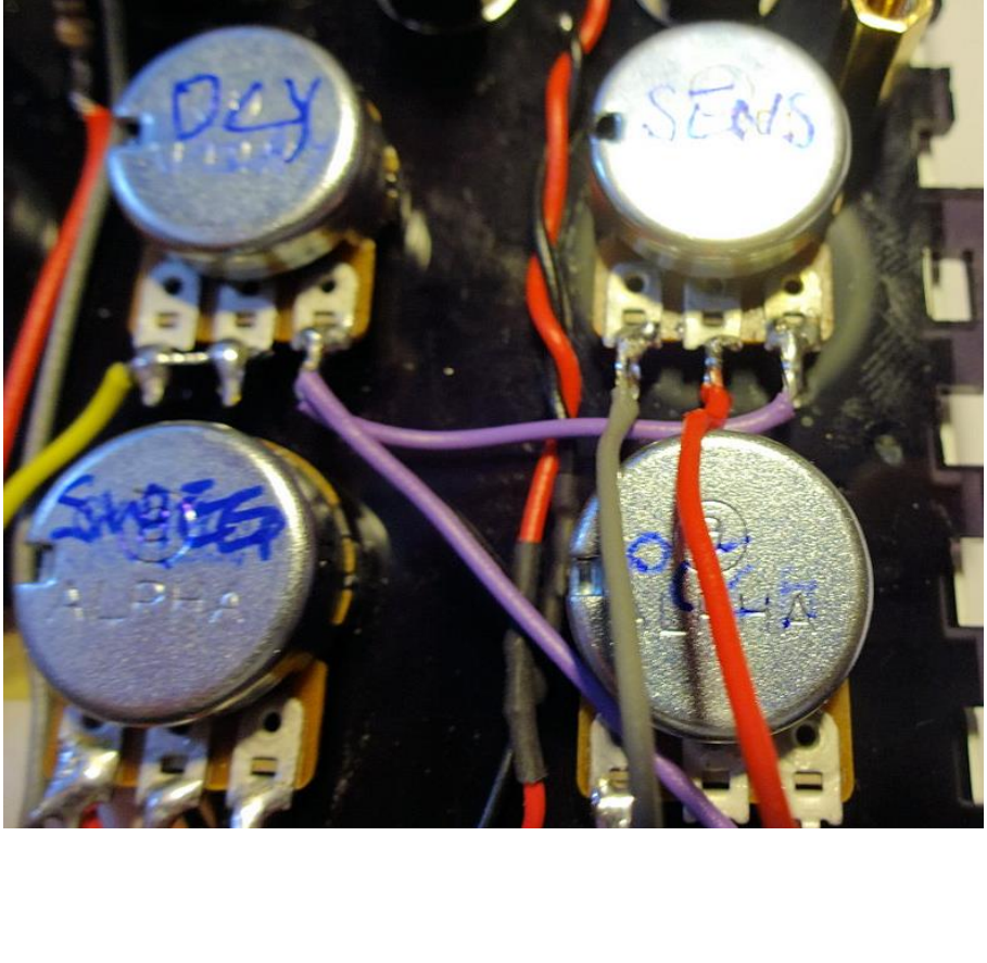
Using about 4cm of purple wire, connect the right tabs of the DECAY and
SENSITIVITY pots together. Add another 15cm length of purle wire to the
right tab of DECAY.
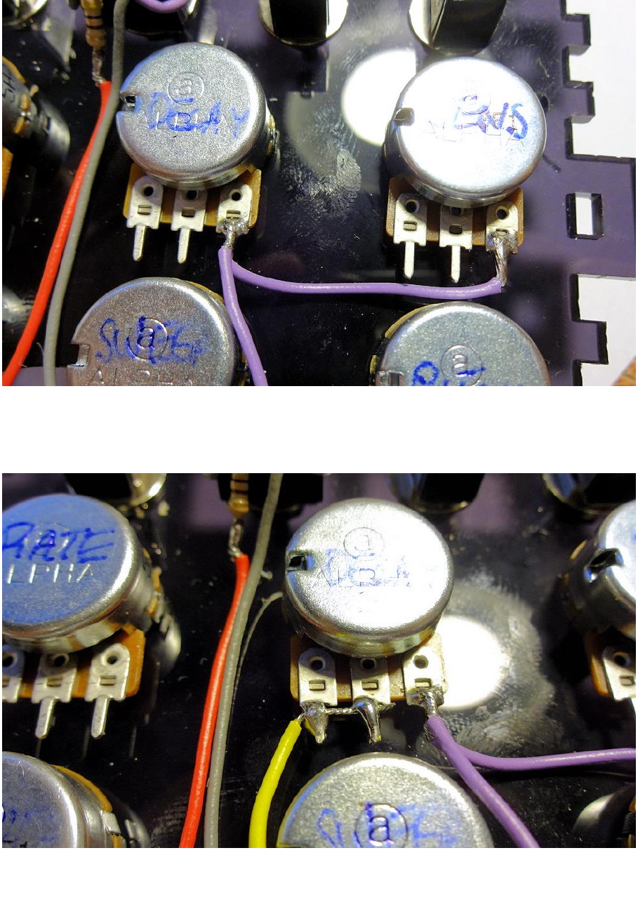
Strip back about 2cm of insulation from a 17cm piece of yellow wire, to
bridge the left and middle tabs of the DECAY pot.
Now place the face plate on to the panel
Use six black M3 allen bolts to attach the face plate. The top two bolts are
secured by nuts and the lower four bolts are secured by attaching the brass
standoffs. Tighten the bolts carefully so that they are just tight enough to be
secure. Warning : Overtightening the bolts may bend or crack the face
plate
Use about 1cm x 1cm of the sticky foam pad to attach the piezo transducer
to the back of the face plate within the circular space near the DEPTH
control. Take care not to break the wires off the transducer.
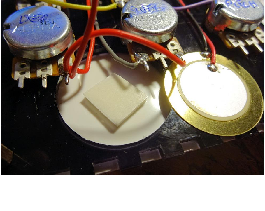
Make sure the transducer wires can reach the top right of the panel, and
tuck them back behind the other wiring
Locate the five 3.5mm sockets and their fixing nuts
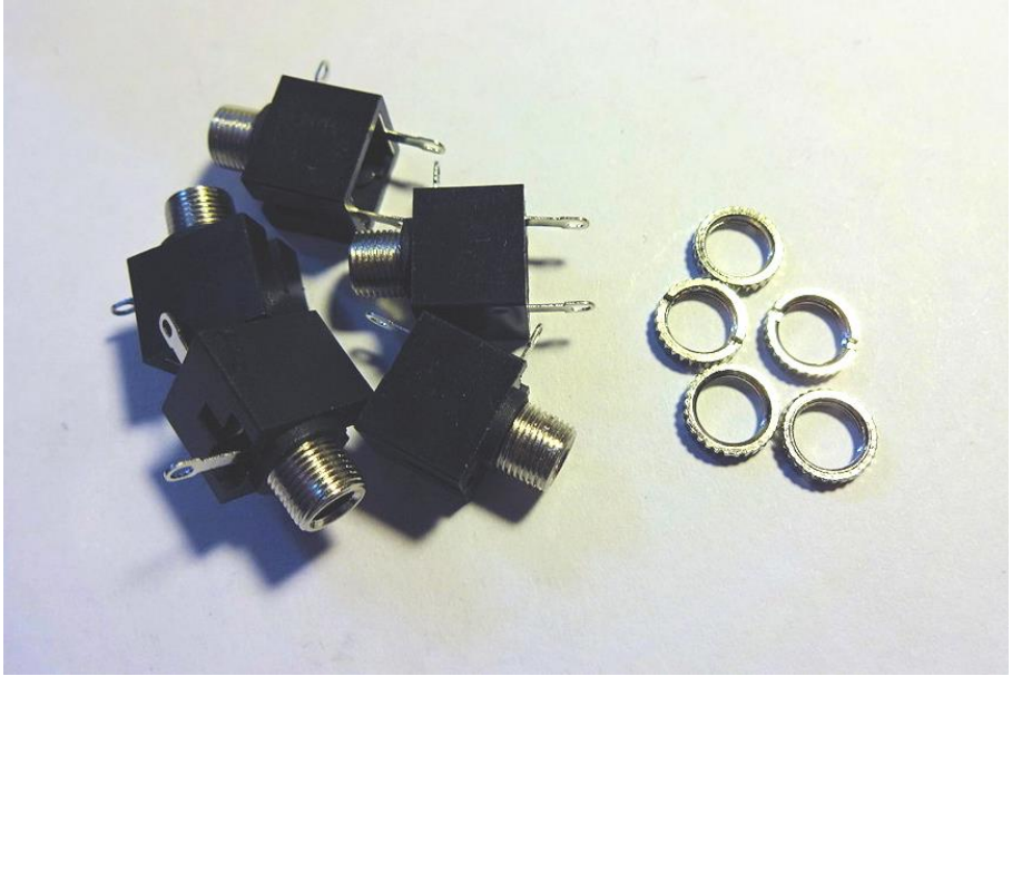
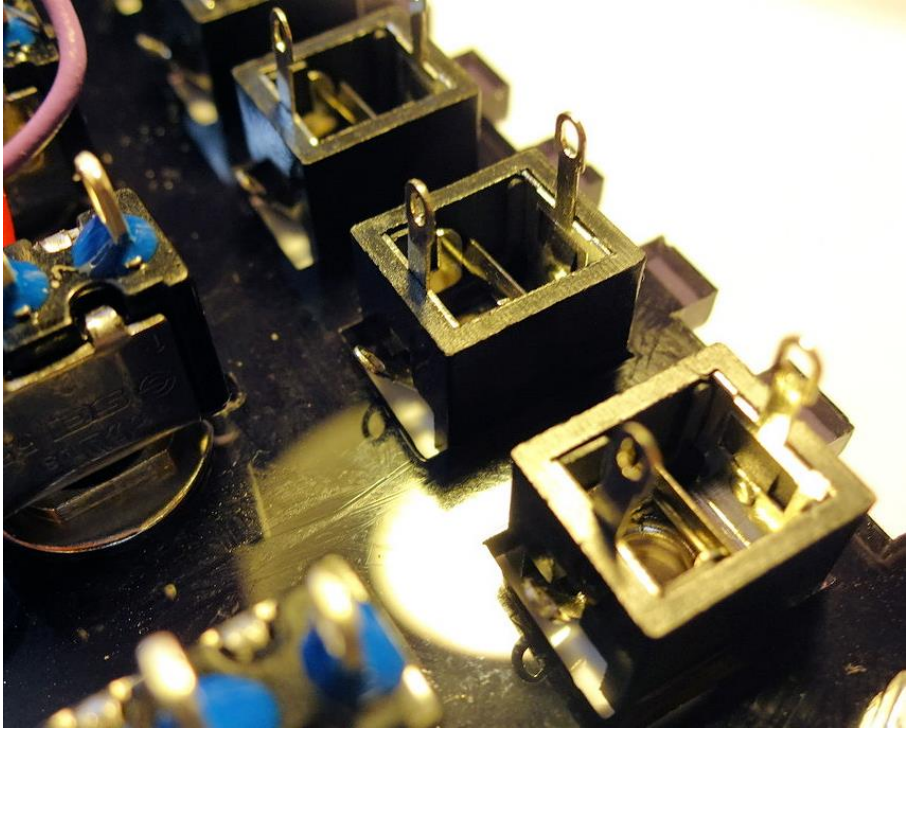
Place the sockets into the five spaces along the top of the panel. Make
sure that the sleeve tab (on the side of each socket) is on the lower edge,
and bend it back slightly so it is about 45 degrees from the body of the
socket.
Secure the sockets using the fixing nuts. Finger-tight should be fine.
Strip the insulation off about 7cm of wire and twist the strands together.
Use this to connect the sleeve tabs of the five sockets as shown.
Trim the wires from the piezo transducer to an appropriate length and
connect the black wire to the bare wire we soldered in the previous step.
Connect the red wire to the lower tab on the right hand socket.
Use about 8cm of white wire to connect the left tab of the DEPTH control to
the left tab of the PITCH control. Add another 10cm of white wire
connected at one end to the left tab of PITCH
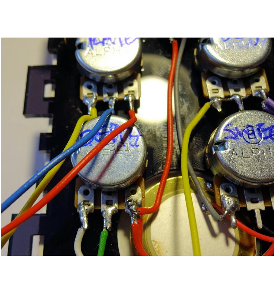
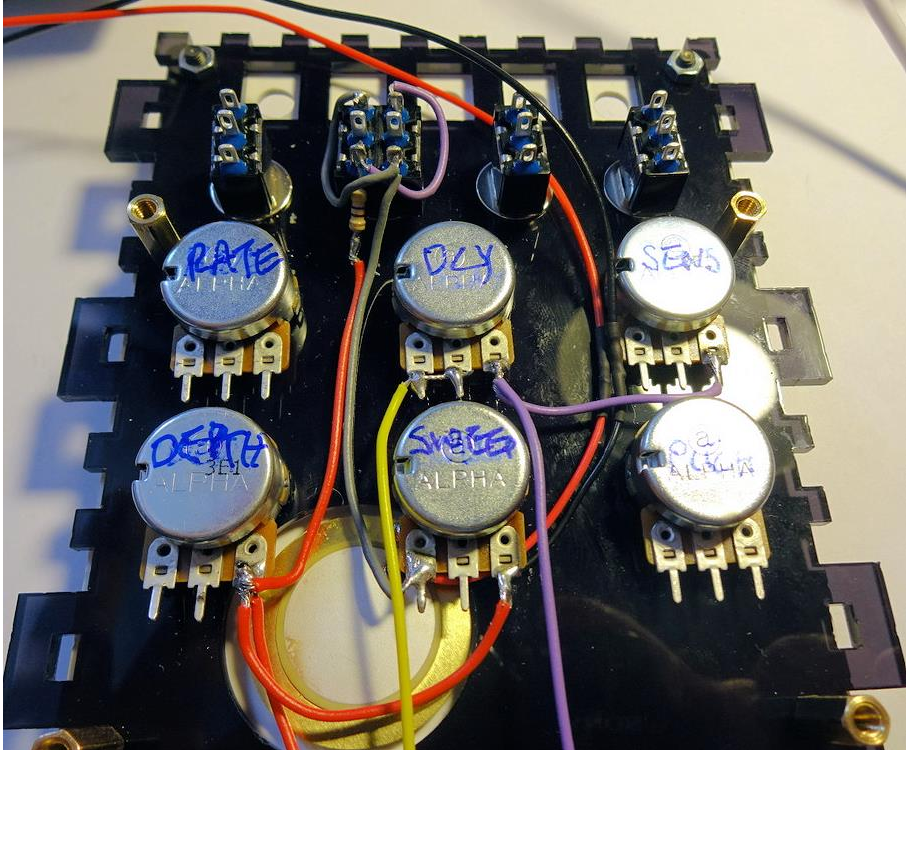
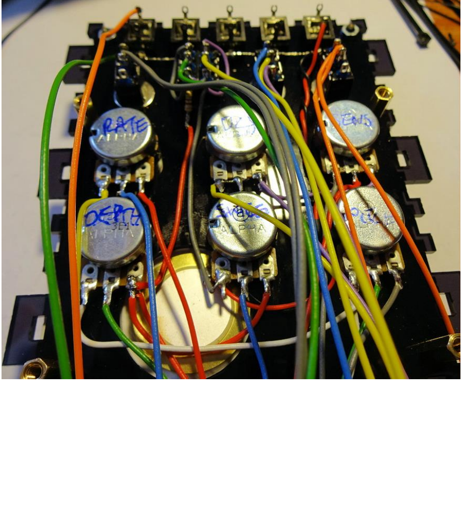
Connect yellow, blue and red wires (about 15cm length each) to the RATE
control, extending them below the bottom edge of the panel. Connect a
green wire of about 14cm length to middle tab of DEPTH control.
Connect a blue wire of about 10cm to the middle tab of the SWEEP control
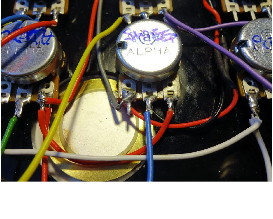
Connect 15cm red and grey wires to the left and middle tabs of the
SENSITIVITY control
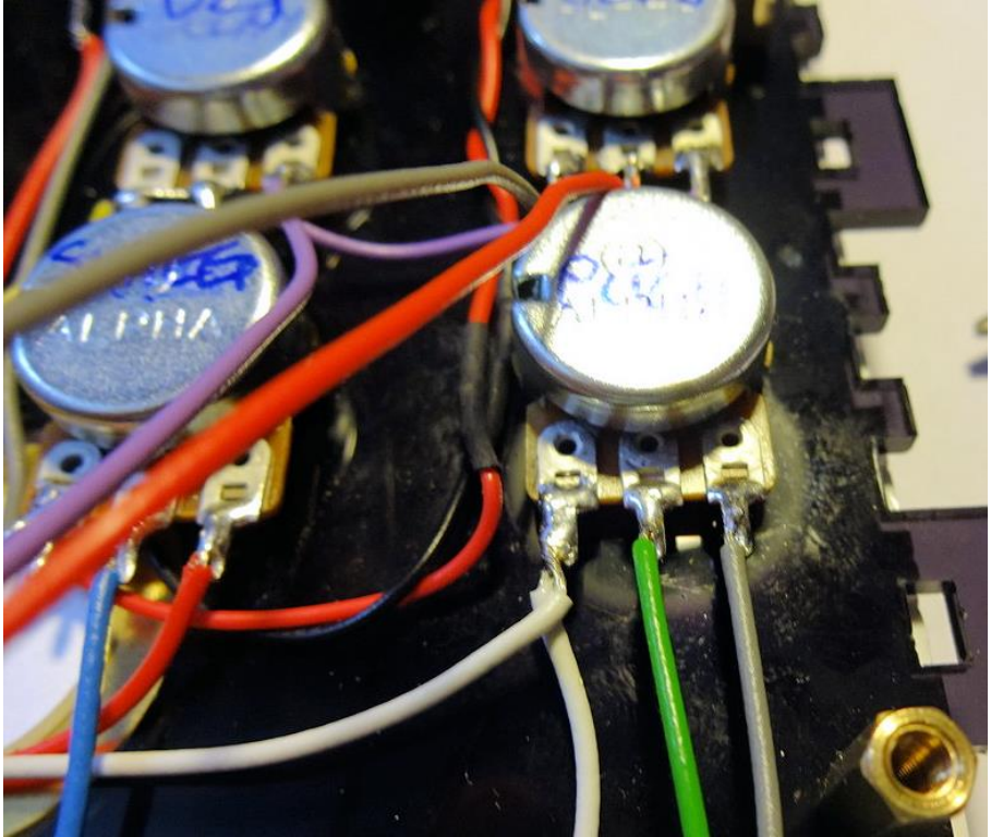
Connect 10cm green and grey wires to the middle and right tabs of the
PITCH control
Connect two 18cm orange wires to the top and middle pins of the right
hand switch
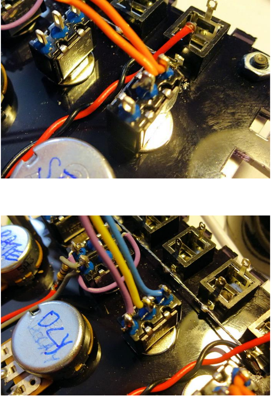
Connect blue, yellow and purple wires of about 20cms each to top, middle
and bottom pins of the second switch from the right
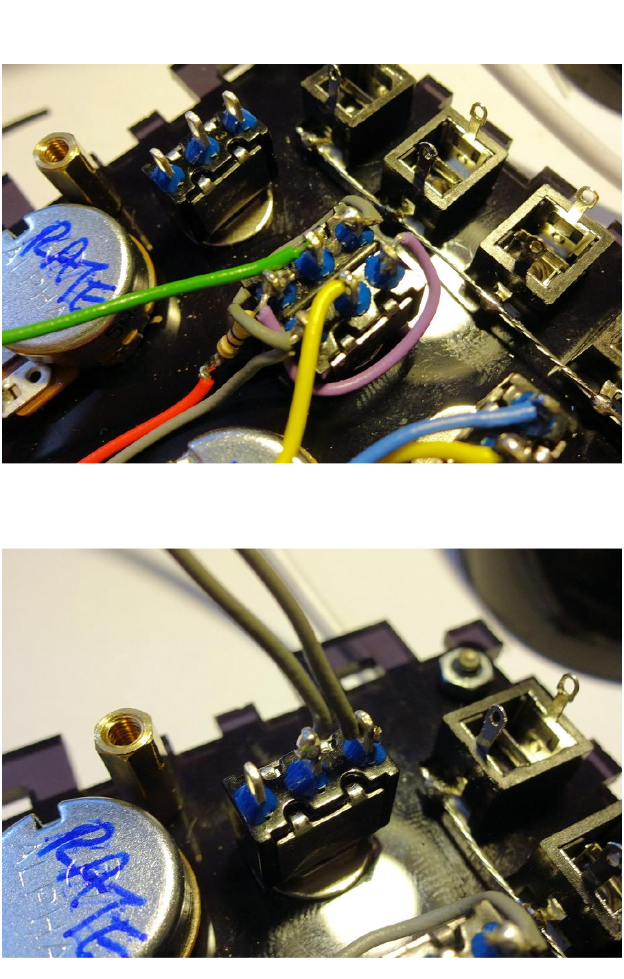
Attach green and yellow wires of about 16cm each to the left middle and
right middle pins of the DPDT switch
Connect two 20cm grey wires to the top and middle pins of the left hand
switch.
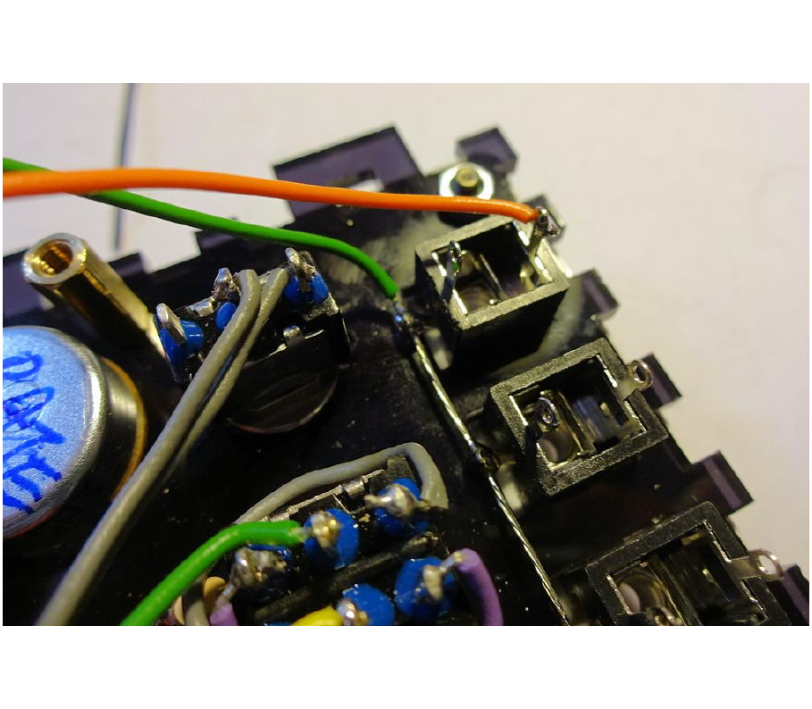
Connect orange and green wires of about 22cm to the left hand socket and
bare ground wire as shown
Connect a 20cm white wire to the top pin on the right hand socket
And now we have a great ugly mass of wires… yay!
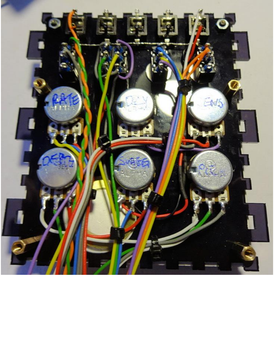
Tidy the wires up using zip ties and routing the bundles between the
potentiometers:
Bundle the white wire from TRIG input with the wires from the
SENSITIVITY and DECAY controls (Five wires; white, puple, red, grey,
yellow). Route the bundle along between DECAY and SWEEP pots then
downwards between DEPTH and SWEEP
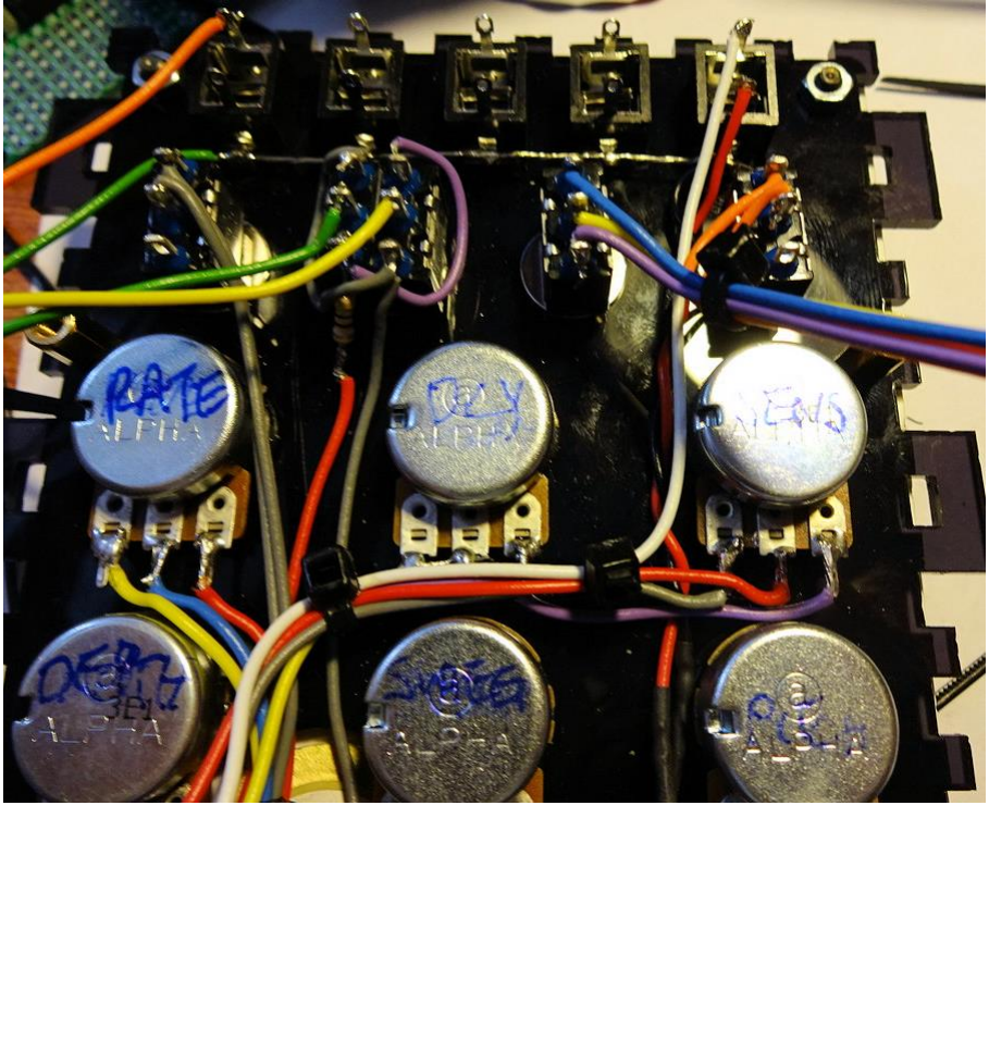
Bundle the wires from the CLICK and VCO WAVE switches (Five wires;
Blue, yellow, purple, orange, orange). Route the bundle down between
DECAY and SENSITIVITY pots and between SWEEP and PITCH)
Twist together the green and orange wires from the OUT socket
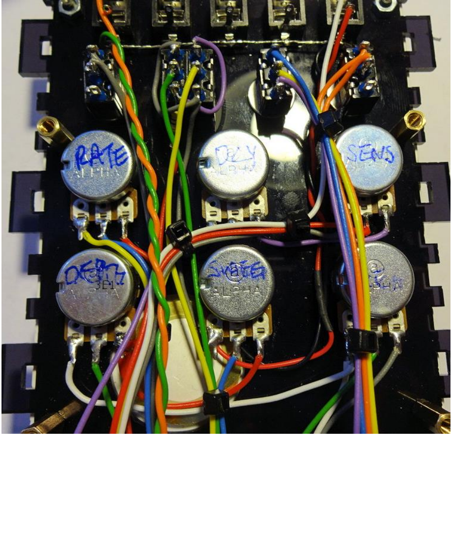
Bundle the wires from the PITCH control. (Three wires; white, green, grey).
Route along the white wire between PITCH and DEPTH
Bundle the yellow and green wires from the SWEEP DIR switch with the
blue wire from the SWEEP pot. (Three wires; yellow, green, blue). Route
downwards from the SWEEP pot
Bundle the wires from the LFO WAVE switch with those from the RATE pot
(five wires; grey, grey, yellow, blue, red). Route between DEPTH and
SWEEP pots then along towards the right side
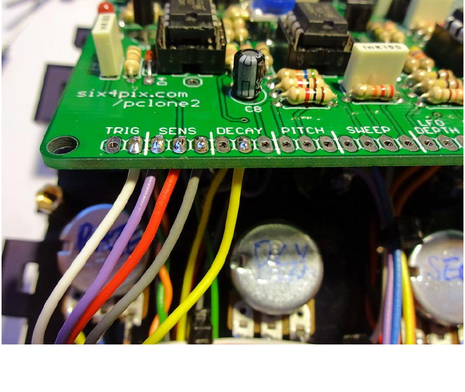
Now we can start attaching the wires to the PCB. Not all of the holes are
used so make sure that you are connecting your wires to the correct holes.
Also try to trim all wires so that they have minimum excess bulk while still
allowing the PCB to be moved.
First off, the wire from the right hand socket, and the SENSIVITY and
DECAY controls. All the wires are joined from the rear of the PCB.
Now the wiring for PITCH, the DPDT switch and the SWEEP pot
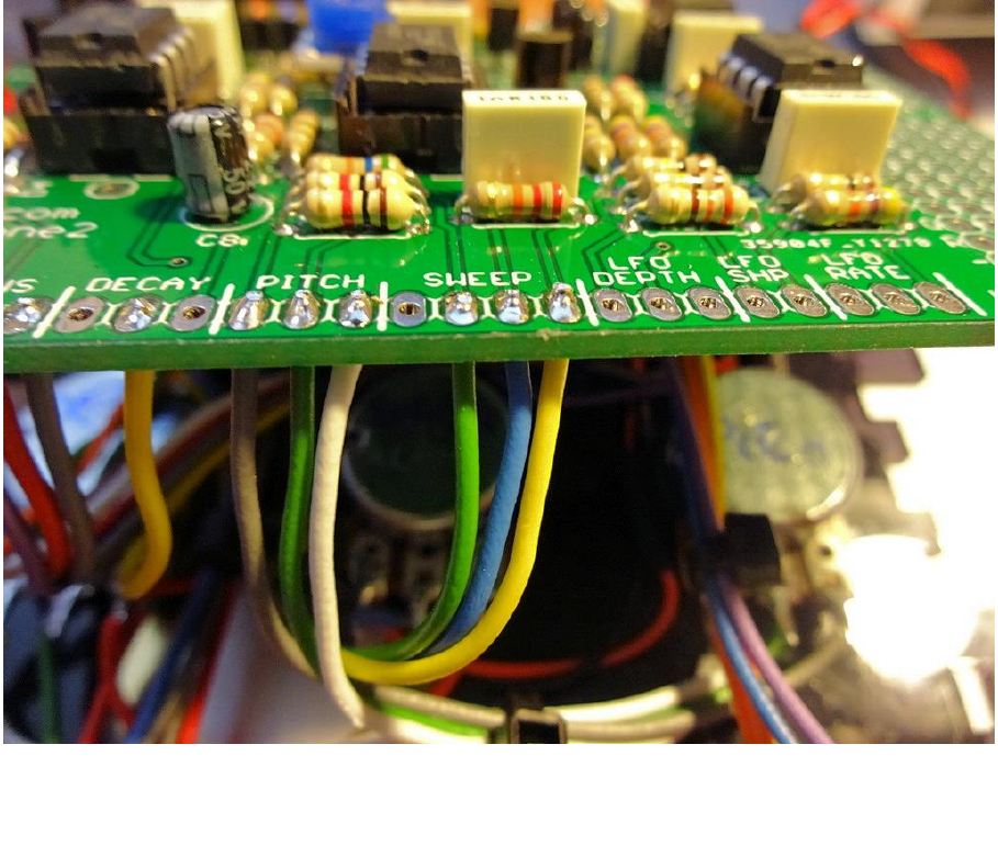
For DEPTH
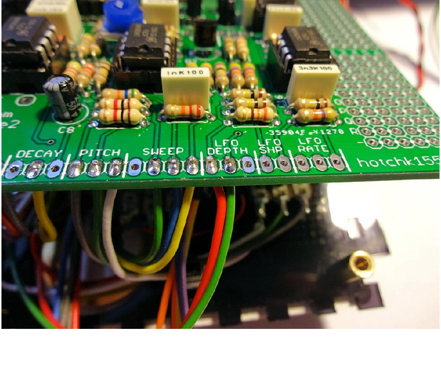
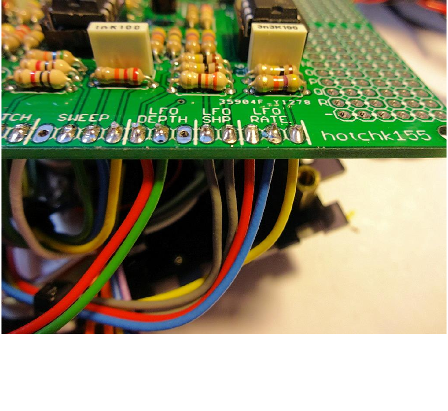
For RATE and also the grey wires from the LFO Shape switch
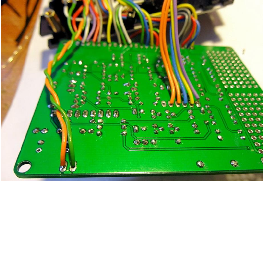
Now the wiring from the other two switches and the output socket. The
switches are connected to a row of holes near the middle of the board (The
first hole is empty)
Twist together a pair of red and black wires of about 22cm. Connect these
to the (+) and (-) power supply pads on the PCB (Unfortunately I didn’t get
a photo of this step)
Now pack the wiring carefully under the PCB and attach the PCB to the
spacers using the screws provided
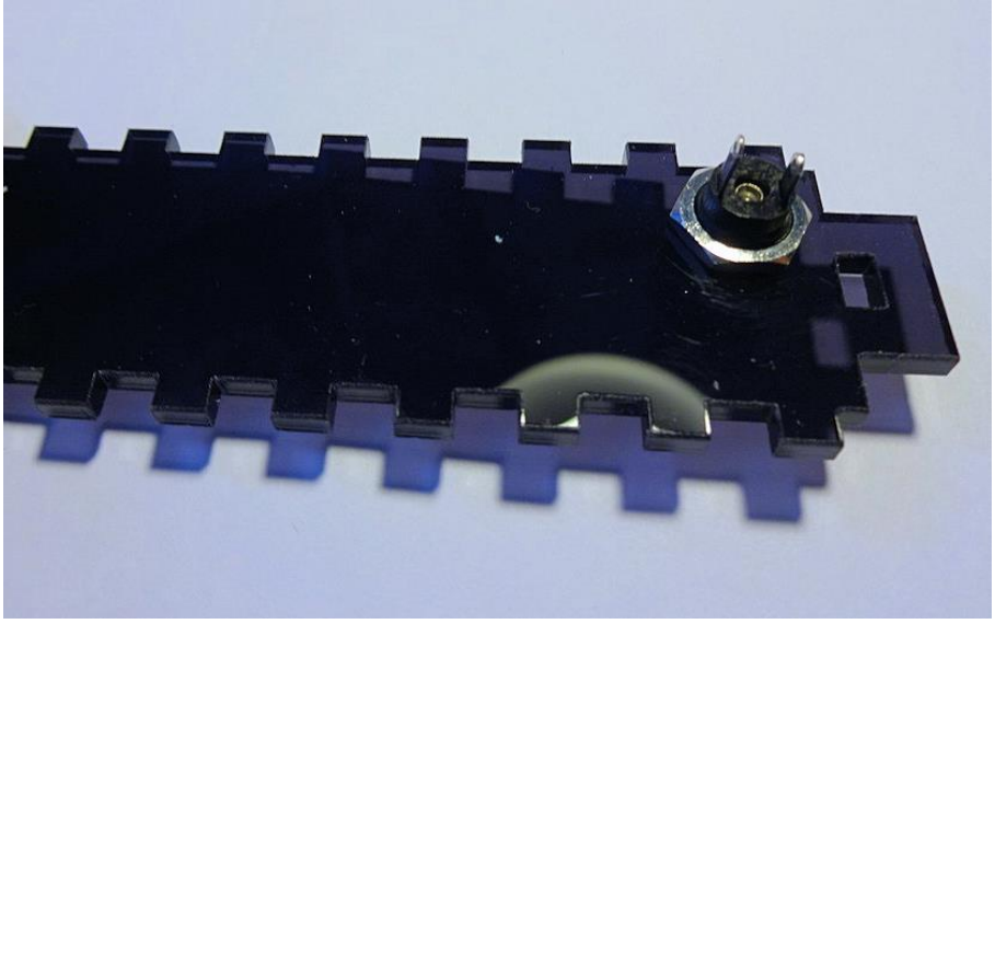
Attach the power connector to the acrylic end panel
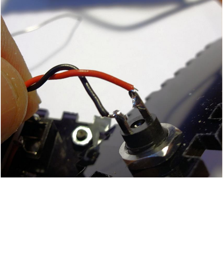
Solder the power leads to the socket. The shorter tab is the central pin of
the power socket – most guitar pedal style 9V DC adaptors connect this to
the negative supply and have the plug barrel as the positive supply. If you
are using this type of supply, connect the wires as shown. If you want to
use a centre-pin positive supply, solder the wires the other way around.
Note: The rectifier diode on the board protects the circuit from damage by
incorrect polarity but the device won’t work with the wrong type of adaptor.
Now is a good time to try it out, before you assemble the enclosure….
move all the control pots to their fully clockwise position and also turn the
trim pot R45 fully clockwise. Connect an amp/speaker (start at low volume!)
and apply power. Tap the piezo… you should be hearing something… if
not, please refer to the Troubleshooting tab.
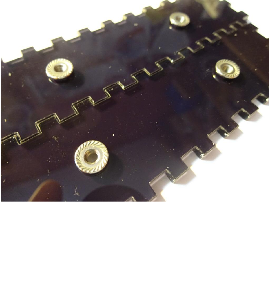
Otherwise let’s finish things off! Locate the four flange nuts and remove the
film from the acrylic side panels
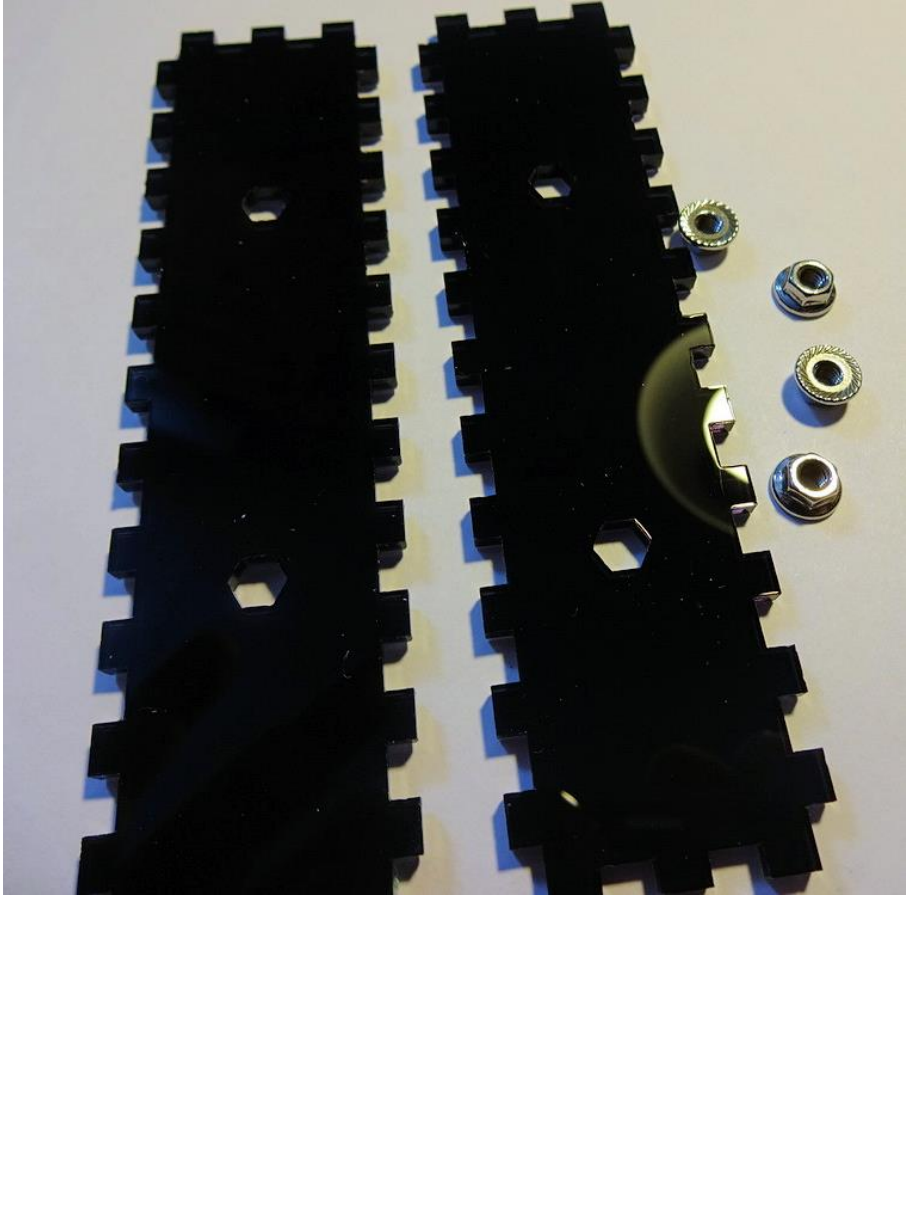
Push the hexagonal parts of the flange nuts into the holes using pressure
from your thumb. Do not hammer them or use a a vice etc as you will
shatter the acrylic!
Note that the laser cut holes for the nuts are very slightly tapered (due to
the shape of the laser beam) which means the nuts can be pushed in more
easily from one side of the panel than the other. Try to ensure the nuts are
inserted from the wider side of the hexagonal holes.
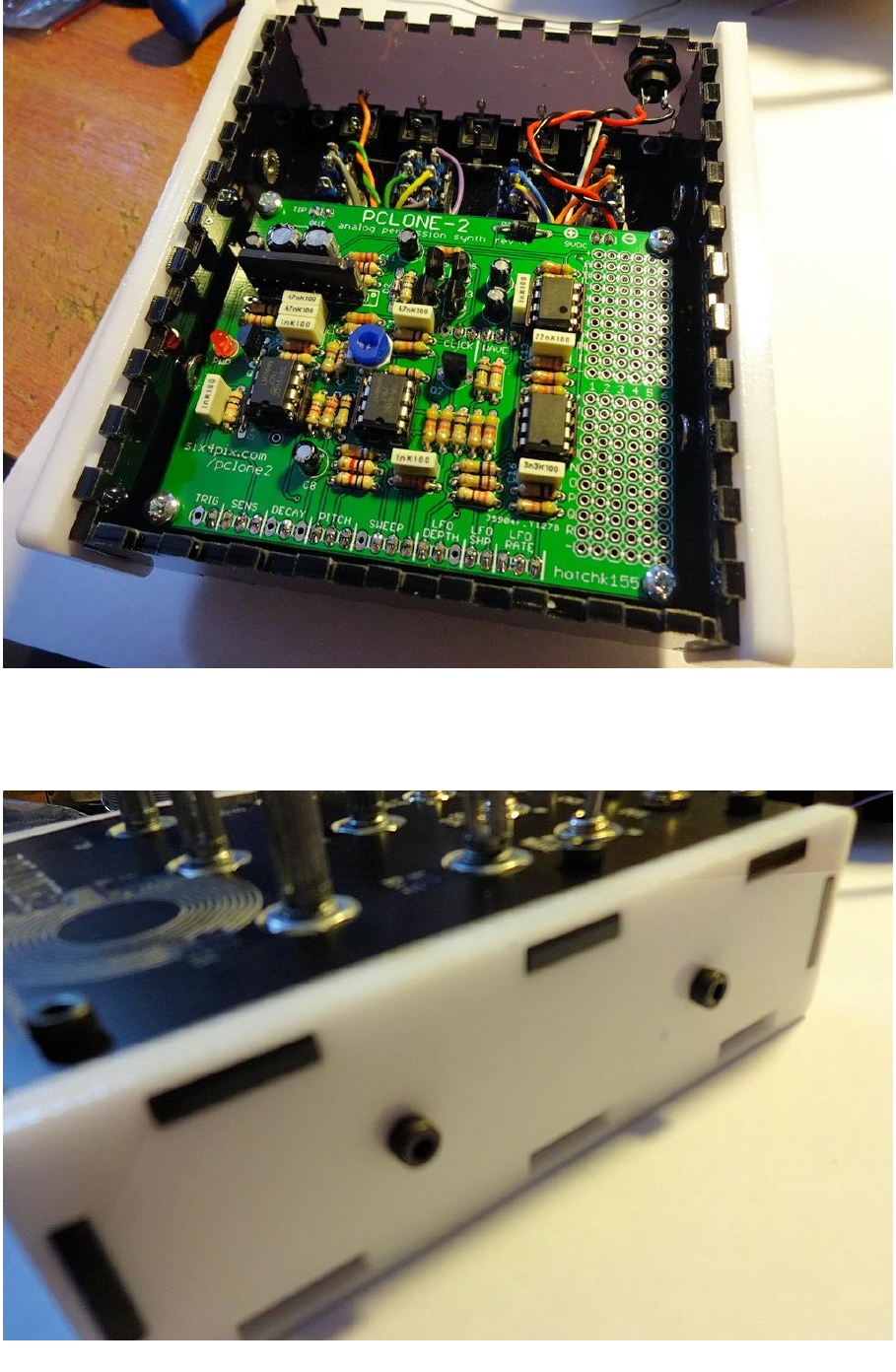
Ensure the film is removed from all the remaining acrylic parts and
assemble the sides of the case. Make sure the flange nuts are on the
inside! Push on the 5mm acrylic side cheeks which hold everything
together.
At this point leave the back of the case off, so we have access to the
electronics in case we need to trouble shoot anything. Later, add the back
panel by removing the side panels.
Use the remaining four allen bolts to attach the side panels. Be careful not
to over tighten the bolts as this could crack the side panels.

Wind all the pots to their lowest position and attach the knobs (when pots
are at minimum the marker on the knob should be at about the 8-o’clock
position)
Congrats! you are done. Enjoy the PCLONE2!
