OM50F42U
User Manual: 2018 Lexus LS 500H Owners Manual PDF | SERVICE MANUAL OWNERS
Open the PDF directly: View PDF ![]() .
.
Page Count: 528 [warning: Documents this large are best viewed by clicking the View PDF Link!]
- Lexus 2018 LS500h Owner's Manual (OM50F42U)

LS500h_OM_OM50F42U_(U)
1
2
3
4
5
6
7
8
9
Pictorial index Search by illustration
For safety
and security
Make sure to read through them
(Main topics: Child seat, theft deterrent system)
Vehicle status
information and
indicators
Reading driving-related information
(Main topics: Meters, multi-information display)
Before driving Opening and closing the doors and windows,
adjustment before driving
(Main topics: Keys, doors, seats)
Driving Operations and advice which are necessary for driving
(Main topics: Starting hybrid system, refueling)
Interior features Usage of the interior features
(Main topics: Air conditioner, storage features)
Maintenance
and care
Caring for your vehicle and maintenance procedures
(Main topics: Interior and exterior, light bulbs)
When trouble
arises
What to do in case of malfunction and emergency
(Main topics: Battery discharge, flat tire)
Vehicle
specifications
Vehicle specifications, customizable features
(Main topics: Fuel, oil, tire inflation pressure)
For owners Reporting safety defects for U.S. owners, seat belt and
SRS airbag instructions for Canadian owners
Index Search by symptom
Search alphabetically

2
LS500h_OM_OM50F42U_(U)
TABLE OF CONTENTS
For your information......................................6
Reading this manual.................................... 10
How to search .................................................11
Pictorial index.................................................12
1-1. For safe use
Before driving....................................22
For safe driving..................................23
Seat belts .............................................24
SRS airbags ........................................29
Pop Up Hood ...................................38
Front passenger occupant classifi-
cation system ................................. 40
Exhaust gas precautions.............. 44
1-2. Child safety
Riding with children........................ 45
Child restraint systems ................. 45
1-3. Hybrid system
Hybrid system features.................58
Hybrid system precautions...........61
1-4. Theft deterrent system
Immobilizer system ........................ 66
Alarm....................................................68
2-1. Instrument cluster
Warning lights and indicators.....72
Gauges and meters (except F
SPORT models) ............................77
Gauges and meters (F SPORT
models).............................................. 81
Multi-information display.............86
Head-up display ...............................92
Energy monitor/consumption
screen................................................96
3-1. Key information
Keys.................................................... 104
3-2. Opening, closing and locking the
doors and trunk
Doors.................................................108
Trunk....................................................112
Smart access system with push-but-
ton start ............................................119
3-3. Adjusting the seats
Front seats........................................ 128
Power rear seat............................. 135
Driving position memory........... 139
Rear seat position memory........143
Head restraints ...............................144
3-4. Adjusting the steering wheel and
mirrors
Steering wheel................................147
Inside rear view mirror ............... 148
Outside rear view mirrors......... 149
3-5. Opening, closing the windows and
moon roof
Power windows ...............................151
Moon roof........................................ 153
4-1. Before driving
Driving the vehicle........................ 158
Cargo and luggage...................... 164
Vehicle load limits......................... 166
Trailer towing.................................. 166
1For safety and security
2Vehicle status information and
indicators
3Before driving
4Driving

3
TABLE OF CONTENTS
LS500h_OM_OM50F42U_(U)
1
2
3
4
5
6
7
8
9
Dinghy towing ................................167
4-2. Driving procedures
Power (ignition) switch...............168
EV drive mode ............................... 172
Hybrid transmission.....................174
Turn signal lever.............................180
Parking brake ..................................181
Brake Hold.......................................183
4-3. Operating the lights and wipers
Headlight switch............................185
AHB (Automatic High Beam)
............................................................188
Windshield wipers and washer
............................................................190
4-4. Refueling
Opening the fuel tank cap......... 194
4-5. Using the driving support systems
Lexus Safety System+A..............196
Lexus Safety System+ ................203
PCS (Pre-Collision System) (vehi-
cles with Lexus Safety System+A)
...........................................................209
PCS (Pre-Collision System) (vehi-
cles with Lexus Safety System+)
...........................................................220
FCTA (Front Cross Traffic Alert)
........................................................... 227
LTA (Lane Tracing Assist)........230
LKA (Lane-Keeping Assist) ....240
RSA (Road Sign Assist)............. 247
Dynamic radar cruise control with
full-speed range.........................250
BSM (Blind Spot Monitor) .......260
PKSA (Parking Support Alert)
...........................................................265
Intuitive parking assist ................266
RCTA (Rear Cross Traffic Alert)
function.......................................... 273
RCD (Rear Camera Detection)
function...........................................277
PKSB (Parking Support Brake)
..........................................................280
Parking Support Brake function
(static objects)............................ 286
Parking Support Brake function
(rear-crossing vehicles)...........291
Parking Support Brake function
(rear pedestrians)..................... 295
Driving mode select switch .....298
Electronically modulated air sus-
pension.......................................... 299
Driving assist systems ................ 302
4-6. Driving tips
Hybrid vehicle driving tips .......307
Winter driving tips.......................309
5-1. Remote Touch/Display
Remote Touch.................................314
Center Display............................... 316
Rear Multi Operation Panel .... 318
5-2. Lexus Climate Concierge
Lexus Climate Concierge..........321
5-3. Using the air conditioning system
and defogger
Front automatic air conditioning
system............................................ 323
Rear air conditioning system... 333
Heated steering wheel/seat heat-
ers/seat ventilators................... 336
5-4. Using the interior lights
Interior lights list ...........................340
5Interior features

4TABLE OF CONTENTS
LS500h_OM_OM50F42U_(U)
5-5. Using the storage features
List of storage features...............343
Trunk features................................348
5-6. Using the other interior features
Other interior features ...............351
Garage door opener..................358
Lexus Enform Safety Connect
...........................................................364
6-1. Maintenance and care
Cleaning and protecting the vehi-
cle exterior...................................370
Cleaning and protecting the vehi-
cle interior....................................373
6-2. Maintenance
Maintenance requirements.....378
General maintenance................379
Emission inspection and mainte-
nance (I/M) programs............382
6-3. Do-it-yourself maintenance
Do-it-yourself service precautions
...........................................................383
Hood..................................................385
Positioning a floor jack...............385
Engine compartment..................387
12-volt battery................................393
Tires ...................................................395
Replacing the tire.........................405
Tire inflation pressure.................408
Wheels...............................................410
Air conditioning filter.................... 411
Electronic key battery.................413
Checking and replacing fuses
............................................................414
Light bulbs.........................................417
7-1. Essential information
Emergency flashers .................... 420
If your vehicle has to be stopped in
an emergency ............................420
7-2. Steps to take in an emergency
If your vehicle needs to be towed
...........................................................422
If you think something is wrong
.......................................................... 426
If a warning light turns on or a warn-
ing buzzer sounds......................427
If a warning message is displayed
.......................................................... 437
If you have a flat tire .....................442
If the hybrid system will not start
.......................................................... 443
If you lose your keys.................... 444
If the fuel filler door cannot be
opened .......................................... 445
If the electronic key does not oper-
ate properly................................. 445
If the 12-volt battery is discharged
.......................................................... 447
If your vehicle overheats........... 453
If the vehicle becomes stuck... 457
8-1. Specifications
Maintenance data (fuel, oil level,
etc.).................................................460
Fuel information............................470
Tire information .............................472
6Maintenance and care
7When trouble arises
8Vehicle specifications

5
TABLE OF CONTENTS
LS500h_OM_OM50F42U_(U)
1
2
3
4
5
6
7
8
9
8-2. Customization
Customizable features................481
8-3. Initialization
Items to initialize...........................495
9-1. For owners
Reporting safety defects for U.S.
owners ...........................................498
Seat belt instructions for Canadian
owners (in French)....................498
SRS airbag instructions for Cana-
dian owners (in French)..........500
What to do if... (Troubleshooting)...
...........................................................508
Alphabetical Index......................... 511
9For owners
Index

6
LS500h_OM_OM50F42U_(U)
Please note that this manual applies to
all models and explains all equipment,
including options. Therefore, you may
find some explanations for equipment
not installed on your vehicle.
All specifications provided in this man-
ual are current at the time of printing.
However, because of the Lexus policy
of continual product improvement, we
reserve the right to make changes at
any time without notice.
Depending on specifications, the vehi-
cle shown in the illustrations may differ
from your vehicle in terms of color and
equipment.
Approximately five hours after the
hybrid system is turned off, you may
hear sound coming from under the
vehicle for several minutes. This is the
sound of a fuel evaporation leakage
check and, it does not indicate a mal-
function.
A wide variety of non-genuine spare
parts and accessories for Lexus vehi-
cles are currently available in the mar-
ket. You should know that Toyota does
not warrant these products and is not
responsible for their performance,
repair, or replacement, or for any dam-
age they may cause to, or adverse
effect they may have on, your Lexus
vehicle.
This vehicle should not be modified
with non-genuine Lexus products.
Modification with non-genuine Lexus
products could affect its performance,
safety or durability, and may even vio-
late governmental regulations. In addi-
tion, damage or performance
problems resulting from the modifica-
tion may not be covered under war-
ranty.
The installation of a mobile two-way
radio system in your vehicle could
affect electronic systems such as:
-Hybrid system
-Multiport fuel injection sys-
tem/sequential multiport fuel injec-
tion system
-Lexus Safety System+A
-Lexus Safety System+
-Anti-lock brake system
-Vehicle dynamics integrated man-
agement
-SRS airbag system
-Seat belt pretensioner system
Be sure to check with your Lexus
dealer for precautionary measures or
special instructions regarding installa-
tion of a mobile two-way radio system.
High voltage parts and cables on the
For your information
Main Owner’s Manual
Noise from under vehicle after turn-
ing off the hybrid system
Accessories, spare parts and modifi-
cation of your Lexus
Installation of a mobile two-way radio
system

7
LS500h_OM_OM50F42U_(U)
hybrid vehicles emit approximately the
same amount of electromagnetic
waves as the conventional gasoline
powered vehicles or home electronic
appliances despite of their electro-
magnetic shielding.
Unwanted noise may occur in the
reception of the mobile two-way radio.
Your Lexus is equipped with several
sophisticated computers that will
record certain data, such as:
-Engine speed
-Electric motor speed (traction
motor speed)
-Accelerator status
-Brake status
-Vehicle speed
-Shift position
-Hybrid battery (traction battery)
status
-Images from the camera sensor
(available only in situations when
sudden inputs occur while driving
[sudden acceleration, etc.], the
pre-collision braking function or the
pre-collision brake assist function
was operating, the Parking Support
Brake function [static objects] was
operating, or your vehicle was
involved in a collision)
The recorded data varies according to
the vehicle grade level and options
with which it is equipped. These com-
puters do not record conversations or
sounds, and only record images out-
side of the vehicle in certain situations.
-Data usage
Lexus may use the data recorded in these
computers to diagnose malfunctions, con-
duct research and development, and
improve quality.
Lexus will not disclose the recorded data to
a third party except:
• With the consent of the vehicle owner or
with the consent of the lessee if the vehi-
cle is leased
• In response to an official request by the
police, a court of law or a government
agency
• For use by Lexus in a lawsuit
• For research purposes where the data is
not tied to a specific vehicle or vehicle
owner
-Usage of data collected through
Safety Connect / Lexus Enform
(U.S. mainland only)
If your Lexus has Safety Connect or Lexus
Enform and if you have subscribed to those
services, please refer to the Safety Con-
nect / Lexus Enform Telematics Subscrip-
tion Service Agreement for information on
data collected and its usage.
This vehicle is equipped with an event
data recorder (EDR). The main pur-
pose of an EDR is to record, in certain
crash or near crash-like situations, such
as an air bag deployment or hitting a
road obstacle, data that will assist in
understanding how a vehicle’s systems
performed. The EDR is designed to
record data related to vehicle dynam-
Vehicle data recordings
Event data recorder

8
LS500h_OM_OM50F42U_(U)
ics and safety systems for a short
period of time, typically 30 seconds or
less.
The EDR in this vehicle is designed to
record such data as:
• How various systems in your vehicle
were operating;
• Whether or not the driver and pas-
senger safety belts were buck-
led/fastened;
• How far (if at all) the driver was
depressing the accelerator and/or
brake pedal; and,
• How fast the vehicle was traveling.
These data can help provide a better
understanding of the circumstances in
which crashes and injuries occur.
NOTE: EDR data are recorded by your
vehicle only if a nontrivial crash situa-
tion occurs; no data are recorded by
the EDR under normal driving condi-
tions and no personal data (e.g., name,
gender, age, and crash location) are
recorded. However, other parties, such
as law enforcement, could combine the
EDR data with the type of personally
identifying data routinely acquired
during a crash investigation.
To read data recorded by an EDR, spe-
cial equipment is required, and access
to the vehicle or the EDR is needed. In
addition to the vehicle manufacturer,
other parties, such as law enforcement,
that have the special equipment, can
read the information if they have
access to the vehicle or the EDR.
-Disclosure of the EDR data
Lexus will not disclose the data recorded in
an EDR to a third party except when:
• An agreement from the vehicle’s owner
(or the lessee for a leased vehicle) is
obtained
• In response to an official request by the
police, a court of law or a government
agency
• For use by Lexus in a lawsuit
However, if necessary, Lexus may:
• Use the data for research on vehicle
safety performance
• Disclose the data to a third party for
research purposes without disclosing
information about the specific vehicle or
vehicle owner
The SRS airbag, seat belt pretensioner
devices and Pop Up Hood system in
your Lexus contain explosive chemi-
cals. If the vehicle is scrapped with the
airbags, seat belt pretensioners and
Pop Up Hood micro gas generators
left as they are, this may cause an acci-
dent such as fire. Be sure to have the
systems of the SRS airbag, seat belt
pretensioner and Pop Up Hood micro
gas generators removed and disposed
of by a qualified service shop or by
your Lexus dealer before you scrap
your vehicle.
Special handling may apply, See
www.dtsc.ca.gov/hazard-
ouswaste/perchlorate.
Your vehicle has components that may
contain perchlorate. These compo-
nents may include airbag, seat belt pre-
Scrapping of your Lexus
Perchlorate Material

9
LS500h_OM_OM50F42U_(U)
tensioners, Pop Up Hood system, and
wireless remote control batteries.
WARNING
■General precautions while driving
Driving under the influence: Never drive
your vehicle when under the influence of
alcohol or drugs that have impaired your
ability to operate your vehicle. Alcohol
and certain drugs delay reaction time,
impair judgment and reduce coordina-
tion, which could lead to an accident that
could result in death or serious injury.
Defensive driving: Always drive defen-
sively. Anticipate mistakes that other
drivers or pedestrians might make and
be ready to avoid accidents.
Driver distraction: Always give your full
attention to driving. Anything that dis-
tracts the driver, such as adjusting con-
trols, talking on a cellular phone or
reading can result in a collision with
resulting death or serious injury to you,
your occupants or others.
■General precaution regarding chil-
dren’s safety
Never leave children unattended in the
vehicle, and never allow children to have
or use the key.
Children may be able to start the vehicle
or shift the vehicle into neutral. There is
also a danger that children may injure
themselves by playing with the windows,
the moon roof, or other features of the
vehicle. In addition, heat build-up or
extremely cold temperatures inside the
vehicle can be fatal to children.
10
LS500h_OM_OM50F42U_(U)
Reading this manual
Explains symbols used in this man-
ual.
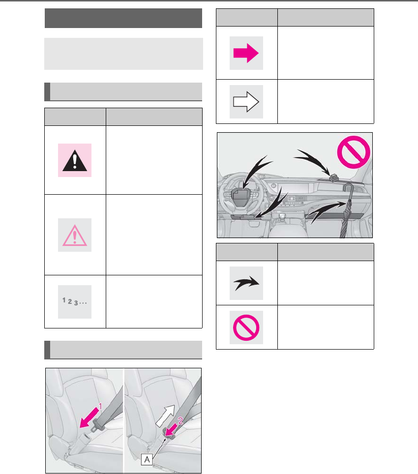
Symbols in this manual
Symbols Meanings
WARNING:
Explains something that,
if not obeyed, could
cause death or serious
injury to people.
NOTICE:
Explains something that,
if not obeyed, could
cause damage to or a
malfunction in the vehi-
cle or its equipment.
Indicates operating or
working procedures. Fol-
low the steps in numeri-
cal order.
Symbols in illustrations
Symbols Meanings
Indicates the action
(pushing, turning, etc.)
used to operate switches
and other devices.
Indicates the outcome of
an operation (e.g. a lid
opens).
Symbols Meanings
Indicates the component
or position being
explained.
Means Do not, Do not do
this, or Do not let this
happen.
12 Pictorial index
Pictorial index
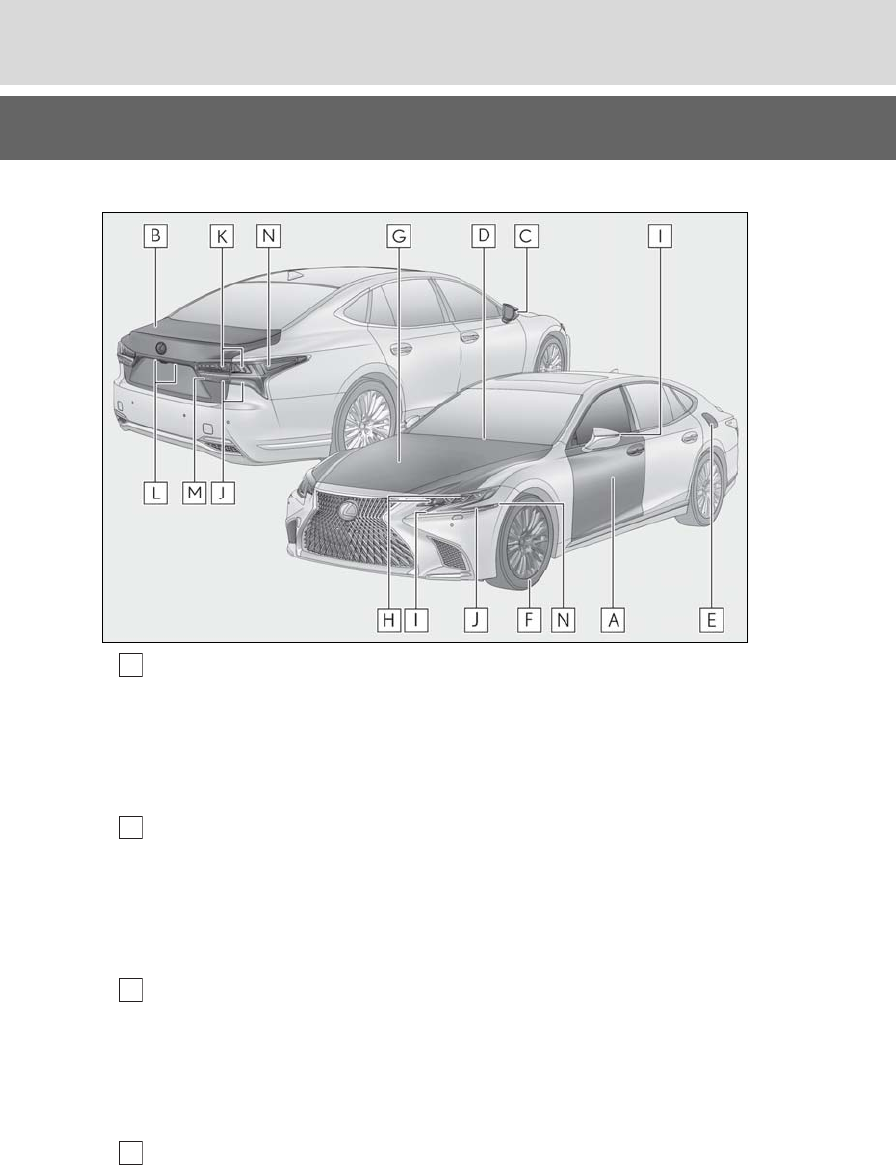
■Exterior
Doors ......................................................................................................................... P.108
Locking/unlocking............................................................................................................P.108
Opening/closing the side windows.............................................................................P.151
Locking/unlocking by using the mechanical key................................................P.445
Warning lights/warning messages ................................................................P.427, 437
Trunk............................................................................................................................ P.112
Opening from inside the cabin ......................................................................................P.114
Opening from outside .......................................................................................................P.115
Opening by using the mechanical key ....................................................................P.446
Warning lights/warning messages ................................................................P.427, 437
Outside rear view mirrors....................................................................................P.149
Adjusting the mirror angle............................................................................................. P.149
Folding the mirrors............................................................................................................P.150
Driving position memory................................................................................................ P.139
Defogging the mirrors....................................................................................................P.323
Windshield wipers ..................................................................................................P.190
A
B
C
D

13
Pictorial index
LS500h_OM_OM50F42U_(U)
Precautions for winter season.....................................................................................P.309
To prevent freezing (windshield wiper de-icer)*.................................................P.327
Precautions for car wash.................................................................................................P.371
Fuel filler door..........................................................................................................P.194
Refueling method .............................................................................................................. P.194
Fuel type/fuel tank capacity...........................................................................................P.461
Tires............................................................................................................................P.395
Tire size/inflation pressure ............................................................................... P.395, 466
Winter tires/tire chains ..................................................................................................P.309
Checking/rotation/tire pressure warning system..............................................P.395
Coping with flat tires........................................................................................................P.442
Hood ......................................................................................................................... P.385
Opening ...............................................................................................................................P.385
Engine compartment cover ........................................................................................ P.388
Engine oil..............................................................................................................................P.462
Coping with overheating...............................................................................................P.453
Warning messages ..........................................................................................................P.437
Headlights/cornering lights ................................................................................P.185
Parking lights/daytime running lights...............................................................P.185
Turn signal lights..................................................................................................... P.180
Tail lights ....................................................................................................................P.185
Stop lights
Hill-start assist control ....................................................................................................P.303
License plate lights .................................................................................................P.185
Back-up lights
Changing the shift position to R....................................................................................P.174
Side marker lights...................................................................................................P.185
*:If equipped
Light bulbs of the exterior lights for driving
(Replacing method: P.417)
E
F
G
H
I
J
K
L
M
N
14 Pictorial index
LS500h_OM_OM50F42U_(U)
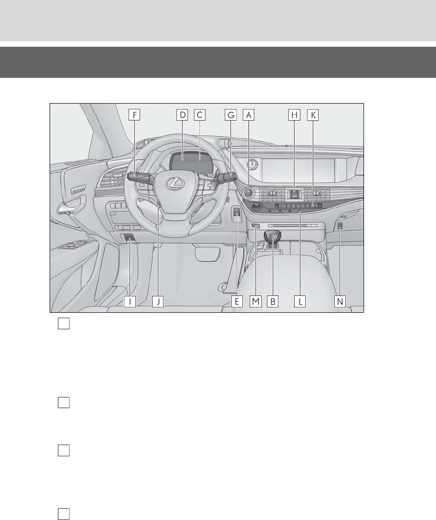
■Instrument panel
Power switch ............................................................................................................P.168
Starting the hybrid system/changing the modes..................................................P.168
Emergency stop of the hybrid system......................................................................P.420
When the hybrid system will not start ......................................................................P.443
Warning messages ..........................................................................................................P.437
Shift lever................................................................................................................... P.174
Changing the shift position.............................................................................................P.176
Precautions for towing ...................................................................................................P.422
Meters................................................................................................................... P.77, 81
Reading the meters/adjusting the instrument panel light............P.77, 79, 81, 85
Warning lights/indicator lights ...................................................................................... P.72
When a warning light turns on .................................................................................... P.427
Multi-information display.......................................................................................P.86
Display......................................................................................................................................P.86
Energy monitor..................................................................................................................... P.97
When a warning messages is displayed..................................................................P.437
A
B
C
D

15
Pictorial index
LS500h_OM_OM50F42U_(U)
Parking brake switch ..............................................................................................P.181
Applying/releasing the parking brake........................................................................P.181
Precautions for winter season......................................................................................P.310
Warning buzzer/messages..........................................................................................P.437
Turn signal lever ..................................................................................................... P.180
Headlight switch......................................................................................................P.185
Headlights/parking lights/tail lights/daytime running lights...........................P.185
AHB (Automatic High Beam)......................................................................................P.188
Windshield wiper and washer switch................................................................P.190
Usage......................................................................................................................................P.190
Adding washer fluid.........................................................................................................P.392
Warning messages ..........................................................................................................P.437
Emergency flasher switch .................................................................................. P.420
Hood lock release lever...................................................................................... P.385
Tilt and telescopic steering control switch...................................................... P.147
Adjustment............................................................................................................................P.147
Driving position memory................................................................................................ P.139
Air conditioning system ...................................................................................... P.323
Usage.....................................................................................................................................P.323
Rear window defogger...................................................................................................P.323
Audio system*
Brake hold switch....................................................................................................P.183
Trunk opener main switch .....................................................................................P.118
*: Refer to “NAVIGATION AND MULTIMEDIA SYSTEM OWNER’S MANUAL”.
E
F
G
H
I
J
K
L
M
N
16 Pictorial index
LS500h_OM_OM50F42U_(U)
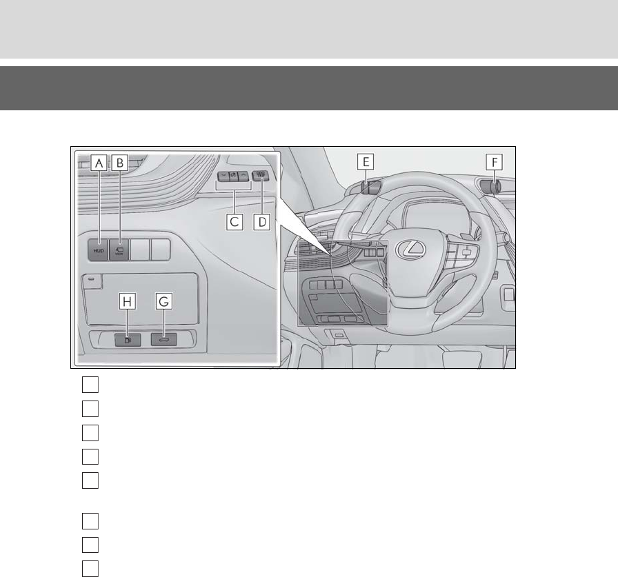
■Switches
HUD (Head-up display) switch*1..........................................................................P.92
Camera switch*1, 2
Instrument panel light control switches .....................................................P.79, 85
“ODO TRIP” switch .........................................................................................P.79, 85
VSC OFF switch.................................................................................................... P.304
Snow mode switch .................................................................................................. P.177
Driving mode select switch................................................................................ P.298
Trunk opener switch................................................................................................ P.114
Fuel filler door opener switch..............................................................................P.195
*1: If equipped
*2: Refer to “NAVIGATION AND MULTIMEDIA SYSTEM OWNER’S MANUAL”.
A
B
C
D
E
F
G
H
17
Pictorial index
LS500h_OM_OM50F42U_(U)
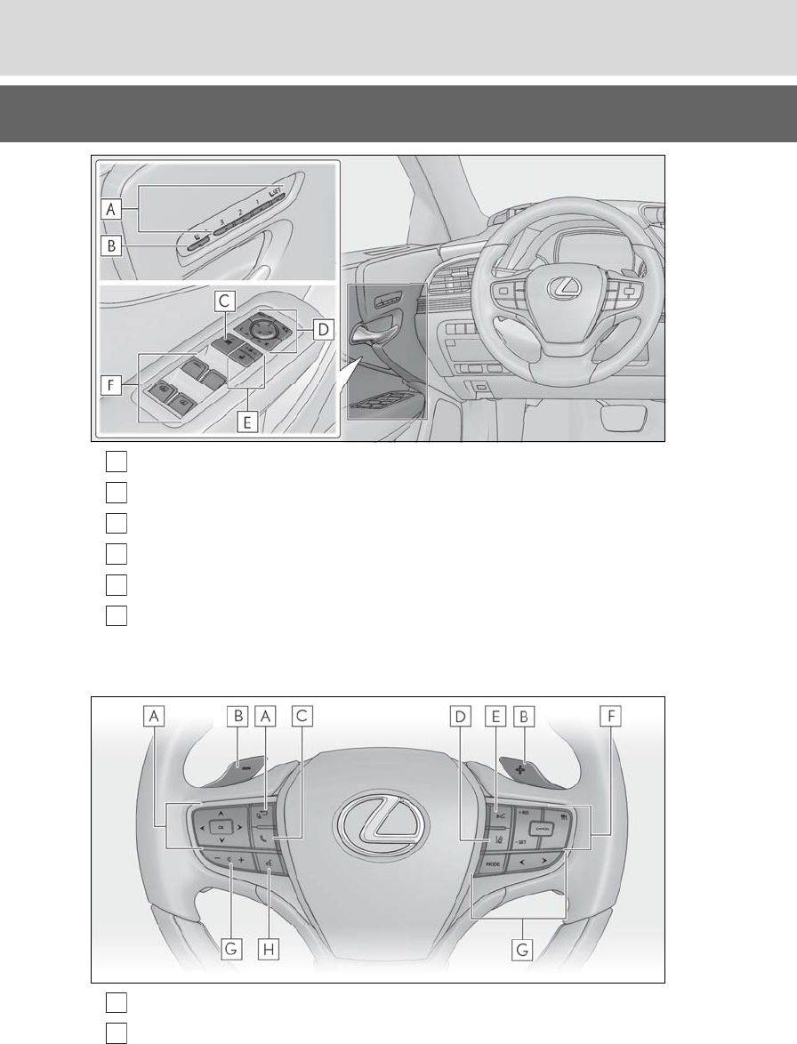
Position memory buttons......................................................................................P.139
Mode change button .............................................................................................P.130
Window lock switch ...............................................................................................P.153
Outside rear view mirror switches....................................................................P.149
Door lock switches ..................................................................................................P.110
Power window switches.........................................................................................P.151
Rear door sunshade switches*.......................................................................... P.355
*:If equipped
Meter control switches ...........................................................................................P.87
Paddle shift switches..............................................................................................P.178
A
B
C
D
E
F
A
B
18 Pictorial index
LS500h_OM_OM50F42U_(U)
Phone switch*1
LTA (Lane Tracing Assist) switch*2 ................................................................. P.230
LKA (Lane-Keeping Assist) switch*2.............................................................. P.240
Vehicle-to-vehicle distance switch ..................................................................P.254
Cruise control switches ...................................................................................... P.250
Audio remote control switches*1
Talk switch*1
*1: Refer to “NAVIGATION AND MULTIMEDIA SYSTEM OWNER’S MANUAL”.
*2: If equipped
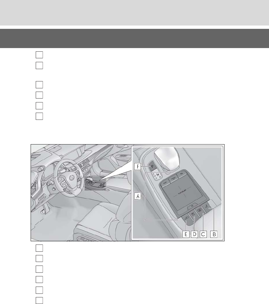
Remote Touch*1.......................................................................................................P.314
Seat switch ................................................................................................................P.129
Rear sunshade switch*2 .......................................................................................P.356
EV drive mode switch ............................................................................................ P.172
Vehicle height adjustment switch*2 .................................................................P.299
P position switch ...................................................................................................... P.176
*1: Refer to “NAVIGATION AND MULTIMEDIA SYSTEM OWNER’S MANUAL”.
*2: If equipped
C
D
E
F
G
H
A
B
C
D
E
F
19
Pictorial index
LS500h_OM_OM50F42U_(U)
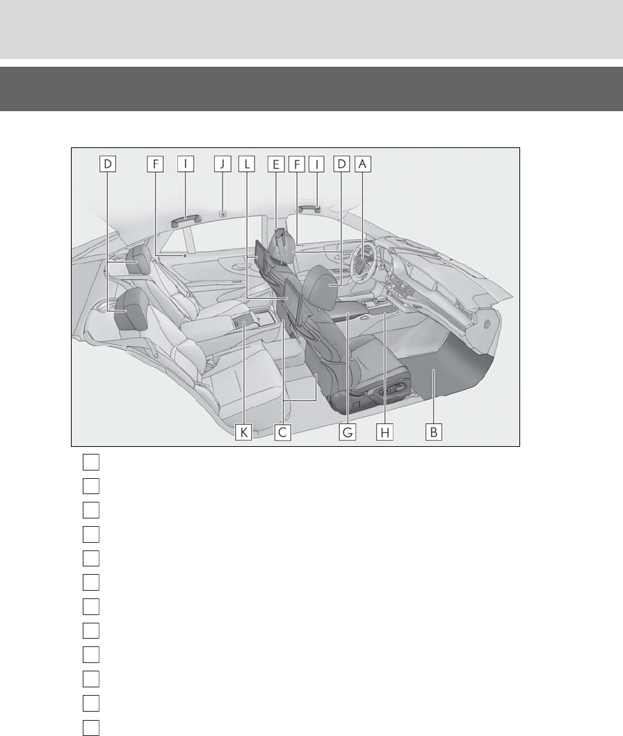
■Interior
SRS airbags.................................................................................................................P.29
Floor mats....................................................................................................................P.22
Front seats.................................................................................................................P.128
Head restraints........................................................................................................P.144
Seat belts .....................................................................................................................P.24
Inside lock buttons...................................................................................................P.110
Console box.............................................................................................................P.346
Cup holders .............................................................................................................P.345
Assist grips .............................................................................................................. P.352
Coat hooks.............................................................................................................. P.352
Rear Multi Operation Panel*1 ............................................................................P.318
Rear seat entertainment system*1, 2
*1: If equipped
*2: Refer to “NAVIGATION AND MULTIMEDIA SYSTEM OWNER’S MANUAL”.
A
B
C
D
E
F
G
H
I
J
K
L
20 Pictorial index
LS500h_OM_OM50F42U_(U)
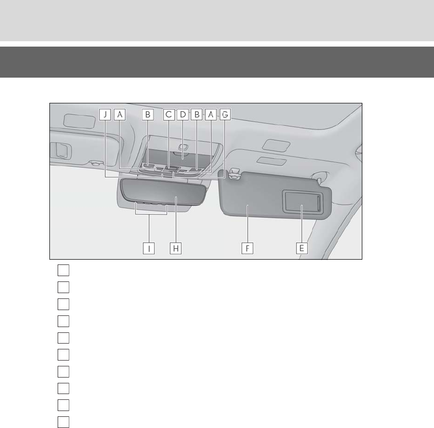
■Ceiling
Moon roof switches................................................................................................P.153
Personal lights..........................................................................................................P.341
“SOS” button*.........................................................................................................P.364
Auxiliary box............................................................................................................P.347
Vanity mirrors .........................................................................................................P.354
Sun visors..................................................................................................................P.354
Door-linked interior light switch ........................................................................P.341
Inside rear view mirror ..........................................................................................P.148
Garage door opener buttons............................................................................ P.358
Interior light ..............................................................................................................P.341
*:If equipped
A
B
C
D
E
F
G
H
I
J

21
LS500h_OM_OM50F42U_(U)
1
1
For safety and security
For safety and security
.
1-1. For safe use
Before driving.................................22
For safe driving.............................. 23
Seat belts ..........................................24
SRS airbags .................................... 29
Pop Up Hood ................................38
Front passenger occupant classifi-
cation system ..............................40
Exhaust gas precautions........... 44
1-2. Child safety
Riding with children..................... 45
Child restraint systems .............. 45
1-3. Hybrid system
Hybrid system features..............58
Hybrid system precautions....... 61
1-4. Theft deterrent system
Immobilizer system ..................... 66
Alarm.................................................68
22 1-1. For safe use
LS500h_OM_OM50F42U_(U)
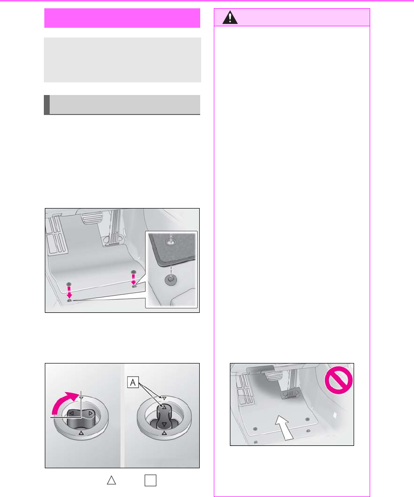
1-1.For safe use
Use only floor mats designed specifi-
cally for vehicles of the same model
and model year as your vehicle. Fix
them securely in place onto the carpet.
1Insert the retaining hooks (clips)
into the floor mat eyelets.
2Turn the upper knob of each retain-
ing hook (clip) to secure the floor
mats in place.
Always align the marks .
The shape of the retaining hooks (clips)
may differ from that shown in the illustra-
tion.
Before driving
Observe the following before start-
ing off in the vehicle to ensure
safety of driving.
Installing floor mats
A
WARNING
Observe the following precautions.
Failure to do so may cause the driver’s
floor mat to slip, possibly interfering with
the pedals while driving. An unexpect-
edly high speed may result or it may
become difficult to stop the vehicle. This
could lead to an accident, resulting in
death or serious injury.
■When installing the driver’s floor mat
●Do not use floor mats designed for
other models or different model year
vehicles, even if they are Lexus Genu-
ine floor mats.
●Only use floor mats designed for the
driver’s seat.
●Always install the floor mat securely
using the retaining hooks (clips) pro-
vided.
●Do not use two or more floor mats on
top of each other.
●Do not place the floor mat bot-
tom-side up or upside-down.
■Before driving
●Check that the floor mat is securely
fixed in the correct place with all the
provided retaining hooks (clips). Be
especially careful to perform this
check after cleaning the floor.
●With the hybrid system stopped and
the shift position in P, fully depress
each pedal to the floor to make sure it
does not interfere with the floor mat.
23
1-1. For safe use
LS500h_OM_OM50F42U_(U)
1
For safety and security
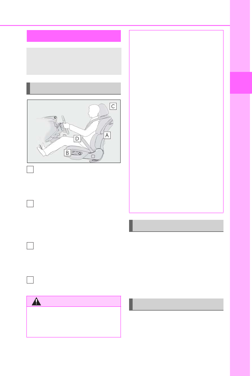
Adjust the angle of the seatback so
that you are sitting straight up and
so that you do not have to lean for-
ward to steer. (→P.128)
Adjust the seat so that you can
depress the pedals fully and so that
your arms bend slightly at the
elbow when gripping the steering
wheel. (→P.128)
Lock the head restraint in place
with the center of the head restraint
closest to the top of your ears.
(→P.144)
Wear the seat belt correctly.
(→P.24)
Make sure that all occupants are wear-
ing their seat belts before driving the
vehicle. (→P.24)
Use a child restraint system appropri-
ate for the child until the child becomes
large enough to properly wear the
vehicle’s seat belt. (→P.45)
Make sure that you can see backward
clearly by adjusting the inside and out-
side rear view mirrors properly.
(→P.148, 149)
For safe driving
For safe driving, adjust the seat and
mirror to an appropriate position
before driving.
Correct driving posture
WARNING
■For safe driving
Observe the following precautions.
Failure to do so may result in death or
serious injury.
A
B
C
D
●Do not adjust the position of the
driver’s seat while driving.
Doing so could cause the driver to lose
control of the vehicle.
●Do not place a cushion between the
driver or passenger and the seatback.
A cushion may prevent correct pos-
ture from being achieved, and reduce
the effectiveness of the seat belt and
head restraint.
●Do not place anything under the front
seats.
Objects placed under the front seats
may become jammed in the seat
tracks and stop the seat from locking in
place. This may lead to an accident
and the adjustment mechanism may
also be damaged.
●Always observe the legal speed limit
when driving on public roads.
●When driving over long distances, take
regular breaks before you start to feel
tired.
Also, if you feel tired or sleepy while
driving, do not force yourself to con-
tinue driving and take a break immedi-
ately.
Correct use of the seat belts
Adjusting the mirrors
24 1-1. For safe use
LS500h_OM_OM50F42U_(U)
Seat belts
Make sure that all occupants are
wearing their seat belts before driv-
ing the vehicle.
WARNING
Observe the following precautions to
reduce the risk of injury in the event of
sudden braking, sudden swerving or an
accident.
Failure to do so may cause death or seri-
ous injury.
■Wearing a seat belt
●Ensure that all passengers wear a seat
belt.
●Always wear a seat belt properly.
●Each seat belt should be used by one
person only. Do not use a seat belt for
more than one person at once, includ-
ing children.
●Lexus recommends that children be
seated in the rear seat and always use
a seat belt and/or an appropriate child
restraint system.
●To achieve a proper seating position,
do not recline the seat more than nec-
essary. The seat belt is most effective
when the occupants are sitting up
straight and well back in the seats.
●Do not wear the shoulder belt under
your arm.
●Always wear your seat belt low and
snug across your hips.
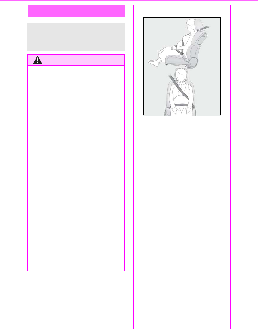
■Pregnant women
Obtain medical advice and wear the seat
belt in the proper way. (→P.25)
Women who are pregnant should posi-
tion the lap belt as low as possible over
the hips in the same manner as other
occupants, extending the shoulder belt
completely over the shoulder and avoid-
ing belt contact with the rounding of the
abdominal area.
If the seat belt is not worn properly, not
only the pregnant woman, but also the
fetus could suffer death or serious injury
as a result of sudden braking or a colli-
sion.
■People suffering illness
Obtain medical advice and wear the seat
belt in the proper way. (→P.25)
■When children are in the vehicle
→P.53
■Seat belt damage and wear
●Do not damage the seat belts by allow-
ing the belt, plate, or buckle to be
jammed in the door.
●Inspect the seat belt system periodi-
cally. Check for cuts, fraying, and loose
parts. Do not use a damaged seat belt
until it is replaced. Damaged seat belts
cannot protect an occupant from
death or serious injury.
25
1-1. For safe use
LS500h_OM_OM50F42U_(U)
1
For safety and security
-Extend the shoulder belt so that it
comes fully over the shoulder, but
does not come into contact with the
neck or slide off the shoulder.
-Position the lap belt as low as possi-
ble over the hips.
-Adjust the position of the seatback.
Sit up straight and well back in the
seat.
-Do not twist the seat belt.
■Child seat belt usage
The seat belts of your vehicle were princi-
pally designed for persons of adult size.
●Use a child restraint system appropriate
for the child, until the child becomes large
enough to properly wear the vehicle’s
seat belt. (→P.45)
●When the child becomes large enough to
properly wear the vehicle’s seat belt, fol-
low the instructions regarding seat belt
usage. (→P.24)
■Seat belt extender
If your seat belts cannot be fastened
securely because they are not long enough,
a personalized seat belt extender is avail-
able from your Lexus dealer free of charge.
WARNING
●Ensure that the belt and plate are
locked and the belt is not twisted.
If the seat belt does not function cor-
rectly, immediately contact your Lexus
dealer.
●Replace the seat assembly, including
the belts, if your vehicle has been
involved in a serious accident, even if
there is no obvious damage.
●Do not attempt to install, remove,
modify, disassemble or dispose of the
seat belts. Have any necessary repairs
carried out by your Lexus dealer. Inap-
propriate handling may lead to incor-
rect operation.
Correct use of the seat belts
WARNING
■Using a seat belt extender
Observe the following precautions to
reduce the risk of injury in the event of
sudden braking, sudden swerving or an
accident.
Failure to do so may cause death or seri-
ous injury.
●Do not wear the seat belt extender if
you can fasten the seat belt without the
extender.
●Do not use the seat belt extender
when installing a child restraint system
because the belt will not securely hold
the child restraint system, increasing
the risk of death or serious injury in the
event of an accident.
●The personalized extender may not be
safe on another vehicle, when used by
another person, or at a different seat-
ing position other than the one origi-
nally intended.
26 1-1. For safe use
LS500h_OM_OM50F42U_(U)
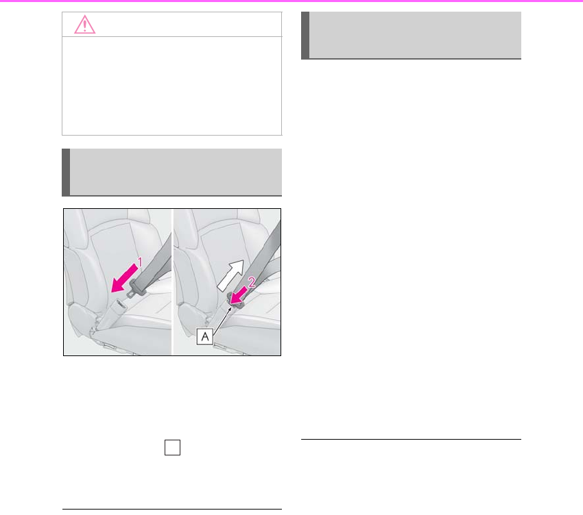
1To fasten the seat belt, push the
plate into the buckle until a click
sound is heard.
2To release the seat belt, press the
release button .
If the seat belt cannot be pulled out of the
retractor, firmly pull the belt and release it.
■Emergency locking retractor (ELR)
The retractor will lock the belt during a sud-
den stop or on impact. It may also lock if you
lean forward too quickly. A slow, easy
motion will allow the belt to extend so that
you can move around fully.
■Automatic locking retractor (ALR)
When a passenger’s shoulder belt is com-
pletely extended and then retracted even
slightly, the belt is locked in that position and
cannot be extended. This feature is used to
hold the child restraint system (CRS) firmly.
To free the belt again, fully retract the belt
and then pull the belt out once more.
(→P.45)
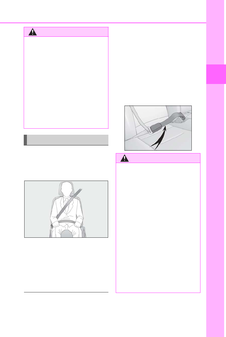
The front seat belt buckles move out-
ward automatically for easier access.
When entering the vehicle
When a front door is opened, the seat
belt buckle for the corresponding seat
will move outward automatically. The
buckle will retract automatically after
the plate is inserted and locked to the
buckle.
When exiting the vehicle (driver’s
seat only)
If the power switch is turned off when
the driver’s seat belt is fastened, the
driver’s seat belt buckle will move out-
ward. The buckle will retract automati-
cally when the driver’s seat belt is
released.
*: If equipped
■Easy Access Buckle
●If the seat belt buckle is not latched when
it is in the outward position, it will return to
its original position after a certain amount
of time.
●If an occupant exits the vehicle and leaves
the front door open and then enters the
vehicle again, the seat belt buckle will not
operate until the door is closed and then
opened again.
■Customization
Some functions can be customized.
(→P.481)
NOTICE
■When using a seat belt extender
When releasing the seat belt, press on
the buckle release button on the
extender, not on the seat belt.
This helps prevent damage to the vehicle
interior and the extender itself.
Fastening and releasing the seat
belt
A
Easy Access Buckle (front
seats)*
27
1-1. For safe use
LS500h_OM_OM50F42U_(U)
1
For safety and security
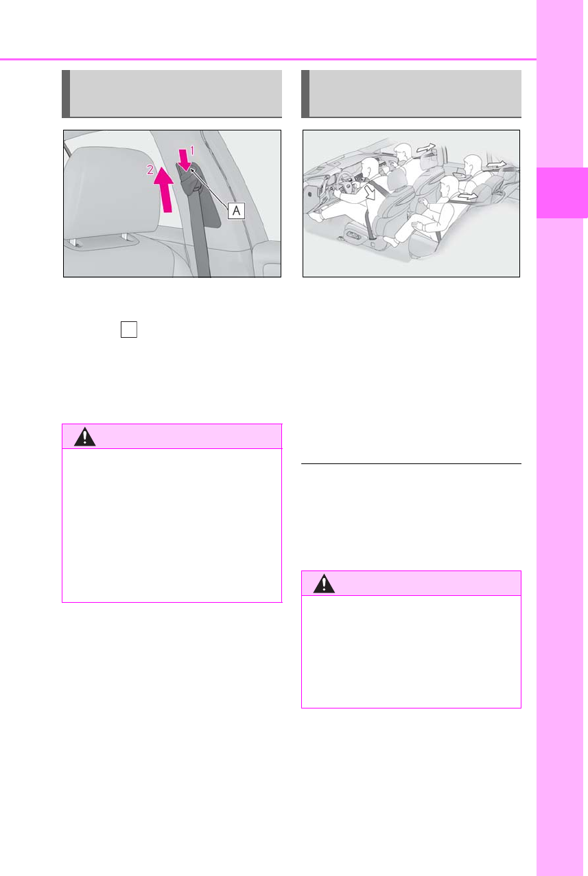
1Push the seat belt shoulder anchor
down while pressing the release
button .
2Push the seat belt shoulder anchor
up.
Move the height adjuster up and down as
needed until you hear a click.
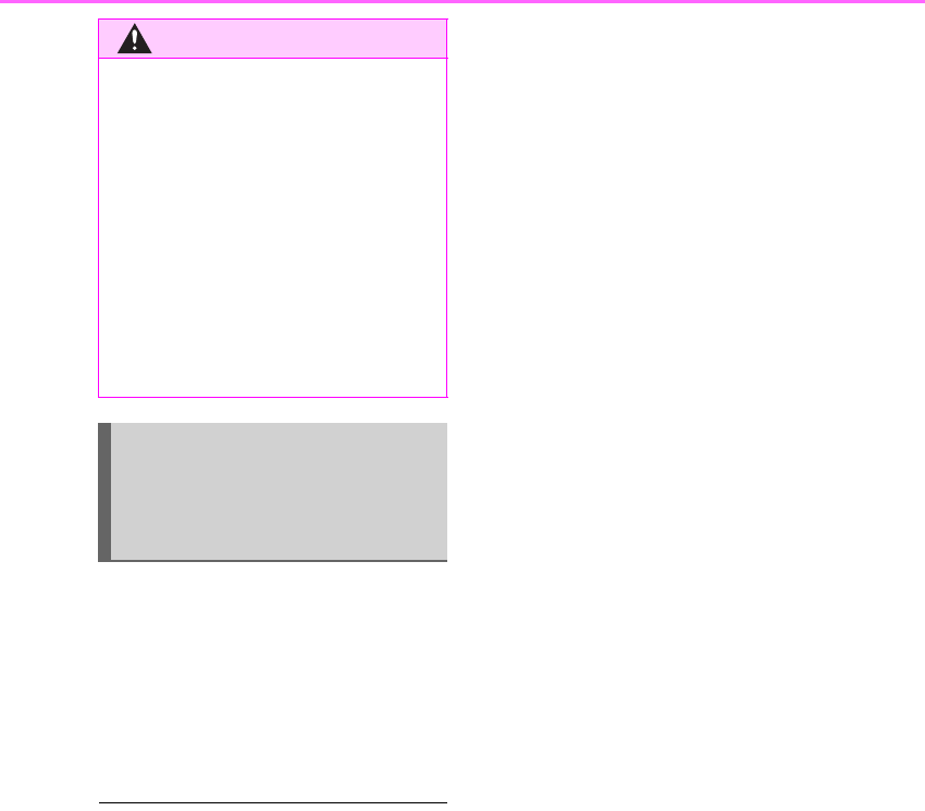
The pretensioners help the seat belts to
quickly restrain the occupants by
retracting the seat belts when the vehi-
cle is subjected to certain types of
severe frontal or side collision or a
vehicle rollover.
The pretensioners do not activate in the
event of a minor frontal impact, a minor
side impact or a rear impact.
■Replacing the belt after the preten-
sioner has been activated
If the vehicle is involved in multiple colli-
sions, the pretensioner will activate for the
first collision, but will not activate for the
second or subsequent collisions.
Adjusting the seat belt shoulder
anchor height (front seats)
WARNING
■Adjustable shoulder anchor
Always make sure the shoulder belt is
positioned across the center of your
shoulder. The belt should be kept away
from your neck, but not falling off your
shoulder. Failure to do so could reduce
the amount of protection in an accident
and cause death or serious injuries in the
event of a sudden stop, sudden swerve or
accident.
A
Seat belt pretensioners (front
and outboard rear seats)
WARNING
■Seat belt pretensioners
Observe the following precautions to
reduce the risk of injury in the event of
sudden braking, sudden swerving or an
accident.
Failure to do so may cause death or seri-
ous injury.
28 1-1. For safe use
LS500h_OM_OM50F42U_(U)
When the vehicle speed reaches
approximately 12 mph (20 km/h) or
higher, the seat belts will retract slightly
to remove any slack.
If the system determines that a collision
is unavoidable, the front seat belts will
retract before the collision. (→P.210)
■Pre-collision seat belts with comfort
function
A motor sound may be heard when a front
seat belt is released or a front door is
opened. This does not indicate a malfunc-
tion.
■Customization
Some functions can be customized.
(→P.481)
WARNING
●Do not place anything, such as a cush-
ion, on the front passenger’s seat.
Doing so will disperse the passenger’s
weight, which prevents the sensor
from detecting the passenger’s weight
properly. As a result, the seat belt pre-
tensioner for the front passenger’s seat
may not activate in the event of a colli-
sion.
●If the pretensioner has activated, the
SRS warning light will come on. In that
case, the seat belt cannot be used
again and must be replaced at your
Lexus dealer.
Pre-collision seat belts with com-
fort function (front seats of vehi-
cles with Lexus Safety
System+A)
29
1-1. For safe use
LS500h_OM_OM50F42U_(U)
1
For safety and security
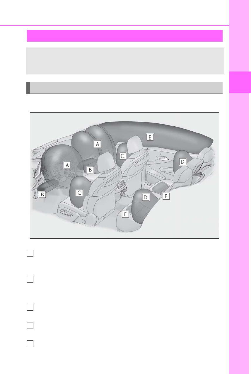
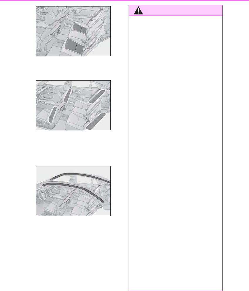
■Location of the SRS airbags
SRS front airbags
SRS driver airbag/front passenger airbag
Can help protect the head and chest of the driver and front passenger from
impact with interior components
SRS knee airbags
Can help provide driver and front passenger protection
SRS side and curtain shield airbags
SRS front side airbags
Can help protect the torso of the front seat occupants
SRS rear side airbags
Can help protect the torso of occupants in the rear outer seats
SRS curtain shield airbags
SRS airbags
The SRS airbags inflate when the vehicle is subjected to certain types of severe
impacts that may cause significant injury to the occupants. They work together
with the seat belts to help reduce the risk of death or serious injury.
SRS airbag system
A
B
C
D
E
30 1-1. For safe use
LS500h_OM_OM50F42U_(U)
• Can help protect primarily the head of occupants in the outer seats
• Can help prevent the occupants from being thrown from the vehicle in the event of vehi-
cle rollover
SRS seat cushion airbags (if equipped)
Can help restrain the power rear seat occupants
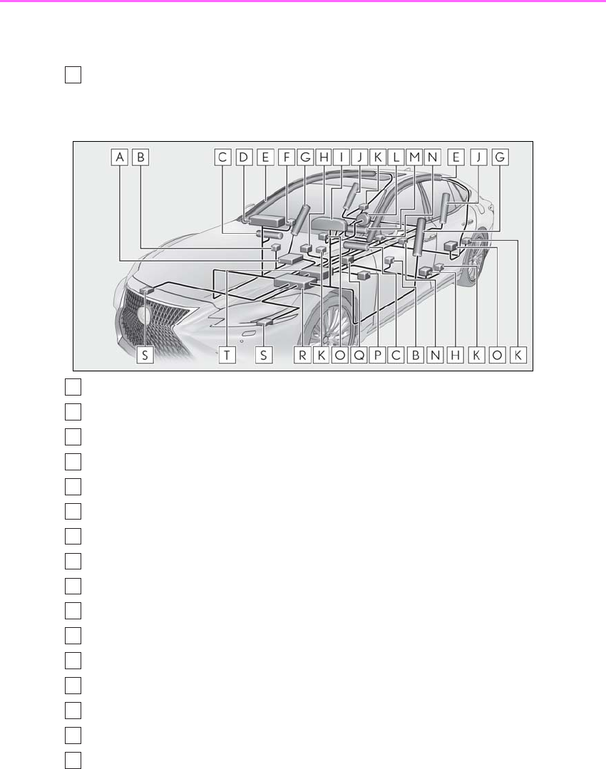
■SRS airbag system components
Front passenger occupant classification system (ECU and sensors)
Side impact sensors (front door)
Knee airbags
Front passenger airbag
Curtain shield airbags
“AIR BAG ON” and “AIR BAG OFF” indicator lights
Front side airbags
Side impact sensors (front)
SRS warning light
Rear side airbags
Seat belt pretensioners
Driver airbag
Seat cushion airbags (if equipped)
Rear seat belt buckle switches (if equipped)
Side impact sensors (rear)
Driver’s seat position sensor
F
A
B
C
D
E
F
G
H
I
J
K
L
M
N
O
P

31
1-1. For safe use
LS500h_OM_OM50F42U_(U)
1
For safety and security
Driver’s seat belt buckle switch
Airbag sensor assembly
Front impact sensors
Pop Up Hood computer assembly
Your vehicle is equipped with ADVANCED AIRBAGS designed based on the US
motor vehicle safety standards (FMVSS208). The airbag sensor assembly (ECU)
controls airbag deployment based on information obtained from the sensors etc.
shown in the system components diagram above. This information includes crash
severity and occupant information. As the airbags deploy, a chemical reaction in
the inflators quickly fills the airbags with non-toxic gas to help restrain the motion of
the occupants.
■If the SRS airbags deploy (inflate)
●Slight abrasions, burns, bruising etc., may
be sustained from SRS airbags, due to the
extremely high speed deployment (infla-
tion) by hot gases.
●A loud noise and white powder will be
emitted.
●Parts of the airbag module (steering
wheel hub, airbag cover and inflator) as
well as the seats, parts of the front and
rear pillars, and roof side rails, may be hot
for several minutes. The airbag itself may
also be hot.
●The windshield may crack.
●The emergency flashers will be turned on
automatically. (→P.420)
●For Lexus Enform Safety Connect sub-
scribers, if any of the following situations
occur, the system is designed to send an
emergency call to the response center,
notifying them of the vehicle’s location
(without needing to push the “SOS” but-
ton) and an agent will attempt to speak
with the occupants to ascertain the level
of emergency and assistance required. If
the occupants are unable to communi-
cate, the agent automatically treats the
call as an emergency and helps to dis-
patch the necessary emergency services.
(→P.364)
• An SRS airbag is deployed.
• A seat belt pretensioner is activated.
• The vehicle is involved in a severe
rear-end collision.
■SRS airbag deployment conditions (SRS
front airbags/SRS seat cushion airbags)
●The SRS front airbags and SRS seat cush-
ion airbags will deploy in the event of an
impact that exceeds the set threshold
level (the level of force corresponding to
an approximately 12 - 18 mph [20 - 30
km/h] frontal collision with a fixed wall
that does not move or deform).
However, this threshold velocity will be
considerably higher in the following situa-
tions:
• If the vehicle strikes an object, such as a
parked vehicle or sign pole, which can
move or deform on impact
• If the vehicle is involved in an underride
collision, such as a collision in which the
front of the vehicle underrides, or goes
under, the bed of a truck
●The SRS front airbags for the front pas-
senger will not activate if there is no pas-
senger sitting in the front passenger seat.
However, the SRS front airbags for the
front passenger may deploy if luggage is
put in the seat, even if the seat is unoccu-
pied.
●The SRS seat cushion airbags on the rear
seat will not operate if the occupant is not
wearing a seat belt.
■SRS airbag deployment conditions (SRS
side and curtain shield airbags)
●The SRS side and curtain shield airbags
will deploy in the event of an impact that
exceeds the set threshold level (the level
Q
R
S
T
32 1-1. For safe use
LS500h_OM_OM50F42U_(U)
of force corresponding to the impact
force produced by an approximately
3300 lb. [1500 kg] vehicle colliding with
the vehicle cabin from a direction per-
pendicular to the vehicle orientation at an
approximate speed of 12 - 18 mph [20 -
30 km/h]).
●Both SRS curtain shield airbags may
deploy in the event of a severe side colli-
sion.
●Both SRS curtain shield airbags will
deploy in the event of vehicle rollover.
●Both SRS curtain shield airbags may also
deploy in the event of a severe frontal col-
lision.
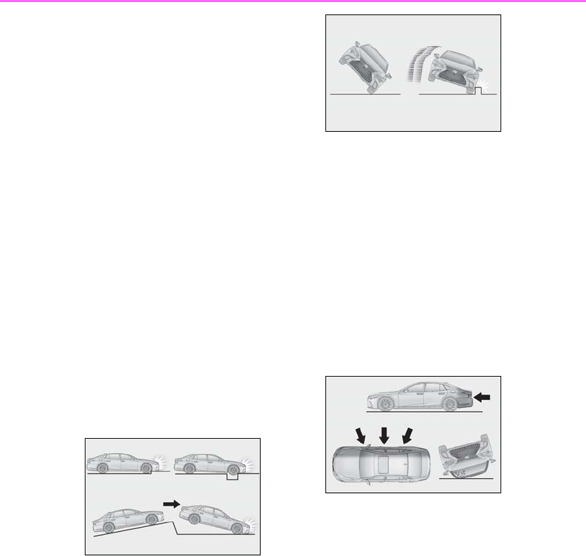
■Conditions under which the SRS air-
bags may deploy (inflate), other than a
collision
The SRS front airbags, SRS curtain shield
airbags and SRS seat cushion airbags may
also deploy if a serious impact occurs to the
underside of your vehicle. Some examples
are shown in the illustration.
●Hitting a curb, edge of pavement or hard
surface
●Falling into or jumping over a deep hole
●Landing hard or falling
The SRS curtain shield airbags may also
deploy under the situations shown in the
illustration.
●The angle of vehicle tip-up is marginal.
●The vehicle skids and hits a curb stone.
■Types of collisions that may not deploy
the SRS airbags (SRS front airbags/SRS
seat cushion airbags)
The SRS front airbags and SRS seat cushion
airbags do not generally inflate if the vehicle
is involved in a side or rear collision, if it rolls
over, or if it is involved in a low-speed frontal
collision. But, whenever a collision of any
type causes sufficient forward deceleration
of the vehicle, deployment of the SRS front
airbags and SRS seat cushion airbags may
occur.
●Collision from the side
●Collision from the rear
●Vehicle rollover
■Types of collisions that may not deploy
the SRS airbags (SRS side and curtain
shield airbags)
The SRS side and curtain shield airbags
may not activate if the vehicle is subjected
to a collision from the side at certain angles,
or a collision to the side of the vehicle body
other than the passenger compartment.
●Collision from the side to the vehicle
body other than the passenger compart-
ment
●Collision from the side at an angle
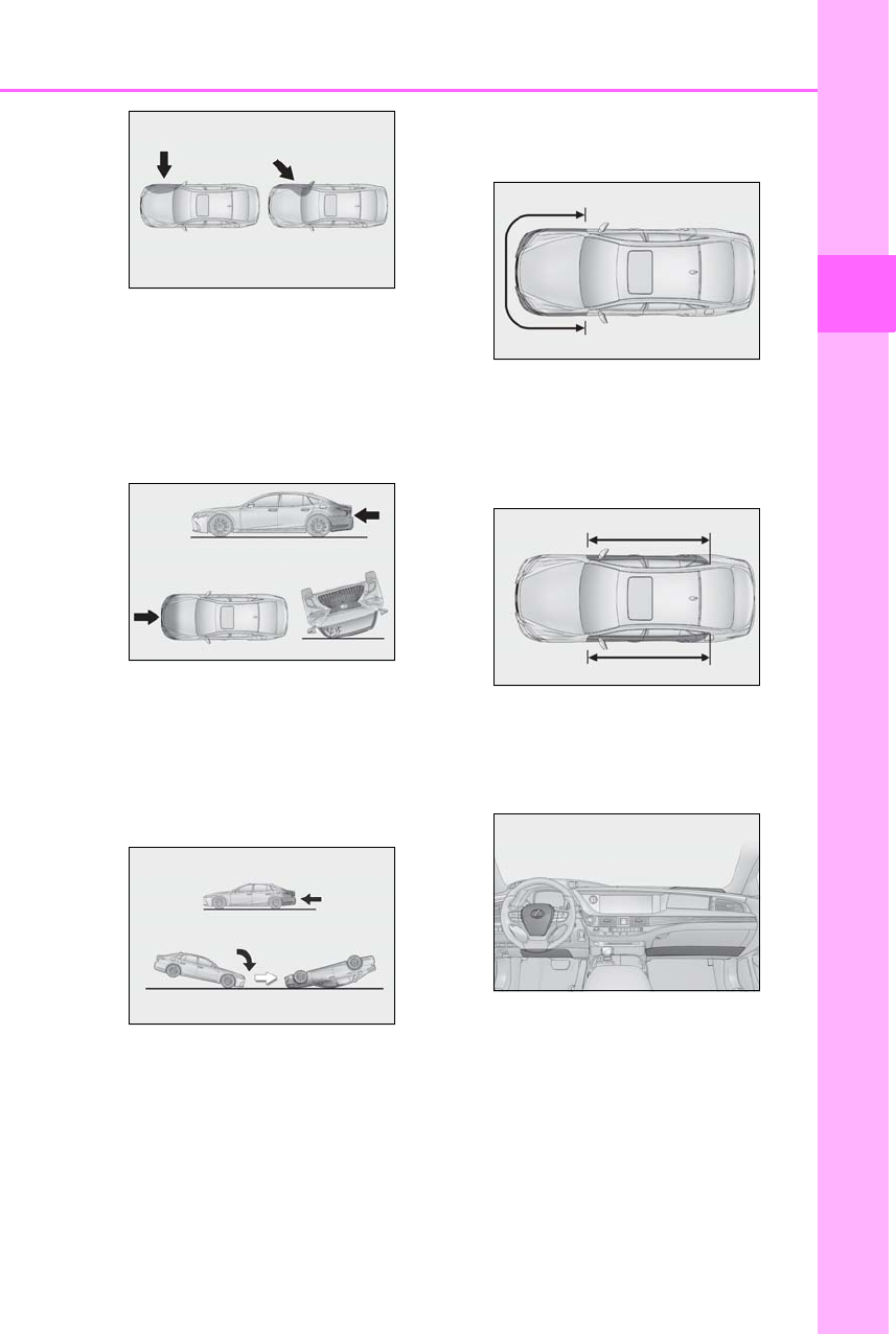
33
1-1. For safe use
LS500h_OM_OM50F42U_(U)
1
For safety and security
The SRS side airbags do not generally
inflate if the vehicle is involved in a frontal or
rear collision, if it rolls over, or if it is involved
in a low-speed side collision.
●Collision from the front
●Collision from the rear
●Vehicle rollover
The SRS curtain shield airbags do not gen-
erally inflate if the vehicle is involved in a
rear collision, if it pitches end over end, or if
it is involved in a low-speed side or
low-speed frontal collision.
●Collision from the rear
●Pitching end over end
■When to contact your Lexus dealer
In the following cases, the vehicle will
require inspection and/or repair. Contact
your Lexus dealer as soon as possible.
●Any of the SRS airbags have been
inflated.
●The front of the vehicle is damaged or
deformed, or was involved in an accident
that was not severe enough to cause the
SRS front airbags and SRS cushion air-
bags to inflate.
●A portion of a door or its surrounding
area is damaged, deformed or has had a
hole made in it, or the vehicle was
involved in an accident that was not
severe enough to cause the SRS side and
curtain shield airbags to inflate.
●The pad section of the steering wheel,
dashboard near the front passenger air-
bag or lower portion of the instrument
panel is scratched, cracked, or otherwise
damaged.
●Vehicles with power rear seat: The seat
cushion surface is scratched, cracked, or
otherwise damaged.
34 1-1. For safe use
LS500h_OM_OM50F42U_(U)
●The surface of the seats with the side air-
bag is scratched, cracked, or otherwise
damaged.
●The portion of the front pillars, rear pillars
or roof side rail garnishes (padding) con-
taining the curtain shield airbags inside is
scratched, cracked, or otherwise dam-
aged.
WARNING
■SRS airbag precautions
Observe the following precautions
regarding the SRS airbags.
Failure to do so may cause death or seri-
ous injury.
●The driver and all passengers in the
vehicle must wear their seat belts
properly.
The SRS airbags are supplemental
devices to be used with the seat belts.
●The SRS driver airbag deploys with
considerable force, and can cause
death or serious injury especially if the
driver is very close to the airbag.
The National Highway Traffic Safety
Administration (NHTSA) advises: Since
the risk zone for the driver’s airbag is the
first 2 - 3 in. (50 - 75 mm) of inflation,
placing yourself 10 in. (250 mm) from
your driver airbag provides you with a
clear margin of safety. This distance is
measured from the center of the steering
wheel to your breastbone. If you sit less
than 10 in. (250 mm) away now, you can
change your driving position in several
ways:
• Move your seat to the rear as far as
you can while still reaching the pedals
comfortably.
• Slightly recline the back of the seat.
Although vehicle designs vary, many
drivers can achieve the 10 in. (250
mm) distance, even with the driver seat
all the way forward, simply by reclining
the back of the seat somewhat. If
reclining the back of your seat makes it
hard to see the road, raise yourself by
using a firm, non-slippery cushion, or
raise the seat if your vehicle has that
feature.
35
1-1. For safe use
LS500h_OM_OM50F42U_(U)
1
For safety and security
WARNING
• If your steering wheel is adjustable, tilt
it downward. This points the airbag
toward your chest instead of your head
and neck.
The seat should be adjusted as recom-
mended by NHTSA above, while still
maintaining control of the foot pedals,
steering wheel, and your view of the
instrument panel controls.
●If the seat belt extender has been con-
nected to the front seat belt buckles
but the seat belt extender has not also
been fastened to the latch plate of the
seat belt, the SRS front airbags will
judge that the driver and front passen-
ger are wearing the seat belt even
though the seat belt has not been con-
nected. In this case, the SRS front air-
bags may not activate correctly in a
collision, resulting in death or serious
injury in the event of a collision. Be
sure to wear the seat belt with the seat
belt extender.
●The SRS front passenger airbag also
deploys with considerable force, and
can cause death or serious injury
especially if the front passenger is very
close to the airbag. The front passen-
ger seat should be as far from the air-
bag as possible with the seatback
adjusted, so the front passenger sits
upright.
●Improperly seated and/or restrained
infants and children can be killed or
seriously injured by a deploying airbag.
An infant or child who is too small to
use a seat belt should be properly
secured using a child restraint system.
Lexus strongly recommends that all
infants and children be placed in the
rear seats of the vehicle and properly
restrained. The rear seats are safer for
infants and children than the front pas-
senger seat. (→P.45)
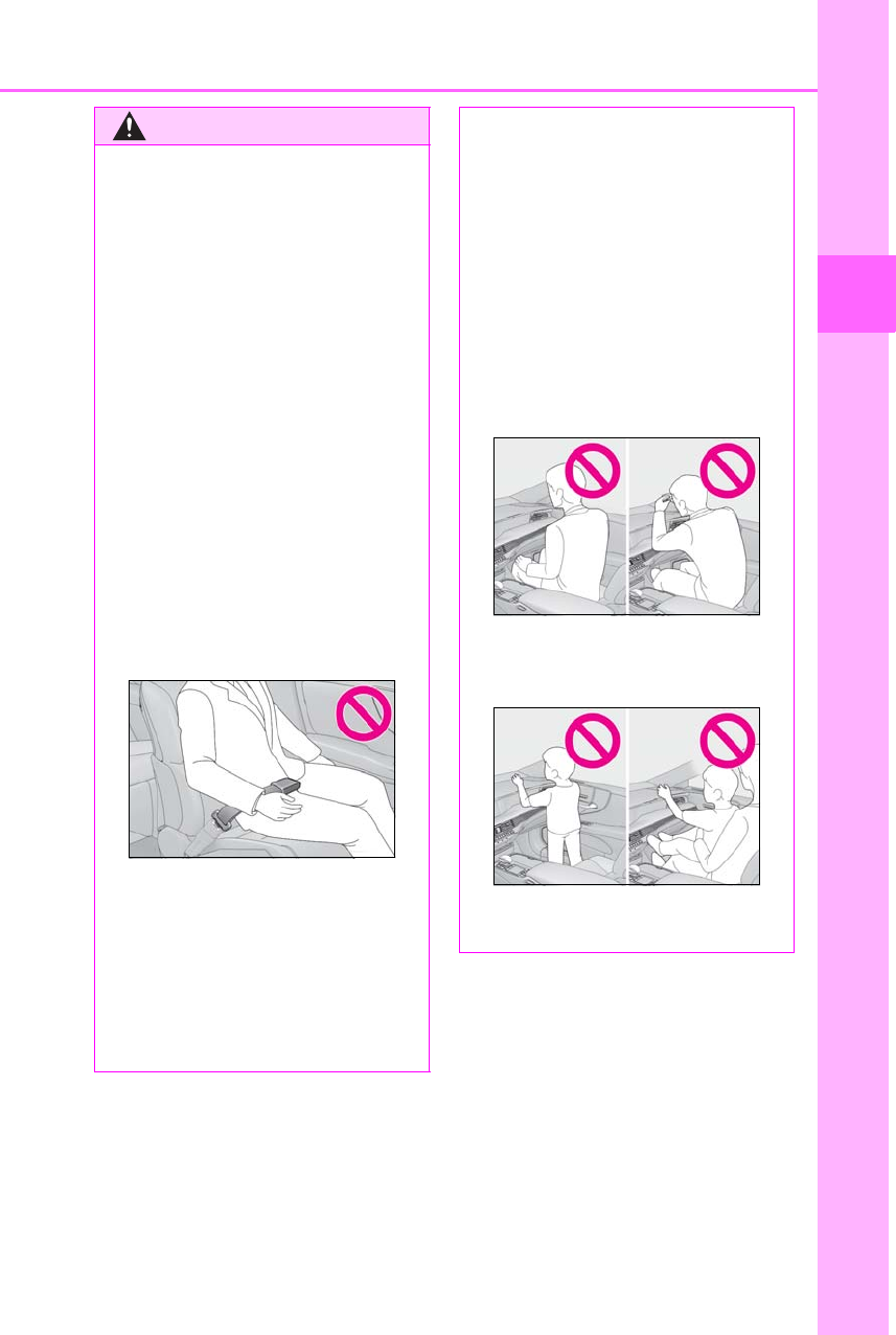
●Do not sit on the edge of the seat or
lean against the dashboard.
●Do not allow a child to stand in front of
the SRS front passenger airbag unit or
sit on the knees of a front passenger.
●Do not allow the front seat occupants
to hold items on their knees.
36 1-1. For safe use
LS500h_OM_OM50F42U_(U)
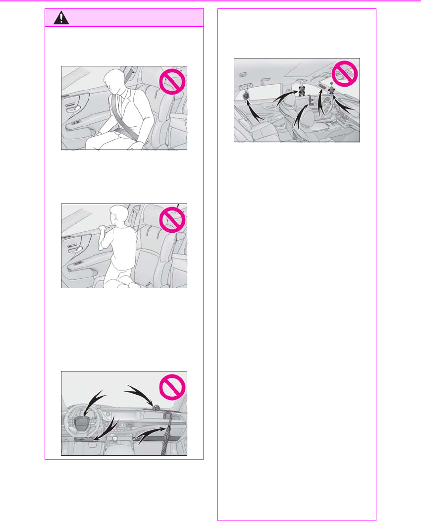
WARNING
●Do not lean against the door, the roof
side rail or the front, side and rear pil-
lars.
●Do not allow anyone to kneel on the
passenger seats toward the door or
put their head or hands outside the
vehicle.
●Do not attach anything to or lean any-
thing against areas such as the dash-
board, steering wheel pad and lower
portion of the instrument panel.
These items can become projectiles
when the SRS driver, front passenger
and knee airbags deploy.
●Do not attach anything to areas such
as a door, windshield, side windows,
front or rear pillar, roof side rail and
assist grip.
●Do not hang coat hangers or hard
objects on the coat hooks. All of these
items could become projectiles and
may cause death or serious injury,
should the SRS curtain shield airbags
deploy.
●If a vinyl cover is put on the area where
the SRS knee airbag will deploy, be
sure to remove it.
●Do not use seat accessories which
cover the parts where the SRS side air-
bags inflate as they may interfere with
inflation of the SRS airbags. Such
accessories may prevent the side air-
bags from activating correctly, disable
the system or cause the side airbags to
inflate accidentally, resulting in death
or serious injury.
●Do not strike or apply significant levels
of force to the area of the SRS airbag
components or the front doors. Doing
so can cause the SRS airbags to mal-
function.
●Do not touch any of the component
parts immediately after the SRS air-
bags have deployed (inflated) as they
may be hot.
●If breathing becomes difficult after the
SRS airbags have deployed, open a
door or window to allow fresh air in, or
leave the vehicle if it is safe to do so.
Wash off any residue as soon as possi-
ble to prevent skin irritation.

37
1-1. For safe use
LS500h_OM_OM50F42U_(U)
1
For safety and security
WARNING
●If the areas where the SRS airbags are
stored, such as the steering wheel pad
and front and rear pillar garnishes are
damaged or cracked, have them
replaced by your Lexus dealer.
●Do not place anything, such as a cush-
ion, on the front passenger’s seat.
Doing so will disperse the passenger’s
weight, which prevents the sensor
from detecting the passenger’s weight
properly. As a result, the SRS front air-
bags for the front passenger may not
deploy in the event of a collision.
■Modification and disposal of SRS air-
bag system components
Do not dispose of your vehicle or per-
form any of the following modifications
without consulting your Lexus dealer.
The SRS airbags may malfunction or
deploy (inflate) accidentally, causing
death or serious injury.
●Installation, removal, disassembly and
repair of the SRS airbags
●Repairs, modifications, removal or
replacement of the steering wheel,
instrument panel, dashboard, seats or
seat upholstery, front, side and rear pil-
lars, roof side rails, front door panels,
front door trims or front door speakers
●Modifications to the front door panel
(such as making a hole in it)
●Repairs or modifications of the front
fender, front bumper, or side of the
occupant compartment
●Installation of a grille guard (bull bars,
kangaroo bar, etc.), snow plows,
winches or roof luggage carrier
●Modifications to the vehicle’s suspen-
sion system
●Installation of electronic devices such
as mobile two-way radios and CD
players
●Modifications to your vehicle for a per-
son with a physical disability
38 1-1. For safe use
LS500h_OM_OM50F42U_(U)
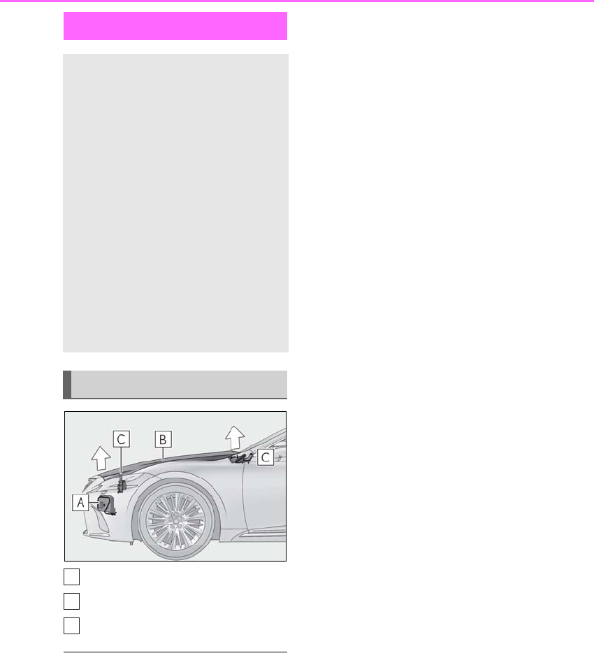
Sensors
Hood
Lifters
■Pop Up Hood precautions
●Before scrapping your vehicle, make sure
to contact your Lexus dealer.
●The Pop Up Hood system cannot be
reused once it has operated. Have it
replaced by your Lexus dealer.
■Pop Up Hood operational conditions
The Pop Up Hood will operate when the
vehicle detects an impact such as the fol-
lowing:
●The front bumper detects a frontal impact
equivalent to or greater than that of a
pedestrian while the vehicle being driven
within the operational speed range of
approximately 16 to 34 mph (25 to 55
km/h). (The system is operated by an
impact of threshold level or greater, even
in the case of a minor collision that may
not leave a trace on the front bumper.
Also, depending on the impact condi-
tions or vehicle speed, the system may
operate by a collision with a light or small
object or a small animal.)
●In other situations, such as the following
the system may operate when an impact
is applied to the lower part of the vehicle
or front bumper:
• Colliding with a curb
• Falling into a deep hole
•Landing hard
• Hitting the slope of a parking lot, an
undulating road, a protruding object or
falling object
■Conditions under which the Pop Up
Hood may not operate properly
●If a pedestrian collides with the right or
left corner of the front bumper or the side
of the vehicle. As such impacts may be
difficult to detect, the system may not
operate.
●If the vehicle speed is not detected cor-
rectly, such as if the vehicle is sliding side-
ways, the system may not operate
properly.
■Conditions under which the Pop Up
Hood will not operate
The Pop Up Hood will not operate in the
following situations:
●Colliding with a lying person
●A frontal impact applied to the front
bumper while driving at speeds outside
of the operational speed range
●A side impact or rear impact
●A vehicle rollover (In some accident situ-
ations, the Pop Up Hood may operate.)
Pop Up Hood
In the event of a frontal collision
with a body, such as a pedestrian,
the Pop Up Hood system raises the
hood to reduce the possibility of a
serious impact to the pedestrian’s
head area by adding clearance to
the engine compartment.
When the sensors located at the
back of the front bumper detect a
frontal impact with a body, such as a
pedestrian, which meets or
exceeds the threshold level while
the vehicle is being driven within
the operational speed range, the
system operates.
System components
A
B
C

39
1-1. For safe use
LS500h_OM_OM50F42U_(U)
1
For safety and security
WARNING
■When the Pop Up Hood is operated
●Do not pull the hood lock release lever.
Doing so after the Pop Up Hood has
operated will further raise the hood
and may cause an injury. Do not drive
with the hood raised, as doing so may
block the driver’s vision, possibly caus-
ing an accident.
●Do not forcibly push down the hood.
As the popped up hood cannot be
lowered by hand, doing so may deform
the hood or cause an injury.
●If the Pop Up Hood has operated, have
it replaced by your Lexus dealer. If the
Pop Up Hood has operated, stop the
vehicle in a safe place and contact
your Lexus dealer.
●Do not touch the lifters immediately
after the Pop Up Hood has operated,
as the lifters may be hot and burn you.
NOTICE
■Pop Up Hood precautions
●Make sure to close the hood before
driving, as the system may not operate
properly if the hood is not fully closed.
●Make sure that all 4 tires are of the
specified size and inflated to the speci-
fied tire pressure. If tires of a different
size are used, the system may not
operate properly.
●If something has hit the area around
the front bumper, the sensors may be
damaged even if the Pop Up Hood has
not operated. Have the vehicle
inspected by your Lexus dealer.
●Do not remove or repair the parts or
wiring of the Pop Up Hood, as doing
so may cause accidental operation or
prevent the system from operating
properly. If repair or replacement is
necessary, contact your Lexus dealer.
●Do not remove such components as
the front bumper, hood or suspension,
or replace them with non-genuine
parts, as doing so may prevent the sys-
tem from operating properly.
●Do not install anything to the front
bumper or hood, as doing so may pre-
vent the sensors from detecting an
impact correctly and prevent the sys-
tem from operating properly.
●Do not close the hood with force or
apply load to the lifters, as doing so
may damage the lifters and prevent the
system from operating properly.
●Do not modify the suspension, as
changes made to the vehicle height
may prevent the system from operat-
ing properly.
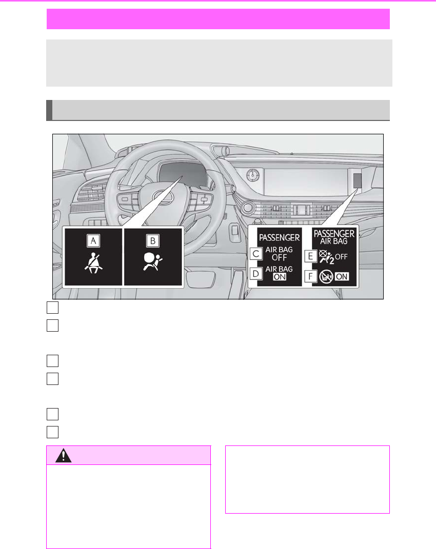
40 1-1. For safe use
LS500h_OM_OM50F42U_(U)
Driver’s and front passenger’s seat belt reminder light
SRS warning light
For the U.S.A.
“AIR BAG OFF” indicator light
“AIR BAG ON” indicator light
For Canada
“AIR BAG OFF” indicator light
“AIR BAG ON” indicator light
Front passenger occupant classification system
Your vehicle is equipped with a front passenger occupant classification system.
This system detects the conditions of the front passenger seat and activates or
deactivates the front passenger airbag and front passenger knee airbag.
System components
A
B
C
D
E
F
WARNING
■Front passenger occupant classifica-
tion system precautions
Observe the following precautions
regarding the front passenger occupant
classification system.
Failure to do so may cause death or seri-
ous injury.
●Wear the seat belt properly.
●Make sure the front passenger’s seat
belt plate has not been left inserted
into the buckle before someone sits in
the front passenger seat.

41
1-1. For safe use
LS500h_OM_OM50F42U_(U)
1
For safety and security
WARNING
●Make sure the “AIR BAG OFF” indica-
tor light is not illuminated when using
the seat belt extender for the front pas-
senger seat. If the “AIR BAG OFF”
indicator light is illuminated, discon-
nect the extender tongue from the seat
belt buckle, and reconnect the seat
belt. Reconnect the seat belt extender
after making sure the “AIR BAG ON”
indicator light is illuminated. If you use
the seat belt extender while the “AIR
BAG OFF” indicator light is illumi-
nated, the SRS airbags for the front
passenger will not activate, which
could cause death or serious injury in
the event of a collision.
●Do not apply a heavy load to the front
passenger seat or equipment (e.g.
seatback pocket).
●Do not put weight on the front passen-
ger seat by putting your hands or feet
on the front passenger seat seatback
from the rear passenger seat.
●Do not let a rear passenger lift the
front passenger seat with their feet or
press on the seatback with their legs.
●Do not put objects under the front pas-
senger seat.
●Do not recline the front passenger
seatback so far that it touches a rear
seat. This may cause the “AIR BAG
OFF” indicator light to be illuminated,
which indicates that the SRS airbags
for the front passenger will not activate
in the event of a severe accident. If the
seatback touches the rear seat, return
the seatback to a position where it
does not touch the rear seat. Keep the
front passenger seatback as upright as
possible when the vehicle is moving.
Reclining the seatback excessively
may lessen the effectiveness of the
seat belt system.
●If an adult sits in the front passenger
seat, the “AIR BAG ON” indicator light
is illuminated. If the “AIR BAG OFF”
indicator is illuminated, ask the passen-
ger to sit up straight, well back in the
seat, feet on the floor, and with the seat
belt worn correctly. If the “AIR BAG
OFF” indicator still remains illumi-
nated, either ask the passenger to
move to the rear seat, or if that is not
possible, move the front passenger
seat fully rearward.
●When it is unavoidable to install a for-
ward-facing child restraint system on
the front passenger seat, install the
child restraint system on the front pas-
senger seat in the proper order.
(→P.46)
●Do not modify or remove the front
seats.
●Do not kick the front passenger seat or
subject it to severe impact. Otherwise,
the SRS warning light may come on to
indicate a malfunction of the front pas-
senger occupant classification system.
In this case, contact your Lexus dealer
immediately.
●Child restraint systems installed on the
rear seat should not contact the front
seatbacks.
●Do not use a seat accessory, such as a
cushion and seat cover, that covers the
seat cushion surface.
●Do not modify or replace the uphol-
stery of the front seat.

42 1-1. For safe use
LS500h_OM_OM50F42U_(U)
■Adult*1
■Child*4
■Child restraint system with infant*5
Condition and operation in the front passenger occupant classification
system
Indicator/warning light
“AIR BAG ON” and “AIR BAG OFF” indi-
cator lights “AIR BAG ON”
SRS warning light Off
Driver’s and front passenger’s seat belt
reminder light Off*2 or flashing*3
Devices Front passenger airbag Activated
Front passenger knee airbag
Indicator/warning light
“AIR BAG ON” and “AIR BAG OFF” indi-
cator lights
“AIR BAG OFF” or
“AIR BAG ON”*4
SRS warning light Off
Driver’s and front passenger’s seat belt
reminder light Off*2 or flashing*3
Devices Front passenger airbag Deactivated or acti-
vated*4
Front passenger knee airbag
Indicator/warning light
“AIR BAG ON” and “AIR BAG OFF” indi-
cator lights “AIR BAG OFF”*6
SRS warning light Off
Driver’s and front passenger’s seat belt
reminder light Off*2 or flashing*3
Devices Front passenger airbag Deactivated
Front passenger knee airbag

43
1-1. For safe use
LS500h_OM_OM50F42U_(U)
1
For safety and security
■Unoccupied
■There is a malfunction in the system
*1: The system judges a person of adult size as an adult. When a smaller adult sits in the
front passenger seat, the system may not recognize him/her as an adult depending on
his/her physique and posture.
*2: In the event the front passenger is wearing a seat belt
*3: In the event the front passenger does not wear a seat belt
*4: For some children, child in seat, child in booster seat or child in convertible seat, the sys-
tem may not recognize him/her as a child. Factors which may affect this can be the phy-
sique or posture.
*5: Never install a rear-facing child restraint system on the front passenger seat. A for-
ward-facing child restraint system should only be installed on the front passenger seat
when it is unavoidable. (→P.45)
*6: In case the indicator light is not illuminated, consult this manual on how to install the child
restraint system properly. (→P.46)
Indicator/warning light
“AIR BAG ON” and “AIR BAG OFF” indi-
cator lights “AIR BAG OFF”
SRS warning light
Off
Driver’s and front passenger’s seat belt
reminder light
Devices Front passenger airbag Deactivated
Front passenger knee airbag
Indicator/warning light
“AIR BAG ON” and “AIR BAG OFF” indi-
cator lights “AIR BAG OFF”
SRS warning light On
Driver’s and front passenger’s seat belt
reminder light Off
Devices Front passenger airbag Deactivated
Front passenger knee airbag

44 1-1. For safe use
LS500h_OM_OM50F42U_(U)
Exhaust gas precautions
Harmful substance to the human
body is included in exhaust gases if
inhaled.
WARNING
Exhaust gases include harmful carbon
monoxide (CO), which is colorless and
odorless. Observe the following precau-
tions.
Failure to do so may cause exhaust gases
enter the vehicle and may lead to an
accident caused by light-headedness, or
may lead to death or a serious health
hazard.
■Important points while driving
●Keep the trunk lid closed.
●If you smell exhaust gases in the vehi-
cle even when the trunk lid is closed,
open the windows and have the vehi-
cle inspected at your Lexus dealer as
soon as possible.
■When parking
●If the vehicle is in a poorly ventilated
area or a closed area, such as a
garage, stop the hybrid system.
●Do not leave the vehicle with the
hybrid system on for a long time.
If such a situation cannot be avoided,
park the vehicle in an open space and
ensure that exhaust fumes do not enter
the vehicle interior.
●Do not leave the hybrid system operat-
ing in an area with snow build-up, or
where it is snowing. If snowbanks build
up around the vehicle while the hybrid
system is operating, exhaust gases
may collect and enter the vehicle.
■Exhaust pipe
The exhaust system needs to be checked
periodically. If there is a hole or crack
caused by corrosion, damage to a joint
or abnormal exhaust noise, be sure to
have the vehicle inspected and repaired
by your Lexus dealer.

45
1-2. Child safety
LS500h_OM_OM50F42U_(U)
1
For safety and security
1-2.Child safety
Points to remember: P.45
Child restraint system: P.46
When using a child restraint system:
P.47
Child restraint system installation
method
• Fixed with a seat belt: P.49
• Fixed with a child restraint LATCH
anchor: P.53
• Using an anchor bracket (for top
tether strap): P.55
The laws of all 50 states of the U.S.A.
as well as Canada now require the use
of child restraint systems.
-Prioritize and observe the warn-
ings, as well as the laws and regula-
Riding with children
Observe the following precautions
when children are in the vehicle.
Use a child restraint system appro-
priate for the child, until the child
becomes large enough to properly
wear the vehicle’s seat belt.
-It is recommended that children
sit in the rear seats to avoid acci-
dental contact with the shift lever,
wiper switch etc.
-Use the rear door child-protector
lock or the window lock switch to
avoid children opening the door
while driving or operating the
power window accidentally.
(→P.111, 153)
-Do not let small children operate
equipment which may catch or
pinch body parts, such as the
power window, hood, trunk, seats
etc.
WARNING
■When children are in the vehicle
Never leave children unattended in the
vehicle, and never allow children to have
or use the key.
Children may be able to start the vehicle
or shift the vehicle into neutral. There is
also a danger that children may injure
themselves by playing with the windows,
the moon roof, or other features of the
vehicle. In addition, heat build-up or
extremely cold temperatures inside the
vehicle can be fatal to children.
Child restraint systems
Before installing a child restraint
system in the vehicle, there are pre-
cautions that need to be observed,
different types of child restraint sys-
tems, as well as installation meth-
ods, etc., written in this manual.
Use a child restraint system when
riding with a small child that cannot
properly use a seat belt. For the
child’s safety, install the child restraint
system to a rear seat. Be sure to fol-
low the installation method that is in
the operation manual enclosed with
the restraint system.
Table of contents
Points to remember

46 1-2. Child safety
LS500h_OM_OM50F42U_(U)
tions for child restraint systems.
-Use a child restraint system until the
child becomes large enough to
properly wear the vehicle’s seat belt.
-Choose a child restraint system that
suits your vehicle and is appropriate
to the age and size of the child.
■Types of child restraint system installation methods
Confirm with the operation manual enclosed with the child restraint system about
the installation of the child restraint system.
WARNING
■When a child is riding
Observe the following precautions.
Failure to do so may result in death or
serious injury.
●For effective protection in automobile
accidents and sudden stops, a child
must be properly restrained, using a
seat belt or child restraint system
which is correctly installed. For installa-
tion details, refer to the operation man-
ual enclosed with the child restraint
system. General installation instruction
is provided in this manual.
●Lexus strongly urges the use of a
proper child restraint system that con-
forms to the weight and size of the
child, installed on the rear seat.
According to accident statistics, the
child is safer when properly restrained
in the rear seat than in the front seat.
●Holding a child in your or someone
else’s arms is not a substitute for a child
restraint system. In an accident, the
child can be crushed against the wind-
shield or between the holder and the
interior of the vehicle.
■Handling the child restraint system
If the child restraint system is not prop-
erly fixed in place, the child or other pas-
sengers may be seriously injured or even
killed in the event of sudden braking, sud-
den swerving, or an accident.
●If the vehicle were to receive a strong
impact from an accident, etc., it is pos-
sible that the child restraint system has
damage that is not readily visible. In
such cases, do not reuse the restraint
system.
●Make sure you have complied with all
installation instructions provided with
the child restraint system manufac-
turer and that the system is properly
secured.
●Keep the child restraint system prop-
erly secured on the seat even if it is not
in use. Do not store the child restraint
system unsecured in the passenger
compartment.
●If it is necessary to detach the child
restraint system, remove it from the
vehicle or store it securely in the trunk.
Child restraint system
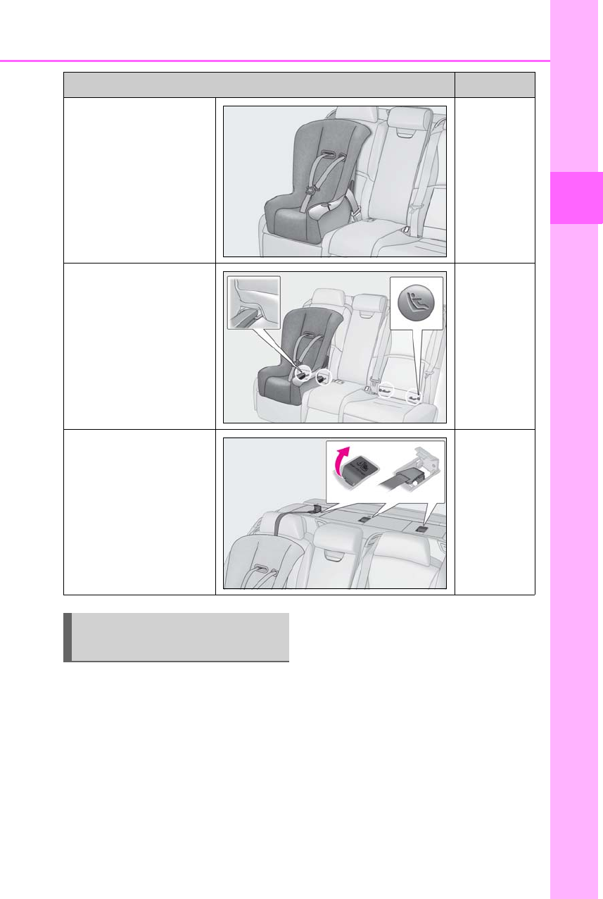
47
1-2. Child safety
LS500h_OM_OM50F42U_(U)
1
For safety and security
■When installing a child restraint
system to a front passenger seat
For the safety of a child, install child
restraint systems to a rear seats. When
installing child restraint system to a
front passenger seat is unavoidable,
adjust the seat as follows and install the
child restraint system.
-Move the front seat fully rearward.
-Adjust the seatback angle to the
most upright position.
-Adjust the front of the seat cushion
to the lowest position.
-Adjust the seat height to the upper-
most position.
-Adjust the lumbar support to the
lowest position.
-Adjust the shoulder bolster to the
Installation method Page
Seat belt attachment P.49
Child restraint LATCH
anchors attachment P.53
Anchor brackets (for top
tether strap) attachment P.55
When using a child restraint sys-
tem
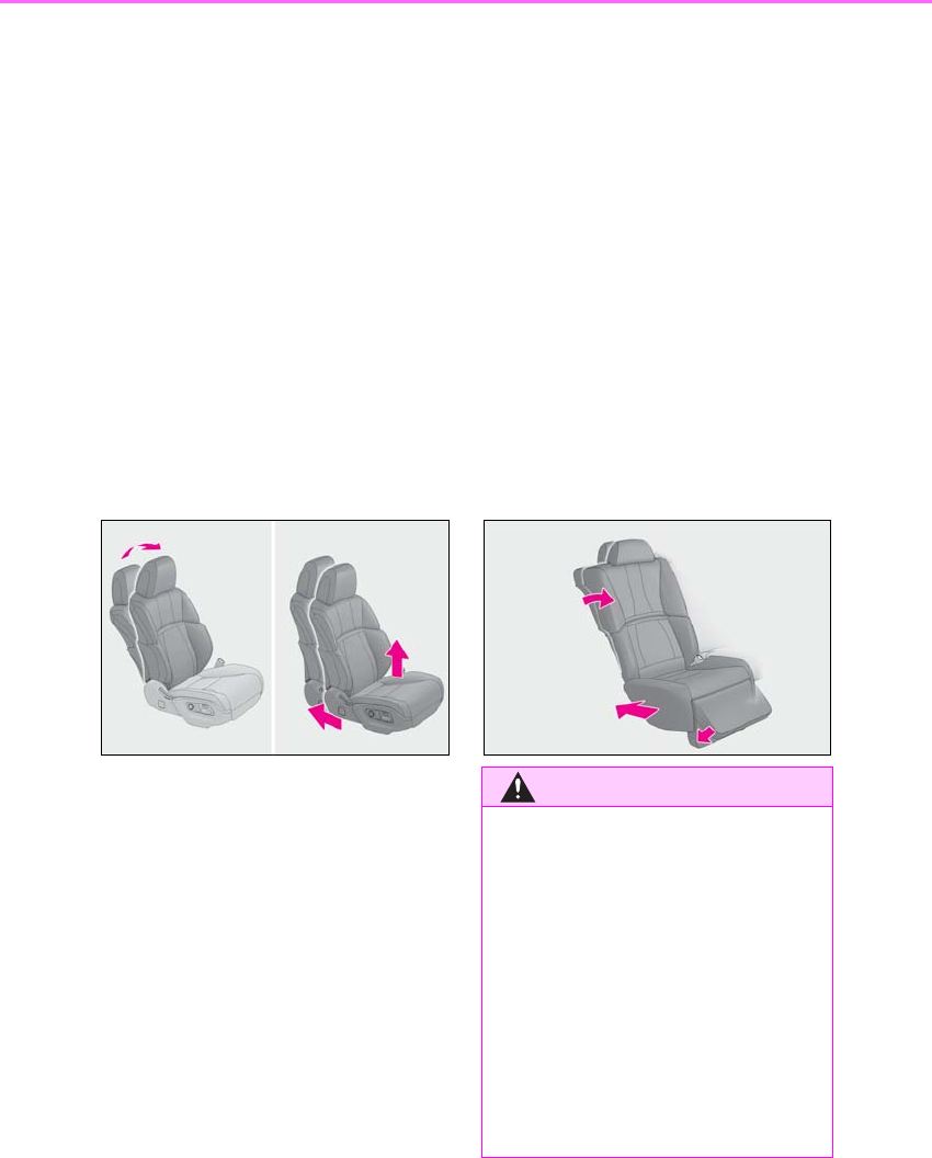
48 1-2. Child safety
LS500h_OM_OM50F42U_(U)
lowest position (if equipped).
-Adjust the pelvic support to the low-
est position.
-Adjust the seatback side bolster to
the widest position (if equipped).
-Adjust the seat cushion side bolster
to the lowest position (if equipped).
-Adjust the hip support to the lowest
position (if equipped).
-If the head restraint interferes with
the child restraint system installa-
tion and the head restraint can be
removed, remove the head restraint.
Otherwise, put the head restraint in
the upper most position.
■When installing a child restraint
system to a power rear seat (if
equipped)
When using a child restraint system in
an outer rear seat, adjust the seat as
follows and install the child restraint
system.
-Adjust the seat cushion to the fully
rearward position.
-Adjust the upper seatback to the
rearmost position.
-Adjust the front of the seat cushion
to the lowest position.
-Adjust the head restraint to the low-
est and rearmost position.
-Adjust the shoulder bolster to the
lowest position.
-Adjust the lumbar support to the
lowest position.
-Adjust the pelvic support to the low-
est position.
-Disable the automatic rear seat
operation. (→P.318)
-For the rear seat with an ottoman (if
equipped): Adjust the seatback to
the most upright position and otto-
man (footrest) to the stowed posi-
tion.
WARNING
■When using a child restraint system
Observe the following precautions.
Failure to do so may result in death or
serious injury.
●Never install a rear-facing child
restraint system on the front passenger
seat even if the “AIR BAG OFF” indi-
cator light is illuminated. In the event of
an accident, the force of the rapid infla-
tion of the front passenger airbag can
cause death or serious injury to the
child if the rear-facing child restraint
system is installed on the front passen-
ger seat.
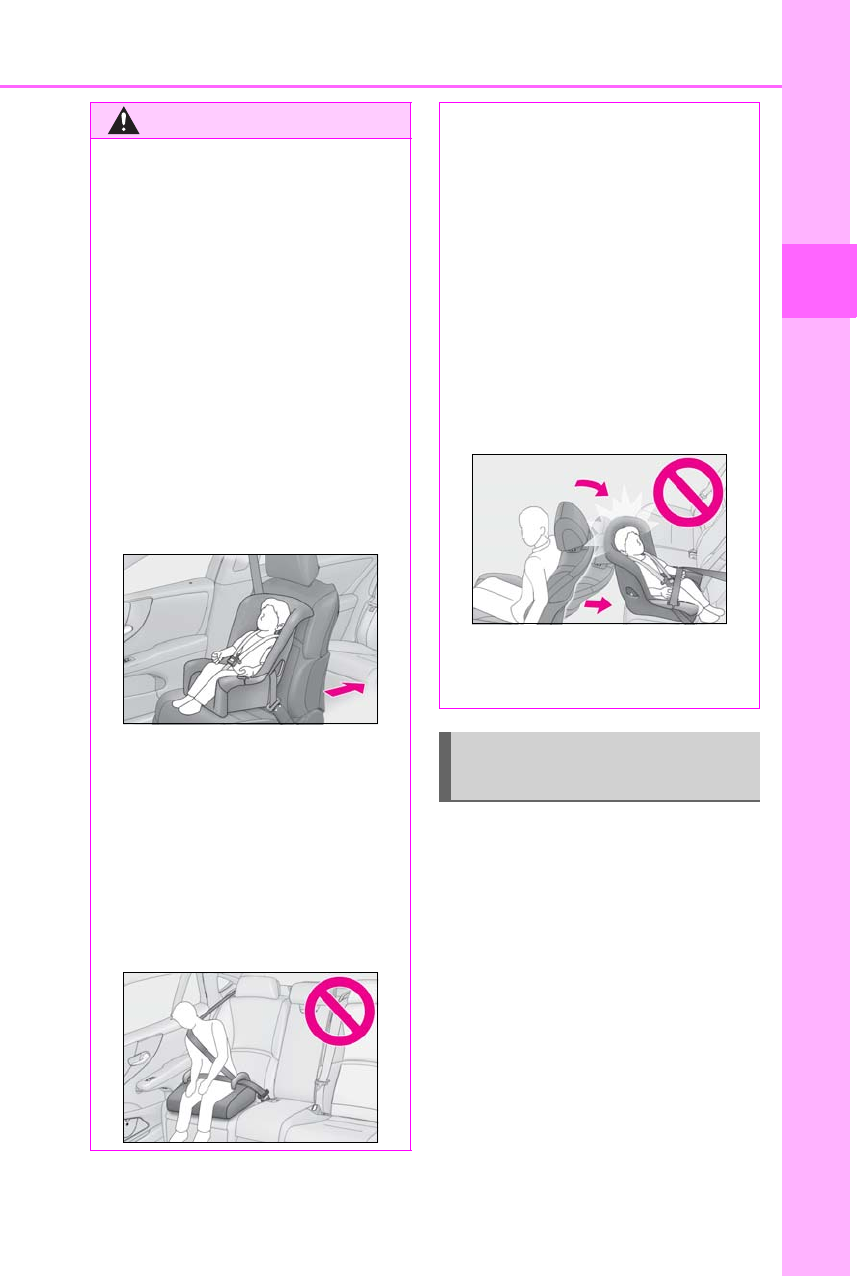
49
1-2. Child safety
LS500h_OM_OM50F42U_(U)
1
For safety and security
A child restraint system for a small
child or baby must itself be properly
restrained on the seat with the lap por-
tion of the lap/shoulder belt.
■Installing child restraint system
using a seat belt (child restraint
lock function belt)
Install the child restraint system in
accordance to the operation manual
enclosed with the child restraint sys-
tem.
WARNING
●A forward-facing child restraint system
may be installed on the front passen-
ger seat only when it is unavoidable. A
child restraint system that requires a
top tether strap should not be used in
the front passenger seat since there is
no top tether strap anchor for the front
passenger seat.
●A forward-facing child restraint system
may be installed on the front passen-
ger seat only when it is unavoidable.
When installing a forward-facing child
restraint system on the front passenger
seat, adjust the seatback angle to the
most upright position, move the seat to
the rearmost position, and raise the
seat to the upper most position, even if
the “AIR BAG OFF” indicator light is
illuminated.
●Do not allow the child to lean his/her
head or any part of his/her body
against the door or the area of the seat,
front or rear pillars, or roof side rails
from which the SRS side airbags or
SRS curtain shield airbags deploy even
if the child is seated in the child
restraint system. It is dangerous if the
SRS side and curtain shield airbags
inflate, and the impact could cause
death or serious injury to the child.
●When a booster seat is installed,
always ensure that the shoulder belt is
positioned across the center of the
child’s shoulder. The belt should be
kept away from the child’s neck, but
not so that it could fall off the child’s
shoulder.
●Use child restraint system suitable to
the age and size of the child and install
it to the rear seat.
●If the driver’s seat interferes with the
child restraint system and prevents it
from being attached correctly, attach
the child restraint system to the
right-hand rear seat.
●Adjust the front passenger seat so that
it does not interfere with the child
restraint system.
Child restraint system fixed with
a seat belt
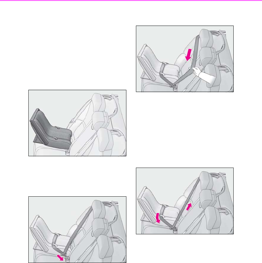
50 1-2. Child safety
LS500h_OM_OM50F42U_(U)
■Rear-facing ⎯ Infant seat/con-
vertible seat
1Adjust the rear seat
Vehicles with power rear seat: If there is a
gap between the child seat and the seat-
back, adjust the seatback angle until good
contact is achieved.
2Place the child restraint system on
the rear seat facing the rear of the
vehicle.
3Run the seat belt through the child
restraint system and insert the plate
into the buckle. Make sure that the
belt is not twisted.
4Fully extend the shoulder belt and
allow it to retract to put it in lock
mode. In lock mode, the belt cannot
be extended.
5While pushing the child restraint
system down into the rear seat,
allow the shoulder belt to retract
until the child restraint system is
securely in place.
After the shoulder belt has retracted to a
point where there is no slack in the belt,
pull the belt to check that it cannot be
extended.
6After installing the child restraint
system, rock it back and forth to
ensure that it is installed securely.
(→P.53)
■Forward-facing ⎯ Convertible
seat
1Adjust the seat
When using the front passenger
seat
If installing the child restraint system to
the front passenger seat is unavoid-
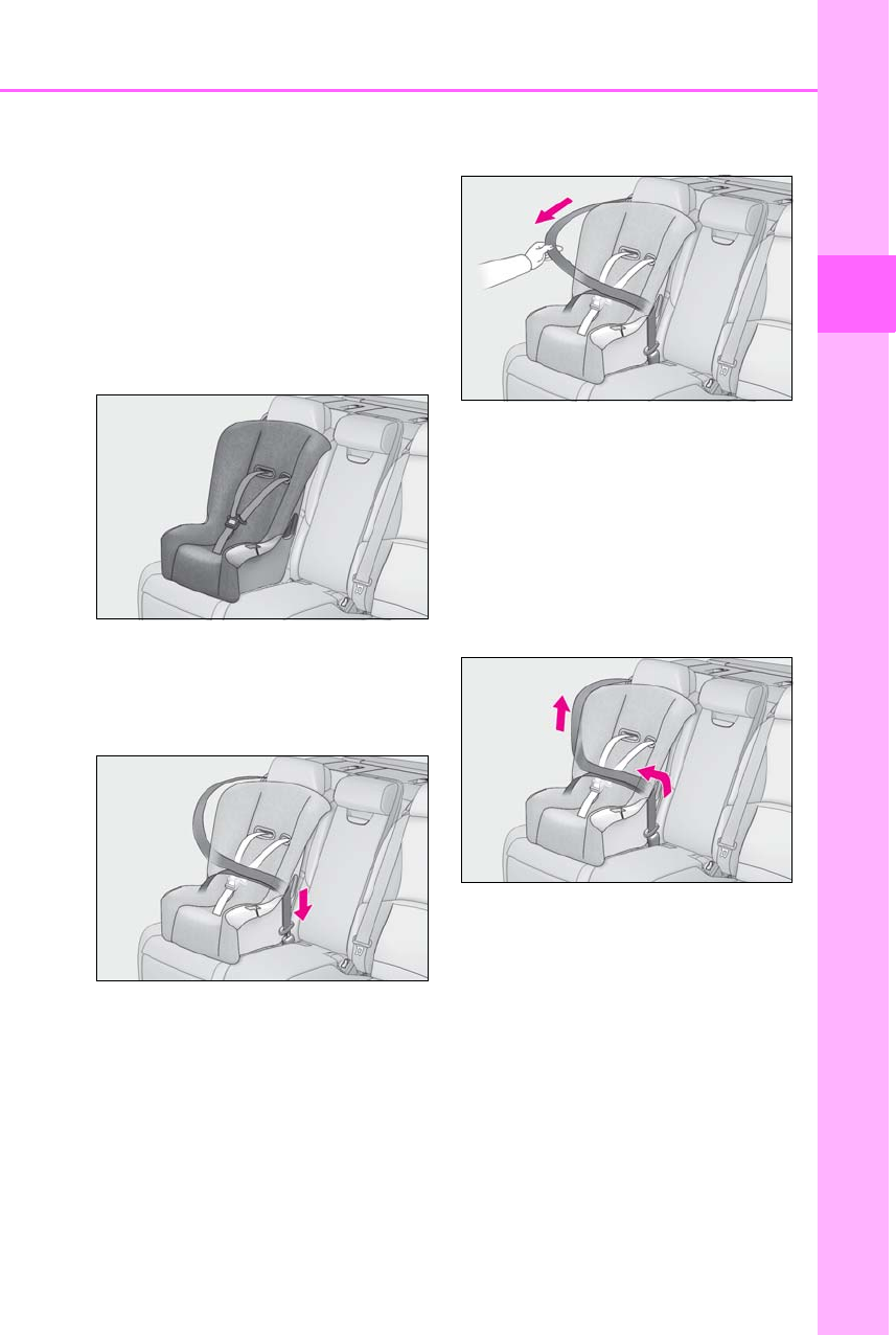
51
1-2. Child safety
LS500h_OM_OM50F42U_(U)
1
For safety and security
able, refer to P.47 for front passenger
seat adjustment.
When using the rear seat
If there is a gap between the child seat
and the seatback, adjust the seatback
angle until good contact is achieved.
2Place the child restraint system on
the seat facing the front of the vehi-
cle.
3Run the seat belt through the child
restraint system and insert the plate
into the buckle. Make sure that the
belt is not twisted.
4Fully extend the shoulder belt and
allow it to retract to put it in lock
mode. In lock mode, the belt cannot
be extended.
5While pushing the child restraint
system into the rear seat, allow the
shoulder belt to retract until the
child restraint system is securely in
place.
After the shoulder belt has retracted to a
point where there is no slack in the belt,
pull the belt to check that it cannot be
extended.
6If the child restraint has a top tether
strap, follow the child restraint man-
ufacturer’s operation manual
regarding the installation, using the
top tether strap to latch onto the
top tether strap anchor. (→P.55)
7After installing the child restraint
system, rock it back and forth to
ensure that it is installed securely.
(→P.53)
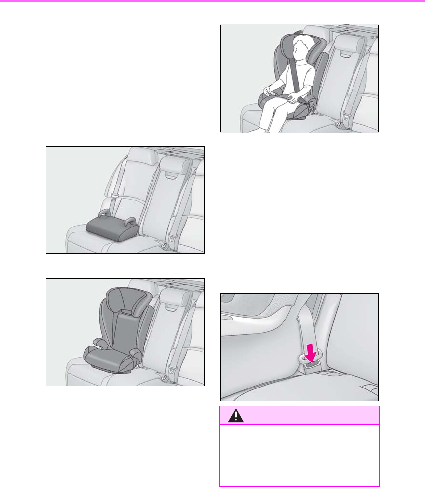
52 1-2. Child safety
LS500h_OM_OM50F42U_(U)
■Booster seat
1If installing the child restraint sys-
tem to the front passenger seat is
unavoidable, refer to P.47 for front
passenger seat adjustment.
2Place the child restraint system on
the seat facing the front of the vehi-
cle.
Booster type
High back type
4Sit the child in the child restraint
system. Fit the seat belt to the child
restraint system according to the
manufacturer’s instructions and
insert the plate into the buckle.
Make sure that the belt is not
twisted.
Check that the shoulder belt is correctly
positioned over the child’s shoulder and
that the lap belt is as low as possible.
(→P.24)
■Removing a child restraint system
installed with a seat belt
Press the buckle release button and
fully retract the seat belt.
When releasing the buckle, the child
restraint system may spring up due to the
rebound of the seat cushion. Release the
buckle while holding down the child
restraint system.
Since the seat belt automatically reels itself,
slowly return it to the stowing position.
WARNING
■When installing a child restraint sys-
tem
Observe the following precautions.
Failure to do so may result in death or
serious injury.
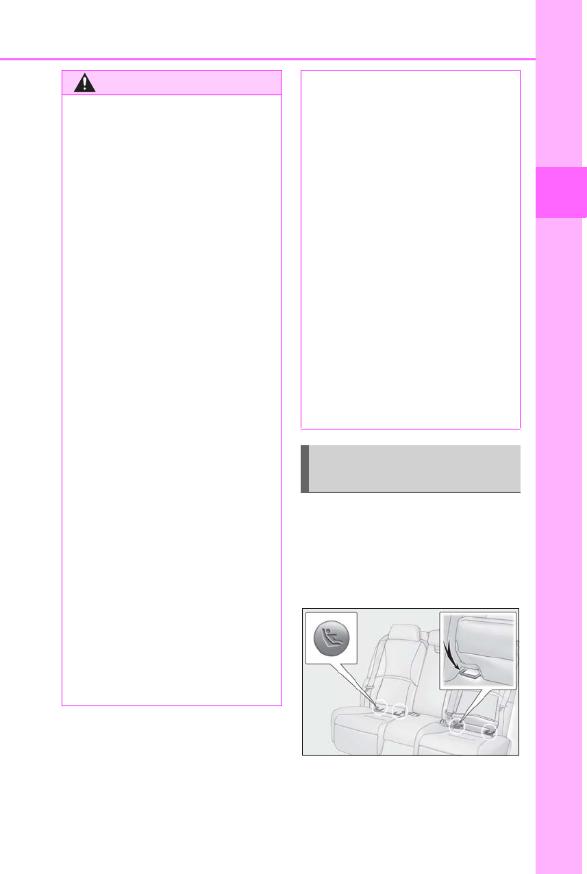
53
1-2. Child safety
LS500h_OM_OM50F42U_(U)
1
For safety and security
■Child restraint LATCH anchors
LATCH anchors are provided for the
outboard rear seat. (Buttons displaying
the location of the anchors are
attached to the seats.)
■Installation with LATCH system
Install the child restraint system in
WARNING
●Do not allow children to play with the
seat belt. If the seat belt becomes
twisted around a child’s neck, it may
lead to choking or other serious inju-
ries that could result in death.
If this occurs and the buckle cannot be
unfastened, scissors should be used to
cut the belt.
●Ensure that the belt and plate are
securely locked and the seat belt is not
twisted.
●Shake the child restraint system left
and right, and forward and backward
to ensure that it has been securely
installed.
●After securing a child restraint system,
never adjust the seat.
●When a booster seat is installed,
always ensure that the shoulder belt is
positioned across the center of the
child’s shoulder. The belt should be
kept away from the child’s neck, but
not so that it could fall off the child’s
shoulder.
●Follow all installation instructions pro-
vided by the child restraint system
manufacturer.
●When securing some types of child
restraint systems in rear seats, it may
not be possible to properly use the
seat belts in positions next to the child
restraint without interfering with it or
affecting seat belt effectiveness. Be
sure your seat belt fits snugly across
your shoulder and low on your hips. If it
does not, or if it interferes with the
child restraint, move to a different posi-
tion. Failure to do so may result in
death or serious injury.
●When installing a child restraint system
in the rear center seat, adjust both seat
cushions to the same position and
align both seatbacks at the same
angle. Otherwise, the child restraint
system cannot be securely restrained
and this may cause death or serious
injuries in the event of sudden braking,
sudden swerving or an accident.
■When installing a booster seat
To prevent the belt from going into ALR
lock mode, do not fully extend the shoul-
der belt. ALR mode causes the belt to
tighten only. This could cause injury or
discomfort to the child. (→P.26)
■Do not use a seat belt extender
If a seat belt extender is used when
installing a child restraint system, the seat
belt will not securely hold the child
restraint system, which could cause
death or serious injury to the child or
other passengers in the event of sudden
braking, sudden swerving or an accident.
Child restraint system fixed with
a child restraint LATCH anchor
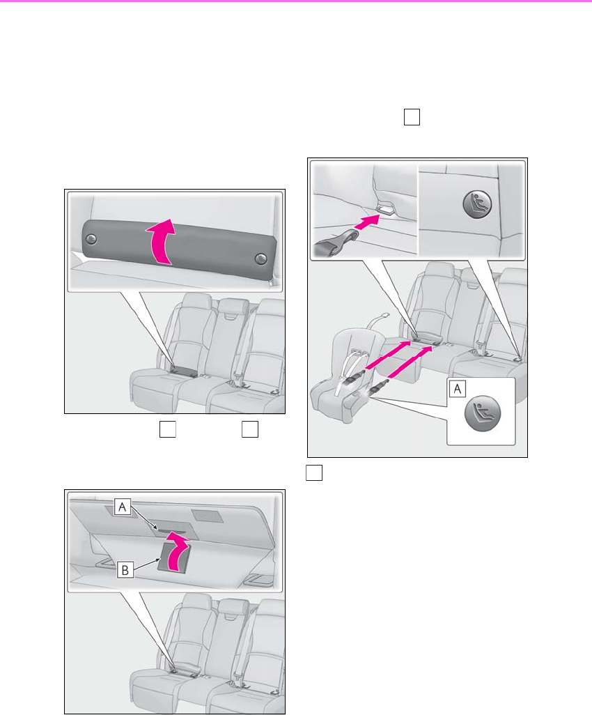
54 1-2. Child safety
LS500h_OM_OM50F42U_(U)
accordance to the operation manual
enclosed with the child restraint sys-
tem.
1Vehicles with power rear seat:
Adjust the seat
If there is a gap between the child seat and
the seatback, adjust the seatback angle
until good contact is achieved. (→P.48)
2Open the cover.
3Insert the tab into the slit of
the cover.
The cover will be held open.
Type A
4Latch the hooks of the lower straps
onto the LATCH anchors.
For owners in Canada:
The symbol on a child restraint sys-
tem indicates the presence of a
lower connector system.
Canada only
Type B
4Latch the buckles onto the LATCH
anchors.
For owners in Canada:
The symbol on a child restraint sys-
B
A
A
A
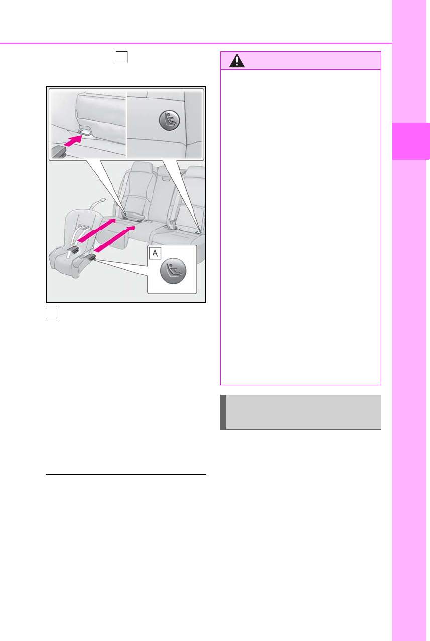
55
1-2. Child safety
LS500h_OM_OM50F42U_(U)
1
For safety and security
tem indicates the presence of a
lower connector system.
Canada only
5If the child restraint has a top tether
strap, follow the child restraint man-
ufacturer’s operation manual
regarding the installation, using the
top tether strap to latch onto the
top tether strap anchor. (→P.55)
6After installing the child restraint
system, rock it back and forth to
ensure that it is installed securely.
(→P.53)
■Laws and regulations pertaining to
anchors
The LATCH system conforms to
FMVSS225 or CMVSS210.2.
Child restraint systems conforming to
FMVSS213 or CMVSS213 specifications
can be used.
This vehicle is designed to conform to SAE
J1819.
■Anchor brackets (for top tether
strap)
Anchor brackets are provided for each
rear seat.
Use anchor brackets when fixing the
top tether strap.
A
A
WARNING
■When installing a child restraint sys-
tem
Observe the following precautions.
Failure to do so may result in death or
serious injury.
●After securing a child restraint system,
never adjust the seat.
●When using the LATCH anchors, be
sure that there are no foreign objects
around the anchors and that the seat
belt is not caught behind the child
restraint system.
●Follow all installation instructions pro-
vided by the child restraint system
manufacturer.
●When securing some types of child
restraint systems in rear seats, it may
not be possible to properly use the
seat belts in positions next to the child
restraint without interfering with it or
affecting seat belt effectiveness. Be
sure your seat belt fits snugly across
your shoulder and low on your hips. If it
does not, or if it interferes with the
child restraint, move to a different posi-
tion. Failure to do so may result in
death or serious injury.
Using an anchor bracket (for top
tether strap)
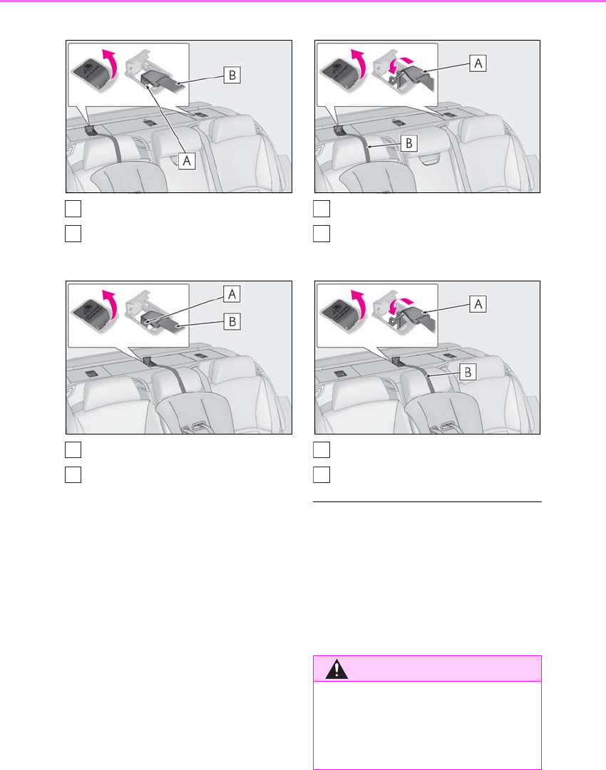
56 1-2. Child safety
LS500h_OM_OM50F42U_(U)
Outboard rear seats
Anchor brackets
Top tether strap
Rear center seat
Anchor bracket
Top tether strap
■Fixing the top tether strap to the
anchor bracket
Install the child restraint system in
accordance to the operation manual
enclosed with the child restraint sys-
tem.
Open the anchor bracket cover, latch
the hook onto the anchor bracket and
tighten the top tether strap.
Make sure the top tether strap is securely
latched. (→P.53)
Outboard rear seats
Hook
Top tether strap
Rear center seat
Hook
Top tether strap
■Laws and regulations pertaining to
anchors
The LATCH system conforms to
FMVSS225 or CMVSS210.2.
Child restraint systems conforming to
FMVSS213 or CMVSS213 specifications
can be used.
This vehicle is designed to conform to SAE
J1819.
A
B
A
B
WARNING
■When installing a child restraint sys-
tem
Observe the following precautions.
Failure to do so may result in death or
serious injury.
A
B
A
B

57
1-2. Child safety
LS500h_OM_OM50F42U_(U)
1
For safety and security
WARNING
●Firmly attach the top tether strap and
make sure that the belt is not twisted.
●Do not attach the top tether strap to
anything other than the anchor
bracket.
●After securing a child restraint system,
never adjust the seat.
●Follow all installation instructions pro-
vided by the child restraint system
manufacturer.
●Be sure to have the top tether strap
pass over the top of the head restraint.
If the belt passes below the head
restraint, it is possible that the child
restraint system may not be securely
fixed.
NOTICE
■Anchor brackets (for top tether
strap)
When not in use, make certain to close
the lid. If it remains open, the lid may be
damaged.
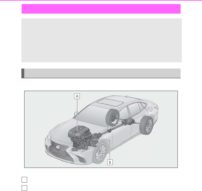
58 1-3. Hybrid system
LS500h_OM_OM50F42U_(U)
1-3.Hybrid system
■System components
The illustration is an example for explanation and may differ from the actual item.
Gasoline engine
Electric motor (traction motor)
■When stopped/during start off
The gasoline engine stops* when the
vehicle is stopped. During start off, the
electric motor (traction motor) drives
the vehicle. At slow speeds or when
traveling down a gentle slope, the
engine is stopped* and the electric
motor (traction motor) is used.
When the shift position is in N, the
hybrid battery (traction battery) is not
being charged.
*: When the hybrid battery (traction bat-
tery) requires charging or the engine is
warming up, etc., the gasoline engine will
not automatically stop.
■During normal driving
The gasoline engine is predominantly
used. The electric motor (traction
motor) charges the hybrid battery
Hybrid system features
Your vehicle is a hybrid vehicle. It has characteristics different from conven-
tional vehicles. Be sure you are closely familiar with the characteristics of your
vehicle, and operate it with care.
The hybrid system combines the use of a gasoline engine and an electric motor
(traction motor) according to driving conditions, improving fuel efficiency and
reducing exhaust emissions.
System components
A
B

59
1-3. Hybrid system
LS500h_OM_OM50F42U_(U)
1
For safety and security
(traction battery) as necessary.
■When accelerating sharply
When the accelerator pedal is
depressed heavily, the power of the
hybrid battery (traction battery) is
added to that of the gasoline engine via
the electric motor (traction motor).
■When braking (regenerative brak-
ing)
The wheels operate the electric motor
(traction motor) as a power generator,
and the hybrid battery (traction bat-
tery) is charged.
■Regenerative braking
In the following situations, kinetic energy is
converted to electric energy and decelera-
tion force can be obtained in conjunction
with the recharging of the hybrid battery
(traction battery).
●The accelerator pedal is released while
driving with the shift position in D or M.
●The brake pedal is depressed while driv-
ing with the shift position in D or M.
■EV indicator
The EV indicator comes on when the vehi-
cle is driven using only the electric motor
(traction motor) or the gasoline engine is
stopped.
■Conditions in which the gasoline engine
may not stop
The gasoline engine starts and stops auto-
matically. However, it may not stop auto-
matically in the following conditions:
●During gasoline engine warm-up
●During hybrid battery (traction battery)
charging
●When the temperature of the hybrid bat-
tery (traction battery) is high or low
●When the heater is switched on
●When the shift position is in M
Depending on the circumstances, the gaso-
line engine may also not stop automatically
in other situations.
■Charging the hybrid battery (traction
battery)
As the gasoline engine charges the hybrid
battery (traction battery), the battery does
not need to be charged from an outside
source. However, if the vehicle is left parked
for a long time the hybrid battery (traction
battery) will slowly discharge. For this rea-
son, be sure to drive the vehicle at least
once every few months for at least 30 min-
utes or 10 miles (16 km). If the hybrid bat-
tery (traction battery) becomes fully
discharged and you are unable to contact
your Lexus dealer.
■Charging the 12-volt battery
→P.447
■After the 12-volt battery has discharged
or when the terminal has been removed
and installed during exchange, etc.
The gasoline engine may not stop even if
the vehicle is being driven by the hybrid bat-
tery (traction battery). If this continues for a
few days, contact your Lexus dealer.
■Sounds and vibrations specific to a
hybrid vehicle
There may be no engine sound or vibration
even though the vehicle is able to move with
the “READY” indicator is illuminated. For
safety, apply the parking brake and make
sure to shift the shift position to P when
parked.
The following sounds or vibrations may
occur when the hybrid system is operating
and are not a malfunction:
●Motor sounds may be heard from the
engine compartment.
●Relay operating sounds such as a snap or
soft clank will be emitted from the hybrid
battery (traction battery), behind the rear

60 1-3. Hybrid system
LS500h_OM_OM50F42U_(U)
seats, when the hybrid system is started
or stopped.
●Sounds may be heard from the hybrid
battery (traction battery) behind the rear
seats when the hybrid system starts or
stops.
●Sounds from the hybrid system may be
heard when the trunk lid is open.
●Sounds may be heard from the transmis-
sion when the gasoline engine starts or
stops, when driving at low speeds, or
during idling.
●Engine sounds may be heard when
accelerating sharply.
●Sounds may be heard due to regenera-
tive braking when the brake pedal is
depressed or as the accelerator pedal is
released.
●Vibration may be felt or sounds may be
heard when the gasoline engine starts or
stops.
●Cooling fan sounds may be heard from
the air intake vents on the both sides of
the rear seatback.
■Maintenance, repair, recycling, and dis-
posal
Contact your Lexus dealer regarding main-
tenance, repair, recycling and disposal. Do
not dispose of the vehicle yourself.
■Customization
Some functions can be customized.
(→P.481)
When driving with the gasoline engine
stopped, a sound, which changes in
accordance with the driving speed, will
be played in order to warn people
nearby of the vehicle’s approach. The
sound will stop when the vehicle speed
exceeds approximately 15 mph (25
km/h).
■Vehicle proximity notification system
In the following cases, the vehicle proximity
notification system may be difficult for sur-
rounding people to hear.
●In very noisy areas
●In the wind or the rain
Also, as the vehicle proximity notification
system is installed on the front of the vehicle,
it may be more difficult to hear from the rear
of the vehicle compared to the front.
■Customization
Some functions can be customized.
(→P.481)
Vehicle proximity notification
system
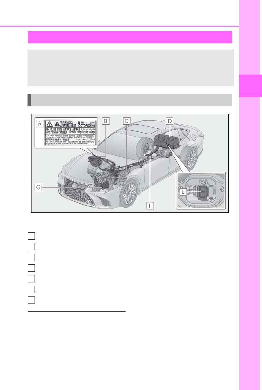
61
1-3. Hybrid system
LS500h_OM_OM50F42U_(U)
1
For safety and security
The illustration is an example for explana-
tion and may differ from the actual item.
Warning label
Power control unit
Electric motor (traction motor)
Hybrid battery (traction battery)
Service plug
High voltage cables (orange)
Air conditioning compressor
■Running out of fuel
When the vehicle has run out of fuel and the
hybrid system cannot be started, refuel the
vehicle with at least enough gasoline to
make the low fuel level warning light
(→P.430) go off. If there is only a small
amount of fuel, the hybrid system may not
be able to start. (The standard amount of
fuel is about 3.4 gal. [13 L, 2.8 Imp. gal.],
when the vehicle is on a level surface. This
value may vary when the vehicle is on a
slope. Add extra fuel when the vehicle is
inclined.)
■Electromagnetic waves
●High voltage parts and cables on hybrid
vehicles incorporate electromagnetic
shielding, and therefore emit approxi-
mately the same amount of electromag-
netic waves as conventional gasoline
powered vehicles or home electronic
appliances.
●Your vehicle may cause sound interfer-
ence in some third party-produced radio
parts.
■Hybrid battery (traction battery)
The hybrid battery (traction battery) has a
limited service life. The lifespan of the
hybrid battery (traction battery) can
Hybrid system precautions
Take care when handling the hybrid system, as it is a high voltage system (about
650 V at maximum) as well as contains parts that become extremely hot when
the hybrid system is operating. Obey the warning labels attached to the vehi-
cle.
System components
A
B
C
D
E
F
G
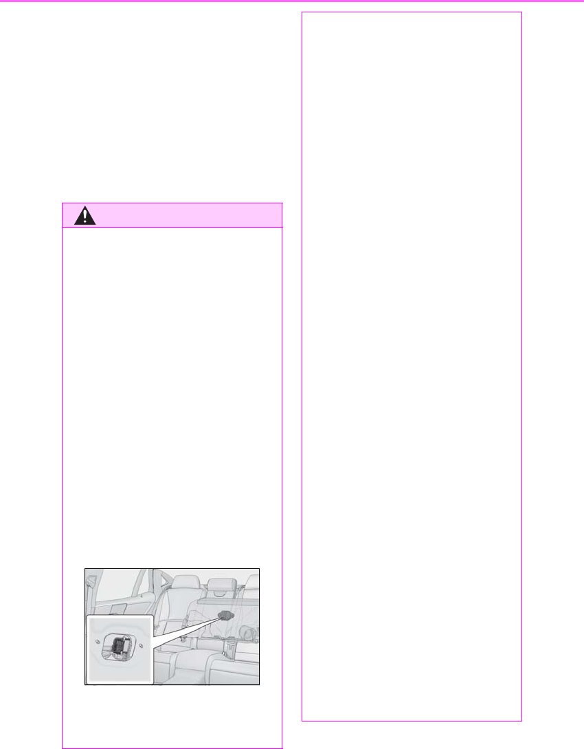
62 1-3. Hybrid system
LS500h_OM_OM50F42U_(U)
change in accordance with driving style and
driving conditions.
■Starting the hybrid system in an
extremely cold environment
When the hybrid battery (traction battery)
is extremely cold (below approximately
-22°F [-30°C]) under the influence of the
outside temperature, it may not be possible
to start the hybrid system. In this case, try to
start the hybrid system again after the tem-
perature of the hybrid battery increases due
to the outside temperature increase etc.
WARNING
■High voltage precautions
This vehicle has high voltage DC and AC
systems as well as a 12-volt system. DC
and AC high voltage is very dangerous
and can cause severe burns and electric
shock that may result in death or serious
injury.
●Never touch, disassemble, remove or
replace the high voltage parts, cables
or their connectors.
●The hybrid system will become hot
after starting as the system uses high
voltage. Be careful of both the high
voltage and the high temperature, and
always obey the warning labels
attached to the vehicle.
●Never try to open the service plug
access hole located behind the rear
seat. The service plug is used only
when the vehicle is serviced and is
subject to high voltage.
■Road accident cautions
Observe the following precautions to
reduce the risk of death or serious injury:
●Stop the vehicle in a safe place to pre-
vent subsequent accidents. While
depressing the brake pedal, apply the
parking brake and shift the shift posi-
tion to P to stop the hybrid system.
Then, slowly release the brake pedal.
●Do not touch the high voltage parts,
cables and connectors.
●If electric wires are exposed inside or
outside your vehicle, an electric shock
may occur. Never touch exposed elec-
tric wires.
●Do not touch the battery if liquid is
leaking from or adhering to it.
If electrolyte (carbonate ester-based
organic electrolyte) from the hybrid
battery (traction battery) comes into
contact with the eyes or skin, it could
cause blindness or skin wounds. In the
unlikely event that it comes into con-
tact with the eyes or skin, wash it off
immediately with a large amount of
water, and seek immediate medical
attention.
●If electrolyte is leaking from the hybrid
battery (traction battery), do not
approach the vehicle.
Even in the unlikely event that the
hybrid battery (traction battery) is
damaged, the internal construction of
the battery will prevent a large amount
of electrolyte from leaking out. How-
ever, any electrolyte that does leak out
will give off a vapor. This vapor is an
irritant to skin and eyes and could
cause acute poisoning if inhaled.
●Do not bring burning or high-tem-
perature items close to the electrolyte.
The electrolyte may ignite and cause a
fire.
●If a fire occurs in the hybrid vehicle,
leave the vehicle as soon as possible.
Never use a fire extinguisher that is not
meant for electric fires. Using even a
small amount of water may be danger-
ous.

63
1-3. Hybrid system
LS500h_OM_OM50F42U_(U)
1
For safety and security
WARNING
●If your vehicle needs to be towed, do
so with four wheels raised. If the
wheels connected to the electric
motor (traction motor) are on the
ground when towing, the motor may
continue to generate electricity. This
may cause a fire. (→P.422)
●Carefully inspect the ground under the
vehicle. If you find that liquid has
leaked onto the ground, the fuel sys-
tem may have been damaged. Leave
the vehicle as soon as possible.
■Hybrid battery (traction battery)
●Your vehicle contains a sealed lith-
ium-ion battery.
●Never resell, hand over or modify the
hybrid battery. To prevent accidents,
hybrid batteries that have been
removed from a disposed vehicle are
collected through your Lexus dealer.
Do not dispose of the battery yourself.
Unless the battery is properly collected,
the following may occur, resulting in
death or serious injury:
• The hybrid battery may be illegally dis-
posed of or dumped, and it is hazard-
ous to the environment or someone
may touch a high voltage part, result-
ing in an electric shock.
• The hybrid battery is intended to be
used exclusively with your hybrid vehi-
cle. If the hybrid battery is used outside
of your vehicle or modified in any way,
accidents such as electric shock, heat
generation, smoke generation, an
explosion and electrolyte leakage may
occur.
When reselling or handing over your
vehicle, the possibility of an accident is
extremely high because the person
receiving the vehicle may not be aware
of these dangers.
●If your vehicle is disposed of without
the hybrid battery having been
removed, there is a danger of serious
electric shock if high voltage parts,
cables and their connectors are
touched. In the event that your vehicle
must be disposed of, the hybrid battery
must be disposed of by your Lexus
dealer or a qualified service shop. If
the hybrid battery is not disposed of
properly, it may cause electric shock
that can result in death or serious
injury.
NOTICE
■Hybrid battery (traction battery) air
intake vents
Do not carry large amounts of water
such as water cooler bottles in the vehi-
cle. If water spills onto the hybrid battery
(traction battery), the battery may be
damaged. Have the vehicle inspected by
your Lexus dealer.
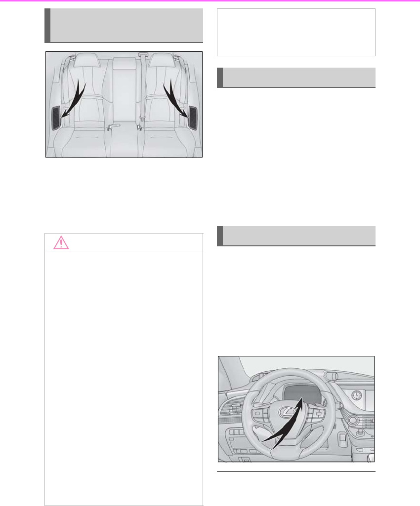
64 1-3. Hybrid system
LS500h_OM_OM50F42U_(U)
There are air intake vents on each side
of the rear seatback with the purpose
of cooling the hybrid battery (traction
battery). If the vents become blocked,
hybrid battery output may be reduced.
When a certain level of impact is
detected by the impact sensor, the
emergency shut off system blocks the
high voltage current and stops the fuel
pump to minimize the risk of electrocu-
tion and fuel leakage. If the emergency
shut off system activates, your vehicle
will not restart. To restart the hybrid
system, contact your Lexus dealer.
A message is automatically displayed
when a malfunction occurs in the
hybrid system or an improper opera-
tion is attempted.
If a warning message is shown on the
multi-information display, read the
message and follow the instructions.
■If a warning light comes on, a warning
message is displayed, or the 12-volt bat-
tery is disconnected
The hybrid system may not start. In this
case, try to start the system again. If the
“READY” indicator does not come on, con-
Hybrid battery (traction bat-
tery) air intake vents
NOTICE
■Hybrid battery (traction battery) air
intake vents
●Make sure not to block the air intake
vent with anything, such as a seat
cover, plastic cover, or luggage. If the
vents become blocked, the hybrid bat-
tery (traction battery) input and output
may be restricted, leading to a reduc-
tion in hybrid battery (traction battery)
output and a malfunction.
●When dust etc. has accumulated in the
air intake vent, periodically clean it
with a vacuum cleaner to prevent the
vent from clogging.
●A filter is installed to the air intake vent.
When the filter remains noticeably
dirty even after cleaning the air intake
vent, filter cleaning or replacement is
recommended. When cleaning or
replacing the filter, contact your Lexus
dealer.
Refer to P.374 for details on how to
clean the filters.
●Do not get water or foreign materials
in the air intake vents as this may cause
a short circuit and damage the hybrid
battery (traction battery).
Emergency shut off system
Hybrid warning message

65
1-3. Hybrid system
LS500h_OM_OM50F42U_(U)
1
For safety and security
tact your Lexus dealer.
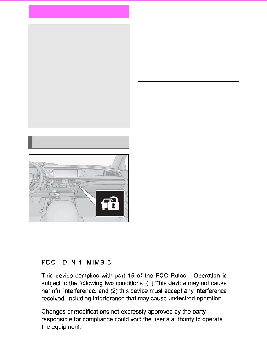
66 1-4. Theft deterrent system
LS500h_OM_OM50F42U_(U)
1-4.Theft deterrent system The indicator light flashes after the
power switch has been turned off to
indicate that the system is operating.
The indicator light stops flashing after
the power switch has been turned to
ACCESSORY or ON mode to indi-
cate that the system has been can-
celed.
■System maintenance
The vehicle has a maintenance-free type
immobilizer system.
■Conditions that may cause the system to
malfunction
●If the grip portion of the key is in contact
with a metallic object
●If the key is in close proximity to or touch-
ing a key to the security system (key with
a built-in transponder chip) of another
vehicle
■Certification for the immobilizer system
For vehicles sold in the U.S.A., Hawaii, Guam and Puerto Rico
Immobilizer system
The vehicle’s keys have built-in tran-
sponder chips that prevent the
hybrid system from starting if a key
has not been previously registered
in the vehicle’s on-board computer.
Never leave the keys inside the
vehicle when you leave the vehicle.
This system is designed to help pre-
vent vehicle theft but does not
guarantee absolute security
against all vehicle thefts.
Operating the system
67
1-4. Theft deterrent system
LS500h_OM_OM50F42U_(U)
1
For safety and security
For vehicles sold in Canada
NOTICE
■To ensure the system operates cor-
rectly
Do not modify or remove the system. If
modified or removed, the proper opera-
tion of the system cannot be guaranteed.
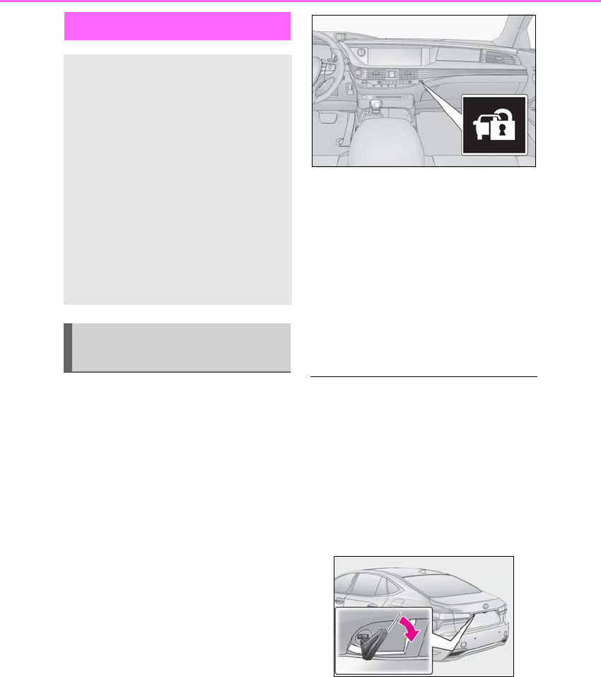
68 1-4. Theft deterrent system
LS500h_OM_OM50F42U_(U)
■Items to check before locking the
vehicle
To prevent unexpected triggering of
the alarm and vehicle theft, make sure
of the following:
-Nobody is in the vehicle.
-The windows and moon roof are
closed before the alarm is set.
-No valuables or other personal
items are left in the vehicle.
■Setting
Close the doors, trunk and hood, and
lock all the doors. The system will be
set automatically after 30 seconds.
The indicator light changes from being on
to flashing when the system is set.
■Canceling or stopping
Do one of the following to deactivate
or stop the alarms:
-Unlock the doors.
-Turn the power switch to ACCES-
SORY or ON mode, or start the
hybrid system. (The alarm will be
deactivated or stopped after a few
seconds.)
■System maintenance
The vehicle has a maintenance-free type
alarm system.
■Triggering of the alarm
The alarm may be triggered in the following
situations:
(Stopping the alarm deactivates the alarm
system.)
●The trunk is opened using the mechanical
key.
●A person inside the vehicle opens a door,
the trunk or hood, or unlocks the vehicle.
Alarm
The alarm uses light and sound to
give an alert when an intrusion is
detected.
The alarm is triggered in the follow-
ing situations when the alarm is set:
-A locked door or trunk is
unlocked or opened in any way
other than using the entry func-
tion, wireless remote control or
mechanical key. (The doors will
lock again automatically.)
-The hood is opened.
Setting/canceling/stopping the
alarm system
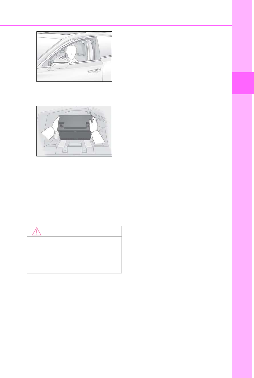
69
1-4. Theft deterrent system
LS500h_OM_OM50F42U_(U)
1
For safety and security
●The 12-volt battery is recharged or
replaced when the vehicle is locked.
(→P.450)
■Alarm-operated door lock
In the following cases, depending on the sit-
uation, the door may automatically lock to
prevent improper entry into the vehicle:
●When a person remaining in the vehicle
unlocks the door and the alarm is acti-
vated.
●While the alarm is activated, a person
remaining in the vehicle unlocks the door.
NOTICE
■To ensure the system operates cor-
rectly
Do not modify or remove the system. If
modified or removed, the proper opera-
tion of the system cannot be guaranteed.

70 1-4. Theft deterrent system
LS500h_OM_OM50F42U_(U)

71
LS500h_OM_OM50F42U_(U)
2
2
Vehicle status information and indicators
Vehicle status information
and indicators
.
2-1. Instrument cluster
Warning lights and indicators
............................................................72
Gauges and meters (except F
SPORT models) ........................ 77
Gauges and meters (F SPORT
models)........................................... 81
Multi-information display..........86
Head-up display ........................... 92
Energy monitor/consumption
screen ............................................ 96
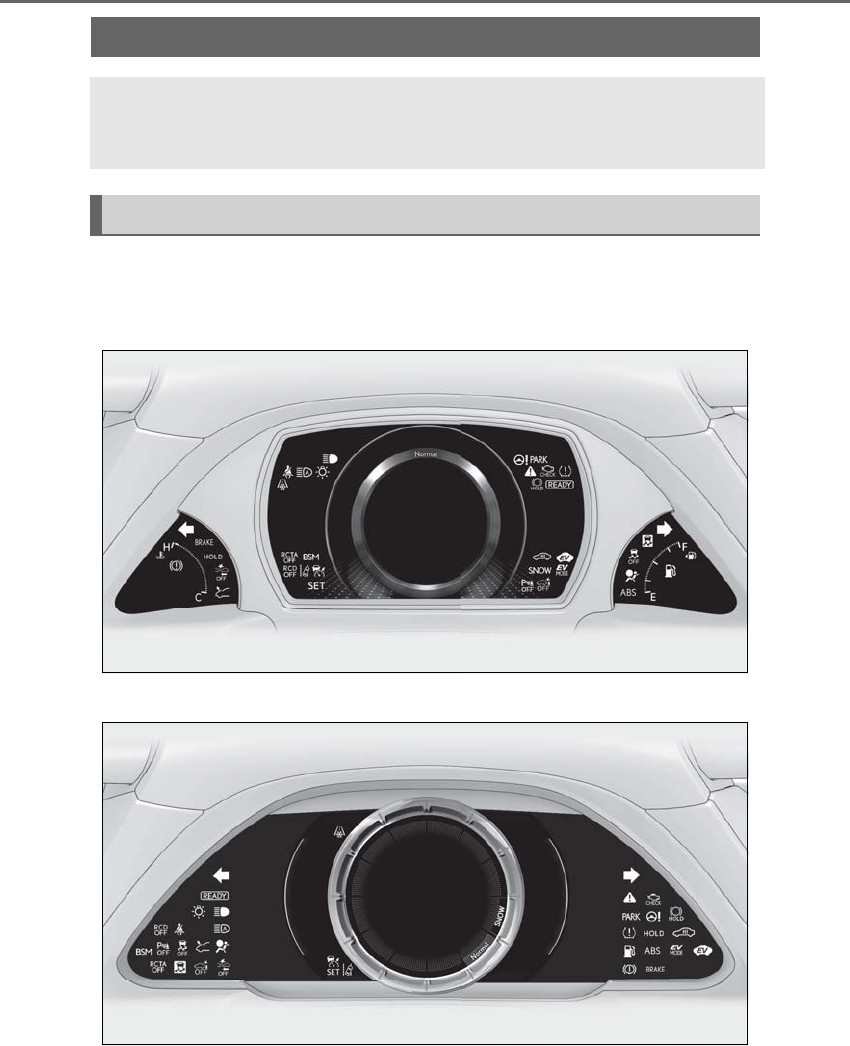
72 2-1. Instrument cluster
LS500h_OM_OM50F42U_(U)
2-1.Instrument cluster
For the purpose of explanation, the following illustrations display all warning lights
and indicators illuminated.
Except F SPORT models
F SPORT models
Warning lights and indicators
The warning lights and indicators on the instrument cluster, center panel and
outside rear view mirrors inform the driver of the status of the vehicle’s various
systems.
Warning lights and indicators displayed on the instrument cluster
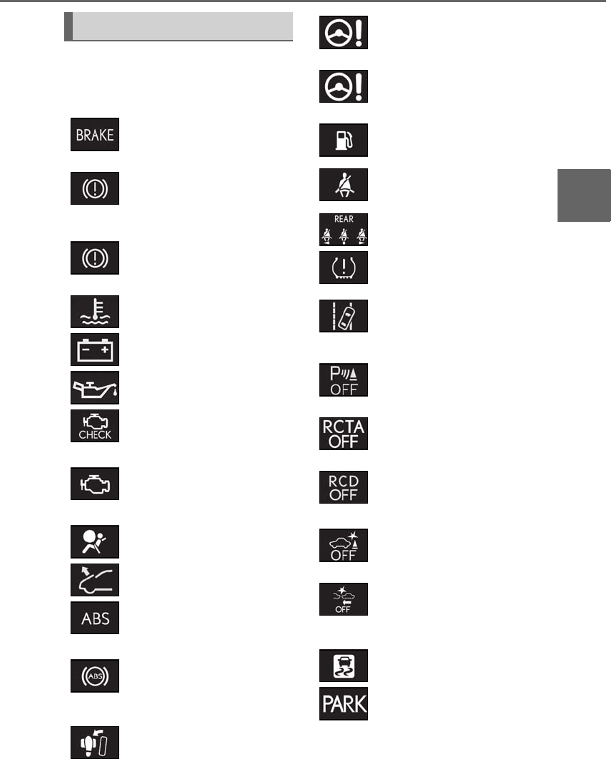
73
2-1. Instrument cluster
LS500h_OM_OM50F42U_(U)
2
Vehicle status information and indicators
Warning lights inform the driver of mal-
functions in the indicated vehicle’s sys-
tems.
Warning lights
(U.S.A.)
Brake system warning light*1
(→P.427)
(red)
(Canada)
Brake system warning light*1
(→P.427)
(yellow)
Brake system warning light*1
(→P.427)
High coolant temperature
warning light*2 (→P.427)
Charging system warning
light*2 (→P.428)
Low engine oil pressure warn-
ing light*2 (→P.428)
(U.S.A.)
Malfunction indicator lamp*1
(→P.428)
(Canada)
Malfunction indicator lamp*1
(→P.428)
SRS warning light*1 (→P.428)
Pop Up Hood warning light*1
(→P.429)
(U.S.A.)
ABS warning light*1 (→P.429)
(Canada)
ABS warning light*1 (→P.429)
Brake Override System warn-
ing light/Drive-Start Control
warning light*2 (→P.429)
(red)
Electric power steering system
warning light*1 (→P.430)
(yellow)
Electric power steering system
warning light*1 (→P.430)
Low fuel level warning light
(→P.430)
Driver’s and front passenger’s
seat belt reminder light
(→P.430)
Rear passengers’ seat belt
reminder lights*3 (→P.431)
Tire pressure warning light*1
(→P.431)
(orange)
LTA indicator (if equipped)
(→P.431)
LKA indicator (if equipped)
(→P.431)
(flashes)
Intuitive parking assist OFF indi-
cator*1 (→P.432)
(flashes)
RCTA OFF indicator*1
(→P.432)
(flashes)
RCD OFF indicator (if
equipped) (→P.432)
(flashes)
PKSB OFF indicator*1
(→P.433)
(flashes or
illuminates)
PCS warning light*1 (→P.433)
Slip indicator*1 (→P.433)
(flashes)
(U.S.A.)
Parking brake indicator
(→P.434)
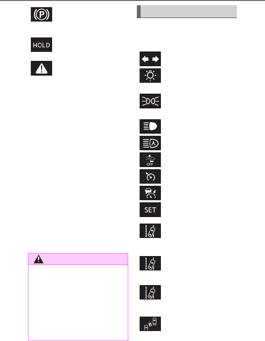
74 2-1. Instrument cluster
LS500h_OM_OM50F42U_(U)
*1: These lights come on when the power
switch is turned to ON mode to indi-
cate that a system check is being per-
formed. They will go off after the hybrid
system is on, or after a few seconds.
There may be a malfunction in a system
if the lights do not come on, or go off.
Have the vehicle inspected by your
Lexus dealer.
*2: This light illuminates on the multi-infor-
mation display.
*3: This light illuminates on the center
panel.
*4: F SPORT models: This light comes on
when the power switch is turned to ON
mode to indicate that a system check is
being performed. They will go off after
the hybrid system is on, or after a few
seconds. There may be a malfunction in
a system if the lights do not come on, or
go off. Have the vehicle inspected by
your Lexus dealer.
The indicators inform the driver of the
operating state of the vehicle’s various
systems.
(flashes)
(Canada)
Parking brake indicator
(→P.434)
(flashes)
Brake hold operated indicator*1
(→P.434)
Master warning light*4
(→P.434)
WARNING
■If a safety system warning light does
not come on
Should a safety system light such as the
ABS and SRS warning light not come on
when you start the hybrid system, this
could mean that these systems are not
available to help protect you in an acci-
dent, which could result in death or seri-
ous injury. Have the vehicle inspected by
your Lexus dealer immediately if this
occurs.
Indicators
Turn signal indicator (→P.180)
(U.S.A.)
Headlight indicator (→P.185)
(Canada)
Tail light indicator (→P.185)
Headlight high beam indicator
(→P.186)
AHB indicator (→P.188)
PCS warning light*1, 2 (→P.212,
222)
Cruise control indicator
(→P.257)
Dynamic radar cruise control
indicator (→P.250)
Cruise control “SET” indicator
(→P.250)
(white)
LTA indicator (if equipped)
(→P.234)
LKA indicator (if equipped)
(→P.242)
(green)
LTA indicator (if equipped)
(→P.234)
LKA indicator (if equipped)
(→P.243)
(orange)
(flashes)
LTA indicator (if equipped)
(→P.234)
LKA indicator (if equipped)
(→P.243)
BSM outside rear view mirror
indicators*1, 3 (→P.260, 273)
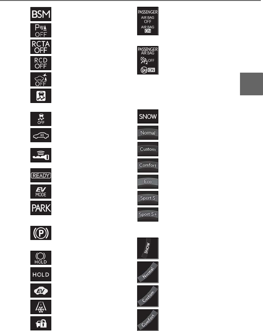
75
2-1. Instrument cluster
LS500h_OM_OM50F42U_(U)
2
Vehicle status information and indicators
-Drive mode indicators
Except F SPORT models
F SPORT models
BSM indicator (→P.260)
Intuitive parking assist OFF indi-
cator*1, 2 (→P.267)
RCTA OFF indicator*1, 2
(→P.273)
RCD OFF indicator*2
(→P.277)
PKSB OFF indicator*1, 2
(→P.281)
(flashes)
Slip indicator*1 (→P.303)
VSC OFF indicator*1, 2
(→P.304)
High mode indicator (if
equipped) (→P.300)
Smart access system with
push-button start indicator*4
(→P.168)
“READY” indicator (→P.168)
EV drive mode indicator
(→P.172)
(U.S.A.)
Parking brake indicator
(→P.181)
(Canada)
Parking brake indicator
(→P.181)
Brake hold standby indicator*1
(→P.183)
Brake hold operated indicator*1
(→P.183)
EV indicator (→P.59)
Low outside temperature indi-
cator*5 (→P.77, 81)
Security indicator*6 (→P.66,
68)
(U.S.A.)
“AIR BAG ON/OFF” indica-
tor*1, 6 (→P.40)
(Canada)
“AIR BAG ON/OFF” indica-
tor*1, 6 (→P.40)
Snow mode indicator (→P.177)
Normal mode indicator
(→P.298)
Custom mode indicator
(→P.298)
Comfort mode indicator
(→P.298)
Eco drive mode indicator
(→P.298)
Sport S mode indicator
(→P.298)
Sport S+ mode indicator
(→P.298)
Snow mode indicator (→P.177)
Normal mode indicator
(→P.298)
Custom mode indicator
(→P.298)
Comfort mode indicator
(→P.298)

76 2-1. Instrument cluster
LS500h_OM_OM50F42U_(U)
*1: These lights come on when the power
switch is turned to ON mode to indi-
cate that a system check is being per-
formed. They will go off after the hybrid
system is on, or after a few seconds.
There may be a malfunction in a system
if the lights do not come on, or go off.
Have the vehicle inspected by your
Lexus dealer.
*2: This light comes on when the system is
turned off.
*3: This light illuminates on the outside rear
view mirrors.
*4: This light illuminates on the multi-infor-
mation display.
*5: When the outside temperature is
approximately 37°F (3°C) or lower, this
indicator will flash for approximately 10
seconds, then stay on.
*6: This light illuminates on the center
panel.
Eco drive mode indicator
(→P.298)
Sport S mode indicator
(→P.298)
Sport S+ mode indicator
(→P.298)
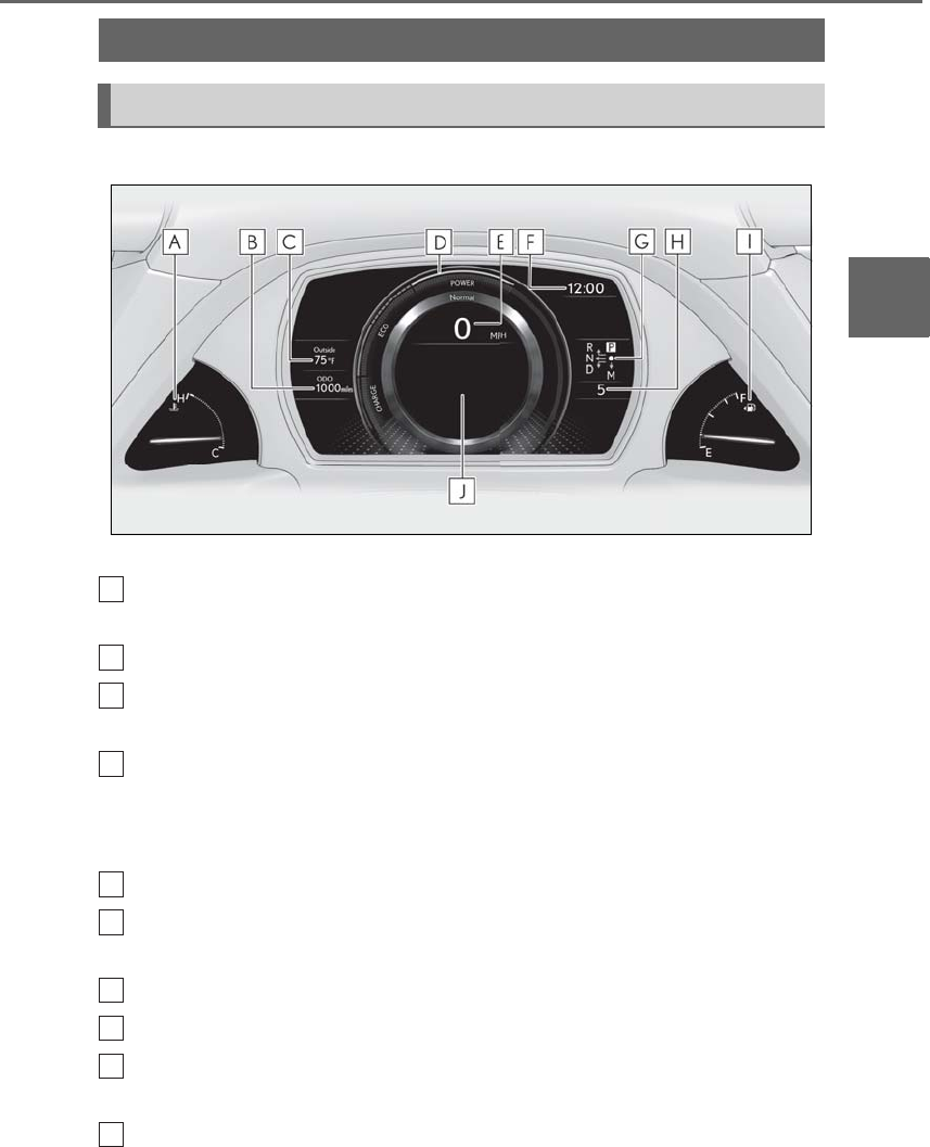
77
2-1. Instrument cluster
LS500h_OM_OM50F42U_(U)
2
Vehicle status information and indicators
■Locations of gauges and meters
The units of measure may differ depending on the intended destination of the vehicle.
Engine coolant temperature gauge
Displays the engine coolant temperature
Odometer and trip meter display (→P.79)
Outside temperature
Displays the outside temperature within the range of -40°F (-40°C) to 122°F (50°C)
Hybrid System Indicator
Displays hybrid system output or regeneration level (→P.78)
This display changes to a tachometer depending on the driving mode, and can be set to
show the tachometer in any driving mode on the settings display. (→P.90, 298)
Speedometer
Clock
Time displayed is linked to the analog clock on the center panel. (→P.353)
Shift position indicator (→P.176)
Shift range/gear position (→P.174)
Fuel gauge
Displays the quantity of fuel remaining in the tank
Multi-information display
Presents the driver with a variety of vehicle data (→P.86)
Gauges and meters (except F SPORT models)
Meter display
A
B
C
D
E
F
G
H
I
J
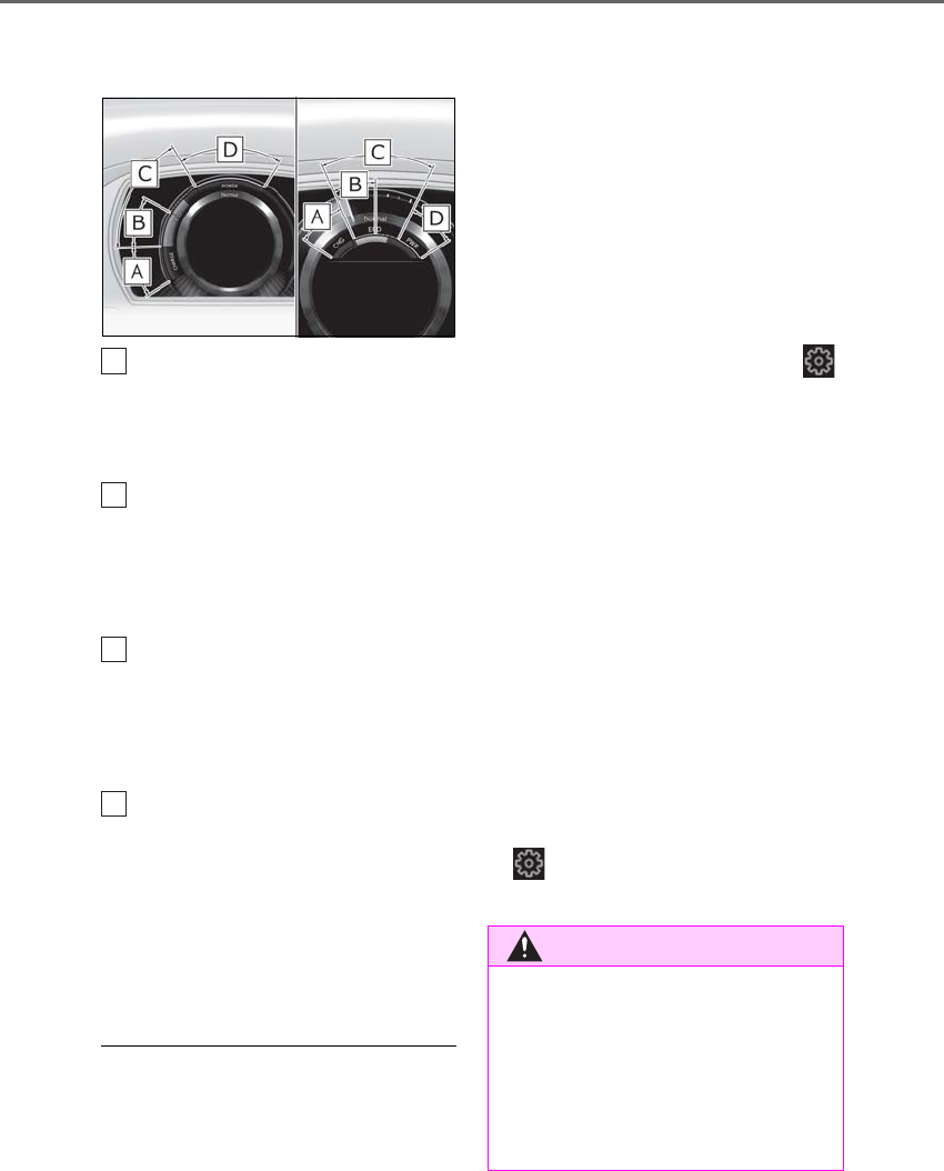
78 2-1. Instrument cluster
LS500h_OM_OM50F42U_(U)
Displays warning messages if a malfunction occurs (→P.437)
■Hybrid System Indicator
Charge area
Shows regeneration* status.
Regenerated energy will be used to charge
the hybrid battery (traction battery).
Hybrid Eco area
Shows that gasoline engine power is not
being used very often.
The gasoline engine will automatically stop
and restart under various conditions.
Eco area
Shows that the vehicle is being driven in an
Eco-friendly manner.
By keeping the bar display within Eco area,
more Eco-friendly driving can be achieved.
Power area
Shows that an Eco-friendly driving range is
being exceeded (during full power driving
etc.)
*: When used in this manual, regeneration
refers to the conversion of energy cre-
ated by the movement of the vehicle into
electrical energy.
■Engine speed
On hybrid vehicles, engine speed is pre-
cisely controlled in order to help improve
fuel efficiency and reduce exhaust emis-
sions etc.
There are times when the engine speed that
is displayed may differ even when vehicle
operation and driving conditions are the
same.
■Hybrid System Indicator is displayed
when
The Hybrid System Indicator is displayed in
the following situations:
●The shift position is in D or M.
●The driving mode is other than sport
mode.
However, the Hybrid System Indicator will
not be displayed when the analog and digi-
tal speedometers are both enabled on
of the multi-information display. (→P.90)
■Outside temperature display
●In the following situations, the correct
outside temperature may not be dis-
played, or the display may take longer
than normal to change:
• When stopped, or driving at low speeds
(less than 12 mph [20 km/h])
• When the outside temperature has
changed suddenly (at the entrance/exit of
a garage, tunnel, etc.)
●When “--” or “E” is displayed, the system
may be malfunctioning. Take your vehicle
to your Lexus dealer.
■Liquid crystal display
→P.87
■Customization
The gauges and meters can be customized
on of the multi-information display.
(→P.90)
A
B
C
D
WARNING
■The information display at low tem-
peratures
Allow the interior of the vehicle to warm
up before using the liquid crystal infor-
mation display. At extremely low tem-
peratures, the information display
monitor may respond slowly, and display
changes may be delayed.
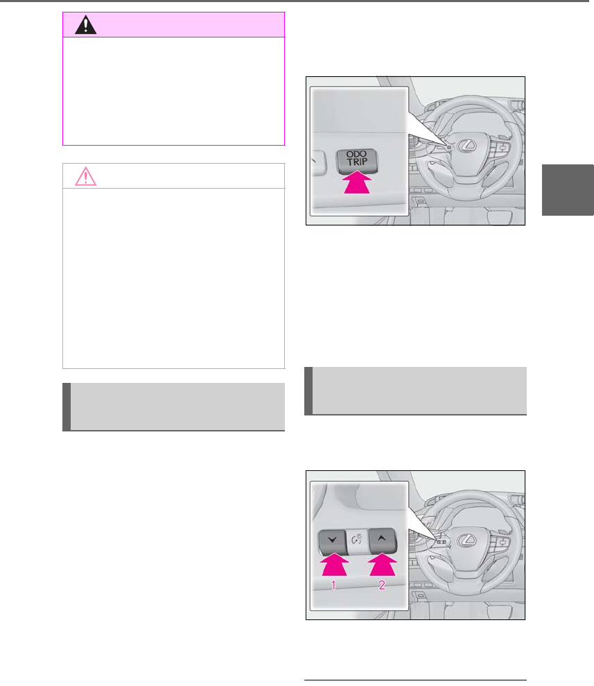
79
2-1. Instrument cluster
LS500h_OM_OM50F42U_(U)
2
Vehicle status information and indicators
■Display items
-Odometer
Displays the total distance the vehicle has
been driven.
-Trip meter A/trip meter B
Displays the distance the vehicle has been
driven since the meter was last reset. Trip
meters A and B can be used to record and
display different distances independently.
-Distance until next engine oil
change
Displays the distance the vehicle can be
driven until an oil change is necessary.
■Changing the display
Each time the “ODO TRIP” switch is
pressed, the displayed item will be
changed. When the trip meter is dis-
played, pressing and holding the switch
will reset the trip meter.
■Pop-up display
Distance until the next engine oil
change will displayed when a warning
message indicating that oil mainte-
nance should be performed soon or is
required is displayed.
The brightness of the instrument panel
lights can be adjusted.
1Darker
2Brighter
■Brightness of the meters (day mode and
night mode)
The brightness of the meters changes
between day mode and night mode.
●Day mode: When the tail lights are off or
WARNING
For example, there is a lag between the
driver’s shifting and the new gear number
appearing on the display. This lag could
cause the driver to downshift again,
causing rapid and excessive engine brak-
ing and possibly an accident resulting in
death or injury.
NOTICE
■To prevent damage to the engine and
its components
●Do not let the indicator needle of the
tachometer enter the red zone, which
indicates the maximum engine speed.
●The engine may be overheating if the
engine coolant temperature gauge is
in the red zone (H). In this case, imme-
diately stop the vehicle in a safe place,
and check the engine after it has
cooled completely. (→P.453)
Odometer and trip meter dis-
play
Changing the instrument panel
light brightness

80 2-1. Instrument cluster
LS500h_OM_OM50F42U_(U)
when the tail lights are on but the sur-
rounding area is bright
●Night mode: When the tail lights are on
and the surrounding area is dark
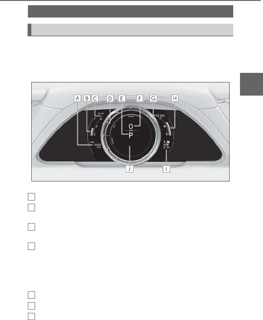
81
2-1. Instrument cluster
LS500h_OM_OM50F42U_(U)
2
Vehicle status information and indicators
■Locations of gauges and meters
When the main meter is moved to the right, some of the meter displays and the
gauge layout will change. (→P.85)
Main meter in center position
The units of measure may differ depending on the intended destination of the vehicle.
Odometer and trip meter display (→P.84)
Engine coolant temperature gauge
Displays the engine coolant temperature
Outside temperature
Displays the outside temperature within the range of -40°F (-40°C) to 122°F (50°C)
Hybrid System Indicator
Displays hybrid system output or regeneration level (→P.78)
This display changes to a tachometer depending on the driving mode, and can be set to
show the tachometer in any driving mode on the settings display. (→P.90, 298)
• Rev indicator (→P.83)
•Rev peak (→P.83)
Shift position/shift range/gear position (→P.174)
Speedometer
Clock
Time displayed is linked to the analog clock on the center panel. (→P.353)
Gauges and meters (F SPORT models)
Meter display
A
B
C
D
E
F
G
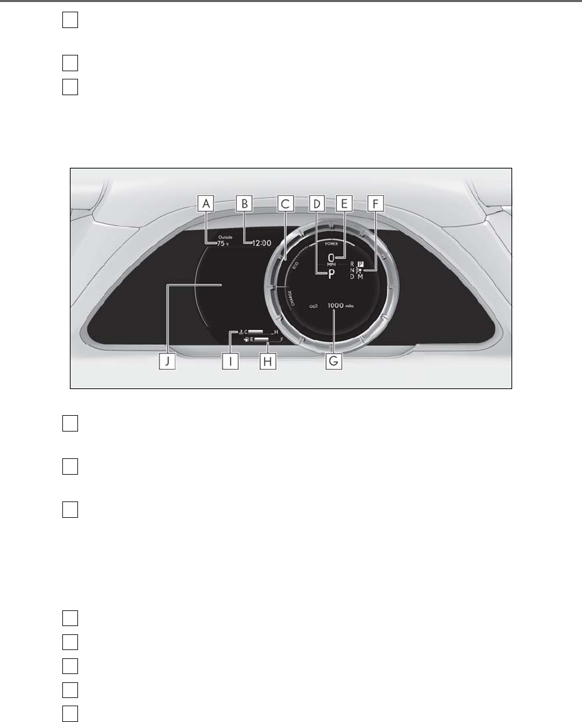
82 2-1. Instrument cluster
LS500h_OM_OM50F42U_(U)
Fuel gauge
Displays the quantity of fuel remaining in the tank
Shift position indicator (→P.176)
Multi-information display
Presents the driver with a variety of vehicle data (→P.86)
Displays warning messages if a malfunction occurs (→P.437)
Main meter moved to the right
The units of measure may differ depending on the intended destination of the vehicle.
Outside temperature
Displays the outside temperature within the range of -40°F (-40°C) to 122°F (50°C)
Clock
Time displayed is linked to the analog clock on the center panel. (→P.353)
Hybrid System Indicator
Displays hybrid system output or regeneration level (→P.78)
This display changes to a tachometer depending on the driving mode, and can be set to
show the tachometer in any driving mode on the settings display. (→P.90, 298)
• Rev indicator (→P.83)
•Rev peak (→P.83)
Shift position/shift range/gear position (→P.174)
Speedometer
Shift position indicator (→P.176)
Odometer and trip meter display (→P.84)
Fuel gauge
Displays the quantity of fuel remaining in the tank
H
I
J
A
B
C
D
E
F
G
H
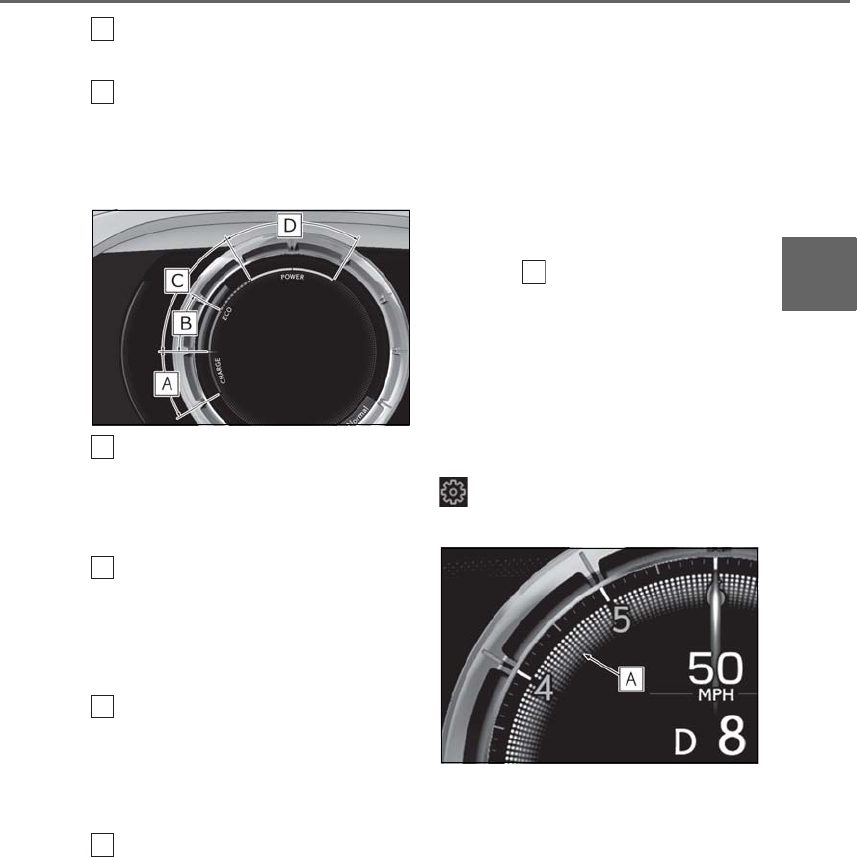
83
2-1. Instrument cluster
LS500h_OM_OM50F42U_(U)
2
Vehicle status information and indicators
Engine coolant temperature gauge
Displays the engine coolant temperature
Multi-information display
Presents the driver with a variety of vehicle data (→P.86)
Displays warning messages if a malfunction occurs (→P.437)
■Hybrid System Indicator
Charge area
Shows regeneration* status.
Regenerated energy will be used to charge
the hybrid battery (traction battery).
Hybrid Eco area
Shows that gasoline engine power is not
being used very often.
The gasoline engine will automatically stop
and restart under various conditions.
Eco area
Shows that the vehicle is being driven in an
Eco-friendly manner.
By keeping the bar display within Eco area,
more Eco-friendly driving can be achieved.
Power area
Shows that an Eco-friendly driving range is
being exceeded (during full power driving
etc.)
*: When used in this manual, regeneration
refers to the conversion of energy cre-
ated by the movement of the vehicle into
electrical energy.
■Rev indicator
When the engine speed reaches a set
speed or the red zone, a ring-shaped
indicator ( ) will be displayed on the
tachometer.
The indicators will be displayed in amber
when the engine speed reaches a set
speed, and in red when the engine speed
reaches the red zone.
The engine speed at which the rev indica-
tor will begin to be displayed can be set on
of the multi-information display.
(→P.90)
■Rev peak
When the engine speed reaches or
exceeds 4000 rpm, an afterimage of
the tachometer will be displayed at the
highest engine speed for approxi-
mately 1 second.
I
J
A
B
C
D
A
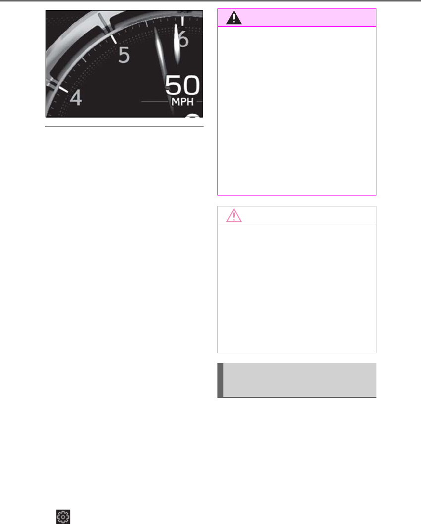
84 2-1. Instrument cluster
LS500h_OM_OM50F42U_(U)
■Engine speed
On hybrid vehicles, engine speed is pre-
cisely controlled in order to help improve
fuel efficiency and reduce exhaust emis-
sions etc.
There are times when the engine speed that
is displayed may differ even when vehicle
operation and driving conditions are the
same.
■Hybrid System Indicator is displayed
when
The Hybrid System Indicator is displayed in
the following situations:
●The shift position is in D or M.
●The driving mode is other than sport
mode.
■Outside temperature display
●In the following situations, the correct
outside temperature may not be dis-
played, or the display may take longer
than normal to change:
• When stopped, or driving at low speeds
(less than 12 mph [20 km/h])
• When the outside temperature has
changed suddenly (at the entrance/exit of
a garage, tunnel, etc.)
●When “--” or “E” is displayed, the system
may be malfunctioning. Take your vehicle
to your Lexus dealer.
■Liquid crystal display
→P.87
■Customization
The gauges and meters can be customized
on of the multi-information display.
(→P.90)
■Display items
-Odometer
Displays the total distance the vehicle has
been driven.
-Trip meter A/trip meter B
Displays the distance the vehicle has been
driven since the meter was last reset. Trip
meters A and B can be used to record and
display different distances independently.
-Distance until next engine oil
WARNING
■The information display at low tem-
peratures
Allow the interior of the vehicle to warm
up before using the liquid crystal infor-
mation display. At extremely low tem-
peratures, the information display
monitor may respond slowly, and display
changes may be delayed.
For example, there is a lag between the
driver’s shifting and the new gear number
appearing on the display. This lag could
cause the driver to downshift again,
causing rapid and excessive engine brak-
ing and possibly an accident resulting in
death or injury.
NOTICE
■To prevent damage to the engine and
its components
●Do not let the indicator needle of the
tachometer enter the red zone, which
indicates the maximum engine speed.
●The engine may be overheating if the
engine coolant temperature gauge is
in the red zone (H). In this case, imme-
diately stop the vehicle in a safe place,
and check the engine after it has
cooled completely. (→P.453)
Odometer and trip meter dis-
play
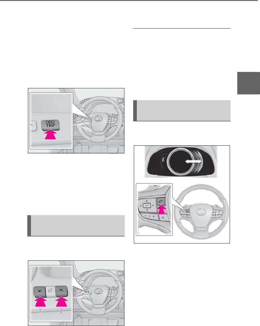
85
2-1. Instrument cluster
LS500h_OM_OM50F42U_(U)
2
Vehicle status information and indicators
change
Displays the distance the vehicle can be
driven until an oil change is necessary.
■Changing the display
Each time the “ODO TRIP” switch is
pressed, the displayed item will be
changed. When the trip meter is dis-
played, pressing and holding the switch
will reset the trip meter.
■Pop-up display
The distance until the next engine oil
change will displayed when a warning
message indicating that oil mainte-
nance should be performed soon or is
required is displayed.
The brightness of the instrument panel
lights can be adjusted.
1Darker
2Brighter
■Brightness of the meters (day mode and
night mode)
The brightness of the meters changes
between day mode and night mode.
●Day mode: When the tail lights are off or
when the tail lights are on but the sur-
rounding area is bright
●Night mode: When the tail lights are on
and the surrounding area is dark
The display can be switched between
the center and side positions.
Changing the instrument panel
light brightness
Changing the main meter loca-
tion
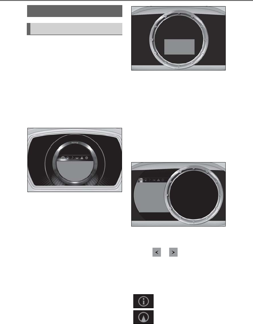
86 2-1. Instrument cluster
LS500h_OM_OM50F42U_(U)
■Display (except F SPORT models)
By selecting menu icons on the
multi-information display, a variety of
driving-related information can be dis-
played. The multi-information display
can also be used to change display set-
tings and other vehicle settings.
Warning or suggestion/advice pop-up
displays are also displayed in certain
situations.
■Display (F SPORT models)
Main meter in center position
The multi-information display presents
the driver with a variety of driv-
ing-related information.
Warning or suggestion/advice pop-up
displays are also displayed in certain
situations.
Main meter moved to the right
By selecting menu icons on the
multi-information display, a variety of
driving-related information can be dis-
played. The multi-information display
can also be used to change display set-
tings and other vehicle settings.
Warning or suggestion/advice pop-up
displays are also displayed in certain
situations.
■Menu icons
The menu icons will be displayed by
pressing or of the meter con-
trol switch.
F SPORT models: The menu icons can be
displayed when the main meter is moved to
the right.
Multi-information display
Display and menu icons
Driving information display
(→P.87)
Navigation system-linked dis-
play (if equipped) (→P.89)
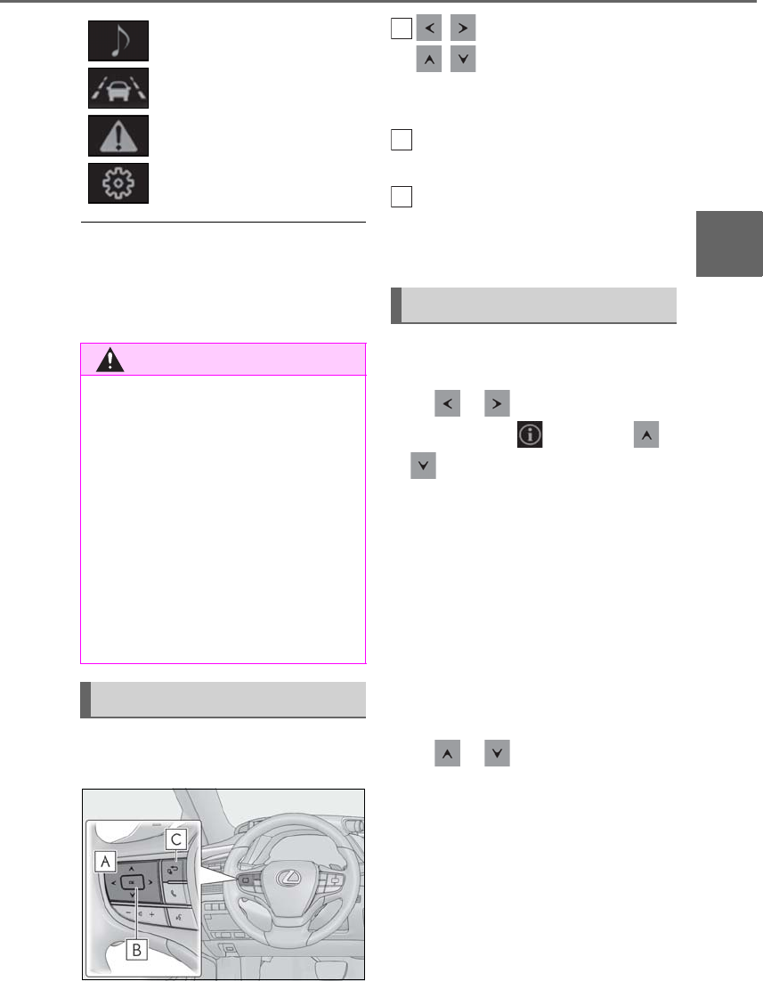
87
2-1. Instrument cluster
LS500h_OM_OM50F42U_(U)
2
Vehicle status information and indicators
■Liquid crystal display
Small spots or light spots may appear on the
display. This phenomenon is characteristic
of liquid crystal displays, and there is no
problem continuing to use the display.
The multi-information display is oper-
ated using the meter control switches.
/ : Select menu icons
/ : Change displayed con-
tent, scroll up/down the screen and
move the cursor up/down
Press: Enter/Set
Press and hold: Reset
Move the main meter* and return
to the previous screen
*:F SPORT models
■Display items (except F SPORT
models)
Press or of the meter control
switch and select . Then press
or to display the following items:
-Drive information 1
-Drive information 2
-Energy monitor (→P.97)
-Tire pressure (→P.397)
-Vehicle sway warning
-Display off
■Display items (F SPORT models)
Main meter in center position
Press or of the meter control
switch to display the following items:
-Drive information 1
-Drive information 2
-Tire pressure (→P.397)
-Gear positions
-Units
-Display off
Audio system-linked display
(→P.90)
Driving support system infor-
mation display (→P.90)
Warning message display
(→P.437)
Settings display (→P.90)
WARNING
■Caution for use while driving
●When operating the multi-information
display while driving, pay extra atten-
tion to the safety of the area around the
vehicle.
●Do not look continuously at the
multi-information display while driving
as you may fail to see pedestrians,
objects on the road, etc. ahead of the
vehicle.
■The information display at low tem-
peratures
→P.78, 84
Changing the meter display
Content of driving information
A
B
C

88 2-1. Instrument cluster
LS500h_OM_OM50F42U_(U)
-Driving support system information*
(→P.90)
*: Can be selected when a driving support
system is enabled. (→P.230, 240, 250)
Main meter moved to the right
Press or of the meter control
switch and select . Then press
or to display the following items:
-Drive information 1
-Drive information 2
-Energy monitor (→P.97)
-G-force
-Gear Position
-Vehicle sway warning
-Tire pressure (→P.397)
-Display off
■Drive information 1/Drive infor-
mation 2
Displays drive information such as the
following:
Use the displayed values as a reference
only.
-Drive information 1
• Current fuel consumption
• Average fuel economy (after reset)
-Drive information 2
• Distance (driving range)
• Average vehicle speed (after reset)
Displayed items (listed below) can be
changed on . (→P.90)
-Current fuel consumption
Bar type: Displays instantaneous current
fuel consumption
-Average fuel economy
After reset: Displays average fuel con-
sumption since the display was reset*1
After start: Displays average fuel con-
sumption since hybrid system start
After refuel: Displays average fuel con-
sumption since refuel
-Average vehicle speed
After reset: Displays average vehicle
speed since the display was reset*1
After start: Displays average vehicle speed
since hybrid system start
-Elapsed time
After reset: Displays elapsed time since the
display was reset*1
After start: Displays elapsed time since
hybrid system start
-Distance
Driving range: Displays driving range with
remaining fuel*2, 3
After start: Displays the distance driven
since hybrid system start
-Other
Blank: No item
*1: To reset, display the desired item and
press and hold of the meter control
switch.
*2: This distance is computed based on
your average fuel consumption. As a
result, the actual distance that can be
driven may differ from that displayed.
*3: When only a small amount of fuel is
added to the tank, the display may not
be updated.
When refueling, turn the power switch
off. If the vehicle is refueled without
turning the power switch off, the display
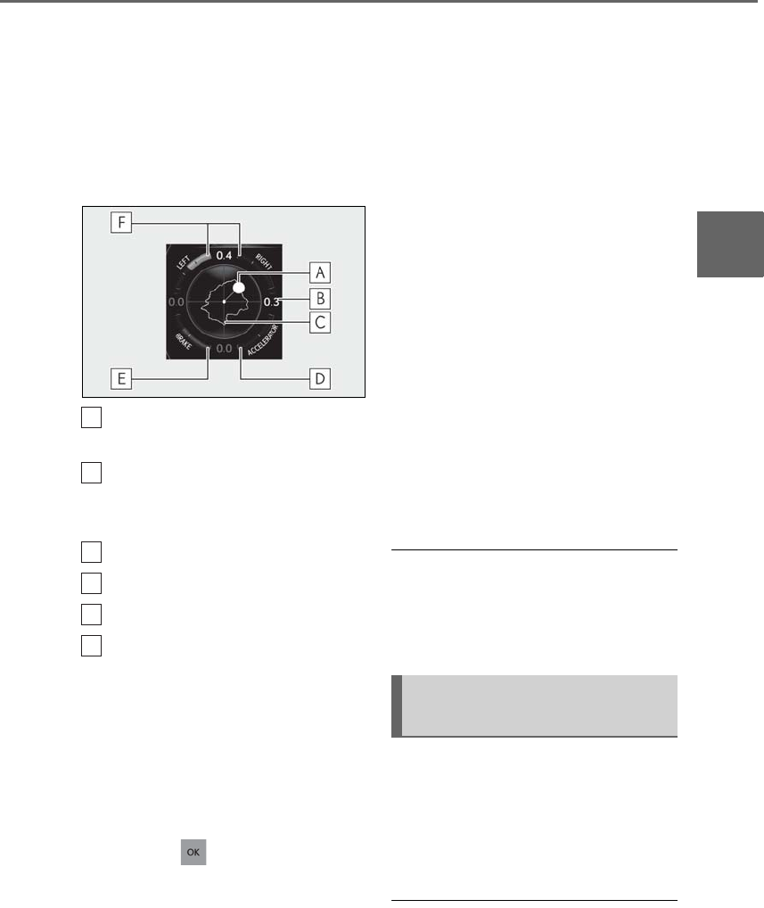
89
2-1. Instrument cluster
LS500h_OM_OM50F42U_(U)
2
Vehicle status information and indicators
may not be updated.
■G-force (F SPORT models)
Displays lateral G-forces on the vehi-
cle. Also displays, around the periph-
ery of the G-force display, the left and
right steering amount, accelerator
pedal input, and brake fluid pressure.
Acceleration G-force on the vehi-
cle
Current G-force value (analyzed
value of front/rear and left/right
G-forces)
Record of the maximum G-forces
Accelerator pedal input
Brake fluid pressure
Steering amount
This display is intended for use as a guide-
line. Depending on factors such as the road
surface condition, temperature and vehicle
speed, the display may not show the actual
condition of the vehicle.
-Resetting the record of maximum
G-forces
Press and hold of the meter control
switch to reset the record.
-Peak hold function
If lateral G-forces of 0.5 G or greater are
generated, the G-force value display will
turn amber and be held for 2 seconds.
■Gear Position (F SPORT models)
Displays the current shift range or gear
position when the shift position is in D
or M.
■Units (F SPORT models)
The units of measure used can be
changed while driving.
Unlike the units setting performed on the
settings display, the units setting per-
formed on the drive information display
can be changed while driving.
■Vehicle sway warning
Detects the sway of the vehicle within a
lane, which is often associated with a
decrease in the driver’s attention level,
and displays the decrease in attention
using a bar display.
The shorter the bar length, the more
the driver may need to rest.
■Vehicle sway warning
This display is enabled when the operating
conditions of the vehicle sway warning of
the LTA (→P.236) or LKA (→P.244) are
met.
Select to display the following naviga-
tion system-linked information.
-Route guidance to destination
-Compass display (heading-up dis-
play)
■Route guidance to destination display
When the route guidance to destination
display is enabled on the head-up display, it
A
B
C
D
E
F
Navigation system-linked dis-
play (if equipped)

90 2-1. Instrument cluster
LS500h_OM_OM50F42U_(U)
will not be displayed on the multi-informa-
tion display. (→P.94)
Select to enable selection of an audio
source or track on the meter using the
meter control switches.
Select to display the operational status
of the following systems:
-LTA (Lane Tracing Assist) (if
equipped) (→P.230)
-LKA (Lane-Keeping Assist) (if
equipped) (→P.240)
-Dynamic radar cruise control with
full-speed range (→P.250)
-RSA (Road Sign Assist) (if
equipped) (→P.247)
■Meter display settings that can be
changed
-Language
Select to change the language displayed.
-Units
Select to change the units of measure dis-
played.
-Speedometer display (except F
SPORT models)
Select to set the display of the speedome-
ter to digital/analog/both digital and ana-
log.
-Drive information 1/Drive informa-
tion 2
Select to select up to 2 items (→P.88) that
will be displayed on each Drive information
screen (Drive information 1 screen and
Drive information 2 screen) respectively.
-Clock
Select to switch between 12-hour display
and 24-hour display.
-Pop-up display
Select to enable/disable pop-up displays
for each relevant system.
-Accent color
Select to change the accent color on the
screen, such as the cursor color.
-Tachometer setting
Select to set the display of the Hybrid Sys-
tem Indicator or tachometer for each driv-
ing mode.
-Rev indicator (F SPORT models)
• Select to enable/disable the rev indica-
tor.
• Select to set the engine speed at which
the rev indicator (amber) will begin to be
displayed.
-Rev peak (F SPORT models)
Select to enable/disable the rev peak.
-EV indicator
Select to enable/disable the EV indicator.
-Default setting
Select to reset the meter display settings to
the default setting.
■Vehicle functions and settings that
can be changed
→P.481
■Suspension of the settings display
●Some settings cannot be changed while
Audio system-linked display
Driving support system informa-
tion display
Settings display
91
2-1. Instrument cluster
LS500h_OM_OM50F42U_(U)
2
Vehicle status information and indicators
driving. When changing settings, park
the vehicle in a safe place.
●If a warning message is displayed, opera-
tion of the settings display will be sus-
pended.
Displays suggestions to the driver in
the following situations. To select a
response to a displayed suggestion,
use the meter control switches.
■Suggestion to turn off the head-
lights
If the headlights are left on for a certain
amount of time with the headlight
switch in after the power switch
has been turned off, a suggestion mes-
sage will be displayed asking if you
wish to turn the headlights off.
To turn the headlights off, select “Yes”.
If a front door is opened after the power
switch is turned off, this suggestion mes-
sage will not be displayed.
■Customization
Some functions can be customized.
(→P.481)
WARNING
■Cautions during setting up the dis-
play
As the hybrid system needs to be operat-
ing during setting up the display, ensure
that the vehicle is parked in a place with
adequate ventilation. In a closed area
such as a garage, exhaust gases includ-
ing harmful carbon monoxide (CO) may
collect and enter the vehicle. This may
lead to death or a serious health hazard.
NOTICE
■During setting up the display
To prevent 12-volt battery discharge,
ensure that the hybrid system is operat-
ing while setting up the display features.
Suggestion function
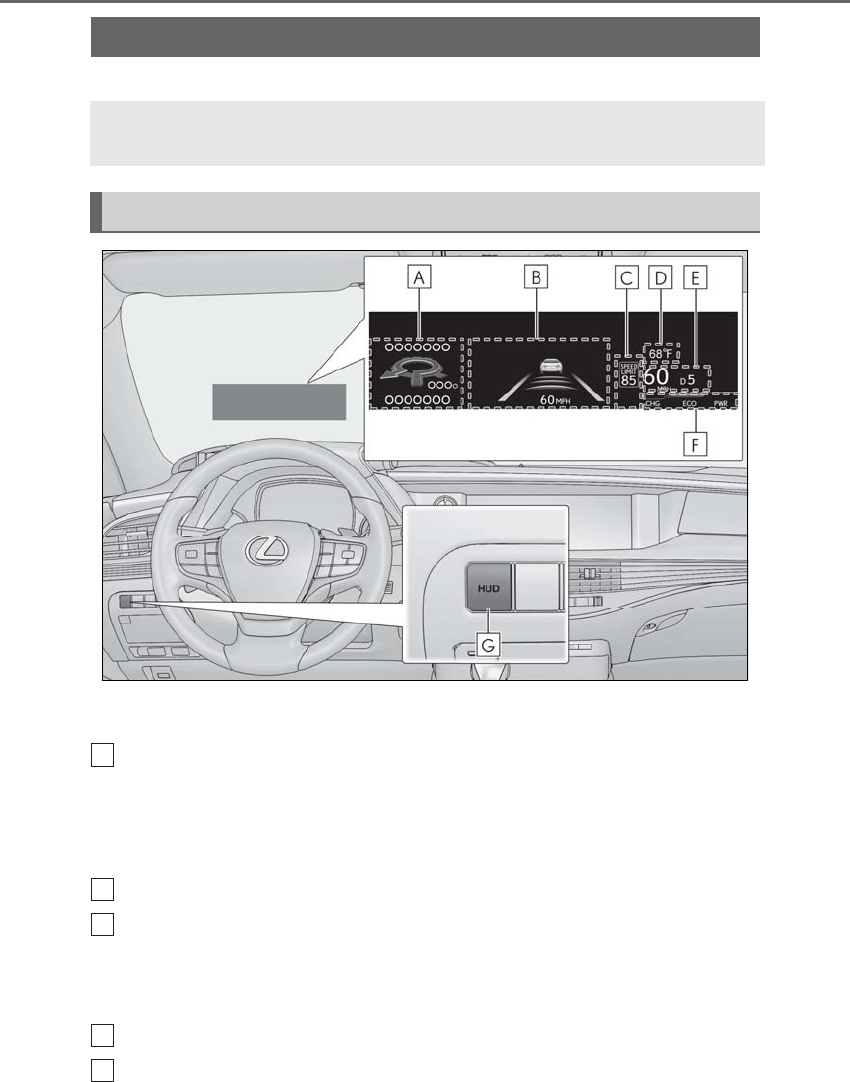
92 2-1. Instrument cluster
LS500h_OM_OM50F42U_(U)
*:If equipped
Illustrations used in this text are intended as examples, and may differ from the image that is
actually displayed by the head-up display.
Navigation system-linked display area (if equipped)
Displays the following items which are linked to the navigation system:
• Route guidance to destination
•Street name
• Compass (heading-up display)
Driving support system display area (→P.95)
Speed limit/RSA (Road Sign Assist) display area (if equipped)
Displays the following items:
• Speed limit of the current road (linked to the navigation system) (U.S.A. only)
• RSA (Road Sign Assist) display (→P.247)
Outside temperature display area
Driving information display area
Head-up display*
The head-up display projects a variety of driving-related information and the
operating state of the driving support systems on the windshield.
System components
A
B
C
D
E
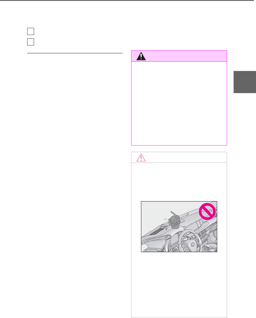
93
2-1. Instrument cluster
LS500h_OM_OM50F42U_(U)
2
Vehicle status information and indicators
Displays the following items:
• Speedometer
• Shift position/shift range/gear position (→P.174)
Hybrid System Indicator/tachometer display area (→P.96)
HUD (Head-up display) switch
■Head-up display will operate when
The power switch is in ON mode.
■When using the head-up display
The head-up display may seem dark or hard
to see when viewed through sunglasses,
especially polarized sunglasses. Adjust the
brightness of the head-up display or
remove your sunglasses.
■Street name display
Only street names which are included in the
map data will be displayed.
■Outside temperature display
●When the ambient temperature is
approximately 37°F (3°C) or lower, the
low outside temperature indicator will
flash for approximately 10 seconds and
the outside temperature display will turn
off. In this case, the display will be dis-
played again when the outside tempera-
ture becomes approximately 41°F (5°C)
or higher.
●In the following situations, the correct
outside temperature may not be dis-
played, or the display may take longer
than normal to change:
• When stopped, or driving at low speeds
(less than 12 mph [20 km/h])
• When the outside temperature has
changed suddenly (at the entrance/exit of
a garage, tunnel, etc.)
●When “--” or “E” is displayed, the system
may be malfunctioning. Take your vehicle
to your Lexus dealer.
F
G
WARNING
■When using the head-up display
●Check that the position and brightness
of the head-up display image does not
interfere with safe driving. Incorrect
adjustment of the image’s position or
brightness may obstruct the driver’s
view and lead to an accident, resulting
in death or serious injury.
●Do not continuously look at the
head-up display while driving as you
may fail to see pedestrians, objects on
the road, etc. ahead of the vehicle.
NOTICE
■Head-up display projector
●Do not place any drinks near the
head-up display projector. If the pro-
jector gets wet, electrical malfunctions
may result.
●Do not place anything on or put stick-
ers onto the head-up display projector.
Doing so could interrupt head-up dis-
play indications.
●Do not touch the inside of the head-up
display projector or thrust sharp edges
or the like into the projector.
Doing so could cause mechanical mal-
functions.
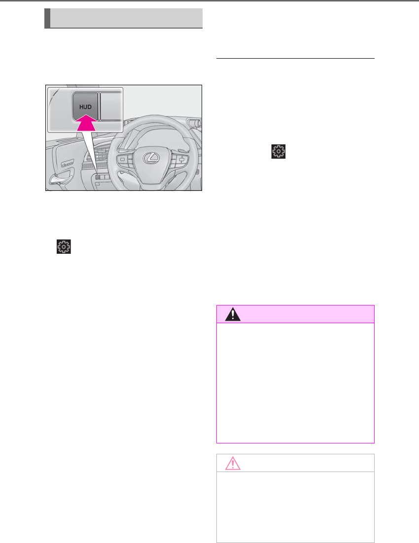
94 2-1. Instrument cluster
LS500h_OM_OM50F42U_(U)
■Enabling/disabling the head-up dis-
play
Press the HUD switch.
■Changing settings of the head-up
display
The following settings can be changed
on of the multi-information display.
(→P.481)
-Brightness and vertical position of
the head-up display
Select to adjust the brightness or vertical
position of the head-up display.
-Hybrid System Indicator/tachome-
ter
Select to display the Hybrid System Indica-
tor, tachometer or no content.
-Display content
Select to enable/disable the following
items:
• Route guidance to destination/street
name
• Driving support system display*
• Compass (heading-up display)
• Audio system operation status
*: Make sure to enable this display when
using the driving support systems
-Display angle
Select to adjust the angle of the head-up
display.
■Enabling/disabling of the head-up dis-
play
If the head-up display is disabled, it will
remain disabled when the power switch is
turned off then back to ON mode.
■Display brightness
The brightness of the head-up display can
be adjusted on of the multi-information
display. Also, it is automatically adjusted
according to the ambient brightness.
■Head-up display automatic position
adjustment
If the display position is recorded into mem-
ory, the head-up display will be automati-
cally adjusted to the desired position.
(→P.139)
■When the 12-volt battery is discon-
nected
The customize settings of the head-up dis-
play will be reset.
Using the head-up display
WARNING
■Caution for changing settings of the
head-up display
As the hybrid system needs to be operat-
ing while changing the settings of the
head-up display, ensure that the vehicle
is parked in a place with adequate venti-
lation. In a closed area such as a garage,
exhaust gases including harmful carbon
monoxide (CO) may collect and enter
the vehicle. This may lead to death or a
serious health hazard.
NOTICE
■When changing the settings of the
head-up display
To prevent 12-volt battery discharge,
ensure that the hybrid system is operat-
ing while the changing the settings of the
head-up display.

95
2-1. Instrument cluster
LS500h_OM_OM50F42U_(U)
2
Vehicle status information and indicators
Displays the operational status of the
following systems:
-LTA (Lane Tracing Assist) (if
equipped) (→P.230)
-LKA (Lane-Keeping Assist) (if
equipped) (→P.240)
-Dynamic radar cruise control with
full-speed range (→P.250)
Details of content displayed on the
head-up display may differ from that dis-
played on the multi-information display. For
details, refer to the explanation of each sys-
tem.
Pop-up displays for the following sys-
tems will be displayed when necessary.
■Driving support systems
Displays a warning/suggestion/advice
message or the operating state of a rel-
evant system.
-PCS (Pre-Collision System)
(→P.209, 220)
-FCTA (Front Cross Traffic Alert) (if
equipped) (→P.227)
-Intuitive parking assist (→P.266)
-Parking Support Brake function (for
static objects) (→P.286)
-Brake Override System (→P.159)
-Drive-Start Control (→P.159)
Details of content displayed on the
head-up display may differ from that dis-
played on the multi-information display. For
details, refer to the explanation of each sys-
tem.
■/ icons
These icons are linked to the
multi-information display
: Master warning icon
Displayed when a warning message is dis-
played on the multi-information display.
(→P.437)
: Information icon
Displayed when a suggestion pop-up dis-
play (→P.91) or advice pop-up display is
displayed on the multi-information display.
■Warning message
Some warning messages are displayed
when necessary, according to certain
conditions.
Details of content displayed on the
head-up display may differ from that dis-
played on the multi-information display.
■Audio system operation status
Displayed when an audio remote con-
trol switch on the steering wheel is
operated.
■Hands-free system status
Displayed when the hands-free system
is operated.
■When a pop-up display is displayed
When a pop-up display is displayed, a cur-
rent display may no longer be displayed. In
this case, the display will return after the
pop-up display disappears.
Driving support system display
area
Pop-up display
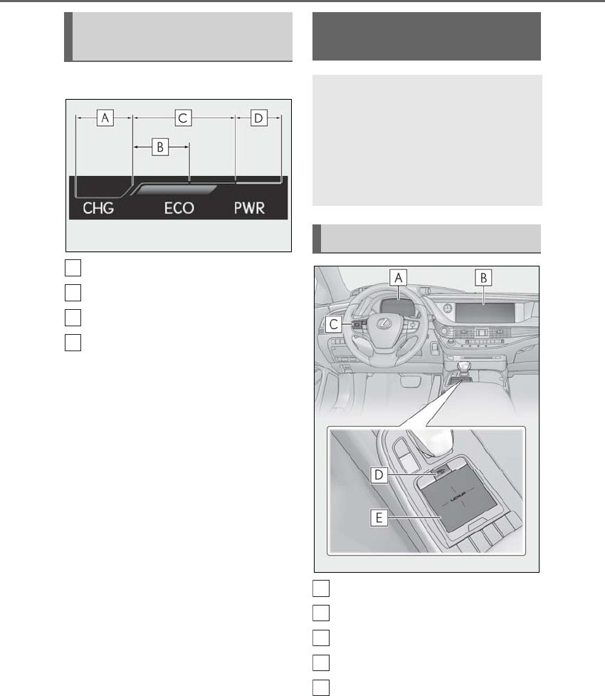
96 2-1. Instrument cluster
LS500h_OM_OM50F42U_(U)
■Hybrid System Indicator
Charge area
Hybrid Eco area
Eco area
Power area
Displayed content is the same as that dis-
played on the meter (Hybrid System Indi-
cator). For details, refer to P.78 or P.83.
■Tachometer
Displays the engine speed in revolu-
tions per minute.
Multi-information display
Center Display
Meter control switches
“MENU” button
Touchpad
Hybrid System Indica-
tor/tachometer
A
B
C
D
Energy monitor/consump-
tion screen
The state of the hybrid system can
be viewed on the multi-information
display and Center Display.
The energy monitor or consump-
tion screen can be displayed and
operated on the side display.
System components
A
B
C
D
E
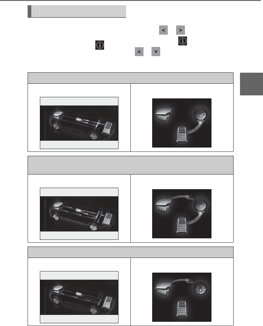
97
2-1. Instrument cluster
LS500h_OM_OM50F42U_(U)
2
Vehicle status information and indicators
■Center Display
Press the “MENU” button on the
Remote Touch, then select on the
menu screen.
If a screen other than “Energy Monitor” is
displayed, select “Energy”.
■Multi-information display
Press the or meter control
switch and select , and then press
or to select the energy monitor
display.
Energy monitor
When the vehicle is powered by the electric motor (traction motor)
Center Display Multi-information display
When the vehicle is powered by both the gasoline engine and the electric motor (traction
motor)
Center Display Multi-information display
When the vehicle is powered by the gasoline engine
Center Display Multi-information display
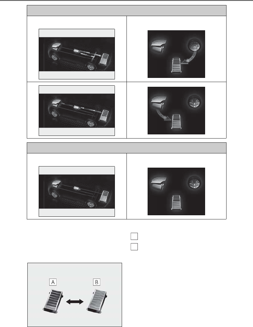
98 2-1. Instrument cluster
LS500h_OM_OM50F42U_(U)
These images are examples only, and may vary slightly from actual conditions.
■Hybrid battery (traction battery)
status
Center Display
Low
High
When the vehicle is charging the hybrid battery (traction battery)
Center Display Multi-information display
When there is no energy flow
Center Display Multi-information display
A
B
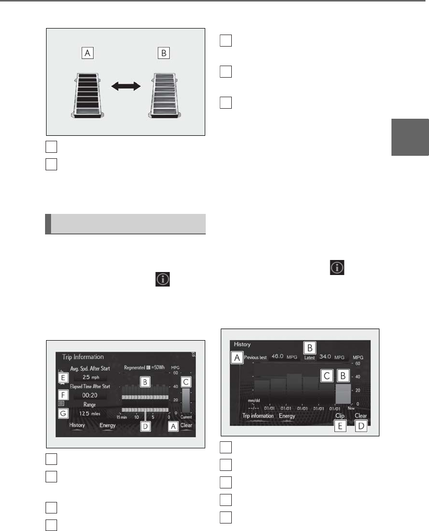
99
2-1. Instrument cluster
LS500h_OM_OM50F42U_(U)
2
Vehicle status information and indicators
Multi-information display
Low
High
These images are examples only, and may
vary slightly from actual conditions.
■Trip information
Press the “MENU” button on the
Remote Touch, then select on the
menu screen.
If a screen other than “Trip Information”
is displayed, select “Trip Information”.
Resetting the consumption data
Fuel consumption in the past 15
minutes
Current fuel consumption
Regenerated energy in the past 15
minutes
One symbol indicates 50 Wh. Up to 5
symbols are shown.
Average vehicle speed since the
hybrid system was started.
Elapsed time since the hybrid sys-
tem was started.
Cruising range
Average fuel consumption for the past
15 minutes is divided by color into past
averages and averages attained since
the power switch was last turned to
ON mode. Use the displayed average
fuel consumption as a reference.
The image is an example only, and may
vary slightly from actual conditions.
■History
Press the “MENU” button on the
Remote Touch, then select on the
menu screen.
If a screen other than “History” is dis-
played, select “History”.
Best recorded fuel consumption
Latest fuel consumption
Previous fuel consumption record
Resetting the history data
Updating the latest fuel consump-
tion data
Consumption
A
B
A
B
C
D
E
F
G
A
B
C
D
E
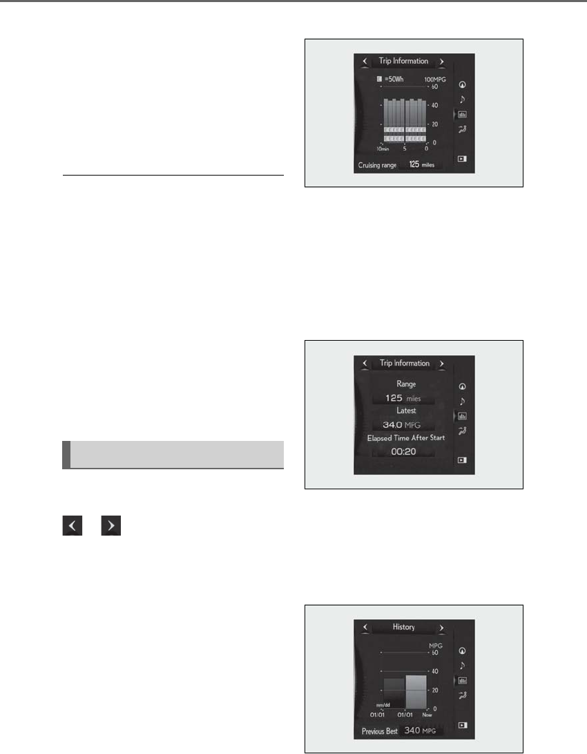
100 2-1. Instrument cluster
LS500h_OM_OM50F42U_(U)
The average fuel consumption history
is divided by color into past averages
and the average fuel consumption
since the last updated. Use the dis-
played average fuel consumption as a
reference.
The image is an example only, and may
vary slightly from actual conditions.
■Updating the history data
Update the latest fuel consumption by
selecting “Clip” to measure the current fuel
consumption again.
■Resetting the data
The fuel consumption data can be deleted
by selecting “Clear”.
■Cruising range
Displays the estimated maximum distance
that can be driven with the quantity of fuel
remaining.
This distance is computed based on your
average fuel consumption.
As a result, the actual distance that can be
driven may differ from that displayed.
Display the vehicle information on the
side display (→P.317), and then select
or to display the desired
screen.
The image is an example only, and may
vary slightly from actual conditions.
Displays the average fuel consumption
and regenerated energy for the past 10
minutes in 1 minute intervals, as well as
the cruising range.
■Trip information (type A)
Use the displayed average fuel consump-
tion as a reference.
■Trip information (type B)
Displays the cruising range, latest fuel
consumption and the amount of time
elapsed since the hybrid system was
started.
Use the displayed average fuel consump-
tion as a reference.
■History
Displays the average fuel consumption
and highest fuel consumption.
Using the side display
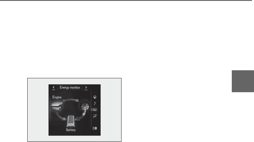
101
2-1. Instrument cluster
LS500h_OM_OM50F42U_(U)
2
Vehicle status information and indicators
Use the displayed average fuel consump-
tion as a reference.
■Energy monitor
Displays the hybrid system operation
and energy recovery states.
Displayed content is the same as that
displayed on the multi-information dis-
play. →P.88

102 2-1. Instrument cluster
LS500h_OM_OM50F42U_(U)

103
LS500h_OM_OM50F42U_(U)
3
3
Before driving
Before driving
.
3-1. Key information
Keys .................................................104
3-2. Opening, closing and locking the
doors and trunk
Doors...............................................108
Trunk................................................. 112
Smart access system with
push-button start...................... 119
3-3. Adjusting the seats
Front seats.....................................128
Power rear seat...........................135
Driving position memory ........139
Rear seat position memory....143
Head restraints............................144
3-4. Adjusting the steering wheel and
mirrors
Steering wheel............................. 147
Inside rear view mirror.............148
Outside rear view mirrors......149
3-5. Opening, closing the windows
and moon roof
Power windows............................ 151
Moon roof .....................................153
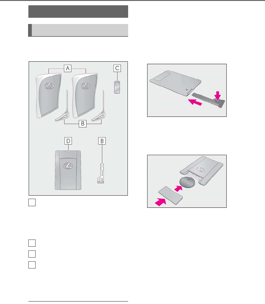
104 3-1. Key information
LS500h_OM_OM50F42U_(U)
3-1.Key informat ion
The following keys are provided with
the vehicle.
Electronic keys
• Operating the smart access system with
push-button start (→P.119)
• Operating the wireless remote control
function (→P.106)
Mechanical keys
Key number plate
Card key (electronic key) (if
equipped)
Operating the smart access system with
push-button start (→P.119)
■Card key (if equipped)
●The card key is not waterproof.
●The mechanical key that is stored inside
the card key should be used only if a
problem arises, such as when the card
key does not operate properly.
●If it is difficult to take out the mechanical
key, push down the lock release button
using a pen tip etc. If it is still difficult to
pull it out, use a coin etc.
●To store the mechanical key in the card
key, insert it while pressing the lock
release button.
●If the battery cover is not installed and the
battery falls out or if the battery was
removed because the key got wet, rein-
stall the battery with the positive terminal
facing the Lexus emblem.
■When riding in an aircraft
When bringing an electronic key onto an
aircraft, make sure you do not press any
buttons on the electronic key while inside
the aircraft cabin. If you are carrying an
electronic key in your bag etc., ensure that
the buttons are not likely to be pressed acci-
dentally. Pressing a button may cause the
electronic key to emit radio waves that
could interfere with the operation of the air-
craft.
■Electronic key battery depletion
●The standard battery life is 1 to 2 years.
(The card key battery life is about a year
and a half.)
●If the battery becomes low, an alarm will
sound in the cabin and a message will be
shown on the multi-information display
when the hybrid system is stopped.
Keys
The keys
A
B
C
D

105
3-1. Key information
LS500h_OM_OM50F42U_(U)
3
Before driving
●To reduce key battery depletion when the
electronic key is to not be used for long
periods of time, set the electronic key to
the battery-saving mode. (→P.120)
●As the electronic key always receives
radio waves, the battery will become
depleted even if the electronic key is not
used. The following symptoms indicate
that the electronic key battery may be
depleted. Replace the battery when nec-
essary. (→P.413)
• The smart access system with push-but-
ton start or the wireless remote control
does not operate.
• The detection area becomes smaller.
•The LED indicator on the key surface
does not turn on.
●To avoid serious deterioration, do not
leave the electronic key within 3 ft. (1 m)
of the following electrical appliances that
produce a magnetic field:
•TVs
• Personal computers
• Cellular phones, cordless phones and
battery chargers
• Recharging cellular phones or cordless
phones
• Table lamps
• Induction cookers
■Replacing the battery
→P.413
■Confirmation of the number of regis-
tered keys
The number of keys already registered to
the vehicle can be confirmed. Ask your
Lexus dealer for details.
■If “A New Key has been Registered
Contact Your Dealer for Details” is
shown on the multi-information display
This message will be displayed each time
the driver’s door is opened when the doors
are unlocked from the outside for approxi-
mately 10 days after a new electronic key
has been registered.
If this message is displayed but you have not
had a new electronic key registered, ask
your Lexus dealer to check if an unknown
electronic key (other than those in your
possession) has been registered.
NOTICE
■To prevent key damage
●Do not drop the keys, subject them to
strong shocks or bend them.
●Do not expose the keys to high tem-
peratures for a long period of time.
●Do not get the keys wet or wash them
in an ultrasonic washer etc.
●Do not attach metallic or magnetic
materials to the keys or place the keys
close to such materials.
●Do not disassemble the keys.
●Do not attach a sticker or anything else
to the surface of the electronic key.
●Do not place the keys near objects that
produce magnetic fields, such as TVs,
audio systems and induction cookers,
or medical electrical equipment, such
as low-frequency therapy equipment.
■Carrying the electronic key on your
person
Carry the electronic key 3.9 in. (10 cm)
or more away from electric appliances
that are turned on. Radio waves emitted
from electric appliances within 3.9 in. (10
cm) of the electronic key may interfere
with the key, causing the key to not func-
tion properly.
■In case of a smart access system with
push-button start malfunction or
other key-related problems
→P.445
■When an electronic key is lost
→P.444
■Handling the card key (if equipped)
●Do not apply excess force when insert-
ing the mechanical key into the card
key. Doing so may damage the card
key.
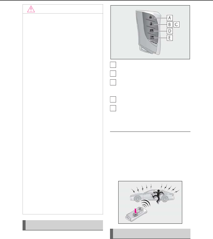
106 3-1. Key information
LS500h_OM_OM50F42U_(U)
The electronic keys are equipped with
the following wireless remote control:
Locks the doors (→P.108)
Unlocks the doors (→P.108)
Opens the windows and moon
roof* (→P.108)
Opens the trunk (→P.115)
Sounds the alarm
*: This setting must be customized at your
Lexus dealer.
■Theft deterrent panic mode
When is pressed for longer than about one
second, an alarm will sound intermittently
and the vehicle lights will flash to deter any
person from trying to break into or damage
your vehicle.
To stop the alarm, press any button on the
electronic key.
To take out the mechanical key, push
the release button and take the key out.
The mechanical key can only be inserted in
one direction, as the key only has grooves
on one side. If the key cannot be inserted in
NOTICE
●If the battery or card key terminals get
wet, the battery may corrode and the
card key may stop working.
If the key is dropped into water, or if
drinking water, etc. is spilled on the key,
immediately remove the battery cover
and wipe the battery and terminals. (To
remove the battery cover, lightly grasp
and pull it.) If the battery is corroded,
have your Lexus dealer replace the
battery.
●Do not crush the battery cover or use
a screwdriver to remove the battery
cover.
Forcibly removing the battery cover
may bend or damage the key.
●If the battery cover is frequently
removed, the battery cover may
become loose.
●When installing the battery, make sure
to check the direction of the battery.
Installing the battery in the wrong
direction may cause the battery to
deplete rapidly.
●The surface of the card key may be
damaged, or its coating may peel off in
the following situations:
• The card key is carried together with
hard objects, such as coins and keys.
• The card key is scraped with a sharp
object, such as the tip of a mechanical
pencil.
• The surface of the card key is wiped
with thinner or benzene.
Wireless remote control
Using the mechanical key
A
B
C
D
E
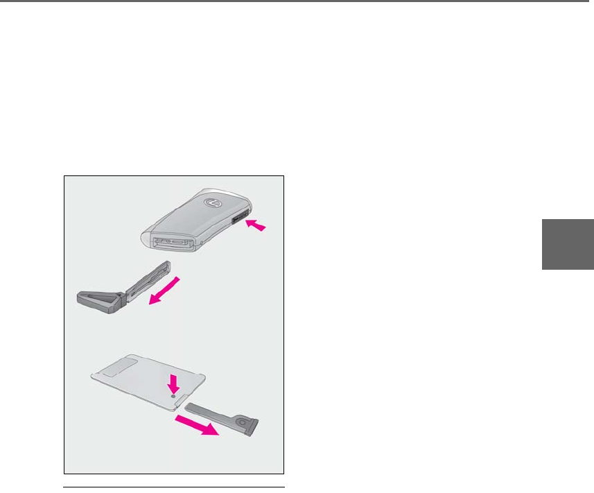
107
3-1. Key information
LS500h_OM_OM50F42U_(U)
3
Before driving
a lock cylinder, turn it over and re-attempt
to insert it.
After using the mechanical key, store it in
the electronic key. Carry the mechanical
key together with the electronic key. If the
electronic key battery is depleted or the
entry function does not operate properly,
you will need the mechanical key.
(→P.413)
■When required to leave the vehicle’s
key with a parking attendant
Turn the trunk opener main switch off
(→P.118) and lock the glove box (→P.344)
as circumstances demand.
Remove the mechanical key for your own
use and provide the attendant with the elec-
tronic key only.
■If you lose your mechanical keys
→P.444
■If a wrong key is used
The key cylinder rotates freely, isolated
from the internal mechanism.
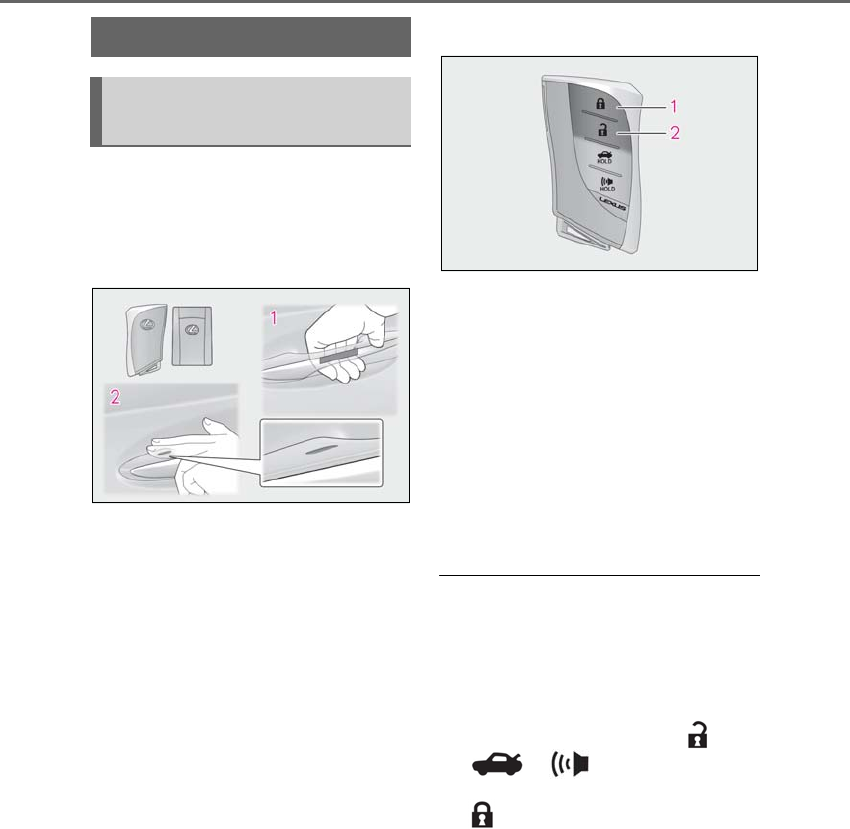
108 3-2. Opening, closing and locking the doors and trunk
LS500h_OM_OM50F42U_(U)
3-2.Opening, closing and locking t he doors and trunk
■Smart access system with
push-button start
Carry the electronic key to enable this
function.
1Grip the driver’s door handle to
unlock the door. Holding the
driver’s door handle for approxi-
mately 2 seconds unlocks all the
doors. Grip any passenger door
handle to unlock all the doors.*
Make sure to touch the sensor on the back
of the handle.
The doors cannot be unlocked for 3 sec-
onds after the doors are locked.
*: The door unlock settings can be
changed.
2Touch the lock sensor (indentation
on the upper part of the door han-
dle) to lock all the doors.
Check that the door is securely locked.
■Wireless remote control
1Locks all the doors
Check that the door is securely locked.
2Unlocks all the doors
Pressing the button unlocks the driver’s
door. Pressing the button again within 5
seconds unlocks the other door.
Press and hold to open the windows and
moon roof.*
*: This setting must be customized at your
Lexus dealer.
■Switching the door unlock function
It is possible to set which doors the entry
function unlocks using the wireless remote
control.
1Turn the power switch off.
2When the indicator light on the key sur-
face is not on, press and hold ,
or for approximately 5
seconds while pressing and holding
.
The setting changes each time an operation
is performed, as shown below. (When
changing the setting continuously, release
the buttons, wait for at least 5 seconds, and
repeat step 3.)
Doors
Unlocking and locking the doors
from the outside
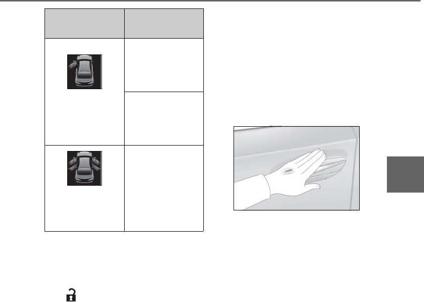
109
3-2. Opening, closing and locking the doors and trunk
LS500h_OM_OM50F42U_(U)
3
Before driving
To prevent unintended triggering of the
alarm, unlock the doors using the wireless
remote control and open and close a door
once after the settings have been changed.
(If a door is not opened within 60 seconds
after is pressed, the doors will be
locked again and the alarm will automati-
cally be set.)
In a case that the alarm is triggered, imme-
diately stop the alarm. (→P.68)
■Impact detection door lock release sys-
tem
In the event that the vehicle is subject to a
strong impact, all the doors are unlocked.
Depending on the force of the impact or the
type of accident, however, the system may
not operate.
■Operation signals
A buzzer sounds and the emergency flash-
ers flash to indicate that the doors have
been locked/unlocked. (Locked: once;
Unlocked: twice)
A buzzer sounds to indicate that the win-
dows and moon roof are operating.
■Security feature
If a door is not opened within approximately
60 seconds after the vehicle is unlocked,
the security feature automatically locks the
vehicle again.
■When the doors cannot be locked by the
lock sensor on the upper part of the
door handle
When the doors cannot be locked even if
the lock sensor on the surface of the door
handle is touched by a finger, touch the lock
sensor with the palm.
If you are wearing gloves, remove them.
■Open door warning buzzer
If an attempt to lock the doors is made when
a door is not fully closed, a buzzer sounds
continuously for 5 seconds. Fully close the
door to stop the buzzer, and lock the vehi-
cle once more.
■Setting the alarm
Locking the doors will set the alarm system.
(→P.68)
■Conditions affecting the operation of
the smart access system with push-but-
ton start or wireless remote control
→P.120
■If the smart access system with
push-button start or the wireless remote
control does not operate properly
Use the mechanical key to lock and unlock
the doors. (→P.445)
Replace the key battery with a new one if it
is depleted. (→P.413)
■If the 12-volt battery is discharged
The doors cannot be locked and unlocked
using the smart access system with
push-button start or wireless remote con-
trol. Lock or unlock the doors using the
mechanical key. (→P.445)
■Customization
Some functions can be customized.
Multi-information
display/Beep Unlocking function
Exterior: Beeps 3
times
Interior: Pings once
Holding the driver’s
door handle unlocks
only the driver’s
door.
Holding any of the
passenger door
handles unlocks all
the doors.
Exterior: Beeps
twice
Interior: Pings once
Holding a door han-
dle unlocks all the
doors.
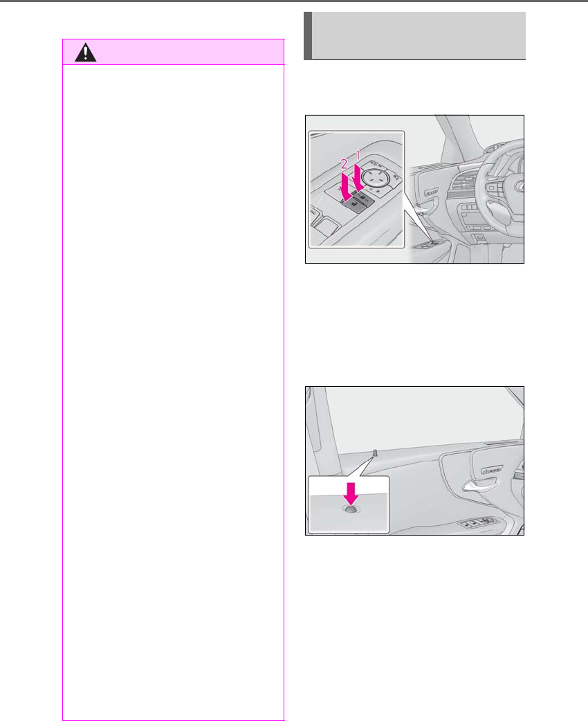
110 3-2. Opening, closing and locking the doors and trunk
LS500h_OM_OM50F42U_(U)
(→P.481)
■Door lock switches (to
lock/unlock)
1Locks all the doors
2Unlocks all the doors
■Inside lock buttons (to lock)
Push down the inside lock button to
lock the door.
■Inside door handles (to unlock)
For the front doors
Pull the handle to unlock and open the
door.
When the door is unlocked, the inside lock
button will pop up.
For the rear doors
Pull the handle to unlock the door. Pull
the handle a second time to open the
door.
WARNING
■To prevent an accident
Observe the following precautions while
driving the vehicle.
Failure to do so may result in a door
opening and an occupant throwing out of
the vehicle, resulting in death or serious
injury.
●Ensure that all doors are properly
closed and locked.
●Do not pull the inside handle of the
doors while driving.
Be especially careful for the front doors,
as the doors may be opened even if the
inside lock buttons are in locked position.
●Set the rear door child-protector locks
when children are seated in the rear
seats.
■When opening or closing a door
Check the surroundings of the vehicle
such as whether the vehicle is on an
incline, whether there is enough space
for a door to open and whether a strong
wind is blowing. When opening or clos-
ing the door, hold the door handle tightly
to prepare for any unpredictable move-
ment.
■Vehicle height control precautions
(vehicles with electronically modu-
lated air suspension)
In the following situations, make sure to
check the safety of the area around the
vehicle, as the vehicle height may change
and part of someone’s body may be
caught in the vehicle, possibly causing
injury or the vehicle may be damaged.
●When opening a door
●When unlocking the doors using the
smart access system with push-button
start
Unlocking and locking the doors
from the inside
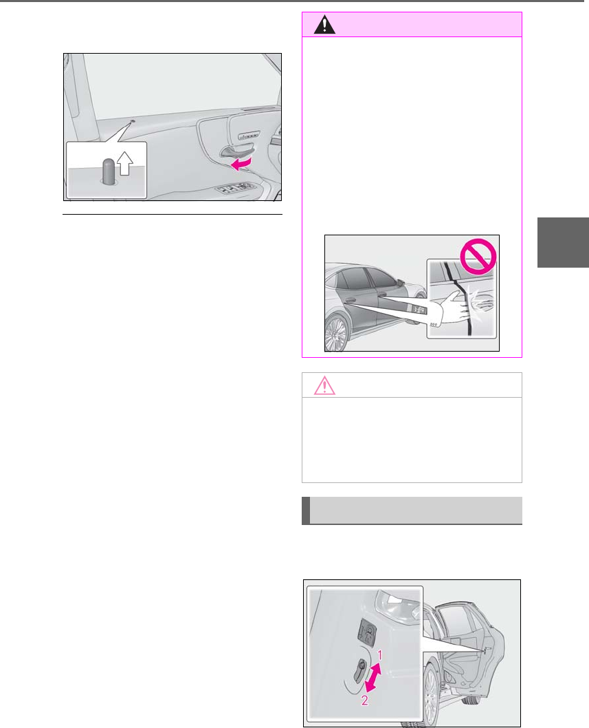
111
3-2. Opening, closing and locking the doors and trunk
LS500h_OM_OM50F42U_(U)
3
Before driving
When the door is unlocked, the inside lock
button will pop up.
■Locking the front doors from the outside
without a key
1Push down the inside lock button.
2Close the door.
The door cannot be locked if the power
switch is in ACCESSORY or ON mode, or
the electronic key is left inside the vehicle.
However, the key may not be detected cor-
rectly and the door may be locked.
■Door closer
In the event that a door is left slightly open,
the door closer will automatically close it to
the fully closed position.
●The door closer will operate regardless
of the power switch mode.
●The door closer will not function if the
door has been closed while pulling the
inside or outside door handle.
●The door can be opened by pulling the
inside or outside door handle, even when
the door closer is operating (except
when the lock button is in the lock posi-
tion or the child-protector lock is set).
●A motor sound may be heard for several
seconds after the door closer closes the
door. This does not indicate a malfunc-
tion.
■Open door warning buzzer
If a door or the trunk is not fully closed, a
buzzer will sound when the vehicle speed
reaches 3 mph (5 km/h).
The open door(s) or trunk is indicated on
the multi-information display.
The door cannot be opened from
inside the vehicle when the lock is set.
1Unlock
WARNING
■Door closer
In the event that a door is left slightly
open, the door closer will automatically
close it to the fully closed position. It
takes several seconds before the door
easy closer begins to operate.
If the child-protector lock is set, the door
closer will not stop during operation even
if an attempt is made to open the door
from inside the vehicle. Be careful not to
catch fingers or anything else in the door.
Failure to do so may result in serious
injury.
NOTICE
■To prevent door closer malfunction
Do not frequently repeat opening and
closing of doors, or apply excessive force
to a door while the door closer is operat-
ing.
Rear door child-protector lock
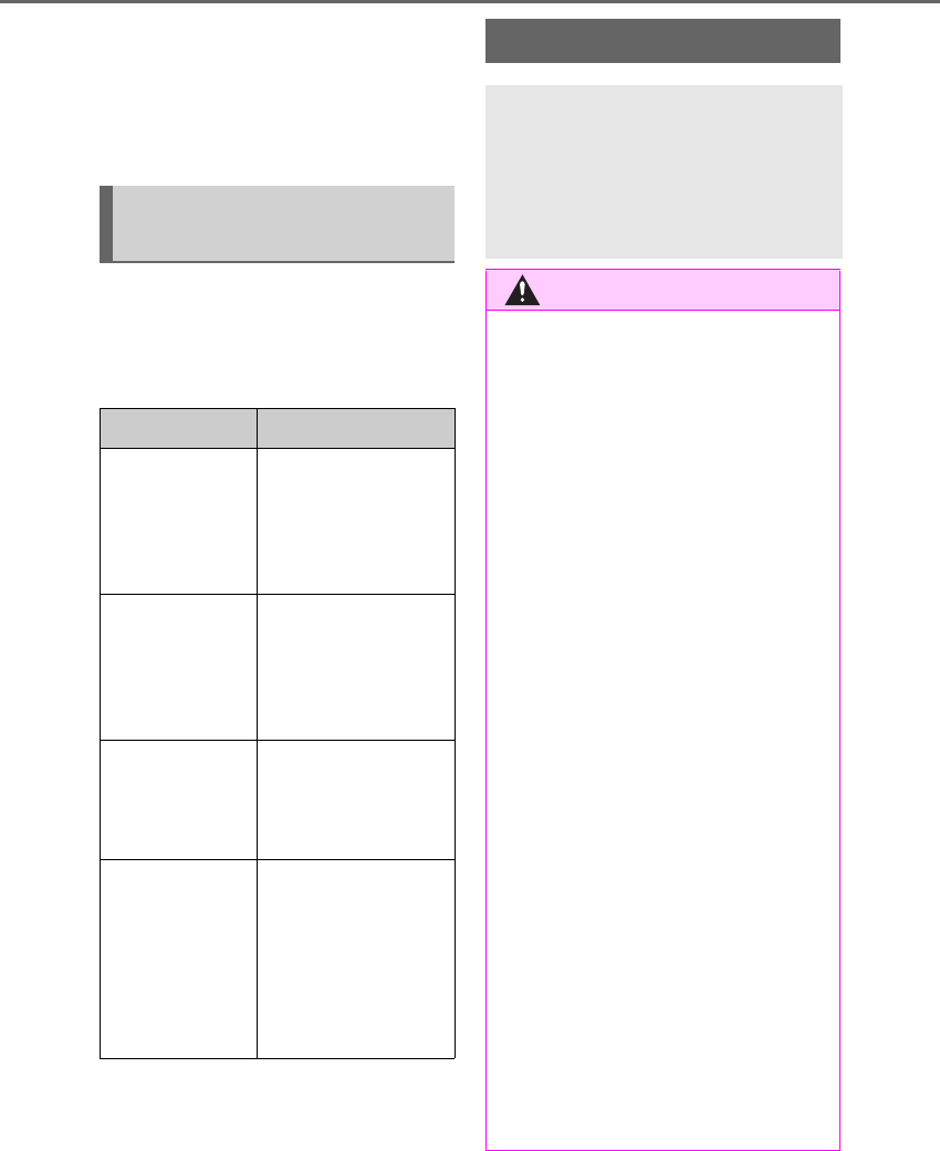
112 3-2. Opening, closing and locking the doors and trunk
LS500h_OM_OM50F42U_(U)
2Lock
These locks can be set to prevent children
from opening the rear doors. Push down
on each rear door switch to lock both rear
doors.
The following functions can be set or
canceled:
For instructions on customizing, refer to
P.481.
Automatic door locking and
unlocking systems
Function Operation
Speed linked
door locking
function
All doors are automati-
cally locked when vehi-
cle speed is
approximately 12 mph
(20 km/h) or higher.
Shift position
linked door lock-
ing function
All doors are automati-
cally locked when the
shift position is shifted
to a position other than
P.
Shift position
linked door
unlocking func-
tion
All doors are automati-
cally unlocked when
the shift position is
shifted to P.
Driver’s door
linked door
unlocking func-
tion
All doors are automati-
cally unlocked when
driver’s door is opened
within approximately
45 seconds after turn-
ing the power switch
off.
Trunk
The trunk can be opened using the
trunk opener switch, entry function
or wireless remote control.
The trunk can be closed using the
trunk closer.
WARNING
Observe the following precautions.
Failure to do so may result in death or
serious injury.
■Before driving
●Make sure that the trunk lid is fully
closed. If the trunk lid is not fully
closed, it may open unexpectedly
while driving and hit near-by objects or
luggage in the trunk may be thrown
out, causing an accident.
●Do not allow children to play in the
trunk.
If a child is accidentally locked in the
trunk, they could suffer from heat
exhaustion, suffocation or other inju-
ries.
●Do not allow a child to open or close
the trunk lid.
Doing so may cause the trunk lid to
open unexpectedly, or cause the
child’s hands, head, or neck to be
caught by the closing trunk lid.
■Important points while driving
Never let anyone sit in the trunk. In the
event of sudden braking or a collision,
they are susceptible to death or serious
injury.
■Using the trunk
Observe the following precautions.
Failure to do so may cause parts of the
body to be caught, resulting in serious
injury.
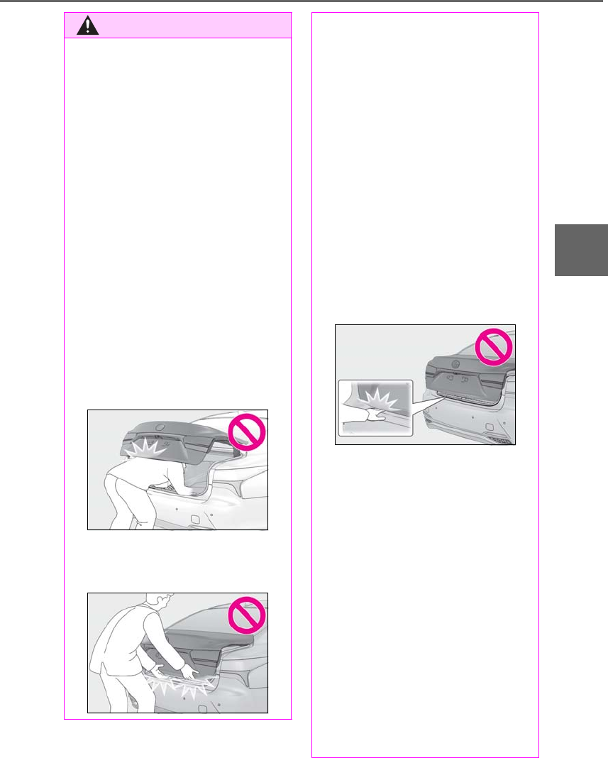
113
3-2. Opening, closing and locking the doors and trunk
LS500h_OM_OM50F42U_(U)
3
Before driving
WARNING
●Remove any heavy loads, such as snow
and ice, from the trunk lid before
opening it. Failure to do so may cause
the trunk lid to suddenly shut again
after it is opened.
●When opening or closing the trunk lid,
thoroughly check to make sure the
surrounding area is safe.
●If anyone is in the vicinity, make sure
they are safe and let them know that
the trunk is about to open or close.
●Use caution when opening or closing
the trunk lid in windy weather as it may
move abruptly in strong wind.
●The trunk lid may suddenly shut if it is
not opened fully. It is more difficult to
open or close the trunk lid on an
incline than on a level surface, so
beware of the trunk lid unexpectedly
opening or closing by itself. Make sure
that the trunk lid is fully open and
secure before using the trunk.
●When closing the trunk lid, take extra
care to prevent your fingers etc. from
being caught.
●When closing the trunk lid, make sure
to press it lightly on its outer surface. If
the trunk handle is used to fully close
the trunk lid, it may result in hands or
arms being caught.
●Do not attach any accessories other
than genuine Lexus parts to the trunk
lid. Such additional weight on the trunk
lid may cause the lid to suddenly shut
again after it is opened.
■Trunk easy closer
In the event that the trunk lid is left slightly
open, the trunk easy closer will automati-
cally close it to the fully closed position. It
takes several seconds before the trunk
easy closer begins to operate. Be careful
not to catch fingers or anything else in
the trunk lid, as this may cause bone frac-
tures or other serious injuries.
■Power trunk opener and closer
Observe the following precautions when
operating the power trunk opener and
closer.
Failure to do so may cause serious injury.
●Check the safety of the surrounding
area to make sure there are no obsta-
cles or anything that could cause any
of your belongings to get caught.
●If anyone is in the vicinity, make sure
they are safe and let them know that
the trunk is about to open or close.
●If the trunk closer switch is pressed
while the trunk lid is opening during
automatic operation, the trunk lid
stops opening. Take extra care when
on an incline, as the trunk lid may open
or close suddenly.

114 3-2. Opening, closing and locking the doors and trunk
LS500h_OM_OM50F42U_(U)
■Trunk opener switch
Press the trunk opener switch.
The trunk lid will fully open.
WARNING
●On an incline, the trunk lid may sud-
denly shut after it opens automatically.
Make sure the trunk lid is fully open
and secure before using the trunk.
●In the following situations, the power
trunk opener and closer may detect an
abnormality and automatic operation
may be stopped. In this case, the trunk
lid has to be operated manually. Take
extra care in this situation, as the
stopped trunk lid may suddenly shut,
causing an accident.
• When the trunk lid contacts an obsta-
cle
• When the 12-volt battery voltage sud-
denly drops, such as when the power
switch is turned to ON mode or the
hybrid system is started during auto-
matic operation
●Do not attach any accessories other
than genuine Lexus parts to the trunk
lid. The power trunk opener and closer
may not operate, causing itself to mal-
function, or the trunk lid may suddenly
shut again after it is opened.
■Hands Free Power Trunk Lid (if
equipped)
Observe the following precautions.
Failure to do so may cause serious injury.
●Exhaust gasses cause the exhaust
pipes to become quite hot. When
operating the Hands Free Power Trunk
Lid, be careful not to touch the exhaust
pipe.
●Do not operate the Hands Free Power
Trunk Lid if there is little space under
the rear bumper.
■Jam protection function
Observe the following precautions.
Failure to do so may cause serious injury.
●Never use any part of your body to
intentionally activate the jam protec-
tion function.
●The jam protection function may not
work if something gets caught just
before the trunk lid fully closes. Be
careful not to catch fingers or anything
else in the trunk lid.
●The jam protection function may not
work depending on the shape of the
object that is caught. Be careful not to
catch fingers or anything else.
NOTICE
■To prevent trunk easy closer malfunc-
tions
Do not apply force to the trunk lid while
the trunk easy closer is operating.
■To prevent damage to the power
trunk opener and closer
●Make sure that there is no luggage or
snow on the trunk lid before operating
the power trunk opener and closer. In
addition, make sure that there is no ice
between the trunk lid and frame that
prevents movement of the trunk lid.
Operating the power trunk opener
and closer when excessive load is
present on the trunk lid may cause a
malfunction.
●Do not apply excessive force to the
trunk lid while the power trunk opener
and closer is operating.
Opening/closing the trunk
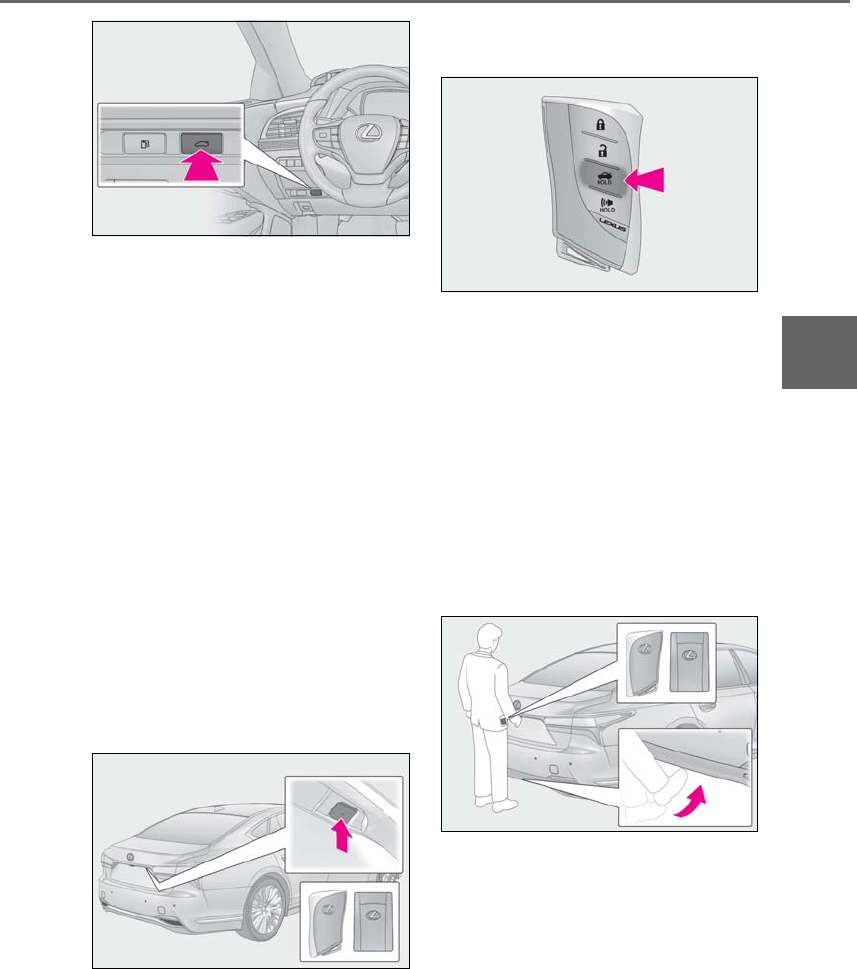
115
3-2. Opening, closing and locking the doors and trunk
LS500h_OM_OM50F42U_(U)
3
Before driving
■Smart access system with
push-button start
While carrying the electronic key,
press the button.
The trunk lid will fully open.
If the button is pressed while the trunk lid is
opening, the trunk lid will stop moving.
When all the doors are unlocked using
one of the following methods, the trunk
can be opened without the electronic
key:
-Entry function
-Wireless remote control
-Door lock switches
-Automatic door unlocking system
-Mechanical key
■Wireless remote control
Press and hold the switch.
A buzzer will sound and the trunk lid will
fully open.
If the button is pressed while the trunk lid is
opening, the trunk lid will stop moving.
■Hands Free Power Trunk Lid (if
equipped)
1While carrying an electronic key,
stand slightly away from the vehicle,
move a foot under the center of the
rear bumper and then pull it back.
The trunk lid will not start operating while a
foot is detected under the rear bumper.
If another electronic key for your vehicle is
in the vehicle, it may take slightly longer
than normal for the trunk lid to start oper-
ating.
2A buzzer will sound and the trunk
lid will fully open/close.
If a foot is moved under the rear bumper
while the trunk lid is opening, the trunk lid
will stop moving.
If a foot is moved under the rear bumper
while the trunk lid is closing, the trunk lid
will open.
■Trunk closer switch
Press the trunk closer switch.
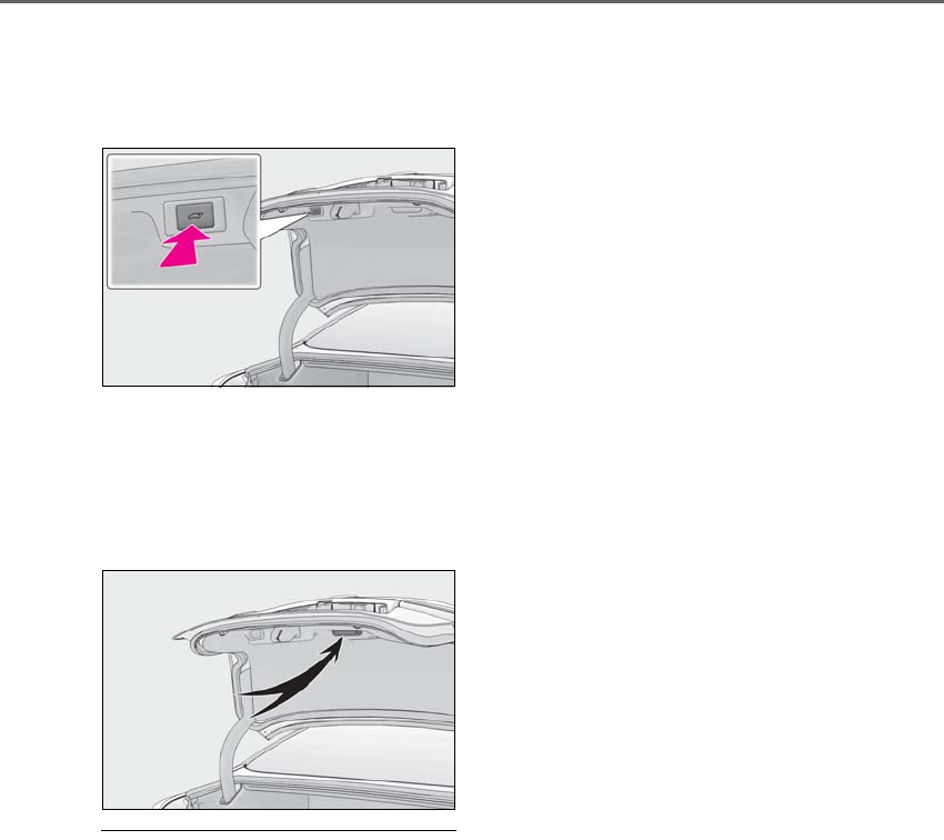
116 3-2. Opening, closing and locking the doors and trunk
LS500h_OM_OM50F42U_(U)
A buzzer will sound and the trunk lid will
fully close.
Pressing the switch while the trunk lid is
closing opens the trunk lid again.
■Trunk grip
Using the trunk grip, pull down the
trunk lid without applying sideways
force and push the trunk lid down from
the outside to close it.
■Trunk lid light/trunk light
●The trunk lid light/trunk light turns on
when the trunk is opened.
●If the trunk lid light/trunk light is left on
when the power switch is turned off, the
light will go off automatically after 20
minutes.
■Trunk easy closer
In the event that the trunk lid is left slightly
open, the trunk easy closer will automati-
cally close it to the fully closed position.
●The trunk easy closer will operate
regardless of the power switch mode.
●If the trunk easy closer does not operate,
open the trunk to the half open position
or more and then close it.
■Function to prevent the trunk being
locked with the electronic key inside
●When all doors are locked, closing the
trunk lid with the electronic key left inside
the trunk will sound an alarm.
In this case, the trunk lid can be opened
pressing the trunk release button on the
trunk lid.
●If the spare electronic key is put in the
trunk with all the doors locked, the key
confinement prevention function is acti-
vated so the trunk can be opened. In
order to prevent theft, take all electronic
keys with you when leaving the vehicle.
●If the electronic key is put in the trunk with
all the doors locked, the key may not be
detected depending on the location of
the key and the surrounding radio wave
conditions. In this case, the key confine-
ment prevention function cannot be acti-
vated, causing the doors to lock when the
trunk is closed. Make sure to check
where the key is before closing the trunk.
●The key confinement prevention function
cannot be activated if any one of the
doors is unlocked. In this case, open the
trunk using the trunk opener.
■Hands Free Power Trunk Lid operating
conditions (if equipped)
The Hands Free Power Trunk Lid (kick sen-
sor) is enabled and the power switch is
turned off.
■Overload protection function
The trunk lid will not operate when exces-
sive load is present on the top of the trunk
lid.
■Fall-down protection function
While the trunk lid is opening automatically,
applying excessive force to it will stop the
opening operation to prevent the trunk lid
from rapidly falling down.
■Jam protection function
While the trunk lid is closing automatically,
the trunk lid will stop closing and open if
something gets caught.
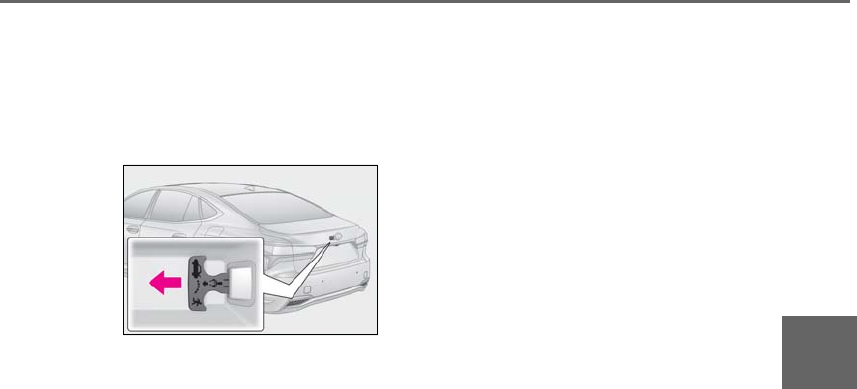
117
3-2. Opening, closing and locking the doors and trunk
LS500h_OM_OM50F42U_(U)
3
Before driving
■Internal trunk release lever
The trunk lid can be opened by pulling the
glow-in-the-dark lever located on the inside
of the trunk lid to the side.
The lever will continue to glow for some
time after the trunk lid is closed.
■Using the mechanical key
The trunk can be also opened using the
mechanical key. (→P.446)
If the trunk is unlocked using the mechani-
cal key, the power trunk lid and trunk easy
closer will not be operational. To return
them to an operational state, fully close the
trunk lid by hand.
■If the smart access system with
push-button start or the wireless remote
control does not operate properly
Use the mechanical key to unlock the trunk.
(→P.446)
Replace the key battery with a new one if it
is depleted. (→P.413)
■Situations in which the Hands Free
Power Trunk Lid may operate uninten-
tionally (if equipped)
In the following situations, the Hands Free
Power Trunk Lid may operate unintention-
ally.
To prevent unintentional operation, do not
leave the electronic key in the trunk and
keep it out of the effective range (detection
area) or disable the Hands Free Power
Trunk Lid (kick sensor).
●When a large amount of water is applied
to the rear bumper, such as when the
vehicle is being washed or in heavy rain
●When dirt is wiped off the rear bumper
●When a small animal or small object, such
as a ball, moves under the rear bumper
●When an object is moved from under the
rear bumper
●When snow, etc. is removed from under
the rear bumper
●If someone is swinging their legs while sit-
ting on the rear bumper
●If the legs or another part of someone’s
body contacts the rear bumper while
passing by the vehicle
●When the vehicle is parked near an elec-
trical noise source which affects the sen-
sitivity of the Hands Free Power Trunk Lid,
such as a pay parking spot, gas station,
electrically heated road, or fluorescent
light
●When the vehicle is near a TV tower,
electric power plant, radio station, large
display, airport or other facility that gen-
erates strong radio waves or electrical
noise
●When the vehicle is parked in a place
where objects, such as grass, move near
the rear bumper
●If luggage, etc. is set near the rear
bumper
●If accessories or a vehicle cover is
installed/removed near the rear bumper
●When the vehicle is being towed
■Situations in which the Hands Free
Power Trunk Lid may not operate prop-
erly (if equipped)
●In the following situations, the Hands Free
Power Trunk Lid may not operate prop-
erly:
• If the rear bumper is strongly hit with a
foot or is touched for a while
Make sure not to touch the rear bumper
with a foot when operating the Hands Free
Power Trunk Lid.
If the rear bumper has been touched for a
while, wait for a short time before attempt-
ing to operate the Hands Free Power Trunk
Lid again.
•When an external radio wave source
interferes with the communication
between the electronic key and the vehi-
cle (→P.120)
• When the vehicle is parked near an elec-
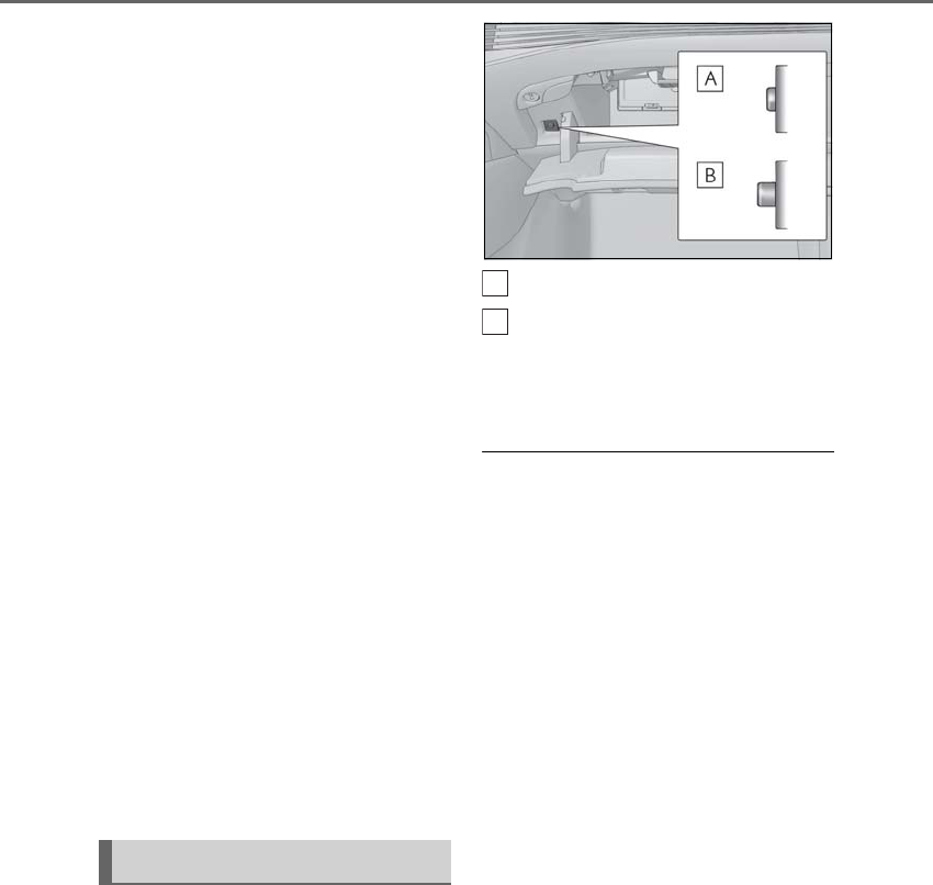
118 3-2. Opening, closing and locking the doors and trunk
LS500h_OM_OM50F42U_(U)
trical noise source which affects the sen-
sitivity of the Hands Free Power Trunk Lid,
such as a pay parking spot, gas station,
electrically heated road, or fluorescent
light
• When the vehicle is near a TV tower,
electric power plant, radio station, large
display, airport or other facility that gen-
erates strong radio waves or electrical
noise
• When a large amount of water is applied
to the rear bumper, such as when the
vehicle is being washed or in heavy rain
• When mud, snow, ice, etc. is attached to
the rear bumper
• When the vehicle has been parked for a
while near objects that may move under
the rear bumper, such as grass
• When an accessory is installed to the rear
bumper
Make sure to disable the Hands Free
Power Trunk Lid (kick sensor) if an acces-
sory is installed to the rear bumper.
●The Hands Free Power Trunk Lid will not
operate in the following situations:
• When an electronic key is not carried
• When an electronic key is not within the
effective range (detection area)
■Open door warning buzzer
→P.111
■Customization
Some functions can be customized.
(→P.481)
The trunk opener switch can be tem-
porarily disabled to protect luggage
stored in the trunk against theft.
Turn the main switch in the glove box
off to disable the trunk opener.
On
Off
The trunk lid cannot be opened even with
the wireless remote control, entry function
or Hands Free Power Trunk Lid.
■When leaving a key to the vehicle with a
parking attendant
→P.107
Luggage security system
A
B
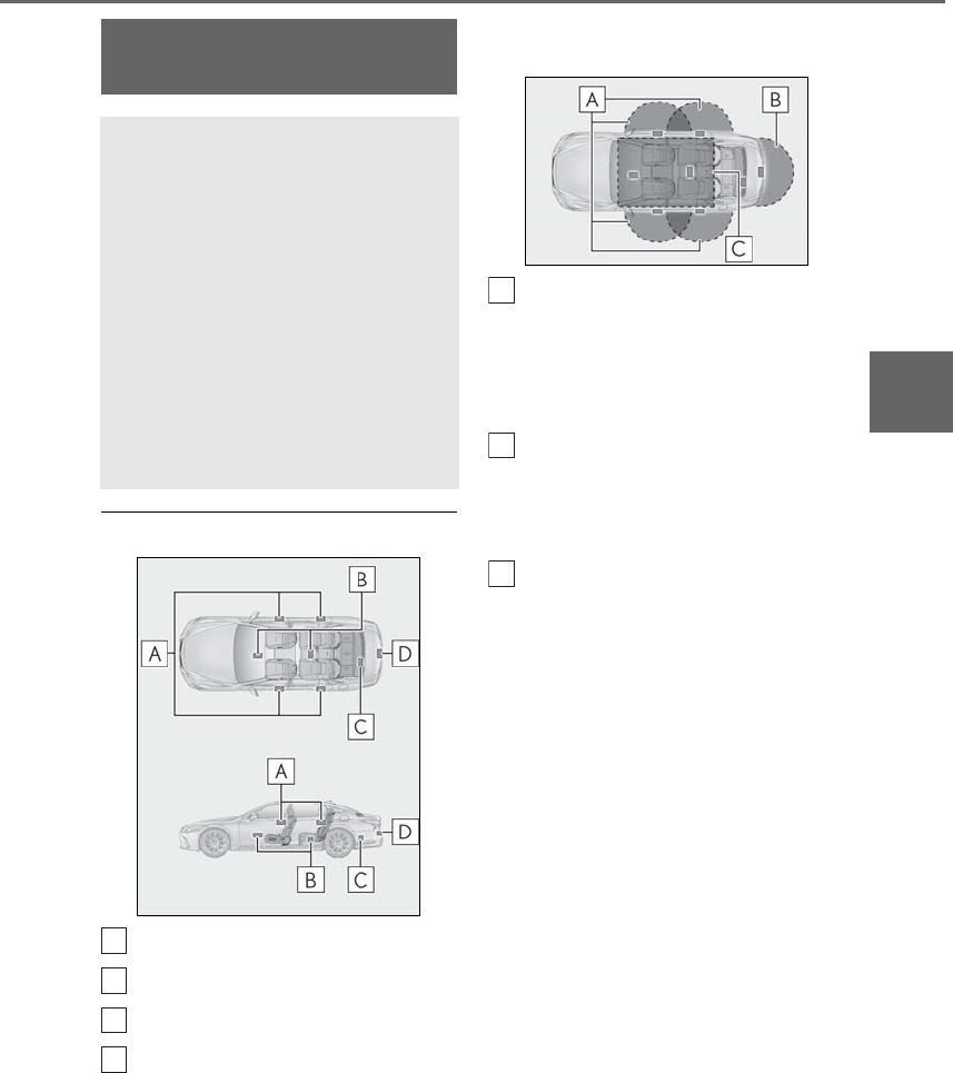
119
3-2. Opening, closing and locking the doors and trunk
LS500h_OM_OM50F42U_(U)
3
Before driving
■Antenna location
Antennas outside the cabin
Antennas inside the cabin
Antenna inside the trunk
Antenna outside the trunk
■Effective range (areas within which the
electronic key is detected)
When locking or unlocking the doors
The system can be operated when the
electronic key is within about 2.3 ft. (0.7 m)
of an outside door handle. (Only the doors
detecting the key can be operated.)
When opening the trunk
The system can be operated when the
electronic key is within about 2.3 ft. (0.7 m)
of the trunk release button.
When starting the hybrid system or
changing power switch modes
The system can be operated when the
electronic key is inside the vehicle.
■Alarms and warning messages
An alarm sounds and warning messages
are displayed on the multi-information dis-
play to protect against unexpected acci-
dents or theft of the vehicle resulting from
erroneous operation. When a warning mes-
sage is displayed, take appropriate mea-
sures based on the displayed message.
(→P.437)
When only an alarm sounds, circumstances
and correction procedures are as follows.
●When an exterior alarm sounds once for
5 seconds
Smart access system with
push-button start
The following operations can be
performed simply by carrying the
electronic key (including the card
key) on your person, for example in
your pocket. The driver should
always carry the electronic key.
-Locks and unlocks the doors
(→P.108)
-Opens the trunk (→P.115)
-Starts the hybrid system
(→P.168)
A
B
C
D
A
B
C
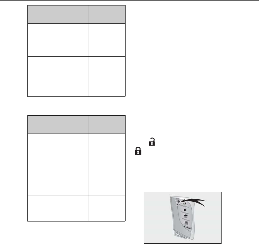
120 3-2. Opening, closing and locking the doors and trunk
LS500h_OM_OM50F42U_(U)
●When an interior alarm sounds continu-
ously
■If “Key Detected in Vehicle” is shown on
the multi-information display
An attempt was made to lock the doors
using the smart access system with push-
button start while the electronic key was still
inside the vehicle. Retrieve the electronic
key from the vehicle and lock the doors
again.
■Battery-saving function
The battery-saving function will be acti-
vated in order to prevent the electronic key
battery and the 12-volt battery from being
discharged while the vehicle is not in opera-
tion for a long time.
●In the following situations, the smart
access system with push-button start may
take some time to unlock the doors.
• The electronic key has been left in an
area of approximately 6 ft. (2 m) of the
outside of the vehicle for 10 minutes or
longer.
• The smart access system with push-but-
ton start has not been used for 5 days or
longer.
●If the smart access system with push-but-
ton start has not been used for 14 days or
longer, the doors cannot be unlocked at
any doors except the driver’s door. In this
case, take hold of the driver’s door han-
dle, or use the wireless remote control or
the mechanical key, to unlock the doors.
■Turning an electronic key to bat-
tery-saving mode
When battery-saving mode is set, battery
depletion is minimized by stopping the elec-
tronic key from receiving radio waves.
Press twice while pressing and holding
. Confirm that the electronic key indica-
tor flashes 4 times.
While the battery-saving mode is set, the
smart access system with push-button start
cannot be used. To cancel the function,
press any of the electronic key buttons.
■Conditions affecting operation
The smart access system with push-button
start uses weak radio waves. In the following
situations, the communication between the
electronic key and the vehicle may be
affected, preventing the smart access sys-
tem with push-button start, wireless remote
control and immobilizer system from oper-
ating properly. (Ways of coping: →P.445)
●When the electronic key battery is
depleted
●Near a TV tower, electric power plant,
gas station, radio station, large display,
Situation Correction
procedure
An attempt was made to
lock the vehicle while a
door was open.
Close all of the
doors and lock
the doors
again.
The trunk was closed
while the electronic key
was still inside the trunk
and all the doors were
locked.
Retrieve the
electronic key
from the trunk
and close the
trunk lid.
Situation Correction
procedure
The power switch was
turned to ACCESSORY
mode while the driver’s
door was open (The
driver’s door was opened
when the power switch
was in ACCESSORY
mode).
Turn the power
switch off and
close the
driver’s door.
The power switch was
turned off while the
driver’s door was open.
Close the
driver’s door.

121
3-2. Opening, closing and locking the doors and trunk
LS500h_OM_OM50F42U_(U)
3
Before driving
airport or other facility that generates
strong radio waves or electrical noise
●When carrying a portable radio, cellular
phone, cordless phone or other wireless
communication device
●When the electronic key is in contact
with, or is covered by the following metal-
lic objects
• Cards to which aluminum foil is attached
• Cigarette boxes that have aluminum foil
inside
• Metallic wallets or bags
•Coins
• Hand warmers made of metal
• Media such as CDs and DVDs
●When other wireless keys (that emit radio
waves) are being used nearby
●When carrying the electronic key
together with the following devices that
emit radio waves
• Another vehicle’s electronic key or a
wireless key that emits radio waves
• Personal computers or personal digital
assistants (PDAs)
• Digital audio players
• Portable game systems
●If window tint with a metallic content or
metallic objects are attached to the rear
window
●When the electronic key is placed near a
battery charger or electronic devices
●When the vehicle is parked in a pay park-
ing spot where radio waves are emitted.
■Note for the entry function
●Even when the electronic key is within the
effective range (detection areas), the sys-
tem may not operate properly in the fol-
lowing cases:
• The electronic key is too close to the win-
dow or outside door handle, near the
ground, or in a high place when the doors
are locked or unlocked.
• The electronic key is near the ground or
in a high place, or too close to the center
of the rear bumper when the trunk is
opened.
• The electronic key is on the instrument
panel, rear package tray or floor, or in the
door pockets or glove box when the
hybrid system is started or power switch
modes are changed.
●Do not leave the electronic key on top of
the instrument panel or near the door
pockets when exiting the vehicle.
Depending on the radio wave reception
conditions, it may be detected by the
antenna outside the cabin and the doors
will become lockable from the outside,
possibly trapping the electronic key
inside the vehicle.
●As long as the electronic key is within the
effective range, the doors may be locked
or unlocked by anyone. However, only
the doors detecting the electronic key
can be used to unlock the vehicle.
●Even if the electronic key is not inside the
vehicle, it may be possible to start the
hybrid system if the electronic key is near
the window.
●The doors may unlock or lock if a large
amount of water splashes on the door
handle, such as in the rain or in a car
wash, when the electronic key is within
the effective range. (The doors will auto-
matically be locked after approximately
60 seconds if the doors are not opened
and closed.)
●If the wireless remote control is used to
lock the doors when the electronic key is
near the vehicle, there is a possibility that
the door may not be unlocked by the
entry function. (Use the wireless remote
control to unlock the doors.)
●Touching the door lock sensor while
wearing gloves may delay or prevent lock
operation.
●When the lock operation is performed
using the lock sensor, recognition signals
will be shown up to two consecutive
times. After this, no recognition signals
will be given.
●If the door handle becomes wet while the
electronic key is within the effective
range, the door may lock and unlock
repeatedly. In this case, follow the follow-
ing correction procedures to wash the
vehicle:
• Place the electronic key in a location 6 ft.
(2 m) or more away from the vehicle.
(Take care to ensure that the key is not
stolen.)

122 3-2. Opening, closing and locking the doors and trunk
LS500h_OM_OM50F42U_(U)
• Set the electronic key to battery-saving
mode to disable the smart access system
with push-button start. (→P.120)
●If the electronic key is inside the vehicle
and a door handle becomes wet during a
car wash, a message may be shown on
the multi-information display and a
buzzer will sound outside the vehicle. To
turn off the alarm, lock all the doors.
●The lock sensor may not work properly if
it comes into contact with ice, snow, mud,
etc. Clean the lock sensor and attempt to
operate it again.
●A sudden approach to the effective
range or door handle may prevent the
doors from being unlocked. In this case,
return the door handle to the original
position and check that the doors unlock
before pulling the door handle again.
●If there is another electronic key in the
detection area, it may take slightly longer
to unlock the doors after the door handle
is gripped.
■When the vehicle is not driven for
extended periods
●To prevent theft of the vehicle, do not
leave the electronic key within 6 ft. (2 m)
of the vehicle.
●The smart access system with push-but-
ton start can be deactivated in advance.
●Setting the electronic key to battery-sav-
ing mode helps to reduce key battery
depletion. (→P.120)
■To operate the system properly
●Make sure to carry the electronic key
when operating the system. Do not get
the electronic key too close to the vehicle
when operating the system from the out-
side of the vehicle.
Depending on the position and holding
condition of the electronic key, the key may
not be detected correctly and the system
may not operate properly. (The alarm may
go off accidentally, or the door lock pre-
vention function may not operate.)
●Do not leave the electronic key inside the
trunk.
The key confinement prevention function
may not operate, depending on the loca-
tion of the key (the inside edge of the
Trunk), conditions (inside a metal bag,
close to metallic objects) and the radio
waves in the surrounding area. (→P.116)
■If the smart access system with
push-button start does not operate
properly
●Locking and unlocking the doors and
trunk: →P.445
●Starting the hybrid system: →P.446
■Customization
Some functions can be customized.
(→P.481)
■If the smart access system with
push-button start has been deactivated
in a customized setting
●Locking and unlocking the doors and
opening the trunk:
Use the wireless remote control or
mechanical key. (→P.108, 115, 445)
●Starting the hybrid system and changing
power switch modes: →P.446
●Stopping the hybrid system: →P.170
123
3-2. Opening, closing and locking the doors and trunk
LS500h_OM_OM50F42U_(U)
3
Before driving
■Certification for the smart access system with push-button start
For vehicles sold in the U.S.A., Hawaii, Guam and Puerto Rico
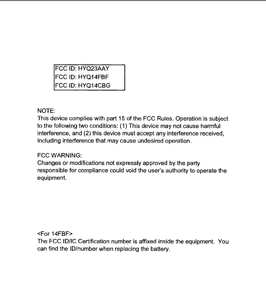
124 3-2. Opening, closing and locking the doors and trunk
LS500h_OM_OM50F42U_(U)
125
3-2. Opening, closing and locking the doors and trunk
LS500h_OM_OM50F42U_(U)
3
Before driving
For vehicles sold in Canada

126 3-2. Opening, closing and locking the doors and trunk
LS500h_OM_OM50F42U_(U)

127
3-2. Opening, closing and locking the doors and trunk
LS500h_OM_OM50F42U_(U)
3
Before driving
WARNING
■Caution regarding interference with
electronic devices
●People with implantable cardiac pace-
makers, cardiac resynchronization
therapy-pacemakers or implantable
cardioverter defibrillators should keep
away from the smart access system
with push-button start antennas.
(→P.119)
The radio waves may affect the opera-
tion of such devices. If necessary, the
entry function can be disabled. Ask
your Lexus dealer for details, such as
the frequency of radio waves and tim-
ing of the emitted radio waves. Then,
consult your doctor to see if you
should disable the entry function.
●Users of any electrical medical device
other than implantable cardiac pace-
makers, cardiac resynchronization
therapy-pacemakers or implantable
cardioverter defibrillators should con-
sult the manufacturer of the device for
information about its operation under
the influence of radio waves.
Radio waves could have unexpected
effects on the operation of such medi-
cal devices.
Ask your Lexus dealer for details on dis-
abling the entry function.
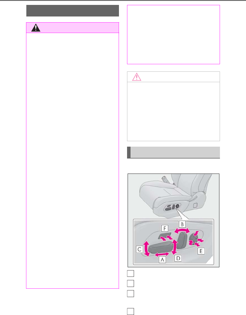
128 3-3. Adjusting the seats
LS500h_OM_OM50F42U_(U)
3-3.Adjusting the seats
■Seat adjustment switches
Seat position adjustment switch
Seatback angle adjustment switch
Seat cushion (front) angle adjust-
ment switch
Vertical height adjustment switch
Front seats
WARNING
■When adjusting the seat position
●Take care when adjusting the seat
position to ensure that other passen-
gers are not injured by the moving
seat.
●Do not put your hands under the seat
or near the moving parts to avoid
injury.
Fingers or hands may become
jammed in the seat mechanism.
●Make sure to leave enough space
around the feet so they do not get
stuck.
■Seat adjustment
To reduce the risk of sliding under the lap
belt during a collision, do not recline the
seat more than necessary.
If the seat is too reclined, the lap belt may
slide past the hips and apply restraint
forces directly to the abdomen, or your
neck may contact the shoulder belt,
increasing the risk of death or serious
injury in the event of an accident.
Adjustments should not be made while
driving as the seat may unexpectedly
move and cause the driver to lose control
of the vehicle.
■Operating the front passenger’s seat
from the driver’s seat or rear seat
Do not operate the front passenger’s seat
when a passenger is seated in it. In addi-
tion, do not let anyone sit down in the
front passenger’s seat while the seat is
being operated or when the head
restraint is being folded. The front pas-
senger may catch their legs between the
instrument panel and seat, or the head
restraint may interfere with their head,
resulting in injury.
■When the front passenger’s seat is
folded forward
If the outside rear view mirror is difficult
to see, due to the position of the front
passenger’s seat, move the front passen-
ger’s seat to an appropriate position.
Doing so may lead to mishandling of the
vehicle and cause an accident, resulting
in death or serious injury.
NOTICE
■Operating the front passenger’s seat
from the driver’s seat or rear seat
Before operating the front passenger’s
seat, make sure that there is no luggage
or any other objects on the seat or in the
footwell that could prevent its operation.
Such items may result in excess force
being applied, causing damage to the
seat and/or the luggage.
Adjustment procedure
A
B
C
D
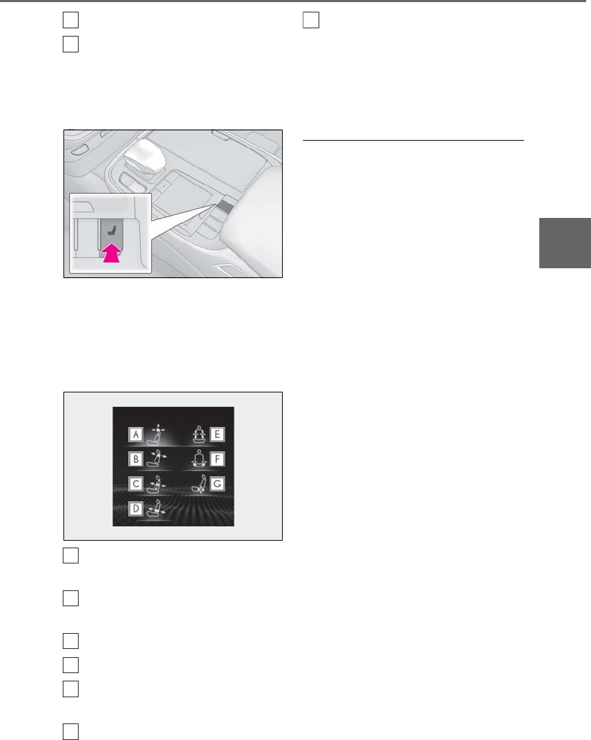
129
3-3. Adjusting the seats
LS500h_OM_OM50F42U_(U)
3
Before driving
Lumbar support adjustment switch
Seat cushion length adjustment
switch (if equipped)
■Center Display
1Press the seat switch.
2Using the Remote Touch pad,
select “Driver Seat Adjustment” or
“Passenger Seat Adjustment”.
3Select the button for the desired
adjustment.
Head restraint adjustment
(→P.144)
Shoulder bolster adjustment (if
equipped)
Lumbar support adjustment
Pelvic support adjustment
Seatback side bolster adjustment (if
equipped)
Seat cushion side bolster adjust-
ment (if equipped)
Hip support adjustment (if
equipped)
4Perform adjustment using the dis-
played buttons.
The seat will move while a button is
selected.
■When adjusting the front seats
While adjusting a front seat, to avoid con-
tact with the ceiling, instrument panel or
rear seats, the operation of the seat may be
restricted or parts of the seat other than that
being adjusted may move.
■Operation after the power switch is
turned off
After a certain time elapses after the power
switch is turned off, the following parts of
the front seats will move to their neutral
positions.
●Shoulder bolster (if equipped)
●Lumbar support
●Pelvic support
●Seatback side bolster (if equipped)
●Seat cushion side bolster (if equipped)
●Hip support (if equipped)
■Automatic angle adjustment of the rear
displays (if equipped)
When a seat is adjusted, the angle of the
rear display will be adjusted automatically
to maintain an optimal viewing angle for the
rear display from the rear seat.
■Pre-collision seatbacks for the passen-
ger seats
→P.210, 220
■Customization
Some functions can be customized.
(→P.481)
E
F
A
B
C
D
E
F
G
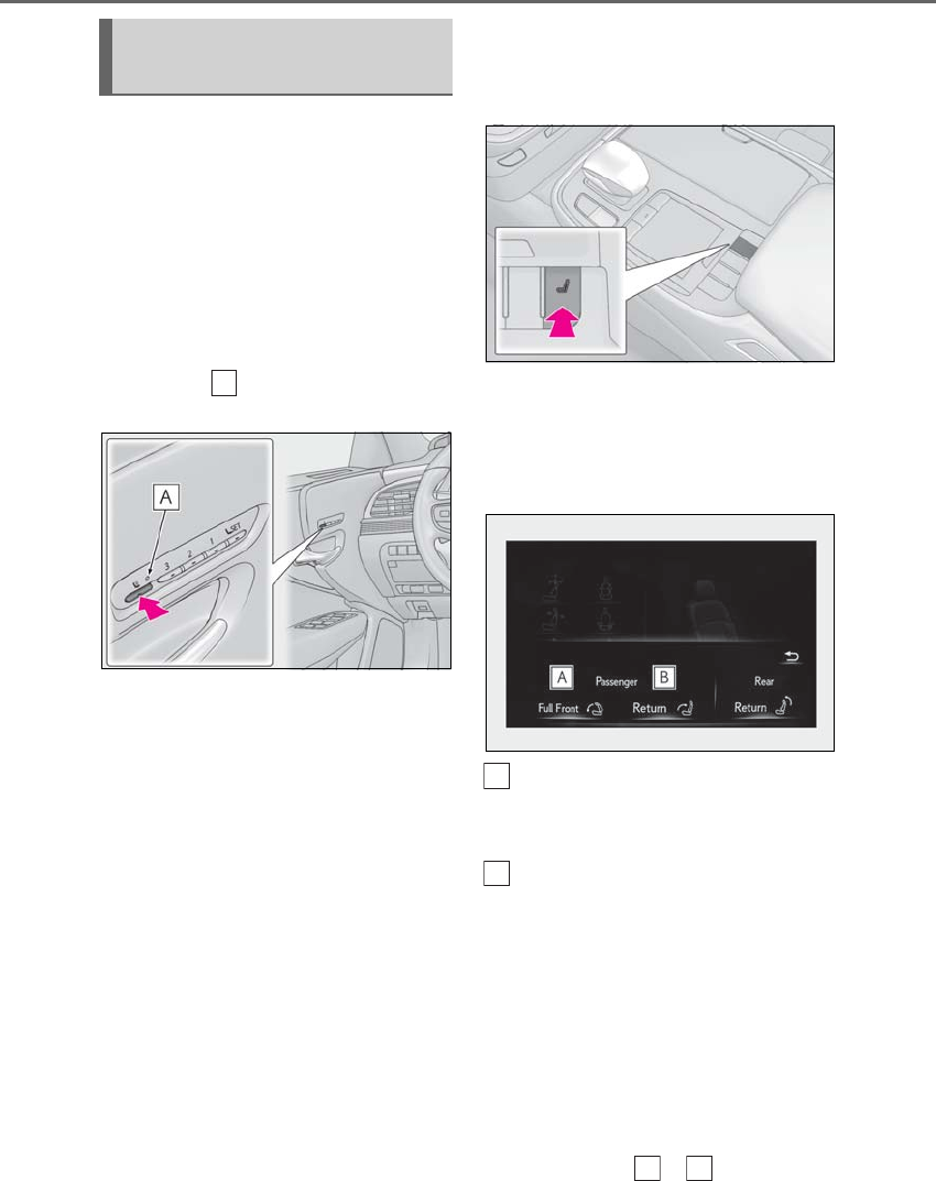
130 3-3. Adjusting the seats
LS500h_OM_OM50F42U_(U)
■Using the driver’s seat adjustment
switches to adjust the front passen-
ger’s seat (front passenger mode)
The mode of the driver’s seat adjust-
ment switches can be changed to
adjust the front passenger’s seat.
1Press the mode change button on
the driver’s side door.
The indicator will illuminate when front
passenger mode is selected.
2Using the seat adjustment switches
on the driver’s seat, adjust the front
passenger’s seat.
To cancel front passenger mode, press the
mode change button again.
Front passenger mode will be canceled
automatically if the driver’s seat adjustment
switches are not operated for approxi-
mately 30 seconds.
■Using the Center Display (vehicles
with a foldable head restraint)
1Press the seat switch.
2Press the sub function button of the
Remote Touch. (→P.314)
3Select the button for the desired
operation.
Moves the front passenger’s seat
forward and folds the seatback and
head restraint forward
Moves the front passenger’s seat
backward and the seatback and
head restraint to the upright posi-
tion
If the rear seat behind the front passenger’s
seat is not in the upright position, it will
move to the upright position before the
front passenger’s seat moves to its upright
position.
To stop the front passenger seat while it is
moving, select the or button or
press the seat switch.
Operating the front passenger’s
seat from the driver’s seat
A
A
B
A
B

131
3-3. Adjusting the seats
LS500h_OM_OM50F42U_(U)
3
Before driving
■Operating the foldable head restraint
using the driver’s seat adjustment
switches in front passenger mode (if
equipped)
●When the front passenger’s seatback
angle is adjusted using the driver’s seat
adjustment switches in front passenger
mode, the front passenger’s head
restraint will operate automatically as fol-
lows:
• When the front passenger’s seatback is
moved forward to the upright position,
the head restraint will lower and fold for-
ward when the seatback angle adjust-
ment switch is released.
• When the front passenger’s seatback is
moved backward to the upright position,
the head restraint will move to the upright
position when the seatback angle adjust-
ment switch is released.
●If any of the following conditions are met,
the front passenger’s head restraint will
not fold forward even though the front
passenger’s seatback angle is being
adjusted using the driver’s seat adjust-
ment switches in front passenger mode:
• The power switch is in ACCESSORY
mode or off.
• The weight of an occupant or heavy
object, etc. is detected on the front pas-
senger’s seat.
Once weight is detected on the seat, the
seat will be judged as occupied until the
front passenger’s door is opened then
closed or the power switch is turned off.
• The front passenger’s seat belt is fas-
tened.
• The front passenger’s door is open. (The
front seat will not move forward.)
• The front passenger’s seat is not in the
lowest position.
• The front passenger’s seat seat cushion
(front) is not in the lowest position.
• The front passenger’s seat seat cushion is
extended (if equipped).
●If either of the following conditions is met,
the front passenger’s head restraint will
not return to the upright position even
though the front passenger’s seatback
angle is being adjusted using the driver’s
seat adjustment switches in front passen-
ger mode:
• The power switch is in ACCESSORY
mode or off.
• The front passenger’s seat position is
moved to a position forward of the neu-
tral position.
■Operating the foldable head restraint
using the front passenger’s seat adjust-
ment switches (if equipped)
When the front passenger’s head restraint is
folded forward and the front passenger’s
door is open, if the front passenger’s seat
adjustment switches are used to move the
seat backward or recline the seatback, the
head restraint will move to the upright posi-
tion automatically when the switch is
released.
To stop the operation of the front passen-
ger’s head restraint part-way, perform any
of the following operations:
●Operate any front passenger’s seat
adjustment switch.
The head restraint will stop when the seat
position adjustment switch or seatback
angle adjustment switch is operated to
move the seat backward or recline the
seatback, and will resume operating when
the switch is released.
●Press the “SET” button.
●Press the “1”, “2” or “3” button.
●Press the seat switch.
■Operation of the front passenger’s seat
using the Center Display will be can-
celed when (vehicles with a foldable
head restraint)
In the following situations, the front passen-
ger’s seat cannot be operated using the
Center Display:
●The power switch is in ACCESSORY
mode or off.
●The weight of an occupant or heavy
object, etc. is detected on the front pas-
senger’s seat.
Once weight is detected on the seat, the
seat will be judged as occupied until the
front passenger’s door is opened then
closed or the power switch is turned off.
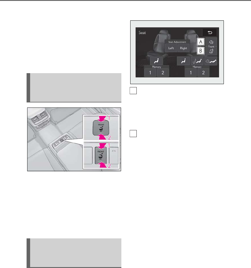
132 3-3. Adjusting the seats
LS500h_OM_OM50F42U_(U)
●The front passenger’s seat belt is fas-
tened.
●The front passenger’s door is open. (The
front seat will not move forward.)
■When the front passenger’s seat is
folded forward
By reclining the front passenger’s seat seat-
back, the forward view of the rear passen-
ger can be improved.
1Press and hold to move the front
passenger’s seat forward and fold
the seatback forward.
2Press and hold to move the front
passenger’s seat backward and
move the seatback to the upright
position.
■Automatic operation
1Display the home screen on the
Rear Multi Operation Panel
(→P.318) and then touch “Seat”.
2Touch the button for the desired
operation.
When the operating conditions are not
met, the buttons will be grayed out.
Move the front passenger’s seat
forward and fold the seatback for-
ward.
On vehicles with a foldable head restraint,
the head restraint will also fold forward.
Move the front passenger’s seat
backward and the seatback to the
upright position.
If the rear seat behind the front passenger’s
seat is not in the upright position, it will
move to the upright position before the
front passenger’s seat moves to its previous
position.
On vehicles with a foldable head restraint,
the head restraint will also move to the
upright position.
To stop the front passenger seat while it is
moving, touch “STOP”.
■Manual operation
1Display the home screen on the
Rear Multi Operation Panel
(→P.318) and then touch “Seat”.
2Touch “Right”
Operating the front passenger’s
seat from the rear seat (vehicles
without power rear seat)
Operating the front passenger’s
seat from the rear seat (vehicles
with power rear seat)
A
B
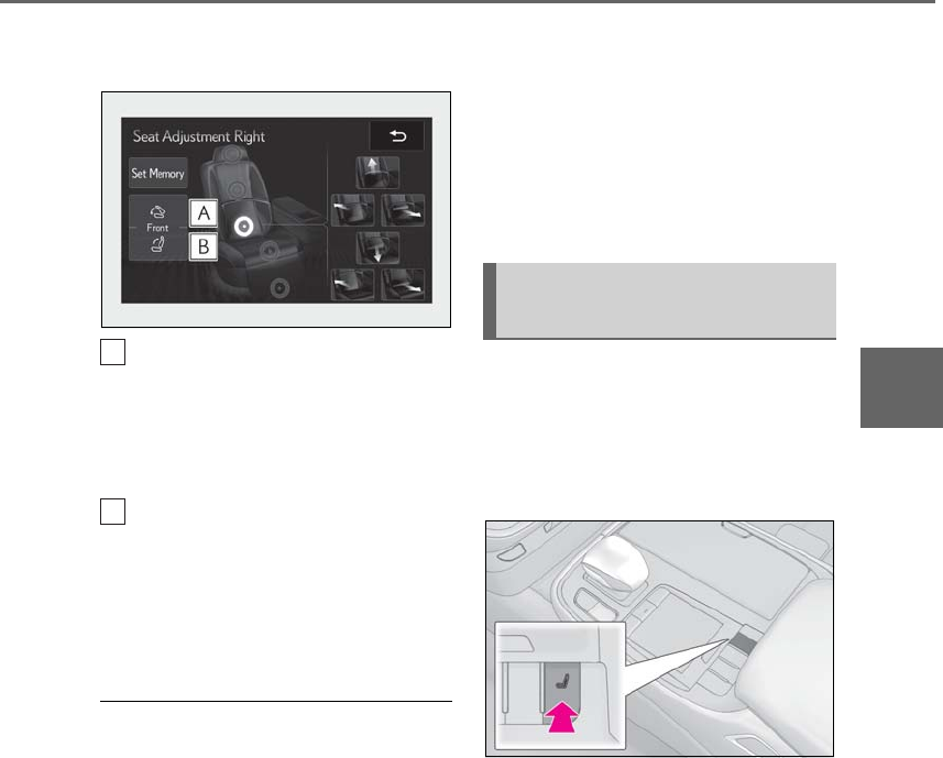
133
3-3. Adjusting the seats
LS500h_OM_OM50F42U_(U)
3
Before driving
3Touch the button for the desired
operation.
Touch and hold to move the front
passenger’s seat forward and fold
the seatback forward.
On vehicles with a foldable head restraint,
the head restraint will also fold forward.
Touch and hold to move the front
passenger’s seat backward and the
seatback to the upright position.
On vehicles with a foldable head restraint,
the head restraint will also move to the
upright position.
■Operating the front passenger’s seat
from the rear seat
In the following situations, the front passen-
ger’s seat cannot be operated using the
Rear Multi Operation Panel:
●The power switch is in ACCESSORY
mode or off.
●The rear seat belt is not fastened and
weight is not detected on the rear seat.
Once weight is detected on the seat, the
seat will be judged as occupied until the
rear door is opened then closed or the
power switch is turned off.
●The weight of an occupant or heavy
object, etc. is detected on the front pas-
senger’s seat.
Once weight is detected on the seat, the
seat will be judged as occupied until the
front passenger’s door is opened then
closed or the power switch is turned off.
●The front passenger’s seat belt is fas-
tened.
●The front passenger’s door is open. (The
front seat will not move forward.)
■When the front passenger’s seat is
folded forward
→P.132
Pneumatic chambers built into the
front seat apply pressure to the occu-
pant’s body at different modes and
intensities.
1Press the seat switch.
2Using the Remote Touch pad,
select “Driver Seat Refresh” or
“Passenger Seat Refresh”.
3Select the desired mode.
-“Centripetal”
Applies pressure sequentially from the
front of the seat cushion to top of the seat-
back
-“Centrifugal”
Applies pressure sequentially from the top
of the seatback to the front of the seat
cushion
-“Upper Body”
A
B
Front seat refresh system (if
equipped)

134 3-3. Adjusting the seats
LS500h_OM_OM50F42U_(U)
Applies pressure sequentially from the bot-
tom to the top of the seatback
-“Lower Body”
Applies pressure sequentially from the
front to the back of the seat cushion
-“Lumbar”
Applies pressure sequentially from the bot-
tom to the top of the lumbar area of the
seatback
4Select the desired intensity and
then confirm the setting.
The intensity can be adjusted in 5 steps.
To stop the operation select “Stop”.
If a seat is not occupied, do not operate the
front seat refresh system for that seat.
■Refresh system
●Operating conditions
• The power switch is in ON mode.
• The temperature in the cabin is not
extremely high.
• For the front passenger’s seat: The weight
of an occupant is detected on the front
passenger’s seat or the front passenger’s
seat belt is fastened.
Once weight is detected on the seat, the
seat will be judged as occupied until the
front passenger’s door is opened then
closed or the power switch is turned off.
●Automatic stop function
• The operation will be canceled automati-
cally after approximately 15 minutes.
•If the power easy access system begins
operating, the front seat refresh system
will stop.
WARNING
■Important points while driving
Do not adjust the driver’s seat refresh
system while driving.
Using it may affect your ability to control
the vehicle, possibly leading to an acci-
dent resulting in death or serious injury.
■Using the refresh system
●Those who are pregnant, have recently
given birth, or suffer from ailments
requiring rest (heart disease etc.)
should consult a doctor before use.
●Do not allow children to use the
refresh function.
●Do not use immediately after consum-
ing a meal or alcohol, or for an
extended period of time.
●If you feel sick while using the refresh
function, immediately discontinue use.
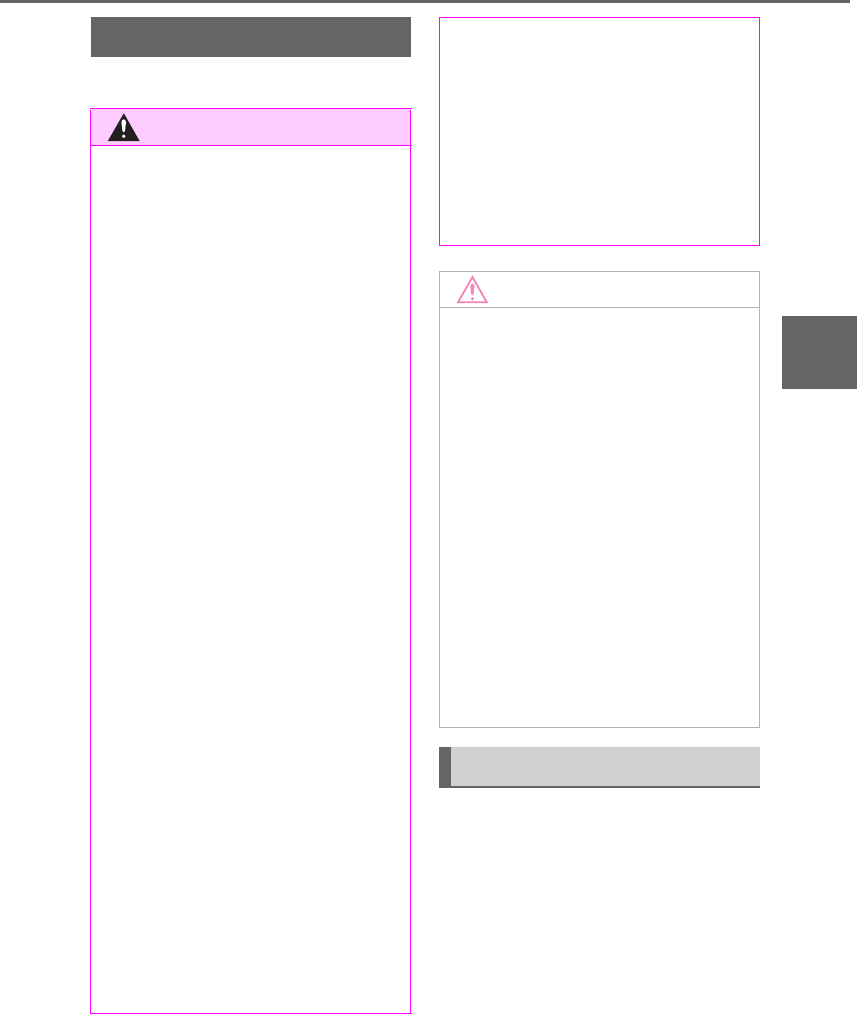
135
3-3. Adjusting the seats
LS500h_OM_OM50F42U_(U)
3
Before driving
*:If equipped
■Manual operation
1Display the home screen on the
Rear Multi Operation Panel
(→P.318) and then touch “Seat”.
2Touch “Left” or “Right”.
Power rear seat*
WARNING
■When adjusting the seat position
●Take care when adjusting the seat
position to ensure that other passen-
gers are not injured by the moving
seat.
●When adjusting the rear seat with an
ottoman, make sure there is sufficient
space so that a foot does not get
caught between the ottoman and front
passenger seat. (If equipped)
●Vehicle with rear seat entertainment
system: When the rear seat is moving
to the Entertainment Mode position,
do not allow hands near the rear dis-
play. Otherwise, a hand or finger may
be caught, possibly causing injury.
■Seat adjustment
To reduce the risk of sliding under the lap
belt during a collision, do not recline the
seat more than necessary.
If the seat is too reclined, the lap belt may
slide past the hips and apply restraint
forces directly to the abdomen, or your
neck may contact the shoulder belt,
increasing the risk of death or serious
injury in the event of an accident.
Adjustments should not be made while
driving as the seat may unexpectedly
move and cause the driver to lose control
of the vehicle.
■Using the ottoman (if equipped)
●Do not sit on the ottoman.
If someone sits on the ottoman, the seat
belt cannot be fitted properly, and they
may be thrown from the seat, resulting in
death or serious injury in the event of an
accident or sudden braking.
●When getting in or out of the vehicle,
retract the ottoman. If the ottoman is
not retracted, it may cause a fall, result-
ing in injury.
●Do not operate the ottoman when the
vehicle is moving.
●Do not allow anyone to put their hands
or feet under the rear seat when stow-
ing the ottoman.
NOTICE
■To prevent an ottoman malfunction (if
equipped)
●Do not place any objects in the rear
seat footwell that could prevent the
operation of the ottoman.
●Do not place heavy luggage on the
ottoman.
●Do not place any objects under the
ottoman while it is raised for use. These
objects may interfere with the ottoman
being folded, causing damage to the
ottoman or the objects themselves.
■To prevent a rear display malfunction
(if equipped)
Do not attempt to move the rear display
by hand, as doing so may damage the
rear display.
Adjustment procedure
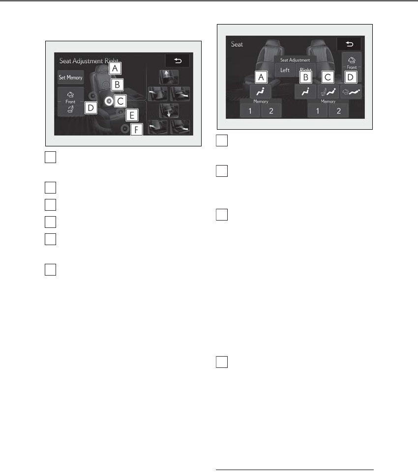
136 3-3. Adjusting the seats
LS500h_OM_OM50F42U_(U)
3Select the button for the desired
adjustment.
Head restraint adjustment
(→P.144)
Shoulder bolster adjustment
Lumbar/pelvic support adjustment
Seatback angle adjustment
Seat cushion (front) angle adjust-
ment
Ottoman adjustment (if equipped)
4Perform adjustment using the dis-
played buttons.
The seat will move while a button is
touched.
■Automatic operation
The seat can be moved to preset posi-
tions.
1Display the home screen on the
Rear Multi Operation Panel
(→P.318) and then touch “Seat”.
2Touch the desired preset button.
When the operating conditions are not
met, the preset buttons will be grayed out.
Moves the left-hand rear seat to the
upright position (Business Mode)
Moves the right-hand rear seat to
the upright position (Business
Mode)
Moves the rear seat with an otto-
man to a slightly reclined position
(Entertainment Mode) (if
equipped)
Vehicle without rear seat entertainment
system: Moves the front passenger’s seat
forward.
Vehicle with rear seat entertainment sys-
tem: Moves the front passenger’s seat and
rear display to allow the rear display to be
comfortably viewed.
Moves the rear seat with an otto-
man to a deeply reclined position
(Relaxation Mode) (if equipped)
Moves the front passenger’s seat forward
and folds the seatback and head restraint
forward.
To stop the front passenger seat while it is
moving, touch “STOP”.
■Adjustment of the rear seat
When a rear seat is close to a front seat, the
operation of the rear seat may be restricted.
■Operating conditions of Business Mode
When the rear seat belt is not fastened and
A
B
C
D
E
F
A
B
C
D

137
3-3. Adjusting the seats
LS500h_OM_OM50F42U_(U)
3
Before driving
weight is not detected on the rear seat,
Business Mode cannot be selected.
Once weight is detected on the seat, the
seat will be judged as occupied until the
rear door is opened then closed or the
power switch is turned off.
■The rear seat with an ottoman cannot be
moved to Entertainment Mode/Relax-
ation Mode when (if equipped)
In the following situations, Entertainment
Mode or Relaxation Mode cannot be
selected:
●The power switch is in ACCESSORY
mode or off.
●The rear seat belt is not fastened and
weight is not detected on the rear seat.
Once weight is detected on the seat, the
seat will be judged as occupied until the
rear door is opened then closed or the
power switch is turned off.
●The weight of an occupant or heavy
object, etc. is detected on the front pas-
senger’s seat.
Once weight is detected on the seat, the
seat will be judged as occupied until the
front passenger’s door is opened then
closed or the power switch is turned off.
●The front passenger’s seat belt is fas-
tened.
●The front passenger’s door is open.
■When the front passenger’s seat is
folded forward
→P.132
■Automatic angle adjustment of the rear
displays (if equipped)
When a seat is adjusted, the angle of the
rear display will be adjusted automatically
to maintain an optimal viewing angle for the
rear display from the rear seat.
■Operation after the power switch is
turned off
After a certain time elapses after the power
switch is turned off, the following parts of
the rear seats will move to their neutral
positions.
●Shoulder bolster
●Lumbar/pelvic support
■Seat return function linked to the door
opening operation
The rear seat will return to the upright posi-
tion automatically when the rear door is
opened for easier entry and exit of the vehi-
cle.
For the rear seat with an ottoman (if
equipped): When the rear door on the side
with the rear seat with an ottoman is
opened, the seatback of the rear seat with
an ottoman will move to a more upright
position. The seatback will move to the
upright position after the door is closed and
the system determines that the rear passen-
ger has exited.
However, if the armrest is stowed, the rear
seat will not move.
■Shift-linked rear seat reclining function
When the shift position is shifted from P, to
enhance rear visibility for the driver, the rear
seats will recline slightly.
However, the shift-linked rear seat reclining
function will not operate in the following sit-
uations:
●The weight of an occupant or heavy
object, etc. is detected on a rear seat.
Once weight is detected on the seat, the
seat will be judged as occupied until the
rear door is opened then closed or the
power switch is turned off.
●A rear seat belt is fastened.
●A rear door is open.
●The armrest is stowed.
When a front seat is close to a rear seat, the
rear seats may not operate or the range of
movement may be restricted.
■Pre-collision seatbacks for the passen-
ger seats
→P.210, 220
■Customization
Some functions can be customized.
(→P.481)
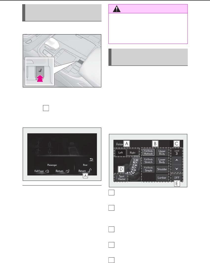
138 3-3. Adjusting the seats
LS500h_OM_OM50F42U_(U)
1Press the seat switch.
2Press the sub function button of the
Remote Touch. (→P.314)
3Select .
The rear seat will move to the upright posi-
tion.
■Operation of the rear seats from the
front seats
In the following situations, the rear seats
cannot be operated from the front seats.
●When the armrest is stowed and weight
of an occupant, heavy object, etc. is
detected on a rear seat
Once weight is detected on the seat, the
seat will be judged as occupied until the
rear door is opened then closed or the
power switch is turned off.
●When the armrest is stowed and a rear
seat belt is fastened.
The rear seat relaxation system utilizes
pneumatic chambers and dedicated
heaters, and applies pressure to the
occupant’s body at different modes
and intensities.
To display the rear seat relaxation sys-
tem screen, display the home screen
on the Rear Multi Operation Panel
(→P.318) and then touch “Relaxation”.
Touch to select the desired rear
seat.
Touch to select the desired mode.
When a button is touched, operation will
begin.
Touch to adjust the intensity.
The intensity can be adjusted in 5 steps.
Touch to turn the spot heaters
on/off.
Touch to stop the operation.
If a seat is not occupied, do not operate the
Returning the rear seat from the
front seats
A
WARNING
■When returning the rear seats to the
neutral position
To avoid injuring the rear passengers,
wait until they have gotten out of the
vehicle before operating the switch.
Rear seat relaxation system (if
equipped)
A
B
C
D
E

139
3-3. Adjusting the seats
LS500h_OM_OM50F42U_(U)
3
Before driving
rear seat relaxation system for that seat.
■Relaxation system
●Operating conditions
• The power switch is in ON mode.
• The temperature in the cabin is not
extremely high.
• The weight of an occupant is detected on
the rear seat or the rear seat belt is fas-
tened.
Once weight is detected on the seat, the
seat will be judged as occupied until the
rear door is opened then closed or the
power switch is turned off.
●Automatic stop function
• The operation will be canceled automati-
cally after approximately 15 minutes.
• If the door for a seat that the relaxation
system is currently being used is opened,
the relaxation system will stop operating.
The seat and steering wheel are auto-
matically adjusted to allow the driver to
enter and exit the vehicle easily.
Driver’s seat
When all of the following have been
performed, the seat and steering
wheel are automatically adjusted to a
position that allows driver to enter and
exit the vehicle easily.
• The shift position has been shifted to
P.
• The power switch has been turned
off.
• The driver’s seat belt has been
unfastened.
When the driver’s seat adjustment
switches are in front passenger mode
(→P.130), the seat and steering wheel will
not move.
WARNING
■Using the relaxation system
●Those who are pregnant, have recently
given birth, or suffer from ailments
requiring rest (heart disease etc.)
should consult a doctor before use.
●Do not allow children to use the relax-
ation function.
●Do not use immediately after consum-
ing a meal or alcohol, or for an
extended period of time.
●If you feel sick while using the relax-
ation function, immediately discon-
tinue use.
Driving position memory
This feature automatically adjusts
the positions of the front seats,
steering wheel, outside rear view
mirrors and head-up display (if
equipped) to make entering and
exiting the vehicle easier or to suit
your preferences.
Up to 3 different driving positions
can be recorded.
Each electronic key (including a
card key) can be registered to
recall your preferred driving posi-
tion.
Power easy access system
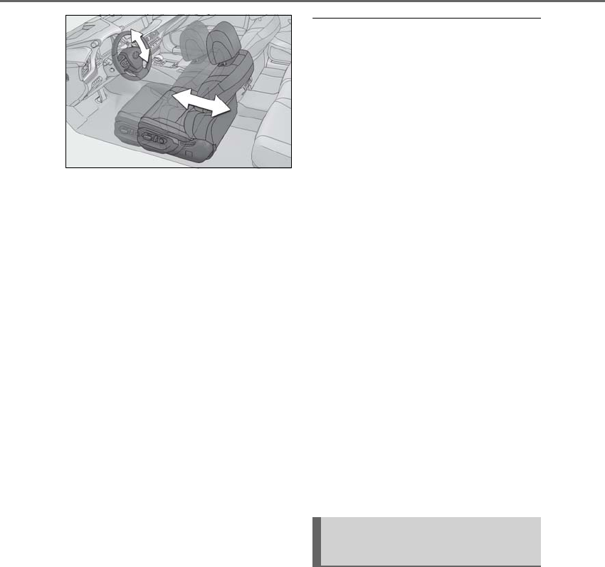
140 3-3. Adjusting the seats
LS500h_OM_OM50F42U_(U)
On vehicles with adjustable seat cush-
ion side bolsters, when the driver’s
door is opened with the power switch
off, the seat cushion side bolsters will
lower if they are in the default position.
When any of the following has been
performed, the seat and steering
wheel automatically return to their
original positions.
• The power switch has been turned
to ACCESSORY mode or ON
mode.
• The driver’s seat belt has been fas-
tened.
Front passenger’s seat
If all of the following have been per-
formed while the vehicle is stopped,
the lumbar support, pelvic support,
shoulder bolster (if equipped), seat-
back side bolster (if equipped), and hip
support (if equipped) will be moved to
their default position. On vehicles with
adjustable seat cushion side bolsters,
the seat cushion side bolsters will
lower.
• The passenger’s seat belt has been
unfastened.
• The front passenger’s door is
opened.
■Operation of the power easy access sys-
tem
●When exiting the vehicle, the power easy
access system may not operate if the seat
is already in the rearmost or uppermost
position or close to the rear seat.
●If the seat position is adjusted during
power easy access system operation, the
automatic operation will stop. (The seat
will change to manual operation.)
●If the seat position is adjusted during or
after the power easy access system oper-
ation when the driver is exiting the vehi-
cle, the power easy access system will not
operate when entering the vehicle.
■Seat cushion side bolster adjustment (if
equipped)
If the seat cushion side bolsters have been
lowered, when the front door is closed, the
seat cushion side bolsters will move to their
default position.
If the seat is adjusted while the seat cushion
side bolsters are moving to the default posi-
tion, their movement will be temporarily
suspended. (The seat cushion side bolsters
will move to the default position after a cer-
tain amount of time.)
■Customization
Some functions can be customized.
(→P.481)
1Turn the power switch to ON
mode.
2Check that the shift position is in P.
3Adjust the driver’s seat, steering
wheel, outside rear view mirrors
and head-up display (if equipped)
to the desired positions.
4While pressing the “SET” button, or
within 3 seconds after the “SET”
Recording a driving position into
memory
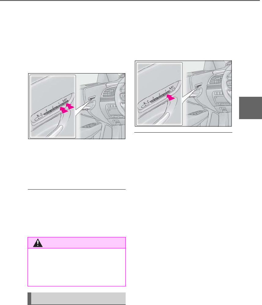
141
3-3. Adjusting the seats
LS500h_OM_OM50F42U_(U)
3
Before driving
button is pressed, press button “1”,
“2” or “3” until the buzzer sounds.
If the selected button has already been
preset, the previously recorded position
will be overwritten.
When the driver’s seat adjustment
switches are in front passenger mode
(→P.130), the position of the driver’s seat
cannot be registered.
To record the position of the front pas-
senger’s seat, adjust the front passen-
ger’s seat to the desired position and
perform step 4 using the buttons on
the front passenger’s side.
■In order to correctly use the driving
position memory function
If a seat position is already in the furthest
possible position and the seat is operated in
the same direction, the recorded position
may be slightly different when it is recalled.
1Turn the power switch to ON
mode.
2Check that the shift position is in P.
3Press one of the buttons for the
driving position you want to recall
until the buzzer sounds.
When the driver’s seat adjustment
switches are in front passenger mode
(→P.130), a driving position cannot be
recalled.
■To stop the position recall operation
part-way through
Perform any of the following operations:
●Press the “SET” button.
●Press button “1”, “2” or “3”.
●Press the mode change button.
●Operate any of the seat adjustment
switches (only cancels seat position
recall).
●Operate the tilt and telescopic steering
control switch (only cancels steering
wheel position recall).
■Recalling a driving position
If a driving position is recalled, the move-
ment of the front seat may be stopped part-
way if the seat moves close to the rear seat.
If a rear passenger is determined to be in
the vehicle, the rearward movement of the
front seat may be stopped partway to
ensure sufficient space for the rear passen-
ger.
■Recalling the front passenger’s seat
position (vehicles with a rear seat with
an ottoman)
If the ottoman of the rear seat is extended,
the front passenger’s seat position cannot
be recalled.
WARNING
■Seat adjustment caution
Take care during seat adjustment so that
the seat does not strike the rear passen-
ger or squeeze your body against the
steering wheel.
Recalling a driving position
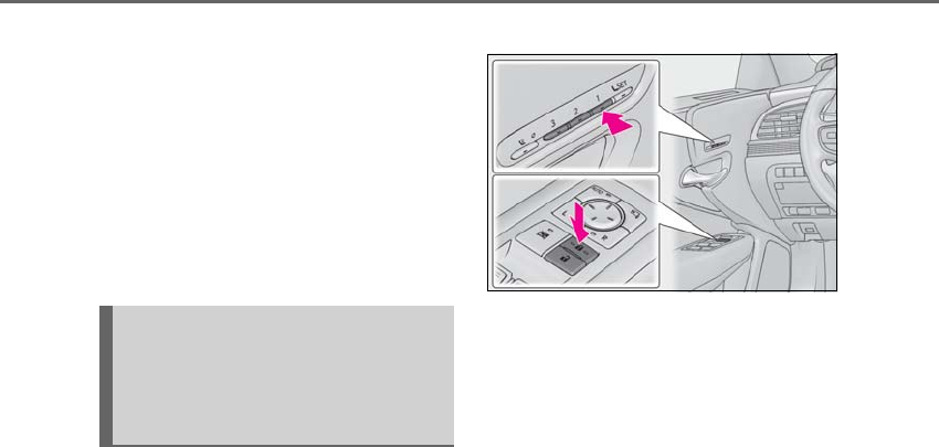
142 3-3. Adjusting the seats
LS500h_OM_OM50F42U_(U)
■Operating the driving position memory
after turning the power switch off
Driver’s seat:
Recorded seat positions can be activated
up to 180 seconds after the driver’s door is
opened and another 60 seconds after it is
closed again.
Front passenger’s seat:
Recorded seat positions can be recalled up
to 180 seconds after the front passenger’s
door is opened.
■Registering procedure
Record your driving position to button
“1”, “2” or “3” before performing the
following:
Carry only the key you want to register,
and then close the driver’s door.
If 2 or more keys are in the vehicle, the
driving position cannot be recorded
properly.
1Turn the power switch to ON
mode.
2Check that the shift position is in P.
3Recall the driving position that you
want to record.
4While pressing the recalled button,
press and hold the door lock switch
(either lock or unlock) until the
buzzer sounds.
If the button could not be registered, the
buzzer sounds continuously for approxi-
mately 3 seconds.
■Cancelation procedure
Carry only the key you want to cancel
and then close the driver’s door.
If 2 or more keys are in the vehicle, the
driving position cannot be canceled
properly.
1Turn the power switch to ON
mode.
2Check that the shift position is in P.
3While pressing the “SET” button,
press and hold the door lock switch
(either lock or unlock) until the
buzzer sounds twice.
If the button could not be canceled, the
buzzer sounds continuously for approxi-
mately 3 seconds.
■Recall procedure
1Make sure that the doors are
locked before recalling the driving
position. Carry the electronic key
that has been registered to the driv-
ing position, and then unlock and
open the driver’s door using the
smart access system with push-but-
ton start or wireless remote control.
The driving position will move to the
recorded position (not including the steer-
ing wheel and head-up display [if
equipped]). However, the seat will move to
a position slightly behind the recorded
position in order to make entering the vehi-
Registering/canceling/recall a
driving position to an electronic
key (including a card key) (mem-
ory recall function)

143
3-3. Adjusting the seats
LS500h_OM_OM50F42U_(U)
3
Before driving
cle easier.
If the driving position is in a position that
has already been recorded, the seat and
outside rear view mirrors will not move.
2Turn the power switch to ACCES-
SORY mode or ON mode, or fas-
ten a seat belt.
The seat, steering wheel and head-up dis-
play (if equipped) will move to the
recorded position.
■Recalling the driving position using the
memory recall function
●Different driving positions can be regis-
tered for each electronic key. Therefore,
the driving position that is recalled may
be different depending on the key being
carried.
●If a door other than the driver’s door is
unlocked with the smart access system
with push-button start, the driving posi-
tion cannot be recalled. In this case, press
the driving position button which has
been set.
■Customization
Some functions can be customized.
(→P.481)
*: If equipped
1Turn the power switch to ON
mode.
2Display the home screen on the
Rear Multi Operation Panel
(→P.318) and then touch “Seat”.
3Touch “Left” or “Right”.
4Adjust the rear seat to the desired
position and then touch “Set Mem-
ory”.
5Touch “1” or “2”.
If the preset is being used, the previously
recorded seat position will be overwritten.
■In order to correctly use the position
memory function
If a seat position is already in the furthest
possible position and the seat is operated in
the same direction, the recorded position
may be slightly different when it is recalled.
Rear seat position memory*
The rear seat position can be mem-
orized and recalled with the touch
of a button.
Recording a position into mem-
ory
WARNING
■Seat adjustment caution
Take care during seat adjustment so that
the rear passengers do not strike the
front seats.
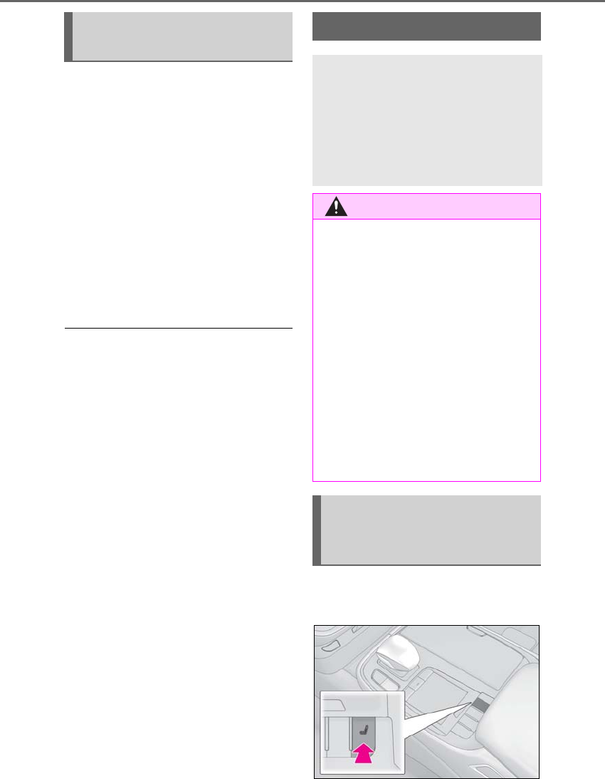
144 3-3. Adjusting the seats
LS500h_OM_OM50F42U_(U)
1Turn the power switch to ON
mode.
2Display the home screen on the
Rear Multi Operation Panel
(→P.318) and then touch “Seat”.
3Touch “1” or “2”.
When the operating conditions are not
met, the buttons will be grayed out.
To stop the operation touch “STOP”.
If the seat is adjusted while a memorized
position is being recalled, the automatic
operation will stop. (The seat will change to
manual operation.)
■Operating condition
The weight of an occupant is detected on
the rear seat or the rear seat belt is fas-
tened.
Once weight is detected on the seat, the
seat will be judged as occupied until the
rear door is opened then closed or the
power switch is turned off.
■Recalling a rear seat position
If a memorized rear seat position is recalled,
the seat may stop part-way to ensure suffi-
cient space for the rear passenger.
■Recalling the ottoman position (if
equipped)
When a seat position is recalled, the otto-
man will not raise or extend. The ottoman
position can only be recalled if the memo-
rized position is lower and shorter than the
current position.
Front seats
1Press the seat switch.
Recalling the memorized posi-
tion
Head restraints
Head restraints are provided for all
seats.
Vehicles with power rear seat: The
head restraint for the rear center
seat is integrated into the seatback
and cannot be adjusted.
WARNING
■Head restraint precautions
Observe the following precautions
regarding the head restraints. Failure to
do so may result in death or serious
injury.
●Use the head restraints designed for
each respective seat.
●Adjust the head restraints to the cor-
rect position at all times.
●Manual type: After adjusting the head
restraints, push down on them and
make sure they are locked in position.
●Do not drive with the head restraints
removed.
Adjusting a head restraint verti-
cally and horizontally (power
head restraints)
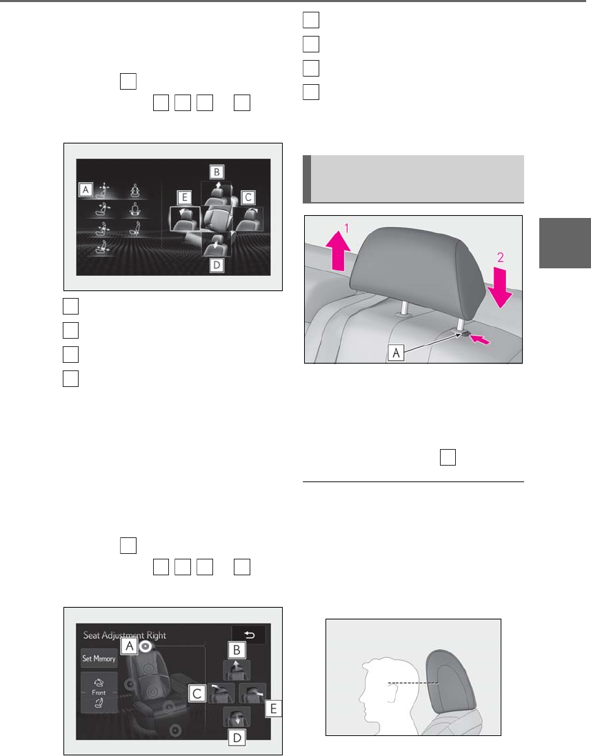
145
3-3. Adjusting the seats
LS500h_OM_OM50F42U_(U)
3
Before driving
2Using the Remote Touch pad,
select “Driver Seat Adjustment” or
“Passenger Seat Adjustment”.
3Select then the desired adjust-
ment button , , , or to
adjust the head restraint.
Up
Backward
Down
Forward
The head restraint moves while the adjust-
ment button is selected.
Rear seats
1Display the home screen on the
Rear Multi Operation Panel
(→P.318) and then touch “Seat”.
2Touch “Left” or “Right”.
3Touch then the desired adjust-
ment button , , , or to
adjust the head restraint.
Up
Backward
Down
Forward
The head restraint moves while the adjust-
ment button is touched.
1Up
Pull the head restraints up.
2Down
Push the head restraint down while press-
ing the lock release button .
■Front seat head restraints (power head
restraints)
Depending on the position of the front seat,
the front head restraint may not be able to
be adjusted upward if it is close to the ceil-
ing.
■Adjusting the height of the head
restraints
Make sure that the head restraints are
A
B
C
D
E
B
C
D
E
A
B
C
D
E
Adjusting a head restraint verti-
cally (manual head restraints)
B
C
D
E
A
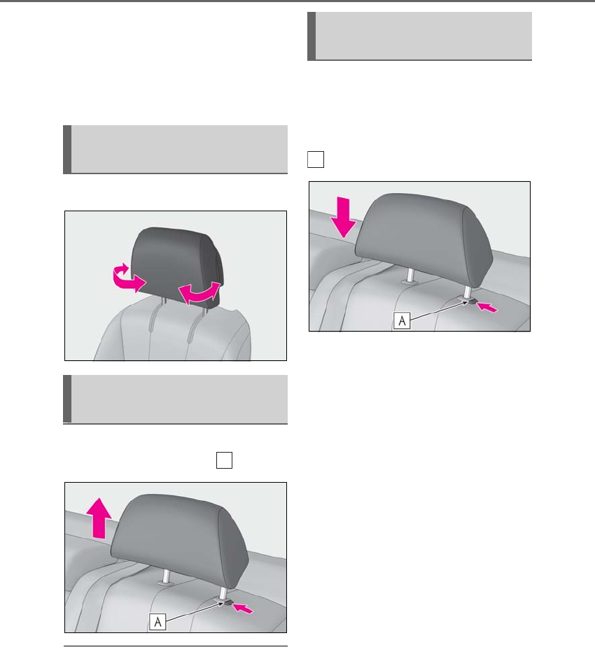
146 3-3. Adjusting the seats
LS500h_OM_OM50F42U_(U)
adjusted so that the center of the head
restraint is closest to the top of your ears.
■Adjusting the rear seat head restraints
(manual head restraints)
Always raise the head restraint one level
from the stowed position when using.
Push the sides of the head restraint.
Pull the head restraint up while press-
ing the lock release button .
■Removing the head restraints (power
head restraints)
For removal and installation of the head
restraint, contact your Lexus dealer.
Align the head restraint with the instal-
lation holes and push it down to the
lock position.
Press and hold the lock release button
when lowering the head restraint.
Adjusting the side supports (if
equipped)
Removing the head restraints
(manual head restraints)
A
Installing the head restraints
(manual head restraints)
A
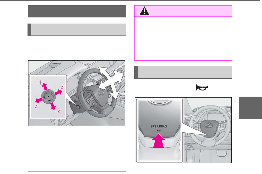
147
3-4. Adjusting the steering wheel and mirrors
LS500h_OM_OM50F42U_(U)
3
Before driving
3-4.Adjusting th e steering wheel and mi rrors
Operating the switch moves the steer-
ing wheel in the following directions:
1Up
2Down
3Toward the driver
4Away from the driver
■The steering wheel can be adjusted
when
The power switch is in ACCESSORY or
ON mode*.
*: If the driver’s seat belt is fastened, the
steering wheel can be adjusted regard-
less of power switch mode.
■Automatic adjustment of the steering
position
A desired steering position can be entered
to memory and recalled automatically by
the driving position memory system.
(→P.139)
■Power easy access system
The steering wheel and driver’s seat move
in accordance with power switch mode and
the driver’s seat belt condition. (→P.139)
■Customization
Some functions can be customized.
(→P.481)
Press on or close to the mark.
Steering wheel
Adjustment procedure
WARNING
■Caution while driving
Do not adjust the steering wheel while
driving.
Doing so may cause the driver to mis-
handle the vehicle and cause an acci-
dent, resulting in death or serious injury.
Sounding the horn
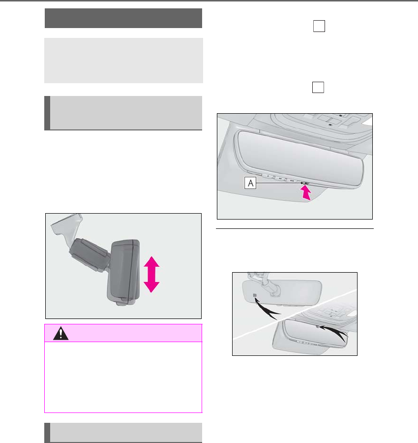
148 3-4. Adjusting the steering wheel and mirrors
LS500h_OM_OM50F42U_(U)
The height of the rear view mirror can
be adjusted to suit your driving pos-
ture.
Adjust the height of the rear view mir-
ror by moving it up and down.
Responding to the level of brightness
of the headlights of vehicles behind, the
reflected light is automatically
reduced.
Turn the automatic anti-glare function
mode on/off
When the automatic anti-glare function is
in ON mode, the indicator illuminates.
The function will set to ON mode each
time the power switch is turned to ON
mode.
Pressing the button turns the function to
OFF mode. (The indicator also turns
off.)
■To prevent sensor error
To ensure that the sensors operate properly,
do not touch or cover them.
Inside rear view mirror
The rear view mirror’s position can
be adjusted to enable sufficient
confirmation of the rear view.
Adjusting the height of rear view
mirror
WARNING
■Caution while driving
Do not adjust the position of the mirror
while driving.
Doing so may lead to mishandling of the
vehicle and cause an accident, resulting
in death or serious injury.
Anti-glare function
A
A
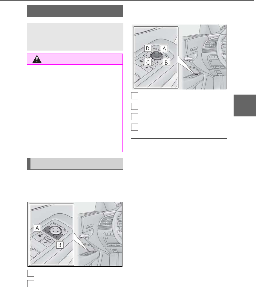
149
3-4. Adjusting the steering wheel and mirrors
LS500h_OM_OM50F42U_(U)
3
Before driving
1To select a mirror to adjust, press
the switch.
The indicator comes on.
Left
Right
Pressing the same switch again will put the
switch in neutral.
2To adjust the mirror, press the
switch.
Up
Right
Down
Left
■Mirror angle can be adjusted when
The power switch is in ACCESSORY or
ON mode.
■Defogging the mirrors
The outside rear view mirrors can be
cleared using the mirror defoggers. Turn on
the rear window defogger to turn on the
outside rear view mirror defoggers.
(→P.324)
■Auto anti-glare function
When the anti-glare inside rear view mirror
is set to automatic mode, the outside rear
view mirrors will activate in conjunction with
the anti-glare inside rear view mirror to
reduce reflected light. (→P.148)
■Automatic adjustment of the mirror
angle
A desired mirror face angle can be entered
to memory and recalled automatically by
the driving position memory. (→P.139)
■Linked mirror function when reversing
When either “L” or “R” of the mirror select
switch is selected, the outside rear view mir-
rors will automatically angle downwards
when the vehicle is reversing in order to
give a better view of the ground.
To disable this function, select neither “L”
Outside rear view mirrors
The rear view mirror’s position can
be adjusted to enable sufficient
confirmation of the rear view.
WARNING
■Important points while driving
Observe the following precautions while
driving.
Failure to do so may result in loss of con-
trol of the vehicle and cause an accident,
resulting in death or serious injury.
●Do not adjust the mirrors while driving.
●Do not drive with the mirrors folded.
●Both the driver and passenger side
mirrors must be extended and prop-
erly adjusted before driving.
Adjustment procedure
A
B
A
B
C
D
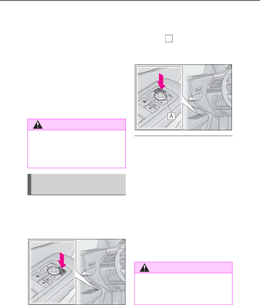
150 3-4. Adjusting the steering wheel and mirrors
LS500h_OM_OM50F42U_(U)
nor “R”.
To set the mirror angle used when the vehi-
cle is reversing, adjust the mirror angle at a
desired position with the shift position in R.
The adjusted angle will be memorized and
the mirror will automatically tilt to the mem-
orized angle whenever the shift position is
shifted to R from next time.
The memorized downward tilt position of
the mirror is linked to the normal position
(angle adjusted with the shift position in
other than R). Therefore, if the normal posi-
tion is changed after adjustment, the tilt
position will also change.
When the normal position is changed, read-
just the angle in reversing.
■Using the switch
Press the switch to fold the mirrors.
Press it again to extend them to the original
position.
■Setting automatic mode
Automatic mode allows the folding or
extending of the mirrors to be linked to
locking/unlocking of the doors.
Press the “AUTO” switch to set auto-
matic mode.
The indicator will come on.
Pressing the switch once more will return
to manual mode.
■When disconnecting and reconnecting
12-volt battery terminals
The automatic folding/extending mirror
function will return to off as default. To turn
the function on, press the switch again to
select on.
■Using automatic mode in cold weather
When automatic mode is used in cold
weather, the door mirror could freeze up
and automatic stowing and return may not
be possible. In this case, remove any ice and
snow from the door mirror, then either
operate the mirror using manual mode or
move the mirror by hand.
■Customization
Some functions can be customized.
(→P.481)
WARNING
■When the mirror defoggers are oper-
ating
Do not touch the rear view mirror sur-
faces, as they can become very hot and
burn you.
Folding and extending the mir-
rors
WARNING
■When a mirror is moving
To avoid personal injury and mirror mal-
function, be careful not to get your hand
caught by the moving mirror.
A
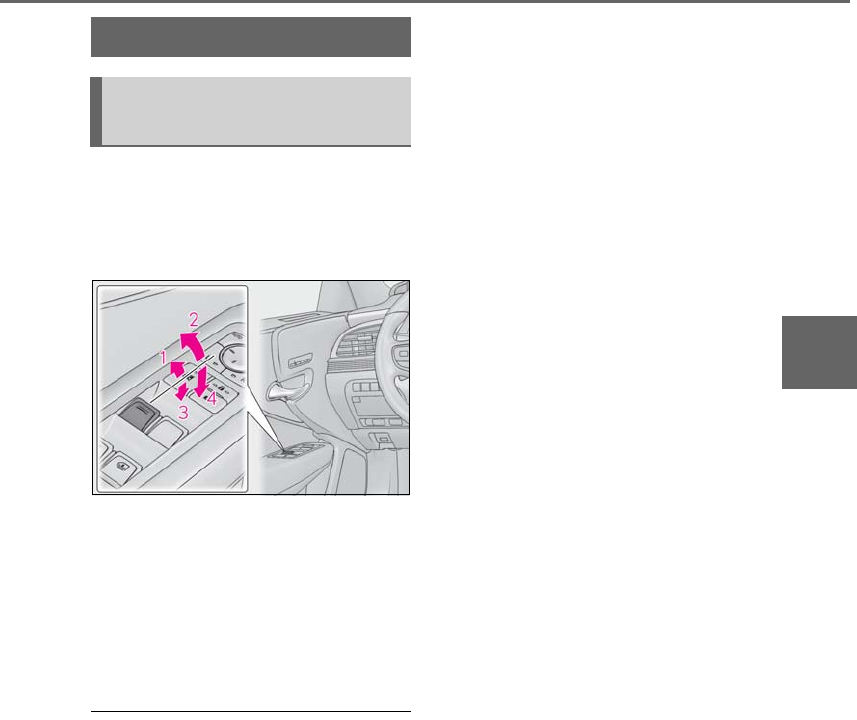
151
3-5. Opening, closing the windows and moon roof
LS500h_OM_OM50F42U_(U)
3
Before driving
3-5.Opening, clo sing the windows and m oon roof
The power windows can be opened
and closed using the switches.
Operating the switch moves the win-
dows as follows:
1Closing
2One-touch closing*
3Opening
4One-touch opening*
*: To stop the window partway, operate the
switch in the opposite direction.
■The power windows can be operated
when
The power switch is in ON mode.
■When the driver’s power window switch
is used to open a rear power window
(vehicles with rear door sunshades)
If a rear door sunshade is extended or being
extended when the driver’s power window
switch is pushed, only the rear door sun-
shade will be retracted. To open the rear
power window from the driver’s seat, push
the driver’s power window switch again.
■Operating the power windows after
turning the hybrid system off
The power windows can be operated for
approximately 45 seconds even after the
power switch is turned to ACCESSORY
mode or turned off. They cannot, however,
be operated once either front door is
opened.
■Jam protection function
If an object becomes jammed between the
window and the window frame while the
window is closing, window movement is
stopped and the window is opened slightly.
■Catch protection function
If an object becomes caught between the
door and window while the window is open-
ing, window movement is stopped.
■When the side window cannot be
opened or closed
When the jam protection function or catch
protection function operates unusually and
the side window cannot be opened or
closed, perform the following operations
with the power window switch of that door.
●Stop the vehicle. With the power switch in
ON mode, within 4 seconds of the jam
protection function or catch protection
function activating, continuously operate
the power window switch in the
one-touch closing direction or one-touch
opening direction so that the side window
can be opened and closed.
●If the side window cannot be opened and
closed even when performing the above
operations, perform the following proce-
dure for function initialization.
1Turn the power switch to ON mode.
2Pull and hold the power window switch
in the one-touch closing direction and
completely close the side window.
3Release the power window switch for a
moment, resume pulling the switch in
the one-touch closing direction, and
hold it there for approximately 6 sec-
onds or more.
4Press and hold the power window
switch in the one-touch opening direc-
tion. After the side window is com-
pletely opened, continue holding the
switch for an additional 1 second or
more.
5Release the power window switch for a
moment, resume pushing the switch in
the one-touch opening direction, and
Power windows
Opening and closing the power
windows
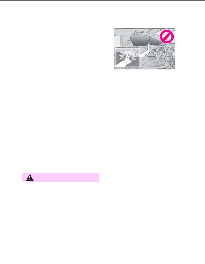
152 3-5. Opening, closing the windows and moon roof
LS500h_OM_OM50F42U_(U)
hold it there for approximately 4 sec-
onds or more.
6Pull and hold the power window switch
in the one-touch closing direction
again. After the side window is com-
pletely closed, continue holding the
switch for a further 1 second or more.
If you release the switch while the window is
moving, start again from the beginning.
If the window reverses and cannot be fully
closed or opened, have the vehicle
inspected by your Lexus dealer.
■Door lock linked window operation
●The power windows can be opened and
closed using the mechanical key.*
(→P.446)
●The power windows can be opened using
the wireless remote control.* (→P.108)
*: These settings must be customized at
your Lexus dealer.
■Power windows open warning buzzer
A buzzer sounds and a message is shown
on the multi-information display in the
instrument cluster when the power switch is
turned off and the driver’s door is opened
with the power windows open.
■Customization
Some functions can be customized.
(→P.481)
WARNING
Observe the following precautions.
Failure to do so may result in death or
serious injury.
■Closing the windows
●The driver is responsible for all the
power window operations, including
the operation for the passengers. In
order to prevent accidental operation,
especially by a child, do not let a child
operate the power windows. It is possi-
ble for children and other passengers
to have body parts caught in the power
window. Also, when riding with a child,
it is recommended to use the window
lock switch. (→P.153)
●Check to make sure that all passen-
gers do not have any part of their body
in a position where it could be caught
when a window is being operated.
●When using the wireless remote con-
trol or mechanical key and operating
the power windows, operate the
power window after checking to make
sure that there is no possibility of any
passenger having any of their body
parts caught in the window. Also do
not let a child operate window by the
wireless remote control or mechanical
key. It is possible for children and other
passengers to get caught in the power
window.
●When exiting the vehicle, turn the
power switch off, carry the key and exit
the vehicle along with the child. There
may be accidental operation, due to
mischief, etc., that may possibly lead to
an accident.
■Jam protection function
●Never use any part of your body to
intentionally activate the jam protec-
tion function.
●The jam protection function may not
work if something gets jammed just
before the window is fully closed. Be
careful not to get any part of your body
jammed in the window.
■Catch protection function
●Never use any part of your body or
clothing to intentionally activate the
catch protection function.
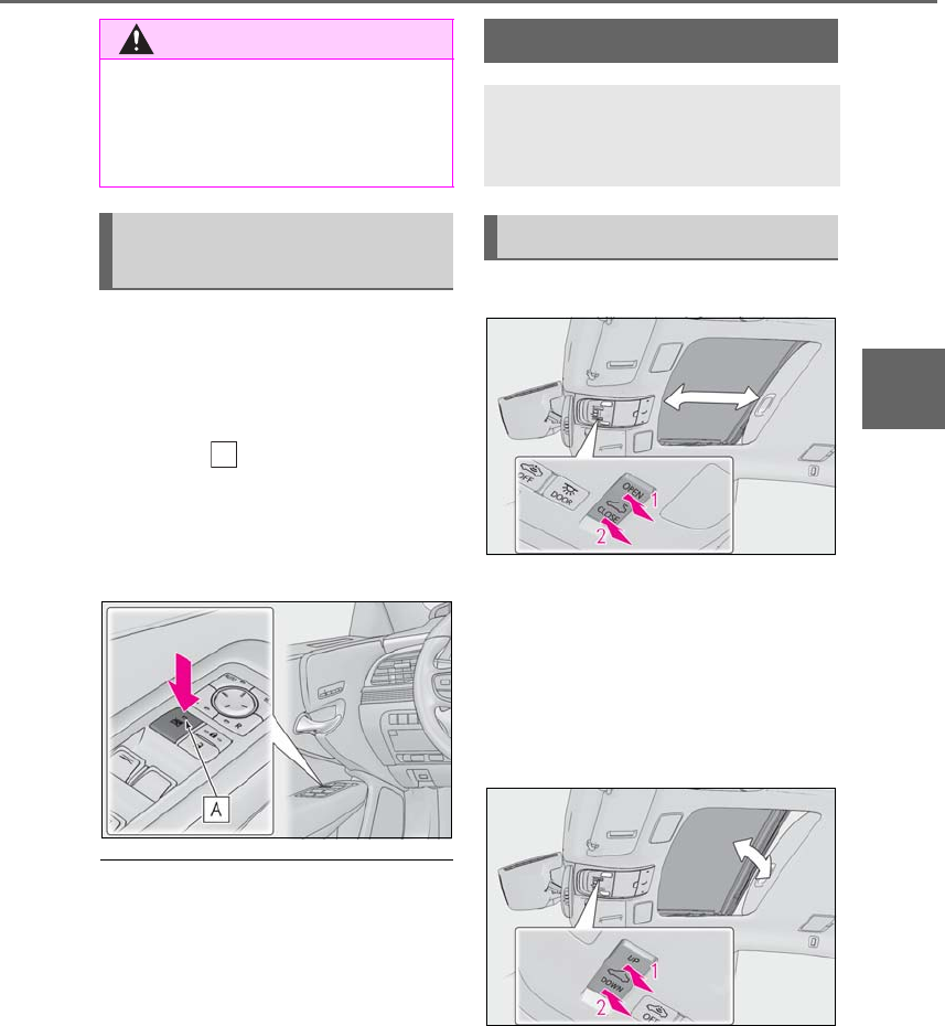
153
3-5. Opening, closing the windows and moon roof
LS500h_OM_OM50F42U_(U)
3
Before driving
This function can be used to prevent
children from accidentally opening or
closing a passenger window.
Press the switch.
The indicator will come on and the pas-
senger windows will be locked.
The passenger windows can still be
opened and closed using the driver’s
switch even if the lock switch is on.
■The power windows can be operated
when
The power switch is in ON mode.
■When the 12-volt battery is discon-
nected
The window lock switch is disabled. If nec-
essary, press the window lock switch after
reconnecting the 12-volt battery.
■Opening and closing
1Opens the moon roof*
The moon roof tilts up and then fully opens.
2Closes the moon roof*
*: Lightly press either side of the moon roof
switch to stop the moon roof partway.
■Tilting up and down
1Tilts the moon roof up*
2Tilts the moon roof down*
*: Lightly press either side of the moon roof
switch to stop the moon roof partway.
WARNING
●The catch protection function may not
work if something gets caught just
before the window is fully opened. Be
careful not to get any part of your body
or closing caught in the window.
Preventing accidental operation
(window lock switch)
A
Moon roof
Use the overhead switches to open
and close the moon roof and tilt it
up and down.
Operating the moon roof

154 3-5. Opening, closing the windows and moon roof
LS500h_OM_OM50F42U_(U)
■The moon roof can be operated when
The power switch is in ON mode.
■Operating the moon roof after turning
the hybrid system off
The moon roof can be operated for approx-
imately 45 seconds after the power switch
is turned to ACCESSORY mode or turned
off. It cannot, however, be operated once
either front door is opened.
■Jam protection function
If an object is detected between the moon
roof and the frame while the moon roof is
closing or tilting down, travel is stopped and
the moon roof opens slightly.
■Sunshade
The sunshade can be opened and closed
manually. However, the sunshade will open
automatically when the moon roof is
opened.
■Door lock linked moon roof operation
●The moon roof can be opened and
closed using the mechanical key.*
(→P.446)
●The moon roof can be opened using the
wireless remote control.* (→P.108)
*: These settings must be customized at
your Lexus dealer.
■When the moon roof does not close nor-
mally
Perform the following procedure:
1Stop the vehicle.
2Press and hold the “CLOSE” switch.*
The moon roof will close, reopen and pause
for approximately 10 seconds. Then it will
close again and stop at the completely
closed position.
3Check to make sure that the moon roof
is completely closed and then release
the switch.
*: If the switch is released at the incorrect
time, the procedure will have to be per-
formed again from the beginning.
If the moon roof does not fully close even
after performing the above procedure cor-
rectly, have the vehicle inspected by your
Lexus dealer.
■If the moon roof does not move normally
If the moon roof does not open or close
normally or the automatic opening function
does not operate, perform the following ini-
tialization procedure.
1Stop the vehicle.
2Press and hold the “DOWN” switch.*
The moon roof will stop at the tilt-up posi-
tion. After that, it will open, close, tilt up, tilt
down, and stop at the fully closed position.
3Confirm that the moon roof has com-
pletely stopped and release the switch.
*:If you release the switch while the moon
roof is moving, perform the procedure
again from the beginning.
If, after performing the above procedures
correctly, the moon roof still does not open
or close normally or the automatic opening
function does not operate, have the vehicle
inspected by your Lexus dealer.
■Moon roof open warning buzzer
A buzzer sounds and a message is shown
on the multi-information display in the
instrument cluster when the power switch is
turned off and the driver’s door is opened
with the moon roof open.
■Customization
Some functions can be customized.
(→P.481)
WARNING
Observe the following precautions.
Failure to do so may cause death or seri-
ous injury.
■Opening the moon roof
●Do not allow any passengers to put
their hands or heads outside the vehi-
cle while it is moving.
●Do not sit on top of the moon roof.
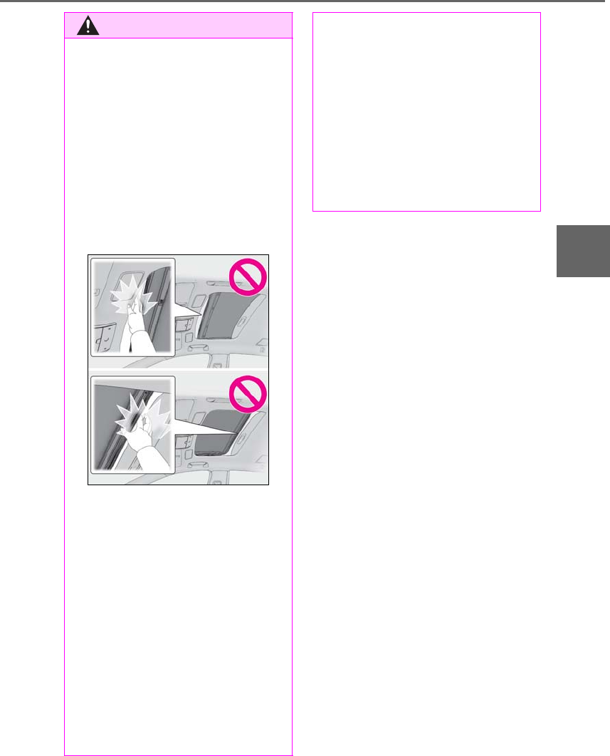
155
3-5. Opening, closing the windows and moon roof
LS500h_OM_OM50F42U_(U)
3
Before driving
WARNING
■Opening and closing the moon roof
●The driver is responsible for moon roof
opening and closing operations.
In order to prevent accidental opera-
tion, especially by a child, do not let a
child operate the moon roof. It is possi-
ble for children and other passengers
to have body parts caught in the moon
roof.
●Check to make sure that all passen-
gers do not have any part of their body
in a position where it could be caught
when the moon roof is being operated.
●When using the wireless remote con-
trol or mechanical key and operating
the moon roof, operate the moon roof
after checking to make sure that there
is no possibility of any passenger hav-
ing any of their body parts caught in
the moon roof. Also, do not let a child
operate moon roof by the wireless
remote control or mechanical key. It is
possible for children and other passen-
gers to get caught in the moon roof.
●When exiting the vehicle, turn the
power switch off, carry the key and exit
the vehicle along with the child. There
may be accidental operation, due to
mischief, etc., that may possibly lead to
an accident.
■Jam protection function
●Never use any part of your body to
intentionally activate the jam protec-
tion function.
●The jam protection function may not
work if something gets caught just
before the moon roof is fully closed.
Also, the jam protection function is not
designed to operate while the moon
roof switch is being pressed. Take care
so that your fingers, etc. do not get
caught.

156 3-5. Opening, closing the windows and moon roof
LS500h_OM_OM50F42U_(U)

157
LS500h_OM_OM50F42U_(U)
4
4
Driving
Driving
.
4-1. Before driving
Driving the vehicle.....................158
Cargo and luggage...................164
Vehicle load limits......................166
Trailer towing...............................166
Dinghy towing .............................167
4-2. Driving procedures
Power (ignition) switch............168
EV drive mode ............................ 172
Hybrid transmission..................174
Turn signal lever..........................180
Parking brake ...............................181
Brake Hold....................................183
4-3. Operating the lights and wipers
Headlight switch.........................185
AHB (Automatic High Beam)
.........................................................188
Windshield wipers and washer
.........................................................190
4-4. Refueling
Opening the fuel tank cap......194
4-5. Using the driving support sys-
tems
Lexus Safety System+A...........196
Lexus Safety System+ .............203
PCS (Pre-Collision System) (vehi-
cles with Lexus Safety Sys-
tem+A) .......................................209
PCS (Pre-Collision System) (vehi-
cles with Lexus Safety System+)
........................................................220
FCTA (Front Cross Traffic Alert)
........................................................227
LTA (Lane Tracing Assist) ....230
LKA (Lane-Keeping Assist)
.......................................................240
RSA (Road Sign Assist).......... 247
Dynamic radar cruise control with
full-speed range......................250
BSM (Blind Spot Monitor)....260
PKSA (Parking Support Alert)
....................................................... 265
Intuitive parking assist............. 266
RCTA (Rear Cross Traffic Alert)
function....................................... 273
RCD (Rear Camera Detection)
function....................................... 277
PKSB (Parking Support Brake)
.......................................................280
Parking Support Brake function
(static objects).........................286
Parking Support Brake function
(rear-crossing vehicles)....... 291
Parking Support Brake function
(rear pedestrians).................. 295
Driving mode select switch ..298
Electronically modulated air sus-
pension....................................... 299
Driving assist systems..............302
4-6. Driving tips
Hybrid vehicle driving tips ....307
Winter driving tips....................309

158 4-1. Before driving
LS500h_OM_OM50F42U_(U)
4-1.Before driving
■Starting the hybrid system
→P.168
■Driving
1With the brake pedal depressed,
shift the shift position to D. (→P.174)
Check that the shift position indicator
shows D.
2If the parking brake is in manual
mode, release the parking brake.
(→P.181)
3Gradually release the brake pedal
and gently depress the accelerator
pedal to accelerate the vehicle.
■Stopping
1With the shift position in D, depress
the brake pedal.
2If necessary, set the parking brake.
If the vehicle is to be stopped for an
extended period of time, shift the shift posi-
tion to P. (→P.176)
■Parking the vehicle
1With the shift position in D, depress
the brake pedal to stop the vehicle
completely.
2If the parking brake is in manual
mode, set the parking brake.
(→P.181)
3Shift the shift position to P. (→P.176)
4Press the power switch to stop the
hybrid system.
5Slowly release the brake pedal.
6Lock the door, making sure that you
have the electronic key on your
person.
If parking on a hill, block the wheels as
needed.
■Starting off on a steep uphill
1Make sure that the parking brake is
set and shift the shift position to D.
Hill-start assist control will operate.
(→P.303)
2Gently depress the accelerator
pedal.
3Release the parking brake.
■For fuel-efficient driving
Keep in mind that hybrid vehicles are similar
to conventional vehicles, and it is necessary
to refrain from activities such as sudden
acceleration. (→P.307)
■Driving in the rain
●Drive carefully when it is raining, because
visibility will be reduced, the windows
may become fogged-up, and the road
will be slippery.
●Drive carefully when it starts to rain,
because the road surface will be espe-
cially slippery.
●Refrain from high speeds when driving on
an expressway in the rain, because there
may be a layer of water between the tires
and the road surface, preventing the
steering and brakes from operating prop-
erly.
■Engine speed while driving
In the following conditions, the engine
speed may become high while driving. This
is due to automatic up-shifting control or
down-shifting implementation to meet driv-
ing conditions. It does not indicate sudden
acceleration.
●The vehicle is judged to be driving uphill
or downhill
●When the accelerator pedal is released
Driving the vehicle
The following procedures should be
observed to ensure safe driving:
Driving procedure

159
4-1. Before driving
LS500h_OM_OM50F42U_(U)
4
Driving
●When the brake pedal is depressed
■Restraining the hybrid system output
(Brake Override System)
●When the accelerator and brake pedals
are depressed at the same time, the
hybrid system output may be restrained.
●A warning message is displayed on the
multi-information display while the sys-
tem is operating.
■Restraining sudden start (Drive-Start
Control)
●When the following unusual operation is
performed, the hybrid system output may
be restrained.
• When the shift position is shifted from R
to D, D to R, N to R, P to D*, or P to R* (D
includes M) with the accelerator pedal
depressed, a warning message appears
on the multi-information display. If a
warning message is shown on the
multi-information display, read the mes-
sage and follow the instruction.
• When the accelerator pedal is depressed
too much while the vehicle is in reverse.
*: Depending on the situation, the shift
position may not be changed.
●While Drive-Start Control is being acti-
vated, your vehicle may have trouble
escaping from the mud or fresh snow. In
such case, deactivate TRAC (→P.304)
to cancel Drive-Start Control so that the
vehicle may become able to escape from
the mud or fresh snow.
■Breaking in your new Lexus
To extend the life of the vehicle, observing
the following precautions is recommended:
●For the first 186 miles (300 km):
Avoid sudden stops.
●For the first 621 miles (1000 km):
• Do not drive at extremely high speeds.
• Avoid sudden acceleration.
• Do not drive continuously in low gears.
• Do not drive at a constant speed for
extended periods.
■Drum-in-disc type parking brake system
Your vehicle has a drum-in-disc type park-
ing brake system. This type of brake system
needs bedding-down of the brake shoes
periodically or whenever the parking brake
shoes and/or drum are replaced. Have your
Lexus dealer perform the bedding down
operation.
■Brake pads and discs (F SPORT models)
The brake pads and discs are designed for
use under high load conditions. Therefore,
brake noise may be generated depending
on the vehicle speed, braking force and
vehicle environment (temperature, humid-
ity, etc.).
■Operating your vehicle in a foreign
country
Comply with the relevant vehicle registra-
tion laws and confirm the availability of the
correct fuel. (→P.461)
WARNING
Observe the following precautions.
Failure to do so may result in death or
serious injury.
■When starting the vehicle
Always keep your foot on the brake
pedal while stopped with the “READY”
indicator is illuminated. This prevents the
vehicle from creeping.
■When driving the vehicle
●Do not drive if you are unfamiliar with
the location of the brake and accelera-
tor pedals to avoid depressing the
wrong pedal.
• Accidentally depressing the accelera-
tor pedal instead of the brake pedal
will result in sudden acceleration that
may lead to an accident.
• When backing up, you may twist your
body around, leading to a difficulty in
operating the pedals. Make sure to
operate the pedals properly.

160 4-1. Before driving
LS500h_OM_OM50F42U_(U)
WARNING
• Make sure to keep a correct driving
posture even when moving the vehicle
only slightly. This allows you to depress
the brake and accelerator pedals
properly.
• Depress the brake pedal using your
right foot. Depressing the brake pedal
using your left foot may delay
response in an emergency, resulting in
an accident.
●The driver should pay extra attention
to pedestrians when the vehicle is
powered only by the electric motor
(traction motor). As there is no engine
noise, the pedestrians may misjudge
the vehicle’s movement. Even with the
vehicle proximity notification system
activate, drive with care as pedestrians
in the vicinity may still not notice the
vehicle if the surrounding area is noisy.
●Do not drive the vehicle over or stop
the vehicle near flammable materials.
The exhaust system and exhaust gases
can be extremely hot. These hot parts
may cause a fire if there is any flamma-
ble material nearby.
●During normal driving, do not turn off
the hybrid system. Turning the hybrid
system off while driving will not cause
loss of steering or braking control,
however, power assist to the steering
will be lost. This will make it more diffi-
cult to steer smoothly, so you should
pull over and stop the vehicle as soon
as it is safe to do so.
In the event of an emergency, such as if
it becomes impossible to stop the vehi-
cle in the normal way: →P.420
●Use engine braking (downshift) to
maintain a safe speed when driving
down a steep hill.
Using the brakes continuously may
cause the brakes to overheat and lose
effectiveness. (→P.174)
●Do not adjust the positions of the
steering wheel, the seat, or the inside
or outside rear view mirrors while driv-
ing.
Doing so may result in a loss of vehicle
control.
●Always check that all passengers’
arms, heads or other parts of their
body are not outside the vehicle.
●Do not drive in excess of the speed
limit. Even if the legal speed limit per-
mits it, do not drive over 85 mph (140
km/h) unless your vehicle has
high-speed capability tires. Driving
over 85 mph (140 km/h) may result in
tire failure, loss of control and possible
injury. Be sure to consult a tire dealer
to determine whether the tires on your
vehicle are high-speed capability tires
or not before driving at such speeds.
■When driving on slippery road sur-
faces
●Sudden braking, acceleration and
steering may cause tire slippage and
reduce your ability to control the vehi-
cle.
●Sudden acceleration, engine braking
due to shifting, or changes in engine
speed could cause the vehicle to skid.
●After driving through a puddle, lightly
depress the brake pedal to make sure
that the brakes are functioning prop-
erly. Wet brake pads may prevent the
brakes from functioning properly. If the
brakes on only one side are wet and
not functioning properly, steering con-
trol may be affected.
■When shifting the shift position
●Do not let the vehicle roll backward
while a forward driving position is
selected, or roll forward while the shift
position is in R.
Doing so may result in an accident or
damage to the vehicle.

161
4-1. Before driving
LS500h_OM_OM50F42U_(U)
4
Driving
WARNING
●Do not shift the shift position to P while
the vehicle is moving.
Doing so can damage the transmission
and may result in a loss of vehicle con-
trol.
●Do not shift the shift position to R while
the vehicle is moving forward.
Doing so can damage the transmission
and may result in a loss of vehicle con-
trol.
●Do not shift the shift position to a driv-
ing position while the vehicle is moving
backward.
Doing so can damage the transmission
and may result in a loss of vehicle con-
trol.
●Changing the shift position to N while
the vehicle is moving will disengage
the hybrid system. Engine braking is
not available with the hybrid system
disengaged.
●Be careful not to change the shift posi-
tion with the accelerator pedal
depressed. Changing the shift posi-
tion to any positions other than P or N
may lead to unexpected rapid acceler-
ation of the vehicle that may cause an
accident and result in death or serious
injury.
After changing the shift position, make
sure to confirm the current shift posi-
tion displayed on the shift position indi-
cator inside the meter.
■Brake pad wear
If any of the following situations occurs,
have the brake pads visually checked and
replaced by your Lexus dealer as soon as
possible.
●If the thickness of the brake pads
exceeds the brake pad wear limit when
visually checking all four brake pads
(for the brake pad wear limit, refer to
P.465)
●If a warning message is displayed on
the multi-information display (only the
right-side pads can be detected)
Rotor damage may result if the pads are
not replaced when needed.
F SPORT models: Moderate levels of the
brake pad and disc wear allow enhanced
braking power. As a result, the discs may
wear more quickly than conventional
brake discs. Therefore, when replacing
the brake pads, Lexus recommends that
you also have the thickness of the discs
measured.
It is dangerous to drive the vehicle when
the wear limits of the brake pads and/or
those of the brake discs are exceeded.
■When the vehicle is stopped
●Do not depress the accelerator pedal
unnecessarily.
If the shift position is any position other
than P or N, the vehicle may acceler-
ate suddenly and unexpectedly, caus-
ing an accident.
●In order to prevent accidents due to
the vehicle rolling away, always keep
depressing the brake pedal while
stopped with the “READY” indicator is
illuminated, and apply the parking
brake as necessary.
●If the vehicle is stopped on an incline,
in order to prevent accidents caused
by the vehicle rolling forward or back-
ward, always depress the brake pedal
and securely apply the parking brake
as needed.
●Avoid revving or racing the engine.
Running the engine at high speed
while the vehicle is stopped may cause
the exhaust system to overheat, which
could result in a fire if combustible
material is nearby.

162 4-1. Before driving
LS500h_OM_OM50F42U_(U)
WARNING
■When the vehicle is parked
●Do not leave glasses, cigarette lighters,
spray cans, or soft drink cans in the
vehicle when it is in the sun.
Doing so may result in the following:
• Gas may leak from a cigarette lighter
or spray can, and may lead to a fire.
• The temperature inside the vehicle
may cause the plastic lenses and plas-
tic material of glasses to deform or
crack.
• Soft drink cans may fracture, causing
the contents to spray over the interior
of the vehicle, and may also cause a
short circuit in the vehicle’s electrical
components.
●Do not leave cigarette lighters in the
vehicle. If a cigarette lighter is in a
place such as the glove box or on the
floor, it may be lit accidentally when
luggage is loaded or the seat is
adjusted, causing a fire.
●Do not attach adhesive discs to the
windshield or windows. Do not place
containers such as air fresheners on
the instrument panel or dashboard.
Adhesive discs or containers may act
as lenses, causing a fire in the vehicle.
●Do not leave a door or window open if
the curved glass is coated with a met-
allized film such as a silver-colored
one. Reflected sunlight may cause the
glass to act as a lens, causing a fire.
●Always apply the parking brake, shift
the shift position to P, stop the hybrid
system and lock the vehicle.
Do not leave the vehicle unattended
while the “READY” indicator is illumi-
nated.
●Do not touch the exhaust pipes while
the “READY” indicator is illuminated
or immediately after turning the hybrid
system off.
Doing so may cause burns.
■When taking a nap in the vehicle
Always turn the hybrid system off. Other-
wise, if you accidentally move the shift
lever or depress the accelerator pedal,
this could cause an accident or fire due
to hybrid system overheating. Addition-
ally, if the vehicle is parked in a poorly
ventilated area, exhaust gases may col-
lect and enter the vehicle, leading to
death or a serious health hazard.
■When braking
●When the brakes are wet, drive more
cautiously.
Braking distance increases when the
brakes are wet, and this may cause one
side of the vehicle to brake differently
than the other side. Also, the parking
brake may not securely hold the vehi-
cle.
●If the electronically controlled brake
system does not operate, do not follow
other vehicles closely and avoid hills or
sharp turns that require braking.
In this case, braking is still possible, but
the brake pedal should be depressed
more firmly than usual. Also, the brak-
ing distance will increase. Have your
brakes fixed immediately.
●The brake system consists of 2 or more
individual hydraulic systems; if one of
the systems fails, the other(s) will still
operate. In this case, the brake pedal
should be depressed more firmly than
usual and the braking distance will
increase. Have your brakes fixed
immediately.
■If the vehicle becomes stuck
Do not spin the wheels excessively when
a driven wheel is up in the air, or the vehi-
cle is stuck in sand, mud, etc. This may
damage the driveline components or
propel the vehicle forward or backward,
causing an accident.

163
4-1. Before driving
LS500h_OM_OM50F42U_(U)
4
Driving
NOTICE
■When driving the vehicle
●Do not depress the accelerator and
brake pedals at the same time during
driving, as this may restrain the hybrid
system output.
●Do not use the accelerator pedal or
depress the accelerator and brake
pedals at the same time to hold the
vehicle on a hill.
■When parking the vehicle
Always set the parking brake, and shift
the shift position to P. Failure to do so
may cause the vehicle to move or the
vehicle may accelerate suddenly if the
accelerator pedal is accidentally
depressed.
■Avoiding damage to vehicle parts
●Do not turn the steering wheel fully in
either direction and hold it there for an
extended period of time.
Doing so may damage the power
steering motor.
●When driving over bumps in the road,
drive as slowly as possible to avoid
damaging the wheels, underside of the
vehicle, etc.
■If you get a flat tire while driving
A flat or damaged tire may cause the fol-
lowing situations. Hold the steering
wheel firmly and gradually depress the
brake pedal to slow down the vehicle.
●It may be difficult to control your vehi-
cle.
●The vehicle will make abnormal
sounds or vibrations.
●The vehicle will lean abnormally.
Information on what to do in case of a flat
tire (→P.442)
■When encountering flooded roads
Do not drive on a road that has flooded
after heavy rain etc. Doing so may cause
the following serious damage to the vehi-
cle:
●Engine stalling
●Short in electrical components
●Engine damage caused by water
immersion
In the event that you drive on a flooded
road and the vehicle is flooded, be sure
to have your Lexus dealer check the fol-
lowing:
●Brake function
●Changes in quantity and quality of oil
and fluid used for the engine, hybrid
transmission, transfer (AWD models),
differential, etc.
●Lubricant condition for the propeller
shaft, bearings and suspension joints
(where possible), and the function of
all joints, bearings, etc.
If the shift control system is damaged by
flooding, it may not be possible to shift
the shift position to P, or from P to other
positions. In this case, contact your Lexus
dealer.
■When parking the vehicle
Always set the parking brake, and shift
the shift position to P. Failure to do so
may cause the vehicle to move or the
vehicle may accelerate suddenly if the
accelerator pedal is accidentally
depressed.
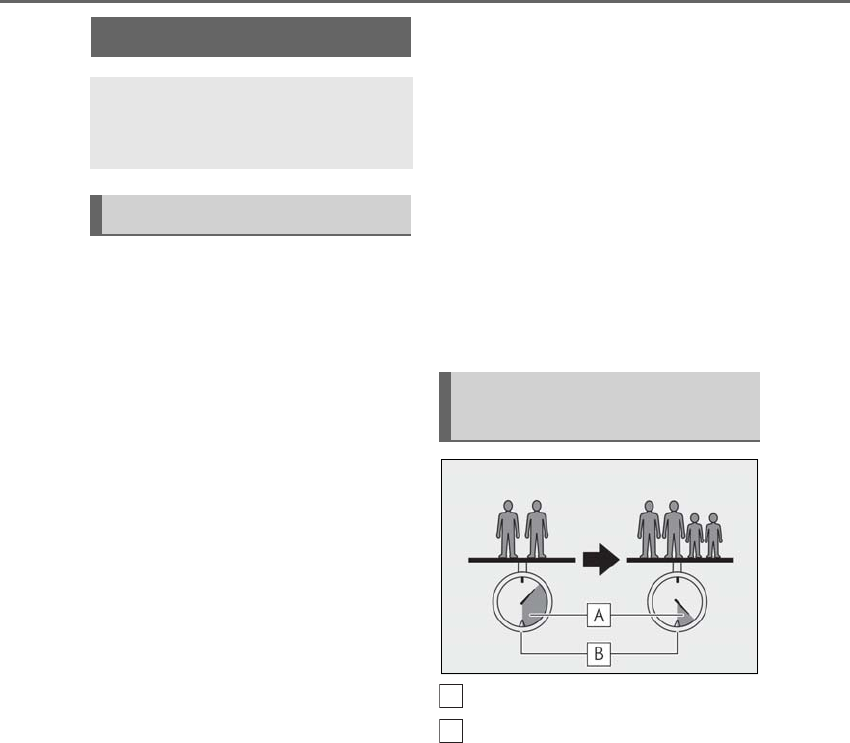
164 4-1. Before driving
LS500h_OM_OM50F42U_(U)
Cargo capacity depends on the total
weight of the occupants.
(Cargo capacity) = (Total load capac-
ity) — (Total weight of occupants)
Steps for Determining Correct Load
Limit —
(1) Locate the statement “The com-
bined weight of occupants and cargo
should never exceed XXX kg or XXX
lbs.” on your vehicle’s placard.
(2) Determine the combined weight of
the driver and passengers that will be
riding in your vehicle.
(3) Subtract the combined weight of
the driver and passengers from XXX
kg or XXX lbs.
(4) The resulting figure equals the
available amount of cargo and luggage
load capacity.
For example, if the “XXX” amount
equals 1400 lbs. and there will be five
150 lb passengers in your vehicle, the
amount of available cargo and luggage
load capacity is 650 lbs. (1400 − 750
(5 × 150) = 650 lbs.)
(5) Determine the combined weight of
luggage and cargo being loaded on
the vehicle. That weight may not safely
exceed the available cargo and lug-
gage load capacity calculated in Step
4.
(6) If your vehicle will be towing a
trailer, load from your trailer will be
transferred to your vehicle. Consult
this manual to determine how this
reduces the available cargo and lug-
gage load capacity of your vehicle.
(→P.166)
Lexus does not recommend towing a
trailer with your vehicle. Your vehicle is not
designed for trailer towing.
Cargo capacity
Total load capacity (vehicle capac-
ity weight) (→P.460)
When 2 people with the combined
weight of A lb. (kg) are riding in your
vehicle, which has a total load capacity
(vehicle capacity weight) of B lb. (kg),
the available amount of cargo and lug-
gage load capacity will be C lb. (kg) as
follows:
B*2 lb. (kg) - A*1 lb. (kg) = C*3 lb. (kg)
*1: A =Weight of people
*2: B =Total load capacity
Cargo and luggage
Take notice of the following infor-
mation about storage precautions,
cargo capacity and load:
Capacity and distribution
Calculation formula for your
vehicle
A
B

165
4-1. Before driving
LS500h_OM_OM50F42U_(U)
4
Driving
*3: C =Available cargo and luggage load
In this condition, if 3 more passengers with
the combined weight of D lb. (kg) get on,
the available cargo and luggage load will
be reduced E lb. (kg) as follows:
C lb. (kg) - D*4 lb. (kg) = E*5 lb. (kg)
*4: D =Additional weight of people
*5: E =Available cargo and luggage load
As shown in the example above, if the
number of occupants increases, the
cargo and luggage load will be
reduced by an amount that equals the
increased weight due to the additional
occupants. In other words, if an
increase in the number of occupants
causes an excess of the total load
capacity (combined weight of occu-
pants plus cargo and luggage load),
you must reduce the cargo and lug-
gage on your vehicle.
WARNING
■Things that must not be carried in the
trunk
The following things may cause a fire if
loaded in the trunk:
●Receptacles containing gasoline
●Aerosol cans
■Storage precautions
Observe the following precautions.
Failure to do so may prevent the pedals
from being depressed properly, may
block the driver’s vision, or may result in
items hitting the driver or passengers,
possibly causing an accident.
●Stow cargo and luggage in the trunk
whenever possible.
●Do not place cargo or luggage in or on
the following locations.
• At the feet of the driver
• On the front passenger or rear seats
(when stacking items)
• On the package tray
• On the instrument panel
•On the dashboard
• In front of the Center Display
●Secure all items in the occupant com-
partment.
■Capacity and distribution
●Do not exceed the maximum axle
weight rating or the total vehicle
weight rating.
●Even if the total load of occupant’s
weight and the cargo load is less than
the total load capacity, do not apply the
load unevenly. Improper loading may
cause deterioration of steering or
braking control which may cause
death or serious injury.
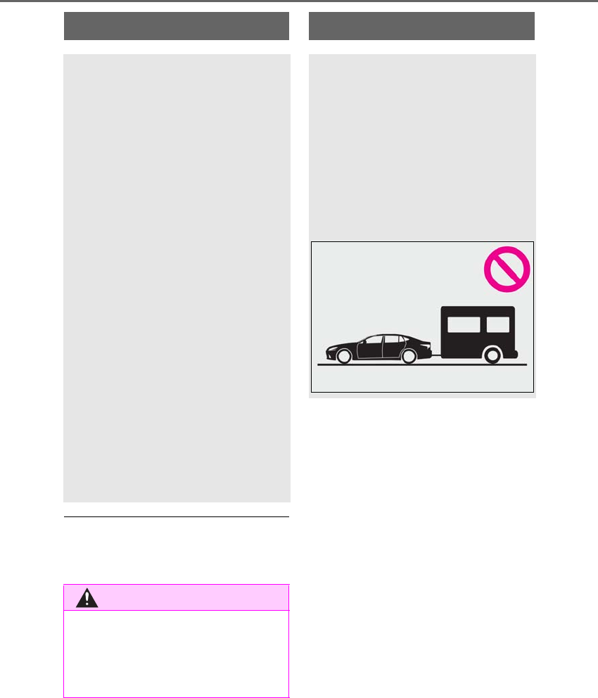
166 4-1. Before driving
LS500h_OM_OM50F42U_(U)
■Total load capacity and seating capacity
These details are also described on the tire
and loading information label. (→P.408)
Vehicle load limits
Vehicle load limits include total
load capacity, seating capacity,
towing capacity and cargo capac-
ity.
-Total load capacity (vehicle
capacity weight): →P.460
Total load capacity means the combined
weight of occupants, cargo and lug-
gage.
-Seating capacity:5 occupants
(Front 2, Rear 3)
Seating capacity means the maximum
number of occupants whose estimated
average weight is 150 lb. (68 kg) per
person.
-Towing capacity
Lexus does not recommend towing a
trailer with your vehicle.
-Cargo capacity
Cargo capacity may increase or
decrease depending on the weight and
the number of occupants.
WARNING
■Overloading the vehicle
Do not overload the vehicle.
It may not only cause damage to the tires,
but also degrade steering and braking
ability, resulting in an accident.
Trailer towing
Lexus does not recommend towing
a trailer with your vehicle. Lexus
also does not recommend the
installation of a tow hitch or the use
of a tow hitch carrier for a wheel-
chair, scooter, bicycle, etc. Your
vehicle is not designed for trailer
towing or for the use of tow hitch
mounted carriers.
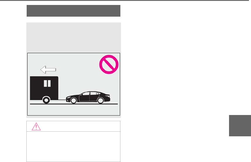
167
4-1. Before driving
LS500h_OM_OM50F42U_(U)
4
Driving
Dinghy towing
Your vehicle is not designed to be
dinghy towed (with 4 wheels on the
ground) behind a motor home.
NOTICE
■To avoid serious damage to your vehi-
cle
Do not tow your vehicle with the four
wheels on the ground.
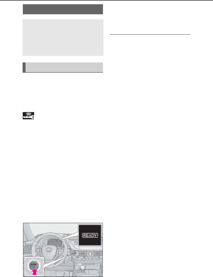
168 4-2. Driving procedures
LS500h_OM_OM50F42U_(U)
4-2.Driving pro cedures
1Press the parking brake switch to
check that the parking brake is set.
(→P.181)
The parking brake indicator will come on.
2Firmly depress the brake pedal.
and a message will be displayed on
the multi-information display.
If it is not displayed, the hybrid system can-
not be started.
When the shift position is N, the hybrid sys-
tem cannot start. Shift the shift position to P
when starting the hybrid system. (→P.176)
3Press the power switch shortly and
firmly.
When operating the power switch, one
short, firm press is enough. It is not neces-
sary to press and hold the switch.
If the “READY” indicator turns on, the
hybrid system will operate normally.
Continue depressing the brake pedal until
the “READY” indicator is illuminated.
The hybrid system can be started from any
power switch mode.
4Check that the “READY” indicator
is illuminated.
The vehicle cannot be driven if the
“READY” indicator is off.
■Power switch illumination
According to the situation, the power
switch illumination operates as follows.
●When a door is opened, or the power
switch mode is changed from ACCES-
SORY or ON mode to off, the power
switch illumination slowly blinks.
●When depressing the brake pedal with
carrying the electronic key on your per-
son, the power switch illumination rapidly
blinks.
●When the power switch is in ACCES-
SORY or ON mode, the power switch
illumination illuminates.
■If the hybrid system does not start
●The immobilizer system may not have
been deactivated. (→P.66)
Contact your Lexus dealer.
●If a message related to start-up is shown
on the multi-information display, read the
message and follow the instructions.
■When the ambient temperature is low,
such as during winter driving conditions
●When starting the hybrid system, the
flashing time of the “READY” indicator
may be long. Leave the vehicle as it is until
the “READY” indicator is steady on, as
steady means the vehicle is able to move.
●When the hybrid battery (traction bat-
tery) is extremely cold (below approxi-
mately -22°F [-30°C]) under the
influence of the outside temperature, it
may not be possible to start the hybrid
system. In this case, try to start the hybrid
system again after the temperature of the
hybrid battery increases due to the out-
side temperature increase etc.
■Sounds and vibrations specific to a
hybrid vehicle
→P.59
Power (ignition) switch
Performing the following opera-
tions when carrying the electronic
key on your person starts the hybrid
system or changes power switch
modes.
Starting the hybrid system
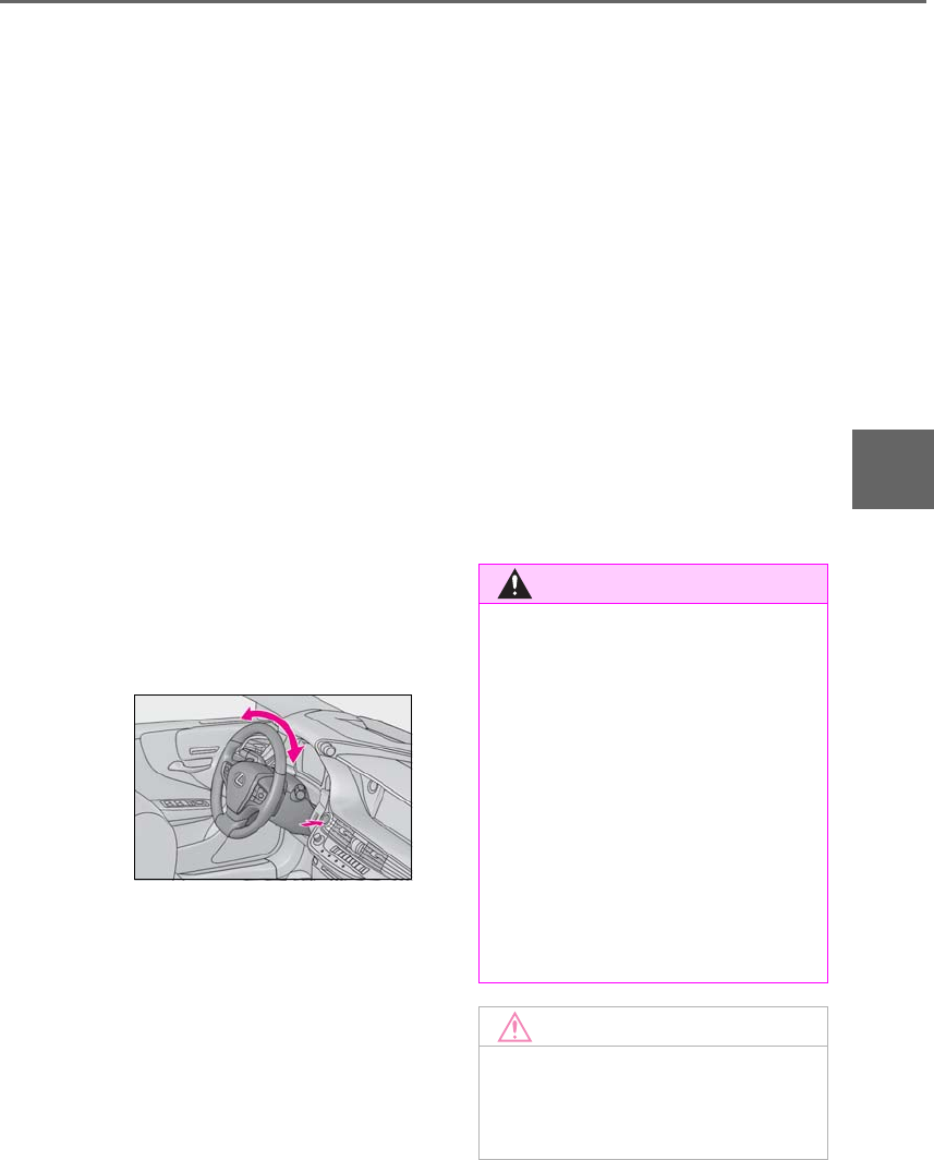
169
4-2. Driving procedures
LS500h_OM_OM50F42U_(U)
4
Driving
■If the 12-volt battery is discharged
The hybrid system cannot be started using
the smart access system with push-button
start. Refer to P.447 to restart the hybrid
system.
■Electronic key battery depletion
→P.104
■Conditions affecting operation
→P.120
■Notes for the entry function
→P.121
■Steering lock function
●After turning the power switch off and
opening and closing the doors, the steer-
ing wheel will be locked due to the steer-
ing lock function. Operating the power
switch again automatically cancels the
steering lock.
●When the steering lock cannot be
released, “Push Power Switch While
Turning Steering Wheel in Either Direc-
tion” will be displayed on the multi-infor-
mation display.
Press the power switch shortly and firmly
while turning the steering wheel left and
right.
●To prevent the steering lock motor from
overheating, the motor may be sus-
pended if the hybrid system is turned on
and off repeatedly in a short period of
time. In this case, refrain from operating
the power switch. After about 10 sec-
onds, the steering lock motor will resume
functioning.
■If the “READY” indicator does not come
on
In the event that the “READY” indicator
does not come on even after performing
the proper procedures for starting the vehi-
cle, contact your Lexus dealer immediately.
■If the hybrid system is malfunctioning
→P.64
■Electronic key battery
→P.413
■Operation of the power switch
●If the switch is not pressed shortly and
firmly, the power switch mode may not
change or the hybrid system may not
start.
●If attempting to restart the hybrid system
immediately after turning the power
switch off, the hybrid system may not start
in some cases. After turning the power
switch off, please wait a few seconds
before restarting the hybrid system.
■Customization
If the smart access system with push-button
start has been deactivated in a customized
setting, refer to P.445.
WARNING
■When starting the hybrid system
Always start the hybrid system while sit-
ting in the driver’s seat. Do not depress
the accelerator pedal while starting the
hybrid system under any circumstances.
Doing so may cause an accident result-
ing in death or serious injury.
■Caution while driving
If hybrid system failure occurs while the
vehicle is moving, do not lock or open the
doors until the vehicle reaches a safe and
complete stop. Activation of the steering
lock in this circumstance may lead to an
accident, resulting in death or serious
injury.
NOTICE
■When starting the hybrid system
If the hybrid system becomes difficult to
start, have your vehicle checked by your
Lexus dealer immediately.
170 4-2. Driving procedures
LS500h_OM_OM50F42U_(U)
1Stop the vehicle completely.
2If the parking brake is in manual
mode, set the parking brake.
(→P.181)
3Shift the shift position to P. (→P.176)
Check that the shift position indicator
shows P. (→P.176)
4Press the power switch.
The hybrid system will stop, and the meter
display will be extinguished (the shift posi-
tion indicator will be extinguished a few
seconds after the meter display).
5Release the brake pedal and check
that “ACCESSORY” or “IGNI-
TION ON” is not shown on the
meter.
■Automatic P position selection function
→P.177
Modes can be changed by pressing
the power switch with the brake pedal
released. (The mode changes each
time the switch is pressed.)
NOTICE
■Symptoms indicating a malfunction
with the power switch
If the power switch seems to be operat-
ing somewhat differently than usual, such
as the switch sticking slightly, there may
be a malfunction. Contact your Lexus
dealer immediately.
Stopping the hybrid system
WARNING
■Stopping the hybrid system in an
emergency
●If you want to stop the hybrid system in
an emergency while driving the vehi-
cle, press and hold the power switch
for more than 2 seconds, or press it
briefly 3 times or more in succession.
(→P.420)
However, do not touch the power
switch while driving except in an emer-
gency. Turning the hybrid system off
while driving will not cause loss of
steering or braking control, however,
power assist to the steering will be lost.
This will make it more difficult to steer
smoothly, so you should pull over and
stop the vehicle as soon as it is safe to
do so.
●If the power switch is operated while
the vehicle is running, a warning mes-
sage will be shown on the multi-infor-
mation display and a buzzer sounds.
●When restarting the hybrid system
after an emergency shutdown, press
the power switch.
Changing power switch modes
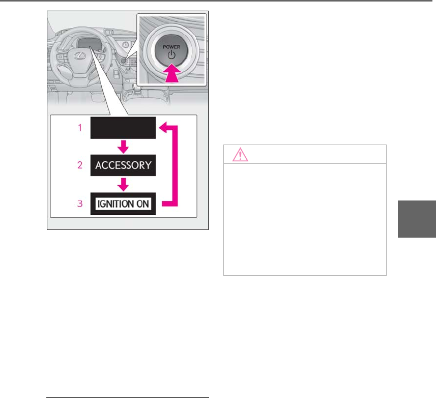
171
4-2. Driving procedures
LS500h_OM_OM50F42U_(U)
4
Driving
1Off
The emergency flashers can be used.
2ACCESSORY mode
Some electrical components such as the
audio system can be used.
“ACCESSORY” will be displayed on the
meter.
3ON mode
All electrical components can be used.
“IGNITION ON” will be displayed on the
meter.
■Auto power off function
If the vehicle is left in ACCESSORY mode
for more than 20 minutes or ON mode
(with hybrid system not operating) for more
than an hour with the shift position in P, the
power switch will automatically turn off.
However, this function cannot entirely pre-
vent the 12-volt battery discharge. Do not
leave the vehicle with the power switch in
ACCESSORY or ON mode for long peri-
ods of time when the hybrid system is not
operating.
■When the shift control system malfunc-
tions
When attempting to turn the power switch
off while there is a malfunction in the shift
control system, the power switch mode may
change to ACCESSORY mode. In this
case, ACCESSORY mode may be turned
off by applying the parking brake and press-
ing the power switch again. If there is a mal-
function in the system, have the vehicle
inspected by your Lexus dealer immedi-
ately.
NOTICE
■To prevent 12-volt battery discharge
●Do not leave the power switch in
ACCESSORY or ON mode for long
periods of time without the hybrid sys-
tem on.
●If “ACCESSORY” or “IGNITION
ON” is displayed on the meter, the
power switch is not off. Exit the vehicle
after turning the power switch off.
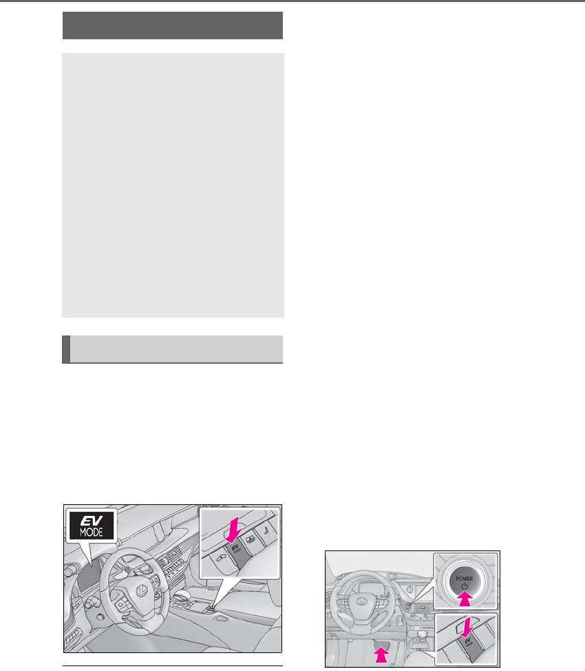
172 4-2. Driving procedures
LS500h_OM_OM50F42U_(U)
Turns EV drive mode on/off
When EV drive mode is turned on, the EV
drive mode indicator will come on. Press-
ing the switch when in EV drive mode will
return the vehicle to normal driving (using
the gasoline engine and electric motor
[traction motor]).
■Situations in which EV drive mode can-
not be turned on
It may not be possible to turn EV drive
mode on in the following situations. If it can-
not be turned on, a buzzer will sound and a
message will be shown on the multi-infor-
mation display.
●The temperature of the hybrid system is
high.
The vehicle has been left in the sun,
driven on a hill, driven at high speeds, etc.
●The temperature of the hybrid system is
low.
The vehicle has been left in temperatures
lower than about 32°F (0°C) for a long
period of time etc.
●The gasoline engine is warming up.
●The hybrid battery (traction battery) is
low.
The remaining battery level indicated in
the “Energy Monitor” display is low.
(→P.96)
●Vehicle speed is high.
●The accelerator pedal is depressed firmly
or the vehicle is on a hill etc.
●The windshield defogger is in use.
●When the shift position is in M.
■Switching to EV drive mode when the
gasoline engine is cold
If the hybrid system is started while the gas-
oline engine is cold, the gasoline engine will
start automatically in order to warm up. In
this case, you will become unable to switch
to EV drive mode.
To prevent gasoline engine warm up in
order to reduce noises, start the hybrid sys-
tem without starting the gasoline engine,
pressing the power switch with fully
depressing the brake pedal and pressing
the EV drive mode switch.
■Automatic cancelation of EV drive
mode
When driving in EV drive mode, the gaso-
line engine may automatically restart in the
following situations. When EV drive mode
EV drive mode
In EV drive mode, electric power is
supplied by the hybrid battery
(traction battery), and only the
electric motor (traction motor) is
used to drive the vehicle.
This mode allows you to drive in res-
idential areas early in the morning
and late at night, or in indoor park-
ing lots etc. without concern for
noises and gas emissions.
However, when the vehicle proxim-
ity notification system is active, the
vehicle may produce sound.
Operating instructions

173
4-2. Driving procedures
LS500h_OM_OM50F42U_(U)
4
Driving
is canceled, a buzzer will sound and the EV
drive mode indicator will flash and go off.
●The hybrid battery (traction battery)
becomes low.
The remaining battery level indicated in
the “Energy Monitor” display is low.
(→P.96)
●Vehicle speed is high.
●The accelerator pedal is depressed firmly
or the vehicle is on a hill etc.
When it is possible to inform the driver of
automatic cancelation in advance, a prior
notice screen will appear on the multi-infor-
mation display.
■Possible driving distance when driving in
EV drive mode
EV drive mode’s possible driving distance
ranges from a few hundred meters to
approximately 0.6 mile (1 km). However,
depending on vehicle conditions, there are
situations when EV drive mode cannot be
used.
(The distance that is possible depends on
the hybrid battery [traction battery] level
and driving conditions.)
■Fuel economy
The hybrid system is designed to achieve
the best possible fuel economy during nor-
mal driving (using the gasoline engine and
electric motor [traction motor]). Driving in
EV drive mode more than necessary may
lower fuel economy.
■If “EV Mode Unavailable” is shown on
the multi-information display
The EV drive mode is not available. The rea-
son the EV drive mode is not available (the
vehicle is idling, battery charge is low, vehi-
cle speed is higher than the EV drive mode
operating speed range or accelerator pedal
is depressed too much) may be displayed.
Use the EV drive mode when it becomes
available.
■If “EV Mode Deactivated” is shown on
the multi-information display
The EV drive mode has been automatically
canceled. The reason the EV drive mode is
not available (the battery charge is low,
vehicle speed is higher than the EV drive
mode operating speed range or accelera-
tor pedal is depressed too much) may be
displayed. Drive the vehicle for a while
before attempting to turn on the EV drive
mode again.
WARNING
■Caution while driving
When driving in EV drive mode, pay spe-
cial attention to the area around the vehi-
cle. Because there is no engine noise,
pedestrians, people riding bicycles or
other people and vehicles in the area
may not be aware of the vehicle starting
off or approaching them, so take extra
care while driving. Therefore, take extra
care while driving even if the vehicle
proximity notification system is active.

174 4-2. Driving procedures
LS500h_OM_OM50F42U_(U)
*1: To improve fuel efficiency and reduce
noise, set the shift position in D for nor-
mal driving. You can choose gear range
suitable for your driving situation by
operating the paddle shift switches.
*2: Any gear range can be fixed when driv-
ing in M mode.
■For the shift positions
●When the power switch is off or in
ACCESSORY mode, the shift position
cannot be changed.
●When the power switch is in ON mode
(the hybrid system is not operating), the
shift position can only be changed to N.
●When the “READY” indicator is on, the
shift position can be changed from P to D,
N or R.
●When the “READY” indicator is flashing,
the shift position cannot be changed from
P to another position even if the shift lever
is operated. Wait until the “READY” indi-
cator changes from a flashing to a solid
light, and then operate the shift lever
again.
●The shift position can only be changed to
M directly from D.
In addition, if an attempt is made to change
the shift position by moving the shift lever or
by pressing the P position switch in any of
the following situations, the buzzer will
sound and the shifting operation will be dis-
abled or the shift position will automatically
change to N. When this happens, select an
appropriate shift position.
●Situations where the shifting operation
will be disabled:
• When an attempt is made to change the
shift position from P to another position
by moving the shift lever without depress-
ing the brake pedal.
• When an attempt is made to change the
shift position from P or N to M by moving
the shift lever.
• When the P position switch is pressed
while the vehicle is running.*1
●Situations where the shift position will
automatically change to N:
• When an attempt is made to select the R
position by moving the shift lever when
the vehicle is moving forward.*2
• When an attempt is made to select the D
position by moving the shift lever when
the vehicle is moving in reverse.*3
• When the shift position is changed from
R to M
●If N is selected while driving at a certain
speed, even if the shift lever is not held in
the N position, the shift position changes
to N. In this situation, the buzzer sounds
and a confirmation message is displayed
on the multi-information display to inform
the driver that the shift position has
changed to N.
*1: Shift position may be changed to P
when driving at extremely low speeds.
*2: Shift position may be changed to R
when driving at low speeds.
*3: Shift position may be changed to D
when driving at low speeds.
Hybrid transmission
Select the shift position depending
on your purpose and situation.
Shift position purpose and func-
tions
Shift posi-
tion Objective or function
PParking the vehicle/starting
the hybrid system
RReversing
NNeutral (Condition in which
the power is not transmitted)
DNormal driving*1
MM mode driving*2 (→P.179)
175
4-2. Driving procedures
LS500h_OM_OM50F42U_(U)
4
Driving
■Reverse warning buzzer
When shifting into R, a buzzer will sound to
inform the driver that the shift position is in
R.
■To protect the hybrid transmission
If the transmission fluid temperature is high,
“Transmission Fluid Temp High See
Owner’s Manual” will be displayed on the
multi-information display and the vehicle
will go into transmission protection mode
automatically. Have the vehicle inspected
by your Lexus dealer.
■When driving with the dynamic radar
cruise control with full-speed range
activated
Even when performing the following
actions with the intent of enabling engine
braking, engine braking will not be acti-
vated because the dynamic radar cruise
control with full-speed range will not be
canceled.
●While driving in the D position, down-
shifting to 9, 8, 7, 6, 5 or 4.
●When switching the driving mode to
sport mode while driving in the D position
(→P.298)
■Restraining sudden start (Drive-Start
Control)
→P.159
■AI-SHIFT
The AI-SHIFT automatically selects the suit-
able gear according to driver performance
and driving conditions.
The AI-SHIFT automatically operates when
the shift position is in D. (Shifting the shift
position to the M position cancels the func-
tion.)
■If a message about a shift operation is
shown
To prevent the shift position from being
selected incorrectly or the vehicle from
moving unexpectedly, the shift position may
be changed automatically or operating the
shift lever may be required. In this case,
change the shift position following the mes-
sages on the multi-information display.
■After recharging/reconnecting the
12-volt battery
→P.393
■Customization
Some functions can be customized.
(→P.481)
WARNING
■When driving on slippery road sur-
faces
Do not accelerate or shift the shift posi-
tion suddenly.
Sudden changes in engine braking may
cause the vehicle to spin or skid, resulting
in an accident.
NOTICE
■Hybrid battery (traction battery)
charge
If the shift position is in N, the hybrid bat-
tery (traction battery) will not be
charged. To help prevent the battery
from discharging, avoid leaving the N
position selected for an extended period
of time.
■Situations where shift control system
malfunctions are possible
If any of the following situations occurs,
shift control system malfunctions are
possible.
Immediately stop the vehicle in a safe
place on level ground, apply the parking
brake, and then contact your Lexus
dealer.
●When the warning message indicating
the shift control system appears on the
multi-information display.
●The display indicates that no shift posi-
tion is selected for more than a few
seconds.
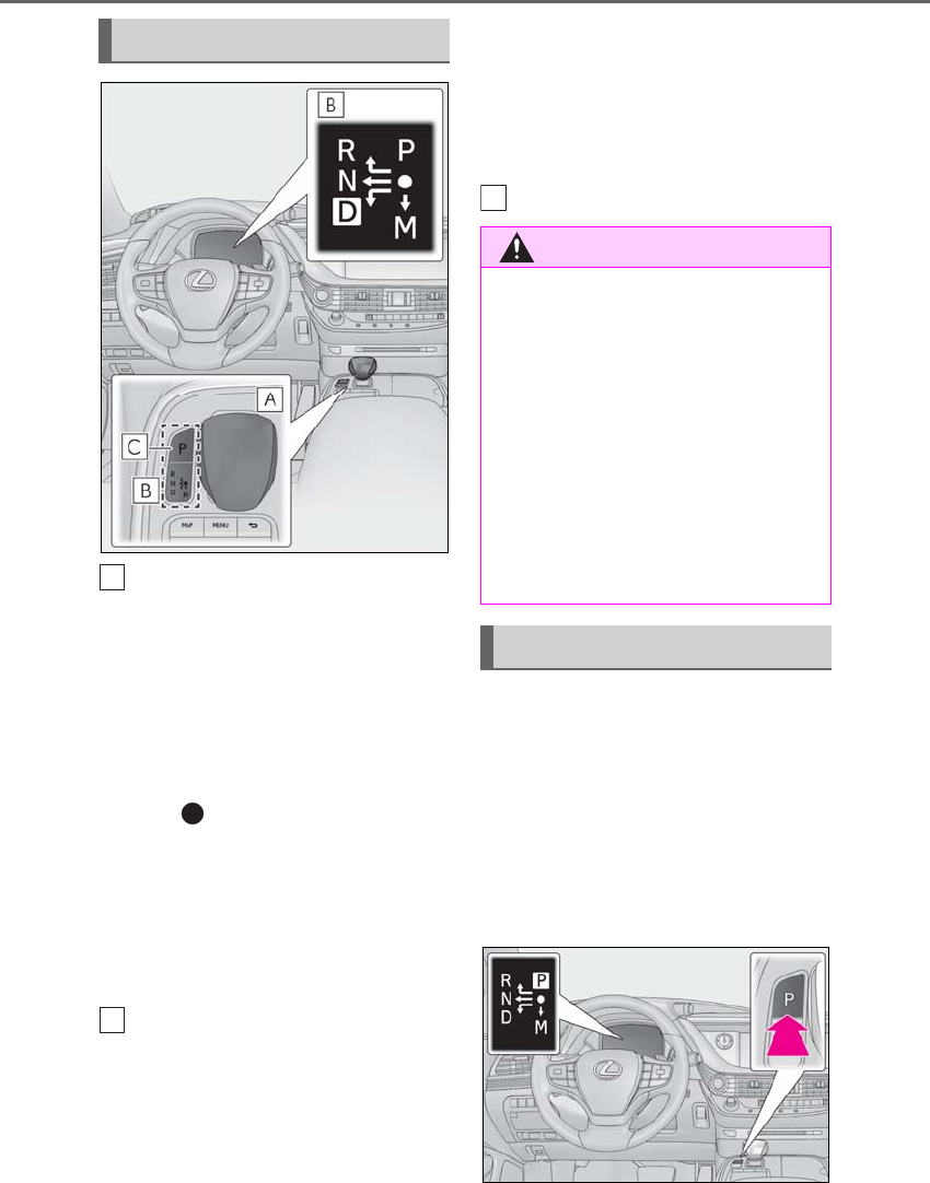
176 4-2. Driving procedures
LS500h_OM_OM50F42U_(U)
Shift lever
Operate the shift lever gently and securely
in the direction of the arrow on the shift
position indicator.
To shift to N, slide the shift lever in the
direction of the arrow and hold it.
Release the shift lever after each shifting
operation to allow it to return to its regular
position ( ).
Shifting to M is only possible when the shift
position is in D.
When shifting from P to N, D or R, from N,
D, M or R to P, from D or M to R, or from R
to D, ensure that the brake pedal is being
depressed and the vehicle is stationary.
Shift position indicator
Meter display:
The current shift position is highlighted.
When any shift position other than D or M
is selected, the arrow toward M and the M
position indicator are displayed in gray.
Shift lever display:
The current shift position is illuminated.
When selecting the shift position, make
sure that the shift position has been
changed to the desired position by check-
ing the shift position indicator provided on
the instrument cluster.
P position switch
■When shifting the shift position to P
Fully stop the vehicle and set the park-
ing brake, and then press the P position
switch.
When the shift position is changed to P, the
switch illuminates.
Check that the shift position indicator
shows P.
Shifting the shift lever
A
B
WARNING
■For the shift lever
●Do not remove the shift lever knob or
use anything but a genuine Lexus shift
lever knob. Also, do not hang anything
on the shift lever.
Doing so could prevent the shift lever
from returning to position, causing
unexpected accidents to occur when
the vehicle is in motion.
●In order to prevent the shift position
from accidentally being changed, do
not touch the shift lever when not using
them.
P position switch
C
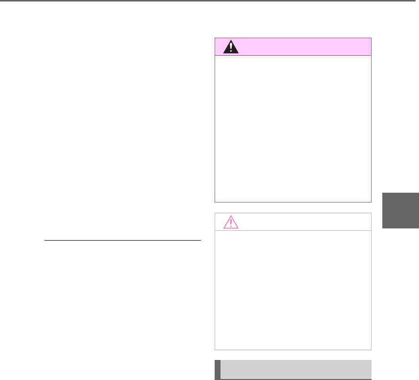
177
4-2. Driving procedures
LS500h_OM_OM50F42U_(U)
4
Driving
■Shifting the shift position from P to
other positions
-While depressing the brake pedal
firmly, operate the shift lever. If the
shift lever is operated without
depressing the brake pedal, the
buzzer will sound and the shifting
operation will be disabled.
-When selecting the shift position,
make sure that the shift position has
been changed to the desired posi-
tion by checking the shift position
indicator provided on the instru-
ment cluster.
-The shift position cannot be
changed from P to M directly.
■Automatic P position selection function
In the following situations, the shift position
is automatically changed to P.
●When pressing the power switch with the
vehicle stopped while the power switch is
in ON mode and the shift position is in a
position other than P (after the shift posi-
tion has changed to P, the power switch
will turn off)*
●When the vehicle is stopped after the
hybrid system has been stopped in an
emergency while driving
●When voltage of the 12-volt battery
drops while the shift position is in a posi-
tion other than P
*: When the power switch is pressed while
driving at extremely slow speeds, such
as immediately before stopping the vehi-
cle, the shift position may automatically
change to P. Make sure that the vehicle
is completely stopped before pressing
the power switch.
■If the shift position cannot be shifted
from P
There is a possibility that the 12-volt battery
is discharged. Check the 12-volt battery in
this situation. (→P.447)
■Driving mode
→P.298
■Snow mode
Snow mode can be selected to suit the
conditions when driving on slippery
road surfaces, such as on snow.
Turn the snow mode switch backward.
The snow mode indicator illuminates.
Turn the snow mode switch backward
again to return to normal mode.
WARNING
■P position switch
●Do not press the P position switch
while the vehicle is moving.
If the P position switch is pressed when
driving at very low speeds (for exam-
ple, directly before stopping the vehi-
cle), the vehicle may stop suddenly
when the shift position switches to P,
which could lead to an accident.
●In order to prevent the shift position
from accidentally being changed, do
not touch the P position switch or shift
lever when not using them.
NOTICE
■Notes regarding shift lever and P
position switch operation
Avoid repeatedly operating the shift
lever and P position switch in quick suc-
cession.
The system protection function may acti-
vate and it will not be temporarily possi-
ble to shift the shift position other than P.
If this happens, please wait for a while
before attempting to change the shift
position again.
Selecting the driving mode
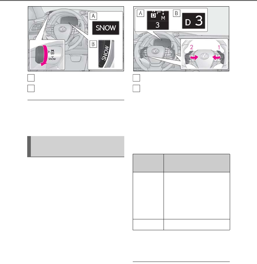
178 4-2. Driving procedures
LS500h_OM_OM50F42U_(U)
Except F SPORT models
F SPORT models
■Snow mode automatic deactivation
Snow mode is automatically deactivated if
the power switch is turned off after driving
in snow mode.
To drive using temporary shift range
selection, operate the “-” or “+” paddle
shift switch.
When the “-” paddle shift switch is
operated, the shift range switches to a
range that enables engine braking
force that is suitable to driving condi-
tions. When the “+” paddle shift switch
is operated, the shift range switches to
a range that is one range higher than
the current range.
Changing the shift range allows
restriction of the highest gear, prevent-
ing unnecessary upshifting and
enabling the level of engine braking
force to be selected.
Except F SPORT models
F SPORT models
1Upshifting
2Downshifting
The selected shift range, from D1 to D10,
will be displayed on the meter.
To return to normal D position driving, the
“+” paddle shift switch must be held down
for a period of time.
A lower shift range will provide greater
engine braking forces than a higher shift
range.
■Automatic deactivation of shift range
selection in the D position
Shift range selection in the D position will
be deactivated in the following situations:
●When the vehicle comes to a stop
●If the accelerator pedal is depressed for
more than a certain period of time
●When the shift position is shifted to a
position other than D.
Selecting shift ranges in the D
position
A
B
Meter dis-
play Function
D2 - D10
A gear in the range between
D1 and the selected shift
range is automatically cho-
sen depending on vehicle
speed and driving condi-
tions
D1 Setting the shift range at D1
A
B
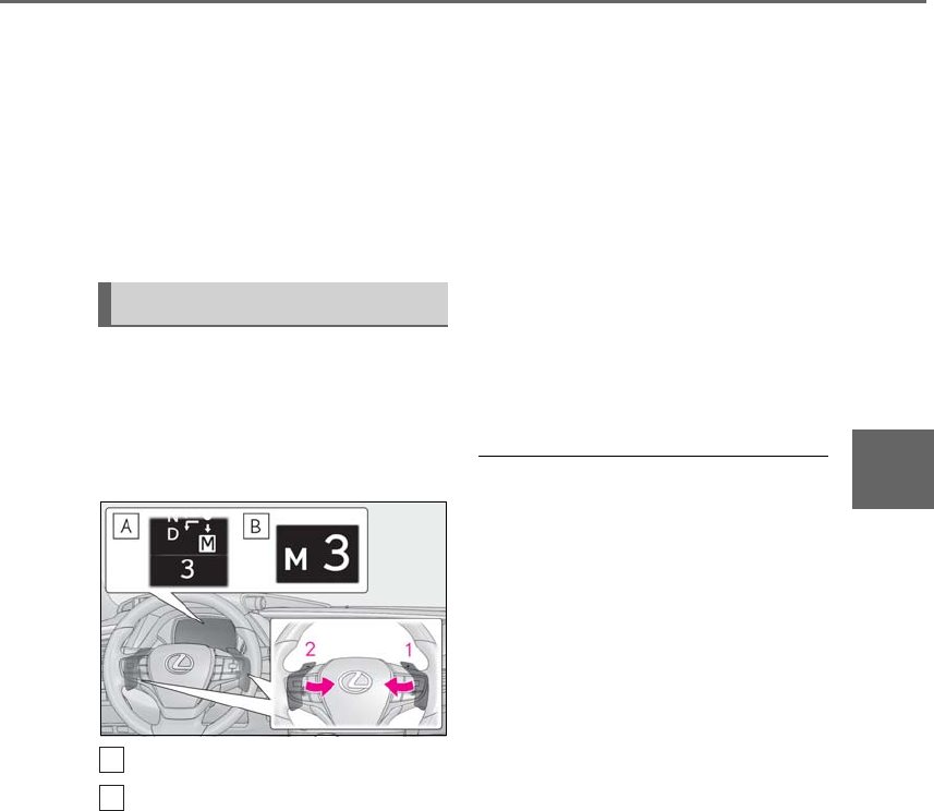
179
4-2. Driving procedures
LS500h_OM_OM50F42U_(U)
4
Driving
●When the “+” paddle shift switch is
pressed and held
■Downshifting restriction warning
buzzer
To help ensure safety and driving perfor-
mance, downshifting operation may some-
times be restricted. In some circumstances,
downshifting may not be possible even
when the paddle shift switch is operated. (A
buzzer will sound twice.)
To enter M mode, shift the shift position
to M. Gears can be selected by oper-
ating the paddle shift switches, allowing
you to drive in the gear of your choos-
ing.
Except F SPORT models
F SPORT models
1Upshifting
2Downshifting
The gear changes once every time the
paddle shift switch is operated.
The selected gear, from M1 to M10, will be
fixed and displayed on the meter.
When in the M position, the gear will
not change unless the paddle shift
switches are operated.
However, even when in the M position,
the gears will be automatically
changed in the following situations:
-When vehicle speed drops (down-
shift only).
-When vehicle speed increases
(upshift only).
-When the accelerator pedal is firmly
depressed.
-When it is necessary to protect the
transmission when the transmission
fluid temperature is high or low, or
other reasons.
Also, the gear will not shift when the
vehicle speed is low, even if an upshift
operation is performed.
■Downshifting restrictions warning
buzzer
To help ensure safety and driving perfor-
mance, downshifting operation may some-
times be restricted. In some circumstances,
downshifting may not be possible even
when the paddle shift switch is operated. (A
buzzer will sound twice.)
Selecting gears in the M position
A
B
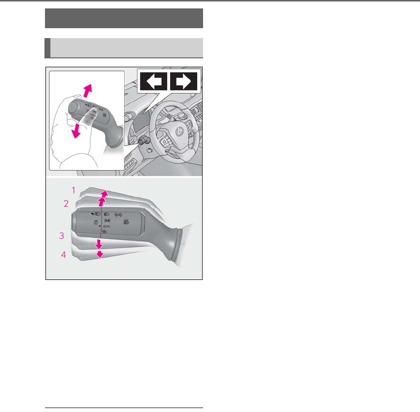
180 4-2. Driving procedures
LS500h_OM_OM50F42U_(U)
1Right turn
2Lane change to the right (move the
lever partway and release it)
The right hand signals will flash 3 times.
3Lane change to the left (move the
lever partway and release it)
The left hand signals will flash 3 times.
4Left turn
■Turn signals can be operated when
The power switch is in ON mode.
■If the indicator flashes faster than usual
Check that a light bulb in the front or rear
turn signal lights has not burned out.
■If the turn signals stop flashing before a
lane change has been performed
Operate the lever again.
■Customization
Some functions can be customized.
(→P.481)
Turn signal lever
Operating instructions
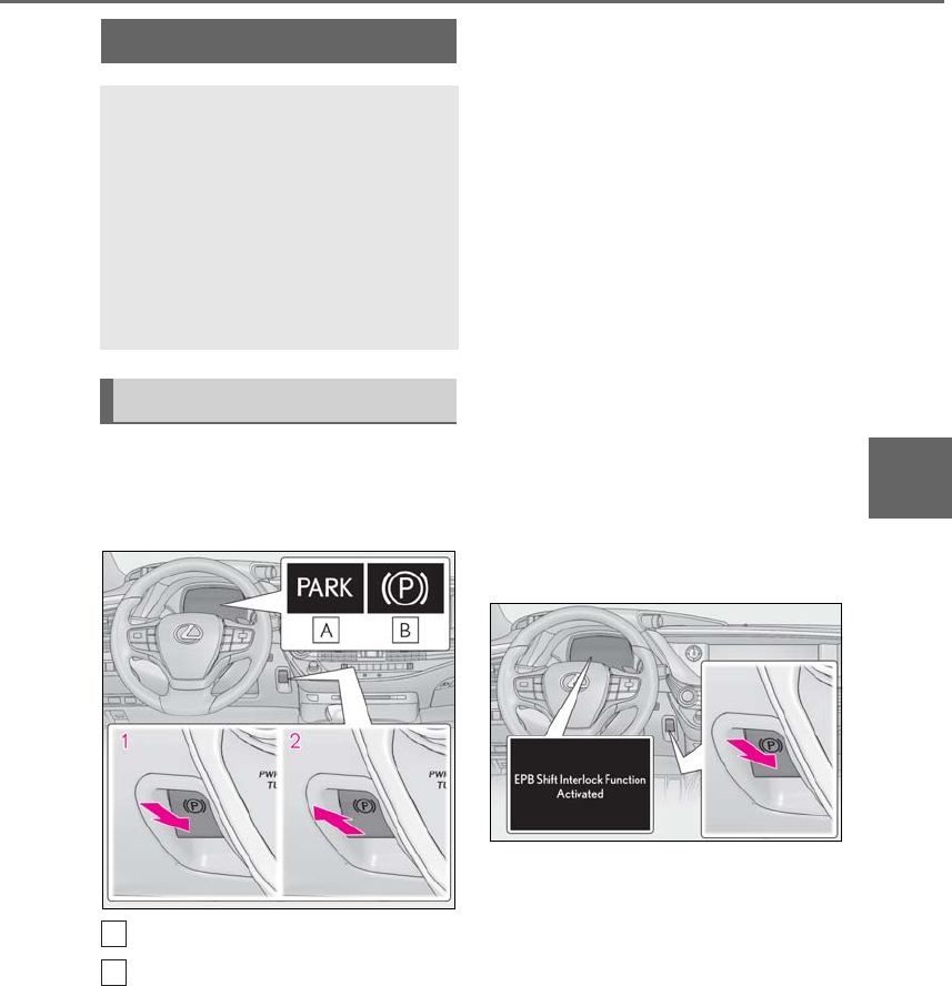
181
4-2. Driving procedures
LS500h_OM_OM50F42U_(U)
4
Driving
■Using the manual mode
The parking brake can be set and
released manually.
U.S.A.
Canada
1Push the switch to set the parking
brake
The parking brake indicator light will turn
on.
Press and hold the parking brake switch if
an emergency occurs and it is necessary to
operate the parking brake while driving.
2Pull the switch to release the park-
ing brake
• Operate the parking brake switch while
depressing the brake pedal.
• Using the parking brake automatic
release function, the parking brake can
be released by depressing the accelera-
tor pedal. When using this function,
slowly depress the accelerator pedal.
Make sure that the parking brake indicator
light turn off.
If the parking brake indicator light
flashes, operate the switch again.
(→P.434)
■Turns automatic mode on
While the vehicle is stopped, press and
hold the parking brake switch until a
message is shown on the multi-infor-
mation display
When the automatic mode is turned
on, the parking brake operates as fol-
lows.
-When the shift position is shifted
from P, the parking brake will be
released, and the parking brake
indicator light will turn off.
-When the shift position is shifted to
P, the parking brake will be set, and
the parking brake indicator light will
turn on.
Parking brake
The parking brake can be set or
released automatically or manually.
In automatic mode, the parking
brake can be set or released auto-
matically according to the shift
lever operation. Also, even in auto-
matic mode, the parking brake can
be set or released manually.
Operating instructions
A
B
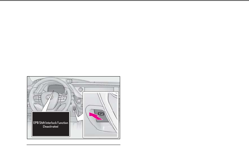
182 4-2. Driving procedures
LS500h_OM_OM50F42U_(U)
Operate the shift lever and P position
switch with the vehicle stopped and the
brake pedal depressed.
■Turns automatic mode off
While the vehicle is stopped, pull and
hold the parking brake switch until a
message is shown on the multi-infor-
mation display
■Parking brake operation
●When the power switch is not in ON
mode, the parking brake cannot be
released using the parking brake switch.
●When the power switch is not in ON
mode, automatic mode (automatic brake
setting and releasing) is not available.
■Parking brake automatic release func-
tion
●When the shift position is shifted from P,
the parking brake will be released in
automatic mode.
●When all of the following conditions are
met in manual mode, the parking brake
can be released by depressing the accel-
erator pedal.
• The driver’s door is closed
• The driver is wearing the seat belt
• The shift position is in D, M or R
■If “EPB Frequently Operated Wait a
Minute” is displayed on the multi-infor-
mation display
If the parking brake is operated repeatedly
over a short period of time, the system may
restrict operation to prevent overheating. If
this happens, refrain from operating the
parking brake. Normal operation will return
after about 1 minute.
■If “EPB Activation Stopped Incom-
pletely” or “EPB unavailable” is dis-
played on the multi-information display
Operate the parking brake switch. If the
message does not disappear after operat-
ing the switch several times, the system may
be malfunctioning. Have the vehicle
inspected by your Lexus dealer.
■Parking brake operation sound
When the parking brake operates, a motor
sound (whirring sound) may be heard. This
does not indicate a malfunction.
■Parking brake operation
●Depending on the power switch mode,
the parking brake indicator light will turn
on and stay on as described below:
ON mode: Comes on until the parking
brake is released.
Not in ON mode: Stays on for approxi-
mately 15 seconds.
●When the power switch is turned off with
the parking brake set, the parking brake
indicator light will stay on for about 15
seconds. This does not indicate a mal-
function.
■When the parking brake switch mal-
functions
Automatic mode (automatic brake setting
and releasing) will be turned on automati-
cally.
■Parking the vehicle
→P.158
■Parking brake engaged warning buzzer
A buzzer will sound if the vehicle is driven
with the parking brake engaged. “EPB
Applied” is displayed on the multi-informa-
tion display. (with the vehicle reached a
speed of 3 mph [5 km/h])
■If the brake system warning light comes
on
→P.427
■Usage in winter time
→P.309
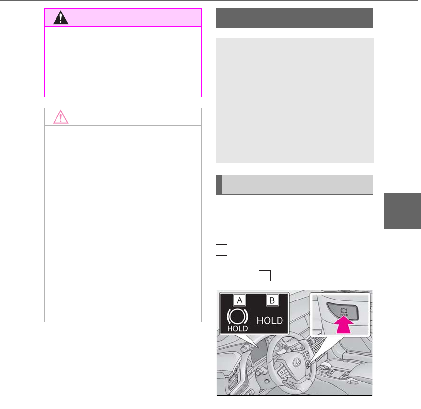
183
4-2. Driving procedures
LS500h_OM_OM50F42U_(U)
4
Driving
Press the brake hold switch to turn the
system on
The brake hold standby indicator (green)
comes on. While the system is holding
the brakes, the brake hold operated indica-
tor (yellow) comes on.
■Brake hold system operating conditions
The brake hold system cannot be turned on
in the following conditions:
●The driver’s door is not closed.
●The driver is not wearing the seat belt.
If any of the conditions above are detected
when the brake hold system is enabled, the
system will turn off and the brake hold
standby indicator light will go off. In addi-
tion, if any of the conditions are detected
while the system is holding the brake, a
warning buzzer will sound and a message
WARNING
■When parking the vehicle
Do not leave a child in the vehicle alone.
The parking brake may be released unin-
tentionally and there is the danger of the
vehicle moving that may lead to an acci-
dent resulting in death or serious injury.
NOTICE
■When parking the vehicle
Before you leave the vehicle, set the
parking brake, shift the shift position to P
and make sure that the vehicle does not
move.
■When the system malfunctions
Stop the vehicle in a safe place and
check the warning messages.
■When the parking brake cannot be
released due to a malfunction
Driving the vehicle with the parking
brake set will lead to brake components
overheating, which may affect braking
performance and increase brake wear.
Have the vehicle inspected by your
Lexus dealer immediately if this occurs.
Brake Hold
The brake hold system keeps the
brake applied when the shift posi-
tion is in D, M or N with the system
on and the brake pedal has been
depressed to stop the vehicle. The
system releases the brake when the
accelerator pedal is depressed with
the shift position in D or M to allow
smooth start off.
Enabling the system
A
B

184 4-2. Driving procedures
LS500h_OM_OM50F42U_(U)
will be shown on the multi-information dis-
play. The parking brake will then be set
automatically.
■Brake hold function
●If the brake pedal is left released for a
period of about 3 minutes after the sys-
tem has started holding the brake, the
parking brake will be set automatically. In
this case, a warning buzzer sounds and a
message is shown on the multi-informa-
tion display.
●To turn the system off while the system is
holding the brake, firmly depress the
brake pedal and press the button again.
●The brake hold function may not hold the
vehicle when the vehicle is on a steep
incline. In this situation, it may be neces-
sary for the driver to apply the brakes. A
warning buzzer will sound and the
multi-information display will inform the
driver of this situation. If a warning mes-
sage is shown on the multi-information
display, read the message and follow the
instructions.
■When the parking brake is set automati-
cally while the system is holding the
brakes
Perform any of the following operations to
release the parking brake.
●Depress the accelerator pedal. (The
parking brake will not be released auto-
matically if the seat belt is not fastened.)
●Operate the parking brake switch with
the brake pedal depressed.
Make sure that the parking brake indicator
light goes off. (→P.181)
■When an inspection at your Lexus
dealer is necessary
When the brake hold standby indicator
(green) does not illuminate even when the
brake hold switch is pressed with the brake
hold system operating conditions met, the
system may be malfunctioning. Have the
vehicle inspected at your Lexus dealer.
■If “Brake Hold Fault Depress Brake to
Deactivate Visit Your Dealer” or “Brake
Hold Malfunction Visit Your Dealer” is
displayed on the multiinformation dis-
play
The system may be malfunctioning. Have
the vehicle inspected by your Lexus dealer.
■Warning messages and buzzers
Warning messages and buzzers are used to
indicate a system malfunction or to inform
the driver of the need for caution. If a warn-
ing message is shown on the multi-informa-
tion display, read the message and follow
the instructions.
■If the brake hold operated indicator
flashes
→P.434
WARNING
■When the vehicle is on a steep incline
When using the brake hold system on a
steep incline exercise caution. The brake
hold function may not hold the vehicle in
such a situation.
■When stopped on a slippery road
The system cannot stop the vehicle when
the gripping ability of the tires has been
exceeded. Do not use the system when
stopped on a slippery road.
NOTICE
■When parking the vehicle
The brake hold system is not designed
for use when parking the vehicle for a
long period of time. Turning the power
switch off while the system is holding the
brake may release the brake, which
would cause the vehicle to move. When
operating the power switch, depress the
brake pedal, shift the shift position to P
and set the parking brake.
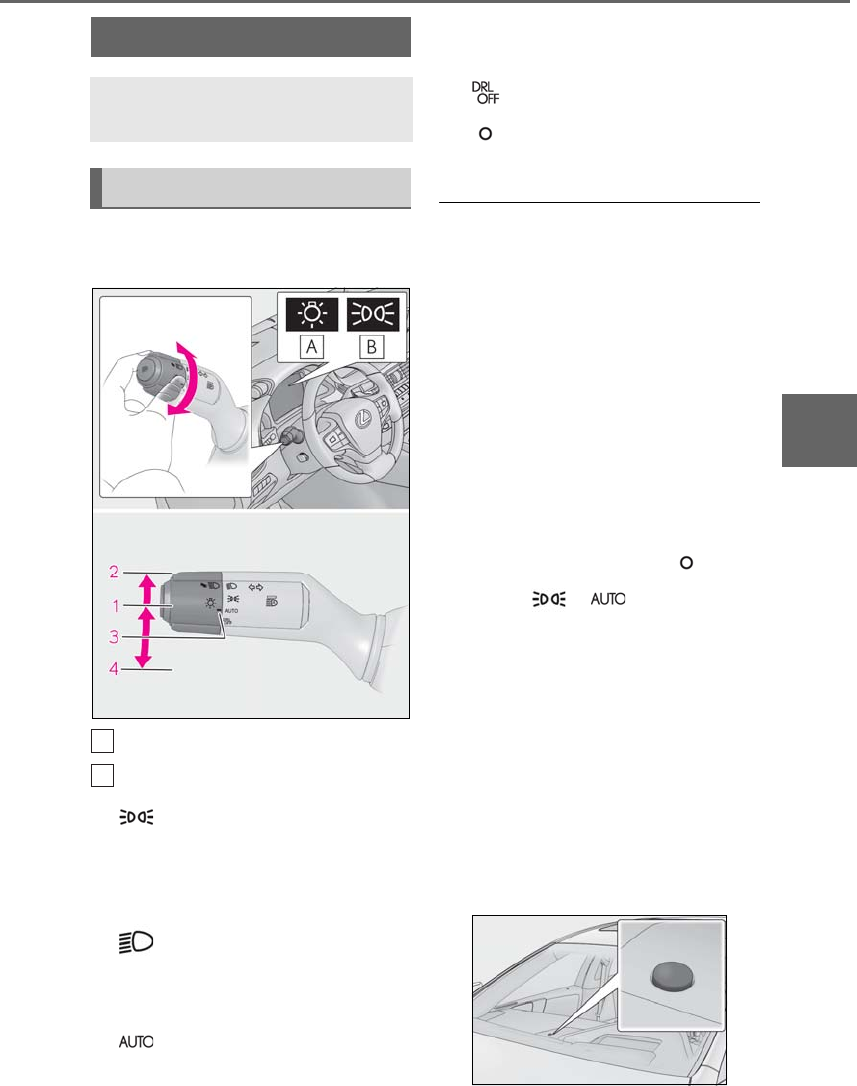
185
4-3. Operating the lights and wipers
LS500h_OM_OM50F42U_(U)
4
Driving
4-3.Operati ng the lights and w ipers
Turning the end of the lever turns on
the lights as follows:
U.S.A.
Canada
1 The side marker, parking, tail,
license plate, instrument panel
lights, and daytime running lights
(→P.185) turn on.
2 The headlights and all lights
listed above (except daytime run-
ning lights) turn on.
3 The headlights, daytime run-
ning lights (→P.185) and all the
lights listed above turn on and off
automatically.
4 (U.S.A.) Off
(Canada) The daytime run-
ning lights turn on. (→P.185)
■AUTO mode can be used when
The power switch is in ON mode.
■Daytime running light system
●The daytime running lights illuminate
using the same lights as the parking lights
and illuminate brighter than the parking
lights.
●To make your vehicle more visible to
other drivers during daytime driving, the
daytime running lights turn on automati-
cally when all of the following conditions
are met. (The daytime running lights are
not designed for use at night.)
• The hybrid system is operating
• The parking brake is released
• The headlight switch is in the (Can-
ada only), or * position
*: When the surroundings are bright
The daytime running lights remain on after
they illuminate, even if the parking brake is
set again.
●For the U.S.A.: Daytime running lights
can be turned off by operating the switch.
●Compared to turning on the headlights,
the daytime running light system offers
greater durability and consumes less
electricity, so it can help improve fuel
economy.
■Headlight control sensor
Headlight switch
The headlights can be operated
manually or automatically.
Operating instructions
A
B
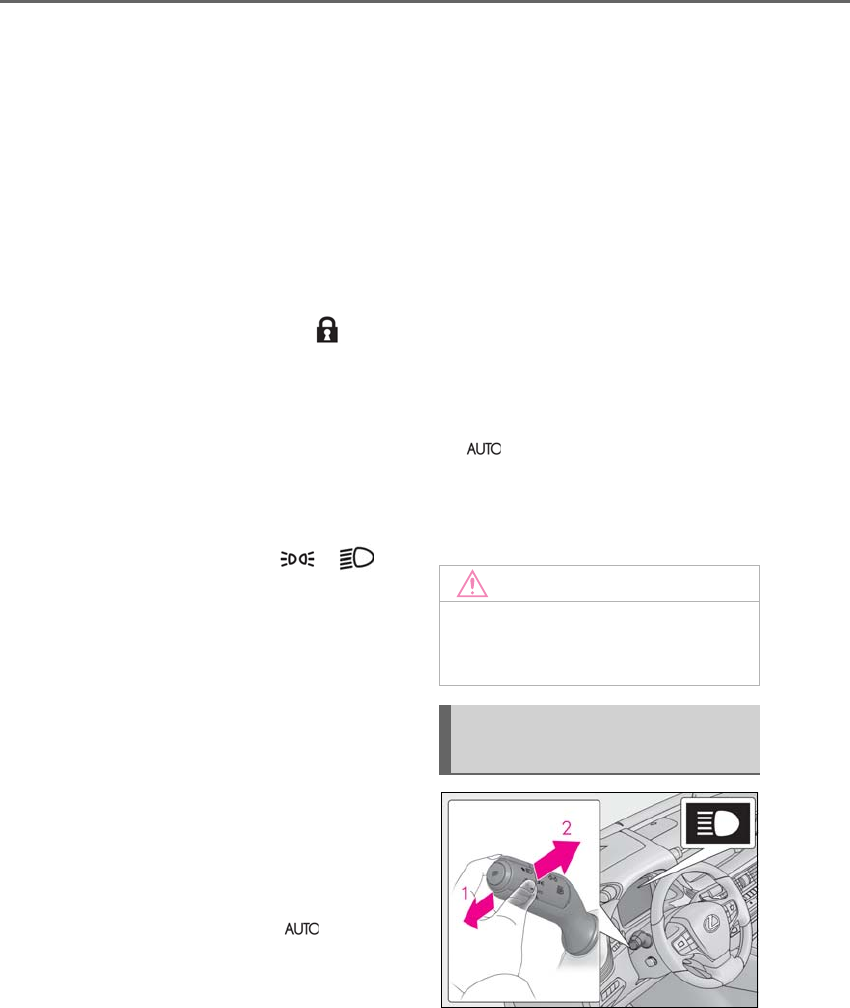
186 4-3. Operating the lights and wipers
LS500h_OM_OM50F42U_(U)
The sensor may not function properly if an
object is placed on the sensor, or anything
that blocks the sensor is affixed to the wind-
shield.
Doing so interferes with the sensor detect-
ing the level of ambient light and may cause
the automatic headlight system to malfunc-
tion.
■Automatic light off system
●When the headlights are on: The head-
lights and tail lights turn off 30 seconds
after the driver’s door is opened and
closed if the power switch is turned to
ACCESSORY mode or turned off. (The
lights turn off immediately if on the
key is pressed after all the doors are
closed.)
●When only the tail lights are on: The tail
lights turn off automatically if the power
switch is turned to ACCESSORY mode
or turned off and the driver’s door is
opened.
To turn the lights on again, turn the power
switch to ON mode, or turn the light switch
off once and then back to or .
■Light reminder buzzer
A buzzer sounds when the power switch is
turned off or turned to ACCESSORY
mode and the driver’s door is opened while
the lights are turned on.
■Automatic headlight leveling system
The level of the headlights is automatically
adjusted according to the number of pas-
sengers and the loading condition of the
vehicle to ensure that the headlights do not
interfere with other road users.
■Windshield wiper linked headlight illu-
mination
When driving during daytime with the
headlight switch turned to , if the wind-
shield wipers are used, the headlights will
turn on automatically after several seconds
to help enhance the visibility of your vehicle.
■12-volt battery-saving function
In order to prevent the 12-volt battery of the
vehicle from discharging, if the headlights
and/or tail lights are on when the power
switch is turned off the 12-volt battery sav-
ing function will operate and automatically
turn off all the lights after approximately 20
minutes. When the power switch is turned
to ON mode, the 12-volt battery-saving
function will be disabled.
When any of the following are performed,
the 12-volt battery-saving function is can-
celed once and then reactivated. All the
lights will turn off automatically 20 minutes
after the 12-volt battery-saving function has
been reactivated:
●When the headlight switch is operated
●When a door is opened or closed
■Welcome light illumination control
The front position and tail lights automati-
cally turn on at night when the doors are
unlocked using the entry function or wire-
less remote control if the light switch is in
the position.
■Customization
Some functions can be customized.
(→P.481)
1With the headlights on, push the
lever away from you to turn on the
high beams.
NOTICE
■To prevent 12-volt battery discharge
Do not leave the lights on longer than
necessary when the hybrid system is off.
Turning on the high beam head-
lights

187
4-3. Operating the lights and wipers
LS500h_OM_OM50F42U_(U)
4
Driving
Pull the lever toward you to the center
position to turn the high beams off.
2Pull the lever toward you and
release it to flash the high beams
once.
You can flash the high beams with the
headlights on or off.
AFS (Adaptive Front-lighting System)
secures excellent visibility at intersec-
tions and on curves by automatically
adjusting the direction of the light axis
of the headlights according to vehicle
speed and the degree of the tire’s angle
as controlled by steering input.
AFS operates at speeds of approximately
6 mph (10 km/h) or higher.
■Customization
Some functions can be customized.
(→P.481)
-When the steering wheel or turn
signal lever is operated while the
headlights are on (low beam), a cor-
nering light will turn on and light up
the direction of movement of the
vehicle. The cornering lights are
designed to ensure excellent visibil-
ity when making a turn at an inter-
section.
However, when vehicle speed is approxi-
mately 22 mph (35 km/h) or higher, the
cornering lights will not turn on.
-When the shift position is in R while
the headlights are on (low beam),
both cornering lights will turn on.
This is designed to enhance visibility
when parking.
■Cornering lights
When the cornering lights are on for more
than 30 minutes, they will turn off automati-
cally.
AFS (Adaptive Front-lighting
System) (if equipped)
Cornering lights
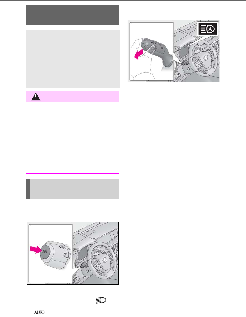
188 4-3. Operating the lights and wipers
LS500h_OM_OM50F42U_(U)
1Press the Automatic High Beam
switch.
2Push the lever away from you with
the headlight switch in the or
position.
The AHB indicator will come on when the
system is operating.
■Conditions to turn the high beams on/off
automatically
●When all of the following conditions are
met, the high beams will be turned on
automatically (after approximately 1 sec-
ond):
• The vehicle speed is approximately 21
mph (34 km/h) or more.
• The area ahead of the vehicle is dark.
• There are no vehicles ahead with head-
lights or tail lights turned on.
• There are few streetlights on the road
ahead.
●If any of the following conditions are met,
the high beams will turn off automatically:
• The vehicle speed is below approxi-
mately 17 mph (27 km/h).
• The area ahead of the vehicle is not dark.
• Vehicles ahead have their headlights or
tail lights turned on.
• There are many streetlights on the road
ahead.
■Camera sensor detection information
●The high beams may not be automatically
turned off in the following situations:
• When a vehicle suddenly appears from
around a curve
• When the vehicle is cut in front of by
another vehicle
• When vehicles ahead cannot be
detected due to repeated curves, road
dividers or roadside trees
• When vehicles ahead appear in a far-
away lane on a wide road
• When the lights of vehicles ahead are not
on
●The high beams may be turned off if a
AHB (Automatic High
Beam)
The Automatic High Beam uses a
camera sensor located behind the
upper portion of the windshield to
assess the brightness of the lights of
vehicles ahead, streetlights, etc.,
and automatically turns the high
beams on or off as necessary.
WARNING
■Limitations of the Automatic High
Beam
Do not overly rely on the Automatic High
Beam. Always drive safely, taking care to
observe your surroundings and turning
the high beams on or off manually if nec-
essary.
■To prevent incorrect operation of the
Automatic High Beam system
Do not overload the vehicle.
Activating the Automatic High
Beam

189
4-3. Operating the lights and wipers
LS500h_OM_OM50F42U_(U)
4
Driving
vehicle ahead that is using fog lights with-
out its headlights turned on is detected.
●House lights, street lights, traffic signals,
and illuminated billboards or signs and
other reflective objects may cause the
high beams to change to the low beams,
or the low beams to remain on.
●The following factors may affect the
amount of time taken for the high beams
to turn on or off:
• The brightness of the headlights, fog
lights, and tail lights of vehicles ahead
• The movement and direction of vehicles
ahead
• When a vehicle ahead only has opera-
tional lights on one side
• When a vehicle ahead is a two-wheeled
vehicle
• The condition of the road (gradient,
curve, condition of the road surface, etc.)
• The number of passengers and amount of
luggage in the vehicle
●The high beams may turn on or off unex-
pectedly.
●Bicycles or similar vehicles may not be
detected.
●In the following situations the system may
not be able to correctly detect the sur-
rounding brightness level. This may cause
the low beams to remain on or the high
beams to flash or dazzle pedestrians or
vehicles ahead. In such a case, it is neces-
sary to manually switch between the high
and low beams.
• When driving in inclement weather
(heavy rain, snow, fog, sandstorms, etc.)
• When the windshield is obscured by fog,
mist, ice, dirt, etc.
• When the windshield is cracked or dam-
aged
• When the camera sensor is deformed or
dirty
• When the temperature of the camera
sensor is extremely high
• When the surrounding brightness level is
equal to that of headlights, tail lights or
fog lights
• When headlights or tail lights of vehicles
ahead are turned off, dirty, changing
color, or not aimed properly
• When the vehicle is hit by water, snow,
dust, etc. from a preceding vehicle
• When driving through an area of inter-
mittently changing brightness and dark-
ness
• When frequently and repeatedly driving
ascending/descending roads, or roads
with rough, bumpy or uneven surfaces
(such as stone-paved roads, gravel roads,
etc.)
• When frequently and repeatedly taking
curves or driving on a winding road
• When there is a highly reflective object
ahead of the vehicle, such as a sign or
mirror
• When the back of a preceding vehicle is
highly reflective, such as a container on a
truck
• When the vehicle’s headlights are dam-
aged or dirty, or are not aimed properly
• When the vehicle is listing or titling due to
a flat tire, a trailer being towed, etc.
• When the headlights are changed
between the high beams and low beams
repeatedly in an abnormal manner
• When the driver believes that the high
beams may be flashing or dazzling
pedestrians or other drivers
■Temporarily lowering sensor sensitivity
The sensitivity of the sensor can be tempo-
rarily lowered.
1Turn the power switch on while the fol-
lowing conditions are met.
●The headlight switch is in or .
●The headlight switch lever is in high beam
position.
●Automatic High Beam switch is on.
2Turn the power switch to ON mode.
3Within 30 seconds after step 2, repeat
pulling the headlight switch lever to the
original position then pushing it to the
high beam position quickly 10 times,
then leave the lever in high beam posi-
tion.
4If the sensitivity is changed, the AHB
indicator is turn on and off 3 times.
Automatic High Beam (headlights) may
turn on even when the vehicle is stopped.
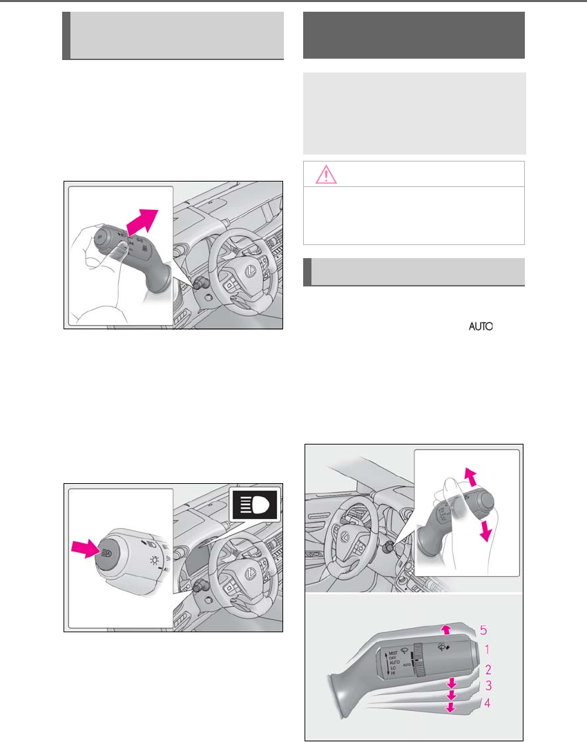
190 4-3. Operating the lights and wipers
LS500h_OM_OM50F42U_(U)
■Switching to the low beams
Pull the lever to its original position.
The AHB indicator will turn off.
Push the lever away from you to activate
the Automatic High Beam system again.
■Switching to the high beams
Press the Automatic High Beam
switch.
The AHB indicator will turn off and the
high beam indicator will turn on.
Press the switch to activate the Automatic
High Beam system again.
Operate the lever and switch as fol-
lows to use the wipers. When is
selected, the wipers will operate auto-
matically when the sensor detects fall-
ing rain. The system automatically
adjusts wiper timing in accordance
with rain volume and vehicle speed.
Turning the high beams on/off
manually
Windshield wipers and
washer
Operating the lever can switch
between automatic operation and
manual operation, or can use the
washer.
NOTICE
■When the windshield is dry
Do not use the wipers, as they may dam-
age the windshield.
Operating the wiper lever
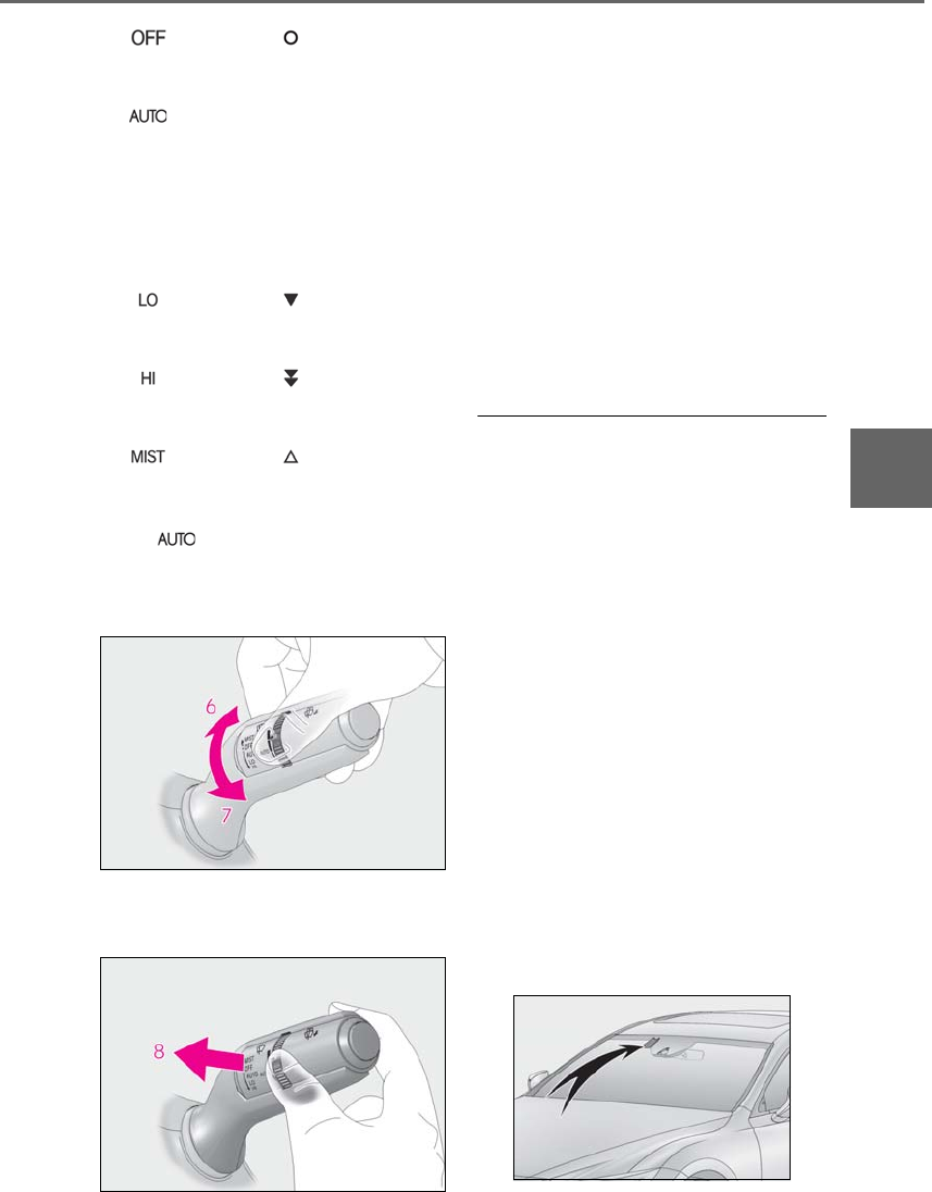
191
4-3. Operating the lights and wipers
LS500h_OM_OM50F42U_(U)
4
Driving
1 (U.S.A.) or (Canada)
Off
2 Rain-sensing wiper operation
The wipers will operate automatically when
the sensor detects falling rain. The system
automatically adjusts wiper timing in
accordance with rain volume and vehicle
speed.
3 (U.S.A.) or (Canada)
Low speed wiper operation
4 (U.S.A.) or (Canada)
High speed wiper operation
5 (U.S.A.) or (Canada)
Temporary operation
When is selected, the sensor sen-
sitivity can be adjusted by turning the
switch ring.
6Increases the sensitivity
7Decreases the sensitivity
8Washer/wiper dual operation
Wipers will automatically operate a couple
of times after the washer squirts.
(After operating several times, the wipers
operate once more time after a short delay
to prevent dripping. However, the dripping
prevention does not operate while the
vehicle is moving.)
Vehicles with headlight cleaners:
When the power switch is in ON mode
and the headlights are on, if the lever is
pulled, the headlight cleaners will operate
once. After this, the headlight cleaners will
operate every 5th time the lever is pulled.
■The windshield wiper and washer can be
operated when
The power switch is in ON mode.
■Effects of vehicle speed on wiper opera-
tion
Even when the wipers are not in AUTO
mode, vehicle speed affects the time until
the drip prevention wiper sweep occurs.
With low speed windshield wiper operation
selected, wiper operation will be switched
from low speed to intermittent wiper opera-
tion only when the vehicle is stationary.
(However, when the sensor sensitivity is
adjusted to the highest level, the mode can-
not be switched.)
■Raindrop sensor
●The raindrop sensor judges the amount
of raindrops.
An optical sensor is adopted. It may not
operate properly when sunlight from the
rising or setting of the sun intermittently
strikes the windshield, or if bugs etc. are
present on the windshield.
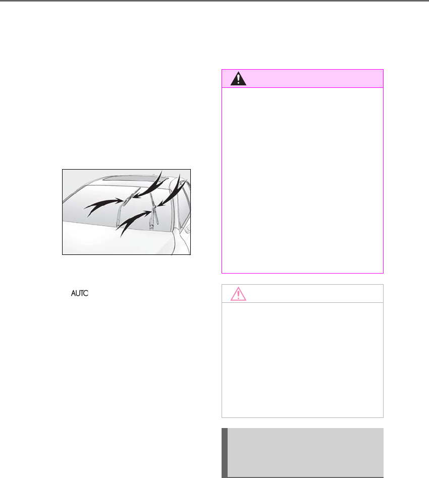
192 4-3. Operating the lights and wipers
LS500h_OM_OM50F42U_(U)
●If the wiper is turned to AUTO mode
while the power switch is in ON mode,
the wipers will operate once to show that
AUTO mode is activated.
●If the temperature of the raindrop sensor
is 185°F (85°C) or higher, or 5°F
(-15°C) or lower, automatic operation
may not occur. In this case, operate the
wipers in any mode other than AUTO
mode.
■If no windshield washer fluid sprays
Check that the washer nozzles are not
blocked if there is washer fluid in the wind-
shield washer fluid reservoir.
■Front door opening linked windshield
wiper stop function
When is selected and the windshield
wipers are operating, if a front door is
opened while the vehicle is stopped and the
P shift position is selected, operation of the
windshield wipers will be stopped to pre-
vent anyone near the vehicle from being
sprayed by water from the wipers. When
the front door is closed, wiper operation will
resume.
■When stopping hybrid system in an
emergency while driving
If the windshield wipers are operating when
hybrid system is stopped, the windshield
wipers will operate in high speed operation.
After the vehicle is stopped, operation will
return to normal when the power switch is
turned to ON mode, or operation will stop
when the driver’s door is opened.
■Outside rear view mirror defogger acti-
vation linked to windshield wiper opera-
tion
The outside rear view mirror defoggers
automatically turn on when you operate the
windshield wipers.
The outside rear view mirror defoggers
automatically turn off approximately 15
minutes after the wipers stop.
For details about the outside rear view mir-
ror defoggers: →P.324
When the windshield wipers are not
being used, they retract to below the
hood. To enable the windshield wipers
to be lifted when parking in cold condi-
tions or when replacing a windshield
WARNING
■Caution regarding the use of wind-
shield wipers in AUTO mode
The windshield wipers may operate
unexpectedly if the sensor is touched or
the windshield is subject to vibration in
AUTO mode. Take care that your fingers
or anything else do not become caught
in the windshield wipers.
■Caution regarding the use of washer
fluid
When it is cold, do not use the washer
fluid until the windshield becomes warm.
The fluid may freeze on the windshield
and cause low visibility. This may lead to
an accident, resulting in death or serious
injury.
NOTICE
■When there is no washer fluid spray
from the nozzle
Damage to the washer fluid pump may
be caused if the lever is pulled toward
you and held continually.
■When a nozzle becomes blocked
In this case, contact your Lexus dealer.
Do not try to clear it with a pin or other
object. The nozzle will be damaged.
Changing the windshield wiper
rest position/Lifting the wind-
shield wipers
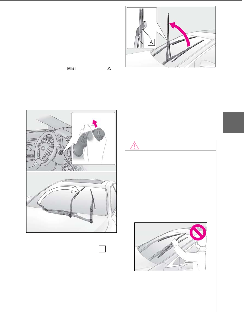
193
4-3. Operating the lights and wipers
LS500h_OM_OM50F42U_(U)
4
Driving
wiper insert, change the rest position of
the windshield wipers to the service
position using the wiper lever.
■Raising the wipers to the service
position
Within approximately 45 seconds of
turning the power switch off, move the
wiper lever to the (U.S.A.) or
(Canada) position and hold it for
approximately 2 seconds or more.
The wipers will move to the service posi-
tion.
■Lifting the windshield wipers
While holding the hook portion of
the wiper arm, lift the windshield wiper
from the windshield.
■Lowering the windshield wipers to the
retracted position
With the windshield wipers placed on the
windshield, turn the power switch to ON
mode and then move the wiper lever to an
operating position. When the wiper switch
is turned off, the windshield wipers will stop
at the retracted position. Even if the wipers
deviate while the power switch is off, the
wipers will return to the normal position.
A
NOTICE
■When lifting the windshield wipers
●Do not lift the windshield wipers when
they are in the retracted position
below the hood. Otherwise, they may
contact the hood, possibly resulting in
damage to a windshield wiper and/or
the hood.
●Do not lift a windshield wiper by the
wiper blade. Otherwise, the wiper
blade may be deformed.
●Do not operate the wiper lever when
the windshield wipers are lifted. Oth-
erwise, the windshield wipers may
contact the hood, possibly resulting in
damage to the windshield wipers
and/or hood.

194 4-4. Refueling
LS500h_OM_OM50F42U_(U)
4-4.Refueling
-Close all the doors and windows,
and turn the power switch off.
-Confirm the type of fuel.
■Fuel types
→P.470
■Fuel tank opening for unleaded gasoline
To help prevent incorrect fueling, your vehi-
cle has a fuel tank opening that only accom-
modates the special nozzle on unleaded
fuel pumps.
Opening the fuel tank cap
The fuel tank of your vehicle has a
special structure, which requires a
reduction in fuel tank pressure
before refueling. After the opener
switch has been pressed, it will take
several seconds until the vehicle is
ready for refueling.
Before refueling the vehicle
WARNING
■When refueling the vehicle
Observe the following precautions while
refueling the vehicle. Failure to do so may
result in death or serious injury.
●After exiting the vehicle and before
opening the fuel door, touch an
unpainted metal surface to discharge
any static electricity. It is important to
discharge static electricity before refu-
eling because sparks resulting from
static electricity can cause fuel vapors
to ignite while refueling.
●Always hold the grips on the fuel tank
cap and turn it slowly to remove it.
A whooshing sound may be heard
when the fuel tank cap is loosened.
Wait until the sound cannot be heard
before fully removing the cap. In hot
weather, pressurized fuel may spray
out the filler neck and cause injury.
●Do not allow anyone that has not dis-
charged static electricity from their
body to come close to an open fuel
tank.
●Do not inhale vaporized fuel.
Fuel contains substances that are
harmful if inhaled.
●Do not smoke while refueling the vehi-
cle.
Doing so may cause the fuel to ignite
and cause a fire.
●Do not return to the vehicle or touch
any person or object that is statically
charged.
This may cause static electricity to
build up, resulting in a possible ignition
hazard.
■When refueling
Observe the following precautions to
prevent fuel overflowing from the fuel
tank:
●Securely insert the fuel nozzle into the
fuel filler neck.
●Stop filling the tank after the fuel noz-
zle automatically clicks off.
●Do not top off the fuel tank.
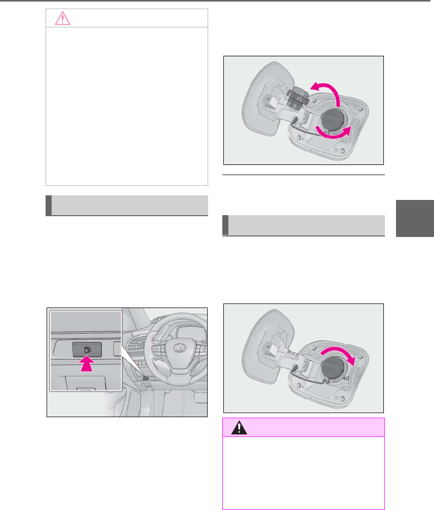
195
4-4. Refueling
LS500h_OM_OM50F42U_(U)
4
Driving
1Press the opener switch.
The fuel filler door will open within about
10 seconds of the switch being pressed.
Before refueling is possible, a message will
be shown on the multi-information display
in the instrument cluster to indicate the
progress of the fuel filler door opener.
2Turn the fuel tank cap slowly and
remove it, then put it into the holder
on the fuel filler door.
■If the fuel filler door cannot be opened
→P.445
After refueling, turn the fuel tank cap
until you hear a click. Once the cap is
released, it will turn slightly in the oppo-
site direction.
NOTICE
■Refueling
●Finish refueling within 30 minutes. If
more than 30 minutes passes, the
internal valve closes. In this condition,
fuel may overflow during the refueling
process.
Press the fuel filler door opener switch
again.
●Do not spill fuel during refueling.
Doing so may damage the vehicle,
such as causing the emission control
system to operate abnormally or dam-
aging fuel system components or the
vehicle’s painted surface.
Opening the fuel tank cap
Closing the fuel tank cap
WARNING
■When replacing the fuel tank cap
Do not use anything but a genuine Lexus
fuel tank cap designed for your vehicle.
Doing so may cause a fire or other inci-
dent which may result in death or serious
injury.

196 4-5. Using the driving support systems
LS500h_OM_OM50F42U_(U)
4-5.Using the dr iving support systems
*:If equipped
■PCS (Pre-Collision System)(vehi-
cles with Lexus Safety System+A)
→P.209
■FCTA (Front Cross Traffic Alert)
→P.227
■LTA (Lane Tracing Assist)
→P.230
■AHB (Automatic High Beam)
→P.188
■RSA (Road Sign Assist)
→P.247
■Dynamic radar cruise control with
full-speed range
→P.250
The pre-collision system is equipped
with a sophisticated computer that will
record certain data, such as:
• Accelerator status
•Brake status
• Vehicle speed
• Operation status of the pre-collision
system functions
• Information (such as the distance
and relative speed between your
vehicle and the vehicle ahead or
other objects)
• Images from the camera sensor
(available only in situations when
sudden inputs occur while driving
[sudden acceleration, etc.], the
pre-collision braking function or the
pre-collision brake assist function
was operating, the Parking Support
Brake function [static objects] was
operating, or your vehicle was
involved in a collision)
The pre-collision system does not
Lexus Safety System+A*
The Lexus Safety System+A con-
sists of the following drive assist sys-
tems and contributes to a safe and
comfortable driving experience:
Drive assist systems of Lexus
Safety System+A
WARNING
■Lexus Safety System+A
The Lexus Safety System+A is designed
to operate under the assumption that the
driver will drive safely, and is designed to
help reduce the impact to the occupants
and the vehicle in the case of a collision
or assist the driver in normal driving con-
ditions.
As there is a limit to the degree of recog-
nition accuracy and control performance
that this system can provide, do not
overly rely on this system. The driver is
always responsible for paying attention
to the vehicle’s surroundings and driving
safely.
Vehicle data recording
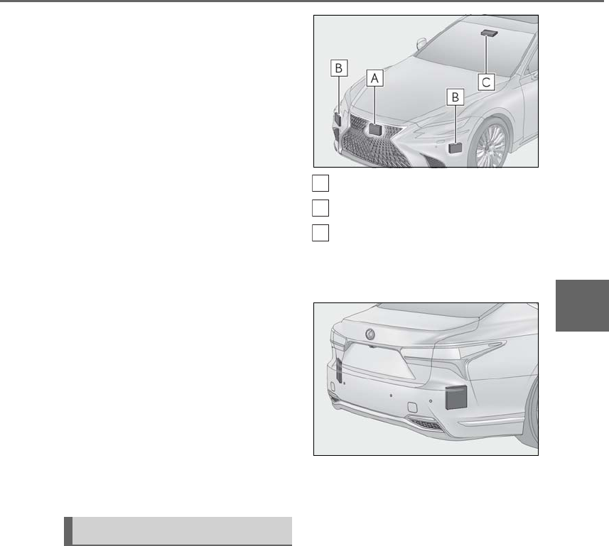
197
4-5. Using the driving support systems
LS500h_OM_OM50F42U_(U)
4
Driving
record conversations, sounds or
images of the inside of the vehicle.
-Data usage
Lexus may use the data recorded in this
computer to diagnose malfunctions, con-
duct research and development, and
improve quality.
Lexus will not disclose the recorded data to
a third party except:
• With the consent of the vehicle owner or
with the consent of the lessee if the vehi-
cle is leased
• In response to an official request by the
police, a court of law or a government
agency
• For use by Lexus in a lawsuit
• For research purposes where the data is
not tied to a specific vehicle or vehicle
owner
-Recorded images can be erased
using a specialized device.
The image recording function can be dis-
abled. However, if the function is disabled,
data from when the pre-collision system
operates will not be available.
Four types of sensors, located behind
the front grille, front bumper, rear
bumper and windshield, detect infor-
mation necessary to operate the drive
assist systems.
-Front
Front radar sensor
Front side radar sensors
Camera sensor
-Rear
Rear side radar sensors (→P.260)
Sensors
A
B
C
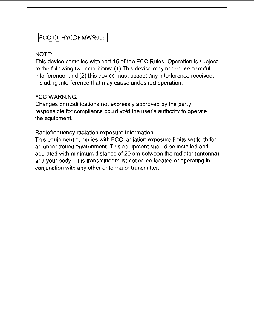
198 4-5. Using the driving support systems
LS500h_OM_OM50F42U_(U)
■Certification
For vehicles sold in the U.S.A., Hawaii
199
4-5. Using the driving support systems
LS500h_OM_OM50F42U_(U)
4
Driving
For vehicles sold in Canada
WARNING
■To avoid malfunction of the front
radar sensor
Observe the following precautions.
Otherwise, the radar sensor may not
operate properly, possibly leading to an
accident resulting in death or serious
injury.
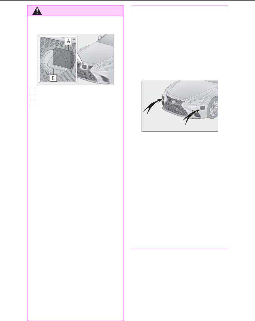
200 4-5. Using the driving support systems
LS500h_OM_OM50F42U_(U)
WARNING
●Keep the radar sensor and front grille
emblem clean at all times.
Radar sensor
Front grille emblem
If the front of the radar sensor or the front
or back of the front grille emblem is dirty
or covered with water droplets, snow,
etc., clean it.
Clean the radar sensor and front grille
emblem with a soft cloth so you do not
mark or damage them.
●Do not attach accessories, stickers
(including transparent stickers), or
other items to the radar sensor, front
grille emblem or surrounding area.
●Do not subject the radar sensor or sur-
rounding area to a strong impact.
If the radar sensor is moved even
slightly off position, the system may
malfunction and objects may not be
detected correctly.
If the radar sensor, front grille, or front
bumper has been subjected to a
strong impact, have the vehicle
inspected by your Lexus dealer.
●Do not disassemble the radar sensor.
●Do not modify or paint the radar sen-
sor, front grille emblem or surrounding
area.
●If the radar sensor, front grille, or front
bumper needs to be removed and
installed, or replaced, contact your
Lexus dealer.
A
B
■To avoid malfunction of the front side
radar sensors
Observe the following precautions.
Otherwise, the radar sensor may not
operate properly, possibly leading to an
accident resulting in death or serious
injury.
●Keep the radar sensors and their sur-
rounding areas on the front bumper
clean at all times.
If a radar sensor or its surrounding area
on the front bumper is dirty or covered
with snow, the system may not operate
and a warning message (→P.440) will
be displayed.
If this occurs, clean off the dirt or snow
and drive the vehicle for approximately
10 minutes.
If the warning message does not disap-
pear, have your vehicle inspected by your
Lexus dealer.
●Do not attach accessories, stickers
(including transparent stickers), alumi-
num tape or other items to the radar
sensors or their surrounding area.
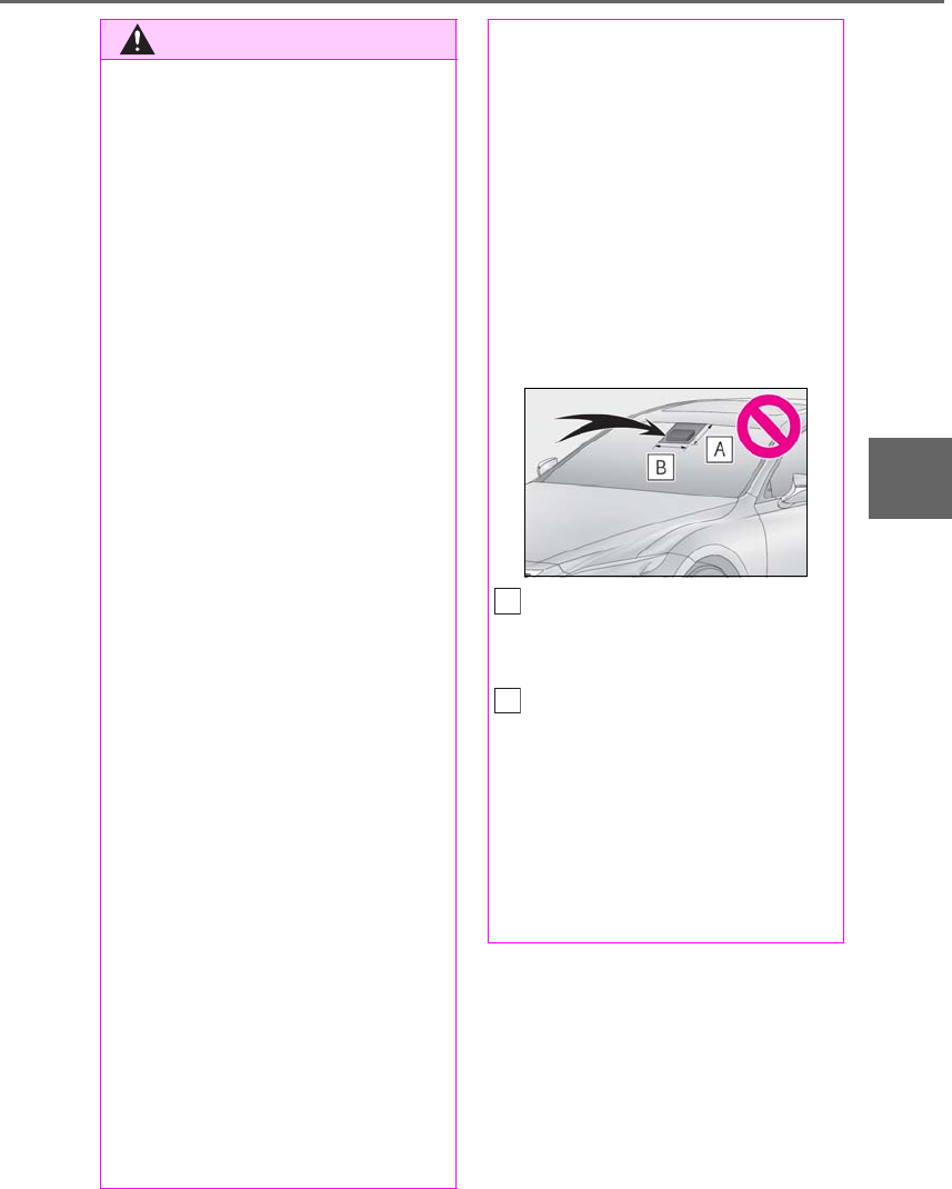
201
4-5. Using the driving support systems
LS500h_OM_OM50F42U_(U)
4
Driving
WARNING
●Do not subject a radar sensor or its
surrounding area on the front bumper
to a strong impact.
If a radar sensor is moved even slightly
off position, the system may malfunction
and vehicles may not be detected cor-
rectly.
In the following situations, have your
vehicle inspected by your Lexus dealer.
• If a radar sensor or its surrounding
area is subject to a strong impact
• If the area on the front bumper around
a radar sensor is scratched or dented,
or the front bumper has become par-
tially disengaged
●Do not disassemble the radar sensors.
●Do not modify the radar sensors or
their surrounding area on the front
bumper.
●If a radar sensor or the front bumper
needs to be removed and installed, or
replaced, contact your Lexus dealer.
●Do not paint the front bumper any
color other than an official Lexus color.
■To avoid malfunction of the camera
sensor
Observe the following precautions.
Otherwise, the camera sensor may not
operate properly, possibly leading to an
accident resulting in death or serious
injury.
●Keep the windshield clean at all times.
• If the windshield is dirty or covered
with an oily film, water droplets, snow,
etc., clear the windshield.
• As some glass coating agents may
affect the detection performance of
the camera sensor, consult your Lexus
dealer when using a glass coating
agent.
• If a glass coating agent is applied to the
windshield, it will still be necessary to
use the windshield wipers to remove
water droplets, etc. from the area of
the windshield in front of the camera
sensor.
• If the inner side of the windshield
where the camera sensor is installed is
dirty, contact your Lexus dealer.
●Do not attach objects, such as stickers,
transparent stickers, and so forth, to
the outer side of the windshield in front
of the camera sensor (shaded area in
the illustration).
From the top of the windshield to
approximately 0.4 in. (1 cm) below
the bottom of the camera sensor
Approximately 14.2 in. (36 cm)
(Approximately 7.1 in. [18 cm] to the
right and left from the center of the
camera sensor)
●If the part of the windshield in front of
the camera sensor is fogged up or
covered with condensation or ice, use
the windshield defogger to remove the
fog, condensation or ice. (→P.324)
A
B

202 4-5. Using the driving support systems
LS500h_OM_OM50F42U_(U)
WARNING
●If water droplets cannot be properly
removed from the area of the wind-
shield in front of the camera sensor by
the windshield wipers, replace the
wiper insert or wiper blade.
If the wiper inserts or wiper blades need
to be replaced, contact your Lexus
dealer.
●Do not attach window tinting to the
windshield.
●Replace the windshield if it is damaged
or cracked.
If the windshield needs to be replaced,
contact your Lexus dealer.
●Do not get the camera sensor wet.
●Do not allow bright lights to shine into
the camera sensor.
●Do not dirty or damage the camera
sensor.
When cleaning the inside of the wind-
shield, do not allow glass cleaner to
contact the lens. Also, do not touch the
lens.
If the lens is dirty or damaged, contact
your Lexus dealer.
●Do not subject the camera sensor to a
strong impact.
●Do not change the installation position
or direction of the camera sensor or
remove it.
●Do not disassemble the camera sen-
sor.
●Do not modify any components of the
vehicle around the camera sensor
(inside rear view mirror, etc.) or ceiling.
●Do not attach any accessories that
may obstruct the camera sensor to the
hood, front grille or front bumper.
Contact your Lexus dealer.
●If a surfboard or other long object is to
be mounted on the roof, make sure
that it will not obstruct the camera sen-
sor.
●Do not modify the headlights or other
lights.

203
4-5. Using the driving support systems
LS500h_OM_OM50F42U_(U)
4
Driving
*:If equipped
■PCS (Pre-Collision System)(vehi-
cles with Lexus Safety System+)
→P.220
■LKA (Lane-Keeping Assist)
→P.240
■AHB (Automatic High Beam)
→P.188
■Dynamic radar cruise control with
full-speed range
→P.250
The pre-collision system is equipped
with a sophisticated computer that will
record certain data, such as:
• Accelerator status
•Brake status
• Vehicle speed
• Operation status of the pre-collision
system functions
• Information (such as the distance
and relative speed between your
vehicle and the vehicle ahead or
other objects)
• Images from the camera sensor
(available only when the pre-colli-
sion braking function or the pre-col-
lision brake assist function was
operating)
The pre-collision system does not
record conversations, sounds or
images of the inside of the vehicle.
-Data usage
Lexus may use the data recorded in this
computer to diagnose malfunctions, con-
duct research and development, and
improve quality.
Lexus will not disclose the recorded data to
a third party except:
• With the consent of the vehicle owner or
with the consent of the lessee if the vehi-
cle is leased
• In response to an official request by the
police, a court of law or a government
agency
Lexus Safety System+*
The Lexus Safety System+ consists
of the following drive assist systems
and contributes to a safe and com-
fortable driving experience:
Drive assist systems of Lexus
Safety System+
WARNING
■Lexus Safety System+
The Lexus Safety System+ is designed to
operate under the assumption that the
driver will drive safely, and is designed to
help reduce the impact to the occupants
and the vehicle in the case of a collision
or assist the driver in normal driving con-
ditions.
As there is a limit to the degree of recog-
nition accuracy and control performance
that this system can provide, do not
overly rely on this system. The driver is
always responsible for paying attention
to the vehicle’s surroundings and driving
safely.
Vehicle data recording
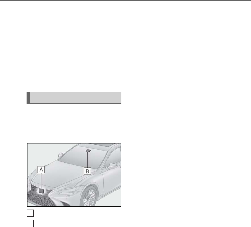
204 4-5. Using the driving support systems
LS500h_OM_OM50F42U_(U)
• For use by Lexus in a lawsuit
• For research purposes where the data is
not tied to a specific vehicle or vehicle
owner
-Recorded images can be erased
using a specialized device.
The image recording function can be dis-
abled. However, if the function is disabled,
data from when the pre-collision system
operates will not be available.
Two types of sensors, located behind
the front grille and windshield, detect
information necessary to operate the
drive assist systems.
Radar sensor
Camera sensor
Sensors
A
B
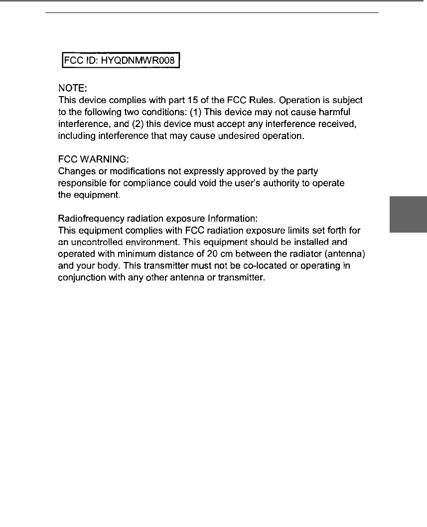
205
4-5. Using the driving support systems
LS500h_OM_OM50F42U_(U)
4
Driving
■Certification
For vehicles sold in the U.S.A., Hawaii, Guam and Puerto Rico
206 4-5. Using the driving support systems
LS500h_OM_OM50F42U_(U)
For vehicles sold in Canada
WARNING
■To avoid malfunction of the radar sen-
sor
Observe the following precautions.
Otherwise, the radar sensor may not
operate properly, possibly leading to an
accident resulting in death or serious
injury.
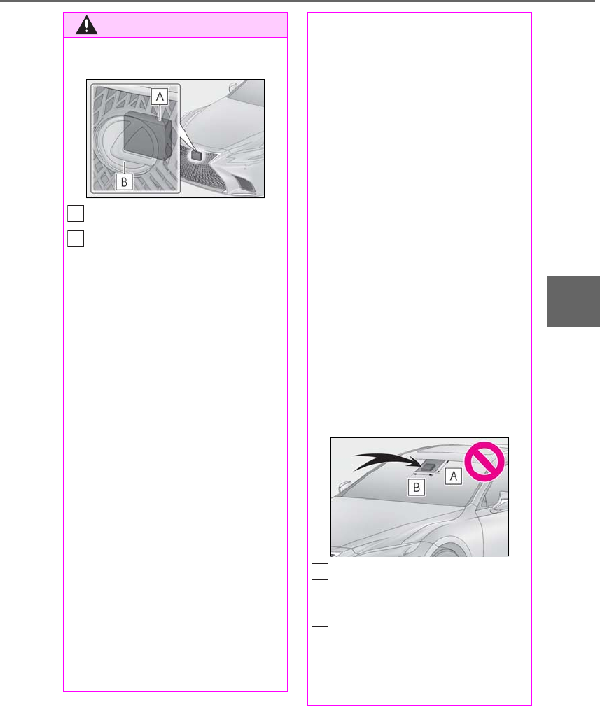
207
4-5. Using the driving support systems
LS500h_OM_OM50F42U_(U)
4
Driving
WARNING
●Keep the radar sensor and front grille
emblem clean at all times.
Radar sensor
Front grille emblem
If the front of the radar sensor or the front
or back of the front grille emblem is dirty
or covered with water droplets, snow,
etc., clean it.
Clean the radar sensor and front grille
emblem with a soft cloth so you do not
mark or damage them.
●Do not attach accessories, stickers
(including transparent stickers), or
other items to the radar sensor, front
grille emblem or surrounding area.
●Do not subject the radar sensor or sur-
rounding area to a strong impact.
If the radar sensor, front grille, or front
bumper has been subjected to a
strong impact, have the vehicle
inspected by your Lexus dealer.
●Do not disassemble the radar sensor.
●Do not modify or paint the radar sen-
sor, front grille emblem or surrounding
area.
●If the radar sensor, front grille, or front
bumper needs to be removed and
installed, or replaced, contact your
Lexus dealer.
A
B
■To avoid malfunction of the camera
sensor
Observe the following precautions.
Otherwise, the camera sensor may not
operate properly, possibly leading to an
accident resulting in death or serious
injury.
●Keep the windshield clean at all times.
• If the windshield is dirty or covered
with an oily film, water droplets, snow,
etc., clear the windshield.
• If a glass coating agent is applied to the
windshield, it will still be necessary to
use the windshield wipers to remove
water droplets, etc. from the area of
the windshield in front of the camera
sensor.
• If the inner side of the windshield
where the camera sensor is installed is
dirty, contact your Lexus dealer.
●Do not attach objects, such as stickers,
transparent stickers, and so forth, to
the outer side of the windshield in front
of the camera sensor (shaded area in
the illustration).
From the top of the windshield to
approximately 0.4 in. (1 cm) below
the bottom of the camera sensor
Approximately 7.9 in. (20 cm)
(Approximately 4.0 in. [10 cm] to the
right and left from the center of the
camera sensor)
A
B

208 4-5. Using the driving support systems
LS500h_OM_OM50F42U_(U)
WARNING
●If the part of the windshield in front of
the camera sensor is fogged up or
covered with condensation or ice, use
the windshield defogger to remove the
fog, condensation or ice. (→P.324)
●If water droplets cannot be properly
removed from the area of the wind-
shield in front of the camera sensor by
the windshield wipers, replace the
wiper insert or wiper blade.
If the wiper inserts or wiper blades need
to be replaced, contact your Lexus
dealer.
●Do not attach window tinting to the
windshield.
●Replace the windshield if it is damaged
or cracked.
If the windshield needs to be replaced,
contact your Lexus dealer.
●Do not get the camera sensor wet.
●Do not allow bright lights to shine into
the camera sensor.
●Do not dirty or damage the camera
sensor.
When cleaning the inside of the wind-
shield, do not allow glass cleaner to
contact the lens. Also, do not touch the
lens.
If the lens is dirty or damaged, contact
your Lexus dealer.
●Do not subject the camera sensor to a
strong impact.
●Do not change the installation position
or direction of the camera sensor or
remove it.
●Do not disassemble the camera sen-
sor.
●Do not modify any components of the
vehicle around the camera sensor
(inside rear view mirror, etc.) or ceiling.
●Do not attach any accessories that
may obstruct the camera sensor to the
hood, front grille or front bumper.
Contact your Lexus dealer.
●If a surfboard or other long object is to
be mounted on the roof, make sure
that it will not obstruct the camera sen-
sor.
●Do not modify the headlights or other
lights.
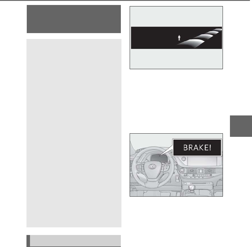
209
4-5. Using the driving support systems
LS500h_OM_OM50F42U_(U)
4
Driving
■Pedestrian alert
When the system determines that
there is a possibility of a frontal collision
with a stationary or moving pedestrian
in front of your vehicle, a message will
be displayed on the head-up display to
warn the driver.
■Pre-collision warning
When the system determines that the
possibility of a frontal collision is high, a
buzzer will sound and a warning mes-
sage will be displayed on the
multi-information display to urge the
driver to take evasive action.
■Pre-collision brake assist
When the system determines that the
possibility of a frontal collision is high,
the system applies greater braking
force in relation to how strongly the
brake pedal is depressed.
■Pre-collision braking
When the system determines that the
possibility of a frontal collision is high,
the system warns the driver. If the sys-
tem determines that the possibility of a
frontal collision is extremely high, the
brakes are automatically applied to
help avoid the collision or reduce the
collision speed.
PCS (Pre-Collision System)
(vehicles with Lexus Safety
System+A)
The pre-collision system uses a
front radar sensor and camera sen-
sor to detect vehicles and pedestri-
ans in front of your vehicle and front
side sensors to detect vehicles
approaching from the front left or
right side. When the system deter-
mines that the possibility of a frontal
collision with a vehicle or pedes-
trian is high, a warning operates to
urge the driver to take evasive
action and the potential brake pres-
sure is increased to help the driver
avoid the collision. If the system
determines that the possibility of a
frontal collision with a vehicle or
pedestrian is extremely high, the
brakes are automatically applied to
help avoid the collision or help
reduce the impact of the collision.
The pre-collision system can be dis-
abled/enabled and the warning tim-
ing can be changed. (→P.213)
System functions

210 4-5. Using the driving support systems
LS500h_OM_OM50F42U_(U)
■Active steering assist
If the system determines that the possi-
bility of a collision with an object, such
as a guardrail, or pedestrian is high,
even though the brakes are applied,
and that the collision may be avoidable
through steering control, the system
will steer the vehicle automatically to
help avoid the collision or help reduce
the impact of the collision.
■Pre-collision seat belts (front seat
only)
If the system determines that the possi-
bility of a frontal collision is high, the
system will retract the seat belts. Addi-
tionally, the system may retract the seat
belts if the brakes are applied suddenly
or control of the vehicle is lost.
■Pre-collision seatbacks (front pas-
senger’s seat / power rear seat [if
equipped])
If the system determines that the possi-
bility of a frontal collision is high, it may
move the seatbacks of the front pas-
senger’s seat and power rear seats to
the upright position automatically, if
reclined.
If a seat is being adjusted, it may not be
moved by the pre-collision seat function.
■Suspension control
When the system determines that the
possibility of a frontal collision is high,
the Adaptive Variable Suspension Sys-
tem (→P.303) will control the damp-
ing force of the shock absorbers to
help maintain an appropriate vehicle
posture.
■Steering control
When the system determines that the
possibility of a frontal collision is high
and the driver is operating the steering
wheel, the LDH system (→P.303) will
control the turning angle of the front
and rear wheels and effort necessary
to turn the steering wheel to help
enhance steering responsiveness.
WARNING
■Limitations of the pre-collision system
●The driver is solely responsible for safe
driving. Always drive safely, taking
care to observe your surroundings.
Do not use the pre-collision system
instead of normal braking operations
under any circumstances. This system
will not prevent collisions or lessen col-
lision damage or injury in every situa-
tion. Do not overly rely on this system.
Failure to do so may lead to an acci-
dent, resulting in death or serious
injury.
●Although this system is designed to
help avoid a collision or help reduce
the impact of the collision, its effective-
ness may change according to various
conditions, therefore the system may
not always be able to achieve the same
level of performance.
Read the following conditions care-
fully. Do not overly rely on this system
and always drive carefully.
• Conditions under which the system
may operate even if there is no possi-
bility of a collision: →P.214
• Conditions under which the system
may not operate properly: →P.216
●Do not attempt to test the operation of
the pre-collision system yourself, as the
system may not operate properly, pos-
sibly leading to an accident.

211
4-5. Using the driving support systems
LS500h_OM_OM50F42U_(U)
4
Driving
WARNING
■Pre-collision braking
●When the pre-collision braking func-
tion is operating, a large amount of
braking force will be applied.
●If the vehicle is stopped by the opera-
tion of the pre-collision braking func-
tion, the pre-collision braking function
operation will be canceled after
approximately 2 seconds. Depress the
brake pedal as necessary.
●The pre-collision braking function may
not operate if certain operations are
performed by the driver. If the acceler-
ator pedal is being depressed strongly
or the steering wheel is being turned,
the system may determine that the
driver is taking evasive action and may
prevent the pre-collision braking func-
tion from operating.
●In some situations, while the pre-colli-
sion braking function is operating,
operation of the function may be can-
celed if the accelerator pedal is
depressed strongly or the steering
wheel is turned and the system deter-
mines that the driver is taking evasive
action.
●If the brake pedal is being depressed,
the system may determine that the
driver is taking evasive action and pos-
sibly delay the operation timing of the
pre-collision braking function.
■Active steering assist
●The steering wheel may turn automati-
cally when active steering assist is
operating.
●As active steering assist operation will
be canceled when the system deter-
mines that a collision has been
avoided, operate the steering wheel as
necessary.
●In the following situations, the system
may determine that the driver is taking
evasive action. In this case, the active
steering assist may not operate or may
be canceled.
• If the accelerator pedal is being
depressed strongly or the steering
wheel is being operated. In this case
the system may determine that the
driver is taking evasive action and the
pre-collision braking may not operate.
• In some situations, while the active
steering assist is operating, operation
of the function may be canceled if the
accelerator pedal is depressed
strongly or the steering wheel is turned
and the system determines that the
driver is taking evasive action.
• When the active steering assist is
operating, if the steering wheel is held
firmly or is operated in the opposite
direction to that which the system is
generating torque, the function may be
canceled.
• If the brake pedal is depressed, the sys-
tem may determine that the driver is
taking evasive action and the active
steering assist operation may be
delayed.
■Pre-collision seat belts with comfort
function
If the pre-collision seat belts have oper-
ated and the seat belts are locked in a
retracted position, immediately stop the
vehicle in a safe place, release and
retract the seat belts to unlock them and
then fasten them again.
Also, if a seat belt can be loosened, it can
be unlocked by slightly retracting it with-
out releasing it.
■When to disable the pre-collision sys-
tem
In the following situations, disable the
system, as it may not operate properly,
possibly leading to an accident resulting
in death or serious injury:
●When the vehicle is being towed
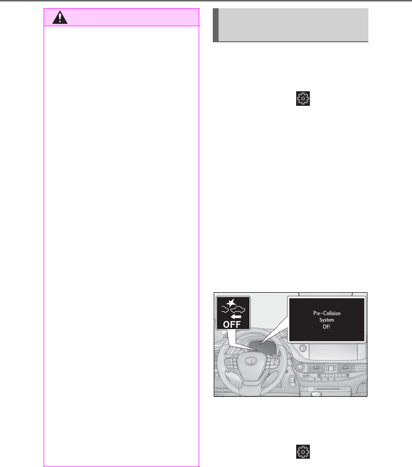
212 4-5. Using the driving support systems
LS500h_OM_OM50F42U_(U)
■Enabling/disabling the pre-colli-
sion system
The pre-collision system can be
enabled/disabled on (→P.86) of
the multi-information display.
The system is automatically enabled each
time the power switch is turned to ON
mode
If the system is disabled, the PCS warn-
ing light will turn on and a message will
be displayed on the multi-information
display.
If the pre-collision system is disabled,
the pedestrian alert system will also be
disabled. At this time, the FCTA (Front
Cross Traffic Alert) (→P.227) system
will also be disabled.
■Enabling/Disabling the pedestrian
alert system
The pedestrian alert can be
enabled/disabled on (→P.86) of
the multi-information display. At this
time, the FCTA (Front Cross Traffic
Alert) system will also be enabled/dis-
abled.
WARNING
●When your vehicle is towing another
vehicle
●When transporting the vehicle via
truck, boat, train or similar means of
transportation
●When the vehicle is raised on a lift with
the hybrid system on and the tires are
allowed to rotate freely
●When inspecting the vehicle using a
drum tester such as a chassis dyna-
mometer or speedometer tester, or
when using an on vehicle wheel bal-
ancer
●When a strong impact has been
applied to the front bumper, rear
bumper or front grille, due to an acci-
dent or other situation
●If the vehicle cannot be driven in a sta-
ble manner, such as when the vehicle
has been in an accident or is malfunc-
tioning
●When the vehicle is driven in a sporty
manner or off-road
●When the tires are not properly
inflated
●When the tires are very worn
●When tires of a size other than speci-
fied are installed
●When tire chains are installed
●When a compact spare tire or an
emergency tire puncture repair kit is
used
●If equipment (snow plow, etc.) that may
obstruct a sensor is temporarily
installed to the vehicle
Changing settings of the pre-col-
lision system
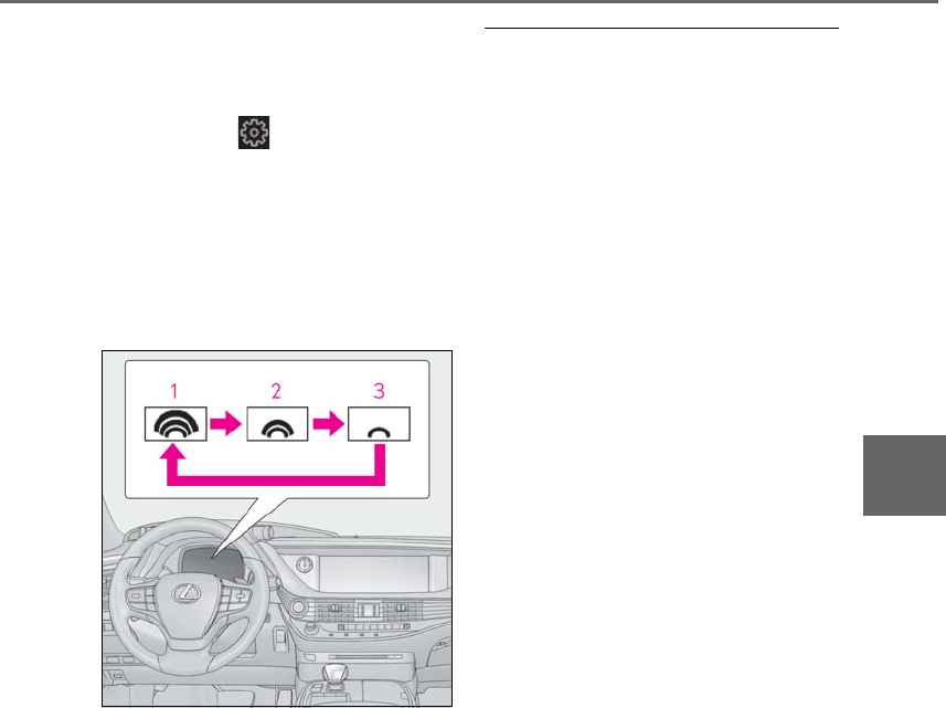
213
4-5. Using the driving support systems
LS500h_OM_OM50F42U_(U)
4
Driving
■Changing the pre-collision warn-
ing timing
The pre-collision warning timing can
be changed on (→P.86) of the
multi-information display. The warning
timing for the pedestrian and FCTA
(Front Cross Traffic Alert) system will
also be changed.
The operation timing setting is retained
when the power switch is turned off.
1Far
The warning will begin to operate earlier
than with the default timing.
2Middle
This is the default setting.
3Near
The warning will begin to operate later
than with the default timing.
■Changing the pedestrian alert tim-
ing
If the pre-collision warning timing is
changed, the pedestrian alert and
FCTA (Front Cross Traffic Alert) timing
will also be changed accordingly.
■Operational conditions
The pre-collision system is enabled and the
system determines that the possibility of a
frontal collision with a vehicle, pedes-
trian/bicyclist, guardrail, etc. or a front side
collision with a vehicle is high. Each function
is operational at the following speeds:
●Pedestrian alert:
• Vehicle speed is between approximately
20 and 40 mph (30 and 65 km/h)
●Pre-collision warning:
• Vehicle speed is between approximately
3 and 110 mph (5 and 180 km/h). (For
detecting a pedestrian or bicyclist, vehi-
cle speed is between approximately 3
and 50 mph [5 and 80 km/h] and for
detecting a vehicle approaching from the
front left or right side, vehicle speed is
between approximately 7 and 37 mph
[10 and 60 km/h].)
• The relative speed between your vehicle
and the detected pedestrian, bicyclist or
vehicle ahead is approximately 3 mph (5
km/h) or more. (For detecting a vehicle
approaching from the front left or right
side, the speed of the approaching vehi-
cle is between approximately 10 and 37
mph [15 and 60 km/h].)
●Pre-collision brake assist:
• Vehicle speed is between approximately
20 and 110 mph (30 and 180 km/h). (For
detecting a pedestrian or bicyclist, vehi-
cle speed is between approximately 20
and 50 mph [30 and 80 km/h] and for
detecting a vehicle approaching from the
front left or right side, vehicle speed is
between approximately 19 and 37 mph
[30 and 60 km/h].)
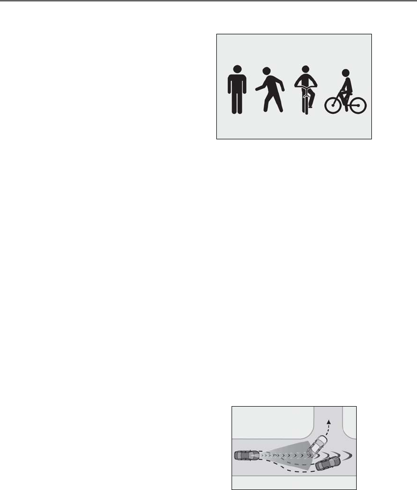
214 4-5. Using the driving support systems
LS500h_OM_OM50F42U_(U)
• The relative speed between your vehicle
and the detected pedestrian, bicyclist or
vehicle ahead is approximately 20 mph
(30 km/h) or more. (For detecting a vehi-
cle approaching from the front left or
right side, the speed of the approaching
vehicle is between approximately 10 and
37 mph [15 and 60 km/h].)
●Pre-collision braking:
• Vehicle speed is between approximately
3 and 110 mph (5 and 180 km/h). (For
detecting a pedestrian or bicyclist, vehi-
cle speed is between approximately 3
and 50 mph [5 and 80 km/h].)
• The relative speed between your vehicle
and the detected pedestrian, bicyclist or
vehicle ahead is approximately 3 mph (5
km/h) or more.
●Active steering assist
• Vehicle speed is between approximately
25 and 50 mph (40 and 80 km/h). (For
detecting a pedestrian, vehicle speed is
between approximately 25 and 40 mph
[40 and 65 km/h] and for detecting a
guardrail, vehicle speed is between
approximately 37 and 50 mph [60 and
80 km/h].)
The system may not operate in the following
situations:
●If a 12-volt battery terminal has been dis-
connected and reconnected and then the
vehicle has not been driven for a certain
amount of time
●If the shift position is in R
●If VSC is disabled (only the pedestrian
alert and pre-collision warning function
will be operational)
●When there is insufficient safe or unob-
structed space for the vehicle to be
steered into
●When an object is approaching the area
the vehicle is to be steered into
■Pedestrian and bicyclist detection func-
tion
The pre-collision system detects pedestri-
ans and bicyclists based on the size, profile,
and motion of the person. However, a
pedestrian or bicyclist may not be detected
depending on the surrounding brightness
and the motion, posture, and angle of the
person, preventing the system from operat-
ing properly. (→P.216)
■Cancelation of pre-collision braking
and active steering assist
If either of the following occur while the
pre-collision braking function is operating, it
will be canceled:
●The accelerator pedal is depressed
strongly.
●The steering wheel is turned sharply or
abruptly.
■Conditions under which the system may
operate even if there is no possibility of a
collision
●In some situations such as the following,
the system may determine that there is a
possibility of a frontal collision and oper-
ate.
• When passing a vehicle, pedestrian or
bicyclist
• When changing lanes while overtaking a
preceding vehicle
• When overtaking a preceding vehicle
that is changing lanes
• When overtaking a preceding vehicle
that is making a left/right turn
• When passing a vehicle in an oncoming
lane that is stopped to make a right/left
turn
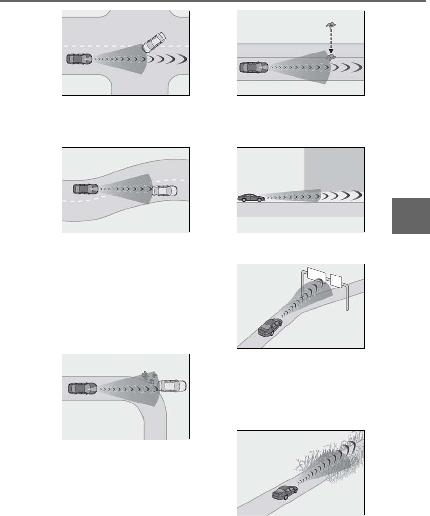
215
4-5. Using the driving support systems
LS500h_OM_OM50F42U_(U)
4
Driving
• When driving on a road where relative
location to vehicle ahead in an adjacent
lane may change, such as on a winding
road
• When rapidly closing on a vehicle ahead
• When the road surface is uneven or
undulating
• If the front of the vehicle is raised or low-
ered
• When approaching objects on the road-
side, such as guardrails, traffic signs, util-
ity poles, street lights, trees, walls, etc.
• When there is a vehicle, pedestrian, bicy-
clist, or object by the roadside at the
entrance of a curve
• When driving on a narrow path sur-
rounded by a structure, such as in a tun-
nel or on an iron bridge
• When there is a metal object (manhole
cover, steel plate, etc.), steps, dips, or a
protrusion on the road surface or road-
side
• When a crossing pedestrian or bicyclist
approaches very close to the vehicle
• When passing through a place with a low
structure above the road such as a low
ceiling, underpass, bridge girder, traffic
sign, etc.
• When passing under an object (billboard,
etc.) at the top of an uphill road
• When rapidly closing on an electric toll
gate barrier, parking area barrier, or
other barrier that opens and closes
• When using an automatic car wash
• When driving through or under objects
that may contact the vehicle, such as thick
grass, tree branches, or a banner
• When the vehicle is hit by water, snow,
dust, etc. from a vehicle ahead
• When driving through steam or smoke
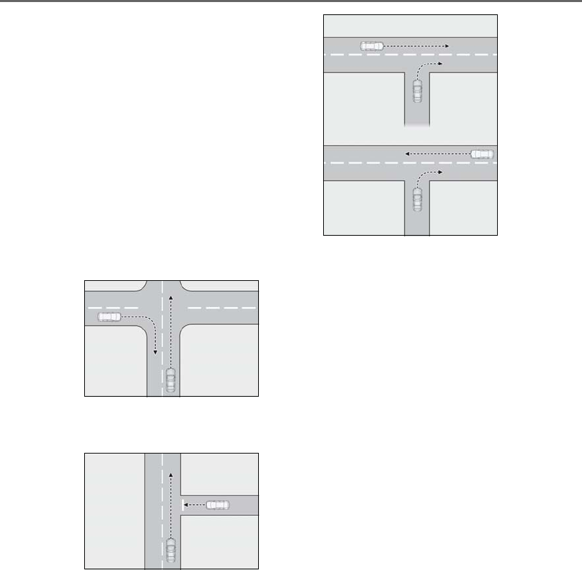
216 4-5. Using the driving support systems
LS500h_OM_OM50F42U_(U)
• When there are patterns or paint on the
road, a wall, or billboard that may be mis-
taken for a vehicle, pedestrian, or bicy-
clist
• When driving near an object that reflects
radio waves, such as a large truck or
guardrail
• When driving near a TV tower, broad-
casting station, electric power plant, or
other location where strong radio waves
or electrical noise may be present
• When passing an oncoming vehicle on a
narrow road
• When driving close to objects such as
walls or poles on a median
• When passing an oncoming vehicle
around a sharp curve
• When passing a vehicle which is making
a left/right turn
• When being passed by a vehicle
approaching from the left or right side in
front of your vehicle
• When making a left/right turn while a
vehicle is approaching from the left or
right side in front of your vehicle
• When passing an object on the side of the
road, such as a parked vehicle
• When passing an oncoming vehicle on a
S curve
• When there is an object that may be mis-
taken for a pedestrian, such as a utility
pole, tree, or pole on the roadside or at
the entrance of a curve
• When there is a bicycle or motorcycle on
the roadside at the entrance of a curve
• If the preceding vehicle is a bicycle or
motorcycle
●The system may operate the pedestrian
alert unnecessarily if it detects the follow-
ing:
• Pedestrians on a sidewalk
• Bicycles and motorcycles
• Patterns or paint on the road, a wall,
median, billboard, etc. that may be mis-
taken for a pedestrian or bicyclist
■Situations in which the system may not
operate properly
●In some situations, such as the following,
a vehicle or other object may not be
detected by the sensors, preventing the
system from operating properly:
• If an oncoming vehicle is approaching
your vehicle
• When approaching the side or front of a
vehicle
• If a preceding vehicle has a small rear
end, such as an unloaded truck
• If a preceding vehicle has a low rear end,
such as a low bed trailer
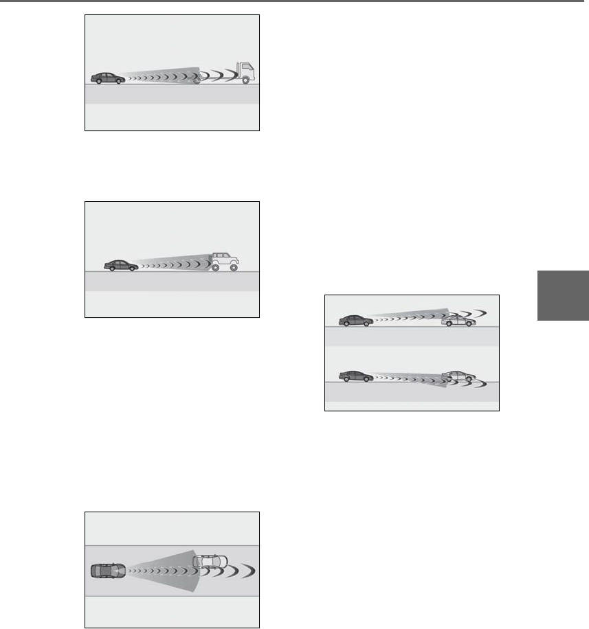
217
4-5. Using the driving support systems
LS500h_OM_OM50F42U_(U)
4
Driving
• If a vehicle ahead is carrying a load which
protrudes past its rear bumper
• If a vehicle ahead has extremely high
ground clearance
• If a vehicle ahead is irregularly shaped,
such as a tractor or side car
• If the sun or other light is shining directly
on a vehicle or guardrail ahead
• If a vehicle cuts in front of your vehicle or
emerges from beside a vehicle
• If a vehicle ahead makes an abrupt
maneuver (such as sudden swerving,
acceleration or deceleration)
• When suddenly cutting behind a preced-
ing vehicle
• When a vehicle ahead is not directly in
front of your vehicle
• When driving in inclement weather such
as heavy rain, fog, snow or a sandstorm
• When the vehicle is hit by water, snow,
dust, etc. from a vehicle ahead
• When driving through steam or smoke
• When driving in a place where the sur-
rounding brightness changes suddenly,
such as at the entrance or exit of a tunnel
• When a very bright light, such as the sun
or the headlights of oncoming traffic,
shines directly into the camera sensor
• When driving in a location where there
are many objects which reflect radar,
such as a tunnel or parking garage
• When driving at night or in a tunnel with
the headlights off
• When the surrounding area is dim, such
as at dawn or dusk, or while at night or in
a tunnel
• After the hybrid system has started the
vehicle has not been driven for a certain
amount of time
• While making a left/right turn and for a
few seconds after making a left/right turn
• While driving on a curve and for a few
seconds after driving on a curve
• If your vehicle is skidding
• If the front of the vehicle is raised or low-
ered
• If the wheels are misaligned
• If a wiper blade is blocking the camera
sensor
• The vehicle is wobbling.
• The vehicle is being driven at extremely
high speeds.
• When driving on a hill
• If a sensor is misaligned
• If the headlights are misaligned
• When approaching a guardrail at a wide
or narrow angle
• When a vehicle approaches your vehicle
from the front left or right side while your
vehicle is entering an intersection with
poor visibility
• When a vehicle approaches your vehicle
from the rear left or right side
• When a vehicle approaches the side of
your vehicle at a shallow angle
• When driving on a road with a grade that
changes sharply (sharp incline/decline)
●In some situations, such as the following,
the sensors may not detect the lane lines
or a safe space the vehicle can be steered

218 4-5. Using the driving support systems
LS500h_OM_OM50F42U_(U)
into, preventing the active steering assist
from operating properly:
• When the white (yellow) lane lines are
difficult to see, such as when they are
faint, diverging/merging, or a shadow is
cast upon them
• When the lane is more wide or narrow
than normal
• When there is a light and dark pattern on
the road surface , such as due to road
repairs
• If the system determines that a collision
can be avoided by only using the brakes
• When a pedestrian is detected near the
centerline of the vehicle
●In some situations such as the following,
sufficient braking force or steering force
may not be obtained, preventing the sys-
tem from performing properly:
• If the braking functions cannot operate to
their full extent, such as when the brake
parts are extremely cold, extremely hot,
or wet
• If the vehicle is not properly maintained
(brakes or tires are excessively worn,
improper tire inflation pressure, etc.)
• When the vehicle is being driven on a
gravel road or other slippery surface
• If there are deep ruts in the road
• When driving on a slope
• When driving on a horizontally slanted
road
●Some pedestrians and bicyclists, such as
the following, may not be detected by the
sensors, preventing the system from
operating properly:
• Pedestrians and bicyclists shorter than
approximately 3.2 ft. (1 m) or taller than
approximately 6.5 ft. (2 m)
• Bicyclists riding on unusual bicycles
(bicycles for small children, tricycles,
folding bicycles, BMX bicycles, tandem
bicycles, etc.)
• Pedestrians and bicyclists who are wear-
ing white and look extremely bright
• Pedestrians and bicyclists which are not
illuminated by the headlights at night, in a
tunnel, etc.
• Pedestrians whose clothing appears to
be nearly the same color or brightness as
their surroundings
• Pedestrians and bicyclists near walls,
fences, guardrails, or large objects
• Pedestrians and bicyclists which are on a
metal object (manhole cover, steel plate,
etc.) on the road
• Pedestrians and bicyclists which are mov-
ing fast
• Pedestrians and bicyclists which change
speed or direction abruptly
• Pedestrians and bicyclists which suddenly
emerge from behind a vehicle or large
object
• Pedestrians and bicyclists which are
extremely close to the side of the vehicle
(outside rear view mirror, etc.)
• Pedestrians and bicyclists wearing over-
sized clothing, such as a rain coat, long
skirt, etc., making their silhouette obscure
• Pedestrians and bicyclists who are carry-
ing large baggage, holding an umbrella,
etc., hiding part of their body
• Pedestrians and bicyclists behind an
object that hides part of their body
• Pedestrians and bicyclists who are bend-
ing forward or squatting
• Pedestrians who are pushing a stroller,
wheelchair, bicycle or other vehicle
• Groups of pedestrians/bicyclists which
are close together
●Some guardrails, such as the following,
may not be detected by the sensors, pre-
venting the system from operating prop-
erly:
• Guardrails which are less than approxi-
mately 1.9 ft. (60 cm) tall
• Short guardrails
• Irregularly-shaped guardrails (wire cable
guardrails, guardrails made of thin poles,
etc.)
• Guardrails which are not illuminated by
the headlights at night, in a tunnel, etc.
• Guardrails which appear to be nearly the
same color or brightness as their sur-
roundings
• Guardrails which appear to be nearly the
same shape as their surroundings (walls,
etc.)
• Guardrails which are over a metal object
(manhole cover, steel plate, etc.)
• Guardrails which are hidden behind thick
grass
• Guardrails which are extremely close to
the side of the vehicle (outside rear view
mirror, etc.)
• Curved guardrails or guardrails at the
entrance of a curve

219
4-5. Using the driving support systems
LS500h_OM_OM50F42U_(U)
4
Driving
●In some situations such as the following,
the system may detect a pedestrian and
display a warning on the head-up display,
even though no pedestrian exists:
• If the front of the vehicle is raised or low-
ered, such as when the road surface is
uneven or undulating (due to ruts, etc.)
• When driving on a slope
• When driving on a horizontally slanted
road
• If the driver’s posture (driver seat posi-
tion) is extreme, such as excessively
reclined
• If the head-up display position is set
extremely high
■If the PCS warning light flashes or illumi-
nates and a warning message is dis-
played on the multi-information display
The pre-collision system may be temporar-
ily unavailable or there may be a malfunc-
tion in the system.
●In the following situations, the warning
light will turn off, the message will disap-
pear and the system will become opera-
tional when normal operating conditions
return:
• When a sensor or the area around a sen-
sor is hot, such as in the sun
• When a sensor or the area around a sen-
sor is cold, such as in an extremely cold
environment
• When a sensor is dirty or covered with
snow, etc.
• When the part of the windshield in front
of the camera sensor is fogged up or cov-
ered with condensation or ice (Defog-
ging the windshield: →P.324)
• If the camera sensor is obstructed, such
as when the hood is open or a sticker is
attached to the windshield near the cam-
era sensor
●If the PCS warning light continues to flash
or remains illuminated or the warning
message does not disappear even
though the vehicle has returned to nor-
mal, the system may be malfunctioning.
Have the vehicle inspected by your Lexus
dealer immediately.
■If VSC is disabled
●If VSC is disabled (→P.302), the
pre-collision brake assist and pre-colli-
sion braking functions are also disabled.
●The PCS warning light will turn on and
“VSC Turned Off Pre-Collision Brake
System Unavailable” will be displayed on
the multi-information display.
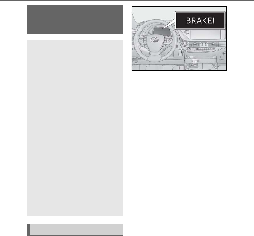
220 4-5. Using the driving support systems
LS500h_OM_OM50F42U_(U)
■Pre-collision warning
When the system determines that the
possibility of a frontal collision is high, a
buzzer will sound and a warning mes-
sage will be displayed on the
multi-information display to urge the
driver to take evasive action.
■Pre-collision brake assist
When the system determines that the
possibility of a frontal collision is high,
the system applies greater braking
force in relation to how strongly the
brake pedal is depressed.
■Pre-collision braking
When the system determines that the
possibility of a frontal collision is high,
the system warns the driver. If the sys-
tem determines that the possibility of a
frontal collision is extremely high, the
brakes are automatically applied to
help avoid the collision or reduce the
collision speed.
■Pre-collision seatbacks (front pas-
senger’s seat / power rear seat [if
equipped])
If the system determines that the possi-
bility of a frontal collision is high, it may
move the seatbacks of the front pas-
senger’s seat and power rear seats to
the upright position automatically, if
reclined.
If a seat is being adjusted, it may not be
moved by the pre-collision seat function.
■Suspension control
When the system determines that the
possibility of a frontal collision is high,
PCS (Pre-Collision System)
(vehicles with Lexus Safety
System+)
The pre-collision system uses a
radar sensor and camera sensor to
detect vehicles and pedestrians in
front of your vehicle. When the sys-
tem determines that the possibility
of a frontal collision with a vehicle
or pedestrian is high, a warning
operates to urge the driver to take
evasive action and the potential
brake pressure is increased to help
the driver avoid the collision. If the
system determines that the possi-
bility of a frontal collision with a
vehicle or pedestrian is extremely
high, the brakes are automatically
applied to help avoid the collision or
help reduce the impact of the colli-
sion.
The pre-collision system can be dis-
abled/enabled and the warning tim-
ing can be changed. (→P.222)
System functions

221
4-5. Using the driving support systems
LS500h_OM_OM50F42U_(U)
4
Driving
the Adaptive Variable Suspension Sys-
tem (→P.303) will control the damp-
ing force of the shock absorbers to
help maintain an appropriate vehicle
posture.
■Steering control
When the system determines that the
possibility of a frontal collision is high
and the driver is operating the steering
wheel, the LDH system (→P.303) will
control the turning angle of the front
and rear wheels and effort necessary
to turn the steering wheel to help
enhance steering responsiveness.
WARNING
■Limitations of the pre-collision system
●The driver is solely responsible for safe
driving. Always drive safely, taking
care to observe your surroundings.
Do not use the pre-collision system
instead of normal braking operations
under any circumstances. This system
will not prevent collisions or lessen col-
lision damage or injury in every situa-
tion. Do not overly rely on this system.
Failure to do so may lead to an acci-
dent, resulting in death or serious
injury.
●Although this system is designed to
help avoid a collision or help reduce
the impact of the collision, its effective-
ness may change according to various
conditions, therefore the system may
not always be able to achieve the same
level of performance.
Read the following conditions care-
fully. Do not overly rely on this system
and always drive carefully.
• Conditions under which the system
may operate even if there is no possi-
bility of a collision: →P.223
• Conditions under which the system
may not operate properly: →P.225
●Do not attempt to test the operation of
the pre-collision system yourself, as the
system may not operate properly, pos-
sibly leading to an accident.
■Pre-collision braking
●When the pre-collision braking func-
tion is operating, a large amount of
braking force will be applied.
●If the vehicle is stopped by the opera-
tion of the pre-collision braking func-
tion, the pre-collision braking function
operation will be canceled after
approximately 2 seconds. Depress the
brake pedal as necessary.
●The pre-collision braking function may
not operate if certain operations are
performed by the driver. If the acceler-
ator pedal is being depressed strongly
or the steering wheel is being turned,
the system may determine that the
driver is taking evasive action and pos-
sibly prevent the pre-collision braking
function from operating.
●In some situations, while the pre-colli-
sion braking function is operating,
operation of the function may be can-
celed if the accelerator pedal is
depressed strongly or the steering
wheel is turned and the system deter-
mines that the driver is taking evasive
action.
●If the brake pedal is being depressed,
the system may determine that the
driver is taking evasive action and pos-
sibly delay the operation timing of the
pre-collision braking function.
■When to disable the pre-collision sys-
tem
In the following situations, disable the
system, as it may not operate properly,
possibly leading to an accident resulting
in death or serious injury:
●When the vehicle is being towed
●When your vehicle is towing another
vehicle
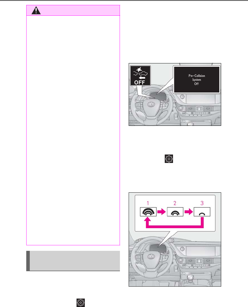
222 4-5. Using the driving support systems
LS500h_OM_OM50F42U_(U)
■Enabling/disabling the pre-colli-
sion system
The pre-collision system can be
enabled/disabled on (→P.86) of
the multi-information display.
The system is automatically enabled each
time the power switch is turned to ON
mode
If the system is disabled, the PCS warn-
ing light will turn on and a message will
be displayed on the multi-information
display.
■Changing the pre-collision warn-
ing timing
The pre-collision warning timing can
be changed on (→P.86) of the
multi-information display.
The operation timing setting is retained
when the power switch is turned off.
1Far
The warning will begin to operate earlier
than with the default timing.
2Middle
WARNING
●When transporting the vehicle via
truck, boat, train or similar means of
transportation
●When the vehicle is raised on a lift with
the hybrid system on and the tires are
allowed to rotate freely
●When inspecting the vehicle using a
drum tester such as a chassis dyna-
mometer or speedometer tester, or
when using an on vehicle wheel bal-
ancer
●When a strong impact is applied to the
front bumper or front grille, due to an
accident or other reasons
●If the vehicle cannot be driven in a sta-
ble manner, such as when the vehicle
has been in an accident or is malfunc-
tioning
●When the vehicle is driven in a sporty
manner or off-road
●When the tires are not properly
inflated
●When the tires are very worn
●When tires of a size other than speci-
fied are installed
●When tire chains are installed
●When a compact spare tire or an
emergency tire puncture repair kit is
used
●If equipment (snow plow, etc.) that may
obstruct the radar sensor or camera
sensor is temporarily installed to the
vehicle
Changing settings of the pre-col-
lision system
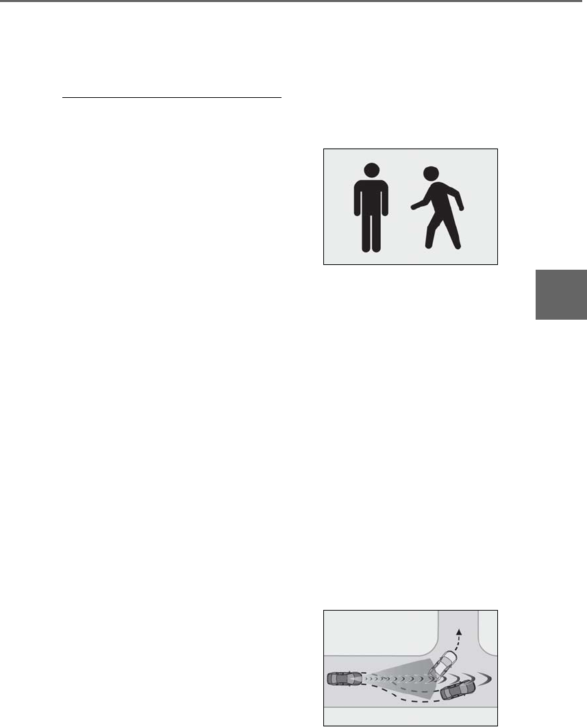
223
4-5. Using the driving support systems
LS500h_OM_OM50F42U_(U)
4
Driving
This is the default setting.
3Near
The warning will begin to operate later
than with the default timing.
■Operational conditions
The pre-collision system is enabled and the
system determines that the possibility of a
frontal collision with a vehicle or pedestrian
is high.
Each function is operational at the following
speeds:
●Pre-collision warning:
• Vehicle speed is between approximately
7 and 110 mph (10 and 180 km/h). (For
detecting a pedestrian, vehicle speed is
between approximately 7 and 50 mph
[10 and 80 km/h].)
• The relative speed between your vehicle
and the vehicle or pedestrian ahead is
approximately 7 mph (10 km/h) or more.
●Pre-collision brake assist:
• Vehicle speed is between approximately
20 and 110 mph (30 and 180 km/h). (For
detecting a pedestrian, vehicle speed is
between approximately 20 and 50 mph
[30 and 80 km/h].)
• The relative speed between your vehicle
and the vehicle or pedestrian ahead is
approximately 20 mph (30 km/h) or
more.
●Pre-collision braking:
• Vehicle speed is between approximately
7 and 110 mph (10 and 180 km/h). (For
detecting a pedestrian, vehicle speed is
between approximately 7 and 50 mph
[10 and 80 km/h].)
• The relative speed between your vehicle
and the vehicle or pedestrian ahead is
approximately 7 mph (10 km/h) or more.
The system may not operate in the following
situations:
●If a 12-volt battery terminal has been dis-
connected and reconnected and then the
vehicle has not been driven for a certain
amount of time
●If the shift position is in R
●If VSC is disabled (only the pre-collision
warning function will be operational)
■Pedestrian detection function
The pre-collision system detects pedestri-
ans based on the size, profile, and motion of
a detected object. However, a pedestrian
may not be detected depending on the sur-
rounding brightness and the motion, pos-
ture, and angle of the detected object,
preventing the system from operating prop-
erly. (→P.225)
■Cancelation of the pre-collision braking
If either of the following occur while the
pre-collision braking function is operating, it
will be canceled:
●The accelerator pedal is depressed
strongly.
●The steering wheel is turned sharply or
abruptly.
■Conditions under which the system may
operate even if there is no possibility of a
collision
●In some situations such as the following,
the system may determine that there is a
possibility of a frontal collision and oper-
ate.
• When passing a vehicle or pedestrian
• When changing lanes while overtaking a
preceding vehicle
• When overtaking a preceding vehicle
that is changing lanes
• When overtaking a preceding vehicle
that is making a left/right turn
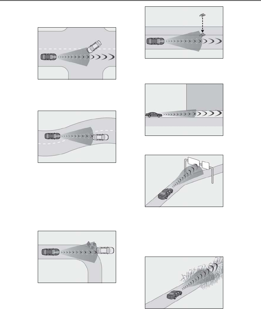
224 4-5. Using the driving support systems
LS500h_OM_OM50F42U_(U)
• When passing a vehicle in an oncoming
lane that is stopped to make a right/left
turn
• When driving on a road where relative
location to vehicle ahead in an adjacent
lane may change, such as on a winding
road
• When rapidly closing on a vehicle ahead
• If the front of the vehicle is raised or low-
ered, such as when the road surface is
uneven or undulating
• When approaching objects on the road-
side, such as guardrails, utility poles,
trees, or walls
• When there is a vehicle, pedestrian, or
object by the roadside at the entrance of
a curve
• When driving on a narrow path sur-
rounded by a structure, such as in a tun-
nel or on an iron bridge
• When there is a metal object (manhole
cover, steel plate, etc.), steps, or a protru-
sion on the road surface or roadside
• When a crossing pedestrian approaches
very close to the vehicle
• When passing through a place with a low
structure above the road (low ceiling,
traffic sign, etc.)
• When passing under an object (billboard,
etc.) at the top of an uphill road
• When rapidly closing on an electric toll
gate barrier, parking area barrier, or
other barrier that opens and closes
• When using an automatic car wash
• When driving through or under objects
that may contact the vehicle, such as thick
grass, tree branches, or a banner
• When the vehicle is hit by water, snow,
dust, etc. from a vehicle ahead
• When driving through steam or smoke
• When there are patterns or paint on the
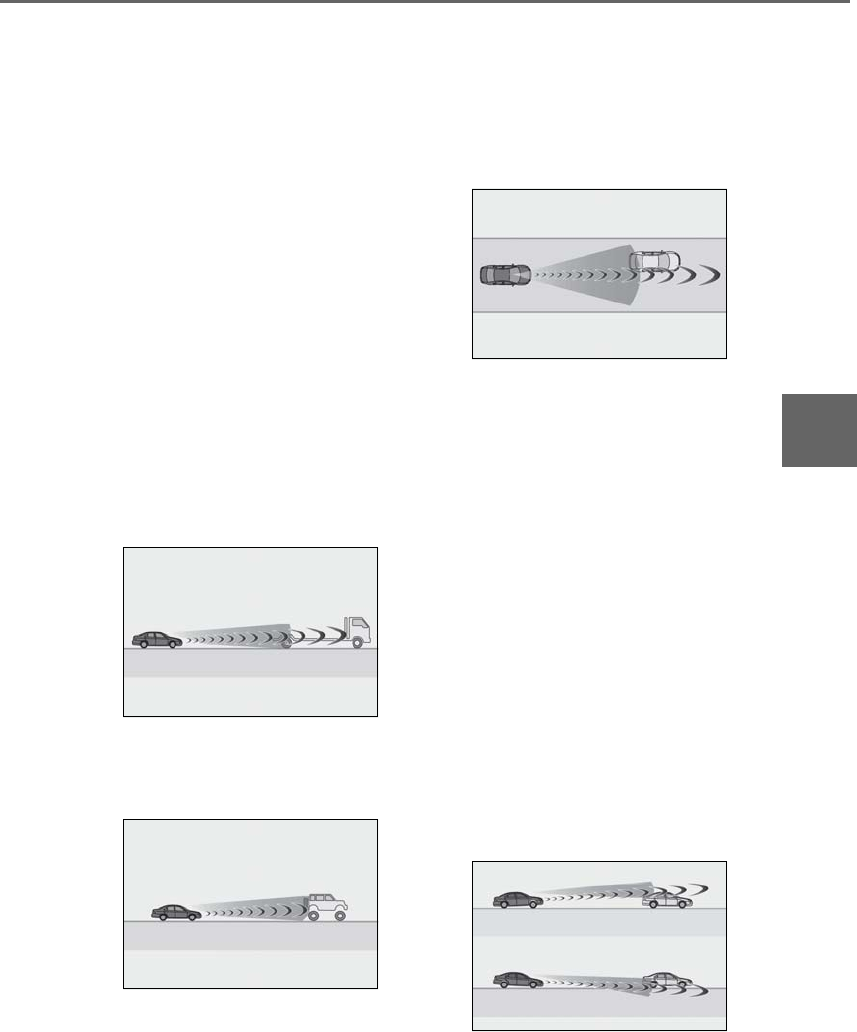
225
4-5. Using the driving support systems
LS500h_OM_OM50F42U_(U)
4
Driving
road or a wall that may be mistaken for a
vehicle or pedestrian
• When driving near an object that reflects
radio waves, such as a large truck or
guardrail
• When driving near a TV tower, broad-
casting station, electric power plant, or
other location where strong radio waves
or electrical noise may be present
■Situations in which the system may not
operate properly
●In some situations such as the following, a
vehicle may not be detected by the radar
sensor and camera sensor, preventing
the system from operating properly:
• If an oncoming vehicle is approaching
your vehicle
• If a vehicle ahead is a motorcycle or bicy-
cle
• When approaching the side or front of a
vehicle
• If a preceding vehicle has a small rear
end, such as an unloaded truck
• If a preceding vehicle has a low rear end,
such as a low bed trailer
• If a vehicle ahead is carrying a load which
protrudes past its rear bumper
• If a vehicle ahead has extremely high
ground clearance
• If a vehicle ahead is irregularly shaped,
such as a tractor or side car
• If the sun or other light is shining directly
on a vehicle ahead
• If a vehicle cuts in front of your vehicle or
emerges from beside a vehicle
• If a vehicle ahead makes an abrupt
maneuver (such as sudden swerving,
acceleration or deceleration)
• When suddenly cutting behind a preced-
ing vehicle
• When a vehicle ahead is not directly in
front of your vehicle
• When driving in inclement weather such
as heavy rain, fog, snow or a sandstorm
• When the vehicle is hit by water, snow,
dust, etc. from a vehicle ahead
• When driving through steam or smoke
• When driving in a place where the sur-
rounding brightness changes suddenly,
such as at the entrance or exit of a tunnel
• When a very bright light, such as the sun
or the headlights of oncoming traffic,
shines directly into the camera sensor
• When the surrounding area is dim, such
as at dawn or dusk, or while at night or in
a tunnel
• After the hybrid system has started the
vehicle has not been driven for a certain
amount of time
• While making a left/right turn and for a
few seconds after making a left/right turn
• While driving on a curve and for a few
seconds after driving on a curve
• If your vehicle is skidding
• If the front of the vehicle is raised or low-
ered
• If the wheels are misaligned
• If a wiper blade is blocking the camera
sensor

226 4-5. Using the driving support systems
LS500h_OM_OM50F42U_(U)
• The vehicle is wobbling.
• The vehicle is being driven at extremely
high speeds.
• When driving on a hill
• If the radar sensor or camera sensor is
misaligned
●In some situations such as the following,
sufficient braking force may not be
obtained, preventing the system from
performing properly:
• If the braking functions cannot operate to
their full extent, such as when the brake
parts are extremely cold, extremely hot,
or wet
• If the vehicle is not properly maintained
(brakes or tires are excessively worn,
improper tire inflation pressure, etc.)
• When the vehicle is being driven on a
gravel road or other slippery surface
●Some pedestrians such as the following
may not be detected by the radar sensor
and camera sensor, preventing the sys-
tem from operating properly:
• Pedestrians shorter than approximately
3.2 ft. (1 m) or taller than approximately
6.5 ft. (2 m)
• Pedestrians wearing oversized clothing
(a rain coat, long skirt, etc.), making their
silhouette obscure
• Pedestrians who are carrying large bag-
gage, holding an umbrella, etc., hiding
part of their body
• Pedestrians who are bending forward or
squatting
• Pedestrians who are pushing a stroller,
wheelchair, bicycle or other vehicle
• Groups of pedestrians which are close
together
• Pedestrians who are wearing white and
look extremely bright
• Pedestrians in the dark, such as at night
or while in a tunnel
• Pedestrians whose clothing appears to
be nearly the same color or brightness as
their surroundings
• Pedestrians near walls, fences, guardrails,
or large objects
• Pedestrians who are on a metal object
(manhole cover, steel plate, etc.) on the
road
• Pedestrians who are walking fast
• Pedestrians who are changing speed
abruptly
• Pedestrians running out from behind a
vehicle or a large object
• Pedestrians who are extremely close to
the side of the vehicle (outside rear view
mirror, etc.)
■If the PCS warning light flashes or illumi-
nates and a warning message is dis-
played on the multi-information display
The pre-collision system may be temporar-
ily unavailable or there may be a malfunc-
tion in the system.
●In the following situations, the warning
light will turn off, the message will disap-
pear and the system will become opera-
tional when normal operating conditions
return:
• When the radar sensor or camera sensor
or the area around either sensor is hot,
such as in the sun
• When the radar sensor or camera sensor
or the area around either sensor is cold,
such as in an extremely cold environment
• When a front sensor is dirty or covered
with snow, etc.
• When the part of the windshield in front
of the camera sensor is fogged up or cov-
ered with condensation or ice (Defog-
ging the windshield: →P.324)
• If the camera sensor is obstructed, such
as when the hood is open or a sticker is
attached to the windshield near the cam-
era sensor
●If the PCS warning light continues to flash
or remains illuminated or the warning
message does not disappear even
though the vehicle has returned to nor-
mal, the system may be malfunctioning.
Have the vehicle inspected by your Lexus
dealer immediately.
■If VSC is disabled
●If VSC is disabled (→P.302), the
pre-collision brake assist and pre-colli-
sion braking functions are also disabled.
●The PCS warning light will turn on and
“VSC Turned Off Pre-Collision Brake
System Unavailable” will be displayed on
the multi-information display.
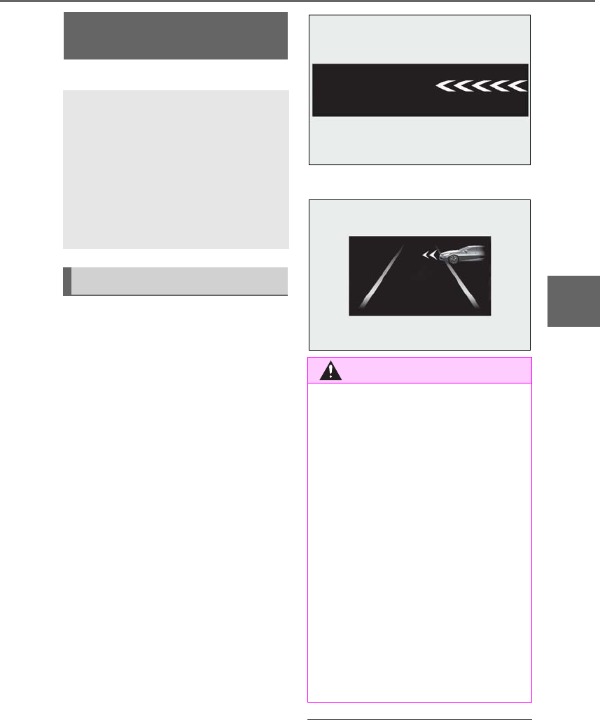
227
4-5. Using the driving support systems
LS500h_OM_OM50F42U_(U)
4
Driving
*:If equipped
When the system detects a vehicle
approaching from the left or right in
front of your vehicle when approaching
an intersection, a notification will be
displayed on the head-up display and
panoramic view monitor*.
*: Refer to “NAVIGATION AND MULTI-
MEDIA SYSTEM OWNER’S MAN-
UAL”.
When the system determines that your
vehicle may be about to enter an inter-
section even though a vehicle is
approaching from the left or right in
front of your vehicle, a buzzer will
sound and a message will be displayed
on the multi-information display to
urge you to depress the brake pedal.
-Head-up display
-Multi-information display
■The FCTA function is operational when
The system operates when all of the follow-
ing conditions are met.
FCTA (Front Cross Traffic
Alert)*
When approaching an intersection
at low speed, the radar sensors on
the front side of the vehicle can
detect approaching vehicles to the
left and right of the front of the vehi-
cle. In this case, the head-up display
is used to inform the driver of
detected vehicles.
FCTA system functions
WARNING
■Cautions regarding the use of the
function
The driver is solely responsible for safe
driving. Always drive safely, taking care
to observe your surroundings.
The FCTA system is a supplementary
system that informs the driver of vehicles
approaching from the left and right of the
front of the vehicle.
Do not overly rely on the FCTA system.
Over reliance on the system may lead to
an accident, resulting in death or serious
injury.
The details of the warning display may
differ from the actual traffic conditions.
Although the warning display will stop
being displayed after a certain amount of
time, this does not indicate that vehicles
or pedestrians are no longer around your
vehicle.
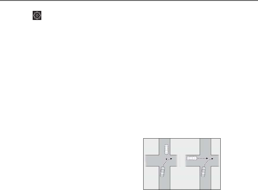
228 4-5. Using the driving support systems
LS500h_OM_OM50F42U_(U)
●Setting for “PCS” and “CAUTION” in
(→P.86) of the multi-information
display.
●A shift position other than P or R is
selected.
●Your vehicle is approaching an intersec-
tion at approximately 9 mph (15 km/h) or
lower.
●A vehicle is approaching from the left or
right in front of your vehicle at a speed
between approximately 6 mph (10 km/h)
and 37 mph (60 km/h).
●There are no preceding vehicles ahead of
your vehicle.
●The accelerator pedal is not strongly
depressed.
●The brake pedal is not being strongly
depressed.
■Situations in which the system may
operate even though no vehicles are
approaching
In certain situations, such as the following,
the system may operate even though no
vehicles are approaching:
●When approaching objects on the road-
side, such as guardrails, traffic signs, util-
ity poles, street lights, trees, or walls
●When driving near a TV tower, broad-
casting station, electric power plant, or
other location where strong radio waves
or electrical noise may be present
●When passing an object on the side of the
road, such as a parked vehicle
●When a vehicle or pedestrian is
approaching from the left or right in front
of your vehicle from far away
●When a vehicle or pedestrian is moving
within a parking spot, etc. next to the lane
your vehicle is driving in
●When a pedestrian or bicyclist is moving
on a sidewalk
●When a vehicle or pedestrian is moving
away from your vehicle
●When a vehicle approaching from the left
or right in front of your vehicle is deceler-
ating or stops
●When a vehicle approaching from the left
or right in front of your vehicle makes a
left/right turn immediately in front of your
vehicle
●When a pedestrian is approaching your
vehicle
●When an oncoming vehicle makes a
left/right turn
●When your vehicle enters an intersection
before a vehicle approaching from the
left or right in front of your vehicle
●When stopped at traffic light and a vehi-
cle approaches from the left or right in
front of your vehicle
●When driving in a location where there
are objects which reflect radar, such as
vehicles, guardrails, walls, traffic signs,
etc.
●When making a left/right turn in front of
an approaching vehicle
●When passing an oncoming vehicle
●When being overtaken by another vehi-
cle
●When driving next to another vehicle or a
pedestrian
●When a vehicle or pedestrian
approaches the side of your vehicle
Some objects, such as the following, may be
detected and cause the FCTA system to
operate:
●Pedestrians
■Situations in which the system may not
operate properly
In some situations, such as the following, a
vehicle may not be detected by a front side
radar sensor, preventing the system from
operating properly:
●If the front end or side of an approaching
vehicle is small (sports cars, etc.)
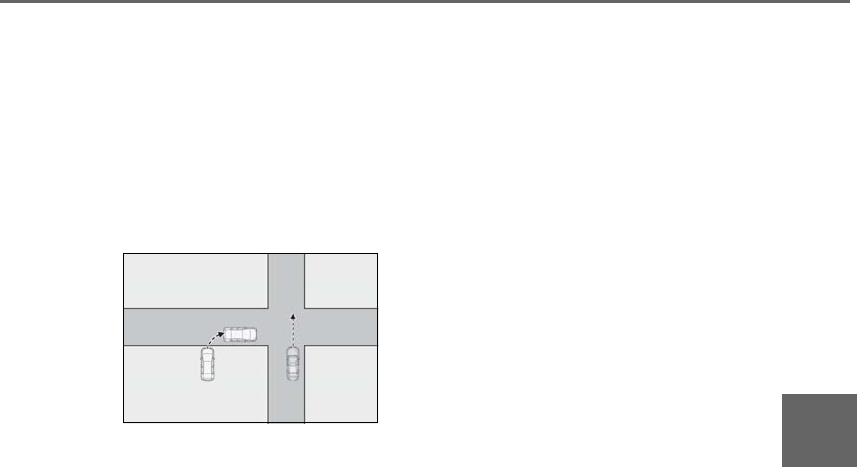
229
4-5. Using the driving support systems
LS500h_OM_OM50F42U_(U)
4
Driving
●If the front end of an approaching vehicle
is low (low-slung sports cars, etc.)
●If the ground clearance of an approach-
ing vehicle is extremely high
●If the shape of an approaching vehicle is
unusual (tractors, motorcycles with side-
cars, etc.)
●If a vehicle suddenly enters the detection
area on the left or right in front of your
vehicle from a parking lot, etc.
●If an approaching vehicle moves sud-
denly (sudden steering, acceleration,
deceleration, etc.)
●When driving in inclement weather such
as heavy rain, fog, snow or a sandstorm
●After the hybrid system has been started
and the vehicle has not been driven for a
certain amount of time
●When driving on a road with a grade that
changes sharply (sharp incline/decline)
●When driving around a sharp curve or on
an undulating road
●If a vehicle is approaching from the left or
right of the front of your vehicle diago-
nally
●When a vehicle is approaching from the
left or right in front of your vehicle from
far away
●When there is an object between your
vehicle and an approaching vehicle
●When driving in a location where there
are objects which reflect radar, such as
guardrails, walls, vehicles, etc.
●When a group of vehicles which are close
together approach
●Immediately after the FCTA system has
been enabled
■When the PCS warning light is flashing
and a message is displayed on the
multi-information display
The system may be temporarily unavailable
or may be malfunctioning.
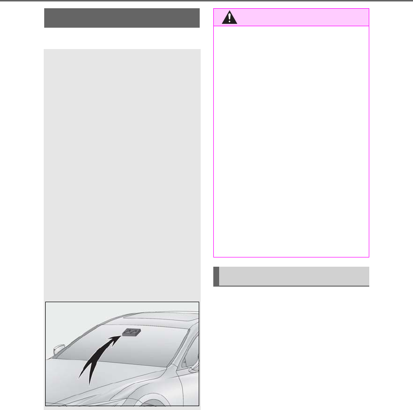
230 4-5. Using the driving support systems
LS500h_OM_OM50F42U_(U)
*:If equipped
■Lane departure alert function
When the system determines that the
vehicle might depart from its lane or
course*, a warning is displayed on the
multi-information display, and either a
warning buzzer will sound or the steer-
ing wheel will vibrate to alert the driver.
*: Boundary between asphalt and the side
of the road, such as grass, soil, or a curb
When the warning buzzer sounds or
the steering wheel vibrates, check the
area around your vehicle and carefully
operate the steering wheel to move the
vehicle back to the center of the lane.
When the system determines that the
vehicle might depart from its lane and
that the possibility of a collision with an
LTA (Lane Tracing Assist)*
When driving on highways and
freeways with white or yellow lines,
this function alerts the driver when
the vehicle might depart from its
lane and provides assistance by
operating the steering wheel to
keep the vehicle in its lane. Further-
more, the system also provides
steering assistance when dynamic
radar cruise control with full-speed
range is operating to keep the vehi-
cle in its lane.
The LTA system recognizes white or
yellow lane lines using a camera
sensor. Additionally, it detects pre-
ceding and surrounding vehicles
using the camera sensor and front
radar sensor.
WARNING
■Before using LTA system
Do not rely solely upon the LTA system.
The LTA system does not automatically
drive the vehicle or reduce the amount of
attention that must be paid to the area in
front of the vehicle. The driver must
always assume full responsibility for driv-
ing safely by paying careful attention to
the surrounding conditions and operat-
ing the steering wheel to correct the path
of the vehicle. Also, the driver must take
adequate breaks when fatigued, such as
from driving for a long period of time.
Failure to perform appropriate driving
operations and pay careful attention may
lead to an accident, resulting in death or
serious injury.
■To avoid operating LTA system by mis-
take
When not using the LTA system, use the
LTA switch to turn the system off.
Functions included in LTA system
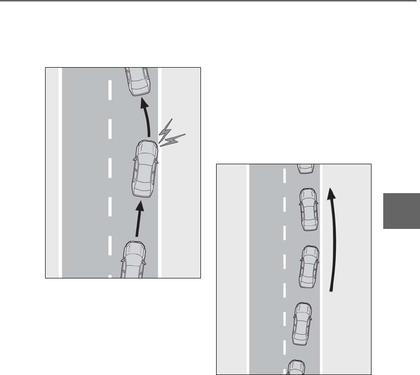
231
4-5. Using the driving support systems
LS500h_OM_OM50F42U_(U)
4
Driving
overtaking vehicle in the adjacent lane
is high, the lane departure alert will
operate even if the turn signals are
operating.
■Steering assist function
When the system determines that the
vehicle might depart from its lane or
course*, the system provides assis-
tance as necessary by operating the
steering wheel in small amounts for a
short period of time to keep the vehicle
in its lane.
*: Boundary between asphalt and the side
of the road, such as grass, soil, or a curb
If the system detects that the steering
wheel has not been operated for a cer-
tain amount of time or the steering
wheel is not being firmly gripped, the
steering assist function may be can-
celed temporarily, a warning message
may be displayed on the multi-informa-
tion display and a warning buzzer may
sound. If the steering assist function is
canceled, release the steering wheel
and then grip it again to enable the
function.
When the system determines that the
vehicle might depart from its lane and
that the possibility of a collision with an
overtaking vehicle in the adjacent lane
is high, the steering assist function will
operate even if the turn signals are
operating.
■Vehicle sway warning function
When the vehicle is swaying within a
lane, the warning buzzer will sound and
a message will be displayed on the
multi-information display to alert the
driver.
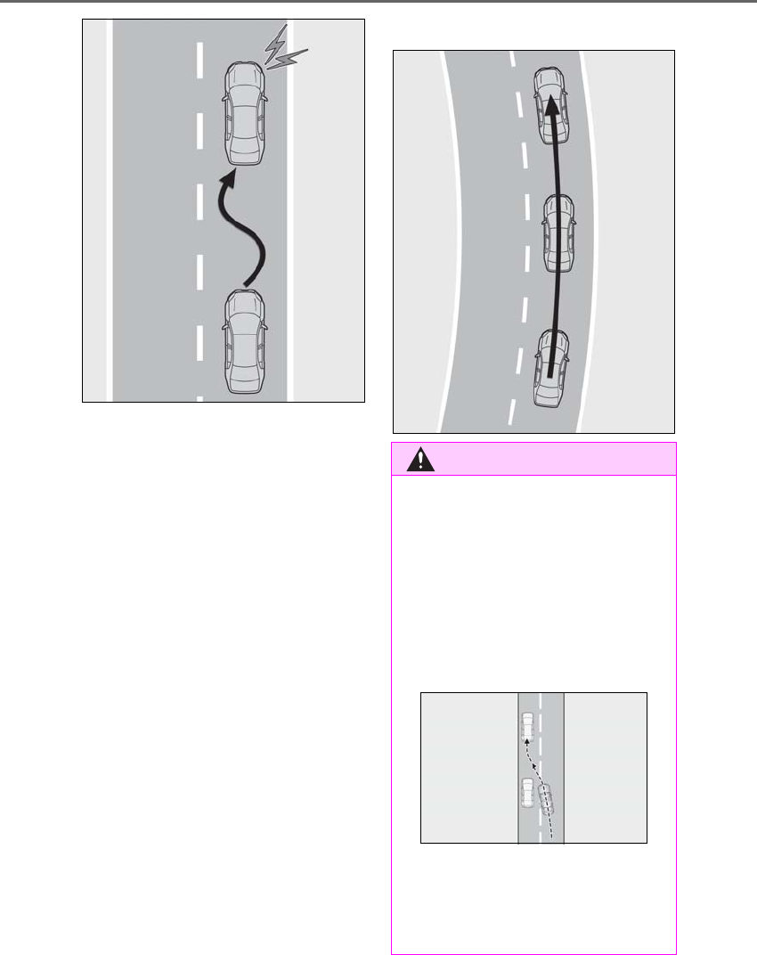
232 4-5. Using the driving support systems
LS500h_OM_OM50F42U_(U)
■Lane centering function
This function is linked with radar cruise
control and provides the required
assistance by operating the steering
wheel to keep the vehicle in its current
lane.
When radar cruise control is not oper-
ating, the lane centering function does
not operate.
In situations where the white (yellow)
lane lines are difficult to see or are not
visible, such as when in a traffic jam,
this function will operate to help follow
a preceding vehicle by monitoring the
position of the preceding vehicle.
If the system detects that the steering
wheel has not been operated for a
fixed amount of time or the steering
wheel is not being firmly gripped, a
warning is displayed on the multi-infor-
mation display and the warning buzzer
sounds. Make sure to grip the steering
wheel firmly.
WARNING
■Situations unsuitable for LTA system
Do not use the LTA system in the follow-
ing situations, as doing so may lead to an
accident, resulting in death or serious
injury.
●When the follow-up cruising display is
displayed (→P.234) and the preced-
ing vehicle changes lanes. (Your vehi-
cle may follow the preceding vehicle
and also change lanes.)
●When the follow-up cruising display is
displayed (→P.234) and the preced-
ing vehicle is swaying. (Your vehicle
may sway accordingly and depart from
the lane.)
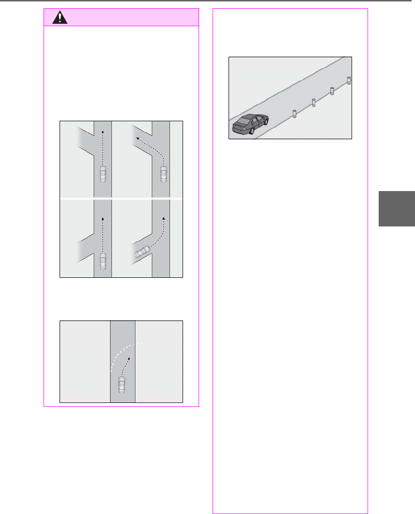
233
4-5. Using the driving support systems
LS500h_OM_OM50F42U_(U)
4
Driving
WARNING
●When the follow-up cruising display is
displayed (→P.234) and the preced-
ing vehicle is being driven extremely
close to the left/right lane line. (Your
vehicle may follow the preceding vehi-
cle and depart from the lane.)
●Vehicle is driven where the road
diverges, merges, etc.
●Asphalt repair marks, white (yellow)
line marks, etc. are present due to road
repair.
●Objects or patterns that could be mis-
taken for white (yellow) lines are pres-
ent on the side of the road (guardrails,
curbs, reflective poles, etc.).
●Vehicle is being driven around a sharp
curve.
●Vehicle is driven on a road surface
which is slippery due to rainy weather,
fallen snow, freezing, etc.
●Vehicle is driven on a snow-covered
road.
●White (yellow) lines are difficult to see
due to rain, snow, fog, dust, etc.
●Vehicle is driven in a temporary lane or
restricted lane due to construction
work.
●Vehicle is driven in a construction
zone.
●A spare tire, tire chains, etc. are
equipped.
●When the tires have been excessively
worn, or when the tire inflation pres-
sure is low.
●Tires which differ by structure, manu-
facturer, brand or tread pattern are
used.
●Vehicle is driven in traffic lanes other
than on highways and freeways.
■Preventing LTA system malfunctions
and operations performed by mistake
●Do not modify the headlights or place
stickers, etc. on the surface of the
lights.
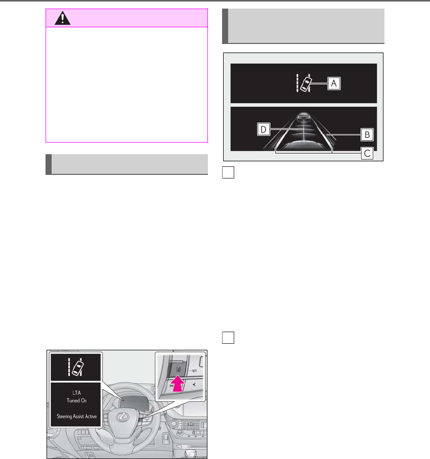
234 4-5. Using the driving support systems
LS500h_OM_OM50F42U_(U)
Press the LTA switch to turn the LTA
system on.
The LTA indicator illuminates and a
message is displayed on the
multi-information display.
Press the LTA switch again to turn the
LTA system off.
When the LTA system is turned on or
off, operation of the LTA system contin-
ues in the same condition the next time
the hybrid system is started.
LTA indicator
The illumination condition of the indicator
informs the driver of the system operation
status.
Illuminated in white:
LTA system is operating.
Illuminated in green:
Steering wheel assistance of the steering
assist function or lane centering function is
operating.
Flashing in orange:
Lane departure alert function is operating.
Operation display of steering
wheel operation support
Indicates that steering wheel assistance of
the steering assist function or lane center-
ing function is operating.
Displayed on the outer side of both lane
displays:
Indicates that steering wheel assist of the
lane centering function is operating.
Displayed on the outer side of a lane dis-
play:
Indicates that steering wheel assist of the
steering assist function is operating.
Display flashing on the outer side of both
lane displays:
Alerts the driver that their input is neces-
sary to stay in the center of the lane (lane
WARNING
●Do not modify the suspension etc. If
the suspension etc. needs to be
replaced, contact your Lexus dealer.
●Do not install or place anything on the
hood or grille. Also, do not install a
grille guard (bull bars, kangaroo bar,
etc.).
●If your windshield needs repairs, con-
tact your Lexus dealer.
Turning LTA system on
Indications on multi-information
display
A
B
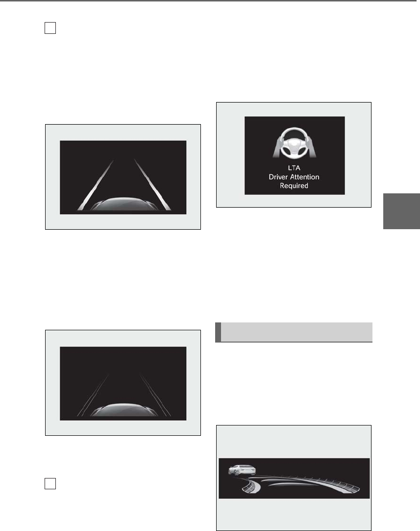
235
4-5. Using the driving support systems
LS500h_OM_OM50F42U_(U)
4
Driving
centering function).
Lane departure alert function dis-
play
Displayed when the multi-information dis-
play is switched to the driving assist system
information screen.
Inside of displayed white lines is
white
Indicates that the system is recognizing
white (yellow) lines. When the vehicle
departs from its lane, the white line dis-
played on the side the vehicle departs from
flashes orange.
Inside of displayed white lines is
black
Indicates that the system is not able to rec-
ognize white (yellow) lines or is temporar-
ily canceled.
Follow-up cruising display
Indicates that steering assist of the lane
centering function is operating by monitor-
ing the position of a preceding vehicle.
When the follow-up cruising display is dis-
played, if the preceding vehicle changes
lanes, your vehicle may change lanes as
well. Always pay careful attention to your
surroundings and operate the steering
wheel as necessary to correct the path of
the vehicle and ensure safety.
■Warning display
When the lane centering function is oper-
ating and the system determines that the
vehicle may depart from its lane due to a
sharp curve, etc., a warning display urging
the driver to operate the steering wheel,
will be displayed.
In some situations a warning display may
not be displayed.
Some displays, which are the same as
those displayed on the multi-informa-
tion display, will be displayed.
■LTA system curve display on the
head-up display
C
D
Indications on head-up display

236 4-5. Using the driving support systems
LS500h_OM_OM50F42U_(U)
The curve display on the head-up display
changes according to the direction and
curvature of the curve.
■Operation conditions of each function
●Lane departure alert function
This function operates when all of the fol-
lowing conditions are met.
• LTA is turned on.
• Vehicle speed is approximately 32 mph
(50 km/h) or more.
•System recognizes white (yellow) lane
lines. (When a white [yellow] line is rec-
ognized on only one side, the system will
operate only for the recognized side.)
• Width of traffic lane is approximately 9.8
ft. (3 m) or more.
• Turn signal lever is not operated. (Except
when a vehicle is in the lane on the side
the turn signal was operated)
• Vehicle is not being driven around a
sharp curve.
• No system malfunctions are detected.
(→P.238)
●Steering assist function
This function operates when all of the fol-
lowing conditions are met in addition to the
operation conditions for the lane depar-
ture alert function.
•Setting for “Steering Assist” in of the
multi-information display is set to “On”.
(→P.86)
• Vehicle is not accelerated or decelerated
by a fixed amount or more.
• Steering wheel is not operated with a
steering force level suitable for changing
lanes.
• ABS, VSC, TRAC and PCS are not oper-
ating.
• TRAC or VSC is not turned off.
• Hands off steering wheel alert is not dis-
played. (→P.237)
●Vehicle sway warning function
This function operates when all of the fol-
lowing conditions are met.
• Setting for “Sway Warning” in of the
multi-information display is set to “On”.
(→P.86)
• Vehicle speed is approximately 32 mph
(50 km/h) or more.
• Width of traffic lane is approximately 9.8
ft. (3 m) or more.
• No system malfunctions are detected.
(→P.238)
●Lane centering function
This function operates when all of the fol-
lowing conditions are met.
• LTA is turned on.
• Setting for “Steering Assist” and “Lane
Center” in of the multi-information
display are set to “On”. (→P.86)
• This function recognizes white (yellow)
lane lines or the position of a preceding
vehicle (except when the preceding vehi-
cle is small, such as a motorcycle).
• The dynamic radar cruise control with
full-speed range is operating in vehi-
cle-to-vehicle distance control mode.
• Width of traffic lane is approximately 10
to 13 ft. (3 to 4 m).
• Turn signal lever is not operated.
• Vehicle is not being driven around a
sharp curve.
• No system malfunctions are detected.
(→P.238)
• Vehicle does not accelerate or deceler-
ate by a fixed amount or more.
• Steering wheel is not operated with a
steering force level suitable for changing
lanes.
• ABS, VSC, TRAC and PCS are not oper-
ating.
• TRAC or VSC is not turned off.
• Hands off steering wheel alert is not dis-
played. (→P.237)
• The driver has one or both hands on the
steering wheel.
• The vehicle is being driven in the center
of a lane.
• Steering assist function is not operating.
■Temporary cancellation of functions
When operation conditions are no longer
met, a function may be temporarily can-
celed. However, when the operation condi-
tions are met again, operation of the
function is automatically restored.
(→P.236)
If the operating conditions are no longer
met while the lane centering function is

237
4-5. Using the driving support systems
LS500h_OM_OM50F42U_(U)
4
Driving
operating, a buzzer may sound to indicate
that the function has been temporarily can-
celed . If the alert type customization setting
is set to vibrate the steering wheel, the
buzzer will not sound. (The steering wheel
will vibrate.)
If a message urging operation of the steer-
ing wheel is displayed, operate the steering
wheel.
■Steering assist function/lane centering
function
Depending on the vehicle speed, lane
departure situation, road conditions, etc.,
the driver may not feel the function is oper-
ating or the function may not operate at all.
The steering control of the function is over-
rided by the driver’s steering wheel opera-
tion.
When the vehicle speed is approximately
31 mph (50 km/h) or less, the warning dis-
play of the lane centering function will not
operate.
Do not attempt to activate the steering
assist function.
■Lane departure alert function
The warning buzzer may be difficult to hear
due to external noise, audio playback, etc.
Also, it may be difficult to feel steering
wheel vibrations due to the road conditions,
etc.
If the edge of the road is not clear or
straight, the lane departure alert function or
steering assist function may not operate.
In situations such as the following, it may not
be possible for the system to determine if
there is danger of a collision with an over-
taking vehicle in an adjacent lane:
●When the relative speed between your
vehicle and surrounding vehicles is large
●When driving around a curve
Do not attempt to activate the lane depar-
ture alert function.
■Hands off steering wheel alert
When the system determines that the driver
has removed the hands from the steering
wheel while the steering assist function or
lane centering function is operating, a warn-
ing message is displayed on the multi-infor-
mation display. If the driver continues to
keep the hands off of the steering wheel for
6 seconds, a buzzer sounds, a warning
message is displayed and the function is
temporarily canceled. This alert also oper-
ates in the same way when the driver con-
tinuously operates the steering wheel only a
small amount. If the steering assist function
is canceled, release the steering wheel and
then grip it again to enable the function.
In situations such as the following, the sys-
tem may not be able to detect when the
driver’s hands are on the steering wheel:
●If a steering wheel cover is installed.
●If the driver is wearing gloves.
●If something is attached to the steering
wheel.
●If the driver is gripping the wood trim,
stitched area, spokes, or other part of the
steering wheel that does not have sen-
sors.
In situations such as the following, the hands
off steering wheel alert may not operate
and the steering assist function and lane
centering function may operate even if the
driver’s hands are off the steering wheel:
●If an object contacts the steering wheel.
●If a wide object or arms are held in front
of the steering wheel.
■Conditions in which functions may not
operate properly
In the following situations, the functions may
not operate properly:
●There are shadows on the road that run
parallel with, or cover, the white (yellow)
lines.
●The vehicle is driven in an area without
white (yellow) lines, such as in front of a
tollgate or checkpoint, or at an intersec-
tion, etc.
●The white (yellow) lines are cracked,
“Botts’ dots”, “Raised pavement marker”
or stones are present.
●The white (yellow) lines cannot be seen
or are difficult to see due to sand, etc.
●The vehicle is driven on a road surface
that is wet due to rain, puddles, etc.

238 4-5. Using the driving support systems
LS500h_OM_OM50F42U_(U)
●The traffic lines are yellow (which may be
more difficult to recognize than lines that
are white).
●The white (yellow) lines cross over a curb,
etc.
●The vehicle is driven on a bright surface,
such as concrete.
●If the edge of the road is not clear or
straight.
●The vehicle is driven on a surface that is
bright due to reflected light, etc.
●The vehicle is driven in an area where the
brightness changes suddenly, such as at
the entrances and exits of tunnels, etc.
●Light from the headlights of an oncoming
vehicle, the sun, etc. enters the camera.
●The vehicle is driven on a slope.
●The vehicle is driven on a road which tilts
left or right, or a winding road.
●The vehicle is driven on an unpaved or
rough road.
●The vehicle is driven around a sharp
curve.
●The traffic lane is excessively narrow or
wide.
●The vehicle is extremely tilted due to car-
rying heavy luggage or having improper
tire pressure.
●The distance to the preceding vehicle is
extremely short.
●The preceding vehicle changes lanes.
(Your vehicle may follow the preceding
vehicle and also change lanes.)
●The preceding vehicle is swaying. (Your
vehicle may sway accordingly and depart
from the lane.)
●The vehicle is moving up and down a
large amount due to road conditions
during driving (poor roads or road
seams).
●When driving in a tunnel or at night with
the headlights off or when a headlight is
dim due to its lens being dirty or it being
misaligned.
●The vehicle is struck by a crosswind.
●The vehicle has just changed lanes
through operation of the steering wheel
by the driver or crossed an intersection.
●Snow tires, etc. are equipped.
●The vehicle is being driven at extremely
high speeds.
■Warning message
If the following warning message is dis-
played on the multi-information display and
the LTA indicator illuminates in orange, fol-
low the appropriate troubleshooting proce-
dure.
Warning message Details/Actions
“LTA Malfunction
Visit Your Dealer”
The system may not be
operating properly.
→Have the vehicle
inspected at your
Lexus dealer.
“Front Camera
Unavailable
Remove Debris
On Windshield”
Dirt, rain, condensa-
tion, ice, snow, etc., are
present on the wind-
shield in front of the
camera sensor.
→Turn the LTA system
off, remove any dirt,
rain, condensation, ice,
snow, etc., from the
windshield, and then
turn the LTA system
back on.

239
4-5. Using the driving support systems
LS500h_OM_OM50F42U_(U)
4
Driving
If a different warning message is displayed,
follow the instructions displayed on the
screen.
■Customization
The following settings can be changed.
For how to change settings, refer to
→P.481
“Front Camera
Unavailable”
The operation condi-
tions of the camera
sensor (temperature,
etc.) are not met.
→When the opera-
tion conditions of the
camera sensor (tem-
perature, etc.) are met,
the LTA system will
become available. Turn
the LTA system off, wait
for a little while, and
then turn the LTA sys-
tem back on.
“LTA Unavailable”
The LTA system is tem-
porarily canceled due
to a malfunction in a
sensor other than the
camera sensor.
→Turn the LTA system
off and follow the
appropriate trouble-
shooting procedures
for the warning mes-
sage. Afterward, drive
the vehicle for a short
time, and then turn the
LTA system back on.
“LTA Unavailable
at Current
Speed”
The LTA system cannot
be used as the vehicle
speed is too high.
→Slow down.
Warning message Details/Actions Function Setting details
Lane departure
alert function
Adjust alert sensitivity
Adjust alert type
Steering assist
function
Turn steering wheel
assistance on and off
Vehicle sway
warning function
Turn function on and
off
Adjust alert sensitivity
Lane centering
function
Turn function on and
off
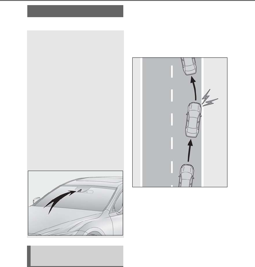
240 4-5. Using the driving support systems
LS500h_OM_OM50F42U_(U)
*:If equipped
■Lane departure alert function
When the system determines that the
vehicle might depart from its lane, a
warning is displayed on the multi-infor-
mation display, and either the warning
buzzer sounds or the steering wheel
vibrates to alert the driver.
When the warning buzzer sounds or
the steering wheel vibrates, check the
surrounding road situation and care-
fully operate the steering wheel to
move the vehicle back to the center of
the lane.
■Steering assist function
When the system determines that the
vehicle might depart from its lane, the
system provides assistance as neces-
sary by operating the steering wheel in
small amounts for a short period of
time to keep the vehicle in its lane.
If the system detects that the steering
wheel has not been operated for a
fixed amount of time or the steering
wheel is not being firmly gripped, a
warning is displayed on the multi-infor-
mation display and the function is tem-
porarily canceled.
LKA (Lane-Keeping Assist)*
When driving on highways and
freeways with white or yellow lines,
this function alerts the driver when
the vehicle might depart from its
lane and provides assistance by
operating the steering wheel to
keep the vehicle in its lane. Further-
more, the system also provides
steering assistance when dynamic
radar cruise control with full-speed
range is operating to keep the vehi-
cle in its lane.
The LKA system recognizes visible
white or yellow lines with the cam-
era sensor on the upper portion of
the windshield.
Functions included in LKA sys-
tem
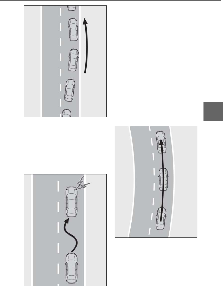
241
4-5. Using the driving support systems
LS500h_OM_OM50F42U_(U)
4
Driving
■Vehicle sway warning function
When the vehicle is swaying or
appears as if it may depart from its lane
multiple times, the warning buzzer
sounds and a message is displayed on
the multi-information display to alert
the driver.
■Lane centering function
This function is linked with radar cruise
control and provides the required
assistance by operating the steering
wheel to keep the vehicle in its current
lane.
When radar cruise control is not oper-
ating, the lane centering function does
not operate.
If the system detects that the steering
wheel has not been operated for a
fixed amount of time or the steering
wheel is not being firmly gripped, a
warning is displayed on the multi-infor-
mation display and the function is tem-
porarily canceled.

242 4-5. Using the driving support systems
LS500h_OM_OM50F42U_(U)
Press the LKA switch to turn the LKA
system on.
WARNING
■Before using LKA system
Do not rely solely upon the LKA system.
The LKA system does not automatically
drive the vehicle or reduce the amount of
attention that must be paid to the area in
front of the vehicle. The driver must
always assume full responsibility for driv-
ing safely by paying careful attention to
the surrounding conditions and operat-
ing the steering wheel to correct the path
of the vehicle. Also, the driver must take
adequate breaks when fatigued, such as
from driving for a long period of time.
Failure to perform appropriate driving
operations and pay careful attention may
lead to an accident, resulting in death or
serious injury.
■To avoid operating LKA system by
mistake
When not using the LKA system, use the
LKA switch to turn the system off.
■Situations unsuitable for LKA system
Do not use the LKA system in the follow-
ing situations.
The system may not operate properly
and lead to an accident, resulting in
death or serious injury.
●A spare tire, tire chains, etc. are
equipped.
●When the tires have been excessively
worn, or when the tire inflation pres-
sure is low.
●Tires which differ by structure, manu-
facturer, brand or tread pattern are
used.
●Objects or patterns that could be mis-
taken for white (yellow) lines are pres-
ent on the side of the road (guardrails,
curbs, reflective poles, etc.).
●Vehicle is driven on a snow-covered
road.
●White (yellow) lines are difficult to see
due to rain, snow, fog, dust, etc.
●Asphalt repair marks, white (yellow)
line marks, etc. are present due to road
repair.
●Vehicle is driven in a temporary lane or
restricted lane due to construction
work.
●Vehicle is driven on a road surface
which is slippery due to rainy weather,
fallen snow, freezing, etc.
●Vehicle is driven in traffic lanes other
than on highways and freeways.
●Vehicle is driven in a construction
zone.
■Preventing LKA system malfunctions
and operations performed by mistake
●Do not modify the headlights or place
stickers, etc. on the surface of the
lights.
●Do not modify the suspension etc. If
the suspension etc. needs to be
replaced, contact your Lexus dealer.
●Do not install or place anything on the
hood or grille. Also, do not install a
grille guard (bull bars, kangaroo bar,
etc.).
●If your windshield needs repairs, con-
tact your Lexus dealer.
Turning LKA system on
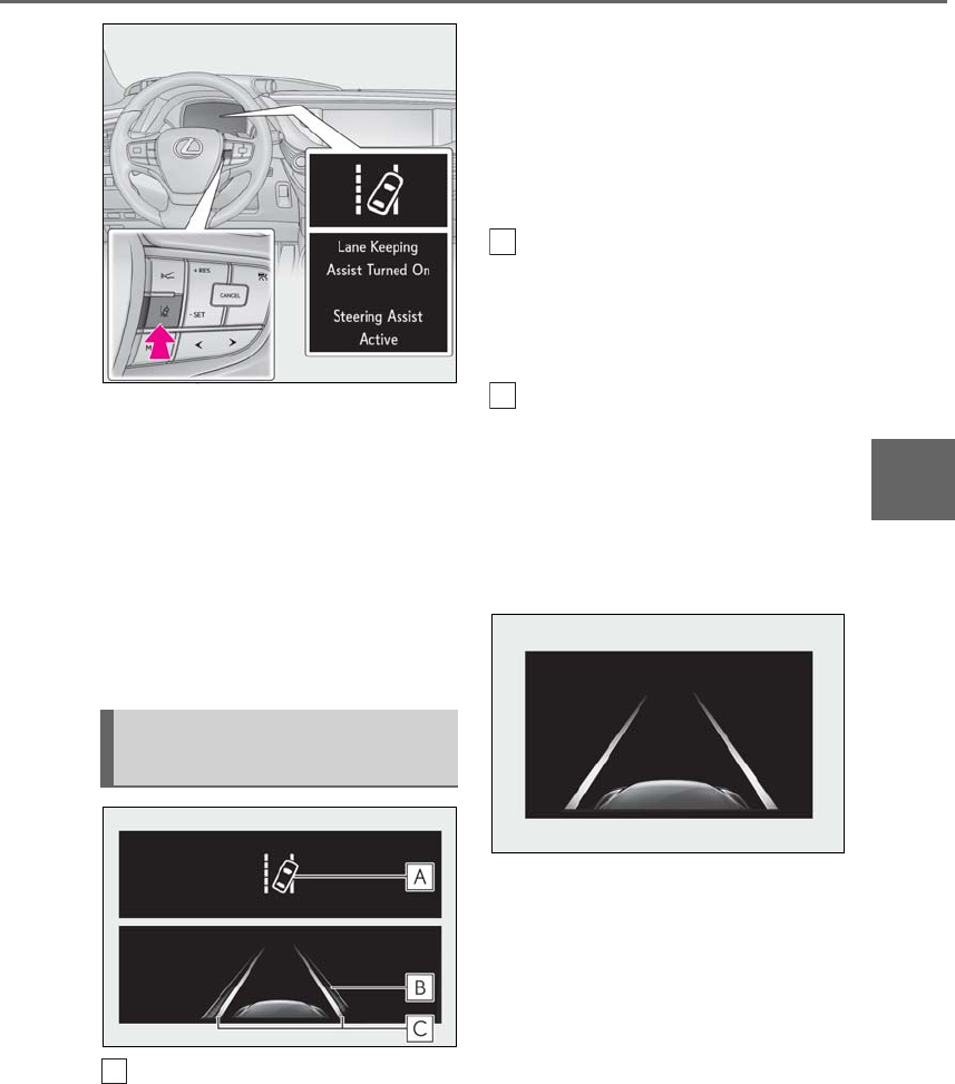
243
4-5. Using the driving support systems
LS500h_OM_OM50F42U_(U)
4
Driving
The LKA indicator illuminates and a
message is displayed on the
multi-information display.
Press the LKA switch again to turn the
LKA system off.
When the LKA system is turned on or
off, operation of the LKA system con-
tinues in the same condition the next
time the hybrid system is started.
LKA indicator
The illumination condition of the indicator
informs the driver of the system operation
status.
Illuminated in white:
LKA system is operating.
Illuminated in green:
Steering wheel assistance of the steering
assist function or lane centering function is
operating.
Flashing in orange:
Lane departure alert function is operating.
Operation display of steering
wheel operation support
Indicates that steering wheel assistance of
the steering assist function or lane center-
ing function is operating.
Lane departure alert function dis-
play
Displayed when the multi-information dis-
play is switched to the driving assist system
information screen.
Inside of displayed white lines is
white
Indicates that the system is recognizing
white (yellow) lines. When the vehicle
departs from its lane, the white line dis-
played on the side the vehicle departs from
flashes orange.
Indications on multi-information
display
A
B
C
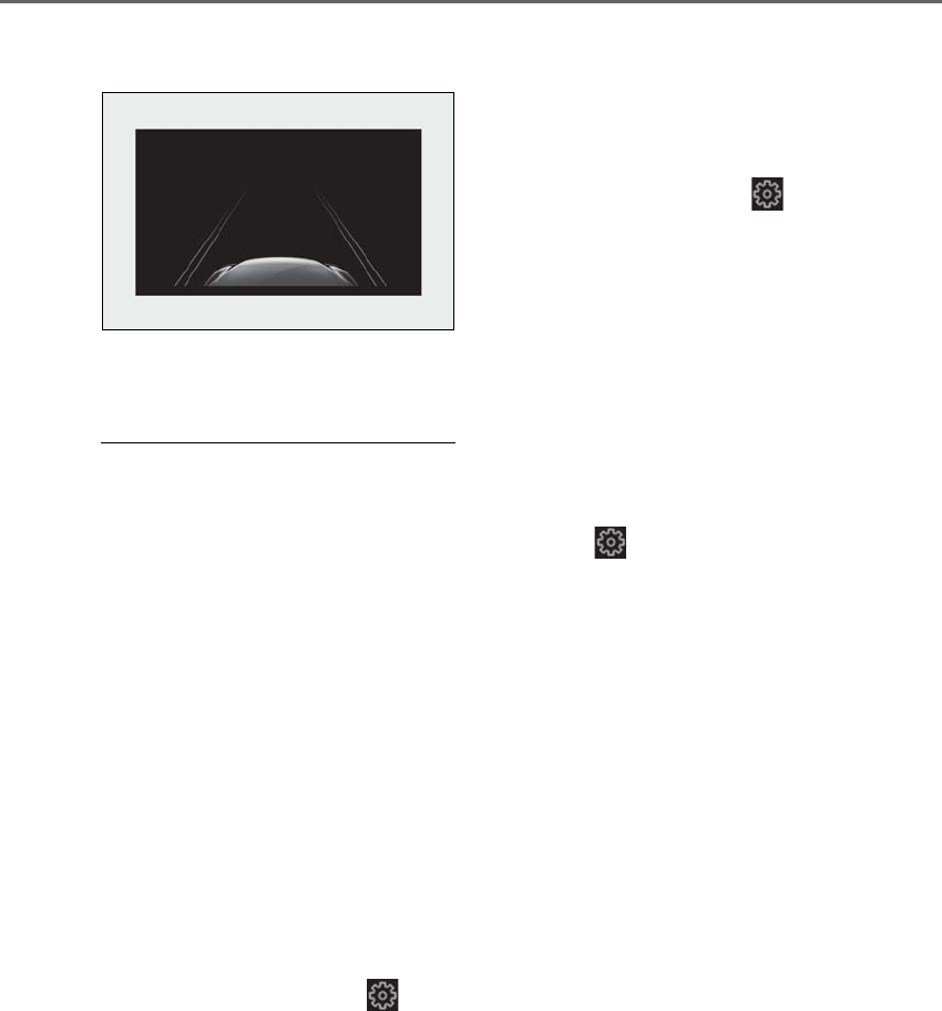
244 4-5. Using the driving support systems
LS500h_OM_OM50F42U_(U)
Inside of displayed white lines is
black
Indicates that the system is not able to rec-
ognize white (yellow) lines or is temporar-
ily canceled.
■Operation conditions of each function
●Lane departure alert function
This function operates when all of the fol-
lowing conditions are met.
• LKA is turned on.
• Vehicle speed is approximately 32 mph
(50 km/h) or more.
• System recognizes white (yellow) lines.
• Width of traffic lane is approximately 9.8
ft. (3 m) or more.
• Turn signal lever is not operated.
• Vehicle is driven on a straight road or
around a gentle curve with a radius of
more than approximately 492 ft. (150 m).
• No system malfunctions are detected.
(→P.246)
●Steering assist function
This function operates when all of the fol-
lowing conditions are met in addition to the
operation conditions for the lane depar-
ture alert function.
•Setting for “Steering Assist” in of the
multi-information display is set to “On”.
(→P.86)
• Vehicle is not accelerated or decelerated
by a fixed amount or more.
• Steering wheel is not operated with a
steering force level suitable for changing
lanes.
• ABS, VSC, TRAC and PCS are not oper-
ating.
• TRAC or VSC is not turned off.
• Hands off steering wheel alert is not dis-
played. (→P.245)
●Vehicle sway warning function
This function operates when all of the fol-
lowing conditions are met.
• Setting for “Sway Warning” in of the
multi-information display is set to “On”.
(→P.86)
• Vehicle speed is approximately 32 mph
(50 km/h) or more.
• Width of traffic lane is approximately 9.8
ft. (3 m) or more.
• No system malfunctions are detected.
(→P.246)
●Lane centering function
This function operates when all of the fol-
lowing conditions are met.
• LKA is turned on.
• Setting for “Steering Assist” and “Lane
Center” in of the multi-information
display are set to “On”. (→P.86)
• System recognizes white (yellow) lines.
• Dynamic radar cruise control with
full-speed range is operating.
• Width of traffic lane is approximately 8.2
to 13.5 ft. (2.5 to 4.1 m).
• Turn signal lever is not operated.
• Vehicle is driven on a straight road or
around a gentle curve with a radius of
more than approximately 656 ft. (200
m).
• No system malfunctions are detected.
(→P.246)
• Vehicle does not accelerate or deceler-
ate by a fixed amount or more.
• Steering wheel is not operated with a
steering force level suitable for changing
lanes.
• ABS, VSC, TRAC and PCS are not oper-
ating.
• TRAC or VSC is not turned off.
• Hands off steering wheel alert is not dis-
played. (→P.245)
• Steering assist function is not operating.
■Temporary cancellation of functions
When operation conditions are no longer
met, a function may be temporarily can-
celed. However, when the operation condi-
tions are met again, operation of the

245
4-5. Using the driving support systems
LS500h_OM_OM50F42U_(U)
4
Driving
function is automatically restored.
(→P.244)
■Steering assist function/lane centering
function
Depending on the vehicle speed, lane
departure situation, road conditions, etc.,
the driver may not feel the function is oper-
ating or the function may not operate at all.
■Lane departure alert function
The warning buzzer may be difficult to hear
due to external noise, audio playback, etc.
Also, it may be difficult to feel steering
wheel vibrations due to the road conditions,
etc.
■Hands off steering wheel alert
When the system determines that the driver
has removed the hands from the steering
wheel while the steering assist function or
lane centering function is operating, a warn-
ing message is displayed on the multi-infor-
mation display. If the driver continues to
keep the hands off of the steering wheel, a
warning message is displayed and the func-
tion is temporarily canceled. This alert also
operates in the same way when the driver
continuously operates the steering wheel
only a small amount. However, depending
on the road conditions, etc., the function
may not cancel.
■White (yellow) lines are only on one side
of road
The LKA system will not operate for the
side on which white (yellow) lines could not
be recognized.
■Conditions in which functions may not
operate properly
In the following situations, the camera sen-
sor may not detect white (yellow) lines and
various functions may not operate normally.
●There are shadows on the road that run
parallel with, or cover, the white (yellow)
lines.
●The vehicle is driven in an area without
white (yellow) lines, such as in front of a
tollgate or checkpoint, or at an intersec-
tion, etc.
●The white (yellow) lines are cracked,
“Botts’ dots”, “Raised pavement marker”
or stones are present.
●The white (yellow) lines cannot be seen
or are difficult to see due to sand, etc.
●The vehicle is driven on a road surface
that is wet due to rain, puddles, etc.
●The traffic lines are yellow (which may be
more difficult to recognize than lines that
are white).
●The white (yellow) lines cross over a curb,
etc.
●The vehicle is driven on a bright surface,
such as concrete.
●The vehicle is driven on a surface that is
bright due to reflected light, etc.
●The vehicle is driven in an area where the
brightness changes suddenly, such as at
the entrances and exits of tunnels, etc.
●Light from the headlights of an oncoming
vehicle, the sun, etc. enters the camera.
●The vehicle is driven where the road
diverges, merges, etc.
●The vehicle is driven on a slope.
●The vehicle is driven on a road which tilts
left or right, or a winding road.
●The vehicle is driven on an unpaved or
rough road.
●The vehicle is driven around a sharp
curve.
●The traffic lane is excessively narrow or
wide.
●The vehicle is extremely tilted due to car-
rying heavy luggage or having improper
tire pressure.
●The distance to the preceding vehicle is
extremely short.
●The vehicle is moving up and down a
large amount due to road conditions
during driving (poor roads or road
seams).
●The headlight lenses are dirty and emit a
faint amount of light at night, or the beam
axis has deviated.
●The vehicle is struck by a crosswind.
●The vehicle has just changed lanes or
crossed an intersection.
●Snow tires, etc. are equipped.

246 4-5. Using the driving support systems
LS500h_OM_OM50F42U_(U)
■Warning message
If the following warning message is dis-
played on the multi-information display and
the LKA indicator illuminates in orange, fol-
low the appropriate troubleshooting proce-
dure.
If a different warning message is displayed,
follow the instructions displayed on the
screen.
■Customization
The following settings can be changed.
Warning message Details/Actions
“Lane Keeping
Assist Malfunc-
tion Visit Your
Dealer”
The system may not be
operating properly.
→Have the vehicle
inspected at your
Lexus dealer.
“Front Camera
Unavailable
Remove Debris
On Windshield”
Dirt, rain, condensa-
tion, ice, snow, etc., are
present on the wind-
shield in front of the
camera sensor.
→Turn the LKA sys-
tem off, remove any
dirt, rain, condensa-
tion, ice, snow, etc.,
from the windshield,
and then turn the LKA
system back on.
“Front Camera
Unavailable”
The operation condi-
tions of the camera
sensor (temperature,
etc.) are not met.
→When the opera-
tion conditions of the
camera sensor (tem-
perature, etc.) are met,
the LKA system will
become available. Turn
the LKA system off,
wait for a little while,
and then turn the LKA
system back on.
“Lane Keeping
Assist Unavail-
able”
The LKA system is
temporarily canceled
due to a malfunction in
a sensor other than the
camera sensor.
→Turn the LKA sys-
tem off and follow the
appropriate trouble-
shooting procedures
for the warning mes-
sage. Afterward, drive
the vehicle for a short
time, and then turn the
LKA system back on.
Function Setting details
Lane departure
alert function
Adjust alert sensitivity
Adjust alert type
Steering assist
function
Turn steering wheel
assistance on and off
Warning message Details/Actions
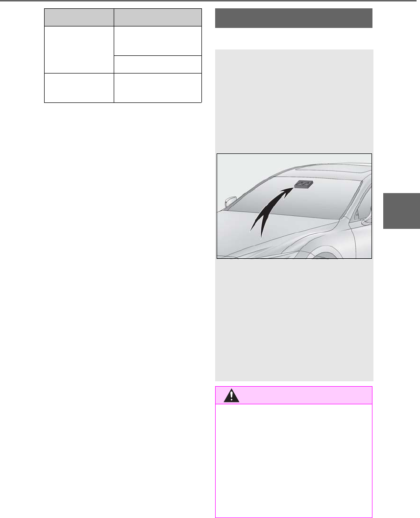
247
4-5. Using the driving support systems
LS500h_OM_OM50F42U_(U)
4
Driving
For how to change settings, refer to
→P.481
*: If equipped
Vehicle sway
warning function
Turn function on and
off
Adjust alert sensitivity
Lane centering
function
Turn function on and
off
Function Setting details RSA (Road Sign Assist)*
The RSA system recognizes spe-
cific road signs using the camera
sensor and navigation system
(when data is available) to provide
information to the driver via the
multi-information display and
head-up display.
If the system judges that the vehicle
is being driven over the speed limit,
performing prohibited actions, etc.
in relation to the recognized road
signs, it alerts the driver using a
warning display and warning
buzzer*.
*: This setting needs to be customized.
WARNING
■Before using the RSA
Do not rely solely upon the RSA system.
RSA is a system which supports the
driver by providing information, but it is
not a replacement for a driver’s own
vision and awareness. Drive safely by
always paying careful attention to the
traffic rules.
Inappropriate or negligent driving could
lead to an unexpected accident.
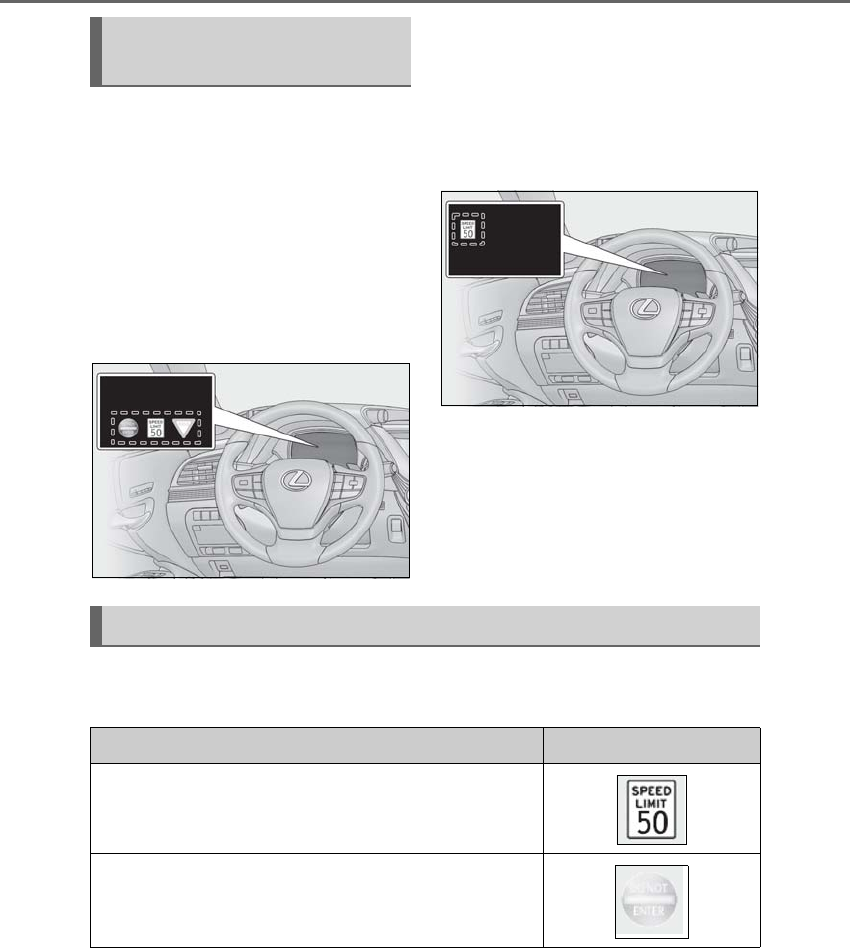
248 4-5. Using the driving support systems
LS500h_OM_OM50F42U_(U)
When the camera sensor recognizes a
sign or information of a sign is available
from the navigation system , the sign
will be displayed on the multi-informa-
tion display.
-When the driving support system
information is selected, a maximum
of 3 signs can be displayed.
(→P.86)
-When a tab other than the driving
support system information tab is
selected, only a recognized speed
limit sign or do not enter sign (when
notification is necessary) will be dis-
played. (→P.86)
If signs other than speed limit signs are rec-
ognized, they will be displayed in an over-
lapping stack under the current speed limit
sign.
The following types of road signs are recognized.
Non-official or recently introduced traffic signs may not be recognized.
Indication on the multi-informa-
tion display
Supported types of road signs
Type Multi-information display
Speed limit begins/ends*
Do Not Enter
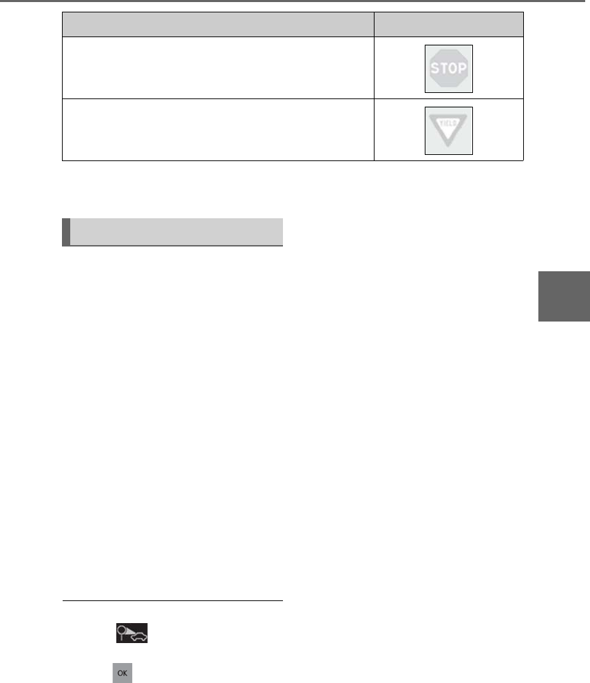
249
4-5. Using the driving support systems
LS500h_OM_OM50F42U_(U)
4
Driving
*: Displayed when speed limit information for the road is available from the navigation sys-
tem
In the following situations, the RSA sys-
tem will alert the driver.
-When the vehicle speed exceeds
the speed warning threshold of the
speed limit sign displayed, the sign
display will be emphasized and a
buzzer will sound.
-When the RSA system recognizes a
do not enter sign and determines
that your vehicle has entered a
no-entry area, the displayed sign will
flash and a buzzer will sound.
Depending on the situation, traffic
environment (traffic direction, speed,
unit) may be detected incorrectly and a
warning display may not operate prop-
erly.
■Turning the system on/off
1Select on of the multi-informa-
tion display (→P.86)
2Press on the steering wheel.
■Automatic turn-off of RSA sign display
In the following situations, a displayed
speed limit sign will stop being displayed
automatically:
●A new sign is not recognized for a certain
distance. (When speed limit information
is not available from the navigation sys-
tem)
In the following situations, do not enter, stop
and yield signs will stop being displayed
automatically:
●The system determines that your vehicle
has passed the sign.
●The road changes due to a left or right
turn, etc.
■Conditions in which the function may
not operate or detect correctly
In the following situations, RSA does not
operate normally and may not recognize
signs, display the incorrect sign, etc. How-
ever, this does not indicate a malfunction.
●The camera sensor is misaligned due to a
strong impact being applied to the sen-
sor, etc.
●Dirt, snow, stickers, etc. are on the wind-
shield near the camera sensor.
●In inclement weather such as heavy rain,
fog, snow or sand storms
●Light from an oncoming vehicle, the sun,
etc. enters the camera sensor.
●The sign is dirty, faded, tilted or bent.
●All or part of the sign is hidden by the
leaves of a tree, a pole, etc.
●The sign is only visible to the camera sen-
sor for a short amount of time.
●The driving scene (turning, lane change,
etc.) is judged incorrectly.
Stop
Yield
Type Multi-information display
Warning indication
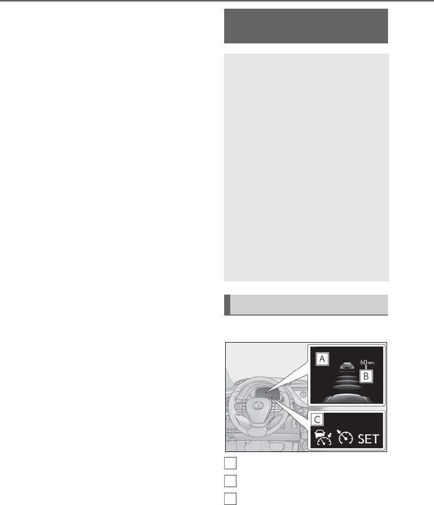
250 4-5. Using the driving support systems
LS500h_OM_OM50F42U_(U)
●Even if it is a sign not appropriate for the
currently traveled lane, such a sign exists
directly after a freeway branches, or in an
adjacent lane just before merging.
●Stickers are attached to the rear of the
preceding vehicle.
●A sign resembling a system compatible
sign is recognized.
●The front of the vehicle is raised or low-
ered due to the carried load.
●The surrounding brightness is not suffi-
cient or changes suddenly.
●When a sign intended for trucks, etc. is
recognized.
●The navigation system map data is old.
●The navigation system is not operating.
●Side road speed signs may be detected
and displayed (if positioned in sight of the
camera sensor) while the vehicle is trav-
eling on the main road.
●Roundabout exit road speed signs may
be detected and displayed (if positioned
in sight of the camera sensor) while trav-
eling on a roundabout.
■Speed limit sign display
If the power switch was last turned off while
a speed limit sign was displayed on the
multi-information display, the same sign dis-
plays again when the power switch is turned
to ON mode.
■Customization
Some functions can be customized.
(→P.481)
■Meter display
Display
Set speed
Indicators
Dynamic radar cruise con-
trol with full-speed range
In vehicle-to-vehicle distance con-
trol mode, the vehicle automati-
cally accelerates, decelerates and
stops to match the speed changes
of the preceding vehicle even if the
accelerator pedal is not depressed.
In constant speed control mode,
the vehicle runs at a fixed speed.
Use the dynamic radar cruise con-
trol with full-speed range on free-
ways and highways.
-Vehicle-to-vehicle distance con-
trol mode (→P.253)
-Constant speed control mode
(→P.257)
System Components
A
B
C
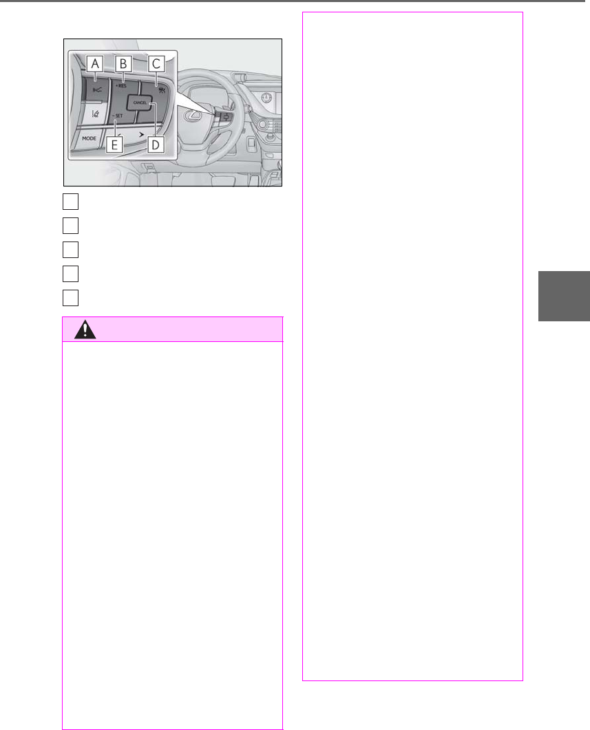
251
4-5. Using the driving support systems
LS500h_OM_OM50F42U_(U)
4
Driving
■Operation switches
Vehicle-to-vehicle distance switch
“+RES” switch
Cruise control main switch
Cancel switch
“-SET” switch
WARNING
■Before using dynamic radar cruise
control with full-speed range
Driving safely is the sole responsibility of
the driver. Do not rely solely on the sys-
tem, and drive safely by always paying
careful attention to your surroundings.
The dynamic radar cruise control with
full-speed range provides driving assis-
tance to reduce the driver’s burden.
However, there are limitations to the
assistance provided.
Set the speed appropriately depending
on the speed limit, traffic flow, road con-
ditions, weather conditions, etc. The
driver is responsible for checking the set
speed.
Even when the system is functioning nor-
mally, the condition of the preceding
vehicle as detected by the system may
differ from the condition observed by the
driver. Therefore, the driver must always
remain alert, assess the danger of each
situation and drive safely. Relying solely
on this system or assuming the system
ensures safety while driving can lead to
an accident, resulting in death or serious
injury.
A
B
C
D
E
■Cautions regarding the driving assist
systems
Observe the following precautions, as
there are limitations to the assistance
provided by the system.
Failure to do so may cause an accident
resulting in death or serious injury.
●Assisting the driver to measure follow-
ing distance
The dynamic radar cruise control with
full-speed range is only intended to
help the driver in determining the fol-
lowing distance between the driver’s
own vehicle and a designated vehicle
traveling ahead. It is not a mechanism
that allows careless or inattentive driv-
ing, and it is not a system that can assist
the driver in low-visibility conditions. It
is still necessary for driver to pay close
attention to the vehicle’s surroundings.
●Assisting the driver to judge proper
following distance
The dynamic radar cruise control with
full-speed range determines whether
the following distance between the
driver’s own vehicle and a designated
vehicle traveling ahead is within a set
range. It is not capable of making any
other type of judgement. Therefore, it
is absolutely necessary for the driver to
remain vigilant and to determine
whether or not there is a possibility of
danger in any given situation.
●Assisting the driver to operate the
vehicle
The dynamic radar cruise control with
full-speed range does not include
functions which will prevent or avoid
collisions with vehicles ahead of your
vehicle. Therefore, if there is ever any
possibility of danger, the driver must
take immediate and direct control of
the vehicle and act appropriately in
order to ensure the safety of all
involved.

252 4-5. Using the driving support systems
LS500h_OM_OM50F42U_(U)
WARNING
■To avoid inadvertent dynamic radar
cruise control with full-speed range
activation
Switch the dynamic radar cruise control
with full-speed range setting to off, using
the cruise control main switch when not
in use.
■Situations unsuitable for dynamic
radar cruise control with full-speed
range
Do not use dynamic radar cruise control
with full-speed range in any of the follow-
ing situations.
Doing so may result in inappropriate
speed control and could cause an acci-
dent resulting in death or serious injury.
●Roads where there are pedestrians,
cyclists, etc.
●In heavy traffic
●On roads with sharp bends
●On winding roads
●On slippery roads, such as those cov-
ered with rain, ice or snow
●On steep downhills, or where there
are sudden changes between sharp up
and down gradients
Vehicle speed may exceed the set
speed when driving down a steep hill.
●At entrances to freeways and highways
●When weather conditions are bad
enough that they may prevent the sen-
sors from detecting correctly (fog,
snow, sandstorm, heavy rain, etc.)
●When there is rain, snow, etc. on the
front surface of the radar sensor or
camera sensor
●In traffic conditions that require fre-
quent repeated acceleration and
deceleration
●When an approach warning buzzer is
heard often
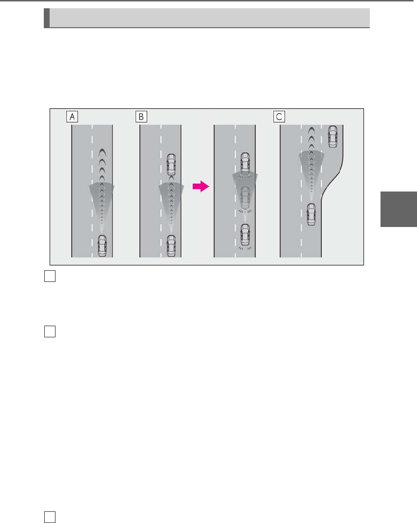
253
4-5. Using the driving support systems
LS500h_OM_OM50F42U_(U)
4
Driving
This mode employs a radar sensor to detect the presence of vehicles up to approx-
imately 328 ft. (100 m) ahead, determines the current vehicle-to-vehicle following
distance, and operates to maintain a suitable following distance from the vehicle
ahead.
Note that vehicle-to-vehicle distance will close in when traveling on long downhill slopes.
Example of constant speed cruising
When there are no vehicles ahead
The vehicle travels at the speed set by the driver. The desired vehicle-to-vehicle distance
can also be set by operating the vehicle-to-vehicle distance switch.
Example of deceleration cruising and follow-up cruising
When a preceding vehicle driving slower than the set speed appears
When a vehicle is detected running ahead of you, the system automatically decelerates
your vehicle. When a greater reduction in vehicle speed is necessary, the system applies
the brakes (the stop lights will come on at this time). The system will respond to changes in
the speed of the vehicle ahead in order to maintain the vehicle-to-vehicle distance set by
the driver. Approach warning warns you when the system cannot decelerate sufficiently to
prevent your vehicle from closing in on the vehicle ahead.
When the vehicle ahead of you stops, your vehicle will also stop (vehicle is stopped by sys-
tem control). After the vehicle ahead starts off, pressing the “+RES” switch or depressing
the accelerator pedal will resume follow-up cruising.
Vehicles with Lexus Safety System+A: If your vehicle is being driven at approximately 43
mph (70 km/h) or more, when the turn signal is operated and a lane change is made to
pass the vehicle ahead, the system will start accelerating your vehicle up to the set speed to
assist smooth overtaking.
Example of acceleration
When there are no longer any preceding vehicles driving slower than the set
Driving in vehicle-to-vehicle distance control mode
A
B
C
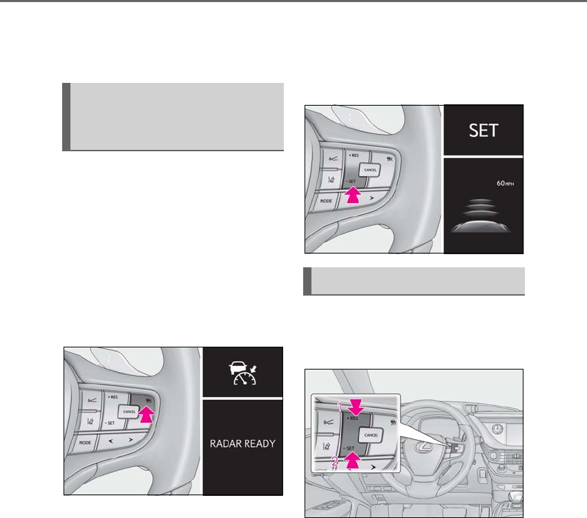
254 4-5. Using the driving support systems
LS500h_OM_OM50F42U_(U)
speed
The system accelerates until the set speed is reached. The system then returns to constant
speed cruising.
1Press the cruise control main switch
to activate the cruise control.
Radar cruise control indicator will come on
and a message will be displayed on the
multi-information display.
Press the switch again to deactivate the
cruise control.
If the cruise control main switch is pressed
and held for 1.5 seconds or more, the sys-
tem turns on in constant speed control
mode. (→P.257)
2Accelerate or decelerate, with
accelerator pedal operation, to the
desired vehicle speed (at or above
approximately 30 mph [50 km/h])
and press the “-SET” switch to set
the speed.
Cruise control “SET” indicator will come
on.
The vehicle speed at the moment the
switch is released becomes the set speed.
If the switch is operated while the vehicle
speed is below approximately 30 mph (50
km/h) and a preceding vehicle is present,
the set speed will be adjusted to approxi-
mately 30 mph (50 km/h).
To change the set speed, operate the
“+RES” or “-SET” switch until the
desired set speed is displayed.
1Increases the speed
(Except when the vehicle has been
stopped by system control in vehi-
cle-to-vehicle distance control mode)
2Decreases the speed
Fine adjustment: Press the switch.
Large adjustment: Press and hold the
switch to change the speed, and
release when the desired speed is
reached.
In the vehicle-to-vehicle distance con-
trol mode, the set speed will be
Setting the vehicle speed (vehi-
cle-to-vehicle distance control
mode)
Adjusting the set speed
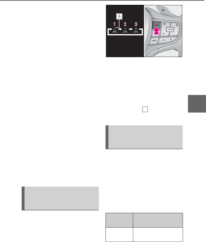
255
4-5. Using the driving support systems
LS500h_OM_OM50F42U_(U)
4
Driving
increased or decreased as follows:
For the U.S. mainland, Hawaii
Fine adjustment: By 1 mph (1.6 km/h)*1 or 1
km/h (0.6mph)*2 each time the switch is
pressed
Large adjustment: Increases or decreases
in 1mph (1.6 km/h)*1 or 1 km/h (0.6 mph)*2
increments for as long as the switch is held
For Canada, Guam and Puerto Rico
Fine adjustment: By 1 mph (1.6 km/h)*1 or 1
km/h (0.6mph)*2 each time the switch is
pressed
Large adjustment: Increases or decreases
in 5 mph (8 km/h)*1 or 5 km/h (3.1 mph)*2
increments for as long as the switch is held
In the constant speed control mode
(→P.257), the set speed will be
increased or decreased as follows:
Fine adjustment: By 1 mph (1.6 km/h)*1 or 1
km/h (0.6 mph)*2 each time the switch is
pressed
Large adjustment: The speed will continue
to change while the switch is held.
*1: When the set speed is shown in “MPH”
*2: When the set speed is shown in “km/h”
Pressing the switch changes the vehi-
cle-to-vehicle distance as follows:
1Long
2Medium
3Short
The vehicle-to-vehicle distance is set auto-
matically to long mode when the power
switch is turned ON mode.
If a vehicle is running ahead of you, the pre-
ceding vehicle mark will also be dis-
played.
Select a distance from the table below.
Note that the distances shown corre-
spond to a vehicle speed of 50 mph
(80 km/h). Vehicle-to-vehicle distance
increases/decreases in accordance
with vehicle speed. When the vehicle is
stopped by system control, the vehicle
stops at a certain vehicle-to-vehicle
distance depending on the situation.
Changing the vehicle-to-vehicle
distance (vehicle-to-vehicle dis-
tance control mode)
Vehicle-to-vehicle distance set-
tings (vehicle-to-vehicle dis-
tance control mode)
Distance
options
Vehicle-to-vehicle dis-
tance
Long Approximately 160 ft. (50
m)
A
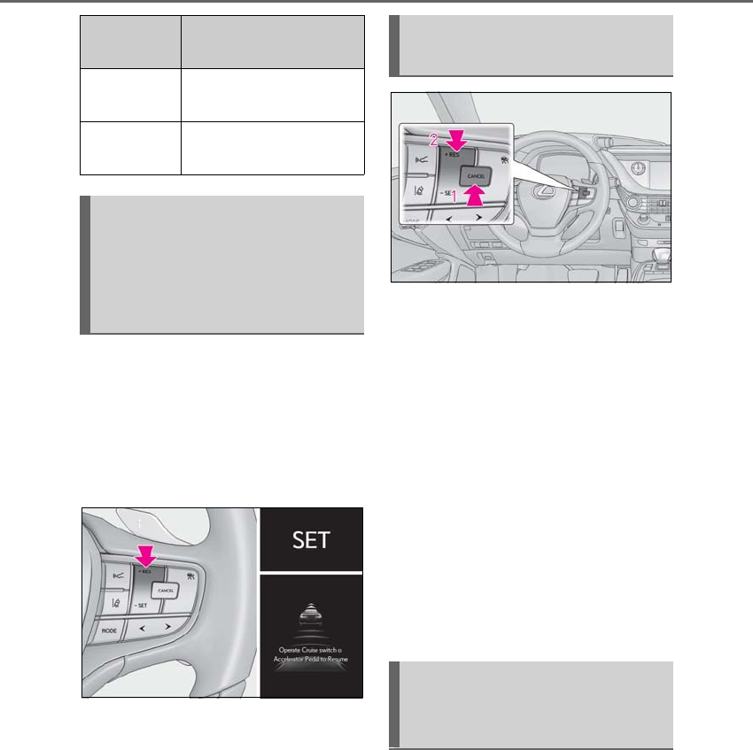
256 4-5. Using the driving support systems
LS500h_OM_OM50F42U_(U)
After the vehicle ahead of you starts
off, press the “+RES” switch.
Your vehicle will also resume follow-up
cruising if the accelerator pedal is
depressed after the vehicle ahead of
you starts off.
1Pressing the cancel switch cancels
the speed control.
The speed control is also canceled when
the brake pedal is depressed.
(When the vehicle has been stopped by
system control, depressing the brake pedal
does not cancel the setting.)
2Pressing the “+RES” switch
resumes the cruise control and
returns vehicle speed to the set
speed.
However, when a vehicle ahead is not
detected, cruise control does not resume
when the vehicle speed is approximately
25 mph (40 km/h) or less.
When your vehicle is too close to a
vehicle ahead, and sufficient automatic
deceleration via the cruise control is
not possible, the display will flash and
the buzzer will sound to alert the driver.
An example of this would be if another
driver cuts in front of you while you are
following a vehicle. Depress the brake
pedal to ensure an appropriate vehi-
Medium Approximately 130 ft. (40
m)
Short Approximately 100 ft. (30
m)
Resuming follow-up cruising
when the vehicle has been
stopped by system control (vehi-
cle-to-vehicle distance control
mode)
Distance
options
Vehicle-to-vehicle dis-
tance Canceling and resuming the
speed control
Approach warning (vehi-
cle-to-vehicle distance control
mode)
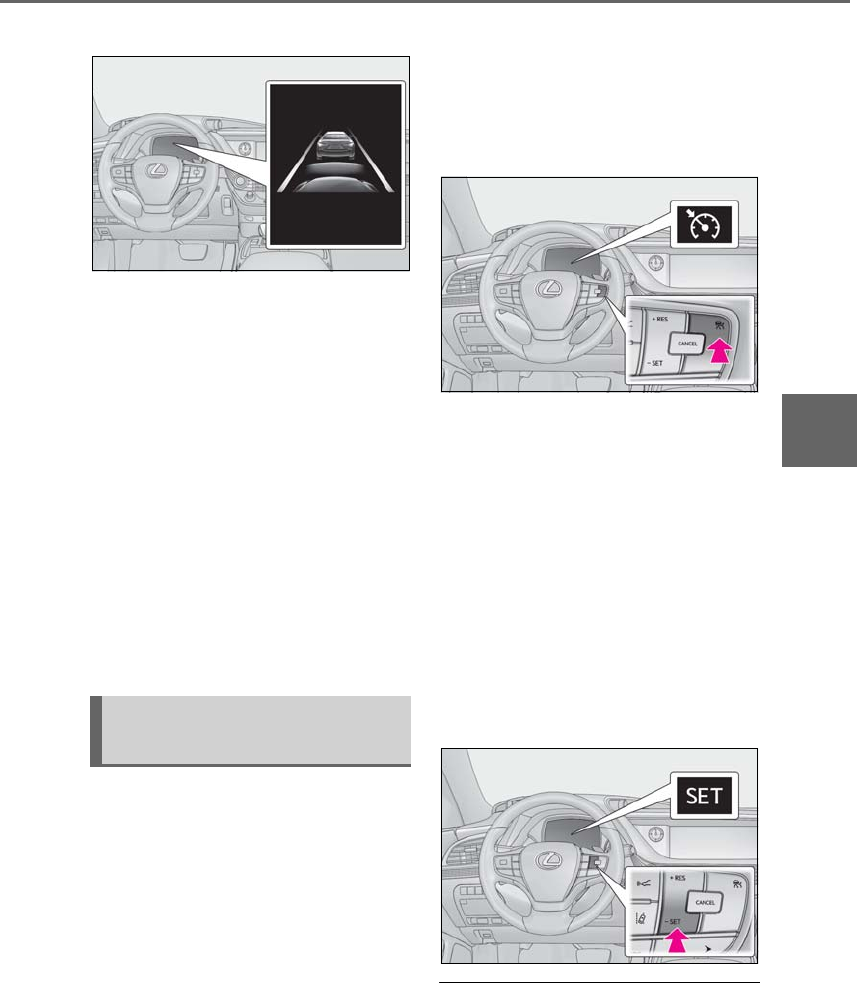
257
4-5. Using the driving support systems
LS500h_OM_OM50F42U_(U)
4
Driving
cle-to-vehicle distance.
■Warnings may not occur when
In the following instances, warnings
may not occur even when the vehi-
cle-to-vehicle distance is small.
-When the speed of the preceding
vehicle matches or exceeds your
vehicle speed
-When the preceding vehicle is trav-
eling at an extremely slow speed
-Immediately after the cruise control
speed was set
-When depressing the accelerator
pedal
When constant speed control mode is
selected, your vehicle will maintain a
set speed without controlling the vehi-
cle-to-vehicle distance. Select this
mode only when vehicle-to-vehicle dis-
tance control mode does not function
correctly due to a dirty radar sensor,
etc.
1With the cruise control off, press
and hold the cruise control main
switch for 1.5 seconds or more.
Immediately after the switch is pressed, the
radar cruise control indicator will come on.
Afterwards, it switches to the cruise con-
trol indicator.
Switching to constant speed control mode
is only possible when operating the switch
with the cruise control off.
2Accelerate or decelerate, with
accelerator pedal operation, to the
desired vehicle speed (at or above
approximately 25 mph [40 km/h])
and press the “-SET” switch to set
the speed.
Cruise control “SET” indicator will come
on.
The vehicle speed at the moment the
switch is released becomes the set speed.
Adjusting the speed setting: →P.254
Canceling and resuming the speed setting:
→P.256
■Dynamic radar cruise control with
full-speed range can be set when
●The shift position is in D.
●Range 4 or higher of D has been selected
Selecting constant speed con-
trol mode

258 4-5. Using the driving support systems
LS500h_OM_OM50F42U_(U)
by using the paddle shift switch.
●Vehicle speed is at or above approxi-
mately 30 mph (50 km/h).
However, when a preceding vehicle is
detected, the dynamic radar cruise con-
trol with full-speed range can be set even
if the vehicle speed is below approxi-
mately 30 mph (50 km/h).
■Accelerating after setting the vehicle
speed
The vehicle can accelerate by operating the
accelerator pedal. After accelerating, the
set speed resumes. However, during vehi-
cle-to-vehicle distance control mode, the
vehicle speed may decrease below the set
speed in order to maintain the distance to
the preceding vehicle.
■When the vehicle stops while follow-up
cruising
●Pressing the “+RES” switch while the
vehicle ahead stops will resume follow-up
cruising if the vehicle ahead starts off
within approximately 3 seconds after the
switch is pressed.
●If the vehicle ahead starts off within 3 sec-
onds after your vehicle stops, follow-up
cruising will be resumed.
■Automatic cancelation of vehi-
cle-to-vehicle distance control mode
Vehicle-to-vehicle distance control mode is
automatically canceled in the following situ-
ations.
●Actual vehicle speed falls at or below
approximately 25 mph (40 km/h) when
there are no vehicles ahead.
●The preceding vehicle leaves the lane
when your vehicle is following at a vehicle
speed at or below approximately 25 mph
(40 km/h). Otherwise, the sensor cannot
properly detect the vehicle. (“CRUISE
NOT AVAILABLE No Preceding Vehi-
cles” is displayed on the multi-information
display.)
●VSC is activated.
●TRAC is activated for a period of time.
●When the VSC or TRAC system is
turned off.
●When snow mode is set.
●The sensor cannot detect correctly
because it is covered in some way.
●Pre-collision braking is activated.
●The parking brake is operated.
●The vehicle is stopped by system control
on a steep incline.
●The following are detected when the
vehicle has been stopped by system con-
trol:
• The driver is not wearing a seat belt.
• The driver’s door is opened.
• The vehicle has been stopped for about 3
minutes.
If vehicle-to-vehicle distance control mode
is automatically canceled for any other rea-
son, there may be a malfunction in the sys-
tem. Contact your Lexus dealer.
■Automatic cancelation of constant
speed control mode
Constant speed control mode is automati-
cally canceled in the following situations:
●Actual vehicle speed is more than
approximately 10 mph (16 km/h) below
the set vehicle speed.
●Actual vehicle speed falls below approxi-
mately 25 mph (40 km/h).
●VSC is activated.
●TRAC is activated for a period of time.
●When the VSC or TRAC system is
turned off.
●Pre-collision braking is activated.
If constant speed control mode is automati-
cally canceled for any other reason, there
may be a malfunction in the system. Con-
tact your Lexus dealer.
■If “Radar Cruise Control Unavailable” is
shown on the multi-information display
The radar cruise control system cannot be
used temporarily. Use the system when it
becomes available again.
■Brake system operation sound
When the brakes are operated in vehi-
cle-to-vehicle distance mode, a brake oper-
ating sound may be heard. This is not a
malfunction.
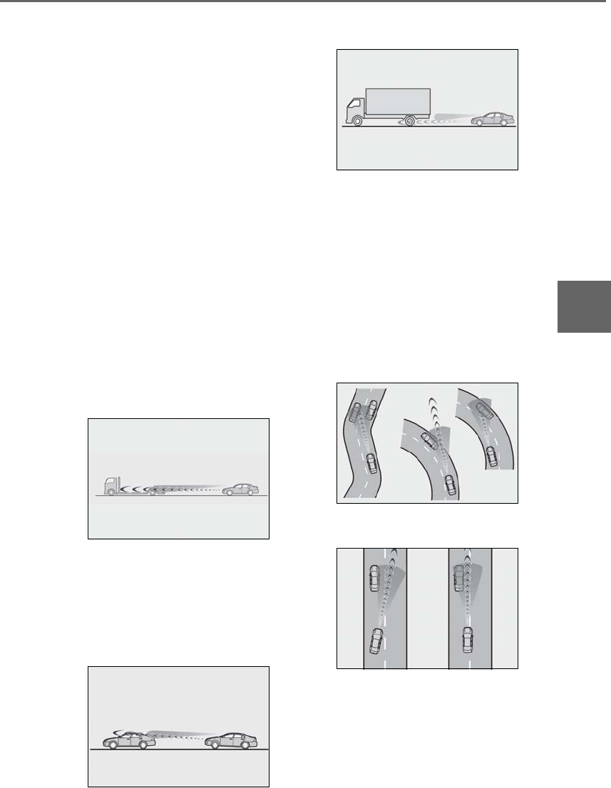
259
4-5. Using the driving support systems
LS500h_OM_OM50F42U_(U)
4
Driving
■Warning messages and buzzers for
dynamic radar cruise control with
full-speed range
Warning messages and buzzers are used to
indicate a system malfunction or to inform
the driver of the need for caution while driv-
ing. If a warning message is shown on the
multi-information display, read the message
and follow the instructions.
■When the sensor may not be correctly
detecting the vehicle ahead
In the case of the following and depending
on the conditions, operate the brake pedal
when deceleration of the system is insuffi-
cient or operate the accelerator pedal
when acceleration is required.
As the sensor may not be able to correctly
detect these types of vehicles, the approach
warning (→P.256) may not be activated.
●Vehicles that cut in suddenly
●Vehicles traveling at low speeds
●Vehicles that are not moving in the same
lane
●Vehicles with small rear ends (trailers
with no load on board, etc.)
●Motorcycles traveling in the same lane
●When water or snow thrown up by the
surrounding vehicles hinders the detect-
ing of the sensor
●When your vehicle is pointing upwards
(caused by a heavy load in the luggage
compartment, etc.)
●Preceding vehicle has an extremely high
ground clearance
■Conditions under which the vehi-
cle-to-vehicle distance control mode
may not function correctly
In the case of the following conditions,
operate the brake pedal (or accelerator
pedal, depending on the situation) as nec-
essary.
As the sensor may not be able to correctly
detect vehicles ahead, the system may not
operate properly.
●When driving around a curve, on a nar-
row road, or on a bridge, in a tunnel, etc.,
where there are objects on the roadside
●When steering wheel operation or your
position in the lane is unstable
●When the vehicle ahead of you deceler-
ates suddenly
●While the vehicle speed is decreasing to
the set speed after the vehicle acceler-
ates by depressing the accelerator pedal.
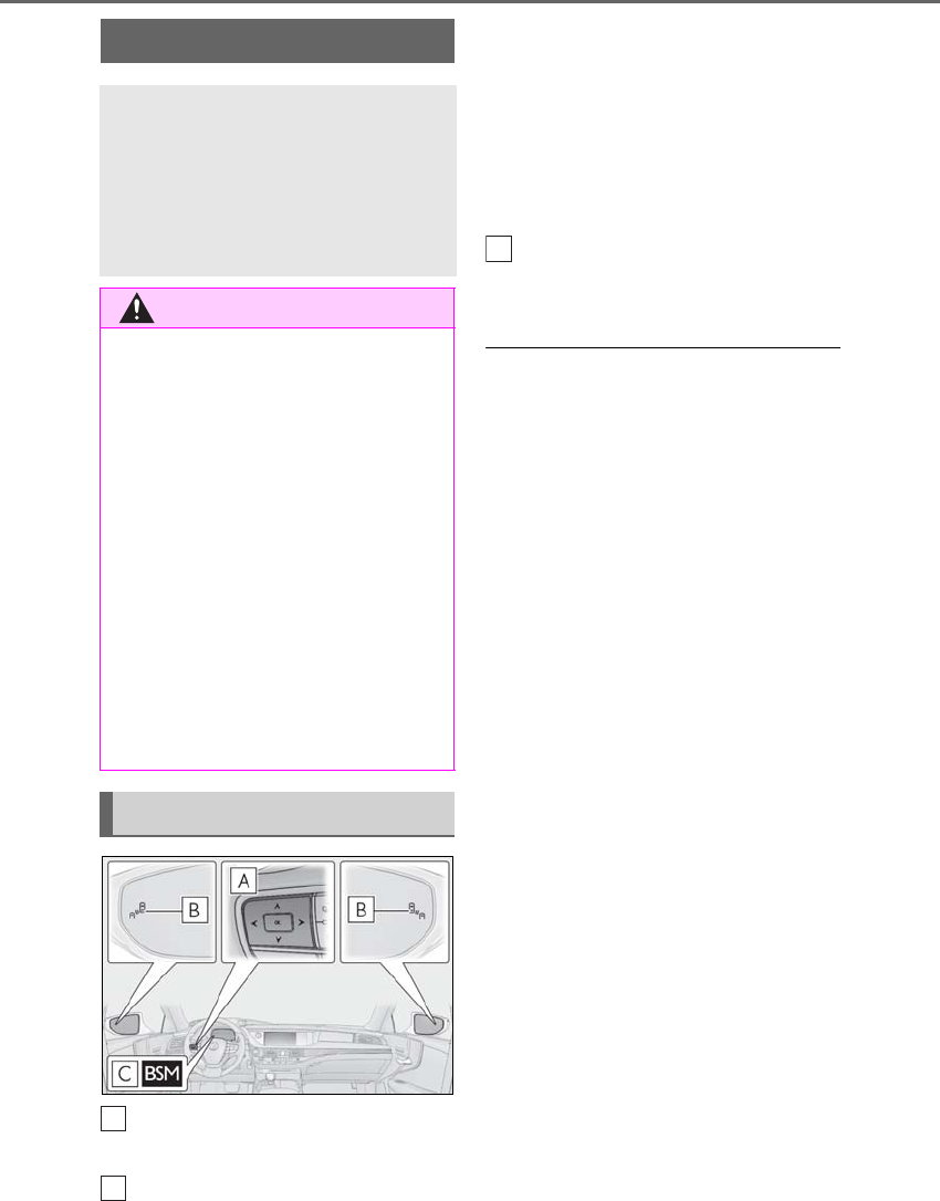
260 4-5. Using the driving support systems
LS500h_OM_OM50F42U_(U)
Meter control switches
Turning the Blind Spot Monitor on/off.
Outside rear view mirror indicators
When a vehicle is detected in a blind spot
of the outside rear view mirrors or
approaching rapidly from behind into a
blind spot, the outside rear view mirror
indicator on the detected side will illumi-
nate. If the turn signal lever is operated
toward the detected side, the outside rear
view mirror indicator flashes.
BSM indicator
Illuminates when the Blind Spot Monitor is
enabled
■Outside rear view mirror indicator visi-
bility
In strong sunlight, the outside rear view mir-
ror indicator may be difficult to see.
■When “BSM Not Available” is shown on
the multi-information display
Ice, snow, mud, etc., may be attached to the
rear bumper around the sensors. (→P.261)
The system should return to normal opera-
tion after removing the ice, snow, mud, etc.
from the rear bumper. Additionally, the sen-
sors may not operate normally when driving
in extremely hot or cold environments.
■Customization
Some functions can be customized.
(→P.481)
BSM (Blind Spot Monitor)
The Blind Spot Monitor is a system
that uses rear side radar sensors
installed on the inner side of the
rear bumper on the left and right
side to assist the driver in confirm-
ing safety when changing lanes.
WARNING
■Cautions regarding the use of the sys-
tem
The driver is solely responsible for safe
driving. Always drive safely, taking care
to observe your surroundings.
The Blind Spot Monitor is a supplemen-
tary function which alerts the driver that a
vehicle is in a blind spot of the outside
rear view mirrors or is approaching rap-
idly from behind into a blind spot. Do not
overly rely on the Blind Spot Monitor. As
the function cannot judge if it is safe to
change lanes, over reliance could lead to
an accident resulting in death or serious
injury.
As the system may not function correctly
under certain conditions, the driver’s own
visual confirmation of safety is necessary.
System components
A
B
C
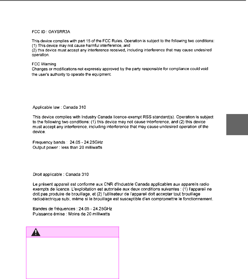
261
4-5. Using the driving support systems
LS500h_OM_OM50F42U_(U)
4
Driving
■Certification
For vehicles sold in the U.S.A., Hawaii, Guam and Puerto Rico
For vehicles sold in Canada
WARNING
■Handling the rear side radar sensor
Blind Spot Monitor sensors are installed
behind the left and right sides of the rear
bumper respectively. Observe the fol-
lowing to ensure the Blind Spot Monitor
can operate correctly.
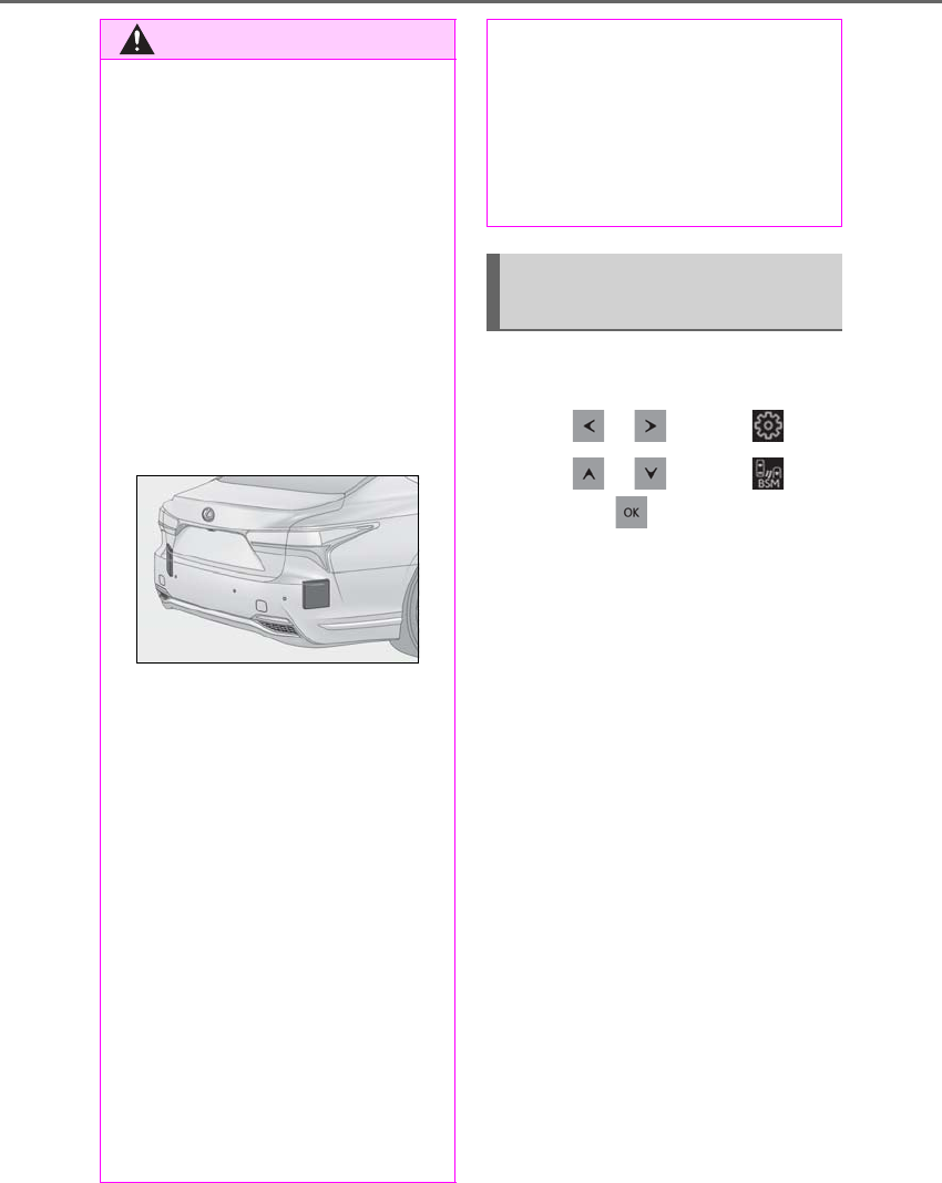
262 4-5. Using the driving support systems
LS500h_OM_OM50F42U_(U)
Use the meter control switches to turn
on/off the function.
1Press or to select .
2Press or to select and
then press .
WARNING
●Keep the sensors and the surrounding
areas on the rear bumper clean at all
times.
If a sensor or its surrounding area on the
rear bumper is dirty or covered with
snow, the Blind Spot Monitor may not
operate and a warning message
(→P.260) will be displayed. In this situa-
tion, clear off the dirt or snow and drive
the vehicle with the operation conditions
of the BSM function (→P.264) satisfied
for approximately 10 minutes. If the
warning message does not disappear,
have the vehicle inspected by your Lexus
dealer.
●Do not attach accessories, stickers
(including transparent stickers), alumi-
num tape, etc. to a sensor or its sur-
rounding area on the rear bumper.
●Do not subject a sensor or its sur-
rounding area on the rear bumper to a
strong impact.
If a sensor is moved even slightly off posi-
tion, the system may malfunction and
vehicles may not be detected correctly.
In the following situations, have your
vehicle inspected by your Lexus dealer.
• A sensor or its surrounding area is
subject to a strong impact.
• If the surrounding area of a sensor is
scratched or dented, or part of them
has become disconnected.
●Do not disassemble the sensor.
●Do not modify the sensor or surround-
ing area on the rear bumper.
●If a sensor or the rear bumper needs to
be removed/installed or replaced,
contact your Lexus dealer.
●Do not paint the rear bumper any
color other than an official Lexus color.
Turning the Blind Spot Monitor
on/off
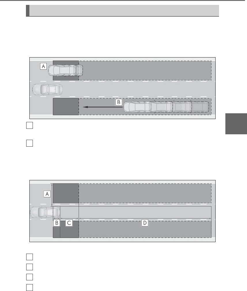
263
4-5. Using the driving support systems
LS500h_OM_OM50F42U_(U)
4
Driving
■Vehicles that can be detected by the Blind Spot Monitor
The Blind Spot Monitor uses rear side radar sensors to detect the following vehi-
cles traveling in adjacent lanes and advises the driver of the presence of such vehi-
cles via the indicators on the outside rear view mirrors.
Vehicles that are traveling in areas that are not visible using the outside rear
view mirrors (the blind spots)
Vehicles that are approaching rapidly from behind in areas that are not visible
using the outside rear view mirrors (the blind spots)
■The Blind Spot Monitor detection areas
The areas that vehicles can be detected in are outlined below.
The range of each detection area is:
Approximately 1.6 ft. (0.5 m) to 11.5 ft. (3.5 m) from either side of the vehicle*1
Approximately 3.3 ft. (1 m) forward of the rear bumper
Approximately 9.8 ft. (3 m) from the rear bumper
Approximately 9.8 ft. (3 m) to 197 ft. (60 m) from the rear bumper*2
*1: The area between the side of the vehicle and 1.6 ft. (0.5 m) from the side of the vehicle
cannot be detected.
*2: The greater the difference in speed between your vehicle and the detected vehicle is,
Blind Spot Monitor operation
A
B
A
B
C
D

264 4-5. Using the driving support systems
LS500h_OM_OM50F42U_(U)
the farther away the vehicle will be detected, causing the outside rear view mirror indi-
cator to illuminate or flash.
■The Blind Spot Monitor is operational
when
The Blind Spot Monitor is operational when
all of the following conditions are met:
●The Blind Spot Monitor is on.
●The shift position is in a position other
than R.
●The vehicle speed is greater than approx-
imately 10 mph (16 km/h).
■The Blind Spot Monitor will detect a
vehicle when
The Blind Spot Monitor will detect a vehicle
present in the detection area in the follow-
ing situations:
●A vehicle in an adjacent lane overtakes
your vehicle.
●You overtake a vehicle in adjacent lane
slowly.
●Another vehicle enters the detection
area when it changes lanes.
■Conditions under which the Blind Spot
Monitor will not detect a vehicle
The Blind Spot Monitor is not designed to
detect the following types of vehicles and/or
objects:
●Small motorcycles, bicycles, pedestrians,
etc.*
●Vehicles traveling in the opposite direc-
tion
●Guardrails, walls, signs, parked vehicles
and similar stationary objects*
●Following vehicles that are in the same
lane*
●Vehicles traveling 2 lanes away from your
vehicle*
*: Depending on the conditions, detection
of a vehicle and/or object may occur.
■Conditions under which the Blind Spot
Monitor may not function correctly
●The Blind Spot Monitor may not detect
vehicles correctly in the following situa-
tions:
• When the sensor is misaligned due to a
strong impact to the sensor or its sur-
rounding area
• When mud, snow, ice, a sticker, etc. is
covering the sensor or surrounding area
on the rear bumper
• When driving on a road surface that is
wet with standing water during bad
weather, such as heavy rain, snow, or fog
• When multiple vehicles are approaching
with only a small gap between each vehi-
cle
• When the distance between your vehicle
and a following vehicle is short
• When there is a significant difference in
speed between your vehicle and the vehi-
cle that enters the detection area
• Vehicles which are being overtaken rap-
idly by your vehicle.
• When the difference in speed between
your vehicle and another vehicle is
changing
• When a vehicle enters a detection area
traveling at about the same speed as your
vehicle
• As your vehicle starts from a stop, a vehi-
cle remains in the detection area
• When driving up and down consecutive
steep inclines, such as hills, dips in the
road, etc.
• When driving on roads with sharp bends,
consecutive curves, or uneven surfaces
• When vehicle lanes are wide, or when
driving on the edge of a lane, and the
vehicle in an adjacent lane is far away
from your vehicle
• When an accessory (such as a bicycle
carrier) is installed to the rear of the vehi-
cle
• When there is a significant difference in
height between your vehicle and the
vehicle that enters the detection area
• Immediately after the Blind Spot Monitor
is turned on
●Instances of the Blind Spot Monitor
unnecessarily detecting a vehicle and/or
object may increase in the following situ-
ations:
• When the sensor is misaligned due to a
strong impact to the sensor or its sur-

265
4-5. Using the driving support systems
LS500h_OM_OM50F42U_(U)
4
Driving
rounding area
• When the distance between your vehicle
and a guardrail, wall, etc. that enters the
detection area is short
• When driving up and down consecutive
steep inclines, such as hills, dips in the
road, etc.
• When vehicle lanes are narrow, or when
driving on the edge of a lane, and a vehi-
cle traveling in a lane other than the adja-
cent lanes enters the detection area
• When driving on roads with sharp bends,
consecutive curves, or uneven surfaces
• When the tires are slipping or spinning
• When the distance between your vehicle
and a following vehicle is short
• When an accessory (such as a bicycle
carrier) is installed to the rear of the vehi-
cle
*: If equipped
■Intuitive parking assist
Ultrasonic sensors are used to detect
static objects in the detection area
when driving at a low speed or backing
up. (→P.266)
■RCTA (Rear Cross Traffic Alert)
function
Radar sensors are used to detect
approaching vehicles in the detection
areas behind the vehicle when backing
up. (→P.273)
■RCD (Rear camera detection)
function (if equipped)
A rear camera sensor is used to detect
pedestrians in the detection area
behind the vehicle when backing up.
(→P.277)
PKSA (Parking Support
Alert)*
The Parking Support Alert system
consists of the following functions
that operate when driving at a low
speed or backing up, such as when
parking. When the system deter-
mines that a collision with a
detected object, such as a wall, or
pedestrian is high, a warning oper-
ates to urge the driver to take eva-
sive action.
PKSA (Parking Support Alert)
system
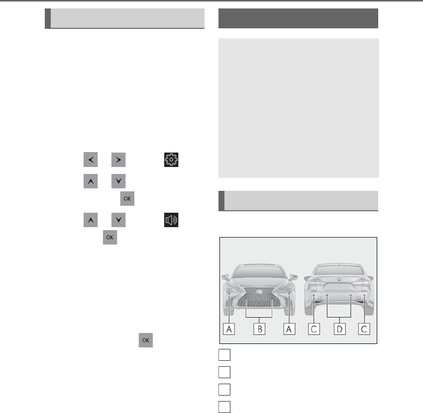
266 4-5. Using the driving support systems
LS500h_OM_OM50F42U_(U)
■Adjusting the buzzer volume
The buzzer volume can be adjusted on
the multi-information display. The vol-
ume of buzzers for the intuitive parking
assist, RCTA function and RCD func-
tion will be adjusted simultaneously.
Use the meter control switches to
change settings. (→P.87)
1Press or to select .
2Press or to select “PKSA”
and then press .
3Press or to select and
then press .
Each time the switch is pressed, the volume
level will change between 1, 2, and 3.
■Muting a buzzer
A mute button will be displayed on the
multi-information display when an
object or pedestrian is detected. To
mute the buzzer, press .
The buzzers for the intuitive parking
assist, RCTA function and RCD func-
tion will be muted simultaneously.
Mute will be canceled automatically in
the following situations:
-When the shift position is changed.
-When the operating function is tem-
porarily canceled.
-When the operating function is dis-
abled manually.
-When the power switch is turned
off.
■Types of sensors
Front corner sensors
Front center sensors
Rear corner sensors
Rear center sensors
■Display
When the sensors detect an object,
such as a wall, a graphic is shown on
the multi-information display, head-up
display (if equipped) and Center Dis-
play depending on the position and dis-
tance to the object.
-Multi-information display and
head-up display
Setting the buzzer volume Intuitive parking assist
The distance from your vehicle to
objects, such as a wall, when paral-
lel parking or maneuvering into a
garage is measured by the sensors
and communicated via the
multi-information display, head-up
display (if equipped), Center Dis-
play and a buzzer. Always check the
surrounding area when using this
system.
System components
A
B
C
D
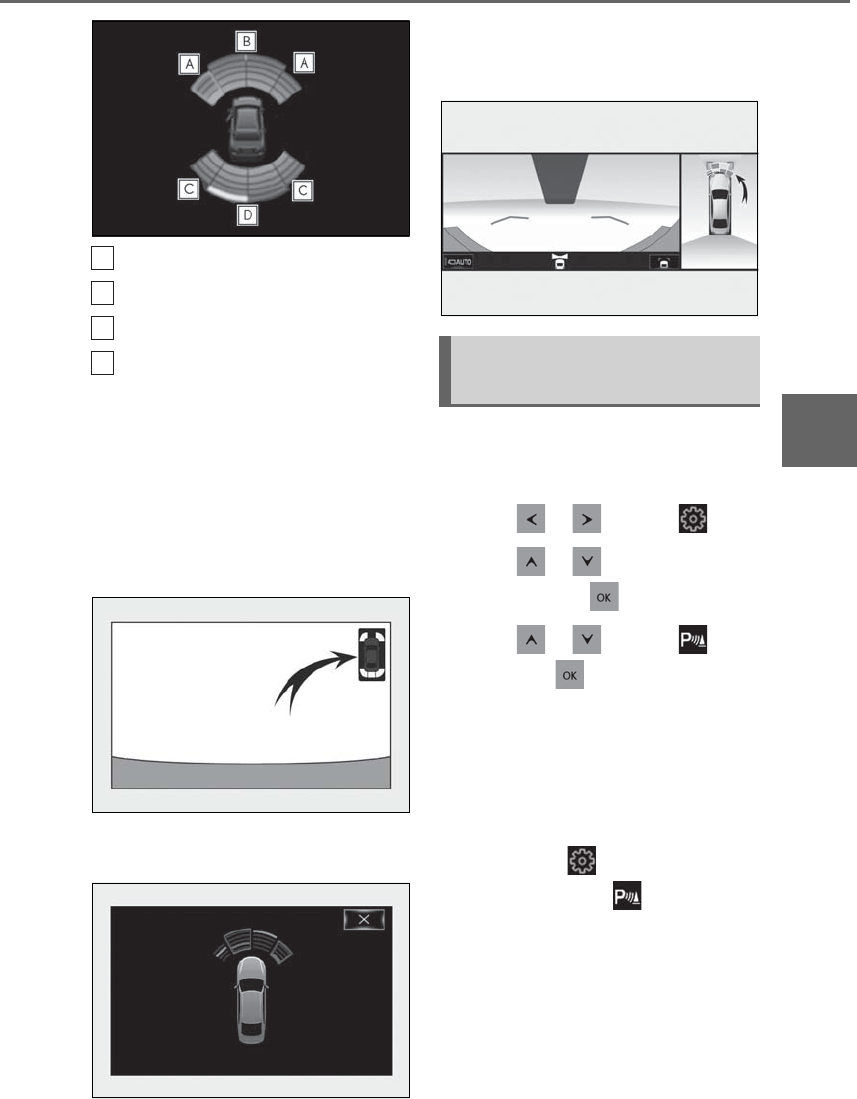
267
4-5. Using the driving support systems
LS500h_OM_OM50F42U_(U)
4
Driving
Front corner sensor detection
Front center sensor detection
Rear corner sensor detection
Rear center sensor detection
-Center Display
A graphic is shown when the Lexus park-
ing assist monitor (if equipped) is dis-
played.
A simplified image is displayed on the
Center Display when an object is detected.
• When the R shift position is selected
• When the N, M or D shift position is
selected (vehicle moving forward)
When an object is detected, a graphic will
be displayed on the panoramic view moni-
tor (if equipped).
Use the meter control switches to
enable/disable the Lexus parking
assist-sensor. (→P.87)
1Press or to select .
2Press or to select “PKSA”
and then press .
3Press or to select and
then press .
When the intuitive parking assist func-
tion is disabled, the intuitive parking
assist OFF indicator (→P.72) illumi-
nates on the multi-information display.
To re-enable the system when it was
disabled, select on the multi-infor-
mation display, select and then On.
If disabled using this method, the sys-
tem will not be re-enabled by turning
the power switch off and then to ON
mode.
A
B
C
D
Turning intuitive parking assist
on/off

268 4-5. Using the driving support systems
LS500h_OM_OM50F42U_(U)
■The system can be operated when
●The power switch is in ON mode.
●Intuitive parking assist function is on.
●The vehicle speed is less than about 6
mph (10 km/h).
●A shift position other than P is selected.
■Setting the buzzer volume
The buzzer volume can be adjusted on the
multi-information display. (→P.266)
■If “Parking Assist Unavailable Clean
Parking Assist Sensor” is displayed on
the multi-information display
A sensor may be covered with ice, snow,
dirt, etc. Remove the ice, snow, dirt, etc.,
from the sensor to return the system to nor-
WARNING
■When using the intuitive parking
assist
Observe the following precautions.
Failing to do so may result in the vehicle
being unable to be driven safely and pos-
sibly cause an accident.
●Do not use the sensor at speeds in
excess of 6 mph (10 km/h).
●The sensors’ detection areas and reac-
tion times are limited. When moving
forward or reversing, check the areas
surrounding the vehicle (especially the
sides of the vehicle) for safety, and
drive slowly, using the brake to control
the vehicle’s speed.
●Do not install accessories within the
sensors’ detection areas.
●The area directly under the bumpers is
not detected.
■When to disable the function
In the following situations, disable the
function as it may operate even though
there is no possibility of a collision.
●The vehicle is equipped with a fender
pole or wireless antenna.
●The front or rear bumper or a sensor
receives a strong impact.
●A non-genuine Lexus suspension
(lowered suspension, etc.) is installed.
●Towing eyelets are installed.
●A backlit licence plate is installed.
■When using intuitive parking assist
In the following situations, the system
may not function correctly due to a sen-
sor malfunction, etc. Have the vehicle
checked by your Lexus dealer.
●The intuitive parking assist operation
display flashes or shows continuously,
and a buzzer sounds when no objects
are detected.
●If the area around a sensor collides
with something, or is subjected to
strong impact.
●If the bumper or grille collides with
something.
●If the display flashes or is displayed
continuously and a buzzer does not
sound, except when the mute function
has been turned on.
●If a display error occurs, first check the
sensor.
If the error occurs even when there is
no ice, snow or mud on the sensor, it is
likely that the sensor is malfunctioning.
■Notes when washing the vehicle
Do not apply intensive bursts of water or
steam to the sensor area.
Doing so may result in the sensor mal-
functioning.
●When using a high pressure washer to
wash the vehicle, do not spray the sen-
sors directly, as doing so may cause a
sensor to malfunction.
●When using steam to clean the vehicle,
do not direct steam too close to the
sensors as doing so may cause a sen-
sor to malfunction.

269
4-5. Using the driving support systems
LS500h_OM_OM50F42U_(U)
4
Driving
mal.
Also, due to ice forming on a sensor at low
temperatures, a warning message may be
displayed or the sensor may not be able to
detect an object. Once the ice melts, the
system will return to normal.
■Sensor detection information
●The following situations may occur
during use.
• Depending on the shape of the object
and other factors, the detection distance
may shorten, or detection may be impos-
sible.
• There will be a short delay between
object detection and display. Even at low
speeds, there is a possibility that the
object will come within the sensor’s
detection areas before the display is
shown and the warning beep sounds.
• It might be difficult to hear the buzzer due
to the volume of the audio system or air
flow noise of the air conditioning system.
■Conditions under which the function
may not function correctly
Certain vehicle conditions and the sur-
rounding environment may affect the ability
of a sensor to correctly detect objects. Par-
ticular instances where this may occur are
listed below.
●There is dirt, snow or ice on a sensor.
(Cleaning the sensors will resolve this
problem.)
●A sensor is frozen. (Thawing the area will
resolve this problem.)
In especially cold weather, if a sensor is
frozen the sensor display may be dis-
played abnormally, or objects, such as a
wall, may not be detected.
●A sensor is covered in any way.
●When a sensor or the area around a sen-
sor is extremely hot or cold.
●On an extremely bumpy road, on an
incline, on gravel, or on grass.
●The vicinity of the vehicle is noisy due to
vehicle horns, motorcycle engines, air
brakes of large vehicles, or other loud
noises producing ultrasonic waves.
●There is another vehicle equipped with
parking assist sensors in the vicinity.
●A sensor is coated with a sheet of spray
or heavy rain.
●If a sensor is hit by a large amount of
water, such as when driving on a flooded
road.
●If the vehicle is significantly tilted.
●The vehicle is approaching a tall or
curved curb.
●If objects draw too close to the sensor.
■Objects which may not be properly
detected
The shape of the object may prevent the
sensor from detecting it. Pay particular
attention to the following objects:
●Wires, fences, ropes, etc.
●Cotton, snow and other materials that
absorb sound waves
●Sharply-angled objects
●Low objects
●Tall objects with upper sections project-
ing outwards in the direction of your vehi-
cle
People may not be detected if they are
wearing certain types of clothing.
■Certification
For vehicles sold in the U.S.A.
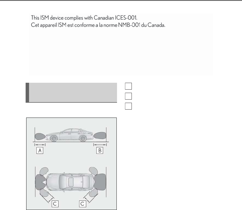
270 4-5. Using the driving support systems
LS500h_OM_OM50F42U_(U)
For vehicles sold in Canada
■Detection range of the sensors
Approximately 3.3 ft. (100 cm)
Approximately 4.9 ft. (150 cm)
Approximately 1.9 ft. (65 cm)
The diagram shows the detection range of
the sensors. Note that the sensors cannot
detect objects that are extremely close to
the vehicle.
The range of the sensors may change
depending on the shape of the object, etc.
■Multi-information display, head-up display (if equipped) and Center Display
When an object is detected by a sensor, the approximate distance to the object will
be displayed on the multi-information display, Center Display, and head-up display
(if equipped). (As the distance to the object becomes short, the distance segments
may blink.)
-Approximate distance to object: 4.9 ft. (150 cm) to 1.9 ft. (65 cm)* (Rear center
sensor)
Sensor detection display, object
distance
A
B
C
271
4-5. Using the driving support systems
LS500h_OM_OM50F42U_(U)
4
Driving
*: Automatic buzzer mute function is enabled. (→P.272)
-Approximate distance to object: 3.3 ft. (100 cm) to 1.9 ft. (65 cm)* (Front center
sensor)
*: Automatic buzzer mute function is enabled. (→P.272)
-Approximate distance to object: 1.9 ft. (65 cm) to 1.5 ft. (45 cm)*
*: Automatic buzzer mute function is enabled. (→P.272)
-Approximate distance to object: 1.5 ft. (45 cm) to 1.0 ft. (30 cm)*
*: Automatic buzzer mute function is enabled. (→P.272)
-Approximate distance to object: 1.0 ft. (30 cm) to 0.5 ft. (15 cm)*1
Multi-information display Center Display Head-up display
Multi-information display Center Display Head-up display
Multi-information display Center Display Head-up display
Multi-information display Center Display Head-up display
Multi-information display*2 Center Display*2 Head-up display
272 4-5. Using the driving support systems
LS500h_OM_OM50F42U_(U)
*1: Automatic buzzer mute function is disabled. (→P.272)
*2: The distance segments will blink slowly.
-Approximate distance to object: Less than 0.5 ft. (15 cm)*1
*1: Automatic buzzer mute function is disabled. (→P.272)
*2: The distance segments will blink rapidly.
■Buzzer operation and distance to
an object
A buzzer sounds when the sensors are
operating.
-The buzzer beeps faster as the vehi-
cle approaches an object. When the
vehicle comes within the following
distance of the object, the buzzer
sounds continuously:
Approximately 1.0 ft. (30 cm)
-When 2 or more objects are
detected simultaneously, the buzzer
sounds for the nearest object. If one
or more objects come within
approximately 1.0 ft. (30 cm) of the
vehicle, the buzzer will repeat a long
tone, followed by fast beeps.
-Automatic buzzer mute function:
After a buzzer begins sounding, if
the distance between the vehicle
and the detected object does not
become shorter, the buzzer will be
muted automatically. (However, if
the distance between the vehicle
and object is 1.0 ft. (30 cm) or less,
this function will not operate.)
The buzzer sounds volume can be
adjusted. (→P.266)
Multi-information display*2 Center Display*2 Head-up display
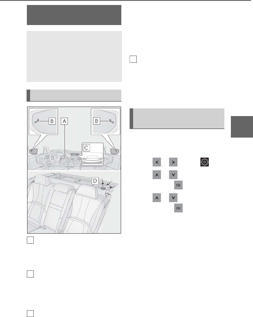
273
4-5. Using the driving support systems
LS500h_OM_OM50F42U_(U)
4
Driving
Meter control switches
Turning the RCTA function on/off.
When the RCTA function is disabled, the
RCTA OFF indicator illuminates.
Outside rear view mirror indicators
When a vehicle approaching from the right
or left at the rear of the vehicle is detected,
both outside rear view mirror indicators
will flash.
Center Display
If a vehicle approaching from the right or
left at the rear of the vehicle is detected,
the RCTA icon (→P.274) for the detected
side will be displayed on the Center Dis-
play. This illustration shows an example of a
vehicle approaching from both sides of the
vehicle.
RCTA buzzer
If a vehicle approaching from the right or
left at the rear of the vehicle is detected, a
buzzer will sound. The buzzer also sounds
for approximately 1 second immediately
after the RCTA function is turned on.
Use the meter control switches to
enable/disable the RCTA function.
(→P.87)
1Press or to select .
2Press or to select “PKSA”
and then press .
3Press or to select “RCTA”
and then press .
When the RCTA function is disabled, the
RCTA OFF indicator (→P.72) illuminates
on the multi-information display. (Each
time the power switch is turned off then
changed to ON mode, the RCTA function
will be enabled automatically.)
RCTA (Rear Cross Traffic
Alert) function
The RCTA function uses the BSM
rear side radar sensors installed
behind the rear bumper. This func-
tion is intended to assist the driver
in checking areas that are not easily
visible when backing up.
System components
A
B
C
Turning the RCTA function
on/off
D
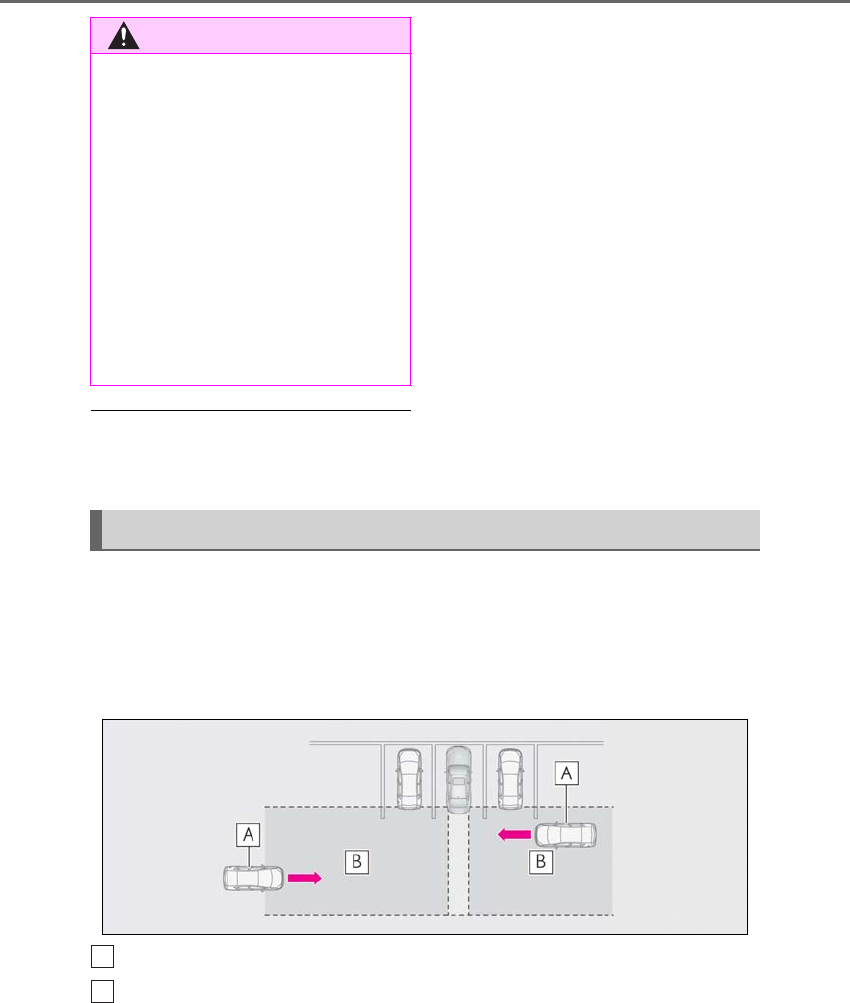
274 4-5. Using the driving support systems
LS500h_OM_OM50F42U_(U)
■Outside rear view mirror indicator visi-
bility
In strong sunlight, the outside rear view mir-
ror indicator may be difficult to see.
■Hearing the RCTA buzzer
The RCTA buzzer may be difficult to hear
over loud noises, such as if the audio system
volume is high.
■When “RCTA NOT AVAILABLE” is
shown on the multi-information display
Water, snow, mud, etc., may be attached to
the rear bumper around the sensors.
(→P.262) Removing the water, snow, mud,
etc., from the attached to the rear bumper
around the sensors to normal.
Additionally, the function may not function
normally when used in extremely hot or
cold environments.
■Rear side radar sensors
→P.262
■Operation of the RCTA function
The RCTA function uses rear side radar sensors to detect vehicles approaching
from the right or left at the rear of the vehicle and alerts the driver of the presence
of such vehicles by flashing the outside rear view mirror indicators and sounding a
buzzer.
Approaching vehicles
Detection areas of approaching vehicles
■RCTA icon display
When a vehicle approaching from the
right or left at the rear of the vehicle is
detected, the following will be dis-
played on the Center Display.
-Example (Lexus parking assist mon-
WARNING
■Cautions regarding the use of the
function
The driver is solely responsible for safe
driving. Always drive safely, taking care
to observe your surroundings.
The RCTA function is only a supplemen-
tary function which alerts the driver that a
vehicle is approaching from the right or
left at the rear of the vehicle. As the
RCTA function may not function cor-
rectly under certain conditions, the
driver’s own visual confirmation of safety
is necessary. Over reliance on this func-
tion may lead to an accident resulting
death or serious injury.
RCTA function
A
B
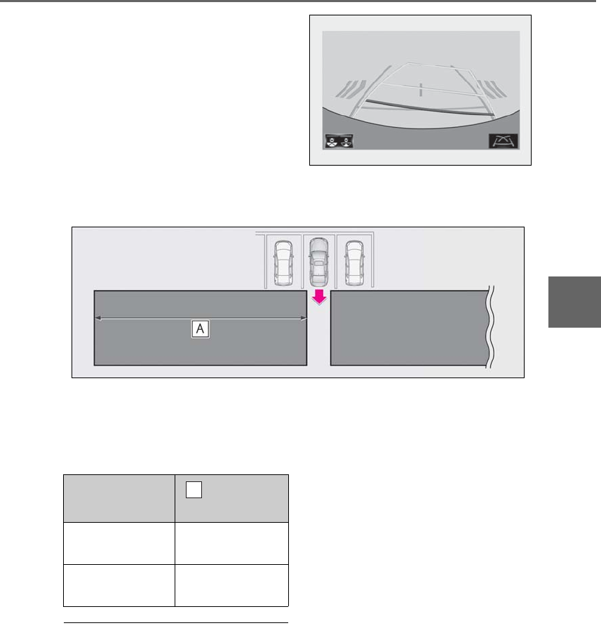
275
4-5. Using the driving support systems
LS500h_OM_OM50F42U_(U)
4
Driving
itor) (if equipped): Vehicles are
approaching from both sides of the
vehicle
■RCTA function detection areas
The areas that vehicles can be detected in are outlined below.
The buzzer can alert the driver of
faster vehicles approaching from far-
ther away.
Example:
■The RCTA function is operational when
The RCTA function operates when all of the
following conditions are met:
●The power switch is in ON mode.
●The RCTA function is on.
●The shift position is in R.
●The vehicle speed is less than approxi-
mately 5 mph (8 km/h).
●The approaching vehicle speed is
between approximately 5 mph (8 km/h)
and 18 mph (28 km/h).
■Setting the buzzer volume
The buzzer volume can be adjusted on the
multi-information display. (→P.266)
■Conditions under which the RCTA func-
tion will not detect a vehicle
The RCTA function is not designed to
detect the following types of vehicles and/or
objects:
●Vehicles approaching from directly
behind
●Vehicles backing up in a parking space
next to your vehicle
●Vehicles that the sensors cannot detect
due to obstructions
Approaching vehi-
cle speed Approximate
alert distance
18 mph (28 km/h)
(fast) 65 ft. (20 m)
5 mph (8 km/h)
(slow) 18 ft. (5.5 m)
A
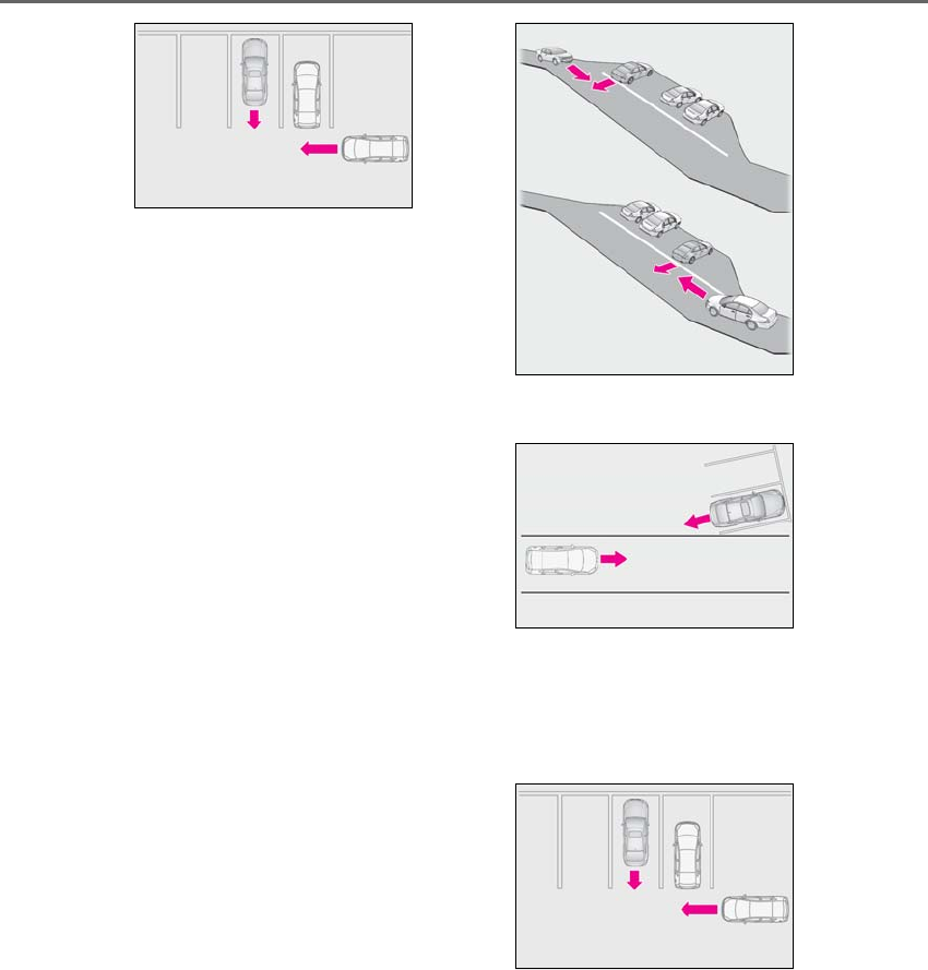
276 4-5. Using the driving support systems
LS500h_OM_OM50F42U_(U)
●Guardrails, walls, signs, parked vehicles
and similar stationary objects
●Small motorcycles, bicycles, pedestrians,
etc.
●Vehicles moving away from your vehicle
●Vehicles approaching from the parking
spaces next to your vehicle
■Conditions under which the RCTA func-
tion may not function correctly
●The RCTA function may not detect vehi-
cles correctly in the following situations:
• When a sensor is misaligned due to a
strong impact to the sensor or its sur-
rounding area
• When mud, snow, ice, a sticker, etc. is
covering a sensor or its surrounding area
on the rear bumper
• When driving on a road surface that is
wet with standing water during bad
weather, such as heavy rain, snow, or fog
• When multiple vehicles are approaching
with only a small gap between each vehi-
cle
• If a vehicle is approaching the rear of
your vehicle rapidly
• When a towing eyelet is installed to the
rear of the vehicle.
• When backing up on a slope with a sharp
change in grade
• When backing out of a shallow angle
parking spot
• Immediately after the RCTA function is
turned on
• Immediately after the hybrid system is
started with the RCTA function on
• When the sensors cannot detect a vehi-
cle due to obstructions
●Instances of the RCTA function unneces-
sarily detecting a vehicle and/or object
may increase in the following situations:
• When a vehicle passes by the side of your
vehicle
• When the parking space faces a street
and vehicles are being driven on the
street
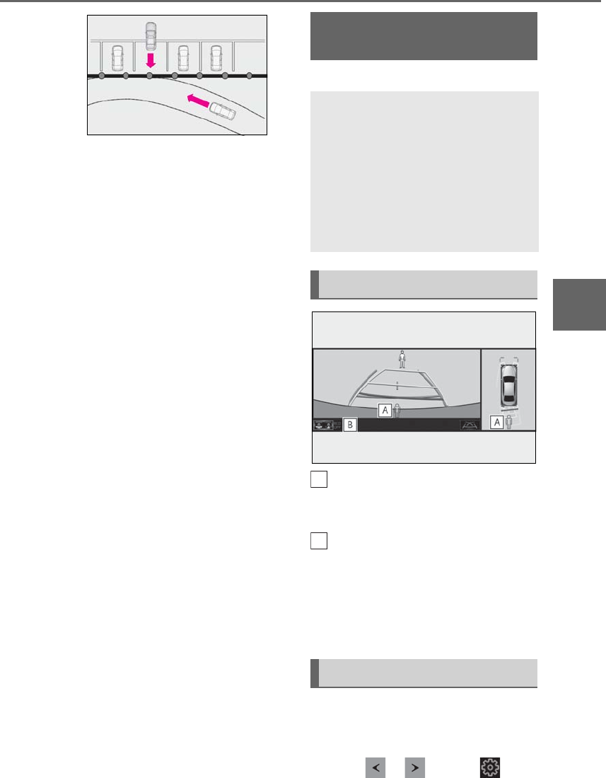
277
4-5. Using the driving support systems
LS500h_OM_OM50F42U_(U)
4
Driving
• When the distance between your vehicle
and metal objects, such as a guardrail,
wall, sign, or parked vehicle, which may
reflect electrical waves toward the rear of
the vehicle, is short
• When a towing eyelet is installed to the
rear of the vehicle
*: If equipped
Pedestrian detection icon
Displayed automatically when a pedestrian
is detected.
RCD OFF icon
When the RCD function is disabled, the
RCD OFF icon illuminates. (Each time the
power switch is turned off then changed to
ON mode, the RCD function will be
enabled automatically.)
Use the meter control switches to
enable/disable the RCD function.
(→P.87)
1Press or to select .
RCD (Rear Camera Detec-
tion) function*
When the vehicle is backing up, the
rear camera detection function can
detect pedestrians in the detection
area behind the vehicle. If a pedes-
trian is detected, a buzzer will
sound and an icon will be displayed
on the Center Display to inform the
driver of the pedestrian.
Center Display
Turning the RCD function on/off
A
B
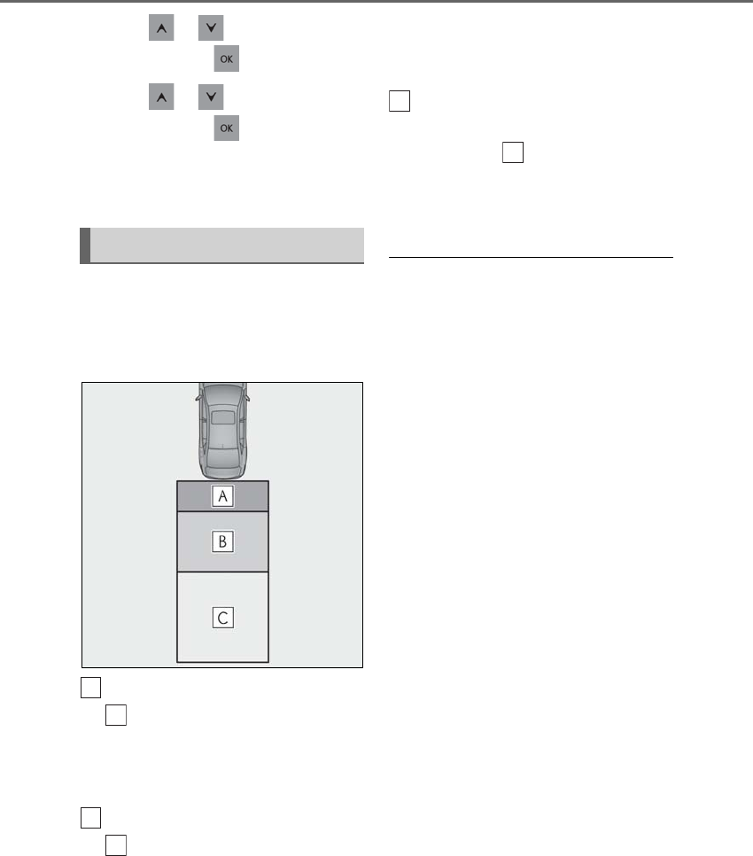
278 4-5. Using the driving support systems
LS500h_OM_OM50F42U_(U)
2Press or to select “PKSA”
and then press .
3Press or to select “RCD”
and then press .
When the RCD function is disabled, the
RCD OFF icon (→P.72) illuminates on the
multi-information display.
If the rear camera detection function
detects a pedestrian in the detection
area, the buzzer and pedestrian detec-
tion will operate as follows:
If a pedestrian is detected in area
Buzzer: Sounds repeatedly
Pedestrian detection icon: Blinks 3
times and then stays on
If a pedestrian is detected in area
Buzzer (When the vehicle is sta-
tionary): Sounds 3 times
Buzzer (When the vehicle is back-
ing up, when a pedestrian
approaches the rear of the vehicle):
Sounds repeatedly
Pedestrian detection icon: Blinks 3
times and then stays on
If the system determines that your
vehicle may collide with a pedes-
trian in area
Buzzer: Sounds repeatedly
Pedestrian detection icon: Blinks 3
times and then stays on
■The rear camera detection function is
operational when
●The power switch is in ON mode.
●RCD function is on.
●The shift position is in R.
■Setting the buzzer volume
The buzzer volume can be adjusted on the
multi-information display. (→P.266)
■If “Rear Camera Detection Unavailable
Remove the Dirt of Rear Camera” is dis-
played on the multi-information display
A rear camera lens may be dirty or covered
with snow or ice. In such cases, if it is
removed from the rear camera lens, the sys-
tem should return to normal. (It may be nec-
essary to drive the vehicle for some time
before the system returns to normal.)
■If “Rear Camera Detection Unavail-
able” is displayed on the multi-informa-
tion display
●If this message is displayed after the
12-volt battery has been disconnected
and reconnected, fully turn the steering
wheel to the left and then the right on
level ground.
●If this message is displayed only when the
R shift position is selected, the rear cam-
era lens may be dirty. Clean the rear
camera lens.
■Situations in which the system may not
operate properly
●Some pedestrians, such as the following,
may not be detected by the rear camera
detection function, preventing the func-
tion from operating properly:
When a pedestrian is detected
A
A
B
B
C
C

279
4-5. Using the driving support systems
LS500h_OM_OM50F42U_(U)
4
Driving
• Pedestrians who are bending forward or
squatting
• Pedestrians who are lying down
• Pedestrians who are running
• Pedestrians who suddenly enter the
detection area
• Pedestrians riding a bicycle, skateboard,
or other light vehicle
• Pedestrians wearing oversized clothing
such as a rain coat, long skirt, etc., making
their silhouette obscure
• Pedestrians whose body is partially hid-
den by an object, such as a cart or
umbrella
• Pedestrians which are obscured by dark-
ness, such as at night
●In some situations, such as the following,
pedestrians may not be detected by the
rear camera detection function, prevent-
ing the function from operating properly:
• When backing up in inclement weather
(rain, snow, fog, etc.)
• When the rear camera is obscured (dirt,
snow, ice, etc. are attached) or scratched
• When a very bright light, such as the sun,
or the headlights of another vehicle,
shines directly into the rear camera
• When backing up in a place where the
surrounding brightness changes sud-
denly, such as at the entrance or exit of a
garage or underground parking lot
• When backing up in a dim environment
such as during dusk or in an underground
parking lot
●Even though there are no pedestrians in
the detection area, some objects, such as
the following, may be detected, possibly
causing the rear camera detection func-
tion to operate.
• Three dimensional objects, such as a
pole, traffic cone, fence, or parked vehi-
cle
• Moving objects, such as a car or motor-
cycle
• Objects moving toward your vehicle
when backing up, such as flags or pud-
dles (or airborne matter, such as smoke,
steam, rain, or snow)
• Cobblestone or gravel roads, tram rails,
road repairs, white lines, pedestrian
crossings or fallen leaves on the road
• Metal covers (gratings), such as those
used for drainage ditches
• Objects reflected in a puddle or on a wet
road surface
• The roadside or bumps on the road
•Shadows on the road
●In some situations, such as the following,
the rear camera detection function may
operate even though there are no pedes-
trians in the detection area.
• When backing up toward the roadside or
a bump on the road
• If the vehicle is significantly tilted, such as
when carrying a heavy load
• When backing up toward an
incline/decline
• If the suspension has been modified or
tires of a size other than specified are
installed
• If the rear of the vehicle is raised or low-
ered due to the carried load
• If an electronic component, such as a
backlit license plate or rear fog light, is
installed near the rear camera
• If a bumper protector, such as an addi-
tional trim strip, is installed to the rear
bumper
• If the orientation of the rear camera has
been changed due to a collision or other
impact, or removal and installation
• If a towing eyelet is installed to the rear of
the vehicle
• When water is flowing over the rear cam-
era lens
• When the rear camera is obscured (dirt,
snow, ice, etc. are attached) or scratched
• If there is a flashing light in the detection
area, such as the emergency flashers of
another vehicle
●Situations in which the rear camera
detection function may be difficult to
notice
• If buzzer may be difficult to hear if the
surrounding area is noisy, the volume of
the audio system volume is high, the air
conditioning system is being used, etc.
• If the temperature in the cabin is
extremely high or low, the audio system
screen may not operate correctly.
280 4-5. Using the driving support systems
LS500h_OM_OM50F42U_(U)
*:If equipped
■Parking Support Brake function
(static objects) (if equipped)
Ultrasonic sensors are used to detect
static objects, such as a wall, in the
detection area when driving at a low
speed or backing up. (→P.286)
■Parking Support Brake function
(rear-crossing vehicles)(if
equipped)
Rear radar sensors are used to detect
approaching vehicles in the detection
area behind the vehicle when backing
up. (→P.291)
■Parking Support Brake function
(rear pedestrians) (if equipped)
A rear camera sensor is used to detect
pedestrians in the detection area
behind the vehicle when backing up.
(→P.295)
PKSB (Parking Support
Brake)*
The Parking Support Brake system
consists of the following functions
that operate when driving at a low
speed or backing up, such as when
parking. When the system deter-
mines that a collision with a
detected object or pedestrian is
high, a warning operates to urge
the driver to take evasive action. If
the system determines that the pos-
sibility of a collision with a detected
object or pedestrian is extremely
high, the brakes are automatically
applied to help avoid the collision or
help reduce the impact of the colli-
sion.
PKSB (Parking Support Brake)
system
WARNING
■Limitations of the Parking Support
Brake system
Do not overly rely on the system, as
doing so may lead to an accident.
●The driver is solely responsible for safe
driving. Always drive carefully, taking
care to observe your surroundings.
The Parking Support Brake system is
designed to provide support to lessen
the severity of collisions. However, it
may not operate in some situations.
●The Parking Support Brake system is
not designed to stop the vehicle com-
pletely. Additionally, even if the system
has stopped the vehicle, it is necessary
to depress the brake pedal immedi-
ately as brake control will be canceled
after approximately 2 seconds.
NOTICE
■If “Parking Support Brake Unavail-
able” is displayed on the multi-infor-
mation display and the PKSB OFF
indicator is flashing
If this message is displayed immediately
after the power switch is changed to ON
mode, operate the vehicle carefully, pay-
ing attention to your surroundings. It may
be necessary to drive the vehicle for a
certain amount of time before the system
returns to normal. (If the system is not
return to normal after driving for a while,
clean the rear camera lens.)
281
4-5. Using the driving support systems
LS500h_OM_OM50F42U_(U)
4
Driving
The Parking Support Brake can be
enabled/disabled on the multi-informa-
tion display. All of the Parking Support
Brake functions (static objects,
rear-crossing vehicles, and rear pedes-
trians) are enabled/disabled simultane-
ously.
Use the meter control switches to
enable/disable the parking support
brake. (→P.87)
1Press or to select .
2Press or to select
and then press .
When the Parking Support Brake is dis-
abled, the PKSB OFF indicator (→P.72)
illuminates on the multi-information dis-
play.
To re-enable the system when it was dis-
abled, select on the multi-information
display, select and then On. If dis-
abled using this method, the system will not
be re-enabled by turning the power switch
off and then to ON mode.
If the hybrid system output restriction con-
trol or brake control operates, a buzzer will
sound and a message will be displayed on
the Center Display and multi-information
display, to alert the driver. On vehicles with
a head-up display, the head-up display will
display the same message as the
multi-information display.
Depending on the situation, hybrid system
output restriction control will operate to
either limit acceleration or restrict output
as much as possible.
-Hybrid system output restriction
control is operating (acceleration
restriction)
Acceleration greater than a certain
amount is restricted by the system.
Center Display (Panoramic view monitor):
No warning displayed
Multi-information display: “Object
Detected Acceleration Reduced”
PKSB OFF indicator: Not illuminated
Buzzer: Does not sound
-Hybrid system output restriction
control is operating (output
restricted as much as possible)
The system has determined that stron-
ger-than-normal brake operation is neces-
sary.
Center Display (Panoramic view monitor):
“BRAKE!”
Multi-information display: “BRAKE!”
PKSB OFF indicator: Not illuminated
Buzzer: Short beep
-Brake control is operating
The system determined that emergency
braking is necessary.
Center Display (Panoramic view monitor):
“BRAKE!”
Multi-information display: “BRAKE!”
PKSB OFF indicator: Not illuminated
Buzzer: Short beep
-Vehicle stopped by system opera-
tion
The vehicle has been stopped by brake
control operation.
Enabling/Disabling the Parking
Support Brake
Displays and buzzers for hybrid
system output restriction con-
trol and brake control
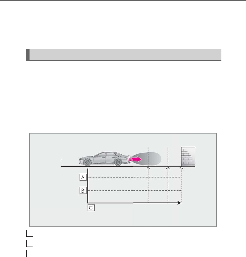
282 4-5. Using the driving support systems
LS500h_OM_OM50F42U_(U)
Center Display (Panoramic view monitor):
“Press Brake Pedal”
Multi-information display: “Switch to
Brake” (If the accelerator pedal is not
depressed, “Press Brake Pedal” will be dis-
played.)
PKSB OFF indicator: Illuminated
Buzzer: Short beep
If the Parking Support Brake determines that a collision with a detected object or
pedestrian is possible, the hybrid system output will be restricted to restrain any
increase in the vehicle speed. (Hybrid system output restriction control: See figure
2 below.)
Additionally, if the accelerator pedal continues to be depressed, the brakes will be
applied automatically to reduce the vehicle speed. (Brake control: See figure 3
below.)
-Figure 1 When the PKSB (Parking Support Brake) is disabled
Hybrid system output
Braking force
Time
-Figure 2 When hybrid system output restriction control operates
System overview
A
B
C
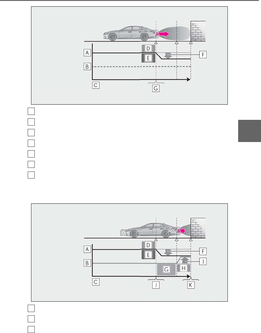
283
4-5. Using the driving support systems
LS500h_OM_OM50F42U_(U)
4
Driving
Hybrid system output
Braking force
Time
Hybrid system output restriction control begins operating
System determines that possibility of collision with detected object is high
Hybrid system output reduced
Example: Multi-infomation display:
“BRAKE!”
-Figure 3 When brake control operates
Hybrid system output
Braking force
Time
A
B
C
D
E
F
G
A
B
C

284 4-5. Using the driving support systems
LS500h_OM_OM50F42U_(U)
Hybrid system output restriction control begins operating
System determines that possibility of collision with detected object is high
Hybrid system output reduced
System determines that possibility of collision with detected object is extremely
high
Brake control begins operating
Brake control strength increased
Example: Multi-infomation display:
“BRAKE!”
Example: Multi-infomation display: “Switch to Brake”
■If the Parking Support Brake has oper-
ated
If the vehicle is stopped due to operation of
the Parking Support Brake, the Parking
Support Brake will be disabled and the
PKSB OFF indicator will illuminate. If the
Parking Support Brake operates unneces-
sarily, brake control can be canceled by
depressing the brake pedal or waiting for
approximately 2 seconds for it to automati-
cally be canceled. Then, the vehicle can be
operated by depressing the accelerator
pedal.
■Re-enabling the Parking Support Brake
To re-enable the Parking Support Brake
when it is disabled due to operation of the
Parking Support Brake, either enable the
system again (→P.281), or turn the power
switch off and then back to ON mode.
Additionally, if the object becomes no lon-
ger in the traveling direction of the vehicle
or if the traveling direction of the vehicle
changes (such as changing from moving
forward to backing up, or from backing up
to moving forward), the system will be
re-enabled automatically.
■If “Parking Support Brake Unavailable”
is displayed on the multi-information
display and the PKSB OFF indicator is
flashing
If the vehicle is stopped due to operation of
the Parking Support Brake, the Parking
Support Brake will be disabled and the
PKSB OFF indicator will illuminate.
●A sensor may be covered with ice, snow,
dirt, etc. Remove the ice, snow, dirt, etc.,
from the sensor to return the system to
normal.
Also, due to ice forming on a sensor at
low temperatures, a warning message
may be displayed or the sensor may not
be able to detect an object. Once the ice
melts, the system will return to normal.
●If this message is displayed only when the
R shift position is selected, the rear cam-
era lens may be dirty. Clean the camera
lens. If this message is displayed in any
forward shift position , a sensor on the
front or rear bumper may be dirty. Clean
the sensors and their surrounding area
on the bumpers.
●If this message continues to be displayed
even after cleaning the sensor, or is dis-
played even though the sensor is clean,
have the vehicle inspected by your Lexus
dealer.
●Initialization may not have been per-
formed after a 12-volt battery terminal
was disconnected and reconnected. Ini-
tialize the system. (→P.284)
If this message continues to be displayed
even after initialization, have the vehicle
inspected by your Lexus dealer.
■If a 12-volt battery terminal has been
disconnected and reconnected
The system needs to be initialized. To initial-
ize the system, drive the vehicle straight
ahead for 5 seconds or more at a speed of
approximately 22 mph (35 km/h) or more.
D
E
F
G
H
I
J
K

285
4-5. Using the driving support systems
LS500h_OM_OM50F42U_(U)
4
Driving
Additionally, for vehicles with the Parking
Support Brake function, turn the steering
wheel fully to the left and right with the vehi-
cle stopped.
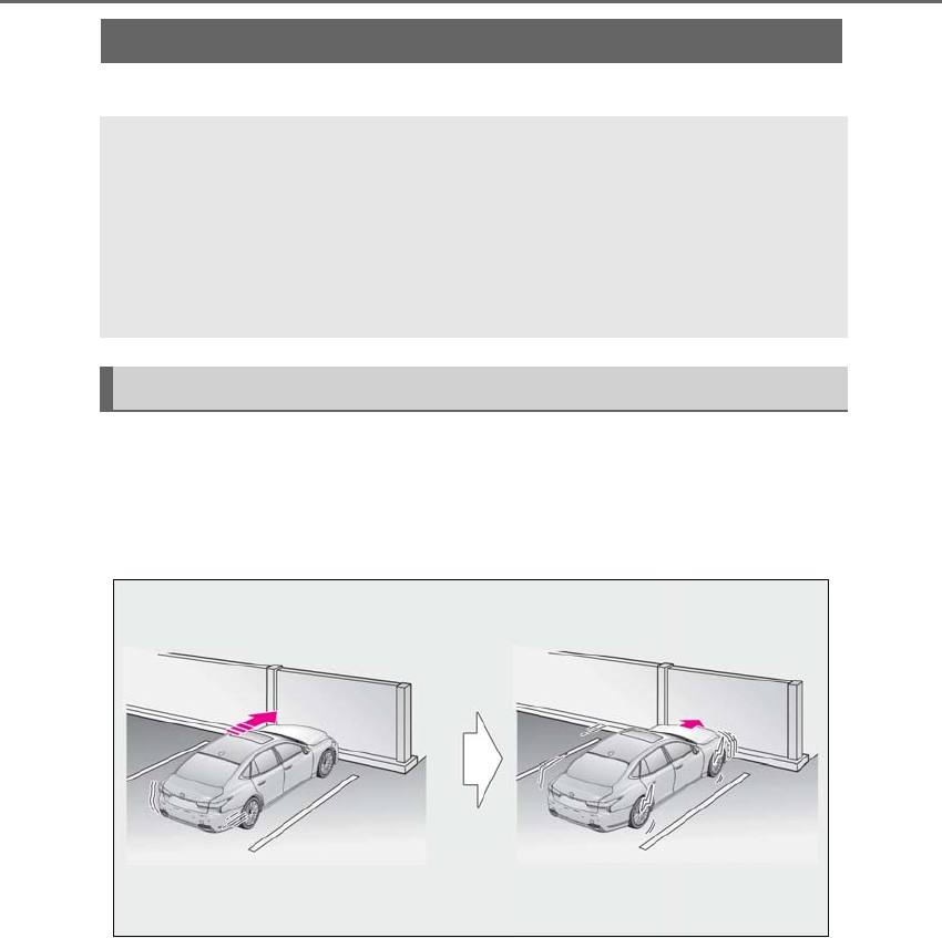
286 4-5. Using the driving support systems
LS500h_OM_OM50F42U_(U)
*:If equipped
This function will operate in situations such as the following if an object is detected
in the traveling direction of the vehicle.
■When traveling at a low speed and the brake pedal is not depressed, or is
depressed late
Parking Support Brake function (static objects)*
If the sensors detect a static object, such as a wall, in the travelling direction of
the vehicle and the system determines that a collision may occur due to the
vehicle suddenly moving forward due to an accidental accelerator pedal oper-
ation, the vehicle moving the unintended direction due to the wrong shift posi-
tion being selected, or while parking or traveling at low speeds, the system will
operate to lessen the impact with the detected static object and reduce the
resulting damage.
Examples of function operation
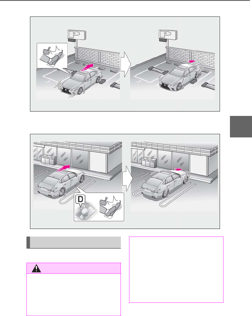
287
4-5. Using the driving support systems
LS500h_OM_OM50F42U_(U)
4
Driving
■When the accelerator pedal is depressed excessively
■When the vehicle moves in the unintended direction due to the wrong shift
position being selected
→P.266
Types of sensors
WARNING
■To ensure the Parking Support Brake
can operate properly
Observe the following precautions
regarding the sensors (→P.287). Failure
to do so may cause a sensor to not oper-
ate properly, and may cause an accident.
●Do not modify, disassemble or paint
the sensors.
●Do not replace a sensor with a part
other than a genuine part.
●Do not subject a sensor or its sur-
rounding area to a strong impact.
●Do not damage the sensors, and
always keep them clean.

288 4-5. Using the driving support systems
LS500h_OM_OM50F42U_(U)
■The Parking Support Brake function
(static object) will operate when
The function will operate when the PKSB
OFF indicator is not illuminated or flashing
(→P.73, 74) and all of the following condi-
tions are met:
●Hybrid system output restriction control
• The Parking Support Brake is enabled.
• The vehicle speed is 10 mph (15 km/h) or
less.
• There is a static object in the traveling
direction of the vehicle and 6 to 13 ft. (2
to 4 m) away.
• The Parking Support Brake determines
that a stronger-than-normal brake opera-
tion is necessary to avoid a collision.
●Brake control
• Hybrid system output restriction control
is operating.
• The Parking Support Brake determines
that an immediate brake operation is nec-
essary to avoid a collision.
■The Parking Support Brake function
(static objects) will stop operating when
The function will stop operating if any of the
following conditions are met:
●Hybrid system output restriction control
• The Parking Support Brake is disabled.
• The system determines that the collision
has become avoidable with normal brake
operation.
WARNING
●If the area around a radar sensor is
subjected to an impact, the system
may not operate properly due to a
sensor malfunction. Have the vehicle
inspected by your Lexus dealer.
■Handling the suspension
Do not modify the suspension, as
changes to the height or inclination of the
vehicle may prevent the sensors from
detecting objects correctly or cause the
system to not operate or operate unnec-
essarily.
■If the Parking Support Brake function
(static objects) operates unnecessar-
ily, such as at a railroad crossing
In the event that the Parking Support
Brake function (static objects) operates
unnecessarily, such as at a railroad cross-
ing, brake control will be canceled after
approximately 2 seconds, allowing you
to proceed forward and leave the area,
brake control can also be canceled by
depressing the brake pedal. Depressing
the accelerator pedal after brake control
is canceled will allow you to proceed for-
ward and leave the area.
■Notes when washing the vehicle
Do not apply intensive bursts of water or
steam to the sensor area.
Doing so may result in the sensor mal-
functioning.
●When using a high pressure washer to
wash the vehicle, do not spray the sen-
sors directly, as doing so may cause a
sensor to malfunction.
●When using steam to clean the vehicle,
do not direct steam too close to the
sensors as doing so may cause a sen-
sor to malfunction.
■When to disable the Parking Support
Brake
In the following situations, disable the
Parking Support Brake as the system
may operate even though there is no
possibility of a collision.
●When inspecting the vehicle using a
chassis roller, chassis dynamo or free
roller
●When loading the vehicle onto a boat,
truck or other transport vessel
●If the suspension has been modified or
tires of a size other than specified are
installed
●If the front of the vehicle is raised or
lowered due to the carried load
●When equipment that may obstruct a
sensor is installed, such as a towing
eyelet, bumper protector (an addi-
tional trim strip, etc.), bicycle carrier, or
snow plow
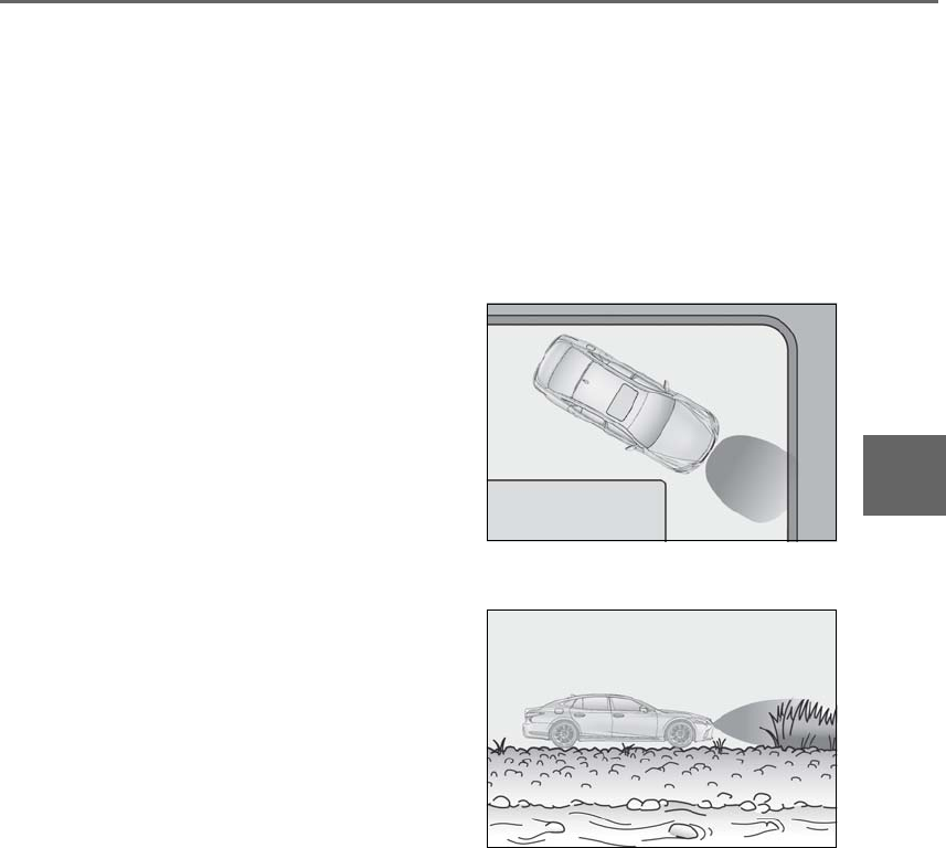
289
4-5. Using the driving support systems
LS500h_OM_OM50F42U_(U)
4
Driving
• The static object is no longer 6 to 13 ft. (2
to 4 m) away from the vehicle or in the
traveling direction of the vehicle.
●Brake control
• The Parking Support Brake is disabled.
• Approximately 2 seconds have elapsed
since the vehicle was stopped by brake
control.
• The brake pedal is depressed after the
vehicle is stopped by brake control.
• The static object is no longer 6 to 13 ft. (2
to 4 m) away from the vehicle or in the
traveling direction of the vehicle.
■Detection range of the Parking Support
Brake function (static objects)
The detection range of the Parking Support
Brake function (static objects) differs from
the detection range of the intuitive parking
assist. (→P.270) Therefore, even if the intui-
tive parking assist detects an object and
provides a warning, the Parking Support
Brake function (static objects) may not start
operating.
■Objects that the Parking Support Brake
function (static objects) may not detect
The sensors may not be able to detect cer-
tain objects, such as the following:
●Pedestrian
●Cotton cloth, snow, and other materials
that are poor reflectors of ultrasonic
waves
●Objects which are not perpendicular to
the ground, are not perpendicular to the
traveling direction of the vehicle, are
uneven or are waving
●Low objects
●Thin objects such as wires, fences, ropes
and signposts
●Objects that are extremely close to the
bumper
■Intuitive parking assist buzzer
Regardless of whether the intuitive parking
assist system is enabled or not (→P.267), if
the Parking Support Brake function (static
objects) is enabled (→P.281), the front or
rear sensors detect an object and brake
control is performed, the intuitive parking
assist buzzer will sound to notify the driver
of the approximate distance to the object.
■Situations in which the Parking Support
Brake function (static objects) may
operate even if there is no possibility of a
collision
In some situations, such as the following, the
Parking Support Brake function (static
objects) may operate even though there is
no possibility of a collision.
●Vehicle surroundings
• When driving on a narrow road
• When driving on a gravel road or in an
area with tall grass
• When driving toward a banner, flag,
low-hanging branch or boom barrier
(such as those used at railroad crossings,
toll gates and parking lots)
• When driving on a narrow path sur-
rounded by a structure, such as in a tun-
nel or on an iron bridge
• When parallel parking
• When there is a rut or hole in the surface
of the road
• When driving on a metal cover (grating),
such as those used for drainage ditches
• When driving on a steep slope
• If a sensor is hit by a large amount of
water, such as when driving on a flooded
road
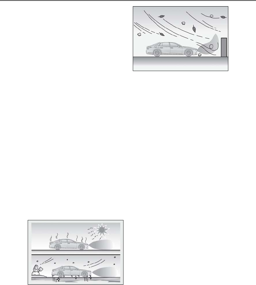
290 4-5. Using the driving support systems
LS500h_OM_OM50F42U_(U)
●Weather
• If a sensor is covered with ice, snow, dirt,
etc. (when cleared, the system will return
to normal)
• If heavy rain or water strikes a sensor
• When driving in inclement weather such
as fog, snow or a sandstorm
●Other ultrasonic wave sources
• When vehicle horns, vehicle detectors,
motorcycle engines, air brakes of large
vehicles, the clearance sonar of other
vehicles or other devices which produce
ultrasonic waves are near the vehicle
• If a sticker or an electronic component,
such as a backlit license plate (especially
fluorescent type), fog lights, fender pole
or wireless antenna is installed near a
sensor
●Changes in the vehicle posture
• If the vehicle is significantly tilted
• If the front of the vehicle is raised or low-
ered due to the carried load
• If the orientation of a sensor has been
changed due to a collision or other
impact
■Situations in which the Parking Support
Brake function (static objects) may not
operate properly
In some situations, such as the following, this
function may not operate properly.
●Weather
• When a sensor or the area around a sen-
sor is extremely hot or cold
• When strong winds are blowing
• If a sensor is covered with ice, snow, dirt,
etc. (when cleared, the system will return
to normal)
• If heavy rain or water strikes a sensor
• When driving in inclement weather such
as fog, snow or a sandstorm
●Vehicle surroundings
• When an object that cannot be detected
is between the vehicle and a detected
object
• If an object such as a vehicle, motorcycle,
bicycle or pedestrian cuts in front of the
vehicle or runs out from the side of the
vehicle
●Other ultrasonic waves sources
• When vehicle horns, vehicle detectors,
motorcycle engines, air brakes of large
vehicles, the clearance sonar of other
vehicles or other devices which produce
ultrasonic waves are near the vehicle
• If a sticker or an electronic component,
such as a backlit license plate (especially
fluorescent type), fog lights, fender pole
or wireless antenna is installed near a
sensor
●Changes in the vehicle posture
• If the vehicle is significantly tilted
• If the front of the vehicle is raised or low-
ered due to the carried load
• If the orientation of a sensor has been
changed due to a collision or other
impact
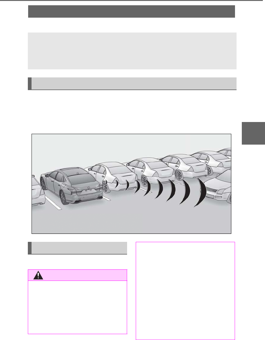
291
4-5. Using the driving support systems
LS500h_OM_OM50F42U_(U)
4
Driving
*:If equipped
This function will operate in situations such as the following if a vehicle is detected
in the traveling direction of the vehicle.
■When reversing, a vehicle is approaching and the brake pedal is not
depressed, or is depressed late
→P.262
Parking Support Brake function (rear-crossing vehicles)*
If a rear radar sensor detects a vehicle approaching from the right or left at the
rear of the vehicle and the system determines that the possibility of a collision
is high, this function will perform brake control to reduce the likelihood of an
impact with the approaching vehicle.
Examples of function operation
Types of sensors
WARNING
Observe the following precautions
regarding the rear radar sensors
(→P.262). Failure to do so may cause a
sensor to not operate properly, and may
cause an accident.
●Do not modify, disassemble or paint
the sensors.
●Do not replace a rear radar sensor
with a part other than a genuine part.
●Do not damage the rear radar sensors,
and always keep the radar sensors and
their surrounding area on the bumper
clean.
■To prevent a rear radar sensor from
malfunctioning
●If the area around a rear radar sensor
is subjected to an impact, the system
may not operate properly due to a
sensor malfunction. Have the vehicle
inspected by your Lexus dealer.
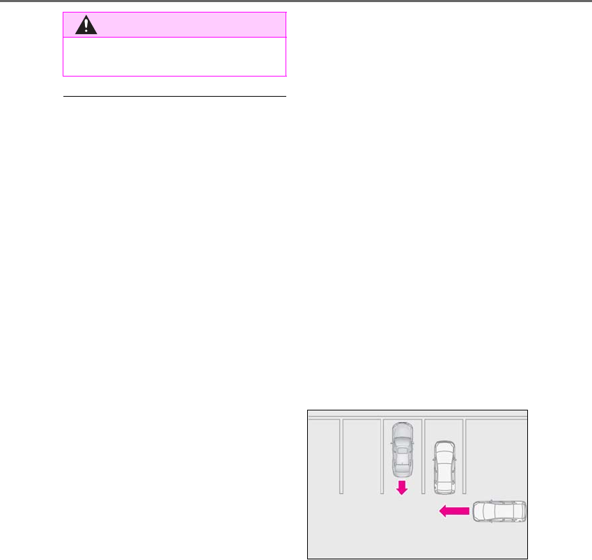
292 4-5. Using the driving support systems
LS500h_OM_OM50F42U_(U)
■The Parking Support Brake function
(rear-crossing vehicles) will operate
when
The function will operate when the PKSB
OFF indicator is not illuminated or flashing
(→P.73, 74) and all of the following condi-
tions are met:
●Hybrid system output restriction control
• The Parking Support Brake is enabled.
• The vehicle speed is 10 mph (15 km/h) or
less.
• Vehicles which are approaching from the
right or left at the rear of the vehicle at a
traveling speed of less than approxi-
mately 5 mph (8 km/h)
• The shift position is in R.
• The Parking Support Brake determines
that a stronger than normal brake opera-
tion is necessary to avoid a collision with
an approaching vehicle.
●Brake control
• Hybrid system output restriction control
is operating.
• The Parking Support Brake determines
that an emergency brake operation is
necessary to avoid a collision with an
approaching vehicle.
■The Parking Support Brake function
(rear-crossing vehicles) will stop operat-
ing when
The function will stop operating if any of the
following conditions are met:
●Hybrid system output restriction control
• The Parking Support Brake is disabled.
• The collision becomes avoidable with
normal brake operation.
• A vehicle is no longer approaching from
the right or left at the rear of the vehicle.
●Brake control
• The Parking Support Brake is disabled.
• Approximately 2 seconds have elapsed
since the vehicle was stopped by brake
control.
• The brake pedal is depressed after the
vehicle is stopped by brake control.
• A vehicle is no longer approaching from
the right or left at the rear of the vehicle.
■Detection area of the Parking Support
Brake function (rear-crossing vehicles)
The detection area of the Parking Support
Brake function (rear-crossing vehicles) dif-
fers from the detection area of the RCTA
function (→P.275). Therefore, even if the
RCTA function detects a vehicle and pro-
vides an alert, the Parking Support Brake
function (rear-crossing vehicles) may not
start operating.
■Conditions under which the Parking
Support Brake function (rear-crossing
vehicles) will not detect a vehicle
The Parking Support Brake function
(rear-crossing vehicles) is not designed to
detect the following types of vehicles and/or
objects:
●Vehicles approaching from directly
behind
●Vehicles backing up in a parking space
next to your vehicle
●Vehicles that the sensors cannot detect
due to obstructions
●Vehicles which suddenly accelerate or
decelerate near your vehicle
●Guardrails, walls, signs, parked vehicles
and similar stationary objects
●Small motorcycles, bicycles, pedestrians,
etc.
●Vehicles moving away from your vehicle
●Vehicles approaching from the parking
spaces next to your vehicle
●Objects which are extremely close to a
radar sensor
●Vehicles which are approaching from the
WARNING
●Observe the rear radar sensor han-
dling precautions. (→P.281)
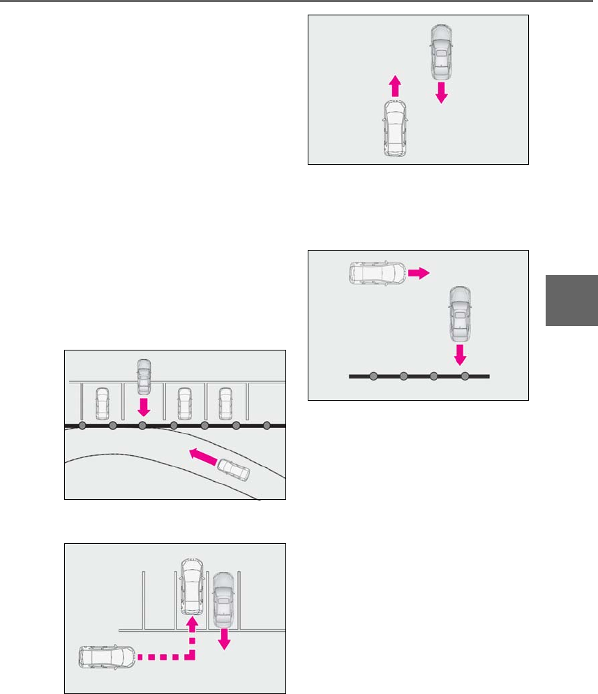
293
4-5. Using the driving support systems
LS500h_OM_OM50F42U_(U)
4
Driving
right or left at the rear of the vehicle at a
traveling speed of less than approxi-
mately 5 mph (8 km/h)
●Vehicles which are approaching from the
right or left at the rear of the vehicle at a
traveling speed of more than approxi-
mately 15 mph (24 km/h)
■PKSB buzzer
If the Parking Support Brake is enabled and
brake control is performed, a buzzer will
sound to notify the driver.
■Situations in which the system may
operate even though there is no possi-
bility of a collision
In some situations such as the following, the
Parking Support Brake function
(rear-crossing vehicles) may operate even
though there is no possibility of a collision.
●When the parking space faces a street
and vehicles are being driven on the
street
●When a detected vehicle turns while
approaching the vehicle
●When a vehicle passes by the side of your
vehicle
●When the distance between your vehicle
and metal objects, such as a guardrail,
wall, sign, or parked vehicle, which may
reflect electrical waves toward the rear of
the vehicle, is short
●When there are spinning objects near
your vehicle such as the fan of an air con-
ditioning unit
●When water is splashed or sprayed
toward the rear bumper, such as from a
sprinkler
■Situations in which the Parking Support
Brake function (rear-crossing vehicles)
may not operate properly
In some situations, such as the following, the
radar sensors may not detect an object and
this function may not operate properly
●Stationary objects
●When a sensor or the area around a sen-
sor is extremely hot or cold
●If the rear bumper is covered with ice,
snow, dirt, etc.
●When it is raining heavily or water strikes
the vehicle
●If the vehicle is significantly tilted
●When equipment that may obstruct a
sensor is installed, such as a towing eye-
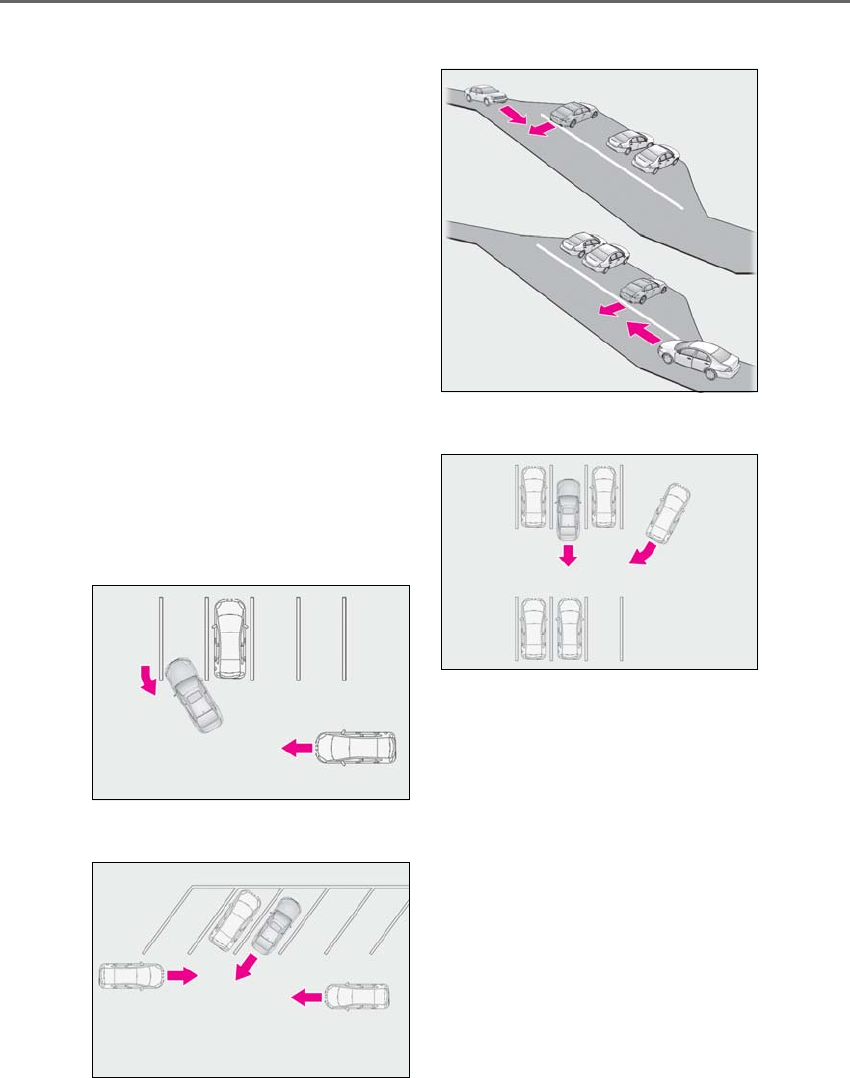
294 4-5. Using the driving support systems
LS500h_OM_OM50F42U_(U)
let, bumper protector (an additional trim
strip, etc.), bicycle carrier, or snow plow
●If the suspension has been modified or
tires of a size other than specified are
installed
●If the front of the vehicle is raised or low-
ered due to the carried load
●If a sticker or an electronic component,
such as a backlit license plate (especially
fluorescent type), fog lights, fender pole
or wireless antenna is installed near a
radar sensor
●If the orientation of a radar sensor has
been changed
●When multiple vehicles are approaching
with only a small gap between each vehi-
cle
●If a vehicle is approaching the rear of
your vehicle rapidly
●Situations in which the radar sensor may
not detect a vehicle
• When a vehicle approaches from the
right or left at the rear of the vehicle while
you are turning while backing up
• When turning while backing up
• When backing out of a shallow angle
parking spot
• When backing up on a slope with a sharp
change in grade
• When a vehicle turns into the detection
area
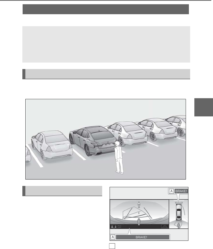
295
4-5. Using the driving support systems
LS500h_OM_OM50F42U_(U)
4
Driving
*:If equipped
When a pedestrian is detected behind the vehicle while backing up, the brake
pedal is not depressed or is depressed late.
Displays a message to urge the driver
to take evasive action when a pedes-
trian is detected in the detection area
behind the vehicle. (A message will
also be displayed on the multi-informa-
tion display and head-up display (if
equipped).) Pedestrian detection icon with
brake reminder
Parking Support Brake function (rear pedestrians)*
If the rear camera sensor detects a pedestrian behind the vehicle while back-
ing up and the system determines that the possibility of colliding with the
detected pedestrian is high, a buzzer will sound. If the system determines that
the possibility of colliding with the detected pedestrian is extremely high, the
brakes will be applied automatically to help reduce the impact of the collision.
Examples of system operation
Center Display
A

296 4-5. Using the driving support systems
LS500h_OM_OM50F42U_(U)
■Parking Support Brake function (rear
pedestrians) will operate when
The function will operate when the PKSB
OFF indicator is not illuminated or flashing
(→P.73, 74) and all of the following condi-
tions are met:
●Hybrid system output restriction control
• The Parking Support Brake is enabled.
• The vehicle speed is 10 mph (15 km/h) or
less.
• The shift position is in R.
• The rear camera sensor detects a pedes-
trian behind the vehicle while backing up
and the system determines that the possi-
bility of colliding with the detected
pedestrian is high.
●Brake control
• Hybrid system output restriction control
is operating.
• The Parking Support Brake determines
that an emergency brake operation is
necessary to avoid a collision with a
pedestrians.
■The Parking Support Brake function
(rear pedestrians) will stop operating
when
The function will stop operating if any of the
following conditions are met:
●Hybrid system output restriction control
• The Parking Support Brake is disabled.
• The collision becomes avoidable with
normal brake operation.
• The pedestrian is no longer detected
behind your vehicle.
●Brake control
• The Parking Support Brake is disabled.
• Approximately 2 seconds have elapsed
since the vehicle was stopped by brake
control.
• The brake pedal is depressed after the
vehicle is stopped by brake control.
• The pedestrian is no longer detected
behind your vehicle.
■Detection area of the Parking Support
Brake function (rear pedestrians)
The detection area of the Parking Support
Brake function (rear pedestrians) differs
from the detection area of the RCD func-
tion (→P.278). Therefore, even if the RCD
function detects a vehicle and provides an
alert, the Parking Support Brake function
(rear-crossing vehicles) may not start oper-
ating.
■Situations in which the system may not
operate properly
●Some pedestrians, such as the following,
may not be detected by the Parking Sup-
port Brake function (rear pedestrians),
preventing the function from operating
properly:
• Pedestrians who are bending forward or
squatting
• Pedestrians who are lying down
• Pedestrians who are running
• Pedestrians who suddenly enter the
detection area
• Pedestrians riding a bicycle, skateboard,
or other light vehicle
• Pedestrians wearing oversized clothing
such as a rain coat, long skirt, etc., making
their silhouette obscure
• Pedestrians whose body is partially hid-
den by an object, such as a cart or
umbrella
• Pedestrians which are obscured by dark-
ness, such as at night
●In some situations, such as the following,
pedestrians may not be detected by the
Parking Support Brake function (rear
pedestrians), preventing the function
from operating properly:
• When backing up in inclement weather
(rain, snow, fog, etc.)
• When the rear camera is obscured (dirt,
snow, ice, etc. are attached) or scratched
• When a very bright light, such as the sun,
or the headlights of another vehicle,
shines directly into the rear camera
• When backing up in a place where the
surrounding brightness changes sud-
WARNING
■If the Parking Support Brake function
(rear pedestrians) operates unneces-
sarily
Depress the brake pedal immediately
after the Parking Support Brake function
(rear pedestrians) operates. (Operation
of the function is canceled by depressing
the brake pedal.)

297
4-5. Using the driving support systems
LS500h_OM_OM50F42U_(U)
4
Driving
denly, such as at the entrance or exit of a
garage or underground parking lot
• When backing up in a dim environment
such as during dusk or in an underground
parking lot
●Even though there are no pedestrians in
the detection area, some objects, such as
the following, may be detected, possibly
causing the Parking Support Brake func-
tion (rear pedestrians) to operate.
• Three dimensional objects, such as a
pole, traffic cone, fence, or parked vehi-
cle
• Moving objects, such as a car or motor-
cycle
• Objects moving toward your vehicle
when backing up, such as flags or pud-
dles (or airborne matter, such as smoke,
steam, rain, or snow)
• Cobblestone or gravel roads, tram rails,
road repairs, white lines, pedestrian
crossings or fallen leaves on the road
• Metal covers (gratings), such as those
used for drainage ditches
• Objects reflected in a puddle or on a wet
road surface
• The roadside or bumps on the road
•Shadows on the road
●In some situations, such as the following,
the Parking Support Brake function (rear
pedestrians) may operate even though
there are no pedestrians in the detection
area.
• When backing up toward the roadside or
a bump on the road
• If the vehicle is significantly tilted, such as
when carrying a heavy load
• When backing up toward an
incline/decline
• If the suspension has been modified or
tires of a size other than specified are
installed
• If the rear of the vehicle is raised or low-
ered due to the carried load
• If an electronic component, such as a
backlit license plate or rear fog light, is
installed near the rear camera
• If a bumper protector, such as an addi-
tional trim strip, is installed to the rear
bumper
• If the orientation of the rear camera has
been changed due to a collision or other
impact, or removal and installation
• If a towing eyelet is installed to the rear of
the vehicle
• When water is flowing over the rear cam-
era lens
• When the rear camera is obscured (dirt,
snow, ice, etc. are attached) or scratched
• If there is a flashing light in the detection
area, such as the emergency flashers of
another vehicle
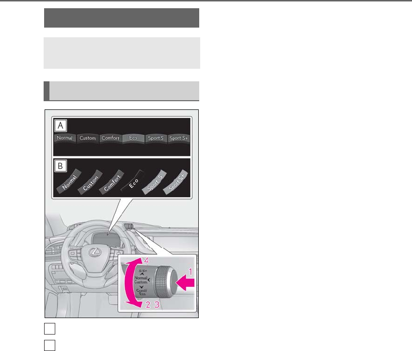
298 4-5. Using the driving support systems
LS500h_OM_OM50F42U_(U)
Except F SPORT models
F SPORT models
1Normal mode/Custom mode
Normal mode and custom mode are
selected by pressing the driving mode
select switch. Each time the switch is
pressed, the driving mode changes
between normal mode and custom mode.
When normal mode is selected, the normal
mode indicator comes on.
When custom mode is selected, the cus-
tom mode indicator comes on.
Press the switch to change the driving
mode to normal mode when not in normal
mode.
•Normal mode
Provides an optimal balance of fuel econ-
omy, quietness, and dynamic performance.
Suitable for city driving.
When the shift position is in D, an appropri-
ate gear for sporty driving may automati-
cally be selected according to driver
performance and driving conditions.
• Custom mode
Allows you to drive with the powertrain,
chassis and air conditioning system func-
tions set to your preferred settings. Cus-
tom mode settings can only be changed on
the drive mode customization display of
the Center Display. (→P.316)
2Comfort mode
By controlling the suspension, riding com-
fort is further enhanced. Suitable for city
driving.
When not in comfort mode and the driving
mode select switch is turned backward, the
comfort mode indicator comes on.
3Eco drive mode
Helps the driver accelerate in an
eco-friendly manner and improve fuel
economy through moderate throttle char-
acteristics and by controlling the operation
of the air conditioning system (heat-
ing/cooling).
When in comfort mode, if the driving mode
select switch is turned backward, the Eco
drive mode indicator comes on.
4Sport mode
• Sport S mode
Controls the hybrid system to provide
quick, powerful acceleration. This mode is
suitable for when agile driving response is
desired, such as when driving on roads
with many curves.
When not in Sport S mode, if the driving
mode select switch is turned forward, the
Sport S mode indicator comes on.
•Sport S+ mode
Driving mode select switch
The driving modes can be selected
to suit driving condition.
Selecting a drive mode
A
B

299
4-5. Using the driving support systems
LS500h_OM_OM50F42U_(U)
4
Driving
Helps to ensure steering performance and
driving stability by simultaneously con-
trolling the steering and suspension in
addition to the hybrid system. Suitable for
sportier driving.
When in Sport S mode, if the driving mode
select switch is turned forward, the Sport
S+ mode indicator comes on.
■If the driving mode select switch is oper-
ated while the opening screen is being
displayed
If the driving mode select switch is operated
while the opening screen is being displayed,
the driving mode will be changed and the
meter display will change accordingly after
the opening screen operation has com-
pleted.
■Operation of the air conditioning sys-
tem in Eco drive mode
Eco drive mode controls the heating/cool-
ing operations and fan speed of the air con-
ditioning system to enhance fuel efficiency.
To improve air conditioning performance,
perform the following operations:
●Turn off eco air conditioning mode
(→P.327)
●Adjust the fan speed (→P.323)
●Turn off Eco drive mode
■Automatic deactivation of sport mode
and custom mode
If the power switch is turned off after driving
in sport mode or custom mode, the drive
mode will be changed to normal mode.
■Driving mode pop-up display
When the driving mode is changed, the
selected driving mode will be temporarily
displayed on the side display. (→P.317)
*: If equipped
■Situations in which the vehicle height
control may not operate properly
●In the following situations, the vehicle
height may change slowly or may not
change to the correct height:
• When the vehicle comes into contact
with snow, ice, stone, etc.
• When the ambient temperature is low
• When the accumulator tank pressure is
low
●In the following situations, the vehicle
height may not change:
• If the hood or trunk is not fully closed
• If the brake pedal depressed and the
vehicle is stopped
• When the vehicle is on a significantly
uneven or undulating road
• When the vehicle is on a slanted road or a
slope
■Operating sound of the air suspension
compressor and valves
When the vehicle height is changed, such
as due to passengers entering the vehicle or
cargo being loaded, or when the vehicle
height is changed using the vehicle height
adjustment switch, the air suspension com-
pressor and valves may operate and a
sound may be heard. This does not indicate
Electronically modulated air
suspension*
The height of the vehicle when driv-
ing can be selected using the vehi-
cle height adjustment switch. The
selected height level will be main-
tained regardless of the number of
passengers or weight of cargo.
Additionally, settings of the follow-
ing functions can be changed:
-Access mode control
-Parking height control
-Vehicle height control
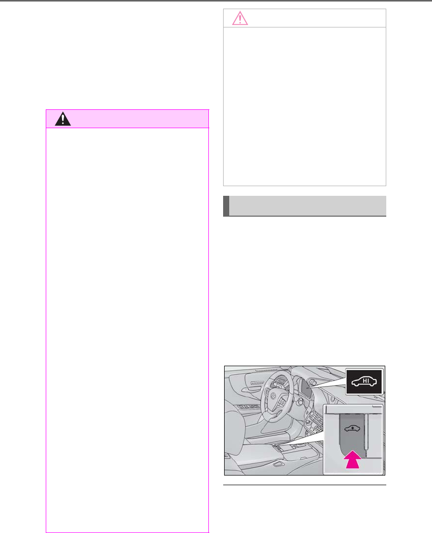
300 4-5. Using the driving support systems
LS500h_OM_OM50F42U_(U)
a malfunction.
■When the accumulator tank pressure is
low
When the accumulator tank pressure is low,
the air suspension compressor and valves
may operate repeatedly even though the
vehicle height is not being changed. This
does not indicate a malfunction.
To adjust the vehicle height to one
appropriate for road and driving con-
ditions, press the vehicle height adjust-
ment switch.
When high mode is enabled, the high
mode indicator on the meter will illuminate.
When the vehicle height is increased by
the access mode control function, press
the vehicle height adjustment switch twice
to enable/disable high mode.
■The vehicle height adjustment switch
can be changed when
The power switch is in ON mode.
■System protection function
If the vehicle height is repeatedly increased
WARNING
■Situations in which the operation of
the electronically modulated air sus-
pension should be canceled
In the following situations, make sure to
disable all functions of the vehicle height
control of the electronically modulated
air suspension and then stopping the
hybrid system. Otherwise, the vehicle
height may change and part of your body
may be caught under the vehicle, possi-
bly causing injury.
●When the vehicle is parked on a curb
●If any of the wheels is not touching the
ground
●If the vehicle needs to be jacked up
●If the vehicle is to be tied down
●If the vehicle is to be towed
■Vehicle height control precautions
In the following situations, make sure to
check the safety of the area around the
vehicle, as the vehicle height may change
and part of someone’s body may be
caught in the vehicle, possibly causing
injury or the vehicle may be damaged.
●When opening a door
●When unlocking the doors using the
smart access system with push-button
start
●When changing the vehicle height
using the vehicle height adjustment
switch
NOTICE
■Parking precaution
If the vehicle is parked for a long time, the
vehicle height may change due to
changes in the ambient temperature.
When parking the vehicle, make sure
that the area above and below the vehi-
cle is clear, so that the vehicle will not
contact anything if its height changes.
Be careful when parking the vehicle in an
area with a low ceiling or near low hang-
ing objects, as the vehicle height will
increase when passengers exit the vehi-
cle and the access mode control oper-
ates.
Selecting the vehicle height
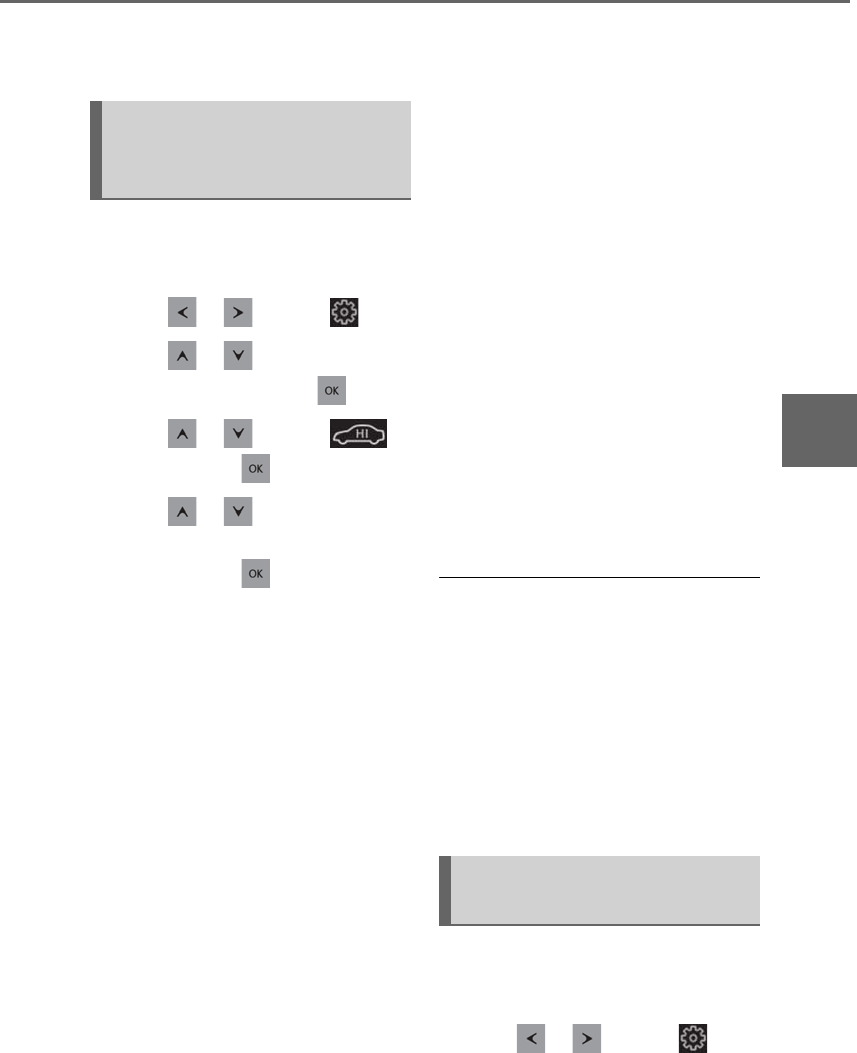
301
4-5. Using the driving support systems
LS500h_OM_OM50F42U_(U)
4
Driving
and decreased using the vehicle height
adjustment switch, etc., the system may not
operate temporarily.
The following settings can be changed
using the meter control switches for
the easy access to the vehicle. (→P.87)
1Press or to select .
2Press or to select “Vehicle
Settings” and then press .
3Press or to select
and then press .
4Press or to select “Access
Mode” or “Select Parking Height”
and then press .
These settings are memorized even if the
power switch is turned off.
-Access mode control (“Access
Mode”)
When access mode control is enabled, the
vehicle height will increase automatically in
the following situations:
• When the doors are unlocked using the
smart access system with push-button
start
• When the doors are unlocked using the
wireless remote control and then a door
is opened.
The vehicle height will increase by approxi-
mately 1.2 in. (30 mm) from its normal
position.
The vehicle height may not increase, if the
vehicle height already reaches the
selected height.
The vehicle will return to its normal height
when the vehicle speed reaches approxi-
mately 12 mph (20 km/h).
When access mode control is disabled, the
parking height control will also be disabled.
-Parking height control (“Select
Parking Height”)
When “High” is selected, the vehicle height
will automatically increase when the P shift
position is selected and a door is opened.
The vehicle height will increase by approxi-
mately 0.4 in. (10 mm) from its normal
position.
The vehicle height may not increase, if the
vehicle height already reaches the
selected height.
The vehicle will return to its normal height
when the vehicle speed reaches approxi-
mately 12 mph (20 km/h).
■When the vehicle height has been
increased by the access mode control
function
Press the vehicle height adjustment switch
with the power switch in any mode to return
the vehicle to its previous vehicle height.
■Situations in which the access mode
control function will not operate
The access mode control function will not
operate if the vehicle is not parked on a
level road surface.
The vehicle height control functions
can be disabled using the meter con-
trol switches. (→P.87)
1Press or to select .
Changing setting of the access
mode control and parking height
control
Disabling the vehicle height con-
trol functions
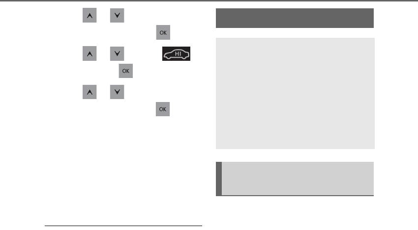
302 4-5. Using the driving support systems
LS500h_OM_OM50F42U_(U)
2Press or to select “Vehicle
Settings” and then press .
3Press or to select
and then press .
4Press or to select “Height
Control” and then press .
This setting is memorized even if the power
switch is turned off.
Even if the vehicle height control func-
tions are disabled, they will be enabled
automatically when the vehicle speed
reaches approximately 19 mph (30
km/h).
■When “Check Air Suspension System”
is displayed on the multi-information
display
The system may not operate properly. Have
the vehicle inspected by your Lexus dealer.
■Customization
Some functions can be customized.
(→P.481)
■ECB (Electronically Controlled
Brake System)
The electronically controlled system
generates braking force correspond-
ing to the brake operation
■ABS (Anti-lock Brake System)
Helps to prevent wheel lock when the
brakes are applied suddenly, or if the
brakes are applied while driving on a
slippery road surface
■Brake assist
Generates an increased level of brak-
ing force after the brake pedal is
depressed when the system detects a
panic stop situation
■VSC (Vehicle Stability Control)
Helps the driver to control skidding
when swerving suddenly or turning on
slippery road surfaces.
■Secondary Collision Brake
When the airbag sensor detects a colli-
sion, the brakes and brake lights are
automatically controlled to reduce the
Driving assist systems
To keep driving safety and perfor-
mance, the following systems oper-
ate automatically in response to
various driving situations. Be aware,
however, that these systems are
supplementary and should not be
relied upon too heavily when oper-
ating the vehicle.
Summary of the driving assist
systems

303
4-5. Using the driving support systems
LS500h_OM_OM50F42U_(U)
4
Driving
vehicle speed and that helps reduce
the possibility of further damage due to
a secondary collision.
■TRAC (Traction Control)
Helps to maintain drive power and pre-
vent the drive wheels from spinning
when starting the vehicle or accelerat-
ing on slippery roads
■Hill-start assist control
Helps to reduce the backward move-
ment of the vehicle when starting on an
uphill
■VGRS (Variable Gear Ratio Steer-
ing) (if equipped)
Adjusts the front wheel turning angle in
accordance with the vehicle speed and
steering wheel movement
■DRS (Dynamic Rear Steering) (if
equipped)
Contributes to the turning characteris-
tics and responsiveness of the vehicle
by adjusting the rear wheel angle of the
vehicle in accordance with steering
wheel movement.
■EPS (Electric Power Steering)
Employs an electric motor to reduce
the amount of effort needed to turn the
steering wheel.
■Adaptive Variable Suspension Sys-
tem
By independently controlling the
damping force of the shock absorbers
for each of the 4 wheels according to
the road and driving conditions, this
system helps riding comfort with supe-
rior vehicle stability, and helps good
vehicle posture.
Also, the damping force changes
depending on the selected driving
mode. (→P.298)
■LDH (Lexus Dynamic Handling
system) (if equipped)
Provides integrated control of the
VGRS, DRS and EPS. Contributes to
turning characteristics at low speeds,
responsiveness at medium speeds and
safety at high speeds by controlling the
steering angle of the front and rear
wheels in accordance with the steering
wheel operation and vehicle speed.
■VDIM (Vehicle Dynamics Inte-
grated Management)
Provides integrated control of the
ABS, brake assist, TRAC, VSC,
hill-start assist control, EPS, VGRS (if
equipped), DRS (if equipped) and
Adaptive Variable Suspension System
Helps to maintain vehicle stability when
swerving on slippery road surfaces by
controlling the brakes, hybrid system
output, steering assist, and steering
ratio
■When the TRAC/VSC/ABS systems are
operating
The slip indicator light will flash while the
TRAC/VSC/ABS systems are operating.
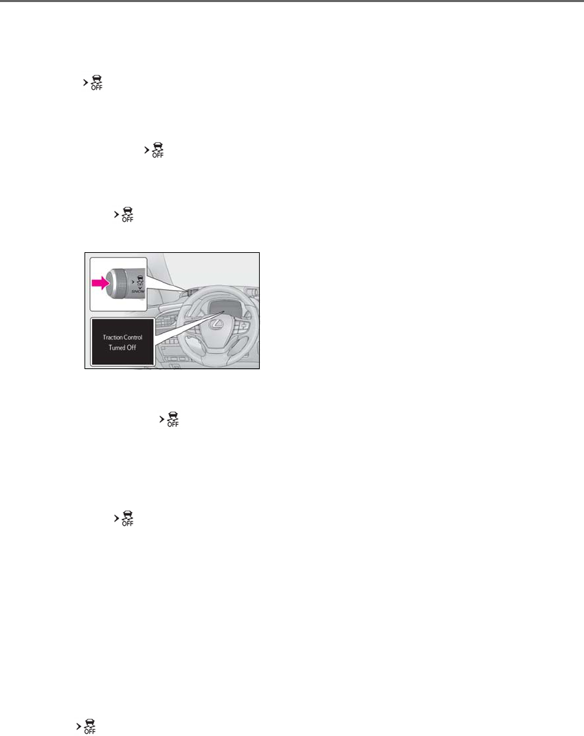
304 4-5. Using the driving support systems
LS500h_OM_OM50F42U_(U)
■Disabling the TRAC system
If the vehicle gets stuck in mud, dirt or snow,
the TRAC system may reduce power from
the hybrid system to the wheels. Pressing
the switch to turn the system off may
make it easier for you to rock the vehicle in
order to free it.
To turn the TRAC system off, quickly press
and release the switch.
The “Traction Control Turned Off” will be
shown on the multi-information display.
Press the switch again to turn the sys-
tem back on.
■Disabling both TRAC and VSC systems
To turn the TRAC and VSC systems off,
press and hold the switch for more
than 3 seconds while the vehicle is stopped.
The VSC OFF indicator light will come on
and the “Traction Control Turned Off” will
be shown on the multi-information display.*
Press the switch again to turn the sys-
tem back on.
*: On vehicles with PCS (Pre-Collision
System), PCS will also be disabled (only
Pre-Collision warning is available). The
PCS warning light will come on and a
message will be displayed on the
multi-information display. (→P.219,
226)
■When the message is displayed on the
multi-information display showing that
TRAC has been disabled even if the
switch has not been pressed
TRAC cannot be operated. Contact your
Lexus dealer.
■Operating conditions of hill-start assist
control
When the following four conditions are met,
the hill-start assist control will operate:
●The shift position is in a position other
than P or N (when stating off for-
ward/backward on an upward incline)
●The vehicle is stopped
●The accelerator pedal is not depressed
●The parking brake is not engaged
■Automatic system cancelation of
hill-start assist control
The hill-start assist control will turn off in any
of the following situations:
●Shift the shift position to P or N
●The accelerator pedal is depressed
●The parking brake is engaged
●2 seconds at maximum elapsed after the
brake pedal is released
■VGRS is disabled when
VGRS may stop operating in the following
situations.
In this event, the steering wheel may move
from its straight forward position, but it will
return when the system restarts.
●When the steering wheel is operated for
an extended period of time while the
vehicle is stopped or is moving very
slowly (on vehicles with LDH, DRS is dis-
abled together with VGRS)
●When the steering wheel has been held
fully to the left or right
The center position of the steering wheel
may change when VGRS is disabled. How-
ever, the position will return to normal after
VGRS is reactivated.
■When the 12-volt battery is discon-
nected (vehicles with VGRS)
The steering wheel may move from its
straight forward position, but this will be
corrected automatically when driving.

305
4-5. Using the driving support systems
LS500h_OM_OM50F42U_(U)
4
Driving
■Sounds and vibrations caused by the
ABS, brake assist, VSC, TRAC, hill-start
assist control and VGRS systems
●A sound may be heard from the engine
compartment when the brake pedal is
depressed repeatedly, when the hybrid
system is started or just after the vehicle
begins to move. This sound does not indi-
cate that a malfunction has occurred in
any of these systems.
●Any of the following conditions may
occur when the above systems are oper-
ating. None of these indicates that a mal-
function has occurred.
• Vibrations may be felt through the vehicle
body and steering.
• A motor sound may be heard also after
the vehicle comes to a stop.
■ECB operating sound
ECB operating sound may be heard in the
following cases, but it does not indicate that
a malfunction has occurred.
●Operating sound heard from the engine
compartment when the brake pedal is
operated.
●Motor sound of the brake system heard
from the front part of the vehicle when
the driver’s door is opened.
●Operating sound heard from the engine
compartment when one or two minutes
passed after the stop of the hybrid sys-
tem.
■EPS, VGRS and DRS operation sound
When the steering wheel is operated, a
motor sound (whirring sound) may be
heard. This does not indicate a malfunction.
■Automatic reactivation of TRAC and
VSC systems
After turning the TRAC and VSC systems
off, the systems will be automatically
re-enabled in the following situations:
●When the power switch is turned off
●If only the TRAC system is turned off, the
TRAC will turn on when vehicle speed
increases
If both the TRAC and VSC systems are
turned off, automatic re-enabling will not
occur when vehicle speed increases.
■Reduced effectiveness of the EPS sys-
tem
The effectiveness of the EPS system is
reduced to prevent the system from over-
heating when there is frequent steering
input over an extended period of time. The
steering wheel may feel heavy as a result.
Should this occur, refrain from excessive
steering input or stop the vehicle and turn
the hybrid system off. The EPS system
should return to normal within 10 minutes.
■Secondary Collision Brake operating
conditions
The vehicle speed is approximately 6 mph
(10 km/h) or more and the airbag sensor
detects a collision. (The Secondary Colli-
sion Brake will not operate when the vehicle
speed is below approximately 6 mph [10
km/h].)
■Secondary Collision Brake automatic
cancellation
The Secondary Collision Brake is automati-
cally canceled in the following situations:
●The vehicle speed drops below approxi-
mately 6 mph (10 km/h)
●A certain amount of time elapses during
operation
●The accelerator pedal is depressed a
large amount
■When “Check VGRS System” or
“CHECK DRS” is displayed on the
multi-information display
The VGRS or DRS may not operate prop-
erly. Have the vehicle inspected by your
Lexus dealer.
WARNING
■The ABS does not operate effectively
when
●The limits of tire gripping performance
have been exceeded (such as exces-
sively worn tires on a snow covered
road).
●The vehicle hydroplanes while driving
at high speed on wet or slick roads.

306 4-5. Using the driving support systems
LS500h_OM_OM50F42U_(U)
WARNING
■Stopping distance when the ABS is
operating may exceed that of normal
conditions
The ABS is not designed to shorten the
vehicle’s stopping distance. Always main-
tain a safe distance from the vehicle in
front of you, especially in the following
situations:
●When driving on dirt, gravel or
snow-covered roads
●When driving with tire chains
●When driving over bumps in the road
●When driving over roads with potholes
or uneven surfaces
■TRAC/VSC may not operate effec-
tively when
Directional control and power may not
be achievable while driving on slippery
road surfaces, even if the TRAC/VSC
system is operating. Drive the vehicle
carefully in conditions where stability and
power may be lost.
■Hill-start assist control does not oper-
ate effectively when
●Do not overly rely on hill-start assist
control. Hill-start assist control may
not operate effectively on steep
inclines and roads covered with ice.
●Unlike the parking brake, hill-start
assist control is not intended to hold
the vehicle stationary for an extended
period of time. Do not attempt to use
hill-start assist control to hold the vehi-
cle on an incline, as doing so may lead
to an accident.
■When the TRAC/ABS/VSC is acti-
vated
The slip indicator light flashes. Always
drive carefully. Reckless driving may
cause an accident. Exercise particular
care when the indicator light flashes.
■When the TRAC/VSC systems are
turned off
Be especially careful and drive at a speed
appropriate to the road conditions. As
these are the systems to help ensure
vehicle stability and driving force, do not
turn the TRAC/VSC systems off unless
necessary.
■Secondary Collision Brake
Do not overly rely on the Secondary Col-
lision Brake. This system is designed to
help reduce the possibility of further
damage due to a secondary collision,
however, that effect changes according
to various conditions. Overly relying on
the system may result in death or serious
injury.
■Replacing tires
Make sure that all tires are of the speci-
fied size, brand, tread pattern and total
load capacity. In addition, make sure that
the tires are inflated to the recom-
mended tire inflation pressure level.
The ABS, TRAC and VSC systems will
not function correctly if different tires are
installed on the vehicle.
Contact your Lexus dealer for further
information when replacing tires or
wheels.
■Handling of tires and the suspension
Using tires with any kind of problem or
modifying the suspension will affect the
driving assist systems, and may cause a
system to malfunction.

307
4-6. Driving tips
LS500h_OM_OM50F42U_(U)
4
Driving
4-6.Driving t ips
When using Eco drive mode, the
torque corresponding to the accelera-
tor pedal depression amount can be
generated more smoothly than it is in
normal conditions. In addition, the
operation of the air conditioning sys-
tem (heating/cooling) will be mini-
mized, improving the fuel economy.
(→P.298)
The Eco-friendly driving is possible by
keeping the indicate of Hybrid System
Indicator within Eco area. (→P.78, 83)
Shift the shift position to D when
stopped at a traffic light, or driving in
heavy traffic etc. Shift the shift position
to P when parking. When using the N
position, there is no positive effect on
fuel consumption. In the N position, the
gasoline engine operates but electric-
ity cannot be generated. Also, when
using the air conditioning system, etc.,
the hybrid battery (traction battery)
power is consumed.
-Drive your vehicle smoothly. Avoid
abrupt acceleration and decelera-
tion. Gradual acceleration and
deceleration will make more effec-
tive use of the electric motor (trac-
tion motor) without having to use
gasoline engine power.
-Avoid repeated acceleration.
Repeated acceleration consumes
hybrid battery (traction battery)
power, resulting in poor fuel con-
sumption. Battery power can be
restored by driving with the acceler-
ator pedal slightly released.
Make sure to operate the brakes gently
and in a timely manner. A greater
amount of electrical energy can be
regenerated when slowing down.
Repeated acceleration and decelera-
tion, as well as long waits at traffic
lights, will lead to bad fuel economy.
Check traffic reports before leaving
and avoid delays as much as possible.
When driving in a traffic jam, gently
release the brake pedal to allow the
vehicle to move forward slightly while
avoiding overuse of the accelerator
pedal. Doing so can help control
excessive gasoline consumption.
Hybrid vehicle driving tips
For economical and ecological
driving, pay attention to the follow-
ing points:
Using Eco drive mode
Use of Hybrid System Indicator
Changing the shift position
Accelerator pedal/brake pedal
operation
When braking
Delays

308 4-6. Driving tips
LS500h_OM_OM50F42U_(U)
Control and maintain the vehicle at a
constant speed. Before stopping at a
toll booth or similar, allow plenty of
time to release the accelerator and
gently apply the brakes. A greater
amount of electrical energy can be
regenerated when slowing down.
Use the air conditioning only when
necessary. Doing so can help reduce
excessive gasoline consumption.
In summer: When the ambient tem-
perature is high, use the recirculated
air mode. Doing so will help to reduce
the burden on the air conditioning sys-
tem and reduce fuel consumption as
well.
In winter: Because the gasoline engine
will not automatically cut out until it and
the interior of the vehicle are warm, it
will consume fuel. Also, fuel consump-
tion can be improved by avoiding over-
use of the heater.
Make sure to check the tire inflation
pressure frequently. Improper tire infla-
tion pressure can cause poor fuel
economy.
Also, as snow tires can cause large
amounts of friction, their use on dry
roads can lead to poor fuel economy.
Use tires that are appropriate for the
season.
Carrying heavy luggage will lead to
poor fuel economy. Avoid carrying
unnecessary luggage. Installing a large
roof rack will also cause poor fuel
economy.
Since the gasoline engine starts up and
cuts out automatically when cold,
warming up the engine is unnecessary.
Moreover, frequently driving short dis-
tances will cause the engine to repeat-
edly warm up, which can lead to excess
fuel consumption.
Highway driving
Air conditioning
Checking tire inflation pressure
Luggage
Warming up before driving

309
4-6. Driving tips
LS500h_OM_OM50F42U_(U)
4
Driving
-Use fluids that are appropriate to
the prevailing outside temperatures.
•Engine oil
• Engine/power control unit coolant
•Washer fluid
-Have a service technician inspect
the condition of the 12-volt battery.
-Have the vehicle fitted with four
snow tires or purchase a set of tire
chains for the rear tires.*
Ensure that all tires are the specified size
and brand, and that chains match the size
of the tires.
*: Tire chains cannot be mounted on vehi-
cles with front and rear tires of differing
sizes.
Winter driving tips
Carry out the necessary prepara-
tions and inspections before driving
the vehicle in winter. Always drive
the vehicle in a manner appropriate
to the prevailing weather condi-
tions.
Preparation for winter
WARNING
■Driving with snow tires
Observe the following precautions to
reduce the risk of accidents.
Failure to do so may result in a loss of
vehicle control and cause death or seri-
ous injury.
●Use tires of the specified size.
●Maintain the recommended level of air
pressure.
●Do not drive in excess of 75 mph (120
km/h), regardless of the type of snow
tires being used.
●Use snow tires on all, not just some
wheels.
■When installing tire chains
Before installing tire chains, make sure to
disable all functions of the vehicle height
control of the electronically modulated
air suspension. Otherwise, the vehicle
height may change while installing the
tire chains and part or your body may be
caught under the vehicle, possibly caus-
ing injury. (→P.301)
■Driving with tire chains
Observe the following precautions to
reduce the risk of accidents.
Failure to do so may result in the vehicle
being unable to be driven safely, and may
cause death or serious injury.
●Do not drive in excess of the speed
limit specified for the tire chains being
used, or 30 mph (50 km/h), which-
ever is lower.
●Avoid driving on bumpy road surfaces
or over potholes.
●Avoid sudden acceleration, abrupt
steering, sudden braking and shifting
operations that cause sudden engine
braking.
●Slow down sufficiently before entering
a curve to ensure that vehicle control is
maintained.
●Do not use LTA (Lane Tracing Assist)
system. (if equipped)
●Do not use LKA (Lane-Keeping
Assist) system. (if equipped)
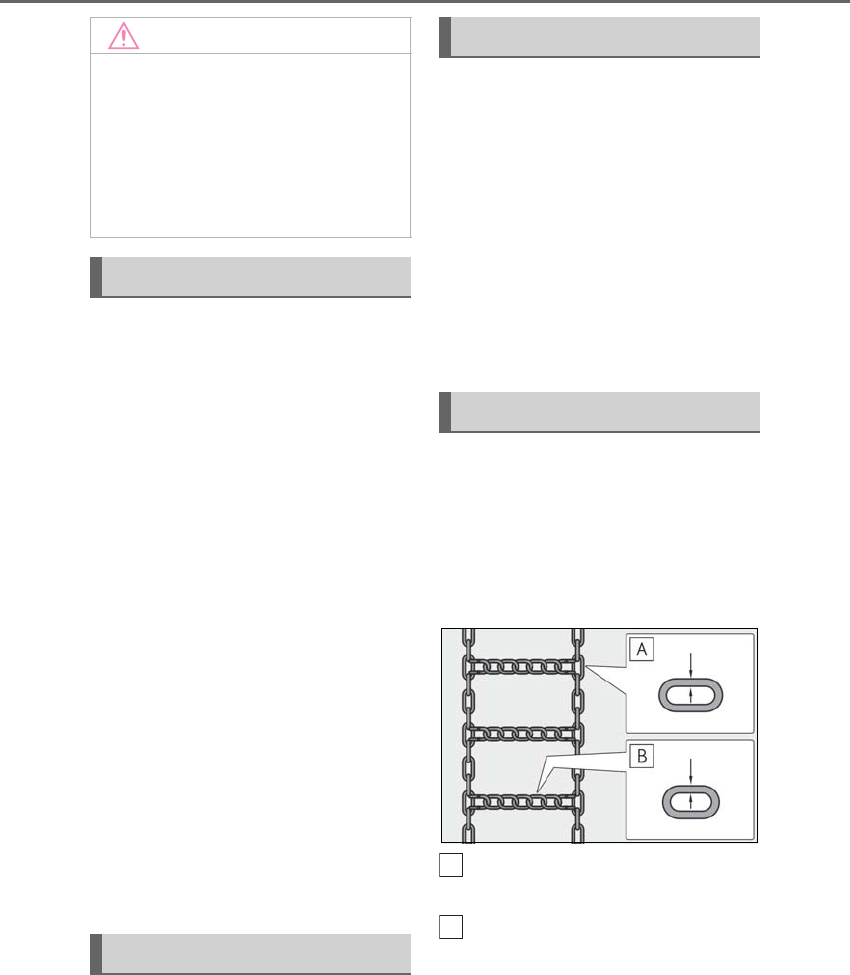
310 4-6. Driving tips
LS500h_OM_OM50F42U_(U)
Perform the following according to the
driving conditions:
-Do not try to forcibly open a window
or move a wiper that is frozen. Pour
warm water over the frozen area to
melt the ice. Wipe away the water
immediately to prevent it from
freezing.
-To ensure proper operation of the
climate control system fan, remove
any snow that has accumulated on
the air inlet vents in front of the
windshield.
-Check for and remove any excess
ice or snow that may have accumu-
lated on the exterior lights, vehicle’s
roof, chassis, around the tires or on
the brakes.
-Remove any snow or mud from the
bottom of your shoes before getting
in the vehicle.
Accelerate the vehicle slowly, keep a
safe distance between you and the
vehicle ahead, and drive at a reduced
speed suitable to road conditions.
Park the vehicle and shift the shift posi-
tion to P without setting the parking
brake. The parking brake may freeze
up, preventing it from being released. If
the vehicle is parked without setting
the parking brake, make sure to block
the wheels.
Failure to do so may be dangerous
because it may cause the vehicle to
move unexpectedly, possibly leading to
an accident.
Vehicles with front and rear tires of
the same size
Use the correct tire chain size when
mounting the tire chains.
Chain size is regulated for each tire
size.
Side chain (0.12 in. [3 mm] in diam-
eter)
Cross chain (0.16 in. [4 mm] in
diameter)
Vehicles with front and rear tires of
differing sizes
Tire chains cannot be mounted.
Snow tires should be used instead.
NOTICE
■Repairing or replacing snow tires
Request repairs or replacement of snow
tires from Lexus dealers or legitimate tire
retailers.
This is because the removal and attach-
ment of snow tires affects the operation
of the tire pressure warning valves and
transmitters.
Before driving the vehicle
When driving the vehicle
When parking the vehicle
Selecting tire chains
A
B

311
4-6. Driving tips
LS500h_OM_OM50F42U_(U)
4
Driving
Regulations regarding the use of tire
chains vary depending on location and
type of road. Always check local regu-
lations before installing chains.
■Tire chain installation
Observe the following precautions when
installing and removing chains:
●Install and remove tire chains in a safe
location.
●Install tire chains on the rear tires. Do not
install tire chains on the front tires.
●Install tire chains on the rear tires as
tightly as possible. Retighten chains after
driving 1/4⎯1/2 mile (0.5⎯1.0 km).
●Install tire chains following the instruc-
tions provided with the tire chains.
To enable the windshield wipers to be
lifted when heavy snow or icy condi-
tions are expected, change the rest
position of the windshield wipers from
the retracted position below the hood
to the service position using the wiper
lever. (→P.193)
Regulations on the use of tire
chains
NOTICE
■Fitting tire chains
The tire pressure warning valves and
transmitters may not function correctly
when tire chains are fitted.
Windshield wipers

312 4-6. Driving tips
LS500h_OM_OM50F42U_(U)

313
LS500h_OM_OM50F42U_(U)
5
5
Interior features
Interior features
.
5-1. Remote Touch/Display
Remote Touch.............................314
Center Display............................316
Rear Multi Operation Panel
.........................................................318
5-2. Lexus Climate Concierge
Lexus Climate Concierge...... 321
5-3. Using the air conditioning system
and defogger
Front automatic air conditioning
system.........................................323
Rear air conditioning system
........................................................333
Heated steering wheel/seat heat-
ers/seat ventilators................336
5-4. Using the interior lights
Interior lights list.........................340
5-5. Using the storage features
List of storage features............343
Trunk features.............................348
5-6. Using the other interior features
Other interior features ............351
Garage door opener...............358
Lexus Enform Safety Connect
........................................................364
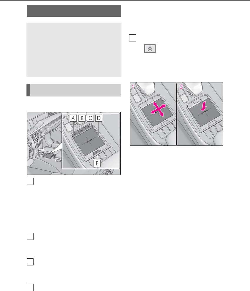
314 5-1. Remote Touch/Display
LS500h_OM_OM50F42U_(U)
5-1.Remote Touch/Display
■Switches
“MAP” button
Vehicles with navigation function:
Press this button to display the vehicle’s
current position.
Vehicles without navigation function:
Press this button to display the compass
mode screen.
“MENU” button
Press this button to display the menu
screen.
Back button
Press this button to display the previous
screen.
Touchpad
Slide your finger on the touchpad and
move the pointer to select a function, letter
and screen button.
Press the touchpad to enter the selected
function, letter or screen button. Certain
finger movements on the touchpad can
perform functions, such as changing map
scalings and scrolling list screens.
Sub function button
When is displayed on the screen, a
function screen assigned to the screen can
be displayed.
■Using the touchpad
1Select: Touch the touchpad to
select the desired button on the
screen.
2Enter: Buttons on the screen can be
selected by either depressing or
double tapping the touchpad.
Once a button has been selected,
the screen will change.
■Touch operation
Operations are performed by touching
the touchpad with your finger.
-Trace
Trace the pad surface while maintaining
contact with the touchpad. Moving the
cursor and the pointer.
Remote Touch
The Remote Touch can be used to
operate the Center Display.
For details on the Remote touch,
refer to “NAVIGATION AND
MULTIMEDIA SYSTEM
OWNER’S MANUAL”.
Remote Touch operation
A
B
C
D
E
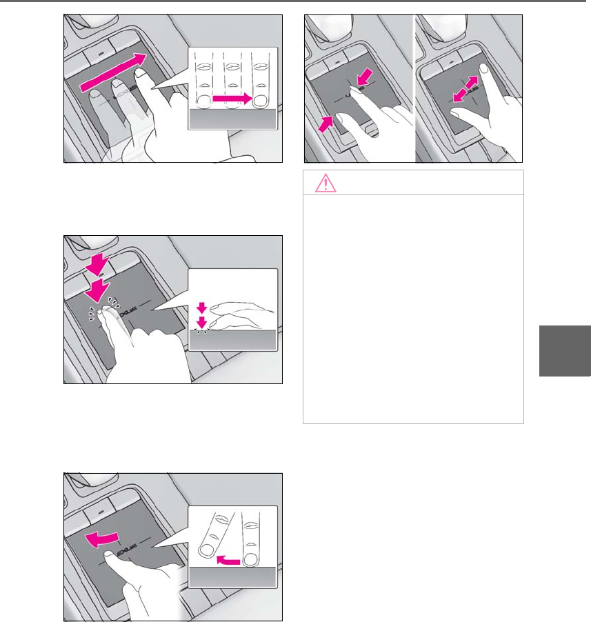
315
5-1. Remote Touch/Display
LS500h_OM_OM50F42U_(U)
5
Interior features
-Double tap
Tap the touchpad twice, quickly. Select the
button on the screen.
-Flick
Quick and short movement along the
touchpad with you finger. Move the list
screen.
-Pinch in/Pinch out
Slide fingers toward each other or apart on
the touchpad. Change the scale of the
map.
NOTICE
■To prevent damage to the Remote
Touch
Observe the following precautions. Fail-
ure to do so may cause damage to the
Remote Touch.
●Do not allow food, liquid, stickers or lit
cigarettes to contact the Remote
Touch.
●Do not subject the Remote Touch to
excessive pressure or strong impact.
●Do not push the touchpad with a
strong force or use a sharp pointed
object to operate the pad.
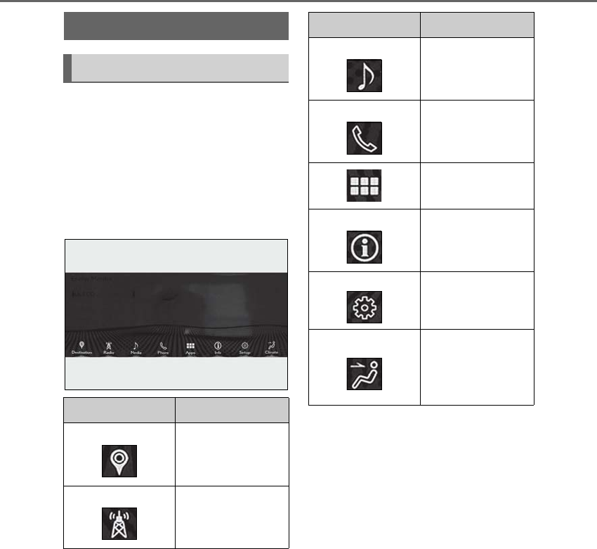
316 5-1. Remote Touch/Display
LS500h_OM_OM50F42U_(U)
■Menu screen
Press the “MENU” button on the
Remote Touch to display the menu
screen.
The displays shown in the illustrations
are used for example only and may dif-
fer from the actual vehicle.
*1: Refer to the “NAVIGATION AND
MULTIMEDIA SYSTEM OWNER’S
MANUAL”.
*2: This function is not available on some
models.
■Split-screen display
Different information can be displayed on the left and right sides of the screen. For
example, air conditioning system screen can be displayed and operated while the
fuel consumption information screen is being displayed. The large screen on the
left of the display is called the main display, and the small screen to the right is
called the side display.
Center Display
Center Display overview
Switch Function
Select to display the
“Destination”
screen.*1
Select to display the
radio control
screen.*1
Select to display the
media control
screen.*1
Select to display the
hands-free control
screen.*1
Select to display the
“Apps” screen.*1, 2
Select to display the
information screen.*1
(→P.97)
Select to display the
setup screen.*1
Select to display the
air conditioning con-
trol screen.
(→P.326)
Switch Function
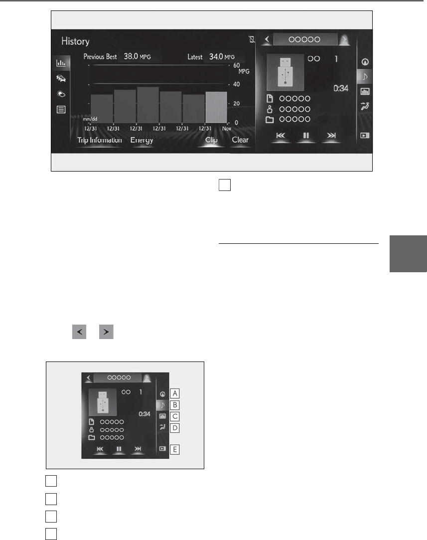
317
5-1. Remote Touch/Display
LS500h_OM_OM50F42U_(U)
5
Interior features
■Main display
For details about the functions and
operation of the main display, refer to
the respective section and “NAVIGA-
TION AND MULTIMEDIA SYSTEM
OWNER’S MANUAL”.
■Side display
The following functions can be dis-
played and operated on the side dis-
play.
Select or to display the desired
screen.
Navigation system*
Audio*
Vehicle information (→P.100)
Air conditioning system (→P.329)
Show/hide the side display*
*: Refer to the “NAVIGATION AND
MULTIMEDIA SYSTEM OWNER’S
MANUAL”.
■Screen display during low temperatures
When the ambient temperature is
extremely low, screen response may be
delayed even if the Remote Touch is oper-
ated.
A
B
C
D
E
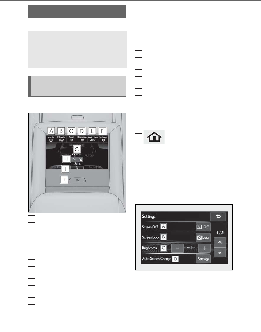
318 5-1. Remote Touch/Display
LS500h_OM_OM50F42U_(U)
*:If equipped
■Home screen
Touch to display the audio control
screen.
Refer to “NAVIGATION AND
MULTIMEDIA SYSTEM
OWNER’S MANUAL”.
Touch to display the rear air condi-
tioning control screen. (→P.334)
Touch to display the rear seat
adjustment screen. (→P.136)
Touch to display the relaxation seat
(if equipped) control screen.
(→P.138)
Touch to display the rear sunshade
(if equipped)/rear interior light con-
trol screen. (→P.355)
Touch to display the Rear Multi
Operation Panel settings screen.
(→P.318)
Show the progress of unlocking the
Rear Multi Operation Panel.
Touch and hold to unlock the Rear
Multi Operation Panel.
Shortcut button
Shortcut screen is displayed. Touch to dis-
play/hide commonly used buttons for a
selected mode on the bottom portion of
the screen.
button
Press to display the home screen.
■Rear Multi Operation Panel set-
tings screen
Screen operation settings and the
brightness of the screen can be
changed.
Rear Multi Operation Panel*
The Rear Multi Operation Panel
built-into the rear armrest can be
used to operate the rear audio sys-
tem, air conditioning system, etc.
Rear Multi Operation Panel
overview
A
B
C
D
E
F
G
H
I
J
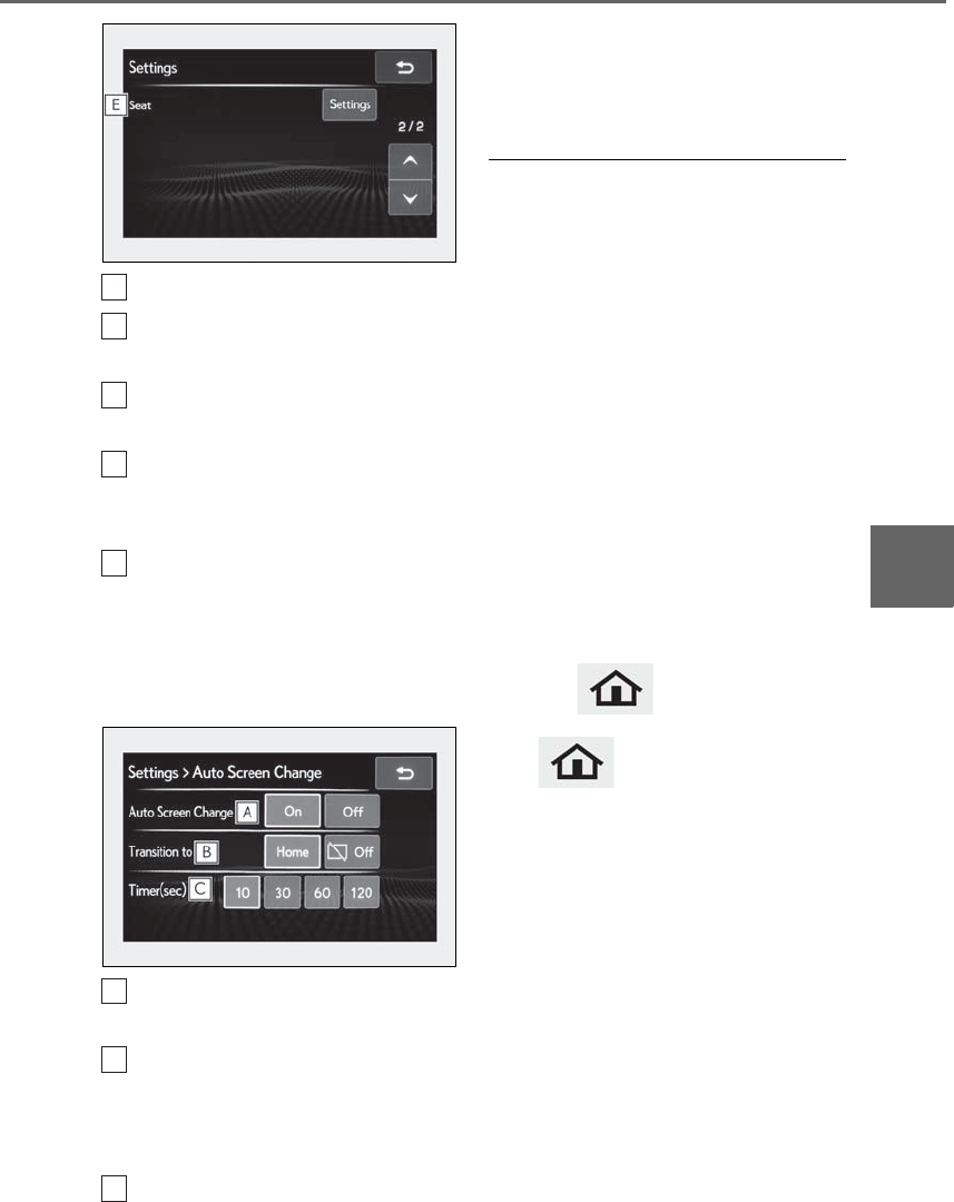
319
5-1. Remote Touch/Display
LS500h_OM_OM50F42U_(U)
5
Interior features
Touch to turn the screen off.
Touch to lock the Rear Multi Oper-
ation Panel.
Touch to adjust the brightness of
the screen.
Touch to display the automatic
screen transition settings screen.
(→P.319)
Touch to display the rear seat
return function settings screen.
(→P.137)
■Auto screen change settings
screen
Touch to turn the automatic screen
transition function on/off.
Touch to set whether the screen will
transition to the home screen or
turn off when the automatic screen
transition function operates.
Touch to set the amount of time
(10/30/60/120 seconds) the Rear
Multi Operation Panel must be idle
before the automatic screen transi-
tion function operates.
■Operating the Rear Multi Operation
Panel
●When operating the Rear Multi Opera-
tion Panel, only use the tip of a finger. The
Rear Multi Operation Panel cannot be
operated with a fingernail, pen, etc.
●Use only one finger when operating the
Rear Multi Operation Panel. The Rear
Multi Operation Panel cannot be oper-
ated with multiple fingers .
●When the power switch is changed to
ACCESSORY or ON mode, if a hand
object, liquid or foreign matter is touch-
ing the Rear Multi Operation Panel, it
may not operate correctly. In this case,
remove anything touching the Rear Multi
Operation Panel and wait for approxi-
mately 30 seconds before operating it
again.
If the Rear Multi Operation Panel still
cannot be operated normally, press and
hold the button to turn the Rear
Multi Operation Panel off, and then press
the button again to turn it back
on and operate it.
●In the following situations, the Rear Multi
Operation Panel may not operate prop-
erly:
• If wearing gloves during operation, non
response may occur.
• If a wet hand is used to operate the Rear
Multi Operation Panel.
• If a screen cover or coating is applied to
on the Rear Multi Operation Panel.
• If the Rear Multi Operation Panel is dirty
or has liquid attached to it, incorrect
operation or non-response may occur.
• If the Rear Multi Operation Panel
receives electro magnetic waves, incor-
rect operation or non-response may
occur.
• If a mobile phone or other wireless com-
munication device brought near the Rear
A
B
C
D
E
A
B
C

320 5-1. Remote Touch/Display
LS500h_OM_OM50F42U_(U)
Multi Operation Panel.
●If the a metal object, such as the follow-
ing, is touching or covering the Rear
Multi Operation Panel:
•Coins
•Keys
• Metallic wallets or bags
• Magnetic isolation cards
• Metallic foil, such as the inner packaging
of a cigarette box
• Disposable heat packs
• Discs, such as a CD or DVD, Cables,
such as a USB cable
• Mobile devices, such as smartphones,
mobile phones, tablets, etc.
●Make sure to keep the Rear Multi Oper-
ation Panel clean . If the Rear Multi Oper-
ation Panel is dirty, it may not operate
correctly. (When cleaning the Rear Multi
Operation Panel, turn the screen off to
avoid unexpected operation.)
NOTICE
■To prevent damage to the Rear Multi
Operation Panel
Observe the following precautions. Fail-
ure to do so may cause damage to the
Rear Multi Operation Panel.
●Keep the Rear Multi Operation Panel
free of liquids, such as drinks or rain ,
as they may cause a short circuit.
●Do not sit on or set heavy objects on
the Rear Multi Operation Panel.
●Do not push the Rear Multi Operation
Panel with a strong force or use a
sharp pointed object to operate the
panel.
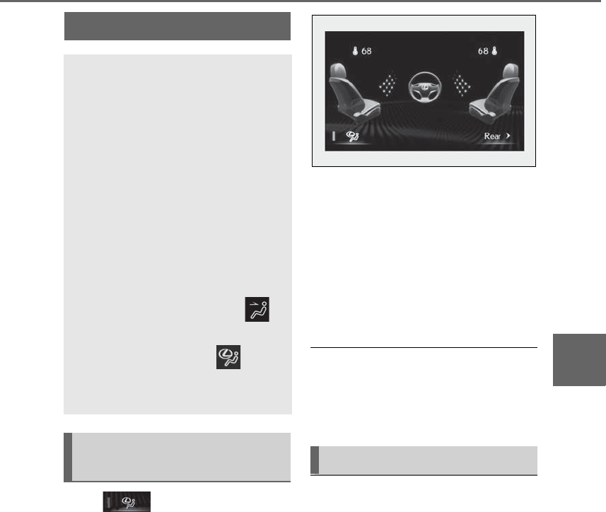
321
5-2. Lexus Climate Concierge
LS500h_OM_OM50F42U_(U)
5
Interior features
5-2.Lexus Climat e Concierge
Select
The indicator on the Lexus Climate Con-
cierge control screen illuminates, and the
automatic air conditioning system, seat
heaters and ventilators, and heated steer-
ing wheel operate in automatic mode.
If any of the system is operated manually,
the indicator turns off. However, all other
functions continue to operate in automatic
mode.
■Changing Lexus Climate Con-
cierge control screen between
front/rear (vehicles with 4-ZONE
climate control)
Select “Rear” to display the rear air
conditioning system screen.
Select “Front” to display the front air condi-
tioning system screen.
■When using the Lexus Climate Con-
cierge
Lexus Climate Concierge can be operated
on the sub function menu or option control
screen. (→P.326)
■Automatic air conditioning system
(→P.323, 333)
The temperature can be adjusted inde-
pendently for each seat.
■Seat heaters and ventilators
(→P.336)
Heating or ventilation is automatically
selected according to the set tempera-
ture of the air conditioning system, the
outside temperature, etc.
■Heated steering wheel (if
equipped) (→P.336)
Heated steering wheel operates auto-
matically according to the set tempera-
Lexus Climate Concierge
The seat heaters, seat ventilators
and heated steering wheel (if
equipped) are each automatically
controlled according to the set
temperature of the air conditioning
system, the outside and cabin tem-
perature, etc. Lexus Climate Con-
cierge allows a comfortable
condition to be maintained without
adjusting each system.
Press the “MENU” button on the
Remote Touch to display the main
menu and move the cursor to
to display the climate control short-
cut buttons. Then, select to dis-
play the Lexus Climate Concierge
control screen.
Turning on Lexus Climate Con-
cierge Operation of each system

322 5-2. Lexus Climate Concierge
LS500h_OM_OM50F42U_(U)
ture of the air conditioning system, the
outside temperature, etc.
■Passenger detection functions
●When a passenger is detected in the
front passenger seat, the seat heater and
ventilator will operate automatically.
●When a passenger is detected in a rear
seat, the seat heater and ventilator will
operate automatically. (vehicles with
4-ZONE climate control)
■Seat heater/ventilator operation
When automatic mode is selected using the
seat heater/ventilator switch, passenger
detection is not performed.
■Rear seat heater operation (vehicles
with DUAL-ZONE climate control)
The rear seat heaters are not controlled by
the Lexus Climate Concierge.
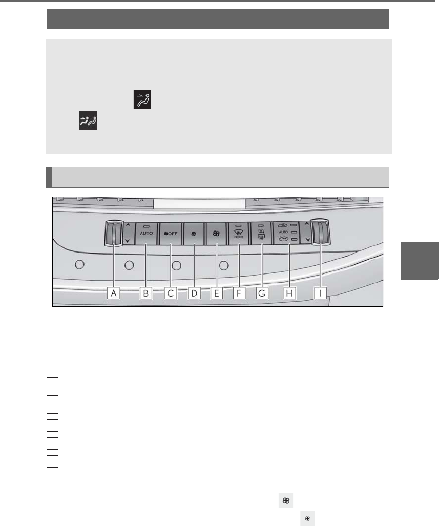
323
5-3. Using the air conditioning system and defogger
LS500h_OM_OM50F42U_(U)
5
Interior features
5-3.Using the a ir conditioning system an d defogger
Left-hand side temperature control switch
Automatic mode switch
Off switch
Fan speed decreases switch
Fan speed increases switch
Windshield defogger switch
Rear window defogger and outside rear view mirror defoggers switch
Outside/recirculated air mode switch
Right-hand side temperature control switch
■Adjusting the temperature
Operate the temperature control
switch upwards to increase the tem-
perature and downwards to decrease
the temperature.
■Setting the fan speed
Operate the switch to increase the
fan speed and the switch to
decrease the fan speed.
Press the off switch to turn the fan off.
Front automatic air conditioning system
Air outlets and fan speed are automatically adjusted according to the tem-
perature setting.
Press the “MENU” button on the Remote Touch to display the main menu and
move the cursor to to display the climate control shortcut buttons. Then,
select to display the air conditioning control screen.
The air conditioning system can be displayed and operated on the side display.
Air conditioning controls
A
B
C
D
E
F
G
H
I

324 5-3. Using the air conditioning system and defogger
LS500h_OM_OM50F42U_(U)
■Changing the air flow mode
→P.326
■Switching between outside air and
recirculated air modes
Press the outside/recirculated air
mode switch.
The mode changes as follows each time
the switch is pressed.
automatic mode → (outside air
mode) → (recirculated air mode)
→ automatic mode
When the system is switched to automatic
mode, the air conditioning system operates
automatically.
■Defogging the windshield
Defoggers are used to defog the wind-
shield and front side windows.
Press the windshield defogger switch.
Set the outside/recirculated air mode
switch to outside air mode if the recircu-
lated air mode is used. (It may switch auto-
matically.)
To defog the windshield and the side win-
dows quickly, turn the air flow and tem-
perature up.
To return to the previous mode, press the
windshield defogger switch again when the
windshield is defogged.
■Defogging the rear window and
outside rear view mirrors
Defoggers are used to defog the rear
window, and to remove raindrops, dew
and frost from the outside rear view
mirrors.
Press the rear window and outside rear
view mirror defoggers switch.
The defoggers will automatically turn off
after a while. The operation time changes
according to the ambient temperature and
vehicle speed.
■Windshield wiper de-icer (if
equipped)
→P.329
■When the outside temperature exceeds
75°F (24°C) and the air conditioning
system is on
●In order to reduce the air conditioning
power consumption, the air conditioning
system may switch to recirculated air
mode automatically. This may also
reduce fuel consumption.
●It is possible to switch to outside air mode
at any time by pressing the outside/recir-
culated air mode switch.
■Fogging up of the windows
The windows will easily fog up when the
humidity in the vehicle is high. Turning “A/C”
on will dehumidify the air from the outlets
and defog the windshield effectively.
●If you turn “A/C” off, the windows may fog
up more easily.
●The windows may fog up if the recircu-
lated air mode is used.
■Outside/recirculated air mode
●When driving on dusty roads such as tun-
nels or in heavy traffic, set the out-
side/recirculated air mode switch to the
recirculated air mode. This is effective in
preventing outside air from entering the
vehicle interior. During cooling opera-
tion, setting the recirculated air mode will
also cool the vehicle interior effectively.
●Outside/recirculated air mode may auto-
matically switch depending on the tem-
perature setting or the inside
temperature.
■Registering air conditioning settings to
electronic keys
●Unlocking the vehicle using an electronic
key and turning the power switch to ON
mode will recall that key’s registered air
conditioning settings.

325
5-3. Using the air conditioning system and defogger
LS500h_OM_OM50F42U_(U)
5
Interior features
●When the power switch is turned off, the
current air conditioning settings will auto-
matically be registered to the electronic
key that was used to unlock the vehicle.
●The system may not operate correctly if
more than one electronic key is in the
vicinity or if the smart access system with
push-button start is used to unlock a pas-
senger door.
●The doors that can recall the air condi-
tioning setting* when unlocked using the
smart access system with push-button
start can be changed. For details, contact
your Lexus dealer.
*: The doors that can recall the driving
position memory are changed at the
same time.
■Operation of the air conditioning sys-
tem in Eco drive mode
In Eco drive mode, the air conditioning sys-
tem is controlled as follows to prioritize fuel
efficiency:
●Engine speed and compressor operation
controlled to restrict heating/cooling
capacity
●Fan speed restricted when automatic
mode is selected
To improve air conditioning performance,
perform the following operations:
●Turn off eco air conditioning mode
(→P.326)
●Adjust the fan speed
●Turn off Eco drive mode (→P.298)
■When the outside temperature falls to
nearly 32°F (0°C)
The dehumidification function may not
operate even when “A/C” is selected.
■Ventilation and air conditioning odors
●To let fresh air in, set the air conditioning
system to the outside air mode.
●During use, various odors from inside and
outside the vehicle may enter into and
accumulate in the air conditioning sys-
tem. This may then cause odor to be
emitted from the vents.
●To reduce potential odors from occur-
ring:
• It is recommended that the air condition-
ing system be set to outside air mode
prior to turning the vehicle off.
• The start timing of the blower may be
delayed for a short period of time imme-
diately after the air conditioning system is
started in automatic mode or with the
micro dust and pollen filter on.
●When parking, the system automatically
switches to outside air mode to encour-
age better air circulation throughout the
vehicle, helping to reduce odors that
occur when starting the vehicle.
■Using the voice command system
Air conditioning system can be operated
using voice commands. For details, refer to
the “NAVIGATION AND MULTIMEDIA
SYSTEM OWNER’S MANUAL”.
■Air conditioning filter
→P.411
■Customization
Some functions can be customized.
(→P.481)
WARNING
■To prevent the windshield from fog-
ging up
Do not use the windshield defogger
switch during cool air operation in
extremely humid weather. The difference
between the temperature of the outside
air and that of the windshield can cause
the outer surface of the windshield to fog
up, blocking your vision.
■When the outside rear view mirror
defoggers are operating
Do not touch the outside rear view mir-
ror surfaces, as they can become very
hot and burn you.
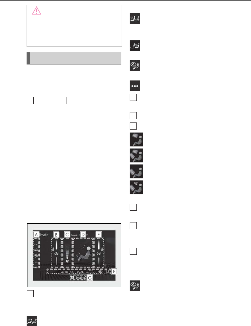
326 5-3. Using the air conditioning system and defogger
LS500h_OM_OM50F42U_(U)
■Main control screen
Using the touchpad of the Remote
Touch, select the button on the screen.
to and can be adjusted by
performing the following operations.
Flick operation: Move the pointer to
the desired item and flick the touchpad
up or down.
The item can be adjusted by one level.
Trace operation: After selecting the
desired item, trace the pad surface.
The item can be adjusted by the amount
that you trace.
Trace operation cannot be used while driv-
ing.
Vehicles with DUAL-ZONE climate
control
Sub menu
Selecting the sub menu item to switch the
main screen.
: Display the air conditioning control
screen
: Display the heated steering
wheel/front seat heater/front seat ventila-
tor control screen
: Display the rear seat heater/rear seat
ventilator control screen (if equipped)
: Display the Lexus Climate Con-
cierge control screen
: Display the option control screen
Adjust the left side seat tempera-
ture setting
Adjust the fan speed setting
Select the air flow mode
: Air flows to the upper body
: Air flows to the upper body and feet
: Air flows to the feet
: Air flows to the feet and the wind-
shield defogger operates
Adjust the right side seat tempera-
ture setting
Function on/off indicators
When the function is on, the indicator illu-
minates on the control screen.
Sub function menu
When the sub function button on the
Remote Touch is pressed, the following
functions can be switched on and off.
: Set Lexus Climate Concierge
(→P.321)
“AUTO”: Set automatic mode on/off
(→P.330)
“OFF”: Turn the fan off
NOTICE
■To prevent 12-volt battery discharge
Do not leave the air conditioning system
on longer than necessary when the
hybrid system is off.
Air conditioning control screen
B
E
H
A
B
C
D
E
F
G
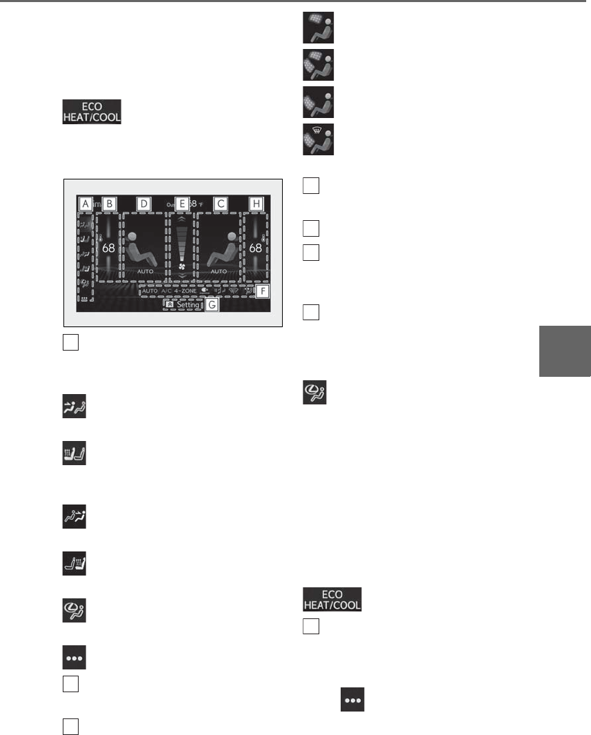
327
5-3. Using the air conditioning system and defogger
LS500h_OM_OM50F42U_(U)
5
Interior features
“A/C”: Set cooling and dehumidification
function
“DUAL”: Adjust the temperature for driver
and passenger seats separately (“DUAL”
mode) (→P.331)
: Set eco air conditioning mode
Vehicles with 4-ZONE climate con-
trol
Sub menu
Selecting the sub menu item to switch the
main screen.
: Display the front air conditioning
control screen
: Display the heated steering
wheel/front seat heater/front seat ventila-
tor control screen
: Display the rear air conditioning con-
trol screen
: Display the rear seat heater/rear seat
ventilator control screen
: Display the Lexus Climate Con-
cierge control screen
: Display the option control screen
Adjust the left side seat tempera-
ture setting
Select the right side seat air flow
mode
: Air flows to the upper body
: Air flows to the upper body and feet
: Air flows to the feet
: Air flows to the feet and the wind-
shield defogger operates
Select the left side seat air flow
mode
Adjust the fan speed setting
Function on/off indicators
When the function is on, the indicator illu-
minates on the control screen.
Sub function menu
When the sub function button on the
Remote Touch is pressed, the following
functions can be switched on and off.
: Set Lexus Climate Concierge
(→P.321)
“AUTO”: Set automatic mode on/off
(→P.330)
“OFF”: Turn the fan off
“A/C”: Set cooling and dehumidification
function
“4-ZONE”: Adjust the temperature for the
driver, front passenger and left and right
rear passenger seats separately
(“4-ZONE” mode) (→P.331)
: Set eco air conditioning mode
Adjust the right side seat tempera-
ture setting
■Option control screen
Select on the sub menu to display
the option control screen.
The functions can be switched on and off.
A
B
C
D
E
F
G
H
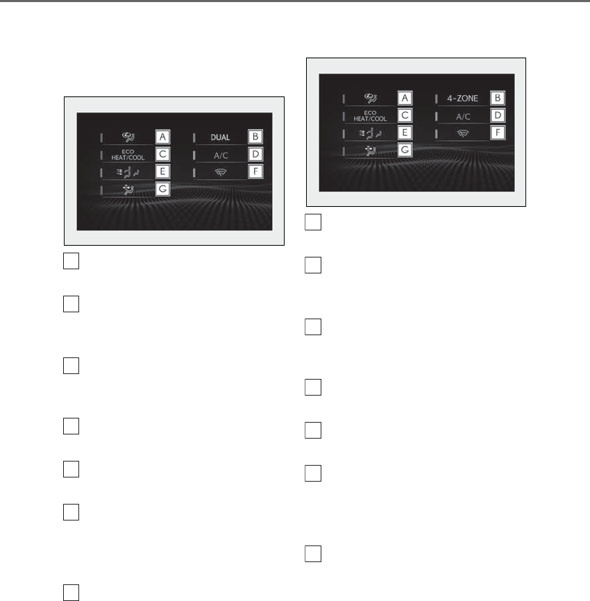
328 5-3. Using the air conditioning system and defogger
LS500h_OM_OM50F42U_(U)
When the function is on, the indicator illu-
minates on the screen.
Vehicles with DUAL-ZONE climate
control
Set Lexus Climate Concierge
(→P.321)
Adjusting the temperature for
driver and passenger seats sepa-
rately (“DUAL” mode) (→P.331)
Set eco air conditioning mode
Air conditioning and heater output is lim-
ited to prioritize fuel economy.
Cooling and dehumidification func-
tion
Select the S-FLOW mode
(→P.330)
Prevent ice from building up on the
windshield and wiper blades
(Windshield wiper de-icer) (if
equipped)
Removing pollen from the air
(Micro dust and pollen filter)
Vehicles with 4-ZONE climate con-
trol
Set Lexus Climate Concierge
(→P.321)
Adjust the temperature for driver,
passenger and rear seats sepa-
rately (“4-ZONE” mode) (→P.331)
Set eco air conditioning mode
Air conditioning and heater output is lim-
ited to prioritize fuel economy.
Cooling and dehumidification func-
tion
Select the S-FLOW mode
(→P.330)
Prevent ice from building up on the
windshield and wiper blades
(Windshield wiper de-icer) (if
equipped)
Removing pollen from the air
(Micro dust and pollen filter)
A
B
C
D
E
F
G
A
B
C
D
E
F
G
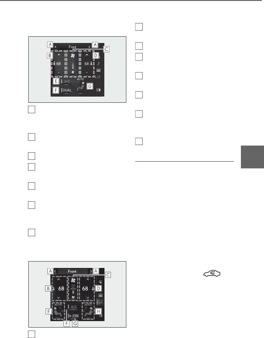
329
5-3. Using the air conditioning system and defogger
LS500h_OM_OM50F42U_(U)
5
Interior features
■Side display
Vehicles with DUAL-ZONE climate
control
Display the front seat heaters/front
seat ventilators control screen
(→P.337)
Adjust the left-hand front seat side
temperature setting
Adjust the fan speed setting
Adjust the right side seat tempera-
ture setting
Set cooling and dehumidification
function on/off
Adjusting the temperature for
driver and passenger seats sepa-
rately (“DUAL” mode) (→P.331)
Select the air flow mode
Vehicles with 4-ZONE climate con-
trol
Display the front seat heaters/front
seat ventilators control screen
(→P.337)
Adjust the left-hand front seat side
temperature setting
Adjust the fan speed setting
Adjust the right side seat tempera-
ture setting
Select the left side seat air flow
mode
Set cooling and dehumidification
function on/off
Adjust the temperature for driver,
passenger and rear seats sepa-
rately (“4-ZONE” mode) (→P.331)
Select the right side seat air flow
mode
■Windshield wiper de-icer (if equipped)
This feature is used to prevent ice from
building up on the windshield and wiper
blades.
The windshield de-icer will automatically
turn off after a while.
■Eco air conditioning mode
When Eco drive mode is selected using the
driving mode select switch, eco air condi-
tioning mode turns on.
When a drive mode other than Eco drive
mode is selected, eco air conditioning
mode may turn off.
■Micro dust and pollen filter
Outside air mode switches to
(recirculated air) mode. Pollen is removed
from the air and the air flows to the upper
part of the body.
Usually the system will automatically turn
off after a while.
In order to prevent the windshield from fog-
ging up when the outside air is cold, the
dehumidification function may operate or
the outside/recirculated air mode may not
A
B
C
D
E
F
G
A
B
C
D
E
F
G
H
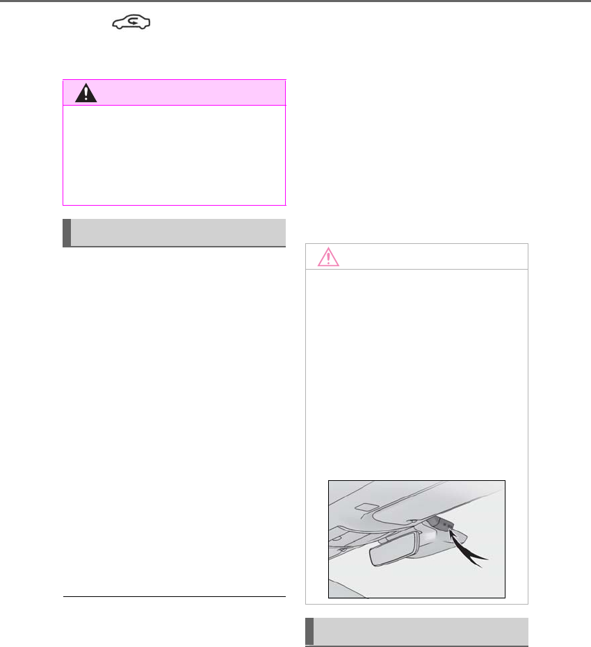
330 5-3. Using the air conditioning system and defogger
LS500h_OM_OM50F42U_(U)
switch to (recirculated air) mode.
Pollen is filtered even if the micro dust and
pollen filter is turned off.
1Press the automatic mode switch or
select “AUTO” on the sub function
menu. (→P.326)
2Press the outside/recirculated air
mode switch to switch to automatic
air intake mode.
The air conditioning system automatically
switches between outside air and recircu-
lated air modes.
3Adjust the temperature setting.
4To stop the operation, press the off
switch or select “OFF” on the sub
function menu. (→P.326)
If the fan speed setting or air flow modes
are operated, the automatic mode indica-
tor goes off. However, automatic mode for
functions other than that operated is main-
tained.
■Using automatic mode
Fan speed is adjusted automatically accord-
ing to the temperature setting and the
ambient conditions.
Therefore, the fan may stop for a while until
warm or cool air is ready to flow immedi-
ately after the automatic mode switch is
pressed or “AUTO” is selected.
Cool air may blow around the upper body
even when the heater is on due to sunlight.
■Windshield fog detection function
When automatic mode is set, the humidity
sensor detects fog on the windshield and
controls the air conditioning system to pre-
vent fog.
■Automatic mode for air intake control
In automatic mode, the system detects
exhaust gas and other pollutants and auto-
matically switches between outside air and
recirculated air modes.
When the dehumidification function is off,
and the fan is operating, turning automatic
mode on will activate the dehumidification
function.
In S-FLOW mode, priority for the air-
flow is given to the front seats, reducing
the airflow and air conditioning effect
on the rear seats.
The system determines whether or not
WARNING
■To prevent burns (vehicles with wind-
shield wiper de-icer)
Do not touch the glass at lower part of
the windshield or to the side of the front
pillars when the windshield wiper de-icer
is on.
Using automatic mode
NOTICE
■Humidity sensor
In order to detect fog on the windshield,
a sensor which monitors the temperature
of the windshield, the surround humidity,
etc. is installed.
Follow these points to avoid damaging
the sensor:
●Do not disassemble the sensor
●Do not spray glass cleaner on the sen-
sor or subject it to strong impacts
●Do not stick anything on the sensor
S-FLOW mode

331
5-3. Using the air conditioning system and defogger
LS500h_OM_OM50F42U_(U)
5
Interior features
a front passenger is in the vehicle by
the opening and closing of the front
passenger’s door.
When a front passenger is determined
not to be in the vehicle, the tempera-
ture indicator and air flow indicator for
the front passenger side will turn off. In
this case, depending on the set tem-
perature and ambient temperature,
priority for the airflow will be given to
the driver’s seat only.
The following S-FLOW modes are
available:
Automatic S-FLOW mode
In this mode, the system determines
whether or not a rear passenger is in
the vehicle by the opening and closing
of a rear door. When a rear passenger
is determined to be in the vehicle,
S-FLOW mode will be automatically
disabled.
The indicator will illuminate on the air con-
ditioning control screen when S-FLOW
mode is enabled.
To enable/disable S-FLOW mode and
enter manual S-FLOW mode, select the
S-FLOW mode switch.
Manual S-FLOW mode
When the S-FLOW mode switch is
selected, S-FLOW mode will be manu-
ally enabled/ disabled.
The indicator will illuminate on the air con-
ditioning control screen when S-FLOW
mode is enabled.
■Operation of the air conditioning sys-
tem in S-FLOW mode
If the front passenger’s door or a rear door
is opened then closed, the air conditioning
system determines that a passenger is in the
vehicle. In this case, priority for the airflow
will be changed from the driver’s seat only
to the front seats only or all seats, respec-
tively.
(Depending on the set temperature or
ambient temperature, priority for the air-
flow may not be given to the driver’s seat
only.)
If a passenger is judged to be in the vehicle,
the system will retain the judgement for a
certain amount of time after the power
switch is turned off.
■Operation of automatic S-FLOW mode
When the system is operating in automatic
S-FLOW mode, if a rear door is opened
and then closed, S-FLOW mode will be dis-
abled. To enable S-FLOW mode, select the
S-FLOW mode switch.
■Changing from manual S-FLOW mode
to automatic S-FLOW mode
1Select the S-FLOW mode switch to dis-
able S-FLOW mode.
2Turn the power switch off.
3After 60 minutes have elapsed, change
the power switch to ON mode.
Vehicles with DUAL-ZONE climate
control
To turn on the “DUAL” mode, perform
any of the following procedures:
-Select “DUAL” on the sub function
menu. (→P.326)
-Select “DUAL” on the option con-
trol screen.
-Adjust the passenger’s side tem-
perature setting.
The indicator on the main control screen
comes on when the “DUAL” mode is on.
Adjusting the temperature for
the driver and passenger seats
separately
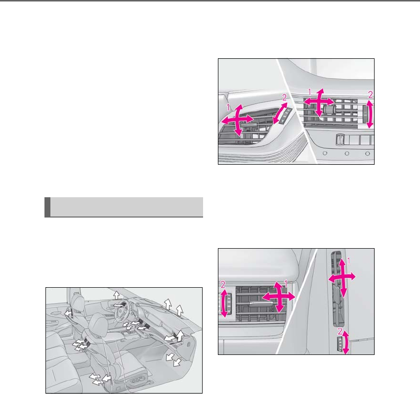
332 5-3. Using the air conditioning system and defogger
LS500h_OM_OM50F42U_(U)
Vehicles with 4-ZONE climate con-
trol
To turn on the “4-ZONE” mode, per-
form any of the following procedures:
-Select “4-ZONE” on the sub func-
tion menu. (→P.326)
-Select “4-ZONE” on the option
control screen.
-Adjust a passenger seat tempera-
ture setting.
The indicator on the main control screen
comes on when the “4-ZONE” mode is on.
■Location of air outlets
The air outlets and air volume changes
according to the selected air flow
mode.
■Adjusting the position of and open-
ing and closing the air outlets
Front center/front side
1Direct air flow to the left or right, up
or down
2Turn the knob to open or close the
vent
Rear center/rear side
1Direct air flow to the left or right, up
or down
2Turn the knob to open or close the
vent
Air outlet layout and operations
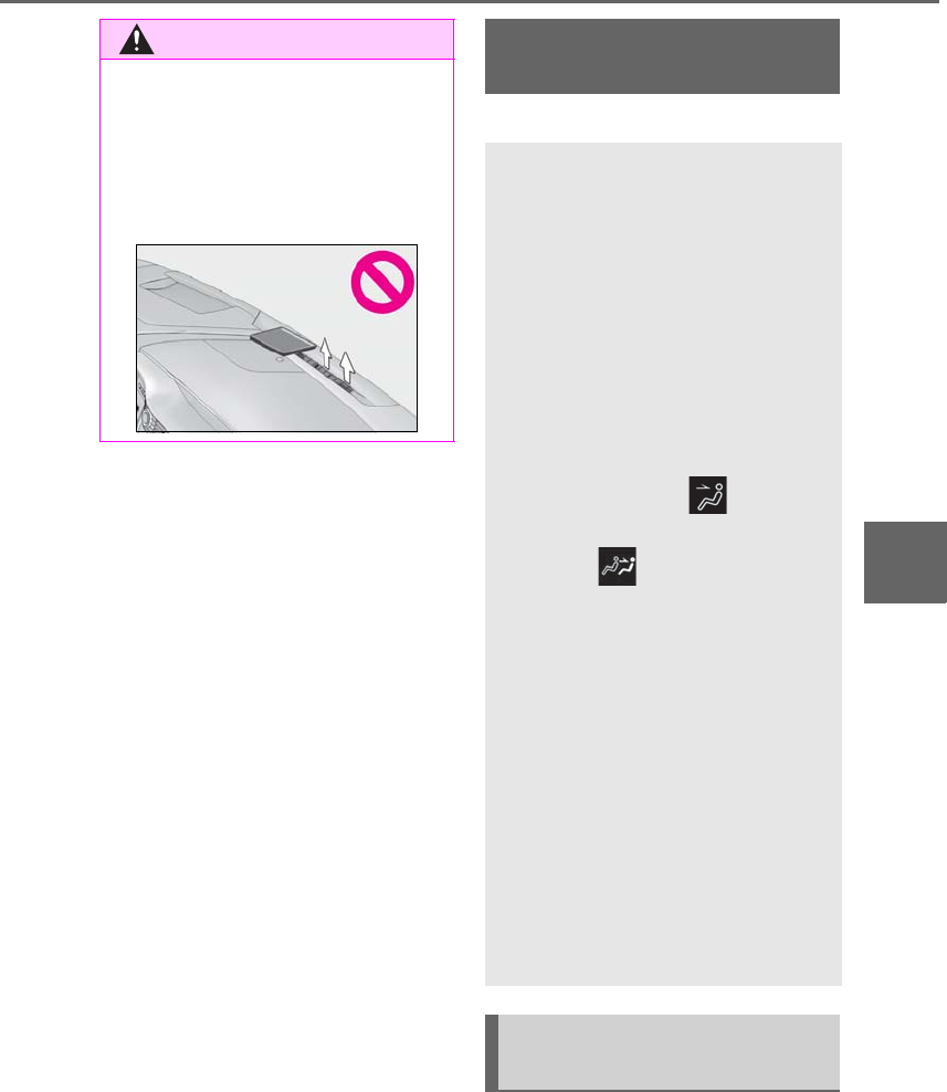
333
5-3. Using the air conditioning system and defogger
LS500h_OM_OM50F42U_(U)
5
Interior features
*: If equipped
■Center Display
Using the touchpad of the Remote
Touch, select the button on the screen.
WARNING
■To prevent the windshield defogger
from operating improperly
Do not place anything on the instrument
panel which may cover the air outlets.
Otherwise, air flow may be obstructed,
preventing the windshield defoggers
from defogging.
Rear air conditioning sys-
tem*
The air outlets and fan speed are
automatically adjusted according
to the temperature setting.
The rear air conditioning system
can be operated using the Center
Display and Rear Multi Operation
Panel.
-Center Display
Press the “MENU” button on the
Remote Touch to display the main menu
and move the cursor to to display
the climate control shortcut buttons.
Then, select to display the rear air
conditioning control screen.
-Rear Multi Operation Panel*
Touch “Climate” on the home screen to
display the rear air conditioning control
screen.(→P.318)
Touching the shortcut button on the
home screen will also display operation
buttons for some of the rear air condi-
tioning system functions.
*: The Rear Multi Operation Panel can-
not be used to operate the rear air
conditioning system if the function is
disabled. (→P.333)
Rear air conditioning control
screen
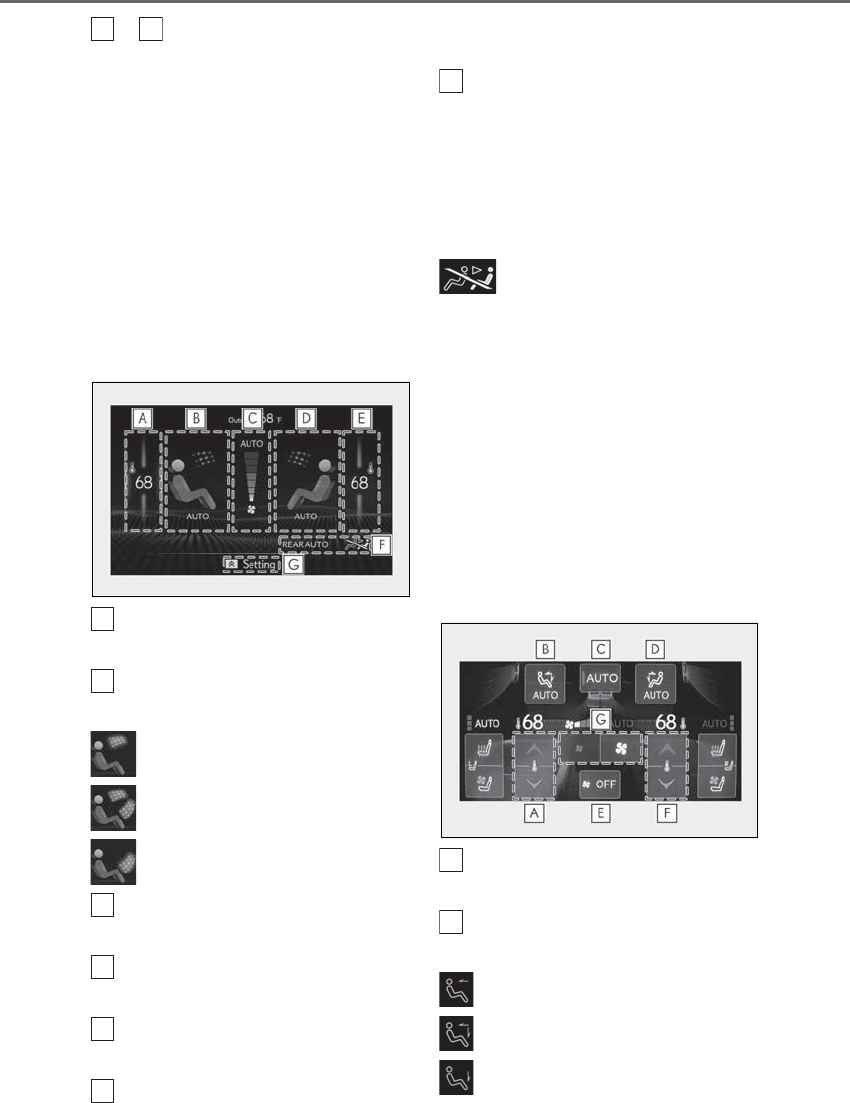
334 5-3. Using the air conditioning system and defogger
LS500h_OM_OM50F42U_(U)
to can be adjusted by perform-
ing the following operations.
Flick operation: Move the pointer to
the desired item and flick the touchpad
up or down.
The item can be adjusted by one level.
Trace operation: After selecting the
desired item, trace the pad surface.
The item can be adjusted by the amount
that you trace.
Trace operation cannot be used while driv-
ing.
Adjust the left side rear seat tem-
perature setting
Select the left side rear seat air flow
mode
: Air flows to the upper body
: Air flows to the upper body and feet
: Air flows to the feet
Adjust the rear seats fan speed set-
ting
Select the right side rear seat air
flow mode
Adjust the right side rear seat tem-
perature setting
Function on/off indicators
When the function is on, the indicator illu-
minates on the control screen.
Sub function menu
When the sub function button on the
Remote Touch is pressed, the following
functions can be switched on and off.
“Rear off”: Turn the rear seats fan off
“Rear AUTO”: Set the rear seats automatic
mode on/off (→P.335)
: Disables operation of the rear air
conditioning system using the Rear Multi
Operation Panel
■Rear Multi Operation Panel*
Various functions can be operated by
touching the displayed buttons on the
Rear Multi Operation Panel.
*: The Rear Multi Operation Panel cannot
be used to operate the rear air condi-
tioning system if the function is disabled.
(→P.333)
Rear air conditioning control screen
Adjust the left side rear seat tem-
perature setting
Select the left side rear seat air flow
mode
: Air flows to the upper body
: Air flows to the upper body and feet
: Air flows to the feet
A
E
A
B
C
D
E
F
G
A
B
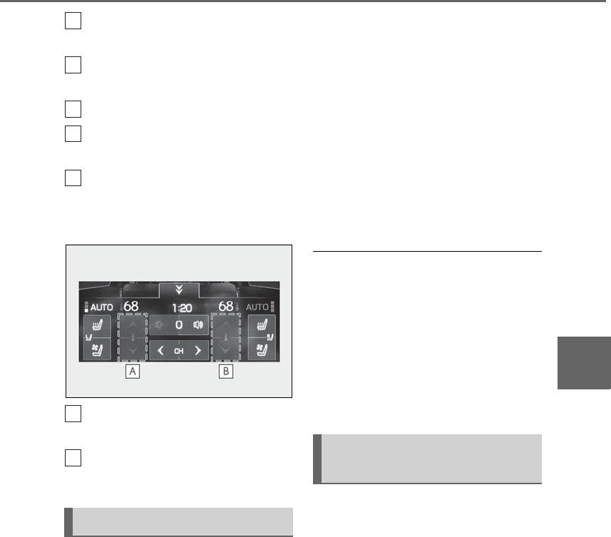
335
5-3. Using the air conditioning system and defogger
LS500h_OM_OM50F42U_(U)
5
Interior features
Set the rear seats automatic mode
on/off (→P.335)
Select the right side rear seat air
flow mode
Turn the rear seats fan off
Adjust the right side rear seat tem-
perature setting
Adjust the rear seats fan speed set-
ting
Shortcut screen
Adjust the left side rear seat tem-
perature setting
Adjust the right side rear seat tem-
perature setting
Center Display
1Select “Rear AUTO” on the sub
function menu. (→P.333)
2To stop the operation, select “Rear
off” on the sub function menu.
(→P.333)
If the fan speed setting or air flow
modes are operated, the automatic
mode indicator goes off. However,
automatic mode for functions other
than that operated is maintained.
Rear Multi Operation Panel
1Select “AUTO” on the rear air con-
ditioning control screen. (→P.334)
2To stop the operation, select “OFF”
on the rear air conditioning control
screen. (→P.333)
If the fan speed setting or air flow
modes are operated, the automatic
mode indicator goes off. However,
automatic mode for functions other
than that operated is maintained.
■Using automatic mode
Fan speed is adjusted automatically accord-
ing to the temperature setting and the
ambient conditions.
Therefore, the fan may stop for a while until
warm or cool air is ready to flow immedi-
ately after “Rear AUTO” is selected or
“AUTO” is touched.
Cool air may blow around the upper body
even when the heater is on due to sunlight.
The temperature setting of the rear
seats can be adjusted using the follow-
ing methods:
-When the “4-ZONE” indicator is
off: Adjust the driver’s seat tempera-
ture.
Adjust the temperature setting of each
rear seat using the Center Display or Rear
Multi Operation Panel.
-Adjust the temperature setting of
each rear seat using the Center Dis-
play (rear air conditioning control
screen) or Rear Multi Operation
Panel.
Using automatic mode
C
D
E
F
G
A
B
Adjusting the temperature set-
ting of the rear seats
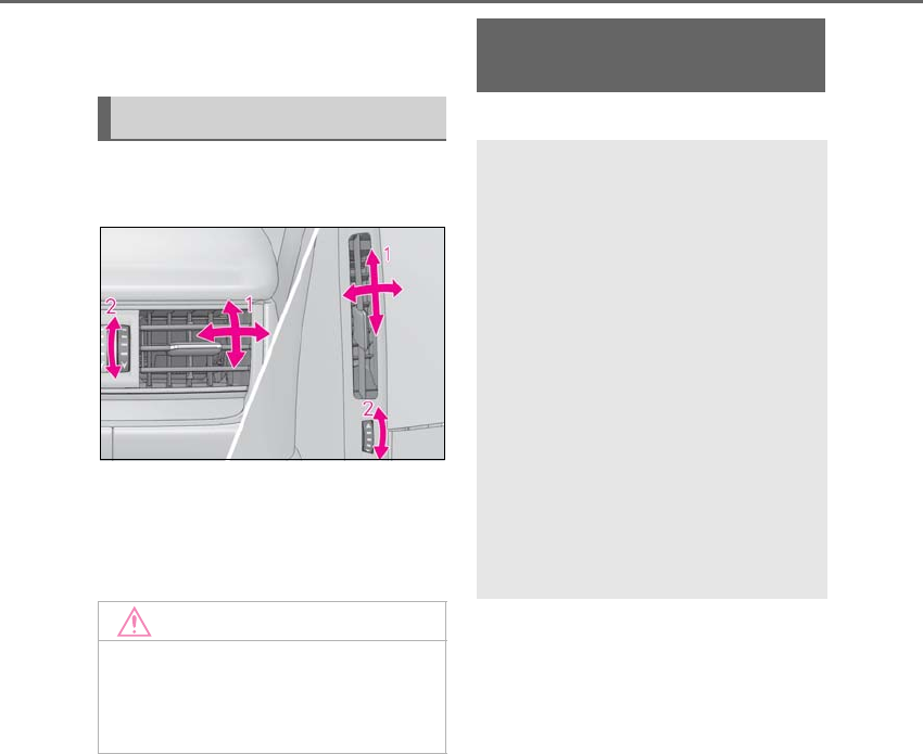
336 5-3. Using the air conditioning system and defogger
LS500h_OM_OM50F42U_(U)
The temperature setting of each rear seat
can be changed independently.
■Rear center outlets and rear side
outlets
1Direct air flow to the left or right, up
or down
2Turn the knob to open or close the
vent
*: If equipped
Air outlet layout and operations
NOTICE
■To prevent 12-volt battery discharge
Do not leave the air conditioning system
on longer than necessary when the
hybrid system is off.
Heated steering wheel*/seat
heaters/seat ventilators
-Heated steering wheel
Warms up the grip of the steering wheel
-Front seat heaters/Rear seat
heaters
Warm up the seat upholstery
-Front seat ventilators/Rear seat
ventilators
Maintain good ventilation by pulling air
through the seat upholstery
The Center Display and Rear Multi
Operation Panel/rear control
panel can be used to operate the
heated steering wheel, seat heaters
and seat ventilators as follows:
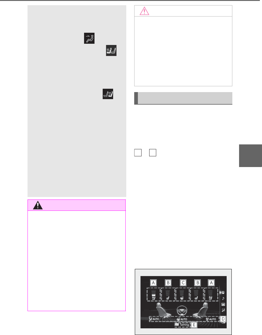
337
5-3. Using the air conditioning system and defogger
LS500h_OM_OM50F42U_(U)
5
Interior features
■Center Display
Main screen
Using the touchpad of the Remote
Touch, select the button on the screen.
to can be adjusted by perform-
ing the following operations.
Flick operation: Move the pointer to
the desired item and flick the touchpad
up or down.
The item can be adjusted by one level.
Trace operation: After selecting the
desired item, trace the touchpad sur-
face.
The item can be adjusted by the amount
that you trace.
Trace operation cannot be used while driv-
ing.
-Center Display
Press the “MENU” button on the
Remote Touch to display the main menu
and move the cursor to to display
the shortcut buttons. Then, select
to display the heated steering
wheel/front seat heater/front seat venti-
lator control screen.
To display the rear seat heater/rear seat
ventilator control screen, select . (if
equipped)
-Rear Multi Operation Panel
Touch “Climate” on the home screen to
display the air conditioning control
screen.(→P.318)
Touching the shortcut button on the
home screen will display operation but-
tons for the rear seat heaters and rear
seat ventilators.
-Rear control panel
The rear seat heaters can be operated.
WARNING
■To prevent minor burn injuries
Care should be taken if anyone in the fol-
lowing categories comes in contact with
the steering wheel or seats when the
heater is on:
●Babies, small children, the elderly, the
sick and the physically challenged
●Persons with sensitive skin
●Persons who are fatigued
●Persons who have taken alcohol or
drugs that induce sleep (sleeping
drugs, cold remedies, etc.)
NOTICE
■To prevent damage to the seat heat-
ers and seat ventilators
Do not put heavy objects that have an
uneven surface on the seat and do not
stick sharp objects (needles, nails, etc.)
into the seat.
■To prevent 12-volt battery discharge
Do not use the functions when the hybrid
system is off.
Control screen
A
C
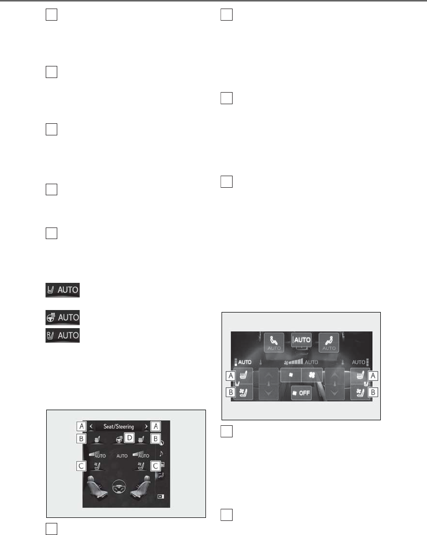
338 5-3. Using the air conditioning system and defogger
LS500h_OM_OM50F42U_(U)
Adjust the seat ventilator fan speed
level
The seat ventilator can be adjusted in 3 lev-
els. (Low, Mid or Hi)
Adjust the seat heater temperature
level
The seat heater can be adjusted in 3 levels.
(Low, Mid or Hi)
Adjust the heated steering wheel
temperature level*
The heated steering wheel can be adjusted
in 2 levels. (Low or Hi)
Automatic mode on/off indicators
When the automatic mode is on, the indi-
cator illuminates on the screen.
Sub function menu
When the sub function button on the
Remote Touch is pressed, the following
functions can be set to automatic mode.
: Left-hand side seat heater/seat
ventilator
: Heated steering wheel*
: Right-hand side seat heater/seat
ventilator
*: Available on the front seat control
screen only
Side screen
Display the air conditioning control
screen →P.329
Adjust the front seat heater tem-
perature level
Each time the switch is selected, the tem-
perature level and level indicator (orange)
change as follows:
AUTO→Hi→Mid→Lo→OFF
Adjust the front seat ventilator fan
speed level
Each time the switch is selected, the fan
speed level and level indicator (blue)
change as follows:
AUTO→Hi→Mid→Lo→OFF
Adjust the heated steering wheel
temperature level
Each time the switch is selected, the tem-
perature level and level indicator change
as follows:
AUTO→Hi→Lo→OFF
■Rear Multi Operation Panel (if
equipped)
Rear air conditioning control screen
Adjust the rear seat heater tem-
perature level
Each time the switch is selected, the tem-
perature level and level indicator (orange)
change as follows:
AUTO→Hi→Mid→Lo→OFF
Adjust the rear seat ventilator fan
speed level
Each time the switch is selected, the fan
A
B
C
D
E
A
B
C
D
A
B
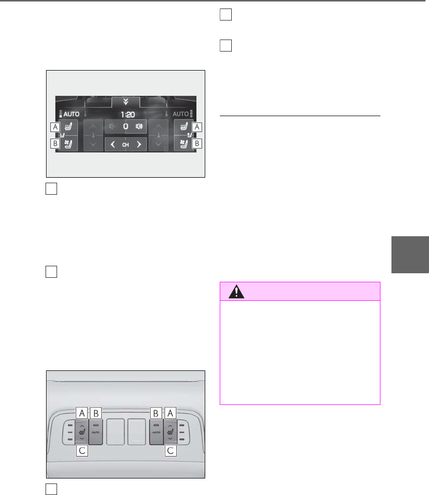
339
5-3. Using the air conditioning system and defogger
LS500h_OM_OM50F42U_(U)
5
Interior features
speed level and level indicator (blue)
change as follows:
AUTO→Hi→Mid→Lo→OFF
Shortcut screen
Adjust the rear seat heater tem-
perature level
Each time the switch is selected, the tem-
perature level and level indicator (orange)
change as follows:
AUTO→Hi→Mid→Lo→OFF
Adjust the rear seat ventilator fan
speed level
Each time the switch is selected, the fan
speed level and level indicator (blue)
change as follows:
AUTO→Hi→Mid→Lo→OFF
■Rear control panel (if equipped)
Increases the rear seat heater tem-
perature level
The seat ventilator can be adjusted in 3 lev-
els. (Low, Mid or Hi)
Enables/Disables the automatic
mode of the rear seat heaters
Decreases the rear seat heater
temperature level
If this switch is selected when the rear seat
heater temperature level is set to Lo, the
rear seat heater will turn off.
■The heated steering wheel, seat heaters
and seat ventilators wheel can be used
when
The power switch is in ON mode.
■Air conditioning system-linked control
mode
When the seat ventilator fan speed level is
Hi, the seat ventilator fan speed becomes
higher according to the fan speed of the air
conditioning system.
■Customization
Some functions can be customized.
(→P.481)
A
B
A
WARNING
■To prevent overheating and minor
burn injuries
Observe the following precautions when
using the seat heaters.
●Do not cover the seat with a blanket or
cushion when using the seat heater.
●Do not use seat heater more than nec-
essary.
B
C
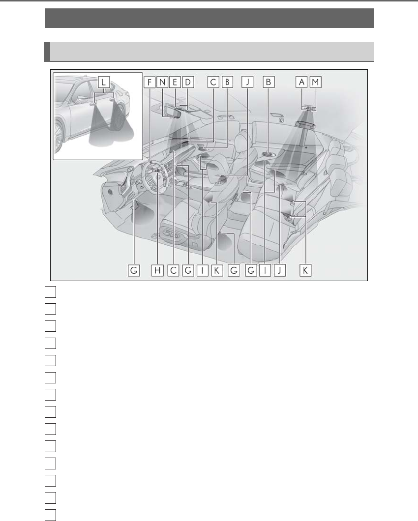
340 5-4. Using the interior lights
LS500h_OM_OM50F42U_(U)
5-4.Using the interior lights
Rear personal lights (→P.341)
Inside door handle lights
Instrument panel ornament lights (if equipped)
Front personal lights (→P.341)
Front interior lights (→P.341)
Clock light
Footwell lights
Power switch light
Door trim ornament lights
Door courtesy lights
Seat belt buckle lights
Outer foot lights
Rear interior light (→P.341)
Shift lever lights
Interior lights list
Location of the interior lights
A
B
C
D
E
F
G
H
I
J
K
L
M
N
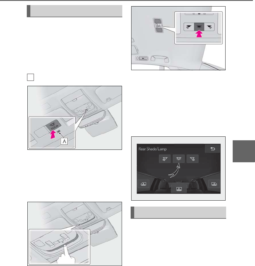
341
5-4. Using the interior lights
LS500h_OM_OM50F42U_(U)
5
Interior features
■Turning the door position on
Press the door-linked interior light
switch
The lights are turned on and off according
to whether the doors are opened/closed.
When the door position is on, the indicator
illuminates.
■Turning the lights on/off
Front
Turns the lights on/off (touch the light)
When a door is opened while the door
position is on, the lights turn on.
Rear
On/off
The rear interior lights turn on/off together
the front interior lights.
When a door is opened while the door
position is on, the lights turn on.
■Using the Rear Multi Operation
Panel (if equipped)
1Display the home screen and then
touch “Rear Shade/Lamp”.
(→P.318)
2To turn on/off the rear interior
lights, touch the respective button.
■Turning the lights on/off
Front
Turns the lights on/off (touch the light)
When a door is opened while the door
position is on, the lights turn on.
Operating the interior lights
A
Operating the personal lights
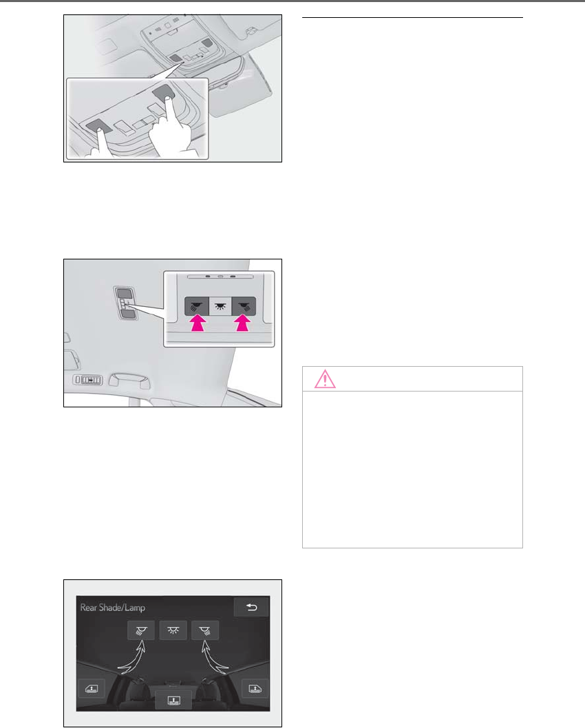
342 5-4. Using the interior lights
LS500h_OM_OM50F42U_(U)
Rear
On/dimmed/off
When a door is opened while the door
position is on, the lights turn on.
■Using the Rear Multi Operation
Panel (if equipped)
1Display the home screen and then
touch “Rear Shade/Lamp”.
(→P.318)
2To turn on/dimmed/off the rear per-
sonal lights, touch the respective
button.
■Illuminated entry system
The lights automatically turn on/off accord-
ing to the power switch mode, the presence
of the electronic key, whether the doors are
locked/unlocked, and whether the doors
are open/closed.
■To prevent the 12-volt battery from
being discharged
If the interior lights remain on when the
power switch is turned off, the lights will go
off automatically after 20 minutes.
■When front interior light or front per-
sonal lights do not respond as normal
●When water, dirt, etc., have adhered to
the lens surface
●When operated with a wet hand
●When wearing gloves, etc.
■Customization
Some functions can be customized.
(→P.481)
NOTICE
■To prevent 12-volt battery discharge
Do not leave the lights on longer than
necessary when the hybrid system is off.
■Removing light lenses
Never remove the lens for the front inte-
rior light and front personal lights. Other-
wise, the lights will be damaged. If a lens
needs to be removed, contact your Lexus
dealer.
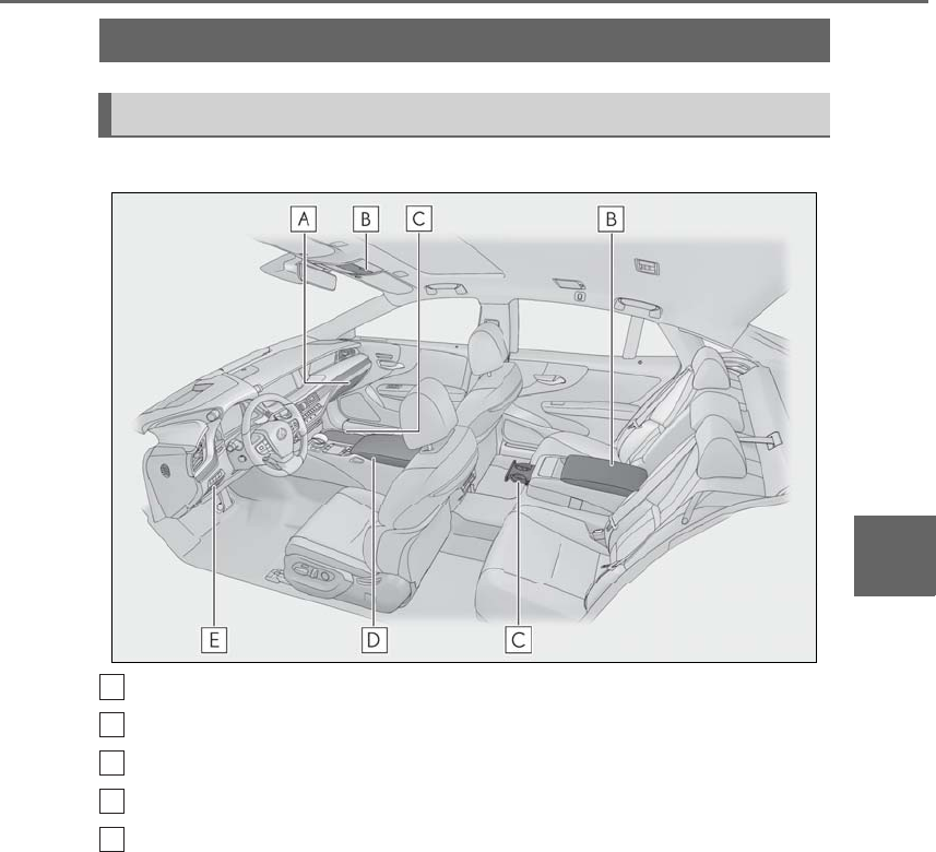
343
5-5. Using the storage features
LS500h_OM_OM50F42U_(U)
5
Interior features
5-5.Using th e storage features
Vehicles without power rear seat
Glove box (→P.344)
Auxiliary boxes (→P.347)
Cup holders (→P.345)
Console box (→P.346)
Coin holder (→P.345)
List of storage features
Location of the storage features
A
B
C
D
E
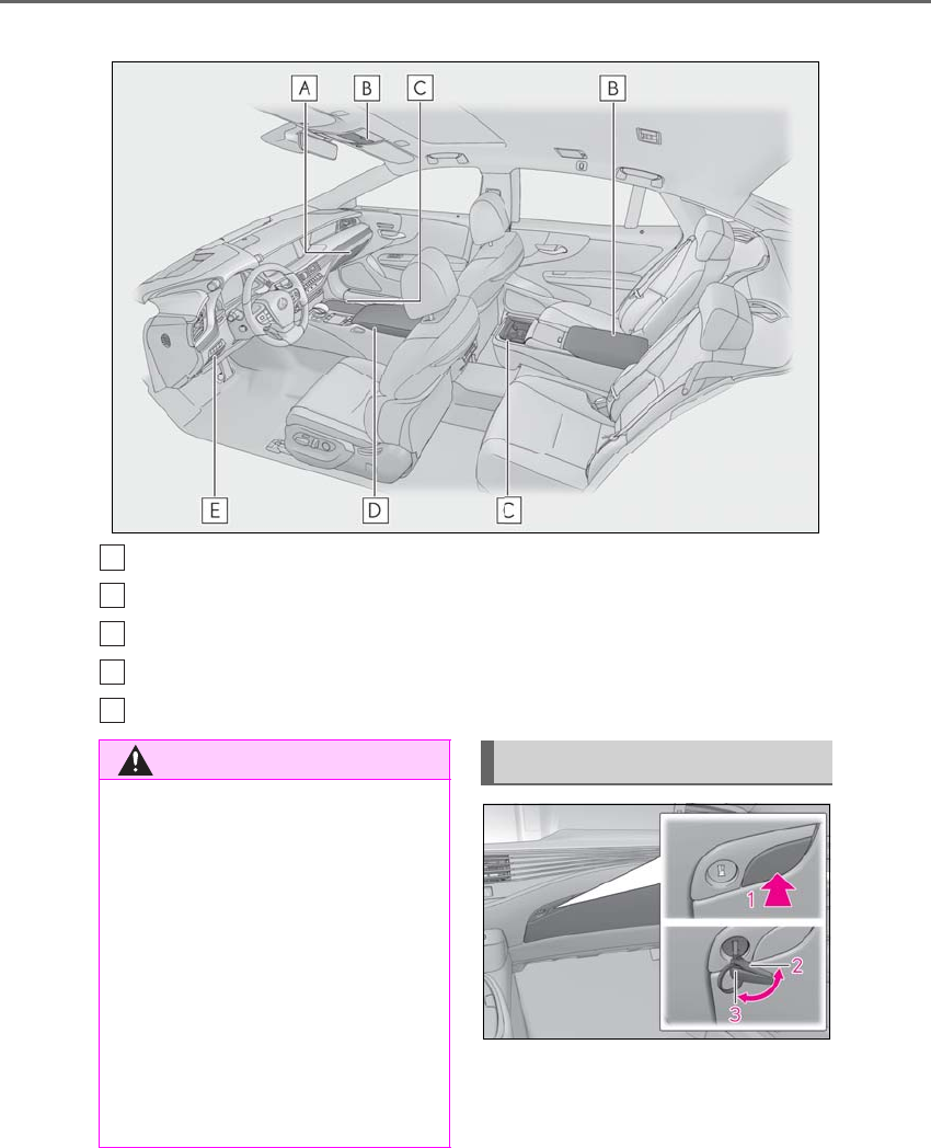
344 5-5. Using the storage features
LS500h_OM_OM50F42U_(U)
Vehicles with power rear seat
Glove box (→P.344)
Auxiliary boxes (→P.347)
Cup holders (→P.345)
Console box (→P.346)
Coin holder (→P.118)
1Open (push button)
2Unlock with the mechanical key
3Lock with the mechanical key
A
B
C
D
E
WARNING
■Items that should not be left in the
storage spaces
Do not leave glasses, lighters or spray
cans in the storage spaces, as this may
cause the following when cabin tempera-
ture becomes high:
●Glasses may be deformed by heat or
cracked if they come into contact with
other stored items.
●Lighters or spray cans may explode. If
they come into contact with other
stored items, the lighter may catch fire
or the spray can may release gas,
causing a fire hazard.
Glove box
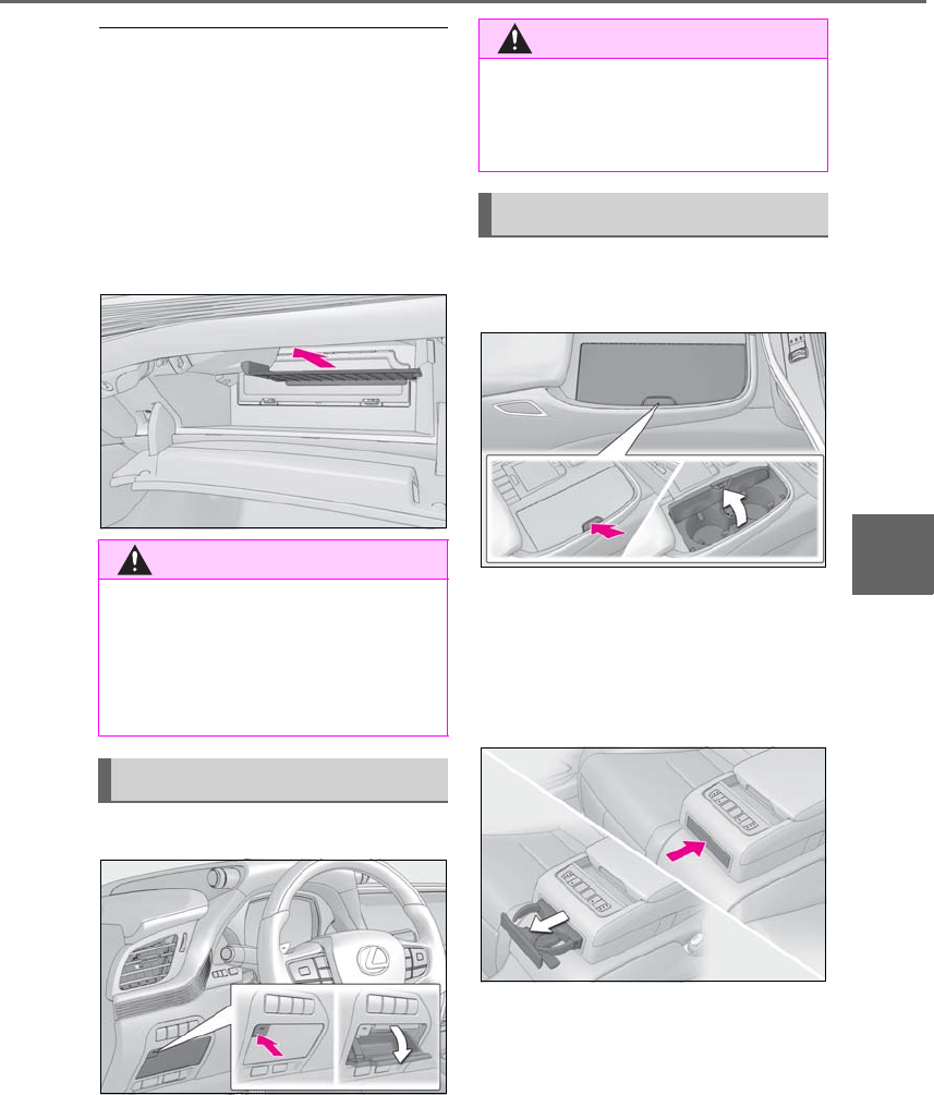
345
5-5. Using the storage features
LS500h_OM_OM50F42U_(U)
5
Interior features
■Glove box light
The glove box light turns on when the tail
lights are on.
■Trunk opener main switch
The trunk opener main switch is located in
the glove box. (→P.118)
■Removing the partition
The partition inside the glove box can be
removed by pulling it.
Push the button.
Front
Press in and release the button.
Rear (vehicles without power rear
seat)
Pull the armrest down then push in the
cup holder trim to extend the cup hold-
ers.
Rear (vehicles with power rear seat)
Press in and release the button.
WARNING
■Caution while driving
Keep the glove box closed. In the event
of sudden braking or sudden swerving,
an accident may occur due to an occu-
pant being struck by the open glove box
or the items stored inside.
Coin holder
WARNING
■Caution while driving
Keep the coin holder closed.
Injuries may result in the event of an acci-
dent or sudden braking.
Cup holders
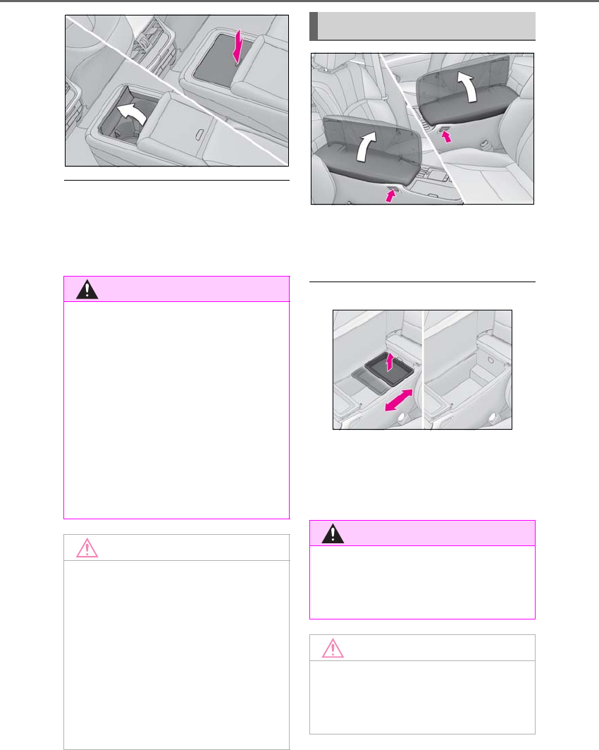
346 5-5. Using the storage features
LS500h_OM_OM50F42U_(U)
■When stowing the rear cup holders
(vehicles without power rear seat)
Stow the cup holder with the armrest down.
The cup holder cannot be stowed if the
armrest is not down.
Press a button to open the console box.
The console box can be opened from
either side.
■Tray in the console box
The tray can be slid and removed.
■Console box light
The console box light turns on when the tail
lights are on.
WARNING
■Items unsuitable for the cup holder
Do not place anything other than cups or
beverage cans in the cup holders.
Inappropriate items must not be stored in
the cup holders even if the lid is closed.
Other items may be thrown out of the
holders in the event of an accident or
sudden braking and cause injury. If possi-
ble, cover hot drinks to prevent burns.
■When not in use
Keep the cup holders closed.
Injuries may result in the event of an acci-
dent or sudden braking.
NOTICE
■To prevent damage to the rear cup
holder (vehicles without power rear
seat)
Stow the cup holder before stowing the
armrest.
■To avoid damaging the power outlet
Close the lid of the power outlet in the
front cup holder when the power outlet is
not in use. Foreign objects or liquids that
enter the power outlet may cause a short
circuit.
Console box
WARNING
■Caution while driving
Keep the console box closed.
Injuries may result in the event of an acci-
dent or sudden braking.
NOTICE
■Tray
Do not insert items exceeding the height
of the tray. Doing so may prevent open-
ing and closing of the lid.
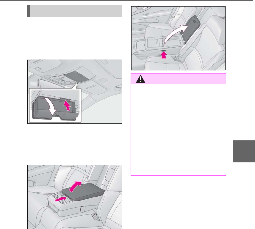
347
5-5. Using the storage features
LS500h_OM_OM50F42U_(U)
5
Interior features
Overhead
Press in the button.
This box is useful for temporarily storing
sunglasses and similar small items.
Rear seat (vehicles without power
rear seat)
Pull the armrest down then push the
knob and lift the lid to open it.
Rear seat (vehicles with power rear
seat)
Pull the armrest down then press the
button to open the lid.
Auxiliary boxes
WARNING
■Caution while driving
Do not leave the auxiliary box open while
driving.
Items may fall out and cause death or
serious injury in case of an accident or
sudden stop.
■Items unsuitable for storing (over-
head)
Do not store items heavier than 0.4 lb.
(0.2 kg).
Doing so may cause the auxiliary box to
open and the items inside may fall out,
resulting in an accident.
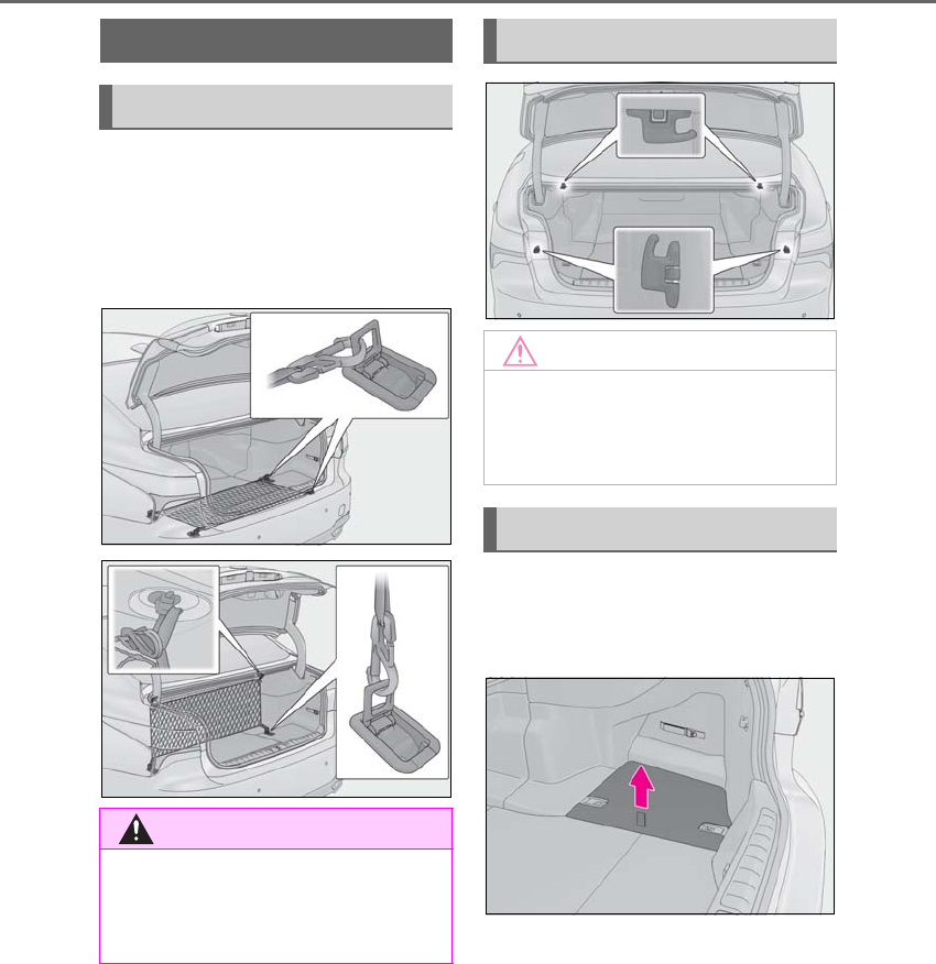
348 5-5. Using the storage features
LS500h_OM_OM50F42U_(U)
The cargo net is provided for securing
loose items on the floor or items inside
the trunk.
Raise the cargo hooks on the floor.
Hook the net on the cargo hooks.
Side
Pull the strap upwards to lift the lug-
gage mat and remove it.
Trunk features
Cargo net (if equipped)
WARNING
■When the cargo net is not in use
To avoid injury, always return the cargo
hooks on the floor to their stowed posi-
tions.
Shopping bag hooks
NOTICE
■To prevent damage to the grocery
bag hooks
Do not hang any object heavier than 11 lb.
(5 kg) on the grocery bag hooks.
Luggage mats
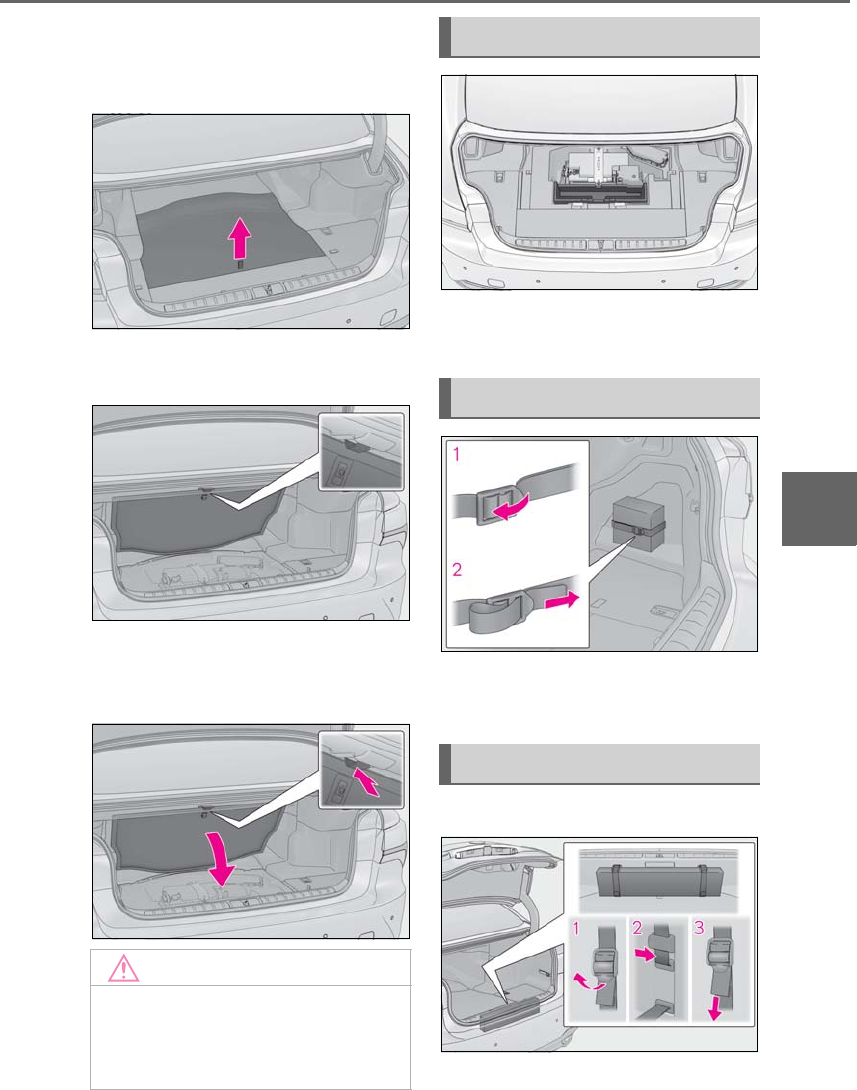
349
5-5. Using the storage features
LS500h_OM_OM50F42U_(U)
5
Interior features
Front
1Pull the strap upwards and lift up
the luggage mat.
2Lift the luggage mat until it engages
with the hook.
To return the luggage mat to its original
position, push the hook and lower the
luggage mat.
Auxiliary boxes are under the luggage
mats.
1Loosen the belt
2Tighten the belt
■Using a belt to hold an object
1Loosen the belt
NOTICE
■To prevent damage to the hook for
the front luggage mat
Do not hang a grocery bag or any other
object from the hook.
Auxiliary boxes
First-aid kit storage belt
Warning reflector storage belt
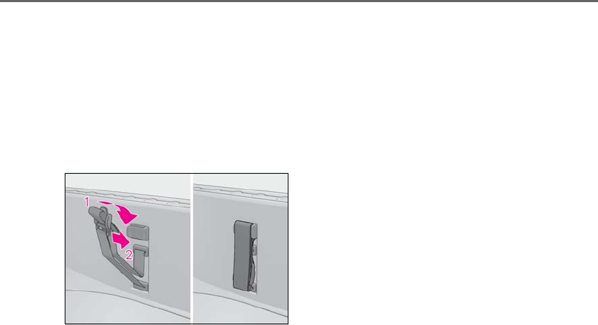
350 5-5. Using the storage features
LS500h_OM_OM50F42U_(U)
2Pass the belt through the clip
3Tighten the belt
Depending on the size and shape of an
object, such as the case of a warning
reflector, the object may not be able to be
secured with the belts or stowed in an aux-
iliary box.
■Stowing the belt
1Fold the belt
2Secure the belt with the clip
To prevent damage to the warning reflec-
tor storage belt when it is not in use, stow
the belt.
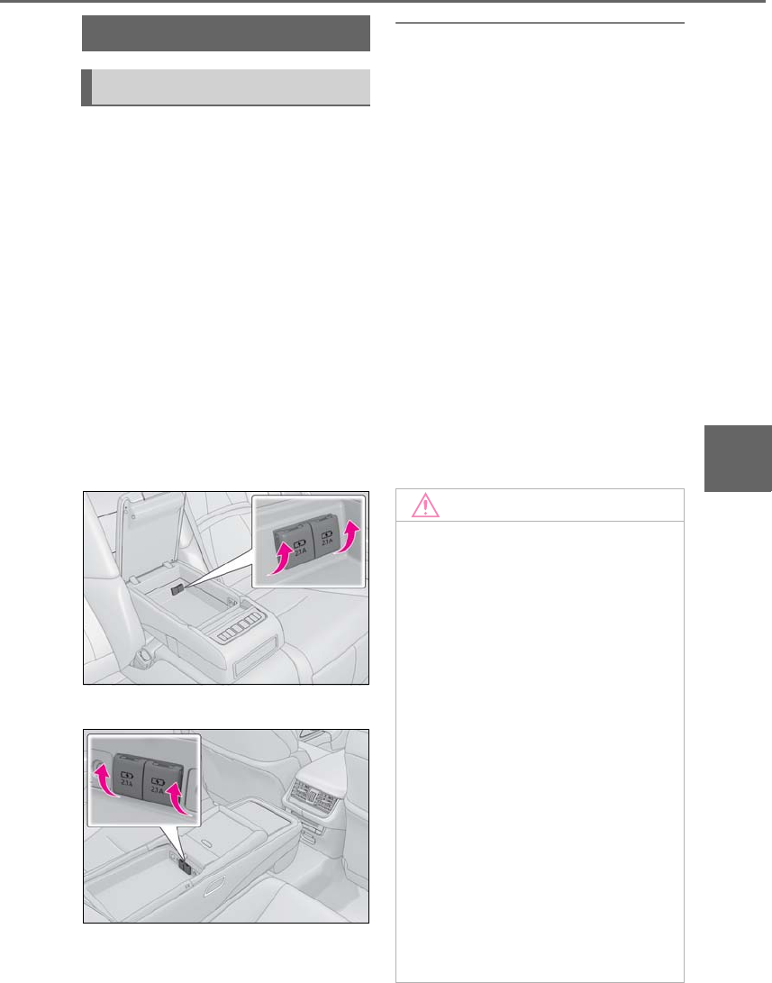
351
5-6. Using the other interior features
LS500h_OM_OM50F42U_(U)
5
Interior features
5-6.Using the ot her interior features
The USB charging ports are used to
supply 2.1 A of electricity at 5 V to
external devices.
The USB charging ports are for
charging only. They are not designed
for data transfer or other purposes.
Depending on the external device, it
may not charge properly. Refer to the
manual included with the device
before using a USB charging port.
■Using the USB charging ports
Open the console box lid and open the
lid.
Vehicles without power rear seat
Vehicles with power rear seat
■The USB charging ports can be used
when
The power switch is in ACCESSORY or
ON mode.
■Situations in which the USB charging
ports may not operate correctly
●If a device which consumes more than 2.1
A at 5 V is connected
●If a device designed to communicate with
a personal computer, such as a USB
memory device, is connected
●If the connected external device is turned
off (depending on device)
●If the temperature inside the vehicle is
high, such as after the vehicle has been
parked in the sun
■About connected external devices
Depending on the connected external
device, charging may occasionally be sus-
pended and then start again. This is not a
malfunction.
Other interior features
USB charging ports
NOTICE
■To prevent damage to the USB
charging ports
●Do not insert foreign objects into the
ports.
●Do not spill water or other liquids into
the ports.
●When the USB charging ports are not
in use, close the lids. If a foreign object
or liquid enters a port may cause a
short circuit.
●Do not apply excessive force to or
impact the USB charging ports.
●Do not disassemble or modify the USB
charging ports.
■To prevent damage to external
devices
●Do not leave external devices in the
vehicle. The temperature inside the
vehicle may become high, resulting in
damage to an external device.
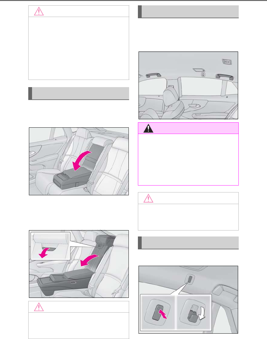
352 5-6. Using the other interior features
LS500h_OM_OM50F42U_(U)
Vehicle without power rear seat
Pull the armrest down for use.
Vehicle with power rear seat
Pull the lock release lever and fold the
rear seatback down.
An assist grip installed on the ceiling
can be used to support your body
while sitting on the seat.
To use the coat hook, push it on.
NOTICE
●Do not push down on or apply unnec-
essary force to an external device or
the cable of an external device while it
is connected.
■To prevent 12-volt battery discharge
Do not use the USB charging ports for a
long period of time with the hybrid sys-
tem stopped.
Armrest
NOTICE
■To prevent damage to the armrest
Do not place too much strain on the arm-
rest.
Assist grips
WARNING
■Assist grip
Do not use the assist grip when getting in
or out of the vehicle or rising from your
seat.
Doing so could damage the assist grip, or
could cause you to injure yourself by fall-
ing over.
NOTICE
■To prevent damage to the assist grip
Do not hang any heavy object or put a
heavy load on the assist grip.
Coat hooks
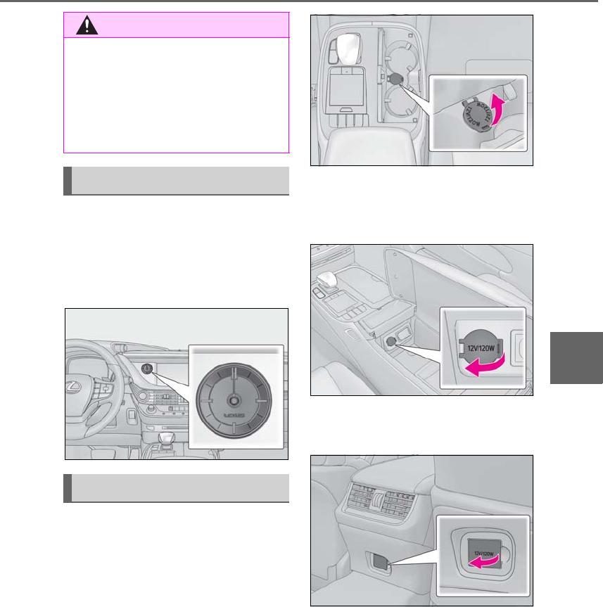
353
5-6. Using the other interior features
LS500h_OM_OM50F42U_(U)
5
Interior features
The GPS clock’s time is automatically
adjusted by utilizing GPS time infor-
mation. For details, refer to “NAVIGA-
TION AND MULTIMEDIA SYSTEM
OWNER’S MANUAL”.
The power outlet can be used for the
following components:
12 V: Accessories that run on less than
10 A.
120 VAC: Accessories that use less
than 100 W.
■12 V
Front
Open the cup holder, and open the lid.
Console box
Open the console box and open the
lid.
Rear (if equipped)
Open the lid.
■120 VAC (if equipped)
Open the lid.
WARNING
■Items that must not be hung on the
hook
Do not hang a coat hanger or other hard
or sharp object on the hook. If the SRS
curtain shield airbags deploy, these items
may become projectiles that cause death
or serious injury.
Clock
Power outlets
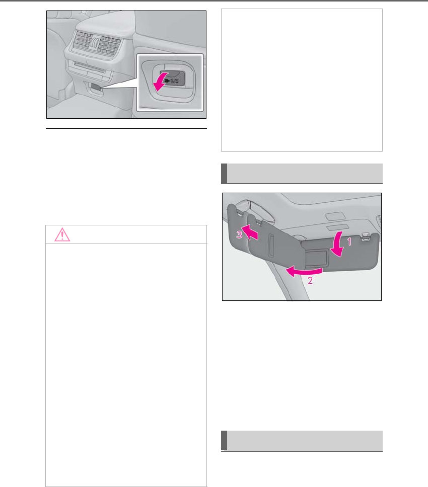
354 5-6. Using the other interior features
LS500h_OM_OM50F42U_(U)
■The power outlet can be used when
●12 V
The power switch is in ACCESSORY or
ON mode.
●120 VAC
The power switch is in ON mode.
1To set the visor in the forward posi-
tion, flip it down.
2To set the visor in the side position,
flip down, unhook, and swing it to
the side.
3To use the side extender, place the
visor in the side position, then slide
it backward.
Front
Slide the cover to open.
The vanity light turns on.
NOTICE
■To avoid damaging the power outlet
Close the power outlet lid when the
power outlet is not in use.
Foreign objects or liquids that enter the
power outlet may cause a short circuit.
■To prevent the fuse from being blown
●12 V
Do not use an accessory that uses more
than 12 V 10 A.
●120 VAC
Do not use a 120 VAC appliance that
requires more than 100 W. If a 120 VAC
appliance that consumes more than 100
W is used, the protection circuit will cut
the power supply.
■To prevent 12-volt battery discharge
Do not use the power outlet longer than
necessary when the hybrid system is off.
■Appliances that may not operate
properly (120 VAC)
The following 120 VAC appliances may
not operate properly even if their power
consumption is under 100 W.
●Appliances with high initial peak watt-
age
●Measuring devices that process pre-
cise data
●Other appliances that require an
extremely stable power supply
Sun visors
Vanity mirrors
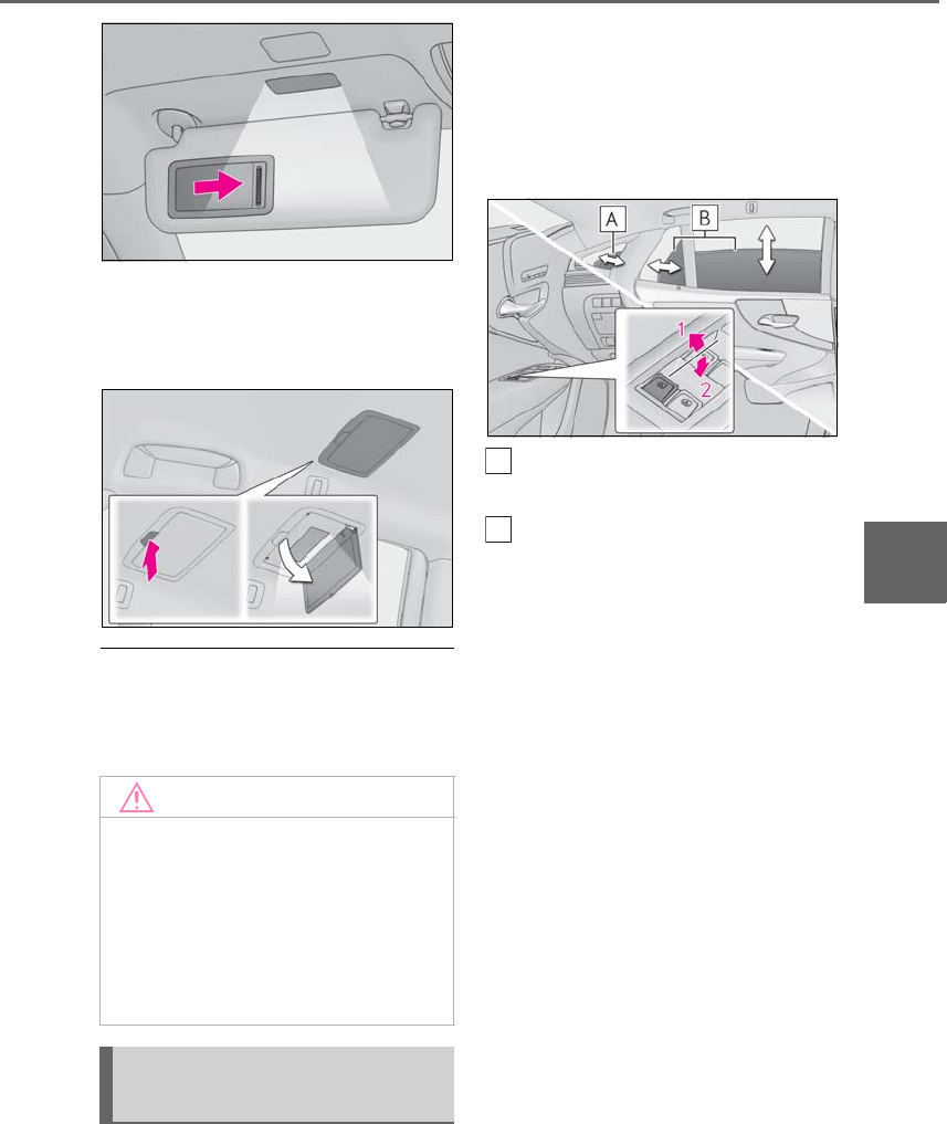
355
5-6. Using the other interior features
LS500h_OM_OM50F42U_(U)
5
Interior features
Rear
Press the button to open.
The vanity light turns on.
■To prevent 12-volt battery discharge
If the vanity lights remain on when the
power switch is turned off, the lights will go
off automatically after 20 minutes.
The rear door/rear quarter sunshades
can be extended and retracted using
the driver’s power window switch and
Rear Multi Operation Panel.
■From driver’s seat
Operate the driver’s power window
switch.
Rear quarter sunshade (if
equipped)
Rear door sunshade
1Extend
2Retract*
*: If the driver’s power window switch is
operated when a rear door sun-
shade/rear quarter sunshade is
retracted or being retracted, the rear
window will open.
■From rear seat
The rear seat power window switches
cannot be used to extend the rear door
sunshades/rear quarter sunshades.
1Display the home screen and then
touch “Rear Shade/Lamp”.
(→P.318)
NOTICE
■When not in use
Keep the rear vanity mirror closed.
■To prevent the 12-volt battery from
being discharged
Do not leave the vanity lights on for
extended periods while the hybrid sys-
tem is off.
Rear door/rear quarter sun-
shades (if equipped)
A
B
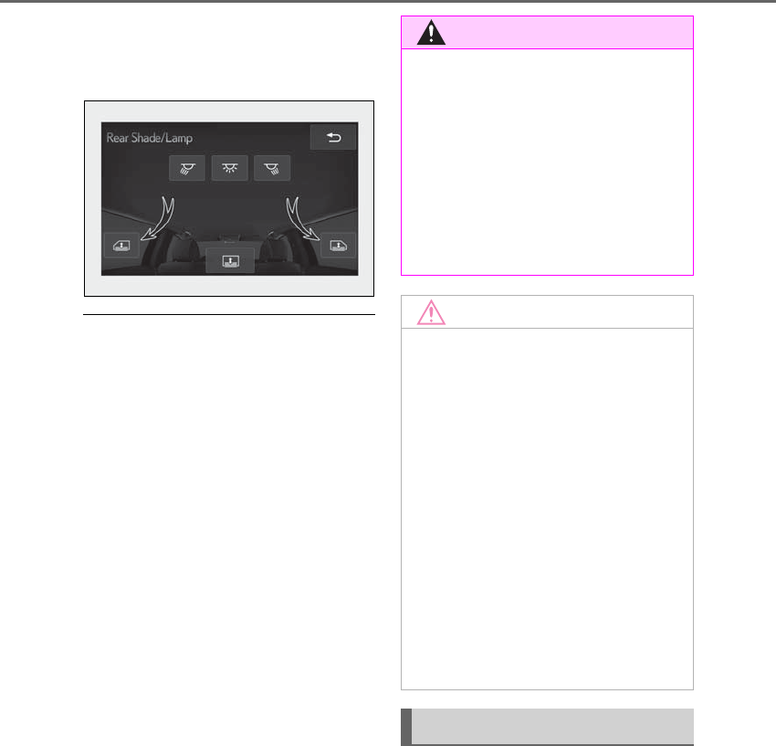
356 5-6. Using the other interior features
LS500h_OM_OM50F42U_(U)
2To fully extend/retract a rear
door/rear quarter sunshade, touch
the respective button.
■Operating conditions
●The power switch is in ON mode.
●The rear side windows are fully closed.
■Operation of rear door sunshades/rear
quarter sunshades when extended
If a rear door power window switch is oper-
ated when the rear door sunshade/rear
quarter sunshade is extended, the rear door
sunshade/rear quarter sunshade will retract
while the rear window is opening.
■Operating the rear door/rear quarter
sunshades after turning the hybrid sys-
tem off
The rear door/rear quarter sunshades can
be operated for a while even after the
power switch is turned to ACCESSORY
mode or off.
However, they cannot be operated using
the driver’s power window switch after
either front door is opened.
■Jam protection function
If an object becomes caught between a rear
door sunshade and the window frame, the
rear door sunshade will stop and then
extend/retract slightly.
■When reconnecting the 12-volt battery
The rear door/rear quarter sunshades will
always be retracted the first time the button
is pressed.
The rear sunshade can be raised and
lowered by operating any of the
switches shown below.
■From front seat
Extend/retract
WARNING
■When the rear door/rear quarter sun-
shades are being extended or
retracted
Do not place fingers or other objects in
the shade mechanism or in the opening
as injury may result.
■Jam protection function
Never use any part of your body to inten-
tionally activate the jam protection func-
tion.
NOTICE
■To ensure normal operation of the
sunshades
Observe the following precautions:
●Do not place excessive load on the
motor or other components.
●Do not place objects where they may
hinder opening and closing opera-
tions.
●Do not attach items to the rear
door/rear quarter sunshades.
●Keep the opening clean and clear of
obstructions.
●Do not operate the rear door/rear
quarter sunshades continuously for
long periods of time.
Rear sunshade (if equipped)
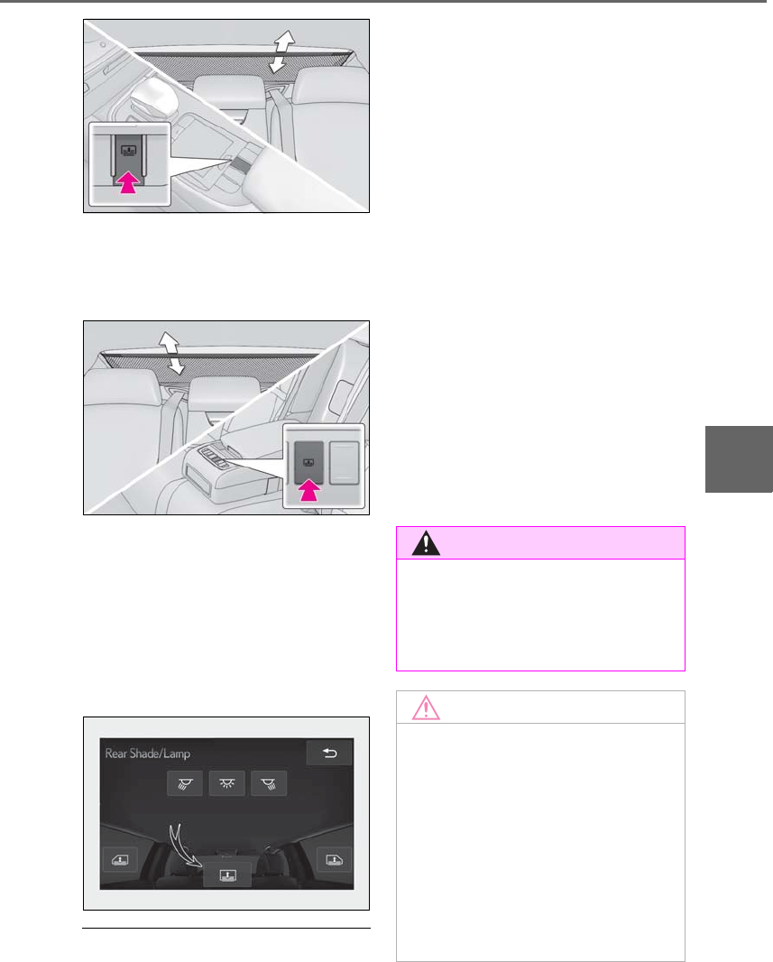
357
5-6. Using the other interior features
LS500h_OM_OM50F42U_(U)
5
Interior features
■From rear seat
Vehicles without power rear seat
Extend/retract
Vehicles with power rear seat
1Display the home screen and then
touch “Rear Shade/Lamp”.
(→P.318)
2To fully extend/retract a rear door
sunshade, touch the respective but-
ton.
■The rear sunshade can be used when
The power switch is in ON mode.
■Operating the rear sunshade after turn-
ing the hybrid system off
The rear sunshade can be operated for a
while even after the power switch is
switched to ACCESSORY mode or turned
off.
■Reverse operation feature
To ensure adequate rear visibility, the rear
sunshade automatically lowers when the
shift position is shifted to R.
However, the rear sunshade is raised again
if any of the following occurs:
●The switch is pressed again.
●The shift position is shifted to P.
●The shift position is shifted out of P and R,
and the vehicle reaches a speed of 9 mph
(15 km/h).
If the hybrid system is turned off when the
rear sunshade has been lowered due to the
reverse operation feature, it will not be
raised even when the hybrid system is
turned on again and the vehicle reaches a
speed of 9 mph (15 km/h). To raise the sun-
shade again, press the switch.
WARNING
■When the rear sunshade is being
raised or lowered
Do not place fingers or other objects in
the shade mechanism or in the opening
as injury may result.
NOTICE
■To ensure normal operation of the
sunshade
Observe the following precautions:
●Do not place excessive load on the
motor or other components.
●Do not place objects where they may
hinder opening and closing opera-
tions.
●Do not attach items to the rear sun-
shade.
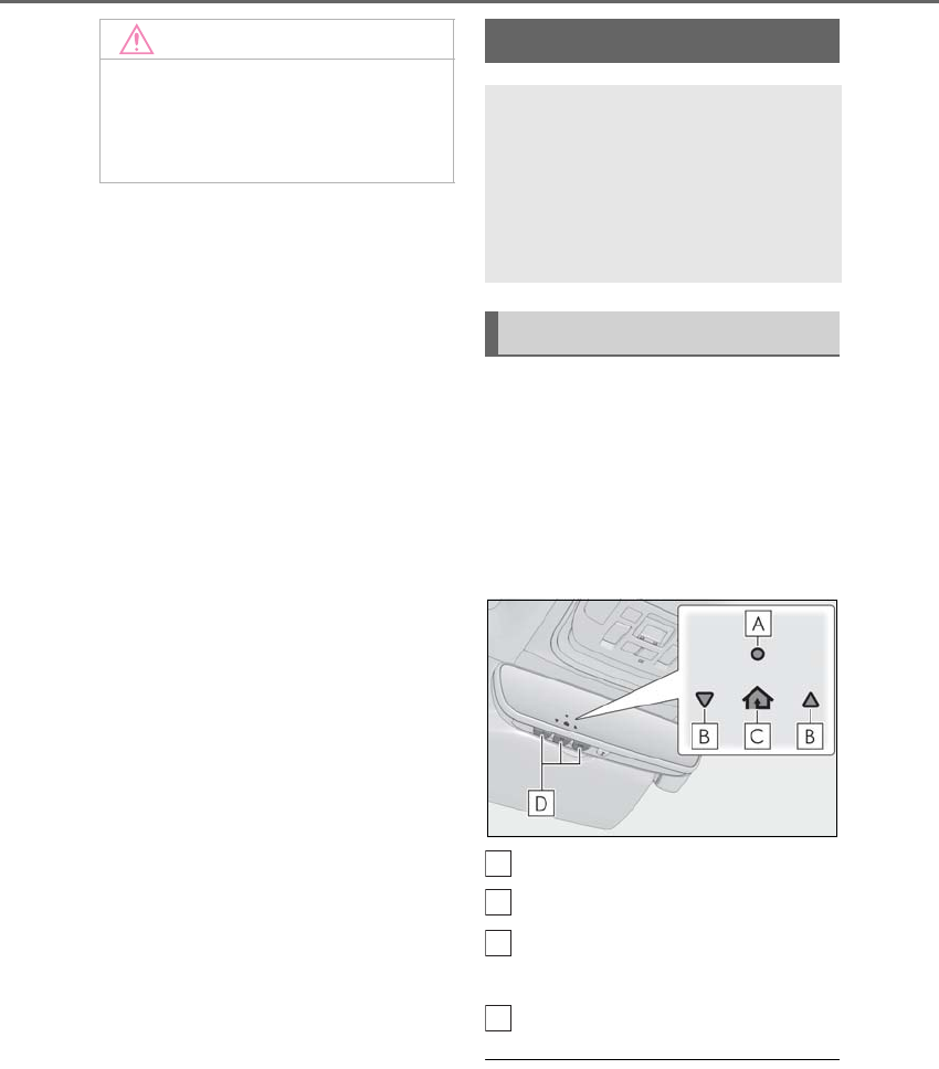
358 5-6. Using the other interior features
LS500h_OM_OM50F42U_(U)
The HomeLink® wireless control sys-
tem in your vehicle has 3 buttons which
can be programmed to operate 3 dif-
ferent devices. Refer to the program-
ming methods on the following pages
to determine the method which is
appropriate for the device.
HomeLink® indicator light
Garage door operation indicators
HomeLink® icon
Illuminates while HomeLink® is operating.
Buttons
■Codes stored in the HomeLink® mem-
ory
●The registered codes are not erased even
if the 12-volt battery cable is discon-
nected.
NOTICE
●Keep the opening clean and clear of
obstructions.
●Do not operate the rear sunshade con-
tinuously for long periods of time.
Garage door opener
The garage door opener can be
programmed using the Home-
Link® to operate garage doors,
gates, entry doors, door locks,
home lighting systems, security sys-
tems, and other devices.
System components
A
B
C
D
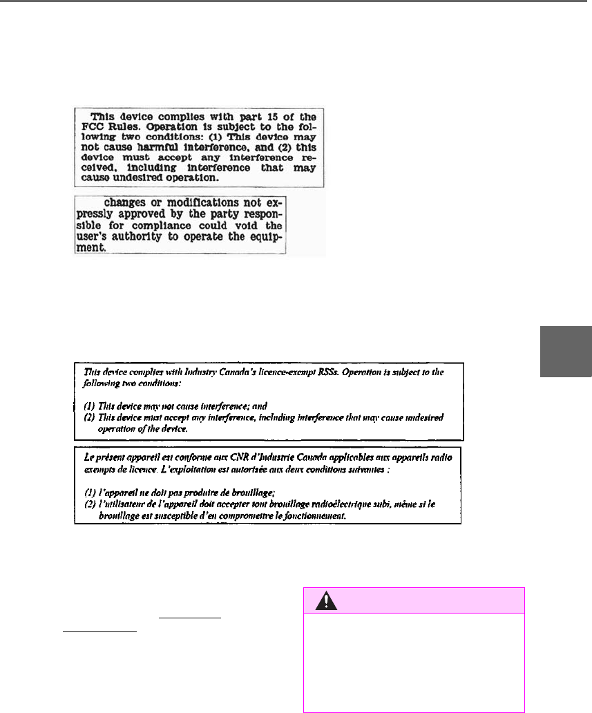
359
5-6. Using the other interior features
LS500h_OM_OM50F42U_(U)
5
Interior features
●If learning failed when registering a dif-
ferent code to a HomeLink® button that
already has a code registered to it, the
already registered code will not be
erased.
■Certification for the garage door opener
For vehicles sold in the U.S.A., Hawaii, Guam and Puerto Rico
For vehicles sold in Canada
■When support is necessary
Visit on the web at www.home-
link.com/lexus or call 1-800-355-3515.
WARNING
■When programming a garage door or
other remote control device
The garage door or other device may
operate, so ensure people and objects
are out of danger to prevent potential
harm.
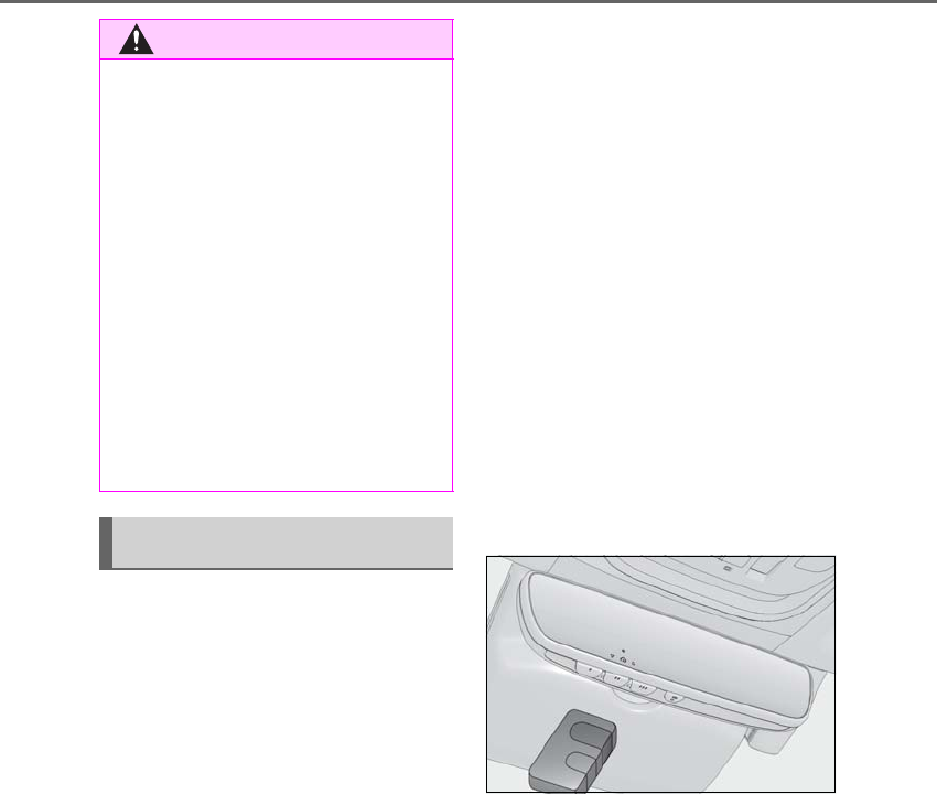
360 5-6. Using the other interior features
LS500h_OM_OM50F42U_(U)
■Before programming HomeLink®
-During programming, it is possible
that garage doors, gates, or other
devices may operate. For this rea-
son, make sure that people and
objects are clear of the garage door
or other devices to prevent injury or
other potential harm.
-It is recommended that a new bat-
tery be placed in the remote control
transmitter for more accurate pro-
gramming.
-Garage door opener motors manu-
factured after 1995 may be
equipped with rolling code protec-
tion. If this is the case, you may need
a stepladder or other sturdy, safe
device to reach the “Learn” or
“Smart” button on the garage door
opener motor.
■Programming HomeLink®
Steps 1 through 3 must be performed
within 60 seconds, otherwise the indi-
cator light will stop flashing and pro-
gramming will not be able to be
completed.
1Press and release the HomeLink®
button you want to program and
check that the HomeLink® indica-
tor light flashes (orange).
2Point the remote control transmit-
ter for the device at the rear view
mirror, 1 to 3 in. (25 to 75 mm)
from the HomeLink® buttons.
Keep the HomeLink® indicator light in
view while programming.
3Program a device.
Programming a device other than
an entry gate (for U.S.A. owners)
Press and hold the handheld transmit-
ter button until the HomeLink® indica-
tor light changes from slowly flashing
orange to rapidly flashing green (roll-
ing code) or continuously lit green
(fixed code), then release the button.
WARNING
■Conforming to federal safety stan-
dards
Do not use the HomeLink® compatible
transceiver with any garage door opener
or device that lacks safety stop and
reverse features as required by federal
safety standards.
This includes any garage door that can-
not detect an interfering object. A door
or device without these features
increases the risk of death or serious
injury.
■When operating or programming
HomeLink®
Never allow a child to operate or play
with the HomeLink® buttons.
Programming the HomeLink®
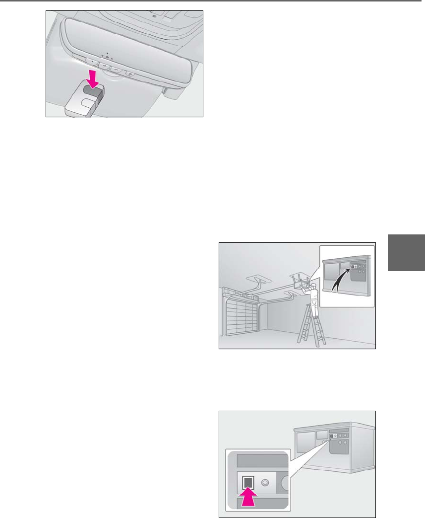
361
5-6. Using the other interior features
LS500h_OM_OM50F42U_(U)
5
Interior features
Programming an entry gate (for
U.S.A. owners)/Programming a
device in the Canadian market
Press and release the remote control
transmitter button at 2 second inter-
vals, repeatedly, until the HomeLink®
indicator light changes from slowly
flashing (orange) to rapidly flashing
(green) (rolling code) or continuously
lit (green) (fixed code).
4Test the HomeLink® operation by
pressing the newly programmed
button and observing the indicator
light:
-Indicator light illuminates: Program-
ming of a fixed code device has
completed. The garage door or
other device should operate when a
HomeLink® button is pressed and
released.
-Indicator light flashes rapidly: The
garage door opener motor or other
device is equipped with a rolling
code. To complete programming,
firmly press and hold the Home-
Link® button for 2 seconds then
release it.
-If the garage door or other device
does not operate, proceed to “Pro-
gramming a rolling code system”.
5Repeat the steps above to program
another device for any of the
remaining HomeLink® buttons.
■Programming a rolling code sys-
tem
2 or more people may be necessary to
complete rolling code programming.
1Locate the “Learn” or “Smart” but-
ton on the garage door opener
motor in the garage.
This button can usually be found where the
hanging antenna wire is attached to the
unit. The name and color of the button may
vary by manufacturer. Refer to the owner’s
manual supplied with the garage door
opener motor for details.
2Press and release the “Learn” or
“Smart” button.
Perform 3 within 30 seconds after per-
forming 2.
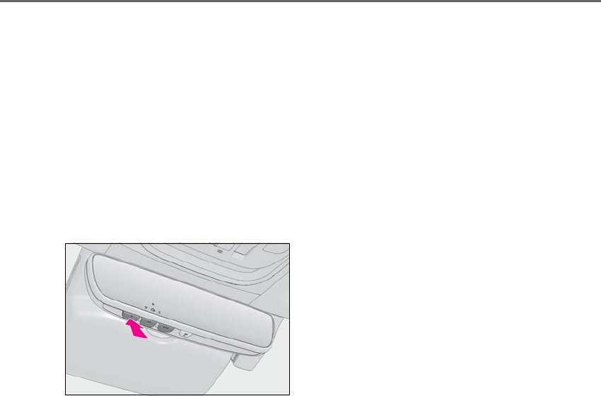
362 5-6. Using the other interior features
LS500h_OM_OM50F42U_(U)
3Press and hold the desired Home-
Link® button (inside the vehicle)
for 2 seconds and release it. Repeat
this sequence (press/hold/release)
up to 3 times to complete pro-
gramming.
If the garage door opener motor
operates when the HomeLink®
button is pressed, the garage door
opener motor recognizes the
HomeLink® signal.
■Enabling 2-way communication
with a garage door (only available
for compatible devices)
When enabled, 2-way communication
allows you to check the status of the
opening and closing of a garage door
through indicators in your vehicle.
2-way communication is only available
if the garage door opener motor used
is a compatible device. (To check
device compatibility, refer to
www.homelink.com.)
1Within 5 seconds after program-
ming the garage door opener has
been completed, if the garage door
opener motor is trained to Home-
Link®, both garage door operation
indicators will flash rapidly (green)
and the light on the garage door
opener motor will blink twice, indi-
cating that 2-way communication is
enabled.
If the indicators do not flash, perform 2 and
3 within the first 10 presses of the Home-
Link® button after programming has been
completed.
2Press a programmed HomeLink®
button to operate a garage door.
3Within 1 minute of pressing the
HomeLink® button, after the
garage door operation has
stopped, press the “Learn” or
“Smart” button on the garage door
opener motor. Within 5 seconds of
the establishment of 2-way com-
munication with the garage door
opener, both garage door opera-
tion indicators in the vehicle will
flash rapidly (green) and the light
on the garage door opener motor
will blink twice, indicating that
2-way communication is enabled.
■Reprogramming a single Home-
Link® button
When the following procedure is per-
formed, buttons which already have
devices registered to them can be
overwritten:
1With one hand, press and hold the
desired HomeLink® button.
2When the HomeLink® indicator
starts flashing (orange), continue to
hold the HomeLink® button and
perform “Programming Home-
Link®” 1 (it takes 20 seconds for
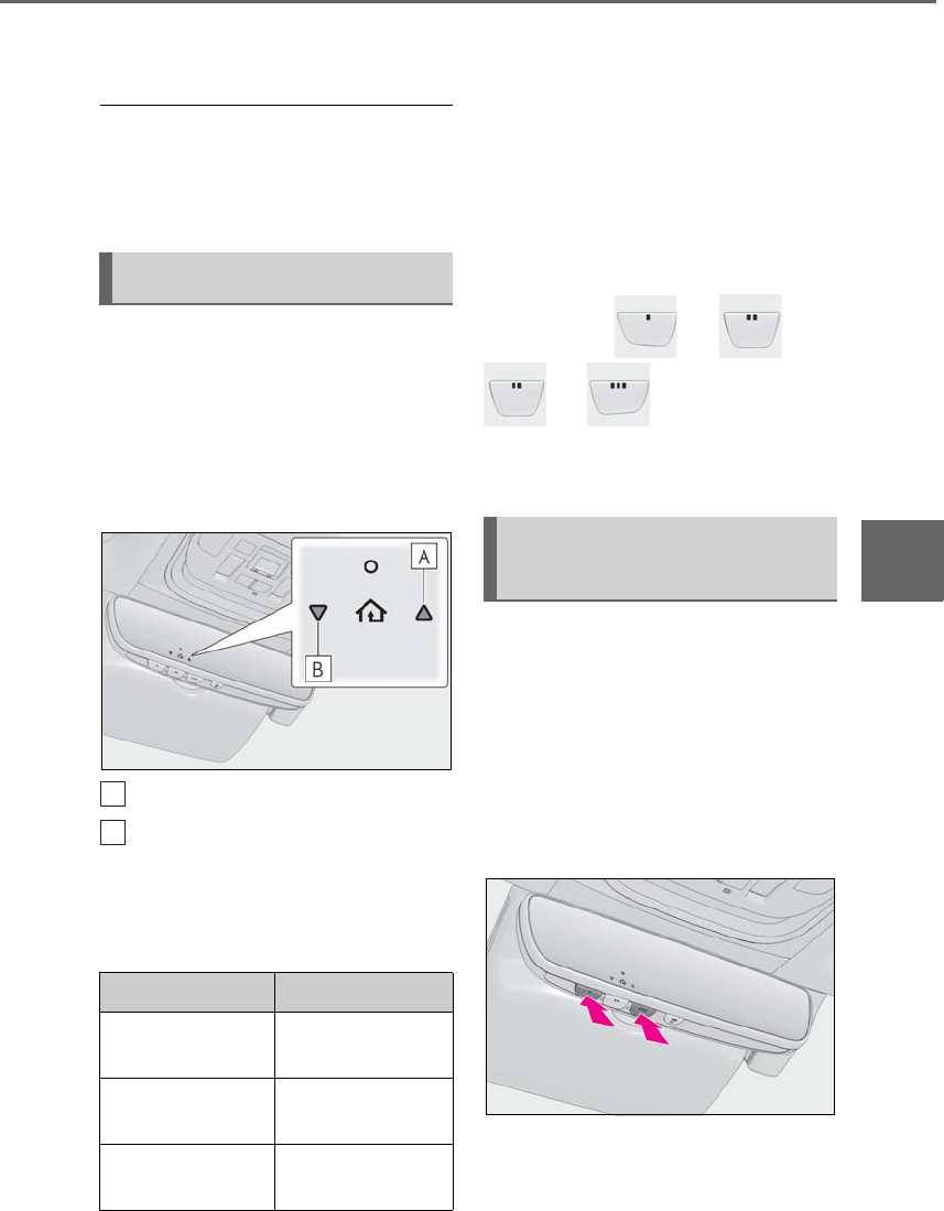
363
5-6. Using the other interior features
LS500h_OM_OM50F42U_(U)
5
Interior features
the HomeLink® indicator to start
flashing).
■Before programming
●Install a new battery in the transmitter.
●The battery side of the transmitter must
be pointed away from the HomeLink®.
Press the appropriate HomeLink®
button. The HomeLink® indicator light
should turn on.
The status of the opening and closing
of a garage door is shown by the indi-
cators.
Opening
Closing
This function is only available if the garage
door opener motor used is a compatible
device. (To check device compatibility,
refer to www.homelink.com.)
The indicators can operate within
approximately 820 ft. (250 m) of the
garage door. However, if there are
obstructions between the garage door
and the vehicle, such as houses and
trees, feedback signals from the
garage door may not be received.
To recall the previous door operation
status, press and release either Home-
Link® buttons and or
and simultaneously. The
last recorded status will be displayed
for 3 seconds.
Press and hold the 2 outside buttons
for 10 seconds until the HomeLink®
indicator light changes from continu-
ously lit (orange) to rapidly flashing
(green).
If you sell your vehicle, be sure to erase the
programs stored in the HomeLink® mem-
ory.
Operating HomeLink®
Color Status
Orange (flashing) Currently open-
ing/closing
Green Opening/closing has
completed
Red (flashing) Feedback signals
cannot be received
A
B
Erasing the entire HomeLink®
memory (all three codes)
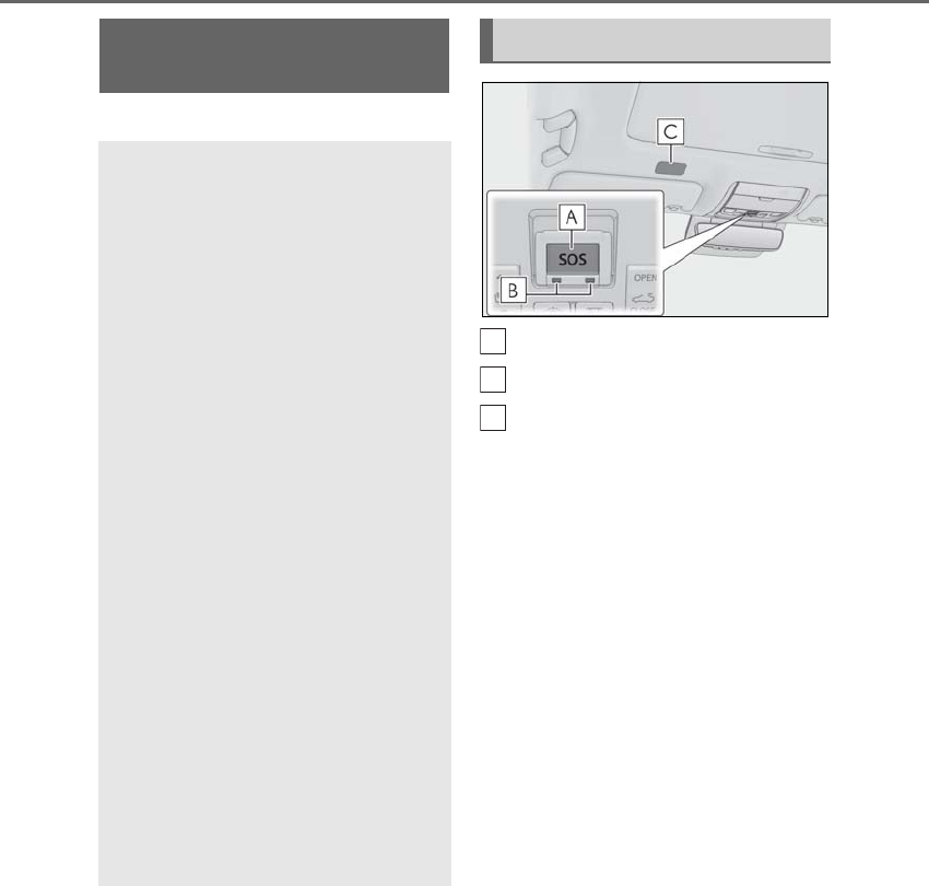
364 5-6. Using the other interior features
LS500h_OM_OM50F42U_(U)
*:If equipped
“SOS” button
LED light indicators
Microphone
Lexus Enform Safety Con-
nect*
Safety Connect is a subscrip-
tion-based telematics service that
uses Global Positioning System
(GPS) data and embedded cellular
technology to provide safety and
security features to subscribers.
Safety Connect is supported by
Lexus’ designated response center,
which operates 24 hours per day, 7
days per week.
Safety Connect service is available
by subscription on select, telemat-
ics hardware-equipped vehicles.
By using the Safety Connect ser-
vice, you are agreeing to be bound
by the Telematics Subscription Ser-
vice Agreement and its Terms and
Conditions, as in effect and
amended from time to time, a cur-
rent copy of which is available at
Lexus.com. All use of the Safety
Connect service is subject to such
then-applicable Terms and Condi-
tions.
System components
A
B
C
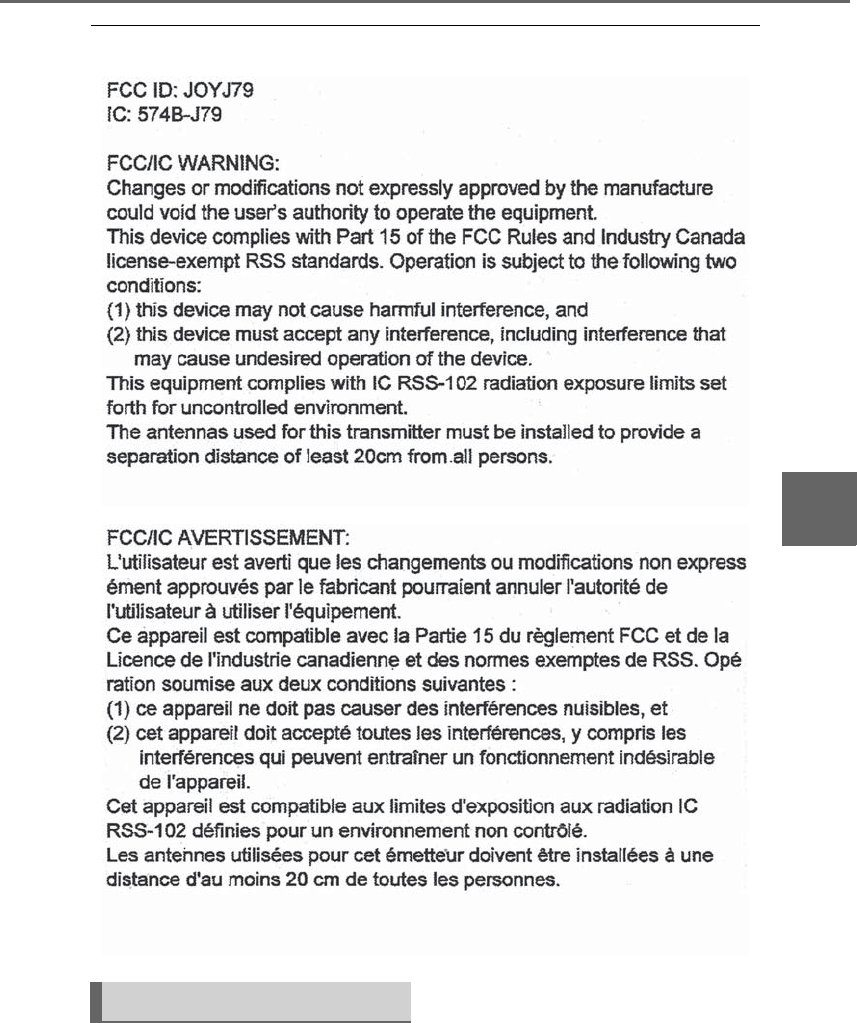
365
5-6. Using the other interior features
LS500h_OM_OM50F42U_(U)
5
Interior features
■Certification for Lexus Enform
Subscribers have the following Safety
Connect services available:
-Automatic Collision Notification*
Helps drivers receive necessary response
from emergency service providers.
(→P.367)
Services

366 5-6. Using the other interior features
LS500h_OM_OM50F42U_(U)
*: U.S. Patent No. 7,508,298 B2
-Stolen Vehicle Location
Helps drivers in the event of vehicle theft.
(→P.367)
-Emergency Assistance Button
(“SOS”)
Connects drivers to response-center sup-
port. (→P.367)
-Enhanced Roadside Assistance
Provides drivers various on-road assis-
tance. (→P.367)
After you have signed the Telematics
Subscription Service Agreement and
are enrolled, you can begin receiving
services.
A variety of subscription terms is avail-
able for purchase. Contact your Lexus
dealer, call 1-800-25-LEXUS
(1-800-255-3987) in the Unites
States (1-877-539-8777 in Puerto
Rico, 1-800-26-LEXUS in Canada) or
push the “SOS” button in your vehicle
for further subscription details.
■Safety Connect Services Information
●Phone calls using the vehicles Blue-
tooth® technology will not be possible
during Safety Connect.
●Safety Connect is available beginning Fall
2009 on select Lexus models (in the
contiguous United States only). Contact
with the Safety Connect response center
is dependent upon the telematics device
being in operative condition, cellular con-
nection availability, and GPS satellite sig-
nal reception, which can limit the ability to
reach the response center or receive
emergency service support. Enrollment
and Telematics Subscription Service
Agreement required. A variety of sub-
scription terms is available; charges vary
by subscription term selected and loca-
tion.
●Automatic Collision Notification, Emer-
gency Assistance and Stolen Vehicle
Location will function in the United
States, including Hawaii and Alaska,
Puerto Rico and in Canada, and
Enhanced Roadside Assistance will func-
tion in the United States, Puerto Rico and
in Canada.
●Automatic Collision Notification, Emer-
gency Assistance, Stolen Vehicle Loca-
tion and Enhanced Roadside Assistance
will not function in the United States Vir-
gin Islands.
No Safety Connect services will function
outside of the United States in countries
other than Canada.
For vehicles first sold in the USVI, no
Safety Connect services will function in
and outside the United States Virgin
Islands.
●Safety Connect services are not subject
to section 255 of the Telecommunica-
tions Act and the device is not TTY com-
patible.
■Languages
The Safety Connect response center will
offer support in multiple languages. The
Safety Connect system will offer voice
prompts in English, Spanish, and French.
Please indicate your language of choice
when enrolling.
■When contacting the response center
You may be unable to contact the response
center if the network is busy.
When the power switch is turned to
ON mode, the red indicator light
comes on for 2 seconds then turns off.
Afterward, the green indicator light
comes on, indicating that the service is
active.
Subscription
Safety Connect LED light Indi-
cators

367
5-6. Using the other interior features
LS500h_OM_OM50F42U_(U)
5
Interior features
The following indicator light patterns
indicate specific system usage condi-
tions:
-Green indicator light on = Active
service
-Green indicator light flashing =
Safety Connect call in process
-Red indicator light (except at vehi-
cle start-up) = System malfunction
(contact your Lexus dealer)
-No indicator light (off) = Safety
Connect service not active
■Automatic Collision Notification
In case of either airbag deployment or
severe rear-end collision, the system is
designed to automatically call the
response center. The responding agent
receives the vehicle’s location and
attempts to speak with the vehicle
occupants to assess the level of emer-
gency. If the occupants are unable to
communicate, the agent automatically
treats the call as an emergency, con-
tacts the nearest emergency services
provider to describe the situation, and
requests that assistance be sent to the
location.
■Stolen Vehicle Location
If your vehicle is stolen, Safety Connect
can work with local authorities to assist
them in locating and recovering the
vehicle. After filing a police report, call
the Safety Connect response center at
1-800-25-LEXUS
(1-800-255-3987) and follow the
prompts for Safety Connect to initiate
this service.
In addition to assisting law enforce-
ment with recovery of a stolen vehicle,
Safety-Connect-equipped vehicle
location data may, under certain cir-
cumstances, be shared with third par-
ties to locate your vehicle. Further
information is available at Lexus.com.
■Emergency Assistance Button
(“SOS”)
In the event of an emergency on the
road, push the “SOS” button to reach
the Safety Connect response center.
The answering agent will determine
your vehicle’s location, assess the
emergency, and dispatch the neces-
sary assistance required.
If you accidentally press the “SOS” button,
tell the response-center agent that you are
not experiencing an emergency.
■Enhanced Roadside Assistance
Enhanced Roadside Assistance adds
GPS data to the already included war-
ranty-based Lexus roadside service.
Subscribers can press the “SOS” but-
ton to reach a Safety Connect
response-center agent, who can help
with a wide range of needs, such as:
towing, flat tire, fuel delivery, etc. For a
description of the Roadside Assistance
services and their limitations, please
see the Safety Connect Terms and
Conditions, which are available at
Lexus.com.
Safety Connect services

368 5-6. Using the other interior features
LS500h_OM_OM50F42U_(U)
Important! Read this information about
exposure to radio frequency signals
before using Safety Connect;
The Safety Connect system installed in
your vehicle is a low-power radio trans-
mitter and receiver. It receives and also
sends out radio frequency (RF) signals.
In August 1996, the Federal Commu-
nications Commission (FCC) adopted
RF exposure guidelines with safety lev-
els for mobile wireless phones. Those
guidelines are consistent with the
safety standards previously set by the
following U.S. and international stan-
dards bodies.
-ANSI (American National Stan-
dards Institute) C95.1 [1992]
-NCRP (National Council on Radia-
tion Protection and Measurement)
Report 86 [1986]
-ICNIRP (International Commission
on Non-Ionizing Radiation Protec-
tion) [1996]
Those standards were based on com-
prehensive and periodic evaluations of
the relevant scientific literature. Over
120 scientists, engineers, and physi-
cians from universities, and govern-
ment health agencies and industries
reviewed the available body of
research to develop the ANSI Stan-
dard (C95.1).
The design of Safety Connect com-
plies with the FCC guidelines in addi-
tion to those standards.
Safety information for Safety
Connect

369
LS500h_OM_OM50F42U_(U)
6
6
Maintenance and care
Maintenance and care
.
6-1. Maintenance and care
Cleaning and protecting the vehi-
cle exterior................................370
Cleaning and protecting the vehi-
cle interior.................................373
6-2. Maintenance
Maintenance requirements
........................................................378
General maintenance.............379
Emission inspection and mainte-
nance (I/M) programs.........382
6-3. Do-it-yourself maintenance
Do-it-yourself service precautions
........................................................383
Hood...............................................385
Positioning a floor jack............385
Engine compartment...............387
12-volt battery.............................393
Tires ................................................395
Replacing the tire......................405
Tire inflation pressure..............408
Wheels............................................410
Air conditioning filter................. 411
Electronic key battery..............413
Checking and replacing fuses
.........................................................414
Light bulbs.....................................417

370 6-1. Maintenance and care
LS500h_OM_OM50F42U_(U)
6-1.Maintenance and care
-Working from top to bottom, liber-
ally apply water to the vehicle body,
wheel wells and underside of the
vehicle to remove any dirt and dust.
-Wash the vehicle body using a
sponge or soft cloth, such as a
chamois.
-For hard-to-remove marks, use car
wash soap and rinse thoroughly with
water.
-Wipe away any water.
-Wax the vehicle when the water-
proof coating deteriorates.
If water does not bead on a clean surface,
apply wax when the vehicle body is cool.
■Self-restoring coat
The vehicle body has a self-restoring coat-
ing that is resistant to small surface
scratches caused in a car wash etc.
●The coating lasts for 5 to 8 years from
when the vehicle is delivered from the
plant.
●The restoration time differs depending on
the depth of the scratch and outside tem-
perature.
The restoration time may become
shorter when the coating is warmed by
applying warm water.
●Deep scratches caused by keys, coins,
etc. cannot be restored.
●Do not use wax that contains abrasives.
■Automatic car washes
●Before washing the vehicle:
• Fold the mirrors
• Turn off the power trunk opener and
closer
Start washing from the front of the vehicle.
Extend the mirrors before driving.
●Brushes used in automatic car washes
may scratch the vehicle surface and harm
your vehicle’s paint.
■High pressure car washes
●Do not allow the nozzles of the car wash
to come within close proximity of the win-
dows and the air suspension unit (if
equipped).
●Before using the car wash, check that the
fuel filler door on your vehicle is closed
properly.
■When using a car wash
If the door handle becomes wet while the
electronic key is within the effective range,
the door may lock and unlock repeatedly. In
that case, follow the following correction
procedures to wash the vehicle:
●Place the key in a position 6 ft. (2 m) or
more separate from the vehicle while the
vehicle is being washed. (Take care to
ensure that the key is not stolen.)
●Set the electronic key to battery-saving
mode to disable the smart access system
with push-button start. (→P.120)
■Aluminum wheels
●Remove any dirt immediately by using a
neutral detergent.
●Wash detergent off with water immedi-
ately after use.
●To protect the paint from damage, make
sure to observe the following precau-
tions.
• Do not use acidic, alkaline or abrasive
detergent
• Do not use hard brushes
• Do not use detergent on the wheels when
they are hot, such as after driving or park-
ing in hot weather
Cleaning and protecting the
vehicle exterior
Perform cleaning in a manner
appropriate to each component
and its material.
Cleaning instructions
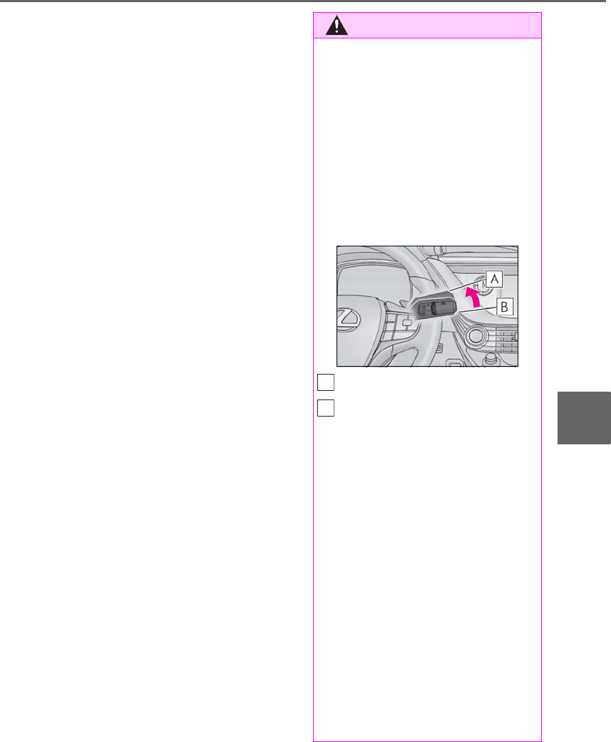
371
6-1. Maintenance and care
LS500h_OM_OM50F42U_(U)
6
Maintenance and care
■Brake caliper coating (F SPORT mod-
els)
●When using detergent, use neutral deter-
gent. Do not use hard brushes or abra-
sive cleaners, as they will damage the
coating.
●Do not use detergent on the brake cali-
pers when they are hot.
●Wash detergent off immediately after
use.
■Bumpers and side moldings
Do not scrub with abrasive cleaners.
■Front side windows water-repellent
coating (if equipped)
●The following precautions can extend the
effectiveness of the water-repellent coat-
ing.
• Remove any dirt, etc. from the front side
windows regularly.
• Do not allow dirt and dust to accumulate
on the windows for a long period.
Clean the windows with a soft, damp
cloth as soon as possible.
• Do not use wax or glass cleaners that
contain abrasives when cleaning the win-
dows.
• Do not use any metallic objects to
remove condensation build up.
●When the water-repellent performance
has become insufficient, the coating can
be repaired. Contact your Lexus dealer.
■Plated portions
If dirt cannot be removed, clean the parts as
follows:
●Use a soft cloth dampened with an
approximately 5% solution of neutral
detergent and water to clean the dirt off.
●Wipe the surface with a dry, soft cloth to
remove any remaining moisture.
●To remove oily deposits, use alcohol wet
wipes or a similar product.
WARNING
■When washing the vehicle
Do not apply water to the inside of the
engine compartment. Doing so may
cause the electrical components, etc. to
catch fire.
■When cleaning the windshield
Set the wiper switch to off.
If the wiper switch is in “AUTO”, the wip-
ers may operate unexpectedly in the fol-
lowing situations, and may result in hands
being caught or other serious injuries
and cause damage to the wiper blades.
Off
AUTO
●When the upper part of the windshield
where the raindrop sensor is located is
touched by hand
●When a wet rag or similar is held close
to the raindrop sensor
●If something bumps against the wind-
shield
●If you directly touch the raindrop sen-
sor body or if something bumps into
the raindrop sensor
■Precautions regarding the exhaust
pipes
Exhaust gasses cause the exhaust pipes
to become quite hot.
When washing the vehicle, be careful not
to touch the pipes until it has cooled suffi-
ciently, as touching a hot exhaust pipes
can cause burns.
A
B

372 6-1. Maintenance and care
LS500h_OM_OM50F42U_(U)
WARNING
■Precaution regarding the front
bumper (vehicles with Lexus Safety
System+A)
If the paint of the front bumper is chipped
or scratched, the Lexus Safety System+A
may not function correctly. If this occurs,
consult your Lexus dealer.
■Precaution regarding the rear
bumper
If the paint of the rear bumper is chipped
or scratched, the following systems may
not function correctly. If this occurs, con-
sult your Lexus dealer.
●Lexus Safety System+A (if equipped)
●BSM
●RCTA
●PKSB
NOTICE
■To prevent paint deterioration and
corrosion on the body and compo-
nents (aluminum wheels, etc.)
●Wash the vehicle immediately in the
following cases:
• After driving near the sea coast
• After driving on salted roads
• If coal tar or tree sap is present on the
paint surface
• If dead insects, insect droppings or
bird droppings are present on the
paint surface
• After driving in an area contaminated
with soot, oily smoke, mine dust, iron
powder or chemical substances
• If the vehicle becomes heavily soiled
with dust or mud
• If liquids such as benzene and gasoline
are spilled on the paint surface
●If the paint is chipped or scratched,
have it repaired immediately.
●To prevent the wheels from corroding,
remove any dirt and store in a place
with low humidity when storing the
wheels.
■Cleaning the exterior lights
●Wash carefully. Do not use organic
substances or scrub with a hard brush.
This may damage the surfaces of the
lights.
●Do not apply wax to the surfaces of the
lights.
Wax may cause damage to the lenses.
■When using an automatic car wash
Set the wiper switch to the off position.
If the wiper switch is in “AUTO”, the wip-
ers may operate and the wiper blades
may be damaged.
■When using a high pressure car wash
●When washing the vehicle, do not
spray the camera or its surrounding
area directly with a high pressure
washer. Shock applied from high pres-
sure water may cause the device to not
operate normally.
●Do not bring the nozzle tip close to
boots (rubber or resin manufactured
cover), connectors or the following
parts. The parts may be damaged if
they come into contact with high-pres-
sure water.
• Traction related parts
•Steering parts
• Suspension parts
• Brake parts
●Do not wash the underside of the vehi-
cle using a high pressure car washer.

373
6-1. Maintenance and care
LS500h_OM_OM50F42U_(U)
6
Maintenance and care
-Remove dirt and dust using a vac-
uum cleaner. Wipe dirty surfaces
with a cloth dampened with luke-
warm water.
-If dirt cannot be removed, wipe it off
with a soft cloth dampened with
neutral detergent diluted to approx-
imately 1%.
Wring out any excess water from
the cloth and thoroughly wipe off
remaining traces of detergent and
water.
■Shampooing the carpets
There are several commercial foaming-type
cleaners available. Use a sponge or brush
to apply the foam. Rub in overlapping cir-
cles. Do not use water. Wipe dirty surfaces
and let them dry. Excellent results are
obtained by keeping the carpet as dry as
possible.
■Handling the seat belts
Clean with mild soap and lukewarm water
using a cloth or sponge. Also check the
belts periodically for excessive wear, fraying
or cuts.
■When cleaning the carpeted portions of
the glove box, console box, etc.
If a strong adhesive tape is used, there is a
possibility that the surface of the carpet
could be damaged.
Cleaning and protecting the
vehicle interior
Perform cleaning in a manner
appropriate to each component
and its material.
Protecting the vehicle interior
WARNING
■Water in the vehicle
●Do not splash or spill liquid in the vehi-
cle, such as on the floor, in the hybrid
battery (traction battery) air vents, and
in the trunk. (→P.64)
Doing so may cause the hybrid battery,
electrical components, etc. to mal-
function or catch fire.
●Do not get any of the SRS components
or wiring in the vehicle interior wet.
(→P.29)
An electrical malfunction may cause
the airbags to deploy or not function
properly, resulting in death or serious
injury.
■Cleaning the interior (especially
instrument panel)
Do not use polish wax or polish cleaner.
The instrument panel may reflect off the
windshield, obstructing the driver’s view
and leading to an accident, resulting in
death or serious injury.
NOTICE
■Cleaning detergents
●Do not use the following types of
detergent, as they may discolor the
vehicle interior or cause streaks or
damage to painted surfaces:
• Areas other than the seats and steer-
ing wheel: Organic substances such as
benzene or gasoline, alkaline or acidic
solutions, dye, and bleach
• Seats : Alkaline or acidic solutions,
such as thinner, benzene, and alcohol
• Steering wheel: Organic substances,
such as thinner, and cleaner that con-
tains alcohol
●Do not use polish wax or polish
cleaner. The instrument panel’s or
other interior part’s painted surface
may be damaged.
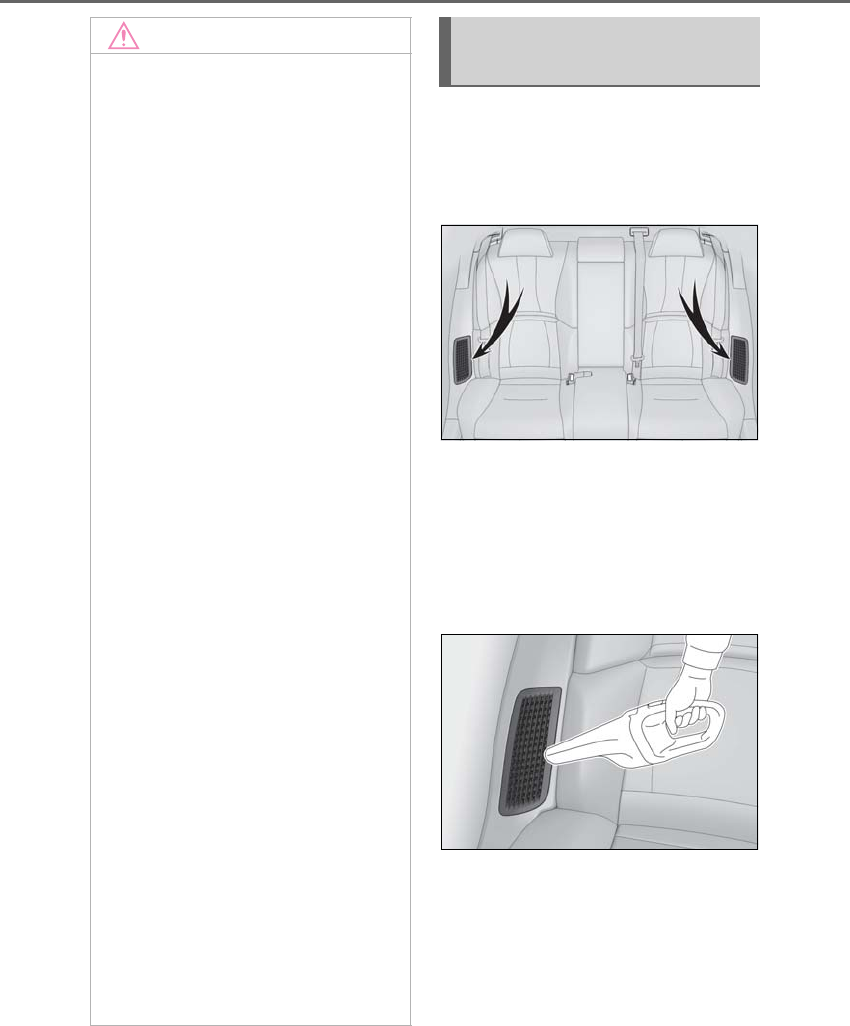
374 6-1. Maintenance and care
LS500h_OM_OM50F42U_(U)
To prevent the hybrid battery (traction
battery) air intake vents from becom-
ing clogged, clean them periodically.
Clean the vents of the both sides.
■Cleaning the air intake vents
Remove any dust and clogs from the
air intake vents with a vacuum cleaner,
etc.
The filters are attached to the back side of
the air intake vent grilles.
If “Maintenance Required for Traction
Battery Cooling Parts See Owner’s
Manual” is displayed on the multi-infor-
mation display, the filters may be
clogged. Remove the air intake vent
grilles and clean the filters.
NOTICE
■Preventing damage to leather sur-
faces
Observe the following precautions to
avoid damage to and deterioration of
leather surfaces:
●Remove any dust or dirt from leather
surfaces immediately.
●Do not expose the vehicle to direct
sunlight for extended periods of time.
Park the vehicle in the shade, espe-
cially during summer.
●Do not place items made of vinyl, plas-
tic, or containing wax on the uphol-
stery, as they may stick to the leather
surface if the vehicle interior heats up
significantly.
■Water on the floor
Do not wash the vehicle floor with water.
Vehicle systems such as the audio system
may be damaged if water comes into
contact with electrical components such
as the audio system above or under the
floor of the vehicle. Water may also
cause the body to rust.
■When cleaning the inside of the wind-
shield
Do not allow glass cleaner to contact the
camera sensor lens. Also, do not touch
the lens. (→P.197, 204)
■Cleaning the inside of the rear win-
dow
●Do not use glass cleaner to clean the
rear window, as this may cause dam-
age to the rear window defogger
heater wires or antenna. Use a cloth
dampened with lukewarm water to
gently wipe the window clean. Wipe
the window in strokes running parallel
to the heater wires or antenna.
●Be careful not to scratch or damage
the heater wires or antenna.
Cleaning the hybrid battery
(traction battery) air intake vents
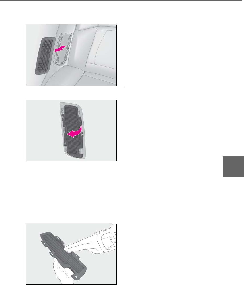
375
6-1. Maintenance and care
LS500h_OM_OM50F42U_(U)
6
Maintenance and care
■Cleaning the air intake vent filters
1Remove the grille.
2Remove the filter.
3Remove any dust and clogs from
the filter using a vacuum cleaner,
etc.
Make sure to also remove dust and clogs
from the inner side of the air intake vent
grille.
If the filter is damaged, have it replaced by
your Lexus dealer.
4Install the filter in its original posi-
tion, and then install the grille.
5Start the hybrid system and check
that “Maintenance Required for
Traction Battery Cooling Parts See
Owner’s Manual” is no longer dis-
played on the multi-information dis-
play.
It may take approximately 20 minutes after
the hybrid system is started until the warn-
ing message disappears. If the warning
message does not disappear, have the
vehicle inspected by your Lexus dealer.
■Air intake vents maintenance
●If the vehicle is driven with the air intake
vents clogged, the hybrid battery (trac-
tion battery) may not be cooled suffi-
ciently, possibly causing in fuel
consumption.
●Depending on the conditions under
which the vehicle is used, the air intake
vents may need to be cleaned more reg-
ularly.
■Cleaning the air intake vent filters
●Improper handling of the air intake vent
grilles and filters may result in damage to
them. If you have any concerns about
cleaning the filter, contact your Lexus
dealer.
●If the vehicle is driven with the air intake
vent filter clogged, the hybrid battery
(traction battery) may not be cooled suf-
ficiently, possibly causing an increase in
the fuel consumption and damage to the
hybrid battery (traction battery).
●Depending on the conditions under
which the vehicle is used, the air intake
vent filters may need to be cleaned more
regularly.
■If “Maintenance Required for Traction
Battery Cooling Parts See Owner’s
Manual” is displayed on the multi-infor-
mation display
●It is possible the air intake vents or filters
are clogged due to accumulated dust.
Clean the air intake vents and filters,
referring to the cleaning method.
●If the vehicle is driven continuously with

376 6-1. Maintenance and care
LS500h_OM_OM50F42U_(U)
this message displayed, the hybrid bat-
tery (traction battery) may not be cooled
sufficiently, which may lead to the driving
distance by the electric motor becoming
shorter and damage to the hybrid battery
(traction battery). Clean the air intake
vents periodically to prevent dust, etc.,
from collecting in the air intake vents and
filters.
●If the massage in the multi-information
display does not turn off, even if the air
intake vents are cleaned, have the vehicle
inspected at your Lexus dealer.
-Remove dirt using a water-damp-
ened soft cloth or synthetic chamois.
-Wipe the surface with a dry, soft
cloth to remove any remaining
moisture.
■Cleaning the areas with satin-finish
metal accents
The metal areas use a layer of real metal for
the surface. It is necessary to clean them
regularly. If dirty areas are left uncleaned for
long periods of time, they may be difficult to
clean.
-Remove dirt and dust using a vac-
uum cleaner.
-Wipe off any excess dirt and dust
with a soft cloth dampened with
diluted detergent.
Use a diluted water solution of approxi-
mately 5% neutral wool detergent.
-Wring out any excess water from
the cloth and thoroughly wipe off all
remaining traces of detergent.
-Wipe the surface with a dry, soft
cloth to remove any remaining
moisture. Allow the leather to dry in
a shaded and ventilated area.
■Caring for leather areas
Lexus recommends cleaning the interior of
the vehicle at least twice a year to maintain
the quality of the vehicle’s interior.
-Remove dirt and dust using a vac-
uum cleaner.
-Wipe it off with a soft cloth damp-
ened with neutral detergent diluted
to approximately 1%.
-Wring out any excess water from
the cloth and thoroughly wipe off
remaining traces of detergent and
water.
-To remove dust from the fabric, use
WARNING
■When cleaning the hybrid battery
(traction battery) air intake vents/fil-
ters
●Do not use water or other liquids to
clean the air intake vents/filters. If
water is applied to the hybrid battery
(traction battery) or other compo-
nents, a malfunction or fire may occur.
●When the air intake vent grilles,
located near the rear seats are to be
removed, make sure to turn the power
switch off to stop the hybrid system.
Cleaning the areas with satin-fin-
ish metal accents
Cleaning the leather areas
Cleaning the synthetic leather
areas
Cleaning fabric portions of the
instrument panel

377
6-1. Maintenance and care
LS500h_OM_OM50F42U_(U)
6
Maintenance and care
a vacuum cleaner or adhesive tape.
-Use a cloth dampened with water to
gently wipe the fabric clean.
Do not use detergents to clean the fabric.

378 6-2. Maintenance
LS500h_OM_OM50F42U_(U)
6-2.Maintenance
■Repair and replacement
It is recommended that genuine Lexus parts
be used for repairs to ensure performance
of each system. If non-Lexus parts are used
in replacement or if a repair shop other than
a Lexus dealer performs repairs, confirm
the warranty coverage.
■Allow inspection and repairs to be per-
formed by a Lexus dealer
●Lexus technicians are well-trained spe-
cialists and are kept up to date with the
latest service information. They are well
informed about the operation of all sys-
tems on your vehicle.
●Keep a copy of the repair order. It proves
that the maintenance that has been per-
formed is under warranty coverage. If any
problem should arise while your vehicle is
under warranty, your Lexus dealer will
promptly take care of it.
General maintenance should be per-
formed on a daily basis. This can be
done by yourself or by a Lexus dealer.
Scheduled maintenance should be
performed at specified intervals
according to the maintenance sched-
ule.
For details about maintenance items and
schedules, refer to the “Warranty and Ser-
vice Guide”, “Owner’s Manual Supple-
ment” or “Scheduled Maintenance”.
■Resetting the message indicating main-
tenance is required
After the required maintenance is per-
formed according to the maintenance
schedule, please reset the message.
To reset the message, follow the procedure
described below:
1Press or of the meter control
switch to select .
2Press or to select “Vehicle Set-
tings” and then press .
Maintenance requirements
To ensure safe and economical driv-
ing, day-to-day care and regular
maintenance are essential. It is the
owner’s responsibility to perform
regular checks. Lexus recommends
the maintenance below.
WARNING
■If your vehicle is not properly main-
tained
Improper maintenance could result in
serious damage to the vehicle and possi-
ble death or serious injury.
■Handling of the 12-volt battery
●Engine exhaust, some of its constitu-
ents, and a wide variety of automobile
components contain or emit chemicals
known to the State of California to
cause cancer and birth defects and
other reproductive harm. Work in a
well ventilated area.
●Oils, fuels and fluids contained in vehi-
cles as well as waste produced by
component wear contain or emit
chemicals known to the State of Cali-
fornia to cause cancer and birth
defects or other reproductive harm.
Avoid exposure and wash any affected
area immediately.
●12-volt battery posts, terminals and
related accessories contain lead and
lead compounds which are known to
cause brain damage. Wash your hands
after handling. (→P.393)
General maintenance
Scheduled maintenance
379
6-2. Maintenance
LS500h_OM_OM50F42U_(U)
6
Maintenance and care
3Press or to select “Scheduled
Maintenance” and then press .
4Press or to select “Yes” and
then press .
A message will be displayed on the
multi-information display when the reset
procedure has been completed.
You can perform some maintenance
procedures by yourself.
Please be aware that do-it-yourself
maintenance may affect warranty cov-
erage.
The use of Lexus repair manuals is recom-
mended.
For details about warranty coverage, refer
to the separate “Owner’s Guide”, “War-
ranty and Service Guide”, “Owner’s Man-
ual Supplement” or “Warranty Booklet”.
Do-it-yourself maintenance
General maintenance
Listed below are the general main-
tenance items that should be per-
formed at the intervals specified in
the “Warranty and Service Guide”
or “Owner’s Manual Supplement”.
It is recommended that any prob-
lem you notice should be brought to
the attention of your Lexus dealer
or qualified service shop for advice.
WARNING
■If the hybrid system is operating
Turn the hybrid system off and ensure
that there is adequate ventilation before
performing maintenance checks.
Engine compartment
Items Check points
Brake fluid
Is the brake fluid at the
correct level?
(→P.391)
Engine/power
control unit cool-
ant
Is the engine/power
control unit coolant at
the correct level?
(→P.390)
Engine oil
Is the engine oil at the
correct level?
(→P.388)
Exhaust system
There should not be
any fumes or strange
sounds.

380 6-2. Maintenance
LS500h_OM_OM50F42U_(U)
Radiator/con-
denser
The radiator and con-
denser should be free
from foreign objects.
(→P.391)
Washer fluid
Is there sufficient
washer fluid?
(→P.392)
Trunk
Items Check points
12-volt battery Check the connec-
tions. (→P.393)
Vehicle interior
Items Check points
Accelerator
pedal
• The accelerator
pedal should move
smoothly (without
uneven pedal effort
or catching).
Hybrid transmis-
sion “Park” mech-
anism
•When parked on a
slope and the shift
position is in P, is the
vehicle securely
stopped?
Brake pedal
• Does the brake
pedal move
smoothly?
• Does the brake
pedal have appro-
priate clearance
from the floor?
• Does the brake
pedal have the cor-
rect amount of free
play?
Items Check points
Brakes
• The vehicle should
not pull to one side
when the brakes are
applied.
•The brakes should
work effectively.
• The brake pedal
should not feel
spongy.
• The brake pedal
should not get too
close to the floor
when the brakes are
applied.
Head restraints
•Do the head
restraints move
smoothly and lock
securely?
Indicators/buzz-
ers
•Do the indicators
and buzzers function
properly?
Lights • Do all the lights
come on?
Parking brake
• Does the parking
brake operate nor-
mally?
• When parked on a
slope and the park-
ing brake is on, is the
vehicle securely
stopped?
Seat belts
• Do the seat belts
operate smoothly?
• The seat belts should
not be damaged.
Items Check points

381
6-2. Maintenance
LS500h_OM_OM50F42U_(U)
6
Maintenance and care
Seats • Do the seat controls
operate properly?
Steering wheel
• Does the steering
wheel rotate
smoothly?
• Does the steering
wheel have the cor-
rect amount of free
play?
•There should not be
any strange sounds
coming from the
steering wheel.
Vehicle exterior
Items Check points
Doors/trunk • Do the doors/trunk
operate smoothly?
Engine hood
•Does the engine
hood lock system
work properly?
Fluid leaks
•There should not be
any signs of fluid
leakage after the
vehicle has been
parked.
Items Check points
Tires
• Is the tire inflation
pressure correct?
• The tires should not
be damaged or
excessively worn.
• Have the tires been
rotated according to
the maintenance
schedule?
•The wheel nuts
should not be loose.
Windshield wip-
ers
• The wiper blades
should not show any
signs of cracking,
splitting, wear, con-
tamination or defor-
mation.
• The wiper blades
should clear the
windshield without
streaking or skip-
ping.
Items Check points

382 6-2. Maintenance
LS500h_OM_OM50F42U_(U)
The OBD system determines that a
problem exists somewhere in the emis-
sion control system. Your vehicle may
not pass the I/M test and may need to
be repaired. Contact your Lexus
dealer to service the vehicle.
-When the 12-volt battery is discon-
nected or discharged
Readiness codes that are set during ordi-
nary driving are erased.
Also, depending on your driving habits, the
readiness codes may not be completely
set.
-When the fuel tank cap is loose
The malfunction indicator lamp comes on
indicating a temporary malfunction and
your vehicle may not pass the I/M test.
The error code in the OBD system will
not be cleared unless the vehicle is
driven 40 or more times.
Contact your Lexus dealer to prepare
the vehicle for re-testing.
Emission inspection and
maintenance (I/M) pro-
grams
Some states have vehicle emission
inspection programs which include
OBD (On Board Diagnostics)
checks. The OBD system monitors
the operation of the emission con-
trol system.
If the malfunction indicator lamp
comes on
Your vehicle may not pass the
I/M test in the following situa-
tions:
When the malfunction indicator
lamp still remains on after sev-
eral driving trips
If your vehicle does not pass the
I/M test

383
6-3. Do-it-yourself maintenance
LS500h_OM_OM50F42U_(U)
6
Maintenance and care
6-3.Do-it-yourself maintenance
Do-it-yourself service pre-
cautions
If you perform maintenance by
yourself, be sure to follow the cor-
rect procedure as given in these
sections.
Maintenance
Items Parts and tools
12-volt battery
condition
(→P.393)
•Grease
• Conventional
wrench (for terminal
clamp bolts)
Brake fluid level
(→P.391)
• FMVSS No.116 DOT
3 or SAE J1703
brake fluid
FMVSS No.116 DOT
4 or SAE J1704
brake fluid
•Rag or paper towel
• Funnel (used only for
adding brake fluid)
Engine/power
control unit cool-
ant level
(→P.390)
•“Toyota Super Long
Life Coolant” or a
similar high quality
ethylene gly-
col-based non-sili-
cate, non-amine,
non-nitrite and
non-borate coolant
with long-life hybrid
organic acid tech-
nology
For the U.S.A.:
“Toyota Super Long
Life Coolant” is
pre-mixed with 50%
coolant and 50%
deionized water.
For Canada:
“Toyota Super Long
Life Coolant” is
pre-mixed with 55%
coolant and 45%
deionized water.
•Funnel (used only for
adding coolant)
Engine oil level
(→P.388)
•“Toyota Genuine
Motor Oil” or equiv-
alent
• Rag or paper towel
•Funnel (used only for
adding engine oil)
Fuses (→P.414)
•Fuse with same
amperage rating as
original
Radiator and con-
denser (→P.391) ⎯
Items Parts and tools
384 6-3. Do-it-yourself maintenance
LS500h_OM_OM50F42U_(U)
Tire inflation pres-
sure (→P.408)
• Tire pressure gauge
•Compressed air
source
Washer fluid
(→P.392)
• Water or washer
fluid containing anti-
freeze (for winter
use)
• Funnel (used only for
adding water or
washer fluid)
WARNING
The engine compartment contains many
mechanisms and fluids that may move
suddenly, become hot, or become elec-
trically energized. To avoid death or seri-
ous injury, observe the following
precautions.
■When working on the engine com-
partment
●Make sure that the “ACCESSORY” or
“IGNITION ON” on the multi-infor-
mation display and the “READY” indi-
cator are both off.
●Keep hands, clothing and tools away
from the moving fan and engine drive
belt.
●Be careful not to touch the engine,
power control unit, radiator, exhaust
manifold, etc. right after driving as they
may be hot. Oil and other fluids may
also be hot.
●Do not leave anything that may burn
easily, such as paper and rags, in the
engine compartment.
●Do not smoke, cause sparks or expose
an open flame to fuel. Fuel fumes are
flammable.
Items Parts and tools ■When working near the electric cool-
ing fan or radiator grille
Be sure the power switch is off.
With the power switch in ON mode, the
electric cooling fan may automatically
start to run if the air conditioning is on
and/or the coolant temperature is high.
(→P.391)
■Safety glasses
Wear safety glasses to prevent flying or
falling material, fluid spray, etc. from get-
ting in your eyes.
NOTICE
■If you remove the air cleaner filter
Driving with the air cleaner filter
removed may cause excessive engine
wear due to dirt in the air.
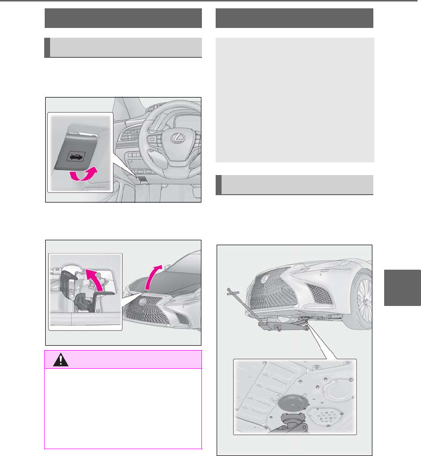
385
6-3. Do-it-yourself maintenance
LS500h_OM_OM50F42U_(U)
6
Maintenance and care
1Pull the hood lock release lever.
The hood will pop up slightly.
2Pull up the auxiliary catch lever and
lift the hood.
■Front
2WD models
Hood
Opening the hood
WARNING
■Pre-driving check
Check that the hood is fully closed and
locked.
If the hood is not locked properly, it may
open while the vehicle is in motion and
cause an accident, which may result in
death or serious injury.
Positioning a floor jack
When using a floor jack, follow the
instructions in the manual provided
with the jack and perform the oper-
ation safely.
When raising your vehicle with a
floor jack, position the jack cor-
rectly. Improper placement may
damage your vehicle or cause
injury.
Location of the jack point
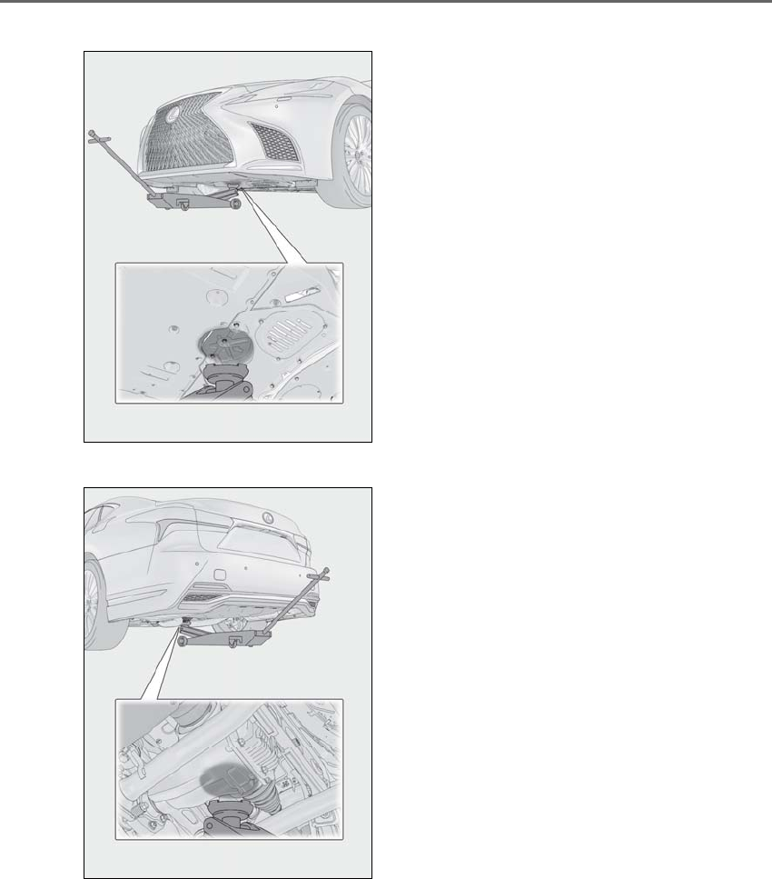
386 6-3. Do-it-yourself maintenance
LS500h_OM_OM50F42U_(U)
AWD models
■Rear
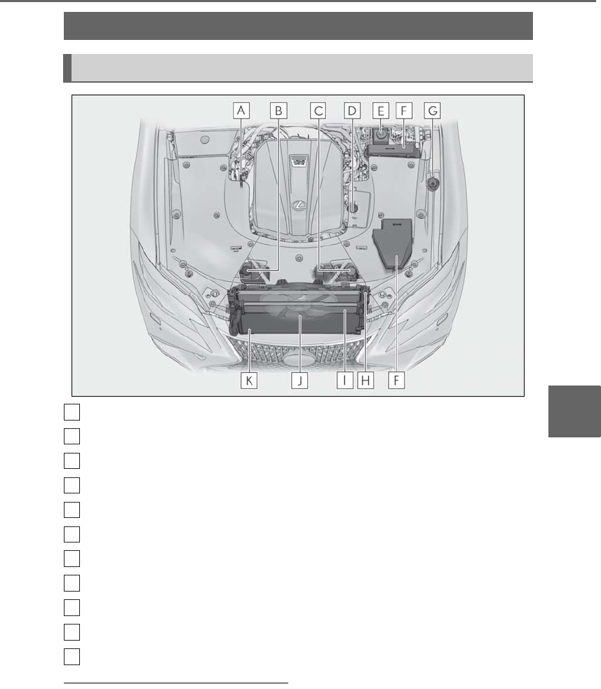
387
6-3. Do-it-yourself maintenance
LS500h_OM_OM50F42U_(U)
6
Maintenance and care
Engine oil level dipstick (→P.388)
Power control unit coolant reservoir (→P.390)
Engine coolant reservoir (→P.390)
Engine oil filler cap (→P.389)
Brake fluid reservoir (→P.391)
Fuse boxes (→P.414)
Washer fluid tank (→P.392)
Engine coolant radiator (→P.391)
Power control unit coolant radiator (→P.391)
Electric cooling fan
Condenser (→P.391)
■12-volt battery
→P.393
Engine compartment
Components
A
B
C
D
E
F
G
H
I
J
K
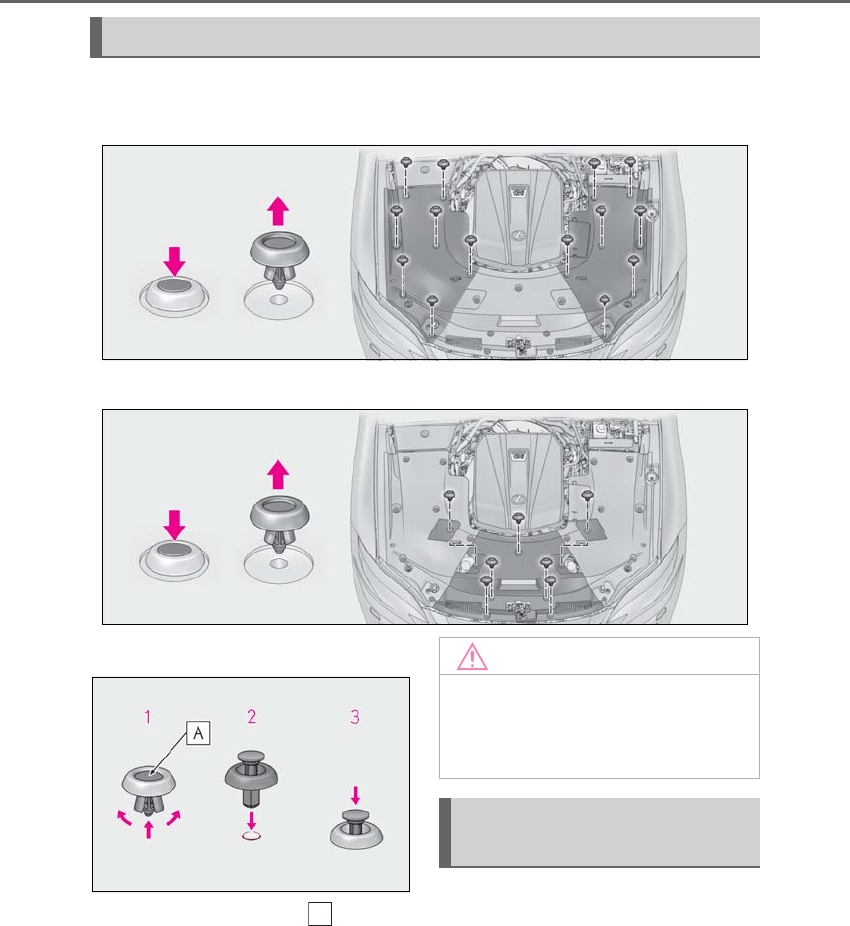
388 6-3. Do-it-yourself maintenance
LS500h_OM_OM50F42U_(U)
■Removing the engine compartment cover
Outside
Front
■Installing the clips
1Push up center portion
2Insert
3Press
With the engine at operating tempera-
ture and turned off, check the oil level
on the dipstick.
■Checking the engine oil
1Park the vehicle on level ground.
After warming up the engine and
turning off the hybrid system, wait
more than 5 minutes for the oil to
Engine compartment cover
A
NOTICE
■Checking the engine compartment
cover after installation
Make sure that the cover is securely
installed in its original position.
Checking and adding the engine
oil
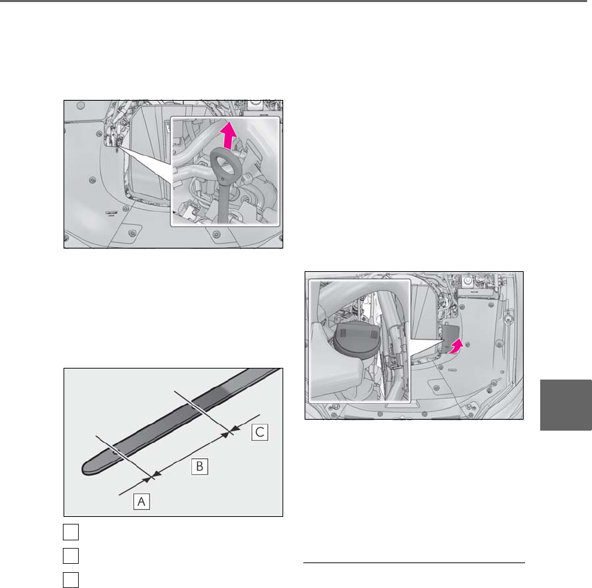
389
6-3. Do-it-yourself maintenance
LS500h_OM_OM50F42U_(U)
6
Maintenance and care
drain back into the bottom of the
engine.
2Holding a rag under the end, pull
the dipstick out.
3Wipe the dipstick clean.
4Reinsert the dipstick fully.
5Holding a rag under the end, pull
the dipstick out and check the oil
level.
Low
Normal
Excessive
The shape of the dipstick may differ
depending on the type of vehicle or
engine.
6Wipe the dipstick and reinsert it
fully.
■Checking the oil type and prepar-
ing the item needed
Make sure to check the oil type and
prepare the items needed before add-
ing oil.
-Engine oil selection
→P.462
-Oil quantity (Low → Full)
1.6 qt. (1.5 L, 1.3 Imp. qt.)
-Item
Clean funnel
■Adding engine oil
If the oil level is below or near the low
level mark, add engine oil of the same
type as that already in the engine.
1Remove the oil filler cap by turning
it counterclockwise.
2Add engine oil slowly, checking the
dipstick.
3Install the oil filler cap by turning it
clockwise.
■Engine oil consumption
A certain amount of engine oil will be con-
sumed while driving. In the following situa-
tions, oil consumption may increase, and
engine oil may need to be refilled in
between oil maintenance intervals.
●When the engine is new, for example
directly after purchasing the vehicle or
after replacing the engine
●If low quality oil or oil of an inappropriate
viscosity is used
●When driving at high engine speeds or
A
B
C
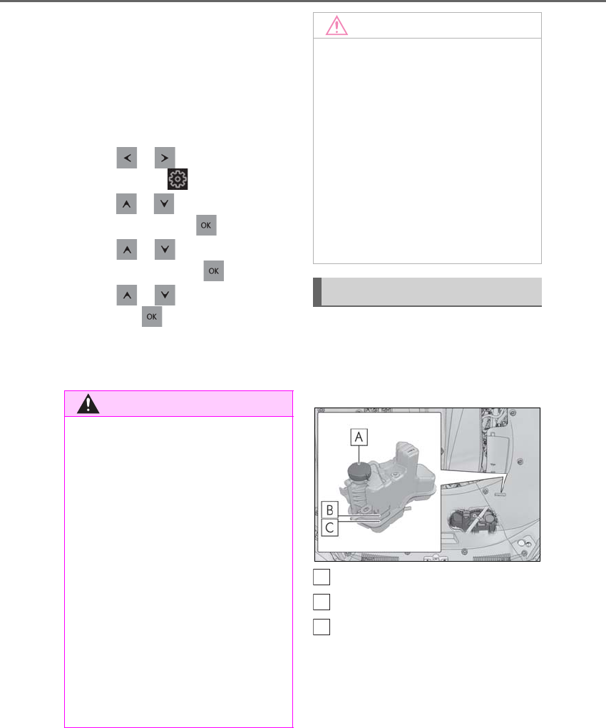
390 6-3. Do-it-yourself maintenance
LS500h_OM_OM50F42U_(U)
with a heavy load, or when driving while
accelerating or decelerating frequently
●When leaving the engine idling for a long
time, or when driving frequently through
heavy traffic
■After changing the engine oil
The engine oil maintenance data should be
reset. Perform the following procedures:
1Press or of the meter control
switch to select .
2Press or to select “Vehicle Set-
tings” and then press .
3Press or to select “Oil Mainte-
nance” and then press .
4Press or to select “Yes” and
then press .
A message will be displayed on the
multi-information display when the reset
procedure has been completed.
The coolant level is satisfactory if it is
between the “F” and “L” lines on the
reservoir when the engine is cold.
■Engine coolant reservoir
Reservoir cap
“F” line
“L” line
If the level is on or below the “L” line, add
coolant up to the “F” line. (→P.453)
■Power control unit coolant reser-
voir
The coolant level is satisfactory if it is
between the “F” and “L” lines on the
reservoir when the hybrid system is
WARNING
■Used engine oil
●Used engine oil contains potentially
harmful contaminants which may
cause skin disorders such as inflamma-
tion and skin cancer, so care should be
taken to avoid prolonged and
repeated contact. To remove used
engine oil from your skin, wash thor-
oughly with soap and water.
●Dispose of used oil and filters only in a
safe and acceptable manner. Do not
dispose of used oil and filters in house-
hold trash, in sewers or onto the
ground.
Call your Lexus dealer, service station
or auto parts store for information
concerning recycling or disposal.
●Do not leave used engine oil within the
reach of children.
NOTICE
■To prevent serious engine damage
Check the oil level on a regular basis.
■When replacing the engine oil
●Be careful not to spill engine oil on the
vehicle components.
●Avoid overfilling, or the engine could
be damaged.
●Check the oil level on the dipstick
every time you refill the vehicle.
●Be sure the engine oil filler cap is prop-
erly tightened.
Checking the coolant
A
B
C
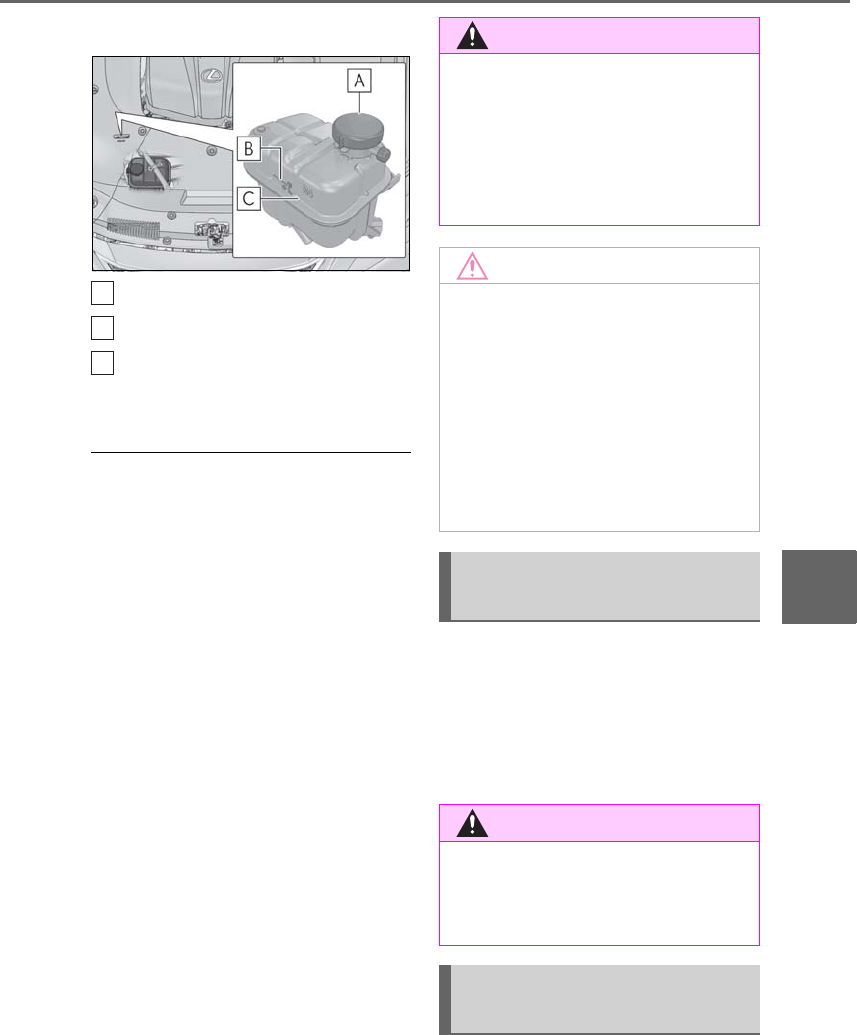
391
6-3. Do-it-yourself maintenance
LS500h_OM_OM50F42U_(U)
6
Maintenance and care
cold.
Reservoir cap
“F” line
“L” line
If the level is on or below the “L” line, add
coolant up to the “F” line. (→P.453)
■Coolant selection
Only use “Toyota Super Long Life Coolant”
or a similar high quality ethylene glycol
based non-silicate, non-amine, non-nitrite,
and non-borate coolant with long-life
hybrid organic acid technology.
U.S.A.:
“Toyota Super Long Life Coolant” is a mix-
ture of 50% coolant and 50% deionized
water. (Minimum temperature: -31°F
[-35°C])
Canada:
“Toyota Super Long Life Coolant” is a mix-
ture of 55% coolant and 45% deionized
water. (Minimum temperature: -44°F
[-42°C])
For more details about coolant, contact
your Lexus dealer.
■If the coolant level drops within a short
time of replenishing
Visually check the radiator, hoses,
engine/power control unit coolant reservoir
caps, drain cock and water pump.
If you cannot find a leak, have your Lexus
dealer test the cap and check for leaks in
the cooling system.
Check the radiator and condenser and
clear away any foreign objects. If either
of the above parts is extremely dirty or
you are not sure of their condition,
have your vehicle inspected by your
Lexus dealer.
■Checking fluid level
The brake fluid level should be
A
B
C
WARNING
■When the hybrid system is hot
Do not remove the engine/power control
unit coolant reservoir caps. (→P.456)
The cooling system may be under pres-
sure and may spray hot coolant if the cap
is removed, causing serious injuries, such
as burns.
NOTICE
■When adding coolant
Coolant is neither plain water nor
straight antifreeze. The correct mixture
of water and antifreeze must be used to
provide proper lubrication, corrosion
protection and cooling. Be sure to read
the antifreeze or coolant label.
■If you spill coolant
Be sure to wash it off with water to pre-
vent it from damaging parts or paint.
Checking the radiator and con-
denser
WARNING
■When the hybrid system is hot
Do not touch the radiator or condenser
as they may be hot and cause serious
injuries, such as burns.
Checking and adding the brake
fluid
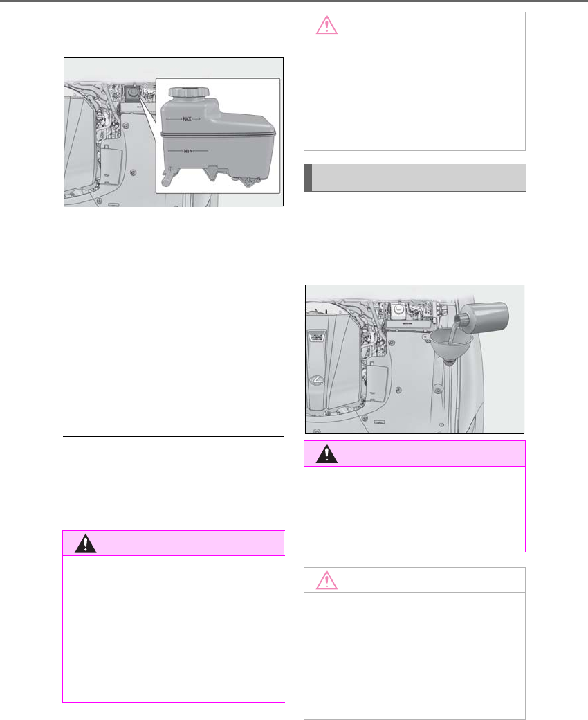
392 6-3. Do-it-yourself maintenance
LS500h_OM_OM50F42U_(U)
between the “MAX” and “MIN” lines
on the tank.
■Adding fluid
Make sure to check the fluid type and
prepare the necessary item.
-Fluid type
FMVSS No.116 DOT 3 or SAE J1703
brake fluid
FMVSS No.116 DOT 4 or SAE J1704
brake fluid
-Item
Clean funnel
■Brake fluid can absorb moisture from
the air
Excess moisture in the brake fluid can cause
a dangerous loss of braking efficiency. Use
only newly opened brake fluid.
If any washer does not work or the
warning message appears on the
multi-information display, the washer
tank may be empty. Add washer fluid.
WARNING
■When filling the reservoir
Take care as brake fluid can harm your
hands and eyes and damage painted sur-
faces.
If fluid gets on your hands or in your eyes,
flush the affected area with clean water
immediately.
If you still experience discomfort, see a
doctor.
NOTICE
■If the fluid level is low or high
It is normal for the brake fluid level to go
down slightly as the brake pads wear out
or when the fluid level in the accumulator
is high.
If the reservoir needs frequent refilling,
there may be a serious problem.
Adding the washer fluid
WARNING
■When adding washer fluid
Do not add washer fluid when the hybrid
system is hot or operating as washer fluid
contains alcohol and may catch fire if
spilled on the engine, etc.
NOTICE
■Do not use any fluid other than
washer fluid
Do not use soapy water or engine anti-
freeze instead of washer fluid.
Doing so may cause streaking on the
vehicle’s painted surfaces, as well as
damaging the pump leading to problems
of the washer fluid not spraying.
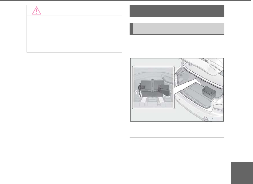
393
6-3. Do-it-yourself maintenance
LS500h_OM_OM50F42U_(U)
6
Maintenance and care
The 12-volt battery is located in the
trunk under the luggage mat.
Removing the luggage mat: →P.348
■Before recharging
When recharging, the 12-volt battery pro-
duces hydrogen gas which is flammable
and explosive. Therefore, observe the fol-
lowing precautions before recharging:
●If recharging with the 12-volt battery
installed on the vehicle, be sure to discon-
nect the ground cable.
●Make sure the power switch on the char-
ger is off when connecting and discon-
necting the charger cables to the 12-volt
battery.
■After recharging/reconnecting the
12-volt battery
●Unlocking the doors using the smart
access system with push-button may not
be possible immediately after reconnect-
ing the 12-volt battery. If this happens, use
the wireless remote control or the
mechanical key to lock/unlock the doors.
●Start the hybrid system with the power
switch in ACCESSORY mode. The
hybrid system may not start with the
power switch turned off. However, the
hybrid system will operate normally from
the second attempt.
●The power switch mode is recorded by
the vehicle. If the 12-volt battery is recon-
NOTICE
■Diluting washer fluid
Dilute washer fluid with water as neces-
sary.
Refer to the freezing temperatures listed
on the label of the washer fluid bottle.
12-volt battery
Location
394 6-3. Do-it-yourself maintenance
LS500h_OM_OM50F42U_(U)
nected, the vehicle will return the power
switch mode to the status it was in before
the 12-volt battery was disconnected.
Make sure to turn off the power before
disconnecting the 12-volt battery. Take
extra care when connecting the 12-volt
battery if the power switch mode prior to
discharge is unknown.
If the system will not start even after multiple
attempts, contact your Lexus dealer.
Make sure that the 12-volt battery ter-
minals are not corroded and that there
are no loose connections, cracks, or
loose clamps.
WARNING
■Chemicals in the 12-volt battery
The 12-volt battery contains poisonous
and corrosive sulfuric acid and may pro-
duce hydrogen gas which is flammable
and explosive. To reduce the risk of death
or serious injury, take the following pre-
cautions while working on or near the
12-volt battery:
●Do not cause sparks by touching the
12-volt battery terminals with tools.
●Do not smoke or light a match near the
12-volt battery.
●Avoid contact with eyes, skin and
clothes.
●Never inhale or swallow electrolyte.
●Wear protective safety glasses when
working near the 12-volt battery.
●Keep children away from the 12-volt
battery.
■Where to safely charge the 12-volt
battery
Always charge the 12-volt battery in an
open area. Do not charge the 12-volt bat-
tery in a garage or closed room where
there is insufficient ventilation.
■Emergency measures regarding
electrolyte
●If electrolyte gets in your eyes
Flush your eyes with clean water for at
least 15 minutes and get immediate
medical attention. If possible, continue
to apply water with a sponge or cloth
while traveling to the nearest medical
facility.
●If electrolyte gets on your skin
Wash the affected area thoroughly. If
you feel pain or burning, get medical
attention immediately.
●If electrolyte gets on your clothes
It can soak through clothing on to your
skin. Immediately take off the clothing
and follow the procedure above if nec-
essary.
●If you accidentally swallow electrolyte
Drink a large quantity of water or milk.
Get emergency medical attention
immediately.
■When replacing the 12-volt battery
Use a 12-volt battery designed for this
vehicle. Failure to do so may cause gas
(hydrogen) to enter the passenger com-
partment, causing a fire or explosion.
For replacement of the 12-volt battery,
contact your Lexus dealer.
NOTICE
■When recharging the 12-volt battery
Never recharge the 12-volt battery while
the hybrid system is operating. Also, be
sure all accessories are turned off.
Exterior
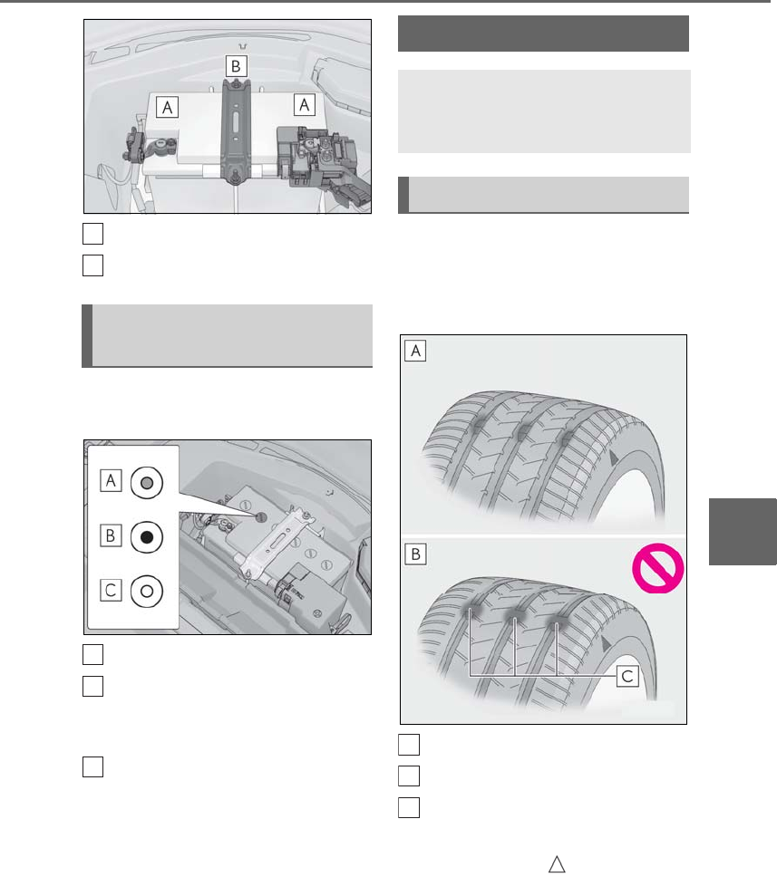
395
6-3. Do-it-yourself maintenance
LS500h_OM_OM50F42U_(U)
6
Maintenance and care
Terminals
Hold-down clamp
Check the 12-volt battery condition by
indicator color.
Blue: Good condition
Red: Charging is necessary.
Have the vehicle inspected by your
Lexus dealer.
Clear: Replacement is necessary.
Have the 12-volt battery checked
by your Lexus dealer.
Check if the treadwear indicators are
showing on the tires. Also check the
tires for uneven wear, such as excessive
wear on one side of the tread.
New tread
Worn tread
Treadwear indicator
The location of treadwear indicators is
shown by a “TWI” or “ ” mark, etc.,
molded into the sidewall of each tire.
Replace the tires if the treadwear indica-
tors are showing on a tire.
Checking the 12-volt battery
condition
A
B
A
B
C
Tires
Replace or rotate tires in accor-
dance with maintenance schedules
and treadwear.
Checking tires
A
B
C
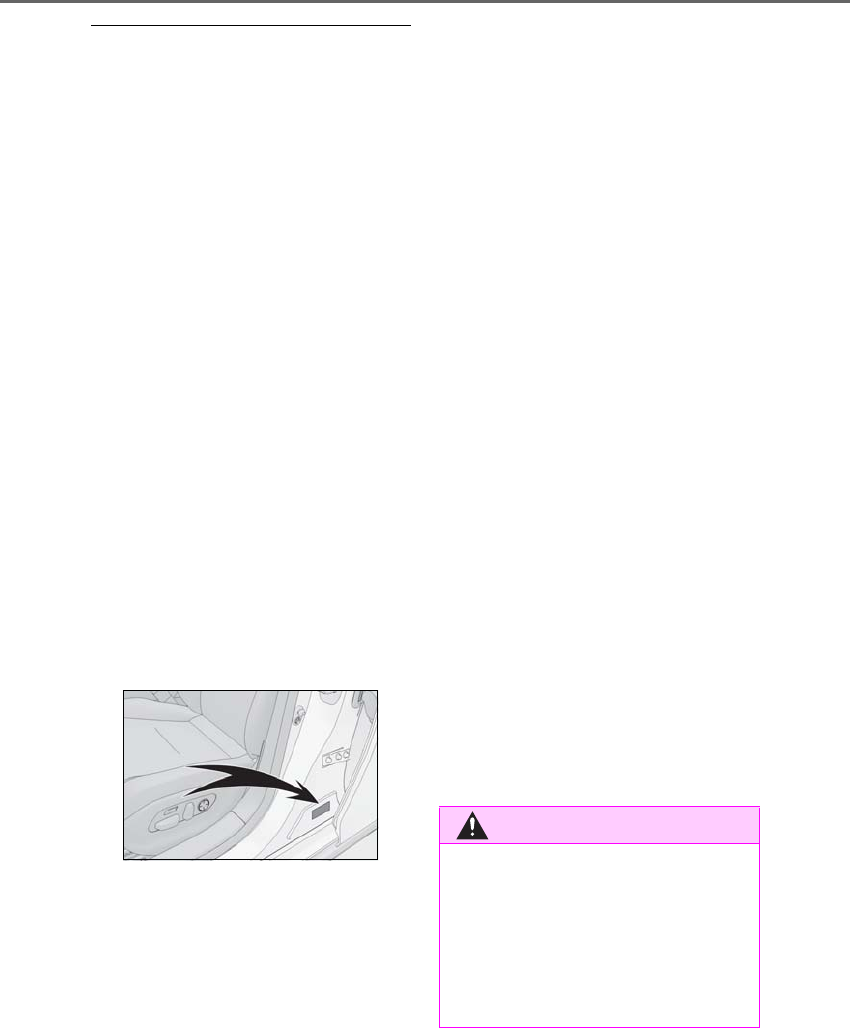
396 6-3. Do-it-yourself maintenance
LS500h_OM_OM50F42U_(U)
■When to replace your vehicle’s tires
Tires should be replaced if:
●The treadwear indicators are showing on
a tire.
●You have tire damage such as cuts, splits,
cracks deep enough to expose the fabric,
and bulges indicating internal damage
●A tire goes flat repeatedly or cannot be
properly repaired due to the size or loca-
tion of a cut or other damage
If you are not sure, consult with your Lexus
dealer.
■Tire life
Any tire over 6 years old must be checked
by a qualified technician even if it has sel-
dom or never been used or damage is not
obvious.
■Maximum load of tire
Check that the maximum load of the
replacement tire is greater than 1/2 of the
Gross Axle Weight Ratings (GAWR) of
either the front axle or the rear axle, which-
ever is greater.
For the GAWR, see the Certification Label.
For the maximum load of the tire, see the
load limit at maximum cold tire inflation
pressure mentioned on the sidewall of the
tire. (→P.472)
■Tire types
●Summer tires
Summer tires are high-speed performance
tires best suited to highway driving under
dry conditions. Since summer tires do not
have the same traction performance as
snow tires, summer tires are inadequate for
driving on snow-covered or icy roads. For
driving on snow-covered roads or icy
roads, the use of snow tires is recom-
mended. When installing snow tires, be
sure to replace all four tires.
●All season tires
All season tires are designed to provide
better traction in snow and to be adequate
for driving in most winter conditions as well
as for use year-round. All season tires,
however, do not have adequate traction
performance compared with snow tires in
heavy or loose snow. Also, all season tires
fall short in acceleration and handling per-
formance compared with summer tires in
highway driving.
●Snow tires
For driving on snow-covered roads or icy
roads, we recommend using snow tires. If
you need snow tires, select tires of the
same size, construction and load capacity
as the originally installed tires. Since your
vehicle has radial tires as original equip-
ment, make sure your snow tires also have
radial construction. Do not install studded
tires without first checking local regula-
tions for possible restrictions. Snow tires
should be installed on all wheels.
(→P.309)
■If the tread on snow tires wears down
below 0.16 in. (4 mm)
The effectiveness of the tires as snow tires is
lost.
WARNING
■When inspecting or replacing tires
Observe the following precautions to
prevent accidents.
Failure to do so may cause damage to
parts of the drive train as well as danger-
ous handling characteristics, which may
lead to an accident resulting in death or
serious injury.
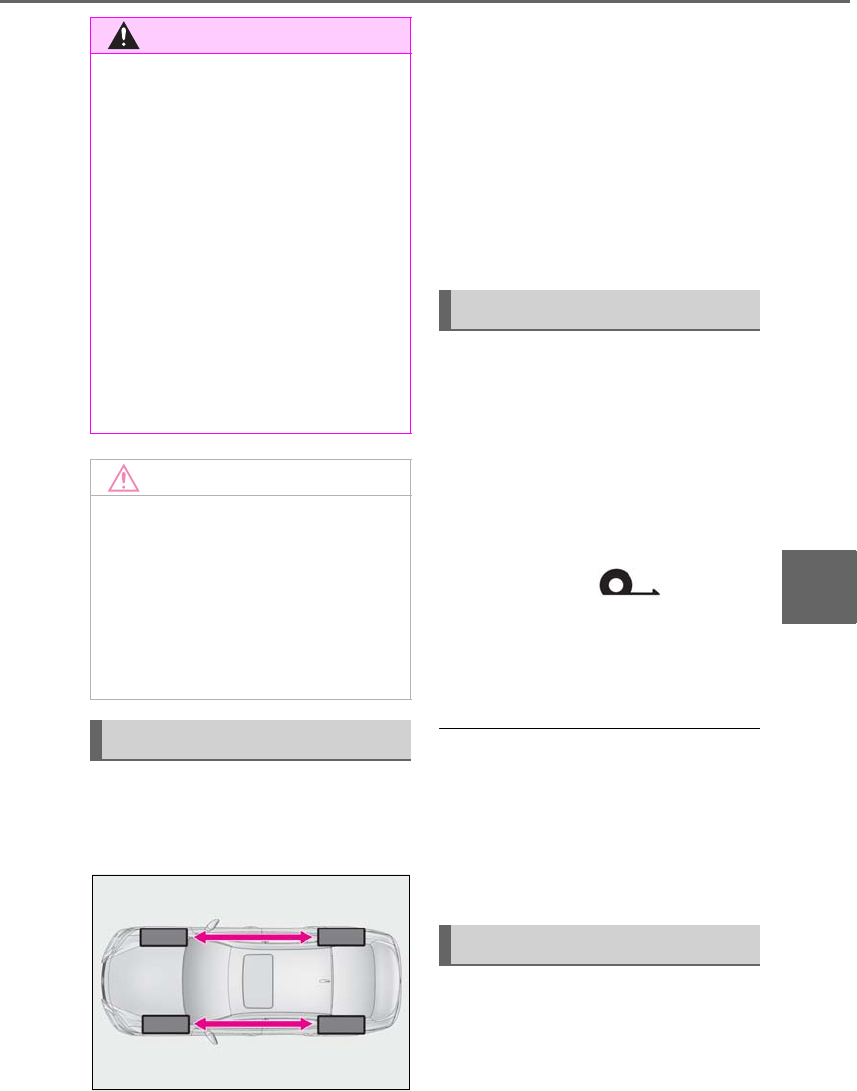
397
6-3. Do-it-yourself maintenance
LS500h_OM_OM50F42U_(U)
6
Maintenance and care
Vehicles with front and rear tires of
the same size
Rotate the tires in the order shown.
To equalize tire wear and extend tire life,
Lexus recommends that tire rotation is car-
ried out at the same interval as tire inspec-
tion.
Do not fail to initialize the tire pressure
warning system after tire rotation.
Vehicles with front and rear tires of
differing sizes
Tires cannot be rotated.
When run-flat tires are installed, the
vehicle can be driven for a maximum of
100 miles (160 km) at a speed below
50 mph (80 km/h) after any tire goes
flat. (However, the vehicle speed may
not increase to near 50 mph [80
km/h] depending on weather or driv-
ing conditions.)
A run-flat tire has a mark on
the side wall.
Make sure to replace the flat tire before the
vehicle has been driven for near 100 miles
(160 km). Also, do not use a repaired tire.
■Run-flat tires
●The run-flat tires are for only this vehicle.
Do not use the tires on other vehicles.
●Do not mix run-flat tires and normal tires.
●If non-genuine Lexus wheels are used, it
may be impossible to sufficiently demon-
strate the performance of run-flat tires.
Your vehicle is equipped with a tire
pressure warning system that uses tire
pressure warning valves and transmit-
ters to detect low tire inflation pressure
WARNING
●Do not mix tires of different makes,
models or tread patterns.
Also, do not mix tires of remarkably
different treadwear.
●Do not use tire sizes other than those
recommended by Lexus.
●Do not mix differently constructed
tires (radial, bias-belted or bias-ply
tires).
●Do not mix summer, all season and
snow tires.
●Do not use tires that have been used
on another vehicle.
Do not use tires if you do not know
how they were used previously.
NOTICE
■Driving on rough roads
Take particular care when driving on
roads with loose surfaces or potholes.
These conditions may cause losses in tire
inflation pressure, reducing the cushion-
ing ability of the tires. In addition, driving
on rough roads may cause damage to
the tires themselves, as well as the vehi-
cle’s wheels and body.
Tire rotation
Run-flat tires
Tire pressure warning system
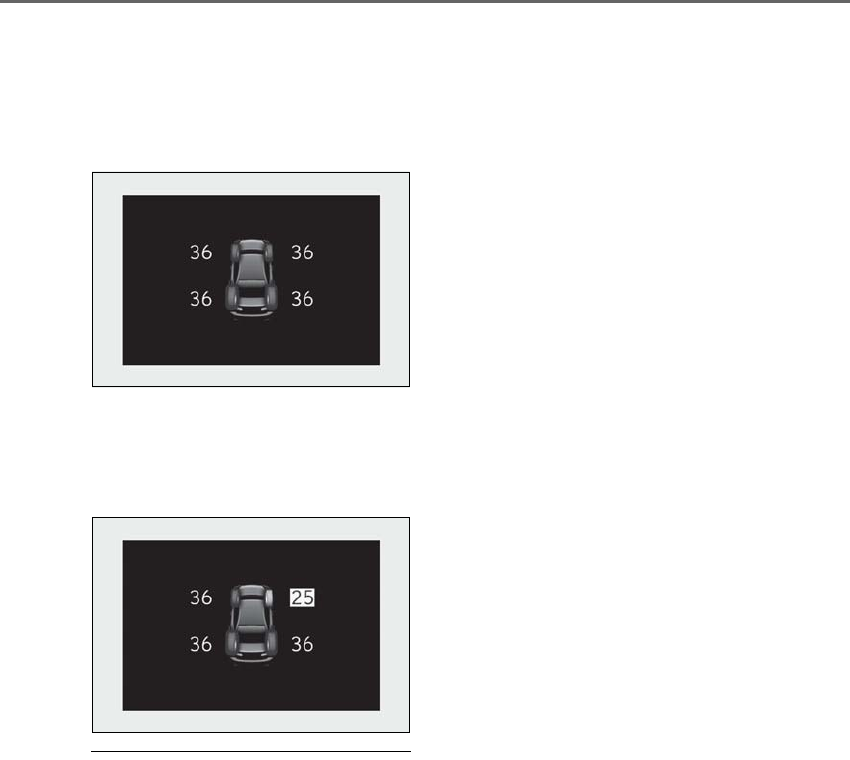
398 6-3. Do-it-yourself maintenance
LS500h_OM_OM50F42U_(U)
before serious problems arise.
-The tire pressure detected by the
tire pressure warning system can be
displayed on the multi-information
display. (→P.86)
-If the tire pressure drops below a
predetermined level, the driver is
warned by a screen display and a
warning light. (→P.431)
■Routine tire inflation pressure checks
The tire pressure warning system does not
replace routine tire inflation pressure
checks. Make sure to check tire inflation
pressure as part of your routine of daily
vehicle checks.
■Tire inflation pressure
●It may take a few minutes to display the
tire inflation pressure after the power
switch is turned to ON mode. It may also
take a few minutes to display the tire infla-
tion pressure after inflation pressure has
been adjusted.
●Tire inflation pressure changes with tem-
perature. The displayed values may also
be different from the values measured
using a tire pressure gauge.
■Situations in which the tire pressure
warning system may not operate prop-
erly
●In the following cases, the tire pressure
warning system may not operate prop-
erly.
• If non-genuine Lexus wheels are used.
• If a tire has been replaced with a tire that
is not an OE (Original Equipment) tire.
• If a tire has been replaced with a tire that
is not of the specified size.
• If tire chains, etc. are installed.
• An auxiliary-supported run-flat tire is
equipped.
• If a window tint that affects the radio wave
signals is installed.
• If there is a lot of snow or ice on the vehi-
cle, particularly around the wheels or
wheel housings.
• If the tire inflation pressure is much higher
than the specified level.
• If wheels not equipped with tire pressure
warning valves and transmitter are used.
• If the ID code on the tire pressure warn-
ing valves and transmitters is not regis-
tered in the tire pressure warning
computer.
●Performance may be affected in the fol-
lowing situations.
• When driving near a TV tower, electric
power plant, gas station, radio station,
large display, airport or other facility that
generates strong radio waves or electri-
cal noise
• When carrying a portable radio, cellular
phone, cordless phone or other wireless
communication device
If tire position information is not correctly
displayed due to the radio wave conditions,
the display may be corrected by changing
the location of the vehicle as the radio wave
conditions may change.
●When the vehicle is stopped, the time
taken for the warning to start or turn off
may be longer.
●When the inflation pressure of a tire
drops rapidly, for example when a tire has
burst, the warning may not operate.
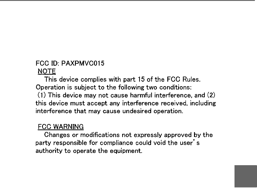
399
6-3. Do-it-yourself maintenance
LS500h_OM_OM50F42U_(U)
6
Maintenance and care
■Warning performance of the tire pres-
sure warning system
The warning of the tire pressure warning
system will change in accordance with driv-
ing conditions. For this reason, the system
may give a warning even if the tire pressure
does not reach a low enough level, or if the
pressure is higher than the pressure that
was adjusted to when the system was initial-
ized.
■Tire pressure warning system certification
For vehicles sold in the U.S.A., Hawaii, Guam and Puerto Rico
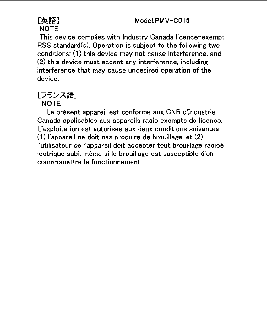
400 6-3. Do-it-yourself maintenance
LS500h_OM_OM50F42U_(U)
For vehicles sold in Canada

401
6-3. Do-it-yourself maintenance
LS500h_OM_OM50F42U_(U)
6
Maintenance and care
When replacing the tires or wheels, the
tire pressure warning valve and trans-
mitters must be installed to the wheels
which will be installed to the vehicle.
When new tire pressure warning
valves and transmitters are installed,
new ID codes must be registered in the
tire pressure warning computer and
the tire pressure warning system must
be initialized. (→P.403)
■Replacing tires and wheels
If the ID codes of the tire pressure warning
valve and transmitters are not registered,
the tire pressure warning system will not
work properly. In this case, after driving for
about 20 minutes, the tire pressure warning
light will blink for approximately 1 minute
and then illuminate to indicate a system
malfunction.
■The tire pressure warning system
must be initialized in the following
circumstances:
-When the tire inflation pressure is
changed such as when changing
traveling speed or load weight.
-When the tire inflation pressure is
changed such as when the tire size
is changed.
-When rotating the tires.
-After performing the transmitter ID
code registration procedure.
(→P.403)
When the tire pressure warning system
is initialized, the current tire inflation
pressure is set as the benchmark pres-
sure.
■How to initialize the tire pressure
warning system
1Park the vehicle in a safe place and
turn the power switch off.
The initialization procedure cannot be
started while the vehicle is moving.
2Adjust the tire inflation pressure to
the specified cold tire inflation pres-
sure level.
Make sure to adjust the tire pressure to the
specified cold tire inflation pressure level.
The tire pressure warning system will oper-
ate based on this pressure level.
3Turn the power switch to ON
mode.
4Press or of the meter con-
trol switch to select .
Installing tire pressure warning
valves and transmitters
NOTICE
■Repairing or replacing tires, wheels,
tire pressure warning valves, trans-
mitters and tire valve caps
●When removing or fitting the wheels,
tires or the tire pressure warning
valves and transmitters, contact your
Lexus dealer as the tire pressure warn-
ing valves and transmitters may be
damaged if not handled correctly.
●Make sure to install the tire valve caps.
If the tire valve caps are not installed,
water may enter the valves of the tire
pressure warning valve and transmit-
ters and the valves may become stuck.
●When replacing tire valve caps, do not
use tire valve caps other than those
specified. The cap may become stuck.
Initializing the tire pressure
warning system
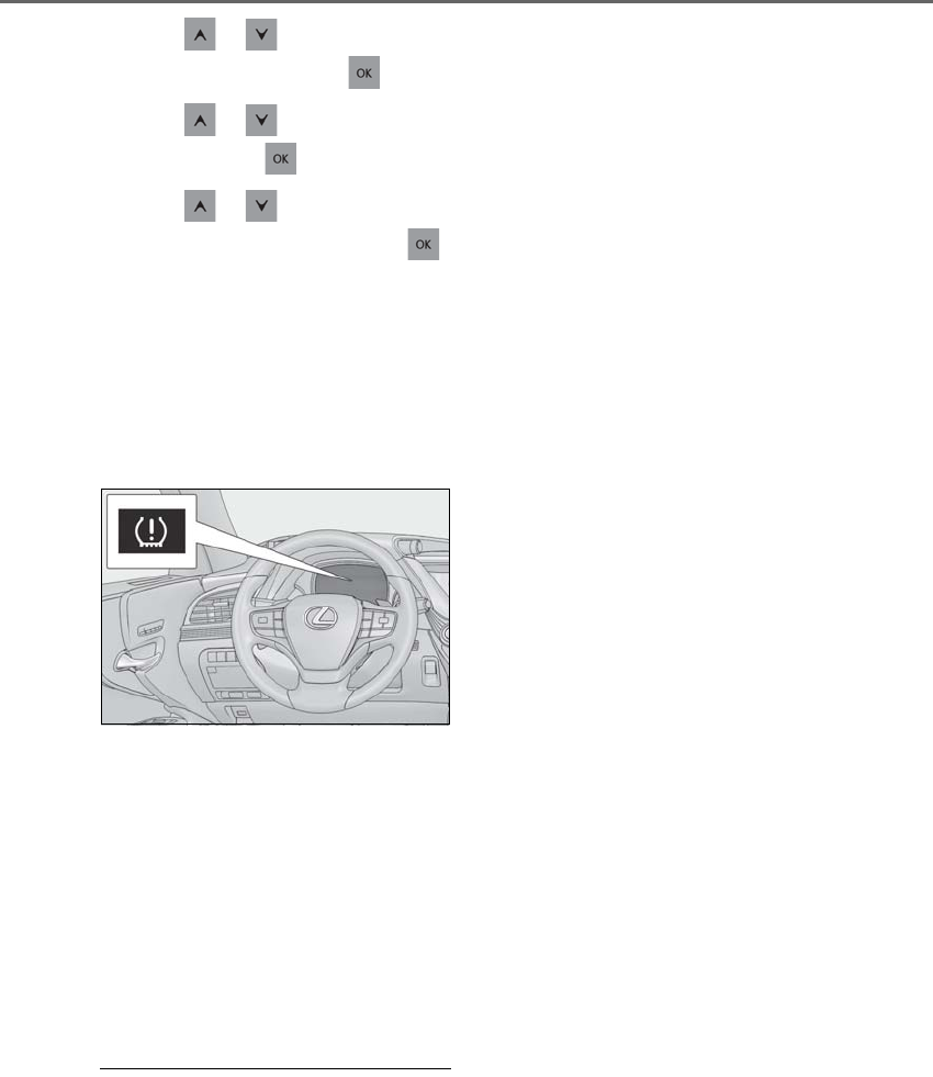
402 6-3. Do-it-yourself maintenance
LS500h_OM_OM50F42U_(U)
5Press or to select “Vehicle
Settings” and then press .
6Press or to select “TPWS”
and then press .
7Press or to select “Set
Pressure”. Then press and hold
until the tire pressure warning light
blinks 3 times.
Then a message will be displayed on the
multi-information display.
“--” will be displayed on the multiinforma-
tion display for the inflation pressure of
each tire while initialization is being per-
formed.
8Drive straight (with occasional left
and right turns) at approximately
25 mph (40 km/h) or more for
approximately 10 to 30 minutes.
Initialization is complete when the position
of each tire is determined and the inflation
pressure of each tire is displayed on the
multi-information display.
Initialization may take longer than approxi-
mately 1 hour in certain situations, such as
when the vehicle is stopped for a long time
at traffic lights, etc. (→P.402)
■Initialization procedure
●Make sure to perform the initialization
procedure after adjusting the tire inflation
pressure.
Also, make sure the tires are cold before
performing the initialization procedure or
adjusting the tire inflation pressure.
●If the power switch is turned off during
initialization, it is not necessary to restart
the initialization procedure from the
beginning as it will begin automatically
when the power switch is turned back to
ON mode.
●If initialization has accidentally been
started when it is not necessary, adjust
the tire inflation pressure to the specified
level when the tires are cold and then
perform the initialization procedure
again.
●While the position of each tire is being
determined and the inflation pressures
are not being displayed on the
multi-information display, if the inflation
pressure of a tire drops, the tire pressure
warning light will come on.
■If the tire pressure warning system is not
initialized properly
●In the following situations, initialization
may take longer than usual to be com-
pleted or may not be possible. (Usually,
the vehicle will need to be driven for
approximately 10 to 30 minutes to com-
plete initialization.) If initialization is not
complete after driving approximately 30
minutes, continue driving for a while.
• If the vehicle is driven on an unpaved
road, it may take longer to complete ini-
tialization.
• If the vehicle is backed up while perform-
ing initialization, data collected during ini-
tialization will be cleared and it will take
longer than normal to complete.
• If the vehicle is driven in heavy traffic or
another situation where other vehicles
are driven close by, it may take time for
the system to recognize the tire pressure
warning valve and transmitters of your
vehicle over those of other vehicles.
If initialization is not complete after driving
for approximately 1 hour, park the vehicle in
a safe place for approximately 20 minutes
and then drive the vehicle again.
●In the following situations, initialization
will not be started or was not completed
properly and the system will not operate
properly. Perform the initialization proce-
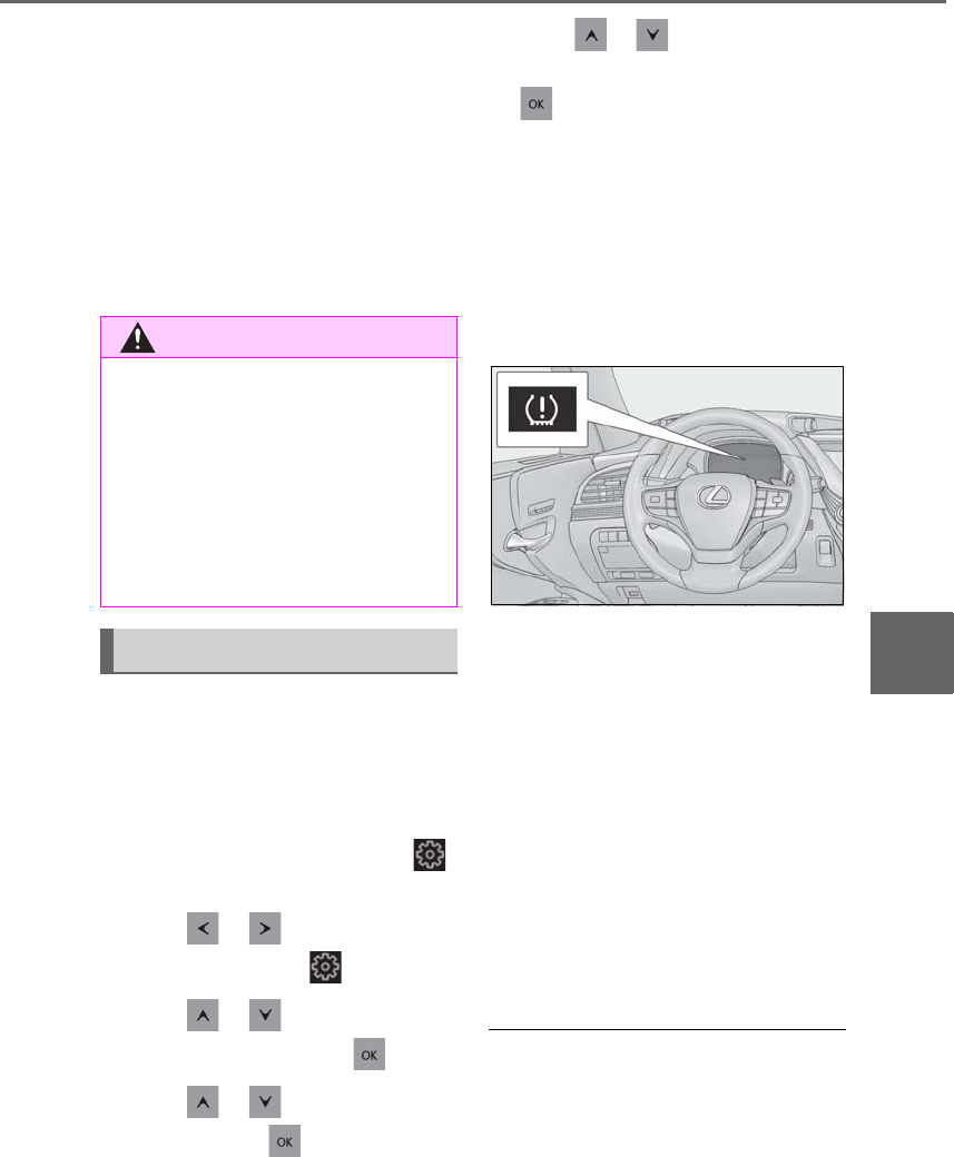
403
6-3. Do-it-yourself maintenance
LS500h_OM_OM50F42U_(U)
6
Maintenance and care
dure again.
• If, when attempting to start initialization,
the tire pressure warning light does not
blink 3 times.
• If, when the vehicle has been driven for
about 20 minutes after performing ini-
tialization, the tire pressure warning light
blinks for approximately 1 minute and
then illuminates.
●If initialization cannot be completed after
performing the above procedure, con-
tact your Lexus dealer.
Every tire pressure warning valve and
transmitter has a unique ID code.
When replacing a tire pressure warn-
ing valve and transmitter, it is necessary
to register the ID codes.
The ID codes can be registered on
of the multi-information display.
1Press or of the meter con-
trol switch to select .
2Press or to select “Vehicle
Settings” and then press .
3Press or to select “TPWS”
and then press .
4Press or to select “Change
Wheel Set”. Then press and hold
until the tire pressure warning
light blinks slowly 3 times.
Then a message will be displayed on the
multi-information display.
When registration is being performed, the
tire pressure warning light will blink for
approximately 1 minute then illuminate and
“--” will be displayed for the inflation pres-
sure of each tire on the multi-information
display.
5Drive straight (with occasional left
and right turns) at approximately
25 mph (40 km/h) or more for
approximately 10 to 30 minutes.
Registration is complete when the tire
pressure warning light turns off and the
inflation pressure of each tire is displayed
on the multiinformation display.
Registration may take longer than approxi-
mately 1 hour in certain situations, such as
when the vehicle is stopped for a long time
at traffic lights, etc. (→P.404)
After registering the ID codes, make sure
to initialize the tire pressure warning sys-
tem. (→P.401)
■When registering ID codes
●Before performing ID code registration,
make sure that no wheels with tire pres-
sure warning valve and transmitters
installed are near the vehicle.
●Make sure to initialize the tire pressure
warning system after registering the ID
WARNING
■When initializing the tire pressure
warning system
Do not initialize the tire pressure warning
system without first adjusting the tire
inflation pressure to the specified level.
Otherwise, the tire pressure warning
light may not come on even if the tire
inflation pressure is low, or it may come
on when the tire inflation pressure is
actually normal.
Registering ID codes

404 6-3. Do-it-yourself maintenance
LS500h_OM_OM50F42U_(U)
codes. If the system is initialized before
registering the ID codes, the initialized
values will be invalid.
●As the tires will be warm when registra-
tion is completed, make sure to allow the
tires to cool before performing initializa-
tion.
■Canceling ID code registration
●To cancel ID code registration after it has
been started, turn the power switch off
before driving the vehicle.
If the vehicle is driven after ID code regis-
tration is started, to cancel registration,
perform the ID code registration start
procedure again and turn the power
switch off before driving.
●If ID code registration has been canceled,
the tire pressure warning light will blink
for approximately 1 minute when the
power switch is turned to ON mode and
then illuminate. The tire pressure warning
system will be operational when the tire
pressure warning light turns off.
●If the warning light does not turn off even
after several minutes have elapsed, ID
code registration may not have been can-
celled correctly. To cancel registration,
perform the ID code registration start
procedure again and then turn the power
switch off before driving.
■If ID codes are not registered properly
●In the following situations, ID code regis-
tration may take longer than usual to be
completed or may not be possible. (Usu-
ally, the vehicle will need to be driven for
approximately 10 to 30 minutes to com-
plete ID code registration.)
If ID code registration is not complete
after driving for approximately 30 min-
utes, continue driving for a while.
• If the vehicle is driven on an unpaved
road, it may take longer than normal to
complete registration.
• If the vehicle is backed up while perform-
ing registration, data collected during
registration will be cleared, and it will take
longer than normal to complete.
• If the vehicle is driven in heavy traffic or
another situation where other vehicles
are driven close by, it may take time for
the system to recognize the tire pressure
warning valve and transmitters of your
vehicle over those of other vehicles.
•If a wheel with a tire pressure warning
valve and transmitter installed is inside or
near the vehicle, registration of the ID
codes for the installed wheels may not be
possible.
If ID registration is not complete after driv-
ing for approximately 1 hour, park the vehi-
cle in a safe place for approximately 20
minutes and then perform the ID code reg-
istration procedure again.
●In the following situations, ID code regis-
tration will not be started or was not com-
pleted properly and the system will not
operate properly. Perform the ID code
registration procedure again.
• If, when attempting to start ID code regis-
tration, the tire pressure warning light
does not blink slowly 3 times.
• If, when the vehicle has been driven for
about 20 minutes after performing ID
code registration, the tire pressure warn-
ing light blinks for approximately 1 minute
and then illuminates.
●If ID code registration cannot be com-
pleted after performing the above proce-
dure, contact your Lexus dealer.

405
6-3. Do-it-yourself maintenance
LS500h_OM_OM50F42U_(U)
6
Maintenance and care
-Stop the vehicle in a safe place on a
hard, flat surface.
-Set the parking brake.
-Shift the shift position to P.
-Disabling the height control. (if
equipped) (→P.301)
-Stop the hybrid system.
■Jack and tools
As your vehicle is equipped with run-flat
tires, the following tools for replacing a tire
are not included with your vehicle. They can
be purchased at your Lexus dealer.
●Wheel nut wrench
●Jack
●Jack handle
Replacing the tire
When raising your vehicle with a
jack, position the jack correctly.
Improper placement may damage
your vehicle or cause injury.
If necessary tire replacement
seems difficult to perform, contact
your Lexus dealer.
Before jacking up the vehicle
WARNING
■Using the tire jack
Observe the following precautions.
Improper use of the tire jack may cause
the vehicle to suddenly fall off the jack,
leading to death or serious injury.
●Do not use the tire jack for any pur-
pose other than replacing tires or
installing and removing tire chains.
●Do not use other tire jacks for replac-
ing tires on this vehicle.
●Put the jack properly in its jack point.
●Do not put any part of your body under
the vehicle while it is supported by the
jack.
●Do not start the hybrid system or drive
the vehicle while the vehicle is sup-
ported by the jack.
●Do not raise the vehicle while some-
one is inside.
●When raising the vehicle, do not put an
object on or under the jack.
●Do not raise the vehicle to a height
greater than that required to replace
the tire.
●Use a jack stand if it is necessary to get
under the vehicle.
●Make sure to disable all functions of
the vehicle height control of the elec-
tronically modulated air suspension
and then stopping the hybrid system.
(→P.301)
●When lowering the vehicle, make sure
that there is no-one near the vehicle. If
there are people nearby, warn them
vocally before lowering.
■Replacing a flat tire for vehicles with
power trunk opener and closer
In cases such as when replacing tires,
make sure to turn off the trunk opener
main switch (→P.118). Failure to do so
may cause the trunk lid to operate unin-
tentionally if the power trunk opener and
closer switch is accidentally touched,
resulting in hands and fingers being
caught and injured.
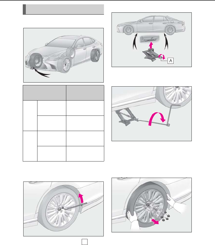
406 6-3. Do-it-yourself maintenance
LS500h_OM_OM50F42U_(U)
1Chock the tires.
2Slightly loosen the wheel nuts (one
turn).
3Turn the tire jack portion by
hand until the notch of the jack is in
contact with the jack point.
The jack point guides are located under
the rocker panel. They indicate the jack
point positions.
4Raise the vehicle until the tire is
slightly raised off the ground.
5Remove all the wheel nuts and the
tire.
When resting the tire on the ground, place
the tire so that the wheel design faces up to
avoid scratching the wheel surface.
Removing a tire
Tire Wheel chock posi-
tions
Front
Left-hand side Behind the rear
right-hand side tire
Right-hand
side
Behind the rear
left-hand side tire
Rear
Left-hand side In front of the front
right-hand side tire
Right-hand
side
In front of the front
left-hand side tire
A
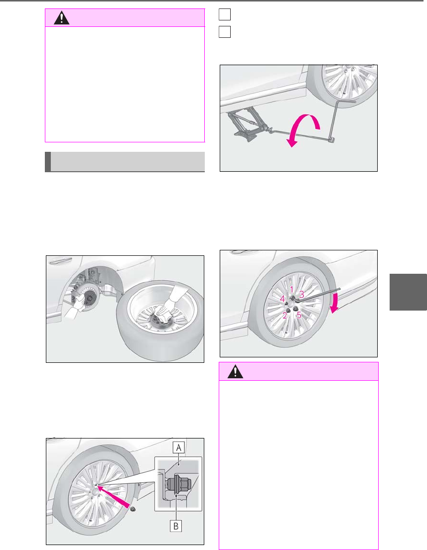
407
6-3. Do-it-yourself maintenance
LS500h_OM_OM50F42U_(U)
6
Maintenance and care
1Remove any dirt or foreign matter
from the wheel contact surface.
If foreign matter is on the wheel contact
surface, the wheel nuts may loosen while
the vehicle is in motion, causing the tire to
come off.
2Install the tire and loosely tighten
each wheel nut by hand by approxi-
mately the same amount.
Turn the wheel nuts until the washers come
into contact with the disc wheel.
Disc wheel
Washer
3Lower the vehicle.
4Firmly tighten each wheel nut two
or three times in the order shown in
the illustration.
Tightening torque:
103 ft•lbf (140 N•m, 14.3 kgf•m)
WARNING
■Replacing a tire
Do not touch the disc wheels or the area
around the brakes immediately after the
vehicle has been driven.
After the vehicle has been driven the disc
wheels and the area around the brakes
will be extremely hot. Touching these
areas with hands, feet or other body
parts while changing a tire, etc. may
result in burns.
Installing the tire
WARNING
■When installing the tire
Failure to follow these precautions could
cause the wheel nuts to loosen and the
tire to fall off, resulting in death or serious
injury.
●Never use oil or grease on the wheel
bolts or wheel nuts.
Oil and grease may cause the wheel
nuts to be excessively tightened, lead-
ing to bolt or disc wheel damage. In
addition, the oil or grease can cause
the wheel nuts to loosen and the wheel
may fall off, causing a serious accident.
Remove any oil or grease from the
wheel bolts or wheel nuts.
A
B
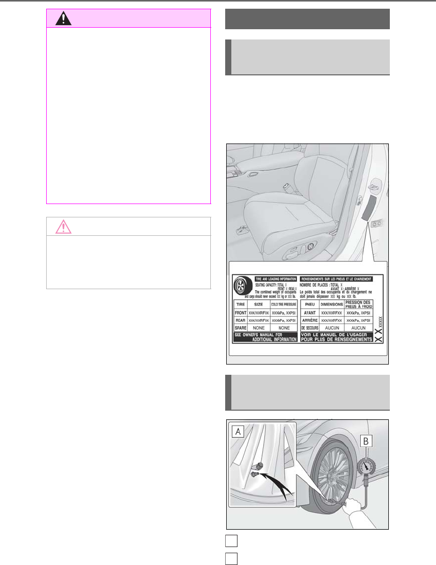
408 6-3. Do-it-yourself maintenance
LS500h_OM_OM50F42U_(U)
The recommended cold tire inflation
pressure and tire size are displayed on
the tire and loading information label.
(→P.466)
Tire valve
Tire pressure gauge
WARNING
●Have the wheel nuts tightened with a
torque wrench to 103 ft•lbf (140 N•m,
14.3 kgf•m) as soon as possible after
changing wheels.
●Do not attach a heavily damaged
wheel ornament, as it may fly off the
wheel while the vehicle is moving.
●When installing a tire, only use wheel
nuts that have been specifically
designed for that wheel.
●If there are any cracks or deformations
in the bolt screws, nut threads or bolt
holes of the wheel, have the vehicle
inspected by your Lexus dealer.
NOTICE
■Repairing or replacing tires, wheels,
tire pressure warning valves, trans-
mitters and tire valve caps
→P.401
Tire inflation pressure
Checking the specified tire infla-
tion pressure
Inspection and adjustment pro-
cedure
A
B

409
6-3. Do-it-yourself maintenance
LS500h_OM_OM50F42U_(U)
6
Maintenance and care
1Remove the tire valve cap.
2Press the tip of the tire pressure
gauge onto the tire valve.
3Read the pressure using the gauge
gradations.
4If the tire inflation pressure is not at
the recommended level, adjust the
pressure.
If you add too much air, press the
center of the valve to deflate.
5After completing the tire inflation
pressure measurement and adjust-
ment, apply soapy water to the
valve and check for leakage.
6Put the tire valve cap back on.
■Tire inflation pressure check interval
You should check tire inflation pressure
every two weeks, or at least once a month.
Do not forget to check the spare.
■Effects of incorrect tire inflation pres-
sure
Driving with incorrect tire inflation pressure
may result in the following:
●Reduced fuel economy
●Reduced driving comfort and poor han-
dling
●Reduced tire life due to wear
●Reduced safety
●Damage to the drive train
If a tire needs frequent inflating, have it
checked by your Lexus dealer.
■Instructions for checking tire inflation
pressure
When checking tire inflation pressure,
observe the following:
●Check only when the tires are cold.
If your vehicle has been parked for at
least 3 hours or has not been driven for
more than 1 mile or 1.5 km, you will get an
accurate cold tire inflation pressure read-
ing.
●Always use a tire pressure gauge.
It is difficult to judge if a tire is properly
inflated based only on its appearance.
●It is normal for the tire inflation pressure
to be higher after driving as heat is gen-
erated in the tire. Do not reduce tire infla-
tion pressure after driving.
●Never exceed the vehicle capacity
weight.
Passengers and luggage weight should
be placed so that the vehicle is balanced.
WARNING
■Proper inflation is critical to save tire
performance
Keep your tires properly inflated.
If the tires are not properly inflated, the
following conditions may occur which
could lead to an accident resulting in
death or serious injury:
●Excessive wear
●Uneven wear
●Poor handling
●Possibility of blowouts resulting from
overheated tires
●Air leaking from between tire and
wheel
●Wheel deformation and/or tire dam-
age
●Greater possibility of tire damage
while driving (due to road hazards,
expansion joints, sharp edges on the
road, etc.)
NOTICE
■When inspecting and adjusting tire
inflation pressure
Be sure to put the tire valve caps back on.
If a valve cap is not installed, dirt or mois-
ture may get into the valve and cause an
air leak, resulting in decreased tire infla-
tion pressure.
410 6-3. Do-it-yourself maintenance
LS500h_OM_OM50F42U_(U)
When replacing wheels, care should
be taken to ensure that they are equiv-
alent to those removed in load capac-
ity, diameter, rim width and inset*.
Replacement wheels are available at
your Lexus dealer.
*: Conventionally referred to as offset.
Lexus does not recommend using the
following:
-Wheels of different sizes or types
-Used wheels
-Bent wheels that have been straight-
ened
■When replacing wheels
The wheels of your vehicle are equipped
with tire pressure warning valves and trans-
mitters that allow the tire pressure warning
system to provide advance warning in the
event of a loss in tire inflation pressure.
Whenever wheels are replaced, the tire
pressure warning valves and transmitters
must be installed. (→P.401)
-Use only Lexus wheel nuts and
wheel nut wrenches designed for
use with your aluminum wheels.
-When rotating, repairing or chang-
ing your tires, check that the wheel
nuts are still tight after driving 1000
miles (1600 km).
-Be careful not to damage the alumi-
num wheels when using tire chains.
-Use only Lexus genuine balance
weights or equivalent and a plastic
Wheels
If a wheel is bent, cracked or heavily
corroded, it should be replaced.
Otherwise, the tire may separate
from the wheel or cause a loss of
handling control.
Wheel selection
WARNING
■When replacing wheels
●Do not use wheels that are a different
size from those recommended in the
Owner’s Manual, as this may result in a
loss of handling control.
WARNING
●Never use an inner tube in a leaking
wheel which is designed for a tubeless
tire.
Doing so may result in an accident,
causing death or serious injury.
■Use of defective wheels prohibited
Do not use cracked or deformed wheels.
Doing so could cause the tire to leak air
during driving, possibly causing an acci-
dent.
NOTICE
■Replacing tire pressure warning
valves and transmitters
●Because tire repair or replacement
may affect the tire pressure warning
valves and transmitters, make sure to
have tires serviced by your Lexus
dealer or other qualified service shop.
In addition, make sure to purchase
your tire pressure warning valves and
transmitters at your Lexus dealer.
●Ensure that only genuine Lexus wheels
are used on your vehicle.
Tire pressure warning valves and trans-
mitters may not work properly with
non-genuine wheels.
Aluminum wheel precautions
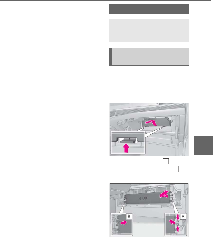
411
6-3. Do-it-yourself maintenance
LS500h_OM_OM50F42U_(U)
6
Maintenance and care
or rubber hammer when balancing
your wheels.
1Turn the power switch off.
2Open the glove box. Remove the
partition. (→P.345)
3Remove the panel.
4Unlock the filter cover ( ), pull the
filter cover out of the claws ( ),
and remove the filter cover.
Air conditioning filter
The air conditioning filter must be
changed regularly to maintain air
conditioning efficiency.
Removing the air conditioning
filter
A
B
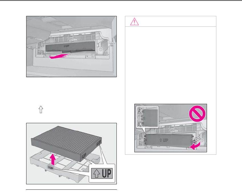
412 6-3. Do-it-yourself maintenance
LS500h_OM_OM50F42U_(U)
5Remove the filter case.
6Remove the air conditioning filter
from the filter case and replace it
with a new one.
The “ UP” marks shown on the filter
and the filter case should be pointing up.
■Checking interval
Inspect and replace the air conditioning fil-
ter according to the maintenance schedule.
In dusty areas or areas with heavy traffic
flow, early replacement may be required.
(For scheduled maintenance information,
please refer to the “Owner’s Manual Sup-
plement” or “Scheduled Maintenance”.)
■If air flow from the vents decreases dra-
matically
The filter may be clogged. Check the filter
and replace if necessary.
■Air conditioning filter with deodorizing
function
When fragrances are placed in your vehi-
cle, the deodorizing effect may become
significantly weakened in a short period.
When an air conditioning odor comes out
continuously, replace the air conditioning
filter.
NOTICE
■When using the air conditioning sys-
tem
Make sure that a filter is always installed.
Using the air conditioning system without
a filter may cause damage to the system.
■To prevent damage to the filter cover
When moving the filter cover in the
direction of arrow to release the fitting,
pay attention not to apply excessive force
to the claws. Otherwise, the claws may
be damaged.
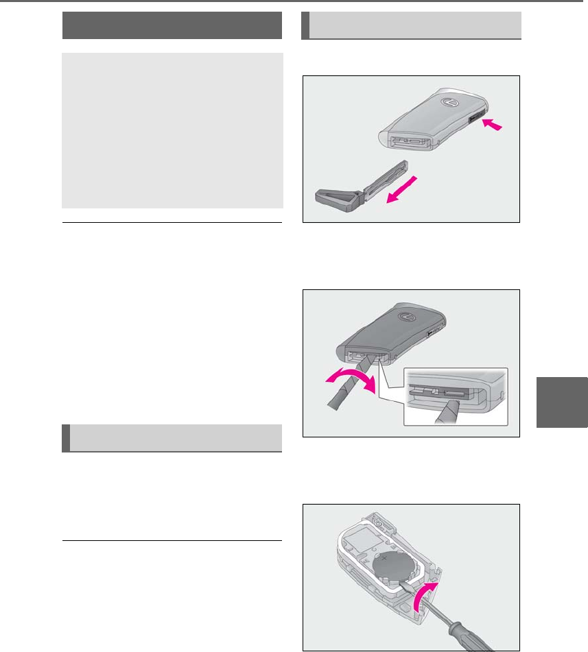
413
6-3. Do-it-yourself maintenance
LS500h_OM_OM50F42U_(U)
6
Maintenance and care
■If the electronic key battery is depleted
The following symptoms may occur:
●The smart access system with push-but-
ton start and wireless remote control will
not function properly.
●The operational range will be reduced.
■When the card key battery needs to be
replaced (if equipped)
The battery for the card key is available only
at Lexus dealers. Your Lexus dealer can
replace the battery for you.
-Flathead screwdriver
-Small flathead screwdriver
-Lithium battery CR2032
■Use a CR2032 lithium battery
●Batteries can be purchased at your Lexus
dealer, local electrical appliance shops or
camera stores.
●Replace only with the same or equivalent
type recommended by the manufacturer.
●Dispose of used batteries according to
local laws.
1Take out the mechanical key.
2Remove the cover.
To prevent damage to the key, cover the tip
of the flathead screwdriver with a tape.
3Remove the depleted battery.
Insert a new battery with the “+” terminal
facing up.
Electronic key battery
Replace the battery with a new one
if it is depleted.
As the key may be damaged if the
following procedure is not per-
formed properly, it is recom-
mended that key battery
replacement be performed by your
Lexus dealer.
Items to prepare
Replacing the battery
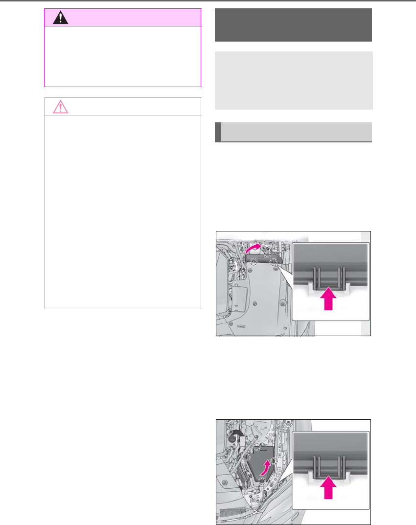
414 6-3. Do-it-yourself maintenance
LS500h_OM_OM50F42U_(U)
1Turn the power switch off.
2Open the fuse box cover.
Engine compartment: type A fuse
box
Push the tabs in and lift the lid off.
Engine compartment: type B fuse
box
Remove the engine compartment cover
(→P.388) and push the tabs in and lift the
lid off.
WARNING
■Removed battery and other parts
These parts are small and if swallowed by
a child, they can cause choking. Keep
away from children. Failure to do so
could result in death or serious injury.
NOTICE
■When replacing the battery
Use a flathead screwdriver of appropri-
ate size. Applying excessive force may
deform or damage the cover.
■For normal operation after replacing
the battery
Observe the following precautions to
prevent accidents:
●Always work with dry hands.
Moisture may cause the battery to
rust.
●Do not touch or move any other com-
ponent inside the remote control.
●Do not bend either of the battery ter-
minals.
Checking and replacing
fuses
If any of the electrical components
do not operate, a fuse may have
blown. If this happens, check and
replace the fuses as necessary.
Checking and replacing fuses
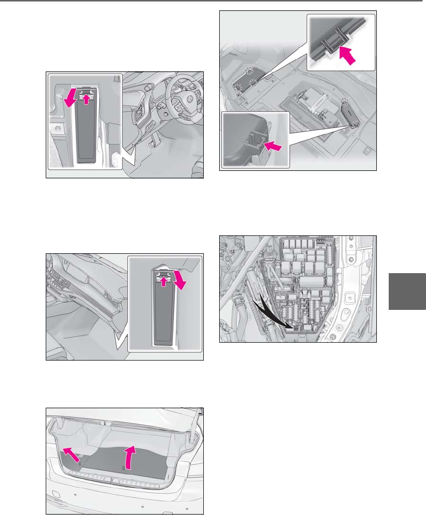
415
6-3. Do-it-yourself maintenance
LS500h_OM_OM50F42U_(U)
6
Maintenance and care
Driver’s side instrument panel
Push the tab in and remove the lid.
Make sure to push the tab in during
removal or installation.
Passenger’s side instrument panel
Push the tab in and remove the lid.
Make sure to push the tab in during
removal or installation.
Trunk
Remove the luggage mat. (→P.348)
Push the tab in and lift the lid off.
3Remove the fuse with the pullout
tool.
Only type A fuse can be removed
using the pullout tool.
4Check if the fuse is blown.
Type A and B:
Replace the blown fuse with a new fuse of
an appropriate amperage rating. The
amperage rating can be found on the fuse
box lid.
Type C and D:
Contact your Lexus dealer.
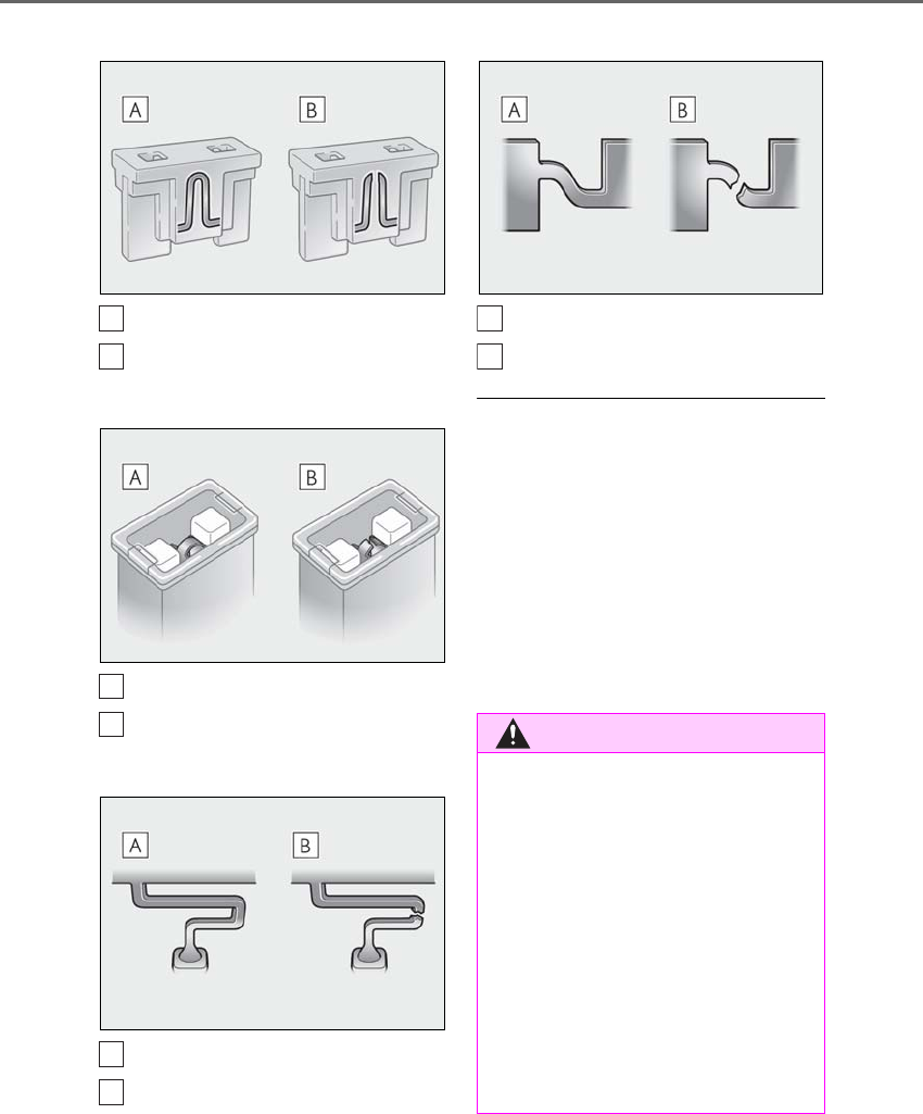
416 6-3. Do-it-yourself maintenance
LS500h_OM_OM50F42U_(U)
Type A
Normal fuse
Blown fuse
Type B
Normal fuse
Blown fuse
Type C
Normal fuse
Blown fuse
Type D
Normal fuse
Blown fuse
■After a fuse is replaced
●When installing the lid, make sure that the
tab is installed securely.
●If the lights do not turn on even after the
fuse has been replaced, a bulb may need
replacement.
●If the replaced fuse blows again, have the
vehicle inspected by your Lexus dealer.
■If there is an overload in a circuit
The fuses are designed to blow, protecting
the wiring harness from damage.
A
B
A
B
A
B
WARNING
■To prevent system breakdowns and
vehicle fire
Observe the following precautions.
Failure to do so may cause damage to
the vehicle, and possibly a fire or injury.
●Never use a fuse of a higher amperage
rating than that indicated, or use any
other object in place of a fuse.
●Always use a genuine Lexus fuse or
equivalent.
Never replace a fuse with a wire, even
as a temporary fix.
●Do not modify the fuses or fuse boxes.
A
B

417
6-3. Do-it-yourself maintenance
LS500h_OM_OM50F42U_(U)
6
Maintenance and care
■LED Lights
The lights consist of a number of LEDs. If
any of the LEDs burn out, take your vehicle
to your Lexus dealer to have the light
replaced.
■Condensation build-up on the inside of
the lens
Temporary condensation build-up on the
inside of the headlight lens does not indi-
cate a malfunction. Contact your Lexus
dealer for more information in the following
situations:
●Large drops of water have built up on the
inside of the lens.
●Water has built up inside the headlight.
NOTICE
■Before replacing fuses
Have the cause of electrical overload
determined and repaired by your Lexus
dealer as soon as possible.
Light bulbs
If any lights burn out, have it
replaced by your Lexus dealer.

418 6-3. Do-it-yourself maintenance
LS500h_OM_OM50F42U_(U)

419
LS500h_OM_OM50F42U_(U)
7
7
When trouble arises
When trouble arises
.
7-1. Essential information
Emergency flashers..................420
If your vehicle has to be stopped in
an emergency..........................420
7-2. Steps to take in an emergency
If your vehicle needs to be towed
........................................................ 422
If you think something is wrong
........................................................ 426
If a warning light turns on or a
warning buzzer sounds .......427
If a warning message is displayed
........................................................437
If you have a flat tire..................442
If the hybrid system will not start
........................................................443
If you lose your keys.................444
If the fuel filler door cannot be
opened........................................445
If the electronic key does not
operate properly....................445
If the 12-volt battery is discharged
........................................................ 447
If your vehicle overheats........453
If the vehicle becomes stuck
........................................................457
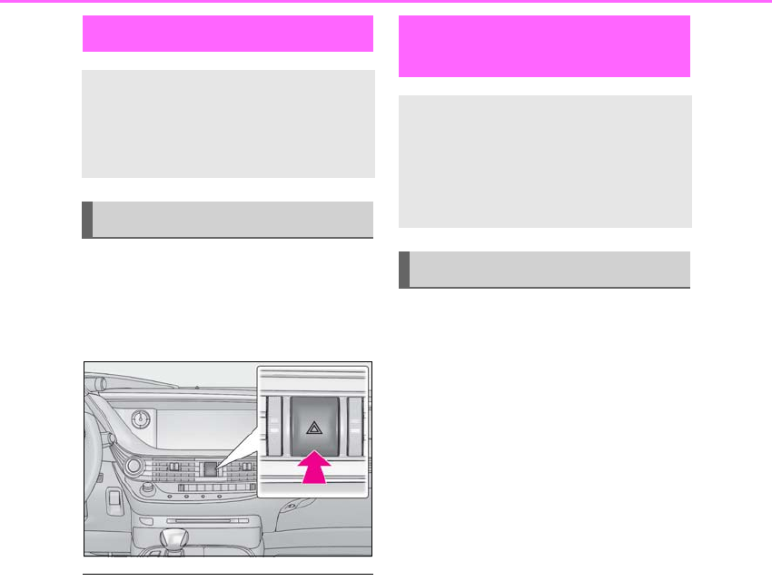
420 7-1. Essential information
LS500h_OM_OM50F42U_(U)
7-1.Essential inf ormation
Press the switch to flash all of the turn
signal lights.
To turn them off, press the switch once
again.
■Emergency flashers
●If the emergency flashers are used for a
long time while the hybrid system is not
operating (while the “READY” indicator
is not illuminated), the 12-volt battery may
discharge.
●If any of the SRS airbags deploy (inflate)
or in the event of a strong rear impact, the
emergency flashers will turn on automati-
cally.
The emergency flashers will turn off auto-
matically after operating for approxi-
mately 20 minutes. To manually turn the
emergency flashers off, press the switch
twice.
(The emergency flashers may not turn on
automatically depending on the force of
the impact and conditions of the colli-
sion.)
1Steadily step on the brake pedal
with both feet and firmly depress it.
Do not pump the brake pedal repeatedly
as this will increase the effort required to
slow the vehicle.
2Shift the shift position to N.
If the shift position is shifted to N
3After slowing down, stop the vehi-
cle in a safe place by the road.
4Stop the hybrid system.
If the shift position cannot be shifted
to N
3Keep depressing the brake pedal
with both feet to reduce vehicle
speed as much as possible.
4To stop the hybrid system, press
and hold the power switch for 2
consecutive seconds or more, or
Emergency flashers
The emergency flashers are used to
warn other drivers when the vehicle
has to be stopped on the road due
to a breakdown, etc.
Operating instructions
If your vehicle has to be
stopped in an emergency
Only in an emergency, such as if it
becomes impossible to stop the
vehicle in the normal way, stop the
vehicle using the following proce-
dure:
Stopping the vehicle
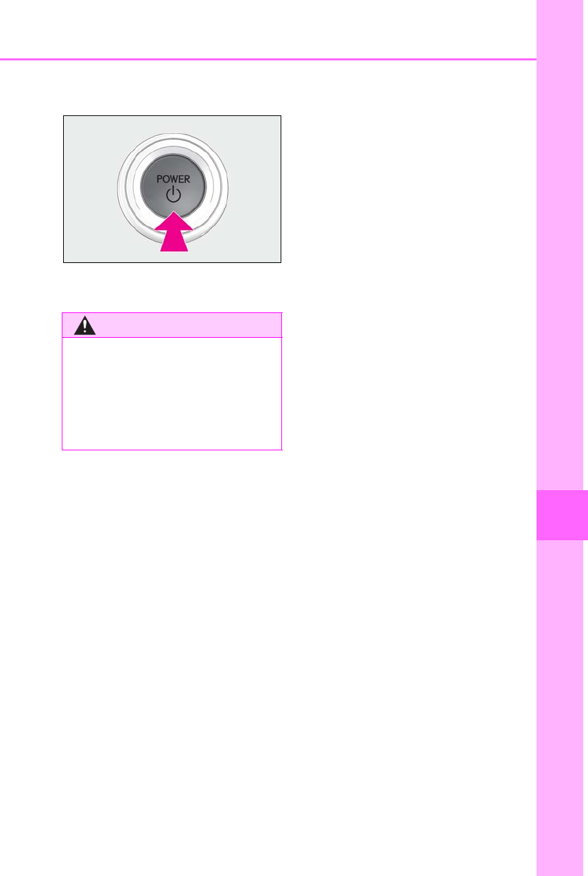
421
7-1. Essential information
LS500h_OM_OM50F42U_(U)
7
When trouble arises
press it briefly 3 times or more in
succession.
5Stop the vehicle in a safe place by
the road.
WARNING
■If the hybrid system has to be turned
off while driving
Power assist for the steering wheel will
be lost, making the steering wheel
heavier to turn. Decelerate as much as
possible before turning off the hybrid sys-
tem.
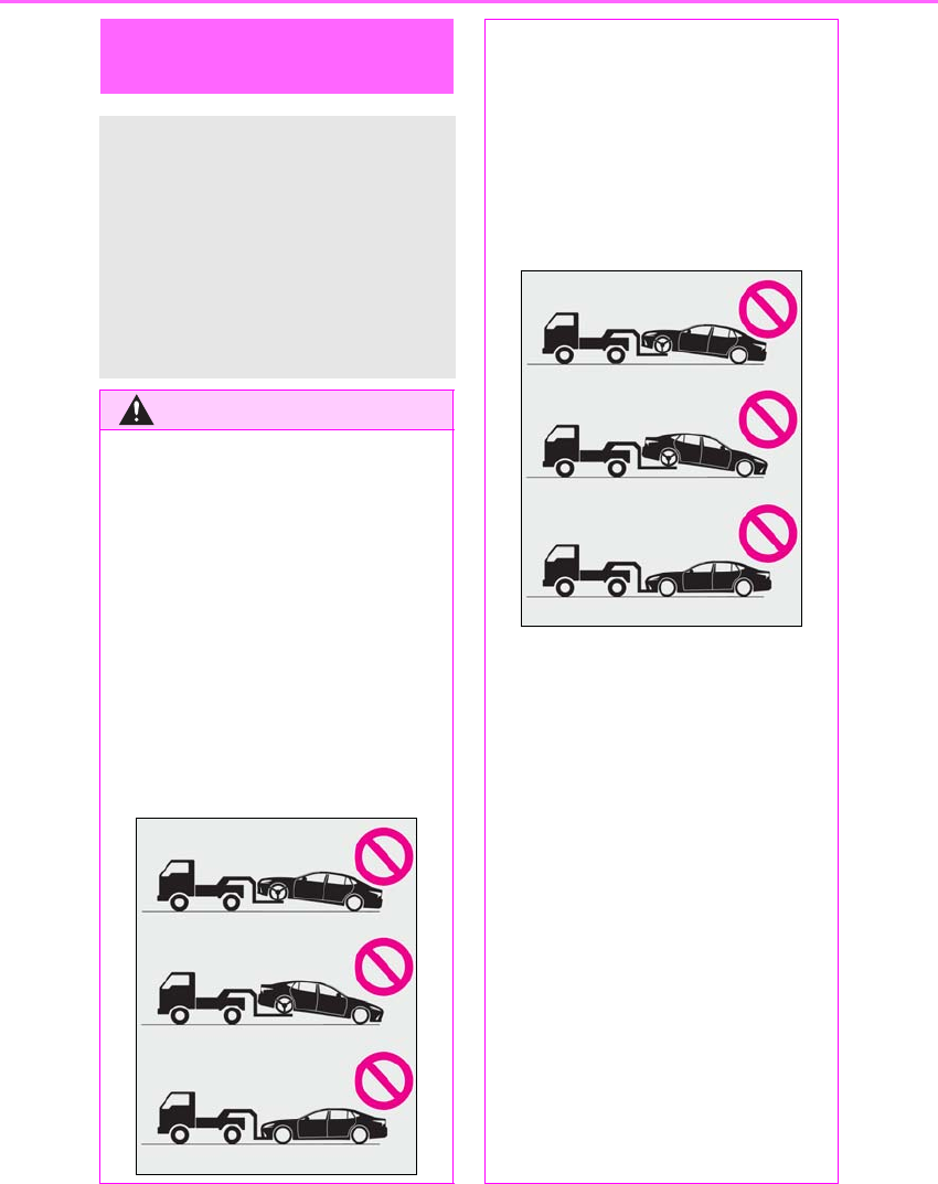
422 7-2. Steps to take in an emergency
LS500h_OM_OM50F42U_(U)
7-2.Steps to take in an emergency
If your vehicle needs to be
towed
If towing is necessary, we recom-
mend having your vehicle towed by
your Lexus dealer or commercial
towing service, using a wheel-lift
type truck or flatbed truck.
Use a safety chain system for all
towing, and abide by all state/pro-
vincial and local laws.
WARNING
Observe the following precautions.
Failure to do so may result in death or
serious injury.
■When towing the vehicle
2WD models
Be sure to transport the vehicle with all
four wheels raised off the ground. If the
vehicle is towed with the tires contacting
the ground, the drivetrain and related
parts may be damaged, an accident may
occur due to a change in direction of the
vehicle or electricity generated by the
operation of the motor may cause a fire
to occur depending on the nature of the
damage or malfunction.
AWD models
Be sure to transport the vehicle with all
four wheels raised off the ground. If the
vehicle is towed with the tires contacting
the ground, the drivetrain or related
parts may be damaged, the vehicle may
fly off the truck, or electricity generated
by the operation of the motor may cause
a fire to occur depending on the nature
of the damage or malfunction.
■While towing
●When towing using cables or chains,
avoid sudden starts, etc. which place
excessive stress on the towing eyelets,
cables or chains. The towing eyelets,
cables or chains may become dam-
aged, broken debris may hit people,
and cause serious damage.
●Make sure to disable all functions of
the vehicle height control of the elec-
tronically modulated air suspension.
Otherwise, the vehicle height may
change and part of your body may be
caught under the vehicle, possibly
causing injury. (→P.301)
●Do not turn the power switch off.
This may lead to an accident as the
rear wheels will be locked by the park-
ing lock.
Also, there is a possibility that the
steering wheel is locked and cannot be
operated.
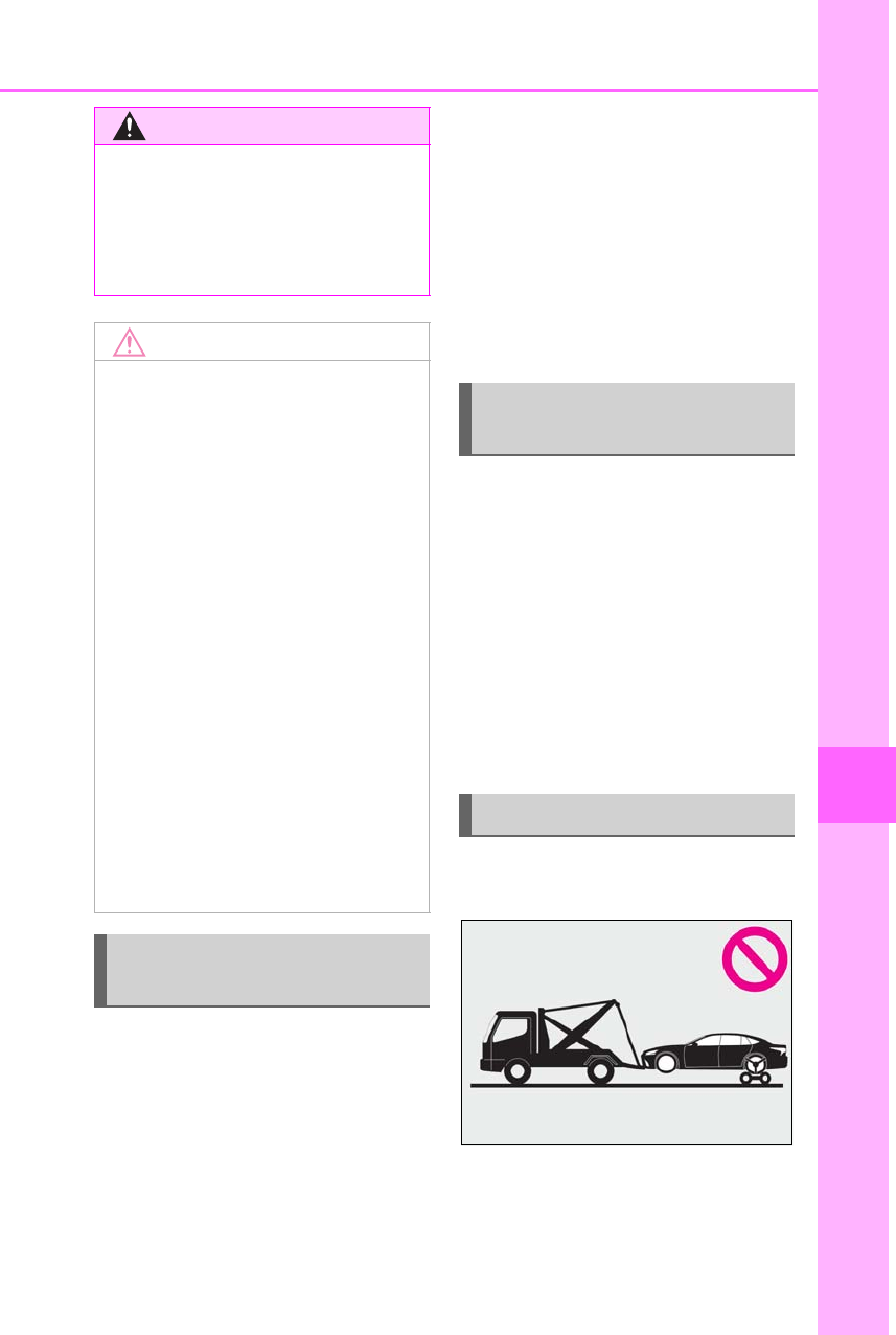
423
7-2. Steps to take in an emergency
LS500h_OM_OM50F42U_(U)
7
When trouble arises
In the following situations, it is not pos-
sible to be towed by another vehicle
using cables or chains, as the rear
wheels may be locked due to the park-
ing lock. Contact your Lexus dealer or
commercial towing service.
-There is a malfunction in the shift
control system. (→P.171, 437)
-There is a malfunction in the immo-
bilizer system. (→P.66)
-There is a malfunction in the smart
access system with push-button
start. (→P.445)
-The 12-volt battery is discharged.
(→P.447)
The following may indicate a problem
with your transmission. Contact your
Lexus dealer or commercial towing
service before towing.
-The hybrid system warning message
is shown on the multi-information
display and the vehicle does not
move.
-The vehicle makes an abnormal
sound.
Do not tow with a sling-type truck to
prevent body damage.
WARNING
■Installing towing eyelets to the vehi-
cle
Make sure that towing eyelets are
installed securely.
If not securely installed, towing eyelets
may come loose during towing.
NOTICE
■To prevent damage to the vehicle
when towing using a wheel-lift type
truck
●Do not tow the vehicle from the rear
when the power switch is off. The
steering lock mechanism is not strong
enough to hold the front wheels
straight.
●When raising the vehicle, ensure ade-
quate ground clearance for towing at
the opposite end of the raised vehicle.
Without adequate clearance, the vehi-
cle could be damaged while being
towed.
■To prevent damage to the vehicle
when towing with a sling-type truck
Do not tow with a sling-type truck, either
from the front or rear.
■To prevent damage to the vehicle
during emergency towing
Do not secure cables or chains to the
suspension components.
Situations when it is not possible
to be towed by another vehicle
Situations when it is necessary to
contact dealers before towing
Towing with a sling-type truck
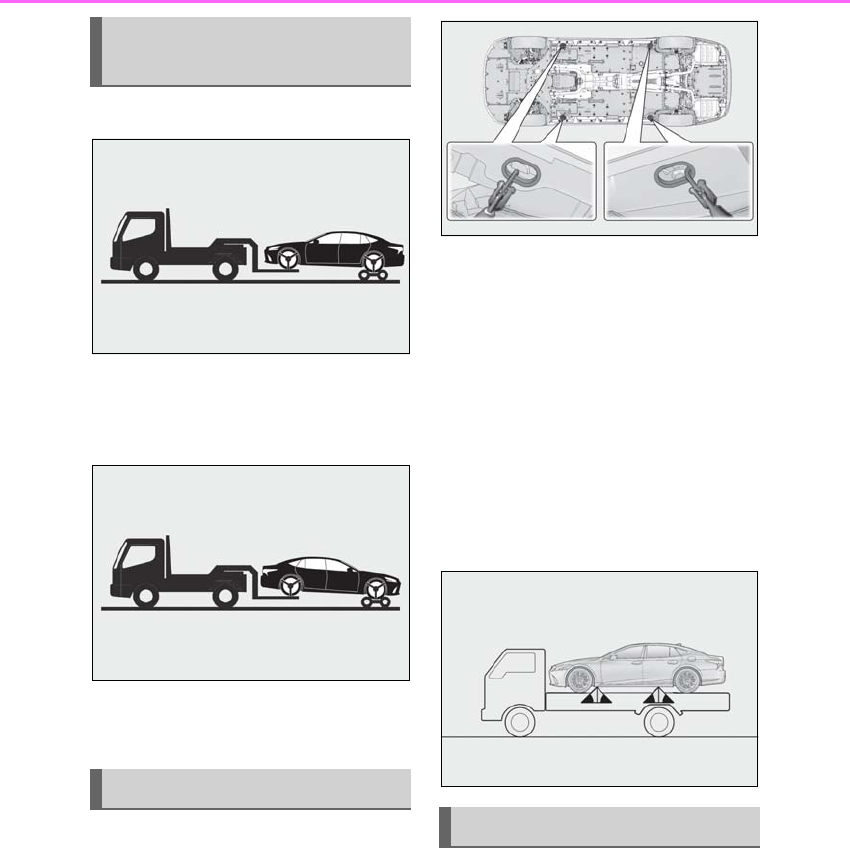
424 7-2. Steps to take in an emergency
LS500h_OM_OM50F42U_(U)
From the front
Use a towing dolly under the rear
wheels.
From the rear
Use a towing dolly under the front
wheels.
If your vehicle is transported by a flat-
bed truck, it should be tied down at the
locations shown in the illustration.
If you use chains or cables to tie down
your vehicle, the angles shaded in
black must be 45°.
Do not overly tighten the tie downs or
the vehicle may be damaged.
Make sure to disable all functions of
the vehicle height control of the elec-
tronically modulated air suspension.
Otherwise, the vehicle height may
change and the vehicle may be dam-
aged. (→P.301)
If a tow truck is not available in an
emergency, your vehicle may be tem-
porarily towed using cables or chains
secured to the emergency towing eye-
lets. This should only be attempted on
hard surfaced roads for short distances
at under 18 mph (30 km/h).
A driver must be in the vehicle to steer
and operate the brakes. The vehicle’s
Towing with a wheel-lift type
truck
Using a flatbed truck
Emergency towing
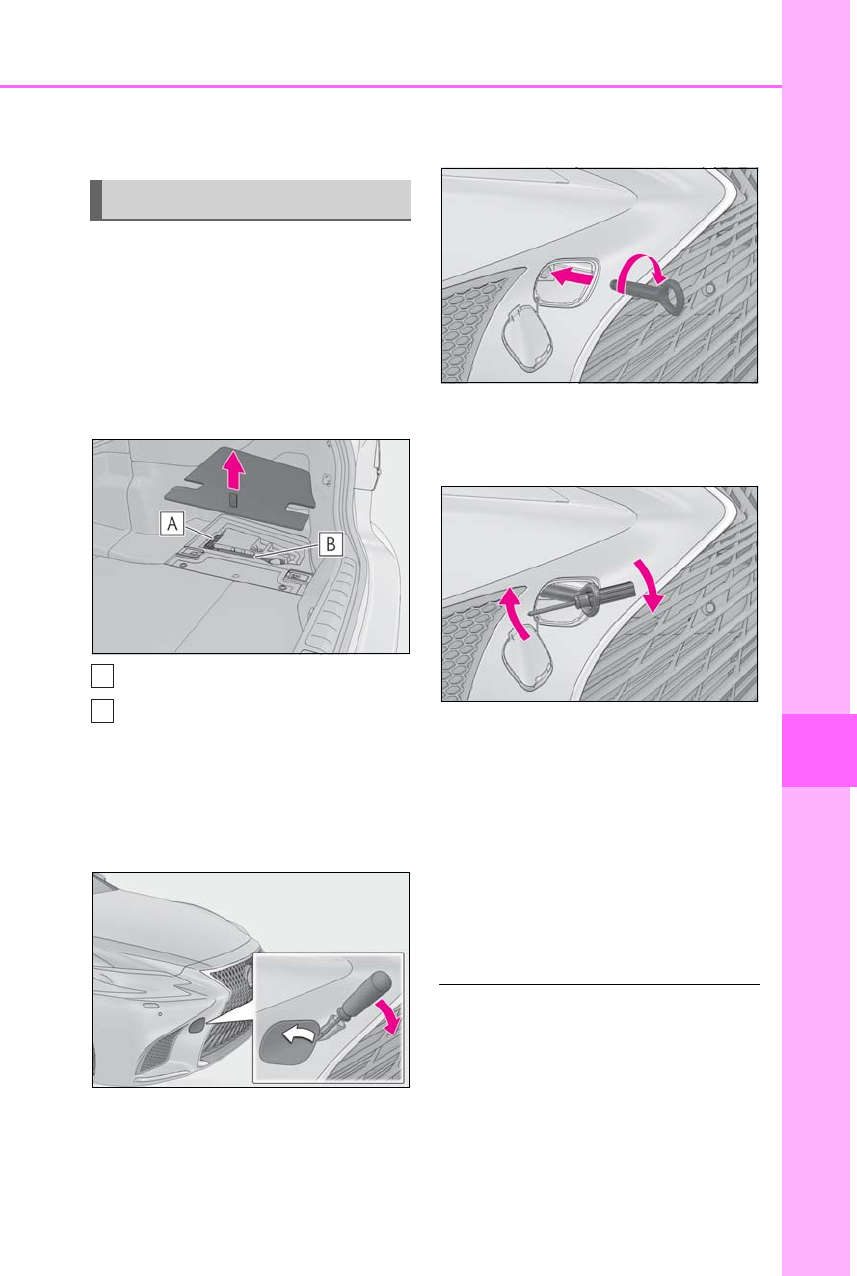
425
7-2. Steps to take in an emergency
LS500h_OM_OM50F42U_(U)
7
When trouble arises
wheels, drive train, axles, steering and
brakes must be in good condition.
To have your vehicle towed by another
vehicle, the towing eyelet must be
installed to your vehicle. Install the tow-
ing eyelet using the following proce-
dure.
1Take out the phillips-head screw-
driver and towing eyelet.
Phillips-head screwdriver
Towing eyelet
2Remove the eyelet cover using a
flathead screwdriver.
To protect the bodywork, place a rag
between the screwdriver and the vehicle
body as shown in the illustration.
3Insert the towing eyelet into the
hole and tighten partially by hand.
4Tighten down the towing eyelet
securely using a phillips-head
screwdriver or hard metal bar.
5Securely attach cables or chains to
the towing eyelet.
Take care not to damage the vehicle body.
6Enter the vehicle being towed and
start the hybrid system.
If the hybrid system does not start, turn the
power switch to ON mode.
7Shift the shift position to N and
release the parking brake.
■While towing
If the hybrid system is off, the power assist
for the brakes and steering will not function,
making steering and braking more difficult.
Emergency towing procedure
A
B

426 7-2. Steps to take in an emergency
LS500h_OM_OM50F42U_(U)
-Fluid leaks under the vehicle.
(Water dripping from the air condi-
tioning after use is normal.)
-Flat-looking tires or uneven tire
wear
-Engine coolant temperature gauge
needle continually points higher
than normal.
-Changes in exhaust sound
-Excessive tire squeal when corner-
ing
-Strange noises related to the sus-
pension system
-Pinging or other noises related to
the hybrid system
-Engine missing, stumbling or run-
ning roughly
-Appreciable loss of power
-Vehicle pulls heavily to one side
when braking
-Vehicle pulls heavily to one side
when driving on a level road
-Loss of brake effectiveness, spongy
feeling, pedal almost touches the
floor
If you think something is
wrong
If you notice any of the following
symptoms, your vehicle probably
needs adjustment or repair. Con-
tact your Lexus dealer as soon as
possible.
Visible symptoms
Audible symptoms
Operational symptoms
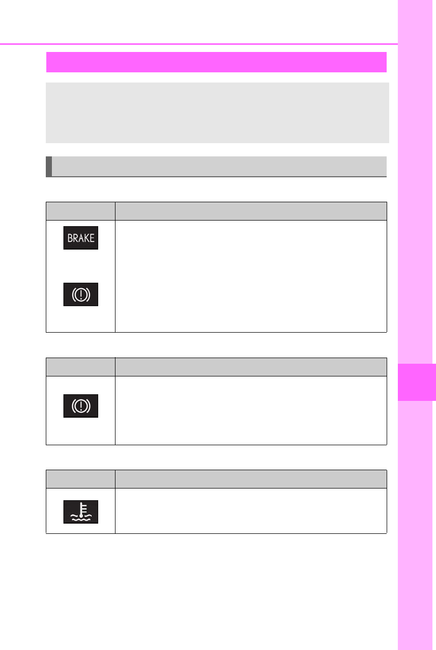
427
7-2. Steps to take in an emergency
LS500h_OM_OM50F42U_(U)
7
When trouble arises
■Brake system warning light (warning buzzer)
■Brake system warning light (warning buzzer)
■High coolant temperature warning light* (warning buzzer)
*: This light illuminates on the multi-information display.
If a warning light turns on or a warning buzzer sounds
Calmly perform the following actions if any of the warning lights comes on or
flashes. If a light comes on or flashes, but then goes off, this does not necessar-
ily indicate a malfunction in the system. However, if this continues to occur,
have the vehicle inspected by your Lexus dealer.
Actions to the warning lights or warning buzzers
Warning light Details/Actions
(U.S.A.)
or
(red)
(Canada)
Indicates that:
-The brake fluid level is low; or
-The brake system is malfunctioning
→Immediately stop the vehicle in a safe place and contact your Lexus
dealer. Continuing to drive the vehicle may be dangerous.
Indicates that the brake pads are worn out (only the right-side pads can
be detected)
→Have the vehicle inspected by your Lexus dealer.
Warning light Details/Actions
(yellow)
Indicates a malfunction in:
-The regenerative braking system;
-The electronically controlled brake system; or
-The parking brake system
→Have the vehicle inspected by your Lexus dealer immediately.
Warning light Details/Actions
Indicates that the engine coolant temperature is too high
→Immediately stop the vehicle in a safe place.
Handling method (→P.453)
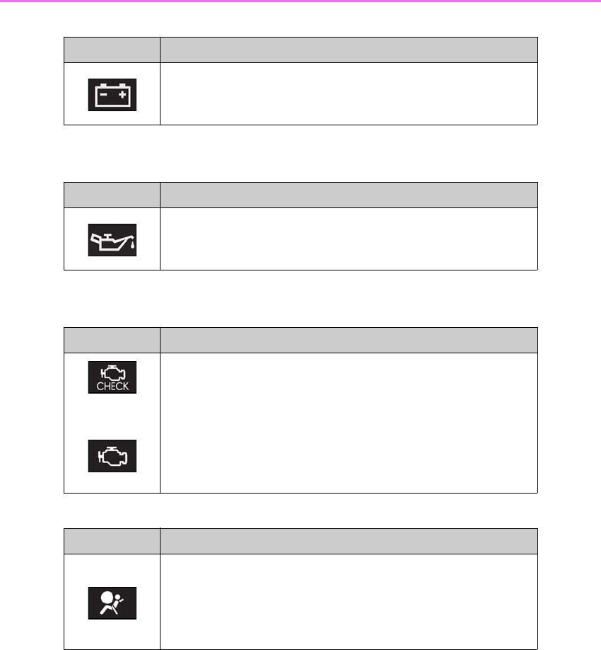
428 7-2. Steps to take in an emergency
LS500h_OM_OM50F42U_(U)
■Charging system warning light* (warning buzzer)
*: This light illuminates on the multi-information display.
■Low engine oil pressure warning light* (warning buzzer)
*: This light illuminates on the multi-information display.
■Malfunction indicator lamp (warning buzzer)
■SRS warning light (warning buzzer)
Warning light Details/Actions
Indicates a malfunction in the vehicle’s charging system
→Immediately stop the vehicle in a safe place and contact your Lexus
dealer.
Warning light Details/Actions
Indicates that the engine oil pressure is too low
→Immediately stop the vehicle in a safe place and contact your Lexus
dealer.
Warning light Details/Actions
(U.S.A.)
or
(Canada)
Indicates a malfunction in:
-The hybrid system;
-The electronic engine control system;
-The electronic throttle control system; or
-The electronic hybrid transmission control system
→Immediately stop the vehicle in a safe place and contact your Lexus
dealer.
Warning light Details/Actions
Indicates a malfunction in:
-The SRS airbag system;
-The front passenger occupant classification system; or
-The seat belt pretensioner system
→Have the vehicle inspected by your Lexus dealer immediately.
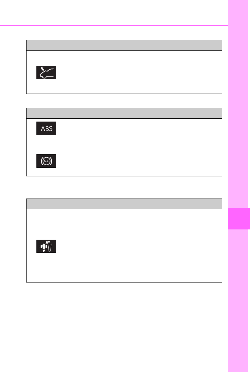
429
7-2. Steps to take in an emergency
LS500h_OM_OM50F42U_(U)
7
When trouble arises
■Pop Up Hood warning light (warning buzzer)
■ABS warning light (warning buzzer)
■Brake Override System warning light/Drive-Start Control warning light*
(warning buzzer)
*: This light illuminates on the multi-information display.
Warning light Details/Actions
Indicates that the Pop Up Hood system has operated
→The Pop Up Hood system cannot be reused once it has operated.
Have it replaced by your Lexus dealer.
Indicates a malfunction in the Pop Up Hood system
→Have the vehicle inspected by your Lexus dealer immediately.
Warning light Details/Actions
(U.S.A.)
or
(Canada)
Indicates a malfunction in:
-The ABS; or
-The brake assist system
→Have the vehicle inspected by your Lexus dealer immediately.
Warning light Details/Actions
When a buzzer sounds:
-Brake Override System is malfunctioning;
-Drive-Start Control is operating;
-Drive-Start Control is malfunctioning; or
-Parking Support Brake function (for static objects) is operating
→Follow the instructions displayed on the multi-information display.
When a buzzer does not sound:
Brake Override System is operating
→Release the accelerator pedal and depress the brake pedal.
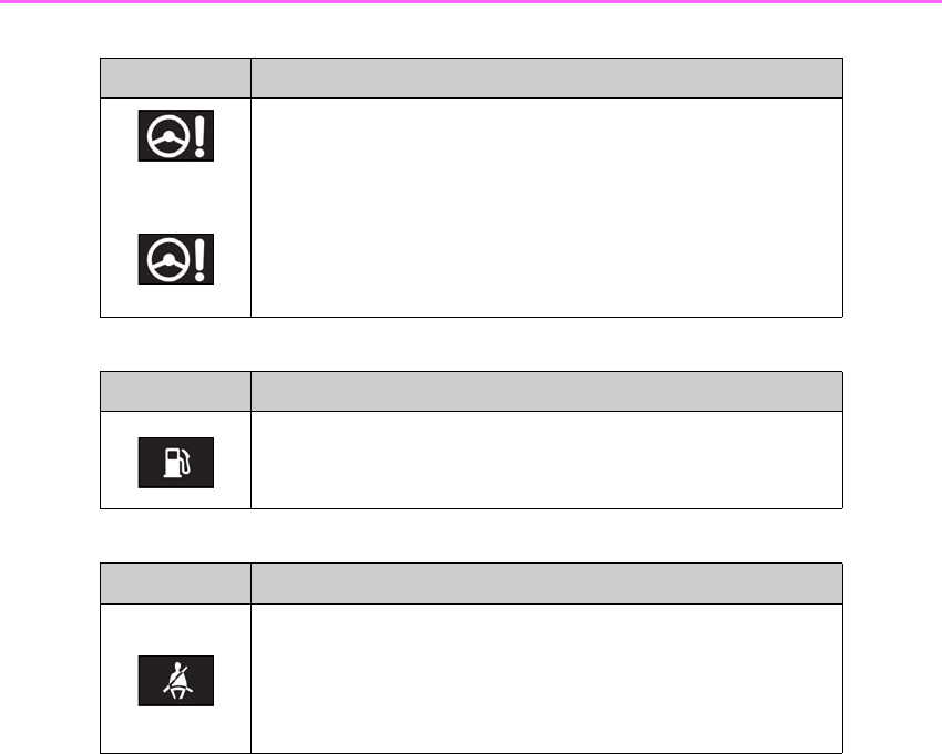
430 7-2. Steps to take in an emergency
LS500h_OM_OM50F42U_(U)
■Electric power steering system warning light (warning buzzer)
■Low fuel level warning light
■Driver’s and front passenger’s seat belt reminder light (warning buzzer)*
*: Driver’s seat belt warning buzzer:
The driver’s seat belt warning buzzer sounds to alert the driver that his or her seat belt is not
fastened. Once the power switch is turned to ON mode, the buzzer sounds for 6 seconds.
If the vehicle reaches a speed of 12 mph (20 km/h), the buzzer sounds once. If the seat belt
is still unfastened after 24 seconds, the buzzer will sound intermittently for 6 seconds. Then,
if the seat belt is still unfastened, the buzzer will sound in a different tone for 90 more sec-
onds.
Front passenger’s seat belt warning buzzer:
The front passenger’s seat belt warning buzzer sounds to alert the front passenger that his
or her seat belt is not fastened. The buzzer sounds once if the vehicle reaches a speed of 12
mph (20 km/h). If the seat belt is still unfastened after 24 seconds, the buzzer will sound
intermittently for 6 seconds. Then, if the seat belt is still unfastened, the buzzer will sound in
a different tone for 90 more seconds.
Warning light Details/Actions
(red)
or
(yellow)
Indicates a malfunction in the EPS (Electric Power Steering) system
→Have the vehicle inspected by your Lexus dealer immediately.
Warning light Details/Actions
Indicates that remaining fuel is approximately 3.4 gal. (13 L, 2.8 Imp.
gal.) or less
→Refuel the vehicle.
Warning light Details/Actions
Warns the driver and/or front passenger to fasten their seat belts
→Fasten the seat belt.
If the front passenger’s seat is occupied, the front passenger’s seat
belt also needs to be fastened to make the warning light (warning
buzzer) turn off.
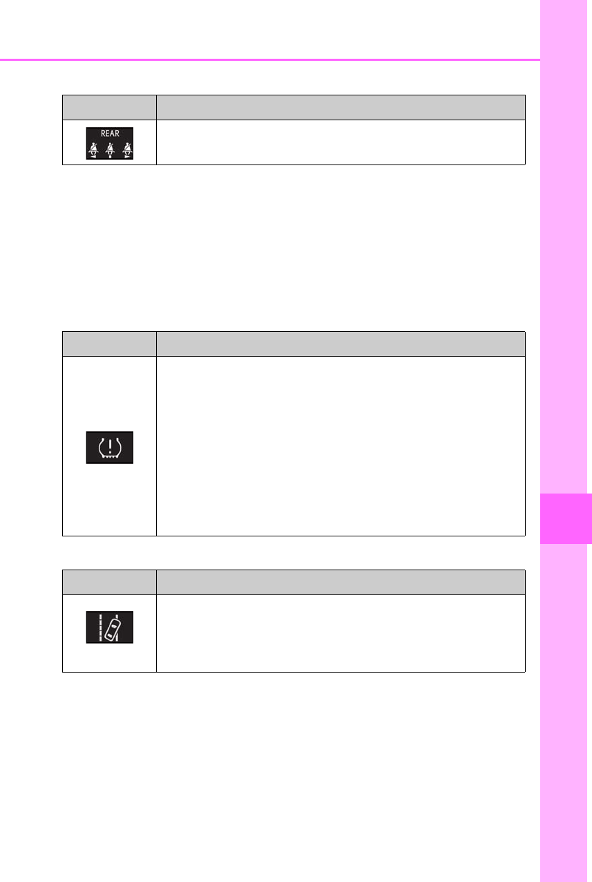
431
7-2. Steps to take in an emergency
LS500h_OM_OM50F42U_(U)
7
When trouble arises
■Rear passengers’ seat belt reminder lights*1 (warning buzzer)*2
*1: This light illuminates on the center panel.
*2: Rear passengers’ seat belt warning buzzer:
The rear passengers’ seat belt warning buzzer sounds to alert the rear passengers that his
or her seat belt is not fastened. The buzzer sounds once if the vehicle reaches a speed of 12
mph (20 km/h). If the seat belt is still unfastened after 24 seconds, the buzzer will sound
intermittently for 6 seconds. Then, if the seat belt is still unfastened, the buzzer will sound in
a different tone for 30 more seconds.
■Tire pressure warning light
■LTA indicator/LKA indicator (warning buzzer)
Warning light Details/Actions
Warns the rear passengers to fasten their seat belts
→Fasten the seat belt.
Warning light Details/Actions
When the light comes on after blinking for approximately 1 minute:
Malfunction in the tire pressure warning system
→Have the system checked by your Lexus dealer.
When the light comes on:
Low tire inflation pressure such as
-Natural causes
-Flat tire
→Immediately stop the vehicle in a safe place.
Handling method (→P.435)
Warning light Details/Actions
(orange)
Indicates a malfunction in the LTA (Lane Tracing Assist) or LKA
(Lane-Keeping Assist)
→Follow the instructions displayed on the multi-information display.
(→P.238, 246)

432 7-2. Steps to take in an emergency
LS500h_OM_OM50F42U_(U)
■Intuitive parking assist OFF indicator (warning buzzer)
■RCTA OFF indicator (warning buzzer)
■RCD OFF indicator (warning buzzer)
Warning light Details/Actions
(flashes)
When a buzzer sounds:
Indicates a malfunction in the intuitive parking assist function
→Have the vehicle inspected by your Lexus dealer immediately.
When a buzzer does not sound:
Indicates that the system is temporarily unavailable, possibly due to a
sensor being dirty or covered with ice, etc.
→Follow the instructions displayed on the multi-information display.
(→P.268)
Warning light Details/Actions
(flashes)
When a buzzer sounds:
Indicates a malfunction in the RCTA (Rear Cross Traffic Alert) function
→Have the vehicle inspected by your Lexus dealer immediately.
When a buzzer does not sound:
Indicates that the rear bumper around the radar sensor is covered with
dirt, etc. (→P.261)
→Follow the instructions displayed on the multi-information display.
(→P.274)
Warning light Details/Actions
(flashes)
(if equipped)
When a buzzer sounds:
Indicates a malfunction in the RCD (Rear Camera Detection) function
→Have the vehicle inspected by your Lexus dealer immediately.
When a buzzer does not sound:
Indicates that the function temporarily cannot be used due to the cam-
era being dirty, etc.
→Follow the instructions displayed on the multi-information display.
(→P.278, 437)
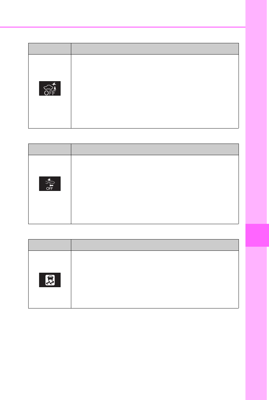
433
7-2. Steps to take in an emergency
LS500h_OM_OM50F42U_(U)
7
When trouble arises
■PKSB OFF indicator (warning buzzer)
■PCS warning light (warning buzzer)
■Slip indicator
Warning light Details/Actions
(flashes)
When a buzzer sounds:
Indicates a malfunction in the PKSB (Parking Support Brake) system
→Have the vehicle inspected by your Lexus dealer immediately.
When a buzzer does not sound:
Indicates that the system is temporarily unavailable, possibly due to a
sensor being dirty or covered with ice, etc.
→Follow the instructions displayed on the multi-information display.
(→P.284, 437)
Warning light Details/Actions
(flashes or illumi-
nates)
Indicates a malfunction in the PCS (Pre-Collision System) or that the
system is temporarily unavailable due to the vehicle being extremely
hot/cold, or dirt around a front sensor, etc.
→Follow the instructions displayed on the multi-information display.
(→P.219, 226, 440)
If the PCS (Pre-Collision System) or VSC (Vehicle Stability Control)
system is disabled, the PCS warning light will illuminate.
→P.219, 226
Warning light Details/Actions
Indicates a malfunction in:
-The VSC system;
-The TRAC system;
-The hill-start assist control system;
-The VGRS system (if equipped); or
-The DRS system (if equipped)
→Have the vehicle inspected by your Lexus dealer immediately.
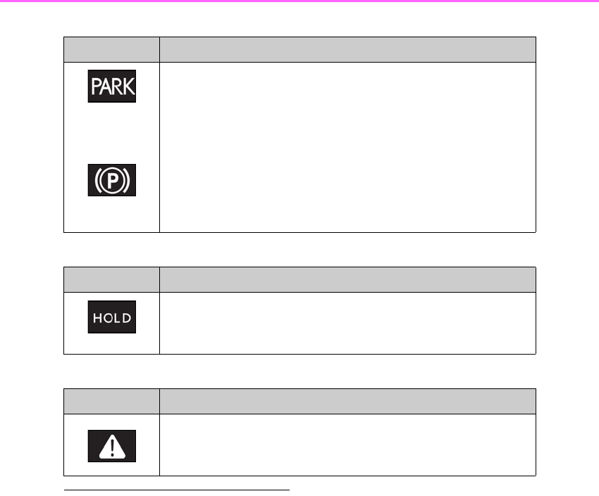
434 7-2. Steps to take in an emergency
LS500h_OM_OM50F42U_(U)
■Parking brake indicator
■Brake hold operated indicator (warning buzzer)
■Master warning light (warning buzzer)
■Warning buzzer
In some cases, the buzzer may not be heard
due to being in a noisy location or audio
sound.
■Front passenger detection sensor, seat
belt reminder and warning buzzer
●If luggage is placed on the front passen-
ger seat, the front passenger detection
sensor may cause the warning light to
flash and the warning buzzer to sound
even if a passenger is not sitting in the
seat.
●If a cushion is placed on the seat, the sen-
sor may not detect a passenger, and the
warning light may not operate properly.
■SRS warning light
This warning light system monitors the air-
bag sensor assembly, Pop Up Hood com-
puter assembly, front impact sensors, side
impact sensors (front door), side impact
sensors (front), side impact sensors (rear),
driver’s seat position sensor, driver’s seat
belt buckle switch, front passenger occu-
pant classification system (ECU and sen-
sors), rear seat belt buckle switches (if
equipped), “AIR BAG ON” indicator light,
“AIR BAG OFF” indicator light, front pas-
senger’s seat belt buckle switch, seat belt
pretensioners, airbags, interconnecting wir-
ing and power sources. (→P.29)
■If the malfunction indicator lamp comes
on while driving
First check the following:
●Is the fuel tank empty?
If it is, fill the fuel tank immediately.
●Is the fuel tank cap loose?
Warning light Details/Actions
(flashes)
(U.S.A.)
or
(flashes)
(Canada)
Indicates a malfunction in the parking brake system
→Have the vehicle inspected by your Lexus dealer immediately.
Warning light Details/Actions
(flashes)
Indicates a malfunction in the brake hold system
→Have the vehicle inspected by your Lexus dealer immediately.
Warning light Details/Actions
A buzzer sounds and the warning light comes on and flashes to indicate
that the master warning system has detected a malfunction.
→P.437

435
7-2. Steps to take in an emergency
LS500h_OM_OM50F42U_(U)
7
When trouble arises
If it is, tighten it securely.
The light will go off after several driving
trips.
If the light does not go off even after several
trips, contact your Lexus dealer as soon as
possible.
■Electric power steering system warning
light (warning buzzer)
When the 12-volt battery charge becomes
insufficient or the voltage temporarily
drops, the electric power steering system
warning light may come on and the warning
buzzer may sound.
■When the tire pressure warning light
comes on
Inspect the tires to check if a tire is punc-
tured.
If a tire is punctured: →P.442
If none of the tires are punctured:
Turn the power switch off then turn it to ON
mode. Check if the tire pressure warning
light comes on or blinks.
If the tire pressure warning light blinks for
approximately 1 minute then stays on
There may be a malfunction in the tire
pressure warning system. Have the vehicle
inspected by your Lexus dealer immedi-
ately.
If the tire pressure warning light comes
on
1After the temperature of the tires has
lowered sufficiently, check the inflation
pressure of each tire and adjust them to
the specified level.
2If the warning light does not turn off
even after several minutes have
elapsed, check that the inflation pres-
sure of each tire is at the specified level
and perform initialization. (→P.401)
■The tire pressure warning light may
come on due to natural causes
The tire pressure warning light may come
on due to natural causes such as natural air
leaks and tire inflation pressure changes
caused by temperature. In this case, adjust-
ing the tire inflation pressure will turn off the
warning light (after a few minutes).
■Conditions that the tire pressure warn-
ing system may not function properly
→P.398
WARNING
■If both the ABS and the brake system
warning lights remain on
Stop your vehicle in a safe place immedi-
ately and contact your Lexus dealer.
The vehicle will become extremely
unstable during braking, and the ABS
system may fail, which could cause an
accident resulting in death or serious
injury.
■When the electric power steering
system warning light comes on
When the light comes on yellow, the
assist to the power steering is restricted.
When the light comes on red, the assist
to the power steering is lost and handling
operations of the steering wheel become
extremely heavy.
When steering wheel operations are
heavier than usual, grip the steering
wheel firmly and operate it using more
force than usual.
■If the tire pressure warning light
comes on
Be sure to observe the following precau-
tions.
Failure to do so could cause a loss of
vehicle control and result in death or
serious injury.
●Decelerate to the lowest appropriate
speed as soon as possible. Do not
drive over 50 mph (80 km/h).
●Check and adjust the tire inflation
pressure immediately.
●If the tire pressure warning light comes
on even after tire inflation pressure
adjustment, it is probable that you have
a flat tire. Have the flat tire replaced by
the nearest Lexus dealer.

436 7-2. Steps to take in an emergency
LS500h_OM_OM50F42U_(U)
WARNING
●Avoid abrupt maneuvering and brak-
ing.
If the vehicle tires deteriorate, you
could lose control of the steering
wheel or the brakes.
■If a blowout or sudden air leakage
should occur
The tire pressure warning system may
not activate immediately.
■Maintenance of the tires
Each tire, including the spare (if pro-
vided), should be checked monthly when
cold and inflated to the inflation pressure
recommended by the vehicle manufac-
turer on the vehicle placard or tire infla-
tion pressure label (tire and load
information label). (If your vehicle has
tires of a different size than the size indi-
cated on the vehicle placard or tire infla-
tion pressure label [tire and load
information label], you should determine
the proper tire inflation pressure for
those tires.)
As an added safety feature, your vehicle
has been equipped with a tire pressure
monitoring system (TPMS-tire pressure
warning system) that illuminates a low
tire pressure telltale (tire pressure warn-
ing light) when one or more of your tires
is significantly under-inflated. Accord-
ingly, when the low tire pressure telltale
(tire pressure warning light) illuminates,
you should stop and check your tires as
soon as possible, and inflate them to the
proper pressure. Driving on a signifi-
cantly under-inflated tire causes the tire
to overheat and can lead to tire failure.
Under-inflation also reduces fuel effi-
ciency and tire tread life, and may affect
the vehicle’s handling and stopping abil-
ity.
Please note that the TPMS (tire pressure
warning system) is not a substitute for
proper tire maintenance, and it is the
driver’s responsibility to maintain correct
tire pressure, even if under-inflation has
not reached the level to trigger illumina-
tion of the TPMS low tire pressure telltale
(tire pressure warning light).
Your vehicle has also been equipped with
a TPMS (tire pressure warning system)
malfunction indicator to indicate when
the system is not operating properly. The
TPMS (tire pressure warning system)
malfunction indicator is combined with
the low tire pressure telltale (tire pres-
sure warning light). When the system
detects a malfunction, the telltale will
flash for approximately one minute and
then remain continuously illuminated.
This sequence will continue upon subse-
quent vehicle start-ups as long as the
malfunction exists. When the malfunction
indicator is illuminated, the system may
not be able to detect or signal low tire
pressure as intended.
TPMS (tire pressure warning system)
malfunctions may occur for a variety of
reasons, including the installation of
replacement or alternate tires or wheels
on the vehicle that prevent the TPMS
(tire pressure warning system) from func-
tioning properly. Always check the
TPMS (tire pressure warning system)
malfunction telltale after replacing one
or more tires or wheels on your vehicle to
ensure that the replacement or alternate
tires and wheels allow the TPMS (tire
pressure warning system) to continue to
function properly.
NOTICE
■To ensure the tire pressure warning
system operates properly
Do not install tires with different specifi-
cations or makers, as the tire pressure
warning system may not operate prop-
erly.
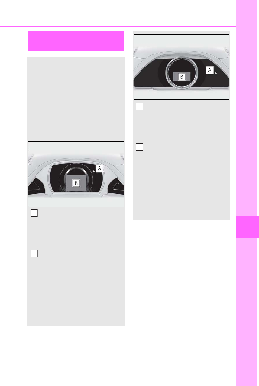
437
7-2. Steps to take in an emergency
LS500h_OM_OM50F42U_(U)
7
When trouble arises
If a warning message is dis-
played
The multi-information display
shows warnings of system malfunc-
tions, incorrectly performed opera-
tions, and messages that indicate a
need for maintenance. When a
message is shown, perform the cor-
rection procedure appropriate to
the message.
Except F SPORT models:
Master warning light
The master warning light also comes on
or flashes in order to indicate that a mes-
sage is currently being displayed on the
multi-information display.
Multi-information display
Follow the instructions of the message
on the multi-information display.
If any of the warning messages are
shown again after the appropriate
actions have been performed, contact
your Lexus dealer.
F SPORT models (main meter in
center position):
A
B
Master warning light
The master warning light also comes on
or flashes in order to indicate that a mes-
sage is currently being displayed on the
multi-information display.
Multi-information display
Follow the instructions of the message
on the multi-information display.
If any of the warning messages are
shown again after the appropriate
actions have been performed, contact
your Lexus dealer.
F SPORT models (main meter
moved to the right):
A
B
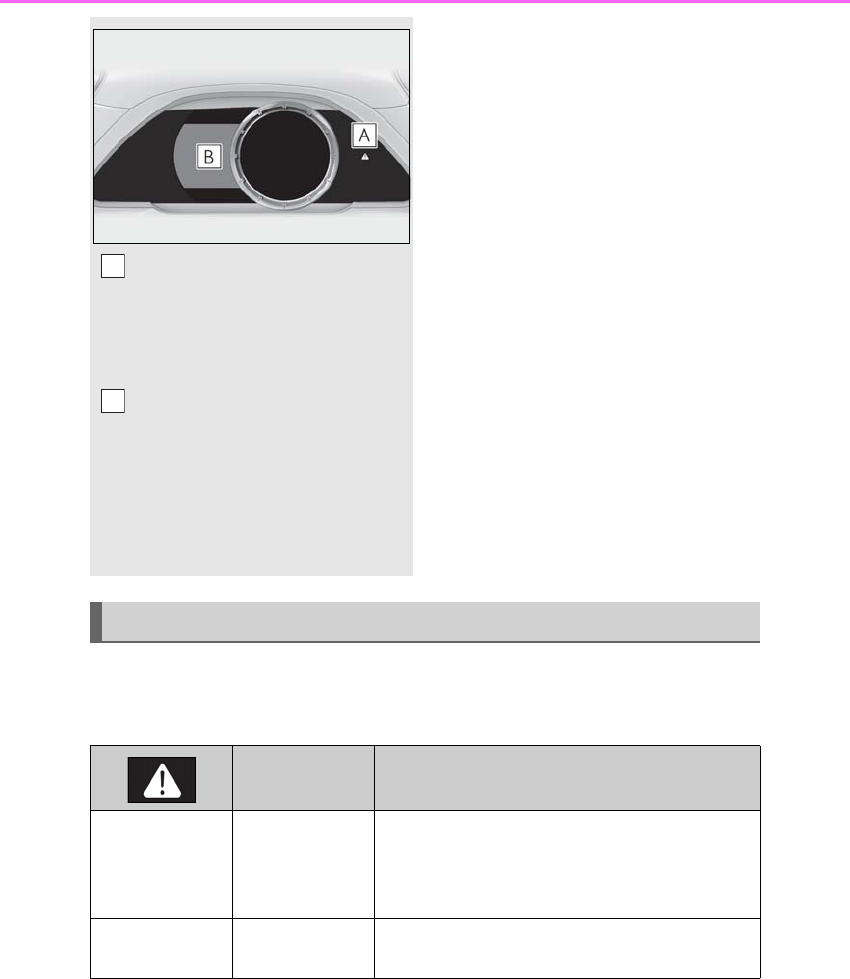
438 7-2. Steps to take in an emergency
LS500h_OM_OM50F42U_(U)
The master warning light and warning buzzers operate as follows depending on
the content of the message. If a message indicates the need for inspection by a
dealer, have the vehicle inspected by your Lexus dealer immediately.
Master warning light
The master warning light also comes on
or flashes in order to indicate that a mes-
sage is currently being displayed on the
multi-information display.
Multi-information display
Follow the instructions of the message
on the multi-information display.
If any of the warning messages are
shown again after the appropriate
actions have been performed, contact
your Lexus dealer.
A
B
Messages and warnings
Warning buzzer*Warning
Comes on Sounds
Indicates an important situation, such as when a sys-
tem related to driving is malfunctioning or that dan-
ger may result if the correction procedure is not
performed
Flashes Sounds Indicates a situation, such as when damage to the
vehicle or danger may result

439
7-2. Steps to take in an emergency
LS500h_OM_OM50F42U_(U)
7
When trouble arises
-In some situations, the master warning light and warning buzzer may not oper-
ate as specified. In this case, follow the instructions displayed in the warning
message.
-If a warning light comes on or flashes at the same time that a warning message is
displayed, take corrective action according to the warning light. (→P.427)
*: A buzzer sounds the first time a message is shown on the multi-information display.
■Warning messages
The warning messages explained below
may differ from the actual messages
according to operation conditions and vehi-
cle specifications.
■Warning buzzer
In some cases, the buzzer may not be heard
due to being in a noisy location or audio
sound.
■If “Engine Oil Level Low Add or
Replace” is displayed
The engine oil level is low. Check the level
of the engine oil, and add if necessary.
This message may appear if the vehicle is
stopped on a slope. Move the vehicle to a
level surface and check to see if the mes-
sage disappears.
■If “Hybrid System Stopped Steering
Power Low” is displayed
This message is displayed if the hybrid sys-
tem is stopped while driving.
When steering wheel operations are
heavier than usual, grip the steering wheel
firmly and operate it using more force than
usual.
■If “Hybrid System Overheated Reduced
Output Power” is displayed
This message may be displayed when driv-
ing under severe operating conditions. (For
example, when driving up a long steep hill.)
Handling method: →P.453
■If “Warming Up Maximum Vehicle
Speed: 65 MPH” is displayed
The transmission is being warmed up and
the vehicle is unable to be driven over 65
mph (110 km/h). Wait until the transmission
warms up.
■If “Stop the Vehicle in a Safe Place Shift
to P position” is displayed
There may be a malfunction in the hybrid
system or the shift position may be shifted to
N for a long time. Immediately stop the
vehicle and contact your Lexus dealer.
■If “Traction Battery Needs to be Pro-
tected Refrain From the Use of N Posi-
tion” is displayed
The remaining charge for the hybrid battery
(traction battery) is low.
As the hybrid battery (traction battery) can-
not be charged when the shift position is in
N, when stopping the vehicle for a long
period of time, shift the shift position to P.
Comes on Does not sound
Indicates a condition, such as malfunction of electri-
cal components, their condition, or indicates the
need for maintenance
Flashes Does not sound
Indicates a situation, such as when an operation has
been performed incorrectly, or indicates how to
perform an operation correctly
Warning buzzer*Warning

440 7-2. Steps to take in an emergency
LS500h_OM_OM50F42U_(U)
■If “Traction Battery Needs to be Pro-
tected Shift into P to Restart” is dis-
played
The remaining charge for the hybrid battery
(traction battery) is low, because the shift
position has been shifted to N for a long
period of time.
When moving the vehicle, shift the shift
position to P and restart the hybrid system.
■If “Shift Is in N Release Accelerator
Before Shifting” is displayed
The accelerator pedal has been depressed
when the shift position is in N.
Release the accelerator pedal and shift the
shift position to D or R.
■If “Depress Brake When Vehicle Is
Stopped Hybrid System May Overheat”
is displayed
The message may be displayed when the
accelerator pedal is depressed to hold the
vehicle while the vehicle is stopped on an
incline, etc. The hybrid system may over-
heat. Release the accelerator pedal and
depress the brake pedal.
■If “Auto Power Off to Conserve Battery”
is displayed
Power was turned off due to the automatic
power off function. Next time when starting
the hybrid system, operate the hybrid sys-
tem for approximately 5 minutes to
recharge the 12-volt battery.
■If “Headlight System Malfunction Visit
Your Dealer” is displayed
The following systems may be malfunction-
ing. Have the vehicle inspected by your
Lexus dealer immediately.
●The LED headlight system
●AFS (Adaptive Front-lighting System)
●The automatic headlight leveling system
●AHB (Automatic High Beam)
■If “Front Camera Unavailable” or “Front
Camera Unavailable Remove Debris
On Windshield” is displayed
The following systems may be suspended
until the problem shown in the message is
resolved. (→P.219, 226, 433)
●PCS (Pre-Collision system)
●LTA (Lane Tracing Assist) (if equipped)
●LKA (Lane Keeping Assist) (if equipped)
●Dynamic radar cruise control with
full-speed range
●RSA (Road Sign Assist) (if equipped)
●AHB (Automatic High Beam)
■If “Maintenance Required Soon” is dis-
played
Indicates that all maintenance according to
the driven distance on the maintenance
schedule* should be performed soon.
Comes on approximately 4500 miles
(7200 km) after the message has been
reset. If necessary, perform maintenance.
Please reset the message after the mainte-
nance is performed. (→P.378)
*: Refer to the separate “Scheduled Main-
tenance” or “Owner’s Manual Supple-
ment” for the maintenance interval
applicable to your vehicle.
■If “Maintenance Required Visit Your
Dealer” is displayed
Indicates that all maintenance is required to
correspond to the driven distance on the
maintenance schedule*.
Comes on approximately 5000 miles
(8000 km) after the message has been
reset. (The indicator will not work properly
unless the message has been reset.) Per-
form the necessary maintenance. Please
reset the message after the maintenance is
performed. (→P.378)
*: Refer to the separate “Scheduled Main-
tenance” or “Owner’s Manual Supple-
ment” for the maintenance interval
applicable to your vehicle.
■If “Oil Maintenance Required Soon” is
displayed
Indicates that the engine oil should be
scheduled to be changed.
Check the engine oil and change it if neces-
sary. After changing the engine oil, make
sure to reset the message. (→P.390)

441
7-2. Steps to take in an emergency
LS500h_OM_OM50F42U_(U)
7
When trouble arises
■If “Oil Maintenance Required” is dis-
played
Indicates that the engine oil should be
changed.
Check and change the engine oil, and oil fil-
ter by your Lexus dealer. After changing the
engine oil, make sure to reset the message.
(→P.390)
■If “Shift System Malfunction Driving
Unavailable” is displayed
There is a malfunction in the shift control
system. Have the vehicle inspected by your
Lexus dealer immediately.
■If a message that indicates the need for
the shift lever operation is displayed
To prevent the shift lever from being oper-
ated incorrectly or the vehicle from moving
unexpectedly, a message that requires shift-
ing the shift position may be displayed on
the multi-information display. In that case,
follow the instruction of the message and
shift the shift position.
■If a message that indicates the need for
visiting your Lexus dealer is displayed
The system or part shown on the
multi-information display is malfunctioning.
Have the vehicle inspected by your Lexus
dealer immediately.
■If a message that indicates the need for
referring to Owner’s Manual is dis-
played
●If any of the following messages are
shown on the multi-information display,
follow the instructions.
• “Engine Coolant Temp High” (→P.453)
•“Battery Low” (→P.447)
• “Transmission Fluid Temp High” (→P.175)
●If any of the following messages are
shown on the multi-information display, it
may indicate a malfunction. Have the
vehicle inspected by your Lexus dealer
immediately.
• “Access System with Elec. Key Malfunc-
tion”
• “Shift System Malfunction”
• “P Switch Malfunction”
• “Shift System Unavailable”
• “Hybrid System Malfunction”
•“Check Engine”
• “Hybrid Battery System Malfunction”
• “Accelerator System Malfunction”
●If any of the following messages are
shown on the multi-information display, it
may indicate a malfunction. Immediately
stop the vehicle and contact your Lexus
dealer.
• “Braking Power Low”
• “Charging System Malfunction”
• “Oil Pressure Low”
●If “Maintenance Required for Traction
Battery Cooling Parts” is shown, the fil-
ters may be clogged, the air intake vents
may be blocked, or there may be a gap in
the duct. Therefore, perform the follow-
ing correction procedure.
• If the air intake vents and filters of the
hybrid battery (traction battery) are dirty,
perform the procedure on P.374 to clean
them.
• If the warning message is shown when
the air intake vents and filters of the
hybrid battery (traction battery) are not
dirty, have the vehicle inspected by your
Lexus dealer.
NOTICE
■If “High Power Consumption Partial
Limit On AC/Heater Operation” is
displayed frequently
There is a possible malfunction relating
to the charging system or the 12-volt bat-
tery may be deteriorating. Have the vehi-
cle inspected by your Lexus dealer.
■If “Have Traction Battery Inspected”
is displayed
This message indicates that the hybrid
battery (traction battery) may require
inspection or replacement. Have the
vehicle inspected by your Lexus dealer
immediately.
Do not continue driving the vehicle, as
the hybrid system may become not able
to be started again.
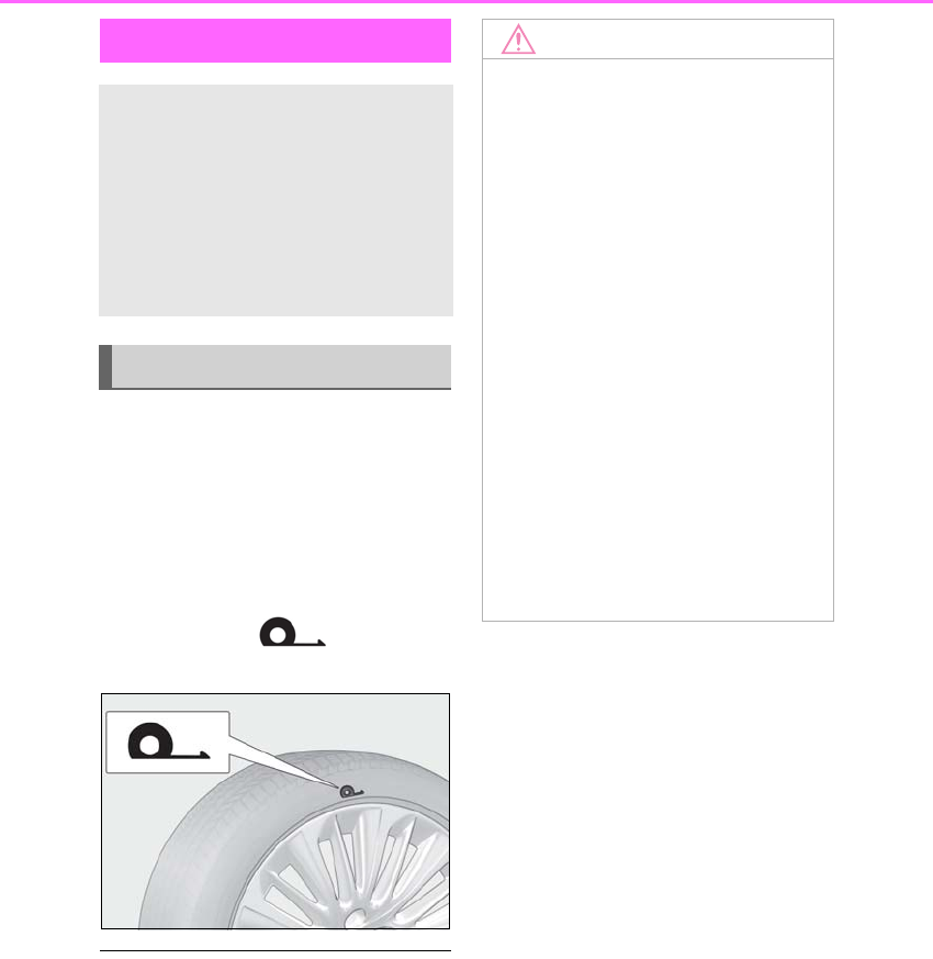
442 7-2. Steps to take in an emergency
LS500h_OM_OM50F42U_(U)
Take your vehicle to the nearest Lexus
dealer or authorized tire dealer as
soon as possible if any tire goes flat.
The vehicle can be driven for a maximum
of 100 miles (160 km) at a speed below 50
mph (80 km/h) after the tire pressure
warning light comes on. (→P.431)
A run-flat tire has a mark on the
side wall.
■In some conditions (such as at high tem-
peratures)
You cannot continue driving for up to 160
miles (100 km).
■For the detailed information on run-flat
tires
See the tire warranty booklet.
If you have a flat tire
Your vehicle is not equipped with a
spare tire, but instead you can con-
tinue driving the vehicle with
run-flat tires even if any tire goes
flat.
In this case, slow down and drive
with extra caution.
Run-flat tires
NOTICE
■When replacing the tires
When removing or fitting the wheels,
tires or the tire pressure warning valve
and transmitter, contact your Lexus
dealer as the tire pressure warning valve
and transmitter may be damaged if not
handled correctly.
■When driving over bumps
If a vehicle has a flat tire, the vehicle
height will be lower than usual. Ensure
that nothing strikes the bottom of the
vehicle.
■To avoid damage to the tire pressure
warning valves and transmitters
When a tire is repaired with liquid seal-
ants, the tire pressure warning valve and
transmitter may not operate properly. If a
liquid sealant is used, contact your Lexus
dealer or other qualified service shop as
soon as possible. Make sure to replace
the tire pressure warning valve and trans-
mitter when replacing the tire. (→P.401)

443
7-2. Steps to take in an emergency
LS500h_OM_OM50F42U_(U)
7
When trouble arises
One of the following may be the cause
of the problem:
-The electronic key may not be func-
tioning properly. (→P.445)
-There may not be sufficient fuel in
the vehicle’s tank.
Refuel the vehicle.
-There may be a malfunction in the
immobilizer system. (→P.66)
-There may be a malfunction in the
shift control system.* (→P.171, 441)
-There may be a malfunction in the
steering lock system.
-The hybrid system may be malfunc-
tioning due to an electrical problem
such as electronic key battery
depletion or a blown fuse. However,
depending on the type of malfunc-
tion, an interim measure is available
to start the hybrid system. (→P.443)
-There is a possibility that the tem-
perature of the hybrid battery (trac-
tion battery) is extremely low
(approximately below -22°F
[-30°C]). (→P.168)
*: It may not be possible to shift the shift
position from P.
One of the following may be the cause
of the problem:
-The 12-volt battery may be dis-
charged. (→P.447)
-The 12-volt battery terminal con-
nections may be loose or corroded.
(→P.393)
One of the following may be the cause
of the problem:
-One or both of the 12-volt battery
terminals may be disconnected.
(→P.393)
-The 12-volt battery may be dis-
charged. (→P.447)
Contact your Lexus dealer if the problem
cannot be repaired, or if repair procedures
are unknown.
When the hybrid system does not start,
the following steps can be used as an
interim measure to start the hybrid sys-
tem if the power switch is functioning
If the hybrid system will not
start
Reasons for the hybrid system not
starting vary depending on the situ-
ation. Check the following and per-
form the appropriate procedure:
The hybrid system will not start
even though the correct starting
procedure is being followed.
(→P.168)
The interior lights and head-
lights are dim, or the horn does
not sound or sounds at a low vol-
ume.
The interior lights and head-
lights do not turn on, or the horn
does not sound.
Starting the hybrid system in an
emergency

444 7-2. Steps to take in an emergency
LS500h_OM_OM50F42U_(U)
normally.
Do not use this starting procedure
except in cases of emergency.
1Press the parking brake switch to
check that the parking brake is set.
(→P.181)
Parking brake indicator will come on.
2Turn the power switch to ACCES-
SORY mode.
3Press and hold the power switch for
about 15 seconds while depressing
the brake pedal firmly.
Even if the hybrid system can be
started using the above steps, the sys-
tem may be malfunctioning. Have the
vehicle inspected by your Lexus dealer.
If you lose your keys
New genuine mechanical keys can
be made by your Lexus dealer using
another mechanical key and the
key number stamped on your key
number plate.
Keep the plate in a safe place such
as your wallet, not in the vehicle.
NOTICE
■When an electronic key is lost
If the electronic key remains lost, the risk
of vehicle theft increases significantly.
Visit your Lexus dealer immediately with
all remaining electronic keys and the
card key (if equipped) that were pro-
vided with your vehicle.
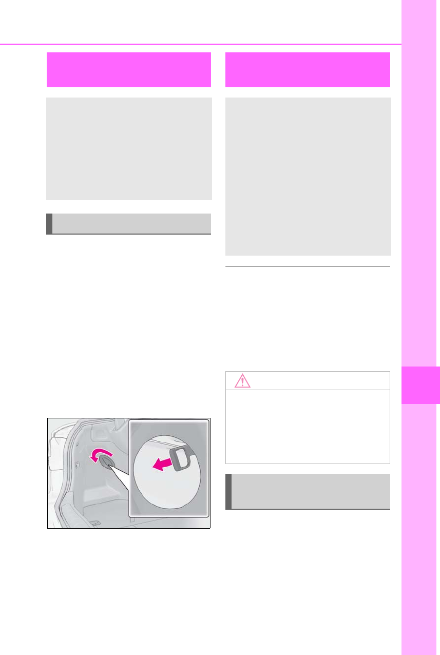
445
7-2. Steps to take in an emergency
LS500h_OM_OM50F42U_(U)
7
When trouble arises
Remove the cover inside the trunk and
pull the lever.
Using the lever to open the fuel filler
door may not allow for an adequate
reduction in fuel tank pressure before
refueling. To prevent fuel from spilling
out, turn the cap slowly when removing
it. During refueling, fuel may spill out
from the filler opening due to air being
discharged from inside the fuel tank.
Therefore, fill the fuel tank carefully and
slowly.
■When the electronic key does not work
properly
●Make sure that the smart access system
with push-button start has not been dis-
abled at your Lexus dealer. If it has been
disabled, re-enable it.
●Check if battery-saving mode is set. If it is
set, cancel the function. (→P.120)
■Unlocking the door
Use the mechanical key (→P.106) in
order to perform the following opera-
tions:
If the fuel filler door cannot
be opened
If the fuel filler door opener switch
cannot be operated, contact your
Lexus dealer to service the vehicle.
In case where refueling is urgently
necessary, the following procedure
can be used to open the fuel filler
door.
Opening the fuel filler door
If the electronic key does not
operate properly
If communication between the
electronic key and vehicle is inter-
rupted (→P.120) or the electronic
key cannot be used because the
battery is depleted, the smart
access system with push-button
start and wireless remote control
cannot be used. In such cases, the
doors and trunk can be opened and
the hybrid system can be started by
following the procedure below.
NOTICE
■In case of a smart access system with
push-button start malfunction or
other key-related problems
Take your vehicle with all the electronic
keys provided with your vehicle to your
Lexus dealer.
Locking and unlocking the
doors, unlocking the trunk
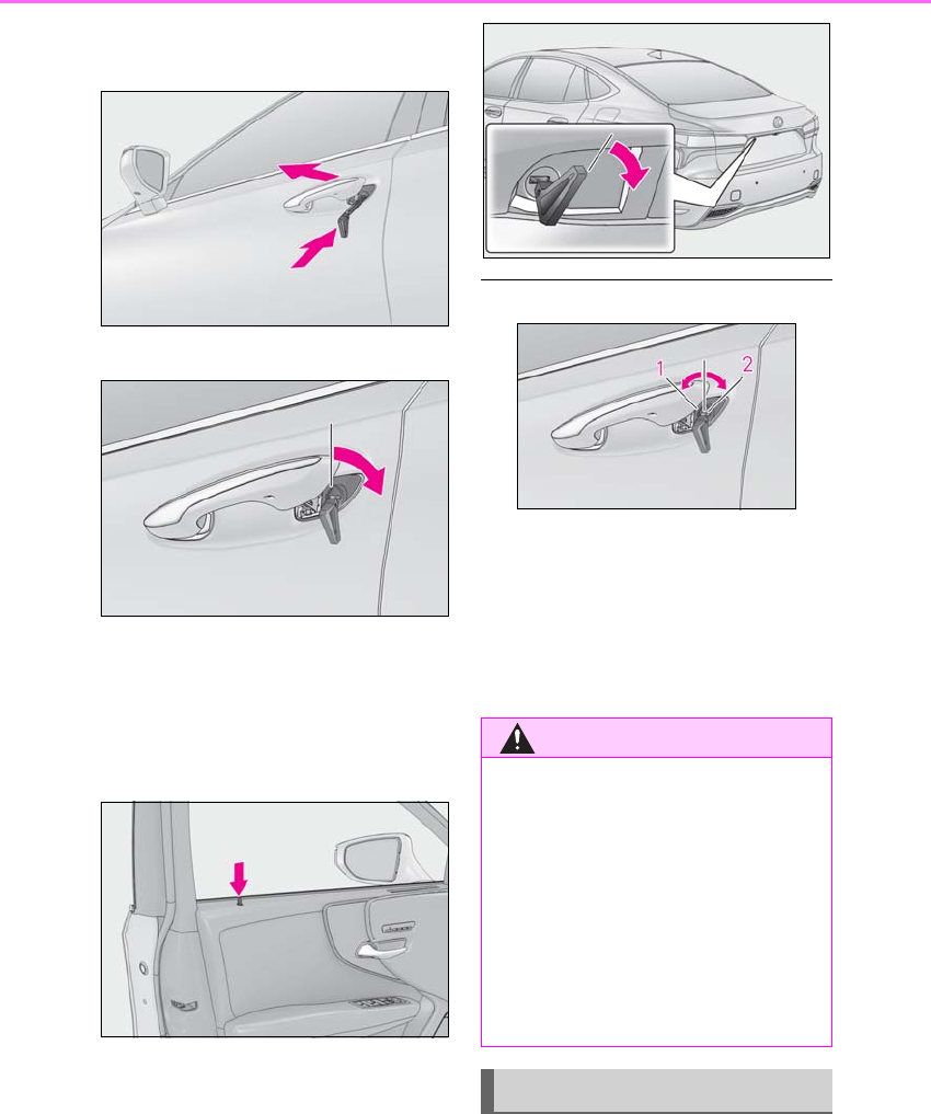
446 7-2. Steps to take in an emergency
LS500h_OM_OM50F42U_(U)
1Pull the driver’s door handle and
insert the mechanical key.
2Unlock the door.
3Remove the key, return the handle,
and then pull the handle again.
■Locking the door
1With the door open, push down the
inside lock button.
2Close the door.
■Trunk
Turn the mechanical key clockwise to
open. (→P.68)
■Key linked functions
1Closes the windows and the moon
roof (turn and hold)
2Opens the windows and the moon
roof (turn and hold)
These settings must be customized at your
Lexus dealer.
1Depress the brake pedal.
WARNING
■When using the mechanical key and
operating the power windows or
moon roof
Operate the power window or moon
roof after checking to make sure that
there is no possibility of any passenger
having any of their body parts caught in
the window or moon roof.
Also, do not allow children to operate the
mechanical key. It is possible for children
and other passengers to get caught in
the power window or moon roof.
Starting the hybrid system
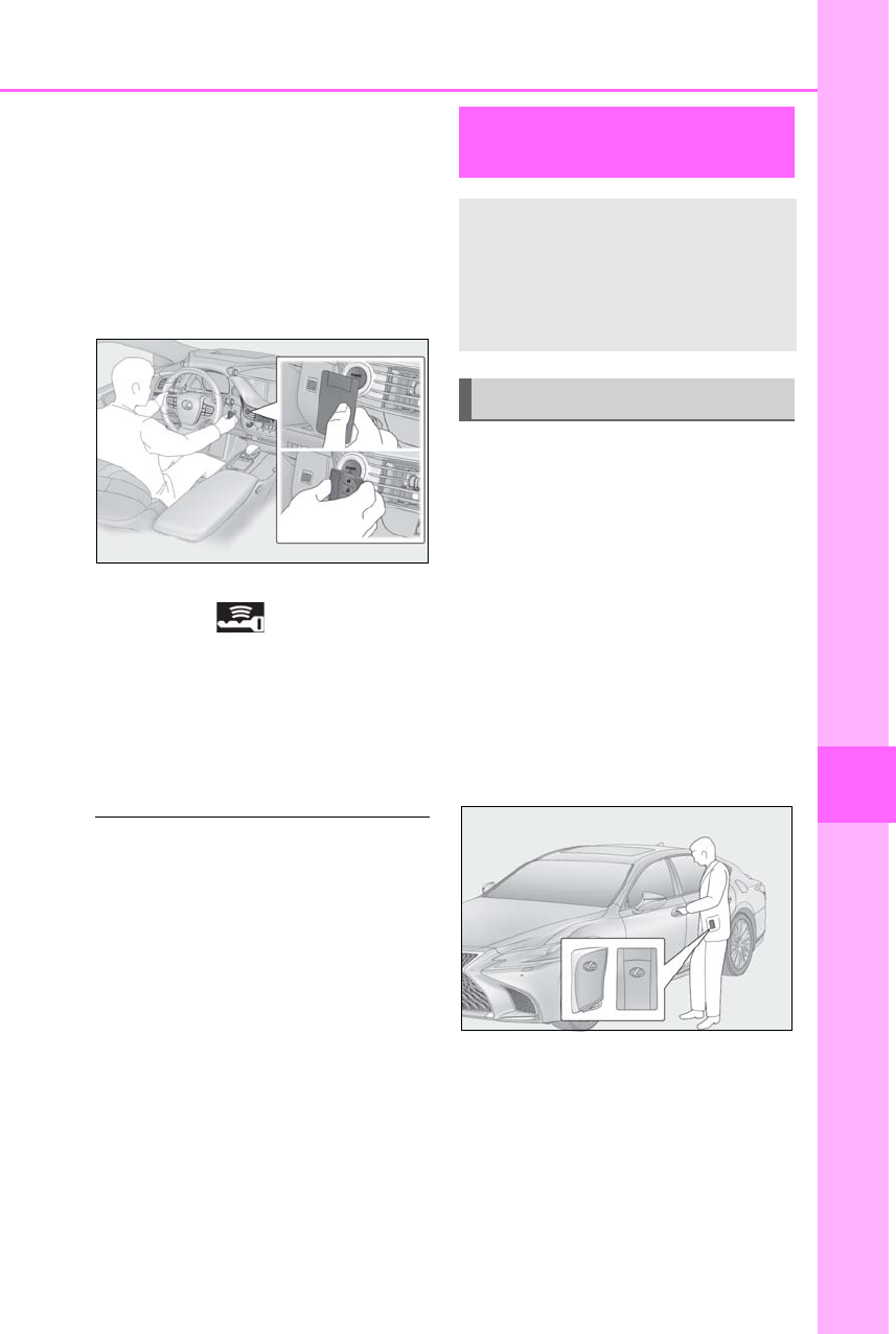
447
7-2. Steps to take in an emergency
LS500h_OM_OM50F42U_(U)
7
When trouble arises
2Touch the Lexus emblem side of the
electronic key to the power switch.
When the electronic key is detected, a
buzzer sounds and the power switch will
turn to ON mode.
When the smart access system with
push-button start is deactivated in custom-
ization setting, the power switch will turn to
ACCESSORY mode.
3Firmly depress the brake pedal and
check that is shown on the
multi-information display.
4Press the power switch.
In the event that the hybrid system still
cannot be started, contact your Lexus
dealer.
■Stopping the hybrid system
Set the parking brake, shift the shift position
to P and press the power switch as you nor-
mally do when stopping the hybrid system.
■Electronic key battery
As the above procedure is a temporary
measure, it is recommended that the elec-
tronic key battery be replaced immediately
when the battery is depleted. (→P.413)
■Changing power switch modes
Release the brake pedal and press the
power switch in step 3 above. The hybrid
system does not start and modes will be
changed each time the switch is pressed.
(→P.170)
If you have a set of jumper (or booster)
cables and a second vehicle with a
12-volt battery, you can jump start your
vehicle by following the steps below.
Method connecting jumper (or
booster) cables to the 12-volt bat-
tery
1Confirm that the electronic key is
being carried.
When connecting the jumper (or booster)
cables, depending on the situation, the
alarm may activate and doors locked.
(→P.69)
2Open the trunk lid and remove the
luggage mat. (→P.348)
In the event that the trunk opener cannot
be used, use the mechanical key to open
the trunk. (→P.445)
If the 12-volt battery is dis-
charged
The following procedures may be
used to start the hybrid system if the
12-volt battery is discharged.
You can also call your Lexus dealer
or a qualified repair shop.
Restarting the hybrid system
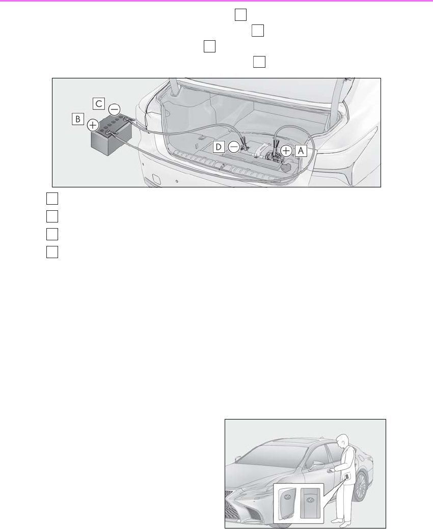
448 7-2. Steps to take in an emergency
LS500h_OM_OM50F42U_(U)
3Connect a positive jumper cable clamp to on your vehicle and connect the
clamp on the other end of the positive cable to on the second vehicle. Then,
connect a negative cable clamp to on the second vehicle and connect the
clamp at the other end of the negative cable to .
Positive (+) battery terminal (your vehicle)
Positive (+) battery terminal (second vehicle)
Negative (-) battery terminal (second vehicle)
Negative (-) battery terminal (your vehicle)
4Start the engine of the second vehi-
cle. Increase the engine speed
slightly and maintain at that level for
approximately 5 minutes to
recharge the 12-volt battery of your
vehicle.
5Open and close any of the doors of
your vehicle with the power switch
off.
6Maintain the engine speed of the
second vehicle and start the hybrid
system of your vehicle by turning
the power switch to ON mode.
7Make sure the “READY” indicator
comes on. If the indicator does not
come on, contact your Lexus
dealer.
8Once the hybrid system has
started, remove the jumper cables
in the exact reverse order from
which they were connected.
Method connecting jumper (or
booster) cables to the exclusive
jump starting terminal
1Confirm that the electronic key is
being carried.
When connecting the jumper (or booster)
cables, depending on the situation, the
alarm may activate and doors locked.
(→P.69)
2Open the hood. Remove the driver
side engine compartment cover
A
B
C
D
A
B
C
D
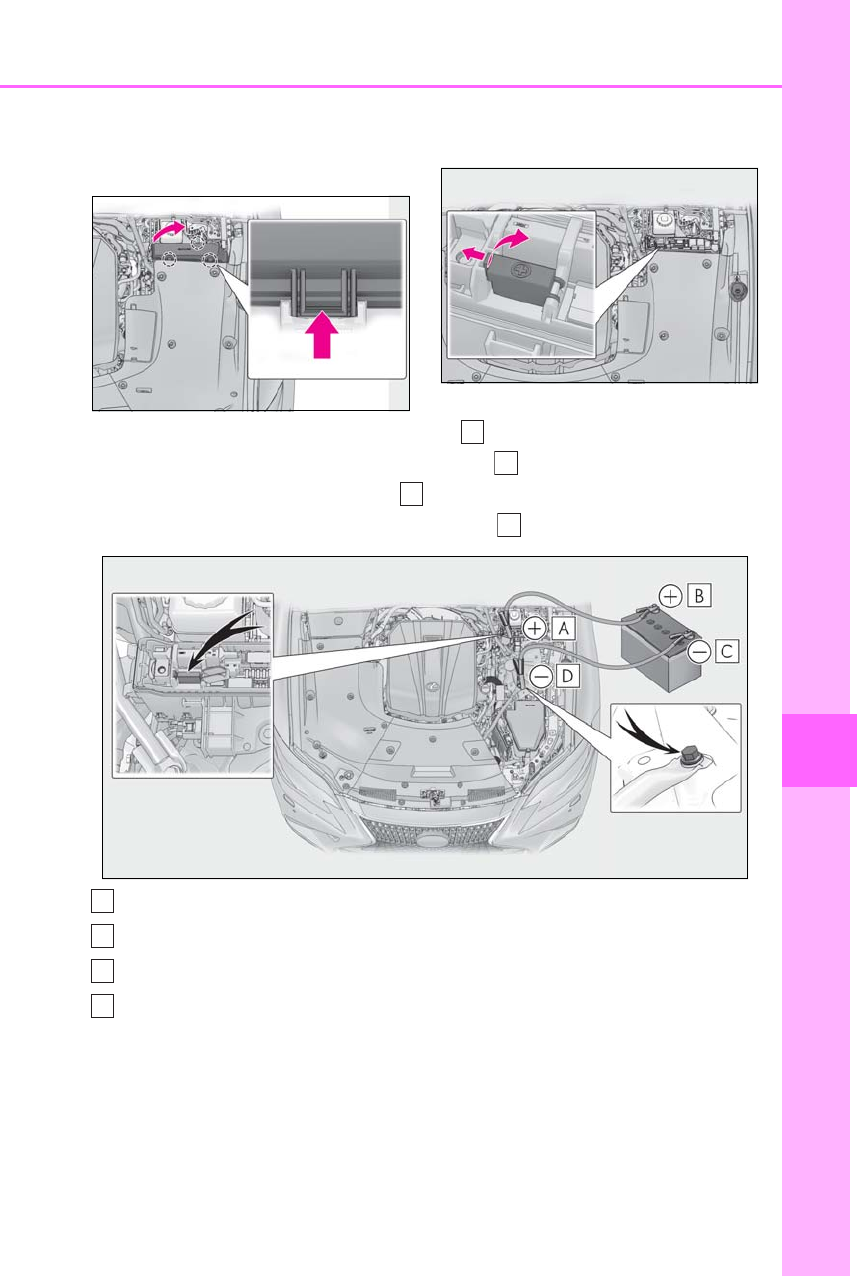
449
7-2. Steps to take in an emergency
LS500h_OM_OM50F42U_(U)
7
When trouble arises
and fuse box cover. (→P.385,
388)
Push the tabs in and lift the lid off.
3Open the exclusive jump starting
terminal cover.
4Connect a positive jumper cable clamp to on your vehicle and connect the
clamp on the other end of the positive cable to on the second vehicle. Then,
connect a negative cable clamp to on the second vehicle and connect the
clamp at the other end of the negative cable to .
Exclusive jump starting terminal (your vehicle)
Positive (+) battery terminal (second vehicle)
Negative (-) battery terminal (second vehicle)
Solid, stationary, unpainted metallic point away from the exclusive jump starting
terminal and any moving parts as shown in the illustration
5Start the engine of the second vehi-
cle. Increase the engine speed
slightly and maintain at that level for
approximately 5 minutes to
recharge the 12-volt battery of your
vehicle.
A
B
C
D
A
B
C
D

450 7-2. Steps to take in an emergency
LS500h_OM_OM50F42U_(U)
6Open and close any of the doors of
your vehicle with the power switch
off.
7Maintain the engine speed of the
second vehicle and start the hybrid
system of your vehicle by turning
the power switch to ON mode.
8Make sure the “READY” indicator
comes on. If the indicator does not
come on, contact your Lexus
dealer.
9Once the hybrid system has
started, remove the jumper cables
in the exact reverse order from
which they were connected.
10 Close the exclusive jump starting
terminal cover and install the fuse
box cover and engine compart-
ment cover.
Once the hybrid system starts, have
the vehicle inspected at your Lexus
dealer as soon as possible.
■Starting the hybrid system when the
12-volt battery is discharged
The hybrid system cannot be started by
push-starting.
■To prevent 12-volt battery discharge
●Turn off the headlights and the audio sys-
tem while the hybrid system is off.
●Turn off any unnecessary electrical com-
ponents when the vehicle is running at a
low speed for an extended period, such
as in heavy traffic.
■When the 12-volt battery is removed or
discharged
●Information stored in the ECU is cleared.
When the 12-volt battery is depleted,
have the vehicle inspected at your Lexus
dealer.
●Some systems may require initialization.
(→P.495)
■When removing the 12-volt battery ter-
minals
When the 12-volt battery terminals are
removed, the information stored in the
ECU is cleared. Before removing the
12-volt battery terminals, contact your
Lexus dealer.
■Charging the 12-volt battery
The electricity stored in the 12-volt battery
will discharge gradually even when the
vehicle is not in use, due to natural dis-
charge and the draining effects of certain
electrical appliances. If the vehicle is left for
a long time, the 12-volt battery may dis-
charge, and the hybrid system may be
unable to start. (The 12-volt battery
recharges automatically while the hybrid
system is operating.)
■When recharging or replacing the
12-volt battery
●In some cases, it may not be possible to
unlock the doors using the smart access
system with push-button start when the
12-volt battery is discharged. Use the
wireless remote control or the mechani-
cal key to lock or unlock the doors.
●The hybrid system may not start on the
first attempt after the 12-volt battery has
recharged but will start normally after the
second attempt. This is not a malfunction.
●The power switch mode is memorized by
the vehicle. When the 12-volt battery is
reconnected, the system will return to the
mode it was in before the 12-volt battery
was discharged. Before disconnecting
the 12-volt battery, turn the power switch
off.
If you are unsure what mode the power
switch was in before the 12-volt battery
discharged, be especially careful when
reconnecting the 12-volt battery.
■When replacing the 12-volt battery
●Use a Central Degassing type 12-volt
battery (European Regulations).
●Use a 12-volt battery with the same case
size as the previous 12-volt battery and an
epuivalent 20 hour rate capacity (20HR)
or greater.
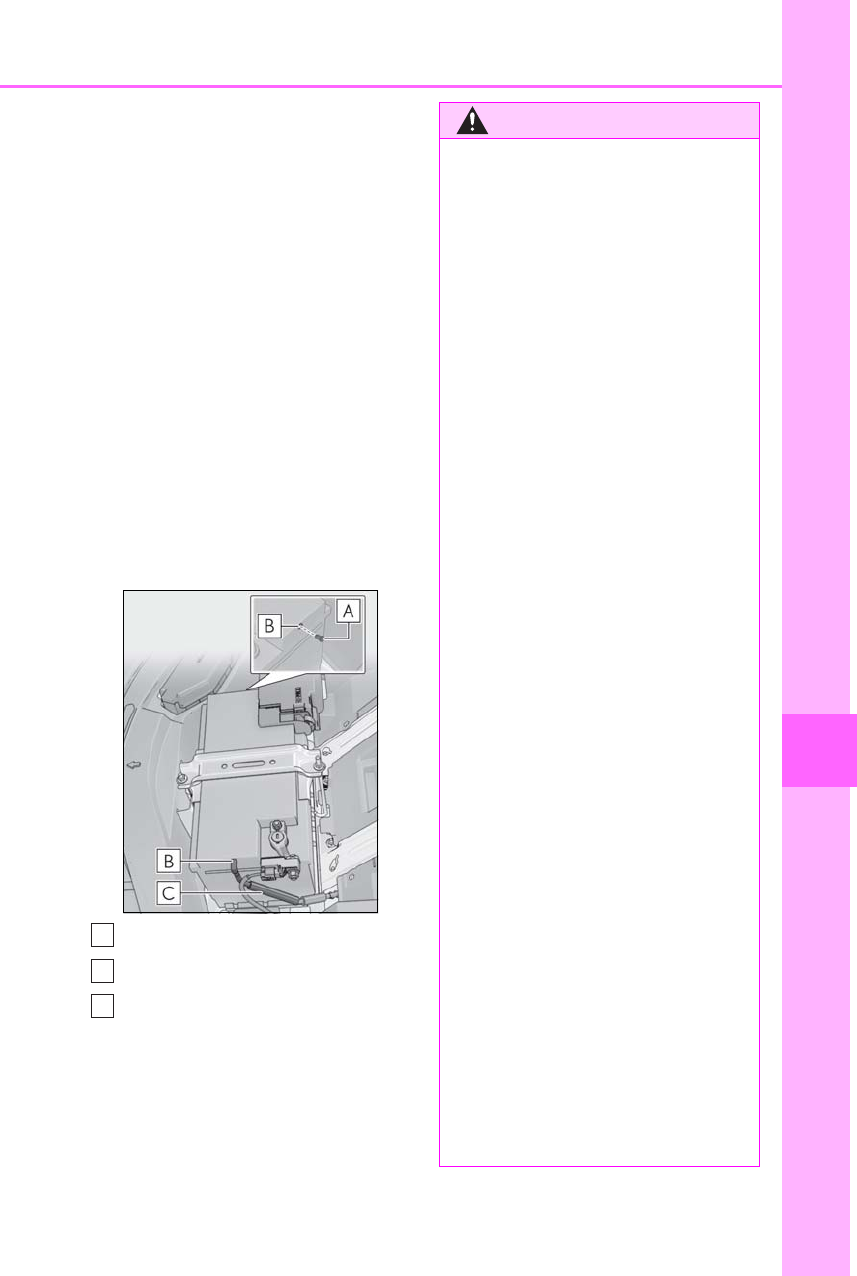
451
7-2. Steps to take in an emergency
LS500h_OM_OM50F42U_(U)
7
When trouble arises
• If the sizes differ, the 12-volt battery can-
not be properly secured.
• If the 20 hour rate capacity is low, even if
the time period where the vehicle is not
used is a short time, the 12-volt battery
may discharge and the hybrid system
may not be able to start.
●Use a 12-volt battery with a handle. If a
12-volt battery without a handle is used,
removal is more difficult.
●After replacing, firmly attach the follow-
ing items to the exhaust hole of the
12-volt battery.
• Use the exhaust hose that was attached
to the 12-volt battery before replacing
and confirm that it is firmly connected to
the hole section of the vehicle.
• Use the exhaust hole plug included with
the 12-volt battery replaced or the one
installed on the 12-volt battery prior to
the replacement. (Depending on the
12-volt battery to be replaced, the
exhaust hole may be plugged.)
Exhaust hole plug
Exhaust hole
Exhaust hose
For details, consult your Lexus dealer.
A
B
C
WARNING
■When removing the 12-volt battery
terminals
Always remove the negative (-) terminal
first. If the positive (+) terminal contacts
any metal in the surrounding area when
the positive (+) terminal is removed, a
spark may occur, leading to a fire in addi-
tion to electrical shocks and death or
serious injury.
■Avoiding 12-volt battery fires or
explosions
Observe the following precautions to
prevent accidentally igniting the flamma-
ble gas that may be emitted from the
12-volt battery:
●Make sure each jumper cable is con-
nected to the correct terminal and that
it is not unintentionally in contact with
any other than the intended terminal.
●Do not allow the other end of the
jumper cable connected to the “+” ter-
minal to come into contact with any
other parts or metal surfaces in the
area, such as brackets or unpainted
metal.
●Do not allow the + and - clamps of the
jumper cables to come into contact
with each other.
●Do not smoke, use matches, cigarette
lighters or allow open flame near the
12-volt battery.
■12-volt battery precautions
The 12-volt battery contains poisonous
and corrosive acidic electrolyte, while
related parts contain lead and lead com-
pounds. Observe the following precau-
tions when handling the 12-volt battery:
●When working with the 12-volt battery,
always wear safety glasses and take
care not to allow any battery fluids
(acid) to come into contact with skin,
clothing or the vehicle body.
●Do not lean over the 12-volt battery.

452 7-2. Steps to take in an emergency
LS500h_OM_OM50F42U_(U)
WARNING
●In the event that battery fluid comes
into contact with the skin or eyes,
immediately wash the affected area
with water and seek medical attention.
Place a wet sponge or cloth over the
affected area until medical attention
can be received.
●Always wash your hands after handling
the 12-volt battery support, terminals,
and other battery-related parts.
●Do not allow children near the 12-volt
battery.
■After recharging the 12-volt battery
Have the 12-volt battery inspected at
your Lexus dealer as soon as possible.
If the 12-volt battery is deteriorating, con-
tinued use may cause the 12-volt battery
to emit a malodorous gas, which may be
detrimental to the health of passengers.
■When replacing the 12-volt battery
●When the vent plug and indicator are
close to the hold down clamp, the bat-
tery fluid (sulfuric acid) may leak.
●For information regarding 12-volt bat-
tery replacement, contact your Lexus
dealer.
●After replacing, securely attach the
exhaust hose and exhaust hole plug to
the exhaust hole of the replaced
12-volt battery. If not properly installed,
gases (hydrogen) may leak into the
vehicle interior, and there is the possi-
ble danger of the gas igniting and
exploding.
NOTICE
■When handling jumper cables
When connecting the jumper cables,
ensure that they do not become entan-
gled in the cooling fan or engine drive
belt.
■To prevent damaging the vehicle
The exclusive jump starting terminal is to
be used when charging the 12-volt bat-
tery from another vehicle in an emer-
gency. It cannot be used to jump start
another vehicle.
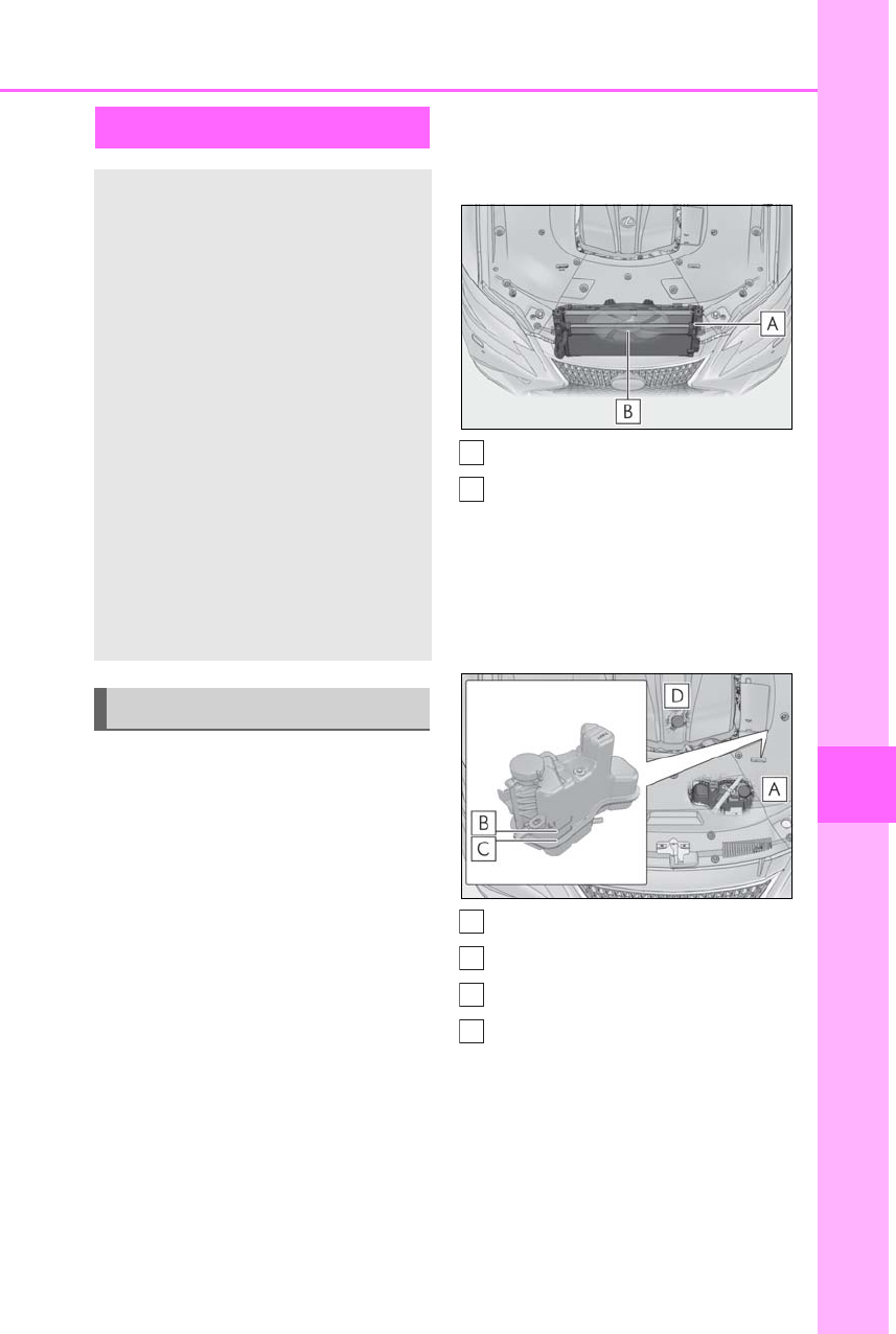
453
7-2. Steps to take in an emergency
LS500h_OM_OM50F42U_(U)
7
When trouble arises
If the engine coolant temperature
gauge enters the red zone or
“Engine Coolant Temp High Stop in
a Safe Place See Owner’s Manual”
is shown on the multi-information
display
1Stop the vehicle in a safe place and
turn off the air conditioning system,
and then stop the hybrid system.
2If you see steam:
Carefully lift the hood after the
steam subsides.
If you do not see steam:
Carefully lift the hood.
3After the hybrid system has cooled
down sufficiently, inspect the hoses
and radiator core (radiator) for any
leaks.
Radiators
Cooling fan
If a large amount of coolant leaks, immedi-
ately contact your Lexus dealer.
4The coolant level is satisfactory if it
is between the “F” and “L” lines on
the reservoir.
Reservoir
“F” line
“L” line
Coolant inlet cap
5Add coolant if necessary.
(→P.455)
Water can be used in an emergency if
If your vehicle overheats
The following may indicate that
your vehicle is overheating.
-The engine coolant temperature
gauge (→P.77, 81) is in the red
zone or a loss of hybrid system
power is experienced. (For exam-
ple, the vehicle speed does not
increase.)
-“Engine Coolant Temp High Stop
in a Safe Place See Owner’s
Manual” or “Hybrid System
Overheated Reduced Output
Power” is shown on the
multi-information display.
-Steam comes out from under the
hood.
Correction procedures
A
B
A
B
C
D
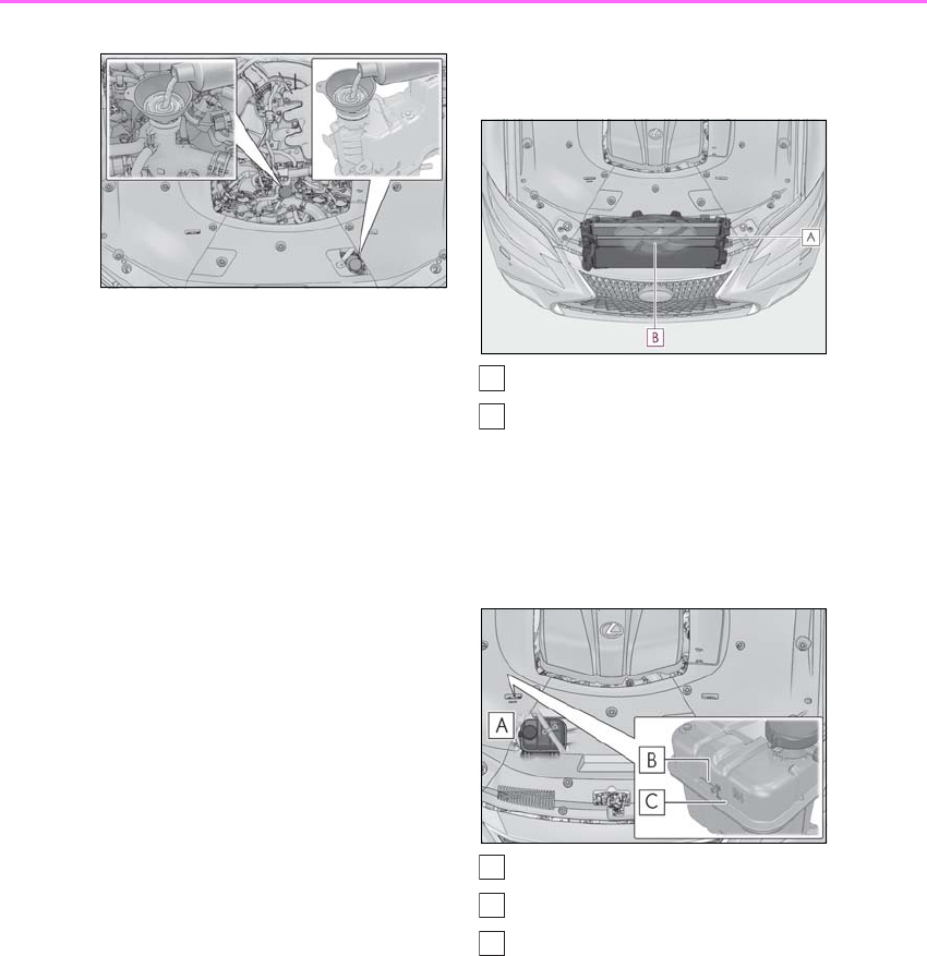
454 7-2. Steps to take in an emergency
LS500h_OM_OM50F42U_(U)
coolant is unavailable.
6Start the hybrid system and turn the
air conditioning system on to check
that the radiator cooling fan oper-
ates and to check for coolant leaks
from the radiator or hoses.
The fan operates when the air conditioning
system is turned on immediately after a
cold start. Confirm that the fan is operating
by checking the fan sound and air flow. If it
is difficult to check these, turn the air con-
ditioning system on and off repeatedly.
(The fan may not operate in freezing tem-
peratures.)
7If the fan is not operating:
Stop the hybrid system immediately
and contact your Lexus dealer.
If the fan is operating:
Have the vehicle inspected at the
nearest Lexus dealer.
If “Hybrid System Overheated
Reduced Output Power” is shown
on the multi-information display
1Stop the vehicle in a safe place.
2Stop the hybrid system and care-
fully lift the hood.
3After the hybrid system has cooled
down, inspect the hoses and radia-
tor core (radiator) for any leaks.
Radiator
Cooling fan
If a large amount of coolant leaks, immedi-
ately contact your Lexus dealer.
4The coolant level is satisfactory if it
is between the “F” and “L” lines on
the reservoir.
Reservoir
“F” line
“L” line
5Remove the engine compartment
cover and add coolant if necessary.
Water can be used in an emergency if
A
B
A
B
C
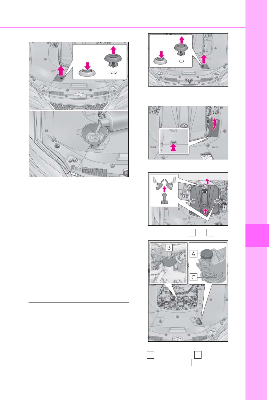
455
7-2. Steps to take in an emergency
LS500h_OM_OM50F42U_(U)
7
When trouble arises
coolant is unavailable.
6After stopping the hybrid system
and waiting for 5 minutes or more,
start the hybrid system again and
check for the multi-information dis-
play.
If the message does not disappear:
Stop the hybrid system and contact
your Lexus dealer.
If the message is not displayed:
The hybrid system temperature has
dropped and the vehicle may be
driven normally.
However, if the message appears again fre-
quently, contact your Lexus dealer.
■When adding engine coolant
Add coolant in accordance with the follow-
ing procedure.
1Remove the engine compartment
cover.
2Push the tab in and open the engine
compartment cover.
3Remove the engine cover.
4Remove the caps and .
5Add coolant through the inlet of the cap
up to the “F” line , and then
replace the cap .
A B
A
C
A

456 7-2. Steps to take in an emergency
LS500h_OM_OM50F42U_(U)
6Add coolant through the inlet of the cap
until it is full, and then replace the
cap .
WARNING
■When inspecting under the hood of
your vehicle
Observe the following precautions.
Failure to do so may result in serious
injury such as burns.
●If steam is seen coming from under the
hood, do not open the hood until the
steam has subsided. The engine com-
partment may be very hot.
●After the hybrid system has been
turned off, check that the indicator on
the power switch and the “READY”
indicator are off.
When the hybrid system is operating,
the gasoline engine may automatically
start, or the cooling fan may suddenly
operate even if the gasoline engine
stops. Do not touch or approach rotat-
ing parts such as the fan, which may
lead to fingers or clothing (especially a
tie, a scarf or a muffler) getting caught,
resulting in serious injury.
●Do not loosen the coolant inlet cap or
the coolant reservoir cap while the
hybrid system and radiator are hot.
High temperature steam or coolant
could spray out.
NOTICE
■When adding engine/power control
unit coolant
Add coolant slowly after the hybrid sys-
tem has cooled down sufficiently. Adding
cool coolant to a hot hybrid system too
quickly can cause damage to the hybrid
system.
B
B
NOTICE
■To prevent damage to the cooling sys-
tem
Observe the following precautions:
●Avoid contaminating the coolant with
foreign matter (such as sand or dust
etc.).
●Do not use any coolant additive.
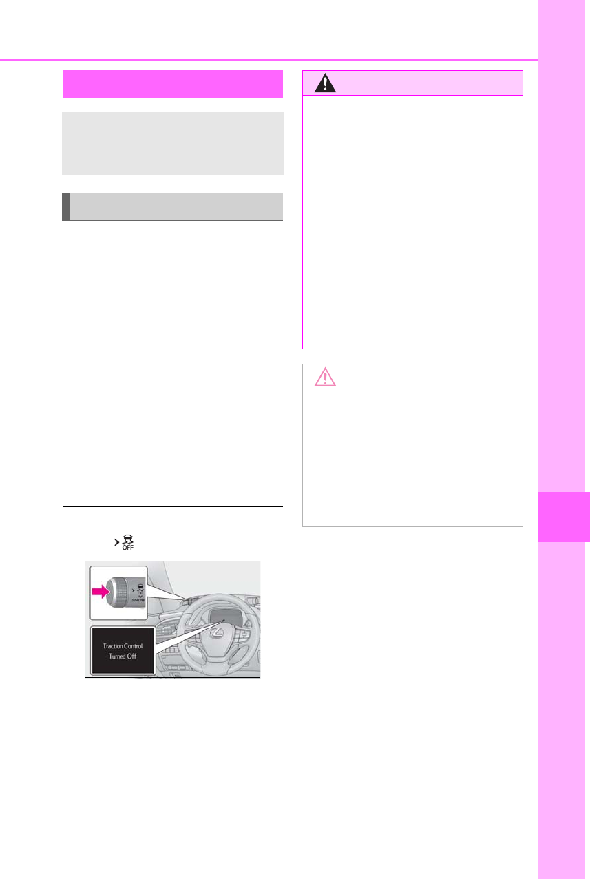
457
7-2. Steps to take in an emergency
LS500h_OM_OM50F42U_(U)
7
When trouble arises
1Stop the hybrid system. Set the
parking brake and shift the shift
position to P.
2Remove the mud, snow or sand
from around the rear wheels.
3Place wood, stones or some other
material under the rear wheels to
help provide traction.
4Restart the hybrid system.
5Shift the shift position to D or R and
release the parking brake. Then,
while exercising caution, depress
the accelerator pedal.
■When it is difficult to free the vehicle
Press the switch to turn off TRAC.
If the vehicle becomes stuck
Carry out the following proce-
dures if the tires spin or the vehicle
becomes stuck in mud, dirt or snow:
Recovering procedure
WARNING
■When attempting to free a stuck vehi-
cle
If you choose to push the vehicle back
and forth to free it, make sure the sur-
rounding area is clear to avoid striking
other vehicles, objects or people. The
vehicle may also lunge forward or lunge
back suddenly as it becomes free. Use
extreme caution.
■When shifting the shift position
Be careful not to shift the shift position
with the accelerator pedal depressed.
This may lead to unexpected rapid accel-
eration of the vehicle that may cause an
accident resulting in death or serious
injury.
NOTICE
■To avoid damaging the transmission
and other components
●Avoid spinning the rear wheels and
depressing the accelerator pedal
more than necessary.
●If the vehicle remains stuck even after
these procedures are performed, the
vehicle may require towing to be freed.

458 7-2. Steps to take in an emergency
LS500h_OM_OM50F42U_(U)

459
LS500h_OM_OM50F42U_(U)
8
8
Vehicle specifications
Vehicle specifications
.
8-1. Specifications
Maintenance data (fuel, oil level,
etc.) ..............................................460
Fuel information.........................470
Tire information.......................... 472
8-2. Customization
Customizable features.............481
8-3. Initialization
Items to initialize........................495

460 8-1. Specifications
LS500h_OM_OM50F42U_(U)
8-1.Specificat ions
*1: Unladen vehicles
*2: Without electronically modulated air suspension
*3: With electronically modulated air suspension
*4:Except F SPORT models
*5:F SPORT models
■Vehicle identification number
The vehicle identification number
(VIN) is the legal identifier for your
vehicle. This is the primary identifica-
tion number for your Lexus. It is used in
registering the ownership of your vehi-
cle.
This number is stamped on the top left
of the instrument panel.
Maintenance data (fuel, oil level, etc.)
Dimensions and weight
Overall length 206.1 in. (5235 mm)
Overall width 74.8 in. (1900 mm)
Overall height*1
2WD models 57.5 in. (1460 mm)*2
57.1 in. (1450 mm)*3
AWD models 57.9 in. (1470 mm)*2
57.5 in. (1460 mm)*3
Wheelbase 123.0 in. (3125 mm)
Tread*1
Front
2WD models 64.2 in. (1630 mm)
AWD models 64.2 in. (1630 mm)*2
64.4 in. (1635 mm)*3
Rear 64.4 in. (1635 mm)*4
63.6 in. (1615 mm)*5
Vehicle capacity weight
(Occupants + luggage) 870 lb. (395 kg)
Vehicle identification
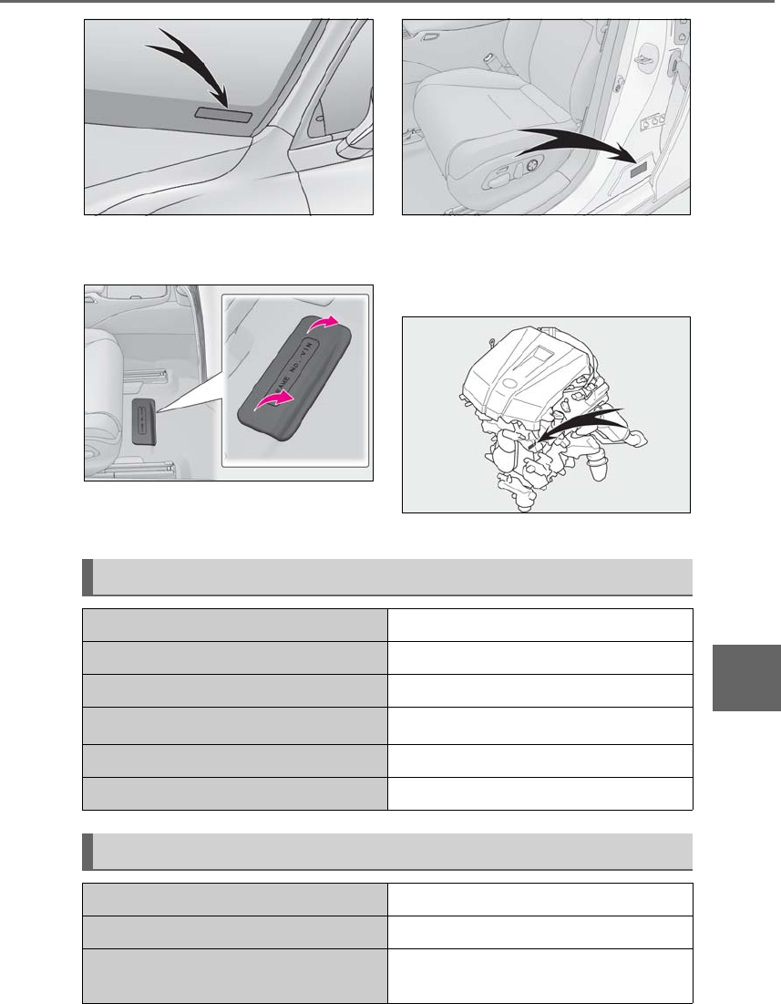
461
8-1. Specifications
LS500h_OM_OM50F42U_(U)
8
Vehicle specifications
This number is also stamped under the
right-hand front seat.
This number is also on the Certification
Label.
■Engine number
The engine number is stamped on the
engine block as shown.
Engine
Model 3.5 L 6-cylinder (8GR-FXS)
Type 6-cylinder V type, 4-cycle, gasoline
Bore and stroke 3.70 × 3.27 in. (94.0 × 83.0 mm)
Displacement 210.9 cu. in. (3456 cm3)
Valve clearance Automatic adjustment
Drive belt tension Automatic adjustment
Fuel
Fuel type Unleaded gasoline only
Octane Rating 91 (Research Octane Number 96) or higher
Fuel tank capacity
(Reference) 22.2 gal. (84.0 L, 18.5 Imp. gal.)

462 8-1. Specifications
LS500h_OM_OM50F42U_(U)
■Oil capacity (Drain and refill [Ref-
erence*])
*: The engine oil capacity is a reference
quantity to be used when changing the
engine oil. Warm up the engine and turn
off the hybrid system, wait more than 5
minutes, and check the oil level on the
dipstick.
■Engine oil selection
“Toyota Genuine Motor Oil” is used in
your Lexus vehicle. Use Lexus
approved “Toyota Genuine Motor Oil”
or equivalent to satisfy the following
grade and viscosity.
Oil grade: ILSAC GF-5 multigrade
engine oil
Recommended viscosity: SAE 0W-20
SAE 0W-20 is the best choice for
good fuel economy and good starting
in cold weather.
If SAE 0W-20 is not available, SAE
5W-20 oil may be used. However, it
must be replaced with SAE 0W-20 at
the next oil change.
Recommended viscosity (SAE):
Electric motor (traction motor)
Type Permanent magnet synchronous motor
Maximum output 131.9 kW
Maximum torque 221.3 ft•lbf (300 N•m, 30.6 kgf•m)
Hybrid battery (traction battery)
Type Lithium-ion battery
Voltage 3.7 V/cell
Capacity 3.6 Ah
Quantity 84 cells
Overall voltage 310.8 V
Lubrication system
With filter
2WD models
6.0 qt. (5.7 L, 5.0 Imp. qt.)
AWD models
7.1 qt. (6.7 L, 5.9 Imp. qt.)
Without fil-
ter
2WD models
5.8 qt. (5.5 L, 4.8 Imp. qt.)
AWD models
6.8 qt. (6.4 L, 5.6 Imp. qt.)
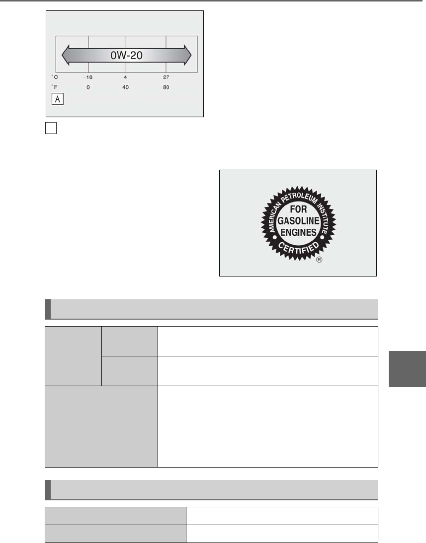
463
8-1. Specifications
LS500h_OM_OM50F42U_(U)
8
Vehicle specifications
Outside temperature
Oil viscosity (0W-20 is explained here
as an example):
• The 0W in 0W-20 indicates the
characteristic of the oil which allows
cold startability. Oils with a lower
value before the W allow for easier
starting of the engine in cold
weather.
• The 20 in 0W-20 indicates the vis-
cosity characteristic of the oil when
the oil is at high temperature. An oil
with a higher viscosity (one with a
higher value) may be better suited if
the vehicle is operated at high
speeds, or under extreme load con-
ditions.
How to read oil container label:
The International Lubricant Specifica-
tion Advisory Committee (ILSAC)
Certification Mark is added to some oil
containers to help you select the oil you
should use.
A
Cooling system
Capacity
Gasoline
engine 11.6 qt. (11.0 L, 9.7 Imp. qt.)
Power con-
trol unit 2.6 qt. (2.5 L, 2.2 Imp. qt.)
Coolant type
Use either of the following:
•“Toyota Super Long Life Coolant”
•Similar high-quality ethylene glycol-based non-silicate,
non-amine, non-nitrite, and non-borate coolant with
long-life hybrid organic acid technology
Do not use plain water alone.
Ignition system (spark plug)
Make DENSO FK20HBR8
Gap 0.031 in. (0.8 mm)

464 8-1. Specifications
LS500h_OM_OM50F42U_(U)
*: The fluid capacity is a reference quantity.
If replacement is necessary, contact your Lexus dealer.
*: Your Lexus vehicle is filled with Toyota genuine gear oil at the factory. Use Lexus
approved Toyota genuine gear oil or an equivalent of matching quality to satisfy the
above specification. Please contact your Lexus dealer for further details.
NOTICE
■Iridium-tipped spark plugs
Use only iridium-tipped spark plugs. Do not adjust the spark plug gap.
Electrical system (12-volt battery)
Specific gravity reading at 68°F
(20°C):
12.0 V or higher
(Turn the power switch off and turn on the high
beam headlights for 30 seconds.)
Charging rates
Quick charge
Slow charge
15 A max.
5 A max.
Hybrid transmission
Fluid capacity*7.2 qt. (6.8 L, 6.0 Imp. qt.)
Fluid type Toyota Genuine ATF WS
NOTICE
■Hybrid transmission fluid type
Using transmission fluid other than “Toyota Genuine ATF WS” may cause deterioration in
shift quality, and ultimately damage the transmission of your vehicle.
Transfer (AWD models)
Oil capacity 0.74 qt. (0.70 L, 0.62 Imp. qt.)
Oil type and viscosity*Toyota Genuine Transfer gear oil LL 80 or equivalent

465
8-1. Specifications
LS500h_OM_OM50F42U_(U)
8
Vehicle specifications
*: Your Lexus vehicle is filled with “Toyota Genuine Differential Gear Oil” at the factory.
Use Lexus approved “Toyota Genuine Differential Gear Oil” or an equivalent oil of
matching quality to satisfy the above specification. Please contact your Lexus dealer for
further details.
2WD models
AWD models
*: Your Lexus vehicle is filled with “Toyota Genuine Differential Gear Oil” at the factory.
Use Lexus approved “Toyota Genuine Differential Gear Oil” or an equivalent oil of
matching quality to satisfy the above specification. Please contact your Lexus dealer for
further details.
Front differential (AWD models)
Oil capacity 0.69 qt. (0.65 L, 0.57 Imp. qt.)
Oil type and viscosity*Toyota Genuine Differential gear oil LT 75W-85
GL-5 or equivalent
Rear differential
Oil capacity 0.90 qt. (0.85 L, 0.75 Imp. qt.)
Oil type and viscosity*Toyota Genuine Differential gear oil LT 75W-85
GL-5 or equivalent
Oil capacity 1.42 qt. (1.35 L, 1.19 Imp. qt.)
Oil type and viscosity*Toyota Genuine Differential gear oil LT 75W-85
GL-5 or equivalent
Brakes
Pedal clearance*1 4.8 in. (122 mm) Min.
Pedal free play 0.04 ⎯ 0.24 in. (1 ⎯ 6 mm)
Brake pad wear limit 0.04 in. (1 mm)
Parking brake lining wear limit 0.04 in. (1 mm)

466 8-1. Specifications
LS500h_OM_OM50F42U_(U)
*1: Minimum pedal clearance when depressed with a force of 112 lbf (500 N, 51 kgf) while
the hybrid system is operating.
When performing the brake pedal inspection, also be sure to check that the brake sys-
tem warning light is not illuminated when the hybrid system is operating. (If the brake
system warning light is illuminated, refer to P.427.)
*2: Make sure to confirm that the brake warning light (yellow) does not illuminate. (If the
brake warning light illuminates, refer to P.427.)
19-inch tires (type A)
Parking brake indicator*2
When pushing the parking brake switch for 1 to 2
seconds: comes on
When pulling the parking brake switch for 1 to 2
seconds: turns off
Fluid type FMVSS No.116 DOT 3 or SAE J1703
FMVSS No.116 DOT 4 or SAE J1704
Steering
Free play Less than 1.2 in. (30 mm)
Tires and wheels
Tire size 245/50RF19 101W
Tire inflation pressure
(Recommended cold tire
inflation pressure)
Driving under normal conditions
Front: 36 psi (250 kPa, 2.5 kgf/cm2 or bar)
Rear: 36 psi (250 kPa, 2.5 kgf/cm2 or bar)
Driving at high speeds above 118 mph (190 km/h) (in coun-
tries where such speeds are permitted by law)
Add 9 psi (60 kPa, 0.6 kgf/cm2 or bar) to the front tires and
rear tires. Never exceed the maximum cold tire inflation
pressure indicated on the tire sidewall.
Wheel size 19 × 8J
Wheel nut torque 103 ft•lbf (140 N•m, 14.3 kgf•m)

467
8-1. Specifications
LS500h_OM_OM50F42U_(U)
8
Vehicle specifications
19-inch tires (type B)
20-inch tires (type A)
Tire size 245/50RF19 101V
Tire inflation pressure
(Recommended cold tire
inflation pressure)
Driving under normal conditions
Front: 36 psi (250 kPa, 2.5 kgf/cm2 or bar)
Rear: 36 psi (250 kPa, 2.5 kgf/cm2 or bar)
Driving at high speeds above 100 mph (160 km/h) (in
countries where such speeds are permitted by law)
Add 9 psi (60 kPa, 0.6 kgf/cm2 or bar) to the front tires and
rear tires. Never exceed the maximum cold tire inflation
pressure indicated on the tire sidewall.
Wheel size 19 × 8J
Wheel nut torque 103 ft•lbf (140 N•m, 14.3 kgf•m)
Tire size 245/45RF20 99Y
Tire inflation pressure
(Recommended cold tire
inflation pressure)
Driving under normal conditions
Front: 35 psi (240 kPa, 2.4 kgf/cm2 or bar)
Rear: 35 psi (240 kPa, 2.4 kgf/cm2 or bar)
Driving at high speeds above 137 mph (220 km/h) (in
countries where such speeds are permitted by law)
Add 9 psi (60 kPa, 0.6 kgf/cm2 or bar) to the front tires and
rear tires. Never exceed the maximum cold tire inflation
pressure indicated on the tire sidewall.
Wheel size 20 × 8 1/2J
Wheel nut torque 103 ft•lbf (140 N•m, 14.3 kgf•m)

468 8-1. Specifications
LS500h_OM_OM50F42U_(U)
20-inch tires (type B)
20-inch tires (type C)
Tire size Front tires: 245/45RF20 99Y
Rear tires: 275/40RF20 102Y
Tire inflation pressure
(Recommended cold tire
inflation pressure)
Driving under normal conditions
Front: 36 psi (250 kPa, 2.5 kgf/cm2 or bar)
Rear: 36 psi (250 kPa, 2.5 kgf/cm2 or bar)
Driving at high speeds above 137 mph (220 km/h) (in
countries where such speeds are permitted by law)
Add 9 psi (60 kPa, 0.6 kgf/cm2 or bar) to the front tires and
rear tires. Never exceed the maximum cold tire inflation
pressure indicated on the tire sidewall.
Wheel size Front wheels: 20 × 8 1/2J
Rear wheels: 20 × 9 1/2J
Wheel nut torque 103 ft•lbf (140 N•m, 14.3 kgf•m)
Tire size 245/45RF20 99V
Tire inflation pressure
(Recommended cold tire
inflation pressure)
Driving under normal conditions
Front: 35 psi (240 kPa, 2.4 kgf/cm2 or bar)
Rear: 35 psi (240 kPa, 2.4 kgf/cm2 or bar)
Driving at high speeds above 100 mph (160 km/h) (in
countries where such speeds are permitted by law)
Add 9 psi (60 kPa, 0.6 kgf/cm2 or bar) to the front tires and
rear tires. Never exceed the maximum cold tire inflation
pressure indicated on the tire sidewall.
Wheel size 20 × 8 1/2J
Wheel nut torque 103 ft•lbf (140 N•m, 14.3 kgf•m)

469
8-1. Specifications
LS500h_OM_OM50F42U_(U)
8
Vehicle specifications
20-inch tires (type D)
Tire size Front tires: 245/45RF20 99V
Rear tires: 275/40RF20 102V
Tire inflation pressure
(Recommended cold tire
inflation pressure)
Driving under normal conditions
Front: 36 psi (250 kPa, 2.5 kgf/cm2 or bar)
Rear: 36 psi (250 kPa, 2.5 kgf/cm2 or bar)
Driving at high speeds above 100 mph (160 km/h) (in
countries where such speeds are permitted by law)
Add 9 psi (60 kPa, 0.6 kgf/cm2 or bar) to the front tires and
rear tires. Never exceed the maximum cold tire inflation
pressure indicated on the tire sidewall.
Wheel size Front wheels: 20 × 8 1/2J
Rear wheels: 20 × 9 1/2J
Wheel nut torque 103 ft•lbf (140 N•m, 14.3 kgf•m)
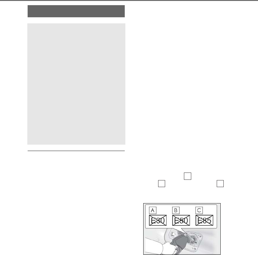
470 8-1. Specifications
LS500h_OM_OM50F42U_(U)
■Gasoline quality
In very few cases, driveability problems may
be caused by the brand of gasoline you are
using. If driveability problems persist, try
changing the brand of gasoline. If this does
not correct the problem, consult your Lexus
dealer.
■Gasoline quality standards
●Automotive manufacturers in the U.S.A.,
Europe and Japan have developed a
specification for fuel quality called the
World-Wide Fuel Charter (WWFC),
which is expected to be applied world-
wide.
●The WWFC improves air quality by low-
ering emissions in vehicle fleets, and
improves customer satisfaction through
better performance.
■Recommendation of the use of gasoline
containing detergent additives
●Lexus recommends the use of gasoline
that contains detergent additives to avoid
the build-up of engine deposits.
●All gasoline sold in the U.S.A. contains
minimum detergent additives to clean
and/or keep clean intake systems, per
EPA’s lowest additives concentration pro-
gram.
●Lexus strongly recommends the use of
Top Tier Detergent Gasoline. For more
information on Top Tier Detergent Gaso-
line and a list of marketers, please go to
the official website www.toptiergas.com.
■Recommendation of the use of low
emissions gasoline
Gasolines containing oxygenates such as
ethers and ethanol, as well as reformulated
gasolines, are available in some cities.
These fuels are typically acceptable for use,
providing they meet other fuel require-
ments.
Lexus recommends these fuels, since the
formulations allow for reduced vehicle
emissions.
■Non-recommendation of the use of
blended gasoline
●Use only gasoline containing up to 15%
ethanol.
DO NOT use any flex-fuel or gasoline
that could contain more than 15% etha-
nol, including from any pump labeled
E30 (30% ethanol [ ]), E50 (50%
ethanol [ ]), E85 (85% ethanol [ ])
(which are only some examples of fuel
containing more than 15% ethanol).
●If you use gasohol in your vehicle, be sure
that it has an octane rating no lower than
91.
●Lexus does not recommend the use of
gasoline containing methanol.
■Non-recommendation of the use of gas-
oline containing MMT
Some gasoline contains an octane enhanc-
ing additive called MMT (Methylcyclopen-
tadienyl Manganese Tricarbonyl).
Lexus does not recommend the use of gas-
Fuel information
You must only use unleaded gaso-
line.
Select premium unleaded gasoline
with an octane rating of 91
(Research Octane Number 96) or
higher required for optimum
engine performance and fuel econ-
omy.
If the octane rating is less than 91,
damage to the engine may occur
and may void the vehicle warranty.
At minimum, the gasoline you use
should meet the specifications of
ASTM D4814 in the U.S.A.
A
B
C

471
8-1. Specifications
LS500h_OM_OM50F42U_(U)
8
Vehicle specifications
oline that contains MMT. If fuel containing
MMT is used, your emission control system
may be adversely affected.
The malfunction indicator lamp on the
instrument cluster may come on. If this hap-
pens, contact your Lexus dealer for service.
■If your engine knocks
●Consult your Lexus dealer.
●You may occasionally notice light knock-
ing for a short time while accelerating or
driving uphill. This is normal and there is
no need for concern.
NOTICE
■Notice on fuel quality
●Do not use improper fuels. If improper
fuels are used, the engine will be dam-
aged.
●Do not use leaded gasoline.
Leaded gasoline can cause damage to
your vehicle’s three-way catalytic con-
verters causing the emission control
system to malfunction.
●Do not use gasohol other than the type
previously stated.
Other gasohol may cause fuel system
damage or vehicle performance prob-
lems.
●Using unleaded gasoline with an
octane number or rating lower than
the level previously stated may cause
persistent heavy knocking.
At worst, this may lead to engine dam-
age and will void the vehicle warranty.
■When refueling with gasohol
Take care not to spill gasohol. It can dam-
age your vehicle’s paint.
■Fuel-related poor driveability
If poor driveability is encountered after
using a different type of fuel (poor hot
starting, vaporization, engine knocking,
etc.), discontinue the use of that type of
fuel.
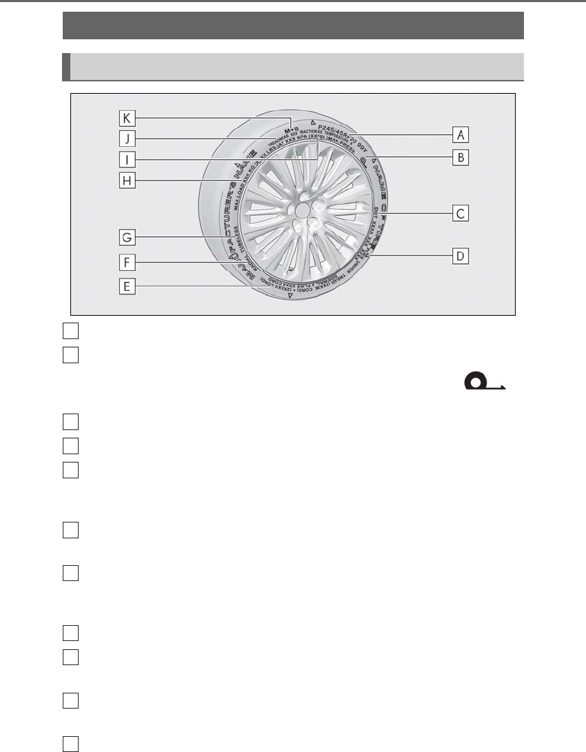
472 8-1. Specifications
LS500h_OM_OM50F42U_(U)
Tire size (→P.473)
Run-flat tire (RFT) or standard tire (→P.442)
This vehicle can be equipped with either run-flat tires (RFT) or standard tires. A
mark is molded on the sidewall of the run-flat tire.
DOT and Tire Identification Number (TIN) (→P.473)
Location of treadwear indicators (→P.395)
Tire ply composition and materials
Plies are layers of rubber-coated parallel cords. Cords are the strands which form the plies
in a tire.
Radial tires or bias-ply tires
A radial tire has “RADIAL” on the sidewall. A tire not marked “RADIAL” is a bias-ply tire.
TUBELESS or TUBE TYPE
A tubeless tire does not have a tube and air is directly put into the tire. A tube type tire has a
tube inside the tire and the tube maintains the air pressure.
Load limit at maximum cold tire inflation pressure (→P.396)
Maximum cold tire inflation pressure (→P.466)
This means the pressure to which a tire may be inflated.
Uniform tire quality grading
For details, see “Uniform Tire Quality Grading” that follows.
Summer tires or all season tires (→P.396)
Tire information
Typical tire symbols
A
B
C
D
E
F
G
H
I
J
K
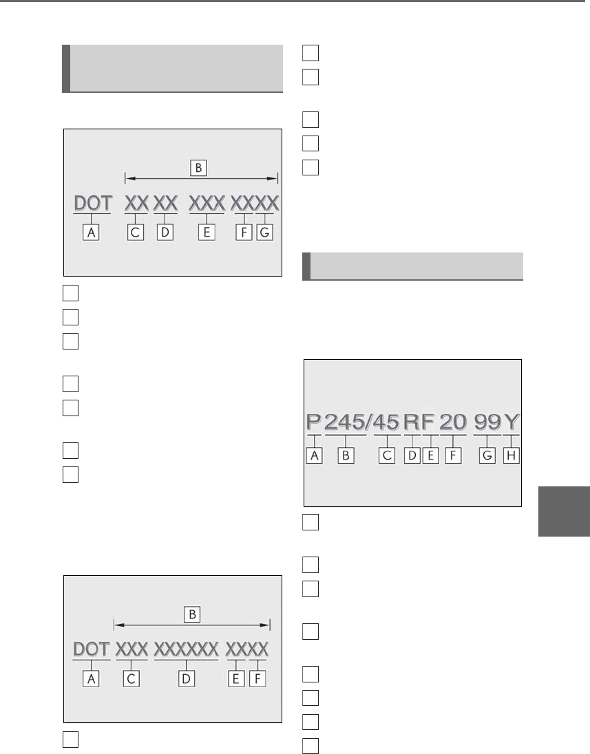
473
8-1. Specifications
LS500h_OM_OM50F42U_(U)
8
Vehicle specifications
An all season tire has “M+S” on the sidewall. A tire not marked “M+S” is a summer tire.
Type A
DOT symbol*
Tire Identification Number (TIN)
Tire manufacturer’s identification
mark
Tire size code
Manufacturer’s optional tire type
code (3 or 4 letters)
Manufacturing week
Manufacturing year
*:The DOT symbol certifies that the tire
conforms to applicable Federal Motor
Vehicle Safety Standards.
Type B
DOT symbol*
Tire Identification Number (TIN)
Tire manufacturer’s identification
mark
Manufacturer’s code
Manufacturing week
Manufacturing year
*: The DOT symbol certifies that the tire
conforms to applicable Federal Motor
Vehicle Safety Standards.
■Typical tire size information
The illustration indicates typical tire
size.
Tire use (P = Passenger car, T =
Temporary use)
Section width (millimeters)
Aspect ratio (tire height to section
width)
Tire construction code (R = Radial,
D = Diagonal)
Run-flat tire code
Wheel diameter (inches)
Load index (2 digits or 3 digits)
Speed symbol (alphabet with one
Typical DOT and Tire Identifica-
tion Number (TIN)
A
B
C
D
E
F
G
A
Tire size
B
C
D
E
F
A
B
C
D
E
F
G
H
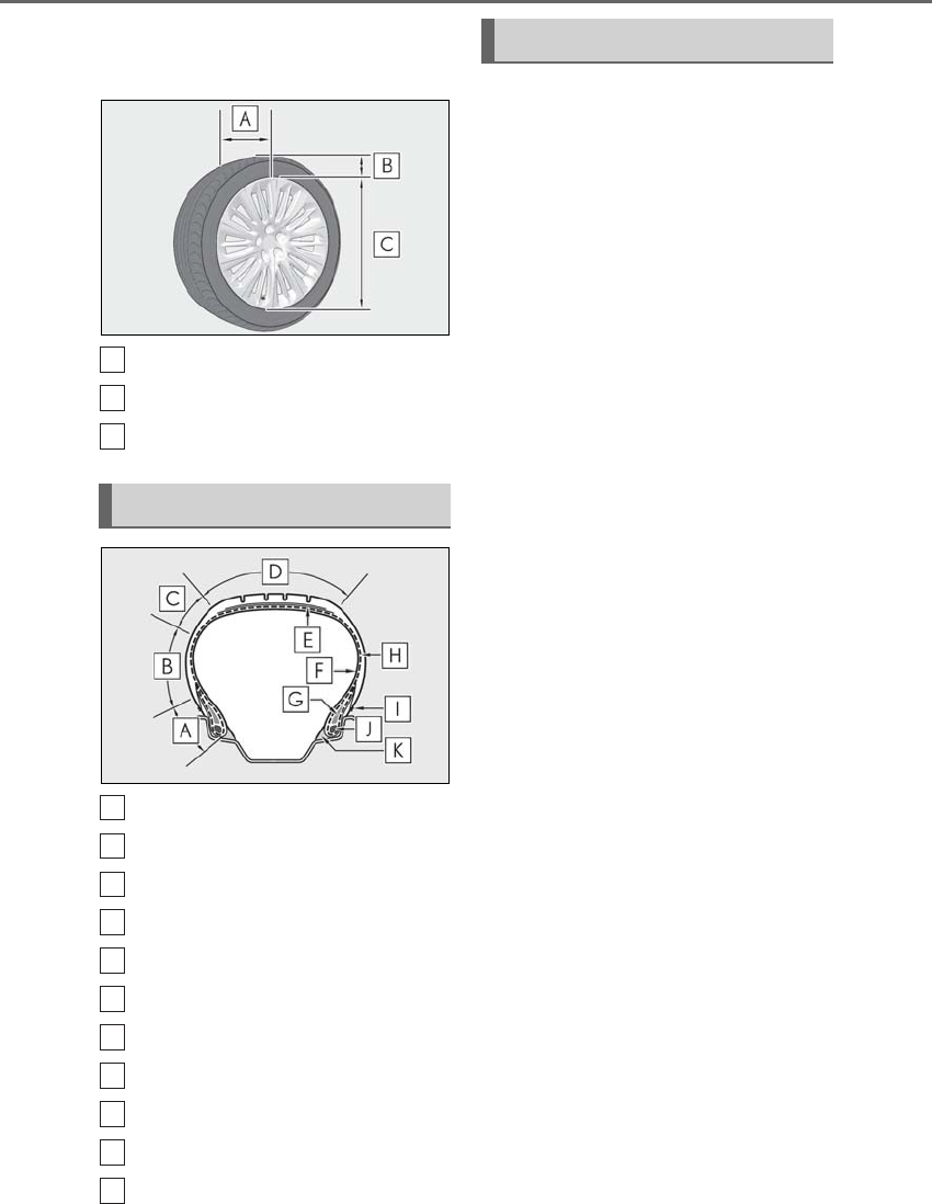
474 8-1. Specifications
LS500h_OM_OM50F42U_(U)
letter)
■Tire dimensions
Section width
Tire height
Wheel diameter
Bead
Sidewall
Shoulder
Tread
Belt
Inner liner
Reinforcing rubber
Carcass
Rim lines
Bead wires
Chafer
This information has been prepared in
accordance with regulations issued by
the National Highway Traffic Safety
Administration of the U.S. Department
of Transportation.
It provides the purchasers and/or pro-
spective purchasers of Lexus vehicles
with information on uniform tire quality
grading.
Your Lexus dealer will help answer any
questions you may have as you read this
information.
■DOT quality grades
All passenger vehicle tires must con-
form to Federal Safety Requirements in
addition to these grades. Quality
grades can be found where applicable
on the tire sidewall between tread
shoulder and maximum section width.
For example: Treadwear 200 Traction AA
Temperature A
■Treadwear
The treadwear grade is a comparative
rating based on the wear rate of the tire
when tested under controlled condi-
tions on a specified government test
course.
For example, a tire graded 150 would wear
one and a half (1 - 1/2) times as well on the
government course as a tire graded 100.
The relative performance of tires depends
upon the actual conditions of their use.
Performance may differ significantly from
the norm due to variations in driving habits,
service practices and differences in road
characteristics and climate.
Tire section names
A
B
C
A
B
C
D
E
F
G
H
I
J
K
Uniform Tire Quality Grading

475
8-1. Specifications
LS500h_OM_OM50F42U_(U)
8
Vehicle specifications
■Traction AA, A, B, C
The traction grades, from highest to
lowest, are AA, A, B and C, and they
represent the tire’s ability to stop on
wet pavement as measured under con-
trolled conditions on specified govern-
ment test surfaces of asphalt and
concrete.
A tire marked C may have poor traction
performance.
Warning: The traction grade assigned to
this tire is based on braking (straight
ahead) traction tests and does not include
cornering (turning) traction.
■Temperature A, B, C
The temperature grades are A (the
highest), B, and C, representing the
tire’s resistance to the generation of
heat and its ability to dissipate heat
when tested under controlled condi-
tions on a specified indoor laboratory
test wheel.
Sustained high temperature can cause the
material of the tire to degenerate and
reduce tire life, and excessive temperature
can lead to sudden tire failure.
Grade C corresponds to a level of perfor-
mance which all passenger car tires must
meet under the Federal Motor Vehicle
Safety Standard No. 109.
Grades B and A represent higher levels of
performance on the laboratory test wheel
than the minimum required by law.
Warning: The temperature grades of a tire
assume that it is properly inflated and not
overloaded.
Excessive speed, underinflation, or exces-
sive loading, either separately or in combi-
nation, can cause heat buildup and
possible tire failure.
Glossary of tire terminology
Tire related term Meaning
Cold tire inflation pressure
Tire pressure when the vehicle has been parked for
three hours or more, or has not been driven more
than 1 mile or 1.5 km under that condition
Maximum inflation pressure The maximum cold inflated pressure to which a tire
may be inflated, shown on the sidewall of the tire
Recommended inflation pressure Cold tire inflation pressure recommended by a
manufacturer
Accessory weight
The combined weight (in excess of those standard
items which may be replaced) of hybrid transmis-
sion, power steering, power brakes, power win-
dows, power seats, radio and heater, to the extent
that these items are available as factory-installed
equipment (whether installed or not)

476 8-1. Specifications
LS500h_OM_OM50F42U_(U)
Curb weight
The weight of a motor vehicle with standard equip-
ment, including the maximum capacity of fuel, oil
and coolant, and if so equipped, air conditioning
and additional weight optional engine
Maximum loaded vehicle weight
The sum of:
(a) Curb weight
(b) Accessory weight
(c) Vehicle capacity weight
(d) Production options weight
Normal occupant weight
150 lb. (68 kg) times the number of occupants
specified in the second column of Table 1* that fol-
lows
Occupant distribution Distribution of occupants in a vehicle as specified in
the third column of Table 1* below
Production options weight
The combined weight of installed regular produc-
tion options weighing over 5 lb. (2.3 kg) in excess of
the standard items which they replace, not previ-
ously considered in curb weight or accessory
weight, including heavy duty brakes, ride levelers,
roof rack, heavy duty 12-volt battery, and special
trim
Rim A metal support for a tire or a tire and tube assem-
bly upon which the tire beads are seated
Rim diameter (Wheel diameter) Nominal diameter of the bead seat
Rim size designation Rim diameter and width
Rim type designation The industry manufacturer’s designation for a rim
by style or code
Rim width Nominal distance between rim flanges
Vehicle capacity weight (Total load
capacity)
The rated cargo and luggage load plus 150 lb. (68
kg) times the vehicle’s designated seating capacity
Vehicle maximum load on the tire
The load on an individual tire that is determined by
distributing to each axle its share of the maximum
loaded vehicle weight, and dividing by two
Tire related term Meaning

477
8-1. Specifications
LS500h_OM_OM50F42U_(U)
8
Vehicle specifications
Vehicle normal load on the tire
The load on an individual tire that is determined by
distributing to each axle its share of curb weight,
accessory weight, and normal occupant weight
(distributed in accordance with Table 1* below), and
dividing by two
Weather side The surface area of the rim not covered by the
inflated tire
Bead
The part of the tire that is made of steel wires,
wrapped or reinforced by ply cords and that is
shaped to fit the rim
Bead separation A breakdown of the bond between components in
the bead
Bias ply tire
A pneumatic tire in which the ply cords that extend
to the beads are laid at alternate angles substan-
tially less than 90 degrees to the centerline of the
tread
Carcass The tire structure, except tread and sidewall rubber
which, when inflated, bears the load
Chunking The breaking away of pieces of the tread or sidewall
Cord The strands forming the plies in the tire
Cord separation The parting of cords from adjacent rubber com-
pounds
Cracking Any parting within the tread, sidewall, or innerliner
of the tire extending to cord material
CT
A pneumatic tire with an inverted flange tire and rim
system in which the rim is designed with rim flanges
pointed radially inward and the tire is designed to fit
on the underside of the rim in a manner that
encloses the rim flanges inside the air cavity of the
tire
Extra load tire
A tire designed to operate at higher loads and at
higher inflation pressures than the corresponding
standard tire
Groove The space between two adjacent tread ribs
Innerliner The layer(s) forming the inside surface of a tubeless
tire that contains the inflating medium within the tire
Tire related term Meaning

478 8-1. Specifications
LS500h_OM_OM50F42U_(U)
Innerliner separation The parting of the innerliner from cord material in
the carcass
Intended outboard sidewall
(a) The sidewall that contains a whitewall, bears
white lettering, or bears manufacturer, brand,
and/or model name molding that is higher or
deeper than the same molding on the other sidewall
of the tire, or
(b) The outward facing sidewall of an asymmetrical
tire that has a particular side that must always face
outward when mounted on a vehicle
Light truck (LT) tire
A tire designated by its manufacturer as primarily
intended for use on lightweight trucks or multipur-
pose passenger vehicles
Load rating The maximum load that a tire is rated to carry for a
given inflation pressure
Maximum load rating The load rating for a tire at the maximum permissi-
ble inflation pressure for that tire
Maximum permissible inflation pres-
sure
The maximum cold inflation pressure to which a tire
may be inflated
Measuring rim The rim on which a tire is fitted for physical dimen-
sion requirements
Open splice Any parting at any junction of tread, sidewall, or
innerliner that extends to cord material
Outer diameter The overall diameter of an inflated new tire
Overall width
The linear distance between the exteriors of the
sidewalls of an inflated tire, including elevations due
to labeling, decorations, or protective bands or ribs
Passenger car tire
A tire intended for use on passenger cars, multipur-
pose passenger vehicles, and trucks, that have a
gross vehicle weight rating (GVWR) of 10,000 lb.
or less.
Ply A layer of rubber-coated parallel cords
Ply separation A parting of rubber compound between adjacent
plies
Tire related term Meaning
479
8-1. Specifications
LS500h_OM_OM50F42U_(U)
8
Vehicle specifications
Pneumatic tire
A mechanical device made of rubber, chemicals,
fabric and steel or other materials, that, when
mounted on an automotive wheel, provides the
traction and contains the gas or fluid that sustains
the load
Radial ply tire
A pneumatic tire in which the ply cords that extend
to the beads are laid at substantially 90 degrees to
the centerline of the tread
Reinforced tire
A tire designed to operate at higher loads and at
higher inflation pressures than the corresponding
standard tire
Section width
The linear distance between the exteriors of the
sidewalls of an inflated tire, excluding elevations
due to labeling, decoration, or protective bands
Sidewall That portion of a tire between the tread and bead
Sidewall separation The parting of the rubber compound from the cord
material in the sidewall
Snow tire
A tire that attains a traction index equal to or
greater than 110, compared to the ASTM E-1136
Standard Reference Test Tire, when using the snow
traction test as described in ASTM F-1805-00,
Standard Test Method for Single Wheel Driving
Traction in a Straight Line on Snow-and Ice-Cov-
ered Surfaces, and which is marked with an Alpine
Symbol ( ) on at least one sidewall
Test rim The rim on which a tire is fitted for testing, and may
be any rim listed as appropriate for use with that tire
Tread That portion of a tire that comes into contact with
the road
Tread rib A tread section running circumferentially around a
tire
Tread separation Pulling away of the tread from the tire carcass
Tire related term Meaning

480 8-1. Specifications
LS500h_OM_OM50F42U_(U)
*: Table 1 -Occupant loading and distribution for vehicle normal load for various desig-
nated seating capacities
Treadwear indicators (TWI)
The projections within the principal grooves
designed to give a visual indication of the degrees
of wear of the tread
Wheel-holding fixture The fixture used to hold the wheel and tire assembly
securely during testing
Tire related term Meaning
Designated seating capac-
ity, Number of occupants
Vehicle normal load, Num-
ber of occupants
Occupant distribution in a
normally loaded vehicle
2 through 4 22 in front
5 through 10 32 in front, 1 in second seat
11 through 15 52 in front, 1 in second seat, 1 in
third seat, 1 in fourth seat
16 through 20 72 in front, 2 in second seat, 2
in third seat, 1 in fourth seat
481
8-2. Customization
LS500h_OM_OM50F42U_(U)
8
Vehicle specifications
8-2.Customization
■Changing by using the meter con-
trol switches
1Press or to select .
2Operate the meter control
switches to select the desired item
to be customized.
3According to the display, select the
desired setting and then press .
To go back to the previous screen or exit
the customize mode, press .
■Changing by using the Remote
Touch
1Press the “MENU” button on the
Remote Touch.
2Select “Setup” on the menu screen
and select “Vehicle”.
3Select “Vehicle Customization” or
“Drive Mode Customization”.
Various setting can be changed. Refer to
the list of settings that can be changed for
details.
For details on the Remote Touch, refer
to the “NAVIGATION AND MULTI-
MEDIA SYSTEM OWNER’S MAN-
UAL”.
■Changing by using the Rear Multi
Operation Panel (if equipped)
1Display the home screen on the
Rear Multi Operation Panel and
then touch “Settings”.
2Touch “Seat”.
3Select the desired setting.
■When customizing using the Remote
Touch
Stop the vehicle in a safe place, apply the
parking brake, and shift the shift position to
P. Also, to prevent 12-volt battery discharge,
leave the hybrid system operating while
customizing the features.
Some function settings are changed simultaneously with other functions being cus-
Customizable features
Your vehicle includes a variety of
electronic features that can be per-
sonalized to your preferences. The
settings of these features can be
changed by using the meter control
switches, the Remote Touch, Rear
Multi Operation Panel or at your
Lexus dealer.
Customizing vehicle features
WARNING
■During customization
As the hybrid system needs to be operat-
ing during customization, ensure that the
vehicle is parked in a place with ade-
quate ventilation. In a closed area such as
a garage, exhaust gases including harm-
ful carbon monoxide (CO) may collect
and enter the vehicle. This may lead to
death or a serious health hazard.
NOTICE
■During customization
To prevent 12-volt battery discharge,
ensure that the hybrid system is operat-
ing while customizing features.
Customizable features
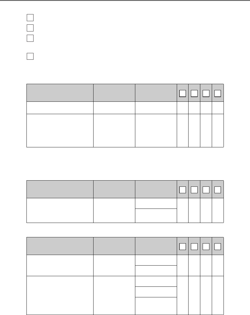
482 8-2. Customization
LS500h_OM_OM50F42U_(U)
tomized. Contact your Lexus dealer for further details.
Settings that can be changed using the Remote Touch
Settings that can be changed using the meter control switches
Settings that can be changed using the Rear Multi Operation Panel (if
equipped)
Settings that can be changed by your Lexus dealer
Definition of symbols: O = Available, — = Not available
■Seat belts (→P.24)
*1: If equipped
*2: Vehicles with pre-collision seat belts with comfort function
■Vehicle proximity notification system (→P.60)
■Gauges, meters and multi-information display (→P.72, 77, 81, 86)
Function Default setting Customized set-
ting
Easy Access Buckle*1 On Off — — — O
Retraction of front seat belts
when vehicle speed reaches
approximately 12 mph (20
km/h)*2
On Off — — — O
Function Default setting Customized set-
ting
The volume of vehicle prox-
imity notification system
sound
Level1
Level2
— — — O
Level3
Function*1 Default setting Customized set-
ting
Language English French O O — —
Spanish
Units*2 miles (MPG)
km (km/L)
O O — —
km (L/100 km)
miles (MPG
Imperial)
A
B
C
D
A
B
C
D
A
B
C
D
A
B
C
D
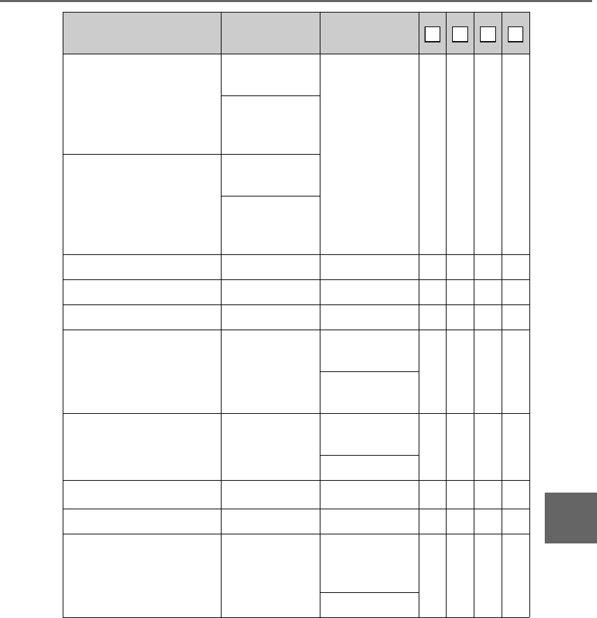
483
8-2. Customization
LS500h_OM_OM50F42U_(U)
8
Vehicle specifications
*1: For details about each function: →P.90
*2: The default setting varies according to country.
*3:F SPORT models
Drive information 1
Current fuel con-
sumption
Customizable
items: →P.88 — O — —
Average fuel
economy (after
reset)
Drive information 2
Distance (driving
range)
Average vehicle
speed (after
reset)
Clock 12-hour display 24-hour display — O — —
Pop-up display On Off — O — —
Accent color Color 1 Color 2 O O — —
Tachometer setting
Change accord-
ing to driving
mode
Always tachome-
ter — O — —
Always Hybrid
System Indicator
Rev indicator*3 4000 r/min.
2000 - 6600
r/min. — O — —
Off
Rev peak*3 On Off — O — —
EV indicator On Off — O — —
Suggestion function On
On (when the
vehicle is
stopped) O — — O
Off
Function*1 Default setting Customized set-
ting
A
B
C
D
484 8-2. Customization
LS500h_OM_OM50F42U_(U)
■Head-up Display* (→P.92)
*:If equipped
■Door lock (→P.108, 112, 445)
Function Default setting Customized set-
ting
Gauge information Hybrid System
Indicator
Tachometer — O — —
No content
Route guidance to destina-
tion/street name*On Off — O — —
Driving support system dis-
play On Off — O — —
Compass*On Off — O — —
Audio system operation sta-
tus On Off — O — —
Function Default setting Customized set-
ting
Unlocking using a mechani-
cal key
Driver’s door
unlocked in one
step, all doors
unlocked in two
step
All doors
unlocked in one
step
— — — O
Automatic door locking func-
tion
Shift position
linked door lock-
ing operation
Off
O — — O
Speed linked
door locking
operation
Automatic door unlocking
function
Shift position
linked door
unlocking opera-
tion
Off
O — — O
Driver’s door
linked door
unlocking opera-
tion
Locking/unlocking of the
trunk when all doors are
locked/unlocked
On Off — — — O
A
B
C
D
A
B
C
D
485
8-2. Customization
LS500h_OM_OM50F42U_(U)
8
Vehicle specifications
■Smart access system with push-button start and wireless remote control
(→P.108, 119)
■Smart access system with push-button start (→P.108, 119)
■Wireless remote control (→P.106, 108, 112)
Function Default setting Customized set-
ting
Operating signal (Buzzers) 5Off O — — O
1 to 7
Operation signal (Emer-
gency flashers) On Off O — — O
Time elapsed before auto-
matic door lock function is
activated if door is not
opened after being unlocked
60 seconds
Off
O — — O30 seconds
120 seconds
Open door warning buzzer On Off — — — O
Function Default setting Customized set-
ting
Smart access system with
push-button start On Off — — — O
Smart door unlocking Driver’s door All the doors O — — O
Time elapsed before unlock-
ing all the door when gripping
and holding the driver’s door
handle
2 seconds
Off
— — — O1.5 seconds
2.5 seconds
Number of consecutive door
lock operations 2 times As many as
desired — — — O
Function Default setting Customized set-
ting
Wireless remote control On Off — — — O
Unlocking operation
Driver’s door
unlocked in one
step, all doors
unlocked in two
step
All doors
unlocked in one
step
O — — O
A
B
C
D
A
B
C
D
A
B
C
D
486 8-2. Customization
LS500h_OM_OM50F42U_(U)
■Trunk (→P.112)
*:If equipped
■Front seats (→P.128)
■Power rear seats* (→P.135)
Trunk unlocking operation Press and hold
(short)
One short press
— — — O
Push twice
Press and hold
(long)
Off
Theft deterrent panic mode On Off — — — O
Reservation lock On Off O — — O
Function Default setting Customized set-
ting
Hands Free Power Trunk Lid
(kick sensor)*On Off — O — —
Function Default setting Customized set-
ting
Driver’s seat position linked
head restraint height opera-
tion
Off On — — — O
Function Default setting Customized set-
ting
Automatic rear seat opera-
tion (door-linked rear seat
return function and
shift-linked rear seat reclining
function)
On Off — — O —
Function Default setting Customized set-
ting
A
B
C
D
A
B
C
D
A
B
C
D
A
B
C
D
487
8-2. Customization
LS500h_OM_OM50F42U_(U)
8
Vehicle specifications
*:If equipped
■Driving position memory (→P.139)
■Outside rear view mirrors (→P.149)
Door linked rear seat with
ottoman seatback position for
exiting*
More upright
than upright posi-
tion
Upright position — — O —
Shift-linked rear seat reclining
function On Off — — — O
Function Default setting Customized set-
ting
Selecting doors linked to the
memory recall function Driver’s door All doors — — — O
Driver’s seat slide movement
when exiting the vehicle Full Off O — — O
Partial
Driver’s seat height move-
ment when exiting the vehicle Off Full O — — O
Partial
Front passenger’s seat move-
ment when exiting the vehicle On Off — — — O
Steering wheel movement Tilt only
Off
O — — OTelescopic only
Tilt and telescopic
Function Default setting Customized set-
ting
Automatic mirror folding and
extending operation
Linked to the
locking/ unlock-
ing of the doors
Off
— — — O
Linked to opera-
tion of the power
switch
Function Default setting Customized set-
ting
A
B
C
D
A
B
C
D
A
B
C
D
488 8-2. Customization
LS500h_OM_OM50F42U_(U)
■Power windows and moon roof (→P.151, 153)
■Automatic light control system (→P.185)
■Lights (→P.185)
*1:Except for Canada
*2: If equipped
Function Default setting Customized set-
ting
Mechanical key linked opera-
tion Off On — — — O
Wireless remote control
linked operation Off On (open only) — — — O
Wireless remote control
linked operation signal
(buzzer)
On Off — — — O
Function Default setting Customized set-
ting
Light sensor sensitivity Standard -2 to 2 O — — O
Time elapsed before head-
lights automatically turn off
after doors are closed
30 seconds
Off
O — — O60 seconds
90 seconds
Windshield wiper linked
headlight illumination On Off — — — O
Function Default setting Customized set-
ting
Daytime running lights On Off*1 O — — O
Welcome lighting On Off — — — O
AFS (Adaptive Front-lighting
System)*2 On Off — — — O
A
B
C
D
A
B
C
D
A
B
C
D
489
8-2. Customization
LS500h_OM_OM50F42U_(U)
8
Vehicle specifications
■PCS (Pre-Collision System) and FCTA (Front Cross Traffic Alert)* (→P.209,
220, 227)
*:If equipped
■LTA (Lane Tracing Assist)* (→P.230)
*:If equipped
■LKA (Lane-Keeping Assist)* (→P.240)
Function Default setting Customized set-
ting
PCS (Pre-Collision System)
and FCTA function On Off — O — —
Adjust alert timing Middle Far — O — —
Near
Pedestrian alert* and FCTA
function On Off — O — —
Function Default setting Customized set-
ting
Lane centering function On Off — O — —
Steering assist function On Off — O — —
Alert type Steering wheel
vibration Buzzer — O — —
Alert sensitivity High Standard — O — —
Vehicle sway warning func-
tion On Off — O — —
Vehicle sway warning sensi-
tivity Standard High — O — —
Low
Function Default setting Customized set-
ting
Lane centering function Off On — O — —
Steering assist function On Off — O — —
Alert type Steering wheel
vibration Buzzer — O — —
Alert sensitivity Standard High — O — —
A
B
C
D
A
B
C
D
A
B
C
D
490 8-2. Customization
LS500h_OM_OM50F42U_(U)
*:If equipped
■RSA (Road Sign Assist)* (→P.247)
*:If equipped
■BSM (Blind Spot Monitor) (→P.260)
Vehicle sway warning func-
tion On Off — O — —
Vehicle sway warning sensi-
tivity Standard High — O — —
Low
Function Default setting Customized set-
ting
RSA (Road Sign Assist) On Off — O — —
Excess speed notification
method Display only
No notification
— O — —
Display and
buzzer
Excess speed notification
level 1 mph (2 km/h) 3 mph (5 km/h) — O — —
5 mph (10 km/h)
Other notifications method
(No-entry notification) Display only
No notification
— O — —
Display and
buzzer
Function Default setting Customized set-
ting
BSM (Blind Spot Monitor) On Off — O — —
Outside rear view mirror indi-
cator brightness Bright Dim — O — —
Alert timing for presence of
approaching vehicle (sensitiv-
ity)
Intermediate
Early
— O — —
Late
Only when vehi-
cle detected in
blind spot
Function Default setting Customized set-
ting
A
B
C
D
A
B
C
D
A
B
C
D
491
8-2. Customization
LS500h_OM_OM50F42U_(U)
8
Vehicle specifications
■PKSA (Parking Support Alert) (→P.265)
■Intuitive parking assist (→P.266)
■RCTA (Rear cross traffic alert) function (→P.273)
■RCD (Rear camera detection) function* (→P.277)
*:If equipped
■PKSB (Parking Support Brake) (→P.280)
■Driving mode select switch (→P.298)
Function Default setting Customized set-
ting
Buzzer volume Level2 Level1 — O — —
Level3
Function Default setting Customized set-
ting
Intuitive parking assist On Off — O — —
Function Default setting Customized set-
ting
RCTA (Rear cross traffic
alert) function On Off — O — —
Function Default setting Customized set-
ting
RCD (Rear camera detec-
tion) function On Off — O — —
Function Default setting Customized set-
ting
PKSB (Parking Support
Brake) function On Off — O — —
Function Default setting Customized set-
ting
Powertrain control in custom
mode Normal Power O — — —
Eco
A
B
C
D
A
B
C
D
A
B
C
D
A
B
C
D
A
B
C
D
A
B
C
D
492 8-2. Customization
LS500h_OM_OM50F42U_(U)
■Electronically modulated air suspension* (→P.299)
*:If equipped
■Automatic air conditioning system (→P.323)
■Seat heater/seat ventilators (→P.336)
Chassis control in custom
mode Normal Sport O — — —
Comfort
Air conditioning operation in
custom mode Normal Eco O — — —
Function Default setting Customized set-
ting
Vehicle height control On Off — O — —
Ingress/egress height control
function On Off — O — —
Vehicle height when parked Normal High — O — —
Function Default setting Customized set-
ting
A/C auto switch operation On Off O — — O
Exhaust gas sensor sensitivity Standard -3 to 3 O — — O
Function Default setting Customized set-
ting
Driver’s seat temperature
preference in automatic
mode
Standard -2 (cooler) to 2
(warmer) O — — O
Passenger’s seat tempera-
ture preference in automatic
mode
Standard -2 (cooler) to 2
(warmer) O — — O
Left-hand rear seat tempera-
ture preference in automatic
mode*
Standard -2 (cooler) to 2
(warmer) O — — O
Function Default setting Customized set-
ting
A
B
C
D
A
B
C
D
A
B
C
D
A
B
C
D
493
8-2. Customization
LS500h_OM_OM50F42U_(U)
8
Vehicle specifications
*:If equipped
■Heated steering wheel* (→P.336)
*:If equipped
■Illumination (→P.340)
Right-hand rear seat tem-
perature preference in auto-
matic mode*
Standard -2 (cooler) to 2
(warmer) O — — O
Power switch linked auto-
matic activation of the
left-hand rear seat
heater/ventilator*
Off On O — — O
Power switch linked auto-
matic activation of the
right-hand rear seat
heater/ventilator*
Off On O — — O
Function Default setting Customized set-
ting
Steering wheel heating pref-
erence in automatic mode Standard -2 (low) to 2
(high) O — — O
Function Default setting Customized set-
ting
Time elapsed before the inte-
rior lights turn off 15 seconds
Off
O — — O7.5 seconds
30 seconds
Operation after the power
switch is turned off On Off — — — O
Operation when the doors
are unlocked On Off — — — O
Operation when you
approach the vehicle with the
electronic key on your person
On Off — — — O
Footwell lights On Off — — — O
Function Default setting Customized set-
ting
A
B
C
D
A
B
C
D
A
B
C
D

494 8-2. Customization
LS500h_OM_OM50F42U_(U)
■Vehicle customization
●When the smart access system with
push-button start is off, the entry unlock
function cannot be customized.
●When the doors remain closed after
unlocking the doors and the timer acti-
vated automatic door lock function acti-
vates, signals will be generated in
accordance with the operation buzzer
volume and operational signal (Emer-
gency flashers) function settings.
●Some settings can be changed using a
switch or the audio system screen. If a
setting is changed using a switch, the
changed setting will not be reflected on
the audio system screen until the power
switch is turned off and then to ON
mode.
■Clock settings screen
If the clock adjustment screen is displayed
continuously when attempting to change
the clock settings, the system may be mal-
functioning. Have the vehicle inspected by
your Lexus dealer.
Instrument panel ornament
light and door trim ornament
lights
On Off — — — O
Time elapsed before the outer
foot lights turn off 15 seconds
Off
O — — O7.5 seconds
30 seconds
Operation of the outer foot
lights when you approach the
vehicle with the electronic
key on your person
On Off — — — O
Operation of the outer foot
lights when the doors are
unlocked
On Off — — — O
Operation of the outer foot
lights when a door is opened On Off — — — O
Fading out of the outer foot
lights when they turn off Long Short — — — O
Function Default setting Customized set-
ting
A
B
C
D

495
8-3. Initialization
LS500h_OM_OM50F42U_(U)
8
Vehicle specifications
8-3.Initializat ion
*:If equipped
Items to initialize
The following items must be initialized for normal system operation after such
cases as the 12-volt battery being reconnected, or maintenance being per-
formed on the vehicle:
List of items to initialize
Item When to initialize Reference
PKSB (Parking Support
Brake)
• After reconnecting or changing the
12-volt battery P.284
Message indicating
maintenance is
required
• After maintenance is performed P.378
Oil maintenance • After maintenance is performed P.390
Tire pressure warning
system
• When the tire inflation pressure is
changed, such as when changing trav-
eling speed or load weight.
• When the tire inflation pressure is
changed, such as when the tire size is
changed.
• When rotating the tires.
• After performing the transmitter ID
code registration procedure.
P.401
Lexus parking assist
monitor*
• 12-volt battery has been reinstalled.
• The steering wheel has been moved
while the 12-volt battery was being
reinstalled.
• 12-volt battery power is low.
Refer to the “NAVI-
GATION AND MUL-
TIMEDIA SYSTEM
OWNER’S MAN-
UAL”.
Panoramic view moni-
tor*
• 12-volt battery has been reinstalled.
• The steering wheel has been moved
while the 12-volt battery was being
reinstalled.
• 12-volt battery power is low.
Refer to the “NAVI-
GATION AND MUL-
TIMEDIA SYSTEM
OWNER’S MAN-
UAL”.

496 8-3. Initialization
LS500h_OM_OM50F42U_(U)

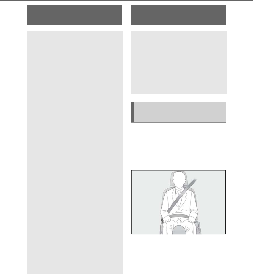
498 9-1. For owners
LS500h_OM_OM50F42U_(U)
9-1.For owners
-Déroulez la sangle diagonale de
telle sorte qu'elle passe bien sur
l'épaule, sans pour autant être en
contact avec le cou ou glisser de
l'épaule.
-Placez la sangle abdominale le plus
bas possible sur les hanches.
-Réglez la position du dossier de
siège. Asseyez-vous le dos droit et
calez-vous bien dans le siège.
-Ne vrillez pas la ceinture de sécu-
rité.
Reporting safety defects for
U.S. owners
If you believe that your vehicle has a
defect which could cause a crash or
could cause injury or death, you
should immediately inform the
National Highway Traffic Safety
Administration (NHTSA) in addition
to notifying the Lexus Division of
Toyota Motor Sales, U.S.A., Inc.
(Toll-free: 1-800-25-LEXUS).
If NHTSA receives similar com-
plaints, it may open an investigation,
and if it finds that a safety defect
exists in a group of vehicles, it may
order a recall and remedy campaign.
However, NHTSA cannot become
involved in individual problems
between you, your dealer, or Lexus
Division of Toyota Motor Sales,
U.S.A., Inc.
To contact NHTSA, you may call the
Vehicle Safety Hotline toll-free at
1-888-327-4236 (TTY:
1-800-424-9153); go to
http://www.safercar.gov
; or write to:
Administrator, NHTSA, 1200 New
Jersey Ave, S.E., Washington, DC
20590. You can also obtain other
information about motor vehicle
safety from
http://www.safercar.gov
.
Seat belt instructions for
Canadian owners (in French)
The following is a French explana-
tion of seat belt instructions
extracted from the seat belt section
in this manual.
See the seat belt section for more
detailed seat belt instructions in
English.
Utilisation correcte des cein-
tures de sécurité

499
9-1. For owners
LS500h_OM_OM50F42U_(U)
9
For owners
Nettoyez avec un chiffon ou une
éponge humidifiés avec de l'eau savon-
neuse tiède. Vérifiez régulièrement
que les ceintures ne sont pas usées,
effilochées ou entaillées excessive-
ment.
Traitement des ceintures de
sécurité
ATTENTION
Inspectez le système de ceintures de
sécurité régulièrement. Contrôlez
l'absence de coupures, d'effilochages et
de pièces desserrées. N'utilisez pas une
ceinture de sécurité endommagée avant
qu'elle ne soit remplacée. Une ceinture
de sécurité endommagée ne permet pas
de protéger un occupant de blessures
graves ou mortelles.
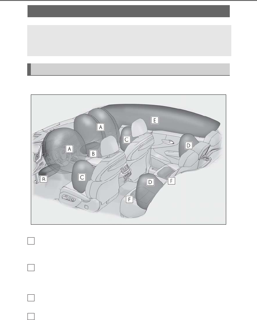
500 9-1. For owners
LS500h_OM_OM50F42U_(U)
■Emplacement des coussins gonflables SRS
Coussins gonflables frontaux SRS
Coussin gonflable conducteur/coussin gonflable du passager avant SRS
Participe à la protection de la tête et du thorax du conducteur et du passager
avant contre les chocs contre les éléments de l'habitacle
Coussins gonflables de genoux SRS
Participent à la protection du conducteur et du passager avant
Coussins gonflables latéraux et rideaux SRS
Coussins gonflables latéraux avant SRS
Participent à la protection du torse des occupants de siège avant
Coussins gonflables latéraux arrière SRS
Participent à la protection du torse des occupants des sièges latéraux arrière
SRS airbag instructions for Canadian owners (in French)
The following is a French explanation of SRS airbag instructions extracted
from the SRS airbag section in this manual.
See the SRS airbag section for more detailed SRS airbag instructions in English.
Système de coussins gonflables SRS
A
B
C
D
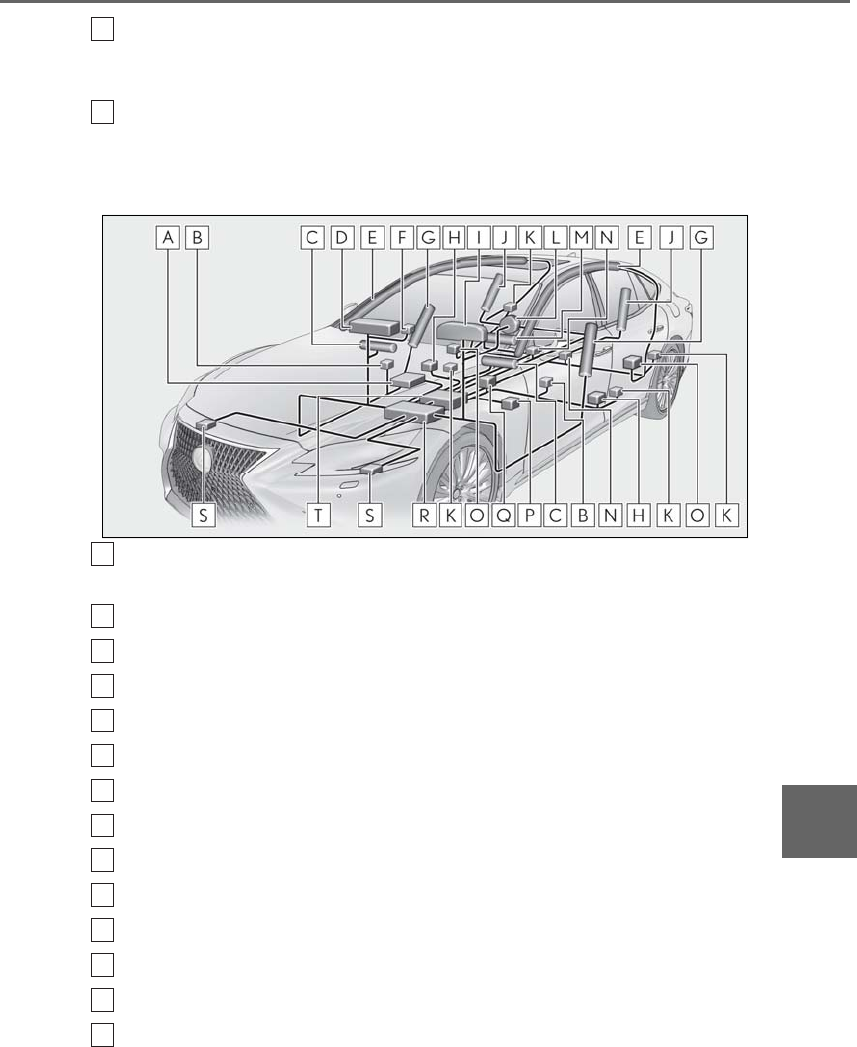
501
9-1. For owners
LS500h_OM_OM50F42U_(U)
9
For owners
Coussins gonflables rideaux SRS
• Participent principalement à la protection de la tête des occupants des sièges latéraux
• Peut contribuer à empêcher les occupants d’être éjectés du véhicule en cas de tonneau
Coussins gonflables de coussin de siège SRS (sur modèles équipés)
Contribue à retenir les occupants des sièges arrière électriques
■Composants du système de coussins gonflables SRS
Système de classification de l'occupant du siège passager avant (ECU et cap-
teurs)
Capteurs d'impact latéral (porte avant)
Coussins gonflables de genoux
Coussin gonflable passager avant
Coussins gonflables rideaux
Témoins indicateurs “AIR BAG ON” et “AIR BAG OFF”
Coussins gonflables latéraux avant
Capteurs d'impact latéral (avant)
Témoin d'avertissement SRS
Coussins gonflables latéraux arrière
Prétensionneurs de ceinture de sécurité
Coussin gonflable conducteur
Coussins gonflables de coussin de siège (sur modèles équipés)
Contacts de boucle de ceinture de sécurité de siège arrière (sur modèles
équipés)
E
F
A
B
C
D
E
F
G
H
I
J
K
L
M
N

502 9-1. For owners
LS500h_OM_OM50F42U_(U)
Capteurs d'impact latéral (arrière)
Capteur de position du siège conducteur
Contact de boucle de ceinture de sécurité conducteur
Ensemble de capteurs de coussins gonflables
Capteurs d'impact avant
Ensemble informatique du capot actif
Votre véhicule est équipé de COUSSINS GONFLABLES INTELLIGENTS
conçus selon les normes de sécurité américaines applicables aux véhicules à
moteur (FMVSS208). L'ensemble de capteurs de coussins gonflables (ECU)
régule le déploiement des coussins gonflables sur la base des informations qu'il
reçoit des capteurs, etc., indiqués ci-dessus dans le schéma illustrant les com-
posants du système. Parmi ces informations figurent la gravité du choc et l'occupa-
tion du véhicule par les passagers. Le déploiement rapide des coussins gonflables
est obtenu au moyen d'une réaction chimique dans les dispositifs pyrotechniques,
qui produit un gaz inoffensif permettant d'amortir le mouvement des occupants.
O
P
Q
R
S
T
ATTENTION
■Précautions relatives aux coussins
gonflables SRS
Respectez les précautions suivantes
concernant les coussins gonflables SRS.
Le non-respect de ces précautions peut
occasionner des blessures graves, voire
mortelles.
●Le conducteur et tous les passagers du
véhicule doivent porter correctement
leur ceinture de sécurité.
Les coussins gonflables SRS sont des
dispositifs supplémentaires à utiliser
avec les ceintures de sécurité.
●Le coussin gonflable conducteur SRS
se déploie avec une force con-
sidérable, pouvant occasionner des
blessures graves, voire mortelles, si le
conducteur se trouve très près du
coussin gonflable.
L'autorité fédérale chargée de la sécurité
routière aux États-Unis (NHTSA) con-
seille: La zone à risque du coussin gon-
flable conducteur se situant dans les
premiers 2 à 3 in. (50 à 75 mm) de
déploiement, vous placer à 10 in. (250
mm) de votre coussin gonflable conduc-
teur vous garantit une marge de sécurité
suffisante. Cette distance est à mesurer
entre le centre du volant et le sternum. Si
vous êtes assis à moins de 10 in. (250
mm), vous pouvez changer votre posi-
tion de conduite de plusieurs façons:
• Reculez votre siège le plus possible, de
manière à pouvoir encore atteindre
confortablement les pédales.
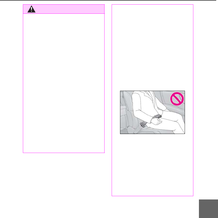
503
9-1. For owners
LS500h_OM_OM50F42U_(U)
9
For owners
ATTENTION
• Inclinez légèrement le dossier du
siège.
Bien que les véhicules aient une con-
ception différente, un grand nombre
de conducteurs peuvent s'asseoir à
une distance de 10 in. (250 mm),
même avec le siège conducteur com-
plètement avancé, simplement en
inclinant un peu le dossier de siège. Si
vous avez des difficultés à voir la route
après avoir incliné le dossier de votre
siège, utilisez un coussin ferme et
antidérapant pour vous rehausser ou
remontez le siège si votre véhicule est
équipé de cette fonction.
• Si votre volant est réglable, inclinez-le
vers le bas. Cela a pour effet d'orienter
le coussin gonflable en direction de
votre poitrine plutôt que de votre tête
et de votre cou.
Réglez votre siège selon les recomman-
dations de la NHTSA ci-dessus, tout en
conservant le contrôle des pédales, du
volant et la vue des commandes du tab-
leau de bord.
●Si vous attachez une rallonge de cein-
ture de sécurité aux boucles de cein-
ture de sécurité avant, sans l'attacher
au pêne de la ceinture de sécurité, les
coussins gonflables frontaux SRS
déterminent que le conducteur et le
passager avant ont attaché leur cein-
ture de sécurité, bien que la ceinture
de sécurité ne soit pas attachée. Dans
ce cas, les coussins gonflables frontaux
SRS peuvent ne pas se déployer cor-
rectement en cas de collision, pouvant
occasionner des blessures graves,
voire mortelles. Veillez à porter la
ceinture de sécurité avec la rallonge
de ceinture de sécurité.
●Le coussin gonflable passager avant
SRS se déploie également avec une
force considérable, pouvant occasion-
ner des blessures graves, voire mor-
telles, si le passager avant se trouve
très près du coussin gonflable. Le
siège du passager avant doit être éloi-
gné le plus possible du coussin gon-
flable en réglant le dossier de siège de
façon à ce que le passager avant soit
assis bien droit dans le siège.
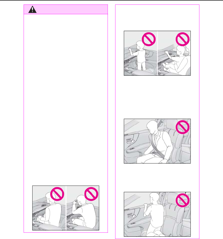
504 9-1. For owners
LS500h_OM_OM50F42U_(U)
ATTENTION
●Les nourrissons et les enfants qui ne
sont pas correctement assis et/ou
attachés peuvent être grièvement
blessés ou tués par le déploiement
d'un coussin gonflable. Un nourrisson
ou un enfant trop petit pour utiliser une
ceinture de sécurité doit être cor-
rectement attaché au moyen d'un
siège de sécurité enfant. Lexus recom-
mande vivement d'installer tous les
nourrissons et enfants sur les sièges
arrière du véhicule et de prévoir pour
eux des systèmes de retenue adaptés.
Les sièges arrière sont plus sûrs pour
les nourrissons et les enfants que le
siège du passager avant.
●N'installez jamais un siège de sécurité
enfant type dos à la route sur le siège
passager avant, même si le témoin
indicateur “AIR BAG OFF” est allumé.
En cas d'accident, la force engendrée
par le déploiement rapide du coussin
gonflable du passager avant peut
blesser grièvement, voire tuer l'enfant
si le siège de sécurité enfant type dos à
la route est installé sur le siège du pas-
sager avant.
●Ne vous asseyez pas sur le bord du
siège et ne vous appuyez pas contre la
planche de bord.
●Ne laissez pas un enfant rester debout
devant le coussin gonflable passager
avant SRS ou s'asseoir sur les genoux
du passager avant.
●Ne laissez pas les occupants des
sièges avant voyager avec un objet sur
les genoux.
●Ne vous appuyez pas contre la porte,
le rail latéral de toit ou les montants
avant, latéraux et arrière.
●Ne laissez personne s'agenouiller sur
les sièges passagers en appui contre la
porte ou sortir la tête ou les mains à
l'extérieur du véhicule.
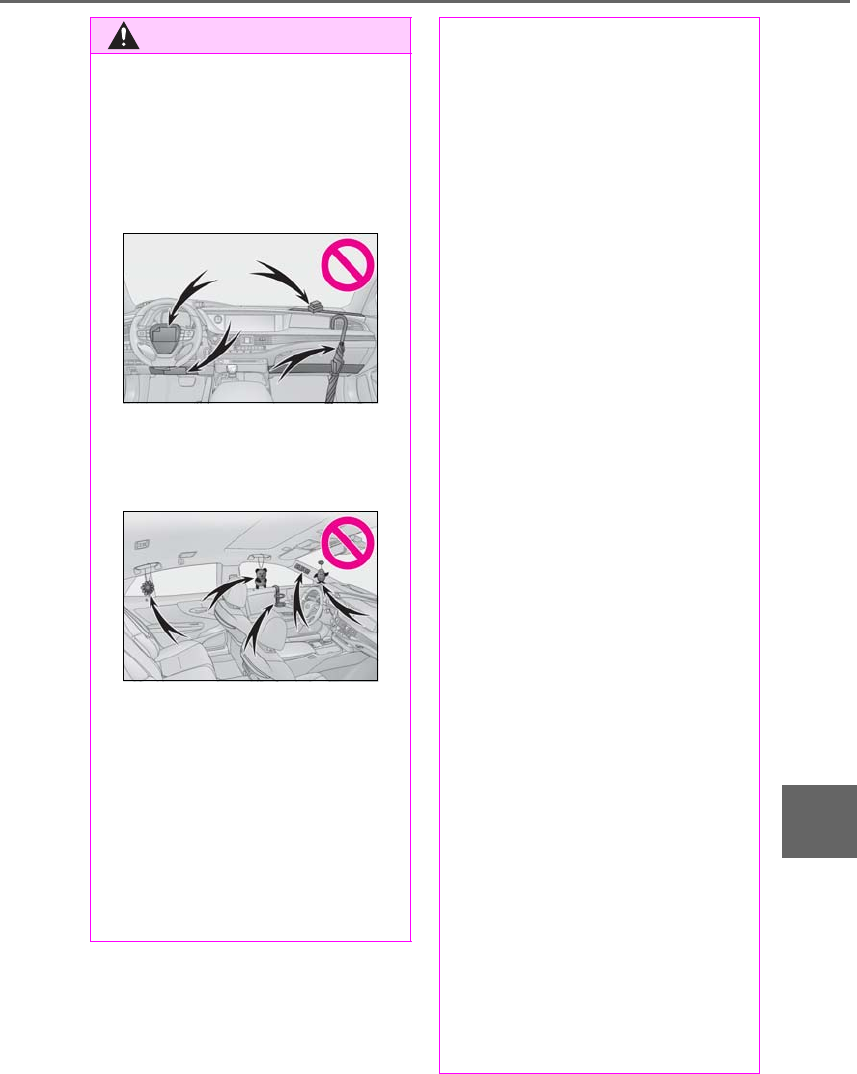
505
9-1. For owners
LS500h_OM_OM50F42U_(U)
9
For owners
ATTENTION
●Ne fixez rien et ne posez rien sur des
emplacements tels que la planche de
bord, la garniture du volant et la partie
inférieure du tableau de bord.
Ces éléments peuvent se transformer
en projectiles lorsque les coussins
gonflables conducteur, passager avant
et genoux SRS se déploient.
●Ne fixez rien aux portes, à la vitre du
pare-brise, aux vitres latérales, aux
montants avant et arrière, au rail latéral
de toit et à la poignée de maintien.
●Ne suspendez aucun cintre ou objet
dur aux crochets à vêtements. Tous
ces objets pourraient se transformer
en projectiles et causer des blessures
graves, voire mortelles en cas de
déploiement des coussins gonflables
rideaux SRS.
●Si un cache en vinyle est placé sur la
zone où le coussin gonflable de
genoux SRS se déploie, assurez-vous
de le retirer.
●N'utilisez aucun accessoire de siège
recouvrant les zones de déploiement
des coussins gonflables latéraux SRS,
car il risque de gêner le déploiement
des coussins gonflables SRS. De tels
accessoires peuvent empêcher les
coussins gonflables latéraux de
fonctionner correctement, désactiver
le système ou entraîner le déploiement
accidentel des coussins gonflables
latéraux, occasionnant des blessures
graves, voire mortelles.
●Évitez de faire subir des chocs ou des
pressions excessives aux parties ren-
fermant les composants de coussins
gonflables SRS ou aux portes avant.
En effet, cela pourrait entraîner un dys-
fonctionnement des coussins gonfla-
bles SRS.
●Ne touchez aucun composant
immédiatement après le déploiement
(gonflage) des coussins gonflables
SRS, car ils peuvent être chauds.
●Si vous avez des difficultés à respirer
après le déploiement des coussins
gonflables SRS, ouvrez une porte ou
une vitre pour faire entrer de l'air frais,
ou bien descendez du véhicule si cela
ne présente pas de danger. Essuyez
tout résidu dès que possible afin
d'éviter d'éventuelles irritations de la
peau.
●Si les parties renfermant les coussins
gonflables SRS, comme les garnitures
du volant et des montants avant et
arrière, sont endommagées ou cra-
quelées, faites-les remplacer par votre
concessionnaire Lexus.
●Ne placez rien sur le siège du pas-
sager avant, comme un coussin par
exemple. Cela a pour conséquence de
répartir le poids du passager sur toute
la surface du siège, ce qui empêche le
capteur de détecter correctement le
poids du passager. En conséquence,
les coussins gonflables frontaux SRS
du passager avant risquent de ne pas
se déployer en cas de collision.

506 9-1. For owners
LS500h_OM_OM50F42U_(U)
ATTENTION
■Modification et mise au rebut des
composants du système de coussins
gonflables SRS
Ne mettez pas votre véhicule au rebut et
ne procédez à aucune des modifications
suivantes sans consulter votre conces-
sionnaire Lexus. Les coussins gonflables
SRS peuvent ne pas fonctionner cor-
rectement ou se déployer (se gonfler)
accidentellement, provoquant la mort ou
de graves blessures.
●Installation, dépose, démontage et
réparation des coussins gonflables
SRS
●Réparations, modifications, démon-
tage ou remplacement du volant, du
tableau de bord, de la planche de
bord, des sièges ou de leur garnissage,
des montants avant, latéraux et arrière,
des rails latéraux de toit, des panneaux
de porte avant, des garnitures de
porte avant ou des haut-parleurs de
porte avant
●Modifications du panneau de porte
avant (par exemple, perçage d'un trou
dans le panneau)
●Réparations ou modifications des ailes
avant, du pare-chocs avant ou des
flancs de l'habitacle
●Installation d'un protège-calandre
(pare-buffle, pare-kangourou, etc.), de
chasse-neige, de treuils ou d'un
porte-bagages de toit
●Modifications du système de suspen-
sion du véhicule
●Installation d'appareils électroniques
tels que les émetteurs/récepteurs
radios mobiles et les lecteurs CD
●Modifications de votre véhicule pour
une personne atteinte d'un handicap
physique

508 What to do if... (Troubleshooting)
LS500h_OM_OM50F42U_(U)
1-1.What to do if... (Troubleshooting)
What to do if... (Troubleshooting)
-If you lose your mechanical keys,
new genuine mechanical keys can
be made by your Lexus dealer.
(→P.444)
-If you lose your electronic keys, the
risk of vehicle theft increases signifi-
cantly. Contact your Lexus dealer
immediately. (→P.444)
-Is the electronic key battery weak or
depleted? (→P.413)
-Is the power switch in ON mode?
When locking the doors, turn the power
switch off. (→P.170)
-Is the electronic key left inside the
vehicle?
When locking the doors, make sure that
you have the electronic key on your per-
son.
-The function may not operate prop-
erly due to the condition of the radio
wave. (→P.120)
-Is the child-protector lock set?
The rear door cannot be opened from
inside the vehicle when the lock is set.
Open the rear door from outside and then
unlock the child-protector lock. (→P.111)
-The function to prevent the elec-
tronic key from being left inside the
trunk will operate and you can open
the trunk as usual. Take the key out
from the trunk. (→P.116)
-Did you press the power switch
while firmly depressing the brake
pedal? (→P.168)
-Is the electronic key anywhere
detectable inside the vehicle?
(→P.119)
-Is the steering wheel unlocked?
(→P.169)
-Is the electronic key battery weak or
depleted?
In this case, the hybrid system can be
started in a temporary way. (→P.446)
-Is the 12-volt battery discharged?
If you have a problem, check the
following before contacting your
Lexus dealer.
The doors cannot be locked,
unlocked, opened or closed
You lose your keys
The doors cannot be locked or
unlocked
The rear door cannot be opened
The trunk lid is closed with the
electronic key left inside
If you think something is wrong
The hybrid system does not start
509
1-1. What to do if... (Troubleshooting)
LS500h_OM_OM50F42U_(U)
509
What to do if... (Troubleshooting)
(→P.447)
-It is locked automatically to prevent
theft of the vehicle. (→P.169)
-Is the window lock switch pressed?
The power window except for the one at
the driver’s seat cannot be operated if the
window lock switch is pressed. (→P.153)
-The auto power off function will be
operated if the vehicle is left in
ACCESSORY mode for a period of
time. (→P.171)
-The seat belt reminder light is flash-
ing
Are the driver and the front passenger
wearing the seat belts? (→P.430)
-The parking brake indicator is on
Is the parking brake released? (→P.181)
Depending on the situation, other
types of warning buzzer may also
sound. (→P.427, 437)
-Did anyone inside the vehicle open
a door during setting the alarm?
The sensor detects it and the alarm sounds.
(→P.68)
Do one of the following to deactivate
or stop the alarms:
-Unlock the doors.
-Turn the power switch to ACCES-
SORY or ON mode, or start the
hybrid system. (The alarm will be
deactivated or stopped after a few
seconds.)
-Is the message displayed on the
multi-information display?
Check the message on the multi-informa-
tion display. (→P.437)
-When a warning light turns on or a
warning message is displayed, refer
to P.427, 437.
-Slow down the vehicle, drive with
The steering wheel cannot be
turned after the hybrid system is
stopped
The windows do not open or
close by operating the power
window switches
The power switch is turned off
automatically
A warning buzzer sounds during
driving
An alarm is activated and the
horn sounds
A warning buzzer sounds when
leaving the vehicle
A warning light turns on or a
warning message is displayed
When a problem has occurred
If you have a flat tire

510 What to do if... (Troubleshooting)
LS500h_OM_OM50F42U_(U)
extra caution, and take your vehicle
to the nearest Lexus dealer or
authorized tire dealer as soon as
possible to have the tire replaced.
(→P.442)
-Try the procedure for when the vehi-
cle becomes stuck in mud, dirt, or
snow. (→P.457)
The vehicle becomes stuck

511
1-1. What to do if... (Troubleshooting)
LS500h_OM_OM50F42U_(U)
511
Alphabetical Index
Alphabetical Index
A
A/C
Air conditioning filter ...................................411
Front automatic air conditioning system
.........................................................................323
Micro dust and pollen filter...................329
Rear air conditioning system...............333
ABS (Anti-lock Brake System)..............302
Warning light...............................................429
Adaptive Front-lighting System (AFS).187
Adaptive Variable Suspension System303
AFS (Adaptive Front-lighting System).187
Air conditioning filter....................................411
Air conditioning system
Air conditioning filter ...................................411
Front automatic air conditioning system
.........................................................................323
Micro dust and pollen filter...................329
Rear air conditioning system...............333
Airbags
Airbag operating conditions.....................31
Airbag precautions for your child........ 34
Correct driving posture.............................23
Curtain shield airbag operating condi-
tions....................................................................31
Curtain shield airbag precautions ....... 34
Front passenger occupant classification
system .............................................................40
General airbag precautions ................... 34
Locations of airbags.................................... 29
Modification and disposal of airbags ..37
Side airbag operating conditions...........31
Side airbag precautions............................ 34
Side and curtain shield airbags operating
conditions........................................................31
Side and curtain shield airbags precau-
tions.................................................................. 34
SRS airbags ..................................................... 29
SRS warning light ......................................428
Alarm
Alarm ..................................................................68
Warning buzzer......................................... 427
Anchor brackets.....................................46, 55
Antennas (smart access system with
push-button start)........................................119
Anti-lock Brake System (ABS)..............302
Warning light ...............................................429
Approach warning......................................256
Armrest............................................................352
Assist grips.....................................................352
Audio system-linked display......................90
Automatic headlight leveling system... 186
Automatic High Beam ...............................188
Automatic light control system...............185
Auxiliary boxes..................................347, 349
Average fuel economy.................................88
Average vehicle speed................................88
B
Back-up lights
Replacing light bulbs..................................417
Battery (12-volt battery)
Battery checking ........................................393
If the 12-volt battery is discharged ....447
Preparing and checking before winter
......................................................................... 309
Warning light ...............................................428
Battery (traction battery) ..............................61
Blind Spot Monitor (BSM).......................260
Brake
Brake hold......................................................183
Fluid.................................................................. 465
Parking brake .................................................181
Regenerative braking.................................59
Warning light ............................................... 427
Brake assist....................................................302
Break-in tips.....................................................159
Brightness control
Instrument panel light control........79, 85
BSM (Blind Spot Monitor).......................260

512 Alphabetical Index
LS500h_OM_OM50F42U_(U)
C
Card key .......................................................... 104
Care
Aluminum wheels......................................370
Exterior ...........................................................370
Interior ............................................................. 373
Seat belts........................................................ 373
Cargo capacity...............................................166
Cargo net .......................................................348
Center Display ...............................................316
Chains............................................................... 310
Child restraint system
Fixed with a LATCH system ..................53
Fixed with a seat belt...................................49
Front passenger occupant classification
system .............................................................40
Points to remember ....................................45
Riding with children.....................................45
Types of child restraint system installation
method ...........................................................46
Using an anchor bracket..........................55
Child safety
12-volt battery precautions........ 394, 451
Airbag precautions......................................34
Child restraint system................................. 46
Heated steering wheel and seat heater
precautions................................................ 337
How your child should wear the seat belt
............................................................................ 25
Moon roof precautions............................154
Power window lock switch.....................153
Power window precautions...................152
Rear door child-protectors ....................... 111
Removed electronic key battery precau-
tions.................................................................414
Seat belt extender precautions .............25
Seat belt precautions..................................45
Trunk precautions.........................................112
Child-protectors...............................................111
Cleaning
Aluminum wheels......................................370
Exterior............................................................370
Interior .............................................................373
Radar sensor........................ 199, 200, 206
Seat belts........................................................373
Clock.................................................77, 81, 353
Clock light......................................................340
Coat hooks.....................................................352
Coin holder....................................................345
Condenser.......................................................391
Console box..................................................346
Cooling system.............................................390
Engine overheating...................................453
Hybrid system overheating ..................454
Cornering lights.............................................187
Cruise control
Dynamic radar cruise control with
full-speed range..........................247, 250
Cup holders...................................................345
Current fuel consumption ..........................88
Curtain shield airbags .................................. 29
Customizable features............................... 481
D
Daytime running light system..................185
Defogger
Outside rear view mirrors.....................324
Rear window ................................................324
Windshield....................................................324
Differential
Front differential oil................................... 465
Rear differential oil.................................... 465
Dimension ......................................................460
Dinghy towing.................................................167
Display
Center Display............................................. 316
Dynamic radar cruise control with
full-speed range..................................... 250
Energy monitor..............................................96
Head-up display............................................ 92
Intuitive parking assist..............................266
LKA (Lane-Keeping Assist).................243
LTA (Lane-Tracing Assist) ...................234

513
1-1. What to do if... (Troubleshooting)
LS500h_OM_OM50F42U_(U)
513
Alphabetical Index
Multi-information display..........................86
Parking Support Brake function (rear
pedestrians) ..............................................295
RCD (Rear Camera Detection).........277
RCTA .............................................................. 273
Warning message..................................... 437
Distance until next engine oil change
.....................................................................79, 84
Do-it-yourself maintenance....................379
Door courtesy lights...................................340
Door lock
Doors................................................................108
Smart access system with push-button
start................................................................... 119
Wireless remote control.........................106
Doors
Automatic door locking and unlocking
system ..............................................................112
Door closer .......................................................111
Door glasses................................................... 151
Door lock........................................................108
Open door warning buzzer .......... 109, 111
Outside rear view mirrors ......................149
Rear door child-protectors ....................... 111
Drive distance..................................................88
Drive info 1/Drive info 2 ..............................88
Driver’s seat position memory
Driving position memory.........................139
Memory recall function ............................142
Power easy access system.....................139
Drive-start control ........................................159
Driving
Break-in tips .................................................. 159
Correct driving posture.............................23
Driving mode select switch..................298
Hybrid vehicle driving tips....................307
Procedures .................................................... 158
Winter drive tips.........................................309
Driving information display........................ 87
Driving position memory............................139
Memory recall function ............................142
Power easy access system.....................139
Driving range...................................................88
Driving support system information display
.............................................................................90
DRS (Dynamic Rear Steering) ..............303
Dynamic radar cruise control with
full-speed range.............................247, 250
Warning message.....................................259
Dynamic Rear Steering (DRS) ..............303
E
ECB (Electronically Controlled Brake Sys-
tem)................................................................302
EDR (Event data recorder)............................7
Elapsed time.....................................................88
Electric motor (traction motor)................58
Electric Power Steering (EPS) ..............303
Warning light .............................................. 430
Electronic key................................................ 104
Battery-saving function............................ 120
If the electronic key does not operate
properly.......................................................445
Replacing the battery.................................413
Electronically Controlled Brake System
(ECB)............................................................302
Electronically modulated air suspension
..........................................................................299
Emergency flashers....................................420
Emergency, in case of
If a warning buzzer sounds................... 427
If a warning light turns on....................... 427
If a warning message is displayed.....437
If the 12-volt battery is discharged ....447
If the electronic key does not operate
properly.......................................................445
If the fuel filler door cannot be opened
..........................................................................445
If the hybrid system will not start ........443
If you have a flat tire ..................................442
If you lose your keys.................................444
If you think something is wrong..........426
If your vehicle becomes stuck.............457
If your vehicle has to be stopped in an

514 Alphabetical Index
LS500h_OM_OM50F42U_(U)
emergency ................................................420
If your vehicle needs to be towed..... 422
If your vehicle overheats........................453
Energy monitor .......................................96, 97
Engine
ACCESSORY mode...............................170
Compartment .............................................387
Engine compartment cover................ 388
Engine switch................................................ 168
Hood............................................................... 385
How to start the hybrid system ........... 168
Identification number.................................461
If the hybrid system will not start........443
If your vehicle has to be stopped in an
emergency ................................................420
Ignition switch (power switch).............168
Overheating.................................................453
Power switch ................................................ 168
Tachometer.............................................. 77, 81
Engine compartment cover....................388
Engine coolant
Capacity.........................................................463
Checking .......................................................390
Preparing and checking before winter
.........................................................................309
Engine coolant temperature gauge .77, 81
Engine oil
Capacity.........................................................462
Checking ...................................................... 388
Preparing and checking before winter
.........................................................................309
Warning light...............................................428
Engine oil maintenance data..................390
Engine switch (power switch)................. 168
If your vehicle has to be stopped in an
emergency ................................................420
EPS (Electric Power Steering) ..............303
Warning light...............................................430
EV drive mode................................................172
EV indicator......................................................59
Event data recorder (EDR)............................7
F
FCTA (Front Cross Traffic Alert)..........227
First-aid kit storage belt............................349
Flat tire
Tire pressure warning system .............397
Floor mats...........................................................22
Fluid
Brake............................................................... 465
Hybrid transmission..................................464
Washer ............................................................ 391
Footwell light.................................................340
Front air conditioning system.................323
Front Cross Traffic Alert (FCTA)..........227
Front passenger occupant classification
system ..............................................................40
Front seats
Adjustment..................................................... 128
Cleaning.........................................................373
Correct driving posture ............................ 23
Driving position memory........................ 139
Head restraints..............................................144
Memory recall function.............................142
Power easy access system .................... 139
Refresh system ............................................. 133
Seat heaters..................................................336
Seat position memory .............................. 139
Seat ventilators............................................336
Front side marker light
Light switch....................................................185
Replacing light bulbs..................................417
Front turn signal lights
Replacing light bulbs..................................417
Turn signal lever ..........................................180
Fuel
Capacity.......................................................... 461
Fuel gauge................................................. 77, 81
Information....................................................470
Refueling.......................................................... 194
Type................................................................... 461
Warning light .............................................. 430

515
1-1. What to do if... (Troubleshooting)
LS500h_OM_OM50F42U_(U)
515
Alphabetical Index
Fuel consumption
Average fuel economy..............................88
Current fuel consumption........................88
Fuel filler door
If the fuel filler door cannot be opened
.........................................................................445
Refueling ..........................................................194
Fuel gauge...................................................77, 81
Fuses...................................................................414
G
Garage door opener.................................358
Gauges.........................................................77, 81
Gear Position...................................................89
G-force...............................................................89
Glove box.......................................................344
Glove box light.............................................345
H
Hands Free Power Trunk Lid....................115
Head restraints...............................................144
Headlights
Adaptive Front-lighting System (AFS)
...........................................................................187
Automatic High Beam system.............188
Light switch.................................................... 185
Replacing light bulbs..................................417
Head-up display.............................................. 92
Driving information display area........... 92
Driving support system display area..95
HUD (Head-up display) switch............94
Hybrid System Indicator...........................96
Navigation system-linked display........ 92
Pop-up display...............................................95
Settings .............................................................. 94
Heated steering wheel..............................336
Heaters
Front air conditioning system.............. 323
Heated steering wheel............................336
Outside rear view mirrors .................... 324
Rear air conditioning system...............333
Seat heaters..................................................336
Height control
Electronically modulated air suspension
.........................................................................300
High-voltage components ...........................61
Hill-start assist control...............................303
Hood
Open............................................................... 385
Pop Up Hood.................................................38
Hooks
Coat hooks ...................................................352
Retaining hooks (floor mat)..................... 22
Horn....................................................................147
HUD (Head-up display) switch................94
Hybrid battery (traction battery)
Location...............................................................61
Specification .................................................462
Warning message........................................64
Hybrid battery (traction battery) air vents
............................................................................. 64
Hybrid system..................................................58
Emergency shut off system......................64
Energy monitor/consumption screen96
EV drive mode..............................................172
High voltage components .........................61
Hybrid system precautions........................61
If the hybrid system will not start ........443
Overheating.................................................454
Power (ignition) switch............................168
Regenerative braking.................................59
Starting the hybrid system......................168
Vehicle proximity notification system.60
Hybrid System Indicator............. 78, 83, 96
Hybrid transmission......................................174
M mode ............................................................179
Paddle shift switches ....................... 178, 179
Snow mode.....................................................177
Hybrid vehicle driving tips.......................307
I
I/M test ............................................................382

516 Alphabetical Index
LS500h_OM_OM50F42U_(U)
Identification
Engine ...............................................................461
Vehicle............................................................460
Ignition switch (power switch) ................ 168
Auto power off function.............................171
Changing the power switch modes..170
If your vehicle has to be stopped in an
emergency ................................................420
Immobilizer system........................................ 66
Indicators............................................................74
Initialization
Items to initialize .........................................495
Maintenance ................................... 378, 390
Power windows............................................. 151
Tire pressure warning system.............. 401
Inside door handle lights ..........................340
Inside rear view mirror............................... 148
Instrument panel light control...........79, 85
Interior lights..................................................340
Front interior light......................................340
Rear interior light .......................................340
Intuitive parking assist.....................265, 266
Function..........................................................266
Warning message.....................................268
J
Jack
Positioning a floor jack........................... 385
Jam protection function
Moon roof.......................................................154
Power trunk opener and closer............ 116
Power windows............................................. 151
Rear door sunshade ................................355
K
Keyless entry
Smart access system with push-button
start................................................................... 119
Wireless remote control.........................106
Keys
Battery-saving function ............................120
Electronic key...............................................104
If the electronic key does not operate
properly.......................................................445
If you lose your keys.................................444
Key number plate .......................................104
Keyless entry........................................108, 119
Mechanical key............................................104
Power switch.................................................168
Replacing the battery.................................413
Warning buzzer............................................119
Wireless remote control.........................106
Knee airbags .................................................... 29
L
Lane Tracing Assist (LTA)
Operation......................................................230
Warning messages...................................238
Lane-Keeping Assist (LKA)
Operation......................................................240
Warning messages...................................246
Language (multi-information display) ...90
LATCH anchors.............................................53
LDH (Lexus Dynamic Handling system)
..........................................................................303
Lever
Auxiliary catch lever ................................ 385
Hood lock release lever........................ 385
Internal trunk release lever....................... 117
Shift lever..........................................................174
Turn signal lever ..........................................180
Wiper lever....................................................190
Lexus climate concierge ............................321
Lexus Dynamic Handling system (LDH)
..........................................................................303
Lexus Enform Safety Connect...............364
Lexus Safety System+
Automatic High Beam.............................188
Dynamic radar cruise control with
full-speed range..........................247, 250
LKA (Lane-Keeping Assist).................240
PCS (Pre-Collision System)................220
RSA (Road Sign Assist)..........................247

517
1-1. What to do if... (Troubleshooting)
LS500h_OM_OM50F42U_(U)
517
Alphabetical Index
Lexus Safety System+A..............................196
Dynamic radar cruise control with
full-speed range..........................247, 250
FCTA (Front Cross Traffic Alert) ......227
LTA (Lane Tracing Assist)....................230
PCS (Pre-Collision System)................209
RSA (Road Sign Assist) ......................... 247
License plate lights
Light switch.................................................... 185
Replacing light bulbs..................................417
Light bulbs
Replacing.........................................................417
Lights
Automatic High Beam system.............188
Front interior lights......................................341
Front personal lights...................................341
Headlight switch .........................................185
Interior lights.................................................340
Interior lights list..........................................340
Rear interior lights.......................................341
Rear personal lights....................................341
Replacing light bulbs..................................417
Trunk lid light................................................... 116
Trunk light......................................................... 116
Turn signal lever..........................................180
Vanity lights..................................................354
Welcome light illumination control... 186
LKA (Lane-Keeping Assist)
Operation......................................................240
Warning messages ..................................246
Lock steering column..................................169
LTA (Lane Tracing Assist)
Operation......................................................230
Warning messages ..................................238
Luggage mats ...............................................348
M
Maintenance
Do-it-yourself maintenance .................383
General maintenance.............................379
Maintenance data......................................460
Maintenance requirements..................378
Malfunction indicator lamp.....................428
Master warning light..................................434
Menu icons........................................................86
Meter
Changing the main meter location......85
Clock............................................................77, 81
Hybrid System Indicator ..................78, 83
Indicators........................................................... 74
Instrument panel light control........79, 85
Meter control switches ..............................87
Meters.......................................................... 77, 81
Multi-information display..........................86
Settings...............................................................90
Units.....................................................................89
Warning lights.............................................427
Warning message.....................................437
Micro dust and pollen filter .....................329
Mirrors
Inside rear view mirror.............................148
Outside rear view mirror defoggers324
Outside rear view mirrors...................... 149
Vanity mirrors..............................................354
Moon roof
Door lock linked moon roof operation
........................................................................... 154
Jam protection function........................... 154
Operation....................................................... 153
Multi-information display............................86
Audio system-linked display...................90
Drive information 1/Drive information 2
............................................................................ 88
Driving information display......................87
Driving support system information dis-
play....................................................................90
Dynamic radar cruise control with
full-speed range..................................... 250
Energy monitor..............................................97
Gear Position .................................................89
G-force..............................................................89
LKA (Lane-Keeping Assist).................243
LTA (Lane-Tracing Assist) ...................234
Menu icons ......................................................86

518 Alphabetical Index
LS500h_OM_OM50F42U_(U)
Meter control switches..............................87
Navigation system-linked display........89
Pop-up display...............................................86
Settings ..............................................................90
Suggestion function.......................................91
Tire pressure................................................397
Units ....................................................................89
Vehicle sway warning................................89
Warning message..................................... 437
N
Navigation system-linked display....89, 92
Noise from under vehicle ...............................6
O
“ODO TRIP”switch...............................79, 85
Odometer .................................................79, 84
Odometer and trip meter display
Display items.......................................... 79, 84
“ODO TRIP” switch........................... 79, 85
Pop-up display......................................79, 85
Oil
Engine oil.......................................................462
Front differential oil...................................465
Rear differential oil ....................................465
Opener
Fuel filler door................................................194
Hood............................................................... 385
Trunk....................................................................114
Outer foot lights
Location..........................................................340
Outside door handle lights......................340
Outside rear view mirrors
Adjustment......................................................149
BSM (Blind Sport Monitor) .................260
Folding ............................................................. 150
Linked mirror function when reversing
...........................................................................149
Mirror position memory...........................139
Outside rear view mirror defoggers324
RCTA function............................................ 273
Outside temperature..............................77, 81
Overheating..................................................453
P
Paddle shift switches..........................178, 179
Panic mode..................................................... 106
Parking assist sensors (intuitive parking
assist).............................................................266
Parking brake
Operation.........................................................181
Parking brake engaged warning buzzer
........................................................................... 182
Warning light ...............................................434
Warning message...................................... 182
Parking lights
Light switch....................................................185
Replacing light bulbs..................................417
Parking Support Brake function (for
rear-crossing vehicles) ............................291
Function............................................................291
Parking Support Brake function (rear
pedestrians)....................................280, 295
Function..........................................................295
Parking Support Brake function
(rear-crossing vehicles).........................280
Parking Support Brake function (static
objects).............................................280, 286
Function......................................................... 286
PCS (Pre-Collision System)
Function............................................. 209, 220
PCS OFF switch .............................. 212, 222
Warning light ...............................................433
Warning message...........................219, 226
Personal lights...............................................340
PKSA (Parking Support Alert)..............265
PKSB (Parking Support Brake).............280
Warning message.....................................284
Pop Up Hood...................................................38
Power control unit............................................61
Power control unit coolant
Capacity.........................................................463
Checking ...................................................... 390

519
1-1. What to do if... (Troubleshooting)
LS500h_OM_OM50F42U_(U)
519
Alphabetical Index
Preparing and checking before winter
.........................................................................309
Power easy access system........................139
Power outlets................................................353
Power rear seat..............................................135
Power steering (Electric power steering
system)..........................................................303
Warning light...............................................430
Power switch.................................................. 168
Auto power off function.............................171
Changing the power switch modes..170
Power switch (engine switch)
If your vehicle has to be stopped in an
emergency ................................................420
Power trunk opener and closer ...............114
Power windows
Door lock linked window operation..152
Jam protection function.............................151
Operation......................................................... 151
Window lock switch ..................................153
Pre-Collision System (PCS)
Function..............................................209, 220
PCS OFF switch...............................212, 222
Warning light...............................................433
Warning message...........................219, 226
R
Radar cruise control (dynamic radar cruise
control with full-speed range)..247, 250
Radiator.............................................................391
RCD (Rear camera detection)..............265
Warning message..................................... 278
RCD (Rear Camera Detection)
Function...........................................................277
RCTA
Function.......................................................... 273
Warning message..................................... 274
RCTA (Rear Cross Traffic Alert).........265
RCTA function ..............................................274
Rear air conditioning system..................333
Rear Cross Traffic Alert (RCTA) ......... 273
Rear door sunshades.................................355
Rear Multi Operation Panel.................... 318
Rear seat position memory .......................143
Rear seats.........................................................135
Adjustment..................................................... 135
Head restraints..............................................144
Rear seat position memory.....................143
Relaxation system.......................................138
Seat heaters..................................................336
Seat ventilators............................................336
Rear side marker lights
Light switch....................................................185
Replacing light bulbs..................................417
Rear sunshades............................................356
Rear turn signal lights
Replacing light bulbs..................................417
Turn signal lever ..........................................180
Rear view mirror
Inside rear view mirror.............................148
Outside rear view mirrors...................... 149
Rear window defogger.............................324
Refueling
Capacity.......................................................... 461
Fuel types........................................................ 461
If the fuel filler door cannot be opened
..........................................................................445
Opening the fuel tank cap ..................... 194
Regenerative braking...................................59
Remote Touch................................................314
Replacing
Electronic key battery................................413
Fuses...................................................................414
Light bulbs.......................................................417
Tires .................................................................405
Resetting the message indicating mainte-
nance is required......................................378
Rev indicator ....................................................83
Rev peak.............................................................83
Road Sign Assist...........................................247
RSA (Road Sign Assist).............................247
Run-flat tires........................................397, 442

520 Alphabetical Index
LS500h_OM_OM50F42U_(U)
S
Seat belt buckle lights................................340
Seat belt reminder light...................430, 431
Seat belts............................................................ 24
Automatic Locking Retractor ................ 26
Child restraint system installation......... 46
Cleaning and maintaining the seat belt
......................................................................... 373
Easy Access Buckle.................................... 26
Emergency Locking Retractor.............. 26
How to wear your seat belt..................... 25
How your child should wear the seat belt
............................................................................ 25
Pregnant women, proper seat belt use
.............................................................................24
Reminder light and buzzer........ 430, 431
Seat belt extender ........................................ 25
SRS warning light ......................................428
Seat heaters...................................................336
Seat position memory........................139, 143
Seat ventilators.............................................336
Seating capacity.............................................166
Seats
Adjustment...........................................128, 135
Adjustment precautions...........................128
Child seats/child restraint system installa-
tion....................................................................45
Cleaning......................................................... 373
Driving position memory.........................139
Front seat refresh system.........................133
Head restraints .............................................144
Power easy access system.....................139
Properly sitting in the seat.........................23
Rear seat relaxation system................... 138
Seat heaters..................................................336
Seat position memory .................... 139, 143
Seat ventilators............................................336
Secondary Collision Brake.....................302
Sensor
Automatic headlight system..................185
Automatic High Beam system.............188
Inside rear view mirror.............................148
Intuitive parking assist..............................266
LKA (Lane-Keeping Assist).................240
LTA (Lane Tracing Assist)....................230
Parking Support Brake function
(rear-crossing vehicles)........................291
Parking Support Brake function (static
objects)........................................................287
Radar sensor...........................197, 204, 261
Rain-sensing windshield wipers............191
RCTA...............................................................274
Service plug........................................................61
Service reminder message .....................378
Shift lever
Hybrid transmission....................................174
Shift lever light ..............................................340
Shopping bag hooks ..................................348
Side airbags ......................................................29
Side marker lights
Light switch....................................................185
Replacing light bulbs..................................417
Side mirrors
Adjustment..................................................... 149
BSM (Blind Sport Monitor)................. 260
Folding..............................................................150
Linked mirror function when reversing
........................................................................... 149
Mirror position memory..........................139
RCTA function ............................................ 273
Side turn signal lights
Replacing light bulbs..................................417
Turn signal lever ..........................................180
Side windows ...................................................151
Smart access system with push-button
start
Antenna location...........................................119
Entry functions..............................................108
Starting the hybrid system......................168
Snow mode......................................................177
Snow tires.......................................................309
Spark plug ......................................................463
Specifications................................................460

521
1-1. What to do if... (Troubleshooting)
LS500h_OM_OM50F42U_(U)
521
Alphabetical Index
Speedometer.............................................77, 81
Steering lock
Column lock release..................................169
Steering lock system warning message
...........................................................................169
Steering wheel
Adjustment......................................................147
Heated steering wheel............................336
Meter control switches..............................87
Power easy access system.....................139
Steering wheel position memory ........139
Stop lights
Replacing light bulbs..................................417
Storage features ..........................................343
Stuck
If the vehicle becomes stuck................457
Suggestion function.........................................91
Sun visors........................................................354
Sunshade
Roof ....................................................................154
Switches
Activating the Automatic High Beam
..........................................................................188
Automatic High Beam system.............188
Brake Hold switch ..................................... 183
Door lock switches...................................... 110
Driving mode select switch..................298
Driving position memory switches.....139
Dynamic radar cruise control with
full-speed range switch.........................251
Emergency flashers switch...................420
EV drive mode switch ..............................172
Garage door opener switches ......... 358
Heated steering wheel switch.............336
HUD (Head-up display) switch............94
Ignition switch...............................................168
Instrument panel light control switches
...................................................................79, 85
Intuitive parking assist switch............... 267
Light switches...............................................185
LKA (Lane-Keeping Assist) switch.. 242
LTA (Lane-Tracing Assist) switch....234
Meter control switches ..............................87
Moon roof switches................................... 153
“ODO TRIP”switch ............................79, 85
Outside rear view mirror switches .... 149
Paddle shift switches ....................... 178, 179
Parking brake switch...................................181
PCS OFF switch .............................. 212, 222
PKSB (Parking Support Brake) switch
........................................................................... 281
Power door lock switch ............................110
Power switch.................................................168
Power window switches ...........................151
RCD (Rear camera detection) switch
.......................................................................... 277
RCTA switch................................................273
Rear door sunshade switch................. 355
Rear seat heater..........................................334
Rear seat position memory switches.143
Rear seat ventilator...................................334
Rear sunshades switch........................... 356
Rear window and outside rear view mir-
ror defoggers switch ............................323
Seat heater switches.................................336
Seat ventilator switches ..........................336
Snow mode switch......................................177
“SOS” button................................................364
Tilt and telescopic steering control switch
............................................................................147
Tire pressure warning reset switch.... 401
Trunk closer switch......................................115
Trunk opener main switch........................118
Trunk opener switch ................................... 114
Vehicle-to-vehicle distance switch.... 251
VSC OFF switch ...................................... 304
Window lock switch..................................153
Windshield wiper and washer switch190
Windshield wiper de-icer switch.......327
T
Tachometer.................................................77, 81
Rev indicator...................................................83
Rev peak............................................................83

522 Alphabetical Index
LS500h_OM_OM50F42U_(U)
Tail lights
Light switch.................................................... 185
Replacing light bulbs..................................417
Theft deterrent system
Alarm ..................................................................68
Immobilizer system......................................66
Tire inflation pressure
Maintenance data......................................466
Tire inflation pressure display function
.........................................................................397
Warning light.................................................431
Tire information.............................................472
Glossary......................................................... 475
Size.................................................................... 473
Tire identification number ..................... 473
Uniform Tire Quality Grading............ 474
Tire pressure display..................................397
Tire pressure warning system
Function..........................................................397
Initializing ........................................................ 401
Installing tire pressure warning valves
and transmitters ....................................... 401
Registering ID codes...............................403
Warning light.................................................431
Tires
Chains .............................................................. 310
Checking .......................................................395
If you have a flat tire.................................. 442
Inflation pressure....................................... 408
Information.................................................... 472
Replacing.......................................................405
Rotating tires ................................................397
Run-flat tires .....................................397, 442
Size....................................................................466
Snow tires......................................................309
Tire inflation pressure display function
.........................................................................397
Tire pressure warning system.............397
Warning light.................................................431
Top tether strap...............................................55
Total load capacity......................................460
Towing
Dinghy towing...............................................167
Emergency towing....................................422
Towing eyelet...............................................425
Trailer towing................................................166
TRAC (Traction Control)........................303
Traction battery (hybrid battery)
Hybrid battery (traction battery) air vents
.............................................................................64
Location...............................................................61
Specification .................................................462
Warning message........................................64
Traction Control (TRAC)........................303
Traction motor (electric motor)...............58
Trailer towing..................................................166
Transmission
Driving mode select switch ................. 298
Hybrid transmission....................................174
M mode ............................................................179
Paddle shift switches ....................... 178, 179
Snow mode.....................................................177
Trip meters................................................79, 84
Trunk....................................................................112
Hands Free Power Trunk Lid.................115
Internal trunk release lever....................... 117
Power trunk opener and closer ............ 114
Smart access system with push-button
start...................................................................115
Trunk closer switch......................................115
Trunk easy closer..........................................116
Trunk features............................................. 348
Trunk grip ......................................................... 116
Trunk lid light...................................................116
Trunk light.........................................................116
Trunk opener main switch........................118
Trunk opener switch ................................... 114
Wireless remote control...........................115
Trunk lid light....................................................116
Trunk light..........................................................116
Turn signal lights
Replacing light bulbs..................................417
Turn signal lever ..........................................180

523
1-1. What to do if... (Troubleshooting)
LS500h_OM_OM50F42U_(U)
523
Alphabetical Index
U
USB charging ports......................................351
V
Vanity lights....................................................354
Vanity mirrors...............................................354
Variable Gear Ratio Steering (VGRS)303
VDIM (Vehicle Dynamics Integrated Man-
agement)......................................................303
Vehicle data recordings..................................7
Vehicle Dynamics Integrated Manage-
ment (VDIM)..............................................303
Vehicle identification number................460
Vehicle Stability Control (VSC)...........302
Vehicle sway warning display...................89
Ventilators (seat ventilators)...................336
VGRS (Variable Gear Ratio Steering)303
VSC (Vehicle Stability Control)...........302
W
Warning buzzers
ABS ..................................................................429
Airbags ...........................................................428
Approach warning....................................256
Brake hold.....................................................434
Brake Override System.........................429
Brake system ............................................... 427
Charging system .......................................428
Downshifting..................................................179
Drive-Start Control .................................. 429
Electric power steering ..........................430
Engine .............................................................428
High coolant temperature .................... 427
Hybrid system .............................................428
Intuitive parking assist...................272, 432
LKA (Lane-Keeping Assist).......240, 431
Low engine oil pressure.........................428
LTA (Lane Tracing Assist)......... 230, 431
Open door.............................................. 109, 111
Open window...............................................152
PKSA (Parking Support Alert) ...........266
PKSB (Parking Support Brake) .........433
Pop Up Hood..............................................429
Pre-collision braking..................... 209, 221
RCD (Rear Camera Detection)........432
RCTA (Rear Cross Traffic Alert) ......432
Seat belt ...............................................430, 431
Warning label ....................................................61
Warning lights................................................427
ABS...................................................................429
Brake hold operated indicator ...........434
Brake Override System.........................429
Brake system................................................ 427
Charging system........................................428
Drive-Start Control...................................429
Electric power steering.......................... 430
High coolant temperature..................... 427
Intuitive parking assist OFF indicator432
LKA indicator.................................................431
Low engine oil pressure.........................428
Low fuel level .............................................. 430
LTA indicator .................................................431
Malfunction indicator lamp...................428
Master warning light.................................434
Parking brake indicator..........................434
PKSB OFF indicator................................433
Pop Up Hood..............................................429
Pre-collision system..................................433
RCD OFF indicator..................................432
RCTA OFF indicator...............................432
Seat belt reminder light................430, 431
Slip indicator.................................................433
SRS....................................................................428
Tire pressure ..................................................431
Warning messages..................................... 437
Warning reflector storage belt..............349
Washer
Checking ........................................................ 391
Preparing and checking before winter
......................................................................... 309
Switch................................................................190
Washing and waxing..................................370

524 Alphabetical Index
LS500h_OM_OM50F42U_(U)
Weight
Cargo capacity.............................................166
Load limits.......................................................166
Weight ............................................................460
Wheels
Replacing wheels.......................................405
Size....................................................................466
Window lock switch.....................................153
Windows
Power windows............................................. 151
Rear window defogger ..........................324
Washer ............................................................ 190
Windshield wiper de-icer ........................ 329
Windshield wipers
Position .............................................................192
Rain-sensing windshield wipers..........190
Winter driving tips.......................................309
Wireless remote control
Battery-Saving Function..........................120
Locking/Unlocking ................................... 106
Replacing the battery.................................413
?
For information regarding the
equipment listed below, refer to
the “NAVIGATION AND MULTI-
MEDIA SYSTEM OWNER’S
MANUAL”.
· Navigation system
· Audio/visual system
· Rear seat entertainment system
· Lexus parking assist monitor

525
1-1. What to do if... (Troubleshooting)
LS500h_OM_OM50F42U_(U)
525
Alphabetical Index

526 Alphabetical Index
LS500h_OM_OM50F42U_(U)

527
1-1. What to do if... (Troubleshooting)
LS500h_OM_OM50F42U_(U)
527
Alphabetical Index
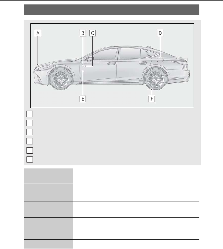
528
LS500h_OM_OM50F42U_(U)
GAS STATION INFORMATION
Auxiliary catch lever (→P.385)
Trunk opener (→P.114)
Fuel filler door opener (→P.195)
Fuel filler door (→P.195)
Hood lock release lever (→P.385)
Tire inflation pressure (→P.466)
Fuel tank capacity (Ref-
erence) 22.2 gal. (84.0 L, 18.5 Imp. gal.)
Fuel type Unleaded gasoline only P.461
P.470
Cold tire inflation pres-
sure P.466
Engine oil capacity
(Drain and refill ⎯ ref-
erence)
P.462
Engine oil type P.462
A
B
C
D
E
F
