OPL1000 SDK Getting Start Guide ENG
User Manual:
Open the PDF directly: View PDF ![]() .
.
Page Count: 21

OPL1000
ULTRA-LOW POWER 2.4GHZ WI-FI + BLUETOOTH SMART SOC
SDK Getting Start Guide
OPULINKS
http://www.opulinks.com/
Copyright © 2019, Opulinks. All Rights Reserved.
OPL1000-SDK-getting-start-guide-R02 Version 06

OPL1000
REVISION HISTORY
Copyright © 2019, Opulinks. All Rights Reserved.
OPL1000-SDK-getting-start-guide-R02, Version V06
Date
Version
Contents Updated
2018-05-11
0.1
⚫ Initial Release
2018-05-17
0.2
⚫ Add section 3.3 to introduce how to download compiled M3
bin file
2018-05-31
0.3
⚫ Fix some typo error
⚫ Update section 3.3
2018-06-05
0.4
⚫ Update section 3.1, 3.2 because hello_world project setting is
changed.
2018-08-02
0.5
⚫ Update section3 images
2018-08-15
0.6
⚫ Update section 2.1 add OTA image file introduction
⚫ Update section 2.2, add OTA support description

OPL1000
TABLE OF CONTENTS
Copyright © 2019, Opulinks. All Rights Reserved.
OPL1000-SDK-getting-start-guide-R02, Version V06
TABLE OF CONTENTS
1. introduction _________________________________________________________________________________ 3
1.1. Scope of Document Application _______________________________________________________ 3
1.2. Abbreviations __________________________________________________________________________ 3
1.3. Reference ______________________________________________________________________________ 3
2. OPL 1000 APP Development Procedure _____________________________________________________ 4
2.1. Relationship between APP & ROM Code & Patch _____________________________________ 4
2.2. APP Development Procedure __________________________________________________________ 8
3. Using Keil to Debug Application Procedure ________________________________________________ 11
3.1. Keil Engineering Setting ______________________________________________________________ 11
3.2. Application Procedure of Online Debugging _________________________________________ 12
3.3. Procedure Download _________________________________________________________________ 15

OPL1000
LIST OF TABLES
Copyright © 2019, Opulinks. All Rights Reserved.
OPL1000-SDK-getting-start-guide-R02, Version V06
LIST OF FIGURES
Figure 1: The Relationship Between User APP & ROM CODE and Patch ___________________ 4
Figure 2: Compiling of User APP & Patch, Loading Process (without OTA Function) ______ 5
Figure 3: Coding of User APP & Patch, Loading Process (Supporting OTA Function) ______ 8
Figure 4: IDE Online Debug Development Mode __________________________________________ 9
Figure 5: Serial-Port Debug Mode ________________________________________________________ 10
Figure 6: Option for Target Dialogue setting _____________________________________________ 11
Figure 7: Correct Identification of J-link ICE Emulator ____________________________________ 12
Figure 8: Keil coding hello_world Example Code__________________________________________ 13
Figure 9: Using Keil Online Debugging ___________________________________________________ 14
Figure 10: Execution Result of Printing Confirmation Procedure of APS Serial Port _______ 14
Figure 11: Add Script and bin Document _________________________________________________ 15
Figure 12: Download APP Procedure _____________________________________________________ 16
Figure 13: Successful Download of OPL1000 Firmware ___________________________________ 17

OPL1000
LIST OF TABLES
Copyright © 2019, Opulinks. All Rights Reserved.
OPL1000-SDK-getting-start-guide-R02, Version V06
LIST OF TABLES
Table 1: Reflective Address of OTA Image Stored in Flash ........................................................................ 6
Table 2: Composition of OPL1000 OTA ............................................................................................................. 7

OPL1000
CHAPTER ONE
Copyright © 2019, Opulinks. All Rights Reserved.
OPL1000-SDK-getting-start-guide-R02, Version V06
1. INTRODUCTION
1.1. Scope of Document Application
This document outlines the procedure and methods of development of OPL1000 application
procedure on OPL1000 DEVKIT. Through the reading of this article, users can quickly grasp the
theory and process of the development of OPL1000 user application procedure.
1.2. Abbreviations
Abbr.
Explanation
APP
APPlication
APS
Application Sub-system ,and it refers to M3 MCU in this
document
AT
Attention Terminal Command Index
DevKit
Development Kit
EVB
Evaluation Board
FW
FirmWare , Operating Software embedded on Processor
ICE
In-Circuit Emulator
OTA
Over-the-Air Technology
RX
Receive
SWD
Serial Wire Debug
TX
Transmit
1.3. Reference
[1] OPL1000-patch-download-tool-user-guide.pdf
[2] OPL1000-DEVKIT-getting-start-guide.pdf
OPL1000
CHAPTER ONE
Copyright © 2019, Opulinks. All Rights Reserved.
OPL1000-SDK-getting-start-guide-R02, Version V06
2. OPL 1000 APP DEVELOPMENT PROCEDURE
2.1. Relationship between APP & ROM Code & Patch
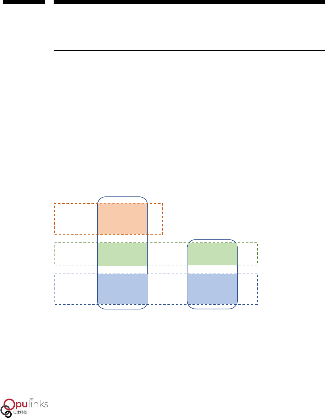
OPL1000 consists of two MCU’s of ARM Cortex M3 and Cortex M0. The so-called OPL1000 APP
Development refers to the application procedure for development users on M3 MCU of OPL1000.
The initial M3, M0 firmware of OPL1000 is comprised in the Chip as ROM CODE. Furthermore, as
functions expand and bugs resolved, OPL1000 also provides firmware patch of M3 and M0.
Therefore, the development of user APP is completed based on the foundation of ROM code and
firmware patch. Their relationship can be demonstrated with Figure 1.
Figure 1: The Relationship Between User APP & ROM CODE and Patch
The M0 Patch is sent out via Opulinks in the format of binary files. M3 Patch is provided in the
format for lib documents, as the user APP and SDK source code from Opulinks are used as Keil C
project for coding, therefore, the generated M3 bin document include M3 Firmware Patch, SDK
and user APP application procedure. Ultimately, M0 Patch Bin documents and M3 Bin documents
ROM CODE
Patch
APP & SDK
M3
M0

OPL1000
CHAPTER ONE
Copyright © 2019, Opulinks. All Rights Reserved.
OPL1000-SDK-getting-start-guide-R02, Version V06
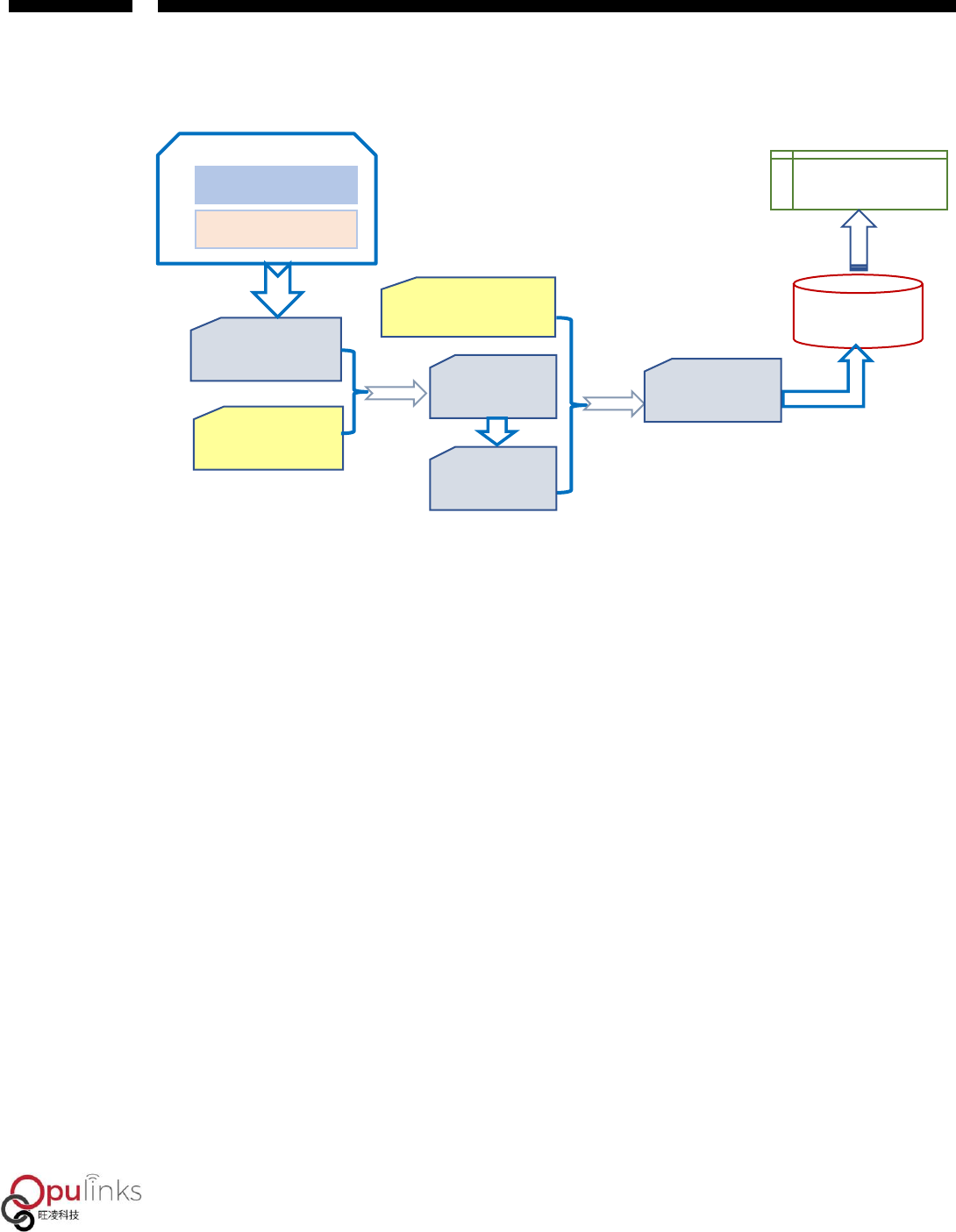
are combined and then downloaded to external Flash, and after OPL1000 is powered up, M3/M0
Bin documents in the Flash is loaded into RAM to execute. The overall process can be shown with
Figure 2.
Figure 2: Compiling of User APP & Patch, Loading Process (without OTA Function)
The two types of Bin documents, supported by OPL1000, are “Pure Bin” documents as shown in
Figure 2, as M3 bin document coded with users’ procedure, then combined with M0 bin
document in generating opl1000.bin file. This file stored in Flash 0x0000 position, neither
including OTA loader, nor supporting OTA (Over-The-Air Download) function, and the other is
called “OTA Image” document which is based on “Pure Bin” document, with messages such as
OTA Loader and Bin Header, etc. included, in generating firmware documents that support OTA
download, with the document generated by using download tool named as “opl1000_ota.bin”.
In order to understand the structure of OTA Image document, we need to first understand the
working process of OPL1000 OTA upgrade firmware. When OPL1000 firmware supports OTA
download for upgrade, there are two firmware maintained in Flash, as shown in Table 1,as the
first OTA Bin file and the second OTA Bin file are placed in 0x00005000 and 0x0003E000 locations
respectively, with the maximum size of 228K Bytes. At the locations of 0x00003000 and
0x00004000 there are Header message of the first and the second OTA bin. Header messages
include the chip type, version message, firmware calibration and firmware size and Header
Calibration, etc., of OTA Bin Firmware. The first OTA bin file and the second OTA bin use ping-
Keil uvision
M3 User APP&SDK
M0 Patch Bin Files
Download
M3 Patch Lib
Flash
RAM
Load & Execution
M3 Patch
Bin File
Compile
& Link

OPL1000
CHAPTER ONE
Copyright © 2019, Opulinks. All Rights Reserved.
OPL1000-SDK-getting-start-guide-R02, Version V06
pong switch method to execute upgrade. For example, when the currently executing firmware
corresponding to the first OTA Bin document, then the firmware (and its Header message)
downloaded through OTA download would be placed in the second OTA Bin document location
(firmware in 0x0003E000, and header in 0x00004000). If the currently executing firmware
corresponding to the second OTA Bin document, then the newly downloaded upgrade firmware
would be placed in the first OTA Bin document location (firmware in 0x00005000, and header in
0x00003000)
Table 1: Reflective Address of OTA Image Stored in Flash
Number
Address
Size
Content
1
0x00000000
~
0x00003000
12K Bytes
OTA Firmware Loading Procedure
2
0x00003000
~
0x00004000
4K Bytes
The Header of the first OTA Bin document only uses
up 64 bytes, and the rest is filled up with 0xFF.
3
0x00004000
~
0x00005000
4K Bytes
The header of the second OTA Bin document, with
the same format as above.
4
0x00005000
~ 0x0003E000
228K Bytes
The first OTA Bin document, just like the previously
mentioned opl1000.bin document. It and the second
OTA Bin document using ping-pong switch upgrade.
5
0x0003E000 ~
0x00077000
228K Bytes
The second OTA Bin document, just like the
previously mentioned opl1000.bin document. It and
the first OTA Bin document using ping-pong switch
upgrade.

OPL1000
CHAPTER ONE
Copyright © 2019, Opulinks. All Rights Reserved.
OPL1000-SDK-getting-start-guide-R02, Version V06
The composition of opl1000_ota.bin document, corresponding to Table 1, is shown in Table 2. Its
first 3 sectors are the same as Table 1. As opl1000_ota.bin document only contains 1 Bin
document, therefore it does not have the 5th sector, i.e. the 2nd OTA BIN document data. Also, the
size of the 4th sector is determined by firmware size. Assumed that there is already an OTA image
in Flash, e.g. the first OTA Bin document corresponding to Table 1. Then the content of the 2nd
and 4th sectors of the newly downloaded opl1000_ota.bin document will be written into the 3rd
and 5th sectors shown in Flash Table 1.
Table 2: Composition of OPL1000 OTA
Number.
Address
Size
content
1
0x00000000 ~
0x00003000
12K Bytes
OTA Firmware Loading Procedure
2
0x00003000 ~
0x00004000
4K Bytes
The Header of the first OTA Bin document only
uses up 64 bytes, and the rest is filled up with
0xFF.
3
0x00004000 ~
0x00005000
4K Bytes
The header of the second OTA Bin document, with
the same format as above.
4
0x00005000 ~
0x00005000+N
N Bytes
OTA Bin file which is the previous mention
opl1000 bin file
Please note that there are two premises for OPL1000 firmware supporting OTA download that
firstly, being structured on opl1000_ota.bin, and the other being OTA Bin document supporting
the function of obtaining firmware through BLE or WIFI. Regarding user APP coding that supports
OTA function, download process is shown in Figure 3, as it includes two-time Pack combination
functions. One is to combine user APP bin document and M0 bin document as opl1000.bin. The
second is to combine opl1000.bin, OTA loader and the Header message of opl1000.bin, in
forming opl1000_ota.bin document.
OPL1000
CHAPTER ONE
Copyright © 2019, Opulinks. All Rights Reserved.
OPL1000-SDK-getting-start-guide-R02, Version V06
Figure 3: Coding of User APP & Patch, Loading Process (Supporting OTA Function)
2.2. APP Development Procedure
User can use two modes to develop application procedure.
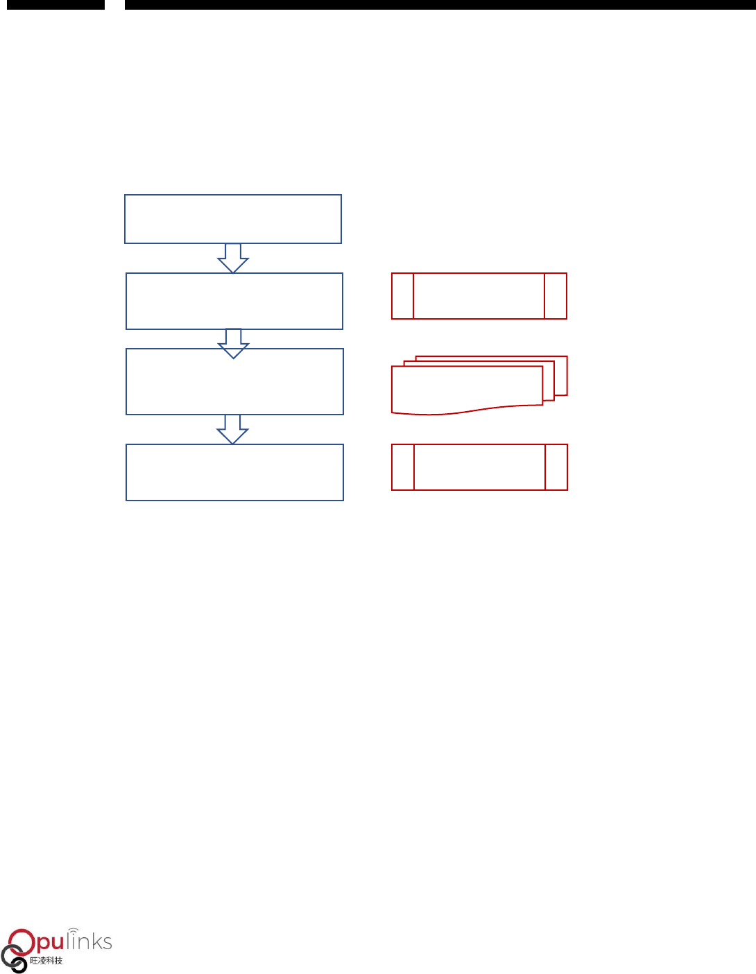
Mode 1: IDE Online Debugging Development Mode
The development entails four steps, as shown in Figure 4.
1. Obtain OPL1000 SDK software pack from the original manufacturer.
2. Pack the M0 Bin document under the “FW_Binary” folder that contains SDK software pack,
according to the download tool guide outlined in Reference (1), into a Bin document and
download it to Flash. Please note that M0 bin document needs only be downloaded from SPI
flash once, when there is no update on SDK Development Pack.
3. Develop user APP on Keil uVision (based on SDK example source code project)
M3 User APP&SDK
M3 Patch Lib
Keil uvision
Compile & Link
M3 Patch Bin File
Opl1000_app_m3.bin
M0Patch Bin File
Opl1000_m0.bin
OPl1000 Bin File
Opl1000.bin
Pack
OTA loader File
Opl1000_ota_loader.bin
OPl1000 Bin File
Header
Flash
Pack &
build
OPL1000 RAM
Download
OTA image Bin File
Opl1000_ota.bin
Load
OPL1000
CHAPTER ONE
Copyright © 2019, Opulinks. All Rights Reserved.
OPL1000-SDK-getting-start-guide-R02, Version V06
4. Under Keil C environment, as online emulator operates and debugs, and confirm execution
result through serial-port, while taking note that code has not yet been downloaded to flash
yet, as code is only operating in RAM.
Figure 4: IDE Online Debug Development Mode
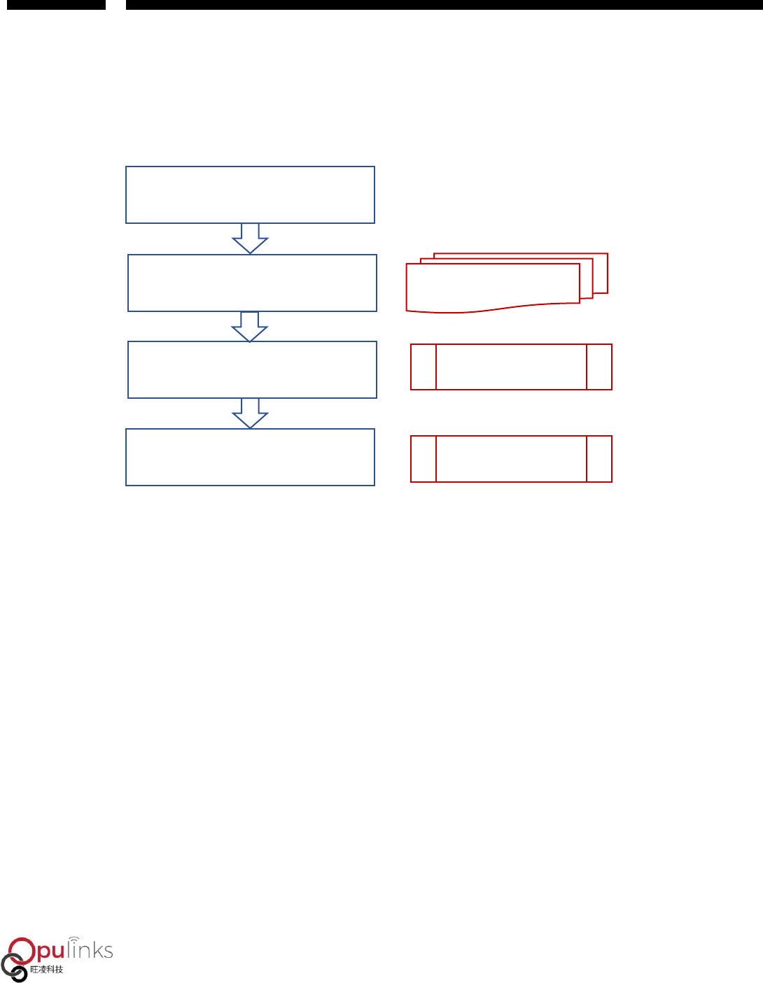
Mode 2: Serial-Port Debugging Development Mode
The development entails five steps, as shown in figure 5.
1. Obtain OPL1000SDK software pack from the original manufacturer.
2. Develop user APP, and executing, debugging and confirm execution result, under Keil C that
is based on SDK source project.
3. Obtain coded M3 Bin Document
4. Pack the M0 Bin document under the “FW_Binary” folder that contains SDK software pack,
according to the download tool guide outlined in Reference (1), into a Bin document and
download it to Flash. Please note that M0 bin document needs only be downloaded from
SPIflash once, when there is no update on SDK Development Pack.
Obtain OPL1000 SDK Development Pack
M0 Bin document packed and combined into a Bin
document before downloaded into Flash
Download Tool
Develop user APP, and executing, debugging and confirm
execution result, under Keil C that is based on SDK
source code project Keil C Development Environment
OPL1000 executes user APP in confirming execution result,
through serial-port printing or other devices.
Serial-Port Debugging Tools, etc.
OPL1000
CHAPTER ONE
Copyright © 2019, Opulinks. All Rights Reserved.
OPL1000-SDK-getting-start-guide-R02, Version V06
5. As OPL1000 is powered on or reset. Execute user APP, and confirm execution result through
serial-port messages.
Figure 5: Serial-Port Debug Mode
During the actual development process, users can combine his/her own development needs to
switch between these two development modes with flexibility.
Obtain OPL1000 SDK Development Pack
Develop user APP, and executing, debugging and confirm
execution result, under Keil C that is based on SDK source
code project
Coded M3 Bin and M0 Bin document packed and
combined into a Bin document before downloaded into
Flash
Download Tool
Keil C Development Environment
When OPL1000 is powered on or reset, it executes user
APP in confirming execution result, through serial-port
printing.
Serial-Port Tools
OPL1000
Copyright © 2019, Opulinks. All Rights Reserved.
OPL1000-SDK-getting-start-guide-R02, Version V06
3. USING KEIL TO DEBUG APPLICATION
PROCEDURE
User application procedure can carry out development and debugging on DEVKIT board. For the
usage of DEVKIT board, please refer to reference (2) DEVKIT Quick Usage Guide.
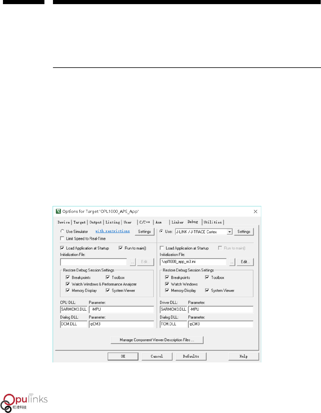
3.1. Keil Engineering Setting
DevKit board uses USB as power-supply, while correctly connecting K-link emulator and DevKit
Board. Opening up project: SDK\APS_PATCH\examples\get_started\hello_world. Select
“Options of Target” button, with dialogue box prompted, before selecting Debug interface,
before the prompted interface shown below appears.
Figure 6: Option for Target Dialogue setting
OPL1000
Copyright © 2019, Opulinks. All Rights Reserved.
OPL1000-SDK-getting-start-guide-R02, Version V06
For debugging port, select the port of JLINK / J-TRACE Cortex port, and if users use other
emulator, please select the corresponding emulator port type, e.g. when using CMSIS DAP
emulator, then the port of CMSIS-DAP Debugger should be chosen. After having selected the
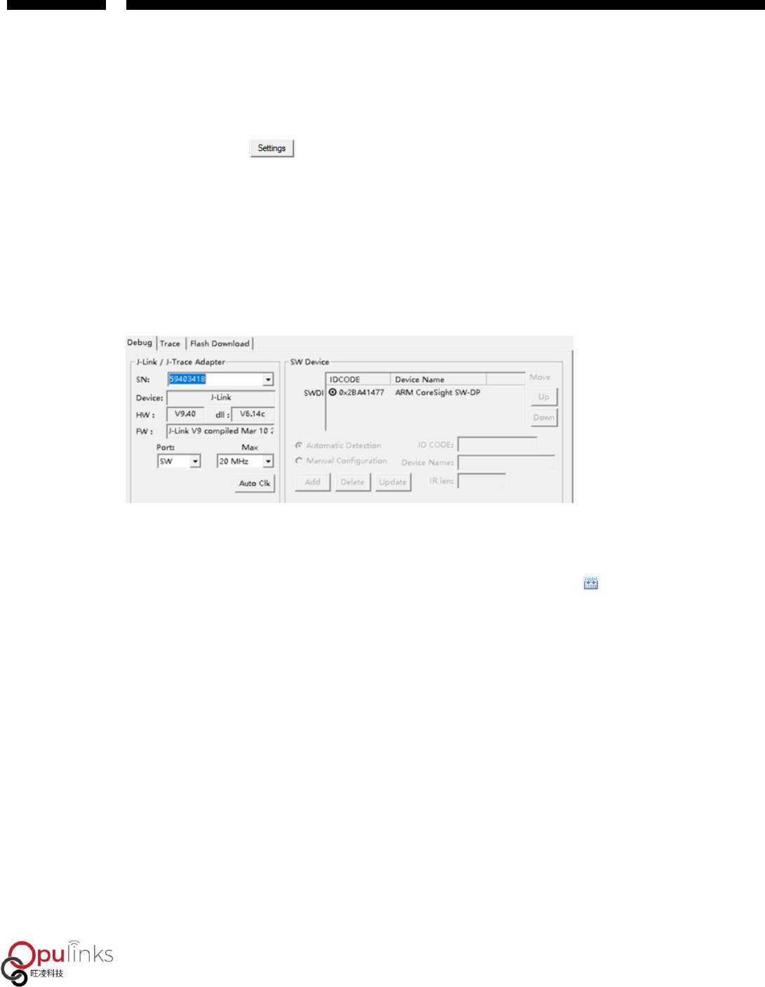
correct port, press button, before what’s illustrated in Figure 7 appears. What is displayed
in SW Device is the designated number of device, indicating the device is properly connected and
operating normally, and if the field of “SW Device” is empty, then device connection should be
checked to ensure correct connection.
Figure 7: Correct Identification of J-link ICE Emulator
3.2. Application Procedure of Online Debugging
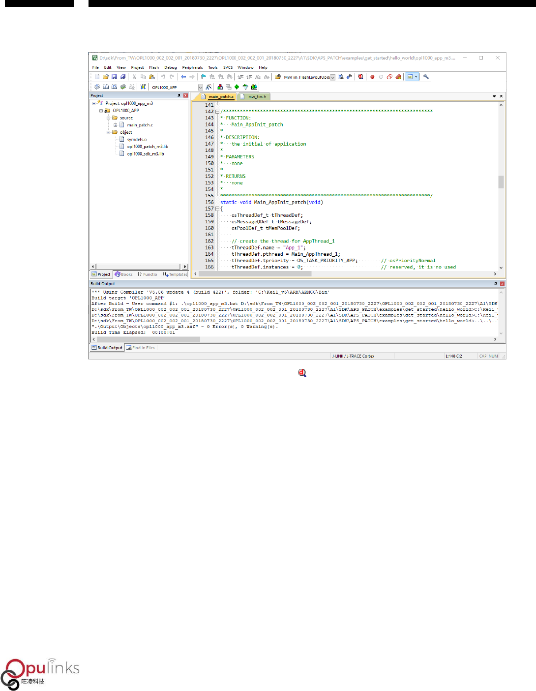
Once Keil software correctly identified OPL1000 device, and build example project, before
arriving at the displayed image as shown in Figure 8, which means coding has been correctly
completed.
OPL1000
Copyright © 2019, Opulinks. All Rights Reserved.
OPL1000-SDK-getting-start-guide-R02, Version V06
Figure 8: Keil coding hello_world Example Code
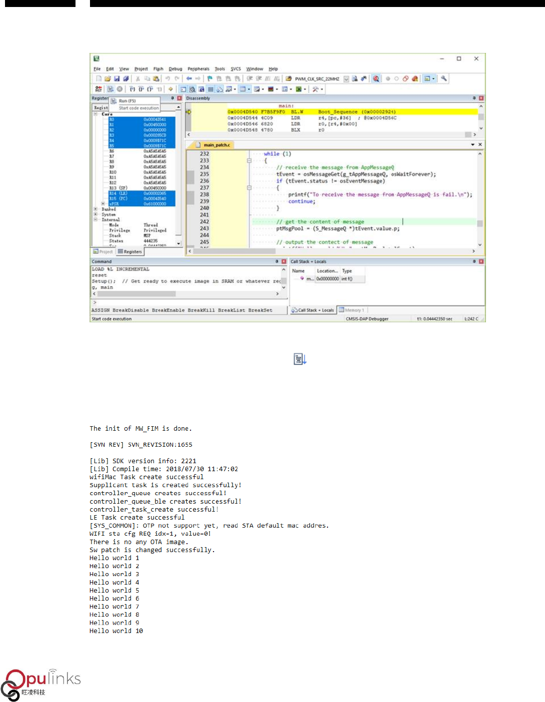
After coding is completed, click “Debug ” button, before correctly entering debugger
environment, as shown in Figure 9.
OPL1000
Copyright © 2019, Opulinks. All Rights Reserved.
OPL1000-SDK-getting-start-guide-R02, Version V06
Figure 9: Using Keil Online Debugging
When proper connection to serial-port is maintained, use serial-port tool to open up APS serial-
port, while clicking “Full-Speed Operation ” in keil, and when APS serial-port prints out log
message as shown in Figure 10, it indicates that the procedure is executing correctly in RAM.
Figure 10: Execution Result of Printing Confirmation Procedure of APS Serial Port
OPL1000
Copyright © 2019, Opulinks. All Rights Reserved.
OPL1000-SDK-getting-start-guide-R02, Version V06
3.3. Procedure Download
。
When performing online debugging, codes will only be loaded to OPL1000 RAM area, and once
users complete APP development through online debugging, and they need to download APP
procedure, through download tool, to flash that is external to OPL1000.
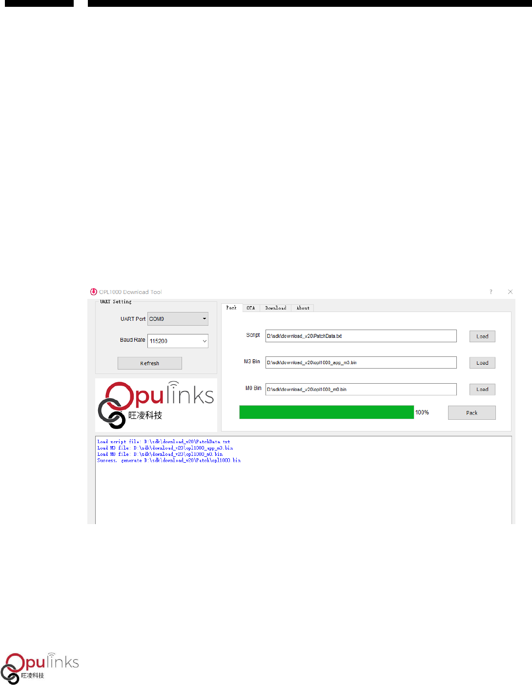
Users first use download tool to load corresponding script document and bin document, and
take note of user APP added to the location of M3 patch. Script document and M0 bin document
are stored under the FW_Binary folder in SDK, which can be accessed by users under this folder.
Figure 11: Add Script and bin Document
Once script document and bin document are added, click “pack” button, and the procedure will
combine user’s M3 bin and M0 bin documents to generate an opl1000.bin document, according
to script definition, and stored in the patch document folder, the same folder as that of download
tool.
OPL1000
Copyright © 2019, Opulinks. All Rights Reserved.
OPL1000-SDK-getting-start-guide-R02, Version V06
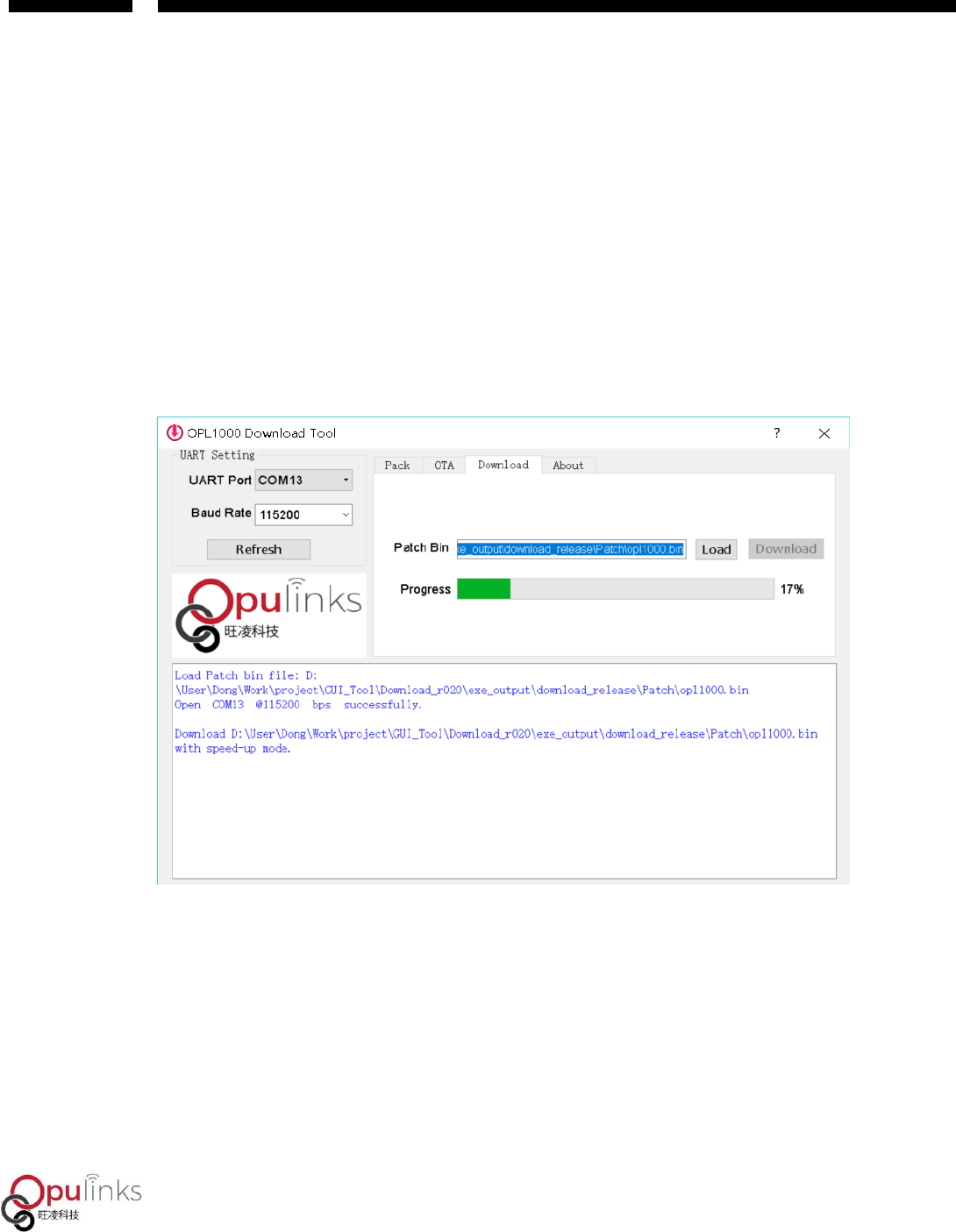
When looking at Download page, the previously combined opl1000.bin document address has
been automatically written in the location of Patch Bin. As outlined in reference (2) DEVKIT Quick
Usage Guide, select the serial-port number connected with mini-USB in the selection box of
UART Port, and click “Download” button, and resetting OPL1000 DEVKIT within 5 seconds, before
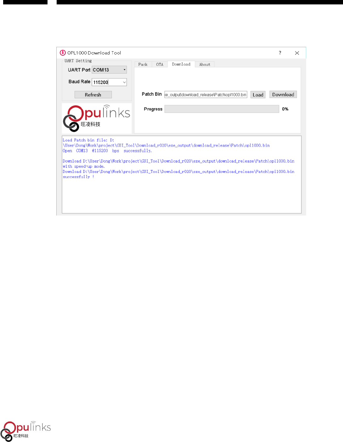
opl10000.bin begins to be downloaded to Flash, as shown in Figure 12. When the green progress
bar reaches 100%, it means that the download is complete, and the interface is shown as in
Figure 13.
Figure 12: Download APP Procedure
OPL1000
Copyright © 2019, Opulinks. All Rights Reserved.
OPL1000-SDK-getting-start-guide-R02, Version V06
Figure 13: Successful Download of OPL1000 Firmware
Users use serial-port tool to open APS serial-port to reset OPL1000 DEVKIT board, and relevant
log of APP procedure can be observed