OS 1 User Guide Software
User Manual:
Open the PDF directly: View PDF ![]() .
.
Page Count: 25
OS-1-64/16 High Resolution Imaging Lidar
Software User Guide

Change Log
Version
Date
Description
v.1.6.x
Add:
“get_sensor_info” command gives “prod_line” info.
v1.7.0
No TCP command change
v1.8.0
Add:
“get_sensor_info” command gives “INITIALIZING”, “UPDATING”, “RUNNING”,
“ERROR” and “UNCONFIGURED” status.
v1.9.0
No TCP command change
v1.10.0
TBD
Page 1 of 24
For OS-1 FW V.1.10.0
Ouster, Inc 350 Treat Ave, San Francisco, CA 94110
REV: 1.10 11/30/2018 • © 2018 Ouster, Inc. • All rights reserved

Table of Contents
Introduction 3
Safety & Legal Notices 3
Drivers & Interface 4
TCP API Command Set 6
Querying Sensor Info and Intrinsic Calibration 6
Querying Active or Staged Parameters 7
Setting Configuration Parameters 10
Lidar Data Format 15
IMU Data Format 17
Data Rates 17
Coordinate Frames 17
Sensor Coordinate Frame 17
Lidar Intrinsic Beam Angles 18
Lidar Range Data To XYZ Lidar Coordinate Frame 18
Lidar Range Data To Sensor XYZ Coordinate Frame 19
IMU Data To Sensor XYZ Coordinate Frame 19
Time Synchronization 20
Internal Clock Source 20
External Trigger Clock Source 21
Updating Firmware 23
Troubleshooting 23
Page 2 of 24
For OS-1 FW V.1.10.0
Ouster, Inc 350 Treat Ave, San Francisco, CA 94110
REV: 1.10 11/30/2018 • © 2018 Ouster, Inc. • All rights reserved

1. Introduction
The OS-1 family of sensors offer a market leading combination of price, performance, reliability
and SWAP. They are designed for indoor/outdoor all-weather environments and long lifetime.
As the smallest high performance lidar on the market, the OS-1 can be directly integrated into
vehicle facias, windshield, side mirrors, and headlight clusters. The OS-1 family of sensors
consist of two models, the OS-1-16 and OS-1-64, with differing resolution, but of identical
mechanical dimensions.
HIGHLIGHTS
● Fixed resolution per frame operating mode
● Camera-grade intensity, ambient, and range data
● Multi-sensor crosstalk immunity
● Simultaneous and co-calibrated 2D and 3D output
● Industry leading intrinsic calibration
●Open source drivers
For the purposes of this document, the term “OS-1” refers to the family of sensors, and only
where there is a difference in performance will each model will be referred to by its specific
model designation.
2. Safety & Legal Notices
The OS-1-16 and OS-1-64 are Class 1 laser products per IEC 60825-1:2014 and operate in the
850nm band.
FDA 21CFR1040 Notice: OS-1-16 and OS-1-64 comply with FDA performance standards for
laser products except for deviations pursuant to Laser Notice No. 50, dated July 26th, 2001.
Page 3 of 24
For OS-1 FW V.1.10.0
Ouster, Inc 350 Treat Ave, San Francisco, CA 94110
REV: 1.10 11/30/2018 • © 2018 Ouster, Inc. • All rights reserved

WARNING: The OS-1 is a sealed unit, and is not user-serviceable.
Your use of the OS-1 is subject to the Terms of Sale that you signed with Ouster or your
distributor/integrator. Included in these terms is the prohibition on removing or otherwise
opening the sensor housing, inspecting the internals of the sensor, reverse-engineering any part
of the sensor, or permitting any third party to do any of the foregoing.
“Ouster” and “OS-1” are both registered trademarks of Ouster. They may not be used without
express permission from Ouster.
If you have any questions about the above points, contact us at legal@ouster.io.
3. Drivers & Interface
Our sample drivers can be found at: www.github.com/orgs/ouster-lidar.
The sensor will automatically turn on, start scanning, obtain an IP address, and start taking
measurements when provided power by the Interface Box. However it will only stream UDP data
packets after receiving a destination IP address on TCP Port 7501.
The sensor is configured to dynamically obtain an IP address using a DHCP server. If the
sensor is plugged into a network switch, it will automatically obtain an IP and you can find that
IP by checking the DNS leases on the network switch.
If the sensor is plugged directly into a computer, you will have to install a DCHP server on the
computer. We recommend dnsmasq for Ubuntu to dynamically assign an IP address. The basic
steps are as follows:
Step
Command
1
Install dnsmasq.
Page 4 of 24
For OS-1 FW V.1.10.0
Ouster, Inc 350 Treat Ave, San Francisco, CA 94110
REV: 1.10 11/30/2018 • © 2018 Ouster, Inc. • All rights reserved

2
In a terminal window, obtain the list of interfaces on the
machine, and note the interface that the sensor is plugged
into.
ip link
3
Edit your network connections to have a manually assigned
IP e.g., 192.168.1.1 , with a Netmask of 255.255.255.0. You
can keep the gateway field blank.
Right click network connections in
the top-right-hand corner of your
screen, and select an interface to
edit.
4
Edit the dnsmasq config file to read the target interface.
sudo nano /etc/dnsmasq.conf
5
Uncomment “#interface=” and add the interface above.
dnsmasq will now search on this interface for allocating IP
addresses.
interface=enp0s25
6
Uncomment DHCP-range and make sure it has the same
subnet as the manual IP you set above.
In the example to the right, dnsmasq will now allocate
addresses 50-150 for leases for new devices on subnet 1.
dhcp-range=192.168.1.50,
192.168.1.150, 12h” -
7
Start (or stop and start) dnsmasq.
sudo systemctl stop dnsmasq
sudo systemctl start dnsmasq
8
After dnsmasq is running with the proper configs per above,
plug in the sensor. Check DNSMasq’s status.
Use “journalctl -fu dnsmasq” to
see dnsmasq’s status. You should
see an IP address be allocated to
the sensor after 10-15 seconds.
9
Then, either when you launch the ROS driver, you will
identify the sensor by hostname or IP address (e.g.,
192.168.1.50), and tell the sensor which IP address to send
the data to (e.g., 192.168.1.1).
NOTE: The sensor hostname does not change when you
restart the sensor, whereas IP usually does with a DHCP
server. We recommend using hostnames (e.g.,
os1-991827000891.local) instead of IP addresses for this
reason. This functionally achieves the same result as a
fixed sensor IP address.
Future firmware releases will support manually setting a sensor IP address over TCP and/or
GUI at a IPv6 linklocal address.
Page 5 of 24
For OS-1 FW V.1.10.0
Ouster, Inc 350 Treat Ave, San Francisco, CA 94110
REV: 1.10 11/30/2018 • © 2018 Ouster, Inc. • All rights reserved

3.1. TCP API Command Set
3.1.1. Querying Sensor Info and Intrinsic Calibration
The sensor can be queried and configured using a simple plaintext protocol over TCP on port
7501. The following commands will return sensor configuration and calibration information:
Command
Description
Response
get_config_txt
Return JSON-formatted sensor
configuration: auto_start_flag,
tcp_port, udp_ip, udp_port_lidar,
udp_port_imu, timestamp_mode,
pps_out_mode, pps_out_polarity,
pps_rate, pps_angle,
pps_pulse_width, pps_in_polarity,
lidar_mode.
{"auto_start_flag": 1, "tcp_port": 7501,
"udp_ip": "", "udp_port_lidar": 7512,
"udp_port_imu": 7513, "timestamp_mode":
"TIME_FROM_INTERNAL_OSC",
"pps_out_mode": "OUTPUT_PPS_OFF",
"pps_out_polarity": "ACTIVE_HIGH",
"pps_rate": 1, "pps_angle": 360,
"pps_pulse_width": 10, "pps_in_polarity":
"ACTIVE_HIGH", "lidar_mode": "2048x10",
"window_rejection_enable": 1}
get_sensor_info
Return JSON-formatted sensor
metadata: serial number, hardware
and software revision, and sensor
status.
{"prod_line": "OS-1-64", "prod_pn":
"840-101396-02", "prod_sn":
"991824000106", "base_pn":
"000-101323-01", "base_sn": "11E0187",
"image_rev":
"ousteros-image-prod-aries-v1.10.0-rc.3-20
181208012156", "build_rev": "v1.10.0-rc.3",
"proto_rev": "v1.1.1", "build_date":
"2018-12-07T23:21:01Z", "status":
"RUNNING"}
get_beam_intrinsics
Returns JSON-formatted beam
altitude and azimuth offsets, in
degrees.
{"beam_altitude_angles": [16.611, ...,
-16.611], "beam_azimuth_angles": [3.164,
…, -3.164]}
get_imu_intrinsics
Returns JSON-formatted imu
transformation matrix needed to
adjust to the Sensor Coordinate
Frame.
{"imu_to_sensor_transform": [1, 0, 0, 6,
253, 0, 1, 0, -11.775, 0, 0, 1, 7.645, 0, 0,
0, 1]}
get_lidar_intrinsics
Returns JSON-formatted lidar
transformation matrix needed to
adjust to the Sensor Coordinate
Frame.
{"lidar_to_sensor_transform": [-1, 0, 0, 0,
0, -1, 0, 0, 0, 0, 1, 36.18, 0, 0, 0, 1]}
Page 6 of 24
For OS-1 FW V.1.10.0
Ouster, Inc 350 Treat Ave, San Francisco, CA 94110
REV: 1.10 11/30/2018 • © 2018 Ouster, Inc. • All rights reserved

get_alerts
Returns JSON-formatted alerts of
the sensor if “get_sensor_info” is
“ERROR”. It has a buffer to hold
upto 8 errors sequentially.
For example:
{"alerts": [{"cursor": 0, "code":
"ETHERNET_LINK_BAD", "realtime":
"1543621378681281792", "brief": "Ethernet
Link Bad", "description": "Link transitioned
to 0/Unknown which != 1000/Full"}],
"next_cursor": 1}
An example session using the unix netcat utility is shown below, with user input in bold:
$ nc os1-991805000142 7501
get_sensor_info
{“prod_line”: “OS-1-64”, "prod_pn": "840-101396-02", "prod_sn": "991805000142", "base_pn":
"000-101323-01", "base_sn": "11E0211", "image_rev":
"ousteros-image-prod-aries-v1.2.0-201804232039", "build_rev": "v1.2.0", "proto_rev": "v1.1.0",
"build_date": "2018-05-02T18:37:13Z", "status": "RUNNING"}
Potentially, sensor may have the following status:
Status
Occurs ...
"INITIALIZING"
When the sensor is booting and not yet outputting data.
"UPDATING"
When the sensor is updating the FPGA firmware on the first reboot after a
firmware upgrade.
"RUNNING"
When the sensor has reached the final running state where it can output data.
"ERROR"
Check error codes in the “errors” field for more information.
"UNCONFIGURED"
An error with factory calibration that requires a return.
Errors supported by get_alerts command are:
Temperature Related
Communication Related
Other
BASE_A_OVERTEMP
UPLINK_ERROR
TEC_RUNAWAY
BASE_B_OVERTEMP
DOWNLINK_ERROR
STATOR_OVERTEMP
ETHERNET_LINK_BAD
Page 7 of 24
For OS-1 FW V.1.10.0
Ouster, Inc 350 Treat Ave, San Francisco, CA 94110
REV: 1.10 11/30/2018 • © 2018 Ouster, Inc. • All rights reserved

ROTOR_OVERTEMP
TX_VCSEL_OVERTEMP
TX_PCB_OVERTEMP
RX_RTD_OVERTEMP
RX_PCB_OVERTEMP
3.1.2. Querying Active or Staged Parameters
Sensor configurations / operating modes can also be queried over TCP. Below is the latest
command format:.
get_config_param active <parameter> will return the current active configuration parameter
values.
get_config_param staged <parameter> will return the parameter values that will take place
after issuing reinitialize command or after sensor reset.
get_config_param
Command
Description
Response
udp_ip
Returns the ip to which the sensor
sends UDP traffic..
“”(default)
udp_port_lidar
Returns the port number of lidar
UDP data packets
7502 (default)
udp_port_imu
Returns the port number of IMU
UDP data packets
7503 (default)
Page 8 of 24
For OS-1 FW V.1.10.0
Ouster, Inc 350 Treat Ave, San Francisco, CA 94110
REV: 1.10 11/30/2018 • © 2018 Ouster, Inc. • All rights reserved

lidar_mode
Returns a string indicating the
horizontal resolution
One of “512x10”, “1024x10”, “2048x10”,
“512x20”, “1024x20”
auto_start_flag
Returns “1” if sensor is on auto start,
and “0” if not. [describe]
1 (default)
timestamp_mode
Get the method used to timestamp
measurements. See section 5.1 for
a detailed description of each option.
One of “TIME_FROM_INTERNAL_OSC”,
“TIME_FROM_PPS_IN_SYNCED”,
“TIME_FROM_PTP_1588”
pps_out_mode
Get the source of the the PPS signal
output by the sensor. See section
5.2 for a detailed description of each
option.
One of
“OUTPUT_FROM_INTERNAL_OSC”,
“OUTPUT_FROM_PPS_IN_SYNCED”,
“OUTPUT_PPS_OFF”,
“OUTPUT_FROM_PTP_1588”
“OUTPUT_FROM_PPS_DEFINED_RAT
E”
“OUTPUT_FROM_ENCODER_ANGLE”
pps_out_polarity
Returns the polarity of PPS output, if
sensor is set as the master sensor
used for time synchronization
One of “ACTIVE_HIGH” or
“ACTIVE_LOW”.
pps_in_polarity
Returns the polarity of PPS input, if
a sensor is set as slave sensor in
time synchronization.
One of “ACTIVE_HIGH” or
“ACTIVE_LOW”.
pps_rate
Returns the output PPS pulse rate in
Hz
Default “1”
pps_angle
Returns the output PPS pulse rate
defined in rotation angles.
Default “360”
pps_pulse_width
Returns the output PPS pulse width
in ms.
Default “10”.
Page 9 of 24
For OS-1 FW V.1.10.0
Ouster, Inc 350 Treat Ave, San Francisco, CA 94110
REV: 1.10 11/30/2018 • © 2018 Ouster, Inc. • All rights reserved

window_rejection_en
able
1: The default. Enabled. Allows the
sensor to achieve full spec.
0: Disabled. Reduces the sensor
range to zero meters but also
causes the sensor to select the
window return echo instead of a
target return echo if the window
echo is stronger. Depending on
window cleanliness this can
significantly reduce sensor range.
No sensor specs are guaranteed in
this mode.
1 (default)
An example session using the unix netcat utility is shown below, with user input in bold:
$ nc os1-991805000142 7501
get_config_param active lidar_mode
1024x10
3.1.3. Setting Configuration Parameters
set_config_param <parameter> <value> will set new values for configuration parameters,
which will take effect after issuing “reinitialize” command, or after sensor reset.
set_config_param
Command
Description
Response
lidar_mode <mode
value>
Set the horizontal resolution and
rotation rate of the sensor. Valid
modes are “512x10”, “1024x10”,
“2048x10”
“512x20”, “1024x20”
Each 50% the total number of points
gathered is reduced - e.g., from
2048x10 to 1024x10 - extends range
by 15-20%.
“set_config_param” on success, “error:”
otherwise
Page 10 of 24
For OS-1 FW V.1.10.0
Ouster, Inc 350 Treat Ave, San Francisco, CA 94110
REV: 1.10 11/30/2018 • © 2018 Ouster, Inc. • All rights reserved

timestamp_mode
<mode value>
Set the method used to timestamp
measurements. Valid modes are
“TIME_FROM_INTERNAL_OSC”,
“TIME_FROM_PPS_IN_SYNCED”,
or “TIME_FROM_PTP_1588
“set_config_param” on success, “error:”
otherwise
udp_ip <ip>
Specifies the ip to which the sensor
sends UDP traffic. On boot, the
sensor will not output data until this
is set.
“set_config_param” on success, “error:”
otherwise
udp_port_lidar
<port>
Lidar data will be sent to
<udp_ip>:<port>
“set_config_param” on success, “error:”
otherwise
udp_port_imu <port>
Imu data will be sent to
<udp_ip>:<port>
“set_config_param” on success, “error:”
otherwise
pps_out_mode
<mode value>
Set the source of the PPS signal.
Valid modes are
“OUTPUT_FROM_INTERNAL_OSC
”,
“OUTPUT_FROM_PPS_IN_SYNCE
D”, “OUTPUT_PPS_OFF”, or
“OUTPUT_FROM_PTP_1588”
“OUTPUT_FROM_PPS_DEFINED_
RATE”
“OUTPUT_FROM_ENCODER_ANG
LE”
“set_config_param” on success, “error:”
otherwise
pps_rate <rate value
in Hz>
Set output PPS rate. Valid inputs are
integers > 0 Hz, but also limited by
the criteria described in section 5.2
of this user manual.
“set_config_param” on success, “error:”
otherwise
pps_angle <angle
value in degrees>
Set output PPS rate defined by
rotation angle. Valid inputs are
integers < 360 degrees, but also
limited by the criteria described in
section 5.2 of this user manual.
“set_config_param” on success, “error:”
otherwise
pps_pulse_width
<width value in ms>
Set output PPS pulse width in ms, in
1ms increments. Valid inputs are
integers > 0 ms, but also limited by
the criteria described in section 5.2
of this user manual.
“set_config_param” on success, “error:”
otherwise
Page 11 of 24
For OS-1 FW V.1.10.0
Ouster, Inc 350 Treat Ave, San Francisco, CA 94110
REV: 1.10 11/30/2018 • © 2018 Ouster, Inc. • All rights reserved

window_rejection_en
able <1/0>
1: The default. Enabled. Allows the
sensor to achieve full spec.
0: Disabled. Reduces the sensor
range to zero meters but also
causes the sensor to select the
window return echo instead of a
target return echo if the window
echo is stronger. Depending on
window cleanliness this can
significantly reduce sensor range.
No sensor specs are guaranteed in
this mode.
“set_config_param” on success, “error:”
otherwise
write_config_txt will write new values of parameters into a configuration file, so they will take
effect after sensor reset.
reinitialize will reinitialize the sensor so the staged values of the parameters will take effect
immediately.
set_config_param
Command
Description
Response
write_config_txt
Make the current settings persist
until the next reboot.
“write_config_txt” on success
reinitialize
Restarts the sensor. Changes to
lidar, pps, and timestamp modes
will only take effect after
reinitialization.
“reinitialize” on success
$ nc os1-991805000142 7501
set_config_param lidar_mode 512x20
set_config_param
set_config_param udp_ip 192.168.11.1
set_config_param
write_config_txt
write_config_txt
reinitialize
reinitialize
For FW 1.5.1 and earlier:
Page 12 of 24
For OS-1 FW V.1.10.0
Ouster, Inc 350 Treat Ave, San Francisco, CA 94110
REV: 1.10 11/30/2018 • © 2018 Ouster, Inc. • All rights reserved

Command
Description
Response
get_sensor_info
Return JSON-formatted sensor
metadata: serial number, hardware
and software revision, and sensor
status.
{"prod_pn": "840-101396-02", "prod_sn":
"991805000142", "base_pn":
"000-101323-01", "base_sn": "11E0211",
"image_rev":
"ousteros-image-prod-aries-20180423203
9", "build_rev": "v1.2.0-21-g337de76",
"proto_rev": "v1.1.0", "build_date":
"2018-05-02T18:37:13Z", "status":
"RUNNING"}
get_beam_intrinsics
Returns JSON-formatted beam
altitude and azimuth offsets, in
degrees.
{"beam_altitude_angles": [16.611, ...,
-16.611], "beam_azimuth_angles": [3.164,
…, -3.164]}
set_udp_ip <ip>
Specifies the ip to which the sensor
sends UDP traffic. On boot, the
sensor will not output data until this
is set.
“set_udp_ip” on success, “error:”
otherwise
set_udp_port_lidar
<port>
Lidar data will be sent to
<udp_ip>:<port>
“set_udp_port_lidar” on success, “error:”
otherwise
set_udp_port_imu
<port>
Imu data will be sent to
<udp_ip>:<port>
“set_udp_port_imu” on success, “error:”
otherwise
get_lidar_mode
Returns a string indicating the
horizontal resolution
One of “512x10”, “1024x10”, “2048x10”,
“512x20”, “1024x20”
set_lidar_mode
<lidar_mode>
Set the horizontal resolution and
rotation rate of the sensor. Valid
modes are “512x10”, “1024x10”,
“2048x10”,
“512x20”, “1024x20”.
“set_lidar_mode” on success, “error:”
otherwise
get_timestamp_mod
e
Get the method used to timestamp
measurements. See section 5.1 for
a detailed description of each option.
One of “TIME_FROM_INTERNAL_OSC”,
“TIME_FROM_PPS_IN_SYNCED”,
“TIME_FROM_PTP_1588”
Page 13 of 24
For OS-1 FW V.1.10.0
Ouster, Inc 350 Treat Ave, San Francisco, CA 94110
REV: 1.10 11/30/2018 • © 2018 Ouster, Inc. • All rights reserved

set_timestamp_mod
e
<timestamp_mode>
Set the method used to timestamp
measurements. Valid modes are
“TIME_FROM_INTERNAL_OSC”,
“TIME_FROM_PPS_IN_SYNCED”,
or “TIME_FROM_PTP_1588”
“set_timestamp_mode” on success,
“error:” otherwise
get_pps_out_mode
Get the source of the the PPS signal
output by the sensor. See section
5.2 for a detailed description of each
option.
One of
“OUTPUT_FROM_INTERNAL_OSC”,
“OUTPUT_FROM_PPS_IN_SYNCED”,
“OUTPUT_PPS_OFF”,
“OUTPUT_FROM_PTP_1588”
set_pps_out_mode
<pps_out_mode>
Set the source of the PPS signal.
Valid modes are
“OUTPUT_FROM_INTERNAL_OSC
”,
“OUTPUT_FROM_PPS_IN_SYNCE
D”, “OUTPUT_PPS_OFF”, or
“OUTPUT_FROM_PTP_1588”
“set_pps_out_mode” on success, “error:”
otherwise
write_config_txt
Make the current settings persist
until the next reboot.
“write_config_txt” on success
reinitialize
Restarts the sensor. Changes to
lidar, pps, and timestamp modes will
only take effect after reinitialization.
“reinitialize” on success
Page 14 of 24
For OS-1 FW V.1.10.0
Ouster, Inc 350 Treat Ave, San Francisco, CA 94110
REV: 1.10 11/30/2018 • © 2018 Ouster, Inc. • All rights reserved

3.2. Lidar Data Format
By default UDP data is forwarded to Port 7502. Lidar data packets consist of 16 azimuth blocks
and are always 12608 Bytes in length. The packet rate is dependent on the output mode. Words
are 32 bits in length.
Word
Azimuth Block 0
Azimuth Block 1
...
Azimuth Block 15
(Word 0,1)
(64 bit unsigned int)
Timestamp (ns)
(64 bit unsigned int)
Timestamp (ns)
...
(64 bit unsigned int)
Timestamp (ns)
(Word 2)
Measurement ID
Measurement ID
...
Measurement ID
(Word 3)
Encoder Count (0 to
90111)
Encoder Count (0 to
90111)
...
Encoder Count (0 to
90111)
(Word 4,5,6)
Channel 0 Data
Block
Channel 0 Data Block
...
Channel 0 Data
Block
(Word 7,8,9)
Channel 1 Data
Block
Channel 1 Data Block
...
Channel 1 Data
Block
.
.
.
.
.
.
.
.
.
(Word 193, 194, 195)
Channel 63 Data
Block
Channel 63 Data
Block
...
Channel 63 Data
Block
(Word 196)
Packet Status
Packet Status
...
Packet Status
Each azimuth block contains:
●Timestamp [64 bits] - Unique time in nanoseconds.
●Measurement ID [32 bits] - a sequentially incrementing azimuth measurement counting
up from 0 to 511, or 0 to 1023, or 0 to 2047 depending on lidar_mode.
●Encoder Count [32 bits] - an azimuth angle as a raw encoder count, starting from 0 with
a max value of 90111 - incrementing 44 ticks every azimuth angle in x2048 mode, 88
ticks in x1024 mode, and 176 ticks in x512 mode.
Page 15 of 24
For OS-1 FW V.1.10.0
Ouster, Inc 350 Treat Ave, San Francisco, CA 94110
REV: 1.10 11/30/2018 • © 2018 Ouster, Inc. • All rights reserved

●Data Block [96 bits] - 3 data words for each of the 16 or 64 pixels. See Table below for
full definition.
○Range [20 bits] - Range in millimeters, discretized to the nearest 12 millimeters.
○Reflectivity [16 bits] - Sensor signal_photon measurements are scaled based on
measured range and sensor sensitivity at that range, providing an indication of
target reflectivity. Calibration of this measurement has not currently been
rigorously implemented, but this will be updated in future a future firmware
release.
○Signal Photons [16 bits] - Signal photons in the signal return measurement are
reported.
○Noise Photons [16 bits] - Noise photons in the noise return measurement are
reported.
●Packet Status - indicates whether the azimuth block is good or bad. Good =
0xFFFFFFFF, Bad = 0x0. If a packet is bad Measurement ID, Encoder Count, and Data
Bock:Range and Data Block:Reflectivity will also be set to 0x0.
Full Description of Data block:
Word in Data
Block
Byte 3
Byte 2
Byte 1
Byte 0
Data Word 0
unused[31:24]
unused[23:20]
range_mm[19:16]
range_mm[15:8]
range_mm[7:0]
Data Word 1
signal_photons[31:24]
signal_photons[23:16]
reflectivity[15:8]
reflectivity[7:0]
Data Word 2
unused[31:24]
unused[23:16]
noise_photons[15:8]
noise_photons[7:0]
Page 16 of 24
For OS-1 FW V.1.10.0
Ouster, Inc 350 Treat Ave, San Francisco, CA 94110
REV: 1.10 11/30/2018 • © 2018 Ouster, Inc. • All rights reserved

3.3. IMU Data Format
UDP Packets - 48 Bytes - Port 7503 - at 100 Hz
Word
IMU and Gyro Data Block
(Word 0,1)
64 bit unsigned int for IMU Start Read Time (ns)
(Word 2,3)
64 bit unsigned int for Accel Read Time (ns)
(Word 4,5)
64 bit unsigned int for Gyro Read Time (ns)
(Word 6)
32 bit float for Acceleration in X (g)
(Word 7)
32 bit float for Acceleration in Y (g)
(Word 8)
32 bit float for Acceleration in Z (g)
(Word 9)
32 bit float for Angular Acceleration About in X-axis (deg per sec)
(Word 10)
32 bit float for Angular Acceleration About in Y-axis (deg per sec)
(Word 11)
32 bit float for Angular Acceleration About in Z-axis (deg per sec)
3.4. Data Rates
Based on 12,608 Bytes/packet and 1280 packets/sec, in 2048x10 or 1048x20 mode the OS-1
outputs 16.138 MB/s (129 Mbps). For this reason a gigabit ethernet network is required for
reliable performance.
4. Coordinate Frames
4.1. Sensor Coordinate Frame
The Sensor Coordinate Frame follows the right-hand rule convention and is defined at the
center of the sensor housing on the bottom, with the x-axis pointed forward, y-axis pointed to
the left and z-axis pointed towards the top of the sensor. The external connector is located in
the negative x direction.
Page 17 of 24
For OS-1 FW V.1.10.0
Ouster, Inc 350 Treat Ave, San Francisco, CA 94110
REV: 1.10 11/30/2018 • © 2018 Ouster, Inc. • All rights reserved

4.2. Lidar Intrinsic Beam Angles
The intrinsic beam angles for each beam may be queried with a TCP command (see OS-1
Software User Guide) and provide an azimuth and elevation adjustment to the each beam. The
azimuth adjustment is referenced off of the current encoder angle and the elevation adjustment
is referenced from the XY plane in the Sensor and Lidar Coordinate Frames.
4.3. Lidar Range Data To XYZ Lidar Coordinate Frame
The origin and axes of the lidar Coordinate Frame are defined by the position of the lidar lens
aperture stop in the sensor and the 0º position of the rotary encoder, which is aligned with the
sensor connector and the negative X axis of the Sensor Coordinate Frame.
For many applications, it is sufficient to calculate the XYZ point cloud in the LIDAR Coordinate
Frame using a combination of the intrinsic beam angles and the encoder reading. The intrinsic
azimuth and elevation beam angles may be queried over TCP as two vectors each 64 elements
Page 18 of 24
For OS-1 FW V.1.10.0
Ouster, Inc 350 Treat Ave, San Francisco, CA 94110
REV: 1.10 11/30/2018 • © 2018 Ouster, Inc. • All rights reserved
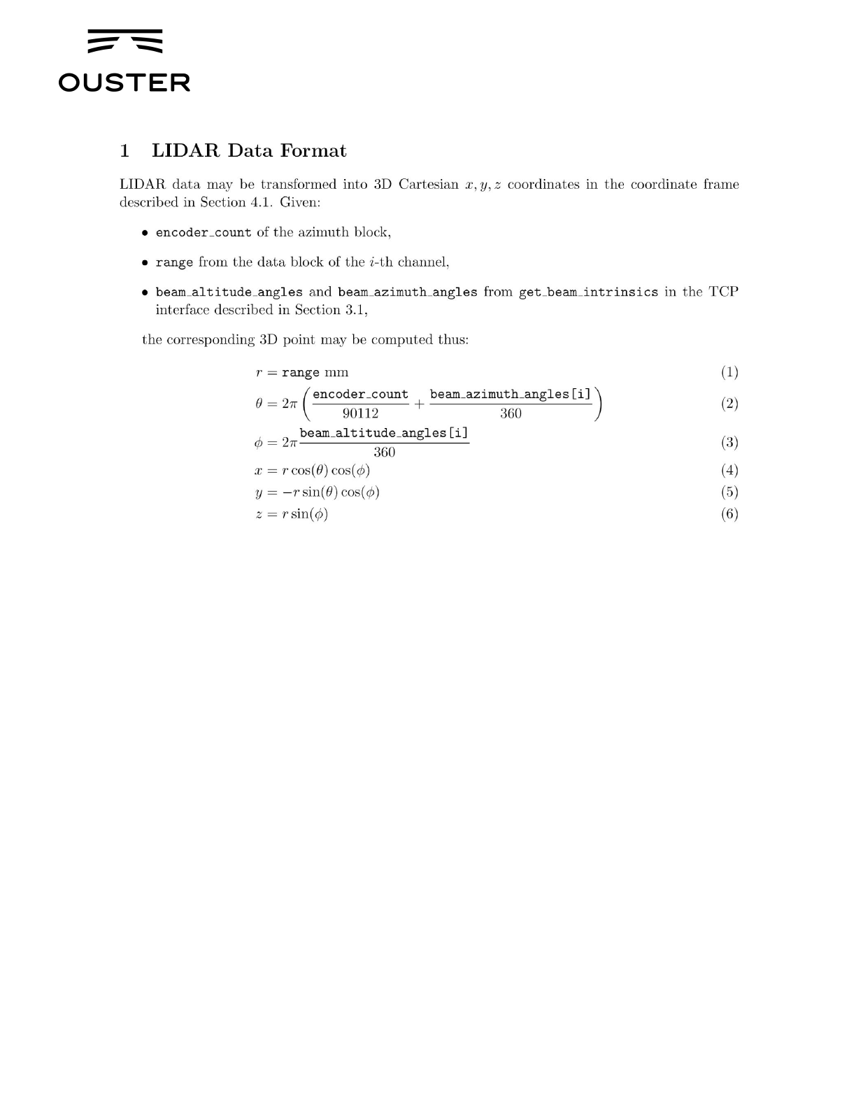
long.
4.4. Lidar Range Data To Sensor XYZ Coordinate Frame
For applications that require calibration against a precision mount or use the IMU data in
combination with the lidar data, the xyz points should be adjusted to the Sensor Coordinate
Frame. This requires a z translation and a rotation of the x,y,z points about the z axis. The z
translation is the height of the lidar aperture stop above the sensor origin, which is 36.180 mm,
and the data must be rotated 180° around the z axis. This information can be queried over TCP
in the form of an intrinsic transformation matrix:
M_lidar_to_sensor = [[X, X, X, X], [X, X, X, X], [X, X, X, X], [0, 0, 0, 1]
4.5. IMU Data To Sensor XYZ Coordinate Frame
The IMU is slightly offset in the Sensor Coordinate Frame for practical reasons. The IMU origin
in the Sensor Coordinate Frame can be queried over TCP in the form of an intrinsic
transformation matrix:
M_imu_to_sensor = [[X, X, X, X], [X, X, X, X], [X, X, X, X], [0, 0, 0, 1]
Page 19 of 24
For OS-1 FW V.1.10.0
Ouster, Inc 350 Treat Ave, San Francisco, CA 94110
REV: 1.10 11/30/2018 • © 2018 Ouster, Inc. • All rights reserved

5. Time Synchronization
● All lidar and IMU data are timestamped to a common timer with 10 nanosecond
precision.
● The common timer can be programmed to run off one of three clock sources:
○ An internal clock derived from a high accuracy, low drift oscillator
○ An opto-isolated digital input from the external connector for timing off an external
hardware trigger such as a GPS. The polarity of this input signal is
programmable. For instance, both a GPS PPS pulse and a 30 Hz frame sync
from an industrial camera can supply a timing signal to the OS-1.
○ Using the IEEE 1588 Precision Time Protocol. PTP provides the convenience of
configuring timing over a network that supports IEEE 1588 with no additional
hardware signals.
5.1. Internal Clock Source
The source for measurement timestamps can be configured using the “set_timestamp_mode”
TCP command (see Section 3.1). The available modes are described below:
Command
Response
TIME_FROM_INTERNAL_OSC
Use the internal clock. Measurements are time stamped with ns since
power-on
Free running counter based on the OS-1’s internal oscillator. Counts
seconds and nanoseconds since OS-1 turn on, reported at ns
resolution (both a second and nanosecond register in every UDP
packet), but min increment is on the order of 10 ns
Accuracy is +/- 90 ppm
TIME_FROM_PPS_IN_SYNCED
Use the internal clock, disciplined by an external PPS signal.
A free running counter synced to the PPS-input to the OS-1. Counts
seconds (# of PPS pulses) and nanoseconds since OS-1 turn on.
Reported at ns resolution (both a second and nanosecond register in
every UDP packet), but min increment is on the order of 10 ns
Accuracy is +/- 1 µs from a perfect PPS source
TIME_FROM_PTP_1588
Synchronize with an external PTP master
A monotonically increasing counter that will begin counting seconds
and nanoseconds since startup. As soon as a 1588 sync event
happens, the time will be updated to seconds and nanoseconds since
1970.
The counter must always count forward in time. If another 1588 sync
event happens the counter will either jump forward to match the new
time, or slow itself down.
Page 20 of 24
For OS-1 FW V.1.10.0
Ouster, Inc 350 Treat Ave, San Francisco, CA 94110
REV: 1.10 11/30/2018 • © 2018 Ouster, Inc. • All rights reserved

It is reported at ns resolution (there is both a second and nanosecond
register in every UDP packet), but the minimum increment varies.
Accuracy is +/- <50 us from the 1588 master.
5.2. External Trigger Clock Source
Additionally, the OS-1 can be configured to output a PPS signal from a variety of sources. See
the “set_config_param pps_out_mode” TCP command in Section 3.1.
Command
Response
OUTPUT_FROM_INTERNAL_OSC
Output a PPS signal synchronized with the internal
clock
OUTPUT_FROM_PPS_IN_SYNCED
Output a PPS signal synchronized with an an
external PPS source
OUTPUT_PPS_OFF
Do not output a PPS signal
OUTPUT_FROM_PTP_1588
Output a PPS signal synchronized with an external
PTP master
OUTPUT_FROM_PPS_DEFINED_RATE
Output a PPS signal with a user defined rate in Hz
OUTPUT_FROM_ENCODER_ANGLE
Output a PPS signal with a user defined rate in
degrees
When the sensor’s PPS_OUT_MODE is set to OUTPUT_FROM_PPS_DEFINED_RATE or
OUTPUT_FROM_ENCODER_ANGLE. PPS_RATE (Hz) and PPS_ANGLE (deg) parameters
are used to define the output pulse rate. The output pulse wide is defined by pps_pulse_width
(ms).
PPS_RATE allows user to output a PPS signal at a defined rate in Hz. Must set output mode
and corresponding rate. Defaults to 1 Hz. It should be > 0 Hz and maximum PPS_RATE is
limited by the criterion below.
PPS_ANGLE allows user to output a PPS signal when the encoder passes a specified angle, or
multiple of the angle, indexed from 0 crossing, in degrees. It should be >0 degrees, and <=360
degrees. However, minimum PPS_ANGLE is also limited by the criterion below.
If [pulse_width] 𝗑 [output pulse frequency] is close to 1 second, the output pulses will not
function (will not return to 0). This means at 10 Hz rotation and a 10ms pulse width, the
limitation on the number of pulses per rotation is 9.
Page 21 of 24
For OS-1 FW V.1.10.0
Ouster, Inc 350 Treat Ave, San Francisco, CA 94110
REV: 1.10 11/30/2018 • © 2018 Ouster, Inc. • All rights reserved

Example commands and their effect on output pulse when LIDAR_MODE is 1024x10, and
assuming PPS_PULSE_WIDTH is 10ms. Pulses will always be evenly spaced.
Command
Response
set_config_param pps_out _mode OUTPUT_FROM_PPS_DEFINED_RATE
set_config_param pps_rate 1
reinitialize
OR
set_pps_out_mode OUTPUT_FROM_PPS_DEFINED_RATE 1
reinitialize
The output pulse frequency is 1Hz.
Each pulse is 10ms wide.
set_config_param pps_out _mode OUTPUT_FROM_PPS_DEFINED_RATE
Set_config_param pps_rate 50
Reinitialize
OR
set_pps_out_mode OUTPUT_FROM_PPS_DEFINED_RATE 50
reinitialize
The output pulse frequency is 50
Hz. Each pulse is 10ms wide.
set_config_param pps_out_mode OUTPUT_FROM_ENCODER_ANGLE
Set_config_param pps_angle 360
Reinitialize
OR
set_pps_out_mode OUTPUT_FROM_ENCODER_ANGLE 360
reinitialize
The output pulse frequency is
10Hz, since the sensor is in 10 Hz
mode (10 rotations per second)
and the angle is set to 360
degrees, a full rotation. Each pulse
is 10ms wide.
set_config_param pps_out_mode OUTPUT_FROM_ENCODER_ANGLE
set_config_param pps_angle 45
reinitialize
OR
set_pps_out_mode OUTPUT_FROM_ENCODER_ANGLE 45
reinitialize
The output pulse frequency is
80Hz, since the sensor is in 10 Hz
mode (10 rotations per second)
and the angle is set to 45 degrees.
Each full rotation will have 8
pulses. Each pulse is 10ms wide.
Configuring the sensor to time off of an external hardware trigger requires sending a series of
TCP commands. To set the sensor into external hardware clock source the user must
send the following TCP commands:
● set_timestamp_mode “TIME_FROM_PPS_IN_SYNCED”
● reinitialize
● [set the polarity of the external trigger] - not yet implemented, to be added in
firmware update
Page 22 of 24
For OS-1 FW V.1.10.0
Ouster, Inc 350 Treat Ave, San Francisco, CA 94110
REV: 1.10 11/30/2018 • © 2018 Ouster, Inc. • All rights reserved

● [set the frequency of the external trigger] - not yet implemented, to be added in
firmware update
● [set timebase source to either an external SPI NEMA GPS message or to the
seconds since the first hardware trigger] - Available on sensors shipping
September 2018
If configured to an external UART NEMA message, the following additional commands must be
sent:
● [set the polarity of the UART data] - Available on sensors shipping September
2018
● [set the frequency of the UART data] - Available on sensors shipping September
2018
If configured to count seconds from the first hardware trigger, this counter may be reset to any
arbitrary integer value of seconds with the following commands
● [command] [seconds value] - not yet implemented, to be added in firmware
update
6. Updating Firmware
Sensor firmware can be updated with an Ouster-provided firmware file at
www.ouster.io/downloads (or directly from the deployment engineering team) by accessing the
sensor over http -- e.g., http://os1-991805000155.local/ and uploading the file as prompted.
Always check your firmware version before attempting to update firmware. Only update to a
equal or higher version number. Do not “roll back” firmware to lower numbered versions without
having been instructed to by Ouster deployment engineering.
7. Troubleshooting
Most problems we get contacted about are associated with the sensor not properly being
assigned an IP address by a network switch or DHCP server on a client computer. Check your
networking settings, the steps in Section 3, and that all wires are firmly connected if you suspect
this problem.
NOTE: If the sensor is not connected to Gigabit ethernet, it will stop sending data and will output
an error code if the cabling is wired incorrectly and fails to achieve a 1000Mb/s + full duplex link.
To check for hardware errors, use the “get_sensor_info” command as described above.
Page 23 of 24
For OS-1 FW V.1.10.0
Ouster, Inc 350 Treat Ave, San Francisco, CA 94110
REV: 1.10 11/30/2018 • © 2018 Ouster, Inc. • All rights reserved

If the watchdog is triggered (various temperatures limits exceeded, uplink/downlink status), an
error code (up to 8) will be appended to the end of TCP command get_sensor_info. The sensor
has an 8 deep buffer that will record the first 8 errors detected by the sensor with the code itself,
timestamp, and an info field (temperature that caused it to trip for temp failures, true/false for
uplink/downlink).
Example showing forced temp sensor failures being sampled at 1 Hz (Three fails at
1533579080, Three at 1533579801, and the last two at 153379082 time):
● {"prod_pn": "840-101396-03", "prod_sn": "991827000111", "base_pn": "000-101323-02",
"base_sn": "101823000127", "image_rev":
"ousteros-image-prod-aries-v1.5.2-20180720031809", "build_rev":
"v1.5.2-71-g43c87c6", "proto_rev": "v1.1.1", "build_date": "2018-08-04T23:43:55Z",
"status":
● "ERROR", "errors": [{"error_code": "BASE_A_OVERTEMP", "error_timestamp":
"1533579080", "error_info": "30.000000"}, {"error_code": "BASE_B_OVERTEMP",
"error_timestamp": "1533579080", "error_info": "29.801411"}, {"error_code":
"STATOR_OVERTEMP", "error_timestamp": "1533579080", "error_info": "30.000000"},
{"error_code": "BASE_A_OVERTEMP", "error_timestamp": "1533579081", "error_info":
"30.000000"}, {"error_code": "BASE_B_OVERTEMP", "error_timestamp": "1533579081",
"error_info": "29.975849"}, {"error_code": "STATOR_OVERTEMP", "error_timestamp":
"1533579081", "error_info": "30.000000"}, {"error_code": "BASE_A_OVERTEMP",
"error_timestamp": "1533579082", "error_info": "30.000000"}, {"error_code":
"BASE_B_OVERTEMP", "error_timestamp": "1533579082", "error_info": "29.997059"}]}
Page 24 of 24
For OS-1 FW V.1.10.0
Ouster, Inc 350 Treat Ave, San Francisco, CA 94110
REV: 1.10 11/30/2018 • © 2018 Ouster, Inc. • All rights reserved
