CTT 1000 Manual_ Oben User Manual
2018-11-27
: Oben Ctt-1000 User Manual oben_ctt-1000_user_manual files 13650 data
Open the PDF directly: View PDF ![]() .
.
Page Count: 16
1
CTT-1000
3-Section Carbon-Fiber Tabletop Tripod
You’re on steady ground®

2
Thank you for choosing Oben!
The Oben CTT tripod is a sturdy and high-quality
carbon-fiber tabletop tripod that provides a compact
and secure platform for vlogging, mobile, and low-
angle photography. This tripod oers a variety of
options ideal for the photographer on the go. Twist-
locking adjustable legs make this tripod quick to set
up and simple to operate.
The 11-pound weight capacity makes the tripod
ideal for cameras from smartphones to full-featured
DSLRs. The included ballhead is outfitted with an
Arca-compatible quick-release plate for rapid camera
mounting and swapping. And for uneven or soft
surfaces, the nonskid rubber feet can be removed to
expose spiked feet.
An extender is included for extra height, and it can
even be used as a selfie stick. The CTT-1000 tripod is
a great addition to the camera bag of photographers
and vloggers who insist on portability and rapid
deployment.
INTRODUCTION

3
Key Features _____________________________________ 4-7
Ballhead Operation ______________________________ 8-12
Mounting the Ballhead ___________________________ 8
Mounting the Quick-Release Plate to the Camera __ 9
Mounting the Camera and Quick-Release Plate to the Ballhead __ 10
Main Locking Knob Operation _____________________11
Panoramic Base ________________________________ 12
Tripod Operation _________________________________12-14
Leg Length Adjustment __________________________ 12
Leg Angle Adjustment ___________________________ 13
Attaching the Extender __________________________ 13
Spiked Feet _____________________________________ 14
Specifications ____________________________________ 14
Warnings __________________________________________ 15
TABLE OF CONTENTS
4
KEY FEATURES
C
E
D
B
A

5
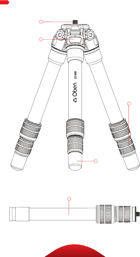
A 1/4-20 mounting screw
B 3-angle leg adjustment
C Leg adjustment twist locks
D Rubber/spiked Feet
E Extender/selfie stick
Also Included: 3/8-16 to 1/4-20 reducer bushings (×2)
Hex keys (×2)
KEY FEATURES
6
KEY FEATURES
A
B
C
F
D
H
G
E

7
KEY FEATURES
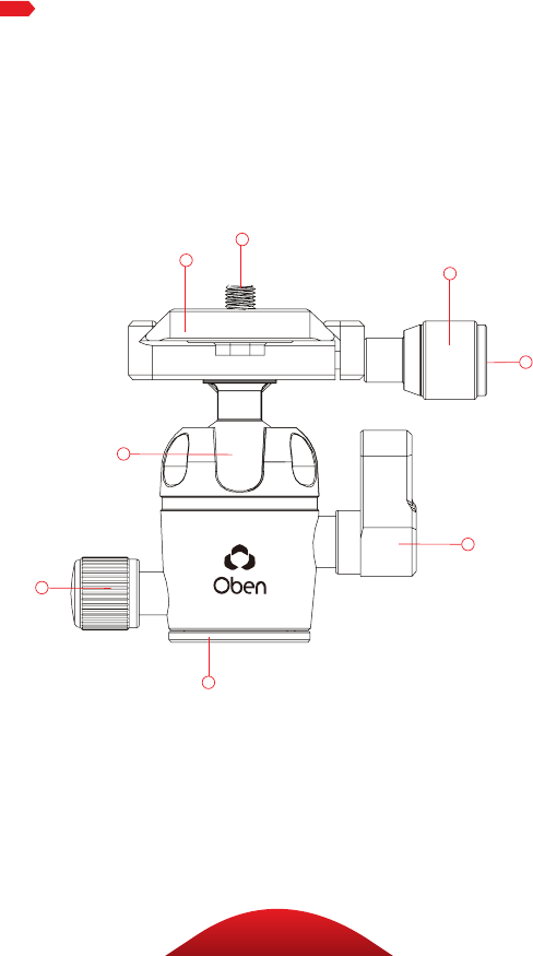
Quick-release plate
1/4-20 mounting screw
Quick-release knob
Vertical bubble level
90° notch
Locking knob
Pan knob
Panoramic base with 360° markings
A
B
F
G
H
E
D
C
8
OPERATIONOPERATION
Ballhead Operation
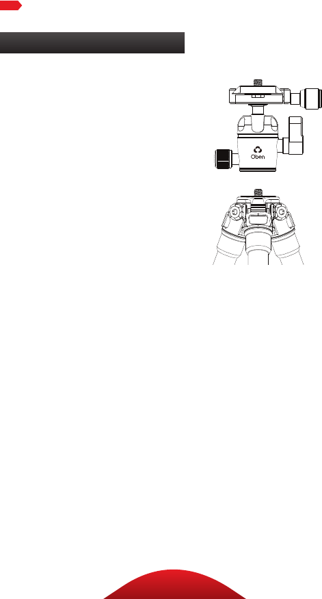
MOUNTING THE BALLHEAD
During normal operation, the
ballhead will occasionally have
to be removed. To mount it back
onto the tripod:
1. Align the ballhead socket with
the tripod mounting screw.
2. Rotate the ballhead clockwise
onto the tripod, and tighten it
by hand.
Note: To use the ballhead with a
tripod that has a 3/8-16 threaded
mounting post, remove the reducer
bushing from the ballhead’s
mounting socket.
9
OPERATIONOPERATION
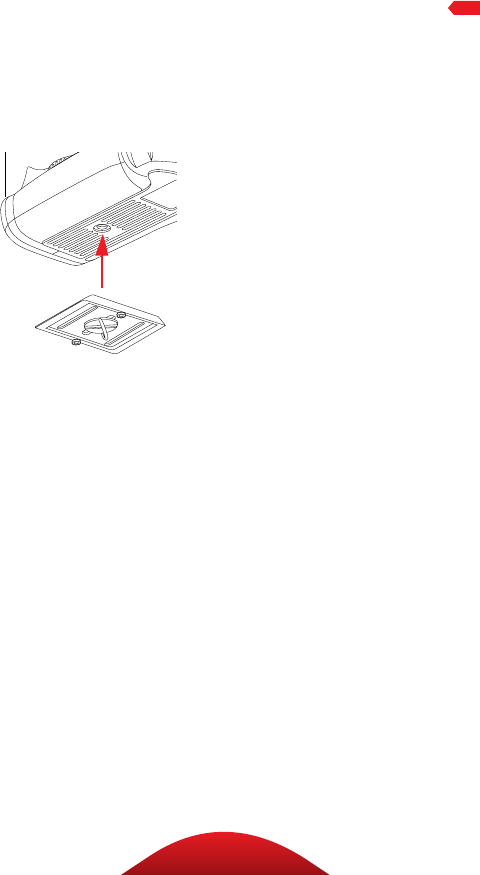
MOUNTING THE QUICK-RELEASE
PLATE TO THE CAMERA
The quick-release plate has
a 1/4-20 screw that fits most
cameras.
1. Loosen the quick-release
knob by turning it
counterclockwise, and
remove the quick-release
plate from the ballhead.
2. Screw the plate onto the
bottom of the camera.
3. Use the D-ring, a slotted
screwdriver, or a coin to
tighten the screw into the
camera’s socket.
Warning: Some manufacturers’
plates do not meet our
specifications and may not lock
your equipment securely in
the Oben quick-release clamp.
Test any camera and lens
plates made by manufacturers
other than Oben to ensure
compatibility.
10
OPERATION
Ballhead Operation (continued)
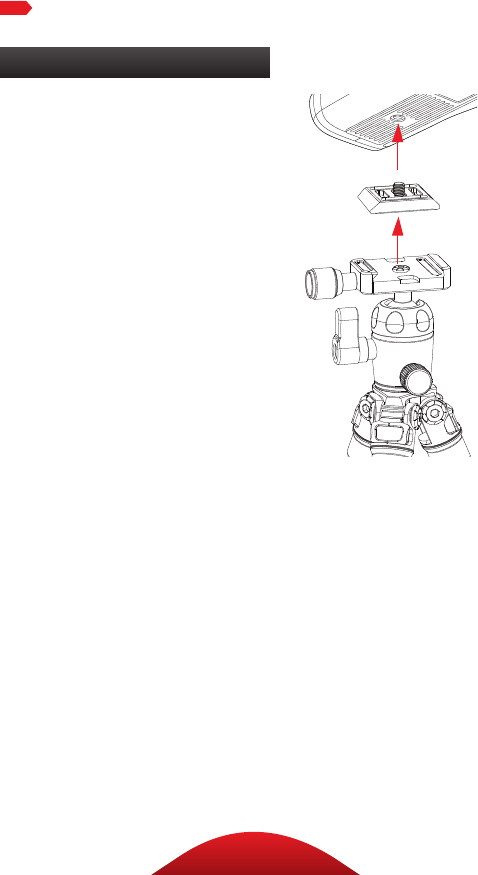
MOUNTING THE CAMERA AND QUICK-
RELEASE PLATE TO THE BALLHEAD
Make sure that all knobs on the
ballhead are tightened, except for
the quick-release knob.
1. Turn the quick-release knob
counterclockwise until it stops.
2. Mount the camera to the
ballhead by sliding one edge of
the quick-release plate into the
ballhead. Then lower the other
side until the quick-release
plate is lying flat in the quick-
release clamp.
Note: Make sure the mounting
screw’s D-ring is flush with the
bottom of the plate.
3. Turn the quick-release knob
clockwise to lock the plate.
11
OPERATION
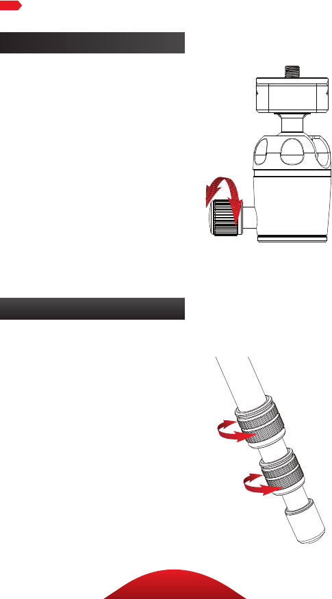
MAIN LOCKING KNOB OPERATION
The main locking knob locks
and unlocks the ballhead, which
allows for changing the position of
the camera.
Always use one hand to secure
the camera while adjusting the
ballhead, and make sure the lock
is engaged before letting go of the
camera.
Note: To adjust the tension in a tight
space, or if something is blocking
your ability to turn the knob, pull the
knob out, reposition it so it can turn
without interference, and release
it. The knob will engage and can be
loosened.
Use the 90° notch to quickly
switch between landscape and
portrait orientations.
12
Ballhead Operation (continued)
Tripod Operation
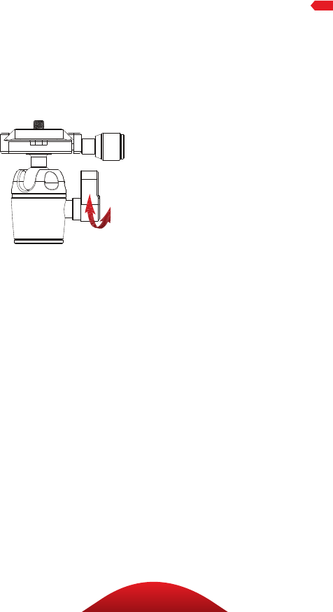
PANORAMIC BASE
The base of the ballhead can be
independently rotated 360°. Use
the degree markings on the base
of the ballhead to accurately
set up panoramic shots.
1. Twist the pan knob
counterclockwise to
unlock the base.
2. Rotate the base to the desired
position, and then lock the base
by turning the knob clockwise.
LEG LENGTH ADJUSTMENT
To independently adjust
the height of each leg,
do the following:
1. Loosen the twist locks enough
so that the legs can be adjusted.
Note: Don’t over-loosen
the twist locks.
2. Adjust the leg to the
desired height.
3. Tighten the twist locks to
secure the leg in place.
OPERATION
13
LEG ANGLE ADJUSTMENT
For stable support when
shooting on an uneven surface,
or for low-angle shots, each
leg can be adjusted to 3 preset
angles. To set the leg angle:
1. Lift the angle adjustment lock.
2. Set the angle of the leg to one
of the three preset positions.
3. Press in the release
lock to secure the leg at
the desired angle.
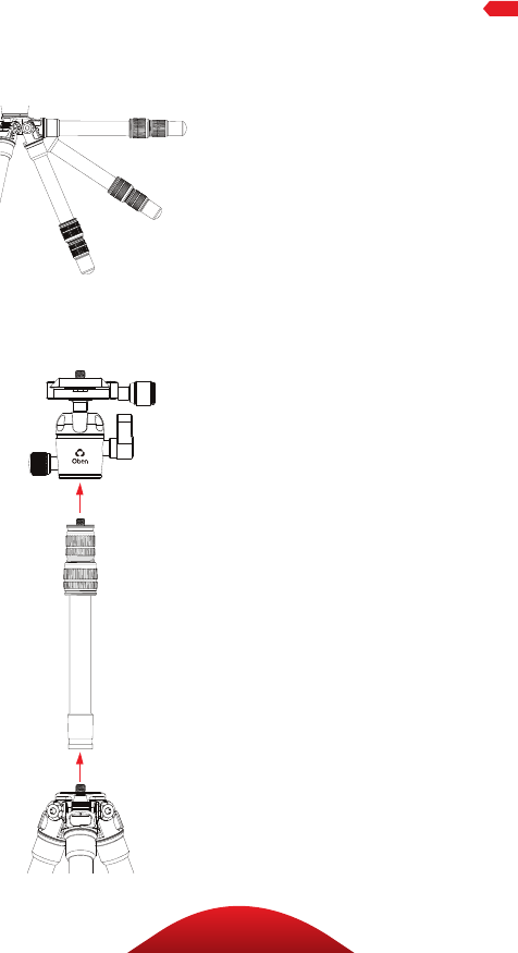
ATTACHING THE EXTENDER
The included extender provides
up to 12.25 inches of height to the
tripod. To attach the extender:
1. Unscrew the ballhead,
and attach the extender
by screwing it onto the
tripod’s mounting post.
2. Attach the ballhead to the
extender’s mounting post, or
attach a camera or other piece
of gear directly to the extender.
Note: The extender comes with
an installed 3/8-16 to 1/4-20
reducer bushing. To use it with a
tripod that has a 3/8-16 threaded
mounting post, remove the bushing
from the extender’s socket.
3. Adjust the extender height
with the two twist locks.
OPERATION
14
OPERATION
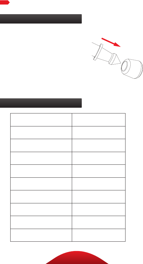
SPIKED FEET
The rubber nonskid feet are for
use indoors or on flat surfaces. The
spikes are for soft ground, grass,
sand, and uneven terrain.
To expose the spikes, remove the
rubber feet by pulling them o.
Tripod Operation (continued)
Specifications
Maximum Load 11 lb. (5 kg)
Maximum Height 15.5 in. (39.4 cm)
Minimum Height 4.2 in. (10.7 cm)
Folded Length 10.4 in. (26.4 cm)
Weight 0.98 lb. (444 g)
Leg Sections 3
Maximum Height with Extender 27.7 in. (70.4 cm)
Ballhead Dual action
Quick-Release Plate Arca compatible
Spikes Yes

15
WARNINGS
!Warnings:
• Do not exceed the tripod’s maximum
load capacity (see Specifications).
• Ensure that all appropriate locks
are engaged when necessary.
• This tripod should be used only
in temperatures between -22°F
and 140°F (-30°C and 60°C).
• Do not use this tripod in salt water.
Dry the tripod o if it becomes wet.
• Remove the camera from the
tripod during transport.
• Keep the tripod out of reach of children.
• To avoid injury, always support your
device or camera with one hand
while adjusting height and locking
the twist lock with the other hand.
• All images are for illustrative purposes only.

16
www.obensupports.com
Oben is a registered trademark of the Gradus Group.
© 2018 Gradus Group LLC. All Rights Reserved.
GG1
