Front Cover PDF Off Road Thunder (39in) [Operation] [English]
User Manual: PDF T E X T F I L E S
Open the PDF directly: View PDF ![]() .
.
Page Count: 148 [warning: Documents this large are best viewed by clicking the View PDF Link!]

DECEMBER 1999
16-20041-101
http://www.midway.com
Sit-In,
Dedicated
39” Video
Game
Operation Manual
zSetup zOperation zAudits zWiring zServicing zTroubleshooting zParts
Midway Games Inc., 3401 North California Avenue, Chicago, Illinois 60618–5899 USA
TM
-ii-
QUICK-START LINKING GUIDE
NOTICE: Before completing installation, verify that each cabinet has a separate and
unique ID. Otherwise the link won’t function. For further information, see Linked-Play
Adjustments Menu in Chapter Three of this manual.
NOTICE: To link three or four cabinets, you must use an Ethernet hub.
SET UP THE LINKS
[ ] 1. Switch off power to all cabinets. Remove cabinet access doors and linking cables. Check cabinet
linking cables. One end of each linking cable must attach to the Arcade Computer’s network
interface jack.
[ ] 2. To link two cabinets: If you’re only linking two cabinets, use one coupler. You don’t need a hub.
(You’ll find a coupler in a Manila envelope inside the cashbox.)
[ ] 3. To link three or more cabinets: You need to add a hub to your network. Place the hub near the
rear of the cabinets. Connect all linking cables. When you use a hub, don’t use any couplers.
[ ] 4. Turn on cabinet power.
ADJUST GAME OPTIONS
CAUTION: Don’t connect or disconnect cables to the game electronics or hub with the
power on. Otherwise, you may damage the electronics and void your warranty.
[ ] 1. Find the diagnostic switches behind each cabinet’s coin door. Press and hold each cabinet’s
TEST MODE button to enter the Menu System.
[ ] 2. From each cabinet’s Operator Menu, select the Adjustments Menu.
[ ] 3. From each cabinet’s Adjustments Menu, select the Linked Play Adjustments Menu.
[ ] 4. LINKED PLAY. At each cabinet, set the LINKED PLAY option to YES.
[ ] 5. UNIT ID. Each cabinet must have a unique unit ID. Set the option UNIT ID to a separate number
for each cabinet.
[ ] 6. EXIT the menu system.
[ ] 7. RESTART ALL CABINETS. After the machines reinitialize, they’ll operate in Linked Mode.
[ ] 8. TEST THE SYSTEM. Test the network by playing a Linked Mode game on all linked machines.
-iii-
-iv-
Setup 1-1
O
OO
OFFROAD
FFROADFFROAD
FFROAD
THUNDER
THUNDERTHUNDER
THUNDER
TM
CHAPTER
1
SETUP
NOTICE: This manual is subject to change without notice. Midway reserves the right to make
improvements in equipment function, design, or components as progress in engineering or
manufacturing methods warrant.
Fill out and mail in the Game Information Card. Include the game serial number from the label on
the rear of the cabinet. For your records, write the game serial number in the manual. SERIAL
NUMBER _______________________________________________________
Setup 1-2
SAFETY INSTRUCTIONS
The following safety instructions apply to operators and service personnel. Read these instructions before
preparing your game for play. Other safety instructions appear throughout this manual.
DEFINITIONS OF SAFETY TERMS
DANGER: If you fail to avoid this hazard, it will cause death or serious injury.
WARNING: If you fail to avoid this hazard, it could cause death or serious injury.
CAUTION: If you fail to avoid this hazard, it may cause minor or moderate injury. CAUTION also alerts
you about unsafe practices.
NOTICE indicates information of special importance.
WARNING: TRANSPORTING GAMES. This game contains glass and fragile
electronic devices. Use appropriate care when transporting this game. Avoid rough
handling when moving the cabinet. Don’t move this game with the power on.
WARNING: DISCONNECT POWER. Always turn power OFF and unplug the game
before servicing or adjusting. Installing or repairing PC boards with power ON can
damage components and void the warranty. Be sure to securely install ground wires.
WARNING: GROUND GAMES. Avoid electrical shocks! Don’t plug in a game until you
have inspected and properly grounded it. Only plug this game into a grounded, three-
wire outlet. Don’t use a “cheater” plug, or cut off the ground pin on the line cord.
WARNING: HAZARD TO EPILEPTICS. A small portion of the population has a
condition which may cause epileptic seizures or momentary loss of consciousness
when viewing certain kinds of flashing lights or patterns that are present in our daily
environment. These persons experience seizures while watching some television
pictures or playing certain video games. People who have not had seizures may
nonetheless have an undetected epileptic condition.
If anyone in your family has experienced symptoms linked to an epileptic condition
(e.g., seizures or loss of awareness), consult your physician before using video games.
Parents should observe their children while they play video games. If you or your child
experience the following symptoms: dizziness, altered vision, eye or muscle twitching,
involuntary movements, loss of awareness, disorientation, or convulsions, discontinue
use immediately and consult a physician.
WARNING: AVOID ELECTRICAL SHOCKS. This video game system does not utilize
an isolation transformer. Internal, cabinet AC isn’t isolated from the external, AC line.
WARNING: HANDLE FLUORESCENT TUBE AND CRT WITH CARE. If you drop a
fluorescent tube or CRT and it breaks, it will implode! Shattered glass can fly eight feet
or more from the implosion.
CAUTION: CHECK POWER SELECTOR. Set the 110/220VAC selector on the power
supply for the correct line voltage. Check the selector setting before switching on the
game.
Setup 1-3
CAUTION: USE PROPER FUSE. Avoid electrical shock! Replacement fuses must be
of the same type as those they replace. Fuse voltage and current ratings must match
ratings on the original fuse.
CAUTION: ATTACH CONNECTORS PROPERLY. Be sure that printed circuit board
(PCB) connectors mate properly. If connectors don’t slip on easily, don’t force them. A
reversed connector may damage your game and void the warranty. Connector keys
only allow a connector to fit one set of pins on a board.
CAUTION: TAKE CARE WHEN SHIPPING HARD DISKS. The hard disk drive must
be packed in an anti-static bag. When shipping the drive for repair or replacement,
pack it in an approved container (P/N 08-8068). Never stack or drop hard disk drives.
PRODUCT SPECIFICATIONS
Operating Requirements
Location
Domestic
Foreign
Japan
Electrical Power
120VAC @ 60Hz 4.0 Amps
230VAC @ 50Hz 2.0 Amps
100VAC @ 50Hz 4.0 Amps
Temperature
32°F to 100°F
(0°C to 38°C)
Humidity
Not to exceed 95% relative
Cabinet Statistics
Shipping Dimensions
Cabinet Section Control Section Shipping Dimensions
Universal Pedestal Shipping Weight
Width
Depth
Height
58” (147 cm)
36” (91 cm)
79” (201 cm)
41” (104 cm)
33” (83.8 cm)
42” (107 cm)
Width
Depth
Height
22.0” (55.8 cm)
36.0” (91.4 cm)
51.0” (130 cm)
Cabinet, 475 lbs (215 kg)
Control Section, 300 lbs (137 kg)
Universal Pedestal, 125 lbs (57 kg)
Equipment Characteristics
Video Monitor
Medium Resolution RGB
39” (99 cm) CRT
Audio System
Digital Stereo Sound
Two 5.5” (14 cm) and Two
6.5” (16.5 cm) Speakers
Currency Acceptors
1 Coin Mechanism, Coin Counter
Dollar Bill Validator Ready
Electronic Coin Acceptor Ready
Game Characteristics
Player Variables
1 to 4 players per game (with linking)
Choice of vehicle and course
High Score Recognition
Operator Variables
Coinage, Game Options,
Difficulty, Force, Volume,
Audits, Statistics
Diagnostics
Automatic Power-Up Self-Test
Manual, Multi-Level Menu System
Setup 1-4
PRODUCT CONFIGURATION
• Standalone Units
Each game is ready to play right out of the box. You can use the game menu system to set player
variables in advance. Or you can leave these choices to players.
• Linked Units
Linking allows players to compete against each other (on one course). Operator menus are the same
as in stand-alone games. Crossover couplers and linking cables to connect two games are factory
installed. You can interconnect up to four games. To do this, use the optional Hub Linking Kit.
GAME SETUP
WARNING: The cabinet is top-heavy. Don’t use the pedestal seat as a handle or lever.
When moving the game, use the two handles on the back of the cabinet.
[ ] 1. Remove and set aside items from shipping containers. You’ll find casters, levelers, and mounting
hardware packed with the pedestal. Inspect the exterior of the cabinet for any signs of damage.
[ ] 2. Remove the keys from the steering wheel. Unlock and open the coin, cash box, and rear doors.
You’ll find electrical cords and spare parts in the cash box.
Setup 1-5
[ ] 3. Unlock and remove the monitor cabinet’s rear door. Inspect the cabinet interior for damage.
Check major assemblies to assure secure mounting. Assure that nothing blocks fan airflow.
[ ] 4. Replace and lock the monitor cabinet’s rear door. Locate the casters. Notice that two of the
swivel casters have red dots on their bases. These two are special-purpose, high-compliance
casters. Tilt the dash cabinet. Install the two casters with red dots at the rear of the dash cabinet.
Each caster mounts to a group of threaded studs. Tighten caster-mounting nuts firmly.
[ ] 5. Tilt the dash cabinet. Install two swivel casters without dots at the front of the dash cabinet. Each
caster mounts to a group of threaded studs. Tighten caster-mounting nuts firmly.
[ ] 6. The pedestal uses three casters. Tilt the pedestal. Install a swivel caster on the front studs. Install
locking casters on the rear studs. Tighten caster-mounting nuts firmly.
[ ] 7. Stand the dash cabinet upright and make certain it is stable. Move the game to its intended
location. Level the cabinet. We’ve designed this game for use only in a fixed position. Assure that
final leg leveler adjustments raise the swivel casters off the floor. Distribute weight equally on
each cabinet corner. Tighten the leveler nuts.
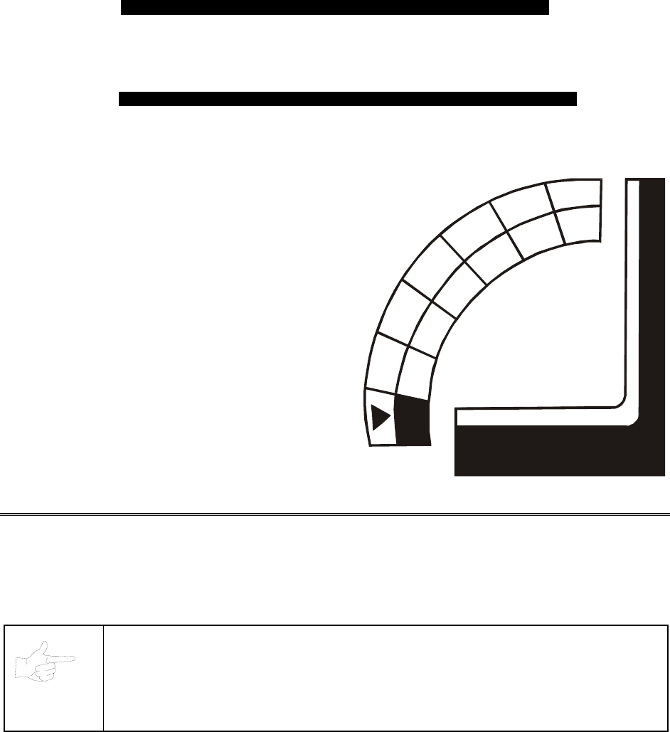
Location of Pedestal Assembly Mounting Holes
[ ] 8. To protect seat pedestal mounting rails during shipment, the factory bolts them inside the dash
cabinet. Remove the 1/4-20 hex-head bolts that secure the rails. Slide the rails partway out of the
bottom-front cabinet opening. (See the nearby diagram for proper placement.)
[ ] 9. Fasten down the rails in this new position. Firmly tighten the rail bolts, but don’t torque them
down. Slide the seat pedestal onto the rails. Vertically position the rails. Remove the seat
pedestal. Tighten the rail bolts with a wrench.

Setup 1-6
NOTICE: When you mate the cabinets, take care to avoid pinching wires!
[ ] 10. Roll the seat pedestal near the dash cabinet. Leave enough space to attach the wiring harness.
Mate each seat pedestal cable connector with its cabinet cable connector. Press connectors
firmly to seat contacts.
[ ] 11. Align the seat pedestal opening with the rail ends. Slide the seat pedestal forward onto the
extended mounting rails. Align holes. Attach the seat pedestal using 1/4-20, tamper-resistant
screws and large flat washers. You’ll find a T27 wrench with the spare parts. Use it to tighten
these screws firmly.
[ ] 12. Fasten the cabinet joining brackets to the monitor cabinet. Align the dash and monitor cabinets.
Carefully slide the dash cabinet between the cabinet joining brackets. When the cabinets are
flush, attach the cabinet joining brackets to the dash cabinet.
[ ] 13. Attach the wiring harness. Mate each dash cable connector with its monitor cabinet cable
connector. Press connectors firmly to seat contacts.
[ ] 14. You can install an extra padlock to secure the rear door. You’ll find a hasp in the spare parts bag.
Remove the two lock bracket nuts from inside the cabinet, above the rear doorway. Slide the
hasp onto the bolts. Now the hasp should protrude from the hole in the cabinet back. Reinstall
the nuts.
[ ] 15. Modify the lock plate at the top of the rear door. Remove the bolts and nuts from the lock plate.
Rotate the plate so that the slot will be above the door. Reinstall and tighten bolts and nuts.
[ ] 16. The power cord is with the spare parts. Remove and save four screws from the line cord cover at
the cabinet rear. Match the holes on the IEC plug with the prongs in the receptacle. Push the plug
firmly to seat the line cord. Hold the cord flat against the cabinet and reinstall the cover plate.
(Point the indentation downward, so that the cord exits toward the cabinet bottom.)
[ ] 17. Refer to the cabinet wiring diagram (elsewhere in this manual). Check to see that cable
connectors are correctly secured. Inspect for damaged connectors. Don’t force connectors. Most
connectors are keyed to prevent reversed connections. Before you plug the line cord into an A.C.
outlet, verify that game electronics are set to correct local A.C. line voltage.
Setup 1-7
Line Cord Installation
[ ] 18. Plug the game into a grounded (3-terminal) AC wall outlet. Switch on the game at the on/off
switch. (This switch is on the cabinet roof. Face the cabinet’s back. Find the on/off switch to your
right.) The game will power up and begin self-diagnostics. If diagnostics find no errors, the game
enters its Attract Mode of operation. (Attract Mode includes scenes and sounds from typical
races, player’s scores, messages, etc.)
[ ] 19. Unlock and open the coin door. Locate the control switches. Press TEST MODE to enter the
Menu System.
[ ] 20. Select “DISK TESTS” at the Diagnostics Menu. Run all the tests in order to verify correct drive
operation.
[ ] 21. Select “SWITCH TESTS” at the Diagnostics Menu. Check to be sure that all control switches
work.
[ ] 22. Select “SOUND TESTS” at the Diagnostics Menu. Verify operation of each speaker.
[ ] 23. Select “FORCE FEEDBACK TESTS” at the Diagnostics Menu. Verify the presence of steering
resistance.
[ ] 24. Select “CALIBRATE CONTROLS” at the Main Menu. Set steering and throttle limits for maximum
accuracy.
[ ] 25. Select “START THE GAME” at the Main Menu. The system should enter Attract Mode. Open the
coin door and press the SERVICE CREDITS button to allow game play. Press the START button
to begin play. Listen to the audio while playing the game. Note sound irregularities (phase
problems, no low frequencies, mono audio from stereo speakers, etc.). If necessary, check the
wiring harness for internal shorts or strapped connections.
[ ] 26. Change the volume and make adjustments as necessary. Close and lock all open doors. Tighten
the leveler nuts. Engage the caster locks.
Setup 1-8
LINKED OPERATION
Equipment Requirements
Linked Mode permits players to compete between networked cabinets in real time. The linking program is
player selectable, so that each cabinet serves player needs.
To achieve linked operation, you must connect cabinets. The factory installs one linking cable in each
cabinet.
Coupler
Cabinet
1
Cabinet
2
Cabinet Cabinet
34
Coupler
Link Two Cabinets with a Coupler
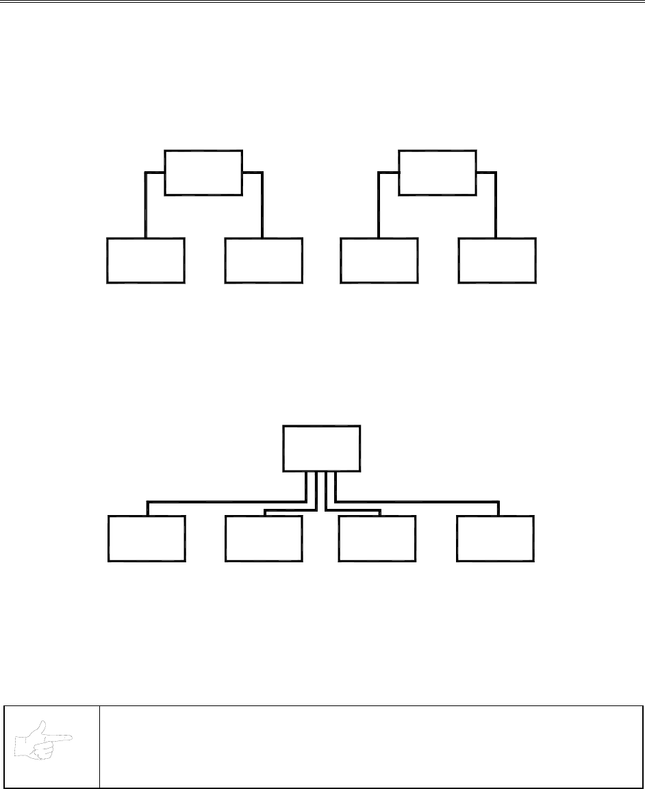
• TO LINK TWO CABINETS, use a crossover coupler. All cabinets contain a crossover coupler to
connect two cabinets together. Use only one coupler between each pair of cabinets. Passive
electronics limit the cable length and number of cabinets that you can link. Most operations attach
linked cabinets, but you can separate cabinets by up to 25 feet. You can add linked pairs as
necessary.
Game
Network
Hub
12
Game Game
3
Game
4
Link Up to Four Cabinets with a Hub
• TO LINK MORE THAN TWO CABINETS, use a network hub. The network hub’s active circuits allow
you to use more and longer cables. Notice that the hub replaces the coupler between cabinets. Each
hub can connect several cabinets. The hub’s active electronics permits use of larger networks. Most
operations attach linked cabinets, but you can separate cabinets by up to 300 feet. You can add
linked cabinets as necessary.
NOTICE: You can’t link more than four Offroad Thunder cabinets.
Setup 1-9
Networking Pointers
• Protect exposed wiring from player foot traffic, cleaning crews, service personnel, etc. Use approved
conduit or wire channels to support cables. Network modular connectors don't include strain relief.
• Keep cables away from heat, moisture and electromagnetic fields. (Avoid neon signs, fluorescent
fixtures, two-way radios, cordless telephones, power circuits, speaker wiring, etc.).
• Universal RJ-45 modular plugs aren't numbered or coded. Clearly mark cabinet network connections.
Otherwise, someone could confuse them with computer or telephone circuits.
• The factory supplies network cables with the cabinets. These cables will reach the hub in networks of
four or fewer cabinets.
• Use only Category 5, twisted pair cable.
• If you want to monitor network activity, you can locate the hub remotely. You can use long cables, if
they satisfy these requirements: (1) Cables must not exceed a length of 328 feet or 100 meters. (2)
Cables must be Category 3 (or higher), 100 ohm, unshielded, twisted pair, communications-grade
wiring. (3) You must not use standard telephone cables.
Network Wiring Setup
NOTICE: Don't use crossover couplers in a hub installation. Otherwise, your network
won’t operate properly.
[ ] 1. Raise the leg levelers. Roll the cabinets to their destination. Lower the leg levelers.
[ ] 2. Verify game operation. Make necessary repairs or adjustments before making changes to the
cabinets.
[ ] 3. Shut down all machines.
[ ] 4. Place the hub near the center of the linked cabinet array.
[ ] 5. You’ll find a linking cable coiled up inside each cabinet. Cut the cable tie. Locate the cable’s free
end. Uncoil enough cable to reach the hub through the rear box of the cabinet.
[ ] 6. Check the other end of the cable. It should attach to an Arcade Computer network jack. You’ll
find this jack in the middle cabinet box.
[ ] 7. Recoil and retie the remainder of the cable. Repeat the cable connection steps at the other
cabinets.
[ ] 8. Plug the cabinet linking cables into any of the jacks on the hub rear panel.
[ ] 9. Plug the hub’s AC power adapter into its jack on the hub.
[ ] 10. Set the hub front panel switches to the LNK (link) position.
[ ] 11. Retract excess cable into the cabinet coils so that the cables don't touch the floor. Retracting the
cable keeps it away from cabinet wheels during relocation.
[ ] 12. Connect the AC Adapter and line cords to AC power. Turn on each of the cabinets. Examine the
screens of all cabinets.
CAUTION: Don’t connect or disconnect cables to the game electronics or hub with the
power on. Otherwise, you may damage the electronics and void your warranty.
[ ] 13. Restart all machines.
Setup 1-10
[ ] 14. The cabinets will begin the Power-On Self Test. If the test doesn’t find any errors, each cabinet
enters its Attract Mode automatically.
[ ] 15. Start up linked cabinets and ensure that each cabinet's player controls affect the same vehicle on
all screens. The CPU and hub LEDS will indicate communication activity between the two
cabinets.
[ ] 16. Close and lock the coin doors. Reinstall and lock the rear cabinet doors. Lower all leg levelers
until wheels lift off of the floor. Then level the cabinets.
Software Setup
[ ] 1. Unlock the coin doors of all cabinets.
[ ] 2. Find the diagnostic switches behind each cabinet’s coin door. Press and hold each cabinet’s
TEST MODE button to enter the Menu System.
[ ] 3. From each cabinet’s Operator Menu, select the Adjustments Menu.
[ ] 4. From each cabinet’s Adjustments Menu, select the Linked Play Adjustments Menu.
[ ] 5. LINKED PLAY. At each cabinet, set the LINKED PLAY option to YES.
[ ] 6. UNIT ID. Each cabinet must have a unique unit ID. Set the option UNIT ID to a separate number
for each cabinet.
[ ] 7. EXIT the menu system.
[ ] 8. RESTART ALL CABINETS. After the machines reinitialize, they’ll operate in Linked Mode.
[ ] 9. TEST THE SYSTEM. Test the network by playing a Linked Mode game on all linked machines.
Operation 2-1
O
OO
OFFROAD
FFROADFFROAD
FFROAD
THUNDER
THUNDERTHUNDER
THUNDER
TM
CHAPTER
2
OPERATION
NOTICE: The term VGM refers to the video game machine.
Operation 2-2
GAME OPERATION
STARTING UP
Whenever you turn on the machine or restore power, the system executes boot ROM code. The boot
ROM contains self-diagnostic tests. These tests automatically verify and report the condition of the CPU
and other hardware. If the hardware fails a test, the system displays an error message.
Having passed power-up tests, the system enters Attract Mode. Attract Mode consists of typical game
scenes and sounds, alternating with high scores. Attract Mode continues until game play commences.
Players insert currency or tokens to start the game. Each player selects a truck and a course. Play begins
after a countdown period. The game will progress until players quit or exhaust their playtime. At Game-
Over Mode, players may choose to begin again. If players choose not to continue, then the system
returns to Attract Mode.
ARCADE COMPUTER
This game uses an Arcade Computer to control its functions. The Arcade Computer is a customized
personal computer. Housing the Arcade Computer is a PC-like case. Inside, you’ll recognize the
motherboard, plug-in cards, modular power supply, disk drives, etc. Despite these familiar features,
Midway optimized this computer specifically for this game. The Arcade Computer design permits
improved upgradability and service access without sacrificing ruggedness or reliability.
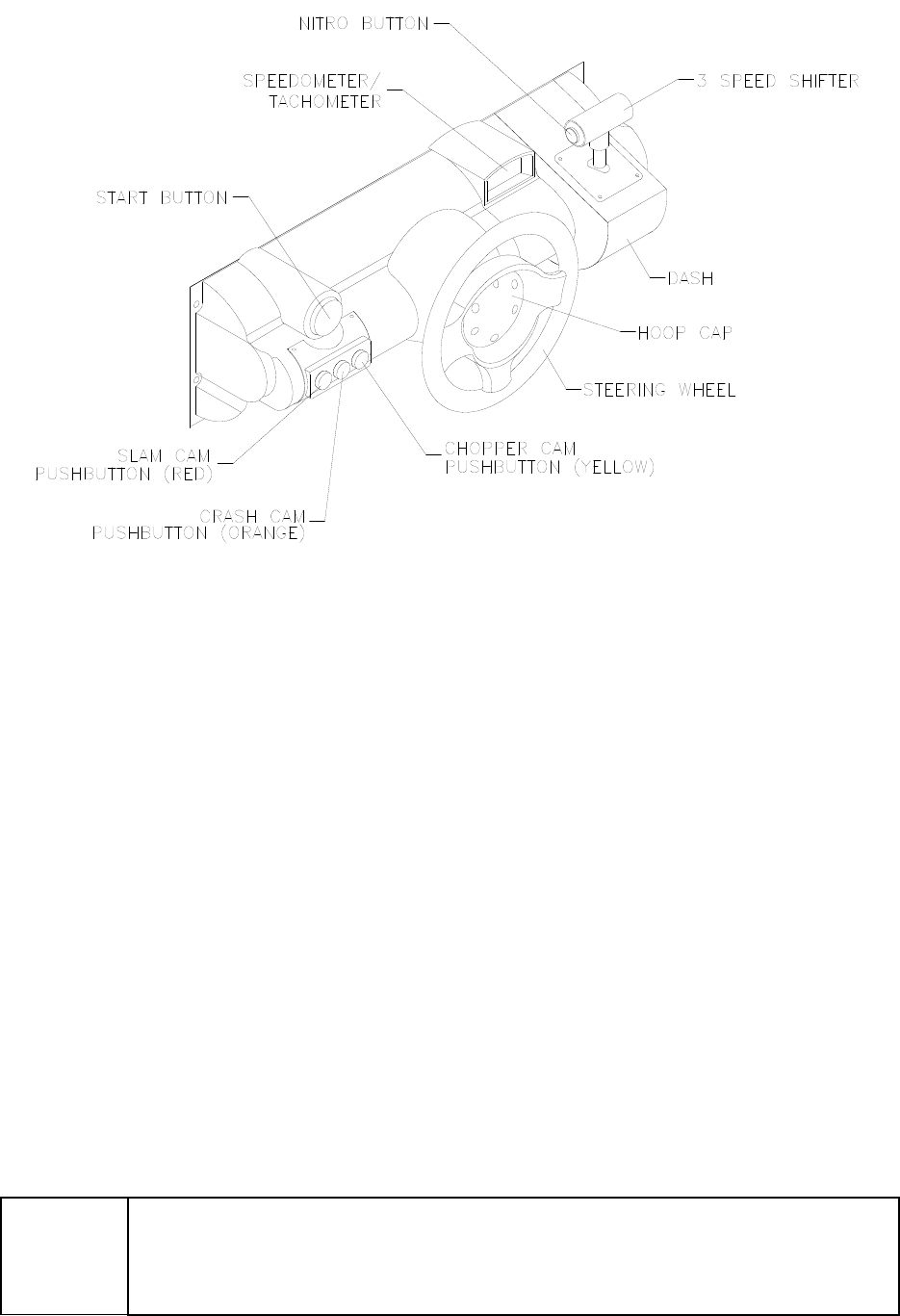
PLAYER CONTROLS
• ACCELERATOR. The accelerator pedal controls vehicle speed and acceleration.
• BRAKE. The brake pedal stops the vehicle, just like a real brake.
• GEARSHIFT. The gearshift lever controls the amount of engine torque that reaches the wheels. The
player may choose manual or automatic shift operation. Manual shift operation requires the player to
upshift while accelerating and downshift while decelerating. (This shift has no reverse gear.) Players
select automatic or manual shift trucks before racing. Manual shift trucks allow skilled drivers more
control and faster starts.
• NITRO BUTTON. The NITRO button is on the end of the shift lever. If the nitro feature is active,
pressing NITRO adds a power burst. (The button illuminates when nitro is available.)
• START BUTTON. The START button allows a player to begin or continue play, select courses and
trucks, etc.
• STEERING WHEEL. The steering wheel aims the vehicle and provides course condition feedback.
• SLAM CAM. The red SLAM CAM button displays the cockpit view. The viewpoint is from the driver’s
seat inside the truck.
• CRASH CAM. The orange CRASH CAM button provides a close-up, aerial view of the course. The
viewpoint is from above and behind the truck. A truck camera would see this view.
• CHOPPER CAM. The yellow CHOPPER CAM button provides a distant aerial view of the course.
The viewpoint is from above and behind the truck. A tracking helichopper camera would see this
view.
Operation 2-3
Player Panel Controls
OPERATOR CONTROLS
CABINET CONTROLS
• DIP Switches on the MagicBus Board set some system variables. These DIP switches are for
factory use only. Keep them set at their default value, all off. You can adjust game variables, check
bookkeeping totals and perform diagnostics with diagnostic control switches.
• The Monitor Remote Control Board allows you to adjust the video display for optimum viewing.
• The Cabinet POWER Switch turns off the game, but does not reset game variables.
• The Computer POWER Switch turns off the computer. It is on the Arcade Computer. During service
procedures, leave this switch ON. Use the main cabinet power switch to control the power.
DIAGNOSTIC CONTROL SWITCHES
• The SERVICE CREDITS Button allots credits without changing the game's bookkeeping total. The
Menu System occasionally assigns a function to SERVICE CREDITS. Check screen directions for
these additional functions.
• The TEST MODE Button causes the game to enter the menu system. To access the Menu System,
press and hold TEST MODE until the Main Menu appears. Within the menu system, check screen
directions for additional TEST MODE functions.
• VOLUME DOWN and VOLUME UP Buttons set game sound levels. To make minor volume
changes, press either button briefly. To make major changes, press and hold a button. In the menu
system, VOLUME UP moves the item highlight bar up the menu. VOLUME DOWN moves the item
highlight bar downward.
NOTICE: The Attract Mode volume level is separate from the Game Mode volume
level. For greater profits, raise volume levels to add realism and draw attention to this
game.

Operation 2-4
Operator Control Switch Locations
GAME FEATURES
GAME RULES
INSTRUCTIONS
Play instructions appear on the left and right sides of the video monitor.
ONE PLAYER
The player inserts currency or tokens to start the game. Next, the player chooses a truck and course and
presses the START button. The game displays individual statistics periodically, during and after the race.
Additional game information appears on screen as needed.
PLAYER CHOICES
The player can drive any truck on any course. Each truck handles and performs differently. Players learn
which trucks are best for a given course and driving style. Press one of the CAM buttons to select more
trucks.
CONTROLLING A TRUCK
The steering wheel, brake and accelerator control the truck. As in real trucks, the steering wheel directs
the truck. The brake slows or stops the truck, and the accelerator sets speed. A NITRO button on the
gearshift provides an extra burst of power. NITRO flashes to indicate nitro availability. Players must
collect nitro icons along a course by steering directly under the icons. A gauge meters the amount of
stored nitro.
INDICATORS
Across the top of the screen, numeric indicators display truck statistics: A ghost image in the upper-left
screen corner indicates shift type, manual or automatic. A meter in the top-left screen corner displays
engine RPM. A top-right gauge measures remaining nitro fuel. At the screen’s top-center, a digital clock
times the current lap in seconds. As appropriate, the screen also flashes CHECKPOINT.

Operation 2-5
DISPLAYS
The player’s vehicle appears at the center of the screen. The numbers floating above some vehicles
indicate that other humans control them. (These are linked players.) The Arcade Computer controls
trucks without numbers. At the bottom of the screen, another instrument displays relative positions of
nearby trucks. The right side of the screen provides race statistics…
• Position per number of trucks (for example, “11th / 12”)
• The number of cars ahead of the player (“9 cars ahead”)
• A lap timer for each lap (“0:2:00”)
GAME ACTION
Action begins after the “three-two-one” countdown. The announcer hollers “Go!” To continue play, the
player must drive past each checkpoint within the time limit. To decrease time between checkpoints,
players must avoid fixed obstacles and other trucks. Ramps allow players to advance more quickly,
collect hovering nitro icons, or avoid obstacles. (Red nitro icons contain more fuel than blue nitro icons.)
Players can change their view of the action by pressing the view buttons. These buttons are on the left
side of the control panel. Game sounds include announcer comments, engine noise, and other effects.
SCORING
Players who set a speed record may enter their initials in the High Score Table. After a player completes
a certain number of courses, he can choose additional courses. (Adjustments determine the number.)
HEAD-TO-HEAD RACING
Networked cabinets offer players linked, head-to-head racing competition. Each player begins the course-
selection process. A join-in message alerts subsequent players to the possibility of a linked race. If
players don't begin their selection process before this message disappears, their races don't link.
(Unlinked players compete in independent races, as usual.) Players may use the solo feature to decline a
link.
If other players begin selection during the join-in message, the cabinets communicate over the network.
Each additional cabinet sends out its own packet containing a unique unit ID. In return, each cabinet
receives data from active cabinets. A "waiting" message indicates that other players are still selecting
race options. Eventually, the last player finishes selecting or the waiting period ends. At this point, all
linked players see the start screen simultaneously.
Latecomers can't participate in an ongoing linked race. They can begin an independent race. The link
automatically terminates when the game is over. Players can then set up another link.
MAINTENANCE
• Cabinet and Seat
Use plastic-safe, non-abrasive cleaners to avoid damage. Apply cleaner to a clean cloth or sponge.
Use this to wipe the seat or cabinet. Don’t apply cleaner directly to the artwork or cabinet!
• Player Controls
Use plastic-safe non-abrasive cleaners to avoid damage. Apply cleaner to a clean cloth or sponge.
Use this to wipe the player controls. Don’t apply the cleaner directly to the controls!
• Viewing Glass
To clean the glass, you don’t need to switch off power to the game. Apply a mild glass cleaner to a
clean cloth or sponge. Use this to wipe the viewing glass. Don’t apply the cleaner directly to the glass!
Liquid could drip down into switch or motor circuits and cause erratic game operation.

Operation 2-6
NOTES
Diagnostic, Audit & Adjustment Menu System 3-1
O
OO
OFFROAD
FFROADFFROAD
FFROAD
THUNDER
THUNDERTHUNDER
THUNDER
TM
CHAPTER
3
DIAGNOSTIC, AUDIT &
ADJUSTMENT MENU SYSTEM
NOTICE: Information in this manual is subject to change without notice. Midway reserves the
right to make improvements in equipment function as progress warrants.
Diagnostic, Audit & Adjustment Menu System 3-2
MENU SYSTEM
WHAT IS THE MENU SYSTEM?
The game’s Menu System is a series of auditing, game adjustment and diagnostic screens. You can
easily access and apply these screens to optimize game performance. For instance…
• Use game audits screens to assess game performance.
• Use adjustment screens to help you to customize game performance. For instance, you can restore
factory default game settings. You can also calibrate player controls for accuracy.
• Use diagnostic screens to verify proper equipment operation.
ACTIVATING THE MENU SYSTEM
Open the coin door. Find the TEST MODE switch inside. Press TEST MODE to invoke the Menu System.
The game system responds by exiting Game Mode and entering Diagnostic Mode. The system runs a
brief self-test, and then displays the Operator Menu. The Operator Menu is the opening screen of the
Menu System.
Game audits, adjustments and diagnostics are line items on the Operator Menu. Selecting an item opens
its submenu. Every submenu presents various options that you may act upon.
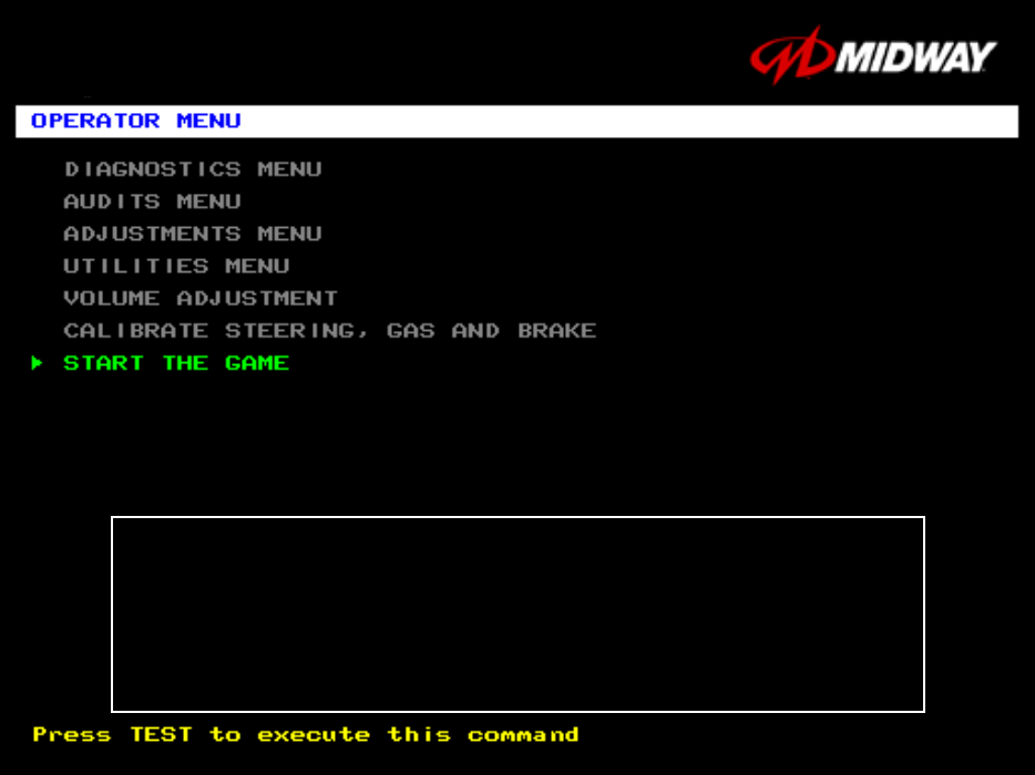
OPERATOR MENU
OFF ROAD THUNDER
1999 Midway Home Entertainment Inc.
All rights reserved.
OFF ROAD THUNDER is a trademark of Midway Home Entertainment Inc.
MIDWAY is a trademark of Midway Games Inc.
Diagnostic, Audit & Adjustment Menu System 3-3
MENU LAYOUT
Menus differ, but related information tends to occupy the same screen locations.
• The block at the top, center of each screen displays the current menu title.
• Data (menu items, video signals, statistics, reports, etc.) appears in the center of the screen.
• Game-operation information appears at the top-center of the screen, between logos.
• Messages (explanations, control functions, revision levels) display at the bottom of the screen.
MENU NAVIGATION CONTROLS
Highlight a menu line item with the middle two diagnostic buttons inside the coin door. (Press VOLUME
UP or VOLUME DOWN.) Select the option with the TEST MODE button. You can only select one
highlighted item at a time. To return the game to play, first highlight START THE GAME. Then press
TEST MODE. (This is the only menu that allows you to exit the Menu System.)
EQUIVALENT MENU NAVIGATION CONTROLS
In most cases, certain player panel buttons duplicate the functions of the diagnostic buttons. You may
find menu navigation easier with the player panel buttons. Here are the player panel functions within the
Menu System…
Player Panel Button Function Equivalent Diagnostic Switch
NITRO Select a menu item (None)
CHOPPER CAM •Select a menu item
•Enter Change Mode
TEST MODE
CRASH CAM Move down the menu VOLUME DOWN
SLAM CAM Move up the menu VOLUME UP
START Various functions, including….
•To bottom of Operator Menu
•Back to Operator Menu
•Cancel
SERVICE CREDITS (for some functions)
Diagnostic, Audit & Adjustment Menu System 3-4
Operator Menu (continued)
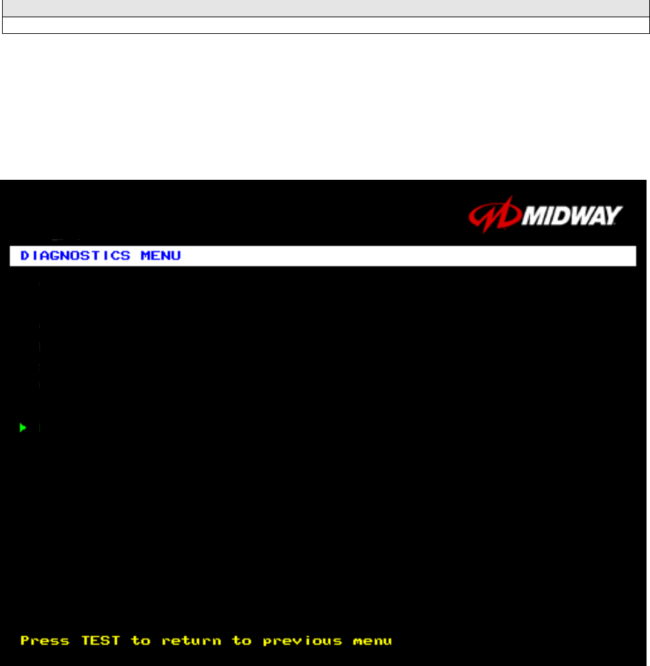
Diagnostics Menu
DIAGNOSTICS
Select DIAGNOSTICS MENU at the Operator Menu. The Diagnostics Menu helps you to verify the
electrical and electronic condition of the game.
Highlight a line item with the middle two diagnostic buttons inside the coin door. Select the option with the
TEST MODE button.
DIAGNOSTICS MENU
SWITCH TEST
LAMP TEST
MONITOR PATTERNS MENU
SOUND TEST
RETURN TO PREVIOUS MENU
Diagnostic, Audit & Adjustment Menu System 3-5
Operator Menu (continued)
Diagnostics Menu (continued)
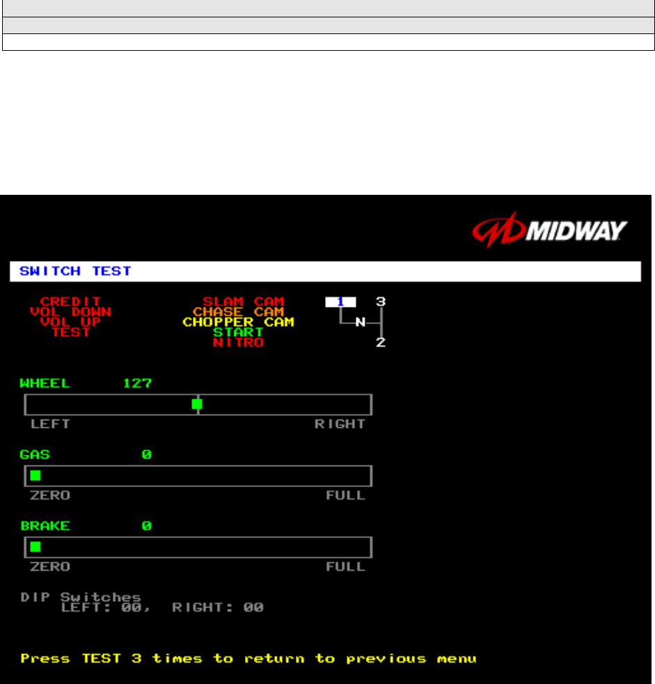
Switch Test Menu
SWITCH TEST
Select SWITCH TEST at the Diagnostics Menu. Use the Switch Test to verify crossed wires, intermittent
conditions, and stuck switches.
Operate the switch and watch the screen display. After completing tests, press TEST MODE three times
to return to the Diagnostics Menu.
SWITCH TEST SCREEN
BUTTON TESTS check player and Diagnostic switches, such as CREDIT, TEST and SLAM CAM.
Activate each button, and the screen indicator changes state. (Gray means off and green means on.)
Release the button and the indicator returns to its previous state. A single indication on the screen should
exactly duplicate each button change.
THE WHEEL TEST indicates the steering wheel position with a moving bar on a graph. The screen also
displays a wheel position number. This number varies between zero (full left) and 255 (full right).
THE GAS TEST indicates the gas pedal position with a moving bar on a graph. The screen also displays
a pedal position number. This number varies between zero (full back) and 255 (full forward).
THE BRAKE TEST indicates the brake pedal position with a moving bar on a graph. The screen also
displays a pedal position number. This number varies between zero (full back) and 255 (full forward).
Diagnostic, Audit & Adjustment Menu System 3-6
Operator Menu (continued)
Diagnostics Menu (continued)
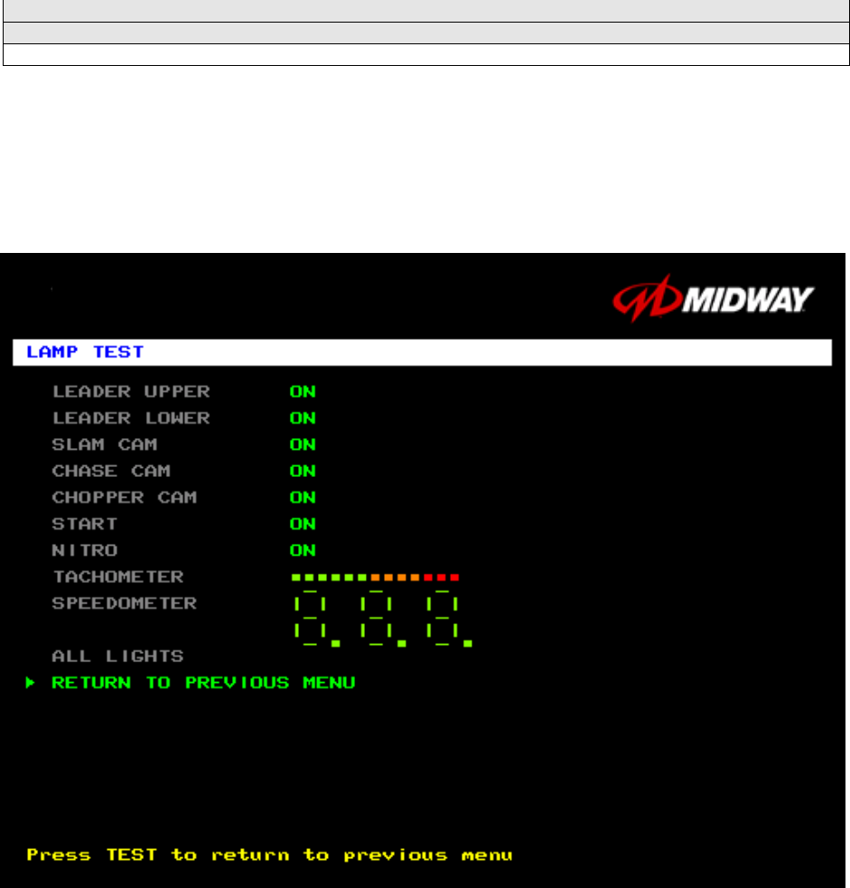
Lamp Test Menu
LAMP TEST
Select LAMP TEST at the Diagnostics Menu. The Lamp Test allows you to check operation of game
lamps. Use the test to check for burned-out bulbs, faulty lamp wiring, etc.
Highlight a test with the middle two diagnostic buttons inside the coin door. Select the option with the
TEST MODE button. Pressing TEST MODE also lights the selected lamp.
LAMP TEST SCREEN
Lamp tests indicate the condition of game lamps. These include lamps in the control panel and overhead
linking sign or optional header. (Unless your cabinet has header lights, the Leader Upper and Leader
Lower tests have no effect.)
For most tests, select a lamp name from the menu. Press TEST MODE (or CHOPPER CAM) to turn on
the selected lamp. Press TEST MODE again to toggle the lamp off. The Tachometer and Speedometer
tests operate slightly differently. These tests lights one LED for each press of TEST MODE. Press
START, SLAM CAM or CRASH CAM to exit. Select ALL LIGHTS to switch on all controlled lamps
simultaneously.
After completing tests, select RETURN TO PREVIOUS MENU. This action closes the Lamp Test Menu
and reopens the Diagnostics Menu.
Diagnostic, Audit & Adjustment Menu System 3-7
Operator Menu (continued)
Diagnostics Menu (continued)
Monitor Patterns Menu
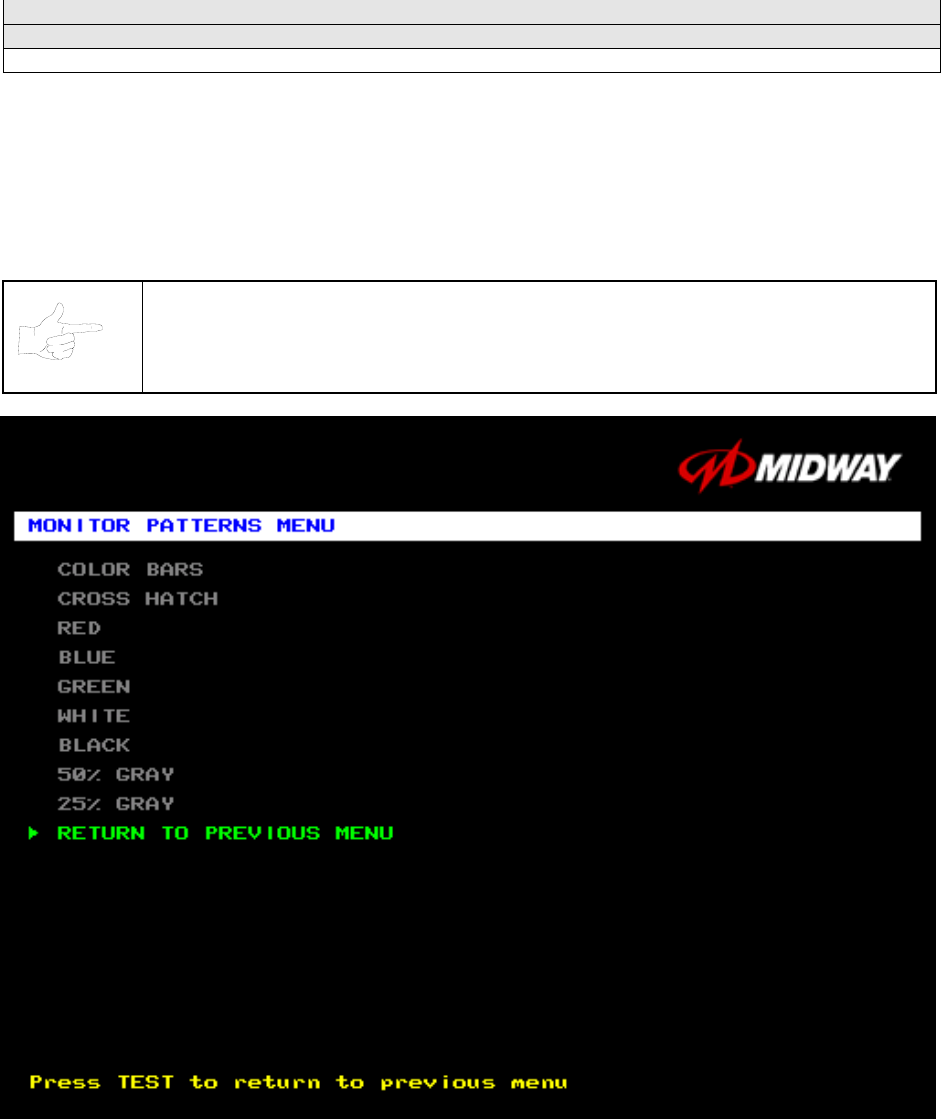
MONITOR PATTERNS TEST
Select MONITOR PATTERNS at the Diagnostics Menu. The Monitor Patterns routine provides test
screens to verify monitor performance or make adjustments.
Highlight a test with the middle two diagnostic buttons inside the coin door. Select the option with the
TEST MODE button.
NOTICE: Use an industrial-grade degaussing coil before attempting monitor
adjustments.
MONITOR PATTERNS MENU
Color Bars paint colored stripes on the screen. Use the color bars to help you to check or adjust monitor
brightness and contrast. The color bars also expose defects in horizontal linearity. Each color bar
consists of 16 intensity levels. On a properly adjusted monitor, the top 15 of these levels are visible. Each
bar should appear sharp, clear, and distinct from bars on either side. Incorrect adjustment can cause
missing detail at the top or bottom of a bar. Bent bars indicate horizontal linearity flaws, such as pie crust,
Diagnostic, Audit & Adjustment Menu System 3-8
pincushion or barrel distortion. (Correct color bar colors, left to right: Green, Red, Blue, Black, White,
Yellow, Magenta, Cyan.)
Set controls as follows: 1. Adjust BRIGHTNESS and CONTRAST to minimum. 2. Turn up BRIGHTNESS
until the pixels in the black stripe begin to glow (turn dark gray). 3. Bring up the CONTRAST control until
you can see 15 bars. Then increase the contrast until you can’t distinguish a difference between the top
two bars.
Crosshatch Patterns consist of an on-screen grid and a series of dots. Crosshatch Patterns help you to
check or adjust several monitor parameters: These parameters include convergence, linearity, active
viewing area and dynamic focus. The grid and the dots should be all white in color, with no fringes or
parallel images. The lines should be straight and the dots round. For more detail on these adjustments,
consult service literature from the monitor manufacturer.
Color Screen tests fill the screen with 100% of the chosen color at normal intensity. The Color Screen
tests help you to check or adjust monitor intensity, black level, blanking and color purity. Each screen
should be absolutely uniform from top to bottom and side to side. No retrace lines or noise should be
visible. Color Screens may not hold their uniformity if the monitor degaussing circuit is defective.
If tests indicate a need for adjustment, use controls on the Monitor Remote Adjustment Board. You can
make other adjustments from the back of the monitor.
White, Gray, and Black Screens fill the screen with black, gray or white at various intensities. These
monochrome screens help you to check or adjust monitor convergence, purity, contrast and intensity.
These screens also simplify black level and color gun control settings. The screens should be uniform
with no color tints or distortion. No retrace lines or noise should be visible.
If tests indicate a need for adjustment, use controls on the Monitor Remote Adjustment Board.
Diagnostic, Audit & Adjustment Menu System 3-9
Operator Menu (continued)
Diagnostics Menu (continued)
Sound Test Menu
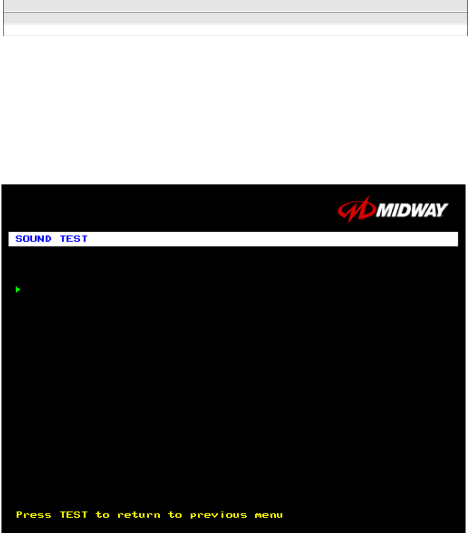
SOUND TEST
Select SOUND TEST at the Diagnostics Menu. The Sound Test verifies the operation of the sound
hardware and speakers. Use the Sound Test to find crossed connections, incorrect phase, rattles,
vibration, distortion, etc. The Sound Test screen reports information, but doesn’t permit changes.
Increase the master volume level before beginning this test.
Highlight a test with the middle two diagnostic buttons inside the coin door. Select the option with the
TEST MODE button. Selecting also activates a sound tone. The tone continues to play until you once
again press TEST MODE.
SOUND TEST SCREEN
After choosing a speaker name, listen to the audio tone from that speaker. Only the specified speaker
should produce sound. The other speakers should remain silent.
To exit the Sound Test Menu, highlight RETURN TO PREVIOUS MENU. Then press TEST MODE.
BEEP FRONT SPEAKER
BEEP RIGHT SPEAKER
RETURN TO PREVIOUS MENU
Diagnostic, Audit & Adjustment Menu System 3-10
Operator Menu (continued)
Audits Menu
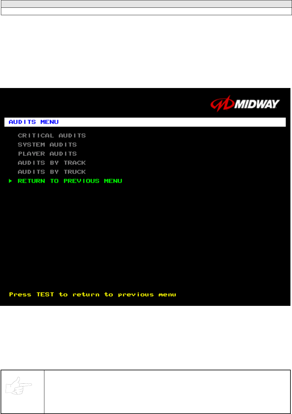
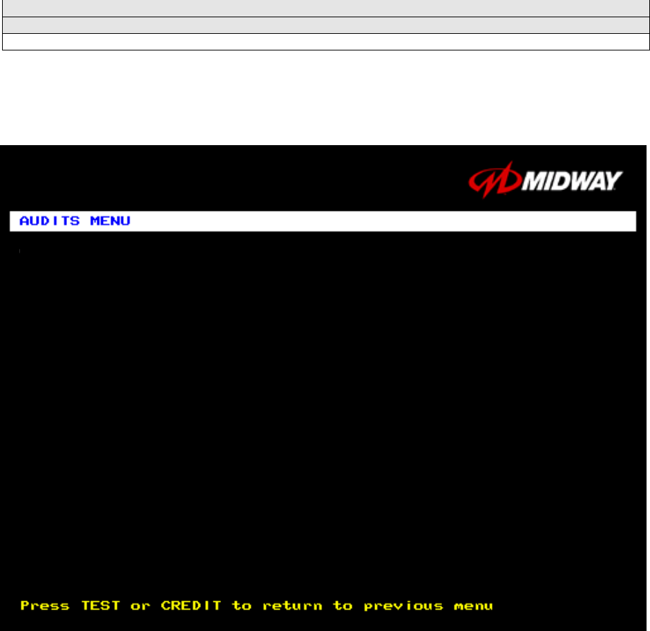
AUDITS MENU
Select AUDITS MENU at the Operator Menu. The Audits Menu permits you to review game play
statistics. Additional menus provide detailed reports for each player position on game starts, ends,
cabinet abuse, fault conditions, etc.
Highlight a line item with the middle two diagnostic buttons inside the coin door. Select the option with the
TEST MODE button.
GAME AUDITS MENU
Use the auditing information to help you to keep records of the game’s popularity and earnings. You may
also analyze favorite tracks, most frequently used vehicles, and other statistics. These screens report
information, but don’t permit changes.
Examine and record all game audit values before doing service or making repairs on this game.
NOTICE:
Take care when clearing audit information. You can’t restore cleared data. If your audit
data is important to you, back it up before proceeding. Use the OPTION SAVE
AUDITS TO FLOPPY DISK on the Utilities Menu. To clear audits, use the Utilities
Menu.
Diagnostic, Audit & Adjustment Menu System 3-11
Operator Menu (continued)
Audits Menu (continued)
Critical Audits Menu
CRITICAL AUDITS
Select CRITICAL AUDITS at the Audits Menu. The Critical Audits Menu reports general information about
coin counts and game use. This menu reports information, but doesn’t permit changes.
CRITICAL AUDITS MENU
CREDITS and PARTIAL CREDITS permit you to assess currency collection. The other items present
information on game operation.
BONUS CREDITS. A running total of bonus credits that the video game awarded to players.
GAME IN PROGRESS DURING LAST SHUTDOWN. Was the machine in Game-Play Mode when it
entered Diagnostic Mode? This function answers the question.
TIME SINCE LAST POWER-ON. This function measures the period between power-ups. The clock
starts counting whenever you switch off the video game machine.
CRITICAL AUDITS
CREDITS 0
PARTIAL CREDITS 0
BONUS CREDITS 0
GAME IN PROGRESS DURING LAST SHUTDOWN: NO
TIME SINCE LAST POWER-ON: 2 DAYS, 20:36:35
Diagnostic, Audit & Adjustment Menu System 3-12
Operator Menu (continued)
Audits Menu (continued)
System Audits
SYSTEM AUDITS
Select SYSTEM AUDITS at the Audits Menu. The System Audits Menu reports general information about
coin counts and game use. Coin Audits is a read-only screen.
To exit, press TEST MODE.
SYSTEM AUDITS MENU
The System Audits Menu reports total quantities of coins, bills or credits collected by each active device.
The menu does not calculate the value of the collected currency.
This menu reports information, but does not permit you to make changes. To reset the coin, bill, and
credit counters to zero, use the Clear Audits menu.
We recommend that you examine and record audit information before you make changes. Once you’ve
cleared the counters, you can’t retrieve the previous data from the system.
THE COIN COUNT AND BILL COUNT items help you to assess currency collection. The other items
present information on game operation.
RESET, LINK, AND SYNC statistics are measures of the game software’s ability to recover from
conditions that adversely affect game play.
SYSTEM AUDITS
POWER ON TIME 0:00:00
RACE TIME 0:00:00
LINKED RACE TIME 0:00:00
POWER ON TIME SINCE LAST RESET 0:00:00
RACE TIME SINCE LAST RESET 0:00:00
NUMBER OF RESETS 0
NUMBER OF WATCHDOG RESETS 0
NUMBER OF GAMES SINCE WATCHDOG RESET 0
NUMBER OF GAMES SINCE PREVIOUS WATCHDOG RESET 0
NUMBER OF DEMOS SINCE LAST GAME 0
NUMBER OF LOST PLAYERS DURING A RACE 0
NUMBER OF LOST LINKS DURING A RACE 0
NUMBER OF RE-LINKS 0
NUMBER FOR OUT OF SYNC GAMES 0
LEFT COIN COUNT 0
RIGHT COIN COUNT 0
FOURTH COIN COUNT 0
BILL COUNT 0
SERVICE CREDITS 0
FREE CREDITS 0
Diagnostic, Audit & Adjustment Menu System 3-13
Operator Menu (continued)
Audits Menu (continued)
Player Audits Menu
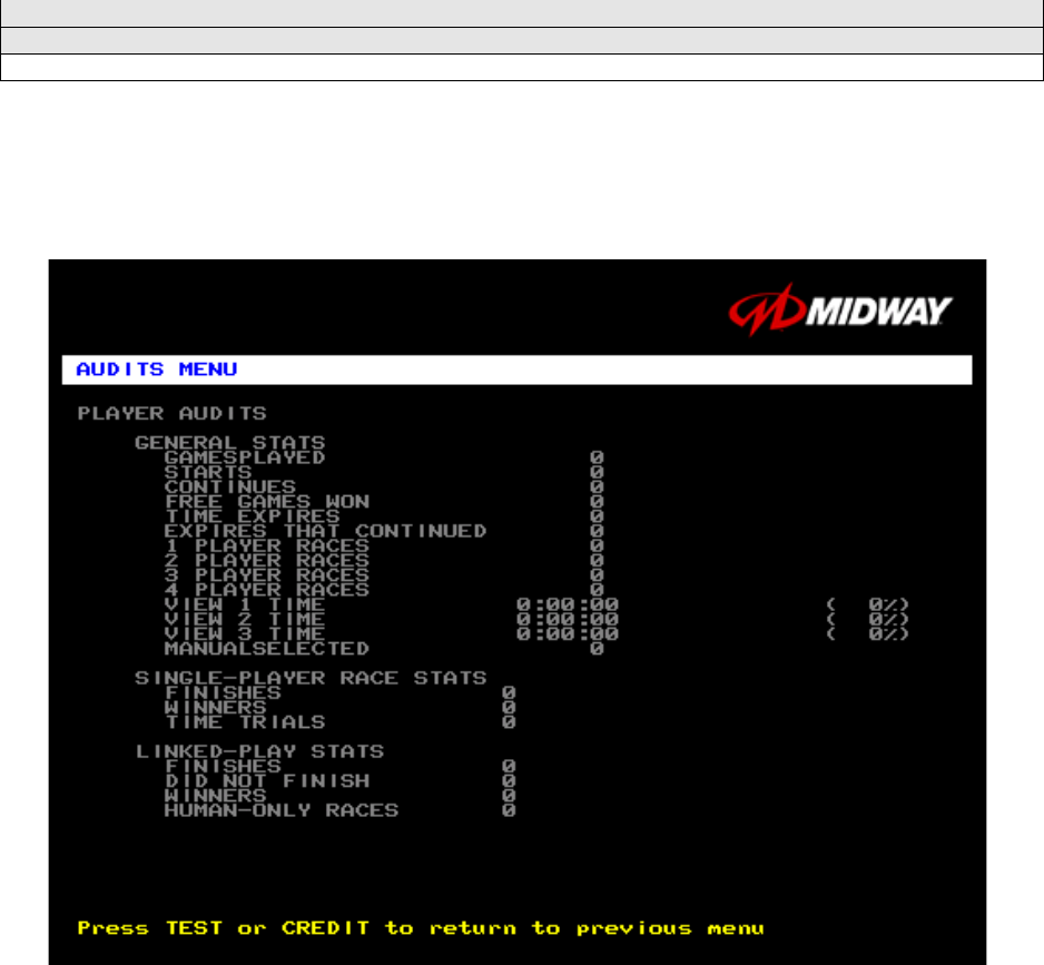
PLAYER AUDITS
Select PLAYER AUDITS at the Audits Menu. The Player Audits Menu displays additional information
about player statistics and ability. This information assists you in understanding game use and
profitability. Player Audits is a read-only screen.
PLAYER AUDITS MENU
GAMES PLAYED. Total number of games that players played on this machine.
CONTINUES. Total number of games on this machine that players paid to continue.
FREE GAMES WON remains at zero if you turn off the bonus and award options. Refer to the General
Adjustments Menu for the bonus and award options settings.
STARTS. Number of games that players started.
FREE GAMES %. Proportion of games that were free, expressed as a percentage.
TIME EXPIRES. Number of times that time expired before a player completed the game.
DID NOT FINISH. Number of incomplete games.
FINISHES. Number of completed games.
TWO, THREE AND FOUR-PLAYER RACES remain at zero if no other games are linked to this one.
Diagnostic, Audit & Adjustment Menu System 3-14
Operator Menu (continued)
Audits Menu (continued)
Track Audits Menu
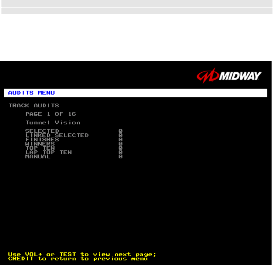
TRACK AUDITS
Select TRACK AUDITS at the Audits Menu. The Track Audits Menu includes specific information about
player choices and ability. This is a read-only menu.
TYPICAL TRACK AUDITS MENU
These audits cover several screen pages. The name of the track appears at the top of the page. Press
the VOLUME UP or VOLUME DOWN buttons to move through these pages.
TRUCK SELECTED WINNER
Hyena 0 0
Outlaw 0 0
General 0 0
Thrasher 0 0
Silver Streak 0 0
Snake Eyes 0 0
Chieftan 0 0
Bad Omen 0 0
Nitro Ninja 0 0
Wilcat 0 0
Dust Devil 0 0
Stinger 0 0
Diagnostic, Audit & Adjustment Menu System 3-15
Operator Menu (continued)
Audits Menu (continued)
Truck Audits Menu
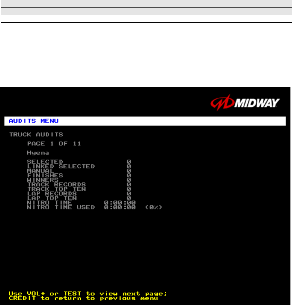
TRUCK AUDITS
Select TRUCK AUDITS at the Audits Menu. The Truck Audits Menu gives you specific information about
player choices and ability. This is a read-only menu.
Menu software includes several pages of audits. The name of the vehicle appears at the top of each
menu page. Press the VOLUME UP or VOLUME DOWN buttons to navigate through these pages.
TYPICAL AUDITS BY TRUCK SCREEN

Diagnostic, Audit & Adjustment Menu System 3-16
Operator Menu (continued)
Adjustments Menu
ADJUSTMENTS MENU
Select ADJUSTMENTS MENU at the Operator Menu. The Adjustments Menu allows you to set game and
player variables. Use these screens to optimize game performance and earnings.
Highlight an option with the middle two diagnostic buttons inside the coin door. Select the option with the
TEST MODE button.
ADJUSTMENTS MENU
GENERAL ADJUSTMENTS MENU
LINKED –PLAY ADJUSTMENTS MENU
TRACK DIFFICULTY ADJUSTMENTS MENU
PRICING MENU
VOLUME ADJUSTMENT
FORCE FEEDBACK ADJUSTMENT
CALIBRATE STEERING, GAS AND BRAKE
SET TIME AND DATE
RETURN TO PREVIOUS MENU
Diagnostic, Audit & Adjustment Menu System 3-17
Operator Menu (continued)
Adjustments Menu (continued)
General Adjustments Menu
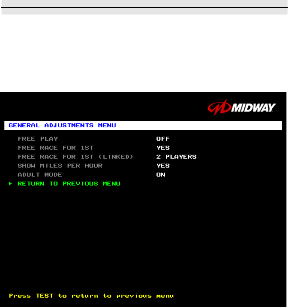
GENERAL ADJUSTMENTS MENU
Select GENERAL ADJUSTMENTS MENU at the Adjustments Menu. At the General Adjustments Menu,
you set the cabinet type, game display and measurement system. General Adjustments Menu options
also control the cost and type of play.
Highlight an option with the middle two diagnostic buttons inside the coin door. Press TEST MODE to
enter Change Mode. Use the diagnostic switches to change the variable. Then press TEST MODE to
save changes and exit the variable.
GENERAL ADJUSTMENTS MENU
FREE PLAY determines whether the game accepts money for play, or allows operation without charge.
For free play, turn this option on. For paid play, turn this option off (the factory default).
FREE RACE FOR 1ST permits a free game for players who finish in first place. To award a free race to a
first-place finisher, turn this option on. To eliminate the free race award, turn this option off. The factory
default is on.
FREE RACE FOR 1ST (LINKED). This feature awards a free game to the first place finisher among
human players. The feature only operates when a minimum number of players join in. To award a free
race to a first-place finisher, turn this option on. To eliminate the free race award, turn this option off.
Available settings include 2, 3 or 4 players, or off. The factory default setting is off.
Diagnostic, Audit & Adjustment Menu System 3-18
SHOW MILES PER HOUR sets the measurement system for display on game screens. To display speed
in kilometers per hour, turn SHOW MILES PER HOUR off. To display speed in miles per hour, turn
SHOW MILES PER HOUR on (the factory default).
ADULT MODE. When you enable Adult Mode, the glamorous cheerleaders appear in bikinis. When you
disable Adult Mode, the cheerleaders appear in more conservative attire. The default setting is on.
Diagnostic, Audit & Adjustment Menu System 3-19
Operator Menu (continued)
Adjustments Menu (continued)
Linked-Play Adjustments Menu
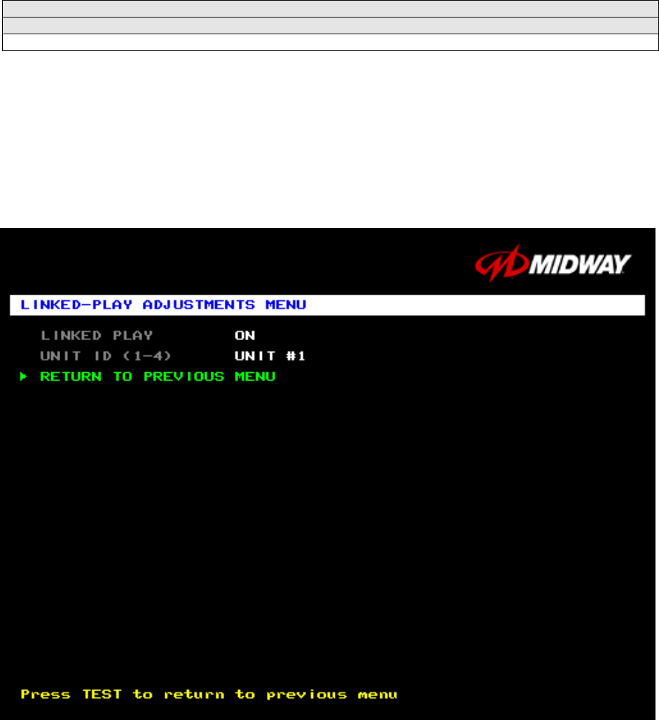
LINKED PLAY ADJUSTMENTS MENU
Select LINKED PLAY ADJUSTMENTS MENU at the Adjustments Menu. The Linked Play Adjustments
Menu allows you to set the game cabinet network identity. After you cable the linked cabinets, use this
menu to set up linked play.
Highlight an option with the middle two diagnostic buttons inside the coin door. Press TEST MODE to
enter Change Mode. Use the diagnostic switches to change the variable. Then press TEST MODE to
save changes and exit the variable.
LINKED-PLAY ADJUSTMENTS MENU
Before proceeding, bring up the Linked Play Adjustments Menu on all linked cabinets.
LINKED PLAY. After you link a cabinet to other games, turn on LINKED PLAY. Now game electronics
can communicate with other cabinets. To prohibit linked play, turn off the feature. The factory default is
off.
UNIT ID determines the game’s address. Each linked game must have a unique number. Never use the
same address for two cabinets. Sequence isn’t important. The factory default ID is 1.
REINITIALIZE. After selecting the ID, exit the Menu System. Shut down each linked cabinet for one
minute. (Leave the computers switched on.) Then restore power to all cabinets. The cabinets should
initialize in Linked Mode. Verify linked operation by playing some linked games.
FREE PLAY
LINKED PLAY ENABLED
UNIT ID (1-4): 1
Diagnostic, Audit & Adjustment Menu System 3-20
Operator Menu (continued)
Adjustments Menu (continued)
Track Difficulty Adjustments Menu
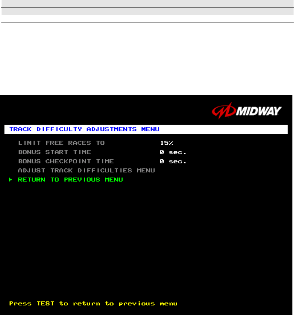
TRACK DIFFICULTY ADJUSTMENTS MENU
Select TRACK DIFFICULTY ADJUSTMENTS MENU at the Adjustments Menu. From the Track Difficulty
Adjustments Menu, you set how much skill players need to complete races.
Highlight an option with the middle two diagnostic buttons inside the coin door. Press TEST MODE to
enter Change Mode. Use the diagnostic switches to change the variable. Then press TEST MODE to
save changes and exit the variable.
TRACK DIFFICULTY ADJUSTMENTS MENU
LIMIT FREE RACES TO (LFRT) is the award cutoff point. LFRT prevents expert players from
monopolizing a cabinet. The range is 1 to 100%. The factory default is 10%.
BONUS START TIME. You can use this feature to award several seconds of extra time to starting
players. The factory default is zero seconds.
BONUS CHECKPOINT TIME. Use this feature to award several seconds of extra time as players pass
checkpoints. The factory default is zero seconds.
ADJUST TRACK DIFFICULTIES MENU allows you to modify the level of challenge that each track
poses.
Diagnostic, Audit & Adjustment Menu System 3-21
Operator Menu (continued)
Adjustments Menu (continued)
Track Difficulty Adjustments Menu (continued)
Adjust Track Difficulties Menu
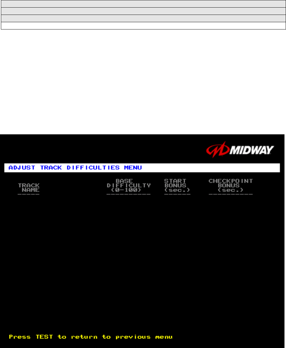
ADJUST TRACK DIFFICULTIES MENU
Select ADJUST TRACK DIFFICULTIES MENU at the Track Difficulty Adjustments Menu. From the Adjust
Track Difficulties Menu, you modify the level of challenge that each track poses. You can also increase or
reduce starting and checkpoint bonus time. Difficulty and bonus default values are all zero.
Highlight an option with the middle two diagnostic buttons inside the coin door. Press TEST MODE to
enter Change Mode. Use the diagnostic switches to change the variable. Press TEST MODE to save
changes and exit the variable. Or press TEST CREDITS to cancel changes and exit the variable.
You’ll notice that each option line has three columns of figures to change. The program lets you edit each
column in turn. First you modify BASE DIFFICULTY, then START BONUS, and last, CHECKPOINT
BONUS.
ADJUST TRACK DIFFICULTIES MENU
Tunnel Vision 0 0 0
Over ‘N’ Under 0 0 0
Air Time 0 0 0
High Octane 0 0 0
Carnie of Chaos 0 0 0
Cliffhanger 0 0 0
Double Barrel 0 0 0
Alpine Air 0 0 0
Tunnel Vision Mirror 0 0 0
Over ‘N’ Under Mirror 0 0 0
Airtime Mirror 0 0 0
High Octane Mirror 0 0 0
Carnie of Chaos Mirror 0 0 0
Cliffhanger Mirror 0 0 0
Double Barrel Mirror 0 0 0
Alpine Air Mirror 0 0 0
Diagnostic, Audit & Adjustment Menu System 3-22
Operator Menu (continued)
Adjustments Menu (continued)
Pricing Menu
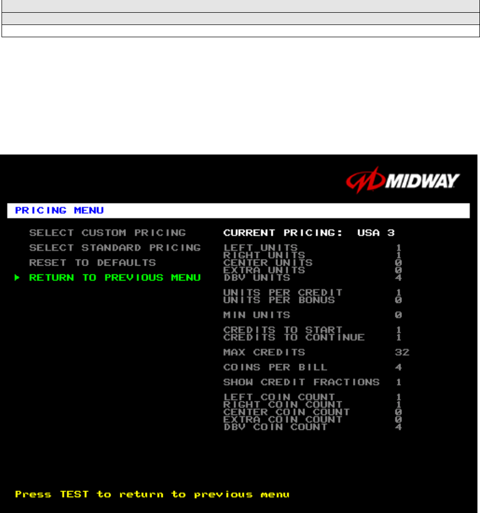
PRICING MENU
Select PRICING MENU at the Adjustments Menu. The Pricing Menu contains options for selecting
standard and custom currency combinations. The factory default is USA1.
Highlight an option with the middle two diagnostic buttons inside the coin door. Press TEST MODE to
enter Change Mode. Use the diagnostic switches to change the variable. Then press TEST MODE to
save changes and exit the variable. Turning on Free Play disables Pricing Menu settings.
PRICING MENU
SELECT CUSTOM PRICING allows you to set coin and credit options manually. Use this option to create
your own pricing schemes. This menu permits changes to default values.
SELECT STANDARD PRICING allows you to select from several ready-made price schemes This menu
permits changes to default values.
RESET TO DEFAULTS returns the price settings to factory default values. This menu permits changing
all current values at once.
Diagnostic, Audit & Adjustment Menu System 3-23
Operator Menu (continued)
Adjustments Menu (continued)
Pricing Menu (continued)
Select Custom Pricing Menu
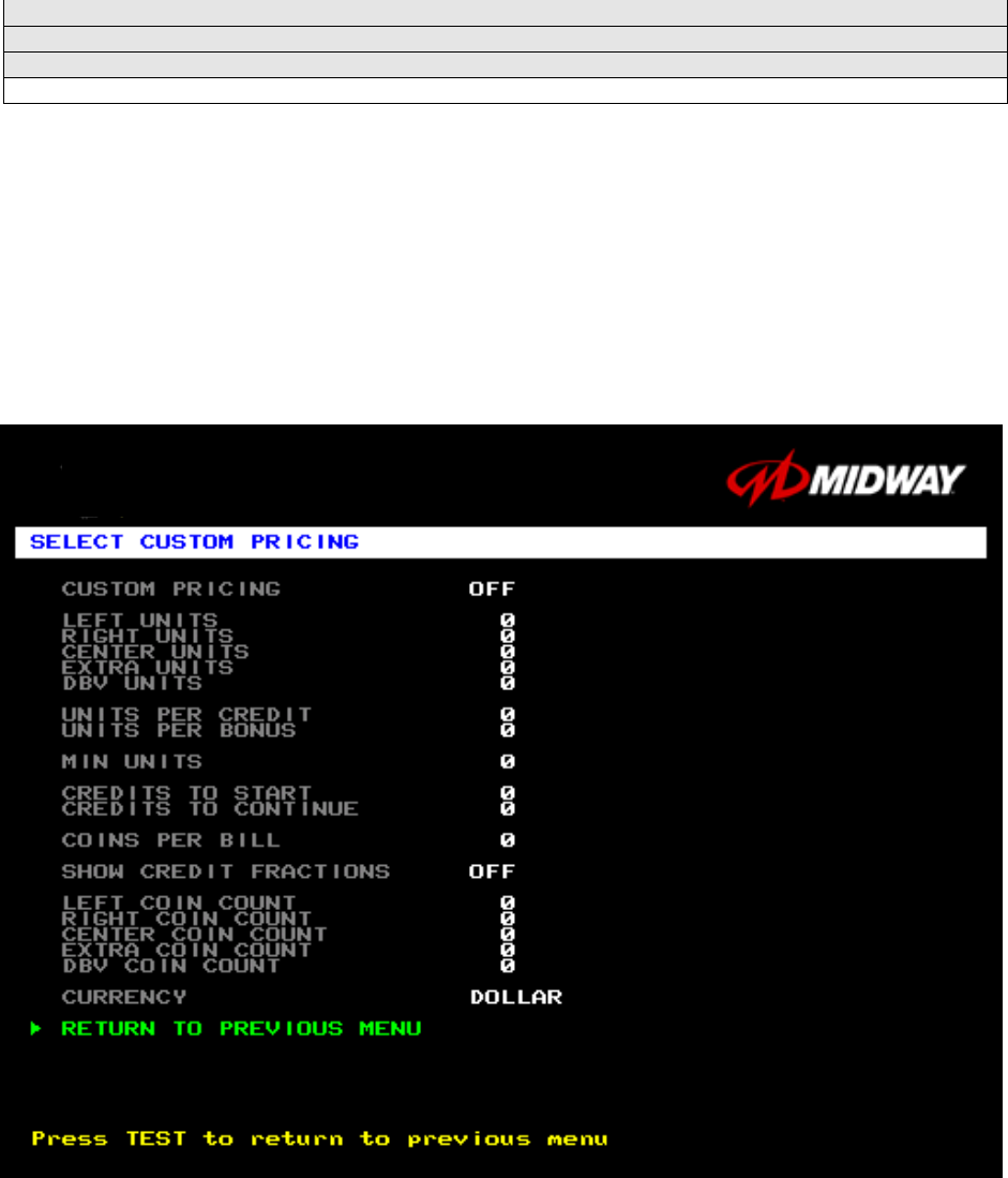
SELECT CUSTOM PRICING MENU
Choose SELECT CUSTOM PRICING at the Pricing Menu. The Select Custom Pricing Menu permits you
to program and use your own pricing table. You can save several pricing schemes and chose between
them as desired.
Highlight an option with the middle two diagnostic buttons inside the coin door. Press TEST MODE to
enter Change Mode. Use the diagnostic switches to change the variable. Then press TEST MODE to
save changes and exit the variable.
TYPICAL SELECT CUSTOM PRICING MENU
The Custom Pricing Menu employs the same terms that appear on the Current Pricing Table. See the
table below for definitions of these terms.
Diagnostic, Audit & Adjustment Menu System 3-24
PRICING MENU TERMS
SCREEN TERM DISCUSSION
Slot Units;
Bill Validator (DBV)
Units
Cyber-currency. This adjustment assigns a number of “units” to each coin mechanism
or bill acceptor. For instance, if a quarter buys 1 unit, then $1 buys 4 units. (See Coins
per Bill.) You insert a coin into a 1-unit coin acceptor. The system, due to its
programming, knows that your coin is worth one unit.
Units per Credit How many units equal one credit. (Units buy credit, the price of one game.)
Units per Bonus Units awarded when a player earns a bonus.
Minimum Units Until this many units accumulate, the system awards no credits.
Credits to Start Number of games a player must purchase to begin play.
Credits to Continue Number of games a player must purchase to resume play.
Max Credits Limits the number of credits that the game will accept.
Coins per Bill How many coins one bill is worth.
BASIC CUSTOM PRICING. Custom pricing creates an imaginary currency exchange. In this currency
exchange, the coins of the realm are “units.” Think of units as a type of cyber-currency, useful only within
the game software. By inserting coins, you purchase units.
Since units are only negotiable within game software, the system stores your units for you. When the
system receives enough units, it buys a game for you. The price of a game is one “credit.” You can think
of credits as a second form of cyber-currency.
Even though you’ve now bought one game, you may not be able to begin playing. In many pricing
schemes, you must buy two or more credits to begin play. The idea here is something like a minimum
order of goods at a store. That is, the operator can “shrink-wrap” two or more games in a package. You
can’t play unless you buy the entire package.
•
••
•1 / 25¢ COIN; 1 CREDIT TO START. In a simple, quarter pricing scheme, the player inserts one coin to buy
one unit. The system exchanges that unit for one credit. If CREDITS TO START contains the value one,
then play commences. A dollar bill buys four units.
Left Slot Units Validator Units Units / Credit Credits to Start Coins / Bill
14114
•
••
•1 / 3 X 25¢; 2 CREDITS TO START. Again, assuming quarter slots, here’s one way to implement 75¢
pricing… In this scheme, each coin that the player inserts buys one unit. The system exchanges three
units for one credit. CREDITS TO START contains the value two. To play, the player must pay for two
credits. In this scheme, a dollar buys four units.
Left Slot Units Validator Units Units / Credit Credits to Start Coins / Bill
14324
•
••
•2 / 1 COIN; 6 CREDITS TO START. Now let’s consider a more unusual pricing scheme. Here, the player
can buy two units with one coin. The system exchanges each of these units for one credit. Notice that
CREDITS TO START contains the value six. To play, the player must insert two more coins to pay for six
credits. Also notice that if the player pays with a bill, the system throws in an extra unit.
Left Slot Units Validator Units Units / Credit Credits to Start Coins / Bill
29164
Diagnostic, Audit & Adjustment Menu System 3-25
Operator Menu (continued)
Adjustments Menu (continued)
Pricing Menu (continued)
Select Standard Pricing Continent Menu
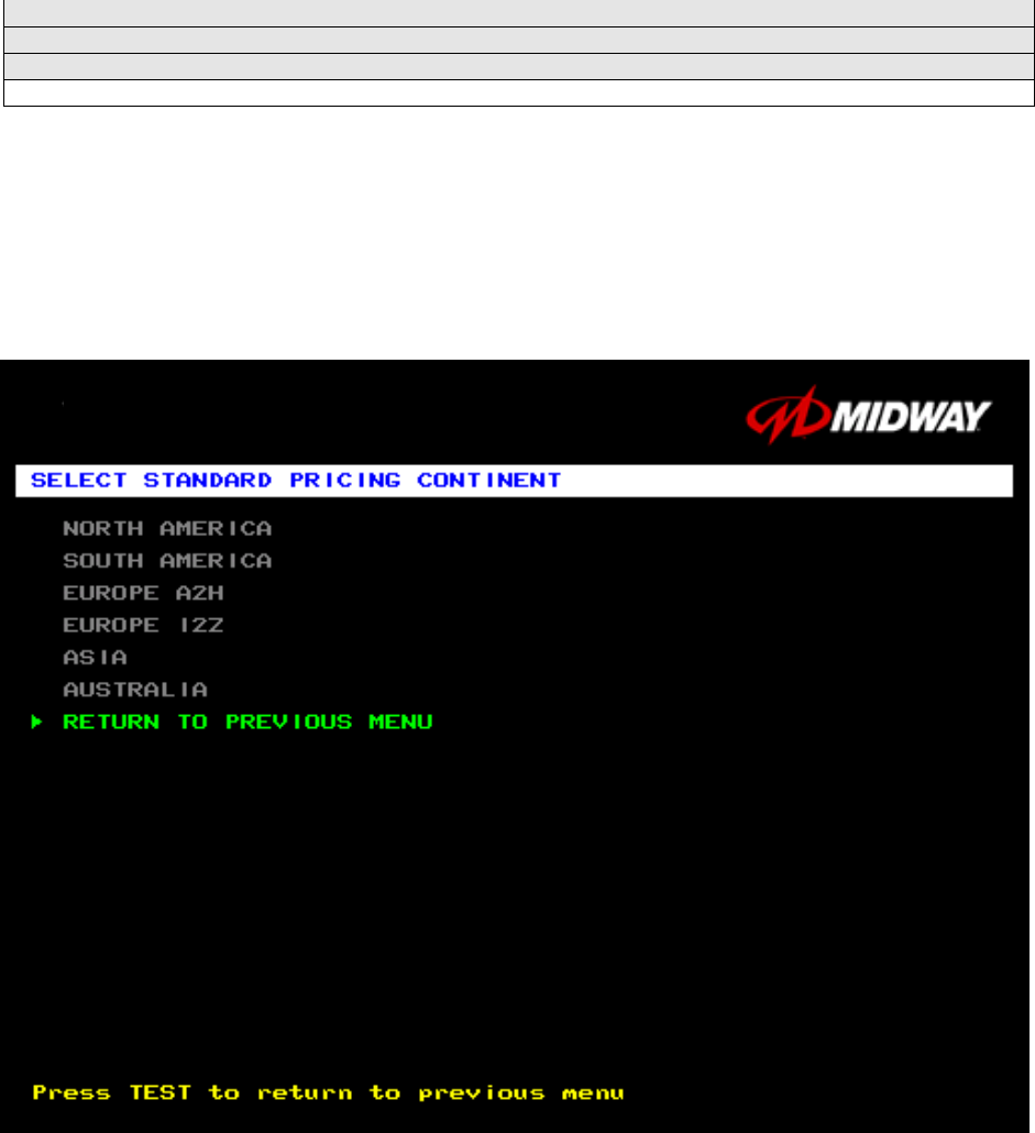
SELECT STANDARD PRICING CONTINENT MENU
Choose SELECT STANDARD PRICING at the Pricing Menu. The Select Standard Pricing Continent
Menu allows you to choose the continent that you are operating in.
Highlight a line item with the middle two diagnostic buttons inside the coin door. Select the option with the
TEST MODE button.
STANDARD PRICING MENU
Diagnostic, Audit & Adjustment Menu System 3-26
Operator Menu (continued)
Adjustments Menu (continued)
Pricing Menu (continued)
Select Standard Pricing Continent Menu
Select Standard Pricing Country for North America Menu
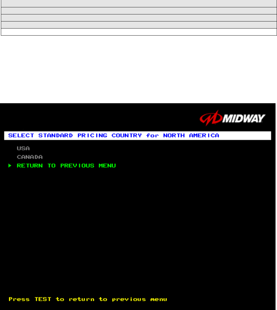
SELECT STANDARD PRICING COUNTRY FOR NORTH AMERICA MENU
Choose a continent (NORTH AMERICA, for example) at the Select Standard Pricing Continent Menu.
The Select Standard Pricing Country for North America Menu contains options for selecting standard
currency combinations. You may use standard pricing schemes as-is, or customize them.
Highlight a line item with the middle two diagnostic buttons inside the coin door. Select the option with the
TEST MODE button.
TYPICAL SELECT STANDARD PRICING FOR NORTH AMERICA MENU
Diagnostic, Audit & Adjustment Menu System 3-27
Operator Menu (continued)
Adjustments Menu (continued)
Pricing Menu (continued)
Select Standard Pricing Continent Menu (continued)
Select Standard Pricing Country for North America Menu (cont’d)
Select Standard Pricing Table for USA Menu (cont’d)
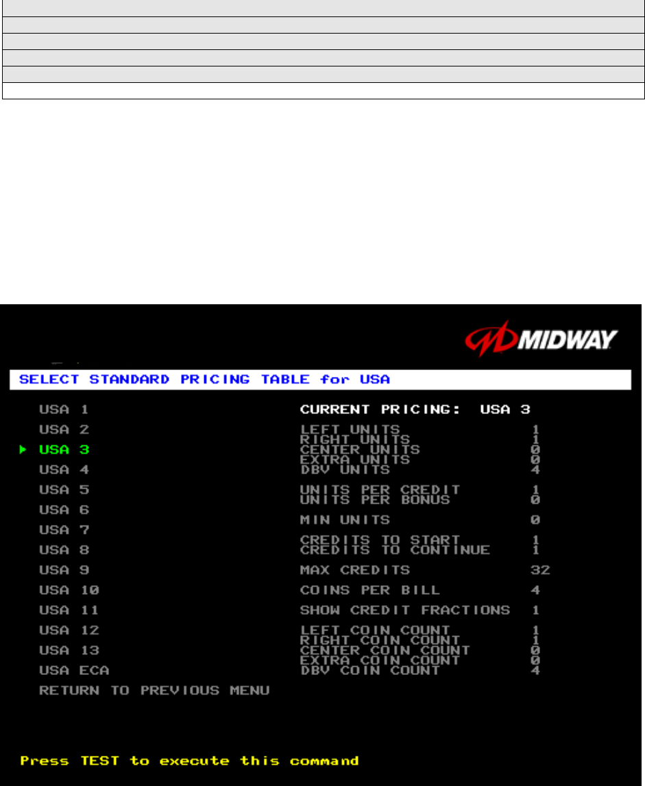
SELECT STANDARD PRICING MENU
Suppose that you want to set U.S. pricing. Choose USA at the menu entitled Select Standard Pricing
Country for North America. This menu contains options for selecting standard U.S. currency
combinations.
Highlight an option with the middle two diagnostic buttons inside the coin door. Press TEST MODE to
enter Change Mode. Use the diagnostic switches to change the variable. Then press TEST MODE to
save changes and exit the variable.
TYPICAL VIEW CURRENT PRICING DISPLAY

Diagnostic, Audit & Adjustment Menu System 3-28
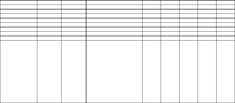
STANDARD PRICING TABLE
NAME
START
CONTINUE
CREDITS/COIN
COIN 1
COIN 2
COIN 3
COIN4
BILL
ANTILLES 2 2 1/25¢, 4/1G .25¢ 1G
AUSTRALIA 1 2 2 1/3X20¢, 2/$1.00 .20¢ $1.00
AUSTRALIA 2 2 2 1/5X20¢, 1/$1.00 .20¢ $1.00
AUSTRIA 1 2 2 1/5Sch, 2/10Sch 5 Sch 10 Sch
AUSTRIA 2 2 2 1/2X5Sch, 3/2X10Sch 5 Sch 10 Sch
BELGIUM 1 2 2 1/20BF 20BF 20BF
BELGIUM 2 2 2 3/20BF 20BF 20BF
BELGIUM 3 2 2 2/20BF 20BF 20BF
BELGIUM ECA 2 2 1/20BF 50BF 20BF 5BF
CANADA 1 2 2 1 / 2 x 25¢, 3 / $1 25¢ 25¢
CANADA 2 2 2 1 / 2 x 25¢, 3 / $1 25¢ $1.00
CANADA 3 2 2 3 / $1.00, 6 / $2.00 $1.00 $2.00
CANADA ECA 2 2 1 / 2 x 25¢, 3 / $1 25¢ $1.00 $2.00
DENMARK 2 2 3/5DKr, 7/10DKr 5DKr 10DKr
FINLAND 2 2 1/1Fmk 1Fmk 5Fmk
FRANCE 1 2 2 2/5Fr, 5/10Fr 5Fr 10Fr
FRANCE 2 2 1 2/5Fr, 4/10Fr 5Fr 10Fr
FRANCE 3 2 1 1/5Fr, 3/10Fr 5Fr 10Fr
FRANCE 4 2 1 1/5Fr, 2/10Fr 5Fr 10Fr
FRANCE 5 2 1 2/5Fr, 5/10Fr, 11/2 X 10Fr 5Fr 10Fr
FRANCE 6 2 1 2/5Fr, 4/10Fr, 9/2 X 10Fr 5Fr 10Fr
FRANCE 7 2 1 1/5Fr, 3/10Fr, 7/2 X 10Fr 5Fr 10Fr
FRANCE 8 2 1 1/5Fr, 2/10Fr, 5/2 X 10Fr 5Fr 10Fr
FRANCE 9 2 1 1/3 X 1Fr, 2/5Fr 1Fr 5Fr
FRANCE 10 2 1 1/2 X 1Fr, 3/5Fr 1Fr 5Fr
FRANCE 11 2 1 1/3 X 1Fr, 2/5Fr, 5/2 X 5Fr 1Fr 5Fr
FRANCE 12 2 1 1/2 X 1Fr, 3/5Fr, 7/2 X 5Fr 1Fr 5Fr
FRANCE ECA 1 1 1 2/5Fr, 5/10Fr 1Fr 5Fr 10Fr 20Fr
FRANCE ECA 2 1 1 2/5Fr, 4/10Fr 1Fr 5Fr 10Fr 20Fr
FRANCE ECA 3 1 1 1/5Fr, 3/10Fr 1Fr 5Fr 10Fr 20Fr
FRANCE ECA 4 1 1 1/5Fr, 2/10Fr 1Fr 5Fr 10Fr 20Fr
FRANCE ECA 5 1 1 2/5Fr, 5/10Fr, 11/2 X 10Fr 1Fr 5Fr 10Fr 20Fr
FRANCE ECA 6 1 1 2/5Fr, 4/10Fr, 9/2 X 10Fr 1Fr 5Fr 10Fr 20Fr
FRANCE ECA 7 1 1 1/5Fr, 3/10Fr, 7/2 X 10Fr 1Fr 5Fr 10Fr 20Fr
FRANCE ECA 8 1 1 1/5Fr, 2/10Fr, 5/2 X 10Fr 1Fr 5Fr 10Fr 20Fr
FRANCE ECA 9 1 1 1/3 X 1Fr, 2/5Fr 1Fr 5Fr 10Fr 20Fr
FRANCE ECA 10 1 1 1/2 X 1Fr, 3/5Fr 1Fr 5Fr 10Fr 20Fr
FRANCE ECA 11 1 1 1/3 X 1Fr, 2/5Fr, 5/10Fr 1Fr 5Fr 10Fr 20Fr
FRANCE ECA 12 1 1 1/2 X 1Fr, 3/5Fr, 7/10Fr 1Fr 5Fr 10Fr 20Fr
FRANCE ECA 13 1 1 1/10Fr, 2/20Fr, 4/30Fr 1Fr 5Fr 10Fr 20Fr
FREE PLAY -- -- -- None None None None None
GERMANY 1 2 2 1/1DM, 6/5DM 1DM 5DM
GERMANY 2 2 1 1/1DM, 7/5DM 1DM 5DM
GERMANY 3 2 1 1/1DM, 8/5DM 1DM 5DM
GERMANY 4 2 1 1/1DM, 5/5DM 1DM 5DM
GERMANY 5 2 1 1/1DM, 6/5DM 1DM 5DM
GERMANY ECA 1 2 2 1/1DM, 2/2DM, 6/5DM 1DM 2DM 5DM
GERMANY ECA 2 2 1 1/1DM, 2/2DM, 6/5DM 1DM 2DM 5DM
GERMANY ECA 3 1 1 1/1DM, 2/2DM, 6/5DM 1DM 2DM 5DM
HUNGARY 2 2 1/2X10Ft, 3/2X20Ft 10Ft 20Ft
ITALY 2 2 1/500LIt 500LIt 500LIt
JAPAN 1 2 2 1/100Yen 100 100
JAPAN 2 2 2 2/100Yen 100 100
NETHERLANDS 2 2 1/1HFI, 3/2.5HFI 1HFI 2.5HFI
NEW ZEALAND 1 1 1 1/$1 $1 $2
NEW ZEALAND 2 1 1 2/$1 $1 $2
NORWAY 2 2 3/5NKr, 6/10NKr 5NKr 10NKr
SPAIN 1 2 2 1/100Pta, 6/500Pta 100Pta 500Pta
SPAIN 2 2 2 1/100Pta, 5/500Pta 100Pta 500Pta
SWEDEN 2 2 1/3X1SKr, 2/5SKr 1SKr 5SKr
SWITZERLAND 1 2 2 1/1SFr, 6/5SFr 1SFr 5SFr
SWITZERLAND 2 2 2 1/1SFr, 7/5SFr 1SFr 5SFr
SWITZERLAND 3 2 2 1/1SFr, 8/5SFr 1SFr 5SFr
(Table continues on next page)
Diagnostic, Audit & Adjustment Menu System 3-29
STANDARD PRICING TABLE, continued
NAME
START
CONTINUE
CREDITS/COIN
COIN 1
COIN 2
COIN 3
COIN4
BILL
UK ECA 1 1 1 1/50p, 3/£1.00 £1.00 50p 20p 10p £2.00
UK ECA 2 1 1 1/50p, 2/£1.00 £1.00 50p 20p 10p £2.00
UK ECA 3 1 1 1/30p, 2/50p, 5/£1.00 £1.00 50p 20p 10p £2.00
UK 4 1 1 1/50p, 3/£1.00 £1.00 50p
UK 5 1 1 1/50p, 2/£1.00 £1.00 50p
UK ECA 6 1 1 1/30p, 2/50p, 4/£1.00 £1.00 50p 20p 10p £2.00
UK ECA 7 1 1 3/£1.00 £1.00 50p 20p 10p £2.00
UK ECA 8 1 1 1/50p, 2/£1.00, 4/£2.00 £1.00 50p 20p 10p £2.00
USA1 2 2 1/25¢ 25¢ 25¢ $1.00
USA2 2 1 1/25¢ 25¢ 25¢ $1.00
USA3 1 1 1/25¢ 25¢ 25¢ $1.00
USA4 1 1 1/50¢, 3/$1.00 25¢ 25¢ $1.00
USA5 2 1 1/50¢, 4/$1.00 25¢ 25¢ $1.00
USA6 1 1 1/50¢ 25¢ 25¢ $1.00
USA7 1 1 1/50¢, 3/$1.00 25¢ 25¢ $1.00
USA8 2 2 1/50¢, 4/$1.00 25¢ 25¢ $1.00
USA9 3 2 1/25¢, 4/$1.00 25¢ 25¢ $1.00
USA10 3 3 1/25¢, 4/$1.00 25¢ 25¢ $1.00
USA11 4 2 1/25¢, 4/$1.00 25¢ 25¢ $1.00
USA12 4 3 1/25¢, 4/$1.00 25¢ 25¢ $1.00
USA13 4 4 1/25¢, 4/$1.00 25¢ 25¢ $1.00
USA ECA 3 3 1/25¢, 4/$1.00 $1.00 25¢ 10¢ 05¢ $1.00
Diagnostic, Audit & Adjustment Menu System 3-30
Operator Menu (continued)
Adjustments Menu (continued)
Volume Adjustment Menu
VOLUME ADJUSTMENT MENU
Select VOLUME ADJUSTMENT at the Adjustments Menu. (You can also access this menu from the
Operator Menu.) The Volume Adjustment Menu allows you to adjust relative sound volume levels.
Highlight an option with the middle two diagnostic buttons inside the coin door. Press TEST MODE to
enter Change Mode. Use the diagnostic switches to change the variable. Then press TEST MODE to
save changes and exit the variable.
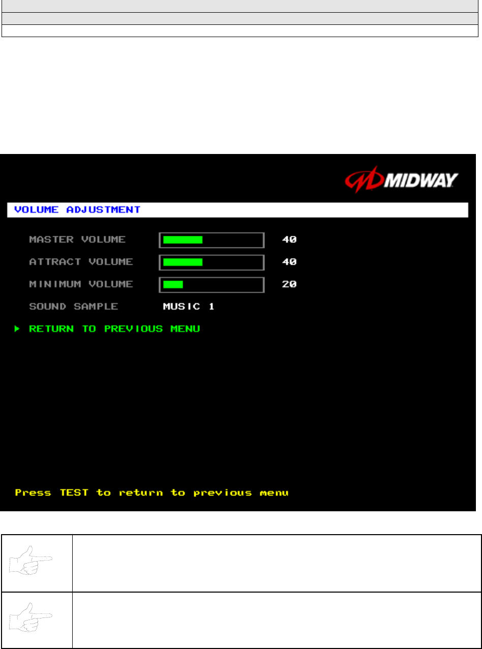
VOLUME ADJUSTMENT MENU
NOTICE: The Master Volume setting affects all other volume adjustments. You can still
alter Attract sounds in relation to normal game sound. For example, suppose that you
set Attract Mode volume to 50%. Then Attract Mode sounds are half as loud as normal
game sounds.
NOTICE: Check the Master Volume setting before testing. Increase Master Volume to
fully test speakers. Restore Master Volume to its previous level before returning to
Game-Over Mode.
Diagnostic, Audit & Adjustment Menu System 3-31
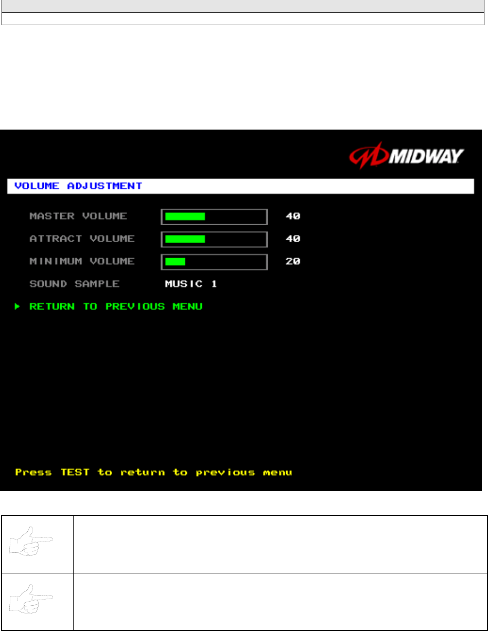
MASTER VOLUME sets the overall volume level during game play. This value simultaneously affects all
other sound settings. The range is 1 to 100%. The factory default is 60%.
ATTRACT VOLUME adjusts the Attract Mode sound level only when you turn on Attract Mode. The
Attract Mode sound level is independent of game audio levels. The Attract Volume range is 1 to 100%.
The factory default is 50%.
MINIMUM VOLUME sets the quietest sound level during game play. The range is 1 to 100%. The factory
default is 20%.
To exit the Volume Adjustment Menu, highlight RETURN TO PREVIOUS MENU. Then press TEST
MODE.
Diagnostic, Audit & Adjustment Menu System 3-32
Operator Menu (continued)
Adjustments Menu (continued)
Force Feedback Adjustment Menu
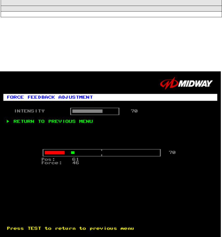
FORCE FEEDBACK ADJUSTMENT
Select FORCE FEEDBACK ADJUSTMENT MENU at the Adjustments Menu. The Force Feedback
Adjustment Menu allows you to alter the intensity of steering wheel feedback.
Highlight an option with the middle two diagnostic buttons inside the coin door. Press TEST MODE to
enter Change Mode. Use the diagnostic switches to change the variable. Then press TEST MODE to
save changes and exit the variable.
FORCE FEEDBACK ADJUSTMENT MENU
THE INTENSITY ADJUSTMENT ranges from 0% (minimum) to 100% (maximum). The factory default
setting is 60%. If players have superior upper body strength, apply greater force. Younger players may be
more comfortable with smaller force settings.
THE FORCE FEEDBACK CENTER TEST checks operation of steering wheel motor drive circuits. Select
this option and move the steering wheel to any position. As soon as you release the wheel, it must
automatically return to its center position. If it doesn’t, then the vehicle won’t respond properly.
Diagnostic, Audit & Adjustment Menu System 3-33
Operator Menu (continued)
Adjustments Menu (continued)
Calibrate Steering, Gas and Brake Menu
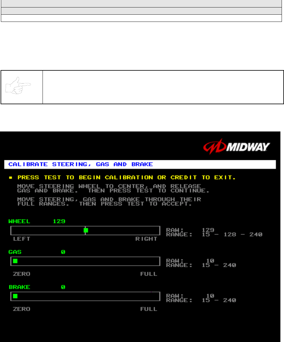
CALIBRATE STEERING, GAS AND BRAKE
Select CALIBRATE STEERING, GAS AND BRAKE at the Adjustments Menu. (You can also access this
menu from the Operator Menu.) This option allows you to set steering and throttle mechanisms for
optimum control during game play. Poorly calibrated player controls can reduce profits.
NOTICE: Before calibrating player control switches, make needed repairs to the game.
If you plan to move the game, move it before calibrating player control switches.
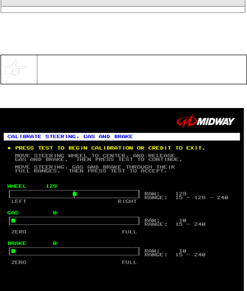
To set up each calibration procedure, follow screen directions. Press TEST MODE to begin the
procedure.
STEERING, GAS AND BRAKE CALIBRATION SCREEN
The steering wheel, brake and gas pedal couple to potentiometers. These potentiometers output DC
voltages between zero and five volts. Game electronics digitize this analog output into an eight-bit (256-
value), numeric stream.
Watch the numbers on the calibration screen. These numbers vary to indicate a control’s position within
that control’s range of motion. For instance, steering straight ahead produces a number halfway between
the left and right steering limits. To accurately simulate steering, numbers must change sequentially.
Diagnostic, Audit & Adjustment Menu System 3-34
Operator Menu (continued)
Adjustments Menu (continued)
Set Time and Date Menu
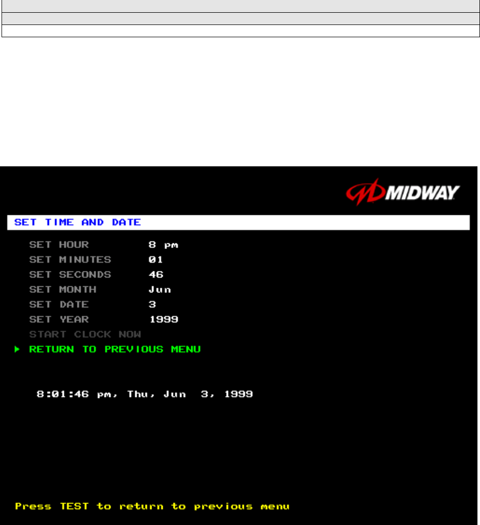
SET THE TIME AND DATE
Select SET TIME AND DATE at the Adjustments Menu. The Set Time and Date Menu provides the
current date and time for the game. This screen also allows clock adjustments for time zone changes and
seasonal time changes.
Highlight an option with the middle two diagnostic buttons inside the coin door. Press TEST MODE to
enter Change Mode. Use the diagnostic switches to change the variable. Then press TEST MODE to
save changes and exit the variable.
SET TIME AND DATE MENU
The clock assists in providing accurate game statistics. It doesn’t affect game operation. When the circuit
board isn’t receiving external power, the clock runs until the battery fails.
Diagnostic, Audit & Adjustment Menu System 3-35
Operator Menu (continued)
Utilities Menu
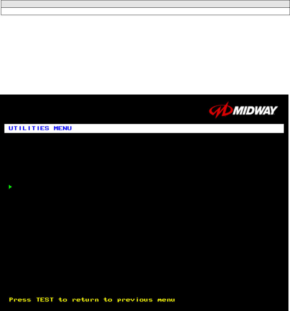
UTILITIES MENU
Select UTILITIES MENU at the Operator Menu. The Game Utilities Menu permits you to clear game
credits, player statistics, and game audits. Here, you restore game settings to factory defaults or save
audit data. A confirmation screen appears before you finalize changes.
Highlight an option with the middle two diagnostic buttons inside the coin door. Press TEST MODE to
enter Change Mode. Use the diagnostic switches to change the variable. Then press TEST MODE to
save changes and exit the variable.
UTILITIES MENU
CLEAR CREDITS zeros all credit variables.
RESET OPERATOR SETTINGS returns Adjustments Menu variables to factory default values.
RESET HIGH SCORES AND SPLIT TIMES overwrites the player high scores with factory default data.
RESET AUDIT STATS zeros track and truck audit values.
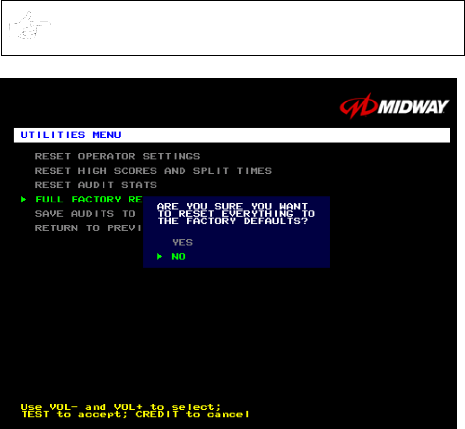
FULL FACTORY RESTORE resets all variables above to factory default values. A confirmation screen
appears before you finalize changes.
CLEAR CREDITS
RESET OPERATOR SETTINGS
RESET HIGH SCORES AND SPLIT TIMES
RESET AUDIT STATS
FULL FACTORY RESTORE
SAVE AUDITS TO FLOPPY DISK
RETURN TO PREVIOUS MENU
Diagnostic, Audit & Adjustment Menu System 3-36
SAVE AUDITS TO FLOPPY DISK allows you to copy game data to a disk. Comparing audit data over
time demonstrates the effect of game variable changes on profits. Use a formatted, 1.44MB high-density
diskette. The floppy drive is in the CPU cabinet.
NOTICE: Be careful when clearing audit information. Once you clear data, you can’t
restore it. Use the Save Audits to Floppy Disk option to save data for analysis. To clear
audit registers, use the Reset or Full Factory Restore functions.
A CONFIRMATION SCREEN APPEARS BEFORE YOU FINALIZE CHANGES
Diagnostic, Audit & Adjustment Menu System 3-37
Operator Menu (continued)
Volume Adjustment Menu
VOLUME ADJUSTMENT MENU
Select VOLUME ADJUSTMENT at the Operator Menu. (You can also access this menu from the
Adjustments Menu.) The Volume Adjustment Menu allows you to adjust relative sound loudness levels.
Highlight an option with the middle two diagnostic buttons inside the coin door. Press TEST MODE to
enter Change Mode. Use the diagnostic switches to change the variable. Then press TEST MODE to
save changes and exit the variable.
VOLUME ADJUSTMENT MENU
NOTICE: The Master Volume setting affects all other volume adjustments. You can still
alter Attract sounds in relation to normal game sound. For example, suppose that you
set Attract Mode volume to 50%. Then Attract Mode sounds are half as loud as normal
game sounds.
NOTICE: Check the Master Volume setting before testing. Increase Master Volume to
fully test speakers. Restore Master Volume to its previous level before returning to
Game-Over Mode.
MASTER VOLUME sets the overall volume level during game play. This value simultaneously affects all
other sound settings. The range is 1 to 100%. The factory default is 60%.
Diagnostic, Audit & Adjustment Menu System 3-38
ATTRACT VOLUME adjusts the Attract Mode sound level only when you turn on Attract Mode. The
Attract Mode sound level is independent of game audio levels. The Attract Volume range is 1 to 100%.
The factory default is 50%.
MINIMUM VOLUME sets the quietest sound level during game play. The range is 1 to 100%. The factory
default is 20%.
To exit the Volume Adjustment Menu, highlight RETURN TO PREVIOUS MENU. Then press TEST
MODE.
Diagnostic, Audit & Adjustment Menu System 3-39
Operator Menu (continued)
Calibrate Steering, Gas and Brake Menu
CALIBRATE STEERING, GAS AND BRAKE
Select CALIBRATE STEERING, GAS AND BRAKE at the Operator Menu. (You can also access this
menu from the Adjustments Menu.) This option allows you to set steering and throttle mechanisms for
optimum control during game play. Poorly calibrated player controls can reduce profits.
NOTICE: Before calibrating player control switches, make needed repairs to the game.
If you plan to move the game, move it before calibrating player control switches.
To set up each calibration procedure, follow screen directions. Press TEST MODE to begin the
procedure.
STEERING, GAS AND BRAKE CALIBRATION SCREEN
The steering wheel, brake and gas pedal couple to potentiometers. These potentiometers output DC
voltages between zero and five volts. Game electronics digitize this analog output into an eight-bit (256-
value), numeric stream.
Watch the numbers on the calibration screen. These numbers vary to indicate a control’s position within
that control’s range of motion. For instance, steering straight ahead produces a number halfway between
the left and right steering limits. To accurately simulate steering, numbers must change sequentially.

Diagnostic, Audit & Adjustment Menu System 3-40
NOTES
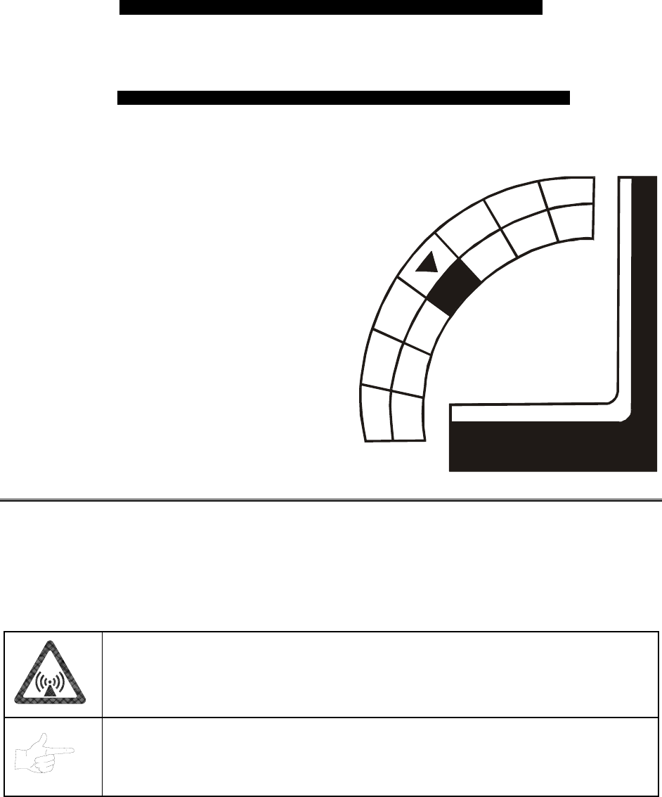
Wiring & Circuit Information 4-1
O
OO
OFFROAD
FFROADFFROAD
FFROAD
THUNDER
THUNDERTHUNDER
THUNDER
TM
CHAPTER
4
WIRING & CIRCUIT
INFORMATION
WARNING: Failure to reconnect ground wires or replace metal shields may result in
radio frequency interference.
NOTICE: The term VGM refers to the video game machine.
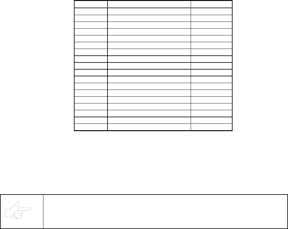
Wiring & Circuit Information 4-2
Harness Connector Prefixes
Prefix Connector Location Example
1 Arcade Computer 1P1
2-- --
3 Magic Bus Interface Board 3P1
4 Fluorescent Lamp 4P1
5 Power Supply 5P1
6 Video Monitor 6P1
7 Wheel Driver Board 7P1
8 Coin Door Area 8P1
9 BB12 Audio Board 9P1
10 LED Interconnect Board 10P1
11 Cabinet 11P1
12 Optional Overhead Marquee 12P1
13 Dashboard 13P1
14 Gas Pedal & Brake 14P1
15 Upper Speakers 15P1
16 Seat Speaker 16P1
17 Dash LED Board 17P1
18 Subwoofer Driver Board 18P1
NOTICE: Look for the connector prefix on wiring diagrams. The prefix shows you
where you’ll find the connector.
Wiring & Circuit Information 4-3
Power Wiring Diagram
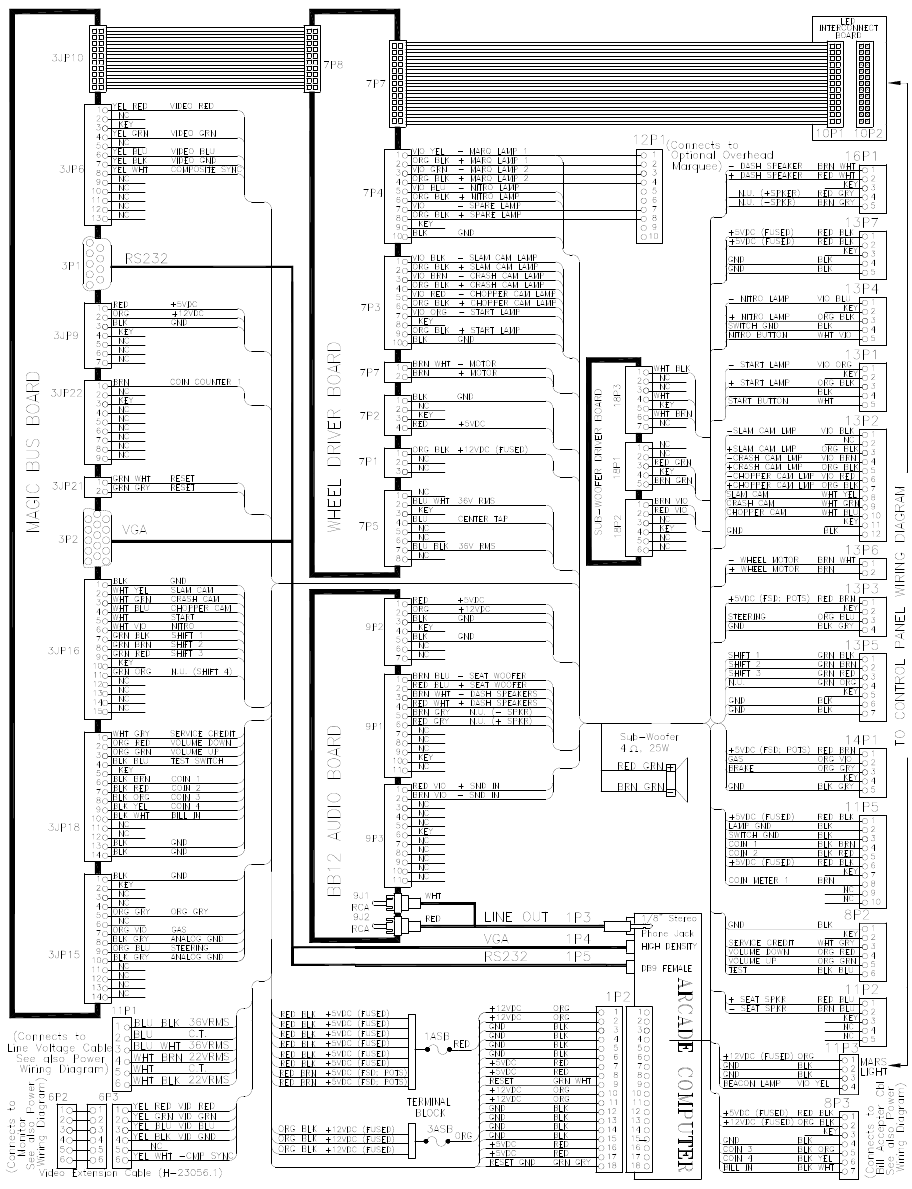
Wiring & Circuit Information 4-4
Cabinet Wiring Diagram
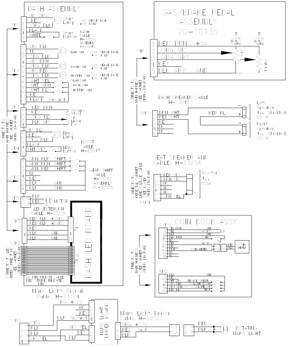
Wiring & Circuit Information 4-5
Player Panel Wiring Diagram
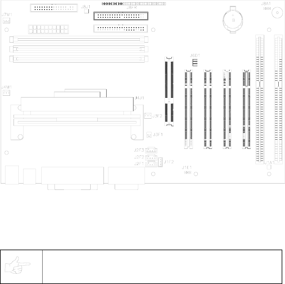
Wiring & Circuit Information 4-6
Computer Motherboard Assembly 20-10554
MOTHERBOARD CONNECTOR AND JUMPER STATUS
(NOTES FOR TABLE ON FOLLOWING PAGE)
NOTICE: The term VGM refers to the video game machine.
NOTES:
1. VGM doesn’t require jumper or telephone connection.
2. VGM doesn’t require jumper. VGM uses proprietary network for game linking.
3. VGM doesn’t require connections. VGM has no ATAPI devices (CD ROMs).
4. VGM doesn’t require jumper. Tamper-detection security feature isn’t installed.
5. Connect processor module fan to this jack. Computer may become unreliable if processor overheats.
6. Connect processor module to this jack. 242-pin socket accepts single microprocessor modules.
7. VGM doesn’t require connections. Case cooling fans connect directly to power supply.
8. VGM doesn’t require connections. VGM doesn’t use SCSI devices (Hard Drives).
9. Connect reset cable from Filter Board to this jack. VGM doesn’t use front-panel devices.
10. Jumper must be set over pins 1 & 2 for this VGM. VGM won’t run with incorrect or missing jumper.
* Replacement Motherboards may not include this jumper. Refer to Parts to order extra shunt jumpers.

Wiring & Circuit Information 4-7
Motherboard Connector and Jumper Status Table
Designation Location Function Meaning Setting Default
J1A1 Lower Right Wake Not Used In This Open
Near Board On VGM (No 1 & 2
(Note 1) Expansion Slot Ring Telephone)
J1E1 Lower Center Wake Not Used In This Open
Near Board On VGM (No
(Note 2) Expansion Slot LAN PC LAN)
J1F2 Lower Center CD Audio Not Used In This Open
Near Board Input VGM (No
(Note 3) Expansion Slot Circuit CD Player)
J2F1 Lower Center CD Data Not Used In This Open
Near Board Input VGM (No
(Note 3) Expansion Slot Circuit CD Player)
J2F2 Lower Center Telephony Not Used In This Open
Near Board Input VGM (No
(Note 1) Expansion Slot Circuit Telephone)
J2F3 Lower Center Auxiliary Not Used In This Open
Near Board Input VGM (No
(Note 3) Expansion Slot Circuit Aux Devices)
J3F1 Middle Center Chassis Not Used In This Open
Near CPU Intrusion VGM (No 1 & 2
(Note 4) And Fan Circuit Intrusion)
J3F2 Middle Center Processor Two Speed Fan Open
Near CPU Fan For Processor 1, 2, & 3
(Note 5) And Fan Circuit Cooling
J4J1 Center Left System System Open
Module With Micro- Micro- Filled
(Note 6) Fan Assembly Processor Processor
J4M1 Center Left Processor Controlled Fan Open
Near CPU Fan For Processor 1, 2, & 3
(Note 7) Module Circuit Cooling
J7M1 Upper Left Case Controlled Fan Open
Near Power & Fan For Hard Disk 1, 2, & 3
(Note 7) Floppy Jacks Circuit Drive Cooling
J8J1 Upper Left SCSI Not Used In This Open
Between Hard Drive VGM (No 1 & 2
(Note 8) & Floppy Jacks Indicator SCSI Drives)
J8FR Upper Center Front Only Reset Open
Near Hard Disk Panel Pins Are Used 1 & 2
(Note 9) Drive Jacks Devices In This VGM
J8A1 Upper Right Configur- Starts System Open
Near Battery ation Setup Routine 1 & 2
(Note 10) And Speaker Select or Operation 2 & 3
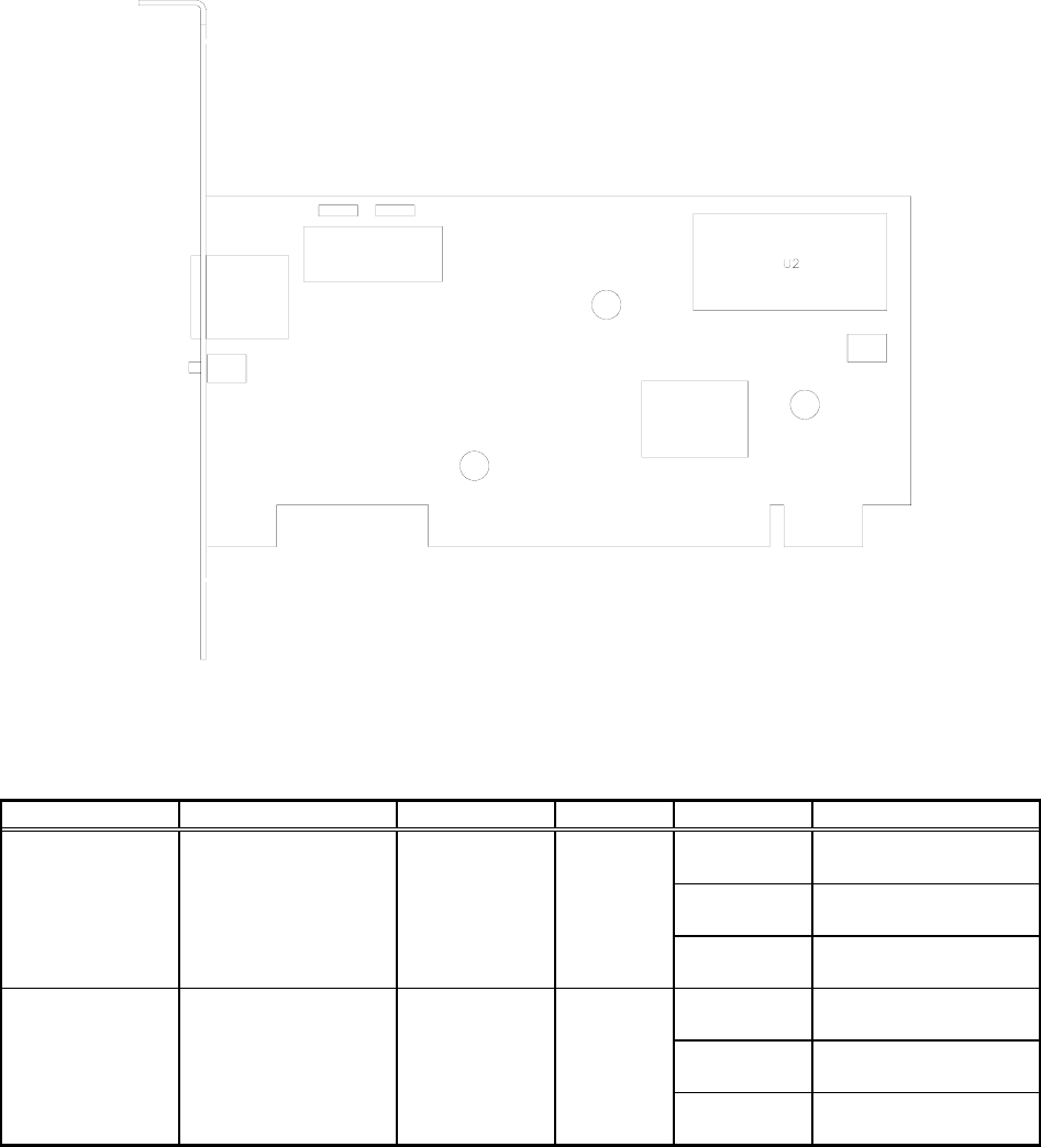
Wiring & Circuit Information 4-8
Network Interface Board Assembly 20-10550
Network Interface LED Indicator Table
Designation Location Function Color State Meaning
LED 1
(LNK) Left Center
Under Jack Link Verify
Indicator Green Off Not In Use
(No Game Link)
On Normal
Operation
Blinking Link Fault
(Note 1)
LED 2
(ACT) Right Center
Under Jack Activity
Indicator Green Off Not In Use
(No Data)
On Receiving Data
(Note 2)
Blinking Normal
Operation
Notes:
1. Intermittent cable or hub problems may cause blinking. Blinking must be continuous during linked
operation.
2. Blinks during data packet exchange. Blinking may appear continuous during heavy network activity.
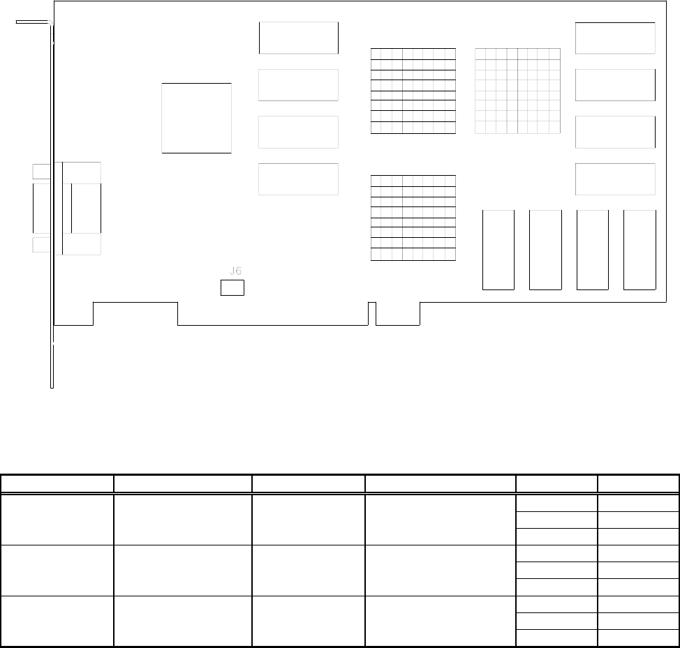
Wiring & Circuit Information 4-9
Video Graphics Board Assembly 20-10551
Video Graphics Connector And Jumper Table
Designation Location Function Meaning Setting Default
J1 Left Center Video Graphic Open
(DB-15 on Signal Information 1-15
(Note 1) Bracket) Output To Interface
J2-J7 None --- Not Used Open
(Note 2)
JP2 None --- Not Used Open
(Note 2)
Notes:
1. Connects to Interface Board through shielded cable. Doesn’t connect directly to monitor.
2. Manufacturer option connectors and jumpers. Not required for this VGM.
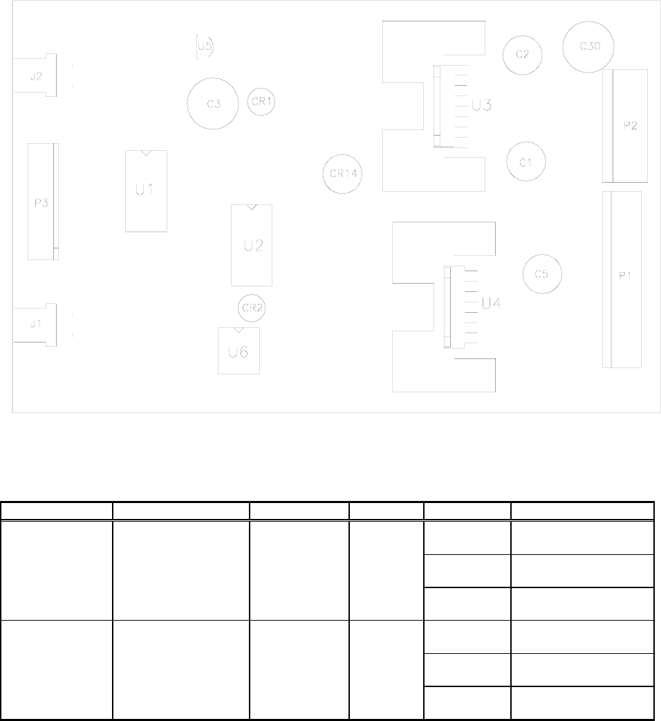
Wiring & Circuit Information 4-10
Audio Amplifier Board Assembly 04-12529.1
BB12 Audio Amplifier LED Indicator Table
Designation Location Function Color State Meaning
LED 1
(CR1) Upper Center
Near C3 Fault
Indicator Red Off Normal
Operation
On Locked Up
(Note 1)
Blinking Overload
(Note 2)
LED 2
(CR2) Lower Center
Near U2 & U6 Fault
Indicator Red Off Normal
Operation
On Locked Up
(Note 1)
Blinking Overload
(Note 2)
NOTES:
1. Active output protection circuit. Attempt to reset circuit by clearing fault and removing power.
2. Intermittent audio overload or overheating may cause blinking. LED should flash only during startup.
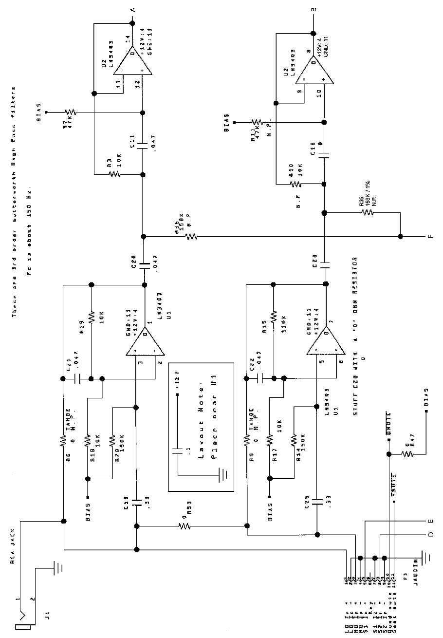
Wiring & Circuit Information 4-11
Audio Amplifier Board Schematic, 1/4
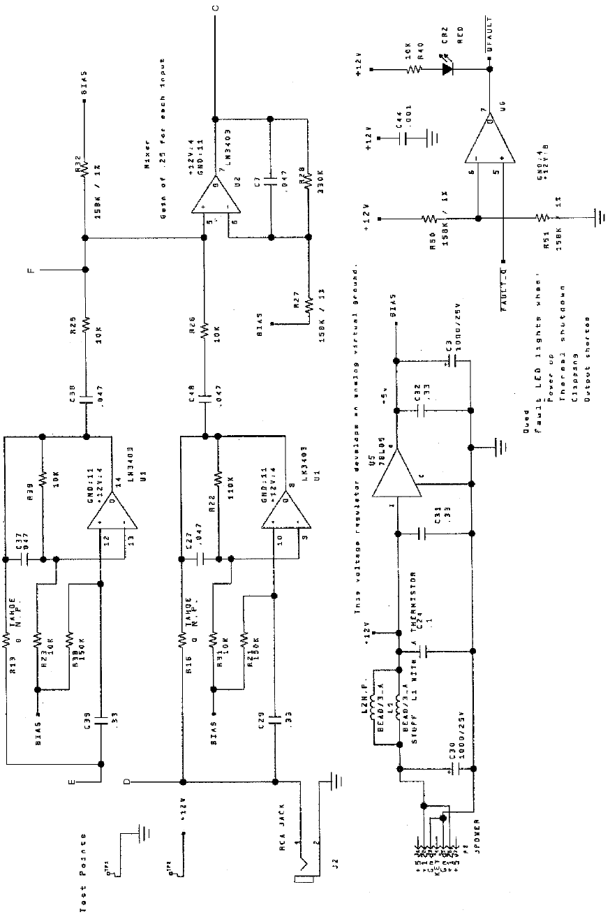
Wiring & Circuit Information 4-12
Audio Amplifier Board Schematic, 2/4
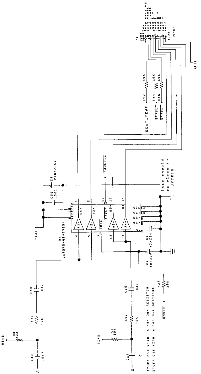
Wiring & Circuit Information 4-13
Audio Amplifier Board Schematic, 3/4
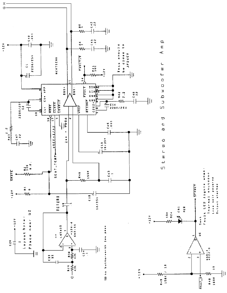
Wiring & Circuit Information 4-14
Audio Amplifier Board Schematic, 4/4

Wiring & Circuit Information 4-15
MagicBus
Interface Board Assembly 04-12697.3
MagicBus
Interface Board Switches
Designation Location Function Positions State Meaning
S1-7 Right Center Near
D19 – D26 USB / UART
Mode Selector 2 Off* UART Mode
(Offroad VGMs)
On USB Mode
S1-8 Right Center Near
D19 – D26 Host Watchdog
Reset 2 Off* Watchdog
Enabled
On Watchdog
Disabled
Notes:
1. Bank 1, Switch 7 should be off for Offroad Thunder. This switch selects USB or UART mode. USB
mode is for factory testing only, and is not supported. Leave this switch in the off position.
2. Bank 1, switches 1 through 6 have no assigned function. Leave these switches off.
3. Bank 2, switch 1 through 8 have no assigned function. Leave these switches off.

Wiring & Circuit Information 4-16
MagicBus
Board LED Indicator Table, 1/2
LED # Location Function Color State Meaning
LED 28 Left Center, Near
Fuse F2 & Off No +12V
+12V Power
for Output Connector JP12 Indicator Red On +12V Present
Lamps Blinking Intermittent +12V
LED 27 Off No +5V
+5V Power for
Analog Right, Near DIP
Fuse F1 Indicator Red On +5V Present
Inputs Blinking Intermittent +5V
LED 10 Off Not In Use
Communi-
cation Right Center, Near
DIP Switch S1 Indicator Red On Communication
Error
Blinking Normal Operation
LED 9 Off Not In Use
EEPROM Right Center, Near
DIP Switch S1 Indicator Red On EEPROM not
responding
Blinking Normal Operation
LED 8 Off Not In Use
Security Right Center, Near
DIP Switch S1 Indicator Red On Security error
Blinking Normal Operation
LED 7 Off Not In Use
MagicBus
Reset Right Center, Near
DIP Switch S1 Indicator Red On MagicBus Reset
Blinking Normal Operation
LED 6 Off Faulty MagicBus
Board
MagicBus
Program Right Center, Near
DIP Switch S1 Indicator Green On Faulty MagicBus
Board
Running Blinking Normal Operation
LED 5 Off Not In Use
UART / USB
Mode Right Center, Near
DIP Switch S1 Indicator Green On Faulty MagicBus
Board
Blinking With 4 & 3: UART;
Individually: USB
Wiring & Circuit Information 4-17
MagicBus
Board LED Indicator Table, 2/2
LED 4 Off Not In Use
UART / USB
Mode Right Center, Near
DIP Switch S1 Indicator Green On Faulty MagicBus
Board
Blinking With 5 & 3: UART;
Individually: USB
LED 3 Off Not In Use
UART / USB
Mode Right Center, Near
DIP Switch S1 Indicator Green On Faulty MagicBus
Board
Blinking With 5 & 4: UART;
Individually: USB
LED 1 Off No Power
Power to
MagicBus
Center, Near
Fuse F2 Indicator Red On Power Present
Board Blinking Intermittent Power
MagicBus
Interface Connector & Jumper Table
Jumper Location Function Meaning Setting Default
JP 1 Upper Right Blue High Impedance Open
Between Video Low Impedance 1 & 2
(Note 1) JP4 and JP2 Impedance High Impedance 2 & 3
JP 2 Upper Right Green High Impedance Open
Between Video Low Impedance 1 & 2
JP1 & JP3 Impedance High Impedance 2 & 3
JP 3 Upper Right Red High Impedance Open
Between Video Low Impedance 1 & 2
(Note 3) JP2 & JP5 Impedance High Impedance 2 & 3
JP 4 Upper Right Video Positive Sync Open
Near Sync Negative Sync 1 & 2
(Note 3) JP1 & JP2 Polarity Positive Sync 2 & 3
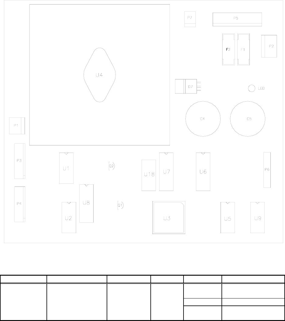
Wiring & Circuit Information 4-18
Wheel Driver Board Assembly 04-12770.1
Wheel Driver Board Led Indicator Table
Designation Location Function Color State Meaning
LED 1 Right Center, Near
C5 & P2 Indicator Red Off Not In Use
On Normal Operation
Blinking Power Fault
(Note 1)
Notes:
1. LED 1 monitors regulated power supply voltage source. Must be on continuously. Flash or blinking
indicates intermittent connection, power problem, circuit fault, etc.
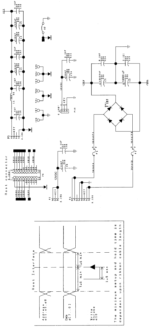
Wiring & Circuit Information 4-19
Wheel Driver Board Schematic, 1/8
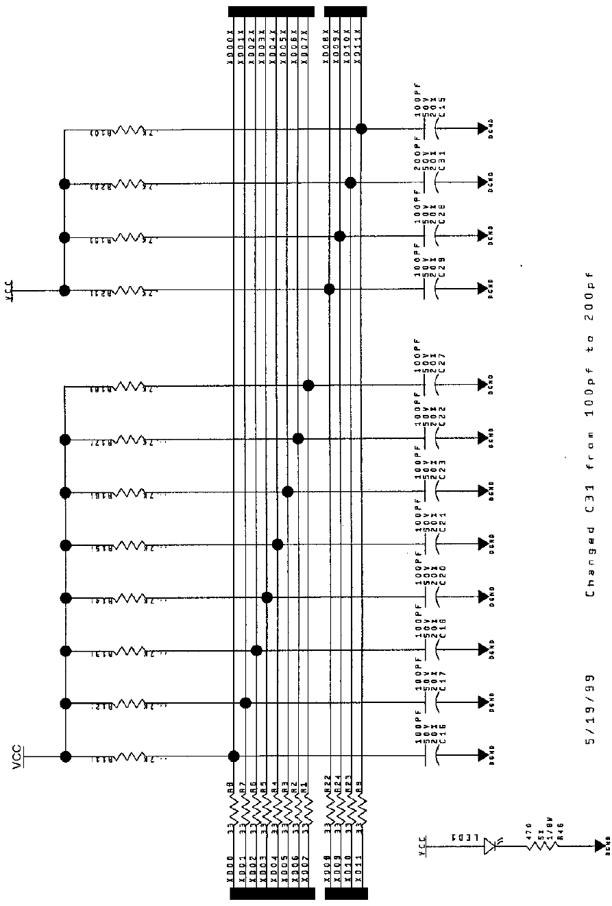
Wiring & Circuit Information 4-20
Wheel Driver Board Schematic, 2/8
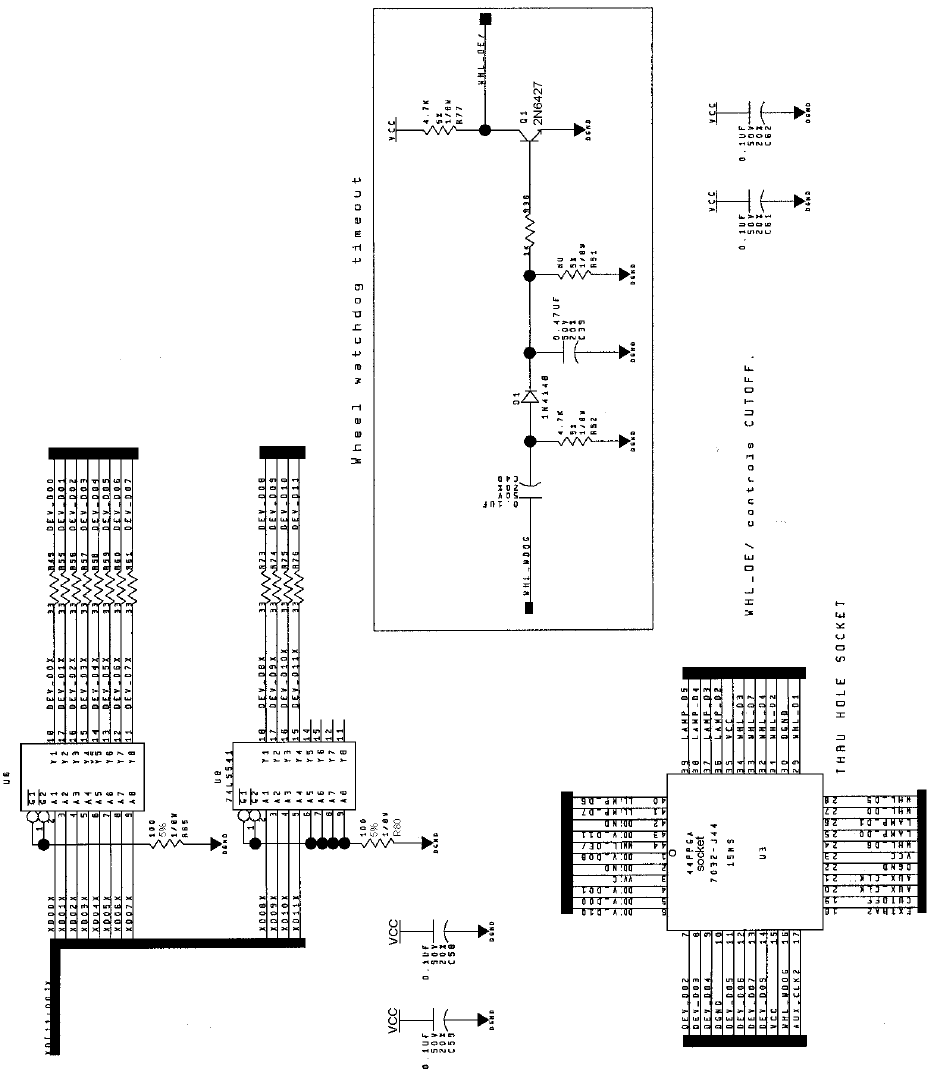
Wiring & Circuit Information 4-21
Wheel Driver Board Schematic, 3/8
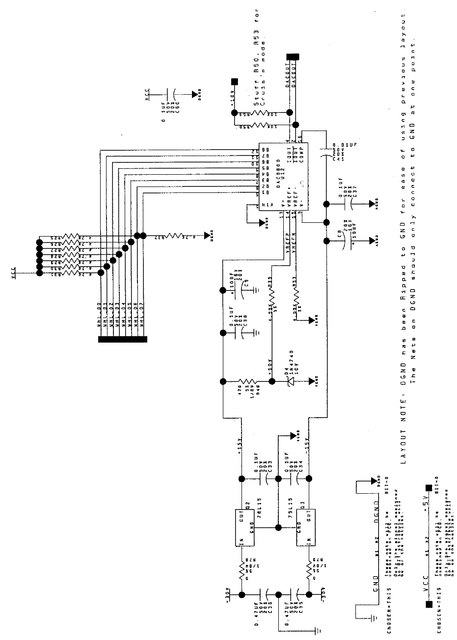
Wiring & Circuit Information 4-22
Wheel Driver Board Schematic, 4/8
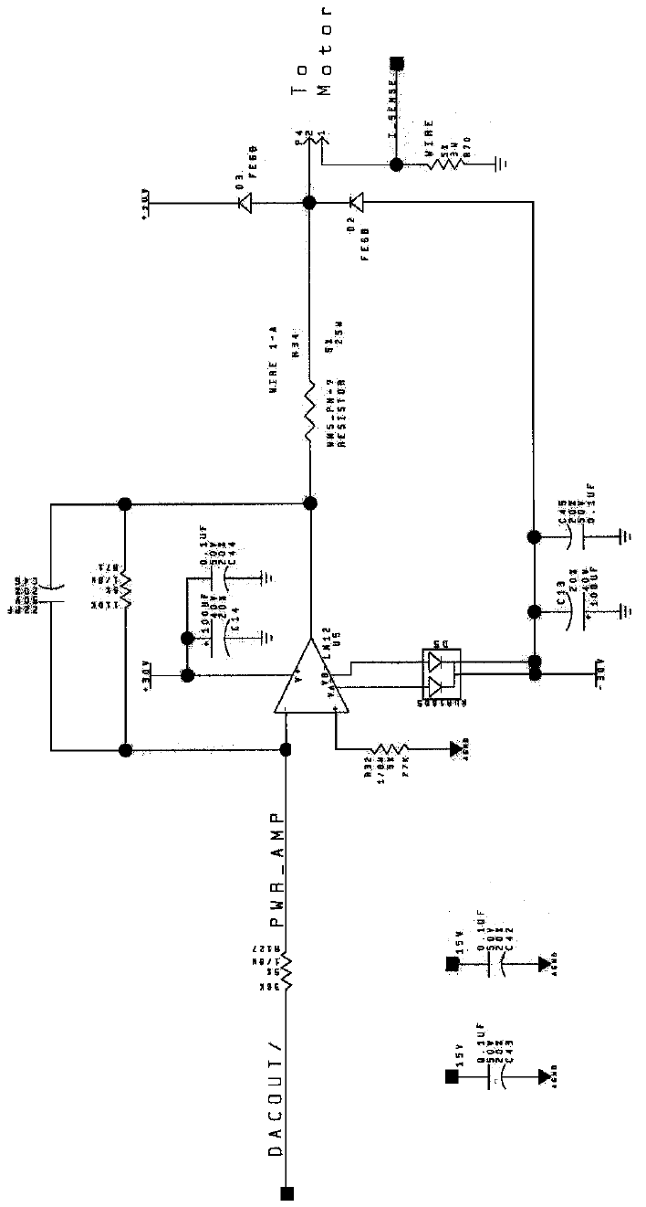
Wiring & Circuit Information 4-23
Wheel Driver Board Schematic, 5/8
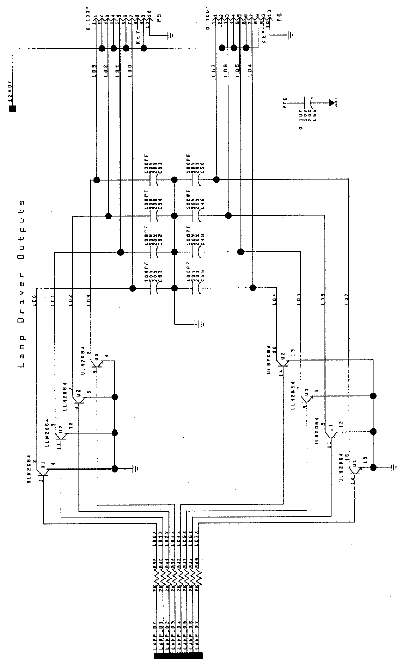
Wiring & Circuit Information 4-24
Wheel Driver Board Schematic, 6/8
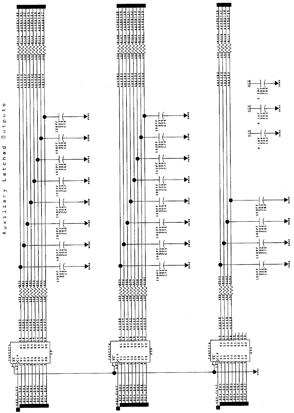
Wiring & Circuit Information 4-25
Wheel Driver Board Schematic, 7/8
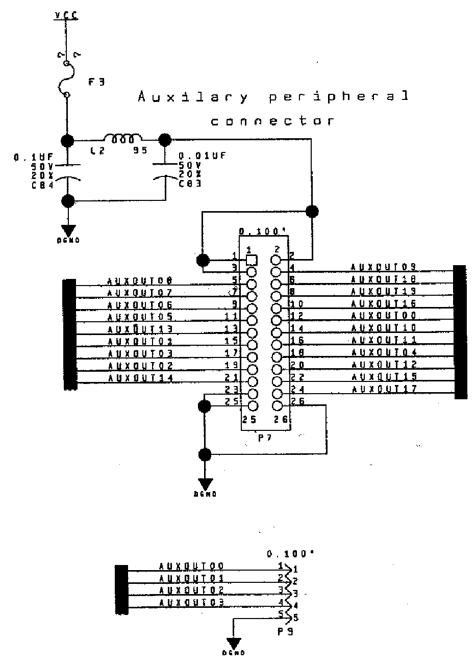
Wiring & Circuit Information 4-26
Wheel Driver Board Schematic, 8/8
Servicing 5-1
O
OO
OFFROAD
FFROADFFROAD
FFROAD
THUNDER
THUNDERTHUNDER
THUNDER
TM
CHAPTER
5
SERVICING
NOTICE: The term VGM refers to the video game machine.
NOTICE: Avoid damage to electronics! Turn off VGM power before servicing circuit
boards or any electronic assembly. Never “hot plug” circuit boards.
CAUTION: Static electricity builds up on your body. This static can damage or destroy
sensitive circuits. Before touching or handling electronics, discharge static electricity by
touching the power supply chassis.
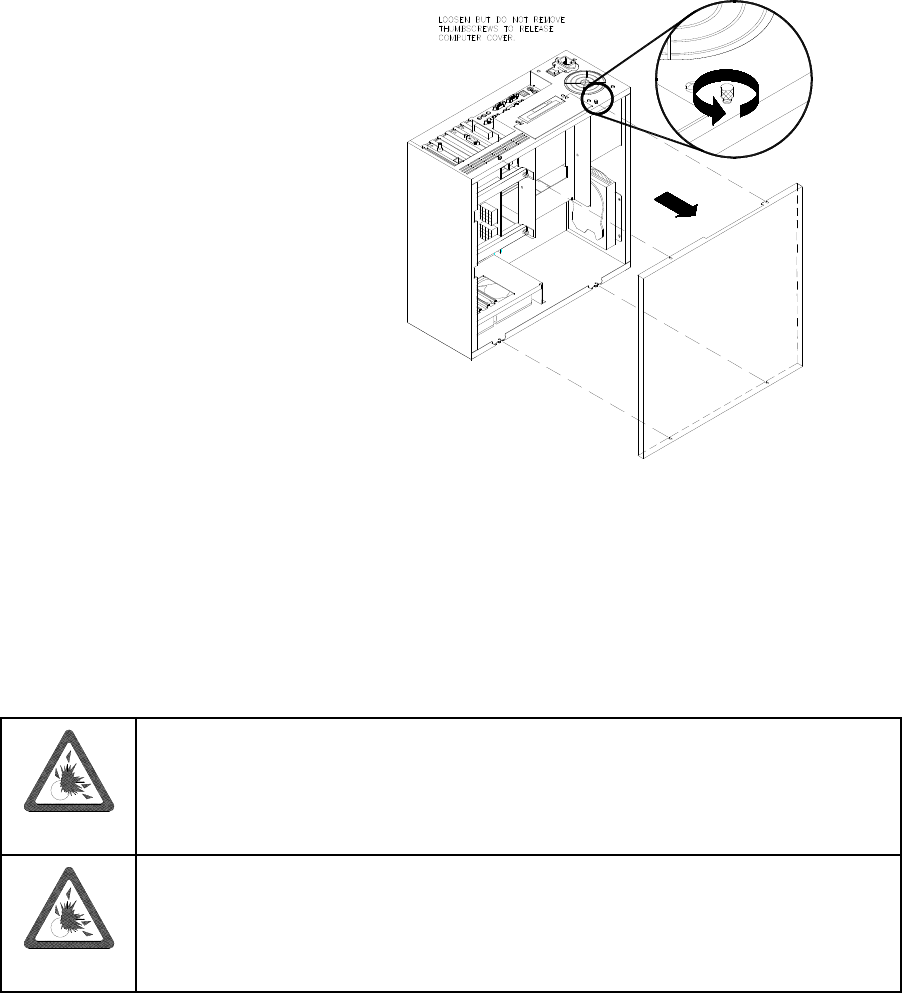
Servicing 5-2
DISASSEMBLY & REASSEMBLY
This chapter includes summarized procedures for disassembling and reassembling VGM components.
Only qualified service personnel should repair VGM equipment. The following product guidelines apply to
all video game operators and service personnel. Notes, cautions and warnings appear throughout this
manual where they apply. Study the Safety pages before beginning service.
• Arcade Computer
Switch off power to the VGM. Open
and remove the rear door. The
Arcade Computer is behind this door.
To expose Arcade Computer circuitry,
loosen four metal thumbscrews. Don’t
remove the screws. These screws
reside at the top and bottom corners
of the case. Slide off the back of the
computer. For most computer service,
you must also separate the Player
Panel Cabinet and Monitor Cabinet.
• Audio Amplifier Board
Switch off power to the VGM. Unlock and raise the top door of the Player Panel Cabinet. Note the
orientation of the connector and other cables. Extract the harnesses from the board connectors.
Remove mounting screws and washers from the Audio Board. Lift the board off its mounting posts.
Handle the board by a heatsink. If you aren’t reinstalling the board, store it in an anti-static bag and
protective container.
• Battery
CAUTION: If you install the battery incorrectly, it may explode! Avoid direct shorts
across the terminals or from terminals to ground. These batteries are designed for
very long life. Don’t attempt to recharge these batteries!
CAUTION: Avoid an explosion! Replacement batteries must match the originals in
size, voltage rating, and composition. Manufacturer recommended equivalent types
are acceptable. Store batteries in a safe place until you’ve completed repairs.
Dispose of used batteries according to manufacturer instructions.
A battery on the CPU Board retains data in memory during power disruptions. This battery is a 3-volt,
lithium button cell. Switch off power to the VGM. Separate the Player Panel Cabinet and Monitor
Cabinet. Unlock and raise the top door of the Player Panel Cabinet. The Arcade Computer is under
this door. Remove the back of the Arcade Computer. The battery resides toward the edge of the
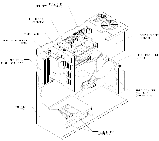
Servicing 5-3
motherboard, near the daughter board sockets. Carefully pry up the battery retaining lever. Then
grasp the battery edges and remove the device. Set the battery aside.
Note the “+” marking on one side of the replacement battery. When you install a battery, this “+”
marking must face the battery retaining lever. After replacing the battery, set the system clock to the
correct date and time. Also enter the Menu System and check or update system adjustments as
necessary.
• Coin Counter
Meter replacement requires vault removal. Switch off power to the VGM. Unlock and open the coin
door and cashbox door. Find the meter behind the bottom of the cashbox door. Remove the cashbox.
Remove two mounting screws at the bottom (front) of the vault assembly. Reach through the cash
door. You’ll find two mounting screws at the back of the vault. Remove these. Access the four
remaining vault screws from the inside-back of the cabinet. Remove these four screws. Slide the vault
out of the cabinet.
Locate the meter wires under the vault. Disconnect wiring at the connector. Remove two mounting
screws from the front of the meter. Remove the meter. Assure that the replacement meter has a
diode across its terminals. This diode protects driver circuits from the meter’s inductive kick. Install
the new meter. Log the new meter count.
• Coin Mechanism
Switch off power to the VGM. Unlock the coin door and swing it open. To clean or replace a coin
mechanism, unlatch and remove it. After reinstallation, assure that the mechanism seats fully in its
bracket. Close and lock the release latch. Then close the door. Enter the Menu System to change the
coin mechanism setup. Test known good and bad coins to verify operation.
• CPU Board
The CPU Board is part of the Arcade
Computer. Switch off power to the
VGM. Separate the Player Panel
Cabinet and Monitor Cabinet. Unlock
and raise the top door of the Player
Panel Cabinet. The Arcade Computer
is under this door. Find the four metal
thumbscrews at the top and bottom
corners of the computer case. To
expose the CPU Board, loosen, but
don’t remove these screws. Slide off
the back of the computer. Disconnect
the floppy disk power and data cables
at the disk drive. Remove the floppy
drive mounting bracket. Lift the
bracket and floppy drive out of the
cabinet. Set these aside for
reassembly. Remove the CPU Board
power cables at the CPU Board.
Remove the circuit board retention
bars. Remove the Video card,
Network card, and DC Filter board.
Disconnect the hard drive power and
data cables at the disk drive. Remove
CPU Board mounting screws. Lift the
circuit board out of the cabinet and set
it aside for reassembly. Use anti-static
packaging from new parts to store
boards that you won’t reinstall.
20-10551
04-12651
20-10550
A-23350
5795-15344-12
20-10552
20-10555
20-10554
04-12687
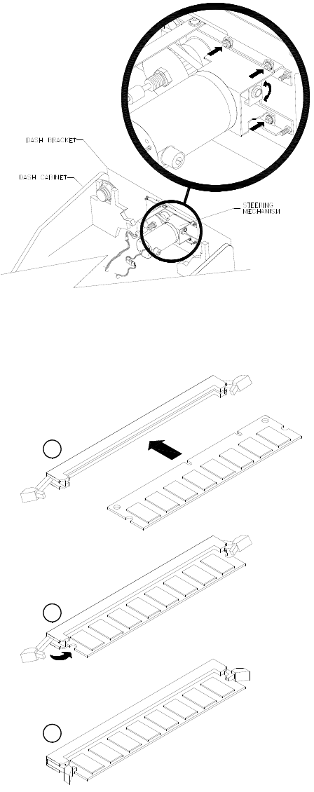
Servicing 5-4
• Dashboard and Steering Mechanism
Switch off power to the VGM. Separate the
Player Panel Cabinet and Monitor Cabinet.
Unlock and raise the top door of the Player
Panel Cabinet. Disconnect the wiring
harnesses from the dashboard. Support the
steering wheel. Remove one screw from
each corner of the instrument cluster.
Remove the support. Carefully set the dash
assembly on your workbench.
Inspect the motor, pulleys, and belt. If the
belt is broken or shows signs of wear,
replace it. Locate the two nuts on each side
of the motor mounting bracket. Loosen all
four bracket nuts. Rotate the tension
adjustment bolt as necessary. Tighten this
bolt until the belt is taut. Then restore correct
tension by loosening the bolt one full turn.
Tighten the motor bracket nuts.
• DIMMs (Dual In-Line Memory Modules)
DIMM circuits contain the computer read-write
memory for this VGM. Switch off power to the
VGM. Separate the Player Panel Cabinet and
Monitor Cabinet. Unlock and raise the top door
of the Player Panel Cabinet. Remove the back
of the Arcade Computer. Unplug the ribbon
cable from the floppy drive. Leave the other
end of the cable attached to the CPU Board.
Unscrew and remove the circuit board retention
bars. Remove the floppy drive mounting
bracket. Remove the floppy drive. Note DIMM
positions. Press out on the locking retainer on
each side of the DIMM. The DIMM should
partially or completely pop out of its socket. Lift
the DIMM from its socket. Handle the DIMM
only by its edges.
To reinstall memory circuits, orient the DIMM
over its socket. Make sure that you’ve
positioned the keying holes and notch properly.
Push the DIMM board into its socket, so that
the board snaps into place under the locking
retainer on each side of the socket. Be sure
that the retainers mate tightly with DIMM board
notches. Don’t attempt to force a DIMM into its
socket.
C
B
A
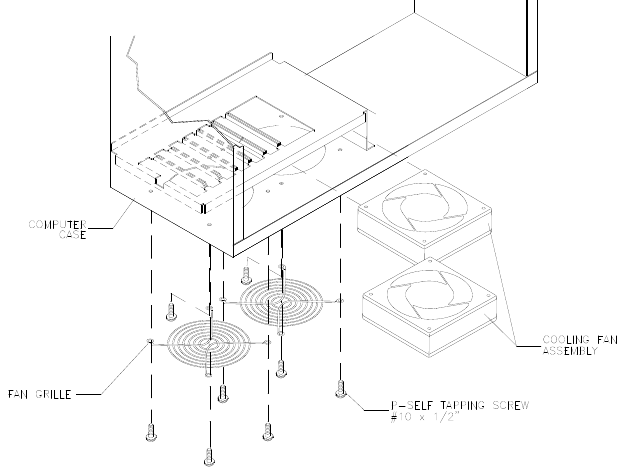
Servicing 5-5
• Dollar Bill Validator
(Use MARS AE2451-U3E, UL-recognized currency changer)
You can install dollar bill validators in VGMs manufactured with the additional wiring connector. Other
currency acceptors will also work with this connector.
Switch off power to the VGM and unplug the AC line cord. Unlock the coin door and swing it open.
Read the coin door label for additional information.
Remove nuts, spacers, and the cover plate from the door. before mounting the validator, change
switch settings or make adjustments. If the manufacturer supplied an adapter plate, place it over the
door cutout. Install spacers on threaded studs. Then align the validator mounting holes with the
studs. Seat the validator in the door opening. Install the nuts and tighten them.
Attach the ground wire (green with yellow stripe) lug to the door ground stud. The stud is beside the
hinge. Mate the wiring harnesses and press them together to fully seat connectors. Route wires away
from the door edges and hinge. Inspect the bill chute for proper alignment. Set the dollar bill validator
to produce 50ms output pulse widths, 1 pulse per dollar. This setting avoids counting errors. To
remove a validator for service or replacement, reverse these steps.
Plug in the line cord and turn on the VGM. From the Menu System, change the mechanism setup and
pricing. Then test known good and bad bills to verify proper operation. Close and lock the coin door.
• Fans
The Arcade Computer incorporates several fans. Two fans reside at the bottom of the Arcade
Computer enclosure. The power supply includes one fan. Inside the microprocessor cartridge is
another small fan.
Switch off power to the
VGM. Separate the Player
Panel Cabinet and Monitor
Cabinet. Unlock and raise
the top door of the Player
Panel Cabinet. Remove the
back of the Arcade
Computer.
FANS AT THE BOTTOM
OF THE ENCLOSURE.
Disconnect the fan’s power
harness. Remove the fan
mounting screws. Note the
fan orientation. Each fan
has an arrow molded into its
plastic case to indicate
airflow direction. Slide the
fan out of its mounting
bracket. Be certain to
reinstall the fan in the
proper direction to assure
airflow over circuitry.
POWER SUPPLY FAN. The power supply contains no user-serviceable parts. Never open the power
supply.
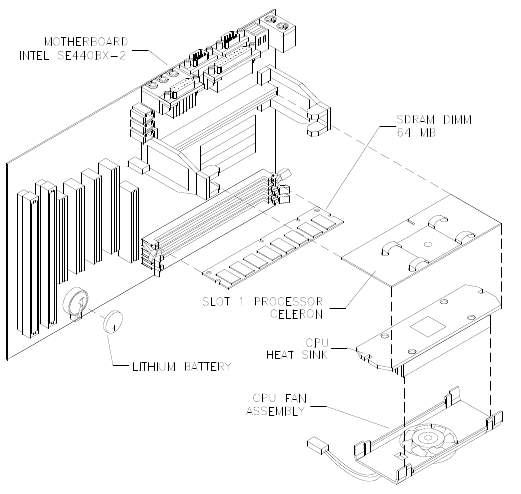
Servicing 5-6
MICROPROCESSOR FAN.
Unscrew and remove the
circuit board retention bars.
Remove the floppy drive
mounting bracket. Unplug the
ribbon cable from the floppy
drive. Remove the floppy
drive. Disconnect the fan’s
power harness. Remove the
microprocessor cartridge.
Squeeze the plastic end tabs
on the fan side of the
cartridge. While squeezing,
carefully pry the fan assembly
away from the heatsink. If the
fan is bad, replace the entire
fan assembly with a new one.
Reassemble the cartridge and
insert it into the computer.
Then reconnect fan power.
• Floppy Disk Drive
Switch off power to the VGM. Separate the Player Panel Cabinet and Monitor Cabinet. Unlock and
raise the top door of the Player Panel Cabinet. Remove the back of the Arcade Computer. Disconnect
the DC power cable from the floppy drive Unplug the ribbon cable from the floppy drive. Leave the
other end of the cable attached to the CPU Board. Unscrew and remove the circuit board retention
bars. Remove the drive bracket mounting hardware. Remove the bracket. Remove the drive
mounting screws. Lift the drive off the mounting bracket. Save the mounting screws for reuse in future
floppy drive installations. When returning a floppy drive to your distributor, pack it in an anti-static bag.
REINSTALLATION. Mount the floppy drive in its bracket. Install the drive mounting screws. Reinstall
the bracket and drive in the Arcade Computer enclosure. Connect the drive’s ribbon and power
cables.
• Front Housing
OPENING THE DOOR AND HOUSING. Switch off power to the VGM. Unlock the front cabinet door
and swing it open. Release the latches at the corners under the front housing. Gently pull out on the
bottom of the formed front housing and swing it towards the control section. Remove the free end of
the prop rod from the retainer at the left side of the monitor shelf. Swing the rod up until it rests in the
rod bracket on the lower right side of the front housing. Lower the housing until the prop rod supports
the housing’s weight.
CLOSING THE DOOR AND HOUSING. Snap the rod into the retainer. Close the housing. Engage
latches and snap them shut. Close the front cabinet door
• Pedal Assembly
Switch off power to the VGM. Unlock and raise the top door of the Player Panel Cabinet. Disconnect
the pedal cable from the wiring harness. Disconnect the safety ground from the pedal frame. Adjust
the seat to the maximum rear position. Remove four outer mounting screws from the front perimeter
of the pedal plate. Pull the pedal toward the seat until it clears the opening. Then lift it up and away
from the cabinet.
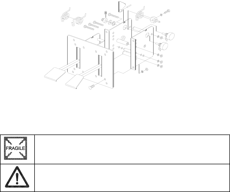
Servicing 5-7
• Gear Shift
Switch off power to the VGM. Unlock and raise the top door of the Player Panel Cabinet. Disconnect
the two cables from the back of the shifter. At the front of the shifter, remove shift plate mounting
screws. Lift the shifter up and out of the player panel.
• Hard Disk Drive
CAUTION: Hard disk drives are very fragile! Handle them with care. Keep disk
drives away from magnets, heat and vibration. Don’t move a VGM with the power
on.
CAUTION: Don’t stack or drop hard disk drives. Use an anti-static bag and an
approved shipping container to return the drive to your distributor.
Switch off power to the VGM. Separate the Player Panel Cabinet and Monitor Cabinet. Unlock and
raise the top door of the Player Panel Cabinet. Remove the back of the Arcade Computer. Disconnect
the DC power cable from the hard drive. Unplug the ribbon cable from the hard drive. Leave the other
end of the cable attached to the CPU Board. Remove the drive mounting screws. (Don’t remove the
drive-mounting bracket.) Lift the drive out of the cabinet. Save the mounting screws for reuse in future
hard drive installations. When returning a hard drive to your distributor, pack it in an anti-static bag.
Box the drive in approved shipping container 08-8068.
REINSTALLATION. Before mounting the hard drive in its bracket, install the drive mounting screws.
To avoid damage during installation, mount the hard drive in the brackets before connecting cables.
After a driver plays one game, the new drive copies data from other linked VGMs. Important! The
data won’t copy if players are actively driving. Files transfer only when all VGMs return to Attract
Mode.
• MagicBus
Interface Board
Switch off power to the VGM. Unlock and raise the top door of the Player Panel Cabinet. Extract the
harnesses from the board connectors. Remove mounting screws and washers from the MagicBus
Board. Remove the MagicBus Board. Lift the board off its mounting posts. During reinstallation,
tighten the screws: Start at the board’s center and work toward the outer edge. If you aren’t
reinstalling the board, store it in an anti-static bag and protective container.
• Marquee
Switch off power to the VGM. Open the front, monitor cabinet door. To replace the marquee, you
must completely remove the front housing from the monitor cabinet. Then you can access the

Servicing 5-8
marquee, and remove it from the bezel. Take the glass and artwork out of the front housing. Clean
the glass before reinstalling it. Install the bracket and tighten screws. Replace the front housing on the
monitor cabinet. Tighten mounting screws. Don’t use excess force.
• Mars Light Driver Board
Switch off power to the VGM. Unlock and remove the rear door of the Monitor Cabinet. Note the
orientation of the connector and the other cables. Extract the harnesses from the board connectors.
Remove mounting screws and washers from the Mars Light Driver Board. Lift the board off its
mounting posts. Handle the board by the edges. If you aren’t reinstalling the board, store it in an anti-
static bag and protective container.
• Microprocessor
This VGM’s microprocessor is in a postcard-size cartridge that also includes cache RAM. The
cartridge is inside the Arcade Computer, near the DIMM sockets. Switch off power to the VGM.
Separate the Player Panel Cabinet and Monitor Cabinet. Unlock and raise the top door of the Player
Panel Cabinet. Remove the back of the Arcade Computer. Unplug the ribbon cable from the floppy
drive. Leave the other end of the cable attached to the CPU Board. Unscrew and remove the circuit
board retention bars. Remove the floppy drive mounting bracket. Remove the floppy drive.
Disconnect the microprocessor fan power harness. Spread the locking retainers on each side of the
microprocessor cartridge. Pull the cartridge out of its socket. Take care not to touch the copper traces
on the socket.
To reinstall a microprocessor cartridge, orient the cartridge over its socket. Make sure that you’ve
positioned the keying notch properly. Push the microprocessor cartridge into its socket, so that the
cartridge snaps into place under the locking retainer on each side of the socket. Be sure that the
retainers mate tightly with cartridge notches. Don’t attempt to force a cartridge into its socket.
Reconnect the microprocessor fan harness.
• Monitor
WARNING: The video monitor is very heavy, with most of the weight toward
the front. Solidly support the monitor as you remove from it from the cabinet.
WARNING: When operating the monitor outside the cabinet, use an isolation
transformer. In normal operation, the monitor doesn’t require isolation from AC
line voltage.
The monitor is very heavy and difficult to balance. Removing the monitor is a two-person task. Don’t
attempt to remove it by yourself. Switch off power to the VGM. Open the front cabinet door.
Disconnect the fluorescent light assembly connector and all monitor cables. Remove the front
housing hinge screws and set the housing aside. Remove the monitor bezel and both barrier panels.
Remove the four flange nuts securing the monitor's mounting brackets to its mounting panel. Pull the
monitor carefully from the cabinet and set in a safe place. The monitor remote adjustment board is
behind the front door with the rest of the electronics. Clean the face of the CRT before reinstalling the
barrier panels and the monitor bezel.
The monitor is a medium resolution type. Other monitors may look as if you can use them for
replacements. Yet the screens of different monitor types curve differently. Only medium resolution
monitors fit correctly against the monitor bezel. Other monitor styles won’t seal properly, and also
won’t synchronize.
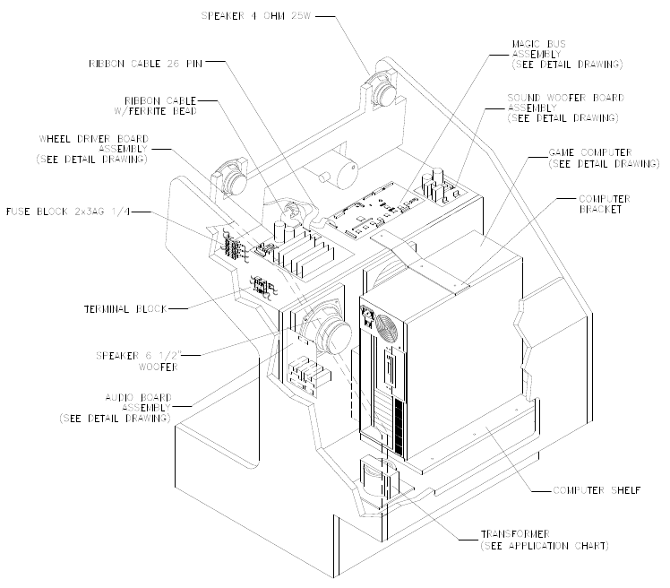
Servicing 5-9
• Network Interface Board
Switch off power to the VGM. Unlock and raise the top door of the Player Panel Cabinet. Remove the
back of the Arcade Computer. Note the orientation of the cables. Loosen the header-mounting screw.
Disconnect the network cables from the board header connectors. Remove the circuit board retention
bars. Remove the board. As you remove the board, handle it only by its edges. Don’t touch the
copper traces! If you aren’t reinstalling the board, store it in an anti-static bag and protective
container.
• Power Filter Board
Switch off power to the VGM. Unlock and raise the top door of the Player Panel Cabinet. Remove the
back of the Arcade Computer. Loosen the header-mounting screw. Disconnect the cables from the
board header connector. Remove the circuit board retention bars. Remove the board. As you remove
the board, handle it only by its edges. Don’t touch the copper traces! Use anti-static bags and
protective containers to store the board if you won’t reinstall it.
• Power Supply
Switch off power to the VGM. Disconnect the line cord. Unlock and raise the top door of the Player
Panel Cabinet. Remove the back of the Arcade Computer. Unplug the IEC AC power cord. Inside the
Arcade Computer, disconnect DC power cables. These connect to the hard drive, motherboard and
other peripherals. Remove four mounting screws from the outside of the Arcade Computer enclosure.
Lift the power supply out of the cabinet. Before reinstalling the power supply, check the line voltage
switch setting.
• Speakers
This VGM has four speakers. One woofer is behind a grille at the back of the driver’s seat. Smaller,
full range speakers are behind the front of the Player Panel. Below these full-range speakers is one
more woofer. Switch off power to the VGM.

Servicing 5-10
ACCESSING THE SEAT WOOFER. Remove mounting screws and set the speaker grille aside. Don’t
use excess force when removing or tightening mounting screws threaded into plastic. Avoid speaker
damage by removing the upper mounting screws first. Replace these top screws last.
ACCESSING A PLAYER PANEL CABINET SPEAKER. Unlock and raise the top door of the Player
Panel Cabinet. Remove mounting screws from the rear of the speaker.
SPEAKER REMOVAL. Assure proper polarity by marking each speaker wire (“+” or “Gnd”). Remove
the speaker from the enclosure and disconnect the wire lugs.
• Sub-Woofer Driver Board
Switch off power to the VGM. Separate the Player Panel Cabinet and Monitor Cabinet. Unlock and
raise the top door of the Player Panel Cabinet. Note the orientation of the connector and the other
cables. Extract the harnesses from the board connectors. Remove mounting screws and washers
from the Sub-Woofer Driver Board. Lift the board off its mounting posts. Handle the board by a
heatsink. If you aren’t reinstalling the board, store it in an anti-static bag and protective container. The
board has two 0.5A, 250-volt fuses. Check these with an ohmmeter. Replace bad fuses only with the
identical type.
• A.C. Power Chassis
Switch off power to the VGM. Unlock and remove the rear door of the Monitor Cabinet. Note the
orientation of the connector and the other cables. Disconnect A.C. Power Chassis harness
connectors. Remove mounting hardware from the chassis. Lift the chassis out of the cabinet.
• Video Board
Switch off power to the VGM. Separate the Player Panel Cabinet and Monitor Cabinet. Unlock and
raise the top door of the Player Panel Cabinet. Remove the back of the Arcade Computer. Loosen the
header-mounting screw. Disconnect the video cable from the board header connector. Remove the
circuit board retention bars. Remove the board. As you remove the board, handle it only by its edges.
Don’t touch the copper traces! Use anti-static bags and protective containers to store the board if you
won’t reinstall it.
• Viewing Glass
Switch off power to the game. Open the front cabinet door. To replace the viewing glass, you must
completely remove the front housing from the monitor cabinet. Lift the glass out of the front housing.
Clean the glass before reinstalling it. Install the bracket and tighten screws. Replace the front housing
on the monitor cabinet. Tighten mounting screws. Don’t use excess force.
CAUTION: Before you replace the CRT viewing glass, completely remove the
front housing assembly from the cabinet. Glass is hazardous to handle with the
housing pivoted up on the drop rod.
• Wheel Driver Board
Switch off power to the VGM. Separate the Player Panel Cabinet and Monitor Cabinet. Unlock and
raise the top door of the Player Panel Cabinet. Note the orientation of the connector and the other
cables. Extract the harnesses from the board connectors. Leave the other end of the ribbon cable
connected to the MagicBus Board. Remove four mounting screws and washers from the Wheel
Driver Board. Lift the board off its mounting posts. Handle the board by the heatsink. If you aren’t
reinstalling the board, store it in an anti-static bag and protective container.
Troubleshooting 6-1
O
OO
OFFROAD
FFROADFFROAD
FFROAD
THUNDER
THUNDERTHUNDER
THUNDER
TM
CHAPTER
6
TROUBLESHOOTING
NOTICE: The term VGM refers to the video game machine.
CAUTION: This VGM uses complex electronic components that are very sensitive to
static electricity. Observe the following precautions before handling VGM electronics.
Failure to do so may void your warranty and could damage electronic assemblies.
• Before servicing electronics, turn off AC power to the VGM. Wait for capacitors to discharge.
• Before touching or handling electronic assemblies, discharge static electricity on your body. To
discharge this static, begin by connecting the line cord to a grounded outlet. Don’t turn on the
VGM! Next, touch the safety ground stud of the power supply chassis.
• Store electronic assemblies in an anti-static area. Use anti-static bags to store or transport VGM
circuit boards. Transport the hard drive in its shipping container.
• Don’t remove or connect electronic assemblies when cabinet power is on. Otherwise, you’ll
damage electronic assemblies and void the VGM warranty.
• After you complete maintenance or service, replace ground wires, shields, safety covers, etc.
Install and tighten ground and mounting screws.

Troubleshooting 6-2
Coin Mechanism and Pricing Troubleshooting Table
SYMPTOM CAUSE REQUIRED ACTION
Improper settings at
Pricing Menu
From Adjustments Menu, choose PRICING
MENU. Verify that units and credits are set
correctly.
Faulty wiring 1. Check that cabinet wiring is correct for this
VGM.
2. Assure that coin meter and coin switches
connect properly to control input wires.
• VGM (video game machine)
accepts currency or tokens,
but number of credits per
coin or bill is incorrect.
Incorrect pulse width
on bill validators 1. Consult bill validator manufacturer’s literature.
Adjust pulse width on validator to long setting.
2. Retest validator operation.
Improper currency 1. Unlock and open cash door. Empty cash box.
Inspect revenue for counterfeit currency.
2. Check vault. Remove any items that block path
from mechanism.
Faulty coin
mechanism
1. Unlock and open coin door. Check each
mechanism for proper mounting.
2. Remove mechanism.
3. Clear currency path.
4. Reinstall mechanism and latch it.
5. Enter Menu System by pressing and holding
TEST MODE switch inside coin door. From
Diagnostics Menu, choose SWITCH TEST. Use
tests to confirm operation of coin switches.
• VGM won’t accept currency
or tokens.
• VGM won’t start.
• Audio and video are present.
Tilted coin
mechanism or VGM
1. Verify that mechanism is level after doors close.
2. Repair or replace coin door if it is bent or
damaged.
3. If necessary, adjust cabinet leg levelers to keep
mechanisms vertical.
Burned-out bulb 1. Burned-out bulbs may appear white or
darkened. Check continuity with DVM.
2. Replace burned-out bulb with same type.
• Coin indicators don’t light
Open fuse circuit 1. Check fuse continuity with DVM.
2. If fuse is blown, replace fuse with same type.
3. If fuse isn’t blown, check wiring.
Typical Coin Mechanism Mounting
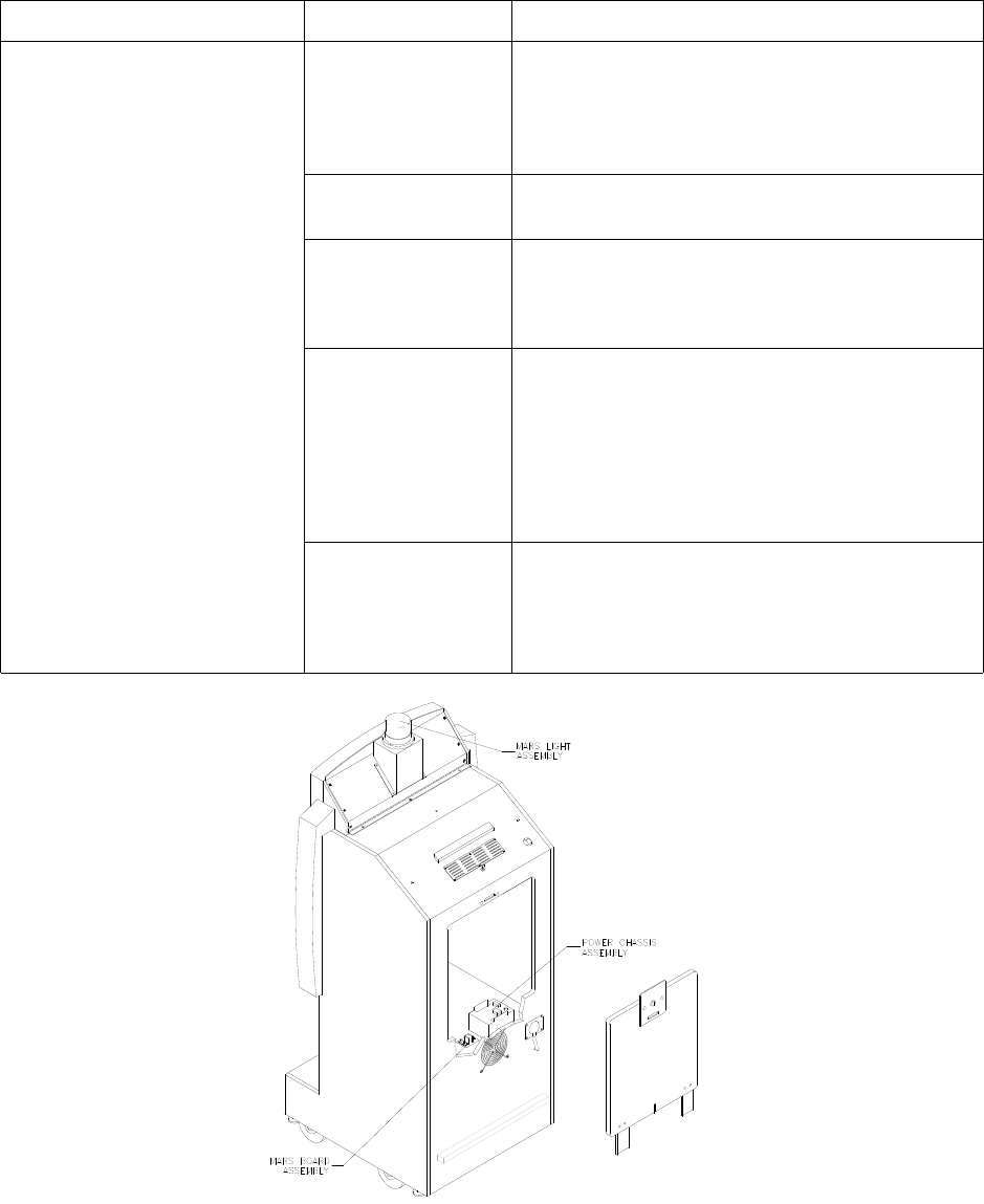
Troubleshooting 6-3
VGM Startup Troubleshooting Table
SYMPTOM CAUSE REQUIRED ACTION
Power problem 1. Check that VGM power switch is on.
2. Inspect computer to see if fans are turning. If not:
Is computer power supply connected to its power
cable? Is computer power supply turned on?
3. Plug VGM into AC power outlet. Verify presence
of AC line voltage.
Improper line voltage
switch setting
Turn off VGM power. Unplug AC line cord. Check
line voltage switch. If necessary, set it to agree
with local AC line voltage. Retest VGM.
Open fuse 1. Turn off VGM power. Examine AC fuse at rear of
VGM, on AC cord plug plate.
2. Replace faulty fuses with identically rated parts.
3. Turn on VGM power. If fuse opens again, check
AC wiring harness and connectors.
Faulty wiring 1. Remove line cord. Test line cord, power plug,
and IEC connector for breaks or damage. Verify
continuity of each wire in cord. Install cord at
power chassis. Press connector firmly to seat it.
2. Check computer cord in same manner.
3. Assure that cabinet wiring harness connectors
fully seat in corresponding power supply and
board connectors.
4. Inspect wiring for breaks or damage.
• VGM (video game machine)
doesn’t start.
• VGM appears completely
non-functional.
• No audio
• No illumination
• No video display
Arcade computer
problem Turn off power for one minute and turn VGM on
again. Power On Self-Test checks electronics.
Screen may report errors. If video circuits don’t
operate properly, computer produces series of
beeps. (See Error Message Troubleshooting
Table.)
Location of Power Supply and Line Cord
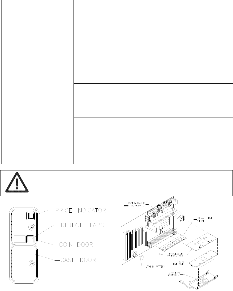
Troubleshooting 6-4
VGM Startup Troubleshooting Table, continued
SYMPTOM CAUSE REQUIRED ACTION
Power problem 1. Inspect circuit boards under low-light conditions.
LEDs glow if processor circuits receive voltage.
Fan should be turning. These indications prove
presence of DC from power supply. Still,
voltages or signals may not be normal.
Computer has no internal LEDs.
2. Turn on VGM power. Using 20-volt DC setting
on digital voltmeter, measure DC voltages at
power connector pins. (Power supply voltage
isn’t adjustable.)
3. Using 2-volt AC setting on digital voltmeter,
measure same DC voltages as above. Any
reading here indicates that supply voltages are
unstable and may contain ripple or noise.
Faulty wiring Turn off VGM power. Assure that wiring
harness connectors attach and fully seat onto
mating board connectors. Verify that harness
connects to computer.
Improper jumper or
DIP switch settings Verify that circuit board jumpers are set as
intended. Check DIP switch settings.
• VGM (video game machine)
appears non-functional.
• Currency acceptor price
indicator is illuminated.
Faulty circuit boards
or arcade computer
1. Run power-up self-test sequence. Note errors
or failures during tests. Compare LEDs with
LED indicator status charts. Note discrepancies.
2. Turn off computer. Wait for hard disk to stop
spinning. Leave VGM power on. Loosen
computer case thumbscrews and lift off cover.
Turn computer power on. Listen for beeping
sounds. Compare beeps with Error Message
Troubleshooting Table.
CAUTION: Don’t remove or install any connector while power is turned on. Doing so
will damage circuit boards or hard disk drive, and void warranty.
Front View of Coin Door Interior View of Electronics
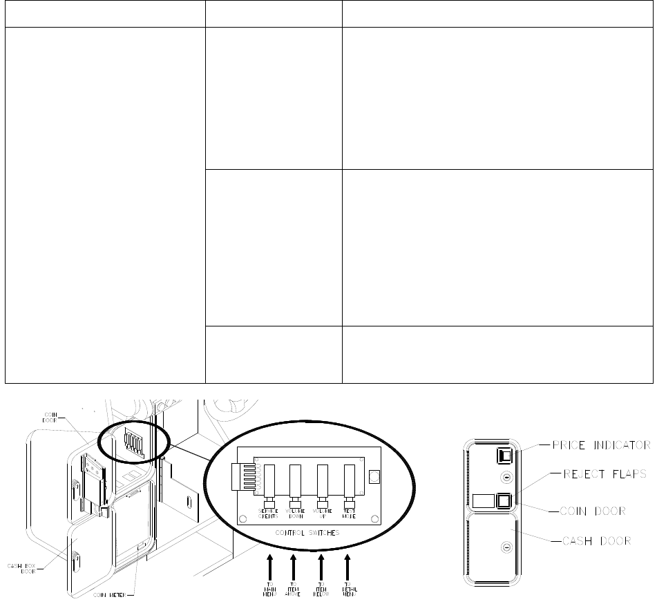
Troubleshooting 6-5
VGM Startup Troubleshooting Table, continued
SYMPTOM CAUSE REQUIRED ACTION
Faulty coin
mechanism
1. Unlock and open coin door. Check each
currency acceptor to assure proper mounting.
Verify that each release latch is closed and
locked. Does mechanism accept and reject
currency correctly? Test mechanism with good
and bad coins.
2. Inspect to see if external acceptor indicators
(Pricing, Flashing Arrows, etc.) are lit.
1. Verify that each acceptor operates properly by
placing it in working VGM. Replace bad parts.
Faulty switches 1. Enter Menu System by pressing and holding
TEST MODE switch inside coin door. From
Diagnostics Menu, choose SWITCH TEST. Use
tests to confirm operation of each switch in VGM.
2. Assure that no loose parts or wires are caught in
switch contacts.
3. Check for continuity in each suspect switch
connection (Common to Normally Open or
Common to Normally Closed).
4. Replace faulty switches (bent levers, broken
actuators, etc.).
• VGM (video game machine)
doesn’t start.
• VGM accepts currency or
tokens.
• Audio and video are present.
Faulty wiring 1. Assure that no wires are caught in hinges,
latches or switch contacts.
2. Check wiring continuity from circuit board
connectors to acceptors.
Interior View of Coin Door and Cash Door

Troubleshooting 6-6
Audio Troubleshooting Table
SYMPTOM CAUSE REQUIRED ACTION
Improper volume
setting
Enter Menu System by pressing and holding
TEST MODE switch. From Operator (Main)
Menu, choose VOLUME MENU. Check that
Attract Music is on (enabled). Verify that all
volume levels are set well above zero. If
necessary, change levels to make VGM audible.
Faulty wiring Turn off VGM power. Assure that wiring harness
connectors attach and fully seat onto mating
board connectors. Verify that harness connects
to computer. Check audio cable connectors in
same way.
Faulty or obstructed
speaker Remove grilles and inspect speakers. Free
speaker cones, terminals, mounting screws and
magnets of loose parts or wires.
• No audio
• Video is present
• VGM (video game machine)
appears to operate normally
Faulty Audio Board Verify proper operation of Audio Board by
placing it in working VGM.
Faulty wiring 1. Check that cabinet wiring is correct for this VGM.
2. Verify that cabinet wiring provides separate wires
(not common return) for each speaker.
3. Check connection of all cabinet ground wires.
Faulty Audio Board 1. Run power-up self-test sequence. Note errors
that VGM finds during tests.
2. Verify that BB12 Audio Board operates by
placing it in working VGM.
3. If problem persists: Check regulator U5;
capacitors C1, C2, C3, C14 and C30.
4. Replace bad parts.
• Constant low hum from all
speakers.
Faulty power supply Using 2 Volt AC setting on digital voltmeter,
measure voltages at speaker terminals. Any
reading indicates unstable supply that may
contain ripple or noise.
Faulty or improper
speaker
1. Turn off VGM power. Remove grilles and check
speakers. Assure that speakers are full range
(100 to 10,000 Hz response) and rated for at
least 20 watts. Woofers must be rated for at least
40 watts.
2. Verify proper speaker operation by connecting
speaker in question to working VGM.
• Audio is distorted, muffled or
has missing frequencies.
Faulty wiring Multiple-speaker installations: Check for
reversed wires at one speaker. Weak low
frequencies and thin or hollow sound quality is
symptom of incorrectly phased speakers. Sound
tests may not detect this condition, but you can
hear it during Game Mode.
Faulty speaker 1. From Diagnostics Menu, choose SOUND TEST.
Recheck speakers with audio signals provided
by test.
2. Verify proper speaker operation by connecting
speaker in question to working VGM.
Faulty circuit board Run power-up self-test sequence. Note errors
that VGM finds during tests. Compare circuit
board LEDs with LED indicator status charts.
Note discrepancies.
• Dead sound channel
Faulty wiring Verify that cabinet wiring is correct. Assure that
all speakers connect to audio wires. Audio cable
must be fully seated in Computer Line Output
Jack. Check for broken or shorted wires.
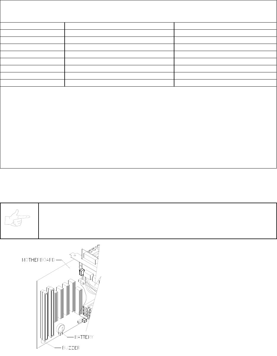
Troubleshooting 6-7
Error Message Troubleshooting Table
Power-On Self-Test Beep Codes
Audio beeps only. Video may or may not be present. See notes.
MESSAGE MEANING REQUIRED ACTION
No beep No system power Check power supply and cables
1 continuous beep Partial system power Check power supply and cables
1 short beep Normal start; no errors Check other VGM components
2 short beeps Processor problem Check processor/fan module
3 short beeps Graphics initialization problem Check Video Board, cables
4 short beeps Processor problem Check processor/fan module
5 short beeps Insufficient system memory Check DIMM circuit modules
6 short beeps Peripheral problem Check other VGM components
Notes
• The audio buzzer that generates 1 kHz beeps is in the computer, inside the VGM (video game machine). If
you have difficulty hearing beep codes, remove the rear cabinet door and computer cover.
• Arcade Computer circuit boards resemble those in personal computers. Yet Midway engineers reprogrammed
the boards for application in this VGM. Power-On Self-Test codes are unique to the Arcade Computer in this
VGM.
• Wiring or peripheral circuit problems may not trigger on-screen error messages. You may discover difficulties
during Menu System diagnostic or calibration procedures.
• For help with unresolved error messages, call your authorized distributor.
NOTICE: Don’t attempt to move computer circuit boards into alternate slots. Midway
assigned boards to specific slots. The custom operating system won’t recognize
improperly placed boards, even though they function normally.
Location of Beeper in Arcade Computer

Troubleshooting 6-8
Link Troubleshooting Table
SYMPTOM CAUSE REQUIRED ACTION
Faulty wiring 1. Don’t extend linking cables that come with VGM.
2. Install required crossover between VGM
cabinets. Each coupler connects two cabinets
(one pair). Don’t use standard telephone type
couplers or wiring to link cabinets.
3. Use only 10Base-T, Ethernet-type, Category 5,
twisted-pair wiring for VGM data.
• Can’t connect VGMs (video
game machines) together
Improper linking
hardware
Use required network hub for your local network.
Hub Link Kit permits up to four cabinet
connections. Cabinet array completion requires
basic kit brackets and spacers.
Improper settings 1. Record any error messages that occur during
self-test.
2. From Operator (Main) Menu, choose
Adjustments Menu. Then select Linked Play
Adjustments Menu. Assure that you’ve set
LINKED PLAY to ON.
3. Be sure that each VGM has unique ID number.
Power problem If hub is in use, verify that power is applied. AC
adapter wires are thin and easily damaged.
• VGM doesn’t recognize
other players in linking
operation
• VGM functions normally by
itself
Faulty wiring
(3 or more cabinets)
1. Inspect hub indicator lights. Each active port
should have illuminated indicator. If cable
connects, and that position has no lit indicator,
check for cable continuity from hub to cabinet.
2. Assure that no loose wires catch in hinges,
doors, or under cabinet.
3. Verify that linking cable connects to Network
Board at each VGM’s computer.
4. Verify that each linking cable operates properly
by placing it in working VGM.
Improper hub switch
setting
1. Assure that switches on hub are set correctly
according to Hub Link Kit instructions.
(Networked cabinets don’t require couplers. Hub
has electronic crossover.)
2. Inspect hub indicator lights for link activity. See
manufacturer’s literature for diagnostics.
Wrong software
version
Verify that all linked cabinets use same software
version. Otherwise, linked cabinets won’t
recognize each other. Contact your distributor.
Faulty wiring
(2 cabinets)
1. Insert crossover connections between coupled
cabinets. Standard couplers appear identical to
devices supplied with cabinets, but don’t include
internal crossover.
2. Verify that each linking crossover coupler
operates properly by placing it in working link
between two cabinets.
• Some VGMs in group link
properly, while others don’t
Faulty wiring
(3 or more cabinets)
1. You used additional crossover connector and
cable to extend VGM or hub link connection. Two
crossovers cancel and cause same problem as
no link crossover.
2. Connect cables directly to hub. Don’t use
crossover coupler and hub together in single
network.
3. Separate communications wiring from other
wiring. Wires that must cross should cross at
right angles to limit noise pickup.

Troubleshooting 6-9
Player Control Troubleshooting Table
SYMPTOM CAUSE REQUIRED ACTION
Faulty switches or
lamps
1. Enter Menu System by pressing and holding
TEST MODE switch inside coin door. From
Diagnostic Menu, choose SWITCH TEST. Run
tests to confirm switch operation.
2. Check for loose parts or wires caught in switch
contacts.
3. Check continuity at each switch connection
(Common to Normally Open or Common to
Normally Closed).
4. Verify that control operates properly by placing it
in working VGM.
5. Verify that dashboard switch light bulbs are type
specified in parts listing. Other types light, but
may produce too much heat. Eventually excess
heat may cause switches to bind.
• Intermittent or completely
non-functional player
controls
• VGM (video game machine)
starts normally.
Faulty switch wiring 1. Check for wires caught in door hinges, latches,
or switch contacts.
2. Verify that harness connectors are attached and
fully seated.
3. Assure that control switches connect properly to
control input wires.
4. Check that cabinet wiring is correct for this VGM.
• Steering pulls to one side Faulty Wheel Driver
Board Find power amp on Wheel Driver Board’s large
heatsink. Test and replace bad part or board.
How to Adjust Belt Tightness

Troubleshooting 6-10
Player Control Troubleshooting Table, continued
SYMPTOM CAUSE REQUIRED ACTION
Blocked or faulty fan With VGM power on, check airflow near each
computer fan. Case cooling fans are intake fans.
Power supply fan is exhaust fan. Assure that
nothing blocks airflow.
Faulty mechanical
parts
Turn off VGM power. Open dashboard. Support
steering wheel and remove outer mounting
screws. Remove metal shield (if your VGM has
one) over motor. Inspect for faulty or worn belts,
bearings, couplings, gears, etc.
Faulty Wheel Driver
Board
1. Inspect Wheel Driver Board under low-light
conditions. LEDs glow if motor driver circuits
receive AC power from transformer. (Voltages or
signals may or may not be normal.)
2. Examine fuses and cables on Wheel Driver
Board. Replace bad fuses. Using digital
voltmeter, verify AC voltage between each fuse
holder and ground. You should measure
approximately 25V. See Wiring Diagram.
3. Using 20 VAC setting on digital voltmeter,
measure DC voltage at motor. Don’t move
steering wheel, drive belt, or motor while making
this measurement. Any reading indicates
unstable supply that may contain ripple or noise.
4. Verify proper operation of Wheel Driver Board by
placing it in working VGM.
• Sloppy, unpredictable or
ineffective steering
• Video appears on screen
• VGM (video game machine)
starts normally
Loose or worn drive
belt
1. Turn off VGM power. Open dashboard. Support
steering wheel and remove outer mounting
screws. Remove metal shield (if your VGM has
one) over motor. Inspect for faulty or worn belts,
bearings, couplings, gears, etc.
2. If drive belt isn’t worn or damaged, check its
tightness.
Improperly set
feedback
1. From Diagnostics Menu, choose FORCE
FEEDBACK ADJUSTMENT.
2. Set feedback to match player requirements.
Maximum force may be too extreme for very
young or inexperienced customers.
Faulty circuit 1. Examine fuses and cables on Wheel Driver
Board.
2. Check cables and wiring between computer,
interface, driver and motor.
3. Check resistance of motor series resistors
4. Replace bad parts.
• No wheel feedback
• Steering aims vehicle as
expected
Faulty motor 1. Turn off VGM power. Open dashboard. Support
steering wheel and remove outer mounting
screws.
2. Remove metal shield (if your VGM has one) over
motor.
3. Unscrew caps.
4. Inspect motor brushes. Replace worn parts.
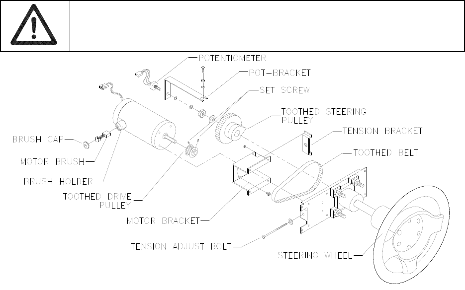
Troubleshooting 6-11
Player Panel Controls
WARNING: The Wheel Driver Board heatsink, power resistors, and other components
may be very hot. The DC Motor in the steering wheel may also be hot.
Steering Components
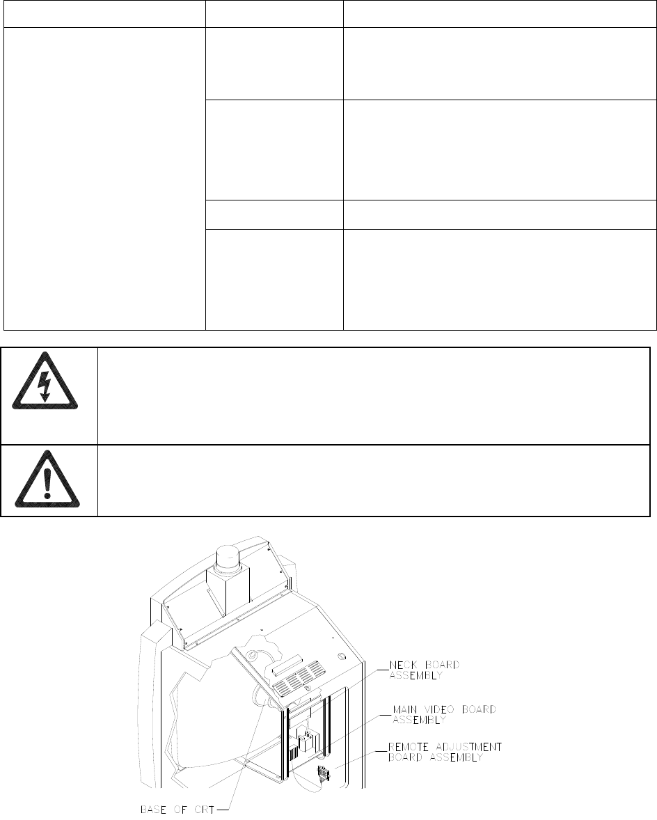
Troubleshooting 6-12
Video Troubleshooting Table
SYMPTOM CAUSE REQUIRED ACTION
Power problem Verify connection of AC Power to video monitor.
Inspect CRT neck in dim light. Glowing filament
near CRT base proves that some monitor circuits
receive power. Still, voltages or signals may not
be normal.
Faulty wiring 1. Turn off VGM power. Verify that video signal and
Remote Adjustment Board connectors seat
properly on Video Monitor Board.
2. Assure that video cables connect to circuit
boards and computer.
3. Assure that no wires are caught on chassis or
mounting brackets.
Improper monitor
adjustments Check that BRIGHTNESS (intensity) and
CONTRAST are set above their minimum levels.
• Monitor appears non-
functional
• Audio is present
• VGM (video game machine)
controls operate normally
Faulty monitor
circuitry
1. Examine AC line fuse on Video Monitor Board. If
fuse is faulty, replace it with identical fuse.
2. If fuse is good: Verify that video monitor operates
correctly by placing it in working VGM.
3. If monitor is bad: Check monitor power supply.
4. If power supply is good: Check monitor
horizontal output transistor and related circuitry.
WARNING: HIGH VOLTAGE. VGM (video game machine) monitors generate and
store potentially lethal high voltages. Avoid touching any part of the monitor until power
has been off for some time. A picture tube can maintain a hazardous charge for up to
several days. Only qualified technicians should service monitors. Turn off the power,
unplug the VGM and discharge the CRT before attempting service. Even properly
discharged tubes can revert to a highly charged state, without reapplication of power.
WARNING: In normal operation, the monitor doesn’t require isolation from AC line
voltage. During bench servicing, you may need to operate the monitor outside the
cabinet. If you do, isolate the monitor from line voltage with an isolation transformer.
Typical Cutaway Rear View
Troubleshooting 6-13
Video Troubleshooting Table, continued
SYMPTOM CAUSE REQUIRED ACTION
Floppy disk in drive Check floppy drive for diskette. If you find disk,
eject it. Leave VGM (video game machine)
power on. Turn off computer. Wait for hard disk
to stop spinning. Turn on computer.
Faulty wiring Loosen computer case lid thumbscrews and lift
off cover. Assure that hard drive ribbon cable
connector is fully seated into mating connector
on motherboard. Check hard drive power cable.
Improper components 1. Verify that hard disk drive is correct for this VGM.
Label on drive records manufacturer name,
assembly number and program version.
2. Verify that circuit boards are correct for this
VGM. Label on each board records manufacturer
name, assembly number and hardware version.
• Game doesn’t appear
• No audio
• Power-up self-test runs
Hard drive problems 1. Turn computer on. Immediately look under hard
drive. Hard Drive Activity LED flashes if drive is
operating properly.
2. Allow software to load normally. Note and record
any error messages that occur during self-test.
3. Remove hard drive and install it in working VGM.
If symptom recurs there, hard drive is faulty.
Replace it.
• Blotches of color appear on
screen
Picture tube aperture
mask is magnetized Remove diskettes from room. Demagnetize
monitor with external degaussing coil. Take care
not to magnetize neighboring VGMs. Monitor
may be on or off for this procedure.
• White areas in center of
screen appear tinged with
color
• Object edges have fringe of
one or more colors
Picture tube purity or
static convergence is
out of alignment
1. Turn on VGM.
2. Press and hold TEST MODE to enter Menu
System. At Operator (Main) Menu, select
Diagnostic Menu. Then select Monitor Patterns
Menu. Run through Crosshatch, Red, Green and
Blue screens to find clearest display of problem.
3. Display screen with greatest problem.
4. Display Crosshatch Screen. Locate purity and
static convergence ring magnets on back of
monitor neck. Watch screen in mirror. Adjust
magnets to minimize problem. Follow
instructions from monitor manufacturer.
5. Display Crosshatch Screen. Touch up
adjustments while watching screen in mirror.
CAUTION: Don’t operate the monitor without its Remote Adjustment Board.
WARNING: HANDLE FLUORESCENT TUBE AND CRT WITH CARE. If you drop a
fluorescent tube or CRT and it breaks, it will implode! Shattered glass can fly eight feet
or more from the implosion.

Troubleshooting 6-14
Video Troubleshooting Table, continued
SYMPTOM CAUSE REQUIRED ACTION
• White areas at screen edges
appear tinged with color
• Dots at screen edges appear
ovoid or cylindrical
Picture tube dynamic
convergence is out of
alignment
Have service bureau dynamically reconverge
monitor. This procedure requires removing and
repositioning yoke. Service bureau must follow
instructions from monitor manufacturer.
Faulty wiring 1. Check connectors and cables for wiring
continuity. Video cables connect computer to
circuit boards, and then to video monitor.
2. Assure connection of all cabinet ground wires,
especially at video monitor chassis.
Faulty monitor
circuitry
1. Verify that video monitor operates correctly by
connecting it to working VGM.
2. Assure that video monitor is correct type for this
VGM. Video monitors with wrong resolution can’t
lock sync.
Improper sync signals 1. Check to see if Video Board puts out type of
sync that your monitor requires.
2. Verify that jumpers are set correctly for monitor.
3. If necessary, add or remove video sync jumper
at MagicBus Board jumper block JP4. With no
pins connected (or pins 2 and 3 connected),
board outputs positive sync. With pins 1 and 2
connected, board outputs negative sync.
• Video tears or rolls, or has
black bar down middle of
screen
Electromagnetic fields Move cabinet far away from machines,
appliances, or VGMs (video game machines).
Faulty wiring Check connectors and cables for wiring
continuity from circuit boards to video monitor.
• Missing colors
Faulty monitor color
drive circuitry Verify that video monitor operates correctly by
connecting it to working VGM.
• One color is dimmer or
brighter than others
• Whites appear tinted
everywhere on screen
Maladjusted color
bias pots
1. Turn on VGM.
2. Enter Monitor Patterns Menu.
3. Watch Color Bars screen in mirror.
4. Adjust three bias pots for best colors. (Most
monitor neck boards include these pots.)
5. Also check White Screen. Touch up controls.
6. If whites still seem tinted, have service bureau
rejuvenate picture tube.
• Picture is dim or faded Maladjusted
BRIGHTNESS pot or
subnormal picture
tube emission
1. Watch Color Bars screen. Adjust BRIGHTNESS
and CONTRAST pots for greatest number of
grays. You’ll find these pots on Monitor Remote
Control Board, behind coin door.
2. If pots have no effect, have service bureau
rejuvenate picture tube.
• Picture is too narrow Maladjusted WIDTH
pot
Enter Monitor Patterns Menu. Watch Crosshatch
Screen while adjusting WIDTH pot for best
picture. You’ll find this pot on Monitor Remote
Control Board, behind coin door.
Troubleshooting 6-15
Video Troubleshooting Table, continued
SYMPTOM CAUSE REQUIRED ACTION
• Picture is too short Maladjusted HEIGHT
pot or damaged
vertical circuit
1. Enter Monitor Patterns Menu. Watch Crosshatch
Screen while adjusting HEIGHT pot for best
picture. You’ll find this pot on Monitor Remote
Control Board, behind coin door.
2. If pot has no effect, service vertical output circuit.
• Picture seems shifted to one
side Maladjusted
HORIZONTAL
POSITION pot
Enter Monitor Patterns Menu. Watch Crosshatch
Screen while adjusting HORIZONTAL POSITION
pot for best picture. You’ll find this pot on Monitor
Remote Control Board, behind coin door.
• Keystone-shaped picture Shorted turns in yoke 1. Substitute working yoke.
2. Have service bureau converge monitor.
3. Retest monitor.
Software Update Troubleshooting Table
SYMPTOM CAUSE REQUIRED ACTION
You skipped steps or
performed them out
of sequence.
Return update components to kit, reinstall
original parts in cabinet, and try process again.
You connected linked
VGMs to cabinet
being updated.
1. Network communication circuits may have
prevented full update. Turn off power to all
connected cabinets.
2. Perform update on one cabinet at time. If power
is off, you need not disconnect linking cables.
• Update didn’t work
• After update procedure,
screen reports lower than
latest version
Installation error may
have damaged
device.
1. Inspect for bent or broken pins.
2. If you have another kit, try it.
3. Ask your distributor to check your floppy disk.
NOTICE: Someday, software updates for your VGM (video game machine) might
become available. These upgrades may improve your VGM’s performance or add new
features. Such upgrades tend to appear sometime after factory first releases a VGM.
Contact your distributor for information about updates.
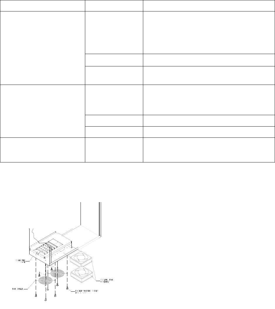
Troubleshooting 6-16
Miscellaneous Problem Troubleshooting Table
SYMPTOM CAUSE REQUIRED ACTION
Faulty fluorescent
tube
1. Remove fluorescent tube from its sockets. If you
find cracks or darkened ends, install new lamp.
Clean tube.
2. Check continuity of both fluorescent tube
filaments.
3. Verify that fluorescent tube operates by placing it
in working VGM.
Faulty lamp fixture Verify that lamp pins make good connection with
socket contacts.
• Marquee lamp is intermittent
or non-functional
• VGM (video game machine)
starts and plays normally
Faulty wiring Measure fluorescent lamp AC voltages. Check
wiring and connector continuity from AC power
chassis to lamp assembly.
Obstructed fan 1. Check bottom and rear of cabinet for blocked
airflow.
2. Move VGM away from sources of heat.
3. Turn off VGM power. Remove dust from vent
holes with high-power vacuum cleaner.
Faulty wiring Check fan wiring and connectors.
• VGM operates normally
• Cabinet becomes warm after
several hours of use
Faulty fan Check operation of all fans.
• Error messages appear on
screen Faulty hardware 1. Check any assembly (RAM, ROM, Battery, etc.)
identified in error messages.
2. Call your authorized distributor for help with
unresolved screen messages.
Fan Location and Mounting
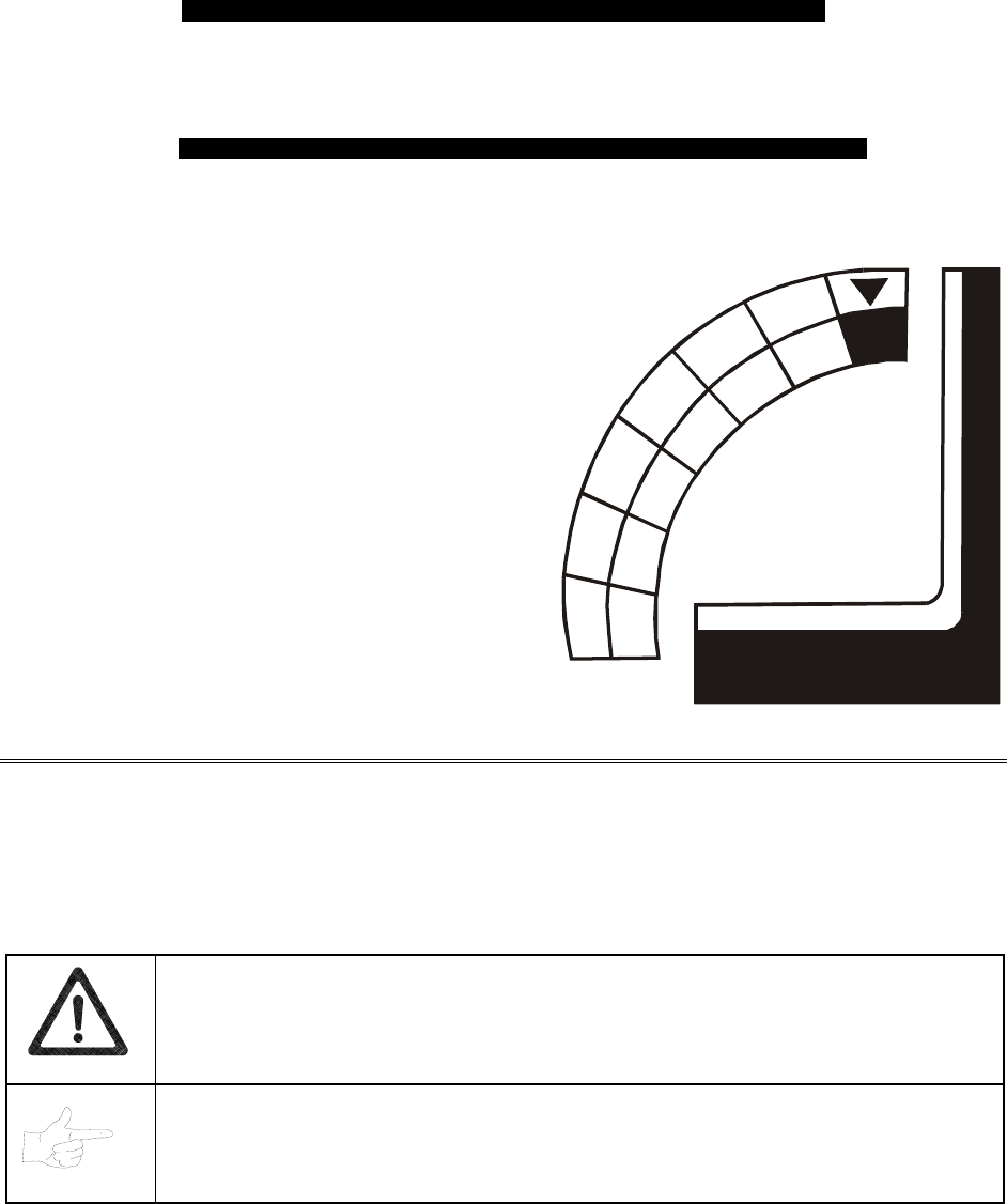
Parts 7-1
O
OO
OFFROAD
FFROADFFROAD
FFROAD
THUNDER
THUNDERTHUNDER
THUNDER
TM
CHAPTER
7
PARTS
WARNING: Use of non-Midway parts or circuit modifications may cause serious injury or
equipment damage! Use only Midway authorized parts.
For safety and reliability, don’t substitute parts or modify Midway products. Substitute parts or
modifications may void the game’s EMC directive or FCC type acceptance.
NOTICE: The term VGM refers to the video game machine.
Parts 7-2
Cabinet Front View
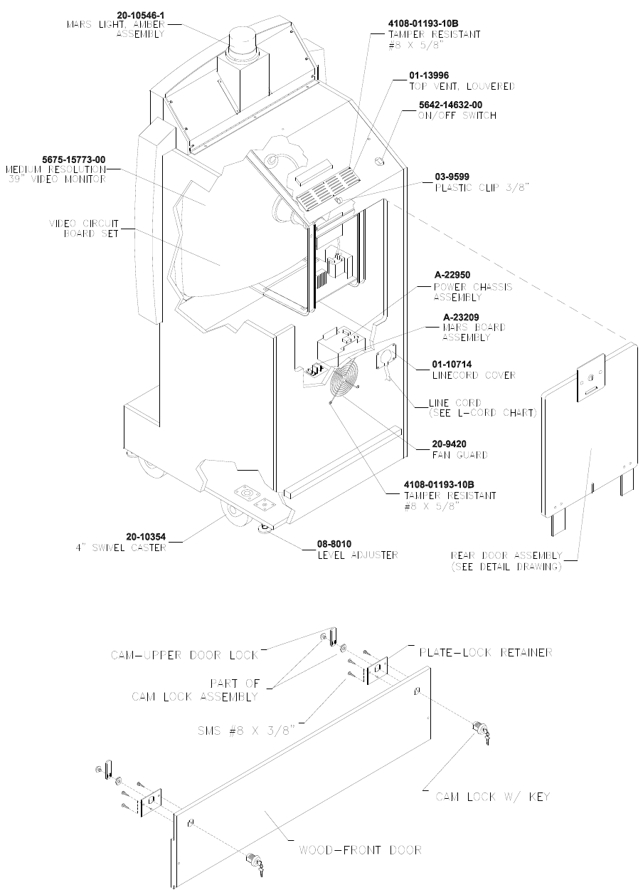
Parts 7-3
Cabinet Rear View
Front Access Door Assembly A-23055
11-1361.1
20-10475
01-7264
01-8989
4108-01115-06
Parts 7-4
Cabinet Joining Details
Parts 7-5
Casters and Levelers
Parts 7-6
Rear Door Assembly A-23058
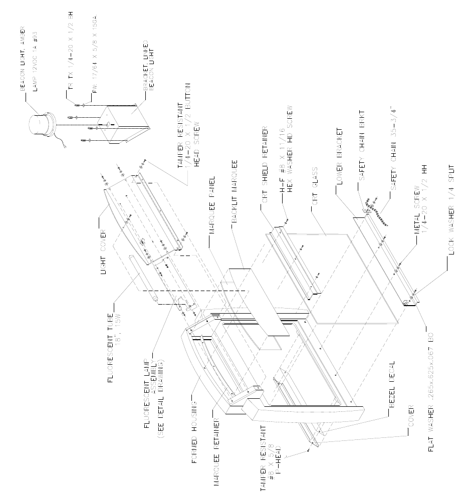
Parts 7-7
Monitor Bezel Assembly A-23361
04-12654.1
4700-00032-00B
4020-01100-08
20-10546-1
24-8862
03-9633
04-10639.1-1
4108-01193-10B
4700-00032-00B
31-3451.1
03-9635
4020-01100-08
4108-01219-11
04-10641.2
04-10795
20-9275-3
4020-01070-08
4701-00005-00
08-8015
03-9632
01-14521
31-3450.1
04-10640-2
Parts 7-8
Padlock
Parts 7-9
Coin Door Assembly
(See Coin Door Application Table for Assembly Number)
Parts 7-10
Pushbutton Assembly
20-9663-XX 20-10129-5
Parts 7-11
Dash Assembly A-23365 (Assembled)

Parts 7-12
Dash Assembly A-23365 (Exploded)
Parts 7-13
Optional Bill Validator
(MARS AE 2451-U3E)
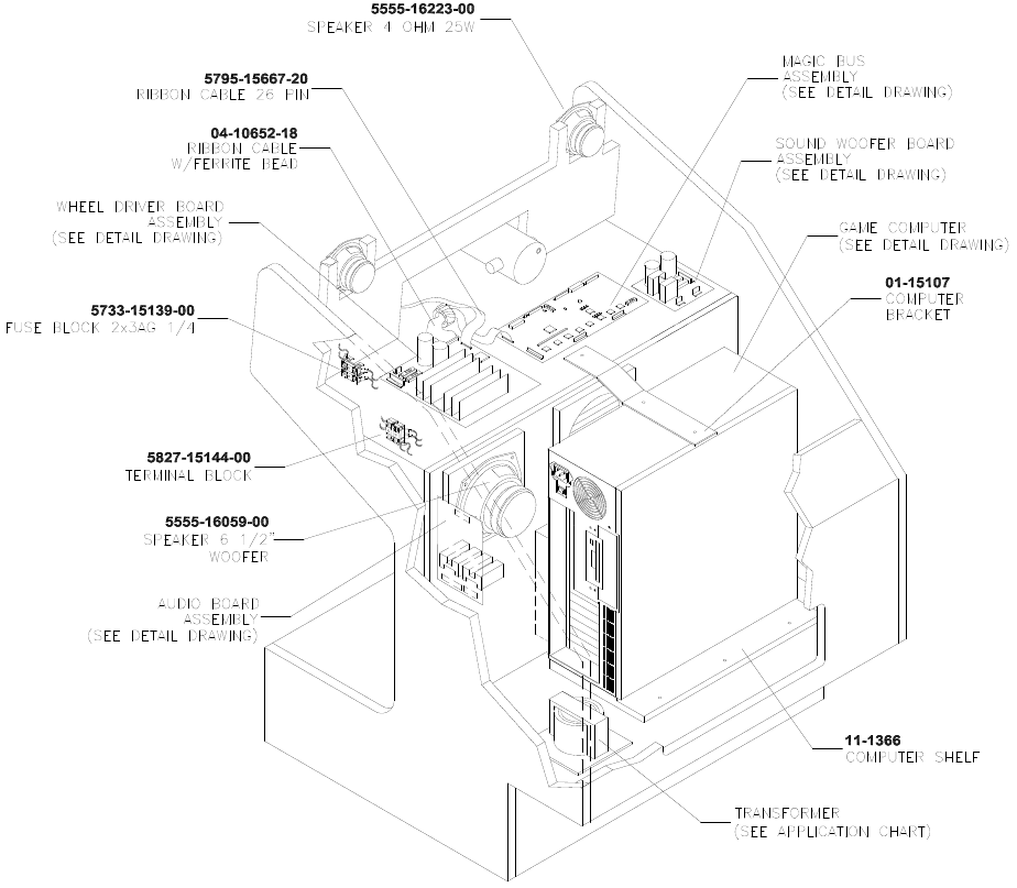
Parts 7-14
Dash Cabinet Assembly A-23357
Parts 7-15
Seat and Pedestal Assembly A-23231
Parts 7-16
Throttle Assembly 20-10135
Parts 7-17
Fluorescent Lamp Assembly A-22506
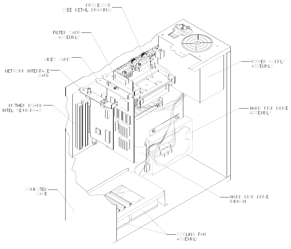
Parts 7-18
Arcade Computer Assembly 04-12758.3
04-12687
20-10554
20-10555
5795-15344-12
A-23350
20-10550
20-10551
04-12651
20-10552
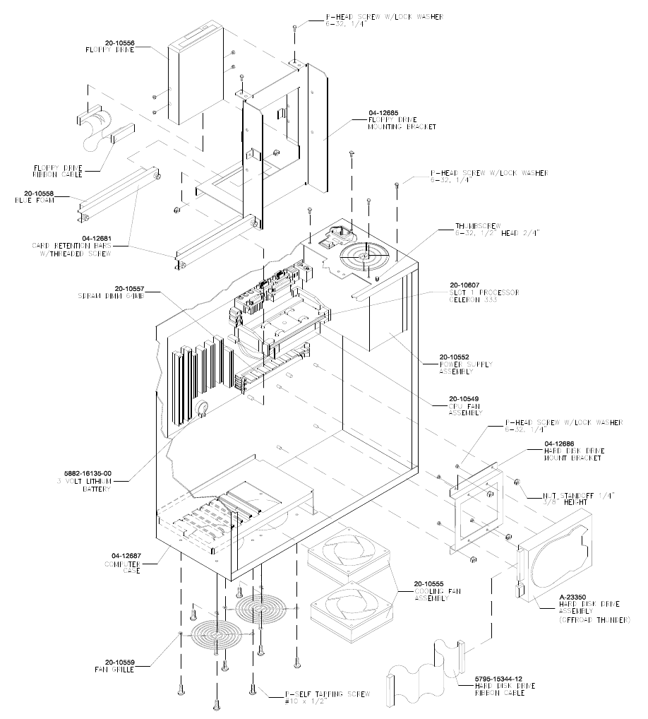
Parts 7-19
Arcade Computer Mechanical Components

Parts 7-20
Arcade Computer Cables
NOTICE: DC power cables are part of the power supply. You can’t replace these cables
individually.

Parts 7-21
Arcade Computer Electronic Components
NOTICE: Many stock computers use a motherboard that resembles this one. Still, a
standard motherboard won’t function correctly in this video game machine. Operation
in this VGM also requires a custom operating system.
NOTICE: Before attempting to use other than factory authorized parts, ask your
distributor for information. Other DIMM and processor modules may be equivalent or
superior to those illustrated here. Yet Midway hasn’t verified performance with
alternate components.
NOTICE: Celeron and Slot 1 are registered trademarks of Intel.
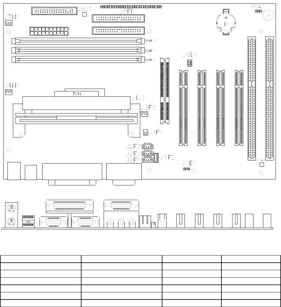
Parts 7-22
Computer Motherboard Assembly 20-10554
Field Replaceable Parts
Component Description Board Location Part Number
Dual Inline Memory Module 64MB SDRAM DIMM BANK 0-1-2 20-10557
Memory Backup 3-Volt Lithium Battery B 5882-16135-00
Processor Assembly Celeron Processor J4J1 20-10607
Processor Cooling Fan with Bracket FAN 20-10549
Shunt Jumper BIOS Startup Configuration J8A1 5882-13046-00
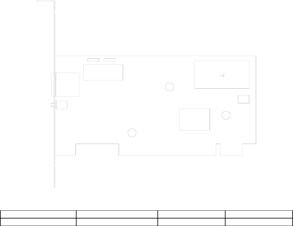
Parts 7-23
Network Interface Card Assembly 20-10550
Field Replaceable Parts
Component Description Board Location Part Number
Instruction ROM Not required in this game U2 --
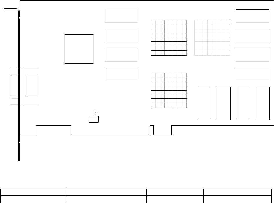
Parts 7-24
Video Graphics Card Assembly 20-10551
Field Replaceable Parts
Component Description Board Location Part Number
Graphics Mode Select Not required in this game J6 --

Parts 7-25
Filter Card Assembly 04-12651
Field Replaceable Parts
Component Description Board Location Part Number
EMI Filter 2200 pF Dual Capacitor F1-F5 5060-15633-00
EMI Filter Ferrite Bead Inductor L1-L5 5556-14181-00

Parts 7-26
BB12 Audio Amp Board Assembly 04-12529.1
Field Replaceable Parts
Component Description Board Location Part Number
Audio Amplifier LM3403 Quad Amplifier U1-U2 5370-15163-00
Audio Output TDA1560Q Power Amplifier U3 5370-15984-00
Audio Output TDA7375 Power Amplifier U4 5370-15833-00
Voltage Regulator +5VDC, 5% Fixed Regulator U5 5250-13302-00
None Not required in this game U6 --
Parts 7-27
Sub-Woofer Driver Board Assembly 04-11128-1
Field Replaceable Parts
Component Description Board Location Part Number
Amplifier , Power IC, TDA 2030AV, 18W U1 5370-13419-00
Fuse 5 x 20mm, T2,.5A/250V F1, F2 5731-14532-00
Preamplifier TL084 Op Amp U2 5370-12730-00
Regulator, Voltage 78L05, 5VDC Q1 5250-13302-00
Regulator, Voltage 79L05, -5VDC Q2 5250-13303-00

Parts 7-28
MagicBus
Interface Board Assembly 04-12697.3
Field Replaceable Parts
Component Description Board Location Part Number
Crystal 6 MHz Y2 5520-16004-00
Diode 1N270 D11-15, D17-25, D28 5070-16229-00
Diode 1N5817, 1A D2 5070-09266-00
Fuse 5 x 20mm, 2ASB F1 5735-13853-00
Jumper 2-Pin JP1, JP2, JP3, JP4 5791-13045-00
Transistor 2N2369 NPN Q1 5190-15997-00
Transistor 2N3904 NPN Q5-Q6 5160-14035-00
Transistor ULN2064 NPN Q3-Q4 5160-14035-00
Parts 7-29
Wheel Driver Board Assembly 04-12770.1
Field Replaceable Parts
Component Description Board Location Part Number
-- TO-92 Device Q4 Not Used
Darlington 2N6427 NPN Q1 5162-08976-00
Diode Fast FE6B-35nS D2, D3 5070-16272-00
Driver, Power LM12 Op Amplifier U5 5370-14069-00
Fuse 0.63AFB, 250V, 5x20mm F3 5731-15627-00
Fuse 4ASB, 125V, 5x20mm F1, F2 5731-14094-00
Pre-Driver ULN2064B IC U1, U2 5370-12602-00
Rectifier, Bridge 100V, 6A, SIP BR1 5100-13945-01
Regulator, Voltage 78L15, 15VDC, TO-92 Q2 5250-15624-00
Regulator, Voltage 79L15, -15VDC, TO-92 Q3 5250-15625-00
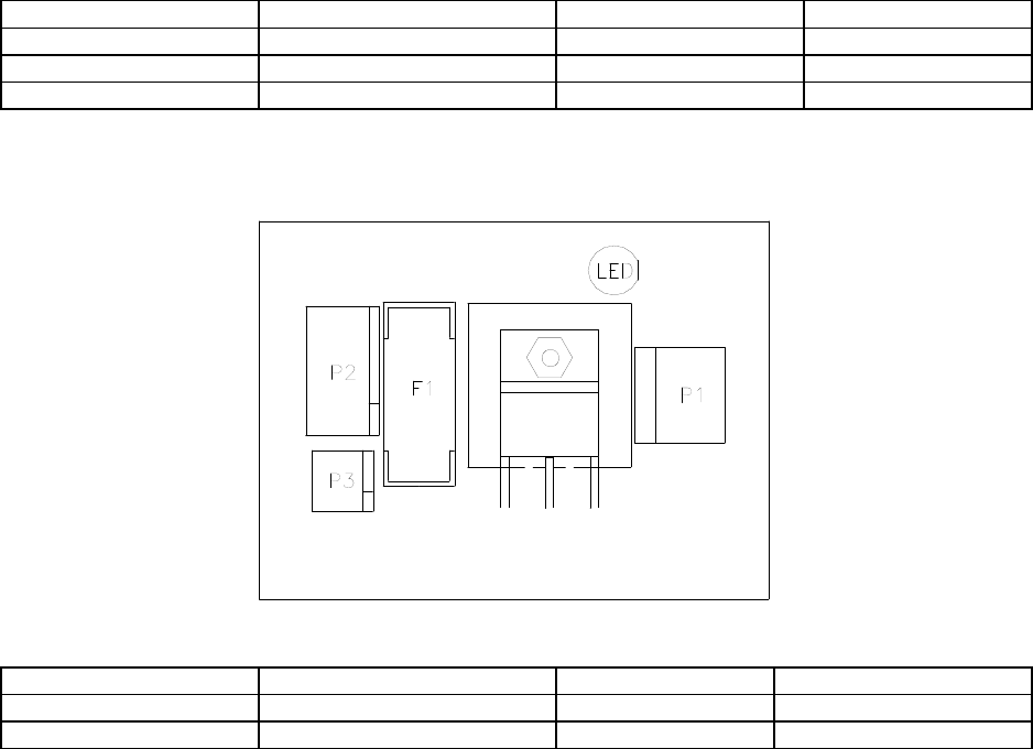
Parts 7-30
Speedometer Board Assembly 04-12759.1
Field Replaceable Parts
Component Description Board Location Part Number
LED Green, Bright LED1 - 6 5671-16256-00
LED Orange, Bright LED7 - 10 5671-15953-00
LED Red, Bright LED11 - 13 5671-15954-00
Mars Light Board Assembly A-23209
Field Replaceable Parts
Component Description Board Location Part Number
Fuse 5 x 20mm T2.5A/250V F1 5731-14532-00
Transistor TIP36C, PNP Q1 5191-12179-00
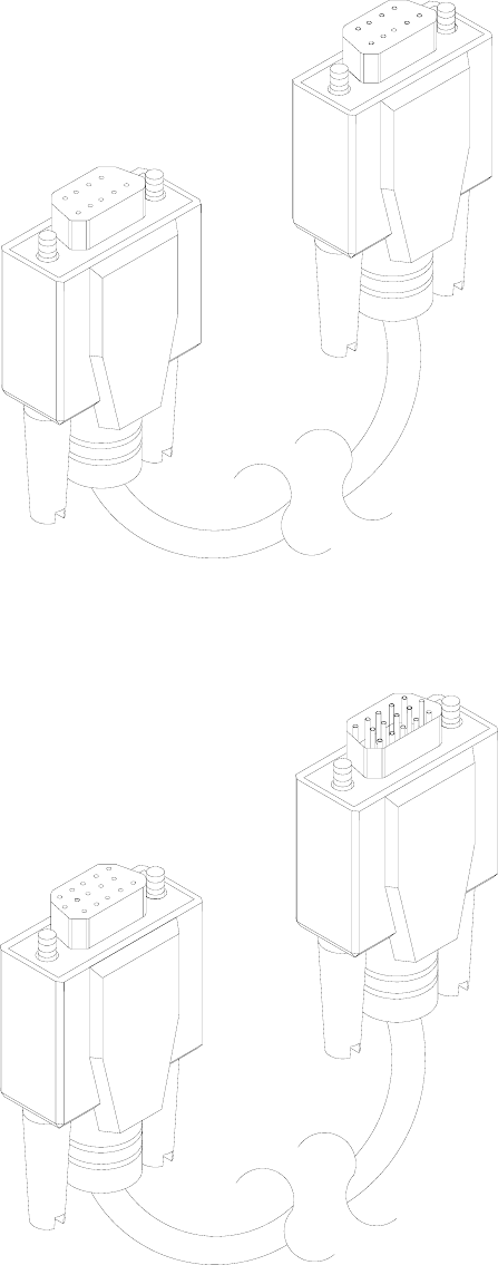
Parts 7-31
Electronic Cable Assemblies
SERIAL COMMUNICATIONS CABLE (NULL MODEM DB-9F TO DB-9F)
20-10532
VIDEO COMMUNICATIONS CABLE (SHIELDED DB-15F TO DB-15M)
5797-13171-00
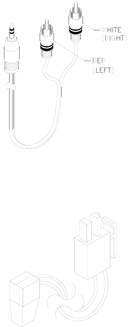
Parts 7-32
Electronic Cable Assemblies
AUDIO AMPLIFIER CABLE (SHIELDED, MINIATURE STEREO PHONE PLUG TO PHONO PLUGS)
04-12578-2
COMPUTER RESET CABLE (2-PIN PLUG TO LOCKING, 2-PIN PLUG)
04-12657
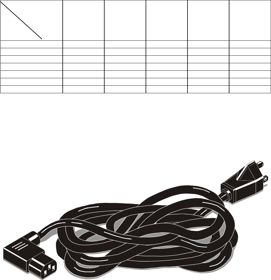
Parts 7-33
Line Cord Application Table
Part Number
Country
5850-
13271-
00
5850-
15521-
00
5850-
15521-
02
5850-
15521-
03
5850-
15521-
06
France
Germany
Italy
Japan
Spain
UK
USA
TYPICAL LINE CORD
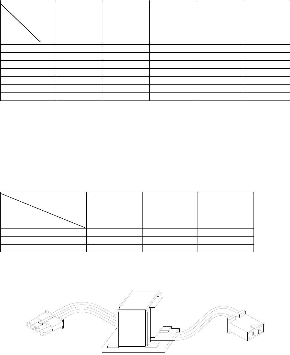
Parts 7-34
Coin Door Application Table
ELECTROMECHANICAL COIN DOOR ASSEMBLIES
Part Number
Country
09-72000-14
09-72000-15
09-72000-20
09-96011.1
09-96023-33
France
Germany
Italy
Japan
Spain
UK
USA, DBV Ready
Transformer Application Table
POWER TRANSFORMER ASSEMBLIES
Part Number
Line Power
5610-14927-00 5610-14926-01 5610-15275-00
120 VAC 60 HZ
230 VAC 50HZ
100 VAC 50HZ
TYPICAL POWER TRANSFORMER ASSEMBLY
WARNINGS & NOTICES
WARNING
• Use of non-Midway parts or circuit modifications may cause serious injury or equipment damage!
• Use only Midway authorized components and parts. Failure to do so will void your warranty and may result in
incorrect or unsafe operation. Substitute parts or modifications may void the EMC directive or FCC type
acceptance.
• Federal copyright, trademark and patent laws protect this game. Unauthorized modifications may be illegal under
Federal law. The modification ban also applies to Midway game logos, designs, publications and assemblies.
Moreover, facsimiles of Midway equipment (or any feature thereof) may be illegal under federal law, regardless
of whether or not such facsimiles are manufactured with Midway Games Inc. components.
WARNING
Prevent shock hazard and assure proper game operation. Plug this game into a properly grounded outlet. Don’t use a
cheater plug to defeat the power cord's grounding pin. Don’t cut off the ground pin.
WARNING
A small portion of the population has a condition which may cause epileptic seizures or momentary loss of
consciousness when viewing certain kinds of flashing lights or patterns that are present in our daily environment.
These persons experience seizures while watching some television pictures or playing certain video games. People
who have not had seizures may nonetheless have an undetected epileptic condition.
If anyone in your family has experienced symptoms linked to an epileptic condition (e.g., seizures or loss of
awareness), consult your physician before using video games.
Parents should observe their children while they play video games. If you or your child experience the following
symptoms: dizziness, altered vision, eye or muscle twitching, involuntary movements, loss of awareness,
disorientation, or convulsions, discontinue use immediately and consult your physician.
NOTICE
This video game machine was tested. It complies with limits for a Class A digital device, under FCC Rules, Part 15.
These limits provide reasonable protection against harmful interference when the equipment operates in a
commercial environment. This equipment generates, uses and can radiate radio frequency energy. If not installed and
used according to the instruction manual, this equipment may cause harmful interference to radio communications.
Operation of this equipment in a residential area is likely to cause harmful interference. If interference occurs, the
user must correct it at his own expense.
NOTICE
When Midway Games Inc. ships a game, it complies with FCC regulations. Your FCC label is proof of compliance.
Legal repercussions to the owner or distributor may result if the label is missing or damaged. If your game does not
contain an FCC compliance label, call Midway Games Inc. immediately.
NOTICE
You may not reproduce any part of this publication by mechanical, photographic, or electronic means. You may not
prepare phonograph recordings of this document. You may not transmit this publication or otherwise copy it for public
or private use, without permission from the publisher.
COPYRIGHT & TRADEMARK NOTICE
Entire contents of this manual copyright ©1999 Midway Games Inc. All rights reserved. Midway® and Offroad
Thunder™ are trademarks of Midway Games Inc.
FOR SERVICE
Call your authorized Midway Games distributor.
MIDWAY GAMES INC.
3401 N. CALIFORNIA AVE.
CHICAGO, ILLINOIS 60618-5899
USA
