Pos 441 Oki Users Guide
441 to the manual e58aed88-1e0f-4e64-87f9-dcf9bf31012b
User Manual: Pos 441
Open the PDF directly: View PDF ![]() .
.
Page Count: 56

User’s Guide
59307701
OkiPos 441
Federal Communications Commission
Radio Frequency Interference
Statement
This equipment has been tested and found to comply with the limits for a Class A digital device, pursuant to Part 15
of the FCC Rules. These limits are designed to provide reasonable protection against harmful interference when the
equipment is operated in a commercial environment. This equipment generates, uses and can radiate radio frequency
energy and, if not installed and used in accordance with the instruction manual, may cause harmful interference to
radio communications. Operation of this equipment in a residential area is likely to cause harmful interference in
which case the user will be required to correct the interference at his own expense.
For compliance with the Federal Noise Interference Standard, this equipment requires a shielded cable.
This statement will be applied only for the printers marketed in U.S.A.
Statement of
The Canadian Department of Communications
Radio Interference Regulations
This digital apparatus does not exceed the Class A limits for radio noise emissions from digital apparatus set out
in the Radio Interference Regulations of the Canadian Department of Communications.
Le présent appareil numérique n’émet pas de bruits radioélectriques dépassant les limites applicables aux appareils
numériques de la classe A prescrites dans le Règlement sur le brouillage radioélectrique édicté par le ministère des
Communications du Canada.
The above statement applies only to printers marketed in Canada.
CE
Manufacturer’s Declaration of Conformity
EC Council Directive 89/336/EEC of 3 May 1989
This product, has been designed and manufactured in accordance with the International Standards EN 61000-6-
3 / 2001 and EN 55024 / 1998, following the provisions of the Electro Magnetic Compatibility Directive of the
European Communities as of May 1989.
EC Council Directive 73/23/EEC and 93/68/EEC of 22 July 1993
This product, has been designed and manufactured in accordance with the International Standards EN 60950-1,
following the provisions of the Low Voltage Directive of the European Communities as of 2001.
The above statement applies only to printers marketed in EU.
Trademark acknowledgments
OKIPOS441: Oki Data Corporation
Notice
• All rights reserved. Reproduction of any part of this manual in any form whatsoever, without OKI express
permission is forbidden.
• The contents of this manual are subject to change without notice.
• All efforts have been made to ensure the accuracy of the contents of this manual at the time of going to press.
However, should any errors be detected, OKI would greatly appreciate being informed of them.
• The above notwithstanding, OKI can assume no responsibility for any errors in this manual.
© Copyright 2007 Oki Data Corporation
TABLE OF CONTENTS
1. Outline .......................................................................................................................................................1
2. Unpacking and Installation .....................................................................................................................2
2-1. Unpacking ....................................................................................................................................2
2-2. Choosing a place for the printer ...................................................................................................3
2-3. Handling Care ..............................................................................................................................4
2-4. Maintenance .................................................................................................................................4
3. Parts Identification and Nomenclature ..................................................................................................5
4. Setup ..........................................................................................................................................................6
4-1. Connecting the Cable to the PC ...................................................................................................6
4-2. Connecting the Cable to the Printer .............................................................................................7
4-3. Installing the Printer Software ...................................................................................................10
4-4. Connecting to a Peripheral Unit .................................................................................................11
4-5. Connecting the Power Cord .......................................................................................................12
4-6. Turning Power On ......................................................................................................................13
4-7. Installing the Cable ....................................................................................................................14
4-8. Switch Blind Installation ............................................................................................................14
5. Loading the Ribbon Cartridge and Paper ...........................................................................................15
5-1. Loading the Ribbon Cartridge ...................................................................................................15
5-2. Loading the paper ......................................................................................................................16
5-3. Installing the Roll Paper Guide ..................................................................................................18
6. Control Panel and Other Functions .....................................................................................................21
6-1. Control Panel..............................................................................................................................21
6-2. Basic Indicators ..........................................................................................................................21
6-3. Errors ..........................................................................................................................................22
6-4. Adjustment Mode .......................................................................................................................24
7. Preventing and Clearing Paper Jams ...................................................................................................30
7-1. Preventing Paper Jams ...............................................................................................................30
7-2. Removing Paper Jam .................................................................................................................30
7-3. Releasing a Locked Cutter (Auto Cutter Mode only) ................................................................31
8. Peripheral Unit Drive Circuit ...............................................................................................................33
9. General Specifications ...........................................................................................................................35
9-1. General Specifications ...............................................................................................................35
9-2. Power Supply Specifications ......................................................................................................37
10. Dip Switch Setting ................................................................................................................................38
10-1. RS-232C Interface Model ..........................................................................................................40
10-2. Parallel Interface Model .............................................................................................................41
10-3. USB Interface Model .................................................................................................................41
10-4. Ethernet Interface Model ...........................................................................................................41
10-5. Wireless LAN Interface Model ..................................................................................................42
11. RS-232C Serial Interface .....................................................................................................................45
11-1. Interface Specifications ..............................................................................................................45
11-2. Pins and Signal Names ...............................................................................................................46
11-3. Interface Connections ................................................................................................................47
12. Parallel Interface ..................................................................................................................................48
12-1. Table of Connection Signals for Each Mode .............................................................................48
13. USB, Ethernet and Wireless LAN Interface ......................................................................................50
13-1. USB Interface Specifications .....................................................................................................50
13-2. Ethernet Interface Specifications ................................................................................................50
13-3. Wireless LAN Interface Specifications ......................................................................................50
14. Memory Switch Settings ......................................................................................................................51

– 1 –
1. Outline
OKIPOS441 Series Serial Impact Dot Matrix Printer is designed for use with electronic instru-
ments such as POS, banking equipment, computer peripheral equipment, etc.
– 2 –
2. Unpacking and Installation
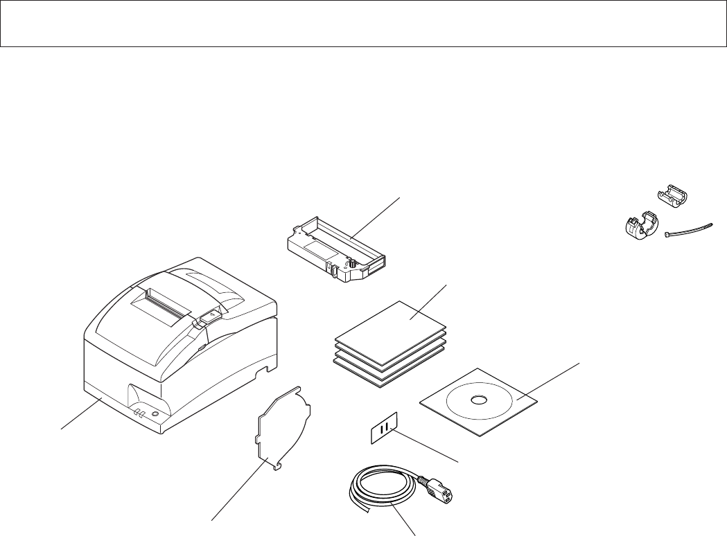
2-1. Unpacking
After unpacking the unit, check that all the necessary accessories are included in the package.
Note: The ferrite core and fastener provided with your
printer depend on your printer configuration.
Fig. 1-1 Unpacking
If anything is missing, contact the dealer where you bought the printer and ask them to supply
the missing part. Note that it is a good idea to keep the original box and all the packing materials
just in case you need to pack the printer up again and send it somewhere at a later date.
Printer
Switch blind
Power cord
Roll paper guide
Ribbon cartridge
Setup sheets
CD-ROM
Note

– 3 –
2-2. Choosing a place for the printer
Before actually unpacking the printer, you should take a few minutes to think about where
you plan to use it. Remember the following points when doing this.
3 Choose a firm, level surface where the printer will not be exposed to vibration.
3 The power outlet you plan to connect to for power should be nearby and unobstructed.
3 Make sure that the printer is close enough to your host computer for you to connect
the two.
3 Make sure that the printer is not exposed to direct sunlight.
3 Make sure that the printer is well away from heaters and other sources of extreme
heat.
3 Make sure that the surrounding area is clean, dry, and free of dust.
3 Make sure that the printer is connected to a reliable power outlet. It should not be on
the same electric circuit as copiers, refrigerators, or other appliances that cause power
spikes.
3 Make sure that the room where you are using the printer is not too humid.
WARNING
3 Shut down your equipment immediately if it produces smoke, a strange odor, or unu-
sual noise. Immediately unplug the equipment and contact your dealer for advice.
3 Never attempt to repair this product yourself. Improper repair work can be dangerous.
3 Never disassemble or modify this product. Tampering with this product may result in
injury, fire, or electric shock.
– 4 –
2-3. Handling Care
1. Be careful not to drop paper clips, pins or other foreign matter into the unit as these cause
the printer to malfunction.
2. Do not attempt to print when either paper or ribbon cartridge is not located in the printer,
otherwise the print head can be damaged.
3. Do not open the cover while printing.
4. Do not touch the print head immediately after printing as it gets very hot.
5. Use only roll paper that is not glued to the core.
6. When the paper end mark appears on the paper, replace the roll paper before it runs out.
2-4. Maintenance
Essentially, your printer is a robust piece of equipment, but should be treated with a modicum
of care in order to avoid malfunctions. For example:
1. Keep your printer in a “comfortable” environment. Roughly speaking, if you feel comfort-
able, then the environment is suitable for your printer.
2. Do not subject the printer to physical shocks or excessive vibration.
3. Avoid over-dusty environments. Dust is the enemy of all precision mechanical devices.
4. To clean the exterior of the printer, use a cloth barely dampened with either water with a
little detergent or a little alcohol, but do not allow any liquid to fall inside the printer.
5. The interior of the printer may be cleaned with a small cleaner or a compressed-air aerosol
(sold for this purpose). When performing this operation, be sure not to bend or damage any
cable connections or electronic components.
– 5 –
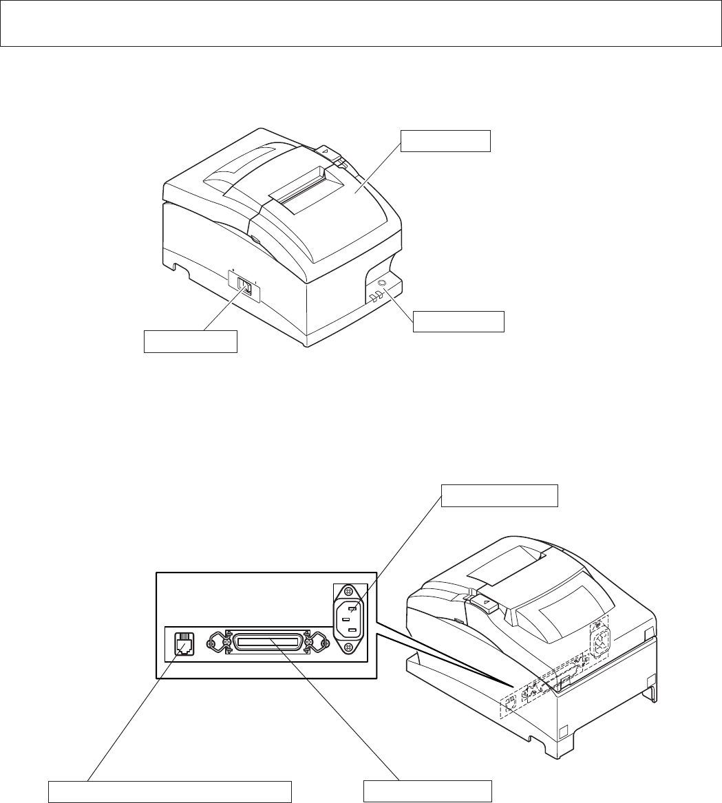
3. Parts Identication and Nomenclature
Printer cover
Protects the printer from dust and reduces noise.
Do not open the cover while printing.
Control panel
Features one control switch and two indicators
to indicate printer status.
Interface connector
Connects the printer with host
computer.
Power switch
Turns printer power
on and off.
Peripheral unit drive circuit connector
Connects to peripheral units such as cash
drawers, etc.
Do not connect this to a telephone.
Power connector
For connection of the power cord.
– 6 –
4. Setup
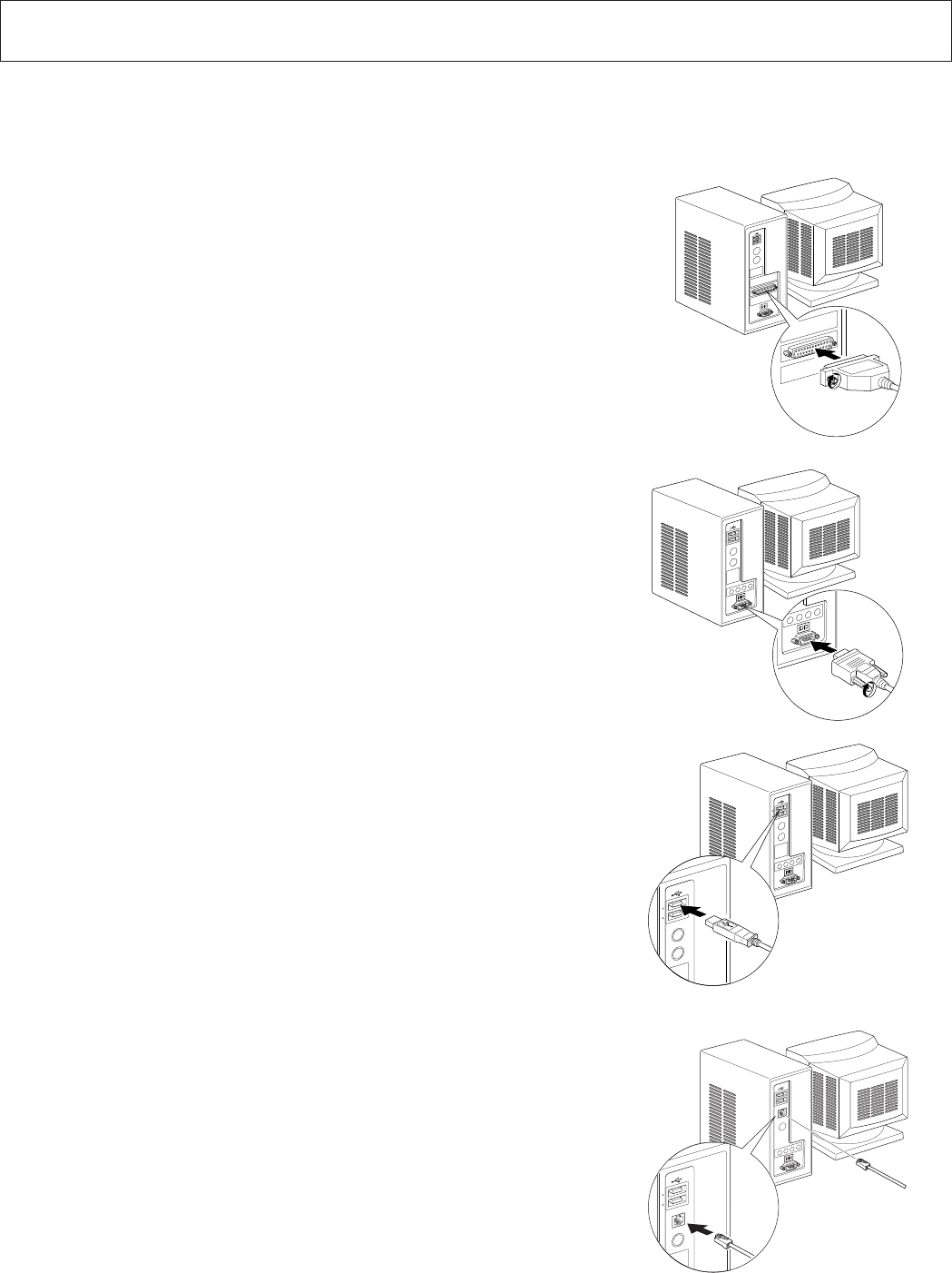
4-1. Connecting the Cable to the PC
4-1-1. Parallel Interface Cable
Connect the parallel interface cable to a parallel port
of your PC.
4-1-2. RC-232 Interface Cable
Connect the RC-232 interface cable to a RS-232 port
of your PC.
4-1-3. USB Interface Cable
Connect the USB interface cable to a USB port of
your PC.
4-1-4. Ethernet Interface cable
Connect the ethernet interface cable to a ethernet port
of your PC.
– 7 –
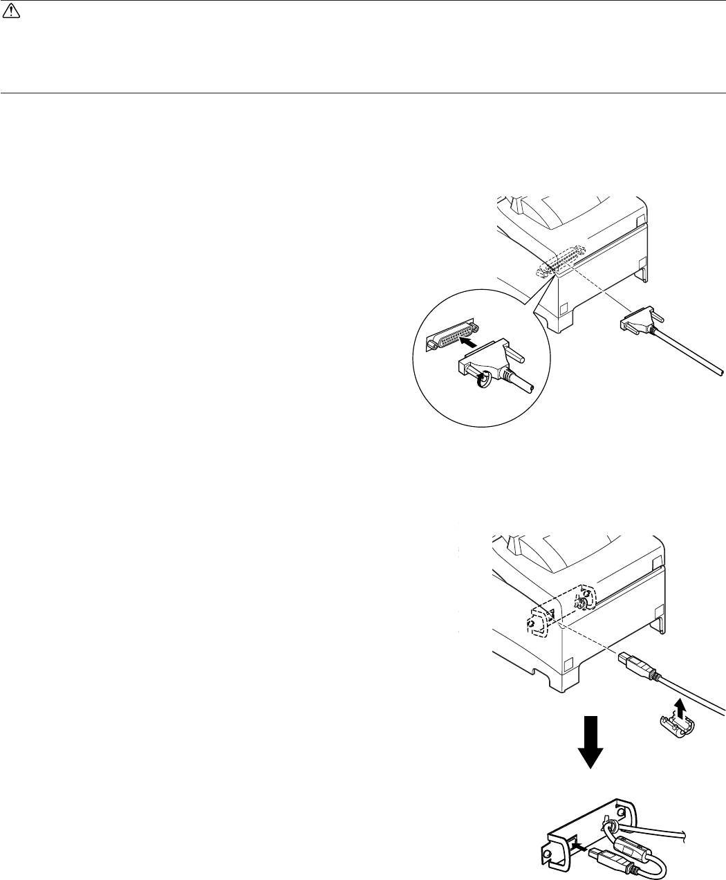
4-2. Connecting the Cable to the Printer
Note that the interface cable is not provided. Please use a cable that meets specifications.
CAUTION
Before connecting/disconnecting the interface cable, make sure that power to the printer and
all the devices connected to the printer is turned off. Also make sure the power cable plug is
disconnected from the AC outlet.
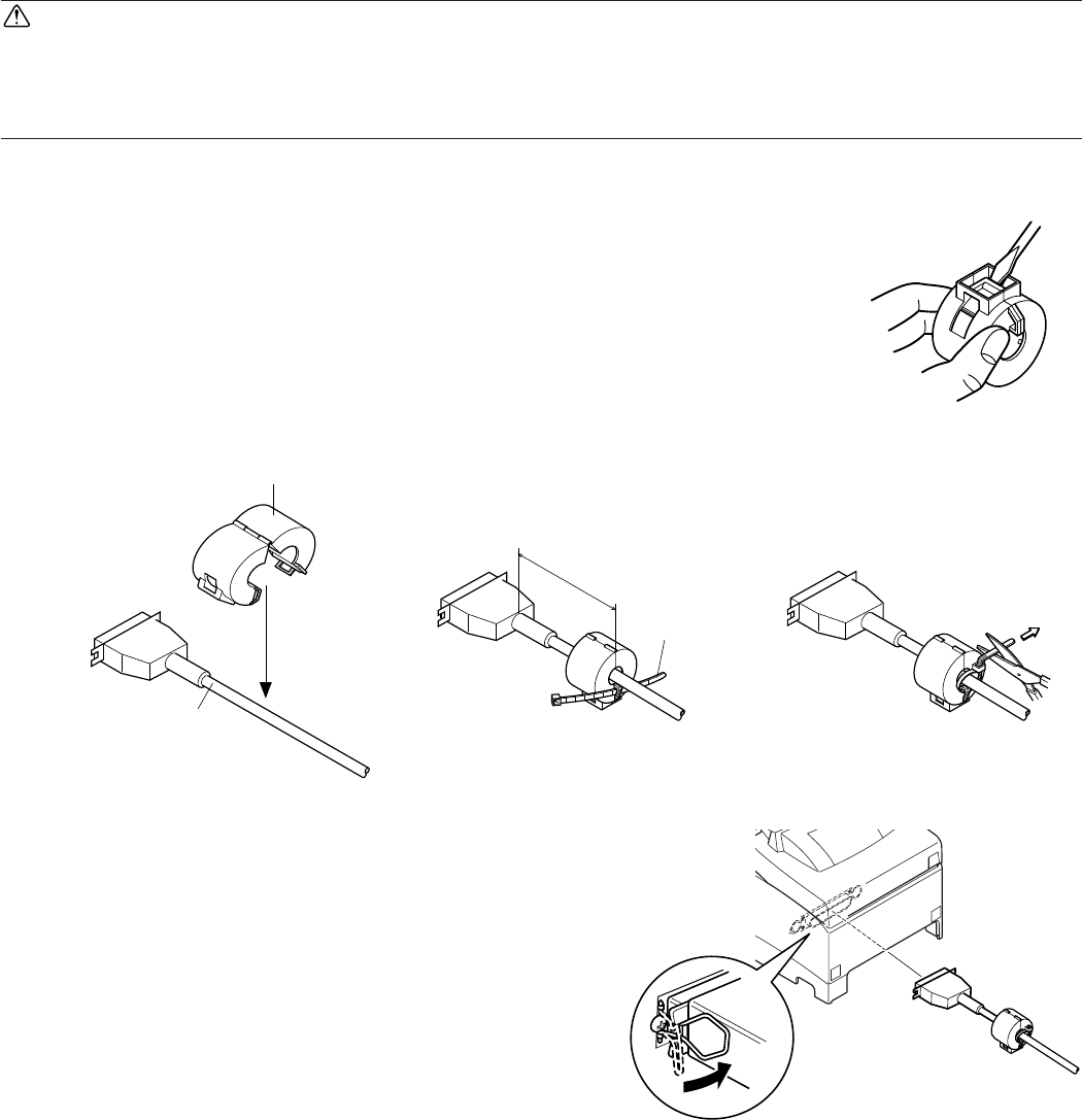
4-2-1. Parallel Interface Cable
(1) Make sure the printer is turn off.
(2) Affix the ferrite core onto the cable as shown in
the illustration.
(3) Pass the fastener through the ferrite core.
(4) Loop the fastener around the cable and lock it.
Use scissors to cut off any excess.
(5) Connect the interface cable to the connector on
the rear panel of the printer.
(6) Fasten the connector clasps.
Ferrite core
Interface cable
10 cm
(maximum)
Fastener
– 8 –
4-2-2. RS-232 Interface Cable
(1) Make sure the printer is turn off.
CAUTION
Before connecting/disconnecting the interface cable, make sure that power to the printer and
all the devices connected to the printer is turned off. Also make sure the power cable plug is
disconnected from the AC outlet.
(2) Connect the interface cable to the connector on the rear panel of the printer.
(3) Tighten the connector screws.
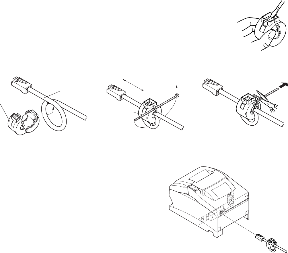
4-2-3. USB Interface Cable
Affix the ferrite core onto the USB cable as shown in
the illustration below and make sure to pass the cable
through the cable support as shown in the illustra-
tion.
– 9 –
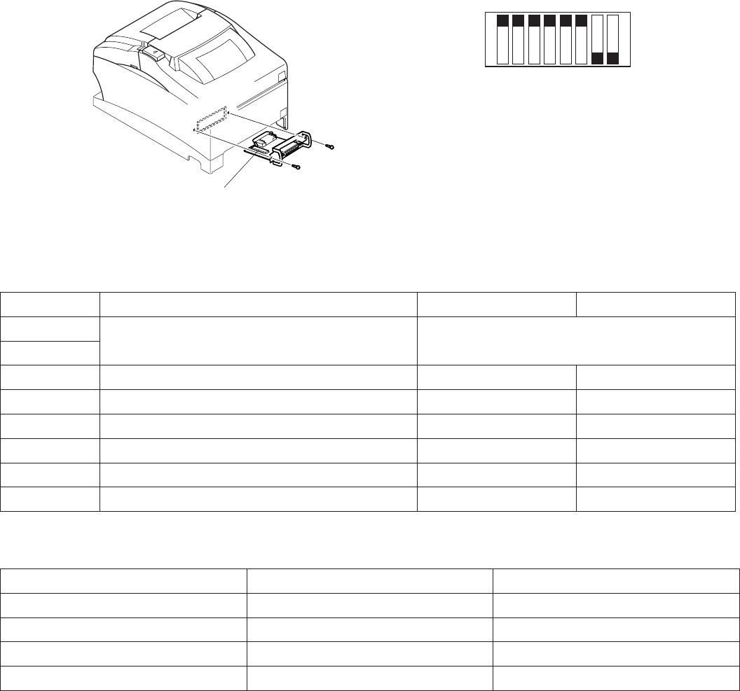
4-2-4. Connecting Ethernet Cable
(1) Make sure the printer is turned off.
(2) Affix the ferrite core onto the ethernet cable as
shown in the illustration below.
(3) Pass the fastener through the ferrite core.
(4) Loop the fastener around the cable and lock it.
Use scissors to cut off any excess.
(5) Connect the interface cable to the connector on
the rear panel of the printer.
Ferrite core
Ethernet cable
1 cm
(maximum)
Fastener
– 10 –
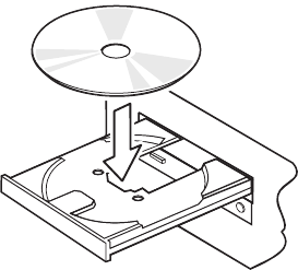
4-3. Installing the Printer Software
Here is the procedure for installing the printer driver and utility software, which are stored on
the supplied CD-ROM.
The procedure applies to the Windows operating systems shown below.
• Windows 2000
• Windows XP
• Windows Vista
(1) Turn ON the power to your PC to start Windows.
(2) Insert the supplied CD-ROM (Drivers and Utilities)
into the CD-ROM drive.
(3) Follow the instructions that appear on the screen.
– 11 –
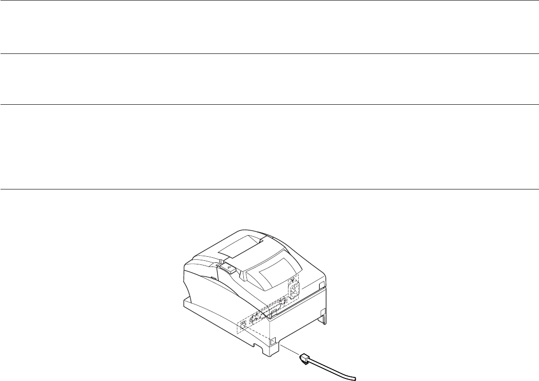
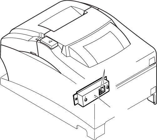
4-4. Connecting to a Peripheral Unit
You can connect a peripheral unit to the printer using a modular plug. See “Modular plug” on
page 33 for details about the type of modular plug that is required. Note that this printer does
not come with a modular plug or wire, so it is up to you to obtain one that suits your needs.
Important!
Make sure that the printer is turned off and unplugged from the AC outlet and that the computer
is turned off before making connections.
(1) Connect the peripheral drive cable to the connector on the rear panel of the printer.
Important!
Do not connect a telephone line into the peripheral drive connector. Failure to observe this may
result in damage to the printer.
Also, for safety purposes, do not connect wiring to the external drive connector if there is a
chance it may carry peripheral voltage.
– 12 –
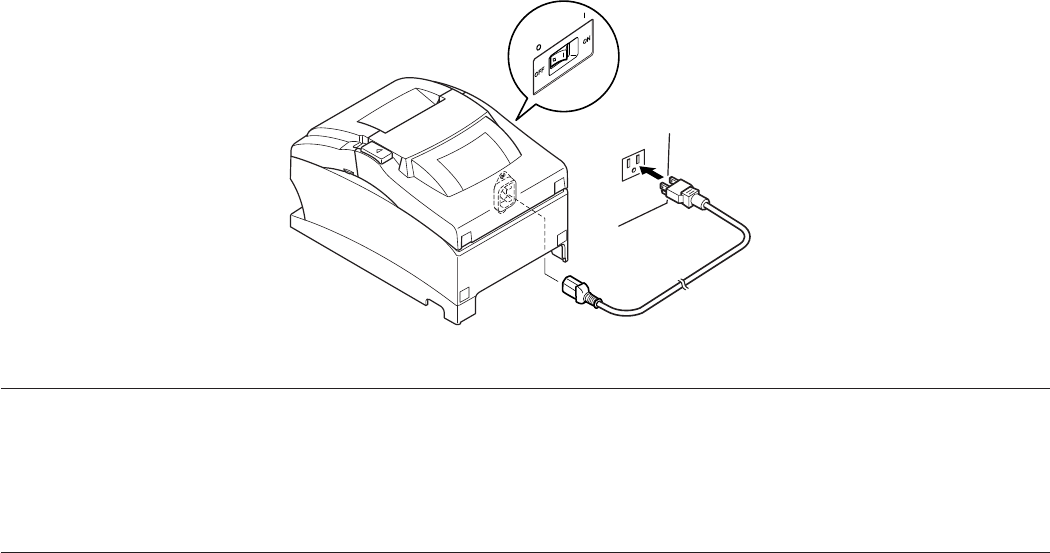
4-5. Connecting the Power Cord
Note: Before connecting/disconnecting the power cord, make sure that power to the printer
and all the devices connected to the printer is turned off. Also make sure the power
cable plug is disconnected from the AC outlet.
(1) Check the label on the back or bottom of the printer to make sure its voltage matches that
of the AC outlet. Also make sure the plug on the power cord matches the AC outlet.
(2) If the power cord is not attached to the printer, plug the appropriate end into the AC inlet
on the back of the printer.
(3) Plug the power cord into a properly grounded AC outlet.
Important!
If the voltage shown on the label on the of your printer does not match the voltage for your area,
contact your dealer immediately.
The power cord is designed for use with this printer only. Do not connect it to any other de-
vice.
OFFON
– 13 –
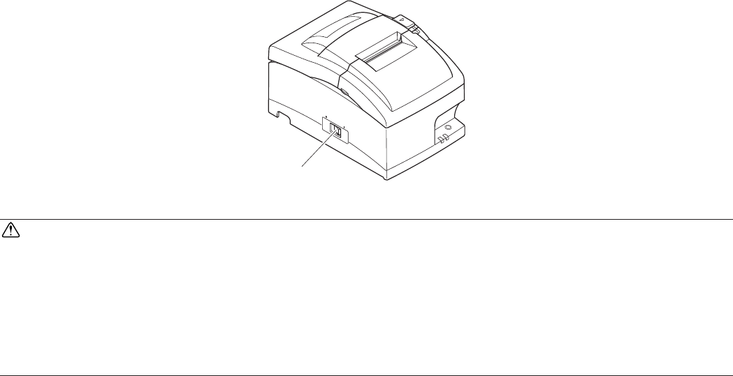
4-6. Turning Power On
Make sure that the Power cord has been connected as described in 4-5.
Turn ON the power switch located on the front of the printer.
The POWER lamp on the control panel will light up.
CAUTION
We recommend that you unplug the printer from the power outlet whenever you do not plan to
use it for long periods. Because of this, you should locate the printer so that the power outlet it
is plugged into is nearby and easy to access.
When an Switch blind is affixed to the printer above the power switch, the ON/OFF marks of
the power switch may be hidden. If this occurs, remove the power cord from the outlet to turn
the printer OFF.
Power switch
– 14 –
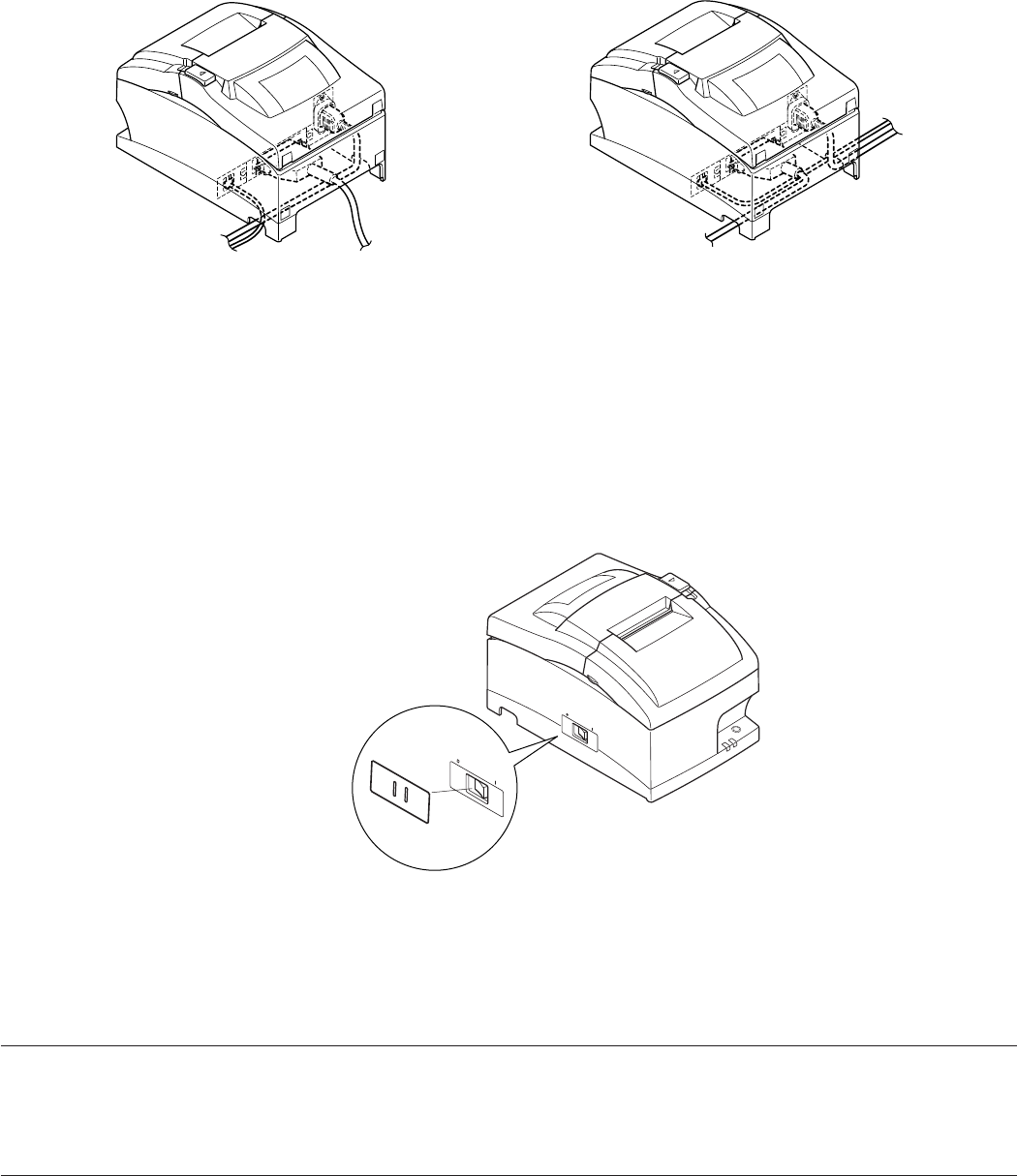
4-7. Installing the Cable
Install the cable as shown in the diagram below.
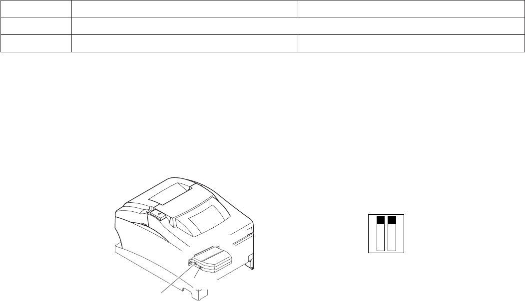
4-8. Switch Blind Installation
It is not necessary to install the switch blind. Only install it if it is necessary for you. By install-
ing the switch blind, the following become possible.
• Preventing the power switch from being operated by mistake.
• Ensuring that other people can not easily operate the power switch.
Install the switch blind as shown in the diagram below.
The power switch can be turned ON ( | ) and OFF (O) by inserting a narrow instrument (ball pen
etc) in the holes in the switch blind.
Important!
We recommend that you unplug the printer from the power outlet whenever you do not plan to
use it for long periods. Because of this, you should locate the printer so that the power outlet it
is plugged into is nearby and easy to access.
– 15 –
5. Loading the Ribbon Cartridge and Paper
Finger grip
Finger grip
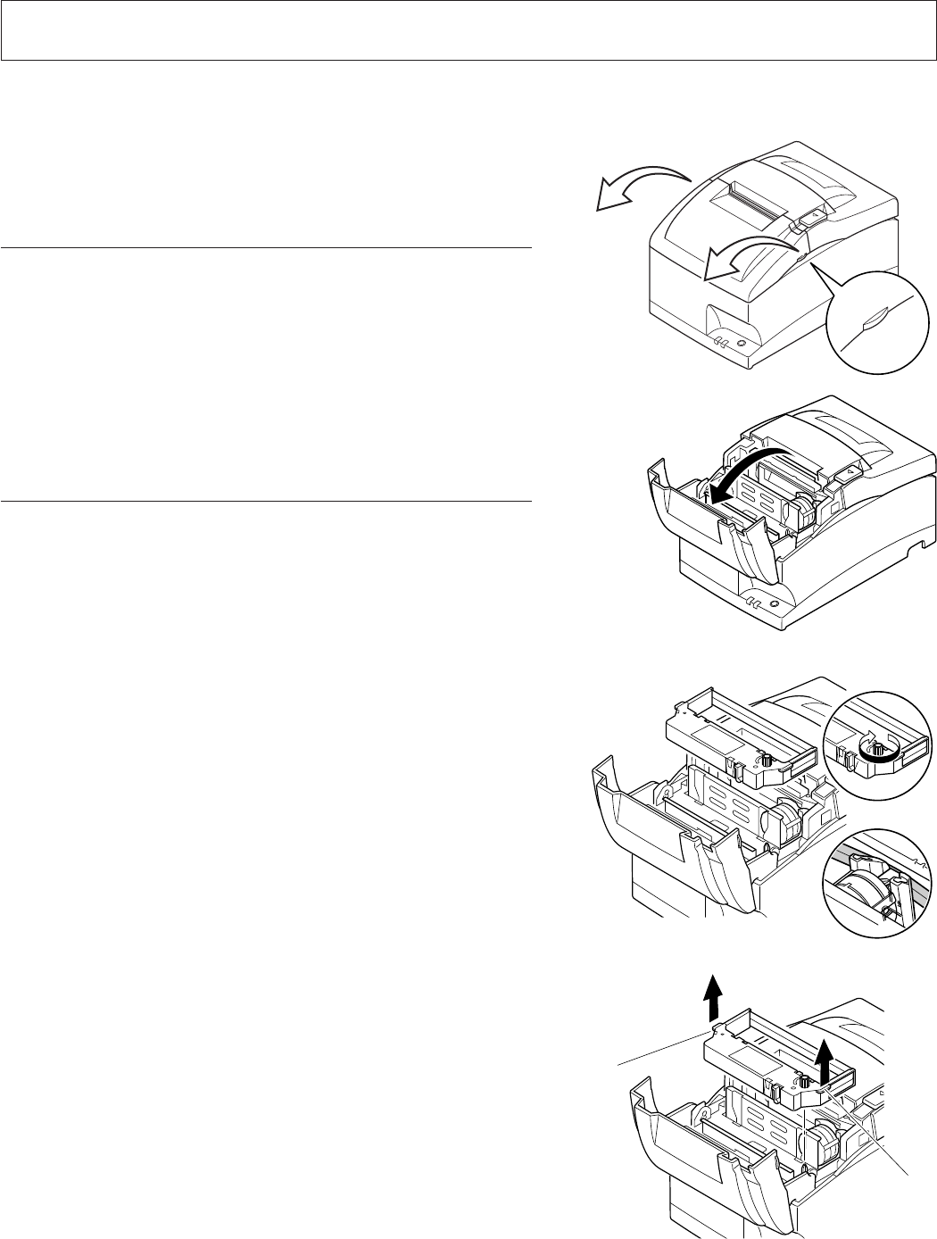
5-1. Loading the Ribbon Cartridge
1 Turn off power to the printer.
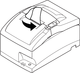
2 Open the front cover by holding the finger grips
on both ends of the cover and lifting it up.
Important!
1. Do not touch the print head immediately after
printing as it can be extremely hot.
2. Do not touch the cutter blade.
· There is a cutter inside the paper outlet slot.
Not only should you not put your hand in the
paper outlet slot while printing is in progress,
never put your hand into the outlet even when
printing is not in progress.
3 Place the ribbon cartridge in the direction shown
in the figure and press it down to load it. If loading
of the ribbon cartridge is not satisfactory, press
down the cartridge while rotating the ribbon feed
knob in the direction of the arrow.
4 Turn the ribbon feed knob of the ribbon cartridge
in the direction of the arrow to remove slack in
the ribbon.
5 Close the front cover.
Note: When removing the ribbon cartridge, raise
the finger grips as shown in the figure.

– 16 –
5-2. Loading the paper
1 Open the printer cover by sliding the latch toward
you.
Important!
1. Do not touch the print head immediately after
printing as it can be extremely hot.
2. Do not touch the cutter blade.
· There is a cutter inside the paper outlet slot.
Not only should you not put your hand in the
paper outlet slot while printing is in progress,
never put your hand into the outlet even when
printing is not in progress.
2 While observing the direction of the roll, set the
paper roll into the hollow, and pull on the leading
edge of the paper toward you.
3 Push down both sides of the printer cover to
close.
Note: Make sure that the printer cover is securely
closed.
– 17 –
4 Tear Bar Model:
Tear off the paper as shown.
Auto Cutter Model:
If the printer cover is closed after turning on the
power, the cutter operates automatically and the
front end of the paper is cut.
Note: When the paper end mark appears on the
paper, replace the roll paper before it runs
out.
– 18 –
5-3. Installing the Roll Paper Guide
When using paper roll with 57.5 mm or 69.5 mm width, install the attached roll paper guide
in the groove in the printer. The setting for memory switch 2-A and 2-B must be changed to
change the print width.
For instructions on setting the memory switch, please refer to the separate Specification Man-
ual.
69.5 mm width Roll paper guide
57.5 mm width
Roll paper guide

– 19 –
Caution Symbol
This symbol is placed near the print head to indicate that it may be hot. Never touch
the print head immediately after the printer has been used. Let the print head cool
for a few minutes before touching it.
This symbol is placed near the cutter (auto cutter or manual cutter tear bar).
Never touch the cutter blade, as you could injure your fingers.
This symbol label or stamp is placed near the screws securing the case, which should
not be opened by individuals other than service personnel.
Individuals, other than service personnel, should not remove these screws.
High voltage areas in the case can be dangerous.
WARNING
3 Shut down your equipment immediately if it produces smoke, a strange odor, or unu-
sual noise. Immediately unplug the equipment and contact your dealer for advice.
3 Never attempt to repair this product yourself. Improper repair work can be danger-
ous.
3 Never disassemble or modify this product. Tampering with this product may result in
injury, fire, or electric shock.
3 Do not touch the cutter blade.
- There is a cutter inside the paper outlet slot. Not only should you not put your hand
in the paper outlet slot while printing is in progress, never put your hand into the
outlet even when printing is not in progress.
- The printer cover can be opened when replacing the paper. However, since the cutter
blade is on the inside of the printer cover, be careful not to place your face or hands
too close to the cutter blade.
3 During and immediately after printing, the area around the print head is very hot. Do
not touch it, as you could be burned.
3 Since working on the cutter may be dangerous, be sure to turn off the printer first.

– 20 –
CAUTION
3 We recommend that you unplug the printer from the power outlet whenever you do
not plan to use it for long periods. Because of this, you should locate the printer so
that the power outlet it is plugged into is nearby and easy to access.
3 If the voltage shown on the label on the of your printer does not match the voltage for
your area, contact your dealer immediately.
3 Make sure that the printer is turned off and unplugged from the AC outlet and that the
computer is turned off before making connections.
3 Do not connect a telephone line into the peripheral drive connector.
Failure to observe this may result in damage to the printer.
Also, for safety purposes, do not connect wiring to the external drive connector if there
is a chance it may carry peripheral voltage.
3 Do not operate the cover open lever while pressing on the printer cover with your
hand.
3 Do not pull the cover open lever and open the printer cover when printing is in progress
or when the auto cutter is operating.
3 Do not pull out paper while the printer cover is closed.
3 If liquids, foreign objects (coins and paper clips), and so on enter the printer, turn off
the printer, unplug it from the AC outlet, and contact your dealer for advice. Continued
use could cause a short circuit, which may result in fire or electric shock.
3 Place the printer in a horizontal position when installing the paper, even if the model
can be installed vertically. If the paper is installed with the printer in a vertical posi-
tion, the printer will be unstable and could fall, which may result in injury.
– 21 –
6. Control Panel and Other Functions
6-1. Control Panel
2 FEED button
3 ERROR lamp (Red LED)
1 POWER lamp (Green LED)
1 POWER lamp (Green LED)
Lights when the power is ON.
2 FEED button
Press the FEED button to feed roll paper.
3 ERROR lamp (Red LED)
Indicates various errors in combination with
POWER lamp.
6-2. Basic Indicators
POWER lamp ERROR lamp Buzzer
Power On/Off On/Off — —
No Error On Off —

– 22 –
6-3. Errors
1) Recoverable error
Error Descrip-
tion
POWER lamp ERROR lamp Buzzer Recovery
Conditions
Paper end error On Flashes (On: 1 sec./
Off: 1 sec.)
4 short beeps (0.13
sec.) repeated
twice
*1
Printer cover open
error
On On Beep *2
Front cover open
error
Flashes (On: 0.5
sec./Off: 0.5 sec.)
On Beep *3
Paper near end
error
On Flashes (On: 2
sec./Off: 2 sec.)
None *4
Head high temper-
ature detection
Flashes (On: 1
sec./Off: 1 sec.)
Off None *5
Board high tem-
perature detec-
tion
Flashes (On: 2
sec./Off: 2 sec.)
Off None *6
Cutter error (on
models with cut-
ter)
On Flashes (On: 0.125
sec./Off: 0.125
sec.)
3 short beeps (0.13
sec. + 0.13 sec. +
0.5 sec.)
*7
Mechanical error
(other than cutter
error)
On Flashes (On: 0.25
sec./Off: 0.25
sec.)
2 short beeps (0.13
sec. + 0.5 sec.)
*8
Black mark detec-
tion error
On Flashes (On: 0.5
sec./Off: 0.5 sec.)
3 short beeps (0.13
sec. + 0.13 sec. +
0.13 sec.)
*9
*1 Automatically recovered by loading a new paper roll, then closing the printer cover.
*2 Automatically recovered by closing the printer cover.
*3 Automatically recovered by closing the front cover.
*4 Automatically recovered by loading a new paper roll, then closing the printer cover.
*5 Automatically the printer is recovered after the print head has cooled.
A print head temperature error is not abnormal.
*6 Automatically the printer is recovered after the board has cooled.

– 23 –
*7 Automatically the printer is recovered if the cutter returns to the home position after turn-
ing the power OFF and ON.
Restoration is also possible with the <DLE> <ENQ> n command when in the ESC/POS
mode.
Note
1) If the cutter doesn’t return to the home position, or doesn’t perform the initial move-
ment, it cannot be recovered.
2) If the paper is jammed, turn the power OFF, clear the jammed paper, then turn the
power ON.
3) When the error occurs:
STAR Mode: Non recoverable error
ESC/POS Mode: Recoverable error
*8 Turn the power OFF, clear the jammed paper or remedy another problem and then turn
the power ON. Automatically the printer is recovered if the carriage returns to the home
position after turning the power OFF and ON.
Restoration is also possible with the <DLE> <ENQ> n command when in the ESC/POS
mode.
When the error occurs:
STAR Mode: Non recoverable error
ESC/POS Mode: Recoverable error
*9 For paper jam errors:
Clear the jammed paper and change the paper roll if necessary.
For incorrect paper format errors:
Change the paper roll and use a paper roll with the correct black mark.
2) Non recoverable error
Error Description POWER lamp ERROR lamp Buzzer
Flash memory write
error
Off Flashes (On: 1 sec./
Off: 1 sec.)
None
Thermistor failure
error
Off Flashes (On: 0.25
sec./Off: 0.25 sec.)
2 short beeps (0.13 sec. + 0.5 sec.)
Power supply error Off Flashes (On: 2 sec./
Off: 2 sec.)
None
CPU error Off On One long beep (2 sec.)
RAM R/W error Off On None
Note
If a non-recoverable error occurs, turn the power OFF, wait at least 10 seconds, and turn
the power back ON. If the non-recoverable error continues to be indicated, consult a dealer
for repairs.

– 24 –
6-4. Adjustment Mode
There are the following seven adjustment modes.
The device will enter the adjustment mode if your turn it on while pressing the FEED switch.
(1) The Self Printing Mode is entered by releasing the FEED switch after the buzzer sounds
once. (Refer to Section 6-4-1.)
(Holding down for 2 more seconds)
(2) Adjusting the Dot Alignment Mode is entered by releasing the FEED switch after the buzzer
sounds twice. (Refer to Section 6-4-2.)
(Holding down for 2 more seconds)
(3) The Hexadecimal Dump Mode is entered by releasing the FEED switch after the buzzer
sounds three times. (Refer to Section 6-4-3.)
(Holding down for 2 more seconds)
(4) The Black Mark Sensor Alignment Mode is entered by releasing the FEED switch after
the buzzer sounds four times. (Refer to Section 6-4-4.)
(Holding down for 2 more seconds)
(5) The Near End Sensor Adjustment Mode is entered by releasing the FEED switch after the
buzzer sounds five times. (Refer to the separate Specifications Manual for details.)
(Holding down for 2 more seconds)
(6) The Memory Switch Manual Setting Mode is entered by releasing the FEED switch after
the buzzer sounds six times. (Refer to the separate Specifications Manual for details.)
(Holding down for 2 more seconds)
(7) The Memory Switch Override Mode is entered by releasing the FEED switch after the
buzzer sounds seven times. (Refer to the separate Specifications Manual for details.)
(Holding down for 2 more seconds)
Returns to (1).
– 25 –
6-4-1. Self Printing Mode
Self-printing will be performed to print the Ver. No. and printer settings. ASCII-printing will
be repeated when the FEED switch is held continuously at the end of ASCII-printing. The
self-printing mode will end automatically when the FEED button is released at the end of
ASCII-printing.
– 26 –
or like this
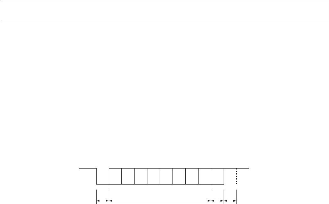
6-4-2. Adjusting the Dot Alignment Mode
You may never have to use the procedure described in this section, but after you have been using
your printer for some time you may find that the dots of some graphics do not align correctly.
For example, what should look like:
may come out looking like one of the following:
This is caused when mechanical parts of the printer get out of alignment. This happens only
rarely and you may never experience it at all throughout the life of the printer. If you do have
problems, use the following procedure to correct it.
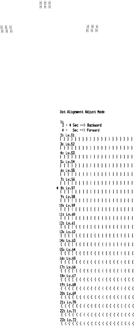
(1) Enter the Dot Alignment Adjust Mode according to the procedure described in Section 6-4.
(2) After entering the Dot Alignment Adjust Mode, a printout of the adjustment patterns
similar to the printout below will be printed. The asterisk indicates the current adjustment
pattern.
– 27 –
(3) To adjust, use the FEED switch to select the adjustment pattern from the printout with the
smallest gap between the first printing pass and the return printing pass. Press the FEED
switch once to specify the first adjustment pattern, twice to specify the second adjustment
pattern, and so on up to seven times to specify the seventh adjustment pattern.
At the number that you want to specify, press and hold (2 seconds) the FEED switch until
the long buzzer sounds. This will specify the setting value. (For example, if you want to
select the eighth pattern from the top, press the FEED switch seven times. Then, at the eighth
pattern, press and hold (2 seconds) the FEED switch until the long buzzer sounds.)
There are only twenty three adjustment patterns. The buzzer will sound each time the FEED
switch is pressed. However, if you press the FEED switch more than twenty three times, a
warning alert will sound.
(4) If there is no matching pattern among the adjustment patterns, perform the “Backward” or
“Forward” operation described below in order to print a printing pattern in which the dot
alignment settings are changed. Then, repeat step (3).
Backward:
Press and hold the FEED switch for 2 to 4 seconds. The buzzer will beep, and the
printer will print a pattern in which the forward is adjusted more leftward of the pres-
ently indicated pattern and the backward is adjusted more rightward.
Forward:
Press and hold the FEED switch for 4 seconds or longer. The buzzer will beep-beep,
and the printer will print a pattern in which the forward is adjusted more rightward
of the presently indicated pattern and the backward is adjusted more leftward.
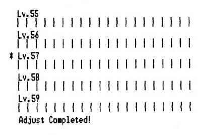
(5) After selecting the adjustment pattern, the setting value is stored in the non-volatile memory.
A printout similar to the one below with the selected adjustment pattern highlighted and
the message “Adjust Completed!” will be printed.
Note: Before the printout is printed, the setting value is stored in the non-volatile memory
of the printer after the adjustment pattern has been selected and the long buzzer
sounds. During this period, do not set the power switch to off. If this power switch
is set to off when the setting value is being stored in the non-volatile memory, the
setting value for the adjustment pattern and all of the memory switch settings will
be reset.
(6) The long buzzer sounds once more and the setting value is automatically set.
The adjusting the dot alignment mode is complete.
– 28 –
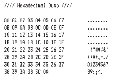
6-4-3. Hexadecimal Dump Mode
Each of the signals sent from the computer to the printer will be printed out in hexadecimal
code.
This function allows you to check if a control code sent to the printer by the program being
used is correct or not. The last line is not printed if its data is less than one full line. However,
if the FEED switch is pressed, the last line will be printed. To turn off the mode, it is necessary
to turn off the printer completely.
– 29 –
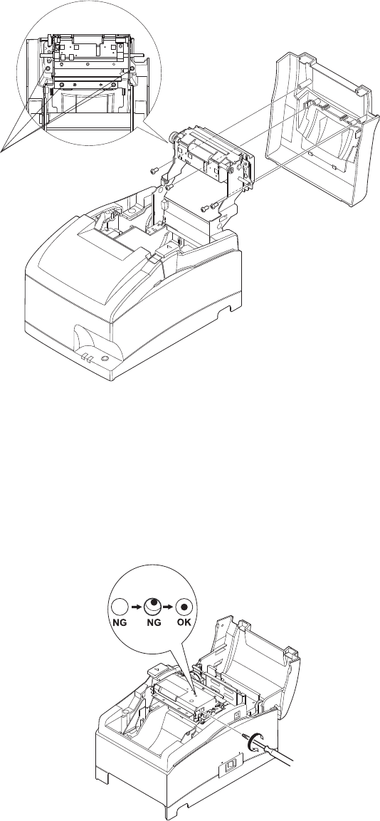
6-4-4. Black Mark Sensor Alignment Mode
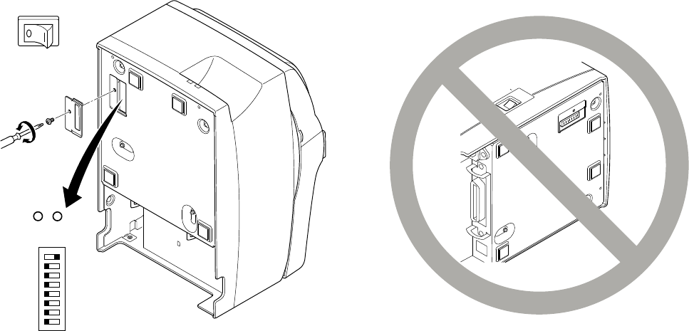
1. Turn the printer off and unplug the power cord.
2. Place the printer upright as shown below to remove the screws and remove the dip switch
cover from the bottom of the printer. Be sure to place the printer upright because you will
not be able to properly adjust the printer if it is placed on its side.
3. Since it is adjusted by rotating the volume VR2, check the position of the volume. Prepare
a small slotted screwdriver that will fit in the hole.
4. Set the roll paper not for black mark.
5. Enter the black mark sensor adjustment mode according to the procedure described Section
6-4.
6. Rotate the volume VR2 using micro screwdriver, to adjust it to a position whereat both the
ERROR (red LED) and the POWER (green LED) lamps light.
7. Turn the power OFF.
This completes the black mark sensor adjustment.
81
Power OFF
VR2
VR1

– 30 –
7. Preventing and Clearing Paper Jams
7-1. Preventing Paper Jams
The paper should not be touched during ejection and before it is cut.
Pressing or pulling the paper during ejection may cause a paper jam, paper cutting failure or
line feed failure.
7-2. Removing Paper Jam
If a paper jam occurs, clear it as described below.
(1) Set the power switch to off to turn off power to the printer.
(2) Push the cover open lever, and open the printer cover.
If the printer cover will not open on an auto cutter model, it means that the auto cutter is
not in the home position (or locked). In this case, return the auto cutter to the home posi-
tion by following the instructions provided in Section 7-3.
(3) Remove the jammed paper.
CAUTION
Take care not to damage the printer when removing the jammed paper.
(4) Position the roll paper straight and close the printer cover gently.
Note 1: Make sure that the paper is positioned straight. If the printer cover is closed with
the paper skewed, a paper jam may result.
Note 2: Lock the printer cover by pressing down on the sides. Do not try to close it by
pressing down on the center. The cover may not lock properly.
(5) Set the power switch to on to turn on power to the printer. Make sure that the ERROR LED
is not lit.
Note: While the ERROR LED is lit, the printer will not accept any commands such as
the print command, so make sure that the printer cover is locked properly.
– 31 –
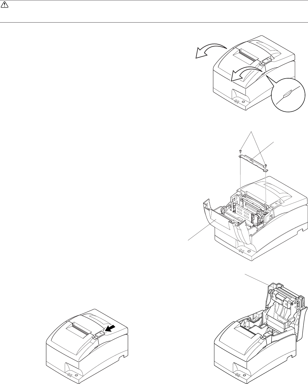
7-3. Releasing a Locked Cutter (Auto Cutter Mode only)
If the auto cutter locks up or fails to cut the paper, follow the steps below.
WARNING
Since working on the cutter may be dangerous, be sure to turn off the printer first.
(1) Set the power switch to OFF to turn off the printer.
(2) Ordinarily, a locked cutter will recover automati-
cally by closing all the covers and turning the power
back ON.
Recovery means that the locked cutter has been
released, so steps (3) and thereafter are unneces-
sary. If the cutter has not recovered, proceed to
step (3).
(3) Pull the cover open lever towards you, and open
the printer cover. The printer cover may not open
due to the cutter being locked. In this case, follow
steps (4) and (5) to first open the front cover and
remove the tear bar. If the printer cover opens,
proceed to step (6).
Note: Since the print head is hot immediately
after printing, be sure not to touch it. On
an auto cutter model, a paper cutter is
located at the paper outlet slot. Be careful
not to touch the cutter blade.
(4) Open the front cover by holding the finger grips
on both ends of the cover and lifting it up.
(5) Remove the two screws to remove the tear bar.
Front cover
Screws
Tear bar
Printer cover
– 32 –
(6) After you have opened the printer cover, remove the four screws to remove the printer cover
and reveal the cutter.
(7) If the cutter is locked, insert a Phillips screwdriver into the Phillips screw hole on the side
of the cutter, and turn it in the direction of the arrow shown below, in order to return the
cutter to its normal position.
(8) Reinstall the printer cover by tightening its screws.
(9) Reinstall the tear bar by tightening its screws.
Screws
– 33 –
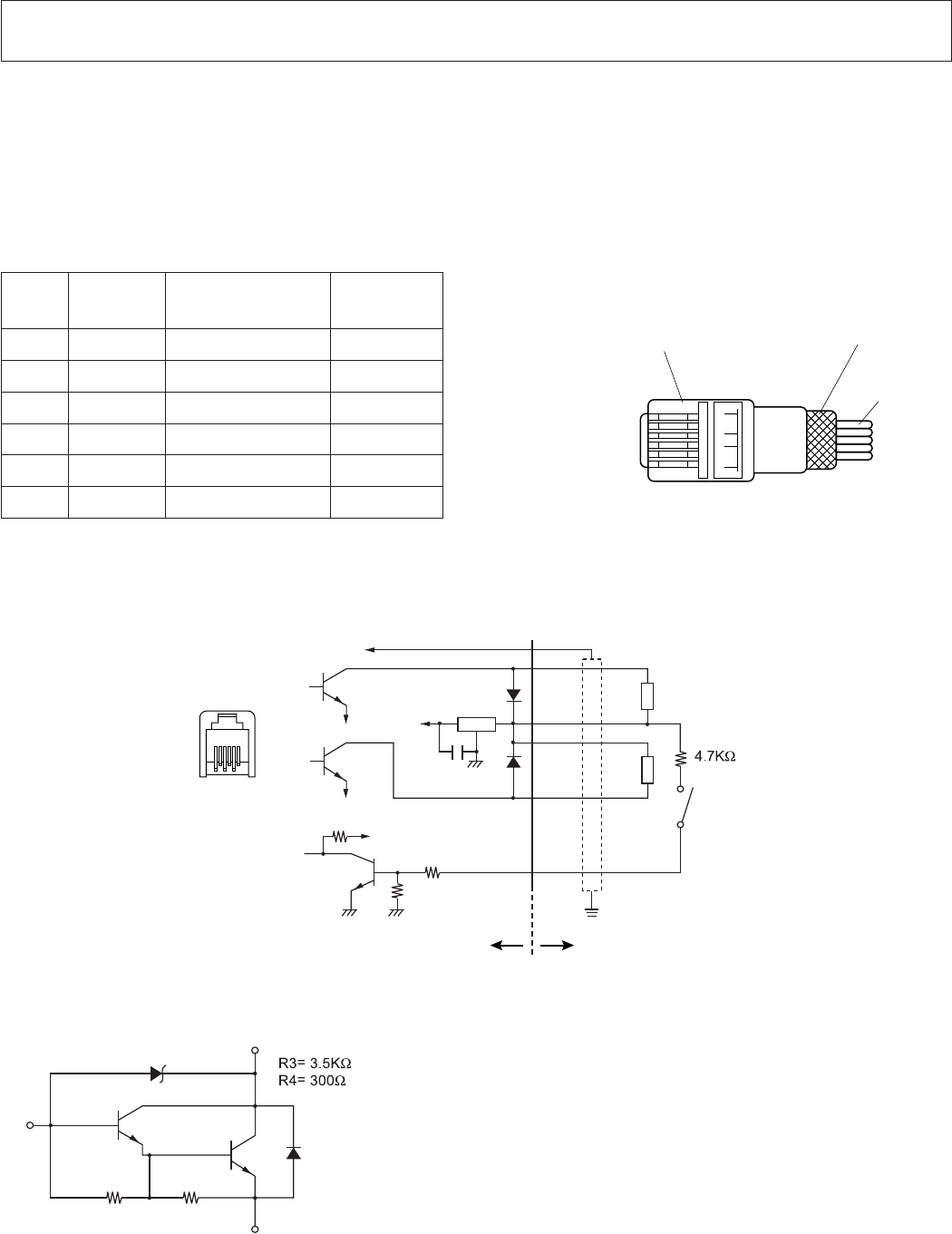
Modular plug
Pin
No.
Signal
name
Function I/O
direction
1 FG Frame ground —
2 DRD1 Drive signal 1 OUT
3 +24V Drive power OUT
4 +24V Drive power OUT
5 DRD2 Drive signal 2 OUT
6 DRSNS Sense signal IN
8. Peripheral Unit Drive Circuit
Peripheral unit drive circuit connector only connects to peripheral units such as cash drawers,
etc.
Do not connect it to a telephone.
Use cables which meet the following specifications.
Peripheral Drive Connector
Drive circuit
The recommended drive unit is shown below.
Drive Output: 24V, Max. 1.0A
TR1, TR2: Transistor 2SD1866 or equivalent
R1=10k W
R2=33k W
Reference
2SD 1866 Circuit Conguration
1 6
Wire lead
Modular plug: MOLEX 90075-
0007, AMP641337, or FCI B-66-4 Shield
User side
6 1
1
2
3
4
5
6
F.G
D1
D2
TR1
TR2
TR3
R2
+24V 7824
R1
+5V
R3
1/4W
M-GND
M-GND
L1
L2
6-P Modular
jack connector
With shield
Peripheral unit
Peripheral
unit 2
Compulsion
switch
Frame
ground
Printer side
E
C
R3 R4
B
– 34 –
Notes: 1. Peripheral units 1 and 2 cannot be driven simultaneously. To drive them continu-
ously, set the duty cycle ratio to 20% or less (excluding an externally connected
buzzer). Refer to the separate Specifications Manual for details.
2. The following external buzzer is available as an option.
External buzzer model: RMB-24
Voltage rating: 24V
Average consumption current: Max. 21 mA (at 24V)
Sound pressure: Min. 75 dB at 1 m
Lead wires: red (+) black (-)
3. Never use the external buzzer command if you connect a device (such as a cash
drawer) other than an external buzzer. It could damage the connected device
and the printer circuit. Refer to the separate Specifications Manual for details
on commands.
4. The status of the compulsion switch can be known from the status command.
Refer to the separate Specifications Manual for details.
5. Minimum resistance for coils L1 and L2 is 24.
6. Absolute maximum ratings for diodes D1 and D2 (Ta = 25°C) are:
Average Rectified Current Io = 1A
7. Absolute maximum rating for transistors TR1 and TR2 (Ta = 25°C) are:
Collector current IC = 2.0 A

– 35 –
9. General Specications
9-1. General Specifications
Printing method: Serial impact dot matrix
Print direction: Bi-directional
Number of head pins: 9 wires
Number of print columns: 42 columns
Character set: ASCII 95 characters
Extended graphics:
128 × 40 pages (Star mode)
128 × 9 pages (ESC/POS)
International characters:
46 (Star mode)
37 (ESC/POS)
Font configuration (ANK) 7 (Half dots) × 9 or 5 × 9
Printing width: 63 mm (210 dots)/57 mm (190 dots)/45 mm (150 dots)
Print speed: Max. 4.7 lines per sec. (76 mm paper width, 40 columns)
Line spacing: 1/6-inch (default), n/144-inch (programmable by command)
Paper feed method: Friction feed
Paper feed speed: Approx. 141 mm/sec.
Paper specifications
Paper type: Ordinary bond and carbonless copy paper
Paper width: 76±0.5 mm (3.0 inches)/57.5±0.5 mm (2.25 inches)/
69.5±0.5 mm (2.75 inches)
Roll diameter: 85mm (3.35 inches) max.
Core: 12±1 mm (Inner dia.), 18±1 mm (Outer dia.)
Note: Paper rolls with the end of the paper glued or taped to the
paper roll core or paper rolls with the end of the paper folded can
cause a paper jam.
Thickness Single: 0.06 mm to 0.085 mm
Copies: Original + 2 copies (Max. 0.2 mm)
Auto cutter Partial cut (Auto cutter model only)
Ink ribbon specifications
Ribbon type: Cartridge cassette
Color: 441Ribbon Black/Red: 2 colors (Black/Red)
441Ribbon Black: Single color (Black)
– 36 –
Ribbon material: Nylon 66 (#40 denier)
Ribbon life: 441Ribbon Black/Red: Black 1,500,000 characters/Red 750,000
characters
441Ribbon Black: Black 3,000,000 characters
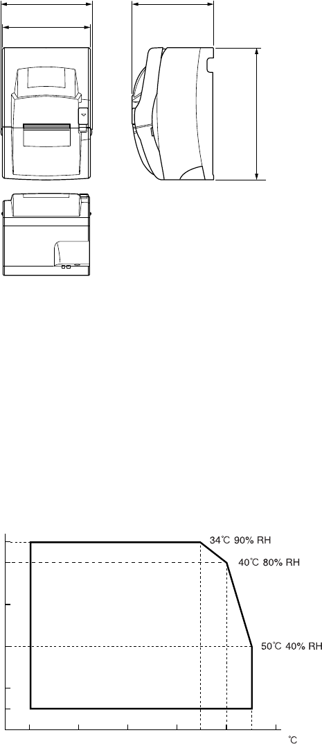
Overall dimensions: 160 (W) × 245 (D) × 152 (H) mm
160
164 152
245
Mechanical life: 10 million lines (except head life and auto cutter)
Print head life: 150 million characters
Auto cutter life: 1 million cuttings (if the paper thickness is between 65 and 100 µm)
(%RH)
90
80
60
40
20
10
0 10 20 30 40 50
Relative humidity Operating ambient
range
Ambient temperature
Weight: Approx. 3.0 kg (Tear bar model)
Approx. 3.2 kg (Auto cutter model)
Interface Parallel interface or RS-232C interface or USB Interface or Eth-
ernet Interface or Wireless LAN Interface
Peripheral unit drive circuit: 2 circuits (24V, max. 1A)
Ambient temperature/humidity
Operating temperature: 0°C to +50°C
Operating humidity: 0% to 90% RH (at 34°C, without condensation)
Storage temperature: –20°C to +70°C
Storage humidity: 5% to 95%RH (at 40°C, without condensation)
– 37 –
9-2. Power Supply Specifications
Power Supply:
Input: 100 to 240V AC, 50/60Hz
Consumption Current:
Conditions: Excluding perpheral unit driving
Operating: Approx. 36 W (at ASCII printing)
Stand-by: Approx. 10 W

– 38 –
10. Dip Switch Setting
A DIP switch is provided at the bottom of the printer, and can be set as given in the table be-
low. Be sure to set the power switch to off before changing the settings. It is recommended to
use a pointed item like a pen or flat-blade driver screw to change the settings. The settings will
become effective when the power switch is set to on again.
The following is the procedure for changing the settings on DIP switches.
1. Make sure the printer is turned off.
2. Remove the screw from the DIP switch cover. Then take off the DIP switch cover, as shown
in the illustration below.
3. Set the switches using a pointed tool, such as a pen or flat-blade screwdriver.
4. Replace the DIP switch cover. Then secure it with the screw.
The new settings take effect when you turn on the printer.
81
Power OFF
OFF
ON

– 39 –
n DIP switch
SW No. Function ON OFF
1-1 Always ON Should be set on
1-2 Auto Cutter *1 Invalid Valid
1-3 Always ON Should be set on
1-4 Command emulation Star ESC/POS
1-5 USB mode *2 Printer class Vendor class
1-6 2 colors printing Valid Invalid
1-7 Reserved
1-8 Print head model *3 18 pin wire 9 pin wire
*1 The factory settings for enabling/disabling the auto cutter are as follows.
Models without auto cutter: Invalid (Switch 1-2 = on)
Models with auto cutter: Valid (Switch 1-2 = off)
Note: Do not enable the auto cutter for models without the auto cutter (i.e., models with a
tear bar). A mechanical error will occur.
*2 USB interface model only
*3 Do not change the default setting (Switch 1-8 = off).
– 40 –
10-1. RS-232C Interface Model
The RS-232C interface model is equipped with DIP switches on the serial interface board unit
to change the communication settings. Change the settings for DIP switch No. 2 according to
the following procedures.
1. Turn off the printer and all components connected to it.
2. Remove the 2 screws.
3. Remove the serial interface board unit.
4. Change the setting of the DIP switches.
5. Replace the serial interface board unit.
Then secure it with the screws.
6. Turn on the printer and all components connected to it.
The factory settings of DIP switch are all on, except for switches 7 and 8.
DIP-SW 2
Switch Function ON OFF
2-1 Baud Rate See table below
2-2
2-3 Data Length 8 bits 7 bits
2-4 Parity Check Disabled Enabled
2-5 Parity Odd Even
2-6 Handshake DTR/DSR XON/XOFF
2-7 Pin #6 (DSR) reset signal Valid Invalid
2-8 Pin #25 (INIT) reset signal Valid Invalid
Baud Rate Settings Table
Baud Rate Switch 2-1 Switch 2-2
4800BPS OFF ON
9600BPS ON ON
19200BPS ON OFF
38400BPS OFF OFF
No. 1
DIP-SW2
2 3 4 5 6 7 8
ON
OFF
DIP switch 2
– 41 –
10-2. Parallel Interface Model
The parallel interface model is equipped with the main DIP switch only.
10-3. USB Interface Model
The USB interface model is equipped with the main DIP switch only.
10-4. Ethernet Interface Model
n Initializing Settings
Set the push switch as described below to initialize the setting information.
Push the switch for one to five seconds while running under normal operating mode. The green
and red LEDs will flash with a regular pattern. After that, push the switch once again in that
state to turn OFF both of the red and green LEDs. This will return the settings of the interface
board to their default, or ex-factory, settings. After the interface board has been initialized, the
printer will automatically reboot itself.
n LED Display
Green : Lights when other party connection is recognized as 100BASE-TX.
Red : Lights when packets are received.
LED
Push switch
– 42 –
10-5. Wireless LAN Interface Model
DIP-SW 2
Switch ON OFF
2-1 Fixed at OFF
2-2 Initialize of setting information —
Change DIP Switch 2-2 to ON to initialize the setting information when the power is turned
on.
The factory settings of DIP switch are all off.
LED Display
Green : Lights when pockets are received.
Note:
• This product contains a built-in wireless device and can only be used in the following
countries.
USA, UK, France, Ireland, Belgium, Germany, Austria, Switzerland, Italy, Denmark,
Norway, Sweden, Portugal, Spain, Estonia, Finland, Greece, Liechtenstein, Luxem-
burg, Netherlands, Canada, Slovakia, Slovenia, Czech, Hungary, Poland, Latvia, and
Lithuania.
No. 1 2
ON
OFF
DIP switch 2
LED
DIP switch 2

– 43 –
* This product contains Transmitter Module which conforms to the R&TTE Directive.
* This product contains Transmitter Module FCC ID: M4B6180210.
* This product contains Transmitter Module IC: 5844A-6180210.
* Strictly observe the export control laws of the country for export when exporting this
product.
Installing the Ferrite Core (Wireless LAN Model for EU Only)
Install the ferrite core onto the peripheral drive cable to prevent radio interference. Use the fer-
rite core only for the wireless LAN model in the EU.
1 Install the ferrite core onto the peripheral drive cable as shown in the illustration.
2 Pass the fastener through the holes in the ferrite core as shown in the illustration.
3 Loop the fastener around the cable, and then pull the end of the fastener tightly through its
buckle. Use a pair of scissors to cut off the excess end of the fastener.
Ethernet cable
Ferrite core
(EU only)
10cm
(Maximum)
Fastener
EU only
EU only

– 44 –
Connecting the peripheral drive cable
Connect the peripheral drive cable to the connector on the printer. Then, connect the other end
of the cable to the peripheral drive circuit.
Except for EU
EU only
– 45 –
11. RS-232C Serial Interface
MARK “1”
A: Start bit
B: Data bit
C: Parity bit
D: Stop bit
11-1. Interface Specifications
1 Data transmission method: Asynchronous serial interface
2 Baud rate: Selectable from 4800, 9600, 19200, 38400 bps
(Refer to “10. DIP Switch Setting”.)
3 Word length Start bit: 1 bit
Data bit: 7 or 8 bits (selectable.)
Parity bit: Odd, even or none (selectable.)
Stop bit: 1 bit length
4 Signal polarity RS-232
MARK: Logic “1” (–3V to –15V)
SPACE: Logic “0” (+3V to +15V)
! " # $
B B B B B B B B
SPACE “0”
– 46 –
11-2. Pins and Signal Names
Pin No. Signal Name Direction Function
1 FG — Frame ground
2 TXD OUT Transmission data
3 RXD IN Receive data
4 RTS OUT Always space
5 N.C. Not connected
6 DSR IN Dip switch 2-7 = OFF
(1) STAR Mode
Status of this signal is not checked.
(2) ESC/POS Mode
• In DTR/DSR communication mode
Memory Switch 4-5 = “0”:
signal line indicating whether host is
enabled or disabled to receive data is
checked.
Space: Host enabled to receive
Mark: Host disabled to receive
Memory switch 4-5 = 1:
Status of this signal is not checked.
• In X-ON/X-OFF communication mode, status of
this signal is not checked.
Dip switch 2-7 = ON
This is an externally reset signal.
A mark above 1 ms pulse width engages reset.
7 SG Signal ground
8 -19 N.C. Not connected
20 DTR OUT Indicates whether data receive from host is enabled or
disabled.
DTR/DSR Communication Mode
Space when receive is enabled.
Printer status Memory switch 6-9
0 1
1. During the period from when
the power is turned on (includ-
ing resetting using the interface)
to when the printer is ready to
receive data.
BUSY BUSY
2. During self printing and dot align-
ment adjustment. BUSY BUSY
3. When the printer stops printing
due to a paper end or an optional
paper near end.
BUSY —
4. When an error has occurred. BUSY —
5. When the receive buffer becomes
full. BUSY BUSY
– 47 –
Pin No. Signal Name Direction Function
20 DTR OUT X-On/X-Off Communication Mode
Always space, except during following conditions:
• Period between reset and communication enabled
• During self printing and dot alignment adjustment
21 - 24 N.C. Not connected
25 INIT Dip switch 2-8 = OFF
Status of this signal is not checked.
Dip switch 2-8 = ON
This is an externally reset signal.
A space above 1 ms pulse width engages reset.
11-3. Interface Connections
Refer to the interface specifications of the host for details on connecting to its interface connec-
tor. The following illustration shows a typical connection configuration.
Printer side PC side
&'.$
48$
28$
243
$32
3'.$
$42
$SUBPIN
&'.$
48$
28$
243
#43
$32
3'.$
$#$
$42
PINPIN
13
25
1
14

– 48 –
12. Parallel Interface
The two-way parallel interface is compatible with the IEEE1284 compatibility mode and nib-
ble mode.
12-1. Table of Connection Signals for Each Mode
Pin No. Direction Compatibility Mode
Signal Name
Nibble Mode
Signal Name
1 In nStorobe HostClk
2 In Data0 Data0
3 In Data1 Data1
4 In Data2 Data2
5 In Data3 Data3
6 In Data4 Data4
7 In Data5 Data5
8 In Data6 Data6
9 In Data7 Data7
10 Out nAck PtrClk
11 Out Busy PtrBusy/Data3,7
12 Out PError AckDataReq/Data2,6
13 Out Select Xflag/Data1,5
14 In nAutoFd HostBusy
15 N/C —
16 GND GND
17 Flame GND Flame GND
18 Out Logic High Logic High
19 GND GND
20 GND GND
21 GND GND
22 GND GND
23 GND GND
24 GND GND
25 GND GND
26 GND GND
27 GND GND
28 GND GND
29 GND GND
30 GND GND
– 49 –
Pin No. Direction Compatibility Mode
Signal Name
Nibble Mode
Signal Name
31 In nInit nInit
32 Out nFault nDataAvail/Data0,4
33 EXT GND —
34 Out Compulsion Status —
35 Out Logic High (+5V) —
36 In nSelectIn 1284Active
Note: 1. The prefix “n” on the signal name refers to low active signals.
If the host does not have any one of the signal lines listed above, two-way com-
munication fails.
2. For interfacing, signal lines should always use twisted pair cables with the return
sides connected to the signal ground level.
3. Cautions when resetting the printer using the nInit signal (#31 pin).
Reset can be made from #31 pin (nInit signal) of the interface by memory switch
setting. (Factory setting is reset.)
In addition, when reset has been enabled by #31 pin (nInit signal), it can be set to
reset when the following conditions have been established: memory switch set-
tings for 6-D and 6-E have been changed, #36 pin (nSelectIn/1284 active signal)
is low, and #31 pin (nInit signal) is low.
For instructions on setting the memory switch, please refer to the separate Speci-
fication Manual.
4. During factory output, IFEE 1284 printer device ID reply will be “Invalid.” To get
the device ID, change memory switch 6-C to “Valid.” For instructions on setting
the memory switch, please refer to the separate Specification Manual.
Parallel interface connector (printer side)
This connector mates with an Amphenol
57-30360 connector

– 50 –
13. USB, Ethernet and Wireless LAN Interface
13-1. USB Interface Specifications
1. General Specification: Conforms to USB 2.0 Specifications
2. Communication Speed: USB Full Speed Mode (12 Mbps)
3. Communication Method: USB Bulk Transmission Mode
4. Power Specifications: USB Self-power Function
5. Connector: USB Up-Stream Port Connector (USB Type-B)
13-2. Ethernet Interface Specifications
1. General Specification: Conforms to IEEE802.3
2. Communication Media: 10 Base-T/100 Base-TX
3. Communication Speed: 10/100 Mbps
4. Protocol: TCP/IP
5. TCP/IP detail: ARP, RARP, BOOTP, DHCP, LPR, #9100, FTP,
HTTP, TELNET, TFTP
6. Connector: RJ-45 (8-pin modular)
13-3. Wireless LAN Interface Specifications
1. General Specification: Conforms to IEEE802.1lb
2. Communication Media: 2.4 GHZ DSSS wireless CF card
3. Communication Speed: 1M/2M/5.5M/11Mbps AUTO Full-Back
4. Protocol: TCP/IP
5. TCP/IP detail: ARP, RARP, BOOTP, DHCP, LPR, #9100, IPP, POP3,
HTTP, TELNET, SMTP, SNMP, FTP
6. Operating Channels: North America : 1-11 ch
Japan : 1-14 ch
Europe : 1-13 ch

– 51 –
14. Memory Switch Settings
Each memory switch is stored in EEPROM. For details on the functions and settings of memory
switches, see the separate Specification Manual.
The table below shows the factory settings for the memory switches.
Memory Switch Hexadecimal Code
0 0000
1 0000
2 0000
3 0000
4 0000
5 0000
6 0000
7 0000
8 0000
9 0000
WARNING
Changing the memory switch settings can cause the printer to fail to operate correctly.
Oki Data Americas, Inc., 2000 Bishops Gate Blvd., Mt.Laurel, NJ 08054-4620
Tel: 1-800-Oki-Data (1-800-654-3282) Fax: (856) 222-5320 www.okiprintingsolutions.com
Oki Data de Mexico, S.A. de C.V., Mariano Escobedo NO. 748-8 Piso, Col. Anzures, e.p. 11590, Mexico, DF
Tel: 52-555-263-8780 Fax:52-555-250-3501 www.okiprintingsolutions.com
