OmniAccess SafeGuard OS Administration Guide Omni Access Safe Guard Controller Admin
User Manual: OmniAccess SafeGuard Controller Admin Guide
Open the PDF directly: View PDF ![]() .
.
Page Count: 426 [warning: Documents this large are best viewed by clicking the View PDF Link!]
- Contents
- Preface
- SafeGuard OS Overview
- Accessing and Managing the System
- Connecting to a SafeGuard Device Console
- Accessing the SafeGuard Device Command Line Interface
- Configuring Management Users
- Managing Out-of-Band Management Port
- Setting Up the System Time and Date (SNTP)
- Managing Device Information
- Managing Network Information
- Configuring SNMP on the Device
- Configuring Domain Name Servers
- Resetting the Device
- Configuring Data Traffic Ports
- Configuring High Availability Support
- Working with Configuration Files and Upgrading Images
- Understanding Configuration Files
- Upgrading System Images
- Upgrading the Boot Image
- Displaying Image and Boot Loader Information
- Removing All Data from Memory
- Configuring SafeGuard Controllers
- Setting Up SafeGuard Switches
- Overview of VLANs
- Tagged and Untagged Frames
- Ingress VLAN Classification and Egress Forwarding for the SafeGuard Switch
- Why Use VLANs?
- Configuring VLANs on the SafeGuard Switch
- Displaying Forwarding Database Entries Information
- Configuring Spanning Trees
- Enabling or Disabling STP Globally
- Forcing Transmission of Rapid Spanning Tree
- Setting the Configuration Identifier Name
- Setting the Configuration Identifier Revision Level
- Specifying an Edge Port
- Setting the Force Protocol Version Parameter
- Setting the Bridge Forward Delay Parameter
- Setting the Bridge Max Age Parameter
- Setting the Path Cost or Port Priority
- Setting the Bridge Priority
- Setting the Administrative Switch Port State for a Port
- Setting the Administrative Switch Port State for all Ports
- Displaying STP Information
- Configuring IGMP Snooping
- Configuring Global IGMP Snooping
- Configuring IGMP Snooping on a VLAN
- Optional IGMP Snooping Configuration
- Displaying IGMP Snooping Information
- Configuring Port Security
- Enabling Port Locking
- Setting the Maximum Number of Dynamically Locked MAC Addresses
- Setting the Maximum Number of Statically Locked MAC Addresses
- Adding a MAC Address to the Statically Locked List
- Converting Dynamically Locked Address To Statically Locked Addresses
- Displaying the Port Security Settings
- Displaying the Dynamically Locked MAC Addresses for a Port
- Displaying the Statically Locked MAC Addresses for a Port
- Displaying the Source MAC Address of the Last Packet Discarded on a Locked Port
- Configuring Routing
- Overview of VLANs
- Configuring Authentication and Role Derivation
- Configuring User Authentication
- Authentication Concepts
- Limiting Access with Trusted Servers
- Maintaining the Host Mapping Table
- Working with Protocol Data Unit Parsers
- Configuring Captive Portal
- Configuring MAC-Based RADIUS
- Configuring Device Authentication Lists
- Setting Up Authentication Servers
- IEEE 802.1x Authentication
- Role Derivation
- Configuring User Authentication
- Establishing a Security Policy
- Policy Concepts
- System White-Black List
- User Policies
- Configuring User Policies
- EPV Policies
- Configuring Policy-Based Mirroring
- Policy Debug
- System Generated Policies and Roles
- Displaying Policy Configurations
- Visualization
- End Point Validation
- Determining the Posture of a Host
- Configuring EPV
- Enabling EPV
- Optional EPV Configuration
- Displaying and Clearing the EPV Posture State
- Detecting and Isolating Malware Security Threats
- Detecting and Quarantining Malware
- Configuring Malware Detection
- Configuring a Malware White-list
- Configuring Mirroring
- Displaying Malware Configurations
- Displaying DNS Information
- Displaying a Malware Policy Configuration
- Displaying DNS Server Names and Refresh Rates
- Displaying User-roles
- Displaying Malware Actions
- Displaying the Malware Detection State
- Displaying Malware Status
- Displaying which Algorithm Detected the Malware
- Displaying Malware for an IP Address
- Displaying Malware Trace Information
- Displaying the Contents of the Malware White-List
- Downloading Malware Definition Files
- Clearing Malware Configurations
- Troubleshooting
- Sample Output
- Index
- Command Index

PART NUMBER: 005-0033 REV A1
PUBLISHED: MARCH 2007
ALCATEL-LUCENT
26801 WEST AGOURA ROAD
CALABASAS, CA 91301 USA
(818) 880-3500
WWW.ALCATEL-LUCENT.COM
OmniAccess SafeGuard
OS Administration
Guide
Release 3.0.2

OmniAccess SafeGuard OS Administration Guide
2
Alcatel-Lucent Proprietary
Copyright © 2007 Alcatel-Lucent. All rights reserved. This document may not be reproduced in whole
or in part without the expressed written permission Alcatel-Lucent. Alcatel-Lucent ® and the Alcatel-
Lucent logo are registered trademarks of Alcatel-Lucent. All other trademarks are the property of their
respective owners.

OmniAccess SafeGuard OS Administration Guide 3
Contents
Preface
About This Guide. . . . . . . . . . . . . . . . . . . . . . . . . . . . . . . . . . . . . . . . . . . . . . . . . . . . . . . . . . . . . . . . . .16
Audience. . . . . . . . . . . . . . . . . . . . . . . . . . . . . . . . . . . . . . . . . . . . . . . . . . . . . . . . . . . . . . . . . . . . .16
Conventions Used in This Guide . . . . . . . . . . . . . . . . . . . . . . . . . . . . . . . . . . . . . . . . . . . . . . . . . .16
Related Publications. . . . . . . . . . . . . . . . . . . . . . . . . . . . . . . . . . . . . . . . . . . . . . . . . . . . . . . . . . . . . . .17
Additional Resources . . . . . . . . . . . . . . . . . . . . . . . . . . . . . . . . . . . . . . . . . . . . . . . . . . . . . . . . . . .17
Guide Organization . . . . . . . . . . . . . . . . . . . . . . . . . . . . . . . . . . . . . . . . . . . . . . . . . . . . . . . . . . . . . . .17
Chapter 1: SafeGuard OS Overview
Alcatel-Lucent Solution and Product Overview . . . . . . . . . . . . . . . . . . . . . . . . . . . . . . . . . . . . . . . .20
Deployment Models. . . . . . . . . . . . . . . . . . . . . . . . . . . . . . . . . . . . . . . . . . . . . . . . . . . . . . . . . . . . . . .22
Understanding Protection Modes. . . . . . . . . . . . . . . . . . . . . . . . . . . . . . . . . . . . . . . . . . . . . . . . . . . .24
SafeGuard OS Overall Feature Summary . . . . . . . . . . . . . . . . . . . . . . . . . . . . . . . . . . . . . . . . . . . . .26
Chapter 2: Accessing and Managing the System
Connecting to a SafeGuard Device Console. . . . . . . . . . . . . . . . . . . . . . . . . . . . . . . . . . . . . . . . . .28
Accessing the SafeGuard Device Command Line Interface . . . . . . . . . . . . . . . . . . . . . . . . . . . . .28
Using Telnet . . . . . . . . . . . . . . . . . . . . . . . . . . . . . . . . . . . . . . . . . . . . . . . . . . . . . . . . . . . . . . . . . . .29
Enabling and Disabling Telnet . . . . . . . . . . . . . . . . . . . . . . . . . . . . . . . . . . . . . . . . . . . . . . . .29
Displaying the Current Telnet and Serial Port Connections . . . . . . . . . . . . . . . . . . . . . . . .29
Closing a Telnet or SSH Session. . . . . . . . . . . . . . . . . . . . . . . . . . . . . . . . . . . . . . . . . . . . . . . .30
Specifying the Maximum Number of Telnet Connections Allowed. . . . . . . . . . . . . . . . . .30
Setting the Telnet Connection Session Timeout . . . . . . . . . . . . . . . . . . . . . . . . . . . . . . . . . .30
Using Secure Shell (SSH) . . . . . . . . . . . . . . . . . . . . . . . . . . . . . . . . . . . . . . . . . . . . . . . . . . . . . . . . .31
Enabling an SSH Session . . . . . . . . . . . . . . . . . . . . . . . . . . . . . . . . . . . . . . . . . . . . . . . . . . . . .32
Downloading SSH Key Files from TFTP Server. . . . . . . . . . . . . . . . . . . . . . . . . . . . . . . . . . . . .32
Generating DSA, RSA, RSA Keys. . . . . . . . . . . . . . . . . . . . . . . . . . . . . . . . . . . . . . . . . . . . . . .33
Deleting DSA, RSA, RSA Keys. . . . . . . . . . . . . . . . . . . . . . . . . . . . . . . . . . . . . . . . . . . . . . . . . .33
Changing SSH Protocols . . . . . . . . . . . . . . . . . . . . . . . . . . . . . . . . . . . . . . . . . . . . . . . . . . . . .34
Limiting SSH Sessions. . . . . . . . . . . . . . . . . . . . . . . . . . . . . . . . . . . . . . . . . . . . . . . . . . . . . . . . .34
Setting the SSH Timer . . . . . . . . . . . . . . . . . . . . . . . . . . . . . . . . . . . . . . . . . . . . . . . . . . . . . . . .35
Displaying SSH Configuration Information. . . . . . . . . . . . . . . . . . . . . . . . . . . . . . . . . . . . . . .35
Customizing and Working with the Command Line Interface Default Settings . . . . . . . . . . .36
Changing the System Command Prompt . . . . . . . . . . . . . . . . . . . . . . . . . . . . . . . . . . . . . .37
Setting a Maximum Serial Console Connect Time. . . . . . . . . . . . . . . . . . . . . . . . . . . . . . . .37

Contents
OmniAccess SafeGuard OS Administration Guide
4
Enabling and Disabling CLI Display Paging . . . . . . . . . . . . . . . . . . . . . . . . . . . . . . . . . . . . .37
Uploading a New CLI Banner File . . . . . . . . . . . . . . . . . . . . . . . . . . . . . . . . . . . . . . . . . . . . .38
Uploading the CLI Log File . . . . . . . . . . . . . . . . . . . . . . . . . . . . . . . . . . . . . . . . . . . . . . . . . . .38
Copying the System Diagnostics File. . . . . . . . . . . . . . . . . . . . . . . . . . . . . . . . . . . . . . . . . . .38
Copying the System Debug File. . . . . . . . . . . . . . . . . . . . . . . . . . . . . . . . . . . . . . . . . . . . . . .39
Displaying the Current HTTP Information . . . . . . . . . . . . . . . . . . . . . . . . . . . . . . . . . . . . . . . .39
Exiting or Logging Out of a Command Line Session . . . . . . . . . . . . . . . . . . . . . . . . . . . . . . . . .39
Configuring Management Users. . . . . . . . . . . . . . . . . . . . . . . . . . . . . . . . . . . . . . . . . . . . . . . . . . . . .39
Configuring Management Users. . . . . . . . . . . . . . . . . . . . . . . . . . . . . . . . . . . . . . . . . . . . . . . . . .40
Adding Management Users to the Database . . . . . . . . . . . . . . . . . . . . . . . . . . . . . . . . . . .40
Displaying the Management Users . . . . . . . . . . . . . . . . . . . . . . . . . . . . . . . . . . . . . . . . . . . .41
Setting a Password for the Default Admin Account . . . . . . . . . . . . . . . . . . . . . . . . . . . . . .42
Configuring Local Authentication for Management Users. . . . . . . . . . . . . . . . . . . . . . . . .43
Assigning a Login List to the Default Login User . . . . . . . . . . . . . . . . . . . . . . . . . . . . . . . . . . . . .44
Configuring RADIUS Users for Management Users . . . . . . . . . . . . . . . . . . . . . . . . . . . . . . . . . . .45
Clearing All Passwords. . . . . . . . . . . . . . . . . . . . . . . . . . . . . . . . . . . . . . . . . . . . . . . . . . . . . . . . . .46
Managing Out-of-Band Management Port . . . . . . . . . . . . . . . . . . . . . . . . . . . . . . . . . . . . . . . . . . .46
Setting the IP Configuration Protocol. . . . . . . . . . . . . . . . . . . . . . . . . . . . . . . . . . . . . . . . . . . . . .46
Setting the IP Address, Netmask, and Gateway of the System . . . . . . . . . . . . . . . . . . . . . . . .47
Enabling or Disabling the Management Port . . . . . . . . . . . . . . . . . . . . . . . . . . . . . . . . . . . . . . .47
Setting Speed and Duplex for the Management Port. . . . . . . . . . . . . . . . . . . . . . . . . . . . . . . .48
Displaying Configuration Information for the Management Port. . . . . . . . . . . . . . . . . . . . . . .48
Displaying Address Resolution Protocol Information . . . . . . . . . . . . . . . . . . . . . . . . . . . . . . . . .51
Setting Up the System Time and Date (SNTP) . . . . . . . . . . . . . . . . . . . . . . . . . . . . . . . . . . . . . . . . . .51
Manually Setting the Time and Date . . . . . . . . . . . . . . . . . . . . . . . . . . . . . . . . . . . . . . . . . . . . . .51
Configuring SNTP . . . . . . . . . . . . . . . . . . . . . . . . . . . . . . . . . . . . . . . . . . . . . . . . . . . . . . . . . . . . . .54
Optional SNTP Client Configurations . . . . . . . . . . . . . . . . . . . . . . . . . . . . . . . . . . . . . . . . . . . . . .58
Setting the Poll Interval . . . . . . . . . . . . . . . . . . . . . . . . . . . . . . . . . . . . . . . . . . . . . . . . . . . . . .58
Setting the Poll Retry and Poll-Timeout Timers for Unicast Clients. . . . . . . . . . . . . . . . . . . .58
Setting the Port ID for the Port Client. . . . . . . . . . . . . . . . . . . . . . . . . . . . . . . . . . . . . . . . . . .59
Managing Device Information . . . . . . . . . . . . . . . . . . . . . . . . . . . . . . . . . . . . . . . . . . . . . . . . . . . . . .60
Clearing the Counters . . . . . . . . . . . . . . . . . . . . . . . . . . . . . . . . . . . . . . . . . . . . . . . . . . . . . . . . . .60
Checking for Another Computer on the Network . . . . . . . . . . . . . . . . . . . . . . . . . . . . . . . . . . .60
Displaying Version Information . . . . . . . . . . . . . . . . . . . . . . . . . . . . . . . . . . . . . . . . . . . . . . . . . . .61
Displaying Hardware Information. . . . . . . . . . . . . . . . . . . . . . . . . . . . . . . . . . . . . . . . . . . . . . . . .63
Displaying the Serial Communication Settings for the Device . . . . . . . . . . . . . . . . . . . . . . . . .65
Setting Up a Trace Route. . . . . . . . . . . . . . . . . . . . . . . . . . . . . . . . . . . . . . . . . . . . . . . . . . . . . . . .66
Managing Network Information . . . . . . . . . . . . . . . . . . . . . . . . . . . . . . . . . . . . . . . . . . . . . . . . . . . . .67
Configuring the Network MAC Address. . . . . . . . . . . . . . . . . . . . . . . . . . . . . . . . . . . . . . . . . . . .67
Configuring the Network MAC Type . . . . . . . . . . . . . . . . . . . . . . . . . . . . . . . . . . . . . . . . . . . . . .67
Configuring the Network VLAN ID . . . . . . . . . . . . . . . . . . . . . . . . . . . . . . . . . . . . . . . . . . . . . . . .68
Configuring the Network Protocol . . . . . . . . . . . . . . . . . . . . . . . . . . . . . . . . . . . . . . . . . . . . . . . .68

OmniAccess SafeGuard OS Administration Guide 5
Contents
Configuring SNMP on the Device . . . . . . . . . . . . . . . . . . . . . . . . . . . . . . . . . . . . . . . . . . . . . . . . . . . .68
Setting the SNMP Name . . . . . . . . . . . . . . . . . . . . . . . . . . . . . . . . . . . . . . . . . . . . . . . . . . . . . . . .69
Setting the SNMP Physical Location. . . . . . . . . . . . . . . . . . . . . . . . . . . . . . . . . . . . . . . . . . . . . . .69
Designating the SNMP Contact . . . . . . . . . . . . . . . . . . . . . . . . . . . . . . . . . . . . . . . . . . . . . . . . . .70
Configuring SNMP Communities. . . . . . . . . . . . . . . . . . . . . . . . . . . . . . . . . . . . . . . . . . . . . . . . . .70
Adding and Naming a New SNMP Community. . . . . . . . . . . . . . . . . . . . . . . . . . . . . . . . . .70
Establishing Access for the SNMP Community . . . . . . . . . . . . . . . . . . . . . . . . . . . . . . . . . . .71
Setting a Client IP Address for an SNMP Community. . . . . . . . . . . . . . . . . . . . . . . . . . . . . .71
Setting a Client Netmask SNMP Community . . . . . . . . . . . . . . . . . . . . . . . . . . . . . . . . . . . .72
Configuring a SNMP Target. . . . . . . . . . . . . . . . . . . . . . . . . . . . . . . . . . . . . . . . . . . . . . . . . . . . . .72
Creating the Trap Receiver . . . . . . . . . . . . . . . . . . . . . . . . . . . . . . . . . . . . . . . . . . . . . . . . . .72
Changing the IP Address of a Trap Receiver . . . . . . . . . . . . . . . . . . . . . . . . . . . . . . . . . . . .72
Changing the Trap Receiver Version. . . . . . . . . . . . . . . . . . . . . . . . . . . . . . . . . . . . . . . . . . .73
Enabling and Disabling SNMP Traps. . . . . . . . . . . . . . . . . . . . . . . . . . . . . . . . . . . . . . . . . . . . . . .73
Displaying SNMP Community Information. . . . . . . . . . . . . . . . . . . . . . . . . . . . . . . . . . . . . . . . . .74
Displaying SNMP Target Information . . . . . . . . . . . . . . . . . . . . . . . . . . . . . . . . . . . . . . . . . . . . . .75
Displaying SNMP System Information . . . . . . . . . . . . . . . . . . . . . . . . . . . . . . . . . . . . . . . . . . . . . .75
Configuring Domain Name Servers . . . . . . . . . . . . . . . . . . . . . . . . . . . . . . . . . . . . . . . . . . . . . . . . . .77
Specifying a Default Domain . . . . . . . . . . . . . . . . . . . . . . . . . . . . . . . . . . . . . . . . . . . . . . . . . . . .77
Creating a DNS Name Server List . . . . . . . . . . . . . . . . . . . . . . . . . . . . . . . . . . . . . . . . . . . . . . . . .78
Displaying DNS Information. . . . . . . . . . . . . . . . . . . . . . . . . . . . . . . . . . . . . . . . . . . . . . . . . . . . . .78
Resetting the Device . . . . . . . . . . . . . . . . . . . . . . . . . . . . . . . . . . . . . . . . . . . . . . . . . . . . . . . . . . . . . .79
Configuring Data Traffic Ports . . . . . . . . . . . . . . . . . . . . . . . . . . . . . . . . . . . . . . . . . . . . . . . . . . . . . . .79
Entering Interface Configuration Mode . . . . . . . . . . . . . . . . . . . . . . . . . . . . . . . . . . . . . . . . . . .79
Enabling and Disabling an Interface . . . . . . . . . . . . . . . . . . . . . . . . . . . . . . . . . . . . . . . . . . . . . .80
Displaying Interface Information . . . . . . . . . . . . . . . . . . . . . . . . . . . . . . . . . . . . . . . . . . . . . . . . .80
Displaying Ethernet Interface Information. . . . . . . . . . . . . . . . . . . . . . . . . . . . . . . . . . . . . . . . . .82
Switchport Statistics Display Information. . . . . . . . . . . . . . . . . . . . . . . . . . . . . . . . . . . . . . . .89
Additional Statistics Display Information . . . . . . . . . . . . . . . . . . . . . . . . . . . . . . . . . . . . . . . .90
Understanding Mirroring and Monitoring Ports . . . . . . . . . . . . . . . . . . . . . . . . . . . . . . . . . . . . . .91
About Remote Span Support. . . . . . . . . . . . . . . . . . . . . . . . . . . . . . . . . . . . . . . . . . . . . . . . .91
Configuring Port-Based Mirroring . . . . . . . . . . . . . . . . . . . . . . . . . . . . . . . . . . . . . . . . . . . . . . . . .93
Setting the Source or Destination Port. . . . . . . . . . . . . . . . . . . . . . . . . . . . . . . . . . . . . . . . . .93
Restoring the Default Mirror Session Mode . . . . . . . . . . . . . . . . . . . . . . . . . . . . . . . . . . . . . .94
Showing the Monitor Session . . . . . . . . . . . . . . . . . . . . . . . . . . . . . . . . . . . . . . . . . . . . . . . . .94
Changing the Protection Mode of Ports . . . . . . . . . . . . . . . . . . . . . . . . . . . . . . . . . . . . . . . . . . .95
For the SafeGuard Controller . . . . . . . . . . . . . . . . . . . . . . . . . . . . . . . . . . . . . . . . . . . . . . . . .96
For the SafeGuard Switch. . . . . . . . . . . . . . . . . . . . . . . . . . . . . . . . . . . . . . . . . . . . . . . . . . . .97
Displaying Protection Mode Information . . . . . . . . . . . . . . . . . . . . . . . . . . . . . . . . . . . . . . .98
Configuring High Availability Support. . . . . . . . . . . . . . . . . . . . . . . . . . . . . . . . . . . . . . . . . . . . . . . .100
Configuring Fail-over Device Support . . . . . . . . . . . . . . . . . . . . . . . . . . . . . . . . . . . . . . . . . . . .100
Configuring System Recovery. . . . . . . . . . . . . . . . . . . . . . . . . . . . . . . . . . . . . . . . . . . . . . . . . . .105
Configuring Exception Recovery . . . . . . . . . . . . . . . . . . . . . . . . . . . . . . . . . . . . . . . . . . . . . . . .106
Enabling and Disabling Exception Recovery . . . . . . . . . . . . . . . . . . . . . . . . . . . . . . . . . . .106

Contents
OmniAccess SafeGuard OS Administration Guide
6
Changing the Exception Recovery Parameters . . . . . . . . . . . . . . . . . . . . . . . . . . . . . . . .107
Enabling System Reboots on LSP Watchdog Events . . . . . . . . . . . . . . . . . . . . . . . . . . . . .108
Viewing the Exception Recovery Status . . . . . . . . . . . . . . . . . . . . . . . . . . . . . . . . . . . . . . .108
Chapter 3: Working with Configuration Files and Upgrading Images
Understanding Configuration Files . . . . . . . . . . . . . . . . . . . . . . . . . . . . . . . . . . . . . . . . . . . . . . . . . .110
Saving Changes to the Running Configuration . . . . . . . . . . . . . . . . . . . . . . . . . . . . . . . . . . . .110
From Running to the Startup. . . . . . . . . . . . . . . . . . . . . . . . . . . . . . . . . . . . . . . . . . . . . . . . .110
From Running to External Storage . . . . . . . . . . . . . . . . . . . . . . . . . . . . . . . . . . . . . . . . . . . .111
Saving Changes to the Startup Configuration . . . . . . . . . . . . . . . . . . . . . . . . . . . . . . . . . . . . .111
From Startup to Backup. . . . . . . . . . . . . . . . . . . . . . . . . . . . . . . . . . . . . . . . . . . . . . . . . . . . .111
From Startup to External Storage . . . . . . . . . . . . . . . . . . . . . . . . . . . . . . . . . . . . . . . . . . . . .112
Moving Backup Files to External Storage. . . . . . . . . . . . . . . . . . . . . . . . . . . . . . . . . . . . . . . . . .112
Restoring Configuration Files. . . . . . . . . . . . . . . . . . . . . . . . . . . . . . . . . . . . . . . . . . . . . . . . . . . .112
From Flash Memory to Flash Memory . . . . . . . . . . . . . . . . . . . . . . . . . . . . . . . . . . . . . . . . .112
From TFTP to Flash Memory . . . . . . . . . . . . . . . . . . . . . . . . . . . . . . . . . . . . . . . . . . . . . . . . . .113
From Compact Flash to Flash Memory . . . . . . . . . . . . . . . . . . . . . . . . . . . . . . . . . . . . . . . .113
Erasing the Startup Configuration . . . . . . . . . . . . . . . . . . . . . . . . . . . . . . . . . . . . . . . . . . . . . . .114
Displaying Configuration Information . . . . . . . . . . . . . . . . . . . . . . . . . . . . . . . . . . . . . . . . . . . .114
Running Config. . . . . . . . . . . . . . . . . . . . . . . . . . . . . . . . . . . . . . . . . . . . . . . . . . . . . . . . . . . .114
Startup Config . . . . . . . . . . . . . . . . . . . . . . . . . . . . . . . . . . . . . . . . . . . . . . . . . . . . . . . . . . . .115
Upgrading System Images. . . . . . . . . . . . . . . . . . . . . . . . . . . . . . . . . . . . . . . . . . . . . . . . . . . . . . . . .115
Copying Images. . . . . . . . . . . . . . . . . . . . . . . . . . . . . . . . . . . . . . . . . . . . . . . . . . . . . . . . . . . . . .116
Specifying the System Image . . . . . . . . . . . . . . . . . . . . . . . . . . . . . . . . . . . . . . . . . . . . . . . . . . .116
Upgrading the Boot Image . . . . . . . . . . . . . . . . . . . . . . . . . . . . . . . . . . . . . . . . . . . . . . . . . . . . . . . .117
Dual-Stage Boot Loader Upgrades . . . . . . . . . . . . . . . . . . . . . . . . . . . . . . . . . . . . . . . . . . . . . .117
Copying a Boot Loader from a TFTP Server . . . . . . . . . . . . . . . . . . . . . . . . . . . . . . . . . . . .118
Specifying the Boot Loader . . . . . . . . . . . . . . . . . . . . . . . . . . . . . . . . . . . . . . . . . . . . . . . . .118
Simple Boot Loader Upgrades . . . . . . . . . . . . . . . . . . . . . . . . . . . . . . . . . . . . . . . . . . . . . . . . . .119
Updating the Simple Boot Loader . . . . . . . . . . . . . . . . . . . . . . . . . . . . . . . . . . . . . . . . . . . .119
Migrating a Simple Boot Loader to a Dual-Stage Boot Loader . . . . . . . . . . . . . . . . . . . .119
Displaying Image and Boot Loader Information. . . . . . . . . . . . . . . . . . . . . . . . . . . . . . . . . . . . . . .120
Removing All Data from Memory . . . . . . . . . . . . . . . . . . . . . . . . . . . . . . . . . . . . . . . . . . . . . . . . . . .123
Chapter 4: Configuring SafeGuard Controllers
Configuring VLANs on the SafeGuard Controller . . . . . . . . . . . . . . . . . . . . . . . . . . . . . . . . . . . . . .126
Link Pair Synchronization . . . . . . . . . . . . . . . . . . . . . . . . . . . . . . . . . . . . . . . . . . . . . . . . . . . . . . . . . .127
Chapter 5: Setting Up SafeGuard Switches
Overview of VLANs . . . . . . . . . . . . . . . . . . . . . . . . . . . . . . . . . . . . . . . . . . . . . . . . . . . . . . . . . . . . . . .130
Tagged and Untagged Frames . . . . . . . . . . . . . . . . . . . . . . . . . . . . . . . . . . . . . . . . . . . . . . . . .130
Ingress VLAN Classification and Egress Forwarding for the SafeGuard Switch. . . . . . . . . . .130
Ingress VLAN Classification . . . . . . . . . . . . . . . . . . . . . . . . . . . . . . . . . . . . . . . . . . . . . . . . . .131

OmniAccess SafeGuard OS Administration Guide 7
Contents
Assigning Ports to VLANs . . . . . . . . . . . . . . . . . . . . . . . . . . . . . . . . . . . . . . . . . . . . . . . . . . . .132
Forwarding Tagged and Untagged Frames. . . . . . . . . . . . . . . . . . . . . . . . . . . . . . . . . . . .132
Why Use VLANs?. . . . . . . . . . . . . . . . . . . . . . . . . . . . . . . . . . . . . . . . . . . . . . . . . . . . . . . . . . . . . .132
Configuring VLANs on the SafeGuard Switch. . . . . . . . . . . . . . . . . . . . . . . . . . . . . . . . . . . . . .133
Configuring Port-Based VLANs . . . . . . . . . . . . . . . . . . . . . . . . . . . . . . . . . . . . . . . . . . . . . . .133
Configuring Protocol-Based VLANs . . . . . . . . . . . . . . . . . . . . . . . . . . . . . . . . . . . . . . . . . . .139
Configuring MAC-Based VLANs . . . . . . . . . . . . . . . . . . . . . . . . . . . . . . . . . . . . . . . . . . . . . .142
Configuring IP Subnet-Based VLANs . . . . . . . . . . . . . . . . . . . . . . . . . . . . . . . . . . . . . . . . . .143
Deleting a VLAN. . . . . . . . . . . . . . . . . . . . . . . . . . . . . . . . . . . . . . . . . . . . . . . . . . . . . . . . . . .144
Verifying the VLAN Configuration . . . . . . . . . . . . . . . . . . . . . . . . . . . . . . . . . . . . . . . . . . . .145
Displaying Forwarding Database Entries Information . . . . . . . . . . . . . . . . . . . . . . . . . . . . . . .152
Configuring Spanning Trees. . . . . . . . . . . . . . . . . . . . . . . . . . . . . . . . . . . . . . . . . . . . . . . . . . . . . . . .153
Enabling or Disabling STP Globally . . . . . . . . . . . . . . . . . . . . . . . . . . . . . . . . . . . . . . . . . . . . . . .154
Forcing Transmission of Rapid Spanning Tree . . . . . . . . . . . . . . . . . . . . . . . . . . . . . . . . . . . . . .154
Setting the Configuration Identifier Name . . . . . . . . . . . . . . . . . . . . . . . . . . . . . . . . . . . . . . . .155
Setting the Configuration Identifier Revision Level. . . . . . . . . . . . . . . . . . . . . . . . . . . . . . . . . .155
Specifying an Edge Port . . . . . . . . . . . . . . . . . . . . . . . . . . . . . . . . . . . . . . . . . . . . . . . . . . . . . . .156
Setting the Force Protocol Version Parameter . . . . . . . . . . . . . . . . . . . . . . . . . . . . . . . . . . . . .156
Setting the Bridge Forward Delay Parameter . . . . . . . . . . . . . . . . . . . . . . . . . . . . . . . . . . . . . .157
Setting the Bridge Max Age Parameter. . . . . . . . . . . . . . . . . . . . . . . . . . . . . . . . . . . . . . . . . . .157
Setting the Path Cost or Port Priority. . . . . . . . . . . . . . . . . . . . . . . . . . . . . . . . . . . . . . . . . . . . . .158
Setting the Bridge Priority. . . . . . . . . . . . . . . . . . . . . . . . . . . . . . . . . . . . . . . . . . . . . . . . . . . . . . .159
Setting the Administrative Switch Port State for a Port. . . . . . . . . . . . . . . . . . . . . . . . . . . . . . .159
Setting the Administrative Switch Port State for all Ports . . . . . . . . . . . . . . . . . . . . . . . . . . . . .160
Displaying STP Information. . . . . . . . . . . . . . . . . . . . . . . . . . . . . . . . . . . . . . . . . . . . . . . . . . . . . .160
Displaying Spanning Tree Settings for the Bridge. . . . . . . . . . . . . . . . . . . . . . . . . . . . . . . .160
Displaying Settings for a Port. . . . . . . . . . . . . . . . . . . . . . . . . . . . . . . . . . . . . . . . . . . . . . . . .162
Displaying Spanning Tree Settings and Parameters for a Switch. . . . . . . . . . . . . . . . . . .163
Configuring IGMP Snooping . . . . . . . . . . . . . . . . . . . . . . . . . . . . . . . . . . . . . . . . . . . . . . . . . . . . . . .164
Configuring Global IGMP Snooping. . . . . . . . . . . . . . . . . . . . . . . . . . . . . . . . . . . . . . . . . . . . . .164
Configuring IGMP Snooping on a VLAN . . . . . . . . . . . . . . . . . . . . . . . . . . . . . . . . . . . . . . . . . .165
Optional IGMP Snooping Configuration . . . . . . . . . . . . . . . . . . . . . . . . . . . . . . . . . . . . . . . . . .165
Setting the Group Membership Interval Time. . . . . . . . . . . . . . . . . . . . . . . . . . . . . . . . . . .166
Setting the Maximum Response Time . . . . . . . . . . . . . . . . . . . . . . . . . . . . . . . . . . . . . . . . .167
Setting the Multicast Router Expiration Time. . . . . . . . . . . . . . . . . . . . . . . . . . . . . . . . . . . .168
Enabling Fast-Leave Mode. . . . . . . . . . . . . . . . . . . . . . . . . . . . . . . . . . . . . . . . . . . . . . . . . .170
Enabling Fast-Leave Mode On An Interface . . . . . . . . . . . . . . . . . . . . . . . . . . . . . . . . . . .171
Creating a Static Connection to a Multicast Router. . . . . . . . . . . . . . . . . . . . . . . . . . . . .171
Clearing IGMP Snooping Entries Globally. . . . . . . . . . . . . . . . . . . . . . . . . . . . . . . . . . . . . .171
Displaying IGMP Snooping Information . . . . . . . . . . . . . . . . . . . . . . . . . . . . . . . . . . . . . . . . . . .172
Showing the IGMP Snooping Configuration. . . . . . . . . . . . . . . . . . . . . . . . . . . . . . . . . . . .172
Displaying Static Configurations to a Multicast Router . . . . . . . . . . . . . . . . . . . . . . . . . . .174
Showing IGMP Snooping Entries. . . . . . . . . . . . . . . . . . . . . . . . . . . . . . . . . . . . . . . . . . . . . .175

Contents
OmniAccess SafeGuard OS Administration Guide
8
Configuring Port Security . . . . . . . . . . . . . . . . . . . . . . . . . . . . . . . . . . . . . . . . . . . . . . . . . . . . . . . . . .176
Enabling Port Locking. . . . . . . . . . . . . . . . . . . . . . . . . . . . . . . . . . . . . . . . . . . . . . . . . . . . . . . . . .176
Setting the Maximum Number of Dynamically Locked MAC Addresses . . . . . . . . . . . . . . .177
Setting the Maximum Number of Statically Locked MAC Addresses . . . . . . . . . . . . . . . . . .178
Adding a MAC Address to the Statically Locked List. . . . . . . . . . . . . . . . . . . . . . . . . . . . . . . .179
Converting Dynamically Locked Address To Statically Locked Addresses. . . . . . . . . . . . . .180
Displaying the Port Security Settings. . . . . . . . . . . . . . . . . . . . . . . . . . . . . . . . . . . . . . . . . . . . . .180
Displaying the Dynamically Locked MAC Addresses for a Port . . . . . . . . . . . . . . . . . . . . . . .182
Displaying the Statically Locked MAC Addresses for a Port . . . . . . . . . . . . . . . . . . . . . . . . . .182
Displaying the Source MAC Address of the Last Packet Discarded on a Locked Port . . . .183
Configuring Routing . . . . . . . . . . . . . . . . . . . . . . . . . . . . . . . . . . . . . . . . . . . . . . . . . . . . . . . . . . . . . .184
Configuring IP Unicast Routing . . . . . . . . . . . . . . . . . . . . . . . . . . . . . . . . . . . . . . . . . . . . . . . . . .184
Configuring Address Resolution Protocol . . . . . . . . . . . . . . . . . . . . . . . . . . . . . . . . . . . . . .184
Displaying ARP Information. . . . . . . . . . . . . . . . . . . . . . . . . . . . . . . . . . . . . . . . . . . . . . . . . .189
Configuring Static Routing . . . . . . . . . . . . . . . . . . . . . . . . . . . . . . . . . . . . . . . . . . . . . . . . . . . . .191
Optional Routing Configurations . . . . . . . . . . . . . . . . . . . . . . . . . . . . . . . . . . . . . . . . . . . . .192
Setting an Administrative Distance or Preference. . . . . . . . . . . . . . . . . . . . . . . . . . . . . . .192
Creating a Default Route . . . . . . . . . . . . . . . . . . . . . . . . . . . . . . . . . . . . . . . . . . . . . . . . . . .193
Displaying Routing Information. . . . . . . . . . . . . . . . . . . . . . . . . . . . . . . . . . . . . . . . . . . . . . . . . .194
Configuring Bootstrap or DHCP Relay . . . . . . . . . . . . . . . . . . . . . . . . . . . . . . . . . . . . . . . . . . . .194
Enabling BOOTP or DHCP Relay. . . . . . . . . . . . . . . . . . . . . . . . . . . . . . . . . . . . . . . . . . . . . .195
Optional BOOTP or DHCP Relay Configuration . . . . . . . . . . . . . . . . . . . . . . . . . . . . . . . . .195
IP Multicast Routing . . . . . . . . . . . . . . . . . . . . . . . . . . . . . . . . . . . . . . . . . . . . . . . . . . . . . . . . . . .199
Chapter 6: Configuring Authentication and Role Derivation
Configuring User Authentication. . . . . . . . . . . . . . . . . . . . . . . . . . . . . . . . . . . . . . . . . . . . . . . . . . . .202
Authentication Concepts . . . . . . . . . . . . . . . . . . . . . . . . . . . . . . . . . . . . . . . . . . . . . . . . . . . . . .202
Authentication Component Process. . . . . . . . . . . . . . . . . . . . . . . . . . . . . . . . . . . . . . . . . .203
Planning for Your Authentication and Policy Deployment. . . . . . . . . . . . . . . . . . . . . . . .204
Limiting Access with Trusted Servers. . . . . . . . . . . . . . . . . . . . . . . . . . . . . . . . . . . . . . . . . . . . . .205
Displaying Trusted Server Information . . . . . . . . . . . . . . . . . . . . . . . . . . . . . . . . . . . . . . . . .206
Maintaining the Host Mapping Table . . . . . . . . . . . . . . . . . . . . . . . . . . . . . . . . . . . . . . . . . . . .206
Configuring Layer 3 Devices for Mapping . . . . . . . . . . . . . . . . . . . . . . . . . . . . . . . . . . . . .207
Displaying the Current Contents of the Mapping Table. . . . . . . . . . . . . . . . . . . . . . . . . .208
Displaying Layer 3 Devices . . . . . . . . . . . . . . . . . . . . . . . . . . . . . . . . . . . . . . . . . . . . . . . . . .213
Displaying Authenticated Users . . . . . . . . . . . . . . . . . . . . . . . . . . . . . . . . . . . . . . . . . . . . . .213
Working with Protocol Data Unit Parsers . . . . . . . . . . . . . . . . . . . . . . . . . . . . . . . . . . . . . . . . . .216
Port Checking. . . . . . . . . . . . . . . . . . . . . . . . . . . . . . . . . . . . . . . . . . . . . . . . . . . . . . . . . . . . .216
Enabling Safe Mode . . . . . . . . . . . . . . . . . . . . . . . . . . . . . . . . . . . . . . . . . . . . . . . . . . . . . . .217
Disabling Safe Mode . . . . . . . . . . . . . . . . . . . . . . . . . . . . . . . . . . . . . . . . . . . . . . . . . . . . . . .217
Displaying PDU Counters. . . . . . . . . . . . . . . . . . . . . . . . . . . . . . . . . . . . . . . . . . . . . . . . . . . .217
Tracking an Authenticated User Session. . . . . . . . . . . . . . . . . . . . . . . . . . . . . . . . . . . . . . .219

OmniAccess SafeGuard OS Administration Guide 9
Contents
Configuring Captive Portal . . . . . . . . . . . . . . . . . . . . . . . . . . . . . . . . . . . . . . . . . . . . . . . . . . . . .220
Planning for Captive Portal. . . . . . . . . . . . . . . . . . . . . . . . . . . . . . . . . . . . . . . . . . . . . . . . . .221
Configuring the Hijack Port. . . . . . . . . . . . . . . . . . . . . . . . . . . . . . . . . . . . . . . . . . . . . . . . . .222
Configuring the Redirect Port. . . . . . . . . . . . . . . . . . . . . . . . . . . . . . . . . . . . . . . . . . . . . . . .222
Configuring the Redirect Location . . . . . . . . . . . . . . . . . . . . . . . . . . . . . . . . . . . . . . . . . . .223
Setting the Refresh Interval Timer. . . . . . . . . . . . . . . . . . . . . . . . . . . . . . . . . . . . . . . . . . . . .223
Enabling and Disabling Captive Portal . . . . . . . . . . . . . . . . . . . . . . . . . . . . . . . . . . . . . . . .224
Optional Captive Portal Configuration. . . . . . . . . . . . . . . . . . . . . . . . . . . . . . . . . . . . . . . .225
Downloading New Certificates . . . . . . . . . . . . . . . . . . . . . . . . . . . . . . . . . . . . . . . . . . . . . .227
Configuring MAC-Based RADIUS . . . . . . . . . . . . . . . . . . . . . . . . . . . . . . . . . . . . . . . . . . . . . . . .232
Configuring Device Authentication Lists . . . . . . . . . . . . . . . . . . . . . . . . . . . . . . . . . . . . . . . . . . . . .234
Configuring Simple White Lists. . . . . . . . . . . . . . . . . . . . . . . . . . . . . . . . . . . . . . . . . . . . . . . . . . .234
Creating a Simple White List . . . . . . . . . . . . . . . . . . . . . . . . . . . . . . . . . . . . . . . . . . . . . . . . .234
Removing a Simple White List Entry . . . . . . . . . . . . . . . . . . . . . . . . . . . . . . . . . . . . . . . . . . .236
Displaying a Simple White List. . . . . . . . . . . . . . . . . . . . . . . . . . . . . . . . . . . . . . . . . . . . . . . .236
Configuring Extended White Lists . . . . . . . . . . . . . . . . . . . . . . . . . . . . . . . . . . . . . . . . . . . . . . . .237
Removing an Extended White List Entry . . . . . . . . . . . . . . . . . . . . . . . . . . . . . . . . . . . . . . .248
Displaying Extended White List Information . . . . . . . . . . . . . . . . . . . . . . . . . . . . . . . . . . . .248
Configuring Grey Lists. . . . . . . . . . . . . . . . . . . . . . . . . . . . . . . . . . . . . . . . . . . . . . . . . . . . . . . . . .250
Creating a Grey List Entry . . . . . . . . . . . . . . . . . . . . . . . . . . . . . . . . . . . . . . . . . . . . . . . . . . .251
Removing a Grey List Entry . . . . . . . . . . . . . . . . . . . . . . . . . . . . . . . . . . . . . . . . . . . . . . . . . .251
Displaying a Grey List. . . . . . . . . . . . . . . . . . . . . . . . . . . . . . . . . . . . . . . . . . . . . . . . . . . . . . .251
Setting Up Authentication Servers. . . . . . . . . . . . . . . . . . . . . . . . . . . . . . . . . . . . . . . . . . . . . . . . . . .252
Configuring RADIUS Servers. . . . . . . . . . . . . . . . . . . . . . . . . . . . . . . . . . . . . . . . . . . . . . . . . . . . .252
Displaying RADIUS Configurations . . . . . . . . . . . . . . . . . . . . . . . . . . . . . . . . . . . . . . . . . . . .253
Configuring Active Directory Servers. . . . . . . . . . . . . . . . . . . . . . . . . . . . . . . . . . . . . . . . . .255
Displaying Active Directory Configurations . . . . . . . . . . . . . . . . . . . . . . . . . . . . . . . . . . . .256
Maintaining Users . . . . . . . . . . . . . . . . . . . . . . . . . . . . . . . . . . . . . . . . . . . . . . . . . . . . . . . . . . . . .258
Adding or Deleting a User from the Local Authentication Database. . . . . . . . . . . . . . .258
Displaying the Local Authentication Database. . . . . . . . . . . . . . . . . . . . . . . . . . . . . . . . .259
Clearing an Authenticated User . . . . . . . . . . . . . . . . . . . . . . . . . . . . . . . . . . . . . . . . . . . . .260
Displaying User Sessions . . . . . . . . . . . . . . . . . . . . . . . . . . . . . . . . . . . . . . . . . . . . . . . . . . . . . . . .260
Configuring Remote Authentication . . . . . . . . . . . . . . . . . . . . . . . . . . . . . . . . . . . . . . . . . . . . .261
IEEE 802.1x Authentication . . . . . . . . . . . . . . . . . . . . . . . . . . . . . . . . . . . . . . . . . . . . . . . . . . . . . . . .261
Component Requirements . . . . . . . . . . . . . . . . . . . . . . . . . . . . . . . . . . . . . . . . . . . . . . . . . . . . .262
Impact of Protection Modes on 802.1x . . . . . . . . . . . . . . . . . . . . . . . . . . . . . . . . . . . . . . . . . . .263
Configuring IEEE 802.1x Authentication. . . . . . . . . . . . . . . . . . . . . . . . . . . . . . . . . . . . . . . . . . .264
Displaying 802.1x Configuration Information . . . . . . . . . . . . . . . . . . . . . . . . . . . . . . . . . . . . . .267
Showing a Detailed Configuration . . . . . . . . . . . . . . . . . . . . . . . . . . . . . . . . . . . . . . . . . . .268
Showing 802.1x Statistics . . . . . . . . . . . . . . . . . . . . . . . . . . . . . . . . . . . . . . . . . . . . . . . . . . . .270
Showing Summary Information for 802.1x. . . . . . . . . . . . . . . . . . . . . . . . . . . . . . . . . . . . . .271
Optional 802.1x Configuration Commands . . . . . . . . . . . . . . . . . . . . . . . . . . . . . . . . . . . . . . .273
Clearing 802.1x Statistics . . . . . . . . . . . . . . . . . . . . . . . . . . . . . . . . . . . . . . . . . . . . . . . . . . . .273
Initializing the 802.1x Port. . . . . . . . . . . . . . . . . . . . . . . . . . . . . . . . . . . . . . . . . . . . . . . . . . . .274

Contents
OmniAccess SafeGuard OS Administration Guide
10
Reauthenticating the 802.1x Port. . . . . . . . . . . . . . . . . . . . . . . . . . . . . . . . . . . . . . . . . . . . .274
Configuring the Maximum Authentications for the 802.1x Port . . . . . . . . . . . . . . . . . . . .274
Re-authenticating the Supplicant for the 802.1x Port . . . . . . . . . . . . . . . . . . . . . . . . . . . .275
Configuring the 802.1x Port Timeout . . . . . . . . . . . . . . . . . . . . . . . . . . . . . . . . . . . . . . . . . .275
Role Derivation . . . . . . . . . . . . . . . . . . . . . . . . . . . . . . . . . . . . . . . . . . . . . . . . . . . . . . . . . . . . . . . . . .276
Configuring Rule Maps . . . . . . . . . . . . . . . . . . . . . . . . . . . . . . . . . . . . . . . . . . . . . . . . . . . . . . . .279
Assigning a Name . . . . . . . . . . . . . . . . . . . . . . . . . . . . . . . . . . . . . . . . . . . . . . . . . . . . . . . . .279
Adding a Description. . . . . . . . . . . . . . . . . . . . . . . . . . . . . . . . . . . . . . . . . . . . . . . . . . . . . . .279
Specifying Logical Operators (Optional) . . . . . . . . . . . . . . . . . . . . . . . . . . . . . . . . . . . . . .280
Configuring the Rule Map Attributes. . . . . . . . . . . . . . . . . . . . . . . . . . . . . . . . . . . . . . . . . .281
Setting the Role . . . . . . . . . . . . . . . . . . . . . . . . . . . . . . . . . . . . . . . . . . . . . . . . . . . . . . . . . . .290
Applying the Rule Map and Assign a Precedence. . . . . . . . . . . . . . . . . . . . . . . . . . . . . .291
Removing the Rule Map . . . . . . . . . . . . . . . . . . . . . . . . . . . . . . . . . . . . . . . . . . . . . . . . . . . . . . .292
Displaying Rule Map Information . . . . . . . . . . . . . . . . . . . . . . . . . . . . . . . . . . . . . . . . . . . . . . . .292
Showing Rule Map Usage. . . . . . . . . . . . . . . . . . . . . . . . . . . . . . . . . . . . . . . . . . . . . . . . . . .293
Showing a Rule Map Configuration. . . . . . . . . . . . . . . . . . . . . . . . . . . . . . . . . . . . . . . . . . .293
Adding VSAs to the Dictionary File . . . . . . . . . . . . . . . . . . . . . . . . . . . . . . . . . . . . . . . . . . .294
Chapter 7: Establishing a Security Policy
Policy Concepts . . . . . . . . . . . . . . . . . . . . . . . . . . . . . . . . . . . . . . . . . . . . . . . . . . . . . . . . . . . . . . . . .298
Traffic Flow. . . . . . . . . . . . . . . . . . . . . . . . . . . . . . . . . . . . . . . . . . . . . . . . . . . . . . . . . . . . . . . . . . .299
Policy Enforcement . . . . . . . . . . . . . . . . . . . . . . . . . . . . . . . . . . . . . . . . . . . . . . . . . . . . . . . . . . .299
Precedence . . . . . . . . . . . . . . . . . . . . . . . . . . . . . . . . . . . . . . . . . . . . . . . . . . . . . . . . . . . . . .300
Designing a Policy Workflow . . . . . . . . . . . . . . . . . . . . . . . . . . . . . . . . . . . . . . . . . . . . . . . . . . . .301
System White-Black List. . . . . . . . . . . . . . . . . . . . . . . . . . . . . . . . . . . . . . . . . . . . . . . . . . . . . . . . . . . .302
Adding a System White-Black List Entry . . . . . . . . . . . . . . . . . . . . . . . . . . . . . . . . . . . . . . . . . . .302
Prioritizing List Entries. . . . . . . . . . . . . . . . . . . . . . . . . . . . . . . . . . . . . . . . . . . . . . . . . . . . . . . . . . .303
Removing an Entry . . . . . . . . . . . . . . . . . . . . . . . . . . . . . . . . . . . . . . . . . . . . . . . . . . . . . . . . . . . .304
User Policies . . . . . . . . . . . . . . . . . . . . . . . . . . . . . . . . . . . . . . . . . . . . . . . . . . . . . . . . . . . . . . . . . . . . .305
Role Hierarchy. . . . . . . . . . . . . . . . . . . . . . . . . . . . . . . . . . . . . . . . . . . . . . . . . . . . . . . . . . . . . . . .306
Layer 7 Policies . . . . . . . . . . . . . . . . . . . . . . . . . . . . . . . . . . . . . . . . . . . . . . . . . . . . . . . . . . . . . . .307
Visualization . . . . . . . . . . . . . . . . . . . . . . . . . . . . . . . . . . . . . . . . . . . . . . . . . . . . . . . . . . . . . .307
Configuring User Policies . . . . . . . . . . . . . . . . . . . . . . . . . . . . . . . . . . . . . . . . . . . . . . . . . . . . . . . . . .307
Policy Made Simple . . . . . . . . . . . . . . . . . . . . . . . . . . . . . . . . . . . . . . . . . . . . . . . . . . . . . . . . . . .308
Network Zone . . . . . . . . . . . . . . . . . . . . . . . . . . . . . . . . . . . . . . . . . . . . . . . . . . . . . . . . . . . . .308
Application Group. . . . . . . . . . . . . . . . . . . . . . . . . . . . . . . . . . . . . . . . . . . . . . . . . . . . . . . . .310
Application Filters. . . . . . . . . . . . . . . . . . . . . . . . . . . . . . . . . . . . . . . . . . . . . . . . . . . . . . . . . .311
Defining and Applying User Policies. . . . . . . . . . . . . . . . . . . . . . . . . . . . . . . . . . . . . . . . . . . . . .314
Assigning the Policy a Name . . . . . . . . . . . . . . . . . . . . . . . . . . . . . . . . . . . . . . . . . . . . . . . .315
Adding a Description. . . . . . . . . . . . . . . . . . . . . . . . . . . . . . . . . . . . . . . . . . . . . . . . . . . . . . .315
Adding a Severity. . . . . . . . . . . . . . . . . . . . . . . . . . . . . . . . . . . . . . . . . . . . . . . . . . . . . . . . . .315
Adding a Category . . . . . . . . . . . . . . . . . . . . . . . . . . . . . . . . . . . . . . . . . . . . . . . . . . . . . . . .316
Configuring the Rules . . . . . . . . . . . . . . . . . . . . . . . . . . . . . . . . . . . . . . . . . . . . . . . . . . . . . .316
Configuring the Roles . . . . . . . . . . . . . . . . . . . . . . . . . . . . . . . . . . . . . . . . . . . . . . . . . . . . . .319

OmniAccess SafeGuard OS Administration Guide 11
Contents
Refreshing Policies and Roles . . . . . . . . . . . . . . . . . . . . . . . . . . . . . . . . . . . . . . . . . . . . . . . . . . .321
Network Zones Example . . . . . . . . . . . . . . . . . . . . . . . . . . . . . . . . . . . . . . . . . . . . . . . . . . . .321
Application Groups Example . . . . . . . . . . . . . . . . . . . . . . . . . . . . . . . . . . . . . . . . . . . . . . . .322
Overriding System Policies with a User Policy . . . . . . . . . . . . . . . . . . . . . . . . . . . . . . . . . . . . . .323
EPV Policies . . . . . . . . . . . . . . . . . . . . . . . . . . . . . . . . . . . . . . . . . . . . . . . . . . . . . . . . . . . . . . . . . . . . .323
Configuring Policy-Based Mirroring. . . . . . . . . . . . . . . . . . . . . . . . . . . . . . . . . . . . . . . . . . . . . . . . . .323
Policy Debug. . . . . . . . . . . . . . . . . . . . . . . . . . . . . . . . . . . . . . . . . . . . . . . . . . . . . . . . . . . . . . . . . . . .324
System Generated Policies and Roles . . . . . . . . . . . . . . . . . . . . . . . . . . . . . . . . . . . . . . . . . . . . . . .325
Default System Policies . . . . . . . . . . . . . . . . . . . . . . . . . . . . . . . . . . . . . . . . . . . . . . . . . . . . . . . .325
EPV System Policies. . . . . . . . . . . . . . . . . . . . . . . . . . . . . . . . . . . . . . . . . . . . . . . . . . . . . . . . . . . .326
Default System Roles . . . . . . . . . . . . . . . . . . . . . . . . . . . . . . . . . . . . . . . . . . . . . . . . . . . . . . . . . .326
Dynamic System Policies . . . . . . . . . . . . . . . . . . . . . . . . . . . . . . . . . . . . . . . . . . . . . . . . . . . . . . .326
Displaying Policy Configurations. . . . . . . . . . . . . . . . . . . . . . . . . . . . . . . . . . . . . . . . . . . . . . . . . . . .327
Showing Application Filters . . . . . . . . . . . . . . . . . . . . . . . . . . . . . . . . . . . . . . . . . . . . . . . . . . . . .327
Showing Application-Group . . . . . . . . . . . . . . . . . . . . . . . . . . . . . . . . . . . . . . . . . . . . . . . . . . . .328
Showing Policy-Based Mirroring . . . . . . . . . . . . . . . . . . . . . . . . . . . . . . . . . . . . . . . . . . . . . . . . .329
Showing Network Zones. . . . . . . . . . . . . . . . . . . . . . . . . . . . . . . . . . . . . . . . . . . . . . . . . . . . . . . .329
Showing Policy Debug. . . . . . . . . . . . . . . . . . . . . . . . . . . . . . . . . . . . . . . . . . . . . . . . . . . . . . . . .330
Showing Policy Enforcement-Priority . . . . . . . . . . . . . . . . . . . . . . . . . . . . . . . . . . . . . . . . . . . . .330
Showing Policy EPV . . . . . . . . . . . . . . . . . . . . . . . . . . . . . . . . . . . . . . . . . . . . . . . . . . . . . . . . . . .330
Showing Policy EPV Host-Table. . . . . . . . . . . . . . . . . . . . . . . . . . . . . . . . . . . . . . . . . . . . . . .330
Showing Policy EPV All. . . . . . . . . . . . . . . . . . . . . . . . . . . . . . . . . . . . . . . . . . . . . . . . . . . . . .331
Showing Policy EPV System. . . . . . . . . . . . . . . . . . . . . . . . . . . . . . . . . . . . . . . . . . . . . . . . . .331
Showing Policy Override . . . . . . . . . . . . . . . . . . . . . . . . . . . . . . . . . . . . . . . . . . . . . . . . . . . . . . .332
Showing Policy User . . . . . . . . . . . . . . . . . . . . . . . . . . . . . . . . . . . . . . . . . . . . . . . . . . . . . . . . . . .332
Showing System White-Black List. . . . . . . . . . . . . . . . . . . . . . . . . . . . . . . . . . . . . . . . . . . . . . . . .333
Showing User-Role . . . . . . . . . . . . . . . . . . . . . . . . . . . . . . . . . . . . . . . . . . . . . . . . . . . . . . . . . . . .334
Chapter 8: Visualization
About Visualization . . . . . . . . . . . . . . . . . . . . . . . . . . . . . . . . . . . . . . . . . . . . . . . . . . . . . . . . . . . . . . .336
Total User Awareness . . . . . . . . . . . . . . . . . . . . . . . . . . . . . . . . . . . . . . . . . . . . . . . . . . . . . . . . . .336
Application Control . . . . . . . . . . . . . . . . . . . . . . . . . . . . . . . . . . . . . . . . . . . . . . . . . . . . . . . . . . .337
OmniVista SafeGuard Manager Table Support . . . . . . . . . . . . . . . . . . . . . . . . . . . . . . . . . . . .337
Configuring Visualization . . . . . . . . . . . . . . . . . . . . . . . . . . . . . . . . . . . . . . . . . . . . . . . . . . . . . . . . . .338
Setting Up the Controller or Switch for OmniVista SafeGuard Manager. . . . . . . . . . . . . . . .338
Setting the Update Interval for OmniVista SafeGuard Manager . . . . . . . . . . . . . . . . . . . . . .338
Displaying Visualization Information. . . . . . . . . . . . . . . . . . . . . . . . . . . . . . . . . . . . . . . . . . . . . .339
Showing Server Connections . . . . . . . . . . . . . . . . . . . . . . . . . . . . . . . . . . . . . . . . . . . . . . . .339
Showing the Update Interval . . . . . . . . . . . . . . . . . . . . . . . . . . . . . . . . . . . . . . . . . . . . . . . .340
Showing Connection Information . . . . . . . . . . . . . . . . . . . . . . . . . . . . . . . . . . . . . . . . . . . .340

Contents
OmniAccess SafeGuard OS Administration Guide
12
Chapter 9: End Point Validation
Determining the Posture of a Host . . . . . . . . . . . . . . . . . . . . . . . . . . . . . . . . . . . . . . . . . . . . . . . . . .342
Configuring EPV . . . . . . . . . . . . . . . . . . . . . . . . . . . . . . . . . . . . . . . . . . . . . . . . . . . . . . . . . . . . . . . . .345
Configuring EPV Policies . . . . . . . . . . . . . . . . . . . . . . . . . . . . . . . . . . . . . . . . . . . . . . . . . . . . . . .345
Creating Global Bypass Policies. . . . . . . . . . . . . . . . . . . . . . . . . . . . . . . . . . . . . . . . . . . . . .346
Bypass Examples . . . . . . . . . . . . . . . . . . . . . . . . . . . . . . . . . . . . . . . . . . . . . . . . . . . . . . . . . .348
Configuring a Trigger Policy . . . . . . . . . . . . . . . . . . . . . . . . . . . . . . . . . . . . . . . . . . . . . . . . .348
Trigger Examples . . . . . . . . . . . . . . . . . . . . . . . . . . . . . . . . . . . . . . . . . . . . . . . . . . . . . . . . . .351
Enabling EPV . . . . . . . . . . . . . . . . . . . . . . . . . . . . . . . . . . . . . . . . . . . . . . . . . . . . . . . . . . . . . . . . . . . .351
Optional EPV Configuration. . . . . . . . . . . . . . . . . . . . . . . . . . . . . . . . . . . . . . . . . . . . . . . . . . . . . . . .352
Adding or Deleting Additional ICS Administrators . . . . . . . . . . . . . . . . . . . . . . . . . . . . . . . . . .352
Adding ICS Administrators. . . . . . . . . . . . . . . . . . . . . . . . . . . . . . . . . . . . . . . . . . . . . . . . . . .352
Modifying ICS Administrator Passwords. . . . . . . . . . . . . . . . . . . . . . . . . . . . . . . . . . . . . . . .353
Deleting ICS Administrators. . . . . . . . . . . . . . . . . . . . . . . . . . . . . . . . . . . . . . . . . . . . . . . . . .353
Backing Up and Restoring ICS Policies and Rules. . . . . . . . . . . . . . . . . . . . . . . . . . . . . . . . . . .353
Saving (Copying) ICS Policy and Rules Settings. . . . . . . . . . . . . . . . . . . . . . . . . . . . . . . . .354
Restoring the Policy Backup File. . . . . . . . . . . . . . . . . . . . . . . . . . . . . . . . . . . . . . . . . . . . . .354
Restoring the Policy Default Configuration File . . . . . . . . . . . . . . . . . . . . . . . . . . . . . . . . .355
Backing Up and Restoring the ICS Gateway Configuration. . . . . . . . . . . . . . . . . . . . . . . . . .355
Copying and Saving Portal Settings . . . . . . . . . . . . . . . . . . . . . . . . . . . . . . . . . . . . . . . . . .355
Restoring the Portal Backup File. . . . . . . . . . . . . . . . . . . . . . . . . . . . . . . . . . . . . . . . . . . . . .356
Restoring the Portal Default Configuration File . . . . . . . . . . . . . . . . . . . . . . . . . . . . . . . . .356
Tailoring Contact Information. . . . . . . . . . . . . . . . . . . . . . . . . . . . . . . . . . . . . . . . . . . . . . . . . . .356
Displaying and Clearing the EPV Posture State. . . . . . . . . . . . . . . . . . . . . . . . . . . . . . . . . . . . . . . .357
Showing EPV Host Status . . . . . . . . . . . . . . . . . . . . . . . . . . . . . . . . . . . . . . . . . . . . . . . . . . . . . . .357
Showing EPV User Status . . . . . . . . . . . . . . . . . . . . . . . . . . . . . . . . . . . . . . . . . . . . . . . . . . . . . . .358
Configuring EPV Rescan Timers. . . . . . . . . . . . . . . . . . . . . . . . . . . . . . . . . . . . . . . . . . . . . . . . . .359
Configuring Refresh Window. . . . . . . . . . . . . . . . . . . . . . . . . . . . . . . . . . . . . . . . . . . . . . . . . . . .359
Showing the EPV Configuration . . . . . . . . . . . . . . . . . . . . . . . . . . . . . . . . . . . . . . . . . . . . . . . . .360
Clearing EPV Status . . . . . . . . . . . . . . . . . . . . . . . . . . . . . . . . . . . . . . . . . . . . . . . . . . . . . . . . . . .360
Chapter 10: Detecting and Isolating Malware Security Threats
Detecting and Quarantining Malware . . . . . . . . . . . . . . . . . . . . . . . . . . . . . . . . . . . . . . . . . . . . . .362
Configuring Malware Detection. . . . . . . . . . . . . . . . . . . . . . . . . . . . . . . . . . . . . . . . . . . . . . . . . . . .363
Enabling and Disabling Global Malware Detection . . . . . . . . . . . . . . . . . . . . . . . . . . . . . . . .363
Configuring Malware Controls . . . . . . . . . . . . . . . . . . . . . . . . . . . . . . . . . . . . . . . . . . . . . . . . . .364
Configuring a Malware Remediation Policy. . . . . . . . . . . . . . . . . . . . . . . . . . . . . . . . . . . . . . .364
Configuring Malware Policies. . . . . . . . . . . . . . . . . . . . . . . . . . . . . . . . . . . . . . . . . . . . . . . .365
Configuring for Domain Name Service (DNS) Server Support (optional) . . . . . . . . . . . .367
Configuring a Malware White-list . . . . . . . . . . . . . . . . . . . . . . . . . . . . . . . . . . . . . . . . . . . . . . . . . . .368
Clearing the Malware White-List. . . . . . . . . . . . . . . . . . . . . . . . . . . . . . . . . . . . . . . . . . . . . . . . .369
Removing IP Addresses from the White-List. . . . . . . . . . . . . . . . . . . . . . . . . . . . . . . . . . . . . . . .369

OmniAccess SafeGuard OS Administration Guide 13
Contents
Configuring Mirroring . . . . . . . . . . . . . . . . . . . . . . . . . . . . . . . . . . . . . . . . . . . . . . . . . . . . . . . . . . . . .369
Displaying Malware Configurations . . . . . . . . . . . . . . . . . . . . . . . . . . . . . . . . . . . . . . . . . . . . . . . . .370
Displaying DNS Information. . . . . . . . . . . . . . . . . . . . . . . . . . . . . . . . . . . . . . . . . . . . . . . . . . . . .371
Displaying a Malware Policy Configuration . . . . . . . . . . . . . . . . . . . . . . . . . . . . . . . . . . . . . . .371
Displaying DNS Server Names and Refresh Rates. . . . . . . . . . . . . . . . . . . . . . . . . . . . . . . . . . .372
Displaying User-roles. . . . . . . . . . . . . . . . . . . . . . . . . . . . . . . . . . . . . . . . . . . . . . . . . . . . . . . . . . .372
Displaying Malware Actions . . . . . . . . . . . . . . . . . . . . . . . . . . . . . . . . . . . . . . . . . . . . . . . . . . . .373
Displaying the Malware Detection State. . . . . . . . . . . . . . . . . . . . . . . . . . . . . . . . . . . . . . . . . .373
Displaying Malware Status. . . . . . . . . . . . . . . . . . . . . . . . . . . . . . . . . . . . . . . . . . . . . . . . . . . . . .373
Displaying which Algorithm Detected the Malware . . . . . . . . . . . . . . . . . . . . . . . . . . . . . . . .374
Displaying Malware for an IP Address . . . . . . . . . . . . . . . . . . . . . . . . . . . . . . . . . . . . . . . . . . . .376
Displaying Malware Trace Information . . . . . . . . . . . . . . . . . . . . . . . . . . . . . . . . . . . . . . . . . . .377
Displaying the Contents of the Malware White-List . . . . . . . . . . . . . . . . . . . . . . . . . . . . . . . . .379
Downloading Malware Definition Files. . . . . . . . . . . . . . . . . . . . . . . . . . . . . . . . . . . . . . . . . . . . . . .379
Clearing Malware Configurations. . . . . . . . . . . . . . . . . . . . . . . . . . . . . . . . . . . . . . . . . . . . . . . . . . .380
Chapter 11: Troubleshooting
Logging Overview. . . . . . . . . . . . . . . . . . . . . . . . . . . . . . . . . . . . . . . . . . . . . . . . . . . . . . . . . . . . . . . .384
Setting Logging Levels . . . . . . . . . . . . . . . . . . . . . . . . . . . . . . . . . . . . . . . . . . . . . . . . . . . . . . . . . . . .386
Setting Logging Hosts . . . . . . . . . . . . . . . . . . . . . . . . . . . . . . . . . . . . . . . . . . . . . . . . . . . . . . . . . . . . .386
Terminal Monitor . . . . . . . . . . . . . . . . . . . . . . . . . . . . . . . . . . . . . . . . . . . . . . . . . . . . . . . . . . . . . . . . .387
Enabling and Disabling the Logging of Commands . . . . . . . . . . . . . . . . . . . . . . . . . . . . . . . . . . .388
Clearing the Logs . . . . . . . . . . . . . . . . . . . . . . . . . . . . . . . . . . . . . . . . . . . . . . . . . . . . . . . . . . . . . . . .388
Clearing the Alarm LED . . . . . . . . . . . . . . . . . . . . . . . . . . . . . . . . . . . . . . . . . . . . . . . . . . . . . . . . . . .388
Displaying the Logging Level. . . . . . . . . . . . . . . . . . . . . . . . . . . . . . . . . . . . . . . . . . . . . . . . . . . . . . .389
Displaying Log Information . . . . . . . . . . . . . . . . . . . . . . . . . . . . . . . . . . . . . . . . . . . . . . . . . . . . . . . .390
Logging Display Options . . . . . . . . . . . . . . . . . . . . . . . . . . . . . . . . . . . . . . . . . . . . . . . . . . . . . . . . . .391
Appendix A: Sample Output
Show AAA Users Command . . . . . . . . . . . . . . . . . . . . . . . . . . . . . . . . . . . . . . . . . . . . . . . . . . . . . . .396
Show AAA Session-Tracking Mapping-Table Command. . . . . . . . . . . . . . . . . . . . . . . . . . . . . . . .397
Show Running-Config Command. . . . . . . . . . . . . . . . . . . . . . . . . . . . . . . . . . . . . . . . . . . . . . . . . . .400
Index
Command Index

Contents
OmniAccess SafeGuard OS Administration Guide
14

OmniAccess SafeGuard OS Administration Guide
16
Preface
About This Guide
This guide provides concept and configuration instructions for the major features
SafeGuard OS and its supported products.
Audience
This guide is intended for experienced network administrators who are responsible for
managing SafeGuard OS.
Conventions Used in This Guide
Tabl e 1 lists the text conventions used in this guide.
This guide uses the following formats to highlight special messages in the text:
Table 1 Text Conventions
Convention Description
courier Command name or screen text.
courier bold Command text to be entered by the user.
italic Indicates a book title, menu item, or new term.
NOTE: Highlights information that is important or that has special interest.
CAUTION: Highlights information to help prevent damage to equipment
or loss of data.
WARNING: Highlights safety information that is related to electric shock
or bodily injury.

OmniAccess SafeGuard OS Administration Guide 17
Preface
Related Publications
For more information about configuring and managing a SafeGuard device, refer to the
following guides:
■
OmniAccess SafeGuard Controller Installation Guide
Describes the OmniAccess SafeGuard Controller. The guide provides detailed
installation instructions and technical specifications for the OmniAccess
SafeGuard Controller.
■
OmniVista SafeGuard Manager Administration Guide
Describes how to manage the OmniAccess SafeGuard Controller using the
OmniVista SafeGuard Manager software.
■
ICS Dissolvable Agent for SafeGuard Administration Guide
Describes how to configure the Integrity Clientless Security (ICS) module of the
Alcatel-Lucent Network Admission Control (NAC).
Additional Resources
Alcatel-Lucent publishes documents for Alcatel-Lucent customers at:
www.Alcatel-Lucent.com
Guide Organization
Tabl e 2 briefly describes each chapter in this guide.
Table 2 Guide Organization
Chapter or Appendix Contents
Chapter 1, SafeGuard OS
Overview Provides an overview to the Alcatel-Lucent SafeGuard
OS, the basic feature overview, and how it supports the
Alcatel-Lucent SafeGuard product line. Also, describes
typical deployment models for SafeGuard devices; they
can be deployed in either a standard topology or in a
High Availability (HA) topology.
Chapter 2, Accessing and
Managing the System Describes connecting display devices, such as a
terminal, PC, or laptop computer, to the SafeGuard
device and logging in to the system.
Chapter 3, Working with
Configuration Files and
Upgrading Images
Describes functions and commands related to
configuration files and upgrade processes.

OmniAccess SafeGuard OS Administration Guide
18
Preface
Chapter 4, Configuring
SafeGuard Controllers Describes features specific to SafeGuard Controllers.
Chapter 5, Setting Up
SafeGuard Switches Describes numerous configurations specific to
SafeGuard switches, including:
■setting up Virtual Local Area Networks (VLANs)
■setting up IP unicast or multicast routing.
Chapter 6, Configuring
Authentication and Role
Derivation
This chapter describes the commands used for
configuring authentication, including their names,
descriptions, prototypes, arguments, and argument
descriptions. SafeGuard OS supports two types of user
authentication: active and passive.
Describes the different types of user authentication
available in SafeGuard OS as well as applicable CLI
commands for implementing authentication.
Describes how to configure special authentication lists
used for circumventing the normal authentication
processes, as needed.
Explains the different types of user authentication
available in SafeGuard OS. It also explains how to
configure the SafeGuard device using the CLI to
achieve the maximum benefit in a deployment.
Describes how to configure IEEE 802.1x, port-based
authentication, on the SafeGuard Switch.
Chapter 7, Establishing a
Security Policy Discusses the key concepts of policy, how to develop a
Policy workflow, and procedures for coding Policy
commands.
Chapter 8, Visualization Describes the concepts and procedures for configuring
the Visualization component.
Chapter 9, End Point
Validation Describes the concepts and procedures for configuring
End Point Validation (EPV) commands.
Chapter 10, Detecting
and Isolating Malware
Security Threats
Provides an overview of the malware detection process
and provides procedures for coding the commands
used for detecting and remedying malware.
Chapter 11,
Troubleshooting Describes the commands used for configuring logging,
including their names, descriptions, prototypes,
arguments, and argument descriptions.
Table 2 Guide Organization (continued)
Chapter or Appendix Contents


OmniAccess SafeGuard OS Administration Guide
20
Chapter 1: SafeGuard OS Overview
Alcatel-Lucent enables enterprises to secure their LANs with purpose-built devices based
on custom silicon. IT can control who is allowed onto the LAN, restrict what users can do
on the LAN, and prevent threats from disrupting network services or compromising
data.
Customers can embed security directly in their LAN infrastructure using Alcatel-
Lucent’s network device products: the SafeGuard Controller and SafeGuard Switch.
This chapter reviews Alcatel-Lucent’s devices and products which make up the complete
Alcatel-Lucent solution.
Alcatel-Lucent Solution and Product Overview
Alcatel-Lucent’ solution and products are comprised of:
■SafeGuard device(s)
A SafeGuard device, such as a SafeGuard Controller and/or SafeGuard Switch, is a
network infrastructure device for inline policy enforcement. The hardware is
designed with custom security silicon consisting of multi-core processors and
custom traffic-processing programmable ASICs. The flexible architecture of these
devices is the backbone for the SafeGuard operating system (OS).
The SafeGuard Controller is available in two models:
—The OmniAccess 1000 SafeGuard supports up to 800 authenticated users
across four gigabit uplinks, with deep packet inspection at 4 Gbps, with
appropriate licensing.
—The OmniAccess 2400 SafeGuard supports up to 2000 authenticated users
across ten 1-Gb uplinks, with 10 Gbps of deep packet inspection, with
appropriate licensing.
The OAG4048X Switch includes 10/100/1000 Mbps ports and 10 Gbps ports. A
similar model, the OAG4048X-PoE, includes additional Power over Ethernet. As
an enterprise-class switch, it has the performance, resiliency, and software
features expected of a network switch connecting user machines into the core or
distribution layer of the LAN. It has dual-homed uplinks, Rapid-Spanning Tree
for fast failover, and hot-swappable power supplies and fans.
While user and application-based controls are available for both the SafeGuard
Controller and SafeGuard Switch devices, the SafeGuard Switch provides per-
port control. The SafeGuard Controller provides per-uplink control.
■SafeGuard OS
The operating system that runs on Alcatel-Lucent SafeGuard devices is the
SafeGuard OS. The SafeGuard OS drives the device, providing traffic usage
monitoring, access, and malware controls. The SafeGuard OS provides all of the

OmniAccess SafeGuard OS Administration Guide 21
Chapter 1: SafeGuard OS Overview
following capabilities in the same device, ensuring that there is no centralized
point of failure:
— Device Management – Administrators can set up, manage, and diagnose
problems for the device as a network device.
— Authentication – With Network Access Control (NAC) capabilities,
authentication and posture check is provided to control who can enter the
LAN. NAC leverages an organization’s existing authentication servers and
identity stores with flexibility to provide either passive or active
authentication using Active Directory, RADIUS, or Captive Portal web logon.
— End Point Validation (EPV) – As an optional component of NAC to validate
health or posture of end-user host machines, EPV policies use a temporary or
dissolvable client to check for out-of-date OS, anti-virus software, etc. Hosts
that are not in compliance with corporate security standards are redirected to
an appropriate site to download patches and fixes before accessing the
internet.
— Security Policy – Role-based provisioning learned from the authentication
component, the defined policy component allows the administrator to assign
ACLs (Access Control Lists) at Layer 4 and Layer 7 to individual users. This
capability is especially useful in the post admission separation of users
regardless of point of entry (for example, separation of employees, contractors
and business partners). While initiating policy enforcement on TCP
connections or groupings of UDP packets, a stateful deep packet inspection of
all flows is allowed.
— Threat Control – An essential part of LAN control, Alcatel-Lucent threat
control algorithms monitor application connection patters for signs of
malicious behavior. Because these algorithms do not rely on signatures, they
can detect zero-day malware. The threat detection algorithms are built with a
goal of preventing network meltdown by detecting the malicious activity in
the quickest amount of time with very low false-positive rates.
— Visualization – Collects information about users and applications and how
those users and applications impact the network. Visualization serves as the
conduit between other SafeGuard OS components and the Alcatel-Lucent
OmniVista SafeGuard Manager Command Center.
■OmniVista SafeGuard Manager Command Center
OmniVista SafeGuard Manager is a central command center that displays data
flow information collected from the SafeGuard OS visualization component. The
OmniVista SafeGuard Manager interface, a graphical user interface, provides at-a-
glance views of network usage and security violations, which enables the IT
administrator to properly define security policies—global access and malware
policies—relevant to the unique characteristics, trends, and usage patterns and
characteristics of users on the network.

OmniAccess SafeGuard OS Administration Guide
22
Chapter 1: SafeGuard OS Overview
OmniVista SafeGuard Manager compiles information based on user transactions,
presenting all of the activities and access violations tied to usernames. It provides
traffic views on a per-user and per-flow basis, allowing for detailed auditing,
reporting, and forensics. For example, OmniVista SafeGuard Manager could
display all users running Instant Messenger or detail every application, computer,
and file a particular user has touched.
OmniVista SafeGuard Manager also supports role-based provisioning, allowing
IT to define access controls for broad groups of users, such as employees,
contractors, and guests, or for smaller groups, such as the finance department.
OmniVista SafeGuard Manager gives IT flexible malware control, allowing traffic
to be stopped on a per-user or per-application basis if malware is detected.
Using the Alcatel-Lucent OmniVista SafeGuard Manager command center, IT is
provided with full LAN visibility, policy creation capabilities and distribution.
The SafeGuard product family provides the full set of capabilities needed to protect
enterprise assets.
Deployment Models
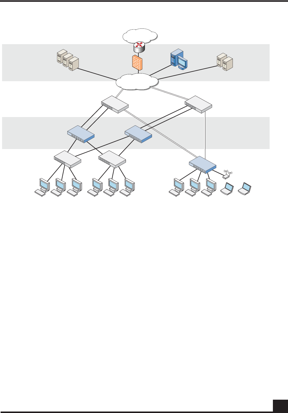
In terms of deployment, the SafeGuard Controller sits between access switches and the
distribution or core layer, aggregating uplinks from the wiring closets and enforcing
access policies on all traffic. As a transparent device, the Controller requires no changes to
network design or user behavior, simplifying deployment and IT’s cost of operations.
The Controller supports high availability and resiliency modes. Enterprises that have
dual-homed wiring closet switches can deploy two SafeGuard Controllers as peers—the
two platforms would share state and preserve user authentications in case of failover. The
Controller runs in fail pass-through mode following a failure, where all LAN traffic will
traverse the Controller untouched, or protect mode, where all traffic is stopped (based on
security policy settings).
While the Controller sits behind existing switches, which suits environments not
upgrading their switches, the SafeGuard Switch provides an integrated secure switch
ideal for customers in the midst of a switch upgrade or building a new LAN for
enterprises to secure the fabric of their LAN.
The integrated platform with both the SafeGuard Controller and SafeGuard Switch
reduces the number of platforms customers need to buy and manage, lowering capital
and operational costs. The SafeGuard Switch also provides per-port control, vs. the per-
uplink control in the SafeGuard Controller. While user- and application-based controls
are available in both SafeGuard platforms, the switch’s per-port control means worms are
contained to a single user rather than all users connected to one uplink port.
OmniAccess SafeGuard OS Administration Guide 23
Chapter 1: SafeGuard OS Overview
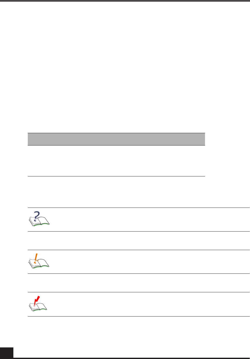
Figure 1 SafeGuard Controller and Switch in a Typical Deployment
With the preferred standard and typical deployment model, the SafeGuard Controller
device is a multi-port “bump-in-the-wire” device between the edge switch and the next
layer switch, whether that be the distribution layer or the core switch. The uplinks can
either be fiber or copper. A SafeGuard Switch is deployed like any other switch device,
but it can link directly to the distribution layer.
When deploying SafeGuard devices using this model, all SafeGuard OS features are
supported, including policy enforcement, captive portal, IP header validity, and malware
enforcement. Further, devices can be deployed without disrupting existing wiring closet
configurations. Figure 1 shows SafeGuard devices in the typical deployment model.
System recovery and high availability (HA) can be configured when deploying
SafeGuard Controllers. To, it requires an additional (redundant) SafeGuard Controller of
the same model, running the same software release, and configured with the same port
configuration.
In HA mode, the authentication state is propagated to the peer device before there is a
failure so that users do not have to re-authenticate. For example, end users do not need to
log in to the captive portal feature again if there is a system failure. Figure 2 shows this
type of deployment (for details on configuring high availability, see Configuring High
Availability Support on page 100).
CST_055
Internet
LAN Core
Data Center
Distribution Layer
OmniAccess
switch
OmniAccess
SafeGuard 10 Gigabit
uplinks
Remediation
servers
Active Directory
RADIUS servers
Alcatel-Lucent
OmniVista
SafeGuard
Manager
Access Layer
Transparent
Deployment
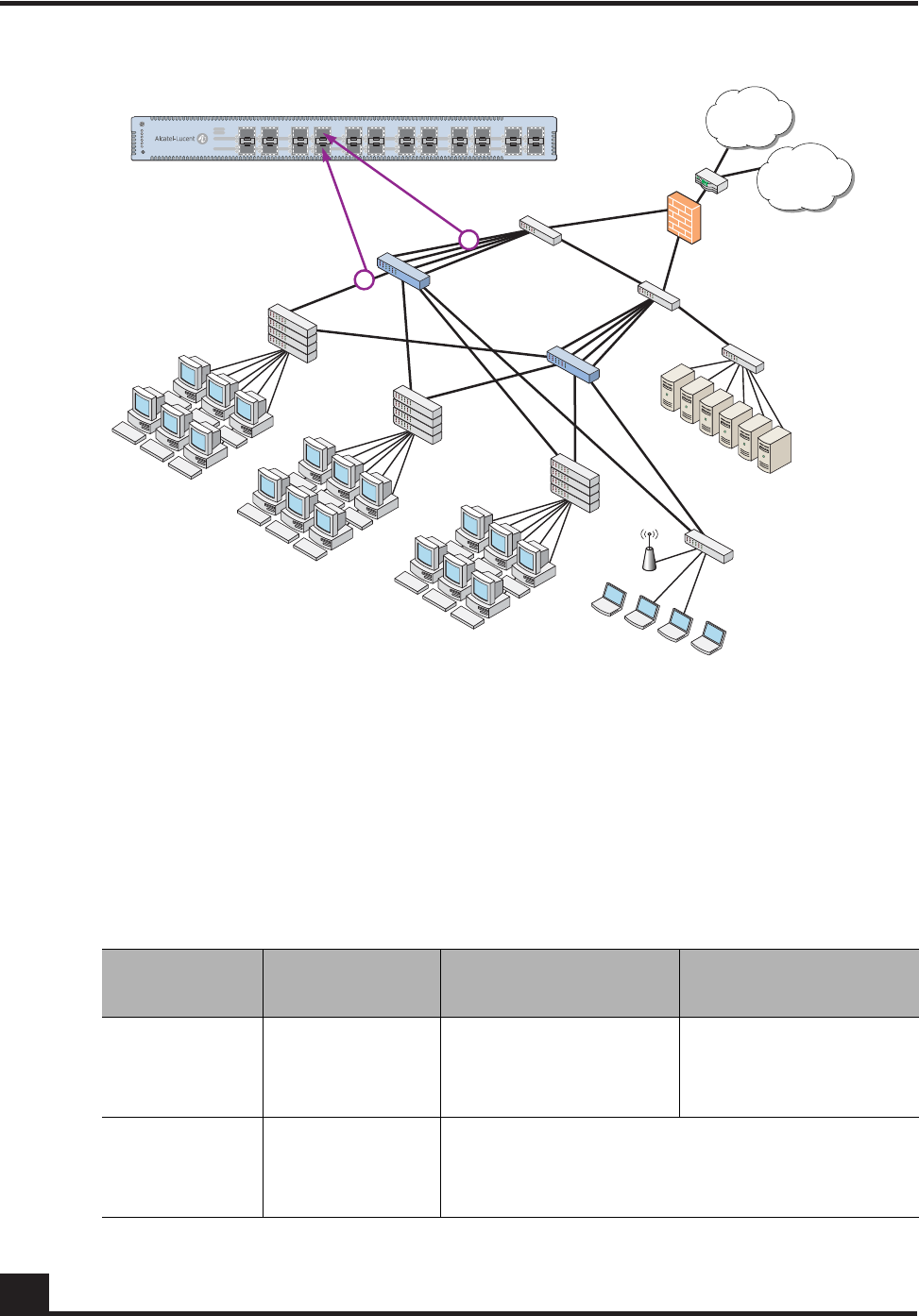
OmniAccess SafeGuard OS Administration Guide
24
Chapter 1: SafeGuard OS Overview
Figure 2 High Availability (Redundant) SafeGuard Controller Deployment
Understanding Protection Modes
Ingress and egress data traffic is managed by SafeGuard devices based on the level of
protection mode set within the device. Based on the established protection mode—Pass-
thru mode, Monitor mode, or Protect mode. For details on setting protection modes, see
Changing the Protection Mode of Ports on page 95.
Table 3 Supported Protection Modes
Protection
Mode When Used SafeGuard Controller SafeGuard Switch
Pass-thru
Mode First time set up
and cabling Acts as a transparent
bridge. All security
functionality is
bypassed.
Acts as a standard L2/
L3 switch. All security
functionality is
bypassed.
Monitor Mode Testing and
trials Authentication, captive portal, visualization,
malware detection and protection and user-
based policy checking is applied to all data
traffic, but enforcement is ignored.
CST_011
Internet
WAN/VPN
Secure LAN
controller
Firewall
Core
switch
Active
directory
Data center
RADIUS
Executive
suite
1st floor
edge switch
[Marketing]
2nd floor
edge switch
[Operations]
3rd floor
edge switch
[Finance]
Host / edge
Network / core

OmniAccess SafeGuard OS Administration Guide 25
Chapter 1: SafeGuard OS Overview
Protect Mode Typical
Deployment Authentication, captive portal, visualization,
malware detection and protection and user-
based policy checking is applied to all data
traffic, and actively enforced.
Table 3 Supported Protection Modes (continued)
Protection
Mode When Used SafeGuard Controller SafeGuard Switch

OmniAccess SafeGuard OS Administration Guide
26
Chapter 1: SafeGuard OS Overview
SafeGuard OS Overall Feature Summary
The following table summarizes SafeGuard OS features supported by SafeGuard devices.
User/Machine Authentication
■Authentication via 802.1X or
MAC address
■Passive Active Directory
authentication snooping
■Passive RADIUS
authentication snooping
■Captive portal
authentication
■Trusted DHCP serve
Role Derivation
■RADIUS attributes
■Active Directory attributes
■Physical location
■Combination of above
Role-Based Policy (Access
Control By)
■User group
■Application
■Select application attributes
■Destination port
■Resource (e.g. servers)
Host Posture Check
■Dissolvable agent
■Scan for known threats, anti-
virus definition, service
packs, and custom registry
keys and files
Enforcement Actions
■Allow
■Deny
■TCP reset
■Mirroring, logging
Threat Detection/Mitigation
■Zero-hour threat detection
■No signature updates
necessary
■Drops malformed packets
■Block by: physical port, SRC
MAC, offending application
Visualization
■Ties usernames to
applications and security
violations
■Identifies applications and
application content
■Reports application details
to centralized policy center
Centralized Visualization
■Ties into Alcatel-Lucent
OmniVista SafeGuard
Manager Command Center
■User and application usage
repository
■Real-time alert dashboard
■Fully drillable forensics
capability
■Reporting and scheduler
■Full policy and role-
derivation configuration GUI
Logging and Reporting
■Direct syslog reporting
■Detailed security log
messages
■Formatted for SIEM
integration
■Formatted syslog to multiple
destinations
Management and Control
■Industry-standard
Command Line Interface
(CLI)
■Managed by Alcatel-Lucent
OmniVista SafeGuard
Manager Command Center
■SNMP v1/v2
■Telnet
■SSH
■TFTP
■Standard and privileged
access modes
Administrator Authentication
■RADIUS authentication
Performance (Switch Only)
■Switching capacity: 101
million pps
■Secure Switching Rate: 10
Gbps
Protocols (Switch Only)
■802.1D Bridging
■802.1D Spanning Tree
■802.1Q/p VLAN Tagging and
Priority
■802.1w Rapid Spanning Tree
■802.1S MSTP
■802.1X Port-based
authentication
■802.3 10Base-T
■802.3u 100Base-T
■802.3z 1000Base-SX/T
■802.3ae 10 Gbps Ethernet
■802.3af Power-over-Ethernet
Layer 2 Features (Switch Only)
■4,096 VLANs
■16,000 MAC Addresses
■Protocol VLAN (802.1v)
■Port Security (MAC address
locking)
■Mirror/monitor ports
■IGMP v1/v2 snooping
Layer 3 Features (Switch Only)
■Static routing
■Additional L3 capabilities
due in future software
releases

chapter
2Accessing and
Managing the System
In this chapter:
■Connecting to a SafeGuard Device Console
■Accessing the SafeGuard Device Command Line Interface
■Configuring Management Users
■Managing Out-of-Band Management Port
■Setting Up the System Time and Date (SNTP)
■Managing Device Information
■Managing Network Information
■Configuring the Network Protocol
■Configuring SNMP on the Device
■Configuring Domain Name Servers
■Resetting the Device
■Configuring Data Traffic Ports
■Configuring High Availability Support

OmniAccess SafeGuard OS Administration Guide
28
Chapter 2: Accessing and Managing the System
This chapter describes the tasks associated with managing the SafeGuard Controller or
the SafeGuard Switch as a device in the network.
Connecting to a SafeGuard Device Console
SafeGuard devices can be managed using a PC or laptop computer connected to the
SafeGuard Controller or SafeGuard Switch.
To connect a SafeGuard device console:
1Using a null cable, connect a PC or laptop computer to the DCE port on the back
of the device.
2Launch a terminal emulation program and configure the settings as shown in
Tabl e 4.
3The login prompt is displayed.
See the following sections for details on accessing the SafeGuard device command line
interface.
Accessing the SafeGuard Device Command Line
Interface
The first time that you log into a SafeGuard device, use the default ‘Admin’ as a
username (and no [null] password). Upon first logging into the command interface, you
are in Non-Privileged mode. To perform management and configuration functions, you
need to be in Privileged mode.
To access Privileged mode, use the enable command in Non-Privileged mode.
Table 4 PC Terminal Emulator Settings
PC or Laptop Setting
Emulation type vt100
Bits per second 9600
Data bits 8
Parity bits None
Stop bits 1
Flow control None

OmniAccess SafeGuard OS Administration Guide 29
Chapter 2: Accessing and Managing the System
enable
This command has no parameters or variables.
For example:
(SafeGuardOS) #?
(SafeGuardOS) #enable
(SafeGuardOS) #
(SafeGuardOS) #configure terminal
(SafeGuardOS) (config) #
See the following sections for more details on accessing SafeGuard devices:
■Using Telnet
■Using Secure Shell (SSH)
■Customizing and Working with the Command Line Interface Default Settings
Using Telnet
A SafeGuard device can be accessed via a Telnet session.
This section describes basic Telnet commands that may be useful when first accessing a
SafeGuard device via a Telnet session. See the following sections for more details:
■Enabling and Disabling Telnet
■Displaying the Current Telnet and Serial Port Connections
■Closing a Telnet or SSH Session
■Specifying the Maximum Number of Telnet Connections Allowed
■Setting the Telnet Connection Session Timeout
Enabling and Disabling Telnet
Telnet access is enabled by default. If Telnet has been disabled, use the ip telnet
command in Privileged Exec mode. To disable Telnet, use the no form of the command.
ip telnet
no ip telnet
The commands have no parameters or variables.
Displaying the Current Telnet and Serial Port Connections
To display the current Telnet and serial port connections, use the show sessions
command in Privileged Exec mode.

OmniAccess SafeGuard OS Administration Guide
30
Chapter 2: Accessing and Managing the System
show sessions
An example of this output and explanation of the fields is described in Tracking an
Authenticated User Session on page 219.
Closing a Telnet or SSH Session
To close a Telnet or SSH session, use the disconnect command in Privileged Exec mode.
disconnect [sessionID | all]
The following example disconnects session ID 10:
(SafeGuardOS) # disconnect 10
(SafeGuardOS) #
Specifying the Maximum Number of Telnet Connections Allowed
To specify the maximum number of Telnet connection sessions that can be established,
use the ip telnet maxsessions command in Global Configuration mode. Use the no
version of the command to restore the default value.
ip telnet maxsessions number
no ip telnet maxsessions
The following example sets the number of Telnet sessions to 3:
(SafeGuardOS) # configure terminal
(SafeGuardOS) (config) # ip telnet maxsessions 3
(SafeGuardOS) (config) #
Setting the Telnet Connection Session Timeout
To set the Telnet connection session timeout value (in minutes), use the ip telnet timeout
command in Global Configuration mode. Use the no version of the command to restore
the default value.
ip telnet timeout timeout
Syntax Description sessionID Disconnects the session specified by the
session identifier. Use the show sessions
command to find the session ID.
all Disconnects all remote sessions.
Syntax Description number Sets the number of Telnet sessions. Valid range
is from 1 to 5. The default value is 5.

OmniAccess SafeGuard OS Administration Guide 31
Chapter 2: Accessing and Managing the System
no ip telnet timeout
The following example sets the Telnet connection timer to never expire:
(SafeGuardOS)# configure terminal
(SafeGuardOS) (config) # ip telnet timeout 0
(SafeGuardOS) (config) #
Using Secure Shell (SSH)
Like Telnet, Secure Shell (SSH) is a protocol that allows the logging into of another
computer over a network to execute commands in a remote machine, and to move files
from one machine to another. Unlike Telnet that sends text in a clear text format, however,
SSH encrypts the connection session.
SSH provides more security for remote connections than Telnet by providing strong
encryption when a device is authenticated. The SafeGuard OS supports:
■SSH version 1 (SSHv1)
■SSH version 2 (SSHv2)
■Rivest, Shamir and Adleman (RSA) keys, versions 1 and 2
■Digital Signature Standard (DSA) keys
■A maximum of 5 SSH sessions
This section describes basic SSH commands that may be useful when first accessing a
SafeGuard device via a SSH session.
See the following sections:
■Enabling an SSH Session
■Downloading SSH Key Files from TFTP Server
■Generating DSA, RSA, RSA Keys
■Deleting DSA, RSA, RSA Keys
Syntax Description timeout Sets the number of minutes that a session can
be idle. Valid range is a decimal value from 0
to 160. A value of 0 indicates that the session
remains active indefinitely. The default value is
5.
NOTE: SafeGuard OS does not support SSH passwords or passkeys.

OmniAccess SafeGuard OS Administration Guide
32
Chapter 2: Accessing and Managing the System
■Changing SSH Protocols
■Limiting SSH Sessions
■Setting the SSH Timer
■Displaying SSH Configuration Information
Enabling an SSH Session
To enable an SSH session on the device:
1Enable SSH on the device by entering the ip ssh command in Global
Configuration mode. The no version of the command disables SSH, which is the
default state.
ip ssh
no ip ssh
The commands have no parameters or variables. The first time that SSH is
enabled on a device, SafeGuard OS detects that keys are not present and generates
the keys automatically.
(SafeGuardOS) #configure terminal
(SafeGuardOS) (config) #ip ssh
(SafeGuardOS) (config) #exit
(SafeGuardOS) #
2Verify the configuration using the show ip ssh command.
Downloading SSH Key Files from TFTP Server
To download private key files from a Trivial File Transfer Protocol (TFTP) server for SSH (that do
not contain passkeys), use the Privileged Exec copy command to download a key file.
copy tftp://ip/{filepath/}file nvram:[sshkey-dsa |sshkey-rsa1 |sshkey-
rsa]
NOTE: If you want to TFTP your own keys instead of having them generated
by the SafeGuard device, you must TFTP all three types of keys (DSA, RSA1,
AND RSA). All three keys are required for proper SSH functionality.
Syntax Description ip IP address of the TFTP server
filepath (Optional) Directory path to the file.
file Filename of the key file.
nvram:sshkey-dsa Specifies to download a SSH DSA key
file.

OmniAccess SafeGuard OS Administration Guide 33
Chapter 2: Accessing and Managing the System
The following example specifies how to download an SSH RSA1 key file from the TFTP server:
(SafeGuardOS) # copy tftp://180.29.52.20/keys nvram:sshkey-rsa1
(SafeGuardOS) #
Generating DSA, RSA, RSA Keys
The first time that SSH is enabled, the SafeGuard OS generates keys for DSA, RSA and
RSA1 which are not installed. The key deciphers the SSH encryption. To generate new
SSH keys, in Global Configuration mode use the ip ssh key generate command.
ip ssh key generate key
The following example generates all SSH keys:
(SafeGuardOS) #configure terminal
(SafeGuardOS) (config) #ip ssh key generate all
(SafeGuardOS) (config) #exit
(SafeGuardOS) #
Deleting DSA, RSA, RSA Keys
To delete all installed SSH keys, in Global Configuration mode enter the ip ssh key delete
command. The command has no parameters or variables.
The following example deletes all installed keys:
nvram:sshkey-rsa1 Specifies to download a SSH RSA1 key
file.
nvram:sshkey-rsa Specifies to download a SSH RSA2 key
file.
NOTE: In order to be in export compliance, the SafeGuard OS generates keys
that are just 56-bits in length. If you need a key that is larger than this, create
the key externally.
Syntax Description key Key to generate. Valid entries are:
■DSA
■RSA
■RSA1
■all
Specifying all generates all SSH keys.
If key is not specified, the command
generates any keys not currently installed.

OmniAccess SafeGuard OS Administration Guide
34
Chapter 2: Accessing and Managing the System
(SafeGuardOS) #configure terminal
(SafeGuardOS) (config) #ip ssh key delete
(SafeGuardOS) (config) #exit
(SafeGuardOS) #
Changing SSH Protocols
By default, SafeGuard OS supports both SSH versions 1 and 2. The protocols can be
deleted or added as necessary by explicitly defining one or both. Use the ip ssh protocol
command in Global Configuration mode to change the protocol support.
ip ssh protocol protocol_level {protocol_level}
The following example limits the SSH protocol to SSH version 2:
(SafeGuardOS) #configure terminal
(SafeGuardOS) (config) #ip ssh protocol 2
(SafeGuardOS) (config) #exit
(SafeGuardOS) #
Limiting SSH Sessions
The default for SSH sessions is set to the maximum of 5 sessions. To reduce the number of
sessions, in Global Configuration mode use the ip ssh maxsessions command.
ip ssh maxsessions sessions
The following example limits the SSH sessions to 3:
(SafeGuardOS) #configure terminal
(SafeGuardOS) (config) #ip ssh maxsessions 3
(SafeGuardOS) (config) #exit
(SafeGuardOS) #
Syntax Description protocol_level Specifies one or both SSH protocols. Valid
entries are:
■1 – SSH version 1
■2 – SSH version 2
■1 2 – for both
Syntax Description sessions Specifies the maximum number of SSH
sessions allowed. Valid entries are 1 to 5.

OmniAccess SafeGuard OS Administration Guide 35
Chapter 2: Accessing and Managing the System
Setting the SSH Timer
SSH connections time out at 5 minutes, by default. To change the timeout timer from 1 to
160 minutes, in Global Configuration mode use the ip ssh timeout command.
ip ssh timeout minutes
The following example limits the idle time for SSH connections to 20 minutes:
(SafeGuardOS) #configure terminal
(SafeGuardOS) (config) #ip ssh timeout 20
(SafeGuardOS) (config) #exit
(SafeGuardOS) #
Displaying SSH Configuration Information
To display the current SSH configuration, use the show ip ssh command in Privileged
Exec mode:
show ip ssh
The command has no parameters or variables.
The following example is representative of the command output:
(SafeGuardOS) #show ip ssh
SSH Configuration
Administrative Mode: .......................... Enabled
Operational Mode: ............................. Enabled
Protocol Levels: .............................. Versions 1 and 2
SSH Sessions Currently Active: ................ 0
Max SSH Sessions Allowed: ..................... 2
SSH Timeout: .................................. 4
SSH Keys Installed: ........................... RSA1 RSA DSA
(SafeGuardOS) #
NOTE: A session is active as long as the session is idle for the value set.
Changing the timeout value for active sessions does not become effective until
the session is re-accessed. Also, any keystroke activates the new timeout
duration.
Syntax Description minutes Specifies the connection timer in minutes.
Valid entries are 1 to 160.

OmniAccess SafeGuard OS Administration Guide
36
Chapter 2: Accessing and Managing the System
The fields in the output represent:
Customizing and Working with the Command Line Interface Default
Settings
See the following sections for details on how to customize the command line interface
default settings:
■Changing the System Command Prompt
■Setting a Maximum Serial Console Connect Time
■Enabling and Disabling CLI Display Paging
■Uploading a New CLI Banner File
■Uploading the CLI Log File
■Copying the System Diagnostics File
■Copying the System Debug File
■Displaying the Current HTTP Information
Display Description
Administrative Mode Displays whether the administrative state of SSH has
been enabled or disabled.
Operational Mode Displays the operational status of SSH and indicates
whether SSH is currently enabled or disabled.
Protocol Levels Displays the protocol level. This field may have the
values of version 1, version 2 or both versions 1 and
version 2.
SSH Sessions Currently
Active Displays the number currently active SSH
connections. This field can be from 0 to 5.
Max SSH Sessions Allowed Displays the maximum number of SSH connections
allowed. This field can be from 0 to 5. The default is 5.
SSH Timeout Displays the idle timer for connection time. This field can
be from 1 to 160 minutes.
SSH Keys Installed Displays which keys are currently installed. Possible keys
are: RSA1, RSA and DSA.

OmniAccess SafeGuard OS Administration Guide 37
Chapter 2: Accessing and Managing the System
Changing the System Command Prompt
To change the command line interface prompt, use the set prompt command in enable
mode. The length of the prompt can be up to 64 alphanumeric characters.
set prompt string
The following example sets the command prompt to OmniAccess 2400 SafeGuard:
(SafeGuardOS) # set prompt OmniAccess 2400 SafeGuard
(OmniAccess 2400 SafeGuard) #
Setting a Maximum Serial Console Connect Time
To set a maximum connect time (in minutes) without console activity for the serial
console, use the serial timeout command in Line Configuration submode. Line
Configuration Mode is entered by using the lineconfig command in Global
Configuration mode.
serial timeout time
The following example sets the console timeout to 10 minutes:
(SafeGuardOS) # configure terminal
(SafeGuardOS) (config) # lineconfig
(SafeGuardOS) (line) # serial timeout 10
(SafeGuardOS) (line) #
Enabling and Disabling CLI Display Paging
To enable or disable CLI display paging, use the paging command in Privileged Exec
mode.
paging [enable | disable]
Syntax Description string Sets the command prompt to an
alphanumeric string up to 64 characters and
numbers. The prompt is case sensitive
Syntax Description time Sets the number of minutes that a serial
console can be idle. Valid range is a decimal
value from 0 to 160. A value of 0 indicates that
the console remains active indefinitely. The
default value is 5.
Syntax Description enable Enable CLI display paging mode.
disable Disable CLI display paging mode.

OmniAccess SafeGuard OS Administration Guide
38
Chapter 2: Accessing and Managing the System
The following example disables CLI display paging:
(SafeGuardOS)# paging disable
(SafeGuardOS)#
Uploading a New CLI Banner File
To upload the CLI banner file, use the copy nvram:clibanner command in Global
Configuration mode.
copy nvram:clibanner tftp://ip/{filepath/}filename
Uploading the CLI Log File
To upload the log file, use the copy nvram:log command in Global Configuration mode.
copy nvram:log tftp://ip/{filepath/}filename
Copying the System Diagnostics File
To copy a system diagnostics file, use the copy system:diag-info command in Global
Configuration mode.
copy system:diag-info tftp://ip/{filepath/}filename
Syntax Description ip Specifies the IP address of the TFTP server.
filepath (Optional) Specifies the directory path to the file.
filename Specifies the filename of the file being saved.
Syntax Description ip Specifies the IP address of the TFTP server.
filepath (Optional) Specifies the directory path to the file.
filename Specifies the filename of the file being saved.
Syntax Description ip Specifies the IP address of the TFTP server.
filepath (Optional) Specifies the directory path to the file.
filename Specifies the filename of the file being saved.

OmniAccess SafeGuard OS Administration Guide 39
Chapter 2: Accessing and Managing the System
Copying the System Debug File
To copy a system debug file, use the copy system:dump command in Global
Configuration mode.
copy system:dump://ip/{filepath/}filename
Displaying the Current HTTP Information
To display the current HTTP information, use the show ip http command in Privileged
Exec mode.
show ip http
This command has no parameters or variables.
Exiting or Logging Out of a Command Line Session
To exit or log out of a command level session, use either the exit or logout command in
any mode.
exit
logout
The command has no options or parameters. For example:
(SafeGuardOS) # logout
Configuring Management Users
The Admin user has full access to all CLI both from the front-panel ports and from the
rear-panel management port.
■Management Users – A management user can be defined as having three levels of
authority:
— Admin-user has full access to all commands.
— Privilege-user has permission to execute action, clear and configure
commands, with the exception of the user management commands.
—Exec-user has access to limited commands.
Syntax Description ip Specifies the IP address of the TFTP server.
filepath (Optional) Specifies the directory path to the file.
filename Specifies the filename of the file being saved.

OmniAccess SafeGuard OS Administration Guide
40
Chapter 2: Accessing and Managing the System
■Network Users – Network users are end-users defined in the SafeGuard local
authentication database. Network users do not have authority to execute
commands at the command line. For more information on managing network
users, see Maintaining Users on page 258.
This section describes setting up administrator and network user access to SafeGuard
devices. By default, an “Admin” user is configured with the initial configuration. See the
following sections for more details:
■Configuring Management Users
■Assigning a Login List to the Default Login User
■Configuring RADIUS Users for Management Users
■Clearing All Passwords
For more information on managing network users, see Maintaining Users on page 258.
Configuring Management Users
This section describes adding and changing management accounts. See the following
sections for more details:
■Adding Management Users to the Database
■Displaying the Management Users
■Setting a Password for the Default Admin Account
■Configuring Local Authentication for Management Users
Adding Management Users to the Database
Management users are the administrators who will be logging in from the service/front
panel port and manage SafeGuard. To add a management user to the database, in the
Global Configuration mode use the aaa mgmt-user command.
To remove a management user use the no form of the command.
aaa mgmt-user username passwd password access-mode mode
no aaa mgmt-user username
Syntax Description username The name of the user being added to
the database. User names can be up
to 31 characters long.
password The login password. Login passwords
can be up to 31 characters long.

OmniAccess SafeGuard OS Administration Guide 41
Chapter 2: Accessing and Managing the System
The following example adds a management user with username abcd, password abcd
and access mode exec-user:
(SafeGuardOS) (config) #no aaa mgmt-user abcd passwd abcd access-mode exec-user
The following example deletes the management user with username abcd:
(SafeGuardOS) (config) #no aaa mgmt-user abcd
The following example changes the password of an administrator user (mgmtuser) to
f00onU3.
(SafeGuardOS) (config) # aaa mgmt-user mgmtuser passwd f00onU3
When a password is changed, a prompt asks for the former password. If none exists,
press the Enter key. The passwords are stored in encrypted format for protection.
The system contains a default “Admin” administrator user that cannot be deleted. The
default administrative password (set to null by default), however, can be changed and
encrypted.
Displaying the Management Users
To display the management users, in the Global Configuration mode use the show aaa
mgmt-users command.
show aaa mgmt-users
The command has no parameters.
The following example shows sample output from the show aaa mgmt-users command:
(SafeGuardOS) #show aaa mgmt-users
SNMPv3 SNMPv3 SNMPv3
User Name User Access Mode Access Mode Authentication Encryption
---------- ---------------- ----------- -------------- ----------
admin Admin Read/Write None None
guest Exec Read Only None None
execuser Exec Read Only None None
admin1 Admin Read Only None None
mode The mode from highest to lowest
privileges are:
■admin-user – An admin user is
allowed to access all commands.
■priv-user – The privilege user is
allowed to access only show and
action commands.
■exec-user – The exec user is
allowed to access only show
commands.

OmniAccess SafeGuard OS Administration Guide
42
Chapter 2: Accessing and Managing the System
abcd Exec Read Only None None
priv-user Exec Read Only None None
(SafeGuardOS) #
The fields in the output represent:
Setting a Password for the Default Admin Account
To set the password for the default administrator (admin) account, use the aaa mgmt-
user passwd admin command. If a user is authorized for authentication or encryption
is enabled, the password must be at least eight alphanumeric characters in length.
The username and password are not case sensitive. When a password is changed, a
prompt asks for the former password. If none exists, press the Enter key. Use the no
version of the command to set the password to blank.
aaa mgmt-user passwd admin passwd
no aaa mgmt-user passwd admin passwd
The following example sets the default password to f00onU2:
(SafeGuardOS) #configure terminal
(SafeGuardOS) (config) #aaa mgmt-user passwd admin f00onU2
Password Changed!
(SafeGuardOS) (config) #exit
(SafeGuardOS) #
NOTE: SafeGuard OS will support SNMPv3 will be supported in a future
release.
Field Description
User Name Username as detected by its authentication.
User Access Mode The user’s access mode.
SNMPv3 Access Mode The SNMPv3 access mode.
SNMPv3 Authentication Whether the user has SNMPv3 authentication.
SNMPv3 Encryption Whether the user has SNMPv3 Encryption.
Syntax Description passwd Specifies the new password.

OmniAccess SafeGuard OS Administration Guide 43
Chapter 2: Accessing and Managing the System
Configuring Local Authentication for Management Users
Users are set up in the authentication database by assigning them to a set of roles usually
defined by group and then by mapping a set of authentication protocol-specific attributes
and their values to a role. The attributes are first obtained by user authentication against
the local authentication database. If the user does not authenticate against the local
database, you can configure the user to authenticate against a centralized RADIUS
database as a backup.
Creating Authentication Lists
In most instances, users are assigned roles based on their group or job responsibilities. To
identify those groups of users, you need to create a list for each distinct user group.
Use the aaa mgmt-user authentication login command in Global Configuration mode to
create a user group or organizational list.
aaa mgmt-user authentication login listname {methods}
The following example creates an authentication list for a group of sales people. The
group uses local authentication as the only authentication method and users who are
unable to authenticate using that method are denied access to the network:
(SafeGuardOS) #configure terminal
(SafeGuardOS) (config) #aaa mgmt-user authentication login salesList local
reject
(SafeGuardOS) (config) #exit
(SafeGuardOS) #
Displaying the Authentication Login List
To verify the contents and methods being used for authentication, use the show aaa
mgmt-users authentication-list command in Privileged Exec mode:
Syntax Description listname The name of the list being created. A list
name can be up to 15 characters long.
methods One or more authentication methods used to
authenticate this group of users. You may
specify up to 3 non-repeating methods. If not
specified, the system uses the default-list. If
less than 3 methods are specified, the
remaining methods are classified as
undefined. Specify the method in the order
of precedence you want to run. Valid values
for methods are:
■local – Use local authentication.
■RADIUS – Use remote RADIUS
authentication.
■Reject – Deny the user.

OmniAccess SafeGuard OS Administration Guide
44
Chapter 2: Accessing and Managing the System
show aaa mgmt-users authentication list
This command has no options or parameters. The following is sample output from the
command:
Authentication Login List Method 1 Method 2 Method 3
------------------------- -------- -------- --------
defaultList local undefined undefined
list123 reject undefined undefined
authLoginList radius local reject
radius-list radius local reject
salesList radius local reject
The fields of the output represent:
Assigning a Login List to the Default Login User
To ensure that any non-configured users who attempt to log into the management port
are forced to authenticate against the RADIUS server, use the aaa mgmt-user
defaultlogin command in the Global Configuration mode. To disable RADIUS
authentication, use the no version of the command.
aaa mgmt-user defaultlogin listname
no aaa mgmt-user defaultlogin listname
The following example assigns salesList to the defaultLogin list:
(SafeGuardOS) #configure terminal
(SafeGuardOS) (config) #aaa mgmt-user defaultlogin salesList
(SafeGuardOS) (config) #exit
(SafeGuardOS) #
Field Description
Authentication Login The name of the authentication login list.
Method 1 The primary method of authentication.
Method 2 This method of authentication is used if the primary
method is unavailable. If a secondary method is not
used, this field is undefined.
Method 3 This method of authentication is used if the secondary
method is unavailable. If a secondary method is not
used, this field is undefined.
Syntax Description listname Name of the authentication list or group name
being authenticated.

OmniAccess SafeGuard OS Administration Guide 45
Chapter 2: Accessing and Managing the System
The following example shows the disabling RADIUS authentication of non-configured
users:
(SafeGuardOS) (config) # no aaa mgmt-user defaultlogin salesList
(SafeGuardOS) (config) #
Configuring RADIUS Users for Management Users
In order to provide administrative privileges to remote RADIUS users, the Service-Type
field in RADIUS must be configured to return the appropriate value. Configure the
RADIUS server to return Service-Type = 1 or Login for priv-user, Service-Type = 7 or
NAS Prompt for exec-user. For FreeRadius, Service-Type = NAS-Prompt-User and
Service-Type = Login-User.
Different implementations of RADIUS might have slight variations on how to set this
field. See Tab le 5 for some examples of this field, and see your RADIUS product
documentation for further help.
In the following example, MyCompany uses FreeRADIUS. Users Moe and Larry are
setup for administrative privileges while user Curley logs in as priv-user has most of the
privileges of the administrative user.
Table 5 RADIUS Service-Type Settings
Implementation Service-Type
FreeRADIUS 6 or Administrative-User
Microsoft IAS Administrative
SteelBelt RADIUS Administrative
Moe Auth-Type:=System
Service-Type=6
Login-Service=Telnet
Larry Auth-Type:=System
Service-Type=Administrative-User
Login-Service=Telnet
Curley Auth-Type:=System
Service-Type=Login-User
Login-Service=Telnet
Alcatel-Lucent-Role=”Curley-Alcatel-Lucent-
VSA”

OmniAccess SafeGuard OS Administration Guide
46
Chapter 2: Accessing and Managing the System
Clearing All Passwords
To clear all user passwords and reset them to the factory defaults (null) without powering
off the device, use the clear pass command in Privileged Exec mode. When prompted to
confirm that the password reset should proceed, enter y for Yes.
clear pass
The following example clears all user passwords and reinstates the system defaults:
(SafeGuardOS) #clear pass
Are you sure you want to reset all passwords? <n/y> y
Passwords reset
(SafeGuardOS) #
Managing Out-of-Band Management Port
This section describes the tasks and commands used for configuring and displaying
information for the out-of-band management port on SafeGuard devices. The
management port is also referred to as the service port.
See the following sections for more details:
■Setting the IP Configuration Protocol
■Enabling or Disabling the Management Port
■Setting Speed and Duplex for the Management Port
■Displaying Configuration Information for the Management Port
Setting the IP Configuration Protocol
To set the configuration protocol for the management port, use the serviceport protocol
command in Global Configuration mode.
When using this command, it is suggested to run the command twice: once with the
value none, and once with the value desired for the management port’s protocol support
(either bootp or dhcp). When modified, the change takes effect immediately.
For more details on bootstrap and DHCP protocols, see Configuring Bootstrap or DHCP
Relay on page 194.
serviceport protocol [none | bootp | dhcp]
Syntax Description none Specifies no protocol.
bootp Specifies BOOTP as the protocol.

OmniAccess SafeGuard OS Administration Guide 47
Chapter 2: Accessing and Managing the System
The following command example changes the protocol to bootstrap:
(SafeGuardOS) # configure terminal
(SafeGuardOS) (config) # service protocol none
(SafeGuardOS) (config) # service protocol bootp
(SafeGuardOS) (config) #
Setting the IP Address, Netmask, and Gateway of the System
To set the IP address, netmask, and gateway of the management port, use the serviceport
ip command in Global Configuration mode. Before running this command, however, the
service port protocol must be set to none first (see Setting the IP Configuration Protocol on
page 46).
serviceport ip ipaddr netmask [gateway]
The following example sets the service port configuration:
(SafeGuardOS) # configure terminal
(SafeGuardOS) (config) # serviceport protocol none
(SafeGuardOS) (config) # serviceport ip 172.68.15.1 255.255.0.0
(SafeGuardOS) (config) #
Enabling or Disabling the Management Port
The management port is enabled, by default, and so therefore is not explicitly displayed
in the show running-config command output. The serviceport enable command enables
the PHY and lights the management port link LED. The no version of the command
disables the PHY and extinguishes the management port link LED. The Global
Configuration commands use the following syntax:
serviceport enable
no serviceport enable
The commands have no parameters or variables.
dhcp (Default) Specifies DHCP as the protocol.
Syntax Description ipaddr IP address for the service port.
netmask Network mask for the service port.
gateway Optional for Controller only. Gateway IP
address. (To set the default gateway on the
Switch, use ip route.)

OmniAccess SafeGuard OS Administration Guide
48
Chapter 2: Accessing and Managing the System
Setting Speed and Duplex for the Management Port
The management port can operate at a variety of speeds and duplex settings. The default
settings are to auto-negotiate with the link partner. For auto-negotiation to succeed, the
management port and the link partner must both be set for auto-negotiating. Otherwise,
the management port attempts to auto-negotiate but could fail if traffic does not match
the auto-negotiated speed.
Use the serviceport speed command in Global Configuration mode to override the auto-
negotiation and set the speed and duplex for the management port using the following
syntax:
serviceport speed [10 | 100] [full-duplex | half-duplex]
The following example forces the management port to run at 100 Mbps half-duplex.
(SafeGuardOS) # configure terminal
(SafeGuardOS) (config) # serviceport speed 100 half-duplex
(SafeGuardOS) (config) # exit
Use the show serviceport command in Privileged Exec mode to verify the configuration.
See Displaying Configuration Information for the Management Port on page 48.
Use the serviceport auto-negotiate command in Global Configuration mode to override
the speed and duplex settings on the management port. The no version of the command
disables auto-negotiation.
serviceport auto-negotiate
no serviceport auto-negotiate
Displaying Configuration Information for the Management Port
To display service port configuration information, use the show serviceport command in
Privileged Exec mode. For example:
show serviceport
Syntax Description 10 Specifies running the management port
at 10 Mbps.
100 Specifies running the management port
at 100 Mbps.
half-duplex Specifies half duplex; transmitting and
receiving data one direction at a time.
full-duplex Specifies full duplex; transmitting and
receiving data at the same time.

OmniAccess SafeGuard OS Administration Guide 49
Chapter 2: Accessing and Managing the System
The command has no options or parameters.
The following output is representative of the show serviceport command on a SafeGuard
Switch. This command’s output on a SafeGuard Controller would be similar, but with the
addition of “Gateway Address” following the “Subnet Mask” line:
(SafeGuardOS) #show serviceport
Current ServicePort IP configuration
IP Address..................................... 172.16.1.10
Subnet Mask.................................... 255.255.192.0
ServPort Configured Protocol Current........... None
Burned In MAC Address.......................... 00:12:36:FE:92:CE
ServicePort Link Status........................ Up
ServicePort Admin Status....................... Enabled
Configured ServicePort speed................... auto-negotiate
ServicePort Duplex Status...................... 100M FULL
ServicePort Statistics
Total Packets Received ........................ 110
Total Packets Transmitted ..................... 46
Total Bytes Received........................... 9784
Total Bytes Transmitted........................ 4166
Total Bad Packets Received..................... 0
Total Packet Transmit Problems................. 0
No Receive Space in Buffers.................... 0
No Transmit Space in Buffers................... 0
Multicast Packets Received ................... 0
Total Collisions............................... 0
ServicePort Detailed Rx Statistics
Packet Length Errors........................... 0
Ring Buffer Overflow Errors.................... 0
CRC Errors..................................... 0
Frame Alignment Errors......................... 0
Fifo Overrun Errors............................ 0
Missed Errors.................................. 0
ServicePort Detailed Tx Statistics
Aborted Errors................................. 0
Carrier Errors................................. 0
Fifo Overrun Errors............................ 0
Heartbeat Errors............................... 0
Window Errors.................................. 0
The fields in the output represent:
Field Description
Current service Port IP configuration
IP address IP address of the interface.
Subnet Mask IP subnet mask for this interface.

OmniAccess SafeGuard OS Administration Guide
50
Chapter 2: Accessing and Managing the System
ServPort Configured
Protocol Current Network protocol that is currently being used, if any.
Service Port Statistics
Total Packets Received Total number of packets (including broadcast packets
and multicast packets) that were received by the
management port.
Total Packets Transmitted Total number of packets that were transmitted from the
management port.
Total Bytes Received Total number of octets of data (including those in
bad packets) received on the port.
Total Bytes Transmitted Total number of octets of data (including those in
bad packets) transmitted from the port.
Total Bad Packets
Received Total number of bad packets received on the port.
Total Packet Transmit
Problems Total number of bad packets transmitted from the
port.
No Receive Space in
Buffers 0
No Transmit Space in
Buffers 0
Multicast Packets
Received 0
Total Collisions 0
Service Port Detailed Rx Statistics
Packet Length Errors 0
Ring Buffer Overflow Errors 0
CRC Errors 0
Frame Alignment Errors 0
Fifo Overrun Errors 0
Missed Errors 0
Service Port Detailed Tx Statistics
Aborted Errors 0
Carrier Errors 0
Fifo Overrun Errors 0
Field Description

OmniAccess SafeGuard OS Administration Guide 51
Chapter 2: Accessing and Managing the System
Displaying Address Resolution Protocol Information
SafeGuard Controllers have a preset configuration for the address resolution protocol
(ARP) table and the ARP cache. SafeGuard Switches allow modification of the ARP
settings. For details on configuring ARP on the SafeGuard Switch, see Configuring Address
Resolution Protocol on page 184. To display ARP information, see Displaying ARP
Information on page 189
Setting Up the System Time and Date (SNTP)
If a Simple Network Time Protocol (SNTP) server is used to synchronize time settings in
the network, it is not necessary to manually configure clock settings for the SafeGuard
device(s). SNTP setup is discussed in Configuring SNTP on page 54.
See the following sections for more details:
■Manually Setting the Time and Date
■Configuring SNTP
■Optional SNTP Client Configurations
Manually Setting the Time and Date
SafeGuard devices have an on-board real-time clock. The following settings can be
manually adjusted:
■Timezone setting. Setting the timezone is a recommended step during product
installation.
■Automatic changeover for daylight savings settings
■Software system clock settings
To manually configure the time and date on the device:
1Set the timezone. Skip this step if the timezone was set up during installation.
Heartbeat Errors 0
Window Errors 0
NOTE: The order in which clock settings are configured can affect the
accuracy of the time setting.
Field Description

OmniAccess SafeGuard OS Administration Guide
52
Chapter 2: Accessing and Managing the System
To set the device to the correct timezone, use the clock timezone command in
either Privileged Exec or Global Configuration modes.
clock timezone zonename hours_offset {minutes_offset}
The following example sets the timezone to Pacific Standard Time (PST).
(SafeGuardOS) # clock timezone PST -8
(SafeGuardOS) #
2Set the time and date.
If no other time sources are available to set the current time and date, use the set
clock command in Privileged Exec mode. The time specified in this command is
relative to Universal Time Clock (UTC) time zone. The system can then be
synchronized to an external Network Time Protocol (NTP) clock source.
This command also updates the real time clock chip so it is preserved across
reboots.
clock set time month day year
The following example sets the time to November 29, 2007 at 4:25:37 PM:
(SafeGuardOS) # clock set 16:25:37 NOV 29 2007
(SafeGuardOS) #
Syntax Description zonename Specifies an arbitrary name of the
timezone in a
3-letter abbreviation. For example,
Eastern Standard Time is entered
as EST.
hours_offset Specifies the number of hours
difference from Universal Time
(a.k.a. Greenwich Mean Time,
GMT). Valid entries are -23 to 23.
minutes_offset (Optional) Specifies the number of
minutes offset from Universal Time.
Syntax Description time Time using 24 hour format
(military).
month Month abbreviated to 3
characters, for example, Jan for
January or Jun for June.
day Date in the month, for example, 29
for October 29th.
year 4-digit year, for example, 2006.

OmniAccess SafeGuard OS Administration Guide 53
Chapter 2: Accessing and Managing the System
3Set up Daylight Savings Time.
In many countries, clocks are set back an hour in the Summer when the days
become longer. Often referred to as Daylight Savings Time, system clocks must be
reset for this seasonal adjustment. Use the clock summer-time command in
Global Configuration modes to adjust for this seasonal change.
clock summer-time zonename [recurring | startweek startday
startmonth starttime endweek endday endmonth endtime]
Syntax Description zonename An arbitrary name of the timezone
in a 3-letter abbreviation. For
example, Eastern Standard Time is
entered as EST.
recurring Indicates that the change
happens every year.
If this option is used, the system
uses the United States Daylight
Savings Time rules as enacted by
the Uniform Time Act amended in
1986.
In the European Union, Daylight
Saving Time starts at slightly
different times of the year and
need to be manually entered.
startweek Week in the month to make the
time change. Valid values are 1 to
5 or last.
startday Day of the week to make the time
change. Valid values are Monday
through Sunday.
startmonth Month to start the time change.
Valid values are January though
December.
starttime Hour to make the change. The
format is hh:mm.
endweek Week in the month to change the
time back. Valid values are 1 to 5
or last.
endday Day of the week to change the
time back. Valid values are
Monday through Sunday.
endmonth Month to change the time back.
Valid values are January though
December.

OmniAccess SafeGuard OS Administration Guide
54
Chapter 2: Accessing and Managing the System
The following example, configures Summer hours as a recurring event.
(SafeGuardOS) # configure terminal
(SafeGuardOS) (config) # clock summertime recurring
(SafeGuardOS) (config) # exit
4To display the system time, use the show clock command in Privileged Exec
mode using the following syntax:
show clock
The command has no parameters or variables.
Configuring SNTP
Simple Network Time Protocol (SNTP) is an adaptation of the Network Time Protocol
(NTP) used to synchronize computer clocks across the Internet. For a stand-alone system
that sets and synchronizes the time for the network, configure SNTP on the SafeGuard
device.
To configure SNTP:
1Designate a SNTP server using the sntp server command in Global Configuration
mode. Up to 3 SNTP servers can be configured.
sntp server ipaddr {priority {version {portid}}}
The following example configures an SNTP server running SNTPv4 on port ID 25.
(SafeGuardOS) # configure terminal
(SafeGuardOS) (config) # sntp server 172.82.45.23
endtime Hour to change the time back.
The format is hh:mm.
Syntax Description ipaddr Specifies the poll interval for SNTP
unicast clients in seconds as a
power of two. Valid values are 6 to
30 seconds.
priority (Optional) Ranks or prioritizes the
server among other servers. Up to 3
SNTP servers may be specified.
Valid values are 1 to 3.
version (Optional) Specifies the version of
SNTP. Valid values are 1 to 4.
portid (Optional) Specifies the port
identification number. Valid values
are 1 to 65535.

OmniAccess SafeGuard OS Administration Guide 55
Chapter 2: Accessing and Managing the System
(SafeGuardOS) (config) # exit
(SafeGuardOS) #
To delete this server, use the no version of the command.
2Validate the SNTP server setup using the show sntp server command in
Privileged Exec mode.
show sntp server
This command has no options or parameters.
The following example is representative of the command output:
(SafeGuardOS) #show sntp server
Most recent SNTP response
-------------------------
Server IP Address: 172.16.3.100
Server Type: ipv4
Server Stratum: 15
Server Reference Id:
Server Mode: Server
Server Maximum Entries: 3
Server Current Entries: 1
SNTP Servers
------------
IP Address: 172.16.3.100
Address Type: IPV4
Priority: 1
Version: 4
Port: 123
Last Update Time: Jul 28 00:01:46 2006 UTC
Last Attempt Time: Jul 28 00:01:46 2006 UTC
Last Update Status: Success
Total Unicast Requests: 5888
Failed Unicast Requests: 164
(SafeGuardOS) #
The fields in the show sntp server output represent:
Display Description
Server IP Address Displays the address of the configured SNTP server.
Server Type Displays the address type of server.
Server Stratum Displays the claimed stratum of the server for the
last received valid packet.

OmniAccess SafeGuard OS Administration Guide
56
Chapter 2: Accessing and Managing the System
3Enable SafeGuard devices to operate as an SNTP client. Allow the client to either
broadcast or unicast to synchronize clocks using the sntp client mode command.
The Global Configuration command has the following syntax:
sntp client mode [broadcast | unicast]
The no version of the command disables SNTP client mode.
The following example enables SNTP client mode for unicast:
(SafeGuardOS) # configure terminal
(SafeGuardOS) (config) # sntp client mode unicast
(SafeGuardOS) (config) # exit
(SafeGuardOS) #
4Validate the SNTP client settings and status using the show sntp client command
in Privileged Exec mode.
Server Reference ID Displays the reference clock identifier of the server
for the last received valid packet.
Server Mode Displays the SNTP server mode.
Server Maximum Entries Displays the total number of SNTP servers allowed.
Server Current Entries Displays the total number of SNTP servers
configured.
IP Address Displays the IP address of the SNTP server.
Address Type Displays the address type of the configured server.
Priority Displays the IP priority type of the configured server.
Version Displays the SNTP version number of the server. The
protocol version used to query the server in unicast
mode.
Port Displays the server port number.
Last Attempt Time Displays the last server attempt time for the
specified server.
Last Update Status Displays the last server attempt for the server.
Total Unicast Requests Displays the number of requests to the server.
Failed Unicast Requests Displays the number of failed requests to the server.
broadcast Specifies the SNTP client mode is broadcast.
unicast Specifies the SNTP client mode is unicast.
Display Description

OmniAccess SafeGuard OS Administration Guide 57
Chapter 2: Accessing and Managing the System
show sntp client
This command has no options or parameters.
The following example is representative of the command output:
(SafeGuardOS) #show sntp client
Client Supported Modes: unicast broadcast
SNTP Version: 4
Port: 123
Client Mode: disabled
The fields in the show sntp client output represent:
To display SNTP information, use the show sntp info command in Privileged Exec mode.
show sntp info
The following example shows a sample output from the show sntp info command:
(SafeGuardOS) #show sntp info
Last Update Time: Never
Last Unicast Attempt Time: Dec 16 11:35:10 2006 PST
Last Attempt Status: Request Timed Out
Broadcast Count: 0
Display Description
Client Supported Modes Displays the supported SNTP Modes (Broadcast
or Unicast).
SNTP Version Displays the highest SNTP version the client
supports.
Port Displays the SNTP client port.
Client Mode Displays the configured SNTP client mode.
Poll Interval Displays the poll interval value for SNTP clients in
seconds as a power of two.
Poll Timeout Displays the poll timeout value in seconds for
SNTP clients.
Poll Retry Displays the poll retry value for SNTP clients.

OmniAccess SafeGuard OS Administration Guide
58
Chapter 2: Accessing and Managing the System
Optional SNTP Client Configurations
SafeGuard OS also allows for optional SNTP configuration. The poll interval can be set
for either broadcast or unicast clients. The poll retry and the poll timeout values can also
be set for the clients.
See the following sections for more details:
■Setting the Poll Interval
■Setting the Poll Retry and Poll-Timeout Timers for Unicast Clients
■Setting the Port ID for the Port Client
Setting the Poll Interval
Set the poll interval for either broadcast or unicast clients using the following Global
Configuration commands. The no version of the command resets the poll interval back to
the default of 64 seconds.
sntp broadcast client poll-interval seconds
no sntp broadcast client poll-interval
sntp unicast client poll-interval seconds
no sntp unicast client poll-interval
The following example sets the poll-interval to 8 seconds for a broadcast client.
(SafeGuardOS) # configure terminal
(SafeGuardOS) (config) # sntp broadcast client poll-interval 8
(SafeGuardOS) (config) # exit
(SafeGuardOS) #
Setting the Poll Retry and Poll-Timeout Timers for Unicast Clients
Set the poll retry using the following Global Configuration command. The no version of
the command resets the poll retry times for SNTP unicast clients to the default value of 1.
seconds Specifies the poll interval for SNTP clients in seconds as a power
of two. Valid values for both broadcast and unicast clients are:
■6 = 64 seconds
■7 = 128 seconds
■8 = 256 seconds
■9 = 512 seconds
■10 = 1024 seconds
■The default is 6, for both commands

OmniAccess SafeGuard OS Administration Guide 59
Chapter 2: Accessing and Managing the System
sntp unicast client poll-retry retry
no sntp unicast client poll-retry
The following example sets the SNTP retries to 2:
(SafeGuardOS) # configure terminal
(SafeGuardOS) (config) # sntp unicast client poll-retry 2
(SafeGuardOS) (config) # exit
(SafeGuardOS) #
To set the poll-timeout timers for unicast clients, use the sntp unicast client poll-timeout
Global Configuration command. The no form of this command resets the poll time-out
for SNTP unicast clients to its default value of 5 seconds.
sntp unicast client poll-timeout seconds
no sntp unicast client poll-timeout
The following example sets the timer to 10 seconds.
(SafeGuardOS) # configure terminal
(SafeGuardOS) (config) # sntp unicast client poll-timeout 10
(SafeGuardOS) (config) # exit
(SafeGuardOS) #
Setting the Port ID for the Port Client
To set the port ID for the client port, use the sntp client port command in Global
Configuration mode. The no version of the command resets the client port back to the
default value of 123.
sntp client port portid
no sntp client port
The following example configures SNTP clients to use port 1200.
(SafeGuardOS) # configure terminal
(SafeGuardOS) (config) # sntp client port 1000
(SafeGuardOS) (config) # exit
retry Specifies the number of retries for SNTP client polling. Valid
values are 0 to 10. The default is 1.
seconds Specifies the number of seconds for polling. Valid values are 1
to 30 seconds. The default is 5 seconds.
portid Specifies the SNTP client port ID. Valid values are 1 to 65535.

OmniAccess SafeGuard OS Administration Guide
60
Chapter 2: Accessing and Managing the System
(SafeGuardOS) #
Managing Device Information
This section describes the commands used for managing the Alcatel-Lucent SafeGuard
device, including their names, description, arguments, and argument descriptions.
See the following information for more details:
■Clearing the Counters
■Checking for Another Computer on the Network
■Displaying Version Information
■Displaying Hardware Information
■Displaying the Serial Communication Settings for the Device
■Setting Up a Trace Route
Clearing the Counters
To clear the statistics for a specified slot or port, all ports, or the entire device based on the
argument, use the clear command in Privileged Exec mode.
clear counters [slot/port | all]
The following example clears port 8 of the counters:
(SafeGuardOS) # clear counters 0/8
(SafeGuardOS) #
Checking for Another Computer on the Network
To check whether another node is alive on the network, use the ping command in
Privileged Exec mode. To use this command, configure the device for network (in-band)
connection. The source and target devices must have the ping utility enabled and be
running on top of TCP/IP.
The SafeGuard device can be pinged from any IP workstation with which the device is
connected through the default VLAN (VLAN 1), as long as a physical path exists between
the device and workstation. The terminal interface sends three pings to the target device.
Syntax Description slot/port Clears the counters for the specified port.
all Clears the counters for all ports on the device.

OmniAccess SafeGuard OS Administration Guide 61
Chapter 2: Accessing and Managing the System
ping ipaddr
The following example pings the device at IP address 10.1.1.0:
(SafeGuardOS) # ping 10.1.1.0
(SafeGuardOS) #
Displaying Version Information
To display the SafeGuard OS version information, use the show version command in
Privileged Exec mode.
show version
The command has no options or parameters.
The following sample output is representative of the show version command:
(SafeGuardOS) #show version
Manufacturer................................... Alcatel-Lucent Inc.
System Description............................. OmniAccess 2400 SafeGuard
Serial Number.................................. 0538FCS002
Burned In MAC Address.......................... 00:12:36:FF:DA:FE
Software Version............................... SafeGuardOS-3.0.2.X-xp
Software Build Date............................ Dec 19 22:33:40 PST 2006
Image Selected................................. Secondary
Image Booted................................... Secondary
Primary Image.................................. SafeGuardOS-3.0.2.X-xp-release-
042512192006
Secondary Image................................ SafeGuardOS-3.0.2.X-xp-release-
223312192006
Bootstrap Version.............................. 1.0.0.3 (Boot Package: 1.0.0.10)
Active Bootrom Version......................... 2.0.0.26 (Boot Package:
1.0.0.10)
Bootrom Selected............................... Primary
Bootrom Booted................................. Primary
Primary Bootrom Version........................ 2.0.0.26 (Boot Package:
1.0.0.10)
Secondary Bootrom Version...................... 2.0.0.26 (Boot Package:
1.0.0.10)
System Time.................................... Dec 20 14:09:40 PST 2006
CPU Utilization................................ user: 0.98% system 27.45% idle:
71.57%
Free Memory.................................... 188 MB / Total 244 MB
Uptime......................................... 2 hours 54 minutes 46 seconds
(SafeGuardOS) #
Syntax Description ipaddr Target IP address to ping.

OmniAccess SafeGuard OS Administration Guide
62
Chapter 2: Accessing and Managing the System
The fields in the output represent:
Display Description
Manufacturer Identifies the device as manufactured by Alcatel-Lucent
System Description Factory-assigned description of the system
Serial Number Serial number of the device.
Burned In MAC Address Burned-in MAC address. Used as the MAC address for the
serviceport.
Software Version Version of SafeGuard OS. The version is in the format of:
version.release.maintence_level.build_number
Software Build Date When the build was created
Image Selected Primary or secondary image being run
Image Booted Method used to boot the device. Valid entries are primary,
secondary and TFTP
Primary Image Release information of the primary image
Secondary Image Release information of the secondary image
Bootstrap Version Bootrom version number. The current release of SafeGuard
OS supports a simple boot loader or a two-stage boot
loader. If both boot loaders are on the system, the simple
boot loader cannot read version information from the two-
stage boot loader. In that case, the show version
command does not display bootRom information.
Active Bootrom Version The active bootrom version number.
Bootrom Selected Which bootrom is selected, primary or secondary.
Bootrom Booted Which bootrom was used to boot the device.
Primary Bootrom
Version Version of primary bootrom version.
Secondary Bootrom
Version Version of secondary bootrom version.
System Time Date and time stamp.
CPU Utilization Percentage being used by the user, system and the
remaining percentage for idle.
Free Memory Amount of free memory in megabytes; amount of total
memory in megabytes.
Uptime Elapsed time since the last reboot.

OmniAccess SafeGuard OS Administration Guide 63
Chapter 2: Accessing and Managing the System
Displaying Hardware Information
To display the device hardware information for either a SafeGuard Controller or a
SafeGuard Switch, use the show hardware command in Privileged Exec mode.
show hardware
The command has no options or parameters. The following sample output is
representative of the command on a controller:
(SafeGuardOS) #show hardware
Manufacturer................................... Alcatel-Lucent Inc.
System Description............................. OmniAccess 2400 SafeGuard
Serial Number.................................. 123-45-6789
Part Number.................................... 9000004
Hardware revision.............................. 2.1
System Memory.................................. 256 MB
Flash Memory................................... 128 MB
CAM Size....................................... 256K Entries
Network Processing Device...................... SafeGuard Processor 1.1 128MMT
Network Processor Revision..................... 0x01
SafeGuard Accelerator Chip Id. ................. 0x44
SafeGuard Accelerator Revision Level........... 0x36
SafeGuard Visualizer Chip Id................... 0x26
SafeGuard Visualizer Revision Level............ 0x17
Switching Chip Revision........................ A1
Internal Temperature........................... 46 Celsius
Fan 1 Speed.................................... 6435 RPM
Fan 2 Speed.................................... 6435 RPM
Fan 3 Speed.................................... 6435 RPM
Fan 4 Speed.................................... 6435 RPM
Fan 5 Speed.................................... 6435 RPM
Fan 6 Speed.................................... 6435 RPM
Power Supply 1 (AC)............................ PASS
Power Supply 2................................. NOT DETECTED
(SafeGuardOS) #
The following sample output is representative of the command on a switch:
(SafeGuardOS) #show hardware
Manufacturer................................... Alcatel-Lucent Inc.
System Description............................. OAG4048X
Serial Number.................................. C06100003
Part Number.................................... 9000007
Hardware revision.............................. A1
System Memory.................................. 512 MB
Flash Memory................................... 256 MB
CAM Size....................................... 64K Entries
Network Processing Device...................... SafeGuard Processor 1.1 128MMT
Network Processor Revision..................... 0x01
SafeGuard Accelerator Chip Id. ................. 0x45
SafeGuard Accelerator Revision Level........... 0x35
SafeGuard Visualizer Chip Id................... 0x27
SafeGuard Visualizer Revision Level............ 0x18
LSD Part Number................................ 6000008

OmniAccess SafeGuard OS Administration Guide
64
Chapter 2: Accessing and Managing the System
LSD Serial Number.............................. 0614FCB008
LSD Rev........................................ 11
Main Board CPLD Version........................ 08
Internal Temperature........................... 41 Celsius
Fan 1 Speed.................................... 5066 RPM
Fan 2 Speed.................................... 5066 RPM
Power Supply 1 (AC)............................ OFF
Power Supply 2 (AC)............................ PASS
(SafeGuardOS) #
The fields in the output represent:
Field Description
Manufacturer Identifies the device as manufactured by Alcatel-Lucent
System Description The factory-assigned description of the system
Serial Number The factory-assigned serial number
Part Number The Alcatel-Lucent part number for the device
Hardware Revision Alcatel-Lucent internal revision code
System Memory The total memory available for the system, fixed at 256 MB
Flash Memory Internal Flash memory for system images; size in
megabytes.
CAM Size Table space available in Content Addressable Memory
(CAM)
Network Processing
Device Alcatel-Lucent internal revision code
Network Processing
Revision Alcatel-Lucent internal revision code
SafeGuard Accelerator
Chip ID Alcatel-Lucent internal revision code
SafeGuard Accelerator
Revision Level Alcatel-Lucent internal revision code
SafeGuard Visualizer
Chip ID Alcatel-Lucent internal revision code
SafeGuard Visualizer
Revision Level Alcatel-Lucent internal revision code
Switching Chip Revision Alcatel-Lucent internal revision code
Internal Temperature The internal temperature of the device. Valid ranges are
from 0 to 40o degrees Celsius. Typically, the internal
temperature is 5-10 degrees warmer than ambient.
Fan Speed Cooling fan speed. Valid range is from 2000 to 10000 RPM

OmniAccess SafeGuard OS Administration Guide 65
Chapter 2: Accessing and Managing the System
To display the device compact flash memory information for either a SafeGuard
Controller or a SafeGuard Switch, use the show hardware media command in Privileged
Exec mode.
show hardware media
The command has no options or parameters.
The following example is representative of the command output:
(SafeGuardOS) #show hardware media
Compact Flash................................... 1024 MB (Free 978 MB)
(SafeGuardOS) #
The fields in the output represent:
Displaying the Serial Communication Settings for the Device
To display serial communication settings for the device, use the show serial command in
Privileged Exec mode.
show serial
The command has no options or parameters. The following example is representative of
the command output:
(SafeGuardOS) #show serial
Serial Port Login Timeout (minutes)............ 5
Baud Rate (bps)................................ 9600
Character Size (bits).......................... 8
Flow Control................................... Disable
Stop Bits...................................... 1
Power Supply SafeGuard Controllers have one power supply that cannot
be hot swapped. The SafeGuard Switch has two power
supplies that can be hot swapped.
If the power supply is present and operating, it displays as
PASS. If the power supply is absent or not operating, it
displays as FAIL.
Field Description
Compact Flash The amount of compact flash memory (in megabytes).
Free indicates the number of megabytes of available
space.
Field Description

OmniAccess SafeGuard OS Administration Guide
66
Chapter 2: Accessing and Managing the System
Parity......................................... none
(SafeGuardOS)#
The fields in the output represent:
Setting Up a Trace Route
To set up a trace route, that is, to discover the routes that packets actually take when
traveling to their destination through the network on a hop-by-hop basis, use the
traceroute command. The Privileged Exec mode command has the following syntax:
traceroute ipaddr port
The following example performs a trace route for port 8080 on IP address 10.10.10.2:
(SafeGuardOS) # traceroute 10.10.10.2 8080
(SafeGuardOS) #
Field Description
Serial Port Login Timeout
(minutes) The time (in minutes) of inactivity on a serial port
connection, after which the device closes the
configured connection. Any numeric value between 0
and 160 is allowed. The factory default is 5. A value of 0
disables the timeout.
Baud Rate The default baud rate at which the serial port tries to
connect. The available bauds are 1200, 2400, 4800,
9600, 19200, 38400, 57600, and 115200. The factory
default is 9600 baud.
Character Size The number of bits in a character. The number of bits is
always 8.
Flow Control Whether hardware flow control is enabled or disabled.
Hardware flow control is always disabled.
Stop Bits The number of stop bits for each character. The number
of stop bits is always 1.
Parity Type The parity method used on the serial port. The parity
method is always none.
Syntax Description ipaddr IP address.
port Decimal integer in the range of 0(zero) to 65535.
The default value is 33434. This argument is the UDP
port used as the destination of packets sent as part
of the traceroute. This port should be an unused
port on the destination system.

OmniAccess SafeGuard OS Administration Guide 67
Chapter 2: Accessing and Managing the System
The following example performs a trace route on IP address 172.16.1.22:
(SafeGuardOS) # traceroute 172.16.1.22
Tracing route over a maximum of 20 hops
1 172.16.1.22 1 ms 0 ms 0 ms
(SafeGuardOS) #
Managing Network Information
This section describes the commands used for configuring the network. See the following
sections for more details:
■Configuring the Network MAC Address
■Configuring the Network MAC Type
■Configuring the Network VLAN ID
■Configuring the Network Protocol
Configuring the Network MAC Address
To configure the network MAC address, use the network mac-address command in
Global Configuration mode.
network mac-address mac-address
The following example sets the network MAC address to 3f:78:45:a2:34 50:
(SafeGuardOS) #terminal
(SafeGuardOS) (config) #network mac-address 3f:78:45:a2:34 50
(SafeGuardOS) (config) #
Configuring the Network MAC Type
To select the locally administered or burned in MAC address, use the network mac-type
command in Global Configuration mode.
Syntax Description mac-
address The network MAC address.

OmniAccess SafeGuard OS Administration Guide
68
Chapter 2: Accessing and Managing the System
network mac-type {network | burnedin}
The following example selects the locally administered MAC address:
(SafeGuardOS) #terminal
(SafeGuardOS) (config) #network mac-type network
(SafeGuardOS) (config) #
Configuring the Network VLAN ID
To configure the management VLAN ID of the switch, use the network mgmt_vlan
command in Global Configuration mode.
network mgmt_vlan vlan_id
The following example sets the management VLAN ID to 3:
(SafeGuardOS) #terminal
(SafeGuardOS) (config) #network mgmt_vlan 3
(SafeGuardOS) (config) #
Configuring the Network Protocol
To specify the network port configuration protocol, use the network protocol command
in Global Configuration mode.
network protocol
Configuring SNMP on the Device
This section describes the commands used for configuring SNMP. See the following
sections for more details:
■Setting the SNMP Name
■Setting the SNMP Physical Location
■Designating the SNMP Contact
Syntax Description network Select the locally administered MAC address.
burnedin Select the burned in MAC address.
Syntax Description vlan_id VLAN ID of the management VLAN. Range is 1 to
4094.

OmniAccess SafeGuard OS Administration Guide 69
Chapter 2: Accessing and Managing the System
■Configuring SNMP Communities
■Configuring a SNMP Target
■Enabling and Disabling SNMP Traps
■Displaying SNMP Community Information
■Displaying SNMP Target Information
■Displaying SNMP System Information
Setting the SNMP Name
To set the SNMP name of the device, use the snmp-server sysinfo name command. The
syntax for the Global Configuration command is:
snmp-server sysinfo name name
The following example sets the SNMP name for a device to bridge OmniAccess 2400
SafeGuard:
(SafeGuardOS) # configure terminal
(SafeGuardOS) (config) # snmp-server sysinfo name bridgeOmniAccess 2400
SafeGuard
(SafeGuardOS) (config) #
Setting the SNMP Physical Location
To set the SNMP physical location of the device, use the snmp-server sysinfo location
command. The syntax for the Global Configuration command is:
snmp-server sysinfo location location
The following example indicates that the SNMP server is located in the central data
center:
(SafeGuardOS) # configure terminal
(SafeGuardOS) (config) # snmp-server sysinfo location central_data_center
(SafeGuardOS) (config) #
Syntax Description name Name of a device. It can be up to 31
alphanumeric characters.
Syntax Description location Text used to identify the location of the device.
It can be up to 31 alphanumeric characters.
The factory default is blank.

OmniAccess SafeGuard OS Administration Guide
70
Chapter 2: Accessing and Managing the System
Designating the SNMP Contact
To designate the person or the organization responsible for SNMP on the network, use
the snmp-server sysinfo contact command. The syntax for the Global Configuration
command is:
snmp-server sysinfo contact contact
The following example indicates that the SNMP server maintained by Joe in the IT
department:
(SafeGuardOS) # configure terminal
(SafeGuardOS) (config) # snmp-server sysinfo contact IT_joe
(SafeGuardOS) (config) #
Configuring SNMP Communities
Adding and Naming a New SNMP Community
To add and name a new SNMP community, use the snmp-server community command.
A community name is a name associated with the device and a set of SNMP managers
that manage it with a specified privileged level.
No default community strings exist; SNMP access is disabled by default on the device.
On initial installation, the read-only and read-write community strings must be
configured. Configure OmniVista SafeGuard Manager with the device names.
snmp-server community name
The following example creates a community string with the name public.
(SafeGuardOS) # configure terminal
(SafeGuardOS) (config) # snmp-server community public
(SafeGuardOS) (config) #
Syntax Description contact Text used to identify a contact person or
organization for the device. It can be up to 31
alphanumeric characters. The factory default is
blank.
Syntax Description name Name for an SNMP server community. By default,
this community string is read only. The name can
be up to 16 case-sensitive characters.

OmniAccess SafeGuard OS Administration Guide 71
Chapter 2: Accessing and Managing the System
Establishing Access for the SNMP Community
To change an existing community string to read-write access privileges, use the snmp-
service community rw command.
snmp-server community [rw name| ro name]
The following example shows how to configure the well-known standard community
strings “public” and “private”:
(SafeGuardOS) (config) #no snmp-server community public
(SafeGuardOS) (config) #no snmp-server community private
(SafeGuardOS) (config) #snmp-server community public
(SafeGuardOS) (config) #snmp-server community private
(SafeGuardOS) (config) #snmp-server community rw private
(SafeGuardOS) (config) #show snmpcommunity
SNMP Community Name Client IP Address Client IP Mask Access Mode Status
------------------- ----------------- ----------------- ----------- --------
public 0.0.0.0 0.0.0.0 Read Only Enable
private 0.0.0.0 0.0.0.0 Read/Write Enable
Setting a Client IP Address for an SNMP Community
To set a client IP address for an SNMP community, use the snmp-server community
ipaddr command. The address is the associated community SNMP packet-sending
address and is used along with the client IP mask to denote a range of IP addresses from
which SNMP clients may use that community to access the device. A value of 0.0.0.0
allows access from any IP address. Otherwise, this value is ANDed with the mask to
determine the range of allowed client IP addresses. The name is the applicable
community name.
snmp-server community ipaddr addr name
Syntax Description ro (Default) Indicates that the specified name has
read-only privileges.
rw Indicates that the specified name has read-write
privileges.
name Name of an SNMP server community.
Syntax Description ip_addr IP address (or portion thereof) from which this
device accepts SNMP packets with the
associated community.
name SNMP community name.

OmniAccess SafeGuard OS Administration Guide
72
Chapter 2: Accessing and Managing the System
Setting a Client Netmask SNMP Community
To set a client netmask for an SNMP community, use the snmp-server community
netmask command.
snmp-server community netmask mask name
Configuring a SNMP Target
The SafeGuard device allows authorized SNMP community trap receivers to be one or
more network management stations on the network.
Creating the Trap Receiver
To create and enable a trap receiver use the snmp-server target command in Global
Configuration mode.
snmp-server target trapcomm ipaddr
The following example assigns community “public” to the trap receiver 172,16.140.90:
(SafeGuardOS) # configure terminal
(SafeGuardOS) (config) # snmp-server target ipaddr public 172.16.140.90
(SafeGuardOS) (config) #
Changing the IP Address of a Trap Receiver
The IP address of the trap receiver can be changed by using the snmp-server target
ipaddr command. This Global Configuration command acts as a toggle to switch
between enabled and disabled mode.
snmp-server target ipaddr trapcomm old-ipaddr new-ipaddr
Syntax Description mask The netmask.
name SNMP community name.
Syntax Description trapcomm The name for this SNMP community trap
receiver.
ipaddr IP address of the trap receiver.
Syntax Description trapcomm The name for this SNMP community trap
receiver.
old-ipaddr The existing IP address of the trap
receiver.

OmniAccess SafeGuard OS Administration Guide 73
Chapter 2: Accessing and Managing the System
The following example changes the address of the trap receiver with the community
“public” and the IP address of 172.16.140.90 to have an IP Address of 172.16.230.10:
(SafeGuardOS) # configure terminal
(SafeGuardOS) (config) # snmp-server target ipaddr public 172.16.140.90
172.16.230.10
(SafeGuardOS) (config) #
Changing the Trap Receiver Version
The trap receiver version may be changed using the snmp-server target version
command.
snmp-server target version trapcomm ipaddress version
The following example sets the version of the trap receiver at 172.16.140.90 to v1:
(SafeGuardOS) (config) # snmp-server target version public 172.16.140.90 v1
(SafeGuardOS) (config) #
Enabling and Disabling SNMP Traps
To enable an SNMP trap, use the snmp-server traps command. To disable the trap, use
the no form of the command.
snmp-server traps trap
no snmp-server traps trap
The following example enables the authentication trap:
(SafeGuardOS) (config) # snmp-server traps authentication
(SafeGuardOS) (config) #
The following example disables the multiple users login trap:
(SafeGuardOS) (config) # no snmp-server traps multiusers
(SafeGuardOS) (config) #
new-ipaddr The new IP address of the trap receiver.
Syntax Description trapcomm The community name for the SNMP trap
receiver.
ipaddress The IP address of the trap receiver.
version The version to set.
Syntax Description trap The trap to enable/disable.

OmniAccess SafeGuard OS Administration Guide
74
Chapter 2: Accessing and Managing the System
Displaying SNMP Community Information
To display the SafeGuard device SNMP community information, use the show snmp-
server community command.
Communities can be added, changed, or deleted. The device does not have to be reset for
changes to take effect.
The SNMP agent of the device complies with SNMP Version 2 (for more information
about the SNMP specification, refer to the SNMP RFCs). The SNMP agent sends traps
through TCP/IP to an external SNMP manager based on the SNMP configuration.
show snmp-server community
The command has no options or parameters.
The following example is representative of the command output:
(SafeGuardOS) #show snmp-server community
SNMP Community Name Client IP Address Client IP Mask Access Mode Status
------------------- ----------------- ----------------- ----------- --------
Alcatel-Lucent_ro 0.0.0.0 0.0.0.0 Read Only Enable
Alcatel-Lucent_rw 0.0.0.0 0.0.0.0 Read/Write Enable
(SafeGuardOS) #
Tabl e 6 describes the output displayed with the show snmp-server community
command.
Table 6 Parameters Displayed with the show snmp-server community
Command
Option Description
SNMP
Community
Name
Community string to which this entry grants access. A valid entry is a
case-sensitive alphanumeric string of up to 16 characters. Each row
of this table must contain a unique community name.
Client IP
Address IP address (or portion thereof) from which this device accepts SNMP
packets with the associated community. The IP address of the
requesting entity is ANDed with the subnet mask before being
compared to the IP address.
Note: that if the subnet mask is set to 0.0.0.0, an IP address of 0.0.0.0
matches all IP addresses. The default value is 0.0.0.0
Client IP
Mask Mask to be ANDed with the IP address of the requesting entity before
comparison with the IP address. If the result matches the IP address,
then the address is an authenticated IP address.
For example, if the IP address is 9.47.128.0 and the corresponding
subnet mask is 255.255.255.0 a range of incoming IP addresses would
match, that is, the incoming IP address could be from 9.47.128.0 to
9.47.128.255. The default value is 0.0.0.0

OmniAccess SafeGuard OS Administration Guide 75
Chapter 2: Accessing and Managing the System
Displaying SNMP Target Information
To display the SNMP target information, use the show snmp-server target command.
show snmp-server target
The following sample output is representative of the show snmp-server target command:
(SafeGuardOS) #show snmp-server target
Trap Community IP Address Version Status
------------------- ----------------- -------------- --------
private 172.16.3.77 snmpv2 Enable
public 172.16.3.77 snmpv2 Enable
Alcatel-Lucent 172.16.3.77 snmpv2 Enable
Alcatel-Lucent 172.16.3.103 snmpv2 Enable
apple 172.16.3.115 snmpv2 Enable
orange 172.16.3.115 snmpv2 Enable
(SafeGuardOS) #
Tabl e 7 describes the output displayed with the show snmp-server target command.
Displaying SNMP System Information
To display the SNMP information, use the show snmp-server sysinfo command.
show snmp-server sysinfo
The following example is representative of the show snmp-server sysinfo command:
Access
Mode Access level for this community string, valid entries are read only and
read/write.
Status Status of this community access entry, either enabled or disabled.
Table 7 Parameters Displayed with the show snmp-server target Command
Option Description
SNMP Trap
Community Displays the name of an SNMP trap community.
IP Address Displays the IP address assigned to a specified community name.
Status One of two modes, either enabled or disabled.
Table 6 Parameters Displayed with the show snmp-server community
Command
Option Description

OmniAccess SafeGuard OS Administration Guide
76
Chapter 2: Accessing and Managing the System
(SafeGuardOS) #show snmp-server sysinfo
System Description............................. OAG4048x
System Name.................................... oag4048
System Location................................ ca95134
System Contact................................. it2028
System Object ID............................... Alcatel-Lucent.2.1.3
System Up Time................................. 2 days 22 hrs 39 mins 52 secs
MIBs Supported:
RFC 1907 - SNMPv2-MIB The MIB module for SNMPv2 entities
Alcatel-Lucent-MIB Alcatel-Lucent MIB
SNMP-COMMUNITY-MIB This MIB module defines objects to help
support coexistence between SNMPv1, SNMPv2,
and SNMPv3.
SNMP-FRAMEWORK-MIB The SNMP Management Architecture MIB
SNMP-MPD-MIB The MIB for Message Processing and
Dispatching
SNMP-NOTIFICATION-MIB The Notification MIB Module
SNMP-TARGET-MIB The Target MIB Module
SNMP-USER-BASED-SM-MIB The management information definitions for
the SNMP User-based Security Model.
SNMP-VIEW-BASED-ACM-MIB The management information definitions for
the View-based Access Control Model for SNMP.
USM-TARGET-TAG-MIB SNMP Research, Inc.
RFC 1213 - RFC1213-MIB Management Information Base for Network
Management of TCP/IP-based internets: MIB-II
RFC 1493 - BRIDGE-MIB Definitions of Managed Objects for Bridges
(dot1d)
RFC 2674 - P-BRIDGE-MIB The Bridge MIB Extension module for managing
Priority and Multicast Filtering, defined by
IEEE 802.1D-1998.
RFC 2674 - Q-BRIDGE-MIB The VLAN Bridge MIB module for managing
Virtual Bridged Local Area Networks
RFC 2863 - IF-MIB The Interfaces Group MIB using SMIv2
RFC 3635 - Etherlike-MIB Definitions of Managed Objects for the
Ethernet-like Interface Types
Tabl e 7 describes the output displayed with the show snmp-server sysinfo command.
Table 8 Parameters Displayed with the show snmp-server sysinfo Command
Option Description
System
Description Description of the system.
System
Name Name of the system.
System
Location Location of the system.
System
Contact Contact for the system.

OmniAccess SafeGuard OS Administration Guide 77
Chapter 2: Accessing and Managing the System
Configuring Domain Name Servers
To use some of the posture checking features, domain name servers (DNS) must be
configured. In order to resolve a host name, the system uses the default DNS domain and
the names of the servers in the DNS name server list. See the following sections for more
details:
■Specifying a Default Domain
■Creating a DNS Name Server List
■Displaying DNS Information
Specifying a Default Domain
To create a default DNS domain, use the ip domain command in Privileged Exec mode.
This results of this command stay in persistent memory.
ip domain [lookup] [name name] [retry number] [round-robin] [timeout
seconds]
This example specifies Alcatel-Lucent.com as the default domain name.
(SafeGuardOS) # ip domain name Alcatel-Lucent.com
(SafeGuardOS) #
System
Object ID System Object ID.
System Up
Time The amount of time the system has been running.
MIBs
Supported A list of supported MIBs.
Syntax Description lookup Enable DNS lookups.
name Default domain name.
number Number of retries (1-100).
round-robin Load balance nameservers in round-robin order.
seconds Number of seconds to wait for a DNS
response.
Table 8 Parameters Displayed with the show snmp-server sysinfo Command
Option Description

OmniAccess SafeGuard OS Administration Guide
78
Chapter 2: Accessing and Managing the System
Creating a DNS Name Server List
A DNS name server list with up to three IP addresses in the list can be created. When
more than one address is listed, the system uses the order specified to determine the
order of priority for name resolution. To create a DNS name list, use the ip nameserver
command in Privileged Exec mode.
To remove one or two of the name servers, re-enter the ip nameserver command without
their IP addresses. Specifying the command replaces all the existing nameservers with
the new IP addresses. To remove all of the nameservers, use the no version of the
command:
ip nameserver ipaddr {ipaddr2 ipaddr3}
no ip nameserver
For example,
(SafeGuardOS) # ip name-server 1.1.1.1
(SafeGuardOS) #
Displaying DNS Information
Use the show dns command in Privileged Exec mode to display the current DNS
configuration:
show dns
For example,
(SafeGuardOS) #show dns
DNS configuration:
ip domain lookup
ip domain name Alcatel-Lucent.com
ip name-server 1.1.1.1
(SafeGuardOS)
Syntax Description ipaddr Specifies the IP address of a name server.
ipaddr2 (Optional) Specifies the IP address of the
secondary name server.
ipaddr3 (Optional) Specifies the IP address of the
final name server.

OmniAccess SafeGuard OS Administration Guide 79
Chapter 2: Accessing and Managing the System
Resetting the Device
To reset the SafeGuard device without powering it off, use the reload command in
Privilege Exec mode. A reset means that all network connections are terminated and the
boot code executes.
The device uses the stored configuration to initialize itself. When prompted to confirm
that the reset should proceed, enter y for Yes. The LEDs on the device indicate a
successful reset.
reload
Configuring Data Traffic Ports
This section describes the commands used for configuring the device port on the device.
See the following sections for more details:
■Entering Interface Configuration Mode
■Enabling and Disabling an Interface
■Displaying Interface Information
■Displaying Ethernet Interface Information
■Understanding Mirroring and Monitoring Ports
■Configuring Port-Based Mirroring
■Changing the Protection Mode of Ports
Entering Interface Configuration Mode
To enter into interface configuration mode, use the interface command in Global
Configuration mode using the following syntax:
interface [slot/port | vlan id id | vlan name name]
Syntax Description slot/port Slot/port format for interface.
vlan id Keyword for configuration of a VLAN
interface by ID.
vlan name Keyword for configuration of a VLAN
interface by name.
id ID of VLAN interface to configure.
name Name of VLAN interface to configure.

OmniAccess SafeGuard OS Administration Guide
80
Chapter 2: Accessing and Managing the System
The following example enters interface configuration mode for slot 0 port 25:
(SafeGuardOS)#configure terminal
(SafeGuardOS) (config) #interface 0/25
(SafeGuardOS) (Interface 0/25)#
Enabling and Disabling an Interface
To disable an interface, use the shutdown command in interface configuration submode.
This command disables all functions on the specified interface and marks it as
unavailable.
shutdown
This command has no options or arguments.
The following command sequence brings down port 9:
(SafeGuardOS) # configure terminal
(SafeGuardOS) (config) # interface 0/9
(SafeGuardOS) (interface 0/9) # shutdown
(SafeGuardOS) (interface 0/9) #
By default, all interfaces are initially disabled. To start or restart a disabled interface, use
the no form of this command. The command enables the specified interface. For example,
to restore port 9:
(SafeGuardOS) # configure terminal
(SafeGuardOS) (config) # interface 0/9
(SafeGuardOS) (interface 0/9) # no shutdown
(SafeGuardOS) (interface 0/9) #
Using the shutdown all command in global configuration mode disables all ports in the
system. The no form of the command enables all ports in the system. The following
example enables all ports in the system:
(SafeGuardOS) # configure terminal
(SafeGuardOS) (config) # no shutdown all
Displaying Interface Information
To display the interface information for the device, use the show interface command.
This command displays a summary of statistics for a specific port or a count of all CPU
traffic based on the argument.
show interface [slot/port | switchport]
Syntax Description slot/port Displays information for a specific interface.

OmniAccess SafeGuard OS Administration Guide 81
Chapter 2: Accessing and Managing the System
The following example shows the data available for port 20:
(SafeGuardOS) (config) #show interface 0/20
Packets Received............................... 30495512
Packets Received With Error.................... 0
Broadcast Packets Received..................... 0
Packets Transmitted............................ 0
Transmit Packet Errors......................... 0
Collision Frames............................... 0
Time Since Counters Last Cleared............... 0 day 3 hr 45 min 6 sec
(SafeGuard) (config) #
Options for the show interface command specifying an interface are listed in Ta b le 9.
switchport Displays statistics for the entire switch.
Table 9 Show interface Option Descriptions
Option Description
Packets
Received The total number of packets (including broadcast packets and
multicast packets) received by the processor.
Packets
Received With
Error
The number of inbound packets that contained errors preventing
them from being deliverable to a higher-layer protocol.
Broadcast
Packets
Received
The total number of packets received that were directed to the
broadcast address. Note that this does not include multicast
packets.
Packets
Transmitted The total number of packets transmitted out of the interface.
Transmit Packets
Errors The number of outbound packets that could not be transmitted
because of errors.
Collisions Frames The best estimate of the total number of collisions on this Ethernet
segment.
The display parameters, when the argument is 'switchport', is as
follows:
■Packets Received Without Error – The total number of packets
(including broadcast packets and multicast packets) received
by the processor.
■Broadcast Packets Received – The total number of packets
received that were directed to the broadcast address. Note
that this does not include multicast packets.
■Packets Received With Error – The number of inbound packets
that contained errors preventing them from being deliverable
to a higher-layer protocol.

OmniAccess SafeGuard OS Administration Guide
82
Chapter 2: Accessing and Managing the System
Displaying Ethernet Interface Information
To display the Ethernet interface information for the device, use the show interface
ethernet command. This command displays a summary of statistics for a specific port or
a count of all CPU traffic based on the argument.
show interface ethernet [slot/port | switchport]
The following example is representative of the show interface ethernet command:
(SafeGuardOS) #show interface ethernet 0/21
Total Bytes Received: 0
Packets Received > 1522 Octets: 0
Packets RX and TX 64 Octets: 0
Packets RX and TX 65-127 Octets: 0
Packets RX and TX 128-255 Octets: 0
Packets RX and TX 256-511 Octets: 0
Packets RX and TX 512-1023 Octets: 0
Packets RX and TX 1024-1518 Octets: 0
Packets Received: 0
Unicast Packets Received: 0
Multicast Packets Received: 0
Broadcast Packets Received: 0
Total Packets Received with MAC Errors: 0
Jabbers Received: 0
Fragments/Undersize Received: 0
FCS Errors: 0
Overruns: 0
Total Received Packets Not Forwarded: 0
Local Traffic Frames: 0
802.3x Pause Frames Received: 0
Unacceptable Frame Type: 0
VLAN Membership Mismatch: 0
VLAN Viable Discards: 0
Multicast Tree Viable Discards: 0
Reserved Address Discards: 0
Broadcast Storm Recovery: 0
CFI Discards: 0
Upstream Threshold: 0
Time Since
Counters Last
Cleared
The elapsed time, in days, hours, minutes, and seconds since the
statistics for this port were last cleared.
Syntax Description slot/port Displays information for a specific interface.
switchport Displays statistics for the entire switch.
Table 9 Show interface Option Descriptions (continued)
Option Description

OmniAccess SafeGuard OS Administration Guide 83
Chapter 2: Accessing and Managing the System
Total Bytes Transmitted: 0
Max Frame Size: 1522
Total Packets Transmitted Successfully: 0
Unicast Packets Transmitted: 0
Multicast Packets Transmitted: 0
Broadcast Packets Transmitted: 0
Total Transmit Errors: 0
FCS Errors: 0
Tx Oversized: 0
Underrun Errors: 0
Total Transmit Packets Discarded: 0
Single Collision Frames: 0
Multiple Collision Frames: 0
Excessive Collision Frames: 0
Port Membership Discards: 0
VLAN Viable Discards: 0
802.3x Pause Frames Transmitted: 0
STP BPDUs Transmitted: 0
STP BPDUs Received: 0
RSTP BPDUs Transmitted: 0
RSTP BPDUs Received: 0
MSTP BPDUs Transmitted: 0
MSTP BPDUs Received: 0
EAPOL Frames Transmitted: 0
EAPOL Start Frames Received: 0
Time Since Counters Last Cleared: 3 day 6 hr 57 min
(SafeGuardOS) #

OmniAccess SafeGuard OS Administration Guide
84
Chapter 2: Accessing and Managing the System
Tabl e 10 shows Ethernet interface options and descriptions.
Table 10 Ethernet Interface Options
Option Description
Packets Received Without
Error Octets Received – The total number of octets of data (including
those in bad packets) received on the network (excluding
framing bits but including Frame Check Sequence (FCS) octets).
This object can be used as a reasonable estimate of Ethernet
utilization. If greater precision is desired, the etherStatsPkts and
etherStatsOctets objects should be sampled before and after a
common interval. The result of this equation is the value
Utilization which is the percent utilization of the ethernet
segment on a scale of 0 to 100 percent.
Packets Received < 64 Octets – The total number of packets
(including bad packets) received that were < 64 octets in
length (excluding framing bits but including FCS octets).
Packets Received 64 Octets – The total number of packets
(including bad packets) received that were 64 octets in length
(excluding framing bits but including FCS octets).
Packets Received 65-127 Octets – The total number of packets
(including bad packets) received that were between 65 and
127 octets in length inclusive (excluding framing bits but
including FCS octets).
Packets Received 128-255 Octets – The total number of packets
(including bad packets) received that were between 128 and
255 octets in length inclusive (excluding framing bits but
including FCS octets).
Packets Received 256-511 Octets – The total number of packets
(including bad packets) received that were between 256 and
511 octets in length inclusive (excluding framing bits but
including FCS octets).
Packets Received 512-1023 Octets – The total number of
packets (including bad packets) received that were between
512 and 1023 octets in length inclusive (excluding framing bits
but including FCS octets).
Packets Received 1024-1518 Octets – The total number of
packets (including bad packets) received that were between
1024 and 1518 octets in length inclusive (excluding framing bits
but including FCS octets).
Packets Received 1519-1522 Octets – The total number of
packets (including bad packets) received that were between
1519 and 1522 octets in length inclusive (excluding framing bits
but including FCS octets).
Packets Received > 1522 Octets – The total number of packets
received that were longer than 1522 octets (excluding framing
bits, but including FCS octets) and were otherwise well formed.

OmniAccess SafeGuard OS Administration Guide 85
Chapter 2: Accessing and Managing the System
Packets Received
Successfully Total – The total number of packets received that were without
errors.
Unicast Packets Received – The number of subnetwork-unicast
packets delivered to a higher-layer protocol.
Multicast Packets Received – The total number of good packets
received that were directed to a multicast address. Note that
this number does not include packets directed to the broadcast
address.
Broadcast Packets Received – The total number of good
packets received that were directed to the broadcast address.
Note that this does not include multicast packets.
Packets Received with MAC
Errors Total – The total number of inbound packets that contained
errors preventing them from being deliverable to a higher-layer
protocol.
Jabbers Received – The total number of packets received that
were longer than 1518 octets (excluding framing bits, but
including FCS octets), and had either a bad Frame Check
Sequence (FCS) with an integral number of octets (FCS Error) or
a bad FCS with a non-integral number of octets (Alignment
Error). Note that this definition of jabber is different than the
definition in IEEE-802.3 section 8.2.1.5 (10BASE5) and section
10.3.1.4 (10BASE2). These documents define jabber as the
condition where any packet exceeds 20 ms. The allowed range
to detect jabber is between 20 ms and 150 ms.
Fragments/Undersize Received – The total number of packets
received that were less than 64 octets in length (excluding
framing bits but including FCS octets).
Alignment Errors – The total number of packets received that
had a length (excluding framing bits, but including FCS octets)
of between 64 and 1518 octets, inclusive, but had a bad Frame
Check Sequence (FCS) with a non-integral number of octets.
Rx FCS Errors – The total number of packets received that had a
length (excluding framing bits, but including FCS octets) of
between 64 and 1518 octets, inclusive, but had a bad Frame
Check Sequence (FCS) with an integral number of octets
Overruns – The total number of frames discarded as this port
was overloaded with incoming packets, and could not keep up
with the inflow.
Table 10 Ethernet Interface Options (continued)
Option Description

OmniAccess SafeGuard OS Administration Guide
86
Chapter 2: Accessing and Managing the System
Received Packets not
Forwarded Total – A count of valid frames received which were discarded
(i.e.,filtered) by the forwarding process.
Local Traffic Frames – The total number of frames dropped in the
forwarding process because the destination address was
located off of this port.
802.3x Pause Frames Received – A count of MAC Control
frames received on this interface with an opcode indicating the
PAUSE operation. This counter does not increment when the
interface is operating in half-duplex mode.
Unacceptable Frame Type – The number of frames discarded
from this port due to being an unacceptable frame type.
VLAN Membership Mismatch – The number of frames discarded
on this port due to ingress filtering.
VLAN Viable Discards – The number of frames discarded on this
port when a lookup on a particular VLAN occurs while that entry
in the VLAN table is being modified, or if the VLAN has not been
configured.
Multicast Tree Viable Discards – The number of frames
discarded when a lookup in the multicast tree for a VLAN occurs
while that tree is being modified.
Reserved Address Discards – The number of frames discarded
that are destined to an IEEE 802.1 reserved address and are not
supported by the system.
Broadcast Storm Recovery – The number of frames discarded
that are destined for FF:FF:FF:FF:FF:FF when Broadcast Storm
Recovery is enabled.
CFI Discards – The number of frames discarded that have CFI bit
set and the addresses in RIF are in non-canonical format.
Upstream Threshold – The number of frames discarded due to
lack of cell descriptors available for that packet's priority level.
Table 10 Ethernet Interface Options (continued)
Option Description

OmniAccess SafeGuard OS Administration Guide 87
Chapter 2: Accessing and Managing the System
Packets Transmitted Octets Total Bytes – The total number of octets of data (including those
in bad packets) received on the network (excluding framing bits
but including FCS octets). This object can be used as a
reasonable estimate of ethernet utilization. If greater precision is
desired, the etherStatsPkts and etherStatsOctets objects should
be sampled before and after a common interval.
Packets Transmitted 64 Octets – The total number of packets
(including bad packets) received that were 64 octets in length
(excluding framing bits but including FCS octets).
Packets Transmitted 65-127 Octets – The total number of
packets (including bad packets) received that were between
65 and 127 octets in length inclusive (excluding framing bits but
including FCS octets).
Packets Transmitted 128-255 Octets – The total number of
packets (including bad packets) received that were between
128 and 255 octets in length inclusive (excluding framing bits but
including FCS octets).
Packets Transmitted 256-511 Octets – The total number of
packets (including bad packets) received that were between
256 and 511 octets in length inclusive (excluding framing bits but
including FCS octets).
Packets Transmitted 512-1023 Octets – The total number of
packets (including bad packets) received that were between
512 and 1023 octets in length inclusive (excluding framing bits
but including FCS octets).
Packets Transmitted 1024-1518 Octets – The total number of
packets (including bad packets) received that were between
1024 and 1518 octets in length inclusive (excluding framing bits
but including FCS octets).
Packets Transmitted 1519-1522 Octets – The total number of
packets (including bad packets) received that were between
1519 and 1522 octets in length inclusive (excluding framing bits
but including FCS octets).
Max Info – The maximum size of the Info (non-MAC) field that this
port will receive or transmit.
Table 10 Ethernet Interface Options (continued)
Option Description

OmniAccess SafeGuard OS Administration Guide
88
Chapter 2: Accessing and Managing the System
Packets Transmitted
Successfully Total – The number of frames that have been transmitted by this
port to its segment.
Unicast Packets Transmitted – The total number of packets that
higher-level protocols requested be transmitted to a
subnetwork-unicast address, including those that were
discarded or not sent.
Multicast Packets Transmitted – The total number of packets
that higher-level protocols requested be transmitted to a
Multicast address, including those that were discarded or not
sent.
Broadcast Packets Transmitted – The total number of packets
that higher-level protocols requested be transmitted to the
Broadcast address, including those that were discarded or not
sent.
Transmit Errors Total Errors – The sum of Single, Multiple, and Excessive Collisions.
Tx FCS Errors – The total number of packets transmitted that had
a length (excluding framing bits, but including FCS octets) of
between 64 and 1518 octets, inclusive, but had a bad Frame
Check Sequence (FCS) with an integral number of octets
Oversized – The total number of frames that exceeded the max
permitted frame size. This counter has a max increment rate of
815 counts per sec. at 10 Mb/s.
Underrun Errors – The total number of frames discarded because
the transmit FIFO buffer became empty during frame
transmission.
Transmit Discards Total Discards – The sum of single collision frames discarded,
multiple collision frames discarded, and excessive frames
discarded.
Single Collision Frames – A count of the number of successfully
transmitted frames on a particular interface for which
transmission is inhibited by exactly one collision.
Multiple Collision Frames – A count of the number of successfully
transmitted frames on a particular interface for which
transmission is inhibited by more than one collision.
Excessive Collisions – A count of frames for which transmission
on a particular interface fails due to excessive collisions.
Port Membership – The number of frames discarded on egress
for this port due to egress filtering being enabled.
VLAN Viable Discards – The number of frames discarded on this
port when a lookup on a particular VLAN occurs while that entry
in the VLAN table is being modified, or if the VLAN has not been
configured.
Table 10 Ethernet Interface Options (continued)
Option Description

OmniAccess SafeGuard OS Administration Guide 89
Chapter 2: Accessing and Managing the System
Switchport Statistics Display Information
(SafeGuardOS) #show interface ethernet switchport
Total Bytes Received........................... 0
Unicast Packets Received....................... 0
Multicast Packets Received..................... 0
Broadcast Packets Received..................... 0
Receive Packets Discarded...................... 0
Octets Transmitted............................. 0
Packets Transmitted............................ 0
Unicast Packets Transmitted.................... 0
Multicast Packets Transmitted.................. 0
Broadcast Packets Transmitted.................. 0
Transmit Packets Discarded..................... 0
Protocol Statistics BPDU received – The count of BPDUs (Bridge Protocol Data Units)
received in the spanning tree layer.
BPDUs Transmitted – The count of BPDUs (Bridge Protocol Data
Units) transmitted from the spanning tree layer.
802.3x Pause Frames Received – A count of MAC Control
frames received on this interface with an opcode indicating the
PAUSE operation. This counter does not increment when the
interface is operating in half-duplex mode.
GARP layer.
STP BPDUs Transmitted – Spanning Tree Protocol Bridge Protocol
Data Units sent
STP BPDUs Received – Spanning Tree Protocol Bridge Protocol
Data Units received
RST BPDUs Transmitted – Rapid Spanning Tree Protocol Bridge
Protocol Data Units sent
RSTP BPDUs Received – Rapid Spanning Tree Protocol Bridge
Protocol Data Units received
MSTP BPDUs Transmitted – Multiple Spanning Tree Protocol Bridge
Protocol Data Units sent
MSTP BPDUs Received – Multiple Spanning Tree Protocol Bridge
Protocol Data Units received
Dot1x Statistics EAPOL Frames Received – The number of valid EAPOL frames of
any type that has been received by this authenticator.
EAPOL Frames Transmitted – The number of EAPOL frames of any
type that have been transmitted by this authenticator.
Time Since Counters Last
Cleared The elapsed time, in days, hours, minutes, and seconds since the
statistics for this port were last cleared.
Table 10 Ethernet Interface Options (continued)
Option Description

OmniAccess SafeGuard OS Administration Guide
90
Chapter 2: Accessing and Managing the System
Most Address Entries Ever Used................. 2
Address Entries Currently in Use............... 1
Maximum VLAN Entries........................... 4094
Most VLAN Entries Ever Used.................... 4094
Static VLAN Entries............................ 4094
Dynamic VLAN Entries........................... 0
VLAN Deletes................................... 0
Time Since Counters Last Cleared............... 3 day 6 hr 48 min 0 sec
(SafeGuardOS) #
Additional Statistics Display Information
Tabl e 11 shows additional Ethernet options.
Table 11 Additional Ethernet Options
Option Description
Total Packets Received
Without Error Total number of packets (including broadcast packets
and multicast packets) that were received by the
processor.
Broadcast Packets
Received Total number of packets that were received and
directed to the broadcast address. Note that this
number does not include multicast packets.
Packets Transmitted
without Errors Total number of packets that were transmitted from the
interface.
Broadcast Packets
Transmitted Total number of packets that higher-level protocols
requested to be transmitted to the broadcast address,
including those that were discarded or not sent.
Address Entries in Use Number of learned and static entries in the Forwarding
Database Address Table for this device.
Static VLAN Entries The number of static VLAN entries configured on the
interface.
Dynamic VLAN Entries The number of dynamic VLAN entries configured on the
interface.
VLAN Deletes The number of frames discarded on this port when a
lookup on a particular VLAN occurs while that entry in
the VLAN table is being modified, or if the VLAN has not
been configured.
Time Since Counters Last
Cleared Elapsed time (in days, hours, minutes, and seconds)
since statistics for this device were last cleared.
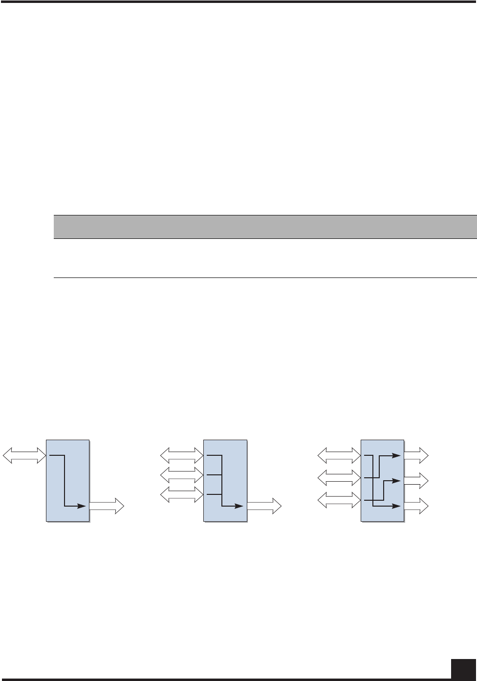
OmniAccess SafeGuard OS Administration Guide 91
Chapter 2: Accessing and Managing the System
Understanding Mirroring and Monitoring Ports
The SafeGuard OS supports two types of mirroring:
■port-based mirroring – Monitors all of the traffic on a port and copies, or mirrors,
the data to a destination port.
■policy-based mirroring – Allows mirroring at the rule-level of a policy. Policy-
based mirroring is described in Configuring Policy-Based Mirroring on page 323.
Port-based mirroring is device dependant. The SafeGuard Switch supports multiple
mirroring sessions and the forwarding of mirrored frames to a remote port. Table 1 2
shows the differences between the devices.
As shown in Figure 3, the SafeGuard Switch supports:
■A single mirroring port to a single mirrored-to port.
■Multiple mirroring ports to a single mirrored-to port
■Multiple mirroring ports to multiple mirrored-to ports
However, note that a single mirroring port cannot be connected to multiple mirrored-to
ports.
Figure 3 Example of Port-Based Mirroring Configuration for SafeGuard Switch
About Remote Span Support
The system can direct a mirrored frame to a specified remote monitoring device. This
device may not be another Alcatel-Lucent Switch. Frames are identified during VLAN
classification, tagged and directed to the RSPAN VLAN. The mirrored frames are
Table 12 Port-Based Mirroring on SafeGuard Devices
Device Mirror Sessions Remote Mirroring
SafeGuard Switch 1-4 Yes
SafeGuard Controller 1 No
CST_039
Mirroring
port Mirrored-to
port Mirrored-to
port
Mirrored-to
ports
Mirroring
ports
Mirroring
ports

OmniAccess SafeGuard OS Administration Guide
92
Chapter 2: Accessing and Managing the System
directed to the analyzer that is attached to the other switching device. Table 13 shows the
impact of frames traversing port ingress and egress with RSPAN enabled and disabled.
Table 13 RSPAN Ingress and Egress Frame Tagging
Figure 4 illustrates the packet frame data translation from ingress to egress.
NOTE: If RSPAN is enabled, the receiver should be configured to support
jumbo frames, since adding a VLAN tag to the ingress frame may result in a
jumbo frame being sent on the mirror port.
RSPAN Disabled
Ingress Frame Egress Frame
Untagged Untagged
802.1Q tagged 802.1Q tagged
Double Tagged (802.1Q in 802.1Q) Double Tagged (802.1Q in 802.1Q)
RSPAN Enabled
Ingress Frame Egress Frame
Untagged 802.1Q tagged (RSPAN VLAN)
802.1Q tagged 802.1Q in 802.1Q tagged (Outer RSPAN VlanId,
Inner original VlanId)
Double Tagged (802.1Q in 802.1Q) 3 tagged 802.1Q in 802.1Q tagged (Outer
RSPAN VID, Inner original VID
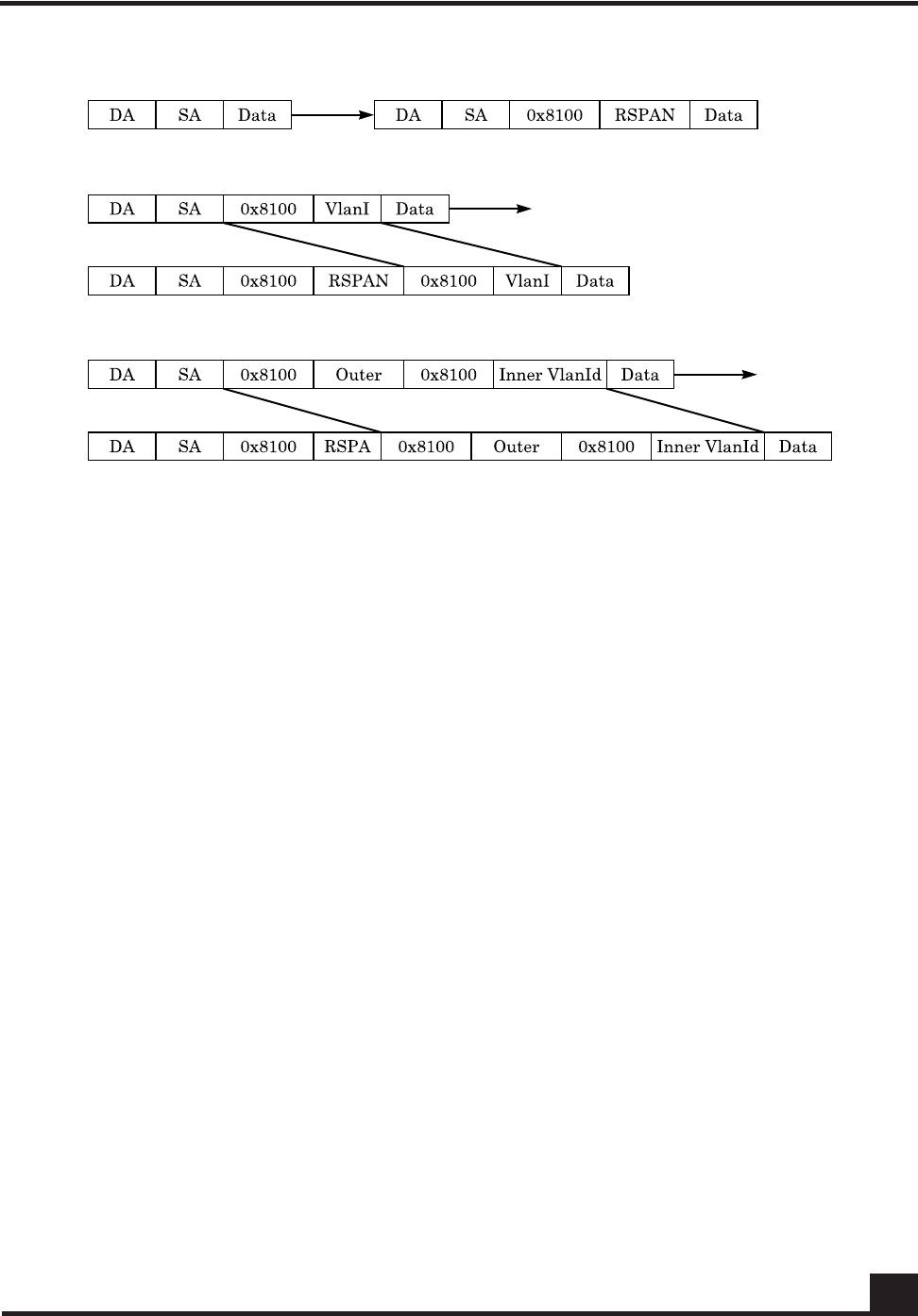
OmniAccess SafeGuard OS Administration Guide 93
Chapter 2: Accessing and Managing the System
Figure 4 RSPAN Frame Translation
Configuring Port-Based Mirroring
Port mirroring, which is also known as port monitoring, selects network traffic that you
can analyze with a network analyzer, such as a SwitchProbe device or other Remote
Monitoring (RMON) probe.
For details on policy-based mirroring, see Configuring Policy-Based Mirroring on page 323.
Setting the Source or Destination Port
To configure a probe port or a monitored port for a monitor session, use the monitor
session command in the Global configuration mode. Use the no version of the
command without optional parameters to remove the monitor session designation from
the source probe port, the destination monitored port and all VLANs.
Once the port is removed from the VLAN, you must manually add the port to any
desired VLANs. In a session on the OAG4048 there can be up to eight source ports. On
the OmniAccess 2400 SafeGuard/1000 there can be up to three source ports.
monitor session sessionID {source interface slot/port [rx | tx]} |
destination interface slot/port | mode
CST_056

OmniAccess SafeGuard OS Administration Guide
94
Chapter 2: Accessing and Managing the System
no monitor session sessionID destination interface
Restoring the Default Mirror Session Mode
To restore the default mirror session mode value for all configured sessions and remove
all source and destination ports, use the no monitor command in the Global
configuration mode.
no monitor
This command has no parameters.
Showing the Monitor Session
To display port monitoring information for a particular mirroring session, use the show
monitor session command in the Privileged Exec mode.
show monitor session sessionID
Syntax Description source
interface
slot/port
Specifies the interface to monitor. The no
form of the command removes the
specified interface from the port
monitoring session.
rx (Optional, for Switch only) Monitor only
ingress packets. If neither rx or tx is
chosen, both ingress and egress packets
will be monitored.
tx (Optional, for Switch only) Monitor only
egress packets. If neither rx or tx is
chosen, both ingress and egress packets
will be monitored.
destination
interface
slot/port
Interface to receive the monitored traffic.
The no form of the command does not
specify the slot/port; see syntax example.
mode Enable or disable (using the no form of the
command) the administrative mode of the
session. If enabled, the probe port monitors
all the traffic received and transmitted on
the monitored port.
Syntax Description sessionID An integer value used to identify the
session. Its value can be anything between
1 and the maximum number of mirroring
sessions allowed on the platform.

OmniAccess SafeGuard OS Administration Guide 95
Chapter 2: Accessing and Managing the System
Following is an example of the command output on a SafeGuard Controller:
(SafeGuardOS) #show monitor session 1
Session ID Admin Mode Probe Port Mirrored Port
---------- ---------- ---------- -------------
1 Enable 0/21 0/20
Following is an example of the command output on a SafeGuard Switch:
(SafeGuardOS) #show monitor session 1
Session ID Admin Mode Probe Port RSPAN VLAN Mirrored Port Type
---------- ---------- ---------- ------------ ------------- -----
1 Enable 0/9 0/1 Rx,Tx
0/2 Rx,Tx
(SafeGuardOS) #
The fields in the output represent:
Changing the Protection Mode of Ports
The device has three protection modes which have an impact on IP forwarding:
■Pass-thru – No protection policies are employed. This mode is the default.
■Monitor – The system monitors for policy visualization based on user-defined
policy controls, however no enforcement actions are taken.
Field Description
Session ID Id to identify the session.
Admin Mode Indicates whether the Port Mirroring feature is enabled
or disabled for the session. The possible values are
Enabled and Disabled.
Probe Port The Probe (destination) port for the session. If the probe
port is not set the field is blank.
RSPAN VLAN In Switch output only. The VLAN RSPAN.
Mirrored Port The port configured as the mirrored (source) port for the
session If no source port is configured for this session then
this field is blank.
Type Shown in Switch output only. Direction in which the
source port is configured for port mirroring. Values are tx,
for transmitted packets, or rx for received packets.

OmniAccess SafeGuard OS Administration Guide
96
Chapter 2: Accessing and Managing the System
■Protect – The system monitors and enforces policies on user-defined and malware
policy controls.
For the SafeGuard Controller
For the SafeGuard Controller, device protection mode is set per port-pair. The global form
of the protection-mode command will set all ports to the specified configuration. Use the
protection-mode command in Global or Interface Configuration submode.
protection-mode mode all
Table 14 Supported Protection Modes
Protection
Mode When Used SafeGuard Controller SafeGuard Switch
Pass-thru
Mode First time set up
and cabling Acts as a transparent
bridge. All security
functionality is
bypassed.
Acts as a standard L2/
L3 switch. All security
functionality is
bypassed.
Monitor Mode Testing and
trials Authentication, captive portal, visualization,
malware detection and protection and user-
based policy checking is applied to all data
traffic, but enforcement is ignored.
Protect Mode Typical
Deployment Authentication, captive portal, visualization,
malware detection and protection and user-
based policy checking is applied to all data
traffic, and actively enforced.
Syntax Description mode The protection mode of the port-pair. Valid
values are:
■pass-thru – (Default) No protection
policies are employed.
■monitor – The system monitors for policy
visualization based on user-defined
policy controls, however no
enforcement actions are taken.
■protect – The system monitors and
enforces policies on user-defined and
malware policy controls.
all Indicates that the mode parameter applies
to all interfaces.
The all keyword applies only in the Global
Configuration mode. In Interface
Configuration mode, it does not apply.

OmniAccess SafeGuard OS Administration Guide 97
Chapter 2: Accessing and Managing the System
The following example sets ports 1 and 2 to protect mode, in Global Configuration mode:
(SafeGuardOS) #configure terminal
(SafeGuardOS) (config) #interface 0/1
(SafeGuardOS) (interface 0/1) #protection-mode protect all
(SafeGuardOS) (interface 0/1) #exit
(SafeGuardOS) (config) #exit
The following example sets the protection-mode globally (on all ports).
(CS106) #configure terminal
(CS106) (config) #protection-mode protect all
Enabled: All SafeGuard security features
(CS106) (config) #
Another example showing protection mode settings follows:
(SafeGuardOS) #show protection-mode
Interface Protection Mode port type
--------- --------------- ---------
0/1 Protect network
0/2 Protect host
0/3 Protect network
0/4 Protect host
0/5 Protect network
0/6 Protect host
0/7 Protect network
0/8 Protect host
0/9 Protect network
0/10 Protect host
0/11 Protect network
0/12 Protect host
0/13 Protect network
0/14 Protect host
0/15 Protect network
0/16 Protect host
0/17 Protect network
0/18 Protect host
0/19 Protect network
0/20 Protect host
0/21 Pass-thru network
0/22 Pass-thru host
0/23 Pass-thru network
0/24 Pass-thru host
(SafeGuardOS) #
For the SafeGuard Switch
For the SafeGuard Switch, device protection mode is set on a global basis. Individual
interfaces cannot be configured with different protection modes. Use the protection-
mode command in Global Configuration mode.

OmniAccess SafeGuard OS Administration Guide
98
Chapter 2: Accessing and Managing the System
protection-mode mode all
The following example sets the SafeGuard Switch to protect mode:
(SafeGuardOS) #configure terminal
(SafeGuardOS) (config) #protection-mode protect all
Enabled: All SafeGuard security features
(SafeGuardOS) (config) #exit
(SafeGuardOS) #
Displaying Protection Mode Information
Use the show protection-mode command to verify the protection mode setting. The
following sample output is representative from a SafeGuard Controller:
(SafeGuardOS) #show protection-mode
Interface Protection Mode port type
--------- --------------- ---------
0/1 Protect network
0/2 Protect host
0/3 Protect network
0/4 Protect host
0/5 Protect network
0/6 Protect host
0/7 Protect network
0/8 Protect host
0/9 Protect network
0/10 Protect host
0/11 Protect network
0/12 Protect host
0/13 Protect network
0/14 Protect host
0/15 Protect network
0/16 Protect host
0/17 Protect network
0/18 Protect host
0/19 Protect network
0/20 Protect host
Syntax Description mode The protection mode of the port-pair. Valid
values are:
■Pass-thru – (Default) No protection
policies are employed.
■Monitor – The system monitors for policy
visualization based on user-defined
policy controls, however no
enforcement actions are taken.
■Protect – The system monitors and
enforces policies on user-defined and
malware policy controls.

OmniAccess SafeGuard OS Administration Guide 99
Chapter 2: Accessing and Managing the System
0/21 Pass-thru network
0/22 Pass-thru host
0/23 Pass-thru network
0/24 Pass-thru host
(SafeGuardOS) #
The next example is representative output of the show protection-mode command on the
SafeGuard Switch:
(SafeGuardOS) #show protection-mode
Interface Protection Mode Port Type
---- --------------- ---------
0/1 Monitor host
0/2 Monitor host
0/3 Monitor host
0/4 Monitor host
0/5 Monitor host
0/6 Monitor host
0/7 Monitor host
0/8 Monitor host
0/9 Monitor host
0/10 Monitor host
0/11 Monitor host
0/12 Monitor host
0/13 Monitor host
0/14 Monitor host
0/15 Monitor host
0/16 Monitor host
0/17 Monitor host
0/18 Monitor host
0/19 Monitor host
0/20 Monitor host
0/21 Monitor host
0/22 Monitor host
0/23 Monitor host
0/24 Monitor host
0/25 Monitor host
0/26 Monitor host
0/27 Monitor host
0/28 Monitor host
0/29 Monitor host
0/30 Monitor host
0/31 Monitor host
0/32 Monitor host
0/33 Monitor host
0/34 Monitor host
0/35 Monitor host
0/36 Monitor host
0/37 Monitor host
0/38 Monitor host
0/39 Monitor host
0/40 Monitor host
0/41 Monitor host
0/42 Monitor host
0/43 Monitor host
0/44 Monitor host

OmniAccess SafeGuard OS Administration Guide
100
Chapter 2: Accessing and Managing the System
0/45 Monitor network
0/46 Monitor network
0/47 Monitor network
0/48 Monitor network
0/49 Monitor network
0/50 Monitor network
(SafeGuardOS) #
The fields in the show protection-mode output represent:
Configuring High Availability Support
This section discusses the high availability options. It contains the following sections:
■Configuring Fail-over Device Support
■Configuring System Recovery
■Configuring Exception Recovery
Configuring Fail-over Device Support
For high-availability, the SafeGuard Controller device must be configured to populate the
authentication state to a fail-over device.
To take configure the SafeGuard Controller device to accommodate high-availability:
1Ensure that the devices in the topology have identical versions and identical
configurations.
2Ensure that cabling to the downstream and upstream devices are the same. For
example, if an edge switch is connected to port 5 on the device, the same edge
switch must also be connected to port 5 on the redundant device.
3Ensure that the system is configured to reboot (default) should there be a critical
error. If the devices are set in fail-passthru mode, the redundant system does not
take over traffic when a crucial error occurs. The traffic continues to pass through
Display Description
Interface Displays the interface number in slot/port format.
Protection Mode Displays the protection mode of the interface. Entries
can be pass-thru, monitor, or protect.
Port Type Identifies whether the port is connected to the hosts
or network.

OmniAccess SafeGuard OS Administration Guide 101
Chapter 2: Accessing and Managing the System
the failed system. Use the show system recovery command in Privileged Exec
mode to check the setting for system recovery.
4Configure each device to have a peer that synchronizes authentication state. To
add the peer, use the Global Configuration command:
ha peer ip_address
The following example establishes two devices (172.15.4.2 and 172.10.10.1) as
peers:
(SafeGuardOS) # configure terminal
(SafeGuardOS) (config) #ha peer 172.15.4.2
(SafeGuardOS) (config) #ha peer 172.10.10.1
(SafeGuardOS) #
Use the no version of the command to remove a peer:
no ha peer ip_address
The following commands describe the show commands that can be used to show high
availability configuration information.
■Use the following Global Configuration command to verify the recovery setting
for a peer:
show system recovery
The system either displays that on a critical system error, the system will either
reboot or it will go into pass-through mode.
■Use the following Global Configuration command to locate a peer device:
show ha peer
The following output is representative of the show ha peer command:
(SafeGuardOS) #show ha peers
HA Peer Table
-------------
Number of Rows:1
Peer ID IP Conns MSG TX MSG RX HB
TX HB RX Connect time

OmniAccess SafeGuard OS Administration Guide
102
Chapter 2: Accessing and Managing the System
------- -- ----- ------ ------ --
--- ----- ------------
001236fffffecbc2 172.16.5.101 1 4 0
661 661 22:26:44 UTC 13-Feb-2006
■Use the following Global Configuration command to display the current HA
configuration:
show ha info
The following output is representative of the show ha info command:
(SafeGuardOS) #show ha info
ha heartbeat-loss-threshold = 10 seconds
ha heartbeat-interval = 1 seconds
■Use the following Global Configuration commands to display the authentication
tables used in HA configurations:
—The Interface Table contains an entry for each Layer 3 interface detected on the
network. Use the following Global Configuration command to display the
Interface Table:
show ha aaa interface-table
The output of the command has these fields:
Table 15 Field Descriptions of the Interface Table
Field Description
IP The IP address of a downstream device, which is used as the primary
key to this table. Each L3 learning event for a unique source gener-
ates a new entry in the table.
MAC The MAC address, which can be used as a secondary key to this
table. The system can learn an L2 mapping based on an L3 learning
event.
Hostname The hostname displays when the information is available to the L3
mapping event.
Interface
Spec For an L3 learning event, the system records the port and VLAN infor-
mation for the user.
Credential ID This field binds an interface to a particular credential.
Role This is a list of roles assigned to a user interface.

OmniAccess SafeGuard OS Administration Guide 103
Chapter 2: Accessing and Managing the System
Sample output from the show ha aaa interface-table follows:
(SafeGuardOS) #show ha aaa interface-table
HA Interface Table
------------------
Number of Rows:1
IP Cred ID Origin Owner Active Flows Aging
-- ------- ------ ----- ------ ------ -----
10.25.0.93 0 L0CAL LOCAL true 3600
Each interface is mapped to a single credential, representing the user
information associated with that IP or MAC address. The entry in the
credential table, mapped to each interface, is represented by the Credential ID
field. To display the contents of the Credential Table, use the following Global
Configuration command:
show ha aaa credential-table
The output of the command has these fields:
Source The protocol from which the entry was learned. Possible values are:
■DHCP – The entry was created by DHCP; There is a MAC value
associated with this entry.
■LSP – The entry was learned based on active network traffic noted
by the SafeGuard Processor.
■PROTO – The entry was learned from the protocol header from one
of the authentication events.
State Provides the age out time and backup for each entry in the system.
Attribute ID The attribute ID for any interface with attributes associated with it.
Table 16 Field Descriptions of the Credential Table
Field Description
MAC The primary index for L2 entries.
IP The primary index for L3 entries.
Credential ID The system-wide identifier used by the Interface Table to map
to a credential. This field is shared by the two tables.
User Name This field is the login name generated by the authentication
event.
Table 15 Field Descriptions of the Interface Table (continued)
Field Description

OmniAccess SafeGuard OS Administration Guide
104
Chapter 2: Accessing and Managing the System
Sample output from the show ha aaa credential-table follows:
(SafeGuardOS) #show ha aaa credential-table
HA Credential Table
-------------------
Number of Rows:1
ID IP MAC User Origin Owner Ref Count
-- -- --- ---- ------ ----- ---------
2 10.25.0.9300:0f:1f:b8:44:68 jdoe LOCAL LOCAL 1
Source The protocol that generated the entry. Possible values are:
■white-list
■captive portal
■RADIUS
■Kerberos
State The authentication state. Possible values are:
■authing
■failed
■success
State Provides the age out time and backup for each entry in the
system.
Attribute ID When this is a non-zero field, it provides an index into the
attribute table. Any attributes derived from the authentication
protocol are stored in this entry.
Table 16 Field Descriptions of the Credential Table (continued)
Field Description

OmniAccess SafeGuard OS Administration Guide 105
Chapter 2: Accessing and Managing the System
Configuring System Recovery
Because there is only one SafeGuard device in the typical deployment model, the device
must be configured for fail-passthru mode. When in fail-passthru mode, the device sets
the protection mode to pass-thru if a critical error occurs.
When the protection mode is set to pass-thru mode, policy enforcement, visualization,
and malware detection are not enabled in addition to any high availability features.
Table 17 depicts the protection modes in greater details for the SafeGuard Switch or
Controller.
To configure the system recovery mode, use the system recovery command in Global
Configuration mode.
system recovery [reboot | fail-passthru]
Table 17 Supported Protection Modes
Protection
Mode When Used SafeGuard Controller SafeGuard Switch
Pass-thru
Mode First time set up
and cabling Acts as a transparent
bridge. All security
functionality is
bypassed.
Acts as a standard L2/
L3 switch. All security
functionality is
bypassed.
Monitor Mode Testing and
trials Authentication, captive portal, visualization,
malware detection and protection and user-
based policy checking is applied to all data
traffic, but enforcement is ignored.
Protect Mode Typical
Deployment Authentication, captive portal, visualization,
malware detection and protection and user-
based policy checking is applied to all data
traffic, and actively enforced.
Syntax Description reboot The switch will be rebooted on system fault.
This is the default setting.
fail-
passthru Sets the switch to fail-passthru mode. If a
critical error occurs, the device will be set
to pass-thru mode.

OmniAccess SafeGuard OS Administration Guide
106
Chapter 2: Accessing and Managing the System
The following example shows how to verify system recovery settings:
(SafeGuardOS) #show system recovery
Recovery Mode.................................. Fail-Passthru
Recovery State................................. N/A
(SafeGuardOS) #
In the above example, the system has been configured for “system recovery fail-
passthru”. N/A means there has not been a critical fault since the last reboot.
After a critical error has occurred, the output would look like this:
(SafeGuardOS) #show system recovery
Recovery Mode.................................. Fail-Passthru
Recovery State................................. Fail-Passthru on Dec 13 14:53:59
PST 2006
(SafeGuardOS) #
The Recovery State timestamps exactly when the system was put in fail-passthru mode.
Configuring Exception Recovery
Exception recovery is intended to allow the controller’s processor to survive certain kinds
of errors and keep processing. The user may enable the recovery feature and set the limits
before rebooting the unit as well as inspecting the state of recovery while viewing
statistics about its operation since reboot.
See the following sections for more details:
■Enabling and Disabling Exception Recovery
■Changing the Exception Recovery Parameters
■Viewing the Exception Recovery Status
Enabling and Disabling Exception Recovery
To enable exception recovery, use the lsp recovery-mode command in Global
Configuration mode. To disable exception recovery, use the no form of the command.
CAUTION: When the user logs into the system, a warning message is
displayed if the system is in Fail-PassThru mode. When system is in Fail-
PassThru mode, the user should not make any configuration changes because
some components are not operational.
In this state, user can use show commands for debugging and use the copy
command to transfer the core file and perform an upgrade. However, all other
commands are not disabled. Use any commands with extra caution.

OmniAccess SafeGuard OS Administration Guide 107
Chapter 2: Accessing and Managing the System
lsp recovery-mode
no lsp recovery-mode
This command has no options or parameters.
For example:
(SafeGuardOS) # configure terminal
(SafeGuardOS) (config) # lsp recovery-mode
(SafeGuardOS) (config) #
Changing the Exception Recovery Parameters
Recovery will “permit” a certain rate of exceptions per second, but will not tolerate a
certain number of exceptions over time. This is done with a “leaky bucket” system using
a sustain rate and threshold value. The sustain rate defines how many recoveries per
second the system can sustain. Each second, the recovery quota is increased by the
sustain value. The threshold is the recovery quota’s maximum value. No matter what the
sustain value is, the quota cannot exceed the threshold limit.
For example, to configure up to two recoveries per second to never crash the controller,
but any period of ten seconds when the recoveries happen faster than that to force a
reboot, the solution would look something like this:
■A threshold of twenty is defined, to indicate that ten seconds of more than two
recoveries each second will reach the threshold between continued operation and
a reboot.
■A sustain rate of two is defined, to indicate that every second the system can
restore two recoveries to the recovery quota.
The recoveries are defined per group. Traffic passing through the LSP processor is
divided into four groups for processing. These groups are related to the front-panel ports
of the SafeGuard controller.
To change the exception recovery parameters, use the lsp recovery command in Global
Configuration mode.
lsp recovery [threshold threshold] [sustain sustain]]
For example:
(SafeGuardOS) # configure terminal
(SafeGuardOS) (config) # lsp recovery threshold 20 sustain 2
Syntax Description threshold The maximum value of the recovery quota.
sustain Exceptions credited per second that the
system can sustain.

OmniAccess SafeGuard OS Administration Guide
108
Chapter 2: Accessing and Managing the System
(SafeGuardOS) (config) #
Enabling System Reboots on LSP Watchdog Events
To enable system reboots on LSP watchdog events, use the lsp watchdog command in
Global Configuration mode. To disable system reboots on LSP watchdog events, use the
no form of the command.
lsp watchdog
no lsp watchdog
This command has no options or parameters.
For example:
(SafeGuardOS) # configure terminal
(SafeGuardOS) (config) # lsp watchdog
(SafeGuardOS) (config) #
Viewing the Exception Recovery Status
To view the exception recovery status, use the show lsp recovery-mode command in
Privileged Mode.
show lsp recovery-mode
This command has no options or parameters.
For example:
(SafeGuardOS) #show lsp recovery-mode
(SafeGuardOS) #
LSP group 0: threshold 20, sustain 2, remaining 20, recoveries 1
LSP group 1: threshold 20, sustain 2, remaining 20, recoveries 4
LSP group 2: threshold 20, sustain 2, remaining 20, recoveries 1
LSP group 3: threshold 20, sustain 2, remaining 20, recoveries 0
(SafeGuardOS) #


OmniAccess SafeGuard OS Administration Guide
110
Chapter 3: Working with Configuration Files and Upgrading Images
This chapter describes the tasks associated with the configuration files and how to
upgrade system software.
Understanding Configuration Files
The SafeGuard OS maintains two basic configuration files that manage the device: the
startup configuration and the running configuration.
■The startup configuration is used when the device is started or rebooted.
■The running configuration is the current operating configuration.
While the two configurations can be the same, the running configuration and the startup
configuration can also be different. A third kind of configuration file, a backup
configuration, can also be created. This file may be a backup of an existing running
configuration, or a starting configuration.
See the following sections for more details:
■Saving Changes to the Running Configuration
■Saving Changes to the Startup Configuration
■Moving Backup Files to External Storage
■Restoring Configuration Files
■Erasing the Startup Configuration
■Displaying Configuration Information
Saving Changes to the Running Configuration
After making changes to the running configuration, save the changes to the startup
configuration to make sure that the changes persist across system reloads. In addition to
saving the running configuration as the startup file, it is recommended to store the file to
external storage (for example, Compact Flash (CF) or to a Trivial File Transfer Protocol
(TFTP) server).
From Running to the Startup
If the startup file is overwritten with the running configuration, the system uses the
updated file on the next reboot.
There are two separate Privileged Exec commands that can be used to save the running
configuration as the startup configuration: write memory or copy system:running-
config.
■write memory has no parameters or variables.

OmniAccess SafeGuard OS Administration Guide 111
Chapter 3: Working with Configuration Files and Upgrading Images
■copy system:running-config has the following syntax:
copy system:running-config [nvram:startup-config | nvram:backup-
config]
From Running to External Storage
A copy of the running configuration can be stored directly onto external storage, such as CF or to a
TFTP server, using the following copy system:running-config command in Privileged Exec
mode:
copy system:running-config [[tftp://ip/{filepath/}filename] |
[cf://{filepath/}filename]]
Saving Changes to the Startup Configuration
Startup configurations can be saved as follows:
■As the backup file in flash memory.
■To external storage; either CF or to a Trivial File Transfer Protocol (TFTP) server
From Startup to Backup
To save the startup configuration in flash memory as a backup configuration file, use the
copy nvram:startup-config command in Privileged Exec mode.
copy nvram:startup-config nvram:backup-config
Syntax Description startup-config Saves the running configuration to
the start up configuration in flash.
backup-config Saves the running configuration to
the backup configuration on flash.
Syntax Description tftp | cf Specifies whether to save the configuration onto
a TFTP server or CF. The cf parameter is a
controller only feature.
ip Specifies the IP address of the TFTP server.
filepath (Optional) Specifies the directory path to the file.
filename Specifies the filename of the file being saved.
Syntax Description backup-config Saves the starting configuration in flash
memory as a backup configuration.

OmniAccess SafeGuard OS Administration Guide
112
Chapter 3: Working with Configuration Files and Upgrading Images
From Startup to External Storage
To save the startup configuration to either a Trivial File Transfer Protocol (TFTP) server or
to CF use the copy nvram:startup-config command in Privileged Exec mode.
copy system:startup-config [[tftp://ip/{filepath/}filename] |
[cf://{filepath/}filename]]
Moving Backup Files to External Storage
Use this command to copy a backup file in flash memory to a TFTP server or to CF.
copy nvram:backup-config [[tftp://ip/{filepath/}filename] |
[cf://filename]
The following example copies the backed-up startup configuration file to CF.
(SafeGuardOS) #
(SafeGuardOS) # copy nvram:backup-config cf://start091207
(SafeGuardOS) #
Restoring Configuration Files
Either as part of a back up and recovery system or as a method of propagating files to
multiple machines, backup configuration files can be restored to flash memory.
From Flash Memory to Flash Memory
If the startup configuration has been saved to flash memory as a backup file, this file can
be used again using the copy nvram:backup-config command to write over the startup
Syntax Description tftp | cf Specifies whether to save the configuration onto
a TFTP server or CF.
ip Specifies the IP address of the TFTP server.
filepath (Optional) Specifies the directory path to the file.
filename Specifies the filename of the file being saved.
Syntax Description tftp | cf Specifies whether to save the configuration onto
a TFTP server or CF.
ip Specifies the IP address of the TFTP server.
filepath (Optional) Specifies the directory path to the file.
filename Specifies the filename of the file being saved.

OmniAccess SafeGuard OS Administration Guide 113
Chapter 3: Working with Configuration Files and Upgrading Images
configuration. The change takes effect after a system reboot. The syntax of the Privileged
Exec command is:
copy nvram:backup-config nvram:startup-config
There are no parameters or variables.
From TFTP to Flash Memory
Either a startup configuration or a running configuration can be downloaded from a
TFTP server location using the copy tftp:startup command and the copy tftp:backup
command in Privileged Exec mode to perform the download.
copy tftp://ip/{filepath/}file [nvram:backup-config | nvram:startup-
config]
The following example downloads a startup configuration file from a TFTP server:
(SafeGuardOS) #
(SafeGuardOS) # copy tftp://175.39.34.30/start45 nvram:startup-config
(SafeGuardOS) #
From Compact Flash to Flash Memory
To copy a startup or backup configuration file from Compact Flash (CF) to non-volatile
memory, use the copy cf:nvram command. The syntax of the Privileged Exec command
is:
copy cf://{filepath/}filename [nvram:startup-config | nvram:backup-
config]
Syntax Description ip Specifies the IP address of the TFTP
server.
filepath (Optional) Specifies the directory
path to the file.
file Specifies the filename of the startup
or running configuration being
downloaded.
nvram:backup-config Specifies to download a backup
configuration file.
nvram:startup-config Specifies to download a startup
configuration file.
Syntax Description filepath (Optional) Specifies the directory
path to the file.

OmniAccess SafeGuard OS Administration Guide
114
Chapter 3: Working with Configuration Files and Upgrading Images
The following example copies a back up file to flash memory:
(SafeGuardOS) #
(SafeGuardOS) # copy cf://start45 nvram:backup-config
(SafeGuardOS) #
Erasing the Startup Configuration
To erase the startup configuration and reset it to the factory defaults without powering
off the device, use the write erase command in Privileged Exec mode. After a write erase,
a reload is required.
write erase
The following example erases and reloads the startup configuration:
(SafeGuardOS) # write erase
(SafeGuardOS) # Are you sure that you would like to erase the running
configuration? <y/n>
(SafeGuardOS) # y
(SafeGuardOS) #
(SafeGuardOS) #reload
(SafeGuardOS) #
Displaying Configuration Information
To display configuration information, use one of the commands in the following sections:
■Running Config
■Startup Config
Running Config
There are two Privileged Exec commands that display the contents of the running
configuration to the terminal, show running-config and write terminal:
■The show running-config command has no parameters or variables.
show running-config
filename Specifies the filename of the startup
or running configuration being
downloaded.
nvram:startup-config Specifies to copy a start up
configuration file to flash memory.
nvram:backup-config Specifies to copy a back up
configuration file to flash memory.

OmniAccess SafeGuard OS Administration Guide 115
Chapter 3: Working with Configuration Files and Upgrading Images
■The write terminal command also has no parameters or variables.
write terminal
The output is displayed in the script format, which can be used to configure another
device with the same configuration. The output from the show running-config
command is shown in Appendix A, Sample Output.
Startup Config
To display the contents of the startup configuration to the terminal, use the show startup-
config command in Privileged Exec mode.
show startup-config
The command has no parameters or variables.
The output from the show startup-config command is shown in Appendix A, Sample
Output.
Upgrading System Images
This section describes the overall tasks associated with upgrading system software on the
Alcatel-Lucent SafeGuard devices. Be sure to check the Alcatel-Lucent Release Notes for the
specifics of upgrading an image.
The system image file contains executable code that brings up the system. An initial copy
is pre-installed on the device at the factory. Periodically, the software should be upgraded
to take advantage of new features and software updates.
To upgrade SafeGuard OS software:
1Download the new image from Alcatel-Lucent to an external TFTP server.
2Copy the image file to either the primary or secondary image location.
3Specify whether to boot using the primary or secondary image.
The following sections describe additional commands useful in version control and
software management tasks:
■Copying Images
NOTE: A new boot loader became available with SafeGuard OS Release 3.0.2.
If both 2.x and 3.0 releases are installed concurrently and 2.x is the running
image, the 2.x image cannot indicate that the 3.0 image is installed. For more
details on the boot loader, see Upgrading the Boot Image on page 117.

OmniAccess SafeGuard OS Administration Guide
116
Chapter 3: Working with Configuration Files and Upgrading Images
■Specifying the System Image
Copying Images
To copy the image file to either the primary or secondary image location, use the
copy tftp command in the Privileged Exec mode.
copy tftp://ip/{filepath/}file [image-primary | image-secondary]
The following example loads an EPV image into the primary image area:
(SafeGuardOS) #
(SafeGuardOS) # copy tftp://192.158.25.25/SafeGuardOS-3.0.2.x-cp.img image-
primary
(SafeGuardOS) #
Specifying the System Image
The device boots with the primary system image. To specify whether the system loads the
primary or secondary image, use the use image command in Privileged Exec mode. With
the next boot, the system loads the selected image.
use image [primary |secondary]
The following example loads the secondary image on the next bootup.
(SafeGuardOS) # use image secondary
(SafeGuardOS) #
Syntax Description ip Specifies the IP address of the TFTP server.
filepath (Optional) Specifies the directory path to the
file.
file Specifies the filename of the file being
downloaded.
image-
primary Copies an image file to the primary image
area.
image-
secondary Copies an image file to the secondary image
area.
Syntax Description primary Specifies to load the primary image on the next
boot.
secondary Specifies to load the secondary image on the
next boot.

OmniAccess SafeGuard OS Administration Guide 117
Chapter 3: Working with Configuration Files and Upgrading Images
Upgrading the Boot Image
SafeGuard devices use a boot sequence to bring up the device and load application
software, such as SafeGuard OS into memory. There are two methods of performing this
boot sequence:
■Simple – A single piece of code that performs both the bootstrap and boot loader
function.
This type of boot loader was introduced in SafeGuard OS release 1.0 and
continues to be supported. The simple boot loader provides backward
compatibility to early releases and allow SafeGuard OS users to use Release 3.0
without upgrading the boot loader. The simple boot loader stores the image into a
raw image partition.
■Dual-stage – Two distinct pieces of code that separate the bootstrap and boot
loader functions.
This type of boot loader was introduced in SafeGuard OS release 3.0 and provides
improved reliability over the simple boot loader. The dual-stage boot loader
stores the image into a set of components that are industry-standard.
For information on migrating a simple boot loader system to a dual-stage boot
loader, see Migrating a Simple Boot Loader to a Dual-Stage Boot Loader on page 119.
To update the Boot Loader:
1Download the new boot loader from Alcatel-Lucent to an external TFTP server.
2Copy the boot loader to either the primary or secondary flash location.
3Specify whether to boot using the primary or secondary boot loader.
4Validate the configuration using the show version command.
See the following sections for more details:
■Dual-Stage Boot Loader Upgrades
■Simple Boot Loader Upgrades
Dual-Stage Boot Loader Upgrades
The dual-stage boot loader is comprised of two components: the bootstrap and a primary
and secondary boot loader. The bootstrap runs when the system is reset and is
responsible for locating, selecting, validating and running the boot loader. The boot
loader is responsible for loading and running application software, such as SafeGuard
OS.

OmniAccess SafeGuard OS Administration Guide
118
Chapter 3: Working with Configuration Files and Upgrading Images
The bootstrap component may only be upgraded at the factory, as opposed to the boot
loader, which can be upgraded with a software update.
Copying a Boot Loader from a TFTP Server
Use the copy bootrom Privileged Exec command to install a single boot loader into the
either the primary or secondary image area of flash.
copy tftp://ip/{filepath/}bootfile [bootrom-package | bootrom-primary |
bootrom-secondary]
The following example loads a dual-stage boot loader into both the primary and
secondary image areas:
(SafeGuardOS) #
(SafeGuardOS) # copy tftp://192.158.25.25/oagbootpackage-1.0.0.0.img bootrom-
package
(SafeGuardOS) #
Specifying the Boot Loader
To specify whether the bootstrap should use the primary or secondary boot loader on a
dual-stage boot loader system, specify the use bootrom command in Privileged Exec
mode.
use bootrom [primary |secondary]
The following example specifies using the primary boot loader.
Syntax Description ip Specifies the IP address of the TFTP server.
filepath (Optional) Specifies the directory path to the
boot loader.
bootfile Specifies the name of the boot loader being
downloaded.
bootrom-
package This is the recommended option since it
updates both the primary and secondary
image areas in a single command.
bootrom-
primary Copies the boot loader to the primary image
area.
bootrom-
secondary Copies the boot loader to the secondary
image area.
Syntax Description primary Specifies to load the primary boot loader.
secondary Specifies to load the secondary boot loader.

OmniAccess SafeGuard OS Administration Guide 119
Chapter 3: Working with Configuration Files and Upgrading Images
(SafeGuardOS) # use bootrom primary
(SafeGuardOS) #
Simple Boot Loader Upgrades
With a simple boot loader system, see the following sections for either of the following
upgrade procedures, as desired. Only one of these procedures need to be performed for
an upgrade:
■Updating the Simple Boot Loader
■Migrating a Simple Boot Loader to a Dual-Stage Boot Loader
Updating the Simple Boot Loader
To update boot code on a simple boot loader system or to downgrade from a dual-stage
boot loader system, use the copy tftp image-bootrom command. The Privileged Exec
command has the following syntax:
copy tftp://ip/{filepath/}bootcode-filename image-bootrom
After the image is downloaded and installed, the CLI prompt is released.
Migrating a Simple Boot Loader to a Dual-Stage Boot Loader
The dual-stage boot loader can be loaded along with the simple boot loader. When both
types of boot loaders are found on the system, the switch installs the dual-stage boot
loader and converts the raw image to an industry standard format. The installation
process is:
1Install the dual-stage boot loader system using the copy bootrom-package
command. The Privileged Exec command has the following syntax:
copy tftp://ip/filepath/bootpkg-filename bootrom-package
Syntax Description ip Specifies the IP address of the TFTP server.
filepath (Optional) Specifies the directory path to the
simple boot loader.
bootcode-
filename Specifies the name of the boot loader being
downloaded.
Syntax
Description ip Specifies the IP address of the TFTP server.
filepath (Optional) Specifies the directory path to
the dual-stage boot loader package.

OmniAccess SafeGuard OS Administration Guide
120
Chapter 3: Working with Configuration Files and Upgrading Images
2Specify using the 3.0 image in either the primary or secondary image location as
described in Specifying the Boot Loader on page 118. If not specified, the boot loader
uses the primary image.
3Reboot the system.
When the system comes back up, SafeGuard OS detects the dual-stage boot loader
and that it was booted from a raw image partition. SafeGuard OS installs the
dual-stage boot loader and converts the raw image partition to the new format.
4Reboot the system again.
The dual-stage boot loader boots the SafeGuard OS from the new format.
Displaying Image and Boot Loader Information
The show version command displays both image and boot loader information. The
following example is representative of the output of the command for an EPV image with
a simple boot loader.
(SafeGuardOS) #show version
Manufacturer................................... Alcatel-Lucent Inc.
System Description............................. OmniAccess 2400 SafeGuard
Serial Number.................................. 0538FCS002
Burned In MAC Address.......................... 00:12:36:FF:DA:FE
Software Version............................... SafeGuardOS-3.0.2.X-xp
Software Build Date............................ Dec 19 22:33:40 PST 2006
Image Selected................................. Secondary
Image Booted................................... Secondary
Primary Image.................................. SafeGuardOS-3.0.2.X-xp-release-
042512192006
Secondary Image................................ SafeGuardOS-3.0.2.X-xp-release-
223312192006
Bootstrap Version.............................. 1.0.0.3 (Boot Package: 1.0.0.10)
Active Bootrom Version......................... 2.0.0.26 (Boot Package:
1.0.0.10)
Bootrom Selected............................... Primary
Bootrom Booted................................. Primary
Primary Bootrom Version........................ 2.0.0.26 (Boot Package:
1.0.0.10)
Secondary Bootrom Version...................... 2.0.0.26 (Boot Package:
1.0.0.10)
System Time.................................... Dec 20 14:09:40 PST 2006
CPU Utilization................................ user: 0.98% system 27.45% idle:
71.57%
Free Memory.................................... 188 MB / Total 244 MB
Uptime......................................... 2 hours 54 minutes 46 seconds
bootpkg-
filename Specifies the name of the boot loader
package being downloaded.

OmniAccess SafeGuard OS Administration Guide 121
Chapter 3: Working with Configuration Files and Upgrading Images
(SafeGuardOS) #
The fields of the output represent:
Following is an example of the show version output when using the dual-stage
bootloader.
(SafeGuardOS) #show version
Manufacturer................................... Alcatel-Lucent Inc.
System Description............................. OmniAccess 2400 SafeGuard
Base mgmt port MAC Address..................... 00:12:36:FF:F9:E0
Software Version............................... SafeGuardOS-3.0.2.x-cp
Software Build Date............................ Jul 30 10:45:49 PDT 2006
Image Selected................................. Secondary
Image Booted................................... Secondary
Field Description
Manufacturer Indicates the device is manufactured by Alcatel-Lucent
System Description The model number of the device
Base Mgmt Port MAC
Address The MAC address of the management port
Software Version The software version; an extension of Captive Portal
indicates an EPV version.
Software Build Date The time and date that the build was created.
Image Selected Indicates whether the primary or secondary image was
selected to boot.
Image Booted Indicates whether the primary or secondary image was
actually booted.
Primary Image The image name in the primary image area of flash
memory.
Secondary Image The image name in the secondary image area of flash
memory.
Bootrom Version Displays the boot loader version for simple boot loader
systems.
System Time The creation date and time for the system.
CPU Utilization Current CPU utilization, both of the user and the system.
Free Memory The amount of free memory and total memory.
Uptime The amount of time since the last reload.
Protection Mode The protection mode configured for the system. Possible
values are pass-thru, monitor, and protect.

OmniAccess SafeGuard OS Administration Guide
122
Chapter 3: Working with Configuration Files and Upgrading Images
Primary Image.................................. SafeGuardOS-3.0.2.x-cp-exxxxx-
104507302006
Secondary Image................................ SafeGuardOS-3.0.2.x-cp-exxxxx-
104507302006
Bootstrap Version.............................. 1.0.0.0
Bootrom Selected............................... Secondary
Bootrom Booted................................. Primary
Primary Bootrom Version........................ 2.0.0.16
Secondary Bootrom Version...................... 2.0.0.16
System Time.................................... Jan 1 00:01:07 2006
Cpu Utilization................................ user: 0.98% system 9.80% idle:
89.22%
Free Memory.................................... 153 MB / Total 244 MB
Uptime......................................... 1 minutes 13 seconds
Protection Mode................................ protect
The fields of the output represent:
Field Description
Manufacturer Indicates the device is manufactured by Alcatel-Lucent
System Description The model number of the device
Base Mgmt Port MAC
Address The MAC address of the management port
Software Version The software version; an extension of Captive Portal
indicates an EPV version.
Software Build Date The time and date that the build was created.
Image Selected Indicates whether the primary or secondary image was
selected to boot.
Image Booted Indicates whether the primary or secondary image was
actually booted.
Primary Image The image name in the primary image area of flash
memory.
Secondary Image The image name in the secondary image area of flash
memory.
Bootstrap Version Displays the bootstrap version for dual-stage boot loader
systems.
Bootrom Selected Indicates whether the primary or secondary boot loader
was selected on dual-stage boot loader systems.
Bootrom Booted Indicates the actual boot loader running on a dual-
stage boot loader system.
Primary Bootrom Version Indicates the version number of the boot loader in the
primary image area.
Secondary Bootrom
Version Indicates the version number of the boot loader in the
secondary image area.

OmniAccess SafeGuard OS Administration Guide 123
Chapter 3: Working with Configuration Files and Upgrading Images
Removing All Data from Memory
Government installations or companies that require mil-spec compliance might need to
completely remove all data from memory before the device can leave the site.
Use the following procedure to perform a military scrub of the NAND and NOR Flash
memory:
1Connect a serial cable to the management port on the rear panel of the SafeGuard
device.
2Attach the other end of the serial cable to a properly configured terminal or
terminal emulator.
3Power cycle the SafeGuard device.
4When prompted, press any key to display the boot loader prompt.
5Enter the formatF nand command to completely remove all data from NAND
flash. For example:
Alcatel-Lucent> formatF nand
offset=5000000, size=3000000
Start: 5000000, Num Blocks: 3072
Erasing flash region:
................................................................
................................................................
................................................................
Alcatel-Lucent>
6Enter the formatVars command to completely remove all data from NOR flash.
For example:
Alcatel-Lucent> formatVars
Erasing flash env variables sector.....
>>> Done
..
Done.
System Time The creation date and time for the system.
CPU Utilization Current CPU utilization, both of the user and the system.
Free Memory The amount of free memory and total memory.
Uptime The amount of time since the last reload.
Protection Mode The protection mode configured for the system. Possible
values are pass-thru, monitor, and protect.
Field Description

OmniAccess SafeGuard OS Administration Guide
124
Chapter 3: Working with Configuration Files and Upgrading Images


OmniAccess SafeGuard OS Administration Guide
126
Chapter 4: Configuring SafeGuard Controllers
Configuring VLANs on the SafeGuard Controller
A VLAN is a logical grouping of endpoint devices on different physical LAN segments
that communicate as if they are on the same physical LAN segment. These endpoint
devices are referred to as members of the VLAN. Unlike a LAN connected using hardware,
a VLAN is configured using the SafeGuard OS CLI, making it a virtual connection.
VLANs are part of the IEEE 802.1Q standard, which is designed to address how to break
large networks into smaller parts so broadcast and multicast traffic would not grab more
bandwidth than necessary. The standard also helps provide a higher level of security
between segments of internal networks.
On SafeGuard Controllers, VLANs do not need to be created; they are pre-configured
already. However, some of the VLAN settings are adjustable. Controllers classify all
untagged traffic upon ingress into the Controller and into the reserved VLAN. The
reserved VLAN is always enabled. The reserved VLAN is set to a VLAN ID of 1 by
default.
To set the VLAN ID for the reserved VLAN, use the reserved vlan command in Global
Configuration mode.
reserved vlan vlanid
The following example assigns a VLAN ID of 50 to a Controller;
(SafeGuardOS) #configure terminal
(SafeGuardOS) (config) #reserved vlan 50
(SafeGuardOS) (config) #
To validate the assignment of the VLAN ID, use the show reserved vlan or the show
running-config commands. An example of the show running-config is shown in Sample
Output on page 395. The syntax of the show reserved vlan command is:
show reserved vlan
The Privileged Exec command has no options or parameters. The following example is
representative of the output from the command.
(SafeGuardOS) #show reserved vlan
The untagged Vlan id = 50
(SafeGuardOS) #
For more details on SafeGuard Controllers and their features, see Alcatel-Lucent Solution
and Product Overview on page 20.
Syntax Description vlanid Specifies a VLAN ID number. Valid entries are 1
to 4094.

OmniAccess SafeGuard OS Administration Guide 127
Chapter 4: Configuring SafeGuard Controllers
Link Pair Synchronization
The SafeGuard Controller sits between the user and the network. It is important that if a
link between a user and the controller goes down, the link between the controller and the
network is also brought down. In addition, if the link between the controller and the
network goes down, the link between the user and the controller must be brought down.
This is required so that protocols can converge in the event of link failures. By default,
link pair synchronization is enabled on controllers.
Link pair synchronization is a feature available only on the SafeGuard Controller to
constantly monitor the link on both the user and network side. If either side of the link
fails or is brought down administratively, link pair synchronization will bring the other
side of the link down. Link pair synchronization will mark the link that it brought down
as SUSPENDED. If the failed link comes back up then link pair synchronization will
restore the link it brought down to UP state.
A link pair is a combination of neighbor ports, such as {P1,P2}, {P3, P4}, and so on. A link
pair cannot be formed with arbitrary port sets such as {P1, P5}. A link pair combination
consists of the user connected on one side of the pair and the network connected to the
other side of the pair.
The network administrator can monitor changes in link states using the show port all
command.
For example:
(SafeGuard) #show port all
Admin Physical Physical Link LACP
Intf Type Mode Mode Status Status Mode
------ ------ ------- ---------- ---------- ------ -------
0/1 Enable Auto Down Disable short
0/2 Enable Auto Suspended Disable short
In the example above port 0/1 is down, so Link pari synchronization will suspend port
0/2 to allow for protocols such as STP, RSTP, EAP, etc to converge.
The current Link pair synchronization settings can be seen by executing the following
command from Privileged Exec mode:
(SafeGuard) #show linkpair-sync
Link pair synchronization is enabled.
(SafeGuard) #
To enable Link pair synchronization (enabled by default):
(SafeGuard) #config terminal
(SafeGuard) (config) #linkpair-sync enable
(SafeGuard) (config) #
To disable Link pair synchronization:

OmniAccess SafeGuard OS Administration Guide
128
Chapter 4: Configuring SafeGuard Controllers
(SafeGuard) #config terminal
(SafeGuard) (config) #linkpair-sync disable
(SafeGuard) (config) #


OmniAccess SafeGuard OS Administration Guide
130
Chapter 5: Setting Up SafeGuard Switches
Overview of VLANs
This chapter describes setting up Virtual Local Area Networks (VLANs) on SafeGuard
devices. The SafeGuard Switch and the Controller both support VLANs but use different
techniques and commands.
A VLAN is a logical grouping of endpoint devices on different physical LAN segments
that communicate as if they are on the same physical LAN segment. These endpoint
devices are referred to as members of the VLAN. Unlike a LAN connected using hardware,
a VLAN is configured using the SafeGuard OS CLI, making it a virtual connection.
VLANs are part of the IEEE 802.1Q standard, which is designed to address how to break
large networks into smaller parts so broadcast and multicast traffic would not grab more
bandwidth than necessary. The standard also helps provide a higher level of security
between segments of internal networks.
See the following sections for more details:
■Tagged and Untagged Frames
■Ingress VLAN Classification and Egress Forwarding for the SafeGuard Switch
■Why Use VLANs?
■Configuring VLANs on the SafeGuard Switch
For more details on SafeGuard Switches and their features, see Alcatel-Lucent Solution and
Product Overview on page 20.
Tagged and Untagged Frames
The IEEE 802.1Q specification establishes a standard method for tagging Ethernet frames
with VLAN membership information. To tag a VLAN, insert an identification number
(VLAN ID) into a predefined field through configuration.
Tagged VLANs provide switch-to-switch connectivity over a single physical connection
called a trunk. Tagged VLANs over trunk lines allow multiple VLANs to span from
switch to switch.
An untagged frame received at a port will be classified into an appropriate VLAN based
on one of the criteria specified in the following section.
Ingress VLAN Classification and Egress Forwarding for the
SafeGuard Switch
The switch uses a set of rules to determine VLAN membership when a frame enters a
port (ingress). After the frame is examined and the VLAN membership is determined, the
packet is assigned to the VLAN and transmitted out of the ports (egress) associated with
the VLAN.

OmniAccess SafeGuard OS Administration Guide 131
Chapter 5: Setting Up SafeGuard Switches
Ingress VLAN Classification
A frame can be tagged, untagged or priority-tagged. When a switch receives a frame, it
will first classify the incoming frame to assign the VLAN ID, as described in the
following points:
■If the frame is 802.1Q tagged, the switch uses the VID in the frame to assign the
VLAN ID.
■If the frame is untagged or priority-tagged, the switch uses one of four
classifications methods to assign the VLAN ID. Internally, each packet is evaluated
in the following precedence order. The switch uses whichever method matches
first.
— MAC-based VLAN assigns the VLAN ID based on the source MAC address
in the frame using a global MAC-based VLAN association table. The MAC
address is the hardwired address built into the NIC (network interface card)
of the endpoint device. These VLANs offer the capability of defining a VLAN
composed of specific hosts.
The MAC-based VLAN association table is configured globally. Each entry in
the table defines mapping between a MAC-address and an associated VLAN
ID. Any incoming frame with the matching source MAC address is assigned
the associated VLAN ID. The MAC-based association table is built using CLI
commands.
— IP subnet-based classification assigns the VLAN ID based on the source IP
address in the packet using an IP subnet-based VLAN association table. The
IP subnet-based VLAN association table is defined globally. Each entry in the
table defines mapping between the IP subnet address (address/mask) and
associated VLAN ID. Any incoming IP packet with the matching IP source
address is assigned the associated VLAN ID. This type of VLAN permits
multiple subnets on a single interface. IP subnet-based VLANs are typically
used when all of the hosts can belong to the same VLAN.
— Protocol-based classification assigns the VLAN ID based on the type field of
the Ethernet header in the packet. Protocol-based VLANs are configured on a
per-interface basis and use the VID that is mapped from the link-layer
protocol carried in the frame.
— Port-based classification assigns the VLAN ID based on the Port VID (PVID)
configured on the ingress port.LAN membership on assignment to a port or to
a group of ports. If no other classification matches, SafeGuard OS uses port-
based classification as the default classification method.
All frames assigned a VLAN ID for a VLAN that does not exist will be discarded.
NOTE: By default, the PVID of a port is set to 1. The user needs to set the
proper PVID on every port.

OmniAccess SafeGuard OS Administration Guide
132
Chapter 5: Setting Up SafeGuard Switches
Ingress Filtering
If ingress filtering is enabled, incoming frames for VLANs which do not include this
ingress port in their member set will be discarded at the ingress port; otherwise, the
incoming frames are admitted and forwarded to the ports that are member of that VLAN.
By default, ingress filtering is enabled per port, and can be disabled.
Ingress filtering does not affect VLAN independent BPDU frames, such as STP. However,
it does affect VLAN dependent BPDU frames, such as GMRP.
For example, VLAN2 is dedicated to hosts running the IPX protocol on ports 6-10. A host
connected to port 5 is also running IPX, but port 5 is not in the VLAN configuration for
the VLAN2. When the frame goes through the ingress rules the system classifies the
frame as protocol-based. The system assigns the frame to VLAN 2 even though the port is
not configured in the VLAN. To have the system drop the frame rather than forward to
VLAN 2, it needs to filter on the ingress. For more information on ingress filtering, see
Enabling Ingress Filtering on page 138.
Assigning Ports to VLANs
Before a VLAN becomes active, you need to assign one or more ports to the VLAN in
which it participates. By default, all ports are assigned to default VLAN 1 as untagged
ports. A port can be member of multiple VLANs as either tagged or untagged.
Add a port as a tagged port if this port carries traffic for one or more VLANs, and
intermediate network devices or the host at the other end of connection supports VLANs.
Tagging mode of a member port decides whether switch should transmit a frame out of
this port as tagged or untagged frame.
Forwarding Tagged and Untagged Frames
After the Ingress classification determines the VLAN ID for the received frame, the
switch decides to which member ports of the VLAN switch the frame should be
forwarded.
Tagged and untagged frames are treated as follows:
■Tagged frames – If an egress port is a tagged member, the frame will be
transmitted as a tagged frame. Otherwise, the switch will first strip off the VLAN
tag before forwarding the frame as an untagged frame.
■Untagged frames – If an egress port is a tagged member, A VLAN tag will be
inserted into the frame before forwarding. Otherwise, the switch will forward the
frame as untagged.
Why Use VLANs?
VLANs provide several advantages:

OmniAccess SafeGuard OS Administration Guide 133
Chapter 5: Setting Up SafeGuard Switches
■Location independent – When an endpoint device is moved to another location, it
can remain on the same VLAN without needing to reconfigure any hardware.
■Increased network efficiency – The network is more efficient by allowing a VLAN to
control and screen broadcast traffic.
■Increased security – By confining broadcast traffic to users in a workgroup, there is
increased security because sensitive data is confined to only that group.
Configuring VLANs on the SafeGuard Switch
The SafeGuard Switch comes with a single pre-configured VLAN or default VLAN. The
default VLAN is assigned the ID of 1 (VID 1) and is reserved, which means it cannot be
deleted.
See the following sections for more details on configuring VLANs:
■Configuring Port-Based VLANs
■Configuring Protocol-Based VLANs
■Configuring MAC-Based VLANs
■Configuring IP Subnet-Based VLANs
■Deleting a VLAN
■Verifying the VLAN Configuration
Configuring Port-Based VLANs
To create a port-based VLAN on the SafeGuard Switch, follow these steps, described in
more detail in the following sections:
1Creating the VLAN and Assigning a VLAN ID on page 134
2Assigning a Name to the VLAN on page 135
3Assigning the Ports and Egress Tagging on page 136
4Assigning a Port VLAN ID on page 137
5Assigning an IP Address to the VLAN on page 137
6Setting Frame Acceptance on page 138
7Enabling Ingress Filtering on page 138
8Verifying the Configurations on page 139

OmniAccess SafeGuard OS Administration Guide
134
Chapter 5: Setting Up SafeGuard Switches
Creating the VLAN and Assigning a VLAN ID
Create VLANs in the VLAN database mode, which is a submode of Global
Configuration. To enter the mode, use the vlan database command:
vlan database
The command has no parameters or variables. For example:
(SafeGuardOS) (config) #vlan database
(SafeGuardOS) (Vlan)#
To assign an ID and an optional name to the VLAN, use the vlan command in VLAN
database mode. Eligible ID numbers are from 2 to 4094. Each VLAN is assigned a default
system-generated name in the format “VLANxxxx”, where xxx is the ID of the VLAN.
The VLAN can be renamed to any name meaningful to its network configuration, such as
“finance_dept”. However, the following restrictions apply:
■The new name can not be a system reserved name, such as: “default”,
“MgmgVlan”, “ServicePort”, or “VLANxxxx”.
■Each VLAN name must be unique within the system.
vlan id {name name}
The following example assigns a VLAN with the ID of 85:
(SafeGuardOS) (config) #vlan database
(SafeGuardOS) (Vlan)#vlan 85
(SafeGuardOS) (Vlan)#exit
To validate the creation of the VLAN, use the show vlan brief command in Privileged
Exec mode.
(SafeGuardOS) #show vlan brief
VLAN ID Name Type IP Addr/MaskLen Ports(active/total)
------- --------------- ------- ------------------ ------------------
1 Default Default 0/50
85 VLAN0085 Static 0/0
Note that the system assigned an internal name to the VLAN when the VLAN was
created. The internal name is comprised of the word VLAN concatenated to the ID
number in a four digit format.
Syntax Description id Assigns a VLAN having this identification
number. Valid assignment numbers are from 2
to 4094. ID 1 is reserved for the default VLAN.
name A user defined name for the VLAN.

OmniAccess SafeGuard OS Administration Guide 135
Chapter 5: Setting Up SafeGuard Switches
For further discussion of the show vlan brief command and a description of the output
fields, see Showing a VLAN Brief on page 146.
Assigning a Name to the VLAN
This step is optional, however, most organizations prefer to identify their VLANs by an
organizational name rather than by a number. Use the vlan name command in VLAN
database submode of Privileged Exec.
vlan name vlanid name
In the following example, VLAN 85 is assigned the name of sales.
(SafeGuardOS) (Vlan)#vlan name 85 sales
(SafeGuardOS) (Vlan)#exit
The show vlan brief command no longer displays the system-generated name of
VLAN0085 for VLAN 85, but instead displays sales.
(SafeGuardOS) #show vlan brief
VLAN ID Name Type IP Addr/MaskLen Ports(active/total)
------- --------------- ------- ------------------ ------------------
1 Default Default 0/50
85 sales Static 0/0
For further discussion of the show vlan brief command and a description of the output
fields, see Showing a VLAN Brief on page 146.
Restoring the System Generated VLAN Name
To change the name of a VLAN back to the system generated name, use the no vlan
name command in VLAN database mode.
no vlan name vlanid
Syntax Description vlanid Specifies an existing VLAN ID number. Valid
entries are 1 to 4094.
name Assigns a name to the VLAN by the ID. VLAN
names can be up to 32 characters in length.
The following restrictions apply:
■The new name can not be a system
reserved name, such as: “default”,
“MgmgVlan”, “ServicePort”, or “VLANxxxx”.
■Each VLAN name must be unique within the
system.
Syntax Description vlanid ID of the VLAN.

OmniAccess SafeGuard OS Administration Guide
136
Chapter 5: Setting Up SafeGuard Switches
Assigning the Ports and Egress Tagging
Although packets are inspected at port ingress, the system acts on the frame when it exits
the port (on egress). At the assignment time, the ports can also be designated as tagged or
untagged, as desired. Tagging is optional.
For port-based VLANs, port membership and tagging are assigned on a per interface
basis. At the assignment time, the ports can also be designated as tagged or untagged.
To configure a VLAN by individual interface basis, use the vlan participation command
in Interface mode.
vlan participation [auto | include | exclude] vlanid {tagged}
The following command sets the participation to auto for interface 0/13:
(SafeGuardOS) #configure terminal
(SafeGuardOS) (config) #interface 0/13
(SafeGuardOS) (interface 0/13) #vlan participation auto name sales
(SafeGuardOS) (interface 0/13) #exit
(SafeGuardOS) (config) #exit
To display the configuration, use the show vlan brief command. This command is
discussed in Showing a VLAN Brief on page 146.
Syntax Description auto Specifies that the interface is automatically
registered in the VLAN after a join request is
received on the interface. This option is
equivalent to registration normal.
include Specifies that the interface is always a
member of the VLAN. This option is
equivalent to registration fixed.
exclude Specifies that the interface is never a member of
the VLAN. This is equivalent to registration
forbidden.
vlanid Specifies the VLAN ID of the VLAN being
individually tagged.
tagged Specified that the VLAN is tagged.

OmniAccess SafeGuard OS Administration Guide 137
Chapter 5: Setting Up SafeGuard Switches
Assigning a Port VLAN ID
To specify that the VLAN is classified as port-based, use the vlan pvid command in
Interface Configuration submode of Global Configuration.
vlan pvid vid
The following example specifies VLAN 85 using a port VLAN ID on port 18:
(SafeGuardOS) #configure terminal
(SafeGuardOS) (config) #interface 0/18
(SafeGuardOS) (interface 0/18) #vlan pvid 85
(SafeGuardOS) (interface 0/18) #exit
(SafeGuardOS) (config) #
Verify the configuration using the show vlan association command. This command is
discussed in Showing a VLAN Association on page 145.
Assigning an IP Address to the VLAN
This optional step assigns an IP address to the VLAN. The IP address should be assigned
if the VLAN will be a Layer 3 VLAN providing logical routing interfaces to VLANs on
Layer 2 switches. Use the no version of the command to delete the IP address. To assign
the IP address, use the ip address command in Interface configuration submode of
Global Configuration.
ip address ipaddr subnet-mask {secondary}
no ip address ipaddr subnet-mask {secondary}
The following example adds an IP address and mask to the sales VLAN (85):
(SafeGuardOS) (config) #interface vlan name sales
(SafeGuardOS) (interface vlan sales) #ip address 172.68.24.1 255.255.255.0
(SafeGuardOS) (interface vlan sales) #exit
(SafeGuardOS) (config) #exit
Syntax Description vid Specifies the VLAN ID being associated with the
port.
Syntax Description ipaddr Specifies the IP address of the routing interface
in 32-bit dotted quad format.
subnet-
mask Specifies a 4-digit dotted-decimal number that
represents the subnet mask of the interface. The
subnet mask must be contiguous and be no
longer than 30 bits, for example 255.255.255.0.
secondary (Optional) Species that the IP address is a
secondary address.

OmniAccess SafeGuard OS Administration Guide
138
Chapter 5: Setting Up SafeGuard Switches
Setting Frame Acceptance
To select the types of frames that can be received on a port, use the vlan acceptframe
command. Untagged or priority tagged frames are either discarded or accepted and
assigned the value of the VLAN ID for the interface.
With either option, VLAN tagged frames are forwarded in accordance with the IEEE
802.1Q VLAN specification. Use the no version of the command to set the frame
acceptance mode for all interfaces to accept or admit all. To select whether to accept or
reject the frame type, use the following syntax in Interface configuration mode:
vlan acceptframe [all | vlanonly]
no vlan acceptframe
In the following example, all priority frames are accepted on interface 0/18:
(SafeGuardOS) #configure terminal
(SafeGuardOS) (config) #interface 0/18
(SafeGuardOS) (interface 0/18) #vlan acceptframe all
(SafeGuardOS) (interface 0/18) #exit
(SafeGuardOS) (config) #exit
Use the show vlan name command as described in Showing a VLAN Name on page 149 or
the show vlan port command as described on Showing a VLAN Port on page 151 to verify
the configuration.
Enabling Ingress Filtering
When ingress filtering is disabled, frames received with VLAN IDs that do not match the
VLAN membership of the receiving interface are admitted and forwarded to ports that
are members of that VLAN.
By default, ingress filtering is enabled per port in SafeGuardOS.
Global Filtering
To enable ingress filtering for all interfaces, use the vlan port ingressfilter all command
in Global Configuration mode. The no version of the command disables ingress filtering
for all interfaces.
vlan port ingressfilter all
Syntax Description all Specifies that untagged frames or priority
frames received on this interface are
accepted and assigned the value of the
interface VLAN ID for this port.
vlanonly Specifies that untagged frames or priority
frames received on this interface are
discarded.

OmniAccess SafeGuard OS Administration Guide 139
Chapter 5: Setting Up SafeGuard Switches
no vlan port ingressfilter all
The commands have no parameters or variables.
In the following example, ingress filtering is enabled:
(SafeGuardOS) #configure terminal
(SafeGuardOS) (config) #vlan port ingressfilter all
(SafeGuardOS) (config) #exit
Per-Interface Filtering
To enable ingress filtering for a specific interface, use the vlan port ingressfilter
command in Interface Configuration mode. The no version of the command disables
ingress filtering for the interface.
vlan ingressfilter
no vlan ingressfilter
These commands have no parameters or variables.
In the following example, ingress filtering is enabled on port 0/12:
(SafeGuardOS) #configure terminal
(SafeGuardOS) (config) #interface 0/12
(SafeGuardOS) (interface 0/12) #vlan ingressfilter
(SafeGuardOS) (interface 0/12) #exit
(SafeGuardOS) (config) #exit
Verifying the Configurations
Verify the configuration using either of the following commands:
■show vlan port command as described in Showing a VLAN Port on page 151
■show vlan name command as described in Showing a VLAN Name on page 149
Configuring Protocol-Based VLANs
A protocol VLAN filters protocol traffic from being forwarded out of the switch. Use a
protocol VLAN when only one of the supported protocols—ARP, IP or IPX—should run
on the VLAN. Protocol VLANs are configured in a similar manner as port-based VLANs.
To create a Protocol-Based VLAN:
1Assign the VLAN ID. See Creating the VLAN and Assigning a VLAN ID on page 134
for more details.
2(Optional) Assign a name to the VLAN. See Assigning a Name to the VLAN on
page 135 for more details.
3Assign ports to the VLAN and (optionally) set egress tagging

OmniAccess SafeGuard OS Administration Guide
140
Chapter 5: Setting Up SafeGuard Switches
4Create a protocol group name.
5Assign a protocol to that group name.
6Assign the VLAN to the group name.
7Associate the VLAN ID to a protocol group.
8(Optional) Assign an IP address. See Assigning an IP Address to the VLAN on
page 137 for more details.
9(Optional) Enable ingress filtering. See Enabling Ingress Filtering on page 138 for
more details.
10 Verify the configuration using the show vlan brief or show running-config
commands. See Verifying the VLAN Configuration on page 145 for more details.
Assigning the Egress Port Membership and Optional Tagging for All Ports
To configure the VLAN for all ports on the Switch, use the Global Configuration vlan
participation all command.
vlan participation all [auto |include |exclude] vlanid {tagged}
For example, the following command sets all ports to be members of the VLAN:
(SafeGuardOS) #configure terminal
(SafeGuardOS) (config) #vlan participation all include id 50
(SafeGuardOS) (config) #exit
To display the configuration, use the show vlan brief command. This command is
discussed in Showing a VLAN Brief on page 146.
Syntax Description auto (Default) Specifies that the interface is
automatically registered in the VLAN after a
join request is received on the interface. This
option is equivalent to registration normal.
include Specifies that the interface is always a
member of the VLAN. This option is
equivalent to registration fixed.
exclude Specifies that the interface is never a member of
the VLAN. This is equivalent to registration
forbidden.
vlanid Specifies the VLAN ID of the VLAN being globally
tagged
tagged (Optional) Specified that the VLAN is tagged.

OmniAccess SafeGuard OS Administration Guide 141
Chapter 5: Setting Up SafeGuard Switches
Creating a Protocol Group
A protocol group is associated with a specific protocol identified by a group name. Use
the vlan protocol group command to create a group name for a protocol group. Use the
no version of the command to remove the group.
vlan protocol group groupname
no vlan protocol group groupname
The following example creates a group called ipgroup.
(SafeGuardOS) #configure terminal
(SafeGuardOS) (config) #vlan protocol group ipgroup
(SafeGuardOS) (config) #
Assigning a Protocol to the Group Name
Use the vlan protocol group add protocol command in Global Configuration mode to
add a protocol to the protocol-based VLAN group. Use the no version of the command to
remove the protocol from the VLAN group.
vlan protocol group add protocol groupname [ip | arp | ipx]
no vlan protocol group add protocol
The following example adds the IP protocol to the IPgroup.
(SafeGuardOS) #configure terminal
(SafeGuardOS) (config) #vlan protocol group add protocol ipgroup ip
(SafeGuardOS) (config) #
Assigning the VLAN to the Group Name
To add a single physical interface to the protocol-based VLAN, or add all physical
interfaces to the protocol-based VLAN, use the protocol vlan group command in Global
Configuration mode using the following syntax:
Syntax Description groupname Specifies to associate the VLAN with this VLAN ID
to the group name. Valid entries are from 1 to
128 characters.
Syntax Description groupname Specifies the group name for the protocol VLAN.
ip Specifies to use the Internet Protocol (IP).
arp Specifies to use the Address Resolution Protocol
(ARP).
ipx Specifies to use the Internetwork Packet
Exchange (IPX).

OmniAccess SafeGuard OS Administration Guide
142
Chapter 5: Setting Up SafeGuard Switches
protocol vlan group {all} groupname
The following example adds all physical interfaces to the protocol VLAN.
(SafeGuardOS) #configure terminal
(SafeGuardOS) (config) #protocol vlan group all ipgroup
(SafeGuardOS) (config) #exit
Configuring MAC-Based VLANs
A MAC-based VLAN is a VLAN of specific end point devices. These VLANs are useful
for workstations that move frequently because they are not tied to a port. MAC-based
VLANs are defined globally; all traffic from the device with the matching MAC address
is funneled into the VLAN.
To create a MAC-based VLAN, follow these steps described in the following sections:
1Creating the VLAN and Assigning a VLAN ID on page 134.
2Assigning a Name to the VLAN on page 135.
3Assigning the Egress Port Membership and Optional Tagging for All Ports on page 140.
4Associating the VLAN to a MAC address on page 142
5Assigning an IP Address to the VLAN on page 137
6Setting Frame Acceptance on page 138
7Enabling Ingress Filtering on page 138
8Verify the configuration using the show vlan brief or show running-config
commands. This step is described in Verifying the VLAN Configuration on page 145.
Associating the VLAN to a MAC address
To associate the VLAN to a MAC address, use the vlan association command in VLAN
database submode of Global Configuration. The no version of the command removes the
association.
vlan association [mac macaddr] vlanid
Syntax Description all Specifies to all physical interfaces to the
protocol VLAN.
groupname Specifies to associate the VLAN with this VLAN ID
to the group name. Valid entries are from 1 to
128 characters.

OmniAccess SafeGuard OS Administration Guide 143
Chapter 5: Setting Up SafeGuard Switches
no vlan association [mac macaddr]
The following command associates a MAC address to a VLAN with the VLAN ID of 50.
(SafeGuardOS) (config) #vlan database
(SafeGuardOS) (Vlan) #vlan association mac 3f:78:45:a2:34 50
(SafeGuardOS) (Vlan) #exit
Verify the configuration using the show vlan association command. This command is
described further in Showing a VLAN Association on page 145.
Configuring IP Subnet-Based VLANs
IP subnet-based VLANs filter Layer 3 information to build VLANs based on a source IP
address, network mask, and the VLAN ID. This type of VLAN permits multiple subnets
on a single interface. IP subnet-based VLANs are typically used when all of the end
points can belong to the same VLAN. These VLANs are defined globally; all traffic from
matching devices are included in the VLAN.
To create an IP Subnet-based VLAN:
1Creating the VLAN and Assigning a VLAN ID on page 134.
2Assigning a Name to the VLAN on page 135.
3Assigning the Egress Port Membership and Optional Tagging for All Ports on page 140.
4Associate the VLAN to an IP Subnet Address on page 144
5Assigning an IP Address to the VLAN on page 137.
6Setting Frame Acceptance on page 138.
7Enabling Ingress Filtering on page 138.
8Verify the configuration using the show vlan brief or show running-config
commands. This step is described in Verifying the VLAN Configuration on page 145.
Syntax Description macaddr Species the MAC address being associated to
the VLAN. MAC addresses may be specified in
any of the following formats:
■aa:bb:cc:dd:ee:ff
■aabb:ccdd:eeff
■aa-bb-cc-dd-ee-ff
■aabb.ccdd.eeff
■aabbccddeeff
vlanid Specifies the VLAN ID being associated.

OmniAccess SafeGuard OS Administration Guide
144
Chapter 5: Setting Up SafeGuard Switches
Associate the VLAN to an IP Subnet Address
To associate the VLAN to an IP subnet address, use the vlan association command in
VLAN database mode. The no version of the command removes the association.
vlan association [subnet ipaddr netmask] vlanid
no vlan association [subnet ipaddr netmask]
The following command associates an IP subnet to a VLAN with the ID of 50.
(SafeGuardOS) (config) #vlan database
(SafeGuardOS) (Vlan) #vlan association subnet 10.201.4.99 255.255.255.0 50
(SafeGuardOS) (Vlan) #exit
Verify the configuration using the show vlan association command. This command is
described further in Showing a VLAN Association on page 145.
Deleting a VLAN
With the exception of a reserved VLAN, to delete a VLAN, use the no vlan command in
vlan database mode.
no vlan [vlanid |name]
The following example deletes the sales VLAN with the ID of 85.
(SafeGuardOS) #configure terminal
(SafeGuardOS) (config) #vlan database
(SafeGuardOS) (Vlan) #no vlan 85
(SafeGuardOS) (Vlan) #exit
Syntax Description ipaddr Specifies the IP address being associated to the
VLAN.
netmask Specifies a 4-digit dotted-decimal number that
represents the subnet mask. The subnet mask
must be contiguous and be no longer than 30
bits, for example 255.255.255.0.
vlanid Specifies the VLAN ID being associated.
Syntax Description vlanid Specifies to delete the VLAN based on its ID.
name Specifies to delete the VLAN based on its
name.

OmniAccess SafeGuard OS Administration Guide 145
Chapter 5: Setting Up SafeGuard Switches
Verifying the VLAN Configuration
There are Privileged Exec show commands to display VLAN and VLAN-related
configurations:
Showing a VLAN Association
The show vlan association command displays the VLAN associated with a specific IP
address or netmask.
show vlan association [mac macaddr | subnet mask]
The following sample output is representative of the show vlan association command:
(SafeGuardOS) #show vlan association subnet
IP Address IP Mask VLAN ID
10.201.4.99 255.255.255.0 50
77.77.77.10 255.255.255.0 50
Command Use
show running-configuration Displays the running configuration for the Switch,
which includes VLAN configuration. An example of the
show running-config is shown in Appendix A, Sample
Output.
show vlan association Displays the VLAN associated with a specific
configured IP address or netmask.
show vlan brief Displays a summary of all configured VLANs.
show vlan ID Displays VLAN information about tagging, link state
and the Include Mode by VLAN ID.
show vlan name Displays VLAN summary or detailed information by
VLAN name.
show vlan port Displays information about an interface, all interfaces,
or a port-channel.
Syntax Description macaddr Specifies to display the VLAN information
associated with this MAC address.
mask Specifies to display the VLAN information
associated with this subnet mask.

OmniAccess SafeGuard OS Administration Guide
146
Chapter 5: Setting Up SafeGuard Switches
The fields in the show vlan association output represent:
Showing a VLAN Brief
The show vlan brief command displays summary information about all configured VLANs.
show vlan brief
This command has no options or parameters.
The following sample output is representative of the show vlan brief command:
(SafeGuardOS) #show vlan brief
VLAN ID Name Type IP Addr/MaskLen Ports(active/total)
------- --------------- ------- ------------------ ------------------
1 Default Default 0/50
85 sales Static 172.68.24.1 /24 0/0
The fields in the show vlan brief output represent:
Display Description
IP Address Displays the IP address associated with the VLAN.
IP Mask Displays the subnet mask associated with the VLAN.
VLAN ID Displays the ID for the associated VLAN.
Display Description
VLAN ID Displays the VLAN identification number.
Name Displays the name assigned to the VLAN.
Type Displays the type of VLAN. Valid types are default,
port, static or protocol.
IP Addr/MaskLen Displays the IP address and mask associated with the
VLAN.
Ports (active/total) Displays the active and total port count.

OmniAccess SafeGuard OS Administration Guide 147
Chapter 5: Setting Up SafeGuard Switches
Showing VLAN ID
The show vlan ID command displays either a summary or detailed information about a
VLAN by the VLAN ID.
show vlan id [id vlanid | name vlan_name]{detailed}
The following example displays summary information for the default VLAN:
(SafeGuardOS) #show vlan id 1
VLAN ID : 1
VLAN Name : Default
VLAN Type : Default
Ports : 50 (Number of active ports = 2)
IP Address :
Interface Tagging Link State
--------------- ------- ----------
0/1 Untagged Disable
0/2 Untagged Down
0/3 Untagged Disable
0/4 Untagged Down
0/5 Untagged Disable
0/6 Untagged Disable
0/7 Untagged Up
0/8 Untagged Up
0/9 Untagged Disable
0/10 Untagged Disable
0/11 Untagged Disable
0/12 Untagged Disable
0/13 Untagged Disable
0/14 Untagged Disable
0/15 Untagged Disable
0/16 Untagged Disable
0/17 Untagged Disable
0/18 Untagged Disable
The next example includes additional fields when the detailed parameter is specified.
(SafeGuardOS) #show vlan id 1 detailed
VLAN ID : 1
VLAN Name : Default
VLAN Type : Default
Ports : 50 (Number of active ports = 2)
IP Address :
Syntax Description vlanid Specifies to display information about the VLAN
identified by this VLAN ID.
detailed (Optional) Displays Include mode information
about the specified VLAN.

OmniAccess SafeGuard OS Administration Guide
148
Chapter 5: Setting Up SafeGuard Switches
Interface Current Configured Tagging Link State
--------------- ------- ---------- ------- ----------
0/1 Include Include Untagged Disable
0/2 Include Include Untagged Down
0/3 Include Include Untagged Disable
0/4 Include Include Untagged Down
0/5 Include Include Untagged Disable
0/6 Include Include Untagged Disable
0/7 Include Include Untagged Up
0/8 Include Include Untagged Up
0/9 Include Include Untagged Disable
0/10 Include Include Untagged Disable
0/11 Include Include Untagged Disable
0/12 Include Include Untagged Disable
0/13 Include Include Untagged Disable
0/14 Include Include Untagged Disable
0/15 Include Include Untagged Disable
0/16 Include Include Untagged Disable
0/17 Include Include Untagged Disable
0/18 Include Include Untagged Disable
The fields in the show vlan id output represent:
Display Description
VLAN ID Displays the VLAN identification number.
VLAN Name Displays the name assigned to the VLAN.
VLAN Type Displays the type of VLAN. Valid types are default,
port or protocol.
Ports Displays the total port count and the number of active
ports.
IP Address Displays the following information for the IP address:
■Interface number in slot/port format
■(detailed only) Displays the current VLAN
participation. Valid values are include, exclude, or
auto.
■(detailed only) Displays the configuration of the
VLAN participation. Valid values are include,
exclude, or auto.
■Displays whether the VLAN is tagged or untagged.
■Displays the link state: disabled, up or down.
Interface Displays the interface number in slot/port format.
Current Displays whether this VLAN is included in the current
configuration.
Configured Displays whether this VLAN is configured in the startup
configuration.

OmniAccess SafeGuard OS Administration Guide 149
Chapter 5: Setting Up SafeGuard Switches
Showing a VLAN Name
Use this command to display either a summary or detailed information about a VLAN by
name.
show vlan name vlan_name {detailed}
The following example displays summary information for the default VLAN:
(SafeGuardOS) #show vlan name default
VLAN ID : 1
VLAN Name : Default
VLAN Type : Default
Ports : 50 (Number of active ports = 2)
IP Address :
Interface Tagging Link State
--------------- ------- ----------
0/1 Untagged Disable
0/2 Untagged Down
0/3 Untagged Disable
0/4 Untagged Down
0/5 Untagged Disable
0/6 Untagged Disable
0/7 Untagged Up
0/8 Untagged Up
0/9 Untagged Disable
0/10 Untagged Disable
0/11 Untagged Disable
0/12 Untagged Disable
0/13 Untagged Disable
0/14 Untagged Disable
0/15 Untagged Disable
0/16 Untagged Disable
0/17 Untagged Disable
0/18 Untagged Disable
The next example includes additional fields when the detailed parameter is specified.
(SafeGuardOS) #show vlan name default detailed
Tagging Displays whether this interface is configured for tagging.
Link State Displays the link state: disabled, down (enabled), or up.
Syntax Description vlan_name Specifies to display information about the VLAN
identified by the VLAN name.
detailed (Optional) Displays Include mode information
about the specified VLAN.
Display Description

OmniAccess SafeGuard OS Administration Guide
150
Chapter 5: Setting Up SafeGuard Switches
VLAN ID : 1
VLAN Name : Default
VLAN Type : Default
Ports : 50 (Number of active ports = 2)
IP Address :
Interface Current Configured Tagging Link State
--------------- ------- ---------- ------- ----------
0/1 Include Include Untagged Disable
0/2 Include Include Untagged Down
0/3 Include Include Untagged Disable
0/4 Include Include Untagged Down
0/5 Include Include Untagged Disable
0/6 Include Include Untagged Disable
0/7 Include Include Untagged Up
0/8 Include Include Untagged Up
0/9 Include Include Untagged Disable
0/10 Include Include Untagged Disable
0/11 Include Include Untagged Disable
0/12 Include Include Untagged Disable
0/13 Include Include Untagged Disable
0/14 Include Include Untagged Disable
0/15 Include Include Untagged Disable
0/16 Include Include Untagged Disable
0/17 Include Include Untagged Disable
0/18 Include Include Untagged Disable
The fields in the show vlan name output represent:
Display Description
VLAN ID Displays the VLAN identification number.
VLAN Name Displays the name assigned to the VLAN.
VLAN Type Displays the type of VLAN. Valid types are default,
port or protocol.
Ports Displays the total port count and the number of active
ports.
IP Address Displays the following information for the IP address:
■Interface number in slot/port format
■(detailed only) Displays the current VLAN
participation. Valid values are include, exclude, or
auto.
■(detailed only) Displays the configuration of the
VLAN participation. Valid values are include,
exclude, or auto.
■Displays whether the VLAN is tagged or untagged.
■Displays the link state.

OmniAccess SafeGuard OS Administration Guide 151
Chapter 5: Setting Up SafeGuard Switches
Showing a VLAN Port
Use this command to display information about an interface, all interfaces or a port-
channel.
show vlan port [slot/port | all | port-channel port-channel-name
The following example is representative of the output of the show vlan port command:
(SafeGuardOS) #show vlan port 0/22
Port Acceptable Ingress Default
Interface VLAN ID Frame Types Filtering GVRP Priority
--------- ------- ------------ ----------- ------- --------
0/22 1 Admit All Enable Disable 0
The fields in the show vlan name output represent:
slot/port Specifies to display information about the interface that is
shown in slot/port format.
all Specifies to display information about all of the interfaces.
port-channel-name Specifies to display information about the named port-
channel.
Display Description
Interface Displays a valid slot and port number separated by
forward slashes.
Port ID or VLAN ID Displays the port-channel name or VLAN
identification number that this port uses to assign
untagged frames or priority tagged frames.
Acceptable Frame Types Displays the types of frames that may be received
on this port. The options are 'VLAN only' and 'Admit
All'.
■When set to 'VLAN only', untagged frames or priority
tagged frames received on this port are discarded.
■When set to 'Admit All', untagged frames or priority
tagged frames received on this port are accepted
and assigned the value of the Port VLAN ID for this
port.
With either option, VLAN tagged frames are forwarded
in accordance to the 802.1Q VLAN specification.

OmniAccess SafeGuard OS Administration Guide
152
Chapter 5: Setting Up SafeGuard Switches
Displaying Forwarding Database Entries Information
To display the forwarding database entries, use the show mac fdb-table command in
Privileged Exec mode. This command applies to the switch only. It is not available on the
controller.
If the command is entered with no argument, the entire table is displayed. Or, the
administrator can enter a MAC address to display the table entry for the requested MAC
address and all entries following the requested MAC address.
show mac fdb-table [macaddr | all]
Following is example output of the show mac fdb-table command:
(SafeGuardOS) # show mac fdb-table all
VlanID Mac Address Interface IfIndex Status
-------- ----------------- --------- ------- ------------
0001 00:01:09:00:01:00 0/20 20 Learned
1005 00:12:36:FF:DC:F2 0/1 1 Management
Ingress Filtering Displays whether filtering is enabled or disabled.
When enabled, the frame is discarded if this port is
not a member of the VLAN with which this frame is
associated. In a tagged frame, the VLAN is identified by
the VLAN ID in the tag. In an untagged frame, the VLAN
is the Port VLAN ID specified for the port that received
this frame. When disabled, all frames are forwarded in
accordance with the 802.1Q VLAN bridge specification.
The factory default is disabled.
GVRP Displays whether GVRP may be enabled or disabled.
Default Priority Displays the 802.1p priority assigned to tagged packets
arriving on the port.
Syntax Description macaddr Displays the table entry for the specified MAC
address. MAC addresses may be specified in
any of the following formats:
■aa:bb:cc:dd:ee:ff
■aabb:ccdd:eeff
■aa-bb-cc-dd-ee-ff
■aabb.ccdd.eeff
■aabbccddeeff
all Displays all forwarding database entries.
Display Description

OmniAccess SafeGuard OS Administration Guide 153
Chapter 5: Setting Up SafeGuard Switches
The fields in the output represent:
Configuring Spanning Trees
The SafeGuard Switch supports the Spanning-Tree Protocol (STP) on all Ethernet, Fast
Ethernet, Gigabit Ethernet, and port-based VLANs. STP eliminates undesirable Layer 2
loops in networks, by selectively blocking some ports and allowing other ports to
forward traffic, based on configurable bridge and port parameters.
STP ensures that the most efficient path is taken when multiple paths exist between ports
or VLANs. If the selected path fails, STP searches for and then establishes an alternate
path to prevent or limit retransmission of data. STP is transparent to end stations, which
cannot detect whether they are connected to a single LAN segment or a switched LAN of
multiple segments.
By default, a single instance of STP runs on each configured VLAN (assuming that STP is
not disabled). STP can be enabled on a global basis. STP is disabled by default. When STP
is enabled on a switch, STP is still disabled on each port.
Field Description
VLAN ID Identifier for the VLAN.
MAC Address A unicast MAC address for which the device has forwarding
and or filtering information. MAC addresses may be specified
in any of the following formats:
■aa:bb:cc:dd:ee:ff
■aabb:ccdd:eeff
■aa-bb-cc-dd-ee-ff
■aabb.ccdd.eeff
■aabbccddeeff
Interface Slot and port which this address was learned.
If Index IfIndex of the interface table entry associated with this port.
Status Status of this entry, which can be:
■Learned – Value of the corresponding instance was
learned by observing the source MAC addresses of
incoming traffic and is currently in use.
■Management – Value of the corresponding instance
(system MAC address) is also the value of an existing
instance of dot1dStaticAddress. It is identified with
interface 0/1 and is currently used when enabling VLANs
for routing.

OmniAccess SafeGuard OS Administration Guide
154
Chapter 5: Setting Up SafeGuard Switches
The following sections describe commands to support STP:
■Enabling or Disabling STP Globally
■Forcing Transmission of Rapid Spanning Tree
■Setting the Configuration Identifier Name
■Setting the Configuration Identifier Revision Level
■Specifying an Edge Port
■Setting the Force Protocol Version Parameter
■Setting the Bridge Forward Delay Parameter
■Setting the Bridge Max Age Parameter
■Setting the Path Cost or Port Priority
■Setting the Bridge Priority
■Setting the Administrative Switch Port State for a Port
■Setting the Administrative Switch Port State for all Ports
■Displaying STP Information
Enabling or Disabling STP Globally
STP is disabled by default. The only required configuration step is to enable the feature.
To enable STP globally on the SafeGuard Switch, use the spanning-tree command in
Global Configuration mode.
Use the no version of the command to disable STP.
spanning-tree
no spanning-tree
The commands have no parameters or variables.
The following example enables STP on the SafeGuard Switch:
(SafeGuardOS) #configure terminal
(SafeGuardOS) (config) #spanning-tree
(SafeGuardOS) (config) #exit
Forcing Transmission of Rapid Spanning Tree
To force a transmission of rapid spanning tree (RSTP) BPDUs, use the spanning-tree
bdpumigrationcheck command in Global Configuration mode. Use the slot/port
parameter to transmit a BPDU from a specified interface, or use the all keyword to
transmit BPDUs from all interfaces.

OmniAccess SafeGuard OS Administration Guide 155
Chapter 5: Setting Up SafeGuard Switches
This command forces the BPDU transmission, so the command does not change the
system configuration or have a “no” version.
spanning-tree bdpumigrationcheck [slot/port | all]
The following example forces a transmission of RSTP and MSTP BPDUs on all ports of
the SafeGuard switch:
(SafeGuardOS) #configure terminal
(SafeGuardOS) (config) #spanning-tree bdpumigrationcheck all
(SafeGuardOS) (config) #exit
Setting the Configuration Identifier Name
To set the Configuration Identifier Name for identifying the configuration that a switch is
currently using, use the spanning-tree configuration name command in Global
Configuration mode. The default value is the base MAC address in hexadecimal notation.
spanning-tree configuration name name
The following example sets “00-12-36-FE-76-FF” as the configuration identifier name that
the switch is using:
(SafeGuardOS) #configure terminal
(SafeGuardOS) (config) #spanning-tree configuration name “00-12-36-FE-76-FF”
(SafeGuardOS) (config) #exit
Setting the Configuration Identifier Revision Level
To set the Configuration Identifier Revision Level for use in identifying the configuration
that a switch is currently using, use the spanning-tree configuration revision
command in Global Configuration mode. The default level is 0.
To set the Configuration Identifier Revision Level to the default, use the no version of the
command.
spanning-tree configuration revision revision-level
Syntax Description slot/port Specifies to transmit a BDPU from the
interface that is shown in slot/port format.
all Transmits BDPUs from all interfaces.
Syntax Description name The configuration identifier name. It is string
of up to 32 characters.

OmniAccess SafeGuard OS Administration Guide
156
Chapter 5: Setting Up SafeGuard Switches
no spanning-tree configuration revision
The following example sets “32768” as the configuration revision for the SafeGuard
switch:
(SafeGuardOS) #configure terminal
(SafeGuardOS) (config) #spanning-tree configuration revision 32768
(SafeGuardOS) (config) #exit
Specifying an Edge Port
To specify that a port is an edge port within the common and internal spanning tree, use
the spanning-tree edgeport command in Interface Configuration mode. This allows
the port to transition to forwarding state without delay.
To specify that a port is not an edge port within the common and internal spanning tree,
use the no version of the command.
spanning-tree edgeport
no spanning-tree edgeport
The commands have no parameters or variables.
The following example specifies 0/25 as an edge port within the common and internal
spanning tree:
(SafeGuardOS) #configure terminal
(SafeGuardOS) (config) #interface 0/25
(SafeGuardOS) (interface 0/25) #spanning-tree edgeport
(SafeGuardOS) (interface 0/25) #exit
Setting the Force Protocol Version Parameter
To set the Force Protocol Version parameter to a new value, use the spanning-tree
forceversion command in Global Configuration mode. The default version is 802.1w.
To set the Force Protocol Version parameter to the default value, use the no version of the
command.
spanning-tree forceversion [802.1d | 802.1w]
Syntax Description revision-
level The configuration revision level. It is number
in the range of 0 to 65535. The default value
is 0.

OmniAccess SafeGuard OS Administration Guide 157
Chapter 5: Setting Up SafeGuard Switches
no spanning-tree forceversion
The following example sets the force protocol version parameter to 802.1d:
(SafeGuardOS) #configure terminal
(SafeGuardOS) (config) #spanning-tree forceversion 802.1d
(SafeGuardOS) (config) #exit
Setting the Bridge Forward Delay Parameter
To set the Bridge Forward Delay parameter to a new value for the common and internal
spanning tree, use the spanning-tree forward-time command in Global
Configuration mode. The default value is 15.
To set the Bridge Forward Delay parameter to the default value, use the no version of the
command.
spanning-tree forward-time time
no spanning-tree forward-time
The following example sets the Bridge Forward Delay parameter to 10:
(SafeGuardOS) #configure terminal
(SafeGuardOS) (config) #spanning-tree forward-time 10
(SafeGuardOS) (config) #exit
Setting the Bridge Max Age Parameter
To set the Bridge Max Age parameter to a new value for the common and internal
spanning tree, use the spanning-tree forward-time command in Global
Configuration mode. The default value is 20.
To set the Bridge Max Age parameter to the default value, use the no version of the
command.
Syntax Description 802.1d Specifies that the switch transmits ST BPDUs
rather than MST BPDUs (IEEE 802.1d
functionality supported).
802.1w Specifies that the switch transmits RST BPDUs
rather than MST BPDUs (IEEE 802.1w
functionality supported).
Syntax Description time Time in seconds within a range of 4 to 30.
The value must be greater than or equal to
(Bridge Max Age / 2) + 1.

OmniAccess SafeGuard OS Administration Guide
158
Chapter 5: Setting Up SafeGuard Switches
spanning-tree max-age time
no spanning-tree max-age
The following example sets the Bridge Max Age parameter to 20:
(SafeGuardOS) #configure terminal
(SafeGuardOS) (config) #spanning-tree max-age 20
(SafeGuardOS) (config) #exit
Setting the Path Cost or Port Priority
To set the Path Cost or Port Priority for a port, use the spanning-tree port command in
Interface Configuration mode.
To set the Path Cost or Port Priority for a port in the common and internal spanning tree
to the respective default values, use the no version of the command.
spanning-tree port [cost [1-200000000 | auto] | priority 0-240]
no spanning-tree port [cost | priority]
The following example sets the path cost and port priority:
(SafeGuardOS)#configure terminal
(SafeGuardOS) (config) #interface 0/25
(SafeGuardOS) (interface 0/25)#spanning-tree port cost 32768
(SafeGuardOS) (interface 0/25)#spanning-tree port priority 128
(SafeGuardOS) (interface 0/25)#exit
(SafeGuardOS) (config) #exit
Syntax Description time Time in seconds within a range of 6 to 40.
The value must be less than or equal to - 1
(2 x Bridge Forward Delay).
Syntax Description port Spanning tree settings for a port.
cost 1-200000000 The path cost. Must be a number in the
range of 1 to 200000000.
auto Selecting auto causes the path cost value
to be based on link speed.
priority 0-240 The priority for this port. The priority value is
a number in the range of 0 to 240 in
increments of 16.

OmniAccess SafeGuard OS Administration Guide 159
Chapter 5: Setting Up SafeGuard Switches
Setting the Bridge Priority
To set the bridge priority, use the spanning-tree priority command in Global
Configuration mode. The default priority is 32768.
To set the bridge priority, use the no version of the command.
spanning-tree priority priority
no spanning-tree priority
The following example sets the bridge priority to 0:
(SafeGuardOS) #configure terminal
(SafeGuardOS) (config) #spanning-tree priority 0
(SafeGuardOS) (config) #exit
Setting the Administrative Switch Port State for a Port
To set the Administrative Switch Port State for a port to be enabled, use the spanning-
tree port mode command in Interface Configuration mode By default the port is
disabled.
To set the Administrative Switch Port State for a port to be disabled, use the no version of
the command.
spanning-tree port mode
no spanning-tree port mode
The commands have no parameters or variables.
The following example sets the Administrative Switch Port State for a port to be enabled:
(SafeGuardOS)#configure terminal
(SafeGuardOS) (config) #interface 0/25
(SafeGuardOS) (interface 0/25)#spanning-tree port mode
(SafeGuardOS) (interface 0/25)#exit
(SafeGuardOS) (config) #exit
Syntax Description priority The priority. A number within a range of 0 to
61440 in increments of 4096. The twelve
least significant bits are masked according
to the 802.1s specification. This causes the
priority to be rounded down to the next
lower valid priority.

OmniAccess SafeGuard OS Administration Guide
160
Chapter 5: Setting Up SafeGuard Switches
Setting the Administrative Switch Port State for all Ports
To set the Administrative Switch Port State for all ports to be enabled, use the spanning-
tree port mode all command in Global Configuration mode By default the ports are
disabled. To set the Administrative Switch Port State for all ports to be disabled, use the
no version of the command.
spanning-tree port mode all
no spanning-tree port mode all
The commands have no parameters or variables.
(SafeGuardOS)#configure terminal
(SafeGuardOS) (config) #spanning-tree port mode all
(SafeGuardOS) (config) #exit
Displaying STP Information
The following commands allow the display of STP information.
Displaying Spanning Tree Settings for the Bridge
To display STP information for the bridge, use the show spanning-tree command in the
Privileged Exec or User Exec modes.
show spanning-tree
The command has no parameters or variables.
The following example displays spanning tree settings for the bridge:
(SafeGuardOS) #show spanning-tree
(SafeGuardOS) #
Spanning Tree.................................. Enabled
Spanning Tree Version.......................... IEEE 802.1d
Bridge Info:
Priority................................. 32768
Identifier............................... 80:00:00:12:36:FE:76:69
Max Age.................................. 20
Hello Time............................... 2
Forward Delay............................ 15
Hold Time................................ 3
Root Bridge:
Identifier............................... 80:00:00:12:36:FE:76:69
Path Cost................................ 0
Port Identifier.......................... 00:00
Max Age.................................. 20
Forward Delay............................ 15
Hello Time............................... 2
Time Since Topology Change..................... 0 day 0 hr 0 min 3 sec

OmniAccess SafeGuard OS Administration Guide 161
Chapter 5: Setting Up SafeGuard Switches
Topology Change Count.......................... 1
Topology Change in progress.................... TRUE
Interface STP Mode STP State Port Role Cost
--------- -------- ---------------- --------- ------
0/1 Enabled Forwarding Designated 20000
0/43 Enabled Forwarding Designated 20000
0/44 Enabled Discarding Backup 20000
The fields in the output represent:
Field Description
Bridge Priority Configured value.
Bridge Identifier The bridge identifier for the selected MST instance. It is
made up using the bridge priority and the base MAC
address of the bridge.
Bridge Max Age Configured value.
Bridge Hold Time Minimum time between transmission of Configuration
Bridge Protocol Data Units (BPDUs).
Bridge Forward Delay Configured value.
Bridge Hello Time Configured value.
Bridge Max Hops Bridge max-hops count for the device.
Root Path Cost Value of the Root Path Cost parameter for the common
and internal spanning tree.
Root Port Identifier Identifier of the port to access the Designated Root for
the CST.
Time Since Topology
Change Time in seconds.
Topology Change Count Number of times changed.
Topology Change In
Progress Boolean value of the Topology Change parameter for
the switch indicating if a topology change is in progress
on any port assigned to the common and internal
spanning tree.
STP Mode The STP Mode.
STP State The STP State.
Port Role The role of the port.
Cost The port cost.

OmniAccess SafeGuard OS Administration Guide
162
Chapter 5: Setting Up SafeGuard Switches
Displaying Settings for a Port
To display settings and parameters for a specific switch port, use the show spanning-tree
port command in the Privileged Exec or User Exec mode.
show spanning-tree port [slot/port detailed | [slot/port | all] summary |
slot/port statistics]
The following example displays STP information:
(SafeGuardOS) #show spanning-tree port 0/1 summary
(SafeGuardOS) #
MST Instance ID................................ CST
STP STP Port
Interface Mode Type State Role
--------- -------- ------- ----------------- ----------
0/1 Enabled Forwarding Designated
(SafeGuardOS) #show spanning-tree port 0/1 statistics
Hello Time..................................... Not Configured
Port Mode...................................... Enabled
Port Up Time Since Counters Last Cleared....... 0 day 0 hr 7 min 9 sec
STP BPDUs Transmitted.......................... 217
STP BPDUs Received............................. 0
RSTP BPDUs Transmitted......................... 0
RSTP BPDUs Received............................ 0
The fields in the output represent:
Syntax Description slot/port The desired switch port.
detailed Show detailed settings.
all Show settings for all slot/ports.
summary Show a summary of the settings.
statistics Show statistics.
Field Description
Hello Time Admin hello time for this port.
Port mode Enabled or disabled.
Port Up Time Since
Counters Last Cleared Time since port was reset, displayed in days, hours,
minutes, and seconds.
STP BPDUs Transmitted Spanning Tree Protocol Bridge Protocol Data Units sent.

OmniAccess SafeGuard OS Administration Guide 163
Chapter 5: Setting Up SafeGuard Switches
Displaying Spanning Tree Settings and Parameters for a Switch
To display STP settings and parameters for a switch, use the show spanning-tree
summary command in the Privileged Exec or User Exec mode.
show spanning-tree summary
The command has no parameters or variables.
The following example displays STP settings and parameters for a switch:
(SafeGuardOS) #show spanning-tree summary
(SafeGuardOS) #
Spanning Tree..................... Enabled
Spanning Tree Version............. IEEE 802.1d
Configuration Name................ 00-12-36-FE-76-FF
Configuration Revision Level...... 2222
Configuration Digest Key.......... 0xac36177f50283cd4b83821d8ab26de62
Configuration Format Selector..... 0
The fields in the output represent:
STP BPDUs Received Spanning Tree Protocol Bridge Protocol Data Units
received.
RST BPDUs Transmitted Rapid Spanning Tree Protocol Bridge Protocol Data Units
sent.
RST BPDUs Received Rapid Spanning Tree Protocol Bridge Protocol Data Units
received.
Field Description
Spanning Tree
Adminmode Enabled or disabled.
Spanning Tree Version Spanning tree version of 802.1 currently supported (IEEE
802.1w, or 802.1d) based on the Force Protocol.
Configuration Name Identifier used to identify the configuration currently
being used.
Configuration Revision
Level Identifier used to identify the configuration currently
being
used.
Configuration Digest Key Identifier used to identify the configuration currently
being used.
Field Description

OmniAccess SafeGuard OS Administration Guide
164
Chapter 5: Setting Up SafeGuard Switches
Configuring IGMP Snooping
Internet Group Management Protocol (IGMP) is a multicast group membership
discovery protocol. In subnets where IGMP is configured, a host that wants to be a
multicast data receiver joins the group by sending a message to a multicast router on a
local interface. There are three versions of IGMP: IGMPv1, IGMPv2, and IGMPv3. All
three versions are supported by SafeGuard OS.
Even though multicast routing is more efficient than unicast routing, if the data receivers
are sparsely distributed, it can still be a waste of network resources. A more intelligent
method of forwarding multicast packets in a broadcast domain is called IGMP Snooping.
IGMP Snooping is a multicast traffic pruning technique on a LAN or VLAN.
The IGMP Snooping configuration tells the SafeGuard Switch which switch ports are
members of IGMP groups. By snooping IGMP registers information as it passes through
the switch, SafeGuard can determine which hosts are to receive packets with a specific
multicast address.
The following sections describe commands to configure IGMP Snooping:
■Configuring Global IGMP Snooping
■Configuring IGMP Snooping on a VLAN
■Optional IGMP Snooping Configuration
■Displaying IGMP Snooping Information
Configuring Global IGMP Snooping
IGMP Snooping is disabled by default. The only required configuration step is to enable
the feature. All other global IGMP Snooping configuration is optional. To enable IGMP
Snooping globally on the SafeGuard Switch, use the Igmpsnooping command in Global
Configuration mode. Use the no version of the command to disable IGMP Snooping.
Igmpsnooping
no Igmpsnooping
The commands have no parameters or variables.
The following example enables IPMP Snooping on the SafeGuard Switch:
(SafeGuardOS) #configure terminal
(SafeGuardOS) (config) #Igmpsnooping
(SafeGuardOS) (config) #exit
(SafeGuardOS) #
To verify the configuration, use the Privileged Exec show igmpsnooping command. This
command is described further in Showing the IGMP Snooping Configuration on page 172.

OmniAccess SafeGuard OS Administration Guide 165
Chapter 5: Setting Up SafeGuard Switches
Configuring IGMP Snooping on a VLAN
IGMP Snooping is disabled by default. The only required configuration step is to enable
the feature on the VLAN. All other VLAN for l IGMP Snooping configuration is optional.
To enable IGMP Snooping on a VLAN, use the igmpsnooping command in VLAN
Database mode. Use the no version of the command to disable IGMP snooping.
igmpsnooping vlan vlanid
no igmpsnooping vlan vlanid
The following example enables IGMP Snooping on the VLAN with the ID of 2.
(SafeGuardOS) #configure terminal
(SafeGuardOS) (config) #vlan database
(SafeGuardOS) (Vlan) #igmpsnooping vlan 2
(SafeGuardOS) (Vlan) #exit
(SafeGuardOS) (config) #exit
(SafeGuardOS) #
To verify the configuration, use the Privileged Exec show igmpsnooping command. This
command is described further in Showing the IGMP Snooping Configuration on page 172.
Optional IGMP Snooping Configuration
For global IGMP Snooping configurations, the following configuration settings can be
changed:
■Setting the Group Membership Interval Time on page 166
■Setting the Maximum Response Time on page 167
■Setting the Multicast Router Expiration Time on page 168
■Clearing IGMP Snooping Entries Globally on page 171
For VLAN IGMP Snooping configurations, the following configuration settings can be
changed:
■Setting the Group Membership Interval Time on page 166
■Setting the Maximum Response Time on page 167
■Setting the Multicast Router Expiration Time on page 168
■Enabling Fast-Leave Mode on page 170
Syntax Description vlanid Enables IGMP Snooping on a VLAN having this
identification number. Valid assignment
numbers are from 1 to 4094.

OmniAccess SafeGuard OS Administration Guide
166
Chapter 5: Setting Up SafeGuard Switches
■Creating a Static Connection to a Multicast Router on page 171
■Clearing IGMP Snooping Entries Globally on page 171
Setting the Group Membership Interval Time
This optional configuration step is only valid for IGMPv3 environments and is available
both globally and for VLANs. The group membership interval time is the amount of time
in seconds that the switch waits for a report from a particular group on an interface
before deleting the interface from the entry. The valid range is between 2 to 3600 seconds.
The default setting is 260 seconds.
Global
To globally set the group membership interval time, in Global Configuration mode use
the igmpsnooping vlan group-membership-interval command.
Use the no version of the command to return the setting to the default value.
igmpsnooping group-membership-interval seconds
no igmpsnooping group-membership-interval
The following example sets all interfaces to have a group membership interval time of
360 seconds:
(SafeGuardOS) #configure terminal
(SafeGuardOS) (config) #igmpsnooping group-membership-interval 360
(SafeGuardOS) (config) #exit
(SafeGuardOS) #
To verify the configuration, use the Privileged Exec show igmpsnooping command. This
command is described further in Showing the IGMP Snooping Configuration on page 172.
Per VLAN
To set the group membership interval time by VLAN, in VLAN database mode use the
igmpsnooping groupmembership-interval command. Use the no version of the
command to return the setting to the default value.
igmpsnooping vlan vlanid group-membership-interval seconds
Syntax Description seconds Sets the group membership interval time in
seconds in IGMPv3 environments. Valid ranges
are from 2 to 3600 seconds. The default is 260
seconds.

OmniAccess SafeGuard OS Administration Guide 167
Chapter 5: Setting Up SafeGuard Switches
no igmpsnooping vlan vlanid group-membership-interval
The following example sets interfaces on VLAN 2 to have a group membership interval
time of 360 seconds:
(SafeGuardOS) #configure terminal
(SafeGuardOS) (config) #vlan database
(SafeGuardOS) (Vlan) #igmpsnooping vlan 2 group-membership-interval 360
(SafeGuardOS) (Vlan) #exit
(SafeGuardOS) (config) #exit
(SafeGuardOS) #
To verify the configuration, use the Privileged Exec show igmpsnooping command. This
command is described further in Showing the IGMP Snooping Configuration on page 172.
Setting the Maximum Response Time
This optional configuration step is available both globally and for VLANs. The maximum
response time is the amount of time in seconds that the switch waits after sending a
query on an interface when it does not receive a report for a particular group in that
interface. The valid range is between 1 to 3599 seconds and must be less than the IGMP
query interval time value (which is equal to group membership-interval). The default
setting is 10 seconds.
Global
To globally set the maximum response time, in Global Configuration mode use the
igmpsnooping maximum-response-time command. Use the no version of the command
to return the setting to the default value.
igmpsnooping maximum-response-time seconds
no igmpsnooping maximum-response-time
The following example sets the maximum response time to 15 seconds:
Syntax Description vlanid Sets the group membership interval on a VLAN
having this identification number in IGMPv3
environments. Valid assignment numbers are
from 1 to 4094.
seconds Sets the group membership interval time in
seconds. Valid ranges are from 2 to 3600
seconds. The default is 260 seconds.
Syntax Description seconds Sets the maximum response time in seconds for
queries sent after not receiving a report. Valid
ranges are from 1 to 3599 seconds and must
be less than the IGMP query interval time
value. The default is 10 seconds.

OmniAccess SafeGuard OS Administration Guide
168
Chapter 5: Setting Up SafeGuard Switches
(SafeGuardOS) #configure terminal
(SafeGuardOS) (config) #igmpsnooping maximum-response-time 15
(SafeGuardOS) (config) #exit
(SafeGuardOS) #
To verify the configuration, use the Privileged Exec show igmpsnooping command. This
command is described further in Showing the IGMP Snooping Configuration on page 172.
Per VLAN
To set the maximum response time by VLAN, in VLAN database mode use the
igmpsnooping vlan maximum-response-time command. Use the no version of the
command to return the setting to the default value.
igmpsnooping vlan vlanid maximum-response-time seconds
no igmpsnooping vlan vlanid maximum-response-time
The following example sets interfaces on VLAN 2 to have a maximum response time of
15 seconds:
(SafeGuardOS) #configure terminal
(SafeGuardOS) (config) #vlan database
(SafeGuardOS) (Vlan) #igmpsnooping vlan 2 maximum-response-time 15
(SafeGuardOS) (Vlan) #exit
(SafeGuardOS) (config) #exit
(SafeGuardOS) #
To verify the configuration, use the Privileged Exec show igmpsnooping command. This
command is described further in Showing the IGMP Snooping Configuration on page 172.
Setting the Multicast Router Expiration Time
This optional configuration step is available both globally and for VLANs. The multicast
router expiration time is the amount of time in seconds that the switch waits for a query
to be received on an interface before the interface is removed from the list of interfaces
with multicast routers attached. The valid range is between 0 to 3600 seconds. A value of
0 indicates that the timer never expires, which is the default.
Syntax Description vlanid Sets the maximum response time on a VLAN
having this identification number. Valid
assignment numbers are from 1 to 4094.
seconds Sets the maximum response time in seconds on
a VLAN for queries sent after not receiving a
report. Valid ranges are from 1 to 3599 seconds
and must be less than the IGMP query interval
time value. The default is 10 seconds.

OmniAccess SafeGuard OS Administration Guide 169
Chapter 5: Setting Up SafeGuard Switches
Global
To globally set the multicast router expiration time, use the igmpsnooping
mrouter-expire-time command in Global Configuration mode. Use the no version of the
command to return the setting to the default value.
igmpsnooping mrouter-expire-time seconds
no igmpsnooping mrouter-expire-time
The following example sets the multicast router time to 2400 seconds:
(SafeGuardOS) #configure terminal
(SafeGuardOS) (config) #igmpsnooping mrouter-expire-time 2400
(SafeGuardOS) (config) #exit
(SafeGuardOS) #
To verify the configuration, use the Privileged Exec show igmpsnooping command. This
command is described further in Showing the IGMP Snooping Configuration on page 172.
Per VLAN
To set the multicast router expiration time by VLAN, in VLAN database mode use the
igmpsnooping vlan mrouter-expire-time command. Use the no version of the command
to return the setting to the default value.
igmpsnooping vlan vlanid mrouter-expire-time vlanid seconds
no igmpsnooping vlan vlanid mrouter-expire-time
The following example sets the multicast router time on VLAN 2 to 2400 seconds:
(SafeGuardOS) #configure terminal
Syntax Description seconds Sets the multicast router expiration time in
seconds for queries for a query to be received
on an interface before the interface is
removed from the list of interfaces with
multicast routers attached. Valid ranges are
from 0 to 3600 seconds. The default is 0
seconds, which is an infinite timeout.
Syntax Description vlanid Sets the multicast router expiration time on a
VLAN having this identification number. Valid
assignment numbers are from 1 to 4094.
seconds Sets the multicast router expiration time in
seconds for queries for a query to be received
on an interface before the interface is
removed from the list of interfaces with
multicast routers attached. Valid ranges are
from 0 to 3600 seconds. The default is 0
seconds, which is an infinite timeout.

OmniAccess SafeGuard OS Administration Guide
170
Chapter 5: Setting Up SafeGuard Switches
(SafeGuardOS) (config) #vlan database
(SafeGuardOS) (Vlan) #igmpsnooping vlan 2 mrouter-expire-time 2400
(SafeGuardOS) (Vlan) #exit
(SafeGuardOS) (config) #exit
(SafeGuardOS) #
To verify the configuration, use the Privileged Exec show igmpsnooping command. This
command is described further in Showing the IGMP Snooping Configuration on page 172.
Enabling Fast-Leave Mode
Fast-leave is an optional feature of IGMP Snooping for VLANs and is only supported on
IGMPv2 hosts. Use fast-leave processing only on VLANs where only one host is
connected to each interface. Fast-leave mode is disabled by default. If fast-leave is
enabled on VLANs where more than one host is connected to an interface, some hosts can
be dropped when connected to the same Layer 2 port receiving multicast traffic directed
to the group.
This feature allows the switch to remove the Layer 2 LAN interface from the forwarding-
table entry without first sending out MAC-based queries to the interface. To enable fast-
leave mode, use the igmpsnooping vlan fast-leave command in Vlan Configuration
mode. Use the no version of the command to disable the feature.
igmpsnooping vlan vlanid fast-leave
no igmpsnooping vlan vlanid fast-leave
The following example enables fast-leave mode on the VLAN:
(SafeGuardOS) #configure terminal
(SafeGuardOS) (interface interface 0/3) #igmpsnooping vlan 2 fast-leave
(SafeGuardOS) (interface interface 0/3) #exit
(SafeGuardOS) (config) #exit
(SafeGuardOS) #
To verify the configuration, use the Privileged Exec show igmpsnooping command. This
command is described further in Showing the IGMP Snooping Configuration on page 172.
Enabling Fast-Leave Mode On An Interface
to enable fast-leave mode on an interface, use the igmpsnooping fast-leave command
in Interface Configuration mode. To disable fast-leave mode on an interface, use the no
form of the command.
Syntax Description vlanid Enables fast-leave mode on a VLAN having
this identification number. Valid assignment
numbers are from 1 to 4094.

OmniAccess SafeGuard OS Administration Guide 171
Chapter 5: Setting Up SafeGuard Switches
igmpsnooping fast-leave
no igmpsnooping fast-leave
The following example enables fast-leave mode on an interface:
(SafeGuardOS) #configure terminal
(SafeGuardOS) (config) #vlan database
(SafeGuardOS) (interface interface 0/3) #igmpsnooping fast-leave
(SafeGuardOS) (interface interface 0/3) #exit
(SafeGuardOS) (config) #exit
(SafeGuardOS) #
Creating a Static Connection to a Multicast Router
To enable a static connection to a multicast router, use the igmpsnooping mrouter
command in Interface Configuration mode. Use the no version of the command to
disable the interface.
igmpsnooping mrouter vlan vlanid
no igmpsnooping mrouter vlan vlanid
The following example enables static connection to a multicast router on the VLAN
running over interface 0/5, which has a VLAN ID of 85:
(SafeGuardOS) #configure terminal
(SafeGuardOS) (config) #interface 0/5
(SafeGuardOS) (interface interface 0/5) #igmpsnooping mrouter vlan 85
(SafeGuardOS) (interface interface 0/5) #exit
(SafeGuardOS) (config) #exit
(SafeGuardOS) #
To verify the configuration, use the Privileged Exec show igmpsnooping mrouter
command. This command is described further in Displaying Static Configurations to a
Multicast Router on page 174.
Clearing IGMP Snooping Entries Globally
To clear the MAC multicast tables managed by IGMP Snooping and to delete these
entries from the multicast Forwarding Database, use the clear igmpsnooping command
in Privileged Exec mode. The command has no parameters or variables.
The following example clears IGMP Snooping entries globally:
(SafeGuardOS) #clear igmpsnooping
(SafeGuardOS) #
Syntax Description vlanid Enables a static connection to a multicast
router on a VLAN having this identification
number. Valid assignment numbers are from 2
to 3965. ID 1 is reserved for the default VLAN.

OmniAccess SafeGuard OS Administration Guide
172
Chapter 5: Setting Up SafeGuard Switches
To verify that the tables have been cleared, use the Privileged Exec show mac multicast-
table igmpsnooping command. This command is described further in Showing IGMP
Snooping Entries on page 175.
Displaying IGMP Snooping Information
There are Privileged Exec show commands to display IGMP Snooping configurations
and related table information
Showing the IGMP Snooping Configuration
To display or verify the IGMP Snooping configuration, use the show igmpsnooping
command in Privileged Exec mode. The command has the following syntax
show igmpsnooping vlan [vlanid]
The following sample output is representative of the command without specifying a
VLAN ID.
(SafeGuardOS) #show igmpsnooping
Global IGMP Snooping Admin Mode................ Enabled
Multicast Control Frame Count.................. 0
Group Membership Interval...................... 360
Maximum Response Time.......................... 15
Multicast Router Expiry Time................... 2400
(SafeGuardOS) #
Command Use
show igmpsnooping Displays the IGMP Snooping configuration.
show igmpsnooping mrouter Displays information about the statically configured
multicast router interface.
show mac multicast-table
igmpsnooping Displays the MAC multicast tables managed by IGMP
Snooping.
Syntax Description vlanid (Optional) Displays the IGMP Snooping
information on the VLAN having this
identification number. Valid numbers are from
1 to 4094.

OmniAccess SafeGuard OS Administration Guide 173
Chapter 5: Setting Up SafeGuard Switches
The fields in the output represent:
The following is sample output is representative of the command when specifying a
VLAN id.
(SafeGuardOS) #show igmpsnooping vlan 1
Vlan ID........................................ 1
IGMP Snooping Admin Mode....................... Disabled
Fast Leave Mode................................ Disabled
Group Membership Interval...................... 260
Maximum Response Time.......................... 10
Multicast Router Expiry Time................... 0
(SafeGuardOS) #
The fields in the output for the VLAN represent:
Field Description
Global IGMP Snooping
Admin Mode Displays whether IGMP Snooping is globally enabled
on the switch.
Multicast Control Frame
Count Displays the number of multicast control frames that are
processed by the CPU.
Group Membership
Interval Displays the amount of time in seconds that a switch
waits for a report from a particular group on a specific
interface that is participating in a VLAN before deleting
the interface from the entry. This value must be greater
than the IGMP V3 Maximum Response Time value. The
range is 2 to 3600 seconds.
Maximum Response Time Displays the amount of time in seconds the switch waits
after it sends a query on an interface, participating in
the VLAN, because it did not receive a report for a
particular group on that interface. This value must be less
than the IGMP Query Interval time value. The range is 1
to 3599 seconds.
Multicast Router Expiry
Time Displays the amount of time in seconds that a switch
waits for a query to be received on an interface before
the interface is removed from the interfaces with
multicast routers attached. the range is 0 to 3600
seconds. A value of ‘0’ indicates an infinite time- out,
meaning no expiration.
Field Description
VLAN ID Displays the number of the VLAN having this
identification number.

OmniAccess SafeGuard OS Administration Guide
174
Chapter 5: Setting Up SafeGuard Switches
Displaying Static Configurations to a Multicast Router
To display information about statically configured multicast routers, use the show
igmpsnooping mrouter command.
show igmpsnooping mrouter [vlan vlanid]
The following sample output is representative of the command without specifying a
VLAN ID.
(SafeGuardOS) #show igmpsnooping mrouter
VlanID Interface
-------- ---------------
2 0/1,0/2
1111 0/1
The next sample is representative of the command when specifying a VLAN ID.
(SafeGuardOS) #show igmpsnooping mrouter vlan 2
VlanID Interface
-------- ---------------
2 0/1,0/2
IGMP Snooping Admin
Mode Displays whether IGMP Snooping is active on the
VLAN.
Fast Leave Mode Displays whether fast leave mode is enabled or disabled
on the VLAN.
Group Membership
Interval Displays the amount of time in seconds that a switch
waits for a report from a particular group on a specific
interface that is participating in a VLAN before deleting
the interface from the entry. This value must be greater
than the IGMP V3 Maximum Response time value. The
range is 2 to 3600 seconds.
Maximum Response Time Displays the amount of time the switch waits after it
sends a query on an interface, participating in the VLAN,
because it did not receive a report for a particular group
on that interface. This value must be less than the IGMP
Query Interval time value. the range is 1 to 3599 seconds.
Multicast Router Expiry
Time Displays the amount of time in seconds that a switch
waits for a query to be received on an interface before
the interface is removed from the interfaces with
multicast routers attached. The range is 0 to 3600
seconds. A value of '0' indicates an infinite time-out,
meaning no expiration.
Field Description

OmniAccess SafeGuard OS Administration Guide 175
Chapter 5: Setting Up SafeGuard Switches
The fields in the output represent:
Showing IGMP Snooping Entries
To display information about the IGMP Snooping entries in the multicasting Forwarding
Database, use the show mac multicast-table igmpsnooping command.
show mac multicast-table igmpsnooping
The command has no parameters or variables.
The following example is representative of the command output:
MAC AddressTypeDescriptionInterfaces
----------------------------------------------------------
00:14:01:00:5E:01:02:02DynamicNetwork AssistFwd: 0/23,0/25
00:14:01:00:5E:01:02:03DynamicNetwork AssistFwd: 0/23,0/25
00:14:01:00:5E:01:02:04DynamicNetwork AssistFwd: 0/23,0/25
00:14:01:00:5E:01:02:05DynamicNetwork AssistFwd: 0/23,0/25
00:14:01:00:5E:01:02:06DynamicNetwork AssistFwd: 0/23,0/25
00:14:01:00:5E:01:02:07DynamicNetwork AssistFwd: 0/23,0/25
00:14:01:00:5E:01:02:08DynamicNetwork AssistFwd: 0/23,0/25
00:14:01:00:5E:01:02:09DynamicNetwork AssistFwd: 0/23,0/25
00:14:01:00:5E:01:02:0ADynamicNetwork AssistFwd: 0/23,0/25
00:14:01:00:5E:01:02:0BDynamicNetwork AssistFwd: 0/23,0/25
00:14:01:00:5E:01:02:0CDynamicNetwork AssistFwd: 0/23,0/25
00:14:01:00:5E:01:02:0DDynamicNetwork AssistFwd: 0/23,0/25
00:14:01:00:5E:01:02:0EDynamicNetwork AssistFwd: 0/23,0/25
00:14:01:00:5E:01:02:0FDynamicNetwork AssistFwd: 0/23,0/25
00:14:01:00:5E:01:02:10DynamicNetwork AssistFwd: 0/23,0/25
00:14:01:00:5E:01:02:11DynamicNetwork AssistFwd: 0/23,0/25
00:14:01:00:5E:01:02:12DynamicNetwork AssistFwd: 0/23,0/25
00:14:01:00:5E:01:02:13DynamicNetwork AssistFwd: 0/23,0/25
00:14:01:00:5E:01:02:14DynamicNetwork AssistFwd: 0/23,0/25
The fields in the output represent:
Field Description
VLAN ID Displays the number of the VLAN having this
identification number.
Interface Displays the interface number running the static
connection.
Field Description
MAC Address Physical address of the multicast devices.
Type Indicates whether dynamic (learned through IGMP
protocol) or static (administratively configured).

OmniAccess SafeGuard OS Administration Guide
176
Chapter 5: Setting Up SafeGuard Switches
Configuring Port Security
This section describes the commands used to configure port security on the switch. Port
security, which is also known as port MAC locking, allows the network to be secured by
locking certain MAC addresses on a given port. Packets with a matching source MAC
address are forwarded normally, and all other packets are discarded. Port security also
limits the number of MAC addresses that can be learned on a port. Once the maximum
number has been reached, new MAC addresses will not be learned and packets with new
MAC addresses will be discarded. The Port security feature must be enabled both
globally and at the interface level.
See the following sections for more details:
■Enabling Port Locking
■Setting the Maximum Number of Dynamically Locked MAC Addresses
■Setting the Maximum Number of Statically Locked MAC Addresses
■Adding a MAC Address to the Statically Locked List
■Converting Dynamically Locked Address To Statically Locked Addresses
■Displaying the Port Security Settings
■Displaying the Dynamically Locked MAC Addresses for a Port
■Displaying the Statically Locked MAC Addresses for a Port
Enabling Port Locking
To enable port locking, use the port-security command. The command may be used in
the Global Configuration mode for system level port locking and in the Interface
Configuration mode for port level locking (for enabling on a specific interface/port). Use
the no version of the command to disable port locking in the appropriate configuration
mode.
port-security
no port-security
Description Possible values are: “Mgmt Config” (management
configured entries) and “Network Assist” (network
assisted entries).
Interfaces Interfaces on which this multicast address was learned or
the mrouter ports for this particular VLAN.
Field Description

OmniAccess SafeGuard OS Administration Guide 177
Chapter 5: Setting Up SafeGuard Switches
The commands have no parameters or variables.
The following example enables port security at the system level on the SafeGuard Switch:
(SafeGuardOS) #configure terminal
(SafeGuardOS) (config) #port-security
(SafeGuardOS) (config) #exit
(SafeGuardOS) #
Setting the Maximum Number of Dynamically Locked MAC
Addresses
To set the maximum number of dynamically locked MAC addresses allowed on a specific
port, use the port-security max-dynamic command in Interface Configuration mode. To
reset the maximum number of dynamically locked MAC addresses allowed on a specific
port to its default value, use the no version of the command.
port-security max-dynamic maxvalue
no port-security max-dynamic
The following example sets the maximum number of dynamically locked addresses to 20:
SafeGuardOS) (Interface 0/1)#show port-security 0/1
Admin Dynamic Static Violation
Intf Mode Limit Limit Trap Mode
------ ------- ---------- --------- ----------
0/1 Disabled 600 20 Disabled
(SafeGuardOS) (interface 0/1)#
(SafeGuardOS) (interface 0/1)#port-security max-dynamic 20
(SafeGuardOS) #show port-security 0/1
Admin Dynamic Static Violation
Intf Mode Limit Limit Trap Mode
------ ------- ---------- --------- ----------
0/1 Disabled 20 20 Disabled
NOTE: The global configuration setting overrides all interface configuration,
thus to enable port-security functionality, the global configuration port-security
must be enabled. By default, port-security is disabled
Syntax Description maxvalue The maximum number of dynamically
locked MAC addresses allowed on a
specific port. The default value is 600.

OmniAccess SafeGuard OS Administration Guide
178
Chapter 5: Setting Up SafeGuard Switches
The following example restores the maximum number of dynamically locked MAC
addresses to the default (600):
(SafeGuardOS) (interface 0/1)#no port-security max-dynamic
(SafeGuardOS) (interface 0/1)#show port-security 0/1
Admin Dynamic Static Violation
Intf Mode Limit Limit Trap Mode
------ ------- ---------- --------- ----------
0/1 Disabled 600 20 Disabled
(SafeGuardOS) (interface 0/1)#
Setting the Maximum Number of Statically Locked MAC Addresses
To set the maximum number of statically locked MAC addresses allowed on a specific
port, use the port-security max-static command in Interface Configuration mode. To reset
the maximum number of statically locked MAC addresses allowed on a specific port to
its default value, use the no version of the command.
port-security max-static maxvalue
no port-security max-static
The following example sets the maximum number of statically locked addresses to 10:
(SafeGuardOS) #show port-security 0/1
Admin Dynamic Static Violation
Intf Mode Limit Limit Trap Mode
------ ------- ---------- --------- ----------
0/1 Disabled 600 20 Disabled
(SafeGuardOS) #configure terminal
(SafeGuardOS) (config) #interface 0/1
(SafeGuardOS) (interface 0/1)#
(SafeGuardOS) (interface 0/1)#port-security max-static 10
(SafeGuardOS) (interface 0/1)#show port-security 0/1
Admin Dynamic Static Violation
Intf Mode Limit Limit Trap Mode
------ ------- ---------- --------- ----------
0/1 Disabled 600 10 Disabled
Syntax Description maxvalue The maximum number of statically locked
MAC addresses allowed on a specific port.
The default value is 20.

OmniAccess SafeGuard OS Administration Guide 179
Chapter 5: Setting Up SafeGuard Switches
The following example restores the maximum number of statically locked MAC
addresses to the default (20):
(SafeGuardOS) (interface 0/1)#no port-security max-static
(SafeGuardOS) (interface 0/1)#show port-security 0/1
Admin Dynamic Static Violation
Intf Mode Limit Limit Trap Mode
------ ------- ---------- --------- ----------
0/1 Disabled 600 20 Disabled
(SafeGuardOS) (interface 0/1)#
Adding a MAC Address to the Statically Locked List
To add a MAC address to the list of statically locked MAC address, use the port-security
mac-address command in Interface Configuration mode. To remove a MAC address from
the list, use the no version of the command.
port-security mac-address mac-address vid
no port-security mac-address mac-address vid
The following example adds MAC address 01:02:03:04:05:06 to the list with the VLAN ID
of 1:
(SafeGuardOS) #show port-security static 0/1
There are no dynamically learned MAC addresses.
(SafeGuardOS) #configure terminal
(SafeGuardOS) (config) #interface 0/1
(SafeGuardOS) (interface 0/1)#port-security mac-address 01:02:03:04:05:06 1
(SafeGuardOS) (interface 0/1)#exit
(SafeGuardOS) (config) #exit
(SafeGuardOS) #show port-security static 0/1
Number of static MAC addresses configured: 1
Statically configured MAC Address VLAN ID
--------------------------------- -------
01:02:03:04:05:06 1
(SafeGuardOS) #
Syntax Description mac-address The address to add or remove.
vid The VLAN ID.

OmniAccess SafeGuard OS Administration Guide
180
Chapter 5: Setting Up SafeGuard Switches
Converting Dynamically Locked Address To Statically Locked
Addresses
To convert dynamically locked MAC addresses to statically locked addresses, use the
port-security mac-address move command in Interface Configuration mode.
port-security mac-address move
This command has no parameters.
The following examples shows this command:
(SafeGuardOS) (interface 0/4)#show port-security static 0/4
There are no dynamically learned MAC addresses.
(SafeGuardOS) (interface 0/4)#port-security mac-address move
(SafeGuardOS) (interface 0/4)#show port-security static 0/4
Number of static MAC addresses configured: 1
Statically configured MAC Address VLAN ID
--------------------------------- -------
00:00:00:22:22:22 1
Displaying the Port Security Settings
To display the port security settings, use the show port-security command in Privileged
Exec mode.
show port-security [slot/port | all]
The fields in the output represent:
Syntax Description slot/port Slot and port number to display.
all Display the settings on all interfaces
Field Description
Admin Mode Port Locking mode for the entire system. This field
displays if you do not supply any parameters.
Admin Mode Port Locking mode for the Interface.
Dynamic Limit Maximum dynamically allocated MAC Addresses.
Static Limit Maximum statically allocated MAC Addresses.

OmniAccess SafeGuard OS Administration Guide 181
Chapter 5: Setting Up SafeGuard Switches
The following example shows the show port-security command using the all keyword:
(SafeGuardOS) (interface 0/8)#show port-security all
Admin Dynamic Static Violation
Intf Mode Limit Limit Trap Mode
------ ------- ---------- --------- ----------
0/1 Enabled 124 10 Disabled
0/2 Disabled 600 20 Disabled
0/3 Disabled 600 20 Disabled
0/4 Enabled 600 20 Disabled
0/5 Disabled 600 20 Disabled
0/6 Disabled 600 20 Disabled
0/7 Disabled 600 20 Disabled
0/8 Enabled 600 20 Disabled
0/9 Disabled 600 20 Disabled
0/10 Disabled 600 20 Disabled
0/11 Disabled 600 20 Disabled
0/12 Disabled 600 20 Disabled
0/13 Disabled 600 20 Disabled
0/14 Disabled 600 20 Disabled
0/15 Disabled 600 20 Disabled
0/16 Disabled 600 20 Disabled
0/17 Disabled 600 20 Disabled
0/18 Disabled 600 20 Disabled
0/19 Disabled 600 20 Disabled
--More-- or (q)uit
0/20 Disabled 600 20 Disabled
0/21 Disabled 600 20 Disabled
0/22 Disabled 600 20 Disabled
0/23 Disabled 600 20 Disabled
0/24 Disabled 600 20 Disabled
0/25 Disabled 600 20 Disabled
0/26 Disabled 600 20 Disabled
0/27 Disabled 600 20 Disabled
0/28 Disabled 600 20 Disabled
0/29 Disabled 600 20 Disabled
0/30 Disabled 600 20 Disabled
0/31 Disabled 600 20 Disabled
0/32 Disabled 600 20 Disabled
0/33 Disabled 600 20 Disabled
0/34 Disabled 600 20 Disabled
0/35 Disabled 600 20 Disabled
0/36 Disabled 600 20 Disabled
0/37 Disabled 600 20 Disabled
0/38 Disabled 600 20 Disabled
--More-- or (q)uit
Violation Trap Mode Whether violation traps are enabled.
Field Description

OmniAccess SafeGuard OS Administration Guide
182
Chapter 5: Setting Up SafeGuard Switches
0/39 Disabled 600 20 Disabled
0/40 Disabled 600 20 Disabled
0/41 Disabled 600 20 Disabled
0/42 Disabled 600 20 Disabled
0/43 Disabled 600 20 Disabled
0/44 Disabled 600 20 Disabled
0/45 Disabled 600 20 Disabled
0/46 Disabled 600 20 Disabled
0/47 Disabled 600 20 Disabled
0/48 Disabled 600 20 Disabled
0/49 Disabled 600 20 Disabled
0/50 Disabled 600 20 Disabled
(SafeGuardOS) (interface 0/8)#
Displaying the Dynamically Locked MAC Addresses for a Port
To display the dynamically locked MAC addresses for a port, use the show port-security
dynamic command in Privileged Exec mode.
show port-security dynamic slot/port
The fields in the output represent:
The following example shows the output of the show port-security dynamic
command:
(SafeGuardOS))#show port-security dynamic 0/8
00:0B:0C:0D:0E:0F 1
(SafeGuardOS)#
Displaying the Statically Locked MAC Addresses for a Port
To display the statically locked MAC addresses for a port, use the show port-security
static command in Privileged Exec mode.
show port-security static slot/port
Syntax Description slot/port Slot and port number.
Field Description
MAC Address Dynamically locked MAC address.
Syntax Description slot/port Slot and port number.

OmniAccess SafeGuard OS Administration Guide 183
Chapter 5: Setting Up SafeGuard Switches
The fields in the output represent:
The following example shows the output of the show port-security static
command:
(SafeGuardOS) (interface 0/4)#show port-security static 0/4
Number of static MAC addresses configured: 1
Statically configured MAC Address VLAN ID
--------------------------------- -------
00:00:00:22:22:22 1
Displaying the Source MAC Address of the Last Packet Discarded
on a Locked Port
To display the source MAC address of the last packet discarded on a locked port, use the
show port-security violation command in Privileged Exec mode.
show port-security violation slot/port
The fields in the output represent:
The following example shows the output of the show port-security violation
command:
(SafeGuardOS) (interface 0/4)#show port-security violation 0/4
Last Violation MAC Address VLAN ID
-------------------------- -------
00:00:00:22:22:28 1
Field Description
MAC Address Statically locked MAC addresses.
Syntax Description slot/port Slot and port number.
Field Description
MAC Address MAC address of the last discarded packet on a locked
port.

OmniAccess SafeGuard OS Administration Guide
184
Chapter 5: Setting Up SafeGuard Switches
Configuring Routing
SafeGuard OS supports both IP unicast and IP multicast routing on the SafeGuard
Switch. In IP unicast routing, data packets are sent from a single source device to a single
recipient. In IP multicast routing, a single copy of data is sent to a group of recipients
using a single address for the group.
Networks that employ IP unicast communication send datagrams from a source device to
a single destination device. SafeGuard Switches use Address Resolution Protocol (ARP)
to resolve the link layer address.
Multicasting allows a device on a LAN or VLAN to send packets, not to just one
recipient, but to a group or collection of other devices. Multicasting is considered a more
efficient method of routing because it conserves bandwidth and reduces traffic by being
able to deliver simultaneously a single stream of information to multiple devices.
In a multicast environment, instead of using an individual IP address, the source device
uses an address that identifies the members of the group. When the source device sends
the group IP address, routers on the LAN or VLAN forward the packets to all the
members of the multicast group. If necessary, the routers forward duplicate data packets
wherever the path to recipients diverge.
See the following sections for more details:
■Configuring IP Unicast Routing
■Configuring Static Routing
■Displaying Routing Information
■Configuring Bootstrap or DHCP Relay
■IP Multicast Routing
Configuring IP Unicast Routing
This section describes how to configure IP unicast routing. See the following sections for
more details:
■Configuring Address Resolution Protocol
■Displaying ARP Information
■Optional Routing Configurations
■Setting an Administrative Distance or Preference
Configuring Address Resolution Protocol
A network device uses Address Resolution Protocol (ARP) to locate other devices by
associating MAC addresses with IP Addresses. ARP is a very simple protocol that

OmniAccess SafeGuard OS Administration Guide 185
Chapter 5: Setting Up SafeGuard Switches
broadcasts IP addresses and gets the MAC address as a response from the device owning
that IP.
Layer 3 devices can respond to an ARP request for the host for which it has a route. This
type of ARP response is called Proxy ARP. Even though a host is on another LAN segment
or network, the hosts behaves as if all other hosts are actually on the network. If a host
does not know the default gateway, proxy ARP can learn the first hop.
The SafeGuard Switch has an ARP cache to store IP addresses and MAC addresses so that
it does not need to broadcast to locate local devices. ARP entries are created either
statically or dynamically and stored in the cache. Static entries are added manually to the
cache table for a device and kept in the cache permanently. Dynamic entries are added to
the cache by the system as the result of previous ARP requests being successfully
completed. Dynamic entries are aged-out periodically to limit the size of the cache.
ARP and proxy ARP are enabled by default. The following sections describe the
configuration options for ARP:
■Creating a Static ARP entry
■Setting the ARP Cache Size
■Enabling or Disabling Proxy ARP
■Controlling ARP Renewals
■Setting the ARP Response Time
■Setting the Retry Limit
■Changing the ARP Timer
■Clearing the ARP Cache
Creating a Static ARP entry
To create a static ARP entry, use the arp command in Global Configuration mode. Use the
no version of the command to discard the entry.
arp ipaddr macaddr
no arp ipaddr macaddr
Syntax Description ipaddr Specifies the IP address of a device on a
subnet attached to an existing routing
interface.

OmniAccess SafeGuard OS Administration Guide
186
Chapter 5: Setting Up SafeGuard Switches
The following example creates an entry with an IP address of 10.12.14.1 and a MAC
address of 34:78:A8:23:56:9B:
(SafeGuardOS) #configure terminal
Enter configuration commands, one per line. End with CNTL/Z
(SafeGuardOS) (config) #arp 10.12.14.1 34:78:a8:23:56:9b
(SafeGuardOS) (config) #exit
(SafeGuardOS) #
Setting the ARP Cache Size
The arp cachesize command configures the ARP cache size. The default cache size is
3968, the maximum cache size.
This Global Configuration command has the following syntax:
arp cachesize size
The following example sets the size of the cache to 500 entries:
(SafeGuardOS) #configure terminal
Enter configuration commands, one per line. End with CNTL/Z
(SafeGuardOS) (config) #arp cachesize 500
(SafeGuardOS) (config) #exit
(SafeGuardOS) #
Enabling or Disabling Proxy ARP
Proxy ARP is enabled by default on a router interface. To disable Proxy ARP use the no
version of the ip proxy-arp command. Without proxy ARP, a device only responds to an
ARP request if the target IP address is an address configured on the interface where the
ARP request arrived.
With proxy ARP, the device may also respond if the target IP address is reachable. The
device only responds if all next hops in its route to the destination are through interfaces
other than the interface that received the ARP request. The syntax of the Interface
Configuration mode commands are:
macaddr Specifies a unicast MAC address for that
device. MAC addresses may be specified in
any of the following formats:
■aa:bb:cc:dd:ee:ff
■aabb:ccdd:eeff
■aa-bb-cc-dd-ee-ff
■aabb.ccdd.eeff
■aabbccddeeff
Syntax Description size Specifies the ARP cache size number of
entries. Valid entries are 384 to 3968.

OmniAccess SafeGuard OS Administration Guide 187
Chapter 5: Setting Up SafeGuard Switches
ip proxy-arp
no ip proxy-arp
The commands have no parameters or variables.
This example enables Proxy ARP on interface 0/48, which is an uplink to a router:
(SafeGuardOS) #configure terminal
Enter configuration commands, one per line. End with CNTL/Z
(SafeGuardOS) (config) #interface 0/48
(SafeGuardOS) (interface 0/48) #ip proxy-arp
(SafeGuardOS) (interface 0/48) #exit
(SafeGuardOS) (config) #exit
(SafeGuardOS) #
Controlling ARP Renewals
To choose whether ARP automatically renews entries when they time out or not (by
default, entries are renewed dynamically), use the arp dynamicrenew command in
Privileged Exec mode to renew entries. Use the no version of the command to allow the
entry to age out.
arp dynamicrenew
no dynamicrenew
These commands have no parameters or variables.
The following example forces ARP entries to age out of the table:
(SafeGuardOS) #no dynamicrenew
(SafeGuardOS) #
Setting the ARP Response Time
To set the ARP request response time out, use the arp resptime command in Global
Configuration mode. Use the no version of the command to reset the response time to the
default value of 1 second.
arp resptime seconds
no arp resptime
Syntax Description seconds Specifies the amount of time in seconds. Valid
entries are from 1 to 10 seconds. The default is
1 second.

OmniAccess SafeGuard OS Administration Guide
188
Chapter 5: Setting Up SafeGuard Switches
Setting the Retry Limit
By default, the system retries an ARP request up to 4 times. Use the arp retries command
to change the maximum retry limit. Use the no version of the command to reinstate the
default retry limit to 4 tries. The syntax of the Global Configuration commands are:
arp retries attempts
no arp retries
The following example sets the retry limit to 8 retries.
(SafeGuardOS) #configure terminal
Enter configuration commands, one per line. End with CNTL/Z
(SafeGuardOS) (config) #arp retries 8
(SafeGuardOS) (config) #exit
(SafeGuardOS) #
Changing the ARP Timer
An ARP entry ages out of the ARP cache after 20 minutes. To change the ARP entry age
timeout, use the arp timeout Global Configuration command. Use the no version of the
command to reinstate the default value of 1200 seconds.
arp timeout seconds
no arp timeout
The following example sets the age out time to 5 minutes.
(SafeGuardOS) #configure terminal
Enter configuration commands, one per line. End with CNTL/Z
(SafeGuardOS) (config) #arp timeout 60
(SafeGuardOS) (config) #exit
(SafeGuardOS) #
Clearing the ARP Cache
To clear the ARP cache of dynamic (and gateway) entries, use the clear arp-cache
command in Privileged Exec mode. If the gateway parameter is specified, dynamic
entries of type gateway are also removed. This command does not clear static entries.
Syntax Description attempts Specifies the maximum number of request for
retries. Valid values are 0 to 10 retries.
Syntax Description seconds Specifies the amount of time in seconds
before an ARP entry ages out. Valid entries
are 15 to 21600 seconds. The default value is
1200 seconds.

OmniAccess SafeGuard OS Administration Guide 189
Chapter 5: Setting Up SafeGuard Switches
clear arp-cache {gateway}
Displaying ARP Information
There are two Privileged Exec show commands to display the ARP cache and ARP table
configurations:
To display all ARP entries, enter both the show arp and the show arp switch commands.
Showing the ARP Cache
To display the contents of the ARP cache, in Privileged Exec mode use the show arp
command. To only see the ARP configuration, use the optional parameter brief.
show arp {brief}
The following example is representative of the command output:
(SafeGuardOS) #show arp
Age Time (seconds)............................. 1200
Response Time (seconds)........................ 1
Retries........................................ 4
Cache Size..................................... 3968
Dynamic Renew Mode ............................ Enable
Total Entry Count Current / Peak .............. 6 / 6
Static Entry Count Configured / Active / Max .. 0 / 0 / 128
IP Address MAC Address Interface Type Age
--------------- ----------------- -------------- -------- -----------
10.10.1.1 00:12:36:FE:76:06 vlan700 Local n/a
10.10.1.10 00:15:C5:5F:FA:95 vlan700 Dynamic 0h 2m 49s
Syntax Description gateway (Optional) Clears all dynamic entries,
including gateway entries from the ARP
cache. A gateway ARP entry is the ARP entry
ARPed by the switch for the IP address that is
used as nexthop in static and dynamic routes.
Command Use
show arp Displays the ARP cache. The displayed results are not the total
ARP entries.
show arp switch Displays the contents of the ARP table for the service port
(management port).
Syntax Description brief (Optional) Clears all dynamic entries,
including gateway entries from the ARP
cache.

OmniAccess SafeGuard OS Administration Guide
190
Chapter 5: Setting Up SafeGuard Switches
10.10.2.1 00:12:36:FE:76:06 vlan701 Local n/a
10.10.2.200 00:16:76:4B:65:BB vlan701 Dynamic 0h 2m 52s
10.20.3.1 00:12:36:FE:76:06 vlan702 Local n/a
66.66.66.1 00:12:36:FE:76:06 vlan300 Local n/a
The fields in the output represent:
Showing the ARP Table
To display the contents of the ARP table for the service port (management port), use the
show arp switch command.
show arp switch
Field Description
Age Time (seconds) Displays the time it takes for an ARP entry to age out. This
value was configured into the unit. Age time is measured
in seconds.
Response Time (seconds) Displays the time it takes for an ARP request to timeout.
Response time is measured in seconds.
Retries Displays the maximum number of times an ARP request is
retried.
Cache Size Displays the maximum number of entries in the ARP
table.
Dynamic Renew Mode Displays whether the ARP component automatically
attempts to renew dynamic ARP entries when they age
out.
Total Entry Count Current /
Peak Displays the total number of entries in the ARP table and
the peak entry count in the ARP table.
Static Entry Count Current
/ Max Displays the static entry count in the ARP table and
maximum static entry count in the ARP table.
When the brief keyword is not used, the following fields are displayed for each ARP
entry:
IP Address Displays the IP address of a device on a subnet
attached to an existing routing interface.
MAC Address Displays the hardware MAC address of that device.
Interface Displays the routing slot/port associated with the device
ARP entry.
Type Displays the type that was configured into the unit. The
possible values are Local, Gateway, Dynamic and
Static.
Age Displays the current age of the ARP entry since last
refresh (in hh:mm:ss format).

OmniAccess SafeGuard OS Administration Guide 191
Chapter 5: Setting Up SafeGuard Switches
The command has no parameters or variables.
The following example is representative of the command output:
(SafeGuardOS) #show arp switch
MAC Address IP Address Interface
------------------- ---------------- ------------
00:15:C5:03:63:36 172.16.3.35 Management
00:0D:56:38:BB:63 172.16.3.134 Management
The fields in the output represent:
Configuring Static Routing
SafeGuard OS supports simple, static routing. A static route entry consists of the
destination IP network address and the IP address of the next hop router.
1Verify that routing is enabled on the VLANs using the interface. Use the show
vlan id command to display the link state of the interface. If the VLAN is enabled,
it shows as being in either the up or down link state. See Showing VLAN ID on
page 147. An ip address must be configured on the VLANs
2Enable routing on the switch using the ip routing command in Global
Configuration mode. Use the no version of the command to disable routing
(default).
ip routing
no ip routing
The commands have no parameters or variables. The following example enables
routing on the switch:
(SafeGuardOS) #configure terminal
(SafeGuardOS) (config) #ip routing
(SafeGuardOS) (config) #
3Create the static route to the destination router using the ip route command in
Global Configuration mode. Use the no version of the command to delete the next
hop to the destination router.
Field Description
MAC Address Displays the hardware MAC address of the device.
IP Address Displays the IP address of a device on a subnet
attached to the switch.
Interface Displays the routing slot/port associated with the
device’s ARP entry.

OmniAccess SafeGuard OS Administration Guide
192
Chapter 5: Setting Up SafeGuard Switches
ip route net_addr netmask next_hop {distance}
no ip route net_addr netmask {next_hop}
Optional Routing Configurations
See the following sections for additional optional routing configurations:
■Setting an Administrative Distance or Preference
■Creating a Default Route
Setting an Administrative Distance or Preference
A default administrative distance, or metric, for all new routes can be defined. When
determining the best route, use a lower value for distance. The ip route and ip route
default commands allows the distance (metric) of an individual static route to be set.
The default distance is used when no distance is specified in these commands. Changing
the default distance does not update the distance of existing static routes, even if they
were assigned the original default distance. The default distance is only applied to static
routes created after invoking the ip route distance command.
Use the ip route distance command in Global Configuration mode to use the same
distance or hop value for all new routes. Use the no version of the command to return the
administrative distance to the default value of 1.
ip route distance distance
Syntax Description net_addr A valid IP address entered in dotted
quad format. For example 172.23.45.1.
netmask A subnet mask entered in dotted
quad format. For example:
255.255.255.0.
next_hop Specifies the IP address of the next
hop router. If next_hop is specified in
the no form, the route with that next
hop will be deleted. If next_hop is not
specified, all the static routes to the
specific network address are deleted.
distance Specifies the administrative distance
of this individual static route.
Among routes to the same
destination, the route with the lowest
metric value is the route entered into
the forwarding database. A route with
a metric of 255 cannot be used to
forward traffic. The default is 1.

OmniAccess SafeGuard OS Administration Guide 193
Chapter 5: Setting Up SafeGuard Switches
no ip route distance
This example sets the administrative distance to 2 hops for all static routes.
(SafeGuardOS) #configure terminal
(SafeGuardOS) (config) #ip route distance 2
(SafeGuardOS) (config) #
Creating a Default Route
The switch uses a default route when a more specific route is unavailable. To create a
default route, use the ip route default command in Global Configuration mode. Use the
no version of the command to delete the default route.
ip route default next_hop {distance}
no ip route default {next_hop}
For example:
(SafeGuardOS) #configure terminal
(SafeGuardOS) (config) #ip route default 192.38.28.5 1
(SafeGuardOS) (config) #
Syntax Description distance Specifies the administrative distance of all
new static routes. Among routes to the
same destination, the route with the
lowest metric value is the route entered
into the forwarding database. A route
with a metric of 255 cannot be used to
forward traffic. The default is 1.
Syntax Description next_hop Specifies the IP address of the next hop router.
If next_hop is specified in the no form, the
default route with that next hop will be
deleted. If next_hop is not specified, all the
static default routes are deleted
distance Specifies the administrative distance of this
individual static route. Among routes to the
same destination, the route with the lowest
metric value is the route entered into the
forwarding database. A route with a metric of
255 cannot be used to forward traffic. The
default is 1.
For more details, see Setting an Administrative
Distance or Preference on page 192.

OmniAccess SafeGuard OS Administration Guide
194
Chapter 5: Setting Up SafeGuard Switches
Displaying Routing Information
To display or verify the routing configuration, use the show ip route command in
Privileged Exec mode.
The syntax for this command is:
show ip route
The following example is representative of the command output:
(SafeGuardOS) #configure terminal
(SafeGuardOS) (config) #show ip route
Route Codes: C - Connected, S - Static
S 0.0.0.0/0 [1/0] via 172.16.0.254, ServicePort
C 2.2.2.0/24 [0/1] directly connected, Default
S 3.3.3.0/24 [1/0] via 2.2.2.20, Default
S 4.3.3.0/24 [1/0] via 2.2.2.20, Default
S 5.3.3.0/24 [1/0] via 2.2.2.20, Default
S 88.8.8.0/24 [1/0] via 2.2.2.20, Default
C 172.16.0.0/18 [0/1] directly connected, ServicePort
(SafeGuardOS) (config) #
The fields in the output represent:
Configuring Bootstrap or DHCP Relay
The Bootstrap Protocol (BOOTP) is a relatively simple UDP network protocol that
automatically assigns an IP address to a network host during the bootstrap process. The
protocol was originally defined in RFC 951. The Dynamic Host Configuration Protocol
(DHCP) is the more recent and robust follow-on to BOOTP.
When the BOOTP and DHCP relay feature is configured in SafeGuard OS, the Alcatel-
Lucent Switch forwards the protocol requests coming from connected hosts to the
Column Description
Route Code Displays either a C for connected or an S for static.
IP Address and mask Displays the IP address of the destination network
corresponding to this route.
Interface Displays the routing slot/port associated with the
device’s ARP entry.
Directly Connected or via
IP address Shows whether directly connected or IP route.
VLAN The name of the VLAN.

OmniAccess SafeGuard OS Administration Guide 195
Chapter 5: Setting Up SafeGuard Switches
BOOP/DHCP servers on different subnets. BOOTP and DHCP relay are disabled by
default.
Enabling BOOTP or DHCP Relay
To enable BOOTP or DHCP relay:
1Configure VLANs and IP unicast routing before enabling BOOTP and DHCP
relay. VLANs are discussed at length in Chapter 5, Setting Up SafeGuard Switches.
Steps for configuring unicast routing are found in Configuring Static Routing on
page 191.
2Enable the DHCP and BOOTP relay function, using the bootpdhcprelay enable
command. The no version of the command disables the forwarding of relay
requests. These Global Configuration commands have the following syntax:
bootpdhcprelay enable
no bootpdhcprelay enable
The commands have no parameters or variables.
3Specify the server address for DHCP or BOOTP relay requests, using the
bootpdhcprelay serverip Global Configuration command. The no version of the
command reinstates the default server IP address (0.0.0.0).
bootpdhcprelay serverip ipaddr
no bootpdhcprelay serverip
Optional BOOTP or DHCP Relay Configuration
Optional BOOTP or DHCP relay feature options and configurations are described in the
following sections:
■Enabling the Circuit ID Option Mode
■Setting the Maximum Hop Count
■Establishing a BOOTP or DHCP Relay Minimum Wait Time
■Displaying BOOTP or DHCP Relay Information
Enabling the Circuit ID Option Mode
This DHCP feature allows information to be inserted into the request packet by the relay
agent when forwarding host-originated DHCP packets to a DHCP server. This feature
Syntax Description ipaddr Specifies the IP address of the BOOTP or DHCP
server.
The default IP is 0.0.0.0, meaning not yet
configured.

OmniAccess SafeGuard OS Administration Guide
196
Chapter 5: Setting Up SafeGuard Switches
inserts a piece of information, called the relay agent information option (option 82), into
any DHCP request packet that is being relayed by the switch. The relay agent information
option is organized as a single DHCP option that contains one or more sub-options. One
of these sub-options is for the incoming circuit in a public circuit access unit. Examples of
a public circuit access unit include RAS's, cable modem termination systems, and ADSL
access units.
The relay agent automatically adds the circuit identifier to the relay agent information
option and forwards it to the DHCP server. When a DHCP reply contains a valid relay
agent option, the option is stripped from the packet before it is relayed to the host.
This sub-option MAY be added by DHCP relay agents which terminate switched or
permanent circuits. It encodes an agent-local identifier of the circuit from which a DHCP
client-to-server packet was received. It is intended for use by agents in relaying DHCP
responses back to the proper circuit. Possible uses of this field include:
■Router interface number
■Switching Hub port number
■Remote Access Server port number
To enable the circuit ID option, use the bootpdhcprelay cidoptmode command in Global
Configuration mode. Use the no version of the command to disable the circuit ID option
mode.
bootpdhcprelay cidoptmode
no bootpdhcprelay cidoptmode
The commands have no parameters or variables.
The following example, enables port information to be inserted into the DHCP request
packet:
(SafeGuardOS) #configure terminal
(SafeGuardOS) (config) #bootpdhcprelay cidoptmode
(SafeGuardOS) (config) #exit
(SafeGuardOS) #
Setting the Maximum Hop Count
By default, a relay agent can hop 4 times. To change the maximum number of hop counts
for a relay agent, use the bootpdhcprelay maxhopcount command. Use the no version of
the command to reinstate the default maximum allowable relay agent hops. These Global
Configuration commands have the following syntax:
bootpdhcprelay maxhopcount hops
no bootpdhcprelay maxhopcount
Syntax Description hops Specifies the maximum number of permitted
hops for a relay request. Valid values are 1 to 16.
The default is 4 hops

OmniAccess SafeGuard OS Administration Guide 197
Chapter 5: Setting Up SafeGuard Switches
The following example, extends the BOOTP or DHCP relay hop count to 8:
(SafeGuardOS) #configure terminal
(SafeGuardOS) (config) #bootpdhcprelay maxhopcount 8
(SafeGuardOS) (config) #exit
(SafeGuardOS) #
Establishing a BOOTP or DHCP Relay Minimum Wait Time
When the BOOTP or DHCP relay agent receives a BOOTREQUEST message the request
is immediately relayed. To configure a minimum delay or wait time of up to 100 seconds
using the seconds-since-client-began-booting field for BOOTP or DHCP relay requests,
use the bootphcprelay minwaittime command in Global Configuration mode.
bootpdhcprelay minwaittime seconds
The following example sets the relay minimum wait time to 4 seconds:
(SafeGuardOS) #configure terminal
(SafeGuardOS) (config) #bootpdhcprelay minwaittime 4
(SafeGuardOS) (config) #exit
(SafeGuardOS) #
Displaying BOOTP or DHCP Relay Information
To display BOOTP or DHCP relay information, use the show bootpdhcprelay command
in Privileged Exec mode.
show bootpdhcprelay
The command has no parameters or variables.
The following example is representative of the command output:
(SafeGuardOS) #show bootpdhcprelay
Maximum Hop Count.............................. 8
Minimum Wait Time(Seconds)..................... 3
Admin Mode..................................... Enable
Server IP Address.............................. 172.56.20.1
Circuit Id Option Mode......................... Enable
Requests Received.............................. 40
Requests Relayed............................... 40
Packets Discarded.............................. 0
(SafeGuardOS) #
Syntax Description seconds Minimum amount of time in seconds before a
BOOTP or DHCP relay request is relayed. Valid
values are 0 to 100. The default value is 0.

OmniAccess SafeGuard OS Administration Guide
198
Chapter 5: Setting Up SafeGuard Switches
The fields in the show bootpdhcprelay output represent:
Clearing BOOTP or DHCP Relay Information
To clear BOOTP or DHCP relay information, use the clear bootpdhcprelay statistics
command in Privileged Exec mode.
clear bootpdhcprelay statistics
The command has no parameters or variables.
The following example is representative of the command output:
(SafeGuardOS) #show bootpdhcprelay
Maximum Hop Count.............................. 8
Minimum Wait Time(Seconds)..................... 3
Admin Mode..................................... Enable
Server IP Address.............................. 172.56.20.1
Circuit Id Option Mode......................... Enable
Requests Received.............................. 40
Requests Relayed............................... 40
Packets Discarded.............................. 0
(SafeGuardOS) #clear bootpdhcprelay statistics
(SafeGuardOS) #show bootpdhcprelay
Maximum Hop Count.............................. 8
Minimum Wait Time(Seconds)..................... 3
Admin Mode..................................... Enable
Server IP Address.............................. 172.56.20.1
Circuit Id Option Mode......................... Enable
Requests Received.............................. 0
Display Description
Maximum Hop Count Maximum allowable relay agent hops.
Minimum Wait Time
(Seconds) Minimum wait time.
Admin Mode Indicates whether the relaying of requests is
enabled or disabled.
Server IP Address IP address of either the BOOTP or DHCP relay server.
Circuit Id Option Mode Indicates if the DHCP circuit ID option is enabled or
disabled.
Requests Received Number of requests received.
Requests Relayed Number of requests relayed.
Packets Discarded Number of packets discarded.

OmniAccess SafeGuard OS Administration Guide 199
Chapter 5: Setting Up SafeGuard Switches
Requests Relayed............................... 0
Packets Discarded.............................. 0
IP Multicast Routing
IP multicasting allows a device on a LAN or VLAN to send packets, not to just one
recipient, but to a group or collection of other devices. Multicasting is considered a more
efficient method of routing because it conserves bandwidth and reduces traffic by being
able to deliver simultaneously a single stream of information to multiple devices.
In a multicast environment, instead of using an individual IP address, the source device
uses an address that identifies the members of the group. When the source device sends
the group IP address, routers on the LAN or VLAN forward the packets to all the
members of the multicast group. If necessary, the routers forward duplicate data packets
wherever the path to recipients diverge.
Internet Group Management Protocol (IGMP) is a multicast group membership
discovery protocol. In subnets where IGMP is configured, a host that wants to be a data
receiver joins the group by sending a message to a multicast router on a local interface.
There are three versions of IGMP: IGMPv1, IGMPv2, and IGMPv3. All three versions are
supported by SafeGuard OS. For more details, see Configuring IGMP Snooping on page 164.

OmniAccess SafeGuard OS Administration Guide
200
Chapter 5: Setting Up SafeGuard Switches


OmniAccess SafeGuard OS Administration Guide
202
Chapter 6: Configuring Authentication and Role Derivation
Configuring User Authentication
This section explains the different types of user authentication available in SafeGuard OS.
It also explains how to configure the SafeGuard device using the CLI to achieve the
maximum benefit in your deployment. It contains the following sections:
■Authentication Concepts
■Limiting Access with Trusted Servers
■Maintaining the Host Mapping Table
■Working with Protocol Data Unit Parsers
■Configuring Captive Portal
■Configuring MAC-Based RADIUS
Authentication Concepts
An integral part of any security solution is access control, which is the way you control
user access into the network and what services users are allowed to use after they have
access.
Authentication, Authorization, and Accounting (AAA) is an industry accepted
framework that implements access control. This chapter focuses on the authentication
component and how SafeGuard OS offers a wide variety of implementation features that
can be tailored to various types of network configurations.
Users in the network belong to one of two groups: authenticated users, and
unauthenticated users. Unauthenticated users are users that have not authenticated, or
have tried to authenticate and failed. These users are placed in the unauthenticated user
role (for more information on roles, see Role Derivation on page 276). Authenticated users
are users that have authenticated through either an active mechanism (Captive Portal,
802.1x), or a passive mechanism (snooped kerberos or RADIUS). When a user is
authenticated, they are granted additional network access, as defined by their user
specific role.
Authentication is defined as the process by which we map or associate a user’s identity
with a set of user hosts. SafeGuard OS supports two forms of authentication: active and
passive.
During active authentication, the SafeGuard OS interacts directly with the end-user’s
host machine to obtain the authentication status of a client. Examples of active
authentication are:
■HTTP-based Captive Portal
■MAC-based RADIUS
■IEEE 802.1x with either local or RADIUS backend (SafeGuard Switch only)
OmniAccess SafeGuard OS Administration Guide 203
Chapter 6: Configuring Authentication and Role Derivation
When providing active authentication, the system disables network access for client
stations until an authentication exchange takes place. When access is disabled, it prevents
users from accessing the network without the proper credentials.
During passive authentication, the SafeGuard OS sniffs the results of external
authentication devices and servers to obtain a user name that can then be used in traffic
visualization. Examples of passive authentication are:
■Windows Active Directory (AD) login
■RADIUS
Users in the LANSheild OS are kept in the user table. This table keeps information on
each user in the network including the user name, interfaces, and assigned roles. Entries,
including the credentials, are aged from the user table based on inactivity of the end
hosts. In addition, per-protocol timers can be configured to forcibly age out users after
some time.
Authentication Component Process
The authentication component begins by receiving login events using either the active or
passive authentication methods, and then updates the user tables with information
contained in the login event. After the tables are updated, the authentication component
assigns a role to the new user.
The information in the event can be matched against other sets of criteria or rules. The
rules can be matched against an AD store, RADIUS protocol, or known system
information. If the information in the event matches the rules, then a role can be assigned
based on the match. The matching of event information to rules is called role derivation.
The rules that we use to perform the match are called rule maps. Role derivation and rule
maps are described, in length in Role Derivation on page 276.
After the role is derived, it is sent to the policy component for group-specific access
control and policy enforcement. The flow through the authentication component to the
policy component is shown in Figure 5.
NOTE: No user configuration is required to passively authenticate a user on a
new SafeGuard device. By default, when the device is in monitor or protection
mode, passive authentication will work without any user configuration
required.

OmniAccess SafeGuard OS Administration Guide
204
Chapter 6: Configuring Authentication and Role Derivation
Figure 5 Authentication Component Process
Planning for Your Authentication and Policy Deployment
Authentication and policy are tightly interwoven. When planning to implement a new
security system, it is important to understand how policy is dependent on authentication.
Role definition and policy definition are part of the policy component, but role derivation
is part of the authentication component.
Before defining rule maps for deriving a role, outline the following aspects required for
authentication and policy deployment:
1Configure backend servers. See Configuring RADIUS Servers on page 252 and
Configuring Active Directory Servers on page 255.
2Logically define users by role definitions. See User Policies on page 305 for more
details on roles and role hierarchy.
It is not necessary to configure the roles before configuring rule maps, but they
must be complete before attempting to bring up a full system.
3Determine the policies that apply to each role. See Defining and Applying User
Policies on page 314.
4Determine the resources available for each role. Access control not only means
access to the network, it is also access to the resources on a network.
SafeGuard OS supports policy enforcement at the Application Layer, which
allows you to set resources by role. For more information about controlling
resources through policies, see Layer 7 Policies on page 307.
5Determine how users will be distinguished based upon attributes.
This step is important for specifying rule maps. As mentioned in Authentication
Concepts on page 202, there is information in the authentication event that can be
unique to a user. Often these protocol and system elements are sufficient enough
to categorize the user to a role. Some of the attributes supported are:
CST_060
Authentication
component
Events
Role
Updates
Mapping table
User table
Attribute table
Creates
Processes rule maps
to derive a role
Policy
component

OmniAccess SafeGuard OS Administration Guide 205
Chapter 6: Configuring Authentication and Role Derivation
—System attributes: source IP, source MAC, port number, VLAN ID,
authentication type, mapping type, user name, role name, domain name, and
time of day
—DHCP attributes: requested IP address, subnet mask.
—Active Directory attributes: member of, title, department, host operating
system, and version
—RADIUS attributes: calling station, called station, network access server (NAS)
IP and Vendor Specific Attributes (VSAs)
For more details, see Configuring the Rule Map Attributes on page 281.
Limiting Access with Trusted Servers
SafeGuard OS provides two methods of filtering authentication events:
■trusted servers
■grey lists
To create a trusted server, the SafeGuard device can be configured to respond only to
authentication events from specific servers, such as Kerberos or RADIUS. When so
configured, the system applies a default action to leases from all unrecognized servers.
To configure access to services, use the aaa session-tracking trusted-server Global
Configuration command.
aaa session-tracking trusted-server [default-action protocol | ip-address
ipaddr] action [deny|permit]
Syntax Description protocol The protocol to permit or deny by default.
Valid values are:
■all
■dhcp
■kerberos
■lsp (only for default action)
■radius
ipaddr IP address of the server. This address is
obtained from the SERVER_ID field of the
packet.
deny The mapping table does not accept new
mappings.
permit The mapping table is updated to reflect the
new mapping. Permit is the default action.

OmniAccess SafeGuard OS Administration Guide
206
Chapter 6: Configuring Authentication and Role Derivation
Displaying Trusted Server Information
To review the current trusted server configuration, use the show aaa trusted-server
command in Privileged Exec mode:
show aaa session-tracking trusted-server
This command has no options or parameters. Output of the command is similar to this
example:
(SafeGuardOS) #show aaa session-tracking trusted-server
Trusted Servers
---------------
Number of Rows:1
Server Allowed Protocols Denied Protocols
------ ----------------- ----------------
1.2.3.4 DHCP,LSP KRB,RADIUS
(SafeGuardOS) #
Maintaining the Host Mapping Table
SafeGuard OS creates a set of mappings between MAC and IP addresses on the network.
All traffic with the same MAC address is assumed to have originated from the same host.
To build up these mappings, the system processes the following events:
■DHCP traffic – The system can detect the DHCP traffic and determine which IP
address has been assigned to a client.
■Static IP traffic – This is the traffic seen in the data path by the SafeGuard
Processor (LSP).
Entries are aged from the mapping table after an idle period (default 30 minutes after the
last detected flow). After idle period, connectivity will timeout.
To display the contents of the mapping table, see Displaying the Current Contents of the
Mapping Table on page 208.
Field Description
Server Indicates the server name or the default server.
Allowed Protocols Indicates all protocols that are configured as permitted.
Denied Protocols Indicates all protocols that are configured as denied.

OmniAccess SafeGuard OS Administration Guide 207
Chapter 6: Configuring Authentication and Role Derivation
Configuring Layer 3 Devices for Mapping
Because SafeGuard OS assumes that all traffic with the same MAC address has originated
from the same host, it implies that a change in authentication status for one IP on a MAC
changes the authentication status for all IPs on that MAC address. When a Layer 3 device
(such as a router) is placed downstream of the SafeGuard device, all Layer 3 traffic is
incorrectly mapped to a single user device.
To ensure correct mapping for Layer 3 devices, use the Global Configuration aaa session-
tracking l3device command. This command instructs SafeGuard OS to use IP addresses
to map to hosts rather than the default process of mapping MAC addresses to hosts in
session tracking mode.
To specify up to 32 MAC addresses as Layer 3 addresses, use the aaa session-tracking
l3device description command. Traffic from these MAC addresses is not assumed to be
from the same host and authentication is processed by IP address only.
aaa session-tracking l3device mac description {description}
The following example identifies a Cisco Systems router to the mapping table:
(SafeGuardOS) # aaa session-tracking l3device 00:11:11:ea:8b:7d description
“Cisco 811”
(SafeGuardOS) #
To remove a Layer 3 device from the mapping table, use the no version of the command:
Syntax Description mac MAC addresses may be specified in any of
the following formats:
■aa:bb:cc:dd:ee:ff
■aabb:ccdd:eeff
■aa-bb-cc-dd-ee-ff
■aabb.ccdd.eeff
■aabbccddeeff
description (Optional) A string description for the MAC
address. The length of the string can be up to
30 characters. Specify descriptions in double
quotation marks.

OmniAccess SafeGuard OS Administration Guide
208
Chapter 6: Configuring Authentication and Role Derivation
no aaa session-tracking l3device mac
Use the show aaa session-tracking l3device command to display the list of currently
configured Layer 3 devices. This command is described in Displaying the Current Contents
of the Mapping Table on page 208.
Displaying the Current Contents of the Mapping Table
To display the current contents of the mapping table, use the show host l3 interfaces
Privileged Exec command. To see all of the entries in the table, enter the command
without any options.
show host l3 interfaces {[ip-address ipaddr] | [mac-address macaddr] |
[port-number slot/port] | [vlan vlanid] | [hostname host]}
Syntax Description mac MAC addresses may be specified in any of
the following formats:
■aa:bb:cc:dd:ee:ff
■aabb:ccdd:eeff
■aa-bb-cc-dd-ee-ff
■aabb.ccdd.eeff
■aabbccddeeff
Syntax Description ipaddr IP address of the mapping.
macaddr MAC address of the mapping. MAC addresses
may be specified in any of the following
formats:
■aa:bb:cc:dd:ee:ff
■aabb:ccdd:eeff
■aa-bb-cc-dd-ee-ff
■aabb.ccdd.eeff
■aabbccddeeff
slot/port Physical port where the mapping was
detected.
vlanid VLAN that the mapping was detected on.
VLAN 1 is the default VLAN.
host String name of the host that the IP is assigned
to.

OmniAccess SafeGuard OS Administration Guide 209
Chapter 6: Configuring Authentication and Role Derivation
Based on the options selected, this command displays in tabular or single-user form the
following information.
Field Description
Port The physical port where the mapping was detected. The
interface is shown in slot/port notation.
VLAN The VLAN the mapping was detected on. VLAN 1 is the
default VLAN.
MAC The MAC address of the mapping. MAC addresses may
be specified in any of the following formats:
■aa:bb:cc:dd:ee:ff
■aabb:ccdd:eeff
■aa-bb-cc-dd-ee-ff
■aabb.ccdd.eeff
■aabbccddeeff
IP The IP address of the mapping.
Source The source of the mapping. Possible options are:
■dhcp – The mapping was learned via DHCP
■lsp – The mapping was learned from LSP
Role Name A string role name that has been assigned to this IP.
Unauthenticated indicates that this user failed
authentication. No role will be assigned if authentication
failed. Authenticated indicates the default system role
has been assigned.
Learned The time at which the L3 entry was learned.
HA Indicates whether a local or remote high availability
server. Possible values are:
■LOCAL – Indicates that traffic for this L3 interface has
been seen on this peer.
■REMOTE – Indicates that this L3 interface was learned
from the other HA peer.
Ed. Note:

OmniAccess SafeGuard OS Administration Guide
210
Chapter 6: Configuring Authentication and Role Derivation
In the detail mode the following additional information is shown:
To see the l2-interface information, use the show host l2 interfaces Privileged Exec
command. To see all of the entries in the table, enter the command without any options.
show host l2 interfaces {[ip-address ipaddr] | [mac-address macaddr] |
[port-number slot/port] | [vlan vlanid] | [hostname host]}
Field Description
MAP Source LSP for mappings learned based on traffic, DHCP for
mappings learned based on DHCP.
Ed. Note:
Configured Role This is the role derived from role derivation. It is also
displayed in the brief output.
Effective Role This is the role that policy has used for enforcement. It
may be different than the configured role based on
misconfiguration.
HA State ADDED indicates the interface has been seen and
processed, REMOVED indicates the interface has been
removed by this peer, and is waiting for an
acknowledgement from the other peer. PENDING
TRAFFIC indicates that this interface was learned from a
peer which subsequently failed, and this device is
waiting for traffic from the interface before marking it
active.
EPV Posture Either "healthy" or "unknown" based on the results of the
EPV scan.
EPV State "discovered" indicates that this host has started the scan
process, "postured" indicates the host has finished being
scanned, "unknown" indicates that the host has not
engaged with the EPV feature.
EPV Scan Started/Refresh Time when the EPV scan was started (host first was
redirected to scan page) and the last refresh was
processed.
Syntax Description ipaddr IP address of the mapping.

OmniAccess SafeGuard OS Administration Guide 211
Chapter 6: Configuring Authentication and Role Derivation
Based on the options selected, this command displays in tabular or single-user form the
following information.
In the detail mode the following additional information is shown:
macaddr MAC address of the mapping. MAC addresses
may be specified in any of the following
formats:
■aa:bb:cc:dd:ee:ff
■aabb:ccdd:eeff
■aa-bb-cc-dd-ee-ff
■aabb.ccdd.eeff
■aabbccddeeff
slot/port Physical port where the mapping was
detected.
vlanid VLAN that the mapping was detected on.
VLAN 1 is the default VLAN.
host String name of the host that the IP is assigned
to.
Field Description
Port Physical interface this L2 interface was seen on.
VLAN VLAN traffic was seen on.
MAC MAC address of this L2 interface.
Type HOST/RTR indicates if this is an L2/L3 interface.
Learned Time when this interface was first seen.
Idle Indicates if traffic has been seen from this interface, or it
was just learned from HA.
Field Description
HA Owner Local/Remote indicates who “owns” the interface from
the timer perspective.
HA State ADDED/REMOVED/PENDING TRAFFIC the state field
indicates the interface was just ADDED, is being
REMOVED pending HA notification, or was learned from
an HA peer that has failed but has not sent traffic yet.

OmniAccess SafeGuard OS Administration Guide
212
Chapter 6: Configuring Authentication and Role Derivation
When the host database sees a DHCP exchange for an interface it makes an entry in the
DHCP cache. When traffic is observed from that host, the cache entry is removed from
the cache and the information contained in it is applied to the host table.
To see the contents of the DHCP cache, use the show host dhcp-cache command.
show host dhcp-cache
The following table describes the output of the command:
The host database maintains counters for each event that it processes. These events are
viewable with the command show host counters. These events include:
■L2 Events – The number of times L2 interfaces have been added, deleted, or
moved from one port to another.
■L3 Events – The number of times L3 interfaces have been added, deleted or
filtered (L3 events from network side ports are filtered).
■DHCP Events – The number of entries that have been added to/deleted from the
DHCP table.
For example:
SafeGuardOS) #show host counters
L2 Add Events.................................. 2
L2 Del Events.................................. 1
L2 Move Events................................. 0
L2 Errors...................................... 0
L2 Filter...................................... 4
L3 Add Events.................................. 4
L3 Del Events.................................. 2
L3 Errors...................................... 0
L3 Filter...................................... 9
DHCP Del....................................... 0
DHCP Add....................................... 2
DB Errors...................................... 0
HA Errors...................................... 0
Field Description
VLAN VLAN that traffic was seen on.
MAC Client MAC address (this is the hwaddr field in the bootp
packets).
IP Addr IP address assigned by the DHCP server.
SRC Mapping source (DHCP).
Learned Time when the DHCP cache entry was made.
HA - Remote/Local Indicates which system originally saw the DHCP
exchange.

OmniAccess SafeGuard OS Administration Guide 213
Chapter 6: Configuring Authentication and Role Derivation
SOAP Reqs...................................... 1
SOAP Errors.................................... 0
AES Errors..................................... 0
Ticks.......................................... 117
DHCP Age Out................................... 1
These counters can be cleared with the command clear host counters.
Displaying Layer 3 Devices
Up to 32 MAC address can be configured as Layer 3 devices. To display information
about these addresses, use the show aaa session-tracking l3device command.
show aaa session-tracking l3device
This command has no options or parameters. The following is sample output from the
command:
(SafeGuardOS) #show aaa session-tracking l3device
Layer 3 Devices
Total Count : 4
MAC Address Description
---------------- --------------------------------
00:c0:a8:01:14:00 test14
00:c0:a8:01:21:00 test21
00:c0:a8:01:26:00 test26
00:c0:a8:01:04:00 test4
The fields of the output represent:
Displaying Authenticated Users
To display authenticated users, use the show aaa users command. If you specify the
command without options, all authenticated users are displayed.
Field Description
Total Count Total number of MAC addresses configured. The system
limit is 32.
MAC address MAC address for the L3 device. MAC addresses may be
specified in any of the following formats:
■aa:bb:cc:dd:ee:ff
■aabb:ccdd:eeff
■aa-bb-cc-dd-ee-ff
■aabb.ccdd.eeff
■aabbccddeeff
Description Description for the entry, if provided.

OmniAccess SafeGuard OS Administration Guide
214
Chapter 6: Configuring Authentication and Role Derivation
show aaa users {[user-name Name] | [ip-address Ipaddr] | [mac-address Mac]
| [port-number slot/port| [role-name rolename] | [vlan vlanid]}
Show AAA Users Command on page 396 shows the output format from the show aaa users
command.
Based on the options, this command displays in tabular or single-user form the following
information.
Syntax Description Name (Optional) Filter the user table and show entries
corresponding to the given user name. User
name here is case-sensitive. A single user can be
authenticated on multiple hosts and multiple
interfaces.
Ipaddr (Optional) Filter the user table and only show the
entry which corresponds to the argument IP
address.
Mac (Optional) Filter the user table and only show
entries corresponding to the given MAC
address. For a single MAC address there may be
more than one entry, if that MAC has more than
one IP address mapped to it. MAC addresses
may be specified in any of the following formats:
■aa:bb:cc:dd:ee:ff
■aabb:ccdd:eeff
■aa-bb-cc-dd-ee-ff
■aabb.ccdd.eeff
■aabbccddeeff
slot/port (Optional) Filter the user table by the interface.
The interface is entered in slot/port notation.
rolename (Optional) Filter the user table by the given role
name. The role name is case-sensitive.
vlan_id (Optional) Filter the user table by the VLAN ID.
Field Description
Port Physical port on which the user was detected.
IP Address IP address for the interface of the user.
User Name Username as detected by its authentication.
Role Role derived for this user-based on the authentication
protocol, server, and username.

OmniAccess SafeGuard OS Administration Guide 215
Chapter 6: Configuring Authentication and Role Derivation
In addition to the tabular format, the show aaa users command provides a detail version
as well. If this option is specified, the following information is printed for each user.
SATE Coded string that indicates the following information
using the following syntax: SATE
■S – current state of the user, based on the state of the
users authentication. Possible values are: f (failed) or
s(success).
■A – authentication type. Possible values are:
k(Kerberos), c (captive-portal), m (mac-radius),
r(radius), x (802.1x), w (white-list)
■T – Interface type. Possible values are: h (normal host)
or r (L3 interface)
■E – EPV state. Possible values are: u (unknown) or
h(healthy).
Login Time The login time of the user.
Field Description
Port Physical port on which the user was detected.
User Name Username of the user.
Domain Name Domain name for the user.
IP Address IP address for the interface of the user.
Auth Source The protocol that authenticated the user (such as
Kerberos, Captive-Portal or RADIUS).
Auth Server IP address of the server that authenticated the user. In
the case of Kerberos, this is the ticket-granting server. In
the case of RADIUS, the RADIUS server. If Captive-Portal,
it gives the IP of the backend server that authenticated
the user.
Login Time Time that the user was last seen logging in.
Last Refresh System up time as of the last authentication attempt by
the user.
Force logout If a protocol specific logout time is configured, this will be
show here.
White List Name or ID of the white-list entry, if any, that
authenticated the user.
Role Name Role name that the role derivation component has
assigned to the user.
Field Description

OmniAccess SafeGuard OS Administration Guide
216
Chapter 6: Configuring Authentication and Role Derivation
Working with Protocol Data Unit Parsers
It is sometimes helpful to look at the protocol data unit (PDU) parser information.
SafeGuard OS provides two toggles that allow you to control the handling of PDUs.
Port Checking
As described in Traffic Flow on page 299, the device is configured so that requests from the
user arrive on the user ports and network responses arrive on the network side of the
Effective Role Role name that the policy component has enforced for
the user.
Rule Map Name Name of the rule map that assigned the role for the user.
MAC MAC address associated with the L3 interface for this
user.
VLAN VLAN ID associated with this interface.
Port Physical port the user is connected on.
Type Type of the L2 interface the user is connected on, Router
or Host.
EPV Posture Posture state of the user. Possible values are:
■unknown – EPV scan has not been run for this user
■healthy – EPV scan has determined this user’s PC
conforms to the IT policies.
EPV State State of the user machine in the EPV component:
■unknown – Host has not been seen by EPV yet.
■postured – Host has been processed by the EPV
component, and the posture is good.
■discovered – Host has been hijacked by EPV, but has
not started a scan yet.
■timedout – Host has been aged out of the EPV tables.
■force – Host has been cleared by a management
user from the EPV tables.
EPV Scan Started Time when the user was hijacked by the EPV feature.
EPV Scan Refresh Last time when the user refreshed their scan results.
Field Description

OmniAccess SafeGuard OS Administration Guide 217
Chapter 6: Configuring Authentication and Role Derivation
device. When traffic arrives in other directions, it is not examined. To enable port
checking, use the following Global Configuration command:
aaa session-tracking do-port-check
Verify the setting of the port check using the show aaa debug command in Global
Configuration mode.
To disable the checking of ingress interface, use the no version of the command:
no aaa session-tracking do-port-check
This command has no options or parameters.
Enabling Safe Mode
Under some circumstances, such as an SMB mount, the protocol traffic is identical to a
login. To avoid these false login failures, run in safe mode. When safe mode is enabled,
failed logins are ignored. Safe mode is also useful when users enter incorrect passwords
to unlock their stations and there are processes running that require network
connectivity. If safe mode is disabled, the user becomes unauthenticated on the device
with the first login failure.
Safe mode is enabled by default. If disabled, use the aaa session-tracking safe-mode
command to enable it in Global Configuration mode.
aaa session-tracking safe-mode
This command has no options or parameters. Verify the setting of safe mode using the
show aaa debug command in Global Configuration mode.
Disabling Safe Mode
To reset safe mode to the default setting, use the no version of the command:
no aaa session-tracking safe-mode
This command has no options or parameters.
Displaying PDU Counters
To see various PDU counters for passive authentication, use the aaa debug command in
Global Configuration mode.
show aaa debug
SECURITY: Disabling of port checking is not recommended. When disabled,
users can replay previously successful login attempts and appear as
authenticated on the device.

OmniAccess SafeGuard OS Administration Guide
218
Chapter 6: Configuring Authentication and Role Derivation
This command has no options or parameters. The output of the command is similar to
this example:
(SafeGuardOS) #show aaa debug
CACHE AGE...................................... 0
L2 AUTH ADDED.................................. 0
L2 AUTH REMOVED................................ 0
L2 AUTH REFRESH................................ 0
L2 AUTH IGNORE................................. 0
L2 AUTH ERROR.................................. 0
L3 AUTH ADDED.................................. 0
L3 AUTH REMOVED................................ 0
L3 AUTH REFRESH................................ 0
L3 AUTH IGNORE................................. 0
L3 AUTH ERROR.................................. 0
L3 MAP ADDED................................... 0
L3 MAP REMOVED................................. 0
L3 MAP UPDATE.................................. 0
L3 MAP ERROR................................... 0
L3 ACTIVE...................................... 0
AES ERROR...................................... 0
Current State.................................. enabled
FDB events..................................... disabled
Safe Mode...................................... enabled
Port Check..................................... enabled
Total Intercepts............................... 3389
Total PDU Msgs................................. 2942
Total PDUs OK.................................. 2629
Total PDU Errors............................... 313
FDB Events..................................... 0
Total Ticks.................................... 157927
Max Protocols.................................. 4
Name Status OK ERROR CUR MAX HIGH TOUT
---------------- -------- ------ ------ ------ ------ ------ ------
DHCP : enabled 2591 295 0 256 238
RADIUS : enabled 18 7 0 128 20
KRB.UDP : enabled 20 11 0 128 00
KRB.TCP : enabled 0 0 0 0 00
(SafeGuardOS) #
The fields in the output represent:
Field Description
Name PDU type.
Status State of the protocol, either enabled or disabled.
OK Number of PDUs that are alright. This sum of this column
should match the total PDUs OK field.

OmniAccess SafeGuard OS Administration Guide 219
Chapter 6: Configuring Authentication and Role Derivation
Tracking an Authenticated User Session
The authentication component records the time at which a user logs in. By default, the
system will keep the user session until the IP in question has been idle for a certain period
of time.
It may be desirable to force users to log in over a certain time period, for example a work
day. To do this, the administrator can configure a force-timeout. When a force timeout has
been configured for a protocol, users logging in using that protocol will be logged out
after the indicated time, regardless of subsequent activity. This is done using the aaa
timer-config [protocol] force timeout routine.
To configure the per-protocol timer, use the aaa session-tracking protocol-config
timeout Global Configuration command.
aaa timer-config protocol force-timeout
To display the age-out timer settings by protocol, use the show aaa timer-config
Privileged Exec command.
show aaa timer-config
ERROR Number of PDU errors. The sum of this column should
match the total PDU Errors field.
CUR Current number of events in the queue.
MAX Maximum queue limit.
HIGH High water mark.
TOUT Number of times a user’s request was aged out.
NOTE: A white-list can have a specific force-timeout applied to it. In this
case, the specific time out “wins” in priority over the less-specific protocol-
based white-list timeout.
Syntax Description protocol Protocol being configured. The argument can
be any one of the following:
■Captive-portal
■Kerberos
■MAC-based RADIUS
■802.1x
■RADIUS
Field Description

OmniAccess SafeGuard OS Administration Guide
220
Chapter 6: Configuring Authentication and Role Derivation
This command has no options or parameters. The output of the command is similar to
this example:
(SafeGuardOS) #show aaa timer-config
Protocol Configuration
----------------------
Number of Rows:6
Protocol Force Ageout (Secs 0 - never)
-------- ---------------
mac-radius 600
radius 600
kerberos 600
captive-portal 3600
(SafeGuardOS) #
Configuring Captive Portal
This section describes the commands used for configuring, enabling, and customizing
Captive Portal.
Captive Portal provides active, HTTP-based authentication for users. When a user first
attempts to open a web browser, the initial connection is hijacked. The user is redirected
to a switch-local web page that prompts him or her for a user name and password. This
login page also allows the user to select from one or more domains using a pull-down
menu. By default, the redirected location is cp.Alcatel-Lucent.com. This name is available
through DNS to any host connected to the Internet. If DNS is not available, or the client is
on a private network, this name can either be added to private DNS or the redirected
location can be reconfigured..
The local user name and password are found in the local authentication database, if not
found, the RADIUS server is presented with the credentials. If the user is authenticated, a
welcome screen popup is displayed and the original URL is opened in the browser.
The device opens a final window, called the heartbeat window. This window periodically
re-contacts the device to let it know that the user is still logged in. The refresh interval on
this window is configurable. If the user fails authentication, a failure message is
displayed and user traffic continues to be blocked. SafeGuard devices support both SSL
and clear-text versions of this setup. If the device is configured to do SSL, the redirected
URL reflects this configuration with an https prefix.
Field Description
Protocol Configured protocols.
Force Ageout Timeout (in seconds) for a user authenticating with this
protocol. Valid range is between 1to 5184000 seconds.

OmniAccess SafeGuard OS Administration Guide 221
Chapter 6: Configuring Authentication and Role Derivation
Captive Portal can be turned on or off for each port. By default, Captive Portal is disabled
on all ports. If Captive Portal is enabled on a port and a user uses a different
authentication mechanism (for example, Kerberos), the user is not presented with the
Captive Portal screens.
Planning for Captive Portal
The basic configuration checklist for Captive Portal follows:
1Configure backend authentication, which means configuring:
—One or more RADIUS servers for backend authentication. See Configuring
RADIUS Servers on page 252.
—The local user database. See Configuring Rule Maps on page 279.
2Configure the SafeGuard device to operate in monitor or protect mode (Captive
Portal does not operate in pass-through mode).
3Configuring the Hijack Port
4Configuring the Redirect Port
5Configuring the Redirect Location
6Setting the Refresh Interval Timer
7Enabling and Disabling Captive Portal
8Optional Captive Portal Configuration
9Downloading New Certificates
Other tasks that are useful when working with Captive Portal CLI include:
■Enabling and Disabling HTTPS
■Specifying a Proxy Server
■Restoring Certificates
■Customizing Captive Portal and EPV Pages
■Clearing the Login Page
■Displaying the Current Configuration
■Displaying Captive Portal Statistics
NOTE: Captive Portal can be enabled only on downstream interfaces. The
Captive Portal command has no effect on upstream interfaces or on SPAN
interfaces.

OmniAccess SafeGuard OS Administration Guide
222
Chapter 6: Configuring Authentication and Role Derivation
Configuring the Hijack Port
See the following sections for details on hijack port configurations options:
■Adding or Changing the Hijack Port
■Removing the Hijack Port
Adding or Changing the Hijack Port
By default, the SafeGuard OS hijacks port 80. To change or to add additional hijack ports,
use the aaa captive-portal hijack-port Global Configuration command.
aaa captive-portal hijack-port port number [use-ssl]
For example, to add port 800 to the list containing port 80, use the following commands:
(SafeGuardOS) #configure terminal
(SafeGuardOS)(config) #aaa captive-portal hijack-port 800
(SafeGuardOS)(config) #exit
(SafeGuardOS) #
Removing the Hijack Port
Ports can be removed from the Captive Portal hijack list with the no form of the
command.
no aaa captive-portal hijack-port port number
For example, to remove port 800 as a Captive Portal hijack port:
(SafeGuardOS) #configure terminal
(SafeGuardOS)(config) #no aaa captive-portal hijack-port 800
(SafeGuardOS)(config) #exit
(SafeGuardOS) #
Configuring the Redirect Port
By default, SafeGuard OS uses 16978 and 16979 as the redirect port. To change the port to
which the user is redirected, use the aaa captive-portal redirect-port Global
Syntax Description port_number TCP port that is captured. Valid port
range is from 1 to 65535.
use-ssl If this option is used, traffic on this port will
be treated as SSL and decrypted.
Syntax Description port_number TCP port that is reinstated. Valid port
range is from 1 to 65535.

OmniAccess SafeGuard OS Administration Guide 223
Chapter 6: Configuring Authentication and Role Derivation
Configuration command. The system uses both the specified port (for cleartext traffic)
and next port number (for SSL traffic).
aaa captive-portal redirect-port port number
For example, to change the redirect port from port 16978 to port 128:
(SafeGuardOS) #configure terminal
(SafeGuardOS)(config) #aaa captive-portal redirect-port 128
(SafeGuardOS)(config) #exit
(SafeGuardOS #
Configuring the Redirect Location
The location of the redirect is the server name to which the client is being redirected. By
default, the system redirects users to cp.Alcatel-Lucent.com. Because the traffic is
intercepted by the system, the actual value is irrelevant. It simply must resolve to an IP
address that the client tries to reach.
However when an address in the same broadcast domain is used, then the address must
actually exist, or must have a proxy-arp setup. To change the redirect location, use the aaa
captive-portal redirect-location Global Configuration command:
aaa captive-portal redirect-location dns-name
The system automatically supplies http://.
For example, this command resolves the redirection-location to the home page for
myCompany.com:
(SafeGuardOS) #configure terminal
(SafeGuardOS)(config) #aaa captive-portal redirect-location mycompany.com/home
(SafeGuardOS)(config) #exit
(SafeGuardOS) #
Setting the Refresh Interval Timer
Captive Portal contains a timer called the refresh interval. The refresh interval controls
how long (in minutes) before the client browser refreshes the connection with the system
through the heartbeat page. When the timer expires, the user is marked as idle. If the idle
Syntax Description port_number TCP port for redirected traffic. Valid port
range is from 1 to 65535
Syntax Description dns-name Host name to which clients are redirected
during capture. The default location is
cp.Alcatel-Lucent.com.

OmniAccess SafeGuard OS Administration Guide
224
Chapter 6: Configuring Authentication and Role Derivation
timer also expires, the user loses connection with Captive Portal and needs to re-
authenticate again.
Use the aaa captive-portal refresh-interval Global Configuration command to set the
timer limits.
aaa captive-portal refresh-interval minutes
This example sets the refresh-interval to the maximum limit:
(SafeGuardOS) #configure terminal
(SafeGuardOS)(config) #aaa captive-portal refresh-interval 720
(SafeGuardOS)(config) #exit
(SafeGuardOS) #
Enabling and Disabling Captive Portal
See the following sections for details on enabling and disabling Captive Portal
configuration options:
■Enabling a Captive Portal Port
■Disabling a Captive Portal Port
Enabling a Captive Portal Port
By default, Captive Portal is disabled on all ports. By enabling Captive Portal on a port,
you indicate that all web traffic from unauthenticated users is directed to the redirect
port. Use the aaa captive-portal interface submode command to enable Captive
Portal.
aaa captive-portal
The command has no options or parameters. The following example enables Captive
Portal on port 2:
(SafeGuard OS) (config) #interface 0/2
(SafeGuard OS) (interface) #aaa captive-portal
(SafeGuard OS) (interface) #
Disabling a Captive Portal Port
To disable Captive Portal on a port, use the no form of this command.
Syntax Description minutes Interval (in minutes) between refresh
reloads. The interval can range from 0 to
720 minutes. The default is 15 minutes.
0 infers no refresh.

OmniAccess SafeGuard OS Administration Guide 225
Chapter 6: Configuring Authentication and Role Derivation
no aaa captive-portalv
For example, to return port 1 to the default setting, enter the following commands:
(SafeGuardOS) #configure terminal
(SafeGuardOS) (config) #interface 0/2
(SafeGuardOS) (interface 0/2) #no aaa captive-portal
(SafeGuardOS) (interface 0/2) #exit
(SafeGuardOS) (config) #exit
(SafeGuardOS) #
Optional Captive Portal Configuration
See the following sections for details on additional yet optional Captive Portal
configuration options:
■Enabling and Disabling HTTPS
■Specifying a Proxy Server
■Restoring Certificates
■Customizing Captive Portal and EPV Pages
■Clearing the Login Page
■Displaying the Current Configuration
■Displaying Captive Portal Statistics
Enabling and Disabling HTTPS
Captive Portal supports Secure Socket Layer (SSL) for client credential protection. By
default, the SafeGuard OS ships with a server certificate for cp.Alcatel-Lucent.com. This
certificate is issued by the Alcatel-Lucent Captive Portal Root Certification Authority
(CA).
To configure HTTPS for most user configurations, use the aaa captive-portal https-login
Global Configuration command:
aaa captive-portal https-login
This command has no options or parameters. For example:
(SafeGuardOS) #configure terminal
(SafeGuardOS)(config) #aaa captive-portal https-login
(SafeGuardOS)(config) #exit
(SafeGuardOS) #
NOTE: Captive Portal is supported only on ports that face towards hosts.
Entering the command for a network-facing port has no effect.

OmniAccess SafeGuard OS Administration Guide
226
Chapter 6: Configuring Authentication and Role Derivation
This command forces the user to use SSL when submitting their username and password.
It has no effect on ports added with the use-ssl keyword.
To disable HTTPS, use the no form of the command:
no aaa captive-portal https-login
This command has no options or parameters. For example:
(SafeGuardOS) #configure terminal
(SafeGuardOS)(config) #no aaa captive-portal https-login
(SafeGuardOS)(config) #exit
(SafeGuardOS) #
Captive Portal now runs under HTTP.
Specifying a Proxy Server
If you use an automatic proxy, the SafeGuard device does not display the login splash
page for Captive Portal. In order to display the login splash screen correctly, the IP
address of the proxy must be specified.
In the following example, we are resolving the Alcatel-Lucent Captive Portal splash
screen (cp.Alcatel-Lucent.com IP: 63.233.160.203).
(SafeGuardOS) #configure terminal
(SafeGuardOS) (config) #aaa captive-portal redirect-location cp.Alcatel-
Lucent.com
Captive-portal redirect url updated
(SafeGuardOS) (config) #aaa captive-portal redirect-port 16978
HTTP Redirect port now 16978
(SafeGuardOS) (config) #aaa captive-portal hijack-port 8088
HTTP hijack port 8088 added
(SafeGuardOS) (config) #aaa captive-portal use-popup
Popup enabled
(SafeGuardOS) (config) #aaa captive-portal proxy-ip 172.58.28.18
(SafeGuardOS) (config) #exit
(SafeGuardOS) #
Microsoft Windows proxy server settings are found under the Internet Connections,
Advanced Proxy Server Settings. Ensure that the DNS and IP address are in the
exceptions list.
NOTE: Hijack port settings only take effect after resetting the interface using
the aaa captive portal (Captive Portal enable) command.
OmniAccess SafeGuard OS Administration Guide 227
Chapter 6: Configuring Authentication and Role Derivation
Downloading New Certificates
SafeGuard devices ship with default certificates. To download new certificates and new
Diffie-Helmann (DH) key material, use the following Global Configuration commands:
copy tftp://ip/file nvram:sslpem-root
copy tftp://ip/file nvram:sslpem-server
The nvram:sslpem-root keywords download the root certificate, and nvram:sslpem-
server keywords download the server certificate. Both files must be downloaded for SSL
to operate and both files should be in PEM format.
For example:
(SafeGuardOS) #configure terminal
(SafeGuardOS)(config) #copy tftp://172.58.17.19/cert1 nvram:sslpem-root
(SafeGuardOS)(config) #copy tftp://172.58.17.19/cert1 nvram:sslpem-server
(SafeGuardOS)(config) #exit
(SafeGuardOS) #
The system uses DH key exchange during the SSL process and supports the downloading
of DH key parameters using the following commands:
copy tftp://ip/file nvram:sslpem-dhweak
copy tftp://ip/file nvram:sslpem-dhstrong
These are the 512- and 1024-bit DH parameters, respectively. These files are also in PEM
format.
For example, the following commands support 1024-bit DH parameters:
(SafeGuardOS) #configure terminal
(SafeGuardOS)(config) #copy tftp://172.58.17.19/cert1 nvram:sslpem-root
(SafeGuardOS)(config) #copy tftp://172.58.17.19/cert1 nvram:sslpem-server
(SafeGuardOS)(config) #copy tftp://172.58.17.19/cert1 nvram:sslpem-dhstrong
Syntax Description ip IP address of the TFTP server.
file Filename of the certificate.
NOTE: When using copy tftp://ip/file nvram:sslpem-server, the file
to be downloaded must contain both the certificate and the matching private
key. The certificate and key can be concatenated together, as:
-----BEGIN CERTIFICATE-----
<encoded certificate>
-----END CERTIFICATE-----
-----BEGIN RSA PRIVATE KEY-----
<encoded private key>
-----END RSA PRIVATE KEY-----
OmniAccess SafeGuard OS Administration Guide
228
Chapter 6: Configuring Authentication and Role Derivation
(SafeGuardOS)(config) #exit
(SafeGuardOS) #
Restoring Certificates
If you have changed the certificates and want to restore the them to the system defaults,
use the clear aaa captive-portal cert-store Global Configuration command:
clear aaa captive-portal cert-store
This command has no options or parameters. For example, the following command
reinstates the default certificates:
(SafeGuardOS) #configure terminal
(SafeGuardOS)(config) #clear aaa captive-portal cert-store
(SafeGuardOS)(config) #exit
(SafeGuardOS) #
There is an interaction between the redirect location and the subject name, as given in a
certificate. Most Web browsers check that the DNS name of the server matches the subject
name of the certificate that is presented by that server.
If a new certificate is downloaded, the redirect URL and any corresponding DNS might
need to be updated. For more information on configuring the DNS, see Configuring the
Redirect Location on page 223.
Customizing Captive Portal and EPV Pages
Customers often wish to modify the Login Web page and subsequently displayed pages
with custom details, layout, and images. After customizing Web pages, they are deployed
to a SafeGuard device using OmniVista SafeGuard Manager or a TFTP command. Both
Captive Portal and End Point Validation (EPV) use the same customized Web pages.
The following Web pages can be customized:
NOTE: After entering this command, you must reboot the SafeGuard device
for the changes to take effect.
Page Name Description HTML Page
Login page On a Login page, Captive Portal and EPV require
the user to enter their username and password
credentials in order to be authenticated by the
device for network access. In addition, this page
can be customized with additional information,
pointers (URLs), terms & conditions, disclaimers,
and so on.
Login.html
(Loginform.html)
a

OmniAccess SafeGuard OS Administration Guide 229
Chapter 6: Configuring Authentication and Role Derivation
To customize the SafeGuard device Web pages:
1At the command line, issue the following command, which clears existing Web
pages and restores a default set of Captive Portal Web pages. Even with a new
device, this command should be issued:
clear aaa captive-portal customization
2Upload the Captive Portal set of pages to your local disk by issuing the following
command:
copy nvram:captive-portal tftp://ip/cpfiles.tar
3Locally, edit the Web pages with customizations, as appropriate. Swap in a new
logo.gif file, if desired. Be careful to not break the existing HTML flow and syntax
of the pages; if you did need to start over and get the defaults HTML files again,
repeat step 2.
4Review the edited Web pages in a Web browser to make sure they lay out and
display as desired.
5When done, “tar” up all six edited HTML files in a flat directory tarball. The six
required files are:
— Login.html
Authorization
page The Authorization page is displayed by the
SafeGuard device while processing an
authentication request.
Authing.html
Refresh or
Reload page After authentication is successful, the SafeGuard
device displays the Refresh or Reload pop-up
page that continues to refresh a user’s session at
periodic intervals.
Note: This page displays only if enabled on the
device and allowed by the user’s browser.
Reload.html
Failed page If authentication is unsuccessful, a Failed page is
displayed for a brief moment before the user is
redirected back to the Login page.
Failed.html
Notes . . .
aLoginform.html does not get customized (like the others), but it is critically important and
required to be included with the rest of the Web pages. Login.html refers to it and requires
it. A stylesheet called style.css is referred to by the above pages.
NOTE: When editing the login.html page, do not omit the reference to the
loginform.html. If this is omitted, users will not see the login input form.
Page Name Description HTML Page

OmniAccess SafeGuard OS Administration Guide
230
Chapter 6: Configuring Authentication and Role Derivation
— Authing.html
— Reload.html
— Failed.html
— logo.gif
— style.css
6Download the HTML files to the SafeGuard Switch or Controller using the
following command:
copy tftp://ip/cpfiles.tar nvram:captive-portal
Clearing the Login Page
If you have customized the splash screen and wish to reinstate the default setup, use the
Privileged Exec clear aaa captive-portal customization command. This command has no
parameters or variables.
Displaying the Current Configuration
To display the current configuration of captive portal, use the show aaa captive-portal
configuration Privileged Exec command:
show aaa captive-portal configuration
This command has no options or parameters. Output of the command is similar to this
example:
(SafeGuardOS) #show aaa captive-portal configuration
HTTPS Login Enabled............................ TRUE
Popup Enabled.................................. FALSE
Refresh Interval(min).......................... 20
Redirect Port.................................. 16978
Redirect Location.............................. cp.Alcatel-Lucent.com
Proxy Server Configuration..................... NONE
Hijack non-SSL Ports........................... 80,3128
Hijack SSL Ports............................... NONE
Interfaces..................................... 0/8,0/44
(SafeGuardOS) #
The fields in the output represent:
Field Description
HTTPS Login Enabled ■If HTTPS is enabled for login, this field is true
■If HTTP is enabled for login, this field is false
Popup Enabled ■If pop-ups are allowed, this field is true
■If pop-ups are denied, this field is false

OmniAccess SafeGuard OS Administration Guide 231
Chapter 6: Configuring Authentication and Role Derivation
Displaying Captive Portal Statistics
To display the statistics, use the show aaa captive-portal statistics command in
Privileged Exec mode:
show aaa captive-portal statistics
The command has no options or parameters. The output of the command is similar to this
example:
(SafeGuardOS) #show aaa captive-portal statistics
RX TX DROP HDR FRAG CHKSUM PROTO
------ ------ ------ ------ ------ ------ ------
241 266 0 0 0 0 0
RX TX DROP CHKSUM ACKERR RST RXMIT SYNRST SYNDRP
------ ------ ------ ------ ------ ------ ------ ------ ------
241 266 0 0 0 2 43 0 0
(SafeGuardOS) #
The fields in the output represent:
Refresh Interval Interval (in minutes) between refresh reloads. The interval
can range from 1 to 720 minutes.
Redirect Port TCP port for redirected traffic. Valid port range is from 1
to 65535. Port 16978 is the default.
Redirect Location The location of the redirect is the server name to which
the client is being redirected. The default location is
cp.Alcatel-Lucent.com
Proxy Server Configuration If a proxy server is configured, displays configuration
information.
Hijack non-SSL Ports One or more clear-text ports that Captive Portal uses to
hijack users. The default port is 80.
Hijack SSL ports One or more SSL-based ports that Captive Portal uses to
hijack users. The default is 443.
Interfaces Interfaces that have Captive Portal enabled.
Field Description
RX Requests received
TX Responses sent
Field Description
OmniAccess SafeGuard OS Administration Guide
232
Chapter 6: Configuring Authentication and Role Derivation
Configuring MAC-Based RADIUS
SafeGuard OS supports MAC-based RADIUS as an active authentication method. MAC-
based authentication is a Layer 2 interface-based authentication method that uses the
MAC address of the client for authentication.
MAC-based RADIUS authentication begins when the system sees IP traffic from a new
host interface. The MAC address is sent internally in ASCII format without colons for
both a user name and user password to the local database. If the user does not exist in the
local database, the system generates a RADIUS PAP request to the RADIUS server for
authentication.
To configure the local database for MAC-based RADIUS supplicants, follow the
procedure in Adding or Deleting a User from the Local Authentication Database on page 258. Be
sure to use the MAC address in ASCII format without colons for both the user name and
user password.
MAC-based RADIUS is enabled on individual interfaces. Use the aaa mac-radius
command in Interface Configuration mode to enable an interface. Use the no version of
the command to disable an interface.
aaa mac-radius
no aaa mac-radius
These commands have no parameters or variables. The following example enables MAC-
based RADIUS on interface 0/8:
DROP Requests dropped
HDR Invalid TCP header
FRAG IP fragment
CHKSUM Invalid checksum
ACKERR Number of segments with a bad acknowledgement
RST TCP resets
RXMIT Retransmits
SYNRST TCP SYNs for closed ports
SYNDRP TCP SYNs for dropped connections
SECURITY: Because MAC addresses can be spoofed on a network, use this
authentication method only for IP devices that cannot function as 802.1x
supplicants, such as printers or IP phones.
Field Description

OmniAccess SafeGuard OS Administration Guide 233
Chapter 6: Configuring Authentication and Role Derivation
(SafeGuardOS) #configure terminal
(SafeGuardOS) (config) #interface 0/8
(SafeGuardOS) (interface 0/8) #aaa mac-radius
(SafeGuardOS) (interface 0/8) #exit
(SafeGuardOS) (config) #exit
(SafeGuardOS) #
Use the show mac-radius configuration command in Privileged Exec Mode to verify the
configuration. For example, the previous configuration of interface 0/8 displays as
follows:
(SafeGuardOS) #show aaa mac-radius configuration
Interfaces..................................... 0/8
(SafeGuardOS) #

OmniAccess SafeGuard OS Administration Guide
234
Chapter 6: Configuring Authentication and Role Derivation
Configuring Device Authentication Lists
Sometimes the normal authentication process needs to be circumvented for a user or a
process. SafeGuard OS allows for the creation of special lists—authentication lists—to
handle these situations. This chapter explains how to configure those authentication lists.
The authentication manager allows you to use these special purpose lists:
■White list – Allows you to authenticate a user manually. The white list is a
mechanism to pre-provision a users’ authentication status. When traffic is seen
from a new host, the authentication system consults the white-lists for an entry
that matched based on some criteria. If a match is found, the system simulates a
user authentication event, which results in the host being automatically
authenticated.
There are two types of white list:
—Simple – Identifies the user being placed on the white list by IP address,
subnet mask, MAC address, or MAC mask.
—Extended – Identifies the user by using an extensive set of attributes gathered
from mapping and authentication events.
■Grey list – Allows you to run scripts on a user’s machine without logging the
credentials of the administrator.
See the following sections for more details:
■Configuring Simple White Lists
■Configuring Extended White Lists
■Configuring Grey Lists
Configuring Simple White Lists
This section describes how to create, remove, and display a simple white list. See the
following sections for more details.
■Creating a Simple White List
■Removing a Simple White List Entry
■Displaying a Simple White List
Creating a Simple White List
Use the simple form of white list when the IP or MAC address information is readily
available, or when backwards compatibility to older releases is desired.

OmniAccess SafeGuard OS Administration Guide 235
Chapter 6: Configuring Authentication and Role Derivation
To create a white list, use the aaa session-tracking white-list id command in Global
Configuration mode.
aaa session-tracking white-list id int user name
[[mac-address macaddr mac-mask macmask]|
[ip-address ipaddr net-mask netmask]] [host hostname]
[comment text] [role rolename] [force-timeout sec]
In the following example, user cisco_1_&2_users is added to the white list and is
authenticated with the role of engineer:
(SafeGuardOS) #configure terminal
Syntax Description int An unique integer for this white-list entry.
name A string identifying the user.
macaddr The MAC address for this user session. MAC
addresses may be specified in any of the
following formats:
■aa:bb:cc:dd:ee:ff
■aabb:ccdd:eeff
■aa-bb-cc-dd-ee-ff
■aabb.ccdd.eeff
■aabbccddeeff
macmask Specifies the MAC mask in dotted-quad
notation. To specify a wildcard match, use
zeros in the lower portion of the mask,
i.e. ff:ff:ff:00:00:00
ipaddr IP address of the user.
netmask Specifies the IP mask. To specify a wildcard
match, use zeros in the lower portion of the
address, i.e. 255.255.255.0
hostname Hostname of the client machine.
text Description or comment as to why this entry is
being made. Enter comments within double
quotation marks.
rolename Role being assigned to this user. Once
assigned, the user no longer runs role
derivation; the system uses this assignment.
sec Specifies the timeout in seconds. Valid range is
0 to 518400 seconds. Default is 0 seconds.
Specifying 0 seconds indicates no timeout for
the session being placed on the white list. Note
that a white-list force-timeout value will take
precedence over a protocol-based timeout.

OmniAccess SafeGuard OS Administration Guide
236
Chapter 6: Configuring Authentication and Role Derivation
(SafeGuardOS) (config) #aaa session-tracking white-list id 1
user cisco_1_&_2_users ip-address 170.25.68.10 net-mask 255.255.255.0
host stonehenge comment “engineering requirements” role engineer
force-timeout 20
(SafeGuardOS) (config) #exit
(SafeGuardOS) #
Removing a Simple White List Entry
Removing a white list entry reinstates the user to the normal authentication process. To
remove a user from the white-list, use the no form of this command:
no aaa session-tracking white-list id id
Displaying a Simple White List
To see white list entries, use the show aaa session-tracking white-list command in
Global Configuration mode.
show aaa session-tracking white-list
There are no options or parameters for this command.
The following example is representative of the command output:
(SafeGuard OS) (config) #show aaa session-tracking white-list
Number of Entries : 2
Id ............................................ 1
User .......................................... cisco_1_&_2_users
Mac Address ................................... 00:00:00:00:00:00
Mac mask ...................................... 00:00:00:00:00:00
Ip Address .................................... 170.25.68.0
Net mask .......................................255.255.255.0
Host name ..................................... Stonehenge
Role name ..................................... Engineer
Auth state .................................... ok
Timeout ....................................... 0
Comment ....................................... Engineering requirements
Id ............................................ 3
User .......................................... printer
Mac Address ................................... 12:3c:3f:5d:00:00
Mac mask ...................................... ff:ff:ff:ff:ff:00
Ip Address .................................... 0.0.0.0
Net mask .......................................0.0.0.0
Host name ..................................... Piccadilly
Role name .....................................
Auth state .................................... ok
Syntax Description id A unique ID to identify the client being deleted
from the list.

OmniAccess SafeGuard OS Administration Guide 237
Chapter 6: Configuring Authentication and Role Derivation
Timeout ....................................... 0
Comment ....................................... unauthenticated printers
(SafeGuard OS) (config) #
Configuring Extended White Lists
Like the simple white list, the extended white list manually sets the authentication state
for a host. In addition to the simple criteria such as subnet and MAC address, the
extended white lists provide the ability to recognize trusted systems based on a range of
criteria such as the source port or VLAN, or the time of day. Extended white lists also
provide the ability to combine these attribute requirements into arbitrarily complex
statements.
To create an extended white list:
1(Optional) Create one or more attribute rule sets. An attribute rule set is a
collection of match statements. While it is possible to create an extended white list
without using attribute rule sets, an attribute rule set allows many white list
Field Description
ID A unique system-wide ID.
User Name The userid of the client being added to the list.
MAC Address MAC address for the interface of the user. MAC
addresses may be specified in any of the following
formats:
■aa:bb:cc:dd:ee:ff
■aabb:ccdd:eeff
■aa-bb-cc-dd-ee-ff
■aabb.ccdd.eeff
■aabbccddeeff
MAC Mask The mask for the MAC address.
IP Address The IP address of the user.
Netmask The mask for the IP address.
Host Name The hostname of the client machine.
Role Name The role assigned to this user.
Auth State Indicates whether the user was able to successfully
authenticate.
Timeout Indicates the force-timeout setting.
Comment A description or comment as to why this entry is being
made.

OmniAccess SafeGuard OS Administration Guide
238
Chapter 6: Configuring Authentication and Role Derivation
entries to call on the same set of match conditions. An attribute rule set is
comprised of:
—The name of the rule
—(Optional) A description
—(Optional) An operation
—A set of match statements
2Create the extended white list entry. The white list entry is comprised of:
—The name of the white list entry
—(Optional) A description
—(Optional) An operation
—One or more match statements
—A set command that reflects how to set user name and role values
3Apply the white list and assign a precedence number
Create an Attribute Rule Set
Choose to place your match statements in an attribute ruleset, place them inline within
the extended white list entry, or a mixture of the two.
1Create the attribute rule set by assigning a name to the rule.
If you choose to create an attribute rule set, start by naming the attribute rule set.
The name is a text string to identify the rule; the name has no bearing on the
matches it performs. It must be unique within the system.
To assign a name to an attribute rule set, enter rule map submode by using the aaa
attribute-rule command in Global Configuration mode:
aaa attribute-rule rule_name
The following example creates an attribute rule set called “briefingCtr”:
(SafeGuardOS) #configure terminal
(SafeGuardOS) (config) #aaa attribute-rule briefingctr
(SafeGuardOS) (attr-rule)#
To remove an attribute rule set, use the no version of this command.
2(Optional) Add a description of the attribute rule set.
Syntax
Description rule_name The name of the attribute rule being
created.

OmniAccess SafeGuard OS Administration Guide 239
Chapter 6: Configuring Authentication and Role Derivation
This step allows you to define a string that describes the entry. Specify the
description in double quotation marks. In Attribute Rule submode, use the
description statement using the following syntax:
description string
The following example creates a description statement for the customer briefing
center attribute rule set:
(SafeGuardOS) (config) #aaa attribute-rule briefingctr
(SafeGuardOS) (attr-rule) #description “Customer Briefing Center rules”
(SafeGuardOS) (attr-rule) #
To delete a description statement, use the no version of the command.
3(Optional) Specify logical operators.
Attribute rule sets support the boolean AND and OR logical operators when
performing the attribute match. When the AND operator is specified, all match
statements within an attribute rule set must evaluate to true for the attribute rule
set to be true. When the OR operator is specified, the attribute rule set is true if
any of the match statements are true. The expression is short-circuit evaluated for
increased system performance. Use the following syntax for the operation
statement in Attribute Rule submode:
operator [AND | OR]
The following example explicitly sets the criteria for a customer briefing center.
The match statement requirements are described in the next step.
(SafeGuardOS) (config) #aaa attribute-rule briefingctr
(SafeGuardOS) (attr-rule) #description “Customer Briefing Center rules”
(SafeGuardOS) (attr-rule) #operation and
(SafeGuardOS) (attr-rule) #match system.srcIP contained-by 172.58.0.0/24
(SafeGuardOS) (attr-rule) #match system.timeOfDay contained-by 8:00 /
17:00
(SafeGuardOS) (attr-rule) #exit
(SafeGuardOS) (config) #
Syntax
Description string The description of the attribute rule
being created. Enter the string in
double quotation marks.
Syntax Description AND Specifies that all of the conditions in the
following match statements must be true for
the attribute rule to be true.
OR (Default) Specifies that only one of the match
statements must be true for the attribute rule
to be true.

OmniAccess SafeGuard OS Administration Guide
240
Chapter 6: Configuring Authentication and Role Derivation
4Define the match conditions.
The match statement describes what constitutes a match against the attribute rule.
All match attributes are string values that are identified in the system by an
attribute class and an attribute name. The notation for attributes is: class.name.
Attribute rule sets support two types of attribute data:
—System Attributes
These attributes are common system attributes that are available for every
mapping event.
—DHCP Attributes
These attributes can be found if the mapping is DHCP-based.
5Specify the match statements.
To match attribute values, use the match command in Attribute Rule mode:
NOTE: Match statements are not case sensitive.

OmniAccess SafeGuard OS Administration Guide 241
Chapter 6: Configuring Authentication and Role Derivation
match class.name rule-op value
Syntax Description class.name Name of the attribute based on the
authentication type. See the following list of
attributes by class:
■System attribute are shown in System
Attributes for Attribute Rules on page 241.
■DHCP attributes are shown in DHCP Attributes
for Attribute Rules on page 243.
rule-op Each attribute type can support one or more
rule comparator operations depending the
class.name. The comparator operators are
defined as:
■exists – The attribute exists in the
authentication event
■equals – The attribute value matches the
user-supplied rule value
■contains – The attribute value contains the
user-supplied rule value
■contained-by – The attribute is completely
contained by the rule value
■less-than – The numeric value is converted
and compared to see if it is less than the
value in the mapping table
■greater-than – The numeric value is
converted and compared to see if it is more
than the value in the mapping table
■not – Inverts the match criteria
value Value can have one or more items listed as
entries. Multiple entries are listed and separated
by commas. String values are not case sensitive.
Table 18 System Attributes for Attribute Rules
Attribute Description
system.domainName Match rule based on value of domain name. Supported
operations for this attribute are:
■contains
■equals
■not
system.mapType Match rule based on mapping type used. Supported
operations for this attribute are:
■equals
■not

OmniAccess SafeGuard OS Administration Guide
242
Chapter 6: Configuring Authentication and Role Derivation
system.portNum Match rule based on user slot/port. Supported operations
for this attribute are:
■equals
■greater-than
■less-than
■not
system.srcIP Match rule based on source IP. Supported operations for
this attribute are:
■contains
■equals
■not
system.srcMAC Match rule based on source MAC. Supported operations
for this attribute are:
■contains
■equals
■not
system.timeOfDay Match rule based on current system time. Supported
operations for this attribute are:
■contained-by
■equals
■greater-than
■less-than
■not
system.vlanID Match rule based on the value of the user VLAN ID.
Supported operations for this attribute are:
■equals
■greater-than
■less-than
■not
Table 18 System Attributes for Attribute Rules (continued)
Attribute Description

OmniAccess SafeGuard OS Administration Guide 243
Chapter 6: Configuring Authentication and Role Derivation
Table 19 DHCP Attributes for Attribute Rules
dhcp.netmask (1) Match rule based on value of dhcp.netmask. Supported
operations are:
■equals
■exists
■not
dhcp.timeOffset (2) Match rule based on the value of dhcp.timeOffset.
Supported operations are:
■equals
■exists
■greater than
■less than
■not
dhcp.router (3) Match rule based on value of dhcp.router. Supported
operations are:
■contained by
■equals
■exists
■not
dhcp.hostName (4) Match rule based on value of dhcp.hostName.
Supported operations are:
■contains
■equals
■exists
■not
dhcp.domainName (15) Match rule based on value of dhcp.domainName.
Supported operations are:
■contains
■equals
■exists
■not
dhcp.serverIP (54) Match rule based on value of dhcp.serverIP. Supported
operations are:
■contained by
■equals
■exists
■not

OmniAccess SafeGuard OS Administration Guide
244
Chapter 6: Configuring Authentication and Role Derivation
After specifying the match conditions, verify the attribute rule configuration using the
show aaa attribute-rules command in Privileged Exec mode. For details of this
command, see Showing Attribute Rules Information on page 249.
Create an Extended White List Entry
The extended white list allow you to specify a set of attributes for a host or a group of
hosts.
As mentioned earlier, place match statements in an attribute rule and then reference that
rule in the extended white list entry, or place them inline within the extended white list
entry, or a mixture of the two.
1Create the extended white list by assigning a name to the entry.
The name of an extended white list is a text string to identify the entry; the name
has no bearing on the matches it performs. It must be unique within the white list.
To assign a name to an extended white list, enter White-list submode by using the
aaa extended white-list command in Global Configuration mode:
dhcp.vendorClass (60) Match rule based on value of dhcp.vendorClass. Must
be ASCII text string in order to be processed (if not, any
rule matches against them will fail). Supported
operations are:
■contains
■equals
■exists
■not
dhcp.userClass (77) Match rule based on value of dhcp.userClass. Must be
ASCII text string in order to be processed (if not, any rule
matches against them will fail). Supported operations
are:
■contains
■equals
■exists
■not
dhcp.leaseTime (51) Match rule based on the value of the lease time option.
Supported operations are:
■equals
■exists
■greater than
■less than
■not
Table 19 DHCP Attributes for Attribute Rules (continued)

OmniAccess SafeGuard OS Administration Guide 245
Chapter 6: Configuring Authentication and Role Derivation
aaa extended white-list entry_name
Suppose your IT department has a lab or office where they perform installations.
The devices boot with a special DCHP class ID, which is changed during the
installation. The following example creates an extended white list entry called
“WHinstall” for those device installations.
(SafeGuardOS) #configure terminal
(SafeGuardOS) (config) #aaa extended white-list WHinstall
(SafeGuardOS) (white-list)#
To remove a white-list entry, use the no version of the command after removing
the apply. For details see Removing an Extended White List Entry on page 248.
2(Optional) Add a description of the extended white-list entry.
This step allows you to define a string that describes the entry. Specify the
description in double quotation marks. In White-list submode, use the
description statement using the following syntax:
description string
The following example creates a description statement for DHCP installations:
(SafeGuardOS) (config) #aaa extended white-list WHinstall
(SafeGuardOS) (white-list)#description “DHCP installs white list”
(SafeGuardOS) (white-list)#
To delete a description statement, use the no version of the command.
3(Optional) Specify logical operators
Extended white-list entries support the boolean AND and OR logical operators
when performing the attribute match. When the AND operation is specified the
set statements are only evaluated if all the match statements are true. If the OR
operation is specified, the set statements are evaluated if any of the match
statements are true. The expression is short-circuit evaluated for increased system
performance. Use the following syntax for the operation statement in White-list
submode:
Syntax
Description entry_name The name of the white list entry being
created.
Syntax
Description string The description of the white list being
created. Enter the string in double
quotation marks.

OmniAccess SafeGuard OS Administration Guide
246
Chapter 6: Configuring Authentication and Role Derivation
operation [AND | OR]
The AND logical operator specifies that all conditions must be said to match.
(SafeGuardOS) (config) #aaa extended white-list WHinstall
(SafeGuardOS) (white-list)#description “DHCP installs white list”
(SafeGuardOS) (white-list)#operation and
4Specify the match statements.
Match statements can be included directly in the body of an extended white list, or
indirectly using an attribute rule. For more information on match statements see Specify
the match statements. on page 240.
To build on our existing example:
(SafeGuardOS) (config) #aaa extended white-list WHinstall
(SafeGuardOS) (white-list)#description “DHCP installs white list”
(SafeGuardOS) (white-list)#operation and
(SafeGuardOS) (white-list)#match system.srcIP contained-by 192.168.0.0 /
24
(SafeGuardOS) (white-list)#match dhcp.classID equals “DLSINSTL”
5Set the values in the attribute map.
Values in the attribute map can be set two ways:
—They can be set the current value of an attribute in the map.
—They can be set explicitly using the command line. Use the set statement in
White-list submode using this syntax:
set system.attr [value | value-of class.attr]
Syntax Description AND Specifies that all of the conditions in the
following match statements must be true for
the attribute rule to be true.
OR (Default) Specifies that only one of the match
statements must be true for the attribute rule
to be true.
Syntax Description system.attr The name of a system attribute. Possible
values are:
■system.roleName
■system.forceAgeOut
■system.userName
value The value of the attribute in the
attribute map, such as the value of
dhcp.classID.

OmniAccess SafeGuard OS Administration Guide 247
Chapter 6: Configuring Authentication and Role Derivation
When both match conditions are satisfied, the set command assigns the user name
and role for the host.
(SafeGuardOS) (config) #aaa extended white-list WHinstall
(SafeGuardOS) (white-list)#description “DHCP installs white list”
(SafeGuardOS) (white-list)#operation and
(SafeGuardOS) (white-list)#match system.srcIP contained-by 192.168.0.0 /
24
(SafeGuardOS) (white-list)#match dhcp.classID equals “DLSINSTL”
(SafeGuardOS) (white-list)#set system.username “INSTALL”
(SafeGuardOS) (white-list)#set system.roleName “ONLYIT”
(SafeGuardOS) (white-list)#
The same result could be accomplished using an attribute rule that could be
referenced by multiple extended white list entries:
(SafeGuardOS) (config) #aaa attribute-rule installMachine
(SafeGuardOS) (attr-rule)#description “DHCP match conditions”
(SafeGuardOS) (attr-rule)#operation and
(SafeGuardOS) (attr-rule)#match system.srcIP contained-by 192.168.0.0 / 24
(SafeGuardOS) (attr-rule)#match dhcp.classID equals “DLSINSTL”
(SafeGuardOS) (attr-rule)#exit
(SafeGuardOS) (config) #
(SafeGuardOS) (config) #aaa extended white-list WHinstall
(SafeGuardOS) (white-list)#description “DHCP installs white list”
(SafeGuardOS) (white-list)#match attribute-rule installMachine
(SafeGuardOS) (white-list)#set system.username “INSTALL”
(SafeGuardOS) (white-list)#set system.roleName “ONLYIT”
(SafeGuardOS) (white-list)#exit
(SafeGuardOS) (config) #
Apply the White List and Assign a Precedence
The final step is to apply the white list. White lists are evaluated in precedence order from
lowest number (1) to highest number (65535). Do not assign the same precedence number
to multiple white lists.
Use the aaa extended white-list apply command in Global Configuration mode using the
following syntax:
aaa extended white-list apply list_name (precedence number)
class.attr The name of a system or DHCP
attribute. These attributes are listed in
Table 18 on page 241 and Table 19 on
page 243.
Syntax Description list_name Name of the white list that is being bound.
number Specifies the precedence order for the white
list. Valid values are 1 through 65535, with 1
being the highest precedence value.

OmniAccess SafeGuard OS Administration Guide
248
Chapter 6: Configuring Authentication and Role Derivation
The apply command for the DHCP install scenario is:
(SafeGuardOS) (config) # aaa extended white-list apply WHinstall precedence 100
(SafeGuardOS) (config) #
Removing an Extended White List Entry
Before removing the extended white list entry, remove the apply for the white-list using
the following command in Global Configuration mode:
no aaa extended white-list apply whitelist_name
The command has no options or parameters.
Next, remove the configured extended white list using the no version of the aaa extended
white-list command.
no aaa extended white-list whitelist_name
In this example, we are removing the extended white-list called “WHinstall”.
(SafeGuardOS) (config) # no aaa extended white-list apply WHinstall
(SafeGuardOS) (config) # no aaa extended white-list specialUsers
(SafeGuardOS) (config) #
Displaying Extended White List Information
There are Privileged Exec show commands to display attribute rules and extended white
list configurations:
Syntax Description whitelist_name White list name in character string
format.
Syntax Description whitelist-name White list name in character string
format.
Command Use
show aaa attribute-rules Displays configuration information for an
attribute rule or for all attribute rules.
show aaa extended white-list
application Displays statistics and precedence information
for one of more of the white lists.
show aaa extended white-list
configuration Displays the current configuration of one or
more extended white lists.

OmniAccess SafeGuard OS Administration Guide 249
Chapter 6: Configuring Authentication and Role Derivation
Showing Attribute Rules Information
To display information about a single attribute rule or all attribute rules, use the show aaa
attribute-rules configuration command using the following syntax:
show aaa attribute-rules configuration {rule_name}
Specifying the command without a attribute rule name displays all the configured
attribute rules.
The following example is representative of the command output:
(SafeGuardOS) #show aaa attribute-rules configuration installMachine
aaa attribute-rule installMachine
description "DHCP match conditions"
operation and
match system.srcIP contained-by "192.168.0.0 / 24"
match dhcp.classID equals "dlsinstl"
(SafeGuardOS) #
Showing Extended White List Usage
To display the activity level of one or more extended white list entries, use the show aaa
extended white-list application command in Privileged Exec mode:
show aaa extended white-list application {whitelist_name}
The following example is representative of the command output:
(SafeGuardOS) #show aaa extended white-list application whinstall
Precedence White-List Name Hit Count Hit Failure
----------------------------------------------------------------------------
100 WHinstall 3 0
(SafeGuardOS) #
Syntax Description rule-name Displays the description of the attribute rule. If
you do not specify an attribute rule name, all
configured attribute rules are displayed.
Syntax Description whitelist_
name (Optional) Displays the usage for the specified
white list. If you do not specify a white list
name, all configured white list entries are
displayed.

OmniAccess SafeGuard OS Administration Guide
250
Chapter 6: Configuring Authentication and Role Derivation
The fields in the output represent:
Showing an Extended White List Configuration
To display the configuration of one or more white list entries, use the show aaa extended
white-list configuration command in Privileged Exec mode:
show aaa extended white-list configuration {whitelist_name}
The following example is representative of the command output:
(SafeGuardOS) #show aaa extended white-list configuration whinstall
aaa extended white-list WHinstall
description "DHCP installs white list"
operation and
match attribute-rule installMachine
set system.userName "INSTALL"
set system.roleName "ONLYIT"
(SafeGuardOS) #
Configuring Grey Lists
A user on a grey list is ignored during authentication.For environments where scripts are
pushed-down from the system to users on a regular basis, you can filter PDU events by
creating a grey list for the administrator. Entries that are on a grey list are not logged by
the system.
Field Description
Precedence The precedence order for the white list. Valid values are
1 through 65535, with 1 being the highest precedence
value.
White List Name The name of the white list entry.
Hit Count The number of times a white list’s condition has matched
causing the variables to be set.
Hit Failures The number of times a match was made, but the
variable could not be assigned.
Syntax Description whitelist_name (Optional) Displays the configuration for
the specified white list entry. If you do not
specify a white list name, all configured
white list entries are displayed.

OmniAccess SafeGuard OS Administration Guide 251
Chapter 6: Configuring Authentication and Role Derivation
Creating a Grey List Entry
To create a grey list entry, use the aaa session-tracking grey-list id command in
Global Configuration mode:
aaa session-tracking grey-list id entryid user name {is-partial}
In the following example, user admin is added to the grey list.
(SafeGuardOS) #configure terminal
(SafeGuardOS) (config) #aaa session-tracking grey-list id 1 user admin
is-partial
(SafeGuardOS) (config) #exit
(SafeGuardOS) #
Removing a Grey List Entry
Removing a grey list entry causes the system to log the update to the credential. To
remove a user from the grey-list, use the no form of this command:
no aaa session-tracking grey-list id entryid
Displaying a Grey List
To see grey list entries, use the show aaa session-tracking grey-list command in Global
Configuration mode.
show aaa session-tracking grey-list
There are no options or parameters for this command.
The following example is representative of the command output:
(SafeGuardOS) (config) #show aaa session-tracking grey-list
Grey List Table
---------------
Number of Rows:1
ID User Is Partial
-- ---- ----------
Syntax Description entryid A unique numerical ID.
name The userid being dropped from logging.
is-partial (Optional) Use to match part of a string.
Syntax Description entryid The system-generated number for this entry.

OmniAccess SafeGuard OS Administration Guide
252
Chapter 6: Configuring Authentication and Role Derivation
1 admin yes
(SafeGuardOS) (config) #
Setting Up Authentication Servers
This chapter explains the different types of user authentication available in SafeGuard
OS. It also explains how to configure the SafeGuard device using the CLI to achieve the
maximum benefit in your deployment. It contains the following sections:
■Configuring RADIUS Servers
■Maintaining Users
■Displaying User Sessions
■Configuring Remote Authentication
Configuring RADIUS Servers
RADIUS servers are identified to SafeGuard OS by unique integers. To configure a
RADIUS server, use the following command in Global Configuration mode:
aaa radius-server Global Configuration command.
aaa radius-server id [ip-address ipaddr] [key secret][port authport]
[retransmit retries] [timeout seconds]
Field Description
ID A system-generated indicator.
User The userid of the user not being logged.
Is Partial A partial string identifier used when you want to match
part of a string
Syntax Description id Unique numeric identifier for the RADIUS server.
Valid range is 0 (primary) and 1 (secondary).
ipaddr The IP address of the RADIUS server.
secret Shared secret as configured on the RADIUS
server for this client.
authport The authentication port.
retries Number of times to retry a request to the
backend server. The default is 3.

OmniAccess SafeGuard OS Administration Guide 253
Chapter 6: Configuring Authentication and Role Derivation
The following example configures the a RADIUS server:
(SafeGuardOS) #configure terminal
(SafeGuardOS) (config) #aaa radius-server 1 ip-address 192.200.187.101 key
r0kar0unddaCl0ck port 4078 retransmit timeout 4
(SafeGuardOS) (config) #exit
(SafeGuardOS) #
To remove a RADIUS server, use the no version of the command. For example:
(SafeGuardOS) (config) #no aaa radius-server 1
Displaying RADIUS Configurations
There are Privileged Exec show commands to display RADIUS configurations:
Show AAA RADIUS Server Configuration
The show aaa radius-server configuration command displays information about
RADIUS configurations. The Privileged Exec command has the following syntax:
show aaa radius-server configuration {id [0|1]}
In this example we are requesting the configuration information of RADIUS server 0:
(SafeGuardOS) # show aaa radius-server configuration id 0
(SafeGuardOS) #
The following output is representative of the command:
(SafeGuardOS) # show aaa radius-server configuration id 0
Secret Message
Current IP Address Port Type Configured Authenticator
------- ---------------- ---- --------- ---------- -------------
* 172.16.0.20 1812 Primary Yes Enable
(SafeGuardOS) #
seconds Number of seconds between retries to the
backend server. The default is 3.
Command Use
show aaa radius server configuration Displays either a specific RADIUS server
configuration or all RADIUS configurations.
show aaa radius server statistics Displays the statistics.
Syntax Description id (Optional) Unique numeric identifier for the
RADIUS server. Valid range is 0 and 1.

OmniAccess SafeGuard OS Administration Guide
254
Chapter 6: Configuring Authentication and Role Derivation
Show AAA RADIUS Server Statistics
The show aaa radius-server statistics command provides information about the
transmissions to and from the server. The Privileged Exec command has the following
syntax:
show aaa radius-server statistics
The command has no options or keywords. The following example and sample output
are representative of the command:
(SafeGuardOS) #show aaa radius-server statistics
Server......................................... 172.16.0.20
Total Request.................................. 0
Total Pending.................................. 0
Total Retransmit............................... 0
Total OK....................................... 0
Total Failed................................... 0
RTT............................................ 0
Total Challenged............................... 0
Total Timeout.................................. 0
Total Bad Authenticator........................ 0
Total Other.................................... 0
(SafeGuardOS) #
The output of the command has these fields:
Field Description
Server The IP address of the RADIUS server.
Total Requests The total number of RADIUS queries sent to this server.
Total Pending The total number of queries pending for this server.
Total Retransmit The total number of requests that were transmitted
again.
Total OK The total number of successful requests to the RADIUS
server.
Total Failed The total number of all failures on the RADIUS server.
RTT The round-trip time for the request.
Total Challenged The number of requests that were challenged.
Total Timeout The number of times a query request timed-out for the
RADIUS server.
Total Bad Authenticator The number of requests with a bad authenticator field.
Total Other The total number of other types of failures.

OmniAccess SafeGuard OS Administration Guide 255
Chapter 6: Configuring Authentication and Role Derivation
Configuring Active Directory Servers
For networks using Active Directory (AD) for authentication, SafeGuard OS can query
the backend AD servers for user attributes. SafeGuard OS maintains a list of the AD
servers and retrieves the information from AD by domain name and by server IP address.
You can have multiple servers per domain. SafeGuard OS first searches AD by domain,
then by IP address.
To add an AD server to the system’s list, use the aaa ldap-server command in Global
Configuration mode:
aaa ldap-server domain ip [bind-dn dn]
[password pwd | password-encrypted pwd]
[base-dn base]{timeout secs} {port num} {no-ssl}
The following example configures a server:
(SafeGuardOS) #configure terminal
(SafeGuardOS) (config) #aaa ldap-server authdomain 172.58.36.17 bind-dn
cn=Administrator,c=Users,dc=Alcatel-Lucent,dc=com password m00nllght base-dn
dc=Alcatel-Lucent,dc=com
(SafeGuardOS) (config) #exit
(SafeGuardOS) #
To remove an AD server, use the no version of the command. For example:
(SafeGuardOS) (config) #no aaa ldap-server authdomain 172.58.36.17
Syntax Description domain Specifies the domain for the LDAP server. You
can have multiple servers per domain.
ip The IP address of the domain server.
dn The Distinguished Name used in the LDAP bind.
pwd The login password used for the LDAP bind.
base Specifies the Distinguished Name used as a
root of all LDAP searches.
secs (Optional) Number of seconds to the backend
server. The valid range is 1 to 60 seconds. The
default is 1 second.
num (Optional) The TCP port number.
no-ssl (Optional) Turns off secure socket layer. No
information is encrypted.

OmniAccess SafeGuard OS Administration Guide
256
Chapter 6: Configuring Authentication and Role Derivation
Displaying Active Directory Configurations
There are Privileged Exec show commands to display AD and LDAP configurations. See
the following sections:
■Showing AAA LDAP Servers Configuration
■Showing AAA LDAP Servers Status
Showing AAA LDAP Servers Configuration
To display information about AD and LDAP configurations, use the show aaa ldap-
servers configuration command. The Privileged Exec command has the following
syntax:
show aaa ldap-servers configuration
The command has no options or parameters. In the following example is representative
of the output.
(SafeGuardOS) # show aaa ldap-servers configuration
Server Domain.................................. authdomain
Server IP...................................... 172.58.36.17
Bind DN........................................ cn=Administrator,c=Users,dc=auth,dc=com
Base DN........................................ dc=Alcatel-Lucent,dc=com
Timeout........................................ 1
Port Number.................................... 636
SSL............................................ Enabled
(SafeGuardOS) #
The output of the command has these fields:
Field Description
Server Domain The domain name of the LDAP server.
Server IP The IP address the server. This address must be unique
across the device.
Bind DN The Distinguished Name for the bind request.
Base DN The Distinguished Name used as a root of all LDAP
searches
Timeout The currently configured time out.
Port Number The port for contacting the LDAP server.

OmniAccess SafeGuard OS Administration Guide 257
Chapter 6: Configuring Authentication and Role Derivation
Showing AAA LDAP Servers Status
The show aaa ldap-servers status command provides information about the
transmissions to and from the server. The Privileged Exec command has the following
syntax:
show aaa ldap-server status
The command has no options or keywords. The following example and sample output
are representative of the command:
(SafeGuardOS) # show aaa ldap-servers status
Server Domain.................................. AUTH.DEV
Server IP...................................... 172.16.3.108
Server State................................... idle
Total Requests................................. 0
Total Responses................................ 0
Total Timeouts................................. 0
Bind Failures.................................. 0
Other Errors................................... 0
(SafeGuardOS) #
The output of the command has these fields:
SSL The secure socket layer. Valid values are: enabled or
disabled. Enabled, is the default, and encrypts the
connection
Disabled indicates that passwords are in clear text.
Field Description
Server Domain The domain name of the LDAP server.
Server IP The IP address the server. This address must be unique
across the device.
Server State The state of the server. Valid values are:
■idle – The server is bound but is inactive
■binding – The system is trying to bind to the server
■pending – A request has been sent to this server and
the system is waiting for a response
Total Requests The total number of LDAP queries that have been sent to
server.
Total Responses The total number of complete responses received from
this server.
Total Timeouts The number of times a bind or query request has timed
out from this server.
Field Description

OmniAccess SafeGuard OS Administration Guide
258
Chapter 6: Configuring Authentication and Role Derivation
Maintaining Users
SafeGuard OS has a local authentication mechanism built-in to the authentication
manager. You can use SafeGuard OS’ authentication in stand-alone mode or use it with
external authentication servers such as RADIUS. The local system also serves as a local
mechanism to derive the role for a given user.
The database contains an entry for each user, which includes the user name, password,
and the role being assigned to the user.
Adding or Deleting a User from the Local Authentication Database
The following sections describe adding and deleting users from the local authentication
database.
■Adding Users to the Database
■Deleting a User from the Database
■Continuing or Stopping Assigning Roles
Adding Users to the Database
Enter the aaa user command in Global Configuration mode.
aaa user username passwd password {role role}
Bind Failures The number of times the system has failed to find to this
server.
Other Errors The total number of failures, other than bind and
timeouts, that have occurred on this server.
Syntax Description username The name of the user being added to
the database. User names can be up
to 31 characters long.
Note: If you are adding a MAC RADIUS
user, use the MAC address without
colons as the uname and pwd.
password The login password. Login passwords
can be up to 31 characters long.
role Once assigned, the user no longer runs
role derivation; the system uses this
assignment. This is an optional
parameter.
Field Description

OmniAccess SafeGuard OS Administration Guide 259
Chapter 6: Configuring Authentication and Role Derivation
The following example adds a user with and without a role:
(SafeGuardOS) (config) #aaa user test passwd test role engineer
(SafeGuardOS) (config) #aaa user test1 passwd test1
(SafeGuardOS) (config) #
Deleting a User from the Database
To remove a user from the database, use the no version of the aaa command in Global
Configuration Mode.
no aa user username
For example:
(SafeGuardOS) (config) #no aaa user test1
(SafeGuardOS) (config) #
Displaying the Local Authentication Database
To display the contents of the user authentication database, use the show aaa users
database Privileged Exec command:
show aaa users database
There are no parameters or options for this command.
The following example shows sample output from the show aaa users database
command:
(SafeGuardOS) #show aaa users database
Contents of User authentication database
----------------------------------------
Number of Rows:206
User name Encrypted Password Role name
--------- ------------------ ---------
eap10 8D0R0K035[ Local 802.1x User
test 8=8D0U8= engineer
user1 8E0U8D0M03
user10 8E0U8D0M035[
user100 8E0U8D0M035[5[
user101 8E0U8D0M035[03 Role-101
The fields in the output represent:
Field Description
User Name The username.
Encrypted Password The user’s encrypted password
Role Name Role that will be assigned to this user when they log in.

OmniAccess SafeGuard OS Administration Guide
260
Chapter 6: Configuring Authentication and Role Derivation
Clearing an Authenticated User
Entries are aged from the user table at configurable intervals. You can also clear them by
using the CLI. To clear authenticated users, use the clear aaa user Privileged Exec
command.
clear aaa user [all | [ip-address ipaddr]]
Displaying User Sessions
To display the status of a user session, use the show sessions Privileged Exec command:
show sessions
This command does not have any options or parameters. The following output is
representative of the show sessions command:
(SafeGuardOS) #show sessions
ID User Name Connection From Idle Time Session Time Session Type
-- --------------- --------------- ------------ ------------ ------------
00 admin EIA-232 01:55:40 90:29:43 Serial Port
01 admin 172.16.3.102 00:00:00 00:00:58 Telnet
(SafeGuardOS) #
Syntax Description all All user sessions are removed from the user
table.
ipaddr The user session matching this IP address will be
removed from the user table.
Field Description
ID Unique session ID.
User Name Username as detected by its authentication.
Connection From The IP address or connection type. Valid connection
types are:
■EIA-232
■IP address of the remote telnet client
Idle Time The amount of time the user in this session has been idle.
The time is displayed in hour:minute:second format.
Session Time The amount of time the user has been in this session. The
time is displayed in hour:minute:second format.

OmniAccess SafeGuard OS Administration Guide 261
Chapter 6: Configuring Authentication and Role Derivation
Configuring Remote Authentication
In addition to local authentication, SafeGuard OS also supports authentication by
RADIUS servers.
To configure a RADIUS server, use the following checklist:
1Configure the RADIUS servers on the SafeGuard device by using the aaa radius-
server command described in Configuring RADIUS Servers on page 252.
2Create an authentication login list that uses RADIUS as the authentication
method. The commands for creating and displaying the configuration are
described in Adding or Deleting a User from the Local Authentication Database on
page 258 and Displaying the Local Authentication Database on page 259.
3Assign the list to the defaultLogin user to ensure that any non-configured users
who attempt to login to the management port are authenticated against the
RADIUS server. See Assigning a Login List to the Default Login User on page 44 for
further details.
4Verify that your RADIUS list is assigned to the defaultLogin list using the show
running-config command. This command is described in Displaying Configuration
Information on page 114.
5Configure users on the RADIUS server to have administrative access.
IEEE 802.1x Authentication
This section describes how to configure IEEE 802.1x, port-based authentication, on the
SafeGuard Switch. The IEEE 802.1x is a standard for network access control that covers
both wired and wireless network authentication for hosts or supplicants. Under 802.1x,
the network port remains disconnected until the host completes authentication.
There are three components to an 802.1x implementation:
Session Type The type of connection the user is using. The session type
can either be telnet or serial.
NOTE: IEEE 802.1x authentication applies to SafeGuard Switches, and does
not apply to SafeGuard Controllers.
Field Description
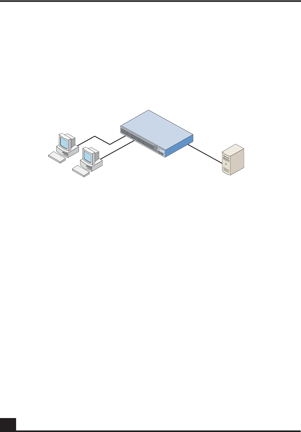
OmniAccess SafeGuard OS Administration Guide
262
Chapter 6: Configuring Authentication and Role Derivation
■Host – This component has many names, it is also referred to as the supplicant,
the client, or the workstation. It is the device that is making the request to the
LAN for switch services.
■Switch – This component is the SafeGuard Switch. The switch controls the
physical access to the network using the authentication status of the host.
■RADIUS server – This component is the remote authentication server.
Figure 6 shows the relationship of these components.
Figure 6 802.1x Components
Communication between components is conducted using extensible authentication
protocol (EAP). EAP messages are encapsulated in another protocol called EAP over
LAN (EAPOL). 802.1X uses EAPOL to start and end the authentication session and pass
EAP messages between the host and switch and from the host to the authentication
server. EAP messages from the switch to an external authentication server use the
RADIUS protocol.
See the following sections for more details:
■Component Requirements
■Impact of Protection Modes on 802.1x
■Configuring IEEE 802.1x Authentication
■Displaying 802.1x Configuration Information
Component Requirements
SafeGuard OS supports the following configurations:
■802.1x supplicants running
—Microsoft Windows XP
—Microsoft Windows CE with Odyssey Software
CST_038b
Hosts or supplicants RADIUS server
SafeGuard Switch
authenticator and
local authentication server

OmniAccess SafeGuard OS Administration Guide 263
Chapter 6: Configuring Authentication and Role Derivation
—Open1x X supplicant for Linux systems
■RADIUS servers
—OpenSource FreeRADIUS
—Juniper Networks Steel-Belted Radius
—Microsoft Internet Authentication Server (IAS) for Windows 2000
—Microsoft IAS for Windows 2003
—Open Systems Consultants Radiator
The SafeGuard Switch supports the following EAP authentication types or methods on
hosts.
Impact of Protection Modes on 802.1x
The SafeGuard Switch can be set for different security levels called protection modes. The
protection level can influence how 802.1x behaves because it can change the forwarding
mode.
■Pass-thru – This mode is the default for the switch. In this mode, the switch
implements 802.1x in accordance to the standard but cannot take advantage of
any of the SafeGuard features, such as security policies or role derivation.
■Monitor – The system monitors for policy visualization based on user-defined
policy controls, however no enforcement actions are taken. In this mode, the
switch uses the Authentication Manager to provide SafeGuard features, such as
session tracking and role derivation for 802.1x authenticated hosts.
■Protect – The system monitors and enforces policies on user-defined and malware
policy controls. In this mode, the switch is able to provide the same services as in
monitor mode for 802.1x authenticated hosts in addition to enforcing policies.
For information on the protection-mode command and on changing the protection mode,
see Changing the Protection Mode of Ports on page 95.
Table 20 Supported EAP Methods
Host Authentication Method Operating
Environment Local
Authentication RADIUS
Authentication
EAP-MD5 – Message Digest 5 Windows and Linux Yes Yes
EAP-TLS – Transport Layer Security Windows and Linux No Yes
EAP-TTLS – Tunneled TLS Linux only No Yes
PEAP – Protected EAP Windows and Linux No Yes

OmniAccess SafeGuard OS Administration Guide
264
Chapter 6: Configuring Authentication and Role Derivation
If you plan to take advantage of the SafeGuard features, in addition to setting the
protection mode you need to control the port authorization state. You set the port’s
authorization state using the aaa dot1x port-control command, which works in either
Global Configuration mode or in Interface Configuration mode. The commands use the
following keywords:
Force Authorized
The port acts as if 802.1x is disabled. Any authorized host connected to the port does not
need to support 802.1x. The Authentication Manager does not receive the credentials for
the host but does receive the port’s traffic because the unauthenticated policy is still
applied.
Instead, the Authentication Manager derives the credentials using passive authentication
(Kerberos, RADIUS), active authentication (Captive Portal, MAC RADIUS, or a white
list), or from mapping information (DHCP, the SafeGuard processor.) When the user
authenticates and a policy and role are applied, the port remains in the authenticated
state even after the user clears the credentials.
Force Unauthorized
The port is blocked and is administratively unauthorized. Traffic is prohibited in all
directions for all clients.
Auto
The port enforced 802.1x authentication for 802.1x clients and grants controlled access to
an authenticated 802.1x client. 802.1x communicates status changes of clients with the
Authentication Manager. The Authentication Manager removes the unauthenticated
policy for 802.1x clients and applies the authentication policy and role after role
derivation.
If the SafeGuard Switch is set in protect or monitor mode, you must also set the 802.1x
port control mode to auto to take advantage of the SafeGuard features and 8021.x port
access control.
Configuring IEEE 802.1x Authentication
The primary process of configuring 802.1x authentication involves preparing for
authentication, enabling 802.1x globally on the switch, specifying the port to use, and
specifying the port control.
NOTE: One 802.1x client (supplicant) is supported on a physical port.
Clients/hosts attempting to access the port are permitted while the port is
authenticated for one 802.1x client. In protect and monitor mode the additional
hosts/clients can be authenticated with SafeGuard authentication features.
The number of hosts permitted on a port can be controlled using port (MAC)
security. Reference to chapter 5, page 156.
OmniAccess SafeGuard OS Administration Guide 265
Chapter 6: Configuring Authentication and Role Derivation
To configure 802.1x authentication:
1Prepare for authentication by configuring the following:
—One or more RADIUS servers for backend authentication. See Configuring
RADIUS Servers on page 252.
—The local user database. See Configuring Rule Maps on page 279.
2Enable 802.1x authentication globally for the switch, as follows:
By default, 802.1x is disabled. When disabled, the 802.1x configuration is retained
and can be changed, but is not activated.
Use the aaa dot1x system-auth-control command in Global Configuration mode
to enable 802.1x. Use the no version of the command to disable the dot1x
authentication support.
aaa dot1x system-auth-control
no aaa dot1x system-auth-control
These commands have no options or parameters.
The following example enables 802.1x globally:
(SafeGuardOS) #configure terminal
(SafeGuardOS) (config) #aaa dot1x system-auth-control
(SafeGuardOS) (config) #exit
(SafeGuardOS) #
3Set the port authorization state either globally or at an interface level.
To Set Globally:
To set the port authorization for the entire switch, use the aaa dot1x port-control
all in Global Configuration mode. Use the no version of the command to reinstate
the switch to the default value.
aaa dot1x port-control all [auto | force-authorized | force-
unauthorized]
NOTE: If you plan to connect the host to a VLAN, complete the VLAN
configuration before setting up 802.1x authentication.
NOTE: This command has a substantial impact on the protection mode of the
switch, see Impact of Protection Modes on 802.1x on page 263 before configuring
these commands.

OmniAccess SafeGuard OS Administration Guide
266
Chapter 6: Configuring Authentication and Role Derivation
no aaa dot1x port-control all
The following example sets the authentication mode to force-unauthorized:
(SafeGuardOS) # configure terminal
(SafeGuardOS) (config) # aaa dot1x port-control all force-unauthorized
(SafeGuardOS) (config) # exit
To Set for an Interface:
Use the aaa dot1x port-control command in Interface Configuration mode to set
the authentication mode for a specific port. Use the no version of the command to
return to the default value of auto.
aaa dot1x port-control [auto | force-authorized | force-
unauthorized]
Syntax Description auto (Default) Specifies that all ports
enforce 802.1x authentication
for 802.1x clients and grants
controlled access to an
authenticated 802.1x client.
802.1x communicates status
changes of clients with the
Authentication Manager.
force-unauthorized Specifies that all ports are
blocked and are
administratively unauthorized.
Traffic is prohibited in all
directions for all clients.
force-authorized Specifies that the ports act as if
802.1x is disabled. Any
authorized host connected to
the port does not need to
support 802.1x. The
Authentication Manager does
not receive the credentials for
the host but does receive the
port’s traffic because the
unauthenticated policy is still
applied. Instead, the
Authentication Manager
derives the credentials using
passive or active
authentication.

OmniAccess SafeGuard OS Administration Guide 267
Chapter 6: Configuring Authentication and Role Derivation
no aaa dot1x port-control
The following example sets the authentication mode to force-authorized on
interface 0/12:
(SafeGuardOS) #configure terminal
(SafeGuardOS) (config) #interface 0/12
(SafeGuardOS) (interface 0/12) #aaa dot1x port-control force-authorized
(SafeGuardOS) (interface 0/12) #
4Initialize the port for auto (dot1x initialize).
5Verify your configuration with the show aaa dot1x command.
Displaying 802.1x Configuration Information
There are Privileged Exec show commands to display 802.1x configuration and 802.1x-
related information. See the following sections:
■Showing a Detailed Configuration
■Showing 802.1x Statistics
Syntax Description auto (Default) Specifies that all ports
enforce 802.1x authentication
for 802.1x clients and grants
controlled access to an
authenticated 802.1x client.
802.1x communicates status
changes of clients with the
Authentication Manager.
force-unauthorized Specifies that all ports are
blocked and are
administratively unauthorized.
Traffic is prohibited in all
directions for all clients.
force-authorized Specifies that the ports act as if
802.1x is disabled. Any
authorized host connected to
the port does not need to
support 802.1x. The
Authentication Manager does
not receive the credentials for
the host but does receive the
port’s traffic because the
unauthenticated policy is still
applied. Instead, the
Authentication Manager
derives the credentials using
passive or active
authentication.

OmniAccess SafeGuard OS Administration Guide
268
Chapter 6: Configuring Authentication and Role Derivation
■Showing Summary Information for 802.1x
Showing a Detailed Configuration
Use the show aaa dot1x detail command to display the all of the 802.1x configuration
information for a specified interface. The comm and has the following syntax:
show aaa dot1x detail slot/port
The following sample output is representative of the output:
(SafeGuardOS) #show aaa dot1x detail 0/22
Port........................................... 0/22
Protocol Version............................... 1
PAE Capabilities............................... Authenticator
Authenticator PAE State........................ Initialize
Backend Authentication State................... Initialize
Quiet Period................................... 60
Transmit Period................................ 30
Supplicant Timeout............................. 30
Server Timeout (secs).......................... 30
Maximum Requests............................... 2
Reauthentication Period........................ 3600
Reauthentication Enabled....................... FALSE
Key Transmission Enabled....................... FALSE
Control Direction.............................. both
(SafeGuardOS) #
The fields in the output represent:
Syntax Description slot/port Displays the 802.1x configuration for this
interface. The slot number is 0.
Display Description
Port Displays the interface number.
Protocol Version Displays the protocol version associated with this port.
The only possible value is 1, which corresponds to the
first version of the 802.1x specification.
PAE Capabilities Displays the port access entity (PAE) functions of this
port. Possible values are Authenticator or Supplicant.

OmniAccess SafeGuard OS Administration Guide 269
Chapter 6: Configuring Authentication and Role Derivation
Authenticator PAE State Displays the current state of the authenticator PAE state
machine. Possible values are:
■Initialize
■Disconnected
■Connecting
■Authenticating
■Authenticated
■Aborting
■Held
■ForceAuthorized
■ForceUnauthorized
Quiet Period Displays the timer used by the authenticator state
machine on this port to define periods of time in
which it does not attempt to acquire a supplicant. The
quiet period range is from 0 to 65535 seconds.
Transmit Period Displays the timer value used by the authenticator
state machine on the specified port to determine
when to send an EAPOL EAP Request/Identity frame to
the supplicant.
The timer range is from 1 to 65535 seconds.
Supplicant Timeout Displays the timer value used by the authenticator
state machine on this port to timeout the supplicant.
The timer range is from 1 to 65535 seconds.
Server Timeout (secs) Displays the timer value used by the authenticator
on this port to timeout the authentication server.
The timer range is from 1 to 65535 seconds.
Maximum Requests Displays the maximum number of times the
authenticator state machine on this port retransmits an
EAPOL EAP Request/Identity before timing out the
supplicant.
The request maximum has the range from 1 to 10.
Reauthentication Period Displays the timer used by the authenticator state
machine on this port to determine when
reauthentication of the supplicant takes place.
The period has the range of 1 to 65535 seconds.
Reauthentication Enabled Displays whether reauthentication is enabled on this
port. Possible values are true or false.
Key Transmission Enabled Displays whether the key is transmitted to the supplicant
for the specified port. Possible values are true or false.
Display Description

OmniAccess SafeGuard OS Administration Guide
270
Chapter 6: Configuring Authentication and Role Derivation
Showing 802.1x Statistics
Use the show aaa 802.1x statistics command to display the statistics for a specified
interface.
show aaa dot1x statistics slot/port
The following example is representative of the command output:
(SafeGuardOS) #show aaa dot1x statistics 0/22
Port........................................... 0/22
EAPOL Frames Received.......................... 0
EAPOL Frames Transmitted....................... 1
EAPOL Start Frames Received.................... 0
EAPOL Logoff Frames Received................... 0
Last EAPOL Frame Version....................... 0
Last EAPOL Frame Source........................ 00:00:00:00:00:00
EAP Response/Id Frames Received................ 0
EAP Response Frames Received................... 0
EAP Request/Id Frames Transmitted.............. 0
EAP Request Frames Transmitted................. 0
Invalid EAPOL Frames Received.................. 0
EAPOL Length Error Frames Received............. 0
(SafeGuardOS) #
The fields in the output represent:
Control Direction Displays the control direction for the specified port. The
control direction is always both directions.
Syntax Description slot/port Displays the 802.1x statistics for this
interface. The slot number is 0.
Display Description
Port Displays the interface number.
EAPOL Frames Received Displays the number of valid EAPOL frames of any
type that are received by this authenticator.
EAPOL Frames Transmitted Displays the number of EAPOL frames of any type
that are transmitted by this authenticator.
EAPOL Start Frames
Received Displays the number of EAPOL start frames of any
type that are received by this authenticator.
Display Description

OmniAccess SafeGuard OS Administration Guide 271
Chapter 6: Configuring Authentication and Role Derivation
Showing Summary Information for 802.1x
Use the show aaa dot1x summary command to display a summary of the global 802.1x
configuration for a specific interface or for all switch interfaces.
show aaa dot1x summary [slot/port | all
This sample output represents output for a single port:
(SafeGuardOS) #show aaa dot1x summary 0/22
Operating Reauthentication
Interface Control Mode Control Mode Enabled Port Status
--------- ------------------ ------------------ ---------------- -------------
0/22 auto auto FALSE Authorized
In this example, the output represents output for all ports.
(SafeGuardOS) #show aaa dot1x summary all
Operating Reauthentication
Interface Control Mode Control Mode Enabled Port Status
--------- ------------------ ------------------ ---------------- -------------
0/1 auto auto FALSE Unauthorized
EAPOL Logoff Frames
Received Displays the number of EAPOL logoff frames of any
type that are received by this authenticator.
Last EAPOL Frame Version Displays the protocol version number carried in the most
recently received EAPOL frame.
Last EAPOL Frame Source Displays the source MAC address carried in the most
recently received EAPOL frame.
EAP Response/ID Frames
Transmitted Displays the number of EAP response/identity frames
transmitted by this authenticator.
EAP Response Frames
Transmitted Displays the number of valid EAP response frames (other
than resp/id frames) received by this authenticator.
Invalid EAPOL Frames
Received Displays the number of EAPOL frames received by
this authenticator in which the frame type is not
recognized.
EAPOL Length Error
Frames Received Displays the number of EAPOL frames received by
this authenticator that had a length error.
slot/port Displays a summary of the 802.1x configuration for this interface. The
slot number is 0.
all Displays a summary of the 802.1x configuration for all interfaces.
Display Description

OmniAccess SafeGuard OS Administration Guide
272
Chapter 6: Configuring Authentication and Role Derivation
0/2 auto auto FALSE Unauthorized
0/3 auto auto FALSE Unauthorized
0/4 auto auto FALSE Unauthorized
0/5 auto auto FALSE Unauthorized
0/6 auto auto FALSE Unauthorized
0/7 force-authorized force-authorized FALSE Authorized
0/8 force-authorized force-authorized TRUE Authorized
0/9 auto auto FALSE Unauthorized
0/10 auto auto FALSE Unauthorized
0/11 auto auto FALSE Unauthorized
0/12 auto auto FALSE Unauthorized
0/13 auto auto FALSE Unauthorized
0/14 auto auto FALSE Unauthorized
0/15 auto auto FALSE Unauthorized
0/16 auto auto FALSE Unauthorized
0/17 auto auto FALSE Unauthorized
0/18 auto auto FALSE Unauthorized
0/19 auto auto FALSE Unauthorized
0/20 auto auto FALSE Unauthorized
0/21 auto auto FALSE Unauthorized
0/22 auto auto FALSE Unauthorized
0/23 auto auto FALSE Unauthorized
0/24 auto auto FALSE Unauthorized
0/25 auto auto FALSE Unauthorized
0/26 auto auto FALSE Unauthorized
0/27 auto auto FALSE Unauthorized
0/28 auto auto FALSE Unauthorized
0/29 auto auto FALSE Unauthorized
0/30 auto auto FALSE Unauthorized
0/31 auto auto FALSE Unauthorized
0/32 auto auto FALSE Unauthorized
0/33 auto auto FALSE Unauthorized
0/34 auto auto FALSE Unauthorized
0/35 auto auto FALSE Unauthorized
0/36 auto auto FALSE Unauthorized
0/37 auto auto FALSE Unauthorized
0/38 auto auto FALSE Unauthorized
0/39 auto auto FALSE Unauthorized
0/40 auto auto FALSE Unauthorized
(SafeGuardOS) #
The fields in the output represent:
Display Description
Interface Displays the interface number.
Control Mode Displays the configured control mode for this port.
Possible values are:
■force-unauthorized
■force-authorized
■auto

OmniAccess SafeGuard OS Administration Guide 273
Chapter 6: Configuring Authentication and Role Derivation
Optional 802.1x Configuration Commands
Optional 802.1x configuration commands are described in the following sections:
■Clearing 802.1x Statistics
■Initializing the 802.1x Port
■Reauthenticating the 802.1x Port
■Configuring the Maximum Authentications for the 802.1x Port
■Re-authenticating the Supplicant for the 802.1x Port
■Configuring the 802.1x Port Timeout
Clearing 802.1x Statistics
Use the clear aaa dot1x statistics command in Privileged Exec mode to reset the 802.1x
statistics for a specified port or for all ports.
clear aaa dot1x statistics {slot/port | all}
The following example is representative of the command:
(SafeGuardOS) #clear aaa dot1x statistics all
Are you sure you want to clear dot1x stats? (y/n)y
(SafeGuardOS) #
Operating Control Mode Displays the control mode under which this port is
operating. Possible values are:
■authorized
■unauthorized
Reauthentication Enabled Displays whether re-authentication is enabled on this
port. Values are either true or false.
Port Status Displays the authorization of the port. Values are
either authorized or unauthorized.
slot/port Port for which to reset statistics. The slot number is 0.
all Clear statistics for all ports.
Display Description

OmniAccess SafeGuard OS Administration Guide
274
Chapter 6: Configuring Authentication and Role Derivation
Initializing the 802.1x Port
Use the aaa dot1x initialize command in Privileged Exec mode to begin the initialization
sequence on the specified port. This command is only valid if the control mode for the
specified port is 'auto'. If the control mode is not 'auto' an error will be returned.
aaa dot1x initialize slot/port
The following example is representative of the command:
(SafeGuardOS) #configure terminal
(SafeGuardOS) (config) #interface 0/5
(SafeGuardOS) (interface 0/5) #aaa dot1x initialize 0/5
(SafeGuardOS) (interface 0/5) #
Reauthenticating the 802.1x Port
User the aaa dot1x re-authenticate command in Privileged Exec mode to begin the re-
authentication sequence on the specified port. This command is only valid if the control
mode for the specified port is 'auto'. If the control mode is not 'auto' an error will be
returned.
aaa dot1x re-authenticate slot/port
The following example is representative of the command:
(SafeGuardOS) #configure terminal
(SafeGuardOS) (config) #interface 0/5
(SafeGuardOS) (interface 0/5) #aaa dot1x re-authenticate 0/5
(SafeGuardOS) (interface 0/5) #
Configuring the Maximum Authentications for the 802.1x Port
Use the aaa dot1x max-req command in interface configuration mode to set the
maximum number of times the authenticator state machine on a port will transmit an
EAPOL EAP Request/Identity frame before timing out the supplicant. Use the no form of
the command to set the maximum number to the default.
aaa dot1x max-req count
slot/port Port on which to begin initialization sequence. The slot number is 0.
slot/port Port on which to begin re-authentication sequence. The slot
number is 0.

OmniAccess SafeGuard OS Administration Guide 275
Chapter 6: Configuring Authentication and Role Derivation
no aaa dot1x max-req
The following example is representative of the command:
(SafeGuardOS) #configure terminal
(SafeGuardOS) (config) #interface 0/5
(SafeGuardOS) (interface 0/5) #aaa dot1x max-req 5
(SafeGuardOS) (interface 0/5) #
Re-authenticating the Supplicant for the 802.1x Port
Use the aaa dot1x re-authentication command in interface configuration mode to enable
re-authentication of the supplicant for the specified port. Use the no form of the
command to disable re-authentication. By default re-authentication is disabled.
aaa dot1x re-authentication
no aaa dot1x re-authentication
The following example is representative of the command:
(SafeGuardOS) #configure terminal
(SafeGuardOS) (config) #interface 0/5
(SafeGuardOS) (interface 0/5) #aaa dot1x re-authentication
(SafeGuardOS) (interface 0/5) #
Configuring the 802.1x Port Timeout
Use the aaa dot1x timeout command in interface configuration mode to set the value, in
seconds, of the timer used by the authenticator state machine on a port. Depending on the
token used and the value (in seconds) passed, various timeout configurable parameters
are set. Use the no form of the command to set the value to its default.
aaa dot1x timeout [reauth-period seconds | quiet-period seconds | tx-period
seconds | supp-timeout seconds | server-timeout seconds]
no aaa dot1x timeout [reauth-period | quiet-period | tx-period | supp-
timeout | server-timeout]
count Maximum number of transmissions. The range is 1 to 10. The default
value is 2.
re-auth period
seconds Sets the value, in seconds, of the timer used by the authenticator
state machine on this port to determine when re-authentication of
the supplicant takes place. The reauthperiod must be a value in the
range 1 - 65535. The default value is 3600.

OmniAccess SafeGuard OS Administration Guide
276
Chapter 6: Configuring Authentication and Role Derivation
The following example is representative of the command:
(SafeGuardOS) #configure terminal
(SafeGuardOS) (config) #interface 0/5
(SafeGuardOS) (interface 0/5) #aaa dot1x timeout reauth-period 3000
(SafeGuardOS) (interface 0/5) #
Role Derivation
As discussed in Authentication Component Process on page 203, after a user authenticates,
he or she is assigned to a user role. There are multiple methods for assigning a role to a
user. One assignment method is to explicitly configure the role using the white list.
Another method is to apply rule maps to groups of users.
Using this method, a role can be defined based on a set of rules called rule maps. A rule
map is a conditional set of statements that we process in a linear order to match the user
attributes. Each rule map contains:
■A precedence value (which is the order that we apply the rule)
■A series of rules
■A name
■A description
■A value to set
■A logical AND or OR operation
quiet-period
seconds Sets the value, in seconds, of the timer used by the authenticator
state machine on this port to define periods of time in which it will
not attempt to acquire a supplicant. The quiet-period must be a
value in the range 0 - 65535. The default value is 60.
tx-period
seconds Sets the value, in seconds, of the timer used by the authenticator
state machine on this port to determine when to send an EAPOL
EAP Request/Identity frame to the supplicant. The tx-period must be
a value in the range 1 - 65535. The default value is 30.
supp-timeout
seconds Sets the value, in seconds, of the timer used by the authenticator
state machine on this port to timeout the supplicant. The supp-
timeout must be a value in the range 1 - 65535. The default value is
30.
server-timeout
seconds Sets the value, in seconds, of the timer used by the authenticator
state machine on this port to timeout the authentication server. The
supp-timeout must be a value in the range 1 - 65535. The default
value is 30.

OmniAccess SafeGuard OS Administration Guide 277
Chapter 6: Configuring Authentication and Role Derivation
Each rule in the rule map is evaluated, in order, against information in the user
authentication event. If the rule map's conditions are met, the rule map is said to match.
When a rule map matches, a role value can be assigned to the user.
The role value can be explicitly specified, or it can be derived based on the value of some
information in the authentication event. For example, an explicitly specified role value
would be where you place a user in group “systems”. The derived method would be to
indicate that the user's role should be equal to the value of the authentication attribute, if
one exists.
Rule maps are applied in order, based on their precedence. A rule map with a lower
precedence is evaluated before a rule map with a higher precedence. After a rule map
matches, the system can either stop evaluating rule maps or continue processing. The
decision to stop or continue processing rule maps is user configurable.
Within a rule map, each individual rule is evaluated in the order it was configured. When
the system determines that the current rule map matches, or cannot match, it stops
processing rules in the current rule map and either assigns the role value (in the case of a
match) or continues processing (in the case of a match failure). Some performance gains
can be obtained with careful ordering of rules and rule maps.
If a rule map specifies the role value as an attribute using the value-of syntax, an error can
occur if the specified attribute does not exist in the authentication attributes. For example,
if the role value was configured to be based on the value of radius.filterId and the user
did not use the RADIUS protocol, an error would occur. In this case, the system acts as if
the rule map failed to match; the system continues to process and evaluates the next rule
map. In addition, the system increments the “Hit Failure” counter to indicate a role-
assignment failure.
The derived role information is passed to the policy component to bind the role to the
network resource permissions. The importance of roles is further discussed in Role
Hierarchy on page 306.
Match conditions are evaluated against information in the login event. This information
is stored in attributes. All attributes are string values that are identified in the system by
an attribute class and an attribute name. The notation for attributes is: class.name. The
attribute class identifies the source of the attribute, such as DHCP, RADIUS, or AD. The
attribute name is the protocol element that is unique to the authentication event.
System attributes are automatically created for each login event based on system
parameters. These parameters are common to all authentication types and protocols. For
example:
Attribute Description
system.userName The name of the user
system.srcIP IP of the user interface
system.authType Protocol used to authenticate

OmniAccess SafeGuard OS Administration Guide
278
Chapter 6: Configuring Authentication and Role Derivation
AD and RADIUS also have attributes that can be used for deriving a role. AD attributes
are queried using LDAP when a user authenticates. For each domain, the SafeGuard
device has one or more domain controllers that it can query. RADIUS attributes are
collected from the sniffed conversation between a NAS and a server. RADIUS attributes
can also be collected from a Captive Portal login when it is implemented in the network.
The system supports both standard RADIUS attributes and Vendor Supported Attributes
(VSAs). In addition, DHCP options obtained when the client machined received it’s IP
address can also be used.
The following are examples of DHCP, AD, and RADIUS attributes:
See the following sections for more details:
■Configuring Rule Maps
■Removing the Rule Map
■Displaying Rule Map Information
system.timeOfDay Time of day when the user authenticated
system.roleName A special attribute, used to assign a role to
the user based on a rule-map match
Attribute Description
ad.department User department. Be sure that the department
attribute on the AD Organization tab matches the
department name you are entering into the
Alcatel-Lucent database.
ad.distinguishedName User’s distinguished name, such as Alcatel-
Lucent.com/Users/Bill Smith
ad.company Employer, such as Alcatel-Lucent
ad.memberOf List of AD groups to which the user belongs
ad.hostOperatingSystem Host operating system where the user is logged in
radius.nasIP IP address of the NAS
radius.calledStation String indicating the network service accessed by
the user
radius.Alcatel-Lucent.roleName Vendor-specific attribute indicating the user role-
name
Attribute Description
OmniAccess SafeGuard OS Administration Guide 279
Chapter 6: Configuring Authentication and Role Derivation
Configuring Rule Maps
To creating a rule map, follow the steps described in the following sections:
1Assigning a Name
2Adding a Description
3Specifying Logical Operators (Optional)
4Configuring the Rule Map Attributes
5Setting the Role
6Continuing or Stopping Assigning Roles
7Applying the Rule Map and Assign a Precedence
Assigning a Name
The name of a rule map is a text string to identify the rule map; the name has no bearing
on the role being assigned. It must be unique within the system. To assign a name to a
rule map, enter rule map submode by using the aaa rule-map command in Global
Configuration mode:
aaa rule-map rulemap_name
The following example creates a rule map called “sales”:
(SafeGuardOS) #configure terminal
(SafeGuardOS) (config) # aaa rule-map sales
(SafeGuardOS) (rulemap) #
To remove a rule map, use the no version of this command.
Adding a Description
This optional step allows you to define a string that describes the entry. Specify the
description in double quotation marks. In rule map submode, use the description
statement using the following syntax:
NOTE: The syntax for creating a rule map is lengthy. Use the syntax described
in this section to define each user, or use the question mark (?) prompt and
allow the CLI to guide the process. By using the prompted method, only the
keyword choices that are applicable at that point in the process are shown. For
ease, the prompted method of entry is recommended.
Syntax Description rulemap_name The name of the rule map being created.

OmniAccess SafeGuard OS Administration Guide
280
Chapter 6: Configuring Authentication and Role Derivation
description string
The following example creates a rule map for the sales department and adds a
description string to it:
(SafeGuardOS) (config) # aaa rule-map sales
(SafeGuardOS) (rulemap) # description “rule map for the sales force”
(SafeGuardOS) (rulemap) #
Specifying Logical Operators (Optional)
Rule maps support the boolean AND and OR logical operators when performing the role
match.
■When the AND operator is specified, a rule map is only evaluated when all of the
conditions are met.
■When the OR operator is specified, a rule map is evaluated when any of the
conditions are met.
The expression is short-circuit evaluated for increased system performance. Use the
following syntax for the operation statement in rule map submode:
operation [AND | OR]
The following example explicitly sets any user from hardware engineering, software
engineering, or quality assurance to the role of “Engineering”. The match statement
requirements are described in Configuring the Rule Map Attributes.
(SafeGuardOS) (config) # aaa rule-map engr
(SafeGuardOS) (rulemap) # description “HW, SW and QA are engineering”
(SafeGuardOS) (rulemap) # operation or
(SafeGuardOS) (rulemap) # match ad.department equals HARDWARE
(SafeGuardOS) (rulemap) # match ad.department equals SOFTWARE
(SafeGuardOS) (rulemap) # match ad.department equals QA
(SafeGuardOS) (rulemap) # set system.roleName “ENGINEERING”
(SafeGuardOS) (rulemap) # end
Syntax Description string Description of the rulemap being
created. Enter the string in double
quotation marks.
Syntax Description AND Specifies that all of the conditions in the
following match statements must be said
to match to set the role.
OR (Default) Specifies that only one of the
conditions in the following match
statements must be said to match to set
the role.
OmniAccess SafeGuard OS Administration Guide 281
Chapter 6: Configuring Authentication and Role Derivation
(SafeGuardOS) (config) #
In this example, the role name is picked up and assigned from the value on the Active
Directory department attribute if the entry is listed on the AD server and the domain
name has “corp” within the name.
(SafeGuardOS) (config) # aaa rule-map others
(SafeGuardOS) (rulemap) # description “the remainder of the company”
(SafeGuardOS) (rulemap) # operation and
(SafeGuardOS) (rulemap) # match ad.department exists
(SafeGuardOS) (rulemap) # match ad.domainName contains corp
(SafeGuardOS) (rulemap) # set system.roleName value-of ad.department
(SafeGuardOS) (rulemap) # end
(SafeGuardOS) (config) #
Configuring the Rule Map Attributes
The match statement describes what constitutes a match against the rule map. All match
attributes are string values that are identified in the system by an attribute class and an
attribute name. The notation for attributes is: class.name.
NOTE: Match statements are not case sensitive.
Table 21 Match Attributes When Creating a Rule
Attribute Area Description
System
Attributes System attributes are common system attributes that are available
for every authentication event.
DHCP
Attributes DHCP attributes are learned from DHCP protocol exchange.
AD Attributes AD attributes are derived from an external LDAP server. Some
attributes contain multiple values, such as ad.memberOf.
Attributes with multiple values are separated by commas.
For more details, see Configuring Active Directory Servers on
page 255.
Note: The Distinguished Name (DN) is presented in AD canonical
format. For example: “cn=John Smith,cn=Users,dc=Auth,dc=dev”
would be translated to “auth.dev/Users/John Smith”.

OmniAccess SafeGuard OS Administration Guide
282
Chapter 6: Configuring Authentication and Role Derivation
RADIUS
Attributes RADIUS attributes are learned from RADIUS protocol exchanges.
The class.name notation in the match statement for standard
RADIUS attributes would translate to:
radius.attrName
For RADIUS vendor-specific extensions (VSAs), this would be
radius.vendor.attrName. For example, NAS-IP would be given
as radius.nasIP, whereas 3 Com Corporation’s User Access
Level attribute would be given as radius.3com.3Com-User-
Access-Level. Alcatel-Lucent Network’s VSA is radius.Alcatel-
Lucent.roleName.
For more details, see Adding VSAs to the Dictionary File on
page 294.
Table 21 Match Attributes When Creating a Rule (continued)
Attribute Area Description

OmniAccess SafeGuard OS Administration Guide 283
Chapter 6: Configuring Authentication and Role Derivation
To match attribute values, use the match command in rulemap mode:
match class.name rule-op value
Syntax Description class.name Attribute name based on the authentication
type. For detailed lists of attributes by class, see
the following references:
■AD attributes; see Table 22 on page 283
■RADIUS attributes; see Table 23 on page 286
■System attributes; see Table 24 on page 288
■DHCP attributes; see Table 25 on page 288
■Text string formats; see Table 26 on page 289
rule-op Each attribute type can support one or more
rule comparator operations depending the
class.name. See the corresponding description
of the attribute to see the supported rule
operations. The comparator operators are
defined as:
■exists – The attribute exists in the
authentication event
■equals – The attribute value matches the
user-supplied rule value
■contains – The attribute value contains the
user-supplied rule value
■contained-by – The attribute is completely
contained by the rule value
■less-than – The numeric value is converted
and compared to see if it is less than the
value in the mapping table
■greater-than – The numeric value is
converted and compared to see if it is more
than the value in the mapping table
■not – Inverts the match criteria
value Value can have one or more items listed as
entries. Multiple entries are listed and separated
by commas. String values are not case sensitive.
Table 22 AD Attributes
Attribute Description
ad.city Match rule baed on value of ad.city. Supported
operations for this attribute are: contains, equals, exists,
not.

OmniAccess SafeGuard OS Administration Guide
284
Chapter 6: Configuring Authentication and Role Derivation
ad.comment Match rule based on value of ad.comment. Supported
operations for this attribute are: contains, equals, exists,
not.
ad.commonName Match rule based on value of ad.commonName.
Supported operations for this attribute are: contains,
equals, exists, not.
ad.company Match rule based on value of ad.company. Supported
operations for this attribute are: contains, equals, exists,
not.
ad.country Match rule based on value of ad.country. Supported
operations for this attribute are: contains, equals, exists,
not.
ad.department Match rule based on value of ad.department.
Supported operations for this attribute are: contains,
equals, exists, not.
ad.description Match rule based on value of ad.description. Supported
operations for this attribute are: contains, equals, exists,
not.
ad.distinguishedName Match rule based on value of ad.distinguishedName.
Supported operations for this attribute are: contains,
equals, exists, not.
ad.emailAddresses Match rule based on value of ad.emailAddresses.
Supported operations for this attribute are: contains,
equals, exists, not.
ad.employeeID Match rule based on value of ad.employeeID.
Supported operations for this attribute are: contains,
equals, exists, not.
ad.hostCommonName Match rule based on value of ad.hostCommonName.
Supported operations for this attribute are: contains,
equals, exists, not.
ad.hostCanonicalName Match rule based on value of ad.hostCanonicalName.
Supported operations for this attribute are: contains,
equals, exists, not.
ad.hostDescription Match rule based on value of ad.hostDescription.
Supported operations for this attribute are: contains,
equals, exists, not.
ad.hostDistinguishedName Match rule based on value of
ad.hostDistinguishedName. Supported operations for this
attribute are: contains, equals, exists, not.
ad.hostDNSHostName Match rule based on value of ad.hostDNSHostName.
Supported operations for this attribute are: contains,
equals, exists, not.
Table 22 AD Attributes (continued)
Attribute Description

OmniAccess SafeGuard OS Administration Guide 285
Chapter 6: Configuring Authentication and Role Derivation
ad.hostMemberOf Match rule based on value of ad.hostMemberOf.
Supported operations for this attribute are: contains,
exists, not.
ad.hostOperatingSystem Match rule based on value of ad.hostOperatingSystem.
Supported operations for this attribute are: contains,
equals, exists, not.
ad.hostOperatingSystemServicePack Match rule based on value of
ad.hostOperatingSystemServicePack. Supported
operations for this attribute are: contains, equals, exists,
not.
ad.hostOperatingSystemVersion Match rule based on value of
ad.hostOperatingSystemVersion. Supported operations
for this attribute are: contains, equals, exists, not.
ad.manager Match rule based on value of ad.manager. Supported
operations for this attribute are: contains, equals, exists,
not.
ad.memberOf Match rule based on value of ad.memberOf. Supported
operations for this attribute are: contains, exists, not.
ad.phoneHome Match rule based on value of ad.phoneHome.
Supported operations for this attribute are: contains,
equals, exists, not.
ad.phoneHomeOther Match rule based on value of ad.phoneHomeOther.
Supported operations for this attribute are: contains,
equals, exists, not.
ad.postalCode Match rule based on value of ad.postalCode. Supported
operations for this attribute are: contains, equals, exists,
not.
ad.state Match rule based on value of ad.state. Supported
operations for this attribute are: contains, equals, exists,
not.
ad.streetAddress Match rule based on value of ad.streetAddress.
Supported operations for this attribute are: contains,
equals, exists, not.
ad.telephoneNumber Match rule based on value of ad.telephoneNumber.
Supported operations for this attribute are: contains,
equals, exists, not.
ad.title Match rule based on value of ad.title. Supported
operations for this attribute are: contains, equals, exists,
not.
ad.userPrincipleName Match rule based on value of ad.userPrincipleName.
Supported operations for this attribute are: contains,
equals, exists, not.
Table 22 AD Attributes (continued)
Attribute Description

OmniAccess SafeGuard OS Administration Guide
286
Chapter 6: Configuring Authentication and Role Derivation
Table 23 RADIUS Attributes
Attribute Description
radius.calledStation Match rule based on the RADIUS Called Station attribute.
Supported operations for this attribute are: contains,
equals, not.
radius.callingStation Match rule based on the RADIUS Calling Station attribute.
Supported operations for this attribute are: contains,
equals, not.
radius.Alcatel-Lucent.roleName Match rule based on the RADIUS Alcatel-Lucent
attribute. Supported operations for this attribute are:
equals, exists, greater-than, less-than, not.
radius.filterId Match rule based on the RADIUS Filter Id attribute.
Supported operations for this attribute are: contains,
equals, not.
radius.loginIP Match rule based on the RADIUS NAS login IP attribute.
Supported operations for this attribute are: contains,
equals, not.
radius.loginService Match rule based on the RADIUS login service attribute.
Supported operations for this attribute are: equals, exists,
greater-than, less-than, not.
radius.loginTCPPort Match rule based on the RADIUS login TCP port attribute.
Supported operations for this attribute are: equals, exists,
greater-than, less-than, not.
radius.nasFramedIP Match rule based on RADIUS NAS Framed IP attribute.
Supported operations for this attribute are: contained-by,
contains, equals, not.
radius.nasFramedNetmask Match rule based on RADIUS NAS Framed Netmask
attribute. Supported operations for this attribute are:
contained-by, contains, equals, not.
radius.nasID Match rule based on RADIUS NAS ID attribute. Supported
operations for this attribute are: contained-by, equals,
exists, not.
radius.nasIP Match rule based on RADIUS NAS IP attribute. Supported
operations for this attribute are: contains, equals, not.
radius.nasPort Match rule based on the RADIUS NAS port attribute.
Supported operations for this attribute are: equals, exists,
greater-than, less-than, not.
radius.nasPortType Match rule based on the RADIUS NAS port type attribute.
Supported operations for this attribute are: equals, exists,
not.

OmniAccess SafeGuard OS Administration Guide 287
Chapter 6: Configuring Authentication and Role Derivation
radius.nasServiceType Match rule based on the RADIUS NAS service type
attribute. Supported operations for this attribute are:
equals, exists, not.
radius.reply Match rule based on RADIUS Reply attribute. Supported
operations for this attribute are: contains, equals, not.
radius.userName Match rule based on RADIUS User Name attribute.
Supported operations for this attribute are: contains,
equals, not.
Table 23 RADIUS Attributes (continued)
Attribute Description

OmniAccess SafeGuard OS Administration Guide
288
Chapter 6: Configuring Authentication and Role Derivation
Table 24 System Attributes
Attribute Description
system.authType Match rule based on authentication type used.
Supported operations for this attribute are: equals, not.
system.domainName Match rule based on value of domain name. Supported
operations for this attribute are: contains, equals, not.
system.mapType Match rule based on mapping type used. Supported
operations for this attribute are: equals, not.
system.portNum Match rule based on user slot/port. Supported operations
for this attribute are: equals, greater-than, less-than, not.
system.roleName The value of the role name, if it is already assigned. This
attribute allows you to chain rule maps together.
Supported operations for this attribute are: contains,
exists, equals, not.
system.srcIP Match rule based on source IP. Supported operations for
this attribute are: contains, equals, not.
system.srcMAC Match rule based on source MAC. Supported operations
for this attribute are: contains, equals, not.
system.timeOfDay Match rule based on current system time. Supported
operations for this attribute are: between, equals,
greater-than, less-than, not.
system.userName Match rule based on the value of the user name.
Supported operations for this attribute are: equals, not.
system.vlanID Match rule based on the value of the user VLAN ID.
Supported operations for this attribute are: equals,
greater-than, less-than, not.
system.matchValue This is a special attribute, available only when assigning a
role value. It it equal to the string form of the last
matched value. By using this attribute in the set
statement, you can assign multiple roles at one time. For
an example of this attribute, see Examples on page 290.
Table 25 DHCP Attributes
Attribute Description
dhcp.netmask Netmask option (1) as returned by the DHCP server.
dhcp.timeOffset Time offset option (2), which is the number of seconds
offset from GMT time in the given location.

OmniAccess SafeGuard OS Administration Guide 289
Chapter 6: Configuring Authentication and Role Derivation
dhcp.hostName Host name option (12), as supplied by the DHCP client.
dhcp.domainName Domain name option (15) as supplied by the DHCP
server.
dhcp.leaseTime Lease time option (51), which is the number of seconds
the IP address lease is good for.
dhcp.serverIP IP address of the granting server, option (54)
dhcp.vendorClass Vendor class option (60), which is a free form text string.
dhcp.userClass User class option (77), which is a free form text string.
Table 26 Text String Formats
Type Format Description
IP address 100.100.100.100 IP addresses are expressed in dotted decimal
notation.
MAC address FF:FF:FF:FF:FF:FF MAC addresses may be specified in any of the
following formats:
■aa:bb:cc:dd:ee:ff
■aabb:ccdd:eeff
■aa-bb-cc-dd-ee-ff
■aabb.ccdd.eeff
■aabbccddeeff
Date Universal Time
Coordinated (UTC) Dates are expressed in UTC format. For example:
Wed Apr 5 19:33:01 PST 2006.
Time HH:MM:SS Timestamp without the date is expressed in hours,
minutes and seconds using a 24 hour clock. The
decimal numbers are separated by colons, for
example: 18:36:45.
List of xx1,x2,x3 A list is expressed as items separated by commas.
Subnet IP address/24 Subnets are expressed in the number of maskbits in
the subnet mask.
MAC Mask MAC address/24 Subnets are expressed in the number of maskbits in
the MAC mask.
Table 25 DHCP Attributes (continued)
Attribute Description

OmniAccess SafeGuard OS Administration Guide
290
Chapter 6: Configuring Authentication and Role Derivation
The following example, defines a rule-map called execStaff and creates two match
statements for that rule-map.
(SafeGuardOS) (config) # aaa rule-map execStaff
(SafeGuardOS) (rulemap) # description “The top brass of the company”
(SafeGuardOS) (rulemap) # match ad.distinguishedName contains “Finance”
(SafeGuardOS) (rulemap) # match ad.distinguishedName contains “Exec”
(SafeGuardOS) (rulemap) # set system.roleName “HIGHPOWER”
(SafeGuardOS) (rulemap) # end
(SafeGuardOS) (config) #
The no form of the statement removes the match statement from the rule map. If you
wanted to remove the only match statement for Finance in the last example, change it as
follows:
(SafeGuardOS) (config) # aaa rule-map execStaff
(SafeGuardOS) (rulemap) # no match ad.distinguishedName contains “Finance”
(SafeGuardOS) (rulemap) # end
(SafeGuardOS) (config) #
After specifying the no statement, it is equivalent to:
(SafeGuardOS) (config) # aaa rule-map execStaff
(SafeGuardOS) (rulemap) # description “The top brass of the company”
(SafeGuardOS) (rulemap) # match ad.distinguishedName contains “Exec”
(SafeGuardOS) (rulemap) # set system.roleName “HIGHPOWER”
(SafeGuardOS) (rulemap) # end
(SafeGuardOS) (config) #
Setting the Role
After defining the matching criteria, you set the role. The role information is sent to the
policy component for enforcement. Use the set system.roleName statement in rule map
submode using this syntax:
set system.roleName (value | value of attribute_name)
Examples
In the following example, we select a role based on membership in a particular group.
Because the value is in a list, we use the contains operation to see if a user is a member of
a particular group before assigning a role.
(SafeGuardOS) (config) # aaa rule-map specialGroups
(SafeGuardOS) (rulemap) # operation or
(SafeGuardOS) (rulemap) # match ad.memberOf contains “specialGroup1”
(SafeGuardOS) (rulemap) # match ad.memberOf contains “specialGroup2”
Syntax Description value A string literal such as “Marketing”.
attribute_name The value of another attribute in the
attribute map, such as the value of
ad.department.

OmniAccess SafeGuard OS Administration Guide 291
Chapter 6: Configuring Authentication and Role Derivation
(SafeGuardOS) (rulemap) # set system.roleName “specialPerson”
(SafeGuardOS) (rulemap) # end
(SafeGuardOS) (config) #
In this next example, the role name is set to any match in the list. Therefore, matches for
Sales are set to sales and matches for Engineering are set to engineering.
(SafeGuardOS) (config) # aaa rule-map alphaGroup
(SafeGuardOS) (rulemap) # operation or
(SafeGuardOS) (rulemap) # match ad.memberOf contains “Engineering”
(SafeGuardOS) (rulemap) # match ad.memberOf contains “Sales”
(SafeGuardOS) (rulemap) # match ad.memberOf contains “Exec”
(SafeGuardOS) (rulemap) # match ad.memberOf contains “FrontOffice”
(SafeGuardOS) (rulemap) # set system.roleName value-of system.matchedValue
(SafeGuardOS) (rulemap) # end
(SafeGuardOS) (config) #
Continuing or Stopping Assigning Roles
Depending on how the rule maps have been structured, either stop assigning roles after
the first successful match or continue to evaluate further. The default action is to stop
evaluating rule maps after the first role assignment. Use the action statement in rule map
submode using this syntax:
action [continue | stop]
Applying the Rule Map and Assign a Precedence
The final step is to apply the rule map. Rule maps are evaluated in precedence order from
lowest number (1) to highest number (65535). It is possible to assign to rule maps to the
same precedence level. In this case, the evaluation order of the rule maps is not
predetermined. Assigning the same precedence level should only be done when the two
rule maps apply to completely distinct groups of people.
Use the aaa rule-map apply command in Global Configuration mode using the following
syntax:
aaa rule-map apply rule_name (precedence number)
Syntax Description continue Specifies to continue processing rule
maps to find more role matches.
stop Specifies to stop processing rule maps.
Syntax Description rule_name Name of the rule map that is being bound.
number Specifies the precedence order for the rule
map. Valid values are 1 through 65535, with 1
being the highest precedence value.

OmniAccess SafeGuard OS Administration Guide
292
Chapter 6: Configuring Authentication and Role Derivation
Building off of the previous example of the two types of user groups, we would want to
assign a higher precedence value to the “highPower” user group over the normal “user”
group.
(SafeGuardOS) (config) # aaa rule-map apply allUsers precedence 2000
(SafeGuardOS) (config) # aaa rule-map apply specialUser precedence 10
(SafeGuardOS) (config) #
Removing the Rule Map
Before removing the rule map, remove the apply for the rule map using the following
command in Global Configuration mode:
no aaa rule-map apply [rulemap_name | all]
The command has no options or parameters.
Next, remove the configured rule map using the no version of the aaa rule-map
command.
no aaa rule-map [rulemap_name | all]
In this example, we are removing the rule map called “specialUsers”.
(SafeGuardOS) (config) # no aaa rule-map apply specialUsers
(SafeGuardOS) (config) # no aaa rule-map specialUsers
(SafeGuardOS) (config) #
Displaying Rule Map Information
There are Privileged Exec show commands to display rule map and rule-related
configurations. See the following sections:
■Showing Rule Map Usage
■Showing a Rule Map Configuration
■Adding VSAs to the Dictionary File
Syntax Description rulemap_name Rule map name in character string
all This will unapply all the currently applied rule
maps.
Syntax Description rulemap_name Rule map name in character string
all This will unapply all the currently applied rule
maps.

OmniAccess SafeGuard OS Administration Guide 293
Chapter 6: Configuring Authentication and Role Derivation
Showing Rule Map Usage
To display the activity level of one or more rule maps, use the show aaa rule-maps
application command in Privileged Exec mode:
show aaa rule-maps application {mapname}
The following example is representative of the command output:
(SafeGuardOS) # show aaa rule-maps application
Precedence Rule Map Name Hit Count Hit Failures
---------- ------------- --------- ------------
9 greyListExample 109 0
12 whiteListExample 112 0
The fields in the output represent:
Showing a Rule Map Configuration
To display the configuration of one or more rule maps, use the show aaa rule-maps
configuration command in Privileged Exec mode:
show aaa rule-maps configuration {mapname}
Syntax Description mapname (Optional) Displays the usage for the specified
rule-map. If you do not specify a rule map
name, all configured rule maps are displayed.
Field Description
Precedence The precedence order for the rule map. Valid values are
1 through 65535, with 1 being the highest precedence
value.
Rule Map Name The name of the rule map.
Hit Count The number of times a rule-map’s condition have
matched causing the role to be assigned.
Hit Failures The number of times a match was made, but the role
couldn’t be assigned.
Syntax Description mapname (Optional) Displays the configuration for the
specified rule-map. If you do not specify a rule
map name, all configured rule maps are
displayed.

OmniAccess SafeGuard OS Administration Guide
294
Chapter 6: Configuring Authentication and Role Derivation
The following example is representative of the command output:
(SafeGuardOS) # show aaa rule-maps configuration j9
aaa rule-map j9
operation or
action stop
match system.userName equals “jjones”
set system.roleName “writer”
(SafeGuardOS) #
Adding VSAs to the Dictionary File
To add the VSA to the VSA dictionary file, use the following syntax:
vendorName vendor-ID stringName VSA-ID type
Syntax
Description vendorName RADIUS vendor name.
vendor-ID A unique ID number for each RADIUS vendor.
stringName A description of the vendor in string format.
VSA-ID A unique ID number for each RADIUS dictionary
entry.

OmniAccess SafeGuard OS Administration Guide 295
Chapter 6: Configuring Authentication and Role Derivation
For example, the following shows the specification of the 3Com Corporations’s User
Access Level attribute:
3com 43 3Com-User-Access-Level 1 integer
The user downloads a VSA file by using the following copy command:
copy tftp:/ip/filename radius-dictionary
After the file completes downloading, the syntax is checked. If there are errors they are
printed to the console and no update action is taken. When the file has successfully
parsed, the file is copied to permanent storage and the box must be rebooted using the
reload command. When the box reboots, the VSAs are added to the CLI and to the
parsing engine.
type Each vendor has a unique 3-byte OUI which is
appended to a one-byte tag to provide a VSA
value. These are conforming attributes. Each
conforming attribute in the system can be of the
following types:
■int – The protocol unit being specified is
converted into a standard 32-bit signed
integer. If fewer than 4 bytes are found in the
PDU the resulting value is sign extended. If
more than 4 bytes are found, the value is
truncated.
■uint – The protocol unit being specified. It is
converted into a standard 32-bit unsigned
integer. The rules are the same as for signed
integers.
■MAC – 6 byte MAC address. MAC addresses
may be specified in any of the following
formats:
aa:bb:cc:dd:ee:ff
aabb:ccdd:eeff
aa-bb-cc-dd-ee-ff
aabb.ccdd.eeff
aabbccddeeff
■IP – 4 byte IP address.
■string – The printable characters in the
protocol unit are copied into a NULL-
terminated character string. The value will be
truncated at the first non-printable character.
Syntax
Description ip The IP address.
filename The filename of the VSA file.

OmniAccess SafeGuard OS Administration Guide
296
Chapter 6: Configuring Authentication and Role Derivation
To remove already configured VSAs, us either write erase or clear aaa radius-dictionary
commands.


OmniAccess SafeGuard OS Administration Guide
298
Chapter 7: Establishing a Security Policy
Policy Concepts
Policy is an important aspect of the SafeGuard OS solution. This chapter discusses the
key concepts of policy, how to develop a policy workflow, and procedures for coding
policy commands.
Policies are the rules that govern access for users and resources. We use policies to
establish the boundaries and enforce a security philosophy for these users and resources.
Policies can be divided into the following categories:
■System white-black list – Is a list of MAC addresses, IP addresses, or VLAN IDs that
are either permitted or denied traffic into the network. Use the system white-
black list to override policy enforcement, visualization, and malware detection. To
configure a system white-black list, see System White-Black List on page 302.
■Malware policies – When SafeGuard OS detects malware on the system, malware
policies specify how the infection is handled. These policies allow you to set how
little or how much access a user or application can have on the network when it is
suspected of being infected.
Malware policies can be set up to block an infected user or application, or allow
the end device to communicate to an IT server or Internet website for automatic
upload of the most recent anti-virus software or operating system patch. When
the attack is specific to a particular application, malware policies allow traffic
from other applications to continue unimpeded. Malware polices are described
further in Detecting and Isolating Malware Security Threats on page 361
■Override policies – Allows you to override a system policy with this special user
policy. Override policies are discussed in Overriding System Policies with a User
Policy on page 323.
■System policies – SafeGuard OS has a set of default policies and roles that are
primarily used by internal routines. These policies are normally not configured by
users. For more information about these policies, see System Generated Policies and
Roles on page 325
■EPV policies – EPV helps ensure that a user’s system and virus software are kept
up-to-date. End point Posture Verification (EPV) is a component of SafeGuard OS
that validates software compliance. EPV policies are the mechanisms that control
whether a user’s machine is scanned (checked) or whether the user is allowed to
bypass the check. EPV policies are discussed in EPV System Policies on page 326.
■User policies – Allow user access to network resources and applications based on
the authentication state of the user. These are policies configured by the user/
administrator to control the network access to his network.
Unlike competitive products that look at the destination L4 port to determine the
application, SafeGuard OS performs deep packet inspection. After performing deep
packet inspection, the SafeGuard OS not only knows the application but knows
what the user is trying to accomplish with the application. With this information

OmniAccess SafeGuard OS Administration Guide 299
Chapter 7: Establishing a Security Policy
the system can enforce access control based on the what the user is doing with the
application and extend enforcement from Layer 3 through Layer 7. User policies
are discussed in User Policies on page 305.
Traffic Flow
Unlike competitive products, SafeGuard devices are not packet-based nor do they use
packet-based control mechanisms. Instead, the system initiates policy enforcement on
TCP connections or groupings of UDP packets. These connections are called flows.
The upper physical ports of the SafeGuard devices are called the network side of the device
and the lower physical ports the host side. In the default policy configuration, we express
a policy from the host side perspective but it is applied to traffic in both directions. This
bidirectional behavior is unlike traditional Access Control Lists (ACLs), which require
explicit command level configuration for each direction. This physical distribution for
user and network ports is only for controllers. In a switch/user network it is just a logical
concept and its use is more as originator and destination.
However, there might be an occasion when you want to control a flow from the network
side of the device. This change of direction can be configured using the flow-in and flow-
out keywords on the policy filter. These keywords are described in Configuring the Rules
on page 316.
Figure 7 Flow Direction
Policy Enforcement
The order in which a policy is enforced depends on two factors:
CST_026b
Flow-out
Flow-in
Host Side Network Side

OmniAccess SafeGuard OS Administration Guide
300
Chapter 7: Establishing a Security Policy
1The ranking of the type of policy
2The precedence of the policy within a policy type
Policies have an internal ranking system that stacks the policies in the order shown in
Figure 8. This ranking is done by SafeGuard OS and cannot be overridden by users.
Figure 8 Order of Policy Enforcement
Precedence
Malware and user policies allow you to assign a precedence number to rules and policies.
These precedence numbers for policies are secondary to the overall ranking of the
policies; the precedence numbers for rules are tertiary (nested within a policy).
Filter Precedence
Because a policy can have many rules, a precedence number can be assigned to the filter
statements of a rule. The precedence of a filter will determine the order in which the rule
is applied for a specific user. Precedence numbers can be in the range of 1 to 65535, where
1 has the highest precedence and 65535 the lowest.
If you do not specify a precedence number on a filter, SafeGuard OS assigns a precedence
number for you (auto-precedence). The system assigns the precedence in the sequential
order the filters are configured. If you already have precedence numbers assigned on
other filter statements in the policy, SafeGuard OS adds 10 to the highest number and
assigns it to the rule. If you do not have any precedence numbers on the rules within a
policy, SafeGuard OS begins assigning precedence numbers beginning with 10 and
adding in increments of 10.
CST_057
enforcement White-Black List
Malware Policies
Override Policies
System Policies
EPV Policies
User Policies

OmniAccess SafeGuard OS Administration Guide 301
Chapter 7: Establishing a Security Policy
Policy Precedence
Multiple user policies can be assigned to a role. When a user policy is applied to a role, it
too can have a precedence. Precedence numbers can be in the range of 1 to 65535, where 1
has the highest precedence and 65535 the lowest. Policy precedence comes before rule
precedence. Figure 9 shows an example of policy precedence.
Figure 9 Policy and Filter Precedence
Designing a Policy Workflow
A policy workflow is simply an approach to planning, organizing, and implementing a
policy management strategy. Before configuring your rules, roles and policies, it is
helpful to do some ground work.
1Determine your corporate philosophy to security.
There are two schools of thought on how to execute a policy system. One method
creates a wall where all users are initially denied access. You then punch holes, or
exceptions into the wall. The other method is to allow everything through and
then to block specific network resources and applications.
SafeGuard OS is best suited for the later approach, as it optimizes the number of
rules required to enforce a specific access policy. The default condition for
SafeGuard OS is to assume that everyone and everything can go through.
Table 27 Policy Precedence Ranges within a Role
Policy Type Precedence range
Malware policies 0
Override user policies 1–9
System policies Starts with 10 and increments by 10
EPV-System policies Not Applicable
User policies User Defined
CST_058
user role technician
Policy A is applied before policy B.
Filter precedence is applied after
policy precedence.
policy A precedence 110
policy B precedence 210
filter f1 precedence 2100
filter f1 precedence 1100

OmniAccess SafeGuard OS Administration Guide
302
Chapter 7: Establishing a Security Policy
2Using your existing corporate security plan and documents for organizing your
role hierarchy, organize your users, servers, and other resources into logical
groups.
As mentioned before, users are organized by role. Resources can also be
organized into network zones, which are collections of nodes and network
segments.
A network zone is an easy way to take all of the resources for a group and naming
that entity. For example, define a network zone for the servers for the Finance
organization or for the resources that will be unauthenticated users.
3Determine what applications and what files you want to monitor or block.
4Define the list of permissions (rules) based on the access criteria.
5Order the filters within each role by precedence.
System White-Black List
SafeGuard OS allows designating specific MAC address, VLAN, or IP address (TCP,
UDP, or ICMP) as white/black listed addresses.
In addition to permitting or denying access to the network, a system white-black list
disables the following features for specified entries:
■Malware detection
■Policy
■Visualization
Adding a System White-Black List Entry
To configure a system white-black list:
1Use the Global Configuration command, system white-black list, to enter the
whiteblack-list submode. This command does not have any options or
parameters.

OmniAccess SafeGuard OS Administration Guide 303
Chapter 7: Establishing a Security Policy
2Specify one or more MAC addresses, VLAN, or IP addresses (TCP, UDP, or ICMP)
to add using the command:
system white-black list [mac mac_addr mask | vlan vlan | IP address]
[deny|permit] {description string}
The following example adds MAC address 11:22:33:44:55:66 to the white list, or
those addresses permitted into the network.
(SafeGuardOS) #configure terminal
(SafeGuardOS) (config) #system white-black list
(SafeGuardOS) (whiteblack-list) #mac 11:22:33:44:55:66 ff:ff:ff:ff:ff:ff
permit description “printer”
(SafeGuardOS) (whiteblack-list) #
To put the MAC address on the black list, specify the deny option:
(SafeGuardOS) #configure terminal
(SafeGuardOS) (config) #system white-black list
(SafeGuardOS) (whiteblack-list) #mac 11:22:33:44:55:66 ff:ff:ff:ff:ff:ff
deny description “printer”
(SafeGuardOS) (whiteblack-list) #
Prioritizing List Entries
System white-black list entries are processed from the top to the bottom of the list. Items
found first in the list have priority over items lower on the list.
For example, take the following scenario. An administrator has 100 IP phones and want
to create a single system MAC entry with a MAC mask to deny access for all of the
Syntax Description mac_addr MAC address that overrides policy. The
MAC address can either be the source or
destination address; it is independent of
direction. MAC addresses may be
specified in any of the following formats:
■aa:bb:cc:dd:ee:ff
■aabb:ccdd:eeff
■aa-bb-cc-dd-ee-ff
■aabb.ccdd.eeff
■aabbccddeeff
mask Specifies a MAC mask in dotted-quad
notation. For example, ff:ff:ff:ff:ff:ff
deny Denies access to the MAC address.
permit Permits access to the MAC address.
string (Optional) A string that describes the entry.
Specify strings in double quotation marks.

OmniAccess SafeGuard OS Administration Guide
304
Chapter 7: Establishing a Security Policy
phones. However, she wants an exception for one IP phone to be permitted. The order of
the entries becomes important.
Example 1, (incorrect):
(SafeGuardOS) #configure terminal
(SafeGuardOS) (config) #system white-black list
(SafeGuardOS) (whiteblack-list) #mac 1a:2b:3c:00:00:00 ff:ff:ff:00:00:00 deny
description “IP phones”
(SafeGuardOS) (whiteblack-list) #mac 1a:2b:3c:aa:bb:cc ff:ff:ff:ff:ff:ff permit
description “My IP phone”
Example 2, (correct):
(SafeGuardOS) #configure terminal
(SafeGuardOS) (config) #system white-black list
(SafeGuardOS) (whiteblack-list) #mac 1a:2b:3c:aa:bb:cc ff:ff:ff:ff:ff:ff permit
description “My IP phone”
(SafeGuardOS) (whiteblack-list) #mac 1a:2b:3c:00:00:00 ff:ff:ff:00:00:00 deny
description “IP phones”
(SafeGuardOS) (whiteblack-list) #exit
(SafeGuardOS) (config) #exit
(SafeGuardOS) #
Example 2 has the correct configuration because the more specific MAC address/mask
overrides the following deny statement. In example 1 is incorrect because even though
the second statement is more specific, the deny statement has already set all phones to
deny.
Removing an Entry
To remove an entry from the system white-black list, use the no version of the command:
no mac mac_addr mask
The no version of the command removes the MAC address from the system white-black
list. This example removes a printer from the system white-black list:
(SafeGuardOS) #configure terminal
(SafeGuardOS) (config) #system white-black list
(SafeGuardOS) (whiteblack-list) #no mac 11:22:33:44:55:66 ff:ff:ff:ff:ff:ff
(SafeGuardOS) (whiteblack-list) #exit
(SafeGuardOS) (config) #exit
(SafeGuardOS) #
Use the show system white-black list command to see the contents of the list. This
command is further discussed in Showing System White-Black List on page 333.
Syntax Description mask Specifies a subnet mask in dotted-quad notation.
For example, ff:ff:ff:ff:ff:ff.

OmniAccess SafeGuard OS Administration Guide 305
Chapter 7: Establishing a Security Policy
User Policies
User policies allow the control of user access to network resources. When a user logs on
to the network, the host starts authentication. It provides the user name and password
information to the authentication server, such as Microsoft AD or Kerberos.
The SafeGuard device notes the machine’s IP address, the user name and that it is in the
process of authenticating. When the authentication server sends back the response,
SafeGuard OS intercepts that information, which includes:
■User name
■Password credentials
■IP address
■MAC address
■Authentication state
■User role
The system matches the IP address and notes whether the user is authenticated or
unauthenticated. Using a set of configured role mapping rules and information
intercepted from the authentication server, a user role is derived for the user. The system
uses the role and the configured role mapping rules. Using a role hierarchical system, it
applies all of the policies or rules for that particular user based on the user role. A user
role is a designation for the user, for example, a job classification such as a software
engineer. If the role derived by applying the rule map is not configured in the system, The
user assumes the default 'authenticated' role.
Each policy is comprised of multiple rules, which is the how we match the traffic. A rule
has two parts: a filter and an action. When a filter condition is true, its action might be to
allow access or deny access to a resource. For example, all software engineers might be
allowed to use instant messaging (IM) but are not allowed to access any of the Human
Resources or Finance servers. Figure 10, shows the relationship between policies, roles,
and rules.
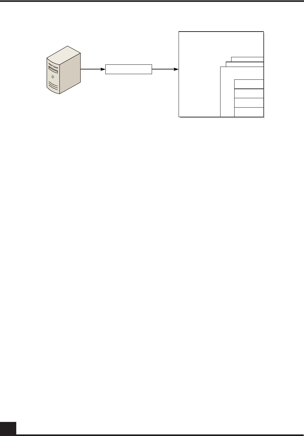
OmniAccess SafeGuard OS Administration Guide
306
Chapter 7: Establishing a Security Policy
Figure 10 Policies, Rules, and Roles
Therefore, when you enforce a policy you are applying a set of rules against a user role.
Role Hierarchy
Each role has a different set of privileges. Any user-defined role, by default, has the
authenticated role as the parent. A role can be designated as a child of other roles, except
for the authenticated and unauthenticated roles. If a role hierarchy is not established,
then duplicate policies would need to be duplicated throughout each role. A child role
can only have one parent role.
SafeGuard OS provides two default system roles:
■authenticated
■unauthenticated.
Any user who is unauthenticated is assigned the unauthenticated role. Any policies
defined for that role are assigned to all users having that role.
Policies are applied from the bottom of the hierarchy to the top of the hierarchy. In other
words, applied from the most specific to the least specific role. Figure 11 shows a simple
role hierarchy.
CST_059
Authentication
server
SLC
Matches the role to a set
of policies
User: Pat Lee
Role: Software Engineer
Password Credentials
Authenticated
Software
Engineer
role information
Rule n
Rule 3
Rule 2
Rule 1
Policies
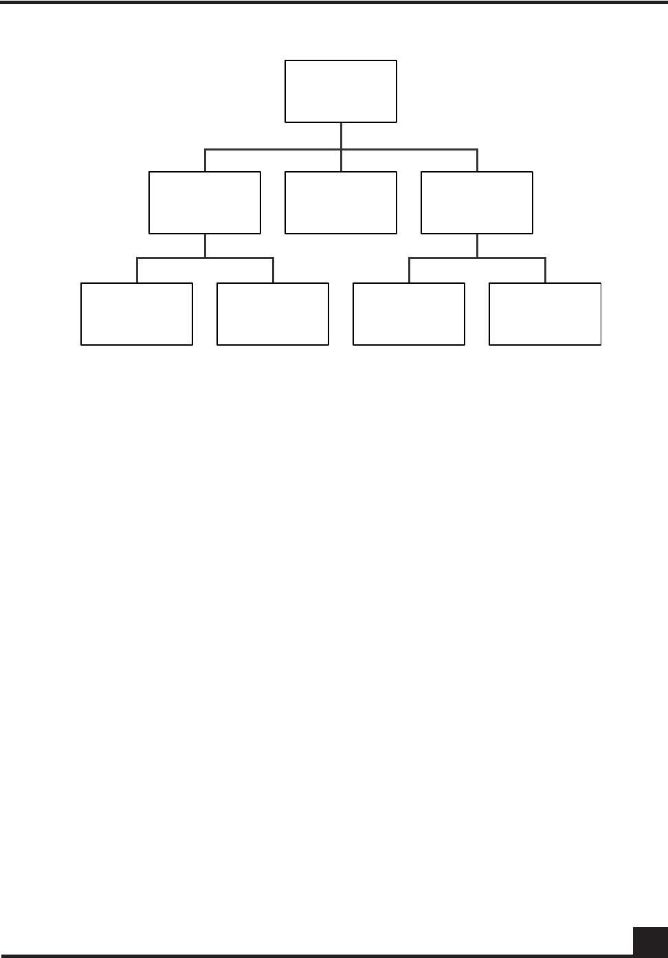
OmniAccess SafeGuard OS Administration Guide 307
Chapter 7: Establishing a Security Policy
Figure 11 Role Hierarchy
Layer 7 Policies
A unique feature of SafeGuard OS is the ability to enforce policies at the Application
Layer. A Layer 7 policy is a type of user policy. By defining an application group, you
could restrict a vendor or contractor from using an application such as FTP. Application
traffic can be refined in the policy to permit or deny a certain filetypes.
An application filter is even further refinement of an application group. It blocks the
application based upon some action that the user performs. For example, suppose that a
vendor is allowed to use FTP, unless they attempt to upload any document that has the
string ‘payroll’ in the filename.
Visualization
The internal analysis of what the user is doing with an application is called Visualization.
Without Visualization, administrators cannot tell what users are doing in the network. To
control what is sent to OmniVista SafeGuard Manager when there is a policy violation or
to monitor statistics by indicating the log option in the filter action, deep packet
inspection and Visualization are integral to performing Layer 7 policies.
Configuring User Policies
Policy offers an enormous variety of configuration possibilities. This section describes the
coding and syntax for the basic policy commands and gives you guidance on the many
options available.
CST_061
Hardware Software Asia-Pac US
Engineering Marketing
Authenticated Least specific
Finance
Most specific

OmniAccess SafeGuard OS Administration Guide
308
Chapter 7: Establishing a Security Policy
Policy Made Simple
For those who are new to configuring policies, start with some simple, yet powerful
policy statements. For example:
■Network Zone – Is a collection of nodes and network segments?
■Application Group – Is a method of permitting or denying a group of applications?
■Application Filters – Is a further refinement of application group?
Network Zone
An easy way to define a collection of nodes or network segments is to create a network
zone. The order of the entries is not significant. By defining the network into zones, uses
can later be filtered based upon their zone. A zone is a useful way to designate a physical
topology or a building configuration.
1Name the zone using the network-zone Global Configuration command. To
remove a zone, use the no form of the command. The syntax of the commands is:
network-zone zone_name
no network-zone zone_name
The following example defines a network zone for all the servers in a topology.
(SafeGuardOS) #configure terminal
(SafeGuardOS) (config) #network-zone finance_servers
(SafeGuardOS) (network_zone) #
The network-zone command places you in network_zone mode.
2Define the zone by host, IP address, or a range of IP addresses.
—Host – By IP or MAC address
host [ip-address addr | mac-address addr]
The following example specifies the finance_servers zone as host address
192.168.0.2:
(SafeGuardOS) (config) # network-zone finance_servers
(SafeGuardOS) (network_zone) # host ip-address 192.168.0.2
(SafeGuardOS) (network_zone) #
Syntax Description zone_name Name of the zone
Syntax Description addr IP or MAC address of the host

OmniAccess SafeGuard OS Administration Guide 309
Chapter 7: Establishing a Security Policy
—Network – By a subnet
network ipaddr mask
This example specifies the finance_servers zone by subnet:
(SafeGuardOS) (config) # network-zone finance_servers
(SafeGuardOS) (network_zone) # network 192.168.0.0 255.255.252.0
(SafeGuardOS) (network_zone)#
—Range – By IP range
range starting_addr ending_address
This example specifies the finance_servers zone by an IP range:
(SafeGuardOS) (config) # network-zone finance_servers
(SafeGuardOS) (network_zone) # network 192.168.0.2 192.168.0.56
(SafeGuardOS) (network_zone) #
For additional examples of network zones, see Network Zones Example on page 321.
3To remove an existing configuration use the no version of the command.
no host [ip-address addr|mac-address addr]| network [ipaddr|mask]
| range starting_addr ending_address
This example removes the previously configured subnet configuration:
(SafeGuardOS) (config) # network-zone billing
(SafeGuardOS) (network_zone) # no network 192.168.0.0 255.255.252.0
(SafeGuardOS) (network_zone) #
The following example defines a network zone for telnet called netzoneTelnet, that
contains four IP addresses:
(SafeGuardOS) #configure terminal
(SafeGuardOS) (config) # network-zone netzoneTelnet
(SafeGuardOS) (network-zone) # host ip-address 192.168.4.7
(SafeGuardOS) (network-zone) # host ip-address 192.168.4.24
(SafeGuardOS) (network-zone) # host ip-address 192.168.5.10
(SafeGuardOS) (network-zone) # host ip-address 192.168.5.26
(SafeGuardOS) (network-zone) # end
(SafeGuardOS) #
Syntax Description ipaddr An IP address.
mask A subnet mask in dotted-quad notation.
For example, 255.255.255.255.
Syntax Description starting_addr Start the range at this IP address
ending_address End the range at this IP address

OmniAccess SafeGuard OS Administration Guide
310
Chapter 7: Establishing a Security Policy
For an additional example of network zones, see Network Zones Example on page 321.
Application Group
Application groups are collections of application protocols used to filter Layer 7
applications in rules. Either define custom application groups or use one of the
predefined supplied groups:
■application-group IM
—application AOLIM
—application MSNIM
—application YAHOOIM
■application-group NetworkConnectivity
—application CIFS
—application FTP
—application SSH
—application TELNET
■application-group P2P
—application WINNY
■application-group Web
—application ALT-HTTP
—application HTTP
To create or delete a custom application group, use the application-group Global
Configuration command:
application-group group_name
This example create a custom IM group called verbotenIM:
(SafeGuardOS) #configure terminal
(SafeGuardOS) (config) #application-group verbotenIM
(SafeGuardOS) (app-group) #
The application-group command places you in app-group mode. In this mode, define the
custom group using any combination of application protocol found in the default groups.
application application_name
This example adds three application protocols to verbotenIM:
(SafeGuardOS) (config) # application-group verbotenIM
(SafeGuardOS) (app-group) # application AOLIM

OmniAccess SafeGuard OS Administration Guide 311
Chapter 7: Establishing a Security Policy
(SafeGuardOS) (app-group) # application MSMIM
(SafeGuardOS) (app-group) # application YAHOOIM
(SafeGuardOS) (app-group) #
The no version of the command removes an application from an existing group. For
example, this statement removes AOLIM from verbotemIM:
(SafeGuardOS) (app-group) # no application AOLIM
(SafeGuardOS) (app-group) #
For an additional example of application groups, see Application Groups Example on
page 322.
Application Filters
Application filters are a special type of user policies that allow you to filter Layer 7
applications against a user. To be able to filter by user and application, you must first
define the user policy. For example, the file name in an FTP transfer can be matched
against in a policy. The supported applications are FTP, HTTP and CIFS.
See the following sections for more details:
■Creating FTP Application Filters
■Creating HTTP Application Filters
■Creating CIFS Application Filters
Creating FTP Application Filters
To create an application filter for an FTP application:
1Enter app-filter submode by using the application-filter command in Global
Configuration mode:
application-filter filter_name
2(Optional) Specify a boolean logical operator that the filter is to use:
{operation [OR]}
Syntax
Description filter_name The name of the application filter
being created.
Note: Filter names are case sensitive.
Syntax
Description OR Logical OR operator.

OmniAccess SafeGuard OS Administration Guide
312
Chapter 7: Establishing a Security Policy
3Specify the filter conditions:
FTP [FileName|UserName]
[{contains string}|{does-not-contain string}|
{does-not-end-with string}|
{does-not-match string}|
{does-not-start-with string}|
{ends-with string}|
{matches string}|
{starts-with string}]
Creating HTTP Application Filters
Ed. Note:
The syntax for an application filter for an HTTP application is slightly different than the
an application filter for FTP.
To create an application filter for an HTTP application:
1Enter app-filter submode by using the application-filter command in Global
Configuration mode:
application-filter filter_name
2(Optional) Specify a boolean logical operator that the filter is to use:
{operation [OR]}
Syntax Description string A value to be matched against.
Syntax
Description filter_name The name of the application filter
being created.
Syntax
Description OR Logical OR operator.

OmniAccess SafeGuard OS Administration Guide 313
Chapter 7: Establishing a Security Policy
3Specify the filter conditions:
HTTP [Host
[{contains string}|{does-not-contain string}|
{does-not-end-with string}|
{does-not-match string}|
{does-not-start-with string}|
{ends-with string}|
{matches string}|
{starts-with string}]|
UserAgent [contains string | does-not-contain string]|
ContentType [contains string]]
Following is an example of an HTTP application filter user policy using a logical OR
operation:
(SafeGuardOS) #configure terminal
(SafeGuardOS) (config) #policy application-filter "afAppleMarketing"
(SafeGuardOS) (app-filter) #operation OR
(SafeGuardOS) (app-filter) #HTTP ContentType contains "application/x-javascript"
(SafeGuardOS) (app-filter) #HTTP Host contains "www.google.com"
(SafeGuardOS) (app-filter) #HTTP Host does-not-contain "www.google.com"
(SafeGuardOS) (app-filter) #HTTP Host does-not-end-with ".google.com"
(SafeGuardOS) (app-filter) #HTTP Host does-not-match "www.google.com"
(SafeGuardOS) (app-filter) #HTTP Host does-not-start-with "www.google."
(SafeGuardOS) (app-filter) #HTTP Host ends-with ".google.com"
(SafeGuardOS) (app-filter) #HTTP UserAgent contains "Mozilla/5.0"
(SafeGuardOS) (app-filter) #HTTP UserAgent does-not-contain "/5.0"
(SafeGuardOS) (app-filter) #exit
(SafeGuardOS) (config) #exit
(SafeGuardOS) #
To display application filters, use the show policy application-filter command, as
discussed in Showing Application Filters on page 327.
Creating CIFS Application Filters
To create an application filter for a CIFS application:
1Enter app-filter submode by using the application-filter command in Global
Configuration mode:
application-filter filter_name
2(Optional) Specify a boolean logical operator that the filter is to use:
Syntax Description string A value to be matched against.
Syntax
Description filter_name The name of the application filter
being created.

OmniAccess SafeGuard OS Administration Guide
314
Chapter 7: Establishing a Security Policy
{operation [OR]}
CIFS [UserName
[{contains string}|{does-not-contain string}|
{does-not-end-with string}|
{does-not-match string}|
{does-not-start-with string}|
{ends-with string}|
{matches string}|
{starts-with string}]|
FileName contains string]
For example,
(SafeGuardOS) #configure terminal
(SafeGuardOS) (config) #application-filter "test1"
(SafeGuardOS) (config) #CIFS FileName contains "test.exe"
(SafeGuardOS) (config) #application-filter "test2"
(SafeGuardOS) (config) #CIFS UserName contains "marisa"
(SafeGuardOS) (config) #exit
(SafeGuardOS) #
Defining and Applying User Policies
A policy is a set of rules that define a set of permissions for the user. For each policy you
create:
1Assigning the Policy a Name on page 315
2Adding a Description on page 315
3Adding a Severity on page 315
4Adding a Category on page 316
5Configuring the Rules on page 316
6Configuring the Roles on page 319
Syntax
Description OR Logical OR operator.
Syntax Description string A value to be matched against.

OmniAccess SafeGuard OS Administration Guide 315
Chapter 7: Establishing a Security Policy
Assigning the Policy a Name
To define a user policy, begin by assigning a name to a policy using the Global
Configuration command:
policy user name
For example, the following statement defines a policy for the Finance group called
finance_policy.
(SafeGuardOS) (config) # policy user finance_policy
(SafeGuardOS) (policy-user) #
After defining the policy name, the system goes into user policy mode.
To display the contents of a user policy, use the show policy user command. This
command is discussed further in Showing Policy User on page 332.
Adding a Description
An optional description of the user policy can be added in double quotation marks with
the following command:
description string
Building on our previous example, a description might be:
(SafeGuardOS) (config) # policy user finance_policy
(SafeGuardOS) (policy-user) # description “Policy for finance users and
resources”
(SafeGuardOS) (policy-user) #
Adding a Severity
If you specify a severity, it dictates the color that the message displays in OmniVista
SafeGuard Manager. Add an optional severity of the user policy with the severity
command:
severity [critical | info | major | minor]
Syntax Description name A name that identifies the policy.
Syntax Description string A description of the policy. Place the string
within double quotation marks.
Syntax Description critical Indicates a critical severity and the message
displays in red.

OmniAccess SafeGuard OS Administration Guide
316
Chapter 7: Establishing a Security Policy
The following example assigns the policy, sw_engineering_policy, as a major severity:
(SafeGuardOS) (config) # policy user sw_engineering_policy
(SafeGuardOS) (policy-user) # severity major
(SafeGuardOS) (policy-user) #
The severity of the policy does not influence the order in which policy is assigned. The
order is specified by precedence number.
Adding a Category
A policy can be optionally designated in a certain category as a method of controlling
applications or of controlling resources. If the log option is specified in rules, this
information displays in OmniVista SafeGuard Manager. Add this optional parameter
using the following command:
category [ApplicationControl | ResourceAccess | string]
The following example assigns the policy, testbed_policy, as being under resource
control:
(SafeGuardOS) (config) # policy user testbed_policy
(SafeGuardOS) (policy-user) # category ResourceAccess
(SafeGuardOS) (policy-user) #
Configuring the Rules
For each rule we need to define a filter and an action to execute. The overall syntax of a
policy filter is:
info Indicates an informational severity and the message
displays in white.
major Indicates a major severity and the message displays
in orange.
minor Indicates a minor severity and the message displays
in yellow.
Syntax Description ApplicationControl Indicates that the policy is being used to
control applications.
ResourceAccess Indicates that the policy is being used to
control resources.
string Indicates a custom use of the policy.

OmniAccess SafeGuard OS Administration Guide 317
Chapter 7: Establishing a Security Policy
filter name {direction} from source to destination protocol action
{[mirror] [log] [precedence number]}
Syntax Description name Name of the user filter.
direction Specifies the direction that a flow is initiated.
Direction can be any of the following:
■flow-in – apply to flows initiated from the
host-side of the SafeGuard device
■flow-out – apply to flows initiated from the
network-side of the device
■(Default) blank, which applies to flows in
either direction
source Specifies the source endpoint of the traffic. It
can be any of the following:
■any – Wildcard, which matches all source
■host – L3 IP address of the host
■macmask – L2 MAC mask of the host
■network – L3 IP address of the subnet
■network-zone – L3 address (MAC address, IP
address, network address, or address range)
■port – L1 physical source port
■range – L3 IP address range
■role – User role
■username – User name
■NOT – Negates the from criteria, except for
‘any’
Note: Filters using role or username are not
supported for unauthenticated user role. Also
these filters do not take effect if the policy
applied to a role of a user does not match.
destination Specifies the destination endpoint of the traffic.
It can be any of the following:
■any – Wildcard, which matches all
destination.
■host – L3 IP address of the host
■network – L3 IP address of the subnet
■network-zone – L3 address (MAC address, IP
address, network address, or address range)
■range – L3 IP address range
■NOT – Negates the from criteria, except for
‘any’

OmniAccess SafeGuard OS Administration Guide
318
Chapter 7: Establishing a Security Policy
protocol Matches the IP protocol of the traffic. It can be
any of the following:
■any – Wildcard, which matches TCP or UDP
protocols and application
■application-filter – L7+ rule
Configuring application filters is discussed
separately. For more details, see Application
Filters on page 311.
■application-group – L7 application
Configuring application groups is discussed
separately. For more details, see Application
Group on page 310.
■tcp – TCP; specify protocol port number and
the port operation:
1 to 65535 – End port or the start of the end
port
GE – Greater than or equal to
NE – Not equal to
LE – Less than or equal to
range – Destination TCP port range
out-of-range – Out of the destination TCP port
range
■udp – UDP; specify protocol port number and
the port operation:
1 to 65535 – End port or the start of the end
port
GE – Greater than or equal to
NE – Not equal to
LE – Less than or equal to
range – Destination UDP port range
out-of-range – Out of the destination UDP
port range
■AND logical operator. Make a UDP or TCP
protocol condition more specific by using the
AND logical operator with an L7 application
filter to application group. For example,
specify ‘tcp 80 AND application-group web’
to define that the traffic is web and that it
only runs on TCP port 80.

OmniAccess SafeGuard OS Administration Guide 319
Chapter 7: Establishing a Security Policy
Configuring the Roles
Two system roles, authenticated and unauthenticated, are created by default for you. All
user-defined roles are assumed to be children of the authenticated role, unless the new
role is designated to be a child of another role.
Although configure roles can be configured in any order, it is usually easiest to configure
roles from the least specific to the most specific. For example, Figure 11 on page 307, shows
a simple role hierarchy. In this example, perhaps you would start configuring a role for
the Engineering role, and continue down the tree towards Hardware Engineer and
Software Engineer roles.
After binding all the required user policies to the role, issue a “refresh policy role blah”
command to refresh the policies applied to the role blah. Likewise, unbinding the policy
from a user role will also be effective only after refresh is done.
Some rules for configuring roles are:
■Each user role can have up to eight policies bound to it.
■The chain within a role hierarchy cannot be cyclical.
■The default role of unauthenticated cannot be a parent of other user configured
roles.
■Default roles cannot be deleted.
For more details on system roles, see System Generated Policies and Roles on page 325.
action Specifies the action to be taken if the traffic
matches the preceding patterns. When log is
specified, it is sent to OmniVista SafeGuard
Manager as part of Visualization. Action can be
any of the following:
■action deny – drop the packet
■action deny RESET – drop the packet and
reset the denied TCP connection (L7 only)
■action permit – permit the packet
mirror Mirror the flow. For more details, see Configuring
Policy-Based Mirroring on page 323.
log Log the event to OmniVista SafeGuard
Manager.
precedence
number
Each policy filter has an associated
precedence, which sorts the filters with in the
policy. The precedences have a valid range of
1(highest) to 65535 (lowest). If a precedence
number is not supplied, the system assigns a
precedence. For more details, see Displaying
Policy Configurations on page 327.

OmniAccess SafeGuard OS Administration Guide
320
Chapter 7: Establishing a Security Policy
The procedure for creating a role is:
1Assigning the Role a Name on page 320
2Defining the Parent Role on page 320
3Configuring the Role for User or Malware Policies on page 320
Assigning the Role a Name
Assign the role a name using the Global Configuration command:
user-role name
This statement creates a user role called finance. The policies defined in our earlier
example of finance_policy are applied to this new role when a user is authenticated.
(SafeGuardOS) (config) # user-role finance
(SafeGuardOS) (user-role) #
Entering a role name places you in user-role mode.
Defining the Parent Role
By default, the authenticated role is the parent role. To change to a new parent, designate
the parent using the following command:
parent role_name
In this example, we are assigning the finance role as a child of the default authenticated
role.
(SafeGuardOS) (config) #user-role finance
(SafeGuardOS) (user-role) #parent authenticated
(SafeGuardOS) (user-role) #
Configuring the Role for User or Malware Policies
Multiple user policies and malware remediation policies can be configured for a role. You
would configure the user-policy keyword to bind policies to roles. A malware-policy
keyword binds malware remediation policies to the role. Malware remediation policies
are further discussed in Configuring a Malware Remediation Policy on page 364. For either
designation, you must specify a precedence number. Precedence numbers are discussed
in Displaying Policy Configurations on page 327.
Syntax Description name A name that identifies the role.
Syntax Description role_name A name that identifies the role.

OmniAccess SafeGuard OS Administration Guide 321
Chapter 7: Establishing a Security Policy
In this example, we are binding both a malware policy and a user policy to the Finance
role. We are also assigning a precedence number to the user policy but we are allowing
the system to assign an auto-precedence number to blaster-policy.
(SafeGuardOS) (config) #user-role finance
(SafeGuardOS) (user-role) #malware-policy blaster-policy
(SafeGuardOS) (user-role) #user-policy finance-policy precedence 101
(SafeGuardOS) (user-role) #
Removing a Role
A role can be deleted using the no version of the command:
no user-role role_name
In this example, we are removing the user role for Finance.
(SafeGuardOS) (config) # user-role finance
(SafeGuardOS) (user-role) # no user-role finance
(SafeGuardOS) (user-role) #
Refreshing Policies and Roles
When you map to a role, or if you remove a role, an update is automatically triggered by
the software. However, if you modify a policy that has already been mapped or if you
change a role definition, you must refresh the policy or role. You must perform a refresh
even if the policy configuration occurred while in pass-thru mode.
To individually refresh a policy or role, use the refresh command. All policies and roles
can be refreshed at the same time.
To allow the system to download the changed policy and roles for the affected users, use
the following refresh Privileged Exec command:
refresh policy [all | policy name | role name]
Network Zones Example
The following is an example of a user policy with a network zone. In the first portion of
the example we define the network zone; in the second portion, we bind the zone to a
user policy.
Syntax Description role_name A name that identifies the role.
Syntax Description all Refreshes all policies and roles.
name Refreshes an individual policy or role.

OmniAccess SafeGuard OS Administration Guide
322
Chapter 7: Establishing a Security Policy
(SafeGuardOS) #configure terminal
(SafeGuardOS) (config) #network-zone nzSample1
(SafeGuardOS) (network-zone) #host ip-address 192.168.4.7
(SafeGuardOS) (network-zone) #host mac-address 00:ab:cd:11:22:33
(SafeGuardOS) (network-zone) #network 192.168.200.0 255.255.255.0
(SafeGuardOS) (network-zone) #range 192.168.5.1 192.168.5.50
(SafeGuardOS) (network-zone) #exit
(SafeGuardOS) (config) #
(SafeGuardOS) (config) #policy user policyTelnet
(SafeGuardOS) (policy-user) #filter f1 from any to network-zone nzSample1 tcp 23
permit precedence 10
(SafeGuardOS) (policy-user) #exit
(SafeGuardOS) (config) #exit
(SafeGuardOS) #
In the next example of network zones, two zones are created: one for internal servers and
another zone for external servers.
# Network-zone Our Company internal networks.
(SafeGuardOS) #configure terminal
(SafeGuardOS) (config) #network-zone nzInternal
(SafeGuardOS) (network-zone) #network 172.16.192.0 255.255.255.0
(SafeGuardOS) (network-zone) #network 172.16.193.0 255.255.255.0
(SafeGuardOS) (network-zone) #network 172.16.195.0 255.255.255.0
(SafeGuardOS) (network-zone) #network 172.16.196.0 255.255.255.0
(SafeGuardOS) (network-zone) #network 172.16.197.0 255.255.255.0
(SafeGuardOS) (network-zone) #network 172.16.198.0 255.255.255.0
(SafeGuardOS) (network-zone) #network 172.16.199.0 255.255.255.0
(SafeGuardOS) (network-zone) #exit
(SafeGuardOS) (config) #exit
(SafeGuardOS) #
# Network-zone for Active Directory servers.
(SafeGuardOS) #configure terminal
(SafeGuardOS) (config) #network-zone nzAdServers
(SafeGuardOS) (network-zone) #host ip-address 172.16.194.30
(SafeGuardOS) (network-zone) #host ip-address 172.16.194.31
(SafeGuardOS) (network-zone) #host ip-address 172.16.194.32
(SafeGuardOS) (network-zone) #host ip-address 172.16.0.20
(SafeGuardOS) (network-zone) #exit
(SafeGuardOS) (config) #exit
(SafeGuardOS) #
Application Groups Example
The following example defines an application group with three applications and then
binds the group to a user policy:
(SafeGuardOS) #configure terminal
(SafeGuardOS) (config) #application-group agSshTelnetWinNY
(SafeGuardOS) (app-group) #application SSH
(SafeGuardOS) (app-group) #application TELNET
(SafeGuardOS) (app-group) #application WINNY
(SafeGuardOS) (app-group) #exit

OmniAccess SafeGuard OS Administration Guide 323
Chapter 7: Establishing a Security Policy
(SafeGuardOS) (config) #policy user policySshTelnetWinNY
(SafeGuardOS) (policy-user) #filter f1 from any to any application-group
agSshTelnetWinNY deny log precedence 20
(SafeGuardOS) (policy-user) #exit
(SafeGuardOS) (config) #exit
(SafeGuardOS) #
Overriding System Policies with a User Policy
In the rare case where it is necessary to temporarily override a system policy, create an
override policy. These policies have a higher ranking than system policies and are
executed after malware policies. For more information on the ranking of policies, see
Policy Enforcement on page 299.
The policy override command follows all of the syntax of the policy user command, see
Defining and Applying User Policies on page 314 for further details.
EPV Policies
End point Posture Validation (EPV) is a component of SafeGuard OS that verifies that an
end user’s system and virus software is current. EPV uses policies as the enforcement
agent to determine whether the user needs to have their machine scanned for current
software levels or whether the user can bypass examination. There are two required EPV
policies: trigger and bypass.
■The trigger policy determines which packets need checking and what to do with
those packets until EPV is complete.
■The bypass policy defines users and resources that do not require checking. For
example, you might want to put an IP-enabled printer in the bypass policy.
For a full discussion of EPV and how to configure the EPV policies, see End Point
Validation on page 341.
Configuring Policy-Based Mirroring
SafeGuard OS supports both port-based mirroring and policy-based mirroring. Port-
based mirroring copies all traffic from a port onto a destination port. Port-based
mirroring is further discussed in Understanding Mirroring and Monitoring Ports on page 91.
Policy-based mirroring is a refinement on port-based mirroring. Policy-based mirroring
allows you to specify mirroring at the rule-level of a policy. When you specify the
keyword mirror on the filter statement of a user or malware policy, only the traffic
matching that user or malware policy is mirrored to the destination port. See also,
Configuring the Rules on page 316.

OmniAccess SafeGuard OS Administration Guide
324
Chapter 7: Establishing a Security Policy
Policy-based mirroring is used in user and malware policies to mirror specific host
activities. Port 21 on the OmniAccess 2400 SafeGuard and port 9 on the OmniAccess 1000
SafeGuard may be configured as the destination port for mirroring. To configure policy-
based mirroring use the monitor policy-based destination m1 command in Global
Configuration mode.
monitor policy-based destination m1 [slot/port]
This command is used in conjunction with the policy filter which controls the specific
traffic to mirror.
For example, the following command assigns port 9 on a OmniAccess 1000 SafeGuard to
receive the mirrored data:
(SafeGuardOS) #configure terminal
(SafeGuardOS) (config) #monitor policy-based destination m1 0/9
(SafeGuardOS) (config) #exit
(SafeGuardOS) #
Use the no version of the monitor policy-based destination m1 command to clear the
mirroring port configuration. The syntax of the Global Configuration command is:
no monitor policy-based destination m1
The following example clears port 21 on a OmniAccess 2400 SafeGuard as the destination
port for mirroring:
(SafeGuardOS) #configure terminal
(SafeGuardOS) (config) #no monitor policy-based destination m1
(SafeGuardOS) (config) #exit
(SafeGuardOS) #
Policy Debug
To enable the capture of debug information for policy, use the policy debug command in
Privileged Exec mode. When policy debug is enabled, the policy hit events are logged on
the host side and some additional statistics is maintained to help system debugging.
Syntax Description slot/port The port assigned as the mirror destination
port. The port is designated in slot/port
notation. Valid entries are 0/21 for the
OmniAccess 2400 SafeGuard and 0/9 on
the OmniAccess 1000 SafeGuard. On the
OAG4048, any port can be designated as
the destination port.

OmniAccess SafeGuard OS Administration Guide 325
Chapter 7: Establishing a Security Policy
policy debug [enable | disable]
To verify the settings of policy debug, use the show policy debug command as discussed
in Showing Policy Debug on page 330.
System Generated Policies and Roles
SafeGuard OS creates policies and roles for internal use. These policies and roles are not
available for external configuration, but have key significance when understanding
policy. Configure whether this information should be hidden or displayed in related
show command output. To enable viewing of system policy information, use the
following Global Configuration command:
policy system-display
The command has no options or parameters. The command is enabled by default. To
prevent system policy information from displaying in show command output, use the no
version of the command:
no policy system-display
Default System Policies
The SafeGuard OS creates default policies to facilitate the authentication process.
The System_CPAuthRedir helps to redirect Captive Portal traffic to the CPU.
policy user System_CPAuthRedir
filter System_CPAuthRedir-1 from any to any tcp 16978 redirect-cpu precedence 1
filter System_CPAuthRedir-2 from any to any tcp 16979 redirect-cpu precedence 2
The System_Redirect helps to send the supported authentication packets to the CPU to
facilitate the initial authentication and reauthentication process.
system-policy System_Redirect
filter System_Redirect-radius from any to any udp 1812 copy-cpu precedence 1
filter System_Redirect-dhcp-1 from any to any udp 67 copy-cpu precedence 2
filter System_Redirect-dhcp-2 from any to any udp 68 copy-cpu precedence 3
filter System_Redirect-krb from any to any udp 88 copy-cpu precedence 4
filter System_Redirect-krb-tcp from any to any tcp 88 copy-cpu precedence 5
Syntax Description enable Enables the capture of debug information.
disable Disables the capture of debug information.

OmniAccess SafeGuard OS Administration Guide
326
Chapter 7: Establishing a Security Policy
EPV System Policies
EPV also maintains a system-level policy to permit EPV processing for certain types of
packets.
Filter System_Redirect-epvhttp-tcp from any to host 69.233.160.203 tcp 31862
redirect-cpu precedence 7
EPV also has system-level bypass policies to bypass certain types of packets:
(SW108) #show policy epv system
policy epv "System-epv"
filter "bypass1" from host 255.255.255.255 to any any bypass precedence 1
filter "bypass2" from network 0.0.0.0 255.255.255.255 to any any bypass
precedence 2
filter "bypass3" from network 224.0.0.0 240.0.0.0 to any any bypass precedence 3
filter "bypass4" from network 127.0.0.0 255.0.0.0 to any any bypass precedence 4
filter "bypass-dhcp1" from any to any udp 67 bypass precedence 5
filter "bypass-dhcp2" from any to any udp 68 bypass precedence 6
filter "bypass-dns-udp" from any to any udp 53 bypass precedence 7
Default System Roles
SafeGuard OS creates two system roles, with all other user roles are based off of,
authenticated and unauthenticated. These default roles are automatically applied to the
default system and EPV system policies. All customer-defined roles are assumed to be
children of the authenticated role, unless the new role is designated to be a child of
another role.
Dynamic System Policies
Dynamic system policies only apply to the unauthenticated role.
After Captive Portal is enabled using the aaa captive portal command, the system
automatically creates a policy to redirect web portal traffic. An example for port 6
follows:
system-policy System_6
filter System_6-1 from port 6 to any tcp 3128 redirect-cpu
filter System_6-2 from port 6 to any tcp 443 redirect-cpu
filter System_6-3 from port 6 to any tcp 80 redirect-cpu
Likewise, if you configure EPV bypass and trigger policies, the system automatically
creates system policies.

OmniAccess SafeGuard OS Administration Guide 327
Chapter 7: Establishing a Security Policy
Displaying Policy Configurations
Following are Privileged Exec show commands to display policy and policy-related
configurations:
Related show commands are discussed in:
■Displaying Malware Configurations on page 370.
■Displaying and Clearing the EPV Posture State on page 357.
Showing Application Filters
The show application-filter Privileged Exec command displays all configured
application filters.
Command Use
show application-filters Displays the filters for all policy application rules.
show application-group Displays either a specific application-group
configuration or all application groups.
show monitor policy-based Displays the mirror configuration.
show network-zone Displays a network zone configuration or all network
zone configurations.
show policy debug Displays whether policy debug is enabled or disabled.
show policy enforcement-
priority Displays the order of enforcement among the
different policy types.
show policy epv A series of commands that display information about
EPV policies.
show policy malware Displays either the named malware policy or all
malware policies. This command is described in
Displaying a Malware Policy Configuration on
page 371.
show policy override Displays details of override policies.
show policy user Displays all user or system policies.
show system white-black list Displays the contents of the system white-black list.
show user-role Displays a single user-role or all user-roles on the
SafeGuard device.

OmniAccess SafeGuard OS Administration Guide
328
Chapter 7: Establishing a Security Policy
show application-filter [filter_name | all]
The following sample output is representative of the show policy application-filter
command:
SafeGuardOS) #show application-filter all
policy application-filter "af0001"
operation OR
CIFS FileName contains "bogus"
CIFS UserName contains "bozo"
!
policy application-filter "af0002"
operation OR
FTP FileName contains "abcxyz"
FTP UserName contains "bozo"
!
policy application-filter "af0003"
operation OR
HTTP ContentType contains "bogus"
HTTP Host ends-with ".abcxyz.com"
HTTP UserAgent contains "Mozilla/5.0"
!
Showing Application-Group
The Privileged Exec show application-group command either displays the configuration
of a named application group or the configuration of all application-groups on the
SafeGuard device.
show application-group [app_group_name |all]
The following sample output is representative of the show application-group command:
(SafeGuardOS) #show application-group all
application-group IM
application AOLIM
application MSNIM
application YAHOOIM
!
application-group NetworkConnectivity
application CIFS
Syntax Description filter_name Displays the named application filter.
all Displays all configured application filters.
Syntax Description app_group_name Displays the named application group.
all Displays all configured application groups.

OmniAccess SafeGuard OS Administration Guide 329
Chapter 7: Establishing a Security Policy
application FTP
application SSH
application TELNET
!
application-group Web
application ALT-HTTP
application HTTP
!
Showing Policy-Based Mirroring
The Privileged Exec show monitor policy-based command displays the assignment for
the mirroring ports. The destination port for a OmniAccess 2400 SafeGuard is 0/21 and
for a OmniAccess 1000 SafeGuard it is 0/9.
show monitor policy-based
The command has no options or parameters.
The following sample output shows the format of the show monitor policy-based
command for a OmniAccess 2400 SafeGuard:
(SafeGuard OS) #show monitor policy-based
mirror port m1: 0/21
Showing Network Zones
The Privileged Exec show network-zone command either displays the configuration of a
named network zone or the configuration of all network zones on the SafeGuard device.
show network-zone [zone_name |all]]
The following sample output shows the format from the show network-zone command
for a zone called print_pool:
(SafeGuard OS) #show network-zone print_pool
network-zone print_pool
host ip-address 192.168.4.7
range 192.168.5.1 192.168.5.50
network 192.168.200.0 255.255.255.0
!
(SafeGuard OS) #
Syntax Description zone_name Displays the named network zone.
all Displays all configured network zones.

OmniAccess SafeGuard OS Administration Guide
330
Chapter 7: Establishing a Security Policy
Showing Policy Debug
The show policy debug command indicates whether policy debug is enabled or disabled.
show policy debug
The command has no options or parameters. The following sample output is
representative of the show policy debug command:
(SafeGuardOS) # show policy debug
Policy Debug is Enabled
(SafeGuardOS) #
Showing Policy Enforcement-Priority
The show policy enforcement-priority command is an easy way to display the ranking
of policies for a user.
show policy enforcement-priority
The command has no options or parameters. The following sample output is
representative of the show policy enforcement-priority command:
(SafeGuardOS) #show policy enforcement-priority
Policy enforcement priority in descending order:
Malware policy
Override policy
EPV-system policy
EPV policy
System policy
User policy
(SafeGuardOS) #
Showing Policy EPV
The following commands display information about EPV policies:
■Showing Policy EPV Host-Table
■Showing Policy EPV All
■Showing Policy EPV System
Showing Policy EPV Host-Table
This command displays the mapping between hosts in the EPV table and the dynamic
policies they inherit.
show policy epv host-table

OmniAccess SafeGuard OS Administration Guide 331
Chapter 7: Establishing a Security Policy
The command has no options or parameters. The following sample output is
representative of the show policy epv host-table command:
(SafeGuardOS) #show policy epv host-table
Global EPV status: enabled
IP MAC Policy
-------------------------------------------------
172.16.145.17 00:0c:29:93:c4:51 dynamic_e
172.16.145.2 00:11:11:79:c4:de dynamic_a
The fields in the output represent:
Showing Policy EPV All
This command displays all configured bypass and trigger policies.
show policy epv all
The command has no options or parameters. The following sample output is
representative of the show policy epv all command:
(SafeGuardOS) #show policy epv all
policy epv "bypass"
filter "f1" from any to any tcp 53 bypass precedence 10
filter "f2" from any to any udp 53 bypass precedence 20
filter "f3" from any to any tcp 88 bypass precedence 30
filter "f4" from any to any udp 88 bypass precedence 40
filter "f5" from any to any tcp 389 bypass precedence 50
filter "f6" from any to any udp 389 bypass precedence 60
filter "f7" from network-zone "EPV Bypass Hosts" to any any bypass precedence 70
filter "f8" from any to network-zone "EPV Remediation" any bypass precedence 80
!
policy epv "trigger"
filter "f1" flow-out from any to any tcp 80 redirect-cpu precedence 10
filter "f2" flow-out from any to any any deny precedence 20
!
(SafeGuardOS) #
Showing Policy EPV System
This command displays the pre-configured EPV system policies.
Field Description
Global EPV status Indicates whether EPV is enabled or disabled.
IP The IP address of the EPV host.
MAC The MAC address of the host.
Policy The policy that this host inherits.

OmniAccess SafeGuard OS Administration Guide
332
Chapter 7: Establishing a Security Policy
The command has no options or parameters. The following sample output is
representative of the show policy epv system command:
(SW108) #show policy epv system
policy epv "System-epv"
filter "bypass1" from host 255.255.255.255 to any any bypass precedence 1
filter "bypass2" from network 0.0.0.0 255.255.255.255 to any any bypass
precedence 2
filter "bypass3" from network 224.0.0.0 240.0.0.0 to any any bypass precedence 3
filter "bypass4" from network 127.0.0.0 255.0.0.0 to any any bypass precedence 4
filter "bypass-dhcp1" from any to any udp 67 bypass precedence 5
filter "bypass-dhcp2" from any to any udp 68 bypass precedence 6
filter "bypass-dns-udp" from any to any udp 53 bypass precedence 7
filter "bypass-dns-tcp" from any to any tcp 53 bypass precedence 8
Showing Policy Override
The show policy override command displays any configured override policies. The
command has no options or parameters. The following sample output is representative of
the show policy override command:
(SafeGuardOS) (policy-override )# show policy override all
policy override "RIDEover"
filter "bypass1" from host 172.15.28.1 to any any deny precedence 1
!
(SafeGuardOS) (policy-override)#
Showing Policy User
The show policy user command can display user or system policies.
show policy user [policy_name|all|system]
The following sample output shows the default system policies:
(SafeGuardOS) #show policy user system
policy user System_CPAuthRedir
severity MAJOR
filter System_CPAuthRedir-1 from any to any tcp 16978 redirect-cpu precedence
1
Syntax Description policy_name Displays the named user policy.
all Displays all configured user policies.
system Displays the internal system policies.

OmniAccess SafeGuard OS Administration Guide 333
Chapter 7: Establishing a Security Policy
filter System_CPAuthRedir-2 from any to any tcp 16979 redirect-cpu precedence
2
!
policy user System_Redirect
severity MAJOR
filter System_Redirect-radius from any to any udp 1812 copy-cpu precedence 1
filter System_Redirect-dhcp-1 from any to any udp 67 copy-cpu precedence 2
filter System_Redirect-dhcp-2 from any to any udp 68 copy-cpu precedence 3
filter System_Redirect-krb from any to any udp 88 copy-cpu precedence 4
filter System_Redirect-krb-tcp from any to any tcp 88 copy-cpu precedence 5
The following sample shows the output of user policies:
(OmniAccess 2400 SafeGuard) #show policy user all
policy user global_policy
filter global1 from any to any application-group outsideFTP deny log
precedence 10
!
policy user j9
description “Tech Pubs”
filter pubs from any to any any permit
!
policy user port_restrict_policy
description "Restrict Eng from server 172.80.10.4"
filter hrFilter from any to host 172.80.10.4 any deny log
!
Showing System White-Black List
The show system white-black list command displays all of the nodes that are in the list.
show system white-black list
The command does not have any options or parameters.
The output of the command displays the number of items in the list. It also provides the
source MAC address, action, and a description (if configured) for each list item in tabular
format.
For example,
(SafeGuardOS) #show system white-black list
Contents of system white and black list
---------------------------------------
Number of Rows:2
MAC Addr MAC Mask Action Description
-------- -------- ------ -----------
00:11:22:33:44:55 ff:ff:ff:ff:ff:ff permit you rock girl
11:22:33:44:55:66 ff:ff:ff:ff:ff:ff deny no way Jose
(SafeGuardOS) #

OmniAccess SafeGuard OS Administration Guide
334
Chapter 7: Establishing a Security Policy
Showing User-Role
To displays a single user-role name or all user-role names on the device, use the show
user-role command.
show user-role [user_role_name | all]
The following example is representative output from the show user-role command:
(SafeGuardOS) #show user-role all
user-role “authenticated”
user-policy “POLICY4U” precedence 10
!
user-role “hw_engr”
!
user-role “sw_engr”
!
user-role “unauthenticated”
malware-policy “a4” precedence 10
override-policy “testrun” precedence 10
user-policy “a1” precedence 10
user-policy “a3” precedence 20
!
(SafeGuardOS) #
Syntax Description user_role_name Displays a specific user role.
all Displays all configured user roles.


OmniAccess SafeGuard OS Administration Guide
336
Chapter 8: Visualization
About Visualization
The visualization component of SafeGuard OS allows you to collect information about
users, applications and how those users and applications impact on your network. This
component serves as the conduit between the other SafeGuard OS components and the
Alcatel-Lucent OmniVista SafeGuard Manager Command Center. OmniVista SafeGuard
Manager is a central management system that displays this information through a GUI.
Network visualization can derive detailed information about what users are doing with
an application by collecting network events and aggregating those events on a user and
application basis.
These events are passed to OmniVista SafeGuard Manager where they are presented in a
visual and easy-to-understand format. Having network visualization allows you to take
remediation steps faster and have a better understanding when problems occur.
Say for example, you have a vendor working on site on a regular basis. You might want
to give this vendor more privileges than a visitor, but might also want to restrict their use
to certain applications or to certain file types. Network visualization allows you to apply
policies that can block access and can log information about that access to OmniVista
SafeGuard Manager.
Total User Awareness
Network visualization provides all the user, application, and performance information
you need to have visibility into the network usage. This usage is constant and covers all
points in the network.
Network visualization provides granular controls, including:
■Providing active and inactive user data
■Identifying who is using the network
■Identifying applications and resources as they interact with each other
■Identifying traffic patterns that represent normal and legitimate use of the
network
■Identifying which traffic patterns represent abnormal (and possibly abusive)
behavior
■Identifying the response times or throughputs that users are seeing
■Identifying when important events occur
■Identifying classified documents that passed over the network

OmniAccess SafeGuard OS Administration Guide 337
Chapter 8: Visualization
Application Control
To help solve application problems, network visualization evaluates communication
flows and packets in depth to pinpoint the application being used. Network visualization
automatically discovers and records the user and application identities in real time
without changing how users interact with systems and applications. It reports this
information to OmniVista SafeGuard Manager, which offers a simple and accurate
method of audit and control.
OmniVista SafeGuard Manager Table Support
SafeGuard OS maintains a set of tables for OmniVista SafeGuard Manager and for the
CLI. The information in the tables are periodically pushed to OmniVista SafeGuard
Manager at regular intervals. The tables and the fields that make them unique are:
■User Table
—User name
—IP address
—MAC address
■Application Table
—Application name
—Application ID
■Application Instance Table
—Destination IP address
—Destination port
—Application ID
■User Application Instance Table
—Application ID
—User ID
■Flow Table
—User ID
—Application ID
—Source port
■Policy Table
■Malware Table

OmniAccess SafeGuard OS Administration Guide
338
Chapter 8: Visualization
■Layer 7 Event Table
Configuring Visualization
For the most part, you do not need to explicitly configure visualization in order to see
data in OmniVista SafeGuard Manager. SafeGuard OS does however, provide some
options for how you push information to OmniVista SafeGuard Manager. To keep
changes to the configuration after a reboot, save the running configuration to the startup
configuration using the write memory command.
Setting Up the Controller or Switch for OmniVista SafeGuard
Manager
The OmniVista SafeGuard Manager server establishes and maintains the connection with
the SafeGuard device. A SafeGuard device allows up to four OmniVista SafeGuard
Manager servers to be simultaneously connected, which is the default. The mgmt-server
max-servers command allows you to specify the number of OmniVista SafeGuard
Manager servers connected to the SafeGuard device. To change the number of
management servers, use this command in Global Configuration mode:
mgmt-server max-servers number
In the following example, we limit the number of connections to 3 OmniVista SafeGuard
Manager servers:
(SafeGuardOS) #configure terminal
(SafeGuardOS) (config) #mgmt-server max-servers 3
(SafeGuardOS) (config) #exit
(SafeGuardOS) #
You can verify the number of servers configured using the show mgmt-server max-
server command. For more information, see Showing Server Connections on page 339.
Setting the Update Interval for OmniVista SafeGuard Manager
You can change the update interval for the SafeGuard device to send refreshed
information to OmniVista SafeGuard Manager. The default time is 30 seconds, but valid
range are from 15 to 120 seconds. Setting the interval to a shorter time interval causes
more frequent updates and more overhead on OmniVista SafeGuard Manager; longer
intervals use more memory on the device process.
Syntax Description number The number of OmniVista SafeGuard
Manager servers connected to the
SafeGuard device. Valid entries are from 1
to 4. The default is 4.

OmniAccess SafeGuard OS Administration Guide 339
Chapter 8: Visualization
The first time you change the interval setting, the interval update is longer because the
timer completes the existing interval before starting the new interval timer. To change the
update interval, use the mgmt-server update-interval command in Global Configuration
mode.
mgmt-server update-interval seconds
In the following example, we set the update interval to 1 minute:
(SafeGuardOS) #configure terminal
(SafeGuardOS) (config) #mgmt-server update-interval 60
(SafeGuardOS) (config) #exit
(SafeGuardOS) #
You can verify the update interval configured using the show mgmt-server update-
interval command. For more details, see Showing the Update Interval on page 340.
Displaying Visualization Information
There are Privileged Exec show commands to display visualization and OmniVista
SafeGuard Manager-related configurations:
Showing Server Connections
Use the show mgmt-server max-server command to display the number of OmniVista
SafeGuard Manager management servers that are configured to communicate with the
SafeGuard device. The connections exceeding the configured maximum are denied.
show mgmt-server max-server
The command does not have any options or parameters. For example:
Syntax Description seconds The time (in seconds) between updates to
OmniVista SafeGuard Manager. Valid
entries are from 15 to 120 seconds. The
default is 30 seconds.
Command Use
show mgmt-server max-server Displays the number of OmniVista SafeGuard
Manager management servers that can be
connected to the SafeGuard device.
show mgmt-server update
interval Displays the time (in seconds) between updates to
OmniVista SafeGuard Manager. Valid entries are from
15 to 120 seconds. The default is 30 seconds.
show mgmt-server connection
info Displays current OmniVista SafeGuard Manager
connection information

OmniAccess SafeGuard OS Administration Guide
340
Chapter 8: Visualization
(SafeGuardOS) # show mgmt-server max-server
Maximum 3 simultaneous management servers are supported.
(SafeGuardOS) #
Showing the Update Interval
Use the show mgmt-server update-interval command to display the update interval that
the SafeGuard device sends refreshed information to OmniVista SafeGuard Manager.
show mgmt-server update-interval
The command does not have any options or parameters. For example:
(SafeGuardOS) # show mgmt-server update-interval
Mgmt-server update interval is 60 seconds.
(SafeGuardOS) #
Showing Connection Information
Use the show mgmt-server connection-info command to display all the OmniVista
SafeGuard Manager management servers currently connected to the SafeGuard device
with their connection information.
show mgmt-server connection-info
The command does not have any options or parameters. For example:
(SafeGuardOS) # show mgmt-server connection-info
OmniVista SafeGuard Manager connection info
-----------------------
Number of Rows:1
Id OmniVista SafeGuard Manager IP Connect TimeLast update Time Updates Messages
Sent Bytes Sent
-- ---------- ---------------------------- ------- ------------- -
---------
2 172.16.3.187 Fri Mar 3
21:29:21 2006 Fri Mar 3
21:32:42 2006 9 2 60808
(SafeGuardOS) #

OmniAccess SafeGuard OS Administration Guide
342
Chapter 9: End Point Validation
Determining the Posture of a Host
This chapter describes the concepts and procedures for configuring End Point Validation
(EPV).
The EPV component enforces a corporation's or entity’s end point security compliance
rules. When a user’s system is current and in compliance with your corporate or
enterprise security philosophy, it is said to be in good posture. EPV checks the versions
and operational status of end point's (any IP enabled device) security software to ensure
that the software is up-to-date. Some checks that EPV performs are:
■Out-of-date virus definition files
■Out-of-date operating system (Service packs and hot fixes)
■Disabled or missing antivirus software
■Disabled or missing firewall
■Malicious key loggers
■Out-of-date antivirus scan engines
■Windows registry key values
The EPV component is disabled by default. To take advantage of EPV, you must
configure its features. EPV is initiated when a user opens a browser for the first time in a
session. If both EPV and Captive Portal are configured, the end point hosts are logged in
to Captive Portal before being checked by EPV for software compliance. For more
information about Captive Portal and its configuration, see Configuring Captive Portal on
page 220.
The system flow of EPV is:
1A user on an end point host, such as a desktop system, starts the machine and
logs into the network.
2Either the user authenticates (passive authentication) directly to the network, or
the user opens a Web browser, which attempts to access the Internet and the user
authenticates (active authentication) using Captive Portal. In either case, a role is
assigned to the user and the system applies the policies that are pertinent to that
role.
SECURITY: EPV and malware policies have a higher ranking and priority
than user policies. Although a user has authenticated to the system, been
assigned a role, and have one or more user policies assigned, those user
policies could be overruled by a policy having a higher ranking. Policy
ranking is discussed in detail in Precedence on page 300.

OmniAccess SafeGuard OS Administration Guide 343
Chapter 9: End Point Validation
3Once a user has authenticated on a host, the EPV sequence can either be triggered,
or be bypassed, depending on the policies that apply to the IP interfaces on that
host.
The bypass policy defines the IP-enabled devices that are known by IP address, IP
mask, MAC address, or MAC mask and do not require EPV scanning. Examples
of items that might not require scanning and could be put on the bypass policy
are:
—A specific role, such as a guest role.
—An IP-enabled printer, IP phone, or downstream server
—The address of the remediation server, so that infected users or users with out-
of-date software can access the servers to update and correct their machines
—DNS traffic
—Kerberos, LDAP, and RADIUS for passive authentication
For more information on bypass policies, see Creating Global Bypass Policies on
page 346.
The trigger policy determines which packets need EPV and what to do with those
packets until EPV is complete. The trigger policy is configured to either permit the
packet without further evaluation or to deny all packets and redirect the request
to the CPU.
When configuring a trigger policy, ensure the following:
—All possible TCP ports that are being listened to for traffic by HTTP servers
are included in the trigger policy.
—Also, ensure that these ports are included in the Captive Portal hijack list
(even if you are not using Captive Portal features). Configuration of the
Captive Portal hijack ports is discussed in Adding or Changing the Hijack Port on
page 222.
Configuration for a trigger policy is described further in Configuring a Trigger
Policy on page 348.
When the trigger policy redirects to the CPU:
AThe SafeGuard device hijacks the HTTP request and the user is redirected to a
switch-local web page.
BThe redirection causes the browser to download the Integrity™ Clientless
Security (ICS) module from Check Point® Technologies Software Ltd. This
scan agent determines whether the end point conforms to the configured end
point policy.

OmniAccess SafeGuard OS Administration Guide
344
Chapter 9: End Point Validation
CIf the scan agent determines that the end point is in compliance with the
corporate security policy, as defined on the ICS administration page, the end
point is declared to be in good posture.
It also, optionally, can present a web page to the user saying they have passed
posture validation. If the user is not in compliance, they are presented with a
results page that tells what rules failed, how to remediate, and gives them the
option to rescan.
The EPV feature provides web based configuration of conformance policy.
This is available by accessing the ICS configuration and reporting tools by
following this link, where serviceport IP is the IP address assigned to the
management port. This IP address can be obtained using the show
serviceport command. See Displaying Configuration Information for the
Management Port on page 48:
http://serviceport IP:31862/ics/bin/ctool.cgi
Use the ICS graphical user interface (GUI) to configure these ICS features:
…ICS rules.
…ICS policies. When there are multiple policies, determine which policies
are applied.
…The rescan interval.
…Whether a user has access to non-standard operating systems.
Before accessing the ICS tools, you must log in. The default login process is
described in the Integrity Clientless Security Administration Guide. To add
additional users and passwords to the Alcatel-Lucent system, use the optional
EPV configurations described in Adding or Deleting Additional ICS
Administrators on page 352.
When configuring ICS, Alcatel-Lucent recommends that the following boxes
have check marks on ICS gateway page:
…Require Integrity Security Scanner
…Allow access to endpoints running a non-supported OS
…Enforce Interval Scan
Set a scan interval that is 15 minutes or longer and ensure that a corporate
security compliance policy is selected from the drop down list. Do not check
NOTE: When the remediating action is a URL hyperlink to download a file or
a patch, the EPV bypass policy must be configured not to trigger EPV for
HTTP packets going to the remediation web server or network.

OmniAccess SafeGuard OS Administration Guide 345
Chapter 9: End Point Validation
the last two boxes (Require Integrity Secure Workspace and Require
Advanced Anti-keylogger) because Alcatel-Lucent does not support these
features. After being set in ICS, you should keep these settings in an optional
backup file in NVRAM or on a TFTP server. This procedure is described in
Backing Up and Restoring the ICS Gateway Configuration on page 355.
4After the user receives notification of a healthy posture, they must keep the
browser window open. This is a CLI configurable option. The ICS agent that was
downloaded will perform a periodic rescan of the host.
Configuring EPV
Configuration for EPV involves configuring SafeGuard OS components and components
from Check Point Software Technologies Ltd. Details for configuring the ICS module of
Check Point Software are not described in this guide.
To configure ICS posture validation rules and the scan interval, see Chapter 4:
Administering Security Scanner Policies in the Integrity Clientless Security Administration
Guide.
To configure a SafeGuard device for EPV:
1Configure policies for bypass and trigger. These policies are described in
Configuring EPV Policies on page 345.
2Enable EPV. This step is described in Enabling EPV on page 351.
3Configure DNS to ensure that ICS can perform client-side updates. These
commands are discussed in Configuring Domain Name Servers on page 77.
EPV has the flexibility to also allow:
■Adding or Deleting Additional ICS Administrators
■Backing Up and Restoring ICS Policies and Rules
■Backing Up and Restoring the ICS Gateway Configuration
■Tailoring Contact Information
These optional configuration steps are discussed in Optional EPV Configuration on
page 352.
Configuring EPV Policies
In an EPV policy, a set of rules are established that define the bypass conditions or trigger
events for the user. For both types of policies, filter statements are used to create the rules.
See the following sections for more details:

OmniAccess SafeGuard OS Administration Guide
346
Chapter 9: End Point Validation
■Creating Global Bypass Policies
■Configuring a Trigger Policy
Creating Global Bypass Policies
Use a global bypass policy to define users that are not required to have their virus and
system software checked on a regular basis. Global bypass policies are useful for filtering
users with specific roles that do not require posture checking. Also use the global bypass
policy to allow LDAP access for passive authentication. For example, you might have an
employee using their personal machine temporarily for a project. In this case you would
want to allow the employee to authenticate and go through role assignment with user
policies but would not want to check software levels. If users want to do role-based EPV
then that is configured by using bypass policies.
To create a bypass policy:
1Use the Global Configuration command, policy epv bypass, to enter the policy-
epv submode. This command does not have any options or parameters. For
example,
(SafeGuardOS) #configure terminal
(SafeGuardOS) (config) #policy epv bypass
(SafeGuardOS) (policy-epv) #
2Add a description of the policy, using the description keyword. This step is
optional, but is recommended. Strings are entered in double quotation marks. For
example:
(SafeGuardOS) (config) #policy epv bypass
(SafeGuardOS) (policy-epv) #description “This is our standard bypass
policy.”
(SafeGuardOS) (policy-epv) #
3Define a filter for each rule and an action to execute. The syntax of an EPV bypass
filter is:
filter name {direction} from source to destination protocol bypass
Syntax Description name Name of the user filter.
direction Specifies the direction that a flow is initiated.
Direction can be any of the following:
■flow-in – apply to flows initiated from
the user-side of the SafeGuard device
■flow-out – apply to flows initiated from
the network-side of the device
■(Default) blank, which applies to flows in
either direction

OmniAccess SafeGuard OS Administration Guide 347
Chapter 9: End Point Validation
source Specifies the source endpoint of the traffic.
It can be any of the following:
■any – Wildcard, which matches all source
■host – IP address or MAC address of the
host
■macmask – MAC mask of the host
■network – IP address of the subnet
■network-zone – MAC address, IP address,
network address, or address range
■range – IP address range
■role – a user role
■NOT – Negates the from criteria, except
for ‘any’
destination Specifies the destination endpoint of the
traffic. It can be any of the following:
■any – Wildcard, which matches all
destination.
■host – IP address of the host
■network – IP address of the subnet
■network-zone – IP address, network
address, or address range
■range – IP address range
■NOT – Negates the from criteria, except
for ‘any’
protocol Matches the IP protocol of the traffic. It can
be any of the following:
■any – Wildcard, which matches TCP or
UDP protocols and application
■tcp – TCP
■udp – UDP; specify protocol port number
and the port operation:
1 to 65535 – End port or the start of the
end port
GE – Greater than or equal to
NE – Not equal to
LE – Less than or equal to
range – Destination TCP port range
out-of-range – Out of the destination TCP
port range
bypass The only valid action is bypass, which
bypasses EPV policy.

OmniAccess SafeGuard OS Administration Guide
348
Chapter 9: End Point Validation
In addition to the standard L2-L4 policy rules, EPV bypass filters can be
configured based on the assigned user role. This may be useful, for example, if a
group of guest users authenticate via captive-portal, but should not be scanned. If
these guest users are placed in a role called GUEST_ROLE, the following bypass
filter can be used to keep these users from being subjected to EPV bypass:
filter noGuestCheck from role GUEST_ROLE to any bypass
This type of role-based filter can also be used to keep unauthenticated users from
being scanned by EPV. This may be desirable in an environment where the
unauthenticated role is being used to provide some minimal guest access. In this
case, the following filter can be used:
filter noUnauthCheck from role unauthenticated to any bypass
Bypass Examples
In the following example, the UDP traffic coming from the conference center (conf_ctr)
going to any destination is bypassed from posture checking:
(SafeGuardOS) #configure terminal
(SafeGuardOS) (config) #policy epv bypass
(SafeGuardOS) (policy-epv) #description “This is our standard bypass policy.”
(SafeGuardOS) (policy-epv) #filter stdBypass from network-zone conf_ctr to any
UDP range 60000 65535 bypass
(SafeGuardOS) (policy-epv) #exit
(SafeGuardOS) (config) #exit
(SafeGuardOS) #
In the next example, users with the role of “guest” are bypassed from posture checking:
(SafeGuardOS) #configure terminal
(SafeGuardOS) (config) #policy epv bypass
(SafeGuardOS) (policy-epv) #description “Bypass policy for guests.”
(SafeGuardOS) (policy-epv) #filter guestPolicy from role guest to any any bypass
(SafeGuardOS) (policy-epv) #exit
(SafeGuardOS) (config) #exit
(SafeGuardOS) #
Configuring a Trigger Policy
Trigger policies control which conversations the EPV feature will hijack.
To create a trigger policy:
1Use the Global Configuration command, policy epv trigger, to enter the
Policy-epv submode. This command does not have any options or parameters.
For example,
(SafeGuardOS) #configure terminal
(SafeGuardOS) (config) #policy epv trigger
(SafeGuardOS) (policy-epv) #

OmniAccess SafeGuard OS Administration Guide 349
Chapter 9: End Point Validation
2Add a description of the policy, using the description keyword. This step is
optional, but is recommended. Strings are entered in double quotation marks. For
example:
(SafeGuardOS) (config) #policy epv trigger
(SafeGuardOS) (policy-epv) #description “This is our standard trigger
policy for EPV.”
(SafeGuardOS) (policy-epv) #
3Define a filter for each rule and an action to execute. The syntax of a trigger policy
filter is:
filter name {direction} from source to destination protocol action
Syntax Description name Name of the user filter.
direction (Optional) Specifies the direction that a flow
is initiated. Direction can be any of the
following:
■flow-in – apply to flows initiated from
the user-side of the SafeGuard device
■flow-out – apply to flows initiated from
the network-side of the device
■(Default) blank, which applies to flows in
either direction
source Specifies the source endpoint of the traffic.
It can be any of the following:
■any – Wildcard, which matches all source
■host – IP address or MAC address of the
host
■macmask – MAC mask of the host
■network – IP address of the subnet
■network-zone – MAC address, IP address,
network address, or address range
■range – IP address range
■NOT – Negates the from criteria, except
for ‘any’

OmniAccess SafeGuard OS Administration Guide
350
Chapter 9: End Point Validation
destination Specifies the destination endpoint of the
traffic. It can be any of the following:
■any – Wildcard, which matches all
destination.
■host – IP address of the host
■network – IP address of the subnet
■network-zone – IP address, network
address, or address range
■range – IP address range
■NOT – Negates the from criteria, except
for ‘any’
protocol Matches the IP protocol of the traffic. It can
be any of the following:
■any – Wildcard, which matches TCP or
UDP protocols and application
■tcp – TCP; specify protocol port number
and the port operation:
1 to 65535 – End port or the start of the
end port
GE – Greater than or equal to
NE – Not equal to
LE – Less than or equal to
range – Destination TCP port range
out-of-range – Out of the destination TCP
port range
■udp – UDP; specify protocol port number
and the port operation:
1 to 65535 – End port or the start of the
end port
GE – Greater than or equal to
NE – Not equal to
LE – Less than or equal to
range – Destination UDP port range
out-of-range – Out of the destination UDP
port range

OmniAccess SafeGuard OS Administration Guide 351
Chapter 9: End Point Validation
Trigger Examples
In the following example, all Web traffic is redirected to the CPU.
(SafeGuardOS) #configure terminal
(SafeGuardOS) (config) #policy epv trigger
(SafeGuardOS) (policy-epv) #description “This is our standard trigger policy for
EPV.”
(SafeGuardOS) (policy-epv) #filter stdTrigger flow-out from any to any tcp 80
redirect-CPU
(SafeGuardOS) (policy-epv) #exit
(SafeGuardOS) (config) #exit
(SafeGuardOS) #
In the next example, TCP traffic coming from devices in a specific network range are
permitted without redirection.
(SafeGuardOS) #configure terminal
(SafeGuardOS) (config) #policy epv trigger
(SafeGuardOS) (policy-epv) #description “Trigger policy for CEO office, which is
exempt.”
(SafeGuardOS) (policy-epv) #filter CEOTrigger range 172.28.15.6 172.28.15 42 any
any permit
(SafeGuardOS) (policy-epv) #exit
(SafeGuardOS) (config) #exit
(SafeGuardOS) #
Enabling EPV
The EPV feature can be globally enabled or disabled on the SafeGuard device. EPV is
disabled by default. When enabled, EPV uses the configured trigger and bypass policies
for all authenticated and unauthenticated hosts. Posture policies are applied based on the
outcome of the validations.
action Specifies the action to be taken if the traffic
matches the preceding patterns. The
preferred options are to redirect to the CPU
or to permit the packet.
Action can be any of the following:
■deny – drop the packet
■permit – allows the packet without further
evaluation
■redirect-CPU – redirect the packet to the
CPU
Note: The deny action can cause heavy
network traffic, so use with caution.

OmniAccess SafeGuard OS Administration Guide
352
Chapter 9: End Point Validation
To set EPV to the enabled state, use the following command:
epv enable
EPV trigger and bypass policies do not take effect when EPV is disabled.
Use the no version of the Global Configuration command to disable EPV.
no epv enable
Optional EPV Configuration
Additional configuration options for EPV are described in the following sections:
■Adding or Deleting Additional ICS Administrators
■Backing Up and Restoring ICS Policies and Rules
■Backing Up and Restoring the ICS Gateway Configuration
■Tailoring Contact Information
Adding or Deleting Additional ICS Administrators
The default administrator user name and password are both set to icsadm. You can create
additional users or delete the default user and password. This information is stored in
persistent memory.
See the following sections for more details:
■Adding ICS Administrators
■Modifying ICS Administrator Passwords
■Deleting ICS Administrators
Adding ICS Administrators
To create a new ICS admin user, use the following command in Global Configuration
mode:
epv admin add user uname password pwd
In the following example, a new administrator called “icsadmin2” is created with the
password of “Alcatel-Lucent”.
Syntax Description uname Specifies name of the new ICS administrator.
pwd Specifies the password.

OmniAccess SafeGuard OS Administration Guide 353
Chapter 9: End Point Validation
(SafeGuardOS) # configure terminal
(SafeGuardOS) (config) #epv admin add user icsadmin2 password Alcatel-Lucent
(SafeGuardOS) (config) #
Modifying ICS Administrator Passwords
To modify the password of an existing ICS admin user, use the following command in
Global Configuration mode:
epv admin modify user uname password pwd
In the following example, we are changing the password of the default ICS
administrative user:
(SafeGuardOS) #configure terminal
(SafeGuardOS) (config) #epv admin modify user icsadm password newpassword
(SafeGuardOS) (config) #
Deleting ICS Administrators
To delete an existing ICS admin user, use the following command in Global
Configuration mode:
epv admin delete user uname
In the following example, we are deleting the default ICS administrative user:
(SafeGuardOS) #configure terminal
(SafeGuardOS) (config) #epv admin delete user icsadm password icsadm
(SafeGuardOS) (config) #
Backing Up and Restoring ICS Policies and Rules
After setting the ICS Policies and ICS Rules, you should backup the configuration to non-
volatile memory (NVRAM) or to the root directory of a TFTP server. If you intend to keep
multiple copies of the file, save the file to a different filename on the TFTP server each
time.
See the following sections for more details:
■Saving (Copying) ICS Policy and Rules Settings
Syntax Description uname Specifies name of the ICS administrator to modify.
pwd Specifies the new password.
Syntax Description uname Specifies name of the ICS administrator being
deleted.

OmniAccess SafeGuard OS Administration Guide
354
Chapter 9: End Point Validation
■Restoring the Policy Backup File
■Restoring the Policy Default Configuration File
Saving (Copying) ICS Policy and Rules Settings
To save the policy and rules settings in an optional backup file, use the following
Privileged Exec command:
copy nvram:ics-policy [[tftp://ipaddr / filename]| [nvram:ics-policy-
backup]]
The following example saves the new policy configuration to a TFTP server at IP address
192.208.58.1:
(SafeGuardOS) # copy nvram:ics-policy tftp://192.208.58.1/epv-policy1
(SafeGuardOS) #
Restoring the Policy Backup File
If you created a backup policy file, you can restore the configuration using the policy.xml
as the restore file. To restore the policy backup file, use the following command in
Privileged Exec mode:
copy [[tftp://ipaddr/ filename]| [nvram:ics-policy-backup]]
nvram:ics-policy
Syntax Description ipaddr Specifies that the configuration is saved to
the root directory of an TFTP server at this
IP address.
filename Specifies the EPV policy configuration
saved on the TFTP server.
ics-policy-backup Specifies that the configuration is saved in
non-volatile memory, NVRAM.
Syntax Description ipaddr Specifies to use the configuration saved in the root
directory of an TFTP server at this IP address.
filename Specifies to use the ICS policy configuration saved
on the TFTP server.
ics-policy-
backup Specifies to use the configuration saved in non-
volatile memory, NVRAM.

OmniAccess SafeGuard OS Administration Guide 355
Chapter 9: End Point Validation
Restoring the Policy Default Configuration File
To restore the policy file to the factory default settings, use the following command in
Privileged Exec mode:
copy nvram:ics-policy-default nvram:ics-policy
This command has no options or parameters.
Backing Up and Restoring the ICS Gateway Configuration
Alcatel-Lucent recommends backing up the ICS gateway configuration, also called the
portal configuration. This configuration is made on the ICS Gateway Page and should be
changed as follows:
■Require integrity security scanner
■Allow access to endpoints running a non-supported OS
■Enforce interval scan
Set a scan interval that is 15 minutes or longer and ensure that a corporate security
compliance policy is selected from the drop down list. Do not check the last two boxes
(Require Integrity Secure Workspace and Require Advanced Anti-keylogger). After being
set in ICS, you can save these settings in an optional backup file (portal.xml) in NVRAM
or on a TFTP server.
See the following sections for more details:
■Copying and Saving Portal Settings
■Restoring the Portal Backup File
■Restoring the Portal Default Configuration File
Copying and Saving Portal Settings
To copy and save the portal settings, use the following command:
copy nvram:ics-portal [[tftp://ipaddr/ filename]| [nvram:ics-portal-
backup]]
Syntax Description ipaddr Specifies that the ICS gateway configuration is
saved to the root directory of an TFTP server at this
IP address.
filename Specifies the ICS gateway configuration saved on
the TFTP server.
ics-portal-
backup Specifies that the ICS gateway configuration is
saved in non-volatile memory, NVRAM.

OmniAccess SafeGuard OS Administration Guide
356
Chapter 9: End Point Validation
The following example saves the new portal configuration to NVRAM:
(SafeGuardOS) # copy nvram:ics-portal nvram:ics-portal-backup
(SafeGuardOS) #
Restoring the Portal Backup File
If you created a backup portal file, you can restore the configuration using the portal.xml
as the restore file. To restore the portal backup file, use the following command in
Privileged Exec mode:
copy [[tftp://ipaddr/ filename]| [nvram:ics-portal-backup]] nvram:ics-
portal
Restoring the Portal Default Configuration File
To restore the portal file to the factory default settings, use the following command in
Privileged Exec mode:
copy nvram:ics-portal-default nvram:ics-portal
After returning to the factory defaults, you need to configure the ICS Gateway again as
described above.
Tailoring Contact Information
The default remediation message for users who are not in compliance is “Please contact
your administrator”. This text is in HTML format and can be modified using standard
HTML tags. You can change the default message to a custom remediation message by
using the epv ics-config admin-info command in Global Configuration mode for end
users if they fail a scan.
epv ics-config admin-info string
For example:
Syntax Description ipaddr Specifies to use the configuration saved in the root
directory of an TFTP server at this IP address.
filename Specifies to use this ICS gateway configuration file
saved on the TFTP server.
ics-portal-
backup Specifies to use the configuration saved in non-
volatile memory, NVRAM.
Syntax Description string The contact information displayed when a user fails
a scan. The text for the string must be in double
quotation marks.

OmniAccess SafeGuard OS Administration Guide 357
Chapter 9: End Point Validation
(SafeGuardOS) #configure terminal
(SafeGuardOS)(config) #epv ics-config admin-info “For assistance with your
software problem, contact the help desk at 4-HELP (4-4357).”
(SafeGuardOS)(config) #
Displaying and Clearing the EPV Posture State
There are Privileged Exec Show commands to display EPV and EPV-policy related
configurations:
See the following sections for more details:
■Showing EPV Host Status
■Showing EPV User Status
■Configuring EPV Rescan Timers
■Configuring Refresh Window
■Showing the EPV Configuration
Showing EPV Host Status
The Privileged Exec show epv command displays the EPV status of a host by IP address,
MAC address, its posture, or by all hosts.
show epv [ip ip_addr | mac mac_addr | posture [healthy | unknown] all]
The following sample output is representative of the show epv command:
Command Use
show epv Displays the EPV configuration of a host.
show policy epv Displays the EPV configuration of a host.
Syntax Description ip_addr Displays the host with this IP address.
mac_addr Displays the host with this MAC address.
healthy Displays hosts with healthy posture.
unknown Displays hosts that are in the process of
having their posture checked and those
that have failed the posture check.
all Displays the posture of all known hosts.

OmniAccess SafeGuard OS Administration Guide
358
Chapter 9: End Point Validation
This example shows all of the hosts in the posture database:
(SafeGuardOS) #show epv all
Contents of Host posture database
---------------------------------
Number of Rows:3
Host IPHost MACHost PostureLast Scan StartedLast Scan Finished
--------------------------------------------------------------
10.25.0.300:0e:0c:80:1a:dcunknownNEVERNEVER
192.168.0.10200:11:43:4e:78:07unknownNEVERNEVER
192.168.0.10900:11:43:4e:78:48healthyOct 26 2006 11:51:50Oct 26 200611:52:00
This example shows the status of all known hosts with unknown posture:
(SafeGuardOS) #show epv posture unknown
Contents of Host posture database
---------------------------------
Number of Rows:2
Host IPHost MACHost PostureLast Scan StartedLast Scan Finished
-------------------------------------------------------------
10.25.0.300:0e:0c:80:1a:dcunknownNEVERNEVER
192.168.0.10200:11:43:4e:78:07unknownNEVERNEVER
This example shows the EPV posture of the end point with IP address 10.25.0.3:
(SafeGuardOS) #show epv ip 10.25.0.3
Contents of Host posture database
---------------------------------
Number of Rows:1
Host IPHost MACHost PostureLast Scan StartedLast Scan Finished
------------------------------------------------------------
10.25.0.300:0e:0c:80:1a:dcunknownNEVERNEVER
This example shows the EPV posture of the end point with MAC address
00:0e:0c:80:1a:dc:
(SafeGuardOS) #show epv mac 00:0e:0c:80:1a:dc
Contents of Host posture database
---------------------------------
Number of Rows:1
Host IPHost MACHost PostureLast Scan StartedLast Scan Finished
------------------------------------------------------------
10.25.0.300:0e:0c:80:1a:dcunknownNEVERNEVER
Showing EPV User Status
In addition to displaying EPV status based on host IP, the EPV state information has been
integrated with the output of the show aaa users command.
This command has the following syntax:
show aaa users [options]

OmniAccess SafeGuard OS Administration Guide 359
Chapter 9: End Point Validation
Example 1: The example below shows the summary view of the user table. In the state
column (header SATE) the E field indicates the current EPV state. Note that IP
172.16.145.2 (user echua) is healthy, IP 172.16.145.5 (user alice) has not even attempted an
EPV scan and IP 172.16.145.126 (user bob) is unknown:
(CS107) #show aaa users
Port IP User Role SATE Login Time
---- --------------- ---------------- ---------------- ---- -----------------
0/20 172.16.145.2 echua kerberos-users skHh Nov 28 2006 18:26:53
0/20 172.16.145.5 alice radius-users srH- Nov 28 2006 20:06:38
0/20 172.16.145.126 bob cp-users scHu Nov 28 2006 20:07:18
Code:
(S)tate: "f"=failed, "s"=success
(A)uthType: "k"=kerberos, "c"=captive-portal, "m"=mac-radius, "r"=radius
"x"=802.1x, "w"=white-list
(T)ype: "H"=host, "R"=router
(E)PV State: "-"=not scanned "u"=unknown "h"=healthy
Configuring EPV Rescan Timers
The number of minutes between ICS rescans of a host is configurable via both the
CTOOL web interface, as well as through the device epv rescan-interval command.
This command has the following syntax:
epv rescan-interval [minutes]
Configuring Refresh Window
In the default configuration, once the user has been successfully scanned they are
presented with a popup window that stays open for the remainder of their session. This
window periodically reloads, causing the ICS component to rescan the host. This
command has the following syntax:
epv refresh-window
The window can also be disabled by using the no form of the command. In this case, the
rescan will not happen in the background. If the user is found to be unhealthy they will
be re-hijacked by the device. The syntax of the no form of the command is:
no epv refresh-window
Following is an example of this command:
(SafeGuardOS) #configure terminal
Syntax Description minutes This is the number of minutes between rescans. The
default value is 15 minutes. The minimum value is 1
minute, the maximum value is 9999 minutes.

OmniAccess SafeGuard OS Administration Guide
360
Chapter 9: End Point Validation
(SafeGuardOS) (config) #no epv refresh-window
Showing the EPV Configuration
The current configuration of the EPV feature can be displayed by using the show epv
configuration command.
This command has the following syntax:
show epv configuration
Following is an example of this command:
(BOX101) #show epv configuration
Enabled........................................ FALSE
Use Refresh Window............................. TRUE
Rescan Interval................................ 15
Clearing EPV Status
Use the clear epv command in Privileged Exec mode to clear the EPV status by IP
address, MAC address, posture, or all hosts configured for EPV.
clear epv [ip ip_addr | mac mac_addr | posture [healthy || unknown] all]
For example, the following command clears all EPV hosts that have an unknown state or
are in remediation:
(SafeGuardOS) #clear epv posture unknown
Syntax Description ip_addr Clears the host with this IP address.
mac_addr Clears the host with this MAC address.
healthy Clears hosts with healthy posture.
unknown Clears hosts that are either unknown or that
are in remediation.
all Clears all configured EPV hosts.


OmniAccess SafeGuard OS Administration Guide
362
Chapter 10: Detecting and Isolating Malware Security Threats
Detecting and Quarantining Malware
The term malware is derived from malicious software, which is any program or file that is
harmful to a computer system. Common types of malware include computer viruses,
worms, Trojan horses and spyware.
SafeGuard OS stops malware from propagating past the edge switch. Not only can the
system detect malware, but it can stop an attack before network resources are impacted.
The system can create a “soft quarantine” for the infected device. This soft quarantine
achieves two goals. First, it blocks only the infected traffic but allows the end device to
communicate a carefully monitored connection to an IT server or Internet website for
automatic upload of the most recent anti-virus software or OS patch. Second, if the attack
is specific to a particular application, the SafeGuard device allows traffic from other
applications to continue unimpeded.
The SafeGuard Controller examines all traffic, identifying traffic anomalies and malware
infections. The device stops the attacks before they get to the core switch and shuts down
the application traffic without shutting down all the traffic from that device using
multiple detection mechanisms, such as:
■Detecting deviations of usage behavior on a per-application basis
■Detecting deviations of network access patterns for each host without the need of
daily signature updates
■Detecting devices trying to reach computers that do not exist
■Detecting devices trying to access services that are not available
■Detecting IP scanning, port scanning and other reconnaissance activity by
infected devices
■Monitoring the rate at which a particular application from a user is interacting
with the network
■Detecting sudden and large changes in user usage of the network
■Detecting zero-day attacks
■Detecting Denial of Service (DoS) including SYN flood attacks, and ICMP flood
attacks.
■Detecting IP source address spoofing
The system does detection and monitoring by analyzing the host and user behavior using
event-driven algorithms. Malware detection works by analyzing the rates of these
various events and by maintaining the state for each event on a per host or per user basis.
At each event, the state is verified against the profile and anomalies are reported to
OmniVista SafeGuard Manager.

OmniAccess SafeGuard OS Administration Guide 363
Chapter 10: Detecting and Isolating Malware Security Threats
The system uses the following malware algorithms:
■High Connection Attempts Rate (HCAR) to detect fast worms
■High Connection Attempts Failures (HCAF) to detect blind worms
■HCARHCAF combination to detect fast and blind worms
After malware is detected on the host or host application, the system reports the event to
the policy component for enforcement action. Depending on how the malware policy is
constructed, the system enforces whether the user or application is permitted or blocked.
This chapter provides an overview of the malware detection process and provides
procedures for coding the commands used for detecting and remedying malware.
Configuring Malware Detection
Basic configuration of the malware detection feature on the SafeGuard device requires:
1Enabling and Disabling Global Malware Detection
2Configuring Malware Controls
3Configuring a Malware Remediation Policy
Enabling and Disabling Global Malware Detection
Malware is disabled by default. To enable the malware detection feature, use the Global
Configuration malware detection command:
malware detection [enable| disable]
For example, the following command enables malware detection:
(SafeGuardOS) #configure terminal
(SafeGuardOS) (config) #malware detection enable
(SafeGuardOS) (config) #exit
(SafeGuardOS) #
To validate the setting, see Displaying the Malware Detection State on page 373.
Syntax Description enable Enables malware detection in the
SafeGuard device. Detection includes
malware reporting, logging, and
visualization.
disable (Default) Disables malware detection in
the SafeGuard device. Malware
processing is bypassed.

OmniAccess SafeGuard OS Administration Guide
364
Chapter 10: Detecting and Isolating Malware Security Threats
Configuring Malware Controls
The enforcement the system makes when malware is detected on a host or host
application is controlled by the malware action command. Use the Global Configuration
command to block or unblock traffic.
malware action [none] [block [host | hostapp]]
The malware action can be changed at run time and the changes take effect immediately.
However, if the action is set to none, the malware becomes unblocked but is not cleared.
To clear the malware, use the clear malware command, as described in Clearing Malware
Configurations on page 380.
The following example blocks malware at the application level:
(SafeGuardOS) #configure terminal
(SafeGuardOS) (config) #malware action block hostapp
(SafeGuardOS) (config) #exit
(SafeGuardOS) #
See the following sections to verify the configuration.
■Displaying Configuration Information on page 114.
■Displaying Malware Actions on page 373
■Displaying the Contents of the Malware White-List on page 379
Configuring a Malware Remediation Policy
When SafeGuard OS detects that the traffic is classified as malware, the global malware
controls determine whether the traffic is permitted or denied to a host or to the
application. If traffic is permitted, malware remediation policies are not used. If traffic is
Syntax Description host Blocks the host traffic by IP address.
hostapp Attempts to block the host application
based on the type of service observed on
the host. If the type of malware is DoS,
port scanning, or if the anomaly detected
on the host, the system blocks the entire
host. The action taken is displayed in the
show malware status command. When
three or more application-related events
are reported, the entire host is blocked.
none (Default) Does not block traffic and takes
no enforcement action. Even when
malware is detected on a host, the traffic
from the host is not dropped or denied
access.

OmniAccess SafeGuard OS Administration Guide 365
Chapter 10: Detecting and Isolating Malware Security Threats
denied, the traffic is quarantined and malware remediation policies are used to determine
where the user is sent to resolve the problem.
When traffic is denied, the malware configuration determines that either the application
or the host is to be blocked. If a malware mediation policy is configured it is applied to
punch a hole into the firewall for the specified traffic. The most common use for this type
of policy is to allow end users access to the remediation server to download software
patches for the infection.
Configuring Malware Policies
To create malware policies, follow the steps in the following sections:
1Assigning the Policy a Name
2Adding a Description
3Configuring the Rules
4Attaching the Policy to the User Roles
Assigning the Policy a Name
To define a malware policy, begin by assigning a name to a policy using the Global
Configuration command:
policy malware name
For example, the following statement defines a malware policy called blaster_policy.
(SafeGuardOS) #configure terminal
(SafeGuardOS) (config) #policy malware blaster_policy
(SafeGuardOS) (policy-malware) #
After defining the policy name, the system enters the policy-malware submode.
Adding a Description
Add an optional description of the malware policy with the following command:
description string
Building off of our previous example, a description might be:
Syntax Description name A name that identifies the policy.
Syntax Description string A description of the policy. Place the string
within double quotation marks.

OmniAccess SafeGuard OS Administration Guide
366
Chapter 10: Detecting and Isolating Malware Security Threats
(SafeGuardOS) (config) #policy malware blaster_policy
(SafeGuardOS) (policy-malware) #description Blaster worm policy
(SafeGuardOS) (policy-malware) #
Configuring the Rules
For each rule, define a filter, an action to execute, and the precedence. The overall syntax
of a policy filter is:
filter name from source to destination protocol action precedence number
Syntax Description name Name of the malware filter.
source Specifies the source endpoint of the traffic. It
can be any of the following:
■any – Wildcard, which matches all source
■host – IP address of the host
■network – IP address of the subnet
destination Specifies the destination endpoint of the traffic.
It can be any of the following:
■any – Wildcard, which matches all
destination
■domain – Domain name. Up to 3 servers with
10 domain names may be specified before
the list is overridden with new entries. See also
Configuring for Domain Name Service (DNS)
Server Support (optional) on page 367.
■host – IP address of the host
■network – IP address of the subnet
protocol Matches the IP protocol of the traffic. It can be
any of the following:
■any – Wildcard, apply to all traffic
■tcp – TCP; specify a protocol port number
and the port operation:
1 to 65535 – End port or the start of the end
port
■udp – UDP; specify a protocol port number
and the port operation:
1 to 65535 – End port or the start of the end
port
action Specifies the action to be taken if the traffic
matches the preceding patterns. Action can be
any of the following:
■action deny – drops the packet
■action permit – allows the packet

OmniAccess SafeGuard OS Administration Guide 367
Chapter 10: Detecting and Isolating Malware Security Threats
In the following example, a rule or filter called “worm1” is created. The source endpoint
for worm1 is IP address 192.168.0.2 with any destination over TCP port 1275. When a
match is found, the rule drops the packet. The filter has a precedence of 500.
(SafeGuardOS) (policy-malware) #filter worm1 from host 192.168.0.2 to any TCP
1275 action deny 500
(SafeGuardOS) (policy-malware) #
In the next example, filterfix1 allows any endpoint to access Microsoft’s update page:
(SafeGuardOS) (policy-malware) #filter filterfix1 from any to domain
windowsupdate.microsoft.com TCP 1275 permit
(SafeGuardOS) (policy-malware) #
Attaching the Policy to the User Roles
Attach the malware remediation policy to the various user roles that are defined in the
system. Use the malware-policy command in user-role submode, with the following
syntax:
malware-policy name
In following example, we attach the malware policy to the two default roles
“unauthenticated” and “authenticated”.
(SafeGuardOS) (config) # user-role unauthenticated
(SafeGuardOS) (user-role) # malware-policy Allow-to-Remediation-Server
(SafeGuardOS) (user-role) # exit
(SafeGuardOS) (config) # user-role authenticated
(SafeGuardOS) (user-role) # malware-policy Allow-to-Remediation-Server
(SafeGuardOS) (user-role) #
Configuring for Domain Name Service (DNS) Server Support (optional)
If specifying a domain name as the destination on a filter, SafeGuard OS offers some
additional customization to support DNS, as follows:
■Configuring DNS Server IP Addresses
■Configuring a Refresh Rate
precedence
number
Each policy filter has an associated precedence
which sorts the filters with in the policy. The
precedences have a valid range of 1(highest)
to 65535 (lowest). If a precedence number is not
supplied, the system assigns a precedence. For
an overview to precedence numbers and auto-
precedence, see Displaying Policy
Configurations on page 327.
Syntax Description name A name that identifies the policy.

OmniAccess SafeGuard OS Administration Guide
368
Chapter 10: Detecting and Isolating Malware Security Threats
Configuring DNS Server IP Addresses
Up to 3 DNS server IP addresses can be specified using the Privileged Exec command:
dns nameserver ipaddr1 ipaddr2 ipadd3
For example,
(SafeGuardOS) #dns nameserver 10.0.0.1 10.0.0.2 10.0.0.3
Also see Displaying DNS Information on page 371.
Configuring a Refresh Rate
To configure the domain name refresh interval, use the policy name-resolution interval
command in Global Configuration mode:
policy name-resolution interval minutes
In this example, the domain name refresh interval is set to 5 minutes:
(SafeGuardOS) #configure terminal
(SafeGuardOS) (config) #policy name-resolution interval 5
(SafeGuardOS) (config) #exit
(SafeGuardOS) #
To verify the configuration, see Displaying DNS Server Names and Refresh Rates on page 372.
Configuring a Malware White-list
If a host exhibits behavior that triggers a malware event, but is proven to be clean, the
host can be configured to bypass evaluation for malware. Likewise in the event of a
Denial of Service (DoS) attack, certain destinations might erroneously appear.
If needed, a list of IP addresses can be specified that bypass malware detection or DoS
attack destination known as the malware white-list. These IP addresses can be configured
using the Global Configuration malware white-list command:
Syntax Description ipaddr Specifies the IP address of a DNS server.
Syntax Description minutes Specifies the number of minutes until a refresh
occurs. Valid entries are 1 to 65535 minutes. The
default is 60 minutes.

OmniAccess SafeGuard OS Administration Guide 369
Chapter 10: Detecting and Isolating Malware Security Threats
malware white-list [host ip_address | dos-destination ip_address]
For example, the following command makes the user-host machine 10.0.10.7 exempt
from malware detection.
(SafeGuardOS) #configure terminal
(SafeGuardOS) (config) #malware white-list host 10.0.10.7
(SafeGuardOS) (config) #exit
(SafeGuardOS) #
To verify the configuration, see Displaying the Contents of the Malware White-List on
page 379.
Clearing the Malware White-List
When a host IP-address is placed in the white-list, the system also clears all outstanding
malware events for the host. However, events cannot be cleared for a DoS destination.
Removing IP Addresses from the White-List
To remove an IP address from the malware white-list and restore malware checking on a
device, use the no version of the malware white-list command.
The Global Configuration command has the following syntax:
no malware white-list [host ip_address | destination ip-address]
For example, the following command removes the user-host machine 10.0.10.7 from the
white-list. This IP address now is subject to malware detection.
(SafeGuardOS) #configure terminal
(SafeGuardOS) (config) #no malware white-list host 10.0.10.7
(SafeGuardOS) (config) #exit
(SafeGuardOS) #
Configuring Mirroring
All traffic can be mirrored from a host to a mirroring port when a malware event is
detected by the system. Malware mirroring uses the setup and configuration of policy-
based mirroring for implementation.
Syntax Description ip_address IP address that overrides policy.
Syntax Description ip_address Clears the white-list entry for this IP address.

OmniAccess SafeGuard OS Administration Guide
370
Chapter 10: Detecting and Isolating Malware Security Threats
Before configuring malware mirroring, configure policy-based mirroring as described in
Configuring Policy-Based Mirroring on page 323. To enable malware mirroring, use the
malware action mirror command in Global Configuration mode:
malware action mirror [disable | enable seconds]
If a second malware event occurs while the system is mirroring an existing event, the
mirroring timer restarts for the host. Mirroring can be enabled or disabled at run time;
disabling stops all outstanding mirroring, enabling only affects future malware events.
The following example enables mirroring on port 9 of a OmniAccess 1000 SafeGuard.
Each event will be mirrored for 90 seconds:
(SafeGuardOS) #configure terminal
(SafeGuardOS) (config) #monitor policy-based destination m1 0/9
(SafeGuardOS) (config) #malware action mirror enable 90
(SafeGuardOS) (config) #exit
(SafeGuardOS) #
To verify the setting for mirroring, see Displaying Malware Actions on page 373.
Displaying Malware Configurations
Following are Privileged Exec Show commands to display malware and malware-policy
related configurations:
Syntax Description disable Malware traffic is not mirrored.
enable Malware traffic is mirrored for all ports for
future events.
seconds The amount of time that traffic is mirrored.
Valid values are from 15 to 180 seconds. The
default is 60 seconds.
Command Use
show dns file Displays DNS server IP addresses.
show policy malware Displays either the named malware policy or all
malware policies.
show policy name-resolution Displays either the DNS names or the refresh interval.
show user-role Displays either a single user-role or all user-roles.
show malware action Displays the system action for malware detection.

OmniAccess SafeGuard OS Administration Guide 371
Chapter 10: Detecting and Isolating Malware Security Threats
Displaying DNS Information
To display the configured IP addresses used during malware remediation, use the show
dns file command.
show dns file
The command has no options or parameters. The following sample output is
representative of the show dns file command:
(SafeGuardOS) #show dns file
nameserver 10.0.0.1
nameserver 10.0.0.2
nameserver 10.0.0.3
Also see Displaying DNS Server Names and Refresh Rates on page 372.
Displaying a Malware Policy Configuration
To display the results of a malware configuration, use the show policy malware
command.
show policy malware [policy_name |all]
show malware detection Displays whether malware detection is enabled or
disabled.
show malware algorithm-info Displays algorithm-related information for each
malware event.
show malware event-info Displays connection event-related information
about each malware event.
show malware status Displays the malware status of the host by IP
address.
show malware trace Displays the last eight sights visited before the
malware event triggered.
show malware white-list Displays the contents of the malware white-list.
Syntax Description policy_name Displays the configuration for the named
malware policy.
all Displays all configured malware policies.
Command Use

OmniAccess SafeGuard OS Administration Guide
372
Chapter 10: Detecting and Isolating Malware Security Threats
The following sample output is representative of the show policy malware command:
(SafeGuardOS) #show policy malware all
policy malware Allow-to-Remediation-Server
filter Allow-to-McAfee-Srv from any to host 172.16.0.55 any permit precedence 10
!
Displaying DNS Server Names and Refresh Rates
To display either the domain names being resolved during malware remediation or the
refresh interval for the name resolution, use the show policy name-resolution command.
show policy name-resolution [entries | interval]
The following sample output is representative of the show policy name-resolution
entries command:
(SafeGuardOS) # show policy name-resolution entries
windowsupdate.microsoft.com
(SafeGuardOS) #
The following sample output is representative of the show policy name-resolution
interval command:
(SafeGuardOS) # show policy name-resolution interval
policy name-resolution interval 60
(SafeGuardOS)#
Displaying User-roles
To display a single user-role name or all user-role names on the SafeGuard device, use the
show user-role command.
show user-role [user_role_name | all]
Syntax Description entries Displays the domain names configured as
destinations in the malware remediation
policy.
interval Displays the refresh intervals for domain
name resolution.
Syntax Description user_role_name Displays a specific user role.
all Displays all configured user roles.

OmniAccess SafeGuard OS Administration Guide 373
Chapter 10: Detecting and Isolating Malware Security Threats
The following example is representative output from the show user-role command:
(SafeGuardOS) #show user-role unauthenticated
user-role unauthenticated
malware-policy Allow-to-Remediation-Server precedence 10
!
(SafeGuardOS) #show user-role authenticated
user-role authenticated
malware-policy Allow-to-Remediation-Server precedence 10
!
Displaying Malware Actions
To display the action the system takes for malware and the mirroring settings, use the
show malware action command.
show malware action
The command has no options or parameters.
The following example is representative of sample output from the command:
(SafeGuardOS) #show malware action
Malware action is currently set to block HOST
Malware mirroring is enabled for 65 seconds
Displaying the Malware Detection State
To display the malware state, use the show malware detection command.
show malware detection
The command has no options or parameters.
The following example is representative of sample output from the command:
(SafeGuardOS) #show malware detection
Malware is enabled
Displaying Malware Status
To display the current malware state for a host or for all hosts, use the show malware
status command.
show malware status {ipaddress}
Syntax Description ipaddress (Optional) Displays the status of the host at
this IP address.

OmniAccess SafeGuard OS Administration Guide
374
Chapter 10: Detecting and Isolating Malware Security Threats
The following example is representative of sample output from the command; it shows
the malware status of any hosts having a malware event:
(SafeGuardOS) # show malware status
Current Malware Status
----------------------
Number of Rows:2
Host IP Host MAC User ID Last Event Time Action Event Count
------- -------- ------- --------------- ------ -----------
192.168.101.1 00:0c:29:d0:e8:49 2 Fri Mar 17 13:02:51.002 2006 HOSTAPP 2
66.166.203.235 00:0c:29:d0:e8:49 1 Fri Mar 17 13:02:31.171 2006 HOSTAPP 2
Tabl e 28 explains the output fields of the show malware status command.
Displaying which Algorithm Detected the Malware
To display the algorithms associated with a malware event, use the show malware
algorithm-info command. The Privileged Exec command has the following syntax:
Table 28 Show Malware Status Output Fields
Field Description
Host IP The host at this address is generating the event.
Host MAC The MAC address for the host generating the event.
User ID A system-generated identifier for the event.
Last Event Time The date and timestamp for the last occurrence that this host
was hit.
Action The blocking action. The blocking action is either host or
hostapp. Host blocks the traffic by IP address; hostapp blocks
the host application by destination port. See Configuring
Malware Controls on page 364.
Event Count The number of events for this host.

OmniAccess SafeGuard OS Administration Guide 375
Chapter 10: Detecting and Isolating Malware Security Threats
show malware algorithm-info {ipaddress}
The following example is representative of sample output from the command:
(SafeGuardOS) # show malware algorithm-info
Additional Malware Information
------------------------------
Number of Rows:4
Event Id Host IP Category Algorithm App Group Time(msec) Attempts Success
-------- ------- -------- -------- --------- ---------- -------- -------
1 66.166.203.235 Outbout TCP/UDP IP Scan HCARHCAF Microsoft 173 23 0
2 66.166.203.235 Outbout TCP/UDP IP Scan None Microsoft N/A N/A N/A
3 192.168.101.1 Outbout TCP/UDP IP Scan HCARHCAF Microsoft 170 23 0
4 192.168.101.1 Outbout TCP/UDP IP Scan None Microsoft N/A N/A N/A
Tabl e 29 explains the output fields of the show malware algorithm-info command.
Syntax Description ipaddress (Optional) Displays additional malware and
algorithm information for this specific IP
address.
Table 29 Show Malware Algorithm-Info Output Fields
Field Description
Event ID A system-generated identifier for the event.
Host IP The host at this address is generating the event.
Category The type of scan or attack: Valid categories are:
■Outbound TCP/UDP IP scan
■Outbound TCP/UDP port scan
■Outbound ICMP IP scan
■Outbound TCPSYN Denial of Service (DoS) attack
■Outbound ICMP DoS attack

OmniAccess SafeGuard OS Administration Guide
376
Chapter 10: Detecting and Isolating Malware Security Threats
Displaying Malware for an IP Address
To display the malware configuration for an infected host by IP address, use the show
malware event-info command in Privileged Exec mode.
show malware event-info {ipaddress}
The following example is representative of sample output from the command:
(SafeGuardOS) # show malware event-info
Additional Malware Information
------------------------------
Number of Rows:4
Event Id Host IP Protocol Src Port Dst Port Dst IP Mirror Interval(seconds)/Start Time
-------- ------- -------- -------- -------- ------ -----------------------------------
1 66.166.203.235 TCP 4765 135 66.137.210.181 65/Fri Mar 17 13:02:30.801 2006
Algorithm The algorithm detecting the event. Algorithm types are:
■HCAR
■HCAF
■HCARHCAF
App Group The type of application generating the event.
Time(msec) The duration of the event in milliseconds.
Attempts The number of times the malware attempted to contact a host
during the event.
Success The number of times the malware was able to connect
successfully.
Syntax Description ipaddress (Optional) Displays the IP address of the
infected host.
Table 29 Show Malware Algorithm-Info Output Fields (continued)
Field Description

OmniAccess SafeGuard OS Administration Guide 377
Chapter 10: Detecting and Isolating Malware Security Threats
2 66.166.203.235 TCP 4322 445 66.166.141.177 65/Fri Mar 17 13:02:31.171 2006
3 192.168.101.1 TCP 4765 135 66.137.210.181 65/Fri Mar 17 13:02:50.622 2006
4 192.168.101.1 TCP 4322 445 66.166.141.177 65/Fri Mar 17 13:02:51.002 2006
Tabl e 30 explains the output fields of the show malware event-info command.
Displaying Malware Trace Information
Trace information is available for certain types of new worms. When trace is specified,
the history of the last eight unique sites the infected host visited are displayed. Repeated
events are not shown. Depending upon the type of event trace information is available in
IP trace and port trace formats. Malware categories that do not carry trace information
are:
■Outbound TCPSYN DoS attacks
■Outbound ICMP DoS attacks
■Outbound ICMP IP scans
To display the contents of the last eight sites visited before the malware event triggered
for a given host, use the show malware trace command. The Privileged Exec command
has the following syntax:
show malware trace ipaddress
Table 30 Show Malware Event-Info Output Fields
Field Description
Event ID A system-generated identifier for the event.
Host IP The host at this address is generating the event.
Protocol The protocol being used when the event was triggered. Valid
protocols are TCP, UDP or ICMP.
Src Port The source port number generating the request. This field shows
as N/A for ICMP.
Dst Port The destination port number. This field shows as N/A for ICMP.
Dst IP The destination IP address.
Mirror Interval (Seconds) The amount of time that traffic is mirrored. Valid values are from
15 to 180 seconds. The default is 60 seconds.
Start Time The date an timestamp for when the malware event began.
Syntax Description ipaddress Displays last eight destination IP and
destination ports for this infected IP address.

OmniAccess SafeGuard OS Administration Guide
378
Chapter 10: Detecting and Isolating Malware Security Threats
The following example is representative of sample output from the command for an IP
scan event:
(SafeGuardOS) # show malware trace 66.166.203.235
Trace Information
-----------------
Number of Rows:8
Event Id DstIP Protocol DstPort SrcPort Visits Last Visited Time
-------- ----- -------- ------- ------- ------ -----------------
1 66.137.210.181 TCP 135 4765 1 Fri Mar 17 13:02:30.801 2006
1 66.211.161.30 TCP 135 4764 1 Fri Mar 17 13:02:30.732 2006
1 66.238.4.54 TCP 135 4762 1 Fri Mar 17 13:02:30.732 2006
1 66.166.142.180 TCP 445 4260 1 Fri Mar 17 13:02:30.732 2006
1 66.166.142.190 TCP 445 4282 1 Fri Mar 17 13:02:30.732 2006
1 66.166.142.185 TCP 445 4270 1 Fri Mar 17 13:02:30.732 2006
1 66.166.142.182 TCP 445 4264 1 Fri Mar 17 13:02:30.732 2006
1 66.166.142.177 TCP 445 4251 1 Fri Mar 17 13:02:30.732 2006
Tabl e 31 explains the output fields of the show malware trace command
Table 31 Show Malware Trace Output Fields
Field Description
Event ID A system-generated identifier for the event.
Dst IP The destination IP address.
Protocol The protocol being used when the event was triggered. Valid
protocols are TCP, UDP or ICMP.
DstPort The destination port number. This field shows as N/A for ICMP.
SrcPort The source port number generating the request. This field shows
as N/A for ICMP.

OmniAccess SafeGuard OS Administration Guide 379
Chapter 10: Detecting and Isolating Malware Security Threats
Displaying the Contents of the Malware White-List
To display the contents of the malware white-list, use the show malware white-list
command.
show malware white-list [host |dos-destination]
The command has no options or parameters.
The following example is representative of sample output from the command:
(SafeGuardOS) #show malware white-list host
Number of white-list Entries:3
10.0.10.7
10.0.10.6
10.0.10.5
Downloading Malware Definition Files
To download the malware app categorization definition file or the malware profile definition file,
use the Privileged Exec copy command.
Visits The number of hits to this address.
Last Visited Time The date an timestamp for the last visit.
SECURITY: To see the full extent of the event, use Alcatel-Lucent OmniVista
SafeGuard Manager.
Syntax Description host Displays host IP addresses.
dos-destination Displays IP addresses of DoS attack
destinations.
Table 31 Show Malware Trace Output Fields (continued)
Field Description

OmniAccess SafeGuard OS Administration Guide
380
Chapter 10: Detecting and Isolating Malware Security Threats
copy tftp://ip/{filepath/}file [malware-app-categories | malware-
profile]
The following example copies a malware-app-categorization file from the TFTP server:
(SafeGuardOS) #
(SafeGuardOS) # copy tftp://180.29.52.20/mwareapp malware-app-categories
(SafeGuardOS) #
Clearing Malware Configurations
SafeGuard OS provides clear commands to change the malware state or to remove an IP
address from the white-list.
To clear the malware state of both host or host application infections use the clear
malware command. This Privileged Exec command clears the state of the specified host
(IP or MAC) and restores network access, as determined by the policy for the host.
clear malware [[ip-address ip]| [mac mac-address]| all]
Syntax Description ip Specifies the IP address of the TFTP
server
filepath (Optional) Specifies the directory path
to the file.
file Specifies the filename of the key file.
malware-app-
categories Copies the app categorization
definition file.
malware-profile Copies the malware profile definition
file.
Syntax Description ip Clears the state for the infected host or host
application at this IP address.
mac-address Clears the state for the infected host or host
application at this MAC address. MAC
addresses may be specified in any of the
following formats:
■aa:bb:cc:dd:ee:ff
■aabb:ccdd:eeff
■aa-bb-cc-dd-ee-ff
■aabb.ccdd.eeff
■aabbccddeeff
all Clears all malware states.

OmniAccess SafeGuard OS Administration Guide 381
Chapter 10: Detecting and Isolating Malware Security Threats
For example, the following command clears the malware state for IP address 10.0.10.2.
(SafeGuardOS) #clear malware ip-address 10.0.10.2
NOTE: After clearing a host, it might takes a few seconds before the show
commands reflect the change in state.

OmniAccess SafeGuard OS Administration Guide
382
Chapter 10: Detecting and Isolating Malware Security Threats


OmniAccess SafeGuard OS Administration Guide
384
Chapter 11: Troubleshooting
This chapter describes the commands used for configuring logging.
Logging Overview
Two types of log messages exist in the SafeGuard device: trace messages and syslog
messages.
■Trace messages provide developers with debugging information for the product
in the field. This information is primarily used by the system engineers and TAC
to diagnose problems.
■Syslog messages inform the user of normal operational events.
Each message in the system has a type, severity level, and source component. The
severity levels are shown in the table that follows:
Tabl e 32 describes security levels and their severity.
Each component in the system is identified by a string name. Each component can have
independent threshold levels for both trace and syslog messages.
Table 32 Security Levels and Their Security
Severity Level Description
Emergency These messages are always logged.
Alert Action must be taken immediately to avoid system failure.
Critical Recoverable failure of a component that may lead to system failure
if not addressed
Error Recoverable failure of a component
Warning Minor failure, misconfiguration, etc.
Notice Normal but significant conditions
Informational Normal condition may be of interest to the operator.
Debug Debug level messages, normally disabled unless operator is
debugging

OmniAccess SafeGuard OS Administration Guide 385
Chapter 11: Troubleshooting
Currently supported components are shown in the table that follows:
The SafeGuard device can send log messages to three different locations: a local file
(buffered logging), currently active system console, or remote syslog server. Levels can be
configured for each destination and component for both trace and syslog logging.
Table 33 System Components and Descriptions
Component Description
AUTH Covers events generated by network login/logout, passive
authentication, etc.
ALL All components.
AUTH Passive/active authentication.
CFGM Device configuration processing including cross-process
configuration.
CLI CLI processing including configuration files, user actions, etc.
EPV End Point Validation operations.
HIGHAVAIL Events related to High Availability features.
HOST Host L2/L3 mapping tables.
HWMON Monitoring hardware events.
ICC Communications with OmniVista SafeGuard Manager.
IPC Communication between subsystems on the device.
LSP SafeGuard Processor events.
LSPD LSPD process debugging.
MALWARE Malware component including detection, configuration, etc.
PLATFORM Platform related issues including L2 configuration, link status, boot
messages, etc.
POLICY Policy operations.
PORTMON Device port management.
PROMAN Device process management.
TRAPMGR Trap manager event supporting.
USERMGR Role derivation and local user authentication.
VIZ Visualization component. Includes flow updates, etc.

OmniAccess SafeGuard OS Administration Guide
386
Chapter 11: Troubleshooting
Setting Logging Levels
To configure trace and syslog levels for every component by each log destination, use the
logging command. Note the presence of a special component all. If all is specified, then
all components are configured.
By default, each component is configured so that syslog messages of INFO or greater are
sent to the local system buffer. The Global Configuration command has the following
syntax:
logging [buffered | console | syslog] component name log-level level
trace-level level
For example, to send syslog messages at information level and higher and all debug trace
messages from the AUTH component to the syslog destination, enter the following
command:
(SafeGuardOS) #configure terminal
(SafeGuardOS) (config) #logging syslog component AUTH log-level INFO trace-level
DEBUG
(SafeGuardOS) (config) #exit
(SafeGuardOS) #
Setting Logging Hosts
To configure a component to send syslog messages to a remote server, perform these
steps:
1Configure the component to send the messages to syslog as the destination.
2Configure a remote host/port.
The first step is like configuring any other logging destination (that is, buffered logging).
The second step uses the following Global Configuration logging host command:
Syntax Description buffered Log destination is internal buffer.
console Log destination is console.
syslog Log destination is syslog.
name Component name as listed in the Component
Table.
level Severity level as defined in the Severity Level
Table.

OmniAccess SafeGuard OS Administration Guide 387
Chapter 11: Troubleshooting
logging host ip port
For example, to configure all components to log syslog messages at INFO and higher to
the server 1.2.3.4, use the following commands:
(SafeGuardOS) #configure terminal
(SafeGuardOS) (config) #logging host 1.2.3.4
(SafeGuardOS) (config) #logging syslog component ALL log-level INFO trace-level
EMERGENCY
(SafeGuardOS) (config) #exit
(SafeGuardOS) #
The SafeGuard device supports up to four syslog servers.
To send syslog messages to a remote syslog server using the Global Configuration
logging remote-facility command:
logging remote-facility local[0-7]
For example,
(SafeGuardOS) #configure terminal
(SafeGuardOS) (config) #logging remote-facility local6
(SafeGuardOS) (config) #exit
(SafeGuardOS) #
Terminal Monitor
To enable logging to a particular user session the console target should be specified. In
addition the particular session must be configured to display log messages using the
terminal monitor command. The Global Configuration command has the following
syntax:
terminal monitor
The command has no options or parameters. To disable the display of log messages on a particular
login session, use the no form of this command.
Syntax Description ip IP address of the host.
port UDP port number of the syslog daemon on
receiver host. Must be between 1 and 65535.
Syntax Description local[0-7] Specifies to log messages to a remote host
using this remote facility.

OmniAccess SafeGuard OS Administration Guide
388
Chapter 11: Troubleshooting
Enabling and Disabling the Logging of Commands
To enable the logging of commands, use the logging commands log-level command. The
SafeGuard device can log all commands typed at the CLI by any user. These commands
are logged at a user-specified syslog level. Use the following syntax for the logging
commands log-level Global Configuration command:
logging commands log-level level
To disable the logging of commands, use the no form of the command.
Clearing the Logs
To clear the contents of the log (buffered logging), use the clear logging command in
Global Configuration mode.
clear logging {logfile | tracefile | all}
Clearing the Alarm LED
When Emergency, Alert, or Critical errors are logged, the alarm LED is lit on the front
panel of the device. To extinguish the LED, use the clear alarm-led command in
Privileged Exec mode.
clear alarm-led
The command has no parameters or variables.
Syntax Description level Severity level as defined in the table of severity
levels.
Syntax Description logfile Clear contents of the local syslog buffer.
tracefile Clear contents of the local debug buffer.
all Clear contents of all local buffers. This is the
default operation if no parameters are
specified.

OmniAccess SafeGuard OS Administration Guide 389
Chapter 11: Troubleshooting
Displaying the Logging Level
To display the currently configured trace and syslog levels, use the show logging
configuration command in Privileged Exec mode.
show logging configuration
The command has no parameters or variables.
The following example is representative of the command output:
(SafeGuardOS) #show logging configuration
Command Logging Level
-------------- ----------
ENABLED INFO
Remote Facility
---------------
local0
Module SYSLOG CONSOLE BUFFER
LOG TRACE LOG TRACE LOG TRACE
------------ ------------------- ------------------- -------------------
AUTH DEBUG DEBUG INFO DEBUG DEBUG
CFGM INFO CRITICAL INFO INFO CRITICAL
CLI INFO CRITICAL INFO INFO CRITICAL
EPV INFO INFO INFO
HIGHAVAIL INFO CRITICAL INFO INFO CRITICAL
HOST INFO INFO INFO
HWMON INFO CRITICAL INFO INFO CRITICAL
ICC INFO CRITICAL INFO INFO CRITICAL
IPC INFO CRITICAL INFO INFO CRITICAL
LSP INFO CRITICAL INFO INFO CRITICAL
LSPD INFO CRITICAL INFO INFO CRITICAL
MALWARE INFO CRITICAL INFO INFO CRITICAL
PLATFORM INFO CRITICAL INFO INFO CRITICAL
POLICY INFO INFO INFO INFO CRITICAL
PORTMON INFO CRITICAL INFO INFO CRITICAL
PROMAN INFO CRITICAL INFO INFO CRITICAL
TRAPMGR INFO CRITICAL INFO INFO CRITICAL
USERMGR INFO CRITICAL INFO DEBUG DEBUG
VIZ INFO CRITICAL INFO INFO CRITICAL
ADDRESS PORT
----------------- ----
172.16.137.21 514
172.16.197.10 514
Terminal Monitor State
----------------------
(SafeGuardOS) #

OmniAccess SafeGuard OS Administration Guide
390
Chapter 11: Troubleshooting
Displaying Log Information
Trace and syslog messages are buffered in two separate files: syslog messages are
contained in the logfile and trace messages are contained in the trace file. To display the
contents of either file, use the show logging command in Privileged Exec mode.
show logging [logfile | tracefile | all] [[-]#lines | match | reverse]
Note that each command is logged with the following format:
<DATE> task: %%<component>-<level>: src=(host ip address) suser=(source
username)(connected session identifier) CMD: “command text”
The following sample output is representative of the show logging tracefile command:
(SafeGuardOS) # show logging tracefile
Total number of lines: 3283
May 12 2006 16:32:50 TRACE [369] %%TAUTH-DEBU auth client - map event 20:1 00:11
:11:79:c4:ec-172.16.3.110 (mapped)
May 12 2006 16:32:50 TRACE [286] %%TAUTH-INFO auth event - map (1210850) 20:1 00
:11:11:79:c4:ec-172.16.3.110 (mapped) filtered
May 12 2006 16:32:53 TRACE [369] %%TAUTH-DEBU auth client - map event 18:1 00:11
:11:79:be:ca-172.16.3.75 (mapped)
May 12 2006 16:32:53 TRACE [286] %%TAUTH-INFO auth event - map (1210851) 18:1 00
:11:11:79:be:ca-172.16.3.75 (mapped) filtered
May 12 2006 16:32:53 TRACE [369] %%TAUTH-DEBU auth client - map event 20:1 00:11
:11:79:be:ca-172.16.3.75 (mapped)
Syntax Description logfile Displays the log file for syslog information.
tracefile Displays the trace file for trace information.
all Displays all log information.
#lines Displays specified first or last (-) number of lines.
match Display lines containing match pattern.
reverse Process the command in reverse
chronological order (last message first).

OmniAccess SafeGuard OS Administration Guide 391
Chapter 11: Troubleshooting
May 12 2006 16:32:53 TRACE [286] %%TAUTH-INFO auth event - map (1210852) 20:1 00
:11:11:79:be:ca-172.16.3.75 (mapped) filtered
May 12 2006 16:33:01 TRACE [369] %%TAUTH-DEBU auth client - map event 18:1 00:13
:20:04:07:b0-172.16.3.169 (mapped)
May 12 2006 16:33:01 TRACE [286] %%TAUTH-INFO auth event - map (1210853) 18:1 00
:13:20:04:07:b0-172.16.3.169 (mapped) filtered
May 12 2006 16:33:01 TRACE [369] %%TAUTH-DEBU auth client - map event 20:1 00:13
:20:04:07:b0-172.16.3.169 (mapped)
May 12 2006 16:33:01 TRACE [286] %%TAUTH-INFO auth event - map (1210854) 20:1 00
:13:20:04:07:b0-172.16.3.169 (mapped) filtered
May 12 2006 16:33:05 TRACE [369] %%TAUTH-DEBU auth client - map event 18:1 00:12
:3f:23:e7:df-172.16.3.98 (mapped)
May 12 2006 16:33:05 TRACE [286] %%TAUTH-INFO auth event - map (1210855) 18:1 00
:12:3f:23:e7:df-172.16.3.98 (mapped) filtered
May 12 2006 16:33:05 TRACE [369] %%TAUTH-DEBU auth client - map event 20:1 00:12
:3f:23:e7:df-172.16.3.98 (mapped)
May 12 2006 16:33:05 TRACE [286] %%TAUTH-INFO auth event - map (1210856) 20:1 00
:12:3f:23:e7:df-172.16.3.98 (mapped) filtered
May 12 2006 16:33:15 TRACE [369] %%TAUTH-DEBU auth client - map event 18:1 00:13
:72:08:5e:16-172.16.1.45 (mapped)
May 12 2006 16:33:15 TRACE [286] %%TAUTH-INFO auth event - map (1210857) 18:1 00
:13:72:08:5e:16-172.16.1.45 (mapped) filtered
Logging Display Options
The show logging command includes optional parameters for output display. These
paramters can be specified at any point in the command line.
show logging [[-]#lines] [reverse] [match] ]
Syntax Description #lines Displays specified first or last (-) number of lines.
match Display lines containing match pattern.

OmniAccess SafeGuard OS Administration Guide
392
Chapter 11: Troubleshooting
The following sample output displays the last five lines of the system log:
SafeGuardOS) #show logging logfile -5
Total number of lines: 55
Nov 10 17:15:33 2006 switchdrvr: %%PFRM-EMER src=127.0.0.1 suser=admin (0)
act=cmd: enable
Nov 10 17:15:37 2006 switchdrvr: %%PFRM-EMER src=127.0.0.1 suser=admin (0)
act=cmd: show logging all
Nov 10 17:16:38 2006 switchdrvr: %%PFRM-EMER src=127.0.0.1 suser=admin (0)
act=cmd: show logging all reverse
Nov 10 17:16:49 2006 switchdrvr: %%PFRM-EMER src=127.0.0.1 suser=admin (0)
act=cmd: show logging all -5
Nov 10 17:17:09 2006 switchdrvr: %%PFRM-EMER src=127.0.0.1 suser=admin (0)
act=cmd: show logging all match policy -5
To show a file in reverse time order:
(SafeGuardOS) #show logging logfile reverse
Total number of lines: 61
Nov 10 17:29:21 2006 switchdrvr: %%PFRM-EMER src=127.0.0.1 suser=admin (0) act=cmd: enable
Nov 10 17:29:19 2006 switchdrvr: %%PFRM-EMER src=127.0.0.1 suser=admin (0) act=cmd: enbale
Nov 10 17:29:18 2006 switchdrvr: %%PFRM-EMER src=127.0.0.1 suser=admin (0) act=cmd: admin
Nov 10 17:29:01 2006 switchdrvr: %%PFRM-EMER src=127.0.0.1 suser=admin (0) act=cmd: enable
Nov 10 17:29:00 2006 switchdrvr: %%USRMGR-INFO src=127.0.0.1 suser=admin (0) Login attempt
act=succeeded msg=console session
Nov 10 17:22:26 2006 switchdrvr: %%PFRM-EMER src=127.0.0.1 suser=admin (0) act=cmd: show
logging logfile -5
Nov 10 17:17:09 2006 switchdrvr: %%PFRM-EMER src=127.0.0.1 suser=admin (0) act=cmd: show
logging all match policy -5
Nov 10 17:16:49 2006 switchdrvr: %%PFRM-EMER src=127.0.0.1 suser=admin (0) act=cmd: show
logging all -5
Nov 10 17:16:38 2006 switchdrvr: %%PFRM-EMER src=127.0.0.1 suser=admin (0) act=cmd: show
logging all reverse
reverse Process the command in reverse
chronological order (last message first).

OmniAccess SafeGuard OS Administration Guide 393
Chapter 11: Troubleshooting
Nov 10 17:15:37 2006 switchdrvr: %%PFRM-EMER src=127.0.0.1 suser=admin (0) act=cmd: show
logging all
Nov 10 17:15:33 2006 switchdrvr: %%USRMGR-INFO src=127.0.0.1 suser=admin (0) Login attempt
act=succeeded msg=console session
Nov 10 17:15:33 2006 switchdrvr: %%PFRM-EMER src=127.0.0.1 suser=admin (0) act=cmd: enable
Nov 10 17:15:31 2006 switchdrvr: %%USRMGR-INFO src=127.0.0.1 suser=admni (-1) Login attempt
act=failed (incorrect password) msg=console session
To show the most recent 5 lines in a file in reverse time order:
(SafeGuardOS) #show logging logfile reverse 5
Total number of lines: 62
Nov 10 17:29:27 2006 switchdrvr: %%PFRM-EMER src=127.0.0.1 suser=admin (0) act=cmd: show
logging logfile reverse
Nov 10 17:29:21 2006 switchdrvr: %%PFRM-EMER src=127.0.0.1 suser=admin (0) act=cmd: enable
Nov 10 17:29:19 2006 switchdrvr: %%PFRM-EMER src=127.0.0.1 suser=admin (0) act=cmd: enbale
Nov 10 17:29:18 2006 switchdrvr: %%PFRM-EMER src=127.0.0.1 suser=admin (0) act=cmd: admin
Nov 10 17:29:01 2006 switchdrvr: %%PFRM-EMER src=127.0.0.1 suser=admin (0) act=cmd: enable

OmniAccess SafeGuard OS Administration Guide
394
Chapter 11: Troubleshooting


OmniAccess SafeGuard OS Administration Guide
396
Appendix A: Sample Output
Show AAA Users Command
(SafeGuardOS) #show aaa users
User Table
----------
Number of Rows:7
Port VLAN MAC IP Address User Name Role Type State Last Update
---- ---- --- ---------- --------- ---- ---- ----- ---------
----------
0/20 0 00:12:f0:17:3b:0a 169.254.89.195 jlew employees radius success Wed Mar
1 18:05:53 2006
0/20 0 00:0a:95:a4:eb:c8 169.254.194.253 rcabaler employees captive-portal success Wed Mar
1 17:21:52 2006
0/18 0 00:11:43:1e:77:8d 172.16.1.37 lwollric employees kerberos success Wed Mar
1 17:05:45 2006
0/18 0 00:11:11:ea:8b:7d 172.16.1.124 sandee authenticated white-list success Wed
Mar 1 17:25:20 2006
0/20 0 00:14:22:4f:dd:e5 172.16.1.139 guest guest captive-portal success Wed Mar 1
17:58:24 2006
0/20 0 00:13:ce:1a:53:5b 172.16.3.11 msmith authenticated radius success
Mon Feb 27 17:40:21 2006
0/20 0 00:13:ce:25:f8:2d 172.16.3.13 jchin unauthenticated radius failed Wed Mar 1
17:55:23 2006
(SafeGuardOS) #

OmniAccess SafeGuard OS Administration Guide 397
Appendix A: Sample Output
Show AAA Session-Tracking Mapping-Table Command
(SafeGuardOS) #show aaa session-tracking mapping-table
Current IP/MAC Mappings
-----------------------
Number of Rows:17
Port VLAN MAC IP Source Authed Idle Server Lease TimeL3
---- ---- --- -- ------ ------ ---- ------ ------------
0/20 0 00:0a:95:a4:eb:c8 169.254.42.0 lsp true true 0.0.0.0 Mon May 1 09:14:50 2006false
0/18 0 00:0d:56:38:bb:63 169.254.113.156 lsp true true0.0.0.0 Mon May 1 13:39:59 2006
false
0/20 0 00:0b:85:33:10:20 172.16.0.16 lsp false false 0.0.0.0 Mon May 1 12:14:14 2006
false
0/20 0 00:0b:85:33:10:20 172.16.0.222 lsp false true 0.0.0.0 Mon May 1 13:34:33 2006
false
0/20 0 02:00:07:e3:34:7b 172.16.1.22 lsp false false 0.0.0.0 Mon May 1 13:03:30 2006
false

OmniAccess SafeGuard OS Administration Guide
398
Appendix A: Sample Output
0/18 0 00:11:43:1e:77:8d 172.16.1.37 2 true false 0.0.0.0 Mon May 1 13:05:25 2006
false
0/20 0 00:0f:1f:76:34:d1 172.16.1.98 2 true false 0.0.0.0 Mon May 1 12:05:25 2006
false
0/20 0 00:08:02:42:65:e3 172.16.1.103 lsp false false 0.0.0.0 Mon May 1 13:03:30 2006
false
0/18 0 00:0d:61:5f:55:17 172.16.1.115 2 true false 0.0.0.0 Mon May 1 13:05:25 2006
false
0/20 0 00:11:11:ea:90:06 172.16.1.122 2 false false 0.0.0.0 Mon May 1 13:03:30 2006
false
0/20 0 00:11:11:79:be:99 172.16.1.125 lsp false false 0.0.0.0 Mon May 1 13:03:30 2006
false
0/20 0 00:13:20:04:07:2a 172.16.1.127 lsp false false 0.0.0.0 Mon May 1 13:03:30 2006
false
0/18 0 00:11:43:1e:76:e8 172.16.1.130 2 true false 0.0.0.0 Mon May 1 13:05:25 2006
false
0/20 0 00:12:3f:75:a4:3a 172.16.1.136 2 true true 0.0.0.0 Mon May 1 12:50:41 2006
false

OmniAccess SafeGuard OS Administration Guide 399
Appendix A: Sample Output
0/20 0 00:14:22:4f:dd:e5 172.16.1.139 2 false false 0.0.0.0 Mon May 1 13:03:30 2006
false
0/18 0 00:11:11:ea:8f:ae 172.16.1.141 lsp false false 0.0.0.0 Mon May 1 13:05:25 2006
false
0/18 0 00:14:22:4f:63:d9 172.16.1.148 2 true false 0.0.0.0 Mon May 1 12:35:43 2006
false
(SafeGuardOS) #

OmniAccess SafeGuard OS Administration Guide
400
Appendix A: Sample Output
Show Running-Config Command
(SafeGuardOS) #show running-config
set prompt "OmniAccess 2400 SafeGuard"
!Current Configuration:
!
serviceport protocol none
serviceport ip 172.16.5.22 255.255.192.0 0.0.0.0
!System Description "OmniAccess 2400 SafeGuard"
!System Description SafeGuardOS-2.1.0.13
snmp-server sysname "CS102"
snmp-server location "1690 McCandless Drive, Milpitas"
snmp-server sysinfo contact “Ivan Chroyla"
!
ip telnet timeout 30
forwarding-mode bridge
reserved vlan 1
sntp client mode unicast
!
sntp server status is active
sntp server 172.16.145.3

OmniAccess SafeGuard OS Administration Guide 401
Appendix A: Sample Output
snmptrap public 172.16.145.3
lineconfig
serial timeout 1
exit
snmp-server community public
snmp-server community ipaddr 172.16.3.185 public
snmp-server community ipmask 255.255.192.0 public
snmp-server community private
snmp-server community ipaddr 172.16.145.3 private
snmp-server community ipmask 255.255.255.0 private
snmp-server community rw private
logging commands log-level INFO
logging host 172.16.145.3
logging buffered component AUTH log-level INFO
logging buffered component CLI log-level INFO
logging buffered component CFGM log-level INFO
logging buffered component EPV log-level INFO
logging buffered component HWMON log-level INFO
logging buffered component HIGHAVAIL log-level INFO
logging buffered component ICC log-level INFO
logging buffered component IPC log-level INFO

OmniAccess SafeGuard OS Administration Guide
402
Appendix A: Sample Output
logging buffered component LSP log-level INFO
logging buffered component PLATFORM log-level INFO
logging buffered component POLICY log-level INFO
logging buffered component PORTMON log-level INFO
logging buffered component PROMAN log-level INFO
logging buffered component USERMGR log-level INFO
logging buffered component VIZ log-level INFO
logging syslog component AUTH log-level INFO
logging syslog component CLI log-level INFO
logging syslog component CFGM log-level INFO
logging syslog component EPV log-level INFO
logging syslog component HWMON log-level INFO
logging syslog component HIGHAVAIL log-level INFO
logging syslog component ICC log-level INFO
logging syslog component IPC log-level INFO
logging syslog component LSP log-level INFO
logging syslog component MALWARE log-level INFO
logging syslog component PLATFORM log-level INFO
logging syslog component POLICY log-level INFO
logging syslog component PORTMON log-level INFO
logging syslog component PROMAN log-level INFO
logging syslog component USERMGR log-level INFO
logging syslog component VIZ log-level INFO

OmniAccess SafeGuard OS Administration Guide 403
Appendix A: Sample Output
logging console component AUTH log-level INFO
logging console component CLI log-level INFO
logging console component CFGM log-level INFO
logging console component EPV log-level INFO
logging console component HWMON log-level INFO
logging console component HIGHAVAIL log-level INFO
logging console component ICC log-level INFO
logging console component IPC log-level INFO
logging console component LSP log-level INFO
logging console component MALWARE log-level INFO
logging console component PLATFORM log-level INFO
logging console component POLICY log-level INFO
logging console component PORTMON log-level INFO
logging console component PROMAN log-level INFO
logging console component USERMGR log-level INFO
logging console component VIZ log-level INFO
lsp watchdog reboot
linkpair-sync enable
aaa session-tracking safe-mode
aaa session-tracking do-port-check

OmniAccess SafeGuard OS Administration Guide
404
Appendix A: Sample Output
aaa captive-portal redirect-location cp.Alcatel-Lucent.com
aaa captive-portal redirect-port 16978
aaa captive-portal hijack-port 80
aaa captive-portal use-popup
clock timezone PST -8
clock summer-time PDT recurring
interface 0/1
no shutdown
protection-mode monitor
exit
interface 0/2
no shutdown
protection-mode monitor
exit
interface 0/3
shutdown
protection-mode monitor
exit

OmniAccess SafeGuard OS Administration Guide 405
Appendix A: Sample Output
interface 0/4
shutdown
protection-mode monitor
exit
interface 0/5
shutdown
protection-mode monitor
exit
interface 0/6
shutdown
protection-mode monitor
exit
interface 0/7
shutdown
protection-mode monitor
exit
interface 0/8
shutdown
protection-mode monitor

OmniAccess SafeGuard OS Administration Guide
406
Appendix A: Sample Output
exit
interface 0/9
shutdown
protection-mode monitor
exit
interface 0/10
shutdown
protection-mode monitor
exit
interface 0/11
shutdown
protection-mode monitor
exit
interface 0/12
shutdown
protection-mode monitor
exit

OmniAccess SafeGuard OS Administration Guide 407
Appendix A: Sample Output
interface 0/13
shutdown
protection-mode monitor
exit
interface 0/14
shutdown
protection-mode monitor
exit
interface 0/15
shutdown
protection-mode monitor
exit
interface 0/16
shutdown
protection-mode monitor
exit
interface 0/17
shutdown
protection-mode monitor

OmniAccess SafeGuard OS Administration Guide
408
Appendix A: Sample Output
exit
interface 0/18
shutdown
protection-mode monitor
exit
interface 0/19
shutdown
protection-mode monitor
exit
interface 0/20
shutdown
protection-mode monitor
exit
interface 0/21
shutdown
protection-mode pass-thru
exit
interface 0/22

OmniAccess SafeGuard OS Administration Guide 409
Appendix A: Sample Output
shutdown
protection-mode pass-thru
exit
interface 0/23
shutdown
protection-mode pass-thru
exit
interface 0/24
shutdown
protection-mode pass-thru
exit
application-group IM
application AOLIM
application ICHAT
application IRC
application IRCS
application IRCU
application MSNIM
application NET2PHONE
application YAHOOIM

OmniAccess SafeGuard OS Administration Guide
410
Appendix A: Sample Output
!
application-group NetworkConnectivity
application CIFS
application FTP
application NFS
application SSH
application TELNET
!
application-group Web
application ALT-HTTP
application HTTP
application HTTPS
!
user-role "authenticated"
!
user-role "unauthenticated"
!
aaa session-tracking trusted-server default-action protocol dhcp action permit
aaa session-tracking trusted-server default-action protocol proto action permit
aaa session-tracking trusted-server default-action protocol lsp action permit
aaa session-tracking trusted-server default-action protocol kerberos action perm
it
aaa session-tracking trusted-server default-action protocol radius action permit

OmniAccess SafeGuard OS Administration Guide 411
Appendix A: Sample Output
!
ha heartbeat-loss-threshold 10
ha heartbeat-interval 1
(SafeGuardOS) #

OmniAccess SafeGuard OS Administration Guide
412
Appendix A: Sample Output

OmniAccess SafeGuard OS Administration Guide 413
Index
Numerics
802.1x . . . 261
displaying configurations . . . 267
A
AAA see authentication
accessing SafeGuard devices . . . 28
action statement in rule map . . . 291
actions
EPV . . . 351
malware policies . . . 366
user policies . . . 319
active authentication . . . 202, 203
Active Directory
attributes . . . 277, 284
configuring servers . . . 255
displaying configurations . . . 256
administrator access . . . 40
alarm LED . . . 388
AND logical operator
attribute rule . . . 239
extended white list . . . 245
rule map . . . 280
antivirus software . . . 342
appending roles . . . 290
application filter
configuring . . . 311
defined . . . 307
displaying . . . 327
application group
configuring . . . 310
custom . . . 310
defined . . . 307
examples . . . 311, 322
applying
extended white lists . . . 247
rule maps . . . 291
ARPclearing cache . . . 188
displaying configurations . . . 51, 189
displaying table . . . 190
IP proxy . . . 186
overview . . . 184
response time . . . 187
retry limit . . . 188
static entries . . . 185
attribute rule
descriptions . . . 239, 245
match statement . . . 240
naming . . . 238
attributes, rule map . . . 277, 281
authenticated role . . . 306
authentication . . . 202
802.1x . . . 261
active . . . 202
captive portal . . . 220
concepts . . . 202
displaying users . . . 213
extended white lists . . . 237, 248
grey list . . . 250
local . . . 43
local department lists . . . 43
maintaining users . . . 258
passive . . . 203
relationship to policy . . . 204
role derivation . . . 276
rule maps . . . 279
servers . . . 252
simple white lists . . . 234
system attribute overview . . . 277
auto-negotiation . . . 48
auto-precedence . . . 300
B
backup configuration . . . 110, 112
boot image . . . 117

OmniAccess SafeGuard OS Administration Guide
414
Index
boot loader
migration . . . 119
update procedure . . . 117
BOOTP relay . . . 194
BOOTP, on management port . . . 46
browser requirements for EPV . . . 345
bypass policy
creating . . . 346
defined . . . 343
C
Captive Portal . . . 220
collecting RADIUS attributes . . . 278
enabling and disabling . . . 224
optional configuration . . . 225
redirect port . . . 222
certificates . . . 227
changing the command prompt . . . 37
circuit ID option mode . . . 195
clearing
ARP . . . 188
EPV status . . . 360
IGMP Snooping statistics . . . 171
malware states . . . 380
passwords . . . 46
port counters . . . 60
rule map . . . 292
trace log . . . 388
white list entry . . . 248
client IP address, SNMP . . . 71, 72
clock setting . . . 52
clock synchronization . . . 56
closing a Telnet session . . . 30
color scheme for messages . . . 315
community name . . . 70
compact flash
restoring config files . . . 113
configuration files . . . 110
configuratiton files
restoring . . . 112
copy tftp image . . . 119
credential timer . . . 219
custom application groups . . . 310
D
date, setting . . . 51
daylight savings time . . . 53
deep packet inspection . . . 298
default
system policies . . . 325
VLAN . . . 60
department lists . . . 43
deployment model
standard, typical . . . 23
descriptions in policy statements . . . 315, 346
designing a policy workflow . . . 301
device information . . . 60
device reset . . . 79, 117
DHCP
attributes . . . 244
option 82 . . . 195
over management port . . . 46
relay . . . 194
disabling
an interface . . . 80
Captive Portal . . . 224
EPV . . . 351
logging . . . 388
displaying
802.1x configurations . . . 267
ARP configurations . . . 189
authenticated users . . . 213
boot loader information . . . 120
BOOTP/DHCP relay . . . 197, 198
captive portal configuration . . . 230
extended white list configurations . . . 248
grey list entries . . . 251
high availability options . . . 101
IGMP Snooping configurations . . . 172
image information . . . 120
infected host machines . . . 373
interface information . . . 80
local auth database . . . 259
logging levels . . . 389
management port information . . . 48
mapping table current contents . . . 208, 210
policy configurations . . . 327
posture state . . . 357
protection modes . . . 98
RADIUS configurations . . . 253
rule map configurations . . . 292

OmniAccess SafeGuard OS Administration Guide 415
Index
running configuration . . . 114
SNTP server information . . . 55
startup configuration . . . 115
system information . . . 60
trusted server . . . 206
user sessions . . . 260
VLAN configurations . . . 145
downloading certificates . . . 227
dual-stage boot loader
defined . . . 117
upgrading . . . 117
duplex settings . . . 48
dynamic system policies . . . 326
E
enabling
an interface . . . 80
BOOTP/DHCP relay . . . 195
Captive Portal . . . 224
EPV . . . 351
HTTPS . . . 225
logging . . . 388
End Point Validation (EPV) . . . 342–360
bypass policy . . . 346
clearing . . . 360
displaying posture state . . . 357
enabling/disabling . . . 351
filters . . . 346
enforcement of policy . . . 306
EPV see End Point Validation
Ethernet interface information . . . 81
expiration time, multicast router . . . 168
extended white lists
applying . . . 247
clearing . . . 248
displaying configurations . . . 248
logical operators . . . 239, 245
naming . . . 244
procedure . . . 237
usage . . . 249
F
fall clock setting . . . 53
Fast-Leave, IGMP Snooping . . . 170
filters see rules
firewalls . . . 342
forwarding database . . . 152
forwarding-mode . . . 98
G
gateway, setting . . . 47
global bypass policy of EPV . . . 346
grey list (authentication) . . . 250
group membership interval time . . . 166
H
hardware information . . . 63
heartbeat window . . . 220
high availability
single system bridge mode . . . 105
hijack port . . . 222
hop count, BOOTP/DHCP relay . . . 196
host-side ports . . . 299
hot fix . . . 342
HTTP . . . 220
HTTPS . . . 220, 225
I
IGMP Snooping
clearing statistics . . . 171
displaying configurations . . . 172
Fast-Leave mode . . . 170
global configuration . . . 164
group membership interval time . . . 166
maximum response time . . . 167
overview . . . 164
static connections . . . 171
versions supported . . . 164, 199
VLAN configuration . . . 165
image . . . 115
boot . . . 117
displaying . . . 120
system . . . 115
Integrity Clientless Security (ICS) module . . . 343
IP Address, setting . . . 47
IP multicast, overview . . . 199
IP proxy ARP . . . 186
isolating malware . . . 362

OmniAccess SafeGuard OS Administration Guide
416
Index
K
key loggers . . . 342
L
Layer 7 policies . . . 307
LDAP servers . . . 255
LEDs . . . 47, 388
limiting access to servers . . . 205
local authentication . . . 43
local authentication database . . . 259
logging . . . 386
logging out . . . 39
logical operators . . . 239, 245, 280
M
MAC-based RADIUS . . . 232
malware
detecting and remedying . . . 363
enabling detection . . . 363
global action . . . 364
remediation policies . . . 364
management port
displaying configuration . . . 48
link LED . . . 47
out-of-band . . . 46
setting protocol . . . 46
speed and duplex . . . 48
managing the system . . . 60
mapping rules . . . 305
mapping table
displaying current contents . . . 208, 210
maintaining . . . 206
match statement on attribute rule . . . 240
maximum response time, IGMP Snooping . . . 167
maximum Telnet connections . . . 29, 30
memory scrubbing . . . 123
migrating the boot loader . . . 119
minimum wait time, BOOTP/DHCP relay . . . 197
monitor mode . . . 95
multiple policies . . . 320
N
name, setting for SNMP . . . 69, 70
naming policies . . . 315
netmask, setting . . . 47
network side ports . . . 216, 299
network zone
configuring . . . 308
defined . . . 302
examples . . . 309, 321
removing . . . 309
notation supported for text strings . . . 289
O
option 82 . . . 195
OR logical operator . . . 239, 245, 280
P
passive authentication . . . 203
pass-thru mode . . . 95
passwords . . . 46
PDUs see protocol data parsers
physical location, SNMP . . . 69, 70
pinging devices . . . 60
policy . . . 297
application filter . . . 311
application group . . . 310
bypass . . . 346
configuring malware remediation . . . 365
configuring rules
EPV policies . . . 345–351
malware policies . . . 365
user policies . . . 316
configuring user policy . . . 307
displaying configurations . . . 327, 357, 370
dynamic system . . . 326
enforcement . . . 306
EPV . . . 345–352
Layer 7 . . . 307
malware . . . 320
malware remediation . . . 364
multiple . . . 320
network zone . . . 308
overview . . . 298
refreshing . . . 321
relationship to authentication . . . 204
removing roles . . . 321

OmniAccess SafeGuard OS Administration Guide 417
Index
system generated . . . 325
system white-black list . . . 302
white-black list . . . 333
workflow . . . 301
posture, defined . . . 342
precedence
extended white list . . . 247
for policy . . . 300
primary image . . . 116
primary system image . . . 116
protect mode . . . 96
protection modes . . . 95
protocol age-out timer . . . 219
protocol data parsers . . . 216
protocol VLAN . . . 139
proxy ARP . . . 186
proxy servers . . . 226
Q
quarantines . . . 362
R
RADIUS
attributes . . . 278, 286
configuring . . . 252
configuring MAC-based authentication . . .
232
displaying configurations . . . 253
read-write access to SNMP communities . . . 71
redirect location . . . 223
redirect port . . . 222
redirect ports . . . 222
redirected URL . . . 220
refresh interval timer, Captive Portal . . . 223
refreshing policies and roles . . . 321
relay agent information option . . . 195
remote server logging . . . 386
removing
extended white lists . . . 248
grey list entries . . . 251
hijack port . . . 222
LDAP servers . . . 255
rule maps . . . 292
users from database . . . 259
white list entries . . . 236
removing a role . . . 321
removing data from memory . . . 123
resetting SafeGuard devices . . . 117
resetting the device . . . 79
response time, ARP . . . 187
restoring certificates . . . 228
restoring configuration files . . . 112
retry limit, ARP . . . 188
roleconfiguring . . . 319
default system . . . 326
defined . . . 305
derivation . . . 276
displaying user roles
hierarchy . . . 306
refreshing . . . 321
set or append . . . 290
stop or continue assignment . . . 291
role derivation methods . . . 276
routing
IP multicast . . . 184
rule map
applying . . . 291
attributes overview . . . 277, 281
clearing . . . 292
configuring . . . 279
descriptions . . . 279
displaying configurations . . . 292
logical operators . . . 280
naming . . . 279
overview . . . 276
usage . . . 293
rules, configuring
EPV policies . . . 346–351
malware policies . . . 366
user policies . . . 316
rules, defined . . . 305
running configuration
defined . . . 110
displaying . . . 114
saving changes . . . 110
saving to external storage . . . 111
show command . . . 115

OmniAccess SafeGuard OS Administration Guide
418
Index
S
secondary image . . . 116
secondary system image . . . 116
secure shell (SSH) . . . 31
security compliance . . . 342
serial port connections . . . 29, 65
server access . . . 205
servers, trusted . . . 205, 206
service packs . . . 342
service port . . . 46
session timeout for Telnet . . . 30
set role . . . 290
setting
client IP address for SNMP community . . . 71,
72
IP address for device, gateway . . . 47
maximum serial connection time . . . 37
netmask for device and gateway . . . 47
severity levels . . . 315
SNMP name and physical location . . . 69, 70
Telnet session timeout . . . 30
time and date . . . 51
severity levels for OmniVista SafeGuard
Manager . . . 315
severity, OmniVista SafeGuard Manager
messages . . . 315
shared secret . . . 252
simple boot loader
defined . . . 117
updating . . . 119
simple white list . . . 234
single system bridge mode . . . 105
SNMP . . . 68
SNTP server . . . 51, 54
soft quarantine . . . 362
software version information . . . 61
SPAN see also double SPAN
speed and duplex settings . . . 48
SSL . . . 220
startup configuration
defined . . . 110
displaying . . . 115
erasing . . . 114
saving changes from running . . . 110
saving to backup . . . 111
saving to external storage . . . 112
static ARP entries . . . 185
static connections to multicast router . . . 171
static routing . . . 191
summer clock setting . . . 53
switchport statistics . . . 90
Syslog messages . . . 384
system
generated policies and roles . . . 325
logging options . . . 386
messages . . . 384
recovery . . . 105
reset . . . 117
system attributes
descriptions . . . 288
overview . . . 277
text string formats . . . 289
system white-black list . . . 302
T
Telnet connections . . . 29
terminal monitor . . . 387
text string formats for system attributes . . . 289
time, setting . . . 51
timers
Captive Portal refresh interval . . . 223
Captive Portal transient timeout . . . 223
trace messages . . . 384
trace route . . . 66
tracking authenticated user session . . . 219
transient timeout timer, Captive Portal . . . 223
troubleshooting . . . 384
trusted servers . . . 205, 206

OmniAccess SafeGuard OS Administration Guide 419
Index
U
unauthenticated role . . . 306
update boot loader . . . 117
upgrading boot image . . . 117
upgrading system images . . . 115
user policy see policy
user role see role
user sessions . . . 219, 260
V
version, displaying . . . 61
Virtual LANs. See VLANs
virus definition files . . . 342
Visualization
Layer 7 policies . . . 307
specifying user policies to OmniVista Safe-
Guard Manager . . . 319
VLANs . . . 130
displaying configurations . . . 145
Fast-Leave, IGMP Snooping . . . 170
multicast router expiration time . . . 168
protocol . . . 139
VLAN database . . . 134
VSAs . . . 278
W
web proxy servers . . . 226
white lists . . . 234
white-black list . . . 333
Windows registry key values . . . 342
workflow, designing . . . 301

OmniAccess SafeGuard OS Administration Guide
420
Index

OmniAccess SafeGuard OS Administration Guide 421
Command Index
A
aaa attribute-rule 217, 224
aaa captive-portal 204
aaa captive-portal hijack-port 202
aaa captive-portal https-login 205
aaa captive-portal redirect-location 203
aaa captive-portal redirect-port 203
aaa captive-portal refresh-interval 204
aaa dot1x initialize 252
aaa dot1x max-req 253
aaa dot1x port-control 245
aaa dot1x port-control all 244
aaa dot1x re-authenticate 252
aaa dot1x re-authentication 253
aaa dot1x system-auth-control 244
aaa dot1x timeout 254
aaa extended white-list apply 226
aaa ldap-server 234
aaa mac-radius 212
aaa mgmt-user 22
aaa mgmt-user authentication login 25
aaa mgmt-user defaultlogin 26
aaa mgmt-user passwd admin 24
aaa radius-server 231
aaa rule-map 257
aaa rule-map apply 270
aaa session-tracking do-port-check 197
aaa session-tracking grey-list id 230
aaa session-tracking l3device 187
aaa session-tracking safe-mode 197
aaa session-tracking trusted-server 185
aaa session-tracking white-list id 214
aaa timer-config force-timeout 199
aaa user 237
action 270
application 288
application-filter 288, 289, 290
application-group 287
arp 167
arp cachesize 168
arp dynamicrenew 168
arp resptime 169
arp retries 169
arp timeout 170
B
bootpdhcprelay cidoptmode 178
bootpdhcprelay enable 176
bootpdhcprelay maxhopcount 178
bootpdhcprelay minwaittime 178
bootpdhcprelay serverip 177
C
category 293
CIFS 291
clear aaa captive-portal cert-store 207
clear aaa captive-portal customization 209
clear aaa dot1x statistics 252
clear aaa radius-dictionary command 274
clear aaa user 238
clear alarm-led 362
clear arp-cache 170
clear bootpdhcprelay statistics 180
clear counters 42
clear epv 336
clear igmpsnooping 153
clear logging 362
clear malware 355
clear pass 27
clock set 34
clock summer-time 34
clock timezone 33
copy bootrom-package 102
copy cf nvram 95
copy nvram
backup-config nvram
startup-config 95
clibanner tftp 20
log tftp 20
startup-config nvram
backup-config 93
copy nvram backup-config 94
copy nvram captive-portal 209
copy nvram ics-policy 329, 330
copy nvram ics-policy-default nvram ics-policy
330

OmniAccess SafeGuard OS Administration Guide
422
Command Index
copy nvram ics-portal 331
copy nvram ics-portal-default nvram ics-portal
332
copy system
diag-info tftp 20, 21
running-config 93
startup-config 94
copy tftp 98
copy tftp (malware) 355
copy tftp bootrom 100
copy tftp image-bootrom 101
copy tftp nvram captive-portal 209
copy tftp nvram sslpem-dhstrong 207
copy tftp nvram sslpem-dhweak 207
copy tftp nvram sslpem-root 206
copy tftp nvram sslpem-server 206
copy tftp radius-dictionary 274
copy tftp running 95
copy tftp sshkey 14, 355
copy tftp startup 95
D
description (EPV) 322, 324
description (extended white-list) 218, 224
description (malware) 341
description (policy) 292
description (rule map) 258
disconnect 12
dns nameserver 344
E
enable 10
epv admin add user 328
epv admin delete user 329
epv admin modify user 328
epv enable 327
epv ics-config admin-info 332
epv refresh-window 335
epv rescan-interval 335
exit 21
F
filter (EPV) 322, 324
filter (malware) 342
filter (policy) 293
FTP 289
H
ha peer 83
host 285
HTTP 290
I
Igmpsnooping 146
igmpsnooping fast-leave 152
igmpsnooping group-membership-interval 148
igmpsnooping maximum-response-time 149
igmpsnooping mrouter vlan 153
igmpsnooping mrouter-expire-time 150
igmpsnooping vlan 147
igmpsnooping vlan fast-leave 152
igmpsnooping vlan group-membership-interval
148
igmpsnooping vlan maximum-response-time 150
igmpsnooping vlan vlanid mrouter-expire-time
151
interface 61
ip address 119
ip domain 59
ip nameserver 59
ip proxy-arp 168
ip route 173
ip route default 175
ip route distance 174
ip routing 173
ip ssh 14
ip ssh key generate 15
ip ssh maxsessions 16
ip ssh protocol 16
ip ssh timeout 17
ip telnet maxsessions 12
ip telnet timeout 12
L
logging 360
logging commands log-level 361
logging host 360
logging remote-facility 361
logout 21
lsp recovery 88
lsp recovery-mode 88
lsp watchdog 89
M
malware action 340
malware action mirror 346
malware detection 339
malware white-list 345
malware-policy 343
match 219
match (rule map) 260
mgmt-server max-servers 314
mgmt-server update-interval 315

OmniAccess SafeGuard OS Administration Guide 423
Command Index
monitor policy-based destination m1 301
monitor session 75
N
network 286
network mac-address 49
network mac-type 49
network mgmt_vlan 50
network protocol 50
network-zone 285
no aa user 237
no aaa captive-portal 204
no aaa captive-portal hijack-port 202
no aaa captive-portal https-login 205
no aaa dot1x max-req 253
no aaa dot1x port-control 245
no aaa dot1x port-control all 244
no aaa dot1x re-authentication 253
no aaa dot1x system-auth-control 244
no aaa dot1x timeout 254
no aaa extended white-list 227
no aaa extended white-list apply 227
no aaa mac-radius 212
no aaa mgmt-user 22
no aaa mgmt-user defaultlogin 26
no aaa mgmt-user passwd admin 24
no aaa rule-map 271
no aaa rule-map apply 270
no aaa session-tracking do-port-check 197
no aaa session-tracking grey-list id 230
no aaa session-tracking l3device 188
no aaa session-tracking safe-mode 197
no aaa session-tracking white-list id 215
no arp 167
no arp resptime 169
no arp retries 169
no arp timeout 170
no bootpdhcprelay cidoptmode 178
no bootpdhcprelay enable 176
no bootpdhcprelay maxhopcount 178
no bootpdhcprelay serverip 177
no dynamicrenew 168
no epv enable 327
no epv refresh-window 335
no ha peer 83
no host 286
no Igmpsnooping 146
no igmpsnooping fast-leave 152
no igmpsnooping group-membership-interval
148
no igmpsnooping maximum-response-time 149
no igmpsnooping mrouter vlan 153
no igmpsnooping mrouter-expire-time 150
no igmpsnooping vlan 147
no igmpsnooping vlan fast-leave 152
no igmpsnooping vlan group-membership-
interval 148
no igmpsnooping vlan maximum-response-time
150
no igmpsnooping vlan mrouter-expire-time 151
no ip address 119
no ip nameserver 60
no ip proxy-arp 168
no ip route 173
no ip route default 175
no ip route distance 174
no ip routing 173
no ip ssh 14
no ip telnet 11
no ip telnet maxsessions 12
no ip telnet timeout 13
no lsp recovery-mode 88
no lsp watchdog 89
no mac 282
no malware white-list 345
no monitor 76
no monitor policy-based destination m1 301
no monitor session 76
no network-zone 285
no policy system-display 302
no port-security 158
no port-security mac-address 161
no port-security max-dynamic 159
no port-security max-static 160
no serviceport auto-negotiate 30
no serviceport enable 29
no shutdown 62
no snmp-server traps 55
no sntp broadcast client poll-interval 40
no sntp client port 41
no sntp unicast client poll-interval 40
no sntp unicast client poll-retry 40
no sntp unicast client poll-timeout 41
no spanning-tree 136
no spanning-tree configuration revision 138
no spanning-tree edgeport 138
no spanning-tree forceversion 139
no spanning-tree forward-time 139
no spanning-tree max-age 140
no spanning-tree port 140
no spanning-tree port mode 141
no spanning-tree port mode all 142
no spanning-tree priority 141
no user-role 298

OmniAccess SafeGuard OS Administration Guide
424
Command Index
no vlan 126
no vlan acceptframe 120
no vlan association 125, 126
no vlan ingressfilter 121
no vlan name 117
no vlan port ingressfilter all 120
no vlan protocol group 123
no vlan protocol group add protocol 123
O
operation (application filter) 289, 291
operator (attribute rule) 218
operator (extended white-list) 225
operator (rule map) 258
P
paging 19
parent 297
ping 42
policy debug 301
policy epv bypass 322
policy epv trigger 324
policy malware 341
policy name-resolution interval 344
policy override 300
policy system-display 302
policy user 292
port-security 158
port-security mac-address 161
port-security mac-address move 161
port-security max-dynamic 159
port-security max-static 160
protection-mode 78
protection-mode all 80
protocol vlan group 123
R
range 286
refresh policy 298
reload 60
reserved vlan 108
S
serial timeout 19
serviceport auto-negotiate 30
serviceport enable 29
serviceport ip 29
serviceport protocol 28
serviceport speed 30
set 225
set (extended-whitelist) 225
set prompt 19
set system.roleName 269
severity 292
show aaa attribute-rules configuration 228
show aaa captive-portal configuration 210
show aaa captive-portal statistics 211
show aaa debug 197
show aaa dot1x detail 246
show aaa dot1x statistics 248
show aaa dot1x summary 250
show aaa extended white-list application 228
show aaa extended white-list configuration 229
show aaa ldap-server status 235
show aaa ldap-servers configuration 235
show aaa mgmt-users 23
show aaa mgmt-users authentication list 25
show aaa radius-server configuration 232
show aaa radius-server statistics 233
show aaa rule-maps application 271
show aaa rule-maps configuration 272
show aaa session-tracking grey-list 230
show aaa session-tracking l3device 193
show aaa session-tracking trusted-server 186
show aaa session-tracking white-list 215
show aaa timer-config 199
show aaa users 194, 334
show aaa users database 238
show application-filter 304
show application-group 305
show arp 171
show arp switch 172
show bootpdhcprelay 179
show clock 36
show dns 60
show dns file 347
show epv 333
show epv configuration 335
show forwarding-mode 80
show ha aaa credential-table 85
show ha aaa interface-table 84
show ha info 83
show ha peer 83
show hardware 44
show hardware media 47
show host dhcp-cache 192
show host l2 interfaces 190
show host l3 interfaces 188
show igmpsnooping 154
show igmpsnooping mrouter 156
show igmpsnooping vlan 154
show interface 62
show interface ethernet 63

OmniAccess SafeGuard OS Administration Guide 425
Command Index
show ip route 175
show ip ssh 17, 21
show logging 363, 364
show logging configuration 362
show lsp recovery-mode 89
show mac fdb-table 134
show mac multicast-table igmpsnooping 157
show malware action 349
show malware algorithm-info 350
show malware detection 349
show malware event-info 352
show malware status 349
show malware trace 353
show malware white-list 354
show mgmt-server connection-info 316
show mgmt-server max-server 315
show mgmt-server update-interval 316
show monitor policy-based 305
show monitor session 76
show network-zone 306
show policy application-filter 290
show policy debug 306
show policy enforcement-priority 306
show policy epv all 308
show policy epv host-table 307
show policy epv system 308
show policy malware 347
show policy name-resolution 348
show policy override 308
show policy user 309
show port all 109
show port-security 162
show port-security dynamic 164
show port-security static 164
show port-security violation 165
show reserved vlan 108
show running-config 97, 108
show serial 47
show serviceport 30, 320
show sessions 11, 239
show snmp-server community 56
show snmp-server sysinfo 57
show snmp-server target 57
show sntp client 38
show sntp info 39
show sntp server 36
show spanning-tree 142
show spanning-tree port 144
show spanning-tree summary 145
show startup-config 97
show system recovery 83
show system white-black list 282, 310
show user-role 310, 348
show version 43, 102
show vlan association 127
show vlan brief 116, 117, 128
show vlan id 129
show vlan name 131
show vlan port 133
shutdown 61
snmp-server community 52
snmp-server community ipaddrr 53
snmp-server community netmask 53
snmp-server community rw | ro 52
snmp-server sysinfo contact 52
snmp-server sysinfo location 51
snmp-server sysinfo name 51
snmp-server target 54
snmp-server target ipaddr 54
snmp-server target version 55
snmp-server traps 55
sntp broadcast client poll-interval 40
sntp client mode 38
sntp client port 41
sntp server 36
sntp unicast client poll-interval 40
sntp unicast client poll-retry 40
sntp unicast client poll-timeout 41
spanning-tree 136
spanning-tree bdpumigrationcheck 137
spanning-tree configuration name 137
spanning-tree configuration revision 137
spanning-tree edgeport 138
spanning-tree forceversion 138
spanning-tree forward-time 139
spanning-tree max-age 139
spanning-tree port 140
spanning-tree port mode 141
spanning-tree port mode all 142
spanning-tree priority 141
system recovery 86
system white-black list 280
T
telnetcon maxsessions 11
terminal monitor 361
traceroute 48
U
use bootrom 101
use image 99
user-role 297

OmniAccess SafeGuard OS Administration Guide
426
Command Index
V
vlan 116
vlan acceptframe 119
vlan association 124, 126
vlan database 115
vlan ingressfilter 121
vlan name 117
vlan participation 118
vlan participation all 122
vlan port ingressfilter all 120
vlan protocol group 122
vlan protocol group add protocol 123
vlan pvid 118
W
write erase 96, 274
write memory 92, 314
write terminal 97
