OpenBlocks_iot_Developer_Guide Open Blocks Developer Guide V3.1.0 Eng 20180604
User Manual:
Open the PDF directly: View PDF ![]() .
.
Page Count: 39
- Chapter 1 General
- Chapter 2 Before starting to use the OpenBlocks IoT Family
- Chapter 3 Using the OpenBlocks IoT Family
- 3-1. Indication colors of status indicators
- 3-2. Modem control for mobile networks
- 3-3-1. On-demand connections
- 3-3-2. User control of mobile network modem
- 3-4. Backup
- 3-5. Restoration
- 3-6. Applications
- 3-7. WEB UI extensions
- 3-7-1. Script editing
- 3-7-2. Command execution
- 3-7-3. SMS command execution
- 3-8 Switching boot modes
- 3-9. WEB UI extensions
- 3-10. Special setting of WEB UI filter table
- 3-11. Sending SMS messages
- 3-12. Switching operations of LTE module (KDDI)
- 3-13. Factory Reset (Reset to condition at time of factory shipment)
- 3-14. Recovery startup
- 3-15. Building a cross-development environment
- 3-16. Automatic external storage mounting in WEB UI
- 3-17. Recommended device files to use
- 3-18. Docker
- Chapter 4 Product specifications
- Chapter 5 Cautions and supplementary information
OpenBlocks IoT Family
Developer Guide
Version 3.1.0
Plat'Home Co., Ltd.
■ About trademarks
・ Linux is a trademark or registered trademark of Linus Torvalds in the United States
and/or other countries.
・ Company and product names mentioned in this Developer Guide may be trademarks or
registered trademarks of their respective companies.
・ Product names and other proper nouns in this Developer Guide are trademarks or
registered trademarks of their respective companies.
・ Docker and Docker logo are trademarks or registered trademarks of Docker, Inc. in the
United States and/or other countries. Docker, Inc. and other parties may also have
trademark rights in other terms used herein.
■ Before using this product
・ No reproduction of this material is allowed without written permission of Plat'Home Co.,
Ltd.
・ Content and information contained within this material may be changed or updated
without prior notice.
・ We consistently aim to keep the content in this material as precise as possible. However,
should any errors in descriptions, etc. be noticed, please contact Plat'Home Co., Ltd.
The latest version of this material can be downloaded from our website.
・ While using this product, please be aware that it is not designed or assumed for use in
fields where there is a risk to life.
・ Regardless of the aforementioned, in no event will Plat'Home be liable for any special,
incidental, indirect or consequential damage arising out of use of this product, including
but not limited to damage to profits or loss.
3/39
Table of contents
Chapter 1 General .................................................................................................................. 5
1-1. Items included in package for VX2 .............................................................................. 5
1-2. Names of parts (VX2 main body) ................................................................................ 6
Chapter 2 Before starting to use the OpenBlocks IoT Family ................................................ 8
2-1. Product overview ......................................................................................................... 8
2-2 Cautions about SSD-based system development ....................................................... 8
2-3 About SIM cards .......................................................................................................... 11
2-4 eMMC storage partition information ............................................................................ 11
2-5 Storage mode ............................................................................................................. 12
2-6. Connecting PC to OpenBlocks IoT Family ................................................................ 13
2-7. WEB UI ...................................................................................................................... 14
Chapter 3 Using the OpenBlocks IoT Family ....................................................................... 15
3-1. Indication colors of status indicators ......................................................................... 15
3-2. Modem control for mobile networks .......................................................................... 18
3-3-1. On-demand connections ........................................................................................ 20
3-3-2. User control of mobile network modem ................................................................. 21
3-4. Backup ....................................................................................................................... 24
3-5. Restoration ................................................................................................................ 25
3-6. Applications ................................................................................................................ 26
3-7. WEB UI extensions .................................................................................................... 27
3-7-1. Script editing ........................................................................................................... 27
3-7-2. Command execution .............................................................................................. 28
3-7-3. SMS command execution ...................................................................................... 28
3-8 Switching boot modes ................................................................................................ 29
3-9. WEB UI extensions .................................................................................................... 29
3-10. Special setting of WEB UI filter table ...................................................................... 29
3-11. Sending SMS messages ......................................................................................... 30
3-12. Switching operations of LTE module (KDDI) ........................................................... 30
3-13. Factory Reset (Reset to condition at time of factory shipment) .............................. 32
3-14. Recovery startup ..................................................................................................... 33
3-15. Building a cross-development environment ............................................................ 33
3-16. Automatic external storage mounting in WEB UI .................................................... 34
3-17. Recommended device files to use .......................................................................... 35
3-18. Docker ..................................................................................................................... 35
Chapter 4 Product specifications ......................................................................................... 36
4/39
4-1. Open Blocks IoT VX2 main body specifications ....................................................... 36
4-2. OpenBlocks IoT VX series options ............................................................................ 37
4-2-1. 3G module .............................................................................................................. 37
Chapter 5 Cautions and supplementary information............................................................ 38
5-1. Countermeasures against delays due to script processing ...................................... 38
5-2. List of ports used ....................................................................................................... 38
5/39
Chapter 1 General
This manual is a developer guide for the OpenBlocks IoT Family.
If a general user, please refer to the OpenBlocks IoT Family WEB UI Set-up Guide.
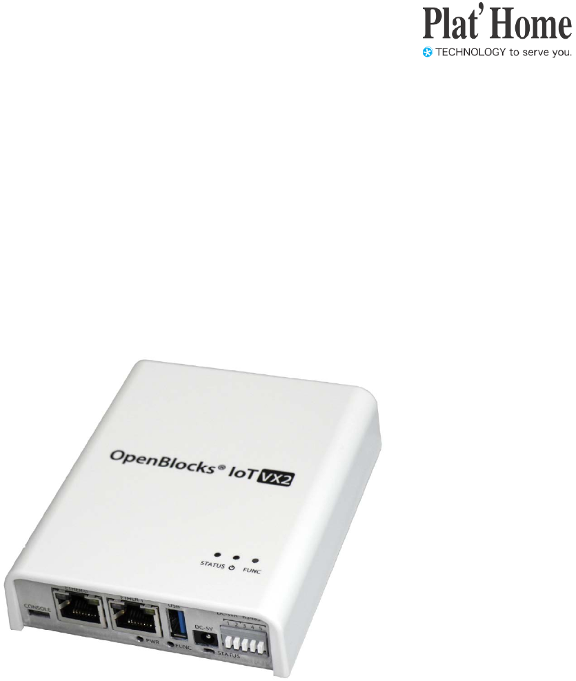
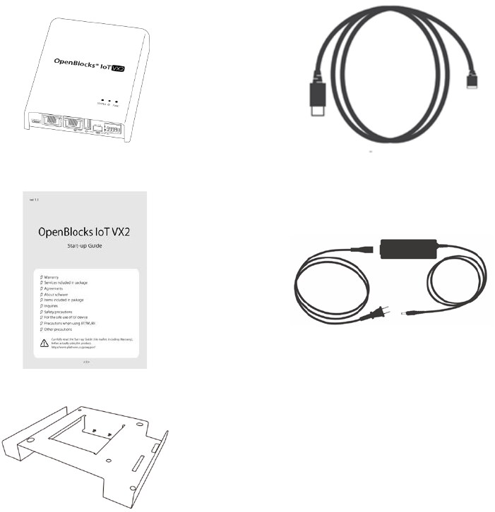
1-1. Items included in package for VX2
Standard configuration of OpenBlocks IoT VX2 is as follows:
1 x VX2 main body 1 x USB Type-A Micro USB cable
1 x Start-up Guide 1 x AC adapter
1 x Heat radiation and installation bracket
6/39
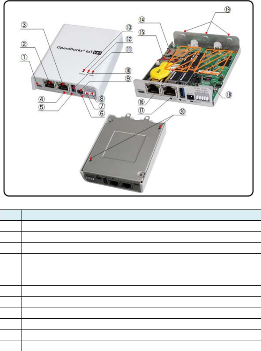
1-2. Names of parts (VX2 main body)
No. Name Remarks
① USB serial console port Micro USB Micro-B
② Ethernet port 0 10BASE-T / 100BASE-TX / 1000BASE-T
③ Ethernet port 1 10BASE-T / 100BASE-TX / 1000BASE-T
④ Power switch Shuts down OS if in operation.
Starts up OS if not in operation.
⑤ FUNC switch Enables allocated functions.
⑥ Status indicator LEDs illuminate or flash in seven colors.
⑦ RS-485 (half duplex) connector
⑧ Wide range power supply input
⑨ USB host mode port A-Type/USB3.0
⑩ USB host mode port A-Type/USB3.0
⑪ FUNC switch Enables allocated functions.

7/39
No. Name Remarks
⑫ Power switch Shuts down OS if in operation.
Starts up OS if not in operation.
⑬ Status indicator LEDs illuminate or flash in seven colors.
⑭ SIM slot Slot for inserting SIM card.
*Supports mini-
SIM card format (2FF) (standard
SIM)
⑮ MMC slot
As MMC cards cannot secure sufficient reliability
for system operations, use them for file exchanges
and log storage only.
⑯ Expansion slot 2 Expansion slot for EnOcean, Wi-
SUN and other
modules.
⑰ Expansion slot 1
Expansion slot for mobile adapter card of mobile
networks.
Mobile adapter card supporting carrier To be use is
mounted. Essentially, this is a factory option.
⑱ DIP switch As this switch is set prior to factory shipment, do
not alter the settings.
SW1-3: For modem identification
SW4-5: Not used
SW6: OFF=RS485 terminator ON (default)
⑲ Holes to install external antenna Holes are unopened in image.
⑳
Holes to mount heat radiation
and installation bracket
*To insert a SIM card, turn the VX2 main body upside down and insert into the back of the
slot. Similarly, to remove a SIM card, turn the VX2 main body upside down and extract the
card.
●Modem type identification
Modem type SW1 SW2 SW3
3G module ON OFF OFF
Modem uninstalled ON ON ON
8/39
Chapter 2 Before starting to use the
OpenBlocks IoT Family
2-1. Product overview
The OpenBlocks IoT Family is a general-purpose server product employing Debian
GNU/Linux as an OS. Though customized to take advantage of hardware properties, it is
possible to use the OpenBlocks IoT Family in a general operational method for Debian and
other Linux products, apart from such customization.
2-2 Cautions about SSD-based system development
In recent times, cost reductions in flash memories have led to the employment of Solid State
Drives ("SSD"), replacing conventional hard disk drives used in smartphones, laptop PCs
and many other devices. This product uses embedded MMC (eMMC), which is a type of
SSD.
With advantages such as high-speed random access performance and solid-state design,
SSD has extremely high resistance against mechanical failures and environmental
performance. However, compared to hard disk drives, the data writing limit is a lot less.
SSD can generally be divided into SLC and MLC. The SLC type with tens of thousands of
counts of write performance was the mainstream in the capacity range of a few gigabytes,
but the low-cost MLC with a write count of thousands has drastically increased capacity and
is applied to smartphones and PCs. Currently, SLC SSDs are gradually being faded out.
In actual fact, SLC products as options for our micro-servers only remain in the range of
small capacity products.
Thus, the number of operations with micro-servers using MLC SSD is enormous.
Generally, MLC has a write capability of 3,000 times. Just beyond 3,000 times, it starts to
cause bit errors, which can be recovered with ECC.
As soon as MLC exceeds the limit for an ECC recovery, read errors will be caused.
Therefore, consider system design to avoid MLC being in this condition.
9/39
●Write count per cell and block size of flash memory
Despite a write capacity of 3,000 times per cell, just one byte of writing onto an SSD means
one count.
To support large capacity with a small number of address lines, recent flash memory is read
and written in a block as large as 512 KB.
In other words, writing one byte or 512 KB is counted once.
For this reason, in relation to writing on SSD, it is possible to minimize the number of write
counts on SSD by writing in large data sizes through accumulating as much data as possible
in a buffer, as opposed to writing in small data sizes with more counts.
●Wear leveling function
As SSD can endure only a relatively small number of write cycles in a specific block, it will
average the number of writes so that the writes do not concentrate on the same actual block
address against actions to write onto the same block over and over.
This is achieved by virtualizing block addresses.
OS will notify used and unused blocks to SSD. In order to be ready for a next write to be
performed, SSD will prepare a block with the smallest number of writes for a write.
By doing so, the number of writes to individual blocks are consequently averaged out.
●Static wear leveling
In the case of conventional wear leveling, it is assumed that 50% of data is in a used domain
and rarely rewritten. This means that since installation of OS, 50% of available blocks are
written only once. While these blocks are virtually new, the remaining 50% are rewritten over
and over. Compared to the case where rewriting is averaged, the end life for SSD comes
twice as fast.
As a countermeasure to this, static wear leveling was devised. Data in rarely rewritten
blocks are moved to frequently rewritten blocks, while applying blocks that are virtually new
to a domain for reuse.
By doing so, even if 50% of blocks are rarely written, the life of SSD is almost fully exploited.
●Assuming total write cycles of SSD
For example, supposing there is a 4-gigabyte SSD using 512 KB blocks and 3,000 write
cycles per cell available. If writing data of 512 KB or less, we can assume that the total
number of write cycles of SSD is as follows:
4,294,967,296 Bytes ÷ 524,288 Bytes = 8,192 (4 GB ÷ 512 KB)
10/39
Number of physical blocks is 8,192.
If each of them are rewritten 3,000 times:
8,192 × 3,000 = 24,576,000 times
In other words, if writing one-byte data per time, the life will end when writing 18.4MB.
(Actually, SSD promotes efficiency of such writes). Furthermore, if assuming that for writes
of 512 KB in size, a block segment does not overlap the border of 512 KB, it will be one write,
whereas in fact, file access by OS may start writing in the middle of the block, so even if a
write of 512 KB or less is written twice with a 50% probability.
i.e.
24,576,000 times x 75% = 18,432,000 times (Only 512 KB writes are assumed here).
Furthermore, with access from OS, one more write cycle is added.
This is due to the fact that updating a file control block in the file closing process will result in
at least one rewrite.
Of course, SSD further reduces the number of write cycles by, for example, using cache, but
basically, this is the mechanism for processing.
●Use an SSD that is as large as possible
For example, the above-mentioned 4-gigabyte SSD has 8,192 blocks, but if there is a
8-gigabyte SSD, it has 16,384 blocks, which is twice that of a 4-gigabyte SSD. Simply put,
the number of write cycles is twice.
If SSDs have the same block size, the number of write cycles will simply increase in
proportion to the size.
For this reason, by using an SSD as large in size as possible, it will resist against problems
caused by an increasing number of writes.
●Reducing the number of writes to SSD by using tmpfs
In a Linux system, system development without due consideration will assume that storage
can be used as a device that can be used infinitely.
Even if no data storage is required, storage domain will be carelessly used as a buffer for
operation.
To avoid reducing the life of SSD for such a reason, give due consideration to system design

11/39
so that the storage necessary for operation processes are stored in tmpfs as much as
possible.
In addition, open source software frequently uses a storage domain secured for its use as a
temporary storage area. In this case, and as a countermeasure, that file is linked to a
domain in tmpfs.
●Log
It is general practice with a Linux system to keep a log in storage for everything. However, if
there is a process that records logs on a very frequent basis, contrivances such as writing in
tmpfs first and then moving logs to SSD periodically are recommended.
Though such countermeasures cannot respond to a sudden blackout, due consideration
should be given to whether one regards this as a trade-off or to send logs to a system log
server equipped with UPS.
2-3 About SIM cards
SIM cards that can be mounted onto OpenBlocks IoT Family are in a mini-SIM (2FF) format.
If there is a need to use micro-SIM or nano-SIM cards, use an adapter that can fix a SIM
card with a fall-preventing film and adhesive tape. Please note that any damage to the SIM
slot while a SIM adapter is used will be subject to repair on an at-cost basis.
2-4 eMMC storage partition information
Partition information of eMMC used for this product is as follows:
●In the case of OpenBlocks IoT VX2
Number Format Size OBS application Device name
1 fat16 1.5 gigabytes Boot mmcblk0p1
2 ext4 30.5 gigabytes Primary mmcblk0p2

12/39
2-5 Storage mode
Operation is conducted by referring to basic user land data from eMMC. Should an
unexpected power interruption occur, there is a risk of damage to files in physical storage,
but for Docker and other applications, data in storage are referenced by unionfs, thereby
securing normal operation.
Damage to files by a sudden power interruption mainly happen to files into which data is
being written. For this reason, it is recommended that to reduce any influence on OS, files
that are normally written should be limited to log files or such like.
*Execution results of mount command
root@obsiot:/var/webui/docroot# mount
/dev/mmcblk0p2 on / type ext4 (rw,relatime,data=ordered)
devtmpfs on /dev type devtmpfs (rw,relatime,size=956312k,nr_inodes=239078,mode=755)
sysfs on /sys type sysfs (rw,nosuid,nodev,noexec,relatime)
proc on /proc type proc (rw,nosuid,nodev,noexec,relatime)
securityfs on /sys/kernel/security type securityfs (rw,nosuid,nodev,noexec,relatime)
tmpfs on /dev/shm type tmpfs (rw,nosuid,nodev)
devpts on /dev/pts type devpts (rw,nosuid,noexec,relatime,gid=5,mode=620,ptmxmode=000)
tmpfs on /run type tmpfs (rw,nosuid,nodev,mode=755)
tmpfs on /run/lock type tmpfs (rw,nosuid,nodev,noexec,relatime,size=5120k)
tmpfs on /sys/fs/cgroup type tmpfs (ro,nosuid,nodev,noexec,mode=755)
cgroup on /sys/fs/cgroup/systemd type cgroup
(rw,nosuid,nodev,noexec,relatime,xattr,release_agent=/lib/systemd/systemd-cgroups-agent,name=systemd)
cgroup on /sys/fs/cgroup/freezer type cgroup (rw,nosuid,nodev,noexec,relatime,freezer)
cgroup on /sys/fs/cgroup/memory type cgroup (rw,nosuid,nodev,noexec,relatime,memory)
cgroup on /sys/fs/cgroup/cpuset type cgroup (rw,nosuid,nodev,noexec,relatime,cpuset)
cgroup on /sys/fs/cgroup/perf_event type cgroup (rw,nosuid,nodev,noexec,relatime,perf_event)
cgroup on /sys/fs/cgroup/pids type cgroup (rw,nosuid,nodev,noexec,relatime,pids)
cgroup on /sys/fs/cgroup/devices type cgroup (rw,nosuid,nodev,noexec,relatime,devices)
cgroup on /sys/fs/cgroup/blkio type cgroup (rw,nosuid,nodev,noexec,relatime,blkio)
cgroup on /sys/fs/cgroup/net_cls,net_prio type cgroup (rw,nosuid,nodev,noexec,relatime,net_cls,net_prio)
cgroup on /sys/fs/cgroup/cpu,cpuacct type cgroup (rw,nosuid,nodev,noexec,relatime,cpu,cpuacct)
cgroup on /sys/fs/cgroup/debug type cgroup (rw,nosuid,nodev,noexec,relatime,debug)
systemd-1 on /proc/sys/fs/binfmt_misc type autofs
(rw,relatime,fd=37,pgrp=1,timeout=0,minproto=5,maxproto=5,direct)
mqueue on /dev/mqueue type mqueue (rw,relatime)
debugfs on /sys/kernel/debug type debugfs (rw,relatime)
tmpfs on /tmp type tmpfs (rw,relatime)
13/39
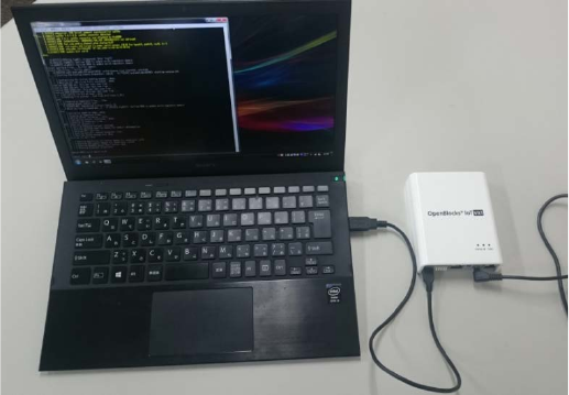
2-6. Connecting PC to OpenBlocks IoT Family
The OpenBlocks IoT Family and a PC are connected via an accessory USB cable.
The OpenBlocks IoT VX series must be supplied with power via an AC adapter or a
wide-range power supply input.
In the case of a Windows PC, connection to a USB port will automatically install a USB
serial driver (if Windows PC is connected to an Internet environment).
After completing installation of driver, it is possible to make serial port connections via
terminal software such as TeraTerm and PuTTY.
Default communication parameters of serial port on OpenBlocks IoT Family are as
follows:
Communication speed: 115,200 bps
Data length: 8-bit
Parity: None
Stop bit: 1-bit
When the startup process is completed after establishing communication, a login prompt
will be displayed. With default root privileges, start the login process.
Login: root
Password: 0BSI0T
*The above password is a default password. If the password has been changed
via WEB UI, please use password already set.
14/39
2-7. WEB UI
To enable basic system setup, this system is installed with WEB UI.
Use WEB UI to set up networks and control mobile networks.
In addition, WEB UI enables various functions to be added. Please refer to the WEB UI
Set-up Guide for basic use, etc. For functions added, refer to corresponding manuals.

15/39
Chapter 3 Using the OpenBlocks IoT
Family
The OpenBlocks IoT Family is a general-purpose server product employing Debian
GNU/Linux.
The OpenBlocks IoT Family can be used in the same way as with a regular Debian product.
This Chapter describes information that is particular to the OpenBlock IoT Family.
3-1. Indication colors of status indicators
The LEDs at the front of the OpenBlocks IoT Family product illuminate in seven colors with a
combination of RGB colors. For each color, flashing, etc. is controlled by script.
When WEB UI is employed, the specifications for default LED illuminations are as follows:
Status Color Illumination
status
Remarks
Main body and OS in
operation Yellow Illuminating
After completing startup of the main body
and OS, the unit will begin to check for a
signal reception in mobile network.
*Flashes green if no SIM card is inserted.
When the SIM slot is
unused Green Flashing
Normal operation without a SIM card or in a
waiting status before changing over to
waiting for signal reception
Mobile network signal:
Strong White Flashing Refer to "Details of signal status"
Mobile network signal:
Medium
Light
blue Flashing Refer to "Details of signal status"
Mobile network signal:
Weak Blue Flashing
Refer to "Details of signal status"
*Communication at this field intensity may
cause frequent retrials. If a mobile network
is being employed, use the unit with a
medium field strength or better.
Mobile network signal:
No signal Purple Flashing Refer to "Details of signal status"
When function is
Yellow Flashing
Alternately flashes with status indicator

16/39
Status Color Illumination
status
Remarks
enabled by FUNC button displaying that mobile network or SIM slot is
not used.
Terminating OS Yellow Illuminating
Initial trial to access
AirManage failed Red Illuminating
This indication is shown when an initial
access to AirManage remote control server
has failed. If WEB UI is not being used, the
OS will start to terminate in five minutes.
OS terminating after
initial access to
AirManage remote
control server has failed.
Red Flashing
*Details of signal status
Modem type Signal: Strong Signal: Medium Signal: Weak Signal: No
signal
3G module -
87 dBm or
higher
-88 to -108 dBm -109 to -112 dBm -113 dBm or lower
BWA module -
95 dBm or
higher
-95.1 to -105 dBm -105.1 to -120 dBm -
120.1 dBm or
lower
LED illumination control script when WEB UI is used
/var/webui/bin/set_signal_value.sh
/var/webui/scripts/led_updater.sh
●LED control
To change indication colors and illumination statuses of LEDs, edit /tmp/.runled file.
Please note that when a SIM card is inserted while using WEB UI, it will work with the field
strength, regularly updating this file. For this reason, to intentionally change this file, stop
using WEB UI or terminate the script to control LED illumination.

17/39
Line Setting description Remarks
1st line
Illumination #1 hours
(msec)
1 or more
2nd line
Illumination #2 hours
(msec)
1 or more
3rd line Illumination #1 color Refer to table below.
4th line Illumination #2 color Refer to table below. (If omitted: 0)
Color # Color
0 Not
illuminated
1 Red
2 Green
Color
number
Color
3 Yellow
4 Blue
5 Purple
6 Light blue
7 White
Out of
range
Not
illuminated
*Yellow flash every second
# echo -e "1000¥n1000¥n3" > /tmp/.runled
*Yellow and green flash alternately every second
# echo -e "1000¥n1000¥n3¥n2" > /tmp/.runled

18/39
3-2. Modem control for mobile networks
A tool to check the power ON/OFF state of module installed in this unit and radio wave state
is provided.
Command name: atcmd
Startup method 1: atcmd [Command]
Startup method 2: atcmd [Command 1] [Command 2] [Command 3]
Startup method 3: atcmd -d [Device file] [Command]
As shown in Startup method 2, it is possible to list commands and execute them in
sequence.
As shown in Startup method 3, it is also possible to designate a device file to use and
execute it.
Command Function Remarks
PON Turn the modem ON
POFF Turn the modem OFF
PRST Modem reboot Software reset
(Partial hardware reset)
HRST Modem reboot Hardware reset
CSQ Obtain radio wave strength
CCID Obtain SIM number
CTZU 1
Automatically obtain time
zone
*With a space
ATI Obtain modem type number
CGSN
Obtain modem serial
number
Commands to be assigned as per the above content.
*Turn the modem ON, obtain SIM number, turn the modem OFF
# atcmd PON CCID POFF
Xxxxxxxxxxxxxx
*Turn the modem ON, obtain radio wave strength, turn the modem OFF
# atcmd PON CSQ POFF
-86

19/39
When constantly obtaining radio wave status, WEB UI will occupy the device file. For this
command, designate a device file not used by WEB UI and execute it. In an environment or
user control not using WEB UI, this restriction will not apply.
Please note that depending on module in use, the device files that can be used by atcmd will
differ.
●3G module
Device file If atcmd can be used
/dev/ttyACM0 Yes
/dev/ttyACM1 Yes
/dev/ttyACM2 Yes
/dev/ttyACM3 No
/dev/ttyACM4 No
/dev/ttyACM5 No
/dev/ttyACM6 No
20/39
3-3. Mobile network connection
It can control the mobile line's modem using the Service network (Mobile line) menu in the
[Network]-[Basic] tab in WEB UI.
The OpenBlocks IoT Family supports a method to make a connection to mobile networks
whenever necessary through control by WEB UI (On-demand connections), and a method
to make a connection by the user fully excluding control by the modem.
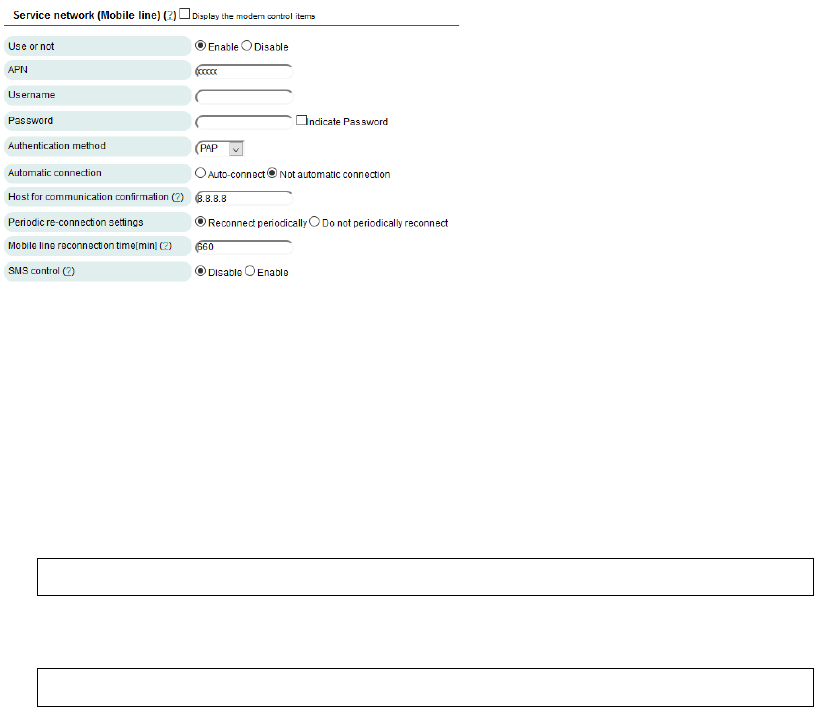
3-3-1. On-demand connections
Press the [Network]-[Basic] tab and enter necessary information for mobile network
connections.
Following information is required:
・APN (This item does not exist for LTE
module (KDDI)).
・Username
・Password
・Authentication method
・Automatic connection:
Choose "Not
automatic connection."
・Host for communication confirmation
・Periodic re-connection settings
・Mobile network reconnection times
・SMS control
*Enable this item only when it is used.
Press the Save button and reboot the unit to reflect changes to mobile network modem.
To connect/disconnect to a mobile network, use the following commands:
●Connection to a mobile network
# /var/webui/scripts/mobile_control.sh con 1
●Disconnection from a mobile network
# /var/webui/scripts/mobile_control.sh coff 1

21/39
Below is a sample of a combination of the above commands, meaning:
1. Connect to mobile network.
2. Execute ping command to DNS server.
3. Disconnect from mobile network.
#!/bin/bash
echo "#------------------------------------------------------------#"
echo "# Connect (`date`)"
echo "#------------------------------------------------------------#"
/var/webui/scripts/mobile_control.sh con 1
sleep 2
echo ""
echo "#------------------------------------------------------------#"
echo "# Command Exec (`date`)"
echo "#------------------------------------------------------------#"
ping -c 3 8.8.8.8
echo ""
echo "#------------------------------------------------------------#"
echo "# Disconnect (`date`)"
echo "#------------------------------------------------------------#"
/var/webui/scripts/mobile_control.sh coff 1
sleep 2
exit 0
3-3-2. User control of mobile network modem
Press the [Network]-[Basic] tab and set up necessary information for mobile network
connections. Note that the LTE module does not support this function.
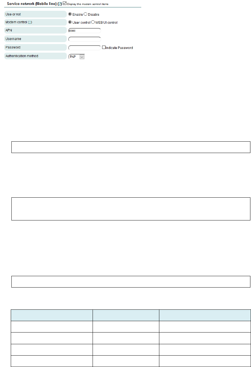
22/39
To implement this item, check "Display
the modem control items."
The following information is required for
settings:
・Modem control:
Choose "User
control."
・APN
・Username
・Password
・Authentication method
Information set up via WEB UI can be reflected upon modem using the following command:
●Command to reflect modem settings
# /var/webui/scripts/setapn.sh
Config. files used by command to reflect modem settings are as follows:
●Config. files to reflect modem settings
/var/webui/config/ppp0_device.sh
/var/webui/upload_dir/modem.sh
If further changes have been made to setting information, it is possible to overwrite
information by creating and setting the file below:
●File to overwrite information
/var/webui/upload_dir/user_modem.sh
●Description of variables
Variable Description Remarks
modem_ppp0_apn APN
modem_ppp0_user Username
modem_ppp0_pass Password
modem_ppp0_authtype Authentication PAP or CHAP

23/39
Variable Description Remarks
method
modem_ppp0_provier Provider name
To be designated by
PON/POFF command
DEVICE_CONNECT Device file for mobile
network connections
Will be /dev/ttyACM[0-9]*.
DEVICE_SETTING Device file for mobile
network connections
Will be /dev/ttyACM[0-9]*.
●Sample settings
modem_ppp0_apn="iixxxx.jp"
modem_ppp0_user="test@iixxxx"
modem_ppp0_pass="xxxx"
modem_ppp0_authtype="PAP"
modem_ppp0_provier="usermobile"
With each of the following commands, can connect to or disconnect from mobile network.
●Command for mobile network connection
# pon <modem_ppp0_provier>
●Command for mobile network disconnection
# poff <modem_ppp0_provier>
*<modem_ppp0_provier> is set up by a variable. If not changed by user_modem.sh, it will
be "mobile."
●To obtain radio wave strength, etc., use atcmd. Cannot obtain
information from a device file connected to the network.
●If default gateway has been set up before connection to a mobile
network,
it will not be reflected at the time of connection. For this
reason, open the default gateway before making connection to mobile
network.
After disconnecting from mobile network, the default gateway will
remain open. For this reason, to separately access
an Internet
environment, etc. set up the default gateway.
24/39
3-4. Backup
When customizing the file syatem etc, It can back up the file system that will be booted as
Normal boot mode, to TGZ format file in following.
1. Rebooting the unit
# sync
# reboot
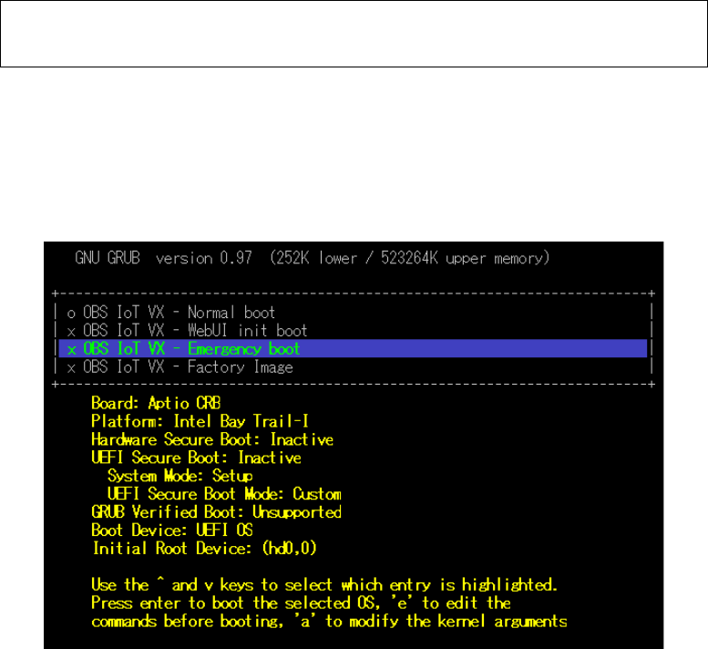
2. Startup in emergency boot mode
For the OpenBlocks IoT VX series, choose "Emergency boot" from the GRUB screen at
the time of startup.

25/39
3. Deletion of unnecessary data and backup
obsiot login: root
Password: root
# mount /dev/mmcblk0p2 /mnt
*Delete files particular to hardware, etc. below /mnt. BT information is deleted.
# rm -rf /mnt/var/lib/bluetooth/*
# cd /mnt
# tar --exclude=lost+found --exclude=<tgz filename> -cpzf <tgz filename> .
/mnt/<tgz file> will be a backed up file.
Caution:
Under the /var/lib/bluetooth/ directory, information particular to hardware is included.
It is recommended to delete intermediate files during programming.
3-5. Restoration
Using emergency boot mode, It can restore file system using the shell scripts (init.sh and
post-init.sh) described in Chapter 3-6 from the TGZ format backup file saved in external
storage such as USB memory.
For details on how to make backup files, please refer to Chapter 3-4.
The external storage is one of ext2 / ext3 / vfat file system, and the volume label of
DB_CONFIG needs to be set.
Caution:
・Before decompressing a backed up file, format the /dev/mmcblk0p2 domain (for
OpenBlocks IoT VX series).
・Backed up file and kernel-image must be consistent. Separately check the kernel-image of
the unit to be restored.
26/39
3-6. Applications
In emergency boot mode, in addition to a backup file, it is possible to run a script, etc. by
preparing a file with a designated name as a volume label in DEB_CONFIG. This will be
effective only if a file actually exists.
・init.sh (sh script; line feed code is LF only)
Execution before mounting overlayfs while KERNEL is starting up.
・post-init.sh (sh script; line feed code is LF only)
Execution after mounting overlayfs while KERNEL is starting up.
*This products employs systemd. For this reason, at the stage when KERNEL is starting up,
systemd has not been started up, and soem commands (such as poweroff/reboot) cannot
be used. To use such a command, execute commands to be used after starting up daemon
and other programs that need to be started up in the background.
27/39
3-7. WEB UI extensions
As an extension in the [Extension] tab in WEB UI, the following are available.
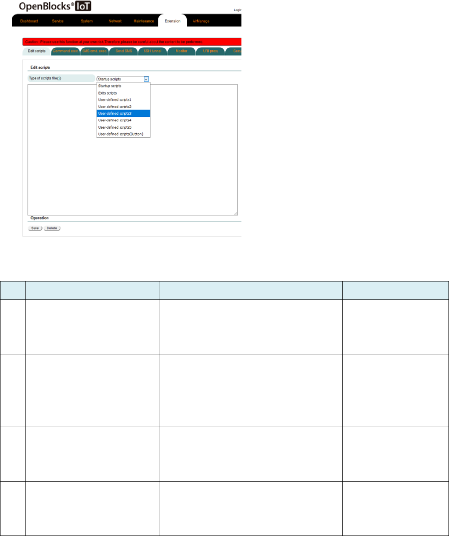
3-7-1. Script editing
Choose the [Extension] –[Edit Scripts] tab to
create and edit the following scripts from WEB
UI.
・Startup scripts
・Exit scripts
・User-defined scripts 1-5
・User-defined scripts (Button)
Please note that this function depends on
what user has actually installed.
# Script type Execution timing Remarks
1 Startup scripts
Executed after startup process of
WEB UI is completed at the time of
starting up the unit.
2 Exit scripts
Executed immediately after
termination process of WEB UI has
started at the time of terminating the
unit.
3 User-defined scripts Not executed in normal processes.
Executed when instruction is applied
using the SMS control function.
4 User-
defined scripts
(Button)
If such scripts are set up using the
FUNC function allocation, executed
when FUNC switch is pressed.
28/39
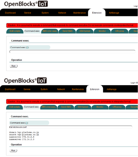
3-7-2. Command execution
Use the [Extension]-[Command exec.] tab,
can execute a command of one line or so.
When executing a command, response results
will be displayed.
Please note that if executing a command that
is permanently run in the foreground with this
function, will not obtain web response.
3-7-3. SMS command execution
This is described in the WEB UI Set-up Guide for the OpenBlocks IoT Family. Please refer to
said document.
29/39
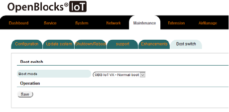
3-8 Switching boot modes
Can set up bo
ot mode at the next startup
using the [Maintenance]-[Boot switch] tab .
At the time of normal factory shipment, only
one boot mode can be selected.
*By rewriting a part of
/dev/mmcblk0p1/EFI/boot/bootx64.conf file,
can show boot modes here. However,
selectable boot modes mean a risk to actual
operations, for example, restoring setting to
factory condition.
For this reason, examine each boot mode to
determine if it should be added for display.
3-9. WEB UI extensions
This is described in the WEB UI Set-up Guide for the OpenBlocks IoT Family. Please refer to
said document.
3-10. Special setting of WEB UI filter table
If a /var/webui/local/bin/iptables-ext.sh file is present, the Edit extended filter configuration
file item will be displayed in the [System]-[Filter] tab in WEB UI.
For this item, customization of filter setting by iptables and ip6tables commands is assumed.
Execution timing of iptables-ext.sh is at the time of startup and changing filter settings.

30/39
What is described in this section is a shell
script.
Edit with iptables command as appropriate.
3-11. Sending SMS messages
If the unit uses WEB UI, is equipped with a modem module (other than an LTE module
(KDDI)) and is inserted with a SIM card that can send SMS messages, it is possible to send
SMS messages from the command line.
Use the following command to use create a form of SMS data.
*After creating form, message will be automatically sent.
# /var/webui/bin/create_sms.py <recipient's telephone number> <body>
*Example of execution
# /var/webui/bin/create_sms.py 09012345678 “TEST MESSAGE”
3-12. Switching operations of LTE module (KDDI)
The LTE module (KDDI) has a function to serve as a SIM card. With the commands below,
can switch between internal SIM mode to turn the module into a SIM card and external SIM
mode to refer to an inserted SIM card.
●Command to switch to internal SIM mode
# /var/webui/scripts/kym_set_mode.sh in

31/39
●Command to switch to external SIM mode
# /var/webui/scripts/kym_set_mode.sh out
32/39
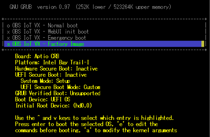
3-13. Factory Reset (Reset to condition at time of factory
shipment)
With the OpenBlocks IoT VX series, if a package has been added to the storage domain or if
important data has been deleted and to reset the unit to the condition at the time of factory
shipment, choose "Factory Image" in the GRUB menu to do so.
Please note that if resetting the unit to the condition at the time of factory shipment, data set
up, etc. will be deleted.
33/39
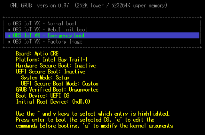
3-14. Recovery startup
A file system for recovery is prepared for the case where the file system used for normal
startup is damaged and can not be started.
With the OpenBlocks IoT VX series, choose "Emergency boot" from the GRUB menu to start
up the unit in the RAMdisk mode.
Login account and password by the console in this startup mode is "root"/"root".
3-15. Building a cross-development environment
A method to create firmware for the OpenBlocks IoT Family is available from the web page
below. If building a cross-development environment, refer to this page.
https://github.com/plathome/debian_based_firmware

34/39
3-16. Automatic external storage mounting in WEB UI
If WEB UI finds storage devices with specific volume labels, they will be automatically
mounted.
Please use this function to manage storage using WEB UI functions, etc.
Volume label Mounting destination Supplement
WEBUI_STORAGE /var/tmp/storage Use the NTFS file system.

35/39
3-17. Recommended device files to use
With Linux, each device file is assigned with a name in the order of recognition.
For this reason, device files may differ depending on the power ON/OFF conditions of
devices.
As device file links are setup for individual models, to access device files, use the following
recommended device files.
●OpenBlocks IoT VX series
Recommended device file Subject device
/dev/ttyRS485 Device file for RS-485
/dev/ttyEX1 Device file for extension slot 1 (LoRaWAN,
etc.)
/dev/ttyEX2 Device file for extension slot 2 (EnOcean,
etc.)
/dev/ttyS4 Device file for RS-232C
(For VX1 only)
3-18. Docker
Docker can be operated with the OpenBlocks IoT VX series.
Docker can be installed by using the function to add extensions in the
[Maintenance]-[Enhancements] tab in WEBUI.
Can also use the following commands to install Docker.
●How to install Docker (Connection to an Internet environment required).
# apt-get update
# apt-get ?y install docker-ce
At present, there is no function to control Docker containers from WEB UI. To control
containers, use a command line. If using Docker after going live, refer to the official Docker
site for commands, including container startup and stop.

36/39
Chapter 4 Product specifications
4-1. Open Blocks IoT VX2 main body specifications
Model # OBSVX2
CPU
Model Intel Atom E3805
Clock speed 1.3 GHz (dual core)
Built-
in secondary
cache
1024 kB/Core
Main memory On-board 2 GB (64 bit bus DDR3L)
Built-in storage 32 GB (eMMC)
Additional storage 1 x MMC slot
Wireless interface BT 4.0+2.1 EDR
WLAN (IEEE802.11a/b/g/n/ac) *4
SIM interface MiniSIM for communication (25 mm x 15 mm x
0.76 mm) card slot
Wired interface
USB (HOST) 1 x USB 3.0 (type-A) *2
USB (Console) 1 x Micro USB (type-B)
Ethernet 2 x 10Base-T/100BASE-TX/1000BASE-T
RS-485
1 x half-duplex
(Applicable electric wire range: AWG28 to
AWG22)
Measurements
91.9 mm (W) x 114.8 mm (D) x 25 mm (H)
(Excluding protrusions)
Weight 160 g
Power supply DC-Jack: 4.75 to 5.25VDC
Wide DC: 10 to 48VDC*3
Power consumption In an idle mode 5.5 W
At a high load 9.0 W
MTBF 435,613 hours
EMC standard VCCI class A
Energy Consumption Efficiency based
on Act Concerning the Rational Use of
Energy
[Unit: W/GTOPS] *1
Classification: H
0.52

37/39
Environmental protection Conforms to RoHS Directives
Authentication JATE/ TELEC
RTC backup time 10 years
OS at the time of shipment Debian GNU/Linux
*1: Energy Consumption Efficiency is measured power consumption (Measurement method
defined by the Act Concerning the Rational Use of Energy) divided by composite theoretical
performance, as defined by the Act Concerning the Rational Use of Energy.
*2: Supported cable length is less than 3 meters.
*3: To use this function, it is necessary to connect an external nose filter (SNR-10-223-T
(COSEL) or an equivalent).
*4: Access point function of 802.11ac not supported.
4-2. OpenBlocks IoT VX series options
4-2-1. 3G module
Supported frequencies
GSM/GPRS/EDGE:
Quad band 850/900/1800/1900 MHz
W-CDMA(UMTS/HSPA+):
Five band 800/850/900/1900/2100 MHz
Data communication speed
Downstream: 7.2 Mbps Upstream: 5.7 Mbps
*Theoretical values
Control method AT commands
Authentication JATE/TELEC
Power supply voltage 3.3 to 4.4VDC
Power consumption Idle 0.18 W *Average power
At a high load 2.6 W *Average power

38/39
Chapter 5 Cautions and supplementary
information
5-1. Countermeasures against delays due to script
processing
When writes to storage are made using init.sh and post-init.sh scripts in emergency boot
mode, a next command process may be implemented before writing is complete. For this
reason, expressly execute sleep and sync commands.
5-2. List of ports used
The OpenBlocks IoT Family with WEB UI uses or may use the following ports:
Service type Port # Supplementary information
SSH 22 Port number can be changed
DNS 53
DHCP 67
NetBIOS 137 When Sama is installed (UDP)
NetBIOS 138 When Sama is installed (UDP)
NetBIOS 139 When Sama is installed
Samba 445 When Sama is installed
Modbus 502 When IoT data control is installed
WEB UI (HTTP access) 880
Node-RED 1880 When Node-RED is installed
(Port # can be changed)
Shell in a box (WEB SSH) 4200
WEB UI (HTTPS access) 4430

39/39
OpenBlocks IoT Family Developer Guide
Version 3.1.0 (May 31, 2018)
Plat'Home Co., Ltd.
NIHON BUILDING KUDANBEKKAN, 3F
4-2-3, Kudankita, Chiyoda-ku, TOKYO 102-0073, JAPAN
