Operating Manual_DASbox Manual DASbox
User Manual: Operating-Manual_DASbox
Open the PDF directly: View PDF ![]() .
.
Page Count: 136 [warning: Documents this large are best viewed by clicking the View PDF Link!]
- Operating Manual
- Table of contents
- 1 User instructions 5
- 2 Product description 11
- 3 General safety instructions 17
- 4 Installation 27
- 4.1 Selecting the location 27
- 4.2 Ports 28
- 4.2.1 Mains connection unit and communication ports 28
- 4.2.2 DASbox® Base Unit 30
- 4.2.3 MP8-pHpO multi pump and sensor module 33
- 4.3 Installing the device 34
- 4.3.1 Establishing the electrical supply and communication 35
- 4.3.2 Connecting off-gas condensers, overhead drives and temperature sensors 38
- 4.3.3 Connecting Sensors and cables to the MP8-pHpO module 39
- 4.3.4 Connecting the gas supply 40
- 5 Hardware and operation 41
- 5.1 Gassing, temperature control and agitation - the DASbox® Base Unit 41
- 5.1.1 Gas mixing and gassing 42
- 5.1.2 Temperature control 43
- 5.1.3 Agitation 43
- 5.2 Off-gas condensers 44
- 5.2.1 Assembly of the off-gas condensers 45
- 5.2.2 Operation of the off-gas condensers 47
- 5.2.3 Deicing the off-gas condensers - Deice function 48
- 5.3 Addition of media - the MP8-pHpO module 49
- 5.3.1 Feed tubing and feed ranges 49
- 5.3.2 Continuous and pulsed feeding operation 51
- 5.3.3 Inserting pump head tubing 52
- 5.3.4 Calibrating pump head tubing 54
- 5.3.5 Sterilizing feed tubing 54
- 5.3.6 Manual operation of the pumps 55
- 5.4 Monitoring - the MP8-pHpO module 57
- 5.4.1 Sterilizing sensors 57
- 5.4.2 Calibrating sensors 58
- 5.4.3 pH sensors - handling instructions 60
- 5.4.4 DO sensors (Clark type) - handling instructions 61
- 5.4.5 DO sensors for single-use bioreactors 63
- 5.4.6 Redox sensors 64
- 5.5 DASbox® Storage and autoclavable cage 65
- 5.5.1 DASbox® Storage 65
- 5.5.2 LCD monitor display principle 65
- 5.5.3 Autoclavable Carrier System 67
- 5.6 DASbox® Bioreactors 69
- 5.6.1 Typical head plate assignments 70
- 5.6.2 Glass reactor assembly instructions 71
- 5.6.3 Assembling the overhead stirrer 72
- 5.7 Cultivation – a typical workflow 73
- 6 Software - DASGIP Control 75
- 7 Maintenance 95
- 8 Transport, storage and disposal 102
- 9 Technical data 105
- 9.1 Ambient conditions 105
- 9.2 DASbox® System 105
- 9.2.1 Power supply 105
- 9.2.2 Weight / dimensions 106
- 9.2.3 Bioreactors 106
- 9.2.4 Agitation 107
- 9.2.5 Gassing 107
- 9.2.6 Dispensing 107
- 9.2.7 Monitoring and control 107
- 9.3 Ports - specifications 109
- 9.3.1 Connection assignments 110
- 9.3.2 Communication ports (DTP in/out, AUX) 110
- 9.3.3 RS485 (optional) 110
- 9.3.4 Sensor connectors 111
- 10 Ordering information 113
- 1 User instructions
- 2 Product description
- 3 General safety instructions
- 3.1 Intended use
- 3.2 User profile
- 3.3 Notes on product liability
- 3.4 Warnings for intended use
- WARNING! Lethal voltages inside the device.
- WARNING! Risk of electric shock from damage to devices or mains power cables.
- WARNING! Risk from incorrect supply voltage
- WARNING! Electrical hazard if protective grounding is missing.
- DANGER! Risk of explosion.
- CAUTION! Risk of personal injury and material damage when lifting and carrying heavy loads.
- WARNING! Danger to health from pathogenic germs or infectious liquids.
- WARNING! Danger to health from aggressive chemicals.
- WARNING! Danger from oxidizing or explosive gases and gas mixtures
- WARNING! Danger due to oxygen enriched atmospheres.
- WARNING! Maximum operating pressure of 0.5 bar. Exceeding the limit may result in burst risk.
- CAUTION! Risk of explosion due to damaged glass vessels.
- CAUTION! Danger from hot surfaces.
- CAUTION! Danger from rotating parts.
- CAUTION! Danger from squirting of dispensing media.
- CAUTION! Danger from liquids and gases leaking.
- NOTICE! Observe the ambient conditions.
- CAUTION! Do not cover the ventilation slots.
- CAUTION! Do not confuse connecting sockets! Observe the connection values.
- CAUTION! Risk of product damage when connecting gases to the DASbox.
- CAUTION! Risk of product damage. Do not disconnect any connectors during operation.
- CAUTION! Risk of product damage due to increased top-heaviness of bioreactors with an off-gas condenser and a stirring drive.
- CAUTION! Risk of product damage during the assembly and storage of Pt 100 temperature sensors.
- CAUTION! Risk of product damage when handling DO sensors for DASbox Single-Use Reactors.
- CAUTION! Risk of collision with rotating stirring elements
- CAUTION! Risk of damage to device from improper use of cleaning agents.
- 3.5 Warning symbols on devices and accessories
- 4 Installation
- 4.1 Selecting the location
- 4.2 Ports
- 4.2.1 Mains connection unit and communication ports
- 4.2.2 DASbox® Base Unit
- Fig. 4-2: Ports at the rear of the DASbox® Base Unit
- CAUTION! Risk of damage to device.
- Gas supply
- Fig. 4-3: DASbox Base Unit - ports for the gas supply
- WARNING! Risk of explosion if oxygen comes into contact with greases and oils.
- CAUTION! Risk of damage to device if the DASbox is operated without a particle filter.
- Even if the connected gases have a very high purity grade, a discharge of particles from gas bottles or pipelines cannot be excluded. Particles can be the cause of operational changes in electronic mass flow sensors or leaks in valves. To avoid such ...
- CAUTION! Risk of damage to device from moist compressed air or gases.
- Moisture can damage the sensors inside the DASbox.
- WARNING! Danger from overpressure. Maximum operating pressure of 0.5 bar.
- 4.2.3 MP8-pHpO multi pump and sensor module
- 4.3 Installing the device
- 5 Hardware and operation
- 5.1 Gassing, temperature control and agitation - the DASbox® Base Unit
- 5.2 Off-gas condensers
- 5.3 Addition of media - the MP8-pHpO module
- 5.3.1 Feed tubing and feed ranges
- 5.3.2 Continuous and pulsed feeding operation
- 5.3.3 Inserting pump head tubing
- Fig. 5-5: Design of the pump head
- 1. Open the pump guard.
- 2. Insert the pump head tubing into the pump tube guide at the bottom left.
- 3. Route the pump head tubing around the pump rotor and insert it into the tube guide on the right side.
- 4. Grasp the elastic tube at both ends and pull it down slightly.
- 5. Check the position of the tubing in the tubing bed. The tubing must not be jammed in the tubing bed.
- 6. Close the pump guard.
- CAUTION! Risk of deformation of the pump head tubing.
- Fig. 5-5: Design of the pump head
- 5.3.4 Calibrating pump head tubing
- 5.3.5 Sterilizing feed tubing
- 5.3.6 Manual operation of the pumps
- 5.4 Monitoring - the MP8-pHpO module
- 5.5 DASbox® Storage and autoclavable cage
- 5.6 DASbox® Bioreactors
- 5.7 Cultivation – a typical workflow
- 6 Software - DASGIP Control
- 7 Maintenance
- 7.1 Cleaning and decontamination
- 7.2 Service
- 7.3 Additional information on care and maintenance
- 7.3.1 DO sensors (Clark type)
- NOTICE! Risk of sensor damage from improper handling.
- Sensor inspection and replacement of electrolyte solution
- CAUTION! The O2 electrolyte solution is strongly alkaline!
- 1. Unscrew the cap from the sensor body.
- 2. Carefully remove the cap from the sensor.
- 3. Remove the membrane body from the cap. If the body is too firmly connected, gently push it out with your fingertip.
- 4. Rinse the inner body with demineralized water and gently pat it dry with paper towels.
- 5. Visually inspect the O-rings and the trapeze rubber for mechanical defects.
- 6. Half fill the membrane body with O2 electrolyte solution.
- 7. Remove air bubbles by gently tapping on the membrane body.
- 8. Hold the sensor in a vertical position and slide the body membrane onto the inner body.
- 9. Remove excess electrolyte solution with a paper towel.
- 10. Carefully slip the cap over the fitted membrane body and tighten it firmly.
- Note:
- CAUTION! The O2 electrolyte solution is strongly alkaline!
- 7.3.2 pH sensors
- 7.3.3 MP8-pHpO module
- Regularly replace pump head tubing
- Regularly replace the back-up batteries
- NOTICE! Risk of internal data loss and equipment damage.
- 1. Ensure that the MP8-PHPO module is switched on. The status LED of the device has to be illuminated green.
- 2. Open the flap of the lower storage compartment. The holders for the back-up batteries are located on the right and left side in the storage compartment.
- 3. Unscrew the lid of the battery holder by a quarter turn in a counterclockwise direction. Use a flat head screwdriver if necessary.
- 4. Now remove all 3 batteries from the holder. The batteries are magnetic. They can easily brought out using a magnetic stick (e.g. a stir bar retriever).
- 5. You will find 3 Batteries per holder. Always replace all 6 back-up batteries of the module. Only use approved batteries (see chapter 10.3).
- 6. When replacing the batteries, the positive terminal of the batteries must show to the outside.
- 7. Check the orientation of the battery compartment lid. Metal flaps and slot on the lid must be in horizontal orientation to close the lid.
- 8. Align the lid of the battery holder and close it by turning the lid clockwise until safely locked.
- NOTICE! Risk of internal data loss and equipment damage.
- 7.3.1 DO sensors (Clark type)
- 8 Transport, storage and disposal
- 9 Technical data
- 10 Ordering information
- 10.1 DASbox base unit
- 10.2 System / cables
- 10.3 MP8-pH4pO4 multi pump and sensor module
- 10.4 DASbox Bioreactors
- Index
- Abbreviations 7
- Addition of media 92
- Agitation 43
- Agitation control 91
- Alarm
- Alarm Option - DASGIP Control 84
- Alarms 67
- Ambient conditions 27, 105, 106
- Assembly
- Autoclavable Carrier System 67
- Autoclave
- AUX 29
- back-up batteries 99
- BioBLU® 0.3c/f Single-Use Vessel 13
- Bioreactor
- Bioreactors 13, 69
- Calibrate
- Calibration factor FCal 50
- Calibration procedures 15
- Carrier System (autoclavable) 67
- Cascade control 90, 92
- C-Flex® tubing 54, 96
- CIP - seeCleaning-in-place
- Cleaning
- Cleaning agents 95
- Cleaning-in-place (CIP) 9, 54
- Cleaning-in-place procedures 15
- CO2
- Colors
- COM ports 33
- Condensate
- Condenser adapter 44
- Condensers
- Conductivity Sensors
- Connect
- Connection assignments 110
- Control - see DASGIP Control
- Cooling System 43
- Cultivation 73
- Danger
- DASbox
- DASbox Base Unit 11, 12
- DASGIP
- Service 97
- DASGIP Control
- DASGIP Software 15
- DASware 15
- Decontamination 95, 96
- Definition
- Definitions 7
- Deice Function 48
- Delivery package 14
- Dimensions 106
- Disassembly tool 40
- Dispensing
- Display 65
- Disposal 102, 103
- DO
- DO cascade control 91
- DO connector 111
- DO Sensors
- Documents
- DTP cable 36
- DTP in 29
- DTP network 36
- DTP out 29
- Edit boxes 80
- Electrical connections
- Electrical supply
- Electrolyte solution
- Errors and Alarms 67
- Event Monitor 76, 87
- Exhaust filter blockages 47
- Exhaust gas line insulation 44, 45
- External power supply 35
- FCal 50
- Features DASbox 14
- Feed
- Feed tubing
- Feeding
- Filter blockages 47
- Freezing of condensate 48
- Fuses 29
- Gas IN - see Gas inlets
- Gas inlets 31
- Gas Mixing System 42
- Gas outlets 31
- Gas quality 28
- Gas supply
- Gassing 42
- Gassing tubes
- Glass Reactor 13
- Glossary 9
- Head plate
- Inlet pressure
- Installation instructions 27
- Intended use 17
- Internal power supply 35
- LCD Monitor 65
- Level
- Location
- L-Sparger 70
- Main illustration 11
- Mains connection 109
- Mains connection unit 29
- Mains disconnect switch 29
- Maintenance 97
- Media addition - see Feed
- Microfuses 109
- Monitor - seeLCD Monitor
- Monitor cable 37
- Monitoring 57, 93
- MP8-pHpO Module
- Multi Pump and Sensor Module 33
- MX4/4-3 Gas Mixing Module - see Gas Mixing System
- Navigation Area 76
- New Workflow 77
- Not connected 65
- Off-gas condensers 44
- Offline Values 85
- Operating pressure
- Ordering information 113
- Original packaging 102
- Other applicable documents 5
- Overhead drives
- Overhead Stirrer
- Overlay 40
- Overpressure 32
- Packaging 102
- Parameter
- Particle filter 40
- Peltier elements 44, 48
- pH cable 39
- pH connector 111
- pH Sensors
- pH sensors
- Plant Overview 88
- pO2 Sensors - see DO Sensors
- Polarize 62, 63
- Ports
- Power cord 35
- Power supply 29
- Pressure reducer 40
- Process View 80
- Product liability 18
- Profile
- Profile Source 83
- Program Start 75
- Pt connector 112
- Pt100 temperature sensor 39
- Pump head tubing 49, 50
- pump head tubing
- Pump tubing
- Pumps
- Redox cable 39
- Redox connector 112
- Redox Sensors 64
- Replacement of electrolyte 97
- Return delivery information 104
- Rx/Tx 29
- Safety instructions 17
- Save User Chart Settings 87
- Sensor membrane 61, 62
- Sensors
- Serial interfaces 28
- Serial number 33
- Service 96, 97
- Set-point Profile
- Settings
- Shipment 96
- Software
- Splitter Function 15, 42
- Stas 200 plug 3 5
- State 29
- Sterilize
- Storage 65, 102
- Submerged 15, 31, 40
- Surfaces
- Symbol
- Symbols
- System components
- Tab
- Technical data 105
- Telescopic rails 68
- Temperature control 43
- Temperature control actuator 44
- Temperature sensor 23, 70
- Temperature sensors
- Terminator connector 36
- Top-heaviness
- Transport 102
- Typical workflow 73
- USB cable 36
- USB port 36
- User profile 17
- Ventilation grating 30
- Ventilation slots 33
- Vessel
- Warning symbols 6
- Warnings
- Weight 106
- Workflow 73
- Working Area 76
- Workplace
e
-Bedienungsanleitung
DASbox®
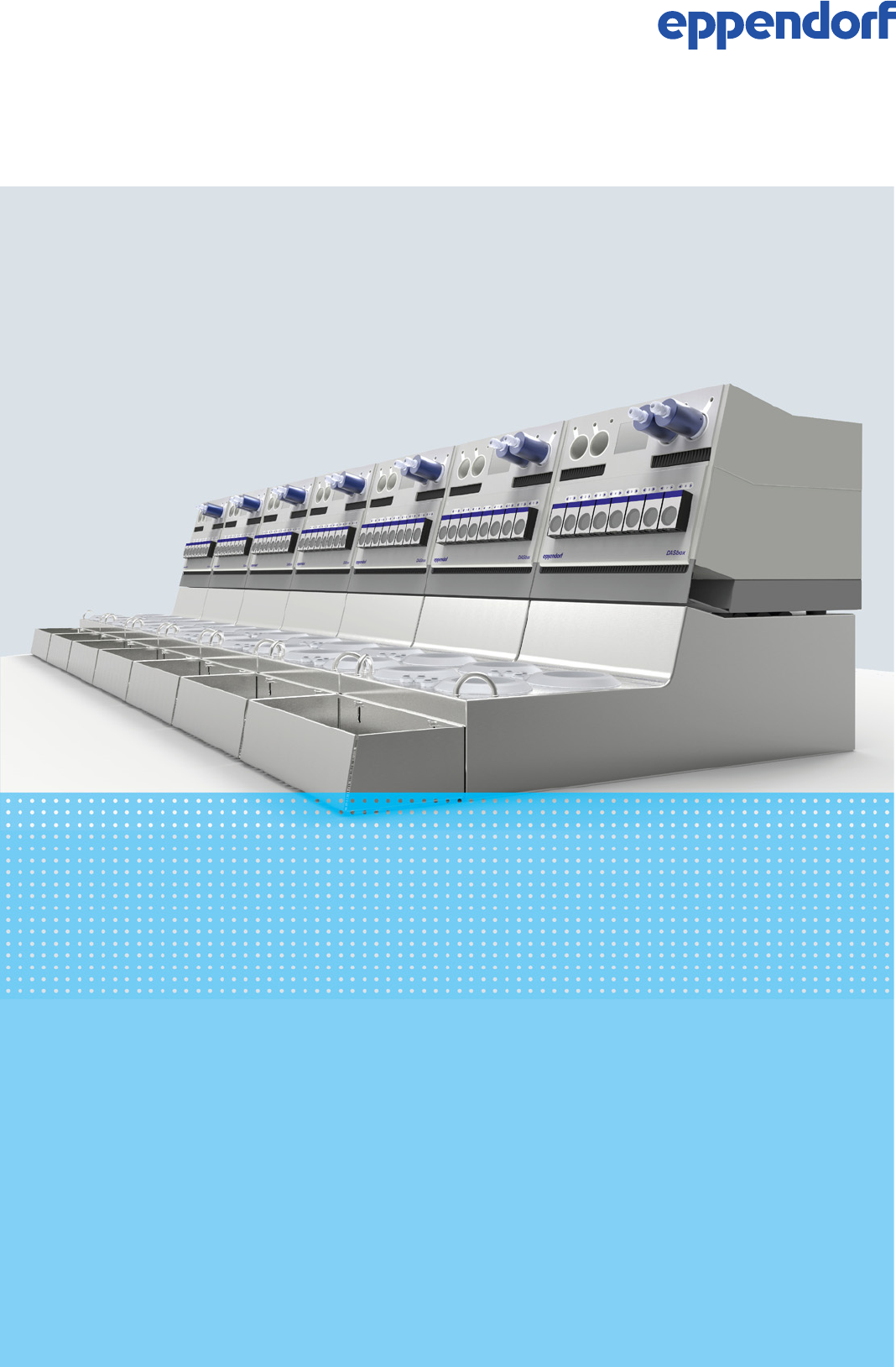
Mini Bioreactor System
Operating Manual
78000148-03.1/112014
Copyright © 2014 DASGIP Information and Process Technology GmbH, Jülich. All rights reserved,
including graphics an images. No part of this publication may be reproduced without the prior permission
of the copyright owner.
Eppendorf® and the Eppendorf logo are registered trademarks of Eppendorf AG, Hamburg, Germany.
DASGIP®, DASbox®, DASware® and BioBLU® are registered trademarks of DASGIP Information and
Process Technology GmbH.
Teflon® is a registered trademark of DuPont.
C-Flex® is a registered trademark of Saint-Gobain Performance Plastics.
Bioprene® and Marprene® are registered trademarks of Watson-Marlow Limited.
Registered trademarks are not marked in all cases with ® or TM in this manual.

Table of contents
DASbox® Mini Bioreactor System
English (EN)
1
Table of contents
1User instructions . . . . . . . . . . . . . . . . . . . . . . . . . . . . . . . . . . . . . . . . . . . . . . . . . . . . . . . . . . . . . . . . . . 5
1.1 How to use this manual . . . . . . . . . . . . . . . . . . . . . . . . . . . . . . . . . . . . . . . . . . . . . . . . . . . . . . . . 5
1.2 Danger symbols and danger levels . . . . . . . . . . . . . . . . . . . . . . . . . . . . . . . . . . . . . . . . . . . . . . . 6
1.2.1 Danger symbols . . . . . . . . . . . . . . . . . . . . . . . . . . . . . . . . . . . . . . . . . . . . . . . . . . . . . . . 6
1.2.2 Danger levels . . . . . . . . . . . . . . . . . . . . . . . . . . . . . . . . . . . . . . . . . . . . . . . . . . . . . . . . . 6
1.3 Symbols used . . . . . . . . . . . . . . . . . . . . . . . . . . . . . . . . . . . . . . . . . . . . . . . . . . . . . . . . . . . . . . . . 7
1.4 Abbreviations used and definitions . . . . . . . . . . . . . . . . . . . . . . . . . . . . . . . . . . . . . . . . . . . . . . . 7
1.5 Glossary . . . . . . . . . . . . . . . . . . . . . . . . . . . . . . . . . . . . . . . . . . . . . . . . . . . . . . . . . . . . . . . . . . . . 9
2Product description . . . . . . . . . . . . . . . . . . . . . . . . . . . . . . . . . . . . . . . . . . . . . . . . . . . . . . . . . . . . . . . 11
2.1 Main illustration . . . . . . . . . . . . . . . . . . . . . . . . . . . . . . . . . . . . . . . . . . . . . . . . . . . . . . . . . . . . . 11
2.1.1 DASbox® System . . . . . . . . . . . . . . . . . . . . . . . . . . . . . . . . . . . . . . . . . . . . . . . . . . . . . 11
2.1.2 DASbox® Bioreactors . . . . . . . . . . . . . . . . . . . . . . . . . . . . . . . . . . . . . . . . . . . . . . . . . . 13
2.2 Delivery package of the DASbox® Standard System . . . . . . . . . . . . . . . . . . . . . . . . . . . . . . . . . 14
2.3 Features . . . . . . . . . . . . . . . . . . . . . . . . . . . . . . . . . . . . . . . . . . . . . . . . . . . . . . . . . . . . . . . . . . . 14
2.3.1 Technology . . . . . . . . . . . . . . . . . . . . . . . . . . . . . . . . . . . . . . . . . . . . . . . . . . . . . . . . . . 14
2.3.2 DASGIP® Control . . . . . . . . . . . . . . . . . . . . . . . . . . . . . . . . . . . . . . . . . . . . . . . . . . . . . 15
2.3.3 Applications . . . . . . . . . . . . . . . . . . . . . . . . . . . . . . . . . . . . . . . . . . . . . . . . . . . . . . . . . 15
3General safety instructions . . . . . . . . . . . . . . . . . . . . . . . . . . . . . . . . . . . . . . . . . . . . . . . . . . . . . . . . . 17
3.1 Intended use . . . . . . . . . . . . . . . . . . . . . . . . . . . . . . . . . . . . . . . . . . . . . . . . . . . . . . . . . . . . . . . . 17
3.2 User profile . . . . . . . . . . . . . . . . . . . . . . . . . . . . . . . . . . . . . . . . . . . . . . . . . . . . . . . . . . . . . . . . 17
3.3 Notes on product liability . . . . . . . . . . . . . . . . . . . . . . . . . . . . . . . . . . . . . . . . . . . . . . . . . . . . . . 18
3.4 Warnings for intended use . . . . . . . . . . . . . . . . . . . . . . . . . . . . . . . . . . . . . . . . . . . . . . . . . . . . . 18
3.5 Warning symbols on devices and accessories . . . . . . . . . . . . . . . . . . . . . . . . . . . . . . . . . . . . . . 24
4Installation . . . . . . . . . . . . . . . . . . . . . . . . . . . . . . . . . . . . . . . . . . . . . . . . . . . . . . . . . . . . . . . . . . . . . . 27
4.1 Selecting the location . . . . . . . . . . . . . . . . . . . . . . . . . . . . . . . . . . . . . . . . . . . . . . . . . . . . . . . . . 27
4.2 Ports . . . . . . . . . . . . . . . . . . . . . . . . . . . . . . . . . . . . . . . . . . . . . . . . . . . . . . . . . . . . . . . . . . . . . . 28
4.2.1 Mains connection unit and communication ports . . . . . . . . . . . . . . . . . . . . . . . . . . . . 28
4.2.2 DASbox® Base Unit . . . . . . . . . . . . . . . . . . . . . . . . . . . . . . . . . . . . . . . . . . . . . . . . . . . 30
4.2.3 MP8-pHpO multi pump and sensor module . . . . . . . . . . . . . . . . . . . . . . . . . . . . . . . . 33
4.3 Installing the device . . . . . . . . . . . . . . . . . . . . . . . . . . . . . . . . . . . . . . . . . . . . . . . . . . . . . . . . . . 34
4.3.1 Establishing the electrical supply and communication . . . . . . . . . . . . . . . . . . . . . . . . 35
4.3.2 Connecting off-gas condensers, overhead drives and temperature sensors . . . . . . . . 38
4.3.3 Connecting Sensors and cables to the MP8-pHpO module . . . . . . . . . . . . . . . . . . . . . 39
4.3.4 Connecting the gas supply . . . . . . . . . . . . . . . . . . . . . . . . . . . . . . . . . . . . . . . . . . . . . . 40
5Hardware and operation . . . . . . . . . . . . . . . . . . . . . . . . . . . . . . . . . . . . . . . . . . . . . . . . . . . . . . . . . . . 41
5.1 Gassing, temperature control and agitation - the DASbox® Base Unit . . . . . . . . . . . . . . . . . . . 41
5.1.1 Gas mixing and gassing . . . . . . . . . . . . . . . . . . . . . . . . . . . . . . . . . . . . . . . . . . . . . . . . 42
5.1.2 Temperature control . . . . . . . . . . . . . . . . . . . . . . . . . . . . . . . . . . . . . . . . . . . . . . . . . . . 43
5.1.3 Agitation . . . . . . . . . . . . . . . . . . . . . . . . . . . . . . . . . . . . . . . . . . . . . . . . . . . . . . . . . . . . 43
5.2 Off-gas condensers . . . . . . . . . . . . . . . . . . . . . . . . . . . . . . . . . . . . . . . . . . . . . . . . . . . . . . . . . . 44
5.2.1 Assembly of the off-gas condensers . . . . . . . . . . . . . . . . . . . . . . . . . . . . . . . . . . . . . . 45
5.2.2 Operation of the off-gas condensers . . . . . . . . . . . . . . . . . . . . . . . . . . . . . . . . . . . . . . 47
5.2.3 Deicing the off-gas condensers - Deice function . . . . . . . . . . . . . . . . . . . . . . . . . . . . . 48
5.3 Addition of media - the MP8-pHpO module . . . . . . . . . . . . . . . . . . . . . . . . . . . . . . . . . . . . . . . 49

Table of contents
DASbox® Mini Bioreactor System
English (EN)
2
5.3.1 Feed tubing and feed ranges . . . . . . . . . . . . . . . . . . . . . . . . . . . . . . . . . . . . . . . . . . . . 49
5.3.2 Continuous and pulsed feeding operation . . . . . . . . . . . . . . . . . . . . . . . . . . . . . . . . . . 51
5.3.3 Inserting pump head tubing . . . . . . . . . . . . . . . . . . . . . . . . . . . . . . . . . . . . . . . . . . . . 52
5.3.4 Calibrating pump head tubing . . . . . . . . . . . . . . . . . . . . . . . . . . . . . . . . . . . . . . . . . . 54
5.3.5 Sterilizing feed tubing . . . . . . . . . . . . . . . . . . . . . . . . . . . . . . . . . . . . . . . . . . . . . . . . . 54
5.3.6 Manual operation of the pumps . . . . . . . . . . . . . . . . . . . . . . . . . . . . . . . . . . . . . . . . . . 55
5.4 Monitoring - the MP8-pHpO module . . . . . . . . . . . . . . . . . . . . . . . . . . . . . . . . . . . . . . . . . . . . . 57
5.4.1 Sterilizing sensors . . . . . . . . . . . . . . . . . . . . . . . . . . . . . . . . . . . . . . . . . . . . . . . . . . . . 57
5.4.2 Calibrating sensors . . . . . . . . . . . . . . . . . . . . . . . . . . . . . . . . . . . . . . . . . . . . . . . . . . . 58
5.4.3 pH sensors - handling instructions . . . . . . . . . . . . . . . . . . . . . . . . . . . . . . . . . . . . . . . 60
5.4.4 DO sensors (Clark type) - handling instructions . . . . . . . . . . . . . . . . . . . . . . . . . . . . . 61
5.4.5 DO sensors for single-use bioreactors . . . . . . . . . . . . . . . . . . . . . . . . . . . . . . . . . . . . . 63
5.4.6 Redox sensors . . . . . . . . . . . . . . . . . . . . . . . . . . . . . . . . . . . . . . . . . . . . . . . . . . . . . . . 64
5.5 DASbox® Storage and autoclavable cage . . . . . . . . . . . . . . . . . . . . . . . . . . . . . . . . . . . . . . . . . 65
5.5.1 DASbox® Storage . . . . . . . . . . . . . . . . . . . . . . . . . . . . . . . . . . . . . . . . . . . . . . . . . . . . . 65
5.5.2 LCD monitor display principle . . . . . . . . . . . . . . . . . . . . . . . . . . . . . . . . . . . . . . . . . . . 65
5.5.3 Autoclavable Carrier System . . . . . . . . . . . . . . . . . . . . . . . . . . . . . . . . . . . . . . . . . . . . 67
5.6 DASbox® Bioreactors . . . . . . . . . . . . . . . . . . . . . . . . . . . . . . . . . . . . . . . . . . . . . . . . . . . . . . . . . 69
5.6.1 Typical head plate assignments . . . . . . . . . . . . . . . . . . . . . . . . . . . . . . . . . . . . . . . . . . 70
5.6.2 Glass reactor assembly instructions . . . . . . . . . . . . . . . . . . . . . . . . . . . . . . . . . . . . . . . 71
5.6.3 Assembling the overhead stirrer . . . . . . . . . . . . . . . . . . . . . . . . . . . . . . . . . . . . . . . . . 72
5.7 Cultivation – a typical workflow . . . . . . . . . . . . . . . . . . . . . . . . . . . . . . . . . . . . . . . . . . . . . . . . . 73
6Software - DASGIP Control . . . . . . . . . . . . . . . . . . . . . . . . . . . . . . . . . . . . . . . . . . . . . . . . . . . . . . . . . 75
6.1 Short overview . . . . . . . . . . . . . . . . . . . . . . . . . . . . . . . . . . . . . . . . . . . . . . . . . . . . . . . . . . . . . . 75
6.1.1 Login . . . . . . . . . . . . . . . . . . . . . . . . . . . . . . . . . . . . . . . . . . . . . . . . . . . . . . . . . . . . . . 75
6.1.2 Overview of Operations . . . . . . . . . . . . . . . . . . . . . . . . . . . . . . . . . . . . . . . . . . . . . . . . 76
6.1.3 New Workflow . . . . . . . . . . . . . . . . . . . . . . . . . . . . . . . . . . . . . . . . . . . . . . . . . . . . . . . 77
6.1.4 Functional Overview . . . . . . . . . . . . . . . . . . . . . . . . . . . . . . . . . . . . . . . . . . . . . . . . . . . 77
6.2 Functions . . . . . . . . . . . . . . . . . . . . . . . . . . . . . . . . . . . . . . . . . . . . . . . . . . . . . . . . . . . . . . . . . . 90
6.2.1 Gassing . . . . . . . . . . . . . . . . . . . . . . . . . . . . . . . . . . . . . . . . . . . . . . . . . . . . . . . . . . . . . 90
6.2.2 Temperature control . . . . . . . . . . . . . . . . . . . . . . . . . . . . . . . . . . . . . . . . . . . . . . . . . . . 91
6.2.3 Agitation . . . . . . . . . . . . . . . . . . . . . . . . . . . . . . . . . . . . . . . . . . . . . . . . . . . . . . . . . . . . 91
6.2.4 Addition of media . . . . . . . . . . . . . . . . . . . . . . . . . . . . . . . . . . . . . . . . . . . . . . . . . . . . . 92
6.2.5 Monitoring . . . . . . . . . . . . . . . . . . . . . . . . . . . . . . . . . . . . . . . . . . . . . . . . . . . . . . . . . . 93
7Maintenance . . . . . . . . . . . . . . . . . . . . . . . . . . . . . . . . . . . . . . . . . . . . . . . . . . . . . . . . . . . . . . . . . . . . 95
7.1 Cleaning and decontamination . . . . . . . . . . . . . . . . . . . . . . . . . . . . . . . . . . . . . . . . . . . . . . . . . 95
7.1.1 Surfaces, modules . . . . . . . . . . . . . . . . . . . . . . . . . . . . . . . . . . . . . . . . . . . . . . . . . . . . 95
7.1.2 Cleaning feed tubing and pump tubing . . . . . . . . . . . . . . . . . . . . . . . . . . . . . . . . . . . 95
7.1.3 Decontamination before service or shipment . . . . . . . . . . . . . . . . . . . . . . . . . . . . . . . 96
7.2 Service . . . . . . . . . . . . . . . . . . . . . . . . . . . . . . . . . . . . . . . . . . . . . . . . . . . . . . . . . . . . . . . . . . . . 97
7.3 Additional information on care and maintenance . . . . . . . . . . . . . . . . . . . . . . . . . . . . . . . . . . . 97
7.3.1 DO sensors (Clark type) . . . . . . . . . . . . . . . . . . . . . . . . . . . . . . . . . . . . . . . . . . . . . . . . 97
7.3.2 pH sensors . . . . . . . . . . . . . . . . . . . . . . . . . . . . . . . . . . . . . . . . . . . . . . . . . . . . . . . . . . 98
7.3.3 MP8-pHpO module . . . . . . . . . . . . . . . . . . . . . . . . . . . . . . . . . . . . . . . . . . . . . . . . . . . 99
8Transport, storage and disposal . . . . . . . . . . . . . . . . . . . . . . . . . . . . . . . . . . . . . . . . . . . . . . . . . . . . 102
8.1 Transport . . . . . . . . . . . . . . . . . . . . . . . . . . . . . . . . . . . . . . . . . . . . . . . . . . . . . . . . . . . . . . . . . 102
8.2 Storage . . . . . . . . . . . . . . . . . . . . . . . . . . . . . . . . . . . . . . . . . . . . . . . . . . . . . . . . . . . . . . . . . . . 102

Table of contents
DASbox® Mini Bioreactor System
English (EN)
3
8.3 Disposal . . . . . . . . . . . . . . . . . . . . . . . . . . . . . . . . . . . . . . . . . . . . . . . . . . . . . . . . . . . . . . . . . . 103
8.4 General return delivery information . . . . . . . . . . . . . . . . . . . . . . . . . . . . . . . . . . . . . . . . . . . . 104
9Technical data . . . . . . . . . . . . . . . . . . . . . . . . . . . . . . . . . . . . . . . . . . . . . . . . . . . . . . . . . . . . . . . . . . 105
9.1 Ambient conditions . . . . . . . . . . . . . . . . . . . . . . . . . . . . . . . . . . . . . . . . . . . . . . . . . . . . . . . . . 105
9.2 DASbox® System . . . . . . . . . . . . . . . . . . . . . . . . . . . . . . . . . . . . . . . . . . . . . . . . . . . . . . . . . . . 105
9.2.1 Power supply . . . . . . . . . . . . . . . . . . . . . . . . . . . . . . . . . . . . . . . . . . . . . . . . . . . . . . . 105
9.2.2 Weight / dimensions . . . . . . . . . . . . . . . . . . . . . . . . . . . . . . . . . . . . . . . . . . . . . . . . . 106
9.2.3 Bioreactors . . . . . . . . . . . . . . . . . . . . . . . . . . . . . . . . . . . . . . . . . . . . . . . . . . . . . . . . . 106
9.2.4 Agitation . . . . . . . . . . . . . . . . . . . . . . . . . . . . . . . . . . . . . . . . . . . . . . . . . . . . . . . . . . . 107
9.2.5 Gassing . . . . . . . . . . . . . . . . . . . . . . . . . . . . . . . . . . . . . . . . . . . . . . . . . . . . . . . . . . . . 107
9.2.6 Dispensing . . . . . . . . . . . . . . . . . . . . . . . . . . . . . . . . . . . . . . . . . . . . . . . . . . . . . . . . . 107
9.2.7 Monitoring and control . . . . . . . . . . . . . . . . . . . . . . . . . . . . . . . . . . . . . . . . . . . . . . . 107
9.3 Ports - specifications . . . . . . . . . . . . . . . . . . . . . . . . . . . . . . . . . . . . . . . . . . . . . . . . . . . . . . . . 109
9.3.1 Connection assignments . . . . . . . . . . . . . . . . . . . . . . . . . . . . . . . . . . . . . . . . . . . . . . 110
9.3.2 Communication ports (DTP in/out, AUX) . . . . . . . . . . . . . . . . . . . . . . . . . . . . . . . . . . 110
9.3.3 RS485 (optional) . . . . . . . . . . . . . . . . . . . . . . . . . . . . . . . . . . . . . . . . . . . . . . . . . . . . . 110
9.3.4 Sensor connectors . . . . . . . . . . . . . . . . . . . . . . . . . . . . . . . . . . . . . . . . . . . . . . . . . . . 111
10 Ordering information . . . . . . . . . . . . . . . . . . . . . . . . . . . . . . . . . . . . . . . . . . . . . . . . . . . . . . . . . . . . 113
10.1 DASbox base unit . . . . . . . . . . . . . . . . . . . . . . . . . . . . . . . . . . . . . . . . . . . . . . . . . . . . . . . . . . . 113
10.2 System / cables . . . . . . . . . . . . . . . . . . . . . . . . . . . . . . . . . . . . . . . . . . . . . . . . . . . . . . . . . . . . . 114
10.3 MP8-pH4pO4 multi pump and sensor module . . . . . . . . . . . . . . . . . . . . . . . . . . . . . . . . . . . . 115
10.4 DASbox Bioreactors . . . . . . . . . . . . . . . . . . . . . . . . . . . . . . . . . . . . . . . . . . . . . . . . . . . . . . . . . 117
10.5 Single-Use Vessels . . . . . . . . . . . . . . . . . . . . . . . . . . . . . . . . . . . . . . . . . . . . . . . . . . . . . . . . . . 117
10.6 Glass Reactors . . . . . . . . . . . . . . . . . . . . . . . . . . . . . . . . . . . . . . . . . . . . . . . . . . . . . . . . . . . . . 117

Table of contents
DASbox® Mini Bioreactor System
English (EN)
4

5
User instructions
DASbox® Mini Bioreactor System
English (EN)
1 User instructions
This operating manual describes the design of a DASbox System and explains the handling and operation
of its system elements.
The DASbox System is also referred to in short as the DASbox in this operating manual.
1.1 How to use this manual
Make sure to carefully read this operating manual before using the DASbox for the first time.
This operating manual is part of the product. It must always be kept to hand at the site of use.
If this operating manual is lost, please request a replacement:
bioprocess-support@eppendorf.de or phone: +49(0)2461-980-0.
This operating manual applies to two versions of the DASbox:
• Version for cell culture with max. 5 sl/h gassing (for CO2 max. 3.5 sl/h*)
• Version for microbiology with max. 25 sl/h gassing (for CO2 max. 18 sl/h*).
The versions for cell culture and microbiology also differ in respect to the type of associated bioreactors.
Differences between the versions are indicated in the corresponding sections of the operating manual.
Other applicable documents
The DASbox System is controlled via the DASGIP Control software. Therefore, the complete operating man-
ual for the DASbox System consists of:
• this operating manual
• the User Manual DASGIP Control
Special information on handling DASbox Bioreactors can be found in the following documents:
•BioBLU 0.3c/f Single-Use Vessel Instructions for Use
• DASGIP Bioreactors.
*Note:
Due to the physical properties of the gas, the same maximum flow rates cannot be guaranteed
for CO2 as for the other gases with which the DASbox System is operated.
User instructions
DASbox® Mini Bioreactor System
English (EN)
6
1.2 Danger symbols and danger levels
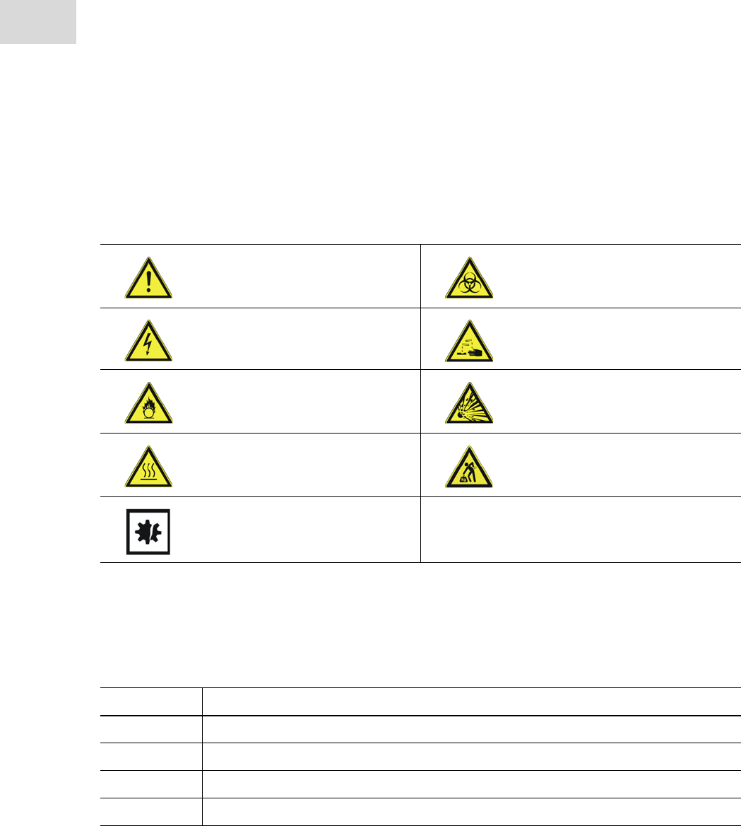
1.2.1 Danger symbols
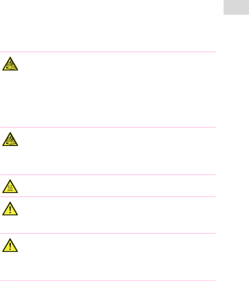
The warning symbols used in this operating manual have the following meanings:
General hazard point Biologically active substances
Risk of electric shock Aggressive chemicals
Oxidizing substances Explosive substances
Hot surfaces Heavy loads
Material damage
1.2.2 Danger levels
Signal word Severity of danger
DANGER Failure to observe this safety information will lead to serious injuries or death.
WARNING Failure to observe this safety information may lead to serious injuries or death.
CAUTION Failure to observe this safety information may lead to minor or moderate injuries.
NOTICE Failure to observe this safety information may lead to product or material damage.
The severity of the danger is indicated by means of signal words.

User instructions
DASbox® Mini Bioreactor System
English (EN)
7
1.3 Symbols used
Depiction Meaning
You are requested to perform an action.
1. ...
2. ...
Perform these actions in the sequence described.
•List
Useful information
1.4 Abbreviations used and definitions
AS
Ampere slow
CF4/CF6/CF12
4/6/12 mm Compression Fitting
COM port
Communications port
D/OD/ID
Diameter/outer diameter/inner diameter
DO
Dissolved oxygen
DoE
Design of experiments
DTP
DASGIP Tiger Protocol;
a transmission protocol for the communication with DASGIP modules (devices) via serial interfaces
FDA
Food and Drug Administration
IEC
International Electrotechnical Commission
LED
Light emitting diode

User instructions
DASbox® Mini Bioreactor System
English (EN)
8
PA
Polyamide
PDF
Portable Document Format
PG (PG13.5)
Steel conduit thread
PS
Polystyrene
PTFE
Polytetrafluoroethylene; DuPont brand name Teflon®
QbD
Quality by Design
rH
Relative humidity
RD
Redox
rpm
Rotations/revolutions per minute
RTD
Resistance temperature detector
Rx
Receiver
SUB-D/D-SUB
D-Subminiature; connector type for data
Tx
Transmitter
USB
Universal Serial Bus

User instructions
DASbox® Mini Bioreactor System
English (EN)
9
1.5 Glossary
Cleaning-in-place (CIP)
A method for the stationary cleaning of process plants or plant parts; in this case, a cleaning procedure for
feed tubing without being moved.
DASbox®
The proper term for the Base Unit of the DASbox System (Chapter 2.1.1).
It is often also used as the short name for a complete DASbox System.
DASbox® System
The term for the sum of all the individual components (DASbox Base Unit and modules) belonging to a
DASbox System.
DTP network
Several DASGIP modules that are connected to one another for communication via serial interfaces.
Headspace
See: Overlay
Level
The option of integrating conductivity sensors which can be used for level or foam control.
Module
A term for a DASGIP device that is used as a component in the DASbox System (examples include the multi
pump module or the sensor module).
Overlay
(Also Headspace); The process of adding media above the surface of the liquid.
The media (gas, liquids) are added to the headspace of the bioreactor.
Push-in connector/socket
A plug-in connection system that enables supply lines to be easily connected and separated.
Stirring element
A stirrer construction in the bioreactor; a general term used to describe the sum of all components.
Submerged
The process of adding media below the surface of the liquid.
The media (liquids, gas) are added directly into the culture medium.
Thermowell
Thermometer protection tube. A tube-shaped fixture for the integration of a Pt100 RTD temperature sensor
into the bioreactor.
Top ring
A silicone ring around the edge of a well in the DASbox. Designed to provide protection against broken
glass due to impact when handling glass bioreactors.

User instructions
DASbox® Mini Bioreactor System
English (EN)
10
Product description
DASbox® Mini Bioreactor System
English (EN)
11
2 Product description
The DASbox is a unique parallel mini bioreactor system suitable for fermentation in microbiology and cell
culture applications. Requiring only minimum lab space, the DASbox provides the functionality of fully
equipped industrial bioreactors.
2.1 Main illustration
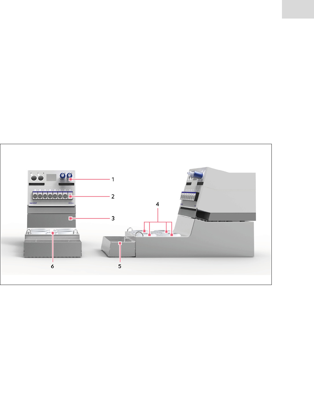
2.1.1 DASbox® System
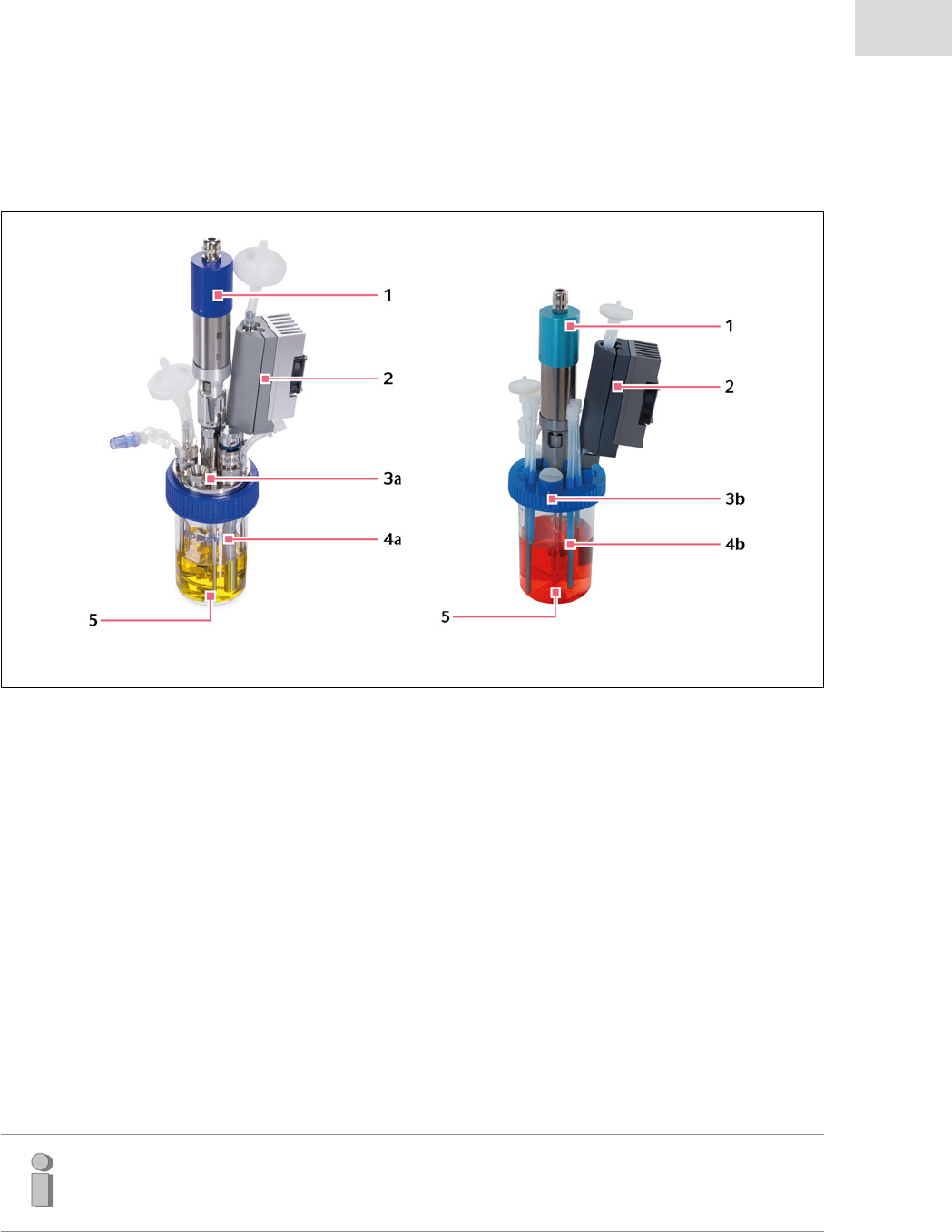
Fig. 2-1: General view of the DASbox® System
1DASbox Storage Unit
Storage compartments for accessories
Monitor for displaying current process values
2 Multi pump and sensor module MP8-pHpO
Multi pumps for media feeding
Sensor ports for the control of process values:
pH, DO, level or pH, DO, redox
3 DASbox Base Unit
(Incl. MX4/4-3 gas mixing module)
Gas supply, gas mixing
Temperature control, agitation
4 Wells for DASbox Bioreactors
Wells suitable for BioBLU 0.3c/f Single-Use Ves-
sels and DASbox Glass Reactors with overhead
stirrer and off-gas condensation
5 Autoclavable Carrier
Removeable carrier for reservoir bottles
6Gas outlets
Push-in ports for gas outlets
(overlay/submerged)
Product description
DASbox® Mini Bioreactor System
English (EN)
12
Fig. 2-2: Rear view of the DASbox® System
1DASbox Storage
Storage compartments for accessories
Port for connecting the monitor
2 Multi pump and sensor module MP8-pHpO
Sensor ports for pH, DO, redox, level
Pt100 temperature sensor port
Communications ports
3 DASbox Base Unit
Gas inlets
Analog interfaces (optional)
Pt100 temperature sensors
Overhead drives
(for glass reactors or single-use vessels)
Off-gas condensers
(for glass reactors or single-use vessels)
Communications ports
Port for connecting the monitor
Note:
Detailed information on the connection elements at the rear of the system can be found in
chapter 4.2, Ports.
Product description
DASbox® Mini Bioreactor System
English (EN)
13
2.1.2 DASbox® Bioreactors
BioBLU® 0.3c/f Single-Use Vessels
DASbox® Glass Reactors
Fig. 2-3: DASbox® Bioreactors for microbiology and cell culture
<
1Overhead motor
For glass reactors or single-use vessels
2 Off-gas condenser with Peltier element
For glass reactors or single-use vessels
3a Head plate (GLS80) for glass reactors
Ports: 5x Pg13.5 and 4x 4 mm pipe ports
Flexible installation of equipment options using
DASGIP Compression Fittings
3b Head plate with integrated ports
For example, for sensors, addition of liquids,
gassing, sampling etc.; magnetic coupling for
overhead motor
4a DASGIP Glass Vessel (GLS80)
Flat bottom vessel with an outer diameter of
70 mm
4b Reactor vessel with integrated fixtures
For example, impellers for cell culture or micro-
biology, thermowell, port for DO sensor, pipe
port
5Agitation
Impellers for microbiology: Rushton type
Impellers for cell culture:
pitched blade (single-use)/
Marine type (glass reactors)
Note:
DASbox Glass Reactors and BioBLU 0.3c/f Single-Use Vessels are each available as cell cul-
ture and microbiology versions.

Product description
DASbox® Mini Bioreactor System
English (EN)
14
2.2 Delivery package of the DASbox® Standard System
The delivery package of a DASbox System depends on the respective configuration and can therefore vary
greatly. Please refer to the corresponding delivery note for full details of the scope of your system.
The delivery package of a DASbox System always includes the following system components:
• DASbox Base Unit with 5 sl/ or 25 sl/h gassing
• MP8-pHpO multi pump and sensor module as a combination module with DASbox Storage and Monitor
• Process computer with monitor, keyboard and mouse
• 4 DASbox Bioreactors (glass reactors or single-use vessels)
• Sensors, condensers, overhead drives, tubing for liquids and gases, media and reservoir vessels
All of the required cables, connectors and multiple socket strips are included in the delivery package.
2.3 Features
2.3.1 Technology
DASbox System
The DASbox features advanced temperature and agitation control and allows for accurate monitoring and
control of pH, DO and level. Mass flow controllers control the individual gas supply to the bioreactors.
The modular design of the DASbox System allows several systems to be stacked together. The DASbox Sys-
tem can be extended to consist of up to 24 parallel operating bioreactors with a minimum use of space. A
parallel system of 24 units requires only 1.8 m of lab bench space.
DASbox Bioreactors
The DASbox can be operated with glass reactors or single-use bioreactors (BioBLU 0.3c/f Single-Use Ves-
sel). Both reactor types are each available as cell culture or microbiology versions and support applications
with a volume range of approximately 60 - 250 ml.
• Glass reactors: 60 - 250 ml
• Single-use vessels: 65 - 250 ml (microbiology); 100 - 250 ml (cell culture).
• Refer to the chapter 10, Ordering information. This chapter contains a list of accessory
parts for DASbox Systems.
• The multi pump and sensor module is optionally available with level or redox measure-
ment (correct product designation: MP8-PH4PO4LS or MP8-PH4PO4RD4S).

Product description
DASbox® Mini Bioreactor System
English (EN)
15
Overhead-operated mini impellers are used for the agitation of the DASbox Bioreactors.
• Glass reactors: Rushton type (microbiology) or marine type (cell culture)
• Single-use vessels: Rushton type (microbiology) or pitched blade (cell culture)
Gases can either be supplied submerged or via the headspace of the bioreactor (overlay). In addition, an
integrated splitter function in the DASbox Base Unit enables individual gas types to be routed directly into
the medium (submerged) or to the headspace. Off-gas condensers with Peltier elements are available for
exhaust gas routing.
2.3.2 DASGIP® Control
The DASbox is exclusively controlled via the DASGIP Control software.
The software allows for flexible configuration of fermentation processes with online processing of set-point
profiles and enhanced automation options via trigger functions.
Parallel calibration procedures and preconfigured cleaning-in-place (CIP) procedures help with the prepa-
ration and follow-up of your processes.
During the fermentation process, numerous intervention options are available via the intuitive process
view.
DASware® options
The DASGIP DASware Bioprocess Software Suite offers a range of flexible and intelligent solutions for the
implementation of key Quality by Design (QbD) aspects of the current FDA's Process Validation Guidance,
thus accelerating the development of bioprocess operations.
In particular, DASware design, a tool for the application of sta-
tistical Design of Experiment (DoE), and DASware discover, a
comprehensive and user-friendly software for data and infor-
mation management, are designed to make working with the
DASbox even easier.
2.3.3 Applications
With the above-mentioned features and mini bioreactors with a minimum working volume, the DASbox is
the optimal tool for advanced process development.
Other typical applications include screening of cells and cloning, media optimization and statistical Design
of Experiment (DoE) applications.

Product description
DASbox® Mini Bioreactor System
English (EN)
16

General safety instructions
DASbox® Mini Bioreactor System
English (EN)
17
3 General safety instructions
This section contains important information for the intended use of the DASbox System.
3.1 Intended use
The DASbox System is designed for the cultivation of cells and microorganisms in biotechnological labora-
tories.
Typical areas in which the DASbox System is used include research, process development and quality con-
trol in different biotechnology fields (e.g., industrial, pharmaceutical, biotechnology).
Only original accessory parts may be used for operating the DASbox System.
WARNING! Not approved for use in medical diagnostics or therapy!
The DASbox System has not been developed for applications in medical diagnosis or therapy
and must not be used in such applications. It is not a medical device within the meaning of
Directive 93/42/EEC.
WARNING! Risk of electrical hazard when wet.
The DASbox System is neither splash-proof nor suitable for outdoor use.
The DASbox System is intended for indoor use only.
3.2 User profile
The DASbox System must only be operated by qualified personnel.
The qualified personnel must have received training for the system described here which has been orga-
nized by an Eppendorf Bioprocess Center service technician.
The qualified personnel must have carefully read this operating manual.
General safety instructions
DASbox® Mini Bioreactor System
English (EN)
18
3.3 Notes on product liability
The operating safety of the DASbox System may be compromised in the cases outlined below. In such
cases, the owner is responsible for assuming liability associated with material damage or personal injury
claims of any sort.
• Commissioning and using the DASbox System without observing the notes and instructions provided in
this operating manual and the other applicable documents.
•Improper use.
• Using accessory parts that are not recommended by DASGIP.
• Operating the DASbox System outside of the application limits described in this operating manual.
• Maintenance or repair of the system by persons who have not been authorized to do so by
Eppendorf AG or DASGIP.
• In the case of unauthorized modifications to the DASbox System.
3.4 Warnings for intended use
WARNING! Lethal voltages inside the device.
Make sure that the housings of the devices belonging to the DASbox System are always
closed and undamaged to ensure that no parts inside the devices can be touched inadver-
tently.
Never open the housings of the devices.
Avoid the ingress of liquid into the inside of the devices.
The devices may only be opened by service personal who have been authorized to carry
out such work by DASGIP or Eppendorf.
WARNING! Risk of electric shock from damage to devices or mains power cables.
Do not switch on any devices belonging to the DASbox System if visibly damaged.
Only use devices that have been properly installed or repaired.
Disconnect the device from the mains power supply in the event of danger.
Only replace damaged parts with original spare parts.
Access to the mains power switch must not be blocked.
WARNING! Risk from incorrect supply voltage
Only connect the devices belonging to the DASbox System to power sources that meet the
electrical specifications on the back of the devices.
Only use sockets with a protective earth (PE) conductor and a suitable mains power cable.
WARNING! Electrical hazard if protective grounding is missing.
Each device within the DASbox System is connected via a cable with a protective grounding
conductor to the mains power supply.
Make sure that your mains power supply system has a functional protective ground contact
for each device and that it is properly connected to the protective ground contact on the
power cable of the device.
WARNING! Electrical hazard. Mains isolating device must be freely accessible.
In an emergency, it must be possible to quickly unplug the power supply cables of all devices
within the DASbox System.
When installing the system, ensure that each of the power supply cables of the DASbox
System are freely accessible at one of the two ends.
WARNING! Electrical hazard when replacing safety fuses in the device.
The device safety fuses are located in the mains connection unit at the back of each device.
Disconnect the plug on the device from the power supply before replacing device safety
fuses.
Only use fuses of the following type:
Dimensions: 5x20 mm; rated voltage at least 250 V, characteristic "slow-blow".
nominal current 2.5 A (MP8-pHpO); 10 A (DASbox Base Unit).
Observe the information on the rear panel of the device.
DANGER! Risk of explosion.
Do not operate the DASbox System in rooms where work is being carried out with explo-
sive substances.
Do not use the DASbox System to process any explosive or highly reactive substances.
Do not use the DASbox System to process any substances which could create an explosive
atmosphere.
General safety instructions
DASbox® Mini Bioreactor System
English (EN)
19
CAUTION! Risk of personal injury and material damage when lifting and carrying heavy
loads.
The DASbox is heavy. Lifting and carrying the device can lead to back injuries.
The hooks at the front and the grip at the back of the DASbox are not handles. They are only
designed for moving the DASbox on telescopic rails or for lifting the lid during service work.
NEVER use the hooks and the grip on the DASbox as handles.
The DASbox must be transported by least two people.
Lift the DASbox by reaching under the device.
Use a transport aid (such as a dolly) to transport the device over longer distances.
WARNING! Danger to health from pathogenic germs or infectious liquids.
When handling pathogenic germs and infectious liquids, observe the national regulations,
the biological safety level of your laboratory, the safety data sheets, and the manufacturer's
application notes.
Wear personal protective equipment (PPE).
WARNING! Danger to health from aggressive chemicals.
Observe the safety data sheets of all substances used (e.g., pH adjustment agent).
Wear personal protective equipment (PPE).
WARNING! Danger from oxidizing or explosive gases and gas mixtures
Gas mixtures in specific ratios can be explosive.
Determine and observe the upper and lower explosion limits (UEL; LEL) of the gases used.
Also consider the possible production of gas during the cultivation process.
Do not use the DASbox to process gases within the explosion limits.
WARNING! Danger due to oxygen enriched atmospheres.
Even a slightly oxygen-enriched atmosphere increases the risk of materials igniting more
easily and burning more intensely. Oxygen-enriched hair or clothing can catch fire and result
in serious injury or death. There is a risk of self-ignition in case of contact with oils and
greases.
Only use oil-free compressed air for operating the DASbox.
Keep all parts which come into contact with oxygen free from oils and greases.
Always make sure that no excess oxygen can increase the ambient concentration to a
dangerous level.
Regularly check the fitting and tightness of the gassing tubes to the bioreactors.
General safety instructions
DASbox® Mini Bioreactor System
English (EN)
20
WARNING! Maximum operating pressure of 0.5bar. Exceeding the limit may result in
burst risk.
DASbox Bioreactors are designed for a maximum operating pressure of 0.5 bar (relative
overpressure).
Do not operate the bioreactors with a higher pressure.
Never block the outlet filters.
Observe the maximum inlet pressure of 0.5 bar for all connected gases.
Do not connect the gases without a pressure reducer.
Wear personal protective equipment (PPE) while handling gassed bioreactors.
CAUTION! Risk of explosion due to damaged glass vessels.
Hairline cracks, fissures or deep scratches in the glass can endanger the stability of glass
reactors. This may pose a risk of explosion! Splinters can fly out in an uncontrolled manner.
Inspect for visible signs of damage and do not use damaged glass reactors.
Wear protective goggles in the vicinity of gassed bioreactors.
CAUTION! Danger from hot surfaces.
Please note that the wells for holding the reactors of the DASbox can become hot.
G
Check the secure fitting of all sensors prior to the start of a fermentation.
CAUTION! Danger from rotating parts.
When operating overhead operated stirring elements outside of the bioreactor there is a risk
of injury and the danger of clothing or hair getting entangled.
Do not touch the rotating parts.
Only operate overhead operated stirring elements within the bioreactor.
General safety instructions
DASbox® Mini Bioreactor System
English (EN)
21
WARNING! Danger from uncontrolled flying parts.
In the event of an increase in pressure in the bioreactor, inadequately secured sensors can be
ejected from the reactor and become dangerous projectiles.
CAUTION! Danger from squirting of dispensing media.
If blockages occur on the outlet side of the feed line, this may result in a significant increase in
pressure within the supply line due to the pumping capacity of the peristaltic pump. There is
the potential risk of aggressive liquids escaping or being squirted out.
Regularly check the feed tubing for blockages (kinks, encrustations, etc.).
Wear protective goggles and protective clothing.
CAUTION! Danger from liquids and gases leaking.
Inadequately fastened or incorrectly fitted Luer connectors can result in leaks. Leaked
dispensing media can cause encrustation between the DASbox Base Unit and the bioreactor.
Check that all Luer connectors are straight and securely attached before each use.
NOTICE! Observe the ambient conditions.
Observe the permissible ambient conditions when installing and operating the DASbox.
Before using the DASbox at high temperatures and high air humidity, contact DASGIP to
check system suitability.
CAUTION! Do not cover the ventilation slots.
Always ensure sufficient convection to allow heat to dissipate.
Make sure that the ventilation grating of the system components is not covered.
CAUTION! Do not confuse connecting sockets! Observe the connection values.
When connecting accessory parts, observe the labeling on the connectors and the speci-
fied connection values.
When connecting sensors, observe the input limits specified in the manual.
CAUTION! Risk of product damage when connecting gases to the DASbox.
Particles passing through the gas inlets into the interior of the DASbox can damage valves and
flow sensors.
Forcibly detaching the connected gas tubing may cause plastic shavings that can get inside
the DASbox.
Do not connect the gases without a particle filter.
Use the supplied disassembly tool to disconnect the push-in connectors.
General safety instructions
DASbox® Mini Bioreactor System
English (EN)
22

CAUTION! Risk of product damage. Do not disconnect any connectors during operation.
Devices and accessory parts may be damaged.
Do not disconnect any connectors during system operation.
CAUTION! Risk of product damage due to increased top-heaviness of bioreactors with an
off-gas condenser and a stirring drive.
The installation of an off-gas condenser and a stirring drive greatly increases the
top-heaviness of DASbox Bioreactors. The reactors may tip over easily.
Before assembling accessory parts, ensure the reactor is stable by positioning it in a well
in the DASbox.
CAUTION! Risk of product damage during the assembly and storage of Pt 100 temperature
sensors.
The Pt 100 temperature sensors can be bent by improper assembly and storage. In particular,
the matt part at the lower end of the sensor can easily break.
Carefully guide the sensor into the thermowell.
Store unused temperature sensors in a protective covering or similar or in the designated
holders provided in the DASbox Storage Unit.
CAUTION! Risk of product damage when handling DO sensors for DASbox Single-Use
Reactors.
The DO sensors for DASbox Single-Use Reactors can be damaged by improper handling.
Avoid exerting mechanical stress on the sensor tip.
Store unused sensors in the storage box.
CAUTION! Risk of collision with rotating stirring elements
Rotating stirrer impellers can damage sensors and other fixtures in the bioreactor (this may
include broken glass and scratch marks).
Make sure that all stirring elements and fixtures are mounted correctly.
CAUTION! Risk of damage to device from improper use of cleaning agents.
Do not use any aggressive, corrosive or abrasive disinfectants or cleaning agents.
If you have any questions about the compatibility of cleaning agents and disinfectants or
their ingredients, please contact a service technician at the Eppendorf Bioprocess Center.
General safety instructions
DASbox® Mini Bioreactor System
English (EN)
23
General safety instructions
DASbox® Mini Bioreactor System
English (EN)
24
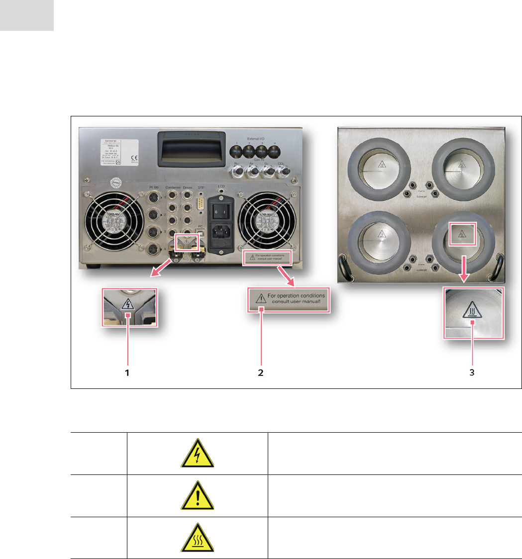
3.5 Warning symbols on devices and accessories
Abb. 3-1: General view of the epMotion
Fig. 3-1: Warning symbols on the DASbox® System
1WARNING! Observe the connection values.
Observe the information on the connection values
provided in the operating manual.
2CAUTION! Consult user manual.
For operation conditions consult user manual
3CAUTION! Hot surfaces.
Please note that the wells for bioreactors can become hot.
General safety instructions
DASbox® Mini Bioreactor System
English (EN)
25
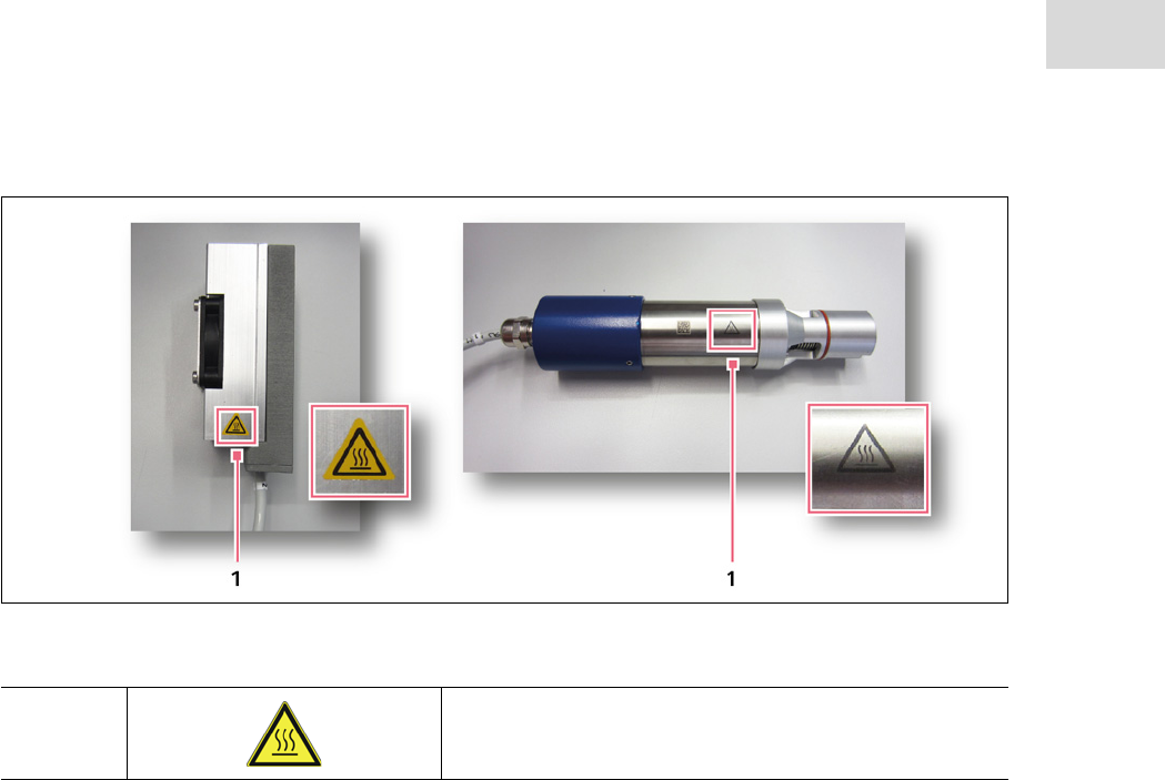
Fig. 3-2: Warning symbols on the DASbox® accessories
1CAUTION! Hot surfaces.
The surfaces of the off-gas condensers and stirring drives
can become hot after a longer operating time.

General safety instructions
DASbox® Mini Bioreactor System
English (EN)
26

Installation
DASbox® Mini Bioreactor System
English (EN)
27
4 Installation
The DASbox System is delivered in a transport-safe wooden box. The system must be unpacked and
installed by Eppendorf Bioprocess Center service technicians.
Have the wooden box transported as close as possible to the future installation site.
Do not unpack the box after delivery.
Check the packaging for external damage only.
In the case of visible damage to the outer packaging, inform your contact person at the Eppendorf
Bioprocess Center.
Only unpack the box together with a service technician. This procedure enables the technician to check
the equipment for any hidden transport damage.
If possible keep the padded packaging for future transport or shipment.
4.1 Selecting the location
Information on ambient conditions, system dimensions and weights can be found in the technical data
(chapter 9).
WARNING! Risk of danger from electrical current.
The DASbox is suitable for indoor installation only!
Select the location for the device according to the following criteria:
Location
• The ambient conditions match the specifications in the technical data.
• The location is dry, clean and free of dust.
• The convection of air at the rear of the device must be sufficient to ensure heat can dissipate.
• The location is protected from direct sunlight.
• The location is not next to heat sources, such as heaters or drier compartments.
• The device can be safely and easily operated at this location.
• When the device is in operation, the device mains power switch and the mains isolating device
(e.g., FI safety switch) must be freely accessible.
Workplace
• The lab bench is stable and designed to accommodate the weight of the DASbox System.

Installation
DASbox® Mini Bioreactor System
English (EN)
28
• The lab bench has a horizontal, plane work surface.
• In addition to the system, the lab bench also offers enough space for performing work necessary during
the completion of cultivation processes.
Electrical connections
• 2 mains power connections for a DASbox System with 4 to 8 bioreactors.
• Mains power connections: 100-240 VAC (no manual switching required), 50/60 Hz.
Gas supply
The compressed air and all gases that are connected to the DASbox System must meet the following crite-
ria:
• Compressed air: oil-free, dry and free of particles.
• Gases: clean, free of particles, dry, non-condensing.
CAUTION! Risk of damage to device from incorrect gas quality.
Only gases that meet all the above-mentioned criteria may be used for operating the
DASbox System.
4.2 Ports
4.2.1 Mains connection unit and communication ports
The mains connection unit and communication ports (serial interfaces) are identical for all DASbox devices.
Therefore, the details of these connection units are described here first.
Communication ports
Mains connection unit
Installation
DASbox® Mini Bioreactor System
English (EN)
29
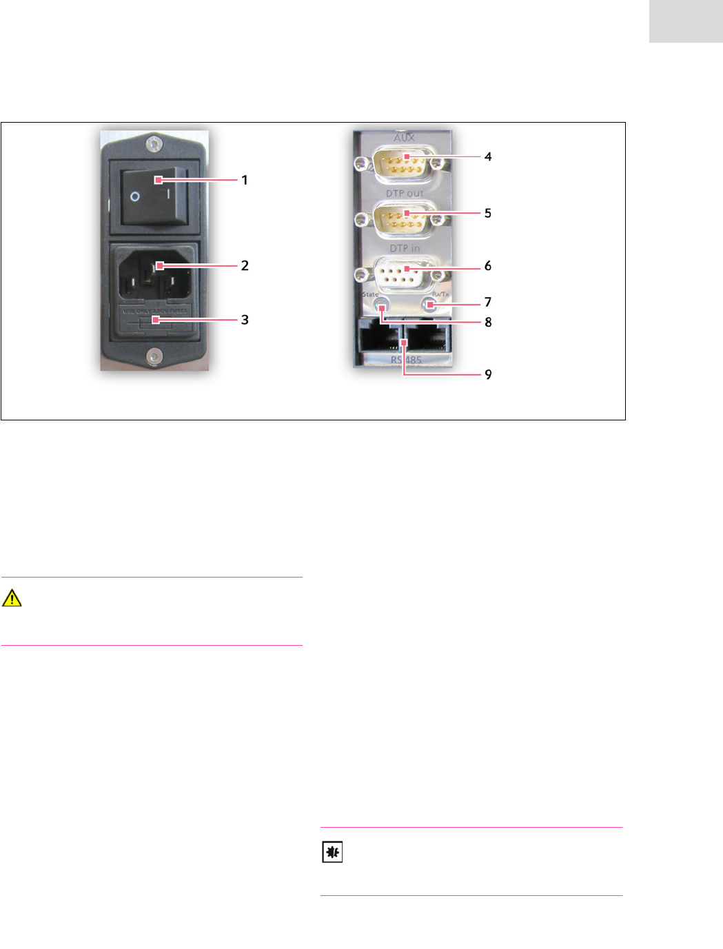
Fig. 4-1: Mains connection unit and communication ports
1Mains disconnect switch of the device
The on and off positions are marked according
to standard:
I = ON
O = OFF
WARNING
The mains disconnect switch of the device
must always be freely accessible.
2Mains connection
IEC power connector for connecting a power
cord 100-240 VAC, 50/60 Hz.
3Fuse holder
Fuse holder for holding two 20 mm x 5 mm
microfuses.
DASbox Base Unit: 2 x 10 AT
MP8-pHpO: 2 x 2.5 AT.
4AUX
SUB D9M / RS232 plug for connecting addi-
tional devices and potential free alarm contacts.
5"DTP out"
SUB D9M / RS232 plug for integrating
DTP-capable add-on modules (e.g., GA4, MP8)
to a DTP network.
6"DTP in"
SUB D9F / RS232 connector for communication
with the process computer. This port is either
connected directly with the process computer,
or alternatively with the DTP Out output of
another DTP-capable device.
7"Rx/Tx" (DTP communication display)
Gray = no signal
Green = receive
Orange = transmit
Red = communication fault
8"State" (DTP state indicator)
Gray = DTP in/out ports enabled
Green = RS485 ports enabled
NOTICE!
Do not confuse the "RS485" ports with the
Ethernet ports as the design is the same.
9)*RJ45 connectors for a RS485 network
Potential-free (*assignment optional)
Installation
DASbox® Mini Bioreactor System
English (EN)
30
4.2.2 DASbox® Base Unit
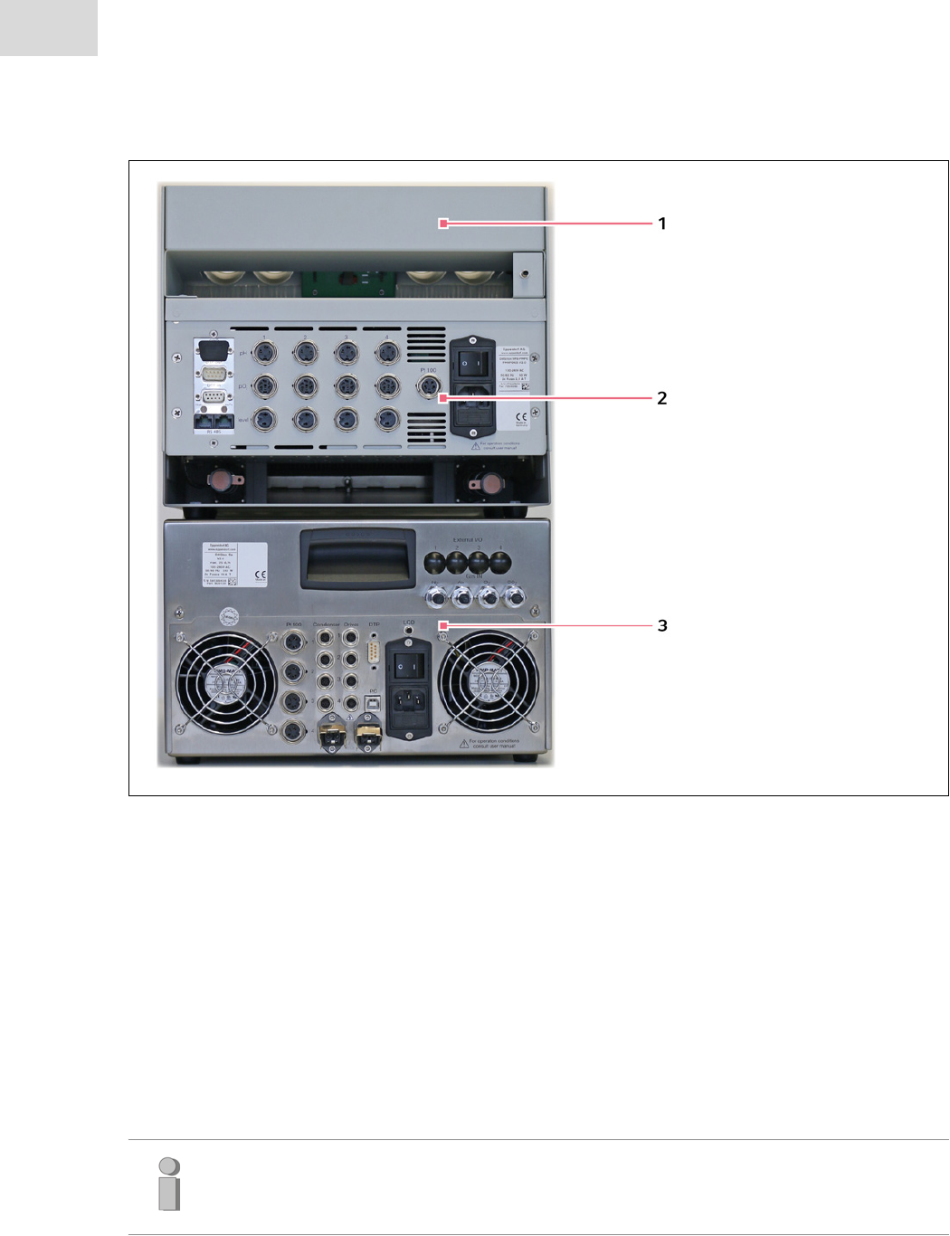
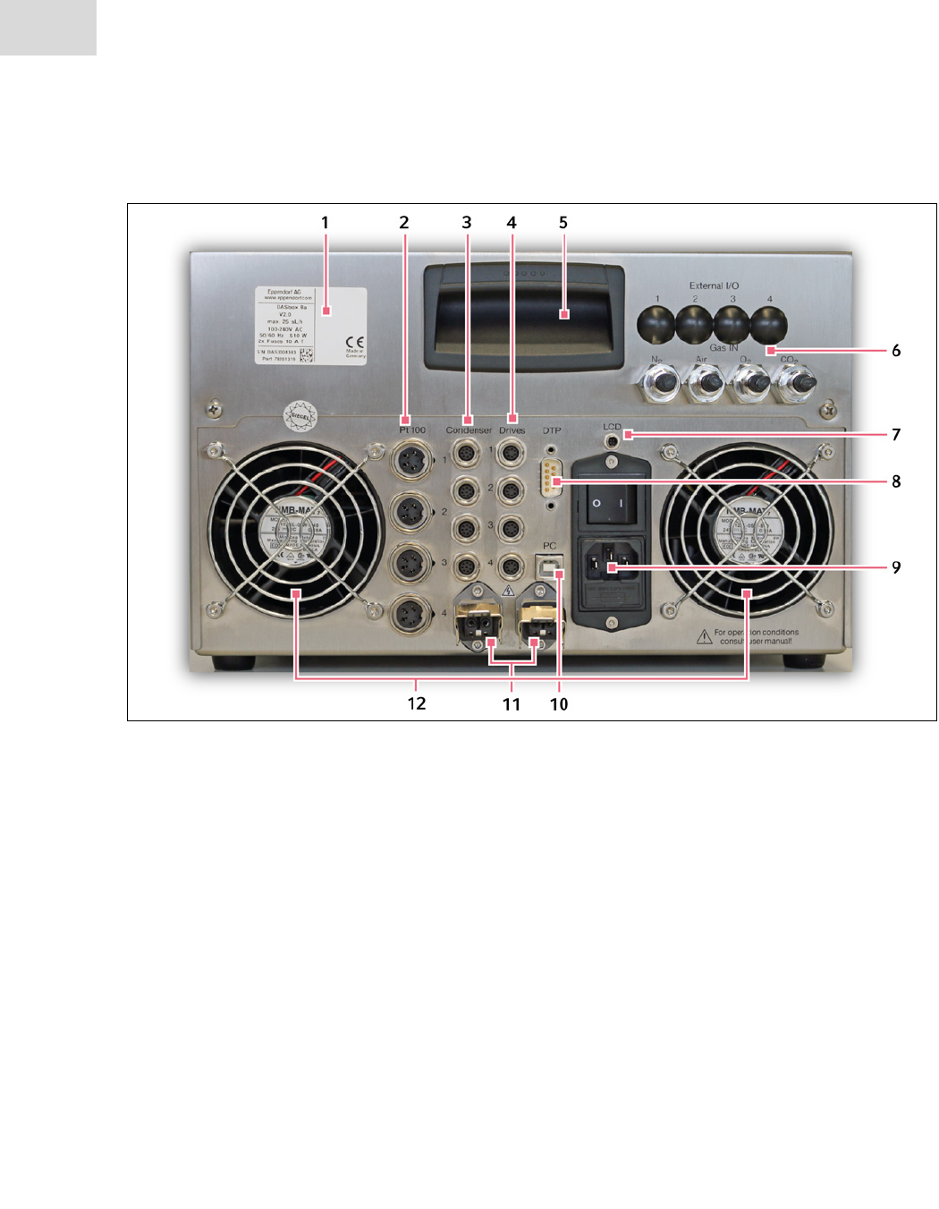
Fig. 4-2: Ports at the rear of the DASbox® Base Unit
1 Sticker with important information
DASbox version, gas flow, part number, serial
number, CE marking, contact information
2 Pt 100 1-4 for temperature sensors
Pt 100 temperature sensors for measurement in
the bioreactors.
3 Condenser 1-4 for off-gas condensers
Off-gas condensers
(typically 10 W per condenser)
4 Drives 1-4 for overhead motors
Overhead motors für DASbox Bioreactors
(Glass or Single-Use Bioreactors)
5Grip
Used to open the DASbox for service purposes.
Not suitable for carrying purposes.
6 Gas ports and *optional external interfaces
For an explanation see Fig. 6-2
7LCD Monitor
Port for the LCD monitor integrated in DASbox
Storage.
8 DTP port for internal system communication
The DTP ports (COM Ports) of the DASbox
modules are connected with serial DTP cables.
9External power supply
Mains connection unit, Fig. 4-1
10 USB port for external communication
This port is connected with a USB cable to a
USB port on the process computer.
11 Internal power supply
Stas 200 type ports for the internal power sup-
ply of the system.
12 Ventilation grating
For removing heat from the inside of the device.
Do not cover the ventilation grating.
* Further information about specifications of ports can be found in chapter 9, Technical data.
CAUTION! Risk of damage to device.
When connecting DASbox components, observe the labeling on the connecting sockets
and the specified connection values.
Don’t connect the plugs of the overhead motors with the connecting-sockets of the off-gas
condensers. The design of the plugs is similar, but not identic.
Observe the input limits specified in the manual.
Do not disconnect any plugs during system operation.
Do not cover the ventilation grating.
Installation
DASbox® Mini Bioreactor System
English (EN)
31
Gas supply
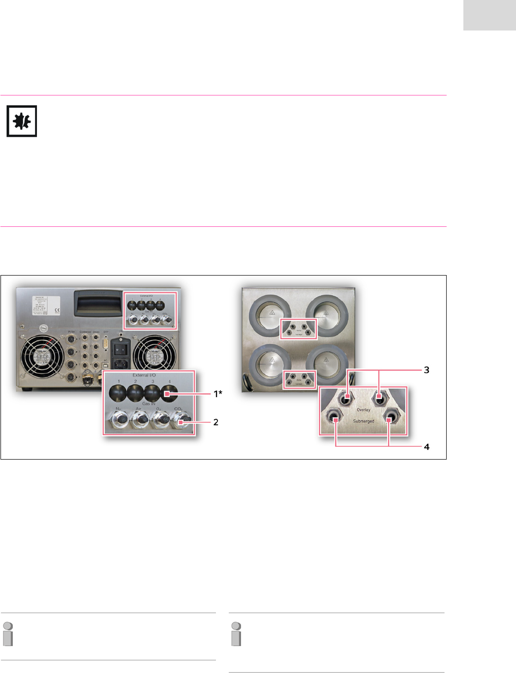
Fig. 4-3: DASbox Base Unit - ports for the gas supply
1* External I/O (optional)
External interfaces; option for analog system
contol.
2Gas IN (gas inlets) N2,Air, O2,CO2
Gas inlets for nitrogen, compressed air, oxygen
and carbon dioxide.
6 mm push-in connector for connecting gas tub-
ing.
To protect the sensors inside the device,
particle filters are integrated by default into
the gas tubing on the inlet side.
3Overlay (overlay gas outlets)
Outlets of channels 1-4 for gas types which are
to be directed into the headspace of the bioreac-
tor (4 mm push-in connector).
4Submerged (submerged gas outlets)
Outlets of channels 1-4 for gas types which are
to be directed into the medium
(4 mm push-in connector).
To protect the sensors inside the device,
nonreturn valves have been integrated here to
prevent medium from flowing back through
the gassing tube.
* Further information about specifications of ports can be found in chapter 9, Technical data.
<
WARNING! Risk of explosion if oxygen comes into contact with greases and oils.
There is a risk of self-ignition if oxygen comes into contact with oils and greases.
Only use oil-free compressed air for operating the DASbox.
Keep all parts which come into contact with oxygen free from oils and greases.
CAUTION! Risk of damage to device if the DASbox is operated without a particle filter.
Even if the connected gases have a very high purity grade, a discharge of particles from gas
bottles or pipelines cannot be excluded. Particles can be the cause of operational changes in
electronic mass flow sensors or leaks in valves.
To avoid such errors, particle filters are integrated into the gas tubing on the inlet side.
Do not operate the DASbox System without a particle filter.
CAUTION! Risk of damage to device from moist compressed air or gases.
Moisture can damage the sensors inside the DASbox.
Only use dry, non-condensing gases and compressed air for operating the DASbox System.
WARNING! Danger from overpressure. Maximum operating pressure of 0.5 bar.
DASbox Bioreactors are designed for a maximum operating pressure of 0.5 bar (relative
overpressure).
Observe the maximum inlet pressure of 0.5 bar for all connected gases.
Do not connect the gases without a pressure reducer.
Installation
DASbox® Mini Bioreactor System
English (EN)
32
Installation
DASbox® Mini Bioreactor System
English (EN)
33
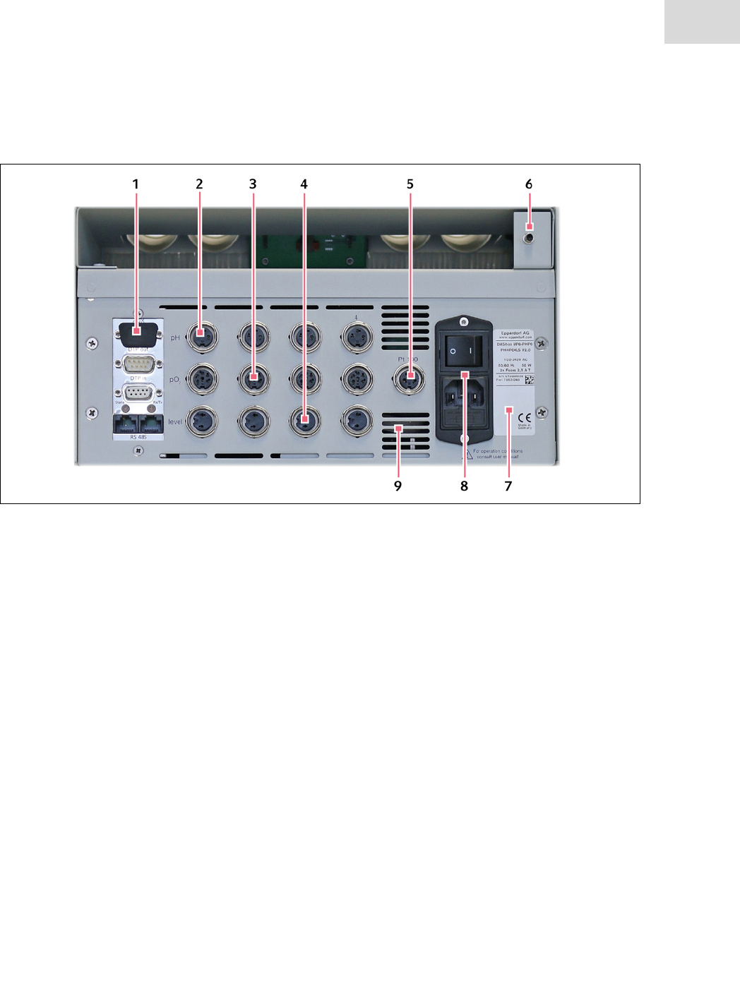
4.2.3 MP8-pHpO multi pump and sensor module
Fig. 4-4: Rear of the multi pump and sensor unit of the DASbox®
1DTP ports for internal system communication
Serial ports (COM ports) for internal communi-
cation among the DASGIP modules.
The Serial ports of the DASbox modules are
connected by serial cables (DTP cables).
2 pH 1-4 for pH sensors
Measuring range: pH 0 – pH 14 (± 0.01 pH)
(at a sensor temperature of max. 67°C)
3 pO2 1-4 for DO sensors
Measuring range DO:
0 – 500 % DO
Measuring range Temperature (NTC):
-10°C – 140°C (± 0.2 K)
4 level 1-4 for conductivity sensors
(optional: for redox sensors)
Conductivity measurement for foam or level
control
Input limits: 0 – 20 mS
Measurement of the redox potential
Input limits: -2000 – 2000 mV (± 1 mV)
5 "Pt100" temperature sensor
Pt 100 temperature sensor for automatic tem-
perature compensation during calibration and
measurement.
Input limits: 90 – 160 Ohm
Measuring range: -25°C – 116°C (± 1 °C)
6LCD Monitor
Port for the LCD monitor integrated in DASbox
Storage.
7Serial number
When contacting DASGIP, please always provide
the serial number of the device.
8 Mains connection unit
Power supply, mains power switch and fuse
holder (see chapter 4.2.1).
The mains power connection is connected to the
internal mains power supply of the base unit.
9 Ventilation slots
Ventilation slots for removing heat from the
inside of the device.
Always ensure the flow of exhaust air is unre-
stricted.
* Further information about specifications of ports can be found in chapter 9, Technical data.

CAUTION! Risk of damage to device from incorrect connections.
When connecting DASbox components, observe the labeling on the connecting sockets
and the specified connection values.
Observe the input limits specified in the manual.
Do not disconnect any plugs during system operation.
Installation
DASbox® Mini Bioreactor System
English (EN)
34
4.3 Installing the device
CAUTION! Risk of damage to device.
The DASbox may only be installed and commissioned by skilled personnel authorized by
DASGIP.
Please contact the Service Department before making any changes to your system.
Refer to the following instructions on connecting components belonging to the DASbox
System.
Also refer to the information on the connection elements provided in the chapters 4.2.1 to
4.2.3.
Installation
DASbox® Mini Bioreactor System
English (EN)
35
4.3.1 Establishing the electrical supply and communication
First establish all the connections needed to ensure the power supply and to secure communication
between the devices.
Electrical supply
First make sure that all mains power switches are in the "O"
(=OFF) position.
For the external power supply, use the supplied power cord
to connect the power connector of the base unit to a mains
socket (1).
Then establish the internal power supply of the system:
Connect one of the Stas 200 plugs on the DASbox Base Unit
to the mains power connection of the MP8-pHpO module
(2).
*Optional add-on modules:
Either connect an add-on module (e.g., MP8 or GA4) via the
second Stas 200 plug to the DASbox Base Unit or connect it
with an additional power connector to a mains power
socket.
Use the adapter cable with a Stas 200 (Hirschmann) plug.
Lock the Stas 200 plugs by folding down the metal brackets.
WARNING! Risk of electric shock.
Never use any devices if the power cord or plug is damaged.
Installation
DASbox® Mini Bioreactor System
English (EN)
36
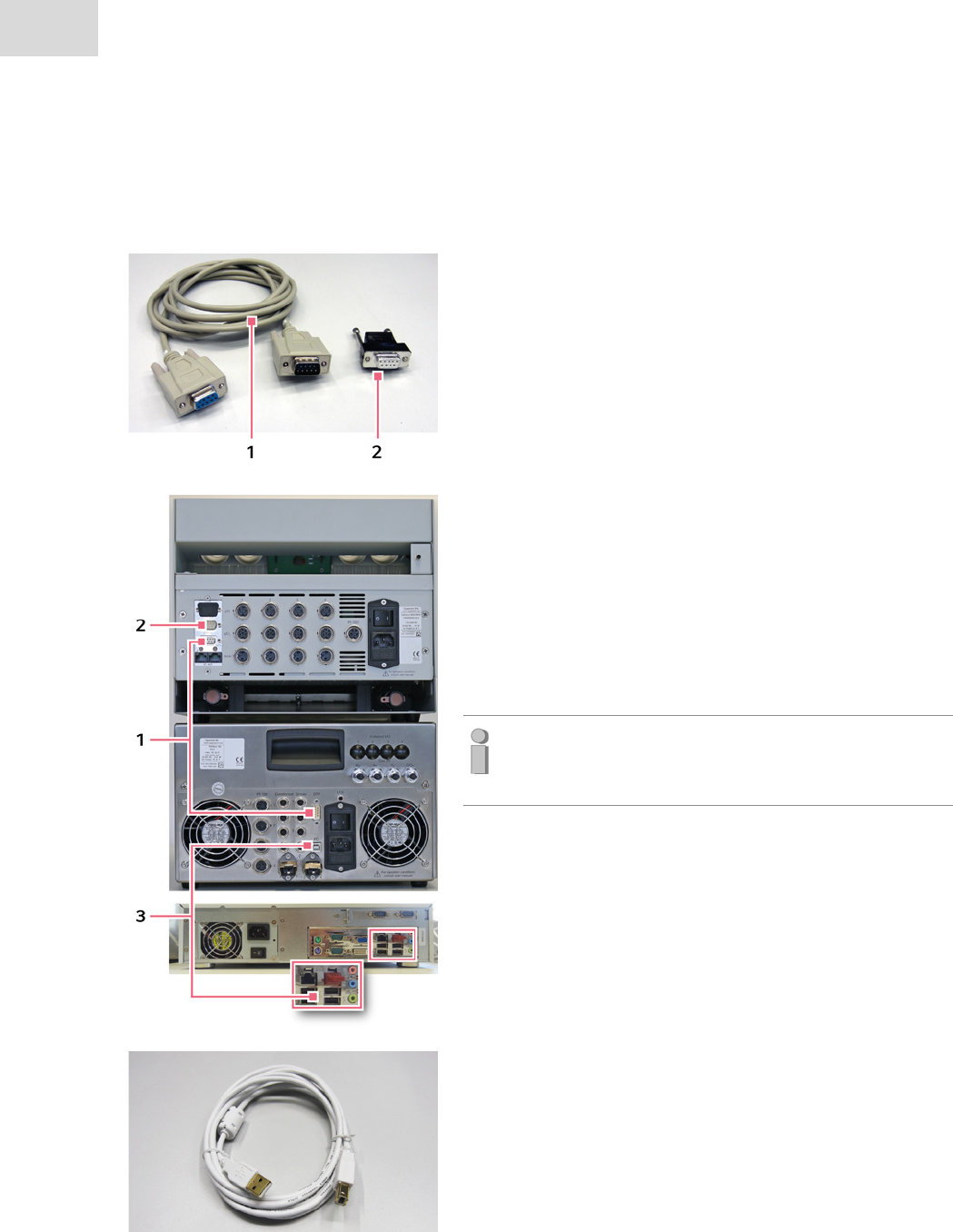
Communication (establishing the DTP network)
Next establish the connections for device communication.
Within a DASbox System, the individual modules are connected
in series with each other starting from the base unit using DTP
cables (1).
The end is formed by a terminator connector (2).
Connect the DTP port on the base unit (no. 8 in Fig. 4-2) to
the "DTP in" port on the MP8-pHpO module (1).
*Optional:
If an additional DASGIP module should be integrated,
connect the "DTP out" connector on the MP8-pHpO module
to the "DTP in" input on the additional module.
Provide the "DTP out" output on the MP8-pHpO module
(*optional on the additional module) with the terminator‐
connector (2).
Note:
To ensure stable data transfer, each "DTP out" output of
the last device is provided with a terminator connector.
For external communication, connect the USB port "PC" on
the base unit (no. 10 in Fig. 4-2) to a free USB port on the
process computer (3).
Use the supplied USB cable for this purpose.
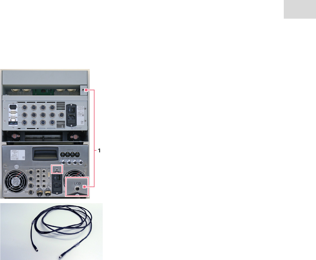
Connect the monitor port at the rear of DASbox Storage to
the "LCD" port on the DASbox Base Unit (1).
Use the supplied monitor cable for this purpose.
Installation
DASbox® Mini Bioreactor System
English (EN)
37
Connecting the LCD monitor
Installation
DASbox® Mini Bioreactor System
English (EN)
38
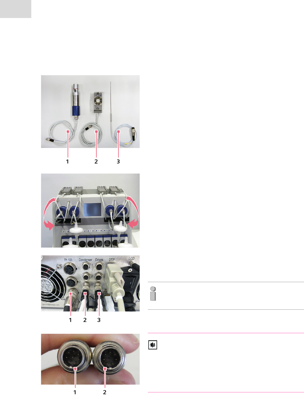
4.3.2 Connecting off-gas condensers, overhead drives and temperature sensors
Now connect all the elements to the DASbox Base Unit
which are housed in the storage compartments of DASbox
Storage:
• Overhead motors (1),
• Actuators for off-gas condensers (2),
• Temperature sensors (3).
Position the actuators for off-gas condensers, overhead
motors and the temperature sensors as shown in the
adjacent figure in the storage compartments of the DASbox
Base Unit.
Guide all the cables from front to back through the storage
compartment.
Now connect the temperature sensors (1) , off-gas condens-
ers (2), and overhead drives (3) for the reactors 1 - 4 to the
base unit.
Note:
Observe the number marks on the cables.
NOTICE! Possible risk of damage to connectors!
The connectors for the actuators have 8 pins (1); the con-
nectors for the overhead drives have 7 pins (2). They are
otherwise identical in construction so that the overhead
drives are also suitable for the connectors of the off-gas
condensers.
Plug and socket connectors must not be confused.
39
Installation
DASbox® Mini Bioreactor System
English (EN)
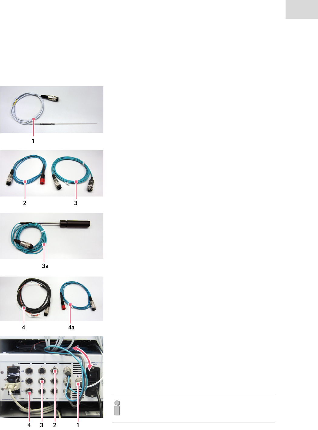
4.3.3 Connecting Sensors and cables to the MP8-pHpO module
Next, connect the following sensor cables to the MP8-pHpO module:
•Pt100 temperature sensor for temperature compensation
during pH calibration (1).
•4x pH cable (2)
•4x DO cable (3)
• or optionally 4x DO sensors for single-use vessels (3a)
(DO sensor for DASGIP D 4.7 mm, L 162 mm)
• 4x cable for conductivity sensors for the level option (4)
• or optionally 4x cable for redox sensors (4a)
Guide the sensor cables from front to back through the
cable compartment of the DASbox Storage Unit.
Connect the cables according to the labeling to the
connecting sockets at the rear of the MP8-pHpO module:
Pt100 Sensor (1), pH cables 1-4 (2),
DO cables 1-4 or DO sensors 1-4 for single-use vessels (3)
cables 1-4 for the level option or redox cables 1-4 (4).
Note:
Observe the number marks on the cables.
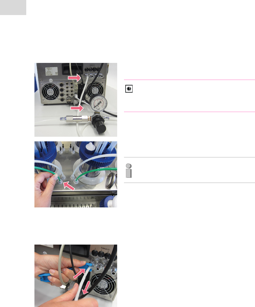
Installation
DASbox® Mini Bioreactor System
English (EN)
40
4.3.4 Connecting the gas supply
Connect the gas tubing of the four inlet gases to the "Gas
IN" gas inlets at the rear of the DASbox Base Unit.
NOTICE! Risk of damage to device.
Do not connect inlet gases without a particle filter and a
pressure reducer.
There is a maximum inlet pressure of 0.5 bar.
Connect the gassing tubes to the "Overlay" and
"Submerged" outputs next to the wells for bioreactors.
Note:
Insert the supply lines into the push-in ports applying
slight pressure, until you can feel them engage.
Loosen the gassing tubes
To loosen the gassing tubes, use the provided disassembly
tool for push-in ports.
Pull the gas tube out while pressing down the outer ring of
the push-in port.
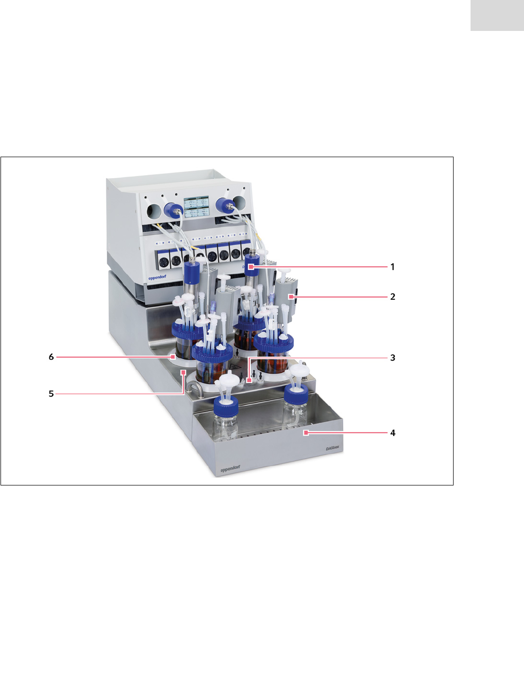
41
Hardware and operation
DASbox® Mini Bioreactor System
English (EN)
5 Hardware and operation
5.1 Gassing, temperature control and agitation - the DASbox® Base Unit
Fig. 5-1: Functions of the DASbox® Base Unit
1 Agitation
Individual agitation with overhead motors for
glass reactors and single-use vessels.
2 Off-gas condensers
Suitable for for glass reactors and single-use
vessels, see chapter 5.2.
3 Gassing
Gas mixing system with integrated splitter func-
tion: "Overlay" and "Submerged" gas outputs
next to each bioreactor well.
4Autoclavable Carrier
Removable storage facility for up to 8 reservoir
bottles with media (see chapter 5.5).
5 Temperature control
Wells for 4 DASbox Bioreactors, suitable for
glass reactors and single-use vessels.
Individual temperature control, liquid free using
Peltier elements.
6Top rings
Silicone impact protectors designed to prevent
broken glass when handling DASbox Glass
Reactors.

Hardware and operation
DASbox® Mini Bioreactor System
English (EN)
42
5.1.1 Gas mixing and gassing
Gas mixing system
The gas mixing system integrated in the DASbox is fully mass flow controlled and supports software config-
urable gassing schemes.
It has 4 gas inlets as well as 4 device channels, each of which can be assigned to a bioreactor.
The gas inlets are supplied by default with N2, Air, O2 and CO2. Each device channel is equipped with two
outlets for submerged or overlay gassing (see below "Integrated splitter function").
4 x 4 independently operating mass flow controllers for each gas and each channel allow for continuous
mixing of individual gas compositions.
Variants
For different applications the DASbox Gas Mixing System is available in two versions:
• Microbiology: 0 .. 30 sl/h (for CO2 max. 18 sl/h*)
• Cell culture: 0 .. 5 sl/h (for CO2 max. 3.5 sl/h*)
Integrated splitter function
The DASbox Gas Mixing System features a splitter function.
For each channel it can be determined which of the connected input gases should be directed through pro-
portional valves to one of the two output channels ("Overlay" or Submerged"). Defining the supply of gas
types either to the headspace of the bioreactor or directly into the medium is thus possible.
The assignment of the gas types to the gas outlets is defined via the DASGIP Control software.
Find more information in the User Manual DASGIP Control.
• *Due to the physical properties of the gas, the same maximum flow rates cannot be guar-
anteed for CO2 as for the other gases with which the DASbox Gas Mixing System is oper-
ated.
• The accuracy of flow values can not be guaranteed above the maximum flow rates.
• Nonreturn valves are integrated inside the device on the gas output side. They prevent
medium from flowing back into the interior of the device.

43
Hardware and operation
DASbox® Mini Bioreactor System
English (EN)
5.1.2 Temperature control
The DASbox is equipped with a quick and accurate temperature control for each individual bioreactor.
It operates in a range of 10 – 60°C (at an ambient temperature of 25°C).
Pt 100 temperature sensors (class A RTD) ensure high temperature measurement accuracy.
The cooling system is completely free of liquid. An additional supply of coolant is not required.
Find more information in chapter 6.2.2 and in the User Manual DASGIP Control.
5.1.3 Agitation
The highly accurate DASbox agitation control enables a working range of between 20 and 2500 rpm.
For single-use vessels, the upper speed limit is 2000 rpm.
In DASbox Systems for cell culture applications, the maximal permissible speed is limited to 500 rpm
within the DASGIP Control software.
Depending on the type of application, DASbox Bioreactors are equipped with Rushton type impellers or
Marine type respectively pitched blade impellers.
The glass reactors have miniaturized industry standard lip seal assemblies.
The impellers are driven by brushless overhead drives offering long service life and minimal operating
noise.
Support for online calculation of the stirrer torque provides feedback on culture viscosity.
Notice! Risk of damage to overhead drive.
The overhead drives are not waterproof.
Do not immerse the overhead drives in liquid.

Hardware and operation
DASbox® Mini Bioreactor System
English (EN)
44
5.2 Off-gas condensers
The DASbox features special miniaturized off-gas condensers operated with Peltier elements. They allow
liquid-free cooling and heating without additional supply of coolant.
The DASbox Off-Gas Condenser is characterized by easy handling. Magnetic connection and disconnection
is used to enable or disable cooling operation.
A thermally insulated construction minimizes the formation of condensation on the outside of the exhaust
gas line.
Component parts
Abb. 5-2: Component parts of the DASbox® Off-Gas Condensers for glass reactors and single-use vessels
1 Condenser adapter for glass reactors
Adapter plate with exhaust gas line.
Version with 12 mm gas pipe for compression
fittings (12 mm, CF12).
2 Condenser adapter for single-use vessels
Adapterplate with exhaust gas line .
Version with an exhaust tube guide for single-
use vessels.
3 Exhaust gas line insulation
For glass reactors and single-use vessels
(not autoclavable).
4 Temperature control actuator
For use with glass reactors and single-use ves-
sels.
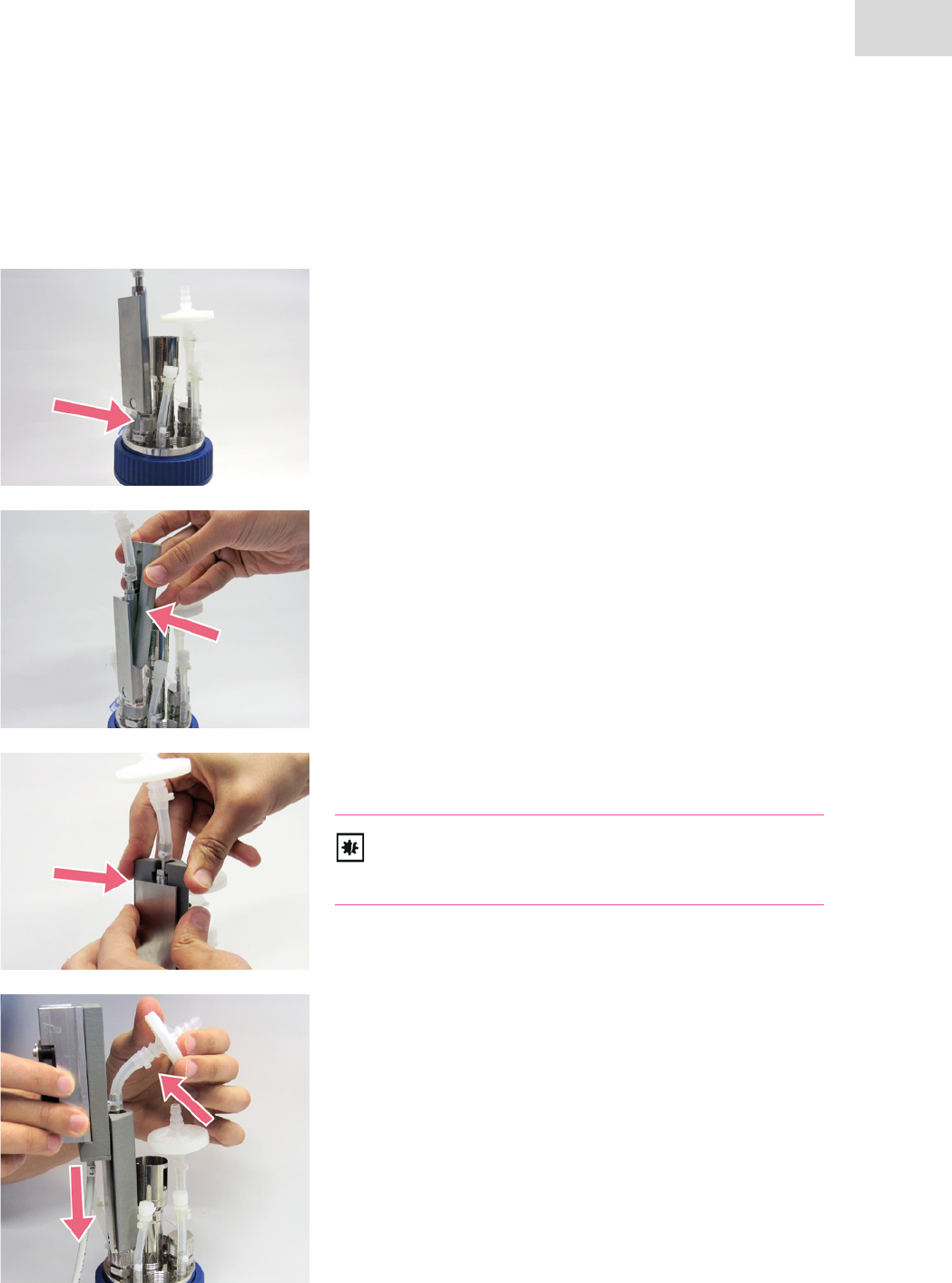
45
Hardware and operation
DASbox® Mini Bioreactor System
English (EN)
5.2.1 Assembly of the off-gas condensers
Off-gas condensers for glass reactors
Install the condenser adapter using a 12 mm Compression
Fitting (CF12) in the bioreactor head plate.
The adapter plate has to be turned outwards.
Press the exhaust gas line insulation onto the condenser
adapter.
Slide it as far as it will go onto the exhaust gas line tube on
the adapter plate.
NOTICE! Insulation is not autoclavable.
The exhaust gas line insulation is not temperature-resis-
tant and must be removed for autoclaving.
Slide the temperature control actuator onto to the adapter
plate from above.
If necessary, bend the silicone tubing with the outlet filter
slightly to the side in the process.
If it is positioned correctly, actuator operation is
automatically enabled via an integrated magnetic switch.
Slide the actuator down from the adapter plate to disable
operation.
Also refer to the chapter 5.2.2.
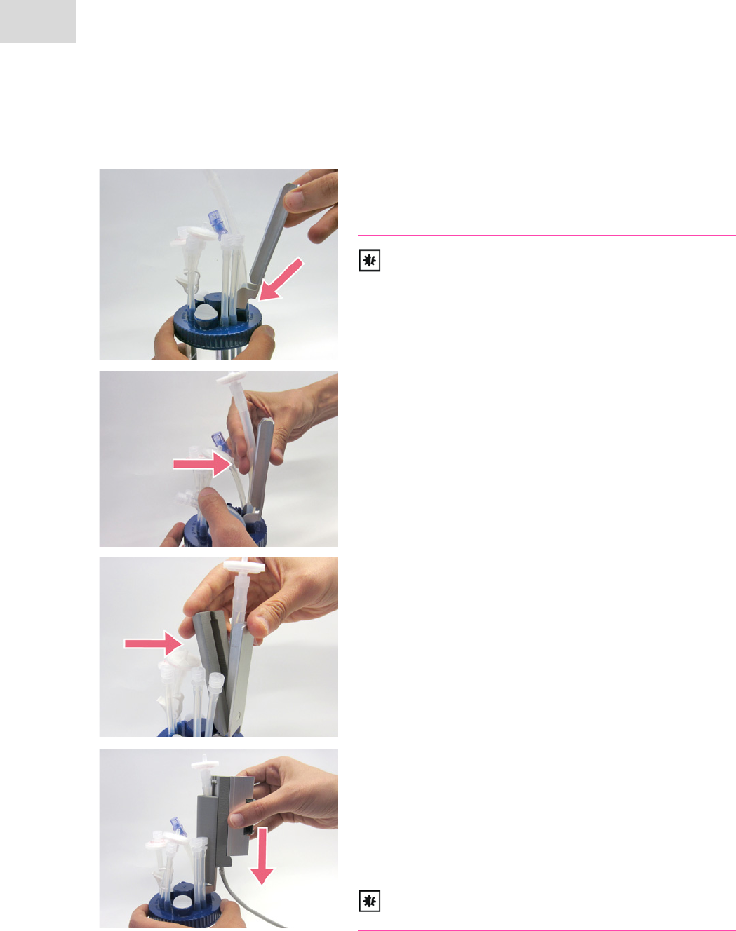
Hardware and operation
DASbox® Mini Bioreactor System
English (EN)
46
Off-gas condensers for single-use-vessels
Carefully insert the condenser adapter into the holder
provided in the head plate of the BioBLU 0.3c/f Single-Use
Vessel.
NOTICE! Risk of material damage.
If force is applied during assembly, the lever action of the
adapter may cause cracks to form in the holder of the head
plate.
Press the exhaust gas tubing of the BioBLU 0.3c/f
Single-Use Vessel into the groove on the condenser adapter.
Press the tube insulation onto the condenser adapter as
shown and then push it down to the stop.
Slide the actuator onto the plate of the adapter from above.
If it is positioned correctly, actuator operation is
automatically enabled via an integrated magnetic switch.
Slide the actuator down from the adapter plate to disable
operation.
Also refer to the chapter 5.2.2.
CAUTION! Increased top-heaviness.
The bioreactors may tip over easily (see next page).
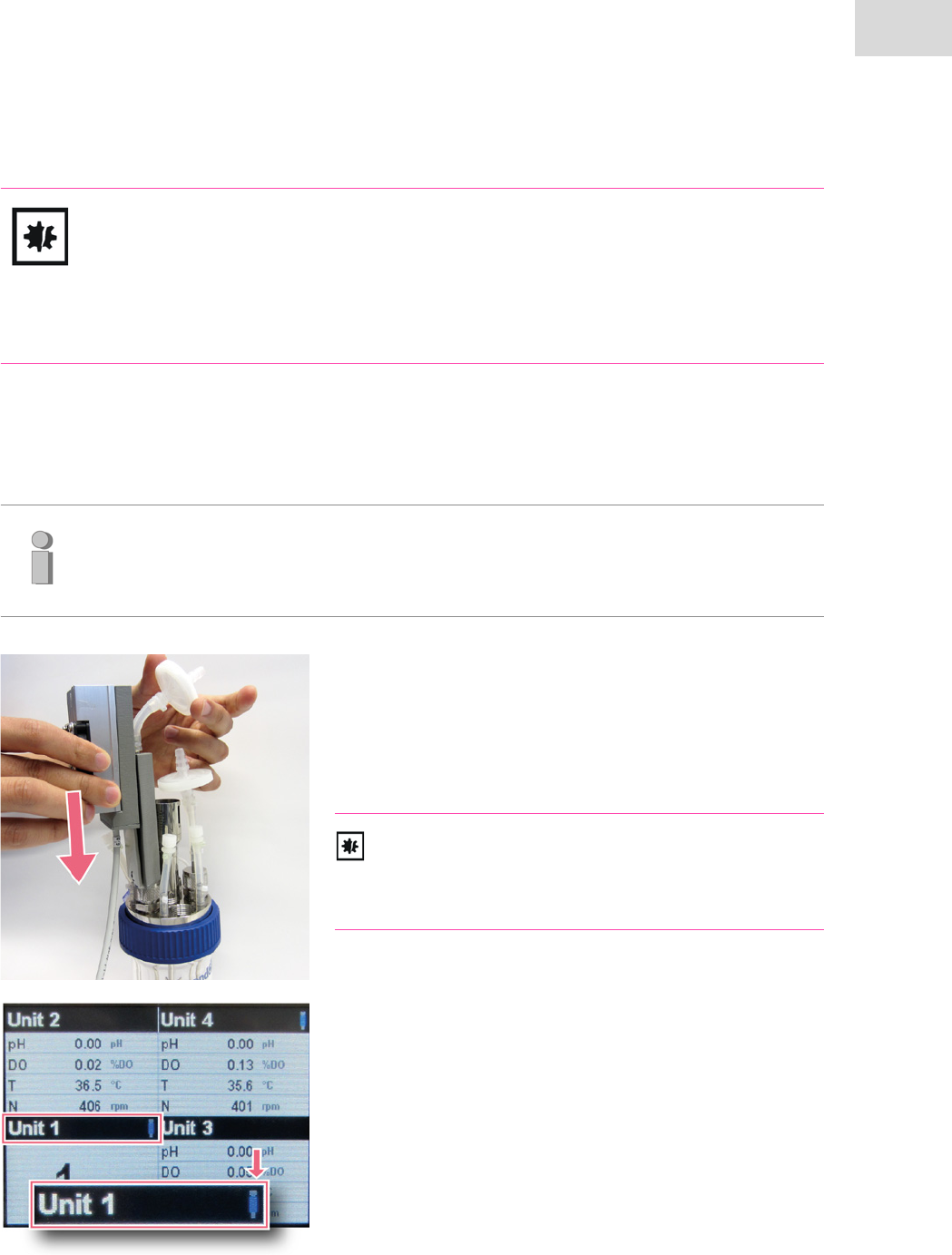
CAUTION! Increased top-heaviness of bioreactors with off-gas condensers.
The installation of off-gas condensers greatly increases the top-heaviness of single-use
bioreactors in particular. The bioreactors may tip over easily.
Before assembling the off-gas condensers, position the reactors in the wells of the DASbox
Base Unit.
47
Hardware and operation
DASbox® Mini Bioreactor System
English (EN)
5.2.2 Operation of the off-gas condensers
Slide the temperature control actuator on to the adapter
plate from above.
If it is positioned correctly, the actuator is automatically
enabled via an integrated magnetic switch.
Remove the actuator from the adapter plate to disable
condenser operation.
NOTICE! Ventilator in operation.
The ventilator of the fan rotates at a very high speed!
Avoid contact with accessory parts (e.g., Pt100 tempera-
ture sensors).
As soon as the DASGIP Control software is started, the
operating status of the connected off-gas condensers is
displayed on the LCD monitor.
A blue cooling symbol next to the unit concerned indicates
the current operation of the respective off-gas condenser.
Note:
Activate the off-gas condensers BEFORE gassing is started via the software. The condenser
must have reached its operating temperature before exhaust filter blockages can be pre-
vented.
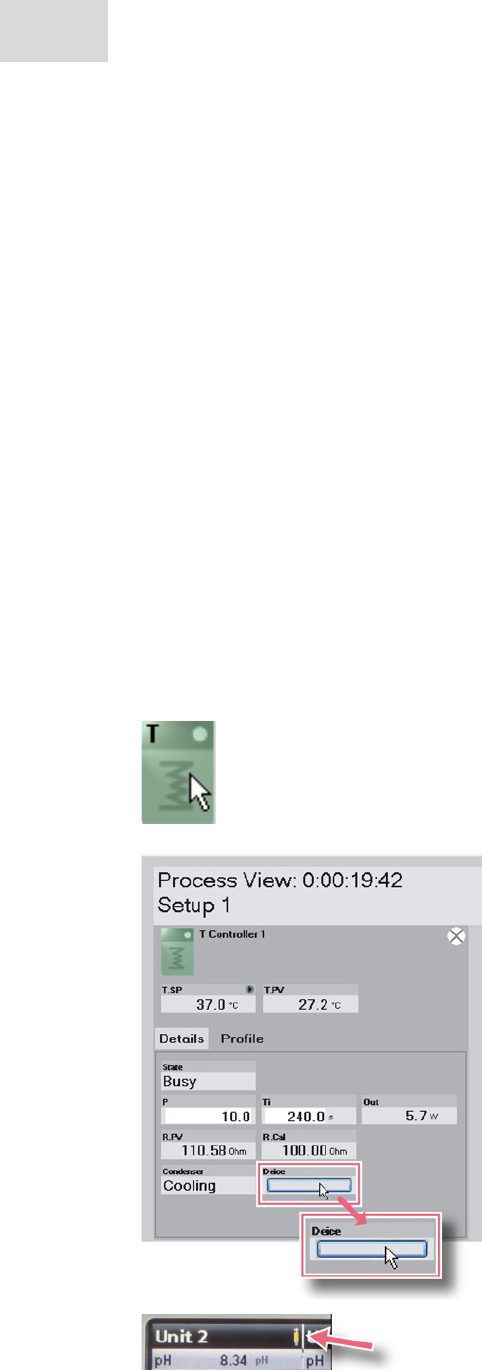
Hardware and operation
DASbox® Mini Bioreactor System
English (EN)
48
5.2.3 Deicing the off-gas condensers - Deice function
DASbox Off-Gas Condensers always operate at maximum cooling capacity. Longer periods of operation
may result in condensate freezing on cooled components.
If this happens, the temperature control actuator can no longer be detached from the condenser adapter
plate.
A setting in the DASGIP Control software therefore ensures that the operation of the Peltier elements is
automatically briefly reversed after each process is completed. For five minutes the off-gas condenser is not
cooled but heated in order to facilitate the disassembly of the temperature control actuator.
The DASGIP Control software also provides the "Deice" function by means of which the off-gas condenser
can also be heated during a process run for five minutes.
As soon as the actuator is separated from the adapter plate, the control switches back to standby mode.
Cooling operation starts again as soon as the actuator and the adapter plate are brought together again or
after the short heating period has elapsed.
Starting the "Deice" function
During the process run, click on the symbol for
temperature control T Controller in the process view of the
software.
The window containing the temperature control
parameters is opened.
Activate the Deice function by clicking on the Deice button.
The actuator briefly switches from cooling to heating
mode.
The Deice function is automatically stopped afterwards.
You can now remove the temperature control actuator from
the adapter plate.
The condenser heating mode is indicated by a yellow
heating symbol next to the unit concerned on the DASbox
LCD monitor.
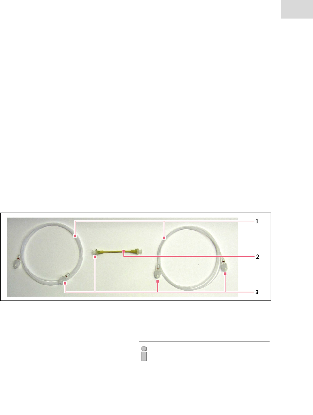
49
Hardware and operation
DASbox® Mini Bioreactor System
English (EN)
5.3 Addition of media - the MP8-pHpO module
The DASbox MP8-pHpO Module combines the functions of the DASGIP MP8 Multi Pump Module and the
DASGIP pHpO Sensor Module in a single device. This chapter describes the main functions of the
MP8 multi pump module.
Eight electronic speed-controlled feed pumps ensure the supply of DASbox Bioreactors with liquid media.
In standard process configurations, two feeding lines are thus available per bioreactor which enable the
continuous addition of nutrients and optimal pH control.
By using different pump tube types, a wide range of different feeding rates from 0 to 420 ml/h are possible.
The integrated calibration of the individual pumps ensures reproducible results.
5.3.1 Feed tubing and feed ranges
DASbox Feed Tubing
DASbox Feed Tubing consists of three individual parts:
The connection line between the reservoir bottle and the pump is connected via a flexible piece of tubing
(pump head tubing) to the connecting line between the pump and the bioreactor.
Fig. 5-3: Design of DASbox® Feed Tubing
1 Feed tubing
A connecting line between the reservoir bottle
and the pump or the pump and the bioreactor.
Different lengths are available.
Material:
PTFE (not resistant to autoclaving)
C-Flex (autoclavable)
2 Pump head tubing
A flexible piece of tubing that is inserted into
the tubing bed of the pump head for pumping
liquids. Different inner diameters are available
for variable feeding ranges.
Material of the pump head tubing:
Bioprene or Marprene (both autoclavable)
Note:
Pump head tubing is a wear part. Replace
pump head tubing at regular intervals.
3 Luer connectors
Easy connection of reservoir bottles and biore-
actors.
Quick replacement of worn pump head tubing.
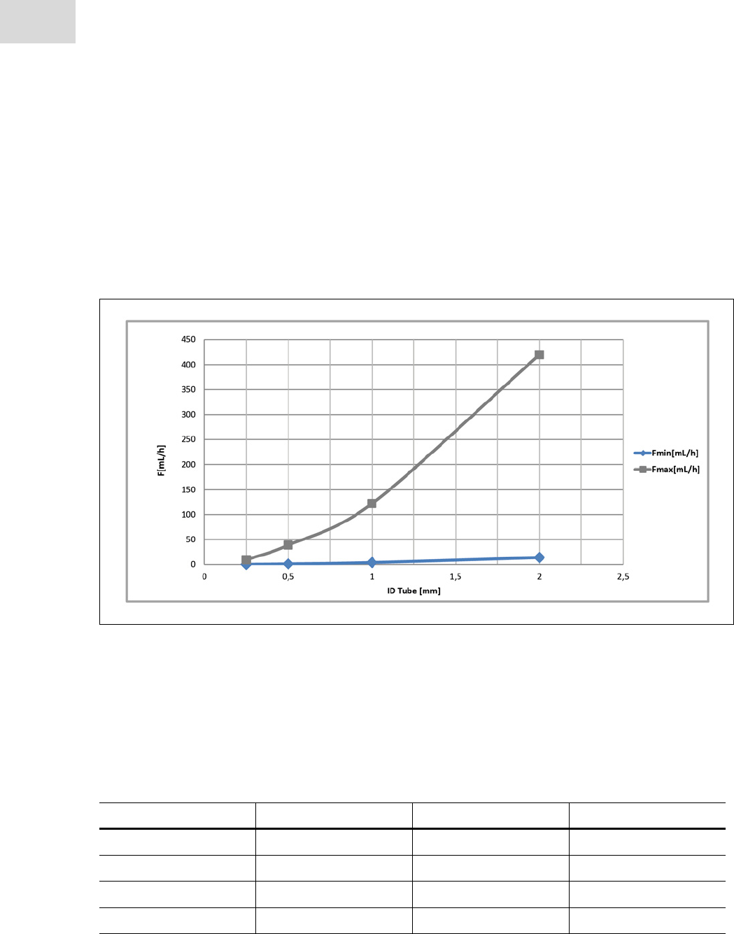
Hardware and operation
DASbox® Mini Bioreactor System
English (EN)
50
Pump head tubing
For the operation of the DASbox in standard applications, pump head tubing with an inner diameter of
0.5 mm is used. With this type of tube, a feeding range of 1.3 - 39 ml/h is possible.
Depending on requirements, other ranges can be covered by varying the pump head tubing used.
For information on standard tube types and the corresponding feeding ranges, refer to Fig. 5-4 and the
associated table 5-1.
Fig. 5-4: Typical feeding rates (F in mL/h) for different pump head tubing diameters (ID in mm)
The table shows the minimum and maximum feeding rates that can be achieved belonging to pump head
tubing as well as the typical calibration factor FCal.
The calibration factor FCal is defined as the number of pump head revolutions per milliliter of the fed
medium. The exact value of the factor is determined during the calibration of the pump head tubing.
Tab. 5-1: Feeding ranges of different pump head tubes
ID x wall [mm] Fmin [ml/h] Fmax [ml/h] FCal [1/ml]
0.25 x 1.0 0.3 9.5 450
0.5 x 1.0 1.3 39 110
1 x 1.0 4.0 122 35
2 x 0.8 14.0 420 10
*The values of the pump head tubes used as a standard are indicated in bold.
51
Hardware and operation
DASbox® Mini Bioreactor System
English (EN)
5.3.2 Continuous and pulsed feeding operation
Continuous feeding operation
The area limited by the minimum and maximum feeding rates in Fig. 5-4 shows the operating range which
allows a continuous feeding operation of the multi pumps.
• Continuous feeding operation is indicated by the pump
LED remaining constantly lit:
Green: clockwise rotation
Orange: counterclockwise rotation
Pulsed feeding operation
As soon as the values for the minimum possible feeding rates drop below the set-points, the pump switches
to a pulsed operating mode. In this mode, longer periods of pump inactivity alternate with feeding opera-
tion phases.
• In this operating mode, the pump LED only remains lit as
long as the pump is rotating.
• When the pump is stationary, a short flashing in longer
intervals indicates that the pump is active and is in the
standing phase of the pulsed feeding operating mode.
For further clarification of this principle of operation, refer to the typical working ranges of the pumps in
the table below.
Tab. 5-2:
Working range [%] [rpm]
Maximum possible speed of the pump head (100%) 71
Upper speed limit of the typical operating range (60%)
(upper speed limit)
43
Minimum speed for continuous operation* (3.3%)
(lower speed limit)
2.4
*Pulsed feeding operation is activated if the speed drops below the minimum values.
Typical working ranges of the pumps
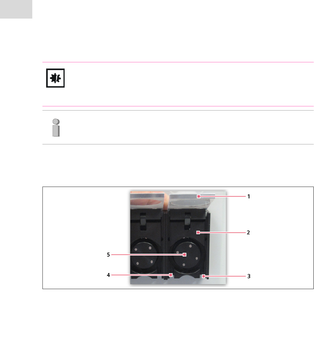
CAUTION! Risk of damage to pumps by exceeding the upper speed limit!
The upper speed limit of the typical pump operating range (60%) must not be permanently
exceeded. Permanently exceeding the limit will reduce the service life of the tubing and drive.
Use pump head tubing with a larger inner diameter.
Hardware and operation
DASbox® Mini Bioreactor System
English (EN)
52
5.3.3 Inserting pump head tubing
Fig. 5-5: Design of the pump head
1Pump guard
2Tubing bed
3 Tube guide on the right side
4 Tube guide on the left side
5Pump rotor
The pump must be switched off before the pump head tubing is inserted.
Follow the instructions below:
If the pump is operated permanently in the minimum speed region within an application, we
recommend the use of pump head tubing with a smaller inner diameter.
This allows feeding accuracy to be improved.
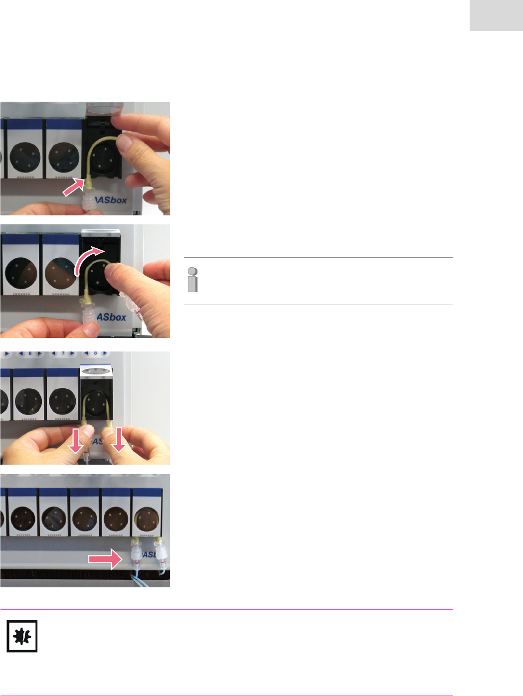
1. Open the pump guard.
The tubing bed is lifted automatically and the pump head
tubing can be loaded.
2. Insert the pump head tubing into the pump tube guide at
the bottom left.
3. Route the pump head tubing around the pump rotor and
insert it into the tube guide on the right side.
4. Grasp the elastic tube at both ends and pull it down slightly.
5. Check the position of the tubing in the tubing bed.
The tubing must not be jammed in the tubing bed.
6. Close the pump guard.
The tubing bed is lowered and the pump head tubing is
pressed gently between tubing bed and pump rotor.
CAUTION! Risk of deformation of the pump head tubing.
Do not allow pump tubing to be jammed in the tubing bed for prolonged periods. This can
lead to permanent deformation and thus to inhomogeneous feeding.
If the pump is not used for an extended period, open the pump guard in order to loosen the
tubing bed.
53
Hardware and operation
DASbox® Mini Bioreactor System
English (EN)
In the case of thicker tube types it may be necessary to
press the tubing into the tubing bed by applying light
pressure with your finger.

Hardware and operation
DASbox® Mini Bioreactor System
English (EN)
54
5.3.4 Calibrating pump head tubing
To be able to operate the pumps with defined feeding rates, the pump head tubing must first be calibrated.
The DASGIP Control software is used for calibration:
During this process, each of the theoretical feeding amounts per time unit are compared with the actual
feeding amounts within a preconfigured feeding program, taking into account the density of each media.
In addition, a calibration factor FCal [1/ml] is determined, i.e., the number of pump head revolutions per
milliliter of the fed medium.
For more information, refer to the User Manual DASGIP Control. It describes in detail how to carry out
the calibration procedure.
5.3.5 Sterilizing feed tubing
DASbox Feed Tubing in microbiology applications is usually sterilized using a cleaning-in-place (CIP) pro-
cedure. PTFE supply lines are used in most cases.
In cell culture applications, the supply lines are usually autoclaved for sterilization.
For this reason, C-Flex® supply lines are used.
CIP (cleaning-in-place) procedure
The sequential application of ethanol and sodium hydroxide is described in literature as an effective steril-
ization method, which also exhibits a deactivating effect on spores.
(Source: P. Girot, Y. Moroux, X.P. Duteil, C. Nguyen, E. Boschetti; Composite affinity sorbents and their
cleaning in place; Journal of chromatography, (1990) 510 213-223.)
The DASGIP Control software contains a preconfigured CIP procedure:
During this process, the feed tubing is successively rinsed with ethanol (70%) and sodium hydroxide (2 N).
This CIP procedure can be customized as needed.
Refer to the User Manual DASGIP Control. This manual describes in detail how to carry out the CIP
procedure.
NOTICE! Limited chemical resistance of C-Flex® tubing!
C-Flex® tubing is not suitable for use with alcohols and organic solvents.
Do not carry out CIP procedures on this type of feed tubing. Autoclave the supply lines
instead.
55
Hardware and operation
DASbox® Mini Bioreactor System
English (EN)
Autoclaving
You can also remove C-Flex® feed tubing from the mini pumps for autoclaving.
This practice is especially standard in cell culture applications:
Autoclave the feed tubing individually or connected with the reservoir bottles for media.
Seal the ends of the supply lines, e.g., with the corresponding Luer caps or aluminum foil.
CAUTION! Risk of product damage to feed tubing from autoclaving!
Only autoclave thoroughly rinsed feed tubing.
Media residues can crystallize in the supply lines and cause them to become irreversibly
blocked.
Do not sterilize PTFE feed tubing by autoclaving.
PTFE feed tubing is not resistant to autoclaving.
Do not seal feed tubing made of C-Flex® with a hose clip for autoclaving. The C-Flex®
material may become irreparably deformed.
5.3.6 Manual operation of the pumps
The mini pumps are usually controlled by the DASGIP Control software.
The software also offers several options for intervention during the process run.
Manually operating the MP8 is possible, but not absolutely necessary.
The following sections contain the main possibilities of manual operation:
Activating the manual operating mode
To switch a pump to manual operating mode, press both
arrow keys 1 x short simultaneously.
The indicator light (LED) of the pump flashes orange
and green alternately.
Hardware and operation
DASbox® Mini Bioreactor System
English (EN)
56
Short feeding (< 4 seconds)
To perform very short feeding (< 4 seconds), either press
the right or left arrow key for the desired seconds,
depending on the direction of rotation.
• The pump will stop as soon as the button is released.
• The LED will flash as long as the pump is running:
Clockwise rotation green
Counterclockwise rotation orange
Continuous feeding
Press the right or left arrow key for longer than a few
seconds (default 4 s) to activate the continuous feeding
operating mode.
• In this operating mode, the pump will continue to run after
the control button has been released.
• Briefly pressing one of the two arrow keys again stops the
pump.
•The start of continuous feeding is indicated by a short
acoustic signal.
• The LED will flash as long as the pump is running:
Clockwise rotation green
Counterclockwise rotation orange
Ending the manual operating mode
• Briefly pressing both arrow keys simultaneously switches
the pump from manual mode back to computer-controlled
mode.
Note:
During the switch to remote control operation, the pump immediately accepts the last com-
mands that were transmitted. The pumps may start immediately!

57
Hardware and operation
DASbox® Mini Bioreactor System
English (EN)
5.4 Monitoring - the MP8-pHpO module
The MP8 - pHpO module combines the functions of a DASGIP MP8 Multi Pump Module and a pHpO sensor
module in a single device. This chapter contains important information on the functions of the sensor mod-
ule and the associated sensors.
The pHpO sensor module supports the use of standard pH and DO sensors for the measurement and con-
trol of process values.
A separate input for a Pt100 temperature sensor allows for automatic temperature compensation during
calibration and measurement.
In addition, the control of conductivity sensors for level control or as an anti foam probe is supported.
As an alternative to the level option, a redox measurement is offered.
CAUTION! Risk of sensor damage from improper handling.
The sensors supplied with the DASbox are sensitive wet-chemical systems that require proper
handling, good care and regular maintenance.
Make sure to observe the manufacturer's instructions for the respective sensor types.
Please follow the instructions and information in this chapter and in chapter 7.3.
5.4.1 Sterilizing sensors
Please observe the following information:
• The DASbox sensors which are in direct contact with the culture medium can generally be sterilized by
autoclaving.
Before using alternative sterilization methods, please observe the instructions of the respective sensor
manufacturer.
• All Pt100 temperature sensors and the DO sensors for use with single-use bioreactors are not autoclav-
able.
• The sensors used in DASbox Glass Reactors are generally integrated in the bioreactor and autoclaved
along with it.
• The calibration of pH sensors takes place BEFORE autoclaving (see typical workflow Fig. 5-7).
• The calibration of DO sensors only takes place AFTER autoclaving (see typical workflow Fig. 5-7).
Add a few drops of water into the bioreactor for autoclaving as the sensors should ideally be autoclaved
in a steam atmosphere.
Hardware and operation
DASbox® Mini Bioreactor System
English (EN)
58
Seal the connectors of the sensors with the corresponding cap in order to prevent the ingress of
moisture.
CAUTION! Risk of damage to sensors.
Do not autoclave the pH sensors in deionized water under any circumstances.
The electrode gel will otherwise bleed out.
Information on the use of single-use bioreactors
• Autoclavable sensors which are operated in single-use bioreactors can be sterilized in advance and then
fitted into the single-use reactor under sterile conditions.
For more information, also refer to the BioBLU® 0.3c/f Single-Use Vessel Instructions for Use.
5.4.2 Calibrating sensors
The DASGIP Control software contains procedures for carrying out parallel one or two-point calibrations of
pH and DO sensors:
In the navigation tree on the left side, right-click on the
desired calibration entry to open the context menu.
Click on Run to start the calibration procedure.
Refer to the User Manual DASGIP Control. This manual contains detailed descriptions how to carry out
sen‐sor calibrations using the control software.
Observe the following information on calibrating sensors:
pH sensors - information on calibrating
We recommend carrying out a two-point calibration of the pH sensors before autoclaving (see workflow,
Fig. 5-7).
When carrying out calibration, take into account the desired working pH-range for the intended use.
Typically, the buffers pH 4 and pH 7 can be used for calibration.
Note: Do not mix up sensor channels.
During the cultivation process, the sensors must be used for the MP8-pHpO module channels
for which they were previously calibrated. Subsequently mixing up the sensor channels will
make it necessary for the calibration to be repeated.
After disconnecting the sensors from the sensor module (e.g., for autoclaving purposes),
make sure they are reconnected with the correct assignment.

59
Hardware and operation
DASbox® Mini Bioreactor System
English (EN)
DO sensors - information on calibrating
The following information also applies to DO sensors for use in single-use bioreactors.
• In contrast to the pH sensors, the DO sensors are only calibrated AFTER autoclaving.
The slope of the sensor can be influenced by the autoclaving process.
• We generally recommend a one-point calibration (at 100 % saturation) immediately before the start of
the main procedure (see workflow, Fig. 5-7).
• A two-point calibration is only necessary for processes in very low DO ranges or which require a very
high level of accuracy.
• Calibration must always be carried out BEFORE the culture is inoculated.
• Calibration can be carried out in the culture medium. The medium must be in a state of equilibrium with
the ambient air, i.e., saturated at 100% with the oxygen of the ambient air.
• To achieve the saturation state, set a medium gassing rate, start a light agitation and control the tem-
perature of the medium to the desired operating temperature.
• Ensure that operating conditions are constant.
• As soon as a constant DO value has been reached, the calibration procedure can be started in the
DASGIP Control software.
For more information, refer to the User Manual DASGIP Control.
Redox sensors - verification of the correct functioning
Their correct functioning can be verified with the aid of buffers with defined redox potentials or a Chinon /
Hydrochinon redox test.
Please follow the instructions in the documentation provided by the sensor manufacturer.
The DASGIP Control software features a check procedure which supports such a function test.
If you have any questions, contact a technician at the Eppendorf Bioprocess Center.
Level Sensors
Level sensors do not need to be calibrated.

Hardware and operation
DASbox® Mini Bioreactor System
English (EN)
60
5.4.3 pH sensors - handling instructions
Please observe the following instructions for the correct handling of pH sensors to ensure the proper
function of the sensors.
In addition, always also observe the instructions of the respective sensor manufacturer.
General
• pH sensors generally have a limited service life.
Their aging is essentially accelerated by the number of autoclaving cycles.
• The thickness of the source layer of the sensitive glass increases over the course of time, contributing to
the inertia of the sensor. The sensor becomes slower.
• After several autoclaving cycles, the electrolyte can take on a brown discoloration. This has no effect on
the functioning of the sensor.
• Signs of contamination of the diaphragm include:
• Long response times
• Unstable measurement signals
• Strong offset shifts
• Low sensor slope
You can find information on the regeneration of pH sensors in chapter 7.3.2.
Correct storage
Store the pH sensors upright in KCl solution
(Mettler Toledo 3.0 mol/l, Broadley James 3.8 mol/l).
You can store the pH sensor in buffer pH 4 for a short period if no KCl solution is available.
Rinse the sensor with tap water and pat it gently dry when you remove it from the KCl solution before
use.
CAUTION! Risk of sensor damage.
Do not leave the sensor in the open air for a long period of time.
Do not store the sensors in deionized water.
The electrode gel will otherwise bleed out.
Visual sensor check
Before each use of the pH sensors, inspect the sensors for the following:
• The plug connector must be dry and free from signs of corrosion and contamination.
Otherwise, the transmission of measured values may be interrupted.

61
Hardware and operation
DASbox® Mini Bioreactor System
English (EN)
• The sensor cables must not have any sharp bends or be brittle.
• The sensor tip must be completely filled with electrolyte solution.
If necessary, shake the sensor gently like a clinical thermometer, so that it fills up.
• The pH-sensitive glass of the sensor tip must be free of cracks, scratches or deposits.
• Usually, the diaphragm of the pH sensor is white.
Gray-black discoloration indicates contamination with sulfide.
Refer to the chapter 7.3.2 for information on cleaning and regeneration of pH sensors.
Checking the raw signal of the pH Sensors
During the calibration process of the pH sensors, pay attention to the raw signal of the sensor as an
important indicator of its proper functioning.
• Limit values:
pH 7 buffer raw 0 mV ± 5 mV
pH 4 buffer raw 180 mV ± 10 mV
• Regenerate the sensor or replace it if the sensor slope is below 90% after a two-point calibration.
5.4.4 DO sensors (Clark type) - handling instructions
Please observe the following instructions for the correct handling of DO sensors to ensure the proper
functioning of the sensors.
In addition, always also observe the instructions of the respective sensor manufacturer.
Visual sensor check
Before each calibration and each time the DO sensors are used, check the following points:
• The plug connectors must be dry and free from signs of corrosion and contamination. Otherwise, the
transmission of measured values may be interrupted.
• The sensor cables must not have any sharp bends or be brittle.
• Inspect the sensor membrane for visual signs of damage or contamination.
• Clean contaminated membranes by wiping with a soft, damp cloth.
Note:
The raw value (raw) in mV can be displayed during the calibration procedure by clicking on
the pH sensor symbol.
For information on carrying out calibration, refer to the User Manual DASGIP Control.

Hardware and operation
DASbox® Mini Bioreactor System
English (EN)
62
• Replace membranes with strong signs of wear or scratches.
• Replacing the membrane body can also be useful in the case of non-calibrated sensors, long response
times, unstable measured values or significant drift of measured values.
• Replace the electrolyte solution at regular intervals (see chapter 7.3.1).
Checking the raw signal of the DO Sensors
During the calibration process of the DO sensors, pay attention to the raw signal of the sensor as an
important indicator of its proper functioning.
• Limit values:
100% DO raw between 50 nA and 100 nA (slope)
0% DO raw 0 up to 3 nA (offset)
Polarize
The sensors must be allowed to polarize for approximately 10 h before use.
For this, connect the sensors to the corresponding connectors on the pHpO sensor module and switch
on the device.
Note:
A baggy membrane has no effect on the functioning of the sensor, as long as the membrane is
intact.
Note:
Polarized sensors may be temporarily disconnected from the sensor module. However, an
equally long subsequent polarization time should always be observed afterwards.
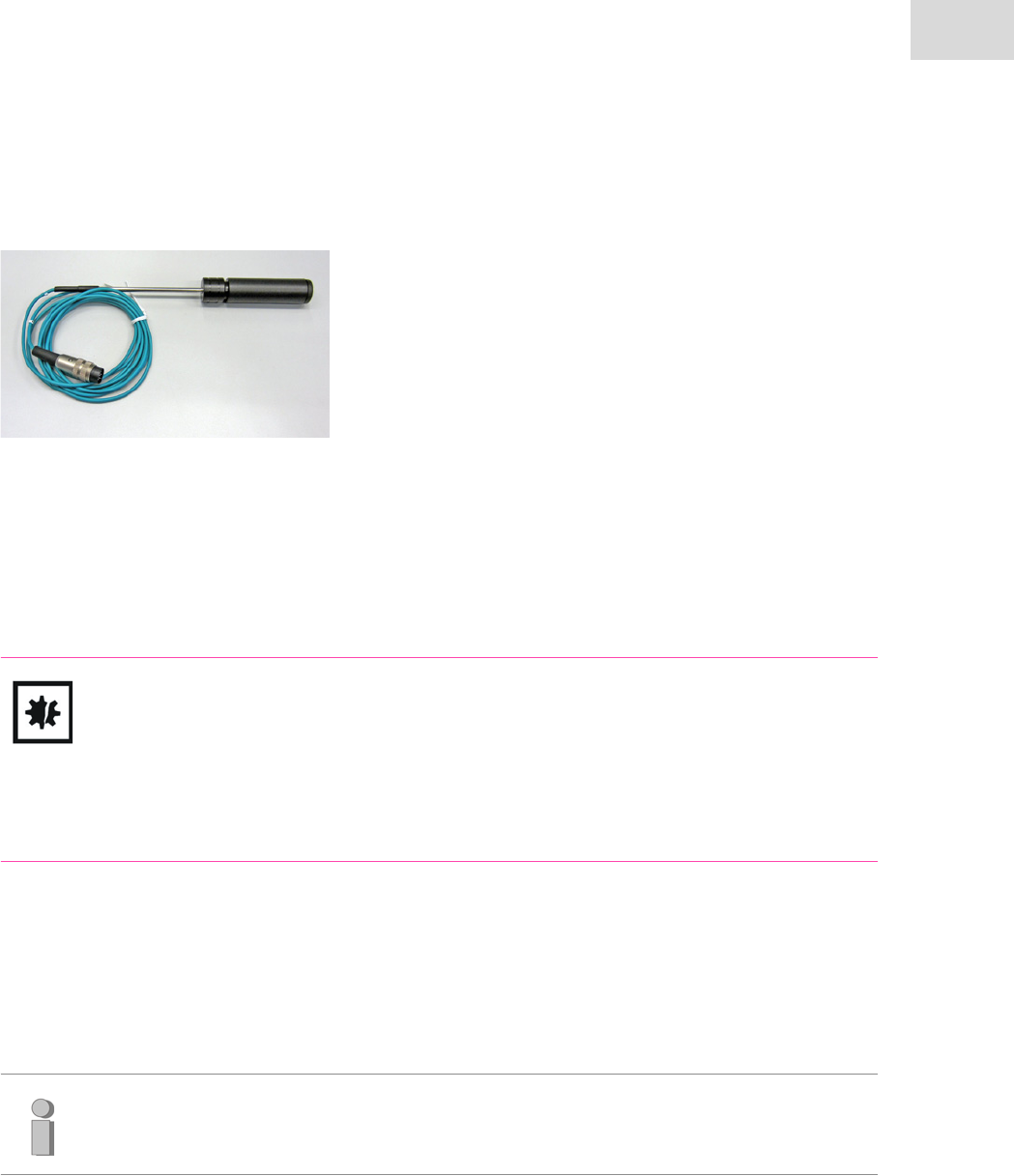
63
Hardware and operation
DASbox® Mini Bioreactor System
English (EN)
5.4.5 DO sensors for single-use bioreactors
Observe the BioBLU® 0.3c/f Single-Use Vessel Instructions
for Use for more detailed instructions on operating the
sensors in single-use bioreactors (DO sensor DASGIP
D 4.7 mm, L 162 mm).
Storage
Store the DO sensors for use in single-use bioreactors in the black screw box in a humid atmosphere.
Regularly moisten the sponges located in the screw cap with deionized water.
Store the sensors in an upright position.
CAUTION! Risk of sensor damage.
Avoid mechanical stress and handle the sensors with care.
Protect the sensors from hard impacts.
Do not hold the membrane by the sensor tip unnecessarily and keep it away from sharp
objects.
The sensors are not autoclavable.
Polarization
The sensors must be allowed to polarize for approximately 10 h before use.
For this, connect the sensors to the corresponding connectors on the pHpO sensor module and switch
on the device.
Cleaning
Rinse off any encrustation or visible contamination on the sensor tip with warm water.
Carefully wipe away any stubborn deposits using a soft, lint-free cloth.
Do not use any pointed or sharp-edged objects to scrape away contamination.
Note:
Polarized sensors may be temporarily disconnected from the sensor module. However, an
equally long subsequent polarization time should always be observed afterwards.

Hardware and operation
DASbox® Mini Bioreactor System
English (EN)
64
5.4.6 Redox sensors
Please observe the following instructions for the correct handling of Redox sensors to ensure the proper
functioning of the sensors.
In addition, always also observe the instructions of the respective sensor manufacturer.
Check the diaphragm of the sensor. It should be bright, white and intact.
Check the internal pressure condition and sealing. The sensor must show sufficient inner pressure and
an intact sealing according to the manufacturer’s manual.
Check the electrolyte colour. A slight brown discoloration is acceptable and caused by normal tear and
wear.
Run a full two point calibration according to the calibration procedure in the DASGIP control Software
Store the sensors in 3M KCl solution , when not in use.
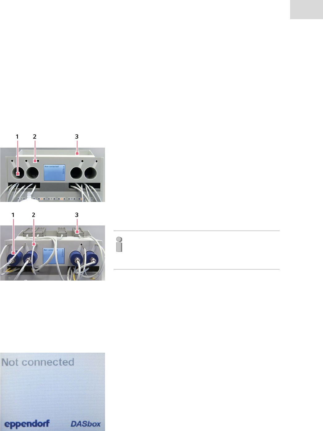
65
Hardware and operation
DASbox® Mini Bioreactor System
English (EN)
5.5 DASbox® Storage and autoclavable cage
5.5.1 DASbox® Storage
The storage unit DASbox Storage forms the upper part of the DASbox System.
It provides special storage compartments for DASbox accessories:
Use of storage compartments
• DASbox Storage provides storage space for typical DASbox
accessories.
1. Overhead motors
2. Pt100 temperature sensors
3. Off-gas condensers
Store all accessory parts that are not needed as shown in the
figure.
Note:
The Pt100 temperature sensors in particular are thus pro-
tected against damage due to improper storage or exces-
sive mechanical stress.
5.5.2 LCD monitor display principle
The front of DASbox Storage incorporates a LCD monitor for displaying current process information:
Stand by
• As soon as the DASbox System is switched on, the display
"DASbox Not connected" which is shown on the left appears
on the monitor.
• This display remains active until the DASGIP Control soft-
ware is started.
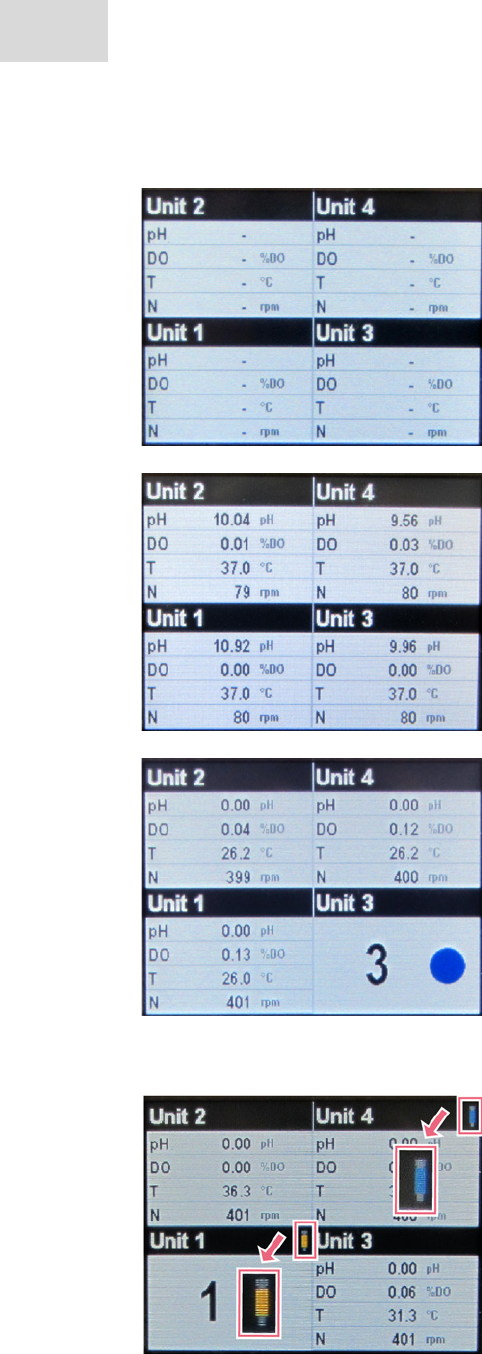
Hardware and operation
DASbox® Mini Bioreactor System
English (EN)
66
Current process values
• After the DASGIP Control software starts, a four-part display
appears.
• In this display, current process values can be displayed for
each of the four reactors of the relevant DASbox System.
• As long as no cultivation has been started via the software,
missing measured values are represented as lines in front of
the unit concerned.
• After a control procedure has been started, current values
for pH, DO, temperature and speed are displayed for each
bioreactor.
Identification of bioreactors
• If you click on the view of a single reactor during a cultiva-
tion process, this is visually highlighted on the LCD monitor
of the relevant DASbox.
• An enlarged view of the number of the respective bioreactor
appears. A blue spot is blinking.
• This simplifies the process of assigning the values observed
in the software to a specific bioreactor, especially in the case
of large plants with several parallel DASbox Systems.
• The normal display appears again after approximately 10
seconds.
Condenser status
• As soon as off-gas condensers are connected to the DASbox,
their operating status is shown by means of a small con-
denser symbol to the right next to the reactor name:
blue = cooling operation
yellow = heating operation (Deice function)
gray = condenser has been disconnected from the
actuator
red = internal error message
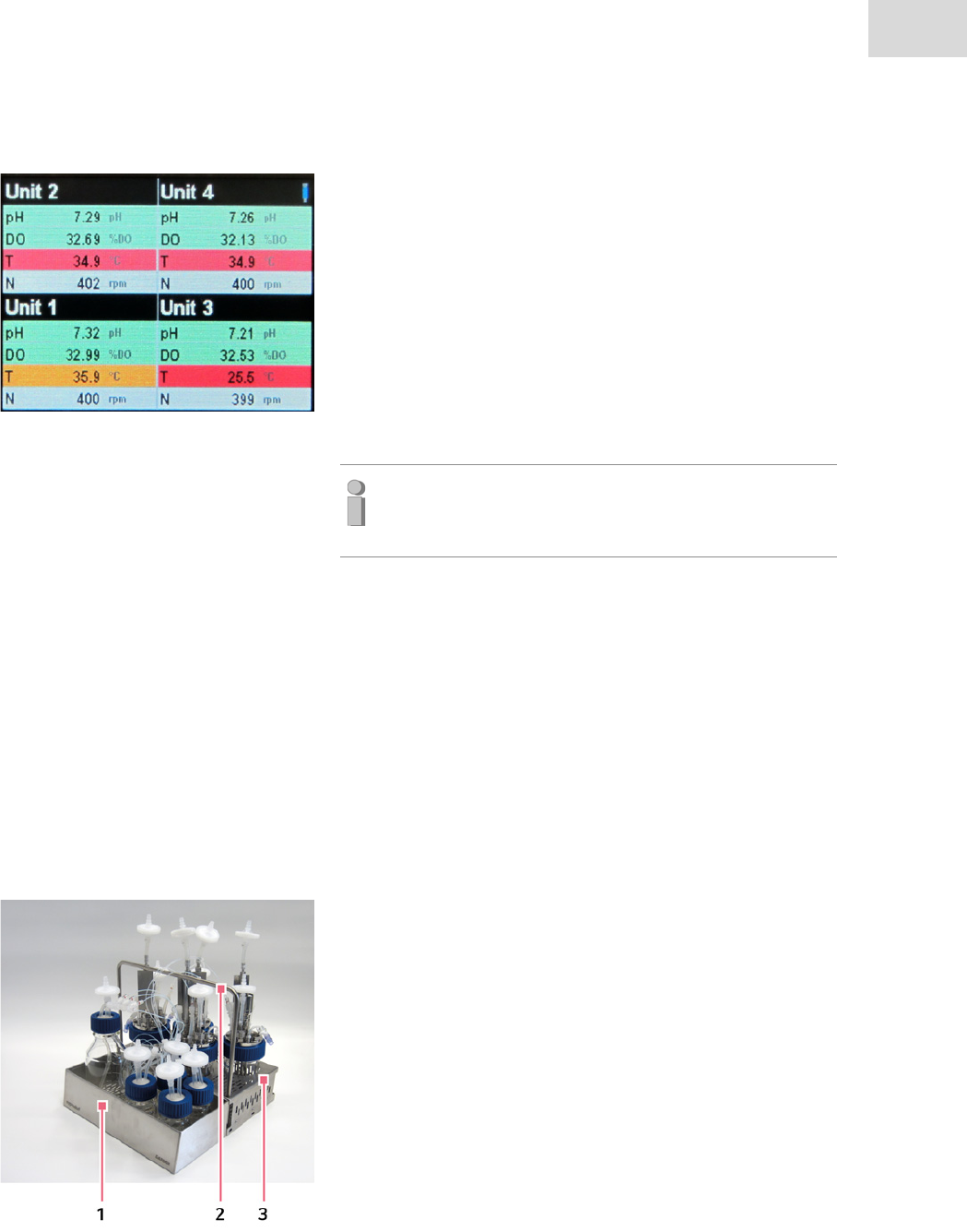
67
Hardware and operation
DASbox® Mini Bioreactor System
English (EN)
5.5.3 Autoclavable Carrier System
The accessories for the DASbox include an autoclavable carrier system which consists of 3 main compo-
nents:
Errors and alarms
• The LCD monitor allows for the display of errors and alarms
in the four-part view:
green = process value OK
orange = warning (minor deviation from set-point)
red = error (significant deviation from set-point)
To visually display errors and alarms, activate the alarm
function in the control software.
Then start the cultivation run by pressing the Inoculation
button.
Note:
For more information on alarm functions, refer to the User
Manual DASGIP Control.
1. Cage for reservoir bottles
2. Adjustable carrying handle
3. Cage for 4 DASbox Bioreactors
• All components are made of autoclavable stainless steel.

Hardware and operation
DASbox® Mini Bioreactor System
English (EN)
68
Telescopic rails for the DASbox Base Unit
• Parallel DASbox Systems consisting of three DASboxes or
more are generally mounted on rails.
• They allow individual base units to be pulled out to the front.
• This option allows for easy handling of the bioreactors, e.g.,
during sampling.
At the front of the DASbox Base Unit there are two screws.
Hook in the cage for reservoir bottles there to attach it to the
DASbox.
Remove the cage from the base unit by lifting it slightly and
then unhooking it.
Connect the cage for reservoir bottles to the cage for
bioreactors by hooking it in at the side screws.
Loosen the Allen screws on the cage for bioreactors and
position the handle in the middle of the cage construction.
Attach the carrying handle by tightening the Allen screws.
• This ensures that bioreactors and the associated media bot-
tles can be transported safely, e.g., for autoclaving and that
they can also be autoclaved in the cage.

69
Hardware and operation
DASbox® Mini Bioreactor System
English (EN)
5.6 DASbox® Bioreactors
Note:
The following chapters are excerpts from the User Manual DASGIP Bioreactors.
Due to the wide variety of special equipment options for DASbox Glass Reactors, please refer
to this User Manual for further information.
It contains detailed information and instructions on the integration and installation of the
equipment options mentioned here.
Please observe the User Manual DASGIP Bioreactors.
For single-use vessels, please observe the BioBLU 0.3c/f Single-Use Vessel Instructions for
Use.

Hardware and operation
DASbox® Mini Bioreactor System
English (EN)
70
5.6.1 Typical head plate assignments
The head plate of the DASbox Bioreactor supports a wide variety of equipment options via 6 x Pg13.5 and
4 x 4 mm pipe ports. The figure shows a typical head plate assignment for microbiology and cell culture
applications.
:
Fig. 5-6:
1 Lip seal assembly
for overhead stirrer
2 For example, septumholder
with rubber sealing
3 Short 4 mm pipe ports
for addition of media
4Gas supply
via L-sparger (4 mm Compression Fitting)
or sparger (4 mm Compression Fitting)
5DO sensor
6 ports (2mm)
for level sensor
7 dip tube (4 mm)
as a sampling option
8 Exhaust gas line with or without off-gas
condenser
Installation of off-gas condenser:
12 mm Compression Fitting
Installation of exhaust gas pipe:
6 mm Compression Fitting
9Thermowell
for temperature sensor
10 pH sensor
11 4 mm dip tube
for media feeding
Typical head plate assignment for a DASbox® Bioreactor
Optional equipment
The following optional equipment is possible:
• OD sensor with Pg13.5
• Sensor for level and anti foam control via a 4 mm Compression Fitting
71
Hardware and operation
DASbox® Mini Bioreactor System
English (EN)
Install pH and DO sensors on opposite sides.
In this arrangement the sensors can act as additional baffles.
Seal all ports that are not used with blind plugs or rubber seals.
Refer to the User Manual DASGIP Bioreactors for more information on installing equipment options and
using DASGIP Compression Fittings.
5.6.2 Glass reactor assembly instructions
• On the underside of the head plate there is a groove contain-
ing an O-ring for sealing.
Before each use, check the O-ring for cracks and damage
and replace it if there is visible damage.
Place the head plate with the seal on the thread of the glass
vessel and center it there.
Place the screw cap on the head plate and screw it tight onto
the glass thread.
Note:
Place the screw cap on the head plate already before
installing the equipment options. It may no longer be pos-
sible to slide the screw cap over all the fixtures later.
Note:
You have the option of changing the arrangement of the equipment options in the head plate.
However, please note the following hints:
Note:
Please keep in mind that some equipment options must be installed in the head plate from
below.
Install these options before closing the reactor.
Hardware and operation
DASbox® Mini Bioreactor System
English (EN)
72
5.6.3 Assembling the overhead stirrer
• The lip seal assembly (2) of the overhead stirrer of DASbox
Glass Reactors has a Pg13.5 thread for screwing into the
stainless steel head plates (1) of DASbox Bioreactors.
• A silicone O-ring (3) is used to seal the construction.
Regularly check the O-ring for cracks and damage and
replace it if necessary.
Screw the lip seal assembly into the middle Pg13.5 port in
the head plate and tighten it.
Next, attach impellers for cell culture or microbiology
applications to the shaft as required.
Loosen the set screw on the impeller using an Allen key
until the impeller can be pushed along the stirrer shaft.
Fix one or two impellers on the stirrer shaft depending on
the application and requirements.
After mounting the impellers, close the bioreactor with the
head plate.
Note the following when attaching the motor to the lip seal
assembly:
•The latches (2) at the top end of of the lip seal assembly
must engange the groove (1) in the motor drive ring.
The latches (2) at the top end of the lip seal assembly must engage in the groove (1) in the motor drive ring.
The set screws are wear parts and must be replaced
regularly.
The motors for single-use bioreactors are connected by
magnetic coupling to the bioreactor. You can find relevant
information in the BioBLU 0.3c/f Instructions for Use.
73
Hardware and operation
DASbox® Mini Bioreactor System
English (EN)
5.7 Cultivation – a typical workflow
The following figure shows a typical process scheme for working with a parallel DASGIP Bioreactor Sys-
tem. It shows the sequence of individual work steps together with the approximate times required.
Fig. 5-7: Work steps in a typical workflow for parallel DASGIP® Systems

Hardware and operation
DASbox® Mini Bioreactor System
English (EN)
74
75
Software - DASGIP Control
DASbox® Mini Bioreactor System
English (EN)
6 Software - DASGIP Control
6.1 Short overview
6.1.1 Login
The program symbol of DASGIP Control is displayed on the desktop of the process computer.
Double click on the program symbol to start DASGIP Control.
Enter your user Name and the corresponding Password.
Click Login to continue.
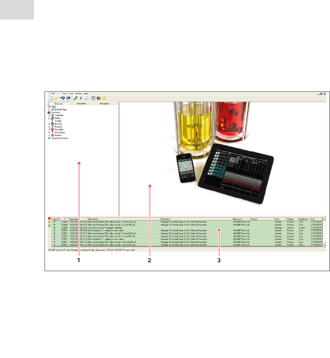
Software - DASGIP Control
DASbox® Mini Bioreactor System
English (EN)
76
6.1.2 Overview of Operations
DASGIP Control is subdivided into three areas (see Fig. 6-1):
Fig. 6-1: Overview of DASGIP Control
1Navigation area
This area includes three different tabs:
–Overview with Navigation Tree
–Instructions
–Navigation for a quick switching between
the different views
3Event Monitor
Displays all events, interventions and error
messages
2Working Area
This area displays the Summary and Process
View
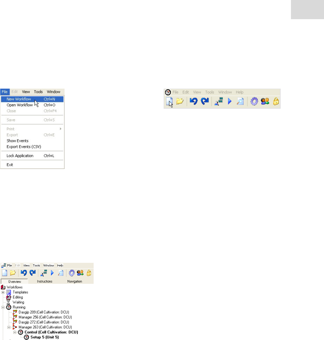
77
Software - DASGIP Control
DASbox® Mini Bioreactor System
English (EN)
6.1.3 New Workflow
Click File in the menu and select New Workflow. Alternatively, click on the corresponding symbol in the
task bar.
Please refer to the DASGIP Control User Manual for more details.
6.1.4 Functional Overview
DASGIP Control displays for the Navigation area three different views - Overview, Instructions, and
Navigation - at the left side (refer to the DASGIP Control User Manual for complementary information).
When you have started a process from the bioprocess controller, DASGIP Control displays the process
name on the Overview tab under the branch Running in the Navigation Tree.
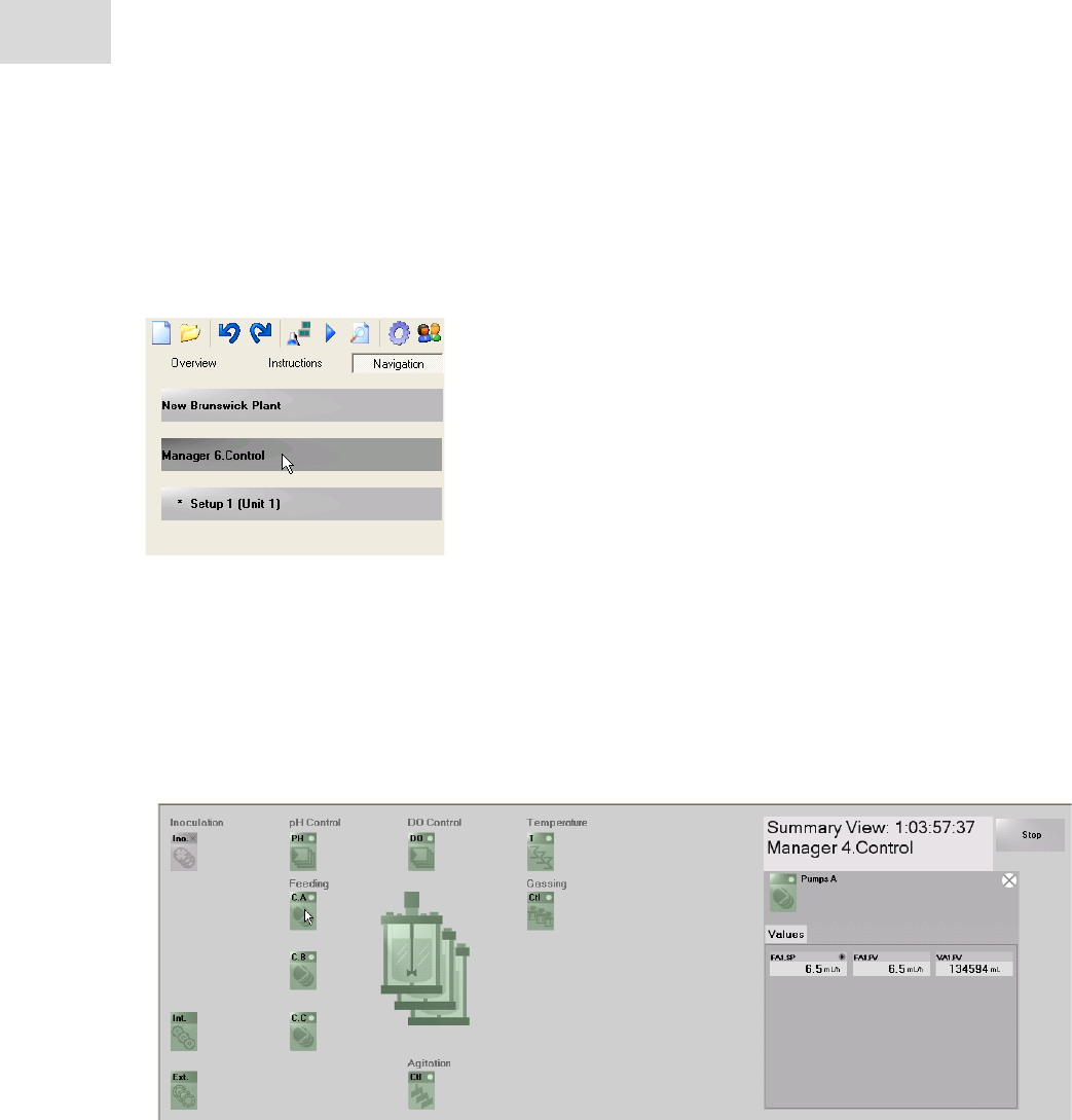
Software - DASGIP Control
DASbox® Mini Bioreactor System
English (EN)
78
Summary View
Use the Navigation tab for a simple and intuitive operation within DASGIP Control. You can easily switch
between Summary and Process View of different setups (vessels) of a process at any time.
Click on the Xxx.Control button to display a Summary View, which gives a summary of all process values
like pH, DO value(s), gas mixture, gassing rate and feeding volumes for a set of vessels selected to be
operated in parallel (Fig. 6-2:). Large numerical display elements facilitate an easy reading of all
relevant process values.
The displayed views vary depending on your system. The following shows a Summary Views of DASGIP
Control illustratively Fig. 6-2:
Fig. 6-2: Summary View
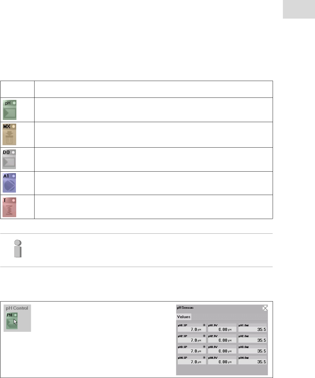
79
Software - DASGIP Control
DASbox® Mini Bioreactor System
English (EN)
The operating status of different sensors and actors (feeding pumps, gasmixer, impellers, etc.) is displayed
by color coded symbols and monitored. The following table 6-1 shows the color definitions for the symbols.
Tab. 6-1: Color definitions of Symbols
Symbol Definition
Green symbols indicate active elements.
Orange symbols indicate elements in manual mode or operated by the bioprocess controller.
Gray symbols indicate elements in standby mode or inactive elements.
Blue symbols indicate elements in idle mode.
Blue symbols indicate elements in error mode.
Additionally, you can click on each symbol to display the current process values of all affected reactors on
the right side in the Summary View.
The operating status of different sensors and actors (feeding pumps, gasmixing, impellers, etc.) is
displayed by color coded symbols and monitored. The following table 6-2 shows the color definitions.
To get the full access to each vessel in the subordinated Process View later on, you have to
activate all sensor and control options in the Summary View superordinately, which means
that all symbols are displayed in green.
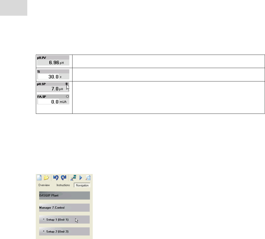
Tab. 6-2: Color definitions of edit boxes
Gray fields indicates read-only values.
Values of white fields can be edited.
Click on a white field to edit the value
Gray fields with small triangles in the right upper corner indicate values, which should be
analyzed before changing.
Click on the triangle for editing.
– Please note that this interrupts the automatic mode (gray) and switches into a
manual one (white).
Software - DASGIP Control
DASbox® Mini Bioreactor System
English (EN)
80
Process View
The Process View (Fig. 6-3:) displays all relevant process values to single setups / vessels.
Switch to the Prozess View of a single setup by clicking on the corresponding Setup button on the Navi-
gation tab.
When you have started a process, the Process View displays all color coded transferred controller states.
The following show a Process View of DASGIP Control illustratively.
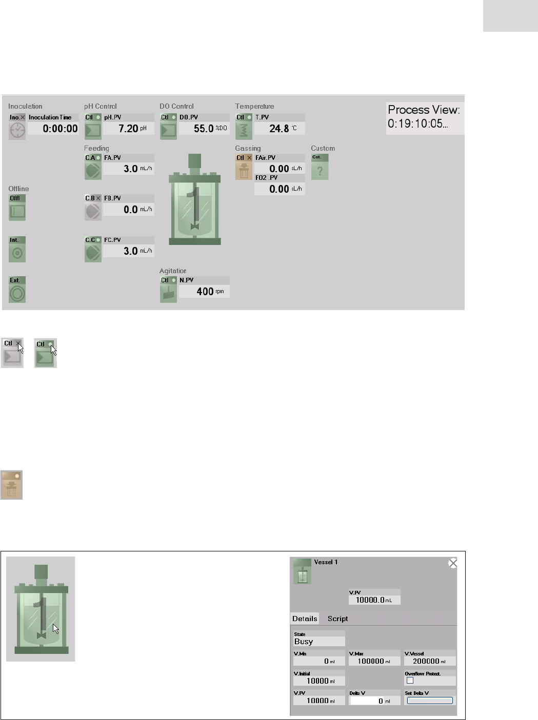
81
Software - DASGIP Control
DASbox® Mini Bioreactor System
English (EN)
Fig. 6-3: Process View
Please check and activate / deactivate each function according to your needs.
Different symbols are available for vessels, sensors and controllers as well as actors like pump, gassing and
agitation
Controllers like pH and DO (i.e. DO Control) can operate actors like pumps, gas mixing or agitation. In this
case orange symbols indicate actors which are controlled interdependently.
The color indicates that direct access it is not possible. You have to inactivate the controller itself first
by clicking on the white point of the symbol e.g. of DO Control to get access to the interdependent
gas mixing. After a short delay the gas mixing symbol will turn from orange to gray and can be ope-
rated manually.
Click on the vessel symbol to display the vessels parameters at the right side of the working area.
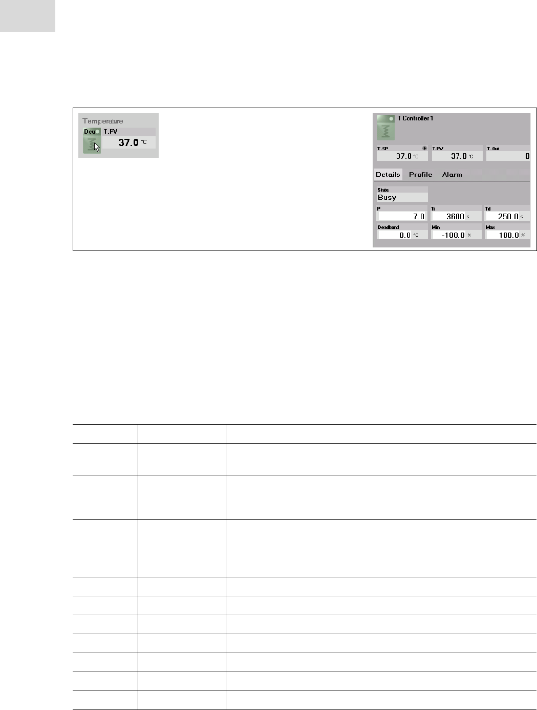
Software - DASGIP Control
DASbox® Mini Bioreactor System
English (EN)
82
Click on a controllers symbol to display the corresponding controller parameters.
The parameter dialogs are subdivided in three tabs:
•Details shows all relevant parameters at a glance. Edit boxes are displayed in white.
•Profile (See “Define or Adapt Set-point Profiles” on page 83.)
•Alarm (See “Alarm Option” on page 84.)
Please refer to the DASGIP Control User Manual for complementary information.
The following table 6-3 lists parameter definitions.
Tab. 6-3:
Abbreviation Parameter Definition
State State The operation state of a controller is displayed as Busy, Manual,
Inactive or Error.
PProportional Value The proportional value (P-Tune) directly determines the intensity of
the control. The higher the chosen value, the more invasive is the
control.
Ti Reset time The reset time (Ti) influences the integrating part and therefore the
sensitivity of the control. The larger the value, the smaller the effect on
the control. The control becomes smoother, but slower at the same
time.
Td Derivation time Differentiator
Min Lower limit Minimum value of the control variable (Anti-Reset-Windup).
Max Upper limit Maximum value of the control variable (Anti-Reset-Windup).
Deadband Deadband Control deadband for a two-sided control.
Slope Slope Sensor slope calibration parameter.
Offset Offset Axis shift as calibration parameter.
Calibration Calibration Flow rate at 100 % output.
Parameter Definitions
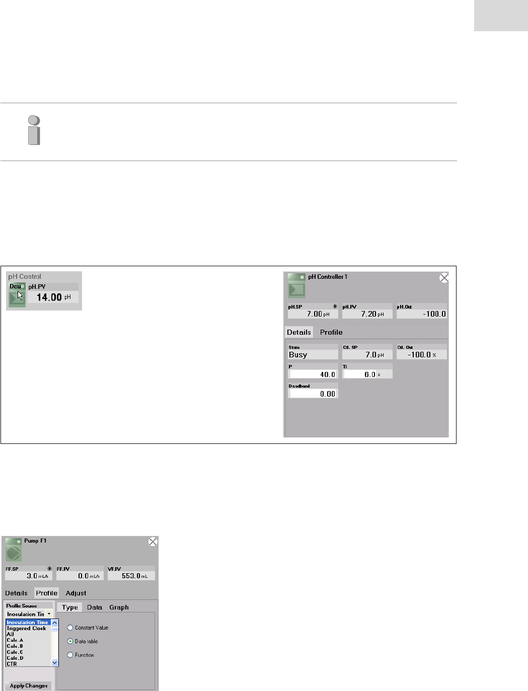
83
Software - DASGIP Control
DASbox® Mini Bioreactor System
English (EN)
Define or Adapt Set-point Profiles
DASGIP Control provides a very easy to use and flexible way to enter and edit controller profiles.
Click on a controller symbol in Process View to open the corresponding values in Details at the right
side.
Click on the Profile tab to enter and edit the corresponding profile options.
The drop down menu of Profile Source gives the opportunity to choose between different time or value
based profiles (a detailed list of all profile sources is given in chapter 3.3.2 of the User Manual DASGIP
Control).
Please note that not each 3rd party bioprocess controller supports all parameters.
Therefore the Details tab in DASGIP Control displays differing parameters depending on
the integrated controller.
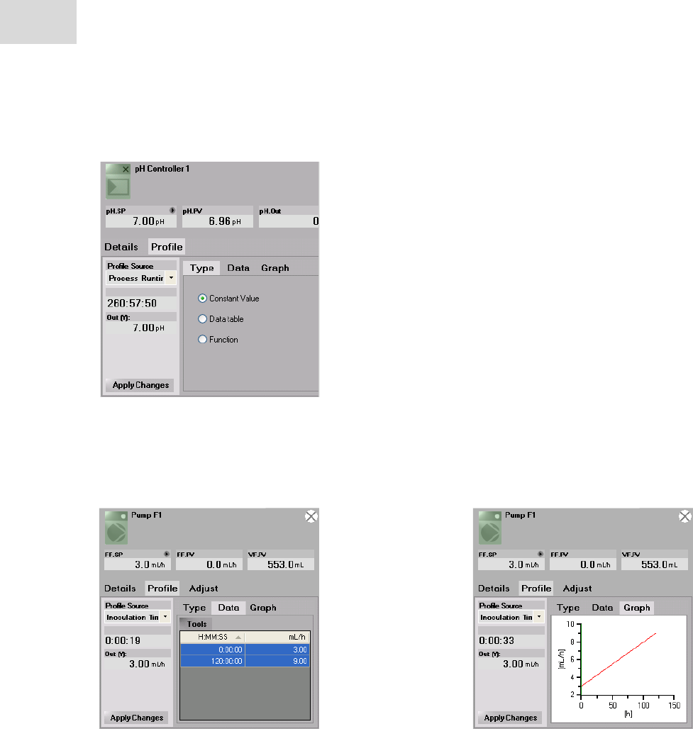
Software - DASGIP Control
DASbox® Mini Bioreactor System
English (EN)
84
Each profile is sectioned into the three distinct presentation modes Type, Data and Graph:
Type comprises three different profile types. Choose Constant Value, Datatable or Function as profile type.
Use the Data tab to enter profile values and Graph to show the corresponding profiles graphically (please
refer to chapter 3.3.2 and 3.7 of the User Manual DASGIP Control for more details).
Alarm Option
If the alarm option is activated, DASGIP Control displays alarm options on an Alarm tab within the specified
sensor values separately.
Click on the title bar or a process value (e.g. DO.PV) to display the corresponding sensor values. There is
an additional Alarm tab, if the alarm option is activated.
Click on the Alarm tab to adjust the alarm settings.
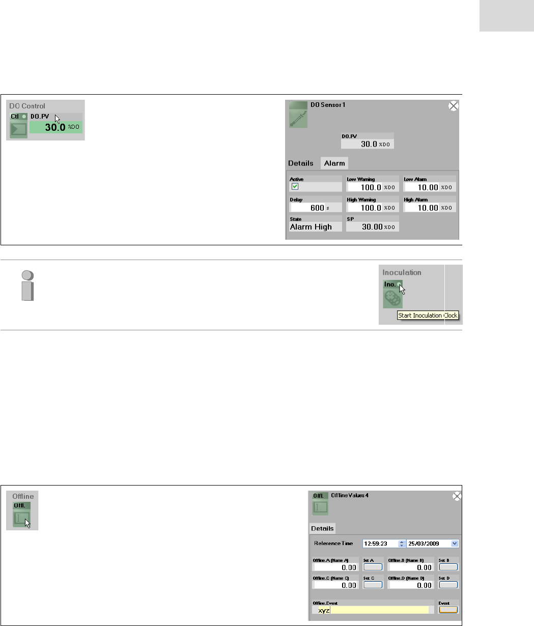
85
Software - DASGIP Control
DASbox® Mini Bioreactor System
English (EN)
Please note that all alarms are inactive until the inoculation clock
(Inoculation) is started.
Offline Values
You can supplement the process documentation with offline values in DASGIP Control. These values deter-
mined by external analyzers can be entered together with the time stamp of determination directly or later
on. They will be stored as an event in the database and can be displayed together with all other process val-
ues e.g. in a diagram.
Click on the Offl. symbol in the Process View to display the dialog at the right side. You can enter up to
four Offline values and user events by default. Additionally, you can specify the name as well as the
engineering unit. Please refer to DASGIP Control User Manual chapter 5.1 for details.
Chart Control Panel.
During a process run all values are visualized in online charts in the Summary or Process View (Fig. 6-4:) at
the bottom of the window.
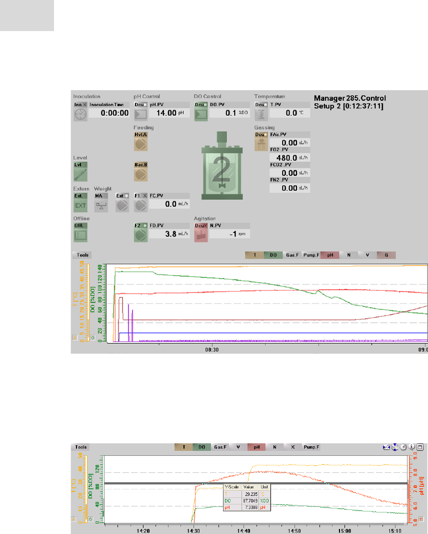
Software - DASGIP Control
DASbox® Mini Bioreactor System
English (EN)
86
Fig. 6-4: Process View with Chart Control Panel
Click on the corresponding curve button to hide or display a curve on the diagram.
Click on the chart, hold the mouse button and drag a box to zoom in an area.
Click on the x- or y-scale and drag down the appearing double line to display a legend with
corresponding values.
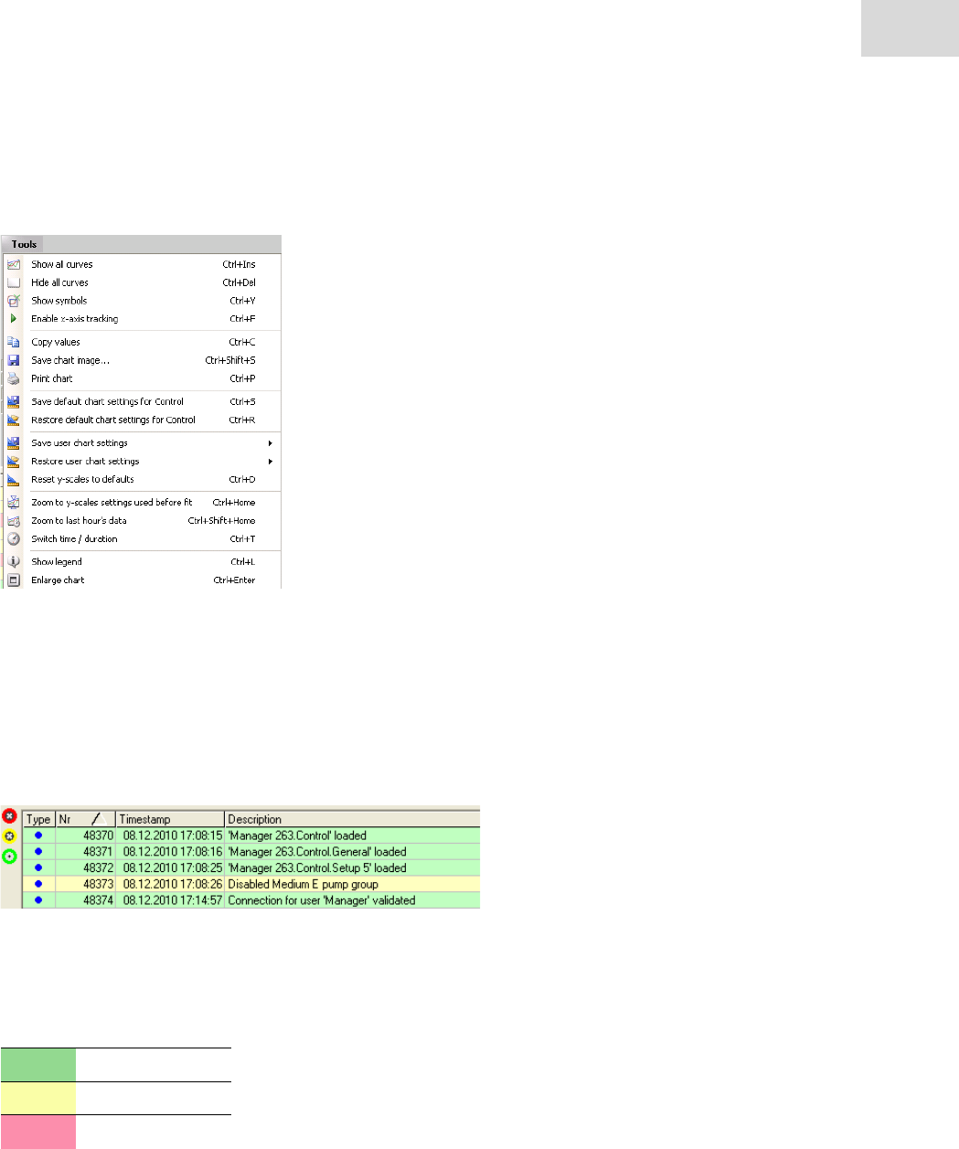
87
Software - DASGIP Control
DASbox® Mini Bioreactor System
English (EN)
Click on the Tools button on the upper left edge of the Chart Control Panel to display further options.
You can display all available data (Show all curves) or just data of determined time intervals (Zoom to last
hour‘s data).
You can configure and save chart settings individually (Save User chart settings). Please refer to the User
Manual DASGIP Control chapter 6.1.1. for more details.
Event Monitor
The Event Monitor at the bottom of the DASGIP Control window displays all events, interventions and
possible error messages of the connected bioprocess controllers during the process runtime.
The following table 6-4 shows the color code of the Event Monitor.
Tab. 6-4:
Color Description
green message
yellow warning
red alarm
Color code for the Event Monitor
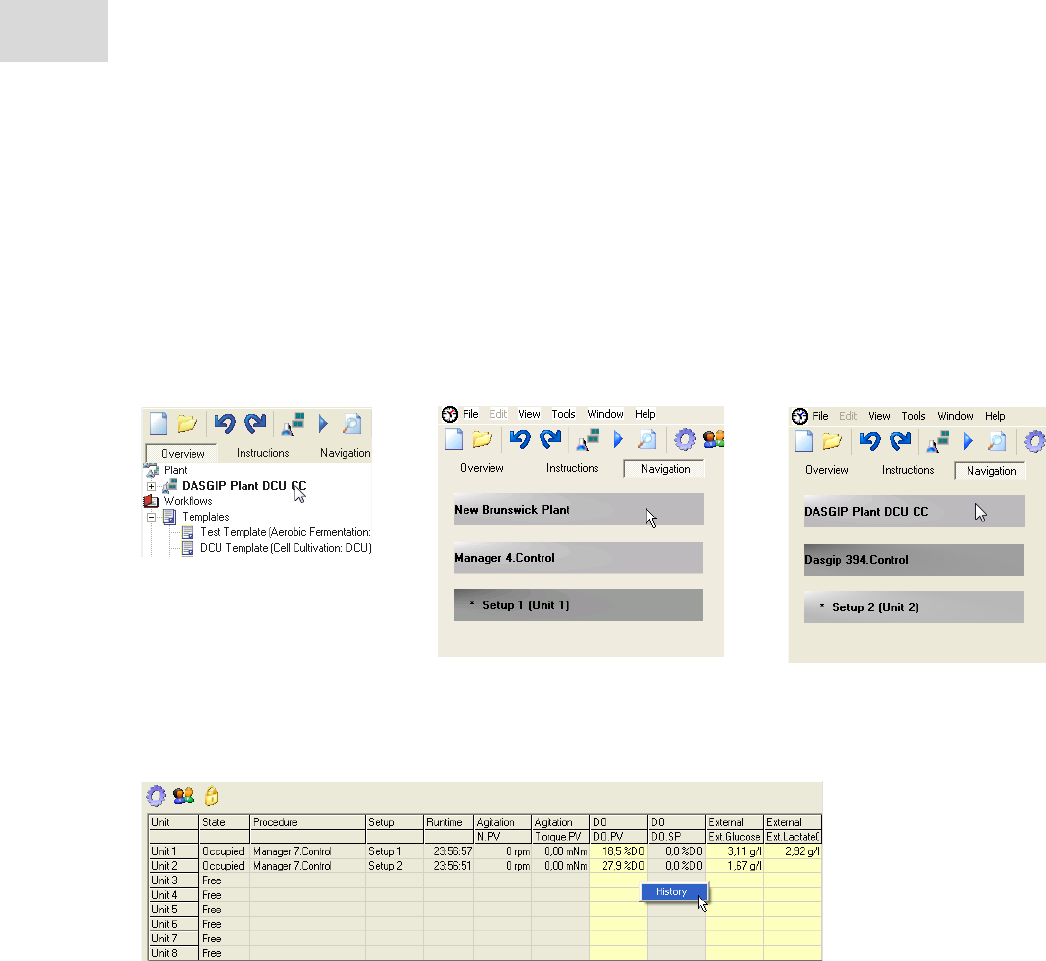
Software - DASGIP Control
DASbox® Mini Bioreactor System
English (EN)
88
Plant Overview
The Plant Overview gives a complete tabular overview of the current process status and eases the access to
main procedures’ process values. Additionally, the already logged process values of the running process
can be viewed graphically and displayed according to individual points of view. Therefore you can combine
any variables even historical ones for trend analysis.
Click on the Navigation tab or on the plant name (XXX Plant) in the Navigation Tree to start the Plant
Overview.
Click on single values or select all values of a column by clicking on the column header. Your selection is
marked by color and you can add values by pressing the <Ctrl> key and clicking simultaneously.
Right click on the selection to display the context menu.
Click History to display a diagram based on the selected values.
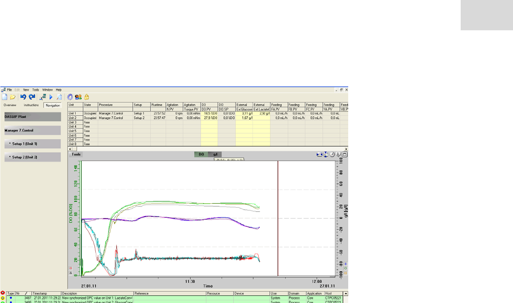
89
Software - DASGIP Control
DASbox® Mini Bioreactor System
English (EN)
Click in the diagram to display the integrated ruler, which shows the numeric values of the curve(s).
Click and drag a frame in the diagram to zoom in or out.
Create and print a diagram for documentation at any time.
Click on the Tools button for the corresponding options. You can save and reload up to seven
individually created diagram settings.

Software - DASGIP Control
DASbox® Mini Bioreactor System
English (EN)
90
6.2 Functions
6.2.1 Gassing
When configuring cultivation processes, any profiles for gassing rates and gas compositions can be defined
in advance.
For the duration of the process, several options are available to intervene in the control and to change cur-
rent process values:
In the DASGIP Control software process view, click on the
Gassing symbol to display the gassing control parameters.
Change current set-points by clicking on the desired fields
and overwriting the respective values contained there.
Gassing as part of DO cascade control
The cascade control for the oxygen concentration which is implemented in the software ensures that the
parameters listed below are successively increased in order to maintain the predefined set-point for the O2
content of the culture:
• Oxygen content in the inlet gas (XO2)
•Gas flow (F)
• Stirrer speed (N)
The order of the parameters changed depends on the field of application.
• With cascade control in microbiology applications, the gassing rate is increased as the last
step as the possible formation of foam is a critical factor here.
• In contrast, high shear forces are not desired in cell culture applications. Consequently, the
stirrer speed is not considered, or optionally only increased as the last parameter, in the
cascade for cell culture applications.
Please refer to the User Manual DASGIP Control for detailed information on configuring gassing pro-
files, setting specific parameters, special gassing strategies and options for intervention during the pro-
cess run.

91
Software - DASGIP Control
DASbox® Mini Bioreactor System
English (EN)
6.2.2 Temperature control
During the configuration of cultivation processes, individual set-point profiles can be defined for the pro-
cess temperature.
During the process, several options are available to intervene in the temperature control and to change cur-
rent values.
In the DASGIP Control software process view, click on the
symbol for temperature control Temperature to display the
parameters for temperature control.
Change current set-points by clicking on the desired fields
and overwriting the respective values contained there.
Please refer to the User Manual DASGIP Control for detailed information on configuring set-point pro-
files and setting control parameters. Options for intervening during the process run are also described
here.
6.2.3 Agitation
During the configuration of cultivation processes, any set-point profiles can be defined for agitation.
During the process, several options are available to intervene in the agitation control and to adapt current
values according to your requirements.
In the DASGIP Control software process view, click on the
symbol for agitation control Agitation to display the parame-
ters for agitation control.
Change current set-points by clicking on the desired fields
and overwriting the respective values contained there.
Agitation as part of DO cascade control
The cascade control for the oxygen concentration which is implemented in the software ensures that the
parameters listed below are successively increased in order to maintain the predefined set-point for the O2
content of the culture:
• Oxygen content in the inlet gas (XO2)
•Gas flow (F)
• Stirrer speed (N)
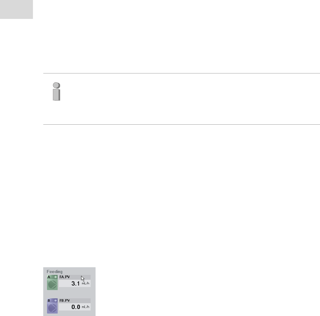
Software - DASGIP Control
DASbox® Mini Bioreactor System
English (EN)
92
The order of the parameters changed depends on the field of application.
• With cascade control in microbiology applications, the gassing rate is increased as the last
step as the possible formation of foam is a critical factor here.
• In contrast, high shear forces are not desired in cell culture applications. Consequently, the
stirrer speed is not considered, or optionally only increased as the last parameter, in the
cascade for cell culture applications.
Please refer to the User Manual DASGIP Control for detailed information on configuring set-point pro-
files and setting control parameters. Options for intervening during the process run are also described
here.
6.2.4 Addition of media
During the configuration of cultivation processes, you can define individual feeding profiles.
Another option of adding substrate is available via DO based feeding. Here, the addition of substrate is con-
trolled via the O2 content of the medium. This strategy allows for substrate-limited feeding.
For the duration of the cultivation process, several options are available to intervene in the feeding control
and to change current process values i ndividually.
In the DASGIP Control software process view, click on the
symbol for feeding Feeding to display the parameters for
feeding control.
Change current set-points by clicking on the desired fields
and overwriting the respective values contained there.
Please refer to the User Manual DASGIP Control for detailed information on configuring feeding profiles
and special feeding strategies. It describes in detail the possibilities of intervention during the process
run.

93
Software - DASGIP Control
DASbox® Mini Bioreactor System
English (EN)
6.2.5 Monitoring
During the configuration of cultivation processes, you can configure individual set-point profiles for pH and
DO. In addition, you can configure parameters for the level and anti foam option or the redox measurement.
For the duration of the cultivation process, you can actively intervene in the control and change current
values.
In the DASGIP Control software process view, click on the
symbol for the desired control (pH, DO, etc.) Control to
display the parameters for the respective control.
Change current set-points by clicking on the desired fields
and overwriting the respective values contained there.
Please refer to the User Manual DASGIP Control for detailed information on configuring set-point pro-
files and setting control parameters.
It also contains details on configuring the options level control with addition of anti foam and redox
measurement.

Software - DASGIP Control
DASbox® Mini Bioreactor System
English (EN)
94

95
Maintenance
DASbox® Mini Bioreactor System
English (EN)
7 Maintenance
7.1 Cleaning and decontamination
7.1.1 Surfaces, modules
Simply wipe off surface contamination with a damp, lint-free cloth.
If necessary, use a mild cleaning agent or disinfectant (such as 80% EtOH). Or clean the surfaces
according to the standard SOP in your laboratory.
NOTICE! Risk of damage to device from corrosive media.
Prolonged contact with aggressive media can attack surfaces.
Remove any acid and base residues by thoroughly washing with water as soon as possible.
CAUTION! Risk of damage to device from improper use of cleaning agents.
Do not use any aggressive, corrosive or abrasive disinfectants or cleaning agents.
If you have any questions about the compatibility of cleaning agents and disinfectants or
their ingredients, please contact a service technician at the Eppendorf Bioprocess Center.
WARNING! The DASbox devices are not splash-proof.
7.1.2 Cleaning feed tubing and pump tubing
Media components which crystallize in the DASbox Feed Tubing can lead to irreversible clogging of the
supply lines.
Media residues remaining in the supply lines may also encourage the growth of microorganisms in the sup-
ply lines.
After each use, thoroughly rinse the feed tubing and pump tubing with water and/or ethanol (do not use
ethanol for C-Flex® supply lines).
Cleaning procedures for feed tubing are implemented in the DASGIP Control software. They can be
adapted to suit your requirements at any time.
Please refer to the User Manual DASGIP Control.
NOTICE! Limited chemical resistance of C-Flex® tubing!
C-Flex® tubing is not suitable for use with alcohols and organic solvents.
Do not rinse feed tubing made of C-Flex® with ethanol for cleaning purposes.
CAUTION! Danger from squirting of liquids!
The blockage of feed tubing may lead to a pressure build-up in the system and the squirting of
liquids!
When working with the DASbox, wear personal protective equipment, especially goggles!
Maintenance
DASbox® Mini Bioreactor System
English (EN)
96
7.1.3 Decontamination before service or shipment
Before shipping DASGIP Systems or system components for service purposes or before an on-site service,
make sure to observe the information in our document "Return delivery information".
It contains a decontamination certificate ("Cleaning and Decontamination Form") which must be completed
in advance and sent to DASGIP.
Download the document "Return delivery information" from our homepage:
(http://www.dasgip.com), see Service/Technical service "Return delivery information").
WARNING! Risk to health from contaminated devices!
Observe the notes on the decontamination certificate. It is available as a fillable PDF docu-
ment on our website
(http://www.dasgip.com), see Service/Technical service "Return delivery information").
Send a copy of the completed decontamination certificate to DASGIP in advance and
attach the original on the outside of the packaging.
If you have any questions, contact our Service Department
(bioprocess-support@eppendorf.de).

97
Maintenance
DASbox® Mini Bioreactor System
English (EN)
7.2 Service
DASbox System components are thoroughly checked and tested before delivery.
To ensure continuous error-free operation, we recommend that the system is serviced annually by a service
technician from the Eppendorf Bioprocess Center.
Information about the support services is available on our website www.dasgip.com.
If you have any questions or problems concerning the operation of DASbox, contact our Service Depart-
ment:
bioprocess-support@eppendorf.de
+49(0)2461 980-0
7.3 Additional information on care and maintenance
7.3.1 DO sensors (Clark type)
NOTICE! Risk of sensor damage from improper handling.
ALWAYS observe the information and instructions provided by the sensor manufacturer
with priority when handling, inspecting and cleaning your DO sensors.
Sensor inspection and replacement of electrolyte solution
Depending on how the DO sensors are used and for how long, the electrolyte solution must be replaced at
regular intervals, at least after 6 months. The following section describes how to replace the electrolyte
solution for the Mettler Toledo sensors which are used as standard.
CAUTION! The O2 electrolyte solution is strongly alkaline!
Wear suitable protective clothing, especially gloves, as liquid will inevitably come into con-
tact with your hands during the process of assembling the membrane body.
Avoid contact with skin and mucous membranes, especially the eyes. Rinse contaminated
areas with plenty of water.
Wear protective goggles!
Maintenance
DASbox® Mini Bioreactor System
English (EN)
98
1. Unscrew the cap from the sensor body.
2. Carefully remove the cap from the sensor.
3. Remove the membrane body from the cap. If the body is too firmly connected, gently push it out with
your fingertip.
4. Rinse the inner body with demineralized water and gently pat it dry with paper towels.
5. Visually inspect the O-rings and the trapeze rubber for mechanical defects.
6. Half fill the membrane body with O2 electrolyte solution.
7. Remove air bubbles by gently tapping on the membrane body.
8. Hold the sensor in a vertical position and slide the body membrane onto the inner body.
9. Remove excess electrolyte solution with a paper towel.
10.Carefully slip the cap over the fitted membrane body and tighten it firmly.
7.3.2 pH sensors
NOTICE! Risk of sensor damage from improper handling.
ALWAYS observe the information and instructions provided by the sensor manufacturer
with priority when handling, inspecting and cleaning your pH sensors.
Regeneration of pH sensors
The functioning of pH sensors that appear visually intact but are sluggish in responding can often be sig-
nificantly improved by a special cleaning process.
Soak pH sensors which have been stored in dry conditions or in water for an extended period in 3 mol/l
KCl solution for several hours.
Note:
After each replacement of electrolyte solution, a calibration must be performed to determine
the zero point and slope of the sensor.
After each replacement of electrolyte solution, the sensor has to be completely polarized
(2 - 6 h) and a calibration carried out afterwards!
Also observe the manufacturer's instructions in the relevant documentation for the DO
sensors.

99
Maintenance
DASbox® Mini Bioreactor System
English (EN)
The method of cleaning varies depending on the type of deposits visible:
Inorganic deposits Store the sensors in 0.1 mol/l HCl or 0.1 mol/l NaOH for
several minutes.
Oily or organic deposits Rinse the sensors with ethanol or acetone.
Proteins Store the sensors in pepsin/HCl solution for several hours.
Sulfide contamination
(black diaphragm)
Store the sensor in Thiourea/HCl solution until the
discoloration of the diaphragm is removed.
7.3.3 MP8-pHpO module
Regularly replace pump head tubing
The pump head tubing that is inserted into the pump tube guide is a wear part.
If possible check for clearly visible signs of wear before each long experiment.
Replace tubing with strong black abrasion, kinking or very irregular wall thickness.
Another sign of wear is if the calibration value strongly deviates from the original value.
Regularly replace the back-up batteries
The back-up batteries of the MP8-PHPO module guarantee the storage of internal data whenever the mod-
ule is switched off. To avoid a loss of internal data, the batteries have to be renewed regularly.
NOTICE! Risk of internal data loss and equipment damage.
Replace the batteries as soon as the battery replacement message is displayed in the
DASGIP control software event log.
Ensure that the MP8-PHPO module is switched on while replacing the batteries.
Replacing the batteries while the device ist switched off will lead to data loss and
equipment damage.
Note:
Make sure to replace tubing in time to avoid leaks and to maintain high feeding accuracy.
Maintenance
DASbox® Mini Bioreactor System
English (EN)
100
The holders for the back-up batteries are located in the lower part of the MP8-PHPO module in the storage
compartment for feed tubing. Obey the following instruction to replace the batteries.
1. Ensure that the MP8-PHPO module is switched on.
The status LED of the device has to be illuminated green.
2. Open the flap of the lower storage compartment.
The holders for the back-up batteries are located on the
right and left side in the storage compartment.
3. Unscrew the lid of the battery holder by a quarter turn in a
counterclockwise direction. Use a flat head screwdriver if
necessary.
4. Now remove all 3 batteries from the holder.
The batteries are magnetic. They can easily brought out
using a magnetic stick (e.g. a stir bar retriever).
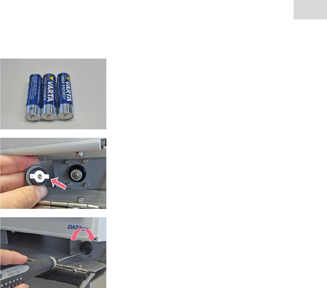
101
Maintenance
DASbox® Mini Bioreactor System
English (EN)
5. You will find 3 Batteries per holder.
Always replace all 6 back-up batteries of the module.
Only use approved batteries (see chapter 10.3).
6. When replacing the batteries, the positive terminal of the
batteries must show to the outside.
7. Check the orientation of the battery compartment lid. Metal
flaps and slot on the lid must be in horizontal orientation to
close the lid.
8. Align the lid of the battery holder and close it by turning the
lid clockwise until safely locked.
Transport, storage and disposal
DASbox® Mini Bioreactor System
English (EN)
102
8 Transport, storage and disposal
8.1 Transport
When sending in products for service purposes as well as during transport to another installation
location, ensure proper packaging is used.
CAUTION! Risk of personal injury and material damage when lifting and carrying heavy
loads.
The DASbox is heavy. Lifting and carrying the device can lead to back injuries.
The hooks at the front and the grip at the back of the DASbox are not handles. They are only
designed for moving the DASbox on telescopic rails or for lifting the lid during service work.
NEVER use the hooks and the grip on the DASbox as handles.
The DASbox must be transported by least two people.
Lift the DASbox by reaching under the device.
Use a transport aid (such as a dolly) to transport the device over longer distances.
NOTICE! Risk of transport damage!
Use the product's original packaging for transport and return of products.
Please also observe the instructions in "How to pack…" in the document "Return delivery
information". Download the document from our website
(http://www.dasgip.com), see Service/Technical service "Return delivery information").
or contact our Service Department (bioprocess-support@eppendorf.de).
If the original packaging of the product is no longer available, the customer is responsible
for providing proper and suitable packaging. Original packaging can be requested from
DASGIP at any time.
8.2 Storage
Observe the ambient conditions during storage.
Ambient temperature during storage 0 - 50°C
Max. relative humidity during storage 90% rH, non-condensing.

103
Transport, storage and disposal
DASbox® Mini Bioreactor System
English (EN)
8.3 Disposal
If disposing of products or product components, make sure to observe the relevant legal regulations.
As the disposal regulations may differ from country to country in the European Union, please contact us
if necessary (bioprocess-support@eppendorf.de).
WARNING! Risk to health from contaminated devices!
Observe the notes on the decontamination certificate. It is available as a fillable PDF docu-
ment on our website
(http://www.dasgip.com), see Service/Technical service "Return delivery information".
Send a copy of the completed decontamination certificate to DASGIP in advance and
attach the original on the outside of the packaging.
If you have any questions, contact our Service Department
(bioprocess-support@eppendorf.de).
Environmentally sound disposal of electrical and electronic equipment in compliance with
EU Directive 2002/96/EC
In order to comply with EU Directive 2002/96/EC, please observe the applicable national
regulations when disposing of DASGIP devices.
*For Germany the law regarding waste electrical and electronic devices (ElektoG) applies:
Under this Directive, no old devices may be disposed of via the public municipal waste/collec-
tion system.
For DASGIP devices located in Germany you can return such devices to us for scrapping.
Decontaminate all the parts you would like to dispatch for disposal.
Observe the following safety instructions and the chapter 7.1.

Transport, storage and disposal
DASbox® Mini Bioreactor System
English (EN)
104
8.4 General return delivery information
When returning products or product components, e.g., for servicing or disposal, and also before an on-site
service, make sure to observe our general return delivery information.
Download the document "Return delivery information" from our website.
(http://www.dasgip.com), see Service/Technical service "Return delivery information".
The document "Return delivery information" as a fillable PDF document contains the following forms:
• Decontamination certificate ("Cleaning and Decontamination Form")
• Service form ("Service and Repair Form")
• Packaging instructions for DASGIP Modules ("How to pack...")
WARNING! Risk to health from contaminated devices!
Observe the notes on the decontamination certificate. It is available as a fillable PDF docu-
ment on our website
(http://www.dasgip.com), see Service/Technical service "Return delivery information".
Send a copy of the completed decontamination certificate to DASGIP in advance and
attach the original on the outside of the packaging.
If you have any questions, contact our service department
(bioprocess-support@eppendorf.com).
105
Technical data
DASbox® Mini Bioreactor System
English (EN)
9 Technical data
9.1 Ambient conditions
Ambience For indoor use only
Ambient temperature during operation 5 – 40°C (41 – 104°F)
Max. relative humidity during opera-
tion
80% rH, non-condensing
Maximum operating altitude 6000 ft above sea level
Ambient temperature during storage 0 - 50°C
Max. relative humidity during storage 90% rH, non-condensing
WARNING!
The DASbox System must not be used outdoors.
9.2 DASbox® System
9.2.1 Power supply
Voltage (DASbox Base Unit and MP8-PHPO module) 100-240 VAC
Operating frequency
(DASbox Base Unit and MP8-PHPO module
)50/60 Hz
Typical power consumption (DASbox Base Unit) Approx. 510 W
Typical power consumption (MP8-PHPO module) Approx. 50 W
Fuses (DASbox Base Unit) 2 x 10 AT, 250 V
Fuses (MP8-pHpO multi pump and sensor module) 2 x 2.5 AT, 250 V
Protection class I
Protection degree (IP Code) IP21 (Ingress Protection Rating)
Overvoltage class II
Back-up battery Varta High Energy 4906 1.5 V, AA,
Alkaline

Technical data
DASbox® Mini Bioreactor System
English (EN)
106
9.2.2 Weight / dimensions
Dimensions W/H/D
DASbox System (four-fold unit w/o autoclavable carrier)
incl. DASbox Base, MP8-pHpO w/ Storage
30/49/62* cm
(11.8/19.3/24.4* in)
DASbox System (four-fold unit w/o autoclavable carrier)
incl. DASbox Base, MP8-pHpO w/ Storage and one additional DASGIP module
30/66/62* cm
(11.8/26/24.4* in)
DASbox Base 30/21/62* cm
(11.8/8.3/24.4* in)
MP8-pHpO w/ Storage 30/29/33* cm
(11.8/11.4/13* in)
DASGIP module 30/20/33* cm
(11.8/7.9/13* in)
Autoclavable carrier 30/7/14 cm
(11.8/2.6/5.5 in)
*Note at least additional 10 – 15 cm (3.9 – 5.9 in) depth for cable and heat dissipation
Weight
DASbox Base Unit w/o accessories approx. 28.6 kg
MP8-pHpO w/ Storage approx. 9 kg
Standard DASbox System (four-fold unit) approx. 44 kg
9.2.3 Bioreactors
Reactors Glass reactors / single-use vessels
Sterilization Autoclavable / presterilized
Cell culture working volume Glass: 60 – 250 ml / single-use: 100 – 250 ml
Microbiology working volume Glass: 60 – 250 ml / single-use: 65 – 250 ml
Total volume Glass: 350 ml / single-use: 380 ml
Dimensions (ID, H) 64 mm/120 mm

107
Technical data
DASbox® Mini Bioreactor System
English (EN)
9.2.4 Agitation
Drive Overhead drives
Glass: directly coupled / single-use: magnetically coupled
Speed ranges Glass: 20 – 2000 rpm / single-use: 20 – 2000 rpm
Cell culture impellers Glass: marine type / single-use: pitched blade
Microbiology impellers Rushton type
9.2.5 Gassing
Gassing TMFC; overlay and/or submerged
Gas mixture (standard) N2, air, O2 and/or CO2
Flow control & mixing 16 independent mass flow controllers
Flow ranges Cell culture: 0-5 sl/h / microbiology: 0-25 sl/h
Off-gas condensation Liquid free using Peltier elements
Off-gas analysis Optional; with additional module DASGIP GA4
9.2.6 Dispensing
Feeding lines per reactor 2 (optional 4)
Feeding rates
(depending on tubing diameter)
0.3 – 9.5 ml/h up to 13 – 420 ml/h
9.2.7 Monitoring and control
Temperature control Liquid-free heating and cooling (Peltier elements)
Temperature range 10 – 60°C at 25°C RT
Temperature sensor Accuracy class A RTD
pH control Cell culture: CO2/base
Microbiology: Acid and/or base
other configurations possible in each case

Technical data
DASbox® Mini Bioreactor System
English (EN)
108
DO control Cell culture:
Cascade (O2 concentration, gassing rate)
Microbiology: Cascade (stirrer speed, O2 concentration, gassing rate)
other configurations possible in each case
Redox measurement
(ORP)
optional; as an alternative to level control
Level/
anti foam control
Optional; as an alternative to Redox measurement
Optical density (OD) Optional; with additional module DASGIP OD4

109
Technical data
DASbox® Mini Bioreactor System
English (EN)
9.3 Ports - specifications
Mains connections
Mains connection DASbox Base Unit (all versions): 100-240 VAC; 50/60 Hz
MP8-pHpO Module (all versions): 100-240 VAC; 50/60 Hz
Microfuses Dimensions 5x20 mm;
rated voltage at least 250 V, characteristic slow-blow;
nominal curent 2.5 A (MP8-pHpO); 10 A (DASbox Base Unit)
Communication
"AUX"; "DTP out" SUB D9M / RS232 plug
"DTP in" SUB D9F / RS232 connector
DASbox Base Unit
USB port 5 V / 100 mA; 5 V +/- 0.25 V
internal power supply Stas 200 type ports; Input limits:
Max. 2.5 A for each port (depending on the incoming power sup-
ply 100-240 VAC, 50/60 Hz at the mains connection unit for the
external power supply).
Pt 100 (temperature sensors) Input limits: 90 – 160 Ohm
Measuring range: -25°C – 116°C (± 1 °C)
Condenser (Off-gas condensers) Typically 10 W per condenser
Gas IN;
Gas OUT
DASbox Base rear side: 6 mm push-in connectors
Next to the wells for bioreactors: 4 mm push-in connectors
External I/O
*optional: external interfaces
0/4 – 20 mA or 0 – 10 V inputs and outputs
MP8-pHpO Module
pH Sensors Input limits: - -472 mV – 472 mV
Measuring range: pH 0 – pH 14 (± 0.01 pH)
(at a sensor temperature of max. 67°C)
DO Sensors DO Measurement:
Input limits: 0 – 400 nA (± 0,5 nA)
Measuring range: 0 – 500 % DO
Integrated temperature measurement (NTC):
Input limits: 1.7 – 10000 kOhm
Measuring range: -10°C – 140°C (± 0.2 K)
Redox Sensors Conductivity measurement
Input limits: 0 – 20 mS
Redox potential measurement
Input limits: -2000 – 2000 mV (± 1 mV)
Technical data
DASbox® Mini Bioreactor System
English (EN)
110
9.4 Connection assignments
9.4.1 Communication ports (DTP in/out, AUX)
The RXD, TXD, GND, RTS, CTS supply lines of the DTP in and DTP out ports are directly connected to ‐one‐
another.
Pin DTP in DTP out AUX
1Alarm
2TXD TXD RXD
3RXD RXD TXD
4
5GND GND GND
6Alarm (normally closed)
7CTS CTS
8RTS RTS
9Alarm (normally open)
In a fault-free state, the pins 1 and 6 are connected to each other (normally closed).
In the event of an error, the pins 1 and 9 are connected to each other (normally open).
Only devices which meet the requirements of IEC 950/EN 60950-1 (UL 1950) standards may be connected
to the interfaces.
CAUTION!
The maximum load capacity of the relay contacts is 30 VDC / 1 A.
9.4.2 RS485 (optional)
The RS485 communication ports are galvanically insulated from the rest of the device electronics.
The pin assignment complies with the specification "Modbus Over Serial Line Specification and Implemen-
tation Guide Version 1.0". The B/D1, A/DO and Common supply lines of the two RJ45 connectors are
directly connected to one another.
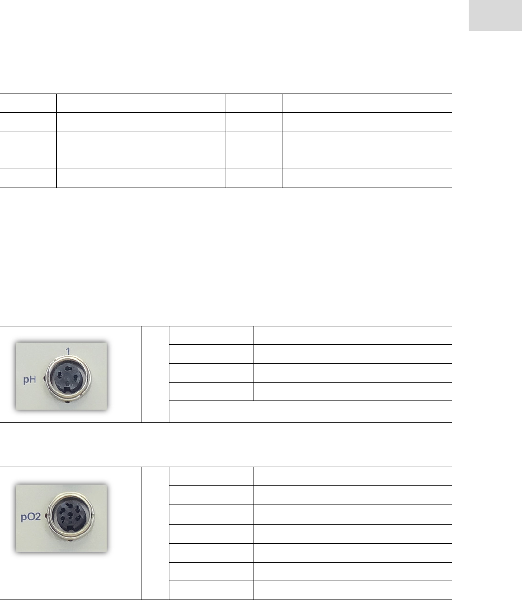
Pin 1-4 Description Pin 5-8 Description
1 5 A/D0
2 6
3 7 + 5 V auxiliary power
4B/D1 8Common
111
Technical data
DASbox® Mini Bioreactor System
English (EN)
9.4.3 Sensor connectors
pH connector
Pin Assignment
1pH+
2
3GND
DO connector
Pin Assignment
1NTC
2 UVisiFerm (10 V)
3GND
4
5DO
6Upol

Technical data
DASbox® Mini Bioreactor System
English (EN)
112
Level connector
Pin Assignment
1LVL+
2GND
Redox connector (optional, instead of level)
Pin Assignment
1RDX
2
3GND
Pt connector
Pin Assignment
1Pt 100 port A
2
3Pt 100 port B
4Pt 100 port B´
To connect the Pt100-type temperature sensors, Binder 680-type 4-pin connectors are used.
To ensure the proper functioning of the three wire circuit, the B and B’ signals have to be directly intercon-
nected at the sensor element of the temperature sensor.
Note:
The measuring amplifiers of the primary and secondary temperature sensors are galvanically
insulated from the rest of the device electronics. The measuring amplifiers have a common
reference potential.

113
Ordering information
DASbox® Mini Bioreactor System
English (EN)
10 Ordering information
10.1 DASbox base unit
Order no.
(international)
Description
78525185 DASbox Overhead Drive for glass reactors
(20-2000 rpm), incl. cable L 1.6 m
78525186 DASbox Overhead Drive for Single-Use Vessels
(20-2000 rpm), incl. cable L 1.6 m
78201321 Actuator unit for DASbox peltier off gas condenser,
incl. cable L 1.6 m
78201323
78201322
Off-gas condenser adapter incl. insulation
for DASbox glass reactor
for DASbox Single-Use Vessel
78109111 Insulation for Off-gas condenser adapter
78590033 Exhaust Gas Condenser Controller EGC4,
4 ports for Peltier Condensers
78109112 DASbox autoclavable carrier for 4 vessels,
stainless steel, labeled
78109113 DASbox autoclavable carrier for media bottles,
stainless steel, labeled
78109030 Holder for DASbox autoclavable carrier
78201035 Flask 100 mL with neck GL45,
transparent, with cap
78201078 Flask 500 mL with neck GL45,
transparent, with cap
78510311 DASGIP head gear for reservoir bottles
with GL45 neck, silicone, female luer
78903224 GL45 screw cap,
PBT, with port D 34 mm
78201311 Pull-out system for one DASbox base unit
78201146 Sealing ring for one well of DASbox base unit,
silicone
78105217 Gas tubing PA, OD 4 mm/ID 2,5 mm,
outside tolerated, oxygen resistant, uncolored
78105218 Gas tubing PA, OD 6 mm/ID 4 mm,
outside tolerated, oxygen resistant, uncolored

Ordering information
DASbox® Mini Bioreactor System
English (EN)
114
10.2 System / cables
Order no.
(international)
Description
78702579
78702468
Cable converting Hirschmann STAS200 plug to IEC 320 C14 connector,
L 60 cm
L 43 cm
78535021 Terminator connector for DTP network
version 2
78100242 DTP control cable,
L 1 m
78702562 DASGIP cable,
4pinM5, L 3 m, (for LCD monitor)
78704128 Disassembly tool for Push-In
OD 4 mm and OD 6 mm, plastic
Order no.
(international)
Description

115
Ordering information
DASbox® Mini Bioreactor System
English (EN)
10.3 MP8-pH4pO4 multi pump and sensor module
Order no.
(international)
Description
78530260 MultiPump & Sensor Module MP8-PH4PO4LS
w/ Storage, 8 pumps and 4xpH, 4xDO and 4xLeveL
78530261 MultiPump & Sensor Module MP8-PH4PO4RD4S
w/ Storage, 8 pumps and 4xpH, 4xDO and 4xRedox
78705383 Back-up battery for DASGIP Module MP8-PHPO
(Varta High Energy 4906 1.5 V, AA, Alkaline
78103314 Platinum RTD temperature sensor,
100 Ohm class A, OD 1.6 mm, L 150 mm, cable L 1.8 m
78522020 DASGIP pH/Redox cable
with AK9 plug; L 3 m
78103207 pH Sensor MTI
D 12 mm, L 120 mm, autoclavable
78103224 Redox Sensor MTI
D 12 mm, L 120 mm, autoclavable
78522040 DASGIP DO cable
with plug Type 82, L3m
78108016 Dust cap for DO Sensor
with 4-pin connector (T82)
78108046 DO Sensor for Single Use Vessels
DO sensor DASGIP D 4.7 mm, L 162 mm, incl. cable L 3m and calibration cap
78108018 DO Sensor MTI
D 12 mm, L 120 mm autoclavable
78108003 DO-Membrane Kit MTI
(4 membrane bodies, spare O-rings, 25 mL electrolyte)
78522031 DASGIP Level Sensor cable,
L 3 m
78103117 DASGIP Level Sensor
OD 4 mm, L 205 mm, L i165 mm
78510119
78510118
78510236
Pump head tubing for MP8 pump,
Bioprene, ID 0.25/W 0.85 mm, female/female
Bioprene, ID 0.5/W 1.05 mm, female/female
Bioprene, ID 1.0/W 1.05 mm, female/female
78510309
78510310
Feed line C-Flex,
ID 0.8 mm, L 1 m, w/ 2x Luer lock fittings, male/male
ID 0.8 mm, L 2 m, w/ 2x Luer lock fittings, male/male

Ordering information
DASbox® Mini Bioreactor System
English (EN)
116
78510242
78510241
78510240
Feed line PTFE,
ID 0.8 mm, L 2 m, uncolored w/ 2x Luer lock fittings, male/male
ID 0.8 mm, L 1 m, uncolored w/ 2x Luer lock fittings, male/male
ID 0.8 mm, L 0.5 m,uncolored w/ 2x Luer lock fittings, male/male
78510246
78510245
Feed line silicone,
ID 0.8 mm, L 2 m, w/ 2x Luer lock fittings, male/male, Pumpsil
ID 0.8 mm, L 1 m, w/ 2x Luer lock fittings, male/male, Pumpsil
Order no.
(international)
Description

117
Ordering information
DASbox® Mini Bioreactor System
English (EN)
10.4 DASbox Bioreactors
10.4.1 Single-Use Vessels
Order no.
(international)
Description
78903508 BioBLU 0.3c single-use vessel, cellculture,
4 pack, pre-sterilized, blue
78903509 BioBLU 0.3f single-use vessel, microbial,
4 pack, pre-sterilized, blue
10.4.2 Glass Reactors
Order no.
(international)
Description
76DS0250ODSS DASbox Vessel Type DS0250ODSS for cell culture applications
(Pitched blade impeller, 60mL - 250mL, overhead drive)
76SR0250ODLS DASbox Vessel Type SR0250ODLS for microbiology applications
(2x Rushton impeller, 60 mL - 250mL, overhead drive)
78903227 DASGIP GLS-80 vessel
OD 70 x H 123 mm, flat bottom, with Eppendorf Logo
78107301 Stainless steel Headplate
OD 77 w/ 6x Pg13.5, 4x D 4 mm dip tubes, 1x thermowell
78903226 Screw cap for OD 80 mm
(GLS80) neck with hole ID 73 mm, PBT, blue
78201138 O-Ring 68 x 3 mm
(IDxd) VMQ Si820
78107304 6 blade Rushton turbine
OD 30 mm, ID 5 mm, stainless steel, for microbiology
78107325 3 blade impeller
30° pitch, OD 30 mm, ID 5 mm, stainless steel, for cell culture
78107326 Stainless steel pipe
OD 4 mm/ID 2 mm, L 180 mm, with barb
78200119 Tubing clamp (Mohr)
L 50 mm, nickel plated brass
78532034 Filter assembly
type "Gas In"
78532035 Filter assembly
type "Gas Out"

Ordering information
DASbox® Mini Bioreactor System
English (EN)
118
78532036 Liquid feed connector assembly
78510145 DASGIP sampling accessory
w/ swabable valve for vessels type BS/DS/SR/DR
78200077 Sampling valve
male luer lock and swabable female luer lock, autoclavable
78200087 Cap for sampling valve
male luer lock, autoclavable
78704149 Hex wrench
w/ ball shaped head, size 1.5mm
78532282 DASGIP compression fitting ID 4 mm
with PG13.5 male thread, all parts included:
78706417 O-Ring 4 x 1.5
(IDxd), Si820, red
78706351 Front ferrule
PFA, for OD 4 mm DASGIP compression fitting
78706352 Back ferrule
PFA, for OD 4 mm DASGIP compression fitting
78706406 O-Ring 14 x 2
(IDxd), VMQ70/Si820, red
78532283 DASGIP compression fitting ID 6 mm
with PG13.5 male thread, all parts included:
78706416 O-Ring 6 x 1.5
(IDxd), Si820, red
78706353 Front ferrule
PFA, for OD 6 mm DASGIP compression fitting
78706354 Back ferrule
PFA, for OD 6 mm DASGIP compression fitting
78706406 O-Ring 14 x 2
(IDxd), VMQ70/Si820, red
78532284 DASGIP compression fitting ID12 mm
with PG13.5 male thread, all parts included:
78706419 O-Ring 12 x 1.5
(IDxd), Si820, red
78706355 Front ferrule
PFA, for OD 12 mm DASGIP compression fitting
78706356 Back ferrule
PFA, for OD 12 mm DASGIP compression fitting
78706406 O-Ring 14 x 2
(IDxd), VMQ70/Si820, red
Order no.
(international)
Description

119
Ordering information
DASbox® Mini Bioreactor System
English (EN)
77102018 DASGIP triple port
w/ 3x OD4mm tubing, w/M18x1.5 male thread, all parts included
78706415 O-Ring 4 x 1
(IDxd), VMQ70/Si973, red
78706406 O-Ring 14 x 2
(IDxd), VMQ70/Si820, red
77102006 Septumholder Pg13.5 male with septum
ID 12 mm, stainless steel
78706409 Septumholder
DASGIP fitting w/ Pg13.5 male thread, ID 12 mm port, stainless steel
78106309 Silicone rubber septa
Pg13.5, OD 18 mm/ ID 12 mm
78525123 DASGIP Lipseal stirrer assembly
Pg13.5 seat, stirrer shaft d 5 mm x Li 112 mm
Order no.
(international)
Description

Ordering information
DASbox® Mini Bioreactor System
English (EN)
120

121
Index
A
Abbreviations ......................................................... 7
Addition of media .................................................92
Addition of media
- see Feed
Agitation ...............................................................43
Speed limits ....................................................43
Technical data ...............................................107
Agitation control ...................................................91
Alarm
Settings ...........................................................84
Alarm Option - DASGIP Control ...........................84
Alarms ..................................................................67
Ambient conditions ..............................27, 105, 106
Assembly
Glass Reactor ..................................................71
Overhead Stirrer .............................................72
Autoclavable Carrier System ................................67
Autoclave
Feed tubing .....................................................55
pH-Sensors ......................................................58
AUX ......................................................................29
B
back-up batteries ..................................................99
BioBLU® 0.3c/f Single-Use Vessel ......................13
Bioreactor
Assembly .........................................................71
Bioreactors .....................................................13, 69
Description ......................................................13
Technical data ...............................................106
C
Calibrate
DO Sensors .....................................................59
pH Sensors ......................................................58
Pump head tubing ...........................................54
Sensors ............................................................58
Calibration factor FCal .........................................50
Calibration procedures ........................................ 15
Carrier System (autoclavable) .............................. 67
Cascade control ............................................. 90, 92
C-Flex® tubing .............................................. 54, 96
CIP
- seeCleaning-in-place
Cleaning
Feed Tubing .................................................... 95
pH Sensors (Regeneration) ............................ 98
Pump tubing ................................................... 95
Surfaces .......................................................... 95
Cleaning agents ................................................... 95
Cleaning-in-place (CIP) .................................... 9, 54
Cleaning-in-place procedures .............................. 15
CO2
Flowrates .......................................................... 5
Colors
Software Event Monitor .................................. 87
Software Symbols ........................................... 79
COM ports ............................................................ 33
Communication ............................................ 109
Install .............................................................. 36
Ports ............................................................... 29
Condensate
Frozen ............................................................. 48
Condenser adapter .............................................. 44
Condensers
Component parts ............................................ 44
Connecting sockets ........................................ 30
Conductivity Sensors
Connecting sockets ........................................ 33
Connect
DASbox Base Unit .......................................... 35
Gas supply ...................................................... 40
Off-gas condensers ......................................... 38
Overhead drives ............................................. 38
Sensors ........................................................... 39
Temperature sensors - Base Unit ................... 38
Connection assignments .................................... 110
Control
- see DASGIP Control

122
Cooling System .....................................................43
Cultivation ............................................................73
D
Danger
Levels ................................................................6
Symbols .............................................................6
DASbox
Base Unit - see DASbox Base Unit
Bioreactors - see Bioreactors
Carrier System ................................................67
Connect ...........................................................34
Features ..........................................................14
Not connected .................................................65
Storage ................................................11, 12, 65
System - general view .....................................11
System - rear view ..........................................12
Versions ............................................................5
DASbox Base Unit ..........................................11, 12
Connect ...........................................................35
Connecting sockets .........................................30
Functions ........................................................41
Rear .................................................................30
DASGIP
Control ............................................................15
Service ..................................................................97
DASGIP Control
Alarm Option ...................................................84
Chart Control Panel .........................................85
Event Monitor .................................................87
Login ...............................................................75
Process View ...................................................80
Summary View ................................................78
DASGIP Software ..................................................15
DASware ...............................................................15
Decontamination ............................................95, 96
Definition
Of Set-point Profiles ........................................83
Software Parameters .......................................82
Definitions ..............................................................7
Deice Function .....................................................48
Delivery package ..................................................14
Dimensions .........................................................106
Disassembly tool .................................................. 40
Dispensing
Continuous ..................................................... 51
Pulsed ............................................................. 51
Technical data .............................................. 107
Display ................................................................. 65
Disposal ..................................................... 102, 103
DO
Cable ............................................................... 39
Sensor for Single Use vessels ........................ 39
Sensor membrane .................................... 61, 62
DO cascade control .............................................. 91
DO connector ..................................................... 111
DO Sensors
Calibrate ......................................................... 59
Connecting sockets ........................................ 33
For Single-Use Bioreactors ............................ 63
Handling instructions ..................................... 61
Maintenance ................................................... 97
Polarize ..................................................... 62, 63
Raw signal ...................................................... 62
Replacement of Electrolyte ............................ 97
Documents
Other applicable ......................................... 5, 18
DTP cable ............................................................. 36
DTP in .................................................................. 29
DTP network ........................................................ 36
DTP out ................................................................ 29
E
Edit boxes ............................................................ 80
Electrical connections
requirements .................................................. 28
Electrical supply
Install .............................................................. 35
Electrolyte solution
DO Sensors ..................................................... 97
Errors and Alarms ................................................ 67
Event Monitor ................................................ 76, 87
Colors ............................................................. 87
Exhaust filter blockages ....................................... 47

123
Exhaust gas line insulation ............................44, 45
External power supply ..........................................35
F
FCal ......................................................................50
Features DASbox ..................................................14
Feed
Pump head tubing ...........................................49
Rates / Ranges ..........................................49, 50
Tubing .............................................................49
Feed tubing
Autoclave ........................................................55
Cleaning ..........................................................95
Sterilize ...........................................................54
Feeding
Continuous ................................................51, 56
Pulsed .............................................................51
Short ................................................................56
Filter blockages ....................................................47
Freezing of condensate ........................................48
Fuses ....................................................................29
G
Gas IN - see Gas inlets
Gas inlets ..............................................................31
Gas Mixing System ...............................................42
Splitter Function .............................................42
Variants ...........................................................42
Gas outlets ............................................................31
Gas quality ............................................................28
Gas supply
Connect ...........................................................40
Ports ................................................................31
Gassing .................................................................42
Technical data ...............................................107
Gassing tubes
Loosen .............................................................40
Glass Reactor ........................................................13
Assembly .........................................................71
Glossary ..................................................................9
H
Head plate
Typical Assignments ....................................... 70
I
Inlet pressure
Gases .............................................................. 21
Installation instructions ....................................... 27
Intended use ........................................................ 17
Warnings ........................................................ 18
Internal power supply .......................................... 35
L
LCD Monitor ........................................................ 65
Connect .......................................................... 37
Port ........................................................... 30, 33
Level
Cable ............................................................... 39
Connector ..................................................... 112
Sensors ........................................................... 59
Location
Requirements ................................................. 27
L-Sparger ............................................................. 70
M
Main illustration ................................................... 11
Mains connection .............................................. 109
Mains connection unit ......................................... 29
Mains disconnect switch ..................................... 29
Maintenance ........................................................ 97
Media addition - see Feed
Microfuses ......................................................... 109
Monitor - seeLCD Monitor
Monitor cable ....................................................... 37
Monitoring ..................................................... 57, 93
MP8-pHpO Module
Connect .......................................................... 39
Function ......................................................... 49
Ports ............................................................... 33
Rear ................................................................ 33

124
Multi Pump and Sensor Module ..........................33
MX4/4-3 Gas Mixing Module
- see Gas Mixing System
N
Navigation Area ....................................................76
New Workflow ......................................................77
Not connected ......................................................65
O
Off-gas condensers ...............................................44
Adapter ...........................................................44
Assembly for glass reactors ............................45
Assembly for single-use vessels ......................46
Connecting sockets .........................................30
Deice ...............................................................48
Heating mode ..................................................48
Operate ............................................................47
Offline Values .......................................................85
Operating pressure
Gases ...............................................................21
Operation
DASGIP Control ..............................................76
Pumps .............................................................55
Ordering information .........................................113
Original packaging .............................................102
Other applicable documents ..................................5
Overhead drives
connect ............................................................38
Connecting sockets .........................................30
Overhead Stirrer
Assembly .........................................................72
Overlay .................................................................40
Overpressure ........................................................32
P
Packaging ...........................................................102
Parameter
Definitions .......................................................82
Sensor .............................................................82
Vessel ..............................................................81
Particle filter .........................................................40
Peltier elements ............................................. 44, 48
pH cable ............................................................... 39
pH connector ..................................................... 111
pH Sensors
Autoclave ........................................................ 58
Calibrate ......................................................... 58
Connecting sockets ........................................ 33
Handling instructions ..................................... 60
Raw signal ...................................................... 61
pH sensors
Regeneration .................................................. 98
Plant Overview ..................................................... 88
History ............................................................ 88
pO2 Sensors - see DO Sensors
Polarize .......................................................... 62, 63
Ports
Specifications ............................................... 109
Power cord ........................................................... 35
Power supply ....................................................... 29
External .......................................................... 35
Internal ............................................... 30, 33, 35
Technical data .............................................. 105
Pressure reducer .................................................. 40
Process View ........................................................ 80
Product liability .................................................... 18
Profile
Constant Value ............................................... 84
Data Table ....................................................... 84
Function ......................................................... 84
Profile Source ...................................................... 83
Program Start ...................................................... 75
Pt connector ....................................................... 112
Pt100 temperature sensor ................................... 39
Pump head tubing ......................................... 49, 50
Calibrate ......................................................... 54
Deformation .................................................... 53
Insert .............................................................. 52
pump head tubing
replace ............................................................ 99

125
Pump tubing
Cleaning ..........................................................95
Pumps
Continuous feeding .........................................56
Manual operation ............................................55
Short feeding 56 ..................................................
Speed limits ....................................................51
Typical working ranges ...................................51
R
Redox cable ..........................................................39
Redox connector ................................................112
Redox Sensors ......................................................64
Connecting sockets .........................................33
Handling instructions ......................................59
Replacement of electrolyte ...................................97
Return delivery information ...............................104
Rx/Tx ....................................................................29
S
Safety instructions ................................................17
Save User Chart Settings ......................................87
Sensor membrane ..........................................61, 62
Sensors
Calibrate ..........................................................58
Connect ...........................................................39
Handling instructions ......................................60
Sterilize ...........................................................57
Serial interfaces ....................................................28
Serial number .......................................................33
Service ............................................................96, 97
Set-point Profile
Definition ........................................................83
Settings
Alarm ...............................................................84
Shipment ..............................................................96
Software
Process View ...................................................80
Summary View ................................................78
Symbols ...........................................................79
Splitter Function .............................................15, 42
Stas 200 plug 3 ....................................................... 5
State ..................................................................... 29
Sterilize
Feed tubing .................................................... 54
Sensors ........................................................... 57
Storage ......................................................... 65, 102
Submerged .............................................. 15, 31, 40
Surfaces
Cleaning ......................................................... 95
Symbol
Colors ............................................................. 79
Controller ........................................................ 83
Vessel ............................................................. 81
Symbols
Danger .............................................................. 6
Explanation ....................................................... 7
Software ......................................................... 79
System components
Delivery package ............................................ 14
T
Tab
Data ................................................................ 84
Graph .............................................................. 84
Navigation ...................................................... 88
Type ................................................................ 84
Technical data .................................................... 105
Power supply ................................................ 105
Telescopic rails .................................................... 68
Temperature control ............................................ 43
Temperature control actuator .............................. 44
Temperature sensor ....................................... 23, 70
Connector ..................................................... 112
Port - MP8-pHpO ............................................ 33
Temperature sensors
Connect .......................................................... 38
Connecting sockets - Base Unit ..................... 30
Port MP8-pHpO .............................................. 33
Terminator connector .......................................... 36
Top-heaviness
Bioreactors ..................................................... 47

126
Transport ............................................................102
Typical workflow ..................................................73
U
USB cable .............................................................36
USB port ...............................................................36
User profile ...........................................................17
V
Ventilation grating ................................................30
Ventilation slots ....................................................33
Vessel
Parameters ......................................................81
W
Warning symbols 6
Devices ......................................................24, 25
Warnings
Gas supply .......................................................32
Weight ................................................................106
Workflow ..............................................................73
New .................................................................77
Working Area .......................................................76
Workplace
Requirements ..................................................27
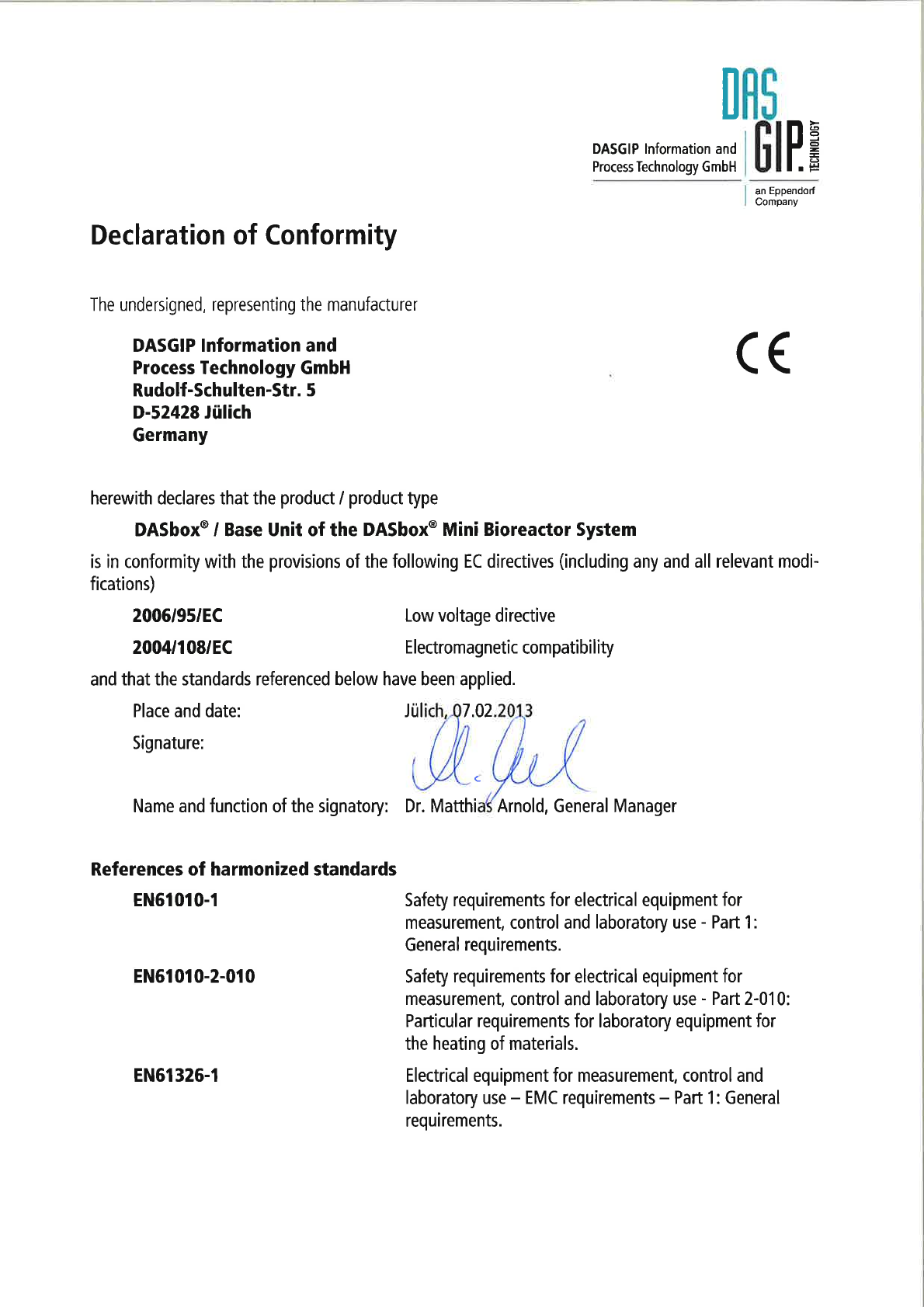


Evaluate your manual
Give us your feedback.
www.eppendorf.com/manualfeedback
Your local distributor: www.eppendorf.com/contact
Eppendorf AG · 22331 Hamburg · Germany ·
eppendorf@eppendorf.com www.eppendorf.com
