MACHINE OPERATING MANUAL Operator For CNC6000 AP EP US15 US20 US30 US40 US50
User Manual:
Open the PDF directly: View PDF ![]() .
.
Page Count: 151 [warning: Documents this large are best viewed by clicking the View PDF Link!]
- 1 American GFM and GFM Austria
- 2 Machine Description
- 3 Machine Safety
- 4 Vacuum System
- Pneumatic System
- 6 CNC and other Machine Control Hardware
- 7 MMI Operation and Machine Startup
- 7.1 Preparation for Machine Startup
- 7.2 Changing the Knife
- 7.3 Displays Common to All Modes
- 7.4 REF Mode
- 7.5 JOG Mode
- 7.6 MDI Mode
- 7.7 Production Mode (AUTO)
- 7.8 F3 Edit Material Data (2D Cutter Mode Only)
- 7.9 F4 Edge of Knife
- F5 Tools (CM10 Machines Only)
- F5 Tools (All other 2D Cutters)
- 7.12 F5 Tools (3D Machines)
- 7.13 F7 ( F2 Offsets
- 7.14 F7 ( F4 Machine States (Additional Functions)
- F7 ( F5 Change Program Flow
- 7.16 F7 ( F6 System Support
- 7.16.1 System Support Group 1
- 7.16.2 Show Error Log File
- View Protocols
- 7.16.4 Mount Points
- Add line to Protocol
- 7.16.6 System Support - Diagnostics
- 7.16.7 Value Display
- 7.16.8 Additional Auto Data
- Analog Input Monitor
- 7.16.10 Analog Output Monitor
- Axis Monitor
- 7.16.12 Machine States
- View Mapping
- 7.16.14 System Support - Service
- Scan Mode
- 7.16.16 View Knife Alignment
- Oscilloscope
- PLI Debugger
- PLI Compiler
- Parameter Editor
- View Versions
- 7.16.22 System Support - Extended
- 7.16.23 Program Management
- 7.16.24 User PLI Command Editor
- System Support - User Defined
- 7.16.26 Edit User Functions
- 7.17 Using Simple Production Log Files
- 7.18 Using Advanced Production Log Files
- 7.19 Adding New Users
- 7.20 Priority Levels
- 7.21 MMI Softkey Flow Diagrams
- 7.22 System Support Menu Tree
- 8 Machine Options
- 9 General Information
- 10 G-Codes, M-Codes, and H-Codes for 2D Machines
- 11 G-Codes, M-Codes, T-Codes, and H-Codes for 3D Machines

O
OP
PE
ER
RA
AT
TO
OR
RS
S
M
MA
AN
NU
UA
AL
L
F
FO
OR
R
2
2D
D
&
&
3
3D
D
U
UL
LT
TR
RA
AS
SO
ON
NI
IC
C
C
CU
UT
TT
TI
IN
NG
G
M
MA
AC
CH
HI
IN
NE
ES
S
Copyright © 2008 American GFM Corporation.
All rights reserved
This description is the intellectual property of GFM and AGFM, and must not be copied by or made available to any
third party without our permission.
GFM AG A-4403 Steyr, Ennser Str. 14, Austria, Tel. (01143)07252-8980, Fax 07252/64934
AGFM 1200 Cavalier Blvd., Chesapeake, VA 23323, USA, Tel. (757)487-2442, Fax (757)487-5274
PREFACE
This Operator's training manual was prepared with the machine operator in mind. Some sections are specific to
certain machine types and will be annotated as such. Also, individual machines will have different options installed.
This manual has been designed primarily as a teaching aid to be used in structured learning situations and for
hands-on training. It is also designed to be used as a reference on the floor when performing cutting operations. It
is divided into five major sections, each covering a specific subject. The sections are designed to take the trainee
smoothly through each phase of operator personnel training. Some maintenance functions for the control are
included at the end of this manual since we recognize that maintenance personnel must know how to operate the
equipment, and they too will read this book for a basic understanding of how the equipment operates. Mechanical
maintenance of the machine is covered comprehensively in another manual.
This manual covers the following general subjects:
1. Basic components of the machine and their function.
2. Operation of the machine.
3. Basic machine programming.
4. Recognizing faults and problems.
5. Information for high priority users.
The illustrations in this manual are for instructional purposes only and are not intended to be used as blue prints. If
more accurate information is needed, the reader should consult the AGFM Maintenance Manual or contact AGFM.
Additional pages are included at the end of this manual. The extra pages are for notes when there is insufficient
space to make notes in the original pages, and may be inserted wherever desired.
AGFM's goal in publishing this manual is to supply the trainee with an organized approach to learning the safety
requirements and the operation of the US-40 Ultrasonic Cutting Machine.
This operation manual is the intellectual property of American GFM and may not, without our permission, be
reproduced nor given to third parties.
American GFM
1200 Cavalier Blvd.
Chesapeake, VA 23323
Phone: (757) 487-2442
Fax: (757) 487-5274
1AMERICAN GFM AND GFM AUSTRIA ........................................................................................................................... 6
1.1HISTORY OF EVOLUTION ................................................................................................................................................... 6
2MACHINE DESCRIPTION .................................................................................................................................................. 7
2.1ULTRASONIC CUTTING AND ULTRASONIC ROUTING MACHINES ....................................................................................... 7
2.1.1Principles of Ultrasonic Operation .......................................................................................................................... 7
2.2FOUNDATION ..................................................................................................................................................................... 7
2.3BASE FRAME ..................................................................................................................................................................... 7
2.42D ULTRASONIC CUTTING MACHINE AXIS LAYOUT ......................................................................................................... 8
2.4.1X Axis ........................................................................................................................................................................ 8
2.4.2Y Axis ........................................................................................................................................................................ 9
2.4.3Z Axis ...................................................................................................................................................................... 10
2.4.4C and P Axes .......................................................................................................................................................... 11
2.5VACUUM TABLE .............................................................................................................................................................. 12
2.63D ULTRASONIC ROUTING MACHINES AXIS LAYOUT ..................................................................................................... 13
2.7X AXIS ............................................................................................................................................................................ 13
2.8Y AXIS ............................................................................................................................................................................ 13
2.9Z AXIS ............................................................................................................................................................................. 14
2.10A AXIS ............................................................................................................................................................................ 14
2.11B AXIS ............................................................................................................................................................................ 15
2.12C AXIS ............................................................................................................................................................................ 15
3MACHINE SAFETY ............................................................................................................................................................ 16
3.1INTRODUCTION ................................................................................................................................................................ 16
3.1.1Danger due to sharp blades .................................................................................................................................... 16
3.2SAFETY COMPONENTS ..................................................................................................................................................... 16
3.2.1Emergency Stop Pushbuttons ................................................................................................................................. 16
3.2.2Safety Light Curtains (if equipped) ......................................................................................................................... 17
3.2.3Safety Mats (if equipped) ........................................................................................................................................ 17
3.2.4Light Guards (if equipped) ..................................................................................................................................... 17
3.2.5Safety Bumpers (if equipped) .................................................................................................................................. 17
3.2.6Machine disconnect switch ..................................................................................................................................... 18
4VACUUM SYSTEM ............................................................................................................................................................ 19
4.1CONTROL OF VACUUM SYSTEM ...................................................................................................................................... 19
5PNEUMATIC SYSTEM ...................................................................................................................................................... 19
5.1CUTTING UNIT................................................................................................................................................................. 19
5.2INKJET PRINTHEAD, LIFT TABLE, GRIPPER BAR, AND CLAMP UNIT (IF EQUIPPED) .......................................................... 19
5.3INKJET (IF EQUIPPED) ...................................................................................................................................................... 19
6CNC AND OTHER MACHINE CONTROL HARDWARE ............................................................................................ 20
6.1CNC6000-EP .................................................................................................................................................................. 20
6.2OPERATOR CONSOLE ....................................................................................................................................................... 21
6.3PERSONAL COMPUTER .................................................................................................................................................... 23
6.4ELECTRICAL CABINETS ................................................................................................................................................... 23
6.5ULTRASONIC GENERATOR ............................................................................................................................................... 23
6.6CONVEYOR DEVIATION SYSTEM (IF EQUIPPED) ............................................................................................................... 24
6.7MATERIAL EDGE GUIDANCE (IF EQUIPPED) ..................................................................................................................... 24
6.8JOG PENDANT .................................................................................................................................................................. 25
7MMI OPERATION AND MACHINE STARTUP ............................................................................................................ 26
7.1PREPARATION FOR MACHINE STARTUP ........................................................................................................................... 26
7.1.1Initial Checks .......................................................................................................................................................... 26
7.1.2Turning the Machine On ......................................................................................................................................... 26
7.1.3Start Up Procedure ................................................................................................................................................. 26
7.1.4Language Selection ................................................................................................................................................. 26
7.1.5Master Control ....................................................................................................................................................... 27
7.1.6E-Stop ..................................................................................................................................................................... 27
7.1.7No Mode ................................................................................................................................................................. 27
7.1.8Machine Mode Selections ....................................................................................................................................... 27
7.2CHANGING THE KNIFE ..................................................................................................................................................... 28
7.2.1Horn Inspection ...................................................................................................................................................... 29
7.2.2Cleaning the converter contact surfaces................................................................................................................. 29
7.3DISPLAYS COMMON TO ALL MODES ............................................................................................................................... 30
7.3.1Display Header ....................................................................................................................................................... 30
7.3.2Axis Display ............................................................................................................................................................ 30
7.3.3Ultrasonic and Spindle Power Display .................................................................................................................. 30
7.3.4Feedrate and Axis Override Display ...................................................................................................................... 31
7.3.5The Message Window ............................................................................................................................................. 31
7.3.6Using the Online RESTART Feature ...................................................................................................................... 32
7.3.7Softkey Lines (REF, JOG, and MDI modes) ........................................................................................................... 33
7.4REF MODE ...................................................................................................................................................................... 34
7.5JOG MODE ...................................................................................................................................................................... 35
7.6MDI MODE ..................................................................................................................................................................... 36
7.7PRODUCTION MODE (AUTO) .......................................................................................................................................... 37
7.7.1Softkey Lines (AUTO Mode) ................................................................................................................................... 37
7.7.2F2 Program Management ....................................................................................................................................... 38
7.8F3 EDIT MATERIAL DATA (2D CUTTER MODE ONLY) .................................................................................................... 42
7.9F4 EDGE OF KNIFE .......................................................................................................................................................... 42
7.10F5 TOOLS (CM10 MACHINES ONLY) .............................................................................................................................. 43
7.11F5 TOOLS (ALL OTHER 2D CUTTERS) .............................................................................................................................. 43
7.12F5 TOOLS (3D MACHINES) .............................................................................................................................................. 44
7.12.1Choosing the Station ............................................................................................................................................... 44
7.12.2Assigning Tool Pockets ........................................................................................................................................... 44
7.12.3F6 Edit Tool Data ................................................................................................................................................... 45
7.12.4Tool Types .............................................................................................................................................................. 46
7.13F7 → F2 OFFSETS ........................................................................................................................................................... 47
7.14F7 → F4 MACHINE STATES (ADDITIONAL FUNCTIONS) .................................................................................................. 47
7.14.1Tool Changer Status ............................................................................................................................................... 47
7.14.2Ultrasonic Status .................................................................................................................................................... 48
7.14.3Scope Files .............................................................................................................................................................. 48
7.14.4PDF Documentation ............................................................................................................................................... 48
7.14.5F7
→
F3 Label Text ............................................................................................................................................... 49
7.14.6F7
→
F4 Additional Functions ............................................................................................................................... 49
7.15F7 → F5 CHANGE PROGRAM FLOW ................................................................................................................................ 49
7.16F7 → F6 SYSTEM SUPPORT ............................................................................................................................................. 50
7.16.1System Support Group 1 ......................................................................................................................................... 50
7.16.2Show Error Log File ............................................................................................................................................... 50
7.16.3View Protocols ........................................................................................................................................................ 51
7.16.4Mount Points .......................................................................................................................................................... 51
7.16.5Add line to Protocol ................................................................................................................................................ 51
7.16.6System Support - Diagnostics ................................................................................................................................. 51
7.16.7Value Display ......................................................................................................................................................... 52
7.16.8Additional Auto Data .............................................................................................................................................. 52
7.16.9Analog Input Monitor ............................................................................................................................................. 53
7.16.10Analog Output Monitor ....................................................................................................................................... 53
7.16.11Axis Monitor ....................................................................................................................................................... 53
7.16.12Machine States .................................................................................................................................................... 54
7.16.13View Mapping ..................................................................................................................................................... 54
7.16.14System Support - Service .................................................................................................................................... 54
7.16.15Scan Mode .......................................................................................................................................................... 54
7.16.16View Knife Alignment ......................................................................................................................................... 55
7.16.17Oscilloscope........................................................................................................................................................ 55
7.16.18PLI Debugger ..................................................................................................................................................... 55
7.16.19PLI Compiler ...................................................................................................................................................... 55
7.16.20Parameter Editor ................................................................................................................................................ 56
7.16.21View Versions ..................................................................................................................................................... 56
7.16.22System Support - Extended ................................................................................................................................. 56
7.16.23Program Management ........................................................................................................................................ 57
7.16.24User PLI Command Editor ................................................................................................................................. 57
7.16.25System Support - User Defined ........................................................................................................................... 57
7.16.26Edit User Functions ............................................................................................................................................ 57
7.17USING SIMPLE PRODUCTION LOG FILES .......................................................................................................................... 58
7.18USING ADVANCED PRODUCTION LOG FILES ................................................................................................................... 60
7.18.1Logging Section: ..................................................................................................................................................... 60
7.18.2Available Events: .................................................................................................................................................... 62
7.18.3Special Parameters: ............................................................................................................................................... 62
7.18.4Available Parameters: ............................................................................................................................................ 63
7.18.5Log file formats ....................................................................................................................................................... 65
7.19ADDING NEW USERS ....................................................................................................................................................... 68
7.20PRIORITY LEVELS ............................................................................................................................................................ 68
7.20.1Program Management Priority Level Access ......................................................................................................... 69
7.20.2System Support Priority Level Access .................................................................................................................... 69
7.21MMI SOFTKEY FLOW DIAGRAMS ................................................................................................................................... 71
7.21.1Manual Mode Softkeys ............................................................................................................................................ 71
7.21.2Production Mode Softkeys ...................................................................................................................................... 73
7.22SYSTEM SUPPORT MENU TREE ........................................................................................................................................ 76
8MACHINE OPTIONS ......................................................................................................................................................... 78
8.1PRINTING PRE-PROCESSOR (PREPRINT.EXE) .................................................................................................................. 78
9GENERAL INFORMATION .............................................................................................................................................. 80
9.1BACKING UP THE MACHINE SOFTWARE .......................................................................................................................... 80
9.1.1Backing up the entire hard drive with Acronis True Image .................................................................................... 80
9.1.2Backing up the CNC6000 software only ................................................................................................................. 83
9.2RESTORING THE DRIVE IMAGE DVD ............................................................................................................................... 83
9.3OTHER AGFM MANUALS ............................................................................................................................................... 84
10G-CODES, M-CODES, AND H-CODES FOR 2D MACHINES ................................................................................. 85
11G-CODES, M-CODES, T-CODES, AND H-CODES FOR 3D MACHINES ............................................................ 112

1 American GFM and GFM Austria
American GFM, located in Chesapeake, VA, is the sister
company of GFM Austria.
GFM Austria, the parent company, was founded in 1945 by Dr.
Bruno Kralowetz. GFM’s initial product was a small radial
Forging Machine built in the 1940’s. American GFM was started
in 1978, and has ever since, been a leading manufacture of high
precision machine tools for the North American continent.
AGFM and GFM Austria are now builders of many different types
of machine tools to satisfy the world’s needs for advanced
machining of complex parts.
1.1 History of Evolution
This graphic shows a representation the various sizes of machines that American GFM and GFM Austria currently
manufacture. Over the years, the evolution of machine types and sizes has grown to an unprecedented
manufacturing process that only GFM and AGFM can duplicate. This illustration shows the dedication that GFM has
put forth to providing all industries solutions to their machining needs. A US40 machine is represented with the
yellow shading in this illustration.
MMI Operation and Machine Startup American GFM Corp.
7
2 Machine Description
The machine consists of an advanced CNC controlled ultrasonic cutting or routing machine with various
options. Options include, but are not limited to: ultrasonic generator with horn assembly, inkjet, labeler,
material dispenser and handling equipment, conveyor, tool change assist pin, and vacuum unit. See
AGFM machine documentation for a list of specific options installed on your machine. Technical data will
vary between different machine types and options. Refer to your maintenance manual for machine
specific data.
2.1 Ultrasonic Cutting and Ultrasonic Routing Machines
The machine is an advanced CNC controlled cutting machine with an ultrasonic knife, with which it is
possible to cut glass fiber, carbon fiber, Kevlar, and other materials at high speeds. The cutting blades can
be refurbished.
2.1.1 Principles of Ultrasonic Operation
Ultrasonic energy is simple mechanical vibratory energy which, by definition, operates beyond threshold
of human hearing. During activation, large amounts of energy are imparted to the cutting blade without
large displacements or large amounts of force. Generating ultrasonic energy starts with conversion of
simple electrical power to high frequency electrical energy by a solid state generator. The high frequency
electrical energy is sent to a transducer (converter) for conversion to up-and-down mechanical vibrations.
These vibrations are then directed and amplified by an amplitude transformer (ultrasonic horn) before
being applied to the cutting blade. The ultrasonic vibrations significantly reduce friction between the
blade and the material being cut which results in faster, easier, more precise cutting of composite
materials than conventional methods. Ultrasonic technology applied to composite materials has
permitted rapid cutting of multiple plies of prepreg and a variety of other materials.
2.2 Foundation
Special foundations are not required, as the machine can be positioned on a solid, single-slab reinforced
concrete floor, and has its own leveling feet.
2.3 Base Frame
The machine base frame is a rigid welded steel structure, incorporating a sectional design which allows
different length machines to be constructed from basic components.

MMI Operation and Machine Startup American GFM Corp.
8
2.4 2D Ultrasonic Cutting Machine Axis Layout
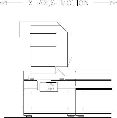
2.4.1 X Axis
The x axis is the movement of the crossbeam along the length of the machine.
The crossbeam runs on linear bearings, along hardened guideways mounted on a continuous support
section. The crossbeam is used to automatically dispense material onto the vacuum table and is able to
park outside of the cutting area to allow for ease of manually unloading cut parts.
The guideways and racks are mounted along the side of the base frame, which facilitates automatic
material loading and manual unloading of material, and keeps the operator from being injured or getting
dirty.
The mechanism used to propel the crossbeam is a rack and pinion system on both ends of the gantry.
Each pinion is driven by separate servomotor/encoder units which are electronically synchronized to each
other.

MMI Operation and Machine Startup American GFM Corp.
9
2.4.2 Y Axis
The y axis is the movement of the carriage, carrying the ultrasonic knife cutting head and inkjet printhead
or labeler units, across the length of the crossbeam.
The carriage runs on linear bearings mounted to the crossbeam, and is propelled by means of a rack and
pinion system. The pinion is coupled through a toothed belt to a servomotor/encoder unit.
MMI Operation and Machine Startup American GFM Corp.
10
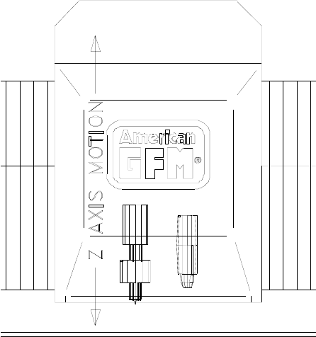
2.4.3 Z Axis
The z axis is the vertical movement of the cutting head and inkjet printhead. This movement allows the
cutting blade to cut through the material into a sacrificial vacuum table surface called Vyon. The operator
controls the depth of this cut using tool offsets and must always be careful not to set the blade too deep in
order to avoid Vyon table surface damage! THE BLADE TIP PENETRATION INTO THE VYON TABLE
SURFACE SHOULD ONLY BE SET TO APPROXIMATELY 0.02 MM (0.001 INCH) DEEP! NOTE
THAT AN AUTOMATIC TOOLSET MUST BE PERFORMED AFTER EVERY BLADE CHANGE!
The height following system in the CNC 6000, which controls the cutting depth of the z axis, is a feature
which is crucial to the proper functioning of the machine. In order to cut to a specified depth in the cutting
table surface, the machine measures and stores the exact height coordinates, or topography, of the
cutting table surface, through a process known as "mapping." These coordinates are then constantly
referred to at the time of cutting to maintain a constant cutting blade height. This is a non-contact method
of implementing precise height control.
The z axis position is controlled by servomotor/encoder unit, directly driving a threaded roller drive
assembly.
To ensure proper cutting depth after the blade is replaced, the CNC calculates and uses new blade
length offset values using an automated toolsetting procedure with the M37/M62 M-Code.
MMI Operation and Machine Startup American GFM Corp.
11
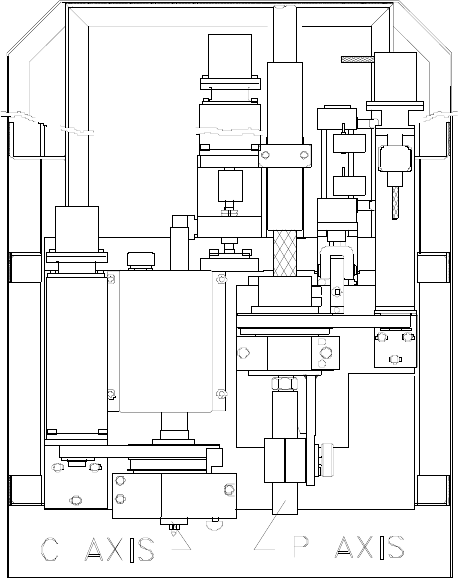
2.4.4 C and P Axes
The c axis is the rotational movement of the cutting blade.
The c axis is commanded by the CNC 6000 control so that the blade is always kept tangent to the cutting
direction. This is necessary so that cutting quality is maintained, and tool life is kept at a maximum.
The cutting blade is fixed to the ultrasonic horn, which in turn is attached to a pulley and rotary bearing.
This pulley is driven via a toothed belt by another pulley mounted to a servomotor/encoder unit.
The p axis is the rotational movement of the inkjet printhead (provided the inkjet printing option is
purchased) or the labeler stamping foot (provided the labeler option is purchased).
During printing, the inkjet must be positioned so that the slot in the printhead nozzle is perpendicular to
the direction of printing, or the labeler stamping foot must be positioned to place the label at the desired
angle. This positioning is directed by the CNC 6000 control through a servomotor/encoder unit, via a
pulley and toothed belt.
The p axis is limited by software and hardware to the rotational range of +/- 90° measured off of the
positive x axis for the inkjet and to 0° - 180° for the labeler.
MMI Operation and Machine Startup American GFM Corp.
12
2.5 Vacuum Table
The vacuum table consists of a steel plate which has a grid of small holes drilled in it. This plate is
welded in place to form the top of a vacuum chamber, which may be subdivided into sections (if zoning
option was purchased, although this does not work well with a Vyon table surface) which can be turned
on and off independently of each other. Applying a vacuum to the table creates a pressure differential,
which holds the material to the surface during cutting. Highly porous materials will usually require the use
of a non-porous cover sheet to maintain enough of a pressure differential to hold the material effectively.
When through cutting material (as opposed to controlled depth cutting), the tip of the ultrasonic knife is
set so that it is just below the top surface of the Vyon (approx. -0.001" CORRECTION value in the Axis
Offset screen. THE OPERATOR CONTROLS THE DEPTH OF THIS CUT USING TOOL OFFSETS
(CORRECTION VALUE IN THE OFFSET SCREEN) AND MUST ALWAYS BE CAREFUL NOT TO SET
THE BLADE TOO DEEP IN ORDER TO AVOID VYON TABLE SURFACE DAMAGE! If this table
covering were not used, the knife would shatter when it touched the steel table top. Vyon is a micro-
porous material which allows the vacuum to pass through it and is glued to the steel table top thereby
acting as a sacrificial surface. A polyethylene 0.006" thick cover sheet must always be used to prevent
vacuum loss. The cover sheet can be automatically dispensed by the machine, or the operator can use
precut strips manually placed along both sides of the material to seal the vacuum while always justifying
the cutting material in the center of the vacuum table. For multiple layer cutting, a cover sheet must be
used across the entire width of the vacuum table.
MMI Operation and Machine Startup American GFM Corp.
13
2.6 3D Ultrasonic Routing Machines Axis Layout
2.7 X Axis
The x axis is the movement of the crossbeam along the length of the machine. The crossbeam runs on
linear bearings, along hardened guideways mounted on a continuous support section. The crossbeam is
able to park outside of the cutting area to allow manual material loading to take place, and for ease of
manually unloading cut parts.
The guideways and gear racks are mounted along the sides of the base frame, which facilitates the
manual loading and unloading of material, and keeps the operator from being injured or getting dirty.
The mechanism used to propel the crossbeam is a rack and pinion system on both ends of the gantry.
Each pinion is driven by separate servomotor/encoder units which are electronically synchronized to each
other.
2.8 Y Axis
The y axis is the movement of the carriage carrying the ultrasonic knife cutting head across the length of
the crossbeam. The carriage runs on linear bearings mounted to the crossbeam, and is propelled by
means of a rack and pinion system powered by a servomotor/encoder unit.
MMI Operation and Machine Startup American GFM Corp.
14
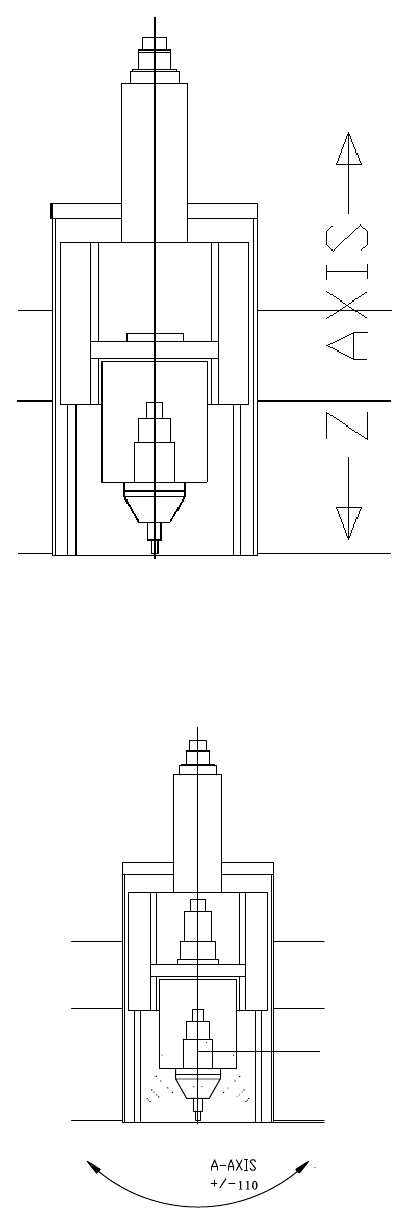
2.9 Z Axis
The z axis is the vertical movement of the cutting
head. This movement allows the cutting blade to cut
through the material into a sacrificial vacuum table
surface called Vyon. The operator controls the depth
of this cut using z-axis offsets in the OFFSET screen
and tool data in the TOOLDATA screen and must
always be careful not to set the blade too deep in
order to avoid Vyon table surface damage! THE
BLADE TIP PENETRATION INTO THE VYON
TABLE SURFACE SHOULD ONLY BE SET TO
APPROXIMATELY 0.02 MM (0.001 INCH) DEEP!
NOTE THAT AN AUTOMATIC TOOLSET WILL BE
PERFORMED AFTER EVERY TOOL CHANGE, AND
MUST BE PERFORMED MANUALLY IF THE
AUTOMATIC TOOLCHANGE OR BLADE CHANGE
SEQUENCE IS INTERRUPTED! The height following
system in the CNC 6000, which controls the cutting
depth of the z axis, is a feature which is crucial to the
proper functioning of the machine. In order to cut to a
specified depth in the cutting table surface, the
machine measures and stores the exact height
coordinates, or topography, of the cutting table
surface, through a process known as "mapping."
These coordinates are then constantly referred to at
the time of cutting to maintain a constant cutting blade
height. This is a non-contact method of implementing precise height control.
The z axis position is controlled by a servomotor/encoder unit, directly driving a ball screw assembly. To
ensure that repeatable cutting tool depth is maintained after a blade is replaced, the control enters new
blade offset figures using an automated toolsetting procedure when prompted.
2.10 A Axis
The a axis is the angular pivoting movement of the
cutting blade. The a axis is commanded by the CNC
6000 control so that the cutting blade can follow three
dimensional contours or make angular cuts. The
ultrasonic horn is mounted in the a axis, which is
driven by a cyclo gear that is attached to a pulley and
rotary bearing. This pulley is driven via a toothed belt
by another pulley mounted to a servomotor/encoder
unit. The a axis is limited by software and hardware to
the rotational range of +/-110 on RMT-50 machines
and +/-90° on US-50 machines with speeds up to
25RPM.
MMI Operation and Machine Startup American GFM Corp.
15
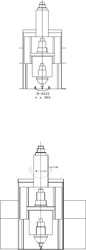
2.11 B Axis
The b axis is the rotational movement of the cutting blade.
The b axis is commanded by the CNC 6000 control so
that the blade is always kept tangent to the cutting
direction during M34 (cutter mode). This is necessary so
that cutting quality is maintained, and tangential knife tool
life is kept at a maximum.
The cutting blade is fixed to the ultrasonic horn or tool
holder, which in turn is attached to a pulley and rotary
bearing. This pulley is driven via a toothed belt by
another pulley mounted to a servomotor/encoder unit.
The b axis is capable of unlimited rotation at variable rpm
rates up to 1500 RPM.
2.12 C Axis
The c axis is the rotational movement of the cutting head
assembly. The c axis is commanded by the CNC 6000
control so that the cutting head assembly can follow the x
and y axis contour of the part being cut, during M35 router
mode only. The c axis position is controlled by a
servomotor/encoder unit, directly driving a rotary bearing
assembly. The c axis is limited by software and hardware
to the rotational range of +/- 380° on RMT-50 machines
and +/-360° on US-50 machines and moves at speeds up
to 60 RPM.

MMI Operation and Machine Startup American GFM Corp.
16
3 Machine Safety
3.1 Introduction
The operator of the machine has a great deal of influence over how safely the machine functions. The
operator should make sure that no one is near the moving parts of the machine both before machine
movement is initiated, and also during machine movement. Operators should never place themselves in
positions in which they may be harmed by the equipment. Simple things, such as turning the feedrate
override to zero and depressing the E-stop button to disable all axis movement before working on the
machine, can make all the difference in the unlikely situation where multiple component failure causes
one of the axes to "run away" possibly causing injury. Most of safety is common sense. Have a good
knowledge of the machine you are operating and think ahead.
The AGFM machine is a multi-axis high speed CNC cutting machine. Operating a high performance,
high precision machine requires the same degree of expertise, skill, and care as it does to design and
manufacture it. Observing good work habits and methods will preclude any significant problems in the
safe use of this machine. This chapter is intended to draw attention to built-in safety features of this
machine and to recommend procedures for safe work practices.
The machine uses high quality safety relays by Banner. These relays are
designed for use in functional stop Category 0 and 1 applications (per
ISO/EN 60204-1 and NFPA79). The machine uses Category 1 ESTOP
functionality for ESTOP pushbuttons.
3.1.1 Danger due to sharp blades
The cutting knifes used on the machine have extremely sharp cutting edges.
Careless handling of these parts or close to them may lead to serious injuries
• Never place your hand close the blades or points even when the machine is switched off.
• When working on and around the cutting head, remove the tool from the tool holder.
• Always wear protection gloves during a manual tool change, when loading the tool changer or when
working on the cutting blades or in the vicinity of the cutting head.
• Always wear gloves when working with material with sharp edges.
3.2 Safety Components
3.2.1 Emergency Stop Pushbuttons
Several E-stop pushbuttons are located around the machine and on the AGFM CNC 6000
operator control console. Pressing any of these emergency stops will cause the machine
movement to cease, and the machine will remain inactive until the emergency has been
cleared. Note, however, that power is not removed from the CNC when an E-stop button
has been depressed. All power will be removed from axis servo drive systems and
pneumatic solenoids with any emergency stop condition.
MMI Operation and Machine Startup American GFM Corp.
17
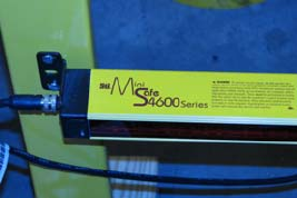
3.2.2 Safety Light Curtains (if equipped)
Photoelectric transmitters and Receivers form a system of protective light curtains
on the machine. They detect any object, which breaks the beam and moves into
the crossbeam’s operating path. There are two separate light beam paths, one on
each side of the base frame. When a human body or any other object is placed
between a light beam transmitter and its receiver, the beam is broken and the
machine goes into an emergency shut down mode where all axes are stopped as
fast as possible. After all axes have stopped, all power is removed from the servo
drive system, ultrasonic system, and pneumatic solenoids. Once the problem or
the event, which caused the curtains to be broken, has been corrected, the program can be restarted where it
was interrupted. To do this, you must cycle the CONFIRM SAFETY DEVICE keyswitch on the AGFM CNC 6000
to restart the servo drive system. After the servo drives are back in regulation, the machine is ready to operate
again. If an automatic program was running when the interruption occurred, the program can be re-started from
the last rapid traverse position (G0) that was encountered in the program by pressing CYCLE START. A detailed
schematic of the safety device stop circuit can be found in the electrical prints, sheet 6.
Important: To ensure proper operation of the safety system, the transmitter / receiver devices should be
inspected for proper operation at monthly intervals.
3.2.3 Safety Mats (if equipped)
There are mats placed along either side of the machine that halt machine movement if a weight is placed
on them. This protects a person from being hit by the crossbeam should they wander into the operations
area.
3.2.4 Light Guards (if equipped)
Photoelectric light beams guard against people or objects which could be harmed should they enter the
operating area of the crossbeam. Four transmitter/receiver assemblies send light beams out to end
reflectors (two beams on each side of the machine), and then detect the returning beams. Should one of
the beams be broken, machine movement is halted. The red lights on the safety devices will be
illuminated when it is unsafe to enter a safety zone, indicating the gantry is working in that area. The
yellow lights will be illuminated when a safety zone can be entered with extreme caution, knowing that
the gantry may return to this area at any time! The cutting program should issue a message to the
operator at the control console when it is safe to enter a safety zone for removing cut parts.
3.2.5 Safety Bumpers (if equipped)
Four safety switches, one on the front and back of each side, are mounted on the crossbeam, which halt
machine movement when pressure is applied to them. These switches are much like those found on the
doors of elevators, and perform the function of placing the machine in an emergency stop state in the
event that a person or object is in the operating zone of the crossbeam during machine movement and is
struck by the safety bumper.

MMI Operation and Machine Startup American GFM Corp.
18
3.2.6 Machine disconnect switch
A machine disconnect switch is attached to the right hand door of the power
cabinet. This switch can only be moved to the "on" position when the door of the
power cabinet is closed. When the door is open, the switch remains in the "off"
position and the machine is disconnected from all electric power. Each door of
the multi-door cabinet is interlocked with the main door. The main door is located
on the far right side of cabinet.
Only qualified electrical and electronic personnel should be allowed to adjust or to
service equipment on this machine, especially inside of the power cabinet.
Whenever possible, work should be carried out with the power disconnected; i.e.
the main disconnect switch in the "OFF" position. Only when working on the drive
modules in the power cabinet and when setting up the machine should it be necessary to work with "live"
power.
MMI Operation and Machine Startup American GFM Corp.
19
4 Vacuum System
The machine is equipped with a high pressure vacuum pump. Because the pump is remote controlled, it
can be installed in an optional sound enclosure away from the machine; however, care must be taken to
prevent overheating of the vacuum pump unit. Many different types of vacuum pumps are used,
depending on the machine size, and type of cutting being performed. It is impossible to discuss all the
different types of vacuum pumps in the document. Please consult your mechanical documentation for
more details on your particular vacuum pump system.
4.1 Control of Vacuum System
The main vacuum system is activated with programmable "M" codes. Vacuum butterfly valves which
control the various vacuum sections are activated with solenoid type directional valves, which in turn are
controlled by the CNC. Monitoring for a low vacuum level is accomplished by the CNC through vacuum
pressure switches. These pressure switches are normally adjusted to show proper vacuum pressure at
300 millibars (mbar) of mercury absolute.
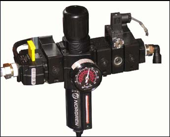
5 Pneumatic System
The machine is supplied with oil free compressed air. The max air
pressure should always be adjusted according to the mechanical
documentation, but normally is set to 90psi, This air pressure is
always monitored by the CNC for pressure drops, and an error will
occur is this ever occurs.
5.1 Cutting Unit
The converter of the ultrasonic cutting head is forced air-cooled
during operation. Whenever the M8 command is issued, a valve will
open allowing air to flow to the US converter
5.2 Inkjet Printhead, Lift Table, Gripper Bar, and Clamp Unit (if equipped)
The vertical positioning of the inkjet printhead, lift table, and clamp bar, when enabled, are accomplished
by pneumatic cylinders. Opening and closing of the gripper bar is accomplished by pneumatic cylinders.
Proximity switches are positioned to sense the extremes of travel.
5.3 Inkjet (if equipped)
By using the inkjet, it is possible to print characters parallel to the x axis, or ± 90° to the x axis, or at any
angular orientation within these limits. Printing modes that are supported are single and twin line 10 x 16
matrix ASCII-Mode, and single line 10 x 16 matrix barcode (numeric or alphanumeric). Parts may be
printed either by commanding the inkjet in MDI mode, or by using a CNC program. Vector printing, or
drawing with the inkjet, is also supported. Further control over the inkjet printer, such as programmable
font control, is available as an option.
MMI Operation and Machine Startup American GFM Corp.
20
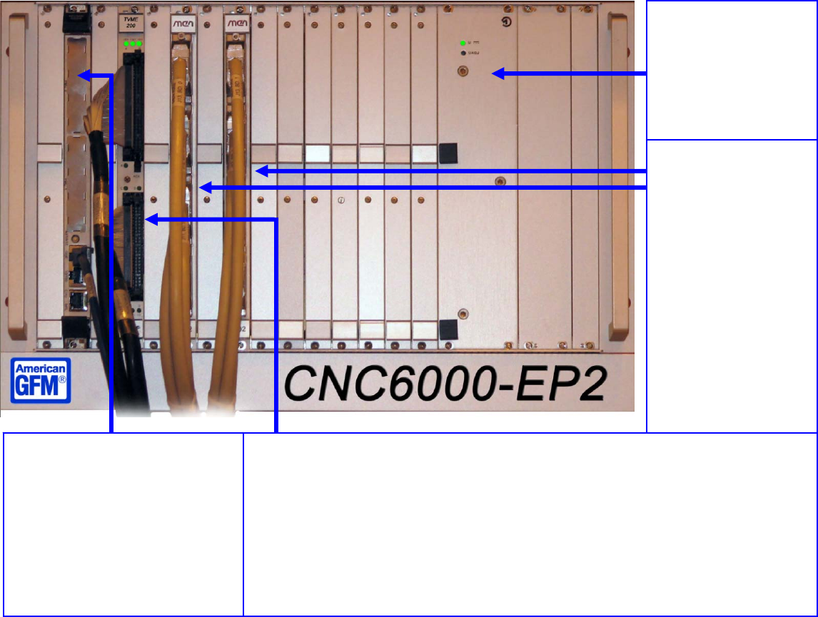
6 CNC and other Machine Control Hardware
6.1 CNC6000-EP
The machine is equipped with a numerical control GFM CNC6000-EP.
EP = Ethernet Version which uses on-board 1GB Ethernet on the MVME 5500 CPU.
The CNC can control up to 16 axes simultaneously. System hardware features include the following:
• 0.0001 mm control resolution at max. machine speed.
• Floating point programming.
• Automatic speed optimization.
Linear, circular, or spline interpolation in the xyz plane with simultaneous automatic tangential
alignment of the knife angle (B or C axis).
Pentium Based Human Interface PC running Windows 2000, or Windows XP.
SYSTEM CPU
Manufacturer: Motorola
Type: MVME 5500 Series
Processor: PowerPC MPC7455
Description: 32-Bit PowerPC MPC7455
microprocessor running at 1Ghz. VME Bus
interface, PCI onboard bus. 512MB onboard
DRAM. Onboard Ethernet interface.
This board serves as the system controller,
interpolator CPU, programmable logic (PLI)
controller, and axis controller.
An ETHERNET Interface connects the CNC to a
PC running the operator interface. Multiple
INDUSTRY PACK CARRIER
Manufacturer: TEWS
Type: TVME200
Description: provisions for four single high IP`s or two double high IP`s. Four 50-pin flat cable headers accessible on front
panel for interfacing to industry pack modules. Installed industry pack modules are the TIP119-50 and the ADA-08.
Included IP`s:
AXIS INTERFACE: Type
TIP119-50
, with 6 channels of differential quadrature decoder inputs. Each channel has a
dedicated 16 bit input counter. All machine axis encoder signals are connected to this interface. Axis position signal are
routed from here to the MVME5500 board via the vme bus.
DAC/ADC INTERFACE Type
ADA-08
, with one octal 12 bit digital to analog (DAC) converter and one 12 bit +sign analog
to digital converter (ADC). The DAC provides eight single ended analog outputs. The ADC provides eight single ended or
four differential analog inputs.
inputs and outputs are ±10 VDC. All analog signals to and from the machine are routed through the ADA-08 to the MVME
5500 via the VME bus.
I/O BOARDS
Manufacturer: MEN
Type: A302
Description: Each board
provides 64 inputs and 64
universals, configurable as
inputs or outputs. I/O
voltage is 24VDC. All
outputs are short circuit
protected and can handle up
to 0.5A (with a maximum
12A per board). Up to ten
boards may be installed in a
19 inch rack.
POWER SUPPLY
Manufacturer: Schroff
Type: MPS-022
Description: Provides +5VDC
& ±12VDC to the VME bus
and boards. Rated at +5VCD
@ 30A and ±12VDC @ 4A.
MMI Operation and Machine Startup American GFM Corp.
21
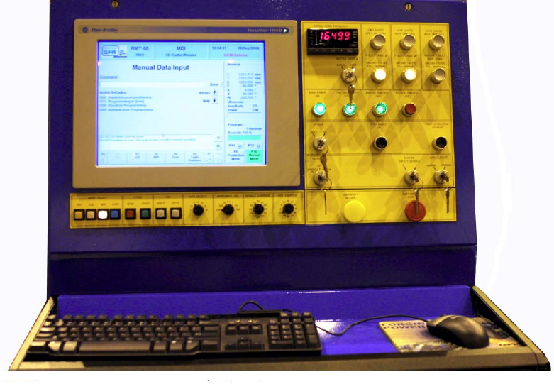
6.2 Operator Console
Most of the control of the machine operation is performed with the use of the main keyboard and
control panel. The following is a list of the main components and their functions:
Keyboard Used to enter MDI commands, step through the menus, select items and edit
programs.
Mode buttons Used to change the machine mode to one of the following modes:
REFerence mode
JOG mode
MDI mode
AUTOmatic mode.
Axis Override This switch overrides the programmed feed rate of all axes in all modes from
0% (stop) to 100% (full speed) in steps of 10%
Spindle Override This switch overrides the programmed feed rate of the spindle when installed
from 60% (stop) to 120% (full speed) in steps of 5%
Axis select This switch selects between the axes for jog mode movements (X, Y, Z, C, A,
B, or W axis
Plus/Minus These buttons only work when the control is in the JOG mode. Pressing the
plus button moves the selected axis in the + direction.
Cycle Start Starts an active program when the control is in the AUTOmatic mode, begins
the referencing procedure when the control is in the REFerence mode, and
restarts the control after a feedhold condition.
Cycle Stop Performs a feedhold at the end of a program block on a running program if
pressed, and a full reset if held down for approximately 2 seconds. Also halts
the referencing procedure.
MMI Operation and Machine Startup American GFM Corp.
22
Incremental Jog Performs an incremental move of the selected axis in JOG MODE in any of
the following increments.
CONT will jog the axis continuously
0.001 will jog the selected axis by 0.001
0.01 will jog the selected axis by 0.01
0.1 will jog the selected axis by 0.1
1.0 will jog the selected axis by 1
10.0 will jog the selected axis by 10
100.0 will jog the selected axis by 100
Handwheel Jog Performs an incremental move of the selected axis in HANDWHEEL MODE
in any of the following increments.
0.001 will jog the selected axis by 0.001
0.01 will jog the selected axis by 0.01
0.1 will jog the selected axis by 0.1
1.0 will jog the selected axis by 1
Select. Switch Selects whether the control with accept commands from the console
pushbuttons or from the jog box.
Spindle Switch Allows the user to manually switch off the spindle for tool inspection
Dust Extraction Switches on the Dust Extraction by means of this pushbutton
Emergency Stop Halts all movement in an emergency situation and cuts power to the drives.
Master Control These two pushbuttons will energize or de-energize all electrical circuits on
the machine. When master control is off, all machine functions are disabled.
No Emerg. Stops This is an indicator light that when illuminated, shows that no Emergency
Stops are active
Main Power On This indicator light shows that Main Power is applied the electrical cabinet.
MMI Operation and Machine Startup American GFM Corp.
23
6.3 Personal Computer
This Pentium IV based CPU, with Ethernet interface to a VME based processor (MVME 5500),
performs the download of the CNC software via the Ethernet interface during the startup. This
system also compiles SRC source files to OV2 object files and transfers these files to the CNC for
execution. The computer also runs the MMI, which is the interface between the operator and the
machine. The computer can also connect to any standard Microsoft network protocols for
connection to a host system for program download. The PC runs Microsoft Windows XP
Professional.
6.4 Electrical Cabinets
The main electrical cabinets contain several high power
compartments. The layout of the compartments from left
to right is as follows:
• GFM CNC6000 control
• General operation and control switches and
transformers
• Drive modules and related power supplies and
transformers
• Main disconnect, motor protection, and other fuses
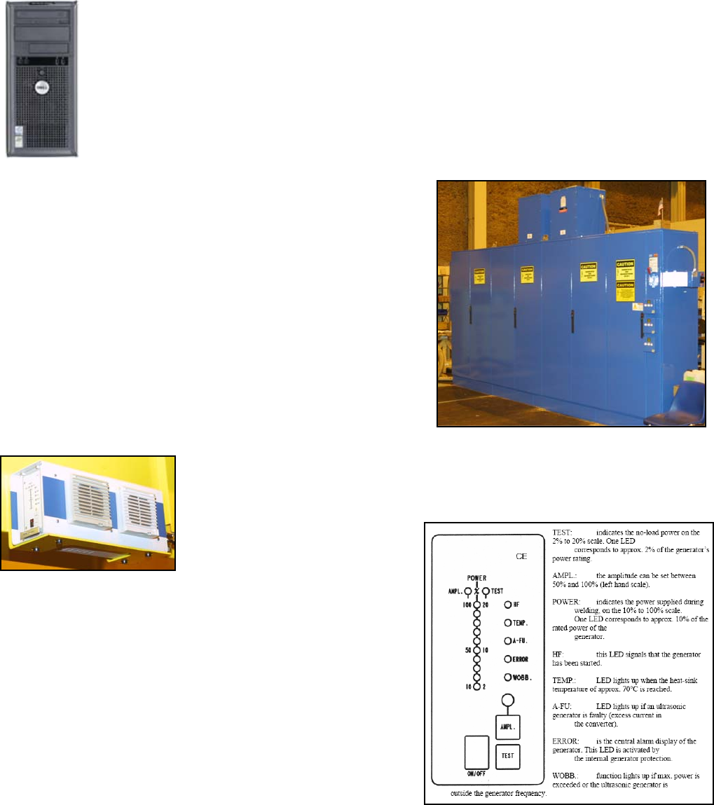
6.5 Ultrasonic Generator
The machine uses a high power multi-frequency ultrasonic generator. The
generator is mounted on the base frame. The generator is self tuning to the proper
resonant frequency of each horn. The ultrasonic output amplitude is activated with
the M08 M-Code. The generator has several LED indicators as well. Their meaning
are described in the below
illustration.
MMI Operation and Machine Startup American GFM Corp.
24
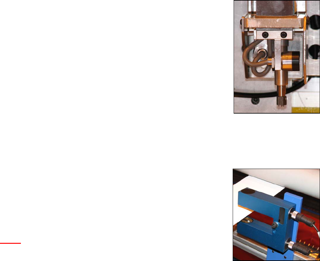
6.6 Conveyor Deviation System (if equipped)
The machine is equipped with a continuous conveyor belt that covers both machine
tables. In order to accurately cut shapes continuously over multiple windows,
perfect positioning accuracy would be required from the conveyor belt. The
conveyor belt can not be positioned accurately enough to perform window cutting of
continuous parts due to the elasticity of the belt material and other mechanical
factors. Therefore, the machine is equipped with a system capable of measuring
the amount of conveyor belt deviation during the M36 material pull-out macro. This
system has 2 independent inductive sensors. One sensor is used to measure the
X-Axis deviation and the other is used to measure the Y-Axis deviation. Each
sensor has a mechanical stroke of +/- 5mm, meaning the system can correct up to
5mm of belt deviation in XY axis. When the M34 command is issued (Grip
Material), the sensors are lowered via a pneumatic cylinder. After the sensors are
down for 1 second, the CNC then reads the values from both sensors as the
“Starting Value”. Then the M36 macro is executed to pull the material with X/U axis
synchronized. As the X/U axis move, there will be some movement of the sensors
caused by the belt deviation. When the M35 command is issued (Release
Material), the CNC reads the sensors again and stores the values as the “Ending Value”. The CNC then
calculates how much deviation occurred during the M36 pull-out and automatically makes a correction to XY axis
compensate for the belt deviation. This correction occurs after every M36 so that every window is accurately cut.
This system is accurate to within +/- 0.20mm.
6.7 Material Edge Guidance (if equipped)
The machine is capable of maintaining the edge of the material exactly on the Y-
Axis zero point during the automatic material dispensing macro, M36. This is very
useful when very little waste material is a requirement at the edges to achieve
maximum material utilization. The system consists of an analog laser sensor with a
16x2mm laser beam. The material is fed through the laser sensor during the
material dispensing process. The output of the laser sensor feeds a servo drive
(W-Axis) which moves the roll +/- relative to the position of the material position in
the laser sensor. The drive will regulate the material’s edge, keeping it at the mid
point of the 16mm laser beam at all times during the M36 macro.
NOTE: If the material falls out of the laser sensor during M36 dispensing macro,
the material dispenser will move all the way to a hardware limit switch,
thus misaligning the material on the table. It is very important to keep the
tension on the roll brake tight enough so that the material stays taught
during the dispensing process and moves smoothly though the laser sensor.
MMI Operation and Machine Startup American GFM Corp.
25
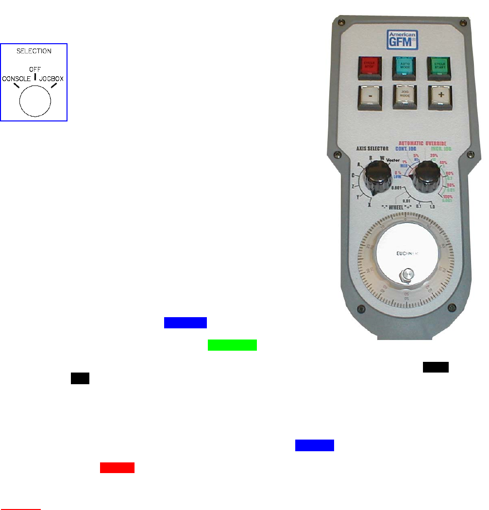
6.8 Jog Pendant
The Jog Box allows the operator to manually move
the axes to a desired position without having to stand
at the operator console. AUTO mode is also available,
however, automatic programs must be started from
the main console first, then can be switched over to
the jogbox after the program is running.. The Jog Box
has a magnetic base so it may be attached to any
ferrous material. In order to activate the Jog Box
controls, the operator must place the machine in JOG mode from the
operator console and turn the selector switch to jog pendant on the
operator console. Additionally, there are two buttons on the jog
pendant, one on each side, which must be pressed to initiate any
movement from the pendant. The selector switch must be placed in the
console position before the operator console controls are reactivated.
Stop button Stops the current program cycle.
Auto button Selects AUTO mode.
Start button Begins the current program cycle.
Minus button Moves selected axis in minus direction if in JOG mode.
Jog button Selects JOG mode.
Plus button Moves selected axis in plus direction if in JOG mode.
Axis Select Selects desired axis to jog. The “Vector “position
allows jogging in the plus direction of the current tool
vector angle.
Cont/Incr Jog If set to Cont. Jog, the axis will move continuously at
the selected feedrate (blue dial) when the plus or minus
button is pressed. If set to Incr. Jog, the machine will
move in the increment selected (green dial) for every
push of the plus or minus button. If set to the region
pointing to the Wheel, the handwheel will move the axis in the selected increment (black
dial) for each “click” of the handwheel.
Handwheel Used to move the axis the selected increment for each “click”.
Deadman Sw. These are 2 single contact safety rated pushbuttons that must be depressed to use the
jogbox.
Override It is possible to control the machine override with the jog box. The right side rotary switch
is used to control the speed of the machine. When in JOG mode, only a LOW, MEDIUM,
& HIGH speeds are available and indicated with the blue dial. In AUTO Mode, this same
rotary switch is used to select the override percentage between 0-100%, and is indicated
as the red dial.
Caution: Safety Curtains and Safety Mats are NOT active during JOG mode with the
Jogbox. This allows the operator to move close to the machine while using
the jogbox. The 2 deadman switches must be depressed to move any axis
with the jogbox. Care must be taken when moving the axes with JOG
mode

MMI Operation and Machine Startup American GFM Corp.
26
7 MMI Operation and Machine Startup
The MMI is the operators interface to the machine. It allows the operator to perform all of the functions
required to successfully operate the machine and produce the highest quality parts possible. It is important
for the operator to fully understand the operation of the MMI and to be aware of what the results will be after
issuing any command. The MMI is also a very powerful tool for maintenance personnel, as it provides
information on the operating condition of the machine. Various screens are available for troubleshooting and
debugging in the service level access levels.
7.1 Preparation for Machine Startup
A few initial checks should be performed before machine startup to ensure safe operation.
7.1.1 Initial Checks
Before start up of the machine, the operator should make certain that the machine is in operable condition,
and that all mechanical and electrical parts are correctly installed and secured. This is especially applicable
to covers and safety equipment. It is also very important to make sure that there are no foreign objects on
the table surface or near moving parts of the machine.
7.1.2 Turning the Machine On
After performing the initial checks, the machine is ready to be turned on.
• Make sure that an emergency stop button is depressed (safety measure during power-up).
• Make sure that compressed air is supplied to the machine and that the main valve is in the open
position.
• Check to make sure that the system air pressure registers 6 Bar (~90 psi).
• If it is not already on, turn on the electrical power with the main switch on the electric cabinet. The
control should go through the "boot up" procedure.
7.1.3 Start Up Procedure
After turning on the main disconnect switch on the electric
cabinet, the PC in the operator console will boot up. After
Windows finishes loading, the MMI will automatically begin,
download required system files to the CNC, and display the user
login screen. Enter your user name, press the ENTER key to
move to the password field, and enter your password. Both the
user name and password are CASE SENSITIVE.
7.1.4 Language Selection
Many different languages are supported with the CNC6000/EP. After the USER-ID
and Password has been entered, choose the desired language from the drop down
list as shown to the left, and then click OK to login.
MMI Operation and Machine Startup American GFM Corp.
27
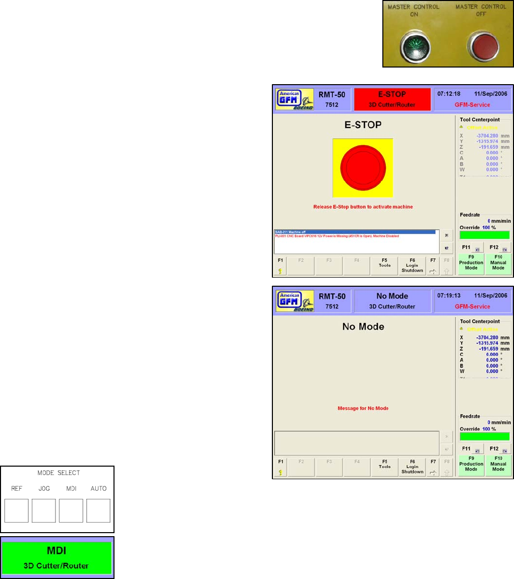
7.1.5 Master Control
After the CNC has booted up and the user has successfully logged into the MMI,
press the “Master Control ON” pushbutton. Ensure the lamp illuminates.
Switching Master Control ON enables many power supplies to be powered up.
7.1.6 E-Stop
After successful login, the E-STOP screen will appear
provided an E-Stop button is pressed. If an E-Stop
button is not pressed, the machine will switch into the
last active mode. If the machine and the surrounding
area is clear release the E-Stop button. The machine
will switch into a No Mode condition with all of available
the mode buttons flashing.
7.1.7 No Mode
A No Mode condition will be active after an E-Stop
condition has been cleared. All of the available mode
buttons will be flashing. AUTO mode will not be
available until successful reference and toolsetting
procedures have been completed.
7.1.8 Machine Mode Selections
The desired machine mode is
selected with the mode buttons on the operator console. Certain conditions
must be met prior to any given mode being available to the operator. Each
mode will have it’s own display showing information pertinent to that particular
mode. There are also areas on the display that are common to almost all
modes. These areas are located at the top, bottom, and the right side of the
display. The active machine mode is also shown in the MMI Header at the top
of the screen.
MMI Operation and Machine Startup American GFM Corp.
28
7.2 Changing the Knife
In the event that the cutting knife breaks or becomes dull, causing poor cutting results, the “Knife
Change” macro is used to replace the damaged knife. This is done using a special M-Code, which,
when entered in MDI mode will position the machine to a predefined position. This is the position where
the operator will enter the machine moving area to exchange the knife. Once the M-Code is executed, Z-
Axis will move to the maximum upper position, and then XY axis will move to the knife change position,
as defined in the USER.CNF. Once this position is reached, the machine’s servo drives are deactivated
for safety. A message will appear on the MMI screen prompting the operator to “Replace the knife, and
then press “CYCLE START”. At this time the operator should walk over to the machine, release the
turning axis locking pin (if equipped) to lock the knife axis to allow the supplied torque wrench to be used
to unscrew the old knife. After the old knife has been removed, follow the below guidelines to install the
new knife.
The M-Code to execute the knife change macro is:
M42 Æ 2D Cutters
M61 Æ 3D Cutters
1. Every blade should be degreased and completely cleaned prior to installation, with solvents similar to
CRC Brand Heavy Degreaser solvent, electronic contact cleaner, acetone or denatured alcohol (please
check with your internal Hazardous Communication Program).
2. Use a brass wire or stiff bristle brush to remove debris and oil from the threads, and then rinse the entire
blade with an approved solvent. We recommend wearing safety glasses during this procedure.
3. Blades should be blown completely dry using dry, filtered and oil-free air prior to installation. We
recommend wearing safety glasses during this procedure.
4. Interior features of the horn should be cleaned in a similar fashion. No oil or solvent should remain in the
horn or on the blades. This should e done each time the blade is changed.
5. The face of the horn where the blade seats should be carefully stoned flat if any sign of galling or scoring
is found during routine maintenance. Steps greater than 0.05mm, (0.0019”), can have an effect on
tuning. Removal of as little as .02mm of material may affect the ultrasonic horns tuning, so this should be
done only when necessary and should be carefully done by a technically astute technician. The entire
horn should be clean inside and out.
6. Check, by hand, to make sure that the blade seats completely flat against the horn face. If any force
greater than what can be exerted by hand is necessary to seat the blade to the horn, there may be a
problem with the threads in the horn, locating diameter, (10.00mm), or on the knife. After several blades
are checked and are not able to be screwed in by hand, contact American GFM for further instructions.
Under no circumstance should a tap be used to “chase” the threads in your horn unless instructed to do
so by AGFM personnel. Blades should be installed to 24 foot pounds of torque with an open end
torque adapter and torque wrench. Most machines are equipped with the correct tools, and training is
provided during machine installation. If a torque adapter is used, make certain the appropriate torque to
be set, or read is recalculated according to documentation contained with your torque measuring
equipment. This information is also available through American GFM.
7. Heat build up is usually an indication of a problem. Isolate the problem and correct it before continuing.
Some things to check are: loose horn and converter assembly, incorrect ultrasonic generator output,
carbon brushes worn or different lengths, damaged horn or converter threads. Some heat build up is
normal. Temperatures exceeding 120F are not common. Build up of melted coversheet on the horn is a
common problem after a vacuum hold down failure and must be removed without damaging the original
polished surface on the horn. Leaving any liquid substances on the blade or in the horn usually creates
excessive heat.
8. A loud shrieking or ticking sound emanating from the horn or knife is often an indication that the blade is
not properly tightened inside of the horn or the horn/converter assembly is loose. Ensure that the blade is
securely tightened and disassemble the horn/converter assembly if required. The face between the horn
and converter should be clean and stoned if necessary. Securely tighten the horn and converter, being
careful not to strip the pin spanner wrench holes. Estimated torque for this assembly is 80-100 ft. lbs.
Also ensure that the threads inside of the horn are not damaged. Check that the carbon brushes are
seating properly and are the same length.
MMI Operation and Machine Startup American GFM Corp.
29
7.2.1 Horn Inspection
All Ultrasonic Horns should be inspected on a regular basis, based on usage, especially Horns operating on 3D
Machines, (US-50, RMT). It is recommended that any Horns running in production for period of one year should
be returned to AGFM, for inspection to ensure the reliability of these horns.
7.2.2 Cleaning the converter contact surfaces
The entire ultrasonic assembly area must remain clean for the ultrasonics to function properly. This
cleaning procedure should be done at least once a month, depending on conditions. Avoid any build up
of glass fibers or dust in the brush contact area. The frequency and voltage often attracts fine airborne
particles, which could arc across the brushes and potentially damage components.
1. Stop machine and turn off ultrasonic generator. Follow your company’s Lock-Out Procedure.
2. Remove carbon brushes.
3. Clean converter contact surface with a cloth dampened with acetone, denatured alcohol or an electronic
cleaning solvent. DO NOT GET SOLVENT INSIDE OF THE CONVERTER !
4. Wipe dry and clean with soft, dry cloth or “dry” clean with dry, filtered, oil-free quality air. Fine “Scotch
Brite” or other mild abrasive fabric may be used lightly to remove heavy carbon build up. Prevent debris
from falling into the converter. Pack a small rag or use tape to cover the ventilation holes in the top of the
converter.
5. Reinstall brushes, wiping them down with a dry rag first. The carbon brushes must be the same length
within 2mm of each other.
6. With brushes completely installed, take a piece of fine emery cloth and place the abrasive side toward the
brushes, in between the brush and the converter. Rotate converter and emery cloth under the brush to
match the brush contact surface. Be careful not to allow the sanding dust to fall into the converter. Do
this to both brushes until the bottom of the brush is flat with the mating surface.
Clean any carbon brush dust from the converter, then test the ultrasonics by bringing the machine out of
E-Stop, switching the generator on, and depressing the “TEST” button on the ultrasonic generator and
note the generators’ digital display. The value displayed should remain fairly constant. It is normal for
the display to fluctuate slightly.
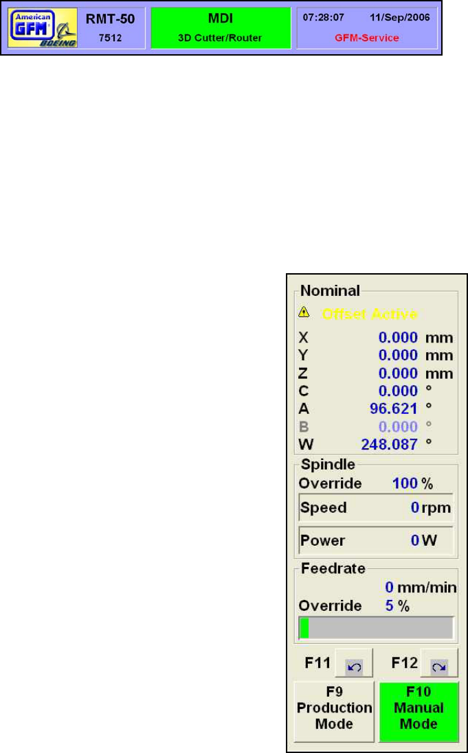
MMI Operation and Machine Startup American GFM Corp.
30
7.3 Displays Common to All Modes
7.3.1 Display Header
The Display Header shows
general machine information.
The left section shows the
machine type and the AGFM
machine number. The center section shows the current machine mode. Different background colors in
this section indicate different machine statuses within the selected mode. A red background will be
displayed when in an E-Stop condition. Blue indicates that no current mode is selected. Yellow indicates
that the mode is active and no axis is moving. Green indicates that the mode is active and at least one
axis is moving. The right section shows the current user, date, and time.
7.3.2 Axis Display
The upper area shows the axis display mode: Tool Center point, Nominal, Actual, Error, Distance To Go,
or TCP Absolute. Double clicking on top of the current axis display mode and choosing the desired
display mode from the drop down window that appears can change the display mode. Below the display
mode “Offset Active” will appear if any machine offsets are active. Next, each axis is shown with a
position display. The display will change depending on which display mode is selected:
Tool Centerpoint Machine position in relation to the tip of the current tool including any active
offsets.
Nominal Machine position being commanded by the CNC
without the tool length considered.
Actual Machine position determined from positioning system
feedback without the tool length considered.
Error Difference between Nominal and Actual position.
Distance To Go Distance remaining until axis reaches the commanded
end point.
TCP Absolute Machine position in relation to the tip of the current
tool not including any active offsets (from true
machine zero).
7.3.3 Ultrasonic and Spindle Power Display
The middle area shows Ultrasonic or Spindle information. The percentage of
amplitude or RPM’s and the real-time ultrasonic power level or spindle power
level is displayed in WATTS. A bar graph shows the current power level. If
the power level is within normal operating range, the bar graph will be green.
If the power level is in the warning range, it will be yellow. If the power level is
yellow, the operator should perform some basic ultrasonic system checks.
These checks include, but are not limited to:
• Is the knife damaged?
• Is the knife dirty?
• Is the knife installed properly in the ultrasonic horn?
• Is the feedrate too high for the type of material being cut?
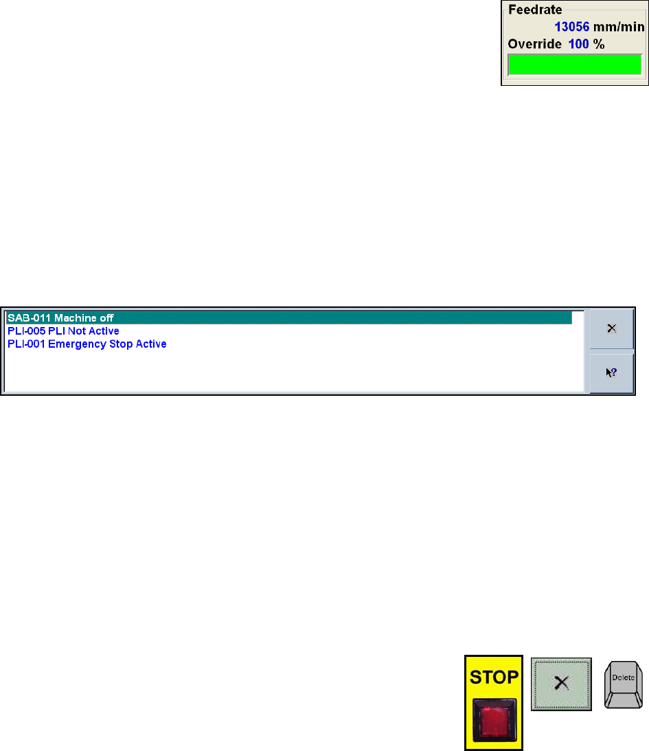
MMI Operation and Machine Startup American GFM Corp.
31
7.3.4 Feedrate and Axis Override Display
The lower area shows feedrate and machine override information. The current
feedrate will be shown in either mm/min or inch/min. This is selectable via a G
Code (G70/G71). The override display shows the position of the override
switch on the operator panel. The bar graph below the override percentage
displays in green the percentage of the current override adjustment. If override
is set to zero, the override text background will flash yellow.
7.3.5 The Message Window
The message window is the most useful tool the operator has. This is the area where messages from the
machine and the CNC6000 will appear whenever faults and/or warnings occur. In the event that the
machine stops running, a message will appear with a brief description as to why the machine stopped.
Reading and understanding these messages is vital to keeping the machine running production.
Hundreds of different messages are possible. The “X” button on the right side deletes the message at
the top of the box. The arrow button will bring up a help screen, which has information on the message at
the top of the box. Alternately, double clicking on the message with the mouse will also bring up a help
screen about the displayed message.
Messages are generated by many different parts of the system. Each message will have a unique
format. This format included 2-3 letters followed by a 3-digit number.
Example:
PLI-001 Emergency Stop pushbutton is pressed
Whereas,
PLI means that the PLI Control Logic generated the message
001 means the message number inside the PLI Fault logic
Messages can have other letters as part of their number. They are as follows:
• PLI-xxx Indicates that the message was generated by the PLI Logic
• SAB-xxx Indicates that the message was generated by the CNC Block controller
• AXC-xxx Indicates that the message was generated by the Axis controller
• ITP-xxx Indicates that the message was generated by the Interpolator
• MMI-xxx Indicates that the message was generated by the MMI software
7.3.5.1 Clearing Messages
There are three ways to clear fault messages. One way is to click the “X”
button with the mouse to the right of the message window, or press the
RED STOP button on the operator console, or press the DEL key on the
keyboard. Some messages are “self-clearing”, meaning they will
disappear automatically when the condition that caused the message has
gone “false”

MMI Operation and Machine Startup American GFM Corp.
32
7.3.5.2 Getting Online Help for Faults
Whenever a message appears in the message
window, additional help can be displayed about
the message. If this is necessary, use the
mouse to double click on the message or click
on the “?” button. Upon pressing this help button, the
following screen will appear with more detailed help about
the message. This detailed help screen gives a “Cause”,
“Effect”, and a “Solution” for the chosen message. Every
message is described in detail in the Online Help. At this
point, the operator can scroll up or down to see other
possible messages if desired.
7.3.5.3 Viewing the ERROR Log
Every message that ever appears in the message
window on the machine will be stored in an online
ERROR LOG. This log shows the time and date of
the fault occurrence and the User-ID and the priority
that was in effect at the time of the fault. To view this
error log, activate the SYSTEM SUPPORT menu
from the Production screen from the 2nd row of
softkeys using F6 System Support. The Error Log is
found by choosing the Group 1. Highlight “Show
Error Log File” ENTER. The screen here will appear.
Comments can be added to this file at any time by
pressing the “Add Comment” button and typing your
comment in. A backup of older messages is also
available by clicking “Backup Log File”. This back-
up log file will be created whenever the current log
file size reaches 100K Bytes. To see the online help
screen described above, double click any of these messages, or highlight the fault and click the “?”
button.
7.3.6 Using the Online RESTART Feature
If the machine is stopped for any reason before the end
of the program is reached (i.e. blade breakage, machine
faults…ect), the remaining portion of the program, which
has not yet been cut, can easily be finished. The
CNC6000 will use its online RESTART feature to achieve
this. Provided that a new program has not been loaded,
or the power has not been cycled, since the program was
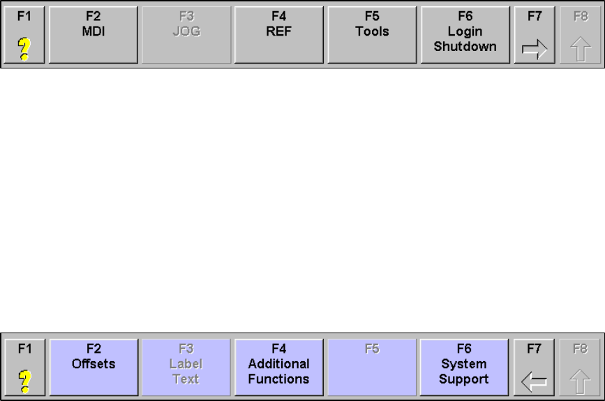
MMI Operation and Machine Startup American GFM Corp.
33
stopped, upon pressing the CYCLE START button, the dialog to the right will appear.
If “Continue” is clicked, the machine will be positioned to the LAST G00 movement, and continue the
program from that point till the end.
If “Start Over” is chosen, the program will be executed from the beginning again.
7.3.7 Softkey Lines (REF, JOG, and MDI modes)
The softkey line at the bottom of the display allows the operator to move between different screens. The
softkey lines are the same for REF, JOG, and MDI modes. AUTO mode has a unique set of softkeys and
will covered in a later section. There are two levels of softkeys.
Softkey line one is shown above. If a button is grayed out, it is either already active or unavailable. A
softkey can be selected by using the corresponding key o the keyboard (F1, F2, etc.) or by clicking on the
button with the mouse.
F1 Opens a PDF manual and jumps to the corresponding page number related to the
displayed screen.
F2 Selects MDI mode
F3 Selects JOG mode
F4 Selects REF mode
F5 Opens the Tool Editor
F6 Opens the initial login screen. The current user will no longer be active. It will be
necessary to login again.
F7 Changes to the next of softkey line (line two)
F8 Returns to the lowest level softkey line (line one)
Softkey line is shown above. The blue buttons indicate that this is the next level of softkeys. If a button is
grayed out, it is either already active or unavailable.
F1 Opens a PDF manual and jumps to the corresponding page number related to the
displayed screen.
F2 Opens the Offset Editor
F3 Opens the Label Text Editor
F4 Opens the Additional Functions display
F5 Not Used
F6 Opens the System Support menu
F7 Changes to the previous softkey line
F8 Returns to the lowest level softkey line
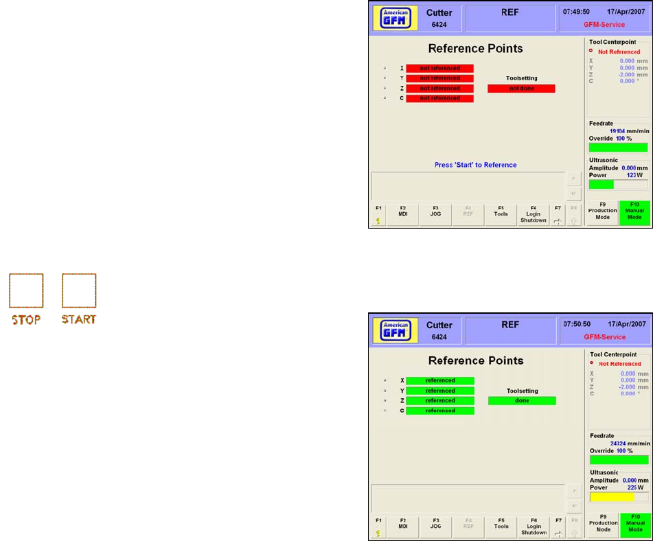
MMI Operation and Machine Startup American GFM Corp.
34
7.4 REF Mode
If the CNC control has been rebooted either by a power
down/power up or by selecting the Reboot CNC icon from
the Windows desktop, the machine must be referenced.
This is done in REF mode. The only function for REF
mode is to perform a machine reference cycle.
When REF mode is chosen and the machine is not
currently referenced, this display will appear.
Each axis is shown with it’s current reference status as
well as the toolsetting status of the current tool. To begin
the reference cycle, press START on the operator
console.
As the machine is performing the reference cycle, the “not referenced” graphic will change to “in
progress”
After a successful reference cycle and toolsetting cycle,
this screen appears. Each axis shows that it is referenced
and a successful toolsetting has been completed. After a
successful reference and toolsetting procedure, it is safe
to change to a REF, JOG, or AUTO mode.
If the machine is not set up to perform an automatic
toolsetting cycle after reference, a toolsetting must be
performed in MDI mode. The method is different for 2D
and 3D machines. Manual toolsetting is covered in the
MDI Mode section below.
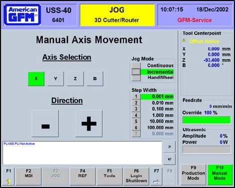
MMI Operation and Machine Startup American GFM Corp.
35
7.5 JOG Mode
JOG Mode allows the operator to manually move
each of the machine axes independently.
Choose the desired axes using the axis selector
switch on the operator console (or jog box) and
move the axis using the PLUS or MINUS buttons
on the operator console (or jog box). The
operator can jog each axis to its user limit.
Therefore, it is extremely important to be careful
when jogging any axis, since they can be moved
all the way through the machine min/max limits.
If an axis is jogged to it’s user limit position, axis
movement will stop. Jog the opposite direction to
move away from the user limit. Each axis has a
different maximum velocity (feedrate) and
acceleration while in jog mode. This is a safety
feature, which allows the operator more reaction
time to control and stop the axes while jogging.
The selected axis will be highlighted in green. As the PLUS or MINUS buttons on the operator console
are pressed, the corresponding “+” or “-“ button on the MMI will also be highlighted in green. While the
selected axis is moving, the position display in the top right corner will increment.
There are two jog modes available to the operator; Continuous and Incremental. In Continuous jog
mode, the selected axis will move as long as one of the direction buttons on the operator console is
pressed. In Incremental jog mode, the axis will move as long as one of the direction buttons is pressed
and the axis has reached the selected incremental jog distance. If the direction button is released before
the selected incremental jog distance has been reached, axis movement will stop.
The jog box also has a jog wheel, which may be used to move an axis. With Handwheel jog mode
selected, the jog wheel will move the selected axis the distance of the step width for each “step” the jog
wheel is turned. The jog wheel is turned clockwise to move an axis plus and counter-clockwise to move
an axis minus.
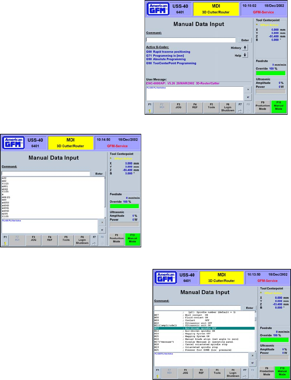
MMI Operation and Machine Startup American GFM Corp.
36
7.6 MDI Mode
MDI mode allows the operator to perform many
manual operations on the machine. MDI mode
uses G-Codes and M-Codes entered by the
operator to give commands to the CNC.
The Manual Data Input (MDI) display has it’s own
set of unique features. The main interface with
the MDI display is the Command: window. This is
where the operator enters the M and G codes
used to issue commands to the CNC. Below the
Command: line the currently active g-codes are
displayed. Use the keyboard to enter the desired
M and G codes. Press enter to send the
commands to the CNC. Alternately, the mouse
can be used to click on the Enter button to send
the command to the CNC.
The History button will open a drop-down menu
showing the most recently entered commands in
the command line. Clicking on a command in the
history menu will enter the command into the
Command: window. Pressing enter will send the
command to the CNC.
The Help button will open a drop-down menu that
displays the available M and G codes and give a brief
description of their function. Right clicking on any of
the codes in the help menu will bring additional help
about that code.
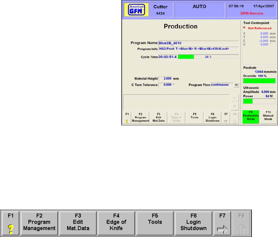
MMI Operation and Machine Startup American GFM Corp.
37
7.7 Production Mode (AUTO)
AUTO Mode allows the operator to
automatically run cutting programs. In AUTO
Mode, cutting programs can be loaded to the
CNC, graphically viewed, edited, and/or
compiled. Auto mode has a unique set of
softkeys from REF, JOG, and MDI mode. The
Production screen gives the operator general
information about the current program.
The currently loaded Program Name and
Program Info are shown.
The Cycle Time will begin incrementing when
the program is started. It will continue to
accumulate until the end of the program is
reached. The bar graph to the right shows the
amount of progress of the running program in
percent.
The Fitted Tool shows the current tool that is loaded in the head.
The Edge of Knife selection is done by clicking “1” or “2”. By clicking on one of these buttons, the
opposite knife-edge will be used and can be done during a cutting cycle.
Program Flow shows the current program flow state. Possible choices are:
CONTINUOUS cutting will not stop until an end of program code in the program is reached,
BLOCKWISE cutting will pause at the end of every program G0 block
STOP ON M01 cutting will stop at every M01 in the program.
Press START to continue cutting if Program Flow is set to Blockwise or Stop on M01.
7.7.1 Softkey Lines (AUTO Mode)
Softkey line one is shown above.
F1 Opens a PDF manual and jumps to the corresponding page number related to the
displayed screen.
F2 Opens the Program Management screen
F3 Opens the Material Data Editor
F4 Changes the Knife Edge being used
F5 Opens the Tool menu
F6 Returns to the initial login screen
F7 Switches to the next softkey line
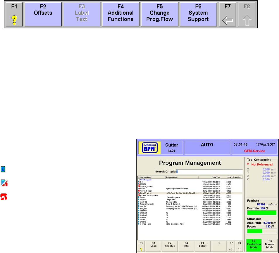
MMI Operation and Machine Startup American GFM Corp.
38
Softkey line two is shown above.
F1 Opens a PDF manual and jumps to the corresponding page number related to the
displayed screen.
F2 Opens the Offset Editor
F3 Opens the Label Text Editor (if labeler is installed)
F4 Opens the Machine State screens
F5 Changes Program Flow to continuous, blockwise, or stop on M01
F6 Opens the System Support menu
F7 Switches to the previous softkey line
7.7.2 F2 Program Management
The Program Management screen shows the
programs available for cutting. The icons to the
left of the program name have different meanings:
Only a SRC file exists. (Not yet compiled.)
SRC and Object files exist. (Compiled)
Only an Object file exists. (Compiled)
If there is no icon beside a program name, the
program exists on the hard drive but is not a valid
type. The Search Criteria box is used to search
for certain programs. Standard Windows
operators can be entered to perform searches.
7.7.2.1 F2 Load
F2 Load will download a part program to the CNC. The program must be compiled before a download
can occur. Highlight the desired part program on the list and use F2 LOAD to download the cutting
program to the CNC. Double clicking on the desired program will also perform a download. If the
program is not a valid program, a message window will appear. If only a SRC file is available, the F2
Load and F3 Graphic buttons will be grayed out. Once the cutting program has been successfully
downloaded, the Production screen will automatically be displayed.

MMI Operation and Machine Startup American GFM Corp.
39
7.7.2.2 F3 Graphic
F3 Graphic will open a graphical part program
viewer. Highlight the desired part program and
use F3 to open the viewer. The graphical
viewer displayed different elements of the
geometry in different colors.
The LEGEND button in tool
bar will display a legend of
the possible colors.
The tool bar of the graphical viewer has many
other features.
Opens a
new file
Measure
Tool
ZOOM
Tools
PAN
Tool
Near
Block #’s
Show Stop
Points
Show End
Points
Spline
Points
Block
Numbers
Show G0
Moves
Search
Tools
About
GraOb
j
W
Printing
Tool
GraObjW
O
p
tions
Show
Le
g
end
Element
Info

MMI Operation and Machine Startup American GFM Corp.
40
7.7.2.3 F4 Info
F4 Info will open an information window. Highlight the desired part program and use F4 to view the part
program information. This info screen shows some
various information about the selected object SRC
and OC5 files.
The date, time, and size of the SRC file is shown at
the top of the form
The time, date, and size of the OC5 file is shown in
the middle of the form
The MIN/MAX limits are also shown for the OC5 file.
This is helpful to see when “ToolTip out limit” errors
occur when starting programs.
The bottom of the INFO screen shows the object
statistics, which is an OST file generated at the time of
compilation of the SRC file.
7.7.2.4 F5 Partial Pre-Cal
The F5 Partial PreCal button allows a
portion of an SRC file to be executed. This
is useful when the need for restarting a
program somewhere in the middle is
required. This feature requires special
codes to be programmed in the SRC file.
These codes are called “Part Markers” and
begin with ;$$ <Text_to_display>
If this button is pressed, and these special
codes are found in the SRC file, the screen
to the right will appear. The dialog shows all
of the programmed part marker names, and
provides options for cutting the selected part
only, or from the selected part till the end.
When the Calculate button is pressed, a
temporary program is created and
automatically downloaded to the CNC for cutting.
NOTE: No spaces are allowed in the part marker names.
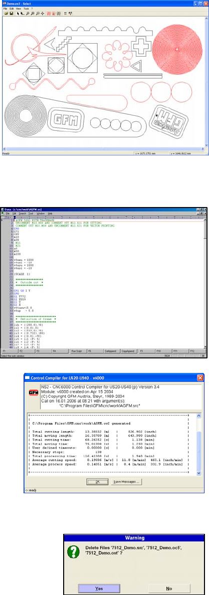
MMI Operation and Machine Startup American GFM Corp.
41
7.7.2.5 F5 Select
Pressing F5 will start the SELECT Utility. This utility
allows operators to “Select” individual parts of
geometry out of an entire part program, for purposes
of restarting a program in the middle (i.e. after a knife
breakage). After all items are selected, a new
temporary program is created and downloaded to the
CNC automatically, upon exiting the utility. To use
this utility, highlight the desired part program and
press F5. Use the mouse to click on the desired
part(s). Selected Parts will turn RED. You may select
multiple parts if required.
Choose File → Exit. Make sure the file is saved in the
current selected mount point. The new temporary file
will be created and automatically downloaded to the
CNC.
7.7.2.6 F7→F2 Edit
F7 will bring up the next row of softkeys in the
Program Management screen. F2 Edit will open the
Dana Editor so the user can edit program files.
Highlight the desired file and choose F2 EDIT. The
program will be opened in the Dana Editor and may
now be edited. Only SRC files, may be edited. After
editing is complete, save the file using File → Save.
The program file must be re-compiled and
downloaded before the changes will take effect.
7.7.2.7 F7 → F3 Generate Part Program
The F3 Generate Part Program softkey will launch the
C6000 compiler, which will create an object file (OC5) from
a valid source file (SRC) program. A new object file must
be created every time the original source file is changed.
To compile an SRC program, highlight the desired source
file and use F3 “Generate Part Program” to create a new
object file for download. After a successful compile of the
highlighted SRC file, the object statistics are displayed.
This statistical information is written to an OST file for later
viewing using the F4 INFO button under Program
Management.
7.7.2.8 F7 → F4 Delete
The F4 Delete softkey will delete the currently highlighted file in the
Program Management screen. If this softkey is pressed, a dialog
will appear requiring the operator to click YES to confirm the file
deletion. Clicking YES will delete ALL files related to that program.
This includes the SRC, OC5, & OST files.
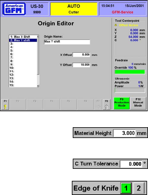
MMI Operation and Machine Startup American GFM Corp.
42
7.7.2.9 F7 → F5 Origin Editor
The F5 Origin Editor softkey will open the Origin editor
screen. Multiple origins may be created using the
Origin Editor. By using the (orgsel,xx) statement in the
SRC file, the cutting process will use origin number xx,
whereas xx is the origin number. To use this feature,
define an XY value for the programmed ORGSEL
statement in the SRC file using this Origin Editor.
7.8 F3 Edit Material Data (2D Cutter Mode Only)
F3 Edit Material Data will highlight the Material Height box in the Production
screen. Entering the nominal material height will maximize cutting results. This
value is the Z-Axis position that the blade will be positioned to for blade angle changes.
The C Turn Tolerance value is a value in degrees which is the maximum allowable C axis angle change
that can occur without a Z axis retract being performed.
7.9 F4 Edge of Knife
The F4 Edge of Knife softkey will change the knife edge being used. If it is
chosen during an automatic cutting cycle, the knife-edge will change at the next
G0 program block. The highlighted number is the current active knife-edge.
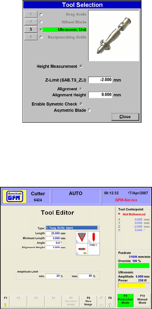
MMI Operation and Machine Startup American GFM Corp.
43
7.10 F5 Tools (CM10 Machines Only)
On CM10 machines, 4 different tool types are possible.
They are as follows:
• Drag Knife (uses no ultrasonics)
• Wheel Blade (looks like a pizza cutter)
• Ultrasonic Knife (uses ultrasonics)
• Reciprocating Knife (uses pneumatics)
Press F5 Tools to open the Tool Selection screen. Place a
check mark in the box beside your available tool types. To
change settings for one of the available tools, highlight the
active tool, then choose Height Management to activate
and use automatic toolsetting for the current tool type.
In the Z-Limit window enter the minimum allowable tool-tip
z position during toolsetting. This provides some safety in
case a toolsetting is executed with out a knife installed.
Check the Alignment box to activate angular tool alignment
for the current tool. In the Alignment Height window, enter
the z position for the angular alignment procedure.
Check the Enable Symmetric Check to allow the angular alignment procedure to check for a symmetric
tool. Check the Asymmetric blade if an asymmetric blade is installed. When the Tool Selection window
is closed, the highlighted tool will be used by the CNC. In order to activate the tool, switch to MDI mode
and enter an M64(1).
7.11 F5 Tools (All other 2D Cutters)
All other 2D Cutters are fitted with the ultrasonic
unit; therefore, a different tool editor screen is
shown. Upon pressing F5 Tools, the screen to the
right will appear.
Choose the type of tool to be used from the Type
drop down list. On 2D cutters, only:
Tang Knife (sym) and
Tang Knife (asym) are the commonly used tools.
Enter the following to adjust the settings for the
selected tool:
• Length of tool
• Minimum Length
• Included Angle of tool
• Alignment Height
• Min/Max Ultrasonic amplitude
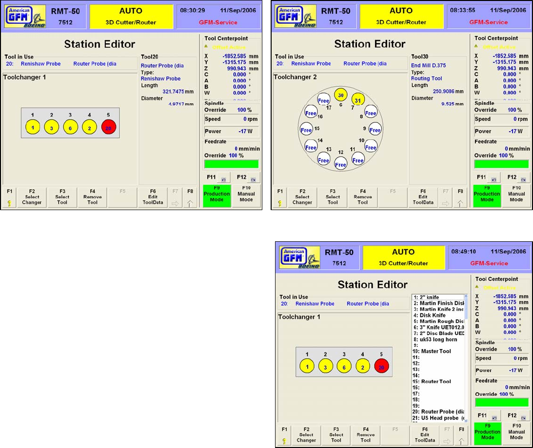
MMI Operation and Machine Startup American GFM Corp.
44
7.12 F5 Tools (3D Machines)
3D cutting machines offer an advanced Station Editor and Tool Data Editor for defining up to 120 different
tools. Upon pressing F5 Tools, the Tool Station Editor will appear.
7.12.1 Choosing the Station
When the F5 Tools softkey is pressed, the Station Editor screen is displayed. A representation of the 5-
pocket linear toolchanger is shown for the ultrasonic tool changer. To choose the routing tool changer,
simply choose F2 “Select Changer”.
7.12.2 Assigning Tool Pockets
Each circle represents a physical tool pocket in the
toolchanger. The number above each circle represents the
tool pocket number. “Free” indicates that a tool has not
been assigned to that pocket. If tool is assigned, the
pocket will turn to red or yellow. A yellow circle indicates
that a tool is assigned to that pocket, but IS NOT the tool
currently loaded in the head. A red circle indicates that a
tool has been assigned to that pocket and IS currently
loaded in the head. The number inside the circle indicates
the tool number that has been assigned to the pocket. As
each pocket is clicked, the information about that assigned
tool is displayed to the right. If a picture has been assigned
to the tool, it will also be displayed, as shown here. To
remove an assigned tool from a pocket, click on the desired
pocket, until the circle begins to flash. Then press F4
Remove Tool. The circle should turn WHITE, and indicate
Free.
To assign a new tool to a pocket, press F3 Select Tool. The
window will display all of the defined tools. The number to the left of the tool is the tool number. Do not confuse
this with the station number! For example, tool number 3 may be placed in tool station number 4 as shown to the
left. Find the desired tool number of the tool to be assigned to the pocket. Double click on the tool to assign it to
the pocket. Once a tool number has been assigned to a pocket, insure that the tool physically exist in that
pocket. If this is not the case, open the tool changer using the Machine State screens, or by issuing the
appropriate M Code, and place the correct tool in the assigned pocket.
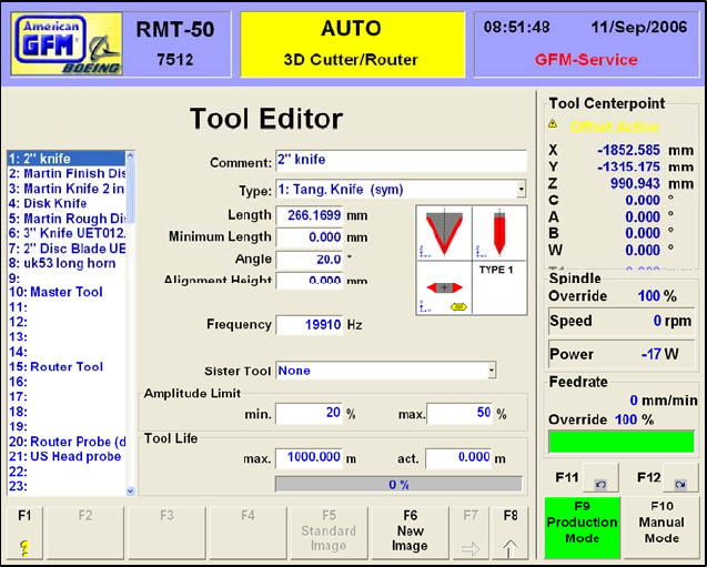
MMI Operation and Machine Startup American GFM Corp.
45
7.12.3 F6 Edit Tool Data
The F6 Edit Tool Data softkey will open
the Tool Editor display. The tool editor
is used to add, modify, and delete
available tools. Each tool must have
all of the defined data to be valid.
To add a new tool, highlight an empty
line number in the window on the left.
This line number will become the tool
number for the new tool.
Fill in the following information about
the new tool. See the table below for a
description about the needed
information.
A picture may also be assigned to a
tool for easier identification. Highlight
the desired tool and choose F6 to see a
list of available tool pictures. Double
click on a file name to assign it to the
tool. The picture will now appear when
the tool is highlighted. All pictures must
be located in the folder:
..\USERDATA\TOOLPIC
Any standard graphical format is supported, including JPG, BMP, GIF and TIF
Any picture files located in that folder will be available for assigning to a tool.
MMI Operation and Machine Startup American GFM Corp.
46
7.12.4 Tool Types
Comment Description of tool
Type Choose one of the following tool types from the drop down list
1 Tangential Knife (symetric)
2 Tangential Knife (asymetric)
3 Disk Knife
4 Routing Tool
5 Drill
6 Renishaw Probe
7 Disc Knife (no Toolsetting)
8 Virtual Disc Knife
9 Virtual tang. Knife (symetric)
10 Routing Tool (no Detag)
11 Peeling Knife
12 Tangential Knife (asymetric2) known as Stringer Knife
13 Mapping Tool
Length Estimated length of tool
Minimum Length Minimum length of tool for safety
Angle Included angle of blade
Alignment Height Height of blade when doing tool alignments
Cutting Edge Select which edge of the knife to use
Sister Tool If defined, this tool will automatically be used in place of the main tool if
the specified tool life has expired
Amplitude Limit These values are used to protect the tool from programming errors for
the ultrasonic amplitude percentage. The amplitude limits for each tool
can be defined to limit the amount of amplitude to the tool to these limit
values
Tool Life These values are used to monitor the tool’s cutting life. Enter the
designed tool life in “meters” to activate this monitor. If 0.00 is used,
the tool life monitor is disabled for that tool
NOTE: It is important to remember that when the data is changed for the tool number
which is currently loaded in the cutting head, the operator MUST change to MDI mode
and enter M64(n), where n is the loaded tool number. This M-Code will update the tool
data in the CNC memory. The changed data will not take effect until this has been
performed!
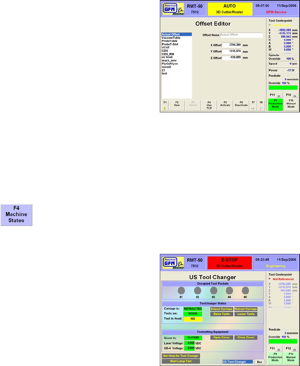
MMI Operation and Machine Startup American GFM Corp.
47
7.13 F7 → F2 Offsets
The F2 Offsets softkey opens the Offset Editor screen.
The offset editor allows the user to shift the 0-point of
any axis. This is useful when small depth changes in
Z-Axis are required during cutting provided that the
parameter “Enable Hot Z-Offset Changes” is enabled
in System.CNF. The user can create a new offset,
modify an existing offset, or delete one of the
previously defined offsets. The current defined offsets
are shown in the window on the left.
To create a new offset, choose F2 New. The cursor
will move to the Offset Name box. Enter a meaningful
description of the new offset. This will become the
name of the offset. The new offset name will appear in
the window on the left.
In the X Offset, Y Offset, and Z Offset fields, enter the
desired amount of offset value for each axis. A plus
value will shift the zero point in the plus direction.
The F4 “Use TCP” softkey provides a convenient method for obtaining an offset value from the current
position of the tool tip. The operator can jog the tool tip anywhere in the working area, then press F4.
The current tool center point values will be automatically entered in the X,Y and Z Offset fields.
To activate any of the defined offsets, highlight one of the offset names from the list window and choose
F5 Activate. The text Offset Active, will appear in the top right corner of the screen above the axis
display as a confirmation that the offset was activated. To verify which offset is active, place the mouse
cursor over the Offset Active text above the axis display. Windows tool tip text should appear next to the
mouse that shows which offset was activated. To deactivate any active offset, choose the F6 Deactivate
softkey.
7.14 F7 → F4 Machine States (Additional Functions)
The F4 Machine States softkey will display several screens that provide the operator with
convenient pushbuttons to perform various functions. Use the PageUp/PageDown keys to
move from one status screen to the next. A list box is also provided at the bottom to choose
different screens. In the next pages are described the various Machine State screens
provided on the machine.
7.14.1 Tool Changer Status
Upon pressing this softkey, the 1st screen displayed
will be for the toolchanger. The 4 pockets are shown
at the top. If the circle is GRAY, the pocket is empty.
If the circle is GREEN, the pocket has a tool in it.
Colorful indicators are also provided to show the state
of the switches on the toolchanger, such as the cover
door, and the tool carriage. Buttons are provided to
open, close, raise and lower the tools. The voltage
from the toolsetting equipment is also displayed near
the bottom. If help is needed about the tool changer, a
help button is provided.
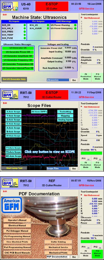
MMI Operation and Machine Startup American GFM Corp.
48
7.14.2 Ultrasonic Status
The next available status screen from the Machine State
section of the MMI is the Ultrasonics screen shown here. It
shows GREEN or RED indicators from status bits from the
ultrasonic generator. The voltage output from the generator
indicating the ultrasonic power is shown along with the
amplitude command voltage from the CNC. Related PLI
I/O signals are also provided at the top of the screen with
the associated PLI equate names.
7.14.3 Scope Files
For advanced users only, the Scope Files machine state
screen allows any of the configured axes to be displayed
using the built-in software O-Scope. Only qualified
personnel should use this particular screen. For more
information on the use of the software o-scope, please see
the online help built-in to Scope.
7.14.4 PDF Documentation
All of the documentation, which was shipped with the
machine, is also available for viewing on the MMI computer.
Each of the different manuals are viewable by clicking the
provided button on this screen.

MMI Operation and Machine Startup American GFM Corp.
49
7.14.5 F7 → F3 Label Text
F3 opens the Label Text Input editor if the
machine is equipped with a labeler unit. The
editor allows the operator to edit the text on up
to five labels. The labels are defined in the
labeler template file.
Use F4 Edit Template File to edit the labeler
template file. Refer to the labeler
documentation for proper structure and syntax.
The operator may use F5 Change Description to
change each labels description from “Label Text
1”, etc., to something more descriptive.
Use F6 Activate Texts to activate text changes.
F2 Undo Changes will undo text changes.
7.14.6 F7 → F4 Additional Functions
The F4 Additional Functions screen shows a set
of buttons or switches that may be programmed
to perform certain functions when pressed.
They are mainly for use by service personnel
and will be programmed by AGFM if needed.
They may perform such functions as turning on /
turning off vacuum pumps, ultrasonics, etc.
7.15 F7 → F5 Change Program Flow
Clicking the circular arrow button to the right of
the Program Flow field changes the Program Flow
selection. This button will allow choosing
between Continuous, Blockwise, or Stop on M01.
Continuous program flow will run the program from beginning to end without stopping.
Blockwise program flow will run the program until the next G0 block is encountered and then stop.
Pressing Cycle Start will allow the program to continue.
Stop on M01 program flow will run the program until an M01 is encountered and then stop. Pressing
Cycle Start will allow the program to continue until the next M01.
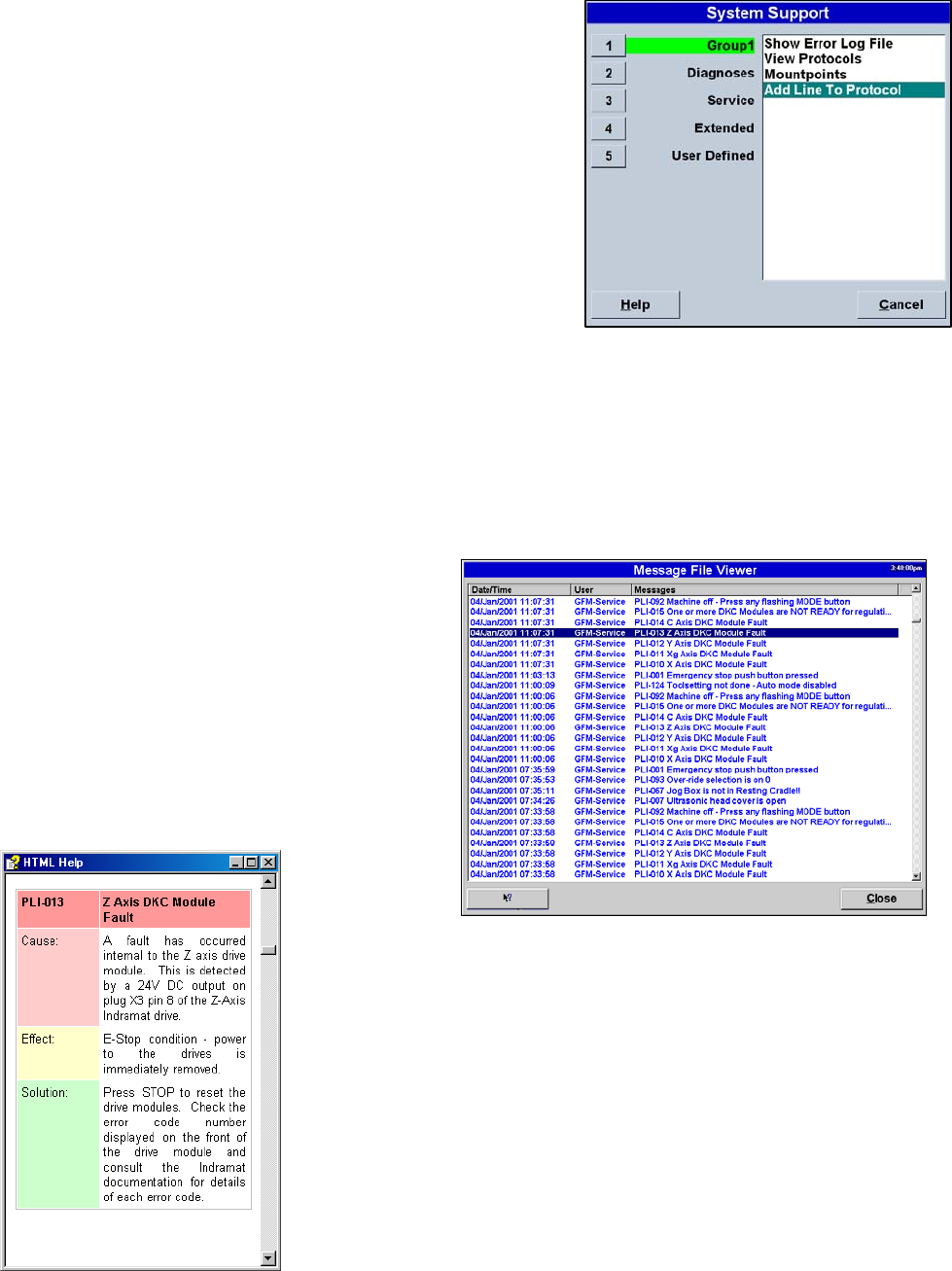
MMI Operation and Machine Startup American GFM Corp.
50
7.16 F7 → F6 System Support
The F6 System Support menu contains tools and applications
mainly intended for service and maintenance personnel.
There are five different sub menus within the system support
menu. Within each sub menu are various applications and
tools. Highlighting a sub menu and double clicking on an item
will open the item. Not all user levels have access to all of the
system support items. The System Support menu can be
displayed at any time by pressing the hotkey combination
<CTRL-S>.
7.16.1 System Support Group 1
Group 1 contains:
Show Error Log File
View Protocols
Mount Points
Add line to Protocol
7.16.2 Show Error Log File
An error log file is written each time an error
occurs on the machine. The file will help in
debugging machine problems. Each error that
occurs will have the Time and Date the error
occurred, The current user that was logged in to
the MMI, and the error itself.
The operator can double click on a message to open an HTML Help
application. The HELP file gives a description of the possible cause of the
error as well as a possible solution to the error. The help file gives
detailed information such as device numbers in the electrical prints that
can point the user in the right direction when solving errors.

MMI Operation and Machine Startup American GFM Corp.
51
7.16.3 View Protocols
This system support entry allows the user to view all of the log
files (Protocols) generated during probing functions. A different
log file is generated for each type of probing function. A list of the
protocols is shown here. Double click one these protocols to view
its log file. The log file will be displayed in the Dana editor and can
be printed if desired.
7.16.4 Mount Points
Mount points allows the user to select a path to where the cutting
programs are located. The path may be on the local machine or
may be on a network drive. If on a network drive, the Network
Neighborhood must be correctly set up in Windows 98.
To create a new mountpoint, choose New. Enter a mountpoint
name, the path, and the desired minimum user priority.
To select a mountpoint, highlight the desired mountpoint name
and choose Select.
To delete a mountpoint, highlight the desired mountpoint and
choose Delete.
7.16.5 Add line to Protocol
If a comment is needed in a log file, the user may choose “Add line
to Protocol” from Group 1. Any text can be written in a Logfile to be
used as a note in the file.
7.16.6 System Support - Diagnostics
Diagnostics contains:
Value Display
Additional Auto Data
Monitor Analog Inputs
Analog Outputs
Axis Monitor
Machine State
View Mapping
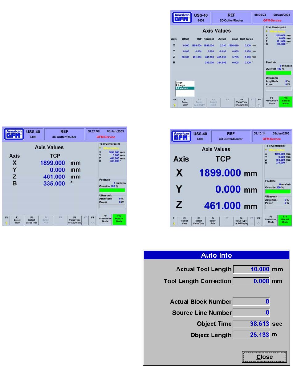
MMI Operation and Machine Startup American GFM Corp.
52
7.16.7 Value Display
Value Display opens the Axis Values screen. This
screen provides and easy way to all values of all axis
with one view. The first view will show All Values.
Choose F2 Select View to change to the other available
display views. When the view is set to X-Large, the F4
Select Axis softkey will appear allowing which of the 3
axes to display. Below are examples of the different
views when choosing F2.
Choose F6 Value Type for Ax Display to change the
displayed value type for the Axis Display in the top right
corner of the display. F8 will exit the Value Display
screen.
7.16.8 Additional Auto Data
Additional Auto Data shows real-time data of the
current cutting cycle.
Actual Tool Length shows the tool length
entered in the Tool Editor screen
Tool Length Correction is the difference
between the tool length in entered in the Tool
Editor screen and the length measured by the
M62 toolsetting macro.
Actual Block Number shows the current object
block of the OC5 cutting program.
Source Line Number shows the current line
number of the SRC cutting program.
Object Time shows the accumulated cutting
time of the current program.
Object Length shows the accumulated
distance cut of the cutting program.
X-Large Values
Large Values
All Values
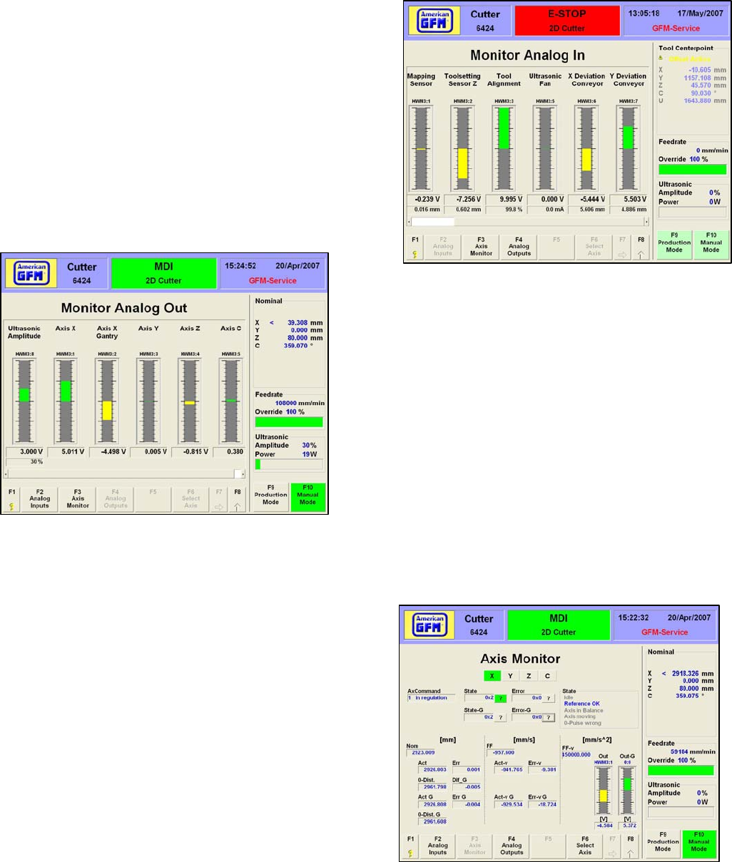
MMI Operation and Machine Startup American GFM Corp.
53
7.16.9 Analog Input Monitor
Monitor Analog Inputs will open the Analog Inputs
Monitor screen. This screen shows a graphical
representation of analog input voltages from the
machine such as: toolsetting sensor, tool alignment
sensor, mapping sensor, etc. The HWM number
above the bar graph is the analog input hardware
module input number. A numerical value of the
voltage is displayed under the graphic as well as the
units of the signal after the CNC scaling factor has
been used for the corresponding input voltage.
7.16.10 Analog Output Monitor
This screen also shows a graphical representation of the
voltage to the servo drives and ultrasonic generator. Each
of these devices uses a +/- 10VDC analog signal as the
command voltage to command motion for the axes. The
HWM number above the bar graph is the analog output
hardware module output number.
7.16.11 Axis Monitor
F3 Axis Monitor will open the Axis Monitor screen.
The Axis Monitor is useful for axis setup and
debugging. Each axis may be displayed by clicking
on one of the axis buttons at the top of the screen or
by choosing F6 Select Axis. Diagnostic messages
are displayed in the State box. The bar graphic in
the bottom right shows the current drive command
voltage from the CNC. Axis nominal, actual, error,
and zero pulse positions are shown in the bottom left
of the screen.

MMI Operation and Machine Startup American GFM Corp.
54
7.16.12 Machine States
The Machine States entry on the system support menu is used to display the Machine State screens.
These screens were already described in an earlier section of this manual. (Section 2.2.7.8)
7.16.13 View Mapping
View Mapping opens the graphical table mapping
viewer. The view shows a graphical view of the table
mapping file. Buttons are provided to rotate the view
in 3 dimensions.
7.16.14 System Support - Service
Service contains:
Scan Mode
View Knife Alignment
Oscilloscope
PLI Debugger
Parameter Editor
View Versions
These items are only useful to service personnel.
7.16.15 Scan Mode
Scan Mode is used to perform a table mapping
sequence. Under normal conditions, table mapping
only needs to be performed once. If this option is
installed, table mapping is done by AGFM service
personnel during machine installation.
To begin a scanning cycle, first re-reference the
machine but do not perform a toolsetting cycle. Next,
go back to Scan Mode and choose F2 Clear to clear
the current mapping file. Next, save the cleared
mapping file with the F4 softkey. Now, press START,
remove the cutting tool, and click on the X to confirm
the message. The machine will now move to the
starting scanning position and begin scanning. The
scanning progress is shown on the screen. Z
Mapping Correction shows the movement of the
mapping sensor in the Z direction. When the scanning cycle is complete, choose F4 Save to save the
mapping data to the mapping file. Lastly, choose F3 Load to load the mapping file to the CNC. The View
Mapping utility is also available by choosing F6 Graphic.
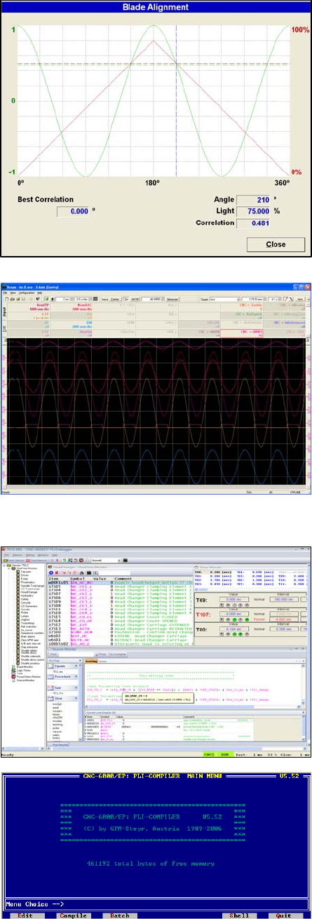
MMI Operation and Machine Startup American GFM Corp.
55
7.16.16 View Knife Alignment
View Knife Alignment is used to set up the knife angular
alignment system. A graph shows the amount of light
transmitted from the sending unit to the receiving unit at a
given angular knife position. The mouse can be used to
move the dashed blue line across the graph. The angle,
received light percentage, and the angular correlation of the
blade will be displayed in the bottom right corner. The best
correlation is shown in the bottom left corner. This value is
usually a good starting point for the blade alignment offset
value in the user.cnf file. The RED line indicates the
amount of light detected while the GREEN line indicates the
blade angle.
7.16.17 Oscilloscope
The software oscilloscope is used to tune the servo drive
speed and position regulators. Refer to the AGFM
Software Oscilloscope Manual for more information.
7.16.18 PLI Debugger
The PLI Debugger is used to debug the PLI program.
Refer to the AGFM PLI Manual for more information.
7.16.19 PLI Compiler
The PLI Compiler is used to compile and download the PLI
program. Refer to the AGFM PLI Manual for more
information. This feature is only available to AGFM service
personnel.

MMI Operation and Machine Startup American GFM Corp.
56
7.16.20 Parameter Editor
The Parameter Editor is used to edit the
AXIS.CNF, SYSTEM.CNF, and USER.CNF
files. These files should not be edited
without first checking with AGFM. Double
click on a heading in the left window to jump
to that topic in the editor window on the right.
To change a parameter value, double click
on the value, enter the new value, and hit the
enter key. After editing is complete, close
the editor, switch to a different mode, and
then return to the previous mode. This will
send the changed value to the CNC. If the
value is shown in red, it is a boot parameter
only. The CNC must be re-booted in order
for the parameter to take effect.
7.16.21 View Versions
View Versions displays the version numbers for the MMI software
components. In the event AGFM ask for the software version running
on your machine, use this screen to determine the versions.
7.16.22 System Support - Extended
The Extended group of system support contains MMI integrated
functions. As future MMI updates become available, they will be added
under this group.
Extended contains:
Program Management
User PLI Command Editor
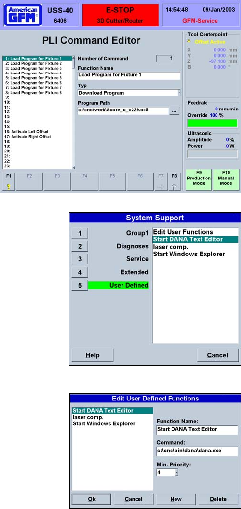
MMI Operation and Machine Startup American GFM Corp.
57
7.16.23 Program Management
This is an easy way to access the Program Management screen if AUTO mode is not available. For
example, if the machine is in ESTOP, the Program Management screen is still accessible via this system
support entry. The Program Management section is described in detail in section 2.4.4.2 of this manual.
7.16.24 User PLI Command Editor
This feature of the MMI is used to associate an
internal PLI command with external program
applications. This feature is setup up to call the
USS40 Utility with many different command line
arguments to perform different functions related to
scanning and scoring part program generation.
7.16.25 System Support - User Defined
The User Defined group of system support contains external
applications defined by the user. If 3rd part software applications are
required to be started while running the MMI, they can be
configured here.
User Defined contains:
Edit User Functions
Functions configured by AGFM
7.16.26 Edit User Functions
Edit User Functions allows the user to set up links to external
applications. If a 3rd party application needs to be executed, use Edit User Functions from this group to
configure the application.
To add a new function, click on New. Enter a description in the
Function Name box. Enter the complete command line for the
application in the Command box. Choose the minimum user priority
for access to the application. When all information is entered,
choose OK. The editor will close and the new function will be
shown in the User Defined window.
To delete a function, highlight the function and choose Delete.

MMI Operation and Machine Startup American GFM Corp.
58
7.17 Using Simple Production Log Files
The CNC6000 is capable of logging many events into a file for later use by production management to track the
machine’s production capacity. This file, by default, is called PRODUCTION1.CSV and is stored in the
CNC\USERDATA folder. The max file size of the CSV file is configured via GFMLogger.INI, using the key
“MaxFileSize”. The default value for the file size is 10485760 bytes (or 10MB). When this limit is reached, the
oldest 20% of the file will be cut off.
The production log data is stored in CSV (Comma Separated Values) format. Each line in the log has the
following entries:
• Timestamp (date and time)
• Name of the currently logged on user
• An Event ID number (see the following table for possible events)
• Short description of the Event (in defined language)
• Additional data depending on the event.
EVENT ID Logged Event Event Description
0 Program Loaded Loading of a program to the CNC-control
Additional data:
- Name of the loaded program
1 Program Begin When the operator start an automatic program
Additional data:
- Name of the currently loaded program
2 Program Restarted When the operator continuous an previously not finished program
Additional data:
- Name of the currently loaded program
3 Program End After finishing a program
Additional data:
- Name of the currently loaded program
- Cutting length
- Total processing time between start end end of the program
- Cutting Time = G1
- Idle Time: Difference between Total and Cutting time
4 Program Abort Abortion of a program (This event is not implemented yet)
Additional Data:
- Name of the currently loaded program
5 Window Transfer Documents the conveyor transfer when window cutting is used
Additional data:
- Name of the currently loaded program
6 Feedhold ON logs when feed hold is activated
Additional data:
- Name of the currently loaded program
7 Feedhold OFF logs when feed hold is deactivated
Additional data:
- Name of the currently loaded program
8 Log Begin Start of the MMI
9 Log End Closing of the MMI
10 Alarm Active Error during a program run
Additional data:
- Alarm number and text in defined language
11 Override Value Changes of Override value
Additional data:
- Name of the currently loaded program
- new Override value in percent
12 Tool Change Logs the tool change
Additional data:
- Name of the currently loaded program
- number of the actual tool
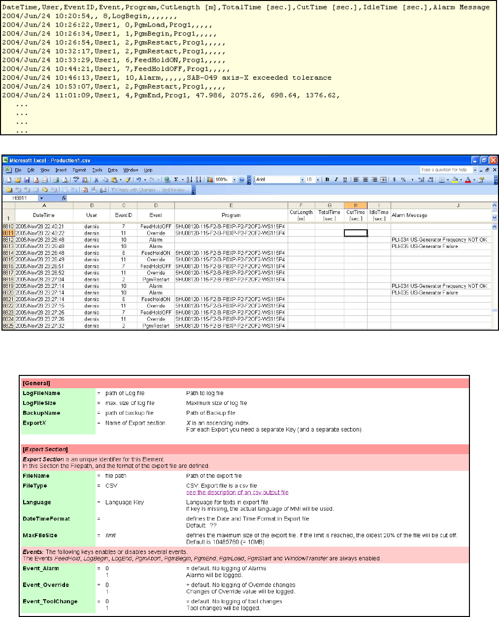
MMI Operation and Machine Startup American GFM Corp.
59
Below is an example of the PRODUCTION1.CSV file output from the CNC6000. This file type can be opened
directly with Microsoft Excel and formatted to desired needs as shown below.
The log file can be configured via GFMLogger.INI in the CNC\UserData folder. Below is an example of this INI
file:
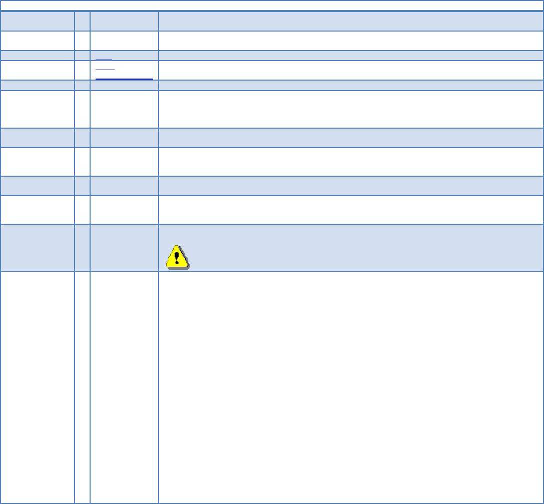
MMI Operation and Machine Startup American GFM Corp.
60
7.18 Using Advanced Production Log Files
If more information is needed in the log files that the simple logging does not provide, a more advanced logging
method is available to use. This logging feature was made available in April 2008 with MMI Version 6.40.1. If the
configuration file “logging.ini” exists in the Userdata folder, the advance logging method will be enabled. A help
file is available called “logging.ini.chm” and is located in the Cnc\Help folder. Below is a copy of this help file.
[General]
Language = <language key> (default ="ENG") defines the language of the protocol file.
Possible Keys are: ENG, DEU, ITA, ...
DateTimeFormat = <format string> default = "yyyy/mm/dd Hh:Nn:Ss" defines the format of date and time in the log file
Here the VB-Format function will be used. For detailed information see VB-Doku.
Format = CSV default = CSV, defines the output format of the log file. CSV = Character Separated Values)
CSV-
ParametersOnly
With this format only Parameters will be logged, not the events. CSV = Character Separated Values.
... additional formats will follow if required.
CSV_Separator = <character> Default is comma ",". If Format = CSV this entry defines the separator character. If more than 1 character
is defined, only the most left one will be used. If you want use the tabulator for separator (ASCII-Code
0x9) type "TAB".
If Format is not CSV, this entry will be ignored.
MaxFileSize = <bytes> default = 1000000. defines the maximum file size of the log file in bytes.
Minimum file size is 10000, maximum file size is 10000000.
BackupStyle = MaxSize-Move
MaxSize-Cut
default = MaxSize-Move. Defines the behavior if the size of the log file exceeds the maximum file size.
MaxSize-Move will make a backup of the current logfile, and starts a new log file.
MaxSize-Move will cut the oldest entries of the file, and will continue the log file.
BackupPrefix = <backup prefix> default = "Backup_". If BackupStyle is MaxSize_Move this defined prefix will put in front of the filename.
If Format is not MaxSize-Move, this entry will be ignored.
PercentToCut = <percent value> default = 20. If BackupStyle is MaxSize-Cut, this value defines the amount of old entries to cut in percent
Minimum is 1, maximum is 50
If Format is not MaxSize-Cut, this entry will be ignored.
LogFolder = <folder> defines the folder were the log files will be written to. The folder must exist.
The maximum size of each individual log file will be checked, but not the size of all files in this
folder.
If you use dynamic elements in filename many small log files can exist.
FileName = <log file name> • defines file name of the log file. This name can have some dynamic elements:
• %PgmName% will be replaced by the file name of the currently loaded part program.
• %Zone% will be replaced by the currently active zone (therefore sab.UsedZoneX will be used.
This is either 0 or 1)
• %Year% will be replaced with the actual year.
• %Month% will be replaced with the actual month.
• %Day% will be replaced with the actual day.
• <PLI address> will be replaced with the value of the given PLI address. The PLI-address must
be in the following format:
< -- E, D or M -- Address -- L, W, B or S -- Index of Word, Byte or Single bit -- >
Examples: <E100L>, <M255S17>, <D35W1>
Example of different log file names:
FileName = Production.log
FileName = Part_%PgmName%.csv
FileName = LogFile<E100B0>.csv
7.18.1 Logging Section:
For each log file a separate section with a unique name must exist. In this section the style and the content of the
log file is defined. If the FileName contains dynamic elements, it is possible that multiple sections refer to the
same log file. (then you should use also the same file format).
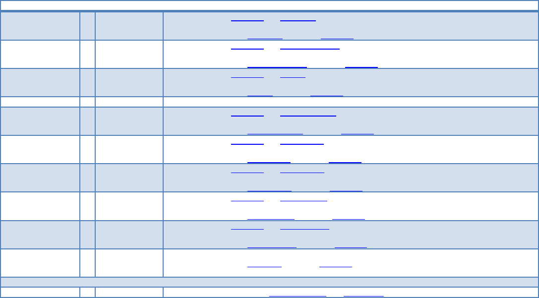
MMI Operation and Machine Startup American GFM Corp.
61
Each event which should be logged to the defined file must be defined in this section. If you want additional
parameters on events, these parameters must also be defined there.
[Logging section] must be a unique name. The name is not used in log files.
Language = <language key> default = section [General] key Language.
defines the language of the protocol file.
see description of key Language in section [General]
DateTimeFormat = <format string> default = section [General] key DateTimeFormat.
defines the format of date and time in the log file.
see description of key DateTimeFormat in section [General]
Format = CSV default = section [General] key Format.
defines the output format of the log file.
see description of key Format in section [General]
... additional formats will follow if required.
CSV_Separator = <character> default = section [General] key CSV_Separator.
defines the separator character in CSV Format
see description of key CSV_Separator in section [General]
MaxFileSize = <bytes> default = section [General] key MaxFileSize.
Defines the maximum file size of the log file in bytes.
see description of key MaxFileSize in section [General]
BackupStyle = MaxSize-Move
MaxSize-Cut
default = section [General] key BackupStyle.
Defines the behavior if the size of the log file exceeds the maximum file size.
see description of key BackupStyle in section [General]
BackupPrefix = <backup prefix> default = section [General] key BackupPrefix.
defines prefix of the log file name
see description of key BackupPrefix in section [General]
PercentToCut = <percent value> default = section [General] key PercentToCut.
defines the amount of old entries to cut in percent
see description of key PercentToCut in section [General]
FileName = <log file name> defines file name of the log file.
see description of key FileName in section [General]
List of events with the requested parameters, which should be logged in the above defined file
Event_????? = <Parameters> Therefore see the table with available events and parameters.

MMI Operation and Machine Startup American GFM Corp.
62
7.18.2 Available Events:
Some of the events have standard parameters which are logged always. Each event can also have additional
parameters. These parameters must be defined as a comma separated list. The parameter will be logged in the
same order as they are defined.
If the special parameter NoStd is defined, the standard parameters will not be logged.
Possible Event keys:
Entry name Event-
ID
Meaning Standard Parameters
Event_LogBegin 1 Occurs on MMI-Start ---
Event_LogEnd 2 Occurs on MMI-End ---
Event_UserChanged 3 Occurs on every Login ---
Event_PgmLoad 10 When a part program is loaded PgmName
Event_PgmStart 11 When a part program is started ---
Event_PgmContinue 12 when continuing a interrupted part program ---
Event_PgmEnd 15 When a program finishes ---
Event_PgmUnload 16 when a part program in CNC is deleted ---
Event_WindowTransfer 21 On conveyor moves
Event_ToolChange 22 when the clamped toll changes ClampedTool
Event_HeadChange 23 When active laying head / cassette changes LayingHead
Event_StripeLaid 25 On TapeLayers when a stripe has laid Stripe data
Event_FeedHold 30 when feed hold state changes ($B_HOLIFT) FeedHoldOnOff
Event_OverrideChanged 32 when override changes
Override, Override for G0 movements and Override for APM
axis will be checked
Override
Event_Alarm 40 when an alarm is pending AlarmMessage
Event_OffsetChanged 50 when offset data changes ---
Event_PrinterData 51 when labeler data changes PrinterData
Event_MappingLoaded 60 when mapping data are loaded MappingFile
Event_MappingSaved 61 when mapping data are saved MappingFile
Event_MappingCleared 62 when mapping data are cleared ---
Event_PliData1Loaded 65 when PLI-Data1 are loaded PliDataIndex1
Event_PliData2Loaded 66 when PLI-Data2 are loaded PliDataIndex2
Event_PliLogRequest 67 when PLI send log command $CP_Call_Logging (=0x600) to
MMI
Event_PliLogRequestX 67 when PLI send log command $CP_Call_Logging to MMI with
command extension $B_CMDEXT unequal to 0.
X must match the command extension to log the event.
PliRequestIndex
Event_TapeChanged 80 when new tape data are loaded LayingHead, TapeID, MaterialID,
TapeLength
Event_BarCodeReceived 90 when a Barcode is received Barcode reader, Barcode, Barcode alias
Event_1s 100 Every second.
Event will only be logged if additional parameters are defined.
Event_10s 101 every 10 seconds.
Event will only be logged if additional parameters are defined.
Event_1m 102 every minute.
Event will only be logged if additional parameters defined.
7.18.3 Special Parameters:
These parameters have a special meaning and don't supply data.
Paramter name Meaning
NoStd Standard parameters of events, listed in the table above, will be not be logged.
MMI Operation and Machine Startup American GFM Corp.
63
7.18.4 Available Parameters:
Each parameter has an ID. Not every parameter can be used as additional parameter on events.
Parameters marked with " " can be used as additional parameters, parameters marked with a ” ” can’t be used
as additional parameters.
Paramter name Parameter
ID Meaning
Override 500 Override value in percent [%]
OverrideG0 530 Override value for G0 movements in percent [%]
OverrideAPM 531 APM axes override in percent [%]
PgmName 501 file name of the currently loaded part program
PgmTime 502 program cycle time in seconds [sec]
ObjCutLen 504 cutting length from object file in meters [m]
ObjTime 503 object time in seconds [sec]
TransferCount 505 Window transfer counter.
ClampedTool 507 number of the currently clamped tool
FeedHoldOnOff 506 1 for feed hold active, 0 for feed hold inactive
PrinterData 509 provides printer text 1 to 5 (PrinterData1 ... PrinterData5)
PrinterData1 525 Printer text 1
PrinterData2 526 Printer text 2
PrinterData3 527 Printer text 3
PrinterData4 528 Printer text 4
PrinterData5 529 Printer text 5
AlarmMessage 508 last alarm message (provided in the defined language)
ObjLimits 510 provides the object limits (ObjLimitXMin, ObjLimitXMax, ObjLimitYMin and ObjLimitYMax) of the currently
loaded program.
ObjPosition 511 provides the area (ObjLimitXMin, ObjLimitXMax, ObjLimitYMin and ObjLimitYMax) where the currently loaded
program is cut.
ObjLimitXMin 512 Object minimum in X axis in meters [m]
ObjLimitXMax 513 Object maximum in X axis in meters [m]
ObjLimitYMin 514 Object minimum in Y axis in meters [m]
ObjLimitYMax 515 Object maximum in Y axis in meters [m]
OffsetName 516 Name of last loaded offset set
OffsetData 517 provides the currently active Offsets: OffsetX, OffsetY, OffsetZ, OffsetDrill and OffsetPgmShift
OffsetX 518 currently active X Offset in meters [m]
OffsetY 519 currently active Y Offset in meters [m]
OffsetZ 520 currently active Z Offset in meters [m]
OffsetDrill 521 currently active drill correction in meters [m]
OffsetPgmShift 522 0: not shifted
1: corner X min. / Y min.
2: corner X max. / Y min.
3: corner X max. / Y max.
4: corner X min. / Y max.
UserName 523 Name of the currently logged on user
UserID 533 ID of the currently logged on user
LanguageKey 532 Key of the currently active language
UserPriority 524 Priority of the currently logged on user
MappingFile 534 path of the last loaded mapping file
PliDataIndex1 535 Index of the last loaded PLI data from file 1
PliDataIndex2 536 Index of the last loaded PLI data from file 2
PliLogRequestIndex 537 PLI command extension
PliValue_<PLI
address>
538 records the value of the given PLI address.
<PLI address> must be in the following format:
< -- E, D or M -- Address -- L, W, B or S -- Index of Word, Byte or Single bit -- >
Examples: PliValue_<E100L>, PliValue_<M255S17>, PliValue_<D35W1>

MMI Operation and Machine Startup American GFM Corp.
64
ActiveLayingHead 539 Number of active laying head / Cassette
TapeID 540 ID of tape. If used as additional parameter, ID of tape clamped in active laying head will be logged.
MaterialID 541 material ID of tape. If used as additional parameter, material ID of tape clamped in active laying head will be
logged.
TapeLength 542 length of tape in [m]. If used as additional parameter tape length of tape in active laying head will be logged.
Barcode reader 543 Number of the barcode reader where the code is from.
Barcode value 544 Received barcode value
Barcode alias 545 Barcode related alias value
TapeDefects 546 TapeDefects: Count of tape defects and a list of TapeDefect Elements
TapeDefect 547 TapeDefect contains a Tape defect begin and a tape defect end parameter
TapeDefectBegin 548 begin of tape defect in meters [m]
TapeDefectEnd 549 End of tape defect in meters [m]
TapeDataCasX 2000 Data of Tape clamped in Cassette / Head X: Cassette / Head number X, Tape ID, Material ID, Tape length,
Tape defects
StripeData 1000 Data of last laid stripe: StripeNumber, ActiveLayingHead, TapeID , StripeType, StripeStartX, StripeStartY,
StripeLength, TapeRollStart, Pressure, Temperature
StripeNumber 1001 Stripe number
StripeType 1002 Stripe Type:
1 = Good
4 = Waste
5 = Error
StripeStartX 1003 Start of stripe in X direction in [m]
StripeStartY 1004 Start of stripe in Y direction in [m]
StripeLen 1005 stripe length in [m]
TapeRollStart 1006 Start position of stripe on roll in [m]
PressureData 1007 Pressure data of last laid stripe: Pressure-Min, Pressure-Max, Pressure-Avg
Pressure-Min 1008 pressure minimum in [N]
Pressure-Max 1009 Pressure maximum in [N]
Pressure-Avg 1010 Pressure average in [N]
TemperatureData 1011 Temperature data of last laid stripe: Temperature-Min, Temperature-Max, Temperature-Avg
Temperature-Min 1012 Temperature minimum in [ºC]
Temperature-Max 1013 Temperature maximum in [ºC]
Temperature-Avg 1014 Temperature average in [ºC]

MMI Operation and Machine Startup American GFM Corp.
65
7.18.5 Log file formats
CSV Format
This format logs the events and the parameters in a plain text file. The values will be separated with the defined
CSV separator character in the according logging section. If the size of the file exceeds the maximum file size
according to the Backup style either a backup of the log file will be made and log file starts new or the oldest part
of the file will be cut. Each line in the file has at least 4 columns:
• Date and time formatted according the defined date and time format string.
• Name of the currently logged on user
• Event ID
• Event Name in the defined language.
Some events can have additional values (parameters) according to the settings in the logging section.
Example of a CSV log file:
2007.12.1016:27:37,,1,LogBegin
2007.12.1016:27:37,,50,Offsetchanged,1.000000,0.200000
2007.12.1016:27:38,,10,Programload,cipolr.oc5
2007.12.1016:27:38,GFM‐Service,3,Operatorchanged,9,ENG
2007.12.1016:27:40,GFM‐Service,32,Override,100,0,0
2007.12.1016:27:59,GFM‐Service,10,Programload,Test_Rampe1.oc5
2007.12.1016:28:07,GFM‐Service,11,Programstart,2.500000,2.800000,0.200000,0.200000,Text5
2007.12.1016:28:11,GFM‐Service,21,Windowtransfer,Test_Rampe1.oc5,1
2007.12.1016:28:15,GFM‐Service,15,Programend,Test_Rampe1.oc5,46.673,0.000,0.000
2007.12.1016:28:24,GFM‐Service,16,Programunloaded
2007.12.1016:28:37,GFM‐Service,40,Errormessage,MMI‐105GfmLicense:Authorizationperiodexpiresin21days
2007.12.1016:30:52,GFM‐Service,2,LogEnd
CSV-ParametersOnly:
This format logs the parameters of the defined events in a plain text file. The event itself will not be logged, only
the standard parameters if they are not blended out by parameter NoStd and the defined additional parameters
will be logged. Each parameter will be written in a separate line. The values will be separated with the defined
CSV separator character in the according logging section. If the size of the file exceeds the maximum file size
according to the Backup style either a backup of the log file will be made and log file starts new or the oldest part
of the file will be cut.
Each line in the file has at least 5 columns:
• Date and time formatted according the defined date and time format string.
• Name of the currently logged on user
• Parameter ID
• Parameter name in the defined language.
• Parameter value
Example of CSV-ParametersOnly log file entries:
2008.02.1314:17:07;GFM‐Service;525;Printerdata1;Hello,howareyou?
2008.02.1314:17:07;GFM‐Service;526;Printerdata2;Printertext2
2008.02.1314:17:07;GFM‐Service;516;OffsetName;Part27
2008.02.1314:17:07;GFM‐Service;2000;Tapedata;3;Steve;80gUD;300;3;0,000;1,050;12,200;16,700;99,800;102,200

MMI Operation and Machine Startup American GFM Corp.
66
Example of the logging.ini file:
[General]
DateTimeFormat=mm/dd/yyyyHh:Nn:Ss
MaxFileSize=1000000
BackupStyle=MaxSize‐Move
BackupPrefix=Backup_
LogFolder=..\logging
[ProductionLog]
CSV_Separator=;
FileName=Production_log.csv
Event_LogBegin=PgmName,Override
Event_LogEnd=
Event_PgmStart=ObjPosition
Event_PgmLoad=
Event_PgmEnd=PgmName,PgmTime,ObjCutLen,ObjTime
Event_WindowTransfer=PgmName,TransferCount
Event_PgmContinue=PgmName
Event_ToolChange=
Event_Alarm=
Event_Feedhold=
Event_OverrideChanged=
Event_PrinterData=NoStd,PrinterData5
Event_OffsetChanged=OffsetX,OffsetY
Event_UserChanged=UserID,UserName,UserPriority,LanguageKey
Event_MappingLoaded=
Event_MappingCleared=
Event_MappingSaved=
Event_PliData1Loaded=
Event_PliData2Loaded=
Event_PgmUnload=
[PartHistory_Shuttle1]
CSV_Separator=;
Filename=PartHistory_0.log.csv
Event_LogBegin=
Event_LogEnd=
Event_UserChanged=UserPriority,LanguageKey
Event_Alarm=
Event_Feedhold=
Event_OverrideChanged=OverrideG0,OverrideAPM
Event_PrinterData=NoStd,PrinterData5
Event_OffsetChanged=OffsetX,OffsetY
Event_PliData1Loaded=
Event_PgmLoad=
Event_PgmUnload=
Event_MappingCleared=
MMI Operation and Machine Startup American GFM Corp.
67
[PartHistory_Shuttle2]
CSV_Separator=;
Filename=PartHistory_1.log.csv
Event_LogBegin=
Event_LogEnd=
Event_UserChanged=UserPriority,LanguageKey
Event_Alarm=
Event_Feedhold=
Event_OverrideChanged=OverrideG0,OverrideAPM
Event_PrinterData=NoStd,PrinterData5
Event_OffsetChanged=OffsetX,OffsetY
Event_PliData2Loaded=
Event_PgmLoad=
Event_PgmUnload=
Event_MappingCleared=
[PartHistory_ZoneDependingEvents]
CSV_Separator=;
FileName=PartHistory_%Zone%.log.csv
Event_PgmStart=ObjPosition,ToolName,PrinterData5
Event_WindowTransfer=PgmName,TransferCount
Event_PgmContinue=PgmName
Event_PgmEnd=PgmName,PgmTime,ObjCutLen,ObjTime
Event_ToolChange=
[PartHistory_Mapping]
CSV_Separator=;
FileName=PartHistory_<E11L>.log.csv
Event_MappingLoaded=
Event_MappingSaved=
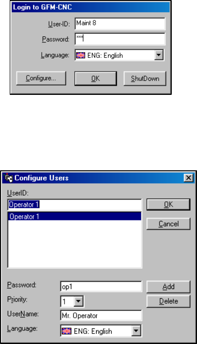
MMI Operation and Machine Startup American GFM Corp.
68
7.19 Adding New Users
New users with unique passwords and user levels may be
added from the login screen. Choose the Configure button to
access the configure screen. Only personnel with user level 8
have access to the configure user screen.
To add a new user, first enter a User ID in the UserID: window
and then choose Add. Next enter a password, a priority, and a user name. Choose OK to exit the
Configure User window. To delete a user, highlight the user id and in the user list window and choose
Delete. The User ID and Password are used for logging on to the MMI. The User Name will be displayed
in the top right corner of the MMI. Passwords are case sensitive.
7.20 Priority Levels
The MMI uses user priority levels to disable features that are
not needed by all users. Each subsequent priority level allows
access to higher-level user functions. The priority level
structure is:
Operators Priority Levels 1, 2, and 3
Programmers Priority Levels 4, 5, and 6
Maintenance Priority Levels 7 and 8
All priority levels have full access to REF, JOG, MDI, and
AUTO modes. Access is limited by priority level to Program Management and System Support menu
functions.
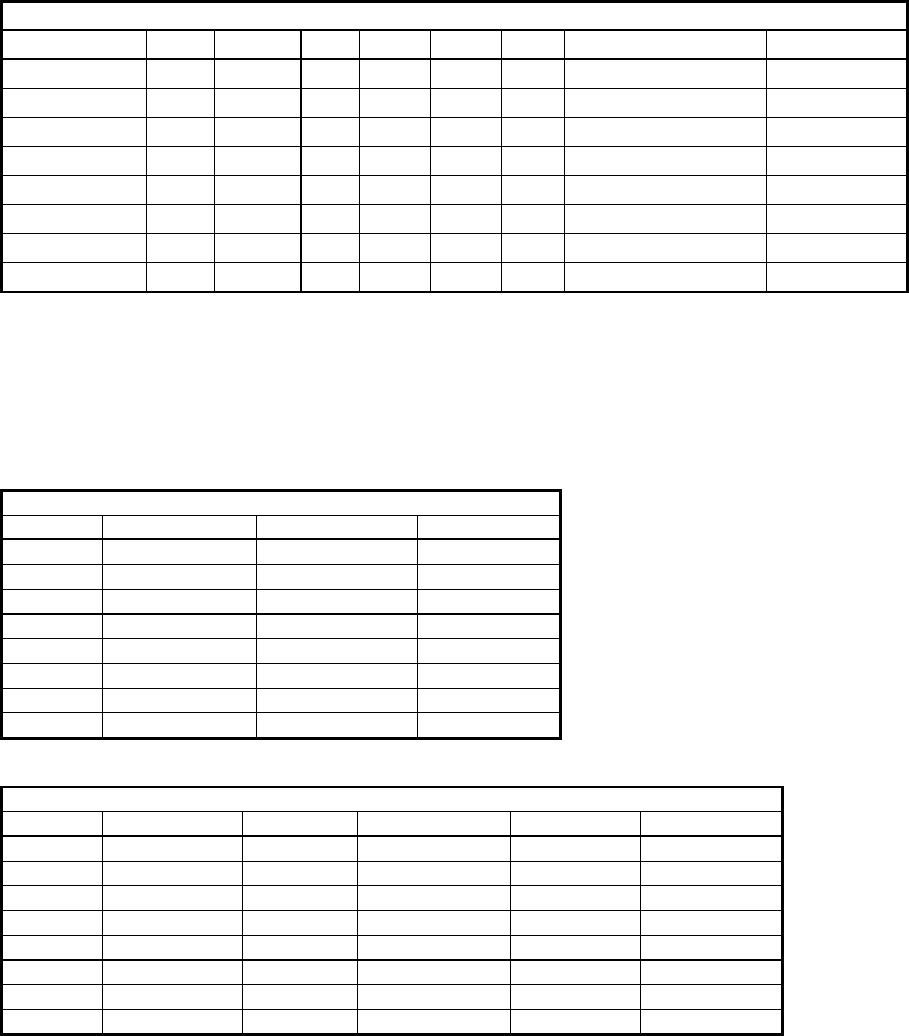
MMI Operation and Machine Startup American GFM Corp.
69
7.20.1 Program Management Priority Level Access
Program Management Features
Priority Level Load Graphic Info Select Delete Edit Generate Part Prog. Origin Editor
1****
2*****
3****** * *
4****** * *
5****** * *
6****** * *
7****** * *
8****** * *
7.20.2 System Support Priority Level Access
System Support Features - Group 1
Priority Online Graphic View Log File Mountpoints
1* * *
2* * *
3* * *
4* * *
5* * *
6* * *
7* * *
8* * *
System Support Features - Diagnostics
Priority Value Display Auto Data Analog Monitor Axis Monitor View Mapping
1* * * * *
2* * * * *
3* * * * *
4* * * * *
5* * * * *
6* * * * *
7* * * * *
8* * * * *
MMI Operation and Machine Startup American GFM Corp.
70
System Support Features - Service
Priority View Knife Align. View Versions Parameter Editor Scan Mode PLI Debugger Oscilloscope
1*
2*
3*
4* * *
5* * *
6* * * *
7* * * *
8* * * ***
System Support Features - Extended
Priority Select
1
2
3*
4*
5*
6*
7*
8*
System Support Features - User Defined
Priority Edit User Functions
1
2
3
4
5
6
7
8*
For Priority Level 8 only – ALT + F4 will exit the MMI to the Windows desktop.
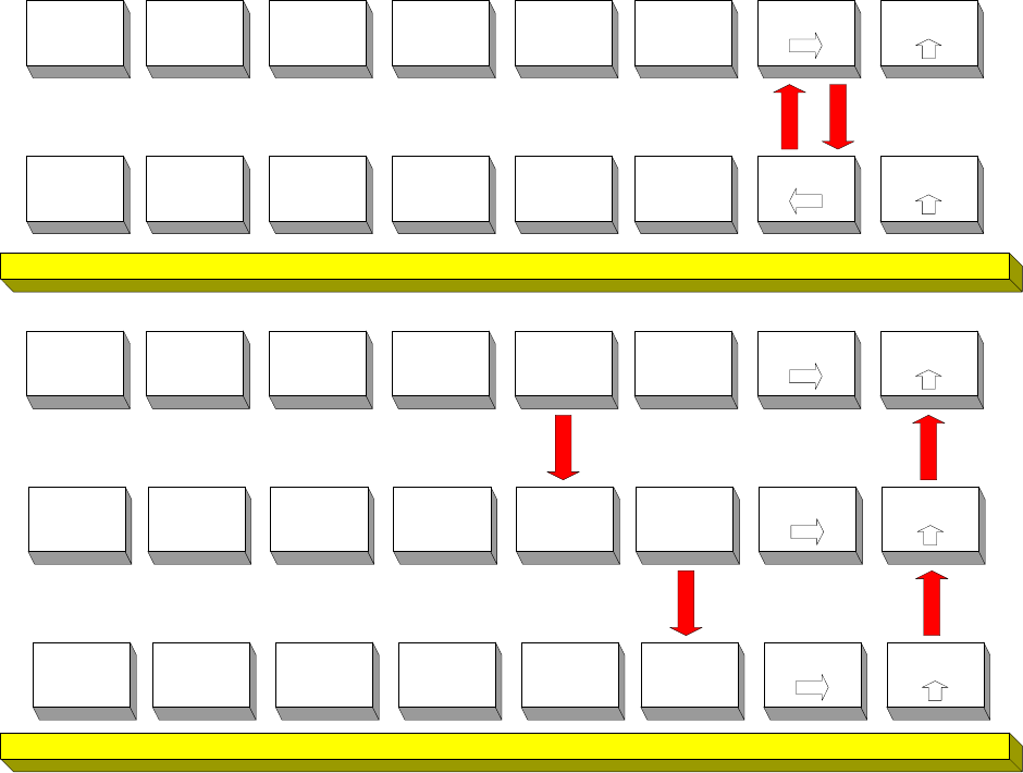
MMI Operation and Machine Startup American GFM Corp.
71
7.21 MMI Softkey Flow Diagrams
The following diagrams show the MMI softkey strokes used to move between different softkey lines and
MMI functions. Not all softkeys are used on all machines. The diagrams are separated according to
Manual mode softkeys and Production mode softkeys. The last diagram shows the flow of the System
Support menu.
7.21.1 Manual Mode Softkeys
F8F7
Soft Key Level 2
F1
?
F2
Offsets
F3
Label
Text
F4
Additional
Functions
F5 F6
System
Support
F8F7
Soft Key Level 1
F1
?
F2
MDI
F3
JOG
F4
REF
F5
Tools
F6
Login
Shutdown
F8F7
Soft Key Level 1 - F5
F1
?
F2 F3
Select
Tool
F4
Remove
Tool
F5 F6
Edit
Tooldata
Manual Mode Soft Keys
Soft Key Level 1
F8F7F1
?
F2
MDI
F3
JOG
F4
REF
F5
Tools
F6
Login
Shutdown
F8F7
Soft Key Level 1 - F5 -F6
F1
?
F2 F3 F4 F5
Standard
Image
F6
New
Image
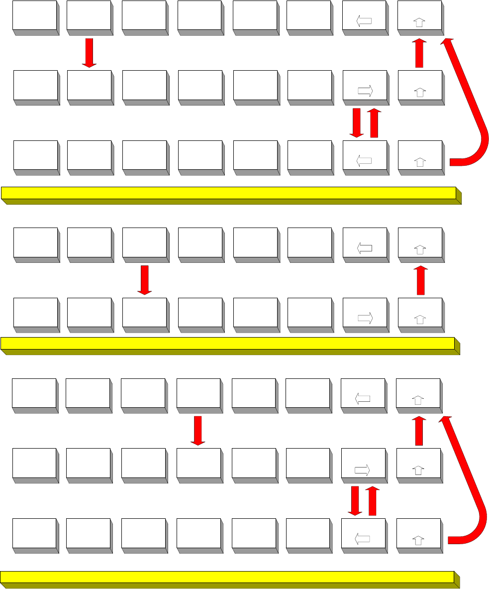
MMI Operation and Machine Startup American GFM Corp.
72
F8F7
Soft Key Level 2 - F2
F1
?
F2
New
F3
Delete
F4
Use
TCP
F5
Activate
F6
Deactivate
F8F7
Soft Key Level 2
F1
?
F2
Offsets
F3
Label
Text
F4
Additional
Functions
F5 F6
System
Support
F8F7
Soft Key Level 2 - F2 - F7
F1
?
F2
Use
Laser X
F3
Use
Laser Y
F4
Use
Laser X/Y
F5 F6
F8F7
Soft Key Level 2
F1
?
F2
Offsets
F3
Label
Text
F4
Additional
Functions
F5 F6
System
Support
F8F7
Soft Key Level 2 - F3
F1
?
F2
Undo
Changes
F3 F4
Edit
Tem plateFile
F5
Change
Description
F6
Activate
Texts
F8F7
Soft Key Level 2
F1
?
F2
Offsets
F3
Label
Text
F4
Additional
Functions
F5 F6
System
Support
F8F7
Soft Key Level 2 - F4
F1
?
F2 F3
Functions
1
F4
Functions
2
F5 F6
F8F7
Soft Key Level 2 - F4 - F7
F1
?
F2 F3 F4 F5
Configure
Function
F6
Configure
Text

MMI Operation and Machine Startup American GFM Corp.
73
7.21.2 Production Mode Softkeys
Product ion Mode Soft Keys
F8F7
Soft Key Level 2
F1
?
F2
Offsets
F3
Label
Text
F4
Additional
Functions
F5
Change
Prog. Flow
F6
System
Support
F8F7
Soft Key Level 1
F1
?
F2
Program
Management
F3
Edit
Mat. Data
F4
Edge of
Knife
F5
Tools
F6
Login
Shutdown
F8F7
Soft Key Level 1
F1
?
F2
Program
Management
F3
Edit
Mat. Data
F4
Edge of
Knife
F5
Tools
F6
Login
Shutdown
F8F7
Soft Key Level 1 - F2
F1
?
F2
Load
F3
Graphic
F4
Info
F5
Partial
Precal
F6
Fixture
Management
F8F7
Soft Key Level 1 - F2 - F6
F1
?
F2
Make
Scanning
F3
Select
Fixture
F4 F5 F6
Fixture
Registration
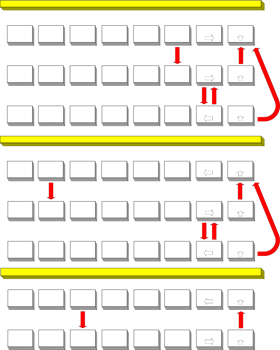
MMI Operation and Machine Startup American GFM Corp.
74
F8F7
Soft Key Level 1 - F2 - F6
F1
?
F2
Make
Scanning
F3
Select
Fixture
F4 F5 F6
Fixture
Registration
F8F7
Soft Key Level 1 - F2 - F6 - F6
F1
?
F2
New
F3
Modify
F4
Delete
F5 F6
F7 F8
Soft Key Level 1 - F2 - F6 - F7
F1
?
F2 F3 F4 F5
View
Data
F6
F8F7
Soft Key Level 2 - F2
F1
?
F2
New
F3
Delete
F4
Use
TCP
F5
Activate
F6
Deactivate
F8F7
Soft Key Level 2
F1
?
F2
Offsets
F3
Label
Text
F4
Additional
Functions
F5 F6
System
Support
F8F7
Soft Key Level 2 - F2 - F7
F1
?
F2
Use
Laser X
F3
Use
Laser Y
F4
Use
Laser X/Y
F5 F6
F8F7
Soft Key Level 2
F1
?
F2
Offsets
F3
Label
Text
F4
Additional
Functions
F5 F6
System
Support
F8F7
Soft Key Level 2 - F3
F1
?
F2
Undo
Changes
F3 F4
Edit
TemplateFile
F5
Change
Description
F6
Activate
Texts
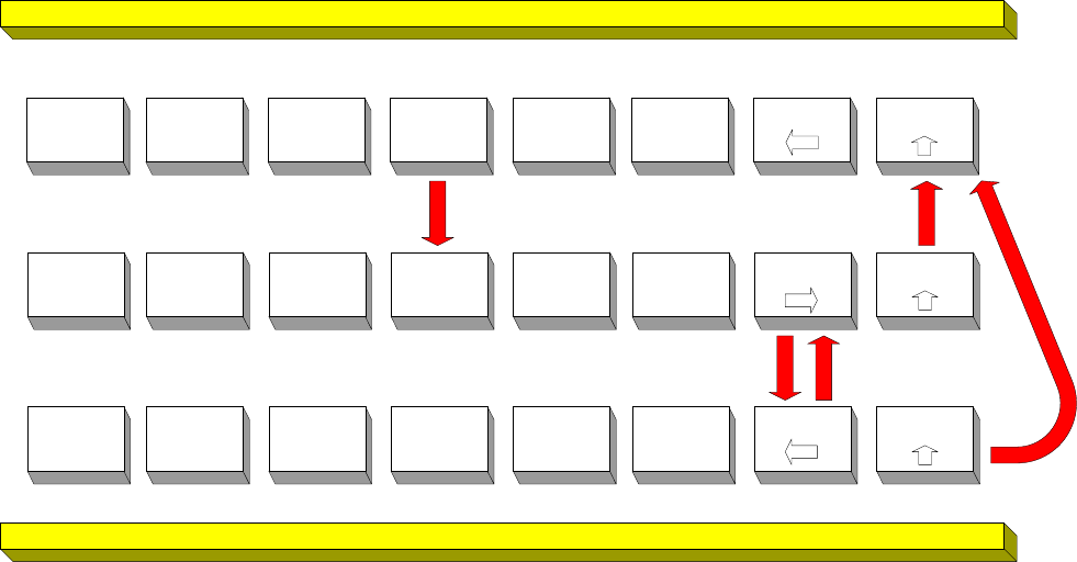
MMI Operation and Machine Startup American GFM Corp.
75
F8F7
Soft Key Level 2
F1
?
F2
Offsets
F3
Label
Text
F4
Additional
Functions
F5 F6
System
Support
F8F7
Soft Key Level 2 - F4
F1
?
F2 F3
Functions
1
F4
Functions
2
F5 F6
F8F7
Soft Key Level 2 - F4 - F7
F1
?
F2 F3 F4 F5
Configure
Function
F6
Configure
Text
MMI Operation and Machine Startup American GFM Corp.
76
7.22 System Support Menu Tree
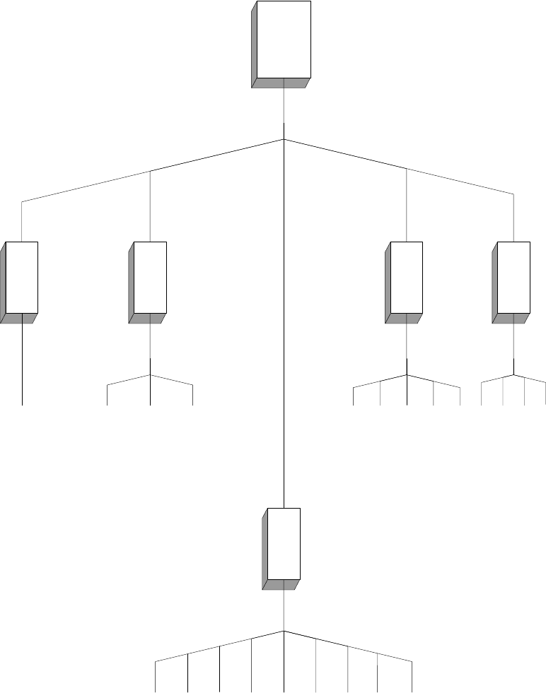
MMI Operation and Machine Startup American GFM Corp.
77
Syst em Support Menu *
* Available menu opt ions will depend on t he current user's priorit y level.
F6
System
Support
Group 1
Diagnoses
Service
Extended
User Defined
View Protocols
Mountpoints
Add Line to Protocol
Value Display
Additional Auto Data
Analog Monitor
Axis Monitor
View Mapping
Program Management
Select Utility
User PLI-Command Editor
Edit User Functions
Scan Mode
View Knife Alignment
Oscilloscope
PLI Debugger
PLI Com piler
Parameter Editor
Text Editor
View Versions
Edit Ini Files
Show Error Log File
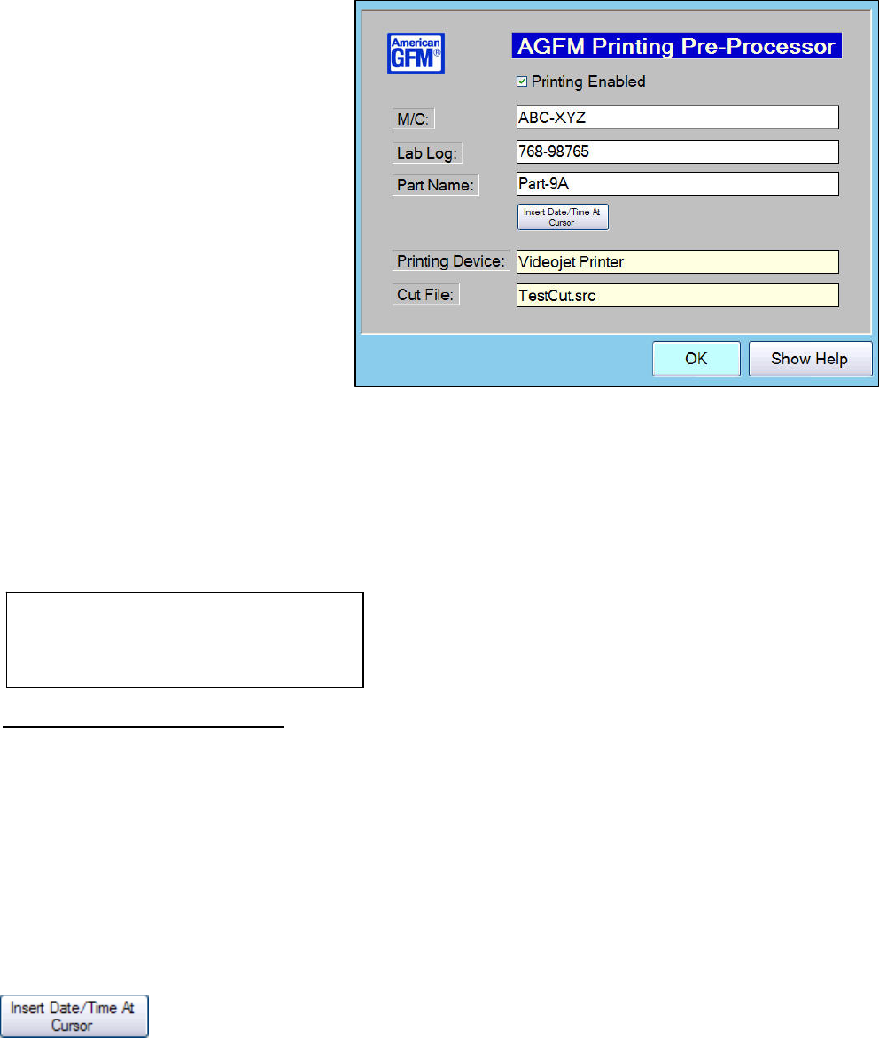
MMI Operation and Machine Startup American GFM Corp.
78
8 Machine Options
8.1 Printing Pre-Processor (PrePrint.EXE)
This application is used to provide
additional printed data at cut time. This
application is called at compile time via
ScriptCompile2.vbs. When launched,
the operator then can add 3 text strings via
text boxes. Pressing ENTER or TAB
moves from one field to the next. Upon
pressing ENTER the 4th time, or clicking
the OK button at any time, PrePrint.EXE
will then make the changes to the SRC
file's M18 (or M20) print commands to add
the user input data from the text boxes,
allowing the entered data to be printed on
the cut parts at run time. By default, the
tildee (~) character is used as a mask.
The M18 command in the incoming SRC
file MUST contain the 3 masks so that
PrePrint knows what to replace them with
from the 3 text boxes.
Text Box 1 (M/C) will be used to replace mask 1 (~~~1)
Text Box 2 (Lab Log) will be used to replace mask 2 (~~~~~~~~~2)
Text Box 3 (Part Name) will be used to replace mask 3 (~~~~~~~~3)
• The incoming SRC format is controlled by the AGFM Nesting System using the LAYOT.TXT file shown
below. For more information about LAYOT.TXT, consult the NS2 Nesting documentation.
Sample LAYOT.TXT in the NS2 Nesting software
Example of an Incoming SRC file.
M18(270.000000,2.000000,"MC: ~~~1 L/L: ~~~~~~~~~2","01/16/08-09:59am ~~~~~~~~3")
will be changed to:
M18(270.000000,2.000000,"MC: ABC-XYZ L/L: 768-98765","01/16/08-09:59am Part-9A")
• The application also supports Topex Labelers. The file USER.CNF is used to determine which device is
used. The enabled printing device is shown on the main form
Parameters used are:
• SAB.IJ_ENA = 1 Inkjet Enabled
SAB.LAB_ENA = 1 Topex Enabled
• Date & Time can be inserted in any text box by clicking the provided button.
pppppppppppppppppppppppppppp
"MC: ~~~1"h "L/L: ~~~~~~~~~2"h
##/##/##-##:##:##h "~~~~~~~~3"h
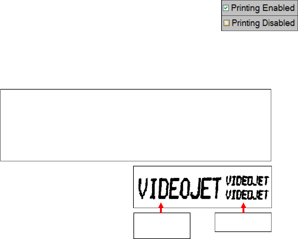
MMI Operation and Machine Startup American GFM Corp.
79
10x16
Print Matrix
(default)
5x7 Twin Line
Print Matrix
• By default, printing is always ENABLED. If printing should be skipped, un-
check the box. When the check is removed, Printing will be disabled.
• Font Control with the Inkjet allows higher quality printing. The default print matrix on AGFM machines
is a 10x16 print matrix. This is a somewhat of a large print font. Some machines require the printed text
to be smaller in size due to small parts. Therefore, the font control feature can be utilized to reduce the
text size. If enabled, via PrePrint.INI, the standard single line print command which uses the 10x16 print
matrix will be changed to a 5x7 Single Line print matrix. Likewise, the standard twin line print command,
which uses a 5x7 lower quality print matrix, will be changed to 5x7 Twin Line - High Quality as shown
below. The 5x7 print matrix will be approximately half the size of the 10x16 print matrix.
This example shows the difference between
the 10x16 print matrix (default), compared to
the 5x7 twin line print matrix. As shown in this
illustration, the larger 10x16 font (default) is
twice the size of the 5x7 font.
• The "Show Help" button will display this help file.
• PrePrint.INI Settings
Below is a sample PrePrint.INI file. The names of the text fields can be changed at any time, by changing
them in PrePrint.INI. This INI file is stored in the CNC\PrePrint folder
[settings]
src_caption = "Cut File:" "Text for source file label name."
label1 = M/C: "Text for label 1."
label2 = "Lab Log:" "Text for label 2."
label3 = "Part Name:" "Text for label 3."
use_font_control = 1 "Switch m18 m-codes to use font control for ink jet printing."
mask1 = ~~~1 "Mask for the first text string to be replaced for inkjet printing."
mask2 = ~~~~~~~~~2 "Mask for the second text string to be replaced for inkjet printing."
mask3 = ~~~~~~~~3 "Mask for the third text string to be replaced for inkjet printing."
helpfile = "C:\Program Files\GFM\cnc\preprint\AGFM Printing Pre-Processor.pdf" "Name of the help file."
Font: 5x7 Single Line
M18(270.000000,10,1,"buyoffa904.p6")
Font: 5x7 Twin Line - High Quality
M18(270.000000,10,5,"MC: ABC-XYZ L/L: 768-98765","%D2%-%T2% Part-9A")
To enable/disable the font control feature, see the following parameter in PrePrint.INI
use_font_control = 1 (or 0)
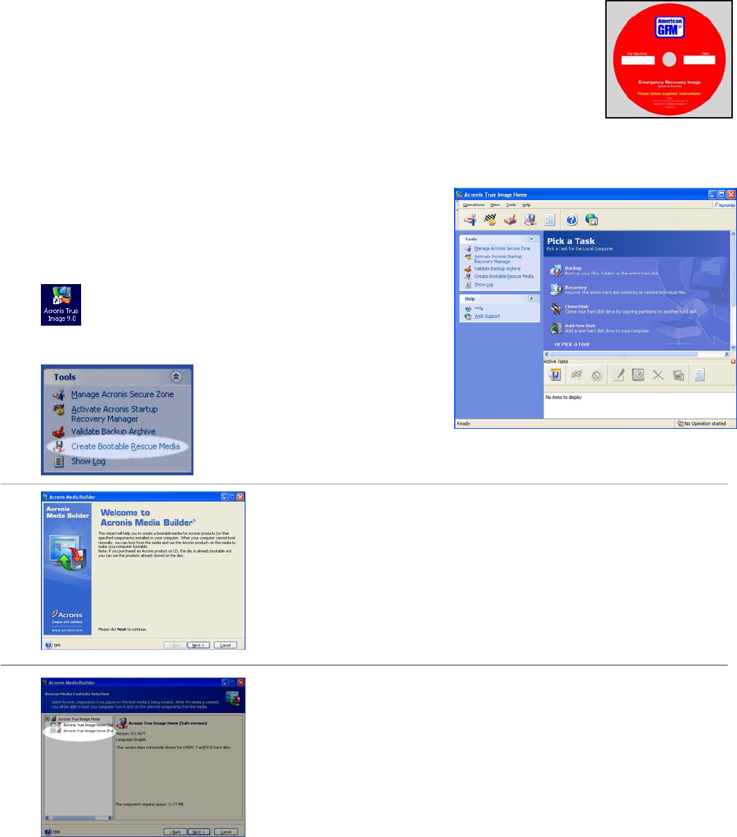
General Information American GFM Corp.
80
9 General Information
9.1 Backing Up the Machine Software
9.1.1 Backing up the entire hard drive with Acronis True Image
The machine is equipped with a powerful backup software package called ACRONIS
True Image. This software allows the ENTIRE C DRIVE to be backed up to DVD-RW
disks. This includes the operating system along with all other applications currently
installed on the hard drive. DVD-RW disks can be re-used over and over, making it
possible over write a previous backup if desired.
NOTE: It is the customer’s responsibility to make periodic back up’s. Failure to
do so will result a machine down time when least expected!!
Tips: These are some things that should be done prior to running Acronis True Image. These tips will help
reduce the amount of required DVD’s to perform the backup should more than one be required:
• Empty the Recycle Bin
• Delete unnecessary applications
• Run Scan Disk
• Run Disk Defragmenter
• Insure no viruses are on the system
• Disable Virus Scanners
To launch the drive image software, click on desktop
icon provided. The screen to the right will appear.
Next, the DVD-RW disk must be
erased and re-formatted as a
bootable disk. To do this click on the
link in the “Tools” section “Create Bootable Rescue Media”.
The below screen should appear.
Click NEXT to continue.
Check the box as shown here. Only choose the “Full Version”. Click
NEXT to continue.
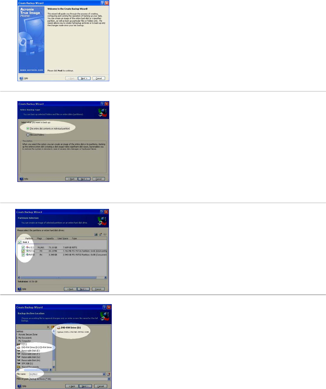
General Information American GFM Corp.
81
Click NEXT to continue.
Choose the entire hard disk as shown here. Click NEXT to continue.
Check all check boxes as shown here. Click NEXT to continue.
Choose the Backup Achieve location here. Give the backup a valid
name. Ensure the DVD-RW drive is chosen. In this example, D: drive is
the DVD-RW drive. In the “Filename” text box, make sure that the D:
drive letter is shown at the beginning of the filename. Click NEXT to
continue.

General Information American GFM Corp.
82
Choose “Create new full backup archive” as shown here. Click NEXT to
continue.
Choose “Default Options” as shown here. Click NEXT to continue.
You are now ready to proceed with the full backup. This screen is a
summary of all settings, and can be verified before proceeding. If any
changes are desired, click BACK. At this point, we recommend to use
these settings, and click PROCEED.
The backup process to the DVD-RW disk is now in process, and will
take several minutes to complete. When this process is complete, store
the DVD in a safe place in case it is needed to restore a defective hard
drive.
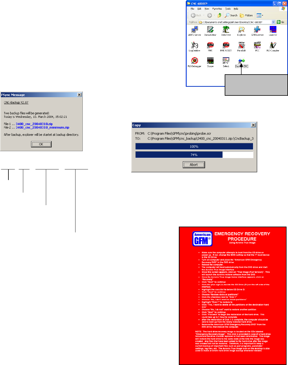
General Information American GFM Corp.
83
9.1.2 Backing up the CNC6000 software only
If a backup of only the CNC6000 software is required, without
backing up the entire hard drive, such as for AGFM service
technicians, a utility is provided to do so. Open the CNC-6000AP
folder on the desktop, and double click on the “Backup CNC” icon as
shown in the picture to the right. Two files will be created with this
method. These two files will be located in the CNC_BACKUP folder.
After the 2 zip files are created, they can be copied to a network
drive, burned to a CD, or copied to a USB flash drive for later
extraction.
The below dialog will appear, confirming that 2 files will be created.
Click OK to continue.
The file names are composed as follows:
3400_CNC_20040310_MINIMUM .ZIP
MaNo.
CNC
Date
(Year/Month/Day)
Minimum Files Only
9.2 Restoring the Drive Image DVD
In the event that the hard drive needs to be replaced or formatted,
the DVD-RW containing the hard drive image is used to restore
the new or formatted hard drive to the state at which it was when
the last image was created.
To restore the hard drive using the image DVD, insert the DVD CD
drive and re-boot the computer. The DVD is bootable, which
allows the drive restoration to begin automatically after the
computer is re-booted. Once the restoration screen appears, any
existing partitions that exist on the drive will be destroyed and re-
created before the image restoration begins.
A RED Emergency Recovery procedure was shipped with the
machine documentation. This red sheet should always stay with
the image DVD-RW disk.
Use this icon in the
CNC6000-EP folder to
start the backup
General Information American GFM Corp.
84
9.3 Other AGFM Manuals
Other AGFM Manuals that may be relevant to the machine are:
• Machine Safety
• Machine Description
• Machine Operator Manual (this document)
• Fixture Registration Manual
• CNC6000 Programmer’s Manual
• Compiler Parameter Manual
• M and G Code Description
• Electrical Service Manual
• 28 Channel Oscilloscope Manual
• Hardware Reference Manual
• System Parameter Manual
• Ultrasonic Generator Manual
• PLI & CNF File Program Print-out

General Information American GFM Corp.
85
10 G-Codes, M-Codes, and H-Codes for 2D Machines
G00 ... Rapid traverse
The axes will be set independent of each other with max. speed to the defined end point.
... see also G01.
e.g.: G0 X3900 Y1250
G01 ... Linear interpolation
The axes will be interpolated linear to the indicated end point with a programmed speed.
... see also G00.
e.g.: G1 X200 Y300 F20000
G04 ... Dwell time at end of move
A delay time (default 1s) will be executed at the end of the block .
G70 ... Programming in [inch]
... see also G71.
G71 ... Programming in [mm]
... see also G70.
G79 ... Programming based on machine origin
The programmed coordinates are related to the absolute machine origin, this means active offsets will be
ignored.
G90 ... Absolute value programming
... see also G91.
G91 ... Incremental value programming
... see also G90.

General Information American GFM Corp.
86
G98 ... Tool-Center-Mode active (TCP positions)
The programmed coordinates are related to the tool center point.
... see also G99.
G99 ... Tool-Center-Mode inactive (NOM positions)
The programmed coordinates are related to the axes.
... see also G98.
M00 ... Unconditional stop
The function M00 causes an interruption of the program at the block in which it is located.
Press <START> to continue the cutting program.
M01 ... Optional stop
The cutting program stops only at the programmed code M01
(=optional stop), if the mode of the program flow is preselected with
"stop on M01" in the menu 'production'. Press <START> to continue
the cutting program.
M05() ... Drilling command
p1 Feed Rate Drilling speed in [mm/min] or [inch/min]
The function starts the drilling cycle defined before with function M24.
e. g.: M24 ( 20.0 , 10.0 , -0.5 , "1")
G0 X100 Y200
M5 ( 100.0 )
G0 X100 Y210
M5 ( 100.0 )
M06 ... Send product detect signal to inkjet
Will be generated automatically by M18 and releases the inkjet to print.

General Information American GFM Corp.
87
M07() ... Place a label
[p1] Angle Angle of the label in [deg]
Places the label. If the label unit has a rotation axis, the specifed angle will be used.
See also M13 to activate the labeler and M20 for printing the labels.
e.g.: M13
M20 ( 1 , 1 , "TESTPRINT" )
G0 X3000 Y500
M07 ( 45.0 )
M20 ( 1 , 12 , "American" , "GFM" , 4400 )
G0 X3200 Y600
M07 ( 90.0 )
M08() ... Ultrasonic unit ON
p1 Amplitude Ultrasonic-amplitude in [%]
Switch on the ultrasonic unit for the cutting knife.
... see also M09.
e.g.: M08 ( 30 )
M09 ... Ultrasonic unit OFF
Switch off the ultrasonic unit for the cutting knife.
... see also M08.
M10 ... Cutting-Head enabled
In cutting mode the automatic lift of the Z-axis between cutting and position processes will be executed
on the value defined in the parameter V$UP
In the same way the Z-axis will be lowered automatically between position and cutting processes on the
value defined in the parameter V$DOWN
At all corners including a greater edge than indicated in the parameter V$TURN the tool will be lifted out
of the material with a defined value
... see also machining modes.

General Information American GFM Corp.
88
M11 ... Inkjet enabled for text print
This function activates the inkjet. The text can be printed with M18.
... see also machining modes.
e.g.: M11
G0 X500 Y300
M18 ( +30.0 , 0, "TESTPRINT" )
G0 X600 Y300
M18 ( -45.0 , 2, "AMERICAN" , "GFM" )
M12() ... Enable pen-marker for drawing or textprint
p1 Height1 Marker height for G0-positioning to start of text in [mm] or [inch]
p2 Height2 Marker height for positioning within a text in [mm] or [inch]
p3 Height3 Marker height for writing in [mm] or [inch]
["t1"] Marker-No Number of the marker (default "1")
This function activates the marker. The positions of the marker will be defined with the parameter during
the process.
Then the text can be printed with M22.
Furthermore the cutting commands G1,G2,G3,... will not be cut, but they will be drawn with the marker.
... see also machining modes.
e.g.: M12 ( 20.0 , 2.5 , -0.1 , "1")
G0 X500 Y300
M22 ( 45.0 , 10.0 , "TESTPRINT" )
G0 X500 Y200
M22 ( 180.0 , 8.0 , "AMERICAN GFM" )
M13 ... Labeler enabled
This function activates the labeler. If the labeler is on a separate Y-slide, so it will be connected
automatically with M54.
The labels can be printed with M20 and placed with M7.
... see also machining modes.
e.g.: M13
M20 ( 1 , 1 , "TESTPRINT" )
G0 X3000 Y500
M07 ( 45.0 )
M20 ( 1 , 12 , "American" , "GFM" , 4400 )
G0 X3200 Y600
M07 ( 90.0 )

General Information American GFM Corp.
89
M14 ... Mapping system OFF
... see also M15.
M15 ... Mapping system ON
Tooltip cutting depth will be held constant with this function; used for possible table inaccuracies.
... see also M14.
M16 ... Manual blade align (set angle to zero)
The actual position of the rotation axis of the cutting knife can be defined as 0°-position with this function.
M18() ... Inkjet printing parameter
M18 has two different modes.
Standard print command which works on all inkjet printers
Print command with font control which works only on special printers
M18 - Standard print command
p1 Angle Print direction 0..360°
p2 Mode 0 ... single line text (ASCII)
1 ... single line bar code
2 ... double line text (ASCII)
10 .... Font control
"t1" Line-1 Text for the upper line or for a single line
"t2" Line-2 Text for the lower line
If the printing operation is activated with M11, the text will be printed with this function.
e.g.: M11
G0 X500 Y300
M18 ( +30.0 , 0 , "TESTPRINT" )
G0 X600 Y300
M18 ( -45.0 , 10 , 5 , "AMERICAN" , "GFM" )
M18 - Print command with font control
Font control is only possible on printers which supports the V-Link™ interface from Videojet®.
p1 Angle Print direction 0..360°
p2 Mode 10 ... Font control with p3
p3 Font 0 ... 5x5 single line matrix
1 ... 5x7 single line matrix
2 ... 7x9 single line matrix
3 ... 10x16 single line matrix
4 ... 5x7 twin line matrix
5 ... 5x7 twin line matrix (High Quality)

General Information American GFM Corp.
90
"t1" Line-1 Text for the upper line or for a single line
"t2" Line-2 Text for the lower line
If the printing operation is activated with M11, the text will be printed with this function.
e.g.: M11
G0 X500 Y300
M18 ( +30.0 , 10 , 2 , "TESTPRINT" )
G0 X600 Y300
M18 ( -45.0 , 10 , 5 , "AMERICAN" , "GFM" )
M19() ... Display message at operating panel
"t1" Text Text of message to display
This function activates the message window above the display field "Errors and Messages" in the
"Production" and "MDI" screens.
The message will remain until M19 is issued again.
e.g.: M19 ( "Remove waste" )
M0
M19 ; Message will be deleted

General Information American GFM Corp.
91
M20() ... Output data via template (Print label)
M20 has two different functions.
Print label
Initialize configuration data
M20 - Print label
p1 Command 1 ... Output
p2 Mask Mask number 0..15 for print format
["t1"] Text1 Text data for label print
["t2"] Text2 Text data for label print
[p3] Value1 Value for label print
[p4] Value2 Value for label print
[p5] Value3 Value for label print
[p6] Value4 Value for label print
[p7] Value5 Value for label print
Sends data for label print with template (mask definition) to RS-232-interface. It is possible to transmit up
to 5 parameters 'p3...p7' and up to 2 texts 't1...t2' to the template.
See also M13 to activate the labeler and M7 to place the labels.
e.g.: M13
M20 ( 1 , 1 , "TESTPRINT" )
G0 X3000 Y500
M07 ( 45.0 )
M20 ( 1 , 12 , "American" , "GFM" , 4400 )
G0 X3200 Y600
M07 ( 90.0 )
M20 - Initialize configuration data
p1 Command 0 ... Initializing
Reads the configuration data from the NET-disk and executes a syntax check.
This will be executed automatically during control startup !
e.g.: M20 ( 0 )
M21 ... Inkjet enabled for shaping
With this function the programmed shape can be drawn on the processing material with the inkjet.
... see also machining modes.

General Information American GFM Corp.
92
M22() ... Pen-marker textprint parameter
p1 Angle Printing direction 0..360°
p2 Size Text height in [mm] or [inch]
"t1" Text text to be print
If the marker operation is activated with M12, the text will be printed with this function.
e.g.: M12 ( 20.0 , 2.5 , -0.1 , "1")
G0 X500 Y300
M22 ( 45.0 , 10.0 , "TESTPRINT" )
G0 X500 Y200
M22 ( 180.0 , 8.0 , "AMERICAN GFM" )
M23 ... LPA-Offsets enabled (Laser Part Alignment)
This function activates the LPA (Laser-Part-Alignment) operation mode. LPA finds out the actual position
of a work piece in the X/Y coordinate system. On the work piece (material) are two defined markers.
Their position will be determined with help of the function M52. Then the coordinates of the part program
will be transformed (moved and rotated) to the position of the work piece.
... see also machining modes.
e.g.: M23
G0 X50 Y70
M52 ( 1 )
G0 X2000 Y56
M52 ( 2 )
M72
M24() ... Drill-Offsets enabled
p1 Height1 Height of the G0-positioning in [mm] or [inch]
p2 Height2 Start height of the drilling in [mm] or [inch]
p3 Height3 Stop height (depth) of the drilling in [mm] or [inch]
["t1"] Drill-No Number of the drill (default "1")
With this function the determination of the operation follows for the M05 drilling cycle.
... see also machining modes.
e.g.: M24 ( 20.0 , 10.0 , -0.5 , "1")
G0 X100 Y200
M5 ( 100.0 )
G0 X100 Y210
M5 ( 100.0 )

General Information American GFM Corp.
93
M25 ... Peeling head enabled
During X/Y positioning commands the peeling knife will be automatically lifted out of the material (Z axis
up).
During X/Y interpolation commands the peeling knife will be automatically lowered into the material (Z
axis down).
... see also machining modes.
M26 ... Camera offsets enabled
This function will activate the camera. X/Y positions inside the part program are related to the camera.
... see also machining modes.
M30 ... End of program
This function marks the end of the program and is always in a separate block.
M31 ... Move to basic position 1A (or 1B ...PLI)
... see also M32.
M32 ... Move to basic position 2
... see also M31.
M33() ... Cut off material
[p1] Position Optional X-cut position in [mm] or [inch]
Partial function of the material macros.
... see also M34 (grip), M36 (pull out) and M35 (release).
e.g.: M34
M36 ( 9500.0 , 1000.0 )
M35
M33 ( 100.0 )

General Information American GFM Corp.
94
M34() ... Grip material
[p1] Position Optional X-grip position in [mm] or [inch] if the material will be loaded with
synchronous X/U-movement.
Partial function of the material macros.
... see also M36 (pull out), M35 (release) and M33 (cut off).
e.g.: M34 ( 4000.0 )
M36 ( 1000.0 ) ; pull out 3m of material
M35
M33
M35 ... Release material
Partial function of the material macros.
... see also M34 (grip), M36 (pull out) and M33 (cut off).
e.g.: M34
M36 ( 9500.0 , 1000.0 )
M35
M33
M36() ... Pull out material
[p1] Position Absolute X-end position for material/foil-corner in [mm] or [inch]
[p2] Speed Pull out-speed in [mm/min] or [inch/min]
Partial function of the material/foil macros.
... see also M34 (grip), M35 (release) and M33 (cut off) of the material respectively M44 (grip), M45
(release) and M46 (cut off) of the foil.
e.g.: M34
M36 ( 9500.0 , 1000.0 )
M35
M33
M44
M36 ( 9530.0 , 2000.0 )
M45
M46
M37 ... Tool setting (and alignment) ... measure length
This function executes the measuring of the tool length and the alignment of the knife edge.
The tool measuring will be executed automatically after the reference cycle of the axes.

General Information American GFM Corp.
95
M38 ... Enable FRONT area for operator
This function is only used for machines with 2-area-operation. It enables the front area of the machine for
the operator.
The function has different meanings depending on the equipment used on the machine (light barrier,
sound protection enclosure, etc.).
The light barriers of the front area are inactive.
The sound protection enclosure moves to the raer area of the machine.
... see also M39.
M39 ... Enable REAR area for operator
... see also M38.
M40 ... Move to last program start point
This function enables to move to the last start point of a program written in an incremental programming
way (G91).
M41() ... Conveyor incremental move
p1 Distance Moving length of the conveyor in [mm] or [inch].
[p2] Grip-Pos Optional grip position in [mm] or [inch].
This function moves the conveyor with the indicated distance.
If the grip position is indicated, so the material will be clamped (with help of M62) during the movement
between conveyor and X-axis.
e.g.: M41 ( 8000.0 , 1200.0 )
M42 ... Knife change
Cutting head will be moved to a special position. In this position it is possible to lock the movement of the
tangential axis with a pin and to change the cutting knife. After changing the knife it is necessary to
unlock the pin.
M43 ... Tool probing
The function measures the actual tool length and compares it with the length measured by M37.
If a determined difference is exceeded (e.g. by break of knife or attrition) an error message will be
caused.
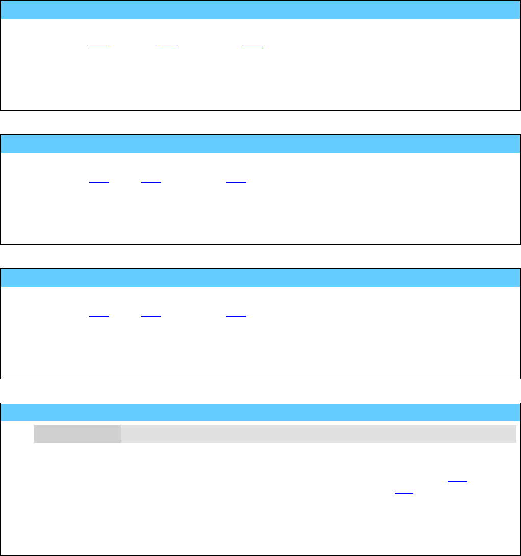
General Information American GFM Corp.
96
M44 ... Grip foil
Partial function of the foil macros.
... see also M36 (pull out), M45 (release) and M46 (cut off).
e.g.: M44
M36 ( 9530.0 , 2000.0 )
M45
M46
M45 ... Release foil
Partial function of the foil macros.
... see also M44 (grip), M36 (pull out) and M46 (cut off).
e.g.: M44
M36 ( 9530.0 , 2000.0 )
M45
M46
M46 ... Cut off foil
Partial function of the foil macros.
... see also M44 (grip), M36 (pull out) and M45 (release).
e.g.: M44
M36 ( 9530.0 , 2000.0 )
M45
M46
M48() ... Loop start
p1 Number 0...n Number of execution
The function enables to execute a part of a program several times.
The parameter p1defines the number of executions of a part of program between M48 and M49.
If 0 is indicated, the inquiry of the number will be caused per MMI-dialog by the H20 function.
e.g.: M48 ( 12 )
..........
.......
M49

General Information American GFM Corp.
97
M49 ... Loop end
... see also M48.
e.g.: M48 ( 12 )
...........
........
.....
M49
M50 ... Remote vacuum pump 1 ON (Serial mode)
... see also M51 and M70.
M51 ... Remote vacuum pump 2 ON (Parallel mode)
... see also M50 and M71.
M52() ... LPA-Laser ON (Laser Part Alignment)
p1 Point-No Number of the align point (1 or 2)
This function determines the X/Y coordinates of the align point (marker) in the LPA-operation mode (see
M23).
... see also M72.
e.g.: M23
G0 X50 Y70
M52 ( 1 )
G0 X2000 Y56
M52 ( 2 )
M72
M53 ... Tile mode ON
This function will be used during cutting of parallel straight lines. This function disables rotating of the
cutting knife during setting to the next parallel straight line. The next parallel straight line will be cut with
the other knife edge. Therefore minor inaccuracies caused by rotating the cutting knife can be avoided.
So the cut parts are absolute parallel.
... see also M73.
M54 ... Couple labeller
This function will be executed automatically by the CNC, if the labeling-mode will be activated by M13.
... see also M74.

General Information American GFM Corp.
98
M55 ... Vacuum cleaner ON
... see also M75.
M56 ... Release bar DOWN
Code which can be generated automatically by the material macros M34 (grip) and M35 (release).
... see also M76.
M57 ... Gripper jaws OPEN
Code which can be generated automatically by the material macros M34 (grip) and M35 (release).
... see also M77.
M58 ... Material UNCLAMPED
Code which can be generated automatically by the material macros M34 (grip) and M35 (release).
... see also M78.
M59 ... Lift table UP
Code which can be generated automatically by the material macros M34 (grip) and M35 (release).
... see also M79.
M61 ... Material holders (Pins) OUT
Code which can be generated automatically by the material macros M34 (grip) and M35 (release).
... see also M81.
M62 ... Needle gripper OUT (Presser bar DOWN)
Code which can be generated automatically by the material macros M34 (grip) and M35 (release)
respectively also by M41 or M165.
... see also M82.
M63 ... Pneumatic knife DOWN
... see also M83.

General Information American GFM Corp.
99
M64() ... Set tool number to <tool_no>
p1 Tool-No 0 ... no tool is in spindle
1 ... tool no. 1 is in spindle
n ... tool no. n is in spindle
If tool data does not exist (e.g. initial start-up, error of the control), the selected tool can be determined
manually with this function.
The number and the data of the selected tool is stored even after switching off the machine.
e.g.: M64 ( 1 )
M66() ... Ultrasonic unit ON (for peeling knife)
p1 Amplitude Ultrasonic-amplitude in [%]
Switch on the ultrasonic unit for the peeling knife.
... see also M86.
e.g.: M66 ( 35 )
M69 ... Gripper arm to GRIP position
Code which can be generated automatically by the material macros M34 (grip) and M35 (release).
... see also M89.
M70 ... Remote vacuum pump 1 OFF
... see also M50.
M71 ... Remote vacuum pump 2 OFF
... see also M51.
M72 ... LPA-Laser OFF
... see also M52.
M73 ... Tile mode OFF (default at program start)
... see also M53.
General Information American GFM Corp.
100
M74 ... Decouple labeller
This function will be executed automatically by the CNC, if the labeler-mode will be left with M10, M11, ...
.
... see also M54.
M75 ... Vacuum cleaner OFF
... see also M55.
M76 ... Release bar UP
Code which can be generated automatically by the material macros M34 (grip) and M35 (release).
... see also M56.
M77 ... Gripper jaws CLOSED
Code which can be generated automatically by the material macros M34 (grip) and M35 (release).
... see also M57.
M78 ... Material CLAMPED
Code which can be generated automatically by the material macros M34 (grip) and M35 (release).
... see also M58.
M79 ... Lift table DOWN
Code which can be generated automatically by the material macros M34 (grip) and M35 (release).
... see also M59.
M81 ... Material holders (Pins) IN
Code which can be generated automatically by the material macros M34 (grip) and M35 (release).
... see also M61.
M82 ... Needle gripper IN (Presser bar UP)
Code which can be generated automatically by the material macros M34 (grip) and M35 (release)
respectively also by M41 or M165 .
... see also M62.

General Information American GFM Corp.
101
M83 ... Pneumatic knife UP
... see also M63.
M86 ... Ultrasonic unit OFF (for peeling knife)
Switch off the ultrasonic unit for the peeling knife.
... see also M66.
M89 ... Gripper arm to BASIC position
Code which can be generated automatically by the material macros M34 (grip) and M35 (release).
... see also M69.
M91() ... START of conditional jump
p1 Condition No 0...n
The function enables a jump over a part of the program.
The condition number will be sent to PLI, which then reports back the result on the variable $O_MRETV .
$O_MRETV = 1 → Part of program between M91 and the next M92 will be ignored.
$O_MRETV = 0 → Part of program between M91 and the next M92 will be executed.
e.g.: M91 ( 17 )
...........
........
.....
M92
M92 ... END of conditional jump
... see also M91.
e.g.: M91 ( 1 )
...........
........
.....
M92
M100 ... Switch ON vacuum at section 1
... see also M120.
Instead of this code, M140 can be used also to switch on a vacuum section.

General Information American GFM Corp.
102
M101 ... Switch ON vacuum at section 2
... see also M121.
Instead of this code, M140 can be used also to switch on a vacuum section.
M102..108... Switch ON vacuum at section 3..9
... see also M122..M128.
Instead of these codes, M140 can be used also to switch on a vacuum section.
M109 ... Lift table vacuum ON (section 10)
Code which can be generated automatically by the material macros M34 (grip), M35 (release) and M33
(cut off).
... see also M129.
M110 ... Foil table vacuum ON (section 11)
Service-Code which will be generated automatically by the foil macros M44 (grip), M45 (release) and
M46 (cut off).
... see also M130.
M111() ... Additional material clamp number <n> ON
p1 Clamp number 1..n
This function enables extending additional material grippers by pulling out of several layers of material on
the cutting table. Thereby the material will be fixed by pulling out of further layers on the cutting table und
cannot be moved (especially with adhesive materials).
... see also M131.
e.g.: M111 ( 1 )
M120 ... Switch OFF vacuum at section 1
... see also M100.
Instead of this code, M141 can be used also to switch off a vacuum section.
M121 ... Switch OFF vacuum at section 2
... see also M101.
Instead of this code, M141 can be used also to switch off a vacuum section.

General Information American GFM Corp.
103
M122..128... Switch OFF vacuum at section 3..9
... see also M102..M108.
Instead of these codes, M141 can be used also to switch off a vacuum section.
M129 ... Lift table vacuum OFF (section 10)
Code which can be generated automatically by the material macros M34 (grip), M35 (release) and M33
(cut off).
... see also M109.
M130 ... Foil table vacuum OFF (section 11)
Service-code which will be generated automatically by the foil macros M44 (grip), M45 (release) and M46
(cut off).
... see also M110.
M131() ... Additional material clamp number <n> OFF
p1 Clamp no 1..n
... see also M111.
e.g.: M131 ( 1 )
M137 ... Tool change and alignment for peeling knife
Cutting head will be moved to a special position. In this position it is possible to lock the movement of the
tangential axis with a pin and to change the peeling knife. After changing it is necessary to unlock the pin.
&nbs;
After knife change the alignment of the cutting edge of the peeling knife will be performed.
M138 ... Camera to calibrate position
M140() ... Switch ON vacuum section
p1 SectionNum 1..n
M140 can be use instead of M100..M108 to switch on an vacuum section.
... see also M141.
e.g.: M140 ( 4 )

General Information American GFM Corp.
104
M141() ... Switch OFF vacuum section
p1 SectionNum 1..n
M141 can be use instead of M120..M128 to switch off an vacuum section.
... see also M140.
e.g.: M141 ( 4 )
M142() ... Dynamic vacuum zone configuration
This function activates the dynamic control of the vacuum zone on the cutting table of the machine. M142
possesses two different functions:
Configuration in rows
Configuration by zone number
M142 - Configuration in rows
p1 Row Row number 1..n along the X-axis
"t1" Column-Config Column configuration as text consisting of the characters ...
'-' ... The zone is always inactive.
'*' ... The zone will be switched on/off dynamically.
'1' ... The zone is always switched on.
With this function each vacuum row of the table can be configured.
The deletion of the configuration occurs with the function M30.
e.g.: M142 ( 1 , "----*----" )
M142 ( 2 , "--**1*---" )
M142 ( 3 , "-*1111**-" )
M142 ( 4 , "-*111111*" )
M142 ( 5 , "-*1111**-" )
M142 ( 6 , "--*111*--" )
M142 ( 7 , "--*1111*-" )
M142 ( 8 , "-*11111*-" )
M142 ( 9 , "--*1111*-" )
M142 ( 10 , "---****--" )
M142 ( 11 , "---------" )
M142 ( 12 , "---------" )
M142 - Configuration by zone number
"t1" Address single zone address "xxyy" or
zone field "xxyy-xxyy" with indication of two corner points.
With this function vacuum zones can be switched on single or as area.
Switch off (delete of the configuration) occurs with M30.
Each zone will be addressed by a 4-digit number. The first both digits in the range 01..99 defines the row
number along the X-axis and the second both digits 01..32 defines the column number along the Y-axis.

General Information American GFM Corp.
105
e.g.: M142 ( "0307" )
M142 ( "0602" )
M142 ( "1104" )
M142 ( "0203-0705" )
M142 ( "1106-1108" )
M143() ... Simple dynamic vacuum (full table area)
p1 Delta 0
...
Only that X/Y-zone will be activated, in which the operating tool is
located at the moment.
1
...
One rotating zone to the present X/Y-zone will be activated.
2
...
Two rotating zones to the present X/Y-zone will be activated.
This function activates the dynamic vacuum zone on the full table area.
... see also M142.
e.g.: M143 ( 1 )
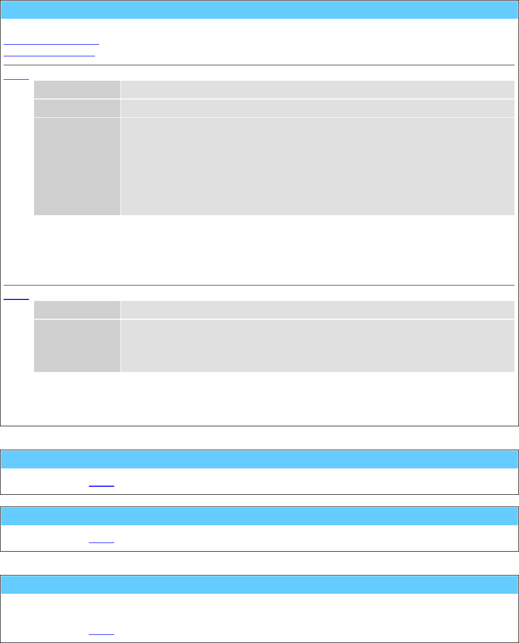
General Information American GFM Corp.
106
M152() ... Control for material dispenser
This function serves to control the material dispenser. There are two different styles for this function.
within a part program
for service purposes
M152 within a part program
p1 Length necessary material length in [mm] or [inch]
"t1" Mat-ID Material identification (name of the roll)
"t2" Additional-Info Up ... uncoil direction up
Down ... uncoil direction down
Grip1 ... grip position at height 1 (down)
Grip2 ... grip position at height 2 (middle)
Grip3 ... grip position auf height 3 (up)
Positions the material changer on the requested material. The additional information will be separated by
commas within the text parameter.
e.g.: M152 ( 7500.0 , "CarbonFiber17" , "Up,Grip2" )
M152 for service purposes
p1 Roll No Number 1..n of the material roll
p2 Sub-Pos 0 ... Changing position
1 ... grip position at height 1 (corresponds "Grip1")
2 ... grip position at height 2 (corresponds "Grip2")
3 ... grip position at height 3 (corresponds "Grip3")
This variant will only be used for service purposes or for initiation of a machine.
e.g.: M152 ( 8 , 2 )
M154 ... Enable 2nd cutting head
... see also M155.
M155 ... Disable 2nd cutting head
... see also M154.
M160 ... End of loading program section
This function marks the end of a loading program section.
It will only be used for separated loading and cutting machines.
... see also M161.

General Information American GFM Corp.
107
M161 ... End of cutting program section
This function marks the end of the cutting program section.
It will only be used for separated loading and cutting machines.
... see also M160.
M164() ... Posit conveyor (+) or (-) to a switch
["t1"] Direction "+" ... movement occurs in direction X+ (standard)
"-" ... movement occurs in direction X-
This function activates the movement of the conveyor till a "switch" (light barrier), buffer,...) will be
reached
e.g.: M164 ( "+" )
M165() ... Material unloading sequence
p1 Mode 0 ... without recognition of zones
1 ... with recognition of zones
p2 Distance Relative distance in [mm] or [inch]
This function activates a special loading and unloading process. Zones can exist for some materials, in
which it is not allowed to cut. These zones will be recognized by the sensor while loading the material.
Then the control determines the coordinates of the forbidden zone and checks, if the program reaches
into this zone. If the coordinates are positioned out of the zone, the program will be executed, if they are
positioned within the forbidden zone, a new loading and unloading process will be started.
e.g.: M165 ( 1 , 4000.0 )
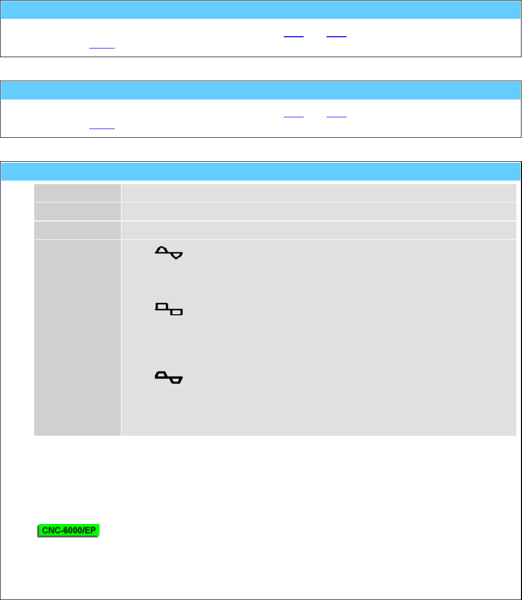
General Information American GFM Corp.
108
M810 ... CLOSE toolsetting equipment cover
Service code which will be generated automatically by M37 and M43.
... see also M811.
M811 ... OPEN toolsetting equipment cover
Service code which will be generated automatically by M37 and M43.
... see also M810.
M828() ... Oscillate axis for PID-Adjustment
"t1" Axis Name of the axis
p1 Min-Pos Minimum position in [mm] or [inch]
p2 Max-Pos Maximum position in [mm] or [inch]
[p3] Profile 0 ... sinusoidal G0
acceleration
Parameter ITP.AX[n].SIN =
1
For acceleration parameter SAB.AX[n].AG0 will
be used.
rectangular G0
acceleration
Parameter ITP.AX[n].SIN =
0
1 ... trapezoidal G1
acceleration
For acceleration parameter SAB.AX[n].A will be
used.
SAB.TL.TAPE_t_Ruck defines the raise time for
TAPE axis,
for all other axes SAB.MDI_ADT will be used.
Oscillating function of the axis to adjust the control parameter manually.
The axis executes G0 or G1 movements between the indicated max/min positions until a <STOP> is
pressed.
e.g.: M828 ( "X" , 100.0 , 800.0 , 1 )
The oscillating function can also be used for APM axes.
In this case the third parameter p3 will be ignored and for the profil the default parameters of the APM
axis will be used.
e.g.: M828 ( "U1" , -1000.0 , 2000.0 )
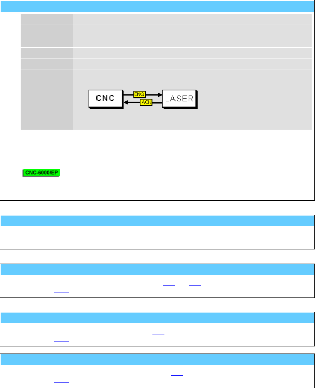
General Information American GFM Corp.
109
M830() ... Autom. calibration of axis with laser system
"t1" Axis Name of axis
p1 Start Pos Start position in [mm] or [inch]
p2 End-Pos End position in [mm] or [inch]
p3 Step Step size in [mm] or [inch]
p4 Delay Dwell time in [s]
p5 Mode 0 ... Only dwell time
1 ... RS-232 handshake over console plug of the CNC-CPU
2 ... M830 handshake to PLI
3 ... <START> key
Function to determine the correction data of the pitch error compensation.
e.g.: M830 ( "X" , 0.0 , 5000.0 , 25.0 , 0.8 , 1 )
The function can also be used for APM axes.
e.g.: M830 ( "U1" , 0.0 , 10000.0 , 100.0 , 1.0 , 0 )
M832 ... Toolsetting equipment to BASIC position
Service code which will be generated automatically by M37 and M43.
... see also M833.
M833 ... Toolsetting equipment to MEASURING position
Service code which will be generated automatically M37 and M43.
... see also M832.
M834 ... Label transfer (printer --> placing unit)
Service code which generated automatically by M20.
... see also M835.
M835 ... Label transfer unit to basic position
Service code which will be generated automatically by M20.
... see also M834.
General Information American GFM Corp.
110
M836 ... Foil table UP
Service code which will be generated automatically by the foil macros M44 (grip) and M45 (release).
... see also M837.
M837 ... Foil table DOWN
Service code which will be generated automatically by the foil macros M44 (grip) and M45 (release).
... see also M836.
M838 ... Foil table OUT
Service code which will be generated automatically by the foil macros M44 (grip) and M45 (release).
... see also M839.
M839 ... Foil table IN
Service code which will be generated automatically by foil macros M44 (grip) and M45 (release).
... see also M838.
M840() ... Material gripper to Z position <posit>
p1 Pos-Index 1..n
Material gripper will be positioned to configured Z-heights.
The positions are stored in the driving module.
e.g.: M840 ( 1 )
M842 ... Couple cabin
Service code which will be generated automatically by M38 and M39.
... see also M843.
M843 ... Decouple cabin
Service code which will be generated automatically by M38 and M39.
... see also M842.

General Information American GFM Corp.
111
M999() ... Display software info string
p1 Info-No 0 ... CNC version (default)
1 ... Compile date/time
2 ... Compiler version
3 ... Company
4 ... Programmer
10 ... Protocol and version of inkjet interface
Display of CNC version number and additional information related to the software.
e.g.: M999 ( 0 )
H10() ... Sync. ext. display device for window cutting
p1 Code 1 ... Start of the part program
2 ... Transfer of a window cutting (M36 with conveyor)
9 ... End of the part program
Synchronization of an external display device.
The codes can be generated automatically by setting of the CNC-parameter SAB.FL_17.
e.g.: H10 ( 9 )
H20 ... Request data string from MMI
Will be generated automatically by M48(0) and serves for the internal CNC/MMI communication.
H40() ... Increment production counter at MMI
p1 Increment Amount of increments.
This function will increment the production counter at the MMI by the specified amount.
e.g.: H40 ( 3 )

General Information American GFM Corp.
112
11 G-Codes, M-Codes, T-Codes, and H-Codes for 3D Machines
G00 ... Rapid traverse
The axes will be set independent of each other with max. speed to the defined end point.
... see also G01.
e.g.: G0 X3900 Y1250 Z100 C90 A-90 B237
G01 ... Linear interpolation
The axes will be interpolated linear to the indicated end point with a programmed speed.
... see also G00.
e.g.: G1 X200 Y300 Z70 F20000
G04 ... Dwell time at end of move
A delay time (default 1s) will be executed at the end of the block .
G70 ... Programming in [inch]
... see also G71.
G71 ... Programming in [mm]
... see also G70.
G79 ... Programming based on machine origin
The programmed coordinates are related to the absolute machine origin, this means active offsets will be
ignored.
G90 ... Absolute value programming
... see also G91.

General Information American GFM Corp.
113
G91 ... Incremental value programming
... see also G90.
G98 ... Tool-Center-Mode active (TCP positions)
The programmed coordinates are related to the tool center point.
... see also G99.
G99 ... Tool-Center-Mode inactive (NOM positions)
The programmed coordinates are related to the axes.
... see also G98.
T() ... Tool-Change command
p1 Tool No 0 ... no tool is clamped
1 ... tool no 1 is clamped
n ... tool no n is clamped
Function to change the tool.
e.g.: T ( 12 )
M00 ... Unconditional stop
The function M00 causes an interruption of the program at the block in which it is located.
Press <START> to continue the cutting program.
M01 ... Optional stop
The cutting program stops only at the programmed code M01
(=optional stop), if the mode of the program flow is preselected with
"stop on M01" in the menu 'production'. Press <START> to continue
the cutting program.

General Information American GFM Corp.
114
M03() ... Spindle unit ON cw
p1 speed Number of rotational speed of a spindle [rpm]
[p2] spindle no Number of spindle (default 1)
Start of the spindle clockwise. If the PLI signal $O_SPCOLD is set, the spindle will be warmed up with a
reduced spindle speed.
... see also M04 and M05.
e.g.: M03 ( 20000 , 1 )
M04() ... Spindle unit ON ccw
p1 speed number of rotational speed of a spindle [rpm]
[p2] spindle no number of spindle (default 1)
Start of the spindle counterclockwise (ccw). If the PLI signal $O_SPCOLD is set, the spindle will be
warmed up with a reduced spindle speed.
... see also M03 and M05.
e.g.: M04 ( 20000 , 1 )
M05() ... Spindle unit and coolant OFF
[p1] spindle no Number of spindle (default 1)
Stop of the spindle.
... see also M03 and M04.
e.g.: M05 ( 1 )
M07 ... Mist coolant ON
... see also M08 / M09.
M08 ... Fluid coolant ON
... see also M07 / M09.

General Information American GFM Corp.
115
M09 ... Coolant OFF
... see also M07 / M08.
M10 ... Ultrasonic unit OFF
Switch off the US-unit.
... see also M11.
M11() ... Ultrasonic unit ON
p1 Amplitude Ultrasonic-amplitude in [%]
Switch on the US-unit
... see also M10.
e.g.: M11 ( 30 )
M12 ... Air-driven spindle OFF
... see also M13.
M13 ... Air-driven spindle ON
Switch ON the pneumatic air-driven spindle clamped instead of the ultrasonic tool.
... see also M12.
M14 ... Mapping System OFF
... see also M15.
M15 ... Mapping System ON
Tooltip cutting depth will be held constant with this function; used for possible table inaccuracies.
... see also M14.

General Information American GFM Corp.
116
M16 ... Manual blade align (set angle to zero)
The actual position of the rotation axis of the cutting knife can be defined as 0°-position with this function.
M17() ... Display message at operating panel
"t1" Text Text of message to display
This function activates the message window above the display field "Errors and Messages" in the
"Production" and "MDI" screens.
The message will remain until M17 is issued again.
e.g.: M17 ( "Remove waste" )
M0
M17 ; Message will be deleted
M18 ... Cancel orientation mode for spindle stop
... see also M19.
M19 ... Activate orientation mode for spindle stop
... see also M18.
M20 ... Height following system OFF
Prepares the height following system to be turned off.
The next Z position command will switch off the height following system.
... see also M21 and M22.
M21 ... Height following system ON without F.L.U.
Prepares the height following system to be turned on.
The next Z position command will switch on the height following system without Flute Length Utilization.
... see also M20 and M22.
M22 ... Height following system ON with F.L.U. /\/\/\/\
Prepares the height following system to be turned on.
The next Z position command will switch on the height following system with Flute Length Utilization.
... see also M20 and M21.

General Information American GFM Corp.
117
M23 ... Height following shoe DOWN
... see also M24.
M24 ... Height following shoe UP
... see also M23.
M25() ... Presser foot DOWN with low pressure
[p1] HighPressZ 0 ... Always low pressure (default)
1 ... High pressure for Z down movement
Lowers the presser foot with low pressure for routing.
If optional parameter p1 is set to one, high pressure will be used for Z down movements.
This can be used to hold the material with higher force during drilling holes.
... see also M26 / M27.
e.g.: M25 ( 1 )
M26 ... Presser foot DOWN with high pressure
Lowers the presser foot with high pressure for the detagging mode.
... see also M25 / M27.
M27 ... Presser foot UP
Lifts up the presser foot for positioning the X/Y-axes.
... see also M25 / M26.
M28 ... DISABLE tool lifting with an active feedhold (default)
... see also M29.
M29 ... ENABLE tool lifting with an active feedhold
... see also M28.

General Information American GFM Corp.
118
M30 ... End of program
This function marks the end of the program and is always in a separate block.
M31 ... Crossbeam (all axis) to basic position 1
... see also M32.
M32 ... Crossbeam (all axis) to basic position 2
... see also M31.
M34() ... CUTTER-Mode
p1 height1 Z-height of the tool center point for G0-positioning in [mm] or [inch]
p2 height2 Z-height of the tool center point for change of direction (positioning of the rotation axis
at corners) in [mm] or [inch]
p3 height3 Z-height of the tool center point for interpolations in [mm] or [inch]
[p4] speed Plunge speed (height2 → height3) of the tool in [mm/min] or [inch/min]
This function activates the cutting mode.
Z axis lifts up automatically between cutting and positioning with the heights defined in the parameters.
... see also machining modes.
e.g.: M34 ( 50.0 , 10.0 , -0.1 , 500.0 )
M35 ... ROUTER-Mode
This function activates the routing mode.
No automatic control of the Z-axis occurs in the routing operation in contrast to the cutting operation.
... see also machining modes.

General Information American GFM Corp.
119
M36 ... LPA-Offsets enabled (Laser Part Alignment)
This function activates the LPA (Laser-Part-Alignment) operation mode. LPA finds out the actual position
of a work piece in the X/Y coordinate system. On the work piece (material) are two defined markers.
Their position will be determined with help of the function M44. Then the coordinates of the part program
will be transformed (moved and rotated) to the position of the work piece.
... see also machining modes.
e.g.: M36
G0 X50 Y70
M44 ( 1 )
G0 X2000 Y56
M44 ( 2 )
M45
M37 ... LABEL-Mode
This function activates the labeler.
The labels can be printed with M80 and placed with M81.
... see also machining modes.
e.g.: M37
M80 ( 1 , 1 , "TESTPRINT" )
G0 X3000 Y500
M81 ( 45.0 )
M80 ( 1 , 12 , "American" , "GFM" , 4400 )
G0 X3200 Y600
M81 ( 90.0 )
M38 ... Enable FRONT area for operator
This function is only used for machines with 2-area-operation. It enables the front area of the machine for
the operator.
The function has different meanings depending on the equipment used on the machine (light barrier,
sound protection enclosure, etc.).
The light barriers of the front area are inactive.
The sound protection enclosure moves to the raer area of the machine.
... see also M39.
M39 ... Enable REAR area for operator
... see also M38.

General Information American GFM Corp.
120
M40 ... Vacuum pump OFF
... see also M41.
M41 ... Vacuum pump ON
... see also M40.
M42() ... Conveyor incremental move
p1 Distance Moving length of the conveyor in [mm] or [inch].
This function moves the conveyor with the indicated distance.
e.g.: M42 ( 8000.0 )
M43 ... Material loading (conveyor and edge detect)
Activates the loading sequence of the material stack.
The material will pulled forward with the conveyor into the operation area of the machine. The front of the
material stack will be detected and pulled forward to the position of the fixed clamping bar. The material
can then be clamped with the function M53.
Note: For machines without a conveyor, the loading/unloading of the material can be executed with the
codes M55/M56.
M44() ... LPA-Laser ON (Laser Part Alignment)
p1 Point-No Number of the align point (1 or 2)
This function determines the X/Y coordinates of the align point (marker) in the LPA-operation mode (see
M36).
... see also M45.
e.g.: M36
G0 X50 Y70
M44 ( 1 )
G0 X2000 Y56
M44 ( 2 )
M45
M45 ... LPA-Laser OFF
... see also M44.
General Information American GFM Corp.
121
M46 ... Measure stack thickness
Measures the thickness of the material stack at the actual X/Y position.
M50 ... Extraction motor OFF
... see also M51.
M51 ... Extraction motor ON
... see also M50.
M53 ... Material clamping sequence at current position
Activates the clamping of the material stack.
The function will be called automatically within M55.
The material will be clamped at the current X-position with a movable clamping bar. Then the movable
clamping bar will be unclamped from the X-slide and the temporary operation limits of the machine will
be set accordingly.
... see also M54.
M54 ... Material unclamping sequence
Releases the clamping of the material stack.
The function will be called automatically within M56.
The unclamped movable clamping bar will be clamped on the X-slide and the temporary operation limit of
the machine will be canceled.
... see also M53.
M55 ... Material loading
Activates the loading sequence of the material stack.
The material will be forwarded into the operation area of the machine and then clamped with the function
M53.
... see also M56.
M56 ... Material unloading (with movable clamps)
Activates the unloading sequence of the material stack.
Clamping of the material will be released with the function M54. Then the material stack will be forwarded
out of the operation area of the machine.
... see also M55.

General Information American GFM Corp.
122
M57() ... Additional material clamp OFF
p1 Clamp number 1..n
... see also M58.
e.g.: M57 ( 1 )
M58() ... Additional material clamp ON
p1 Clamp number 1..n
This function enables extending additional material grippers for material handling.
... see also M57.
e.g.: M58 ( 1 )
M61 ... Knife Change
Cutting head will be moved to a special position. In this position it is possible to lock the movement of the
tangential axis with a pin and to change the cutting knife. After changing the knife it is necessary to
unlock the pin.
M62 ... Tool setting (and alignment)
This function executes the measuring of the tool length and the alignment of the knife edge.
The tool measuring will be executed automatically after the reference cycle of the axes and a tool
change.
M63 ... Tool probing (Length)
The function measures the actual tool length and compares it with the length measured by M62.
If a determined difference is exceeded (e.g. by break of knife or attrition) an error message will be
caused.

General Information American GFM Corp.
123
M64() ... Set tool number to <tool_no>
p1 Tool-No 0 ... no tool is in spindle
1 ... tool no. 1 is in spindle
n ... tool no. n is in spindle
If tool data does not exist (e.g. initial start-up, error of the control), the selected tool can be determined
manually with this function.
The number and the data of the selected tool is stored even after switching off the machine.
e.g.: M64 ( 1 )
M65() ... Tool length correction for part programs
p1 Corr Correction value of the tool length in [mm] or [inch]
The actual length of the used tool will be changed according to the specified value.
A negative correction will cut deeper.
A positive correction will cut less material.
e.g.: M65 ( -1.5 )
M71 ... Detag gantry ROUTING mode
... see also M72.
M72 ... Detag gantry DETAGGING mode
... see also M71.
M73 ... Position mode (for disc knife)
Deactivates the rotation mode of the disc knife.
... see also M74.
General Information American GFM Corp.
124
M74() ... Rotary knife mode (for disc knife)
p1 speed nominal speed value for the rotating axis in [rpm]
+n ... rotation counterclockwise.
-n ... rotation clockwise.
Activates the rotation mode for the disc knife.
... see also M73.
e.g.: M74 ( +1300.0 )
M80() ... Output data via template (Print label)
M80 has two different functions.
Print label
Initialize configuration data
M80 - Print label
p1 Command 1 ... Output
p2 Mask Mask number 0..15 for print format
["t1"] Text1 Text data for label print
["t2"] Text2 Text data for label print
[p3] Value1 Value for label print
[p4] Value2 Value for label print
[p5] Value3 Value for label print
[p6] Value4 Value for label print
[p7] Value5 Value for label print
Sends data for label print with template (mask definition) to RS-232-interface. It is possible to transmit up
to 5 parameters 'p3...p7' and up to 2 texts 't1...t2' to the template.
See also M37 to activate the labeler and M81 to place the labels.
e.g.: M37
M80 ( 1 , 1 , "TESTPRINT" )
G0 X3000 Y500
M81 ( 45.0 )
M80 ( 1 , 12 , "American" , "GFM" , 4400 )
G0 X3200 Y600
M81 ( 90.0 )
M80 - Initialize configuration data
p1 Command 0 ... Initializing
Reads the configuration data from the NET-disk and executes a syntax check.
This will be executed automatically during control startup !
e.g.: M80 ( 0 )

General Information American GFM Corp.
125
M81() ... Place a label
[p1] Angle Angle of the label in [deg]
Places the label. If the label unit has a rotation axis, the specified angle will be used.
See also M37 to activate the labeler and M80 for printing the labels.
e.g.: M37
M80 ( 1 , 1 , "TESTPRINT" )
G0 X3000 Y500
M81 ( 45.0 )
M80 ( 1 , 12 , "GFM-Steyr" , "Austria" , 4400 )
G0 X3200 Y600
M81 ( 90.0 )
M87() ... Drill cycle macro
p1 Down Relative down movement from start-position with programmed feedrate in [mm] or
[inch]
p2 Up Relative up movement with maximum feedrate in [mm] or [inch]
"t1" FeedType "F" ... Feedrate in [mm/min] or [inch/min]
"R" ... Feedrate in [mm/rev] or [inch/rev]
p3 Feedrate Feedrate for down movement
This function performs a drill cycle.
e.g.: M87 ( 10.0 , 10.0 , "F" , 120.0 )
M90() ... Vacuum Intensity
p1 Intensity 0...100%
Function to adjust the vacuum intensity.
Only for systems with controllable vacuum.
e.g.: M90 ( 75 )

General Information American GFM Corp.
126
M91() ... START of conditional jump
p1 Condition No 0...n
The function enables a jump over a part of the program.
The condition number will be sent to PLI, which then reports back the result on the variable $O_MRETV .
$O_MRETV = 1 → Part of program between M91 and the next M92 will be ignored.
$O_MRETV = 0 → Part of program between M91 and the next M92 will be executed.
e.g.: M91 ( 17 )
...........
........
.....
M92
M92 ... END of conditional jump
... see also M91.
e.g.: M91 ( 1 )
...........
........
.....
M92
M100 ... Vacuum section 1 OFF
... see also M101.
M101 ... Vacuum section 1 ON
... see also M100.
M200 ... Vacuum section 2 OFF
... see also M201.
M201 ... Vacuum section 2 ON
... see also M200.

General Information American GFM Corp.
127
M400 ... Inkjet enabled for text print
This function activates the inkjet. The text can be printed with M420.
... see also machining modes.
e.g.: M400
G0 X500 Y300
M420 ( +30.0 , 0, "TESTPRINT" )
G0 X600 Y300
M420 ( -45.0 , 2, "AMERICAN" , "GFM" )
M401 ... Inkjet enabled for shaping (draw mode)
With this function the programmed shape can be drawn on the processing material with the inkjet.
... see also machining modes.
M420() ... Inkjet printing parameter
M420 has two different modes.
Standard print command which works on all inkjet printers
Print command with font control which works only on special printers
M420 - Standard print command
p1 Angle Print direction 0..360°
p2 Mode 0 ... single line text (ASCII)
1 ... single line bar code
2 ... double line text (ASCII)
10 .... Font control
"t1" Line-1 Text for the upper line or for a single line
"t2" Line-2 Text for the lower line
If the printing operation is activated with M400, the text will be printed with this function.
e.g.: M400
G0 X500 Y300
M420 ( +30.0 , 0 , "TESTPRINT" )
G0 X600 Y300
M420 ( -45.0 , 10 , 5 , "AMERICAN" , "GFM" )
M420 - Print command with font control
Font control is only possible on printers which supports the V-Link™ interface from Videojet®.
p1 Angle Print direction 0..360°
p2 Mode 10 ... Font control with p3
p3 Font 0 ... 5x5 single line matrix
1 ... 5x7 single line matrix
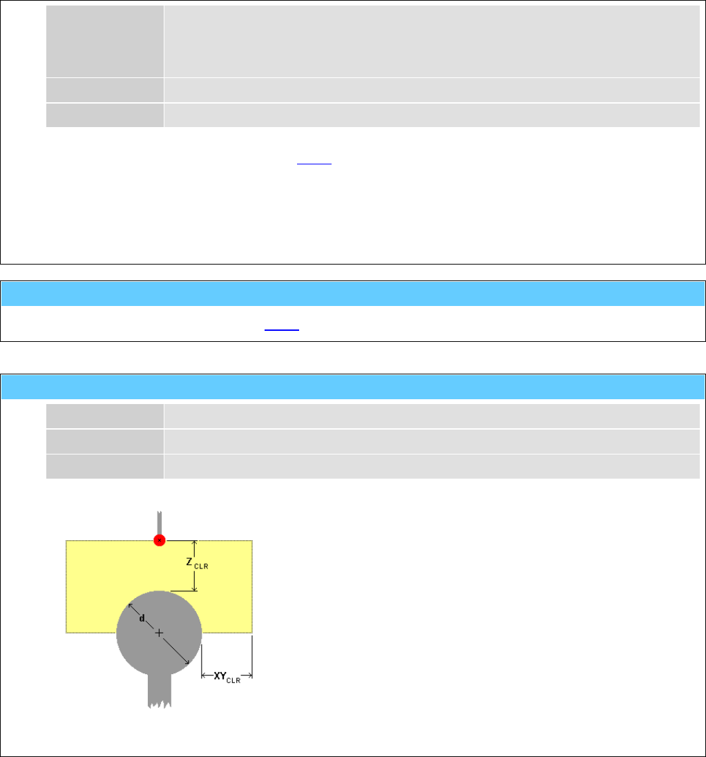
General Information American GFM Corp.
128
2 ... 7x9 single line matrix
3 ... 10x16 single line matrix
4 ... 5x7 twin line matrix
5 ... 5x7 twin line matrix (High Quality)
"t1" Line-1 Text for the upper line or for a single line
"t2" Line-2 Text for the lower line
If the printing operation is activated with M400, the text will be printed with this function.
e.g.: M400
G0 X500 Y300
M420 ( +30.0 , 10 , 2 , "TESTPRINT" )
G0 X600 Y300
M420 ( -45.0 , 10 , 5 , "AMERICAN" , "GFM" )
M429 ... Send product detect signal to inkjet
Will be generated automatically by M420 and releases the inkjet to print.
M500() ... Probe a ball with sequence 'XY -> Z '
p1 d Diameter of the ball in [mm] or [inch]
p2 Z CLR Free space of the Z-axis in [mm] or [inch]
p3 XYCLR Free space of the X/Y-axes in [mm] or [inch]
Measuring cycle 1 for a ball
First the X/Y-coordinates of the ball center are determined and then the
Z-coordinate.
With this function, in contrast to M501, an approximate distance
between the probe and the ball (Z CLR) has to be known so that the ball
will be encountered by the determination of the X/Y-coordinates.
If XYCLR is set to -1, the radius of the ball (d/2) will be used as X/Y
clearance.
The CNC-parameter SAB.AUTOM_H enables the code H500 to be
generated automatically at the end of the measuring cycle.
e.g.: M500 ( 50.0 , 30.0 , -1 )
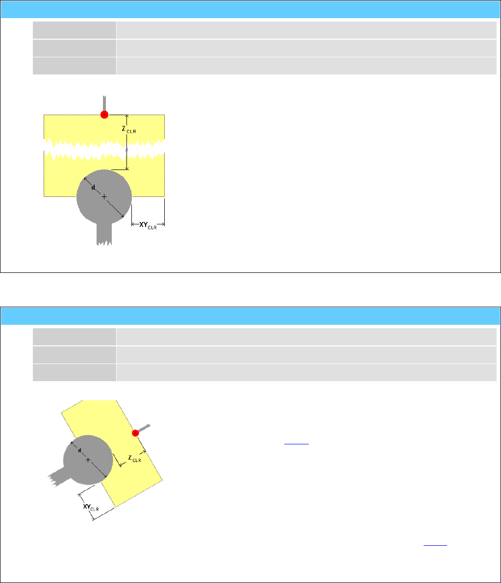
General Information American GFM Corp.
129
M501() ... Probe a ball with sequence 'Z -> XY'
p1 d Diameter of ball in [mm] or [inch]
p2 Z CLR Free space of the Z-axis in [mm] or [inch]
p3 XYCLR Free space of the X/Y-axes in [mm] or [inch]
Measuring cycle 2 for a ball
First the Z-coordinate of the ball center is determined and then the X/Y-
coordinates.
With this function, in contrast to M500, the distance between the probe
and the ball (Z CLR) is not needed. The ball will be encountered by the
determination of the X/Y-coordinates.
If XYCLR is set to -1, the radius of the ball (d/2) will be used as X/Y
clearance.
The CNC-parameter SAB.AUTOM_H enables the code H501 to be
generated automatically at the end of the measuring cycle.
e.g.: M501 ( 50.0 , 270.0 , -1 )
M502() ... Probe a ball along tool-vector
p1 d Diameter of ball in [mm] or [inch]
p2 Z CLR Free space of the virtual Z-axis in [mm] or [inch]
p3 XYCLR Free space of the virtual X/Y-axes in [mm] or [inch]
Measuring cycle 3 for a ball
This function works like M500, except that the ball is mounted along the
tool vector.
An approximate distance between the probe and the ball (ZCLR) has to
be known so that the ball will be encountered by the determination of
the virtual X/Y-coordinates.
If XYCLR is set to -1, the radius of the ball (d/2) will be used as virtual X/Y
clearance.
The CNC-parameter SAB.AUTOM_H enables the code H502 to be
generated automatically at the end of the measuring cycle.
e.g.: M502 ( 12.0 , 15.0 , -1 )
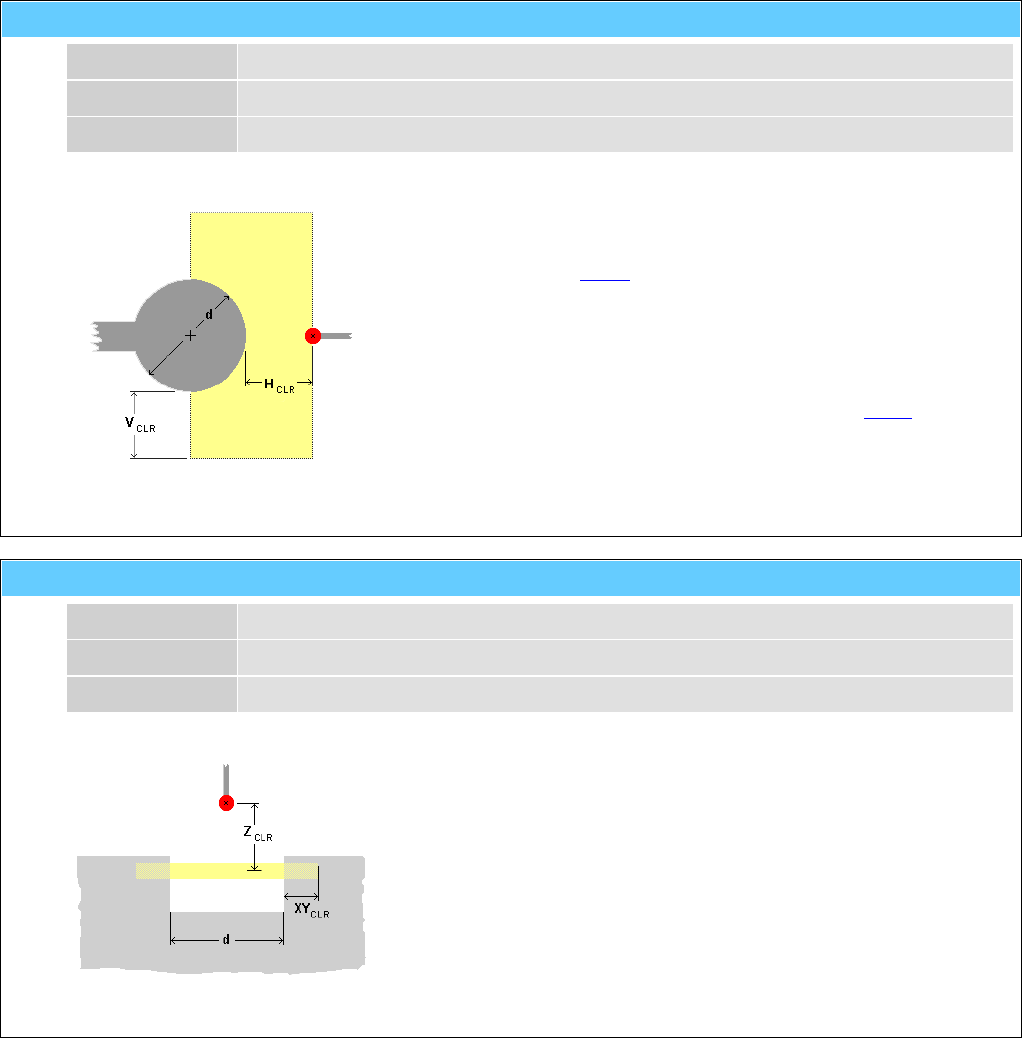
General Information American GFM Corp.
130
M505() ... Probe a ball vertically
p1 d Diameter of the ball in [mm] or [inch]
p2 H CLR Free horizontal space (X/Y plane) in [mm] or [inch]
p3 VCLR Free vertical space (X/Z or Y/Z plane) in [mm] or [inch]
Measuring cycle 4 for a ball
This function works like M500, except that the ball is mounted on a
vertical plane.
If VCLR is set to -1, the radius of the ball (d/2) will be used as vertical
clearance.
The CNC-parameter SAB.AUTOM_H enables the code H505 to be
generated automatically at the end of the measuring cycle
e.g.: M505 ( 50.0 , 30.0 , -1 )
M520() ... Probe a hole in X/Y surface
p1 d Diameter of the hole in [mm] or [inch]
p2 Z CLR Free space of the Z-axis in [mm] or [inch]
p3 XYCLR Free space of the X/Y-axes in [mm] or [inch]
Measuring cycle for a hole
X,Y coordinate of a hole-center will be determined.
If XYCLR is set to -1, the radius of the hole (d/2) will be used as X/Y
clearance.
The CNC-parameter SAB.AUTOM_H enables the code H520 to be
generated automatically at the end of the measuring cycle.
e.g.: M520 ( 10.0 , 30.0 , -1 )
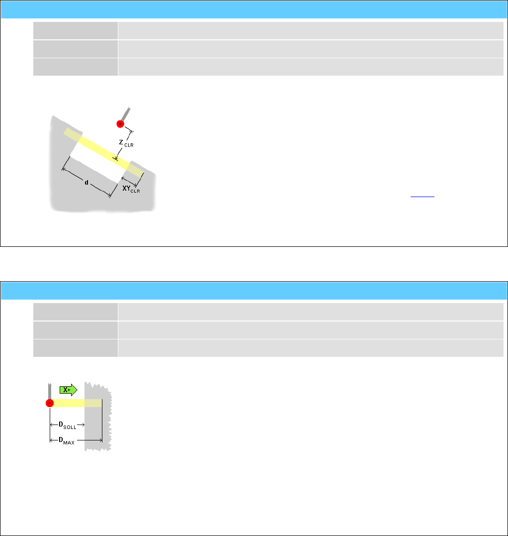
General Information American GFM Corp.
131
M521() ... Probe a hole along tool-vector
p1 d Diameter of the hole in [mm] or [inch]
p2 Z CLR Free space of the virtual Z-axis in [mm] or [inch]
p3 XYCLR Free space of the virtual X/Y-axes in [mm] or [inch]
Measuring cycle 2 for a hole
X,Y and Z coordinate of a hole-center will be determined.
If XYCLR is set to -1, the radius of the hole (d/2) will be used as virtual X/Y
clearance.
The CNC-parameter SAB.AUTOM_H enables the code H521 to be
generated automatically at the end of the measuring cycle.
e.g.: M521 ( 10.0 , 30.0 , -1 )
M530() ... Probe a surface in X/Y/Z-Direction with A0 & C0
"t1" Direction Axis name and direction
p1 DSOLL Estimated distance between probe and surface in [mm] or [inch]
p2 DMAX Maximum distance between probe and surface in [mm] or [inch]
Measuring cycle 1 for a surface
X,Y or Z coordinate of a surface will be determined.
With this function, in contrast to M531, the A and C axes will be adjusted to 0°.
i.e. the probe is located vertical to the X/Y-surface.
If the surface is not found within the distance DMAX, the measuring cycle will be
interrupted and an error message will occur.
The CNC-parameter SAB.AUTOM_H enables the code H530 to be generated
automatically at the end of the measuring cycle.
e.g.: M530 ( "X+" , 50.0 , 70.0 )
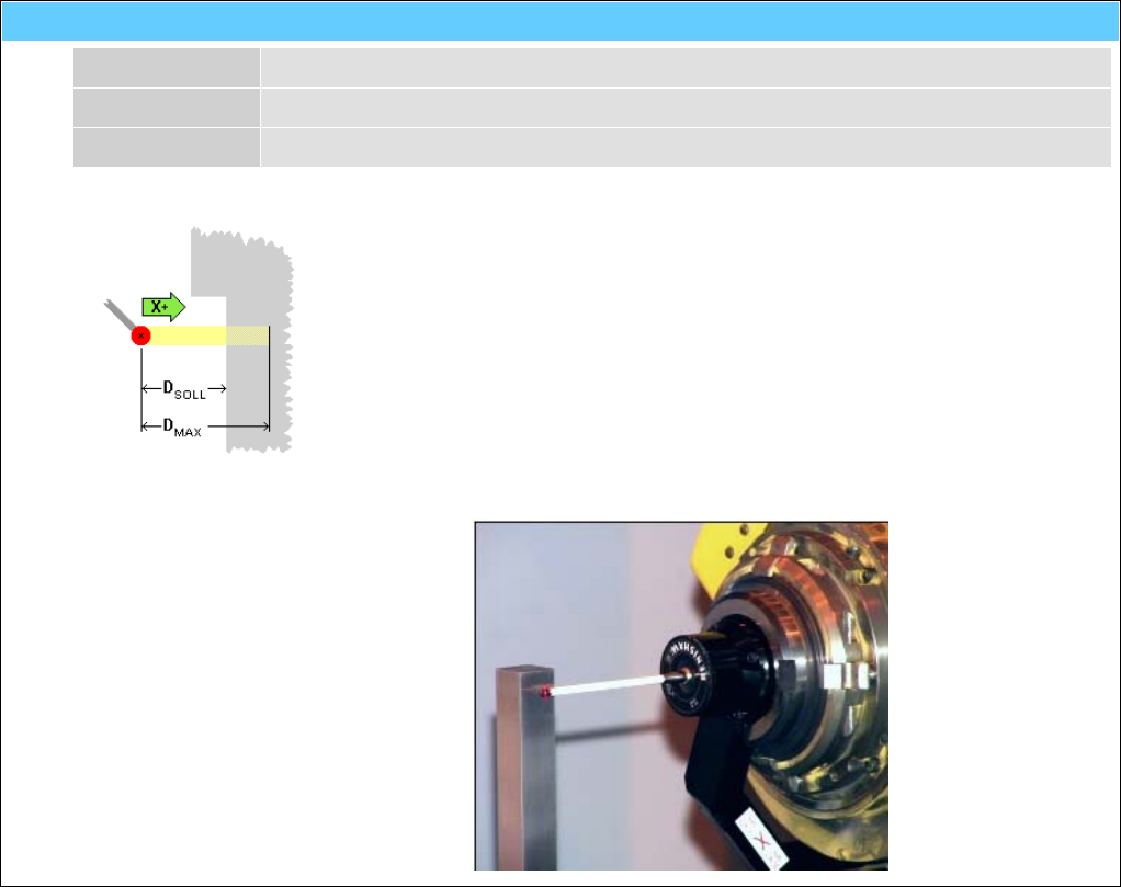
General Information American GFM Corp.
132
M531() ... Probe a surface in X/Y/Z-Direction at any A/C pos.
"t1" Direction Axis name and direction
p1 DSOLL Estimated distance between probe and surface in [mm] or [inch]
p2 DMAX Maximum distance between probe and surface in [mm] or [inch]
Measuring cycle 2 for a surface
The X-, Y- or Z-coordinate of a surface will be determined.
With this function, in contrast to M530, the A and C axes can be positioned to
any angle and will not be moved.
If the surface is not found within the distance DMAX, the measuring cycle will be
interrupted and an error message will occur.
The CNC-parameter SAB.AUTOM_H enables the code H531 to be generated
automatically at the end of the measuring cycle.
e.g.: G0 C90 A-90
M531 ( "X+" , 50.0 , 70.0 )
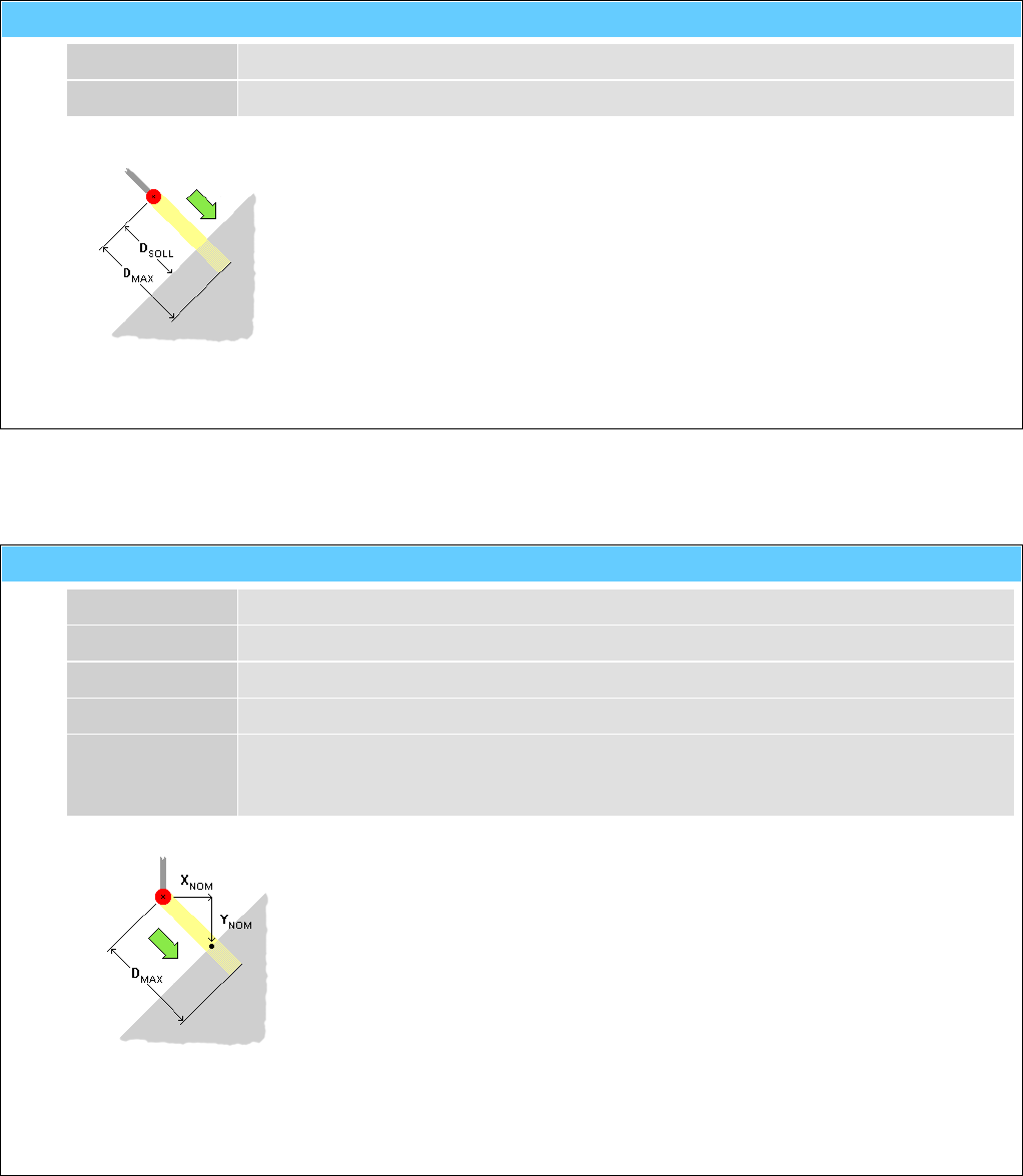
General Information American GFM Corp.
133
M535() ... Probe a surface along tool-vector
p1 DSOLL Estimated distance between probe and surface in [mm] or [inch]
p2 DMAX Maximum distance between probe and surface in [mm] or [inch]
Measuring cycle 3 for a surface
The X/Y/Z coordinate of touch-point on a surface will be determined.
The probe will move along the current tool-vector.
If the surface is not found within the distance DMAX, the measuring cycle will be
interrupted and an error message will occur.
The CNC-parameter SAB.AUTOM_H enables the code H535 to be generated
automatically at the end of the measuring cycle.
e.g.: M535 ( 50.0 , 70.0 )
M536() ... Probe a surface along X/Y/Z vector
p1 XNOM Estimated X coordinate (or distance) of touch-point in [mm] or [inch]
p2 YNOM Estimated Y coordinate (or distance) of touch-point in [mm] or [inch]
p3 ZNOM Estimated Z coordinate (or distance) of touch-point in [mm] or [inch]
p4 DMAX Maximum distance between probe and touch-point in [mm] or [inch]
"t1" Mode "ABS" ... XNOM, YNOM and ZNOM defines absolute position of touch-point
"REL" ... XNOM, YNOM and ZNOM defines relative distance to touch-point
Measuring cycle 4 for a surface
The X/Y/Z coordinate of touch-point on a surface will be determined.
The probe will move along the defined X/Y/Z vector.
If the surface is not found within the distance DMAX, the measuring cycle will be
interrupted and an error message will occur.
The CNC-parameter SAB.AUTOM_H enables the code H536 to be generated
automatically at the end of the measuring cycle.
e.g.: M536 ( 3400.0 , 780.0 , 120.0 , 20.0 , "ABS" )
M536 ( -7.0 , +10.0 , +4.0 , 20.0 , "REL" )

General Information American GFM Corp.
134
M540 ... Probe Qualification
It checks the data of the probe with the help of a calibrated measuring ball or cube mounted on the
machine.
The CNC-parameter SAB.AUTOM_H enables the code H540 to be generated automatically at the end of
the measuring cycle.
M560 ... Machine Check
It checks the precision of the machine axes with the help of a calibrated measuring ball or cube mounted
on the machine and a calibrated probe.
The CNC-parameter SAB.AUTOM_H enables the code H560 to be generated automatically at the end of
the measuring cycle.
M561 ... Part align mode
p1 PointNum Number of check points 1..2
This function activates the PA (Part-Alignment) operation mode. PA finds out the actual position of a work
piece in the X/Y coordinate system. On the work piece (material) are defined probing targets. Their
position will be determined with help of the function M500. Then the coordinates of the part program will
be transformed (moved and rotated) to the position of the work piece.
... see also machining modes.
e.g.: T1 (10)
M561 ( 2 )
G0 X0 Y0 Z20
M500 (20,20,-1)
G0 X2300 Y450 Z20
M500 (20,20,-1)
M590 ... Clear probing tolerances
This function clears a possibly active tolerance for the following probing cycles.
... see also M591.
e.g.: M591 ( 0.2 )
G0 X3000 Y500
M500 ( 20 , 20 , -1 )
M590
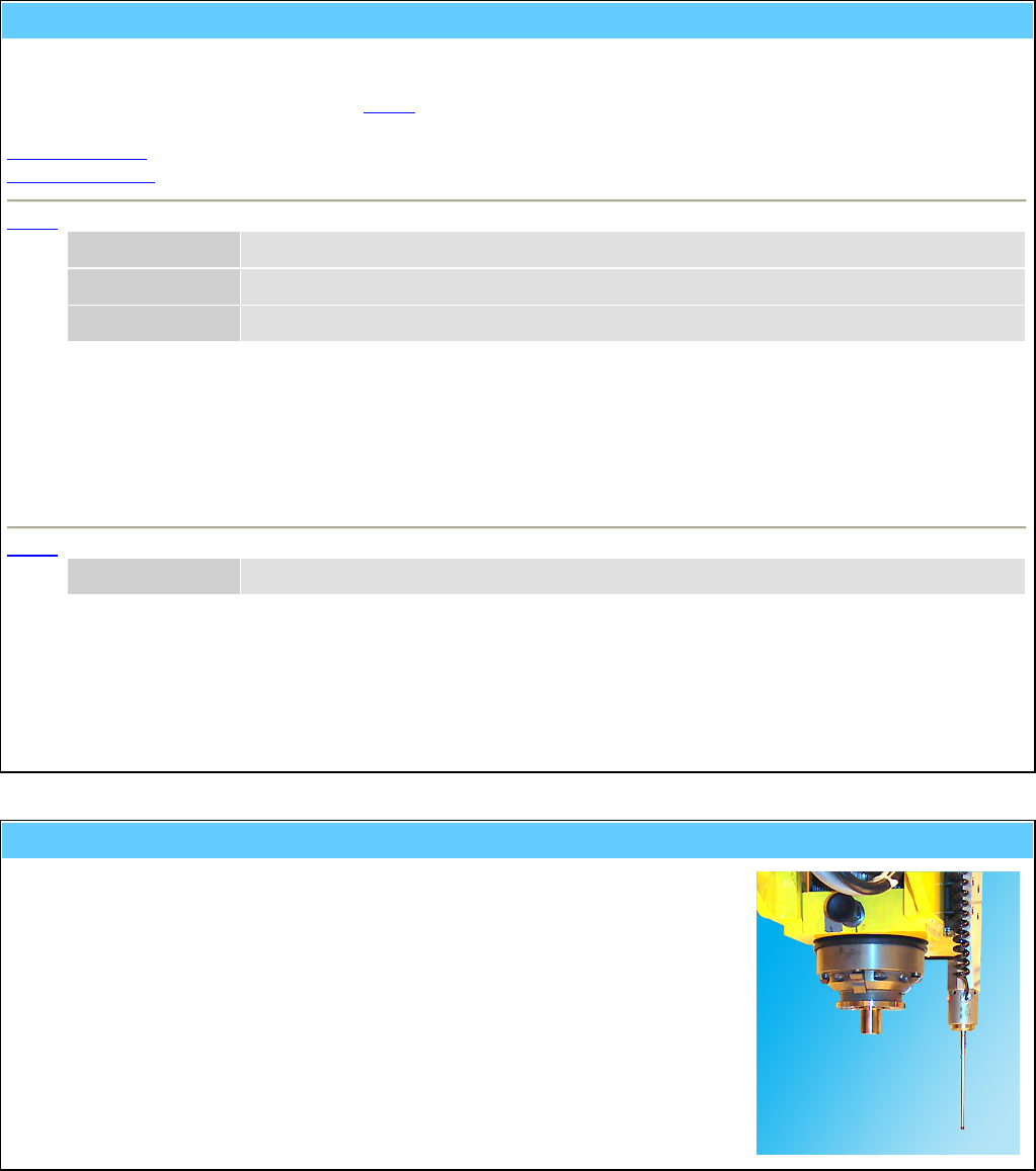
General Information American GFM Corp.
135
M591 ... Set probing tolerances
This function activates a tolerance for the following probing cycles. Exceeds the measured position of the probing
target the tolerance, the part program will be terminated.
The tolerances can be deactivated with M590.
The tolerances can be activated on two different ways:
X/Y/Z tolerance
Vector tolerance
M591 X/Y/Z tolerance
p1 X tolerance for X position
p2 Y tolerance for Y position
p3 Z tolerance for Z position
e.g.: M591 ( 0.12 , 0.12 , 0.37 )
G0 X3000 Y500
M500 ( 20 , 20 , -1 )
M590
M591 Vector tolerance
p1 Vector Vector tolerance
e.g.: M591 ( 0.2 )
G0 X3000 Y500
M500 ( 20 , 20 , -1 )
M590
M599 ... Activate external probe
Activate external probe.
An external probe is mounted permanently beside the spindle.
On activation it will extend by a pneumatic cylinder.
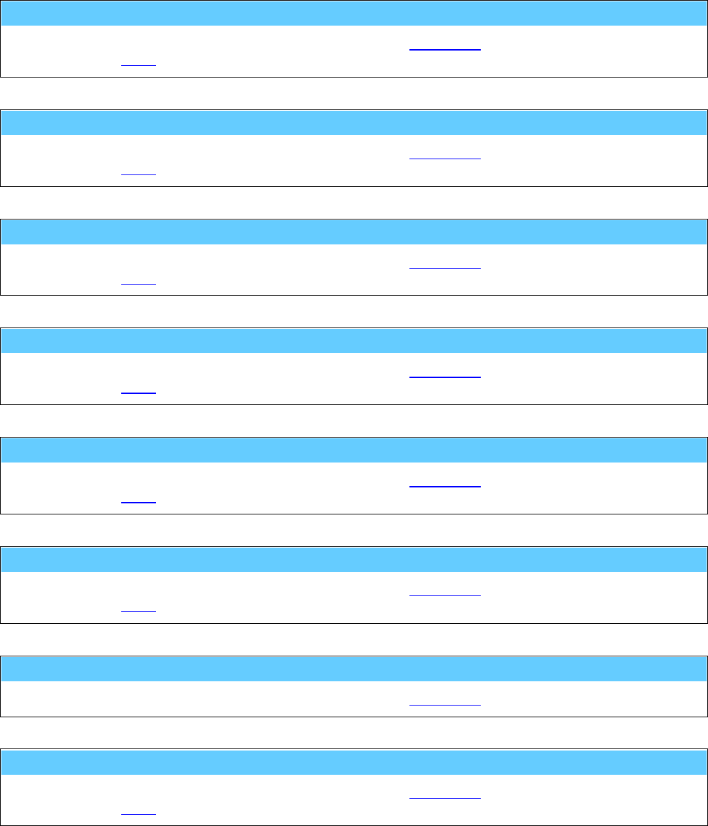
General Information American GFM Corp.
136
M800 ... CLOSE tool changer cover
Service code which will be generated automatically during tool change.
... see also M801.
M801 ... OPEN tool changer cover
Service code which will be generated automatically during tool change.
... see also M800.
M802 ... Tool clamping ON
Service code which will be generated automatically during tool change.
... see also M803.
M803 ... Tool clamping OFF
Service code which will be generated automatically during tool change.
... see also M802.
M804 ... Tool changer to BASIC position
Service code which will be generated automatically during tool change.
... see also M805.
M805 ... Tool changer to CHANGE position
Service code which will be generated automatically during tool change.
... see also M804.
M806 ... Prepare machine for tool change
Service code which will be generated automatically during tool change.
M807 ... DISENGAGE tool from tool pocket
Service code which will be generated automatically during tool change.
... see also M808.
General Information American GFM Corp.
137
M808 ... ENGAGE tool from tool pocket
Service code which will be generated automatically during tool change.
... see also M807.
M809() ... Tool position selection at changer
p1 Station Station number 1..n at respective tool changer.
Service code which will be generated automatically during tool change.
e.g.: M809 ( 3 )
M810 ... CLOSE toolsetting equipment cover
Service code which will be generated automatically by M62 and M63.
... see also M811.
M811 ... OPEN toolsetting equipment cover
Service code which will be generated automatically by M62 and M63.
... see also M810.
M812 ... De-tagging gantry X COUPLED
Service code which will be generated automatically by M71 / M72.
... see also M813.
M813 ... De-tagging gantry X DECOUPLED
Service code which will be generated automatically by M71 / M72.
... see also M812.
M814 ... De-tagging gantry X brake INACTIVE
Service code which will be generated automatically by M71 / M72.
... see also M815.

General Information American GFM Corp.
138
M815 ... De-tagging gantry X brake ACTIVE
Service code which will be generated automatically by M71 / M72.
... see also M814.
M816 ... De-tagging gantry Y COUPLED
Service code which will be generated automatically by M71 / M72.
... see also M817.
M817 ... De-tagging gantry Y DECOUPLED
Service code which will be generated automatically by M71 / M72.
... see also M816.
M818 ... De-tagging gantry Y brake INACTIVE
Service code which will be generated automatically by M71 / M72.
... see also M819.
M819 ... De-tagging gantry Y brake ACTIVE
Service code which will be generated automatically by M71 / M72.
... see also M818.
M820 ... Fixed clamps UP
Service code which will be generated automatically by M53 / M54.
... see also M821.
M821 ... Fixed clamps DOWN
Service code which will be generated automatically by M53 / M54.
... see also M820.
M822 ... Movable clamps UP
Service code which will be generated automatically by M53 / M54.
... see also M823.

General Information American GFM Corp.
139
M823 ... Movable clamps DOWN
Service code which will be generated automatically by M53 / M54.
... see also M822.
M824 ... Movable clamps COUPLED
Service code which will be generated automatically by M53 / M54.
... see also M825.
M825 ... Movable clamps DECOUPLED
Service code which will be generated automatically by M53 / M54.
... see also M824.
M826 ... Movable clamps brake INACTIVE
Service code which will be generated automatically by M53 / M54.
... see also M827.
M827 ... Movable clamps brake ACTIVE
Service code which will be generated automatically by M53 / M54.
... see also M826.
General Information American GFM Corp.
140
M828() ... Oscillate axis for PID-Adjustment
"t1" Axis Name of the axis
p1 Min-Pos Minimum position in [mm] or [inch]
p2 Max-Pos Maximum position in [mm] or [inch]
[p3] Profile 0 ... sinusoidal G0
acceleration
Parameter ITP.AX[n].SIN =
1
For acceleration parameter SAB.AX[n].AG0 will
be used.
rectangular G0
acceleration
Parameter ITP.AX[n].SIN =
0
1 ... trapezoidal G1
acceleration
For acceleration parameter SAB.AX[n].A will be
used.
SAB.TL.TAPE_t_Ruck defines the raise time for
TAPE axis,
for all other axes SAB.MDI_ADT will be used.
Oscillating function of the axis to adjust the control parameter manually.
The axis executes G0 or G1 movements between the indicated max/min positions until a <STOP> is
pressed.
e.g.: M828 ( "X" , 100.0 , 800.0 , 1 )
The oscillating function can also be used for APM axes.
In this case the third parameter p3 will be ignored and for the profil the default parameters of the APM
axis will be used.
e.g.: M828 ( "U1" , -1000.0 , 2000.0 )
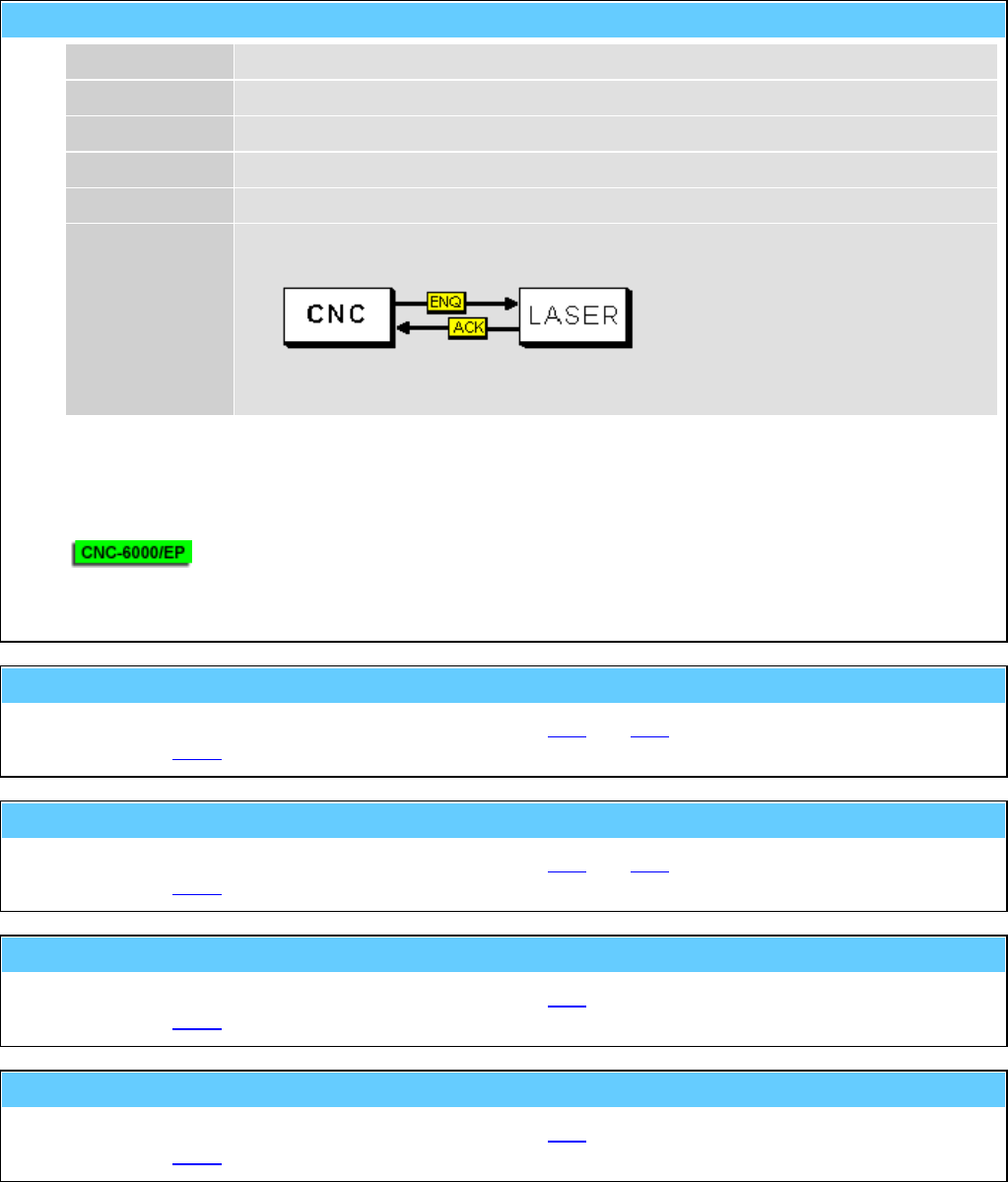
General Information American GFM Corp.
141
M830() ... Autom. calibration of axis with laser system
"t1" Axis Name of axis
p1 Start Pos Start position in [mm] or [inch]
p2 End-Pos End position in [mm] or [inch]
p3 Step Step size in [mm] or [inch]
p4 Delay Dwell time in [s]
p5 Mode 0 ... Only dwell time
1 ... RS-232 handshake over console plug of the CNC-CPU
2 ... M830 handshake to PLI
3 ... <START> key
Function to determine the correction data of the pitch error compensation.
e.g.: M830 ( "X" , 0.0 , 5000.0 , 25.0 , 0.8 , 1 )
The function can also be used for APM axes.
e.g.: M830 ( "U1" , 0.0 , 10000.0 , 100.0 , 1.0 , 0 )
M832 ... Toolsetting equipment to BASIC position
Service code which will be generated automatically by M62 and M63.
... see also M833.
M833 ... Toolsetting equipment to MEASURING position
Service code which will be generated automatically by M62 and M63.
... see also M832.
M834 ... Label transfer (printer --> placing unit)
Service code which will be generated automatically by M80.
... see also M835.
M835 ... Label transfer unit to basic position
Service code which will be generated automatically by M80.
... see also M834.

General Information American GFM Corp.
142
M842 ... COUPLE cabin
Service code which will be generated automatically by M38 and M39.
... see also M843.
M843 ... DECOUPLE cabin
Service code which will be generated automatically by M38 and M39.
... see also M842.
M844 ... Capture LPA point with camera
M860() ... Trimming counterholder INACTIVE (retracted)
p1 Number Counterholder number 1...n
TODO: Enter description here
First used at machine #3503 (US-50).
... see also M861.
z.B.: M860 ( 2 )
M861() ... Trimming counterholder ACTIVE (extended)
p1 Number Counterholder number 1...n
TODO: Enter description here
First used at machine #3503 (US-50).
... see also M860.
z.B.: M861 ( 2 )
M862() ... Trimming support cylinder INACTIVE (down)
p1 Number Support cylinder number 1...n
TODO: Enter description here
First used at machine #3503 (US-50).
... see also M863.
z.B.: M862 ( 15 )

General Information American GFM Corp.
143
M863() ... Trimming support cylinder ACTIVE (up)
p1 Number Support cylinder number 1...n
TODO: Enter description here
First used at machine #3503 (US-50).
... see also M862.
z.B.: M863 ( 15 )
M864() ... Trimming support cylinder UNCLAMPED
p1 Number Support cylinder number 1...n
TODO: Enter description here
First used at machine #3503 (US-50).
... see also M865.
z.B.: M864 ( 9 )
M865() ... Trimming support cylinder CLAMPED
p1 Number Support cylinder number 1...n
TODO: Enter description here
First used at machine #3503 (US-50).
... see also M864.
z.B.: M865 ( 9 )
M866 ... Headchanger to BASIC position (inactive)
Service code which will be generated automatically by M66.
... see also M867.
M867 ... Headchanger to CHANGE position (active)
Service code which will be generated automatically by M66.
... see also M866.
M868 ... Couple routing/ultrasonic head
Service code which will be generated automatically by M66.
... see also M869.
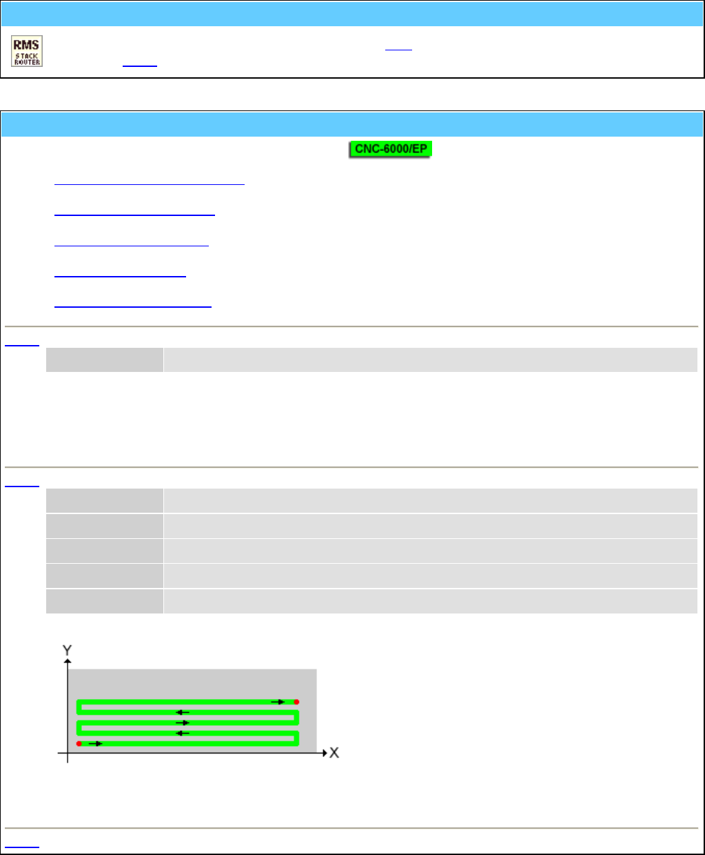
General Information American GFM Corp.
144
M869 ... Decouple routing/ultrasonic head
Service code which will be generated automatically by M66.
... see also M868.
M870() ... Call mapping (scan) functions
With this code several mapping functions can be called.
• Clear entire mapping data area
• Scan an area along X axis
• Scan 2 lines along X axis
• Mapping interpolation
• Correct every second row
M870 - Clear entire mapping data area
"t1" Function "ClearAll"
The function clears the entire mapping data area at the interpolation CPU.
This should be done before a new mapping scan will be started.
e.g.: M870 ( "ClearAll" )
M870 - Scan an area along X axis
"t1" Function "ScanX"
p1 Xmin X start position [mm] or [inch]
p2 Xmax X end position [mm] or [inch]
p3 Ymin Y start position [mm] or [inch]
p4 Ymax Y end position [mm] or [inch]
Scan an area along X axis.
e.g.: M870 ( "ScanX" , 0 , 5000 , 0 x, 2000 )
M870 - Scan 2 lines along X axis

General Information American GFM Corp.
145
"t1" Function "ScanX2"
p1 Xmin X start position [mm] or [inch]
p2 Xmax X end position [mm] or [inch]
p3 PosY1 Y position for first line [mm] or [inch]
p4 PosY2 Y position for second line [mm] or [inch]
Scan 2 lines along X axis.
e.g.: M870 ( "ScanX2" , 0 , 5000 , 350, 690 )
M870 - Mapping interpolation
"t1" Function "Calc1"
p1 PosY1 Min. Y position for interpolation in [mm] or [inch]
p2 PosY2 Max. Y position for Interpolation in [mm] or [inch]
The function processes each Y row and does the following calculation:
Outside of the area posY1 and posY2 the found mapping values at the border will be extended
accordingly.
Inside the area the mapping values will be interpolated.
e.g.: M870 ( "Calc1" , 400 , 650 )
M870 - Correct every second row
"t1" Function "CorrectOddRows"
p1 dVal Z Korrekturwert in [mm] oder [inch]
Correct every second row by dVal.
e.g.: M870 ( "CorrectOddRows" , +0.07 )

General Information American GFM Corp.
146
M871 ... Save mapping data to hard disc
This function copies the mapping date area from the interpolation CPU to the harddisk of the MMI.
This should be done at the end of a mapping scan.
M999() ... Display software info string
p1 Info-No 0 ... CNC version (default)
1 ... Compile date/time
2 ... Compiler version
3 ... Company
4 ... Programmer
10 ... Protocol and version of inkjet interface
Display of CNC version number and additional information related to the software.
e.g.: M999 ( 0 )
H10() ... Sync. ext. display device for window cutting
p1 Code 1 ... Start of the part program
2 ... Transfer of a window cutting (M36 with conveyor)
9 ... End of the part program
Synchronization of an external display device.
The codes can be generated automatically by setting of the CNC-parameter SAB.FL_17.
e.g.: H10 ( 9 )
H20 ... Request data string from MMI
Will be generated automatically by M48(0) and serves for the internal CNC/MMI communication.
H21 ... Tool data updated by CNC
Will be generated automatically at M62 if after tool setting also the automatic amplitude measurement
was executed.

General Information American GFM Corp.
147
H40() ... Increment production counter at MMI
p1 Increment Amount of increments.
This function will increment the production counter at the MMI by the specified amount.
e.g.: H40 ( 3 )
H50() ... LPA data from select program
p1 Alpha Rotation angle around zero point in [rad]
p2 dX Shift in X direction (after rotation) in [m]
p3 dY Shift in Y direction (after rotation) in [m]
This code will be inserted by the select utility in the new generated part program. It represents the LPA
data of the original part program.
e.g.: H50 ( 0.05585 , 1.234234 , 0.23237 )
H51 ... Internally used by select program
This code will be used by the select utility for synchronization points within the new generated part
program.
H70 ... Activate X/Y/Z offset (from MMI)
p1 Name Offset-ID
Activate X/Y/Z offset which is stored at MMI.
z.B.: H70 ( "FixturePos1" )
H500 ... Send tool-ball-data to MMI (after M500)
Function to display the data determined by M500 on MMI.
H501 ... Send tool-ball-data to MMI (after M501)
Function to display the data determined by M501 on MMI.

General Information American GFM Corp.
148
H502 ... Send tool-ball-data to MMI (after M502)
p1 Para1 TODO: Description for Para1
"t1" Text1 TODO: Description for Text1
TODO: Enter description here
e.g.: TODO: Example Mxx ( 0.000 , "Test" )
H505 ... Send tool-ball-data to MMI (after M505)
Function to display the data determined by M505 on MMI.
H510() ... Reset or perform fixture offset calculation
p1 Command 0 ... reset
1 ... perform calculation
Function to determine the position of a part (rotation and displacement) in 3D.
Three different balls search for the X/Y/Z coordinates with the function M500 or M501.
e.g.: H510 ( 0 )
G0 X10 Y20 Z43
M500 ( 50.0 , 13.0 , -1 ) ; 1. Point
G0 X2000 Y20 Z43
M500 ( 50.0 , 13.0 , -1 ) ; 2. Point
G0 X200 Y700 Z43
M500 ( 50.0 , 13.0 , -1 ) ; 3. Point
H510 ( 1 )
H520 ... Send hole-data to MMI (after M520)
Function to display the data determined by M520 on MMI.
H521 ... Send hole-data to MMI (after M521)
p1 Para1 TODO: Description for Para1
"t1" Text1 TODO: Description for Text1
TODO: Enter description here
e.g.: TODO: Example Mxx ( 0.000 , "Test" )

General Information American GFM Corp.
149
H530 ... Send surface-data to MMI (after M530)
Function to display the data determined by M530 on MMI.
H531 ... Send surface-data to MMI (after M531)
Function to display the data determined by M531 on MMI.
H535 ... Send surface-data to MMI (after M535)
Function to display the data determined by M535 on MMI.
H536 ... Send surface-data to MMI (after M536)
Function to display the data determined by M536 on MMI.
H540 ... Send probe-qualification-data to MMI (after M540)
Function to display the data determined by M540 on MMI.
H560 ... Send machine-check-data to MMI (after M560)
Function to display the data determined by M560 on MMI.
H591 ... Send probing target tolerance error to MMI (after M591)
Function to display the data determined by M591 on MMI.

General Information American GFM Corp.
150
NOTES

Index American GFM Corp.
151
INDEX
3D Ultrasonic Routing Machines ................................... 12
A Axis ............................................................................ 13
Additional Auto Data ............................................... 46, 47
Additional Functions .................................... 29, 34, 42, 43
Analog Monitor ........................................................ 46, 47
AUTO Mode .................................................................. 33
Axis Monitor ............................................................ 46, 48
B Axis ............................................................................ 14
Base Frame ....................................................................... 6
C Axis ............................................................................ 14
C Turn Tolerance ........................................................... 38
CNC6000/AP ........................................................... 17, 21
Delete ........................................................... 37, 45, 52, 55
Diagnostics ..................................................................... 46
Display Header ............................................................... 26
Edge of Knife ................................................................. 38
Edit ......................................................... 37, 38, 41, 43, 52
Edit Material Data .......................................................... 38
Edit Tool Data ................................................................ 41
Electrical Cabinets ......................................................... 21
E-Stop ...................................................................... 25, 26
Extended ......................................................................... 51
Foundation ....................................................................... 6
G-Codes and M-Codes for 2D Machines ....................... 67
G-Codes, M-Codes, T-Codes, and H-Codes for 3D
Machines .................................................................... 96
General Information ....................................................... 64
Generate Part Program ................................................... 37
Graphic ......................................................... 34, 35, 44, 49
Group 1 .......................................................................... 44
Info ................................................................................. 36
Initial Checks ................................................................. 24
Jog Box (2D Machines) ................................................. 21
Jog Pendant (3D Machines) ........................................... 22
Label Text .......................................................... 29, 34, 43
Light Guards .................................................................. 15
Load ......................................................................... 34, 49
Machine Description .................................................. 6, 66
Machine Mode Selections .............................................. 25
Machine Status Indicators .............................................. 26
Manuals .......................................................................... 66
Material Height .............................................................. 38
MDI Mode ................................................................ 30, 32
MMI Operation and Machine Startup ............................ 24
MMI Operations ............................................................. 24
Mount Points ............................................................ 44, 45
New users ....................................................................... 55
No Mode ........................................................................ 25
Offsets ............................................................................ 42
Online Graphic ............................................................... 44
Operator Panel ................................................................ 18
Origin Editor .................................................................. 38
Oscilloscope ....................................................... 49, 50, 66
P Axes ............................................................................ 10
Parameter Editor....................................................... 49, 50
Passwords ....................................................................... 55
PLI Compiler .................................................................. 50
PLI Debugger ........................................................... 49, 50
Pneumatic System .......................................................... 16
Preparation for Machine Startup .................................... 24
Priority levels ................................................................. 55
Program Flow ..................................................... 33, 34, 44
Program Management .................................. 33, 34, 37, 55
REF Mode ...................................................................... 30
Safety ........................................................... 15, 21, 22, 66
Safety Bumpers .............................................................. 15
Safety Mats ........................................................ 15, 21, 22
Scan Mode ...................................................................... 49
Select .................................... 20, 21, 22, 37, 45, 46, 48, 51
Service ...................................................................... 49, 66
Show Error Log File ....................................................... 44
Start Up Procedure ......................................................... 24
System Support ...................................... 29, 34, 44, 55, 56
Tools (2D Machines) ...................................................... 39
Tools (3D Machines) ...................................................... 40
Turning the Machine On ................................................ 24
Ultrasonic ................................................... 2, 6, 12, 26, 66
User functions ................................................................ 52
User ID ........................................................................... 55
Vacuum System ............................................................. 15
Vacuum Table ................................................................ 11
Value Display ................................................................. 46
View Knife Alignment ................................................... 49
View Mapping .................................................... 46, 48, 49
View Versions .......................................................... 49, 51
X Axis ........................................................................ 7, 12
Y Axis ........................................................................ 8, 12
Z Axis ......................................................................... 9, 13
