Operator's Manual For UH 60A Helicopter TM 1 1520 237 10
User Manual: manual pdf -FilePursuit
Open the PDF directly: View PDF ![]() .
.
Page Count: 841 [warning: Documents this large are best viewed by clicking the View PDF Link!]
- TABLE OF CONTENTS
- LAST CHANGE
- WARNING
- CHAPTERS
- FIGURES
- FIGURE 2-1
- FIGURE 2-2
- FIGURE 2-3
- FIGURE 2-4
- FIGURE 2-5
- FIGURE 2-6
- FIGURE 2-7
- FIGURE 2-8
- FIGURE 2-9
- FIGURE 2-10
- FIGURE 2-11
- FIGURE 2-12
- FIGURE 2-13
- FIGURE 2-14
- FIGURE 2-15
- FIGURE 2-16
- FIGURE 2-17
- FIGURE 2-18
- FIGURE 2-19
- FIGURE 2-20
- FIGURE 2-21
- FIGURE 2-24
- FIGURE 2-25
- FIGURE 2-26
- FIGURE 3-1
- FIGURE 3-2
- FIGURE 3-5
- FIGURE 3-6
- FIGURE 3-7
- FIGURE 3-8
- FIGURE 3-10
- FIGURE 3-11
- FIGURE 3-12
- FIGURE 3-12.1
- FIGURE 3-12.2
- FIGURE 3-13
- FIGURE 3-14
- FIGURE 3-15
- FIGURE 3-16
- FIGURE 3-17
- FIGURE 3-18
- FIGURE 3-18.1
- FIGURE 3-18.2
- FIGURE 3-19
- FIGURE 3-20
- FIGURE 3-21
- FIGURE 3-22
- FIGURE 3-23
- FIGURE 3-24
- FIGURE 3-26
- FIGURE 3-27
- FIGURE 3-29
- FIGURE 3-30
- FIGURE 3-31
- FIGURE 3-32
- FIGURE 3-33
- FIGURE 3-34
- FIGURE 4-1
- FIGURE 4-2
- FIGURE 4-3
- FIGURE 4-4
- FIGURE 4-5
- FIGURE 4-6
- FIGURE 4-6.1
- FIGURE 4-7
- FIGURE 4-8
- FIGURE 4-10
- FIGURE 4-11
- FIGURE 4-12
- FIGURE 4-13
- FIGURE 4-14
- FIGURE 4-15
- FIGURE 4-16
- FIGURE 4-17
- FIGURE 4-18
- FIGURE 4-19
- FIGURE 4-20
- FIGURE 4-21
- FIGURE 4-22
- FIGURE 4-23
- FIGURE 4-24
- FIGURE 4-25
- FIGURE 4-26
- FIGURE 4-27
- FIGURE 4-27.1
- FIGURE 4-28
- FIGURE 4-29
- FIGURE 5-1
- FIGURE 5-2
- FIGURE 5-3
- FIGURE 5-4
- FIGURE 5-5
- FIGURE 5-6
- FIGURE 5-7
- FIGURE 5-9
- FIGURE 5-10
- FIGURE 6-1
- FIGURE 6-2
- FIGURE 6-3
- FIGURE 6-4
- FIGURE 6-5
- FIGURE 6-6
- FIGURE 6-7
- FIGURE 6-9
- FIGURE 6-10
- FIGURE 6-11
- FIGURE 6-12
- FIGURE 6-13
- FIGURE 7-1
- FIGURE 7-2
- FIGURE 7-3
- FIGURE 7-4
- FIGURE 7-5
- FIGURE 7-6
- FIGURE 7-7
- FIGURE 7-8
- FIGURE 7-9
- FIGURE 7-10
- FIGURE 7-11
- FIGURE 7-12
- FIGURE 7-13
- FIGURE 7-14
- FIGURE 7-15
- FIGURE 7-16
- FIGURE 7-17
- FIGURE 7-18
- FIGURE 7-19
- FIGURE 7-20
- FIGURE 7-21
- FIGURE 7-22
- FIGURE 7-23
- FIGURE 7-24
- FIGURE 7-25
- FIGURE 7-26
- FIGURE 7-27
- FIGURE 7-28
- FIGURE 7-29
- FIGURE 7-30
- FIGURE 7-31
- FIGURE 7-32
- FIGURE 7-33
- FIGURE 7-34
- FIGURE 7-35
- FIGURE 7-36
- FIGURE 7-37
- FIGURE 7-38
- FIGURE 7-39
- FIGURE 7-40
- FIGURE 7A-1
- FIGURE 7A-2
- FIGURE 7A-3
- FIGURE 7A-4
- FIGURE 7A-5
- FIGURE 7A-6
- FIGURE 7A-7
- FIGURE 7A-8
- FIGURE 7A-9
- FIGURE 7A-10
- FIGURE 7A-11
- FIGURE 7A-12
- FIGURE 7A-13
- FIGURE 7A-14
- FIGURE 7A-15
- FIGURE 7A-16
- FIGURE 7A-17
- FIGURE 7A-18
- FIGURE 7A-19
- FIGURE 7A-20
- FIGURE 7A-21
- FIGURE 7A-22
- FIGURE 7A-23
- FIGURE 7A-24
- FIGURE 7A-25
- FIGURE 7A-26
- FIGURE 7A-27
- FIGURE 7A-28
- FIGURE 7A-29
- FIGURE 7A-30
- FIGURE 7A-31
- FIGURE 7A-32
- FIGURE 7A-33
- FIGURE 7A-34
- FIGURE 7A-35
- FIGURE 7A-36
- FIGURE 7A-37
- FIGURE 7A-38
- FIGURE 7A-39
- FIGURE 7A-40
- FIGURE 7A-41
- FIGURE 7A-42
- FIGURE 8-1
- FIGURE 9-1
- FIGURE 9-2
- FIGURE 9-4
- TABLES
- APPENDICES
- INDEX
- PAGES
- PAGE 1-1
- PAGE 2-1
- PAGE 2-2
- PAGE 2-11
- PAGE 2-12
- PAGE 2-15
- PAGE 2-16
- PAGE 2-21
- PAGE 2-24
- PAGE 2-25
- PAGE 2-27
- PAGE 2-31
- PAGE 2-34
- PAGE 2-34.1
- PAGE 2-35
- PAGE 2-36
- PAGE 2-39
- PAGE 2-41
- PAGE 2-45
- PAGE 2-48
- PAGE 2-48.1
- PAGE 2-53
- PAGE 2-55
- PAGE 2-56
- PAGE 2-57
- PAGE 2-62
- PAGE 2-64
- PAGE 2-64.1
- PAGE 2-64.2
- PAGE 2-71
- PAGE 2-74
- PAGE 2-77
- PAGE 2-83
- PAGE 2-84
- PAGE 2-86
- PAGE 2-93
- PAGE 2-94
- PAGE 3-1
- PAGE 3-7
- PAGE 3-8
- PAGE 3-11
- PAGE 3-12
- PAGE 3-19
- PAGE 3-26
- PAGE 3-26.1
- PAGE 3-26.3
- PAGE 3-32.11
- PAGE 3-33
- PAGE 3-34
- PAGE 3-46.3
- PAGE 3-46.8
- PAGE 3-46.11
- PAGE 3-46.18
- PAGE 3-55
- PAGE 3-56
- PAGE 3-73
- PAGE 3-75
- PAGE 3-76
- PAGE 4-1
- PAGE 4-3
- PAGE 4-11
- PAGE 4-25
- PAGE 4-26
- PAGE 4-35
- PAGE 4-40
- PAGE 4-42
- PAGE 4-42.1
- PAGE 4-47
- PAGE 4-48.1
- PAGE 4-49
- PAGE 4-50
- PAGE 4-50.1
- PAGE 4-51
- PAGE 4-56
- PAGE 4-59
- PAGE 4-60
- PAGE 4-60.1
- PAGE 4-60.6
- PAGE 5-1
- PAGE 5-2
- PAGE 5-3
- PAGE 5-8
- PAGE 5-9
- PAGE 5-12
- PAGE 5-13
- PAGE 5-19
- PAGE 5-23
- PAGE 5-24
- PAGE 5-25
- PAGE 6-1
- PAGE 6-3
- PAGE 6-5
- PAGE 6-7
- PAGE 6-12
- PAGE 6-13
- PAGE 6-19
- PAGE 6-24
- PAGE 7-1
- PAGE 7-4
- PAGE 7-6
- PAGE 7-7
- PAGE 7-8
- PAGE 7-9
- PAGE 7-10
- PAGE 7-12
- PAGE 7-13
- PAGE 7-15
- PAGE 7-16
- PAGE 7-22
- PAGE 7-28
- PAGE 7-34
- PAGE 7-40
- PAGE 7-46
- PAGE 7-52
- PAGE 7-58
- PAGE 7-64
- PAGE 7-70
- PAGE 7-76
- PAGE 7-81
- PAGE 7-86
- PAGE 7-91
- PAGE 7-96
- PAGE 7-101
- PAGE 7-106
- PAGE 7-111
- PAGE 7-115
- PAGE 7-120
- PAGE 7-124
- PAGE 7-128
- PAGE 7-132
- PAGE 7-133
- PAGE 7-135
- PAGE 7-136
- PAGE 7-137
- PAGE 7-138
- PAGE 7-139
- PAGE 7-140
- PAGE 7-141
- PAGE 7-142
- PAGE 7-143
- PAGE 7-144
- PAGE 7-145
- PAGE 7-146
- PAGE 7-147
- PAGE 7-148
- PAGE 7-150
- PAGE 7-151
- PAGE 7A-1
- PAGE 7A-3
- PAGE 7A-4
- PAGE 7A-5
- PAGE 7A-6
- PAGE 7A-7
- PAGE 7A-9
- PAGE 7A-10
- PAGE 7A-12
- PAGE 7A-13
- PAGE 7A-14
- PAGE 7A-16
- PAGE 7A-17
- PAGE 7A-18
- PAGE 7A-19
- PAGE 7A-20
- PAGE 7A-26
- PAGE 7A-32
- PAGE 7A-38
- PAGE 7A-44
- PAGE 7A-50
- PAGE 7A-56
- PAGE 7A-62
- PAGE 7A-68
- PAGE 7A-74
- PAGE 7A-80
- PAGE 7A-85
- PAGE 7A-90
- PAGE 7A-95
- PAGE 7A-100
- PAGE 7A-105
- PAGE 7A-110
- PAGE 7A-114
- PAGE 7A-118
- PAGE 7A-122
- PAGE 7A-126
- PAGE 7A-130
- PAGE 7A-134
- PAGE 7A-135
- PAGE 7A-136
- PAGE 7A-137
- PAGE 7A-138
- PAGE 7A-139
- PAGE 7A-140
- PAGE 7A-141
- PAGE 7A-142
- PAGE 7A-143
- PAGE 7A-144
- PAGE 7A-145
- PAGE 7A-146
- PAGE 7A-147
- PAGE 7A-148
- PAGE 7A-150
- PAGE 7A-152
- PAGE 7A-153
- PAGE 8-1
- PAGE 8-3
- PAGE 8-4
- PAGE 8-5
- PAGE 8-6
- PAGE 8-9
- PAGE 8-10
- PAGE 8-10.1
- PAGE 8-11
- PAGE 8-16
- PAGE 8-16.1
- PAGE 8-17
- PAGE 8-18
- PAGE 8-20
- PAGE 8-22
- PAGE 8-22.1
- PAGE 9-1
- PAGE 9-13
- PAGE 9-18
- PAGE 9-18.1
- PAGE 9-19
- PAGE 9-22
- PAGE 9-24
- PAGE A-1
- PAGE B-1
- PAGE C-1
- PAGE INDEX-1

TECHNICAL MANUAL
OPERATOR’S MANUAL
FOR
UH-60A HELICOPTER
UH-60L HELICOPTER
EH-60A HELICOPTER
DISTRIBUTION STATEMENT A. Approved for public release; distribution is unlimited.
*This manual supersedes TM 1-1520-237-10, dated 31 August 1994, including all changes.
*TM 1-1520-237-10
HEADQUARTERS, DEPARTMENT OF THE ARMY
31 OCTOBER 1996
TM 1--1520--237--10
10
CHANGE HEADQUARTERS
DEPARTMENT OF THE ARMY
NO. 10 WASHINGTON, D.C., 30 September 2002
OPERATOR’S MANUAL
FOR
UH-60A, UH-60L AND EH-60A HELICOPTERS
DISTRIBUTION STATEMENT A: Approved for public release; distribution is unlimited.
TM 1--1520--237--10, dated 31 October 1996, is changed as follows:
1. Title has been changed to read as stated above.
2. Remove and insert pages as indicated below. New or changed text material is indicated by a vertical bar
in the margin. An illustration change is indicated by the current change number. Text that flows to the
following page is indicated by the current change number.
Remove pages Insert pages
A through D A through D
i through v/(vi Blank) i through v/(vi Blank)
2--1 and 2--2 2--1 and 2--2
2--11 and 2--12 2--11 and 2--12
2--15 and 2--16 2--15 and 2--16
2--21 through 2--24 2--21 through 2--24
2--31 through 2--34 2--31 through 2--34
2--34.1/(2--34.2 Blank) 2--34.1/(2--34.2 Blank)
2--35 and 2--36 2--35 and 2--36
2--45 through 2--48 2--45 through 2--48
------------------------------ 2--48.1/(2--48.2 Blank)
2--55 and 2--56 2--55 and 2--56
2--64.1 and 2--64.2 2--64.1 and 2--64.2
2--83 and 2--84 2--83 and 2--84
2--93 and 2--94 2--93 and 2--94
3--7 and 3--8 3--7 and 3--8
3--11 and 3--12 3--11 and 3--12
3--19 through 3--26 3--19 through 3--26
------------------------------ 3--26.1 through 3--26.3/(3--26.4 Blank)
3--33 and 3--34 3--33 and 3--34
TM 1--1520--237--10
C10
Remove pages Insert pages
3--46.3 through 3--46.8 3--46.3 through 3--46.8
3--46.11 through 3--46.18 3--46.11 through 3--46.18
3--55 and 3--56 3--55 and 3--56
3--73 through 3--76 3--73 through 3--76
4--3 through 4--12 4--3 through 4--11/(4--12 Blank)
4--12.1/(4--12.2 Blank) ------------------------------
4--25 and 4--26 4--25 and 4--26
4--35 through 4--40 4--35 through 4--40
4--42.1/(4--42.2 Blank) 4--42.1/(4--42.2 Blank)
4--48.1/(4--48.2 Blank) 4--48.1/(4--48.2 Blank)
4--49 and 4--50 4--49 and 4--50
4--50.1/(4--50.2 Blank) 4--50.1/(4--50.2 Blank)
4--51 through 4--56 4--51 through 4--56
4--59 and 4--60 4--59 and 4--60
4--60.1 through 4--60.6 4--60.1 through 4--60.6
5--3 through 5--8 5--3 through 5--8
5--23 through 5--25/(5--26 Blank) 5--23 through 5--25/(5--26 Blank)
6--7 through 6--12 6--7 through 6--12
7A--3 and 7A--4 7A--3 and 7A--4
7A--17 and 7A--18 7A--17 and 7A--18
7A--143 and 7A--144 7A--143 and 7A--144
8--3 and 8--4 8--3 and 8--4
8--5 and 8--6 8--5 and 8--6
8--9 and 8--10 8--9 and 8--10
8--10.1/(8--10.2 Blank) 8--10.1/(8--10.2 Blank)
8--11 through 8--16 8--11 through 8--16
8--16.1/(8--16.2 Blank) 8--16.1/(8--16.2 Blank)
8--17 through 8--22 8--17 through 8--22
------------------------------ 8--22.1/(8--22.2 Blank)
9--13 through 9--18 9--13 through 9--18
9--18.1/(9--18.2 Blank) 9--18.1/(9--18.2 Blank)
9--19 through 9--24 9--19 through 9--24
3. Retain these sheets in front of manual for reference purposes.

TM 1--1520--237--10
10
By Order of the Secretary of the Army:
ERIC K. SHINSEKI
General, United States Army
ChiefofStaff
Official:
JOEL B. HUDSON
Administrative Asssistant to the
Secretary of the Army
0217923
DISTRIBUTION:
To be distributed in accordance with Initial Distribution Number (IDN) 310284, requirements for
TM 1--1520--237--10.

TM 1--1520--237--10
C9
CHANGE HEADQUARTERS
DEPARTMENT OF THE ARMY
NO. 9 WASHINGTON, D.C., 19 April 2002
OPERATOR’S MANUAL
FOR
UH-60A, UH-60L AND EH-60A HELICOPTERS
DISTRIBUTION STATEMENT A: Approved for public release; distribution is unlimited.
TM 1--1520--237--10, dated 31 October 1996, is changed as follows:
1. Remove and insert pages as indicated below. New or changed text material is indicated by a vertical bar
in the margin. An illustration change is indicated by the current change number. Text that flows to the
following page is indicated by the current change number.
Remove pages Insert pages
A through D A through D
i through iv i through iv
v/(vi Blank)
2--1 and 2--2 2--1 and 2--2
2--11 and 2--12 2--11 and 2--12
2--25 through 2--28 2--25 through 2--28
2--31 and 2--32 2--31 and 2--32
2--41 through 2--44 2--41 through 2--44
2--57 and 2--58 2--57 and 2--58
2--61 and 2--62 2--61 and 2--62
2--64.1 and 2--64.2 2--64.1 and 2--64.2
2--67 and 2--68 2--67 and 2--68
2--77 and 2--78 2--77 and 2--78
2--81 through 2--86 2--81 through 2--86
2--89 and 2--90 2--89 and 2--90
2--93 through 2--96 2--93 through 2--96
3--8.1 and 3--8.2 3--8.1 and 3--8.2
3--32.7 and 3--32.8 3--32.7 and 3--32.8
3--35 and 3--36 3--35 and 3--36
3--46.7 through 3--46.12 3--46.7 through 3--46.12
3--65 and 3--66 3--65 and 3--66
4--31 and 4--32 4--31 and 4--32

TM 1--1520--237--10
C9
Remove pages Insert pages
4--41 and 4--42 4--41 and 4--42
4--49 and 4--50 4--49 and 4--50
4--50.1/(4--50.2 Blank) 4--50.1/(4--50.2 Blank)
4--55 and 4--56 4--55 and 4--56
4--67/(4--68 Blank) 4--67/(4--68 Blank)
5--5 through 5--8 5--5 through 5--8
5--11 through 5--14 5--11 through 5--14
5--21 through 5--25/(5--26 Blank) 5--21 through 5--25/(5--26 Blank)
8--3 and 8--4 8--3 and 8--4
8--5 and 8--6 8--5 and 8--6
8--9 and 8--10 8--9 and 8--10
-------------------------------- 8--10.1/(8.10.2 Blank)
8--13 through 8--16 8--13 through 8--16
9--11 and 9--12 9--11 and 9--12
9--15 and 9--16 9--15 and 9--16
2. Retain this sheet in front of manual for reference purposes.
By Order of the Secretary of the Army:
ERIC K. SHINSEKI
General, United States Army
ChiefofStaff
Official:
JOEL B. HUDSON
Administrative Asssistant to the
Secretary of the Army
0122803
DISTRIBUTION:
To be distributed in accordance with Initial Distribution Number (IDN) 310284, requirements for
TM 1--1520--237--10.
TM 1-1520-237-10
C8
CHANGE HEADQUARTERS
DEPARTMENT OF THE ARMY
NO. 8 WASHINGTON, D.C., 15 JUNE 2001
OPERATOR’S MANUAL
FOR
UH-60A HELICOPTERS, UH-60L HELICOPTERS
AND EH-60A HELICOPTERS
DISTRIBUTION STATEMENT A: Approved for public release; distribution is unlimited.
TM 1-1520-237-10, dated 31 October 1996, is changed as follows:
1. Remove and insert pages as indicated below. New or changed text material is indicated by a vertical
bar in the margin. An illustration change is indicated by a vertical bar next to the figure title. Text that
flows to the following page is indicated by a current change number.
Remove pages Insert pages
a and b a and b
A through C/(D Blank) A through D
i through iv i through iv
2-1 and 2-2 2-1 and 2-2
2-11 and 2-12 2-11 and 2-12
2-12.1/(2-12.2 Blank) 2-12.1/(2-12.2 Blank)
2-15 and 2-16 2-15 and 2-16
2-25 and 2-26 2-25 and 2-26
2-29 and 2-30 2-29 and 2-30
2-33 and 2-34 2-33 and 2-34
2-34.1/(2-34.2 Blank) 2-34.1/(2-34.2 Blank)
2-35 through 2-40 2-35 through 2-40
2-53 and 2-54 2-53 and 2-54
2-55 through 2-58 2-55 through 2-58
2-85 and 2-86 2-85 and 2-86
3-1 through 3-4 3-1 through 3-4
3-7 and 3-8 3-7 and 3-8
3-8.1 and 3-8.2 3-8.1 and 3-8.2
3-29 and 3-30 3-29 and 3-30
TM 1-1520-237-10
C8
Remove pages Insert pages
3-32.1 through 3-32.11/(3-32.12 Blank) 3-32.1 through 3-32.13/(3-32.14 Blank)
3-35 and 3-36 3-35 and 3-36
3-46.3 and 3-46.4 3-46.3 and 3-46.4
3-46.7 through 3-46.10 3-46.7 through 3-46.10
3-46.21 and 3-46.22 3-46.21 and 3-46.22
3-65 and 3-66 3-65 and 3-66
3-73 and 3-74 3-73 and 3-74
3-77 and 3-78 3-77 and 3-78
3-78.1 and 3-78.2 3-78.1 and 3-78.2
3-79/(3-80 Blank) 3-79/(3-80 Blank)
4-9 through 4-12 4-9 through 4-12
4-25 and 4-26 4-25 and 4-26
-------------- 4-26.1/(4-26.2 Blank)
4-51 through 4-54 4-51 through 4-54
5-5 and 5-6 5-5 and 5-6
5-19 and 5-20 5-19 and 5-20
6-3 through 6-6 6-3 through 6-6
7-55 and 7-56 7-55 and 7-56
7-125 and 7-126 7-125 and 7-126
7-137 and 7-138 7-137 and 7-138
7A-139 and 7A-140 7A-139 and 7A-140
7A-143 and 7A-144 7A-143 and 7A-144
8-3 and 8-4 8-3 and 8-4
8-4.1/(8-4.2 Blank) 8-4.1/(8-4.2 Blank)
8-5 through 8-8 8-5 through 8-8
8-8.1/(8-8.2 Blank) 8-8.1/(8-8.2 Blank)
8-9 through 8-12 8-9 through 8-12
8-15 and 8-16 8-15 and 8-16
8-17 through 8-22 8-17 through 8-22
8-23/(8-24 Blank) 8-23/(8-24 Blank)
9-1 through 9-6 9-1 through 9-6
9-6.1/(9-6.2 Blank) 9-6.1/(9-6.2 Blank)
9-11 through 9-18 9-11 through 9-18
9-19 and 9-20 9-19 and 9-20
B-1 through B-3/(B-4 Blank) B-1 through B-3/(B-4 Blank)
-------------- C-1 through C-3/(C-4 Blank)

TM 1-1520-237-10
By Order of the Secretary of the Army:
Official:
ERIC K. SHINSEKI
General, United States Army
Chief of Staff
JOEL B. HUDSON
Administrative Assistant to the
Secretary of the Army
0103660
DISTRIBUTION:
To be distributed in accordance with initial distribution number (IDN) 310284 requirements for
TM 1-1520-237-10.
C8
TM1--1520--237--10
C7
CHANGEHEADQUARTERS
DEPARTMENTOF THE ARMY
NO.7WASHINGTON,D.C., 27 NOVEMBER2000
OPERATOR’SMANUAL
FOR
UH--60A HELICOPTERS,UH--60LHELICOPTERS
AND EH--60A HELICOPTERS
DISTRIBUTIONSTATEMENTA:Approved forpublicrelease;distribution isunlimited.
TM1--1520--237--10,dated 31 October1996,is changed asfollows:
1.Removeand insertpagesasindicated below.Neworchanged textmaterial isindicated byaverticalbar
inthe margin.Anillustration change isindicated bythe currentchange number.Text that flowstothe
following page isindicated bythe currentchange number.
Remove pagesInsertpages
Athrough C/(DBlank)Athrough C/(DBlank)
2--1 and 2--2 2--1 and 2--2
2--21 and 2--22 2--21 and 2--22
2--47 and 2--48 2--47 and 2--48
2--87 and 2--88 2--87 and 2--88
2--93 and 2--94 2--93 and 2--94
4--5 and 4--6 4--5 and 4--6
4--9through 4--12 4--9through 4--12
4--43 and 4--44 4--43 and 4--44
4--47 and 4--48 4--47 and 4--48
4--48.1/(4--48.2Blank)4--48.1/(4--48.2Blank)
4--51 through 4--54 4--51 through 4--54
4--60.5 and 4--60.6 4--60.5 and 4--60.6
4--65 and 4--66 4--65 and 4--66
7A--15 and 7A--16 7A--15 and 7A--16
9--1 and 9--2 9--1 and 9--2

TM 1-1520-237-10
C 7
Remove pages Insert pages
9-6.1/(9-6.2 Blank) 9-6.1/(9-6.2 Blank)
9-19 through 9-22 9-19 through 9-22
B-1 and B-2 B-1 and B-2
2. Retain this sheet in front of manual for reference purposes.
By Order of the Secretary of the Army:
Official:
ERIC K. SHINSEKI
General, United States Army
Chief of Staff
JOEL B. HUDSON
Administrative Assistant to the
Secretary of the Army
0019571
DISTRIBUTION:
To be distributed in accordance with Initial Distribution Number (IDN) 310284 requirements for
TM 1-1520-237-10.
TM 1--1520--237--10
C 6
CHANGEHEADQUARTERS
DEPARTMENTOF THE ARMY
NO.6WASHINGTON,D.C., 3APRIL 2000
OPERATOR’SMANUAL
FOR
UH--60A HELICOPTERS,UH--60LHELICOPTERS
AND EH--60A HELICOPTERS
DISTRIBUTIONSTATEMENTA:Approved forpublicrelease;distribution isunlimited.
TM1--1520--237--10,dated 31 October1996,is changed asfollows:
1.Removeand insertpagesasindicated below.Neworchanged textmaterial isindicated byaverticalbar
inthe margin.Anillustration change isindicated bythe currentchange number.Text that flowstothe
following page isindicated bythe currentchange number.
Remove pagesInsertpages
Athrough C/(DBlank)Athrough C/(DBlank)
1--1 and 1--2 1--1 and 1--2
2--11 and 2--12 2--11 and 2--12
2--12.1/(2--12.2Blank)2--12.1/(2--12.2Blank)
2--33 and 2--34 2--33 and 2--34
2--34.1/(2--34.2Blank)2--34.1/(2--34.2Blank)
2--47 and 2--48 2--47 and 2--48
2--51 through 2--54 2--51 through 2--54
2--77 and 2--78 2--77 and 2--78
2--89 and 2--90 2--89 and 2--90
4-9 through 4-12
4--41 and 4--42 4--41 and 4--42
------------------------------------------ 4--42.1/(4--42.2Blank)
4--53 and 4--54 4--53 and 4--54
4--67/(4--68 Blank)4--67/(4--68 Blank)
5--1 and 5--2 5--1 and 5--2
4-9 through 4-12

TM 1-1520-237-10
C 6
Remove pages Insert pages
5-9 and 5-10 5-9 and 5-10
6-1 and 6-2 6-1 and 6-2
7-1 and 7-2 7-1 and 7-2
-------------------- 7-2.1/(7-2.2 Blank)
7A-5 and 7A-6 7A-5 and 7A-6
-------------------- 7A-6.1/(7A-6.2 Blank)
7A-7 through 7A-12
-------------------- 7A-12.1/(7A-12.2 Blank)
7A-15 and 7A-16
8-7 and 8-8 8-7 and 8-8
--------------------
8-11 and 8-12
9-19 through 9-22
A-1 and A-2
2. Retain these sheets in front of the manual for reference purposes.
By Order of the Secretary of the Army:
ERIC K. SHINSEKI
General, United States Army
Chief of Staff
OFFICIAL:
JOEL B. HUDSON
Administrative Assistant to the
Secretary of the Army
9931322
DISTRIBUTION:
To be distributed in accordance with Initial Distribution Number (IDN) 310284,
requirements for TM 1-1520-237-10.
5-23 and 5-24 5-23 and 5-24
7A-7 through 7A-12
7A-15 and 7A-16
8-8.1/(8-8.2 Blank)
8-11 and 8-12
9-19 through 9-22
A-1 and A-2
TM 1-1520-237-10
C 5
CHANGE HEADQUARTERS
DEPARTMENT OF THE ARMY
NO. 5 WASHINGTON, D.C., 30 JULY 1999
OPERATOR’S MANUAL
FOR
UH-60A HELICOPTERS, UH-60L HELICOPTERS
AND EH-60A HELICOPTERS
DISTRIBUTION STATEMENT A: Approved for public release; distribution is unlimited.
TM 1-1520-237-10, dated 31 October 1996, is changed as follows:
1. Remove and insert pages as indicated below. New or changed text material is indicated by a
vertical bar in the margin. An illustration change is indicated by the current change number.
Text that flows to the following page is indicated by the current change number.
Remove pages Insert pages
None A through C/(D blank)
2-11 and 2-12 2-11 and 2-12
2-25 and 2-26 2-25 and 2-26
2-35 and 2-36 2-35 and 2-36
2-45 and 2-46 2-45 and 2-46
2-51 through 2-54 2-51 through 2-54
2-54.1/(2-54.2 blank) 2-54.1/(2-54.2 blank)
2-55 and 2-56 2-55 and 2-56
2-73 and 2-74 2-73 and 2-74
2-77 through 2-80 2-77 through 2-80
2-83 and 2-84 2-83 and 2-84
2-89 through 2-92 2-89 through 2-92
2-95 and 2-96 2-95 and 2-96
3-5 through 3-8 3-5 through 3-8
3-8.1/(3-8.2 blank) 3-8.1/(3-8.2 blank)
3-15 and 3-16 3-15 and 3-16

TM 1-1520-237-10
C 5
Remove pages Insert pages
3-53 and 3-54 3-53 and 3-54
None 3-54.1/(3-54.2 blank)
3-69 through 3-72 3-69 through 3-72
None 3-72.1/(3-72.2 blank)
3-75 and 3-76 3-75 and 3-76
4-11 and 4-12 4-11 and 4-12
4-48.1/(4-48.2 blank) 4-48.1/(4-48.2 blank)
4-49 and 4-50 4-49 and 4-50
None 4-50.1/(4-50.2 blank)
5-19 and 5-20 5-19 and 5-20
6-23 and 6-24 6-23 and 6-24
7A-3 and 7A-4 7A-3 and 7A-4
8-3 and 8-4 8-3 and 8-4
8-5 through 8-10 8-5 through 8-10
8-13 through 8-16 8-13 through 8-16
8-17 through 8-20 8-17 through 8-20
9-17 and 9-18 9-17 and 9-18
9-19 through 9-22 9-19 through 9-22
Index-3 through Index-8 Index-3 through Index-8
None Index-8.1/(Index-8.2 blank)
Index-13 and Index-14 Index-13 and Index-14
None Index-14.1/(Index-14.2 blank)
Index-19 through Index-22 Index-19 through Index-22
None Index-22.1/(Index-22.2 blank)
2. Retain these sheets in front of the manual for reference purposes.
By Order of the Secretary of the Army:
ERIC K. SHINSEKI
General, United States Army
Chief of Staff
OFFICIAL:
JOEL B. HUDSON
Administrative Assistant to the
Secretary of the Army
9917308
DISTRIBUTION:
To be distributed in accordance with Initial Distribution Number (IDN) 313721,
requirements for TM 1-1520-237-10.
TM 1-1520-237-10
C 4
CHANGE HEADQUARTERS
DEPARTMENT OF THE ARMY
NO. 4 WASHINGTON, D.C., 29 JANUARY 1999
OPERATOR’S MANUAL
FOR
UH-60A HELICOPTERS, UH-60L HELICOPTERS, AND EH-60A HELICOPTERS
DISTRIBUTION STATEMENT A: Approved for public release; distribution is unlimited.
TM 1-1520-237-10, dated 31 October 1996, is changed as follows:
1. Remove and insert pages as indicated below. New or changed text material is indicated by a
vertical bar in the margin. An illustration change is indicated by a vertical bar next to the figure
title. Text that flows to the following page is indicated by the current change number
Remove pages Insert pages
a/(b blank) a and b
1-1 and 1-2 1-1 and 1-2
2-1 and 2-2 2-1 and 2-2
2-7 and 2-8 2-7 and 2-8
2-11 and 2-12 2-11 and 2-12
2-12.1/(2-12.2 blank) 2-12.1/(2-12.2 blank)
2-17 through 2-20 2-17 through 2-20
2-63 and 2-64 2-63 and 2-64
3-3 through 3-8 3-3 through 3-8
3-29 through 3-32 3-29 through 3-32
None 3-32.1 through 3-32.11/(3-32.12 blank)
3-35 and 3-36 3-35 and 3-36
3-45 and 3-46 3-45 and 3-46
3-46.3 and 3-46.4 3-46.3 and 3-46.4
3-46.7 through 3-46.12 3-46.7 through 3-46.12
3-46.15 through 3-46.20 3-46.15 through 3-46.20
3-65 and 3-66 3-65 and 3-66
3-69 and 3-70 3-69 and 3-70
3-78.1 and 3-78.2 3-78.1 and 3-78.2
4-11 and 4-12 4-11 and 4-12
None 4-12.1/(4-12.2 blank)

TM 1-1520-237-10
C 4
Remove pages Insert pages
4-15 and 4-16 4-15 and 4-16
4-19 and 4-20 4-19 and 4-20
4-51 through 4-54 4-51 through 4-54
4-57 through 4-60 4-57 through 4-60
None 4-60.1 through 4-60.6
5-23 and 5-24 5-23 and 5-24
None 5-25/(5-26 blank)
8-7 through 8-16 8-7 through 8-16
None 8-16.1/(8-16.2 blank)
8-23/(8-24 blank) 8-23/(8-24 blank)
9-23 and 9-24 9-23 and 9-24
None 9-25/(9-26 blank)
A-1 and A-2 A-1 and A-2
B-1 through B-3/B-4 blank) B-1 through B-3/(B-4 blank)
2. Retain these sheets in front of the manual for reference purposes.
By Order of the Secretary of the Army:
DENNIS J. REIMER
General, United States Army
Chief of Staff
OFFICIAL:
JOEL B. HUDSON
Administrative Assistant to the
Secretary of the Army
05406
DISTRIBUTION:
To be distributed in accordance with Initial Distribution Number (IDN) 310284,
requirements for TM 1-1520-237-10.
TM 1-1520-237-10
C 3
CHANGE HEADQUARTERS
DEPARTMENT OF THE ARMY
NO. 3 WASHINGTON, D.C., 30 OCTOBER 1998
OPERATOR’S MANUAL
FOR
UH-60A HELICOPTERS, UH-60L HELICOPTERS, AND EH-60A HELICOPTERS
DISTRIBUTION STATEMENT A: Approved for public release; distribution is unlimited.
TM 1-1520-237-10, dated 31 October 1996, is changed as follows:
1. Remove and insert pages as indicated below. New or changed text material is indicated by a
vertical bar in the margin. An illustration change is indicated by a vertical bar next to the figure
title. Text that flows to the following page is indicated by the current change number
Remove pages Insert pages
a/(b blank) a and b
i and ii i and ii
2-33 and 2-34 2-33 and 2-34
None 2-34.1/(2-34.2 blank)
2-43 and 2-44 2-43 and 2-44
2-47 and 2-48 2-47 and 2-48
2-63 and 2-64 2-63 and 2-64
2-69 and 2-70 2-69 and 2-70
2-73 through 2-76 2-73 through 2-76
2-91 and 2-92 2-91 and 2-92
4-53 through 4-56 4-53 through 4-56
4-65 and 4-66 4-65 and 4-66
5-1 and 5-2 5-1 and 5-2
5-5 through 5-8 5-5 through 5-8
5-23 and 5-24 5-23 and 5-24
None 5-25/(5-26 blank)
6-15 and 6-16 6-15 and 6-16
7-3 through 7-6 7-3 through 7-6
8-3 and 8-4 8-3 and 8-4
None 8-4.1/(8-4.2 blank)
8-5 through 8-16 8-5 through 8-16
8-19 through 8-22 8-19 through 8-22

TM 1-1520-237-10
C 3
Remove pages Insert pages
8-23/(8-24 blank) 8-23/(8-24 blank)
9-6.1/(9-6.2 blank) 9-6.1/(9-6.2 blank)
9-11 and 9-12 9-11 and 9-12
9-15 through 9-18 9-15 through 9-18
None 9-18.1/(9-18.2 blank)
9-19 through 9-24 9-19 through 9-24
A-1 and A-2 A-1 and A-2
B-1 and B-2 B-1 and B-2
B-3/(B-4 blank) B-3/(B-4 blank)
2. Retain these sheets in front of the manual for reference purposes.
By Order of the Secretary of the Army:
DENNIS J. REIMER
General, United States Army
Chief of Staff
OFFICIAL:
JOEL B. HUDSON
Administrative Assistant to the
Secretary of the Army
05178
DISTRIBUTION:
To be distributed in accordance with Initial Distribution Number (IDN) 310284,
requirements for TM 1-1520-237-10.
TM 1-1520-237-10
C 2
CHANGE HEADQUARTERS
DEPARTMENT OF THE ARMY
NO. 2 WASHINGTON, D.C., 29 MAY 1998
OPERATOR’S MANUAL
FOR
UH-60A HELICOPTERS, UH-60L HELICOPTERS, AND EH-60A HELICOPTERS
DISTRIBUTION STATEMENT A: Approved for public release; distribution is unlimited.
TM 1-1520-237-10, dated 31 October 1996, is changed as follows:
1. Remove and insert pages as indicated below. New or changed text material is indicated by a
vertical bar in the margin. An illustration change is indicated by a vertical bar next to the figure
title. Text that flows to the following page is indicated by the current change number
Remove pages Insert pages
1-1 and 1-2 1-1 and 1-2
2-11 and 2-12 2-11 and 2-12
None 2-12.1/(2-12.2 blank)
2-15 and 2-16 2-15 and 2-16
2-53 and 2-54 2-53 and 2-54
None 2-54.1/(2-54.2 blank)
2-57 and 2-58 2-57 and 2-58
2-63 and 2-64 2-63 and 2-64
2-65 through 2-70 2-65 through 2-70
2-75 through 2-78 2-75 through 2-78
2-95 and 2-96 2-95 and 2-96
3-45 and 3-46 3-45 and 3-46
3-46.1 through 3-46.21/(3-46.22 blank) 3-46.1 through 3-46.22
5-1 and 5-2 5-1 and 5-2
6-1 and 6-2 6-1 and 6-2
7-11 and 7-12 7-11 and 7-12
7-147 through 7-150 7-147 through 7-150
7A-1 and 7A-2 7A-1 and 7A-2
7A-15 and 7A-16 7A-15 and 7A-16
9-1 through 9-4 9-1 through 9-4
9-13 and 9-14 9-13 and 9-14

TM 1-1520-237-10
C 2
2. Retain these sheets in front of the manual for reference purposes.
By Order of the Secretary of the Army:
DENNIS J. REIMER
General, United States Army
Chief of Staff
OFFICIAL:
JOEL B. HUDSON
Administrative Assistant to the
Secretary of the Army
04944
DISTRIBUTION:
To be distributed in accordance with Initial Distribution Number (IDN) 310284,
requirements for TM 1-1520-237-10.
TM 1-1520-237-10
C 1
CHANGE HEADQUARTERS
DEPARTMENT OF THE ARMY
NO. 1 WASHINGTON, D.C., 30 JUNE 1997
OPERATOR’S MANUAL
FOR
UH-60A HELICOPTERS, UH-60L HELICOPTERS, AND EH-60A HELICOPTERS
DISTRIBUTION STATEMENT A: Approved for public release; distribution is unlimited.
TM 1-1520-237-10, dated 31 October 1996, is changed as follows:
1. Remove and insert pages as indicated below. New or changed text material is indicated by a
vertical bar in the margin. An illustration change is indicated by a vertical bar next to the figure
title. Text that flows to the following page is indicated by the current change number
Remove pages Insert pages
1-1 and 1-2 1-1 and 1-2
2-15 and 2-16 2-15 and 2-16
None 2-16.1/(2-16.2 blank)
2-17 through 2-20 2-17 through 2-20
2-51 through 2-54 2-51 through 2-54
2-63 through 2-66 2-63 through 2-66
2-69 and 2-70 2-69 and 2-70
2-73 through 2-80 2-73 through 2-80
2-83 through 2-86 2-83 through 2-86
2-95 and 2-96 2-95 and 2-96
3-1 through 3-8 3-1 through 3-8
None 3-8.1/(3-8.2 blank)
3-19 and 3-20 3-19 and 3-20
3-29 and 3-30 3-29 and 3-30
3-33 through 3-38 3-33 through 3-38
3-43 through 3-46 3-43 through 3-46
None 3-46.1 through 3-46.21/(3-46.22 blank)
3-53 and 3-54 3-53 and 3-54
3-65 through 3-68 3-65 through 3-68
3-69 through 3-78 3-69 through 78
None 3-78.1/(3-78.2 blank)
4-19 and 4-20 4-19 and 4-20
4-23 and 4-24 4-23 and 4-24
4-33 and 4-34 4-33 and 4-34

TM 1-1520-237-10
C 1
Remove pages Insert pages
4-39 and 4-40 4-39 and 4-40
4-47 and 4-48 4-47 and 4-48
None 4-48.1/(4-48.2 blank)
5-11 through 5-14 5-11 through 5-14
9-3 through 9-6 9-3 through 9-6
None 9-6.1/(9-6.2 blank)
9-17 and 9-18 9-17 and 9-18
9-23 and 9-24 9-23 and 9-24
A-1 and A-2 A-1 and A-2
B-1 and B-2 B-1 through B-3/(B-4 blank)
Index-1 through Index-27/(Index-28 blank) Index-1 through Index-27/(Index-28 blank)
2. Retain these sheets in front of the manual for reference purposes.
By Order of the Secretary of the Army:
DENNIS J. REIMER
General, United States Army
Chief of Staff
OFFICIAL:
JOEL B. HUDSON
Administrative Assistant to the
Secretary of the Army
03940
DISTRIBUTION:
To be distributed in accordance with DA Form 12-31 E, block no. 0284, requirements for
TM 1-1520-237-10.

WARNING
Personnel performing operations, procedures, and practices which are included or implied in this technical manual shall
observe the following warnings. Disregard of these warnings and precautionary information can cause serious injury or loss
of life.
BATTERY ELECTROLYTE
Battery electrolyte is harmful to the skin and clothing. If potassium hydroxide is spilled on clothing or other material, wash
immediately with clean water. If spilled on personnel, immediately flush the affected area with clean water. Continue
washing until medical assistance arrives. Neutralize any spilled electrolyte by thoroughly flushing contacted area with water.
CARBON MONOXIDE
When smoke, suspected carbon monoxide fumes, or symptoms of anoxia exist, the crew should immediately ventilate the
cockpit.
ELECTROMAGNETIC INTERFERENCE (EMI)
No electrical/electronic devices of any sort, other than those described in this manual or appropriate airworthiness release and
approved by USAATCOM AMSAT-R-ECU, are to be operated by crewmembers or passengers during operation of this
helicopter.
FIRE EXTINGUISHER
Exposure to high concentrations of extinguishing agent or decomposition products should be avoided. The liquid should not
be allowed to come into contact with the skin, as it may cause frost bite or low temperature burns.
HANDLING FUEL AND OIL
Turbine fuels and lubricating oils contain additives which are poisonous and readily absorbed through the skin. Do not allow
them to remain on skin longer than necessary.
HIGH VOLTAGE
All ground handling personnel shall be informed of high voltage hazards when making external cargo hookups.
NOISE
Sound pressure levels in this helicopter during some operating conditions exceed the Surgeon General’s hearing conservation
criteria, as defined in DA PAM 40-501. Hearing protection devices, such as the aviator helmet or ear plugs are required to
be worn by all personnel in and around the helicopter during its operation. When window guns are firing, when flights exceed
100 minutes during any 24 hour period, or when speeds are above 120 knots, helmet and ear plugs shall be worn by all
crewmembers.
WEAPONS AND AMMUNITION
Observe all standard safety precautions governing the handling of weapons and live ammunition. When not in use, point all
weapons in a direction offering the least exposure to personnel and property in case of accidental firing. Do not walk in front
of weapons. SAFE the machinegun before servicing. To avoid potentially dangerous situations, follow all procedural
warnings in text.
ELECTROMAGNETIC RADIATION
Do not stand within six feet of Aircraft Survivability Equipment (ASE), ALQ-156, ALQ-162, and ALQ-144 transmit
antennas when the ASE equipment is on. High frequency electromagnetic radiation can cause internal burns without causing
any sensation of heat. The HF radio transmits high power electromagnetic radiation. Serious injury or death can occur if you
*TM 1-1520-237-10
Change 8 a

touch the HF antenna while it is transmitting. Do not grasp, or lean against the antenna when power is applied to the
helicopter.
ALQ-144
Do not continuously look at the ALQ-144 infrared countermeasure transmitter during operation, or for a period of over 1
minute from a distance of less than 3 feet. Skin exposure to countermeasure radiation for longer than 10 seconds at a distance
less than 4 inches shall be avoided.
*TM 1-1520-237-10
b Change 8
Insert latest change pages; dispose of superseded pages in accordance with applicable policies.
NOTE: On a changed page, the portion of the text affected by the latest change is indicated by a vertical line
in the outer margin of the page. Changes to illustrations are indicated by a vertical line in the outer margin
of the page next to the illustration title.
Dates of issue for original and change pages are:
Original ....................... 31 October 1996
Change 1 ...................... 30 June 1997
Change 2 ...................... 29 May 1998
Change 3 ...................... 30 October 1998
Change 4 ...................... 29 January 1999
Change 5 ...................... 30 July 1999
Change 6 ...................... 28 January 2000
Change 7 ...................... 27 November 2000
Change 8 ...................... 15 June 2001
Change 9 ...................... 19 April 2002
Change 10 ..................... 30 September 2002
Total number of pages in this manual is 808 consisting of the following:
Page
No.
*Change
No.
Title....................... 0
Blank..................... 0
a - b ..................... 8
A - D .................... 10
i - v....................... 10
vi Blank ................. 8
1-1 ....................... 6
1-2 ....................... 4
2-1 ....................... 9
2-2 ....................... 10
2-3 - 2-6............... 0
2-7 - 2-8............... 4
2-9 - 2-10............. 0
2-11 ..................... 9
2-12 ..................... 10
2-12.1 .................. 8
2-12.2 Blank ......... 8
Page
No.
*Change
No.
2-13 - 2-14........... 0
2-15 ..................... 10
2-16 ..................... 8
2-16.1 .................. 1
2-16.2 Blank ......... 1
2-17 ..................... 0
2-18 - 2-19........... 4
2-20 - 2-21........... 0
2-22 - 2-23........... 10
2-24 ..................... 0
2-25 ..................... 9
2-26 ..................... 8
2-27 ..................... 9
2-28 - 2-29........... 0
2-30 ..................... 8
2-31 ..................... 10
2-32 ..................... 0
Page
No.
*Change
No.
2-33 ..................... 8
2-34 - 2-34.1........ 10
2-34.2 Blank ......... 8
2-35 ..................... 10
2-36 ..................... 8
2-37 ..................... 0
2-38 - 2-40........... 8
2-41 ..................... 0
2-42 ..................... 9
2-43 ..................... 0
2-44 ..................... 9
2-45 - 2-48.1........ 10
2-48.2 Blank ......... 10
2-49 - 2-51........... 0
2-52 ..................... 6
2-53 ..................... 5
2-54 ..................... 8
TM 1-1520-237-10
LIST OF EFFECTIVE PAGES
* Zero in this column indicates an original page.
Change 10 A
Page
No.
*Change
No.
2-54.1 .................. 2
2-54.2 Blank ......... 2
2-55 ..................... 10
2-56 ..................... 0
2-57 ..................... 9
2-58 ..................... 8
2-59 - 2-60........... 0
2-61 ..................... 9
2-62 ..................... 0
2-63 ..................... 3
2-64 ..................... 4
2-64.1 .................. 2
2-64.2 .................. 10
2-65 ..................... 2
2-66 ..................... 1
2-67 ..................... 0
2-68 ..................... 9
2-69 ..................... 1
2-70 ..................... 3
2-71 - 2-73........... 0
2-74 ..................... 5
2-75 - 2-76........... 3
2-77 ..................... 9
2-78 ..................... 6
2-79 ..................... 5
2-80 ..................... 1
2-81 ..................... 0
2-82 - 2-83........... 9
2-84 ..................... 10
2-85 ..................... 9
2-86 ..................... 8
2-87 ..................... 7
2-88 ..................... 0
2-89 ..................... 5
2-90 ..................... 9
2-91 ..................... 5
2-92 ..................... 3
2-93 - 2-94........... 10
2-95 ..................... 9
Page
No.
*Change
No.
2-96 ..................... 1
2-97 ..................... 0
2-98 Blank ............ 0
3-1 ....................... 1
3-2 - 3-3............... 8
3-4 - 3-5............... 4
3-6 - 3-7............... 5
3-8 ....................... 10
3-8.1 - 3-10.......... Deleted
3-11 ..................... 10
3-12 - 3-14........... 0
3-15 ..................... 5
3-16 - 3-18........... 0
3-19 - 3-26.3........ 10
3-26.4 Blank ......... 10
3-27 - 3-28........... 0
3-29 - 3-30........... 8
3-31 - 3-32........... 4
3-32.1 - 3-32.2..... 8
3-32.3 .................. 4
3-32.4 - 3-32.7..... 8
3-32.8 .................. 9
3-32.9 - 3-32.13... 8
3-32.14 Blank ....... 8
3-33 ..................... 1
3-34 ..................... 10
3-35 - 3-36........... 9
3-37 ..................... 1
3-38 - 3-42........... 0
3-43 ..................... 1
3-44 - 3-45........... 0
3-46 ..................... 4
3-46.1 - 3-46.2..... 2
3-46.3 .................. 8
3-46.4 - 3-46.5..... 10
3-46.6 .................. 2
3-46.7 - 3-46.8..... 10
3-46.9 - 3-46.11... 9
3-46.12 - 3-46.17. 10
Page
No.
*Change
No.
3-46.18 ................ 4
3-46.19 ................ 2
3-46.20 ................ 4
3-46.21 - 3-46.22. 8
3-47 - 3-52........... 0
3-53 - 3-54.1........ 5
3-54.2 Blank ......... 5
3-55 ..................... 0
3-56 ..................... 10
3-57 - 3-64........... 0
3-65 ..................... 1
3-66 ..................... 9
3-67 - 3-68........... 1
3-69 ..................... 0
3-70 - 3-72.1........ 5
3-72.2 Blank ......... 5
3-73 - 3-75........... 10
3-76 - 3-77........... 1
3-78 - 3-78.2........ 8
3-79 ..................... 8
3-80 Blank ............ 0
4-1 - 4-3............... 0
4-4 - 4-11............. 10
4-12 Blank ............ 10
4-12.1 - 4-12.2..... Deleted
4-13 - 4-14........... 0
4-15 ..................... 4
4-16 - 4-19........... 0
4-20 ..................... 4
4-21 - 4-22........... 0
4-23 ..................... 1
4-24 - 4-25........... 0
4-26 ..................... 10
4-26.1 .................. 8
4-26.2 Blank ......... 8
4-27 - 4-30........... 0
4-31 ..................... 9
4-32 - 4-33........... 0
4-34 ..................... 1
TM 1-1520-237-10
LIST OF EFFECTIVE PAGES (Cont)
* Zero in this column indicates an original page.
B Change 10
Page
No.
*Change
No.
4-35 ..................... 0
4-36 - 4-38........... 10
4-39 ..................... 1
4-40 ..................... 10
4-41 ..................... 0
4-42 ..................... 9
4-42.1 .................. 10
4-42.2 Blank ......... 6
4-43 ..................... 0
4-44 ..................... 7
4-45 - 4-47........... 0
4-48 ..................... 7
4-48.1 .................. 10
4-48.2 Blank ......... 7
4-49 ..................... 5
4-50 - 4-50.1........ 10
4-50.2 Blank ......... 5
4-51 ..................... 10
4-52 ..................... 8
4-53 ..................... 6
4-54 - 4-56........... 10
4-57 - 4-59........... 4
4-60 - 4-60.6........ 10
4-61 - 4-64........... 0
4-65 ..................... 3
4-66 ..................... 7
4-67 ..................... 9
4-68 Blank ............ 6
5-1 ....................... 6
5-2 ....................... 3
5-3 ....................... 10
5-4 ....................... 0
5-5 - 5-8............... 10
5-9 ....................... 6
5-10 - 5-11........... 0
5-12 - 5-13........... 9
5-14 - 5-18........... 0
5-19 ..................... 8
5-20 ..................... 0
Page
No.
*Change
No.
5-21 ..................... 9
5-22 ..................... 0
5-23 ..................... 9
5-24 - 5-25........... 10
5-26 Blank ............ 4
6-1 ....................... 6
6-2 ....................... 0
6-3 ....................... 8
6-4 ....................... 0
6-5 ....................... 8
6-6 - 6-7............... 0
6-8 - 6-9............... 10
6-10 ..................... 0
6-11 ..................... 10
6-12 - 6-15........... 0
6-16 ..................... 3
6-17 - 6-23........... 0
6-24 ..................... 5
6-25 - 6-29........... 0
6-30 Blank ............ 0
7-1 - 7-2.1............ 6
7-2.2 Blank ........... 6
7-3 ....................... 3
7-4 ....................... 0
7-5 ....................... 3
7-6 - 7-10............. 0
7-11 - 7-12........... 2
7-13 - 7-55........... 0
7-56 ..................... 8
7-57 - 7-125......... 0
7-126 ................... 8
7-127 - 7-136....... 0
7-137 ................... 8
7-138 - 7-147....... 0
7-148 - 7-149....... 2
7-150 - 7-151....... 0
7-152 Blank .......... 0
7A-1..................... 0
7A-2..................... 2
Page
No.
*Change
No.
7A-3..................... 10
7A-4 - 7A-5.......... 0
7A-6 - 7A-6.1....... 6
7A-6.2 Blank......... 6
7A-7..................... 0
7A-8 - 7A-12.1..... 6
7A-12.2 Blank....... 6
7A-13 - 7A-14...... 0
7A-15 - 7A-16...... 7
7A-17................... 10
7A-18 - 7A-138.... 0
7A-139................. 8
7A-140 - 7A-143.. 0
7A-144................. 10
7A-145 - 7A-153.. 0
7A-154 Blank........ 0
8-1 - 8-3............... 0
8-4 ....................... 10
8-4.1 .................... 8
8-4.2 Blank ........... 8
8-5 - 8-6............... 10
8-7 - 8-8.1............ 8
8-8.2 Blank ........... 8
8-9 - 8-10.1.......... 10
8-10.2 Blank ......... 9
8-11 - 8-16.1........ 10
8-16.2 Blank ......... 4
8-17 ..................... 0
8-18 - 8-22.1........ 10
8-22.2 Blank ......... 10
8-23 ..................... 8
8-24 Blank ............ 8
9-1 - 9-3............... 8
9-4 ....................... 2
9-5 ....................... 8
9-6 ....................... 1
9-6.1 .................... 8
9-6.2 Blank ........... 8
9-7 - 9-10............. 0
TM 1-1520-237-10
LIST OF EFFECTIVE PAGES (Cont)
* Zero in this column indicates an original page.
Change 10 C
Page
No.
*Change
No.
9-11 ..................... 8
9-12 ..................... 9
9-13 ..................... 8
9-14 - 9-18.1........ 10
9-18.2 Blank ......... 3
9-19 ..................... 7
9-20 - 9-24........... 10
9-25 ..................... 4
9-26 Blank ............ 4
A-1....................... 6
A-2....................... 1
B-1........................ 7
Page
No.
*Change
No.
B-2 - B-3 ............... 8
B-4 Blank .............. 8
C-1 - C-3 .............. 8
C-4 Blank .............. 8
Index-1 - Index-3... 1
Index-4 - Index-
8.1........................ 5
Index-8.2 Blank ..... 5
Index-9 - Index-12. 1
Index-13 -
Index-14.1............. 5
Index-14.2 Blank ... 5
Page
No.
*Change
No.
Index-15 -
Index-18................ 1
Index-19................ 5
Index-20 -
Index-21................ 1
Index-22 -
Index-22.1............. 5
Index-22.2 Blank ... 5
Index-23 -
Index-28................ 1
TM 1-1520-237-10
LIST OF EFFECTIVE PAGES (Cont)
* Zero in this column indicates an original page.
D Change 10

Operator’s Manual
for
UH-60A, UH-60L, EH-60A HELICOPTERS
REPORTING ERRORS AND RECOMMENDING IMPROVEMENTS
You can help improve this manual. If you find any mistakes, or if you know of a way to improve
these procedures, please let us know. Mail your letter, DA Form 2028 (Recommended Changes to
Publications and Blank Forms), or DA Form 2028-2 located in the back of this manual, direct to:
Commander, US Army Aviation and Missile Command, ATTN: AMSAM-MMC-MA-NP, Redstone
Arsenal, AL 35898-5000. A reply will be furnished to you. You may also provide DA Form 2028
information to AMCOM via e-mail, fax, or the World Wide Web. Our fax number is: DSN 788-6546
or Commercial 256-842-6546. Our e-mail address is: 2028@redstone.army.mil. Instructions for
sending an electronic 2028 may be found at the back of this manual immediately preceding the
hard copy 2028. For the World Wide Web use: https://amcom2028.redstone.army.mil.
DISTRIBUTION STATEMENT A. Approved for public release; distribution is unlimited.
NOTE
This document has been reviewed for the presence of Class I Ozone Depleting Chemicals. As of
Change 4, dated 29 January 1999, all references to Class I Ozone Depleting Chemicals have been
removed from this document by substitution with chemicals that do not cause atmospheric ozone
depletion.
TABLE OF CONTENTS
Chapter
&
Section Page
CHAPTER 1 INTRODUCTION ......................................................................................... 1-1
CHAPTER 2 AIRCRAFT AND SYSTEMS DESCRIPTION AND OPERATION......... 2-1
Section I Aircraft........................................................................................................... 2-1
Section II Emergency Equipment .................................................................................. 2-25
Section III Engines and Related Systems ....................................................................... 2-27
Section IV Fuel System .................................................................................................. 2-39
Section V Flight Controls............................................................................................... 2-41
TM 1-1520-237-10
TECHNICAL MANUAL HEADQUARTERS
DEPARTMENT OF THE ARMY
NO.1-1520-237-10WASHINGTON,D.C.31 OCTOBER1996
Change 10 i

Chapter
&
Section Page
Section VI Hydraulic and Pneumatic System ................................................................. 2-48.1
Section VII Powertrain System......................................................................................... 2-53
Section VIII Main and Tail Rotor Groups......................................................................... 2-55
Section IX Utility Systems .............................................................................................. 2-57
Section X Heating, Ventilating, Cooling, and Environmental Control Unit................ 2-62
Section XI Electrical Power Supply and Distribution Systems...................................... 2-64
Section XII Auxiliary Power Unit .................................................................................... 2-71
Section XIII Lighting.......................................................................................................... 2-74
Section XIV Flight Instruments.......................................................................................... 2-77
Section XV Servicing, Parking, and Mooring.................................................................. 2-86
CHAPTER 3 AVIONICS .................................................................................................... 3-1
Section I General........................................................................................................... 3-1
Section II Communications ............................................................................................ 3-8
Section III Navigation...................................................................................................... 3-32.11
Section IV Transponder and Radar ................................................................................. 3-75
CHAPTER 4 MISSION EQUIPMENT............................................................................... 4-1
Section I Mission Avionics........................................................................................... 4-1
Section II Armament ...................................................................................................... 4-26
Section III Cargo Handling Systems............................................................................... 4-42
Section IV Mission Flexible Systems.............................................................................. 4-47
CHAPTER 5 OPERATING LIMITS AND RESTRICTIONS........................................... 5-1
TM 1-1520-237-10
TABLE OF CONTENTS (Cont)
ii Change 10
Chapter
&
Section Page
Section I General........................................................................................................... 5-1
Section II System Limits................................................................................................ 5-2
Section III Power Limits.................................................................................................. 5-9
Section IV Loading Limits .............................................................................................. 5-12
Section V Airspeed Limits ............................................................................................. 5-13
Section VI Maneuvering Limits ...................................................................................... 5-19
Section VII Environmental Restrictions ........................................................................... 5-23
Section VIII Other Limitations........................................................................................... 5-24
CHAPTER 6 WEIGHT/BALANCE AND LOADING ...................................................... 6-1
Section I General........................................................................................................... 6-1
Section II Weight and Balance ...................................................................................... 6-3
Section III Fuel/Oil .......................................................................................................... 6-5
Section IV Personnel........................................................................................................ 6-7
Section V Mission Equipment........................................................................................ 6-13
Section VI Cargo Loading ............................................................................................... 6-19
Section VII Center of Gravity........................................................................................... 6-24
CHAPTER 7 PERFORMANCE DATA.............................................................................. 7-1
Section I Introduction.................................................................................................... 7-1
Section II Maximum Torque Available......................................................................... 7-6
Section III Hover.............................................................................................................. 7-9
Section IV Cruise ............................................................................................................. 7-13
Section V Optimum Cruise ............................................................................................ 7-132
TM 1-1520-237-10
TABLE OF CONTENTS (Cont)
Change 10 iii

Chapter
&
Section Page
Section VI Drag................................................................................................................ 7-135
Section VII Climb - Descent............................................................................................. 7-138
Section VIII Fuel Flow....................................................................................................... 7-141
Section IX Airspeed System Characteristics................................................................... 7-143
Section X Special Mission Performance........................................................................ 7-147
CHAPTER 7A PERFORMANCE DATA 701C ..................................................................... 7A-1
Section I Introduction.................................................................................................... 7A-1
Section II Maximum Torque Available......................................................................... 7A-6
Section III Hover.............................................................................................................. 7A-13
Section IV Cruise ............................................................................................................. 7A-17
Section V Optimum Cruise ............................................................................................ 7A-134
Section VI Drag................................................................................................................ 7A-137
Section VII Climb-Descent ............................................................................................... 7A-140
Section VIII Fuel Flow....................................................................................................... 7A-143
Section IX Airspeed System Characteristics................................................................... 7A-145
Section X Special Mission Performance........................................................................ 7A-148
CHAPTER 8 NORMAL PROCEDURES........................................................................... 8-1
Section I Mission Planning........................................................................................... 8-1
Section II Operating Procedures and Maneuvers .......................................................... 8-3
Section III Instrument Flight ........................................................................................... 8-17
Section IV Flight Characteristics..................................................................................... 8-18
TM 1-1520-237-10
TABLE OF CONTENTS (Cont)
iv Change 10
Chapter
&
Section Page
Section V Adverse Environmental Conditions .............................................................. 8-20
CHAPTER 9 EMERGENCY PROCEDURES ................................................................... 9-1
Section I Aircraft Systems ............................................................................................ 9-1
Section II Mission Equipment........................................................................................ 9-22
APPENDIX A REFERENCES .............................................................................................. A-1
APPENDIX B ABBREVIATIONS AND TERMS............................................................... B-1
APPENDIX C KY-100. ......................................................................................................... C-1
INDEX INDEX........................................................................................................... INDEX-1
TM 1-1520-237-10
TABLE OF CONTENTS (Cont)
Change 10 v/(vi Blank)

CHAPTER 1
INTRODUCTION
1.1 GENERAL.
These instructions are for use by the operator. They ap-
ply to UH-60A, UH-60L, and EH-60A helicopters.
1.2 WARNINGS, CAUTIONS, AND NOTES.
Warnings, cautions, and notes are used to emphasize
important and critical instructions and are used for the fol-
lowing conditions:
WARNING
An operating procedure, practice, etc.,
which, if not correctly followed, could re-
sult in personal injury or loss of life.
CAUTION
An operating procedure, practice, etc.,
which, if not strictly observed, could re-
sult in damage to or destruction of equip-
ment.
NOTE
An operating procedure, condition, etc.,
which it is essential to highlight.
1.3 DESCRIPTION.
This manual contains the complete operating instructions
and procedures for UH-60A, UH-60L, and EH-60A heli-
copters. The primary mission of this helicopter is that of
tactical transport of troops, medical evacuation, cargo, and
reconnaissance within the capabilities of the helicopter. The
observance of limitations, performance, and weight and
balance data provided is mandatory. The observance of
procedures is mandatory except when modification is re-
quired because of multiple emergencies, adverse weather,
terrain, etc. Your flying experience is recognized and there-
fore, basic flight principles are not included. IT IS RE-
QUIRED THAT THIS MANUAL BE CARRIED IN THE
HELICOPTER AT ALL TIMES.
1.4 APPENDIX A, REFERENCES.
Appendix A is a listing of official publications cited
within the manual applicable to and available for flight
crews, and fault isolation/trouble references.
1.5 APPENDIX B, ABBREVIATIONS, AND TERMS.
Abbreviations listed are to be used to clarify the text in
this manual only. Do not use them as standard abbrevia-
tions.
1.6 INDEX.
The index lists, in alphabetical order, every titled para-
graph, figure, and table contained in this manual. Chapter 7
performance data has an additional index within the chap-
ter.
1.7 ARMY AVIATION SAFETY PROGRAM.
Reports necessary to comply with the safety program are
prescribed in AR 385-40.
1.8 DESTRUCTION OF ARMY MATERIEL TO PRE-
VENT ENEMY USE.
For information concerning destruction of Army mate-
riel to prevent enemy use, refer to TM 750-244-1-5.
1.9 FORMS AND RECORDS.
Army aviators flight record and aircraft inspection and
maintenance records which are to be used by crewmembers
are prescribed in DA PAM 738-751 and TM 55-1500-342-
23.
TM 1-1520-237-10
Change 6 1-1

1.10 EXPLANATION OF CHANGE SYMBOLS.
Changes, except as noted below, to the text and tables,
including new material on added pages, are indicated by a
vertical line in the outer margin extending close to the en-
tire area of the material affected: exception; pages with
emergency markings, which consist of black diagonal lines
around three edges, may have the vertical line or change
symbol placed along the inner margin. Symbols show cur-
rent changes only. A vertical line alongside the title is used
to denote a change to an illustration. However, a vertical
line in the outer margin, is utilized when there have been
extensive changes made to an illustration. Change symbols
are not used to indicate changes in the following:
a. Introductory material.
b. Indexes and tabular data where the change cannot be
identified.
c. Blank space resulting from the deletion of text, an
illustration, or a table.
d. Correction of minor inaccuracies, such as spelling,
punctuation, relocation of material, etc., unless such correc-
tion changes the meaning of instructive information and
procedures.
1.11 SERIES AND EFFECTIVITY CODES.
Designator symbols listed below, are used to show lim-
ited effectivity of airframe information material in conjunc-
tion with text content, paragraph titles, and illustrations.
Designators may be used to indicate proper effectivity, un-
less the material applies to all models and configuration
within the manual. Designator symbols precede procedural
steps in Chapters 8 and 9. If the material applies to all
series and configurations, no designator symbol will be
used.
DESIGNATOR
SYMBOL APPLICATION
UH UH-60A, UH-60L
information.
UH−60A UH-60A peculiar
information.
UH−60L UH-60L peculiar
information.
DESIGNATOR
SYMBOL APPLICATION
EH
EH-60A peculiar
information.
NV
Aircraft with NVG lighting.
ES
Aircraft with External Stores
Support Systems.
700 UH-60A, EH-60A aircraft
equipped with T700-GE-700
engines.
701C UH-60L aircraft equipped
with T700-GE-701C
engines.
VOL Aircraft with volcano
installed.
GPS Aircraft with global
positioning system (GPS)
installed.
ERFS Aircraft with Extended
Range Fuel System.
AFMS Aircraft with Auxiliary Fuel
Management System.
1.12 HIGH DRAG SYMBOL.
This symbol will be used throughout this manual to
designate information applicable to the high drag configu-
ration described in Chapters 7 and 7A.
1.13 PLACARDED AIRCRAFT SYMBOL.
This symbol will be used throughout this manual to
designate applicability to helicopters which have torque
placard limitations.
1.14 USE OF WORDS SHALL, SHOULD, AND MAY.
Within this technical manual the word shall is used to
indicate a mandatory requirement. The word should is used
to indicate a nonmandatory but preferred method of accom-
plishment. The word may is used to indicate an acceptable
method of accomplishment.
TM 1-1520-237-10
1-2 Change 4

CHAPTER 2
AIRCRAFT AND SYSTEMS DESCRIPTION AND OPERATION
Section I AIRCRAFT
2.1 GENERAL.
This chapter describes the UH-60A, UH-60L, and EH-
60A helicopter’s systems and flight controls. The function-
ing of electrical and mechanical components is simplified
where more detailed knowledge is not necessary.
2.2 UH-60A. UH−60A
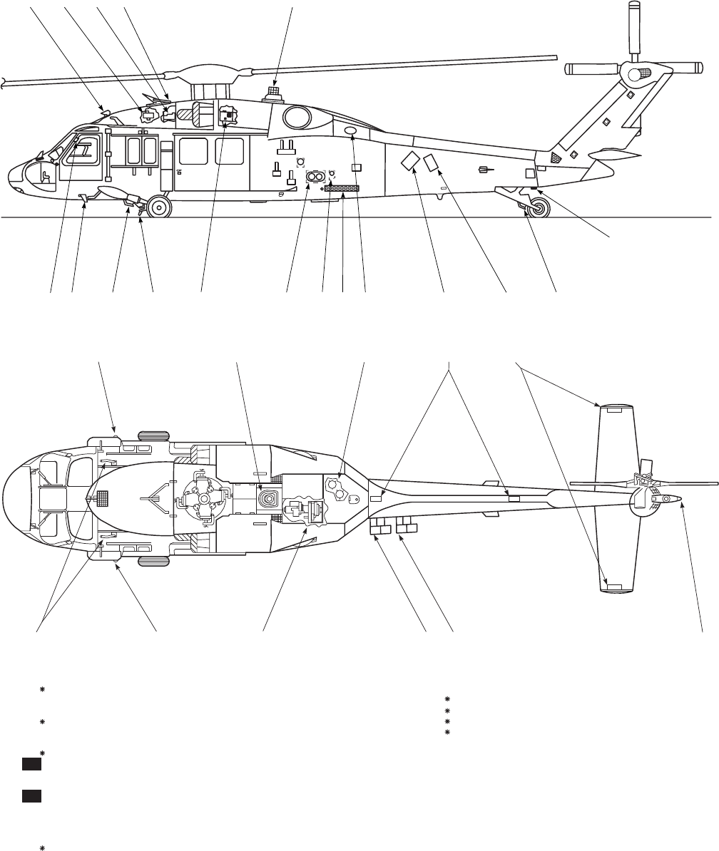
The UH-60A (BLACK HAWK) (Figure 2-1) is a twin
turbine engine, single rotor, semimonocoque fuselage, ro-
tary wing helicopter. Primary mission capability of the he-
licopter is tactical transport of troops, supplies and equip-
ment. Secondary missions include training, mobilization,
development of new and improved concepts, and support of
disaster relief. The main rotor system has four blades made
of titanium/fiberglass. The drive train consists of a main
transmission, intermediate gear box and tail rotor gear box
with interconnecting shafts. The propulsion system has two
T700-GE-700 engines operating in parallel. The nonretract-
able landing gear consists of the main landing gear and a
tailwheel. The armament consists of two 7.62 mm machine-
guns, one on each side of the helicopter in the forward
cabin. Detailed descriptions of these systems are given in
these chapters. For additional weight information, refer to
Chapters 5, 6, and 7. Kit installations for the helicopter
consist of range extension tanks, rescue hoist, medical
evacuation, infrared suppression, blade anti-icing/deicing,
blackout devices, snow skis, winterization and static/
rappelling kit. Refer to this chapter and Chapter 4 for kit
descriptions.
2.3 UH-60L. UH−60L
The UH-60L helicopter is the same as the UH-60A he-
licopter except engines T700-GE-701C replace T700-GE-
700. The main transmission is replaced by an improved
durability gearbox (IDGB).
2.4 EH-60A. EH
The EH-60A helicopter is a modified UH-60A (Figure
2-1) with a crew of four. The Mission equipment consists
of electronic systems with modifications that will ensure
that the mission requirements are met. The EH-60A system
includes air conditioning, helicopter survivability equip-
ment, and avionics equipment. An electronics compartment
within the transition section is used for avionics equipment.
The compartment can be entered from the right side of the
helicopter. The mission systems employ two operators: The
DF (ESM) operator controlling the electronics surveillance
functions, and the electronics countermeasure (ECM) op-
erator controlling the active countermeasure functions. The
EH-60A can operate independently or in conjunction with
up to two additional, similarly equipped, aircraft. When
operating in the multisystem mode, secured air-to-air com-
munications are provided for automatic tasking between
aircraft. Secured air-to-ground communications are also
provided for voice reporting purposes.
TM 1-1520-237-10
Change 9 2-1

2.5 DIMENSIONS.
Principal dimensions of the helicopter are based on the
cyclic stick and tail rotor pedals being centered and the
collective stick being in its lowest position. All dimensions
are approximate and they are as shown on Figure 2-2.
2.6 TURNING RADIUS AND GROUND CLEAR-
ANCE.
WARNING
Main rotor clearance in Figure 2-3 is
shown with cyclic centered and level
ground. Cyclic displacement or sloping
terrain may cause rotor blade clearance
to be significantly less.
For information on turning radius and ground clearance,
see Figure 2-3.
2.7 COMPARTMENT DIAGRAM.
2.7.1 Compartment Diagram. UH The fuselage is di-
vided into two main compartments, the cockpit and cabin.
The cockpit (Figure 2-4) is at the front of the helicopter
with the pilots sitting in parallel, each with a set of flight
controls and instruments. Operation of electrical controls is
shared by both. The cabin compartment contains space for
crew chief seating, troop seating, litter installation and
cargo. Restraint of cargo is by tiedown rings installed in the
floor. Two stowage compartments (Figure 6-11), at the rear
of the cabin over the main fuel tanks, are for flyaway equip-
ment. The equipment storage compartments are reached
from inside the cabin. A gust lock control, APU accumula-
tor handpump and pressure gage, and APU ESU are also
installed (Figure 2-5).
2.7.2 Compartment Diagram. EH A fixed observer
seat is installed to allow observation of either operator po-
sition (Figure 2-6). Floor attachments are provided for se-
curing rack mounts and seats. Blackout curtains may be
used to eliminate any light intrusion into the cockpit during
night operations, or any glare on the operator’s console
during day operations. Blackout curtains may be used be-
tween cockpit and cabin during NVG operations.
2.8 UPPER AND LOWER CONSOLES.
All cockpit electrical controls are on the upper and lower
consoles and instrument panel. The upper console (Figure
2-7), overhead between pilot and copilot, contains engine
controls, fire emergency controls, heater and windshield
wiper controls, internal and external light controls, electri-
cal systems and miscellaneous helicopter system controls.
The rear portion of the upper panel contains the dc essential
bus circuit breaker panels. The lower console (Figure 2-8)
next to the base of the instrument panel and extending
through the cockpit between the pilot and copilot, is easily
reached by either pilot. The console is arranged with com-
munication panels, navigational panels and flight attitude/
stability controls. The rear part of the console houses the
battery bus and battery utility bus circuit breaker panels,
and parking brake handle.
2.9 LANDING GEAR SYSTEM.
The helicopter has a nonretractable landing gear consist-
ing of two main gear assemblies and a tailwheel assembly.
The landing gear permits helicopter takeoffs and landings
on slopes in any direction. The system incorporates a jack
and kneel feature that permits manual raising or lowering
of the fuselage for air transportability. A landing gear
weight-on-wheels (WOW) switch is installed on the left
landing gear to control operation of selected systems (Table
2-1). The switch is deactivated when the weight of the he-
licopter is on the landing gear. On helicopters equipped
with ESSS fixed provisions, a WOW switch is also in-
stalled on the right landing gear drag beam to provide ac
underfrequency cutout and external stores jettison. The left
WOW switch provides all other WOW functions as without
ESSS provisions and the EMER JETT ALL capabilities.
See Table 2-1 for reference.
2.9.1 Main Landing Gear. The main landing gear is
mounted on each side of the helicopter forward of center of
gravity (Figure 2-1). Each individual landing gear has a
single wheel, a drag beam, and a two-stage oleo shock strut.
The lower stage will absorb energy from landings up to 10
feet-per-second (fps). Above 10 fps the upper stage and
lower stage combine to absorb loads up to 39 fps (about
11.25 Gs).
2.9.2 Wheel Brake System. Main landing gear wheels
have disc hydraulic brakes. The self-contained self-
adjusting system is operated by the pilot’s and copilot’s tail
rotor pedals. The brakes have a visual brake puck wear
indicator. Each wheel brake consists of two steel rotating
discs, brake pucks and a housing that contains the hydraulic
pistons. The parking brake handle, marked PARKING
BRAKE, is on the right side of the lower console (Figure
2-8). A hand-operated parking brake handle allows brakes
to be locked by either pilot or copilot after brake pressure is
applied. The parking brakes are applied by pressing the toe
brake pedals, pulling the parking brake handle to its fully
extended position, and then releasing the toe brakes while
holding the handle out. An advisory light will go on, indi-
TM 1-1520-237-10
2-2 Change 10
SA
AA0403_1A
19 520 21 21
22
8
9
23
24
25
1. PITOT CUTTER
2. BACK HYDRAULIC PUMP
3. NO. 1 HYDRAULIC PUMP AND NO.1 GENERATOR
4. UPPER (ROTOR PYLON) CUTTER
5. INFRARED COUNTERMEASURE TRANSMITTER
6. AFT MAINTENANCE LIGHT RECEPTACLE
7. TAIL LANDING GEAR DEFLECTOR
8. FLARE DISPENSER
9. CHAFF DIPENSER
10. APU EXHAUST PORT
11. COOLING AIR INLET PORT
12. PNEUMATIC PORT
13. PRESSURE AND CLOSED CIRCUIT REFUELING PORTS
14. NO. 1 ENGINE
15. MAIN LANDING GEAR DEFLECTOR / CUTTER
16. LANDING GEAR JOINT DEFLECTOR
17. STEP AND EXTENSION DEFLECTOR
18. DOOR HINGE DEFLECTOR
19. RIGHT POSITION LIGHT (GREEN)
20. FIRE EXTINGUISHER BOTTLES
21. FORMATION LIGHTS
22. TAIL POSITION LIGHT (WHITE)
23. APU
24. LEFT POSITION LIGHT (RED)
25. PITOT TUBES
ON HELICOPTERS EQUIPPED WITH WIRE STRIKE PROTECTION SYSTEM
EH
EH
1 2 3 4 5
18 17 16 15 14 13 12 10 9 8 7
6
11
Figure 2-1. General Arrangement (Sheet 1 of 2)
TM 1-1520-237-10
2-3
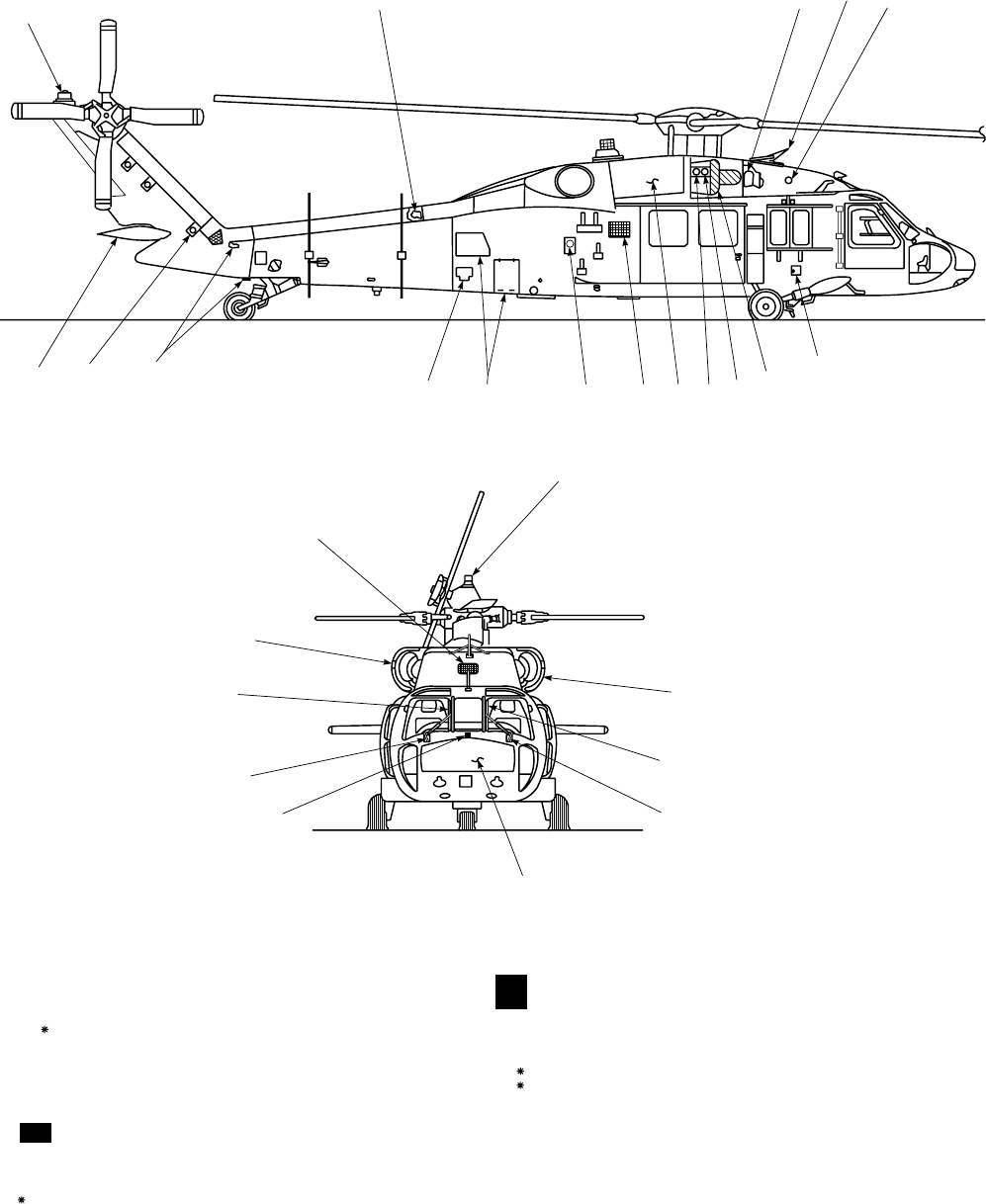
SA
AA0403_2B
27 28 29 30
31
32
33
34
35
36
37
38
39
40
41
42
26
43
44
45
46
47
45
44
48
49
26.
27.
28.
29.
30.
31.
32.
33.
34.
35.
36.
37.
UPPER ANTICOLLISION LIGHT
TAIL DRIVE SHAFT
NO. 2 HYDRAULIC PUMP AND NO. 2 GENERATOR
PYLON CUTTER
HEATER AIR INTAKE PORT
EXTERNAL ELECTRICAL POWER RECEPTACLE
NO. 2. ENGINE
ICE DETECTOR
AMBIENT SENSE PORT
ENGINE FAIRING / WORK PLATFORM (SAME BOTH SIDES)
CONDENSER EXHAUST / STEP
GRAVITY REFUELING PORT (SAME BOTH SIDES)
39.
40.
41.
42.
43.
44.
45.
46.
47.
48.
49.
AFT AVIONICS COMPARTMENT DOORS
IINS BLOWER INLET FILTER
TAIL PYLON FOLD HINGES
TAIL PYLON SERVICE LADDER (SAME BOTH SIDES)
STABILATOR
ENGINE BAY AREA COOLING AIR INTAKE (SAME BOTH SIDES)
WINDSHIELD POST DEFLECTOR
WINDSHIELD WIPER DEFLECTOR
AVIONICS COMPARTMENT
OAT SENSOR
ICE DETECTOR
PYLON COOLING AIR INTAKE
ON HELICOPTERS EQUIPPED WITH WIRE STRIKE PROTECTION SYSTEM
EH
EH
EH
26
38.
Figure 2-1. General Arrangement (Sheet 2 of 2)
TM 1-1520-237-10
2-4
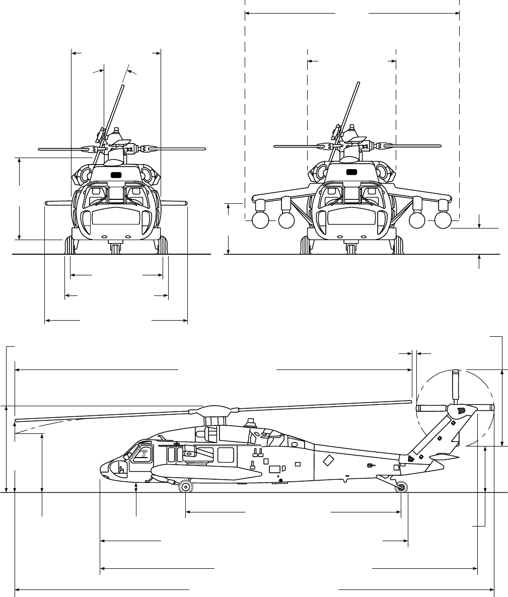
SA
AA0514B
TAIL ROTOR
DIAMETER
11 FEET
12 FEET−
4 INCHES
9 FEET −
5 INCHES
MAIN ROTOR DIAMETER
53 FEET − 8 INCHES
7 FEET −
7 INCHES 1 FOOT −
7 INCHES
WHEEL BASE 29 FEET
LENGTH − ROTORS AND PYLON FOLDED 41 FEET − 4 INCHES
FUSELAGE LENGTH 50 FEET − 7.5 INCHES
OVERALL LENGTH 64 FEET − 10 INCHES
6 FEET −
6 INCHES
2.8 INCHES
FUSELAGE WIDTH
7 FEET − 9 INCHES
TREAD
8 FEET
10.6 INCHES
MAIN LANDING GEAR
9 FEET − 8.6 INCHES
STABILATOR WIDTH
14 FEET − 4 INCHES
8 FEET−
9 INCHES
20O
5 FEET
1 INCH
3 FEET
9.5 INCHES
WIDTH WITH ESSS AND EXTERNAL
EXTENDED RANGE TANKS INSTALLED
21 FEET
FUSELAGE WIDTH WITH
HOVER IR SUPPRESSORS
INSTALLED
9 FEET − 8 INCHES
Figure 2-2. Principal Dimensions
TM 1-1520-237-10
2-5
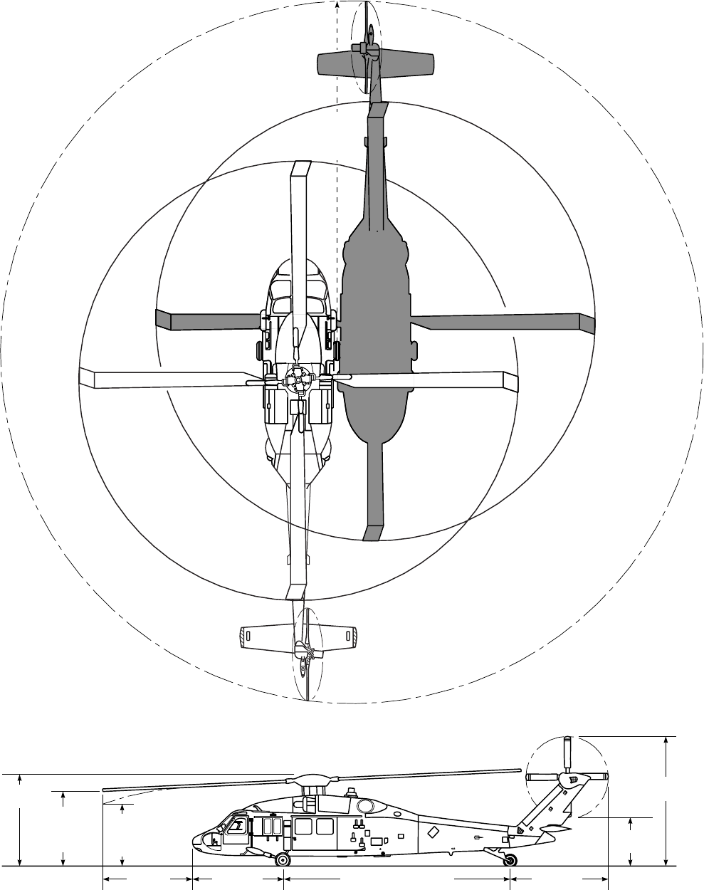
TURNING
RADIUS
41 FEET
7.7 INCHES
12 FEET
4 INCHES
9 FEET
5 INCHES
ROTOR
TURNING
7 FEET
7 INCHES
ROTOR
STATIONARY
12 FEET
1 INCH 11 FEET
4 INCHES WHEELBASE 29 FEET 12 FEET
5 INCHES
6 FEET
6 INCHES
16 FEET
10 INCHES
*
TAIL ROTOR IS CANTED 20O. UPPER
TIP PATH PLANE IS 16 FEET 10 INCHES
ABOVE GROUND LEVEL
*
SA
AA0402
Figure 2-3. Turning Radius and Clearance
TM 1-1520-237-10
2-6
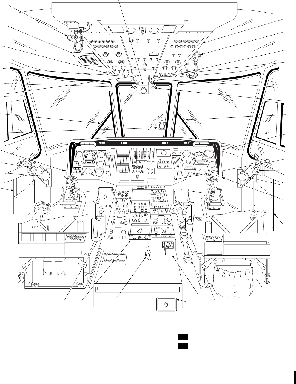
SA
AB0821
25
24
CHECK LIST
STOWAGE
DATA & MAP
CHECK LIST
DATA & MAP
STOWAGE
1. UPPER CONSOLE
2. PILOT’S COCKPIT UTILITY LIGHT
3. FREE−AIR TEMPERATURE GAGE (ON
HELICOPTERS WITH HEATED CENTER
WINDSHIELD)
4. NO. 2 ENGINE FUEL SELECTOR LEVER
5. NO. 2 ENGINE OFF / FIRE T−HANDLE
6. NO. 2 ENGINE POWER CONTROL LEVER
7. WINDSHIELD WIPER
8. INSTRUMENT PANEL GLARE SHIELD
9. INSTRUMENT PANEL
10. VENT / DEFOGGER
11. ASHTRAY
12. PEDAL ADJUST LEVER
13. MAP / DATA CASE
15. CHAFF RELEASE SWITCH
16. PARKING BRAKE LEVER
17. FUEL BOOST PUMP PANEL
18. LOWER CONSOLE UTILITY LIGHT
20. NO. 1 ENGINE POWER CONTROL LEVER
21. NO. 1 ENGINE OFF / FIRE T−HANDLE
22. NO. 1 ENGINE FUEL SELECTOR LEVER
23. AC ESNTL BUS CIRCUIT BREAKER
PANEL
24. COPILOT’S COCKPIT UTILITY LIGHT
25. FREE−AIR TEMPERATURE GAGE (ON
HELICOPTERS WITHOUT HEATED
CENTER WINDSHIELD)
EH
EH
23
3
22
21
20
7
19
12
10
11
13
1
2
3
6
4
5
7
8
9
10
11
12
13
17
15
11
16
18 14
19. STANDBY (MAGNETIC COMPASS)
14. CABIN DOME LIGHTS DIMMER
Figure 2-4. Cockpit Diagram (Sheet 1 of 2)
TM 1-1520-237-10
Change 4 2-7
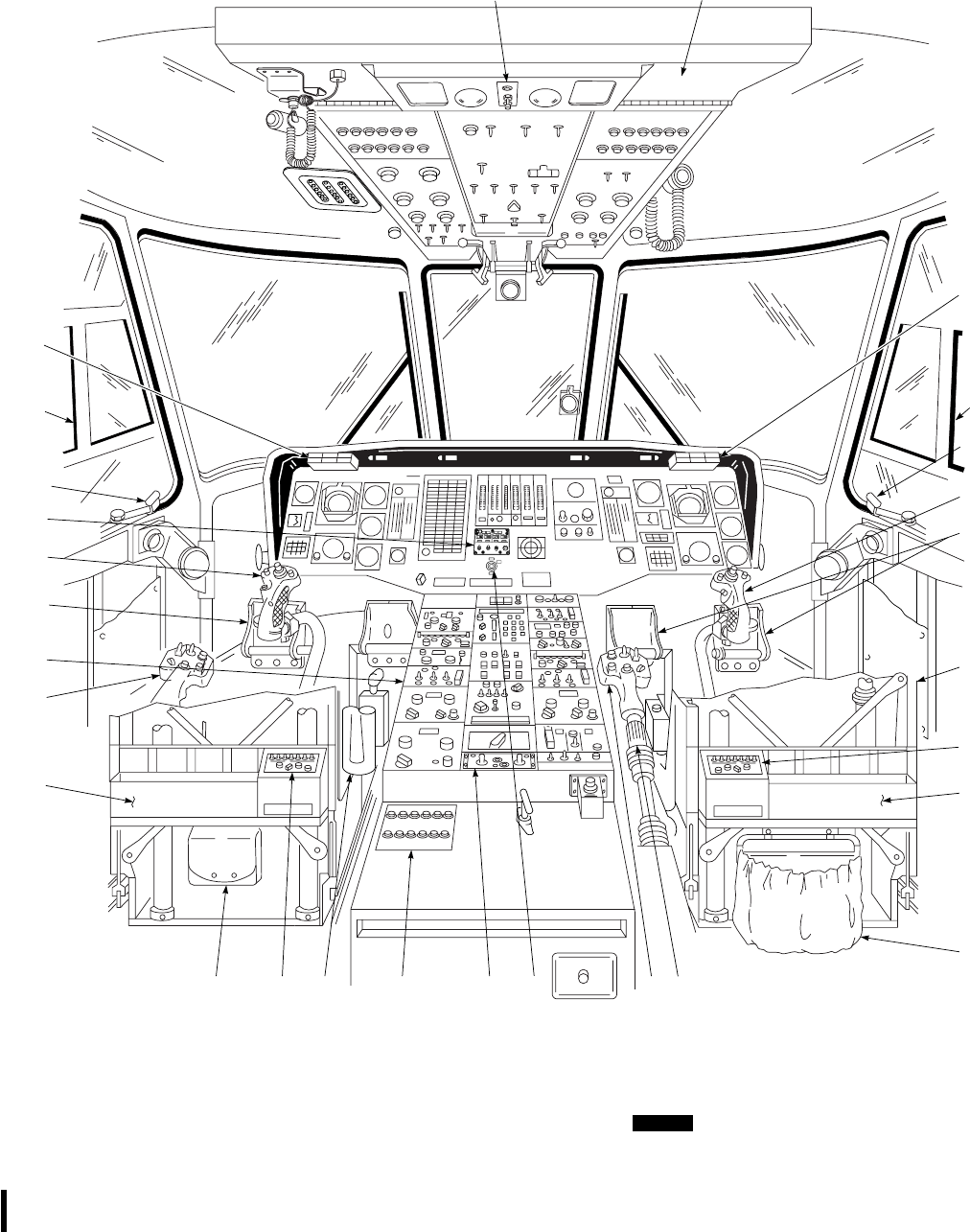
28
30
33
34
35
36
29
32
31
26 27
CHECK LIST
STOWAGE
DATA & MAP
CHECK LIST
DATA & MAP
STOWAGE
26.
27.
28.
29.
30.
31.
32.
33.
34.
28
29
30
31
32
46
38
45
37
384041424344
COCKPIT FLOODLIGHT CONTROL
UPPER CONSOLE
MASTER WARNING PANEL
SLIDING WINDOW
COCKPIT DOOR EMERGENCY RELEASE
CYCLIC STICK
DIRECTIONAL CONTROL PEDALS
PILOT’S SEAT
35.
36.
37.
38.
39.
40.
CREW CHIEF / GUNNER ICS CONTROL
PANEL
CREW CHIEF AMMUNITION / GRENADE
STOWAGE COMPARTMENT
STOWAGE BAG
COLLECTIVE STICK FRICTION CONTROL
COLLECTIVE STICK GRIP
ENGINE IGNITION KEYLOCK
LOWER CONSOLE
41.
42.
43.
44.
45.
46.
BATTERY / BATTERY UTILITY BUS
CIRCUIT BREAKER PANEL
FIRE EXTINGUISHER
GUNNER’S ICS CONTROL PANEL
FIRST AID KIT
GUNNER’S AMMUNITION / GRENADE
COPILOT’S SIDE LOWER CONSOLE
SA
AB0822
39
47
47. AUXILIARY FUEL MANAGEMENT PANEL
AFMS
Figure 2-4. Cockpit Diagram (Sheet 2 of 2)
TM 1-1520-237-10
2-8 Change 4
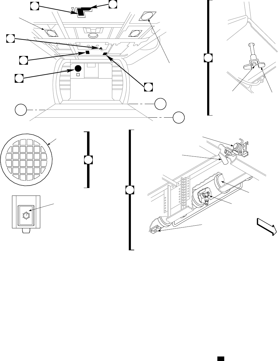
cating PARKING BRAKE ON. Pressing either pilot or
copilot left brake pedal will release the parking brakes, the
handle will return to the off position and the advisory light
will go off. Power for the advisory light comes from the
No. 1 dc primary bus through a circuit breaker marked
LIGHTS ADVSY.
2.9.3 Tail Landing Gear. The tail landing gear (Figure
2-1) is below the rear section of the tail cone. It has a
two-stage oleo shock strut, tailwheel lock system fork as-
sembly, yoke assembly, and a wheel and tire. The fork
assembly is the attachment point for the tailwheel and al-
lows the wheel to swivel 360°. The tailwheel can be locked
in a trail position by a TAILWHEEL switch in the cockpit
indicating LOCK or UNLK (Figure 2-8). The fork is
locked by an electrical actuator through a bellcrank and
locking pin. When the pin is extended, the switch will in-
dicate LOCK. When the pin is retracted, the switch will
indicate UNLK. Power to operate the locking system is by
the dc essential bus through a circuit breaker marked
TAILWHEEL LOCK.
2.10 INSTRUMENT PANEL.
2.10.1 Instrument Panel. UH Engine and dual flight
instruments are on the one-piece instrument panel (Figure
2-9). The panel is tilted back 30°. The master warning pan-
els are mounted on the upper instrument panel below the
SA
AA0323_1B
C
ON HELICOPTERS EQUIPPED WITH
AUXILIARY CABIN HEATER
GUST LOCK CONTROL
APU ACCUMULATOR
(LOOKING UP)
(LOCATED BELOW LEFT GUNNER’S WINDOW)
GUST LOCK
RELEASE
BUTTON
GUST LOCK
HANDLE
HEATER AIR
INLET PORT
67
50 85
CABIN DOME
LIGHTS (THREE)
TROOP COMMANDER’S
ANTENNA COAX
ON HELICOPTERS EQUIPPED
WITH AUXILIARY CABIN HEATER
EF
A
D
B
ACCUMULATOR
PRESSURE GAGE
ACCUMULATOR
HAND PUMP
ACCUMULATOR
PISTON POSITION
INDICATOR
MANUAL
START
VALVE
ACCUMULATOR
B
HEATER TEMPERATURE
CONTROL
C
STA
349.50
STA
378.50
STA
332.50
A
AFT
Figure 2-5. Cabin Interior (Sheet 1 of 2)
TM 1-1520-237-10
2-9
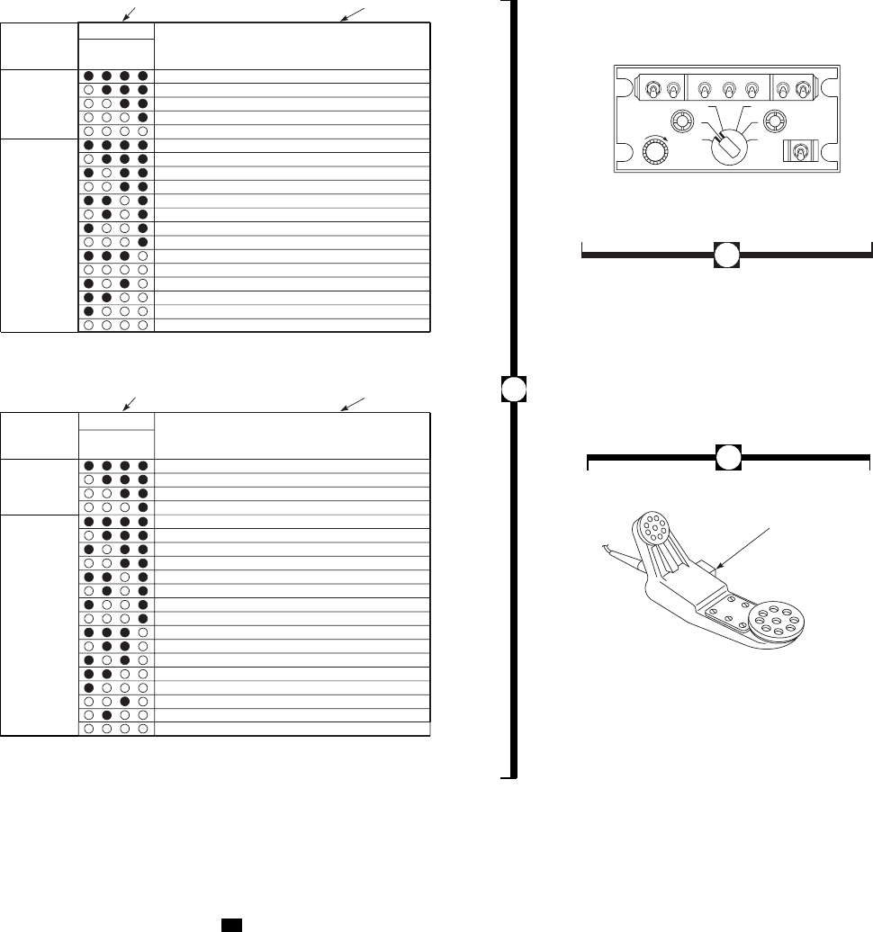
glare shield, to inform the pilot of conditions that require
immediate action.
2.10.2 Instrument Panel. EH The instrument panel of
the EH-60A is as shown on Figure 2-9. Refer to Chapter 3
for description and operation of systems switch panels and
Chapter 4 for BDHI,CREW CALL switch, FLARE
switch and ECM ANTENNA switch and countermeasure
set ALQ-156.
2.10.3 Vertical Instrument Display System (VIDS).
The VIDS (Figure 2-9) consists of a vertical strip central
display unit (CDU), two vertical strip pilot display units
(PDU), and two signal data converters (SDC). Those read-
ings are shown by ascending and descending columns of
multicolored lights (red, yellow, and green) measured
against vertical scales which operate in this manner: the
segments will light in normal progression and remain on as
the received signal level increases. Those scales will go off
in normal progression as the received signal level decreases.
Scales with red-coded and/or amber-coded segments below
green-coded segments operate in this manner: When the
received signal level is zero or bottom scale, the segments
will light in normal progression and will remain on. When
the first segment above the red or amber range goes on, all
red-coded or amber-coded segments will go off. These seg-
ments will remain off until the received signal level indi-
cates a reading at or within the red or amber range. At that
SA
AA0323_2A
TROOP COMMANDER’S ICS CONTROL
APU ELECTRONIC SEQUENCE UNIT FAULT INDICATION
TROOP COMMANDER’S HANDSET
PUSH−TO−TALK
SWITCH
AUX NAV12 3 4 5
OFF
HOT MIKE
ON
OFF
ON
OFF
VOL ICS
1
23
4
5
C
O
N
T
C
O
M
M
RESET
START FUEL VALVE & EXCITER SIGNAL OUT (5%)
MAIN FUEL VALVE SIGNAL OUT (14%)
START FUEL VALVE & EXCITER SIGNAL OFF (70%)
90% RPM SWITCH ON
READY FOR SERVICE (90% + 1.5 SEC)
PROCESSOR BOARD FAILURE
SENSOR/DATA BOARD FAILURE
OVERTEMPERATURE
OVERSPEED
UNDERSPEED
FAIL TO START
LOW OIL PRESSURE
HIGH OIL TEMPERATURE (WARNING)
FAIL TO LIGHT (NO DATA)
SHORTED THERMOCOUPLE PROBE (WARNING)
OPEN THERMOCOUPLE
PROCESSOR SEQUENCE FAIL
NO DATA
OPERATION
START
SEQUENCE
1234
BITE #
T−62T−40−1
DECODED BITE INFORMATION
FAULT INDICATION FAULTS
APU ELECTRONIC SEQUENCE UNIT FAULT INDICATION
RESET (START INITIATED)
FUEL VALVE AND IGNITION SIGNAL ON (5%)
START VALVE SIGNAL OFF (70%)
IGNITION SIGNAL OFF (95%)
READY FOR SERVICE (LOSS OF DC POWER)
A/C START SYSTEM FAILURE
OVERTEMPERATURE
OVERSPEED
UNDERSPEED
FAIL TO START
LOW OIL PRESSURE
HOT SENSOR FAILED
1234
BITE # DECODED BITE INFORMATION
FAULT INDICATION FAULTS
GTC−P36−150
ESU FAILURE
OIL PRESSURE SWITCH FAILED
THERMOCOUPLE FAILED
MONOPOLE FAILED
FUEL SOLENOID FAILED
FUEL TORQUE MOTOR FAILED
IGNITION UNIT FAILED
NO DATA
E
F
OPERATION
START
SEQUENCE
(ON HELICOPTERS EQUIPPED WITH T−62T−40−1 APU)
(ON HELICOPTERS EQUIPPED WITH GTC−P36−150 APU)
D
Figure 2-5. Cabin Interior (Sheet 2 of 2)
TM 1-1520-237-10
2-10
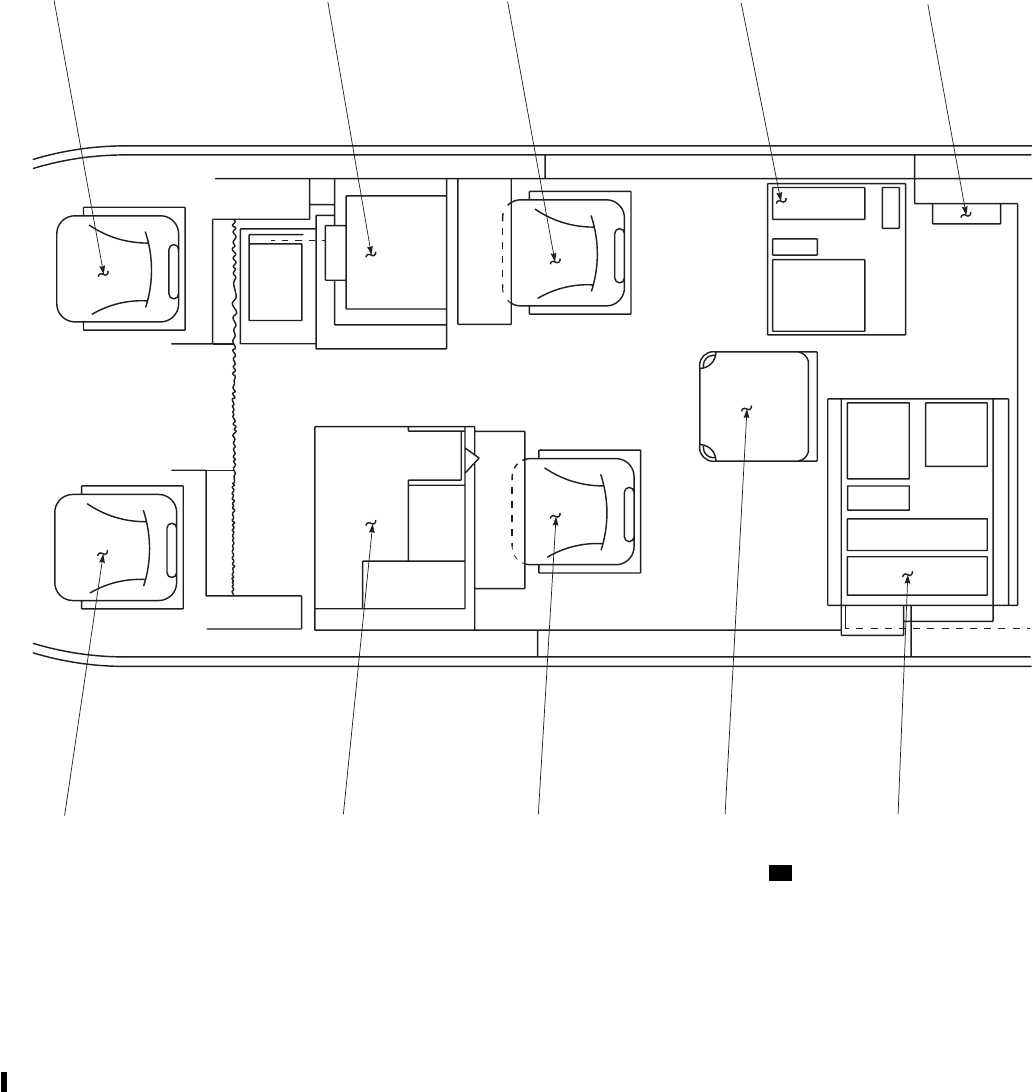
time all red-coded or amber-coded segments will go on and
the scale display will either go on or go off in normal pro-
gression, depending upon the received signal level. The
CDU and PDUs contain photocells that automatically ad-
just lighting of the indicators with respect to ambient light.
If any one of the three photocells should fail, the lights on
the vertical scales of the PDUs or CDU may not be at the
optimum brightness for the ambient conditions. The DIM
knob on the CDU contains an override capability which
allows the pilot to manually set the display light level. The
SDCs receive parameter data from the No. 1 and No. 2
engines, transmission, and fuel system; provides processing
and transmits the resulting signal data to the instrument
display. The No. 1 engine instruments on the CDU and
copilot’s PDU, receive signal data from the No. 1 SDC
(CHAN 1). The No. 2 engine and main transmission instru-
ments on the CDU and pilot’s PDU, receives signal data
from the No. 2 SDC (CHAN 2). If either SDC fails, the
corresponding CHAN 1 or 2light will go on, and it is
likely the pilot’s or copilot’s PDU and the corresponding
instruments will fail. Failure of a lamp power supply within
an SDC will cause every second display light on the CDU
to go off. Both SDCs receive %RPM1and 2,% RPM R
and % TRQ information from both engines. Therefore if
one SDC fails only one PDU will provide % RPM 1 and 2
and % TRQ for both engines.
SA
AA0401
PILOT ECM CONSOLE ECM OPERATOR SEAT ECM EQUIPMENT RACK MISSION INTERFACE PANEL
COPILOT DF CONSOLE DF OPERATOR SEAT OBSERVER SEAT DF EQUIPMENT RACK
Figure 2-6. Cabin Mission Equipment Arrangement EH
TM 1-1520-237-10
Change 9 2-11

2.10.4 Central Display Unit (CDU). The CDU (Figure
2-9) contains instruments that display fuel quantity, trans-
mission oil temperature and pressure, engine oil tempera-
ture and pressure, turbine gas temperature (TGT), and gas
generator speed (Ng) readings. Those readings are shown
by ascending and descending columns of multicolored
lights (red, yellow, and green) measured against vertical
scales. If the instrument contains low range turnoff (red or
yellow lights below green lights) they will go off when the
system is operating within the normal range (green). If the
instrument contains yellow or red lights above the green
range, the green as well as the yellow or red will stay on
when operating above the green range. The operating
ranges for the different instruments are shown in Figures
5-1, 5-2, and 5-3. Digital readouts are also installed on the
TOTAL FUEL quantity, TGT, and Ng gages.
2.10.4.1 Lamp Test System. The lamp test provides a
means of electrically checking all CDU scale lamps, digital
readouts, and % RPM RTR OVERSPEED lights on the
PDUs. When the PUSH TO TEST switch on the CDU is
pressed, all CDU scale lamps should light, digital readouts
should display 888, and three RTR OVERSPEED lights
on the PDUs should be on.
2.10.4.2 Dim Control. The DIM control allows the pilot
to set a desired display light level of the CDU and PDUs in
accordance with the ambient light, or override the auto-dim
sensors. If the auto-dim circuitry should fail or malfunction,
turn the DIM control fully clockwise to regain illumination
of the CDU and PDUs.
2.10.4.3 CDU and PDU Digital Control. An ON,OFF
DIGITS control switch is on the CDU (Figure 2-9) to turn
on or off the digital readout displays on the CDU and PDUs.
If a digital processor fails, all digital displays will go off.
2.10.5 Pilot’s Display Unit (PDU). The PDU (Figure
2-9) displays to the pilot engine power turbine speed (%
RPM 1 and 2), rotor speed (% RPM R), and torque (%
TRQ). Readings are shown by ascending and descending
columns of multicolored lights (red, yellow, and green)
measured against vertical scales. A TEST switch provides
a means of electrically checking all PDU scale lamps and
digital readouts. When the TEST switch is pressed, all PDU
scale lamps should light and digital readouts should display
188. The % RPM indicators contain low range turnoff be-
low the normal operating range. Three overspeed lights at
the top will go on from left to right when a corresponding
WOW SWITCH FUNCTION ON GROUND IN FLIGHT
Backup Pump Automatic Operation Disabled (Except when APU
accumulator is low) Enabled
Hydraulic Leak Test System Enabled Disabled
Backup Pump Thermal Switch Enabled Disabled
Low % RPM R Audio Warning Disabled Enabled
SAS/FPS Computer Degraded Enabled
Generator Underfrequency Protection Enabled Disabled
IFF Mode 4 Operation Disabled Automatic Zeroize Enabled Automatic Zeroize
External Stores Jettison ES Disabled Enabled
Deleted Deleted Deleted
AUX FUEL INCR/DECR Switch ES Enabled Disabled
5 minute delay before continuous BIT
(CBIT) monitors attitude sensor after AFMP
power up AFMS
Enabled Disabled
AFMP Power up BIT (PBIT) and Initiated
BIT (IBIT) AFMS
Enabled Disabled
Table 2-1. Weight-On-Wheels Functions
TM 1-1520-237-10
2-12 Change 10
rotor speed of 127%, 137%, and 142% is reached. Once a
light is turned on, a latch prevents it from going off until
reset by maintenance. Power for the PDUs is from No. 1
and No. 2 ac and dc primary buses through circuit breakers
marked NO. 1 AC INST/NO. 1 DC INST and NO.2AC
INST/NO. 2 DC INST respectively. See Figures 5-1, 5-2,
and 5-3 for instrument markings.
TM 1-1520-237-10
Change 8 2-12.1/(2-12.2 Blank)
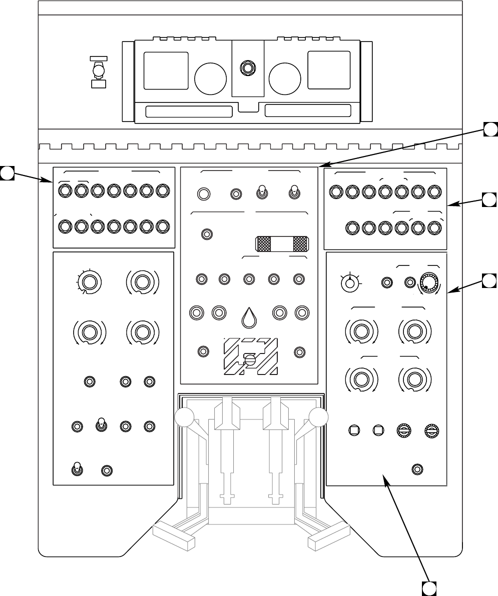
NO.2
ENG SENSE SPLY
5510
ESNTL
DC BATT
BUS
FIRE DET
CONTR SRCH
20 5
5
DC ESNTL BUS
LIGHTS
SEC
PNL PWR CONTR
MED
CONSOLE LT
LOWER
OFF HI
PILOT FLT
INSTR LT
WINDSHIELD
COPILOT ANTI−ICE
PITOT
HEAT
BLOWER
BRT
OFF
BRT
OFF
ON
ON
ON ON
PILOT
HEATER
O
F
F
O
F
F
OO
F
F
SA
AA0364_1A
A
B
C
D
MAIN
TEST
SHORT
SAFE
ARMED
CKPT
NORM
EMERG REL CONTR ARMING
RESET TEST TEST TEST
ON
EXT PWR BATT APU NO. 1 NO. 2
GENERATORS
TEST A TEST B OPER TEST A TEST B
NO. 1 ENG OVSP NO. 2 ENG OVSP
FIRE DETR TEST
1
2
AIR SOURCE
HEAT / START
FUEL PUMP
APU BOOST
FUEL PRIME APU
ENGINE
APU
ON ON ON ON
CARGO HOOK
ALL
APU
CONTR FIRE EXTGH
ON
FIRE EXTGH
RESERVE
O
F
F
O
F
F
O
F
F
O
F
F
O
F
F
O
F
F
R
E
S
E
T
O
F
F
R
E
S
E
T
O
F
F
R
E
S
E
T
O
P
E
N
OFF
PNL CONTR
FUEL
DUMP
NO. 1 VOR / ILS CHIP
DC ESNTL BUS
25
25
255
2
2
5
7.5 5
ICS ESSS
JTSN
PILOT COPILOT VHF FM DET CONTR OUTBD
COMM SCTY SET
NO. 1 FM UHF AM UHF
AM CAUT /
ADVSY BACKUP
HYD HOIST
CABLE
*
ESSS
JTSN
SHEAR INBD
*
NO.1
RATE ENG
525
55
5
7.5
STAB CARGO
HOOK PILOT
TURN
PWR EMER
SAS NO. 1
ENG TAIL
WHEEL
BOOST START LOCK
PARK OFF LOW
HI
UPPER
NON FLT
NO. 1 NO. 2
ENG ANTI−ICE
ON
WINDSHIELD
WIPER
VENT
BRT
OFF
BRT
OFF
ON ON
O
F
F
O
F
F
O
F
FF
F
28V #387
SPARE
LAMPS
OPEN
E
7.5
7.5
FORMATION LT
POSITION
LIGHTS
STEADY
ANTICOLLISION
LIGHTS
LOWER NIGHT
DAY
DIM
BRT FLASH
UPPER
CABIN
DOME LT
WHITE
BLUE
HYD
LEAK TEST
BACKUP
HYD PUMP RESET
TEST
ON
OFF
CARGO
HOOK LT
ON
NAV LTS
IR
LIGHTED
SWITCHES
BRT
OFF
GLARESHIELD
LIGHTS
BRT
OFF
CPLT FLT
INST LTS
BRT
OFF
5
4
3
2
1
OFF
O
F
F
O
F
F
O
F
F
O
F
F
N
O
R
M
N
O
R
M
B
O
T
H
A
U
T
O
BLUE
WHITE
O
F
F
Figure 2-7. Upper Console (Sheet 1 of 2)
TM 1-1520-237-10
2-13
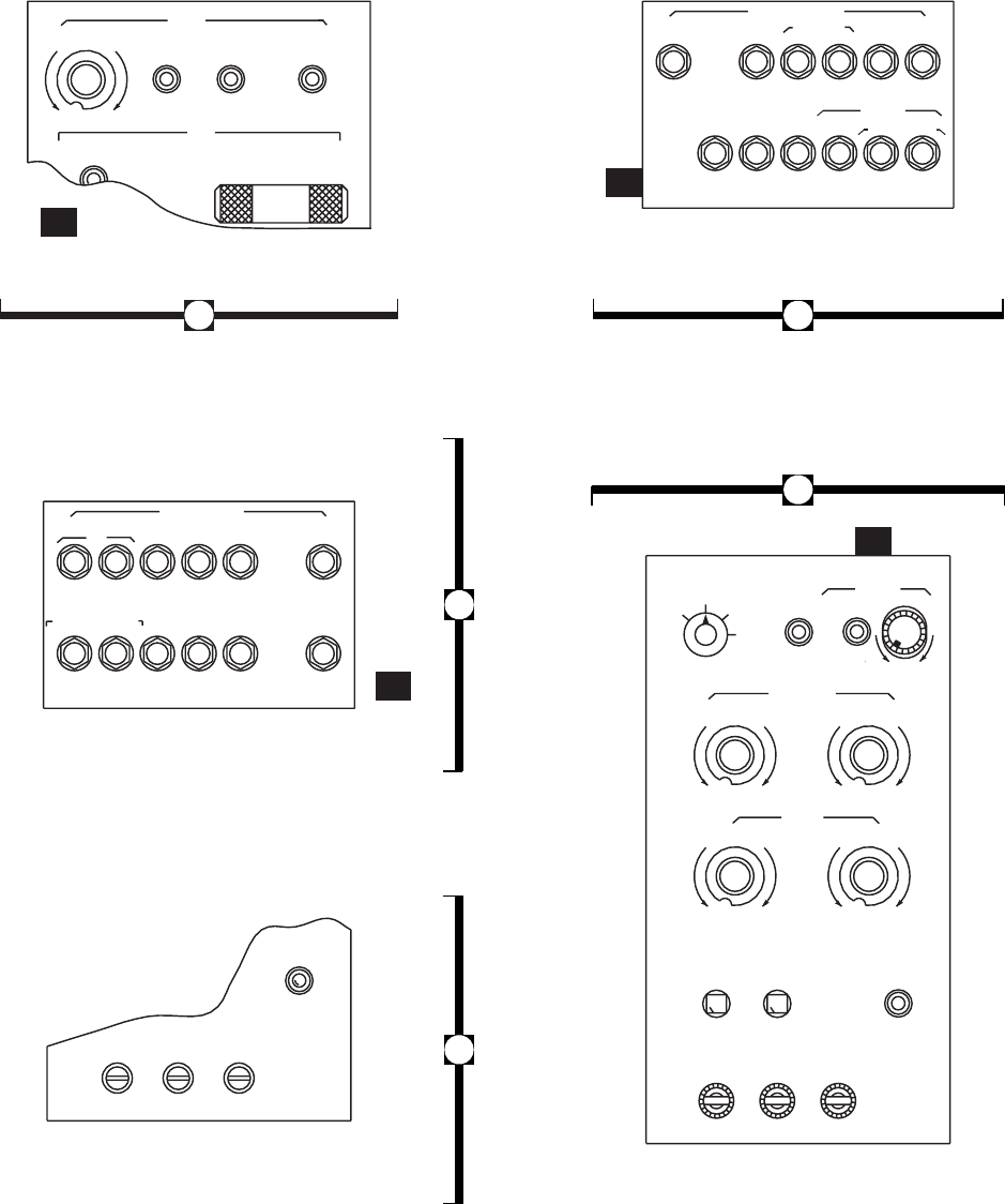
DC ESNTL BUS
SA
AA0364_2A
PNL CONTR
NO. 1 VOR / ILS CHIP
DC ESNTL BUS
25
25
25
2
2
NO.1 NO.2
RATE ENG ENG SENSE SPLY
255510
ESNTL
DC BATT
BUS
FIRE DET
CONTR SRCH
55 20 5
55
LIGHTS
5
ICS ESSS
JTSN
PILOT COPILOT VHF FM DET OUTBD
COMM SCTY SET
NO. 1 FM UHF AM UHF
AM CAUT /
ADVSY BACKUP
HYD ESSS
JTSN
INBD
STAB PILOT
TURN
PWR
SAS NO. 1
ENG TAIL
WHEEL SEC
BOOST START LOCK PNL PWR CONTR
MED
PARK OFF LOW
HI
CONSOLE LT
UPPER LOWER
OFF HI
NON FLT PILOT FLT
INST LT
NO. 1 NO. 2
ENG ANTI−ICE
WINDSHIELD
COPILOT ANTI−ICE
CTR
ON
WINDSHIELD
WIPER
PITOT
HEAT
VENT
BLOWER
BRT
OFF BRT
OFF
BRT
OFF BRT
OFF
ON
ON
ON ON
ON ON ON
PILOT
HEATER
O
F
F
O
F
F
O
F
F
O
F
F
O
F
F
O
F
F
O
F
F
O
F
F
FAN
PWR
ON
HTR
COOL
TEMP CONT Q / F
APU
ECS
ON
APU
CONTR FIRE EXTGH
WINDSHIELD
COPILOT ANTI−ICE
CTR
ON
ON ON ON
PILOT
O
F
F
O
F
F
O
F
F
O
F
F
7.5
7.57.5
7.5
EH
EH
EH
EH
(ON HELICOPTERS EQUIPPED WITH
HEATED CENTER WINDSHIELD)
AIR COND
COOL WARM
O
F
F
O
F
F
O
F
F
AB
C
E
D
Figure 2-7. Upper Console (Sheet 2 of 2)
TM 1-1520-237-10
2-14
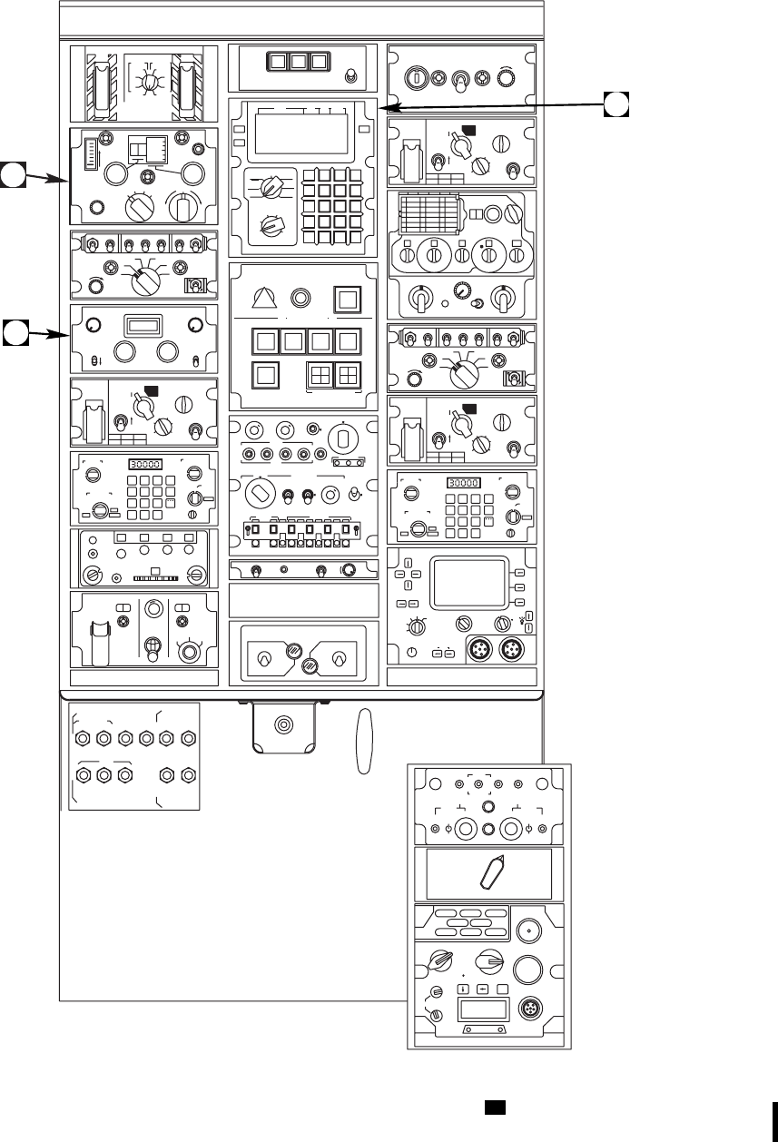
STORES JETTISON
EMER
JETT
ALL JETT
INBD OUTBD
BOTH BOTH
RR
LL
OFF ALL
AUDIO
KILOCYCLES CW
TEST
VOICE
LOOP
T
U
N
E
A
D
F
R
C
V
ROFF LOOP
COMP ANT
29
80
90
LR
ON
OFF
ON
OFF
VOL ICS
124
3
5HOT MIKE
OFF
C
O
M
M
1 2 3 4 5 AUX NAV
C
O
N
T
NAV VOL MB VOL
OFF
VOR / MB
TEST
OFF
MB SENS
HI
LO
108.00
TAIL
WHEEL GYRO
ERECT
TAIL SERVO
NORMAL
BACKUP
M
I
S
C
S
W
FUEL BOOST PUMP CONTROL
ON
OFF
NO. 1
PUMP NO. 2
PUMP
ON
OFF
TEST
COMPASS
SLAVED
FREE
PUSH TO
SET
+00+
CHAN
1
30 0000
MAIN VOL PRESET
GUARDMANUALBOTHOFF
ADF
TONE SQUELCH
OFF ON
U
H
F
ON
OFF
ON
OFF
VOL ICS
124
3
5HOT MIKE
OFF
C
O
M
M
1 2 3 4 5 AUX NAV
C
O
N
T
+
PWR SELF DSCRM
ON
OFF
ON
OFF AUDIO
TEST
PLAIN
C / RAD MODE
DELAY
ON
POWER
OP LD
RV
1
2
34
5
6
Z
E
R
O
I
Z
E
KY
58
R
C
U
FILL
1
235
46
P
R
E
S
S
T
O
T
E
S
T
D
I
M
P
R
E
S
S
T
O
T
E
S
T
D
I
M
TEST TEST/MON TOP
BOT
MASTER
TEST
OUT
STATUS
IDENT
MIC
TEST AUDIO
P
R
E
S
S
T
O
T
E
S
T
D
I
M
REPLY
CODE
M−1 M−2 M−3 / A M−C
A
N
T
D
I
V
O
NO
N
L
I
G
H
T
O
U
T
MODE 1 MODE 3 / A
N
O
G
O
E
M
E
R
N
O
R
M
S
T
B
Y
O
F
F
ALT KIT ANT
001200
A
B
MODE 4
O
N
G
O
FM 1 / FM 2 FM 2 / UHF
FM 2 / VHFFM 1 / VHF
FM 1 / UHF VHF / UHF
OFF
OUT
MAN SLEW
UP
DN
TEST
AUTO
CONTROL
ON
ON ON ON ON
ON
STABILATOR CONTROL
SAS 1 SAS 2 TRIM FPS
AUTO FLIGHT CONTROL
BOOST
R
E
S
E
T
O
F
F
R
E
S
E
T
R
E
S
E
T
POWER ON RESET
CPTR
TRIM
SAS 2
RGYR
ACCL
A / S
CLTV
GYRO
FAILURE ADVISORY
Z
ER
O
H
O
L
D
RAD
TEST
FUEL
IND
F
I
F
RADIO RETRANSMISSION
PLAIN
C / RAD MODE
DELAY
ON
POWER
OP LD
RV
1
2
34
5
6
Z
E
R
O
I
Z
E
KY
58
R
C
U
FILL
1
235
46
1 2 3 FREQ
4 5 6
7 8 9 TIME
CLR Sto
ENT
H−Ld
0
L
LE
ERF
OFST
MAN
12345
6
CUE
PRESET
TEST
SQ ON
SQ OFF LD
LD−V
Z−A
STOW
FUNCTION
RXMT
OFF
OFF
LO
NORM HI
IFM RF PWR
MODE
HOM SC
FH
FH−M
VOL
9
14 1 0 50
FM AM
MAN
PRE
DF
TR
OFF
V
O
L
S
Q
D
I
S
T
O
N
E
EMER
LOAD
PRESET
C
O
M
M
PLAIN
C / RAD MODE
DELAY
ON
POWER
OP LD
RV
1
2
34
5
6
Z
E
R
O
I
Z
E
KY
58
R
C
U
FILL
1
235
46
1 2 3 FREQ
4 5 6
7 8 9 TIME
CLR Sto
ENT
H−Ld
0
L
LE
ERF
OFST
MAN
12345
6
CUE
PRESET
TEST
SQ ON
SQ OFF LD
LD−V
Z−A
STOW
FUNCTION
RXMT
OFF
OFF
LO
NORM HI
IFM RF PWR
MODE
HOM SC
FH
FH−M
VOL
CURSOR
VALUE
T / R
SILENT
STBY
OFF
ZERO
(PULL)
VOL SQL
PRE
MAN
ALE ECCM
EMER
1
2
3456
KEY DATA
DSPL
OFF BRT
PNL
OFF
INIT
FILL
CIK
AUDIO
KY−
100
OFL EB
RK
CT
PT
MODE PRESET
ZALL
(PULL) 1234
6
REM
MAN
PWR
OFF
BAT
123
465
U
CHAFF
DISPENSE
PARKING BRAKE
BATT &
ESNTL DC
WARN
DC AC &
ESNTL BUS FUEL
PRIME BATT
BUS FIRE
SPLY CONV
WARN EXT PWR
CONTR BOOST CONTR EXTGH
APU UTIL
LTS APU
CONTR
INST CONTR
INST
FIRE
DET GEN
CONTR CKPT
B
A
T
T
U
T
I
L
B
U
S
B
A
T
T
B
U
S
50 5 5 5 5 5
555 5 5
ALT/P/R
PGM
INC
SEL
DEC
NXT
ADJ
OFF
ON
BIT
ACKDCLT
1−4
P−PGM
CP−PGM
OP
BRT D / U
DIM L / R
CPLT
DSPL POS
MODE
+MODE
FAIL
ON
D / U
L / R
BRT
DIM
DSPL POS
PLT
1−4
DCLT
00 00
FLARE CHAFF
DISP
CONT
ARM MAN PGRM
R
I
P
P
L
E
F
I
R
E
SAFE
OFF
ARM
P
R
E
S
S
T
O
T
E
S
T
D
IM
LTR
LEFT
LTR
MID
LTR
RIGHT
ABC
1DEF
2GHI
3
JKL
4MNO
5PQR
6
GPS
LDG
LAT /
LONG
MGRS
TEST
LAMP
TEST
OFF
XTK/TKC
KEY
GS/TK
NAV M
PP DIST / BRG
TIME
WIND−UTC
DATA
WP
TGT
DATUM
ROUTE
DISPLAY
N
A
V
MODE
P
/
P
R
STU
7VWX
8YZ*
9
CLR #
0ENT
(PAGE)
KYBD
F1
TGT
STR
INC
(+)
DEC
(−)
MAL
BRT
DIM
17:BANDO 030MG91
GPS : M NA V : C
GS : 1 17KM / HR
TK : 0 2 5 "
FLY TO EPE SYS
STAT TGT
STR
G
S
D
L
A
B
C
SA
AA0385_1E
Figure 2-8. Lower Console (Sheet 1 of 3) UH
TM 1-1520-237-10
Change 10 2-15
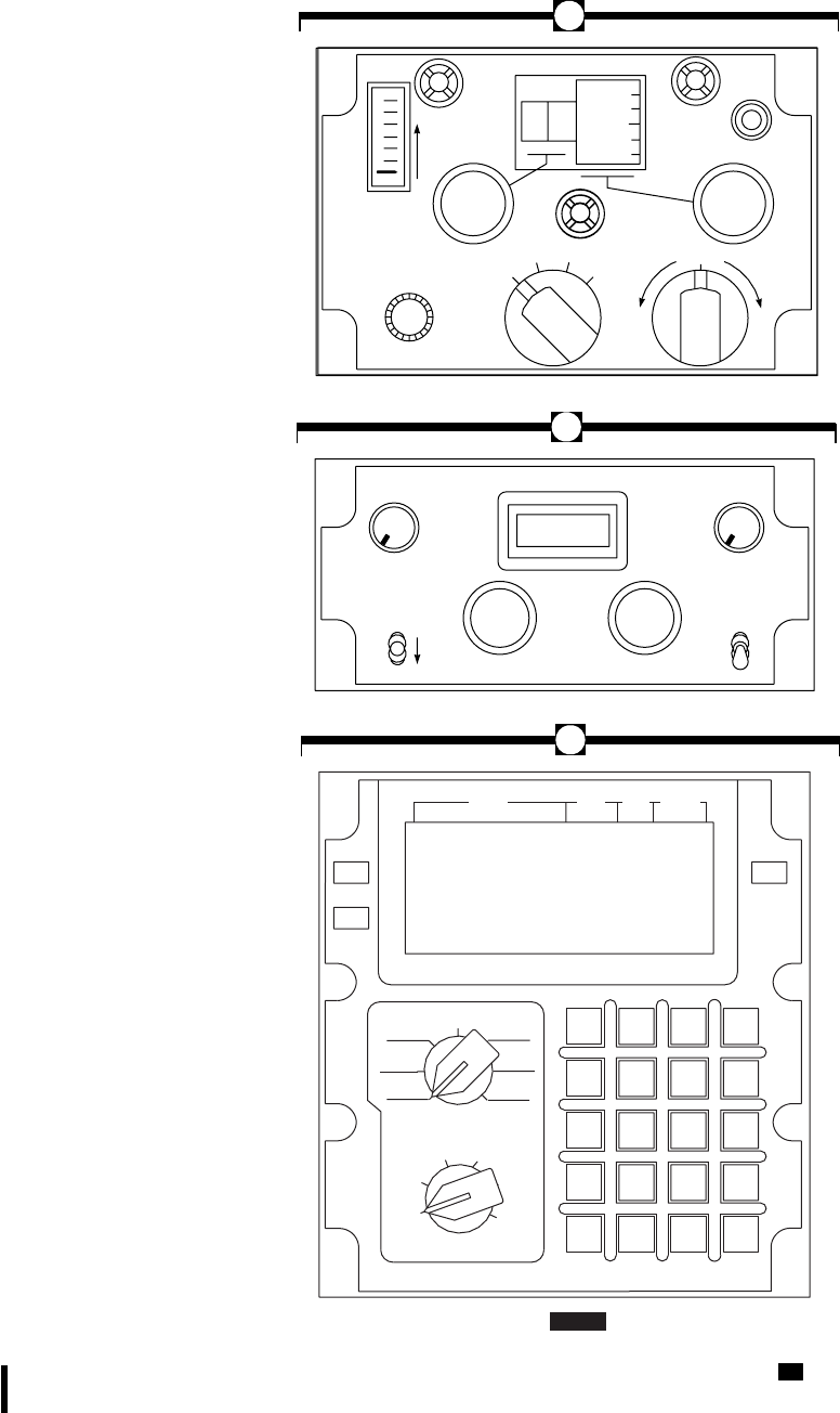
SA
AA0385_2C
LTR
LEFT
LTR
MID
LTR
RIGHT
ABC
1DEF
2GHI
3
JKL
4MNO
5PQR
6
GPS
LDG
LAT /
LONG
MGRS
TEST
LAMP
TEST
OFF
XTK/TKC
KEY
GS/TK
NAV M
PP DIST / BRG
TIME
WIND−UTC
DATA
WP
TGT
DATUM
ROUTE
DISPLAY
N
A
V
MODE
P
/
P
R
STU
7VWX
8YZ*
9
CLR #
0ENT
(PAGE)
KYBD
F1
TGT
STR
INC
(+)
DEC
(−)
MAL
BRT
DIM
17:BANDO 030MG91
GPS : M NAV : C
GS : 1 17KM / HR
TK : 0 2 5 "
FLY TO EPE SYS
STAT TGT
STR
GPS
G
S
D
L
AUDIO
KILOCYCLES CW
TEST
VOICE
LOOP
T
U
N
E
A
D
F
R
C
V
ROFF LOOP
COMP ANT
29
80
90
LR
NAV VOL MB VOL
OFF
VOR / MB
TEST
OFF
MB SENS
HI
LO
108.00
A
B
C
Figure 2-8. Lower Console (Sheet 2 of 3) UH
TM 1-1520-237-10
2-16 Change 8
2.11 DOORS AND WINDOWS.
2.11.1 Cockpit Doors. The crew compartment is
reached through two doors, one on each side of the cockpit.
The doors swing outward and are hinged on the forward
side (Figure 2-1). Each door has a window for ventilation.
Installed on the back of each door is a latch handle to allow
unlatching the door from either inside or outside the cock-
pit. Emergency release handles are on the inside frame of
each door (Figure 9-1). They allow the cockpit doors to be
jettisoned in case of an emergency. There is an emergency
release pull tab on the inside forward portion of each cock-
pit door window for pilot egress.
2.11.2 Troop/Cargo (Cabin) Doors. Aft sliding doors
are on each side of the troop/cargo compartment (Figure
2-1). Single-action door latches allow the doors to be
latched in the fully open or fully closed positions. Each of
the two doors incorporate two jettisonable windows, for
emergency exit (Figure 9-1).
2.11.3 Crew Chief/Gunner Windows. The Crew
Chief/Gunner Stations have forward sliding hatch windows,
split vertically into two panels (Figure 2-1). A spring-
loaded security latch is installed on each gunner’s aft win-
dow, to prevent the window opening from the outside. The
dead bolt lock requires activation of the security latch lever
from inside the helicopter. Another window latch bar is
actuated to allow the forward window to be moved to a
TM 1-1520-237-10
Change 1 2-16.1/(2-16.2 Blank)
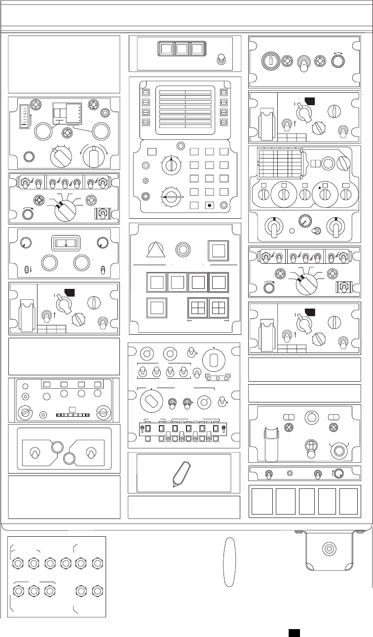
SA
AA1304_2B
AUDIO
KILOCYCLES CW
TEST
VOICE
LOOP
T
U
N
E
A
D
F
R
C
V
ROFF LOOP
COMP ANT
29
80
90
LR
ON
OFF
ON
OFF
VOL ICS
124
3
5HOT MIKE
OFF
C
O
M
M
NAV VOL MB VOL
OFF
108 00
VOR / MB
TEST
OFF
MB SENS
HI
LO
TAIL
WHEEL GYRO
ERECT
TAIL SERVO
NORMAL
BACKUP
M
I
S
C
S
W
9
14 1 0 50
FM AM
MAN
PRE
DF
TR
OFF
V
O
L
S
Q
D
I
S
T
O
N
E
EMER
LOAD
PRESET
C
O
M
M
P
R
E
S
S
T
O
T
E
S
T
D
I
M
P
R
E
S
S
T
O
T
E
S
T
D
I
M
TEST TEST/MON TOP
BOT
MASTER
TEST
OUT
STATUS
IDENT
MIC
TEST AUDIO
OUT
P
R
E
S
S
T
O
T
E
S
T
D
I
M
REPLY
CODE
M−1 M−2 M−3/A M−C RAD
TEST
A
N
T
D
I
V
I
F
F
O
NO
N
L
I
G
H
T
O
U
T
MODE 1 MODE 3 / A
N
O
G
O
E
M
E
R
N
O
R
M
S
T
B
Y
O
F
F
ALT KIT ANT
001200
MODE 4
O
N
G
O
1 2 3 4 5 AUX NAV
C
O
N
T
FM 1 / FM 2 FM 2 / UHF
FM 2 / VHFFM 1 / VHF
FM 1 / UHF VHF / UHF
OFF
COMPASS
SLAVED
FREE
PUSH TO
SET
+00+
CHAN
1
30 0000
MAIN VOL PRESET
GUARDMANUALBOTHOFF
ADF
TONE SQUELCH
OFF ON
U
H
F
ON
OFF
ON
OFF
VOL ICS
124
3
5HOT MIKE
OFF
C
O
M
M
1 2 3 4 5 AUX NAV
C
O
N
T
30 60
FLARE ARM CHAFF
DISP
CONT
ARM
MAN PGRM
R
I
P
P
L
E
F
I
R
E
+
PWR SELF DSCRM
ON
OFF
ON
OFF AUDIO
TEST
CHAFF
DISPENSE
SAFE
FUEL
IND
OUT
FUEL BOOST PUMP CONTROL
ON
OFF
NO. 1
PUMP NO. 2
PUMP
ON
OFF
MAN SLEW
UP
DN
TEST
AUTO
CONTROL
ON
ON ON ON ON
ON
STABILATOR CONTROL
SAS 1 SAS 2 TRIM FPS
AUTO FLIGHT CONTROL
BOOST
R
E
S
E
T
O
F
F
R
E
S
E
T
R
E
S
E
T
POWER ON RESET
CPTR
TRIM
SAS 2
RGYR
ACCL
A / S
CLTV
GYRO
DEF
ABC
GHJ KLM NPQ
RST UVW XYZ
LTR
W4
1
5E6
3
M2
USE 0CLR
FACK
BRT
MRK
STR
BIT
DEST
7S89
I
I
N
S
DEST
INS
POS
STR
TCN
UPDT
NAV
NORM
FAST
OFF
TEST
CAL
ATTD
_
PARKING BRAKE
BATT &
ESNTL DC
WARN
DC AC &
ESNTL BUS
PRIME BATT
BUS FIRE
SPLY CONV
WARN EXT PWR
CONTR BOOST CONTR EXTGH
APU UTIL
LTS APU
CONTR
INST CONTR
INST
FIRE
DET GEN
CONTR CKPT
B
A
T
T
U
T
I
L
B
U
S
B
A
T
T
B
U
S
AN/ARC−201
AN/ALQ−162
COVER
COVER
50 5 5 5 5 5
555 5 5
FAILURE ADVISORY
P
R
E
S
S
T
O
T
E
S
T
D
IM
A
B
Z
ER
O
H
O
L
D
RADIO RETRANSMISSION
FUEL
TEST
ALQ
162 NO
GO
CW
THRT CW
JAM
ALQ−156
CM
JAM
ALQ−144
IRCM
INOP
CM
INOP
PLAIN
C / RAD MODE
DELAY
ON
POWER
OP LD
RV
1
2
34
5
6
Z
E
R
O
I
Z
E
KY
58
R
C
U
FILL
1
235
46
PLAIN
C / RAD MODE
DELAY
ON
POWER
OP LD
RV
1
2
34
5
6
Z
E
R
O
I
Z
E
KY
58
R
C
U
FILL
1
235
46
VHF−FM NO. 1
IFM CONTROL
AN/ARC−201
PLAIN
C / RAD MODE
DELAY
ON
POWER
OP LD
RV
1
2
34
5
6
Z
E
R
O
I
Z
E
KY
58
R
C
U
FILL
1
235
46
VHF−FM NO. 2
Figure 2-8. Lower Console (Sheet 3 of 3) EH
TM 1-1520-237-10
2-17
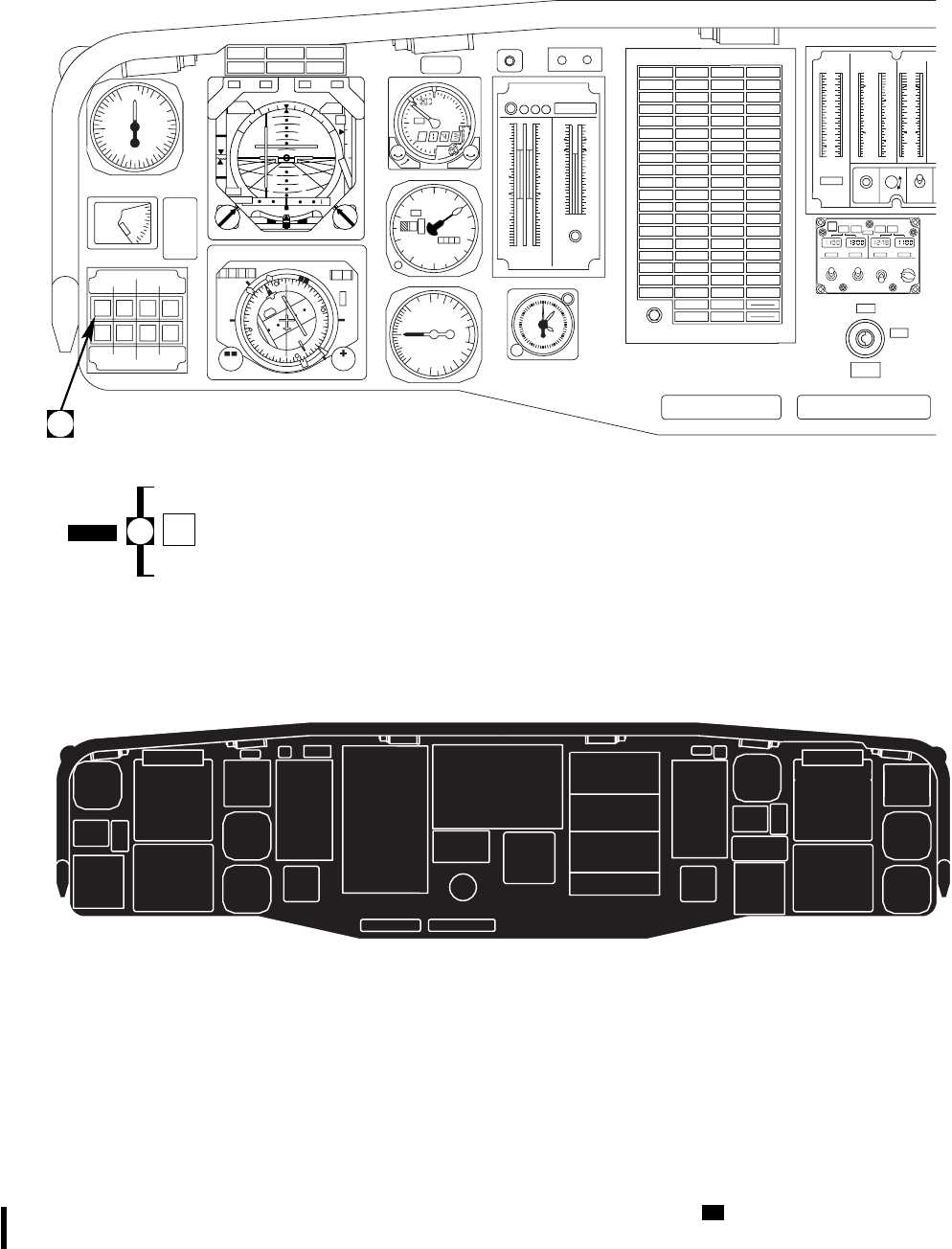
SA
AB0823
0
2
4
6
8
10
12
14
12
TOTAL FUEL
PUSH
TO TEST OFF
DIGITS
DIM
ON
QTY
LB X 100 TEMP
C X 10 PRESS
PSI X 10 TEMP
C X 10
−4
0
4
6
8
10
12
16
0
3
4
5
6
7
11
19
−4
0
4
8
10
12
14
18
12
TEST RTR OVERSPEED
1R2 1 2
0
70
30
90
95
100
105
110
120
130
0
70
30
90
95
100
105
110
120
130
1R2
12
0
20
40
60
80
100
120
140 140
120
100
80
60
40
20
0
100
150
200
250 20
50
KNOTS
VERTICAL SPEED
1000 FT PER
MIN
DOWN
UP
5
5
0
01
2
3
4
5
6
7
89
124
6
4
2
1
10
0
10
20
30
40
DN
O
F
F
STAB
POS
DEG
0O
10O
20O
30O
40O
KIAS
LIMIT
150
100
80
60
45
S
T
A
B
D
E
G
123430 0
HDG CRS
N
W
E
S
3
6
12
15
21
24
30
33
KM COURSE
H
D
G
NAV
2
1
2
1
MODE SEL
DPLR
DPLR
VOR
ILS
VOR
ILS
BACK
CRS
BACK
CRS
FM
HOME
FM
HOME
NORM
ALTR PLT
CPLT NORM
ALTR ADF
VOR
TURN
RATE CRS
HDG VERT
GYRO BRG
2
L
H
5
10
15
FT X 100
LO
ABS ALT
FEET HI
LO
OFF PUSH
0
1
2
SET SET
#1 FUEL LOW #1 GEN #2 GEN #2 FUEL LOW
#2 GEN BRG#1 GEN BRG
#1 ENGINE
OIL PRESS #1 CONV #2 CONV #2 ENGINE
OIL PRESS
#2 ENGINE
OIL TEMP
DC ESS
BUS OFF
AC ESS
BUS OFF
#1 ENGINE
OIL TEMP
CHIP
#1 ENGINE BATT LOW
CHARGE BATTERY
FAULT CHIP
#2 ENGINE
#2 FUEL
FLTR BYPASS
GUST
#1 FUEL
FLTR BYPASS
#1 OIL
FLTR BYPASS #2 OIL
FLTR BYPASS
#1 PRI
SERVO PRESS
IRCM
INOP
#2 HYD
PUMP #2 PRI
SERVO PRESS
#1 TAIL
RTR SERVO
TAIL ROTOR
QUADRANT
MAIN XMSN
OIL TEMP INT XMSN
OIL TEMP TAIL XMSN
OIL TEMP APU OIL
TEMP HI
TRIM FAIL
SAS OFFSTABILATOR
BOOST SERVO
OFF
LFT PITOT
HEAT IFF RT PITOT
HEAT
CHIP INPUT
MDL−LH CHIP
INT XMSN CHIP
TAIL XMSN CHIP INPUT
MDL−RH
CHIP ACCESS
MDL−RH
APU
FAIL
CHIP MAIN
MDL SUMP
CHIP ACCESS
MDL−LH
MR DE−ICE
FAIL MR DE−ICE
FAULT TR DE−ICE
FAIL ICE
DETECTED
BACK−UP
RSVR LOW
#2 RSVR
LOW
#1 RSVR
LOW
MAIN XMSN
OIL PRESS
#2 ENG
ANTI−ICE ON
BACK−UP
PUMP ON
#2 TAIL RTR
SERVO ON
#2 ENG INLET
ANTI−ICE ON
PRIME BOOST
PUMP ON
LDG LT ON
HOOK ARMED
EXT PWR
CONNECTED
#1 ENG INLET
ANTI−ICE ON
APU GEN ON
CARGO
HOOK OPEN
PARKING
BRAKE ON
APU ACCUM
LOW
APU ON
#1 ENG
ANTI−ICE ON
BRT /
TEST
#2 ENGINE
STARTER
FLT PATH
STAB
OFF
ON
ENGINE
IGNITION
NON SECURE RADIOS WILL NOT BE KEYED
WHEN USING ANY SECURE RADIO OR THE
INTERCOM FOR CLASSIFIED COMMUNICATIONS
RADIO FM 1
SW NO. 1
UHF
2
VHF
3
FM2
45
VOR
LOC
AUX
MB
ADF
NAV
ICS IDENT
RAD ALT
DIMMING NVG DIMMING
MA WRN CAUT/ADVSY
TO TEST
ALT
12 12
3
4
5
6
7
8
9
10
11
60
5
10
15
20
25
30
35
40
45
50
55
1000 FT100 FT IN. HG
1
2
2990
#1 ENGINE #2 ENGINE
PRESS PRESS
LOCK PITCH BIAS
FAIL
#1 ENGINE
STARTER
RADIO CALL
00 0 00
22
23
25
7
98
11
5
4
6
12
1
2
3
13
14
24
21
19
20
15
16
17
18
13
14
7
98
10
11
4
5
6
1
2
3
27 26 12 27
#1 ENG
OUT #2 ENG
OUT
LOW ROTOR
RPM
MASTER CAUTION
PRESS TO RESET
FIRE
CMD ATT
30 30
30 30
NAV
ROLL PITCH
C
LI M
B
DI VE
G
S
GA DH MB
DIM
#1 HYD
PUMP
* AUX FUEL
SEARCH LT
* * ON
CODE
OFF
% RPM % TRQ
FUEL XMSN ENG
B
DPLR
GPS
B
GPS
NO
FLOW VENT
FAIL IMBAL
EMPTYEMPTY INBDOUTBD L
NO
FLOW
VENT
OVFL
EMPTYEMPTY OUTBDINBD R
AUX FUEL QTY LBS
TEST /
RESET
XFER MODE
AUTO
MAN
O
F
F
LEFT
RIGHT
O
T
H
INBD
OUTBD
B
MAN XFER XFER FROM PRESS
OUTBD
INBD
OFF
ALL
Figure 2-9. Instrument Panel (Sheet 1 of 4) UH
TM 1-1520-237-10
2-18 Change 4
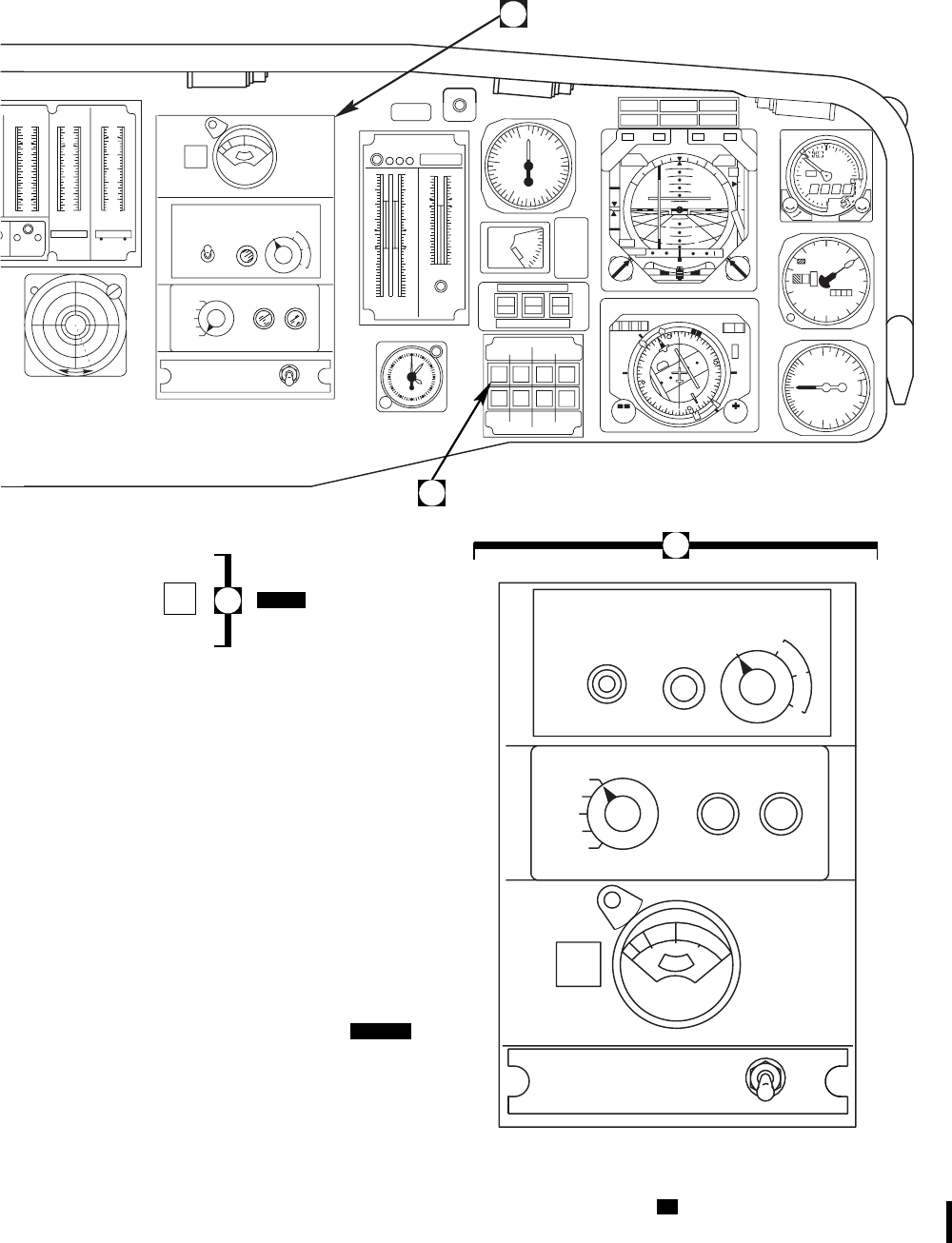
SA
AB0824
OFF
DIGITS 1 − CHAN − 2
PRESS
PSI 5 10 TEMP
\ X 100 SPEED
\ X 10
OIL TGT Ng
TGT Ng
1
4
5
6
7
8
13
17
12 12
0
2
4
5
6
7
8
9
0
4
7
8
9
10
11
HDG NAV ALT
HDG
ON
NAV
ON
ALT
ON
CIS MODE SEL
MODE SEL
DPLR
DPLR
VOR
ILS
VOR
ILS
BACK
CRS
BACK
CRS
FM
HOME
FM
HOME
NORM
ALTR PLT
CPLT NORM
ALTR ADF
VOR
TURN
RATE CRS
HDG VERT
GYRO BRG
2
POWER
ON
TEST
TEST
IN
PROGRESS
MODE
AUTO T
L
M
BLADE DE−ICE TEST
NORM
SYNC 1
SYNC 2
OAT
EOT
PWR
MAIN TAIL
RTR RTR
ON
OFF
PRESS
TO
TEST
B
L
A
D
E
D
E
I
C
E
I
R
C
M
M
AN
U
A
L
L
W
G
9/
m
3
T
L
M
H
0
2
55
10
1
5
2
0
F
A
IL
RADIO CALL
00 0 00
MA
DAY
NIGHT
BRIL
#1 ENG
OUT #2 ENG
OUT
LOW ROTOR
RPM
MASTER CAUTION
PRESS TO RESET
FIRE
CMD ATT
30 30
30 30
NAV
ROLL PITCH
C
LI M
B
DI VE
G
S
123430 0
HDG CRS
N
W
E
S
3
6
12
15
21
24
30
33
KM COURSE
H
D
G
NAV
2
1
2
1
10
0
10
20
30
40
DN
O
F
F
STAB
POS
DEG
0O
10O
20O
30O
40O
KIAS
LIMIT
150
100
80
60
45
S
T
A
B
D
E
G
RAD ALT
DIMMING
TEST RTR OVERSPEED
1R2 1 2
0
70
30
90
95
100
105
110
120
130
0
70
30
90
95
100
105
110
120
130
1R2
12
0
20
40
60
80
100
120
140 140
120
100
80
60
40
20
0
% RPM % TRQ
100
150
200
250 20
50
KNOTS
VERTICAL SPEED
1000 FT PER
MIN
DOWN
UP
.5
.5
1000 FT100 FT IN. HG
1
2
0
29
01
2
3
4
5
6
7
89
124
6
4
2
1
90
L
5
10
15
FT X 100
LO
ABS ALT
FEET HI
LO
OFF PUSH
0
1
2
SET SET
3
41
TO TEST
ALT
12 12
3
4
5
6
7
8
9
10
11
60
5
10
15
20
25
30
35
40
45
50
55
POWER
ON
TEST
TEST
IN
PROGRESS
MODE
AUTO T
L
M
BLADE DE−ICE TEST
NORM
SYNC 1
SYNC 2
OAT
EOT
PWR
MAIN TAIL
RTR RTR
ON
OFF
PRESS
TO
TEST
B
L
A
D
E
D
E
I
C
E
I
R
C
M
M
AN
U
A
L
L
W
G
g/
m
3
T
L
M
H
0
2
5.
5
10
1
5
2
0
F
A
IL
O
F
F
A
1. RADAR ALTIMETER
2. BAROMETRIC ALTIMETER
3. VERTICAL SPEED INDICATOR
4. MASTER WARNING PANEL
5. VERTICAL SITUATION INDICATOR
6. HORIZONTAL SITUATION INDICATOR
7. AIRSPEED INDICATOR
8. STABILATOR POSITION PLACARD
9. STABILATOR INDICATOR
10. CIS MODE SELECTOR
11. VSI / HSI MODE SELECTOR
12. RADIO CALL PLACARD
13. PILOT’S DISPLAY UNIT
14. CLOCK
15. ICE RATE METER
16. BLADE DEICE CONTROL PANEL
17. BLADE DEICE TEST PANEL
18. INFRARED COUNTERMEASURE CONTROL PANEL
19. CENTRAL DISPLAY UNIT
20. RADAR WARNING INDICATOR
21. AUXILIARY FUEL MANAGEMENT PANEL
22. ENGINE IGNITION SWITCH
23. RADIO SELECT PLACARD
24. CAUTION / ADVISORY PANEL
25. SECURE WARNING PLACARD
26. NVG DIMMING CONTROL PANEL
27. RAD ALT DIMMING
A
SA DM MA
DPLR
GPS GPS
B
B
(ON HELICOPTERS WITH REARRANGED
BLADE DEICE PANELS)
AFMS
Figure 2-9. Instrument Panel (Sheet 2 of 4) UH
TM 1-1520-237-10
Change 4 2-19
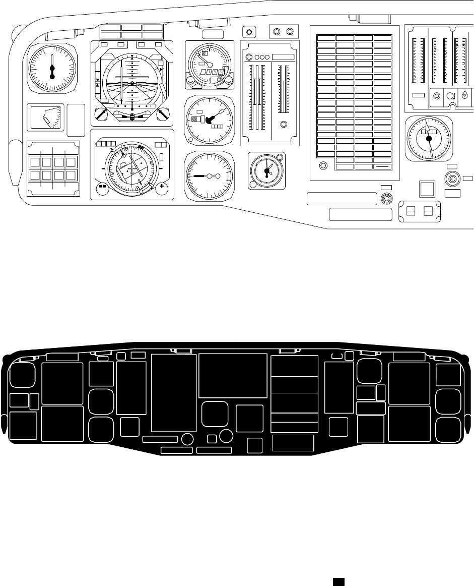
SA
AA0516_3A
0
2
4
6
8
10
12
14
12
TOTAL FUEL TO TEST OFF
DIGITS
DIM ON
QTY
LB X 100 TEMP PRESS
PSI X 10 TEMP
OC X 10
−4
0
4
6
8
10
12
16
0
3
4
5
6
7
11
19
−4
0
4
8
10
12
14
18
12
TEST RTR OVERSPEED
1R2 12
0
70
30
90
95
100
105
110
120
130
0
70
30
90
95
100
105
110
120
130
1R2
12
0
20
40
60
80
100
120
140 140
120
100
80
60
40
20
0
#1 ENG
OUT #2 ENG
OUT
LOW ROTOR
RPM
MASTER CAUTION
PRESS TO RESET
FIRE
VERTICAL SPEED
1000 FT PER
MIN
DOWN
UP
5
5
0
01
2
3
4
5
6
7
89
124
6
4
2
1
10
0
10
20
30
40
DN
O
F
F
STAB
POS
DEG
CMD ATT
30 30
30 30
NAV
ROLL PITCH
C
LI M
B
DI VE
G
S
0O
10O
20O
30O
40O
KIAS
LIMIT
150
100
80
60
45
S
T
A
B
D
E
G
123430 0
HDG CRS
N
W
E
S
3
6
12
15
21
24
30
33
KM COURSE
H
D
G
NAV
2
1
2
1
MODE SEL
IINS
IINS
VOR
ILS
VOR
ILS
BACK
CRS
BACK
CRS
FM
HOME
FM
HOME
NORM
ALTR PLT
CPLT NORM
ALTR ADF
VOR
TURN
RATE CRS
HDG VERT
GYRO BRG
2
L
H
5
10
15
FT X 100
LO
ABS ALT
FEET HI
LO
OFF PUSH
0
1
2
SET SET
#1 FUEL LOW #1 GEN #2 GEN #2 FUEL LOW
#2 GEN BRG#1 GEN BRG
#1 ENGINE
OIL PRESS #1 CONV #2 CONV #2 ENGINE
OIL PRESS
#2 ENGINE
OIL TEMP
DC ESS
BUS OFF
AC ESS
BUS OFF
#1 ENGINE
OIL TEMP
CHIP
#1 ENGINE BATT LOW
CHARGE BATTERY
FAULT CHIP
#2 ENGINE
#2 FUEL
FLTR BYPASS
GUST
#1 FUEL
FLTR BYPASS
#1 OIL
FLTR BYPASS #2 OIL
FLTR BYPASS
#1 PRI
SERVO PRESS #1 HYD
PUMP #2 HYD
PUMP #2 PRI
SERVO PRESS
#1 TAIL
RTR SERVO
TAIL ROTOR
QUADRANT
MAIN XMSN
OIL TEMP INT XMSN
OIL TEMP TAIL XMSN
OIL TEMP APU OIL
TEMP HI
TRIM FAIL
SAS OFFSTABILATOR
BOOST SERVO
OFF
LFT PITOT
HEAT IFF RT PITOT
HEAT
CHIP INPUT
MDL−LH CHIP
INT XMSN CHIP
TAIL XMSN CHIP INPUT
MDL−RH
CHIP ACCESS
MDL−RH
APU
FAIL
CHIP MAIN
MDL SUMP
CHIP ACCESS
MDL−LH
MR DE−ICE
FAIL MR DE−ICE
FAULT TR DE−ICE
FAIL ICE
DETECTED
BACK−UP
RSVR LOW
#2 RSVR
LOW
#1 RSVR
LOW
MAIN XMSN
OIL PRESS
#2 ENG
ANTI−ICE ON
BACK−UP
PUMP ON
#2 TAIL RTR
SERVO ON
#2 ENG INLET
ANTI−ICE ON
PRIME BOOST
PUMP ON
LDG LT ON
EXT PWR
CONNECTED
#1 ENG INLET
ANTI−ICE ON
APU GEN ON
AIR COND
ON
PARKING
BRAKE ON
APU ACCUM
LOW
APU ON
#1 ENG
ANTI−ICE ON
BRT /
TEST
#2 ENGINE
STARTER
FLT PATH
STAB
OFF
ON
ENGINE
IGNITION
NON SECURE RADIOS WILL NOT BE KEYED
SYSTEMS SELECT
INTERCOM FOR CLASSIFIED COMMUNICATIONS
RADIO FM 1
SW NO. 1
UHF
2
VHF
3
FM2
45
VOR
LOC
AUX
MB
ADF
NAV
ICS IDENT
RAD ALT
DIMMING NVG DIMMING
MA WRN CAUT / ADVSY
TO TEST
ALT
12 12
3
4
5
6
7
8
9
10
11
60
5
10
15
20
25
30
35
40
45
50
55
1000 FT100 FT IN. HG
1
2
2990
#1 ENGINE #2 ENGINE
PRESS PRESS
LOCK ANTENNA
EXTENDED
#1 ENGINE
STARTER
RADIO CALL
00 0 00
IRCM
INDP AUX FUEL
SEARCH LT
ON
CABIN HEAT
ON ANTENNA
RETRACTED
DIM
FLARE
3
6
9
12
15
18
0
21
24
27
30
33
0000
K N
CREW
CALL
WHEN USING ANY SECURE RADIO OR THE
DG
IINS
HDG
VG
IINS
ATT
27
31
7
98
11
5
4
6
12
1
2
3
13
14
28
25
21
22
15
16
17
18
13
14
7
98
10
11 6
1
2
3
33 32 12 33
30 29 26 24
23 20
5
4
PUSH
GA DH MB
100
150
200
250 20
50
KNOTS
CODE
OFF
OC X 10
% TRQ% RPM
FUEL XMSN ENG
19
Figure 2-9. Instrument Panel (Sheet 3 of 4) EH
TM 1-1520-237-10
2-20
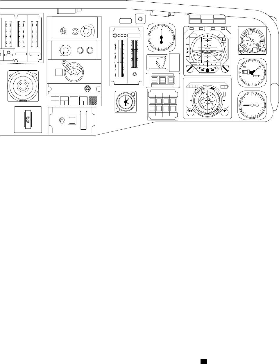
SA
AA0516_4C
HDG NAV ALT
HDG
ON
NAV
ON
ALT
ON
CIS MODE SEL
MODE SEL
DPLR
DPLR
VOR
ILS
VOR
ILS
BACK
CRS
BACK
CRS
FM
HOME
FM
HOME
NORM
ALTR PLT
CPLT NORM
ALTR ADF
VOR
TURN
RATE CRS
HDG VERT
GYRO BRG
2
RADIO CALL
00 0 00
MA
DAY
NIGHT
BRIL
#1 ENG
OUT #2 ENG
OUT
LOW ROTOR
RPM
MASTER CAUTION
PRESS TO RESET
FIRE
CMD ATT
30 30
30 30
NAV
ROLL PITCH
C
LI M
B
DI VE
G
S
123430 0
HDG CRS
N
W
E
S
3
6
12
15
21
24
30
33
KM COURSE
H
D
G
NAV
2
1
2
1
10
0
10
20
30
40
DN
O
F
F
STAB
POS
DEG
0O
10O
20O
30O
40O
KIAS
LIMIT
150
100
80
60
45
S
T
A
B
D
E
G
RAD ALT
DIMMING
TEST RTR OVERSPEED
1R2 12
0
70
30
90
95
100
105
110
120
130
0
70
30
90
95
100
105
110
120
130
1R2
12
0
20
40
60
80
100
120
140 140
120
100
80
60
40
20
0
% RPM % TRQ
100
150
200
250 20
50
KNOTS
VERTICAL SPEED
1000 FT PER
MIN
DOWN
UP
.5
.5
1000 FT100 FT IN. HG
1
2
0
29
01
2
3
4
5
6
7
89
124
6
4
2
1
90
L
5
10
15
FT X 100
LO
ABS ALT
FEET HI
LO
OFF PUSH
0
1
2
SET SET
TO TEST
ALT
12 12
3
4
5
6
7
8
9
10
11
60
5
10
15
20
25
30
35
40
45
50
55
POWER
ON
TEST
TEST
IN
PROGRESS
MODE
AUTO T
L
M
BLADE DE−ICE TEST
NORM
SYNC 1
SYNC 2
OAT
EOT
PWR
MAIN TAIL
RTR RTR
ON
OFF
PRESS
TO
TEST
B
L
A
D
E
D
E
I
C
E
I
R
C
M
M
AN
U
A
L
L
W
G
9 /
m
3
T
L
M
H
0
2
55
10
1
5
2
0
F
A
IL
O
F
F
1. RADAR ALTIMETER
2. BAROMETRIC ALTIMETER
3. VERTICAL SPEED INDICATOR
4. MASTER WARNING PANEL
5. VERTICAL SITUATION INDICATOR
6. HORIZONTAL SITUATION INDICATOR
7. AIRSPEED INDICATOR
8. STABILATOR POSITION PLACARD
9. STABILATOR POSITION INDICATOR
10. CIS MODE SELECTOR
11. VSI / HSI MODE SELECTOR
12. RADIO CALL PLACARD
13. PILOT’S DISPLAY UNIT
14. CLOCK
GA DM MB
RETRACT
OFF
EXTEND OFF
ON
POWER PUSH FOR
STANDBY
STATUS
TEST
FLARE
15. BLADE DEICE CONTROL PANEL
16. BLADE DEICE TEST PANEL
17. ICE RATE METER
18. ALQ−144 INFRARED COUNTERMEASURE
19. ASE STATUS PANEL
21. CENTRAL DISPLAY UNIT
22. RADAR WARNING INDICATOR
23. ECM ANTENNA SWITCH
24. ENGINE IGNITION SWITCH
25. BEARING DISTANCE HEADING INDICATOR
26. CREW CALL SWITCH / INDICATOR
27. SYSTEM SELECT PANEL
28. CAUTION / ADVISORY PANEL
29. FLARE DISPENSE SWITCH
30. RADIO SELECT PLACARD
31. SECURE RADIO WARNING PLACARD
32. NVG DIMMING CONTROL PANEL
33. RADAR ALTIMETER DIMMING
1 − CHAN − 2
PRESS
PSI 5 10 TEMP SPEED
OIL TGT Ng
TGT Ng
1
4
5
6
7
8
13
17
12 12
0
2
4
5
6
7
8
9
0
4
7
8
9
10
11
9
C X 100 % X 10
CONTROL PANEL
ALQ
162
CW
THRT
NO
G0
CW
JAM
ALQ 156
CM
JAM CM
INOP
ALQ 144
IRCM
INOP
ALQ 135
OVER
TEMP RDR
INOP
20. ALQ−156 COUNTERMEASURE PANEL
A
S
E
Figure 2-9. Instrument Panel (Sheet 4 of 4) EH
TM 1-1520-237-10
2-21

stowed position. The windows may be opened to move a
machine gun into position for firing.
2.11.4 Door Locks. Key door locks are installed on
each of the cabin, cockpit and avionics compartment doors.
A common key is used to lock and unlock the doors from
the outside to secure the helicopter. Each crew chief/gunner
sliding window is locked from the inside only.
2.12 CREW SEATS.
2.12.1 Pilots’ Seats.
WARNING
Do not store any items below seats. Seats
stroke downward during a crash and any
obstruction will increase the probability
and severity of injury.
The pilots’ seats provide ballistic protection and can be
adjusted for the pilots’ leg length and height. The pilot’s
seat is on the right side, and the copilot’s is on the left.
Each seat has a one-piece ceramic composite bucket at-
tached to energy absorption tubes. Each seat is positioned
on a track with the bucket directly above a recess in the
cockpit floor. Crash loads are reduced by allowing the seat
and occupant to move vertically as single unit. Occupant
restraint is provided by a shoulder harness, lap belts, and a
crotch belt.
WARNING
To prevent injury to personnel, do not re-
lease either the normal or emergency ver-
tical adjust levers unless someone is sit-
ting in the seat. The extension springs are
under load at all times. With seat at low-
est position, the vertical preload on the
seat could be as high as 150 pounds. If no
one is in the seat and vertical adjust le-
ver(s) is released, the seat will be snapped
to the highest stop. Anyone leaning over
the seat or with hands on guide tubes
above linear bearings, will be seriously in-
jured.
a. Seat Height Adjustment. Vertical seat adjustment is
controlled by a lever on the right front of the seat bucket.
Springs are installed to counterbalance the weight of the
seat. The lever returns to the locked position when released.
b. Forward and Rear Adjustment. The seat is adjusted
for leg length by a locking lever on the left front of the seat
bucket. The lever is spring-loaded and returns to the locked
position when released.
c. Emergency Tilt Levers. The emergency tilt release
levers are on each side of the seat support frame. The seat
may be tilted back into the cabin for removal or treatment
of a wounded pilot. Seat tilting can be done from the cabin
only when the seat is in the full down and aft position. On
RA-30525 seats, tilting is achieved by pushing the tilt le-
vers in toward center, and then pulling the seat top rear-
ward. On D3801 and D3802 seats, tilting is achieved by
pushing the tilt levers outboard, and then pulling the seat
top rearward.
d. Emergency Vertical Release Lever. The emergency
vertical release lever permits the seat to drop to the lowest
adjustment point for tilting. The emergency vertical release
lever is on the upper center back of RA-30525 seats, and is
actuated by pulling right on the lever. The emergency ver-
tical release pedal is on the lower back of the D3801 and
D3802 seats, and is actuated by pushing down on the foot
operated pedal.
e. Seat Belts. The pilot’s and copilot’s seats each con-
tain a shoulder harness, seat belt, and a crotch strap con-
nected to a common buckle assembly. All belts and straps
have adjustment fittings. The attachment buckle has a
single-point release that will be common in configuration
on the pilot’s and copilot’s seats; they may be of the lift
lever or rotary release configuration, when the lanyard is
pulled or the release is turned all belts and straps will re-
lease simultaneously.
2.12.2 Protective Armor. Armor protection is provided
for the body of the pilot and copilot against 7.62 mm rounds
from the side and from the back and below. Armored wings,
attached to the cockpit interior, consist of a sliding panel at
the outboard side of each seat. A release lever at the front
of each panel permits sliding the panel aft to allow rapid
entrance and exit, as well as freedom of movement for the
seat occupant.
2.12.3 Crew Chief/Gunner Seats.
WARNING
Do not store any items below seats. Dur-
ing a crash any obstruction will increase
the probability and severity of injury.
TM 1-1520-237-10
2-22 Change 10

Two outward facing seats (Figure 2-10), one on each
side of the helicopter at the front of the cabin, are for the
crew chief/gunners. Each seat faces a window. Each seat is
a cable-supported steel tube assembly with a fire-resistant,
high strength fabric seat and backrest. Each seat contains
two lower energy attenuators designed and oriented to re-
duce personal injury in a crash. Each seat has a complete
lap belt and dual torso-restraint shoulder harness attached
to a dual action rotary release buckle. The shoulder harness
is connected to inertia reels on the seat back and bottom.
This gives the wearer freedom to move about his station.
On helicopters equipped with improved crewchief/gunner’s
restraint system, the restraint system is equipped with a
single action rotary release buckle with a guard. A release
plate must be pressed to allow rotation of release, prevent-
ing inadvertent handle rotation from contact with equip-
ment, etc. The inertia reel lock control is replaced by a
shorter push/pull manual locking control. Push in and the
inertia reel is manually locked in place. When the control is
pulled out, the reel will lock on sudden pull.
2.13 TROOP PROVISIONS.
WARNING
Do not store any items below seats. Dur-
ing a crash any obstruction will increase
the probability and severity of injury.
UH In addition to crew chief and gunner seats, troop
seats may be installed for 13 persons. Each troop seat has a
belt and shoulder harness for body restraint. The backs and
seat pans are attached through cables to the cabin ceiling
and through cables and rods to seat fittings installed in the
floor. The seats may be installed in any quantity from 1 to
13. Each seat contains two lower energy attenuators de-
signed and oriented to reduce personnel injury. In Row 1,
do not install a passenger/troop seat in the most forward
center position directly behind the cockpit center console.
When seats are removed from the cabin and stowed in the
storage compartment, adjustments must be made for weight
and balance using data in Figures 6-3 and 6-12.
2.13.1 Troop Seat Belt Operation. UH
1. Extend shoulder strap and attach shoulder strap
fittings to buckle.
2. Extend lap belt and place across body.
3. Place lap belt fitting into buckle and make cer-
tain of positive lock.
4. Adjust lap belt tension and shoulder straps for a
comfortable fit.
2.13.2 DF and ECM Operator’s Seats. EH The seats
are similar to the pilot’s and copilot’s seats except that
armored wing protection is not provided.
2.13.3 Observer’s Seat. EH The observer’s seat is
identical to a troop seat (Figure 2-6). It is installed behind,
and to the right, of the DF operator’s seat.
TM 1-1520-237-10
Change 10 2-23
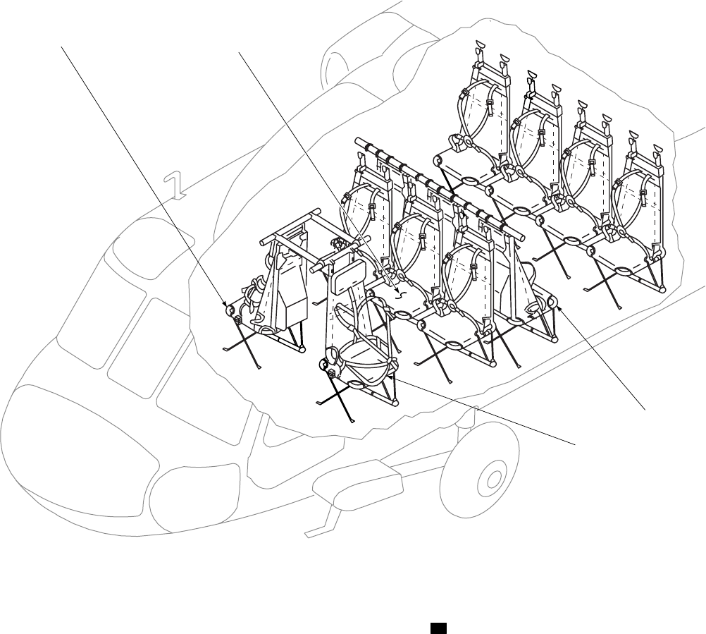

Section II EMERGENCY EQUIPMENT
2.14 FIRE PROTECTION SYSTEMS.
Fire detection and fire extinguishing systems are in-
stalled so that a fire may be detected and put out at either
engine or the APU installation, without affecting the re-
maining two. The engines and APU are monitored by in-
frared radiation type sensing units, and protected by a main
and reserve high-rate discharge type fire extinguisher in-
stallation.
2.14.1 Fire Detection System. A detection system
provides fire warning to the cockpit in case of fire in either
main engine compartment or in the APU compartment. The
system consists of five radiation-sensing flame detectors,
control amplifiers, and a test panel. Two detectors are in-
stalled in each main engine compartment and one detector
is in the APU compartment (Figure 2-1). The flame detec-
tors are solid-state photoconductive cells providing continu-
ous volume optical surveillance of the monitored areas. In
case of fire, the detectors react to the infrared radiation and
send a signal to one of the three control amplifiers which in
turn signals the fire warning assembly lighting the proper
T-handle (Figures 2-7 and 2-13). Also, the master FIRE
warning lights will go on if a fire is detected (Figure 2-9).
The detector system automatically resets itself, with warn-
ing lights off, when the infrared radiation source ceases to
emit.
2.14.2 Fire Detector Test Panel. A test switch on the
FIRE DETR TEST panel on the upper console (Figure
2-7), when moved to positions 1or 2, sends a test signal
through the system to put on the fire warning lights and
verify proper system operation to, but not including, the
photo cells. The No. 1 TEST position lights #1and #2
ENG EMER OFF T-handles and APU T-handle and
checks all firewall mounted detectors. The No. 2 TEST
position lights #1and # 2 ENG EMER OFF T-handle
only, and checks all deck mounted detectors. The engines
and APU are completely enclosed within their own firewall
compartment, thus reducing the possibility of a false fire
warning from outside sources. Electrical power to operate
the No. 1 and No. 2 detector system is by the dc essential
bus through circuit breakers marked FIRE DET,NO. 1
ENG and NO. 2 ENG, respectively. Power to operate the
APU detector system is by the battery bus through a circuit
breaker marked APU FIRE DET.
2.14.3 Fire Extinguishing Systems. A high-rate dis-
charge extinguishing system provides a two-shot, main and
reserve capability to either main engine compartment or
APU compartment. Two containers are each filled with liq-
uid and charged with gaseous nitrogen. The containers are
mounted above the upper deck, behind the right engine
compartment (Figure 2-1). Both containers have dual out-
lets, each with its own firing mechanism. Each extinguish-
ing agent container has a pressure gage, easily viewed for
preflight inspection. The system also has a thermal dis-
charge safety port that will cause a visual indicator on the
right side of the fuselage to rupture, indicating that one or
both containers are empty. Electrical power to operate the
No. 1 main and No. 2 reserve outlet valves is by the No. 2
dc primary bus through a circuit breaker, marked FIRE
EXTGH. Power to operate the No. 2 main and No. 1 re-
serve fire bottles outlet port valves and the directional con-
trol valve is by the battery utility bus through a circuit
breaker on the lower console marked FIRE EXTGH.
2.14.4 Fire Extinguisher Arming Levers (T-
Handles). One APU T-handle is on the upper console
(Figure 2-7) marked APU, and two engine fire extinguisher
T-handles are on the engine control quadrant, marked #1
ENG EMER OFF and #2 ENG EMER OFF (Figures 2-4
and 2-13). The handle marked #1 ENG EMER OFF is for
the No. 1 engine compartment, the handle marked #2 ENG
EMER OFF is for the No. 2 engine compartment, and
APU is for the auxiliary power unit compartment. When a
handle is pulled, dc power actuates the fire extinguisher
logic module to select the compartment to which the fire
extinguisher agent is to be directed, and also energizes the
circuit to the fire extinguisher switch. The ends of the
handles house fire detector warning lights.
2.14.5 Fire Extinguisher Control Panel.
WARNING
In case of fire when ac electrical power is
not applied to the helicopter, the reserve
fire extinguisher must be discharged. Fire
extinguisher agent cannot be discharged
into No. 2 engine compartment if ac elec-
trical power is not applied to helicopter.
The switch, marked FIRE EXTGH, on the upper con-
sole (Figure 2-7), has marked positions RESERVE-OFF-
MAIN. The switch is operative only after one of the ENG
EMER OFF or APU lever (T-handle) has been pulled.
When the switch is placed to MAIN, after an ENG EMER
OFF lever has been pulled, the contents of the main fire
extinguisher bottle are discharged into the corresponding
TM 1-1520-237-10
Change 9 2-25

compartment. When the FIRE EXTGH switch is placed to
RESERVE after an ENG EMER OFF lever has been
pulled, the contents of the opposite fire extinguisher bottle
are discharged into the selected compartment. The contents
of the fire extinguisher bottle discharge into the compart-
ment of the last lever pulled.
2.14.6 Crash-Actuated System. A crash-actuated sys-
tem is part of the fire extinguisher system. An omnidirec-
tional inertia switch is hard-mounted to the airframe to
sense crash forces. Upon impact of a crash of 10 Gs or
more, the switch will automatically fire both fire extinguish-
ing containers into both engine compartments. Electrical
power is supplied from the battery utility bus through a
circuit breaker on the lower console, marked FIRE EX-
TGH.
2.14.7 Hand-Operated Fire Extinguishers.
WARNING
Exposure to high concentrations of extin-
guishing agent or decomposition products
should be avoided. The liquid should not
be allowed to contact the skin; it could
cause frostbite or low temperature burns.
a. UH One hand-operated fire extinguisher (Figure 9-1)
is mounted on the cabin wall left of the gunner’s seat. A
second fire extinguisher is on the copilot’s seat.
b. EH Four hand operated portable fire extinguishers are
installed. One mounted on the right gunner window, one on
the left pilot seat, one on the DF operator seat, and one on
the ECM operator seat. The extinguishers are held in place
by a quick-release spring.
2.15 CRASH AXE.
UH One axe (Figure 9-1) is installed between the pilots’
seats in the cabin.
2.16 FIRST AID KITS.
a. UH Three first aid kits (Figure 9-1) are installed, two
on the back of the left pilot seat and one on the back of the
right pilot seat.
b. EH Five first aid kits are installed. One on the back of
the right pilot seat, two on the back of the left pilot seat,
one on the back of the DF operator seat, and one on the
back of the ECM operator seat.
TM 1-1520-237-10
2-26 Change 8

Section III ENGINES AND RELATED SYSTEMS
2.17 ENGINE.
The T700 engine (Figure 2-11), is a front drive, tur-
boshaft engine of modular construction. One is mounted on
the airframe at either side of the main transmission. The
engine is divided into four modules: cold section, hot sec-
tion, power turbine section, and accessory section.
2.17.1 Cold Section Module. The cold section module
(Figure 2-11), includes the inlet particle separator, the com-
pressor, the output shaft assembly, and line replaceable
units (LRUs). The inlet particle separator removes sand,
dust, and other foreign material from the engine inlet air.
Engine inlet air passes through the swirl vanes, spinning the
air and throwing dirt out by inertial action into the collector
scroll, after which it is sucked through by the engine-driven
blower and discharged overboard around the engine ex-
haust duct. The compressor has five axial stages and one
centrifugal stage. There are variable inlet guide vanes and
variable stage 1 and stage 2 vanes. LRUs mounted on the
cold section module are the electrical control unit (ECU)
700 , or digital electronic control (DEC) 701C , anti-icing
and start bleed valve, history recorder 700 , or history
counter 701C , ignition system, and electrical cables.
2.17.2 Hot Section Module. The hot section module
(Figure 2-11) consists of three subassemblies; the gas gen-
erator turbine, stage 1 nozzle assembly, and combustion
liner. LRUs on the hot section module are ignitors 701C
and primer nozzles and ignitors 700 . The gas generator
turbine consists of a gas generator stator assembly and a
two-stage air cooled turbine rotor assembly which drives
the compressor and the accessory gear box. Stage 1 nozzle
assembly contains air cooled nozzle segments. The nozzle
assemblies direct gas flow to the gas generator turbine. The
combustion liner is a ring type combustor cooled by air
flow from the diffuser case.
2.17.3 Power Turbine Section Module. The power
turbine module (Figure 2-11), includes a two stage power
turbine, exhaust frame, and the shaft and C-sump assembly.
The LRUs mounted on the power turbine section module
are the thermocouple harness, torque and overspeed sensor,
and Np (% RPM 1 or 2) sensor.
2.17.4 Accessory Section Module. The accessory
section module (Figure 2-11) includes the top mounted ac-
cessory gear box and a number of LRUs. The LRUs
mounted on the module are the hydromechanical unit
(HMU), engine driven boost pump, oil filter, oil cooler,
alternator, oil and scavenge pump, particle separator
blower, fuel filter assembly, chip detector, oil filter bypass
sensor, radial drive shaft, fuel pressure sensor, and oil pres-
sure sensor.
2.18 ENGINE FUEL SUPPLY SYSTEM.
The engine fuel supply system consists primarily of the
low pressure engine driven boost pump, fuel filter, fuel fil-
ter bypass valve, fuel pressure sensor, hydromechanical unit
(HMU), pressurizing and overspeed unit (POU)
700
,or
overspeed and drain valve (ODV) 701C .
2.18.1 Engine Driven Boost Pump. A low pressure
suction engine driven boost pump is installed on the front
face of the engine accessory gear box (Figure 2-11). It as-
sures that the airframe fuel supply system is under negative
pressure, lessening the potential of fire in case of fuel sys-
tem damage. Lighting of the #1 or #2 FUEL PRESS cau-
tion light at idle speed and above could indicate a leak, or
failed engine driven boost pump.
2.18.2 Fuel Filter. The fuel filter is a barrier type full
flow filter with integral bypass. An electrical switch lights
the caution panel #1 FUEL FLTR BYPASS or #2 FUEL
FLTR BYPASS caution light to indicate filter bypass. In
addition, a red button on the filter housing pops out when
filter element differential pressure indicates impending by-
pass. Power for the fuel filter bypass lights is from the No.
1 and No. 2 dc primary busses through circuit breakers
marked NO. 1 and NO. 2 ENG WARN LTS respectively.
2.18.3 Fuel Pressure Warning System. The engine
fuel pressure warning system for each engine consists of a
pressure switch that turns on the FUEL PRESS caution
light. Fuel pressure caution lights, marked #1 FUEL
PRESS and #2 FUEL PRESS will light when fuel pres-
sure drops below 9 psi. This light can go on when fuel
pressure drops, due to failure of the low pressure boost
pump or an air leak in the suction fuel system. The effect
will vary depending upon the size of the leak. The effect
will be more serious at low engine power. A large enough
leak may cause a flameout. Power for the No. 1 engine fuel
pressure warning system is supplied by the No. 1 dc pri-
mary bus through the NO. 1 ENG WARN LTS circuit
breaker. Power for the No. 2 engine fuel pressure warning
system is supplied by the No. 2 dc primary bus through the
NO. 2 ENG WARN LTS circuit breaker.
2.18.4 Engine Fuel System Components. Control of
fuel to the combustion system is done by the HMU. The
HMU, mounted on the rear center of the accessory gear box
TM 1-1520-237-10
Change 9 2-27
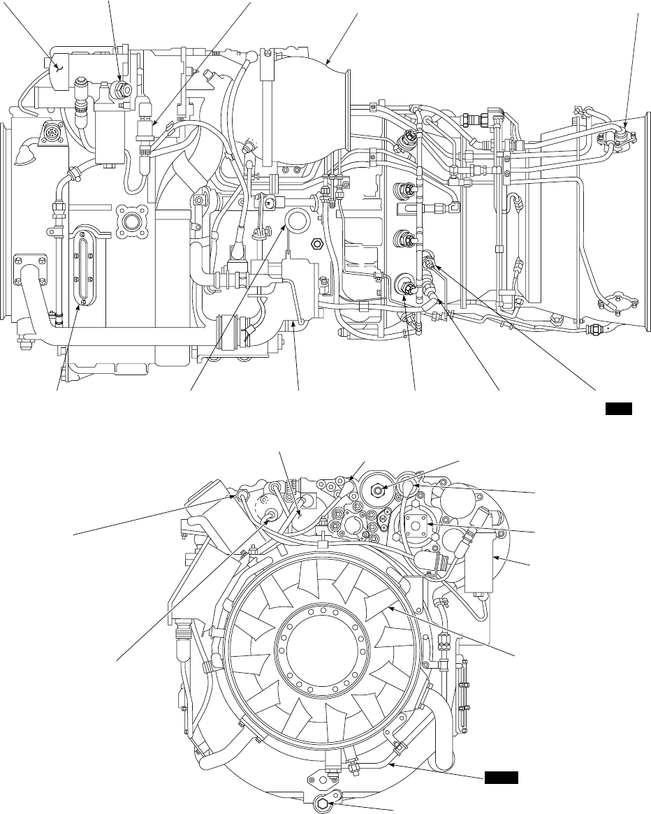
OIL FUEL FILTER IMPENDING FUEL PRESSURE INLET PARTICLE Np
COOLER BYPASS BUTTON SENSOR SEPARATOR
BLOWER
OIL LEVEL
INDICATOR BLEED−AIR PORT ANTI−ICING AND
START BLEED VALVE MAIN FUEL
NOZZLE IGNITER PLUG PRIMER FUEL
NOZZLE
LEFT SIDE
ALTERNATOR OIL FILTER
BYPASS SENSOR OIL FILTER
BYPASS BUTTON
OIL TEMPERATURE
SENSOR
OIL PRESSURE
SENSOR
OIL DRAIN PLUG
IPS BLOWER
DRAIN LINE
SWIRL VANES
FUEL FILTER
FUEL BOOST
PUMP
CHIP DETECTOR
700
FRONT VIEW SA
AA0350_1A
701C
(%RPM)
SENSOR
Figure 2-11. Engine T700 (Sheet 1 of 2)
TM 1-1520-237-10
2-28
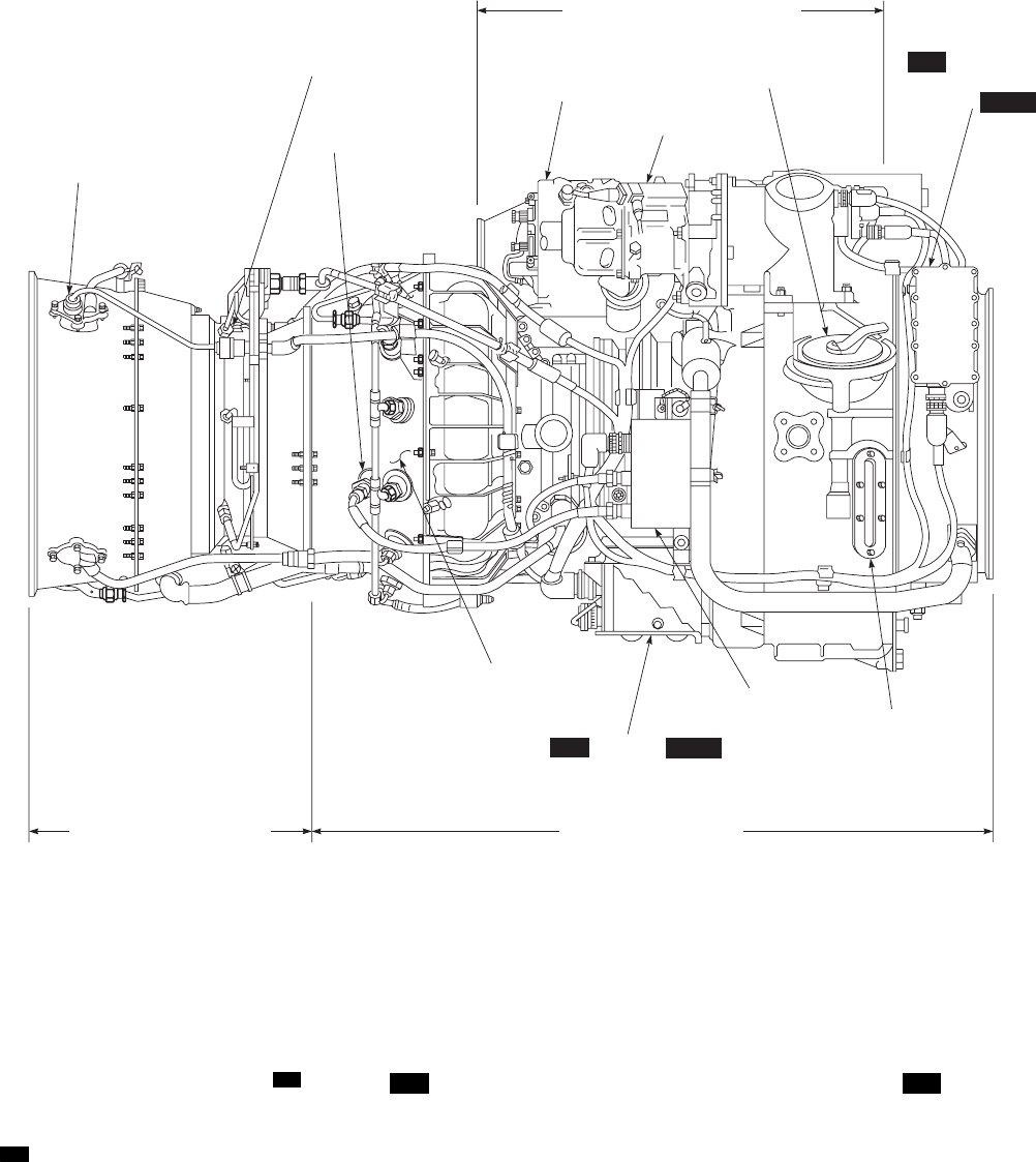
(Figure 2-11), contains a high pressure pump that delivers
fuel to the POU/ODV. Various parameters are sensed by
the HMU and influence fuel flow, variable geometry posi-
tion, and engine anti-ice start bleed valve operation. Fuel
from the HMU flows to a POU 700 or ODV 701C .
2.18.4.1 Pressurizing and Overspeed Unit.
700 The POU sends some of the fuel through the fuel start
manifold tube to the primer nozzles and allows back flow
of high pressure air for purging. The rest of the fuel is sent
through the main fuel manifold to the injectors for starting
acceleration and engine operation. It purges fuel from the
primer nozzles after light off. It purges fuel from the primer
nozzle and main fuel manifold on shutdown. It also reduces
fuel flow to prevent an engine overspeed when the over-
speed system is tripped as sensed by the ECU.
2.18.4.2 Overspeed and Drain Valve. 701C The ODV
sends fuel through the main fuel manifold to the injectors
for starting acceleration and engine operations. It purges
fuel from the main fuel manifold and allows back flow of
high pressure air for purging. It shuts off fuel flow to pre-
vent an engine overspeed when the overspeed system is
tripped as sensed by the DEC. It also shuts off fuel to
prevent hot starts when activated by the hot start preventor
(HSP).
SA
AA0350_2A
TORQUE AND
OVERSPEED SENSOR
IGNITOR
PLUG
ACCESSORY SECTION MODULE
STARTER
HYDROMECHANICAL
UNIT
OIL FILLER
CAP HISTORY
RECORDER /
COUNTER
THERMOCOUPLE
HARNESS
COLD SECTION MODULEPOWER TURBINE MODULE
OIL LEVEL
INDICATOR
IGNITION
EXCITER
ECU / DEC
HOT SECTION
MODULE (INTERNAL)
RIGHT SIDE
700
701C
700 701C
Figure 2-11. Engine T700 (Sheet 2 of 2)
TM 1-1520-237-10
2-29

2.19 ENGINE ALTERNATOR.
2.19.1 Engine Alternator. 700 The engine alternator
(Figure 2-11) supplies ac power to the ignition exciter and
electrical control unit (ECU). It also supplies a signal to the
Ng SPEED cockpit indicator. All essential engine electrical
functions are powered by the alternator.
a. When the alternator power supply to the ECU is in-
terrupted, a loss of % RPM 1 or 2and % TRQ,indications
will occur, with corresponding engine(s) increasing to
maximum power (high side).
b. When the alternator Ng signal is interrupted, a loss of
Ng cockpit indication will occur with a corresponding ENG
OUT warning light and audio.
c. A complete loss of engine alternator power results in
affected engine(s) increasing to maximum power (high
side) with a loss of cockpit indications of % RPM 1 or 2,
% TRQ, and Ng SPEED; and an ENG OUT warning light
and audio will occur. Overspeed protection is still avail-
able.
2.19.2 Engine Alternator. 701C The engine alternator
(Figure 2-11) supplies ac power to the ignition exciter and
digital electronic control (DEC) unit. It also supplies a sig-
nal to the Ng SPEED cockpit indicator. All essential en-
gine electrical functions are powered by the alternator.
a. When the alternator power supply to the DEC is in-
terrupted, 400 Hz 120 VAC aircraft power is utilized to
prevent engine (high side) failure. There will be a loss of
the associated cockpit Ng indication and activation of an
ENG OUT warning light and audio. Overspeed protection
is still available.
b. When the alternator Ng signal is interrupted, a loss of
the associated engine Ng indication, and an ENG OUT
warning light and audio will occur. Because the DEC can
utilize 400 Hz 120 VAC aircraft power, there will be no
loss of associated % RPM 1 or 2and % TRQ indications.
2.20 IGNITION SYSTEM.
The engine ignition system is a noncontinuous ac pow-
ered, capacitor discharge, low voltage system. It includes a
dual exciter, two igniter plugs, ignition leads, and ENGINE
IGNITION keylock switch.
2.21 HISTORY RECORDER. 700
The engine history recorder is mounted on the right side
of the swirl frame (Figure 2-11). It displays four digital
counters which records information for maintenance pur-
poses only. The history recorder will only operate with an
ECU.
2.22 HISTORY COUNTER. 701C
The engine history counter is mounted on the right side
of the swirl frame (Figure 2-11). It displays four digital
counters which records information for maintenance pur-
poses only. The history counter will only operate with a
DEC.
2.23 THERMOCOUPLE HARNESS.
A seven probe harness measures the temperature of the
gases at the power turbine inlet. It provides a signal to the
ECU 700 ,orDEC 701C , that relays it to the history re-
corder 700 , or history counter 701C , through the signal
data converter (SDC) to the cockpit temperature gage.
2.24 TORQUE AND OVERSPEED AND % RPM
SENSORS.
Two sensors are installed on the exhaust frame of the
engine. One sensor provides the power turbine governor
and tachometer signal to the ECU 700 ,orDEC 701C . The
other sensor feeds the torque computation circuit and over-
speed protection system.
TM 1-1520-237-10
2-30 Change 8

2.25 ENGINE BLEED-AIR SYSTEM.
Two bleed-air ports are incorporated on the engine. The
outboard port supplies bleed-air to the engine air inlet anti-
icing system as described in Section III. The inboard port
ties into the pressurized air system. Air from this port is
supplied to the cabin heating system and can be supplied to
the other engine for crossbleed starts.
2.26 ENGINE ANTI-ICING SYSTEMS.
2.26.1 Engine Anti-Icing.
CAUTION
The engine can incur FOD by improper
use of these systems and the other anti-
ice/deice systems. For example, ice shed-
ding off the windshield can cause FOD
damage to the engines.
a. The engine is anti-iced by two systems; the first de-
scribed in subparagraph b is called an engine anti-ice sys-
tem and a second described in paragraph 2.26.2 is called
the engine inlet anti-icing. Both of these systems are turned
on by the ENG ANTI-ICE NO. 1 and NO. 2 switches
(Figure 2-7).
b. Engine anti-icing is a combination of bleed-air and
heated engine oil. Anti-icing is controlled by a solenoid-
operated air valve. The engine anti-ice/start bleed valve
opens during starting and will remain open at low power
settings until engine reaches 88 to 92% Ng, depending on
the outside air temperature, with anti-ice OFF. The engine
anti-ice/deice system is designed so that in the event of an
electrical failure the valve reverts to the anti-icing mode
and turns on an advisory light indicating #1 ENG ANTI-
ICE ON or #2 ENG ANTI-ICE ON. Axial compressor
discharge air is bled from stage five of the compressor cas-
ing, routed through the anti-icing/bleed valve, and deliv-
ered to the front frame through ducting. Within the swirl
frame, hot air is ducted around the outer casing to each
swirl vane splitter lip and inlet guide vanes. The hot air is
directed within each vane by a series of baffles. Hot engine
oil passing within the scroll vanes in the main frame pre-
vents ice buildup. Water, snow, and solids are carried out
through the inlet particle separator discharge system.
Switches marked ENG ANTI-ICE NO. 1 or NO. 2 OFF,
and ON, control engine and inlet anti-ice. At the ON posi-
tion, compressor bleed-air is supplied continuously. Power
to operate the anti-icing system is by the No. 1 and No. 2
dc primary buses respectively, through circuit breakers,
marked NO. 1 ENG ANTI-ICE and ANTI-ICE WARN,
NO. 2 ENG ANTI-ICE and ANTI-ICE WARN respec-
tively.
2.26.2 Engine Inlet Anti-Icing.
a. The engine air inlets are anti-iced by bleed-air from
the engines. Four advisory lights on the caution/advisory
panel, marked #1 ENG ANTI-ICE ON,#2 ENG ANTI-
ICE ON,#1 ENG INLET ANTI-ICE ON and #2 ENG
INLET ANTI-ICE ON are provided for the engines. The
#1 and #2 ENG ANTI-ICE ON advisory lights will go on
when the ENG ANTI-ICE NO. 1 and ENG ANTI-ICE
NO. 2 switches are placed ON. When the anti-ice system is
operating and an engine is started, the inlet anti-ice valve
for that engine will close. The #1 and #2 ENG INLET
ANTI-ICE ON advisory lights operate from temperature
sensed at the engine inlet fairing. When the temperature
reaches about 93°C (199°F), the temperature switch will
turn on the appropriate ENG INLET ANTI-ICE ON ad-
visory light. If this light goes on with the switches at ENG
ANTI-ICE NO. 1 and NO. 2 OFF, it indicates that heat is
being applied to that engine inlet and a malfunction exists.
Inlet anti-icing will turn on if dc primary power failure
occurs; dc electrical power is applied to keep the valve
closed. Functioning of ENG INLET ANTI-ICE is con-
trolled as follows:
(1) Above 13°C (55°F) - Illumination of the ENG IN-
LET ANTI-ICE ON advisory light indicates a system mal-
function.
(2) Above 4°C (39°F) to 13°C (55°F) - The ENG IN-
LET ANTI-ICE ON advisory light may illuminate or may
not illuminate.
(3) At 4°C (39°F) and below - Failure of ENG IN-
LET ANTI-ICE ON advisory light to illuminate indicates
a system malfunction. Do not fly the aircraft in known icing
conditions.
b. At engine power levels of 10% TRQ per engine and
below, full inlet anti-ice capability cannot be provided due
to engine bleed limitations. Power to operate the valves is
normally provided from the No. 1 and No. 2 dc primary
buses, respectively, through circuit breakers marked NO. 1
and NO. 2 ENG ANTI-ICE, respectively. During engine
start, power to operate the No. 1 engine inlet anti-ice valve
is provided from the dc essential bus through a circuit
breaker marked NO. 1 ENG START. The #1 and #2 ENG
INLET ANTI-ICE ON advisory lights receive power from
No. 1 and No. 2 dc primary buses, through circuit breakers,
marked NO. 1 and NO. 2 ENG ANTI-ICE WARN, re-
spectively.
TM 1-1520-237-10
Change 10 2-31

2.27 ENGINE OIL SYSTEM.
Lubrication of each engine is by a self-contained, pres-
surized, recirculating, dry sump system. Included are oil
and scavenge pump, emergency oil system, monitored oil
filter, tank, oil cooler, and seal pressurization and venting.
The oil tank is a part of the main frame. Each scavenge line
has a screen at the scavenge pump to aid fault isolation. A
chip detector with a cockpit warning light is in the line
downstream of the scavenge pump.
2.27.1 Engine Emergency Oil System. The engine
has an emergency oil system in case oil pressure is lost. Oil
reservoirs built into the A and B sumps are kept full during
normal operation by the oil pump. Oil bleeds slowly out of
those reservoirs and is atomized by air jets, providing con-
tinuous oil mist lubrication for the bearings. A #1 ENGINE
OIL PRESS or #2 ENGINE OIL PRESS caution panel
light will go on when indicated oil pressure drops below 25
psi on helicopters without modified faceplates on the instru-
ment panel 700 , or below 20 psi on helicopters with modi-
fied faceplates 700 ,or22psi 701C . Power for the caution
lights comes from the No. 1 and No. 2 dc primary buses
through circuit breakers marked NO. 1 and NO. 2 ENG
WARN LTS respectively.
2.27.2 Oil Tank. The oil tank is an integral part of the
engine. Tank capacity is 7 US quarts. The filler port is on
the right. Oil level is indicated by a sight gage on each side
of the tank. Servicing of the tank is required if the oil level
reaches the ADD line. Overservicing is not possible be-
cause extra oil will flow out the filler port. The scavenge
pump returns oil from the sumps to the oil tank through six
scavenge screens, each one labeled for fault isolation.
2.27.3 Oil Cooler and Filter. The oil cooler (Figure
2-11) cools scavenge oil before it returns to the tank. Oil
from the chip detector passes through the oil cooler and is
cooled by transferring heat from the oil to fuel. After pass-
ing through the oil cooler, oil enters the top of the main
frame where it flows through the scroll vanes. This further
cools the oil and heats the vanes for full-time anti-icing.
The vanes discharge oil into the oil tank. If the oil cooler
pressure becomes too high, a relief valve will open to dump
scavenge oil directly into the oil tank. Oil discharged from
the oil pump is routed to a disposable-element filter. As the
pressure differential across the filter increases, the first in-
dicator will be a popped impending bypass button. As the
pressure increases further, this indication will be followed
by an indication in the cockpit #1 or #2 OIL FLTR BY-
PASS, after which a filter bypass will occur. Power for the
caution lights is from the No. 1 and No. 2 dc primary buses
respectively, through circuit breakers marked NO. 1 and
NO. 2 ENG WARN LTS. During cold weather starting, or
on starting with a partially clogged filter, the high-pressure
drop across the filter will cause the bypass valve to open
and the caution lights to go on. The impending bypass in-
dicator has a thermal lockout below 38°C to prevent the
button from popping. A cold-start relief valve downstream
of the filter protects the system by opening and dumping
the extra oil to the gear box case.
2.27.4 Engine Chip Detector. The chip detector is on
the forward side of the accessory gear box. It consists of a
housing with integral magnet and electrical connector, with
a removable screen surrounding the magnet. The detector
attracts magnetic particles at a primary chip detecting gap.
A common oil discharge from the scavenge pump is routed
to a chip detector wired to a cockpit caution light marked
CHIP #1 ENGINE or CHIP #2 ENGINE. If chips are
detected, a signal is sent to the cockpit to light a caution
light, marked CHIP #1 ENGINE or CHIP #2 ENGINE.
Power to operate the engine chip detector system is from
the No. 1 and No. 2 dc primary buses respectively, through
circuit breakers marked WARN LTS, under the general
headings NO. 1 ENG and NO. 2 ENG.
2.28 ENGINE START SYSTEM.
The pneumatic start system uses an air turbine engine
start motor for engine starting. System components consist
of an engine start motor, start control valve, external start
connector, check valves, controls and ducting. Three pneu-
matic sources may provide air for engine starts: the APU,
engine crossbleed, or a ground source. When the start but-
ton is pressed, air from the selected source is directed
through the start control valve to the engine start motor.
The #1 ENGINE STARTER or #2 ENGINE STARTER
caution light will go on at this time and remain on until the
starter drops out. As the engine start motor begins to turn,
an overrun clutch engages causing the engine to motor. As
the engine alternator begins to turn, electrical current is
supplied to the ignition exciter. Ignition will continue until
either the ENGINE IGNITION switch is moved to OFF
or starter dropout occurs. The ENG POWER CONT lever
is advanced to IDLE detent for light-off and acceleration.
A starter speed switch terminates the start cycle when cut-
off speed is reached (52% to 65% Ng SPEED) and turns
off the starter caution light and engine ignition. Malfunc-
tion of the starter speed switch may be overcome by manu-
ally holding the start button pressed until reaching 52% to
65% Ng SPEED. To drop out the starter, manually pull
down on the ENG POWER CONT lever. To abort a start,
pull down on the ENG POWER CONT lever and move to
OFF in one swift movement. Power to operate the No. 1
engine start control valve is from the dc essential bus
through a circuit breaker marked NO. 1 ENG START.
Power to operate the No. 2 engine start control valve is
TM 1-1520-237-10
2-32

from the No. 2 dc primary bus through a circuit breaker
marked NO. 2 ENG START CONTR. For the 701C en-
gine only, fuel flow to the engine will be automatically shut
off if TGT TEMP exceeds 900°C during the start
sequence 701C .
2.28.1 Engine Ignition Keylock. An ENGINE IGNI-
TION keylock is installed on the instrument panel (Figure
2-9), to short out and prevent ignition exciter current flow
when the switch is OFF and the starter is engaged. The
switch is marked ENGINE IGNITION OFF and ON.
When the switch is ON, the shorts are removed from both
engine alternators, allowing exciter current to flow when
the engine alternator begins to turn. The ENGINE IGNI-
TION is normally ON during flight and turned OFF at
shutdown. One switch serves both engines. If the switch is
OFF, neither engine can be started, although motoring ca-
pability remains. When an engine is to be motored without
a start, make certain the ENGINE IGNITION switch is
OFF. To prevent a possible hot or torching start never turn
the ENGINE IGNITION switch ON after motoring has
started. Abort start procedures must be done to remove ex-
cess fuel from the engine if a start was attempted with the
switch OFF.
2.28.2 APU Source Engine Start. The APU provides
an on-board source of air and auxiliary electrical power.
The APU bleed-air output is enough to start each engine
individually at all required combinations of ambient tem-
peratures and enough to start both engines simultaneously
within a reduced range of ambient temperatures (Figure
5-5). The AIR SOURCE HEAT/START switch must be
at APU. Refer to Section XII for complete APU descrip-
tion.
2.28.3 Crossbleed Engine Start System. Crossbleed
engine starts are used when one engine is operating and it is
desired to start the other engine from the bleed-air source of
the operating engine. To make a crossbleed start, the oper-
ating engine must be at least 90% Ng SPEED. When the
AIR SOURCE HEAT/START switch is placed to ENG,
both engine crossbleed valves will open. Pressing the start
button for the engine not operating will cause the start valve
for that engine to open at the same time the crossbleed
valve for the starting engine will close, and remain closed
until starter dropout occurs. At 52% to 65% Ng SPEED,
the starting engine start valve will close, stopping bleed-air
flow to the starter. Power to operate the bleed shutoff valve
is from No. 1 dc primary bus through a circuit breaker
marked AIR SOURCE HEAT/START.
2.28.4 External Source Engine Start. The external
start pneumatic port (Figure 2-1) is on the left side of the
fuselage. It is the attachment point for a bleed-air line from
an external source for engine starting or helicopter heating
on the ground. The assembly contains a check valve to
prevent engine or APU bleed-air from being vented. The
external air source pressurizes the start system up to the
engine start control valves, requiring only that electrical
power be applied. If an emergency start is made without ac
electrical power, No. 1 engine must be started first because
the No. 2 engine start control valve will not operate without
dc primary bus power.
2.29 ENGINE CONTROL SYSTEM.
The engine control system consists of the ECU
700
DEC
701C
engine quadrant, load demand system and speed
control system.
2.29.1 Electrical Control Unit (ECU). 700 The electri-
cal control unit controls the electrical functions of the en-
gine and transmits operational information to the cockpit. It
is a solid-state device, mounted below the engine compres-
sor casing. The ECU accepts inputs from the alternator,
thermocouple harness, Np (% RPM 1 and 2) sensor, torque
and overspeed sensors, torque signal from opposite engine
for load sharing, feedback signals from the HMU for sys-
tem stabilization, and a demand speed from the engine
speed trim button. The ECU provides signals to the %
RPM 1 and 2indicators, % TRQ meter, TGT TEMP
indicator, and history recorder.
NOTE
Phantom torque may be observed on the Pi-
lot Display Unit (PDU) torque display of a
non-operating engine while the aircraft’s
other engine is operating during a ground
run. Phantom torque readings of up to 14%
have been observed on the PDU of the non-
operating engine. During startup of the non-
operating engine, its ECU will produce a
normal, positive torque signal which dis-
plays the correct torque signal on the respec-
tive PDU.
a. In case of an ECU malfunction, the pilot may over-
ride the ECU by momentarily advancing the ENG
POWER CONT lever to the LOCKOUT stop, then re-
tarding it to manually control engine power. To remove the
ECU from lockout, the ENG POWER CONT lever must
be moved to IDLE.
b. The torque matching/load sharing system increases
power on the lower-torque engine to keep engine torques
approximately equal. The system does not allow an engine
to reduce power to match a lower power engine. If an en-
TM 1-1520-237-10
Change 8 2-33
gine fails to the high side, the good engine will only at-
tempt to increase torque upward until its Np is 3% above
the reference Np.
c. The temperature limiting system limits fuel flow
when the requirement is so great that the turbine tempera-
ture reaches the limiting value of 837°C to 849°C. Fuel
flow is reduced to hold a constant TGT. It is normal to see
a transient increase above the 850°C TGT TEMP when the
pilot demands maximum power (Figure 5-1 transient lim-
its). TGT limiting does not prevent overtemperature during
engine starts, compressor stall, or when the engine is oper-
ated in LOCKOUT (Paragraph 9.3e).
CAUTION
Delay in release of NO. 1 and NO. 2 ENG
OVSP TEST A and TEST B button may
result in Ng recycling below idle, resulting
in subsequent engine stall and TGT in-
crease. To avoid damage, TGT must be
monitored during overspeed check.
d. Overspeed protection protects the power turbine from
destructive overspeeds. The system is set to trigger at
106%61% RPM 1 or 2and will result in an initial reduced
fuel flow and will cycle until the cause of the overspeed is
removed or % RPM is reduced manually. Two momentary
switches marked NO. 1 and NO. 2 ENG OVSP TEST A
and TEST B on the upper console (Figure 2-7), are used to
check the circuits. Testing individual circuits A and B in-
dicates that those systems are complete and performing cor-
rectly. Dual closing of A and B serves to check out the
actual overspeed system itself, the overspeed solenoid and
the POU. This check must be done only on the groundby
designated maintenance personnel. The overspeed protec-
tion is not deactivated when in LOCKOUT. Power to op-
erate the overspeed system is from two independent
sources: the engine alternators as the primary source, and
the No. 1 and No. 2 ac primary buses as alternate backup
source in case of alternator failure. Circuit protection is
through circuit breakers marked NO. 1 ENG OVSP and
NO. 2 ENG OVSP.
2.29.2 Digital Electronic Control (DEC).
701C The digital electronic control unit controls the elec-
trical function of the engine and transmits operational in-
formation to the cockpit. It contains a microcomputer pro-
cessor in a conductive composite molded case. The DEC
can be fully powered by either the engine alternator or by
the 400 Hz, 120 VAC aircraft power. It incorporates logic
that will eliminate the torque spike signal during engine
start and shutdown.
a. The DEC accepts inputs from the alternator, thermo-
couple harness, Np (% RPM 1 and 2) sensor, torque and
overspeed sensors, RPM R sensor and collective position
transducer for improved transient droop response, torque
signal from opposite engine for load sharing, feedback sig-
nals from the HMU for system stabilization, and the engine
speed trim button for Np demand speed reference.
CAUTION
Delay in release of TEST A/B button may
result in Ng recycling below idle, resulting
in subsequent engine stall and TGT in-
crease. To avoid damage, TGT must be
monitored during overspeed check.
b. The DEC provides signals to the % RPM 1 and 2
indicators, % TRQ meter, TGT TEMP indicator, and en-
gine history counter. It also provides signal validations or
selected input signals within the electrical control system.
Signals are continuously validated when the engine is op-
erating at idle and above. If a failure occurred on a selected
input signal, the failed component or related circuit will be
identified by a preselected fault code (Figure 2-12) dis-
played on the engine torque meter. These codes are defined
in terms of engine torque. They are displayed for 4 seconds
on, 2 seconds off, starting with the lowest code and rotating
through all applicable codes, then repeating the cycle. They
will only be displayed 30 seconds after both engines are
shutdown with 400 Hz, 120 VAC power applied. They may
be recalled by maintenance and the engine restarted. The
pilot can suppress the fault code display of an engine by
depressing the associated cockpit overspeed test button
(TEST A/B). The pilot may recall it by again depressing
the associated cockpit overspeed test button.
c. In case of a DEC malfunction, the DEC may be re-
called by maintenance only, and the engine restarted once
action has been performed.
d. The torque matching/load sharing system increases
power on the lower-torque engine to keep engine torques
approximately equal. The system does not allow an engine
to reduce power to match a lower power engine. If an en-
gine fails to the high side, the good engine will only at-
tempt to increase torque upward until its Np is 3% above
the reference Np.
e. The transient compensation system provides signifi-
cant droop improvement during some maneuvers by moni-
toring engine torque, collective rate of change, and RPM R
speed rate of change.
TM 1-1520-237-10
2-34 Change 10

f. The temperature limiting system limits fuel flow when
the TGT TEMP reaches the dual engine 10 minute limit-
ing value of approximately 866°C. The automatic contin-
gency power limiting will switch to a higher single-engine
2 1/2 minute temperature limiting value of approximately
891°C when the opposite % TRQ is less than 50%. Fuel
flow is regulated to hold a constant TGT. It is normal to see
a transient increase above the 903°C TGT TEMP limit
when the pilot demands maximum power (Figure 5-2 tran-
sient limits). TGT limiting does not prevent overtempera-
ture during engine starts, compressor stall, or when the en-
gine is operated in LOCKOUT (Paragraph 9.3e).
g. The hot start prevention system (HSP) is a part of the
DEC. It prevents overtemperature during engine starts. The
HSP system receives Np, Ng, and TGT signals. When Np
and Ng are below their respective hot start reference and
TGT TEMP exceeds 900°C, an output from the HSP sys-
tem activates a solenoid in the ODV. This shuts off fuel
flow and causes the engine to shut down. The HSP system
requires 400 Hz, 120 VAC aircraft power be provided to
the DEC. The pilot can disable the HSP for emergency
starting purposes by pressing and holding the overspeed
test button (TEST A/B) for the engine being started during
the engine start sequence.
h. Overspeed protection protects the power turbine from
destructive overspeeds. The system is set to trigger at
120%61% RPM 1 or 2and will result in a fuel flow
shut-off causing the engine to flame out. When % RPM is
reduced below the overspeed limit, fuel flow is returned to
the engine and engine ignition will come on to provide a
relight. This cycle will continue until the overspeed condi-
tion is removed. Two momentary switches marked NO. 1
TM 1-1520-237-10
Change 10 2-34.1/(2-34.2 Blank)
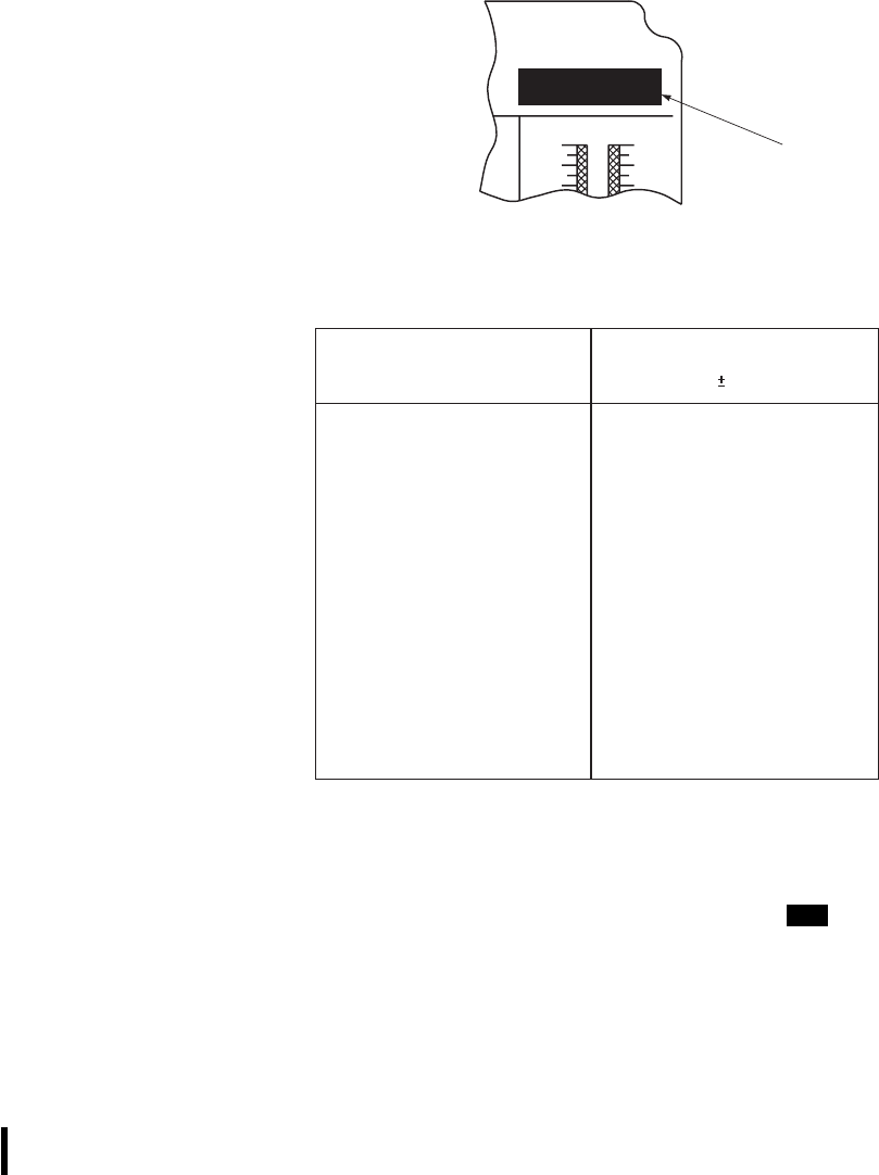
and NO. 2 ENG OVSP TEST A and TEST B on the upper
console (Figure 2-7), are used to check the circuits. Testing
individual circuits A and B indicates that those systems are
complete and performing correctly. Dual closing of A and
B switches serve to check out both the overspeed system,
and the overspeed drain valve (ODV). This check must be
done only on the ground by designated maintenance per-
sonnel. The overspeed protection is not deactivated when in
LOCKOUT. Power to operate the overspeed system is
from two independent sources: the engine alternators as the
primary source, and the No. 1 and No. 2 ac primary buses
as alternate backup source in case of alternator failure. Cir-
cuit protection is through circuit breakers marked NO. 1
ENG OVSP and NO. 2 ENG OVSP.
2.29.3 Engine Control Quadrant. The engine control
quadrant (Figure 2-13) consists of two ENG POWER
CONT levers, two ENG FUEL SYS selector levers, and
two ENG EMER OFF T-handles. A starter button is on
each ENG POWER CONT lever. Each ENG POWER
CONT lever has four positions: OFF-IDLE-FLY-
LOCKOUT. Movement of the ENG POWER CONT le-
vers moves a cable to mechanically shut off fuel or set
available Ng SPEED. The lever is advanced to FLY for
flight. This ENG POWER CONT lever setting represents
the highest power that could be supplied if demanded.
Power turbine speed (% RPM 1 or 2) is not governed until
the power lever is advanced from IDLE. The engine quad-
rant secondary stop, two stop blocks, the quadrant assem-
SA
AA0517
12
140 140
SIGNAL FAILED DIAGNOSTIC
INDICATION ON TORQUE METER
( 3%)
DEC
Np DEMAND CHANNEL
LOAD SHARE CHANNEL
TGT CHANNEL
ALTERNATOR POWER
Ng CHANNEL
Np CHANNEL
TORQUE AND OVERSPEED
CHANNEL
HOT START PREVENTION
CHANNEL
AIRCRAFT 400 Hz POWER
COLLECTIVE CHANNEL
Nr
15%
25%
35%
45%
55%
65%
75%
85%
95%
105%
115%
125%
DIAGNOSTIC
INDICATIONS
DISPLAYED
AT SHUTDOWN
% TRQ
Figure 2-12. Signal Validation - Fault Codes 701C
TM 1-1520-237-10
Change 10 2-35

bly, and a latch on each ENG POWER CONT lever pre-
vent moving the levers below IDLE detent. When
shutdown is required, the ENG POWER CONT lever must
be pulled out slightly, at the same time the latch release
must be pressed, then the ENG POWER CONT lever can
be moved below IDLE detent. After being moved momen-
tarily to LOCKOUT, the ENG POWER CONT lever is
used to manually control Ng SPEED and % RPM 1 or 2.
With the ENG POWER CONT lever at LOCKOUT, the
automatic TGT limiting system is deactivated and TGT
must be manually controlled. The overspeed protection sys-
tem is not deactivated when at LOCKOUT.
2.29.4 Load Demand System. With ENG POWER
CONT lever at FLY, the ECU 700 or DEC 701C and
HMU respond to collective signals to automatically control
engine speed and provide required power. During emer-
gency operations, when the ENG POWER CONT lever is
moved to LOCKOUT and then to some intermediate posi-
tion, the engine will still respond to collective signals.
2.29.5 Engine Speed Control System. An engine
RPM control switch on the collective grips (Figure 2-14)
controls the speed of both engines simultaneously. There is
no individual trim capability. It is used to supply a signal to
the ECU 700 ,orDEC 701C for controlling % RPM 1 and
2as required. The ENG RPM control switch allows adjust-
ment between 96% and 100%. The pilot can override the
copilot’s control. Power for ENG RPM control system is
from the No. 2 dc primary bus through a circuit breaker
marked SPEED TRIM.
2.30 HOVER INFRARED SUPPRESSOR SUB-
SYSTEM (HIRSS).
The hover IR suppressor (Figure 2-2) provides improved
helicopter survivability from heat-seeking missiles through-
out the flight envelope. The HIRSS kit has no moving parts.
It contains a three-stage removable core which reduces
metal surface and exhaust gas temperature radiation and
prevents line-of-sight viewing of hot engine surfaces. The
HIRSS channels hot exhaust gasses through the three-stage
core and inner baffle to induce the flow of cooling air from
the engine bay and the inlet scoops. The three-stage core
and inner baffle cold surfaces are coated with low-
reflectance material. For further cooling, hot exhaust gas is
ducted outboard and downward by the engine, away from
the helicopter by the exhaust deflector, where additional
cooling air is provided by the main rotor downwash. Instal-
lation of each HIRSS module requires removal of the stan-
dard engine exhaust module and aft cabin door track fair-
ings. HIRSS modules are installed on the basic airframe
equipped with HIRSS fixed provisions by two airframe
mounts. The aft fairings are installed using existing mount-
ing points and hardware. While operating in a non-hostile
environment, the inner baffle can be removed to enhance
helicopter performance.
2.31 ENGINE INSTRUMENTS.
The instrument displays (Figure 2-9) consist of ENG
OIL TEMP and PRESS,TGT TEMP, gas generator Ng
SPEED, power turbine speed (% RPM 1 or 2), rotor speed
% RPM R, engine torque % TRQ, and FUEL QTY to
provide the pilots with engine and subsystem monitoring.
Continuous indications of those parameters are indicated on
vertical scales, digital readouts and caution lights. Instru-
ments without low range turn-off feature: % TRQ,TGT
TEMP,Ng SPEED,ENG OIL TEMP and XMSN TEMP
will remain on as parameter increases and go out as it de-
creases (Figure 5-1). Power for lighting the displays is from
the No. 1 and No. 2 ac primary and No. 1 and No. 2 dc
primary buses through the signal data converters.
2.31.1 Engine Oil Temperature Indicator. Each en-
gine has an oil temperature sensor wired through the signal
data converter to a vertical scale instrument, marked ENG
OIL TEMP, on the central display unit; and to an engine
oil temperature caution light, marked ENGINE OIL
TEMP, on the caution/advisory panel.
2.31.2 Engine Oil Pressure Indicator. Each engine
has an engine oil pressure transmitter, downstream of the
oil filter, that sends readings to a vertical scale indicator,
marked ENG OIL PRESS, on the instrument display
panel; and to an engine oil pressure caution light, marked
ENGINE OIL PRESS, on the caution panel. The lower
precautionary and prohibited ranges will go out when
reaching the bottom of the normal range. 700 It may be
possible that during IDLE operations, the ENGINE OIL
PRESS caution light will go on. 700 If ENGINE OIL
PRESS caution light comes on at IDLE, verify oil pressure
is acceptable by setting Ng SPEED at 90%, check that
engine oil pressure is at least 35 psi. As pressure increases
above 100 psi 700 , or 120 psi 701C the respective prohib-
ited scale changes to red.
2.31.3 TGT Temperature Indicator. The TGT indicat-
ing system consists of thermocouples transmitting to a TGT
TEMP indicator. The indicator assembly has two digital
readouts that indicate precise temperatures.
2.31.4 Gas Generator Speed (Ng) Indicator. The Ng
speed indicating system shows Ng speed for each engine.
The system consists of one alternator winding and Ng
SPEED vertical scale instrument, on the instrument panel,
TM 1-1520-237-10
2-36 Change 8
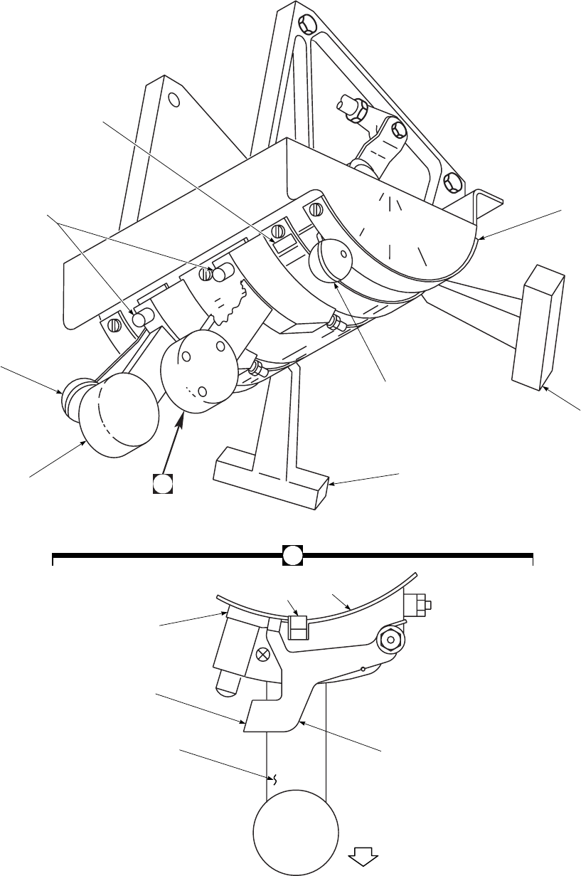
#2 ENG EMER OFF
#1 ENG EMER OFF
E
N
G
P
O
W
E
R
OFF
IDLE
C
O
N
T
LOCKOUT
FLY
D
I
R
O
F
F
XFD
S
Y
S
A
NO. 1 ENG
FUEL SYS
SELECTOR
LEVER
NO. 1 ENG
POWER CONT
LEVER
NO. 1 ENG
EMER OFF
T−HANDLE
NO. 2 ENG
EMER OFF
T−HANDLE
QUADRANT
COVER
NO. 2 ENG FUEL
SYS SELECTOR
LEVER
SECONDARY
IDLE STOP
FOR POWER LEVER
STARTER
BUTTON
NO. 2 ENG
POWER CONT
LEVER
IDLE
DETENT
CENTER
COVER
IDLE
STOP
BLOCK
PUSH TO
RELEASE
LEVER ASSY LATCH
A
LOOKING INBOARD
RIGHT SIDE SA
AA0351A
CONT PULL
DOWN
Figure 2-13. Engine Control Quadrant
TM 1-1520-237-10
2-37

giving percent rpm. Digital readouts for Ng SPEED are at
the lower section of the instrument face plate. The three-
digit readouts provide a closer indication of Ng SPEED.
2.31.5 Engine Power Turbine/Rotor Speed Indica-
tor. Power turbine and rotor speed are indicated for each
engine on a single instrument marked % RPM 1 R 2 on the
display panel with three vertical scales (Figure 5-1). Power
turbine speed is indicated in % RPM 1 or 2and rotor speed
% RPM R. Rotor speed is sensed by a speed sensor on the
right accessory module. Power turbine speed is sensed by a
speed sensor on the engine exhaust frame. At the top of the
panel are three warning lights that indicate varying degrees
of rotor overspeed. These lights remain on, once tripped,
and must be manually reset.
2.31.6 Torque Indicator. The torque indicating system
shows the amount of power the engine is delivering to the
main transmission. A torque sensor mounted on the exhaust
case measures the twist of the power turbine shaft, and
transmits this signal to the ECU 700 ,orDEC 701C and
signal data converter into the torque indicator marked %
TRQ on the display panel, displaying readings for both
engines. Digital readouts giving torques for each engine are
at the top of the indicator. A photocell on the lower center
of the display will automatically adjust the lighting of the
% RPM and % TRQ indicators with respect to ambient
light.
TM 1-1520-237-10
2-38 Change 8
Section IV FUEL SYSTEM
2.32 FUEL SUPPLY SYSTEM.
A separate suction fuel system is provided for each en-
gine. Fuel is stored in two interchangeable, crashworthy,
ballistic-resistant tanks. The fuel system consists of lines
from the main fuel tanks, firewall-mounted selector valves,
prime/boost pump and fuel tanks, and engine-driven suc-
tion pumps. The prime/boost pump primes all fuel lines if
prime is lost, and also acts as an APU boost for APU starts
and operation. A selector valve, driven by cable from the
ENG FUEL SYS selector lever on the engine control
quadrant (Figure 2-13) permits operation of either engine
from either fuel tank. The engines and APU are suction fed,
the APU is fed from the left main fuel tank by a separate
fuel line. All fuel lines are routed in the most direct man-
ner. The fuel line network includes self-sealing breakaway
valves that contain fuel in case of helicopter crash or mal-
function. All engine fuel lines are self-sealing with the ex-
ception of the APU fuel line.
2.32.1 Fuel Tanks. Both main fuel tanks are crashwor-
thy, self-sealing and interchangeable. Each tank contains a
pressure refuel/defuel valve, fuel quantity and low-level
sensors, high-level shutoff valve, low-level shutoff valve,
check valve sump drain, and a self-sealing breakaway vent
valve. (Refer to Table 2-4 for tank capacity.) Fuel tank
drains are in the sumps to permit removal of sediment and
water and provide fuel sampling.
2.32.2 Engine Fuel System Selector Control. Each
fuel system has a selector valve which is manually operated
through the ENG FUEL SYS selector lever on the over-
head engine control quadrant (Figure 2-13). There is an
ENG EMER OFF T-handle on each side of the quadrant
which is arranged so that pulling the handle engages the
ENG FUEL SYS selector lever, bringing it to OFF. The
ENG FUEL SYS selectors are connected to the fuel selec-
tor valves with low-friction flexible push-pull cables. Each
lever can be actuated to three positions: OFF,DIR, and
XFD. With the selectors at OFF, the control valves are
closed, allowing no fuel flow to the engines. When the
selectors are moved forward to DIR, the selector valves are
opened, providing fuel flow for each engine from its indi-
vidual fuel tank. If a tank is empty, or you wish to equalize
fuel in the tanks, the ENG FUEL SYS selector of the en-
gine that normally feeds from the empty or low-level tank
is moved to XFD. This connects that engine to the other
tank through the crossfeed system. A check valve in each
crossfeed line prevents air from an inoperative engine’s fuel
line crossing to the operating one.
2.32.3 Fuel Filter. The engine fuel filter has a bypass
valve and bypass warning device. The filter is mounted on
the forward left side of the engine accessory gear box. An
impending bypass warning is incorporated on the filter
housing in the form of a popout button. The bypass valve
opens to assure continuous fuel flow with a blocked filter.
At the same time the valve opens, an electrical switch
closes to light the #1 or #2 FUEL FLTR BYPASS caution
light. Power to operate the bypass warning system is from
the No. 1 and No. 2 dc primary buses through circuit break-
ers marked NO. 1 and NO. 2 ENG WARN LTS, respec-
tively.
2.33 ENGINE FUEL PRIME SYSTEM.
NOTE
Priming engines using sump mounted fuel
boost pumps is described in paragraph
8.41.3.
A toggle switch on the upper console, marked FUEL
PUMP,FUEL PRIME,OFF and APU BOOST (Figure
2-7), when moved to FUEL PRIME, energizes the prime/
boost pump and solenoid valves to each main engine fuel
supply line and to the solenoid valve for the APU fuel feed
system. Advisory panel indication is displayed during this
mode by a light marked PRIME BOOST PUMP ON.
Prime pump capacity is not enough to prime an engine
when the opposite engine is running. Engines should there-
fore be primed individually with both engines off. The
prime/boost pump is actuated and the engine prime valve is
opened whenever the engine starter is operating. This pro-
vides fuel pressure to aid in a successful engine start. When
the engine speed reaches starter dropout speed, engine fuel
prime valve will close and the prime/boost pump will also
stop operating if the FUEL PUMP switch is OFF. Power
to operate the prime boost system is from the battery bus
through a circuit breaker marked FUEL PRIME BOOST.
TM 1-1520-237-10
Change 8 2-39

2.34 FUEL QUANTITY INDICATING SYSTEM.
All internal fuel is continuously gaged with the FUEL
QTY gage system (Figure 2-8). The system consists of two
tank unit sensors (probes), one in each tank, a dual channel
fuel quantity gage conditioner, and a dual channel low-
level warning system. The tank units are connected to the
fuel quantity gages marked FUEL QTY 1-2 on the central
display panel. A separate total fuel quantity readout nu-
merically displays the total quantity of fuel on board. The
system may be checked out by pressing the FUEL IND
TEST pushbutton on the miscellaneous switch panel. The
vertical scales of the FUEL QTY indicator and the digital
readout should show a change, and the #1 and #2 FUEL
LOW caution lights on the caution/advisory panel should
flash. When the button is released, the scales and digital
readout will return to the original readings. The fuel quan-
tity indicating system is powered by the No. 1 ac primary
bus through a circuit breaker, marked NO. 1 AC INST.
2.34.1 Fuel Low Caution Light. Two low-level sen-
sors, one on each probe, provide signals which activate two
low-level caution lights indicating #1 FUEL LOW or #2
FUEL LOW. Those lights flash when the fuel level de-
creases to approximately 172 pounds in each tank. The il-
lumination of these lights does not mean a fixed time period
remains before fuel exhaustion, but is an indication that a
low fuel condition exists. The fuel-low caution lights are
powered by the No. 1 dc primary bus through a circuit
breaker marked FUEL LOW WARN.
2.34.2 Fuel Boost Pump. The helicopter fuel system
contains an electrically-operated submerged fuel boost
pump in each fuel tank. When the pumps operate, they
provide pressurized fuel to the engine fuel inlet port. Each
boost pump is controlled by a switch on the FUEL BOOST
PUMP CONTROL panel (Figure 2-8). The two-position
switch for each pump, marked ON-OFF, activates the
pump for continuous operation to maintain a head of fuel
pressure at the engine fuel inlet port, regardless of engine
boost pump discharge pressure. An advisory light near each
control switch indicates pump pressure and operation. A
check valve in each pump discharge line prevents fuel re-
circulation during fuel boost operation, and prevents loss of
engine fuel line prime. #1 or #2 FUEL PRESS caution
light going on is also an indicator to turn on boost pumps.
Power to operate the boost pumps is provided from the No.
1 and No. 2 ac primary buses through circuit breakers
marked NO. 1 and NO. 2 FUEL BOOST PUMP, respec-
tively.
2.34.3 Refueling/Defueling. A pressure refueling and
defueling system provides complete refueling and defueling
of both tanks from one point on the left side of the helicop-
ter (Figure 2-26). Closed circuit refueling uses the pressure
refueling system and its components. No electrical power is
required for the system during refueling or defueling. The
tank full shutoff valve is float-operated. A dual high-level
shutoff system acts as back up for each other. The two
high-level float valves close, causing a back pressure to the
fueling/defueling valve at the bottom of the tank, closing
the refuel valve. The tank empty automatic shutoff system
is a function of the low-level float valve opening to allow
air to be drawn into the line, closing the defuel valve. A
filler neck between the fuselage contour and the fuel cell is
a frangible (breakaway) connection. Gravity fueling is done
through filler neck on each side of the fuselage for the
respective tanks. Gravity defueling capability is provided
through the drains.
TM 1-1520-237-10
2-40 Change 8
Section V FLIGHT CONTROLS
2.35 FLIGHT CONTROL SYSTEMS.
NOTE
Flight near high power RF emitters such as
microwave antennas or shipboard radar may
cause uncommanded AFCS and/or stabilator
control inputs. Electromagnetic interference
(EMI) testing has shown that the master cau-
tion light may illuminate before or simulta-
neously with any uncommanded stabilator
trailing edge movement, with 4° or 5° of
movement being the maximum.
The primary flight control system consists of the lateral
control subsystem, the longitudinal control subsystem, the
collective pitch control subsystem, and the directional con-
trol subsystem. Control inputs are transferred from the
cockpit to the rotor blades by mechanical linkages, and
hydraulic servos. Pilot control is assisted by stability aug-
mentation system (SAS), flight path stabilization (FPS),
boost servos, and pitch, roll and yaw trim. Dual cockpit
controls consist of the cyclic stick, collective stick and ped-
als. The pilot and copilot controls are routed separately to a
combining linkage for each control axis. Outputs from the
cockpit controls are carried by mechanical linkage through
the pilot-assist servos to the mixing unit. The mixing unit
combines, sums, and couples the cyclic, collective, and yaw
inputs. It provides proportional output signals, through me-
chanical linkages, to the main and tail rotor controls.
2.35.1 Cyclic Stick. Lateral and longitudinal control of
the helicopter is by movement of the cyclic sticks through
push rods, bellcranks, and servos to the main rotor. Move-
ment in any direction tilts the plane of the main rotor blades
in the same direction, thereby causing the helicopter to go
in that direction. Each cyclic stick grip (Figure 2-14) con-
tains a stick trim switch, marked STICK TRIM FWD,L,
Rand AFT, a go around switch, marked GA, trim release
switch, marked TRIM REL, a panel light kill switch,
marked PNL LTS, a cargo release switch, marked
CARGO REL, and a transmitter ICS switch, marked RA-
DIO and ICS. Refer to major systems for a complete de-
scription of switches on the cyclic grip.
2.35.2 Collective Pitch Control Stick. The collective
sticks change the pitch of the main rotor blades, causing an
increase or decrease in lift on the entire main rotor disc. A
friction control on the pilot’s lever can be turned to adjust
the amount of friction and prevent the collective stick from
creeping. The copilot’s stick telescopes by twisting the grip
and pushing the stick aft to improve access to his seat. Each
collective stick has a grip (Figure 2-14) with switches and
controls for various helicopter systems. These systems are:
landing light control, marked LDG LT PUSH ON/OFF
EXT and RETR; searchlight controls, marked SRCH LT
ON/OFF ,EXT,L,R, and RETR; servo shutoff control
switch, marked SVO OFF 1ST STG and 2ND STG; en-
gine speed trim switch, marked ENG RPM INCR and
DECR; and cargo hook emergency release switch, marked
HOOK EMER REL;HUD control switch, marked BRT,
DIM,MODE, and DCLT. All switches are within easy
reach of the left thumb. For a complete description of
switches and controls, refer to major system description.
2.35.3 Mixing Unit. A mechanical mixing unit provides
control mixing functions which minimizes inherent control
coupling. The four types of mechanical mixing and their
functions are:
a. Collective to Pitch - Compensates for the effects of
changes in rotor downwash on the stabilator caused by col-
lective pitch changes. The mixing unit provides forward
input to the main rotor as collective is increased and aft
input as collective is decreased.
b. Collective to Yaw - Compensates for changes in
torque effect caused by changes in collective position. The
mixing unit increases tail rotor pitch as collective is in-
creased and decreases tail rotor pitch as collective is de-
creased.
c. Collective to Roll - Compensates for the rolling mo-
ments and translating tendency caused by changes in tail
rotor thrust. The mixing unit provides left lateral input to
the main rotor system as collective is increased and right
lateral input as collective is decreased.
d. Yaw to Pitch - Compensates for changes in the ver-
tical thrust component of the canted tail rotor as tail rotor
pitch is changed. The mixing unit provides aft input to the
main rotor system as tail rotor pitch is increased and for-
ward input as tail rotor pitch is decreased.
2.35.4 Collective/Airspeed to Yaw (Electronic Cou-
pling). This mixing is in addition to collective to yaw me-
chanical mixing. It helps compensate for the torque effect
caused by changes in collective position. It has the ability
to decrease tail rotor pitch as airspeed increases and the tail
rotor and cambered fin become more efficient. As airspeed
decreases, the opposite occurs. The SAS/FPS computer
commands the yaw trim actuator to change tail rotor pitch
as collective position changes. The amount of tail rotor
pitch change is proportional to airspeed. Maximum mixing
TM 1-1520-237-10
2-41
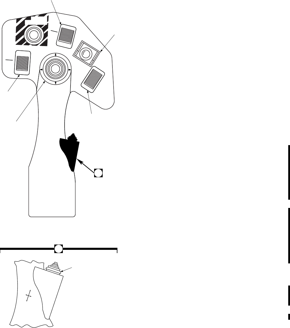
occurs from 0 to 40 knots. As airspeed increases above 40
knots, the amount of mixing decreases until 100 knots, after
which no mixing occurs.
2.35.5 Tail Rotor Control. The tail rotor control system
determines helicopter heading by controlling pitch of the
tail rotor blades. Inputs by the pilot or copilot to the control
pedals are transmitted through a series of control rods,
bellcranks, a mixing unit, control cables and servos to the
pitch change beam that changes blade pitch angle. Hydrau-
lic power to the tail rotor servo is supplied from No. 1 or
the backup hydraulic systems.
2.35.6 Tail Rotor Pedals. The pedals contain switches
that, when pressed, disengage the heading hold feature of
FPS below 60 KIAS. Adjustment for pilot leg length is
done by pulling a T-handle, on each side of the instrument
panel, marked PED ADJ. The pedals are spring-loaded and
will move toward the operator when unlocked. Applying
pressure to both pedals simultaneously will move the ped-
als for desired leg position. The handle is then released to
lock the pedal adjusted position.
2.36 FLIGHT CONTROL SERVO SYSTEMS.
2.36.1 Primary Servos. Main rotor control loads are re-
acted by three, two-stage primary servos mounted on the
upper deck above the cabin, forward of the main gear box.
Each primary servo contains two independent, redundant
stages with only the mechanical input linkage in common.
If one stage becomes inoperative due to pressure loss, a
bypass valve within the depressurized stage will open, pre-
venting hydraulic lock. Electrical interlocks prevent both
flight control servos from being turned off simultaneously.
If the input pilot valve to the servo becomes jammed, by-
pass automatically occurs. Automatic bypass is indicated to
the pilot by lighting of the associated PRI SERVO PRESS
caution light.
2.36.2 Tail Rotor Servo. Tail rotor control loads are re-
acted by a two-stage tail rotor servo mounted on the tail
gear box. With the TAIL SERVO switch at NORMAL,
the first stage of this servo is powered by the No. 1 hydrau-
lic system. When the TAIL SERVO switch is moved to
BACKUP, the second stage is powered by the backup sys-
tem. Should the first stage become inoperative, the backup
pump will come on and power the second stage. All aero-
dynamic loads are then reacted by the second stage.
2.36.3 Flight Control Servo Switch. First and second
stage primary servo systems are controlled by the servo
switch, marked SVO OFF, on the pilot’s and copilot’s col-
lective stick grips (Figure 2-14). The marked switch posi-
tions are 1ST STG and 2ND STG. The servo systems nor-
SA
AA0365_1C
HOOK
EMER REL
EXT
R
L
RETR
EXT
RETR
LDG LT
PUSH
ON
OFF
DECR
INCR
SVO OFF
1ST STG
2ND STG
SRCH LTBRT
ON
OFF
DIM
ENG
RPM
(TYPICAL)
COLLECTIVE STICK GRIP
SEARCHLIGHT
CONTROL
LANDING LIGHT
CONTROL
BRT
M
O
D
E
D
C
L
T
DIM
HUD
HUD CONTROL
SWITCH
(ON HELICOPTERS
MODIFIED BY
MWO 1−1520−237−50−62, HUD)
A
SEARCHLIGHT
SWITCH
SERVO
SHUTOFF
ENGINE
SPEED
TRIM
A
Figure 2-14. Collective and Cyclic Grips
(Sheet 1 of 2)
TM 1-1520-237-10
2-42 Change 9
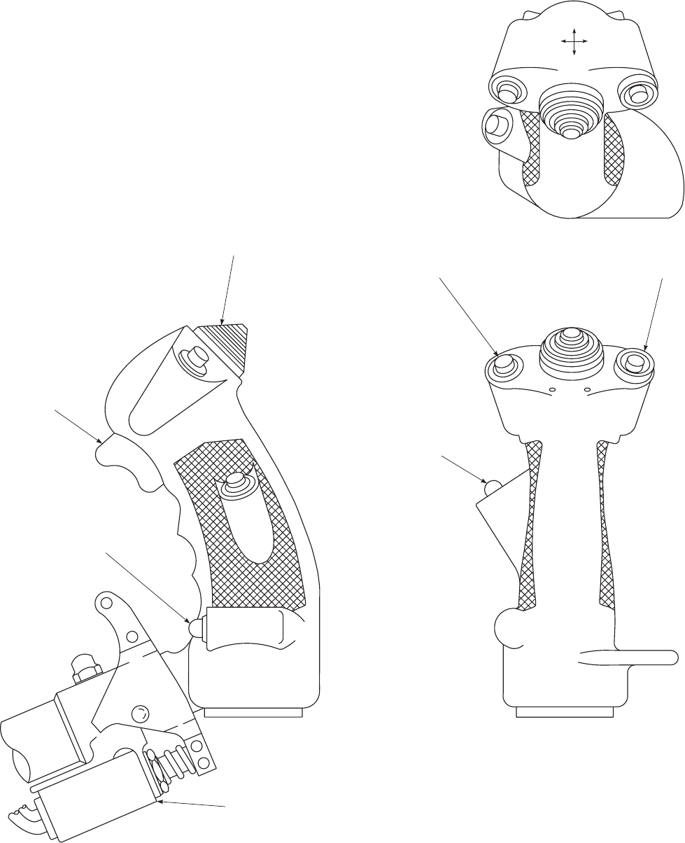
SA
AA0365_2
AFT
FWD
GA
CARGO
REL.
LR
STICK
TRIM
I.C.S.
RADIO
TRIM
REL
PNL
LTS
CYCLIC MOUNTED STABILATOR
SLEW−UP SWITCH
PANEL LIGHTS
KILL SWITCH
ICS RADIO
CONTROL
STICK TRIM
TRIM
RELEASE
SWITCH
GO AROUND
ENABLE SWITCH CARGO HOOK
RELEASE SWITCH
CYCLIC STICK GRIP
(TYPICAL)
Figure 2-14. Collective and Cyclic Grips (Sheet 2 of 2)
TM 1-1520-237-10
2-43
mally operate with the switch in the unmarked center (on)
position. To turn off the first stage primary servos, the SVO
OFF switch is placed to 1ST STG. To turn off the second
stage servo, the switch is placed to 2ND STG. The systems
are interconnected electrically so that regardless of switch
position, a system will not shut off unless there is at least
2350 psi in the remaining system. The servo shutoff valve
operates on current from the No. 1 and No. 2 dc primary
buses through circuit breakers marked NO. 1 and NO. 2
SERVO CONTR respectively.
2.36.4 Flight Control Servo Low-Pressure Caution
Lights. The first, second, and tail rotor stage servo hy-
draulic low-pressure caution lights are marked #1 PRI
SERVO PRESS,#2 PRI SERVO PRESS, and #1 TAIL
RTR SERVO, and will go on if the pressure is below its
respective switch setting, or if the servo pilot valve be-
comes jammed. The servo switches and warning lights op-
erate on direct current from the No. 1 and No. 2 dc primary
buses through circuit breakers, marked NO. 1 SERVO
WARN and NO. 2 SERVO WARN, respectively.
2.36.5 Pilot-Assist Servos. Pilot assist servos are nor-
mally powered by the No. 2 hydraulic system. If the No. 2
hydraulic pump fails, the pilot assist servos and pitch trim
actuator are powered by the backup hydraulic pump. The
following units are pilot-assist servos: collective, yaw, and
pitch boost servos, which reduce control forces; and three
(pitch, roll, yaw) SAS actuators which transfer the output
of the SAS controllers into control actuations.
2.36.6 Boost Servo. There are three boost servos, col-
lective, yaw, and pitch, installed between the cockpit con-
trols and mixing unit, which reduce cockpit control forces.
The collective and yaw boost servos are turned on and off
by pressing the button marked BOOST on the AUTO
FLIGHT CONTROL panel (Figure 2-15). The pitch boost
servo is turned on when SAS 1 or SAS 2 is ON. The boost
shutoff valves receive power from the dc essential bus
through a circuit breaker, marked SAS BOOST.
2.36.7 Pilot-Assist Controls. An AUTO FLIGHT
CONTROL panel (Figure 2-15), in the lower console, con-
tains the controls for operating the pilot-assist servos and
actuators. The panel contains SAS 1,SAS 2,TRIM,FPS,
BOOST and the FAILURE ADVISORY/POWER ON
RESET lights/switches. STICK TRIM and TRIM REL
switches on the cyclic sticks, are manually operated by ei-
ther pilot or copilot.
2.37 AUTOMATIC FLIGHT CONTROL SYSTEM
(AFCS).
The AFCS enhances the stability and handling qualities
of the helicopter. It is comprised of four basic subsystems:
Stabilator, Stability Augmentation System (SAS), Trim
Systems, and Flight Path Stabilization (FPS). The stabilator
system improves flying qualities by positioning the stabila-
tor by means of electromechanical actuators in response to
collective, airspeed, pitch rate and lateral acceleration in-
puts. The stability augmentation system provides short term
rate damping in the pitch, roll, and yaw axes. Trim/FPS
system provides control positioning and force gradient
functions as well as basic autopilot functions with FPS en-
gaged.
2.37.1 Stability Augmentation System (SAS).
NOTE
As the vertical gyro comes up to speed or
when the system is shutdown, the derived
pitch/roll rate signal which feeds SAS 1 will
cause small oscillations in pitch and roll
SAS actuators. This is a temporary situation
and can be eliminated by turning SAS 1 off.
The SAS enhances dynamic stability in the pitch, roll,
and yaw axes. In addition, both SAS 1 and SAS 2 enhance
turn coordination by deriving commands from lateral accel-
erometers which together with roll rate signals are sent to
their respective yaw channels automatically at airspeeds
greater than 60 knots. The SAS 1 amplifier circuitry oper-
ates on 28 vdc power from the dc essential bus through a
circuit breaker marked SAS BOOST providing excitation
for the electronic components within the amplifier. AC
power from the ac essential bus through a circuit breaker
marked SAS AMPL is also required for normal operation
of the SAS. The SAS amplifier uses the vertical gyro roll
output to derive roll attitude and rate for the roll SAS com-
mands and an ac-powered yaw rate gyro for the yaw SAS
commands. Loss of ac power to the vertical gyro or SAS
amplifier causes erratic operation of SAS 1 due to loss of
the reference for the ac demodulators. When this condition
is encountered, the pilot must manually disengage SAS 1.
In case of a malfunction of the SAS 2 function, the input
will normally be removed from the actuator and the SAS 2
fail advisory light on the AUTOFLIGHT CONTROL
panel will go on. If the malfunction is of an intermittent
TM 1-1520-237-10
2-44 Change 9
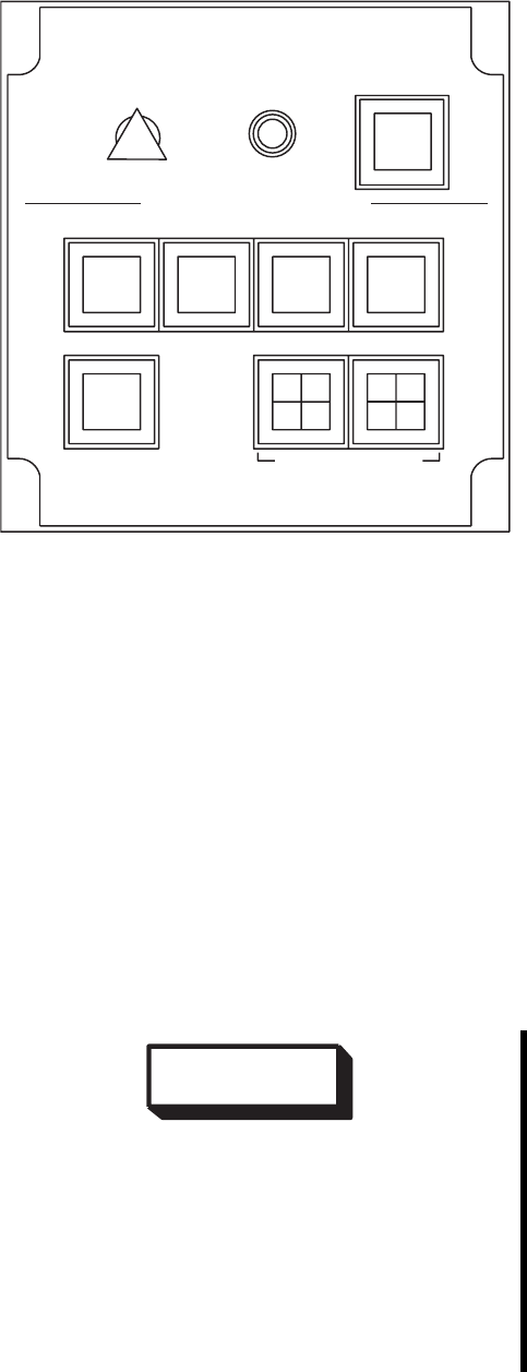
nature the indication can be cleared by simultaneously
pressing POWER ON RESET switches. If the malfunc-
tion is continuous, the SAS 2 should be turned off. With
SAS 1 or SAS 2 off, the control authority of the stability
augmentation system is reduced by one-half (5% control
authority). Malfunction of the SAS 1 system may be de-
tected by the pilot as an erratic motion in the helicopter
without a corresponding failure advisory indication. If a
malfunction is experienced, SAS 1 should be turned off.
SAS actuator hydraulic pressure is monitored. In case of
loss of actuator pressure, or if both SAS 1 and SAS 2 are
off, the SAS OFF caution light will go on.
2.37.2 Trim System. When the TRIM is engaged on
the AUTO FLIGHT CONTROL panel, the pitch, roll and
yaw trim systems are activated to maintain position of the
cyclic and tail rotor controls. Proper operation of the yaw
trim requires that the BOOST on the AUTO FLIGHT
CONTROL panel be on. The tail rotor and lateral cyclic
forces are developed in the electromechanical yaw and roll
trim actuators. Both yaw and roll trim actuators incorporate
slip clutches to allow pilot and copilot control inputs if
either actuator should jam. The forces required to break
through the clutch are 80-pounds maximum in yaw and 13
pounds maximum in roll. The longitudinal force is devel-
oped by an electrohydromechanical actuator operated in
conjunction with the SAS/FPS computer. When the pilot
applies a longitudinal or lateral force to the cyclic stick
with trim engaged, a combination detent and gradient force
is felt. The pilot may remove the force by pressing the
thumb-operated TRIM REL switch on the pilot/copilot cy-
clic grip. The pedal gradient maintains pedal position
whenever the trim is engaged. By placing feet on the ped-
als, the pedal switches are depressed and the gradient force
is removed. The pedals may then be moved to the desired
position and released. The pedals will be held at this posi-
tion by the trim gradient. The pedal trim gradient actuator
also includes a pedal damper. The pedal damper is engaged
continuously, independent of electric power and the TRIM
switch on the AUTO FLIGHT CONTROL panel. Opera-
tion of the trim system is continuously monitored by the
SAS/FPS computer. If a malfunction occurs, the SAS/FPS
computer will shut off the trim actuator(s) driving the af-
fected axis, and the TRIM FAIL and FLT PATH STAB
caution light will illuminate. If the malfunction is of an
intermittent nature, the indication may be cleared by simul-
taneously pressing both POWER ON RESET switches. In
addition to the trim release switch, a four-way trim switch
on each cyclic stick establishes a trim position without re-
leasing trim. With trim engaged, the trim position is moved
in the direction of switch movement. The cyclic is moved
by the trim switch in one direction at a time. When FPS is
engaged, the TRIM switch changes the pitch and roll atti-
tude reference instead of the cyclic stick position reference.
The trim system release feature permits the pilot or copilot
to fly the helicopter with light stick forces. The push-on/
push-off TRIM switch on the AUTO FLIGHT CON-
TROL panel or the TRIM REL switches on the pilot/
copilot cyclic grips may be used to release trim. When the
switch is ON, the trim system provides gradient and detent
holding force for pitch, roll, and yaw. When turned off, the
trim system is released and light cyclic control forces are
present.
2.37.3 Flight Path Stabilization (FPS).
WARNING
Pedal trim switches must be pressed while
changing the helicopter heading during
hover. Do not hold hover heading against
yaw trim force. A rapid release of pedal
trim force will allow the FPS heading hold
feature to immediately correct to the last
known engaged heading. This can result
in rapid, divergent helicopter heading de-
viations.
SA
AA0366A
MAN SLEW
UP
O
F
F
TEST AUTO
CONTROL
DN
ON
R
E
S
E
T
SAS 1 SAS 2 TRIM FPS
ON ON ON ON
BOOST FAILURE ADVISORY
ON
R
E
S
E
T
R
E
S
E
T
POWER ON RESET
STABILATOR CONTROL
AUTO FLIGHT CONTROL
SAS 2CPTR
TRIM RGYR
CLTVACCL
A / S GYRO
Figure 2-15. Automatic Flight Control System
(AFCS) Switch Panel
TM 1-1520-237-10
Change 10 2-45
a. Proper FPS operation requires that the BOOST,
TRIM and SAS 1 and/or SAS 2 functions have been se-
lected on the AUTO FLIGHT CONTROL panel. Al-
though not required for proper operation, the FPS perfor-
mance will be improved by the proper operation of the
stabilator in the automatic mode. To use the FPS features,
the pilot first assures that BOOST,SAS and TRIM are on
and operating, and then turns the FPS switch ON. The
desired pitch and roll attitude of the helicopter may be es-
tablished in one of these ways:
(1) Pressing the STICK TRIM switch to slew the
reference attitude to the desired attitude.
(2) Pressing the TRIM REL switch on the pilot/
copilot cyclic grip, manually flying the helicop-
ter to the desired trim condition, and releasing
the TRIM REL switch.
(3) Overriding the stick trim forces to establish the
desired trim condition, and then neutralizing
stick forces by means of the trim switch.
b. The trim attitude, once established, will be automati-
cally held until changed by the pilot. At airspeeds greater
than 60 knots, the pitch axis seeks to maintain the airspeed
at which the trim is established, by variation of pitch atti-
tude. When pitch attitude is changed by means of the
STICK TRIM switch, there is a delay from the time that
the STICK TRIM switch input is removed until the new
reference airspeed is acquired. This is to allow time for the
helicopter to accelerate or decelerate to the new trim speed.
The yaw axis of the FPS provides heading hold at airspeeds
less than 60 knots and heading hold or turn coordination at
airspeeds greater than 60 knots. For heading hold operation
at airspeeds less than 60 knots, the helicopter is maneu-
vered to the desired heading with feet on pedals. When
trimmed at the desired heading, the pilot may remove feet
from pedals, at which time the existing heading becomes
the reference, which is automatically held. To change head-
ing, the pilot may activate one or both pedal switches, trim
up on the desired heading and remove feet from pedals. At
airspeeds greater than 60 knots, heading hold will be auto-
matically disengaged, and coordinated turn engaged under
these conditions:
(1) STICK TRIM switch is actuated in the lateral
direction.
(2) TRIM REL switch is pressed and roll attitude
is greater than prescribed limits.
(3) About 1/2 inch cyclic displacement and a roll
attitude of about 1.5°. Heading hold is auto-
matically reengaged and turn coordination dis-
engaged upon recovery from the turn when the
lateral stick force, roll attitude, and yaw rate are
within prescribed limits.
c. To make a coordinated turn, the pilot enters a turn in
one of these ways:
(1) Changing reference roll attitude by pressing the
STICK TRIM switch in the desired lateral di-
rection.
(2) Pressing TRIM REL switch on the cyclic grip
and establishing the desired bank angle with
feet off pedal switches.
(3) Exerting a lateral force on the cyclic stick to
achieve the desired bank angle, and then neu-
tralizing the force with the STICK TRIM
switch.
(4) Keeping a lateral force on the cyclic stick for
the duration of the turn.
d. In each of these ways the ball should remain auto-
matically centered during the entry and recovery from the
turn. If feet are on the pedals, care must be taken not to
apply too much force to the pedals to oppose their motion.
If the pilot intentionally miscoordinates the helicopter, the
result will be a pedal force roughly proportional to sideslip.
The pilot may release the pedal force by pressing the cyclic
TRIM REL switch with feet on pedals. During transition
through 60 knots airspeed, the pilot may feel a slight pedal
motion due to a switching transient which may occur when
the commanded coordinated turn pedal position differs
slightly from the pilot-commanded position. The FPS moni-
toring is automatic. If a malfunction is detected, the FLT
PATH STAB caution light will go on and the FPS will
either continue to operate in a degraded mode, such as
without heading hold, or without airspeed hold; or may
cease to function altogether. The pilot must take over
manual flight of the helicopter, and may either turn the FPS
off or evaluate performance to determine the degree and
type of degradation, and continue flight with the remaining
features. To help evaluate the nature of the degradation,
eight failure advisory indicators are displayed on two
FAILURE ADVISORY switches on the flight control
panel. These tell the pilot the type of sensor or actuator
which has experienced the failure. If a light goes on, it may
be turned off by pressing the lighted switch. All failure
advisory lights will be on at initial application of power.
The pilot may attempt to clear the indication of temporary
malfunction by simultaneously pressing both FAILURE
ADVISORY switches. If the FLT PATH STAB caution
TM 1-1520-237-10
2-46 Change 10

light goes off, it may be assumed that normal operation is
restored. All FPS functions are provided by automatically
moving the cockpit controls.
2.38 STABILATOR SYSTEM.
a. The helicopter has a variable angle of incidence sta-
bilator to enhance handling qualities. The automatic mode
of operation positions the stabilator to the best angle of
attack for the existing flight conditions. After the pilot en-
gages the automatic mode, no further pilot action is re-
quired for stabilator operation. Two stabilator amplifiers
receive airspeed, collective stick position, pitch rate, and
lateral acceleration information to program the stabilator
through the dual electric actuators. The stabilator is pro-
grammed to:
(1) Align stabilator and main rotor downwash in low
speed flight to minimize nose-up attitude resulting from
downwash.
(2) Decrease angle of incidence with increased air-
speed to improve static stability.
(3) Provide collective coupling to minimize pitch atti-
tude excursions due to collective inputs from the pilot. Col-
lective position sensors detect pilot collective displacement
and programs the stabilator a corresponding amount to
counteract the pitch changes. The coupling of stabilator po-
sition to collective displacement is automatically phased in
beginning at 30 KIAS.
(4) Provide pitch rate feedback to improve dynamic
stability. The rate of pitch attitude change of the helicopter
is sensed by a pitch rate gyro in each of the two stabilator
amplifiers and used to position the stabilator to help dampen
pitch excursions during gusty wind conditions. A sudden
pitch up due to gusts would cause the stabilator to be pro-
grammed trailing edge down a small amount to induce a
nose-down pitch to dampen the initial reaction.
(5) Provide sideslip to pitch coupling to reduce sus-
ceptibility to gusts. When the helicopter is out of trim in a
slip or skid, pitch excursions are also induced as a result of
the main rotor downwash on the stabilator. Lateral acceler-
ometers sense this out of trim condition and signal the sta-
bilator amplifiers to compensate for the pitch attitude
change (called sideslip to pitch coupling). Nose left (right
slip) results in the trailing edge programming down. Nose
right produces the opposite stabilator reaction.
b. The above features are provided via inputs to dual
actuators which position the stabilator. Failure of one ac-
tuator will restrict total maximum movement of the stabi-
lator to about 35° if failure occurs full down, or about 30°
if failure occurs full up. The stabilator actuators receive
power from the dc essential bus and No. 2 dc primary bus
through circuit breakers marked STAB PWR. Since the dc
essential bus is powered by the battery, it is possible to
manually slew one actuator using battery power only. If the
stabilator is slewed up, regain automatic control by manu-
ally slewing stabilator full down, then push AUTO CON-
TROL RESET twice. Otherwise, when only one actuator
is slewed, it causes a very large mismatch between the two
actuator positions. This is detected by the fault monitor and
shuts down the automatic mode upon attempted engage-
ment. Automatic control function sensors, airspeed sensors,
pitch rate gyros, collective position sensor, and lateral ac-
celerometer receive power from the ac essential bus and
No. 2 ac primary bus through circuit breakers marked
STAB CONTR.
2.38.1 Stabilator Control Panel. The stabilator control
panel (Figure 2-8), on the lower console, provides electrical
control of the stabilator system. The panel contains a MAN
SLEW switch, a TEST button, and AUTO CONTROL
RESET switch with a push-to-reset feature. The automatic
mode will allow the stabilator to be automatically operated
from about 39° trailing edge down to 9° trailing edge up.
Manual operation is also restricted to these limits. If a mal-
function occurs in the automatic mode, the system will
switch to manual, ON will go off in the AUTO CON-
TROL window, and the STABILATOR caution and
MASTER CAUTION lights will go on and a beeping tone
will be heard in the pilot’s and copilot’s headphones. It
may be possible to regain the auto mode by pressing the
AUTO CONTROL RESET. If the automatic mode is re-
gained, ON will appear in the AUTO CONTROL switch
window and the caution lights will go off. The stabilator
automatic mode is held in the energized state within the
stabilator control amplifier. On certain occasions during in-
terruption of dc power, such as switching of generators, it is
possible to have conditions where the stabilator automatic
mode may shut down. If the automatic mode shuts down
during flight because of an ac power failure, the helicopter
shall be slowed to 80 KIAS before power is restored. In this
case the AUTO CONTROL RESET switch may be
pressed to reengage the auto mode. If the automatic mode
is not regained, the MASTER CAUTION must be reset,
which turns off the beeping tone, and the stabilator con-
trolled throughout its range with the MAN SLEW switch.
When initial power is applied to the stabilator system, it
will be in automatic mode. The TEST switch is used to
check the AUTO mode fault detector feature and is inop-
TM 1-1520-237-10
Change 10 2-47

erative above 60 KIAS. When pressed, control of the sta-
bilator should go to the manual mode.
2.38.2 Stabilator Position Indicator. Two STAB
POS indicators (Figure 2-9) are on the instrument panel.
They give pilots a remote indication of stabilator position.
The copilot’s STAB POS indicator may vary from the pi-
lot’s indicator as much as 2°. The indicator range is marked
from 45° DN to 10° up. The stabilator position indicator
system is powered from the ac essential bus 26V through a
circuit breaker marked STAB IND.
2.38.3 Cyclic-Mounted Stabilator Slew Up Switch.
Installed on each cyclic stick below the grip (Figure 2-14)
is a pull-type stabilator manual slew up switch. The switch
provides the pilot and copilot with rapid accessibility to
stabilator slew up. The cyclic slew switch is wired in par-
allel with the stabilator panel MAN SLEW-UP switch po-
sition. When the switch is actuated, the stabilator trailing
edge will begin to move up and continue until the up limit
stop is reached or the switch is released.
TM 1-1520-237-10
2-48 Change 10
Section VI HYDRAULIC AND PNEUMATIC SYSTEM
2.39 HYDRAULIC SYSTEM.
The three hydraulic systems are designed to provide full
flight control pressure. The components of the hydraulic
systems are three hydraulic pump modules, two transfer
modules, a utility module, three dual primary servos, one
dual tail rotor servo, four pilot-assist servos, an APU accu-
mulator, an APU handpump, and a servicing handpump.
There are three hydraulic pressure supply systems, number
1, number 2, and backup. All are completely independent
and each is fully capable of providing essential flight con-
trol pressure for maximum system redundancy. Complete
redundancy is accomplished by the backup pump providing
hydraulic power to both number 1 and/or number 2 systems
if one or both pumps fail. If two systems lose pressure,
there will be a slight restriction in the maximum rate of
flight control movement due to only one pump supplying
both stages with hydraulic power. An automatic turnoff fea-
ture is provided. When the SVO OFF switch (Figure 2-14)
is moved to 1ST STG or 2ND STG position, that stage of
the primary servos is turned off. When the SVO OFF
switch is moved to 1ST STG, the first stage of the primary
servos is turned off. A malfunction in the second stage will
cause first stage (which was turned off) to automatically
turn back on in case the backup system does not take over
the function of the failed second stage. If the second stage
is initially turned off, the sequence is reversed. An addi-
tional hydraulic handpump is provided for APU start sys-
tem.
NOTE
The following listed caution lights may mo-
mentarily flicker when the applicable listed
switch is activated; this is considered nor-
mal.
SUBSYSTEM CAUTION LIGHT
SAS 1 or SAS 2 switch
ON #2 PRI SERVO PRESS
#2 HYD PUMP
BOOST SERVO OFF
BOOST switch ON #2 PRI SERVO PRESS
#2 HYD PUMP
SAS OFF
TAIL SERVO switch
BACKUP #1 PRI SERVO PRESS
#1 HYD PUMP
SUBSYSTEM CAUTION LIGHT
HYD LEAK TEST
switch NORM after
RESET
#1 and #2 PRI SERVO
PRESS
#1 and #2 HYD PUMP
2.40 HYDRAULIC PUMP MODULES.
The hydraulic pump modules are combination hydraulic
pumps and reservoirs. The No. 1, No. 2, and backup pump
modules are identical and interchangeable with each other.
The No. 1 pump module is mounted on and driven by the
left accessory module of the main transmission. The No. 2
pump module is mounted on and driven by the right acces-
sory transmission module. The backup pump module is
mounted on and driven by an ac electric motor. The reser-
voir part of each pump module has a level indicator win-
dow marked, REFILL,FULL, and EXPANSION. A pres-
sure relief and bleed valve protects the pump from high
pressure in the return system. The pump has two filters: a
pressure filter and a return filter. A red indicator button on
each filter will pop out when pressure goes up 70 610 psi
above normal. The pressure filter has no bypass. The return
filter has a bypass valve that opens when return pressure
reaches 100 610 psi above normal. Each pump has three
check valves: one at the external ground coupling, one at
the pressure side, and one at the return side. A fluid quan-
tity switch, mounted on top of each pump module, senses
fluid loss for that system. When the piston in the pump
module moves down to the REFILL mark, the piston
closes the switch, turning on a caution light marked RSVR
LOW. Each hydraulic pump has two temperature sensitive
labels mounted on the side. When a temperature level is
reached a circle turns black. There are two types of labels
used on the pumps. When the temperature label indicates
that a temperature of 132°C (270°F) has been exceeded, an
entry shall be made on DA Form 2408-13-1. The aircraft
should not be flown until appropriate maintenance action
has been taken.
2.40.1 Number 1 Hydraulic System. Number 1 hy-
draulic system operates with the rotor turning, and supplies
the first stage of all primary servos and the first stage of the
tail rotor servo. The system components are an integrated
pump module, a transfer module, first stage primary servos,
and first stage tail rotor servo. The primary servos are con-
trolled by the SVO OFF switch (Figure 2-14). The switch
can turn off either first or second stage of the primary ser-
vos but not both at the same time. First stage tail rotor
TM 1-1520-237-10
Change 10 2-48.1/(2-48.2 Blank)

servo can be manually turned off by a two-position switch
marked TAIL SERVO, on the miscellaneous switch panel
(Figure 2-8). If the fluid quantity of the number one pump
reservoir becomes low, a microswitch will complete an
electrical circuit to close the first stage tail rotor servo
valve. If fluid continues to be lost and the #1 HYD PUMP
caution light goes on, the first stage tail rotor shutoff valve
will open, allowing backup pressure to supply first stage
tail rotor. The logic modules automatically control the hy-
draulic system. The tail rotor servo is a two-stage servo but,
unlike the primary servos, only one stage is pressurized at a
time.
2.40.2 Number 2 Hydraulic System. The number 2
hydraulic system, which also operates with the rotor turn-
ing, supplies the second stage primary servo and the pilot-
assist servos. System components are the integrated pump
module, transfer module, second stage primary servos, and
pilot-assist modules. Second stage primary servos can be
manually turned off by the SVO OFF switch. The pilot-
assist servos cannot be turned off collectively, but SAS,
TRIM and BOOST servos can be manually turned off by
switches on the AUTO FLIGHT CONTROL panel. If
fluid quantity of the number two pump reservoir becomes
low, the pilot-assist servo becomes inoperative. If fluid con-
tinues to be lost, the #2 HYD PUMP caution light will go
on.
2.40.3 Backup Hydraulic System.
CAUTION
Whenever the No. 1 ac generator is inop-
erative (failed, or not on line) and the
BACKUP PUMP PWR circuit breaker is
out for any reason, ac electrical power
must be shut off before resetting
BACKUP PUMP PWR circuit breaker.
Otherwise, it is possible to damage the
current limiters.
The backup hydraulic pump system supplies emergency
pressure to the number 1 and/or number 2 hydraulic sys-
tems whenever a pressure loss occurs. It also supplies pres-
sure to the number 2 stage of the tail rotor servo in case of
a loss of pressure in the first stage of the tail rotor servo or
#1 RSVR LOW indication. This system supplies hydraulic
pressure to all flight control components during ground
checkout. The backup system also provides a hydraulic
pressure for automatic recharging of the APU start system
accumulator. The backup hydraulic system pump module is
driven by an electric motor which can be powered by any
adequate three-phase ac power source. An internal depres-
surizing valve in the backup pump module reduces the out-
put pressure of the pump upon startup of the electric motor.
This valve unloads the electric motor by reducing torque
requirement at low rpm. After about 0.5 second when main
generator is operating, or 4 seconds when operating from
APU generator or external power, the valve is closed and
3000 psi pressure is supplied to the hydraulic system. This
sequence reduces the current demand during backup system
startup. Pressure sensing switches in the number 1 and
number 2 transfer modules constantly monitor the pressure
output of the number 1 and number 2 pumps. Loss of pres-
sure initiates the backup operation. The system then pro-
vides emergency pressure to maintain full flight control ca-
pability. A WOW switch on the left main landing gear
provides automatic operation of the backup pump when the
helicopter is in the air, regardless of BACKUP HYD
PUMP switch position, and disables the backup pump ac
thermal switch. A pressure sensing switch at the tail rotor
monitors supply pressure to the first stage tail rotor servo.
The backup pump can supply pressure to the first stage tail
rotor servo if the number 1 pump loses pressure. This gives
the pilot a backup tail rotor servo even with the loss of the
primary hydraulic supply, or #1 RSVR LOW. If a leak in a
primary servo system depletes the backup system fluid, the
backup reservoir level sensing switch will turn on the
BACK-UP RSVR LOW caution light, and the pilot must
manually turn off the leaking primary system.
2.41 HYDRAULIC LEAK DETECTION/ISOLATION
SYSTEM.
The leak detection/isolation (LDI) system protects the
flight control hydraulic system by preventing the further
loss of hydraulic fluid in case of a leak. The LDI system
uses pressure switches and fluid level sensors for monitor-
ing pump hydraulic fluid level, and pump pressure for pri-
mary and tail rotor servos, and pilot-assist servos. When a
pump module reservoir fluid level switch detects a fluid
loss, the logic module follows the sequence detailed in Fig-
ure 2-16 to isolate the leak. To accomplish this, the logic
module operates the required shutoff valve(s) to isolate the
leak and turns on the backup pump when required. In the
cockpit the RSVR LOW caution light for that system
lights. Backup pump and shutoff valve(s) operation is au-
tomatic through the logic module. If, after the isolation se-
quence, the leak continues, the leakage is in the stage 1 or
2 primary servos and the appropriate SVO OFF switch
must be moved to the off position by the pilot. By placing
the HYD LEAK TEST switch to TEST, all leak detection/
isolation system components are checked electrically. After
a leak test has been made, the HYD LEAK TEST switch
must be moved to RESET momentarily, to turn off caution
and advisory lights that were on during the test. The
TM 1-1520-237-10
2-49
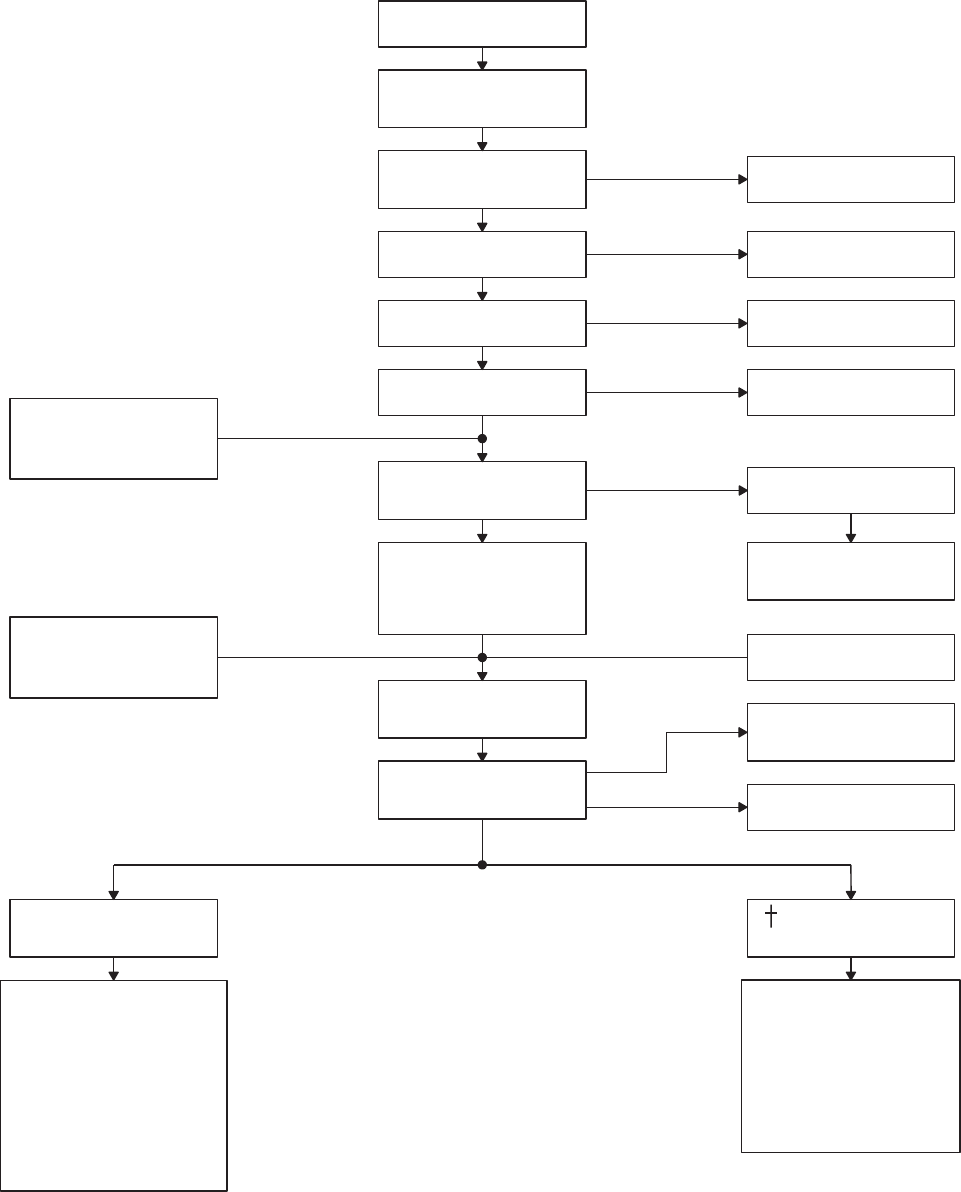
SA
AA0404_1A
BACKUP PUMP SUPPLIES
NO. 1 PRI SERVO AND
NO. 1 TAIL ROTOR SERVO
(NO. 1 TAIL ROTOR
SERVO TURNED BACK ON)
BACKUP PUMP SUPPLIES
NO. 1 PRI SERVO AND
NO. 1 TAIL ROTOR SERVO
(NO. 1 TAIL ROTOR
LEAKAGE IN NO. 1
HYDRAULIC SYSTEM
PARTIAL LOSS OF
NO.1 RESERVOIR
HYDRAULIC FLUID
ACTUATION OF NO. 1
RESERVOIR LEVEL
SENSING SWITCH
TURNS OFF NO. 1
TAIL ROTOR SERVO
COMPLETE LOSS OF
NO. 1 RESERVOIR
HYDRAULIC FLUID
PARTIAL LOSS OF
BACKUP RESERVOIR
HYDRAULIC FLUID
ACTUATION OF BACKUP
RESERVOIR LEVEL
SENSING SWITCH
#1 RSVR LOW
CAUTION LIGHT ON
#1 TAIL RTR SERVO
CAUTION LIGHT ON
BACKUP PUMP
TURNED ON BACK−UP PUMP ON
ADVISORY LIGHT ON
TURNS ON NO. 2
TAIL ROTOR SERVO #2 TAIL RTR SERVO ON
ADVISORY LIGHT ON
#1 HYD PUMP
CAUTION LIGHT ON
#1 PRI SERVO PRESS
CAUTION LIGHT MAY
MOMENTARILY FLICKER
LEAKAGE IN 1ST
STAGE PRI SERVO
SEE CHAPTER 9
BACK−UP RSVR LOW
SEE CHAPTER 5
FOR LIMITATIONS
CAUTION LIGHT ON
IF NO OTHER LIGHTS
ON, LEAK IS IN
NO. 1 STAGE TAIL
ROTOR SERVO
IF NO OTHER LIGHTS ON
LEAKAGE IS UPSTREAM
OF NO. 1 TRANSFER
MODULE
PILOT MOVE SERVO
OFF SWITCH TO
1ST STG
NO PILOT ACTION
1. LOSS OF NO. 1 PRIMARY
SERVO AND NO. 1 AND
NO. 2 TAIL ROTOR
SERVO.
2. CAUTION LIGHTS ON
#1 HYD PUMP,
#1 PRI SERVO PRESS,
#1 RSVR LOW,
BACK−UP RSVR LOW.
3. NO ADVISORY LIGHTS
ON.
RESULTING CONDITION 1. LOSS OF NO. 1 PRIMARY
SERVO.
2. CAUTION LIGHTS ON
#1 HYD PUMP,
#1 PRI SERVO PRESS,
#1 RSVR LOW,
BACK−UP RSVR LOW.
3. ADVISORY LIGHT ON
BACK−UP PUMP ON.
RESULTING CONDITION
#1 TAIL RTR SERVO,
Figure 2-16. Hydraulic Logic Module Operation Principle (Sheet 1 of 2)
TM 1-1520-237-10
2-50

SA
AA0404_2C
LEAKAGE IN NO. 2
HYDRAULIC SYSTEM
PARTIAL LOSS OF
NO. 2 RESERVOIR
HYDRAULIC FLUID
ACTUATION OF NO. 2
RESERVOIR LEVEL
SENSING SWITCH
TURNS OFF − PILOT
ASSIST SERVOS
COMPLETE LOSS OF
NO. 2 RESERVOIR
HYDRAULIC FLUID
PARTIAL LOSS OF
BACKUP RESERVOIR
HYDRAULIC FLUID
ACTUATION OF LOW−
#2 RSVR LOW
CAUTION LIGHT ON
BACKUP PUMP
TURNED ON
#2 HYD PUMP
CAUTION LIGHT ON
#2 PRI SERVO PRESS
CAUTION LIGHT MAY
MOMENTARILY FLICKER
LEAKAGE IN NO. 2
PRI SERVO
SEE CHAPTER 9
BACK−UP RSVR LOW
CAUTION LIGHT ON
IF NO OTHER LIGHTS
PILOT MOVE
SERVO OFF SWITCH
TO 2ND STG
NO PILOT ACTION
1. LOSS OF NO. 2 PRIMARY
2. CAUTION LIGHTS ON
#2 HYD PUMP
#2 PRI SERVO PRESS,
3. NO ADVISORY LIGHTS
ON.
RESULTING CONDITION 1. LOSS OF NO. 2 PRIMARY
SERVO.
RESULTING CONDITION
ON LEAKAGE IS IN
PILOT−ASSIST AREA
PILOT−ASSIST SERVOS
TURNED ON
LEVEL SENSING
SWITCH
#2 RSVR LOW
#2 HYD PUMP,
BACK−UP PUMP ON
ADVISORY LIGHTS ON
AND NO OTHER
LEAKAGE IS
UPSTREAM OF NO. 2
TRANSFER MODULE
SERVOS AND PILOT
ASSIST SERVOS.
#2 RSVR LOW
BACK−UP RSVR LOW,
SAS OFF,
TRIM FAIL,
BOOST SERVO OFF
FLT PATH STAB.
2. PILOT−ASSIST SERVO
PRESSURE SUPPLIED BY
BACK−UP PUMP.
3. CAUTION LIGHTS ON
#2 RSVR LOW,
#2 HYD PUMP,
#2 PRI SERVO PRESS
BACK−UP RSVR LOW.
4. ADVISORY LIGHT ON
BACK−UP PUMP ON.
BOOST SERVO OFF, TRIM
FAIL, FLT PATH STAB
SAS OFF
CAUTION LIGHTS ON
SEE CHAPTER 5 FOR
LIMITATIONS
SEE CHAPTER 9
INCREASED PEDAL
AND COLLECTIVE LOADS
BACK−UP PUMP ON
ADVISORY LIGHT ON
BOOST SERVO OFF / SAS
OFF CAUTION LIGHT OFF
SEE CHAPTER 5
FOR LIMITATIONS POWER ON RESET
PRESS TRIM / FLT
PATH STAB
CAUTION LIGHTS OFF
Figure 2-16. Hydraulic Logic Module Operation Principle (Sheet 2 of 2)
TM 1-1520-237-10
2-51

BACK-UP PUMP ON advisory light will remain on for
about 90 seconds. Refer to Chapter 8 Section II for test
procedure. Except for the HYD LEAK TEST switch, the
hydraulic leak system consists of components of 1st stage,
2nd stage and backup hydraulic systems. A WOW switch
contact prevents hydraulic leak tests from being made in
flight. Power to operate the hydraulic leak test system is
from the No. 2 dc primary bus through a circuit breaker,
marked NO. 2 SERVO CONTR and dc essential bus
through a circuit breaker, marked BACKUP HYD
CONTR.
2.42 TRANSFER MODULES.
The No. 1 and No. 2 transfer modules connect hydraulic
pressure from the pump modules to the flight control ser-
vos. Each module is an integrated assembly of shutoff
valves, pressure switches, check valves, and restrictors. The
modules are interchangeable.
2.42.1 No. 1 Transfer Module. This module has a
transfer valve, a pressure switch, a 1st stage primary shutoff
valve, a 1st stage tail rotor shutoff valve, a restrictor, and
check valves. The transfer valve is spring-loaded to the
open or normal position. If 1st stage hydraulic pressure is
lost, the valve automatically transfers backup pump pres-
sure to the 1st stage system. The 1st stage primary shutoff
valve lets the pilot or copilot shut off 1st stage pressure to
the primary servos and prevents both stages from being
shut off at the same time. The pressure switch lights the #1
HYD PUMP light on the caution advisory panel when
pressure drops below 2000 psi and also sends a signal to a
logic module that pressure is lost in the 1st stage hydraulic
system. The restrictor allows fluid to circulate for cooling
under no-flow conditions. If a fluid leak develops past the
transfer module, the check valves prevent fluid loss on the
return side of the transfer module.
2.42.2 No. 2 Transfer Module. The No. 2 transfer
module is like the No. 1 module except that it supplies 2nd
stage pressure. The pilot assist shutoff valve turns off pres-
sure to the pilot assist module. The 2nd stage primary servo
shutoff valve turns off pressure to the 2nd stage of the pri-
mary servos. The pressure switch turns on the #2 HYD
PUMP caution light on the caution/advisory panel when
2nd stage system pressure is below 2000 psi, and also sends
a signal to a logic module that pressure is lost in the 2nd
stage system.
2.42.3 Utility Module. The utility module connects hy-
draulic pressure from the backup pump to the No. 1 and
No. 2 transfer modules, the 2nd stage of the tail rotor servo,
and the APU accumulator. A pressure switch on the module
senses the backup pump operating and turns on the
BACK-UP PUMP ON advisory light on the caution/
advisory panel. If the flow rate through the module to the
APU accumulator goes over 1-1/2 gpm, a velocity fuse
shuts off flow.
2.42.4 Logic Modules. Two logic modules, one in the
left relay panel and the other in the right relay panel, are
used to control the operation of the hydraulic systems. The
logic modules continually monitor the operation of the hy-
draulic systems by inputs received from pressure switches,
fluid level switches on the pump modules, and inputs re-
ceived from control switches in the hydraulic system. The
outputs of the logic modules will either turn on lights on
the caution/advisory panel notifying the pilot of a failure,
and/or turn off one or more valves due to a system mal-
function. All switching functions of the hydraulic logic
modules are automatic, except as shown by a dagger (†)
which indicates crewmember action (Figure 2-16).
2.43 RESERVOIR FILL SYSTEM.
A handpump and manual selector valve are on the right
side upper deck of the helicopter for system servicing. Re-
fer to Figure 2-25 for servicing. The three hydraulic system
reservoir levels can be seen from the fill pump location.
The handpump reservoir contains a sight gage above the
handpump crank. A 1-quart level mark indicates a require-
ment for refill. Refer to Section XV this chapter for servic-
ing.
2.44 PNEUMATIC SUBSYSTEM.
A pneumatic subsystem operating from bleed-air fur-
nished by the main engines, the APU, or an external pneu-
matic power source, is used to drive the main engine starter,
for heating system operation and external extended range
tank fuel transfer. Bleed-air from the main engines is used
for engine inlet anti-icing subsystem operation. The heating
subsystem and the extended range fuel tanks use bleed-air
supplied by the main engines during flight, and on the
ground by the main engines, APU, or external source. The
subsystem contains check valves at each bleed-air source,
and a shutoff valve at each main engine.
TM 1-1520-237-10
2-52 Change 6

Section VII POWERTRAIN SYSTEM
2.45 POWERTRAIN.
The powertrain consists of inputs from two engines, a
main transmission, intermediate gear box, tail gear box and
connecting drive shafting. Power from the engines is trans-
mitted to the main transmission module through input mod-
ules. The main transmission is mounted on top of the cabin
between the two engines (Figure 2-1). It mounts and pow-
ers the main rotor head, changes the angle of drive from the
engines, reduces rpm from the engines, powers the tail ro-
tor drive shaft and drives the accessory module. The main
transmission consists of five modules: two input modules;
the main module; and two accessory modules. The main
transmission has a built-in 3° forward tilt.
2.45.1 Input Module. The input modules are mounted
on the left and right front of the main module and support
the front of the engines. They contain an input bevel pinion
and gear, and a freewheel unit. The freewheel unit allows
engine disengagement during autorotation, or in case of a
nonoperating engine, the accessory module will continue to
be driven by the main rotor. The input module provides the
first gear reduction between engine and main module.
2.45.2 Accessory Module. One accessory module is
mounted on the forward section of each input module. Each
accessory module provides mounting and drive for an elec-
trical generator and a hydraulic pump package. A rotor
speed sensor is mounted on the right accessory module and
provides signals for the VIDS. On the UH-60L an addi-
tional rotor speed sensor is mounted on the left accessory
module which provides input signals to the DEC for im-
proved transient droop response.
2.45.3 Main Module. The main module contains the
necessary gearing to drive the main rotor and tail rotor
systems. It provides a reduction in speed from the input
module to the main module and the tail drive shaft.
2.46 MAIN TRANSMISSION LUBRICATION
SYSTEM.
CAUTION
UH−60A EH Prolonged nose-down attitudes
of 5 degrees or more may cause high main
transmission oil temperature.
The transmission incorporates an integral wet sump lu-
brication system that provides cooled, filtered oil to all
bearing and gears. The ac generators on the accessory mod-
ules also receive oil for cooling. Oil under pressure is sup-
plied through internally cored oil lines, except for the pres-
sure and return lines of the oil cooler. Refer to servicing
diagram for oil specification and servicing (Table 2-4). The
lubrication system includes two lubrication pumps that are
combination pressure and scavenge types operating in par-
allel. The main transmission may run at cruise flight for 30
minutes with loss of all oil. Main transmission oil pressure
may fluctuate when the aircraft is known to be in a nose-up
attitude (i.e., slope landings or hover with an extreme aft
CG). Pressure regulating and bypass valves protect the lube
system by returning excess high pressure oil back to the
inlet side of the pump. A two-stage oil filter and various
strainers in the sump prevent contamination. The oil filter
has a visual impending bypass indicator (red button) that
protrudes when the first stage filter becomes contaminated.
When the button pops the filter element must be replaced to
reset. A thermal lockout prevents button popping when oil
is cold and thick. The oil cooler uses a blower driven by the
tail rotor drive shaft to cool oil before it enters the various
modules. The oil cooler has a thermostatic bypass valve
that directs oil flow around the cooler when the oil tempera-
ture is below 71°61°C. Other warning and monitoring sys-
tems on the main transmission are: MAIN XMSN OIL
TEMP and PRESS caution lights, and XMSN TEMP and
PRESS oil temperature gages. An oil pressure switch on
the left accessory module, the farthest point from the
pumps, causes the MAIN XMSN OIL PRESS caution
light to go on when the pressure drops to 1462 psi. The
transmission oil temperature warning system is triggered by
an oil temperature switch at the oil cooler input to the main
module, near the tail takeoff drive shaft flange. A caution
light, MAIN XMSN OIL TEMP goes on when transmis-
sion oil temperature reaches 120°C. Temperature for the
gage is sensed between the sump and the pump. Pressure
readings are taken at the main module manifold. Electrical
power for the warning systems, except chip detection, is
from the No. 2 dc primary bus, through the MAIN XMSN
circuit breaker on the overhead circuit breaker panel.
2.46.1 Transmission Oil Temperature Indicator.
The transmission oil temperature indicator marked XMSN
TEMP is a part of the central display unit (Figure 2-9).
Refer to Chapter 5 for limitations. Power to operate the
temperature indicator and MAIN XMSN OIL TEMP cau-
tion light is provided from the No. 1 and No. 2 ac primary
TM 1-1520-237-10
Change 5 2-53

buses through the signal data converters and the No. 2 dc
primary bus through a circuit breaker, marked MAIN
XMSN.
2.46.2 Transmission Oil Pressure Indicator. The
transmission oil pressure indicator, marked XMSN PRESS,
is a part of the central display unit (Figure 2-9). Refer to
Chapter 5 for limitations. Power to operate the pressure
indicator and MAIN XMSN OIL PRESS caution light is
provided from the No. 1 and No. 2 ac primary buses
through the signal data converter and No. 2 dc primary bus
through a circuit breaker marked MAIN XMSN.
2.46.3 Transmission Chip Detector System. The
transmission chip detector system consists of chip detectors
on the left and right input modules, left and right accessory
modules, the main gear box module, and caution lights
marked CHIP INPUT MDL-LH,CHIP INPUT MDL-
RH,CHIP ACCESS MDL-LH,CHIP ACCESS
MDL-RH and CHIP MAIN MDL SUMP. These detec-
tors provide warning of chips in any of five areas of the
main transmission system. Each chip detector incorporates
a self-sealing provision so that it can be removed for visual
inspection without loss of oil. The magnetic plugs on each
chip detector attract ferrous particles at any of the detector
locations. The fuzz burn-off feature prevents false warnings
by burning off small chips and fuzz. The fuzz burn-off fea-
ture is deactivated when oil temperature reaches 140°C.
Deactivation of the fuzz burn-off feature does not disable
detection and illumination of caution lights. The main
transmission chip detector is also connected to a 30 second
time delay relay to allow small chips and fuzz to burn off
and/or wash away. Chips that are too large to burn off or
wash away trigger the detection system which illuminates a
caution light on the caution/advisory panel. The pilot or
maintenance personnel must check the caution/advisory
panel before removing power to determine the location of
the chip. The system is powered by the dc essential bus
through a circuit breaker on the upper console circuit
breaker panel marked CHIP DET.
2.46.4 Built In Test (BIT) Chip Detectors.
NOTE
The MASTER CAUTION PRESS TO RE-
SET light may or may not extinguish after
being pressed to reset while the chip detec-
tors BIT is in progress.
BIT chip detectors will automatically test for a continu-
ous circuit from the caution/advisory panel to the individual
chip detector when power is first applied. Chip detector
caution lights illuminate during test and extinguish after
successful completion of test. When first placing the BATT
switch ON, the CHIP INPUT MDL-LH,CHIP ACCESS
MDL-LH,CHIP INT XMSN,CHIP TAIL XMSN,
CHIP INPUT MDL-RH, and CHIP ACCESS-RH illumi-
nate immediately for approximately 45-70 seconds and then
extinguish. The CHIP MAIN MDL SUMP caution light
illuminates after a 30 second delay for approximately 30
seconds and then extinguishes. A caution light that does not
illuminate indicates a failed test on its chip detector circuit.
2.47 TAIL DRIVE SYSTEM.
Six sections of drive shaft connect the main module to
the tail rotor gear box. The shafts drive the oil cooler blower
and transmit torque to the tail rotor. Each shaft is dynami-
cally balanced tubular aluminum. Multiple disc (flexible)
couplings between sections eliminate universal joints. The
shafts are ballistically tolerant if hit by a projectile and are
suspended at four points in viscous-damped bearings
mounted in adjustable plates and bolted to fuselage support
brackets.
2.47.1 Intermediate Gear Box. Mounted at the base of
the pylon is the oil-lubricated intermediate gear box (Figure
2-1). It transmits torque and reduces shaft speed from the
main gear box to the tail gear box. The intermediate gear
box may run at cruise flight for 30 minutes, with loss of all
oil. An internal metal fuzz suppression chip/temperature
sensor detects metal particles and gear box overtemperature
conditions, to light caution panel lights marked CHIP INT
XMSN and INT XMSN OIL TEMP.
2.47.2 Tail Gear Box. The oil-lubricated tail gear box
(Figure 2-1) at the top of the tail pylon transmits torque to
the tail rotor head. The gear box mounts the tail rotor,
changes angle of drive and gives a gear reduction. It also
enables pitch changes of the tail rotor blades through the
flight control system. The gear box housing is magnesium.
The tail gear box may run at cruise flight for 30 minutes
with loss of all oil. An internal fuzz suppression metal chip/
temperature sensor detects metal particles, and gear box
overtemperature conditions, to light caution panel lights,
marked CHIP TAIL XMSN and TAIL XMSN OIL
TEMP.
2.47.3 Intermediate and Tail Gear Box Chip/
Temperature Systems. The intermediate and tail gear
boxes contain identical chip/temperature sensors that indi-
TM 1-1520-237-10
2-54 Change 8
cate in the cockpit when the gear box temperature is too
high, or a chip is present. The chip detectors incorporate a
fuzz burn-off feature which eliminates false warning due to
fuzz and small particles. When a chip is detected and will
not burn off, a caution light on the caution/advisory panel
will go on, indicating CHIP INT XMSN or CHIP TAIL
XMSN. Power to operate the chip system is provided from
the dc essential bus through a circuit breaker marked CHIP
DET. The oil temperature sensor is a bimetal strip that
reacts to temperatures. When the oil temperature reaches
140°C a switch closes to turn on a caution capsule in the
cockpit, marked INT XMSN OIL TEMP or TAIL XMSN
OIL TEMP. Power to operate the oil temperature system is
from the No. 2 dc primary bus through a circuit breaker
marked MAIN XMSN.
TM 1-1520-237-10
Change 2 2-54.1/(2-54.2 Blank)

Section VIII MAIN AND TAIL ROTOR GROUPS
2.48 ROTOR SYSTEMS.
The rotor system consists of a main rotor and tail rotor.
Both systems are driven by the engines through the trans-
mission system, with pitch controlled by the flight control
system.
2.49 MAIN ROTOR SYSTEM.
The main rotor system consists of four subsystems: main
rotor blades, hub, flight controls and the bifilar vibration
absorber. Four titanium-spar main rotor blades attach to
spindles which are retained by elastomeric bearings con-
tained in one-piece titanium hub. The elastomeric bearing
permits the blade to flap, lead and lag. Lag motion is con-
trolled by hydraulic dampers and blade pitch is controlled
through adjustable control rods which are moved by the
swashplate. When the rotor is not turning, the blades and
spindles rest on hub mounted droop stops. Upper restraints
called antiflapping stops retain flapping motion caused by
the wind. Both stops engage as the rotor slows down during
engine shutdown. Blade retaining pins can be pulled from
the blade spindle joint and the blades folded along the rear
of the fuselage. The bifilar vibration absorber reduces rotor
vibration at the rotor. The absorber is mounted on top of the
hub and consists of a four arm plate with attached weights.
Main rotor dampers are installed between each of the main
rotor spindles modules and the hub to restrain hunting (lead
and lag motions) of the main rotor blades during rotation
and to absorb rotor head starting loads. Each damper is
supplied with pressurized hydraulic fluid from a reservoir
mounted on the side of each damper. The reservoir has an
indicator that monitors the reserve fluid. When the damper
is fully serviced, the indicator will show full gold.
2.49.1 Main Rotor Blades. Four main rotor blades use
a titanium spar for their main structural member. The struc-
ture aft of the spar consists of fiberglass skin, Nomex hon-
eycomb filler and a graphite/fiberglass trailing edge. The
leading edge of each blade has a titanium abrasion strip, the
outboard portion of which is protected by a replaceable
nickel strip. Electro-thermal blankets are bonded into the
blades leading edge for deicing. A Blade Inspection Method
(BIMt) indicator (Figure 2-17), is installed on each blade
at the root end trailing edge to visually indicate when blade
spar structural integrity is degraded. If a spar crack occurs,
or a seal leaks, nitrogen will escape from the spar. When
the pressure drops below minimum the indicator will show
red bands. A manual test lever is installed on each BIMt
indicator to provide a maintenance check. The blades are
attached to the rotor head by two quick-release expandable
pins, that require no tools to either remove or install. To
conserve space, all blades can be folded to the rear and
downward along the tail cone. When mooring, the blades
can be tied down with a fitting on the bottom of each blade.
2.49.2 Main Rotor Gust Lock. The gust lock prevents
the blades from rotating when the helicopter is parked. The
gust lock is designed to withstand torque from one engine
at IDLE, and thus allow engine maintenance checks inde-
pendent of drive train rotation. The locking system consists
of a locking handle at the rear of the cabin (Figure 2-5), a
GUST LOCK caution light on the caution/advisory panel
(Figure 2-9), and a locking device and teeth on the tail rotor
takeoff flange of the main transmission. The lock shall only
be applied when the rotor system is stationary; it can only
be released when both engines are shut down. Power to
operate the caution light is provided from the No. 1 dc
primary bus through a circuit breaker marked LIGHTS
ADVSY.
2.50 TAIL ROTOR SYSTEM.
A cross-beam tail rotor blade system provides anti-
torque action and directional control. The blades are of
graphite and fiberglass construction. Blade flap and pitch
change motion is provided by deflection of the flexible
graphite fiber spar. This feature eliminates all bearings and
lubrication. The spar is a continuous member running from
the tip of one blade to the tip of the opposite blade. Electro-
thermal blankets are bonded into the blade leading edge for
deicing. The tail rotor head and blades are installed on the
right side of the tail pylon, canted 20° upward. In addition
to providing directional control and anti-torque reaction,
the tail rotor provides 2.5% of the total lifting force in a
hover. A spring-loaded feature of the tail rotor control sys-
tem will provide a setting of the tail rotor blades for bal-
ance flight at cruise power setting in case of complete loss
of tail rotor control.
TM 1-1520-237-10
Change 10 2-55
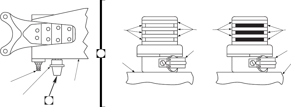
2.51 TAIL ROTOR QUADRANT/WARNING.
The tail rotor quadrant contains microswitches to turn on
a caution light marked TAIL ROTOR QUADRANT if a
tail rotor cable becomes severed. Spring tension allows the
quadrant to operate in a normal manner. Electrical power to
operate the warning system is provided from No. 1 dc pri-
mary bus through a circuit breaker marked T RTR SERVO
WARN. If the helicopter is shut down and/or hydraulic
power is removed with one tail rotor cable failure, discon-
nection of the other tail rotor cable will occur when force
from the boost servo cannot react against control cable
quadrant spring tension. The quadrant spring will displace
the cable and boost servo piston enough to unlatch the
quadrant cable.
SA
AA0518
SERVICE
VALVE
BIM
INDICATOR
MAIN ROTOR
BLADE
A
A
SPAR SPAR
MANUAL
TEST
LEVER
MANUAL
TEST
LEVER
PRESSURE INDICATOR
YELLOW WHITE RED
LOW PRESSURE
(UNSAFE CONDITION)
NORMAL PRESSURE
(SAFE CONDITION)
Figure 2-17. Main Rotor Blade and BIMTSystem
TM 1-1520-237-10
2-56
Section IX UTILITY SYSTEMS
2.52 WINDSHIELD WIPERS.
Two electrically-operated windshield wipers are in-
stalled, one on the pilot’s windshield and one on the copi-
lot’s windshield (Figure 2-1). Both wiper arms are driven
by a common motor through flexible drives and converters.
Power to operate the windshield wiper system is from No.
1 ac primary bus through a circuit breaker, marked
WSHLD WIPER.
NOTE
The use of rain repellent on the windshields
will improve visibility above speeds of 50
KIAS. Rain repellent may be locally pur-
chased.
2.52.1 Windshield Wiper Control.
CAUTION
To prevent possible damage to windshield
surface, do not operate windshield wipers
on a dry windshield.
Control of the windshield wipers is through a spring-
loaded rotary switch on the upper console (Figure 2-7). The
switch is labeled WINDSHIELD WIPER, with marked
positions PARK-OFF-LOW-HI. When the switch is
turned from OFF to LOW or HI, the wipers will operate at
the corresponding speed. The wipers will stop at any posi-
tion when the switch is turned OFF. When the switch is
turned to PARK, the wipers will return to the inboard
windshield frame and stop. When the switch is released, it
will return to OFF.
2.52.2 Windshield Anti-Ice/Defogging System.
CAUTION
Continued use of a faulty windshield anti-
ice system may result in structural dam-
age (delamination and/or cracking) to the
windshield.
Do not allow ice to accumulate on the
windshield, as ice shedding can cause en-
gine FOD.
Pilot’s, copilot’s and center windshields (on helicopters
equipped with center windshield anti-ice system) are elec-
trically anti-iced and defogged. Transparent conductors im-
bedded between the laminations provide heat when electri-
cal power is applied. The temperature of each panel is
controlled to a heat level of about 43°C (109°F). The wind-
shield anti-ice system fault monitoring circuit prevents
windshield burnout when the windshield surface heat is
above 43°C (109°F). If heat increases, the monitor circuit
will turn off the system. Three switches, one for the pilot,
one for the copilot and one for the center windshield, (when
equipped) are on the upper console (Figure 2-7) with mark-
ings of WINDSHIELD ANTI-ICE PILOT-OFF-ON, and
COPILOT-OFF-ON. On helicopters equipped with center
windshield anti-ice an additional switch to control the cen-
ter windshield is marked WINDSHIELD ANTI-ICE-
CTR-OFF-ON. Power to operate the anti-icing system is
provided by the No. 1 and No. 2 ac primary buses through
circuit breakers marked PILOT WSHLD ANTI-ICE and
CPLT WSHLD ANTI-ICE. On helicopters equipped with
center windshield anti-ice, pilot and center windshield anti-
ice circuit breakers are marked WINDSHIELD ANTI-ICE
PILOT and CTR. Power to control the anti-ice system is
provided by the No. 1 and No. 2 dc primary buses through
circuit breakers marked CPLT WSHLD ANTI-ICE and
PILOT WSHLD ANTI-ICE respectively. On helicopters
equipped with center windshield anti-ice system, control
circuit breakers for pilot’s and center windshield are on the
No. 2 dc primary bus and are marked WINDSHIELD
ANTI-ICE PILOT and CTR. If the APU generator is the
sole source of ac-generated power, the backup pump and
the windshield anti-ice cannot be used simultaneously.
2.53 PITOT HEATER.
Pitot tube heat is provided by heating elements within
each pitot tube head. Power to operate both heating ele-
ments is controlled by a single switch on the upper console,
marked PITOT HEAT OFF and ON. When the switch is
placed ON, current flows to the heating elements. Current
sensors in the circuits sense the current flow and keep the
caution lights, marked LFT PITOT HEAT and RT PI-
TOT HEAT, turned off. If a heating element fails, the
current sensor will detect no current flow, and turn on the
caution light for that pitot tube. Power to operate the pitot
tube heaters is provided from the No. 2 ac primary bus for
the right pitot tube, through a circuit breaker marked RT
PITOT HEAT, and from the No. 1 ac primary bus for the
left pitot tube, through a circuit breaker marked LEFT PI-
TM 1-1520-237-10
Change 9 2-57

TOT HEAT. Power to operate the caution lights is pro-
vided from the No. 1 dc primary bus through a circuit
breaker, marked NO. 1 ENG ANTI-ICE.
2.54 ROTOR BLADE DEICE KIT.
CAUTION
Blade deice operation with erosion strips
installed may cause blade damage.
The rotor blade deice kit (Figure 2-18) consists of the
following: deice control panel, deice test panel, system con-
troller, power distributor, main and tail sliprings, main and
tail blade heating elements, droop stop heaters, caution
lights, outside air temperature (OAT) sensor, a modified
ambient temperature sense line and an icing rate meter sub-
system. The blade deice system provides improved mission
performance in icing conditions by applying controlled
electrical power to integral heating elements in the main
and tail rotor blades, causing the ice bond layer to melt,
allowing symmetrical ice shedding. Droop stop heaters ap-
ply heat to the droop stop hinge pins, to prevent icing and
permit proper operation. The heaters are electrically pow-
ered continuously whenever the blade deice system is op-
erating, either with the power switch ON, or the system in
the TEST mode. The blade deice system, excluding
element-on-time (EOT) failure, may be ground checked us-
ing the APU generator. To prevent generator overload when
only the APU generator is operating, an interlock system is
installed to inhibit blade deice test if the backup pump is
operating. If the backup pump should go on during the test
cycle, the MR DE-ICE FAIL caution light will go on im-
mediately, alerting the crew to an invalid test attempt. The
test cycle must then be initiated again. The OAT sensor,
installed below the windshield, provides a signal to the con-
troller for heating EOT of the rotor blades. The lower the
OAT, the longer EOT will be. To reduce power require-
ments, the blades are deiced in cycles. Power to operate the
blade deice is provided from the No. 1 and No. 2 ac pri-
mary buses and No. 2 dc primary bus through circuit break-
ers, marked ICE-DET,DE-ICE CNTRLR, and DE-ICE
PWR TAIL ROTOR, on the mission readiness circuit
breaker panel in the cabin. Main blade deice power is
routed through current limiters in the deice junction box.
When one main generator is inoperative, deice power can
be supplied by the APU generator.
2.54.1 Blade Deice System Operation. The ice de-
tector is operational anytime power is applied to the heli-
copter. The ice detector senses ice accumulation on a vi-
brating probe by a change in probe frequency. The
frequency change is processed by the ice rate meter. The
ice rate meter provides a visual display of icing intensity, T
(trace), L (light) blue, M (moderate) yellow, and H (heavy)
red. Also, the ice rate meter sends a signal to the ICE
DETECTED caution light when the BLADE DE-ICE
POWER switch is off, informing the pilot of the require-
ment to turn on the system. When the system has been
turned on by placing the POWER switch ON, the ice de-
tector aspirator heater is turned on, and the ICE DE-
TECTED caution light is turned off. If the MODE switch
is at AUTO, the rate meter sends an ice rate signal to the
controller. The controller processes the ice rate signal to
produce heater element-off-time, and the OAT signal to
produce the heater EOT. The controller sends command
signals through the main rotor sliprings to the system dis-
tributor which responds to controller signals by switching
power in sequence to the main rotor blade heater zones.
Tail rotor blade power is switched directly by the controller
and sent through the tail rotor sliprings to the tail rotor
blades. A tail blade distributor is not required since the
power is applied to the four tail blades simultaneously. The
deice control panel contains a rotary switch which allows
automatic or manual control of blade heater element-off-
time. In AUTO (automatic), the ice rate signal is passed on
to the controller, which results in off-time variations pro-
portional to the ice rate. In MANUAL,T,L,orM, fixed
signals are transmitted to the controller, resulting in fixed
element-off-time. Ice rate subsystem malfunctions are indi-
cated by the appearance of a FAIL flag on the rate meter
face, requiring operation of the blade deice system in one
of the three manual modes. MANUAL mode should also
be used when the rate meter has no indicated malfunction,
but any of these three conditions has occurred: 1. Pilot has
determined by his judgment of ice intensity that the ice rate
system is inaccurate. 2. Torque required has increased to an
unacceptable level. 3. Helicopter vibration has increased to
an unacceptable level. During a single main generator fail-
ure, blade deice will be dropped until the APU is started
and the APU generator switch is placed ON. Even though
the APU generator switch is ON and providing power to
the blade deice system, the APU GEN ON advisory light
will not be on because of one main generator operating.
2.54.2 Blade Deice System Control Panel. All con-
trols for operating the rotor blade deice system are on the
TM 1-1520-237-10
2-58 Change 8
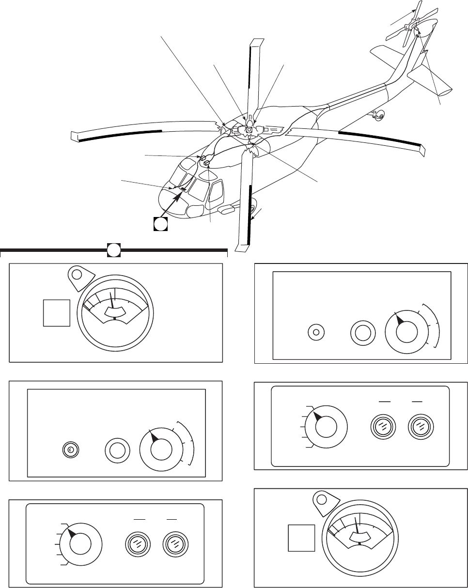
POWER
ON
TEST
TEST
IN
PROGRESS
MODE
AUTO T
L
M
BLADE DE−ICE TEST
NORM
SYNC 1
SYNC 2
OAT
EOT
PWR
MAIN TAIL
RTR RTR
PRESS
TO
TEST
B
L
A
D
E
D
E
I
C
E
M
AN
U
A
L
L
W
C
g/
m
3
T
L
M
H
0
1.0
1.
5
2.
0
F
A
I
L
PRESS
TO
TEST
BLADE DE−ICE TEST
NORM
SYNC 1
SYNC 2
OAT
EOT
PWR
MAIN TAIL
RTR RTR
POWER
ON
TEST
TEST
IN
PROGRESS
MODE
AUTO T
L
M
B
L
A
D
E
D
E
I
C
E
M
AN
U
A
L
SA
AA0389A
DEICE CONTROL PANEL
DEICE CONTROL PANEL
ICING RATE METER
ICING RATE METER
DE−ICE TEST PANEL
DE−ICE TEST PANEL
.25
.5
ICE DETECTOR
DROOP STOP
HEATER
(TYPICAL 4) DISTRIBUTOR
ASSEMBLY
TAIL ROTOR BLADE
ELECTROTHERMAL
HEATING ELEMENT
(SAME ON ALL BLADES)
TAIL
SLIPRING
ASSEMBLY
MAIN
SLIPRING
ASSEMBLY
MAIN ROTOR BLADE
ELECTROTHERMAL
HEATING ELEMENT
(SAME ON ALL BLADES)
CONTROLLER
DE−ICE
JUNCTION BOX
OUTSIDE AIR
TEMPERATURE
SENSOR
A(ON HELICOPTERS WITH
REARRANGED BLADE DE−ICE
PANELS)
L
W
C
g/
m
3
T
L
M
H
0
1.0
1.
5
2.
0
F
A
I
L
.25
.5
A
Figure 2-18. Rotor Blade Deice Kit
TM 1-1520-237-10
2-59
BLADE DEICE system control panel (Figure 2-18). Con-
trols are described as follows:
CONTROL/
INDICATOR FUNCTION
POWER switch TEST Electrically test main and tail
rotor deice system for one
test cycle.
ON Turns on power to blade
deice controller and turns off
ICE DETECTED caution
light.
OFF Turns off deice system.
TEST IN PROGRESS Green light goes on during
test cycle. At end of test
cycle, light should go off.
MODE selector
AUTO System off-time is controlled
by ice rate signal.
MANUAL Gives pilot manual control of
system off-time.
TSets a fixed element-off-time
for trace icing.
LSets a fixed element-off-time
for light icing.
MSets a fixed element-off-time
for moderate icing.
2.54.3 Blade Deice Test. The BLADE DE-ICE TEST
panel (Figure 2-18) allows the pilot to check the blade de-
ice system for failures that are otherwise dormant during
the normal TEST mode, but that can allow abnormal op-
eration during use. The panel accomplishes this by intro-
ducing selected failure signals into the system and requiring
the deice controller built-in-test circuitry to function in a
specific manner. The blade deice test should be done during
the ground checkout before each flight when blade deice
use is anticipated. In the NORM position, the test panel
allows system test to be done without the introduction of
false failure signals. Thus, the system should complete its
self checkout cycle without failure indications on the cau-
tion panel. In the SYNC 1 and SYNC 2 positions, the test
panel interrupts the distributor sync line and provides the
controller with a false sync input. The controller must in-
terpret these false signals as indications of distributor fail-
ure, and produce MR DE-ICE FAIL caution light for both
cases. In the OAT position, the test panel short circuits the
OAT sensor input to the controller. BITE circuitry within
the controller must sense the simulated failure and turn on
both the MR DE-ICE FAIL and TR DE-ICE FAIL cau-
tion lights. In the EOT position, the test panel biases BITE
circuitry in the controller and the OAT sensor to simulate
malfunctioning primary EOT timing circuits. The biased
BITE circuit is thus deceived into believing that the pri-
mary circuits are in error. The controller must turn on both
the MR DE-ICE FAIL and TR DE-ICE FAIL lights when
this occurs. The test panel also functions automatically dur-
ing blade deice system use to sense contradictory signals
from the deice power circuits. If electrical power remains
applied to either the main or tail rotor heating elements
after the controller signals a FAIL condition or when the
system is OFF, then the corresponding PWR monitor light
on the BLADE DE-ICE TEST panel turns on. The light
informs the crew that further action is required to isolate
the deice loads indicated. The test panel provides a reliabil-
ity check of critical deice system functions. The pilot, after
doing the indicated tests properly, can be confident that the
deice system primary and BITE electronics are functioning
within specified tolerances.
2.54.4 Blade Deice Test Panel. The control for select-
ing test functions of the blade deice system is on the
BLADE DE-ICE TEST panel (Figure 2-18). Two PWR
lights on the panel warn of power malfunctions of the main
and tail rotor deice. Control and indicators are as follows:
CONTROL/
INDICATOR FUNCTION
NORM Provides a signal path for
normal operation.
SYNC 1 Provides a signal to the
controller to verify operation
of synchronization check
circuitry when POWER
switch is at TEST.
SYNC 2 Provides an open circuit to
the controller to verify
operation of synchronization
check circuitry when
POWER switch is at TEST.
TM 1-1520-237-10
2-60

CONTROL/
INDICATOR FUNCTION
OAT Short circuits the OAT sensor
to check BITE circuit sensing
a fault when POWER switch
is at TEST.
EOT Disables BITE circuits in
controller and OAT sensor to
simulate a malfunctioning
primary EOT timing circuit
when POWER switch is ON
and MODE select switch is
at M(moderate).
PWR MAIN RTR light Indicates a malfunction has
occurred in the main rotor
primary power.
PWR TAIL RTR light Indicates a malfunction has
occurred in the tail rotor pri-
mary power.
2.55 BLACKOUT CURTAINS.
Curtains are provided to cover the cabin windows and
the opening between the pilot’s compartment and the cabin.
Velcro tape is bonded to the cabin structure and the curtains
with an adhesive. Loops are attached to the curtains to aid
removal.
2.56 WIRE STRIKE PROTECTION SYSTEM.
On helicopters equipped with wire strike protection pro-
visions, the system (Figure 2-1) is a simple, lightweight,
positive system with no motorized or pyrotechnic compo-
nents used to cut, break, or deflect wires that may strike the
helicopter in the frontal area between the tires and fuselage,
and between the fuselage and main rotor in level flight. The
system consists of nine cutters/deflectors located on the fu-
selage and landing gear/support. They are: upper cutter on
the rear of the sliding fairing, the pitot cutter/deflector on
the front of the sliding fairing, windshield post and wiper
deflectors, door hinge deflector, step extension and step de-
flector, landing gear joint deflector, main landing gear
cutter/deflector, and tail landing gear deflector.
2.57 FLIGHT DATA RECORDER (ON HELICOP-
TERS EQUIPPED WITH FLIGHT DATA RECORDER
KIT).
The flight data recorder system installed in the aft tran-
sition avionics compartment is a crash survivable digital
tape recorder providing 25 hours of recorded data on a
continuous loop magnetic tape. Flight data input to the re-
corder is sent from different locations throughout the heli-
copter. The recorder begins to record data as soon as ac and
dc essential power is supplied to the helicopter. Electrical
power to operate the data recorder system is provided from
the dc essential bus and ac essential bus through circuit
breakers marked FLT REC on the mission readiness cir-
cuit breaker panel. There are no controls provided to the
pilot or copilot for control of the recorder.
2.58 DATA COMPARTMENTS.
Data Compartments are on each cockpit door (Figure
2-4).
2.58A SNOW SKIS.
The skis for the UH-60A/L are designed to keep the
aircraft from becoming immobile when operating on snow
(winter) and tundra (summer).
TM 1-1520-237-10
Change 9 2-61

Section X HEATING, VENTILATING, COOLING,
AND ENVIRONMENTAL CONTROL UNIT
2.59 HEATING SYSTEM.
The subsystem consists of a heated air source, cold air
source, mixing unit, temperature sensing unit, overtempera-
ture sensor, controls, ducting and registers. The heating
system is a bleed-air system and bleed-air supplied in flight
by the main engines, and on the ground by the main en-
gines or the APU. An external connector allows connection
of an external ground source in to the pneumatic system,
that can provide heat when connected. Power to operate
electrical components of the heating system is by the No. 1
dc primary bus through a circuit breaker, marked AIR
SOURCE HEAT/START.
2.59.1 Winterized Heater. The winterized heater con-
sists of a high bleed-air flow mixing valve and a modula-
tion valve. The mixing valve is of enough capacity to keep
the interior temperature of the helicopter at 4°C (39°F), to
ambient temperatures down to -54°C (-65°F). The mixture
sensor controls air mixing to allow control of temperature
used for cabin heat. Bleed-air is mixed with ambient air to
get the desired temperature selected by the variable tem-
perature control on the HEATER control panel (Figure
2-7). Bleed-air is regulated with the modulation valve for
downstream mixing with ambient air when the HEATER
control switch is ON. Overtemperature is prevented by two
overtemperature sensors that deenergize solenoid valves
when bleed-air temperature reaches about 90° to 96°C
(194° to 205°F) at the inlet to the mixing valve or in the
mixing chamber. The temperature sensors control current
flow to the on-off solenoid and the winterization solenoid to
hold them energized, allowing bleed-air to flow to the mix-
ing chamber. When the ENG ANTI-ICE switch is placed
ON or a dc power failure occurs, the winterization solenoid
will deenergize. An interlock system between engine anti-
ice system and the heater winterization solenoid valve pre-
vents engine overbleed by reducing bleed-air flow to the
heater when an ENG ANTI-ICE switch is ON. Operation
of the winterization heating system is the same as in Para-
graph 2.59.3.
2.59.2 Heat and Ventilation Controls. A variable
control air mixing valve assembly is used to control the
temperature of air for cabin heating in the helicopter.
Bleed-air from the engine, APU, or external source is mixed
with ambient air to obtain the desired temperature deter-
mined by the setting of the sensor in the downstream air
flow. Regulation of the diaphragm position is by a solenoid.
Should the HEATER control switch (Figure 2-7) be turned
OFF, or dc power fail, bleed-air will shut off. The valve
also has a thermal protective switch that deenergizes the
solenoid if mixed air temperature is over 90° to 96°C (194°
to 205°F). The mixture temperature sensor downstream of
the mixing valve regulates flow output temperature. The
sensor is regulated from the cockpit through a control link-
age at the overhead console. The temperature control is
marked HEATER OFF,MED, and HI. Ventilation is con-
trolled through a panel on the upper console marked VENT
BLOWER. When the switch is placed ON, dc power to the
solenoid allows bleed-air to mix with outside air.
2.59.3 Normal Operation.
1. APU or engine - Start (Refer to paragraph 8.22
or 8.23).
2. AIR SOURCE HEAT/START switch - As re-
quired. ENG if engine is operating; OFF for
heat from external air source.
3. HEATER ON-OFF switch - ON.
4. VENT BLOWER switch - OFF for maximum
heat.
5. HEATER control - As desired.
2.60 VENTILATION SYSTEM.
2.60.1 Ventilation System. UH The helicopter is venti-
lated by an electrically-operated blower system controlled
through the VENT BLOWER control panel on the upper
console (Figure 2-7). The VENT BLOWER switch is
marked OFF and ON. When ON, the blower forces ambi-
ent air into the cabin ducts. The No. 2 ac primary bus
powers the blower through a circuit breaker, marked HEAT
& VENT. It is also controlled by dc power from the No. 2
dc primary bus through the VENT BLOWER switch pro-
tected by a circuit breaker, marked HEAT VENT. Ram air
vents for cooling the cockpit area are on each side of the
upper console and at the front of the lower console (Figure
2-4) and are controlled by turning the nozzle to control the
opening.
2.60.2 Ventilation System. EH In addition to the stan-
dard ventilation system, the EH-60A has a ventilation sys-
tem which operates in conjunction with the air conditioning
system. The system is controlled from the ECS control
panel on the upper console (Figure 2-7). When the AIR
COND switch is placed in the FAN position, fresh air
TM 1-1520-237-10
2-62

is drawn from outside the helicopter into the plenum cham-
ber, mixed with inside air and circulated through the heli-
copter.
2.60.3 Normal Operation.
1. APU, rotor or external power - Operating.
2. VENT BLOWER switch - ON.
2.61 Air Conditioner System. EH The vapor-cycle
system (air conditioner) cools the cabin and cockpit areas.
It consists of a heli-rotor compressor, evaporator, con-
denser, associated valves, protective pressure and tempera-
ture switches, a filter, service valves, a liquid indicator and
an electrical control system. A sight glass in the liquid line
gives an indication of refrigerant liquid servicing level,
when the system is operating. The temperature controller
assembly, in the aft cabin, processes the input signals from
the temperature selection rheostat in the cockpit and the
cabin temperature sensor, and provides the power to the hot
gas bypass valve solenoid. The electrical control box, in the
transition section, contains the relays, time delays, elapsed
time meter and fault indicators for the vapor-cycle system.
The control box routes the power to the electrical compo-
nents. Inputs from the remote control and temperature con-
troller are channeled to their respective electrical interface
in the control box. Across the front of the enclosure are
four fault indicators HI and LO PRESS, and HI and LO
TEMP, which are tripped to indicate red when a fault is
received. These indicators provide visual signals of a fault
occurring, even if it is only temporary, and they can be
manually reset for reuse by pressing in the fault indicator.
The air conditioner system is protected to prevent evapora-
tor freezing. The system may be operated at any ambient
temperature without causing damage, shown in Table 2-2.
Power to operate the air conditioner system is provided
from the No. 2 ac primary bus and controlled from the No.
1 dc primary bus through a breaker marked ECS CONTR
. Control of the air conditioner is through the ECS control
panel on the upper console (Figure 2-7). The panel contains
a temperature control rheostat with an increasing arrow in-
dicator to COOL, two mode selection switches marked
COOL-OFF-FAN and HTR-OFF-ON. The temperature
control rheostat is used with the COOL switch to set the
desired cabin temperature. Placing switch to COOL will
cause AIR COND ON advisory light to illuminate. Selec-
tion of the COOL mode on the cockpit AIR COND con-
trol panel starts a phased sequence of events leading to full
operation of the air conditioner system. To prevent a sud-
den surge in 115 vac power, the major electrical compo-
nents are started at spaced intervals.
2.62 AUXILIARY HEATER SYSTEM. EH
Incorporated in the air conditioner plenum chamber is an
auxiliary heating system to supplement the bleed air heater.
The electrically operated heater is controlled by a switch on
the upper console ECS control panel marked HTR ON &
OFF. The heater element will operate continuously as long
as the switch is ON. With the HTR switch ON and the
AIR COND switch placed in the FAN position the CABIN
HEAT ON advisory light will illuminate. An overtempera-
ture protection is provided at 205°F if there is a heater
malfunction.
POWER SOURCE AIR CONDITIONING SYSTEM OPERATION
APU Generator (Aircraft on
Ground)
vAir Conditioning Interrupted if:
(1) Backup Pump is On.
or
(2) Windshield Anti-Ice is On.
vWindshield Anti-Ice Interrupted when Backup Pump is On.
APU Generator (Aircraft in
Flight)
vAir Conditioning Interrupted while Aircraft in Air.
vWindshield Anti-Ice Interrupted when Backup Pump is On.
Dual Main Generator (No. 1 and No.
2) (Aircraft in Flight or on Ground)
vAir Conditioning, Backup Pump, and Windshield Anti-Ice can
Operate Simultaneously.
Single Generator or External AC Power
(Weight on or off Wheels)
vAir Conditioning Interrupted If:
(1) Backup Pump is On.
Table 2-2. Air Conditioning System Power Source Priority EH
TM 1-1520-237-10
Change 3 2-63

Section XI ELECTRICAL POWER SUPPLY AND DISTRIBUTION SYSTEMS
2.63 ELECTRICAL POWER SYSTEMS.
Alternating current (ac) is the primary source of power.
The primary electrical system consists of two independent
systems, each capable of supplying the total helicopter
power requirements. The prime source of each system is a
115/200 vac generator. A subsystem feeds two independent
ac primary buses and an ac essential bus. A portion of each
ac primary bus load is converted to 28 volts direct current
(vdc) by two 200 ampere ac/dc converters. The 28 vdc is
distributed by two independent dc primary buses and a dc
essential bus. Emergency power is provided by a generator
driven by the auxiliary power unit (APU). The APU gen-
erator is capable of supplying all flight-essential ac and dc
bus loads. In addition, the APU generator can supply power
to the blade deice system (when installed) if one main gen-
erator should fail. Should a second generator fail, the blade
deice load will be dropped and the APU generator will
power the remaining ac bus loads. An electric power prior-
ity feature allows either the No. 1 or No. 2 main generator
to automatically supersede the APU generator, which, in
turn, automatically supersedes external power. A 24-volt
battery provides backup dc power.
2.64 DC POWER SUPPLY SYSTEM.
Primary dc power is obtained from two converters
(transformer-rectifiers) with a battery as the secondary
power source. There is no external dc power connector
(Figure 2-19).
2.64.1 Converters. Two 200-ampere converters, each
normally powered by the No. 1 and No. 2 ac primary buses
respectively, turn ac power into dc power and reduce it to
28 volts. The converter output is applied to the No. 1 and
No. 2 dc primary buses whenever ac power is applied to the
ac primary buses. If one converter’s output is lost, the con-
verter load will be transferred to the operating system, and
a caution light, marked #1 CONV or #2 CONV will go on.
Power to light the caution light is provided by the battery
bus through a circuit breaker marked, AC CONV WARN.
2.64.2 Battery.
a. A 24-volt dc 5.5 ampere hour 20-cell nickel cadmium
(nicad) battery provides secondary or emergency dc power.
The battery is in the cabin section behind the copilot. It
supplies dc power to the battery and battery utility buses
(Figure 2-19) for operating dc essential equipment during
primary dc malfunction. Power to the battery bus is con-
trolled by the BATT switch on the upper console. It has
marked positions OFF and ON. The battery utility bus is
connected directly to the battery. During No. 1 and No. 2
dc primary source malfunction, the dc essential bus is pow-
ered by the battery bus as long as the battery is at least 35%
charged and the BATT switch is ON. When only battery
power is available, the battery life is about 22 minutes day
and 14 minutes night for a battery 80% charged. The BATT
switch should be ON when either external power, APU
generator or main generator power is applied to the heli-
copter. This will recharge the battery. When the battery is
the sole source of dc power, the BATT switch should be
turned OFF immediately upon obtaining a BATT LOW
CHARGE caution light. A malfunction of both dc primary
sources will light caution lights marked #1 and #2 CONV.
If the BATT switch is left ON, the battery will be com-
pletely discharged in less than 3.5 hours. If the maintenance
light and both cockpit utility lights are left on, the battery
will be completely discharged in less than 7 hours. Power
to light the caution light is from the battery bus through a
circuit breaker marked BATT & ESNTL DC WARN EXT
PWR CONTR.
b. A 24-volt dc 9.5 ampere hour sealed lead acid battery
(SLAB) provides secondary or emergency dc power. The
battery is in the cabin section behind the copilot. It supplies
dc power to the battery bus, battery utility bus and dc es-
sential bus (Figure 2-19) for operating dc essential equip-
ment during primary dc malfunction. Power to the battery
bus is controlled by the BATT switch on the upper console.
It has marked positions OFF and ON. The battery utility
bus is connected directly to the battery. The dc essential
bus is powered by the battery bus as long as the BATT
switch is ON. When only battery power is available, the
battery life is about 38 minutes day and 24 minutes night
for a battery 80% charged. The BATT switch should be
ON when either external power, APU generator or main
generator power is applied to the helicopter. This will re-
charge the battery. When the battery is the sole source of dc
power, the BATT switch should be turned OFF immedi-
ately upon obtaining a BATT LOW CHARGE caution
light. This is done so that battery power can be conserved
for an APU start. A malfunction of both dc primary sources
will light caution lights marked #1 and #2 CONV.Ifthe
BATT switch is left ON, the battery will be completely
discharged in less than 6 hours. Power to light the BATT
LOW CHARGE caution light is from the battery bus
through a circuit breaker marked BATT & ESNTL DC
WARN EXT PWR CONTR.
2.64.3 DC Monitor Bus. EH The dc monitor bus is nor-
mally energized by the No. 1 and No. 2 converters when
the generators are operating, and is powered by the No. 2
converter when operating from external power (Figure
TM 1-1520-237-10
2-64 Change 4
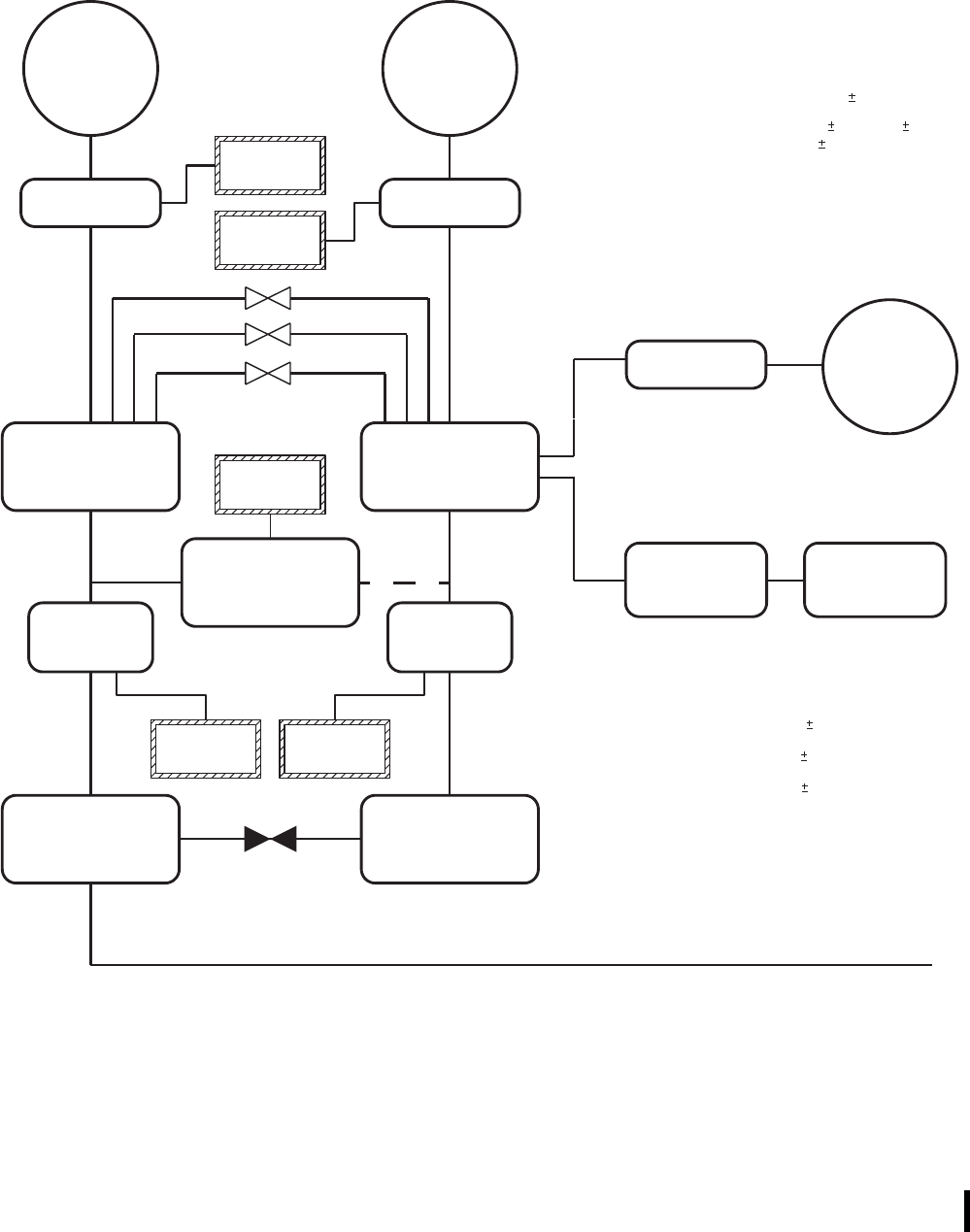
UH60 ELECTRICAL SYSTEM
#1
GENERATOR #2
GENERATOR
GCU GCU
#1 AC
PRIMARY BUS #2 AC
PRIMARY BUS
AC
ESSENTIAL BUS
AC TO DC
CONVERTER AC TO DC
CONVERTER
#1 DC
PRIMARY BUS #2 DC
PRIMARY BUS
GCU APU
GENERATOR
EXT PWR
MON PANEL EXTERNAL AC
POWER
#1 GEN
#2 GEN
AC ESS
BUS OFF
#1 CONV #2 CONV
100 AMP
CURRENT LIMITER
CONVERTS 115 / 200 VAC
TO 28 VDC 200 AMPS
115 / 200 VAC
30 / 45 KVA
400 HZ
3 PHASE GENERATOR CONTROL UNIT
APU GENERATOR
EXTERNAL POWER MONITOR PANEL
(GROUND OPERATION ONLY ON MAIN GEN GCU’S)
UNDERVOLTAGE PROTECTION (100 5 VAC / 6 1 SEC)
OVERVOLTAGE PROTECTION (125 VAC / TIME VARIES
INVERSELY TO OVERVOLTAGE)
FEEDER FAULT (SHORT CIRCUIT TO GROUND)
115 / 200 VAC
20 / 30 KVA, 400 HZ
3 PHASE, AIR COOLED
UNDERVOLTAGE PROTECTION
(100−105 VAC / .85−2.55 SEC)
OVERVOLTAGE PROTECTION
(125−130 VAC / 1 .25 SEC)
UNDERFREQUENCY PROTECTION
(370−375 HZ / 1 .25 SEC)
OVERFREQUENCY PROTECTION
(425−430 HZ / 1 .25 SEC)
CORRECT PHASE ROTATION
UNDERFREQUENCY PROTECTION (375 5 HZ / 1−3 SEC)
MAIN GENERATORS
60 AMP
CURRENT LIMITERS
(6 TOTAL)
1
SA
AA0327_1
Figure 2-19. Electrical System (Sheet 1 of 2)
TM 1-1520-237-10
Change 2 2-64.1
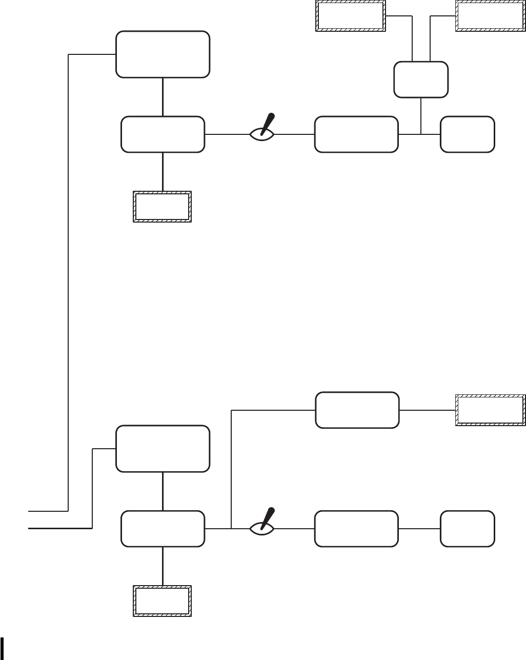
SA
AA0327_2B
BELOW 35% CHARGE
BATTERY
BUS
DC
ESSENTIAL BUS
CHARGER
ANALYZER
BATTERY
UTILITY BUS 24 VDC
BATTERY
DC ESS
BUS OFF
DC ESSENTIAL BUS
IS DROPPED IF
BATTERY FALLS
BATTERY SWITCH
BATTERY
FAULT BATT
LOW CHARGE
INTERNAL TEMP ABOVE
70oC OR CELL
DISSIMILARITY EXISTS
20 CELLS
5.5 AMPERE HOUR
WHEN BATTERY IS
ONLY SOURCE OF
POWER,
BATTERY FALLS
BELOW
40 %
CHARGE
HELICOPTERS WITH NICAD BATTERY INSTALLED
BATTERY
BUS
DC
ESSENTIAL BUS
BATTERY
UTILITY BUS 24 VDC
BATTERY
DC ESS
BUS OFF
BATTERY SWITCH
BATTERY LOW
SENSING RELAY BATT
LOW CHARGE
9.5 AMPERE HOUR
BATTERY FALLS
BELOW
23 VOLTS
HELICOPTERS WITH SLAB INSTALLED
1
1
Figure 2-19. Electrical System (Sheet 2 of 2)
TM 1-1520-237-10
2-64.2 Change 10

2-19). If either converter should fail, the bus will be auto-
matically dropped from the system.
2.64.4 Quick Fix Power. EH Mission equipment dc
power is provided from the No. 1 dc primary bus, and is
controlled by Q/F PWR switch on the upper console.
2.64.5 Battery Charger/Analyzer. A charger/analyzer
system restores the battery charge and determines the con-
dition of the battery. The system charges the battery
through a converter whenever ac power is available on the
helicopter and the BATT switch is ON. The analyzer sys-
tem monitors battery charge and lights a caution light indi-
cating BATT LOW CHARGE when the charge lowers to
35% to 45% of battery capacity. If battery charge continues
to lower, at 30% to 40% of battery capacity, the dc essen-
tial bus will be disconnected from the battery. At 35% ca-
pacity the battery can provide two APU starts. Another
analyzer circuit monitors battery temperature. When the in-
ternal temperature reaches 70°C (158°F), or if a battery cell
dissimilarity condition exists, a caution panel light will go
on, indicating BATTERY FAULT (only on helicopters
equipped with nickel-cadmium batteries). Then the charger/
analyzer should automatically disconnect the battery from
the charging circuit. As a backup, placing the BATT switch
TM 1-1520-237-10
Change 2 2-65
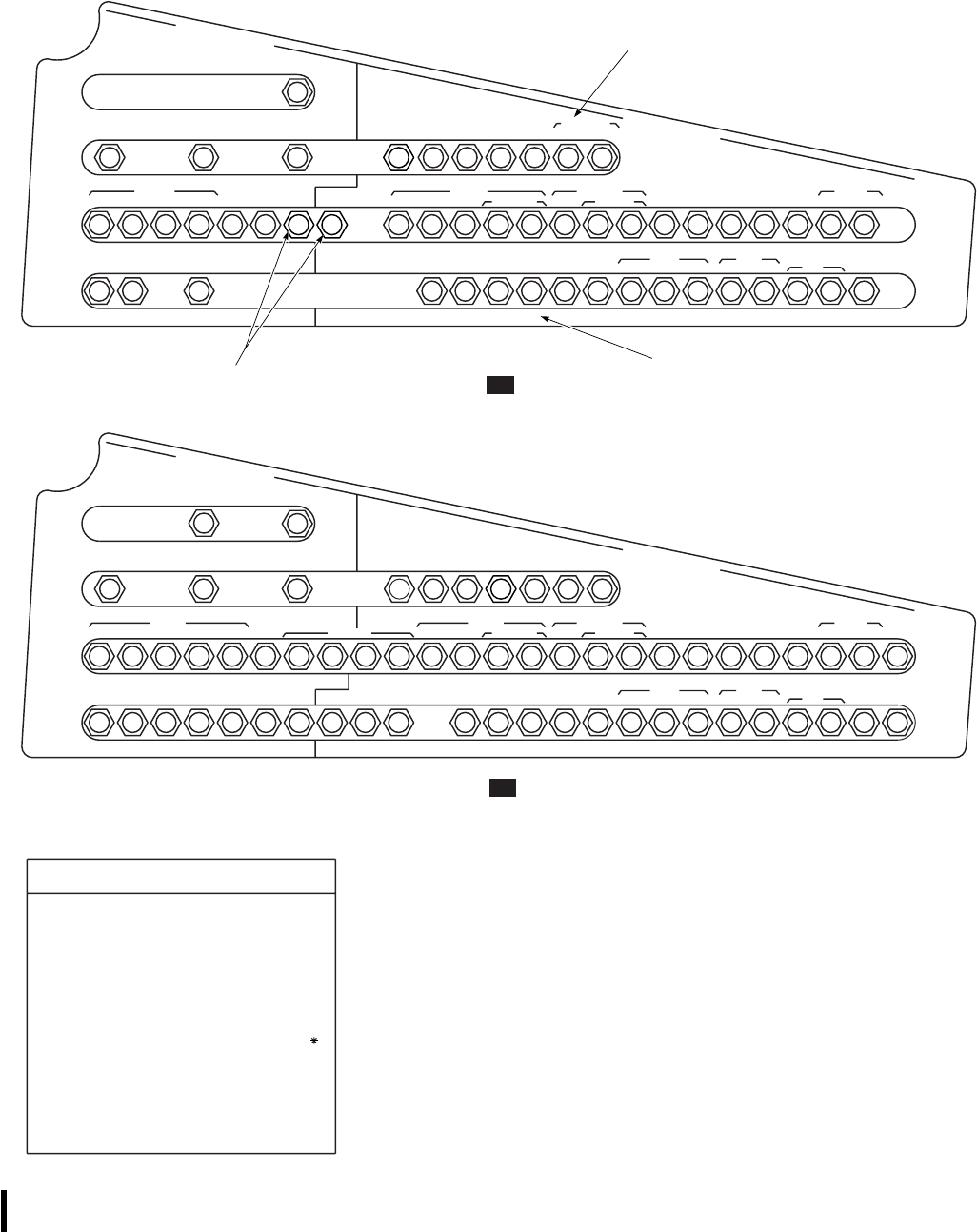
SA
AA0353_1E
NO. 1 AC PRI BUS NO. 1 DC PRI BUS
60 HZ AC
CONVERTER
15
15
CPLT WSHLD
ANTI−ICE WSHLD
WIPER NO. 1
CONVERTER UTIL
RECP
AIR
SOURCE
HEAT/ FUEL
LOW BACKUP
PUMP ESSS JTSN
INBD OUTBD
LIGHTS
520
CPTL UPPER CABIN NO. 1
ENG
555 5
FLT
AC ESNTL
BUS NO. 1
AC
CSL DOME
LEFT
PITOT
OVSP
SPLY INST HEAT
510
CABIN
55
55
55
START WARN PWR
LIGHTS NO. 1 ENG
ADVSY CAUT RETR LDG WARN ANTI−ICE CPTL
WSHLD NO. 1
DC BUS
TIE NO. 1
GEN T RTR
SERVO NO. 1
SERVO
555555555
555
ADVSY CONT PWR LTS
TRIMDPLR IFF ADF CMD CSLCMPTR CHAFF
DISP
225
SET
WARN ANTI−ICE INST
CPLT
TURN ALTM MODE VHF FM COMM
NO. 2
CNTOR WARN WARN CONTR
RDR
WARN
BUS
DC ESNTL
50222
RATE GYRO SELECT
2
FM SCTY SET ALTM WARN SPLY
25 2
7.5 7.5 7.5
7.5
*
7.5 7.5
7.5
.5
5
LWR
CSL
NO. 1 AC PRI BUS NO. 1 DC PRI BUS
IINS
10
15
CPLT WSHLD
ANTI−ICE WSHLD
WIPER NO. 1
CONVERTER FUEL
LOW
AIR
SOURCE
HEAT/ BACKUP
PUMP
LIGHTS
520
CPLT SEC UPPER CABIN LWR NO. 1
ENG
555555
FLT
AC ESNTL
BUS NO. 1
AC
CSL DOME
LEFT
PITOT
CSL OVSP
SPLY INST HEAT
510
WARN
5
5
55
START PWR
LIGHTS NO. 1 ENG
ADVSY CAUT RETR LDG WARN ANTI−ICE CPTL
WSHLD NO. 1
DC BUS
TIE NO. 1
GEN T RTR
SERVO NO. 1
SERVO
555555555
555
ADVSY CONT PWR LTS
TRIMIFF ADF CMPTR CHAFF
DISP
225
PWR
WARN ANTI−ICE INST
CPLT
TURN ALTM MODE VHF FM COMM
NO. 2
CNTOR WARN WARN CONTR
RDR
WARN
BUS
DC ESNTL
50222
DISP RATE GYRO SEL
2
FM SCTY SET ALTM WARN SPLY
25 2
7.5
2
NO. 1 FUEL
BOOST PUMP
Q / F
XFMR
PWR
5
ICE
DET
2
INU
BATT
PWR
5
26 VAC
EQUIP
PWR
5
2
φ
C
EXT
FUEL
LH
5
5.5 .5 .5
PWR PWR
T / R
DE−ICE ECS
2
φ
B
2
φ
A
2
28V
ALQ−156
7.5
ESSS
JTSN
7.5
INBD
7.5
DET
5
DE−ICE
5
IINS
CONTRLR
Q / F
EQUIP
7.5 7.5
ESSS
JTSN
7.5
OUTBD
NOTES
1. ON HELICOPTERS PRIOR TO SERIAL
NO. 81−23579 NOT MODIFIED BY MWO
55−1520−237−50−25.
2. ON HELICOPTERS PRIOR TO SERIAL
NO. 81−23579 MODIFIED BY MWO
55−1520−237−50−25 AND HELICOPTERS
SERIAL NOS 81−23579 AND
SUBSEQUENT.
3. CIRCUIT BREAKERS WITH ASTERISK ( )
ARE ON HELICOPTERS SERIAL NOS
82−23748 AND SUBSEQUENT.
NO. 1 CIRCUIT BREAKER PANEL
NO. 1 CIRCUIT BREAKER PANEL
UH
EH
GLARE LWR
55
SHLD CSL
(SEE NOTE 4)
4. ON HELICOPTERS MODIFIED BY MWO
1−1520−237−50−62, HUD.
IFM
10
1 5
REF SYS
HUDHUD
POWER SOURCE FOR M−139 SYSTEM
WHEN KIT IS INSTALLED
5. ON HELICOPTERS SERIAL NOS
97−26744 AND SUBSEQUENT.
IFM
10
POWER SOURCE FOR JETTISON SYSTEM
WHEN M−139 KIT IS INSTALLED
Figure 2-20. DC and AC Circuit Breaker Panels (Typical) (Sheet 1 of 4)
TM 1-1520-237-10
2-66 Change 1
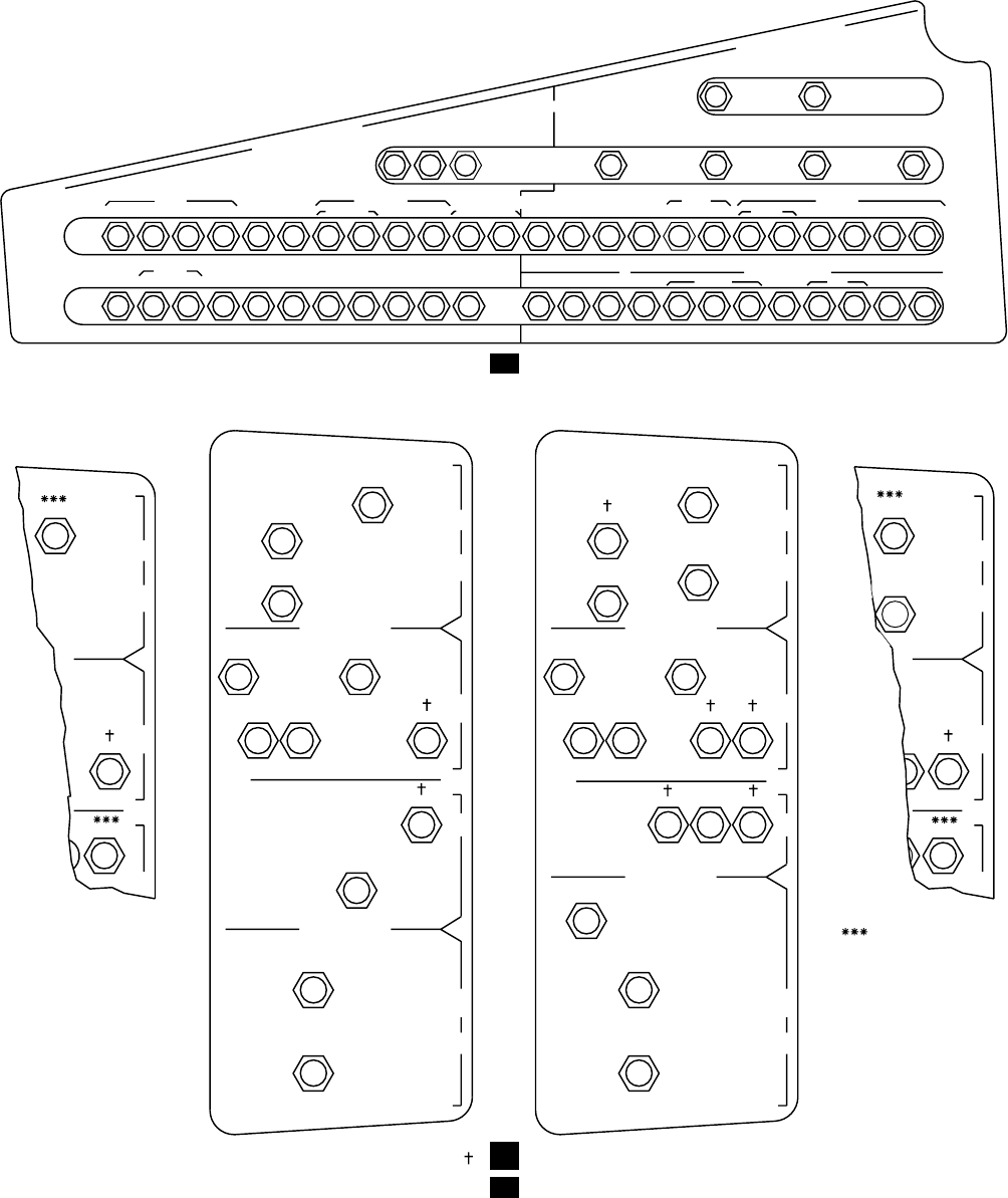
NO. 2 DC PRI BUS NO. 2 AC PRI BUS
HEAT & VENT
ANTI−ICE UTIL RECP PILOT WSHLD
ANTI−ICE
FIRE
SERVO DC GEN
NO. 2 BUS
TIE BATT ANTI−ICE WARN START
NO. 2 ENG CTR EXTGH
CARGOHOOK RT
PITOT STAB AC ENG
NO. 2 FORM ANTI PLT NON
LIGHTS
WARN
BUS
DC ESNTLCONTR INST WARN CNTOR CHGR
PILOT
MODE ALTM HEAT VHF IRCM
SPLY SELECT VENT AM CONTR
WARN
CMPTR STAB SPEED
LTS
TRIM PWR TRIM LTS
CONTR
XMSN
MAIN PWR
POS
CONTR HEAT CONTR INST OVSP
STAB HSI CIS SAS 26 VAC
CONTR PLT / CPLT AMPL STAB IND INST DPLR
AC ESNTL BUS
LV HV COLL FLT
COMP VSI
PLT
FLT
AUTO AC ESNTL
CPLT XFMR BUS WARN
55
55555555
55 555
55
55555
55
5
5
55
20
222
22
222222222
50
10
10
15
7.5
7.5
7.5
7.5
BATT
CHGR
5
AC ESNTL
BUS
SPLY
7.5
7.5
A
C
D
C
D
C
A
C
NO. 2 PRI BUS
NO. 1 PRI BUS
NO. 2 EXTD
RANGE PUMP
AUX FUEL QTY
ICE−DET
RESQ HST NO. 2 LTR
CONTROL LTS
DE−ICE ICE−DET NO. 2 XFER
CNTRLR CONTROL
CONTROL
DE−ICE PWR
TAIL ROTOR
NO. 1 EXTD
RANGE PUMP
5
55
5
2
2
15
15
10
20
7.5
NO. 1 XFER
NO. 1 LTR
5
LTS
A
C
D
C
D
C
A
C
NO. 2 PRI BUS
NO. 1 PRI BUS
NO. 2 EXTD
RANGE PUMP
AUX FUEL QTY
NO. 2 FUEL
ICE−DET
BOOST PUMP
RESQ HST NO. 2 LTR
CONTROL LTS
DE−ICE ICE−DET EXT FUEL NO. 2 XFER
CNTRLR RH CONTROL
EXT FUEL NO. 1 LTR NO. 1 XFER
LH LTS CONTROL
NO. 1 FUEL
BOOST PUMP
DE−ICE PWR
TAIL ROTOR
NO. 1 EXTD
RANGE PUMP
5
555
555
2
2
2
2
15
15
10
20
7.5
A
C
D
C
D
C
US
NO. 2 XFER
CONTROL
CONTROL
5
5
15
AUX HTR
BLOWER
AUX HTR
A
C
D
C
D
C
NO. 2 XFER
CONTROL
CONTROL
5
5
15
AUX HTR
BLOWER
AUX HTR
NO. 2 FUEL
BOOST PUMP
2
(ON HELICOPTERS
EQUIPPED WITH
AUXILIARY CABIN
HEATER)
NO. 2 CIRCUIT BREAKER PANEL
MISSION READINESS
CIRCUIT BREAKER PANELS (CABIN)
(SEE NOTE 1) (SEE NOTES 2 AND 3)
ES
=
UH
UH
H
LE
SA
AA0353_2A
CARGO
HOOK
CTR WSHLD
PILOT
5
ANTI−ICE
WINDSHEILD NO. 2 CONVERTER
CMPTR
2
Figure 2-20. DC and AC Circuit Breaker Panels (Typical) (Sheet 2 of 4)
TM 1-1520-237-10
2-67
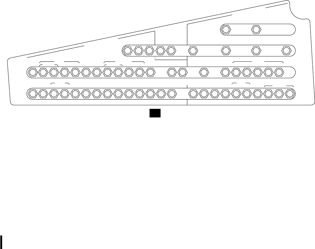
OFF removes input power to the charger/analyzer. By
placing BATT switch OFF, the increasing temperature may
be checked.
2.64.6 Battery Low Sensing Relay. On helicopters
equipped with the sealed lead acid battery the system
charges the battery through the battery charging relay with
one or both converters on. A caution light indicating BATT
LOW CHARGE lights when voltage on the battery utility
bus drops below 23 vdc.
2.64.7 DC and AC Circuit Breaker Panels. The cir-
cuit breaker panels (Figure 2-20) protect the power sys-
tems. One is above and to the rear of each pilot and copilot,
one is on the lower console, and two are on the upper
console . The ac essential bus contains one additional panel.
The circuit breakers provide both ac and dc protection.
Popping of a circuit breaker indicates too much current is
being drawn by a component in the circuit that is powered
through the circuit breaker. Unnecessary recycling of cir-
cuit breakers, or using circuit breakers as a switch should
not be done.
2.65 AC POWER SUPPLY SYSTEM.
A primary ac power system (Figure 2-19) delivers regu-
lated three phase, 115/200 vac, 400 Hz. Each system con-
tains a 30/45 kilovolt-ampere generator mounted on and
driven by the transmission accessory gear box module, a
current transformer, a generator control unit, and current
limiter, all of which are interchangeable. System outputs
are applied to the No. 1 and No. 2 ac primary buses. Cau-
tion lights will go on, indicating #1 GEN or #2 GEN when-
ever generator output is interrupted. Another caution light
goes on, indicating AC ESS BUS OFF when there is no
power to the ac essential bus. Individual generator controls
are provided on the upper console (Figure 2-7), with
marked positions of TEST,OFF/RESET, and ON. A gen-
erator main bearing caution system is installed on each
main generator to light a caution light, marked #1 GEN
BRG or #2 GEN BRG, to indicate a worn or failed bear-
ing. The caution light will remain on until power is re-
moved. The auxiliary bearing will allow 10 additional hours
of operation after the light goes on. Therefore, it should not
be a cause for mission abort. Power to operate the caution
NO. 2 DC PRI BUS NO. 2 AC PRI BUS
HEAT & VENT
N0. 2 CONVERTER
CTR WSHLD
ANTI−ICE UTIL RECP PILOT WSHLD
ANTI−ICE
CMPTR
WINDSHIELD
ANTI−ICE FIRE
SERVO DC GEN
NO. 2 BUS
TIE BATT ANTI−ICE WARN START
NO. 2 ENG
PILOT CTR EXTGH
ECS EXT
FUEL NO. 2 FUEL TACAN FORM ANTI PLT NON
LIGHTS
WARN
BUS
DC ESNTL
CONTR INST WARN CNTOR CHGR
PILOT
MODE ALTM HEAT VHF IRCM
SPLY SELECT VENT AM CONTR
WARN
CMPTR STAB SPEED
LTS
TRIM PWR TRIM LTS SPLY
CONTR
XMSN
MAIN PWR
POS BUS
RH CONTR BOOST PUMP
IR BUS BATT STAB
LTS CHGR HEAT CONTR INST
AUX FUEL
LV HV COLL FLT
QTY
FLT
555
55555555
55 555
525 5
5255
33
5
5
55
20
222
2
2
7.5 5105 5523
50
7.5
15
7.5
7.5
5
7.5
7.5
7.5
PILOT’S CIRCUIT BREAKER PANEL
7.5
UTIL
RECEPT
CABIN
2
TACAN
5
BUS
SEC MON
CONTR
ALQ−162
1
28V
DC MON BUS
AUX
FUEL
DC MON AC ESNTL
SPLY
RIGHT
PITOT
OVSP
AC
NO. 2ENG ALQ−162
φ
A
φ
B
φ
C
EH
SA
AA0353_3B
Figure 2-20. DC and AC Circuit Breaker Panels (Typical) (Sheet 3 of 4)
TM 1-1520-237-10
2-68 Change 9
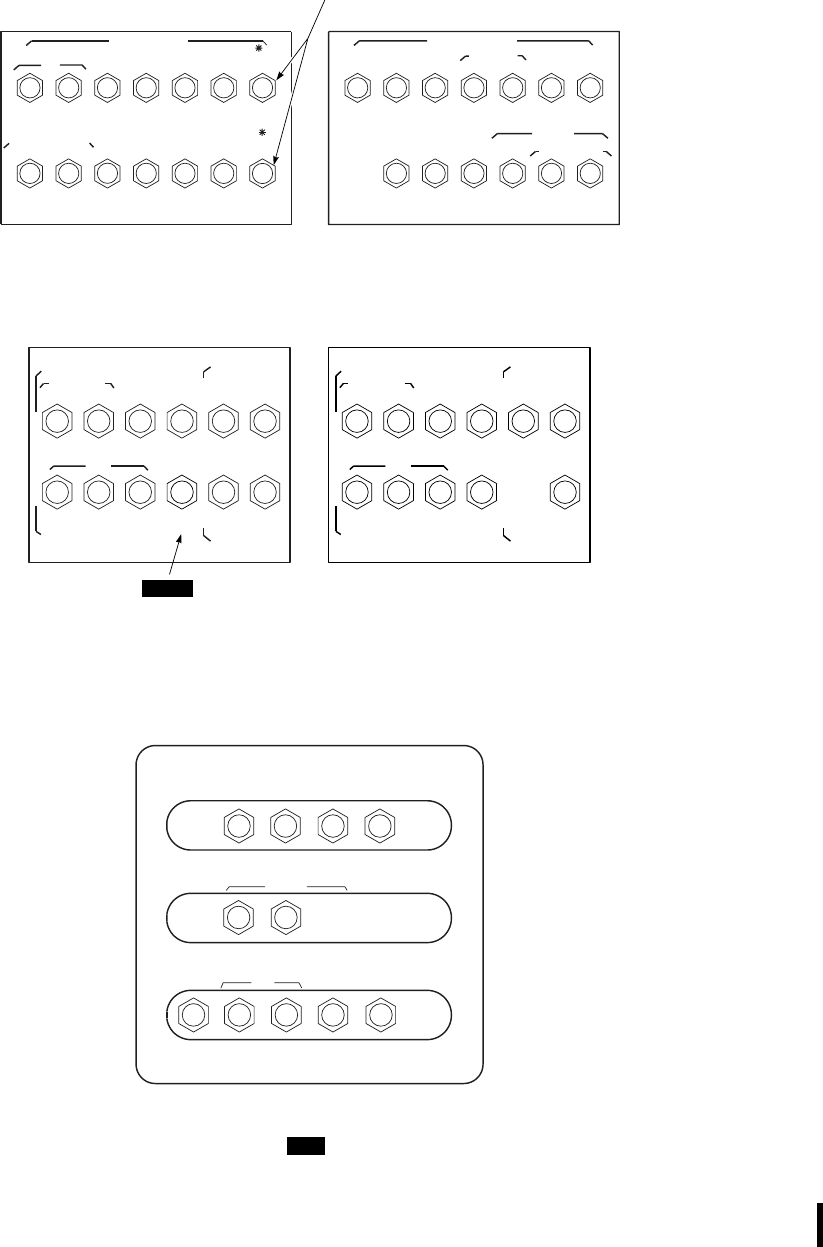
SA
AA0353_4D
50 55555
555 55
B
A
T
T
B
U
S
B
A
T
T
U
T
I
L
B
U
S
DC
ESNTL BUS
AC &
BATT &
ESNTL DC
WARN FUEL
PRIME BATT
BUS FIRE
SPLY CONV
WARN
APU
EXT PWR
CONTR BOOST CONTR EXTGH
UTIL
LTS APU
CONTR
INST FIRE
DET GEN
CONTR CKPT CONTR
INST
BATTERY AND BATTERY UTILITY
PNL CONTR
FUEL
PUMP
NO. 1 VOR / ILS CHIP
DC ESNTL BUS
25
25
255
2
2
5
NO.1 NO.2
DETR ENG ENG SENSE SPLY
5255510
ESNTL
DC BATT
BUS
FIRE DET
CONTR SRCH
55 20 5
55
DC ESNTL BUS
LIGHTS
7.5
7.5 7.5
5
ICS ESSS
JTSN
PILOT COPILOT VHF FM DET CONTR OUTBD
COMM SCTY SET
NO. 1 FM UHF AM UHF
AM CAUT /
ADVSY BACKUP
HYD HOIST
CABLE ESSS
JTSN
SHEAR INBD
7.5
STAB CARGO
HOOK PILOT
TURN
PWR EMER
SAS NO. 1
ENG TAIL
WHEEL SEC
BOOST START LOCK PNL PWR CONTR
UPPER CONSOLE CIRCUIT BREAKER PANEL
BUS CIRCUIT BREAKER PANEL
AC ESSENTIAL BUS
AC ESNTL BUS
5222
22
2225
5
STAB HSI CIS SAS
CONTR PLT / CPLT AMPL
26 VAC
INSTLINDSTAB
COMP VSI AUTO AC ESNTL
WARNBUSXFMRCPLTPLT
POWER SOURCE FOR EMERGENCY
JETTISON SYSTEM WHEN M−139
KIT IS INSTALLED
EH
1
GPS
ALERT
GPS
50 55555
5555 5
B
A
T
T
B
U
S
B
A
T
T
U
T
I
L
B
U
S
DC
ESNTL BUS
AC &
BATT &
ESNTL DC
WARN FUEL
PRIME BATT
BUS FIRE
SPLY CONV
WARN
APU
EXT PWR
CONTR BOOST CONTR EXTGH
UTIL
LTS APU
CONTR
INST FIRE
DET GEN
CONTR CKPT CONTR
INST
(SEE NOTE 5)
Figure 2-20. DC and AC Circuit Breaker Panels (Typical) (Sheet 4 of 4)
TM 1-1520-237-10
Change 1 2-69

system is provided from the No. 1 and No. 2 dc primary
buses, through circuit breakers, marked NO. 1 GEN
WARN and NO. 2 GEN WARN, respectively.
NOTE
When the GEN BRG caution light remains
on for more than 1 minute, make an entry on
the DA Form 2408-13-1.
2.65.1 Generator Control Units (GCU). The GCUs
monitor voltage from the No. 1, No. 2 and APU generators
and take the generator(s) off-line where malfunctions occur.
Underfrequency protection is disabled in flight by the
WOW switch.
2.65.2 AC Secondary Bus. EH The ac secondary bus
is powered by the No. 1 and No. 2 generators when they are
operating and their outputs are acceptable (Figure 2-19).
Current limiters protect the system from excessive current
draw. If the No. 1 and No. 2 generators are off, the APU
generator will supply the ac secondary bus if the output is
acceptable, the backup hydraulic pump is off, the blade
deice is off, and the weight of the helicopter is on the
wheels. The ac secondary bus can also receive power from
external power when the weight of the helicopter is on the
wheels, and the No. 1, No. 2 and APU generators are off,
and the backup hydraulic pump is not operating.
2.66 AUXILIARY AC POWER SYSTEM.
An auxiliary ac power system (Figure 2-19), is a backup
ac power source, providing electrical power for ground
checkouts. The system consists of a 115 vac three-phase,
400 Hz 20/30 kVA, air-cooled generator mounted on and
driven by the APU, a current transformer and a generator
control unit. If the primary ac generators are not operating,
the auxiliary ac power output will be applied through con-
tactors to the No. 2 ac primary bus and through contactors
and current limiters to the No. 1 ac primary bus. An advi-
sory light on the caution/advisory panel will go on, indicat-
ing APU GEN ON when the APU generator is operating,
and the APU generator switch is ON.APU GEN ON light
will be on only when supplying power to the system, it will
be off at any time either No. 1 generator or No. 2 generator
is supplying power. The generator control switch on the
upper console (Figure 2-7), has marked positions of TEST,
OFF/RESET, and ON.
NOTE
If the APU generator is the sole source of ac
generated power, all equipment may be op-
erated, except that when the backup pump is
on, the windshield anti-ice and EH air con-
ditioner are prevented from being used.
2.66.1 Generator Control Switches. Generators are
controlled by a three-position generator switch on the upper
console (Figure 2-7). The switch ON position energizes the
generator and permits connection of generator ac output to
the ac loads. TEST permits you to test the generator ac
output without connecting to the generator loads. OFF/
RESET deenergizes the generator and permits generator
recycling if the generator is disabled and disconnected from
its loads. The control switch is manually placed to RESET
and then back to ON.
2.66.2 External AC Power System.
CAUTION
Do not connect a source of dc power to
the external ac connector.
An external ac power connector, on the right side of the
helicopter (Figure 2-1), accepts ground source of 115 vac,
three-phase, 400 Hz power. The system is controlled by a
switch on the upper console (Figure 2-7), marked EXT
PWR-RESET-OFF and ON. External power will be intro-
duced into the system if acceptable external power is con-
nected, the EXT PWR switch is ON, and no other gener-
ating source is operating. An advisory light on the caution/
advisory panel will go on, indicating EXT PWR
CONNECTED, whenever external power is connected to
the helicopter.
TM 1-1520-237-10
2-70 Change 3
Section XII AUXILIARY POWER UNIT
2.67 AUXILIARY POWER UNIT (APU) SYSTEM.
The auxiliary power unit system (Figure 2-21) consists
of an auxiliary power unit (APU), accessories, controls, a
monitoring system, and a starting system. The APU system
provides pneumatic power for main engine starting and
cabin heating, and electrical power for ground and emer-
gency in-flight electrical operations.
NOTE
The APU is not qualified for normal inflight
use.
APU system accessories include a prime/boost pump,
hydraulic accumulator, hydraulic handpump, hydraulic start
motor, and ac generator. The hydraulic accumulators and
handpump, in the aft midsection cabin ceiling (Figure 2-5),
provide the hydraulic pressure for driving the APU starter.
If the APU does not start, the hydraulic accumulator can be
recharged by pumping the hydraulic handpump. The hy-
draulic utility module and backup pump, on the left forward
deck within the main rotor pylon, will automatically re-
charge the depleted hydraulic accumulator for the next APU
start. The APU controls are in the cockpit on the upper
console. Indicator lights on the caution/advisory panel pro-
vide cockpit monitoring of the APU. An indicator panel in
the cabin will indicate reason for APU shutdown on BITE
indicators. The BITE indicators are incorporated in the
APU electronic sequence unit (ESU), and will indicate rea-
sons for APU shutdown. Those indicators can be monitored
during APU operation without interrupting normal operat-
ing systems. During a start, the ESU compares input signals
from speed, time, and temperature sensors on the APU to
specified values stowed in the ESU memory, and performs
functional steps as a result of the comparison. The system
also provides for APU protective shutdown in case of tur-
bine overspeed, underspeed, high exhaust temperature, low
oil pressure, or loss of electrical power or sequence failure.
Each major sequence step will have a visual indication of
go/no-go. The ESU samples predetermined parameters of
exhaust temperature, turbine speed and oil pressure. If any
one of the predetermined values are exceeded, the APU
will shut down, and appropriate BITE indication is made.
On helicopters modified with improved ESU, if a momen-
tary malfunction occurs (i.e., a power interruption other
than switching of the APU CONTR switch) the APU will
shut down and the APU CONTR switch must be placed at
OFF and then back ON, to restart the APU. There is also
an output signal to the caution/advisory panel to turn on the
APU ON advisory light, indicating the APU is operating.
Power to operate the APU and ESU is provided from the
battery bus through a circuit breaker marked APU CONTR
INST.
2.68 APU.
The auxiliary power unit (Figure 2-21) consists of a gas
turbine shaft power section, a reduction gear drive, and
appropriate controls and accessories. The accessory gear
box provides an axial pad with a 12,000 rpm output drive
for the APU ac generator, rpm pad for mounting the APU
start motor, rpm drive pad for the APU fuel assembly. A
magnetic pickup mounted on the accessory gear box senses
engine speed. The APU is lubricated by a self-contained oil
system. Refer to Figure 2-25 for servicing.
2.68.1 APU Controls. The APU control, on the upper
console (Figure 2-7), consists of a CONTR switch and an
APU fire extinguisher T-handle. The APU CONTR switch,
with marked positions OFF and ON, controls the operation
of the APU. Placing the switch ON starts the APU and
allows it to operate. The APU is off when the switch is
OFF. The APU FAIL caution light will be on any time the
APU automatically shuts down. The APU OIL TEMP HI
caution light is on when APU oil temperature is above nor-
mal range. During ground operation at high ambient tem-
peratures the APU OIL TEMP HI caution light may go
on. If this occurs, the APU should be shut down immedi-
ately to prevent damage. After a 30-minute cooling period,
the oil level should be checked. If OK, the APU may be
restarted. The control system receives electrical power from
the battery bus through a circuit breaker marked APU
CONTR INST on the lower console. When illuminated,
the APU T-handle warns the pilot/ copilot of a fire in the
APU compartment. When the T-handle is pulled, it turns
off fuel to the APU, sends a stop signal to the ESU, arms
the fire extinguisher system, and sets the extinguisher di-
rection control valve to the APU. During APU starts using
battery power, if the fire extinguisher is required, FIRE
EXTGH RESERVE must be used. The T-handle mi-
croswitch receives electrical power from the battery utility
bus through a circuit breaker marked FIRE EXTGH on the
lower console circuit breaker panel.
2.68.2 APU Fuel Control System (Helicopters
equipped with (T-62T-40-1 APU). This system consists
of a fuel pump and a control assembly. The fuel pump is
protected by a filter. Fuel pump output flow passes through
another filter before entering the control assembly. A gov-
ernor and flow metering valve controls fuel flow to the
engine during ignition, permitting automatic starting under
TM 1-1520-237-10
2-71
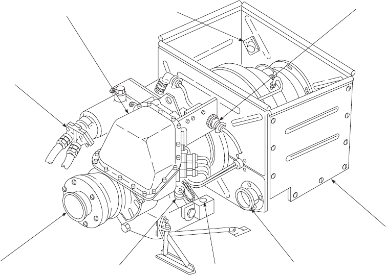
all ambient conditions, and controls the turbine at a con-
stant speed once it has accelerated to operating speed. An
electronic speed sensing device provides automatic fuel
flow, ignition, and operation of the APU.
2.68.3 APU Fuel Control System (Helicopters
equipped with GTC-P36-150 APU). The fuel control
system includes a fuel pump and metering section. The fuel
pump is protected by an integral inlet filter. Fuel pump
output flow passes through a filter screen before entering
the metering assembly. Fuel pump discharge pressure is
limited by an ultimate relief valve which, when activated,
bypasses fuel flow back to the pump inlet. Fuel metering is
accomplished by the torque motor metering valve as a
function of an electrical signal from the electronic sequence
unit (ESU). For accurate fuel metering, a constant, pressure
drop across the metering valve is maintained by the differ-
ential pressure regulating valve. The fuel solenoid valve is
energized by the ESU following the initiation of APU start.
This allows fuel to flow to the engine. The fuel control
assembly subsequently provides fuel according to a pre-
programmed schedule to effect efficient acceleration. The
fuel solenoid valve will close completely without visible
leakage from the minimum operating fuel pressure to 110%
of the maximum operating fuel pressure.
2.68.4 APU Fuel Supply System. APU fuel is sup-
plied to the APU from the left main fuel tank. The FUEL
PUMP switch must be at APU BOOST for all APU op-
eration, except engine priming. The APU prime/boost shut-
off valve is a two-position, open-closed unit mounted on
the APU compartment firewall where it also functions as a
firewall shutoff valve. The valve is pilot-operated from the
upper console FUEL PUMP switch as well as by the FIRE
EXTGH APU T-handle. If the APU does not start and the
APU ACCUM LOW advisory light is not on, the manual
override lever on the accumulator manifold should be
pulled to attempt another start, and held until the APU has
reached self-sustaining speed.
2.69 ACCUMULATOR RECHARGE.
The accumulator recharge cycle starts when the APU
has reached operational speed and the APU-driven genera-
tor comes on the line. The pressure switch for the accumu-
lator causes the APU ACCUM LOW light to go on and
the backup system pump to develop pressure. The APU
accumulator pressure should be at least 2800 psi before
attempting an APU start. The accumulator is recharged
from the backup pump which runs for 90 seconds after the
accumulator low-pressure switch is actuated. When the
SA
AA0519
HYDRAULIC
START MOTOR
FUEL CONTROL
ENCLOSURE FIREWALL
FIRE DETECTOR ELECTRICAL
CONNECTOR
FIREWALL
BLEED−AIR
PORT
OIL LEVEL
SIGHT GAGE
OIL FILLER PORT
AND DIPSTICK
GENERATOR
Figure 2-21. Auxiliary Power Unit (APU) (Typical)
TM 1-1520-237-10
2-72
winterization kit is installed, an additional identical accu-
mulator is installed in parallel with the original accumula-
tor. Discharge and recharge of the added accumulator is the
same, except a 180-second recharge cycle for the two ac-
cumulators will take place when the accumulator pressure
switch senses low accumulator pressure. Both accumulators
are charged or discharged simultaneously. If the accumula-
tors do not fully charge during the first 180 seconds of the
backup pump operating cycle, the pump will continue to
operate in 180-second segments, or until the BACKUP
PUMP PWR circuit breaker is pulled, or 115 vac power is
removed. The backup system pump shuts down after re-
charge, unless required for other purposes. Should the ac-
cumulator pressure drop, the backup system pump restarts
to replenish the accumulator charge. The rate of accumula-
tor charge is limited to protect the backup system from
possible depletion due to ballistic damage to the APU start
system. Should the APU not start, the accumulator may be
recharged by these methods, after the APU CONTR switch
is OFF. An electric ground cart powering the backup hy-
draulic pump or a hydraulic ground cart connected to the
backup hydraulic system through the ground test quick-
disconnects or by using the handpump in the aft upper
cabin. The APU CONTR switch should not be turned ON
again or the BATT switch turned OFF until after the ESU
BITE indicators have been checked. The handpump may
also be used to top off the accumulator charge if the charge
has dropped due to a low temperature condition. A pressure
gage mounted in the aft cabin (Figure 2-5) indicates the
charge. Check valves prevent draining of the accumulator
charge through the system.
TM 1-1520-237-10
2-73

Section XIII LIGHTING
2.70 INTERIOR LIGHTING.
The interior lighting system consists of cockpit dome
lights, utility lights and cabin dome lights (Figure 2-4).
NVG blue-green lighting can be selected for the cockpit
dome, instrument panel glare shield, utility lights and cabin
dome lights.
2.70.1 NVG Lighting System. The NVG lighting sys-
tem consists of interior NVG blue-green lighting. Exterior
lighting consists of cargo hook well area electrolumines-
cent lighting, infrared formation and position lights, and
attachable/detachable controllable searchlight filter. A dim-
ming feature is incorporated in the searchlight system to
provide dimming through the collective SRCH LT PUSH
ON - OFF,BRT,DIM switch. The position and formation
lights have IR emitters installed within close proximity to
the regular installed lights to enhance outside viewing with
night vision goggles.
2.70.2 Cockpit Floodlights. Two blue-green and two
white cockpit floodlights are on the overhead cockpit flood-
light panel, marked BLUE,OFF and WHITE (Figure 2-7).
Power is supplied from the dc essential bus through a cir-
cuit breaker marked LIGHTS SEC PNL. Six lights in-
stalled in the instrument panel glare shield provide second-
ary lighting for the instrument panel. The lights are
mechanically dimmed by a control on the upper console
labeled GLARESHIELD LIGHTS with marked positions
OFF and BRT. Power to operate the glare shield lights is
provided from the No. 1 ac primary bus through a circuit
breaker, marked LIGHTS GLARE SHLD.
2.70.3 Flight Instrument Lights. Instrument lights are
grouped into flight instrument and nonflight instruments.
The flight instrument lights are divided into pilot’s and co-
pilot’s. Lights are controlled by individual rotary intensity
controls (Figure 2-7), marked INSTR LT PILOT FLT,
OFF and BRT, and CPLT FLT INST LTS,OFF and
BRT. The nonflight instrument lights operate in the same
manner as the flight instrument lights. The nonflight lights
intensity is controlled by a rotary control, marked INSTR
LT NON FLT, OFF and BRT. Instrument lighting is pro-
vided by instrument bezels with NVG lights. The radar
altimeters lighting incorporates dimming controls on the
instrument panel, marked RAD ALT DIMMING for pilots
radar altimeters (Figure 2-9). The vertical instrument dis-
play system has NVG information panel lighting to make
those instruments compatible with the NVG system. Power
to operate the instrument lights is provided by the No. 2 ac
primary bus through circuit breakers marked LIGHTS
PLT FLT and LIGHTS NON FLT, and No. 1 ac primary
bus, through a circuit breaker marked LIGHTS CPLT
FLT.
2.70.4 Lighted Switches Dimmer. A dimmer control
labeled LIGHTED SWITCHES (Figure 2-7) is provided
on the upper console to reduce illumination level of the
following panel lighted switches: Pilot and copilot MODE
SEL,TAILWHEEL LOCK,CIS MODE SEL,AUTO
FLIGHT CONTROL and NO. 1 and NO. 2 FUEL
BOOST PUMP on lights. The caution/advisory panel must
be in DIM mode.
2.70.5 Upper and Lower Console Lights. NVG
lights for the upper console, cockpit flood secondary lights,
engine control quadrant, flight control panel, miscellaneous
switch panel, boost pump control panel, ESSS related pan-
els, range extension fuel management panel, retransmission
control and rescue hoist panels, and compass are illumi-
nated from the No. 1 ac primary bus through dimmer con-
trols marked CONSOLE LT UPPER and LOWER. Cir-
cuits are protected by circuit breakers marked LIGHTS
UPPER CSL and LIGHTS LWR CSL. All other lower
console panels are illuminated by the lower console auxil-
iary utility light next to the copilot’s seat.
2.70.6 Utility Lights. All utility lights are dual (blue/
green-white) (Figure 2-4). Two portable cockpit utility
lights with coiled cords are attached to the upper console by
removable brackets, one on each side of the console. The
lights may be adjusted on their mountings to direct the light
beams or they may be removed and used portably. All util-
ity lights are controlled by a rheostat or a pushbutton on the
end of each casting. The lens casting of the lights may be
turned to change from white to blue/green and/or spot to
flood. An auxiliary utility light, located at the right rear of
the copilot’s seat, is used to illuminate some panels on the
lower console for night flight. On helicopters equipped with
a transition equipment bay, a utility light is installed on the
bay shelf to provide bay lighting EH . The utility lights op-
erate in the same manner as above. Make certain cockpit
utility lights are OFF when not in use. The utility lights
operate from the battery utility bus through a circuit breaker
marked UTIL LTS CKPT. On helicopters 97-26744 and
subsequent, utility lights operate from the battery bus
through a circuit breaker marked UTIL LTS CKPT.
2.70.7 Cabin Dome Lights. Three dome lights are pro-
vided for cabin lighting (Figure 2-5). Control of cabin lights
is from the upper console by a control marked CABIN
TM 1-1520-237-10
2-74 Change 5

DOME LT (Figure 2-7) with intensity control and a light
color selector switch. The intensity control has marked po-
sitions OFF and BRT, and the light level control may be
adjusted to any position between the two extremes. The
light color selector switch has marked positions WHITE,
OFF, and BLUE. To place the switch from OFF to
WHITE, the switch must first be pulled out to clear a de-
tent. This prevents accidentally placing the switch to
WHITE. Dimming control for the cabin dome lights is
from a control on the left side of the pilots seat (Figure
2-4), marked CABIN DOME LT, with marked positions
OFF and BRT. Power to operate the cabin dome light sys-
tem is provided from the No. 1 ac primary bus through a
circuit breaker marked LIGHTS CABIN DOME.
2.70.8 Maintenance Light. A portable 20 watt flood-
light, in the cabin at the crew chief station is used by the
crew for maintenance work. The light has a 20-foot cord,
allowing its use within the cabin and around the main trans-
mission. A switch on the rear end of the light with marked
positions, DIM,OFF, and BRIGHT, controls the light in-
tensity. Another maintenance light receptacle, in the aft
tailcone, allows the light to be used around the tail section.
Power to operate the light is from the battery utility bus
through a circuit breaker marked UTIL LTS CKPT. The
maintenance light is stowed in a bag at the back of the
pilot’s seat. Power to operate the maintenance lights is pro-
vided from the battery utility bus through a circuit breaker,
marked UTIL LTS CKPT. Make sure the maintenance
and cockpit utility lights are OFF when not in use.
2.71 EXTERIOR LIGHTS.
2.71.1 Searchlight.
CAUTION
Landing and searchlight have less than
one foot ground clearance when extended.
Use caution when ground taxiing over
rough terrain when landing light and/or
searchlight are extended.
UH The searchlight (Figure 2-1) is mounted on the right
bottom of the nose section, and is controlled from either
collective pitch stick. The 150 watt light can be moved
forward through a 120° arc from the stow position. It can
also be turned 360° in either a right or left direction on its
axis. The light is operated by a switch labeled SRCH LT
ON,OFF,BRT, and DIM (Figure 2-4). Directional control
of the light is provided through the four-position search-
light control switch, labeled EXT (extend), RETR (retract),
L(left), and R(right). When the SRCH LT switch is
placed ON, the lamp will go on, arming the control switch.
Placing the control switch to EXT causes the light beam to
move forward at a rate of about 12° per second. If the
switch is placed to OFF the light will extinguish. To retract
the searchlight, place the switch to RETR. Refer to Chap-
ter 5 for extend/retract limitations. An infrared filter can be
installed on the controllable searchlight to enhance viewing
objects outside the helicopter when wearing the night vi-
sion goggles. With the IR filter installed, maximum wattage
lamp to be used is 250 watt. An OUTPUT switch on the
searchlight dimmer under the pilot’s seat, is placed at
NORM when dimming feature on searchlight is desired.
When in BYPASS position, the searchlight cannot be
dimmed. The IR filter shall not be used with a 450 watt
lamp installed. The dimming feature of the controllable
searchlight provides a variable light level from 250 to 0
watts to the pilot and copilot through a switch on each
collective grip marked SRCH LT ON - OFF. Push ON -
OFF BRT DIM to control power to the light and the DIM/
BRT mode selector. When the light is on, the BRT DIM
switch may be moved to select the desired light level. When
the desired level is reached, the switch is released to the
center position. Power to light and control the searchlight is
provided from the dc essential bus through circuit breakers,
marked LIGHTS,CONTR PWR and SRCH CONTR.
The IR filter may be removed for unaided night flight.
2.71.2 Landing Light. One 600-watt landing light is
mounted on the left side beneath the nose section and is
controlled from both collective pitch stick grips (Figure
2-14). The light can be extended 107° from the stowed
position. A dual function switch is used to operate the light.
The LDG LT PUSH ON-OFF switch controls lighting and
EXT,RETR controls light position. When the light is ON
(LDG LT ON advisory light should be on) and the switch
is at EXT detent, the light can be positioned at any point
between stowed and fully extended, or it will continue to
extend until reaching its limit and power is removed. When
the switch is held at RETR the light retracts to the stowed
position. When the light reaches its stowed position, power
is automatically removed from the motor. The LDG LT
PUSH ON-OFF switch must be pushed OFF (LDG LT
ON advisory light should go off). Refer to Chapter 5 for
extend/retract limitations. During extension, the travel
speed is about 12° per second, and during retract, about 30°
per second. Power to light and control the landing light is
supplied from the No. 1 dc primary bus through circuit
breakers, marked LIGHTS,RETR LDG,CONT and
PWR.
2.71.3 Anticollision Lights. This light system contains
four strobes in two separate units, one beneath the aft fu-
selage and one on top of the aft pylon section. The lights
are controlled by two switches on the upper console (Figure
TM 1-1520-237-10
Change 3 2-75
2-7) labeled ANTI COLLISION LIGHTS UPPER,
BOTH,LOWER and DAY,OFF,NIGHT. The system
consists of a dual power supply and two interchangeable
day/night anticollision lights. The dual supply system pro-
vides separate outputs for the aft fuselage light and the
pylon mounted light. Each anticollision light assembly con-
tains two lamps, the upper lamp within a red lens for night
operation and the lower within a clear lens for day opera-
tion. Proper operation is selected by placing the switch to
DAY or NIGHT. The desired strobe(s) is selected by plac-
ing the switch to UPPER,LOWER or BOTH.Ifat
BOTH, the lower fuselage and the aft pylon lights will
alternately flash. If the selector switch is placed to UPPER
or LOWER, only that light will flash. To discontinue op-
eration of the anticollision light(s), the DAY-NIGHT
switch is placed to OFF. Power to operate the anticollision
light system is provided from the No. 2 ac primary bus
through a circuit breaker, marked LIGHTS,ANTI COLL.
2.71.4 Position Lights. Position lights (Figure 2-1) are
outboard of the left and right landing gear support and top
tail pylon. The lights are red on the left, green on the right,
and white on the tail. Control of the position lights is
through the upper console panel containing two switches,
marked POSITION LIGHTS,DIM,OFF,BRT, and
STEADY,FLASH. When the intensity switch is placed to
DIM or BRT, all three lights go on at once. If the
STEADY-FLASH switch is placed to FLASH, the three
lights will flash. The STEADY position causes the lights to
remain on continuously. Power to operate the position lights
is provided by No. 2 dc primary bus through a circuit
breaker, marked POS LTS. Infrared position lights are in-
stalled within close proximity of the standard position
lights. NVG operation is selected through a toggle switch
on the upper console (Figure 2-7) marked NAV LTS, with
switch positions NORM and IR. Position lights are to be
selected through a switch marked POSITION LIGHTS,
DIM,OFF,orBRT, and mode of operation through a
switch marked STEADY or FLASH. Power for control of
the IR lights is from the No. 2 dc primary bus through a
circuit breaker marked IR LTS.
2.71.5 Formation Lights. These lights (Figure 2-1) are
on top of the main pylon cowling, tail drive shaft cover,
and horizontal stabilator. The system consists of four green
electroluminescent lights. The lights are controlled by a
single rotary selector switch, marked FORMATION LT,
with marked positions OFF and 1through 5. Position 5is
the brightest. When NVG operations are required, IR lights
may be used to enhance viewing outside the helicopter. IR
lights are selected through a toggle switch on the upper
console (Figure 2-7) marked, NAV LTS,NORM, and IR.
This switch shares operation with the IR position lights
when operating in a NVG environment. Dimming of the IR
lights is done with the FORMATION LT control, as used
with the electroluminescent formation lights. Selection of
position 1through 4causes the IR formation lights to illu-
minate at the same intensity. Position 5causes the lights to
illuminate brighter. Power to operate the formation lights is
provided from the No. 2 ac primary bus through two circuit
breakers, marked LIGHTS,FORM LV and HV.
TM 1-1520-237-10
2-76 Change 3

Section XIV FLIGHT INSTRUMENTS
2.72 PITOT-STATIC SYSTEM.
Two electrically-heated pitot tubes with static ports are
aft and above the pilot’s and copilot’s cockpit doors. The
right pitot tube is connected to the pilot’s instruments and
the left pitot tube is connected to the copilot’s instruments.
Tubing connects the pitot tube static pressure ports to the
airspeed indicators and the altimeters. In addition to stan-
dard instrumentation, airspeed data is sensed for operation
of stabilator, flight path stabilization, and command instru-
ment system. Refer to Section IX for pitot tube heater sys-
tem.
2.73 ATTITUDE INDICATING SYSTEM.
Helicopter pitch and roll attitudes are sensed by the pi-
lot’s and copilot’s vertical displacement gyroscopes, that
apply attitude signals to the vertical situation indicators
(VSI) for visual display (Figure 2-9). Signals are applied
through the VERT GYRO select switches to the remote
indicator on the vertical situation indicators. Helicopter
pitch and roll attitudes are shown on the pilot’s and copi-
lot’s vertical situation indicators. The indicator face con-
tains a fixed bar, representing the helicopter, a movable
sphere with a white horizon line dividing the two colors,
white above and black below, a fixed bank angle scale and
a bank index on the moving sphere. Relative position of the
fixed bar (helicopter) and the horizon line indicates the he-
licopter’s attitude referenced to the earth horizon. A ROLL
trim knob on the lower left of the VSI permits adjustment
of the roll index about 14°66° right and left from zero. A
PITCH trim knob on the lower right of the VSI permits
adjustment of the indicator sphere 14°66° for dive and
7°63° for climb from zero index. If a power failure or
unbalance occurs in the pilot’s or copilot’s vertical dis-
placement gyroscope, a gyroscope power failure flag will
appear, indicating ATT, warning the pilot or copilot that
pitch and roll attitude signals are not being sent to his in-
dicator. To restore attitude information to the indicator, the
pilot or copilot should press his VERT GYRO select
switch on the MODE SEL panel so that ALTR appears in
the switch window. This causes the ATT flag on the indi-
cator to disappear, and pitch and roll signals are supplied
from the operating gyro, restoring attitude information dis-
play. Refer to Chapter 3 for description of VERT GYRO
select switch.
2.74 TURN RATE INDICATING SYSTEM.
A 4-minute turn rate (turn and slip) indicator is at the
bottom center of each VSI (Figure 2-9). The pilot’s and
copilot’s indicators operate independently of each other
through TURN RATE switches on the MODE SEL pan-
els. Each system consists of a rate gyro, a turn slip indicator
and a select switch. The VSI contains a moving turn rate
needle and a fixed turn rate scale for indicating rate and
direction of turn. During straight flight the needle is posi-
tioned at the center of the scale. When the helicopter turns,
the rate-of-turn signal from the rate gyroscope deflects the
needle in the proper direction to indicate the turn. Amount
of deflection is proportional to the rate-of-turn. A one-
needle width deflection represents a turn of 1.5° per second.
The VSI also contains a slip indicator that shows uncoor-
dinated turns. If a power failure or unbalance occurs in the
pilot’s or copilot’s rate gyroscope, the associated VSI sig-
nal will be lost. To restore rate-of-turn information to the
indicator, the pilot or copilot will press the TURN RATE
switch on his MODE SEL panel so that ALTR appears in
the switch window. This applies alternate rate gyroscope
signals from the operating gyroscope to the indicator.
Power to operate the pilot’s turn rate system is provided
from the dc essential bus through a circuit breaker, marked
PILOT TURN DETR. The copilot’s system is powered
from the No. 1 dc primary bus through a circuit breaker,
marked CPLT TURN RATE GYRO. Refer to Chapter 3
for a description of the TURN RATE select switch.
2.75 AIRSPEED INDICATOR.
Two airspeed indicators (Figure 2-9), are installed on the
instrument panel, one each for the pilot and copilot. The
indicators are differential pressure instruments, measuring
the difference between impact pressure and static pressure.
Instrument range markings and limitations are contained in
Chapter 5, Section II, System Limits.
2.76 ALTIMETER/ENCODER AAU-32A.
Two altimeters are installed on the instrument panel
(Figures 2-9 and 2-22). The altimeter encoder functions as
a barometric altimeter for the pilot and a barometric alti-
tude sensor for the AN/APX-100 transponder in mode C.
The copilot’s functions only as a barometric altimeter. The
system is equipped with a continuously operating vibrator
to improve altitude measuring accuracy. The altimeter’s op-
erating range is from -1000 feet to 50,000 feet. The face of
the instrument has a marked scale from zero to nine in
50-foot units. The operating indicators and controls are a
100-foot pointer, 100-foot drum, 1,000-foot drum, 10,000-
foot drum, barometric pressure set knob, barometric pres-
sure scale window and warning flag. The warning flag is
only used in conjunction with the encoder. A counter win-
dow next to the sweep hand contains the three digital drums
TM 1-1520-237-10
Change 9 2-77
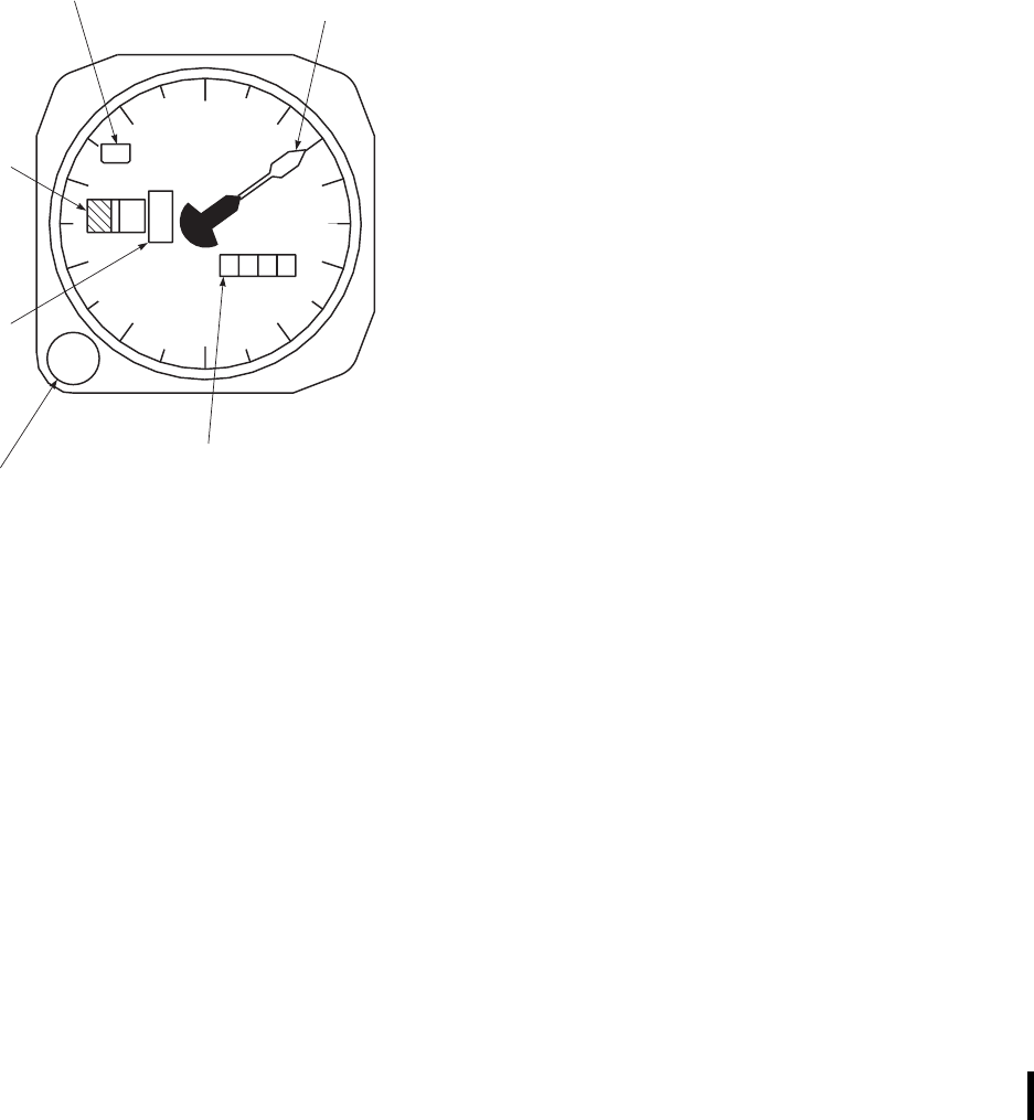
that rotate to indicate the altitude of the helicopter. Another
window in the upper left section of the instrument face
indicates the normal code operation. When the system fails
to transmit signals to the transponder, a flag marked CODE
OFF will appear in the window. A window on the lower
right section of the instrument face indicates barometric
pressure setting. The barometric pressure set knob is on the
lower left corner of the indicator bezel. Power to operate
the encoder system is provided by the No. 2 dc primary bus
through a circuit breaker, marked PILOT ALTM.
2.77 VERTICAL SPEED INDICATOR.
Two indicators are installed, one each in front of the
pilot and copilot (Figure 2-9), to indicate rate of climb or
descent.
2.78 STANDBY MAGNETIC COMPASS.
A magnetic compass is installed above the instrument
panel on the right center windshield frame (Figure 2-4).
The compass is used as a standby instrument for heading
references. A compass correction card with deviation errors
is installed on the right side of the upper console.
2.79 FREE-AIR TEMPERATURE (FAT) INDICATOR.
The free-air temperature indicator is a direct reading in-
strument marked FREE AIR, and reads in degrees Celsius.
One FAT indicator is installed through the center wind-
shield on helicopters without center windshield anti-ice
system. On helicopters with center windshield anti-ice sys-
tem, two indicators are installed through the overhead win-
dows (Figure 2-4).
2.80 CLOCK.
a. Two clocks (Figure 2-9) are installed on the instru-
ment panel. The elapsed time knob is on the upper right
corner of the clock. The clock is wound and set with a knob
on the lower left corner.
b. Two digital clocks may be installed on the instrument
panel. The clock incorporates a six digit liquid crystal dis-
play, 24 hour numerals and sweep second indication. A
battery allows continuous operation for a minimum of one
year when aircraft 28 vdc power is not applied. The clock
has two modes of operation, clock mode (C) and the
elapsed time mode (ET). Power to operate the clock is pro-
vided by the No. 1 dc and No. 2 dc primary buses through
circuit breakers marked CPLT ALTM and PILOT ALTM
respectively.
2.81 MASTER WARNING SYSTEM.
Two master caution lights (Figures 2-9 and 2-23) one
each side for the pilot and copilot, marked MASTER
CAUTION PRESS TO RESET, are on the master warn-
ing panel. They light whenever a caution light goes on.
These lights alert the pilots and direct attention to the
caution/advisory panel. The master caution lights should be
reset at once to provide a similar indication if a second
condition or malfunction occurs while the first is still
present. The master caution light can be reset from either
pilot position. Four amber warning lights, also on the mas-
ter warning panel, require immediate action if they go on.
The markings are #1 ENG OUT,#2 ENG OUT,FIRE,
and LOW ROTOR RPM. The LOW ROTOR RPM
warning light will flash at a rate of three to five flashes per
second if rotor rpm drops below 96% RPM R. In addition,
if % RPM R drops below 96% or Ng drops below 55%, a
low steady tone is provided. The low rotor rpm tone is
inhibited on the ground through the left landing gear
weight-on-wheels switch. The engine Ng steady tone is not
inhibited. The ENG OUT warning lights and tone will go
on at 55% Ng SPEED and below. Refer to paragraph 2.14.1
SA
AA0520
0
01
2
3
4
5
6
7
89ALT
1000 FT100 FT IN. HG
1
2
2990
100−FOOT
ALTITUDE
NEEDLE
BAROMETER
PRESSURE
SCALE
BAROMETRIC
SCALE
SET KNOB
100−FOOT
ALTITUDE
COUNTER
1000−FOOT
ALTITUDE
COUNTER CODE
OFF
ENCODER WARNING
FLAG INDICATOR
.
Figure 2-22. Altimeter Encoder AAU-32A
TM 1-1520-237-10
2-78 Change 6

for description of the FIRE warning lights. Power for the
master caution lights is provided from the No. 1 dc primary
bus through a circuit breaker, marked LIGHTS CAUT/
ADVSY.
2.81.1 Caution/Advisory Light System. The caution/
advisory panel, (Figures 2-9 and 2-24) is on the left of
center of the instrument panel. The caution section (upper
two-thirds) of the panel, indicates certain malfunctions or
unsafe conditions with amber lights. The advisory section
(lower one-third) of the panel shows certain noncritical
conditions with green lights. Each light has its own operat-
ing circuit and will remain on as long as the condition that
caused it to light up exists. The caution and advisory lights
are powered by the No. 1 dc primary bus through a circuit
breaker, marked LIGHTS CAUT/ADVSY. Refer to major
systems for a complete description of caution-advisory
panel capsules. Refer to Table 2-3 for a brief description of
each fault.
2.81.2 Caution/Advisory BRT/DIM - TEST Switch.
Testing of the caution/advisory lights is done through a
momentary spring-loaded to center switch marked BRT/
DIM and TEST, on the lower left of the caution/advisory
panel (Figure 2-24). Placing the switch to TEST simulta-
neously checks all lights on the caution/advisory and the
master warning panels and #1 and #2 FUEL LOW caution
lights and LOW ROTOR RPM warning lights will flash.
When the pilot’s PILOT FLT rotary intensity control is
moved from the OFF position, placing the BRT/DIM-
TEST switch to BRT/DIM causes the caution/advisory
lights and master warning lights to change intensity. When
the lights are dim and power is removed, the light intensity
will return to bright when power is reapplied. The TEST
switch position receives power from the No. 1 dc primary
bus through a circuit breaker, marked LIGHTS CAUT/
ADVSY. The BRT/DIM switch position receives power
from the dc essential bus through a circuit breaker, marked
CAUT/ADVSY PNL, on the No. 1 circuit breaker panel.
Dimming of the cockpit indicator lights operates with the
CAUTION panel dimming system.
Table 2-3. Caution/Advisory and Warning Light Lighting Parameters
LEGEND ILLUMINATING PARAMETER OR FAULT
CAUTION CAPSULES
#1 FUEL LOW Flashes when left fuel tank level is about 172 pounds.
#1 FUEL PRESS Left engine fuel pressure between engine-driven low-pressure fuel pump and high-
pressure fuel pump is low.
#1 ENG
OUT
FIRE LOW ROTOR
RPM
MASTER CAUTION
PRESS TO RESET
#2 ENG
OUT
SA
AA0406
Figure 2-23. Master Warning Panel
TM 1-1520-237-10
Change 5 2-79
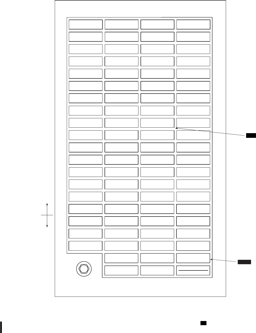
#1 FUEL LOW #1 GEN #2 GEN #2 FUEL LOW
#2 GEN BRG#1 GEN BRG
#1 ENGINE
OIL PRESS #1 CONV #2 CONV #2 ENGINE
OIL PRESS
#2 ENGINE
OIL TEMP
DC ESS
BUS OFF
AC ESS
BUS OFF
#1 ENGINE
OIL TEMP
CHIP
#1 ENGINE BATT LOW
CHARGE BATTERY
FAULT CHIP
#2 ENGINE
#2 FUEL
FLTR BYPASS
#1 FUEL
FLTR BYPASS
#1 OIL
FLTR BYPASS #2 OIL
FLTR BYPASS
#1 PRI
SERVO PRESS #1 HYD
PUMP #2 HYD
PUMP #2 PRI
SERVO PRESS
IRCM
INOP
TAIL ROTOR
QUADRANT
MAIN XMSN
OIL TEMP INT XMSN
OIL TEMP TAIL XMSN
OIL TEMP APU OIL
TEMP HI
TRIM FAIL
SAS OFFSTABILATOR
BOOST SERVO
OFF
LFT PITOT
HEAT IFF RT PITOT
HEAT
CHIP INPUT
MDL − LH CHIP
INT XMSN CHIP
TAIL XMSN CHIP INPUT
MDL − RH
CHIP ACCESS
MDL − RH
APU
FAIL
CHIP MAIN
MDL SUMP
CHIP ACCESS
MDL − LH
MR DE−ICE
FAIL MR DE−ICE
FAULT TR DE−ICE
FAIL ICE
DETECTED
BACK−UP
RSVR LOW
#2 RSVR
LOW
#1 RSVR
LOW
MAIN XMSN
OIL PRESS
#2 ENG
ANTI−ICE ON
BACK−UP
PUMP ON
#2 TAIL RTR
SERVO ON
#2 ENG INLET
ANTI−ICE ON
PRIME BOOST
PUMP ON
LDG LT ON
HOOK ARMED
EXT PWR
CONNECTED
#1 ENG INLET
ANTI−ICE ON
APU GEN ON
CARGO
HOOK OPEN
PARKING
BRAKE ON
APU ACCUM
LOW
APU ON
#1 ENG
ANTI−ICE ON
#2 ENGINE
STARTER
FLT PATH
STAB
SEARCH LT
#1 FUEL
PRESS #2 FUEL
PRESS
#1 ENGINE
STARTER
GUST
LOCK
#1 TAIL RTR
SERVO
C
A
U
T
I
O
N
A
D
V
I
S
O
R
Y
PITCH BIAS
FAIL
AUX FUEL
BRT /
DIM
TEST
ON
SA
AA0354_1B
GPS POS
ALERT GPS
ES
Figure 2-24. Caution/Advisory Panel (Sheet 1 of 2) UH
TM 1-1520-237-10
2-80 Change 1

#1 FUEL LOW #1 GEN #2 GEN #2 FUEL LOW
#2 GEN BRG#1 GEN BRG
#1 ENGINE
OIL PRESS #1 CONV #2 CONV #2 ENGINE
OIL PRESS
#2 ENGINE
OIL TEMP
DC ESS
BUS OFF
AC ESS
BUS OFF
#1 ENGINE
OIL TEMP
CHIP
#1 ENGINE BATT LOW
CHARGE BATTERY
FAULT CHIP
#2 ENGINE
#2 FUEL
FLTR BYPASS
#1 FUEL
FLTR BYPASS
#1 OIL
FLTR BYPASS #2 OIL
FLTR BYPASS
#1 PRI
SERVO PRESS #1 HYD
PUMP #2 HYD
PUMP #2 PRI
SERVO PRESS
ASE
TAIL ROTOR
QUADRANT
MAIN XMSN
OIL TEMP INT XMSN
OIL TEMP TAIL XMSN
OIL TEMP APU OIL
TEMP HI
TRIM FAIL
SAS OFFSTABILATOR
BOOST SERVO
OFF
LFT PITOT
HEAT IFF RT PITOT
HEAT
CHIP INPUT
MDL − LH CHIP
INT XMSN CHIP
TAIL XMSN CHIP INPUT
MDL − RH
CHIP ACCESS
MDL − RH
APU
FAIL
CHIP MAIN
MDL SUMP
CHIP ACCESS
MDL − LH
MR DE−ICE
FAIL MR DE−ICE
FAULT TR DE−ICE
FAIL ICE
DETECTED
BACK−UP
RSVR LOW
#2 RSVR
LOW
#1 RSVR
LOW
MAIN XMSN
OIL PRESS
#2 ENG
ANTI−ICE ON
BACK−UP
PUMP ON
#2 TAIL RTR
SERVO ON
#2 ENG INLET
ANTI−ICE ON
PRIME BOOST
PUMP ON
LDG LT ON
EXT PWR
CONNECTED
#1 ENG INLET
ANTI−ICE ON
APU GEN ON
AIR COND
ON
PARKING
BRAKE ON
APU ACCUM
LOW
APU ON
#1 ENG
ANTI−ICE ON
#2 ENGINE
STARTER
FLT PATH
STAB
SEARCH LT
#1 FUEL
PRESS #2 FUEL
PRESS
#1 ENGINE
STARTER
GUST
LOCK
#1 TAIL RTR
SERVO
SA
AA0354_2
C
A
U
T
I
O
N
A
D
V
I
S
O
R
Y
ANTENNA
EXTENDED
AUX FUEL
BRT /
DIM
TEST
ON
CABIN HEAT
ON ANTENNA
RETRACTED
Figure 2-24. Caution/Advisory Panel (Sheet 2 of 2) EH
TM 1-1520-237-10
2-81

Table 2-3. Caution/Advisory and Warning Light Lighting Parameters (Cont)
LEGEND ILLUMINATING PARAMETER OR FAULT
#1 ENGINE OIL PRESS Left engine oil pressure is too low for continued operation.
#1 ENGINE OIL TEMP Left engine oil temperature is above 150°C.
CHIP #1 ENGINE Left engine chip detector in scavenge oil system has metal chip or particle buildup.
#1 FUEL FLTR BYPASS Left engine fuel filter has excessive pressure differential across filter.
#1 ENGINE STARTER Left engine start circuit is actuated.
#1 PRI SERVO PRESS First stage pressure is shut off, or has dropped below minimum, or servo pilot valve is
jammed.
TAIL ROTOR
QUADRANT Goes on when a tail rotor cable is broken or disconnected.
MAIN XMSN OIL TEMP Main transmission oil temperature is above 120°C.
BOOST SERVO OFF Indicates loss of second stage hydraulic pressure to the boost servo, or a boost servo jam.
LFT PITOT HEAT Indicates left pitot heater element is not receiving power with PITOT HEAT switch ON.
CHIP INPUT MDL-LH Indicates a metal particle has been detected by the chip detector.
CHIP ACCESS MDL-LH Indicates a metal particle has been detected by the chip detector.
MR DE-ICE FAIL Indicates a short or open in the main rotor deice system, which will disable the system.
MAIN XMSN OIL PRESS Main transmission oil pressure is below about 14 psi.
#1 GEN Left generator is not supplying power to the buses.
#1 GEN BRG Generator main bearing is worn or has failed.
#1 CONV Left converter (ac to dc current) has no output.
AC ESS BUS OFF Indicates that no power (115 vac, phase B) is being supplied to the ac essential bus.
BATT LOW CHARGE SLAB - Indicates that the voltage on the battery utility bus is at or below 23 vdc. NICAD
- Indicates that the battery charge state is at or below about 40% of full charge state.
GUST LOCK Indicates the gust lock is not fully disengaged.
#1 OIL FLTR BYPASS Left engine oil filter pressure differential is excessive.
#1 HYD PUMP Left hydraulic pump output pressure below minimum.
IRCM INOP Indicates a malfunction has been detected by the infrared countermeasure system or
infrared countermeasure system is in a cooldown cycle.
ASE EH Indicates the ALQ-156 system is being jammed or the ALQ-136, ALQ-144, ALQ-156, or
ALQ-162 system is degraded.
INT XMSN OIL TEMP Intermediate gear box oil temperature is excessive.
TM 1-1520-237-10
2-82 Change 9

Table 2-3. Caution/Advisory and Warning Light Lighting Parameters (Cont)
LEGEND ILLUMINATING PARAMETER OR FAULT
STABILATOR Stabilator system is turned on but is in the manual mode.
FLT-PATH STAB Indicates that FPS is inoperative in one or more axis.
CHIP INT XMSN Indicates a metal particle has been detected by the chip detector.
CHIP MAIN MDL SUMP Indicates a metal particle has been detected by the chip detector.
MR DE-ICE FAULT Indicates partial failure of the blade deice system. Uneven shedding of ice can be ex-
pected.
#1 RSVR LOW Hydraulic fluid level has dropped below about 60% of full capacity.
#2 GEN Right generator is not supplying power to the buses.
#2 GEN BRG Generator main bearing is worn or has failed.
#2 CONV Right converter (ac to dc current) has no output.
DC ESS BUS OFF Indicates that no power is being supplied to the dc essential bus.
BATTERY FAULT Indicates that the battery has exceeded safe operating temperature (overtemperature), or a
battery cell dissimilarity exists. (On helicopters prior to serial number 97-26744)
PITCH BIAS FAIL (No longer used)
ANTENNA EXTENDED
EH
ECM antenna not fully retracted and at least one of these conditions exist: Helicopter is
below radar altimeter LO bug setting, or power is lost, or AN/APN-209 is turned off or
is removed.
#2 OIL FLTR BYPASS Right engine oil filter pressure differential is excessive.
#2 HYD PUMP Right hydraulic pump output pressure below minimum.
ERFS AUX FUEL Indicates one or more auxiliary fuel tanks are empty and/or a degraded mode of system
operation.
TAIL XMSN OIL TEMP Tail gear box oil temperature is excessive.
SAS OFF Hydraulic pressure supplied to the SAS actuator is below minimum.
IFF Mode 4 is not capable of responding to interrogation.
CHIP TAIL XMSN Indicates a metal particle has been detected by the chip detector.
APU FAIL APU was automatically shut down by the electrical sequence unit.
TR DE-ICE FAIL Indicates a short or open in a tail rotor blade deice element.
#2 RSVR LOW Hydraulic fluid level has dropped below about 60% of full capacity.
#2 FUEL LOW Flashes when right fuel level is about 172 pounds.
#2 FUEL PRESS Right engine fuel pressure between engine-driven low-pressure fuel pump and high-
pressure fuel pump is low.
TM 1-1520-237-10
Change 9 2-83

Table 2-3. Caution/Advisory and Warning Light Lighting Parameters (Cont)
LEGEND ILLUMINATING PARAMETER OR FAULT
#2 ENGINE OIL PRESS Right engine oil pressure is too low for continued operation.
#2 ENGINE OIL TEMP Right engine oil temperature is above 150°C.
CHIP #2 ENGINE Right engine chip detector in scavenge oil system has metal chip or particle buildup.
#2 FUEL FLTR BYPASS Right engine fuel filter has excessive pressure differential across filter.
#2 ENGINE STARTER Right engine start circuit is actuated.
#2 PRI SERVO PRESS Second stage pressure is shut off, or has dropped below minimum, or servo pilot valve is
jammed.
#1 TAIL RTR SERVO Pressure to the first stage tail rotor servo is below minimum, or servo pilot valve is
jammed.
APU OIL TEMP HI APU oil temperature is above the maximum.
TRIM FAIL Indicates that yaw, roll, or pitch trim actuators are not responding accurately to computer
signals.
RT PITOT HEAT Indicates right pitot heat element is not receiving power with PITOT HEAT switch ON.
CHIP INPUT MDL-RH Indicates a metal particle has been detected by the chip detector.
CHIP ACCESS MDL-RH Indicates a metal particle has been detected by the chip detector.
ICE DETECTED Indicates that ice has been detected.
BACK-UP RSVR LOW Hydraulic fluid level has dropped below about 60% of full capacity.
ADVISORY CAPSULES
#1 ENG ANTI-ICE ON Indicates that No. 1 engine anti-ice/start bleed valve is open.
APU ON APU is operative.
APU ACCUM LOW APU accumulator pressure is low.
#1 ENG INLET ANTI-ICE
ON Indicates that No. 1 engine inlet anti-icing air temperature is 93°C or above.
APU GEN ON APU generator output is accepted and being supplied to the helicopter.
SEARCH LT ON Either pilot or copilot has selected SRCH LT switch on.
CARGO HOOK OPEN Indicates that cargo hook load beam is not latched.
AIR COND ON EH Power is applied to air conditioner compressor.
PARKING BRAKE ON Indicates that PARKING BRAKE handle is pulled.
#2 ENG INLET ANTI-ICE
ON Indicates that No. 2 engine inlet anti-icing air temperature is 93°C or above.
TM 1-1520-237-10
2-84 Change 10

Table 2-3. Caution/Advisory and Warning Light Lighting Parameters (Cont)
LEGEND ILLUMINATING PARAMETER OR FAULT
PRIME BOOST PUMP ON Prime boost pump switch is at PRIME or BOOST.
LDG LT ON Either pilot or copilot has selected LDG LT ON.
HOOK ARMED The cargo hook release system is armed.
CABIN HEAT ON EH Aux heater system is operating.
EXT PWR CONNECTED Indicates that external power plug is connected to helicopter’s EXT POWER connector.
#2 ENG ANTI-ICE ON Indicates that No. 2 engine inlet anti-ice/start bleed valve is open.
BACKUP PUMP ON Backup pump pressure is being supplied.
#2 TAIL RTR SERVO ON Pressure to 2nd stage tail rotor servo is above minimum.
ANTENNA RETRACTED
EH
ECM antenna fully retracted.
GPS POS ALERT
GPS
Indicates that GPS signals are not reliable.
MASTER WARNING PANEL
#1 ENG OUT No. 1 engine Ng SPEED is below 55%.
FIRE Indicates a fire detector has actuated a fire warning circuit.
MASTER CAUTION
PRESS TO RESET Indicates a caution light on the caution panel has been actuated by failed system.
#2 ENG OUT No. 2 engine Ng SPEED is below 55%.
LOW ROTOR RPM Rotor speed is below about 96% RPM R.
TM 1-1520-237-10
Change 9 2-85
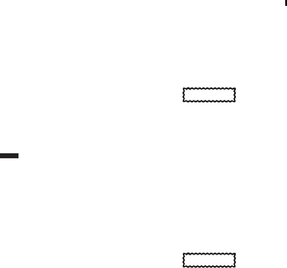
Section XV SERVICING, PARKING, AND MOORING
2.82 SERVICING.
Servicing information is given by systems or compo-
nents. Points used in frequent servicing and replenishment
of fuel, oil and hydraulic fluid are shown in Figure 2-25.
Fuel and lubricant specifications and capacities are in Table
2-4. Table 2-5 contains a listing of acceptable commercial
fuel.
2.83 SERVICE PLATFORMS AND FAIRINGS.
Service platforms are a part of the engine cowlings, pro-
viding access to the engines. Each service platform is about
46 inches long and 18 inches wide. It is capable of support-
ing a static weight of 400 pounds on any area without
yielding. The platform is made of composite metal and fi-
berglass with a honeycomb core. The engine cowling is
opened by releasing a latch on the side and pulling outward
on a locking handle. The cowling is opened outward and
down, providing a standing area at the lower section. When
closed, the cowling lock prevents opening in flight.
2.84 FUEL SYSTEM SERVICING.
a. Both tanks (Figure 2-25) may be serviced simulta-
neously through pressure refueling or closed circuit refuel-
ing. They may be serviced individually by gravity refueling
through refueling ports on the left and right sides of the
helicopter.
b. ERFS The external extended range tanks can only
be serviced by gravity refueling through refueling ports on
the forward top of each tank.
2.84.1 Fuel Types. Fuels are classified in Table 2-5.
2.84.2 Use of Fuels. Mixing of fuels in fuel tanks.
When changing from one type of authorized fuel to an-
other, for example JP-4 to JP-5, it is not necessary to drain
the helicopter fuel system before adding the new fuel. Fuels
having the same NATO code number are interchangeable.
Jet fuels conforming to ASTM D-1655 specification may
be used when MIL-T-5624 fuels are not available. This
usually occurs during cross-country flights where helicop-
ters using NATO F-44 (JP-5) are refueled with NATO F-40
(JP-4) or Commercial ASTM Type B fuels. Whenever this
condition occurs, the operating characteristics may change
in that lower operating temperature: slower acceleration,
easier starting, and shorter range may be experienced. The
reverse is true when changing from F-40 (JP-4) fuel to F-44
(JP-5) or Commercial ASTM Type A-1 fuels.
2.84.3 Gravity Refueling.
1. Ground helicopter to fuel truck or other suitable
ground.
2. Plug hose nozzle ground into the helicopter
grounding jack, marked GROUND HERE,
above refueling ports.
3. Remove fuel filler caps and refuel. Refer to
Table 2-4 for fuel quantities.
2.84.4 Pressure Refueling.
1. Ground helicopter to fuel truck or other suitable
ground.
2. Ground fuel dispenser nozzle to the helicopter
grounding point marked GROUND HERE,
above refueling ports.
CAUTION
Damage to the fuel system could result if
refueling hose pressure exceeds 55 psi
during pressure refueling or 15 psi during
closed circuit refueling.
3. Connect fuel dispenser nozzle to pressure refu-
eling adapter.
NOTE
The system is designed to restrict fuel flow
to 300 gpm during pressure refueling at a
nozzle pressure of 55 psi and 110 gpm at a
nozzle pressure of 15 psi during closed cir-
cuit refueling.
4. Start fuel flow from fuel dispenser and refuel
helicopter.
CAUTION
If fuel is observed flowing from vent, dis-
continue refueling and make an entry on
DA Form 2408-13-1.
TM 1-1520-237-10
2-86 Change 8
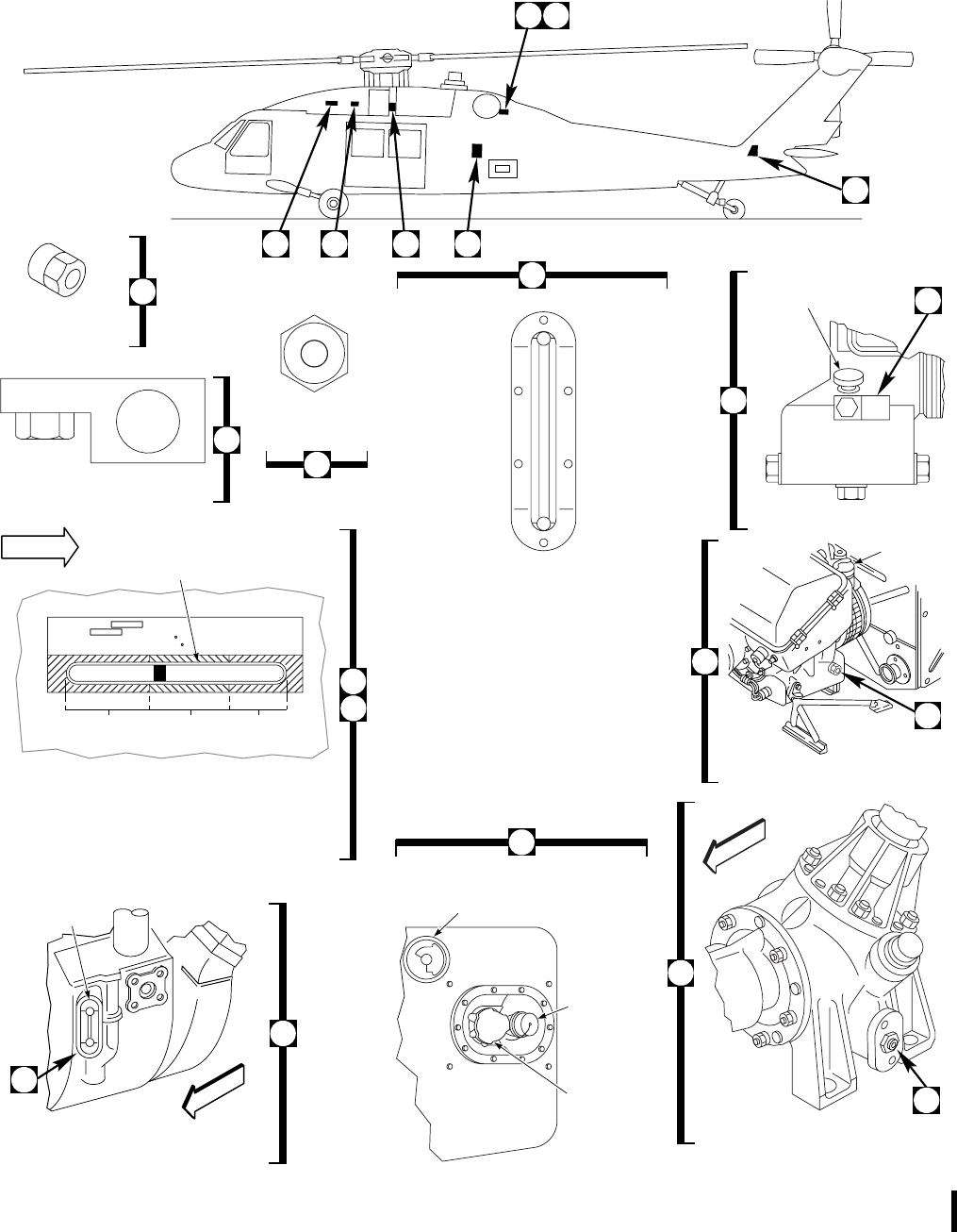
SA
AA0324_1B
K
E
E
P
L
E
V
E
L
I
N
B
U
L
L
S
E
Y
E
FRONT
ENGINE OIL
LEVEL INDICATOR
INTERMEDIATE GEAR BOX
OIL LEVEL
NOTE
OIL LEVEL INDICATOR
SOME HELICOPTERS MAY HAVE COLORS AS RED
FOR REFILL, GREEN FOR FULL, AND BLACK FOR
EXPANSION AS VIEWED FROM HELICOPTER RIGHT
NO. 1 NO. 2 AND BACKUP
HYDRAULIC PUMP MODULES
LEVEL INDICATOR
HYDRAULIC FLUID COLOR
SPEC MIL−H
FULL LEVEL CAPACITY 65 CU. IN. @ 70
REFILL LEVEL CAPACITY 35 CU. IN. @ 70 F
RED
(REFILL) GREEN
(FULL) BLUE
(EXPANSION)
B
ADD
1. & 2. AUXILIARY POWER UNIT
3. INTERMEDIATE GEAR BOX OIL
LEVEL INDICATOR
4. CLOSED CIRCUIT AND PRESSURE
REFUELING PORTS, NO. 1 (LEFT)
6. NO. 1 HYDRAULIC PUMP MODULE
7. BACKUP HYDRAULIC PUMP
MODULE
APU OIL FILLER CAP
AND DIPSTICK
NO. 1 (LEFT) FUEL
TANK GRAVITY
REFUEL PORT
CLOSED
CIRCUIT
REFUEL
PORT CAP
PRESSURE
REFUEL
PORT CAP
A1
7 6 5 4
3
1
(SAME FOR NO. 1
AND NO. 2 ENGINES)
ADD
FULL
ADD
FULL
2
FILL TO
SPILL PLUG
OIL FILL
CAP
T−62T−40−1 APU
GTC−P36−150 APU
A2
C
FRONT
NO. 1 ENGINE LEFT SIDE
NO. 1 ENGINE
OIL LEVEL
INDICATOR
(SAME FOR NO. 1 AND NO. 2 ENGINES)
4
C
1
2
3
5
INDICATOR
A1
B
A2
FRONT
7
6
FUEL TANK GRAVITY REFUEL
PORT
5. NO. 1 AND NO. 2 ENGINE
OIL LEVEL INDICATOR
SIDE
Figure 2-25. Servicing Diagram (Sheet 1 of 3)
TM 1-1520-237-10
Change 7 2-87
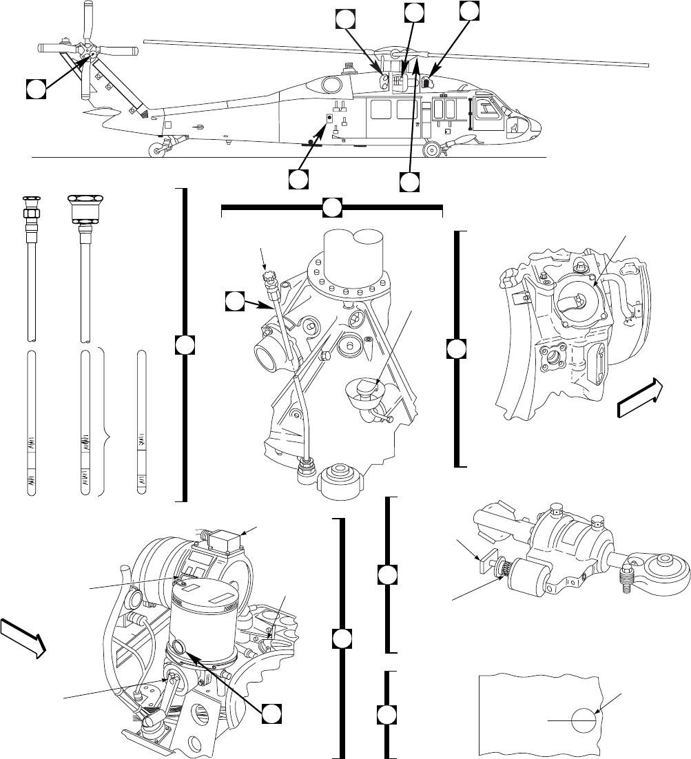
SA
AA0324_2
S T E P
N O
REFILL WITH ONE
QUART WHEN FLUID
REACHES THIS LEVEL
8910
11
12
13
FAR SIDE
VIEW D
8
OR
NO. 2 ENGINE RIGHT SIDE
MAIN ROTOR DAMPER
FRONT
FRONT
(SAME FOR NO. 1 AND NO. 2 ENGINES)
ENGINE OIL
FILLER CAP
OIL LEVEL
INDICATOR
INDICATOR
HANDLE
INDICATOR
(SERVICEABLE IF
GOLD BAND EXPOSED)
11
E
TRANSMISSION OIL
LEVEL DIPSTICK
OIL
FILLER
CAP
D
E
NO. 2 HYDRAULIC
PUMP MODULE
FLUID LEVEL
INDICATOR
(SAME FOR ALL
PUMP MODULES)
HYDRAULIC PUMP
MODULE REFILL
HANDPUMP
RESERVOIR
QUANTITY
LOW SWITCH
HANDPUMP
SELECTOR
VALVE
10
9
8. MAIN TRANSMISSION OIL FILLER PORT
AND DIP STICK
9. NO. 2 ENGINE OIL FILLER PORT AND
SIGHT GAGE
10. NO. 2 HYDRAULIC PUMP MODULE AND
PUMP MODULE REFILL HANDPUMP
11. MAIN ROTOR DAMPER CHARGE
INDICATOR
12. NO. 2 (RIGHT) FUEL TANK GRAVITY
REFUEL PORT
13. TAIL ROTOR GEAR BOX LEVEL SIGHT
GAGE
Figure 2-25. Servicing Diagram (Sheet 2 of 3)
TM 1-1520-237-10
2-88
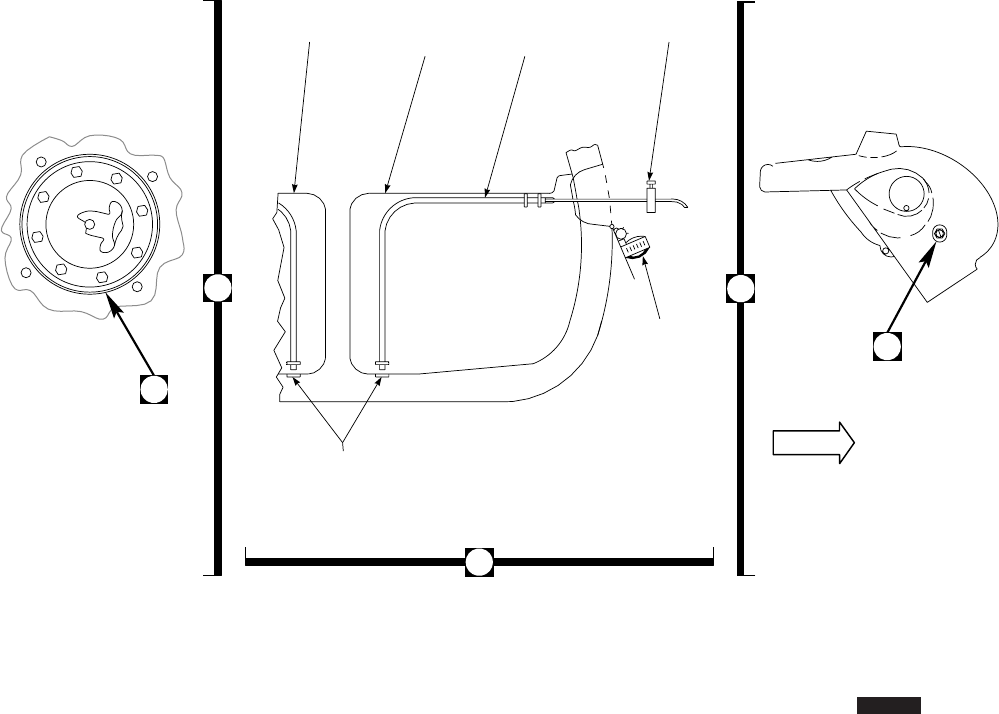
5. Once fuel has reached the desired level, remove
the fuel dispenser nozzle from the refueling
adapter and cap pressure fueling adapter.
2.84.5 Fuel Sampling System. Fuel sampling is done
with a thumb-operated handpump (Figure 2-25) containing
5 feet of plastic tubing. The tubing is placed in a guide tube
inside the fuel tank and is directed to the bottom of the
tank. The handpump is stroked and fuel is drawn from the
tank, with contaminants at the bottom. When sampling is
completed, the tubing is emptied, rolled, and stowed with
the pump on the gravity refueling door. ERFS Fuel sam-
pling of the external extended range fuel system is done by
taking the sample with a fuel sampler tube from the sump
drain located at the bottom aft of each tank.
2.85 EXTERNAL AIR SOURCE/ELECTRICAL RE-
QUIREMENTS.
Refer to Chapter 5 for limitations.
SA
AA0324_3
B
FRONT
NO. 2 TANK NO. 1 TANK
LOOKING AFT GUIDE
TUBE HANDPUMP
SUMP
DRAIN
STOW PUMP
ON GRAVITY
FILL DOOR
FUEL TANK GRAVITY
REFUEL PORT
FUEL SAMPLING TAIL ROTOR
GEAR BOX
F
13
12
F
Figure 2-25. Servicing Diagram (Sheet 3 of 3)
TM 1-1520-237-10
Change 5 2-89

2.86 ENGINE OIL SYSTEM SERVICING.
CAUTION
The helicopter must be level to get accu-
rate oil tank readings. When the helicop-
ter is parked on a slope, the downslope
engine will read higher oil level than ac-
tual, and the upslope engine will read
lower.
NOTE
Do not service the engines with DOD-L-
85734 oil. If DOD-L-85734 oil is inadvert-
ently added to the engines, drain the oil and
add MIL-L-7808 or MIL-L-23699 oil.
Flushing the system before refilling is not
required.
The engine oil tank (Figure 2-25) is within the main
frame. When the oil level reaches the ADD mark, oil should
be added to bring the level to the full mark on the sight
gage. Wait at least 20 minutes after engine shutdown before
checking engine oil level. Before adding oil, determine
whether system contains MIL-L-7808 oil or MIL-L-23699
oil. If flights of over 6 hours are made, engine oil level
must be at the full line of sight glass before flight.
Table 2-4. Fuel and Lubricants, Specifications, and Capacities
SYSTEM SPECIFICATION CAPACITY
Fuel Primary: Grade JP-8 (NATO Code F-34)
(Notes 1 and 5)
Alternate: Grade JP-5 (NATO Code F-44)
(Notes 1and 5)
JP-4 (NATO Code F-40) (Note 5)
Main Tanks usable U. S. Gallons of
fuel are: 360 gravity, 359 pressure,
and 356 closed circuit. External
Tank Gravity Refueling: 230 U. S.
Gallons each tank.
WARNING
Lubricating oils MIL-L-23699, DOD-L-
85734 and MIL-L-7808 contain materials
hazardous to health. They produce pa-
ralysis if swallowed. Prolonged contact
may irritate the skin. Wash hands thor-
oughly after handling. Oils may burn if
exposed to heat or flames. Use only with
proper ventilation.
Engine oil MIL-L-23699 (NATO Code 0-156)
MIL-L-7808 (NATO Code 0-148)
(Notes 2, 3 and 7)
7 U. S. Quarts
Auxiliary power unit MIL-L-23699 (NATO Code 0-156)
MIL-L-7808 (NATO Code 0-148)
(Notes 2, 3 and 7)
3 U. S. Quarts
(T-62T-40-1)
2 U. S. Quarts (GTC-P36-150)
Transmission oil MIL-L-23699 (NATO Code 0-156)
MIL-L-7808 (NATO Code 0-148)
DOD-L-85734 (Notes 2, 3, 6, and 8)
7 U. S. Gallons
TM 1-1520-237-10
2-90 Change 9

Table 2-4. Fuel and Lubricants, Specifications, and Capacities (Cont)
SYSTEM SPECIFICATION CAPACITY
Intermediate gear box oil MIL-L-23699 (NATO Code 0-156)
MIL-L-7808 (NATO Code 0-148)
DOD-L-85734 (Notes 2, 3, 6, and 8)
2.75 U. S. Pints
Tail gear box oil MIL-L-23699 (NATO Code 0-156)
MIL-L-7808 (NATO Code 0-148)
DOD-L-85734 (Notes 2, 3, 6, and 8)
2.75 U. S. Pints
First stage hydraulic reservoir MIL-H-83282
MIL-H-5606 (NATO Code H-515)
(Note 4)
1 U. S. Quart
Second stage hydraulic reservoir MIL-H-83282
MIL-H-5606 (NATO Code H-515)
(Note 4)
1 U. S. Quart
Backup hydraulic reservoir MIL-H-83282
MIL-H-5606 (NATO Code H-515)
(Note 4)
1 U. S. Quart
Rescue Hoist Refer to TM 55-1680-320-23 for servicing. 11.5 U. S. Fluid Ounces
SOURCE PRIMARY OIL ALTERNATE OIL
APPROVED COMMERCIAL OILS
NOTE
Commercial oils listed below are approved alternates for
engines and gear boxes except as indicated.
U. S. Military Oil
NATO Code No. DOD-L-85734 (Note 7) MIL-L-23699 or
0-156 MIL-L-7808
0-148
COMMERCIAL OIL TYPE II TYPE I
Castrol Inc. Castrol 5050
Castrol 5000
Aerojet 5
Castrol 399
Exxon Co. Turbo Oil 25 Turbo Oil 2380 Turbo Oil 2389
Turbo Oil 2391
Hatco Corp. HATCO 3211
HATCO 3611
HATCO 1639
HATCO 1680
HATCO 1278
HATCO 1280
Mobil Corp. Mobil Jet Oil II
Mobil Jet Oil 254
TM 1-1520-237-10
Change 5 2-91

Table 2-4. Fuel and Lubricants, Specifications, and Capacities (Cont)
SOURCE PRIMARY OIL ALTERNATE OIL
Royal Lubricants Royco 555 Royco 500
Royco 560
Royco 899
Royco 899HC
Royco 808
Shell Oil Company Aeroshell 555 Aeroshell 500
Aeroshell 560 Aeroshell 308
NOTE
1. When starting in ambient temperatures below -34°C (-29°F), do not use
JP-5 or JP-8.
2. When starting in ambient temperatures of -34°C (-29°F) or below,
lubricating oil MIL-L-7808 must be used. It is not advisable to mix
MIL-L-23699 or DOD-L- 85734 oil with MIL-L-7808 oil.
3. If the type oil being used is not available, another authorized type oil may
be added. When one type oil is mixed with another, it is not necessary to
drain the system and refill with one type oil. No mixing is allowed for cold
temperature operation. For transmissions and gear boxes, when one type of
oil is mixed with another, it is not necessary to drain the system and refill
with one type oil.
4. For operation below -34°C (-29°F), MIL-H-5606 (NATO Code H-515)
shall be used. Mixing MIL-H-5606 with MIL-H-83282 degrades fire-
resistant qualities of MIL-H-83282.
5. Fuel settling time for jet (JP) fuel is 1 hour per foot depth of fuel. Allow the
fuel to settle for the prescribed period before any samples are taken (about
4 hours for proper settling).
6. DOD-L-85734 oil is the preferred oil for use in the main transmission,
intermediate gearbox, and tail gearbox, except for cold temperature
operation.
7. DOD-L-85734 oil should not be used in the engines or the auxiliary power
unit (APU). If DOD-L-85734 oil is inadvertently added to the engines or
APU, the system should be drained and the correct oil added. There is no
need to flush the system.
8. When changing from MIL-L-7808 or MIL-L-23699 oil to DOD-L-85734
(and vice versa), drain the oil from the system and refill with desired oil.
There is no need to flush the system before refilling.
TM 1-1520-237-10
2-92 Change 3

Table 2-5. Approved Fuels
SOURCE PRIMARY/STANDARD
FUEL ALTERNATE FUELS
U. S. Military Fuel JP-8 JP-5 JP-4
NATO Code No. F-34 F-44 F-40
Commercial Fuel
(ASTM-D-1655) JET A-1 JET A JET B
American Oil Co. American Type A American JP-4
Atlantic Richfield Arcojet A-1 Arcojet A Arcojet B
Richfield Div. Richfield A-1 Richfield A
B. P. Trading B. P. A. T. K. B. P. A. T. G.
Caltex Petroleum Corp. Caltex Jet A-1 Caltex Jet B
City Service Co. CITCO A
Continental Oil Co. Conoco Jet-60 Conoco Jet-50 Conoco JP-4
Exxon Co. U. S. A. Exxon A-1 Exxon A Exxon Turbo Fuel B
Gulf Oil Gulf Jet A-1 Gulf Jet A Gulf Jet B
Mobil Oil Mobil Jet A-1 Mobil Jet A Mobil Jet B
Phillips Petroleum Philjet A-50 Philjet JP-4
Shell Oil Aeroshell 650 Aeroshell 640 Aeroshell JP-4
Sinclair Superjet A-1 Superjet A
Standard Oil Co. Jet A-1 Kerosene Jet A Kerosene
Chevron Chevron A-1 Chevron A-50 Chevron B
Texaco Avjet A-1 Avjet A Texaco Avjet B
Union Oil 76 Turbine Fuel Union JP-4
International Fuel NATO F-34 NATO F-44 NATO F-40
Belgium BA-PF-2B
Canada 3-6P-24C 3GP-22F
Denmark JP-4 MIL-T-5624
France Air 3407A
Germany UTL-9130-007
UTL-9130-010 VTL-9130-006
Greece JP-4 MIL-T-5624
Italy AMC-143 AA-M-C-1421
Netherlands D. Eng RD 2493 JP-4 MIL-T-5624
Norway JP-4 MIL-T-5624
Portugal JP-4 MIL-T-5624
Turkey JP-4 MIL-T-5624
TM 1-1520-237-10
Change 10 2-93

Table 2-5. Approved Fuels (Cont)
SOURCE PRIMARY/STANDARD
FUEL ALTERNATE FUELS
United Kingdom
(Britain) D. Eng RD 2498 D. Eng RD 2454
NOTE
Commercial fuels are commonly made to conform to
American Society for Testing and Materials (ASTM)
Specification D 1655. The ASTM fuel specification does
not contain anti-icing additives unless specified. Icing
inhibitor conforming to MIL-I-85470 or MIL-I-27686
(Commercial name PRIST) shall be added to commer-
cial and NATO fuels, not containing an icing inhibitor,
during refueling operations, regardless of ambient tem-
peratures. Icing inhibitor conforming to MIL-I-85470 is
replacing the MIL-I-27686 version. The use of MIL-I-
27686 icing inhibitor is acceptable until all supplies are
depleted. Adding PRIST during refueling operation shall
be done using accepted commercial mixing procedures.
The additive provides anti-icing protection and also
functions as a biocide to kill microbial growths in heli-
copter fuel systems.
2.87 APU OIL SYSTEM SERVICING.
NOTE
Do not service the APU with DOD-L-85734
oil. If DOD-L-85734 oil is inadvertently
added to the APU, drain the oil and add
MIL-L-7808 or MIL-L-23699 oil. Flushing
the system before refilling is not required.
a. The APU oil supply is in the APU gear box assem-
bly. The sump filler/oil dipstick port (T-62T-40-1) or cap
and fill to spill plug (GTC-P36-150) (Figure 2-25) are on
the left side of the gear box housing.
b. When the APU is cool to the touch the COLD side of
the dipstick may be used, if the APU is hot to the touch the
HOT side of the dipstick may be used.
2.88 HANDPUMP RESERVOIR SERVICING.
CAUTION
Do not allow reservoir level to fall below
refill line.
Servicing of the refill handpump is done when fluid level
decreases to the refill line on the fluid level sight gage, on
the side of the pump tank. When fluid level decreases to the
refill line, 1 quart of hydraulic fluid can be poured into the
reservoir after removing the refill cap. Handpump reservoir
level should be replenished only in 1 quart units.
2.89 HYDRAULIC SYSTEMS SERVICING.
Reservoirs (Figure 2-25) for the hydraulic systems are
on the hydraulic pump modules. Fluid level sight gages are
visible on the side of each pump. All hydraulic pump res-
ervoir capacities are 1 U. S. quart to the blue (black on
some pumps) mark. When the indicator reaches the red area
(refill) point, 2/3 of a pint is required to return the indicator
to the green mark. The fluid level indication is the 1/8 inch
wide gold band at the outboard edge of the level piston. To
refill the reservoirs, the fluid is supplied from the manual
handpump. After flight, fluid in hydraulic systems will be
hot. Piston movement of up to 3/8 inch into the blue (black
on some pumps) (overfill) zone is acceptable. When piston
is beyond this limit, bleed off enough fluid to bring piston
back to 3/8 inch above fill limit. To replenish the pump
reservoir fluid, do the following:
1. Unscrew handpump lid and pour in clean hy-
draulic fluid, MIL-H-83282, until pump is full.
TM 1-1520-237-10
2-94 Change 10

Make sure you can always see oil in pump res-
ervoir window while servicing, so not to pump
air into pump module’s reservoir. Keep filling.
2. Make sure pump cover is clean, then screw lid
on tight.
3. Turn selector valve to desired reservoir to be
filled. OUT 1 is left pump module, OUT 2 is
right pump module, and OUT 3 is backup
pump module.
4. While holding selector valve handle down,
crank pump handle on handpump clockwise
and fill desired hydraulic pump module until
forward end of piston in reservoir window is at
forward end of green decal on reservoir hous-
ing.
5. Check that reservoirs stay full (forward end of
piston at forward end of green decal), with fluid
at ambient temperature 1 hour after flight.
6. Make sure area remains clean during procedure.
7. Stow selector valve handle in OUT 4 (capped
off) position.
8. Turn on electrical power.
9. Check caution panel for #1 RSVR LOW,#2
RSVR LOW, and BACK-UP RSVR LOW
lights are off.
2.90 RESCUE HOIST LUBRICATION SYSTEM
SERVICING.
Servicing of the rescue hoist lubrication system consists
of replacing automatic transmission fluid in the boom head
and the gear box (Figure 4-25) until oil level sight gages
indicate full.
2.91 MAIN TRANSMISSION OIL SYSTEM SERVIC-
ING.
The transmission oil supply is in the sump case with the
filler port and dipstick gage (Figure 2-25), on the right rear
of the main module. When filling is required, oil is poured
through the filler tube on the main module case, and oil
level is checked by a dipstick, marked FULL and ADD,or
FULL COLD and ADD on one side of the dipstick and
FULL HOT and ADD on the other side. Check oil level as
follows:
NOTE
Remove the dipstick, clean and reinsert to
obtain correct reading.
a. Single scale dipstick is for checking cold oil levels.
Wait at least 2 hours after shutdown to check oil. If oil
level must be checked when hot (immediately to 1/2 hour
after shutdown), oil level will read about 1/2 inch low
(halfway between full and add mark or 1/2 inch below add
mark).
b. Dual scale dipstick is for checking cold or hot oil
levels. Use appropriate scale when checking oil level. Read
hot side of dipstick when checking hot oil (immediately to
1/2 hour after shutdown), or cold side of dipstick when
checking cold oil (at least 2 hours after shutdown).
2.92 TAIL AND INTERMEDIATE GEAR BOX SER-
VICING.
The intermediate gear box oil level sight gage (Figure
2-25) is on the left side of the gear box. The tail gear box
oil level sight gage is on the right side.
2.93 PARKING.
The methods used to secure the helicopter for temporary
periods of time will vary with the local commands. The
minimum requirements for parking are: gust lock engaged
and wheel brakes set, tailwheel locked, and wheels properly
chocked. For extended periods of time, engine inlet covers,
exhaust covers, and pitot covers should be installed, and
stabilator slewed to 0°. When required, the ignition system
and the doors and window should be locked.
2.94 PROTECTIVE COVERS AND PLUGS.
The covers and plugs (Figure 2-26) protect vital areas
from grit, snow, and water. The protected areas are avionics
compartment air inlet, engine air inlet/accessory bay, en-
gine and APU exhausts, pitot tubes, IRCM transmitter and
APU air inlet and main transmission oil cooler exhaust.
Covers and plugs should be installed whenever the helicop-
ter is to be on the ground for an extended period of time.
Each cover may be installed independently of the others.
2.95 MOORING.
Mooring fittings are installed at four points on the heli-
copter (Figure 2-26). Two fittings are at the front of the
fuselage, one above each main landing gear strut, and two
TM 1-1520-237-10
Change 9 2-95

at the rear, one attached to each side of the aft transition
section. These fittings are used to tie down the helicopter
when parked, and wind conditions require it.
2.95.1 Mooring Instructions. Refer to TM 1-1500-
250-23 for mooring instructions.
2.95.2 Main Rotor Tiedown. Tiedown of the main ro-
tor should be done when the helicopter will be parked for a
period of time or when actual or projected wind conditions
are 45 knots and above. To tiedown main rotor blades, do
this:
1. Turn rotor head and position a blade over cen-
terline of helicopter. Install tiedown fitting into
receiver while pulling down on lock release
cable. Release cable when fitting is installed in
blade receiver.
2. Uncoil tiedown rope.
3. Repeat steps 1. and 2. for each remaining blade.
4. Turn blade to about 45° angle to centerline of
helicopter and engage gust lock.
CAUTION
Do not deflect main rotor blade tips more
than 6 inches below normal droop posi-
tion when attaching tiedowns. Do not tie
down below normal droop position.
5. Attach tiedown ropes to helicopter as shown in
Figure 2-26. To release tiedown fitting, pull
down on lock release cable and remove fitting
from blade.
TM 1-1520-237-10
2-96 Change 1
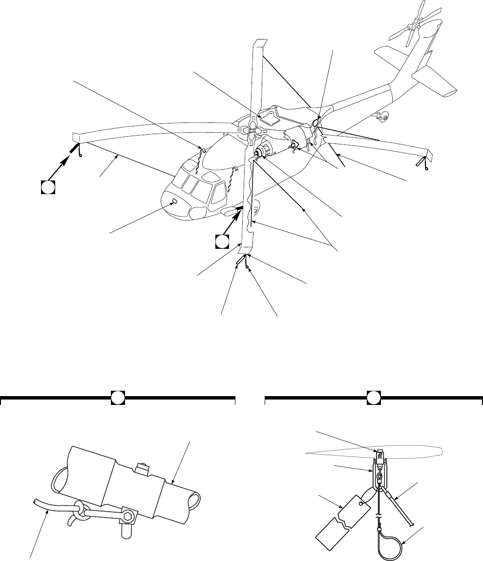
SA
AA0522A
REM GHT
B
AROTOR BLADE
TIEDOWN ROPE
(ON EACH BLADE)
AVIONICS
COMPARTMENT
AIR INLET COVER
MAIN ROTOR
BLADE
WARNING
STREAMER LOCK RELEASE
CABLE
FITTING ASSEMBLY
HELICOPTER TIEDOWN CABLE
(LEFT AND RIGHT SIDE)
ENGINE AIR INLET / ACCESSORY
BAY COVER
(LEFT AND RIGHT SIDE)
ENGINE EXHAUST
PLUGS (LEFT AND
RIGHT SIDE)
HELICOPTER TAIL
TIEDOWN CABLE
(LEFT AND RIGHT
SIDE)
APU EXHAUST
PLUG
IRCM TRANSMITTER
APU AIR INLET,
AND TRANSMISSION
OIL COOLER COVER
PITOT TUBE COVER
AND WARNING STREAMER
(LEFT AND RIGHT SIDE)
LANDING GEAR
DRAG STRUT
TIEDOWN LINE
(LEFT AND
RIGHT SIDE)
RECEIVER
LOCK ASSEMBLY
WARNING
STREAMER
TIEDOWN ROPE
LOCK RELEASE
CABLE
B A
Figure 2-26. Mooring
TM 1-1520-237-10
2-97/(2-98 Blank)

CHAPTER 3
AVIONICS
Section I GENERAL
3.1 DESCRIPTION.
The avionics subsystem consist of the communications
equipment providing VHF-AM, VHF-FM, and UHF-AM
communications. The navigation equipment includes, LF-
ADF, VOR, ILS, marker beacon, Doppler UH , Doppler/
GPS UH , or Integrated Inertial Navigation System
EH VHF-FM homing is provided through the No. 1
VHF-FM communication radio. Transponder equipment
consists of a receiver-transmitter with inputs from baromet-
ric altimeter for altitude fixing. Absolute height is provided
by a radar altimeter. Each antenna will be described with its
major end item, and locations as shown in Figure 3-1.
3.2 AVIONICS EQUIPMENT CONFIGURATION.
Equipment configuration is as shown in Table 3-1.
3.3 AVIONICS POWER SUPPLY.
Primary power to operate the avionics systems is pro-
vided from the No. 1 and No. 2 dc primary buses and the dc
essential bus, and No. 1 and No. 2 ac primary buses (Figure
2-20). When operating any of the avionics equipment, he-
licopter generator output must be available or external ac
power connected. Function selector switches should be at
OFF before applying helicopter power.
Table 3-1. Communication/Navigation Equipment
FACILITY NOMEN-
CLATURE USE RANGE CONTROL
LOCATION REMARKS
Intercommuni-
cation system Interphone
control
C-6533/
ARC
Intercommunication between crew-
members and control of navigation
and communication radio.
Stations
within heli-
copter
Cockpit lower
console,
crewchief/
gunner’s stations
and troop com-
mander’s station
at center of cabin
overhead with
handset
TM 1-1520-237-10
Change 1 3-1

Table 3-1. Communication/Navigation Equipment (Cont)
FACILITY NOMEN-
CLATURE USE RANGE CONTROL
LOCATION REMARKS
FM communi-
cations (If in-
stalled) UH
Radio set
AN/ARC-
114A
VHF-FM
No. 1
Two-way voice communications;
FM and continuous-wave homing
frequency range 30 through 75.95
MHz.
*Line of
sight Lower console FM No. 1
transmitter
may be used
only in heli-
copters serial
No. 79-23273
and subse-
quent and
those helicop-
ters modified
by MOD 99-
122 and 99-
122-1.
FM communi-
cations (If in-
stalled) UH
Radio Set
AN/ARC-
114A
VHF-FM
No. 2
Same as No. 1 VHF-FM, except no
homing is provided. Lower console
VHF commu-
nications (If
installed) UH
Radio Set
AN/ARC-
115A
VHF-AM
Two-way voice communications in
the frequency range of 116.000
through 149.975 MHz.
*Line of
sight Lower console Radio Set AN/
ARC-115 may
be installed on
some helicop-
ters.
VHF AM and
FM communi-
cations (If in-
stalled)
Radio Set
AN/ARC-
186(V)
VHF-
AM/FM
Two-way voice communications in
the frequency range 30.0 through
87.975 MHz and 116.0 through
151.975 MHz range. 108.0 through
115.975 MHz receive only.
*Line of
sight Lower console
UH , ECM opera-
tor’s station
EH
VHF-FM No.
2 Provisional.
FM communi-
cations Radio Set
AN/ARC-
201
VHF-FM
Two-way voice communications,
homing, frequency hopping in 30.0
- 87.975 MHz range.
*Line of
sight Lower console VHF-FM No.
1/2 and MEP
VHF-FM.
Improved Fre-
quency Modu-
lation Ampli-
fier
IFM Am-
plifier AM-
7189A/
ARC
Variable RF power amplifier; in-
creases output from FM 1 (2.5, 10
or 40 watts out.)
FM 1 ARC-201
control box Amplifier con-
trol C-11188A
used only
when ARC-
186 is in-
stalled EH .
TM 1-1520-237-10
3-2 Change 8

Table 3-1. Communication/Navigation Equipment (Cont)
FACILITY NOMEN-
CLATURE USE RANGE CONTROL
LOCATION REMARKS
UHF commu-
nications Radio-
Transmitter
Radio, RT-
1167/ARC-
164(V)
UHF-AM
Two-way voice communications in
the frequency range of 225.000 to
399.975 MHz.
*Line of
sight Lower console
UH , DF opera-
tor’s station EH
Radio, RT-
1167C/
ARC-
164(V)
UHF-AM
HAVE QUICK Lower console
UH
Radio, RT-
1614/ARC-
164(V)
UHF-AM
HAVE QUICK II Lower console
UH
Tunable di-
plexer EH
TD-1336/A Allows narrow band use of guard
channel. Beneath seat of
copilot
High fre-
quency com-
munications
Radio Set
AN/ARC-
220
Two way voice communications in
the frequency range of 2 to 29.9999
MHz.
*Over the
horizon Lower console
UH
Voice security
system TSEC/
KY-58 Secure communications. Not appli-
cable Lower console Can be used
with FM1,
FM2 and
UHF-AM.
Voice security
system TSEC/KY-
100 Secure communications. Not appli-
cable Rear lower con-
sole Used with HF
AN/ARC-220.
Automatic di-
rection finding Direction
Finder Set
AN/
ARN-89 (if
installed)
AN/ARN-
149(V) (if
installed)
Radio range and broadcast recep-
tion; automatic direction finding
and homing in the frequency range
of 100 to 3000 kHz.
*50 to 100
miles range
signals.
Lower console AN/ARN-
149(V) tun-
able, 100 to
2199.5 kHz.
TM 1-1520-237-10
Change 8 3-3

Table 3-1. Communication/Navigation Equipment (Cont)
FACILITY NOMEN-
CLATURE USE RANGE CONTROL
LOCATION REMARKS
VOR/LOC/
GS/MB re-
ceiving set
Radio Re-
ceiving Set
AN/ARN-
123(V) (if
installed)
AN/ARN-
147(V) (if
installed)
VHF navigational aid, VHF audio
reception in the frequency range of
108 to 117.95 MHz and marker
beacon receiver operating at 75
MHz.
*Line of
sight Lower console AN/ARN-
147(V) tun-
able, 108 to
126.95 kHz.
Doppler navi-
gation set UH
Doppler
Navigation
Set AN/
ASN-128
Provides present position or desti-
nation navigation information in
latitude and longitude (degrees and
minutes) or Universal Transverse
Mercator (UTM) coordinates.
Lower console
Doppler/GPS
navigation set
UH
Doppler/
GPS Navi-
gation Set
AN/ASN-
128B
Provides present position or desti-
nation navigation information in
latitude and longitude (degrees and
minutes) or Military Grid Refer-
ence System (MGRS) coordinates.
Combined Mode is prime (default)
mode of operation where the GPS
updates Doppler present position.
When Doppler is in memory (if not
available), the system switches to
GPS only mode. If GPS is jammed
and/or becomes unavailable, the
system automatically switches to
the Doppler only mode. These
modes of operation may also be se-
lected manually.
Lower console Doppler
ONLY or GPS
ONLY navi-
gation is se-
lectable from
CDU.
Integrated In-
ertial Naviga-
tion System
(IINS)
EH
AN/ASN-
132(V) Navigational Aid. Lower console
Magnetic
heading indi-
cations
Gyro Mag-
netic Com-
pass AN/
ASN-43
Navigational Aid. Lower console
Identification
friend or foe Transpon-
der Set AN/
APX-
100(V)
Transmits a specially coded reply
to a ground-based IFF radar Inter-
rogator system.
*Line of
sight Lower console
TM 1-1520-237-10
3-4 Change 4

Table 3-1. Communication/Navigation Equipment (Cont)
FACILITY NOMEN-
CLATURE USE RANGE CONTROL
LOCATION REMARKS
Absolute al-
timeter Radar Al-
timeter AN/
APN-209
Measures absolute altitude. 0 to 1500
feet Instrument panel
NOTE
*Range of transmission or reception depends upon many variables including weather
conditions, time of day, operating frequency, power of transmitter and altitude of the
helicopter.
TM 1-1520-237-10
Change 4 3-5
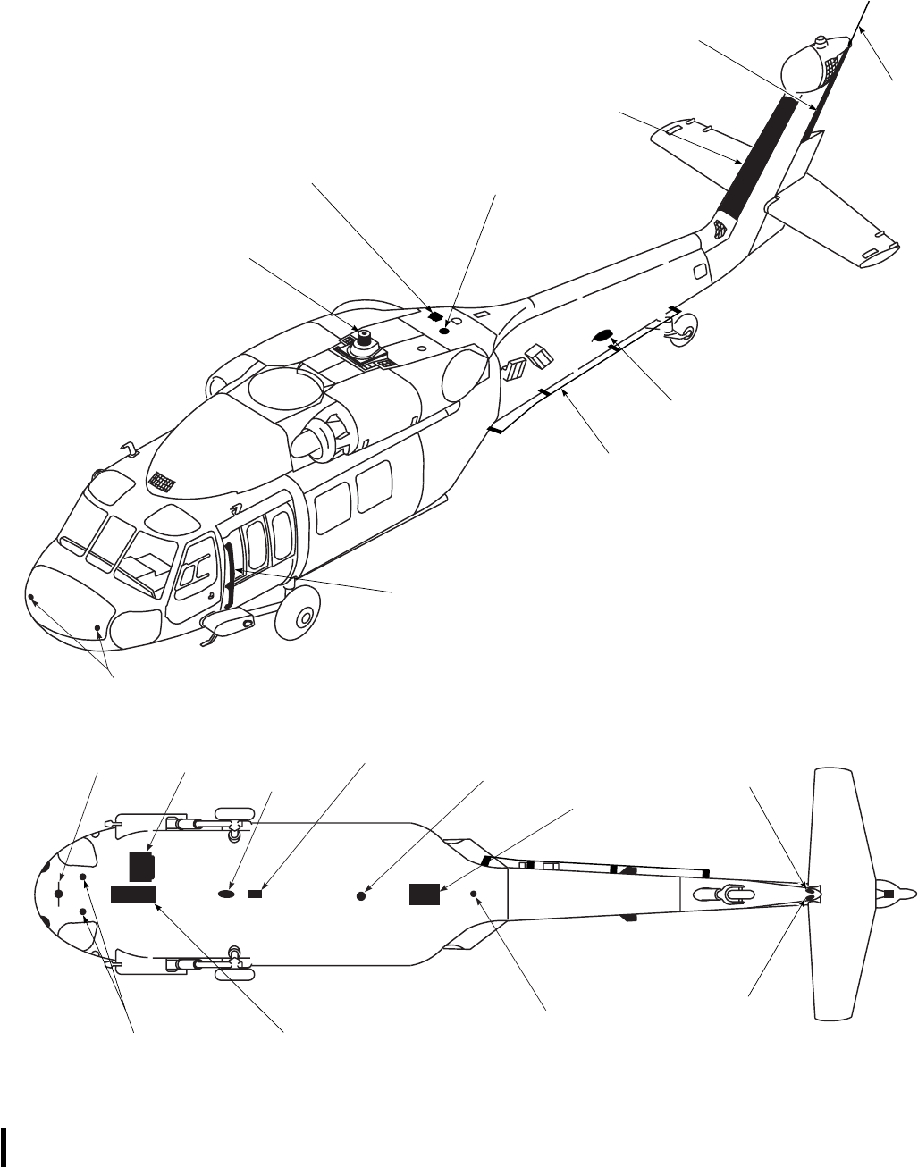
SA
AA0355_1
COMMANDERS VHF / FM
VHF−FM NO. 2
ANTENNA
TRANSPONDER (IFF)
ANTENNA (TOP)
INFRARED
COUNTERMEASURE
TRANSMITTER
VHF−FM HOMING ANTENNA
(SAME BOTH SIDES)
VOR / LOC ANTENNA
(SAME BOTH SIDES)
RADAR WARNING
ANTENNA
RADAR
WARNING
ANTENNA
LF / ADF LOOP
ANTENNA
RADAR
WARNING
ANTENNA
DOPPLER
ANTENNA
SLOPE
ANTENNA
ALTIMETER
ANTENNA
MARKER
BEACON
ANTENNA
VHF−FM NO. 2, VHF−AM
LF / ADF SENSE ANTENNA
TRANSPONDER (IFF)
ANTENNA (BOTTOM)
BOTTOM VIEW
NO. 1 /
VHF−AM
VHF−FM
UHF COMM
ANTENNA
GPS ANTENNA
HF ANTENNA
RADAR
WARNING
ANTENNA
GLIDE
RADAR
UH60A/UH60L HELICOPTERS
TROOP
Figure 3-1. Antenna Arrangement (Sheet 1 of 2)
TM 1-1520-237-10
3-6 Change 5
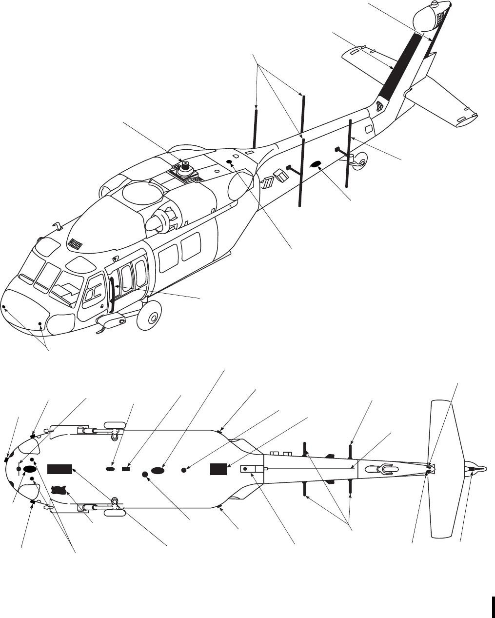
SA
AA0355_2
MISSION VHF / FM
2ND BITE ANTENNA
DF ANTENNA
TRANSPONDER (IFF)
ANTENNA (TOP)
INFRARED
COUNTERMEASURE
TRANSMITTER
VHF−FM HOMING ANTENNA
(SAME BOTH SIDES)
VOR / LOC ANTENNA
(SAME BOTH SIDES)
DF ANTENNA
RADAR WARNING
ANTENNA RADAR
WARNING
ANTENNA
ECM
ANTENNA
MEP UHF
DATA LINK
ANTENNA
LF / ADF LOOP
ANTENNA
ALQ−156
ANTENNA
MEP VHF−FM /
UHF VOICE LINK
ANTENNA
RADAR
WARNING
ANTENNA
SLOPE
ANTENNA
ALQ−156
ANTENNA
ALQ−162
ANTENNA
ALQ−156
ANTENNA
AIRCRAFT
UHF COMM
ANTENNA
ALTIMETER
ANTENNA
MARKER
BEACON
ANTENNA
VHF−AM LF / ADF
SENSE ANTENNA
TAC
ANTENNA ALQ−156
ANTENNA TRANSPONDER (IFF)
ANTENNA (BOTTOM)
DF ANTENNA
DF
ANTENNA ALQ−162
ANTENNA
BOTTOM VIEW
VHF−FM NO. 1
VHF−FM
NO. 2
RADAR
WARNING
ANTENNA
GLIDE
RADAR
EH60A HELICOPTERS
Figure 3-1. Antenna Arrangement (Sheet 2 of 2)
TM 1-1520-237-10
Change 5 3-7
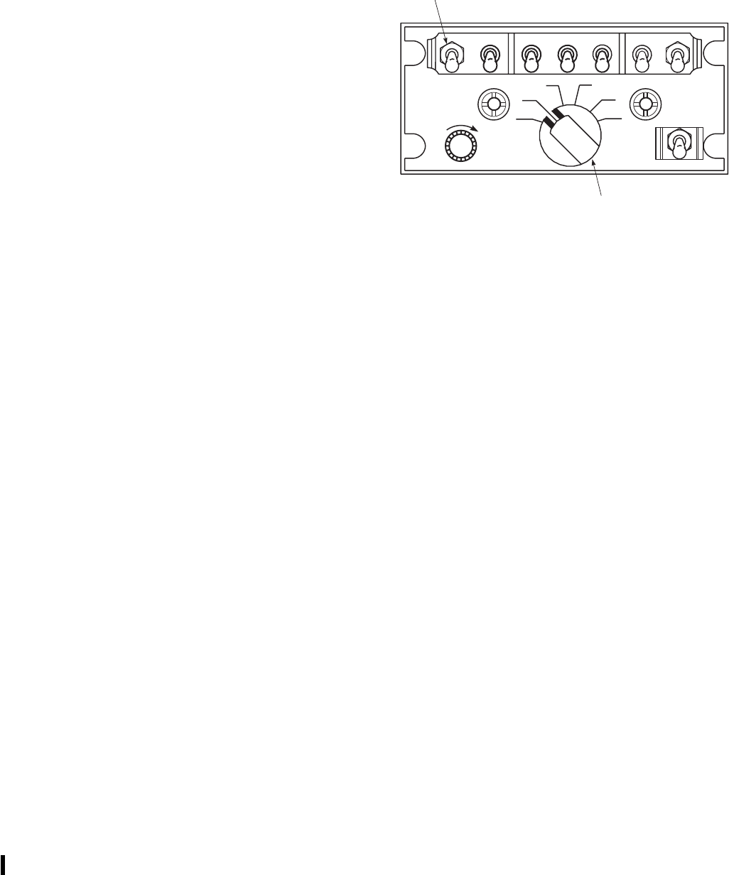
Section II COMMUNICATIONS
3.4 INTERCOMMUNICATION SYSTEM C-6533()
/ARC.
Five intercommunication system (ICS) controls provide
interior intercommunication capability between crew mem-
bers and with the troop commander’s position. They also
provide a means by which the pilot and copilot may select
and control associated radio equipment for voice transmis-
sion and reception. Additional audio circuits may also be
selected for constant monitoring. When the communication
control is operated in conjunction with equipment listed in
Table 3-1, it is used to select associated radio equipment
for voice operations. The operator may select any one of
five transmitters (Figure 3-2), and/or any or all of five re-
ceivers to monitor. Four direct-wired audio circuits allow
continuous monitoring. Hands-free intercommunication is
provided by a hot mike feature. An exterior jack is to the
front and below each gunner’s window. When the
walkaround cord is connected to it, the crewchief can com-
municate with the interior of the helicopter or with the other
exterior jack through thecrewchief/gunner’s control panels.
A placard installed on the instrument panel and above each
troop-cargo compartment ICS station control panel indi-
cates which receiver is selected when a selector switch is
placed ON. Power for the intercommunication system is
provided from the dc essential bus through circuit breakers,
marked ICS PILOT and ICS COPILOT.
3.4.1 Controls and Functions. Controls for the
intercom/radios are on the front panel of the unit (Figure
3-2). The function of each control is as follows:
CONTROL/
INDICATOR FUNCTION
Receiver selector
switches (ON)
1Connects FM 1 receiver to the
headphone.
2Connects UHF receiver to the head-
phone.
3Connects VHF receiver to the head-
phone.
4Connects FM 2 receiver to the
headphone.
5Connects HF receiver to the head-
phone.
AUX Connects VOR/LOC audio to the
headphone.
CONTROL/
INDICATOR FUNCTION
NAV Connects ADF/Marker Beacon au-
dio to the headphone.
VOL control Adjusts headphone volume level.
Transmitter sel-
ector switch
ICS Enables intercom operation when
keyed.
1Enables FM 1 transmission when
keyed.
2Enables UHF transmission when
keyed.
3Enables VHF transmission when
keyed.
4Enables FM 2 transmission when
keyed (provisions).
5Enables HF transmission when
keyed.
HOT MIKE
switch Enables intercom transmission
without manual key.
3.4.2 Intercommunication Keying System. Keying
of the ICS system is done by these controls:
a. Pilot or copilot station. An ICS or RADIO switch on
the top of each cyclic stick, or by a switch on the floor at
the pilot’s left and the copilot’s right foot (Figure 2-4).
SA
AA0523
ON
OFF
ON
OFF
VOL ICS
124
3
5HOT MIKE
OFF
C
O
M
M
1 2 3 4 5 AUX NAV
C
O
N
T
TRANSMITTER
SELECTOR
RECEIVER SELECTOR
SWITCH
SWITCH
Figure 3-2. Intercommunication Control Panel
C-6533/ARC
TM 1-1520-237-10
Pages 3-8.1 through 3-10 deleted.
3-8 Change 10

b. Crewchief/Gunner and Left Gunner. A pushbutton at
the end of the ICS cord or the exterior walkaround cord,
and foot switches on each side of the helicopter at the
crewchief/gunner’s and left gunner’s station.
c. Troop commander. A push switch on the handset at
the troop commander’s station.
3.4.3 Modes of Operation.
3.4.3.1 Primary Operation Check. There are several
methods of intercommunication operation. In all cases, no
operator action is required to receive intercom signals other
than adjusting the VOL control for a comfortable level at
the headset.
3.4.3.2 Intercommunication (All Stations).
1. Transmitter selector switch ICS for pilot and
copilot when using foot switch, any position
when using cyclic switch, ICS for crewchief/
gunner, gunner, and troop commander.
2. Key switch - ICS switch on pilot’s or copilot’s
cyclic, or foot switch at pilot’s, copilot’s or
crewchief/gunner, gunner positions, or push-to-
talk button on crewchief/gunner’s ICS cord,
push-to-talk switch on troop commander hand-
set press, speak into microphone and listen for
sidetone, release to listen.
3.4.3.3 External Radio Communication. All stations
of the helicopter are capable of external radio communica-
tions.
3.4.4 Pilot and Copilot.
1. Transmitter selector - Desired position, 1
through 5.
2. RADIO push-to-talk switch on cyclic stick, or
foot-operated push-to-talk switch - Press; speak
into microphone while holding switch; release
to listen.
3.4.4.1 Crewchief/Gunner.
1. Transmitter selector - Desired position, 1
through 5.
2. Push-to-talk switch on headset-microphone
cord, or foot-operated push-to-talk switch -
Press, speak into microphone while holding
switch, release to listen.
3.4.4.2 Troop commander.
1. Transmitter selector - Desired position 1
through 5.
2. Transmitter key switch on handset - Press,
speak into microphone while holding switch,
release to listen.
3.4.5 Receiver Selection.
1. Receiver selector switch(es) - ON as desired.
2. Adjust volume to a comfortable listening level.
3.5 DELETED.
3.6 DELETED.
3.7 RADIO SET AN/ARC-186(V).
Radio Set AN/ARC-186(V) (Figure 3-5) is a lightweight
multichannel airborne radio communications set, which
provides transmission, reception and retransmission of am-
plitude modulated (AM), frequency modulated (FM) radio
TM 1-1520-237-10
Change 10 3-11

communications, and FM directional finding (homing) with
installation of other associated equipment. AM reception
only is provided on frequencies between 108.000 and
115.975 MHz. Installation of the AN/ARC-186(V) in the
UH-60A helicopter is a VHF-AM and/or VHF-FM instal-
lation(s). The transceiver has a tunable main receiver and
transmitter which operates on any one of 1,469 AM dis-
crete channels, each spaced 25 kHz apart within the fre-
quency range of 116.000 through 151.975 MHz, or 30.000
through 87.975 MHz FM, providing 2,319 channels. FM
homing operations within the 30 through 87.975 MHz band.
The fixed guard channels are between 116.000 and 151.975
MHz AM (usually 121.500 MHz), and between 30.000 and
87.975 MHz FM (usually 40.500 MHz). The guard fre-
quencies are preset and only require selection by the
frequency/emergency select switch. Frequencies can be
preset for 20 channels. VHF-AM installations cannot be
used to transmit VHF-FM signals. If an AM frequency is
selected on an FM only installation, an audible tone would
be heard, warning the pilot of an out-of-band frequency
selection. The same is true in the case of selection of an FM
frequency on an AM installation. Keying the microphone
for voice transmission when in DF (homing) mode will
disable the homing function while the mic is keyed. In DF
mode, audio reception is distorted. When using secured
speech and EMER FM or AM is selected, secure speech
function will be disabled to enable normal voice communi-
cations. Power to operate the AN/ARC-186(V) radio is pro-
vided from the No. 2 dc primary bus through a circuit
breaker, marked VHF-AM for the AM radio, and from the
No. 1 and No. 2 dc primary buses, respectively, through
circuit breakers marked NO. 1 VHF-FM and NO. 2
VHF-FM for the No. 1 and No. 2 VHF-FM radios.
3.7.1 Antennas.
a. UH The VHF-AM antenna is on top of the tail rotor
pylon (Figure 3-1). The antenna operation is shared with
No. 1 VHF-FM. The No. 2 VHF-FM communications an-
tenna is within the leading edge fairing of the tail pylon
drive shaft cover. The two FM homing antennas used with
the No. 1 VHF-FM radio are on each side of the helicopter
fuselage, just behind the cockpit doors.
b. EH The VHF-AM antenna is under the nose section
(Figure 3-1). The antenna operation is shared with ADF
sense. No. 1 VHF-FM communications antenna is within
the leading edge fairing of the tail pylon drive shaft cover.
No. 2 VHF-FM communications antenna is under the nose,
forward of VHF-AM antenna. The two FM homing anten-
nas used with the No. 1 VHF-FM radio are on each side of
the helicopter fuselage, just behind the cockpit doors.
3.7.2 Controls and Functions. Controls for the AN/
ARC-186(V) are on the front panel of the unit (Figure 3-5).
The function of each control is as follows:
CONTROL FUNCTION
0.025 MHz
selector Rotary switch. Selects rt frequency
in 0.025 MHz steps. Clockwise
rotation increases frequency.
0.1 MHz selector Rotary switch. Selects rt frequency
in 0.1 MHz steps. Clockwise
rotation increases frequency.
1.0 MHz selector Rotary switch. Selects rt frequency
in 1.0 MHz steps. Clockwise
rotation increases frequency.
10 MHz selector Rotary switch. Selects rt frequency
in 10 MHz steps from 30 to 150
MHz. Clockwise rotation increases
frequency.
Preset channel
selector Selects preset channel from 1 to 20.
Clockwise rotation increases
channel number selected.
Volume control Potentiometer. Clockwise rotation
increases volume.
Squelch disable/
tone select Three-position switch. Center
position enables squelch, SQ DIS
position disables squelch,
momentary TONE position
transmits tone of approximately
1000 Hz.
Frequency
control/
emergency select
switch
Four-position rotary switch. PRE
position enables preset channel
selection, MAN position enables
manual frequency selection,
EMER AM or FM selects a
prestored guard channel (FM not
used in helicopters with panel-
mounted transceiver).
NOTE
Selecting EMER AM or FM
automatically disables the secure
speech function and enables normal
voice communication.
Mode select
switch Three-position rotary switch. OFF
position disables receiver/
transmitter, TR position enables
transmit/receive modes. DF
position enables FM homing.
TM 1-1520-237-10
3-12
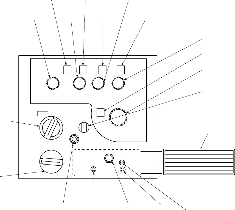
SA
AA0361_1
255115
20
CHAN
FM
AM
EMER
DF
TR
OFF
MAN
PRE VOL
AM
LOCK
OUT
WB
MEM
FM
NB
AM
SQUELCH FM
SQUELCH
LOAD
S
Q
D
I
S
T
O
N
E
1
2
3
4
5
16
17
18
19
20
11
12
13
14
15
6
7
8
9
10
SNAP−ON
COVER
V
H
F
10.0 MHZ
SELECTOR
10.0 MHZ
INDICATOR
1.0 MHZ
SELECTOR
1.0 MHZ
INDICATOR
0.1 MHZ
INDICATOR
0.1 MHZ
SELECTOR
0.025 MHZ
INDICATOR
0.025 MHZ
SELECTOR
PRESET CHANNEL
INDICATOR
PRESET CHANNEL
SELECTOR
VOLUME
CONTROL
BANDWITH /
MEM LOAD
SWITCH
AM
SQUELCH
CONTROL
SQUELCH
DISABLE /
TONE
SELECT
MODE
SELECT
SWITCH
FREQUENCY
CONTROL /
EMERGENCY
SELECT SWITCH
FM SQUELCH
CONTROL
(PANEL−MOUNTED TRANSCEIVER)
BAND LOCKOUT
SWITCH
Figure 3-5. VHF Control AN/ARC-186(V) (Sheet 1 of 2)
TM 1-1520-237-10
3-13
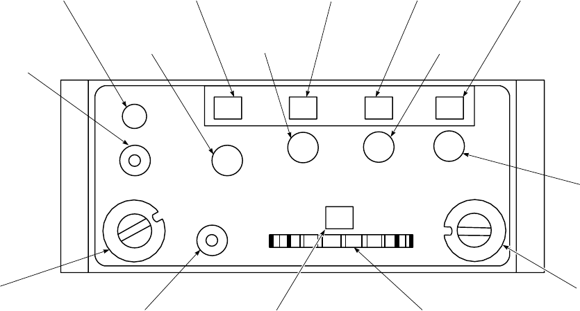
CONTROL FUNCTION
Bandwidth/
MEM LOAD
(On helicopters
with panel-
mounted trans-
ceiver). On heli-
copters with half-
size remote
control panel, the
memory switch is
labeled LOAD.
Bandwidth
switch is inacces-
sible.
Three-position switch NB (NAR-
ROW) position enables narrow-
band selectivity WB (WIDE) en-
ables wideband selectivity in the
FM band, momentary MEM
LOAD position allows manually
selected frequency to go into se-
lected preset channel memory.
AM SQUELCH
control (On heli-
copters with
panel-mounted
transceiver). (Use
of control is a
maintenance
function).
Screwdriver adjustable potentiom-
eter. Squelch overridden at maxi-
mum counterclockwise position,
clockwise rotation increases input
signal required to open the squelch.
CONTROL FUNCTION
FM SQUELCH
control (On heli-
copters with
panel-mounted
transceiver). (Use
of control is a
maintenance
function).
Screwdriver adjustable potentiom-
eter. Squelch overridden at maxi-
mum counterclockwise position,
clockwise rotation increases input
signal required to open the squelch.
Band LOCK-
OUT switch (On
helicopters with
panel-mounted
transceiver). (Use
of control is a
maintenance
function).
Screwdriver settable three-position
switch. Center position enables
both AM and FM bands, AM posi-
tion locks out AM band, FM posi-
tion locks out FM band. (Band
lockout is indicated by a warning
tone.)
3.7.3 Modes of Operation. Depending on the settings
of the operation controls, the radio set can be used for these
modes of operation:
SA
AA0361_2A
9
14 1 0 50
FM AM
MAN
PRE
DF
TR
OFF
V
O
L
S
Q
D
I
S
T
O
N
E
EMER
LOAD
PRESET
C
O
M
M
VOLUME
CONTROL
10.0 MHz
SELECTOR
10.0 MHz
INDICATOR
1.0 MHz
SELECTOR
1.0 MHz
INDICATOR 0.1 MHz
INDICATOR
0.1 MHz
SELECTOR
0.025 MHz
INDICATOR
0.025 MHz
SELECTOR
MODE
SELECTOR
SWITCH
PRESET
CHANNEL
SELECTOR
THUMBWHEEL
PRESET
CHANNEL
INDICATOR
LOAD
PUSHBUTTON
SWITCH
FREQUENCY
CONTROL
SELECT
SWITCH
SQUELCH
DISABLE /
TONE SELECT
Figure 3-5. VHF Control AN/ARC-186(V) (Sheet 2 of 2)
TM 1-1520-237-10
3-14

a. Two-way voice, normal (TR).
b. When voice security system is installed, refer to para-
graph 3.11.
c. Constant monitoring of guard channel 121.5 MHz
only.
d. Guard receive and transmit only (EMER).
3.7.3.1 Starting Procedure. Before starting radio set,
check settings of controls that pertain to communication
equipment. With dc power applied, radio set is turned on
with mode selector (Figure 3-5) in any position other than
OFF or EMER.
3.7.3.2 Operational Check. Select mode and commu-
nicate with or direction to the ground station on selected
frequencies in low, middle, and high range of applicable
frequency band. Check the action of the volume control and
note that the selected frequencies are heard loud and clear.
Check that adequate sidetone is audible during all transmis-
sions.
a. Communications mode check:
(1) Mode select switch - TR.
(2) Select out-of-band frequency to check
warning. (On helicopters with panel-
mounted transceivers.)
(3) Select frequency of station to be used for
check, MAN or PRE as desired.
(4) Communicate with check station.
NOTE
Transmitting with the AN/ARC-186 FM#2
radio may cause the LF-ADF (AN/ARN-89)
bearing pointer to deflect and lose audio
when tuned to a station 400 kHz or below.
Releasing the transmitter key allows the LF-
ADF receiver to return to the normal audio
and bearing indication.
Transmitting with the AN/ARC-186
VHF/AM radio on frequencies from 120
MHz and above may cause the LF-ADF
(AN/ARN-89) bearing pointer to deflect and
lose audio when tuned to a station below
1500 kHz. Releasing the transmitter key al-
lows the LF-ADF receiver to return to the
normal audio and bearing indication.
b. DF mode check.
(1) Select frequency of station to be used for
homing.
(2) Mode select switch - DF.
(3) Frequency control select switch - MAN or
PRE as desired.
(4) Check for homing indication.
c. Squelch disable/tone check.
(1) Select SQ DIS - Check for noise.
(2) Select momentary TONE, check for tone
of about 1000 Hz.
d. Preset channel load.
(1) Mode select switch - TR.
(2) Frequency control select switch - MAN.
(3) Set MHz frequency for desired channel and
rotate PRESET channel to number to be
used with that frequency using channel se-
lector thumbwheel.
(4) LOAD button - Press and release.
(5) Repeat steps 3. and 4. for other preset
channels.
3.7.3.3 Operation.
3.7.3.4 TR Mode AM or FM as Applicable.
1. Set OFF-TR-DF switch to TR.
2. Set frequency control select switch to MAN or
PRE.
3. Rotate four MHz selectors to desired frequency
or set PRESET channel number as desired.
3.7.3.5 Emergency Mode AM or FM as Applicable.
1. Mode select switch - TR or DF.
2. Frequency mode selector switch - EMER AM
or FM as applicable.
TM 1-1520-237-10
Change 5 3-15
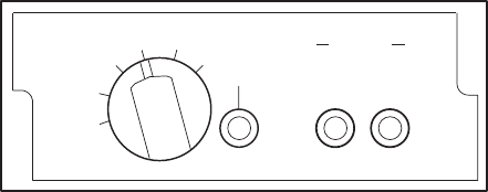
3.7.3.6 DF (Homing) Mode.
1. Mode select switch - DF.
2. Frequency control select switch - MAN or
PRE.
3.7.3.7 Retransmission Mode. Do a retransmission
check as follows:
NOTE
Do not disable squelch when retransmit
switches are in retransmit position. Squelch
level is used to key transmitter for retrans-
mission.
1. Establish two base stations at unrelated fre-
quencies.
2. Set appropriate receiver-transmitter to desired
retransmit frequency.
3. Place RADIO TRANSMISSION selector
switch to radios to be used.
4. Establish communication between base stations
through aircraft radios.
5. Note that selected frequencies are heard loud
and clear and that received audio is present and
clear at each crew station.
3.7.4 Stopping Procedure. Mode Selector - OFF.
3.7.5 IFM Amplifier Control.
NOTE
IFM amplifier control installed in EH-60A
helicopters with ARC-186 as VHF-FM No.
1 (Figure 3-6).
CONTROL FUNCTION
OFF (Bypass amplifier) - 10 watts.
LAMP Tests indicator lights.
TEST Checks IFM amplifier.
LOW (Low power) - 2.5 watts.
CONTROL FUNCTION
NORM (Normal power) - 10 watts.
HIGH (High power) - 40 watts.
3.8 RADIO SET AN/ARC-201 (VHF-FM) (IF IN-
STALLED).
Radio set AN/ARC-201 (Figure 3-7) is an airborne, very
high frequency (VHF), frequency modulated (FM), radio
receiving-transmitting set compatible with the Single Chan-
nel Ground Airborne Radio Sets (SINGCARS) Electronic
Countermeasures (ECCM) mode of operation. The set pro-
vides communications of voice and data, secure or plain
text, and homing over the frequency range of 30 to 87.975
MHz channelized in 25 Khz steps. A frequency offset tun-
ing capability of -10 Khz, -5 Khz, +5 Khz and +10 Khz is
provided in both transmit and receive mode; this capability
is not used in ECCM mode. The set when used in conjunc-
tion with the TSEC/KY-58 equipment, is used for receiving
and transmitting clear-voice or X-mode communications.
An additional capability for retransmission of clear-voice
communications allows use of the set as a relay link. Dur-
ing retransmission, when one radio receives a signal, it
sends a keying signal to the second radio and the first ra-
dio’s received audio modulates the second radio’s transmit-
ter. Use of the homing capability of the No. 1 FM radio set
provides a steering output to the VSI course deviation
pointer for steering indications. No. 1 VHF-FM receives
power from the dc essential bus through a circuit breaker
SA
AA9242
F
MTEST HIGH
LOW NORM
VPA RF IN
FAULT
LAMP
OFF
Figure 3-6. IFM Amplifier Control
TM 1-1520-237-10
3-16

marked NO. 1 VHF-FM. No. 2 VHF-FM receives power
from the No. 1 dc primary bus through a circuit breaker
marked NO. 2 VHF-FM.
3.8.1 Antennas.
a. UH The No. 1 VHF-FM communications antenna is
on top of the tail rotor pylon (Figure 3-1). The No. 2
VHF-FM antenna is within the leading edge fairing of the
tail pylon drive shaft cover. The FM homing antennas, one
on each side of the fuselage, are used with FM No. 1 radio
set. The troop commander’s antenna is on the upper trailing
edge of the tail pylon. Refer to Chapter 4, Section 1 for use
of troop commander’s antenna.
b. EH The No. 1 VHF-FM communications antenna is
within the leading edge fairing of the tail pylon drive shaft
cover (Figure 3-1). The No. 2 VHF-FM antenna is under
the nose section. The FM homing antennas, one on each
side of the fuselage, are used with FM No. 1 radio set. the
troop commander’s antenna in on the upper trailing edge of
the tail pylon. Refer to Chapter 4, Section 1 for use of troop
commander’s antenna.
3.8.2 Controls and Functions. Controls for the ARC-
201 are on the front panel (Figure 3-7). The function of
each control is as follows:
CONTROL FUNCTION
OFF Primary power off;
Memory battery power ON.
TEST RT and ECCM modules are tested,
Results: GOOD or FAIL.
SQ ON RT on with squelch.
SQ OFF RT on with squelch disabled.
RXMT RT is receiving. Used as a radio
relay link.
LD Keyboard loading of preset
frequencies.
LD-V TRANSEC variable loading is
enabled.
Z-A Pull and turn switch. (Not an
operational position). Used to clear
the TRANSEC variable.
STOW Pull and turn switch. All power
removed. Used during extended
storage.
CONTROL FUNCTION
MODE
HOM Homing antennas selected;
communication antenna
disconnected. Provides pilot with
steering, station approach and
signal strength indicators.
SC Single Channel. Operating
frequency is selected by PRESET
switch or keyboard entry.
FH Frequency Hopping. PRESET
switch positions 1-6 select
frequency parameters.
FH-M Frequency hopping-master selects
control station as the time standard
for communicating equipment.
PRESET
MAN Used in single channel mode to
select any operating frequency in
25 Khz increments.
Positions 1-6 In SC mode, preset frequencies are
selected or loaded. In FH or FH-M
mode, frequency hopping nets are
selected.
CUE Used by a non-ECCM radio to
signal ECCM radio.
IFM RF PWR (VHF-FM No. 1 only)
NOTE
This switch is inactive for VHF-
FM No. 2, leave switch in OFF
position.
OFF (Bypass amplifier) - 10 watts.
LO (Low power) - 2.5 watts.
NORM (Normal power) - 10 watts.
HI (High power) - 40 watts.
VOL control Adjust receiver volume to
comfortable level.
KEYBOARD
Switches 1-9 To key in any frequency, load time
information or offsets.
TM 1-1520-237-10
3-17
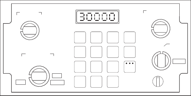
CONTROL FUNCTION
FREQ Display current operating fre-
quency during single channel
(manual or preset) operation.
ERF/OFST Modify single channel operating
frequency, manually selected or
preset, to include offsets of 65 Khz
or 610 Khz.
TIME Used to display or change the time
setting maintained within each RT.
STO Store or enter any frequency into
RT; store a received HOPSET or
LOCKOUT set held in holding
memory.
0/LOAD Enter zeros; initiate transfer of
ECCM parameters.
CLR Zeroize the display; clear erroneous
entries.
3.8.3 Mode of Operation. Depending on the setting of
the operating controls, the radio set can be used for these
modes of operations:
a. Two-way voice, normal (SC).
b. Two-way voice, secure voice, when TSEC/
KY-58 is installed. Refer to paragraph 3.11.
c. Two-way voice, frequency hopping (FH or
FH-M). Secure voice can be used at the same
time if desired.
d. Homing (HOM).
e. Retransmission (Function - RXMT).
3.8.4 Starting Procedure. The radio is capable of op-
erating in any of the modes indicated by the MODE selec-
tor switch (Figure 3-7) and retransmission on the FUNC-
TION switch.
3.8.4.1 Single Channel (SC) Mode.
1. FUNCTION -SQ ON or SQ OFF.
2. MODE -SC.
3. PRESET -MAN.
4. Push FREQ then CLR button. The display will
show all bottom dashes.
5. Enter frequency - 5 digits.
SA
AA9243
1 2 3 FREQ
4 5 6
7 8 9 TIME
CLR Sto
ENT
H−Ld
0
L
LE
ERF
OFST
MAN
12345
6
CUE
PRESET
TEST
SQ ON
SQ OFF LD
LD−V
Z−A
STOW
FUNCTION
RXMT
OFF
OFF
LO
NORM HI
IFM RF PWR
MODE
HOM SC
FH
FH−M
VOL
Figure 3-7. FM Control AN/ARC-201
TM 1-1520-237-10
3-18

6. Push STO button. The display will flash once
to acknowledge correctly entered frequency.
7. ICS transmitter selector - Position 1(FM No.
1), or position 4(FM No. 2).
8. Radio push-to-talk switch - Press to talk; re-
lease to listen.
3.8.4.2 Enter Frequency into PRESET.
1. FUNCTION -LD.
2. PRESET - Desired number 1to 6.
3. MODE -SC.
4. Push FREQ then CLR button. The display will
show all bottom dashes.
5. Enter frequency - 5 digits.
6. Push STO. The display will flash once.
7. Repeat steps 1. through 6. for each desired pre-
set channel.
3.8.4.3 Frequency Hopping (FH or FN-M) Mode.
1. MODE -FH or FH-M.
2. PRESET - Select net (1-6).
3. FUNCTION -SQ ON or SQ OFF.
3.8.4.4 Homing (HOM) Mode (FM No. 1 only).
1. Enter or select frequency - MAN or PRESET.
2. MODE -HOM.
3. MODE SEL -FM HOME.
4. CIS MODE SEL -NAV.
5. Observe homing indicators on vertical situation
indicator (VSI) (Figure 3-30). These are:
a. FM navigation (NAV) flag will move from
view, and will come into view if the re-
ceived signal is too weak.
b. A steering (course indicator) pointer moves
either left or right about 5° to indicate any
deviation from the course to the transmit-
ting station.
c. Station passage will be indicated by course
deviation change and CIS MODE SEL
NAV switch light going out and HDG
switch light going on.
3.8.5 Retransmission (RXMT). Retransmission per-
mits helicopter to be used as an airborne relay (Figure
3-12).
1. FUNCTION -RXMT.
2. Frequency(s) - Select.
3. RADIO RETRANSMISSION selector switch
- Set to radios used.
4. Establish communications between each relay
in helicopter and its counterpart radio at the
terminal station by using appropriate ICS
TRANS selector. If audio monitoring is desired,
adjust VOL control for suitable output.
3.8.6 Stopping Procedure. FUNCTION -OFF.
3.9 DELETED.
3.10 RECEIVER-TRANSMITTER RADIO, RT-1518C/
ARC-164(V).
Receiver-Transmitter Radio, RT-1518C/ARC-164(V)
(Figure 3-8) is an airborne, ultra-high frequency (UHF),
amplitude-modulated (AM), radio transmitting-receiving
(transceiver) set with Have Quick II (provides Have Quick
I and Have Quick II capabilities). Have Quick provides
electronic counter countermeasures (ECCM) which use a
frequency hopping scheme to change channels multiple
times per second. The RT-1518C/ARC-164(V) contains a
multichannel, electronically tunable main transmitter and
receiver, and a fixed-tuned guard receiver. The main trans-
ceiver operates on any one of 7,000 channels, spaced in
0.025 MHz units in the 225.000 to 399.975 MHz UHF
military band. The guard receiver is always tuned to
243.000 MHz. The radio is primarily used for voice com-
munications. An additional capability for retransmission al-
lows use of the radio as a relay link. The radio interfaces
with the Doppler/GPS Navigation Set (DGNS) AN/ASN-
128B. Power to operate the ARC-164(V) radio is from the
dc essential bus through a circuit breaker marked UHF
AM.
TM 1-1520-237-10
Change 10 3-19
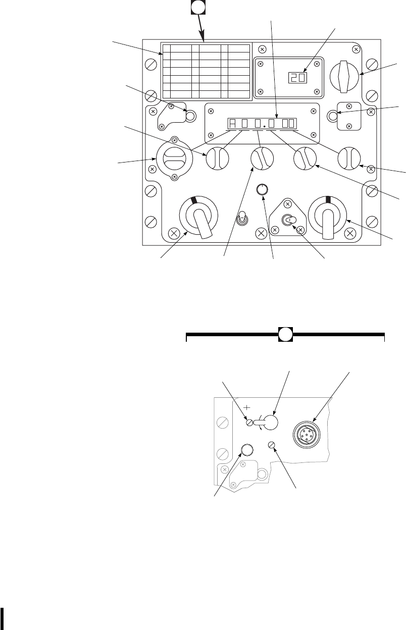
SA
AB2433
PRESET
GRDMNLBOTH
ADF SQUELCH
OFF ON
U
H
F
VOL
MAIN
OFF
T TONE
CHAN
2
3
A
TEST
DISPLAY STATUS
CH FREQ
1
2
3
4
5
6
8
9
10
11
12
13
15
16
17
18
19
20
714
A
FREQUENCY
COVER
TEST
DISPLAY
BUTTON
FREQUENCY
SELECTOR 2
FREQUENCY
SELECTOR 1
MODE
SELECTOR
FREQUENCY
SELECTOR 3 VOLUME
CONTROL SQUELCH
SWITCH
MNL−PRESET−GRD
SELECTOR
FREQUENCY
SELECTOR 5
FREQUENCY
SELECTOR 4
STATUS
BUTTON
CHANNEL
SELECTOR
CHANNEL
INDICATOR
FREQUENCY /
STATUS
INDICATOR
MAIN
SQUELCH
CONTROL
ZERO
SWITCH FILL
CONNECTOR
GUARD
SQUELCH
CONTROL
LOAD
BUTTON
F
I
L
L
ZERO
GD SQ
MN SQ
LOAD
A
Figure 3-8. UHF Control, AN/ARC-164(V)
TM 1-1520-237-10
3-20 Change 10

3.10.1 Antenna.
WARNING
The antenna radiates electromagnetic
waves at dangerous frequencies. Comply
with the requirements of AR 40-583 be-
fore using this equipment.
The UHF-AM antenna is under the fuselage transition
section (Figure 3-1) or EH under the fuselage below the
copilot’s seat. The antenna provides a path for both the
transmitted and received UHF communication signals. The
EH-60 AN/ALQ-151(V) mission package has two
UHF-AM radios that utilize the existing fuselage transition
section conformal antenna for the voice link. The mission
package also includes the data link antenna under the fuse-
lage where the cargo hook would normally be installed.
3.10.2 Tunable Diplexer. EH The tunable diplexer
(TD-1336/A) is connected between the antenna and the out-
put of the ARC-164(V). When properly tuned, the diplexer
acts as a bridge network isolating signals of similar fre-
quency which share the same antenna. The diplexer allows
the guard channel in the ARC-164(V) guard receiver to be
monitored while other frequencies in the main transmitter-
receiver are being used.
3.10.3 Controls and Functions. Controls for the
ARC-164(V) are on the front panel of the unit (Figure 3-8).
The function of each control is as follows:
CONTROL FUNCTION
CHAN indicator Displays selected channel when
MNL-PRESET-GRD selector is
set to PRESET, or displays se-
lected memory location when radio
is in the MWOD load mode or
FMT change mode.
Preset channel
selector Selects one of 20 preset channels.
Also selects the desired memory lo-
cation when radio is in the MWOD
load mode (20-14), manual TOD
entry mode (1), or FMT change
mode (20-5).
CONTROL FUNCTION
TEST DISPLAY
button Lights all segments of the
frequency/status and CHAN indi-
cator. Also used with T TONE
switch for manual clock start.
Frequency/status
indicator Displays the individual frequency
selector settings or any of the fol-
lowing operator prompts:
REMOTE Not used.
VER/OP Indicates radio is in normal operat-
ing mode.
M-LOAD Indicates radio is in MWOD load
mode.
ERASE Indicates radio is in MWOD erase
mode.
FMTCNG Indicates radio is in Frequency
Management Training Change
mode.
FILL Indicates a keyfill device is con-
nected to the front panel FILL con-
nector.
WOD OK Indicates a valid WOD was suc-
cessfully received from the keyfill
device.
BAD Indicates no WOD or a bad parity
WOD was received from the keyfill
device.
STATUS button Initiates an alternate display on the
frequency/status and CHAN indi-
cator for five seconds.
Frequency
selector 1 (A, 3, 2
HQ only)
Selects 100s digit of frequency (ei-
ther 2 or 3) in MHz in the single
frequency mode. Selects the desired
WOD elements or net number in AJ
(Have Quick) mode.
ASelects AJ mode (Figure 3-8).
3Allows manual selection of fre-
quencies in the 300 MHz range
(3XX. XX).
TM 1-1520-237-10
Change 10 3-21

CONTROL FUNCTION
2Allows manual selection of fre-
quencies in the 200 MHz range
(2XX. XX).
Frequency
selector 2 Selects 10s digit of frequency (0
through 9) in MHz. Selects the de-
sired WOD elements or net number
in AJ (Have Quick) mode.
Frequency
selector 3 Selects units digit of frequency (0
through 9) in MHz. Selects the de-
sired WOD elements or net number
in AJ (Have Quick) mode.
Frequency
selector 4 Selects tenths digit of frequency (0
through 9) in MHz. Selects the de-
sired WOD elements or net number
in AJ (Have Quick) mode.
Frequency
selector 5 Selects hundredths and thousandths
digits of frequency (.00, .25, .50, or
.75) in MHz. Selects the desired
WOD elements or net number in AJ
(Have Quick) mode.
Mode selector Selects operating mode function:
OFF Turns power off.
MAIN Enables main receiver and transmit-
ter.
BOTH Enables main receiver, transmitter,
and guard receiver.
ADF Not used.
CONTROL FUNCTION
T TONE switch Three position toggle switch:
middle position is off, and Tand
TONE are spring loaded. When
placed in the TONE position, trans-
mits a 1,020 Hz DF tone on the se-
lected frequency and stops when
switch is released. If radio TOD
clock is started, the TONE position
transmits the TOD message data
followed by the DF tone. When
placed in the Tposition, enables re-
ception of TOD message for one
minute. The T TONE switch also
initiates manual TOD clock start,
loads and erases MWOD elements,
and loads FMT-net operating fre-
quencies when radio is in the re-
spective MWOD operating mode.
VOL control Adjusts volume.
SQUELCH
switch Disables and enables squelch of
main receiver.
MNL-PRESET-
GRD selector Selects method of frequency selec-
tion:
MNL Allows manual selection of fre-
quency using the five frequency se-
lectors.
PRESET Allows selection of frequency from
preset channels (1-20) using the
channel selector. Along with
LOAD switch, also used when pro-
gramming the 20 preset channels.
GRD Automatically tunes the radio main
receiver and transmitter to the
guard frequency (243.000 MHz),
and disables the guard receiver.
MN SQ control Adjusts level of squelch for main
receiver.
ZERO switch Erases all MWOD elements.
LOAD
switch Loads frequency data displayed on
the frequency/status indicator into
preset channels 1-19 as selected by
channel selector. Preset channel 20
is reserved for loading MWOD op-
erating mode data (220.0XX).
TM 1-1520-237-10
3-22 Change 10

CONTROL FUNCTION
GD SQ control Adjusts level of squelch for guard
receiver.
Fill connector Connects a keyfill device to radio
for automatic loading of MWOD.
3.10.4 Modes of Operation. The radio has three differ-
ent methods of frequency selection as determined by the
position of the MNL-PRESET-GRD selector. An explana-
tion of these three positions is given in paragraph 3.10.3. A
procedure for programming the 20 preset channel numbers
to the desired frequencies is given in paragraph 3.10.5.7.
The radio can operate in MAIN,BOTH,orADF.
3.10.4.1 Normal Mode. The normal mode allows two-
way voice communications.
3.10.4.2 Secure Speech (x-mode) Mode. The secure
speech mode allows secure two-way voice communica-
tions. Operation is identical to the normal mode.
3.10.4.3 ADF Mode. This mode is not normally used.
Transmission from the radio is normally not possible with
the mode selector in the ADF position.
3.10.4.4 1,020 Hz Tone Signal Mode. This mode al-
lows transmission of a 1,020 Hz tone.
3.10.4.5 Guard Channel Mode. The BOTH position
allows use of the main receiver while monitoring the guard
receiver. The guard receiver is always tuned to 243.000
MHz.
3.10.4.6 Retransmit Mode. Retransmission permits the
helicopter to be used as an airborne relay link. Two RTs are
required (Figure 3-12) for operation as a relay unit. Opera-
tion in the retransmit mode is identical to the normal mode.
3.10.4.7 Have Quick/Anti-Jam Mode. The Have
Quick II system provides jam resistant (anti-jamming) ca-
pability through frequency hopping. Frequency hopping is
when the frequency being used for a given channel is au-
tomatically changed at a rate common to the transmitter
and receiver. The jam resistance of the system is due to the
automatic frequency changing and the pseudorandom pat-
tern of frequencies used. Certain criteria are necessary for
successful system operations. These are:
1. Common frequencies.
2. Time synchronization.
3. Common hopping pattern and rate.
4. Common net number.
The common frequencies are programmed into all Have
Quick radios. Time synchronization is provided via UHF
radio and/or hardware by an external time distribution sys-
tem. A time-of-day (TOD) signal must be received from the
time distribution system each time the radio is turned on.
The hopping pattern and hopping rate are determined by
the operator inserted word-of-day (WOD). In the AJ mode,
a communications channel is defined by a net number. In
addition to these Have Quick I capabilities, Have Quick II
provides two new frequency tables; multiple word of day
(MWOD); MWOD erase capability; Frequency Manage-
ment Training net (FMT net) in addition to existing Train-
ing net (T net); and operational date information as part of
TOD for proper WOD initialization.
3.10.4.7.1 Word Of Day (WOD). WOD is entered by
using one or more of the six preset channels (15-20).
3.10.4.7.2 Multiple Word Of Day (MWOD). MWOD
allows loading of up to six WODs either manually or au-
tomatically (maintenance can load the radio using a keyfill
device). Each WOD contains a unique date code that is
entered in memory location (channel) 14. The four MWOD
operating modes: VER/OP,M-LOAD,ERASE, and
FMTCNG are used to initiate various programming func-
tions.
3.10.4.7.3 Time Of Day (TOD).
NOTE
Automatic TOD is provided from the
Doppler/GPS Navigation Set (DGNS) AN/
ASN-128B.
TOD allows radios to operate together in the AJ mode.
Transmission and reception are possible in both single fre-
quency and AJ modes. Slightly garbled but otherwise ac-
ceptable communications indicate the radios have drifted
out of synchronization. A time update/resynchronization
corrects this. If single WOD is used, an operational date is
not necessary.
3.10.4.7.4 TOD Clock Manual Start. When TOD from
a UTC (Universal Coordinated Time) source is not avail-
able, the TOD clock can be manually started and used in
the AJ mode. The manually started TOD clock is set to a
time completely independent of UTC. Other radios may
also communicate using this uncoordinated time once the
time has been transmitted to all radios in the net.
TM 1-1520-237-10
Change 10 3-23

3.10.4.7.5 Net Number. The net number programs the
entry point in the AJ frequency hopping pattern, allowing
multiple radio net operations using a common WOD and
TOD without interfering with each other. Selecting Awith
frequency selector 1 places the radio in AJ mode and pro-
grams the radio to use the net number selected by frequency
selectors 2, 3, and 4. The net number begins with Aand is
followed by three digits (000 to 999).
Operational Net Numbers. The last two digits desig-
nate the frequency table being used. Net numbers
ending in 00 select the original A-net and B-net fre-
quency table. Net numbers ending in 25 select the
new NATO/Europe frequency table. Net numbers
ending in 50 select the new non-NATO/Europe fre-
quency table. Net numbers ending in 75 are reserved
for future use and will generate an invalid net alarm
(pulsating warning tone).
Training/FMT Net Numbers. T-net and FMT-net
training numbers are available for training purposes.
In the T-net training mode, the radio hops among five
frequencies loaded in with the WOD. In the FMT-net
training mode, the radio hops among sixteen frequen-
cies.
3.10.4.7.6 Conference Capability. In the AJ mode,
the radio is able to receive and process two simultaneous
transmissions on the same net. In a conference net, the
second transmitting radio automatically shifts its transmis-
sion frequency 25 kHz when it monitors a transmission on
the primary net frequency. The wide band receiver reads
both transmissions without the interference normally asso-
ciated with two radios transmitting simultaneously on the
same frequency. Conference capability is enabled or dis-
abled by the last two digits of the WOD element loaded in
memory location (channel) 19. If the WOD element ends
with 00 or 50, conferencing is enabled. If the WOD ele-
ment ends with 25 or 75, conferencing is disabled. When
operating in secure speech mode, conferencing is automati-
cally disabled. If operating in AJ mode on a single element
WOD (memory location (channel) 20 only), conferencing
is enabled by default. For training mode operation, confer-
encing is always enabled.
3.10.5 Operation.
3.10.5.1 Normal Mode.
1. Mode selector - MAIN.
2. MNL-PRESET-GRD selector - As desired.
3. Frequency selector/channel selector - As de-
sired.
4. ICS transmitter selector switch - Position 2.
5. Establish communication by keying transmitter
and speaking into microphone. Release to listen
and adjust volume for a comfortable level.
3.10.5.2 Secure Speech Mode.
1. Refer to paragraph 3.11 for voice security sys-
tem procedures.
2. Refer to 3.10.5.1 for normal mode procedures.
3.10.5.3 1,020 Hz Tone Signal Mode.
1. Mode selector - MAIN.
2. MNL-PRESET-GRD selector - As desired.
3. Frequency selector/channel selector - As de-
sired.
4. T TONE switch - Press to TONE to transmit
the 1,020 Hz signal.
3.10.5.4 Guard (Emergency) Channel Mode.
Guard frequency only:
1. Mode selector - BOTH.
2. MNL-PRESET-GRD selector - GRD (main
receiver and transmitter are both tuned to
243.000 MHz).
Guard frequency and main (receiver/transmitter) fre-
quency:
1. Mode selector - BOTH.
2. MNL-PRESET-GRD selector - MNL or
PRESET.
3. Frequency selector/channel selector - As de-
sired for main receiver/transmitter.
4. ICS transmitter selector switch - Position 2.
5. Establish communication by keying transmitter
and speaking into microphone. Release to listen
and adjust volume for a comfortable level.
TM 1-1520-237-10
3-24 Change 10

3.10.5.5 Retransmit Mode.
1. RADIO TRANSMISSION selector - Set to
desired radios.
2. Mode selector - MAIN.
3. MNL-PRESET-GRD selector - As desired.
4. Frequency selector/channel selector - As de-
sired.
5. ICS transmitter selector switch - Position 2.
6. Establish communication between each relay
radio in helicopter and its counterpart radio link
terminal station.
3.10.5.6 Have Quick/AJ Mode.
1. Mode selector - MAIN or BOTH.
2. WOD or MWOD - Load per paragraph
3.10.5.6.1 or 3.10.5.6.2.
3. TOD - Synchronize per paragraph 3.10.5.6.4.
4. Verify/operate mode (MWOD only) - Select
per paragraph 3.10.5.6.3.
5. MNL-PRESET-GRD selector - MNL.
NOTE
A steady warning tone is heard when the AJ
mode is selected and a TOD or a valid WOD
has not been entered.
The Acannot be stored in preset channel
memory. If loading a net number into a pre-
set channel is attempted, the Ais accepted
asa3.
6. Frequency selector 1 - A.
7. Frequency selectors 2, 3, 4 - Enter net number.
A pulsating warning tone is heard if an invalid
operating net is selected.
8. Establish communication by keying transmitter
and speaking into microphone. Release to listen
and adjust volume for a comfortable level.
3.10.5.6.1 Manual WOD Loading.
NOTE
If power is lost, or if channel 20 is selected
when the MNL-PRESET-GRD selector is
in the PRESET position, reinitialization of
all WOD elements is necessary.
Use of all channels may not be necessary.
Any unused channels can be used to store
selected preset frequencies.
1. Mode selector - MAIN.
2. MNL-PRESET-GRD selector - PRESET.
3. Channel selector - Channel 20.
4. Frequency selectors - Set desired WOD ele-
ment.
5. LOAD button (under frequency cover) - Press.
6. If needed, repeat steps 3 through 5 for channels
19 - 15.
7. Initialization: a single beep is heard on each
channel with a WOD element with the excep-
tion of the final WOD element which has a
double beep. This indicates the end of WOD
elements and initialization is complete.
8. MNL-PRESET-GRD selector - MNL.
3.10.5.6.2 Manual MWOD Loading.
NOTE
If the frequency selectors are not used within
five seconds, the frequency/status indicator
reverts to the M-LOAD display. Pressing
the STATUS button allows reviewing of the
frequency settings.
When the current operational date is updated
in the radio at midnight (Greenwich Mean
Time), the radio automatically reinitializes
with the WOD having the same date code.
1. Mode selector - MAIN.
2. MNL-PRESET-GRD selector - PRESET.
TM 1-1520-237-10
Change 10 3-25

3. Channel selector - Channel 20.
4. Frequency selectors - Set 220.025 MHz to se-
lect MWOD load mode.
5. LOAD button (under frequency cover) - Press.
6. MNL-PRESET-GRD selector - MNL.
7. Frequency selectors - Set WOD element.
8. T TONE switch - Press to TONE, then release
and note a single beep to ensure WOD element
is entered.
9. Channel selector - Select next lower memory
location.
10. Repeat steps 7 through 9 for loading remaining
WOD elements in memory locations (channels)
19 - 15.
11. Channel selector - Channel 14 (date tag).
12. Frequency selectors - Set to applicable date
code: XAB. XXX (AB represents the day-of-
month (01 to 31); Xs do not need a data entry).
If two or more WODs have the same date code,
the radio recognizes the last one entered.
13. T TONE switch - Press to TONE, then release
(note a double beep). One complete WOD with
date code has been successfully entered.
14. Reselect channel 20 and repeat steps 7 through
13 to load more WODs. If power is removed
from the radio, MWOD data is not lost. All
data remains in memory unless erased. Refer to
the operational date load or change procedures
in paragraph 3.10.5.6.4 for MWOD data recall.
MWOD Date Code Verify:
1. Select MWOD verify/operate mode per para-
graph 3.10.5.6.3.
2. MNL-PRESET-GRD selector - MNL.
3. Frequency selectors - Select date code to be
verified: XAB. XXX (AB represents the day-
of-month (01 to 31); Xs do not need a data
entry).
4. Channel selector - Memory location (channel)
20, then 19, and then 20. Single beep verifies
an MWOD with a matching date code is stored
in memory. If a single beep is not heard, the
selected date code is not stored in memory.
5. Proceed to paragraph 3.10.5.6.4 for TOD.
3.10.5.6.3 MWOD Operating Mode Selection.
1. Channel selector - Channel 20.
2. MNL-PRESET-GRD selector - PRESET.
3. Frequency selectors - As desired (220.000 MHz
for verify/operate mode; 220.025 MHz for
MWOD load mode; 220.050 MHz for MWOD
erase mode; or 220.075 MHz for frequency
management training change mode).
4. LOAD button (under frequency cover) - Press
to enable selected mode. The appropriate oper-
ating mode (M-LOAD,ERASE,or
FMTCNG) is displayed on the frequency/
status indicator (the STATUS button must be
pressed to display the VER/OP mode).
5. MNL-PRESET-GRD selector - MNL.
MWOD erase:
1. Perform steps 1 through 5 to select MWOD
erase mode.
2. T TONE switch - Press to TONE. All
MWODs are now cleared (WOD data and net
number information is not cleared).
3. MNL-PRESET-GRD selector - PRESET.
4. Frequency selectors - Set 220.000 MHz for
verify/operate mode.
5. LOAD button (under frequency cover) - Press
to enable VER/OP mode (the STATUS button
must be pressed to display the VER/OP on the
frequency/status indicator for five seconds).
6. MNL-PRESET-GRD selector - MNL.
TM 1-1520-237-10
3-26 Change 10

Alternate method for MWOD erase:
1. ZERO switch (under frequency cover) - Press,
then release. ERASE is displayed (all MWODs
are now erased). The ZERO switch only erases
the MWOD data. WOD data and net number
information are not erased.
FMT change:
1. Perform steps 1 through 5 to select MWOD
FMT change mode.
2. Channel selector - Set desired memory location
(channels 20-5).
NOTE
If the frequency selectors are not used within
five seconds, the frequency/status indicator
reverts to the current operating mode display
(FMTCNG).
3. Frequency selectors - Select frequency change.
4. T TONE switch - Press to TONE, then release
(note an audible tone).
5. Repeat steps 2 through 4 until all frequency
changes are loaded.
6. Channel selector - Channel 20.
7. MNL-PRESET-GRD selector - PRESET.
8. Frequency selectors - Set 220.000 MHz for
verify/operate mode.
9. LOAD button (under frequency cover) - Press
to enable VER/OP mode (the STATUS button
must be pressed to display the VER/OP on the
frequency/status indicator for five seconds).
3.10.5.6.4 Time of Day (TOD).
Request/Receive TOD:
NOTE
When the radio is turned on, the first TOD
received is accepted. Subsequent messages
are ignored.
1. MNL-PRESET-GRD selector - As desired.
2. Frequency selectors/channel selector - Select
predesignated frequency for TOD transmission.
NOTE
The first TOD received within one minute of
the TOD request is accepted.
3. T TONE switch - Press to Tthen release.
4. If time is not being automatically beaconed, re-
quest TOD from another station on the operat-
ing network. Beacons typically transmit TOD
every ten seconds.
5. TOD may be received on the main or guard
receiver in single frequency or AJ mode. Two
momentary tones (1,667 Hz-high tone and
1,020 Hz-low tone) are heard when the TOD
synchronization signal is received.
Transmit TOD:
1. MNL-PRESET-GRD selector - As desired.
2. Frequency selector/channel selector - As de-
sired.
NOTE
The radio will not transmit while the T
TONE switch is in the Tposition.
3. T TONE switch - Press to TONE then release.
Two momentary tones (1,667 Hz-high tone and
1,020 Hz-low tone) are heard when the TOD
synchronization signal is transmitted.
TOD Resynchronization:
1. T TONE switch - Press to Tthen release.
2. Frequency selectors - Select any normal fre-
quency and request a TOD. The first TOD sig-
nal is heard within one minute of selecting Tis
accepted. A momentary 1,667 Hz tone is heard
when the TOD signal is received. TOD resyn-
chronization should be performed using the
single frequency mode.
TM 1-1520-237-10
Change 10 3-26.1

TOD Clock Manual Start:
NOTE
The new TOD is arbitrary and is not syn-
chronized to UTC or to any other radio.
A manual TOD start clears out a previously
loaded TOD.
1. T TONE switch - Press to Tand hold, while
simultaneously pressing the TEST DISPLAY
button.
2. T TONE switch - Release prior to releasing the
TEST DISPLAY button to prevent inadvertent
Have Quick time loading.
Operational Date Load or Change:
1. Mode selector - MAIN.
2. MNL-PRESET-GRD selector - PRESET.
3. Channel selector - Channel 20.
4. Frequency selectors - Set 220.025 MHz to se-
lect MWOD load mode.
5. LOAD button (under frequency cover) - Press.
6. MNL-PRESET-GRD selector - MNL.
7. Channel selector - Channel 1.
8. Frequency selectors - Set to applicable date
code: XAB. XXX (AB represents the day-of-
month (01 to 31); Xs do not need a data entry).
9. T TONE switch - Press to TONE, then release
and note a tone (the date code has been suc-
cessfully entered).
10. Frequency selectors - Set to 220.000 MHz to
select verify/operate mode.
11. LOAD button (under frequency cover) - Press,
then release. Radio is now in verify/operate
mode.
12. STATUS button - Press, VER/OP is displayed
on the frequency/status indicator for five sec-
onds.
3.10.5.7 Preset Channel Loading.
NOTE
Channels 14 through 20 can be reserved for
loading single WOD and MWOD data. Any
channel not used for WOD or MWOD can
be used as a preset channel.
The Acannot be stored in preset channel
memory. If loading of a net number (AXX.
XXX) into a preset channel is attempted, the
Ais accepted as a 3.
Set 20 preset channel numbers to desired frequencies as
follows (Figure 3-8):
1. Mode selector - MAIN or BOTH.
2. MNL-PRESET-GRD selector - PRESET.
3. Frequency selectors - As desired.
4. Channel selector - As desired.
5. LOAD button - Press, then release.
6. Using a pencil, record frequency selected for
channel on the card located on the front panel.
7. Repeat steps 3 through 6 to load additional pre-
set channels.
3.10.6 Stopping Procedure. Mode selector - OFF.
3.11 VOICE SECURITY SYSTEM.
3.11.1 Deleted. Figure 3-9 deleted.
3.11.2 TSEC/KY-58.
a. Description. A complete description of the TSEC/
KY-58 can be found in TM 11-5810-262-10. This voice
security equipment is used with the FM1, FM2 and
UHF-AM radio to provide secure two-way communication.
The equipment is controlled by the Remote Control Unit
(RCU) (Z-AHP) mounted in the lower console. The
POWER switch must be in the ON position, regardless of
the mode of operation, whenever the equipment is installed.
b. Controls and functions. Figure 3-10.
c. Operating procedures.
TM 1-1520-237-10
3-26.2 Change 10
NOTE
To talk in secure voice, the KY-58 must be
9loaded9with any number of desired vari-
ables.
(1) Secure voice procedures.
(a) MODE switch - OP.
(b) FILL switch - Set to the storage register
which contains the crypto-net variable
(CNV) you desire.
(c) POWER switch - ON.
(d) PLAIN,C/RAD switch - C/RAD1.
(e) DELAY switch - Down unless the signal
is to be retransmitted.
TM 1-1520-237-10
Change 10 3-26.3/(3-26.4 Blank)

NOTE
At this time a crypto alarm, and background
noise, in the aircraft audio intercom system
should be heard.
To clear alarm:
(f) PTT (push-to-transmit) switch - Press and
release.
NOTE
When operating in either secure or clear
(plain) voice operations the volume must be
adjusted on the aircraft radio and intercom
equipment to a comfortable operating level.
(2) Clear voice procedures:
(a) POWER switch - ON.
(b) PLAIN,C/RAD switch - PLAIN.
NOTE
Instructions should originate from the Net
Controller or Commander as to when to ze-
roize the equipment.
(3) Zeroing procedures.
(a) POWER switch - ON.
(b) Spring-loaded ZEROIZE switch - Acti-
vate and release. This will zeroize all posi-
tions (1-6). The equipment is now zeroized
and secure voice communications are no
longer possible.
(4) Automatic remote keying procedures.
NOTE
Automatic remote keying (AK) causes an
9old9crypto-net variable (CNV) to be re-
placed by a 9new9CNV. Net controller sim-
ply transmits the 9new9CNV to your KY-58.
(a) The net controller will use a secure voice
channel, with directions to stand by for an
AK transmission. Calls should not be made
during this standby action.
(b) Several beeps should now be heard in your
headset. This means that the 9old9CNV is
being replaced by a 9new9CNV.
(c) Using this 9new9CNV, the net controller
will ask you for a 9radio check.9
(d) After the 9radio check9is completed, the
net controller instructions will be to resume
normal communications. No action should
be taken until the net controller requests a
9radio check.9
(5) Manual remote keying procedures.
(a) The net controller will make contact on a
secure voice channel with instructions to
stand by for a new crypto-net variable
(CNV) by a manual remote keying (MK)
action. Upon instructions from the net con-
troller:
1Set the Z-AHP FILL switch to posi-
tion 6. Notify the net controller by ra-
dio, and stand by.
2When notified by the net controller, set
the Z-AHP MODE switch to RV (re-
ceive variable). Notify the net control-
ler, and stand by.
3When notified by the net controller, set
the Z-AHP FILL switch to any stor-
age position selected to receive the
new CNV (May be unused or may
contain the variable being replaced).
Notify the net controller, and stand by.
NOTE
When performing Step 3, the storage posi-
tion (1 through 6) selected to receive the new
CNV may be unused, or it may contain the
variable which is being replaced.
(b) Upon instructions from the net controller:
1Listen for a beep on your headset.
2Wait two seconds
3Set the RCU MODE switch to OP
4Confirm
TM 1-1520-237-10
3-27
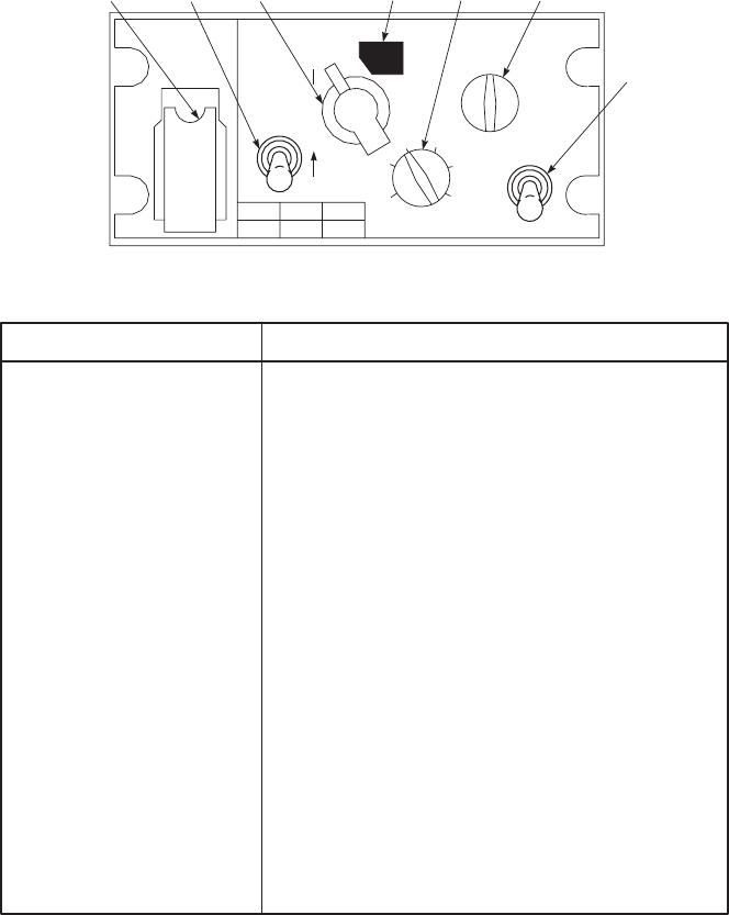
(c) If the MK operation was successful, the net
controller will now contact you via the new
CNV.
(d) If the MK operation was not successful,
the net controller will contact you via clear
voice (plain) transmission; with instruc-
tions to set your Z-AHP FILL selector
switch to position 6, and stand by while the
MK operation is repeated.
(6) It is important to be familiar with certain KY-58
audio tones. Some tones indicate normal opera-
tion, while other indicate equipment malfunc-
tion. These tones are:
(a) Continuous beeping, with background
noise, is cryptoalarm. This occurs when
power is first applied to the KY-58, or
when he KY-58 is zeroized. This beeping
is part of normal KY-58 operation. To clear
this tone, press and release the PTT button
on the Z-AHQ (after the Z-AHQ LOCAL
switch has been pressed). Also the PTT can
be pressed in the cockpit.
(b) Background noise indicates that the KY-58
is working properly. This noise should oc-
cur at TURN ON of the KY-58, and also
when the KY-58 is generating a cryptova-
riable. If the background noise is not heard
SA
AA0524
PLAIN
C / RAD MODE
DELAY
ON
POWER
OP LD
RV
1
2
34
5
6
Z
E
R
O
I
Z
E
KY
58
R
C
U
FILL
1
235
46
1. ZEROIZE SWITCH TWO−
POSITION MOMENTARY
TOGGLE UNDER SPRING
LOADED COVER
ZEROIZES THE KY−58; CLEARS ALL ENCODING IN
THE SYSTEM.
2. DELAY SWITCH TWO−
POSITION TOGGLE UP WHEN SIGNAL IS TO BE RETRANSMITTED.
3. PLAIN−C / RAD SWITCH
ROTARY TWO−POSITION
SELECTOR SWITCH
IN THE PLAIN POSITION, PERMITS NORMAL (UNCI−
PHERED) COMMUNICATIONS ON THE ASSOCIATED
FM RADIO SET.
IN THE C / RAD POSITION, PERMITS CIPHERED COM−
MUNICATIONS ON THE ASSOCIATED RADIO SET.
4. C / RAD2 SWITCH STOP LOCATION STOP FOR C / RAD2 ON FRONT PANEL.
5. FILL SWITCH SIX POSITION
ROTARY SWITCH PERMITS PILOT TO SELECT ONE OF 6 STORAGE
REGISTERS FOR FILLING.
6. MODE SWITCH THREE
POSITION ROTARY IN THE OP POSITION KY−58 NORMAL OPERATING,
IN THE LD POSITION FOR FILLING.
IN THE RV POSITION KY−58 IN RECEIVE−VARIABLE,
FILLED FROM ANOTHER EXTERNAL SOURCE.
7. POWER ON SWITCH TWO
POSITION TOGGLE CONNECTS POWER TO THE ASSOCIATED TSEC / KY−58
CIPHER EQUIPMENT IN THE ON (FORWARD) POSI−
TION, AND DISCONNECTS POWER FROM THE EQUIP−
MENT IN THE OFF (AFT) POSITION. TURNS ON POWER
TO TSEC / KY−58.
CONTROL FUNCTION
REMOTE CONTROL UNIT (RCU) (Z−AHP)
1 3 4 5 6
7
2
Figure 3-10. Voice Security Equipment
TM 1-1520-237-10
3-28
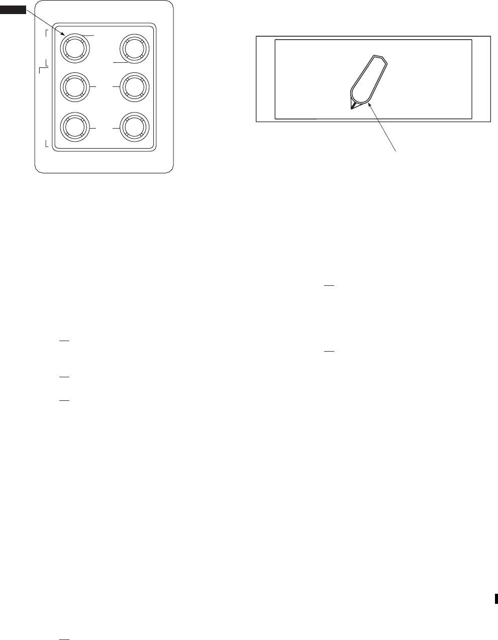
at TURN ON, the equipment must be
checked out by maintenance personnel.
(c) Continuous tone, could indicate a 9parity
alarm.9This will occur whenever an empty
storage register is selected while holding
the PTT button in. This tone can mean any
of three conditions:
1Selection of any empty storage regis-
ter.
2A9bad9cryptovariable is present.
3Equipment failure has occurred. To
clear this tone, follow the 9Loading
Procedures9in TM 11-5810-262-10. If
this tone continues, have the equip-
ment checked out by maintenance per-
sonnel.
(d) Continuous tone could also indicate a cryp-
toalarm. If this tone occurs at any time
other than in (c) above, equipment failure
may have occurred. To clear this tone, re-
peat the 9Loading Procedures9in TM 11-
5810-262-10. If this tone continues, have
the equipment checked out by maintenance
personnel.
(e) Single beep, when RCU is not in TD (Time
Delay), can indicate any of the three nor-
mal conditions:
1Each time the PTT button is pressed
when the KY-58 is in C (cipher) and a
filled storage register is selected, this
tone will be heard. Normal use (speak-
ing) of the KY-58 is possible.
2When the KY-58 has successfully re-
ceived a cryptovariable, this tone indi-
cates that a 9good9cryptovariable is
present in the selected register.
3When you begin to receive a ciphered
message this tone indicates that the
cryptovariable has passed the 9parity9
check, and that it is a good variable.
(f) A single beep, when the RCU is in TD
(Time Delay) occurring after the 9pre-
amble9is sent, indicates that you may be-
gin speaking.
(g) A single beep, followed by a burst of noise
after which exists a seemingly 9dead9con-
dition indicates that your receiver is on a
different variable than the distant transmit-
ter. If this tone occurs when in cipher text
mode: Turn RCU FILL switch to the CNV
and contact the transmitter in PLAIN text
and agree to meet on a particular variable.
3.11.2.1 KY-58 Remote Fill. A remote fill panel (Fig-
ure 3-11) allows a single crew member to load COMSEC
variables into each of the three KY-58’s from the pilots
side lower center console, FM-1 and FM-2 AN/ARC-201
TRANSSEC and HOPSET codes can be loaded from the
same panel.
SA
AA9244A
UHF
FM2
FM1
K
Y
−
5
8
C
O
M
S
E
C
T
R
A
N
S
E
C
/
H
O
P
S
E
T
GPS
SA
/
AS
GPS
Figure 3-11. Remote Fill Panel
SA
AA0359
FM 1 / FM 2 FM 2 / UHF
FM 2 / VHFFM 1 / VHF
FM 1 / UHF VHF / UHF
OFF
RADIO RETRANSMISSION
MODE
SELECTOR
Figure 3-12. Retransmission Control Panel
TM 1-1520-237-10
Change 8 3-29

3.12 RADIO RETRANSMISSION CONTROL.
Control of retransmission is through a switch panel (Fig-
ure 3-12) on the lower console. The position of the switch
determines which radio set pairs will be used when the
corresponding FM and VHF radio function and VOL
switches (not required for UHF) are placed to RETRAN.
Operation of the retransmission control is included with the
operating procedures of each radio set where applicable.
The retransmission control is only a means of directing the
audio output of a receiver to the audio input of a transmitter
through switching.
3.12A HF RADIO SET AN/ARC-220.
WARNING
Make sure that no personnel are within 3
feet of the HF antenna when transmitting,
performing radio checks or when in ALE
mode. Do not touch the RF output termi-
nal on the antenna coupler, the insulated
feed through, or the antenna itself while
the microphone is keyed (after the tuning
cycle is complete) or while the system is in
transmit self-test. Serious RF burns can
result from direct contact with the above
criteria.
a. The AN/ARC-220 HF transceiver provides long
range communications. The HF radio receives and trans-
mits on any one of 280,000 frequencies spaced at 100 Hz
steps on the high frequency (HF) band. The HF radio has a
frequency range of 2.0000 - 29.9999 MHz. Preset nets can
be manually programmed by the pilot, or loaded with a data
transfer device (DTD). Emission modes available are upper
side band (USB) voice, lower side band (LSB) voice, am-
plitude modulation equivalent (AME), or continuous wave
(CW), with a selection of 10, 50, or 175 watts of transmit-
ting power. Transmit tune time is normally less than 1 sec-
ond. The radio also has automatic link establishment (ALE)
and electronic counter countermeasures (ECCM) frequency
hopping mode. Data messages may be composed and stored
in the receiver/transmitter’s memory. These messages may
be transmitted and received using any operational mode of
the radio set.
b. Power for the radio is provided from the No. 1 dc
primary bus through a circuit breaker marked HF.
3.12A.1 Antenna. The tubular antenna element extends
from the left side of the transition area to a point just for-
ward of the hinged tailcone section, and is supported by
four masts. RF energy is supplied to the antenna through
the forward mast (Figure 3-1).
3.12A.2 Controls and Functions. The radio is con-
trolled by a control display unit (CDU) located in the lower
console (Figure 3-12.1). The function of each control and
display is as follows:
CONTROL/
DISPLAY FUNCTION
CURSOR keys. Position the cursor in the direction
of the arrow on the key.
Display screen Used to display system
information, and enter data or
commands in radio.
Line select keys Function depends on adjacent
display.
Brightness keys Changes display screen brightness.
Net selector switch Selects programmed operating net.
The + position allows additional
nets to be selected using the
VALUE keys.
DATA connector Fills radio with preprogrammed
data, required for all modes except
MAN.
KEY connector Used to load ALE and ECCM
presets.
Mode switch
MAN Operating frequency and emission
mode is selected manually. Once
selected, the information is stored
in memory, and can be recalled
using the net selector switch.
PRE Selects a preprogrammed
frequency and emission mode.
ALE Selects Automatic link
establishment (ALE) mode.
ECCM Selects electronic counter
countermeasure (ECCM) mode.
TM 1-1520-237-10
3-30 Change 8
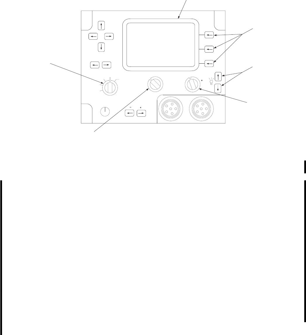
CONTROL/
DISPLAY FUNCTION
EMER Selects emergency mode.
-SQL+ keys Selects level of squelch from
TONE through 5.
TONE provides no muting or
squelch.
0gives muting, but no squelch.
1through 5gives levels of muting
and squelch.
Muting turns off the scanning re-
ceiver audio and gives the pilot a
tone when a ALE link is estab-
lished.
VOL switch Changes receive audio output level.
VOL settings are displayed for 5
seconds when radio is first powered
up, or when the VOL setting is
changed.
Function switch
CONTROL/
DISPLAY FUNCTION
OFF Turns the radio off.
STBY Turns the radio on, performs bit and
enables fill operations.
SILENT Prevents the radio from automati-
cally responding to incoming calls
in ALE or ECCM mode. Used dur-
ing refueling, ordinance loading
and EMCON conditions.
T/R Allows the radio to transmit and re-
ceive in selected operating mode.
ZERO Erases all loaded data, to include
datafill and keyfill information.
VALUE keys Increases or decreases a field value
or single character value that is
marked by the cursor.
SA
AB0988
CURSOR
VALUE
T / R
SILENT
STBY
OFF
ZERO
(PULL)
VOL SQL
PRE
MAN
ALE ECCM
EMER
1
2
3456
KEY DATA
LINE
SELECT
KEY
BRIGHTNESS
KEY
NET
SELECTOR
SWITCH
FUNCTION
SWITCH
MODE
SWITCH
DISPLAY
SCREEN
Figure 3-12.1. Control Display Unit AN/ARC-220
TM 1-1520-237-10
Change 4 3-31

CONTROL/
DISPLAY FUNCTION
Screen displays Each line can display up to 20 al-
phanumeric characters. The 5 char-
acters closest to the line select keys
are used for control selection. See
Table 3-1.1 for advisory messages
and their function.
3.12A.3 Modes of Operation.
3.12A.3.1 Manual (MAN) Mode. Use manual mode to
change transmit and receive frequencies, sidebands and
transmit power, and operate the radio manually.
1. To change radio settings:
a. Mode switch - MAN.
b. Function switch - T/R.
c. Select the desired net (1 through 20), net
selector switch - 1through +. Use VALUE
keys to select 7 through 20.
d. EDIT line select key - Press.
NOTE
Changing the receive frequency and mode
will also change the transmission frequency
and mode to the same values. Changing the
transmission frequency and mode will not
change the receive frequency and mode.
e. Edit frequency, emission mode and trans-
mit power by placing the cursor under field
to be edited with CURSOR key, and
change field value with VALUE keys.
f. To end edit and store changed data, RTN
line select key - Press.
2. To operate in manual mode:
a. Function switch - T/R.
b. Mode switch - MAN.
c. -SQL+ switch - Set squelch to 0.
d. VOL switch - Adjust for comfortable lis-
tening level.
NOTE
If the radio breaks in and out of squelch,
increase setting as required.
e. -SQL+ switch - Set squelch to 1.
f. Select the desired net (1 through 20), net
selector switch - 1through +. Use VALUE
keys to select 7 through 20.
g. ICS Transmitter selector - Position 5.
h. Radio push-to-talk switch - Press to talk;
release to listen.
3.12A.3.2 Preset (PRE) Mode. Preset mode stores pre-
porgrammed frequencies and emission modes that cannot
be changed by the operator. To use the radio in preset mode,
do the following:
1. Function switch - T/R.
2. Mode switch - PRE.
3. -SQL+ switch - Set squelch to 0.
4. VOL switch - Adjust for comfortable listening
level.
NOTE
If the radio breaks in and out of squelch,
increase setting as required.
5. -SQL+ switch - Set squelch to 1.
6. Select the desired net (1 through 20), net selec-
tor switch - 1through +. Use VALUE keys to
select 7 through 20.
7. ICS Transmitter selector - Position 5.
NOTE
If tune tone is heard, wait until it stops be-
fore talking. When radio push-to-talk switch
is pressed, XMT frequency is displayed.
Display returns to preset display when
switch is released.
8. Radio push-to-talk switch - Press to talk; re-
lease to listen.
TM 1-1520-237-10
3-32 Change 4

3.12A.3.3 Automatic Link Establishment (ALE)
Mode.
WARNING
When in ALE mode, the radio transmits
interrogating signals (sounds) and replies
to ALE calls automatically without opera-
tor action. To avoid personnel injury, en-
sure the function switch is not set to ALE
when personnel are working near the he-
licopter, during refueling or loading ordi-
nance.
NOTE
Self address must be selected before using
ALE.
ALE mode may be used for communications, either nor-
mal or link protected, or position reporting.
1. To set up the radio for ALE communications,
do the following:
a. Function switch - T/R.
b. Mode switch - ALE.
c. Select the desired net (1 through 20), net
selector switch - 1through +. Use VALUE
keys to select 7 through 20.
d. -SQL+ switch - Set squelch to TONE.
e. VOL switch - Adjust for comfortable lis-
tening level.
NOTE
Earphone audio is muted until a link is es-
tablished. If the link is noisy, set squelch to
1. Higher squelch settings are not recom-
mended in this mode.
f. -SQL+ switch - Set squelch to 0.
g. To synchronize time in a link protected
channel, EDIT and SYNC soft keys -
Press.
h. To broadcast AN/ARC-220 system time as
net control, EDIT, then TXTIM soft keys
- Press. Time will be transmitted, and radio
will return to scan mode.
2. To receive a ALE call:
a. INCOMING CALL is displayed, fol-
lowed by the caller’s ALE address. A short
tone sounds, and LINKED is displayed.
b. ICS Transmitter selector - Position 5.
NOTE
Wait for the calling station to make the first
transmission.
c. Radio push-to-talk switch - Press to talk;
release to listen.
3. To place a ALE call:
a. Select ALE address:
(1) Select the desired net (1 through 20),
net selector switch - 1through +.To
select 7 through 20, set the selector
switch to the +position and use the
value keys to scroll to the desired se-
lection. Net name and address will be
displayed.
(2) VALUE switch - Press, to scroll
through address list.
(3) If placing an ALE call to an address
not in the list, edit the address as fol-
lows: EDIT soft key - Press. Enter ad-
dress one character at a time with
CURSOR and VALUE switches. To
accept the edit and return to ALE
screen, RTN soft key - Press.
b. ICS Transmitter selector - Position 5.
NOTE
Press ABORT to stop the calling process.
c. Radio push-to-talk switch - Press (and re-
lease). CALLING, then LINKED is dis-
played with a short gong tone in head-
phone.
TM 1-1520-237-10
Change 8 3-32.1

NOTE
ALE will cancel the link, and return to scan
mode if there is no activity on a link for a
predetermined time as set by the data fill (60
seconds is a typical value). To maintain a
link, press HOLD soft key. When commu-
nications are complete, or to return to scan
mode, press SCAN soft key.
d. Radio push-to-talk switch - Press to talk;
release to listen.
e. When communication is complete, to re-
turn to scanning mode, HOLD, then
SCAN soft key - Press.
3.12A.3.4 Electronic Counter Countermeasures
(ECCM) Mode. The radio changes frequency in a se-
quence determined by the ECCM key. Datafill and keyfill
must be loaded prior to using ECCM mode, and system
time must be synchronized between stations. Frequencies
used in hop sets are pretuned in the radio, as ECCM re-
quires frequencies to be changed many times per second.
Frequency hopping is performed in the ECCM mode of
operation. To use this mode, do the following:
1. Initialize the net:
a. Function switch - T/R.
b. Mode switch - ECCM.
c. Select the desired net (1 through 12), net
selector switch - 1through +. Use VALUE
keys to select 7 through 12.
d. To change values on screen, EDIT soft key
- Press. Use CURSOR to position cursor
under area to change, and VALUE to
change the field to desired value.
e. To save changes and return to top level
screen, RTN soft key - Press.
f. Push-to-talk switch - Press, to tune and
time synchronize the radio.
2. To communicate in ECCM only mode, do the
following:
a. -SQL+ switch - Set squelch to TONE.
b. VOL switch - Adjust for comfortable lis-
tening level.
NOTE
If the frequency is noisy, set squelch to 1.
Higher squelch settings are not recom-
mended in this mode.
c. -SQL+ switch - Set squelch to 0.
d. Press and hold the push-to-talk switch until
XMT READY is displayed. Wait for pre-
amble tones to stop.
e. Talk. Release switch to listen.
3. Deleted.
3.12A.3.5 Message Mode. The radio can store up to 10
transmit data and 10 received data messages. Each message
may be
TM 1-1520-237-10
3-32.2 Change 8

500 characters long. Messages are numbered from 1 to 10.
Message 10 is the oldest, and will be deleted if a new
message is received. Messages may be composed using the
AN/ARC-220 CDU dictionary or with a custom dictionary
listing locally generated words, which may be loaded with
datafill.
1. To view a received message:
a. MSG soft key - Press.
b. Use CURSOR keys to scroll left or right,
or up and down in a message.
c. Use VALUE keys to page up and down in
a message.
d. To view additional messages, position cur-
sor under message number with CURSOR
keys. Use VALUE keys to scroll to the
next message number.
e. To retain received messages, RTN soft key
- Press.
f. To delete received messages, position the
cursor under the message number and DEL
soft key - Press, until messages are deleted.
To return to top screen, RTN soft key -
Press.
2. To edit or compose a message:
a. MSG soft key - Press.
b. From MESSAGE screen, PGRM soft key
- Press.
c. Select message to be edited by placing cur-
sor under the message number with CUR-
SOR keys, and change number with
VALUE keys.
d. Edit message by placing cursor under area
to be changed. Use VALUE keys to
change one character at a time. Press DEL
to delete one character at a time.
e. To insert a word from the dictionary in a
message do the following:
(1) Position cursor where the word is to
be inserted
(2) WORD soft key - Press.
(3) Select the word with VALUE keys.
(4) To insert word with blank in message,
SELECT soft key - Press. If desired,
return to message without inserting a
word by pressing CANCL.
f. To load edited message in R/T memory
and return to top level screen, RTN soft
key - Press.
3. To send a message:
a. Access PRGM MSG screen by pressing
MSG, then PRGM soft keys.
b. Select message to send as desired by plac-
ing cursor under message number, and
pressing VALUE keys until desired mes-
sage is displayed.
NOTE
Message will be sent to currently selected
address (ALE modes) or transmitted on the
currently selected frequency and mode
(MAN, PRE, or ECCM).
c. SEND soft key - Press.
3.12A.4 Operation.
3.12A.4.1 Starting Procedure.
1. Function switch - STBY.SYSTEM TESTING
is displayed while power up built in test (PBIT)
is in process. SYSTEM - GO will be displayed
upon successful completion of PBIT.
2. FILL line select key - Press. Status of PRE,
ALE,ECCM, and EMER modes will be dis-
played.
3.12A.4.2 Load Presets. Datafill contains preset fre-
quencies, scan lists, addresses, data messages, and non se-
cure information needed for ALE/ECCM operation. If the
DTD is configured to receive data, it may be copied from
the radio to the DTD by pressing COPY line select key on
the DATA FILL page.
1. Initialize the data transfer device (DTD). Con-
nect the DTD to the DATA connector.
TM 1-1520-237-10
Change 4 3-32.3

2. With the FILL page selected, DATA line se-
lect key - Press.
NOTE
Pressing RTN line select key on DATA
FILL page stops the fill process.
3. On the DATA FILL page, FILL line select
key - Press. FILL ENABLED screen will ap-
pear.
4. Start data fill on DTD. Monitor DTD to see
when data transfer is complete.
3.12A.4.3 Load Secure Keys. Key fill contains secure
information needed for ALE link protection and ECCM
operation.
1. Initialize the DTD. Connect the DTD to the
KEY connector.
2. With the FILL page selected, KEY line select
key - Press.
NOTE
Pressing RTN line select key on KEY FILL
page stops the fill process.
3. On the KEY FILL page, LOAD line select key
- Press. FILL ENABLED message will appear.
4. Start keyfill on DTD. Monitor DTD to see when
data transfer is complete.
3.12A.4.4 Zero Secure Keys.
1. Access KEY FILL page. From FILL screen,
KEY fixed function key - Press.
2. ZERO line select key - Press.
3. Select key to zero with VALUE keys. Default
is all keys.
NOTE
If you do not want to zero the key, press
NO. The FILL screen will then appear.
4. Confirm zero by pressing YES line select key.
ZEROIZE advisory message will appear, fol-
lowed by the FILL screen.
3.12A.4.5 Emergency (EMER) Operation. The
mode, frequency, and net to be used in the EMER position
is determined by the datafill. To use the emergency mode,
do the following:
1. Function switch - T/R.
2. Mode switch - EMER.
3. ICS Transmitter selector - Position 5.
4. Radio push-to-talk switch - Press to talk; re-
lease to listen.
3.12A.5 Shutdown.
1. Function switch - OFF.
2. To erase all preprogrammed information, Func-
tion switch - Pull and turn to ZERO (PULL).
3.12A.6 Messages. Table 3-2 lists display advisory
messages that may appear during operation of the radio:
Table 3-2. AN/ARC-220 Messages
ADVISORY MEANING ACTION
ALE - NO DATA ALE mission data not loaded. Load mission data.
ALE - NO KEYS ALE link protection keys not loaded. Load keys.
CALL FAIL Radio failed to complete an outgoing call.
CALLING Radio is placing an ALE call to another address.
TM 1-1520-237-10
3-32.4 Change 8

Table 3-2. AN/ARC-220 Messages (Cont)
ADVISORY MEANING ACTION
CDU FAIL Radio set control is inoperative.
CHANNEL BUSY ALE or ECCM net is in use. Wait or try another net.
CHANNEL INOP ALE or ECCM keys are not loaded, or not correct.
CHECK MSG A data message has been received.
COMPLETE Indicated power-up BIT is complete.
COPY COMPLETE Copying process finished successfully.
COPY FAIL Copying process was unsuccessful.
COPYING DATA The radio is copying datafill contents from DTS.
ECCM - NO DATA ECCM data not installed. Load mission data.
ECCM - NO KEYS ECCM keys not installed. Load keys.
EMER Mode or net selected for emergency communica-
tion is inoperative.
EMERG - NO KEYS No keys available for net selected for emergency
communication. Load keys.
EOM End of message.
EXT FAIL Radio failed due to external device, such as an-
tenna.
GO DATA Link quality analysis values too low for reliable
voice communication; data transmissions recom-
mended.
GPS FAIL Position report could not be issued.
GPS TIME FAIL Current time could not be established via GPS re-
ceiver.
HELD ALE call being held in specific frequency by op-
erator.
INCOMING CALL Another radio is establishing an ALE link.
INOP MODES EXIST Warning to expect inoperative modes.
LINKED An ALE link is established.
TM 1-1520-237-10
Change 8 3-32.5

Table 3-2. AN/ARC-220 Messages (Cont)
ADVISORY MEANING ACTION
LOAD COMPLETE Keys and data successfully loaded into radio.
LOAD FAIL Keys and data not successfully loaded into radio.
LOADING DATA Radio currently loading data.
LOADING KEYS Radio currently loading keys.
MSG ABORT Radio discontinuing sending of current message.
NET INOP Selected net contains no data, corrupted data, or
hardware cannot support the selected mode of op-
eration.
NO AUTO XMT Radio has been instructed not to make any auto-
matic transmissions.
NO DATA Database is not filled with necessary data to per-
form requested operations.
NO KEYS LOADED Keys are not loaded for current selected mode or
net.
NO RCVD MSGS No messages have been received.
PAC FAIL Failure of radio in PA coupler.
PLGR Precision lightweight GPS receiver.
POSN RPT FAIL Current GPS position report not loaded.
PRE - NO DATA Preset data not loaded.
PTT FOR XMIT BIT Instruction to press microphone PTT switch to en-
able transmission BIT.
RCV BIT - GO Receiver BIT functions completed without failure.
RCV READY Ready to receive ECCM transmissions.
RCVG PREAMBLE ECCM preamble being received.
RCVG DATA Radio currently receiving data.
RT-CDU COMM FAIL Receiver-transmitter is failing to communicate
with the radio set control.
RT FAIL Receiver Transmitter inoperative.
TM 1-1520-237-10
3-32.6 Change 8

Table 3-2. AN/ARC-220 Messages (Cont)
ADVISORY MEANING ACTION
RX-TX DEGRADED Receive and transmit capabilities are degraded.
RX-TX FAIL Radio cannot receive or transmit.
SENDING DATA Radio currently sending data.
SENDING POSN Sending GPS position report.
SOUND Radio sending an ALE sound.
SYNCING Time synchronization being performed.
TESTING BIT in progress.
TIME SYNC FAIL Radio failed in attempt to synchronize.
TRANSEC FAIL BIT detected a failure that will not allow ECCM
operation.
TUNE XX% Indicates percentage of ECCM frequencies tuned
for current net.
TUNING Radio is currently tuning itself.
TX DEGRADED BIT detected a failure that is causing transmission
capability to be degraded.
TX FAIL Radio cannot transmit.
UNSYNC ECCM is not synchronized.
UNTUNED An ECCM hop set is not tuned.
XMT READY Radio is ready to transmit in ECCM mode.
ZEROIZED All mission datafill and keys have been erased.
3.12B TSEC/KY-100 SECURE COMMUNICATION
SYSTEM.
The TSEC/KY-100 provides secure, half duplex voice,
digital data, analog data and remote keying capabilities for
transmission over the AN/ARC-220 HF radio. It has six
operational modes, and can store often used settings on
presets. Power is supplied from the No. 1 dc primary bus
through a circuit breaker marked HF SCTY SET.
3.12B.1 Controls and Functions. The KY-100 is con-
trolled by a control display unit (CDU) located behind the
lower console (Figure 3-12.2). The function of each control
and display is as follows:
CONTROL FUNCTION
AUDIO Speaker for audio tones.
CIK Cryptographic Ignition Key. Not
used in this installation.
FILL connector Used to connect external fill device
to KY-100.
TM 1-1520-237-10
Change 8 3-32.7
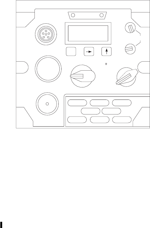
CONTROL FUNCTION
INIT,gand dFunction keys used to access and
navigate in software menus.
DSPL OFF Varies light intensity of display.
Display turned off in OFF position.
PNL OFF Varies light intensity of backlit
display panel. Display turned off in
OFF position.
PRESET switch Controls power to set, and which
key is active.
PWR OFF Removes power from set.
MAN Manual rekeying enabled.
1,2,3,4,5,6 Selects preset settings for use.
REM Allows control of KY-100 from a
remote control unit (RCU).
MODE switch
CONTROL FUNCTION
PT Sets KY-100 to plaintext mode.
CT Sets KY-100 to ciphertext mode.
RK Allows cooperative terminal
rekeying in receive mode.
OFL Sets KY-100 to off line mode.
Disables communications and
accesses screens to select mode
settings, test, and fill screens.
EB Select emergency back-up key.
Z ALL
(PULL) Erases all cryptographic data (keys)
except the emergency back-up key.
3.12B.2 Modes of Operation.
3.12B.2.1 Plaintext (PT) Mode. The ICS voice signal
is routed through the KY-100 to and from the HF radio,
with no processing. Radio transmits and receives unen-
crypted information.
3.12B.2.2 Cyphertext (CT) Mode. The ICS voice sig-
nal is routed to the KY-100, where it is processed, en-
crypted and sent to the HF radio for transmission. Received
audio signals from the HF radio are processed, decoded,
and sent to ICS. Unencrypted information is routed through
the KY-100 if CT ONLY is not selected in configuration
settings. Non cooperative rekey receive is possible only in
this mode.
3.12B.2.3 Rekey Mode. Use this mode to fill crypto in-
formation. The data transfer device must be connected to
FILL to load keys.
3.12B.2.4 Off-line (OFL) Mode. For maintenance use
to configure and test the system. Communications are not
possible in this mode.
3.12B.2.5 Emergency Backup (EB) Mode. Enables a
zeroized terminal to be used for voice privacy operation,
only. Key is not erased when terminal is zeroized. This
mode is not to be used to transmit classified information.
3.12B.2.6 Zeroize (Z ALL) Mode. Erases all keys in
the KY-100 except the emergency back-up key.
SA
AB0987
DSPL
OFF BRT
PNL
OFF
INIT
FILL
CIK
AUDIO
KY−
100
OFL EB
RK
CT
PT
MODE PRESET
ZALL
(PULL) 1234
6
REM
MAN
PWR
OFF
BAT
123
465
U
Figure 3-12.2. KY-100 Secure Communication
Control Panel
TM 1-1520-237-10
3-32.8 Change 9
3.12B.3 Operation.
3.12B.3.1 Keyfill Operation. When there are no TEKs
in the KY-100 at start up, the display will read CLd STRT.
If there are TEKs in the terminal, skip steps 3 and 6, and
load or update keys as required.
1. MODE switch - OFFLINE.
2. PRESET switch - MAN.
3. Wait until CLd STRT is displayed, then INIT
key - Press.
4. Connect a fill device to FILL connector.
5. Turn on device and select key to be loaded.
6. INIT key - Press. At the end of the fill se-
quence, a tone should be heard in the headset,
and KEY101,CIK OK, and PASS will ap-
pear. The key that was loaded is stored in fill
position 1.
7. To fill the rest of the keys, push the dor gkey
until KEY OPS is displayed.
8. INIT key - Push twice. LOAD KEY, then
LOAD X will be displayed with the flashing X
being the number of currently selected key lo-
cation.
9. Press the dor gkey until the desired location
(1,2,3,4,5,6,orU) is displayed.
10. INIT key - Press. The entire LOAD X display
will flash.
11. Turn on device and select key to be loaded.
12. INIT key - Press. At the end of the fill se-
quence, a tone should be heard in the headset,
and KEY X will appear. The display will then
change to LOAD X with the flashing Xbeing
the number of currently selected key location.
13. Repeat steps 9. through 11. until all required
locations are filled.
14. When all keys are transferred, turn off the fill
device, and disconnect it from FILL connector.
15. To exit key load, place MODE switch out of
OFFLINE.
3.12B.3.2 Normal Operation.
1. MODE switch - PT,orCT.
2. PRESET switch - MAN,1,2,or3.
3.12B.3.3 Emergency Operation.
NOTE
Emergency key is not secure. Do not trans-
mit classified information in this mode.
1. MODE switch - EB.
2. PRESET switch - MAN,1,2,or3.
3.12B.3.4 Zeroize All Keys.
NOTE
Power does not have to be applied to unit to
zero all keys.
Emergency backup key is not zeroized in
this procedure.
1. MODE switch - Pull and rotate to Z ALL
(PULL).
3.12B.3.5 Zeroize Specific Keys.
1. MODE switch - OFFLINE.
2. UP ARROW,orRIGHT ARROW soft key -
Press, until KEY OPS is displayed.
3. INIT key - Press. LOAD KEY will be dis-
played.
4. UP ARROW,orRIGHT ARROW key -
Press, until ZERO is displayed.
5. INIT KEY soft key - Press. ZERO X, with a
flashing number (X) appears. The flashing num-
ber indicates the currently selected key to be
zeroized.
NOTE
Number of keys is 1 through 6 TEKs, U
(used to update internal keys) and Eb (emer-
gency backup key).
TM 1-1520-237-10
Change 8 3-32.9

6. UP ARROW,orRIGHT ARROW key -
Press, until key number to zeroize is displayed.
7. INIT key - Press. The entire ZERO X will
now flash.
8. INIT key - Press. The screen will blank while
zeroizing process takes place. When zeroizing
is complete, a tone will be heard in the headset,
the display will briefly change to ZEROED X,
and then revert to ZERO X.
9. Repeat steps 6 through 8 to zero other key po-
sitions, as desired.
10. When all desired key positions are zeroized,
MODE switch - Move to any other position.
3.12B.4 Shutdown.
PRESET switch - PWR OFF.
3.12B.5 Configuration.
Configure as described in Appendix C.
TM 1-1520-237-10
3-32.10 Change 8
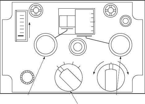
Section III NAVIGATION
3.13 DIRECTION FINDER SET AN/ARN-89. (LF/
ADF).
Direction Finder set AN/ARN-89 (Figure 3-13) is an
airborne, low frequency (LF), automatic direction finder
(ADF) radio, that provides an automatic or manual com-
pass bearing on any radio signal within the frequency range
of 100 to 3,000 kHz. The ADF can identify keyed or con-
tinuous wave (CW) stations. The ADF displays the bearing
of the helicopter relative to a selected radio transmission on
the horizontal situation indicator No. 2 bearing pointer
(Figure 3-31 ). When ADF is selected on the MODE SEL
panel (Figure 3-32) three modes of operation permit the
system to function: as a CW automatic direction finder, as a
CW manual direction finder or as an amplitude-modulated
(AM) broadcast receiver. Power to operate the Direction
Finder AN/ARN-89 is provided by No. 1 dc primary bus
through a circuit breaker, marked ADF, and the ac essential
bus through a circuit breaker, marked 26VAC INST.
3.13.1 Antennas. The ADF sense antenna is a part of
the VHF/FM No. 2, VHF/AM, antenna (Figure 3-1) under
the nose section of the helicopter. The ADF loop antenna is
flush-mounted, under the center fuselage section.
3.13.2 Controls and Functions. Controls for the LF/
ADF receiver are on the front panel of the unit (Figure
3-13). The function of each control is as follows:
CONTROL FUNCTION
Mode selector
switch
OFF Turns power off.
COMP Provides operation as an ADF.
ANT Provides for operation as an AM
receiver using sense antenna.
LOOP Provides for receiver operation as a
manual direction finder using loop
only.
LOOP L-R
control
switch
Provides manual left and right
control of loop when operating
mode selector in LOOP position. It
is spring loaded to return to center.
AUDIO Adjusts volume.
100 Kilohertz
coarse-tune
control knob
Tunes receiver in 100-kHz steps as
indicated by first two digits of
KILOCYCLES indicator.
10 Kilohertz fine
-tune control
knob
Tunes receiver in 10 kHz steps as
indicated by last two digits of
KILOCYCLES indicator.
CW,VOICE,
TEST switch
CW (COMP
mode) Enables tone oscillator to provide
audible tone for tuning to CW
station, when mode function switch
is at COMP.
CW (ANT or
LOOP mode) Enables beat frequency oscillator to
permit tuning to CW station, when
mode function switch is at ANT or
LOOP.
VOICE Permits low frequency receiver to
operate as a receiver with mode
switch in any position.
SA
AA0360
AUDIO
KILOCYCLES CW
TEST
VOICE
LOOP
T
U
N
E
A
D
F
R
C
V
ROFF LOOP
COMP ANT
29
80
90
LR
100 KILOHERTZ COARSE
TUNE CONTROL MODE SELECTOR
10 KILOHERTZ FINE
TUNE CONTROL
Figure 3-13. LF/ADF Control Panel
C-7932/ARN-89
TM 1-1520-237-10
Change 8 3-32.11
CONTROL FUNCTION
TEST (COMP
mode) Provides slewing of loop through
180° to check operation of receiver
in COMP mode. (Switch position
is inoperative in LOOP and ANT
mode.)
TUNE meter Indicates relative signal strength
while tuning receiver to a specific
radio signal.
KILOCYCLES
indicator Indicates operating frequency to
which receiver is tuned.
3.13.3 Operation.
3.13.3.1 Starting Procedure.
1. ICS NAV receiver selector - ON.
2. Mode selector - COMP,ANT,orLOOP.
3. Frequency - Select.
4. CW,VOICE,TEST switch - CW or VOICE
as appropriate.
5. ICS NAV switch - ON.
6. Fine tune control - Adjust for maximum up-
ward indication on TUNE meter.
7. AUDIO control - Adjust as desired.
3.13.3.2 ANT Mode Operation.
1. Mode selector - ANT.
2. ICS NAV switch - ON.
3. Monitor receiver by listening.
3.13.3.3 COMP Mode Operation.
1. Mode selector - COMP.
2. MODE SEL BRG 2 HSI/VSI switch - ADF.
3. The horizontal situation indicator No. 2 bearing
pointer displays the magnetic bearing to the
ground station from the helicopter, as read
against the compass card, when ADF is se-
lected on the MODE SEL BRG 2 switch.
4. ICS NAV switch - ON.
5. To test the ADF, when required:
a. CW,VOICE,TEST switch - TEST.
Check to see that No. 2 bearing pointer
changes about 180°.
b. CW,VOICE,TEST switch - Release.
3.13.3.4 LOOP Mode Operation. Manual direction
finding uses the LOOP mode.
1. Mode selector switch - LOOP.
2. ICS NAV switch - ON.
3. Turn LOOP L-R switch to L(left) or R(right)
to obtain an audio null and a TUNE indicator
null. Watch HSI No. 2 bearing pointer for a
display of magnetic bearing to or from ground
station as read against the compass card. In this
mode of operation, two null positions 180°
apart are possible.
3.13.4 Stopping Procedure. Mode selector - OFF.
3.14 DIRECTION FINDER SET AN/ARN -149 (LF/
ADF) (IF INSTALLED).
The AN/ARN -149 (Figure 3-14) is a low frequency
(LF), automatic direction finder (ADF) radio, providing
compass bearing capability within the frequency range of
100 to 2199.5 kHz. The ADF has two functional modes of
operation: ANT and ADF. The antenna (ANT) mode func-
tions as an aural receiver, providing only an aural output of
the received signal. The ADF mode functions as an auto-
matic direction finder, providing a relative bearing-to-
station signal to the horizontal situation indicator No. 2
bearing pointer and an aural output. A TONE submode of
operation can be selected in either ANT or ADF mode,
providing a 1000-Hz aural output to identify keyed CW
signals. Power is provided to the LF/ADF system by the
No. 1 dc primary bus through a circuit breaker, labeled
ADF, and the ac essential bus through a circuit breaker,
labeled 26 VAC INST.
3.14.1 Antennas. The antenna system is a single com-
bination antenna containing both loop and sense elements.
The RF signal from one loop element is modulated with a
reference sine signal while the other loop element is modu-
lated with a reference cosine signal. The two modulated
signals are combined, phase shifted 90°, and amplified. The
resulting loop signal is summed with the sense antenna sig-
TM 1-1520-237-10
3-32.12 Change 8
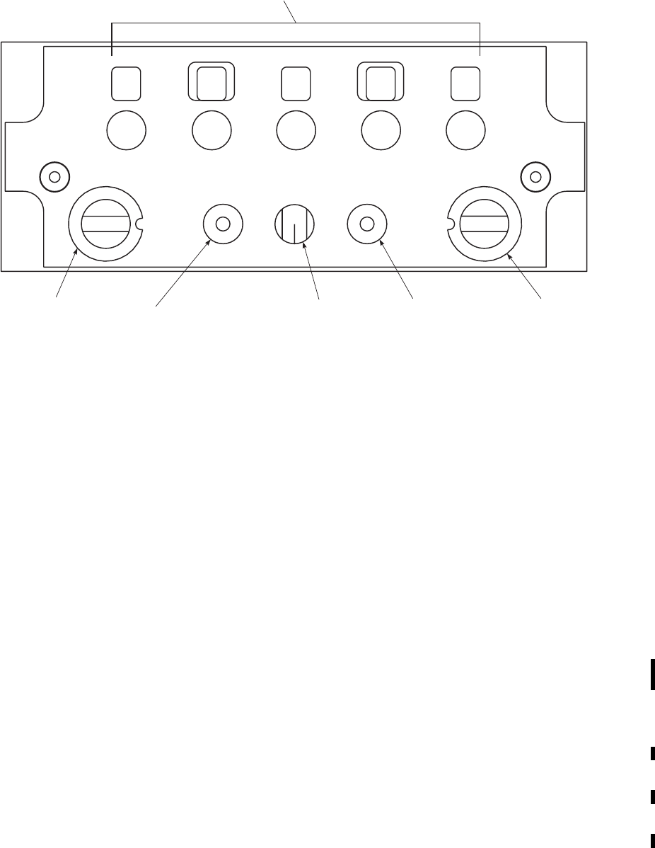
3.14.2 Controls and Functions. Controls and fre-
quency digit displays are on the front of the ADF control
panel (Figure 3-14). The function of each control is as fol-
lows:
CONTROL FUNCTION
Frequency controls
and indicators Controls and indicates the selected
frequency when MAN/2182/500
switch is in MAN.
MAN/2182/500
select
MAN Enables the frequency controls and
indicators.
2182 Selects 2182 kHz as the operating
frequency.
500 Selects 500 kHz as the operating
frequency.
CONTROL FUNCTION
TEST/(OFF)/
TONE select TEST position (up) is a momentary
position that enables a self-test.
Center position is off. TONE
position (down) enables the tone
generator for CW operation.
VOL adjust A 12-position switch controlling
volume in 12 discrete steps.
TAKE CMD select Used in a dual ADF control panel
installation allowing each to take
control of the receiver away from
the other. Not used in this
installation.
ADF/ANT/OFF
select
ADF Applies power to system and turns
on ADF and aural capability.
ANT Applies power to system and turns
on antenna or aural function only.
OFF Removes power from system.
SA
FS0015A
2
MAN
2182
500
A
D
F
TEST
TONE
VOL TAKE
CMD ADF
ANT
OFF
000
.0
FREQUENCY
CONTROLS AND
INDICATORS
MANUAL
2182 / 500
SELECT TEST / (OFF) / TONE
SELECT
VOLUME
ADJUST TAKE
COMMAND
SELECT
ADF / ANT / OFF
SELECT
Figure 3-14. LF/ADF Control Panel AN/ARN-149
TM 1-1520-237-10
Change 1 3-33

3.14.3 Operation.
3.14.3.1 ANT (Aural Only) Operation.
1. ICS NAV reciever selector switch - ON.
2. ADF/ANT/OFF switch - ANT.
3. MAN/2182/500 switch - As desired.
If MAN is selected in step 3:
4. Frequency switches - Select.
5. VOL control - Adjust as desired.
6. TEST/(OFF)TONE switch - TONE.
3.14.3.2 ADF Operation.
1. ICS NAV receiver selector switch - ON.
2. HSI/VSI MODE SEL BRG 2 switch - ADF.
3. ADF/ANT/OFF switch - ADF.
4. MAN/2182/500 switch - As desired.
If MAN is selected in step 4:
5. Frequency controls - Select.
6. VOL control - Adjust as desired.
If CW operation is desired:
7. TEST/(OFF)/TONE switch - TONE.
8. Verify horizontal situation indicator (HSI) No.
2 bearing pointer displays appropriate relative
bearing-to-the-station.
If self-test is required:
9. TEST/(OFF)/TONE switch - TEST (position
up and hold).
10. No. 2 bearing pointer deflects 90° away from
original reading.
11. TEST/(OFF)/TONE switch - Release to off.
12. Verify No. 2 bearing pointer returns to original
reading.
3.14.4 Stopping Procedure. ADF/ANT/OFF switch -
OFF.
3.15 RADIO RECEIVING SET AN/ARN-123(V)
(VOR/ILS/MB).
Radio set AN/ARN 123(V) (Figure 3-15) is a very high-
frequency receiver that operates from 108.00 to 117.95
MHz. Course information is presented by the VSI course
deviation pointer and the selectable No. 2 bearing pointer
on the horizontal situation indicator. The combination of
the glide slope capability and the localizer capability makes
up the instrument landing system (ILS). The marker beacon
portion of the receiver visually indicates on the VSI MB
advisory light, and aurally indicates on the headphones, of
passage of the helicopter over a marker beacon transmitter.
The receiving set may be used as a VOR receiver, or ILS
receiver. The desired type of operation is selected by tuning
the receiving set to the frequency corresponding to that
operation. ILS operation is selected by tuning to the odd
tenth MHz frequencies between 108.0 and 112.0 MHz.
VOR operation is selected by tuning in .050 MHz units to
the frequencies between 108.0 and 117.95 MHz, except the
odd tenth MHz between 108.0 and 112.0 MHz, which are
reserved for ILS operation. The three receiver sections do
the intended functions independent of each other. Perfor-
mance degradation within any one of the major sections
will not affect the performance of the others. Power for the
AN/ARN-123 is provided from the dc essential bus through
a circuit breaker, marked VOR/ILS.
NOTE
Tuning to a localizer frequency will auto-
matically tune to a glide slope frequency,
when available.
3.15.1 Antenna. The VOR/LOC antenna system (Figure
3-1), consists of two blade type collector elements, one on
each side of the fuselage tail cone. The glide slope antenna
is mounted under the avionics compartment in the nose.
The antenna provides the glide slope receiver with a
matched forward-looking receiving antenna. The marker
beacon antenna is flush-mounted under the center section of
the fuselage.
3.15.2 Controls and Functions. The controls for the
VOR/ILS/MB receivers are on the front panel of the unit.
The function of each control is as follows:
TM 1-1520-237-10
3-34 Change 10

CONTROL FUNCTION
NAV VOL-OFF
control Turns VOR/ILS receiver on and
off, adjusts volume.
MB VOL-OFF
control Turns marker beacon receiver on
and off; adjusts volume.
Megahertz tune
control Tunes VOR/ILS receiver in MHz
as indicated on frequency indicator.
Hundredths
megahertz tune
control
Tunes VOR/ILS receiver in
hundredths MHz as indicated on
frequency indicator.
VOR/MB TEST
control Activates VOR test circuit and MB
receiver lamp self-test circuits.
MB SENS HI-
LO control For controlling MB sensitivity.
LO Decreases receiver sensitivity by
shortening time transmitted signal
will be received.
HI Increases receiver sensitivity by
lengthening time transmitted signal
will be received.
3.15.3 Operation.
3.15.3.1 Starting Procedure.
1. ICS AUX selector - ON.
2. NAV VOL OFF control - On.
3. Frequency - Select.
4. MODE SEL BRG 2 switch - VOR.
5. MODE SEL VOR/ILS switch - VOR.
3.15.3.2 VOR/Marker Beacon Test.
NOTE
If acceptable signal is not received, test will
not be valid.
1. HSI CRS set 315° on COURSE set display,
pilot and copilot.
2. VOR/MB TEST switch - Down and hold. The
MB light on the VSI should go on.
3. HSI VOR/LOC course bar and VSI course de-
viation pointer - Centered 61 dot.
4. No. 2 bearing pointer should go to the 310° to
320° position.
5. To-from arrow should indicate - TO.
6. VOR/MB TEST switch - Release.
3.15.3.3 VOR Operation. Course - Set.
3.15.3.4 ILS (LOC/GS) Operation. ILS operation fre-
quency - Set.
3.15.3.5 Marker Beacon (MB) Operation.
1. MB VOL OFF switch - On.
2. MB SENS switch - As desired.
3.15.3.6 VOR Communications Receiving Opera-
tion. Frequency - Set.
3.15.4 Stopping Procedure. NAV VOL OFF switch -
OFF.
3.16 RADIO RECEIVING SET AN/ARN-147(V)(VOR/
ILS/MB)(IF INSTALLED).
Radio set AN/ARN-147 (V) (Figure 3-16) is a very high
frequency receiver, capable of operating from 108.0 to
126.95 MHz. Course information is presented by the verti-
cal situation indicator deviation pointer and the selectable
SA
AA0526
NAV VOL MB VOL
OFF
VOR / MB
TEST
OFF
MB SENS
HI
LO
108.00
MEGAHERTZ
TUNE CONTROL FREQUENCY
INDICATOR HUNDRETHS
MEGAHERTZ
TUNE CONTROL
Figure 3-15. Radio Receiving Set
AN/ARN-123(V)
TM 1-1520-237-10
Change 9 3-35
No. 2 bearing pointer on the horizontal situation indicator.
The combination of the glide slope and localizer capabili-
ties makes up the instrument landing system (ILS). The
marker beacon portion of the receiver visually indicates on
the vertical situation indicator MB advisory light, and au-
rally signals over the headphones helicopter passage over a
transmitting marker beacon. The radio set may be used as a
VHF omnirange (VOR) or ILS receiver. The desired type
of operation is selected by tuning the receiving set to the
frequency corresponding to that operation. ILS operation is
selected by tuning to the odd tenth MHz frequencies from
108.0 to 111.95 MHz. VOR operation is selected by tuning
from 108.0 to 126.95 MHz, except the odd tenth MHz from
108.0 to 111.95 MHz reserved for ILS operation. The three
receiver sections do the intended functions independent of
each other. Performance degradation within any one of the
major sections will not affect performance of the others.
Power for the AN/ARN-147 is provided from the dc essen-
tial bus through a circuit breaker, labeled VOR/ILS.
NOTE
Tuning to a localizer frequency will auto-
matically tune to a glide slope frequency
when available.
3.16.1 Antennas. The VOR/LOC antenna system (Fig-
ure 3-1) consists of two blade type collector elements, one
on each side of the fuselage tail cone. The glide slope an-
tenna is mounted under the avionics compartment in the
nose. The antenna provides the glide slope receiver with a
matched forward looking receiving antenna. The marker
beacon antenna is flush-mounted under the center section of
the fuselage.
3.16.2 Controls and Functions. The controls for the
VOR/ILS/MB receivers are on the front of the control panel
(Figure 3-16). The function of each control is as follows:
CONTROL FUNCTION
Digit window Indicates selected operating
frequency.
NAV VOL adjust Varies navigation (VOR/LOC)
audio gain of associated receiver.
KHz digits select Changes frequency in 50-kHz steps
over the range of control (last two
digits).
TEST/(power) ON/
OFF select Controls application of power to
the associated receiver. Controls
VOR/marker beacon test.
CONTROL FUNCTION
MB HI/LO select Varies marker beacon (MB)
sensitivity (high or low).
MHz digits select Changes frequency in 1-MHz steps
over the range of control (first three
digits).
MB VOL adjust Varies marker beacon (MB) audio
gain of the associated receiver.
3.16.3 Operation.
3.16.3.1 Starting Procedure.
1. ICS AUX receiver selector switch - ON.
2. TEST/(pwr) ON/OFF switch - ON (center po-
sition).
3. MHz (first three digits) control - Select.
4. KHz (last two digits) control - Select.
5. NAV VOL control - Adjust.
6. MODE SEL BRG 2 switch - VOR.
7. MODE SEL VOR/ILS switch - VOR.
8. CIS MODE SEL NAV/ON switch - As de-
sired.
3.16.3.2 VOR/Marker Beacon Test.
NOTE
Test will not be valid if signal reception is
invalid.
1. HSI CRS control (pilot and copilot) - Set 315°
in course display.
2. TEST/(pwr) ON/OFF switch - TEST (position
up and hold). VSI MB advisory light goes on.
3. HSI VOR/LOC course bar and VSI course de-
viator pointer - Centered (61 dot).
4. No. 2 bearing pointer - 315° (65°).
5. To-from arrow - TO.
TM 1-1520-237-10
3-36 Change 9
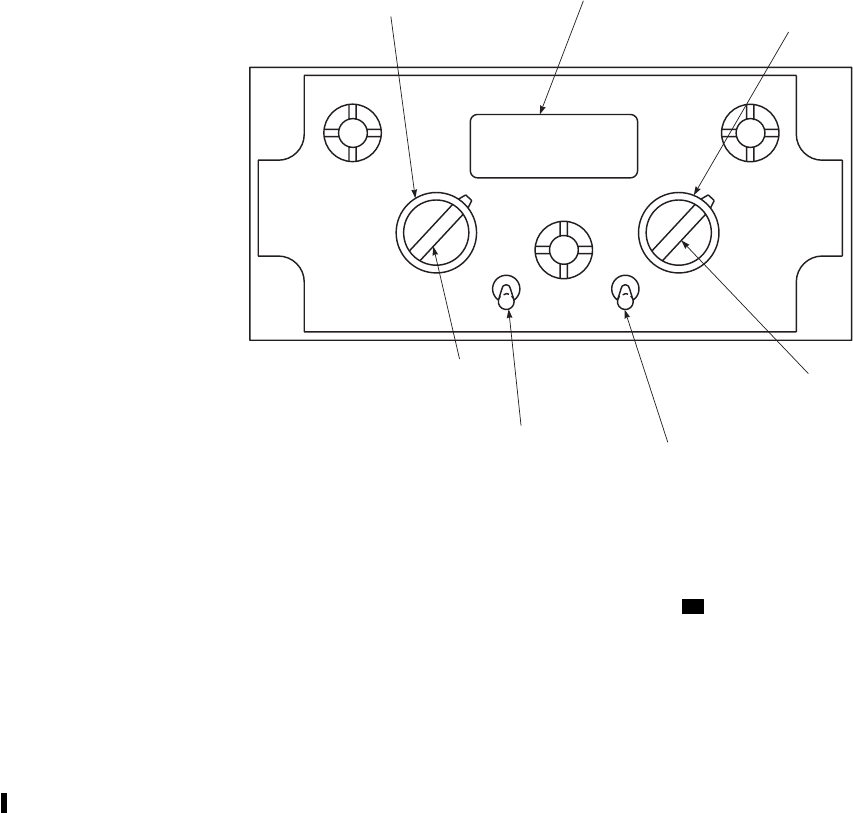
6. TEST/(pwr) ON/OFF switch - Release.
3.16.3.3 VOR Operation. HSI CRS control - Course se-
lect.
3.16.3.4 ILS (LOC/GS) Operation.
1. ILS operation frequency/volume - Set.
2. HSI CRS control - Course select.
3. CIS MODE SEL NAV/ON switch - As de-
sired.
3.16.3.5 Marker Beacon (MB) Operation.
1. ICS NAV receiver selector switch - ON.
2. MB HI/LO switch - As desired.
3. MB VOL control - Adjust as desired.
3.16.3.6 VOR Communications Receiving Opera-
tion. Frequency/Volume - Set.
3.16.4 Stopping Procedure. TEST/(pwr) ON/OFF
switch - OFF.
3.17 DOPPLER NAVIGATION SET
AN/ASN-128. UH
The Doppler navigation set, AN/ASN-128, in conjunc-
tion with the helicopter’s heading and vertical reference
systems, provides helicopter velocity, position, and steering
information from ground level to 10,000 feet. To achieve
best results with the set, pitch and roll angles should be
limited to 30° pitch and 45° roll, and moderate maneuver
rates should be employed. The Doppler navigation system
is a completely self-contained navigation system and does
not require any ground-based aids. The system provides
world-wide navigation, with position readout available in
both Universal Transverse Mercator (UTM) and Latitude
and Longitude (LAT/LONG)(Figure 3-22). Navigation and
steering is done using LAT/LONG coordinates, and a bilat-
eral UTM-LAT/LONG conversion routine is provided for
UTM operation. Up to ten destinations may be entered in
either format and not necessarily the same format. Present
position data entry format is also optional and independent
of destination format. Power to operate the AN/ASN-128 is
provided from No. 1 dc primary bus through a circuit
breaker marked DPLR, and from the ac essential bus
through a circuit breaker, marked 26 VAC DPLR, refer to
TM 11-5841-281-12.
SA
FS0016A
MB
N
A
V
MB
HI
LO
NAV
VOL
TEST
ON
OFF
VOL
MARKER BEACON
VOLUME ADJUST
DIGIT
WINDOW NAV VOLUME
ADJUST
MHZ
DIGITS
SELECT
MARKER BEACON
HI / LO SELECT TEST / (POWER)
ON / OFF SELECT
KHZ DIGITS
SELECT
Figure 3-16. VOR/ILS/MB Control Panel AN/ARN-147 (V)
TM 1-1520-237-10
Change 1 3-37
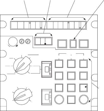
3.17.1 Antenna. The Doppler antenna (Figure 3-1) con-
sists of a combined antenna/radome and a receiver-
transmitter housing below copilot’s seat. The combination
antenna/radome uses a printed-grid antenna.
3.17.2 Controls, Displays, and Function. The con-
trol and displays for the Doppler are on the front panel
(Figure 3-17). The function of each control is as follows:
CONTROL/
INDICATOR FUNCTION
MODE selector Selects Doppler Navigation Mode
of operation.
OFF Turns navigation set off.
LAMP TEST Checks operation of all lamps.
TEST Initiates built-in-test exercise for
navigation set.
UTM Selects Universal Transverse
Mercator (UTM) navigational
mode of operation.
CONTROL/
INDICATOR FUNCTION
LAT/LONG Select latitude/longitude
navigational mode of operation.
BACKUP Places navigation set in estimated
mode of operation or estimated
velocity mode of operation.
DISPLAY
selector Selects navigation data for display.
WIND SP/
DIR Not applicable.
XTK/TKE
(Left Display) Distance crosstrack (XTK)of
initial course to destination in km
and tenths of a km.
(Right Display) Track angle error (TKE) in degrees
displayed as right or left of bearing
to destination.
GS-TK
(Left Display) Ground speed (GS) in km/hr.
(Right Display) Track angle (TK) in degrees
TRUE.
PP with switch
set to UTM
(Center Display)
Present position UTM zone.
(Left Display) Present position UTM area square
designator and easting in km to
nearest ten meters.
(Right Display) Present position UTM area
northing in km to nearest ten
meters.
PP with MODE
switch set to
LAT/LONG
(Left Display)
Present position latitude in degrees,
minutes and tenths of minutes.
(Right Display) Present position longitude in
degrees, minutes and tenths of
minutes.
DIST/BRG-
TIME
(Center
Display)
Time to destination selected by
FLY TO DEST (in minutes and
tenth of minutes).
(Left Display) Distance to destination selected by
FLY TO DEST (in km and tenths
of a km).
SA
AA0663
KEYBOARD
LEFT
DISPLAY
LAMPS
CENTER
DISPLAY
LAMPS
RIGHT
DISPLAY
LAMPS
TARGET
STORAGE
INDICATOR
DIM MEM MAL KYBD TGT
STR
ALPHA
ABC
1DEF
2GHI
3
JKL
4MNO
5PQR
6
STU
7VWX
8YZ
0
CLR ENT
7
3
DEST
DISP
FLY−TO
DEST
MODE
OFF
LAMP
TEST
TEST UTM
LAT /
LONG
BACK
UP
WIND
SP / DIR
XTK
TKE
GS
TK
PP DIST / BRG
TIME
DEST
TGT
SPH
VAR
LEFT MID RIGHT
D
P
L
R
N
A
V
9
DISPLAY
Figure 3-17. Doppler Navigation Set
AN/ASN-128
TM 1-1520-237-10
3-38
CONTROL/
INDICATOR FUNCTION
(Right Display) Bearing to destination selected by
FLY TO DEST (in degrees MAG-
NETIC).
DEST-TGT
(Mode switch set
to UTM)
(Center
Display)
UTM zone of destination selected
by DEST DISP thumbwheel.
(Left Display) UTM area and easting of destina-
tion set on DEST DISP thumb-
wheel.
(Right Display) Northing of destination set on
DEST DISP thumbwheel.
DEST-TGT
(Mode switch set
to LAT/LONG
(Left Display)
Latitude (N 84° or S 80° max.) of
destination set on DEST DISP
thumbwheel.
(Right Display) Longitude of destination set on
DEST DISP thumbwheel.
SPH-VAR
(Left Display) Spheroid code of destination set on
DEST DISP thumbwheel.
(Right Display) Magnetic variation (in degrees and
tenths of degrees) of destination set
on DEST DISP thumbwheel.
MEM indicator
lamp Lights when radar portion of navi-
gation set is in nontrack condition.
MAL indicator
lamp Lights when navigation set mal-
function is detected by built in self-
test.
DIM control Controls light intensity of display
characters.
Left, Right, and
Center display
lamps
Lights to provide data in alphanu-
meric and numeric characters, as
determined by setting of DISPLAY
switch, MODE switch, and opera-
tion of keyboard.
Target storage
indicator Displays destination number
(memory location in which present
position will be stored when TGT
STR pushbutton is pressed.
TGT STR
pushbutton Stores present position data when
pressed.
CONTROL/
INDICATOR FUNCTION
KYBD pushbut-
ton Used in conjunction with the key-
board to allow data to be displayed
and subsequently entered into the
computer when the ENT key is
pressed.
DEST DISP
thumbwheel
switch
Destination display thumbwheel
switch is used along with DEST-
TGT and SPH-VAR position of
DISPLAY switch to select destina-
tion whose coordinates or magnetic
variation are to be displayed, or to
be entered. Destinations are 0
through 9, P (Present Position) and
H (Home).
Keyboard Used to set up data for entry into
memory. When the DISPLAY
switch is turned to the position in
which new data is required and the
KYBD pushbutton is pressed, data
may be displayed on the appropri-
ate left, right, and center display.
To display a number, press the cor-
responding key or keys (1 through
0). To display a letter, first depress
the key corresponding to the de-
sired letter. Then depress a key in
the left, middle or right column,
corresponding to the position of the
letter on the key. Example: To en-
ter an L, first depress L, then 3, 6,
or 9 in the right column.
FLY-TO-DEST
thumbwheel
switch
Selects the destination for which
XTK/TKE and DIST/BRG/TIME
are displayed when the DISPLAY
switch is turned to either of these
positions which steering informa-
tion is desired. Destinations are 0
through 9, and H (Home).
ENT key Enters data set up on keyboard into
memory when pressed.
CLR key Clears last entered character when
pressed once. When pressed twice,
clears entire display panel under
keyboard control.
TM 1-1520-237-10
3-39
3.17.3 Modes of Operation. The three basic modes of
operation are: Navigate, test, and backup.
3.17.3.1 Test Mode. The TEST mode contains two
functions: LAMP TEST mode, in which all display seg-
ments are lit, and TEST mode, in which system operation
is verified. In the LAMP TEST mode, system operation is
identical to that of the navigate mode except that all lamp
segments and the MEM and MAL indicator lamps are
lighted to verify their operation (Figure 3-18). In TEST
mode, the system antenna no longer transmits or receives
electromagnetic energy; instead, self-generated test signals
are inserted into the electronics to verify operation. System
operation automatically reverts into the backup mode dur-
ing test mode. Self-test of the Doppler set is done using
built-in-test equipment (BITE), and all units connected and
energized for normal operation. Self-test isolates failures to
one of the three units. The computer-display unit (except
for the keyboard and display) is on a continuous basis, and
any failure is displayed by turn-on of the MAL indicator
lamp on the computer-display unit. The signal data con-
verter and receiver-transmitter-antenna are tested by turn-
ing the MODE switch to TEST. Failure of those compo-
nents is displayed on the computer-display unit by turn-on
of the MAL indicator lamp. Identification of the failed unit
is indicated by a code on the display panel of the computer-
display unit. Continuous monitoring of the signal data con-
verter and receiver-transmitter-antenna is provided by the
MEM indicator lamp. The MEM indicator lamp will light
in normal operation when flying over smooth water. How-
ever, if the lamp remains on for over 10 minutes, over land
or rough water, there is a malfunction in the Doppler set.
Then the operator should turn the MODE switch to TEST,
to determine the nature of the malfunction. Keyboard op-
eration is verified by observing the alphanumeric readout as
the keyboard is used.
3.17.3.2 Navigate Mode. In the navigate mode (UTM
or LAT/LONG position of the MODE selector), power is
applied to all system components, and all required outputs
and functions are provided. Changes in present position are
computed and added to initial position to determine the
instantaneous latitude/longitude of the helicopter. Destina-
tion and present position coordinates can be entered and
displayed in UTM and latitude/longitude. At the same time,
distance, bearing and time-to-go to any one of ten preset
destinations are computed and displayed as selected by the
FLY-TO DEST thumbwheel.
3.17.3.3 Backup Mode. In this mode, remembered ve-
locity data are used for navigation. The operator can insert
ground speed and track angle with the keyboard and the
display in GS-TK position. This remembered velocity data
can be manually updated through use of the keyboard and
CDU DISPLAY switch in the GS-TK position. When
GS-TK values are inserted under these conditions, naviga-
tion continues using only these values.
3.17.4 Operation.
3.17.4.1 Window Display and Keyboard Operation.
In all data displays except UTM coordinates, the two fields
are the left and right display windows. In UTM coordinates
displays, the first field of control is the center window and
the second field is the combination of the left and right
displays. When pressing the KYBD pushbutton, one or
other of the fields described above is under control. If it is
not desired to change the display in the panel section under
control, the pilot can advance to the next field of the display
panel by pressing the KYBD pushbutton again. The last
character entered may be cleared by pressing the CLR key.
That character may be a symbol or an alphanumeric char-
acter. However, if the CLR key is pressed twice in succes-
sion, all characters in the field under control will be cleared
and that field will still remain under control.
3.17.4.2 Data Entry.
1. To enter a number, press the corresponding key.
To enter a letter, first press the key correspond-
ing to the desired letter. Then press a key in the
left, middle, or right column corresponding to
the position of the letter on the pushbutton.
2. Example: To enter an L, first press L, then ei-
ther 3, 6, or 9 in the right column. The com-
puter program is designed to reject unaccept-
able data (for example, a UTM area of WI does
not exist, and will be rejected). If the operator
attempts to insert unacceptable data, the display
will be blank after ENT is pressed.
3.17.4.3 Starting Procedure.
1. MODE selector - LAMP TEST. All lights
should be lit.
a. Left, right, Center and Target storage indi-
cator - Lit (Figure 3-18). All other lights
should be on.
b. Turn DIM control fully clockwise, then
fully counterclockwise, and return to full
clockwise; all segments of the display
should alternately glow brightly, go off,
and then glow brightly.
2. MODE selector - TEST. After about 15 sec-
onds left display should display GO. Ignore the
TM 1-1520-237-10
3-40
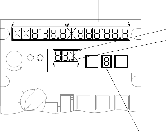
random display of alpha and numeric charac-
ters which occurs during the first 15 seconds.
Also ignore test velocity and angle data dis-
played after the display has frozen. After about
15 seconds, one of the following five displays
will be observed in the first two character posi-
tions in the left display:
NOTE
If the MAL lamp lights during any mode of
operation except LAMP TEST, the
computer-display unit MODE switch should
be turned first to OFF, and then to TEST,to
verify the failure. If the MAL lamp remains
on after recycling to TEST, notify organiza-
tional maintenance personnel of the naviga-
tion set malfunction.
DISPLAY REMARKS
LEFT RIGHT
GO No display.
Display
blanks
(normal).
If right display is blank,
system is operating
satisfactorily.
SA
AA0525
KYBD TGT
STR
MEM MAL
LEFT
DISPLAY
LAMPS
RIGHT
DISPLAY
LAMPS
CENTER
DISPLAY
LAMPS
TARGET
STORAGE
INDICATOR
DECIMAL
TENTHS OF MINUTES
Figure 3-18. Doppler Lamp Test Mode Display
TM 1-1520-237-10
3-41
DISPLAY REMARKS
LEFT RIGHT
GO P If right display is P, then
pitch or roll data is missing,
or pitch exceeds 90°. In this
case, pitch and roll in the
computer are both set to zero
and navigation continues in a
degraded operation. Problem
may be in the vertical gyro-
scope or helicopter cabling.
NOTE
If the TEST mode display is MN or NG, the
MODE switch should be recycled through
OFF to verify that the failure is not a momen-
tary one. If the TEST mode display is MN,
the data entry may be made in the UTM or
LAT/LONG mode, but any navigation must
be carried on with the system in the
BACKUP mode.
BU C, R, S, or H
followed
by a numeric
code
A failure has occurred and the
system has automatically
switched to a BACKUP
mode of operation as follows:
1. The operator has the option
of turning the MODE switch
to BACKUP and entering the
best estimate of ground speed
and track angle. 2. The opera-
tor has the option of turning
the MODE switch to
BACKUP and entering his
best estimate of wind speed
and direction and entering his
best estimate of ground speed
and track angle. The operator
should update present posi-
tion as soon as possible, be-
cause it is possible that sig-
nificant navigation errors may
have accumulated.
DISPLAY REMARKS
LEFT RIGHT
MN C, R, S, or H
followed
by a numeric
code
A failure has occurred and the
BACKUP mode, used for
manual navigation (MN), is
the only means of valid navi-
gation. The operator may use
the computer as a dead reck-
oning device by entering
ground speed and track data.
The operator should update
present position as soon as
possible, because it is pos-
sible significant navigation
errors may have accumulated.
MN HO10000 No heading information to
signal data converter.
SO5000 No 26 vac to signal data con-
verter.
NG C, R, S, or H
followed
by a numeric
code
A failure has occurred in the
system and the operator
should not use the system.
EN The 9V battery has failed. All
stored data must be reentered
after battery replacement.
Blank C with
random
numbers
Computer display unit fail-
ure.
Blank R with
random
numbers
Receiver-transmitter-antenna
failure.
Blank S with
random
numbers
Signal data converter failure.
Random
display Random dis-
play Signal data converter failure.
TM 1-1520-237-10
3-42

3.17.4.4 Entering UTM Data. This initial data is in-
serted before navigating with the Doppler. Refer to para-
graph 3.17.4.9.
a. Spheroid of operation, when using UTM coordinates.
b. UTM coordinates of present position - zone, area,
easting (four significant digits) and northing (four signifi-
cant digits; latitude/longitude coordinates may be used.
c. Variation of present position to the nearest one-tenth
of a degree.
d. Coordinate of desired destination - 0 through 5 and
H; (6 through 9 are normally used for target store locations;
but may also be used for destinations). It is not necessary to
enter all destinations in the same coordinate system.
NOTE
It is not necessary to enter destinations un-
less steering information is required, unless
it is desired to update present position by
overflying a destination, or unless a present
position variation computation is desired
(paragraph 3.17.3.3). If a present position
variation running update is desired, destina-
tion variation must be entered. The operator
may enter one or more destination variations
to effect the variation update; it is not nec-
essary for all destinations to have associated
variations entered.
3.17.4.5 Entering Spheroid and/or Variation.
1. MODE selector - UTM,LAT/LONG or
BACKUP.
2. DISPLAY selector - SPH-VAR.
3. DEST DISP thumbwheel - P, numeral, or H as
desired.
4. KYBD pushbutton - Press. Observe display
freezes and TGT STR indicator blanks. Press
KYBD pushbutton again and observe left dis-
play blinks. If no spheroid data is to be entered,
KYBD pushbutton -Press again, go to step 7.
5. Spheroid data - Entry. (Example: INø). Press
keys 3 (left window blanks), 3, 5, 5 and 0. Left
display should indicate INø. Refer to Figure
3-22 for codes.
6. ENT pushbutton - Press if no variation data is
to be entered.
7. KYBD pushbutton - Press, if variation data is
to be entered, and note right display blanks. (If
no variation data is to be entered, ENT key -
Press.)
8. Variation data - Enter. (Example: E001.2, press
keyboard keys 2 (right window blanks), 2, 0, 0,
1 and 2. Press ENT key, the entire display will
blank and TGT STR number will reappear,
display should indicate INø E 001.2.)
3.17.4.6 Entering Present Position or Destination
In UTM.
1. MODE selector - UTM.
2. DISPLAY selector - DEST-TGT.
3. DEST DISP thumbwheel - P, numerical, or H
as desired.
4. Present position and destination - Enter. (Ex-
ample: Entry of zone 31T, area CF, easting
0958 and northing 3849.)
a. KYBD pushbutton - Press. Observe that
display freeze and TGT STR indicator
blanks.
b. KYBD button - Press. Observe that center
display blanks.
c. Key 3, 1, 7, and 8 - Press.
d. KYBD button - Press. Observe left and
right displays blank.
e. Key 1, 3, 2, 3, 0, 9, 5, 8, 3, 8, 4, 9 - Press.
f. ENT pushbutton - Press. Left, right, and
center displays will momentarily blank and
TGT STR number will appear. Displays
should indicate 31T CF 09583849.
3.17.4.7 Entering Present Position or Destination
Variation In LAT/LONG. The variation of a destination
must be entered after the associated destination coordinates
are entered (since each time a destination is entered its
associated variation is deleted). The order of entry for
present position is irrelevant.
TM 1-1520-237-10
Change 1 3-43
NOTE
If operation is to occur in a region with rela-
tively constant variation, the operator enters
variation only for present position, and the
computer will use this value throughout the
flight.
1. MODE selector - LAT/LONG.
2. DISPLAY selector - DEST-TGT.
3. DEST DISP thumbwheel - P, numerical or H
as desired.
4. Present position or destination - Enter. (Ex-
ample: Entry of N41° 10.1 minutes and E035°
50.2 minutes.) Press KYBD pushbutton. Ob-
serve that display freezes and TGT STR indi-
cator blanks. Press KYBD pushbutton again
and observe left display blanks. Press keys 5, 5,
4, 1, 1, 0 and 1. Press KYBD pushbutton (right
display should clear), and keys 2, 2, 0, 3, 5, 5, 0
and 2.
5. ENT pushbutton - Press. Entire display will
blank and TGT STR number will reappear.
Display should indicate N 41° 10.1 E0 35° 50.2.
3.17.4.8 Ground Speed and Track.
1. MODE selector - BACK UP.
2. DISPLAY selector - GS-TK.
3. Ground speed and track - Enter. (Example: En-
ter 131 km/h and 024°. Press KYBD pushbut-
ton, observe that left display freezes and TGT
STR indicator blanks. Press KYBD pushbutton
and observe that left display blanks. Press keys
1, 3, and 1. Left display indicates 131. Press
KYBD pushbutton, control shifts to right dis-
play, and right display blanks. Press keys 0, 2
and 4.
4. ENT pushbutton - Press. The entire display will
blank, and TGT STR number will reappear.
Display should indicate 131 024°.
3.17.4.9 Initial Data Entry. Initial data entry of varia-
tion in coordinates is normally done prior to takeoff. To
make the initial data entry, do the following:
1. Present positon variation - Enter (paragraph
3.17.4.5).
2. DISPLAY selector - DEST-TGT.
3. DEST DISP thumbwheel - P. Do not press
ENT key now.
4. ENT pushbutton - Press as helicopter is sitting
over or overflies initial fix position.
5. FLY-TO DEST thumbwheel - Desired destina-
tion location.
3.17.4.10 Update of Present Position From Stored
Destination. The helicopter is flying to a destination set
by the FLY-TO DEST thumbwheel. When the helicopter
is over the destination, the computer updates the present
position when the KYBD pushbutton is pressed, by using
stored destination coordinates for the destination number
shown in FLY-TO DEST window, and adding to them the
distance traveled between the time the KYBD pushbutton
was pressed and the ENT key was pressed.
1. DISPLAY selector - DIST/BRG-TIME.
2. KYBD pushbutton - Press, when helicopter is
over the destination. Display freezes.
NOTE
If a present position update is not desired, as
indicated by an appropriately small value of
distance to go on overflying the destination,
set the DISPLAY selector to some other po-
sition, this aborts the update mode.
3. ENT key - Press.
3.17.4.11 Update of Present Position from Land-
mark. There are two methods for updating present posi-
tion from a landmark. Method 1 is useful if the landmark
comes up unexpectedly and the operator needs time to de-
termine the coordinates. Method 2 is used when a landmark
update is anticipated.
a. Method 1.
(1) DISPLAY selector - PP.
(2) KYBD pushbutton - Press as landmark is
overflown. Present position display will
freeze.
(3) Compare landmark coordinates with those
on display.
(4) Landmark coordinates - Enter. If difference
warrants an update.
TM 1-1520-237-10
3-44
(5) ENT key - Press if update is required.
(6) DISPLAY selector - Set to some other po-
sition to abort update.
b. Method 2.
(1) DISPLAY selector - DEST/TGT.
(2) DEST DISP thumbwheel - P. Present pos-
tion coordinate should be displayed.
(3) KYBD pushbutton - Press, observe that
display freezes.
(4) Landmark coordinates - Manually enter via
keyboard.
(5) ENT key - Press when overflying land-
mark.
(6) DISPLAY selector - Set to some other po-
sition to abort update.
3.17.4.12 Left-Right Steering Signals. Flying short-
est distance to destination from present position.
1. DISPLAY selector - XTK-TKE.
2. MODE SEL -DPLR.
3. Fly helicopter in direction of lateral deviation
pointer on vertical situation indicator to center
the pointer, or course deviation bar on HSI.
3.17.4.13 Target Store (TGT STR) Operation. Two
methods may be used for target store operation. Method 1
is normally used when time is not available for preplanning
a target store operation. Method 2 is used when time is
available and it is desired to store a target in a specific
DEST DISP position.
a. Method 1.
(1) TGT STR pushbutton - Press when flying
over target.
(2) Present position is automatically stored and
the destination location is that which was
displayed in the target store indicator (po-
sition 6, 7, 8, or 9) immediately before
pressing the TGT STR pushbutton.
b. Method 2.
(1) MODE selector - UTM or LAT/LONG,
depending on coordinate format desired.
(2) DISPLAY selector - DEST-TGT.
(3) DEST DISP thumbwheel - P.
(4) KYBD pushbutton - Press when over fly-
ing potential target. Display should freeze.
NOTE
Do not press ENT key while DEST DISP
thumbwheel is at P.
(5) If it is desired to store the target, turn
DEST DISP thumbwheel to destination lo-
cation desired and press ENT key.
(6) If it is not desired to store the target, place
DISPLAY selector momentarily to another
position.
3.17.4.14 Transferring Stored Target Coordinates
From One Location to Another. The following proce-
dure allows the operator to transfer stored target coordi-
nates from one thumbwheel location to another. For ex-
ample, it is assumed that the pilot wants to put the
coordinates of stored target 7 into location of destination 2.
NOTE
Throughout this procedure, range, time-to-
go, bearing and left/right steering data are
computed and displayed for the destination
selected via the FLY-TO DEST thumb-
wheel.
1. DISPLAY selector - DEST-TGT.
2. DEST DISP thumbwheel - 7.
3. KYBD pushbutton - Press.
4. DEST DISP thumbwheel - 2.
5. ENT key - Press.
3.17.4.15 Transferring Variation From One Loca-
tion to Another. The procedure to transfer variation data
to the same location where the associated stored target co-
ordinates has been transferred is the same as in paragraph
3.17.4.14. Transferring Stored Target Coordinates From
One Location To Another, except that the DISPLAY selec-
tor is placed at SPH-VAR.
TM 1-1520-237-10
3-45

3.17.4.16 Dead Reckoning Navigation. As an alter-
nate BACKUP mode, dead reckoning navigation can be
done using ground speed and track angle estimates pro-
vided by the operator.
1. MODE selector - BACKUP.
2. DISPLAY selector - GS-TK.
3. Best estimate of ground speed and track angle -
Enter via keyboard.
4. Set MODE selector to any other position to
abort procedure.
3.17.4.17 Operation During and After Power Inter-
ruption. During a dc power interruption inflight, or when
all helicopter power is removed, the random access memory
(RAM) (stored destination and present position) data is re-
tained by power from an 8.4 volt dc dry cell battery. This
makes it unnecessary to reenter any navigational data when
power returns or before each flight. If the battery does not
retain the stored destination data during power interruption,
the display will indicate on EN when power returns. This
indicates to the pilot that previously stored data has been
lost, and that present position, spheroid/variation, and des-
tinations must be entered. The computer, upon return of
power, resets present position variation to E000.0°, desti-
nation and associated variations to a non-entered state, re-
members wind to zero and spheroid to CL6. The following
data must be entered following battery failure:
1. Enter spheroid.
2. Enter present position variation.
3. Enter present position.
4. Enter each destination and its associated varia-
tion.
3.17.5 Stopping Procedure. MODE selector - OFF.
3.17A DOPPLER/GPS NAVIGATION SET (DGNS)
AN/ASN-128B. UH
The AN/ASN-128B DGNS is an AN/ASN-128 LDNS
with an embedded GPS receiver. The AN/ASN-128B in
conjunction with the aircraft’s heading, vertical references,
and position and velocity updates from its internal GPS,
provides accurate aircraft velocity, position and steering in-
formation from ground level to 10,000 feet. The system
provides worldwide navigation, with position readout avail-
able in both Military Grid Reference System (MGRS) and
Latitude and Longitude (LAT/LONG) coordinates. Naviga-
tion and steering is performed using LAT/LONG coordi-
nates and a bilateral MGRS-LAT/LONG conversion rou-
tine is provided for MGRS operation. Up to 100
destinations may be entered in either format and not neces-
sarily the same format.
3.17A.1 Antenna. The GPS antenna is located on the
top aft section of the helicopter. The Doppler antenna is
located below the copilot’s seat (Figure 3-1).
3.17A.2 Controls, Displays, and Function. The con-
trol and displays for the AN/ASN-128B are on the front
panel (Figure 3-18.1). The function of each control is as
follows:
CONTROL/
INDICATOR FUNCTION
NOTE
The MODE switch is locked in the
OFF position and must be pulled
out and turned to get into or out of
the OFF position.
MODE selector Selects mode of operation.
OFF In this position the navigation set is
inoperable: non-volatile RAM
retains stored waypoint data.
LAMP TEST Checks operation of all lamps.
TEST Initiates built-in-self test exercise
for the Doppler and GPS functions
of the navigation set.
MGRS Selects MGRS navigational mode
of operation.
LAT/LONG Selects latitude/longitude
navigational mode of operation.
GPS LDG Places navigation set in GPS
landing mode of operation. This
mode provides real time, tactical
precision landing guidance
information to the HSI and VSI
indicators.
DISPLAY
selector Selects navigation data for display.
TM 1-1520-237-10
3-46 Change 4

CONTROL/
INDICATOR FUNCTION
WIND-UTC
DATA 9Doppler
only9
Used for wind speed and direction
(with TAS sensor installed), UTC
time, sea current, surface wind,
GPS status and data load functions.
XTK/TKE
KEY Displays steering (cross track dis-
tance and track angle error) infor-
mation and GPS variable key sta-
tus. Selection of fly to destination
by direct entry of two digit destina-
tion number.
GS/TK NAV M Displays ground speed, track angle
and selection of GPS and naviga-
tion mode.
PP Displays present position, altitude
and magnetic variation.
CONTROL/
INDICATOR FUNCTION
DIST BRG
TIME Displays distance, bearing and time
information to the destination or
course selected. Selection of fly to
destination can be accomplished by
direct entry of two digit destination
number.
WP TGT Accesses waypoint or target data
(landing data, variation, motion).
Selection of destination for display/
entry by direct entry of two digit
destination number.
DATUM
ROUTE Accesses datum and steering/route
functions.
MAL indicator
lamp Lights when a malfunction is de-
tected by the built-in-test circuitry.
In the event of an intermittent mal-
function, the system may operate
correctly but must be cycled to the
OFF position then to on, to extin-
guish the MAL light.
SA
AA9998A
LTR
LEFT
LTR
MID
LTR
RIGHT
ABC
1DEF
2GHI
3
JKL
4MNO
5PQR
6
GPS
LDG
LAT /
LONG
MGRS
TEST
LAMP
TEST
OFF
XTK/TKC
KEY
GS/TK
NAV M
PP DIST / BRG
TIME
WIND−UTC
DATA
WP
TGT
DATUM
ROUTE
DISPLAY
N
A
V
MODE
P
/
P
R
STU
7VWX
8YZ*
9
CLR #
0ENT
(PAGE)
KYBD
F1
TGT
STR
INC
(+)
DEC
(−)
MAL
BRT
DIM
17:BANDO 030MG91
GPS : M NAV : C
GS : 1 17KM / HR
TK : 0 2 5 "
FLY TO EPE SYS
STAT TGT
STR
G
S
D
L
Figure 3-18.1. Doppler/GPS Navigation Set
AN/ASN-128B
TM 1-1520-237-10
Change 2 3-46.1

CONTROL/
INDICATOR FUNCTION
BRT and DIM
keys Used to brighten or dim the light
intensity of the LCD display.
Four line alpha-
numeric display Displays alphanumeric characters,
as determined by the setting of the
DISPLAY selector, the MODE se-
lector and operation keyboard. The
keys activate function upon press-
ing the key.
TGT STR key Stores present position data in the
indicated target store/memory loca-
tion (90-99) when pressed.
KYBD key Used in conjunction with the key-
board to allow data display and en-
try into the computer.
Keyboard and
LTR keys Used to set up data for entry into
memory. When DISPLAY selector
is set to a position in which new
data is required and KYBD key is
pressed, data may be displayed on
the appropriate input field of dis-
play. To display a number, press the
corresponding key or keys (0-9). To
display a letter, first press the LTR
key corresponding to the position of
the desired letter on a key. Then
press the key which contains the
desired letter. Example: To enter an
L, first press the LTR RIGHT key,
then press key 4.
CONTROL/
INDICATOR FUNCTION
INC and DEC
keys Used to increment or decrement the
displayed waypoint/target number
when the DISPLAY selector is set
to WP/TGT. To access P, press the
LTR LEFT key followed by key 6;
display waypoint 99 then press the
INC key; or display waypoint 00
then press the DEC key. Also used
to increment or decrement the fly-to
destination number when the DIS-
PLAY selector is set to DIST/
BRG/TIME or XTK/TKE/KEY.
ENTkey
(PAGE) Enters data into memory (as set up
on keyboard and displayed). This
key is also used for paging of dis-
plays. The bottom right corner of
the display indicates 9more9when
additional pages are available, and
9end9when no additional pages are
available. Pressing this key when
9end9is displayed will return the
display to the first page.
CLR key Clears last entered character when
pressed once. When pressed twice,
clears entire input field of display
keyboard control.
F1 key Reserved for future growth.
TM 1-1520-237-10
3-46.2 Change 2

3.17A.3 Modes of Operation. Control of the Doppler/
GPS, including selection of modes and displays, and entry
and readout of data is performed via the Computer Display
Unit (CDU) front panel. The system has four basic modes
of operation: OFF, navigate, TEST and GPS LDG.Inthe
navigate mode three submodes may be selected manually
or automatically. These are combined mode (default or pri-
mary mode of operation), GPS only mode, or Doppler only
mode.
3.17A.3.1 OFF Mode. In the OFF mode the system is
inoperable. However, the edge lighting is lighted by an ex-
ternal aircraft power source and is independent of the
Doppler/GPS MODE selector setting. Edge lighting may
not be available if the helicopter is modified with the night
vision MWO.
3.17A.3.2 Navigate Mode. In the navigate mode
(MGRS or LAT/LONG) position of the CDU MODE se-
lector) power is applied to all system components, and all
required outputs and functions are provided. The Doppler
radar velocity sensor (DRVS) measures aircraft velocity,
and converts analog heading, pitch and roll into digital
form. This data and embedded GPS receiver (EGR) veloc-
ity and position data are then sent to the CDU for process-
ing. Barometric altitude is used for aiding the GPS when
only three satellites are available. Four satellites are re-
quired if the barometric altitude sensor is not available.
Present position is computed by using one of three naviga-
tion submodes which can be selected manually or automati-
cally. These submodes are as follows:
3.17A.3.2.1 Combined Mode (Default or Primary
Mode of Operation). Doppler and GPS position and ve-
locity data are combined to provide navigation. This mode
is used when a minimum of three (with barometric sensor)
or four satellites are available, GPS Estimated Position Er-
ror (EPE) is less than approximately 150 meters, and the
Doppler is not in memory. If GPS becomes invalid (e.g.
due to increased EPE), the system will automatically switch
to Doppler mode until a valid GPS status is received. The
GPS POS ALERT advisory light will illuminate when this
happens. If the Doppler becomes invalid (e.g. flight over
glassy smooth water), the system will automatically switch
to GPS mode if GPS is valid or an alternate Doppler mode
if the GPS is not valid.
3.17A.3.2.2 GPS Mode. GPS positions and velocities
are used for navigation by the Doppler navigation processor
in the CDU. If GPS mode is selected and the GPS becomes
invalid (paragraph 3.17A.3.2.1), the system will not navi-
gate. The GPS POS ALERT advisory light indicates that
GPS signals are not reliable.
3.17A.3.2.3 Doppler Mode. Doppler position and ve-
locity data are used for navigation. If Doppler mode is se-
lected and the Doppler becomes invalid (paragraph
3.17A.3.2.1), the system will automatically switch to True
Air Speed (TAS) mode (using remembered wind) if a TAS
sensor is available, or remembered velocity if a TAS sensor
is not available. If Doppler mode is manually selected at
the start of the flight an initial present position must be
obtained and entered prior to flight. Navigation is per-
formed in latitude/longitude for computational convenience
only. At the same time, distance, bearing and time-to-go to
any one of 100 preset destinations are computed (as se-
lected by FLY-TO-DEST).
3.17A.3.3 Test Mode. The TEST mode contains two
functions: LAMP TEST mode, in which all display seg-
ments are lit, and TEST mode, in which system operation
is verified. In the LAMP TEST mode, system operation is
identical to that of the navigate mode except that all lamp
segments and the MEM and MAL indicator lamps are
lighted to verify their operation. In TEST, the RTA no
longer transmits or receives electromagnetic energy; in-
stead, self-generated test signals are inserted into the elec-
tronics to verify operation of the DRVS. At this time a self
test is performed by the GPS and navigation computations
continue using remembered velocity. In the TEST mode,
Doppler test results are displayed on the CDU front panel
for the first 15 seconds (approximate). At the end of this
period either GO is displayed if there is no malfunction in
the navigation set, or a failure code is displayed if a mal-
function has occurred. A rotating bar on the display indi-
cates that the GPS has not completed self test. If the navi-
gation set is maintained in the TEST mode, no navigation
data can be displayed on the CDU front panel. If a Doppler
malfunction is detected, the MAL indicator lamp lights and
DF is displayed. At the completion of GPS self test (up to
two minutes), the rotating bar is replaced with a complete
test result code. The failed unit and the failed circuit card
are also indicated by a code on the CDU display. The CDU
is continuously monitored for failures, using its own com-
puter as built-in-test-equipment (BITE). Any BITE mal-
function causes the MAL indicator lamp on the CDU to
light. If the MODE selector on the CDU is set to TEST,
identification of the failed LRU is indicated by a code on
the display panel. Aircraft heading, pitch and roll are also
displayed in the mode by pressing the ENT key after Dop-
pler test is completed. GPS test status is displayed if the
ENT key is pressed a second time. Malfunction codes are
automatically latched and can only be cleared by recycling
the CDU power via the CDU mode switch (OFF-ON).
3.17A.3.4 GPS Landing Mode. In the GPS LDG
mode, the Doppler navigation system provides information
TM 1-1520-237-10
Change 8 3-46.3

to the HSI and VSI indicators for real time landing guid-
ance to a touch down point previously entered in any of the
100 fly-to destinations. The landing approach is determined
by present position and the entered touch down altitude,
glideslope and inbound approach course.
3.17A.4 CDU Operation. Various required operating
data, such as initial present position (if GPS is not valid or
Doppler mode is selected), destination coordinates with or
without GPS landing data, and magnetic variation can at
any time be entered into the CDU via its keyboard, or the
data loader (Figure 3-11) via the preprogrammed data
loader cartridge. In most cases, these data will be entered
before the aircraft takes off. The GPS provides present po-
sition to the Doppler/GPS. If GPS is not available or Dop-
pler is selected present position can be initialized as fol-
lows:
1. The MODE selector should be set to MGRS or
LAT/LONG, the WP/TGT display position of
the DISPLAY selector is selected, the destina-
tion number is set to P(default waypoint) and
KYBD key is pressed. The coordinates of the
initial position is overflown, the ENT key is
pressed. The computer then determines changes
from the initial position continuously, and the
coordinates of the current present position can
be read either by remaining in this configura-
tion or by setting the DISPLAY selector to PP
(present position) and the MODE selector to
MGRS or LAT/LONG.
2. To update present position over a stored desti-
nation, KYBD key is pressed when the aircraft
overflies this destination. If an update is de-
sired, the ENT key is pressed and the update is
completed. The DISPLAY selector is in the
DIST/BRG/TIME position and the FLY-TO-
DEST is set to this destination during this pro-
cess. The distance-to-go, displayed while over
the stored destination, is the position error of
the system at that moment.
3. To update present position over a fixed point
not previously stored in the computer, the DIS-
PLAY selector is placed to PP and KYBD key
is pressed as the fix point is overflown. This
freezes the display while allowing computation
of changes in present position to continue
within the computer. If an update is required
the coordinates of the fix point are entered via
the keyboard, and ENT key is pressed. The po-
sition change which occurred since over-flying
the fix point is automatically added to the fix
point coordinates to complete the position up-
date.
4. Magnetic variation can be entered for each des-
tination, and the system will compute present
position magnetic variation. If operation is to
occur in a region with relatively constant mag-
netic variation, the operator enters magnetic
variation only for present position and the com-
puter will use this value throughout the flight. If
MGRS data are to be entered or displayed, the
MGRS datum of operation is also entered.
3.17A.5 Target-of-Opportunity. Target-of-opportunity
data can be stored by pressing TGT STR (target store) key
when the target is overflown. This operation stores the co-
ordinates of the target in one of ten destination locations in
the computer; locations 90-99 sequentially incrementing
each time the TGT STR key is pressed. The location is
displayed in the appropriate display field. The computer
can keep track of individual target positions which may
include speeds and directions input by the operator.
3.17A.6 Self Test. Self test of the AN/ASN-128B is ac-
complished using BITE with the RTA,SDC, and CDU
units connected and energized for normal operation. Self
test enables the unit to isolate failures to one of the four
main functions (RTA,SDC,CDU or EGR)ortooneof
the circuit cards in the SDC or CDU. Self test is accom-
plished as follows:
1. The CDU (except for the keyboard and display)
is checked on a continuous basis, and any fail-
ure is displayed by the illumination of the MAL
indicator lamp on the CDU. If the MODE se-
lector on the CDU is set to the TEST position,
identification of the failed circuit card in the
CDU is indicated by a code on the display
panel.
2. The DRVS and EGR are tested by setting the
MODE selector on the CDU to the TEST po-
sition. Failure of the DRVS or EGR are dis-
played on the CDU by illumination of the MAL
indicator lamp, and identification of the failed
unit or circuit card is indicated by a code on the
display panel of the CDU.
3. Continuous monitoring of the signal data con-
verter and receiver transmitter antenna is pro-
vided by the system status indication. The sys-
tem will not use Doppler velocities in normal
operation when flying over glassy smooth wa-
ter. However, if the system continues to not use
TM 1-1520-237-10
3-46.4 Change 10

Doppler (e.g. using GPS only when combined
has been selected) for excessive periods of time
(e.g. more than 10 minutes) over land or rough
water, then a malfunction may exist in the navi-
gation set and the operator should set the
MODE selector to TEST to determine the na-
ture of the failure.
4. The display portion of the CDU is tested by
illuminating all the lamp segments in each al-
phanumeric character in the LAMP TEST
mode.
5. Keyboard operation is verified by observing the
alphanumeric characters as the keyboard is ex-
ercised.
3.17A.7 Route Sequencing Modes. The system has
the ability to fly a preprogrammed sequence of waypoints.
This sequence can be either consecutively numbered in
which case a start and end waypoint are entered or random
numbered, in which case all waypoints are put in a list and
the start and end waypoints are entered. Both sequence
modes can be flown in the order they are in the list or in the
reverse order. Directions will be displayed to the waypoint
next on the list until approximately 10 seconds before over-
flying the waypoint at which time the display will advance
to the next waypoint and the new waypoint number will
blink for ten seconds. One consecutive and one random
sequence may be stored in the system.
3.17A.8 To-To Route Mode. The system has the ability
to provide steering information onto a course defined by the
start and end waypoints. Only the second waypoint will be
overflown. The distance displayed is the distance to the
course when outside two nautical miles of the course and
the distance to the second waypoint when inside two nau-
tical miles of the course.
3.17A.9 General Operating Procedures for Enter-
ing Data. The panel display consists of four line LED
readout. The top line of the display is reserved for the dis-
play of Fly-To destination number and destination name/
International Civil Aeronautic Organization (ICAO) identi-
fier, EPE in meters, mode of GPS and mode of AN/ASN-
128B operation and target store number. The remaining
lines will display data in accordance with the DISPLAY
and MODE selectors. When pressing the KYBD key for
the first time in an entry procedure, the display freezes,
kybd is displayed in the bottom right corner indicating the
display is in the keyboard mode and the input field under
keyboard control blinks. If it is not desired to change the
display field under control, the pilot can advance to the next
field of the display by pressing the KYBD key again. Press-
ing the ENT key (whether or not new data has been en-
tered) causes the display to blank momentarily and return
with the latest computed data. To abort a keyboard opera-
tion, move the MODE or DISPLAY selector to another
position.
a. Data Entry. To display a letter, first press the LTR
key corresponding to the position of the desired letter on a
key. Then press the key which contains the desired letter.
For example, to enter an L, first press the LTR RIGHT
key, then press key 4.
b. Keyboard Correction Capability. The last character
entered may be cleared by pressing the CLR key. If the
CLR key is pressed twice in succession, the field is cleared
but remains under control (indicated by blinking) and the
last valid data entered is displayed.
c. Destination Variation Constraint. The magnetic varia-
tion associated with a destination must be entered after the
coordinates for that destination are entered. The order of
entry for present position is irrelevant.
d. Impossibility of Entering Unacceptable Data. In most
cases the computer program will reject unacceptable data
(for example, a MGRS area of W1 does not exist and will
be rejected). If the operator attempts to insert unacceptable
data, the unacceptable data will be displayed on the panel
and then the selected field will blink after ENT key is
pressed displaying the last valid data.
NOTE
The computer cannot prevent insertion of er-
roneous data resulting, for example, from
human or map errors.
e. Procedure for Displaying Wind Speed and Direction
(TAS Sensor Required).
NOTE
In MGRS mode, wind speed is displayed in
km/hr; in LAT/LONG mode, wind speed is
displayed in knots. Wind direction is defined
as the direction from which the wind origi-
nates.
(1) Set MODE selector to LAT/LONG (MGRS
may also be used).
(2) Set DISPLAY selector to WIND-UTC (coor-
dinated universal time)/DATA and observe
display.
TM 1-1520-237-10
Change 10 3-46.5

(3) The display indicates:
SP:XXXKn
DIR:XXX°
f. Procedure for displaying/entering UTC and display-
ing GPS status.
(1) Set MODE selector to LAT/LONG (MGRS
may also be used).
(2) Set DISPLAY selector to WIND-UTC/DATA
and observe the wind speed/direction display.
(3) Press ENT key. Observe that the CDU display
indicates year ** (default year is 93), day 317
and indicates hours, minutes, and seconds of
UTC time: 09 Hours, 25 Minutes, 10 Seconds.
(4) To enter year, day and time press the KYBD
key to select the field for input shown as a
blinking field, enter the desired data and press
the ENT key.
(5) To display GPS status press the ENT key to
display selection menu.
1>SEA CURRENT
2>SURFACE WIND
3>GPS STATUS
4>DATA LOAD end
(6) To select the GPS STATUS page press key 3.
(7) Observe the CDU display. The display indi-
cated the GPS test mode status as of one of the
following:
GPS TEST: IN PROCESS
GPS TEST: NOT RUN
GPS TEST: PASSED
GPS TEST: FAILED
g. Procedure for displaying GPS key and GPS satellite
status.
(1) Set the DISPLAY selector to XTK/TKE/KEY.
(2) Set the MODE selector to LAT/LONG
(MGRS may also be used).
(3) The display indicates GPS daily key status,
time remaining on the currently entered keys
and how many satellites are currently being
used by the GPS.
KEY STATUS TIME REMARKS
DK OK Days or hours
still available
on key
GPS daily key
in use and
verified
DK NO * No GPS daily
key available
DK IN * GPS daily key
available but
not verified
3.17A.10. Preflight Procedures.
a. Data required prior to DGNS turn-on.
(1) The following initial data must be entered
by the pilot after system turn-on and ini-
tialization, unless previously entered data
is satisfactory:
(2) Datums of operation, when using MGRS
coordinates. This data may be part of the
data load if preprogrammed.
(3) In combined or GPS mode the GPS pro-
vides preset position. If the Doppler only
mode is selected MGRS coordinates of
present position - zone area, easting and
northing; latitude/longitude coordinates
may also be used to input present position.
This data may be part of the data load if
preprogrammed. Variation of present posi-
tion to the nearest one-tenth of a degree.
(4) Coordinates of desired destinations 00-99.
It is not necessary to enter all destinations
in the same coordinate system. This data
may be part of the data load if prepro-
grammed. Destination locations of 70
through 89 are only programmable through
the data loader.
(5) Variation of destinations to the nearest
one-tenth of a degree.
TM 1-1520-237-10
3-46.6 Change 2

(6) Crypto-key variables necessary to enable
the GPS receiver to operate in Ycode are
entered via remote fill data only and not
via the CDU keyboard.
NOTE
Destinations are entered manually when
steering information is required to a destina-
tion that was not in the set of data loaded via
the data loader, or it is desired to update
present position by overflying a destination,
or a present position variation computation
is desired. (See CDU operation). If a present
position variation update is desired, destina-
tion variation must be entered. The operator
may enter one or more destination varia-
tions; it is not necessary for all destinations
to have associated variations entered and
also not necessary to enter all destinations in
any case, but variations must be entered af-
ter destination coordinates are entered.
(7) The Doppler outputs true heading and ac-
cepts magnetic heading from gyromagnetic
heading reference. If accurate magnetic
variations are not applied, then navigation
accuracy will be affected.
b. System Initialization.
(1) Enter GPS mode 9M9.
NOTE
Select GPS mode 9M9during initialization.
If 9Y9mode is selected before crypto-key
variables are loaded the system will lock-up.
System must be turned off, then back on.
(2) Perform self test.
(3) Perform download of data loader cartridge
if necessary, or manually enter datum, des-
tinations, magnetic variations, and present
position.
(4) Load crypto-key variables (Figure 3-11)
(unless previously loaded and still valid)
necessary for operation of the GPS in Y
mode.
NOTE
It is necessary to wait at least 12 minutes for
key validation when new keys have been en-
tered, or collection of almanac data when set
has no previous almanac data. During this
time the GPS operation mode must be M
and uninterrupted. After this time the GPS
operating mode may be switched to Y. Ob-
serve the GPS key status and number of sat-
ellite vehicles (SVs) tracked after switching
to Ymode. If the SV number goes to zero,
repeat this procedure. The key status shall
switch from DK IN to DK OK sometime
during the 12 minutes.
(5) Check datum of operation, if MGRS is be-
ing used.
(6) Check destinations in MGRS or LAT/
LONG coordinates as desired.
(7) Check associated destination variations as
desired. Remove all incorrect variations by
setting DISPLAY selector to WP/TGT,
setting the destination number to appropri-
ate destination, and pressing the KYBD
key and ENT key in that order. Variations
of at least two destinations must be entered
for automatic variation update computation
to be performed. For accurate navigation it
is advised to enter variations after each
destination unless the variations are the
same.
(8) Select DGNS operating mode.
NOTE
The set will automatically select combined
mode (default or primary operating mode) as
this allows the system to select the best pos-
sible navigation method available.
(9) Set the FLY-TO-DEST to the desired des-
tination location.
c. Procedure for downloading data from data-
loader cartridge.
(1) Set the CDU MODE selector to OFF.
(2) Insert the preprogrammed data loader car-
tridge.
(3) Set the CDU MODE selector to MGRS
(LAT/LONG may be used). Enter desired
GPS code (Mor Y) mode of operation.
TM 1-1520-237-10
Change 10 3-46.7

(4) Set the DISPLAY selector to WIND-
UTC/DATA.
(5) To display the select menu press the ENT
key twice.
1>SEA CURRENT
2>SURFACE WIND
3>GPS STATUS
4>DATA LOAD end
(6) To select the DATA LOADER page press
key 4.
DATA LOADER
ENTER DATA:N-Y
(7) To begin the download press the KYBD
and enter Y(yes).
(8) Observe the CDU display. The CDU shall
display DOWNLOAD WAYPTS IN
PROCESS. If a transmission error occurs
the CDU display shall change to ERROR-
RETRYING.
(9) When the transmission is complete the
CDU shall display DOWNLOAD WAY-
PTS COMPLETE. If this display is not
obtained within one minute of beginning
the download check the data programming
and connections.
(10) Set the CDU MODE selector to OFF, re-
move the data loader cartridge if desired,
and then set the CDU MODE selector to
the desired setting.
d. Self-Test.
(1) Set the MODE selector to LAMP TEST.
Enter GPS mode 9M9or 9Y9. Verify the
following:
(a) All edge lighting is illuminated.
(b) The MAL lamp is illuminated.
(c) All keyboard keys are lit.
(2) Set the MODE selector to TEST. After
Doppler and/or GPS self tests have com-
pleted (approximately 15 seconds for Dop-
pler, up to 2 minutes for GPS), one of the
following displays will be observed in the
left and right displays:
NOTE
In the event the TEST mode display is not
GO ALL the system should be recycled
through OFF to verify the failure is to a mo-
mentary one.
(3) Press the BRT pushbutton at least 10
times, then press the DIM pushbutton at
least 10 times, then press the BRT push-
button at least 10 times. LED display shall
alternately glow bright, extinguish, and
glow bright.
LEFT DISPLAY RIGHT DISPLAY REMARKS
GO Doppler has completed BIT and is operating
satisfactorily, GPS is still performing BIT
(GPS has a two minute BIT cycle maxi-
mum). Note that a rotating bar in the display
indicates that the GPS is still performing self
test.
GO ALL The entire system has completed BIT and is
operating satisfactorily.
TM 1-1520-237-10
3-46.8 Change 10

(Cont)
LEFT DISPLAY RIGHT DISPLAY REMARKS
GO P Pitch or Roll data is missing or exceeds 90°.
In this case, pitch and roll in the computer
are both set to zero and navigation in the
Doppler mode continues with degraded
operation. Problem may be in the vertical
gyro or aircraft cabling.
NG C,R,S,orHfollowed by a numeric code A failure has occurred in the computer
display unit or the signal data converter
power supply. The operator should not use
the system.
DN GPS failure code GPS has failed but operator can use Doppler
to perform all navigation.
DF Doppler failure code Doppler has failed. GPS is still performing
self test.
GN Doppler failure code Doppler has failed but operator can use GPS
to perform all navigation.
EN Doppler failure code SDC battery is discharged. Items stored in
memory have been deleted.
e. Procedure for displaying or selecting GPS M
or Yoperating mode, Doppler, GPS or com-
bined operation, and displaying groundspeed
and track.
(1) Set MODE selector to MGRS position
(LAT/LONG or GPS LDG position may
also be used).
(2) Set DISPLAY selector to GS/TK/NAV
M.
(3) The display indicates the current GPS and
navigation mode on the top line:
(a) Selected fly to waypoint.
(b) EPE (GPS estimated position error in
meters). An asterisk (*) in the charac-
ter position of the EPE display indi-
cates an EPE of greater than 999 or
data unavailable.
(c) GPS mode of operation:
Mfor mixed C/A and P/Y code GPS reception.
Yfor only Ycode GPS reception.
(d) DGNS mode of operation:
Cfor combined Doppler and GPS.
Dfor Doppler only.
Gfor GPS only.
Rfor remembered velocities.
* for no navigation.
(e) Target destination where the present
position will be stored next time TGT/
STR is pressed.
NOTE
In MGRS mode, ground speed is displayed
in km/hr; in LAT/LONG mode, ground
speed is displayed in knots.
Only mode C,G, and Dmay be selected as
the primary navigation mode. Modes Rand
* are automatic fall back modes used when
both the Doppler and GPS are unavailable
(4) Selection of GPS mode of operation: As
an example, consider selection of Y- only
TM 1-1520-237-10
Change 9 3-46.9
mode. Press KYBD key two times. Ob-
serve that the GPS mode blinks. To enter
Y(for Ymode) press key LTR LEFT fol-
lowed by key 9, or press key 9only. A Y
will be displayed. Press ENT key. The en-
tire display will blank out for less than one
second and the center display will now in-
dicate: Y.
(5) Selection of DGNS mode of operation. As
an example, consider selection of GPS -
only mode of operation. Press KYBD key.
Observe that the DGNS mode blinks. To
enter G(for GPS mode) press key LTR
LEFT followed by key 3, or press key 3
only. A Gwill be displayed. Press ENT
key. The entire display will blank out for
less than one second and the DGNS mode
will now indicate: G(or * if GPS is not
available).
(6) Ground speed and ground track angle are
displayed on lines 3 and 4.
f. Procedure for entering/displaying present posi-
tion or one of the 100 possible destinations in
MGRS. The DGNS has the capability to dis-
play 100 destinations (numbered 00-99).
100 destinations
-00 to 69 Standard waypoints.
-70 to 89 Data load only waypoints,
observable but not changeable via
CDU keyboard. Used for national
airspace data such as VORs, NDBs,
and intersections.
-90 to 99 Target store waypoints (usable as
standard waypoints, but not as
route sequencing waypoints).
As an example, consider display of destination number
25.
(1) Enter datum as described in paragraph j.
below.
(2) Set MODE selector to MGRS.
(3) Set DISPLAY selector to WP/TGT.
(4) Notice the current destination number dis-
played. To display destination number 25
press the INC or DEC key, or press key 2
then 5. This is a direct key entry action.
(5) Observe that the current destination
MGRS zone, area, and easting/northing
coordinates are now displayed. The desti-
nation number 25 and location name/ICAO
identifier also appears in the display.
(6) Entry for destination coordinates and loca-
tion name/ICAO identifier: As an example,
consider entry of zone 18T, area WN, east-
ing 5000, northing 6000, and ICAO identi-
fier BANDO.
(7) To enter key board mode press the KYBD
key. Observe 9kybd9displayed in the bot-
tom right corner of the display. (Destina-
tion number blinks.) Press KYBD again.
(Zone field blinks.) To enter 18T press
keys 1,8,LTR MID,7.
(8) Press KYBD. (Area and northing/easting
blinks.) To enter WN5000 6000 press keys
LTR MID,8,LTR MID,5,KYBD,5,0,
0,0,6,0,0,0.
(9) Press KYBD. (Location name/ICAO iden-
tifier blinks.) To enter BANDO press keys
LTR MID,1,LTR LEFT,1,LTR MID,
5,LTR LEFT,2,LTR RIGHT,5.
(10) To store the displayed information into the
selected destination display position press
the ENT key.
NOTE
To access P, press the LTR LEFT key fol-
lowed by key 6. Another way to access Pis
to display waypoint 99 then press the INC
key or display waypoint 00 then press the
DEC key.
Waypoints cannot be recalled by location
name/ICAO identifier.
g. Procedure for entering/displaying present posi-
tion or one of the 100 possible destinations in
LAT/LONG. The DGNS set has the capability
to display 100 destinations (number 00-99).
100 destinations
TM 1-1520-237-10
3-46.10 Change 9
-00 to 69 Standard waypoints
-70 to 89 Data load only waypoints,
observable but not changeable via
CDU keyboard. Used for National
Airspace Data such as VORs,
NDBs, and intersections.
-90 to 99 Target store waypoints (Usable as
standard waypoints, but not as
route sequencing waypoints).
As an example, consider display of destination number
25.
(1) Enter the datum as described in paragraph
j. below.
(2) Set MODE selector to LAT/LONG.
(3) Set DISPLAY selector to WP/TGT.
(4) Notice that the current destination number
is displayed. To display destination num-
ber 25 press the INC or DEC key, or press
key 2then 5. This is a direct key entry
action.
(5) Observe that the current latitude and longi-
tude coordinates are now displayed. The
destination number 25 and location name/
ICAO identifier appears in the display.
(6) Entry of destination coordinates and loca-
tion name/ICAO identifier: As an example,
consider entry of Latitude N41° 10.13 min-
utes and longitude E035° 50.27 minutes
and ICAO identifier BANDO.
(7) To enter keyboard mode press KYBD key.
Observe 9kybd9display in the bottom right
corner of the display. (Destination number
blinks.) Press KYBD again. (Latitude field
blinks.) To enter N41° 10.13 press keys N,
4,1,1,0,1,3.
(8) Press KYBD. (Longitude field blinks.) To
enter E035° 50.27 press keys E,0,3,5,5,
0,2,7.
(9) Press KYBD. (Location name/ICAO iden-
tifier blinks.) To enter BANDO press keys
LTR MID,1,LTR LEFT,1,LTR MID,
5,LTR LEFT,2,LTR RIGHT,5.
(10) To store the displayed information into the
selected destination display position press
the ENT key. Display indicates:
N41° 10.13
E035° 50.27.
NOTE
To access P, press the LTR LEFT key fol-
lowed by key 6. Another way to access Pis
to display waypoint 99 then press the INC
key or display waypoint 00 then press the
DEC key.
Waypoints cannot be recalled by location
name/ICAO identifier.
h. Procedures for entering variation and landing
mode data.
(1) Set MODE selector to MGRS position-
altitude entered/displayed in meters (LAT/
LONG may also be used-altitude entered/
displayed in feet).
(2) Set DISPLAY selector to WP/TGT posi-
tion.
(3) Select the waypoint number desired by di-
rectly entering the two digit target number
or pressing the INC/DEC keys. Observe
the waypoint number entered and position
data.
(4) Press the ENT key and observe the way-
point number, variation and/or landing data
if entered.
(5) To enter a magnetic variation and/or land-
ing mode data press the KYBD key to se-
lect the field for entry and enter the desired
data as shown in steps 6 through 10 below.
To end the entry operation press the ENT
key.
(6) Entry of variation: as an example, consider
entry of a variation of E001.2. Press keys
E,0,0,1and 2. The decimal point is in-
serted automatically. If no landing mode
data is to be entered, press ENT to com-
plete the operation. Display indicates:
E001.2°.
TM 1-1520-237-10
Change 9 3-46.11

NOTE
An asterisk appearing in the variation field
indicates the variation is not entered. Varia-
tions may not be entered for waypoints con-
taining target motion.
(7) The bottom two lines indicate the MSL al-
titude, desired glideslope, and the desired
inbound approach course (IAC) to the in-
dicated destination. As an example, con-
sider entry of a glideslope of 8° an IAC of
270°, and an altitude of 230 meters, for
destination number 25.
(8) Press the KYBD key to blink the glide
slope field. Enter glideslope. The maxi-
mum allowable glideslope is 9 degrees. In
the example enter 8 for an eight degree
glideslope.
(9) Press the KYBD key to blink the inbound
approach course field. Enter a three digit
inbound approach course angle. In the ex-
ample enter 2,7,0to enter a 270 degree
inbound approach course. Press the ENT
key to complete the operation.
(10) Press the KYBD key to blink the altitude
field. Press the INC/+ key to enter a posi-
tive altitude, press keys 2,3,0(the leading
zeros may be omitted) for the altitude of
230 meters in the example.
i. Procedures for entering target motion and di-
rection. In MGRS mode, target speed is en-
tered in km/hr; in LAT/LONG mode, target
speed is entered in knots.
(1) Set the MODE selector to LAT/LONG
(MGRS may be used).
(2) Set the DISPLAY selector to WP/TGT
and select the target number desired (00-69
or 90-99) by directly entering the two digit
target number or INC/DEC keys. Observe
the waypoint number entered and position
data.
(3) Press the ENT key and observe the way-
point number, variation and/or landing data
if entered.
(4) Press the ENT key and observe the target
speed and direction page.
(5) To select target speed press the KYBD key
twice and enter the target speed. The maxi-
mum target speed that may be entered is 50
knots.
(6) To select the target direction press the
KYBD key and enter the target direction.
(7) To end the entry operation press the ENT
key. In the example target 93 has a speed
of 18 knots and a bearing of 128 degrees.
At the time the ENT key is pressed and
released, the target position will begin to
be updated as a function of time based on
the speed and direction entered.
NOTE
To abort/cancel and entry of target motion,
enter a target speed of 000 using the above
procedure.
j. Procedure for entering/displaying datum (Table
3-1.1) or clearing all waypoints.
(1) Set the MODE selector to MGRS position
(LAT/LONG may also be used).
(2) Set the DISPLAY selector to DATUM/
ROUTE.
(3) To select the datum field press the KYBD
key.
(4) Entry of ellipsoid: as an example consider
entry of 47, the code of the WGS 84 da-
tum. Press keys 4and 7. Press the ENT
key, the display shall show DATUM: 47.
TM 1-1520-237-10
3-46.12 Change 10

NOTE
Entering a new datum number to a particular
waypoint applies that datum to all waypoints
and converts their coordinates accordingly.
For example, assume that the datum for
waypoint 22 is datum 47 and the datum for
waypoint 23 is datum 25. The datum number
must be changed from 47 to 25 prior to en-
tering data for waypoint 23. This will change
the displayed coordinates for waypoint 22
because they have been converted from da-
tum 47 to datum 25. The actual ground po-
sition of waypoint 22 has not changed. Ex-
treme care must be taken not to confuse
these newly converted coordinates with
those originally entered.
(5) To clear all waypoints, variations, landing
data and target motions, enter RDW for
the datum.
k. Procedure for entering sea current speed and
direction for water motion correction. (Re-
quired only if GPS is not available.)
NOTE
Not required or necessary when in combined
or GPS mode. In MGRS mode, surface
wind speed is entered in km/hr; in LAT/
LONG mode, surface wind speed is entered
in knots. Leading zeros must be entered.
Wind direction is defined as the direction
from which the wind originates.
(1) Set MODE selector to LAT/LONG
(MGRS may be used).
(2) Set DISPLAY selector to WIND-UTC/
DATA and observe the standard wind
speed and direction display.
(3) Press the ENT key twice to display the se-
lection menu.
1>SEA CURRENT
2>SURFACE WIND
3>GPS STATUS
4>DATA LOAD end
(4) Press the 1key to select SEA CURRENT.
The display indicates:
SEA CURRENT
SP:XXXKn
DIR:XXX°
(5) Entry of sea current speed and direction: as
an example, consider the entry of 4 knots
and 135 degrees. Press KYBD key. Ob-
serve that the speed field blinks.
(6) To enter speed, press keys 0,0and 4. The
speed indicates 004Kn. The maximum sea
current speed that may be entered is 50
knots.
(7) Press KYBD key. The direction display
blinks.
(8) To enter direction, press keys 1,3, and 5.
Direction indicates 135°.
(9) Press ENT key. The display momentarily
blinks and then reappears.
NOTE
To abort entry of sea current, enter a sea
current speed of 000 using the above proce-
dure.
Table 3-1.1. Datums (AN/ASN-128B)
ID NAME ELLIPSOID
ID
NOTE
Only use map datums
WGS-84 and NAD-27. Other
map datums were not verified
using the Aviation Mission
Planning System (AMPS),
and should not be used.
01 Adindan CD
02 ARC 1950 CD
03 Australian Goodetic 1966 AN
04 Bukit Rimpah BR
05 Camp Area Astro IN
TM 1-1520-237-10
Change 10 3-46.13
Table 3-1.1. Datums (AN/ASN-128B) (Cont)
ID NAME ELLIPSOID
ID
06 Djakarta BR
07 European 1950 IN
08 Geodetic Datum 1949 IN
09 Ghana WE
10 Guam 1963 CC
11 G. Segara BR
12 G. Serindung WE
13 Herat North IN
14 Hjorsey 1955 IN
15 Hu-tzu-shan IN
16 Indian EA
17 Ireland 1965 AM
18 Kertau (Malayan Revised
Triangulation) EE
19 Liberia 1964 CD
20 USER ENTERED --
21 Luzon CC
22 Merchich CD
23 Montjong Lowe WE
24 Nigeria (Minna) CD
25 North American 1927 (CO-
NUS) CC
26 North American (Alaska and
Canada) CC
27 Old Hawiian, Maui IN
28 Old Hawiian, Oahu IN
29 Old Hawiian, Kauai IN
30 Ordance Survey of Great
Britain 1936 AA
31 Qornoq IN
32 Sierra Leone 1960 WE
33 South American (Provisional
1956) IN
Table 3-1.1. Datums (AN/ASN-128B) (Cont)
ID NAME ELLIPSOID
ID
34 South American (Corrego
Alegre) IN
35 South American (Campo In-
chauspe) IN
36 South American (Chua Astro) IN
37 South American (Yacare) IN
38 Tananarive Observatory 1925 IN
39 Timbalai EA
40 Tokyo BR
41 Voirol WE
42 Special Datum, Indian Spe-
cial EA
43 Special Datum, Luzon Spe-
cial CC
44 Special Datum, Tokyo Spe-
cial BR
45 Special Datum, WGS 84 Spe-
cial WE
46 WGS72 WD
47 WGS84 WE
l. Procedure for entering surface wind speed and
direction for water motion correction.
(1) Set MODE selector to LAT/LONG
(MGRS may also be used).
(2) Set DISPLAY selector to WIND-UTC/
DATA and observe the wind speed/
direction display. Display will not appear
if TAS sensor is not installed.
(3) Press the ENT key twice to display the se-
lection menu.
1>SEA CURRENT
2>SURFACE WIND
3>GPS STATUS
TM 1-1520-237-10
3-46.14 Change 10
4>DATA LOAD end
(4) Press key 2to select SURFACE WIND.
The display indicates:
SURFACE WIND
SP:XXXKn
DIR:XXX°
(5) Entry of wind speed and direction: as an
example, consider the entry of 20 knots and
150 degrees. Press KYBD key. Observe
that the wind speed field blinks.
(6) To enter the speed, press keys 0,2, and 0.
The wind speed indicates 020. The maxi-
mum surface wind speed is 50 knots.
(7) Press KYBD key. The direction display
blinks.
(8) To enter direction, press keys 1,5, and 0.
Wind direction indicates 150°.
(9) Press ENT key. The display momentarily
blinks and then reappears.
NOTE
To abort entry of surface wind speed and
direction, enter a surface wind speed of 000
using the above procedure.
3.17A.11 Flight Procedures.
NOTE
This procedure is applicable to the Doppler
only mode. Present position is automatically
updated when DGNS is in combined mode.
a. Updating present position from a stored desti-
nation.
NOTE
The preface is: The aircraft is flying to a
destination. Destination is set to the number
of the desired destination.
(1) Set DISPLAY selector to DIST/BRG/
TIME position. Distance, bearing and
time-to-go to the fly-to destination are
displayed.
(2) When the aircraft is over the destination,
press KYBD key. Observe that the display
freezes.
(3) Position update can be effected by pressing
the ENT key. The computer updated the
present position at the time the KYBD key
was pressed by using the stored destination
coordinates, and adding to them the dis-
tance traveled between the time the KYBD
key was pressed and the ENT key was
pressed. In addition, if an associated varia-
tion for the stored destination exists, the
present position variation is also updated.
(4) If a present position update is unnecessary
(as indicated by an appropriately small
value of DISTANCE to go on overflying
the destination), set the DISPLAY selector
to some other position - this action aborts
the update mode.
b. Updating present position from a landmark.
Method 1 (Unexpected update)
NOTE
There are two methods for updating present
position from a landmark. Method 1 is par-
ticularly useful if the landmark comes up
unexpectedly and the operator needs time to
determine the coordinates. Method 2 is use-
ful when a landmark update is anticipated.
(1) Set DISPLAY selector to PP position.
(2) Overfly landmark and press KYBD key.
The present position display shall freeze.
(3) Compare landmark coordinates with those
on display.
(4) If the difference warrants an update, enter
the landmark coordinates by pressing the
KYBD key to blink the field to be changed,
enter coordinates, then press the ENT key.
The computer updates the present position
(from the time the KYBD key was pressed)
to the landmark coordinates, and adds to
the updated present position the distance
TM 1-1520-237-10
Change 10 3-46.15

traveled between the time the KYBD key
was pressed and the ENT key was pressed.
(5) If an update is not desired, set the DIS-
PLAY selector to some other position.
This action aborts the update mode.
Method 2 (Anticipated update)
(1) Set DISPLAY selector to WP/TGT posi-
tion.
(2) Access Pby pressing the LTR LEFT key
followed by key 6, entering destination 00
then pressing the DEC key, or entering
destination 99 then pressing the INC key.
(3) Press KYBD key. Observe that the display
freezes.
(4) Manually enter the landmark coordinates
by pressing the KYBD key to blink the
field to be changed and enter the coordi-
nates.
(5) When overflying landmark, press ENT
key.
(6) If an update is not desired, set the DIS-
PLAY selector to some other position.
This action aborts the update mode.
3.17A.12 Fly-To Destination Operation.
a. Initialization of Desired Course. When a fly-to
destination is selected such as at the start of a
leg, the present position at the time is stored in
the computer. A course is then computed be-
tween the selected point and the destination. If
the aircraft deviates from this desired course,
the lateral offset or crosstrack distance error is
computed. Distance and bearing to destination,
actual track angle, and track angle error correc-
tion are computed from resent position to des-
tination. See Figure 3-18.2 for a graphic defini-
tion of these terms.
b. Procedure for selecting one of 100 possible
Fly-To destinations (Direct/Default Mode). The
Doppler/GPS navigation set has the capability
of selecting a fly-to destination from 100 desti-
nations (number 00-99). As an example, con-
sider selecting Fly-To destination number 43.
(1) Set MODE selector to MGRS (LAT/
LONG or GPS LDG may also be used).
(2) Set DISPLAY selector to XTK/TKE. Ob-
serve standard crosstrack (XTK) and track
angle error (TKE) display. (DIST/BRG/
TIME may also be used).
(3) To display Fly-To destination 43 press the
INC or DEC key, or press key 4then 3.
This is a direct key entry action.
Left-Right Steering Signals
c. There are two methods the pilot may use to
fly-to destination, using left-right steering sig-
nals displayed on the computer-display unit. As
an aid to maintaining course, set DISPLAY se-
lector to XTK/TKE position and steer vehicle
to keep track angle error (TKE) nominally zero.
Left-right steering signals may be used when
flying the shortest distance to destination from
present position (Method 1) or when flying a
ground track from start of leg to destination
(Method 2).
Method 1
When flying shortest distance to destination from present
position, set DISPLAY selector to DIST/BRG/TIME po-
sition and steer vehicle to bearing displayed. If the display
indicates a L(left) TKE, the aircraft must be flown to the
left to zero the error and fly directly to the destination.
Method 2
When flying a ground track, set DISPLAY selector to
XTK/TKE position. Steer vehicle to obtain zero for
crosstrack error (XTK). If XTK is left (L), aircraft is to
right of the desired course and must be flown to the left to
regain the initial course. Select the course deviation bar by
pressing, then releasing the DPLR GPS lens on the HSI
MODE SEL panel.
d. Procedure to enter route-sequence to-to mode.
The Doppler/GPS navigation set has the capa-
bility to navigate a course set up between two
destinations. As an example, consider navigat-
ing onto a course starting from destination
number 62 and ending at destination number
45.
(1) Set MODE selector to MGRS (LAT/
LONG may also be used).
(2) Set DISPLAY selector to DATUM/
ROUTE.
TM 1-1520-237-10
3-46.16 Change 10
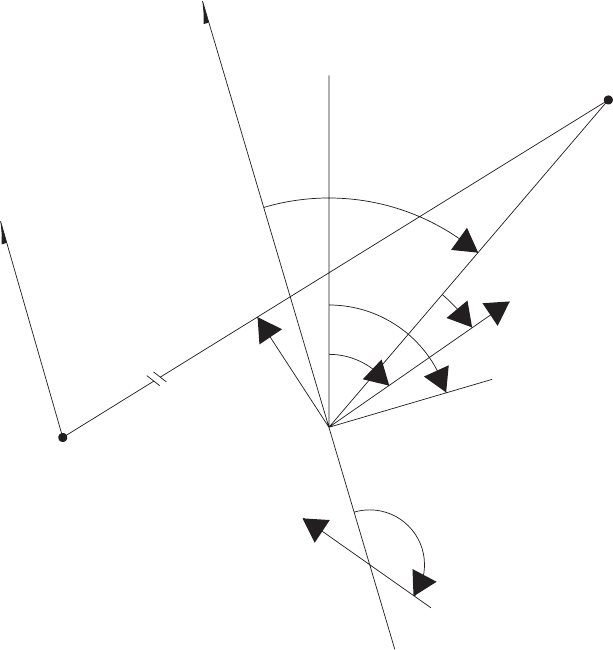
(3) Press the ENT key. Observe that a menu
of special steering functions appears.
1>TO-TO
2>RANDOM
3>CONSEC
END
(4) To select the route-sequence to-to display
press key 1. Observe that TO-TO and se-
lection mode appears in the display. The
display provides entry of starting and end-
ing destination numbers.
(5) To enter keyboard mode press the KYBD
key. (START field blinks.) To enter start-
ing destination 62 press keys 6,2.
(6) Press KYBD key. (END field blinks.) To
enter ending destination 45 press keys 4,5.
(7) Press KYBD key. (SELECT field blinks.)
Enter Y(yes) for mode selection. N(De-
fault mode) may be entered to arm the sys-
tem with the start and end destinations but
without entering the route-sequence to-to
mode, or to exit the Route-sequence to-to
SA
AA9999
MAGNETIC NORTH
MAGNETIC NORTH
TRUE NORTH
BEARING (B)
START
OF LEG
XTK
T
H
PRESENT POSITION
TKE
AIRCRAFT AXIS
GROUND TRACK
DISTANCE (D)
FLY−TO
DESTINATION
WIND SPEED
AND DIRECTION
LEGEND
XTK − CROSSTRACK DISTANCE ERROR
TKE − TRACK ANGLE ERROR
B − BEARING TO DESTINATION
T − ACTUAL TRACK ANGLE (TRUE TRACK)
D − DISTANCE FROM PRESENT POSITION
TO FLY−TO−DESTINATION
H − TRUE HEADING
Figure 3-18.2. Definition of Course Terms
TM 1-1520-237-10
Change 10 3-46.17

mode if the system is currently in that
mode. Then press the ENT key.
NOTE
There must be valid waypoint data to select
a waypoint as a starting or ending waypoint.
If not, upon pressing the ENT key, the in-
valid waypoint number will blink.
If an entry is changed after Yis entered for
selection, an Nmust be entered for the se-
lection then it may be changed to Y. The
sequences must be flown from the beginning
waypoint. The route cannot be flown in re-
verse (R).
No target destination or destination with tar-
get motion may be included as to-to way-
points.
If the MODE switch is placed to the GPS
LDG position when TO-TO,RANDOM,or
RT SEQ CONSEC is selected, it will turn
off the route sequencing mode and change it
back to direct-to.
e. Procedure to enter route-sequence random
mode. The Doppler/GPS navigation set has the
capability to navigate through a sequence of
random number destinations. As an example,
consider navigating through destination num-
bers 32, 25, 74, 01, 48, 83, 35.
(1) Set MODE selector to MGRS (LAT/
LONG may also be used).
(2) Set DISPLAY selector to DATUM/
ROUTE.
(3) Press the ENT key. Observe that a menu
of special steering functions appears.
1>TO-TO
2>RANDOM
3>CONSEC
END
(4) To select the route-sequence random dis-
play press key 2. Observe that RT SEQ
RANDOM now appears in the display fol-
lowed by the sequence of destination num-
bers and a continuation prompt.
(5) Enter the sequence of destination numbers
by pressing the KYBD key to enter key-
board mode. (First destination field blinks.)
To enter destination 32 press keys 3,2.
(6) Press KYBD key. (Next destination field
blinks.) Press keys 2,5to enter second
destination 25.
(7) Repeat step 6 until a maximum of ten des-
tinations are entered or if less than ten need
to be entered, asterisks are left for remain-
ing destinations.
(8) To complete the entry of the random se-
quence of waypoints press ENT key.
(9) To select the start field and enter the start-
ing destination press KYBD key.
(10) To select the ending field and enter the
ending destination press KYBD key.
(11) Press KYBD key. (SELECT field blinks.)
Enter Y(yes) for mode selection. N(de-
fault) may be entered to arm the system but
without entering the route-sequence ran-
dom mode, or to exit the Route-Sequence
Random mode if the system is currently in
that mode. An entry Yand Rindicates a
choice of Y- flying in forward order, or R-
flying in reverse order. To clear the ran-
dom sequence, enter a Cfor selection.
Then press the ENT key.
NOTE
The sequence must be flown from the begin-
ning waypoint.
No target destinations or destinations with
target motion may be included as route se-
quence random waypoints.
If the MODE switch is placed to the GPS
LDG position when TO-TO,RANDOM,or
RT SEQ CONSEC is selected, it will turn
off the route sequencing mode and change it
back to direct-to.
f. Procedure to enter route-sequence-consecutive
mode. The Doppler/GPS navigation set has the
capability to navigate through a sequence of
TM 1-1520-237-10
3-46.18 Change 4

consecutively numbered destinations. As an ex-
ample, consider navigating through destination
numbers 32 through 35.
(1) Set MODE selector to MGRS (LAT/
LONG may also be used).
(2) Set DISPLAY selector to DATUM/
ROUTE.
(3) Press the ENT key. Observe that a menu
of special steering functions appears.
1>TO-TO
2>RANDOM
3>CONSEC
END
(4) To select the route-sequence-consecutive
display press key 3. Observe that RT SEQ
CONSEC now appears in the display, fol-
lowed by the starting and ending destina-
tion numbers, and mode selection.
(5) To enter keyboard mode, press the KYBD
key. (START field blinks.) To enter desti-
nation 32 press keys 3,2.
(6) Press KYBD key. (END field blinks.)Press
keys 3,5to enter ending destination 35.
(7) Press KYBD key. (SELECT field blinks.)
Enter Y(yes) for mode selection. N(de-
fault mode) may be entered to arm the sys-
tem but without entering the route-
sequence-consecutive mode, or to exit the
route-sequence-consecutive mode if the
system is currently in that mode. An entry
of Yand Rindicates a choice of Y- flying
in the forward order, or R- flying in re-
verse order.
NOTE
The sequence must be flown from the begin-
ning waypoint.
No target destinations or destinations with
target motion may be included as route se-
quence consecutive waypoints.
If the MODE switch is placed to the GPS
LDG position when TO-TO,RANDOM,or
RT SEQ CONSEC is selected, it will turn
off the route sequencing mode and change it
back to direct-to.
g. Procedure for displaying distance/bearing/time
information.
(1) Set MODE selector to MGRS (LAT/
LONG or GPS LDG may also be used).
(2) Set DISPLAY selector to DIST/BRG/
TIME.
(3) Observe that the distance-to-go in kilome-
ters (to the fly-to destination), bearing, and
time-to-go appears on the bottom two lines
of the display. (Distance is in nautical
miles when MODE selector position is
LAT/LONG.) Bearing-to-destination is
displayed in degrees, and the time-to-go is
displayed in hours, minutes, and tenths of a
minute.
(4) The display of the second line depends on
the current steering mode as follows:
(a) Direct-To steering (default): Fly-to
destination number and ICAO identi-
fier are displayed. Example:
58:BANDO
(b) To-To Steering: TO-TO-:XX TO YY
where XX is the 9To-To9start-of-leg
destination number, and YY is the
9To-To9fly-to destination number.
(c) Route-sequence steering (both con-
secutive and random): RT-
RANDOM:XX TO YY where XX is
the current route-sequence fly-to desti-
nation number, and YY is the next
destination number in the sequence.
Approximately 10 seconds before
overflying the fly-to destination, the
system automatically ’pickles’ to the
next destination, and the new fly-to
destination number blinks for 10 sec-
onds then stops blinking.
h. Procedure for displaying present position and
GPS Altitude.
(1) Set the MODE selector to MGRS (LAT/
LONG or GPS LDG may also be used).
Set the DISPLAY selector to PP and ob-
serve present position display.
TM 1-1520-237-10
Change 2 3-46.19
(2) To display present position variation and
GPS altitude press the ENT key. Present
position variation may be entered by press-
ing the KYBD key to select the variation
field. A variation is entered and the ENT
key is pressed.
i. Target Store (TGT STR) Operation. Two
methods may be used for target store operation.
Method 1 is normally used when time is not
available to preplan a target store operation.
Method 2 is used when time is available and it
is desired to store a target in a specific location.
Method 1 (uses location 90-99)
(1) Press the TGT STR key while flying over
target.
(2) Present position and variation are automati-
cally stored in the target destination loca-
tion which was displayed in the target store
field immediately prior to pressing the
TGT STR key.
Method 2 (uses locations 00-69 and 90-99)
(1) Set MODE selector to MGRS or LAT/
LONG position, depending on coordinate
from desired.
(2) Set DISPLAY selector to WP/TGT posi-
tion.
(3) To access P, press the LTR LEFT key
followed by key 6. Another way to access
P, is to display waypoint 99 then press the
INC key or display waypoint 00 then press
the DEC key.
(4) Press KYBD key when overflying poten-
tial target. Observe that display freezes and
kybd is displayed in the bottom right cor-
ner of the display indicating keyboard
mode. The destination number is now un-
der keyboard control indicated by a blink-
ing field.
NOTE
Do not press ENT key while destination is
set to P.
(5) If it is desired to store the target, enter the
two digit destination number and press the
ENT key.
(6) If it is not desired to store the target, set the
DISPLAY selector momentarily or perma-
nently to another position.
j. Procedure for entering landing mode.
(1) Set the fly-to destination by setting the
DISPLAY selector to either XTK/TKE/
KEY or DIST/BRG/TIME. Directly enter
the two digit destination number or use the
INC or DEC keys.
(2) Set MODE selector to GPS LDG.
(3) The DISPLAY selector continues to func-
tion as before. To switch between metric
and English units, press the ENT key.
NOTE
In this mode, the DGNS provides real-time
landing guidance information to the HSI and
VSI indicators. To display course deviation
information on VSI and HSI, press then re-
lease the DPLR GPS button on the HSI/VSI
MODE SEL panel.
k. Procedure for transferring stored destination/
target data from one location to another. The
following procedure allows the operator to
transfer (copy) stored destination/target data
from one destination/target location to another
destination location. The transferred data con-
sists of destination name/ICAO identifier, loca-
tion, variation, and landing information. For il-
lustrative purposes only, it is assumed that the
operator wants to put the coordinates of stored
target 97 into the location for destination 12.
(1) Set DISPLAY selector to WP/TGT posi-
tion.
(2) Press key 9then 7.
(3) Press KYBD key, press key 1then 2.
NOTE
Location name/ICAO identifier, variation,
and landing data may be deleted by first dis-
playing the waypoint, pressing the KYBD
key, then the ENT key.
(4) Press ENT key.
TM 1-1520-237-10
3-46.20 Change 4

l. Operation during and after a power interrup-
tion. During a power interruption, the stored
destination and target data and present position
are retained by non-volatile RAM inside the
CDU. This makes it unnecessary to reenter any
navigation data when power returns. GPS sat-
ellite data are also retained by a battery inside
the SDC. This makes it unnecessary to reload
the crypto key or wait for the collection of any
almanac. Navigation will be interrupted during
the absence of power; however the present po-
sition will be updated when the GPS data be-
comes valid provided the DGNS mode has not
been selected as Doppler only. The pilot will
have to re-enter the GPS operating mode (Mor
Y) using a single key (5or 9). In the event the
CDU is initialized, the display will indicate
only EN when the CDU is operated. This is an
indication to the operator that previously stored
data has been lost and that spheroid/variation,
destinations, and calibration data must be en-
tered. Present position needs to be entered only
if Doppler only mode has been selected. The
KYBD key must be pressed to clear the EN.
The pilot will have to re-enter the GPS operat-
ing mode (Monly) using single key (5). The
computer initializes to the following: operating
mode to combined, present position variation to
E000.0, destinations and associated variations
to a nonentered state, wind speed (water mo-
tion) and sea current speed to 000, spheroid to
WGS 84 (WG-4), present position to N45°
00.00’E000°00.00’ (until updated by GPS), tar-
get store location to 90, along track calibration
correction to 00.0 percent, and magnetic com-
pass deviation corrections to 000.0 degrees. The
following data must be entered:
(1) Press KYBD key.
(2) Set MODE selector to OFF momentarily,
to LAMP TEST for approximately one
second, and then to MGRS or LAT/
LONG.
(3) Select GPS M or Ymode.
(4) Select DGNS operating mode if other than
combined.
(5) Enter datum.
(6) Enter present position if Doppler only has
been selected.
(7) Enter each destination and its associated
variation.
m. Procedure for displaying aircraft heading, pitch,
and roll (Maintenance Function).
(1) Set the CDU mode switch to TEST and
observe the CDU test mode display.
(2) After the Doppler test is completed press
the ENT key.
(3) Observe the CDU display. The top three
display lines indicate, in degrees and tenths
of a degree, aircraft system heading, pitch,
and roll.
3.18 INTEGRATED INERTIAL NAVIGATION SYS-
TEM (IINS) AN/ASN-132(V). EH
a. The IINS is a self-contained integrated navigation
system capable of short and/or long-range missions which
can be updated whenever TACAN navigational facilities
exist or manually without TACAN data, and displays loca-
tion of the helicopter on the control display unit (CDU).
The IINS consists of the following equipment:
TYPE
DESIGNATION NAME COMMON
NAME
C-11097/
ASN-132 Control
Indicator Control Display
Unit
CV-3739/ASN-
132 Converter, Signal
Set Signal Converter
Unit (SDC)
AN/UYK-64(V)2 Data Processing
Set Navigation
Processor Unit
(NPU)
RT-1159/A Receiver-
Transmitter,
Radio
TACAN RT
AN/ASN-141 Inertial
Navigation Set Inertial
Navigation Unit
(INU)
MT-4915/A Mounting Base,
Elect Equip TACAN/SCU
Mount
b. Auxiliary components of the IINS includes the SYS-
TEMS SELECT panel, INU blower assembly, INU bat-
tery assembly, and data bus couplers. The IINS provides
TM 1-1520-237-10
Change 8 3-46.21
accurate indications of the helicopter navigation parameters
including present position, velocity, altitude and heading
information. The system employs a serial data bus for data
interchange within the IINS and with external mission sys-
tem computers. The IINS also interfaces with the helicopter
flight instruments and altimeter encoder. The multiplex data
bus system consisting of two buses (A and B), with only
one bus active at any given time. The other bus is in a
standby mode for redundancy purposes to provide a path
for data flow between the Standard Inertial Navigation Sys-
tem (STD INS), Signal Converter Unit, Navigation Proces-
sor Unit, Control Display Unit, and the external mission
systems. Data to and from the TACAN receiver-transmitter
is first processed by the SCU before it is applied to the
multiplex data bus.
3.19 CONTROLS, DISPLAYS, AND FUNCTION.
The IINS controls and displays (Figure 3-19) are con-
tained on the CDU. The function of each control is as fol-
lows:
TM 1-1520-237-10
3-46.22 Change 8
KEY CONTROL OR
INDICATOR FUNCTION
1 Data display Displays multiple flight parameters to the operator on seven
data lines and a scratch pad line on the face of the cathode
ray tube (CRT).
2 Line select keys On both sides of data display lines 1, 3, 5, and 7 are push-
buttons (line select keys) which perform functions as de-
fined by the legend adjacent to the key on the data display.
If a line select key is active on a particular page, an arrow
will appear in the character space closest to the key. Ar-
rows will be oriented toward the legend, up, or toward the
key (away from the legend). These orientations (with ex-
amples) are defined as follows:
1. glegend s(TH 358.3 s). If the arrow points toward the
legend a numeric entry (entered into the scratch pad on line
8) is allowed by pressing the adjacent line select key.
2. slegend g(MAG g). If the arrow points away from the
legend, pressing the adjacent line select key will initiate the
function described by the legend. For example, pressing the
line select key adjacent to 9MAG g9 will change the display
to MAG Heading (MH) and MAG VAR (MV).
3. dlegend d(dT/R). If the arrow points up, the legend
indicates current mode status and pressing the adjacent line
select key will change the mode. If no arrow appears next
to a legend then that line select key performs no operation.
4. Up or down pointing arrows on the sixth line of the data
display allows operator to slew display one page up or
down by pressing page slew toggle switch up or down.
3 Alphanumeric keys Alphanumeric entries are made, by pressing one of the ten
character keys on the keyboard and will appear first in the
scratch pad (line 8). Each actuation of a key will cause a
character to be displayed from left to right in the scratch
pad. When using multiple letter keys (e.g., KLM/5), letters
K, L, or M can be entered into the scratch pad by succes-
sive actuations of the KLM/5 key. The 0-9 and. keys shall
enter the respective number of decimal point unless the
keyboard is in the letter mode. When the LTR/USE key is
pressed, LTR is annunciated to the right of the scratch pad,
and the next keystroke will enter an alpha character. When
the desired data appears in the scratch pad, it will be en-
tered by pressing the line select key adjacent to the data
being updated. When the line select key is pressed, the
scratch pad contents will be checked for proper range and
format. If the entry is valid, it will be transferred to the
IINS, read back, and displayed adjacent to the line select
key. Completion of this cycle will clear the scratch pad.
4CLR key Used for erasing scratch pad parameters before entry. First
actuation clears the last number or letter entered, second
actuation clears the entire entry.
TM 1-1520-237-10
3-47
KEY CONTROL OR
INDICATOR FUNCTION
5BRT control Controls brightness of the data display from full on to full
off.
6 0 key Used to enter number 0 into the scratch pad.
7-/vkey Used to enter a minus symbol or decimal into the scratch
pad. When pressed, vwill be entered into the scratch pad.
When LTR/USE key is pressed, then -/vkey is pressed, -
will be entered into the scratch pad. To use the - in the
scratch pad, the LTR/USE key must be pressed again.
8LTR/USE key When pressed, allows letters to be entered into the scratch
pad. When pressed a second time, signals the CDU to use
the character that was just entered, and deletes LTR entry
mode.
9FACK key When pressed, signals the system that an annunciated fail-
ure has been recognized by the operator, and causes the
flashing annunciation to go to a steady annunciation.
10 Page select switch Selects the type of information to be displayed. The follow-
ing five categories of display pages can be selected:
NOTE
All CDU distance and speed displays in L/L mode are in
nautical miles (NM). All distance and speed displays in
UTM mode are in kilometers.
1. POS. Provides present position; universal transverse
mercator (UTM) or latitude/longitude (L/L) selection; mag-
netic heading selection; magnetic variation; true or mag-
netic heading; ground track; and ground speed.
2. INS. Provides inertial alignment status; barometric pres-
sure; altitude; data zeroize; and access to system data and
unit tests.
3. DEST. Provides selected course entry; destination coor-
dinates; UTM or L/L selection; range, bearing, and time to
destination; cardinal heading/distance.
4. STR. Provides selected course; range, bearing and time
to steerpoint; present position; UTM or L/L selection; car-
dinal heading/distance.
5. TCN. Provides both TACAN control and station data.
The TACAN control page provides power control; mode
selection; slant range and bearing to station; update enable;
and access to station pages. The TACAN station pages pro-
vide station magnetic variation; coordinates, channel; slant
range/bearing; and elevation.
11 Mode select switch Selects eight different modes of operation for the IINS. The
mode select switch selects the following IINS modes of
operation:
TM 1-1520-237-10
3-48
KEY CONTROL OR
INDICATOR FUNCTION
Mode select switch 1. OFF. Turns off the IINS (removes power from TACAN
RT, STD INS, and CDU).
2. FAST. In this position the STD INS either performs a
stored heading alignment or best available true heading
(BATH) alignment. If a BATH alignment is performed,
true or magnetic heading information must be entered not
later than 1 minute after selecting the FAST mode. If mag-
netic heading information is not entered, system will as-
sume a stored heading. After heading information is en-
tered, present position may be entered if desired. FAST
alignment is a degraded mode of operation and should not
be used under normal conditions.
3. NORM. In this position the STD INS performs a gyro-
compass alignment. Present coordinates must be entered
not later than 2 minutes after selecting the NORM mode.
4. NAV. This is the STD INS primary flight mode of op-
eration. NAV is entered after satisfactory alignment condi-
tions have been met.
5. UPDT. In this position the NPU freezes present position
data for a later manual position update by overflying a
known position designated by a mark.
6. ATTD. In this position the STD INS initiates an attitude
reference mode of operation. Although navigation process-
ing is discontinued, the STD INS continues to provide a
stable reference frame for generation of roll, pitch, and in-
ertial heading angles.
7. CAL. In this position the STD INS performs an auto-
matic calibration of the gyro biases.
8. TEST. In this position the STD INS performs functional
performance tests, fault detection, and fault localization
checks.
12 DEST switch Three position toggle switch used to increment/decrement
selected destination. The number of the selected destination
appears on line 1 of the data display. Up increases and
down decreases the selected destination.
13 BIT indicator Used to indicate the results of all internal CDU tests. White
indicates a failure and black indicates test passed.
14 STR switch Three position toggle switch used to increment/decrement
selected steer point. The number of the selected steerpoint
appears on line 1 of the data display. Up increases and
down decreases the steerpoint number.
15 MRK key Used to signal the STD INS to note the current position and
use it for one of two of the following purposes:
TM 1-1520-237-10
3-49

KEY CONTROL OR
INDICATOR FUNCTION
MRK key 1. Store as a markpoint (destination A thru F) when the
mode select switch is in the NAV position.
2. Store present position relative to selected destination for
possible updating when mode select switch is in the UPDT
position.
16 Page slew switch Three position toggle switch used to slew data display one
page up or down by pressing page slew switch up or down.
3.20 SIGNAL CONVERTER UNIT,
CV-3739/ASN-132. EH
The SCU performs data processing to convert the
TACAN RT Aeronautical Radio Incorporated (ARINC) in-
puts and outputs to corresponding serial data formats for
transmission over the multiplex data buses to the NPU and
CDU. The SCU can communicate via one of the two mul-
tiplex data buses. Although the SCU communicates over
only one multiplex data bus at a time, it can monitor both
buses continuously to determine over which bus valid data
communications are taking place. Redundant portions of
the SCU circuitry are isolated to ensure that a failure of one
bus does not degrade performance of the remaining bus.
3.21 TACAN NAVIGATIONAL SET RECEIVER-
TRANSMITTER, RT-1159/A. EH
The position error of an inertial navigation system in-
creases with time, therefore, a position reference sensor is
used to update the inertial data, and thereby bound the
time-growing position error. The IINS derives position up-
dates from the TACAN RT range and bearing measure-
ments. The TACAN RT determines the relative bearing and
range of the helicopter from a selected TACAN ground
station. The TACAN RT operates within 390 nautical miles
of a TACAN ground station. Since the TACAN system
operating limit is line of sight, the actual operating range is
dependent on helicopter altitude. The TACAN system op-
erates on a selected channel from 252 available channels.
The 252 channels are equally divided into 126 x-channels
and 126 y-channels with both x- and y-channels spaced at 1
MHz intervals. Upon being interrogated by the TACAN
RT, the ground station beacon transmits a signal. From the
return signal, the TACAN RT computes bearing and dis-
tance values for updating the inertial system information.
The TACAN RT outputs are processed by the SCU for
compatibility with the multiplex data buses. The TACAN
RT also produces and transmits distance information when
interrogated in the air-to-air operation another TACAN
equipped aircraft, however, this air-to-air mode precludes
using the TACAN information to update the IINS.
3.22 SYSTEMS SELECT PANEL. EH
The SYSTEMS SELECT panel (Figure 3-20) consists
of two switch light indicators, located on the center lower
edge of the instrument panel. It provides a switching capa-
bility for utilization of IINS through a relay assembly. The
SYSTEMS SELECT panel operates as follows:
HDG
DG: ASN-43 directional gyro output is
displayed on the HSI’s. ASN-43
interface with the VSI/HSI Mode
Select System, the SAS/FPS flight
computer, the civil navigation
system, and the Command
Instrument System (CIS).
IINS: IINS heading output is displayed
on the HSI’s. IINS interface with
the above system, replacing the
ASN-43.
ATT
VG: CN-1314 Pilot or copilot vertical
displacement gyro output is
displayed on respective VSI’s and
used by the SAS/FPS computer as
determined by the VSI/HSI MODE
SEL VERT GYRO setting.
IINS: INU output is displayed on the
VSI’s and is used by the SAS/FPS
computer depending on the VSI/
HSI MODE SEL VERT GYRO
setting.
TM 1-1520-237-10
3-50
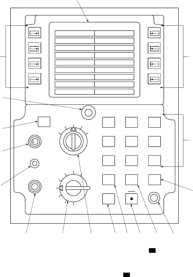
NOTE
If the IINS is to be turned OFF
during flight, the IINS should be
deselected on the SYSTEMS
SELECT panel prior to IINS turn
OFF.
3.23 PILOT AND COPILOT VSI/HSI MODE SEL
PANEL. EH
The VSI/HSI MODE SEL Panel (Figure 3-21) modified
for IINS, operates the same as the UH-60A. The IINS
switch operation is as follows:
IINS
ABC DEF
NPQ
XYZ
CLR
BRT
KLM
UVW
0
GHJ
RST
LTR
FACK
USE
7S89
W45E6
1N23
ATTD
CAL
TEST
OFF
FAST
NORM NAV UPDT
DEST STR
TCN
INS
POS
MRK
STR
BIT
DEST
I
I
N
S
SA
AA0391
1
3
4
56789
1011
12
13
14
15
16
22
Figure 3-19. CDU Controls and Indicators EH
TM 1-1520-237-10
3-51
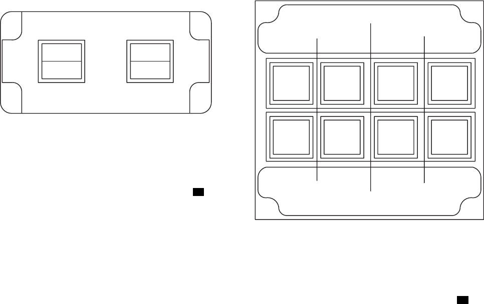
Selection of IINS will display IINS calculated
range, bearing, and course deviation to the
steerpoint on the associated HSI. Range is dis-
played as distance (KM), bearing by the #1
pointer, and deviation by the course deviation
bar.
Selection of IINS disconnects the VOR (ARN-
123) TO/FROM output to the HSI’s and con-
nects the SCU TO/FROM output to the HSI’s.
To select IINS on the MODE SEL panels,
IINS must be selected on the SYSTEMS SE-
LECT panel. Also the CDU must be on and in
the NAV mode.
3.23.1 Valid Entry Procedures. The following para-
graphs describe valid entry formats for data which may be
entered on each of five main pages. An inward pointing
arrow indicates that data can be entered on that line by
pressing the adjacent line select key.
a. POS (Position) Page. The position page provides for
entry of mag/true heading (BATH alignment), present po-
sition (FAST/NORM alignment) and magnetic variation.
(1) Magnetic True Heading Entry. Magnetic heading
and magnetic variation or true heading may be entered dur-
ing the first 60 seconds of a FAST alignment. Scratch pad
entries may be up to four numeric digits including an op-
tional decimal point. If no decimal point is entered, whole
degrees are assumed. Leading zeros are optional.
(2) Latitude Entry. Key in N or S and then the numeric
digits. The first two digits are degrees, third and fourth are
minutes and fifth and sixth are seconds. A leading zero
must be entered for any latitude less than 10 degrees. Entry
examples:
PREVIOUS
VALUE
SCRATCH
PAD
CONTENTS ENTERED
VALUE
S 6° 15 34 N263415 N 26° 34 15
N 33° 25 15 2634 N 26° 34 00
S 46° 13 00 S26 S 26° 00 00
S 46° 13 00 26 S 26° 00 00
(3) Longitude Entry. Key in E or W and then the nu-
meric digits. A leading zero must be entered for a longitude
less than 100 degrees and two leading zeros for a longitude
less than 10 degrees.
PREVIOUS
VALUE
SCRATCH
PAD
CONTENTS ENTERED
VALUE
E 176° 16 00 W1263415 W 126° 34 15
SA
AA0392
SYSTEMS SELECT
HDG ATT
DG VG
IINS
IINS
Figure 3-20. SYSTEMS SELECT Panel EH
SA
AA0393
MODE SEL
IINS VOR
ILS BACK
CRS FM
HOME
IINS VOR
ILS BACK
CRS FM
HOME
PLT
CPLT ADF
VOR
NORM
ALTR
CRS
HDG VERT
GYRO BRG
2
TURN
RATE
NORM
ALTR
Figure 3-21. HSI/VSI MODE SEL Panel EH
TM 1-1520-237-10
3-52

PREVIOUS
VALUE
SCRATCH
PAD
CONTENTS ENTERED
VALUE
E 176° 16 00 12634 E 126° 34 00
W 135° 42 32 E126 E 126° 00 00
E 120° 16 24 126 E 126° 00 00
(4) Spheroid or Grid Zone Entry. Either spheroid or
grid zone may be entered. Spheroid entries consist of num-
bers 0 through 10 and are an alpha display as listed in Table
3-2. Grid zone entries consist of two numbers and alpha
character. Entry examples.
PREVIOUS
VALUE
SCRATCH
PAD
CONTENTS ENTERED
VALUE
16T INT 1 16T CL6
16T INT 18T 18T INT
16T INT 18T1 18T CL6
(5) Area/Eastings/Northings Entry. Scratch pad entries
may be made for area, eastings and northings, just area, or
just eastings and northings. Entries for area must consist of
two alpha characters. Entries for eastings/northings must be
2, 4, 6, 8, or 10 digits. Digits will be evenly split between
eastings and northings with trailing zeros inserted. Al-
though entries may be made and sent to the INU to a reso-
lution of 1 meter, the display will round to the nearest 10
meters. The following illustrates several examples:
Table 3-2. Spheroid Data Codes EH
CODE MODEL ABBR
0 International INT
1 Clark 1866 CL6
2 Clark 1880 CL0
3 Everest EVR
4 Bessel BSL
5 Australian National AUS
Table 3-2. Spheroid Data Codes EH (Cont)
CODE MODEL ABBR
6 Airy ARY
7 Hough HGH
8 South American SAM
9 Modified Everest MEV
10 WGS.72 WGS
NOTE
When mission equipment operator selects
WGS 1984, CDU is code 10.
PREVIOUS
VALUE
SCRATCH
PAD
CONTENTS ENTERED
VALUE
AU 1234 5678 UV23456789 UV 2345 6789
AU 1234 5678 23456789 AU 2345 6789
AU 1234 5678 2345678 AU 2340 6780
AU 1234 5678 2367 AU 2300 6700
AU 1234 5678 26 AU 2000 6000
AU 1234 5678 UV UV 1234 5678
(6) Magnetic Variation Entry. Scratch pad entries con-
sist of an E/W and up to four numeric digits including
decimal point. If no decimal point is entered, while degrees
are assumed. The range of entries is 0.0° to E/W 180.0°.
For entries greater than or equal to 100°, only whole de-
grees are displayed. The following gives some entry ex-
amples.
SCRATCH PAD
CONTENTS ENTERED VALUE
E2 E20
W10.9 W10.9
E.7 E0.7
b. INS (Inertial) Page. The INS page provides miscella-
neous control/display functions such as entry of altitude
and barometric pressure and provides access to INU and
NPU memory.
TM 1-1520-237-10
Change 5 3-53

(1) Manually Entered Altitude (MALT). Field altitude
must be entered to the nearest 100 ft. MSL during align-
ment; however, manually entered altitude may be entered
any time during the mission to override barometric altim-
eter. The range of valid entries is from -1000 to +65,520
feet in increments of 100 feet. Entries shall delete MALT
by causing an output of -65,520 feet over the barometric
pressure.
SCRATCH PAD
CONTENTS ENTERED VALUE
2 2.0
SCRATCH PAD
CONTENTS ENTERED VALUE
10 10.0
10.5 10.5
(2) Barometric Pressure (BARO). Barometric pressure
must be entered (0.01 in Hg) during alignment. The infor-
mation is used by the NPU to initialize the scale factor of
encoding altimeter data during alignment.
(3) DATA Page.
IN0
IN0
IN0
IN0
IN0
IN0
AU0
BE0
BE0
CL6
CL6
CL6
EV0
CL0
SA
AA8669A
Figure 3-22. Doppler World UTM Spheroids (AN/ASN-128)
TM 1-1520-237-10
3-54 Change 5
(a) Press the line select key adjacent to line 5 right
(DATA).
(b) Line 7 of the DATA page provides the capability
to enter and read the contents of various INU registers.
Although the CDU will accept entered memory addresses
with a range of 0 to 65,535 (decimal), the INU will not
accept all of these as valid. If an illegal address is entered,
the illegal address and the message 9ENTRY REJECTED9
will alternately appear in the scratch pad. Pressing the CLR
TM 1-1520-237-10
Change 5 3-54.1/(3-54.2 Blank)

key will clear the scratch pad. Register contents that are
entered may be any six alphanumeric characters plus sign.
Many of the INU registers are 9read only9. That is, their
contents can be read but not altered. If an attempt is made
to change the contents of one of these registers, 9ENTRY
REJECTED9will appear as described above.
c. DEST (Destination) Page. Two types of data may be
entered on the destination page, destination coordinates,
and course to destination.
(1) Destination Coordinates Entry. Destination coordi-
nates may be entered during any phase of the mission. Ei-
ther LAT/LONG or MGRS (UTM) coordinates may be en-
tered. Coordinate selection is provided on line 7 (display
right).
(a) Latitude entry described in paragraph 3.23.1.a.2..
(b) Longitude entry described in paragraph
3.23.1.a.3..
(c) Spheroid and zone entry described in paragraph
3.23.1.a.4..
(d) Area/Eastings/Northings entries described in
paragraph 3.23.1.a.5..
(2) Course to Destination Entry. The desired true
course to destination may be entered for each destination
during any phase of the mission.
(a) Enter the true course in the scratch pad. Entries
may be up to four numeric digits with an optional decimal
point. If no decimal point is entered, whole degrees are
assumed. Leading zeros are optional.
(b) Press line 1 right line select key. The true course
to destination will be displayed on line 1 right.
(c) System will utilize any previous course data. If
no data has been entered, the system will assume a true
course of 000.0 degrees.
d. STR (Steer) Page. This page contains no enterable
parameter.
e. TCN (TACAN) Pages. The TACAN pages consist of
the TACAN control page and TACAN station pages.
(1) TACAN Control Page Data Entry. The only data
entry on this page is channel number. Paragraph 3.23.3.f.
describes the channel number entry.
(2) TACAN Station Page Entries. Parameter entries
are station location magnetic variation channel and eleva-
tion.
(a) Latitude entry described in paragraph 3.23.1.a.2..
(b) Longitude entry decribed in paragraph
3.23.1.a.3..
(c) Spheroid and zone entry described in paragraph
3.23.1.a.4..
(d) Area/Eastings/Northings entries described in
paragraph 3.23.1.a.5..
(e) Station Magnetics Variation entry described in
paragraph 3.23.1.a.6..
(3) Station Channel Entry. The TACAN Station Pages
provide the capability to enter station channel for each of
the 16 stations. A total of 252 channel are possible (126 9X9
channels and 126 9Y9channels). Unless 9Y9is entered, an
9X9channel is assumed.
EXAMPLE
0
0
SA
AA0396
NOTE
TO SELECT THIS PAGE, SET CDU PAGE
SELECT SWITCH TO POS AND PRESS
LINE 5 AND / OR LINE 7 RIGHT LINE
SELECT KEYS AS REQUIRED.
POS I T I ON TH 358 . 3
MV = E 1 . 3 MH 3 4 8 . 0
GTK 3 5 9 . 6 OGS 1 8 1 . 2
13T INT GRID
52/
O
543DW
UV 1234 1234 UTM
[]
Figure 3-23. Position Page EH
TM 1-1520-237-10
3-55

3.23.2 Starting Procedure (NORMAL ALIGN-
MENT).
1. Ensure that the following circuit breakers are
in:
a. NO. 1 AC PRI BUS circuit breaker panel
(1) INS
(2) XFMR PWR
(3) INU BATT PWR
(4) 26 VAC EQUIP PWR
b. NO. 1 DC PRI BUS circuit breaker panel
(1) CPLT ALTM
(2) IINS
c. NO. 2 AC PRI BUS circuit breaker panel
(1) TACAN
d. NO. 2 DC PRI BUS circuit breaker panel
(1) TACAN
NOTE
Present position must be entered during the
first two minutes of NORM alignment. If
present position is displayed, it must be re-
entered. A steady NAVRDY indicates INU
attitude data and degraded NAV perfor-
mance are available. After turn-on, flashing
NAVRDY will be displayed on line 6 indi-
cating full alignment.
2. To turn system on, set mode select switch to
NORM. CDU display will remain blank for 30
seconds after turn-on. If the CDU does not light
after 30 seconds, rotate the brightness control
on the CDU clockwise to provide a comfortable
intensity level.
a. Check for annunciations on line 2 of the
display. If any annunciation is flashing, re-
turn mode select switch to OFF.
CAUTION
Wait two minutes before returning mode
select switch to NORM. Failure to do so
will damage the INU.
b. If mode select switch was turned off, rotate
mode select switch to NORM.Ifanan-
nunciation is still flashing, make an entry
on DA Form 2408-13-1. Refer to para-
graph 3.23.5 for an explanation of annun-
ciations.
3. Set page selector switch to POS (Figure 3-23).
NOTE
If UTM coordinates are selected, the COM-
PLETE UTM coordinates must be entered
for present position: GRID ZONE, SPHER-
OID, AREA, EASTINGS, and NORTH-
INGS.
4. Verify line 7 on right side display indicates de-
sired COORDINATE SYSTEM (UTM or L/L).
If not press the line select key once to switch to
the desired coordinate system.
a. Enter GRID ZONE/SPHEROID or LATI-
TUDE in scratch pad.
b. Press line select key 5 left.
c. Enter AREA, EASTINGS, NORTHINGS,
or LONGITUDE in scratch pad.
d. Press line select key 7 left.
NOTE
If INU computed MV is changed, updated
MV will have to be manually entered as MV
lines are crossed. If INU computed MV is
utilized, automatic MV updating will be per-
formed by the INU.
5. Verify line 3 on left side display indicates cor-
rect magnetic variation, MV.
a. If incorrect, enter MV in scratch pad.
b. Verify scratch pad entry is correct.
TM 1-1520-237-10
3-56 Change 10
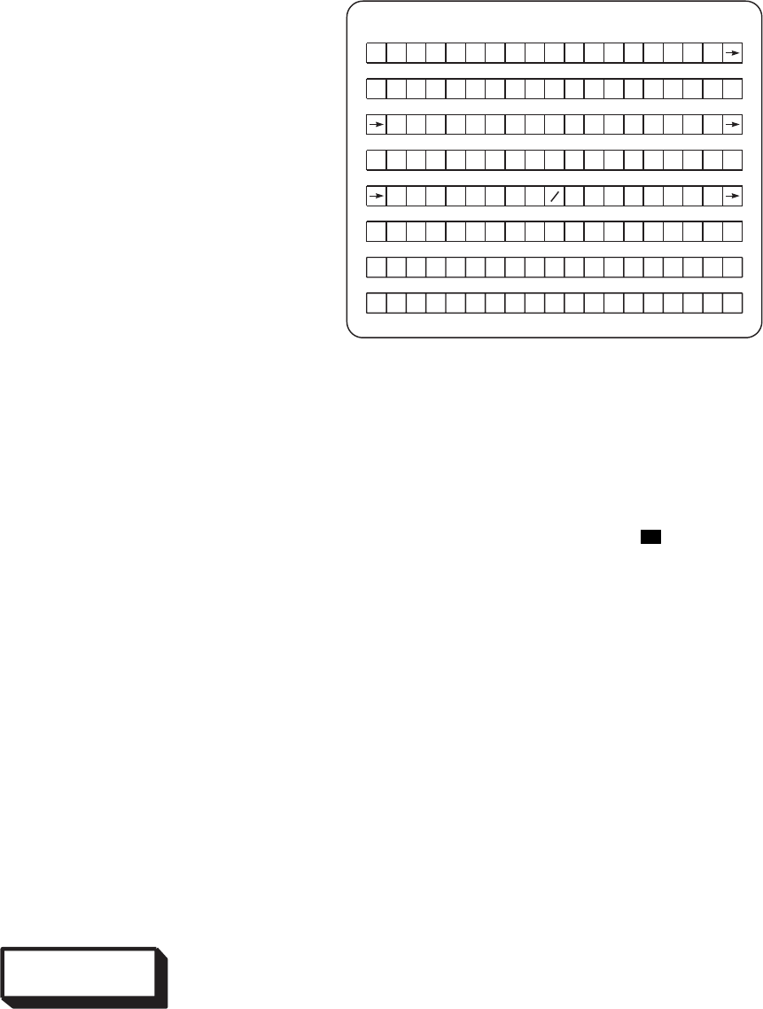
c. Press line select key 3 left.
d. Verify line 3 left displays:->MV=XNN.
N. (The 9=9sign indicates that a manual
MV was entered and automatic MV updat-
ing will not occur.)
6. Rotate page select switch to INS (Figure 3-24).
a. Enter barometric pressure of present posi-
tion in scratch pad.
b. Press line select key 5 left.
c. Enter altitude of present position in scratch
pad (e.g., 156 ft is entered as 0.156 and
displayed as 0.2).
d. Press line select key 3 left.
7. Rotate page select switch to DEST.
a. Press DEST toggle switch to select DEST
desired page.
b. Press line select key 7 right to display de-
sired coordinate system (UTM or L/L).
c. Enter grid zone and spheroid or latitude in
scratch pad.
d. Press line select key 5 left.
e. Enter Area/Eastings/Northings or longitude
in scratch pad.
f. Press line select key 7 left.
g. Press DEST toggle switch (Figure 3-19) to
increment to the next page.
8. Rotate page select switch to TCN.
WARNING
Potential radiation hazard exists at the
TACAN antenna when the TACAN is
turned on. Make sure that no person is
within 3 feet of antenna. When TACAN is
first turned on and line 3 left of CDU dis-
plays anything other than REC, immedi-
ately press line select key 3 left until the
display shows REC.
a. Turn ON TACAN by pressing line select
key 1 left.
b. Press line 3 left until REC is displayed on
the CRT.
c. Press page slew toggle switch to display
TACAN station zero page.
(1) Enter magnetic variation in scratch
pad.
(2) Press line select key 3 left.
(3) Enter latitude in scratch pad.
(4) Press line select key 5 left.
(5) Enter longitude in scratch pad.
(6) Press line select key 7 left.
(7) Press line select key 1 right to display
ACT.
EXAMPLE
[
INS D2 S3 ZEROIZE
IALT 27.5 TESTS
BARO 2 9 . 1 DATA
LAST MRK C
19 . 9MI N STAT=A+H
0
[
NOTE
TO SELECT THIS PAGE, SET CDU PAGE
SELECT SWITCH TO INS.
SA
AA0394
Figure 3-24. INS Page EH
TM 1-1520-237-10
3-57
(8) Enter channel number in scratch pad.
(9) Press line select key 3 right.
(10) Enter elevation of TACAN station on
scratch pad.
(11) Press line select key 5 right.
(12) Press page slew toggle switch to dis-
play next TACAN page.
(13) Enter data as described in steps (a)
through (m).
NOTE
In order for HSI steering command to be
correct, a valid destination and steer point
must be entered prior to switching the
MODE selector to NAV.
Example: If DX is homebase (alignment
point), the SX STEER point is invalid as an
initial Destination/Steer Point.
9. Select an appropriate destination number and
toggle the STR toggle switch to indicate the
number, i.e., S1. (It is not necessary that the
DX and SX numbers agree, only that SX is the
desired destination.)
10. Set mode select switch to NAV. (Pull switch
up; then rotate.)
11. Set page select switch to TCN.
a. Press line select key 3 left to display T/R.
b. Press line select key 5 left to display
UPDT.
12. On HSI/VSI MODE SEL panel (Figure 3-21),
press IINS switch. Note that bearing to desti-
nation (No. 1 needle), range to destination,
course deviation and TO/FROM flag are dis-
played on the HSI.
13. On SYSTEMS SELECT panel (Figure 3-20),
set switches and observe indications as follows:
a. Press HDG switch, INS illuminates and in-
ertial derived heading is displayed on the
HSI.
b. Press ATT switch, INNS illuminates and
inertial derived pitch and roll is displayed
on the VSI.
3.23.3 Starting Procedure (FAST Alignment).
Switching to FAST mode commands the INU to perform
either a stored heading alignment or best available time
heading (BATH) alignment.
a. Stored Alignment.
NOTE
CDU display will remain blank for 30 sec-
onds after turn on. Barometric pressure must
be entered during alignment. Alignment will
be complete when data display line 6
NAVRDY indicator begins to flash if a nor-
mal alignment was performed and the mode
select switch was not set to NAV. Align-
ment will be complete when data display
line 6 NAVRDY indicator lights if a normal
alignment was performed and the mode se-
lect switch was set to NAV.
(1) Ensure system preoperational checks have
been performed and that aircraft power is
on.
(2) Set mode select switch (Figure 3-19) to
FAST.
(3) Set page select switch to POS.
(4) Observe that data display line 7 right indi-
cates desired coordinate system (UTM or
L/L). If it does not, press line select key 7
right until the desired coordinate system is
deployed.
(5) If data display line 8 right indicates LTR,
press LTR/USE key to place the keyboard
in the numeric mode.
(6) Observe that data display line 5 left and
line 7 left indicate present position latitude
and longitude or grid zone, spheroid area,
eastings and northings, respectively. If not,
normal or BATH alignment must be per-
formed:
(7) Set page select switch to INS. Observe that
data display line 3 left indicates present
position altitude. If not, a change must be
TM 1-1520-237-10
3-58
made within the first 60 seconds of this
alignment.
NOTE
The following steps are an example of enter-
ing barometric pressure. Substitute your own
barometric pressure when performing these
steps. Enter local barometric pressure to the
nearest 0.01 inches Hg.
When making keyboard entries, if an incor-
rect key is pressed, press CLR key as re-
quired and begin again.
(8) Enter local barometric pressure on data
display line 8 by pressing in sequence
ABC/N2, XYZ/ 9, -/v, 0, and 1 keys. Ob-
serve that data display line 8 indicates
29.01.
(9) Press data display line 5 left line select key.
Observe that data display line 5 left indi-
cates - > BARO 29.01.
(10) Observe that data display line 7 indicates
alignment and status.
NOTE
Data display line 6 left indicates a flashing
NAVRDY if a normal alignment was per-
formed and the mode select switch was not
set to NAV.
(11) When data display line 6 left NAVRDY
indicator lights, set mode select switch to
NAV.
b. BATH Alignment.
NOTE
CDU display will remain blank for 30 sec-
onds after turn on. True or magnetic heading
must be entered during the first 60 seconds
of turn on. Present position must be entered
within 2 minutes of turn on. Barometric
pressure and altitude must be entered during
alignment.
Alignment will be complete when data dis-
play line 6 NAVRDY indicator lights.
(1) Ensure system preoperational checks have
been performed and that aircraft power is
on.
(2) Set mode select switch to FAST.
(3) Set page select switch to POS.
(4) Observe that data display line 7 right indi-
cates desired coordinate system (UTM or
L/L). If it does not, press line select key 7
right until desired coordinate system is dis-
played.
(5) If data display line 8 right indicates LTR,
press LTR/USE key to place the keyboard
in the numeric mode.
NOTE
The following steps are examples of enter-
ing present position data. Substitute your
own present position and heading when per-
forming these steps. Either true heading or
magnetic heading can be entered. Magnetic
heading is entered by pressing line select
key. The following example uses true head-
ing. When making keyboard entries, if an
incorrect key is pressed, press CLR key as
required and begin again.
(6) Enter true heading on data display line 8
by pressing in sequence DEF/3, KLM/5,
UVW/S8, -/ and DEF/3 keys. Observe that
data display line 8 indicates 358.3.
(7) Press data display line 1 right line select
key. Observe that data display line 1 right
indicates TH 358.3 ,-.
(8) If required, enter present position latitude
(or UTM, GRID ZONE and SPHEROID)
on data display line 8 by pressing in se-
quence LTR/USE, ABC/ N2, LTR/USE,
DEF/3, GHJ/W4, 1, 0, DEF/3, and 0 keys.
Observe that data display line 8 indicates
N341030.
(9) Press data display 5 left line select key.
Observe that data display line 5 left indi-
cates - > N34° 10 30.
(10) If required, enter present position longitude
(or UTM area, EASTING and NORTH-
ING) on data display line 8 by pressing in
TM 1-1520-237-10
3-59

sequence LTR/USE, GHJ/W4, LTR/USE,
1, 1, UVW/S8, DEF/3, and 0 keys. Ob-
serve that data display line 8 indicates
W1183530.
(11) Press data display line 7 left line select key.
Observe that data display 7 left indicates -
> W118° 35 30.
(12) Set page select switch to INS.
NOTE
When entering present position altitude, al-
titude must be entered to the nearest 100 feet
(mean sea level). The range of valid entries
from -1000 to 65,520 feet in increments of
100 feet. Entries are made in thousands of
feet.
(13) If required, enter present position altitude
on data display line 8 by pressing in se-
quence UVW/S8, -/v, and NPQ/E6 keys.
Observe that data display indicates 8.6.
This represents an altitude of 8,600 feet.
(14) Press data display line 3 left line select key.
Observe that data display line 3 left indi-
cates -> AALT 8.6.
NOTE
Enter local barometric pressure to the near-
est 0.01 inches Hg.
(15) Enter local barometric pressure on data
display line 8 by pressing in sequence
ABC/N2, XYZ/ 9, -/v, 0, and 1 keys. Ob-
serve that data display line 8 indicates
29.01.
(16) Press data display line 5 left line select key.
Observe that data display line 5 left indi-
cates - > BARO 29.01.
(17) Observe that data display line 7 indicates
alignment time and status.
(18) When data display line 6 left NAVRDY
indicator lights, set mode select switch to
NAV.
3.23.4 In-flight Procedures.
a. MARK Operation. Current aircraft position may be
stored in one of the markpoint locations (destinations A-F)
by pressing the MRK key when in NAV mode. The loca-
tion where present position was stored is displayed in the
CDU scratch pad regardless of currently selected page. Fig-
ure 3-24 illustrates 9MARK C9in the scratch pad with the
STR page selected.
(1) The MARK locations are used in sequence (-A,
B, C, D, E, F, A, B,..). The MARK display will
remain in the scratch pad unless it is cleared
with the CLR key or the scratch pad is used to
enter some other data.
(2) Pressing the MRK pushbutton will freeze, for
30 seconds, the display of present position on
the Steering and Position pages; and the display
of cardinal headings/distance on both the desti-
nation and Steering Page. After 30 seconds or
after the CLR key is pressed, the current posi-
tion will return.
b. Manual Updating (Overfly Position Updating). An
overfly update represents a manual position update tech-
nique in which the pilot overflies his selected destination
and signals the INU by pressing the MRK key. To initiate
a manual update, proceed as follows.
EXAMPLE
TACAN ON 3ATS
T/ R X521HC
SRNG 42 . 5 BRG 122 O
UPDT 6 OF 1 0
STA
3SIG= 1
[]
NOTE
TO SELECT THIS PAGE, SET CDU PAGE
SELECT SWITCH TO TCN.
SA
AA0395
Figure 3-25. TACAN Control Page EH
TM 1-1520-237-10
3-60
NOTE
If indicated air speed is greater than 5 knots,
the manual update will not remove 100% of
the positional error or zero out the cardinal
headings, time to go (TTG) or distance to
destination. The percentage of actual update
is a dynamic function of the computer soft-
ware.
(1) Indicated airspeed greater than 5 knots.
(a) Ensure that the displayed Destination and
Steerpoint indicators (Dx, Sx) are both set
to the destination that the update will be
performed on.
(b) Rotate the mode select switch to the UPDT
position. The page shown in Figure 3-26
will be displayed.
(c) When the aircraft is directly over the des-
tination point, depress the MRK key. The
page shown in Figure 3-27 will be dis-
played.
(d) If the pilot decides to accept the update
(ACCEPT here means to tell the INU that
the positional update will be accepted) de-
press line select key 7 left to accept the
update (REJECT here means to tell the
INU that the positional update will not be
accepted), depress line select key 7 right to
reject the update. In either case, the page
shown in Figure 3-27 will be redisplayed.
NOTE
The following display changes are not im-
mediate. It will take approximately 5 sec-
onds for the data to change.
(e) Rotate the mode select switch to NAV.
(f) Observe that the cardinal heading, time-
to-go (TTG), and range decrease towards
0.0, and that present position changes to
more closely reflect the coordinates stored
in the selected destination.
(g) If the mission will continue, select a new
steerpoint and proceed.
(2) Indicated air speed is 5 knots or less.
(a) Perform steps 1. (a) through 1. (f) above.
(b) If the cardinal headings, time-to-go (TTG)
and range do not decrease to 0.0, verify
that both the destination and steerpoint in-
dicators (Dx, Sx) are set to the destination
that the update is being performed on. Re-
peat steps 1. (a) through 1. (f).
(c) To proceed with the mission, select a new
steerpoint.
(3) Selection of the 9UPDT9mode on the mode
select switch deletes automatic TACAN updat-
ing during the period of the manual update.
3.23.5 Annunciations.
a. System status messages appear on line 2 and the left
side of line 6 regardless of selected page. The following is
a summary of messages that are presented and the failures/
conditions they represent.
MESSAGE CONDITION LINE
MSC Mission Computer has failed. 2
NPU Navigation Processor has
failed. 2
INU INU navigation processing
has failed
Attitude may be valid. 2
ADC Copilot’s Altimeter-Encoder
has failed. 2
TCN TACAN has failed or is off. 2
PFM Post Flight maintenance is
required. 2
TTG Aircraft is within two
minutes of selected steerpoint
(flashing). 2
FROM Distance to steerpoint is
increasing. 2
TO Distance to steerpoint is
decreasing. 2
SCU Signal Converter Unit or
ARINC BUS has failed. (See
TEST page.) 2
TM 1-1520-237-10
3-61

MES-
SAGE CONDITION LINE
NAVRDY
(steady) During alignment. INU atti-
tude data and degraded nav
performance are available. 6
NAVRDY
(flashing) During alignment. Full INU
nav performance is available. 6
ATTD The INU is in attitude mode
due to: 1. operator selection.
2. INU failure or 3. data bus
failure. Attitude data is valid. 6
DEGRD The INU is in navigate mode
and a degraded performance
alignment, not a full perfor-
mance alignment was per-
formed. 6
UPDT The INU is being automati-
cally updated by the TACAN. 6
DEGUPD Degraded mode update by
TACAN. 6
b. Placement of annunciation on their respective lines is
shown in Figure 3-21. NPU and PFM annunciators occupy
the same location. When a failure occurs, the annunciation
will flash to attract the pilot’s attention. Pressing the
9FACK9key causes the annunciation to go from flashing to
steady. If an LRU recovers from the failure, its annunciator
will clear.
3.24 GYRO MAGNETIC COMPASS SET AN/ASN-
43.
Gyro Magnetic Compass Set AN/ASN-43 provides
heading information by reference to a free directional gyro
when operating in the FREE mode, or by being slaved to
the earth’s magnetic field when operated in the SLAVED
mode. It provides heading information to the horizontal
situation indicator. Power to operate the AN/ASN-43 is
provided from the ac essential bus through circuit breakers,
marked COMP and AUTO XFMR under the general
heading AC ESNTL BUS.
3.24.1 Compass Control C-8021/ASN-75. Control
C-8021/ASN-75 (Figure 3-29) is required to synchronize
(electrically and mechanically align) the AN/ASN-43 to the
correct magnetic heading when used in the SLAVED mode
of operation. The synchronizing knob on the control panel
may be used as a set heading knob for operation in the
FREE mode.
3.24.2 Controls and Functions. Controls for the mag-
netic compass set are on the front panel of the unit. The
function panel of each control is as follows:
CONTROL FUNCTION
Null Meter Moves left (+) or right (v) of center
to indicate misalignment
(synchronization) of the AN/ASN-
43.
Mode Selector
(SLAVED-
FREE)
Selects either magnetically
SLAVED or FREE gyro operation
of the AN/ASN-43.
EXAMPLE
UP
[]
D
RR
E
TT
S
SD3 3
G
GG
BN
361
1
1
67257
O
.
.
.
.
8
SA
AA0397
T
2
.0
NOTE
TO SELECT THIS PAGE, SET CDU MODE
SELECT SWITCH TO UPDT. WHEN THIS
PAGE IS SELECTED, TACAN UPDATING
IS DELETED.
Figure 3-26. Update Page EH
TM 1-1520-237-10
3-62
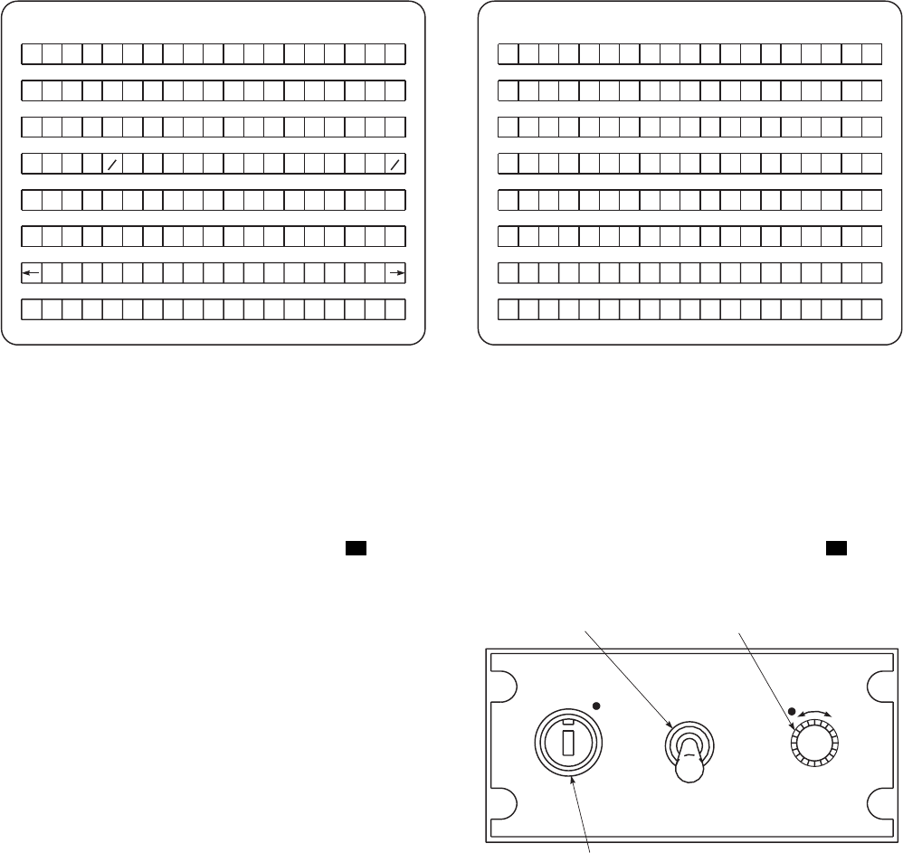
CONTROL FUNCTION
Null Control
PUSH-TO-SET Is manually pressed and turned to
null the annunciator, thereby syn-
chronizing (electrically and me-
chanically aligning) the AN/ASN-
43. Turns compass card of HSI for
alignment.
3.24.3 Operation.
3.24.4 Starting Procedure.
1. Mode selector - As desired.
2. Null control - Push, and turn in direction indi-
cated by null meter (+ or v) until annunciator is
centered. In SLAVED mode, during normal
operation, the annunciator will oscillate slightly
about the center position; however, during cer-
tain helicopter maneuvers the annunciator will
move off center.
3. HSI - check to see that HSI heading agrees with
a known magnetic heading.
3.25 ELECTRONIC NAVIGATION INSTRUMENT
DISPLAY SYSTEM.
The instrument display system provides displays for
navigation and command signals on a vertical situation in-
dicator (VSI) and a horizontal situation indicator (HSI) for
pilot visual reference. The system consists of the two VSIs
and two HSIs on the instrument panel. The system has a
EXAMPLE
NOTE
TO SELECT THIS PAGE, SET CDU MODE
SELECT SWITCH TO UPDT AND PRESS
MRK KEY.
A
A
/
[]
R
RR
RCC CEE
E
TT
T
T
PJE
S
SD3 3
G
GG
BN
22 1
1
1
12257
O
.
.
.
.
8
SA
AA0398
0 0
Figure 3-27. Accept/Reject Page EH
MSCNPU I NU AD CTCN
ATTD
EXAMPLE
NOTE
SYSTEM STATUS MESSAGES APPEAR
ON LINE 2 (2) AND THE LEFT SIDE OF
LINE 6 (6) REGARDLESS OF SELECTED
PAGE (EXCEPT NPU DATA PAGE). DATA
APPEARING ON LINES 1 (1), 3 (3), 4 (4), 5
(5), 7 (7) AND 8 (8) WILL BE WHATEVER
IS APPLICABLE TO THE PAGE SELECTED.
THE FOLLOWING IS A SUMMARY OF
MESSAGES THAT ARE PRESENTED AND
THE FAILURES / CONDITIONS
THEY REPRESENT: SA
AA0399
Figure 3-28. System Annuciators EH
SA
AA0527
COMPASS
SLAVED
FREE
PUSH TO
SET
++
MODE
SELECTOR NULL
CONTROL
NULL METER
Figure 3-29. Compass Control Panel C-8021/
ASN-75
TM 1-1520-237-10
3-63
common command instrument system processor (CISP),
two HSI/VSI mode select panels, and one CIS mode select
panel.
3.25.1 Vertical Situation Indicator. The VSI (Figure
3-30), provides a cockpit display of the helicopter’s pitch,
roll attitude, turn rate, slip or skid, and certain navigational
information. It accepts command instrument system proces-
sor signals and displays the flight command information
needed to arrive at a predetermined point. The system also
monitors and displays warnings when selected navigation
instrument readings lack reliability. The VSI is composed
of a miniature airplane, four warning indicator flags ATT,
GS,NAV and CMD, two trim knobs ROLL and PITCH,
a bank angle scale, a bank angle index on the spheroid, a
turn rate indicator and inclinometer, pitch and roll com-
mand bars, collective position pointer, a course deviation
pointer, and a glide slope deviation pointer. Refer to Chap-
ter 2, Section XIV for a description of the attitude indicat-
ing system, and turn and slip indicator. The gyro erect
switch (Figure 2-8) supplies a fast erect signal to the pilot
and copilot displacement gyros, thereby considerably re-
ducing the time required for the gyros to reach full operat-
ing RPM. The pilot and copilot’s displacement gyros sup-
ply pitch and roll attitude signals to the vertical situation
indicators, automatic flight control system, and the Doppler
navigation system. Power to operate the VSI is provided
from the No. 2 ac primary bus through circuit breakers
marked VSI PLT,CPLT.
3.25.1.1 Steering Command Bars and Pointer. The
roll and pitch command bars and the collective position
pointer operate in conjunction with the command instru-
ment system processor (CISP) and the command instru-
ment system/mode selector (CIS MODE SEL). Selection
of HDG on the CIS MODE SEL panel provides a display
of a roll signal by the roll command bar (Figure 3-30). The
pitch command bar and the collective position pointer are
out of view, and the CMD flag is held from view. Selecting
the CIS MODE SEL switch NAV and the MODE SEL
switch VOR ILS, the roll command bar will display roll
commands from the CISP. If an ILS (LOC) frequency is
tuned in, the pitch command bar and the collective com-
mand pointer will also display CISP signals. If a VOR fre-
quency is tuned-in, the pitch command bar and collective
position pointer will be held from view. The CMD warning
flag will be held from view, indicating that the CISP func-
tional integrity is being monitored. Refer to Figure 3-32 for
VSI indications in other switch positions.
3.25.1.2 Command Warning Flag. The command
warning flag marked CMD is at the top left of the VSI face
(Figure 3-30). It is held from view when initial power is
applied to the CIS processor. When any CIS mode selector
switch is on, and that navigation system operating properly,
the CMD flag is not in view. During operation, if the navi-
gation signal becomes unreliable, or is lost, the CMD flag
will become visible. On helicopters equipped with digital
CIS processor the CMD flag will not come into view when
the navigation signal becomes unreliable or lost. The NAV
flag will come into view when the navigation signal be-
comes unreliable even with the digital CIS.
3.25.1.3 Glide Slope Warning Flag. A glide slope
warning flag marked GS is on the right face of the indicator
(Figure 3-30). The letters GS are black on a red/white stripe
background. The warning flag will move out of view when
the ILS receivers are operating and reliable signals are re-
ceived.
3.25.1.4 Navigation Warning Flag. A navigation flag
marked NAV is installed on both the VSIs and the HSIs
(Figures 3-30 and 3-31) to indicate when navigation sys-
tems are operating and reliable signals are being received.
The VSI NAV flag is marked NAV with a white back-
ground and red strips, and is on the lower left side of the
indicator. The HSI NAV flag is within the compass card
ring. Both instrument flags will retract from view whenever
a navigation receiver is on and a reliable signal is being
received.
3.25.1.5 Course Deviation Pointer. The course devia-
tion pointer is on the VSI instrument (Figure 3-30). The
pointer works with the course bar on the HSI to provide the
pilot with an indication of the helicopter’s position with
respect to the course selected on the HSI. The scales rep-
resent right or left off course, each dot from center (on
course) is 1.25° for ILS, 5° VOR and FM. The pilot must
fly into the needle to regain on-course track.
3.25.1.6 Glide Slope Deviation Pointer. The glide
slope pointer, on the right side of the VSI (Figure 3-30), is
used with ILS. The pointer represents the glide slope posi-
tion with respect to the helicopter. Each side of the on-glide
slope (center) mark are dots, each dot representing .25°
above or below the glide slope.
3.25.1.7 Controls and Indicators. Indicators of the
VSI are on the face of the instrument. The function of each
indicator is as follows:
CONTROL/
INDICATOR FUNCTION
Miniature
airplane/
horizon line
Provides reference to artificial
horizon.
TM 1-1520-237-10
3-64
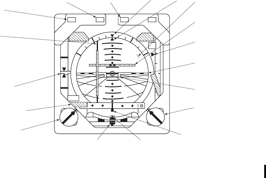
CONTROL/
INDICATOR FUNCTION
Bank angle scale Right and left 0°, 10°, 20°, 30°, 45°,
60°, and 90° of bank.
Artificial horizon Reference of helicopter’s attitude to
horizon.
Turn rate indica-
tor 4-minute turn (one-needle width ei-
ther side of center) 2-minute turn
(two-needle width each side of cen-
ter).
Pitch and roll
command bars Display to the pilot, control inputs
he should make to arrive at a pre-
determined course, or glide slope.
Collective pos-
ition indicator Display to the pilot the position of
the collective relative to where it
should be to arrive at a predeter-
mined altitude.
CONTROL/
INDICATOR FUNCTION
GA Go-around (GA) advisory light will
go on whenever the GA switch on
the pilot’s or copilot’s cyclic stick
is pressed. The light will go off
whenever the go-around mode is
ended by engaging another mode
on the CIS mode selector panel.
DH Decision height (DH) advisory
light will go on whenever the radar
altimeter is operating and the alti-
tude indicator is at or below the ra-
dar altitude L (low bug) setting.
MB Marker beacon (MB) advisory light
will go on and the associated
marker beacon tone will be heard,
depending upon volume control set-
ting, when the helicopter is over the
marker beacon transmitter.
SA
AA0369A
CMD ATT
30 30
30 30
NAV
ROLL PITCH
C
LI M
B
DI VE
G
S
GA DH MB
DECISION
HEIGHT
ADVISORY
LIGHT
MARKER
BEACON
ADVISORY
LIGHT
COLLECTIVE
POSITION
INDICATOR
NAV WARNING
FLAG (DOPPLER / GPS
VOR−LOC−FM HOMER)
GO−AROUND
ADVISORY
LIGHT
ROLL
COMMAND
BAR
BANK
ANGLE
SCALE
BANK
ANGLE
INDEX SPHERE
PITCH
COMMAND
BAR
GLIDESLOPE
DEVIATION
POINTER
ARTIFICIAL
HORIZON
MINIATURE
AIRPLANE
PITCH
TRIM KNOB
COURSE
DEVIATION
POINTER
(FM HOMER STEERING−
VOR−LOC−DOPPLER / GPS)
INCLINOMETER
TURN
RATE
INDICATOR
ROLL TRIM KNOB
Figure 3-30. Vertical Situation Indicator
TM 1-1520-237-10
Change 1 3-65

CONTROL/
INDICATOR FUNCTION
Glide slope
pointer Displays to the pilot the position of
the ILS glide slope relative to the
helicopter. Pointer above center in-
dicates helicopter is below glide
path.
Course deviation
pointer Displays to the pilot the position of
the course reference (VOR, LOC,
DPLR, FM HOME) relative to the
helicopter.
ATT warning
flag Indicates loss of vertical gyro
power or VSI malfunction.
NAV warning
flag Indicates loss, or unreliable signal
indication.
GS warning flag Indicates loss, or unreliable signal
indicator.
PITCH trim
knob Adjust artificial horizon up (climb)
from at least 4°, no more than 10°
or down (dive) from at least 8°, no
more than 20°.
ROLL trim knob Adjust artificial horizon right or left
from at least 8° to no more than
20°.
3.25.2 Horizontal Situation Indicator. Two HSIs
(Figure 3-31) are installed on the instrument panel, one in
front of each pilot. The HSI consists of a compass card, two
bearing-to-station pointers with back-course markers, a
course bar, a KM indicator, heading set (HDG) knob and
marker, a course set (CRS) knob, a COURSE digital read-
out, a to-from arrow, a NAV flag, and a compass HDG
flag. The HSIs operating power is taken from the ac essen-
tial bus through a circuit breaker marked HSI PLT/CPLT.
3.25.3 Controls and Indicators. Controls of the hori-
zontal situation indicators (Figure 3-31) are as follows:
CONTROL/
INDICATOR FUNCTION
Compass card The compass card is a 360° scale
that turns to display heading data
obtained from the compass control.
The helicopter headings are read at
the upper lubber line.
CONTROL/
INDICATOR FUNCTION
COURSE set
display Displays course to nearest degree.
Indicates same as course set
pointer.
Bearing pointer
No. 1 The pointer operates in conjunction
with Doppler/GPS or IINS.
Indicates magnetic bearing to
Doppler/GPS or IINS destination
set on FLY-TO-DEST UH or CDU
EH .
Bearing pointer
No. 2 The pointer operates in conjunction
with selected VOR or ADF
receiver. The pointer is read against
the compass card and indicates the
magnetic bearing to the VOR or
ADF station.
Course deviation
bar This bar indicates lateral deviation
from a selected course. When the
helicopter is flying the selected
course, the course bar will be
aligned with the course set pointer
and will be centered on the fixed
aircraft symbol.
CRS knob Course set (CRS) knob and the
course set counter operate in
conjunction with the course pointer
and allow the pilot to select any of
360 courses. Once set, the course
pointer will turn with the compass
card and will be centered on the
upper lubber line when the
helicopter is flying the selected
course.
KM indicator Digital distance display in
kilometers (KM) to destination set
on Doppler FLY TO DEST.
HDG knob Heading set (HDG) knob operates
in conjunction with the heading
select marker, allows the pilot to
select any one of 360 headings.
Seven full turns of the knob
produces a 360° turn of the marker.
HDG warning
flag Visible when a failure occurs in the
magnetic compass system.
To-From arrow To-from arrow indicates that the
helicopter is flying to or away from
a selected VOR.
TM 1-1520-237-10
3-66 Change 9
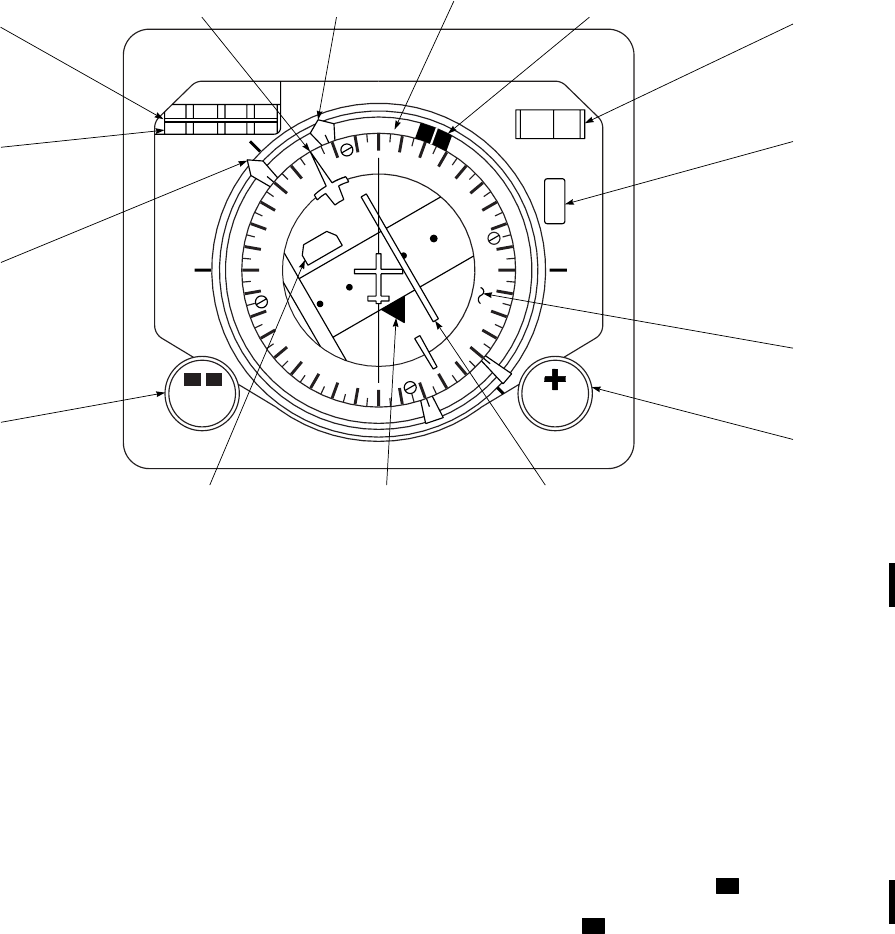
CONTROL/
INDICATOR FUNCTION
NAV flag The NAV flag at the top of the to
indicator, turns with the compass
card. The flag will retract from
view when a reliable navigation
signal is being applied to the instru-
ment.
3.25.4 VSI/HSI and CIS Mode Selector Panels. The
mode select panels (Figure 3-32) are integrally lighted, in-
strument panel mounted controls for the VSI, HSI, and CIS.
The panels provide a means for selecting and displaying
various navigation functions. Power to operate the pilot’s
MODE SEL is taken from the No. 2 dc primary bus
through a circuit breaker, marked PILOT MODE SE-
LECT. The copilot’s MODE SEL takes power from the
No. 1 dc primary bus through a circuit breaker, marked
CPLT MODE SELECT.
NOTE
The switches on the VSI/HSI and CIS mode
select panels may change state when the
caution/advisory panel BRT/DIM-TEST
switch is set to TEST. The original indica-
tions may be restored by pressing the appli-
cable switches.
3.25.4.1 Controls and Functions. Controls of the
mode selector panel (Figure 3-32) are as follows:
CONTROL FUNCTION
DPLR, DPLR/
GPS Directs Doppler UH , Doppler/GPS
UH lateral deviation and NAV flag
signals to VSIs and HSIs.
VOR ILS Directs VOR or ILS signals to
VSIs, and HSIs. Provides a signal
to NAV flag.
BACK CRS Reverse polarity of back course
signal to provide directional display
for VSIs and HSIs. Provides a
signal to NAV flag.
FM HOME Directs FM homing deviation and
flag signals to VSIs.
33
15
30
W
24
21
S
12
E
6
3
N
1234 30 0
COURSE
H
D
G
KM
HDG CRS
1
1
2
2
NAV FLAG
(DOPPLER / GPS−
VOR−LOC)
TO−FROM
ARROW
(VOR)
COURSE
DEVIATION BAR
(DOPPLER − DOPPLER / GPS−VOR−LOC)
COURSE
SET
POINTER
NO. 1 BEARING
POINTER
(DOPPLER / GPS / IINS)
LUBBER
LINE HDG
SELECT
MARKER COURSE
SET
DISPLAY
HDG
WARNING
FLAG
COMPASS
CARD
COURSE
SET KNOB
DOPPLER / GPS
DISTANCE
TO GO DISPLAY
NO. 2 BEARING
POINTER
(VOR−LF / ADF)
HEADING
SET KNOB
DISTANCE
SHUTTER
NAV
SA
AA0328A
Figure 3-31. Horizontal Situation Indicator
TM 1-1520-237-10
Change 1 3-67
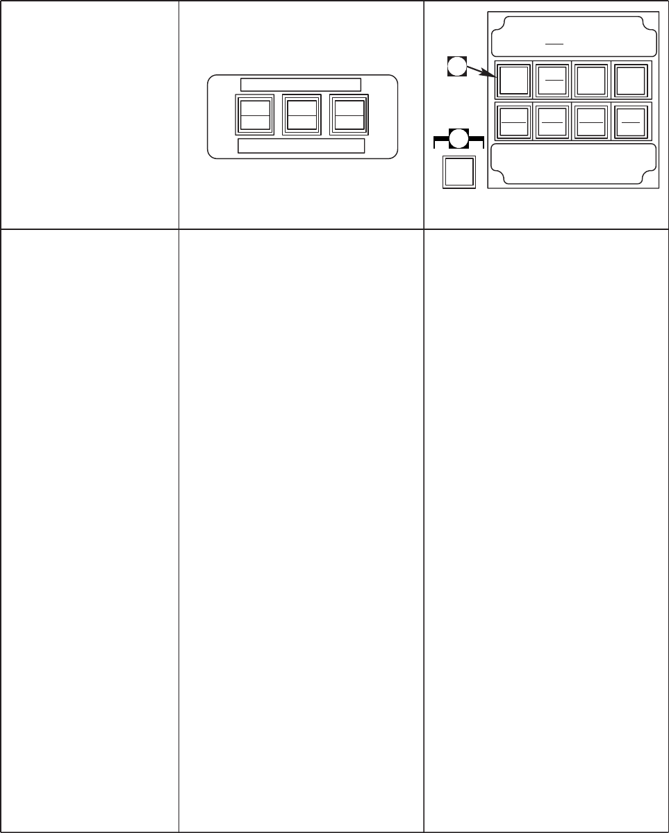
SA
AA0362_1A
MODE OF
OPERATIONS CIS
MODE SELECTOR HSI / VSI
MODE SELECTOR
NONE NONE ANY
MANUAL HEADING HDG ANY
ALTITUDE HOLD ALT ANY
VOR NAVIGATION NAV VOR
ILS NAVIGATION NAV ILS
ILS APPROACH NAV ILS
ILS BACK COURSE NAV BACK CRS
LEVEL OFF NAV VOR / ILS / BACK CRS
GO−AROUND NAV VOR / ILS
DOPPLER, DOPPLER / GPS NAV DPLR, DPLR / GPS
FM HOMING NAV FM HOME
HDG NAV ALT
HDG
ON
NAV
ON
ALT
ON
CIS MODE SEL
MODE SEL
DPLR VOR
ILS
VOR
ILS
BACK
CRS
BACK
CRS
FM
HOME
FM
HOME
PLT
CPLT ADF
VOR
TURN
RATE CRS
HDG VERT
GYRO BRG
2
ALTER ALTER
NORM NORM
DPLR
DPLR
GPS
A
A
Figure 3-32. CIS Modes of Operation (Sheet 1 of 2)
TM 1-1520-237-10
3-68 Change 1

SA
AA0362_2
CYCLIC PITCH
COMMAND BAR COLLECTIVE
POSITION INDICATOR
CYCLIC ROLL
COMMAND BAR
OFF SCALE OFF SCALE OFF SCALE
PROCESSED CYCLIC
ROLL COMMAND OFF SCALE OFF SCALE
OFF SCALE OFF SCALE
PROCESSED CYCLIC
ROLL COMMAND
PROCESSED CYCLIC
ROLL COMMAND
PROCESSED CYCLIC
ROLL COMMAND
PROCESSED CYCLIC
ROLL COMMAND
PROCESSED CYCLIC
ROLL COMMAND
PROCESSED CYCLIC
ROLL COMMAND
PROCESSED CYCLIC
ROLL COMMAND
PROCESSED CYCLIC
ROLL COMMAND
OFF SCALE
OFF SCALE
OFF SCALE
OFF SCALE
OFF SCALE
OFF SCALE
OFF SCALE
OFF SCALE
OFF SCALE
PROCESSED COLLECTIVE
POSITION
PROCESSED COLLECTIVE
POSITION
PROCESSED COLLECTIVE
POSITION
PROCESSED COLLECTIVE
POSITION
PROCESSED COLLECTIVE
POSITION
PROCESSED CYCLIC
PITCH COMMAND
PROCESSED CYCLIC
PITCH COMMAND
PROCESSED CYCLIC
PITCH COMMAND
OR
PROCESSED CYCLIC
PITCH COMMAND
Figure 3-32. CIS Modes of Operation (Sheet 2 of 2)
TM 1-1520-237-10
3-69

CONTROL FUNCTION
TURN RATE
NORM Provides pilot and copilot with his
own turn rate gyro information dis-
played on his VSI.
ALTR Allows copilot’s turn rate gyro in-
formation to be displayed on pilot’s
VSI, or pilot’s gyro information to
be displayed on copilot’s VSI.
CRS HDG
PLT Provides for pilot’s omni-bearing
selector to be connected to naviga-
tion receiver and concurrent con-
nection of pilot’s HSI course datum
and heading datum output to com-
mand instrument system processor.
CPLT Provides for copilot’s omni-bearing
selector to be connected to naviga-
tion receiver and concurrent con-
nection of copilot’s HSI course da-
tum and heading datum output to
command instrument system pro-
cessor.
VERT GYRO
NORM Provides pilot and copilot with his
own vertical gyro information dis-
played on his VSI.
ALTR Allows copilot’s vertical gyro in-
formation to be displayed on pilot’s
VSI, or pilot’s gyro information to
be displayed on copilot’s VSI.
BRG2
ADF Allows pilot or copilot to select
ADF on his No. 2 bearing pointer,
each independent of the other.
VOR Allows pilot or copilot to select
VOR on his No. 2 bearing pointer,
each independent of the other.
CIS mode
selector Selects one of three modes of op-
eration to direct navigational sig-
nals to the CISP for Command Sig-
nal display.
CONTROL FUNCTION
HDG ON Direct heading and roll signals to
CIS processor for steering com-
mands that will allow pilot to main-
tain a selected heading.
NAV ON Gives heading commands to ac-
quire and track a selected VOR,
ILS, DPLR, DPLR/GPS, or FM in-
tercept, or to acquire and track glide
slope beam.
ALT ON Directs barometric pressure signals
and collective stick position signals
to CIS processor.
3.25.4.2 Off Mode. The command instrument system off
mode (no switch legends lit) causes the cyclic roll, cyclic
pitch and collective command pointers on both vertical
situation indicators to be stowed out of view and the com-
mand warning flag on both VSIs to be biased out of view.
The CISP is in the off mode upon initial application of
electrical power, before the pilot selects either HDG,NAV
or ALT mode on the CIS mode selector. When NAV mode
is selected, the CISP remains in the off mode unless the
DPLR,DPLR/GPS,VOR ILS or FM HOME navigation
data has been selected on the pilot’s VSI/HSI mode selec-
tor. The CISP will return to the off mode whenever the
HDG,NAV, and ALT hold modes are disengaged, as in-
dicated by the respective ON legends going off, or by turn-
ing off the associated navigation receiver. Separate modes
are manually disengaged by pressing the mode switch when
ON is lit.
3.25.4.3 Heading Mode. The heading mode processes
the heading error and roll attitude signals to supply a lim-
ited cyclic roll command, which, when followed, causes the
helicopter to acquire and track the heading manually se-
lected on either pilot’s HSI. The processed signal causes
the VSI cyclic roll command bar to deflect in the direction
of the required control response; i.e., bar deflection to the
right indicates a coordinated right turn is required. When
properly followed, the command results in not more than
one overshoot in acquiring the selected heading and a
tracking error of not more than 2°. The processor gain pro-
vides 1° of roll command for each degree of heading error
TM 1-1520-237-10
3-70 Change 5

up to a roll command limit of approximately 20°. The CISP
heading mode is engaged by momentarily pressing the
HDG switch on the pilot’s CIS mode selector, or as de-
scribed in paragraph 3.25.4.5.
3.25.4.4 Altitude Hold Mode. The altitude hold mode
processes barometric pressure signals from the air data
transducer in addition to the collective stick position signal.
When the ALT switch on the pilot’s CIS mode selector is
pressed, the CISP provides collective command signals,
which, when properly followed, cause the helicopter to
maintain altitude to within plus or minus 50 feet. The alti-
tude hold mode synchronizes on the engagement altitude
for vertical rates up to 200 feet per minute and provides
performance for altitude inputs between -1000 and +10,000
feet at airspeeds from 70 to 150 KIAS. It is possible to
engage the altitude hold mode, regardless of whether the
heading mode or navigation mode is engaged, except that
the CISP logic prevents manual selection of the altitude
hold mode whenever the NAV mode is engaged and an ILS
frequency is selected. This prevents the operator from se-
lecting altitude hold mode during an instrument approach.
The altitude hold mode is manually engaged by pressing
the ALT hold switch (subject to above restriction) or auto-
matically engaged as described in paragraph 3.25.4.7. The
altitude hold mode may be manually disengaged by press-
ing the ALT hold switch when the ON legend is lit. Alti-
tude hold may be disengaged also by selecting any other
mode which takes priority (e.g., Go Around).
NOTE
ALT hold mode should be manually dis-
abled during localizer, localizer backcourse,
VOR, and ADF approaches.
3.25.4.5 Navigation Mode. The CISP navigation mode
is engaged by pressing the NAV switch on the CIS Mode
Selector. This navigation mode causes the CISP to enter the
VOR NAV,ILS NAV,DPLR NAV,orFM HOME mode
as selected on the pilot’s VSI/HSI mode selector. The CISP
provides steering commands based on the course selected
on either the pilot’s or copilot’s HSI dependent on the mode
select CRS HDG selection of PLT or CPLT.
3.25.4.6 VOR NAV Mode. The VOR NAV mode is es-
tablished by selecting the VOR/ILS switch on the VSI/HSI
mode selector and pressing the NAV switch on the CIS
mode selector. The CISP processes the heading and course
signals derived from either the pilot’s or the copilot’s HSI
in addition to the lateral deviation and lateral flag signals
applied to the pilot’s VSI. The CISP provides a limited
cyclic roll command, which, when followed, shall cause the
helicopter to acquire and track the course setting manually
selected on the HSI. Engagement of the VOR NAV when
the helicopter position is in excess of 10° to 20° from the
selected radial will cause the initial course intersection to
be made in the heading mode as described in paragraph
3.25.4.3. The CISP logic will light the CIS mode selector
HDG switch ON legend during the initial course intersec-
tion. When the helicopter is within 10° to 20° of the se-
lected course, the CISP beam sensor will capture the VOR
lateral beam. The processor logic will turn off the HDG
switch ON legend and the final course interception, about
45°, acquisition, and tracking will be based on the VOR
lateral deviation signals. The processor causes the roll com-
mand pointer to deflect in the direction of the required con-
trol response. When properly followed, the command will
result in not more than one overshoot at a range of 10 NM
at a cruise speed of 100 610 knots, and not more than two
overshoots at ranges between 5 and 40 NM at speeds from
70 to 140 knots. When passing over the VOR station, the
CISP reverts to a station passage submode and remains in
this submode for 30 seconds. Cyclic roll commands during
the station passage submode will be obtained from the HSI
course datum signal. Outbound course changes may be
implemented by the HSI CRS SET knob during the station
passage submode. Course changes to a new radial, or iden-
tification of VOR intersections may be made before station
passage by setting the HSI HDG control to the present
heading and actuating the HDG switch. This will disengage
the NAV mode and allow the pilot to continue on the origi-
nal radial in the heading mode. A VOR intersection fix or
selection of a new radial course may be made without af-
fecting the CIS steering commands. Actuating the NAV
switch re-engages the VOR NAV mode to either continue
on the original VOR radial or to initiate an intercept to the
new selected radial.
3.25.4.7 ILS NAV Mode. The instrument landing sys-
tem NAV mode is established by selecting the VOR/ILS
switch on the VSI/HSI mode selector, tuning a localizer
frequency on the navigation receiver and selecting the NAV
switch on the pilot’s CIS MODE SEL panel. During the
ILS NAV mode the CISP processes the following signals
in addition to those processed during the VOR NAV mode:
1. The vertical deviation and vertical flag signals, 2. the
indicated airspeed (IAS) and barometric altitude signals,
and 3. the collective stick position sensor and helicopter
pitch attitude signals. The indicated airspeed and pitch at-
titude signals are processed to provide a limited cyclic pitch
command, which, when properly followed, will result in
maintaining an airspeed that should not deviate more than 5
knots from the IAS existing at the time the ILS NAV mode
is engaged. The pitch command bar will deflect in the di-
rection of the required aircraft response, i.e., an upward
deflection of the pitch bar indicates a pitch up is required.
The BAR ALT and collective stick position signals are pro-
TM 1-1520-237-10
Change 5 3-71

cessed to provide a limited collective position indication,
which, when properly followed, will cause the helicopter to
maintain the altitude existing at the time the ILS NAV
mode is engaged. The collective position indicator will de-
flect in the opposite direction of the required control re-
sponse, i.e., an upward deflection of the collective position
indicator indicates a descent is required. The CISP will
cause the ALT hold switch ON legend to light whenever
the altitude hold mode is engaged. Actuating the ALT hold
ON switch will disengage the altitude hold mode. Desired
approach runway course must be set on the CRS window
of the HSI selected by the PLT/CPLT indication of the
CRS HDG switch. The initial course intersection and the
localizer course interception, about 45°, acquisition, and
tracking will be done as described for the VOR NAV mode
except that not more than one overshoot at a range of 10
NM at 100 610 KIAS, and not more than two overshoots
at ranges between 5 and 20 NM should occur for airspeeds
between 70 and 130 KIAS.
3.25.4.8 Approach Mode. The approach mode, a sub-
mode of the ILS NAV mode, will be automatically en-
gaged when the helicopter captures the glide slope. During
the approach mode, the CISP processes the vertical devia-
tion, GS flag, and collective stick position signals to pro-
vide a limited collective position indicator, which, when
properly followed, shall cause the helicopter to acquire and
track the glide slope path during an approach to landing.
When the glide slope is intercepted, the CISP logic disen-
gages the altitude hold mode and causes the ON legend of
the ALT hold switch to go off. The CISP will provide a
down movement of the collective position indicator to ad-
vise the pilot of the transition from altitude hold to glide
slope tracking, and to assist in acquiring the glide slope
path. The cyclic roll commands are limited to 615° during
the approach submode. When properly followed, the roll
commands will result in the helicopter tracking the local-
izer to an approach. The collective position indicator, when
properly followed, will result in not more than one over-
shoot in acquiring the glidepath and have a glidepath track-
ing free of oscillations. The cyclic roll and collective steer-
ing performance is applicable for approach airspeed from
130 KIAS down to 50 KIAS.
3.25.4.9 BACK CRS Mode. The back course mode is a
submode of the ILS NAV mode and is engaged by concur-
rent ILS ON and BACK CRS ON signal from the pilot’s
HSI/VSI mode selector. The CISP monitors the localizer
lateral deviation signals to provide cyclic roll commands,
which, when properly followed, will allow the pilots to
complete back course localizer approach in the same man-
ner as the front course ILS. The desired final approach
course should be set on the selected HSI CRS window.
3.25.4.10 Level-Off Mode. The level-off mode will be
activated when either the VOR NAV or ILS NAV modes
are engaged, and will be deactivated by selection of another
mode or when a radar altitude valid signal is not present.
The level-off mode is not a function of a VOR or ILS CIS
approach. During ILS or VOR approaches, the barometric
altimeter must be used to determine arrival at the minimum
altitude. Radar altimeter setting shall not be used for level
off commands in the VOR NAV/ILS NAV modes because
variations in terrain cause erroneous altitude indications.
The level-off mode provides the pilots with a selectable low
altitude command. This mode is automatically engaged
when the radar altitude goes below either the pilot’s or
copilot’s radar altimeter low altitude warning bug setting,
whichever is at the higher setting. A DH legend on the VSI
and a LO light display on the radar altimeter indicator goes
on whenever the radar altitude is less than the LO bug
setting. The CISP monitors the radar altimeter and the col-
lective stick position sensor to provide a collective pointer
command, which, when properly followed, will cause the
helicopter to maintain an altitude within 10 feet of the low
altitude setting for settings below 250 feet, and 20 feet for
settings above 250 feet. The CISP causes the ALT switch
ON legend to light and the altitude hold mode to be en-
gaged.
3.25.4.11 Go-Around Mode. The go-around mode pro-
cesses roll and pitch attitude, altitude rate, collective stick
position, and airspeed inputs in addition to internally gen-
erated airspeed and vertical speed command signals to pro-
vide cyclic roll, cyclic pitch and collective position indica-
tion. The go-around mode will engage when either pilot
presses the GA (Go Around) switch on his cyclic control
grip. When the go-around mode is engaged, the CISP im-
mediately provides a collective position indication, which,
when followed, will result in a 500 650 fpm rate-of-climb
at zero bank angle. Five seconds after the GA switch is
pressed, the CISP will provide cyclic pitch bar commands,
which, when followed, will result in an 80-KIAS for the
climbout. The go-around mode is disengaged by changing
to any other mode on the pilot’s CIS mode selector.
3.25.4.12 Doppler, Doppler/GPS Mode. The Dop-
pler, Doppler/GPS navigation mode is engaged by selecting
the DPLR,DPLR/GPS switch on the VSI/HSI mode se-
lector and the NAV switch on the CIS mode selector. Dop-
pler and GPS combined navigation is the default setting on
the AN/ASN-128B, but Doppler only or GPS only naviga-
tion can be selected from the DLPR/GPS CDU GPS .
During the Doppler, Doppler/GPS navigation mode, the
CISP processes Doppler, Doppler/GPS track angle error
and the Doppler, Doppler/GPS NAV flag signals in addi-
tion to the roll angle input from the attitude gyro. The CISP
TM 1-1520-237-10
3-72 Change 5
provides cyclic roll bar commands, which, when followed,
result in a straight line, wind-corrected, flight over distances greater than 0.2 kilometer from the destination. The course
TM 1-1520-237-10
Change 5 3-72.1/(3-72.2 Blank)

deviation bar and course deviation pointer provide a visual
display of where the initial course lies in relationship to the
helicopter’s position. The initial course is the course the
Doppler, Doppler/GPS computes from the helicopter’s po-
sition to the destination at the time the fly to destination
thumbwheel is rotated (or entered from the keyboard). The
VSI and HSI course sensitivity is 61000 meters when far-
ther than 12 km from the fly-to destination. Course sensi-
tivity gradually scales down from 61000 meters at 12 km
to 6200 meters at 2 km and less from the fly-to destination.
To achieve a pictorially correct view of the course, rotate
the course knob to the head of the No. 1 needle when the
fly to destination thumbwheel is rotated (or entered from
the keyboard). The DPLR, DPLR/GPS NAV logic detects
the condition of station passover, and automatically
switches to heading mode. The switch to heading mode will
be indicated by the HDG switch ON legend being turned
on, and the NAV switch ON legend being turned off. The
Doppler, Doppler/GPS navigation mode will not automati-
cally re-engage, but will require manual re-engagement of
the NAV switch on the CIS mode selector.
3.25.4.13 FM HOME Mode. The FM homing (Figure
3-32) is engaged by selecting the FM HOME switch on the
pilot’s VSI/HSI mode selector and the NAV switch on the
pilot’s CIS mode selector. Selecting FM homing on the
VSI/HSI mode selector directs FM homing signals only to
the VSI. Other NAV modes will be retained on the HSI if
previously selected. During the FM HOME mode, the
CISP processes the lateral deviation and flag signals dis-
played on the pilot’s VSI in addition to the roll angle input
from the attitude gyro. The CISP filters and dampens the
FM homing deviation signals and provides cyclic roll com-
mands to aid the pilot in homing on a radio station selected
on the No. 1 VHF-FM communications receiver. When
properly followed, the roll commands result in not more
than two overshoot heading changes before maintaining a
tracking error not to go over 3°. The CISP will revert to the
heading mode whenever the lateral deviation rate is over
1.5°/ sec for a period of over 1 second. The CISP will cause
the CIS mode selector HDG switch ON legend to light, and
remain in the heading mode until the FM mode or some
other mode is manually selected. Concurrent VOR and FM
or concurrent DPLR and FM mode inputs will be consid-
ered an FM mode input to the CISP.
3.25.4.14 TURN RATE Select. The turn rate gyro se-
lection provides each pilot the option of having his VSI
display his own turn rate gyro signal (NORM operation) or
of having the other pilot’s turn rate gyro signal displayed
(ALTR operation). The turn rate gyro selection is indepen-
dent of the navigation modes selected by the top row of
switches and is independent of which turn rate gyro the
other pilot has selected. The NORM selection connects
each pilot’s VSI to his own turn rate gyro. The selection of
NORM or ALTR operation is indicated by lighting the
respective legend on the TURN RATE selector switch.
The lamp power to the indicator legends is controlled
through a relay so that the NORM legend is lit in case the
mode selector logic or lamp drivers fail. Sequential opera-
tion of the TURN RATE switch alternates the rate gyro
connected to the VSI.
3.25.4.15 CRS HDG Select. The CRS HDG switch on
the mode selector provides for either the pilot’s or the co-
pilot’s course selector (CRS) to be connected to the navi-
gation receiver, and for concurrent connection of the same
pilot’s HSI course and heading information to the com-
mand instrument system processor. The CRS resolver is
normally connected to the pilot’s HSI until selected by the
copilot on his mode selector. CRS HDG control is trans-
ferred by pressing the CRS HDG switch. The pilot having
the CRS HDG control is indicated by lighting of either the
PLT or the CPLT legend on each mode selector. When
power is first applied to the mode selector, the pilot’s po-
sition is automatically selected. The CRS HDG selection is
independent of the navigation modes selected by the top
row of switches.
3.25.4.16 VERT GYRO Select. The vertical gyro se-
lection provides each pilot the option of having his VSI
display his own vertical gyro attitude (NORM operation),
or of having the other pilot’s vertical gyro attitude dis-
played (ALTR operation). The vertical gyro selection is
independent of the navigation modes selected by the top
row of switches and is independent of which vertical gyro
the other pilot has selected. Each pilot’s VSI is normally
connected to his own vertical gyro. The selection of
NORM or ALTR operation is indicated by lighting the
respective legend on the VERT GYRO selector switch.
The lamp power to the indicator legends is controlled
through a relay so that the NORM legend is lit in case the
mode selector logic or lamp drivers fail. Sequential opera-
tion of the VERT GYRO switch alternates the vertical
gyro connected to the VSI.
3.25.4.17 No. 2 Bearing Select. The HSI number 2
bearing pointer selection allows the option of either the
LF/ADF bearing or the VOR bearing to a selected station.
The ADF/VOR selection is independent of the navigation
modes selected by the top row of switches, and either pilot
selects ADF or VOR, independent of the other pilot’s se-
lection. The number 2 bearing pointer is normally con-
nected to the LF/ADF bearing output. The selection of ei-
ther ADF or VOR bearing is indicated by lighting of the
respective legend on the selector switch. The lamp power to
the indicator legends is controlled through a relay, so that
the ADF legend is lit in case the mode selector logic or
TM 1-1520-237-10
Change 10 3-73
lamp drivers fail. Sequential operation of the ADF/VOR
switch alternates the bearing source connected to the No. 2
bearing pointer between ADF or VOR.
3.25.5 Operation.
a. Heading Hold.
(1) CIS MODE SEL switch - HDG.
(2) HDG set knob on HSI - Set as desired.
(3) Selected heading is achieved by banking
helicopter, to center roll command bar.
b. VOR Course Intercept.
(1) Frequency - Set.
(2) HSI CRS set knob - Set to desired course.
(3) CIS MODE SEL switch - NAV.
(4) Follow roll command bar to initially fol-
low intercept heading and then follow com-
mand bar to intercept VOR course.
c. ILS Approach.
(1) Frequency - Set.
(2) HSI CRS set knob - Set to desired course.
(3) CIS MODE SEL switch - NAV.
(4) At two dots localizer deviation on HSI, fol-
low roll command bar to intercept local-
izer.
(5) As glide slope deviation pointer centers,
follow collective position indications for
glide slope tracking.
(6) At decision height, press GA switch for
go-around mode if breakout has not oc-
curred.
d. Back Course Localizer Approach.
(1) Frequency - Set.
(2) LO altitude bug - SET to missed approach
point HAT.
(3) HSI CRS set knob - Set to inbound back
course.
(4) CIS MODE SEL switch - NAV.
(5) MODE SEL switch - BACK CRS.
(6) Fly same as front course (paragraph
3.25.5c(4)). Turn off MODE SEL ALT
legend to stow collective position indicator
before making manual descent on back
course approach.
TM 1-1520-237-10
3-74 Change 10

Section IV TRANSPONDER AND RADAR
3.26 TRANSPONDER AN/APX-100(V)1 (IFF).
The transponder set (Figure 3-33) provides automatic
radar identification of the helicopter to all suitably equipped
challenging aircraft and surface or ground facilities within
the operating range of the system. AN/APX-100(V) re-
ceives, decodes, and responds to the characteristic interro-
gations of operational modes 1, 2, 3/A, C, and 4. Specially
coded identification of position (IP) and emergency signals
may be transmitted to interrogating stations when condi-
tions warrant. The transceiver can be operated in any one of
four master modes, each of which may be selected by the
operator at the control panel. Five independent coding
modes are available to the operator. The first three modes
may be used independently or in combination. Mode 1 pro-
vides 32 possible code combinations, any one of which
may be selected in flight. Mode 2 provides 4096 possible
code combinations, but only one is available and is nor-
mally preset before takeoff. Mode 3/A provides 4096 pos-
sible codes, any one of which may be selected in flight.
Mode C will indicate pressure altitude of the helicopter
when interrogated. Mode C is only available if both mode
3/A and mode C switches are placed to the ON position.
Mode 4 is the secure mode of cooperative combat identifi-
cation, IFF operational codes are installed, the current pe-
riod’s code and either the previous or the next period’s
code. Power to operate the IFF system is provided from the
No. 1 dc primary bus through a circuit breaker marked IFF.
Refer to TM 11-5895-1199-12 and 11-5895-1037-12.
3.26.1 Antenna.
CAUTION
The transponder will ignore (and not re-
spond to) interrogations received from the
ground if the ANT switch is in the TOP
position and will ignore interrogations re-
ceived from above if the ANT switch is in
the BOT position.
Flush-mounted antennas are installed on the top fairing
between engine exhaust ports, (Figure 3-1) and under the
transition section behind the UHF-AM antenna. They re-
ceive signals of interrogating stations and transmit reply
signals. The AN/APX-100(V) is a diversity transponder,
functioning to receive the rf interrogation from two anten-
nas and transmit the reply via the antenna from which the
stronger interrogation signal was received. If the ANT
switch is in the TOP position and the stronger signal was
received from the bottom antenna, no rf reply will be trans-
mitted. If the ANT switch is in the BOT position and the
stronger signal was received from the top antenna, no rf
reply will be transmitted. Therefore the ANT switch must
be in the DIV position to ensure the IFF will reply to all
valid interrogations.
3.26.2 Controls and Functions. All operating and
mode code select switches for transceiver operation are on
Control Panel RT-1296/APX-100(V) (Figure 3-33).
CONTROL/
INDICATOR FUNCTION
TEST GO Indicates successful BIT.
TEST/MON NO
GO Indicates unit malfunction.
ANT-DIV switch Allows the pilot to select the TOP
(upper antenna), BOT (bottom an-
tenna), or DIV (diversity, both an-
tennas) of the aircraft.
NOTE
The ANT-DIV switch shall be
placed in the DIV position at all
times.
MASTER/OFF/
STBY/NORM/
EMER
Selects operating condition.
NOTE
Emergency reply provisions. This
mode of operation is possible when
the MASTER switch on the IFF
control panel is placed in the
EMER position and the system is
interrogated. Emergency operation
results in four short dashes on the
interrogating radar indicator, which
indicates an aircraft in distress, and
singles out the aircraft in emer-
gency condition within the group of
aircraft. (The MASTER switch
must be in NORM, then lifted and
turned to EMER, therefore pre-
venting the switch from acciden-
tally being in EMER.) The emer-
gency reply consists of a code 7700
in mode 3/A.
TM 1-1520-237-10
Change 10 3-75
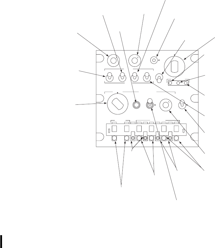
SA
AA0363A
P
R
E
S
S
T
O
T
E
S
T
D
I
M
P
R
E
S
S
T
O
T
E
S
T
D
I
M
TEST TEST / MON TOP
BOT
MASTER
TEST
OUT
STATUS
IDENT
MIC
TEST AUDIO
OUT
P
R
E
S
S
T
O
T
E
S
T
D
I
M
REPLY
CODE
M−1 M−2 M−3/A M−C RAD
TEST
A
N
T
D
I
V
I
F
F
O
NO
N
L
I
G
H
T
O
U
T
MODE 1 MODE 3 / A
N
O
G
O
E
M
E
R
N
O
R
M
S
T
B
Y
O
F
F
ALT KIT ANT
001200
MODE 4
O
N
G
O
OUT
ZE
R
O
B
A
H
O
L
D
MODE 1
FUNCTION
SWITCH
ANTENNA
SELECTOR
SWITCH
MASTER
CONTROL
SWITCH
STATUS
INDICATOR
ALTITUDE
DIGITIZER
STATUS
INDICATOR
EXTERNAL
COMPUTER
STATUS
INDICATOR
ANTENNAS
MODE C
FUNCTION
SWITCH
IDENTIFI−
CATION
POSITION
(IP)
MODE 4
CODE
HOLD−A−B−ZERO
SWITCH
MODE 2
CODE
SELECTOR
BUTTON
MODE 2
FUNCTION
SWITCH
MODE 4
TEST−ON−OUT
SWITCH
MODE 3A
FUNCTION
SWITCH
MODE 4
REPLY
INDICATOR
MODE 4
AUDIO−LIGHT−OUT
SWITCH
MODE 2
CODE
SELECTOR
BUTTON
MODE 3A
CODE
SELECTOR
BUTTON
MODE 1
CODE
SELECTOR
BUTTON
MODE 3A
CODE
SELECTOR
BUTTON
TEST GO
INDICATOR
TEST / MON
NOGO
INDICATOR
RAD
TEST−OUT
SWITCH
Figure 3-33. Control Panel RT-1296/APX-100(V)
TM 1-1520-237-10
3-76 Change 1

CONTROL/
INDICATOR FUNCTION
M-1, M-2,
M-3/A, M-C
switches
The four, three position switches on
the IFF control panel will enable or
disable the system for modes 1, 2,
3/A, or Coperation. Mode 1, mode
2, mode 3/A, or mode Creplies are
possible only when their respective
switches are placed in the ON po-
sitions. Mode Cis available only if
both mode 3/A and mode Care
placed in the ON position. Mode 1
switches permit selection of a de-
sired code from 00 through 73.
Mode 2and mode 3/A switches
permit selection of a desired code
from 0000 through 7777. The OUT
position if each switch prevents a
reply to the respective mode inter-
rogations. The TEST position of
each switch tests the respective
mode operation.
RAD TEST/
OUT The RAD switch is used to allow
the RT to reply to external test in-
terrogation when held in the RAD
position.
RAD TEST Allows receiver transmitter to reply
to external test interrogations.
OUT Disables the RAD TEST features
of the transponder.
STATUS ALT Indicates that BIT or MON failure
is due to altitude digitizer.
STATUS KIT Indicates that BIT or MON failure
is due to external computer.
STATUS ANT Indicates that BIT or MON failure
is due to cables or antenna.
CONTROL/
INDICATOR FUNCTION
MODE 4 CODE
selector When the IFF mode 4 computer is
installed, mode 4 interrogations by-
pass the decoder in the RT and go
directly to the crypto computer. In
the crypto computer the mode 4 in-
terrogation signal is decoded and
applied to the mode 4 recognition
circuit. When a mode 4 complete
concurrence exists, the mode 4 rec-
ognition circuit generates a signal
to the mode 4 computer which in
turn generates a mode 4 reply. The
REPLY light on the IFF control
unit comes on to indicate a mode 4
reply is being transmitted.
ZERO Zeroize code setting in computer.
ASelects mode 4 code setting for pre-
vious, present, or next period, de-
pending on which crypto period ap-
plies.
BSelects mode 4 code setting for pre-
vious, present, or next period, de-
pending on which crypto period ap-
plies.
HOLD Retains mode 4 code setting when
power is removed from transpon-
der.
MODE 4 TEST/
ON/OUT
ON Allows system to reply to mode 4
interrogations.
OUT Prevents reply to mode 4 interroga-
tions.
TEST Provides self test for mode 4.
MODE 4
AUDIO/LIGHT/
OUT
AUDIO Enables aural and REPLY light
monitoring of valid mode 4 interro-
gations and replies. (Preferred posi-
tion)
LIGHT Enables only REPLY light moni-
toring of valid mode 4 interroga-
tions and replies.
TM 1-1520-237-10
Change 1 3-77

CONTROL/
INDICATOR FUNCTION
WARNING
Placing the switch in the OUT
position will disable mode 4 RE-
PLY monitoring and IFF caution
light.
OUT Disables aural, REPLY light, and
caution light monitoring of valid
mode 4 interrogations and replies.
MODE 4 RE-
PLY Indicates that a mode 4 reply is
transmitted.
IDENT/
OUT/MIC The IDENT/OUT/MIC switch is
spring loaded to the OUT position.
If IDENT operation is desired, the
switch must be moved to the
IDENT position momentarily. The
IDENT pulse trains will be trans-
mitted for approximately 30 sec-
onds. The MIC position is not con-
nected in this installation.
MODE 1 selector
buttons Selects mode 1 reply code to be
transmitted.
MODE 2 selector
buttons Selects four digit mode 2 reply code
to be transmitted. (Located on the
control panel or on the remote RT.)
MODE 3/A se-
lector buttons Selects four digit mode 3/A reply
code to be transmitted.
3.26.3 Operation.
3.26.3.1 Starting Procedure.
CAUTION
When flying in a combat situation near
friendly radar sites or in the vicinity of
friendly fighter aircraft, the MODE 4
monitor switch must be in either the AU-
DIO or LIGHT position. This will enable
the pilot to observe that the IFF is peri-
odically responding to expected MODE 4
interrogations.
If the MODE 2 code has not been set previously, loosen
two screws which hold MODE 2 numeral cover, and slide
this cover upward to expose numerals of MODE 2 code
switches (Figure 3-33). Set these switches to code assigned
to helicopter. Slide numeral cover down and tighten screws.
1. MASTER switch - STBY.NO-GO light
should be on.
2. Allow 2 minutes for warmup.
3. MODES 1and 3A CODE selector buttons -
Press and release until desired code shows.
4. TEST,TEST/MON, and REPLY indicators
-PRESS-TO-TEST.IfMODE 1 is to be used,
check as follows:
5. ANT switch - DIV.
6. MASTER switch - NORM.
7. M-1 switch - Hold at TEST, observe that only
TEST GO indicator is on.
8. M-1 switch - Return to ON. If modes 2,3A or
M-C are to be used, check as follows:
9. M-2,M-3/A and M-C switches - Repeat steps
7. and 8.
NOTE
Do not make any checks near a radar site or
with MASTER control switch in EMER,
nor with M-3/A codes 7500, 7600 or 7700,
without first obtaining authorization from the
interrogating station(s) within range of the
transponder.
The following steps can be done only with
KIT/1A computer transponder installed.
10. MODE 4 CODE switch - A.
a. Set assigned test code in the KIT/1A com-
puter transponder.
b. AUDIO-ON-OUT switch - OUT.
c. MODE 4 TEST-ON-OUT switch - Place
to TEST and hold, then release.
d. TEST GO light - ON,MODE 4 REPLY
light off, KIT STATUS light off.
TM 1-1520-237-10
3-78 Change 8

11. When possible, request cooperation from inter-
rogating station to activate radar TEST mode.
a. Verify from interrogating station that
MODE TEST reply was received.
b. RAD TEST switch - RAD TEST and
hold.
c. Verify from interrogating station that
TEST MODE reply was received.
3.26.3.2 Normal Procedures. Completion of the start-
ing procedure leaves the AN/APX-100(V) in operation. The
following steps may be required, depending upon mission.
1. MODE 4 CODE selector switch - Aor Bas
required.
a. If code retention is desired, momentarily
place the MODE 4 CODE selector switch
to HOLD prior to turning the MASTER
switch OFF.
b. If code retention in external computer is
not desired during transponder off mode,
place MODE 4 CODE selector switch to
ZERO to dump external computer code
setting.
2. Mode M-1,M-2,M-3/A,M-C,orMODE 4
switches - Select desired mode.
3. Identification of position (I/P) switch - IDENT,
when required, to transmit identification of po-
sition pulses.
3.26.3.3 Emergency Operation.
NOTE
MASTER control switch must be lifted be-
fore it can be switched to NORM or EMER.
During a helicopter emergency or distress condition the
AN/APX-100(V) may be used to transmit specially coded
emergency signals on mode 1, 2, 3/A and 4 to all interro-
gating stations. Those emergency signals will be transmit-
ted as long as the MASTER control switch on the control
panel remains in EMER and the helicopter is interrogated.
MASTER control switch - EMER.
3.26.4 Stopping Procedure. MASTER switch - OFF.
3.27 TRANSPONDER COMPUTER KIT-1A/TSEC.
The transponder computer in the nose section of the he-
licopter operates in conjunction with mode 4. A caution
light on the caution panel, marked IFF, will go on when a
malfunction occurs in mode 4 or the computer that will
prevent a reply when interrogated. Mode 4 operation is
selected by placing the MODE 4 switch ON, provided the
MASTER switch is at NORM. Placing the MODE 4
switch to OUT disables mode 4. MODE 4 CODE switch
is placarded ZERO,B,A, and HOLD. The switch must be
lifted over a detent to switch to ZERO. It is spring-loaded
to return from HOLD to the Aposition. Position Aselects
the mode 4 code for the previous, present, or next period
depending on which crypto period applies and position B
selects the mode 4 code for previous, present, or next pe-
riod depending on which crypto period applies. Both codes
are mechanically inserted by a code-changing key. The
codes are mechanically held in the transponder computer,
regardless of the position of the MASTER switch or the
status of helicopter power, until the first time the helicopter
becomes airborne. Thereafter, the mode 4 codes will auto-
matically zeroize any time the MASTER switch or heli-
copter power is turned off. The code setting can be me-
chanically retained. With weight on the landing gear, turn
the MODE 4 CODE switch to HOLD (only momentary
actuation is required) and release. Mode 4 codes can be
zeroized any time the helicopter power is on and the MAS-
TER switch is not in OFF, by turning the CODE switch to
ZERO. Power to operate the transponder computer is pro-
vided automatically when the AN/APX-100(V) is on. The
transponder computer KIT-1A/TSEC operation is classi-
fied.
3.28 CRYPTOGRAPHIC COMPUTER KIT-1C.
The cryptographic computer uses electronic key loading.
Key loading is accomplished by use of the KYK-13 Elec-
tronic Transfer Device per TM 11-5810-389-13&P. The
Cryptographic Computer Kit-1C operation is classified.
3.29 RADAR ALTIMETER SET AN/APN-209(V).
The radar altimeter set (Figure 3-34) provides instanta-
neous indication of actual terrain clearance height. Altitude,
in feet, is displayed on two radar altimeter indicators on the
instrument panel in front of the pilot and copilot. The radar
altimeter indicators each contain a pointer that indicates
altitude on a linear scale from 0 to 200 feet (10 feet per
unit) and a second-linear scale from 200 to 1500 feet (100
feet per unit). An on/OFF/LO altitude bug set knob, on the
lower left corner of each indicator, combines functions to
serve as a low level warning bug set control, and an on/
OFF power switch. The system is turned on by turning the
TM 1-1520-237-10
Change 8 3-78.1
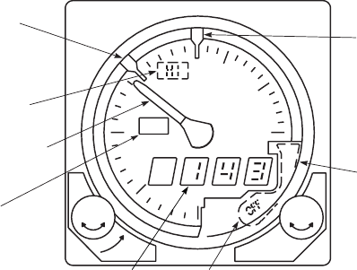
LO control knob, marked SET, of either indicator, clock-
wise from OFF. Continued clockwise turning of the control
knob will permit either pilot to select any desired low-
altitude limit, as indicated by the LO altitude bug. When-
ever the altitude pointer exceeds low-altitude set limit, the
LO altitude warning light will go on. Pressing the PUSH-
TO-TEST HI SET control provides a testing feature of the
system at any time and altitude. When the PUSH-TO-
TEST control knob is pressed, a reading between 900 feet
and 1100 feet on the indicator, and a reading between 900
and 1100 feet on the digital display, and the OFF flag
removed from view, indicates satisfactory system opera-
tion. Releasing the PUSH-TO-TEST SET control knob
restores the system to normal operation. A low-altitude
warning light, on the center left of the indicator, will light
to show the word LO any time the helicopter is at or below
the altitude limit selected by the low altitude bug. Each
pilot may individually select a low-altitude limit and only
his LO light will go on when the low-altitude is reached or
exceeded. Loss of system power will be indicated by the
indicator pointer moving behind the dial mask and the OFF
flag appearing in the center of the instrument. If the system
should become unreliable, the flag will appear and the in-
dicator pointer will go behind the dial mask, to prevent the
pilot from obtaining erroneous readings. Flight operations
above 1600 feet do not require that the system be turned
off. The pointer will go behind the dial mask but the trans-
mitter will be operating. Power to operate the AN/APN-209
is supplied from the No. 1 dc primary through circuit
breakers, marked RDR ALTM.
3.29.1 Antennas. Two identical radar altimeter anten-
nas (Figure 3-1) are on the cockpit section under the avi-
onics compartment. One is for the transmitter and the other
is for the receiver. The antennas are flush-mounted in the
fuselage on the bottom of the helicopter.
3.29.2 Controls or Indicator Function. Control of the
radar altimeter set is provided by the LOW SET OFF knob
on the front of the height indicator. The knob, marked HI
SET, also controls the PUSH TO TEST (Figure 3-34).
CONTROL/
INDICATOR FUNCTION OR INDICATION
LO SET knob Power control turned
counterclockwise to OFF,
clockwise to on.
Lbug Sets altitude trip point of LO
warning light.
Hbug Sets altitude trip point of HI
warning light.
CONTROL/
INDICATOR FUNCTION OR INDICATION
HI SET knob Pushing knob actuates built-in test
system to self-test altimeter.
Altitude pointer Provides an analog indication of
absolute altitude from zero to 1500
feet.
Digital readout Gives a direct-reading four digit
indication of absolute altitude from
zero to 1500 feet.
LO warning light Lights whenever dial pointer goes
below Laltitude bug setting.
HI warning light Lights whenever dial pointer goes
above Haltitude bug setting.
OFF flag Moves into view whenever
altimeter loses track while power is
applied.
3.29.3 Operation.
a. Starting Procedure.
(1) LO SET knob - On.
(2) Lbug - Set to 80 feet.
(3) Hbug - Set to 800 feet.
(4) Indicator pointer - Behind mask above
1500 feet.
SA
AA0528
H
5
10
15
LO
FEET
0
1
2
SET SET
LO
SET
BUG
ALTITUDE
POINTER
HI
WARNING
LIGHT
LO
WARNING
LIGHT
DIGITAL
READOUT SYSTEM
OFF FLAG
HI
SET
BUG
DIAL
MASK
HI
PUSH
TO TEST
OFF
LO
ABS ALT
FT X 100
L
Figure 3-34. Radar Altimeter Set AN/APN-209(V)
TM 1-1520-237-10
3-78.2 Change 8

b. Track Operation. After about 2 minutes of war-
mup, the altimeter will go into track mode with
these indications:
(1) OFF flag - Not in view.
(2) Altitude pointer - 0 65 feet.
(3) Digital readout-0to+3feet.
(4) LO warning light - Will light.
(5) HI warning light - Will be off.
c. HI SET knob - Press and hold. The altimeter
will indicate a track condition as follows:
(1) OFF flag - Not in view.
(2) Altitude pointer - 1000 6100 feet.
(3) Digital readout - 1000 6100 feet.
(4) LO warning light - Will be off.
(5) HI warning light - Will light.
(6) HI SET knob - Release. The altimeter will
return to indications in step b. Track Op-
eration.
3.29.4 Stopping Procedure.
LO SET knob - OFF.
3.30 MISSION EQUIPMENT INTERFACE. EH
CAUTION
The ECM antenna can be extended with
the helicopter on the ground if the radar
altimeter is turned off or removed from
the installation, or the L (LO set) indica-
tor is set below the radar altimeter indi-
cation.
Two signals are provided by the radar altimeter to the
AN/ALQ-151(V)2 mission equipment. RADAR ALTIM-
ETER ON indicates the altimeter is installed and has power
applied. If this signal is not present, and the ECM antenna
is not fully retracted, a signal is generated to light the AN-
TENNA EXTENDED capsule on the CAUTION/
ADVISORY panel. The other signal, RADAR ALTI-
TUDE LOW, is sent to the mission equipment when the
aircraft altitude drops below the LO bug setting of the radar
altimeter. The signal initiates automatic retraction of the
ECM antenna, lights the ANTENNA EXTENDED capsule
until the antenna is fully retracted, and disables the ECM
ANTENNA switch.
TM 1-1520-237-10
Change 8 3-79/(3-80 Blank)

CHAPTER 4
MISSION EQUIPMENT
Section I MISSION AVIONICS
4.1 TROOP COMMANDER’S ANTENNA.
The troop commander’s antenna (Figure 3-1), on the up-
per trailing edge of the tail rotor pylon, provides for use of
a VHF/FM mobile/man pack radio, such as the AN/PRC-25
or AN/PRC-77, from the cabin area. The antenna gives the
troop commander the capability of liaison, command, and
control of ground elements. A coaxial cable, coiled in the
cabin ceiling near the left cabin door, is for connecting the
antenna to the radio set.
4.2 CREW CALL SWITCH/INDICATOR. EH
The CREW CALL switch/indicators are on the instru-
ment panel (Figure 4-1) and in the cabin at the DF and
ECM consoles. The switches are used to provide signals
between crew members to indicate communication is de-
sired, and establishing ICS circuits between cockpit and
cabin. When the pilot/copilot’s CREW CALL switch is
pressed in, it lights steady. This allows only one-way com-
munication, from pilot/ copilot to mission equipment opera-
tor(s). All stations desiring to communicate must then place
their respective intercom switches to ICS. To establish two-
or three-way communications, the flashing switches must
be pressed in. The pilot’s ICS audio overrides all other
mission equipment operator’s audio. To establish commu-
nication from mission equipment operator(s) to pilot/
copilot, the DF and/or ECM operator must press in their
respective CREW CALL switch. The DF and/or ECM op-
erator(s) CREW CALL switch(es) will light steady. The
pilot/copilot’s CREW CALL light flashes. When the pilot/
copilot’s CREW CALL switch is pressed in, the switch
lights steady, and communications can then be established.
In establishing communications, the first CREW CALL
switch pressed will light steady, all others will flash until
pressed in. To terminate two-way communication, the pilot/
copilot and mission equipment operator(s) must press the
respective CREW CALL switch(es), causing all indicators
to go off. In terminating communications, CREW CALL
switches pressed in must be pressed to release. Power to
operate the CREW CALL system is provided from the No.
1 dc primary bus through a circuit breaker marked
LIGHTS ADVSY.
4.3 CHAFF AND FLARE DISPENSER M130.
4.3.1 Chaff Dispenser M130. The general purpose dis-
penser M130 (Figure 4-1) consists of a single system (dis-
penser assembly, payload module assembly, electronics
module and dispenser control panels) and a CHAFF DIS-
PENSE control button (on the lower console) designed to
dispense decoy chaff, M-1 (refer to TM 9-1095-206-13&P).
The system provides effective survival countermeasures
against radar guided weapon systems threats. The dispenser
system, M130, has the capability of dispensing 30 chaff.
Power to operate the chaff dispenser system is provided
from the No. 1 dc primary bus through a circuit breaker,
marked CHAFF DISP.
4.3.2 Flare Dispenser M130. EH The general purpose
dispenser (Figure 4-1) consists of a single system dispenser
assembly, payload module assembly, electronics module,
and dispense control button (on the instrument panel), de-
signed to dispense decoy flares M206. The system provides
effective survival countermeasure against infrared sensing
missile threats. The dispenser system has the capability of
dispensing 30 flares. Power to operate the flare dispenser
system is provided from the No. 1 dc primary bus through
a circuit breaker marked CHAFF DISP.
4.3.3 Controls and Function. The dispenser control
panel (Figure 4-1) contains all necessary controls to operate
the dispenser system from the cockpit. The control panel is
on the lower console.
CONTROL/
INDICATOR FUNCTION
CHAFF counter Shows the number of chaff cartridges
remaining in payload module.
TM 1-1520-237-10
4-1
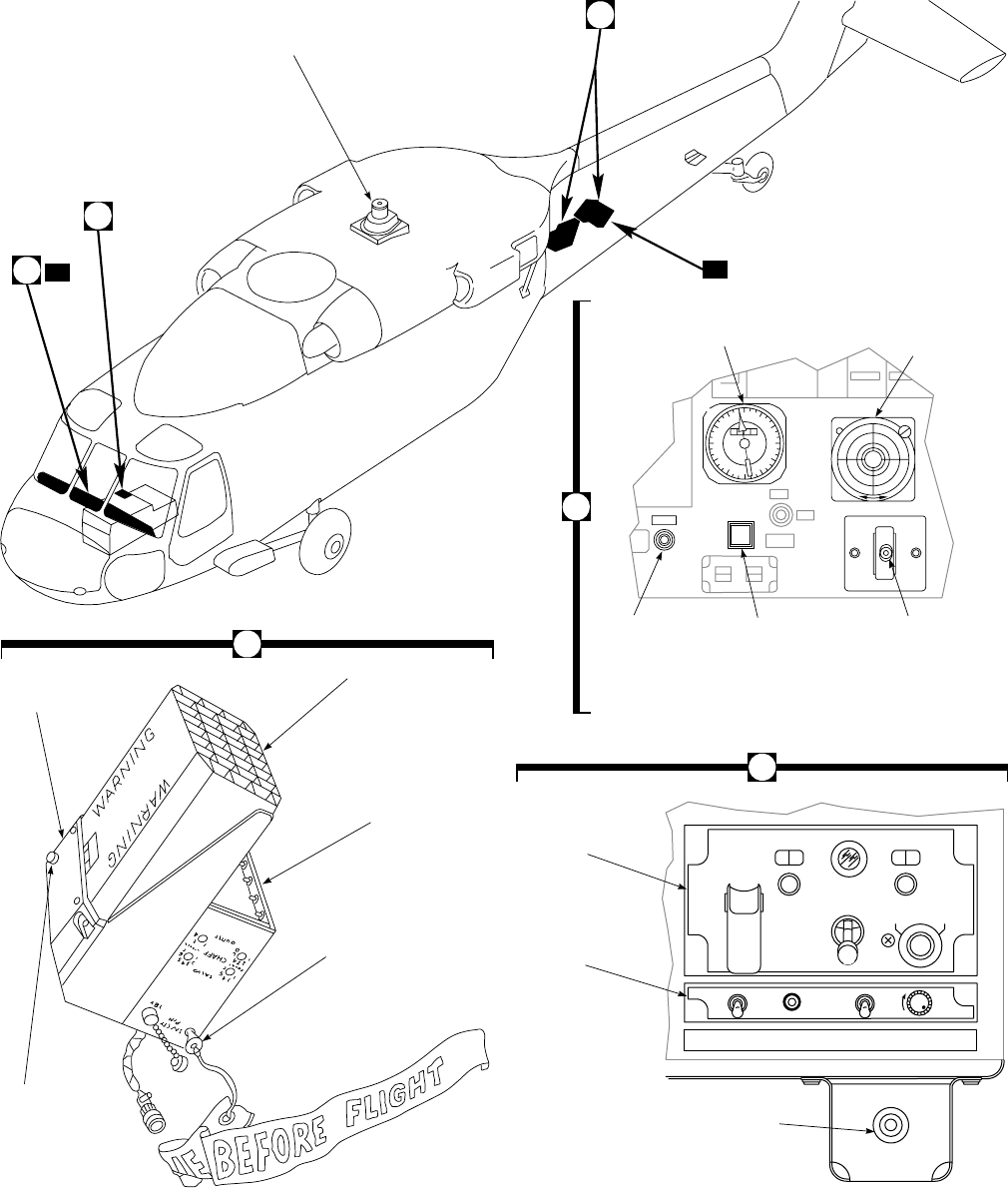
SA
AA0372A
EH
ONLY
A
B
C
INFRARED
COUNTERMEASURE
TRANSMITTER
MA
DAY
NIGHT
BRIL
00 00
FLARE ARM CHAFF
DISP
CONT
ARM
MAN PGRM
R
I
P
P
L
E
F
I
R
E
PWR SELF DSCRM
ON
OFF
ON
OFF AUDIO
TEST
CHAFF
DISPENSE
SAFE
03
6
9
12
15
21
24
27
30
33
0000
FLARE
CREW
CALL RETRACT
OFF
EXTEND
COVER
RADAR SIGNAL
DETECTOR
INDICATOR
BDHI
ECM
ANTENNA
SWITCH
SWITCH / LIGHT
FLARE
RELEASE
BUTTON
INSTRUMENT PANEL
EH
CHAFF / FLARE
DISPENSER
CONTROL PANEL
RADAR SIGNAL
DETECTOR
CONTROL PANEL
CHAFF DISPENSE
SWITCH
LOWER CONSOLE
(TYPICAL)
C
DISPENSER
ASSEMBLY
SELECT
SWITCH
C (CHAFF)
OR F (FLARE)
PAYLOAD
MODULE
ELECTRONIC
MODULE
SAFETY PIN AND
WARNING STREAMER
FLARE/CHAFF DISPENSERS
A
B
Figure 4-1. Mission Kits
TM 1-1520-237-10
4-2

CONTROL/
INDICATOR FUNCTION
Chaff counter setting
knob Adjusts counter to correspond to
number of chaff cartridges remain-
ing in payload module.
PUSH-RESET When pushed, resets chaff counter
to 9009.
ARM indicator
light Indicates that arming switch is at
ARM, safety flag pin is removed,
and payload module is armed.
ARM-SAFE switch
ARM Applies electrical power through
safety flag switch to CHAFF DIS-
PENSE button, and flare firing
switch. Flare firing system is not
used in this installation.
SAFE Removes power from dispenser
system.
FLARE counter
UH
Not used in this installation.
Flare counter setting
knob UH
Not used in this installation.
DISP CONT UH Not used in this installation.
Mode selector Selects type of chaff release opera-
tion.
MAN Dispenses one chaff cartridge each
time dispense button is pressed.
PGRM Dispenses chaff according to prede-
termined burst/salvo and number of
salvos automatically.
CHAFF DIS-
PENSE Ejects chaff cartridges from pay-
load module.
4.3.4 Controls and Function. EH
CONTROL/
INDICATOR FUNCTION
FLARE counter Indicates the number of flare car-
tridges remaining in payload mod-
ule.
Flare counter set
knob Adjusts counter to correspond to
number of flare cartridges in pay-
load module.
CONTROL/
INDICATOR FUNCTION
DISP CONT
RIPPLE FIRE Release (jettison) all flares from
payload module without pressing
FLARE switch for each flare.
FLARE switch
(Instrument panel) Fires one flare from payload mod-
ule each time switch is pressed.
4.3.5 Dispenser Assembly. The dispenser assembly
(Figure 4-1) contains the breech assembly, C-F selector
switch for either chaff or flares, a reset switch, and a hous-
ing containing the sequencer assembly. The sequencer as-
sembly receives power through the firing switches circuit
and furnishes pulses to each of the 30 contacts of the breech
assembly, in sequential order 1 through 30, thus firing each
of the impulse cartridges.
4.3.6 Payload Module Assembly. The payload mod-
ule assembly (Figure 4-1) consists of the payload module
and retaining plate assembly. The payload module has 30
chambers which will accept chaff. The chaff cartridges are
loaded through the studded end of the module, one per
chamber, and are held in place by the retaining assembly.
The payload module assembly is assembled to the dispenser
assembly.
4.3.7 Electronic Module Assembly (EM). The EM
(Figure 4-1) contains a programmer and a cable assembly
which includes a 28-volt supply receptacle and a safety
switch, actuated by inserting the safety pin with streamer
assembly. The programmer consists of a programming cir-
cuit which allows the setting of chaff burst number, chaff
burst interval, chaff salvo number, and chaff salvo interval.
4.3.8 Electronics Module Controls. Controls on the
electronic module are used to program the chaff dispenser
for predetermined release of chaff cartridges. Controls on
the electronic module are as follows (refer to TM 9-1095-
206-13&P):
CONTROL FUNCTION
SAFETY PIN Safety switch to accept the safety
pin with streamer, placing the dis-
penser in a safe condition when the
helicopter is on the ground.
SALVO COUNT Programs the number of salvos; 1,
2, 4, 8 or C (Continuous).
TM 1-1520-237-10
4-3

CONTROL FUNCTION
SALVO INTER-
VAL Programs the time in seconds be-
tween salvos; 1, 2, 3, 4, 5, 8 or R
(Random 2, 5, 3, 4, 3).
BURST COUNT Programs the number of burst; 1, 2,
3,4,6or8.
BURST INTER-
VAL Programs the time in seconds for
burst intervals; 0.1, 0.2, 0.3 or 0.4.
4.3.9 Safety Procedures. The safety pin shall be in-
stalled in the safety switch when the helicopter is parked.
Safety pin is removed immediately before takeoff.
4.3.10 Operation.
1. Counter(s) - Set for number of cartridges in
payload module(s).
2. Mode switch - MAN.
NOTE
Mode switch should always be at MAN
when the ARM-SAFE switch is moved to
ARM to prevent inadvertent salvo of chaff.
3. ARM SAFE switch - ARM.ARM indicator
light on.
4. Dispense button press or mode switch PGRM,
as required.
4.3.11 Flare Operation. EH
1. FLARE counter - Set for number of flare car-
tridges in payload module.
2. ARM switch - ARM.
3. FLARE switch (instrument panel) - Press for
each release.
NOTE
If the flare detector does not detect burning
of the first flare fired, another flare is auto-
matically fired within 75 milliseconds; if
burning is still not detected, a third and final
flare is fired. If all three flares do not fire,
automatic ejection of flares will stop until
the system is activated again by the FLARE
switch.
4.3.12 Stopping Procedure.
ARM SAFE switch - SAFE.
4.4 DELETED.
4.5 BEARING, DISTANCE, HEADING INDICATOR
(BDHI). EH
The BDHI (Figure 4-1) at the center of the instrument
panel consists of three indicators. The position of the indi-
cator allows easy viewing by both pilot and copilot. The
functions of the indicators are as follows:
a. Compass Rose - displays the magnetic heading of the
helicopter.
b. Bearing Pointer - displays bearing to the signal re-
ceived from an airborne or ground emitter/transmitter. The
DF operator selects signal to be displayed.
c. Distance Readout - displays, in kilometers, the dis-
tance to a signal emitter selected by the DF operator.
4.6 RADAR SIGNAL DETECTING SET AN/APR-
39(V)2. EH
The radar signal detecting set indicates the relative po-
sition of search radar stations. Differentiation is also made
between various types of search radar and tracking stations.
Audio warning signals are applied to the pilot’s and copi-
lot’s headsets. The radar signal detecting set is fed through
the 50-ampere LH MAIN AVIONICS and RH MAIN
AVIONICS circuit breakers on the copilot’s circuit breaker
panel and protected by the 7.5-ampere APR-39 circuit
breaker on the copilot’s circuit breaker panel. The associ-
ated antennas are shown in Figure 3-1. Refer to TM 11-
5841-288-12.
4.6.1 Controls and Function. The operating controls
of the AN/APR-39(V)2 panel (Figure 4-2) are as follows:
CONTROL FUNCTION
PWR ON Supplies 28 VDC to the Radar De-
tecting Set. Fully operational after
one minute.
PWR OFF Turns system off.
TM 1-1520-237-10
4-4 Change 10

CONTROL FUNCTION
HI ALT Selects high altitude mode of op-
eration. Selection is based on air-
craft mission profile.
LOW Selects low altitude mode of opera-
tion. Selection is based on aircraft
mission profile.
TEST Initiates system self-test function
when momentarily depressed
downward. Permits flight line test-
ing of Radar Detecting Set when
held in the upward position. (Self
test does not test antennas, antenna/
receiver cabling.)
Audio Controls level of audio output to the
aircraft interphone control system.
Turn to the right for audio volume
increase. Turn to the left for audio
volume decrease.
Direction/Display
(Scope/IP-1150) Shows alphanumeric symbology
for signals programmed in the pro-
cessor emitter identification table.
MA indicator Lamp flashes when low band sig-
nals associated with missile guid-
ance systems are correlated with
high band signals associated with
tracking systems.
BRIL control Varies the brilliance of the alpha-
numeric symbology.
CONTROL FUNCTION
Night-Day filter Varies the intensity of the red po-
larizing face plate filter for day or
night operation. If the IP-1150A is
used in the aircraft, the day-night
switch is not used as the IP-1150A
is night vision compatible.
4.6.2 Processor Unit. The processor has a theater se-
lection switch on the front of the processor. Selection of
one of six theaters is possible depending on mission and
geographical location.
4.6.3 Self-Test Procedures.
a. The self-test confidence checks all AN/APR-39(V)2
circuits except antennas, high pass filters and detectors in
the high band receivers, bandpass filter and detector in the
low band receiver, high low blanking circuits and antenna/
receiver cabling.
b. The radar detecting set performs a self-test sequence
when the TEST switch on the control unit is set to TEST
and then released. This self-test takes seven seconds, during
which time four different patterns are displayed. The alpha-
numeric symbology that is displayed at the 12, 3, 6 and 9
o’clock positions will vary depending upon the selected
theater switch on the processor.
c. In the self-test, four patterns will be displayed in se-
quence (Figure 4-3) on the display MA. Pattern number
one alphanumerics displayed will depend on the selected
theater position on the processor.
d. Observe that the radar signal indicator unit displays
patterns 1-3 and finally, either the NO signal pattern or an
actual threat pattern (Figure 4-3). As each of the first three
patterns are displayed, a different type audio tone will flash
on and off during the display of pattern number 3.
e. An 9H9symbol will appear in the center of the NO
signal pattern if the control unit HI ALT/LOW switch is in
the HI ALT mode. Conversely, an 9L9symbol will appear
in place of the 9H9symbol if this switch is in the LOW
mode.
f. It is important for operators to note if the software
version number displayed at the 12 o’clock position on the
display is the same as the software version sticker attached
to the rear of the processor.
SA
AA1635_1
AUDIO
+
TEST
ON
PWR
OFF
HI ALT
L W
Figure 4-2. AN/APR-39(V)2 Control Panel
TM 1-1520-237-10
Change 10 4-5
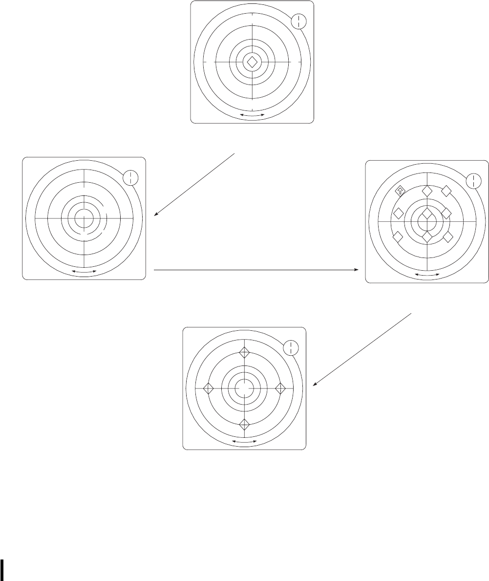
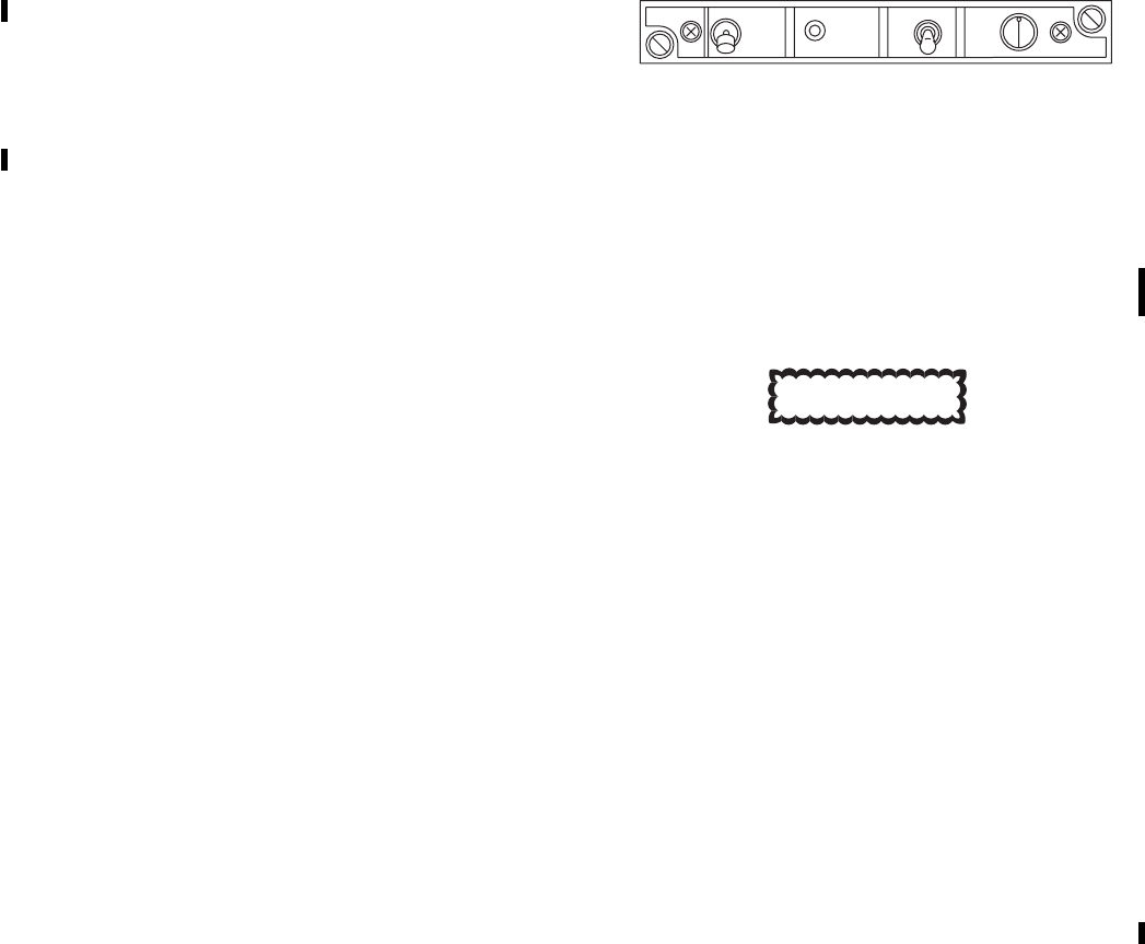
4.7 RADAR SIGNAL DETECTING SET AN/APR-
39A(V)1.
Refer to TM 11-5841-294-12.
4.7.1 Controls and Functions. The operating controls
(Figure 4-4) of the AN/APR-39A(V)1 are as follows:
CONTROL FUNCTION
PWR Controls 28VDC from the No. 1 dc
primary bus.
ON Locks the switch in the ON posi-
tion. System is fully operational af-
ter approximately one minute. On
power up the synthetic voice will
announce 9APR-39 POWER UP9.
The plus (+) symbol will appear
and be centered on the IP 1150A
cathode ray tube (CRT) during sys-
tem operation.
OFF Turns system off. Switch must be
pulled to unlock and turn system
off.
TEST When momentarily depressed ini-
tiates self-test confidence check
(except for antennas and antenna
receiver cabling).
MODE Selects synthetic voice message
format only. MODE ONE (UP) se-
lects normal voice message format.
MODE TWO (DOWN) selects
test/abbreviated voice message for-
mat.
AUDIO Controls volume to the interphone
system.
Direction/Display
(Scope IP 1150A) Shows alphanumeric symbology on
a bearing for each processed emit-
ter signal. Does not indicate any
range data.
MA indicator Not used.
MA switch Not used.
BRIL control Varies brilliance of CRT.
CAUTION
To prevent damage to the receiver detec-
tor crystals, assure that the AN/APR-
39A(V)-1 antennas are at least 60 yards
from active ground radar antennas or 6
yards from active airborne radar anten-
nas. Allow an extra margin for new, un-
usual, or high power emitters.
Excessive indicator display brightness
may damage CRT.
4.7.2 Modes of Operation.
a. Self test mode.
(1) After power up, the AN/APR-39A(V)1
synthetic voice will announce 9APR-39
POWER UP9and the (+) symbol will sta-
bilize in the center of the CRT (Figure 4-5).
Self test should be initiated after approxi-
mately one minute. Self test can be per-
formed in MODE ONE or MODE TWO.
In MODE ONE the synthetic voice will
announce 9SELF TEST SET VOLUME, 1,
2, 3, 4, 5, 6, 7, 8, 9, 10, 11, 12, 9.InMODE
TWO the synthetic voice will announce
9SELF TEST SET VOLUME, 5, 4, 3, 2,
19.
SA
AB2422
+
PWR MODE
ON
OFF 1
2
AUDIO
TEST
Figure 4-4. AN/APR-39A(V)1 Control Panel
TM 1-1520-237-10
Change 10 4-7

(2) The CRT (Figure 4-6) will display specific
software version numbers i.e., operational
flight program (OFP) at the 12 o’clock po-
sition and the emitter identification data
(EID) at the 6 o’clock position.
(3) After the software version numbers have
been displayed the test sequence checks the
receivers. A good visual self test will show
two triangles, one at the 6 o’clock and one
at 12 o’clock position on the CRT (Figure
4-6.1). Snowflake symbols (*) will appear
at the 2, 4, 8, and 10 o’clock positions and
will flash if the AN/AVR-2 laser detecting
set is not installed. This is a normal indi-
cation and does not effect system perfor-
mance.
(4) A good self test (no faults detected) ends
with the message 9APR-39 OPERA-
TIONAL9. A bad self test (faults detected)
ends with the 9APR-39 FAILURE9.
b. MODE ONE operation. Selecting MODE
ONE the operator will hear all the normal syn-
thetic voice audio when an emitter has been
processed e. g., the AN/APR-39A(V)1 will an-
nounce; 9SA, S-18 12 O’CLOCK TRACK-
ING9. Selection of this mode does not have any
effect on emitters received, processed or dis-
played, it only affects synthetic voice audio.
c. MODE TWO operation. Selecting MODE
TWO the operator will hear an abbreviated
synthetic voice audio e. g., the AN/APR-
39A(V)1 will announce; 9MISSILE 12
O’CLOCK TRACKING9.
4.7.3 Function.
a. The radar signal detecting set (RSDS) receives,
processes and displays pulse type signals oper-
ating in the C-D and H-M radio frequency
bands. The emitters that it processes and dis-
plays are derived from the EID contained in the
user data module (UDM) that is inserted in the
top of the digital processor. In normal circum-
stances the processor is classified confidential if
a classified UDM is installed.
b. The UDM contains the electronic warfare threat
data that makes up the specific library for a
specific mission(s) or a geographical location
(it is theaterized). When a match of the elec-
tronic warfare data occurs the processor gener-
ates the appropriate threat symbology and syn-
thetic audio. It is important therefore that the
correct theaterized EID and UDM are installed
for the mission or geographic location.
c. Symbol generation and position relative to the
center of the CRT shows the threat lethality, it
does not show or represent any lethality of
range, but of condition/mode of the emitter.
Highest priority threats (most lethal) are shown
nearest the center. Each symbol defines a ge-
neric threat type, symbols are modified to show
change in the status of the emitter. The symbols
are unclassified, the definitions of what the
symbols mean are classified. The complete set
of symbols and definitions are contained in TM
11-5841-294-30-2. Each theaterized library
EID has a specific classified pilot kneeboard
produced with it. The unit electronic warfare
officer (EWO) should contact PM-ASE if suf-
ficient cards are not available within his unit for
the installed EID.
d. The RSDS on specific aircraft has been inter-
faced with other aircraft survivability equip-
SA
AB2423
Figure 4-5. CRT Power Up Display
TM 1-1520-237-10
4-8 Change 10
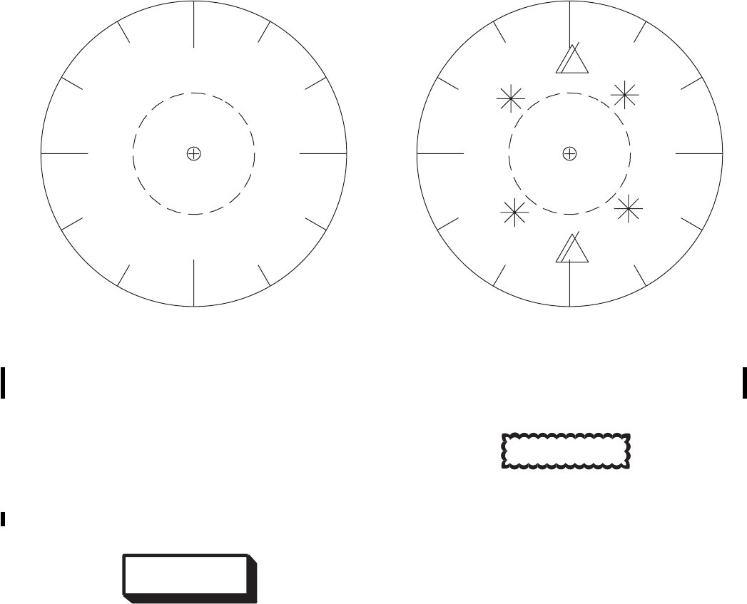
ment. The equipment includes the AN/AVR-2
laser detection set, AN/APR-44(V) continuous
wave receiver and the AN/AAR-47 missile
warning system.
4.8 INFRARED COUNTERMEASURE SET AN/ALQ-
144A(V)1.
WARNING
Do not continuously look at the infrared
countermeasure transmitter (Figure 4-1)
during operation, or for a period of over 1
minute from a distance of less than 3 feet.
Skin exposure to countermeasure radia-
tion for longer than 10 seconds at a dis-
tance less than 4 inches shall be avoided.
Ensure the countermeasure set is cooled
off before touching the unit.
CAUTION
Observe that the IRCM INOP caution
light illuminates when the OCU ON/OFF
switch is set to OFF. After 60 seconds, ob-
serve that the IRCM INOP caution light
extinguishes.
The countermeasure system provides infrared counter-
measure capability. The system transmits radiation modu-
lated mechanically at high and low frequencies using an
electrically-heated source. A built-in test feature monitors
system operation and alerts the pilot should a malfunction
occur. The system is made up of a control panel on the
instrument panel and a transmitter on top of the main rotor
pylon aft of the main rotor. On helicopters Serial No. 78-
22987 and subsequent, the countermeasure system func-
tionally interfaces with the caution/advisory warning sys-
tem through the left relay panel. The countermeasure
system gets dc electrical power from the No. 2 dc primary
SA
AB2425
XXX.X
XXX
Figure 4-6. CRT Version Number Display
SA
AB2424
Figure 4-6.1. CRT Self Test Display
TM 1-1520-237-10
Change 10 4-9
circuit breaker panel and the No. 2 junction box. The 28
vdc is routed through the IRCM PWR circuit breaker in
the No. 2 junction box to the transmitter. The No. 2 dc
primary bus also supplies 28 vdc through the IRCM
CONTR circuit breaker on the No. 2 dc primary circuit
breaker panel to the control unit. Panel lighting of the con-
trol unit is controlled by the INSTR LTS NON FLT con-
trol on the upper console. When the control unit ON-OFF
switch is placed ON, the power distribution and control
circuits are activated and the ON lamp is lit for about 60
seconds on helicopters prior to Serial No. 78-22987. The
source begins to heat, the servo motor and drive circuits are
energized, turning on the high and low speed modulators,
and a signal is applied to stabilize system operations before
energizing the built-in test function. After a warmup period
the stabilizing signal is removed, and the system operates
normally. Placing the ON-OFF control switch momentarily
to OFF causes the power distribution and control circuits to
de-energize the source and initiates a cooldown period.
During the cooldown period, the servo motor drive circuits
remain in operation, applying power to the motors that
cause the modulators to continue turning. The INOP light
will remain on during cooldown cycle, and on helicopters
Serial No. 78-22987 and subsequent, the IRCM INOP cau-
tion light will be lit. After the cooldown period, the power
distribution and control circuits de-energize, all system op-
erating voltage is removed and the IRCM INOP caution
light, or the INOP light, will go off. On helicopters prior to
Serial No. 78-22987, if a malfunction occurs during system
operation, the INOP light on the control unit will go on and
the cooldown period will automatically begin. On helicop-
ters Serial No. 78-22987 and subsequent, if a system mal-
function causes the IRCM INOP caution light on the cau-
tion panel to go on, the IRCM INOP caution light will
remain lit until the control panel ON-OFF switch is mo-
mentarily placed OFF. The system can be returned to op-
erating mode by momentarily placing ON-OFF switch
OFF, then ON, provided the cause of the malfunction has
cleared. For additional information, refer to TM 11-5865-
200-12.
4.8.1 Infrared Countermeasure System Control
Panel. Control of the countermeasure set is provided by
the operator control panel on the helicopter instrument
panel. On helicopters prior to Serial No. 78-22987, the con-
trol panel has one switch (ON-OFF) and an ON indicator
light. On helicopters Serial No. 78-22987 and subsequent,
only a power ON-OFF switch is on the control panel.
Power to operate the countermeasure set is supplied from
the No. 2 dc primary bus through a circuit breaker, marked
IRCM CONTR.
4.8.2 Controls and Function. Controls for the AN/
ALQ-144 are on the front panel of the control unit. The
function of each control is as follows:
CONTROL FUNCTION
ON-OFF switch Turns set on and off.
ON indicator light
(green) (Helicopters
prior to Serial No.
78-22987)
Indicates system is in a 45 to 75
second warmup mode.
INOP indicator light
(red) (Helicopters
prior to Serial No.
78-22987)
Indicates malfunction has occurred
or countermeasure system is in
cooldown cycle.
IRCM INOP cau-
tion light (Helicop-
ters Serial No. 78-
22987 and
subsequent)
Indicates malfunction has occurred
or the countermeasure system is in
cooldown cycle.
4.8.3 Operation.
1. ON and INOP PRESS TO TEST indicator
light - Press. Indicator light should go on. (On
helicopters prior to Serial No. 78-22987.)
2. ON-OFF switch - ON. Green indicator light
should light for 45 to 75 seconds, then go off.
(On helicopters prior to Serial No. 78-22987.)
NOTE
If the INOP indicator or IRCM INOP cau-
tion light goes on after the ON indicator (he-
licopters prior to Serial No. 78-22987) goes
off, place the power switch OFF.
3. ON-OFF switch - ON (helicopters Serial No.
78-22987 and subsequent).
4.8.4 Stopping Procedure.
ON-OFF switch - OFF. The transmitter will
continue to operate for about 60 seconds during
the cooldown cycle. INOP indicator or IRCM
INOP caution light as applicable should remain
on during cooldown cycle.
TM 1-1520-237-10
4-10 Change 10

4.9 ECM ANTENNA SWITCH. EH
The ECM antenna switch is a three-position switch on
the instrument panel (Figure 2-9), providing control of
ECM antenna deployment and retraction. The switch is
spring-loaded to center (OFF), with positions marked EX-
TEND and RETRACT. Normal operation of the switch is
as follows:
CAUTION
The ECM antenna can be extended with
the helicopter on the ground if the radar
altimeter is turned off or removed from
the installation, or the L (LO SET) indi-
cator is set below the radar altimeter in-
dication.
a. Extend. When the helicopter is on the ground with all
systems working properly and the radar altimeter L(LO
SET) indicator is set above the radar altimeter indication,
the antenna cannot be extended because of the interlock
system. When the helicopter is in flight, with the copilot’s
radar altimeter indication above the L(LO SET) indicator,
the antenna can be extended until it reaches the fully ex-
tended position, by momentarily placing the switch to EX-
TEND. Once the extension or retraction process has started,
it cannot be overridden with another command from the
ECM ANTENNA switch. The cycle can be interrupted by
turning off the radar altimeter or setting L SET bug above
radar altitude indication. When the antenna is fully ex-
tended, a light on the ECM operator’s console marked AN-
TENNA DEPLOYED, will go on. The ANTENNA EX-
TENDED caution light on the caution/advisory panel will
not go on when the antenna is extended. It is a condition
light rather than an antenna position light.
NOTE
Automatic ECM antenna retraction is con-
trolled by the copilot’s radar altimeter L(LO
SET) indicator when the altimeter is turned
on.
b. Retract. If the antenna is extended, the pilot may mo-
mentarily select RETRACT to return the antenna to the
retracted position. The antenna will automatically retract if
the helicopter descends below the altimeter Lindicator set-
ting or a failure occurs in the radar altimeter. When the
antenna is fully retracted, the ANTENNA RETRACTED
status advisory light on the caution/advisory panel will go
on and remain on as long as the antenna stays in that posi-
tion. The ANTENNA DEPLOYED and ANTENNA EX-
TENDED lights should be off with antenna retracted. An
emergency retract switch accessible to the ECM operator
may be used to retract the ECM antenna if a failure occurs
in the cockpit retract system. A light next to the switch
indicates when the antenna is extended.
c. Emergency ECM Antenna Retract Switch. An emer-
gency ECM antenna retract switch on the antenna relay
assembly on the ECM equipment rack, provides a backup
mode of retraction of the antenna if a failure occurs in the
cockpit ECM ANTENNA switch. To retract, the switch
must be held at up until the antenna is fully retracted and
the ANTENNA RETRACTED advisory light is on.
TM 1-1520-237-10
Pages 4-12 through 4-12.2 deleted.
Change 10 4-11/(4-12 Blank)

4.10 COUNTERMEASURES SET AN/ALQ-156(V)2.
EH
Countermeasure set AN/ALQ-156(V)2 consists of Re-
ceiver Transmitter RT-1220. Control indicator C-10031,
and four each circular horn antenna AS-3650. Antenna lo-
cations are illustrated on Figure 3-1. The countermeasures
set provides aircraft protection against infrared-seeking
missiles by detecting valid targets and sending pulses to
flare dispenser M130. Decoy flares are then launched away
from the aircraft. Power to operate the countermeasures set
is taken from the No. 1 dc primary and No. 1 ac primary
buses through circuit breakers located on the copilot’s cir-
cuit breaker panel (Figure 2-20).
4.10.1 Basic Principles of Operation. Incoming and
outgoing RF signals are routed between the circular horn
antennas and the receiver transmitter through coaxial
cables. The transmit signal is modulated and amplified in
the receiver transmitter, and routed alternately to forward
and aft antennas. After each pulse transmission, return sig-
nals are received by the same antenna used for transmission
and routed to the receiver transmitter for processing. When
an approaching missile is detected, the countermeasures set
sends a pulse to flare dispenser M130. If armed, the flare
dispenser launches a decoy flare to draw the missile away
from the aircraft.
4.10.2 Controls, Displays, and Functions.
WARNING
During take-off, landing and ground op-
erations, the ALQ-156 POWER switch
must be in the OFF position. Failure to
comply may cause inadvertent release of
flares resulting in personal injury or dam-
age to equipment.
Control indicator C-10131, located on the instrument
panel (Figure 2-9) to the right of the ECM ANTENNA
switch, contains controls and status indicators for system
operation. The control indicator front panel is illuminated
by integral lighting. Controls and indicator of C-10131 are
shown in Figure 4-1 described below:
CONTROL/
INDICATOR FUNCTION
POWER switch Places countermeasure set in
operate (ON) mode. The switch is a
positive-locking type and cannot be
accidentally shut off. The switch
must be pulled out and then down
to turn off the countermeasure set.
TEST FLARE
switch Tests ALQ-156/M130 systems and
enables test flare launch in ON
condition. The switch is a
momentary depress-release type. It
should be used only in conjunction
with flare dispenser M130 test
procedures.
PUSH FOR
STANDBY
STATUS
pushbutton
Places countermeasure set in
standby or operate mode. When
depressed, switch places system in
standby mode and upper half of
indicator shows STBY. In 9out9
position, switch places system in
operate mode. During initial
warmup, lower half of indicator
shows WRMUP. After warmup, the
indicator is blank to show that the
system is on and ready for flare
dispense.
4.10.3 Operation. The following procedures shall be
followed to operate the countermeasure set:
WARNING
Do not stand within six feet of Aircraft
Survivability Equipment (ASE), ALQ-156
and ALQ-162, transmit antennas when
the ASE equipment is on. High frequency
electromagnetic radiation can cause inter-
nal burns without causing any sensation
of heat.
When ALQ-156 POWER switch is ON,
and the M130 Flare system is armed, a
flare can be fired.
1. M130 flare system ARM/SAFE switch -
SAFE.
TM 1-1520-237-10
4-13

NOTE
Prior to beginning the turn-on procedure, en-
sure that the push for standby pushbutton is
in the 9out9position (not depressed).
2. ALQ-156 POWER switch - ON. Observe that
status indicator shows WRMUP, indicating that
receiver transmitter is in warmup mode.
NOTE
The actual length of time that the WRMUP
lamp remains on depends upon a combina-
tion of equipment operating status and envi-
ronmental temperature. Under normal oper-
ating conditions, and with air temperature
about 77°F (25°C), WRMUP lamp will go
out in approximately 8 to 10 minutes.
3. Observe that WRMUP lamp goes out, indicat-
ing that the receiver transmitter is now in the on
condition.
4. PUSH FOR STANDBY/STATUS pushbutton
- Push once to place the countermeasure set in
standby. Subsequent depressions switch the
countermeasure set alternately from on to
standby.
5. M130 flare system ARM/SAFE switch - ARM
(Figure 4-1).
4.10.4 Stopping Procedure. The following procedure
shall be used to turn off the countermeasures set:
ALQ-156 POWER switch - OFF.
4.11 COUNTERMEASURES SET AN/ALQ-162(V)2.
EH
Countermeasures set AN/ALQ-162(V)2 consists of Re-
ceiver Transmitter RT-1377, Control Unit C-11080, and
two each antenna AS-3554. Antenna locations are illus-
trated on Figure 3-1. The countermeasures set provides
warning and protection against surface-to-air (SAM) and
airborne interceptor missiles (AIM). Missile radar signals
are detected by the system, modulated internally, and re-
transmitted as false, misleading echoes. Power to operate
the countermeasures set is taken from the DC MON and
No. 2 ac primary buses through circuit breakers located on
the pilot’s circuit breaker panel (Figure 2-20), refer to TM
11-5865-229-10.
4.11.1 Basic Principles of Operation. Incoming sig-
nals received from SAM and AIM missiles using Continu-
ous Wave (CW) for guidance are validated by the counter-
measures set. Depending upon validation results, the system
initiates jamming action and/or warns the crew of approach-
ing missiles. Automatic jamming/warning decisions are de-
termined by warning and jamming thresholds pre-
programmed in the system. The countermeasures set may
be used in stand-alone fashion or in conjunction with AN/
APR-39(V)2 Radar Warning Receiver (RWR). The RWR
processes and displays threat information. A Built-In Test
(BIT) automatically and continually tests systems opera-
tions. Malfunctions cause a no-go lamp to light in the con-
trol unit front panel. The countermeasures set can be struc-
tured to counter different threats by programming the
program module assembly in the front of the receiver trans-
mitter. The programming is done before flight by the
ground crew, as the receiver transmitter is not within op-
erator reach.
4.11.2 Controls, Displays, and Functions. Located
in the center of the lower console, Control Unit C-11080
contains controls and indicators necessary for countermea-
sures set operation. The control unit is described below:
CONTROL/
INDICATOR FUNCTION
VOLUME control Controls tone generator volume. A
tone is generated in the aircraft
headset immediately upon threat
detection.
BIT test switch Initiates automatic and continuous
Built-In-Test of countermeasures
set operations.
Lamp test switch Tests lamp functions of WRMUP,
NO GO lamps.
Function switch Controls countermeasures set
operation. OFF removes power
from the set. STDY provides
warmup power but does not enable
transmit-receive circuits. RCV
turns on the receiver for
maintenance testing of antenna,
sensing, and processing circuits.
OPR provides full operational
power to both receiver and
transmitter.
TM 1-1520-237-10
4-14

CONTROL/
INDICATOR FUNCTION
Warm up & No Go
Lamps Indicates countermeasures set sta-
tus. WRMUP appears when unit is
first turned on and goes out after
approximately 3 minutes. NO GO
will light if BIT operation detects a
system failure.
4.11.3 Operation.
WARNING
When the countermeasures set is operat-
ing, electromagnetic radiation is present.
DO NOT OPERATE if personnel are
within six feet of transmit antennas. High
frequency electromagnetic radiation can
cause internal burns without causing any
sensation of heat.
NOTE
A complete operational test consisting of a
lamp test, operator-initiated BIT test, and a
signal test is incorporated in normal opera-
tional procedures. The test shall be per-
formed before flying any mission that re-
quires use of the countermeasures set.
The following procedures shall be used to operate the
countermeasure set under usual conditions: OPERATOR-
INITIATED BIT TEST
NOTE
Before beginning step 1, turn control unit
VOLUME control fully clockwise.
1. Control unit function switch - STBY. Observe
front panel and WRMUP lamps light. A tone
should be heard briefly in the headset.
2. Lamp test switch - Press and observe all four
lamps light in pushbutton switch.
NOTE
If the countermeasures set has been without
power for 30 seconds or more, a 3 minute
warmup period is required. Do not attempt
operation of the unit until warmup is suc-
cessfully completed.
3. WRMUP lamp - Check that lamp goes out af-
ter 3 minutes.
WARNING
The countermeasure set will radiate pow-
erful, high-frequency electromagnetic en-
ergy when countermeasures set function
switch is set to OPR. Ensure personnel are
at least six feet from antennas while coun-
termeasures set is in operate mode.
4. Control unit function switch - OPR.
5. BIT switch - Depress. A tone should be heard
in the headset.
4.11.4 Stopping Procedure. The following procedure
shall be used to turn off the countermeasures set: Control
unit function switch - OFF.
4.12 HEADS UP DISPLAY AN/AVS-7.
Heads up display (HUD) AN/AVS-7; (Figure 4-7) con-
sists of signal data converter CV-4229/AVS-7 (SDC) lo-
cated in the avionics compartment, the converter control
C-12293/AVS-7 (CCU) located on the lower console, and
the display, SU-180/AVS-7 (DU) consisting of the optical
unit (OU) and power supply calibration unit (PSCU). Two
thermocouple amplifiers are located in the avionics com-
partment and two HUD control switches are located on the
pilot’s collective sticks. The HUD system serves as an aid
to pilots using the AN/AVS-6 (ANVIS) during night flight
operations by providing operational symbology information
about the aircraft. There are two programming modes and
one operational mode which allow both pilots to indepen-
dently select the symbology for their respective display
modes from a master set of symbols in the signal data con-
verter. Power to operate the HUD system is provided by the
26V ac essential bus and the 28V dc bus through circuit
breakers marked HUD REF and HUD SYS.
4.12.1 Basic Principles of Operation. The pilots can
independently select from four normal symbology modes
and four declutter modes that were pre-programmed. De-
clutter mode has four vital symbols that will always be
displayed: Airspeed, Altitude (MSL), Attitude (pitch and
roll), and Engine Torque(s). An adjust mode, during opera-
TM 1-1520-237-10
Change 4 4-15
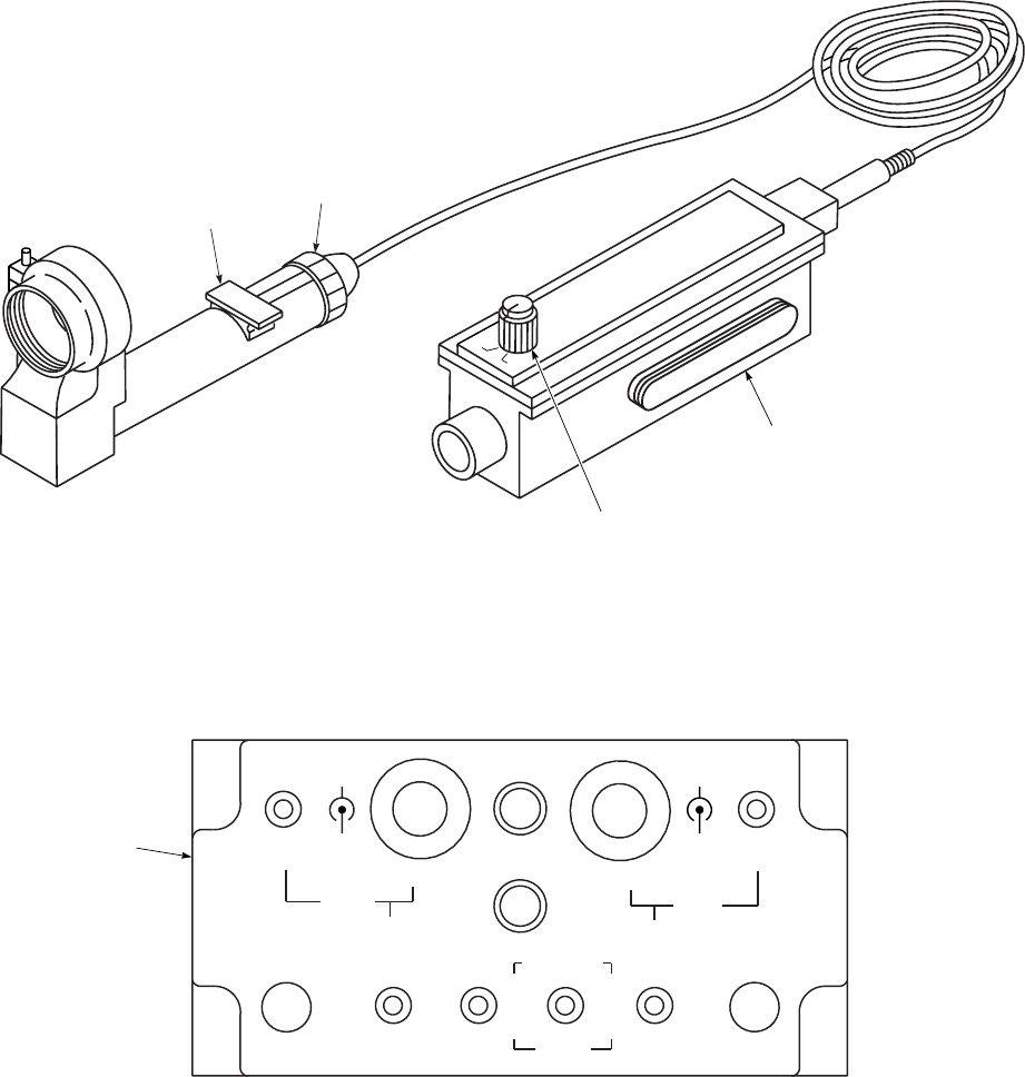
SA
AA9221A
BRT D / U FAIL
ON
DIM L / R DSPL POS
CPLT
MODE+
P−PGM
OP
CP−PGM
1−4
DCLT
BIT
ACK
DEC
NXT
PGM
INC
SEL
DCLT
1−4 ADJ
ON
OFF
D / U
L / R
BRT
DIM
PLT
MODE
ALT / P / R
FOCUS
RING
OPTICAL
UNIT
L / R EYE
SELECT
POWER SUPPLY
AND CALIBRATION
UNIT
CONVERTER
CONTROL
C−12293 / AVS−7
DISPLAY UNIT
SU−180/AVS−7
EYE
SELECT
L
R
DSPL POS
Figure 4-7. Heads Up Display AN/AVS-7
TM 1-1520-237-10
4-16
tion, is used to adjust barometric altitude, pitch, and roll. If
the HUD system loses operating power after adjustments
have been made, the brightness, mode, barometric altitude,
pitch, and roll must be adjusted as necessary. The system
self test is divided into power-up or operator initialized
built-in-test (BIT) and in-flight BIT. The system BIT is
initialized during power-up or selected by the operator. Part
of the BIT is a periodic test that is performed automatically
along with normal system operation. A failure of the SDC,
or the pilot’s DU will illuminate the CCU FAIL light and
display a FAIL message on the display unit. When a FAIL
message is displayed on the DU, the operator should ac-
knowledge the failure and re-run BIT to confirm the fault.
4.12.2 Controls and Functions. The CCU, located on
the lower console, (Figures 2-8 and 4-7), and the control
switches on the pilot’s collective stick (Figure 2-14) are
controls and indicators necessary for HUD operation. The
EYE SELECT L/R position is set when display units are
connected prior to operation. A focus ring on the OU pro-
vides control for focusing the display. The OU is adjusted
by the manufacturer and under normal conditions adjust-
ment is not required.
a. The converter control is described below:
CONTROL/
INDICATOR FUNCTION
CPLT
BRT/DIM Copilot’s control for display
brightness.
DSPL POS D/U/
L/R Copilot’s control for display
position down/up (outer knob) and
left/right (inner knob).
MODE 1-4/
DCLT Copilot’s mode select 1-4 and
declutter switch.
PLT
BRT/DIM Pilot’s control for display
brightness.
DSPL POS D/U/
L/R Pilot’s control for display position
down/up (outer knob) and left/right
(inner knob).
MODE 1-4/
DCLT Pilot’s mode select 1-4 and
declutter switch.
FAIL Indicates a system failure.
ON Indicates system ON.
CONTROL/
INDICATOR FUNCTION
ADJ/ON/OFF Selects adjust mode, enabling the
INC/DEC switch to adjust altitude,
pitch, or roll. Turns power on or off
to HUD system.
P-PGM/OP/CP-
PGM Selects pilot program mode,
operational mode, or copilot
program mode. Used with the
PGM NXT/SEL switch.
BIT/ACK Selects built-in-test or used to
acknowledge a displayed fault,
completion of an adjustment, or
completion of a programming
sequence.
ALT/P/R DEC/
INC Active when adjust mode is
selected to decrease/increase
altitude/pitch roll. When adjusting
altitude (MSL) a momentary
movement of the INC/DEC switch
will change data in 5 feet
increments. When the INC/DEC
switch is held for one second data
will change 10 foot increments.
Pitch and roll change in increments
of one degree.
PGM NXT/SEL Active when program mode is
selected. Allows operator to pre-
program the four normal modes
and four declutter modes. Operator
can select a flashing symbol for
display and/or go to the next
symbol. Once complete, operator
toggles the ACK switch to save
programmed display.
b. Pilot’s collective controls are described as follows:
CONTROL FUNCTION
BRT/DIM Allows pilot’s to control brightness
of their respective displays.
MODE/DCLT Allows pilot’s to select respective
display modes or declutter modes.
c. Attach optic unit to either ANVIS monocular hous-
ing. Set EYE SELECT switch on PSCU to Lor R.
TM 1-1520-237-10
4-17
4.12.3 Modes of Operation. There are two program-
ming modes and one operational mode for the HUD system
selected by the programming switch on the CCU. The ad-
just mode is a submode under the operational mode.
1. Pilot programming switch - Set to P-PGM.
2. Copilot programming switch - Set to CP-PGM.
3. Operation (flight mode) switch - Set to OP.
(Adjust - ADJ/ON/OFF switch to ADJ).
4.12.4 Display Modes. Symbology display modes are
programmable by the pilots via the converter control lo-
cated on the lower console. Modes are defined by selecting
from a master symbology menu (Figure 4-8 and Table 4-1).
Up to eight display modes, four normal and four declutter,
can by programmed for each user and can be selected for
display using the display mode selection switch on the pi-
lot’s collective control or on the CCU. The default declutter
mode has a minimum symbology display of:
• Airspeed - No. 25.
• Altitude (MSL) - No. 7.
• Attitude (pitch and roll) - No. 1, 5, 6, 20, 26.
• Engine Torque(s) - No. 22, 23.
Table 4-1. UH-60A/L Master Mode Symbology Display (HUD)
No. Symbol Source Range/Description
1 Angle of Pitch Scale HUD System 630° (10° units, tic marks flash when angle of pitch is >
630°).
2 Bearing to Waypoint -
Pointer Doppler 0 - 359° (cursor will invert 9V9when aircraft is moving
away from waypoint).
3 Compass Reference Scale HUD System 0 - 359° (10° units).
4 Aircraft Heading Fix In-
dex HUD System Fixed Reference Mark.
5 Angle of Roll - Pointer Copilot’s Vertical
Gyro
630° (right turn moves pointer to right, pointer flashes >
630°).
6 Angle of Roll - Scale HUD System 630° (10° units).
7 Barometric Altitude
(MSL) Air Data System -1000 to 20,000 feet (set during adjustment mode).
8 Adjust/Program Mode
Message HUD System ADJ or PROG.
9OK/FAIL HUD System OK or FAIL.
10 Velocity Vector Doppler 0 - 15 knots/15 kilometers, 0 - 359°.
11 Rate of Climb Pointer Air Data System 62000 feet-per-minute (used with vertical speed scale,
No. 15).
12 Radar Altitude (AGL) -
Numeric Pilot’s Radar Al-
timeter 0 - 1000 feet (0 - 200 feet, 1 foot units; 200 - 1000 feet,
10 foot units; disappears above 999 feet, and reappears
below 950 feet).
13 Minimum Altitude Warn-
ing Pilot’s Radar Al-
timeter Blinking square around symbol - No. 12, (set on pilot’s
low warning bug).
14 Radar Altitude (AGL)
Analog Bar Pilot’s Radar Al-
timeter 0 - 250 feet (disappears at 250 feet, reappears at 230 feet;
digital readout symbol, No. 12).
15 AGL, Vertical Speed -
Scale HUD System 0 - 200 feet/62000 feet-per-minute.
16 HUD Fail Message HUD System CPM, SDR, SDA, PS, PDU, CPDU, NAV, PGM; can
be cleared from the display by selecting ACK (see note).
TM 1-1520-237-10
4-18

Table 4-1. UH-60A/L Master Mode Symbology Display (HUD) (Cont)
No. Symbol Source Range/Description
17 Trim (Slide Ball) SAS/FPS Com-
puter
62 balls (left/right).
18 MST, MEM, HOOK
Messages Master Caution
Panel MST, MEM, HOOK cannot be cleared from the display
by selecting ACK.
19 Sensor, Engine, Fire, RPM
Warnings Master Warning
Panel ATT,ENG 1 or 2,FIRE,RPM;ATT can be cleared
from the display by selecting ACK (see note). ENG,
FIRE, and RPM cannot be cleared.
20 Horizon Line (pitch, roll) Copilot’s Vertical
Gyro Pitch: 630° Roll: 0 - 359°.
21 Display Mode Number HUD System 1N -4N for normal modes, 1D -4D for declutter modes.
22 Torque Limits Torque Trans-
ducer 0 - 150%
Yellow (>100%), (solid box)
Red (>110%) Thresholds (solid box flashes).
23 Torque - Numerics Torque Trans-
ducer 0 - 150% (flashes when engine torque separation is greater
than 5% threshold) Maximum % torque split between
cockpit panel and HUD is 3%.
24 Ground Speed Doppler 0 - 999 knots/0 - 530 km/h (dependent on doppler).
25 Indicated Airspeed SAS/FPS Com-
puter 30 - 180 knots (no symbol 30 knots and below, reappears
at 32 knots).
26 Attitude Reference Indica-
tor HUD System Represents helicopter.
27 Engines Temperature Thermocouple
Amplifers 0 - 999°C (0 - 755°C - 999°C, 1° units) Maximum split
between cockpit and HUD is 615°.
28 Distance to Waypoint Doppler 0 - 999.9 km.
29 Bearing to Waypoint - Nu-
meric Doppler 0 - 359°
NOTE: After ACK is used to acknowledge a
fault, the fault will not reappear until BIT is
selected or power is cycled off and on.
4.12.5 Operation.
4.12.5.1 Starting Procedure.
1. ADJ/ON/OFF switch - OFF.
2. Optical unit support clamps - Installed on AN-
VIS. Verify clamps can by rotated.
NOTE
Check surface of lens for cleanliness. Clean
in accordance with TM 11-5855-300-10.
3. DU lens - Check.
WARNING
Failure to remove the ANVIS neck cord
prior to operation of the HUD may pre-
vent egress from the aircraft in an emer-
gency.
4. ANVIS neck cord - Removed.
5. Optical unit - Install on ANVIS. Attach optical
unit to either monocular housing. Do not
tighten OU clamp completely with thumbscrew
TM 1-1520-237-10
4-19

at this time. The OU (display) may have to be
rotated to horizon after the system is operating.
NOTE
The helmet may now have to be rebalanced.
6. EYE SELECT switch on PSCU - Lor R.
WARNING
CCU ADJ/ON/OFF switch must by OFF
before connecting or disconnecting quick-
release connector.
CAUTION
The AN/AVS-7 system should not be used
if the quick-release connector is not in
working order.
7. PSCU - Connect. Connect PSCU to quick-
release connector by rotating the connector en-
gagement ring.
CAUTION
Keep the protective caps on the ANVIS
whenever it is not in use. Operate the AN-
VIS only under darkened conditions.
NOTE
Ensure ANVIS operator procedures have
been completed.
8. P-PGM/OP/CP-PGM switch -OP.
9. ADJ/ON/OFF switch - ON. System ON and
FAIL lights illuminate and BIT will initiate au-
tomatically.
10. FAIL light - Check. Light should go out after
ten seconds. BIT is complete.
NOTE
Allow one minute for display warm-up. Dis-
play intensity is preset to low each time
ADJ/ON/OFF switch is set from OFF on
ON.
If a fault is displayed in the DU, acknowl-
edge fault and re-run BIT to confirm fault.
11. BRT/DIM switch - As desired.
12. DSPL POS control - As required. Center dis-
play in field of view.
13. Display aligned to horizon - Check. Tighten
OU clamp.
4.12.5.2 Operator Self Test (BIT).
1. BIT/ACK switch - Press to BIT and hold. The
ON and FAIL light will illuminate. At end of
BIT, FAIL indicator will extinguish.
2. BIT/ACK switch - Release.
4.12.5.3 Displayed System Faults. The system self
test is divided into power-up or operator initialized built-
in-test (BIT) and inflight BIT. The faults result as warnings
and messages that blink at a rate of two per second in the
display units. Part of the BIT is a periodic test that is per-
formed automatically along with normal system operation.
This BIT monitors and/or tests SDC functions and/or sig-
nals. A failure of the SDC, NAV signals pilot’s DU, will
illuminate the converter control FAIL light and display a
FAIL message CPM, SDR, SDA, PS, NAV, PDU or
CPDU on the display unit. An attitude (ATT) sensor indi-
cation will be displayed when a gyro invalid condition ex-
its. ATT, NAV, PDU, CPDU, and all SDC faults can be
cleared by setting BIT/ACK switch to ACK. The follow-
ing helicopter status messages are also displayed.
1. The caption MST (first priority) indicates op-
eration of the master caution warning lamp.
This message will disappear during the rest of
the main warning lamp operation.
2. The caption MEM (second priority indicates
that the doppler data is not updated. a previous
computed data is available. This message will
appear simultaneously with the MEM lamp on
the doppler operating panel.
3. The caption HOOK (third priority) indicates
the cargo hook is open.
TM 1-1520-237-10
4-20 Change 4
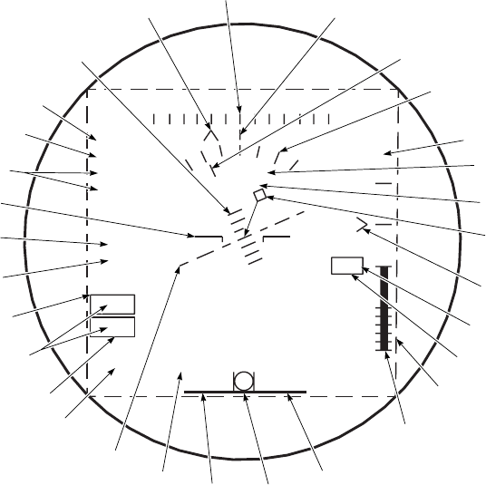
The message will appear simultaneously with
the indication lamp in the cockpit.
Setting BIT/ACK switch to ACK will not clear
MST,MEM,orHOOK status messages from the DU.
Engine, FIRE and RPM warnings cannot be cleared from
the DU. The faulty unit or warning must be removed from
the aircraft. When both engines fail at the same time, en-
gine priority is: ENG 1 then ENG 2.
4.12.5.4 Programming Procedure.
NOTE
The programming procedure for the pilot
and copilot is identical except for the loca-
tion of controls on the CCU.
1. Select mode to be programmed (1N-4N). The
first mode that will appear is 1N (normal mode
1).
2. P-PGM/CP-PGM/OP switch - P-PGM or CP-
PGM.
3. PROG blinking in display - Check. Verify that
a complete set of symbology is displayed and
attitude reference symbol is blinking. Verify
PGM is displayed in the HUD FAIL message
location for the DU not being programmed.
4. BIT/ACK switch - ACK to program the full
display or go to step 5 and select desired sym-
bols.
5. PGM SEL/NXT control - SEL to select sym-
bol. Selected symbol stops blinking. If symbol
is not desired, toggle switch to NXT and the
symbol will disappear.
NOTE
All symbols have been programmed when
the PROG annunciator is the only symbol
flashing.
6. BIT/ACK switch - ACK. (Hold switch to
ACK for one second.)
7. OK displayed - Check. (OK will be displayed
for two seconds.)
SA
AA9222
150
12.3
736T1
710T2
102A
71G
92
100
1630B
PROG
OK
12 15 S 21
1D ATT ENG1 FIRE RPM
MST CPM
97
3
2
1
29
28
27
26
25
22
23
21
20
19 18 17 16
15
14
13
12
11
9
7
10
8
6
5
4
24
22
Figure 4-8. Master Mode Display
TM 1-1520-237-10
4-21

NOTE
If programming is not accepted, FAIL will
be displayed. If a FAIL message is dis-
played, attempt to reprogram the same
mode, if FAIL reappears notify mainte-
nance.
Declutter mode is recognized by flashing
ground speed indicator in lieu of attitude ref-
erence symbology.
8. MODE 1-4/DCLT -DCLT (1D-4D). The first
DCLT mode that will appear is 1D (declutter
mode 1).
NOTE
If MODE 1-4/DCLT switch is toggled to
DCLT a second time the display will cycle
back to the DCLT’s normal mode (1N-4N).
The MODE 1-4/DCLT switch must be set
to MODE 1-4 to advance to another normal
mode.
9. Repeat steps 4 through 7, for declutter.
10. MODE 1-4/DCLT switch - As required.
11. Repeat steps 4 through 10 until all desired
modes are programmed.
12. P-PGM/CP-PGM/OP switch - OP.
4.12.5.5 Adjustment of Barometric Altitude, Pitch,
and Roll.
WARNING
An improperly adjusted barometric al-
timeter will result in an improperly set
HUD barometric altitude display.
NOTE
Barometric altimeter should be set to the
most current altimeter settings, field eleva-
tion.
1. Ensure P-PGM/CP-PGM/OP switch is in the
OP position.
SA
AA9223
NOTE
VERSION NUMBER AND DATE WILL
CHANGE AS SOFTWARE IS UPDATED.
ABCDEFGH I J
KLMNOPQRST
UVWXYZ
TEST
DD / MM / YYYY
UH−60
VER X.XX
S.G.
%
03 06 12 15 21 24 30 33
123 45678 90
123456 7890
Figure 4-9. Symbol Generator Test Mode
TM 1-1520-237-10
4-22

2. ADJ/ON/OFF switch - Pull and set to ADJ.
3. ADJ blinking in display - Check.
NOTE
Changes to barometric altimeter settings re-
quire a corresponding change to the HUD
barometric altitude. Each .01 inch change in
pressure equals 10 feet.
4. INC/DEC switch - As required.
5. BIT/ACK switch - ACK.
6. Repeat steps 3 through 5 for pitch and roll.
7. ADJ/ON/OFF switch - ON.
4.12.5.6 In-flight Operation.
WARNING
Whenever the symbology displayed in the
DU is suspected of being incorrect the pi-
lot’s will compare the data with the air-
craft instrument indicator and take the
appropriate action.
Excessive brightness of the symbology dis-
play may impair vision outside the cock-
pit.
Interruption of electrical power, such as
change over from APU generator to NO.
1 and NO. 2 generators and vice versa,
will cause DU to default to dim and
MODE 1N. Any adjustments made to the
barometric altitude, pitch and roll prior
to flight will be lost, thereby decreasing
the accuracy of the barometric altitude,
pitch and roll.
1. BRT/DIM switch - As desired.
NOTE
Whenever the symbology is interfering with
the outside visibility, decluttering may be
selected to remove symbology.
2. MODE 1-4/DCLT switch - As desired.
4.12.5.7 System Shutdown Procedure.
1. ADJ/ON/OFF switch - OFF.
2. Turn off ANVIS.
WARNING
CCU ADJ/ON/OFF switch must be OFF
before connecting or disconnecting quick-
release connector.
Do not disconnect DU by pulling on the
cable connected to the PSCU. The DU
could be damaged or the cable may sepa-
rate from the PSCU creating an explosive
atmosphere hazard.
Do not attempt to egress the aircraft with-
out performing disconnect as this may re-
sult in neck injury.
CAUTION
Do not disconnect DU by pulling on the
cable. To do so may damage the DU.
3. Display unit - Disconnect. Disconnect DU by
grasping the PSCU and rotating the quick-
release connector engagement ring and pull
downward. Remove OU and remove from the
ANVIS and place into storage case.
4. Reattach neck cord to ANVIS.
4.12.5.8 Emergency Egress. The quick-release fea-
ture allows you to exit quickly from the aircraft in an emer-
gency without:
a. Damaging or turning the unit off.
b. Getting tangled in cords.
c. Being restrained in the cockpit by hardwired
connections.
d. Removing ANVIS.
It is up to the operator to determine the desired mode
of disconnect based upon his evaluation of the emergency
TM 1-1520-237-10
Change 1 4-23

condition and whether or not the ANVIS goggles will be
needed following egress. The available means of discon-
nect are as follows:
a. Release the ANVIS goggles from the helmet.
b. Disconnect the OU from the ANVIS goggles
via the thumbscrew.
c. Grasp PSCU and pull down.
4.13 ASE STATUS PANEL. EH
The ASE status panel (Figure 4-10) is designed to inte-
grate several ASE indicator lights (for various ASE systems
installed) into one location and also tie those status lights to
the MASTER CAUTION light and the caution/advisory
panel. The status panel provides status lights for three ASE
systems currently designated to be installed, and two blank
slots for expansion.
CONTROL/
FUNCTION INDICATOR
NO GO Lights if the AN/ALQ-162 R/T
fails self-test.
CW THRT Lights if the AN/ALQ-162 detects
a continuous wave (CW) threat
radar.
CW JAM Lights if the AN/ALQ-162 is being
jammed.
NOTE
Only a NO GO light will trip the
ASE caution light on the caution/
advisory panel and the MASTER
CAUTION light.
CONTROL/
FUNCTION INDICATOR
AN-ALQ-156
CM JAM Lights if the AN/ALQ-156 is being
jammed.
CM INOP Lights if the AN/ALQ-156 R/T
fails self-test.
NOTE
Only a NO GO light will trip the
ASE caution light on the caution/
advisory panel and the MASTER
CAUTION light.
AN/ALQ-144
IRCM INOP Lights if the AN/ALQ-144 R/T
fails self-test.
NOTE
This condition will trip both ASE
caution light on the caution/
adivisory panel and the MASTER
CAUTION light.
TM 1-1520-237-10
4-24


Section II ARMAMENT
4.14 ARMAMENT SUBSYSTEM.
The subsystem is pintle-mounted in each gunner’s win-
dow at the forward end of the cabin section (Figure 4-11).
The two M60D 7.62 millimeter machineguns are free-
pointing but limited in traverse, elevation, and depression
field of fire. Spent cartridges are collected by an ejector
control bag on the right side of the weapon. An ammunition
can assembly is on the left side, refer to TM 9-1005-224-
10. For information on the gun mount, refer to TM 9-1005-
262-13.
4.15 MACHINEGUN 7.62 MILLIMETER M60D.
The machinegun (Figure 4-12), is air-cooled, gas-
operated and automatic. It uses standard 7.62 mm ammu-
nition (Table 4-2). Headspace is fixed to permit quick
change of barrels. Designed primarily for operation in the
air, the M60D has an aircraft ring-and-post sighting system.
The weapon is pintle-mounted and is held by a quick-
release pin. The weapon mount is on a rotating arm assem-
bly which allows the weapon to be locked outboard in the
firing position, or stowed inside the aircraft when the rotat-
ing arms are locked in the inboard position. It is easily
removed from the helicopter and can be used for ground
defense with the bipod extended. For more detail of the
M60D, refer to TM 9-1005-224-10.
4.15.1 Controls. Controls for the M60D are on the
weapon and consist of: barrel lock lever, safety, cocking
handle, cover, latch grip and trigger and magazine release
latch.
4.15.1.1 Barrel Lock Lever. The lever (Figure 4-12) is
at the right front of the receiver. It is attached to the barrel
locking shaft and turns to lock or unlock the barrel assem-
bly.
4.15.1.2 Safety. The safety (Figures 4-12 and 4-13), at
the lower front of the receiver, consists of a cylindrical pin
with a sear clearance cut which slides across the receiver to
block the sear and prevent firing. The ends of the pin are
marked S(safe) and F(fire). The exposed letter shows the
operating state of the weapon.
4.15.1.3 Cocking Handle. The handle (Figure 4-12), at
the right front of the receiver, is used to manually cock the
weapon.
4.15.1.4 Cover Latch. The latch (Figure 4-12) is at the
right rear side of the cover assembly. When the latch lever
is vertical it locks the cover in the closed position. When
moved to the horizontal it unlocks the cover.
4.15.1.5 Grip and Trigger Assembly. The assembly
(Figure 4-12) at the rear section of the receiver, includes
the spade grips. The U-shaped trigger design permits the
weapon to be fired by thumb pressure from either hand.
Table 4-2. Authorized Ammunition
7.62mm: NATO M59, Ball
7.62mm: NATO M61, Armor pierce
7.62mm: NATO M62, Tracer
7.62mm: NATO M63, Dummy
7.62mm: NATO M80, Ball
4.15.1.6 Magazine Release. The magazine release
latch (Figure 4-12) is on the left side of the receiver. The
latch spring automatically locks when the ammunition box
is seated on the magazine bracket. Pressing the release latch
manually releases the ammunition box.
4.15.2 Installation of Machinegun M60D.
CAUTION
The RS 890224 pintle mount stop must be
installed in its proper position if the exter-
nal stores support system (ESSS) is in-
stalled. The stop is a three-position stop:
stow, wings only, and external tanks. The
stow and wings only positions are inde-
pendent of aircraft side. The external
tanks position is particular to the aircraft
side. Care must be taken to ensure the
correct position and/or side is installed.
Use of the M60D machineguns is prohib-
ited when external ERFS tanks are in-
stalled on the inboard vertical pylon.
1. Install one machinegun M60D on the right side
and one on the left side of the helicopter at the
crew chief/gunner’s stations.
TM 1-1520-237-10
4-26 Change 10
2. Attach gun to pintle with quick-release pin, and
safety by passing a plastic tie or 0.032-in. safety
TM 1-1520-237-10
Change 8 4-26.1/(4-26.2 Blank)
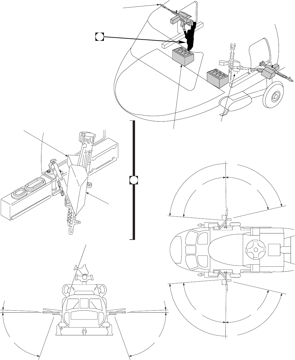
SA
AA0411C
1.5o
70O
160O
85O75O
FORWARD AFT
160O
85O75O
FORWARD AFT
70O
AMMUNITION
BOX
EJECTOR
CONTROL BAG
A
M60 STOWED
(SAME BOTH SIDES)
AMMUNITION AND
GRENADE STORAGE
(SAME BOTH SIDES)
A
M60 DEPLOYED POSITION
(SAME BOTH SIDES)
FIELD OF FIRE
AZIMUTH
FIELD OF FIRE
ELEVATION
AND
DEPRESSION
1.5o
Figure 4-11. Machinegun M60D Installation
TM 1-1520-237-10
4-27
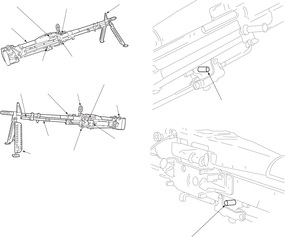
wire through quick-release ring and around the
pintle (Figure 4-14).
3. Check that each gun moves freely in azimuth
and can be depressed.
4. Removal of gun is reverse of installation.
4.15.3 Installation of Ejector Control Bag.
1. Position bag on right side of gun (Figure 4-15).
2. Position forward arm bracket of bag in front of
matching forward mounting point on gun
adapter. At the same time, press down on rear
bracket safety latch lever. Slide bag basket
rearward on mounting points and plate.
3. Position rear bracket of bag behind mounting
plate on bottom of receiver.
4. Release latch to lock bag in place.
5. Check bag for positive attachment to gun.
6. Removal of ejector control bag is reverse of
installation.
4.15.4 Installation of Ammunition Can.
1. Open release latch and install can assembly
(Figure 4-16).
2. Check that latch makes positive lock, holding
can in place.
SA
AA0508
AMMUNITION
FEED TRAY
GRIP AND
TRIGGER
ASSEMBLY
GAS
CYLINDER
EXTENSION CARRYING
HANDLE REAR
SIGHT
QUICK−RELEASE
GAS CYLINDER
BIPOD
SAFETY
AMMUNITION
EJECTION
PORT
COVER
LATCH
FRONT
SIGHT
BARREL
LOCK
LEVER
PIN
MAGAZINE
RELEASE
LATCH
COCKING
HANDLE
Figure 4-12. Machinegun 7.62 Millimeter M60D
SA
AA0507
S
F
SAFETY IN SAFE (S) POSITION
SAFETY IS IN
FIRING (F) POSITION
RIGHT SIDE
LEFT SIDE
Figure 4-13. Location and Identification of
Safety on Machinegun M60D
TM 1-1520-237-10
4-28
3. Removal of ammunition can is reverse of in-
stallation.
4.15.5 Loading Ammunition.
WARNING
Observe all safety precautions for upload-
ing ammunition in accordance with TM
9-1095-206-13.
1. With ammunition can installed, retract bolt
fully.
2. Press safety button to (S) position.
3. Open latch and raise cover assembly.
4. Insert link belt with open side of links down on
tray assembly (Figure 4-17).
5. Close cover and latch in place.
4.15.6 Cocking Machinegun M60D.
WARNING
To prevent accidental firing, do not re-
tract bolt and allow it to go forward if
belted ammunition is in feed tray, or a
live round is in chamber. Move cocking
handle forward by hand.
1. Open ejector control bag and pull cocking
handle fully to rear (Figure 4-18).
WARNING
Cocking handle assembly must be re-
turned to full forward (locked) before fir-
ing.
MOUNTING PIN CABLE
TO INSTALL: POSITION MACHINE
GUN MOUNTING BRACKET IN
PINTLE AND SECURE WITH
MOUNTING PIN
GUN ADAPTER
PLASTIC TIE
PINTLE
QUICK−RELEASE PIN
SA
AA0506
Figure 4-14. Installation of Machinegun M60D
on Pintle
SA
AA0505
LOCKED
REAR
MOUNTING
POINTS
EJECTION
CONTROL
BAG
GUN
ADAPTER
FORWARD
MOUNTING
POINTS FORWARD
ARM BRACKET
STEP 1
POSITION EJECTION CONTROL
BAG ON MOUNTING POINTS
STEP 2
REAR BRACKET SAFETY LATCH
LOCKED POSITION
REAR BRACKET
SAFETY LATCH
MOUNTING
PLATE
RECEIVER
UNLOCKED
Figure 4-15. Installation of Ejector Control Bag
on Machinegun M60D
TM 1-1520-237-10
4-29
2. Move cocking handle full forward to locked
position.
3. Press safety button to (S) position (Figure
4-13).
CAUTION
Do not fire machinegun unless the ejector
control bag is mounted in place.
4. With machinegun M60D positioned, loaded,
and aimed, push safety button (Figure 4-13) to
firing (F) position.
5. To fire gun automatically, press trigger fully
and hold. See Figure 4-11 for field of fire.
6. Low cycle rate of fire of machinegun M60D
allows firing of single rounds or short bursts.
Trigger must be completely released for each
shot.
NOTE
When ammunition is exhausted, the last link
will remain in tray assembly. The link as-
sembly can be removed by hand after the
cover assembly is opened for loading.
SA
AA0693
AMMUNITION
CAN ASSEMBLY
RELEASE LATCH
(PRESS TO OPEN)
MAGAZINE
BRACKET
INSTALL−REMOVE
MOVE
Figure 4-16. Installation and Removal of
Ammunition Can on Machinegun M60D
SA
AA0503
LINK BELT
Figure 4-17. Positioning Cartridge Link Belt on
Machinegun M60D
SA
AA0504
Figure 4-18. Charging (Cocking) Machinegun
M60D
TM 1-1520-237-10
4-30

4.15.7 Firing Malfunctions.
WARNING
If a stoppage occurs, never retract bolt
assembly and allow it to go forward again
without inspecting chamber to see if it is
clear. Such an action strips another car-
tridge from belt. If an unfired cartridge
remains in the chamber, a second car-
tridge can fire the first and cause injury to
personnel and/or weapon damage.
a. Misfire. This is a complete failure to fire. It must be
treated as a hangfire until this possibility is eliminated.
b. Hangfire. This is a delay in functioning of the propel-
ling charge. Time intervals set out in paragraph 4.15.8 must
be observed after a failure to fire.
c. Cookoff. This is firing of the chambered cartridge
from a hot barrel. A cookoff may occur from 10 seconds to
5 minutes after cartridge has been in contact with barrel.
d. Runaway Gun. If gun continues to fire after trigger
has been released, grasp belt, twist and break belt, allowing
the gun to run out of ammunition (usually when the belt is
broken only 3 to 5 rounds will remain).
4.15.8 Failure to Fire Procedure.
1. If a stoppage occurs, wait 5 seconds. Pull
handle assembly to rear, making sure operating
rod assembly is held back.
2. If cartridge ejects, return handle assembly for-
ward, re-aim machinegun, and attempt to fire.
If machinegun does not fire, it must be cleared.
3. If cartridge does not eject, retract bolt assem-
bly. Move safety button to SAFE (S), position.
Remove ammunition and links and inspect re-
ceiver assembly. Move safety button to FIR-
ING (F) and attempt to fire. If cartridge does
not fire and barrel is considered hot enough to
cause a cookoff (200 rounds fired within 2 min-
utes), wait 15 minutes with bolt assembly in
forward position. Remove cartridge and reload.
If weapon is not hot enough to cause a cookoff,
disregard 15-minute wait.
4.15.9 Extracting a Ruptured Cartridge Case. Posi-
tion ruptured cartridge case extractor in chamber. Run
cleaning rod through barrel assembly from muzzle end. Tap
cleaning rod against extractor until extractor and ruptured
cartridge case come out of chamber.
4.15.10 Double Feeding. When a stoppage occurs with
bolt assembly in forward position, assume there is an un-
fired cartridge in chamber. Treat this as a hangfire (para-
graph 4.15.7).
4.15.11 Unloading. Raise cover assembly and remove
linked cartridges. Inspect chamber.
4.15.12 Ammunition. Ammunition for the machinegun
is connected to form a link belt; the rounds are used to hold
two links together. When a round is fired, the cartridge and
link separate and is contained in the ejector bag assembly.
Ammunition stowage in the cabin has compartments for six
grenades and extra rounds of ammunition.
4.16 VOLCANO MULTIPLE MINE DELIVERY
SYSTEM. VOL
The volcano system is an automated, scatterable mine
delivery system that is capable of launching mines from the
helicopter. The system can dispense mines during day/night
and all weather conditions. The system can lay a mine field
of up to 960 mines at an average density of 0.9 mines per
meter front. For a more detailed description of the volcano
system, refer to TM 9-1095-208-23-2&P.
NOTE
The forward two-thirds of the cabin entry/
exit doors are restricted by the volcano sys-
tem making the loading and unloading of
passengers and cargo more difficult. Internal
loads should be planned accordingly.
4.16.1 System Components. The volcano system con-
sists of five major components: dispenser control unit
(DCU), launcher racks, jettison system, aircraft mounting
hardware, interface control panel (ICP) and ammunition
mine canisters.
4.16.1.1 DCU. The DCU (Figure 4-19) is the primary
electronic component and houses the electronics that con-
trol the system and contains a control panel for operating
the system. An interface control panel (ICP) is provided to
connect the applicable controls to the DCU. The DCU con-
trols firing signals to the canisters and conducts built-in
testing (BIT) of the entire mine dispensing system. The
DCU is the main operator interface for the system. On the
DCU TOP panel, the operator controls the system with the
following controls:
TM 1-1520-237-10
Change 9 4-31

a. POWER switch.
b. SELF DESTRUCT TIME control.
c. HELICOPTER DELIVERY SPEED control.
d. FIRE CIRCUIT ENABLE switch.
e. DIM control.
f. FAILURE INDEX switch.
g. TEST/OVERRIDE switch.
From the DCU panel the operator also oversees system
status with the SYSTEM FAILURE IDENTIFICATION/
TEST displays. Power to operate the volcano system is
provided from No. 1 dc primary bus through the CMD
CSL SET circuit breaker.
4.16.1.2 Launcher Rack Jettison System. The jetti-
son system consists of an interface panel, emergency and
primary jettison circuits, and explosive cartridges. Jettison
capability is provided for upper and lower launcher racks
on each side of the helicopter. The one shot jettison circuits
are independent of each other and either may be used to
jettison the launcher racks. Upon activation of JETTISON
or EMER JETTISON, the lower racks on each side will
separate from the helicopter. After a lower racks away sig-
nal is received by the upper racks, the upper racks will
automatically jettison. The EMER JETTISON is a backup
for the JETTISON and provides the same launcher rack
jettison function on an independent circuit. When the heli-
copter is on the ground, the weight-on-wheel switch dis-
ables the jettison circuits to prevent unintentional jettison-
ing of the racks. Power for the jettison system is provided
from the dc essential bus through the ESSS JTSN OUTBD
and ESSS JTSN INBD circuit breakers. Power for emer-
gency jettison is supplied by the battery.
4.16.1.3 Interface Control Panel (ICP). Controls and
indicators for the ICP (Figure 4-19) are on the control panel
and are as follows:
CONTROL/
INDICATOR FUNCTION
EMER
JETTISON/
JETTISON switch
Jettison all launcher racks with
canisters.
CONTROL/
INDICATOR FUNCTION
VOLCANO ARM
switch Arms system.
ARMED light Illuminates when VOLCANO
ARM switch is pulled out and
moved up if canisters are loaded
and system is enabled. Light will
go out when switch is pulled out
and moved down.
Flashing ARMED
light Indicates arm enable or launch
switch error (GA) or all canisters
have been dispensed.
JETTISON TEST/
ARMED switch
indicator
Press to start/stop jettison system
self-test.
PIlluminates if jettison system passes
test.
FIlluminates if jettison cartridges are
missing.
Flashing FIndicates one of the following
malfunctions:
-Weight-on-wheels switch.
-EMER JETTISON switch.
-JETTISON switch.
-Missing rack sensor(s).
NOTE
VOLCANO ARM function is independent
of EMER JETTISON and JETTISON
function.
4.16.2 Volcano Operational Check.
CAUTION
This operation will be completed only
when helicopter is on the ground.
TM 1-1520-237-10
4-32
SA
AA9411B
AFT
FWD
GA
CARGO
REL.
LR
STICK
TRIM
MINE
LAUNCH
CONTROL
SYSTEM FAILURE IDENTIFICATION / TEST
CANISTERS REMAINING
ROWCOLUMNRACK ERRORQUANTITY
TIMEFAILUREPOWER RIGHTLEFT
FAILURE
INDEX
SETDCU
OVERRIDE
TEST
BRIGHT
ENABLE
FIRE CIRCUIT
120
80
55
40
30
27
OFF
DELIVERY SPEED
HELICOPTER
3
21
RESET
TIME
SELF DESTRUCT
POWER
OFF
37
56
74 102
148
222
KPH
KTS
KPH
KTS
B
C
A
INTERFACE CONTROL PANEL (ICP)
CYCLIC STICK GRIP
DISPENSER CONTROL PANEL (DCU)
A
B
C
JETTISON
EMER
JETTISON
ARMED
PF
JETTISON TEST
VOLCANO ARM
(ON HELICOPTERS EQUIPPED WITH M−139 MINE DISPENSER KIT)
Figure 4-19. Volcano Mine Dispenser Controls VOL
TM 1-1520-237-10
4-33

NOTE
If, for any reason prior to a mission, DCU is
turned OFF or loses power, redo steps 2
through 5.
DCU must warm up for two minutes prior to
mine laying operation.
DCU will not function if backup hydraulic
pump is in operation.
1. Install mine canisters (TM 1-1520-237-23).
2. Toggle DCU POWER switch to POWER. BIT
runs automatically. POWER indicator displays
ON. Other indicators displays 8s or 88s except
DCU FAILURE display, which will flash F.
All displays, except for POWER are then blank
(Figure 4-20).
3. Displays automatically go blank followed by
88s being displayed in left and right CANIS-
TERS REMAINING displays. If an error code
appears in ERROR display, refer to TM
9-1095-208-23-2&P.
NOTE
The following assumes a full canister load.
Any load other than 80 canisters each side
should result in the number of canisters
loaded being displayed instead of 80 after
overriding the applicable number of error
code 99’s9for empty canister slots.
4. Toggle TEST/OVERRIDE switch to TEST.
Canister test is initiated. Canister test is com-
plete when 80s are displayed in CANISTERS
REMAINING readout and no error code ap-
pears. If an error code appears in ERROR dis-
play, refer to TM 9-1095-208-23-2&P.
NOTE
Error codes 5, 8 and 9 may be overridden.
Refer to TM 9-1095-208-23-2&P.
WARNING
Check SET TIME display to make sure
number set with dial is displayed in indi-
cator, otherwise, mines may be launched
with a false self-destruct time.
5. SELF-DESTRUCT TIME indicator flashes
after 15 seconds. Set self-destruct time by turn-
ing SELF-DESTRUCT switch to RESET po-
sition for minimum of two seconds, and then to
the desired 1,2or 3setting. The set time dis-
play must agree with SELF-DESTRUCT
switch position. If not, repeat procedure. If
wrong indication appears again, postpone mis-
sion and return to maintenance.
6. Repeat step 5. to reset or change the self-
destruct times.
NOTE
If flashing 1continues to appear in DCU in-
dicator, repeat setting self-destruct time.
7. Set planned dispensing helicopter ground speed
with HELICOPTER DELIVERY SPEED
knob on DCU.
4.16.3 Arming Canisters.
WARNING
Do not walk or stand in front of launcher
racks when racks are loaded and arming
levers are locked in armed position.
NOTE
Green latching levers must be in locked po-
sition before red arming levers are moved to
armed position.
Verify red arming levers are fully forward to
the arm (lock) position by pushing back le-
vers without depressing plungers.
Mechanically arm one row of canisters at a time as fol-
lows:
1. Individually seat each canister of the five can-
isters in a row by pushing canisters in and up
into rack keyholes. Canisters should be loaded
top to bottom back to front.
2. Depress plunger on red arming lever with
thumb and pull lever towards personnel. When
TM 1-1520-237-10
4-34 Change 1
SA
AA9412
RACK COLUMN ROW QUANTITY ERROR
SYSTEM FAILURE IDENTIFICATION / TEST
RACK COLUMN ROW QUANTITY ERROR
SYSTEM FAILURE IDENTIFICATION / TEST
POWER FAILURE TIME LEFT RIGHT
CANISTERS REMAINING
DCU SET POWER FAILURE TIME LEFT RIGHT
CANISTERS REMAINING
DCU SET
RACK COLUMN ROW QUANTITY ERROR
SYSTEM FAILURE IDENTIFICATION / TEST
POWER FAILURE TIME LEFT RIGHT
CANISTERS REMAINING
DCU SET
(SEE NOTE)
NOTE
READOUT IF NO CANISTERS ARE
INSTALLED.
Figure 4-20. Volcano System DCU Displays VOL
TM 1-1520-237-10
4-35

lever begins to move, release thumb from
plunger. When lever reaches locked position
(about 45°) plunger will click out. Push inboard
to ensure lever has locked (Figure 4-21).
3. Repeat steps 1 and 2 for all racks.
4. Remove all eight jettison system REMOVE
BEFORE FLIGHT safety pins from each side
panel.
NOTE
When operating the helicopter configured
with the volcano system at high gross weight
and high airspeeds, the pilot may encounter
intermittent lateral tail pulse 9tail shake9. The
intensity of the tail shake is further aggra-
vated by left sideslip.
5. Lift off and proceed to designated target.
6. Prior to reaching target area remove safety pin
and place the DCU VOLCANO ARM switch
on the ICP in ARMED position (Figure 4-22).
(Pull VOLCANO ARM switch out and lift up.)
7. FIRE CIRCUIT switch to ENABLE.
4.16.4 Mine Launch Control. Launching of mines is
controlled by buttons on the pilot’s cyclic control, marked
GA (go around) (Figure 4-19). When the system is in an
armed condition, pressing and releasing either GA button
will start the launch sequence. If mines are being launched,
press and release either GA button to stop mine launching.
In addition to pressing the GA button to stop mine launch,
the VOLCANO ARM switch may be moved to off (down)
position or the DCU FIRE CIRCUIT switch may be
placed OFF.
NOTE
If launching is stopped by pressing a GA
button before all mines are launched, the
launch must be restarted within 60 seconds
of stopping to prevent an error code. The
VOLCANO ARM switch should also be
moved to off (down) position within 60 sec-
onds of stopping to prevent an error code.
CAUTION
Ensure same number of racks are in-
stalled on either side of aircraft.
Ensure same number of canisters are in-
stalled on either side of aircraft.
Partial load of canisters may result due to
rack or canister failures (error codes 5, 8
or 9).
Partial canister loads, if not adjusted or
balanced, will degrade mine field pattern.
1. Place TEST/OVERRIDE switch to OVER-
RIDE.
2. After overriding error code 9, remove and dis-
card all failed canisters.
3. One at a time, fill vacant positions left by re-
moval of failed canisters as follows:
a. Remove canister from top rack of same
side, forward most column, top most posi-
tion with canister.
b. Place this canister in vacant position.
c. Repeat steps a. and b. above until all posi-
tions, other than those removed to fill va-
cant positions, have canisters.
4. Canister load may be balanced out by moving
canisters from side with most canisters to side
with fewest canisters as follows:
a. Remove canister from top rack, forward
most column, topmost row of side with
canisters.
b. Place removed canister in top rack, rear
most column, lowest position of side with
fewest canisters.
TM 1-1520-237-10
4-36 Change 10
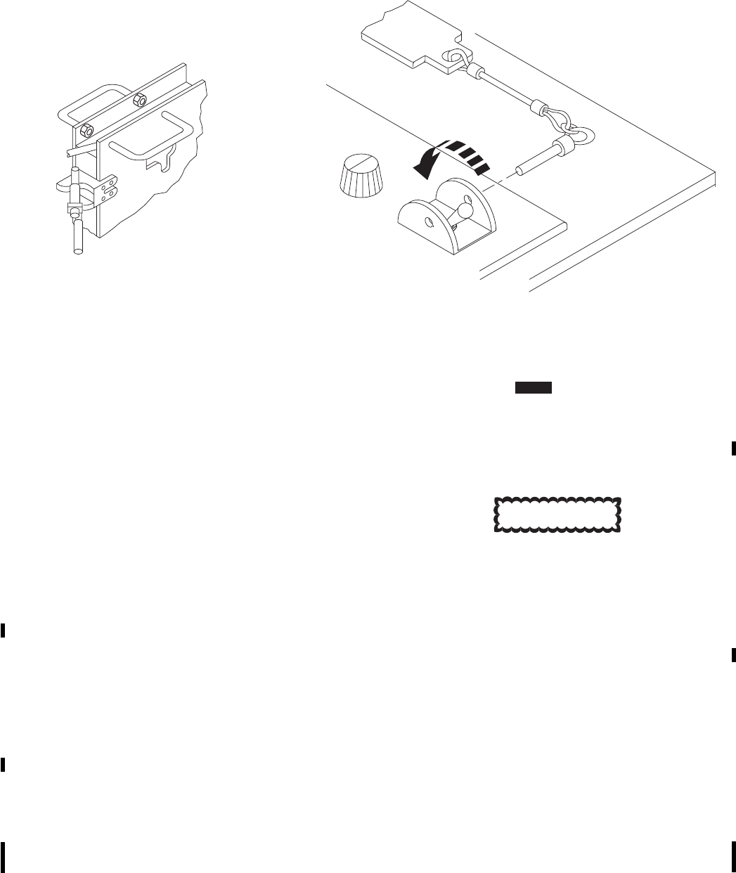
c. Repeat steps a. and b. above until load is
balanced.
4.16.5 Mine Launch.
NOTE
Mine launching may be started and stopped
as many times as required until all mines
have been launched.
If launching is stopped by pressing a GA
button before all mines are launched, the
launch must be restarted within 60 seconds
after stopping to prevent an error code. The
VOLCANO ARM switch may also be
moved to off (down) position within 60 sec-
onds after stopping to prevent an error code.
1. DCU FIRE CIRCUIT switch safety pin and
streamer (Figure 4-21) - Remove.
2. DCU FIRE CIRCUIT switch - ENABLE.
3. Before reaching target, VOLCANO ARM
switch (Figure 4-22) - ARM. Verify P/F/
ARMED indicates ARMED.
4. Verify that the HELICOPTER DELIVERY
SPEED settings agree with the helicopter
ground speed.
CAUTION
FIRE CIRCUIT switch must be enabled
for at least two minutes prior to mine
launching.
5. GA button - Press either pilot’s to start launch-
ing mines. Press either GA button a second
time to stop mine launching.
NOTE
If launching is interrupted for longer than 60
seconds, the ARMED light on the ICP will
flash and error code 1 will be displayed in
the DCU ERROR indicator.
6. If launch is interrupted longer than 60 seconds,
resume launch: VOLCANO ARM switch - Off
for at least sixteen seconds.
SA
AA9413
LAUNCHER RACK DCU
Figure 4-21. Arming Volcano System Canisters VOL
TM 1-1520-237-10
Change 10 4-37
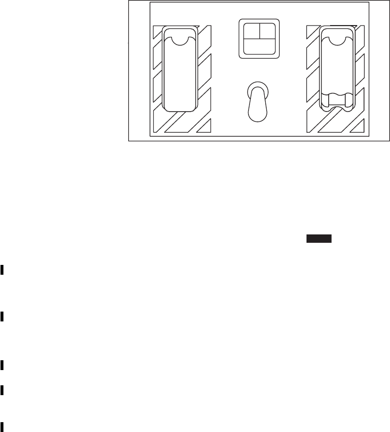
7. VOLCANO ARM switch - ARM. Verify a
steady ARMED is displayed on the ICP.
Launching can then be resumed.
8. During mine launching, if an error code appears
on DCU panel that effects mission perfor-
mance, do the following:
a. DCU FIRE CIRCUIT switch - OFF.
b. Safety pin and streamer assembly - Install
to FIRE CIRCUIT switch.
c. DCU POWER switch - OFF.
d. Return to down loading area and remove
canisters, refer to TM 9-1095-208-23-2&P.
4.16.6 Volcano System Recycle Procedures. These
procedures are to be used in the event of a volcano system
lock-up during a tactical mission.
NOTE
If any error codes occur during this recycle,
return to step 1 and repeat all steps.
1. Identify error code.
2. Return the VOLCANO ARM switch on the
ICP to the safe position.
3. Return the FIRE CIRCUIT ENABLE switch
on the DCU to the OFF position.
4. Toggle the POWER switch on the DCU to
OFF, then release. Ensure DCU turns off.
5. Leave the DCU turned off at least two minutes
prior to system restart.
NOTE
During cold temperature operation (less than
0°C (32°F)) , the DCU should be turned off
at least five minutes prior to system restart.
6. After waiting the minimum time, toggle
POWER switch to on, then release. Ensure that
the DCU displays the following sequence:
a. Error code F.
b. 9ON 9displayed under POWER.
SA
AA9414
PF
ARMED
VOLCANO ARM
JETTISON TEST
EMER
JETTISON JETTISON
Figure 4-22. Volcano ICP
VOL
TM 1-1520-237-10
4-38 Change 10

c. All 98’s9in the remainder of the displays.
d. The DCU is blank, except for the 9ON9
message.
7. Wait approximately one minute. At that time,
the DCU should display 988 889under CANIS-
TERS REMAINING.
8. Toggle the TEST/OVERRIDE switch to
TEST, then release.
9. After approximately two minutes, the DCU
should display 980 809or what was displayed
upon canister installation under CANISTER
REMAINING.
10. After approximately 15 seconds, the number
under SET TIME should flash. At that time,
turn SELF DESTRUCT TIME knob to RE-
SET for 20 seconds.
11. Turn SELF DESTRUCT knob to the desired
setting. Ensure that this setting is displayed un-
der SET TIME without any flashing.
12. Move the FIRE CIRCUIT ENABLE switch
on DCU to ENABLE.
13. Move the VOLCANO ARM switch on the ICP
to ARM, if the switch was in that position be-
fore restarting.
4.16.7 Partial Load Error Codes.
a. Three error codes can be overridden to allow mine
laying without a full load of canisters. These are:
(1) Error code 5 - Rack problems. This allows opera-
tion with less than 4 racks, if desired, for laying an abbre-
viated minefield.
(2) Error code 8 - Rack electronics error. This error
indicates one complete row of ten canisters is not available.
No other errors shall be overridden with the error code 8
override.
(3) Error code 9 - Canister failure. Canister failures
are allowed to be overridden. Failed canister should be re-
moved and remaining canisters balanced prior to mission.
b. Troubleshoot all error codes overridden during mis-
sion after completion of flight and make an
TM 1-1520-237-10
Change 1 4-39

appropriate entry on DA Form 2408-13-1, refer
to TM 9-1095-208-23-2&P.
4.16.8 Volcano Post Mission Procedures.
4.16.8.1 Post Mine Launch Check.
1. ICP VOLCANO ARM switch - Off (down).
2. DCU FIRE CIRCUIT switch - OFF.
3. Safety pin and streamer assembly - Install to
FIRE CIRCUIT switch.
4. DCU POWER switch - OFF.
4.16.8.2 After Landing Checks.
WARNING
Do not stand in front of rack loaded with
mine canisters. All personnel will remain
clear of the outboard side of the launcher
racks until the arming levers are safe and
the jettison safety pins are installed, or
until the helicopter is shutdown and
power removed.
1. Install jettison safety pins (four on each rack).
2. Push in plunger on red arming lever and push
lever back until it is in safe position, parallel
with rack and plunger clicks out. Latch all arm-
ing levers in safe position.
4.16.8.3 Post Flight Checks.
1. Remove canisters.
2. Record all error codes overridden during mis-
sion on DA Form 2408-13-1.
3. Install launcher rack covers.
4.16.9 Volcano Operation Under Unusual Condi-
tions. The volcano system is designed to operate during
adverse weather and extreme temperature conditions. Op-
erator will be required to perform additional checks when
operating during extreme climatic conditions.
4.16.9.1 Operating In Extreme Cold.
CAUTION
Do not force launcher rack levers or
mounting pins to operate.
Static electricity discharges may damage
DCU.
NOTE
Operators wearing arctic gloves should have
no difficulty installing or operating the vol-
cano system.
1. Check movement of launcher rack arming and
latching levers to ensure that they do not bind.
Use warm air source to loosen if required.
2. Install launcher rack cover when dispenser is
installed, but canisters have not been loaded.
3. Perform complete volcano operational check
before any mission (paragraph 4.16.2).
4. Assure all expando and/or single acting pins
have seated and spring button is out.
5. Check to see that launcher rack levers and can-
ister connectors are free of ice, snow and frost.
Use warm air source to clean and dry as neces-
sary.
6. Allow 10 minutes of additional warm up time
before using system.
7. Prior to turning on power, make sure all DCU
switches are free of ice, that FIRE CIRCUIT
switch and streamer are free of ice, and that
rotary switches move freely. Use warm air to
heat and dry sticking or stiff switches.
TM 1-1520-237-10
4-40 Change 10

4.16.9.2 Operating In Wet, Mud, Salt Water and Ice
Conditions.
WARNING
Wet and/or icy hardware may be slippery.
Use extra precaution when handling dis-
penser components. Do not force ice cov-
ered launcher rack levers.
1. During flight in icing conditions shed ice par-
ticles may cause foreign object damage (FOD)
to the helicopter, especially main rotor and tail
rotor blades and engine compressors. Flight
tests have shown that this FOD is difficult to
detect during flight. Minimizing descent rates
after ice has accumulated on the helicopter or
external stores should reduce the probability of
FOD because the airflow will carry particles aft
and down away from the helicopter. Normal
instrument procedure descents or approxi-
mately 100 feet per minute (fpm) or less are
preferable. During shutdown, crewmember’s
should be alert for unusual engine noise (high
pitched whine) that indicates compressor dam-
age. The helicopter should be visually inspected
prior to further flight.
2. Engine torque increase of up to 20 percent can
be expected during cruise flights in icing con-
ditions with the volcano system installed.
3. After flight in icing conditions with the volcano
system installed, the jettison safety pins may be
difficult to install due to ice in and around the
safety pin holes. The forward launcher rack
locking levers and arming levers may also be
covered with ice making it difficult to move the
arming levers to the safe position. Use an ex-
ternal heater to remove ice from these areas. Do
not use foreign objects to break ice from these
areas as this may cause damage to the system.
4. Do not bend ice covered cables until ice has
been removed with a warm air source.
5. Check launcher rack canister connectors for ice.
Use warm air source to melt and dry connec-
tors.
6. Check launcher rack arming and latching levers
for ice. Use warm air source to remove ice.
Test operation of levers to assure they have free
movement.
7. Check expando and single acting pins to ensure
that they are seated and spring button is out.
8. After exposure to mud or salt water, clean and
wash dispenser components immediately. If
dirty, clean, wash and dry components before
repackaging them into shipping containers, re-
fer to TM 9-1095-208-23-2&P.
9. When DCU cover is removed, make sure that
switches are free of ice. Remove ice using
warm air source.
10. Check DCU connectors for ice. Remove ice us-
ing warm air source.
11. Check DCU switch for ice. Remove ice with
warm air source.
12. Allow 10 minutes of additional warm up time
before testing and operating dispenser.
13. Perform PMCS, refer to TM 9-1095-208-23-
2&P.
14. Perform complete volcano operational check
before any mission (paragraph 4.16.2).
4.16.10 Accident Procedures.
WARNING
After an accident, turn DCU power OFF,
evacuate all personnel to a distance of
2000 feet (640 meters) and notify EOD.
TM 1-1520-237-10
4-41

Section III CARGO HANDLING SYSTEMS
4.17 CARGO HOOK SYSTEM.
The system consists of a hook assembly (Figure 4-23)
mounted on the lower fuselage, a control panel on the up-
per console (Figure 2-7), a normal release button on each
cyclic stick grip, one emergency release switch on each
collective stick grip, and a firing key in the cabin for use by
the crew chief. The system incorporates three modes of
load release, an electrical circuit actuated from the cockpit,
a manual release worked by the crewmember through a
covered hatch in the cabin floor, and an emergency release
system using an electrically-activated explosive charge.
4.17.1 Cargo Hook Stowage. The cargo hook shall be
maintained in the stowed position during periods of non-
use. The cargo hook can be placed in a stowed position
(Figure 4-23) by opening the cargo hook access cover in
the cabin floor, and pulling the hook to the right and up.
When the hook is in the stowed position, the load beam
rests on a spring-loaded latch assembly and is prevented
from vibrating by a teflon bumper applying downward
pressure on the load beam. To release the hook from its
stowed position, downward pressure is placed on the latch
assembly lever, retracting the latch from beneath the load
beam, allowing the cargo hook to swing into operating po-
sition.
4.17.2 Cargo Hook Control Panel. The CARGO
HOOK control panel (Figure 4-23), on the upper console,
consists of an EMERG REL NORM,OPEN,SHORT
test switch, a TEST light, CONTR CKPT or ALL station
selector switch and an ARMING,SAFE,ARMED switch.
Before the normal release (electrical) can operate, the
ARMING switch must be at ARMED to provide electrical
power to the release switches. The pilot and copilot
CARGO REL switches, on the cyclics, will release the
load when the CONTR switch is at CKPT or ALL. The
crewmember’s NORMAL RLSE switch will release the
load when the CONTR switch is at ALL. The EMERG
REL switch and TEST light permits checking the emer-
gency release circuit when at SHORT or OPEN. In both
cases of testing, if the release circuit is good, the TEST
light will go on when the HOOK EMER REL switch on
pilot’s or copilot’s collective, or the EMER RLSE switch
on the crewmember’s pendant, is pressed.
4.17.3 Crewmember’s Cargo Hook Control Pen-
dant. The crewmember’s cargo hook control pendant
(Figure 4-24), in the aft cabin, provides the crew chief with
an electrical release and jettison of an external load when
the CARGO HOOK CONTR switch is placed to ALL.
The NORMAL RLSE and EMER RLSE switches are
covered by guards to prevent accidental activation. When
the cover is raised the switch can be pressed. When not in
use, the pendant is stowed in the stowage bag at the back of
the pilot’s seat. Electrical power to operate the pendant is
provided from the No. 2 dc primary bus through a circuit
breaker, marked CARGO HOOK CONTR.
4.17.3.1 Normal Release. Normal release of external
cargo is done by pressing the CARGO REL switch on
either cyclic stick grip or the CARGO HOOK NORMAL
RLSE on the crewmember’s cargo hook pendant, after
placing the CARGO HOOK ARMING switch to
ARMED. A light on the advisory panel will go on, indi-
cating HOOK ARMED. This informs the pilot that elec-
trical power is applied to the control circuit; the actuation
of any of the release switches will release the load. When
the CARGO REL switch is pressed and the release sole-
noid begins to move, a switch closes, lighting the CARGO
HOOK OPEN advisory light. The load arm will swing
open, releasing the cargo. When the sling is detached from
the load beam, spring tension on the arm will cause it to
close and relatch, putting out the CARGO HOOK OPEN
advisory light. The normal release system is a one-shot
cycle; once the solenoid travel begins and the load arm
relatches, the release cycle can again be initiated. Power to
operate the normal release system is supplied from the No.
2 dc primary bus through circuit breakers marked CARGO
HOOK CONTR and PWR.
4.17.3.2 Operational Check - Normal Release
Mode.
1. CARGO HOOK CONTR switch - As re-
quired. CKPT for pilot and copilot check, or
ALL for crewmember check.
2. CARGO HOOK ARMING switch -
ARMED.
3. HOOK ARMED advisory light - Check on.
4. Place about 20 pounds downward pressure on
load beam.
TM 1-1520-237-10
4-42 Change 9

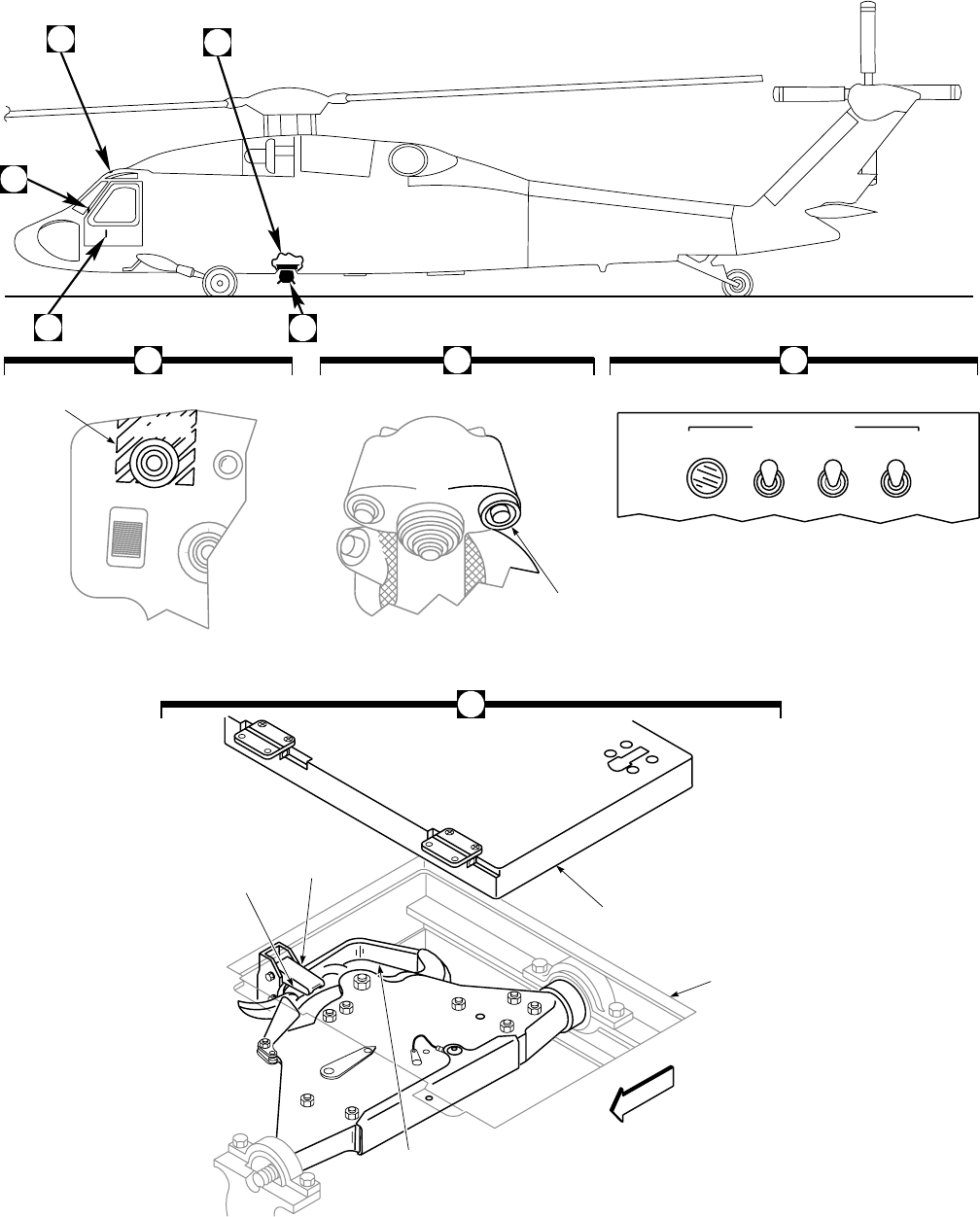
SA
AA0367_1B
CONTR
CKPT ARMING
SAFE
TEST NORM
CARGO HOOK
EMERG REL
O
P
E
NSHORT ALL ARMED
CARGO HOOK STOWAGE
CARGO HOOK CONTROL PANEL
COLLECTIVE STICK GRIP CYCLIC STICK GRIP
EMERGENCY
RELEASE
SWITCH
NORMAL
RELEASE
SWITCH
A B C
C
B
A
D
E
ASSEMBLY
LEVER
BUMPER
CARGO HOOK
ACCESS DOOR
CARGO LOAD
BEAM
CABIN
FLOOR
FRONT
D
CARGO
REL.
HOOK
EMER REL
LATCH
Figure 4-23. Cargo Hook System (Sheet 1 of 2)
TM 1-1520-237-10
4-43
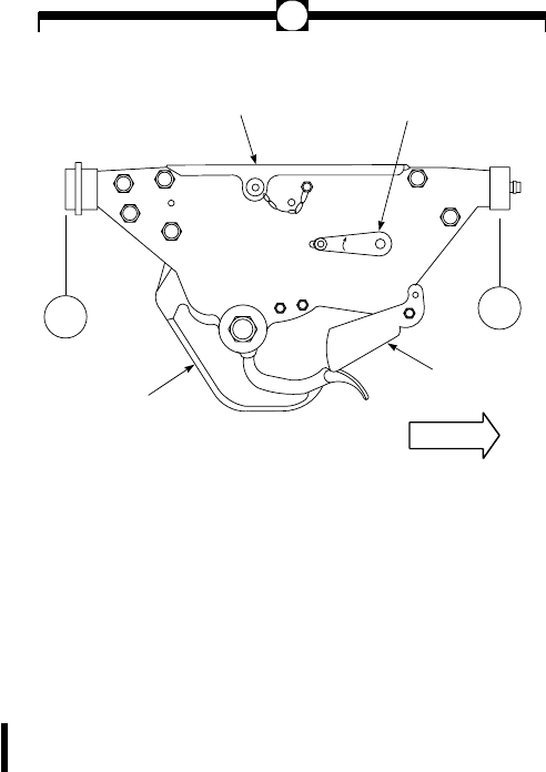
7. CARGO HOOK OPEN advisory light - Check
off when hook closes.
8. Repeat steps 4. through 7. for copilot and crew-
member position.
4.17.3.3 Manual Release. Manual release of external
cargo can be done from the cabin, through a covered port in
the floor, or by ground personnel from outside the helicop-
ter, with power on or off. Turning the release control on the
right side of the hook (Figure 4-23) clockwise, causes the
latching mechanism to release the load beam. The load
beam will not move unless a downward pressure is exerted
to cause opening. With power applied to the helicopter and
the CARGO HOOK ARMING switch at ARMED, the
CARGO HOOK OPEN advisory light will go on at the
start of release control turning, and will go off at the end of
release control rotation.
4.17.3.4 Operational Check - Manual Release
Mode.
1. Manual release lever spring - Installed. Check
that spring is straight and provides positive
pressure on the lever.
2. Place about 20 pounds downward pressure on
load beam.
3. Manual release lever - Pull up/turn fully clock-
wise and release.
4. Load beam - Check open.
5. CARGO HOOK OPEN advisory light - On.
6. When downward pressure is released, load
beam will close and latch.
7. CARGO HOOK OPEN advisory light - Off
when hook closes.
4.17.4 Emergency Release Circuit Tester. The
cargo hook emergency release circuit tester (Figure2-7)
marked CARGO HOOK EMERG REL on the upper con-
sole, contains a test light and switch. The test light, marked
TEST, goes on during circuit testing to indicate the system
is functioning properly. The switch, with marked positions
NORM,OPEN, and SHORT, is normally at NORM.
When the switch is placed to OPEN or SHORT and the
cargo HOOK EMER REL switch on the pilot’s or copi-
lot’s collective, or EMER RLSE switch on the crewmem-
ber’s cargo hook control pendant is pressed, the circuit
tester light will go on if the circuit is good.
4.17.4.1 Cargo Hook Emergency Release Circuit
Check.
1. EMERG REL TEST light - Press. Light
should be on.
NOTE
To prevent unintentional discharge of the
cargo hook explosive cartridge, the pilot
shall call off each procedural step of the
emergency release circuit test before that
step is done. Station being checked shall re-
ply to pilot’s command.
2. Pilot’s release - Check.
a. Short test.
(1) CARGO HOOK EMERG REL
switch - SHORT.
(2) Pilot’s HOOK EMER REL button -
Press and hold.
(3) CARGO HOOK TEST light - On.
MANUAL
RELEASE
LEVER
COVER
(EXPLOSIVE CARTRIDGE
UNDER COVER)
LOAD BEAM
KEEPER
FRONT
CARGO HOOK
OPEN
STA
343.0
STA
363.0
SA
AA0367_2A
E
Figure 4-23. Cargo Hook System
(Sheet 2 of 2)
TM 1-1520-237-10
4-44 Change 7
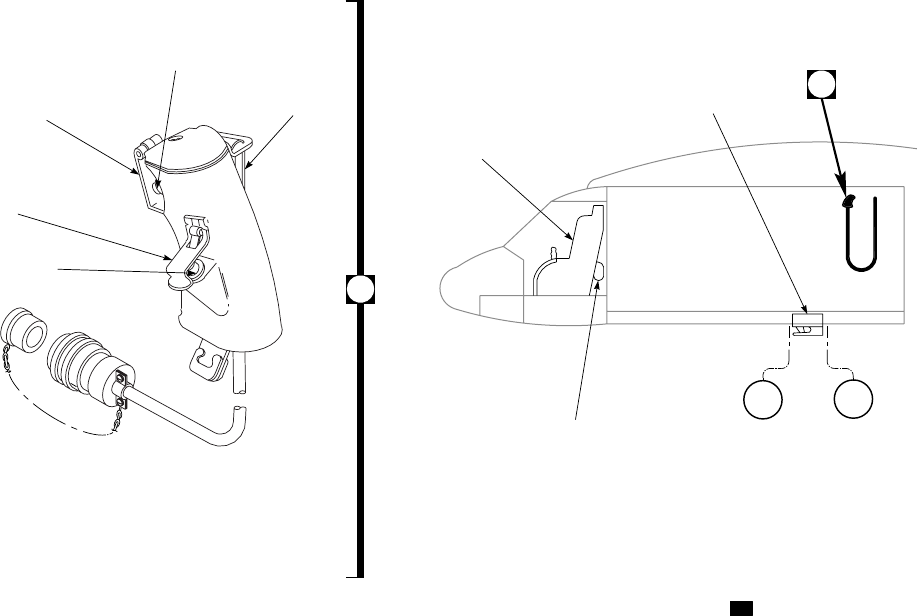
(4) HOOK EMER REL button - Release.
TEST light off.
(5) Repeat steps (2) through (4) for copi-
lot’s HOOK EMER REL button, and
crewmember’s cargo hook control
pendant EMER RLSE button.
b. Open test.
(1) CARGO HOOK EMERG REL
switch - OPEN.
(2) Pilot’s HOOK EMER REL button -
Press and hold.
(3) CARGO HOOK TEST light - On.
(4) HOOK EMER REL button - Release.
TEST light off.
(5) Repeat steps (2) through (4) for copi-
lot’s HOOK EMER REL button, and
crewmember’s cargo hook control
pendant EMER RLSE button.
3. CARGO HOOK EMERG REL switch -
NORM. If the cargo hook is not to be used
immediately after completing the circuit test
check, the EMERG REL switch shall remain
at OPEN until ready for load pickup.
4.17.4.2 Emergency Release.
NOTE
When the emergency hook release has been
used and a replacement squib (explosive car-
tridge) is not available, the hook can not be
used until the explosive device is replaced,
since the hook load beam will not close and
lock.
Emergency release of an external cargo load is done by
an electrically-fired explosive cartridge, initiated from ei-
ther of the collective stick grip switches, marked HOOK
EMER REL, or the crewman’s cargo hook control pen-
dant, marked EMER RLSE. The emergency release is used
when the electrical and manual releases are inoperative,
and the load must be jettisoned. With the CARGO HOOK
EMERG REL switch at NORM, power will be applied to
the emergency release switch. Pressing the switch applies
28 vdc to the explosive cartridge, producing a high gas
pressure to drive a piston in the lock assembly, releasing
the load arm lock. The weight of the load will cause the
EMER
RLSE
CA
R
G
O
H
O
O
K
R
L
S
E
NO
R
M
AL
SA
AA0368
A
STRAP
NORMAL
RELEASE
SWITCH
GUARD
EMER
RLSE
SWITCH
EMERGENCY
RELEASE SWITCH
GUARD
CARGO HOOK
NORMAL RLSE
SWITCH
CREWMEMBER’S CARGO HOOK
CONTROL PENDANT
PILOT SEAT
CARGO HOOK A
CREWMEMBER’S CARGO
HOOK PENDANT STOWAGE
RIGHT SIDE
STA
343.0 STA
363.0
Figure 4-24. Crewmember’s Cargo Hook Control Pendant UH
TM 1-1520-237-10
4-45

load arm to open. Once the emergency release is used, the
hook will remain open and the CARGO HOOK OPEN
advisory light will remain on until the explosive cartridge
device is replaced. When the explosive cartridge device is
replaced the load arm will close, the light will go off, and
the emergency release mode is returned to operation. Power
to operate the emergency release system is from the dc
essential bus through a circuit breaker, marked CARGO
HOOK EMER.
4.17.5 Preflight. When cargo hook loads are to be car-
ried, checks within this paragraph and procedures of para-
graphs 4.17.6, 4.17.7, 4.17.8 and 4.17.9 apply.
1. Cargo hook - Check condition, security and ex-
plosive cartridge installed.
2. Emergency release system - Check. (Go to
paragraph 4.17.4.)
3. Manual release - Check. (Go to paragraph
4.17.3.3.)
4.17.6 Before Takeoff.
1. CARGO HOOK EMERG REL switch -
NORM.
2. CARGO HOOK ARMING switch -
ARMED.
4.17.7 Emergency Release Procedure.
Pilot or copilot HOOK EMER REL or crew-
man’s control pendant EMER RLSE - Press.
4.17.8 In-flight Procedures.
CAUTION
Cargo suspended from the cargo hook
should not be over a 30° cone angle. To
prevent damage to the cargo hook keeper,
the pilot shall use extreme care to prevent
placing load pressure on the keeper.
CARGO HOOK ARMING switch - As required.
ARMED for low altitude/low airspeed. SAFE at cruise al-
titude and airspeed.
4.17.9 Before Landing.
CARGO HOOK ARMING switch -
ARMED.
TM 1-1520-237-10
4-46
Section IV MISSION FLEXIBLE SYSTEMS
4.18 MISSION READINESS CIRCUIT BREAKER
PANEL.
The mission readiness circuit breaker panel (Figure
2-20) is on the No. 1 electrical junction box in the cabin,
and contains all required circuit breakers for mission equip-
ment.
4.19 RESCUE HOIST SYSTEM KIT.
The high performance, two speed rescue hoist (Figure
4-25) is post-mounted in the cabin on the right side of the
helicopter when installed. The hoist system consists of
modular components, electrically-driven and electronically-
controlled, to provide maximum lift capacities of 300
pounds at 0 to 250 feet-per-minute and 600 pounds at 0 to
125 feet-per-minute. The heaviest weight that may be sus-
pended from the hoist is 600 pounds. A speed mode switch
at the back of rescue hoist control panel assembly on the
hoist support assembly, provides a selection of either
SLOW speed (0 to 125 feet-per-minute), or FAST speed (0
to 250 feet-per-minute). The hoist motor mounted at the top
of the pole provides selectable 125 or 250 feet-per-minute
reel-in and reel-out drive of a 250-foot hoist cable. A fail
safe mechanism limits the induced loading to the hoist to
1200 pounds at all times. A continuously running circulat-
ing fan cools the hoist motor. The hoist is controlled
through a lower console mounted RESCUE HOIST CON-
TROL panel and/or crewman’s control pendant grip in the
cabin. A hoist cable cutter system is used to cut the hoist
cable in case of emergency, by exploding a squib-actuated
cable-cutter. The cut cable then drops free of the hoist
boom. Power to operate the rescue hoist system is from the
No. 2 dc primary bus through a circuit breaker on the mis-
sion readiness circuit breaker panel, marked RESQ HST
CONTROL. Power for the cable cutter system is from the
dc essential bus through a circuit breaker, marked HOIST
CABLE SHEAR. Refer to Table 2-4 for servicing.
4.19.1 Controls and Function. The RESCUE HOIST
CONTROL panel (Figure 4-25) has all necessary controls
for operating the hoist from the cockpit, and contains the
system MASTER switch, controlling ON or OFF for both
cockpit and cabin. The hoist will respond to the first control
signal received.
NOTE
During hoist operation, over travel of the
cable assembly may occur in the extended
mode of operation after stopping hoist op-
eration in mid-travel. Cable over travel
should not exceed ten feet.
CONTROL/
INDICATOR FUNCTION
BOOM switch Swings hoist boom in or out from
cockpit.
OFF Static position, removes electrical
power from hoist boom positioning
motor.
IN Provides power to boom motor to
position boom inboard from
cockpit.
OUT Provides power to boom motor to
position boom outboard from
cockpit.
MASTER switch Selects control point for hoist
operation.
OFF Disconnects all electrical power
from hoist operating controls.
ON Provides power to both cockpit
controls and crewman’s pendant for
hoist operation.
CABLE Provide cable up or down control
from cockpit.
OFF Static position, removes electrical
power from hoist reel motor for
cockpit operation.
UP Provides power to hoist reel motor
to reel in cable operation from
cockpit at 250 feet-per-minute
only.
DOWN Provides power to hoist reel motor
to reel out cable operation from
cockpit at 250 feet-per-minute
only.
SQUIB switch Selects either TEST or NORM
operation.
TEST Checks condition of CABLE
SHEAR circuit through squib to
indicate circuit is complete.
TM 1-1520-237-10
4-47

CONTROL/
INDICATOR FUNCTION
NORM Places squib circuit in a ready for
fire condition.
IND Lights when test of CABLE
SHEAR circuit through squib is
good.
CABLE SHEAR
switch Controls cable cutter firing circuit.
FIRE Directs electrical power to cable
cutter squib for shearing hoist
cable.
SAFE Removes electrical power from
cable cutter circuit.
4.19.2 Boom Assembly Module. The boom assembly
module consists of the boom structure boom head, up limit
switch, cable-cut device, and a cable guide, all installed in
the boom. The boom head is allowed to swivel 65° above
the boom cable and 30° from side-to-side and guide the
cable to wrap or unwrap from a 30° cone angle. The upper
limits of cable control includes an automatic means for de-
celerating the cable to 67 feet-per-minute cable speed. At 8
to 10 feet below the boom head, a caution light on the
crewman’s control pendant marked CAUTION will go on.
The cable will again decrease speed to 12 feet-per-minute
at 12 to 18 inches below the boom head.
4.19.3 Limit Switches. Four limit switches are actuated
by actuation assembly cams. They are: a down all stop, that
actuates when 250 feet of cable is reeled out; a down limit
switch, that actuates at 247 feet, to provide deceleration; a
10-foot caution switch that actuates when the hook is within
10 feet of the boom head or within 10 feet of the down
limit (240 feet); and an up deceleration switch, that actuates
when the cable hook is within 12 inches of the boom head.
4.19.4 Crewman’s Control Pendant Grip. The crew-
man’s control pendant grip (Figure 4-25) is a hand-held
control in the cabin. The pendant grip is connected to the
control box by a cable connector. The control pendant con-
tains three switches and two caution/warning lights:
HOIST cable control, BOOM positioning, and ICS
switches; OVERTEMP and cable 10-foot CAUTION
lights. The HOIST control is a directional and variable
speed spring loaded to center switch, with marked positions
of OFF,UP and DOWN. As the switch is moved further
away from OFF, the hoist speed increases in the marked
direction. When the switch is released the hoist will stop.
The BOOM position switch, with marked positions OUT
and IN, operates in the same manner as the HOIST switch,
except the boom moves in or out at a single speed. Two
lights are installed on the crewman’s control pendant. They
are: The 10-foot CAUTION light to warn the crewman
whenever the hoist cable is 10 feet or less from the all stop
limits. A red OVERTEMP light that warns the crewman of
an overtemperature condition in either the hoist lubrication
systems or the hoist motor. Whenever the OVERTEMP
light is on, the hoist should be allowed to cool down until
the light goes off. The ICS control switch, on the front of
the pendant, provides the operator with inter-helicopter
communication.
4.19.5 Cable Shear System. A cable shear feature re-
leases a rescue hoist load in case of an emergency. The
system consists of a squib-actuated cable cutter, a CABLE
SHEAR switch on the pilot’s control panel and a shear
switch at the hoist assembly and a SQUIB test circuit. The
cutter may be fired by the pilot or the copilot from the
SHEAR switch on the control panel (Figure 4-25) or by the
hoist operator using the CABLE-CUT switch on top of the
control box. The SQUIB test circuit consists of a TEST-
NORM switch and a test good IND light. When the
SQUIB switch is at NORM and the SHEAR switch is
placed to FIRE, electrical power is sent to the dual squib
for firing. The exploding cartridge then drives a cutter into
the hoist cable and shears it. The rescue hoist cable shear
feature is operational whenever power is applied to the he-
licopter. Once fired, a replacement cable cutter kit and cable
must be replaced. Power to operate the cable shear is pro-
vided from the dc essential bus, through a circuit breaker
marked HOIST CABLE SHEAR.
TM 1-1520-237-10
4-48 Change 7

4.19.6 Operation.
WARNING
It is the hoist operator’s responsibility to
assure that the hoist cable does not con-
tact any portion of the aircraft. The res-
cue hoist cable must be kept clear of all
parts of the aircraft and free from other
external obstacles when operating the
hoist. Cable abrasion during hoist opera-
tions can lead to cable failure. If cable
contact or snagging occurs, interrupt
hoist operations and inspect the cable for
damage in accordance with applicable
procedures. If any broken wires, unravel-
ing, or kinks are observed, hoisting opera-
tions should be discontinued and the cable
replaced.
Reeling a kinked/damaged cable into the
hoist may cause a hoist jam condition
when reel-out is attempted, rendering
hoist inoperative.
The hoist operator is responsible to maintain stability of
the hoisted load by use of hoist controls, ICS calls to pilot,
and physical control of cable (hand or foot). For minor
oscillation (linear or circular swing), stop reel-in, apply
hand motion to cable in direction opposite to oscillation.
For significant oscillation, stop reel-in, start reel-out or call
for pilot to lower aircraft.
WARNING
If the oscillation is not quickly stopped, it
may become unmanageable. Reeling in an
oscillating load will only aggravate the
motion.
All crew should watch for shock loads, jerks, or snaps
that impart high loads on cable. If observed, hoisting should
be interrupted and cable inspection undertaken to verify
integrity (no broken wires, unraveling, or kinks) before re-
suming operations. Refer to TM 55-1680-320-23&P, high
performance rescue hoist assembly.
4.19.6.1 Preflight (If use is anticipated).
NOTE
For preflight PMCS, refer to TM 55-1680-
320-13&P.
1. Check oil level:
a. Release reaction arm and pivot hoist to op-
erating position.
TM 1-1520-237-10
Change 10 4-48.1/(4-48.2 Blank)
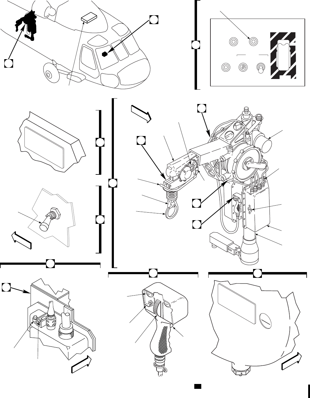
SA
AA0370A
TEST
SQUIB
O
F
F
ON
IN
MASTER
BOOM
OFF
OUT
NORMINDDOWN
O
F
F
UP
CABLE
SAFE
S
H
E
A
R
CABLE SHEAR
RESCUE HOIST CONTROL
FIRE
FILL TO INDICATED LEVEL
WITH MOBIL ATF DEXR220
FOR OPERATION BELOW
−40 F DRAIN AND REFILL
WITH SHELL DONAX T−1
o
ADD
DRAIN
OIL LEVEL
OVERTEMP
DOWN
UP
OUT
IN
CAUTION
HOIST
BOOM
FILL TO CENTER OF GLASS
WITH MOBIL ATF DEXR220
FOR OPERATION BELOW
−40 F DRAIN AND REFILL
WITH SHELL DONAX T−1
o
G
F
SPEED
MODE
SWITCH
MISSION−READY CIRCUIT
BREAKER PANEL
POWER ON
INDICATOR
F
E
MASTER
SWITCH
A
HOIST
MOTOR
HELICOPTER
POSITION
SWITCH
LAPSED
TIME
INDICATOR
CONTROL
BOX
HOIST
POST
C
OIL LEVEL
SIGHT GAGE
BOOM
UP−LIMIT
SWITCH
LEVER
KEEPER
RESCUE
HOOK
G
SQUIB
E
D
10 FOOT
WARNING
LIGHT
BOOM
POSITION
SWITCH
HOIST
WINCH
CONTROL
SWITCH
ICS
SWITCH
B
A
C
FRONT
FRONT
FRONT
FRONT
D
B
CABLE
CUT
SWITCH
HIGH
SPEED
LOW
SPEED
Figure 4-25. Rescue Hoist Kit UH
TM 1-1520-237-10
Change 5 4-49

b. Check oil level in hoist and boom head.
c. Return hoist to stowed position and secure
reaction arm.
2. Check upper attachment (make sure hose clamp
is installed).
3. Check lower attachment (mounting plates, pip
pins, and star plate).
4. Check position switch (positions 2 and 4).
5. Ensure hoist main power cable cannon plug is
safetied at junction box.
6. Cable cut switches - Down and safetied.
7. Make sure metallic shorting strip is removed
from cable cut cannon plug.
8. Cable cutter connector attached.
9. Check recovery devices are functional and
complete. Make sure recovery devices are se-
cure.
10. Make sure crewmembers have proper personal
equipment (safety harness, leather gloves, and
proper visors).
11. Hoist control circuit breaker - In (mission es-
sential circuit breaker panel).
4.19.6.2 Rescue Hoist Squib Circuit Test.
1. SQUIB switch - Hold at TEST.
2. SQUIB IND light - Check on.
3. SQUIB switch - Release to NORM.SQUIB
IND light off.
4.19.6.3 Boom Position and Hoist Cable Control
Operational Check.
To position the rescue hoist inboard or outboard, do this:
1. MASTER switch - ON.
2. Hoist operator - Check power on indicator (blue
light), check yellow caution light on control
pendant is on, and cooling fan operating.
3. Check ICS switch on pendant.
WARNING
Hands must be kept off hoist boom during
operation to prevent hand entrapment
and injury.
4. Hoist operator - BOOM switch - OUT and then
IN.
5. RESCUE HOIST CONTROL panel - Rotate
boom OUT; then IN, then OUT to test boom
operation.
6. Speed mode switch - HIGH.
WARNING
Rescue hoist cable is stiff and abrasive.
Broken cable strands are sharp, therefore
leather work gloves must be worn when-
ever handling rescue hoist cables.
A crewmember must reel cable out from
the boom head in line with the boom axis
during the following test procedures. Care
must be taken not to pull the cable taut
around the cable guide/roller, since kink-
ing of the cable might result. Avoid dam-
aging cable on rough surfaces, including
the ground.
7. RESCUE HOIST CONTROL panel -
DOWN; lower cable hook until all cable is
reeled out. The caution light should extinguish
after the first ten feet of cable is reeled out.
While reeling the cable out, push up on the ac-
tuator arm to ensure proper operation of the up-
limit switch. Hoist shall stop running when up-
limit switch is activated and resume operation
when actuator arm is released.
8. RESCUE HOIST CONTROL panel - Reel in
cable and observe that cable speed slows when
caution light goes on (8 to 10 feet of cable out).
9. Boom up limit actuator arm - Push up on arm
during reeling in to check that hoist stops run-
ning when up limit switches are activated. Ob-
serve that cable slows when hook is 12 to 18
inches from full up position.
TM 1-1520-237-10
4-50 Change 10

10. Repeat steps 7. through 9., using control pen-
dant assembly. Check that cable speed can be
regulated by control pendant from 0 to 250 fpm
when cable is reeled out beyond 10 feet.
11. Speed mode switch - LOW. Repeat steps 7.
through 9, using control pendant assembly.
Check that cable speed can be regulated by
control pendant from 0 to 125 fpm when cable
is reeled out beyond 10 feet.
CAUTION
Make sure hoist cable is completely up, to
prevent cable wear between cable and
hook assembly.
12. BOOM switch - Rotate boom in to stowed po-
sition.
4.19.7 Stopping Procedure.
MASTER switch - As desired.
4.20 AUXILIARY ELECTRICAL CABIN HEATER.
(ON HELICOPTERS EQUIPPED WITH AUXILIARY
CABIN HEATER KIT.)
A 55,000 BTU/hr electrical auxiliary cabin heater is in-
stalled in the transition section to provide an increase in
cabin temperature in extremely cold environments. The
auxiliary heater system consists of a heater control panel on
the lower console replacing the retransmission control panel
when the heater kit is installed (Figure 4-26), a blower and
electrical heater unit in the transition section, a heater inlet
port on the cabin aft bulkhead (Figure 2-5), a temperature
control located under the left gunner’s window, and ducting
throughout the cabin. The auxiliary heater system is turned
on from the cockpit by a switch, marked OFF-ON-RESET
on the AUX CABIN HEATER control panel. With both
main generators operating and AUX CABIN HEATER
switch ON, the HTR ON light on the control panel will go
on indicating that power is applied through the heater con-
trol relay to the duct temperature sensor and to the blower
motor and cabin heater elements. If a heater unit overheats,
an element thermostat circuit will automatically open, caus-
ing the heater to shut off. When the element cools, the
AUX CABIN HEATER switch must be momentarily
placed at RESET to restore the system. A heater outlet
duct cycling thermostat is also provided at the air outlet
side of the heater. If duct temperature exceeds 82° 68°C,
the temperature sensor contacts will open, temporarily in-
terrupting power to the heater elements. On decreasing
temperature, the contacts will automatically reset to closed
at 77° 68°C to restore power. A redundant duct overheat
sensor/shutoff switch is installed next to the duct cycling
thermostat to shut off power to the heater elements if the
delivered air flow temperature exceeds 99° 68°C due to
heater cycling sensor failure. Sensor switch contacts reset
closed on decreasing temperature. However, the cockpit
heater panel switch must be momentarily placed at RESET
to restart system operation. Heated air is carried through the
cabin via ducts along each side of the cabin at the ceiling.
TM 1-1520-237-10
Change 10 4-50.1/(4-50.2 Blank)

Power to operate the auxiliary cabin heater elements is pro-
vided from the No. 1 ac primary bus through the No. 1
junction box and protected by current limiters. Blower
power is provided from the No. 2 ac primary bus and pro-
tected by a circuit breaker, marked AUX HTR BLOWER.
Control of both heater elements and blower is provided by
power from the No. 1 dc primary bus through a circuit
breaker, marked AUX HTR CONTROL. The auxiliary
cabin heater will operate with APU power on and the
backup pump off or with both generators on and the backup
pump off.
4.21 ROTOR BLADE DEICE KIT.
Refer to Chapter 2 for description and operation of the
blade deice kit.
4.22 EXTERNAL EXTENDED RANGE FUEL SYS-
TEM KIT. ERFS
The external extended range fuel system is supported by
the external stores support system extending horizontally
from each side of the fuselage aft of the cockpit doors. The
230-gallon and 450-gallon jettisonable tanks may be sus-
pended from the vertical stores pylons (VSP). Removable
fuel lines, bleed-air lines, valves, and electrical connectors
are within the horizontal stores supports (HSS). A tank
pressurizing system, using bleed-air, transfers fuel to the
main tanks. Fuel lines carrying fuel to the No. 1 and No. 2
main fuel tanks contain check valves to prevent backflow.
The extended range system does not supply fuel directly to
the engines but is used to replenish the main tanks. Servic-
ing of the external tanks can be done only through fueling
ports on the tanks. Control of the system is provided by a
control panel on the lower console. Power to operate the
fuel transfer system is provided from the No. 1 dc primary
bus through circuit breakers marked EXT FUEL LH, and
NO. 1 XFER CONTROL and from the No. 2 dc primary
bus through circuit breakers marked EXT FUEL RH and
NO. 2 XFER CONTROL and from the No. 2 ac primary
bus through a circuit breaker marked AUX FUEL QTY on
the mission readiness circuit breaker panel.
4.22.1 External Extended Range Fuel Transfer
Modes. Fuel can be transferred from external tanks to
main tanks in either of two modes, AUTO MODE or
MANUAL.AUTO (primary) transfers fuel automatically
after switches are manipulated. Fuel transfer will be man-
aged by the microprocessor as described in paragraph
4.22.6. The pilot need only occasionally monitor the AUX-
ILIARY FUEL MANAGEMENT panel to ensure that
during AUTO MODE of fuel transfer, fuel in external
tanks is decreasing as it should. The second mode of trans-
fer is the MANUAL XFR (secondary) mode. In the
MANUAL mode the pilot may replenish main tank fuel in
any quantity or frequency desired. Transfer must be initi-
ated by the pilot. The pilot must constantly monitor the fuel
quantity indicator in order to start and terminate transfer to
remain within CG limits. It is possible to transfer fuel from
any one tank while in MANUAL mode. Transfer is shut off
by the pilot when the external tank low-level sensor signals
that the tank is empty. During manual transfer, at the illu-
mination of a tank EMPTY light, immediately switch from
OUTBD to INBD or to manual transfer MODE OFF.Do
not wait for the NO FLOW light to illuminate. This will
preclude air from entering the fuel line and entering the
main tank. At the illumination of the TANK EMPTY cap-
sule, 2.5 to 4.0 gallons of fuel remain in the tank. Sloshing
of the fuel will cause frequent illumination of the TANK
EMPTY,NO FLOW, and AUX FUEL lights when the
tank is in this condition.
4.22.2 External Extended Range Fuel System
Tanks. External extended range system contains two or
four tanks suspended from supports outboard of the fuse-
lage. The tanks contain baffles to prevent fuel sloshing.
Quick-disconnect valves are provided in external fuel and
bleed-air lines to provide seals when tanks are jettisoned or
removed. If tanks are not installed cccc will be displayed in
the AUX FUEL QTY POUNDS display when OUTBD or
INBD is selected on the rotary fuel quantity selector. The
preferred location of the External Extended Range Fuel
System (External ERFS) auxiliary fuel tank is the outboard
pylon. This facilitates ingress and egress of troops, loading
of cargo, and the use of the M60D door gun.
SA
AA0400
AUX CABIN HEATER
LOWER CONSOLE
HTR
ON HTR
INOP
RESET
OFF
ON
(ON HELICOPTERS EQUIPPED WITH AUXILIARY CABIN HEATER)
Figure 4-26. Auxiliary Cabin Heater Control
Panel
TM 1-1520-237-10
Change 10 4-51

4.22.3 Auxiliary Fuel Management Control Panel.
The AUXILIARY FUEL MANAGEMENT control panel
(Figure 4-27) contains all controls for operating the exter-
nal extended range fuel system. Controls description is as
follows:
CONTROL/
INDICATOR FUNCTION
FUEL XFR Controls fuel management of
external extended range system.
PRESS
OUTBD ON Opens bleed-air valves to outboard
tanks for pressurization.
OFF Closes bleed-air valves to tanks.
INBD ON Opens bleed-air valves to inboard
tanks for pressurization.
OFF Closes bleed-air valves to tanks.
TANKS INBD Selects fuel transfer valves from
inboard tanks for fuel transfer to
main tanks; deselects outboard
valves.
TANKS OUTBD Selects fuel transfer valves from
outboard tanks for fuel transfer to
main tanks; deselects inboard
valves.
MODE Selects AUTO-OFF-MANUAL
mode of fuel transfer from external
fuel tanks.
AUTO Automatically transfers fuel to
main tanks from selected external
tanks, until empty sensor in each
tank interrupts transfer. Transfer
occurs in levels as shown under
fuel transfer sequence. When tanks
are empty, NO FLOW and
EMPTY indicators and AUX
FUEL caution light will be turned
on.
OFF Interrupts automatic or manual
transfer mode of operation.
MANUAL Provides electrical path to
MANUAL XFR switch(es), which
allows transfer from selected
tank(s) until switch is moved to off.
CONTROL/
INDICATOR FUNCTION
MANUAL XFR
RIGHT ON Transfers from right tank used in
conjunction with MODE switch in
MANUAL position of the pair
selected by TANKS select switch.
OFF Interrupts transfer operation.
LEFT ON Transfers from left tank of the pair
selected by TANKS select switch.
OFF Interrupts transfer operation.
AUX FUEL QTY
POUNDS Indicates pounds of external fuel
remaining in symmetrical pair of
tanks total of auxiliary tanks, self-
test indication or failure codes.
Displays K factors of flow meter.
NOTE
Fuel tanks selector and quantity
indicators are also used in
conjunction with INCR-DECR
switch when initializing fuel
quantity of tanks.
OUTBD Total pounds of fuel remaining in
outboard pair of tanks.
INBD Total pounds of fuel remaining in
inboard pair of tanks.
TOTAL Pounds of fuel remaining in all
external extended range tanks.
CAL Adjusts K factor of flow switch on
AUXILIARY FUEL
MANAGEMENT panel.
INCR switch
position Increases setting of digital readout
to adjust for fuel remaining in tanks
selected by fuel tank selector.
DECR switch
position Decreases setting of digital readout
to adjust for fuel remaining in tanks
selected by fuel tank selector.
STATUS button Resets AUX FUEL caution light
and stores condition of NO FLOW
and EMPTY indicators.
TM 1-1520-237-10
4-52 Change 8

CONTROL/
INDICATOR FUNCTION
TEST Checks display and indicator lights.
Performs memory checksum,
displays 8 sequentially in each
digital display. Verifies that
temperature probe is connected;
verifies that flow meter is
connected; performs trial
calculation based on a known
temperature and flow meter input,
compares it with a known good
value, and displays setting of fuel
density switch. At completion of
test, GOOD or error code will be
displayed (Table 4-3).
DEGRADED light Error in critical function has
occurred. Error code will be
displayed as shown under TEST.
Only E02 error will allow
microprocessor to clear failure code
and regain fuel remaining
information by doing two self-tests.
EXTERNAL
*RIGHT NO
FLOW light Fuel flow does not exit from
selected right tank.
*INBD EMPTY
light Right inboard tank fuel exhausted.
*OUTBD
EMPTY light Right outboard tank fuel exhausted.
*LEFT NO
FLOW light Fuel flow does not exit from
selected left tank.
*INBD EMPTY
light Left inboard tank fuel exhausted.
*OUTBD
EMPTY
light
Left outboard tank fuel exhausted.
VENT SENSOR Detects the presence of fuel on the
vent thermistor.
*OVFL Indicates fuel venting overboard.
CONTROL/
INDICATOR FUNCTION
NOTE
Illumination of this capsule on the
Fuel Management Panel will cause
illumination of the AUX FUEL
caution light and the MASTER
CAUTION light. Pushing the
STATUS button will reset the NO
FLOW,AUX FUEL and the
MASTER CAUTION lights, but
does not correct the no flow
condition.
FAIL Open in vent sensor line.
4.22.4 External Extended Range Fuel Quantity In-
dicating System. The AUX FUEL QTY POUNDS
digital readout (Figure 4-27) displays the amount of fuel
remaining. Fuel type is preset by switches in the AUXIL-
IARY FUEL MANAGEMENT panel. Preset can only be
done when the helicopter weight is on the wheels. When
measuring quantity, the readout is used in conjunction with
the rotary selector switch to select tank pair subtotal, or
TOTAL remaining in all tanks. Fuel used is sensed from a
common flow transmitter within the fuel line to the main
tanks. This amount is subtracted from the preset fuel quan-
tity input and is displayed on the digital readout as pounds
remaining. A DEGRADED light will go on when a com-
plete failure has occurred in the microprocessor, or an error
condition is detected by the microprocessor, or when the
temperature sensor has failed. Power for the fuel quantity
subsystem is provided from the No. 2 ac primary bus
through a circuit breaker marked AUX FUEL QTY,onthe
mission readiness circuit breaker panel.
4.22.5 Auxiliary Fuel Management Control Panel
Test.
1. TEST button - Press. Digits should display 8s,
all panel lights and DEGRADED and VENT
SENSOR (FAIL and OVFL) lights should il-
luminate.
TM 1-1520-237-10
Change 6 4-53
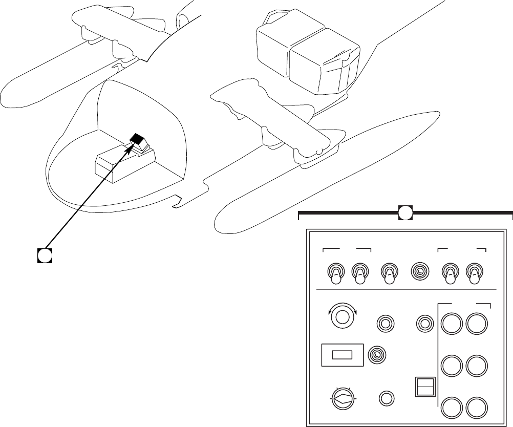
2. TEST button - Release. Digits should display
8s in sequence from left to right three times; 5
seconds later, display GOOD or EO failure
code; 3 seconds later, display type fuel density,
then fuel TOTAL.
3. Deleted.
4. Auxiliary fuel quantity switch - CAL.
NOTE
CAL is the calibration value marked on the
fuel flow transmitter. Enter the four digit
number, disregarding the numbers to the
right of the decimal point.
5. INCR/DECR switch - Set calibration.
6. Auxiliary fuel quantity switch - INBD.
7. INCR/DECR switch - Set inboard fuel quan-
tity.
8. Auxiliary fuel quantity switch - OUTBD.
9. INCR/DECR switch - Set outboard fuel quan-
tity.
SA
AA0665
A
EMPTY
EMPTY
EMPTY
EMPTY
NO
FLOW NO
FLOW
STATUS
EXTERNAL
RIGHT LEFT
INBD INBD
OUTBD OUTBD
9990
VENT
SENSOR
FAIL
OVFL
TEST
QTY
BRIGHTNESS
AUX FUEL QTY
POUNDS
PRESS MANUAL XFR
OFF OFFMANUALOUTBD
OUTBD
ON INBD
ON TANKS
INBD MODE
AUTO RIGHT
ON LEFT
ON
INCR
DECR
TOTAL
OUTBD INBD
CAL
DEGRADED
DECR INCR
O
F
F
FUEL XFR
AUXILIARY FUEL MANAGEMENT
A
Figure 4-27. Auxiliary Fuel Management Control Panel
TM 1-1520-237-10
4-54 Change 10

10. Auxiliary fuel quantity switch move to TOTAL
- Check.
11. PRESS OUTBD and INBD switches - As de-
sired.
4.22.6 Fuel Transfer Sequence.
WARNING
FUEL BOOST PUMP CONTROL
switches shall remain on during external
range fuel transfer and remain on for 10
minutes after PRESS switches are moved
to OFF. Failure to observe this warning
may cause engine flameout.
CAUTION
Fuel transfer sequence must be carefully
planned and executed in order to main-
tain CG within limits.
Fuel transfer sequence shall be based on mission re-
quirement and center of gravity limitations. Automatic
transfer is started when the proper switches are manipulated
and fuel level is as shown below and external range tanks
internal pressure is increased enough to force fuel to the
main tanks. Transfer will continue until the main tank sig-
nal conditioner provides a signal through the microproces-
sor to stop fuel transfer. This cycle is done as required until
interrupted by placing the MODE switch to OFF or
MANUAL or placing the PRESS switch OFF. Manual
transfer will be started on selection of MANUAL and ap-
propriate switches, and external fuel tanks are bleed-air
pressurized to start fuel transfer from external tank(s) to
main tanks. Transfer will continue until tanks are full. They
will remain full as long as the manual mode remains en-
gaged. Manual transfer requires close monitoring of fuel
level to initiate and stop transfer to remain within CG lim-
its. The automatic transfer sequence is as follows:
TOTAL AUXIL-
IARY FUEL RE-
MAINING
(BASED ON
JP-4 DENSITY)
TRANSFER
START WHEN
ONE MAIN
FUEL TANK
QUANTITY
LESS THAN
TRANSFER
STOP WHEN
EACH MAIN
FUEL TANK
QUANTITY
MORE THAN
8840-7041 lbs 950 lbs 1000 lbs
7040-5001 lbs 750 lbs 1000 lbs
5000-0 lbs 600 lbs 1000 lbs
4.22.7 External Extended Range Fuel Transfer
Check.
NOTE
When ambient temperature is below 4°C
(40°F), ESSS/ERFS shall not be turned off
after transfer check has been completed to
avoid potential for freeze-up of the pressure
regulator.
1. AIR SOURCE HEAT/START switch - ENG.
2. FUEL BOOST PUMP CONTROL switches -
Check ON.
WARNING
FUEL BOOST PUMP CONTROL
switches shall remain on during external
range fuel transfer and remain on for 10
minutes after PRESS switches are moved
to OFF. Failure to observe this warning
may cause engine flameout.
3. PRESS OUTBD and INBD switches - ON for
tanks installed.
4. Fuel quantity switch - TOTAL.
5. TANKS switch - OUTBD.
6. MODE switch - MANUAL.
TM 1-1520-237-10
Change 10 4-55

7. MANUAL XFR RIGHT switch - ON.
8. Main FUEL QTY TOTAL FUEL readout -
Check for increase of about 20 pounds.
9. TANKS switch - Repeat steps 7 and 8 for
INBD, if installed.
10. MANUAL XFR RIGHT switch - OFF.
11. MANUAL XFR LEFT switch - ON.
12. Repeat steps 8. and 9. for MANUAL XFR
LEFT.
13. MANUAL XFR LEFT switch - OFF.
14. External extended range fuel system - Set as
desired.
4.22.7.1 External Extended Range Fuel Transfer In
AUTO Mode.
NOTE
If either main fuel quantity is below 1,000
lbs., selecting the automatic mode may ini-
tiate a transfer sequence.
Allow sufficient time for tank pressurization
(approximately 10 minutes for a half full
230-gallon tank).
During transfer, periodically verify that
AUXILIARY FUEL MANAGEMENT
panel quantity is decreasing at a minimum
of 40 pounds per minute, per tank pair. Fuel
transfer rate of less than 40 pounds per
minute may indicate reduced flow from one
or both tanks.
1. AIR SOURCE HEAT/START switch - ENG.
2. FUEL BOOST PUMP CONTROL switches -
Check ON.
3. PRESS OUTBD and INBD switches - ON for
tanks installed.
4. MODE switch - AUTO.
5. TANKS switch - OUTBD. Switch to INBD
after outboard tanks are empty.
4.22.7.2 External Extended Range Fuel Transfer In
MANUAL Mode.
If AUTO mode is inoperative, transfer in MANUAL
mode as follows:
CAUTION
Monitor fuel transfer to remain within
CG limits and avoid asymmetric loading.
1. AIR SOURCE HEAT/START switch - ENG.
2. FUEL BOOST PUMP CONTROL switches -
Check ON.
3. PRESS OUTBD and INBD switches - ON for
tanks installed.
4. MODE switch - MANUAL.
5. TANKS switch - OUTBD. Switch to INBD
after outboard tanks are empty.
6. MANUAL XFR switches RIGHT and LEFT
-ON.
4.22.7.3 External Extended Range Fuel Flow Veri-
fication In Manual Mode. If extended range without
landing is required and the aircraft is not equipped with an
ERFS fuel indicating system, verify fuel flow from each
tank as follows:
NOTE
Ensure main fuel tanks are not completely
full.
1. AIR SOURCE HEAT/START switch - ENG.
2. FUEL BOOST PUMP CONTROL switches -
Check ON.
3. PRESS OUTBD and INBD switches - ON for
tanks installed.
4. MODE switch - MANUAL.
5. TANKS switch - OUTBD. Switch to INBD
after outboard tanks are empty.
6. MANUAL XFR RIGHT switch - ON. Note
the rate of decrease of the AUX FUEL QTY
TM 1-1520-237-10
4-56 Change 10

POUNDS indicator. The normal transfer fuel
flow rate per tank should be between 20 to 38
pounds per minute.
7. MANUAL XFR RIGHT switch - OFF.
8. Repeat steps 6. and 7. for left tank.
4.22A EXTERNAL AUXILIARY FUEL MANAGE-
MENT SYSTEM. AFMS
The external extended range fuel system is supported by
the external stores support system. The 230-gallon and 450-
gallon jettisonable tanks may be suspended from the verti-
cal stores pylons (VSP). Removable fuel lines, bleed-air
SYSTEM FAILURE DEGRADED AUX FUEL DESCRIPTION OF
CODES AND LIGHT CAUTION DEGRADED OPERATION
INDICATIONS LIGHT
E01 MICROPROCESSOR ERROR
E03 FLOWMETER DISCONNECTED
E04 ERROR FUEL FLOW CIRCUITS
E05 ERROR FUEL FLOW
COMPUTATION
E06 MEMORY ERROR
ON ON 1. AUTO XFR CAPABILITIES
REMAIN
2. DEFAULTS TO CURRENT XFR
SCHEDULE
3. PILOT MUST COMPUTE FUEL
USAGE
E02 TEMPERATURE SENSOR NOT
CONNECTED OR OUT OF RANGE ON ON
1. AUTO XFR CAPABILITIES
REMAIN
2. PERFORMING TWO SELF-TESTS
WILL:
A. CLEAR FAILURE CODE AND
REGAIN FUEL REMAINING INFO
B. RESET AUX FUEL LIGHT
C. DEFAULT TO PRESELECTED
TEMP VALUE
LOSS OF
DIGITAL READOUT ON ON
1. AUTO XFR CAPABILITIES
REMAIN
2. NO FLOW AND EMPTY
MONITORING INDICATIONS
REMAIN
3. PILOT MUST COMPUTE FUEL
USAGE
LOSS OF ONE MAIN TANK LEVEL
QUANTITY SENSOR OR LOSS OF
ONE SIGNAL CONDITIONER INPUT OFF OFF NO DEGRADATION
FAILED AUX TANK EMPTY SENSOR
PROVIDES FALSE EMPTY SIGNAL OFF ON-IF FUEL
TRANSFER
SELECTED
AUX TANK FUEL TRANSFER
SHUTOFF VALVE CLOSES.
PILOT SELECTING MANUAL
MODE REOPENS VALVE.
Table 4-3. Extended Range Fuel System Degraded Operation Chart ERFS
TM 1-1520-237-10
Change 4 4-57

lines, valves, and electrical connectors are within the hori-
zontal stores supports (HSS). A tank pressurizing system,
using bleed-air, transfers fuel from the external tanks to the
main tanks. Fuel lines carrying fuel to the No. 1 and No. 2
main fuel tanks contain check valves to prevent backflow.
The external tanks are gravity refueled only. Control of the
system is provided by a auxiliary fuel management panel
(AFMP) located in the center of the instrument panel. Dim-
ming control for the AFMP panel lighting is provided by
the cockpit INST LT NON FLT rheostat on the upper
console. Dimming control for all fuel quantity displays and
annunciators on the AFMP is provided by the LIGHTED
SWITCHES rheostat on the upper console only when the
caution/advisory panel is in the DIM mode. Power for the
auxiliary fuel management system is provided from the No.
2 dc primary bus through circuit breakers marked EXT
FUEL RH and NO. 2 XFER CONTROL on the mission
readiness circuit breaker panel.
4.22A.1 External Auxiliary Fuel Management Sys-
tem. This system contains two or four tanks suspended
from supports outboard of the fuselage. The tanks contain
baffles to prevent fuel sloshing. Quick-disconnect valves
are provided in external fuel and bleed-air lines to provide
seals when tanks are jettisoned or removed. If tanks are not
installed, the fuel quantity display for the removed tank is
blank when the XFER MODE is OFF. When the XFER
MODE switch is in any other position, the removed tank
display will show NT.
4.22A.2 Auxiliary Fuel Management Control Panel
(AFMP). The AFMP (Figure 4-27.1) contains all controls
for operating the external extended range fuel system. Con-
trols description is as follows:
CONTROL/
INDICATOR FUNCTION
PRESS switch Provides control of bleed air
pressurization of auxiliary tanks.
PRESS
ALL Opens bleed-air valves to all
installed tanks for pressurization.
OUTBD Opens bleed-air valves to outboard
tanks for pressurization.
INBD Opens bleed-air valves to inboard
tanks for pressurization.
CONTROL/
INDICATOR FUNCTION
OFF Closes bleed-air valves to tanks.
XFER FROM
INBD Selects fuel transfer from inboard
tanks.
OUTBD Selects fuel transfer from outboard
tanks.
XFER MODE Selects AUTO-OFF-MAN mode
of fuel transfer from external fuel
tanks.
AUTO Activates automatic fuel transfer.
OFF Closes all fuel transfer valves.
Interrupts automatic or manual
transfer mode of operation.
Deactivates NO FLOW indicators.
MAN Selects manual transfer mode.
Activates MAN XFER switches.
MAN XFER
LEFT Transfers from left inboard or
outboard tank.
BOTH Transfers from both left and right
inboard or outboard tanks.
RIGHT Transfers from right inboard or
outboard tank.
AUX FUEL QTY
LBS
L OUTBD Pounds of fuel remaining in the left
outboard tank to the nearest 10 lbs.
L INBD Pounds of fuel remaining in the left
inboard tank to the nearest 10 lbs.
R OUTBD Pounds of fuel remaining in the
right outboard tank to the nearest
10 lbs.
R INBD Pounds of fuel remaining in the
right inboard tank to the nearest 10
lbs.
TM 1-1520-237-10
4-58 Change 4
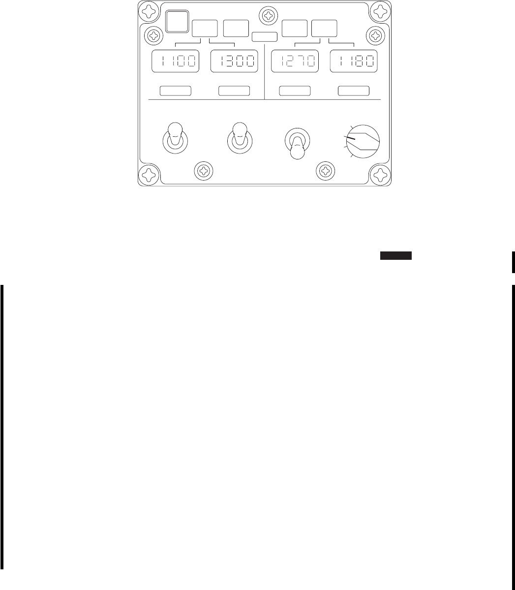
CONTROL/
INDICATOR FUNCTION
TEST/RESET On the ground (weight on wheels) -
Activates the Initiated Built in Test
(IBIT) and conducts a lamp test of
all displays and indicator lights.
System malfunctions are displayed
from left to right in the fuel quan-
tity displays, using the error codes
(Table 4-4). Fuel quantity displays
return after the lamp test, if no er-
rors are identified. Acknowledges
E04 through E07 error codes.
In-flight (weight off wheels) - Re-
sets AUX FUEL caution light and
MASTER CAUTION but does not
correct the condition.
NOTE
Illumination of annunciators on the
AFMP will activate AUX FUEL
caution light and MASTER CAU-
TION lights.
CONTROL/
INDICATOR FUNCTION
The NO FLOW condition must ex-
ist for 5 seconds before the AUX
FUEL caution light and MASTER
CAUTION lights are activated.
One of these indications will occur
if a tank empty sensor fails (for re-
lated tank).
vA false EMPTY light (tank shows
quantity greater than zero).
vA false NT fuel quantity indica-
tion (tank installed, AUTO or
MAN mode selected).
vA false 9blank9fuel quantity indi-
cation (tank installed, XFER
MODE is OFF).
vDegraded operation for the above
conditions: AUTO mode is dis-
abled, use MAN mode.
AUX FUEL QTY
LBS
SA
AB0820
NO
FLOW VENT
FAIL IMBAL
EMPTYEMPTY INBDOUTBD L
NO
FLOW
VENT
OVFL
EMPTYEMPTY OUTBDINBD R
AUX FUEL QTY LBS
TEST /
RESET
XFER MODE
AUTO
MAN
O
F
F
LEFT
RIGHT
O
T
H
INBD
OUTBD
B
MAN XFER XFER FROM PRESS
OUTBD
INBD
OFF
ALL
Figure 4-27.1. Auxiliary Fuel Management Control Panel AFMS
TM 1-1520-237-10
Change 4 4-59

CONTROL/
INDICATOR FUNCTION
*R NO FLOW
light No fuel flowing from right tank(s).
*R INBD EMPTY
light Right inboard tank fuel exhausted.
*R OUTBD
EMPTY light Right outboard tank fuel exhausted.
*L NO FLOW
light No fuel flowing from left tank(s).
*L INBD EMPTY
light Left inboard tank fuel exhausted.
*L OUTBD
EMPTY light Left outboard tank fuel exhausted.
NOTE
EMPTY light will only activate
AUX FUEL caution light and
MASTER CAUTION lights when
its tank is selected for transfer.
If the EMPTY light is on for more
than 10 seconds and the fuel quan-
tity display is greater than zero, the
tank empty sensor has failed.
VENT FAIL lights Vent sensor inoperative.
*VENT OVFL
lights Indicates when AFMS detects the
presence of fuel in vent line.
*IMBAL light Indicates a lateral imbalance of 400
to 680 pounds between fuel quan-
tity indications for outboard tanks.
4.22A.3 External Auxiliary Fuel Management
Quantity Indicating System. AFMS
NOTE
Unmodified 230-gallon and 450-gallon tanks
are prohibited from use on helicopters modi-
fied for AFMS. Crews should visually in-
spect each tank identification plate to verify
that only AFMS modified tanks are installed
on AFMS modified helicopters.
The AUX FUEL QTY LB digital readout indicates
(Figure 4-27.1) the amount of fuel in each of the installed
external tanks in ten pound increments. A fuel probe in
each of the external tanks sends a signal to the AFMP pro-
portional to the fuel level in the tank. The level of fuel at
the probe varies significantly with tank attitude. Aircraft
body pitch angle data from the copilot’s vertical gyro is
used by the AFMP so that the fuel quantity displayed in-
cludes compensation for angles between 10° nose down
and 1° nose up. E07 will result in a drop in AUX fuel
quantities for pitch down attitudes. A pitch up attitude may
result in a slight increase. The copilot’s attitude indicator
will not indicate OFF if the E07 error code occurs due to
failure of AFMP circuits external to the gyro. The pilot’s
vertical gyro is not connected to the AFMP and therefore
not available for attitude compensation. Level flight pro-
vides most accurate fuel quantity. A filter is incorporated in
the AFMP software to minimize fuel quantity variations
due to fuel slosh during maneuvering flight.
NOTE
The AFMP may display fuel quantities of up
to 150 pounds below the actual fuel quantity
per tank due to tank angle when the helicop-
ter is on the ground.
A lateral imbalance is defined as any differ-
ence in fuel quantity readings between tank
pairs greater than 400 pounds. The crew
should not wait for the illumination of the
IMBAL light to begin correcting the lateral
imbalance condition.
The AFMP has three built in test (BIT) functions; power
up (PBIT), initiated (IBIT), and continuous (CBIT). PBIT
and IBIT are disabled in-flight by the WOW interlock. Cir-
cuits tested and related error codes are shown in Table 4-4.
PBIT is initiated when power is applied or reapplied to the
AFMP. IBIT is initiated by pressing the TEST/RESET
button for one second or more. CBIT is activated at the
completion of PBIT or IBIT and runs continuously.
NOTE
The transition from APU to main generators
during engine run up can cause the PBIT to
be initiated. The AFMP will display fuel
quantities once the PBIT functions are com-
pleted.
TM 1-1520-237-10
4-60 Change 10

4.22A.4 External Auxiliary Fuel Management Sys-
tem Modes of Operation.
4.22A.4.1 Automatic Mode Fuel Transfer.
WARNING
FUEL BOOST PUMP CONTROL
switches shall remain on during external
range fuel transfer and remain on for 10
minutes after PRESS switch is moved to
OFF. Failure to observe this warning may
cause engine flameout.
CAUTION
Monitor fuel transfer to remain within
CG limits and avoid asymmetric loading.
The fuel transfer sequence shall be based on mission
requirements and center of gravity limitations. Automatic
transfer is controlled by the AFMP sensing the No. 1 and 2
main tank fuel quantities to start and stop fuel transfer.
When AUTO mode is selected, transfer starts when the fuel
level in either main tank falls below 1,000 pounds, and the
external tanks are pressurized. The NO FLOW lights may
flicker upon initiation of fuel transfer. The AFMP transfers
fuel from both tanks selected with the XFER FROM
switch regardless of the position of the MAN XFER
switch. Fuel transfer stops when the TOTAL FUEL quan-
tity indicates 2,200 pounds or when the EMPTY light on
either tank or VENT OVFL light illuminates on the AFMP.
4.22A.4.2 Manual Mode Fuel Transfer. AFMS
WARNING
FUEL BOOST PUMP CONTROL
switches shall remain on during external
range fuel transfer and remain on for 10
minutes after PRESS switch is moved to
OFF. Failure to observe this warning may
cause engine flameout.
CAUTION
Monitor fuel transfer to remain within
CG limits and avoid asymmetric loading.
If the IMBAL indicator illuminates, the
crew should verify selection of the heavy
tank and closely monitor the fuel quantity
displays on the AFMP. No additional
warnings are provided by the AFMP or
caution advisory system if the crew selects
the wrong tank with the MAN XFER
switch.
Manual transfer requires close monitoring of the main
fuel quantity and AFMP fuel quantity displays to remain
within CG limits and maintain lateral balance. Manual
mode is initiated by the pilot when the XFER MODE
switch is placed to MAN and external tanks are pressur-
ized. Fuel transfer will continue as long as MAN is se-
lected. The NO FLOW lights will randomly flicker as fuel
is transferred until the main fuel quantity reaches approxi-
mately 2,300 pounds, unless the XFER MODE switch is
placed to OFF or AUTO. The NO FLOW condition re-
sults when the tank pressurization can no longer add fuel to
the tanks due to activation of the high level fuel shutoff
valves in the main tanks. Illumination of the EMPTY light
alerts the pilot to change tank pairs using the XFER FROM
switch, select another tank using the MAN XFER switch,
or place the XFER MODE switch to OFF. To avoid
pumping air into the main tanks, do not wait for the NO
FLOW light to illuminate. Sloshing of the fuel will cause
frequent illumination of the EMPTY light only when the
tank is selected for fuel transfer. Sloshing of fuel and acti-
vation of the fuel transfer valves using the XFER MODE
switch can cause flickering of the NO FLOW light; how-
ever the AUX FUEL and MASTER CAUTION will only
illuminate if the NO FLOW lights remain illuminated for
more than 5 seconds. If lateral imbalance results during fuel
transfer, the AFMP senses the imbalance and illuminates
the IMBAL light. The lateral imbalance can be resolved by
selecting fuel transfer from the heavy tank. The IMBAL
light illuminates with approximately 685 pound difference
between outboard tanks, and will remain illuminated until
the lateral imbalance is reduced below approximately 450
pound difference between outboard tanks.
4.22A.5 Auxiliary Fuel Management Control Panel
- TEST. AFMS
1. AUX FUEL QTY digital readouts - Note cur-
rent reading.
2. TEST/RESET button - Press. All annunciators
will light and E07 will be displayed, if test is
initiated within approximately one minute of
applying ac power. If E07 appears, press
TEST/RESET again. E07 should not appear
until test is finished.
TM 1-1520-237-10
Change 10 4-60.1

3. BIT indications - Check. Fuel quantity displays
will appear upon completion of BIT. The pitch
attitude sensor error E07 test has a 5 minute
delay to allow the vertical gyro to obtain full
operating speed.
4. PRESS switch - As desired for tanks installed.
4.22A.6 External Auxiliary Fuel Management Sys-
tem Fuel Transfer Check. AFMS
NOTE
When ambient temperature is below 4° C
(39° F), ERFS/AFMS shall not be turned off
after transfer check has been completed to
avoid potential freeze up of the pressure
regulator.
1. AIR SOURCE HEAT/START switch - ENG.
2. FUEL BOOST PUMP CONTROL switches -
Check ON.
WARNING
FUEL BOOST PUMP CONTROL
switches shall remain on during external
range fuel transfer and remain on for 10
minutes after PRESS switch is moved to
OFF. Failure to observe this warning may
cause engine flameout.
3. PRESS switch - As required for tanks installed.
4. XFER FROM switch - OUTBD.
5. MAN XFER switch - BOTH.
6. XFER MODE switch - MAN.
7. Main FUEL QTY TOTAL FUEL readout -
Check for increase of approximately 40 pounds
and AUX FUEL QTY LBS decrase 20 pounds
per tank.
8. XFER FROM switch - INBD if installed.
9. Main FUEL QTY TOTAL FUEL readout -
Check for increase of approximately 40 pounds
and AUX FUEL QTY LBS decrase 20 pounds
per tank.
10. XFER MODE switch - OFF.
11. External extended range fuel system - Set as
desired.
4.22A.6.1 Fuel Transfer in AUTO Mode. AFMS
NOTE
Allow sufficient time for tank pressurization
(approximately 10 minutes for a half full 230
gallon tank).
During transfer, periodically verify the TO-
TAL FUEL quantity remains above 2,000
pounds and the selected tank pair remains in
balance. A decrease below 2,000 pounds on
the TOTAL FUEL quantity display or the
generation of an imbalance in the AUTO
mode may indicate reduced flow from one
or both of the external tanks selected.
1. AIR SOURCE HEAT/START switch - ENG.
2. FUEL BOOST PUMP CONTROL switches -
Check ON.
3. PRESS switch - As required for tanks installed.
4. XFER FROM switch - OUTBD, then INBD.
5. XFER MODE switch - AUTO.
4.22A.6.2 Fuel Transfer in MANUAL Mode. AFMS
If the AUTO mode is inoperative or a lateral imbalance
greater than 400 pounds between tank pairs is identified,
transfer in the MAN mode as follows:
CAUTION
Monitor fuel transfer to remain within
CG limits and avoid asymmetric loading.
1. AIR SOURCE HEAT/START switch - ENG.
2. FUEL BOOST PUMP CONTROL switches -
Check ON.
3. PRESS switch - As required for tanks installed.
4. XFER FROM switch - OUTBD, then INBD.
TM 1-1520-237-10
4-60.2 Change 10

5. MAN XFER switch - BOTH or select heavy
tank to correct an imbalance.
6. XFER MODE switch - MAN.
4.23 EXTERNAL STORES SUPPORT SYSTEM
(ESSS). ES
ESSS provides a means of carrying a variety of external
stores, including external extended range fuel tanks. The
ESSS consists of fixed and removable provisions.
4.23.1 External Stores Fixed Provisions. Fixed pro-
visions are: upper fuselage fixed fittings for attaching the
horizontal stores support (HSS) subsystem, and lower fuse-
lage strut support fittings for attaching two struts for each
HSS. In addition to exterior components, fixed provisions
are: interior helicopter provisions, including electrical har-
nesses, fuel lines, bleed-air lines, and circuit breakers.
4.23.2 External Stores Removable Provisions. The
external stores removable subsystem extends horizontally
from each side of the helicopter at station 301.5, buttline
42.0. Extending below each horizontal stores support (HSS)
are two vertical stores pylons (VSP) and attaching ejector
racks. The racks are used to attach fuel tanks or other ex-
ternal stores dispensers.
SYSTEM FAILURE CODES AND/
OR INDICATIONS DESCRIPTION OF
DEGRADED OPERATIONS
E01 - AFMP microprocessor fail
E02 - AFMP memory fail
E03 - AFMP display fail
1. E01-E03 error codes displayed continuously if failure
occurs during PBIT or IBIT on the ground (WOW only).
2. Only MAN mode for transfer is available.
E04 - AFMP tank gaging electronics failure
E05 - Auxiliary tank probe (OPEN)
E06 - Auxiliary tank probe (SHORT)
1. Error codes display during PBIT or IBIT if failure
occurs on the ground (WOW only).
2. Acknowledge failure by pressing TEST/RESET
button and error code changes to the CBIT display (---)
or FP.
3. Manual mode only is available for the tank pair
selected. Fuel quantity must be calculated for the tank
with the failure.
(--- ) AFMP tank gaging electronics failure.
FP - Auxiliary tank probe circuit failure (open or short).
NF - No tank detected.
1. (--- ) is the failure indication for error code E04 and
FP is the failure indication for E05 and E06 during
CBIT on the ground or in flight or during PBIT or IBIT
on the ground after the crew acknowledges the error
using TEST/RESET.
2. Manual mode only is available for the tank pair with
the failure. Fuel quantity must be calculated for the tank
with the failure.
3. No tank detected by system, when that tank is
selected for transfer.
E07 - AFMP memory fail 1. May occur on the ground if IBIT is initiated within
approximately 1 minute of applying ac power to the
aircraft. Acknowledge E07 with the TEST/RESET
button.
2. If E07 is observed in flight or persists on the ground,
AUTO and MAN mode are available but the pitch
attitude correction defaults to a level attitude regardless
of flight condition.
Table 4-4. Auxiliary Fuel Management System Fault Messages AFMS
TM 1-1520-237-10
Change 10 4-60.3

4.23.3 ESSS Side Position Lights. A position light is
on each outboard end of HSS. Those lights use the power
source provided to operate the standard installed position
lights, colors are the same. Upon installation of the HSS,
the electrical connectors connected to the jumper plugs,
providing power for the standard position lights, are re-
moved and reconnected to the connectors from the HSS
position lights. Operation and power source for the ESSS
position lights are the same as for the standard installed
position lights.
4.23.4 External Stores Jettison Control Panel. The
jettison control panel (Figure 4-28) provides the capability
of phase jettison of all external stores or symmetrical jetti-
son of fuel tanks. Interlock circuitry prevents jettison of
fuel tanks other than in pairs. Emergency jettison is com-
pletely independent of the primary jettison subsystem.
WARNING
The BRU-22A/A and MAU-40/A Ejector
Rack CARTRIDGES are explosive de-
vices and must not be exposed to heat,
stray voltage or static electricity. Refer to
TM 9-1300-206 for information concern-
ing handling and storage of ammunition.
The jettison control panel (Figure 4-28) contains all con-
trols for jettisoning external stores. Jettison controls are as
follows:
CONTROL FUNCTION
EMER JETT ALL Applies 28 volts from essential dc
bus to all stores stations when the
helicopter weight is off the wheels,
regardless of the rotary selector
switch. A 1-second time delay per-
mits the outboard stations to jetti-
son before the inboard stations.
Rotary selector
switch Determines which station receives
primary jettison signal.
CONTROL FUNCTION
OFF Prevents jettison signal from going
to any stores station.
NOTE
*If fuel tanks are connected to the
left, right, or both stores stations,
the BOTH mode of jettison is au-
tomatically selected even if the se-
lector switch is at Lor R.
INBD
L*Directs jettison signal to inboard
left station.
R*Directs jettison signal to inboard
right station.
BOTH Directs jettison signal to inboard
left and right stores stations.
OUTBD
L*Directs jettison signal to outboard
left station.
R*Direct jettison signal to outboard
right station.
BOTH Directs jettison signal to outboard
left and right stores stations.
ALL Directs primary jettison signal to all
stores stations. Outboard stores will
jettison and 1 second later inboard
stores will jettison.
JETT Applies 28 volts from primary dc
bus through the rotary selector
switch to the selected stores station
if the weight is off the wheels and
the selector switch is not OFF.
TM 1-1520-237-10
4-60.4 Change 10
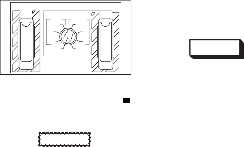
4.23.5 Stores Jettison Control Operation.
CAUTION
To prevent unintentional jettison of exter-
nal stores when the helicopter weight is
on the wheels, do not actuate any jettison
switch.
The jettison system provides two modes of jettisoning
external stores, primary and emergency. The primary sub-
system uses the rotary selector switch and the JETT toggle
switch. The emergency jettison subsystem uses only the
EMER JETT ALL toggle switch. Primary jettison is used
when selective jettison is desired. The rotary switch is used
to select the stores point for release, and the JETT toggle
switch is used to actuate the release. Emergency jettison is
used to release all external stores through one actuation of
the EMER JETT ALL toggle switch, regardless of rotary
switch position. During primary (rotary switch ALL se-
lected) and emergency jettison, a 1-second delay is pro-
vided after the outboard stores are released, before the in-
board stores will be released. When one pair of tanks is
jettisoned in a four tank system, cccc will appear on the
AUX FUEL QTY POUNDS digital readout when the cor-
responding fuel quantity position is selected. The fuel re-
maining in the tanks jettisoned will be subtracted from the
total displayed when TOTAL is selected. Power to operate
the primary jettison subsystem is from the No. 1 dc primary
bus through circuit breakers marked ESSS JTSN INBD
and OUTBD. The emergency jettison subsystem is pow-
ered from the dc essential bus through circuit breakers
marked ESSS JTSN INBD and OUTBD.
4.24 RAPPELING ROPE CONNECTORS.
Rappeling rope connectors consist of four cabin ceiling
tie down fittings.
4.25 MEDICAL EVACUATION (MEDEVAC) KIT.
WARNING
Use of the medevac pedestal ambulatory
configuration for transport of personnel
other than patients or essential medical
personnel is prohibited.
A medevac kit consisting of a pedestal support assembly
and provisions for three rear-facing troop seats may be in-
stalled in the UH-60 helicopter (Figure 4-29) after remov-
ing the existing troop seats. The medevac pedestal assem-
bly, when installed, is directly below the main transmission.
The pedestal can be turned about a vertical axis. Litter sup-
ports are cantilevered from the pedestal. The litter supports
may be positioned to accept four to six litter patients, up to
six ambulatory patients or essential medical personnel, or
combination thereof. The pedestal should be positioned
along the longitudinal axis of the helicopter for flight, to
provide maximum crash attenuation. The pedestal contains
restraint belts for each litter, restraint lap belts for each
ambulatory occupant, eight individually operated lights for
the four-man litter configuration, provisions for eight 1000
ml. intravenous fluid bags, and provisions for two size D
oxygen bottles. Another feature of the medevac kit is a 115
vac, 60 Hz frequency converter to provide electrical power
for use of standard hospital equipment. On missions not
requiring electrical power, the power pack may be left out.
The three-man rear-facing seat provisions are in the for-
ward portion of the cabin, and accommodate standard troop
seats. The four man litter configuration allows rotation of
the pedestal so that the litter patients can be loaded from
either side of the helicopter. The six-man litter configura-
tion also allows for side loading: however, the pedestal
must be rotated back to the locked position along the lon-
gitudinal axis of the helicopter after four litters are loaded.
Floor restraints are then installed to the cabin floor tiedown
studs on both sides of the pedestal. The last two litters are
placed on both sides of the pedestal between the floor re-
straints and secured. Only the upper supports are capable of
being tilted for loading or unloading of the litters. Unload-
ing the patients is the reverse of loading. To convert to the
six-man ambulatory patient or essential medical personnel
configuration, the upper litter supports are folded down to
accommodate three patients or essential medical personnel
seated side by side on either side of the pedestal. The mede-
SA
AA0664
STORES JETTISON
EMER
JETT
ALL JETT
INBD OUTBD
BOTH
RR
LL
BOTH
OFF ALL
Figure 4-28. Stores Jettison Control Panel ES
TM 1-1520-237-10
Change 10 4-60.5
vac pedestal ambulatory configuration provides signifi-
cantly less crashworthiness capability (energy attenuation
and occupant restraint) than the troop seats.
4.25.1 Litter Support. Each litter support is attached to
the center pedestal by two end pivot shafts, (Figure 4-29)
and by two T-shaped fittings, which allows removal, inter-
change, or repositioning of the supports. Crashload absorp-
tion works on the deformation principal. There are five
pivot shaft support holes on the right and left side of the
center console at both ends. Behind the holes are support
rollers for the pivot shafts. From top to bottom, the top hole
is provisions for the upper litter in the six-litter configura-
tion. The second hole is for the upper litter support of a
four-litter configuration. These end holes line up with a
central pivot shaft on the litter support. Only this litter po-
sition allows midposition pivoting for loading or unloading.
The third hole is for the center litter of the six-litter con-
figuration. The fourth hole is used when installing the litter
support in the four-litter configuration. The third, fourth,
and fifth positions do not provide a tilt function.
4.25.2 Litter Lighting. Two litter lights are installed in
the pedestal at each litter (Figure 4-29). Each light contains
aPUSH-ON,PUSH-OFF switch. The positioning of those
lights is adjustable. Power to operate the litter lights is from
the No. 1 and No. 2 dc primary buses through circuit break-
ers on the mission readiness circuit breaker panel, marked
NO. 1 LTR LTS and NO. 2 LTR LTS. The lights are
operated from a split bus to provide one light at each litter
in case of a single dc primary bus failure.
4.25.3 Litter Support Installation. The upper litter
supports are supported by a center pivot shaft and two end
pivot shafts, one at each end of the support (Figure 4-29).
To tilt the upper end of the support only for loading or
unloading of litter patients, the center shaft remains locked
to the pedestal and the end shafts are disengaged for sup-
port pivoting. This system was designed to pivot about the
center shaft. Although the supports may be pivoted at either
end, more effort is required when the loaded litter is in-
stalled. To install the litter supports, do this:
a. Lower Litter Support Installation.
(1) Before installation, each center pivot shaft must be
retracted and unlocked. The center pivot shaft handle must
be secured in the handle retainer. End pivot handles must
be in disengaged position.
(2) Engage T-bars on litter support with split retention
fittings at bottom of pedestal.
(3) Line up end pivot shafts with holes. Disengage
pivot shaft lever locks and move end pivot shaft lever to-
ward pedestal, until pivot shaft is fully inserted into pivot
shaft hole on pedestal and handle lock is engaged.
(4) Repeat step (3) for other end of litter support.
b. Upper Litter Support Installation.
(1) Prepare support. Before installation, each center
pivot pin must be unlocked and retracted, and the handle
disengaged from its retainer. End pivot handles must be in
disengaged position.
(2) Tilt outer edge of litter support slightly down and
engage T-bars into split retention fittings at second support
hole from top of pedestal.
(3) Raise outer edge of litter support until support is
level.
(4) Insert end pivot shaft into pedestal by pulling on
pivot shaft lever lock, and moving lever toward pedestal
until end pivot shaft engages partway in end pivot support
hole.
(5) Position center pivot shaft lock handle counter-
clockwise to horizontal.
(6) Push center pivot shaft toward pedestal until shaft
is fully inserted into center pivot shaft hole. Opposite end
of litter support should be raised or lowered to help line up
center shaft on support with center hole on pedestal.
(7) Turn center pivot lock lever clockwise to horizon-
tal.
(8) Repeat step (4) for other end of litter support. Now
slide both end pivot shafts in fully by moving pivot lever
lock handle to engage position.
c. Litter Support Installation for Ambulatory Patient
Seating.
(1) Prepare support as in b(1) above.
(2) Engage T-bar on litter pan with split retention
brackets below support tilt stop brackets.
(3) Position litter support at second from bottom litter
support end pivot hole on pedestal.
(4) Line up end pivot shafts with holes. Disengage
pivot shaft lever lock and move pivot shaft lever toward
TM 1-1520-237-10
4-60.6 Change 10
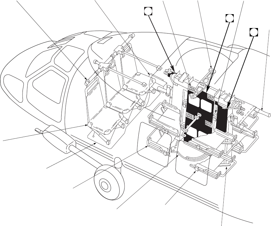
pedestal, until pivot shaft is fully inserted into pivot shaft
hole on pedestal and handle lock is engaged.
(5) Repeat step (3) for other end of litter support.
4.25.4 Litter Support Removal. Removal of the litter
support is the reverse of installation. Before removal, any
litters on the support should be removed and belts unlocked.
If IV or oxygen is installed, make certain hoses are not
tangled with supports, then proceed as required.
4.25.5 Medevac Seats Installation. The seat installa-
tion consists of three of the troop seats that were removed
for medevac system installation. Install required number of
seats at station 271.0.
4.25.6 Litter Loading and Unloading. Litters can be
loaded and unloaded laterally, directly onto the litter sup-
ports, from either side of the helicopter. Whenever rescue
hoist and medevac kit are installed simultaneously, the up-
per, right litter support should be removed from the aircraft.
The lower, right support may be stowed if not actually in
use. The lower right litter support shall be installed in the
lowest position and used when transporting more than two
litter patients or when conducting hoist operations with a
stokes litter. Loading of a stokes litter patient may be fa-
cilitated by rotating the litter pedestal approximately 30 de-
grees from the fly position. When returning the pedestal to
the fly position the aft right corner of the litter support must
be lifted to prevent interference with the lower hoist mount
SA
AA0371_1
60 Hz FREQUENCY
CONVERTER LITTER LIGHT
(TYPICAL 8) CEILING
SUPPORT LITTER RESTRAINT
BELTS (TYPICAL 8)
LITTER
UPPER TROOP SEATS
SUPPORT
TROOP
SEATS
TROOP SEATS
FLOOR PLATE
LITTER SUPPORT
(TYPICAL 4)
FLOOR
SUPPORT
PLATE
LITTER RESTRAINT
BELT FITTING (TYPICAL 8)
END PIVOT SHAFT
LEVER (TYPICAL 8)
1
2
3
Figure 4-29. Medevac and Seat System (Sheet 1 of 5)
TM 1-1520-237-10
4-61
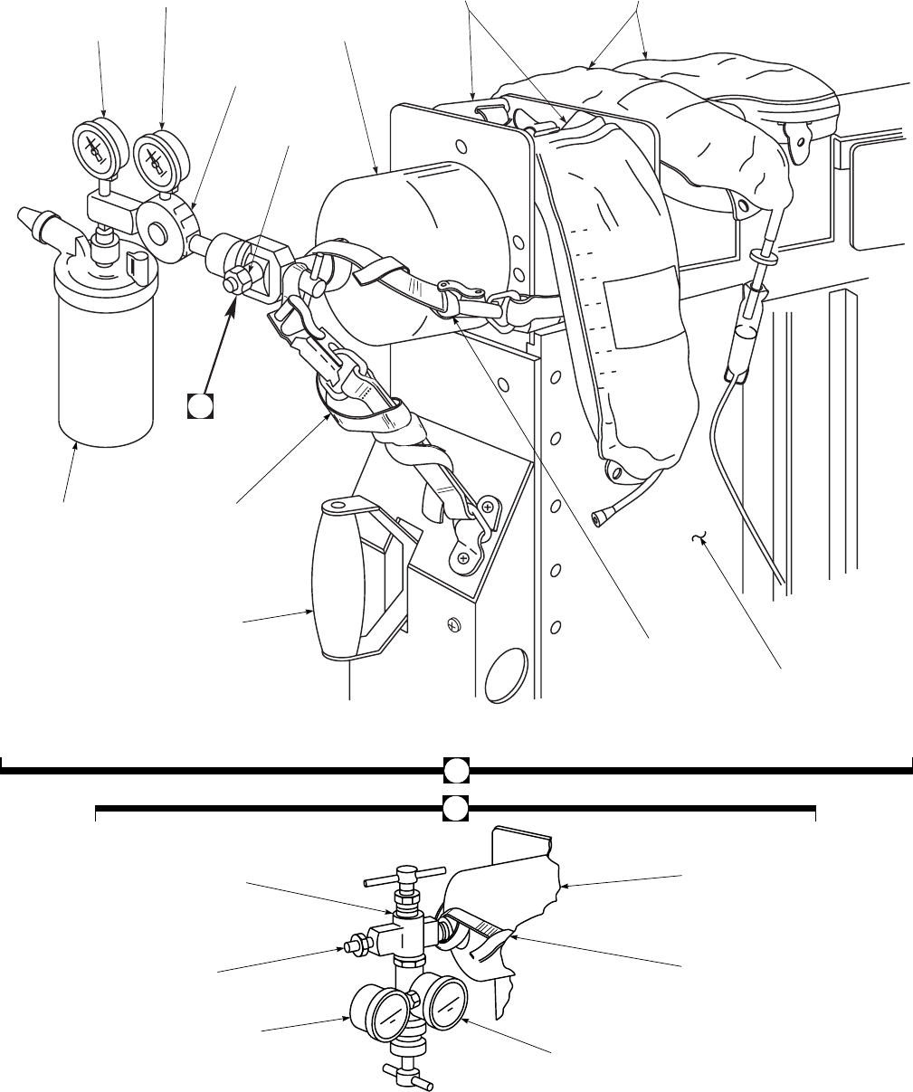
SA
AA0371_2
3
4
5
6
7
8
9
UPPER LITTER
IV BAGS
LOWER LITTER
IV BAGS
PRESSURE
GAGE
FLOW
GAGE
OXYGEN
REGULATOR
OXYGEN TANK
SHUTOFF VALVE
OXYGEN
TANK
A
OXYGEN
HUMIDIFIER LITTER
TIEDOWN
STRAP
ROTATION
RELEASE
LOCK HANDLE
OXYGEN TANK
RESTRAINT STRAP CENTER
PEDESTAL
IC636H 4
ALTERNATE OXYGEN REGULATOR INSTALLATION
TYPICAL IV/OXYGEN TANK INSTALLATION
(SAME AS OTHER END OF PEDESTAL)
1
OXYGEN REGULATOR
OXYGEN TANK
SHUTOFF VALVE
FLOW GAGE
OXYGEN TANK
OXYGEN TANK
RESTRAINT STRAP
PRESSURE GAGE
A
Figure 4-29. Medevac and Seat System (Sheet 2 of 5)
TM 1-1520-237-10
4-62
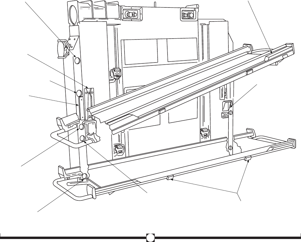
bracket. To load and unload litter patients, assuming the
medevac kit is in the flight position (litters along longitu-
dinal axis), do this:
1. Both cabin doors - Open.
2. Pedestal rotation lock release handle - Pull
handle and turn pedestal clockwise 90° (viewed
from above). On helicopters with extended ex-
ternal range fuel tanks installed, the pedestal
will rotate only 60° from center line for loading
litter patients.
3. Release lock handle while turning pedestal.
Pedestal will automatically lock in a lateral po-
sition for loading and unloading.
4. Release both litter support end pivot shaft on
upper litters. Disengage pivot lever locks and
move levers away from pedestal. Hold support
with opposite hand. Release lever. End pivot
shafts should rest on fitting at hole. Litter sup-
port is now ready to be loaded from either side.
Select side desired. Move end pivot release le-
ver about 1 inch more to compress the shaft
SA
AA0371_3
2
LITTER PIN IN LOAD UNLOAD (TILT) POSITION
(SAME AT OTHER SIDE OF PEDESTAL)
LITTER FEET
WOOD STOPS
UPPER SUPPORT PIVOT HOLE
(PROVISIONAL 6 LITTER)
SUPPORT RESTRAINT
SPLIT GUIDE
UPPER SUPPORT END
SHAFT HOLE (4 LITTER)
GUIDE PLATE
LITTER SUPPORT
TILT STOP BRACKET
LOWER LITTER SUPPORT
RESTRAINT BELT
LOWER SUPPORT END SHAFT
HOLE (4 LITTER)
CENTER SUPPORT
END SHAFT HOLE
(PROVISIONAL)
LITTER SUPPORT
HOLE AMBULATORY
PATIENT SEAT
(EMERGENCY)
Figure 4-29. Medevac and Seat System (Sheet 3 of 5)
TM 1-1520-237-10
4-63
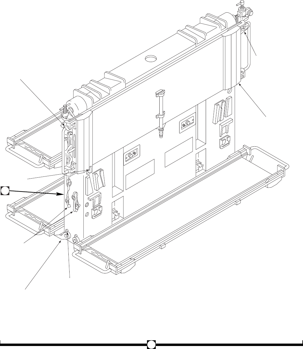
SA
AA0371_4
LITTER SUPPORT STOWAGE
LITTER SUPPORT
STOWAGE STRAP
UPPER STOWAGE
ASSEMBLY
SUPPORT STOWAGE
STRAPS STOWED
STOWAGE
ASSEMBLY
PIN
STOWED LITTER
SUPPORT
SUPPORT STOWAGE
STRAP IN USE
LOWER STOWAGE
ASSEMBLY
4
3
Figure 4-29. Medevac and Seat System (Sheet 4 of 5)
TM 1-1520-237-10
4-64
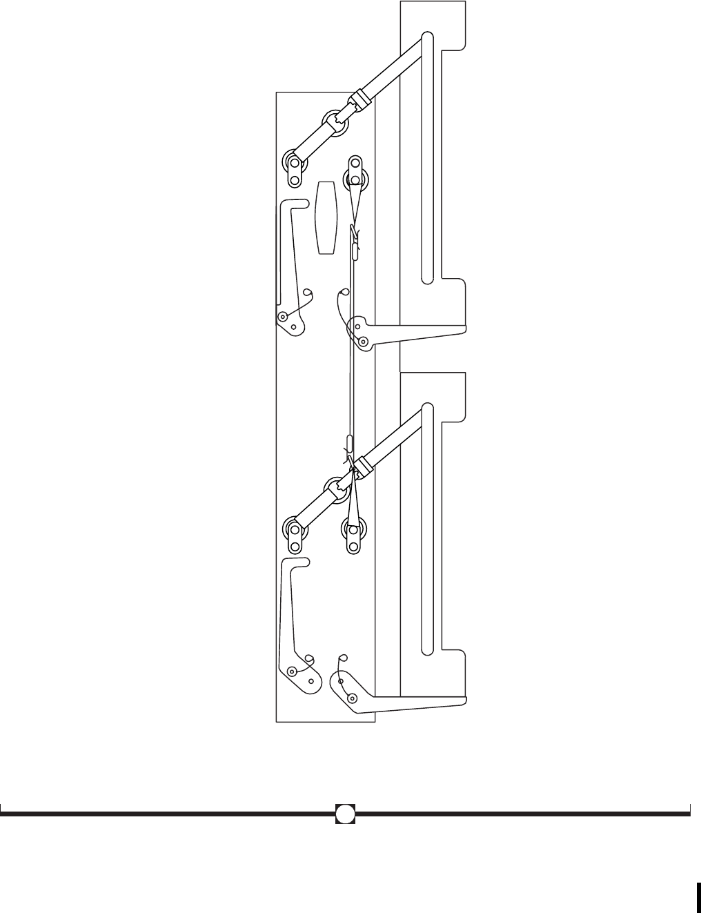
SA
AB0860
STOWAGE ASSEMBLY STOWED LITTER SUPPORTS STOWED
WITH CROSS STRAPS
LEFT SIDE SHOWN RIGHT SIDE SHOWN
4
Figure 4-29. Medevac and Seat System (Sheet 5 of 5)
TM 1-1520-237-10
Change 3 4-65

springs, which allows the shaft to clear the end
guide and the litter support to be lowered at the
end. During the lowering, release pivot shaft
lever to allow pivot shaft spring to push shaft
onto lower stop fitting.
5. Using two persons (one each side or end) -Place
litter with patient on end of upper support and
push litter into position. Note that litter feet
must be trapped between wood stops on litter
support. If three or more patients are to be
loaded, the upper supports must be loaded first.
The reverse applies to unloading.
6. To tilt upper litter support end, pull shaft lever
lock and move lever away from pedestal at sup-
port end which is being raised. Pivot litter sup-
port to level position until pivot shaft holes are
lined up with pivot shafts. Move levers toward
pedestal until shaft is fully inserted into shaft
holes and handle locks are engaged.
7. Lower litters - Using two persons (one each
side or end) place litter with patient on end of
support and push litter into position. Note that
litter feet must be trapped between wood stops
on litter support.
8. Litter straps - Extend straps (on pedestal) and
engage in buckle on litter supports. Pull straps
out uniformly to engage; partial pulling will re-
quire complete retraction of the belt to disen-
gage belt lock.
9. Pedestal rotation lock handle - Pull and turn
pedestal counterclockwise 90° (viewed from
above) into flight position (longitudinal axis),
and release handle.
10. Cabin doors - Close.
11. Unloading is reverse of loading after litter
straps are removed and oxygen and IV tubes
are checked to make certain tangling will not
occur with litter or support.
4.25.7 IV Bags and Oxygen Tanks Installation.
CAUTION
The pilot must be advised when oxygen is
on board, its use must be per the Surgeon
General’s directives, and must have oxy-
gen regulators attached.
Provisions for IV bags and oxygen tanks are on the top
of the pedestal at each end. Four IV bags may be attached
to each IV/oxygen assembly (Figure 4-29). IV bag hooks at
the outer end of the assembly are used for the lower litters
and the inner hooks are used for the upper litters. Eyelets at
the top of the bag are placed on the IV hooks and the bags
are hung downward. To prevent damage to IV bags, check
clearance between transmission drip pan drain tube clamps
and installed IV bags. Flow adjustment and replacement
will be done by the medical attendant. Oxygen tanks are
inserted into the assembly, bottom first. A restraint strap is
provided to prevent the tank from falling out during normal
maneuvering during flight. The strap is placed across the
regulator in a manner and routed as shown in Figure 4-29,
to prevent the restraint strap from slipping. The strap ends
are attached and drawn tight to keep the tank secure.
4.25.8 Litter Support Stowage.
WARNING
Storage of the litter support in the upper
level stowed position can be dangerous
during a crash sequence due to the release
of the litter support from the carousel.
Advise storage in this manner be avoided.
Maintain this litter support in the in-
stalled position or place in the back of the
carousel in the ambulatory level if there
are no occupants along the aft bulkhead
(Row 5).
The litter supports may be stowed along the center ped-
estal on each side, one above the other (Figure 4-29). Stow-
age brackets at each end of the pedestal provide lower sup-
port of the supports, and prevent the supports from moving
away from the pedestal. Web straps attached to rings are
used to hold the upper ends of the supports to the pedestal.
Pins are used to hold the stowage brackets in a stowed
position against the pedestal end. Two brackets are pro-
vided for each litter support. The top support must be
stowed first, then the lower support. For reinstallation the
sequence is reversed.
1. Lower the stowage support arm to the horizon-
tal position and insert the support arm stowage
pin through the support arm and into the center
pedestal.
TM 1-1520-237-10
4-66 Change 7
NOTE
Improper positioning of the support arm
stowage pin reduces the holding capability
of the support arm, which may cause the
support arm to shear its pivot bolt during a
hard landing or aircraft mishap.
2. Place the litter pan in the stowed position, with
the top of the litter pan against the center ped-
estal and the pivot support arm properly
stowed.
3. Secure the litter pan to the center pedestal by
routing the opposite side web strap around the
upper portion of the litter pan handle. Secure
the metal clasp to the metal ring and tighten the
web strap. (Use of the opposite side web strap
will reduce excess movement of the litter pan
while stowed).
4. If only one upper litter pan is to be stowed, as
in step 3, additional security may be added by
routing the same side web strap around the
lower portion of the litter pan handle and fas-
tening the web strap.
CAUTION
Do not store equipment between the
stowed litter pan and the center pedestal.
5. The lower litter pan will be stowed in the same
manner as in steps 1 through 3. The same side
web strap may be used to secure the lower por-
tion of the litter pan as in step 4 if only one
lower litter is to be stowed.
6. Removal of stowed litter pans is accomplished
in the reverse order of steps 1 through 4.
4.26 APU INLET PARTICLE SEPARATOR (IPS) KIT
(HELICOPTERS WITH IPS KIT INSTALLED).
The APU IPS Kit provides APU inlet air filtration via a
centrifugal particle separator unit. The separator is attached
to the APU radial inlet housing and provides for collection
and overboard exhausting of scavenge particles. The pas-
sive separator operation employs APU bleed air to drive an
ejector pump used for particle scavenging. The IPS kit is
designed to be physically compatible with both HIRSS and
non-HIRSS helicopters with the T-62T-40-1 series 200/300
APU installations only. The kit consists of three categories
of removable components:
a. Air particle separator assembly.
b. APU modification kit - Parts required to modify the
APU to accept the separator assembly.
c. Airframe provisions - Parts required to install the
separator assembly and provide bleed air supply and scav-
enge exhaust provisions.
4.27 SNOW SKIS.
Landing gear skis are constructed of fiberglass-
reinforced plastic, and attached to the landing gear axle.
The skis have spring cylinders and check cables to retain
the ski in a 5° nose up attitude during flight.
CAUTION
Installation of skis requires removal of
landing gear wire cutters and severely de-
grades the aircraft wire strike capability.
Upon removal of skis, wire strike hard-
ware shall be reinstalled, restoring air-
craft to standard configuration prior to
next flight.
Cockpit entry/exit paths are partially re-
stricted by the main skis making cockpit
entry/exit slightly more difficult. Addi-
tionally, the cabin entry/exit doors are
partially restricted making the loading/
unloading of cargo slightly more difficult.
NOTE
The hinged main gear ski shall only be used
on the right landing gear of helicopters
equipped with rescue hoists. The hinged ski
is equipped with a retraction cable. This
cable may be removed if it interferes with
the hoist, or other equipment, and alternative
retraction methods, such as a gaff, may be
used.
TM 1-1520-237-10
Change 9 4-67/(4-68 Blank)

CHAPTER 5
OPERATING LIMITS AND RESTRICTIONS
Section I GENERAL
5.1 PURPOSE.
This chapter identifies or refers to all important operat-
ing limits and restrictions that shall be observed during
ground and flight operations.
5.2 GENERAL.
The operating limitations set forth in this chapter are the
direct results of design analysis, tests, and operating expe-
riences. Compliance with these limits will allow the pilot to
safely perform the assigned missions and to derive maxi-
mum use from the aircraft.
NOTE
EH See current Interim Statement of Airwor-
thiness Qualification for operating limits and
restrictions for EH-60A helicopters.
See current Interim Statement of Airworthi-
ness Qualification for operating limits and
restrictions for UH-60L helicopters 96-
26723 and subsequent.
5.3 EXCEEDING OPERATIONAL LIMITS.
Any time an operational limit is exceeded an appropriate
entry shall be made on DA Form 2408-13-1. Entry shall
state what limit or limits were exceeded, range, time be-
yond limits, and any additional data that would aid mainte-
nance personnel in the maintenance action that may be re-
quired. The helicopter shall not be flown until corrective
action is taken.
5.4 MINIMUM CREW REQUIREMENTS.
The minimum crew required to fly the helicopter is two
pilots. Additional crewmembers as required will be added
at the discretion of the commander, in accordance with per-
tinent Department of the Army regulations.
TM 1-1520-237-10
Change 6 5-1

Section II SYSTEM LIMITS
5.5 INSTRUMENT MARKING COLOR CODES.
NOTE
Instrument/color markings may differ from
actual limits.
Operating limitations are shown as side arrows or col-
ored strips on the instrument face plate of engine, flight and
utility system instruments (Figures 5-1, 5-2, and 5-3). Those
readings are shown by ascending and descending columns
of multicolor lights (red, yellow and green) measured
against vertical scales. RED markings indicate the limit
above or below which continued operation is likely to cause
damage or shorten component life. GREEN markings indi-
cate the safe or normal range of operation. YELLOW
markings indicate the range when special attention should
be given to the operation covered by the instrument.
5.6 ROTOR LIMITATIONS.
It is not abnormal to observe a % RPM 1 and 2speed
split during autorotational descent when the engines are
fully decoupled from the main rotor. A speed increase of
one engine from 100% reference to 103% maximum can be
expected. During power recovery, it is normal for the en-
gine operating above 100% RPM to lead the other engine.
Refer to Figure 5-1 for limitations.
5.6.1 Rotor Start and Stop Limits. Maximum wind
velocity for rotor start or stop is 45 knots from any direc-
tion.
5.6.2 Rotor Speed Limitations. Refer to Figure 5-1
for rotor limitations. Power off (autorotation) rotor speeds
up to 120% RPM R are authorized for use by maintenance
test flight pilots during autorotational RPM checks.
5.7 MAIN TRANSMISSION MODULE LIMITATIONS.
a. Oil pressure should remain steady during steady state
forward flight or in level hover. Momentary fluctuations in
oil pressure may occur during transient maneuvers (i.e.
hovering in gusty wind conditions), or when flying with
pitch attitudes above +6°. These types of oil pressure fluc-
tuations are acceptable, even when oil pressure drops into
the yellow range (below 30 psi). Oil pressure should remain
steady and should be in the 45 to 55 psi range for the
UH-60A/EH-60A, and 45 to 60 psi range for the UH-60L,
to ensure that when fluctuations occur they remain in the
acceptable range as defined above. If oil pressure is not
steady during steady state forward flight or in a level hover,
or if oil pressure is steady but under 45 psi, make an entry
on Form 2408-13-1. Sudden pressure drop (more than 10
PSI) without fluctuation requires an entry on Form 2408-
13-1.
b. A demand for maximum power from engines with
different engine torque factors (ETF) will cause a torque
split when the low ETF engine reaches TGT limiting. This
torque split is normal. Under these circumstances, the high
power engine may exceed the dual engine limit. (Example:
#1 TRQ = 96% at TGT limiting, #2 TRQ is allowed to go
up to 104%. Total aircraft torque = (96%+104%)/2 =
100%).
c. With transmission oil temperature operation in the
precautionary range, an entry should be made on DA Form
2408-13-1 except when hovering in adverse conditions de-
scribed in Chapter 8 Desert and Hot Weather Operations.
TM 1-1520-237-10
5-2 Change 3
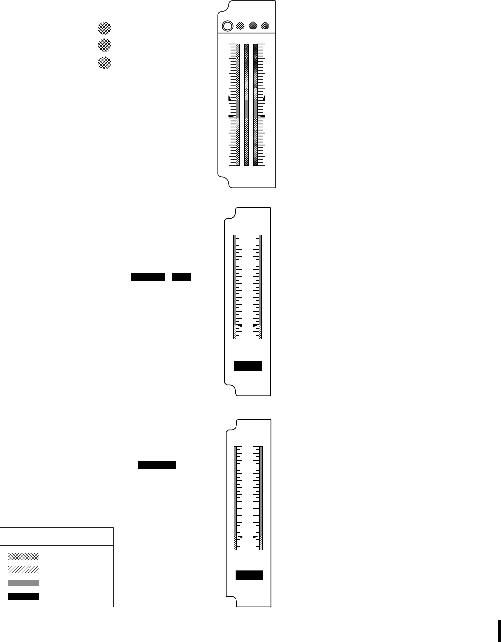
MAIN ROTOR
OVERSPEED
127%
137%
142%
***
**
*
12−SECOND
TRANSIENT
TRANSIENT
CONTINUOUS
TRANSIENT
105% − 107%
101% − 105%
95% − 101%
91% − 95%
TRANSIENT
CONTINUOUS
TRANSIENT
MAXIMUM
TRANSIENT
NORMAL
110%
105% − 110%
90% − 105%
101% − 107%
95% − 101%
91% − 95%
POWER OFF (AUTOROTATION)
POWER ON
TEST RTR
% RPM
OVERSPEED
*** ***
ENGINE % RPM 1−2
MAIN ROTOR % RPM R
LEGEND
RED
YELLOW
GREEN
DIGITAL READOUT
SA
AA8670_1B
0
2
4
6
8
10
12
14
12
TOTAL
QTY
LB X 100
FUEL
FUEL
FUEL QUANTITY
NORMAL 200 − 1500 LBS
PRECAUTIONARY 0 − 200 LBS
MAIN
FUEL
FUEL QUANTITY
NORMAL
PRECAUTIONARY
200 − 1500 LBS
0 − 200 LBS
AVOID OPERATIONS IN 20% − 40%
AND 60% − 90% RANGE EXCEPT
DURING START AND SHUTDOWN
QTY
LB X 100
FUEL
12R
12R130
120
110
105
95
90
70
30
0
100
0
95
90
70
30
130
120
110
105
100
0
2
4
6
8
10
12
14
12
UH60A EH
UH−60L
Figure 5-1. Instrument Markings (Sheet 1 of 2)
TM 1-1520-237-10
Change 10 5-3
SA
AA8670_2A
020
KNOTS
193 KNOTS
MAXIMUM
REFER TO SECTION V FOR
ADDITIONAL AIRSPEED
LIMITATIONS
AIRSPEED
250
200
150 100
50 10
0
10
20
30
40
DN
O
F
F
STAB
POS
DEG
S
T
A
B
D
E
G
0o
10o
20o
30o
40o
150
100
80
60
45
KIAS
LIMIT
Figure 5-1. Instrument Markings (Sheet 2 of 2)
TM 1-1520-237-10
5-4
SA
AA8671_1A
SPEED
% X 10
Ng
Ng
TEMP
C X 10 PRESS
PSI X 10
4
8
10
12
14
5
6
7
8
9
1212
ENG OIL
ENGINE OIL
PRESSURE
CONTINUOUS 20 − 100
PSI*
* 35 PSI MINIMUM AT 90% Ng AND ABOVE
30−MINUTE LIMIT
CONTINUOUS
ENGINE OIL
TEMPERATURE
135
50
−135OC
−
150OC
−
10−SECOND
TRANSIENT 102% − 105%
ENGINE Ng
30−MINUTE
LIMIT 99% − 102%
CONTINUOUS 0 − 99%
LEGEND
RED
YELLOW
GREEN
DIGITAL
READOUT
11
10
9
8
7
4
0
12
11
13
1
2
3
4
0
−4
18 700
Figure 5-2. Instrument Markings (Sheet 1 of 2) 700
TM 1-1520-237-10
Change 10 5-5
SA
AA8671_2C
TGT
TGT
TEMP
XMSN
TEMP
OC X 10 PRESS
PSI X 10
10−SECOND
TRANSIENT
START ABORT
LIMIT
30−MINUTE
LIMIT
NORMAL
850 − 886OC
850OC
775 − 850OC
538 − 775OC
TURBINE GAS
TEMPERATURE
100% − 125%
110% − 135%
CONTINUOUS
SINGLE−ENGINE
ONLY
0% − 100%
ENGINE % TRQ
CONTINUOUS
DUAL−ENGINE
0% − 110%
MAIN TRANSMISSION
OIL PRESSURE
PRECAUTIONARY 65 − 130 PSI
CONTINUOUS
IDLE AND
TRANSIENT 20 − 30 PSI
30 − 65 PSI
MAIN TRANSMISSION
OIL TEMPERATURE
PRECAUTIONARY
CONTINUOUS
105
50
−105OC
−
120OC
−
UH60A EH
700
700
10−SECOND
TRANSIENT
DUAL−ENGINE
SINGLE−ENGINE
% TRQ
140
120
100
80
60
40
20
0
140
120
100
80
60
40
20
0
12
12
OC X 100
9
8
7
6
5
4
2
0
12
19
11
7
6
5
4
3
0
−4
0
4
6
8
10
12
16
Figure 5-2. Instrument Markings (Sheet 2 of 2)
TM 1-1520-237-10
5-6 Change 10
SA
AA8672_1B
ENGINE % TRQ
DUAL−ENGINE
SINGLE−ENGINE
CONTINUOUS
SINGLE−ENGINE
DUAL−ENGINE
135% − 144%
0% − 135%
10−SECOND TRANSIENT
ABOVE 80 KIAS
AT OR BELOW 80 KIAS 0% − 100%
0% − 120%
ABOVE 80 KIAS
80 KIAS OR BELOW 100% − 144%
120% − 144%
NOTE
HELICOPTERS PRIOR TO S / N 91−26354 THAT
ARE NOT EQUIPPED WITH IMPROVED MAIN
ROTOR FLIGHT CONTROLS ARE FURTHER
RESTRICTED ABOVE 80 KIAS TO DUAL−
ENGINE CONTINUOUS TORQUE LIMITS
AS INDICATED BY A PLACARD ON THE
INSTRUMENT PANEL. SEE FIGURE 5−4.
TURBINE GAS
TEMPERATURE
10−SECOND
TRANSIENT
2.5−MINUTES
TRANSIENT
(CONTINGENCY
POWER)
START ABORT LIMIT
10−MINUTE
LIMIT
30−MINUTE
LIMIT
NORMAL
903 949OC
−
878 903OC
−
851 878OC
−
810 851OC
−
538 810OC
−
851OC
LEGEND
RED
YELLOW
GREEN
DIGITAL READOUT
TEMP
OC X 100
TGT
TGT
9
8
7
6
5
4
2
0
12
% TRQ
12
140
120
100
80
60
40
20
0
140
120
100
80
60
40
20
0
12
Figure 5-3. Instrument Markings (Sheet 1 of 2) 701C
TM 1-1520-237-10
Change 10 5-7
SA
AA8672_2C
SPEED
% X 10
Ng
Ng
ENGINE OIL
PRESSURE
5−MINUTE
LIMIT
NORMAL OPERATION
IDLE
100 − 120 PSI
26 − 100 PSI
22 − 26 PSI
30−MINUTE LIMIT
CONTINUOUS
ENGINE OIL
TEMPERATURE
135
50
−135OC
−
150OC
−
MAIN TRANSMISSION
OIL TEMPERATURE
PRECAUTIONARY
CONTINUOUS
105
50
−105OC
−
140OC
−
MAIN TRANSMISSION
OIL PRESSURE
PRECAUTIONARY 65 − 130 PSI
CONTINUOUS
IDLE AND
TRANSIENT 20 − 30 PSI
30 − 65 PSI
10−SECOND
TRANSIENT 102% − 105%
ENGINE Ng
30−MINUTE
LIMIT 99% − 102%
CONTINUOUS 0 − 99%
11
10
9
8
7
4
0
12
XMSN
TEMP
OC X 10 PRESS
PSI
190
110
70
60
50
40
30
0
−4
0
4
6
8
10
12
16
ENG OIL
TEMP
OC X 10 PRESS
PSI
18
14
12
10
8
4
0
−4
20
12
30
50
70
90
100
120
170
1212
UH60L
701C
Figure 5-3. Instrument Markings (Sheet 2 of 2)
TM 1-1520-237-10
5-8 Change 10

Section III POWER LIMITS
5.8 ENGINE LIMITATIONS.
5.8.1 Engine Power Limitations. 700 The limitations
which are presented in Figure 5-2, present absolute limita-
tions, regardless of atmospheric conditions. For variations
in power available with temperature and pressure altitude,
refer to the TORQUE AVAILABLE charts in Chapter 7.
5.8.2 Engine Power Limitations. 701C
a. The limitations which are presented in Figure 5-3,
present absolute limitations regardless of atmospheric con-
ditions. For variations in power available with temperature
and pressure altitude, refer to TORQUE AVAILABLE
charts in Chapter 7A.
b. Helicopters prior to S/N 91-26354 that are not
equipped with improved main rotor flight controls are fur-
ther restricted above 80 KIAS to dual-engine continuous
torque limits as indicated by a placard on the instrument
panel . See Figure 5-4.
5.8.3 Engine % RPM Limitations. Transient % RPM
1or 2operation in yellow range (101% to 105%) is not
recommended as good operating practice. However no
damage to either engine or drive train is incurred by opera-
tion within this range. Momentary transients above 107%
Np are authorized for use by maintenance test pilots during
autorotational rpm checks.
5.8.4 Engine Starter Limits.
a. The pneumatic starter is capable of making the num-
ber of consecutive start cycles listed below, when exposed
to the environmental conditions specified, with an interval
of at least 60 seconds between the completion of one cycle
and the beginning of the next cycle. A starting cycle is the
interval from start initiation and acceleration of the com-
pressor, from zero rpm, to starter dropout. The 60-second
delay between start attempts applies when the first attempt
is aborted for any reason, and it applies regardless of the
duration of the first attempt. If motoring is required for an
emergency, the 60-second delay does not apply.
b. At ambient temperatures of 15°C (59°F) and below,
two consecutive start cycles may be made, followed by a
3-minute rest period, followed by two additional consecu-
tive start cycles. A 30-minute rest period is then required
before any additional starts.
c. At ambient temperatures above 15° up to 52°C (59°
up to 126°F), two consecutive start cycles may be made. A
30-minute rest period is then required before any additional
start cycles.
5.9 PNEUMATIC SOURCE INLET LIMITS.
The minimum ground-air source (pneumatic) required to
start the helicopter engines is 40 psig and 30 ppm at 149°C
(300°F). The maximum ground-air source to be applied to
the helicopter is 50 psig at 249°C (480°F), measured at the
external air connector on the fuselage.
5.10 ENGINE START LIMITS.
CAUTION
Engine start attempts at or above a pres-
sure altitude of 18,000 feet 701C ,or
20,000 feet 700 could result in a Hot Start.
Crossbleed starts shall not be attempted unless the anti-
ice light is off, and operating engine must be at 90% Ng
SPEED or above and rotor speed at 100% RPM R. When
attempting single-engine starts at pressure altitudes above
14,000 feet, press the start switch with the ENG POWER
CONT lever OFF, until the maximum motoring speed
(about 24%) is reached, before going to IDLE. Engine
starts using APU source may be attempted when within the
range of FAT and pressure altitude of Figure 5-5.
5.11 ENGINE OVERSPEED CHECK LIMITATIONS.
Engine overspeed check in flight is prohibited. Engine
overspeed checks, on the ground, are authorized by desig-
nated maintenance personnel only.
5.12 FUEL LIMITATIONS.
When using all fuel types, both fuel boost pumps shall
be on and operational, otherwise engine flameout may re-
sult.
TM 1-1520-237-10
Change 6 5-9
SA
AA1641A
UH−60L DUAL−ENGINE TORQUE LIMITS − % TORQUE
FAT, O C −20 −10 0 10 20 30 40 50
PRESSURE ALT 1000 FT
FAT, O C
FAT, O C −10 0 10 20 30 40 50 FAT, O C
PRESSURE ALT 1000 FT
60
66
72
79
86
93
20
18
16
14
12
10
8
6
5
4
3
58
63
69
75
82
89
97
56
61
66
73
79
85
93
53
59
64
70
76
83
90
97
51
56
61
67
73
80
86
93
97
49
54
59
65
70
77
83
90
93
97
48
52
57
62
68
74
81
87
90
94
97
46
50
55
60
66
71
77
83
87
91
95
20
18
16
14
12
10
8
6
5
4
3
−20
100
100% TORQUE 2000 FT & BELOW
HELICOPTERS PRIOR TO S / N 91−26354 NOT EQUIPPED WITH IMPROVED MAIN ROTOR FLIGHT CONTROLS.
Figure 5-4. Dual-Engine Torque Limitations at Airspeeds Above 80 KIAS 701C
TM 1-1520-237-10
5-10
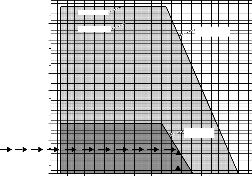
SA
AA0700A
ENGINE START ENVELOPE
FREE−AIR TEMPERATURE ~ OC
EXAMPLE
WANTED
KNOWN
METHOD
IF TWO−ENGINE START CAN BE
DONE AT 2900 FEET PRESSURE
ALTITUDE AND 16 OC
PRESSURE ALTITUDE =
ENTER CHART AT PRESSURE
ALTITUDE 2900 FEET
MOVE RIGHT TO INTERSECT
VERTICAL TEMPERATURE LINE.
IF LINES INTERSECT WITHIN DARK
SHADED AREA, TWO−ENGINE
START CAN BE DONE.
PRESSURE ALTITUDE ~ FEET X 1000
2900 FEET
FREE−AIR TEMPERATURE = 16 OC
−60 −50 −40 −30 −20 −10 0 10 20 30 40 50 60
700 ALT LIMIT
701C ALT LIMIT SINGLE ENGINE
START LIMIT
DUAL ENGINE
START LIMIT
0
2
4
6
8
10
12
14
16
18
20
Figure 5-5. Engine Start Envelope
TM 1-1520-237-10
5-11

Section IV LOADING LIMITS
5.13 CENTER OF GRAVITY LIMITATIONS.
Center of gravity limits for the aircraft to which this
manual applies and instructions for computation of the cen-
ter of gravity are contained in Chapter 6.
5.14 WEIGHT LIMITATIONS.
AIRCRAFT MAXIMUM WEIGHT
UH-60A 20,250
EH-60A 20,250
UH-60A (see paragraph 1) 22,000
EH-60A (see paragraph 1) 22,000
UH-60L 22,000
UH-60A/L with seven lug
wheels (see paragraph 5) 20,500
UH-60L External lift mis-
sion (see paragraph 3) 23,500
ESSS aircraft on ferry
mission (see paragraph 2) 24,500
1. UH-60A and EH-60A maximum gross weight can be
extended from 20,250 pounds to 22,000 pounds only when
wedge mounted pitot-static probes and either/or MWO 55-
1520-237-50-58 or MWO 1-1520-237-50-73 are installed.
2. Airworthiness release required.
3. External lift missions above 22,000 pounds can only
be flown with cargo hook loads above 8,000 pounds and up
to 9,000 pounds.
4. Maximum weight is further limited by cargo floor
maximum capacity of 300 pounds per square foot. Refer to
Chapter 6.
5. When operating at or above gross weights of 20,500
pounds, the seven lug wheel may experience lug failure
resulting in flying debris during ground handling and/or
unexpected tire failure. The fourteen lug wheel shall be
utilized when operating at or above gross weights of 20,500
pounds.
5.15 STOWAGE PROVISIONS.
Maximum capacity for each storage compartment is 125
pounds.
5.16 CABIN CEILING TIEDOWN FITTINGS.
The four cabin ceiling tiedown fittings have a limited
load capability of 4,000 pounds.
5.17 CARGO HOOK WEIGHT LIMITATION.
For UH-60A aircraft, the maximum weight that may be
suspended from the cargo hook is limited to 8,000 pounds.
For UH-60L aircraft, the maximum weight that can be sus-
pended from the cargo hook is 9,000 pounds.
NOTE
UH-60L aircraft prior to serial number 92-
26421, will require an entry into DA Form
2408-13-1 following the first mission carry-
ing an external cargo hook load exceeding
8,000 pounds.
5.18 RESCUE HOIST WEIGHT LIMITATIONS.
The maximum weight that may be suspended from the
rescue hoist is 600 pounds.
TM 1-1520-237-10
5-12 Change 9

Section V AIRSPEED LIMITS
5.19 AIRSPEED OPERATING LIMITS.
The airspeed operating limits charts (Figures 5-6, 5-7
and 5-8) define velocity never exceed (Vne) as a function
of altitude, temperature, and gross weight. The dashed lines
represent the Mach limited airspeeds due to compressibility
effects. Additional airspeed limits not shown on the charts
are:
a. Maximum airspeed with external cargo hook loads
greater than 8,000 pounds and a corresponding gross weight
greater than 22,000 pounds will vary due to the external
load physical configuration, but shall not exceed 120 KIAS.
b. Maximum airspeed for one engine inoperative is 130
KIAS.
c. Maximum airspeed for autorotation at a gross weight
of 16,825 pounds or less is 150 KIAS.
d. Maximum airspeed for autorotation at a gross weight
of greater than 16,825 pounds is 130 KIAS.
e. Sideward/rearward flight limits. Hovering in winds
greater than 45 knots (35 knots with external ERFS) from
the sides or rear is prohibited. Sideward/rearward flight into
the wind, when combined with windspeed, shall not exceed
45 knots (35 knots with external ERFS).
f. SAS inoperative airspeed limits:
(1) One SAS inoperative - 170 KIAS.
(2) Two SAS inoperative - 150 KIAS.
(3) Two SAS inoperative in IMC - 140 KIAS.
g. Hydraulic system inoperative limits:
(1) One hydraulic system inoperative - 170 KIAS.
(2) Two hydraulic systems inoperative - 150 KIAS.
(3) Two hydraulic systems inoperative in IMC - 140
KIAS.
h. Searchlight and landing light airspeed limits.
(1) Landing light. If use is required, the landing light
must be extended prior to reaching a maximum forward
airspeed of 130 KIAS. With landing light extended, air-
speed is limited to 180 KIAS.
(2) Searchlight. If use is required, the searchlight must
be extended prior to reaching a maximum forward airspeed
of 100 KIAS. With searchlight extended, airspeed is limited
to 180 KIAS.
i.
VOL
The maximum airspeed for autorotation shall
be limited to 100 KIAS.
j. Maximum airspeed with skis installed is 155 KIAS.
5.20 FLIGHT WITH CABIN DOOR(S)/WINDOW(S)
OPEN.
The following airspeed limitations are for operating the
helicopter in forward flight with the cabin doors/window
open:
a. Cabin doors.
(1) Cabin doors may be fully open up to 100 KIAS
with soundproofing installed aft of station 379.
(2) Cabin doors may be fully open up to 145 KIAS
with soundproofing removed aft of station 379 or with
soundproofing secured properly.
(3) The doors will not be intentionally moved from the
fully open or closed position in flight. The cabin doors may
be opened or closed during hovering flight. The cabin doors
must be closed or fully opened and latched before forward
flight. Should the door inadvertently open in flight, it may
be secured fully open or closed.
b. Gunner’s window(s) may be fully open up to 170
KIAS.
c. Cockpit doors sliding windows will not be opened or
closed during flight except during hover.
d. Flight with cockpit door(s) removed is prohibited.
e.
VOL
Flight with cabin door(s) open is not autho-
rized.
5.21 AIRSPEED LIMITATIONS FOLLOWING FAIL-
URE OF THE AUTOMATIC STABILATOR CON-
TROL SYSTEM.
a. Manual control available. If the automatic stabilator
control system fails in flight and operation cannot be re-
stored:
TM 1-1520-237-10
Change 9 5-13
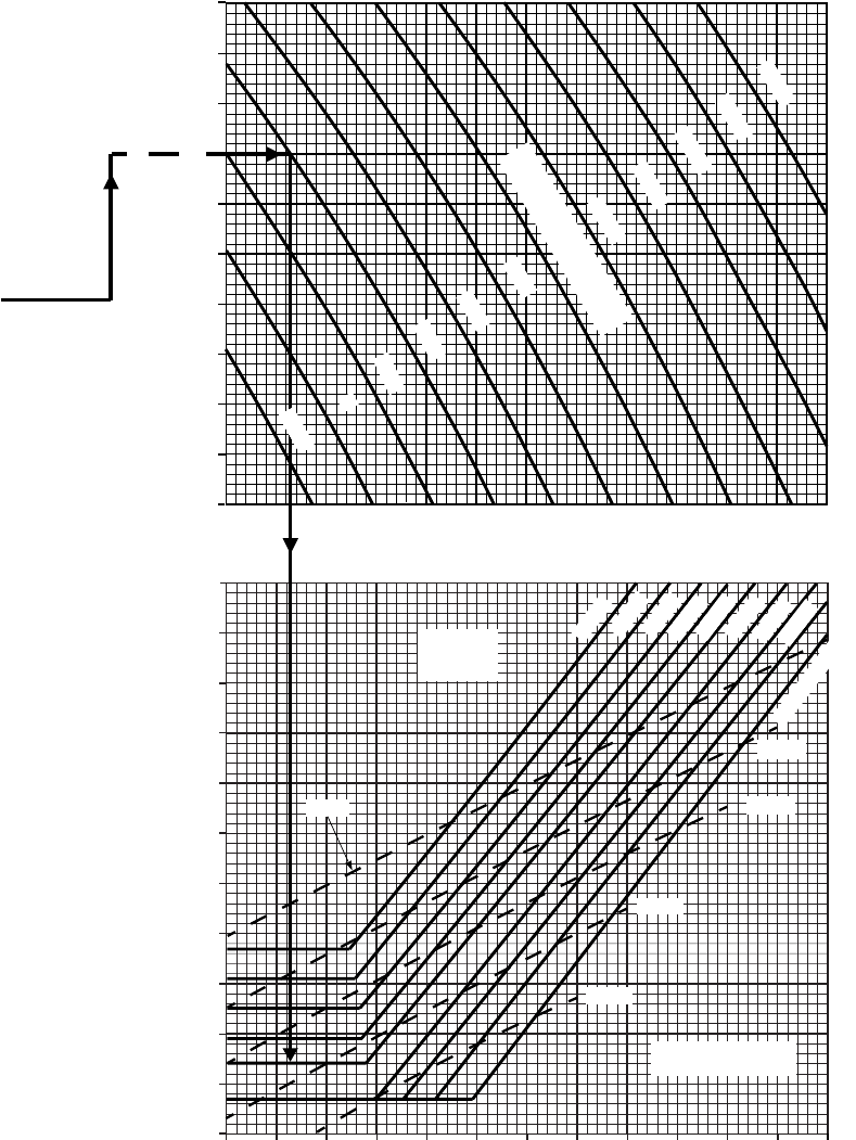
04 8121620
90
100
110
120
130
140
150
160
170
180
190
200
DENSITY ALTITUDE ~ 1000 FEET
MAXIMUM INDICATED AIRSPEED (VNE) ~ KNOTS
GROSS
WEIGHT
~ LBS
METHOD
KNOWN
WANTED
EXAMPLE
−10oC
−20oC
−30oC
−40oC
COMPRESSIBILITY
LIMITS ~ FAT
MAX IAS FOR VARIOUS
TEMPS, PRESSURE
ALTITUDE AND
GROSS WEIGHTS
FAT = − 20oC
PRESSURE ALTITUDE
= 4,000 FEET.
GROSS WEIGHT
= 18,000 POUNDS.
ENTER FAT AT −20oC.
MOVE RIGHT TO
PRESSURE ALTITUDE
4,000 FEET.
MOVE DOWN TO
18,000 POUNDS
GROSS WEIGHT
−2 2 6 10 14 18 22
AIRSPEED OPERATING LIMITATIONS
−40
−30
−10
0
10
20
30
40
50
−50
0
2000
4000
6000
8000
12000
14000
16000
18000
20000
PRESSURE ALTITUDE ~FT
10000
0
2000
4000
6000
8000
12000
14000
16000
18000
20000
−20
−2000
−20
PRESSURE ALTITUDE ~ FT
10000
22000
21000
20000
19000
17000
16000
14000 OR LESS
SA
AA1250A
−2000
−20
−2000
−20
−2000
18000
15000
−50OC
AIRCRAFT WITHOUT ESSS INSTALLED 100% RPM R
OR MACH LIMIT
FAT WHICHEVER
IS ENCOUNTERED
FIRST, IN THIS
CASE 18,000
POUNDS IS
ENCOUNTERED
FIRST. MOVE LEFT
TO READ 186
KNOTS.
FREE AIR TEMPERATURE ~OC
Figure 5-6. Airspeed Operating Limits
TM 1-1520-237-10
5-14
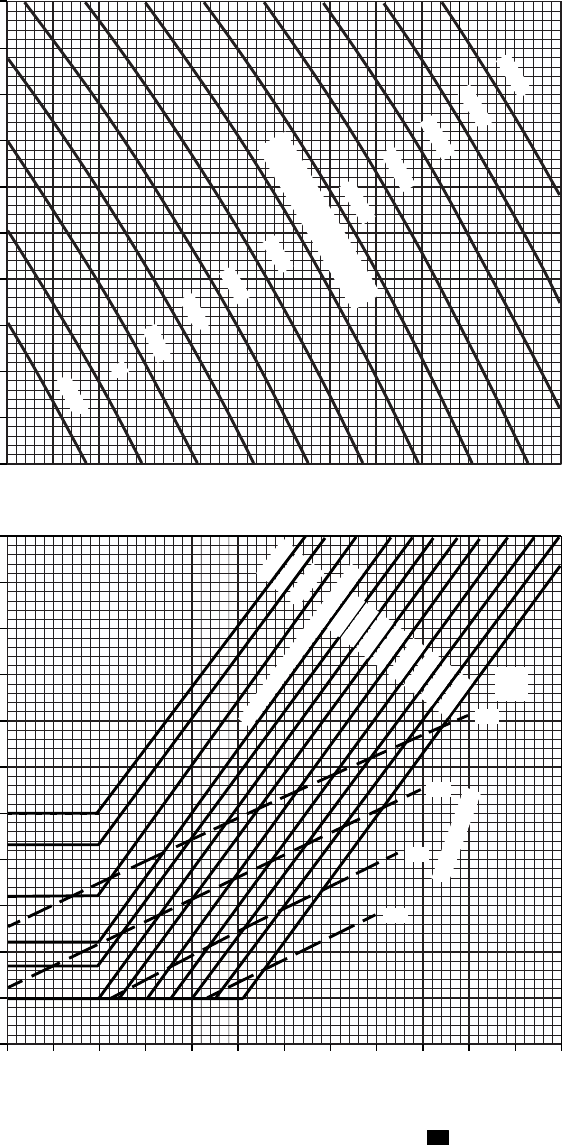
SA
AA1251B
DENSITY ALTITUDE ~ 1000 FEET
MAXIMUM INDICATED AIRSPEED ~ KNOTS
AIRSPEED OPERATING LIMITATIONS
0
2000
4000
6000
8000
12000
14000
16000
18000
20000
−2000−2000
FREE AIR TEMPERATURE ~ OC
−2000
100% RPM R
MACH LIMITS
−20
−30
−40
−50
FAT
~ OC
18000
17000
16000
15000
14000
AIRCRAFT WITH EXTERNAL STORES
SUPPORT SYSTEM INSTALLED
−2 0 2 4 6 8 10 12 14 16 18 20 22
180
170
160
150
140
130
120
110
100
90
80
70
50
40
30
20
10
0
−10
−20
−30
−40
−50
21000
20000
19000
24000
GROSS WEIGHT = 22000 LB
PRESSURE ALTITUDE ~ FT
10000
24500
23000
Figure 5-7. Airspeed Operating Limits ES
TM 1-1520-237-10
5-15
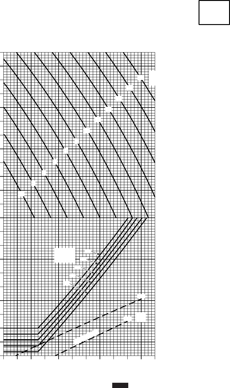
SA
AA9440
AIRSPEED OPERATING LIMITATIONS
VOLCANO MINE DESPENSING SYSTEM
100% RPM R
−2 0 2 4 6 8 10 12 14 16 18 20
150
140
130
120
110
100
90
80
70
60
14
16
18
20
22
−50
−40
50
40
30
20
10
0
−10
−20
−30
−40
−50
−60
20
18
16
14
12
10
8
6
4
2
0
−2
PRESSURE
ALTITUDE
~ 1000 FT
GROSS
WEIGHT
~ 1000 LB
FREE AIR TEMPERATURE ~
OC
MAXIMUM INDICATED AIRSPEED (VNE) ~ KTS
DENSITY ALTITUDE ~ 1000 FT
FAT
~
OC
MACH LIMIT
AIRSPEED
OPERATING
LIMITS
VOLCANO
WITH CANISTERS
Figure 5-8. Airspeed Operating Limits
VOL
(Sheet 1 of 2)
TM 1-1520-237-10
5-16
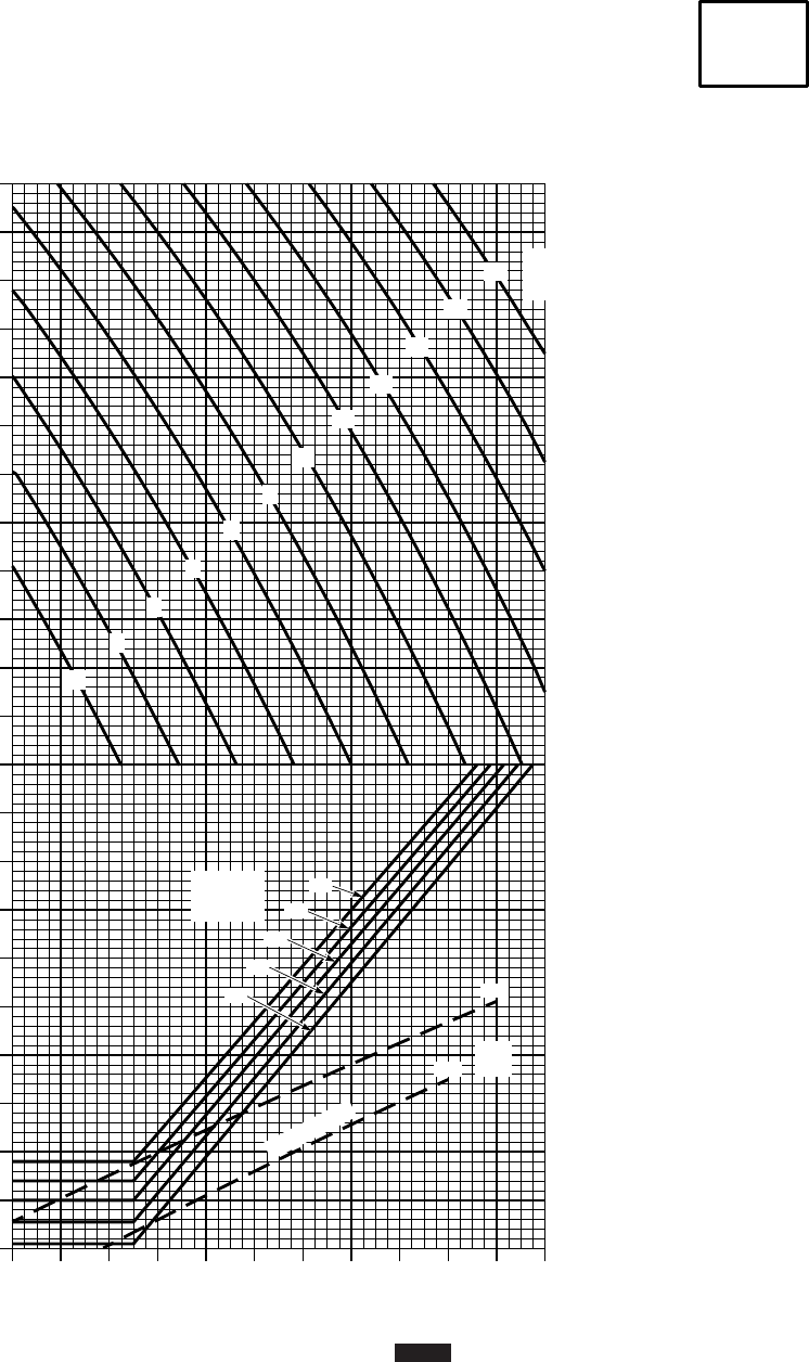
SA
AA9441
AIRSPEED OPERATING LIMITATIONS
VOLCANO MINE DESPENSING SYSTEM
100% RPM R
−2 0 2 4 6 8 10 12 14 16 18 20
150
140
130
120
110
100
90
80
70
60
−50
−40
50
40
30
20
10
0
−10
−20
−30
−40
−50
−60
PRESSURE
ALTITUDE
~ 1000 FT
FREE AIR TEMPERATURE ~
OC
MAXIMUM INDICATED AIRSPEED (VNE) ~ KTS
DENSITY ALTITUDE ~ 1000 FT
FAT
~
OC
MACH LIMIT
AIRSPEED
OPERATING
LIMITS
VOLCANO
WITHOUT CANISTERS
160
20
18
16
14
12
10
8
6
4
2
0
−2
14
16
18
20
22
GROSS
WEIGHT
~ 1000 LB
Figure 5-8. Airspeed Operating Limits
VOL
(Sheet 2 of 2)
TM 1-1520-237-10
5-17
(1) The stabilator shall be set full down at speeds be-
low 40 KIAS.
(2) The stabilator shall be set at zero degrees at speeds
above 40 KIAS.
(3) Autorotation airspeed shall be limited to 120 KIAS
at all gross weights.
b. Manual control not available. The placard airspeed
limits shall be observed as not-to-exceed speed (powered
flight and autorotation), except in no case shall the autoro-
tation limit exceed 120 KIAS.
TM 1-1520-237-10
5-18

Section VI MANEUVERING LIMITS
5.22 PROHIBITED MANEUVERS.
a. Hovering turns greater than 30° per second are pro-
hibited. Intentional maneuvers beyond attitudes of 630° in
pitch or over 60° in roll are prohibited.
b. Simultaneous moving of both ENG POWER CONT
levers to IDLE or OFF (throttle chop) in flight is prohib-
ited.
c. Rearward ground taxi is prohibited.
5.23 RESTRICTED MANEUVERS.
5.23.1 Manual Operation of the Stabilator. Manual
operation of the stabilator in flight is prohibited except as
required by formal training and maintenance test flight re-
quirements, or as alternate stabilator control in case the
AUTO mode malfunctions.
5.23.2 Downwind Hovering. Prolonged rearward flight
and downwind hovering are to be avoided to prevent accu-
mulation of exhaust fumes in the helicopter and heat dam-
age to windows on open cargo doors.
5.23.3 Maneuvering Limitations.
NOTE
Maneuvers entered from a low power setting
may result in transient droop of 5% RPM R
or greater.
a. The maneuvering limits of the helicopter, other than
as limited by other paragraphs within this section, are al-
ways defined by main rotor blade stall. Stall has not been
encountered in one G flight up to the airspeeds shown in
chart Figure 5-6 for aircraft without ESSS installed and
Figure 5-7 for aircraft with ESSS installed.
b. The blade stall chart (Figure 5-9) while not an air-
craft limitation, provides the level flight angle of bank at
which blade stall will begin to occur as a function of air-
speed, gross weight, pressure altitude and temperature.
When operating near blade stall, any increase in airspeed,
load factor (bank angle), turbulence, or abrupt control in-
puts will increase the severity of the stall. Fully developed
stall will be accompanied by heavy four per rev vibration,
increasing torque, and loss of altitude. Recovery is always
accomplished by reducing the severity of the maneuver,
that is by reducing collective, reducing airspeed, and/or re-
ducing the angle of bank. Maneuvering flight which results
in severe blade stall and significant increase in 4 per rev
vibration is prohibited.
5.23.3.1 High Speed Yaw Maneuver Limitation.
Above 80 KIAS avoid abrupt, full pedal inputs to prevent
excess tail rotor system loading.
5.23.3.2 Limitations for Maneuvering With Sling
Loads. Maneuvering limitations with a sling load is lim-
ited to a maximum of 30° angle of bank in forward flight
(Figure 5-10). Side flight is limited by bank angle and is
decreased as airspeed increases. Rearward flight with sling
load is limited to 35 knots.
5.23.3.3 Limitations for Maneuvering With Rescue
Hoist Loads. Maneuvering limitations with a rescue hoist
load is limited to maximum of 30° angle of bank in forward
flight (Figure 5-10). Side flight is limited by bank angle and
is decreased as airspeed is increased. Rearward flight with
hoist load is limited to 35 knots. Rate of descent is limited
to 1,000 feet-per-minute.
5.23.3.4 Bank Angle Limitation. Bank angles shall be
limited to 30° when a PRI SERVO PRESS caution light is
on.
5.24 LANDING GEAR LIMITATIONS.
Do not exceed a touchdown sink rate of 540 feet-per-
minute on level terrain and 360 feet-per-minute on slopes
with gross weights of up to 16,825 pounds; above 16,825
pounds gross weight 300 feet-per-minute on level terrain
and 180 feet-per-minute on slopes.
5.25 LANDING SPEED LIMITATIONS.
Maximum forward touchdown speed is limited to 60
knots ground speed on level terrain.
5.26 SLOPE LANDING LIMITATIONS.
The following slope limitations apply regardless of gross
weight or CG, with or without ESSS/ERFS.
CAUTION
When performing slope landings with Ex-
ternal Extended Range Fuel System
Tanks, ensure tank to ground clearance.
TM 1-1520-237-10
Change 8 5-19
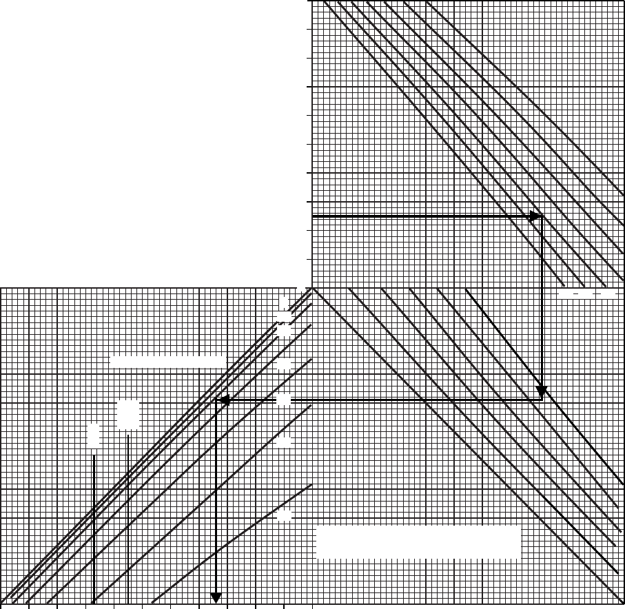
AIRSPEED FOR ONSET OF BLADE STALL
LEVEL FLIGHT 100% RPM R
24.5
22
20
16
14
18
60 40 20 0
−20
−40
−60
FAT OC
0
10
20
30
50
60
ANGLE OF BANK ~ DEG
2
4
6
8
10
12
14
16
18
20
0
PRESSURE ALTITUDE ~ 1000 FT
240 220 200 180 160 140 120 100 80 60 40
INDICATED AIRSPEED ~ KTS
WITH ESSS INSTALLED, REDUCE AIRSPEED
BY 6 KNOTS.
NOTE
40
MAX RECOMMENDED
AIRSPEED FOR KNOWN
ANGLE OF BANK
FAT = 20 OC
PRESSURE ALTITUDE
= 5,000 FEET.
GROSS WEIGHT
= 23,000 POUNDS
ANGLE OF BANK
= 20 DEGREES
ENTER PRESSURE ALTITUDE
AT 5,000 FEET. MOVE
RIGHT TO 20 DEGREES FAT.
MOVE DOWN TO GROSS
WEIGHT 23,000 POUNDS. MOVE
LEFT TO 20 DEGREES ANGLE
OF BANK. MOVE VERTICALLY
DOWN TO READ INDICATED
AIRSPEED OF 108 KNOTS.
WANTED
KNOWN
METHOD
EXAMPLE
GROSS WEIGHT ~ 1000 LBS
VNE
SA
AA1306A
VNE
ESSS
Figure 5-9. Airspeed for Onset of Blade Stall
TM 1-1520-237-10
5-20

NOTE
Because of the flat profile of the main trans-
mission and forward location of both trans-
mission oil pumps, transmission oil pressure
will drop during nose-up slope operations.
At slope angle of 10° an indicated oil pres-
sure of 30 to 35 psi is normal, and at a 15°
slope angle a pressure in the range of 10 to
15 psi is normal, due to pitching of the he-
licopter.
a. 15° nose-up, right wheel up or left wheel upslope.
The slope limitations shall be further reduced by 2° for
every 5 knots of wind.
b. 6° nose downslope. Landing in downslope condi-
tions with tail winds greater than 15 knots shall not be
conducted. A low-frequency oscillation may occur when
landing nose-down on a slope with the cyclic near the aft
stop.
c. The main gearbox may be operated up to 30 minutes
at a time with pressure fluctuations when the helicopter is
known to be at a nose-up attitude (i.e., slope landings or
hover with extreme aft CG).
d. When attempting a nose upslope landing at gross
weights in excess of 16,000 pounds with skis installed, the
parking brake may not hold the aircraft in position. The
pilot should be prepared to use the toe brakes.
e. Slope landings with skis installed are limited to 10°
nose up and right wheel or left wheel upslope.
TM 1-1520-237-10
Change 9 5-21
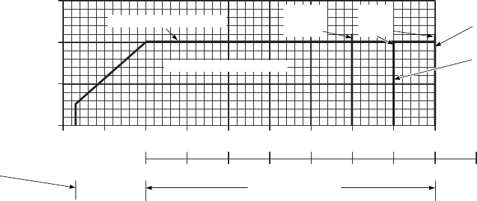
SA
AA0668A
SLING/RESCUE HOIST LOAD
MANEUVERING LIMITS
40 20 0 20 40 60 80 100 120 140
0
20
30
ANGLE OF BANK ~ O
KIAS
ANGLE OF BANK LIMITS RESCUE
HOIST
LIMITS
SLING
LOAD
LIMITS
(SLING LOAD ENVELOPE)
CROSSWIND
AND
SIDE FLIGHT
VNE FOR SLING LOAD
UP TO 8,000 POUNDS
VNE FOR EXTERNAL CARGO
SLING LOADS ABOVE 8,000
POUNDS AND CORRESPONDING
AIRCRAFT GROSS WEIGHTS IN
EXCESS OF 22,000 POUNDS
DUE TO EXTERNAL CARGO
HOOK LOAD
FORWARD FLIGHT
Figure 5-10. Sling/Hoist Load Maneuvering Limitations
TM 1-1520-237-10
5-22

Section VII ENVIRONMENTAL RESTRICTIONS
5.27 FLIGHT IN INSTRUMENT METEOROLOGICAL
CONDITIONS (IMC).
This aircraft is qualified for operation in instrument me-
teorological conditions.
5.28 FLIGHT IN ICING CONDITIONS.
a. When the ambient air temperature is 4°C (39°F) or
below and visible liquid moisture is present, icing may oc-
cur. Icing severity is defined by the liquid water content
(LWC) of the outside air and measured in grams per cubic
meter (g/m3).
(1) Trace :LWC 0 to 0.25 g/m3
(2) Light :LWC 0.25 to 0.5 g/m3
(3) Moderate :LWC 0.5 to 1.0 g/m3
(4) Heavy :LWC greater than 1.0 g/m3
b. Helicopters with the following equipment installed
and operational are permitted to fly into trace or light icing
conditions. Flight into light icing is not recommended with-
out the blade deice kit. Flight into moderate icing shall
comply with paragraph 5.28 c.
(1) Windshield Anti-ice.
(2) Pitot Heat.
(3) Engine Anti-ice.
(4) Engine Inlet Anti-ice Modulating Valve.
(5) Insulated Ambient Air Sensing Tube.
c. For flight into moderate icing conditions, all equip-
ment in paragraph 5.28 b. and blade deice kit must be in-
stalled and operational. Flight into heavy or severe icing is
prohibited.
d. Helicopters equipped with blade erosion kit are pro-
hibited from flight into icing conditions.
5.29 ENGINE AND ENGINE INLET ANTI-ICE LIMI-
TATIONS.
At engine power levels of 10% TRQ per engine and
below, full anti-ice capability cannot be provided, due to
engine bleed limitations. Avoid operation under conditions
of extreme low power requirements such as high rate of
descent (1900 fpm or greater), or ground operation below
100% RPM R, during icing conditions. The cabin heating
system should be turned off before initiating a high rate of
descent.
5.30 BACKUP HYDRAULIC PUMP HOT WEATHER
LIMITATIONS.
During prolonged ground operation of the backup pump
using MIL-H-83282 or MIL-H-5606 with the rotor system
static, the backup pump is limited to the following
temperature/time/cooldown limits because of hydraulic
fluid overheating.
FAT °C (°F) Operating Time
(Minutes) Cooldown Time
(Pump Off)
(Minutes)
-54° - 32°
(-65° - 90°) Unlimited - -
33° - 38°
(91° - 100°) 24 72
39° - 52°
(102° - 126°) 16 48
5.31 APU OPERATING LIMITATIONS.
To prevent APU overheating, APU operation at ambient
temperature of 43°C (109°F) and above with engine and
rotor operating, is limited to 30 minutes. With engine and
rotor not operating, the APU may be operated continuously
up to an ambient temperature of 51°C (124°F).
5.32 WINDSHIELD ANTI-ICE LIMITATIONS.
Windshield anti-ice check shall not be done when FAT
is over 27°C (80°F).
5.33 TURBULENCE AND THUNDERSTORM OP-
ERATION.
a. Intentional flight into severe turbulence is prohibited.
b. Intentional flight into thunderstorms is prohibited.
c. Intentional flight into turbulence with a sling load at-
tached and an inoperative collective pitch control friction is
prohibited.
TM 1-1520-237-10
Change 9 5-23

Section VIII OTHER LIMITATIONS
5.34 EXTERNAL EXTENDED RANGE FUEL SYS-
TEM KIT CONFIGURATIONS. ES
NOTE
Flight with 450-gallon ERFS tanks is pro-
hibited unless operating under an Airworthi-
ness Release from U. S. Army Aviation and
Missile Command.
The ERFS kit shall only be utilized in the following
approved configurations:
a. A 230-gallon tank installed on each inboard vertical
stores pylon.
b. A 230-gallon tank installed on each outboard vertical
stores pylon.
c. Four 230-gallon tanks installed, one on each inboard
and each outboard vertical stores pylon.
5.35 JETTISON LIMITS.
a. ES The jettisoning of fuel tanks in other than an
emergency is prohibited.
b. ES The recommended external fuel tank jettison en-
velope is shown in Table 5-1.
c. VOL Jettisoning, if necessary, shall be accom-
plished at airspeeds not to exceed 110 KIAS and rates of
descent not to exceed 500 fpm.
5.36 ES USE OF M60D GUN(S) WITH ERFS KIT IN-
STALLED.
Use of the M60D gun(s) is prohibited when external
ERFS tanks are installed on the outboard vertical stores
pylons, unless the external ERFS pintle mount stop is in-
stalled. Use of the M60D gun(s) is prohibited when exter-
nal tanks are installed on the inboard vertical stores pylon.
5.37 GUST LOCK LIMITATIONS.
WARNING
Before engine operations can be per-
formed with the gust lock engaged, all
main rotor tie downs shall be removed.
a. Dual-engine operation with gust lock engaged is pro-
hibited.
b. Single-engine operation with gust lock engaged will
be performed by authorized pilot(s) at IDLE only.
c. Gust lock shall not be disengaged with engine run-
ning.
RECOMMENDED EMERGENCY JETTISON ENVELOPE
LEVEL FLIGHT
AIRSPEED KIAS
0 TO 120 120 TO Vh
SLIP INDICATOR DISPLACED NO MORE THAN
ONE BALL WIDTH LEFT OR RIGHT
NO
SIDESLIP
BALL
CENTERED
DESCENT *JETTISON
BELOW
80 KIAS
NOT
RECOMMENDED
AIRSPEED KIAS *JETTISON
ABOVE
120 KIAS
NOT
RECOMMENDED
80 90 100 110 120
1000 875 750 625 500
MAX RATE OF DESCENT
FT/MIN
*Not recommended because safe jettison at these conditions has not been verified by tests.
Table 5-1. Recommended Emergency External Fuel Tank Jettison Envelope
TM 1-1520-237-10
5-24 Change 10

5.38 MAINTENANCE OPERATIONAL CHECKS
(MOC).
Maintenance operational checks (MOC) will be accom-
plished in accordance with TM 1-1500-328-23.
5.39 USE OF AN/ARC-220() HF RADIO.
If installation of the AN/ARC-220() HF radio is not in
accordance with MWO 1-1520-237-50-76, an airworthiness
release from U. S. Army Aviation and Missile Command is
required.
5.40 USE OF AN/ASN-128B DOPPLER/GPS RA-
DIO.
a. The AN/ASN-128B shall not be used as the primary
source of navigation information for Instrument Flight Rule
(IFR) operations in controlled airspace.
b. Use of GPS landing mode of CIS is prohibited under
IMC.
5.41 USE OF SKIS.
Water buckets shall not be used when skis are installed.
TM 1-1520-237-10
Change 10 5-25/(5-26 Blank)

CHAPTER 6
WEIGHT/BALANCE AND LOADING
Section I GENERAL
6.1 INTRODUCTION.
This chapter contains instructions and data to compute
any combination of weight and balance for this helicopter,
if basic weight and moment are known.
6.2 CLASS.
Army helicopters defined in this manual are in Class 1
EH and Class 2 UH . Additional directives governing
weight and balance of Class 1 and Class 2 aircraft forms
and records are contained in AR 95 series, TM 55-1500-
342-23, and DA PAM 738-751.
6.3 HELICOPTER COMPARTMENT AND STATION
DIAGRAM.
Figure 6-1 shows the reference datum line that is 341.2
inches forward of the centroid of the main rotor, the fuse-
lage stations, waterlines and buttlines. The fuselage is di-
vided into compartments A through F. The equipment in
each compartment is listed on DD Form 365-1 (Chart A) in
the individual aircraft weight and balance file.
TM 1-1520-237-10
Change 6 6-1
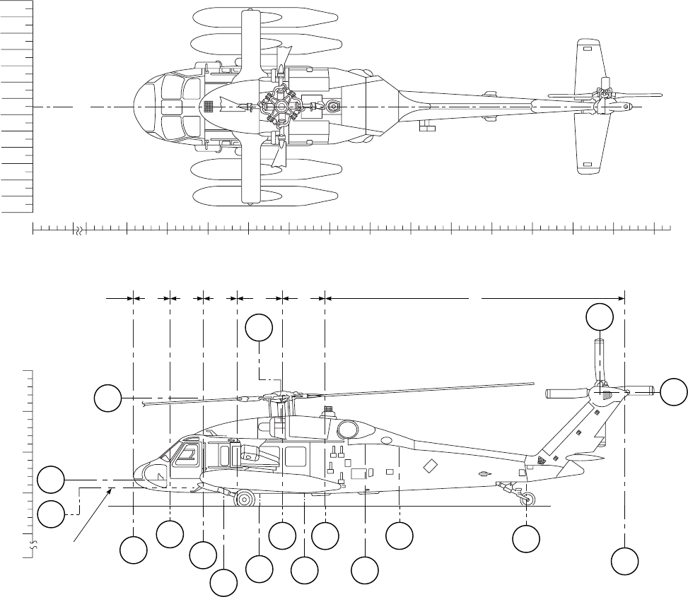
SA
AA0374
130
130
120
110 100
90 80
70 60
50 40
30 20
10 0
10 20
30 40
50 60
70 80
90 100
110 120
BUTT LINES
BL
0BL 0
0 50 100 150 200 250 300 350 400 450 500 550 600 650 700 750 800
STATIONS
350
300
250
200
150
0
WATER LINES
STATIC
GROUND LINE
COCKPIT
FLOOR
CABIN FLOOR
WL
315
COMPARTMENTS A B C D E F
STA
341.2
WL
215
WL
206.7
STA
162
STA
204
STA
247
STA
270
STA
315.5
STA
343
STA
370.5
STA
398
STA
443.5
STA
485 STA
644.6
STA
763.5
STA
732
WL
324.7
Figure 6-1. Helicopter Compartment and Station Diagram
TM 1-1520-237-10
6-2

Section II WEIGHT AND BALANCE
6.4 SCOPE.
This section provides appropriate information required
for the computation of weight and balance for loading an
individual helicopter. The forms currently in use are the
DD Form 365 series. The crewmember has available the
current basic weight and moment which is obtained from
DD Form 365-3 (Chart C) for the individual helicopter.
This chapter contains weight and balance definitions; ex-
planation of, and figures showing weights and moments of
variable load items.
6.5 WEIGHT DEFINITIONS.
a. Basic Weight. Basic weight of an aircraft is that
weight which includes all hydraulic systems and oil sys-
tems full, trapped and unusable fuel, and all fixed equip-
ment, to which it is only necessary to add the crew, fuel,
cargo, and ammunition (if carried) to determine the gross
weight for the aircraft. The basic weight varies with struc-
tural modifications and changes of fixed aircraft equipment.
b. Operating Weight. Operating weight includes the ba-
sic weight plus aircrew, the aircrew’s baggage, and emer-
gency and other equipment that may be required. Operating
weight does not include the weight of fuel, ammunition,
cargo, passengers or external auxiliary fuel tanks if such
tanks are to be disposed of during flight.
c. Gross Weight. Gross weight is the total weight of an
aircraft and its contents.
6.6 BALANCE DEFINITIONS.
6.6.1 Horizontal Reference Datum. The horizontal
reference datum line is an imaginary vertical plane at or
forward of the nose of the helicopter from which all hori-
zontal distances are measured for balance purposes. Dia-
grams of each helicopter show this reference datum line as
balance station zero.
6.6.2 Arm. Arm, for balance purposes, is the horizontal
distance in inches from the reference datum line to the CG
of the item. Arm may be determined from the helicopter
diagram in Figure 6-1.
6.6.3 Moment. Moment is the weight of an item multi-
plied by its arm. Moment divided by a constant is generally
used to simplify balance calculations by reducing the num-
ber of digits. For this helicopter, moment/1000 has been
used.
6.6.4 Average Arm. Average arm is the arm obtained
by adding the weights and moments of a number of items,
and dividing the total moment by the total weight.
6.6.5 Basic Moment. Basic moment is the sum of the
moments for all items making up the basic weight. When
using data from an actual weighing of a helicopter, the
basic moment is the total of the basic helicopter with re-
spect to the reference datum. Basic moment used for com-
puting DD Form 365-4 is the last entry on DD Form 365-3
for the specific helicopter. Cargo Hook Moments and Res-
cue Hoist Moments are shown in Figures 6-7 and 6-8, re-
spectively.
6.6.6 Center of Gravity (CG). Center of gravity is the
point about which a helicopter would balance if suspended.
Its distance from the reference datum line is found by di-
viding the total moment by the gross weight of the helicop-
ter.
6.6.7 CG Limits. CG limits (Figures 6-13 and 6-14) de-
fines the permissible range for CG stations. The CG of the
loaded helicopter must be within these limits at takeoff, in
the air, and on landing.
6.7 DD FORM 365-3 (CHART C) WEIGHT AND BAL-
ANCE RECORDS.
DD Form 365-3 (Chart C) is a continuous history of the
basic weight, moment, and balance, resulting from struc-
tural and equipment changes in service. At all times the last
weight, moment/constant, is considered the current weight
and balance status of the basic helicopter.
6.8 LOADING DATA.
The loading data in this chapter is intended to provide
information necessary to work a loading problem for the
helicopter. From the figures, weight and moment are ob-
tained for all variable load items and are added arithmeti-
cally to the current basic weight and moment from DD
Form 365-3 (Chart C) to obtain the gross weight and mo-
ment. If the helicopter is loaded within the forward and aft
CG limits, the moment figure will fall numerically between
the limiting moments. The effect on the CG of the expen-
ditures in flight of such items as fuel and cargo may be
checked by subtracting the weights and moments of such
items from the takeoff gross weight and moment, and
checking the new moment, with the CG limits chart. This
check should be made to determine whether or not the CG
will remain within limits during the entire flight.
TM 1-1520-237-10
Change 8 6-3
6.9 DD FORM 365-4 (FORM F).
There are two versions of DD Form 365-4. Refer to TM
55-1500-342-23 for completing the form.
TM 1-1520-237-10
6-4

Section III FUEL/OIL
6.10 FUEL MOMENTS.
CAUTION
Fuel transfer sequence must be carefully
planned and executed in order to main-
tain CG within limits.
When operating with a light cabin load or
no load, it may be necessary to adjust fuel
load to remain within aft CG limits. Fuel
loading is likely to be more restricted on
those aircraft with the HIRSS installed.
For a given weight of fuel there is only a very small
variation in fuel moment with change in fuel specific
weight. Fuel moments should be determined from the line
on Figure 6-2 which represents the specific weight closest
to that of the fuel being used. The full tank usable fuel
weight will vary depending upon fuel specific weight. The
aircraft fuel gage system was designed for use with JP-4,
but does tend to compensate for other fuels and provide
acceptable readings. When possible the weight of fuel on-
board should be determined by direct reference to the air-
craft fuel gages. The following information is provided to
show the general range of fuel specific weights to be ex-
pected. Specific weight of fuel will vary depending on fuel
temperature. Specific weight will decrease as fuel tempera-
ture rises and increases as fuel temperature decreases at the
rate of approximately 0.1 lb/gal for each 15°C change. Spe-
cific weight may also vary between lots of the same type
fuel at the same temperature by as much as 0.5 lb/gal. The
following approximate fuel weights at 15°C may be used
for most mission planning:
Fuel Type Specific Weight
JP-4 6.5 lb/gal.
JP-5 6.8 lb/gal.
JP-8 6.7 lb/gal.
Jet A 6.8 lb/gal.
Jet B 6.3 lb/gal.
TM 1-1520-237-10
Change 8 6-5
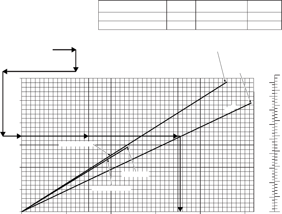
SA
AA0380E
FUEL MOMENTS
EXAMPLE
WANTED
KNOWN
METHOD
FUEL MOMENT
FUEL QUANTITY
FOR MAIN TANK ENTER
AT 1700 POUNDS AND
MOVE RIGHT TO MAIN LINE.
MOVE DOWN READ
MOMENT / 1000 = 710
MAIN 1700 POUNDS
FUEL MOMENT/1000
FUEL WEIGHT (POUNDS)
ARM = 420.75
0
50
100
150
200
250
300
350
400
0
50
100
150
200
250
300
350
400
GALLONS
JP−4 JP−5
0 200 400 600 800 1000
0
500
1000
1500
2000
2500
450
450
3000
ITEM STA WEIGHT LBS MOM/1000
230−GALLON TANK (IB OR OB)
450−GALLON TANK (IB)
321
316
150
234
48
74
ARM = 314.6 = 450−GALLON TANK
319.9 = 230−GALLON TANK
MAIN
ARM = 319.9
OUTBOARD TANK
INBOARD TANK
Figure 6-2. Fuel Moments
TM 1-1520-237-10
6-6
Section IV PERSONNEL
6.11 PERSONNEL MOMENTS.
When aircraft are operated at critical gross weights, the
exact weight of each individual occupant plus equipment
should be used. Personnel moments data is shown on Fig-
ure 6-3. If weighing facilities are not available, or if the
tactical situation dictates otherwise, loads shall be com-
puted as follows:
a. Combat equipped soldiers: 240 pounds per individual.
b. Combat equipped paratroopers: 260 pounds per indi-
vidual.
c. Crew and passengers with no equipment: compute
weight according to each individual’s estimate.
6.12 MEDEVAC KIT PERSONNEL MOMENTS.
a. Litter moments are in Figure 6-4.
b. Medevac system (excluding litters) weight and mo-
ments are included in the helicopter basic weight and mo-
ments Form 365-3 when installed.
c. Litter weight is estimated to 25 pounds which in-
cludes litter, splints, and blankets.
d. Medical attendant’s average weight is 200 pounds.
e. Medical equipment and supplies should be stored per
unit loading plan and considered in weight and balance
computations.
TM 1-1520-237-10
6-7
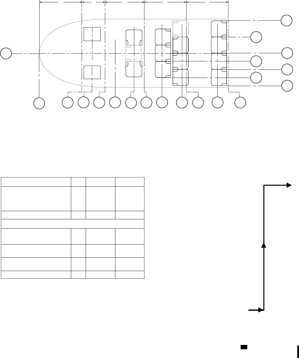
SA
AA0669_1B
SEAT WEIGHT − AND MOMENT TABLE*
ABC DE
STA
162.0
ITEM ROW WEIGHT MOM / 1000
ALTERNATE SEATING (BROKEN LINES)
CREWCHIEF / GUNNER (2)
TROOPS (3)
TROOPS (3)
TROOPS (4)
TOTAL−12 SEATS
FORWARD TROOP
SEAT (NO SEAT AUTHORIZED IN
REAR FACING TROOP
SEAT (1)
REAR FACING TROOP
SEAT (1)
TOTAL−14 SEATS
2
3
4
5
43
48
48
63
12
15
16
25
202 68
1
2
4
16
16
234
5
6
79
CREWCHIEF /
GUNNER
PILOT
COPILOT
METHOD:
KNOWN:
WANTED:
EXAMPLE
PESONNEL MOMENTS
2 PERSONNEL IN ROW 3
TOTAL WEIGHT 480 POUNDS
ENTER WEIGHT AT 480
POUNDS−MOVE RIGHT
TO ROW 3.
MOVE DOWN. READ
MOMENT / 1000=154
BL
0
BL
40.0
BL
20.0
BL
0
BL
10.0
BL
20.0
BL
30.0
BL
40.0
STA
262.0 STA
320.7 STA
387.2 STA
398.0
STA
247.0
STA
227.1
STA
204 STA
282.0 STA
343.0
STA
288.0 STA
339.8
ROW
1ROW
2ROW
3ROW
4ROW
5
PERSONNEL MOMENTS
*SEAT WEIGHT AND MOMENTS
SHOULD BE INCLUDED ON CHART C
THIS POSITION)
Figure 6-3. Personnel Moments (Troop Configuration) (Sheet 1 of 3) UH
TM 1-1520-237-10
6-8 Change 10
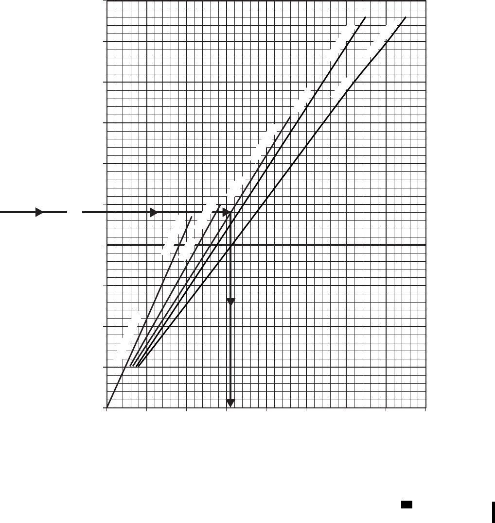
SA
AA0669_2A
0 50 100 150 200 250 300 400350
MOMENT/1000
0
100
200
300
400
500
600
700
800
900
1000
PERSONNEL WEIGHT ~ POUNDS
PERSONNEL MOMENTS
PILOT − COPILOT
ROW 2
ROW 3
ROW 4
ROW 5
ARM = 227.1
ARM = 320.7
ARM = 339.8
ARM = 387.2
DATA BASIS: CALCULATED
ARM =282
Figure 6-3. Personnel Moments (Troop Configuration) (Sheet 2 of 3) UH
TM 1-1520-237-10
Change 10 6-9
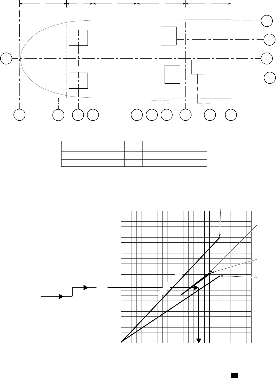
SA
AA0669_3B
STA
204 STA
247.0 STA
288.0 STA
343.0
STA
227.1
STA
162.0 STA
356.0 STA
398.0
BL
0
BL
40.0
BL
20.0
BL
20.0
BL
0
0 50 100
0
100
200
300
400
500
ABC D E
PILOT
COPILOT
* ITEM STA WEIGHT MOM / 1000
356.0 18 6
_18 6
OBSERVER SEAT
TOTAL − 1 SEAT
STA
227.1
MOMENT/1000
PERSONNEL WEIGHT ~ POUNDS
EXAMPLE
WANTED
PERSONNEL MOMENTS
KNOWN
PERSONNEL AT STA 356
METHOD
OBSERVER − 210 POUNDS
ENTER WEIGHT AT 210
POUNDS − MOVE RIGHT
TO OBSERVER ARC (STA 356.0)
MOVE DOWN READ
MOMENT / 1000 = 75
OBSERVER
* SEAT WEIGHT AND MOMENTS SHOULD BE INCLUDED ON CHART C.
ECM OPERATOR
DATA BASIS: CALCULATED
DF
OPERATOR
STA
328.25
STA
324.5
OBSERVER
STA 356.0
PILOT−COPILOT
ECM
OPERATOR
STA 324.5
DF
OPERATOR
STA 328.25
1257525
Figure 6-3. Personnel Moments (EH Configuration) (Sheet 3 of 3) EH
TM 1-1520-237-10
6-10
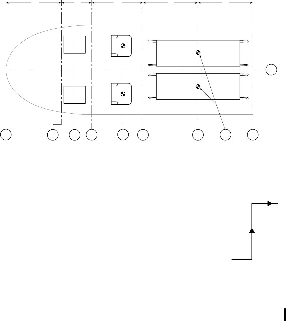
SA
AA0378_1B
STA
162.0 STA
204.0 STA
227.1 STA
247.0 STA
271.0 STA
288.0 STA
343.0 STA
398.0
STA
343.6
BL
0
PILOT
COPILOT
CREW CHIEF
MEDICAL ATTENDANT
ROW
6ROW
7CENTROID
LITTER MOMENTS
LITTER MOMENTS
LITTER WEIGHT
= 265 POUNDS
ENTER WEIGHT AT
265 POUNDS − MOVE
RIGHT TO LITTER
ROW 7
MOVE DOWN. READ
MOMENT / 1000 = 91
METHOD
KNOWN
WANTED
EXAMPLE
ABC D E
Figure 6-4. Personnel Moments (Medevac Configuration) (Sheet 1 of 2)
TM 1-1520-237-10
Change 10 6-11
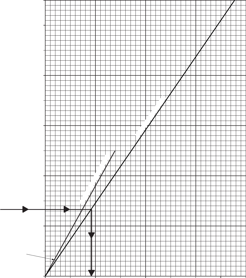
SA
AA0378_2A
LITTER MOMENTS
DATA BASIS:CALCULATED
MOMENT/1000
LITTER PATIENT WEIGHT POUNDS
0 50 100 150 200 250 300 350 400
0
100
200
300
400
500
600
700
800
900
1000
1100 ARM = 343.6
LITTER PATIENTS − ROW 7
MEDICAL ATTENDANT − ROW 6
ARM = 271.0
Figure 6-4. Personnel Moments (Medevac Configuration) (Sheet 2 of 2)
TM 1-1520-237-10
6-12

Section V MISSION EQUIPMENT
6.13 ARMAMENT LOADING DATA MOMENTS.
Armament consists of two M60D machineguns, ammu-
nition, and grenades. Various loads of ammunition are pre-
sented in Figure 6-5. When determining the moments for a
given ammo load not shown on the chart, go to the nearest
load shown. VOL Volcano mine moments are presented
in Figure 6-6.
6.14 EH-60A HELICOPTERS WITHOUT MISSION
EQUIPMENT.
EH When operating without EH-60 mission equipment
or with a light cabin load or no cabin load, it may be nec-
essary to limit fuel load to remain within aft CG limits.
TM 1-1520-237-10
6-13
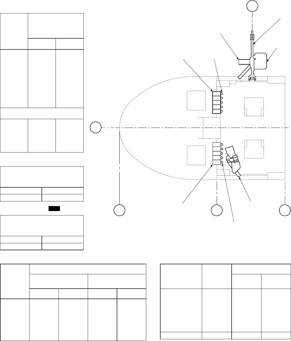
SA
AA0375B
FLARE
CHAFF
AMMUNITION TABLE
LIVE
ROUNDS LIVE AMMO (7.62 MM)
ARM − 247.0
WEIGHT − LB MOM / 1000
ARM − 279.8
CHAFF CARTRIDGE MI. 30 RDS
ARM − 505.0
(SINGLE CHAFF WEIGHT 0.33 LB)
FLARE DISPENSED M130, 30 RDS
ARM − 525.0
(SINGLE FLARE WEIGHT 0.43 LB)
WEIGHT − LB MOM / 1000
WEIGHT − LB MOM / 1000
10 5
13 7
STOWED
QUANTITY GRENADE AN−M8
ARM − 251.0 GRENADE M18
ARM − 251.0
WEIGHT − LB MOM / 1000 WEIGHT − LB MOM / 1000
2
4
6
8
10
12
3
6
9
12
15
18
1
2
2
3
4
5
2
5
7
10
12
14
1
1
2
2
3
4
ITEM WEIGHT
MOM / 1000
STOWED FIRING
POSITION
M60D (2)
EJECTION BAG (2)
AMMO BOX (2)
STORAGE BOX (2)
SUPPORT (2)
BIPOD (2)
45.4
9.0
3.4
2.6
20.2
4.0
84.6
12
2
1
1
5
1
22
13
3
1
1
6
1
25
100
200
300
400
500
600
700
800
100
200
300
400
7
13
20
26
32
39
46
52
7
13
20
26
2
3
5
6
8
10
11
13
2
4
5
7
GRENADE TABLE M60D TABLE
STA
279.8
BL
0
STA
247 STA
308
STA
162
STOWED
POSITION
LH GUN
AMMO
AMMO GRENADES
AMMUNITION
BOX
EJECTION
BAG
FIRING
POSITION
RH GUN
(GUN STOWED AND FIRING POSITIONS ARE SAME EACH SIDE)
GRENADES
TOTAL
DATA BASIS: CALCULATED
ARMAMENT LOADING DATA
EH
Figure 6-5. Armament Loading Data Moments
TM 1-1520-237-10
6-14
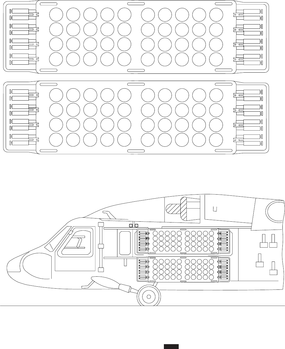

RACK WEIGHTS (PER RACK)
NO CANISTERS EMPTY CANISTERS (40) FULL CANISTERS (40)
Weight (lb) Arm Moment/
1000 Weight (lb) Arm Moment/
1000 Weight (lb) Arm Moment/
1000
226 331.5 74.9 434 331.5 143.9 1450 331.5 480.7
WEIGHT (LB) QUANTITY
PER SYSTEM TOTAL
WEIGHT (LB) ARM MOMENT/1000
Rack Without Canisters 226 4 904 331.5 299.7
Canisters:
Empty 5.2 160 832 331.5 275.8
Full 30.6 160 4896 331.5 1623.0
Side Panels 236 2 472 322.8 152.4
DCU with Pallet 87 1 87 300 26.1
Cabling/ICP/Fairing
/Cable Tubes 54 1 54 264.4 14.3
Total System Full Canisters: 6413 329.7 2114.4
Total System Empty Canisters 2349 326.7 767.4
Total System No Canisters 1517 324.1 491.6
UNIT CANISTER LOADING
COLUMN EMPTY
CANISTER
WEIGHT
FULL
CANISTER
WEIGHT
ARM EMPTY
CANISTER
MOMENT/1000
FULL
CANISTER
MOMENT/1000
1 5.2 30.6 306.3 1.6 9.4
2 5.2 30.6 311.8 1.6 9.5
3 5.2 30.6 317.3 1.6 9.7
4 5.2 30.6 322.8 1.7 9.9
5 5.2 30.6 328.3 1.7 10.0
6 5.2 30.6 333.8 1.7 10.2
7 5.2 30.6 339.3 1.8 10.4
8 5.2 30.6 344.8 1.8 10.6
9 5.2 30.6 350.3 1.8 10.7
10 5.2 30.6 355.8 1.9 10.9
Figure 6-6. Volcano Mine Moments VOL (Sheet 2 of 2)
TM 1-1520-237-10
6-16 Change 3
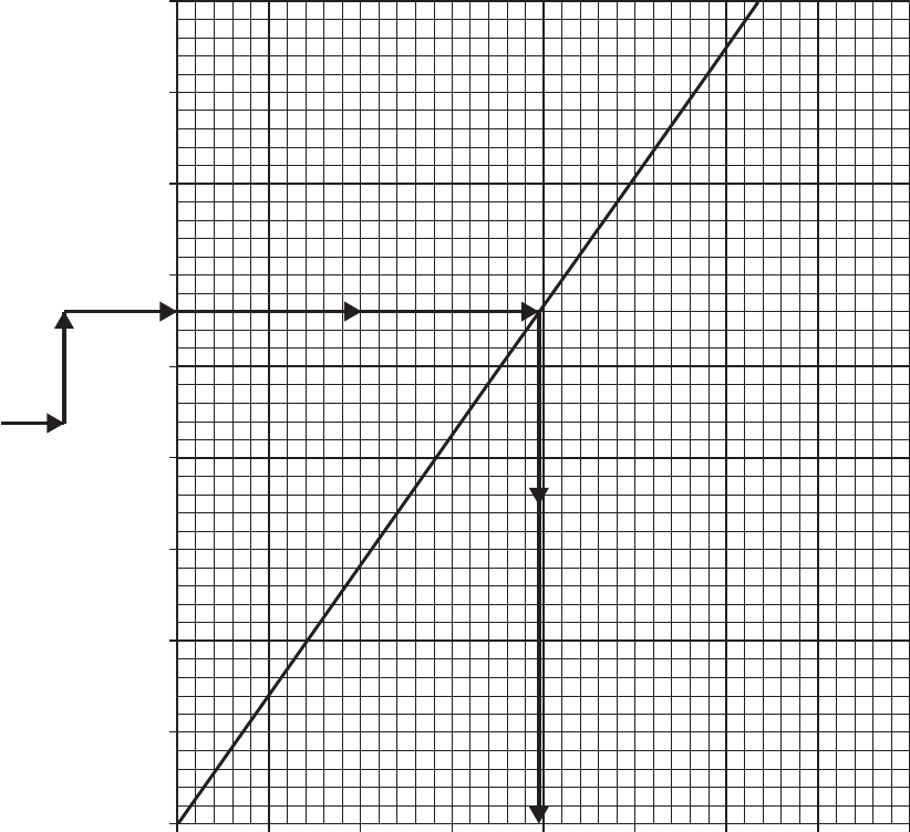
CARGO MOMENTS − CARGO HOOK
EXAMPLE
WANTED
KNOWN
METHOD
MOMENT OF CARGO
ON CARGO HOOK
CARGO = 5600 POUNDS
ENTER WEIGHT AT
5600 POUNDS. MOVE
RIGHT TO LINE. MOVE
DOWN AND READ
MOMENT / 1000
= 1975
0 2000 3000 4000
0
1000
2000
3000
4000
5000
6000
7000
8000
9000 ARM = 352.6
WEIGHT ~ POUNDS
CARGO HOOK MOMENTS/1000 SA
AA8802
1000
Figure 6-7. Cargo Hook Moments
TM 1-1520-237-10
6-17
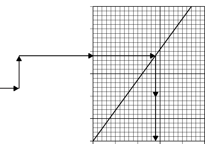
SA
AA0377
RESCUE HOIST MOMENTS
EXAMPLE
WANTED
KNOWN
METHOD
MOMENT OF RESCUE
HOIST LOAD
RESCUE HOIST LOAD
ENTER WEIGHT AT
380 POUNDS − MOVE
RIGHT TO LINE. MOVE
DOWN. READ MOMENT /
1000 = 140
= 380 POUNDS
DATA BASIS: CALCULATED
500 100 150 200 250
0
100
200
300
400
500
600 ARM = 367.5
MOMENT / 1000
WEIGHT ~ POUNDS
Figure 6-8. Rescue Hoist Moments
TM 1-1520-237-10
6-18
Section VI CARGO LOADING
6.15 CABIN DIMENSIONS.
Refer to Figure 6-9 for dimensions. For loading, and
weight and balance purposes, the helicopter fuselage is di-
vided into six compartments, A through F, three of which
are in the cabin, C, D, and E. There are 17 tiedown fittings
rated at 5,000 pounds each. Cargo carrier restraint rings are
at stations 308 and 379, to cover the 71 inches of longitu-
dinal space. Cargo tiedown devices are stored in the equip-
ment stowage space of compartment F.
6.16 CABIN DOORS.
Cabin doors are at the rear of the cargo compartment on
each side of the fuselage. The door openings are 54.5 inches
high and 69 inches wide; maximum package sizes accom-
modated by the openings are 54 inches high by 68 inches
wide and are shown on Figure 6-10.
6.17 MAXIMUM CARGO SIZE DIAGRAM FOR
LOADING THROUGH CABIN DOORS.
Figure 6-10 shows the largest size of cargo of various
shapes that can be loaded into the cabin through the cabin
doors.
6.18 TIEDOWN FITTINGS AND RESTRAINT
RINGS.
The 17 tiedown fittings (Figure 6-11) installed on the
cargo floor can restrain a 5,000-pound load in any direc-
tion. All tiedown fittings incorporate studs that are used to
install the troop seats. Eight net restraint rings in the cargo
compartment prevent cargo from hitting the bulkhead at
station 398, or entering the crew area. Each restraint ring is
rated at 3500-pound capacity in any direction.
6.19 EQUIPMENT STOWAGE COMPARTMENTS.
Equipment stowage compartment moments are shown in
Figure 6-12.
6.20 EQUIPMENT LOADING AND UNLOADING.
6.20.1 Data Prior to Loading. The following data
should be assembled or gathered by the loading crew be-
fore loading (Refer to FM 55-450-2, Army Helicopter In-
ternal Load Operations):
a. Weight of the individual items of cargo.
b. Overall dimensions of each item of cargo (in inches).
c. The helicopter’s center of gravity.
d. Floor loads for each item of cargo.
e. Any shoring that may be required.
f. When required, the location of the center of gravity of
an individual item of cargo.
6.20.2 Cargo Center of Gravity Planning. The detail
planning procedure consists of four steps, as follows:
a. Determine ALLOWABLE LOAD from LIMITA-
TIONS section of DD Form 365-4.
b. Plan the location in the helicopter for the individual
items of cargo. Since the CG of the load is determined by
the station method, then specific locations must be assigned
to each item of cargo.
c. Determine the CG of the cargo load as planned. Re-
gardless of the quantity, type, or size of cargo, use the
station method.
d. Determine the CG of the fully-loaded helicopter from
Figures 6-13 and 6-14, and if the CG of the helicopter falls
within allowable limits. If it does, the cargo can be loaded.
If not, the planned location of the individual items must be
changed until an acceptable loading plan is obtained. When
cargo loads consists of more than one item, the heavier
items of cargo should be placed so that their CG is about in
the center of the cabin, and the lighter items of cargo are
forward and rear of them.
6.20.3 Restraint Criteria. The amount of restraint that
must be used to keep the cargo from moving in any direc-
tion is called the 9restraint criteria9and is usually expressed
in units of the force of gravity, of Gs. Following are the
units of the force of gravity or Gs needed to restrain cargo
in four directions:
Cargo
Forward 12 Gs
Rear 3 Gs
Lateral 8 Gs
Vertical 3 Gs (Up)
3 Gs (Down)
TM 1-1520-237-10
6-19
SA
AA0379
BL
0
BL
34.5 BL
34.5
BL
36.0 BL
36.0
WL
261.0
WL
234.0
WL
206.75
69 INCHES
85 INCHES
84 INCHES
72 INCHES
FRAMES
DOOR
STA 279.0
LOOKING TO THE REAR
STA
266.0
BL
29.0
BL
0
BL
10.0
BL
36.0
BL
0
STA
247.0 STA
256.5 STA
341.2 STA
398.0
AT WL
206.75
BL
36.0 AT WL
206.75
151 INCHES
72 INCHES
AT FLOOR
LEVEL
72 INCHES
AT FLOOR
LEVEL
84 INCHES AT
CABIN DOORS
68
INCHES
54.25
INCHES
52
INCHES
53.5
INCHES
52
INCHES54.25
INCHES
DRIP
PAN
CABIN
DOOR
CABIN AND DOOR DIMENSIONS
MR
C
L
Figure 6-9. Cabin Dimensions
TM 1-1520-237-10
6-20
SA
AA0670
46
48
50
52
54
56
58
60
62
64
66
68
102
102
101
100
99
98
97
96
93
91
86
80
102
102
101
100
99
98
97
96
93
91
86
80
102
102
101
100
99
98
97
96
93
91
86
80
96
96
95
94
93
93
93
91
89
87
80
77
93
93
92
92
91
91
91
90
87
51 52 53 54
HEIGHT − INCHES
MAXIMUM LENGTH − INCHES
WIDTH
INCHES 50 &
UNDER
RIGHT SIDE SHOWN (2 PLACES)
LEFT SIDE SAME (2 SHOWN)
A
TIEDOWN RING
A
DOORWAY
54"
68"
CABIN DOOR − BOTH SIDES
MAXIMUM PACKAGE SIZE TABLE
CABIN DOORS
NOTE
IF GUNNERS AREA NOT USED,
LENGTHS ARE APPROXIMATELY 90%
OF TABLE VALUES.
Figure 6-10. Maximum Package Size for Cargo Door
TM 1-1520-237-10
6-21
SA
AA0671_1A
CARGO
RESTRAINT
NET RING
3500 POUND
CAPACITY
EACH
CARGO
RESTRAINT
NET RING
TOP OF
CABIN
FLOOR
STA 379.0
LOOKING TO THE FRONT
STA 308.0
LOOKING TO THE FRONT
CARGO NETTING
EQUIPMENT STOWAGE
COMPARTMENTS (FORCE
RESTRAINT 1000 POUNDS
EACH)
WL
261.0
WL
240.0
WL
206.75
BL
0.0
MAXIMUM
COMPARTMENT
CAPACITY
5460
8370
STA 402.19 − LOOKING TO THE REAR
TIEDOWN FITTING
5000 POUNDS CAPACITY
250
255
260
265
270
275
280
285
290
295
300
305
310
315
320
325
330
335
340
345
350
355
360
365
370
375
380
385
390
395
10 15 20 25 30 35
5
51015202530
35
BL
0BL
36.5
BL
36.5
STA
247
STA
288
STA
343
STA
398
COMPARTMENT C COMPARTMENT D COMPARTMENT E
FLOOR CAPACITY
POUNDS PER
SQUARE FOOT
300
300
IN POUNDS
Figure 6-11. Cargo Tiedown Arrangement
TM 1-1520-237-10
6-22
SA
AA0595
0 10 20 30 40 50 60 70 80 90 100 110
50
100
150
200
250
MOMENT/1000
STOWAGE COMPARTMENT MOMENTS
EXAMPLE
WANTED
KNOWN
METHOD
MOMENT OF
STOWED EQUIPMENT
EQUIPMENT WEIGHT
= 125 POUNDS
ENTER WEIGHT AT
125 POUNDS − MOVE
RIGHT TO LINE
MOVE DOWN READ
MOMENT / 1000 = 52
ITEM ROW WEIGHT MOMENT / 1000
CREWCHIEF / GUNNER (2)
TROOPS (3)
TROOPS (3)
TROOPS (4)
TOTAL−12 SEATS
ALTERNATE (1)
ALTERNATE (1)
ALTERNATE (1)
TOTAL−15 SEATS
2
3
4
5
1
2
4
43
48
48
63
202
16
16
16
250
18
20
20
27
85
7
7
7
106
STOWED SEAT TABLE
CALCULATEDDATA BASIS:
BL
32.9
BL
10.0
BL
10.0
BL
32.9
STA
398.0 STA
420.8 STA
443.5
WEIGHT ~ POUNDS
ARM = 420.8
Figure 6-12. Stowage Compartment Moments
TM 1-1520-237-10
6-23

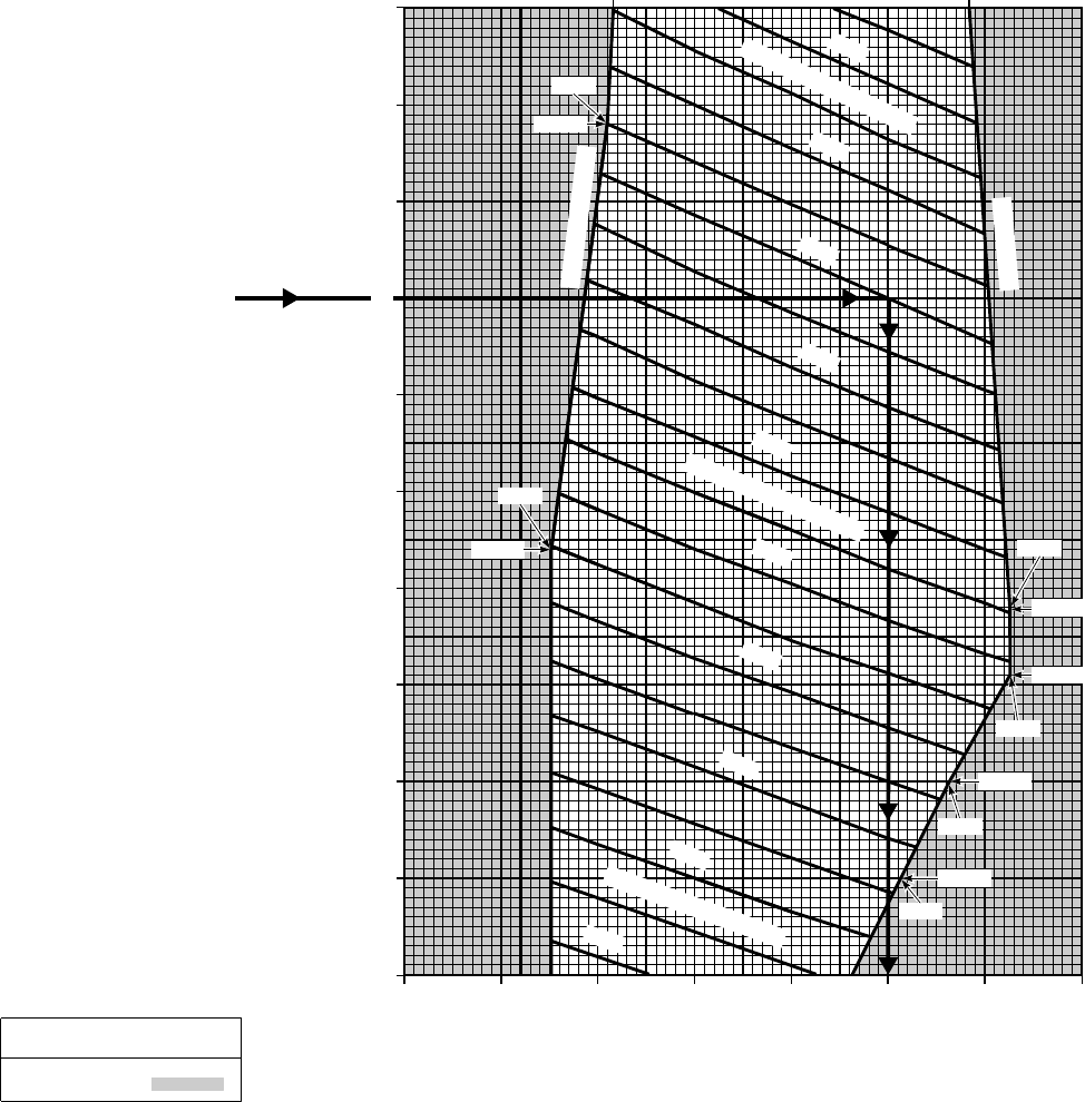
SA
AA0347_1B
CENTER OF GRAVITY
BEYOND LIMITS
DETERMINE IF
LOADING LIMITS
ARE EXCEEDED
GROSS WEIGHT
= 15,000 POUNDS
MOMENT / 1000
= 5,400
ENTER GROSS
WEIGHT AT 15,000
POUNDS. MOVE
RIGHT TOTAL
MOMENT / 1,000
= 5,400 CG
IS WITHIN LIMITS
MOVE DOWN TO
ARM = 360
WANTED
KNOWN
METHOD
EXAMPLE MAIN ROTOR
C
L
335 340 345 350 355 360 365 370
11.5
12
13
14
16
16.5
345.5
15,900
FORWARD LIMITS
TOTAL MOMENTS / 1000
5800
5600
5400
5200
5000
TOTAL MOMENTS / 1000
4800
4600
4400
4200
TOTAL MOMENTS / 1000
4000
342.6
13,700
AFT LIMITS
366.3
13,400
13,050
366.3
12,500
363.2
12,000
360.8
15
345.8 364.2
ARM ~ INCHES
GROSS WEIGHT ~ 1000 POUNDS
EXAMPLE
LEGEND
DATA BASIS: CALCULATED
WITHOUT EXTERNAL STORES SUPPORT SYSTEM OR
VOLCANO MULTIPLE MINE DELIVERY SYSTEM INSTALLED
11,500 TO 16,500 POUNDS GROSS WEIGHT
CENTER OF GRAVITY LIMITS
Figure 6-13. Center of Gravity Limits Chart (Sheet 1 of 2)
TM 1-1520-237-10
6-25
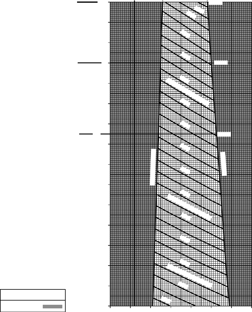
BEYOND LIMITS
MAXIMUM GROSS WEIGHT
FOR ALL UH−60L AND
SOME UH / EH−60A.
SEE PARAGRAPH 5.14
FOR DETAILS.
MAXIMUM GROSS WEIGHT
FOR SOME UH / EH−60A.
SEE PARAGRAPH 5.14
FOR DETAILS.
LEGEND
DATA BASIS: CALCULATED SA
AA8801A
MAXIMUM GROSS WEIGHT
FOR UH−60L EXTERNAL
LOAD MISSION FOR CARGO
ARM ~ INCHES
GROSS WEIGHT ~ 1000 POUNDS
HOOK LOADS ABOVE
8,000 LBS UP TO
9,000 LBS.
335 340 345 350 355 360 365 370
MAIN ROTOR C
L
16
16.5
17
18
19
20
21
22
23.5
23
348.2 359.2
23,500
8400
8200
8000
7800
7600
7400
7200
TOTAL MOMENTS / 1000
TOTAL MOMENTS / 1000
7000
6800
6600
6400
6200
6000
5800
TOTAL MOMENTS / 1000
5600
AFT LIMITS
22,000
20,250
FORWARD LIMITS
CENTER OF GRAVITY
WITHOUT EXTERNAL STORES SUPPORT SYSTEM OR
VOLCANO MULTIPLE MINE DELIVERY SYSTEM INSTALLED
16,000 TO 23,500 POUNDS GROSS WEIGHT
CENTER OF GRAVITY LIMITS
Figure 6-13. Center of Gravity Limits Chart (Sheet 2 of 2)
TM 1-1520-237-10
6-26
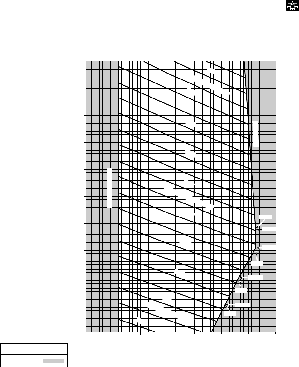
11,500 TO 16,500 POUNDS GROSS WEIGHT
CENTER OF GRAVITY LIMITS
CENTER OF GRAVITY
BEYOND LIMITS
MAIN ROTOR
C
L
SA
AA1254_1B
WITH EXTERNAL STORES SUPPORT SYSTEM INSTALLED
LEGEND
DATA BASIS: CALCULATED
370
365
360
355
350
345
340
335
11.5
12
0
13
0
14
0
15
0
16
16.5
364.2
5800
TOTAL MOMENTS / 1000
5600
5400
5200
5000
TOTAL MOMENTS / 1000
4800
4600
4400
4200
4000
TOTAL MOMENTS / 1000
360.8
12,000
363.2
12,500
366.3
13,050
13,400
366.3
AFT LIMITS
FORWARD LIMITS
ARM ~ INCHES
GROSS WEIGHT ~ 1000 POUNDS
Figure 6-14. Center of Gravity Limits Chart (Sheet 1 of 3)
TM 1-1520-237-10
6-27
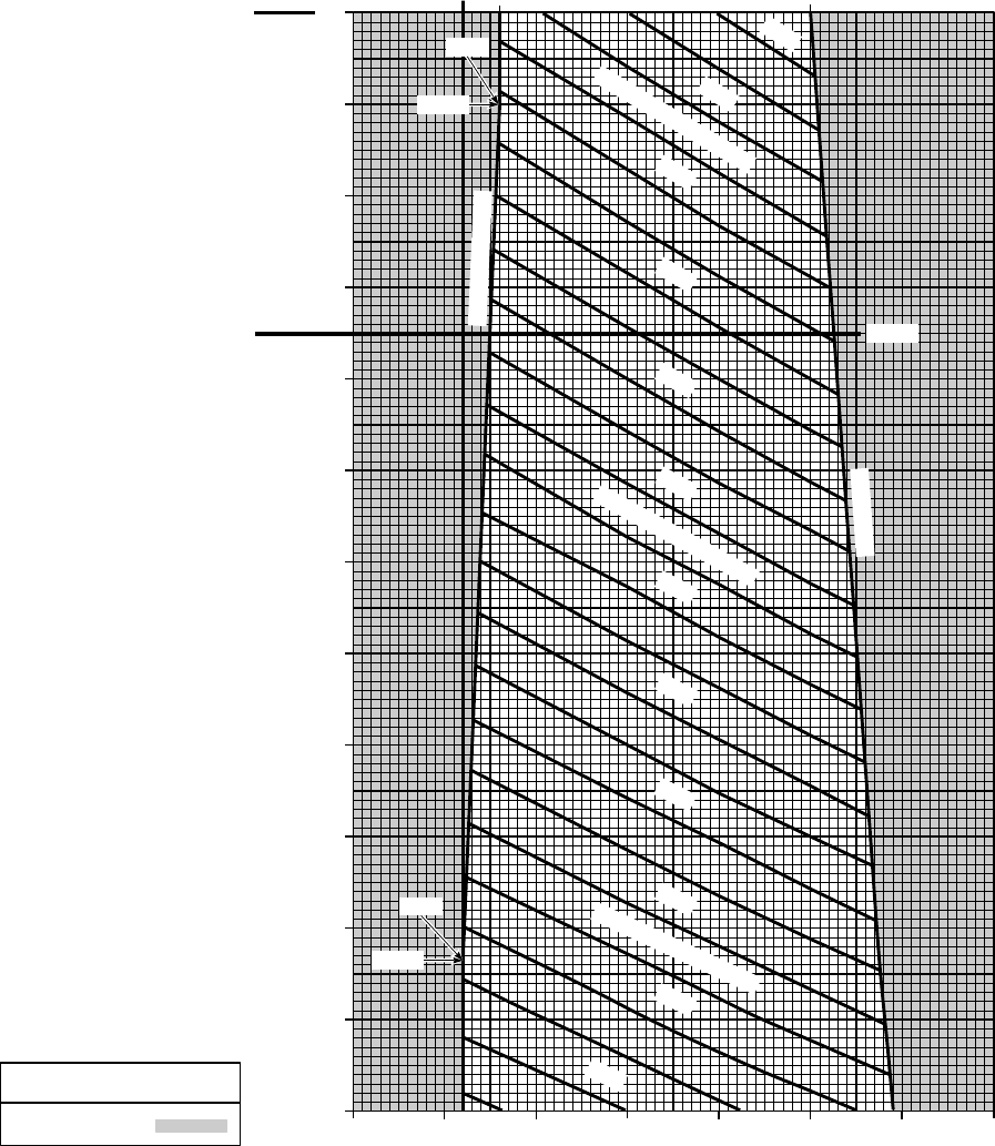
SA
AA1254_2C
BEYOND LIMITS
MAXIMUM GROSS WEIGHT
FOR ALL UH−60L AND
SOME UH / EH−60A.
SEE PARAGRAPH 5.14
FOR DETAILS.
MAXIMUM GROSS WEIGHT
FOR SOME UH / EH−60A.
SEE PARAGRAPH 5.14
FOR DETAILS.
335 340 345 350 355 360 365 370
16
16.5
17
18
19
20
21
22
343.0 360.2
LEGEND
343.0
21,500
7800
7600
TOTAL MOMENTS / 1000
7400
7200
7000
6800
6600
TOTAL MOMENTS / 1000
6400
6200
6000
5800
TOTAL MOMENTS / 1000
341.0
16,825
GROSS WEIGHT ~ 1000 POUNDS
MAIN ROTOR C
L
ARM ~ INCHES
20,250
AFT LIMITS
5600
FORWARD LIMITS
CALCULATED
DATA BASIS:
CENTER OF GRAVITY
WITH EXTERNAL STORES SUPPORT SYSTEM OR
VOLCANO MULTIPLE MINE DELIVERY SYSTEM INSTALLED
16,000 TO 22,000 POUNDS GROSS WEIGHT
CENTER OF GRAVITY LIMITS
Figure 6-14. Center of Gravity Limits Chart (Sheet 2 of 3)
TM 1-1520-237-10
6-28
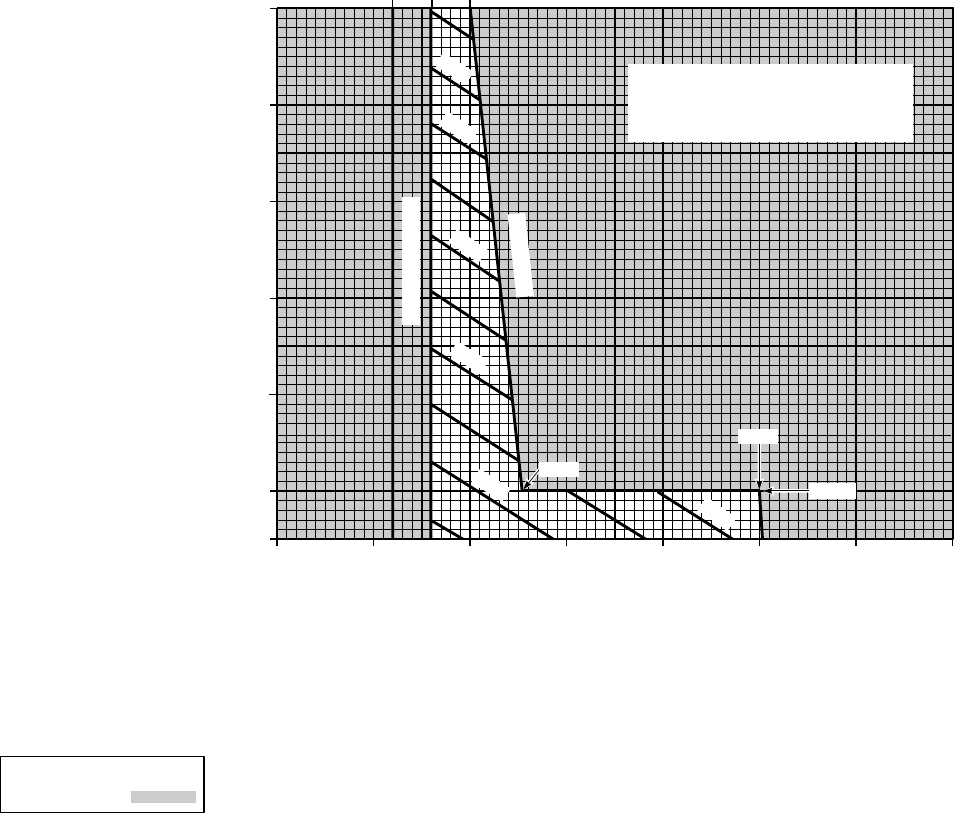
SA
AA1254_3B
ARM ~ INCHES
GROSS WEIGHT ~ 1000 POUNDS
LEGEND
BEYOND LIMITS
MAIN ROTOR
C
21.75
22
23
24
24.5
L345
343
335 340 345 350 355 360 365 370
8200
8000
8200
8000
8200
8000
8200
8000
8300
8200
8000
8200
8000
8200
8000
8200
8000
830083008300
FORWARD LIMITS
AFT LIMITS
360.2
78007800780078007800780078007800
7800780078007800780078007800780078007800780078007800780078007800
GROSS WEIGHTS ABOVE THE MAXIMUM
VALUES SPECIFIED IN PARAGRAPH 5.14
ARE LIMITED TO FERRY MISSIONS
FOR WHICH AN AIRWORTHINESS
RELEASE IS REQUIRED
22,000
347.7
76007600760076007600760076007600
CALCULATED
DATA BASIS:
CENTER OF GRAVITY
WITH EXTERNAL STORES SUPPORT SYSTEM OR
VOLCANO MULTIPLE MINE DELIVERY SYSTEM INSTALLED
21,750 TO 24,500 POUNDS GROSS WEIGHT
CENTER OF GRAVITY LIMITS
Figure 6-14. Center of Gravity Limits Chart (Sheet 3 of 3)
TM 1-1520-237-10
6-29/(6-30 Blank)

CHAPTER 7
PERFORMANCE DATA
Section I INTRODUCTION
NOTE
Chapter 7 contains performance data for air-
craft equipped with T700-GE-700 engines.
Performance data for other models are con-
tained in Chapter 7A. Users are authorized
to remove whichever chapter is not appli-
cable to their model aircraft, and are not re-
quired to carry both chapters on board.
Tabular performance data is presented in the
checklist (TM 1 -1520-237-CL) and may be
used in lieu of Figures 7-3 and 7-4 to obtain
9Maximum Hover Weight9,9Torque Re-
quired to Hover9and 9Maximum Torque
Available9.
7.1 PURPOSE.
a. The purpose of this chapter is to provide the best
available performance data. Regular use of this information
will enable you to receive maximum safe utilization of the
helicopter. Although maximum performance is not always
required, regular use of this chapter is recommended for
these reasons:
(1) Knowledge of your performance margin will allow
you to make better decisions when unexpected conditions
or alternate missions are encountered.
(2) Situations requiring maximum performance will be
more readily recognized.
(3) Familiarity with the data will allow performance to
be computed more easily and quickly.
(4) Experience will be gained in accurately estimating
the effects of variables for which data are not presented.
b. The information is primarily intended for mission
planning and is most useful when planning operations in
unfamiliar areas or at extreme conditions. The data may
also be used in flight, to establish unit or area standard
operating procedures, and to inform ground commanders of
performance/risk trade-offs.
7.2 CHAPTER 7 INDEX.
The following index contains a list of the sections, titles,
figure numbers, subjects and page numbers of each perfor-
mance data chart contained in this chapter.
Section
and
Figure
Number Title Page
I INTRODUCTION ................... 7-1
7-1 Temperature Conversion
Chart......................................... 7-4
II MAXIMUM TORQUE
AVAILABLE........................... 7-6
7-2 Aircraft Torque Factor
(ATF) ....................................... 7-7
7-3 Maximum Torque Available -
30-Minute Limit ...................... 7-8
III HOVER.................................... 7-9
7-4 Hover - Clean
Configuration ........................... 7-10
7-5 Hover - High Drag .................. 7-12
IV CRUISE ................................... 7-13
7-6 Sample Cruise Chart -Clean.... 7-15
7-7 Cruise - Pressure Altitude Sea
Level ........................................ 7-16
7-8 Cruise High Drag - Pressure
Altitude Sea Level................... 7-22
7-9 Cruise - Pressure Altitude
2,000 Feet ................................ 7-28
TM 1-1520-237-10
Change 6 7-1
Section
and
Figure
Number Title Page
7-10 Cruise High Drag - Pressure
Altitude 2,000 Feet.................. 7-34
7-11 Cruise - Pressure Altitude
4,000 Feet ................................ 7-40
7-12 Cruise High Drag - Pressure
Altitude 4,000 Feet.................. 7-46
7-13 Cruise - Pressure Altitude
6,000 Feet ................................ 7-52
7-14 Cruise High Drag - Pressure
Altitude 6,000 Feet.................. 7-58
7-15 Cruise - Pressure Altitude
8,000 Feet ................................ 7-64
7-16 Cruise High Drag - Pressure
Altitude 8,000 Feet.................. 7-70
7-17 Cruise - Pressure Altitude
10,000 Feet .............................. 7-76
7-18 Cruise High Drag- Pressure
Altitude 10,000 Feet................ 7-81
7-19 Cruise - Pressure Altitude
12,000 Feet .............................. 7-86
7-20 Cruise High Drag - Pressure
Altitude 12,000 Feet................ 7-91
7-21 Cruise - Pressure Altitude
14,000 Feet .............................. 7-96
7-22 Cruise High Drag - Pressure
Altitude 14,000 Feet................ 7-101
7-23 Cruise - Pressure Altitude
16,000 Feet .............................. 7-106
7-24 Cruise High Drag - Pressure
Altitude 16,000 Feet................ 7-111
7-25 Cruise - Pressure Altitude
18,000 Feet .............................. 7-115
7-26 Cruise High Drag - Pressure
Altitude 18,000 Feet................ 7-120
7-27 Cruise - Pressure Altitude
20,000 Feet .............................. 7-124
7-28 Cruise High Drag - Pressure
Altitude 20,000 Feet................ 7-128
V OPTIMUM CRUISE ............... 7-132
Section
and
Figure
Number Title Page
7-29 Optimum Altitude for
Maximum Range ..................... 7-133
VI DRAG ...................................... 7-135
7-30 External Load Drag................. 7-136
7-31 Typical High Drag
Configurations.......................... 7-137
VII CLIMB - DESCENT............... 7-138
7-32 Climb/Descent.......................... 7-139
7-33 Climb/Descent -
High Drag ................................ 7-140
VIII FUEL FLOW........................... 7-141
7-34 Single/Dual-Engine
Fuel Flow................................. 7-142
IX AIRSPEED SYSTEM
CHARACTERISTICS............. 7-143
7-35 Airspeed Correction
Aircraft Without Wedge
Mounted Pitot-Static Probes.... 7-144
7-36 Airspeed Correction
Aircraft With Wedge Mounted
Pitot-Static Probes ................... 7-145
7-37 Airspeed Correction
Chart - High Drag ................... 7-146
X SPECIAL MISSION
PERFORMANCE.................... 7-147
7-38 Self Deployment Mission
Profile....................................... 7-148
7-39 Assault Mission Profile
(4 - 230 Gallon Tanks)............ 7-150
7-40 Assault Mission Profile
(2 - 230 Gallon Tanks)............ 7-151
7.3 GENERAL.
The data presented covers the maximum range of con-
ditions and performance that can reasonably be expected.
In each area of performance, the effects of altitude, tem-
perature, gross weight, and other parameters relating to that
phase of flight are presented. In addition to the presented
data, your judgment and experience will be necessary to
TM 1-1520-237-10
7-2 Change 6
accurately obtain performance under a given set of circum-
stances. The conditions for the data are listed under the title
of each chart. The effects of different conditions are dis-
cussed in the text accompanying each phase of perfor-
mance. Where practical, data are presented at conservative
conditions. However, NO GENERAL CONSERVATISM
HAS BEEN APPLIED. All performance data presented are
within the applicable limits of the helicopter. All flight per-
TM 1-1520-237-10
Change 6 7-2.1/(7-2.2 Blank)

formance data are based on JP-4 fuel. The change in fuel
flow and torque available, when using JP-5 or JP-8 aviation
fuel, or any other approved fuels, is insignificant.
7.4 LIMITS.
CAUTION
Exceeding operating limits can cause per-
manent damage to critical components.
Overlimit operation can decrease perfor-
mance, cause early failure, or failure on a
subsequent flight.
Applicable limits are shown on the charts. Performance
generally deteriorates rapidly beyond limits. If limits are
exceeded, minimize the amount and time. Enter the maxi-
mum value and time above limits on DA Form 2408-13-1,
so proper maintenance action can be taken.
7.5 USE OF CHARTS.
7.5.1 Dashed Line Data. Weights above 22,000 pounds
are limited to ferry missions for which an Airworthiness
Release is required. On some charts dashed line data are
shown for gross weights greater than 22,000 pounds.
7.5.2 Data Basis. The type of data used is indicated at
the bottom of each performance chart under DATA BASIS.
The data provided generally is based on one of three cat-
egories:
a. Flight test data. Data obtained by flight test of the
helicopter by experienced flight test personnel at precise
conditions using sensitive calibrated instruments.
b. Calculated data. Data based on tests, but not on flight
test of the complete helicopter.
c. Estimated data. Data based on estimates using aero-
dynamic theory or other means but not verified by flight
test.
7.5.3 Specific Conditions. The data presented is accu-
rate only for specific conditions listed under the title of
each chart. Variables for which data is not presented, but
which may affect that phase of performance, are discussed
in the text. Where data is available or reasonable estimates
can be made, the amount that each variable affects perfor-
mance will be given.
7.6 PERFORMANCE DISCREPANCIES.
Regular use of this chapter will allow you to monitor
instrument and other helicopter systems for malfunction, by
comparing actual performance with planned performance.
Knowledge will also be gained concerning the effects of
variables for which data is not provided, thereby increasing
the accuracy of performance predictions.
7.7 PERFORMANCE DATA BASIS - CLEAN.
The data presented in the performance charts are prima-
rily derived for a clean UH-60A aircraft and are based on
U. S. Army test data. The clean configuration assumes all
doors and windows are closed and includes the following
external configuration:
a. Fixed provisions for the External Stores Support Sys-
tem (ESSS).
b. Main and tail rotor deice system.
c. Mounting brackets for IR jammer and chaff dispenser.
d. The Hover Infrared Suppressor System (HIRSS) with
baffles installed.
e. Includes wire strike protection system.
NOTE
Aircraft which have an external configura-
tion which differs from the clean configura-
tion may be corrected for drag differences
on cruise performance as discussed in Sec-
tion VI DRAG.
7.8 PERFORMANCE DATA BASIS - HIGH DRAG.
The data presented in the high drag performance charts
are primarily derived for the UH-60A with the ESSS sys-
tem installed and the 230-gallon tanks mounted on the out-
board pylons, and are based on U. S. Army test data. The
high drag configuration assumes all doors and windows are
closed and includes the following external configuration:
a. External stores support system installed.
b. Two 230-gallon tanks mounted on the outboard py-
lons.
c. Inboard vertical pylons empty.
d. IR jammer and chaff dispenser installed.
TM 1-1520-237-10
Change 3 7-3

SA
AA0674
TEMPERATURE CONVERSION
FREE AIR TEMPERATURE IN DEGREES CELSIUS
FREE AIR TEMPERATURE = 32oF
ENTER FREE AIR TEMPERATURE HERE
MOVE RIGHT TO DIAGONAL LINE
MOVE DOWN TO DEGREES CELSIUS SCALE
READ FREE AIR TEMPERATURE = 0oC
WANTED:
KNOWN:
METHOD:
EXAMPLE
−60 −50 −40 −30 −20 −10 0 10 20 30 40 50 60
−80
−60
−40
−20
0
20
40
60
80
100
120
140
FAT ~
oC
FAT ~
oF
Figure 7-1. Temperature Conversion Chart
TM 1-1520-237-10
7-4

e. Hover Infrared Suppressor System (HIRSS) with
baffles are installed.
f. Main and tail rotor deice and wire strike protection
systems are installed.
NOTE
Aircraft with an external configuration that
differs from the high drag configuration
baseline may be corrected for differences in
cruise performance as discussed in Section
VI DRAG.
g. VOL Use the high drag configuration hover charts
to determine hover performance with the volcano system
installed. Use the high drag cruise charts and the volcano
drag correction factor to determine cruise performance with
volcano installed. The volcano drag correction factor is
based on flight test data obtained with the complete volcano
system installed, to include all of the canisters and mines.
The drag correction factor may be used to provide a con-
servative estimate of cruise performance for volcano con-
figurations which do not include all of the canisters and
mines.
7.9 FREE AIR TEMPERATURES.
A temperature conversion chart (Figure 7-1) is included
for the purpose of converting Fahrenheit temperature to
Celsius.
TM 1-1520-237-10
Change 3 7-5
Section II MAXIMUM TORQUE AVAILABLE
7.10 TORQUE FACTOR METHOD.
The torque factor method provides an accurate indica-
tion of available power by incorporating ambient tempera-
ture effects on degraded engine performance. This section
presents the procedure to determine the maximum dual- or
single-engine torque available for the T700-GE-700 engine
as installed in each individual aircraft. Specification power
is defined for a newly delivered low time engine. The air-
craft HIT log forms for each engine, provide the engine and
aircraft torque factors which are obtained from the maxi-
mum power check and recorded to be used in calculating
maximum torque available.
7.10.1 Torque Factor Terms. The following terms are
used when determining the maximum torque available for
an individual aircraft:
a. Torque Ratio (TR). The ratio of torque available to
specification torque at the desired ambient temperature.
b. Engine Torque Factor (ETF). The ratio of an indi-
vidual engine torque available to specification torque at ref-
erence temperature of 35°C. The ETF is allowed to range
from 0.85 to 1.0.
c. Aircraft Torque Factor (ATF). The ratio of an indi-
vidual aircraft’s power available to specification power at a
reference temperature of 35°C. The ATF is the average of
the ETF’s of both engines and its value is allowed to range
from 0.9 to 1.0.
7.10.2 Torque Factor Procedure. The use of the ATF
or ETF to obtain the TR from Figure 7-2 for ambient tem-
peratures between -15°C and 35°C is shown by the ex-
ample. The ATF and ETF values for an individual aircraft
are found on the engine HIT Log. The TR always equals
1.0 for ambient temperatures of -15°C and below, and the
TR equals the ATF or ETF for temperatures of 35°C and
above. For these cases, and for an ATF or ETF value of 1.0,
Figure 7-2 need not be used.
7.11 MAXIMUM TORQUE AVAILABLE CHART.
This chart (Figure 7-3) presents the maximum specifica-
tion torque available at zero airspeed and 100% RPM R for
the operational range of pressure altitude and FAT. The
single- and dual-engine transmission limits for continuous
operation are shown and should not be exceeded. The en-
gine torque available data above the single-engine trans-
mission limit is presented as dashed lines and is required
for determining torque available when TR values are below
1.0. When the TR equals 1.0, the maximum torque avail-
able may be read from the horizontal specification torque
available per engine scale. When the TR value is less than
1.0, the maximum torque available is determined by multi-
plying the TR by the specification torque available. The
lower portion of Figure 7-3 presents TR correction lines
which may be used in place of multiplication to read torque
available per engine directly from the vertical scale.
7.12 ENGINE BLEED AIR.
With engine bleed air turned on, the maximum available
torque is reduced as follows:
a. Engine Anti-Ice On: Reduce torque determined from
Figure 7-3 by a constant 16% TRQ. Example: (90% TRQ-
16% TRQ) = 74% TRQ.
b. Cockpit Heater On: Reduce torque available by 4%
TRQ.
c. Both On: Reduce torque available by 20% TRQ.
7.13 INFRARED SUPPRESSOR SYSTEM.
When the hover IR suppressor system is installed and
operating in the benign mode exhaust (baffles removed) the
maximum torque available is increased about 1% TRQ.
When an IR suppressor system is not installed, maximum
torque available is also increased about 1%.
TM 1-1520-237-10
7-6
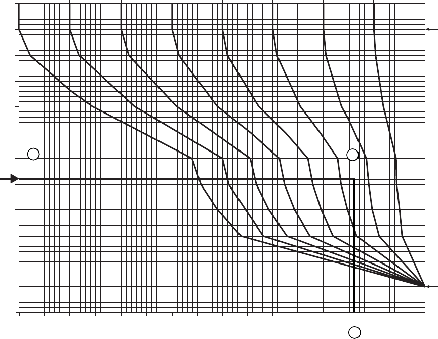
SA
AA0675A
TORQUE FACTOR
DATA BASIS: CALCULATED
40
35
30
25
20
15
10
5
0
−5
−10
−15
−20
.84 .86 .88 .90 .92 .94 .96 .98 1.0
.84 .85 .86 .87 .88 .89 .90 .91 .92 .93 .94 .96.95 .97 .98 .99 1.00
FOR FAT’S
OF 35oC
AND ABOVE
TR = ATF
FOR FAT’S
OF −
AND BELOW
TR = 1.0
12
3
TORQUE RATIO AND MAXIMUM TORQUE AVAILABLE
ATF = .95
PRESSURE ALTITUDE = 6000 FT
FAT = 6oC
TO OBTAIN TORQUE RATIO:
1. ENTER TORQUE FACTOR CHART AT KNOWN FAT
2. MOVE RIGHT TO THE ATF VALUE
3. MOVE DOWN, READ TORQUE RATIO = .972
TO CALCULATE MAXIMUM TORQUE AVAILABLE:
4. ENTER MAXIMUM TORQUE AVAILABLE CHART AT
KNOWN FAT (FIGURE 7−3)
5. MOVE RIGHT TO KNOWN PRESSURE ALTITUDE
6. MOVE DOWN, READ SPECIFICATION TORQUE = 97.2%
TO OBTAIN VALUE FROM CHART:
7. MOVE DOWN TO TORQUE RATIO OBTAINED FROM FIGURE 7−2
8. MOVE LEFT, READ MAXIMUM TORQUE AVAILABLE = 93.0%
WANTED:
KNOWN:
METHOD:
EXAMPLE
TORQUE RATIO = TR
TORQUE FACTOR ~ ATF OR ETF
FREE AIR TEMPERATURE ~oC
15OC
Figure 7-2. Aircraft Torque Factor (ATF)
TM 1-1520-237-10
7-7
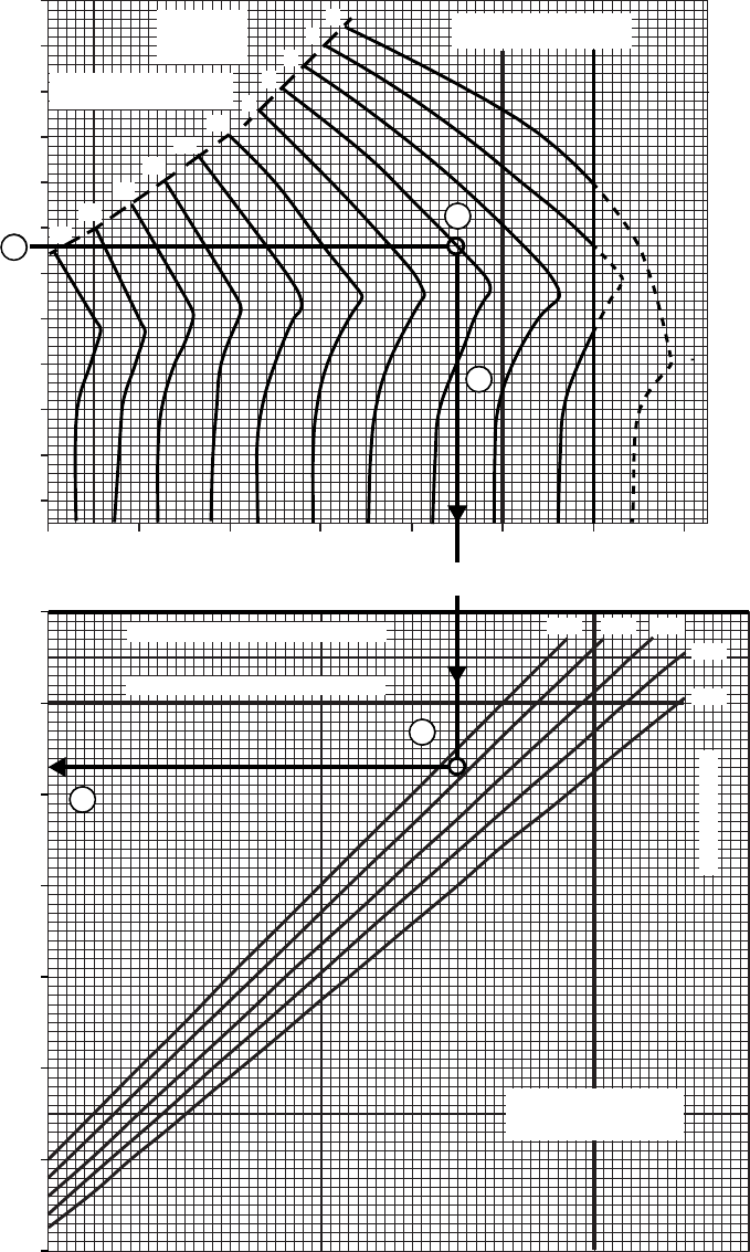
SA
AA0381B
MAXIMUM TORQUE AVAILABLE
SPECIFICATION TORQUE AVAILABLE PER ENGINE %
FREE AIR TEMPERATURE ~ oC
60
50
40
30
20
10
0
−10
−20
−30
−40
−50
50 60 70 80 90 100 110 120
PRESSURE
ALTITUDE
~ 1000 FT
20
16
14
12
10 8
6
4
20
18
TORQUE AVAILABLE ~ %
110
100
90
80
70
60
50
40
DATA BASIS: FLIGHT TEST
TRANSMISSION LIMIT ~ 1 ENGINE
TRANSMISSION LIMIT ~ 2 ENGINE
1.00 0.96 0.92
0.88
0.84
SPECIFIC TORQUE
X TORQUE RATIO
= TORQUE AVAILABLE
TORQUE RATIO
30 MIN LIMITZERO AIRSPEED
100% RPM R HIRSS (BAFFLES INSTALLED)
BLEED AIR OFF
ENGINE HIGH AMBIENT
TEMPERATURE LIMIT
TRANSMISSION LIMITS
2~ENGINE 1~ENGINE
8
7
6
5
4
Figure 7-3. Maximum Torque Available - 30-Minute Limit
TM 1-1520-237-10
7-8

Section III HOVER
7.14 HOVER CHART.
NOTE
VOL For performance calculations with
volcano system installed, use the applicable
high drag performance charts.
a. The primary use of the chart (Figures 7-4 through
7-5) is illustrated by part A of the example. To determine
the torque required to hover, it is necessary to know pres-
sure altitude, free air temperature, gross weight, and desired
wheel height. Enter the upper right grid at the known free
air temperature, move right to the pressure altitude, move
down to gross weight. For OGE hover, move left to the
torque per engine scale and read torque required. For IGE
hover, move left to desired wheel height, deflect down and
read torque required for dual-engine or single-engine op-
eration. The IGE wheel height lines represent a compro-
mise for all possible gross weights and altitude conditions.
A small torque error up to 63% torque may occur at ex-
treme temperature and high altitude. This error is more evi-
dent at lower wheel heights.
b. In addition to the primary use, the hover chart (Figure
7-4) may be used to predict maximum hover height. To
determine maximum hover height, it is necessary to know
pressure altitude, free air temperature, gross weight, and
maximum torque available. Enter the known free air tem-
perature move right to the pressure altitude, move down to
gross weight, move left to intersection with maximum
torque available and read wheel height. This wheel height
is the maximum hover height.
c. The hover chart may also be used to determine maxi-
mum gross weight for hover at a given wheel height, pres-
sure altitude, and temperature as illustrated in method B of
the example (Figure 7-4). Enter at known free air tempera-
ture, move right to the pressure altitude, then move down
and establish a vertical line on the lower grid. Now enter
lower left grid at maximum torque available. Move up to
wheel height, then move right to intersect vertical line from
pressure altitude/FAT intersection. Interpolate from gross
weight lines to read maximum gross weight at which the
helicopter will hover.
7.15 EFFECTS OF BLADE EROSION KIT.
With the blade erosion kit installed, it will be necessary
to make the following corrections. Multiply the torque re-
quired to hover determined from the charts by 1.02. (Ex-
ample: If indicated torque is 90%, multiply 90 x 1.02 =
91.8% actual torque required.) Multiply the maximum gross
weight to hover obtained from the charts by 0.98. (Ex-
ample: If gross weight is 22,000 lb, multiply by 0.98 =
21,560 lb actual gross weight to hover.) When determining
maximum hover wheel height, enter the chart at 1.02 x
gross weight. (Example: If gross weight is 20,000 lb, mul-
tiply 20,000 x 1.02 = 20,400 lb).
TM 1-1520-237-10
7-9
EXAMPLE A
WANTED:
TORQUE REQUIRED TO HOVER OGE AND AT A 10-FOOT WHEEL HEIGHT
KNOWN:
FAT = 30°C
PRESSURE ALTITUDE = 2,000 FEET
GROSS WEIGHT = 19,500 POUNDS
METHOD:
ENTER HOVER CHART AT KNOWN FAT. MOVE RIGHT TO PRESSURE ALTITUDE, MOVE DOWN
THROUGH GROSS WEIGHT LINES TO DESIRED GROSS WEIGHT. MOVE LEFT TO INDICATE
TORQUE/ENGINE % (OGE) SCALE AND READ OGE HOVER TORQUE (94%). MOVE DOWN
FROM INTERSECTION OF 10-FOOT HOVER LINE AND HORIZONTAL LINE TO READ TORQUE
REQUIRED TO HOVER 10 FEET (80%).
EXAMPLE B
WANTED:
MAXIMUM GROSS WEIGHT TO HOVER OGE
KNOWN:
ATF = 1.0
FAT = 15°C
PRESSURE ALTITUDE = 8,000 FEET
MAXIMUM TORQUE AVAILABLE = 96%
METHOD:
ENTER INDICATED TORQUE/ENGINE (IGE) SCALE AT MAXIMUM TORQUE AVAILABLE (96%),
MOVE UP TO OGE LINE. ENTER CHART AT KNOWN FAT (15°C). MOVE RIGHT TO PRESSURE
ALTITUDE LINE (8,000 FT). MOVE DOWN FROM PRESSURE ALTITUDE LINE AND MOVE
RIGHT FROM OGE LINE. WHERE LINES INTERSECT, READ MAXIMUM GROSS WEIGHT TO
HOVER OGE.
Figure 7-4. Hover - Clean Configuration (Sheet 1 of 2)
TM 1-1520-237-10
7-10
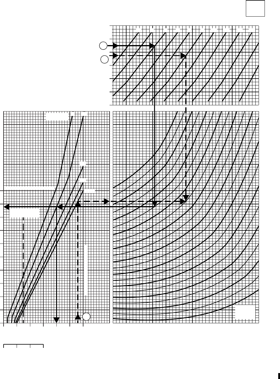
HOVER
CLEAN CONFIGURATION 100% RPM R
ZERO WIND
DATA BASIS: FLIGHT TEST
40 50 60 70 80 90 100
TORQUE PER ENGINE ~ % (IGE)
50
55
60
65
70
75
80
85
90
95
100
TORQUE PER ENGINE ~ % (OGE)
DUAL ENGINE TRANS. LIMIT OGE
40
20
10
5
80 100 120 140
12
13
14
15
16
171819
−60
−40
−20
0
20
40
60
FREE AIR TEMP. ~ OC
−2 0 2 4 6 8 10 12 14 16
18
20
PRESSURE ALTITUDE ~ 1000 FT
SINGLE ENGINE TORQUE ~ %
HOVER
CLEAN
T700(2)
SA
AA2143C
WHEEL
HEIGHT ~FT
22 21 20
GROSS
WEIGHT
~ 1000 LB
SINGLE ENGINE
TRANS. LIMT
A
B
B
DUAL ENGINE TRANS. LIMIT
NOTE
FOR LOW WIND CONDITIONS
AIRCRAFT SHOULD BE HEADED
INTO WIND. 3−5 KT CROSSWIND
OR TAILWIND MAY INCREASE
TORQUE REQUIRED BY UP TO
4% OVER ZERO WIND VALUES
Figure 7-4. Hover - Clean Configuration (Sheet 2 of 2)
TM 1-1520-237-10
Change 2 7-11
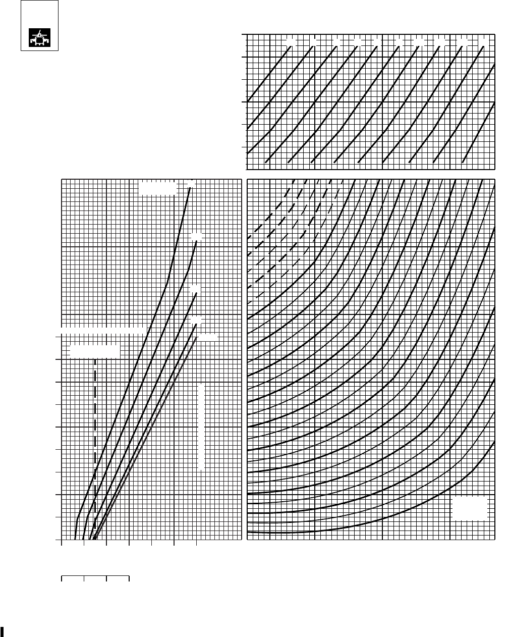
HOVER
HIGH DRAG CONFIGURATION 100% RPM R
ZERO WIND
DATA BASIS: FLIGHT TEST
40 50 60 70 80 90 100
TORQUE PER ENGINE ~ % (IGE)
55
60
65
70
75
80
85
90
95
100
TORQUE PER ENGINE ~ % (OGE)
OGE
20
10
5
DUAL ENGINE TRANS. LIMIT
80 100 120 140
SINGLE ENGINE
TRANS. LIMIT
WHEEL
HEIGHT ~FT
13
14
15
16
17
24
−60
−40
−20
0
20
40
60
FREE AIR TEMP. ~ OC
−2 0 2 4 6 8 10 12 14 16
18
20
PRESSURE ALTITUDE ~ 1000 FT
SINGLE ENGINE TORQUE ~ %
GROSS
WEIGHT
~ 1000 LB
SA
AA2144C
19
20
21
2224.5 23
40
18
HOVER
ESSS
T700 (2)
DUAL ENGINE TRANS. LIMIT
NOTE
FOR LOW WIND CONDITIONS
AIRCRAFT SHOULD BE HEADED
INTO WIND. 3−5 KT CROSSWIND
OR TAILWIND MAY INCREASE
TORQUE REQUIRED BY UP TO
4% OVER ZERO WIND VALUES
Figure 7-5. Hover - High Drag
TM 1-1520-237-10
7-12 Change 2

Section IV CRUISE
7.16 DESCRIPTION.
The cruise charts (Figures 7-6 through 7-28) present
torque required and total fuel flow as a function of airspeed,
altitude, temperature, and gross weight at 100% rotor speed.
Scales for both true airspeed and indicated airspeed are
presented. The baseline aircraft configuration for these
charts was the 9clean and high drag9configuration as de-
fined in Section I. Each cruise chart also presents the
change in torque ( TRQ) required for 10 sq. ft. of addi-
tional flat plate drag with a dashed line on a separate scale.
This line is utilized to correct torque required for external
loads as discussed in Section VI DRAG. Maximum level
flight airspeed (Vh) is obtained at the intersection of gross
weight arc and torque available - 30 minutes or the trans-
mission torque limit, whichever is lower. Airspeeds that
will produce maximum range, maximum endurance, and
maximum rate of climb are also shown. Cruise charts are
provided from sea level to 20,000 feet pressure altitude in
units of 2,000 feet. Each figure number represents a differ-
ent altitude. The charts provide cruise data for free air tem-
peratures from -50° to +60°C, in units of 10°. Charts with
FAT’s that exceed the engine ambient temperature limits
by more than 10°C are deleted.
7.17 USE OF CHARTS.
The primary uses of the charts are illustrated by the
examples of Figure 7-6. To use the charts, it is usually
necessary to know the planned pressure altitude, estimated
free air temperature, planned cruise speed, TAS, and gross
weight. First, select the proper chart on the basis of pres-
sure altitude and FAT. Enter the chart at the cruise air-
speed, IAS, move horizontal and read TAS, move horizon-
tal to the gross weight, move down and read torque
required, and then move up and read associated fuel flow.
Maximum performance conditions are determined by enter-
ing the chart where the maximum range line or the maxi-
mum endurance and rate of climb line intersects the gross
weight line; then read airspeed, fuel flow, and torque re-
quired. Normally, sufficient accuracy can be obtained by
selecting the chart nearest the planned cruising altitude and
FAT or, more conservatively, by selecting the chart with
the next higher altitude and FAT. If greater accuracy is
required, interpolation between altitudes and/or tempera-
tures is permissible. To be conservative, use the gross
weight at the beginning of the cruise flight. For greater
accuracy on long flights, however, it is preferable to deter-
mine cruise information for several flight segments to allow
for the decreasing gross weight.
a. Airspeed. True and indicated airspeeds are presented
at opposite sides of each chart. On any chart, indicated
airspeed can be directly converted to true airspeed (or vice
versa) by reading directly across the chart without regard
for the other chart information. The level flight airspeed
calibration for aircraft with wedge mounted pitot static
probes (hard points only) was used to convert indicated to
true airspeed.
b. Torque. Since pressure altitude and temperature are
fixed for each chart, torque required varies according to
gross weight and airspeed. The torque and torque limits
shown on these charts are for dual-engine operation. The
maximum torque available is presented on each chart as
either the transmission torque limit or torque available - 30
minute for both ATF-1.0 and 0.9 values. The maximum
torque available for aircraft with an ATF value between
these shall be interpolated. The continuous torque available
values shown represent the minimum torque available for
ATF’s of 0.95 or greater. For ATF’s less than 0.95 maxi-
mum continuous torque available may be slightly reduced.
Higher torque than that represented by these lines may be
used if it is available without exceeding the limitations pre-
sented in Chapter 5. An increase or decrease in torque re-
quired because of a drag area change is calculated by add-
ing or subtracting the change in torque from the torque on
the curve, and then reading the new fuel flow total.
c. Fuel Flow. Fuel flow scales are provided opposite the
torque scales. On any chart, torque may be converted di-
rectly to fuel flow without regard to other chart informa-
tion. Data shown in this section is for two-engine operation.
For one-engine fuel flow, refer to Section VIII FUEL
FLOW.
(1) With bleed-air extracted, fuel flow increases:
(a) Engine anti-ice on -About 60 lbs/hr Example:
(760 lbs/hr + 60 lbs/hr = 820 lbs/hr.)
(b) Heater on - About 20 lbs/hr.
(c) Both on - About 80 lbs/hr.
(2) When the cruise IR suppressors are removed or
hover IR suppressor system is installed and operating in the
benign mode (exhaust baffles removed), the dual-engine
fuel flow will decrease about 16 lbs/hr.
d. Maximum Range. The maximum range lines (MAX
RANGE) indicate the combinations of gross weight and
TM 1-1520-237-10
7-13

airspeed that will produce the greatest flight range per
pound of fuel under zero wind conditions. When maximum
range airspeed line is above the maximum torque available,
the resulting maximum airspeed should be used for maxi-
mum range. A method of estimating maximum range speed
in winds is to increase IAS by 2.5 knots per each 10 knots
of effective headwind (which reduces flight time and mini-
mizes loss in range) and decrease IAS by 2.5 knots per 10
knots of effective tailwind for economy.
e. Maximum Endurance and Rate of Climb. The maxi-
mum endurance and rate of climb lines (MAX END and
R/C) indicate the combinations of gross weight and air-
speed that will produce the maximum endurance and the
maximum rate of climb. The torque required for level flight
at this condition is a minimum, providing a minimum fuel
flow (maximum endurance) and a maximum torque change
available for climb (maximum rate of climb).
f. Change in Frontal Area. Since the cruise information
is given for the 9clean configuration,9adjustments to torque
should be made when operating with external sling loads or
aircraft external configuration changes. To determine the
change in torque, first obtain the appropriate multiplying
factor from the drag load chart (Figure 7-30), then enter the
cruise chart at the planned cruise speed TAS, move right to
the broken TRQ line, and move up and read TRQ.
Multiply TRQ by the multiplying factor to obtain change
in torque, then add or subtract change in torque from torque
required for the primary mission configuration. Enter the
cruise chart at resulting torque required, move up, and read
fuel flow. If the resulting torque required exceeds the gov-
erning torque limit, the torque required must be reduced to
the limit. The resulting reduction in airspeed may be found
by subtracting the change in torque from the limit torque;
then enter the cruise chart at the reduced torque, and move
up to the gross weight. Move left or right to read TAS or
IAS. The engine torque setting for maximum range ob-
tained from the clean configuration cruise chart will gener-
ally result in cruise at best range airspeed for the higher
drag configuration. To determine the approximate airspeed
for maximum range for alternative or external load configu-
rations, reduce the value from the cruise chart by 6 knots
for each 10 square foot increase in drag area, F. For
example, if both cabin doors are open the F increases 6
ft
2
and the maximum range airspeed would be reduced by
approximately 4 knots (6 Kts/10 ft
2
36ft
2
= 3.6 Kts).
g. Additional Uses. The low speed end of the cruise
chart (below 40 knots) is shown primarily to familiarize
you with the low speed power requirements of the helicop-
ter. It shows the power margin available for climb or accel-
eration during maneuvers, such as NOE flight. At zero air-
speed, the torque represents the torque required to hover
out of ground effect. In general, mission planning for low
speed flight should be based on hover out of ground effect.
7.18 SINGLE-ENGINE.
a. The minimum or maximum single-engine speeds can
be determined by using a combination of the 700 torque
available and cruise charts. To calculate single-engine
speeds, first determine the torque available from Section II
at the TGT limit desired and divide by 2. (Example: 90%
TRQ42 = 45% TRQ.)
b. Select the appropriate cruise chart for the desired
flight condition and enter the torque scale with the torque
value derived above. Move up to the intersection of torque
available and the mission gross weight arc, and read across
for minimum single-engine airspeed. Move up to the sec-
ond intersection of torque and weight, and read across to
determine the maximum single-engine speed. If no inter-
sections occur, there is no single-engine level flight capa-
bility for the conditions. Single-engine fuel flow at the de-
sired 10 minute, 30 minute, continuous conditions may be
obtained by doubling the torque required from the cruise
chart and referring to Figure 7–34.
TM 1-1520-237-10
7-14
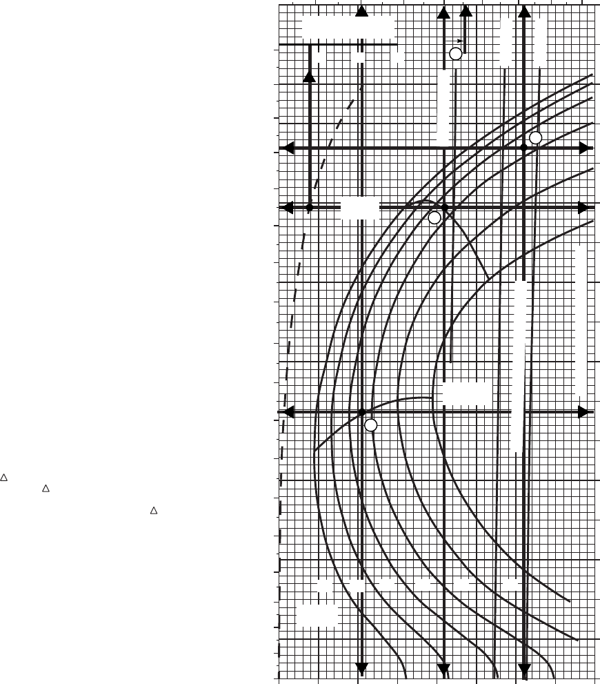
SA
AA0682
A. CRUISE CONDITIONS FOR MAXIMUM RANGE
B. CONDITIONS FOR MAXIMUM ENDURANCE
C. MAXIMUM AIRSPEED IN LEVEL FLIGHT
D. DETERMINE TORQUE AND FUEL FLOW
REQUIRED TO CRUISE AT THE CONDITIONS
OF EXAMPLE A WITH CABIN DOORS OPEN
FAT = + 30oC
PRESSURE ALTITUDE = 6000 FT
GW = 17000 LBS
ATF = 0.95
A. TURN TO CRUISE CHARTS NEAREST KNOWN
FLIGHT CONDITIONS, AT INTERSECTION
OF MAX RANGE LINE AND KNOWN VALUE OF
GROSS WEIGHT:
MOVE LEFT, READ TAS = 135 KTS
MOVE RIGHT, READ IAS = 119 KTS
MOVE DOWN, READ TORQUE = 62% TRQ
MOVE UP, READ TOTAL FUEL FLOW = 900 LBS / HR
B. AT INTERSECTION OF MAX END. / AND R / C
LINE AND KNOWN VALUE OF GROSS WEIGHT:
MOVE LEFT, READ TAS = 82 KTS
MOVE RIGHT, READ IAS = 67 KTS
MOVE DOWN, READ TORQUE = 41% TRQ
MOVE UP, READ TOTAL FUEL FLOW = 700 LBS / HR
C. AT INTERSECTION OF 30−MINUTE TORQUE
AVAILABLE AS INTERPOLATED FOR THE ATF
VALUE AT THE KNOWN GROSS WEIGHT:
MOVE LEFT, READ MAXIMUM TAS = 153 KTS
MOVE RIGHT, READ MAXIMUM IAS = 135 KTS
MOVE DOWN, READ MAXIMUM TORQUE = 82% TRQ
MOVE UP, READ TOTAL FUEL FLOW = 1125 LBS / HR
D. ENTER TRQ% PER 10 SQ FT SCALE AT 135 KTAS
MOVE UP READ TRQ = 8.0%
TURN TO DRAG TABLE IN SECTION VII
NOTE CABIN DOORS OPEN = 6.0 SQ FT F
AND HAS A DRAG MULTIPLYING FACTOR VALUE
OF 0.60, CALCULATE TOTAL TORQUE REQUIRED:
62% + (0.6 X 8.0%) = 66.8% TRQ
READ FUEL FLOW AT−TOTAL TORQUE = 950 LBS / HR
METHOD:
KNOWN:
WANTED:
EXAMPLE
CRUISE EXAMPLE
CLEAN CONFIGURATION
100% RPM R
20 30 40 50 60 70 80 90 100
0
20
10
30
40
50
60
70
80
90
100
110
120
130
140
150
160
170
180
6 7 8 9 10 11 12 13
0
10
20
30
40
50
60
70
80
90
100
110
120
130
140
150
160
170
~ CONTINUOUS
ATF = 0.9
ATF = 1.0
TORQUE AVAILABLE ~ 30 MINUTES
TRANSMISSION TORQUE LIMIT
MAX
RANGE
GW ~
1000 LB
MAX END
AND R / C
12 14 16 18 20 22
TRQ ~ % OR DRAG
AREA OF 10 SQ FT
10 20 30
A
B
C
D
TRUE AIRSPEED ~ KTS
INDICATED AIRSPEED ~ KTS
TORQUE PER ENGINE ~ %
FAT: 30 OC ALT: 6,000 FT
TOTAL FUEL FLOW 100 LB/HR
Figure 7-6. Sample Cruise Chart - Clean
TM 1-1520-237-10
7-15
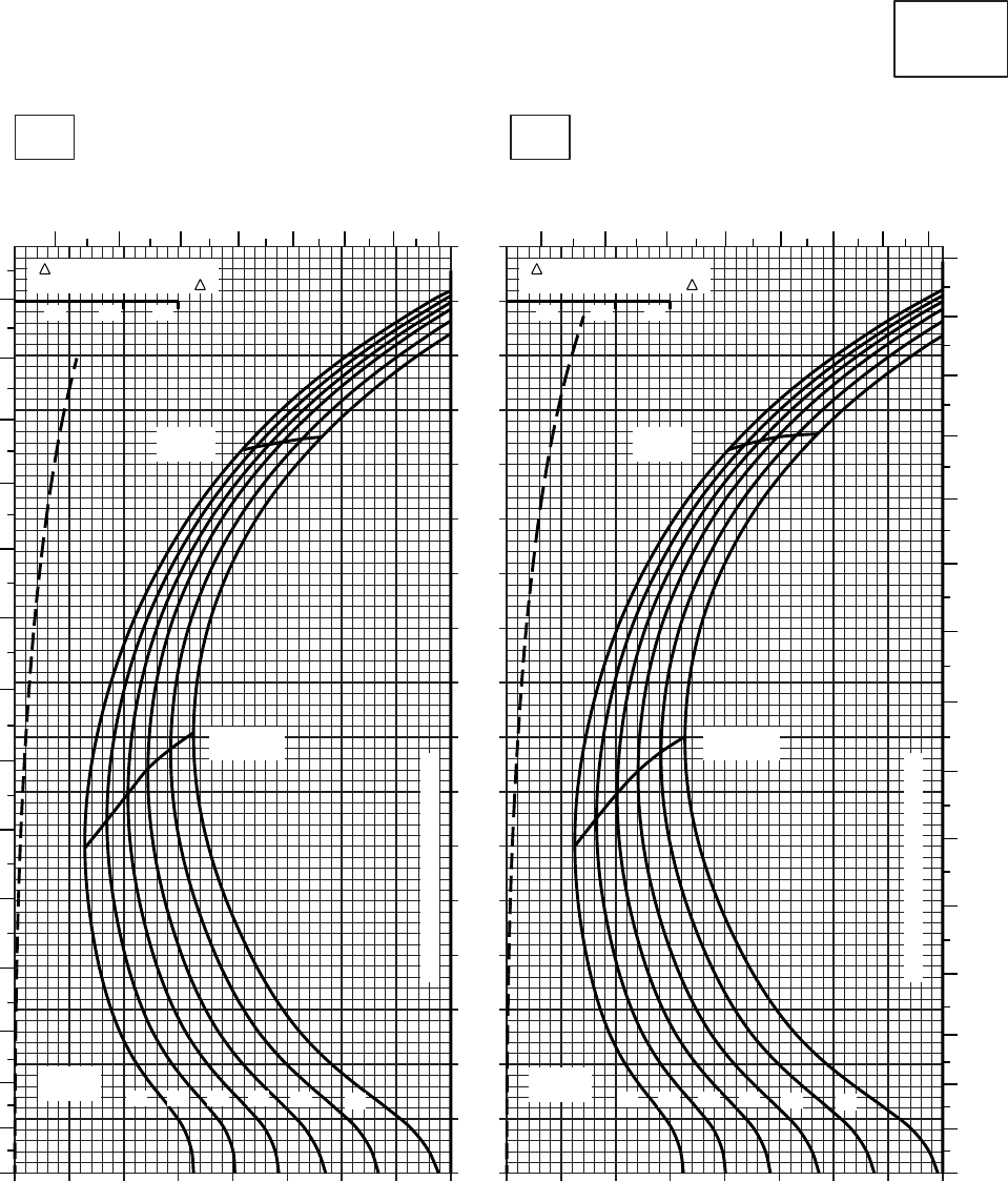
20 30 40 50 60 70 80 90 100
0
10
20
30
40
50
60
70
80
90
100
110
120
130
140
150
160
170
20 30 40 50 60 70 80 90 100
SA
AA0414
CRUISE
CLEAN CONFIGURATION
PRESS ALT: 0 FT
CRUISE
0 FT
T700 (2)
TORQUE PER ENGINE ~ %TORQUE PER ENGINE ~ %
IAS ~ KTS TOTAL FUEL FLOW ~ 100 LB/HRTOTAL FUEL FLOW ~ 100 LB/HR
DATA BASE:FLIGHT TEST
TRUE AIRSPEED ~ KTS
TRUE AIRSPEED ~ KTS
−40OC−50OC
TRQ ~ % FOR DRAG
AREA OF 10 SQ FT OF F
10 20 30
TRQ ~ % FOR DRAG
AREA OF 10 SQ FT OF F
10 20 30
6 7 8 9 10 11 12 13 6 7 8 9 10 11 12 13
150
140
130
120
110
100
90
80
70
60
50
40
30
20
10
0
140
130
120
110
100
90
80
70
60
50
40
30
20
10
0
MAX END
AND R / C
12 14 16 18 20 22
GW ~
1000 LB
TRANSMISSION TORQUE LIMIT
TRANSMISSION TORQUE LIMIT
MAX
RANGE MAX
RANGE
MAX END
AND R / C
12 14 16 18 20 22
GW ~
1000 LB
Figure 7-7. Cruise - Pressure Altitude Sea Level (Sheet 1 of 6)
TM 1-1520-237-10
7-16

20 30 40 50 60 70 80 90 100
0
10
20
30
40
50
60
70
80
90
100
110
120
130
140
150
160
170
20 30 40 50 60 70 80 90 100
SA
AA0413
CRUISE
CLEAN CONFIGURATION
PRESS ALT: 0 FT
CRUISE
0 FT
T700 (2)
TORQUE PER ENGINE ~ %TORQUE PER ENGINE ~ %
IAS ~ KTS TOTAL FUEL FLOW ~ 100 LB/HRTOTAL FUEL FLOW ~ 100 LB/HR
DATA BASE:FLIGHT TEST
TRUE AIRSPEED ~ KTS
TRUE AIRSPEED ~ KTS
−20OC−30OC
TRQ ~ % FOR DRAG
AREA OF 10 SQ FT OF F
10 20 30
TRQ ~ % FOR DRAG
AREA OF 10 SQ FT OF F
10 20 30
150
140
130
120
110
100
90
80
70
60
50
40
30
20
10
0
150
140
130
120
110
100
90
80
70
60
50
40
30
20
10
0
6 7 8 9 10 11 12 13 6 7 8 9 10 11 12 13
12 14 16 18 20 22
GW ~
1000 LB
TRANSMISSION TORQUE LIMIT
TRANSMISSION TORQUE LIMIT
MAX
RANGE
MAX
RANGE
MAX END
AND R / C
MAX END
AND R / C
12 14 16 18 20 22
GW ~
1000 LB
Figure 7-7. Cruise - Pressure Altitude Sea Level (Sheet 2 of 6)
TM 1-1520-237-10
7-17
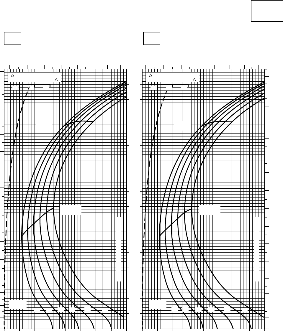
20 30 40 50 60 70 80 90 100
0
10
20
30
40
50
60
70
80
90
100
110
120
130
140
150
160
170
20 30 40 50 60 70 80 90 100
SA
AA0412
CRUISE
CLEAN CONFIGURATION
PRESS ALT: 0 FT
CRUISE
0 FT
T700 (2)
TORQUE PER ENGINE ~ %TORQUE PER ENGINE ~ %
IAS ~ KTS TOTAL FUEL FLOW ~ 100 LB/HRTOTAL FUEL FLOW ~ 100 LB/HR
DATA BASE:FLIGHT TEST
TRUE AIRSPEED ~ KTS
TRUE AIRSPEED ~ KTS
0OC−10OC
TRQ ~ % FOR DRAG
AREA OF 10 SQ FT OF F
10 20 30
TRQ ~ % FOR DRAG
AREA OF 10 SQ FT OF F
10 20 30
6 7 8 9 10 11 12 13 6 7 8 9 10 11 12 13
160
150
140
130
120
110
100
90
80
70
60
50
40
30
20
10
0
160
150
140
130
120
110
100
90
80
70
60
50
40
30
20
10
0
12 14 16 18 20 22
GW ~
1000 LB
TRANSMISSION TORQUE LIMIT
TRANSMISSION TORQUE LIMIT
MAX END
AND R / C
MAX END
AND R / C
MAX
RANGE
MAX
RANGE
12 14 16 18 20 22
GW ~
1000 LB
Figure 7-7. Cruise - Pressure Altitude Sea Level (Sheet 3 of 6)
TM 1-1520-237-10
7-18
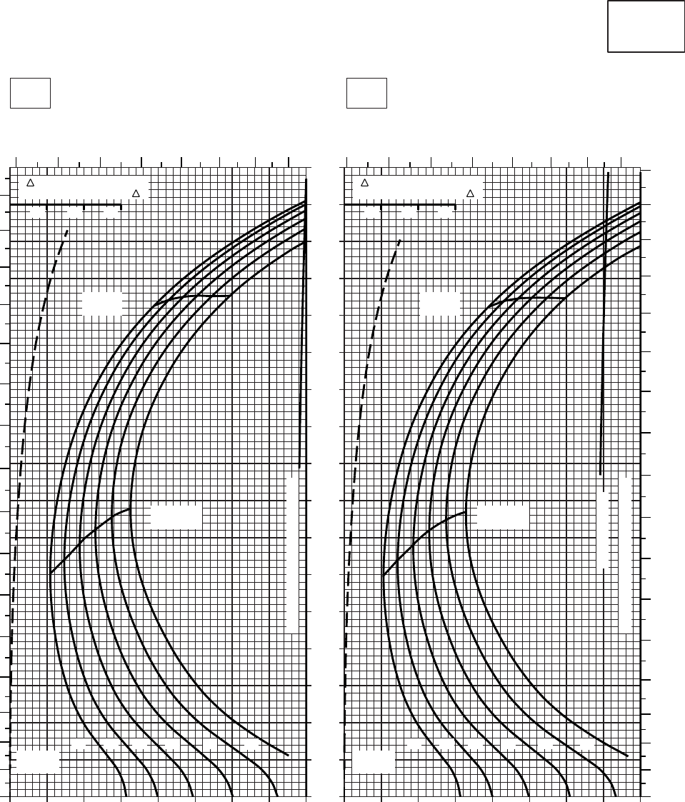
20 30 40 50 60 70 80 90 100
0
10
20
30
40
50
60
70
80
90
100
110
120
130
140
150
160
170
20 30 40 50 60 70 80 90 100
SA
AA0415
CRUISE
CLEAN CONFIGURATION
PRESS ALT: 0 FT
CRUISE
0 FT
T700 (2)
TORQUE PER ENGINE ~ %TORQUE PER ENGINE ~ %
IAS ~ KTS TOTAL FUEL FLOW ~ 100 LB/HRTOTAL FUEL FLOW ~ 100 LB/HR
DATA BASE:FLIGHT TEST
TRUE AIRSPEED ~ KTS
TRUE AIRSPEED ~ KTS
20OC10OC
TRQ ~ % FOR DRAG
AREA OF 10 SQ FT OF F
10 20 30
TRQ ~ % FOR DRAG
AREA OF 10 SQ FT OF F
10 20 30
6 7 8 9 10 11 12 13 6 7 8 9 10 11 12 13
170
160
150
140
130
120
110
100
90
80
70
60
50
40
30
20
10
0
160
150
140
130
120
110
100
90
80
70
60
50
40
30
20
10
0
12 14 16 18 20 22
GW ~
1000 LB
~CONTINUOUS
TRANSMISSION TORQUE LIMIT
TRANSMISSION TORQUE LIMIT
MAX
RANGE
MAX
RANGE
MAX END
AND R / C
MAX END
AND R / C
12 14 16 18 20 22
GW ~
1000 LB
Figure 7-7. Cruise - Pressure Altitude Sea Level (Sheet 4 of 6)
TM 1-1520-237-10
7-19
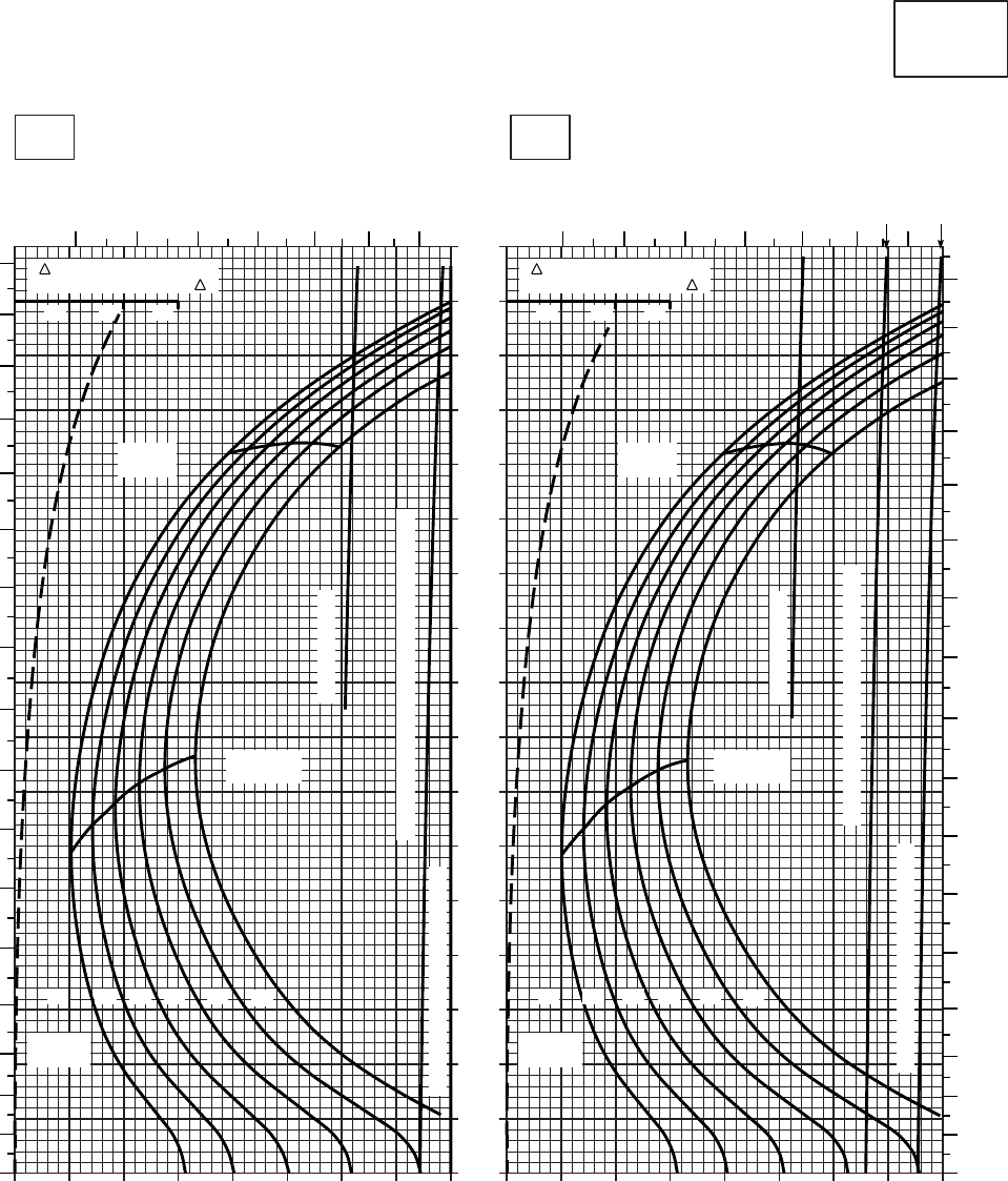
20 30 40 50 60 70 80 90 100
0
10
20
30
40
50
60
70
80
90
100
110
120
130
140
150
160
170
20 30 40 50 60 70 80 90 100
SA
AA0416
CRUISE
CLEAN CONFIGURATION
PRESS ALT: 0 FT
CRUISE
0 FT
T700 (2)
TORQUE PER ENGINE ~ %TORQUE PER ENGINE ~ %
IAS ~ KTS TOTAL FUEL FLOW ~ 100 LB/HRTOTAL FUEL FLOW ~ 100 LB/HR
DATA BASE:FLIGHT TEST
TRUE AIRSPEED ~ KTS
TRUE AIRSPEED ~ KTS
40OC30OC
TRQ ~ % FOR DRAG
AREA OF 10 SQ FT OF F
10 20 30
TRQ ~ % FOR DRAG
AREA OF 10 SQ FT OF F
10 20 30
78910111213 78910111213
170
160
150
140
130
120
110
100
90
80
70
60
50
40
30
20
10
0
170
160
150
140
130
120
110
100
90
80
70
60
50
40
30
20
10
0
MAX
RANGE
MAX
RANGE
MAX END
AND R / C
MAX END
AND R / C
1212 1414 1616 1818 2020 2222
GW ~
1000 LB GW ~
1000 LB
~CONTINUOUS
TRANSMISSION TORQUE LIMIT
TRANSMISSION TORQUE LIMIT
~CONTINUOUS
ATF=0.9
ATF=1.0
TORQUE AVAILABLE ~ 30 MINUTES
TORQUE AVAILABLE ~ 30 MINUTES, ATF=0.9
Figure 7-7. Cruise - Pressure Altitude Sea Level (Sheet 5 of 6)
TM 1-1520-237-10
7-20
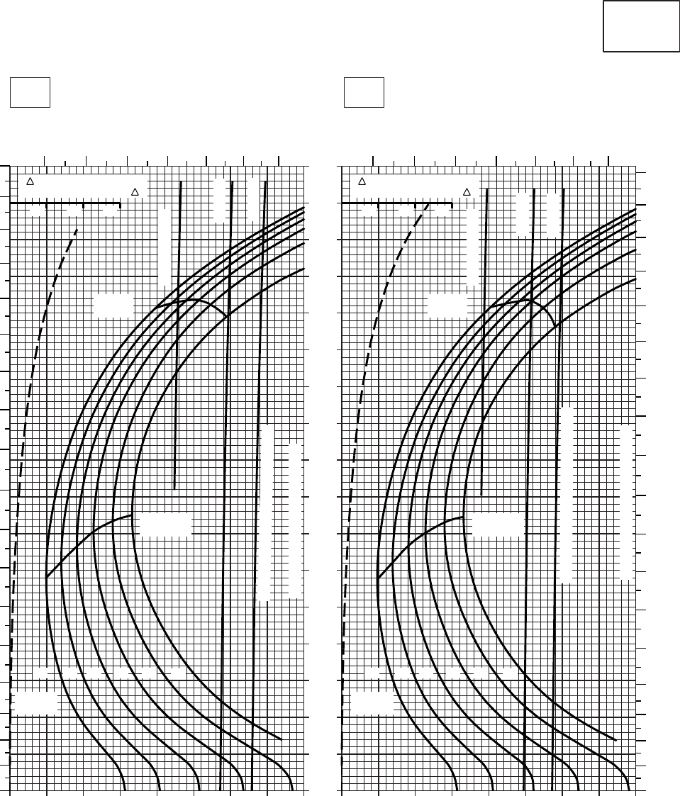
20 30 40 50 60 70 80 90 100
0
10
20
30
40
50
60
70
80
90
100
110
120
130
140
150
160
170
20 30 40 50 60 70 80 90 100
SA
AA0417
CRUISE
CLEAN CONFIGURATION
PRESS ALT: 0 FT
CRUISE
0 FT
T700 (2)
TORQUE PER ENGINE ~ %TORQUE PER ENGINE ~ %
IAS ~ KTS TOTAL FUEL FLOW ~ 100 LB/HRTOTAL FUEL FLOW ~ 100 LB/HR
DATA BASE:FLIGHT TEST
TRUE AIRSPEED ~ KTS
TRUE AIRSPEED ~ KTS
60OC50OC
TRQ ~ % FOR DRAG
AREA OF 10 SQ FT OF F
10 20 30
TRQ ~ % FOR DRAG
AREA OF 10 SQ FT OF F
10 20 30
180
170
160
150
140
130
120
110
100
90
80
70
60
50
40
30
20
10
0
180
170
160
150
140
130
120
100
90
80
70
60
50
40
30
20
10
0
110
7 8 9 10 11 12 13 7 8 9 10 11 12 13
MAX
RANGE
MAX END
AND R / C
12 14 16 18 20 22
TRANSMISSION TORQUE LIMIT
GW ~
1000 LB
GW ~
1000 LB
12 14 16 18 20 22
TRANSMISSION TORQUE LIMIT
MAX
RANGE
~CONTINUOUS
~CONTINUOUS
MAX END
AND R / C
TORQUE AVAILABLE ~ 30 MINUTES
TORQUE AVAILABLE ~ 30 MINUTES
ATF=1.0
ATF=1.0
ATF=0.9
ATF=0.9
Figure 7-7. Cruise - Pressure Altitude Sea Level (Sheet 6 of 6)
TM 1-1520-237-10
7-21

20 30 40 50 60 70 80 90 100
0
10
20
30
40
50
60
70
80
90
100
110
120
130
140
150
160
170
20 30 40 50 60 70 80 90 100
SA
AA0534
CRUISE
PRESS ALT: 0 FT
CRUISE
0 FT
T700 (2)
TORQUE PER ENGINE ~ %TORQUE PER ENGINE ~ %
IAS ~ KTS TOTAL FUEL FLOW ~ 100 LB/HRTOTAL FUEL FLOW ~ 100 LB/HR
DATA BASE:FLIGHT TEST
TRUE AIRSPEED ~ KTS
TRUE AIRSPEED ~ KTS
−40OC−50OC
TRQ ~ % FOR DRAG
AREA OF 10 SQ FT OF F
10 20 30
TRQ ~ % FOR DRAG
AREA OF 10 SQ FT OF F
10 20 30
6 7 8 9 10 11 12 13 6 7 8 9 10 11 12 13
160
150
140
130
120
110
100
90
80
70
60
50
40
30
20
10
0
160
150
140
130
120
110
100
90
80
70
60
50
40
30
20
10
0
12 14 16 18 20 22 23 24.5
GW ~
1000 LB
12 14 16 18 20 22 23 24.5
GW ~
1000 LB
TRANSMISSION TORQUE LIMIT
TRANSMISSION TORQUE LIMIT
MAX
RANGE
MAX
RANGE
MAX END
AND R / C
MAX END
AND R / C
Figure 7-8. Cruise High Drag - Pressure Altitude Sea Level (Sheet 1 of 6)
TM 1-1520-237-10
7-22
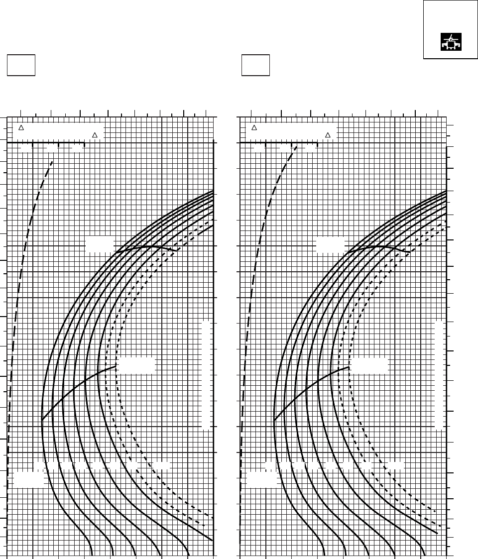
20 30 40 50 60 70 80 90 100
0
10
20
30
40
50
60
70
80
90
100
110
120
130
140
150
160
170
20 30 40 50 60 70 80 90 100
SA
AA0535
CRUISE
PRESS ALT: 0 FT
CRUISE
0 FT
TORQUE PER ENGINE ~ %TORQUE PER ENGINE ~ %
IAS ~ KTS TOTAL FUEL FLOW ~ 100 LB/HRTOTAL FUEL FLOW ~ 100 LB/HR
DATA BASE:FLIGHT TEST
TRUE AIRSPEED ~ KTS
TRUE AIRSPEED ~ KTS
−20OC−30OC
TRQ ~ % FOR DRAG
AREA OF 10 SQ FT OF F
10 20 30
TRQ ~ % FOR DRAG
AREA OF 10 SQ FT OF F
10 20 30
6 7 8 9 10 11 12 13 6 7 8 9 10 11 12 13
170
160
150
140
130
120
110
100
90
80
70
60
50
40
30
20
10
00
10
20
30
40
50
60
70
80
90
100
110
120
130
140
150
160
170
TRANSMISSION TORQUE LIMIT
12 14 16 18 20 22 23 24.5
GW ~
1000 LB
12 14 16 18 20 22 23 24.5
GW ~
1000 LB
TRANSMISSION TORQUE LIMIT
MAX END
AND R / C
MAX
RANGE
MAX
RANGE
MAX END
AND R / C
T700 (2)
Figure 7-8. Cruise High Drag - Pressure Altitude Sea Level (Sheet 2 of 6)
TM 1-1520-237-10
7-23
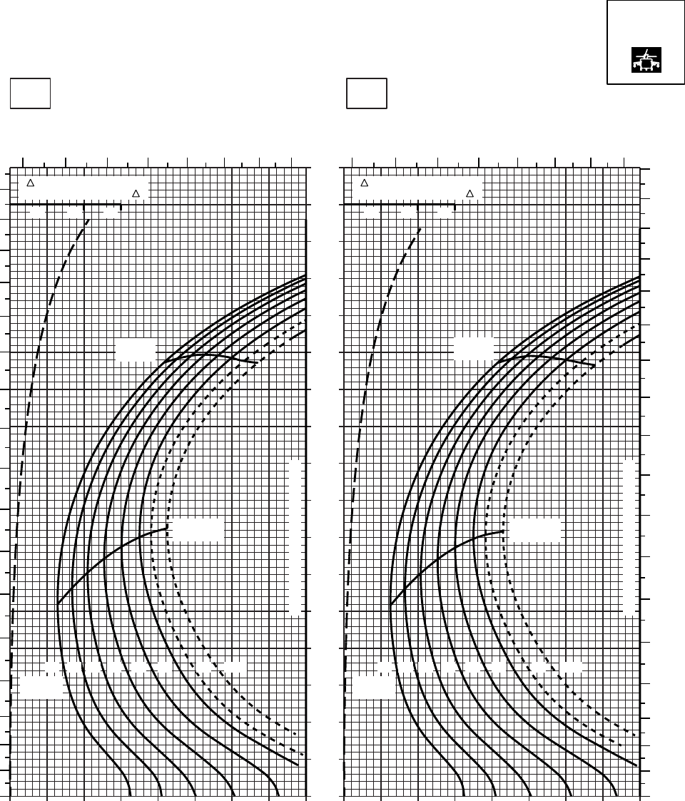
20 30 40 50 60 70 80 90 100
0
10
20
30
40
50
60
70
80
90
100
110
120
130
140
150
160
170
20 30 40 50 60 70 80 90 100
SA
AA0536
CRUISE
PRESS ALT: 0 FT
CRUISE
0 FT
TORQUE PER ENGINE ~ %TORQUE PER ENGINE ~ %
IAS ~ KTS TOTAL FUEL FLOW ~ 100 LB/HRTOTAL FUEL FLOW ~ 100 LB/HR
DATA BASE:FLIGHT TEST
TRUE AIRSPEED ~ KTS
TRUE AIRSPEED ~ KTS
0OC−10OC
TRQ ~ % FOR DRAG
AREA OF 10 SQ FT OF F
10 20 30
TRQ ~ % FOR DRAG
AREA OF 10 SQ FT OF F
10 20 30
6 7 8 9 10 11 12 13 6 7 8 9 10 11 12 13
180
170
160
150
140
130
120
110
100
90
80
70
60
50
40
30
20
10
00
10
20
30
40
50
60
70
80
90
100
110
120
130
140
150
160
170
TRANSMISSION TORQUE LIMIT
12 14 16 18 20 22 23 24.5
GW ~
1000 LB
TRANSMISSION TORQUE LIMIT
12 14 16 18 20 22 23 24.5
GW ~
1000 LB
MAX END
AND R / C
MAX END
AND R / C
MAX
RANGE
MAX
RANGE
T700 (2)
Figure 7-8. Cruise High Drag - Pressure Altitude Sea Level (Sheet 3 of 6)
TM 1-1520-237-10
7-24
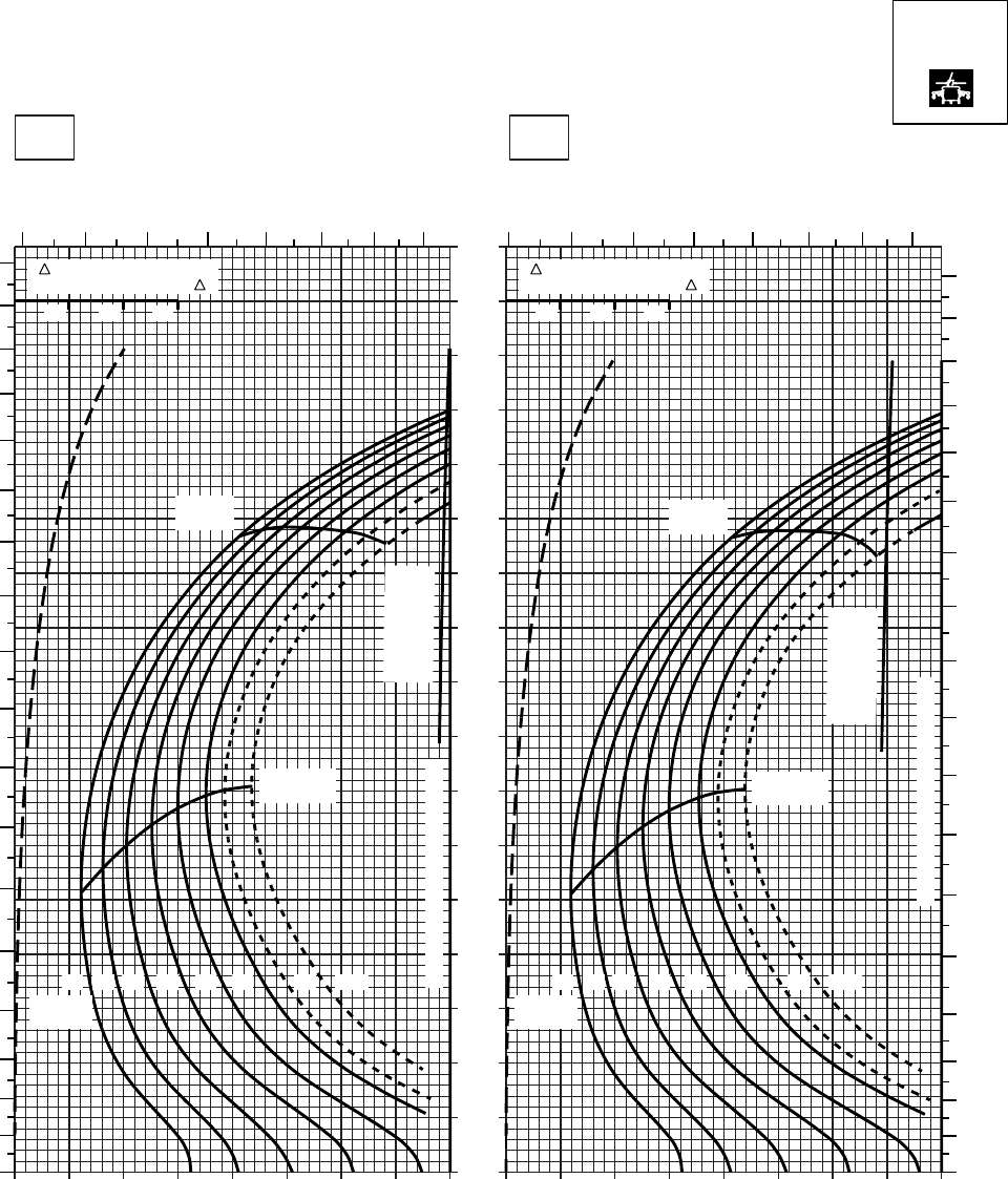
20 30 40 50 60 70 80 90 100
0
10
20
30
40
50
60
70
80
90
100
110
120
130
140
150
160
170
20 30 40 50 60 70 80 90 100
SA
AA0537
CRUISE
PRESS ALT: 0 FT
CRUISE
0 FT
TORQUE PER ENGINE ~ %TORQUE PER ENGINE ~ %
IAS ~ KTS TOTAL FUEL FLOW ~ 100 LB/HRTOTAL FUEL FLOW ~ 100 LB/HR
DATA BASE:FLIGHT TEST
TRUE AIRSPEED ~ KTS
TRUE AIRSPEED ~ KTS
20OC10OC
TRQ ~ % FOR DRAG
AREA OF 10 SQ FT OF F
10 20 30
TRQ ~ % FOR DRAG
AREA OF 10 SQ FT OF F
10 20 30
6 7 8 9 10 11 12 13 6 7 8 9 10 11 12 13
180
170
160
150
140
130
120
110
100
90
80
70
60
50
40
30
20
10
00
10
20
30
40
50
60
70
80
90
100
110
120
130
140
150
160
170
180
TRANSMISSION TORQUE LIMIT
12 14 16 18 20 22 23 24.5
GW ~
1000 LB
TRANSMISSION TORQUE LIMIT
12 14 16 18 20 22 23 24.5
GW ~
1000 LB
MAX
RANGE
MAX
RANGE
MAX END
AND R / C
MAX END
AND R / C
TORQUE
AVAILABLE
~ CONTINUOUS
TORQUE
AVAILABLE
~ CONTINUOUS
T700 (2)
Figure 7-8. Cruise High Drag - Pressure Altitude Sea Level (Sheet 4 of 6)
TM 1-1520-237-10
7-25
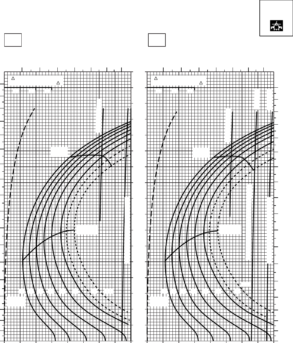
20 30 40 50 60 70 80 90 100
0
10
20
30
40
50
60
70
80
90
100
110
120
130
140
150
160
170
20 30 40 50 60 70 80 90 100
SA
AA0538
CRUISE
PRESS ALT: 0 FT
CRUISE
0 FT
TORQUE PER ENGINE ~ %TORQUE PER ENGINE ~ %
IAS ~ KTS TOTAL FUEL FLOW ~ 100 LB/HRTOTAL FUEL FLOW ~ 100 LB/HR
DATA BASE:FLIGHT TEST
TRUE AIRSPEED ~ KTS
TRUE AIRSPEED ~ KTS
40OC30OC
TRQ ~ % FOR DRAG
AREA OF 10 SQ FT OF F
10 20 30
TRQ ~ % FOR DRAG
AREA OF 10 SQ FT OF F
10 20 30
7 8 9 10 11 12 13 7 8 9 10 11 12 13
180
170
160
150
140
130
120
110
100
90
80
70
60
50
40
30
20
10
00
10
20
30
40
50
60
70
80
90
100
110
120
130
140
150
160
170
180
12 14 16 18 20 22 23 24.5
GW ~
1000 LB
12 14 16 18 20 22 23
24.5
GW ~
1000 LB
TRANSMISSION TORQUE LIMIT
TRANSMISSION TORQUE LIMIT
MAX END
AND R / C
MAX END
AND R / C
MAX
RANGE
MAX
RANGE
~ CONTINUOUS
~ CONTINUOUS
ATF = 0.9
ATF = 1.0
TORQUE AVAILABLE ~ 30 MINUTES
T700 (2)
Figure 7-8. Cruise High Drag - Pressure Altitude Sea Level (Sheet 5 of 6)
TM 1-1520-237-10
7-26
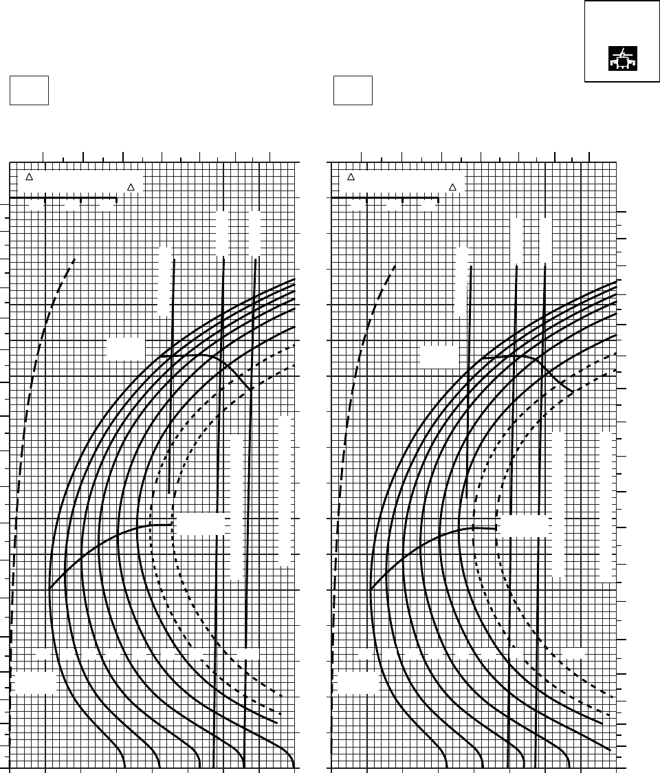
20 30 40 50 60 70 80 90 100
0
10
20
30
40
50
60
70
80
90
100
110
120
130
140
150
160
170
20 30 40 50 60 70 80 90 100
SA
AA0539
CRUISE
TORQUE PER ENGINE ~ %TORQUE PER ENGINE ~ %
IAS ~ KTS TOTAL FUEL FLOW ~ 100 LB/HRTOTAL FUEL FLOW ~ 100 LB/HR
DATA BASE:FLIGHT TEST
TRUE AIRSPEED ~ KTS
TRUE AIRSPEED ~ KTS
TRQ ~ % FOR DRAG
AREA OF 10 SQ FT OF F
10 20 30
TRQ ~ % FOR DRAG
AREA OF 10 SQ FT OF F
10 20 30
50oC60oC
0 FT
PRESS ALT: 0 FT
CRUISE
0
10
20
30
40
50
60
70
80
90
100
110
120
130
140
150
160
170
180
0
10
20
30
40
50
60
70
80
90
100
110
120
130
140
150
160
170
180
MAX
RANGE
ATF= 0.9
ATF= 1.0
MAX END
AND R/C
TORQUE AVAILABLE ~ 30 MIN
TRANSMISSION TORQUE LIMIT
12 14 16 18 20 22 23 24.5
GW ~
1000 LB
ATF= 0.9
ATF= 1.0
MAX
RANGE
TORQUE AVAILABLE ~ 30 MIN
TRANSMISSION TORQUE LIMIT
MAX END
AND R/C
GW ~
1000 LB
12 14 16 18 20 22 23 24.5
7 8 9 10 11 12 13 7 8 9 10 11 12 13
CONTINUOUS
CONTINUOUS
T700 (2)
Figure 7-8. Cruise High Drag - Pressure Altitude Sea Level (Sheet 6 of 6)
TM 1-1520-237-10
7-27
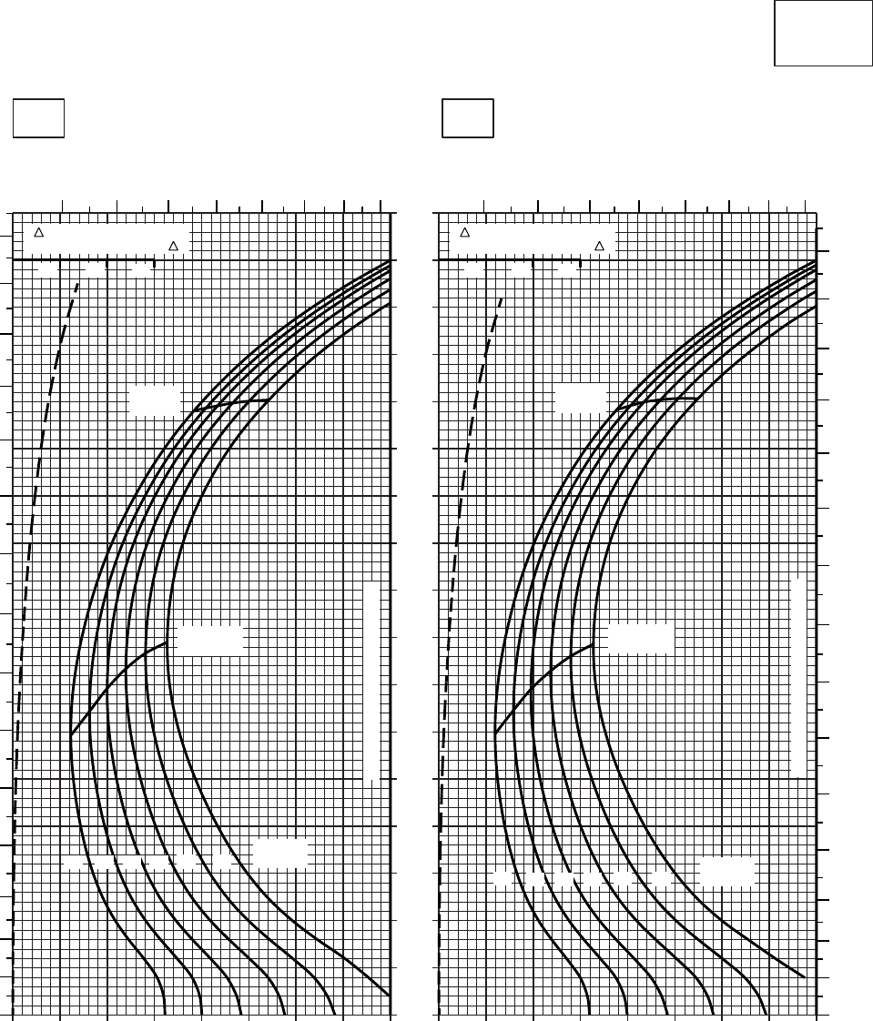
20 30 40 50 60 70 80 90 100
0
10
20
30
40
50
60
70
80
90
100
110
120
130
140
150
160
170
20 30 40 50 60 70 80 90 100
CRUISE
CLEAN CONFIGURATION
CRUISE
T700 (2)
TORQUE PER ENGINE ~ %TORQUE PER ENGINE ~ %
IAS ~ KTS TOTAL FUEL FLOW ~ 100 LB/HRTOTAL FUEL FLOW ~ 100 LB/HR
DATA BASE:FLIGHT TEST
TRUE AIRSPEED ~ KTS
TRUE AIRSPEED ~ KTS
TRQ ~ % FOR DRAG
AREA OF 10 SQ FT OF F
10 20 30
TRQ ~ % FOR DRAG
AREA OF 10 SQ FT OF F
10 20 30
SA
AA0449
6 7 8 9 10 11 12 13
0
10
20
30
40
50
60
70
80
90
100
110
120
130
140
150
678
910 11 12 13
0
10
20
30
40
50
60
70
80
90
100
110
120
130
140
150
MAX
RANGE
MAX END
AND R / C
GW ~
1000 LB
12 14 16 18 20 22
TRANSMISSION TORQUE LIMIT
MAX
RANGE
MAX END
AND R / C
GW ~
1000 LB
12 14 16 18 20 22
TRANSMISSION TORQUE LIMIT
−50oC−40oC
2000 FT
PRESS ALT: 2000 FT
Figure 7-9. Cruise - Pressure Altitude 2,000 Feet (Sheet 1 of 6)
TM 1-1520-237-10
7-28
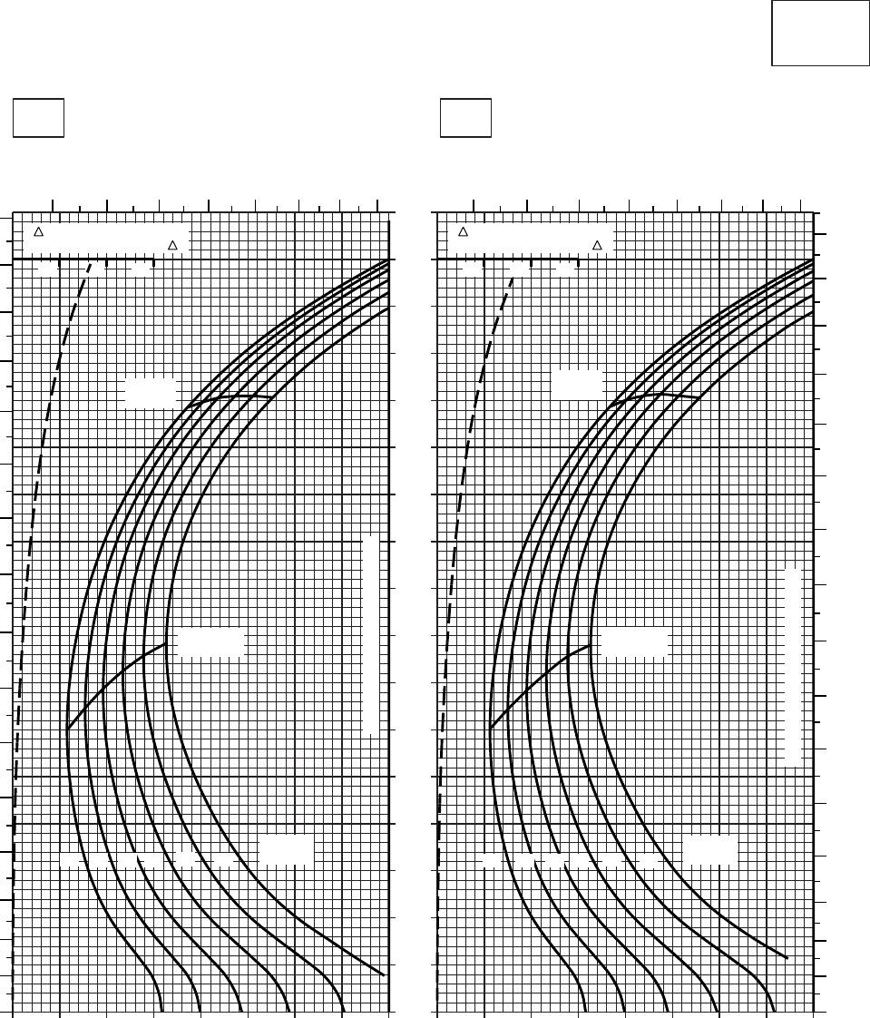
20 30 40 50 60 70 80 90 100
0
10
20
30
40
50
60
70
80
90
100
110
120
130
140
150
160
170
20 30 40 50 60 70 80 90 100
CRUISE
CLEAN CONFIGURATION
CRUISE
T700 (2)
TORQUE PER ENGINE ~ %TORQUE PER ENGINE ~ %
IAS ~ KTS TOTAL FUEL FLOW ~ 100 LB/HRTOTAL FUEL FLOW ~ 100 LB/HR
DATA BASE:FLIGHT TEST
TRUE AIRSPEED ~ KTS
TRUE AIRSPEED ~ KTS
TRQ ~ % FOR DRAG
AREA OF 10 SQ FT OF F
10 20 30
TRQ ~ % FOR DRAG
AREA OF 10 SQ FT OF F
10 20 30
SA
AA0448
−30oC−20oC
2000 FT
PRESS ALT: 2000 FT
6 7 8 9 10 11 12 13
0
10
20
30
40
50
60
70
80
90
100
110
120
130
140
150
160
6 7 8 9 10 11 12 13
0
10
20
30
40
50
60
70
80
90
100
110
120
130
140
150
160
MAX
RANGE
MAX END
AND R / C
GW ~
1000 LB
12 14 16 18 20 22
TRANSMISSION TORQUE LIMIT
MAX
RANGE
MAX END
AND R / C
GW ~
1000 LB
12 14 16 18 20 22
TRANSMISSION TORQUE LIMIT
Figure 7-9. Cruise - Pressure Altitude 2,000 Feet (Sheet 2 of 6)
TM 1-1520-237-10
7-29
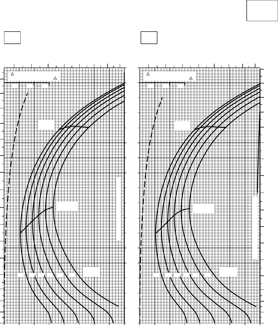
20 30 40 50 60 70 80 90 100
0
10
20
30
40
50
60
70
80
90
100
110
120
130
140
150
160
170
20 30 40 50 60 70 80 90 100
CRUISE
CLEAN CONFIGURATION
CRUISE
T700 (2)
TORQUE PER ENGINE ~ %TORQUE PER ENGINE ~ %
IAS ~ KTS TOTAL FUEL FLOW ~ 100 LB/HRTOTAL FUEL FLOW ~ 100 LB/HR
DATA BASE:FLIGHT TEST
TRUE AIRSPEED ~ KTS
TRUE AIRSPEED ~ KTS
TRQ ~ % FOR DRAG
AREA OF 10 SQ FT OF F
10 20 30
TRQ ~ % FOR DRAG
AREA OF 10 SQ FT OF F
10 20 30
SA
AA0447
−10oC0oC
2000 FT
PRESS ALT: 2000 FT
6789
10 11 12 13
0
10
20
30
40
50
60
70
80
90
100
110
120
130
140
150
160
6 7 8 9 10 11 12 13
0
10
20
30
40
50
60
70
80
90
100
110
120
130
140
150
160
170
MAX END
AND R / C
GW ~
1000 LB
12 14 16 18 20 22
TRANSMISSION TORQUE LIMIT
MAX
RANGE
MAX END
AND R / C
GW ~
1000 LB
12 14 16 18 20 22
TRANSMISSION TORQUE LIMIT
MAX
RANGE
Figure 7-9. Cruise - Pressure Altitude 2,000 Feet (Sheet 3 of 6)
TM 1-1520-237-10
7-30

20 30 40 50 60 70 80 90 100
0
10
20
30
40
50
60
70
80
90
100
110
120
130
140
150
160
170
20 30 40 50 60 70 80 90 100
CRUISE
CLEAN CONFIGURATION
CRUISE
T700 (2)
TORQUE PER ENGINE ~ %TORQUE PER ENGINE ~ %
IAS ~ KTS TOTAL FUEL FLOW ~ 100 LB/HRTOTAL FUEL FLOW ~ 100 LB/HR
DATA BASE:FLIGHT TEST
TRUE AIRSPEED ~ KTS
TRUE AIRSPEED ~ KTS
TRQ ~ % FOR DRAG
AREA OF 10 SQ FT OF F
10 20 30
TRQ ~ % FOR DRAG
AREA OF 10 SQ FT OF F
10 20 30
SA
AA0450
6789
10 11 12 13 678 9 10 11 12 13
0
10
20
30
40
50
60
70
80
90
100
110
120
130
140
150
160
170
0
10
20
30
40
50
60
70
80
90
100
110
120
130
140
150
160
170
10oC20oC
2000 FT
PRESS ALT: 2000 FT
MAX
RANGE
MAX END
AND R / C
GW ~
1000 LB
12 14 16 18 20 22
TRANSMISSION TORQUE LIMIT
MAX
RANGE
MAX END
AND R / C
GW ~
1000 LB
12 14 16 18 20 22
TRANSMISSION TORQUE LIMIT
ATF= 0.9
TORQUE AVAILABLE ~ 30 MINUTES
TORQUE AVAILABLE ~ CONTINUOUS
~ CONTINUOUS
Figure 7-9. Cruise - Pressure Altitude 2,000 Feet (Sheet 4 of 6)
TM 1-1520-237-10
7-31
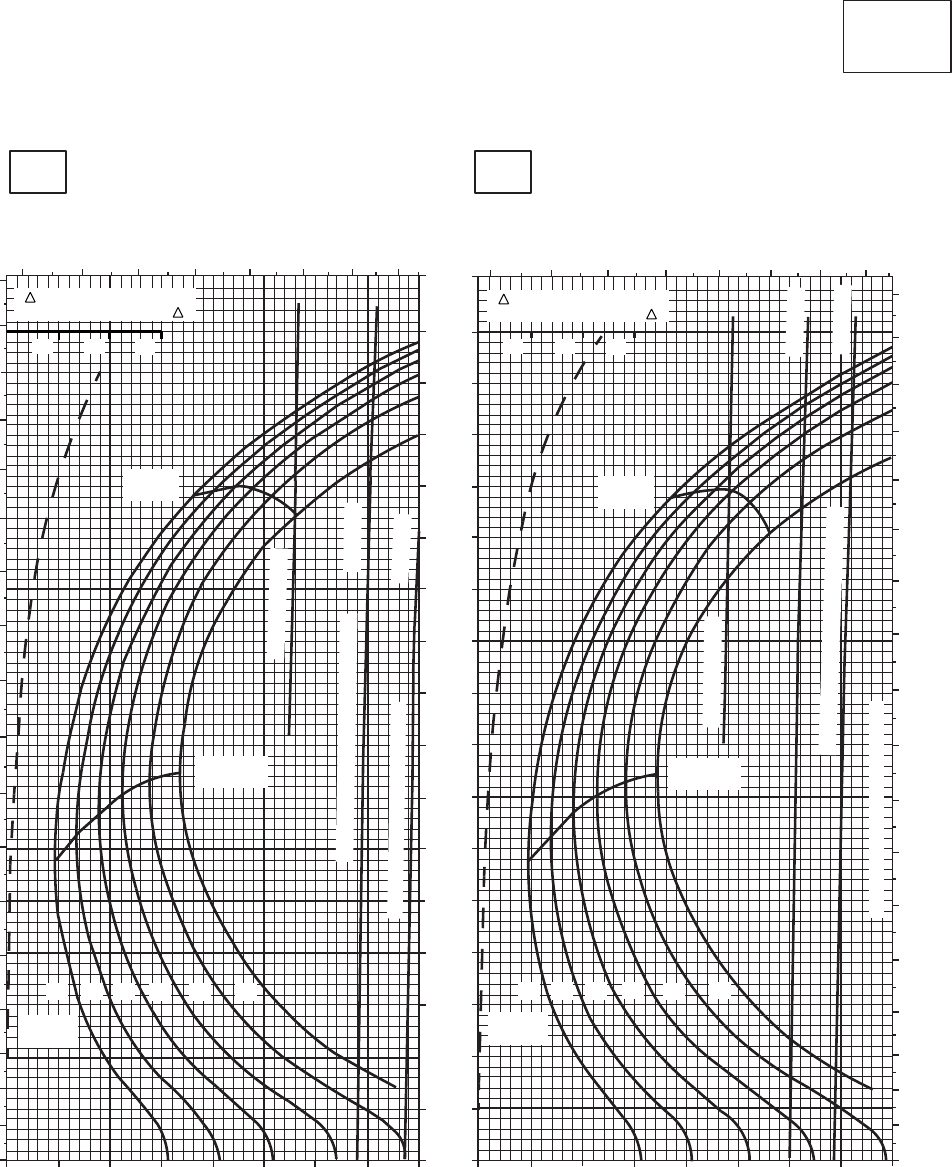
SA
AA0451
CRUISE
CLEAN CONFIGURATION
CRUISE
T700 (2)
30oC
2000 FT
PRESS ALT: 2000 FT
40oC
TOTAL FUEL FLOW ~ 100 LB/HR
TRUE AIRSPEED ~ KTS
TRUE AIRSPEED ~ KTS
TOTAL FUEL FLOW ~ 100 LB/HR
IAS ~ KTS
TORQUE PER ENGINE ~ % TORQUE PER ENGINE ~ %
20 30 40 50 60 70 80 90 1000
10
20
30
40
50
60
70
80
90
100
110
120
130
140
150
160
170
180
6 7 8 9 10 11 12 13
170
160
150
140
130
120
110
100
90
80
70
60
40
50
30
20
10
0
20 30 40 50 60 70 80 90 100
180
170
160
150
140
130
120
110
100
90
80
70
60
50
40
30
20
10
0
6 7 8 9 10 11 12 13
10 20 30
TRQ ~ % FOR DRAG
AREA OF 10 SQ FT OF F
10 20 30
TRQ ~ % FOR DRAG
AREA OF 10 SQ FT OF F
MAX
RANGE
~ CONTINUOUS
MAX END
AND R / C
12 14 16
GW ~
1000 LB
22
20
18
TORQUE AVAILABLE ~ 30 MINUTES
MAX END
AND R / C
MAX
RANGE
~ CONTINUOUS
TORQUE AVAILABLE ~ 30 MINUTES
12 14 16 18 20 22
GW ~
1000 LB
ATF = 0.9
ATF = 1.0
TRANSMISSION TORQUE LIMIT
TRANSMISSION TORQUE LIMIT
ATF = 0.9
ATF = 1.0
Figure 7-9. Cruise - Pressure Altitude 2,000 Feet (Sheet 5 of 6)
TM 1-1520-237-10
7-32
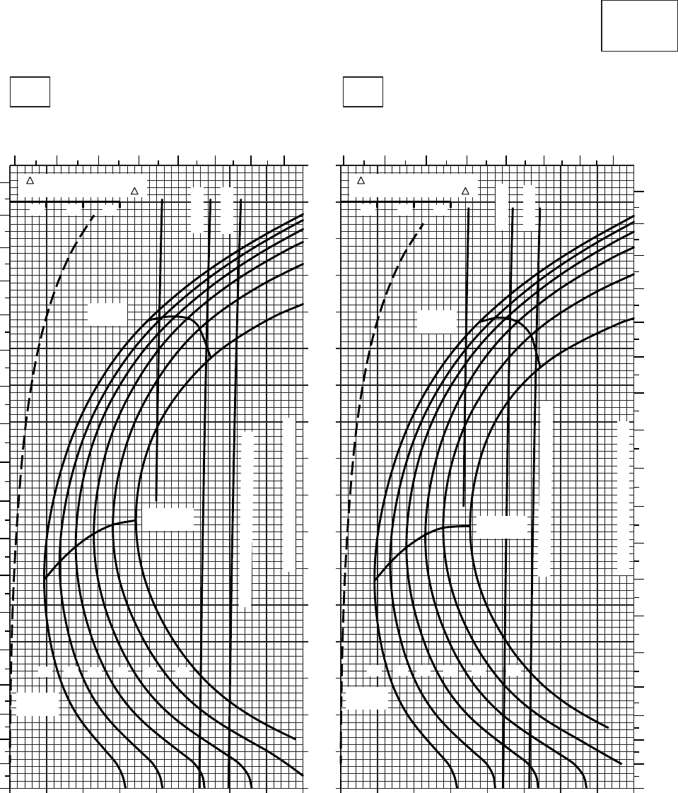
20 30 40 50 60 70 80 90 100
0
10
20
30
40
50
60
70
80
90
100
110
120
130
140
150
160
170
20 30 40 50 60 70 80 90 100
CRUISE
CLEAN CONFIGURATION
CRUISE
T700 (2)
TORQUE PER ENGINE ~ %TORQUE PER ENGINE ~ %
IAS ~ KTS TOTAL FUEL FLOW ~ 100 LB/HRTOTAL FUEL FLOW ~ 100 LB/HR
DATA BASE:FLIGHT TEST
TRUE AIRSPEED ~ KTS
TRUE AIRSPEED ~ KTS
TRQ ~ % FOR DRAG
AREA OF 10 SQ FT OF F
10 20 30
TRQ ~ % FOR DRAG
AREA OF 10 SQ FT OF F
10 20 30
SA
AA0452
50oC60oC
2000 FT
PRESS ALT: 2000 FT
6 7 8 9 10 11 12 13 6 7 8 9 10 11 12 13
0
10
20
30
40
50
60
70
80
90
100
110
120
130
140
150
160
170
180
0
10
20
30
40
50
60
70
80
90
100
110
120
130
140
150
160
170
180
MAX
RANGE
MAX END
AND R / C
GW ~
1000 LB
12 14 16 18 20 22
TRANSMISSION TORQUE LIMIT
ATF= 0.9
ATF= 1.0
TORQUE AVAILABLE ~ 30 MINUTES
MAX
RANGE
MAX END
AND R / C
GW ~
1000 LB
12 14 16 18 20 22
TRANSMISSION TORQUE LIMIT
ATF= 0.9
ATF= 1.0
TORQUE AVAILABLE ~ 30 MINUTES
Figure 7-9. Cruise - Pressure Altitude 2,000 Feet (Sheet 6 of 6)
TM 1-1520-237-10
7-33
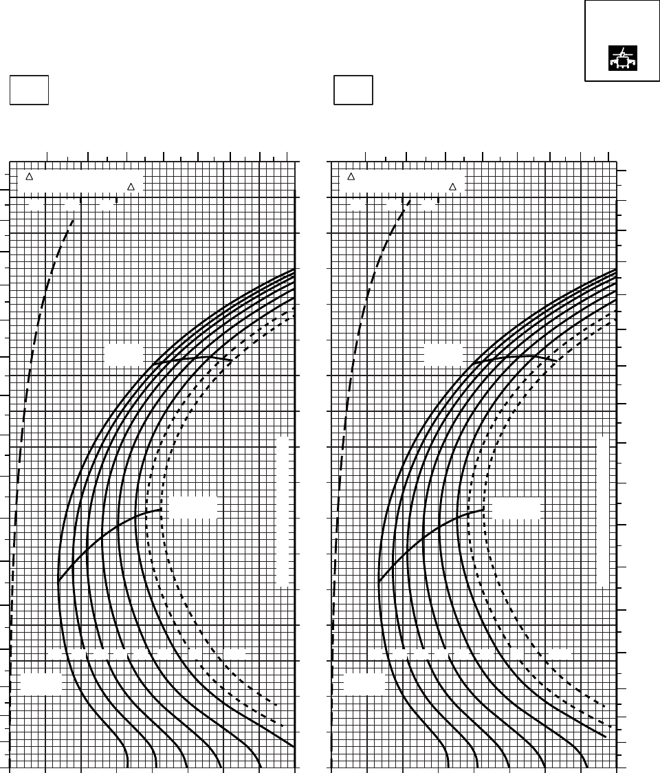
20 30 40 50 60 70 80 90 100
0
10
20
30
40
50
60
70
80
90
100
110
120
130
140
150
160
170
20 30 40 50 60 70 80 90 100
SA
AA0540
CRUISE
TORQUE PER ENGINE ~ %TORQUE PER ENGINE ~ %
IAS ~ KTS TOTAL FUEL FLOW ~ 100 LB/HRTOTAL FUEL FLOW ~ 100 LB/HR
DATA BASE:FLIGHT TEST
TRUE AIRSPEED ~ KTS
TRUE AIRSPEED ~ KTS
TRQ ~ % FOR DRAG
AREA OF 10 SQ FT OF F
10 20 30
TRQ ~ % FOR DRAG
AREA OF 10 SQ FT OF F
10 20 30
−50oC−40oC
2000 FT
PRESS ALT: 2000 FT
CRUISE
MAX
RANGE MAX
RANGE
MAX END
AND R/C MAX END
AND R/C
TRANSMISSION TORQUE LIMIT
TRANSMISSION TORQUE LIMIT
12 1214 1416 1618 1820 2022 2223 2324.5 24.5
GW ~
1000 LB GW ~
1000 LB
0
10
20
30
40
50
60
70
80
90
100
110
120
130
140
150
160
0
10
20
30
40
50
60
70
80
90
100
110
120
130
140
150
160
170
6 7 8 9 10 11 12 13 6 7 8 9 10 11 12 13
T700 (2)
Figure 7-10. Cruise High Drag - Pressure Altitude 2,000 Feet (Sheet 1 of 6)
TM 1-1520-237-10
7-34
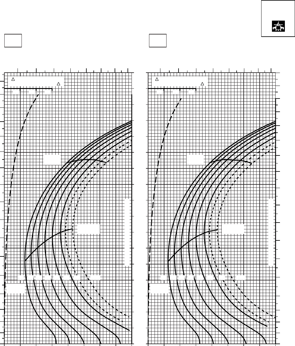
20 30 40 50 60 70 80 90 100
0
10
20
30
40
50
60
70
80
90
100
110
120
130
140
150
160
170
20 30 40 50 60 70 80 90 100
SA
AA0541
CRUISE
TORQUE PER ENGINE ~ %TORQUE PER ENGINE ~ %
IAS ~ KTS TOTAL FUEL FLOW ~ 100 LB/HRTOTAL FUEL FLOW ~ 100 LB/HR
DATA BASE:FLIGHT TEST
TRUE AIRSPEED ~ KTS
TRUE AIRSPEED ~ KTS
TRQ ~ % FOR DRAG
AREA OF 10 SQ FT OF F
10 20 30
TRQ ~ % FOR DRAG
AREA OF 10 SQ FT OF F
10 20 30
−30oC−20oC
2000 FT
PRESS ALT: 2000 FT
CRUISE
0
10
20
30
40
50
60
70
80
90
100
110
120
130
140
150
160
170
678
910 11 12 13 678
910 11 12 13
0
10
20
30
40
50
60
70
80
90
100
110
120
130
140
150
160
170
180
MAX
RANGE MAX
RANGE
MAX END
AND R / C
MAX END
AND R / C
GW ~
1000 LB GW ~
1000 LB
12 14 141216 1618 1820 2022 2223 2324.5 24.5
TRANSMISSION TORQUE LIMIT
TRANSMISSION TORQUE LIMIT
T700 (2)
Figure 7-10. Cruise High Drag - Pressure Altitude 2,000 Feet (Sheet 2 of 6)
TM 1-1520-237-10
7-35

20 30 40 50 60 70 80 90 100
0
10
20
30
40
50
60
70
80
90
100
110
120
130
140
150
160
170
20 30 40 50 60 70 80 90 100
SA
CRUISE
PRESS ALT: 2000 FT
CRUISE
TORQUE PER ENGINE ~ %TORQUE PER ENGINE ~ %
IAS ~ KTS TOTAL FUEL FLOW ~ 100 LB/HRTOTAL FUEL FLOW ~ 100 LB/HR
DATA BASE:FLIGHT TEST
TRUE AIRSPEED ~ KTS
TRUE AIRSPEED ~ KTS
TRQ ~ % FOR DRAG
AREA OF 10 SQ FT OF F
10 20 30
TRQ ~ % FOR DRAG
AREA OF 10 SQ FT OF F
10 20 30
SA
AA0542
MAX
RANGE
MAX
RANGE
MAX END
AND R / C MAX END
AND R / C
GW~
1000 LB GW~
1000 LB
12 12
14 14
16 16
18 18
20 20
22 22
23 23
24.5 24.5
TRANSMISSION TORQUE LIMIT
TRANSMISSION TORQUE LIMIT
0
10
20
30
40
50
60
70
80
90
100
110
120
130
140
150
160
170
180
0
10
20
30
40
50
60
70
80
90
100
110
120
130
140
150
160
170
180
6 7 8 9 10 11 12 13 6 7 8 9 10 11 12 13
−10oC0oC
2000 FT
T700 (2)
Figure 7-10. Cruise High Drag - Pressure Altitude 2,000 Feet (Sheet 3 of 6)
TM 1-1520-237-10
7-36
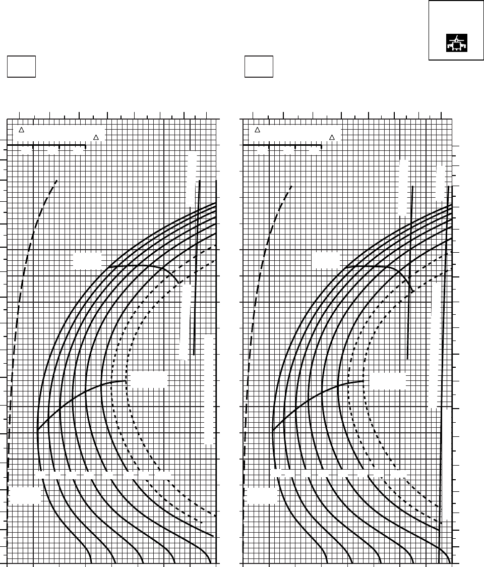
20 30 40 50 60 70 80 90 100
0
10
20
30
40
50
60
70
80
90
100
110
120
130
140
150
160
170
20 30 40 50 60 70 80 90 100
SA
AA0543
CRUISE
TORQUE PER ENGINE ~ %TORQUE PER ENGINE ~ %
IAS ~ KTS TOTAL FUEL FLOW ~ 100 LB/HRTOTAL FUEL FLOW ~ 100 LB/HR
DATA BASE:FLIGHT TEST
TRUE AIRSPEED ~ KTS
TRUE AIRSPEED ~ KTS
TRQ ~ % FOR DRAG
AREA OF 10 SQ FT OF F
10 20 30
TRQ ~ % FOR DRAG
AREA OF 10 SQ FT OF F
10 20 30
10oC20oC
2000 FT
PRESS ALT: 2000 FT
CRUISE
6 7 8 9 10 11 12 13 6 7 8 9 10 11 12 13
0
10
20
30
40
50
60
70
80
90
100
110
120
130
140
150
160
170
180
0
10
20
30
40
50
60
70
80
90
100
110
120
130
140
150
160
170
180
MAX
RANGE MAX
RANGE
MAX END
AND R / C MAX END
AND R / C
GW~
1000 LB
GW~
1000 LB
12 12
14 14
16 16
18 18
20 20
22 22
23 23
24.5 24.5
~ CONTINUOUS
TORQUE AVAILABLE ~ 30 MINUTES
~ CONTINUOUS
TRANSMISSION TORQUE LIMIT
TRANSMISSION TORQUE LIMIT
ATF = 0.9
TORQUE AVAILABLE
T700 (2)
Figure 7-10. Cruise High Drag - Pressure Altitude 2,000 Feet (Sheet 4 of 6)
TM 1-1520-237-10
7-37
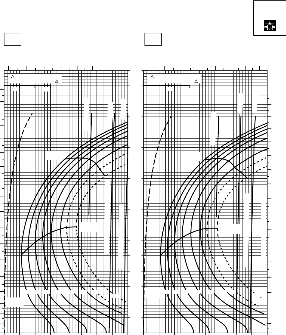
20 30 40 50 60 70 80 90 100
0
10
20
30
40
50
60
70
80
90
100
110
120
130
140
150
160
170
20 30 40 50 60 70 80 90 100
SA
AA0544
CRUISE
TORQUE PER ENGINE ~ %TORQUE PER ENGINE ~ %
IAS ~ KTS TOTAL FUEL FLOW ~ 100 LB/HRTOTAL FUEL FLOW ~ 100 LB/HR
DATA BASE:FLIGHT TEST
TRUE AIRSPEED ~ KTS
TRUE AIRSPEED ~ KTS
TRQ ~ % FOR DRAG
AREA OF 10 SQ FT OF F
10 20 30
TRQ ~ % FOR DRAG
AREA OF 10 SQ FT OF F
10 20 30
30oC40oC
2000 FT
PRESS ALT: 2000 FT
CRUISE
6 7 8 9 10 11 12 13 6 7 8 9 10 11 12 13
0
10
20
30
40
50
60
70
80
90
100
110
120
130
140
150
160
170
180
0
10
20
30
40
50
60
70
80
90
100
110
120
130
140
150
160
170
180
MAX
RANGE MAX
RANGE
MAX END
AND R / C MAX END
AND R / C
GW~
1000 LB
GW~
1000 LB
12 1214 1416 1618 1820 2022 2223 23
24.5 24.5
~ CONTINUOUS
~ CONTINUOUS
ATF = 0.9
ATF = 0.9
ATF = 1.0
ATF = 1.0
TORQUE AVAILABLE ~ 30 MINUTES
TORQUE AVAILABLE ~ 30 MINUTES
TRANSMISSION TORQUE LIMIT
TRANSMISSION TORQUE LIMIT
T700 (2)
Figure 7-10. Cruise High Drag - Pressure Altitude 2,000 Feet (Sheet 5 of 6)
TM 1-1520-237-10
7-38
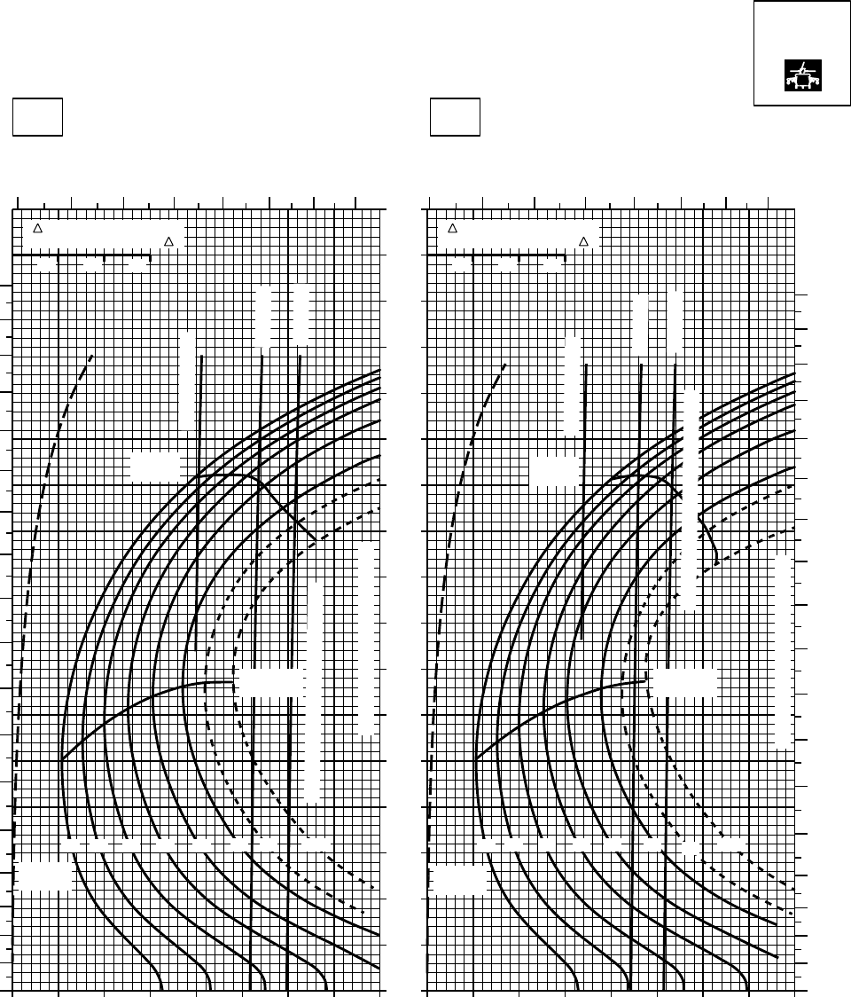
20 30 40 50 60 70 80 90 100
0
10
20
30
40
50
60
70
80
90
100
110
120
130
140
150
160
170
20 30 40 50 60 70 80 90 100
SA
AA0545
CRUISE
TORQUE PER ENGINE ~ %TORQUE PER ENGINE ~ %
IAS ~ KTS TOTAL FUEL FLOW ~ 100 LB/HRTOTAL FUEL FLOW ~ 100 LB/HR
DATA BASE:FLIGHT TEST
TRUE AIRSPEED ~ KTS
TRUE AIRSPEED ~ KTS
TRQ ~ % FOR DRAG
AREA OF 10 SQ FT OF F
10 20 30
TRQ ~ % FOR DRAG
AREA OF 10 SQ FT OF F
10 20 30
50oC60oC
2000 FT
PRESS ALT: 2000 FT
CRUISE
6 7 8 9 10 11 12 13 6 7 8 9 10 11 12 13
0
10
20
30
40
50
60
70
80
90
100
110
120
130
140
150
160
170
180
0
10
20
30
40
50
60
70
80
90
100
110
120
130
140
150
160
170
180
MAX
RANGE MAX
RANGE
MAX END
AND R / C MAX END
AND R / C
GW~
1000 LB GW~
1000 LB
12 1214 14
16 16
18 18
20 2022 2223 23
24.5 24.5
~ CONTINUOUS
~ CONTINUOUS
ATF = 0.9
ATF = 0.9
ATF = 1.0
ATF = 1.0
TORQUE AVAILABLE ~ 30 MINUTES
TRANSMISSION TORQUE LIMIT
TRANSMISSION TORQUE LIMIT
TORQUE AVAILABLE ~ 30 MINUTES
T700 (2)
Figure 7-10. Cruise High Drag - Pressure Altitude 2,000 Feet (Sheet 6 of 6)
TM 1-1520-237-10
7-39
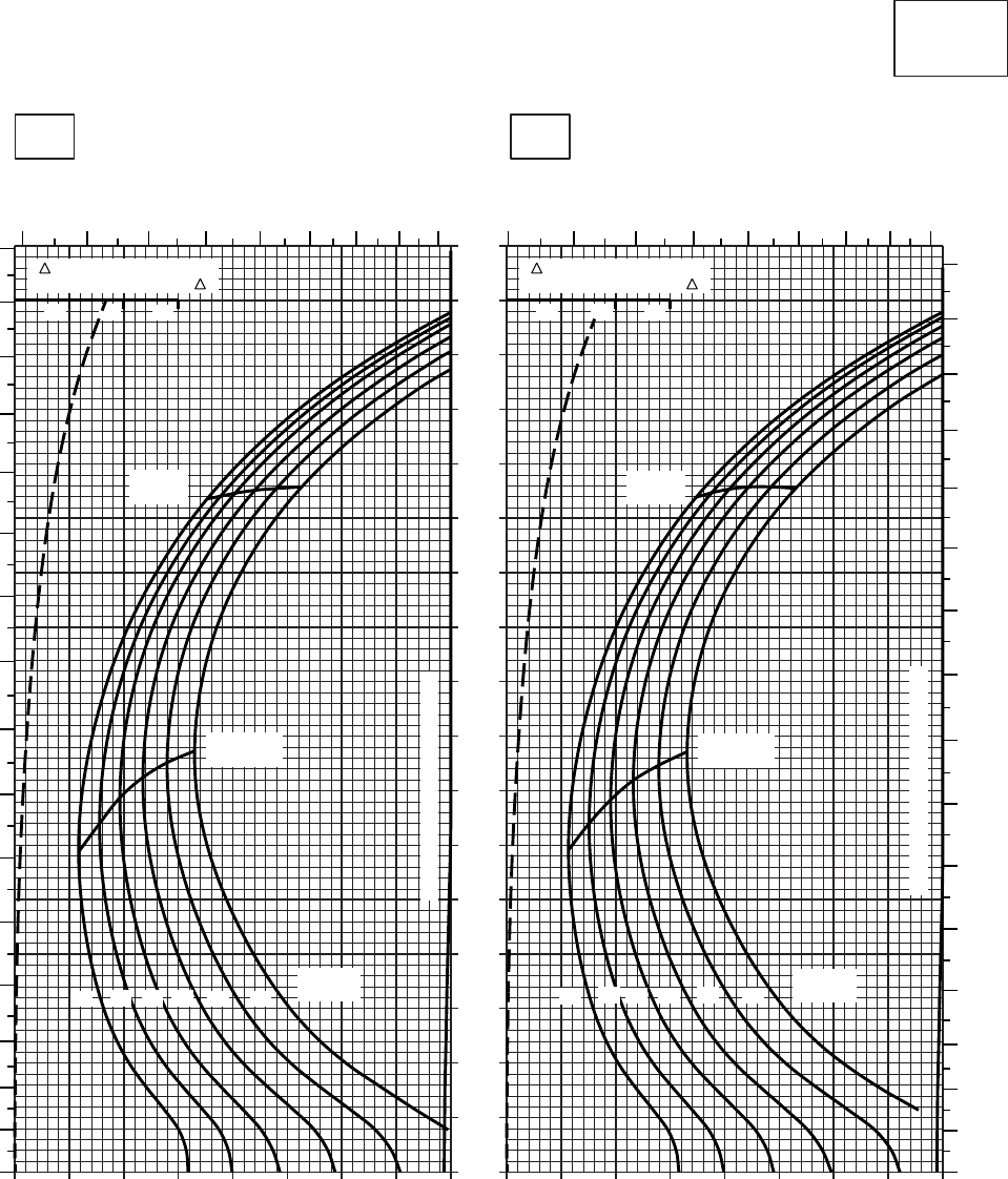
20 30 40 50 60 70 80 90 100
0
10
20
30
40
50
60
70
80
90
100
110
120
130
140
150
160
170
20 30 40 50 60 70 80 90 100
CRUISE
CLEAN CONFIGURATION
CRUISE
T700 (2)
TORQUE PER ENGINE ~ %TORQUE PER ENGINE ~ %
IAS ~ KTS TOTAL FUEL FLOW ~ 100 LB/HRTOTAL FUEL FLOW ~ 100 LB/HR
DATA BASE:FLIGHT TEST
TRUE AIRSPEED ~ KTS
TRUE AIRSPEED ~ KTS
TRQ ~ % FOR DRAG
AREA OF 10 SQ FT OF F
10 20 30
TRQ ~ % FOR DRAG
AREA OF 10 SQ FT OF F
10 20 30
SA
AA0455
−50oC−40oC
4000 FT
PRESS ALT: 4000 FT
56789101112
13 5678910111213
0
10
20
30
40
50
60
70
80
90
100
110
120
130
140
150
160
0
10
20
30
40
50
60
70
80
90
100
110
120
130
140
150
160
MAX
RANGE
MAX END
AND R / C
GW ~
1000 LB
12 14 16 18 20 22
TRANSMISSION TORQUE LIMIT
MAX
RANGE
MAX END
AND R / C
GW ~
1000 LB
12 14 16 18 20 22
TRANSMISSION TORQUE LIMIT
Figure 7-11. Cruise - Pressure Altitude 4,000 Feet (Sheet 1 of 6)
TM 1-1520-237-10
7-40
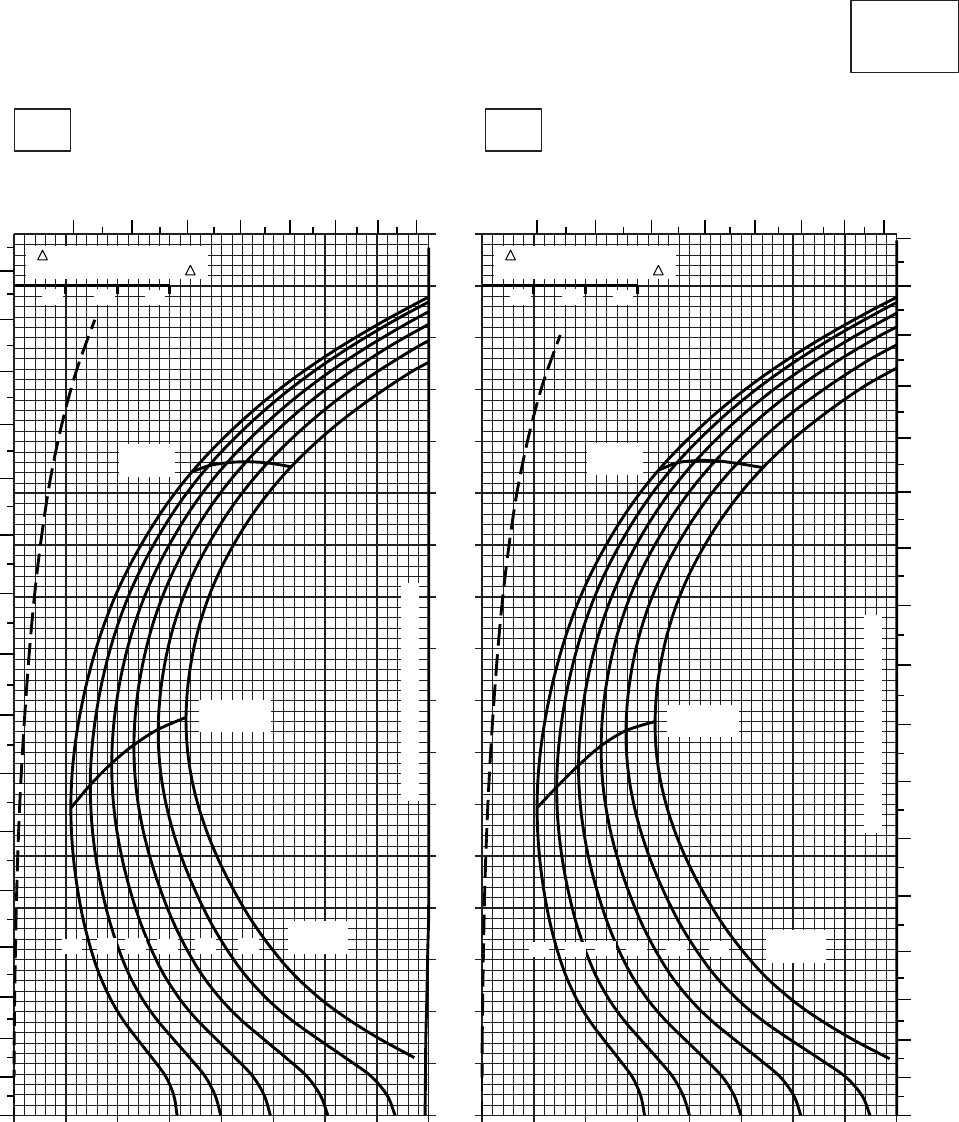
20 30 40 50 60 70 80 90 100
0
10
20
30
40
50
60
70
80
90
100
110
120
130
140
150
160
170
20 30 40 50 60 70 80 90 100
CRUISE
CLEAN CONFIGURATION
CRUISE
T700 (2)
TORQUE PER ENGINE ~ %TORQUE PER ENGINE ~ %
IAS ~ KTS TOTAL FUEL FLOW ~ 100 LB/HRTOTAL FUEL FLOW ~ 100 LB/HR
DATA BASE:FLIGHT TEST
TRUE AIRSPEED ~ KTS
TRUE AIRSPEED ~ KTS
TRQ ~ % FOR DRAG
AREA OF 10 SQ FT OF F
10 20 30
TRQ ~ % FOR DRAG
AREA OF 10 SQ FT OF F
10 20 30
SA
AA0454
−30oC−20oC
4000 FT
PRESS ALT: 4000 FT
6 7 8 9 10 11 12 13
0
10
20
30
40
50
60
70
80
90
100
110
120
130
140
150
160
0
10
20
30
40
50
60
70
80
90
100
110
120
130
140
150
160
170
6 7 8 9 10 11 12 13
MAX
RANGE
MAX END
AND R / C
GW ~
1000 LB
12 14 16 18 20 22
TRANSMISSION TORQUE LIMIT
MAX
RANGE
MAX END
AND R / C
GW ~
1000 LB
12 14 16 18 20 22
TRANSMISSION TORQUE LIMIT
Figure 7-11. Cruise - Pressure Altitude 4,000 Feet (Sheet 2 of 6)
TM 1-1520-237-10
7-41
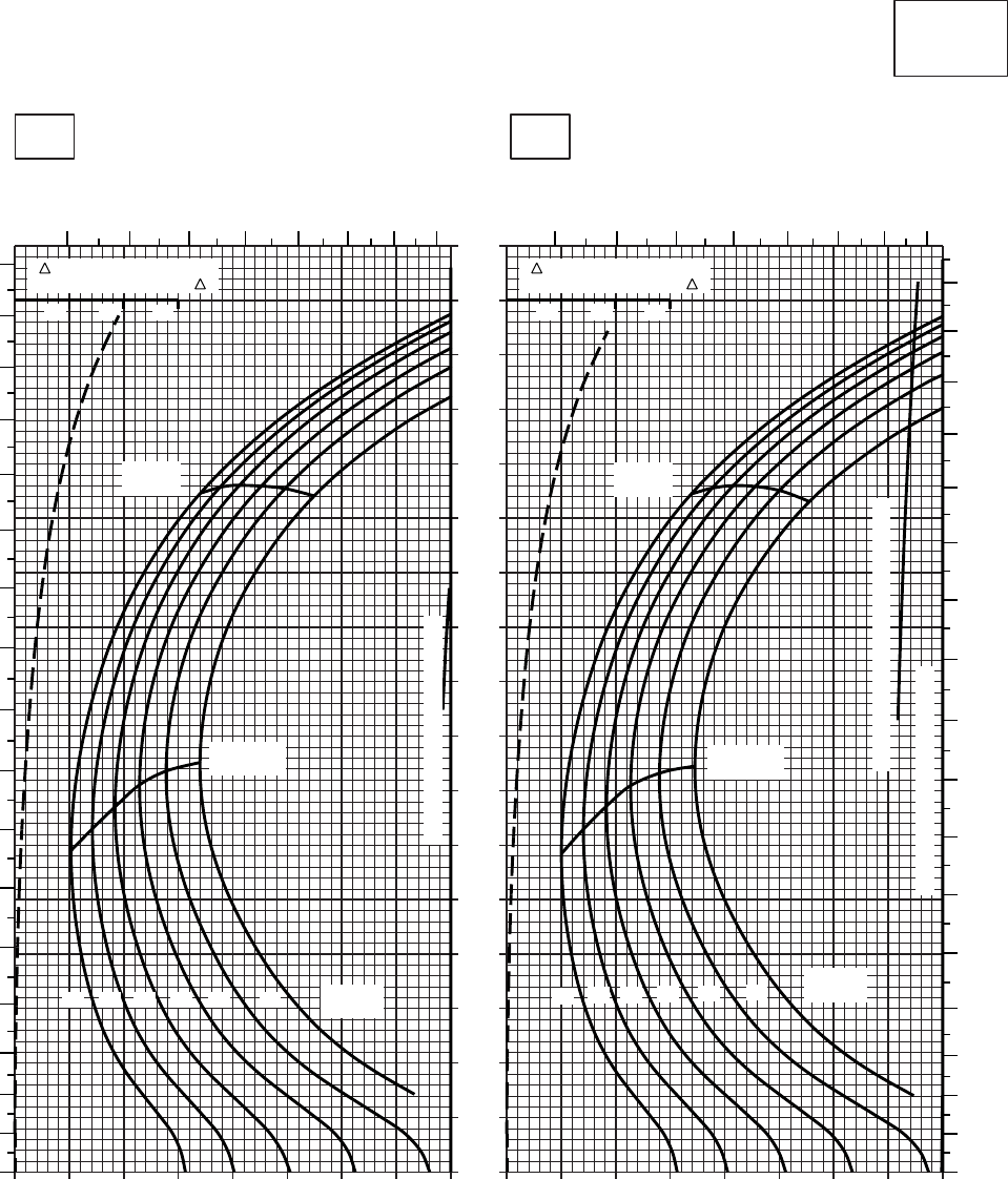
20 30 40 50 60 70 80 90 100
0
10
20
30
40
50
60
70
80
90
100
110
120
130
140
150
160
170
20 30 40 50 60 70 80 90 100
CRUISE
CLEAN CONFIGURATION
CRUISE
T700 (2)
TORQUE PER ENGINE ~ %TORQUE PER ENGINE ~ %
IAS ~ KTS TOTAL FUEL FLOW ~ 100 LB/HRTOTAL FUEL FLOW ~ 100 LB/HR
DATA BASE:FLIGHT TEST
TRUE AIRSPEED ~ KTS
TRUE AIRSPEED ~ KTS
TRQ ~ % FOR DRAG
AREA OF 10 SQ FT OF F
10 20 30
TRQ ~ % FOR DRAG
AREA OF 10 SQ FT OF F
10 20 30
SA
AA0453
−10oC0oC
4000 FT
PRESS ALT: 4000 FT
6 7 8 9 10 11 12 13 6 7 8 9 10 11 12 13
0
10
20
30
40
50
60
70
80
90
100
110
120
130
140
150
160
170
0
10
20
30
40
50
60
70
80
90
100
110
120
130
140
150
160
170
MAX
RANGE
MAX END
AND R / C
GW ~
1000 LB
12 14 16 18 20 22
TRANSMISSION TORQUE LIMIT
MAX
RANGE
MAX END
AND R / C
GW ~
1000 LB
12 14 16 18 20 22
TRANSMISSION TORQUE LIMIT
TORQUE AVAILABLE ~ CONTINUOUS
Figure 7-11. Cruise - Pressure Altitude 4,000 Feet (Sheet 3 of 6)
TM 1-1520-237-10
7-42
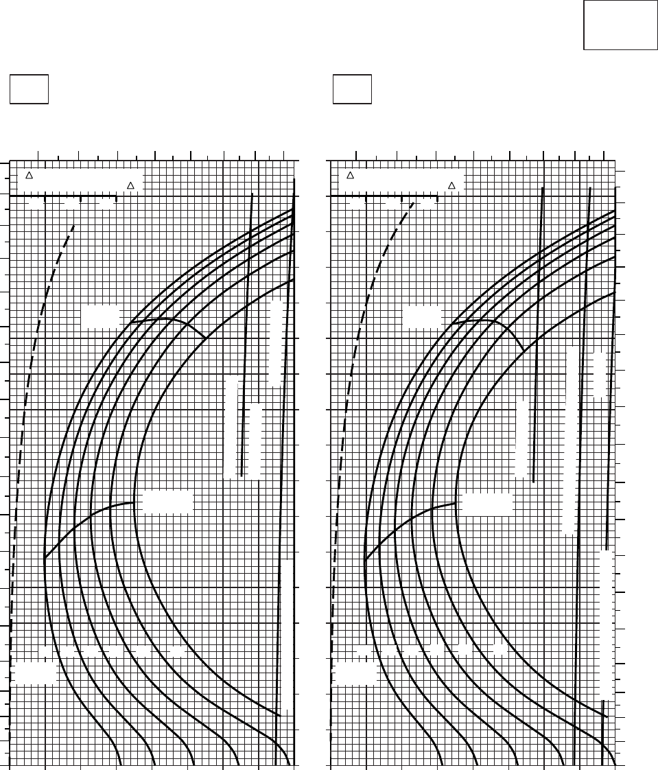
20 30 40 50 60 70 80 90 100
0
10
20
30
40
50
60
70
80
90
100
110
120
130
140
150
160
170
20 30 40 50 60 70 80 90 100
CRUISE
CLEAN CONFIGURATION
CRUISE
T700 (2)
TORQUE PER ENGINE ~ %TORQUE PER ENGINE ~ %
IAS ~ KTS TOTAL FUEL FLOW ~ 100 LB/HRTOTAL FUEL FLOW ~ 100 LB/HR
DATA BASE:FLIGHT TEST
TRUE AIRSPEED ~ KTS
TRUE AIRSPEED ~ KTS
TRQ ~ % FOR DRAG
AREA OF 10 SQ FT OF F
10 20 30
TRQ ~ % FOR DRAG
AREA OF 10 SQ FT OF F
10 20 30
SA
AA0456
10oC20oC
4000 FT
PRESS ALT: 4000 FT
6 7 8 9 10 11 12 13 6 7 8 9 10 11 12 13
0
10
20
30
40
50
60
70
80
90
100
110
120
130
140
150
160
170
180
0
10
20
30
40
50
60
70
80
90
100
110
120
130
140
150
160
170
180
MAX
RANGE
MAX END
AND R / C
GW ~
1000 LB
12 14 16 18 20 22
TRANSMISSION TORQUE LIMIT
MAX
RANGE
MAX END
AND R / C
GW ~
1000 LB
12 14 16 18 20 22
TRANSMISSION TORQUE LIMIT ATF= 1.0
TORQUE AVAILABLE
~ 30 MIN ATF= 0.9
~ CONTINUOUS
~ CONTINUOUS
TORQUE AVAILABLE ~ 30 MIN ATF= 0.9
Figure 7-11. Cruise - Pressure Altitude 4,000 Feet (Sheet 4 of 6)
TM 1-1520-237-10
7-43
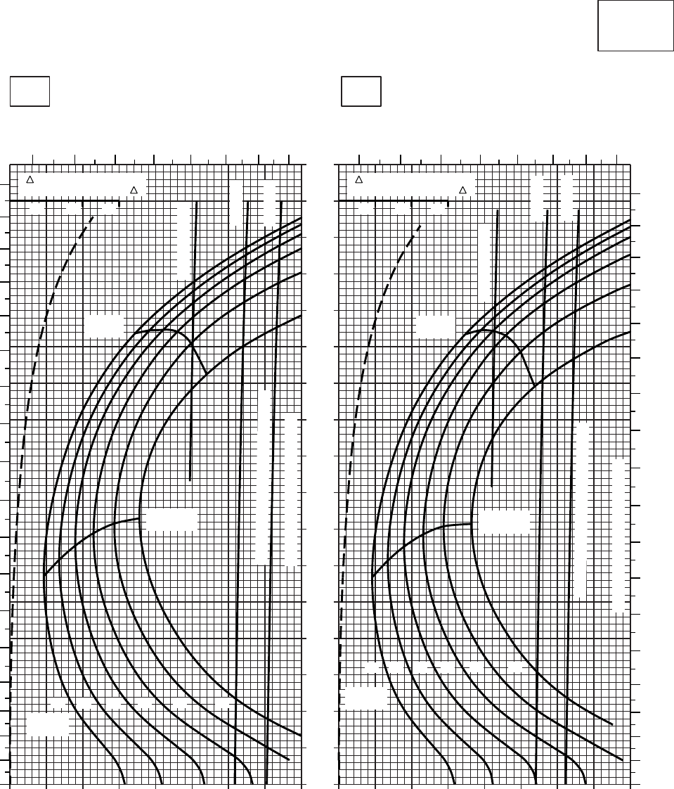
20 30 40 50 60 70 80 90 100
0
10
20
30
40
50
60
70
80
90
100
110
120
130
140
150
160
170
20 30 40 50 60 70 80 90 100
CRUISE
CLEAN CONFIGURATION
CRUISE
T700 (2)
TORQUE PER ENGINE ~ %TORQUE PER ENGINE ~ %
IAS ~ KTS TOTAL FUEL FLOW ~ 100 LB/HRTOTAL FUEL FLOW ~ 100 LB/HR
DATA BASE:FLIGHT TEST
TRUE AIRSPEED ~ KTS
TRUE AIRSPEED ~ KTS
TRQ ~ % FOR DRAG
AREA OF 10 SQ FT OF F
10 20 30
TRQ ~ % FOR DRAG
AREA OF 10 SQ FT OF F
10 20 30
SA
AA0457
30oC40oC
4000 FT
PRESS ALT: 4000 FT
678 9 10 11 12 13 6 7 8 9 10 11 12 13
0
10
20
30
40
50
60
70
80
90
100
110
120
130
140
150
160
170
180
0
10
20
30
40
50
60
70
80
90
100
110
120
130
140
150
160
170
180
MAX
RANGE
MAX END
AND R / C
GW ~
1000 LB
12 14 16 18 20 22
TRANSMISSION TORQUE LIMIT
ATF= 0.9
ATF= 1.0
TORQUE AVAILABLE ~ 30 MINUTES
MAX
RANGE
MAX END
AND R / C
GW ~
1000 LB
12 14 16 18 20 22
TRANSMISSION TORQUE LIMIT
TORQUE AVAILABLE ~ 30 MINUTES
~ CONTINUOUS
~ CONTINUOUS
ATF= 0.9
ATF= 1.0
Figure 7-11. Cruise - Pressure Altitude 4,000 Feet (Sheet 5 of 6)
TM 1-1520-237-10
7-44
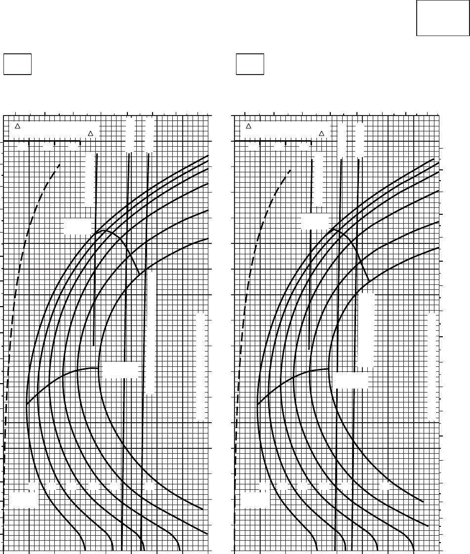
20 30 40 50 60 70 80 90 100
0
10
20
30
40
50
60
70
80
90
100
110
120
130
140
150
160
170
20 30 40 50 60 70 80 90 100
CRUISE
CLEAN CONFIGURATION
PRESS ALT: 4000 FT
CRUISE
4000 FT
T700 (2)
TORQUE PER ENGINE ~ %TORQUE PER ENGINE ~ %
IAS ~ KTS TOTAL FUEL FLOW ~ 100 LB/HRTOTAL FUEL FLOW ~ 100 LB/HR
DATA BASE:FLIGHT TEST
TRUE AIRSPEED ~ KTS
TRUE AIRSPEED ~ KTS
60OC50OC
TRQ ~ % FOR DRAG
AREA OF 10 SQ FT OF F
10 20 30
TRQ ~ % FOR DRAG
AREA OF 10 SQ FT OF F
10 20 30
SA
AA0458
0
10
20
30
40
50
60
70
80
90
100
110
120
130
140
150
160
170
180
6 7 8 9 10 11 12 13 6 7 8 9 10 11 12 13
180
170
160
150
140
130
120
110
100
90
80
70
60
50
40
30
20
10
0
20 2218161412222018161412
GW ~
1000 LB GW ~
1000 LB
MAX END
AND R / C MAX END
AND R / C
TRANSMISSION TORQUE LIMIT
TRANSMISSION TORQUE LIMIT
MAX
RANGE
MAX
RANGE
~ CONTINUOUS
ATF = 0.9
ATF = 1.0
TORQUE AVAILABLE ~ 30 MINUTES
TORQUE AVAILABLE
~ 30 MINUTES
~ CONTINUOUS
ATF = 0.9
ATF = 1.0
Figure 7-11. Cruise - Pressure Altitude 4,000 Feet (Sheet 6 of 6)
TM 1-1520-237-10
7-45

20 30 40 50 60 70 80 90 100
0
10
20
30
40
50
60
70
80
90
100
110
120
130
140
150
160
170
20 30 40 50 60 70 80 90 100
SA
AA0546
CRUISE
PRESS ALT: 4000 FT
CRUISE
4000 FT
TORQUE PER ENGINE ~ %TORQUE PER ENGINE ~ %
IAS ~ KTS TOTAL FUEL FLOW ~ 100 LB/HRTOTAL FUEL FLOW ~ 100 LB/HR
DATA BASE:FLIGHT TEST
TRUE AIRSPEED ~ KTS
TRUE AIRSPEED ~ KTS
−40OC−50OC
TRQ ~ % FOR DRAG
AREA OF 10 SQ FT OF F
10 20 30
TRQ ~ % FOR DRAG
AREA OF 10 SQ FT OF F
10 20 30
5 6 7 8 9 10 11 12 13 5 6 7 8 9 10 11 12 13
170
160
150
140
130
120
110
100
90
80
70
60
50
40
30
20
10
00
10
20
30
40
50
60
70
80
90
100
110
120
130
140
150
160
170
12 14 16 18 20 22 23 24.5
GW ~
1000 LB
12 14 16 18 20 22 23 24.5
GW ~
1000 LB
TRANSMISSION TORQUE LIMIT
TRANSMISSION TORQUE LIMIT
MAX END
AND R / C
MAX END
AND R / C
MAX
RANGE MAX
RANGE
T700 (2)
Figure 7-12. Cruise High Drag - Pressure Altitude 4,000 Feet (Sheet 1 of 6)
TM 1-1520-237-10
7-46

20 30 40 50 60 70 80 90 100
0
10
20
30
40
50
60
70
80
90
100
110
120
130
140
150
160
170
20 30 40 50 60 70 80 90 100
SA
AA0547
CRUISE
PRESS ALT: 4000 FT
CRUISE
4000 FT
TORQUE PER ENGINE ~ %TORQUE PER ENGINE ~ %
IAS ~ KTS TOTAL FUEL FLOW ~ 100 LB/HRTOTAL FUEL FLOW ~ 100 LB/HR
DATA BASE:FLIGHT TEST
TRUE AIRSPEED ~ KTS
TRUE AIRSPEED ~ KTS
−20OC−30OC
TRQ ~ % FOR DRAG
AREA OF 10 SQ FT OF F
10 20 30
TRQ ~ % FOR DRAG
AREA OF 10 SQ FT OF F
10 20 30
6 7 8 9 10 11 12 13 6 7 8 9 10 11 12 13
180
170
160
150
140
130
120
110
100
90
80
70
60
50
40
30
20
10
00
10
20
30
40
50
60
70
80
90
100
110
120
130
140
150
160
170
180
12 14 16 18 20 22 23 24.5
GW ~
1000 LB
12 14 16 18 20 22 23 24.5
GW ~
1000 LB
TRANSMISSION TORQUE LIMIT
TRANSMISSION TORQUE LIMIT
MAX END
AND R / C
MAX END
AND R / C
MAX
RANGE
MAX
RANGE
T700 (2)
Figure 7-12. Cruise High Drag - Pressure Altitude 4,000 Feet (Sheet 2 of 6)
TM 1-1520-237-10
7-47

20 30 40 50 60 70 80 90 100
0
10
20
30
40
50
60
70
80
90
100
110
120
130
140
150
160
170
20 30 40 50 60 70 80 90 100
SA
CRUISE
PRESS ALT: 4000 FT
CRUISE
4000 FT
TORQUE PER ENGINE ~ %TORQUE PER ENGINE ~ %
IAS ~ KTS TOTAL FUEL FLOW ~ 100 LB/HRTOTAL FUEL FLOW ~ 100 LB/HR
DATA BASE:FLIGHT TEST
TRUE AIRSPEED ~ KTS
TRUE AIRSPEED ~ KTS
0OC−10OC
TRQ ~ % FOR DRAG
AREA OF 10 SQ FT OF F
10 20 30
TRQ ~ % FOR DRAG
AREA OF 10 SQ FT OF F
10 20 30
SA
AA0548
6 7 8 9 10 11 12 13 6 7 8 9 10 11 12 13
180
170
160
150
140
130
120
110
100
90
80
70
60
50
40
30
20
10
00
10
20
30
40
50
60
70
80
90
100
110
120
130
140
150
160
170
180
12 14 16 18 20 22 23 24.5
GW ~
1000 LB
12 14 16 18 20 22 23 24.5
GW ~
1000 LB
TRANSMISSION TORQUE LIMIT
TRANSMISSION TORQUE LIMIT
MAX END
AND R / C
MAX END
AND R / C
MAX
RANGE
MAX
RANGE
TORQUE AVAILABLE ~ CONTINUOUS
T700 (2)
Figure 7-12. Cruise High Drag - Pressure Altitude 4,000 Feet (Sheet 3 of 6)
TM 1-1520-237-10
7-48

20 30 40 50 60 70 80 90 100
0
10
20
30
40
50
60
70
80
90
100
110
120
130
140
150
160
170
20 30 40 50 60 70 80 90 100
SA
AA0549
CRUISE
PRESS ALT: 4000 FT
CRUISE
TORQUE PER ENGINE ~ %TORQUE PER ENGINE ~ %
IAS ~ KTS TOTAL FUEL FLOW ~ 100 LB/HRTOTAL FUEL FLOW ~ 100 LB/HR
DATA BASE:FLIGHT TEST
TRUE AIRSPEED ~ KTS
TRUE AIRSPEED ~ KTS
TRQ ~ % FOR DRAG
AREA OF 10 SQ FT OF F
10 20 30
TRQ ~ % FOR DRAG
AREA OF 10 SQ FT OF F
10 20 30
10oC20oC
4000 FT
6 7 8 9 10 11 12 13 6 7 8 9 10 11 12 13
180
170
160
150
140
130
120
110
100
90
80
70
60
50
40
30
20
10
00
10
20
30
40
50
60
70
80
90
100
110
120
130
140
150
160
170
180
12 14 16 18 20 22 23 24.5
GW ~
1000 LB
12 14 16 18 20 22 23
24.5
GW ~
1000 LB
TRANSMISSION TORQUE LIMIT
TRANSMISSION TORQUE LIMIT
MAX END
AND R / C
MAX END
AND R / C
MAX
RANGE
MAX
RANGE
TORQUE AVAILABLE ~ 30 MINUTES
TORQUE AVAILABLE ~ 30 MINUTES
~ CONTINUOUS
~ CONTINUOUS
ATF = 0.9
ATF = 0.9
ATF = 1.0
T700 (2)
Figure 7-12. Cruise High Drag - Pressure Altitude 4,000 Feet (Sheet 4 of 6)
TM 1-1520-237-10
7-49
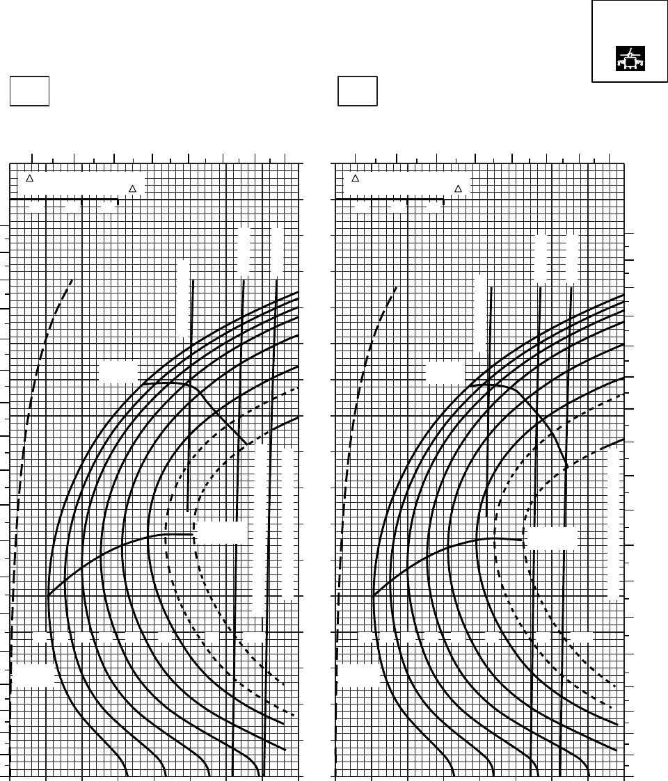
20 30 40 50 60 70 80 90 100
0
10
20
30
40
50
60
70
80
90
100
110
120
130
140
150
160
170
20 30 40 50 60 70 80 90 100
SA
AA0550
CRUISE
PRESS ALT: 4000 FT
CRUISE
TORQUE PER ENGINE ~ %TORQUE PER ENGINE ~ %
IAS ~ KTS TOTAL FUEL FLOW ~ 100 LB/HRTOTAL FUEL FLOW ~ 100 LB/HR
DATA BASE:FLIGHT TEST
TRUE AIRSPEED ~ KTS
TRUE AIRSPEED ~ KTS
TRQ ~ % FOR DRAG
AREA OF 10 SQ FT OF F
10 20 30
TRQ ~ % FOR DRAG
AREA OF 10 SQ FT OF F
10 20 30
30oC40oC
4000 FT
6 7 8 9 10 11 12 13 6 7 8 9 10 11 12 13
180
170
160
150
140
130
120
110
100
90
80
70
60
50
40
30
20
10
00
10
20
30
40
50
60
70
80
90
100
110
120
130
140
150
160
170
180
12 14 16 18 20 22 23 24.5
GW ~
1000 LB
12 14 16 18 20 22 23 24.5
GW ~
1000 LB
TRANSMISSION TORQUE LIMIT
TRANSMISSION TORQUE LIMIT
MAX END
AND R / C
MAX END
AND R / C
MAX
RANGE
MAX
RANGE
TORQUE AVAILABLE ~ 30 MINUTES
~ CONTINUOUS
~ CONTINUOUS
ATF = 0.9
ATF = 1.0
ATF = 0.9
ATF = 1.0
T700 (2)
Figure 7-12. Cruise High Drag - Pressure Altitude 4,000 Feet (Sheet 5 of 6)
TM 1-1520-237-10
7-50
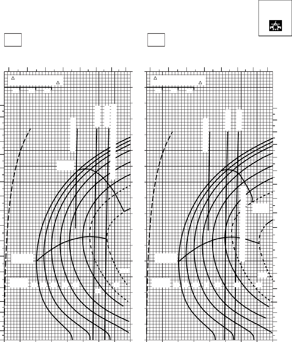
20 30 40 50 60 70 80 90
0
10
20
30
40
50
60
70
80
90
100
110
120
130
140
150
160
170
SA
AA0551
CRUISE
PRESS ALT: 4000 FT
CRUISE
TORQUE PER ENGINE ~ %TORQUE PER ENGINE ~ %
IAS ~ KTS TOTAL FUEL FLOW ~ 100 LB/HRTOTAL FUEL FLOW ~ 100 LB/HR
DATA BASE:FLIGHT TEST
TRUE AIRSPEED ~ KTS
TRUE AIRSPEED ~ KTS
TRQ ~ % FOR DRAG
AREA OF 10 SQ FT OF F
10 20 30
TRQ ~ % FOR DRAG
AREA OF 10 SQ FT OF F
10 20 30
10 20 30 40 50 60 70 80 9010
50oC60oC
4000 FT
5 6 7 8 9 10 11 12 5 6 7 8 9 10 11 12
180
170
160
150
140
130
120
110
100
90
80
70
60
50
40
30
20
10
00
10
20
30
40
50
60
70
80
90
100
110
120
130
140
150
160
170
180
12 14 16 18 20
22
23
24.5
GW ~
1000 LB 12 14 16 18 20 23
24.5
GW ~
1000 LB
MAX END
AND R / C
MAX END
AND R / C
MAX
RANGE
MAX
RANGE
~ CONTINUOUS
~ CONTINUOUS
ATF = 0.9
ATF = 1.0
ATF = 0.9
ATF = 1.0
TORQUE AVAILABLE ~ 30 MINUTES
22
TORQUE AVAILABLE ~ 30 MINUTES
T700 (2)
Figure 7-12. Cruise High Drag - Pressure Altitude 4,000 Feet (Sheet 6 of 6)
TM 1-1520-237-10
7-51
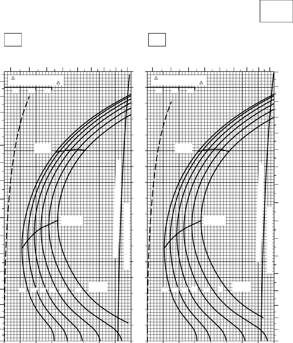
20 30 40 50 60 70 80 90 100
0
10
20
30
40
50
60
70
80
90
100
110
120
130
140
150
160
170
20 30 40 50 60 70 80 90 100
CRUISE
CLEAN CONFIGURATION
CRUISE
T700 (2)
TORQUE PER ENGINE ~ %TORQUE PER ENGINE ~ %
IAS ~ KTS TOTAL FUEL FLOW ~ 100 LB/HRTOTAL FUEL FLOW ~ 100 LB/HR
DATA BASE:FLIGHT TEST
TRUE AIRSPEED ~ KTS
TRUE AIRSPEED ~ KTS
TRQ ~ % FOR DRAG
AREA OF 10 SQ FT OF F
10 20 30
TRQ ~ % FOR DRAG
AREA OF 10 SQ FT OF F
10 20 30
SA
AA0461
−50oC−40oC
6000 FT
PRESS ALT: 6000 FT
567 8 9 10 11 12 13 5 6 7 8 9 10 11 12 13
0
10
20
30
40
50
60
70
80
90
100
110
120
130
140
150
160
0
10
20
30
40
50
60
70
80
90
100
110
120
130
140
150
160
170
MAX
RANGE
MAX END
AND R / C
GW ~
1000 LB
12 14 16 18 20 22
TRANSMISSION TORQUE LIMIT
MAX
RANGE
MAX END
AND R / C
GW ~
1000 LB
12 14 16 18 20 22
TRANSMISSION TORQUE LIMIT
TORQUE AVAILABLE ~ CONTINUOUS & 30 MIN
TORQUE AVAILABLE ~ CONTINUOUS & 30 MIN
Figure 7-13. Cruise - Pressure Altitude 6,000 Feet (Sheet 1 of 6)
TM 1-1520-237-10
7-52
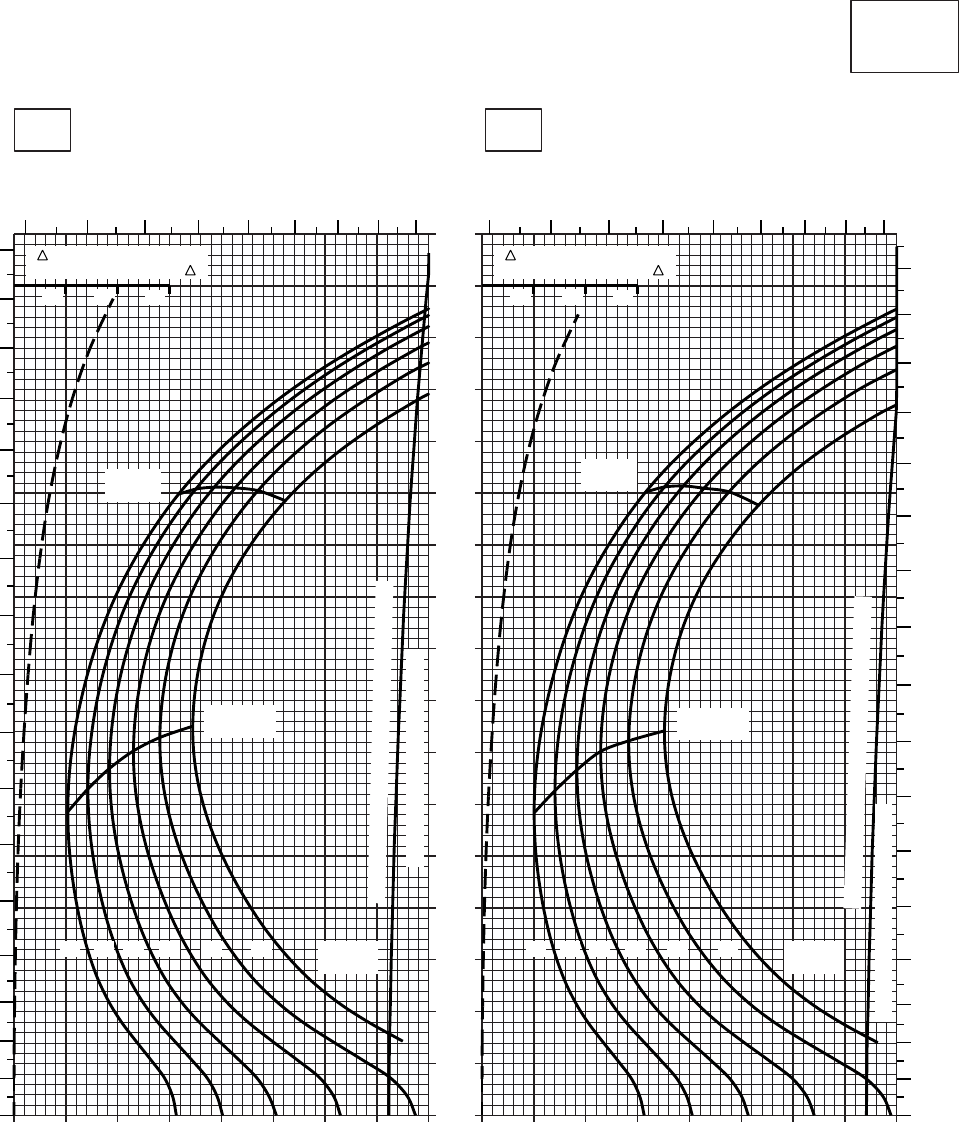
20 30 40 50 60 70 80 90 100
0
10
20
30
40
50
60
70
80
90
100
110
120
130
140
150
160
170
20 30 40 50 60 70 80 90 100
SA
AA0460
CRUISE
CLEAN CONFIGURATION
PRESS ALT: 6000 FT
CRUISE
6000 FT
T700 (2)
TORQUE PER ENGINE ~ %TORQUE PER ENGINE ~ %
IAS ~ KTS TOTAL FUEL FLOW ~ 100 LB/HRTOTAL FUEL FLOW ~ 100 LB/HR
DATA BASE:FLIGHT TEST
TRUE AIRSPEED ~ KTS
TRUE AIRSPEED ~ KTS
−20OC−30OC
TRQ ~ % FOR DRAG
AREA OF 10 SQ FT OF F
10 20 30
TRQ ~ % FOR DRAG
AREA OF 10 SQ FT OF F
10 20 30
5 6 7 8 9 10 11 12 13 5 6 7 8 9 10 11 12 13
0
10
20
30
40
50
60
70
80
90
100
110
120
130
140
150
160
170
MAX
RANGE
MAX END
AND R / C
GW~
1000 LB
12 14 16 18 20 22
MAX
RANGE
MAX END
AND R / C
GW~
1000 LB
12 14 16 18 20 22
TRANSMISSION TORQUE LIMIT
TRANSMISSION TORQUE LIMIT
0
10
20
30
40
50
60
70
80
90
100
110
120
130
140
150
160
170
TORQUE AVAILABLE ~ CONTINUOS & 30 MIN
TORQUE AVAILABLE ~ CONTINUOUS & 30 MIN
Figure 7-13. Cruise - Pressure Altitude 6,000 Feet (Sheet 2 of 6)
TM 1-1520-237-10
7-53
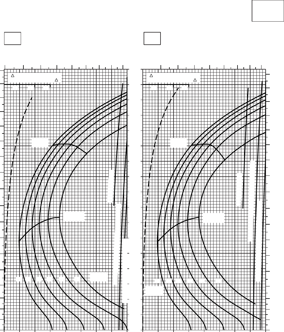
20 30 40 50 60 70 80 90 100
0
10
20
30
40
50
60
70
80
90
100
110
120
130
140
150
160
170
20 30 40 50 60 70 80 90 100
CRUISE
CLEAN CONFIGURATION
CRUISE
T700 (2)
TORQUE PER ENGINE ~ %TORQUE PER ENGINE ~ %
IAS ~ KTS TOTAL FUEL FLOW ~ 100 LB/HRTOTAL FUEL FLOW ~ 100 LB/HR
DATA BASE:FLIGHT TEST
TRUE AIRSPEED ~ KTS
TRUE AIRSPEED ~ KTS
TRQ ~ % FOR DRAG
AREA OF 10 SQ FT OF F
10 20 30
TRQ ~ % FOR DRAG
AREA OF 10 SQ FT OF F
10 20 30
SA
AA0459
5678910111213 678910111213
0
10
20
30
40
50
60
70
80
90
100
110
120
130
140
150
160
170
180
0
10
20
30
40
50
60
70
80
90
100
110
120
130
140
150
160
170
180
MAX
RANGE
MAX END
AND R / C
GW ~
1000 LB
12 14 16 18 20 22
TRANSMISSION TORQUE LIMIT
MAX
RANGE
MAX END
AND R / C
GW ~
1000 LB
12 14 16 18 20 22
~ CONTINUOUS
TORQUE AVAILABLE ~ 30 MIN ATF= 0.9
~ CONTINUOUS
TORQUE AVAILABLE ~ 30 MIN ATF= 0.9
−10oC0oC
6000 FT
PRESS ALT: 6000 FT
TRANSMISSION TORQUE LIMIT AFT~1.0
Figure 7-13. Cruise - Pressure Altitude 6,000 Feet (Sheet 3 of 6)
TM 1-1520-237-10
7-54
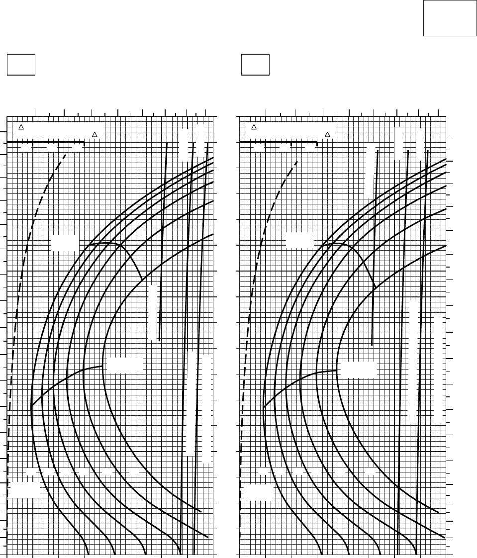
20 30 40 50 60 70 80 90 100
0
10
20
30
40
50
60
70
80
90
100
110
120
130
140
150
160
170
20 30 40 50 60 70 80 90 100
CRUISE
CLEAN CONFIGURATION
CRUISE
T700 (2)
TORQUE PER ENGINE ~ %TORQUE PER ENGINE ~ %
IAS ~ KTS TOTAL FUEL FLOW ~ 100 LB/HRTOTAL FUEL FLOW ~ 100 LB/HR
DATA BASE:FLIGHT TEST
TRUE AIRSPEED ~ KTS
TRUE AIRSPEED ~ KTS
TRQ ~ % FOR DRAG
AREA OF 10 SQ FT OF F
10 20 30
TRQ ~ % FOR DRAG
AREA OF 10 SQ FT OF F
10 20 30
SA
AA0462
10oC20oC
6000 FT
PRESS ALT: 6000 FT
6789
10 11 12 13 6 7 8 9 10 11 12 13
0
10
20
30
40
50
60
70
80
90
100
110
120
130
140
150
160
170
180
0
10
20
30
40
50
60
70
80
90
100
110
120
130
140
150
160
170
180
MAX
RANGE
MAX END
AND R / C
GW ~
1000 LB
12 14 16 18 20 22
TRANSMISSION TORQUE LIMIT
MAX
RANGE
MAX END
AND R / C
GW ~
1000 LB
12 14 16 18 20 22
TRANSMISSION TORQUE LIMIT
TORQUE AVAILABLE ~ 30 MINUTES
TORQUE AVAILABLE ~ 30 MIN
~ CONTINUOUS
ATF= 0.9
ATF= 1.0
ATF= 0.9
ATF= 1.0
~ CONTINUOUS
Figure 7-13. Cruise - Pressure Altitude 6,000 Feet (Sheet 4 of 6)
TM 1-1520-237-10
7-55
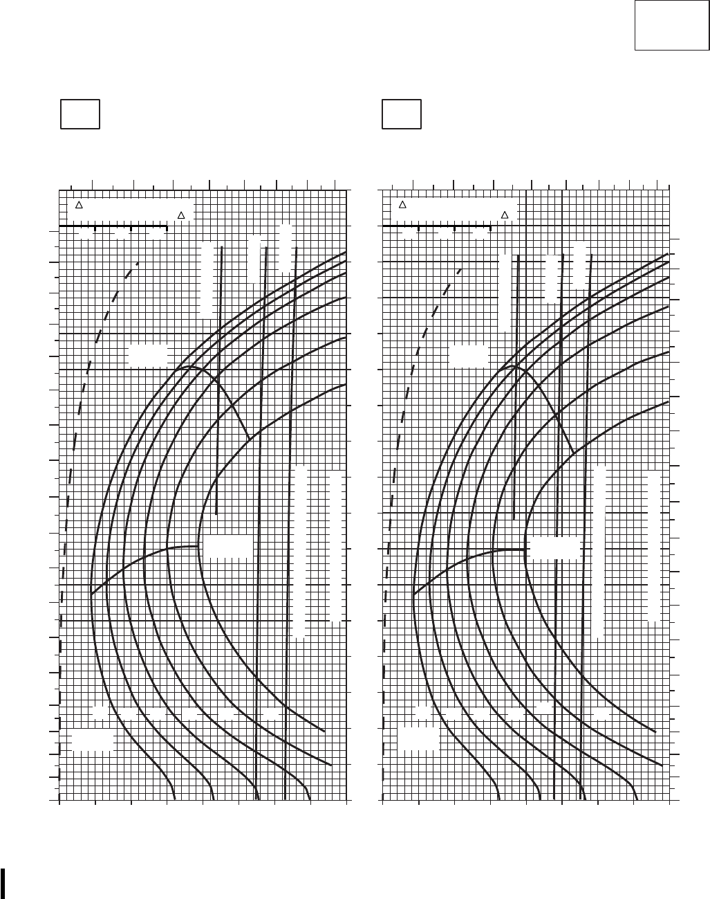
SA
AA0463A
CRUISE
CLEAN CONFIGURATION CRUISE
T700 (2)
30oC
6000 FT
PRESS ALT: 6000 FT
40oC
TOTAL FUEL FLOW ~ 100 LB/HR TOTAL FUEL FLOW ~ 100 LB/HR
IAS ~ KTS
TORQUE PER ENGINE ~ % TORQUE PER ENGINE ~ %
6 7 8 9 10 11 12 13 6 7 8 9 10 11 12 13
0
10
20
30
40
50
60
70
80
90
100
110
120
130
140
150
160
170
180
0
10
20
30
40
50
60
70
80
90
100
110
120
130
140
150
160
170
180
0
TRUE AIRSPEED ~ KTS
TRUE AIRSPEED ~ KTS
10
20
30
40
50
60
70
80
90
100
110
120
130
140
150
160
170
20 30 40 50 60 70 80 90 100 20 30 40 50 60 70 80 90 100
TRQ ~ % FOR DRAG
AREA OF 10 SQ FT OF F
10 20 30
TRQ ~ % FOR DRAG
AREA OF 10 SQ FT OF F
10 20 30
MAX
RANGE MAX
RANGE
MAX END
AND R / C MAX END
AND R / C
12 12
14 1416 1618 18
20 20
GW ~
1000 LB GW ~
1000 LB
~ CONTINUOUS
~ CONTINUOUS
ATF = 0.9
ATF = 0.9
ATF = 1.0
ATF = 1.0
TORQUE AVAILABLE ~ 30 MINUTES
TORQUE AVAILABLE ~ 30 MINUTES
TRANSMISSION TORQUE LIMIT
TRANSMISSION TORQUE LIMIT
22 22
Figure 7-13. Cruise - Pressure Altitude 6,000 Feet (Sheet 5 of 6)
TM 1-1520-237-10
7-56 Change 8
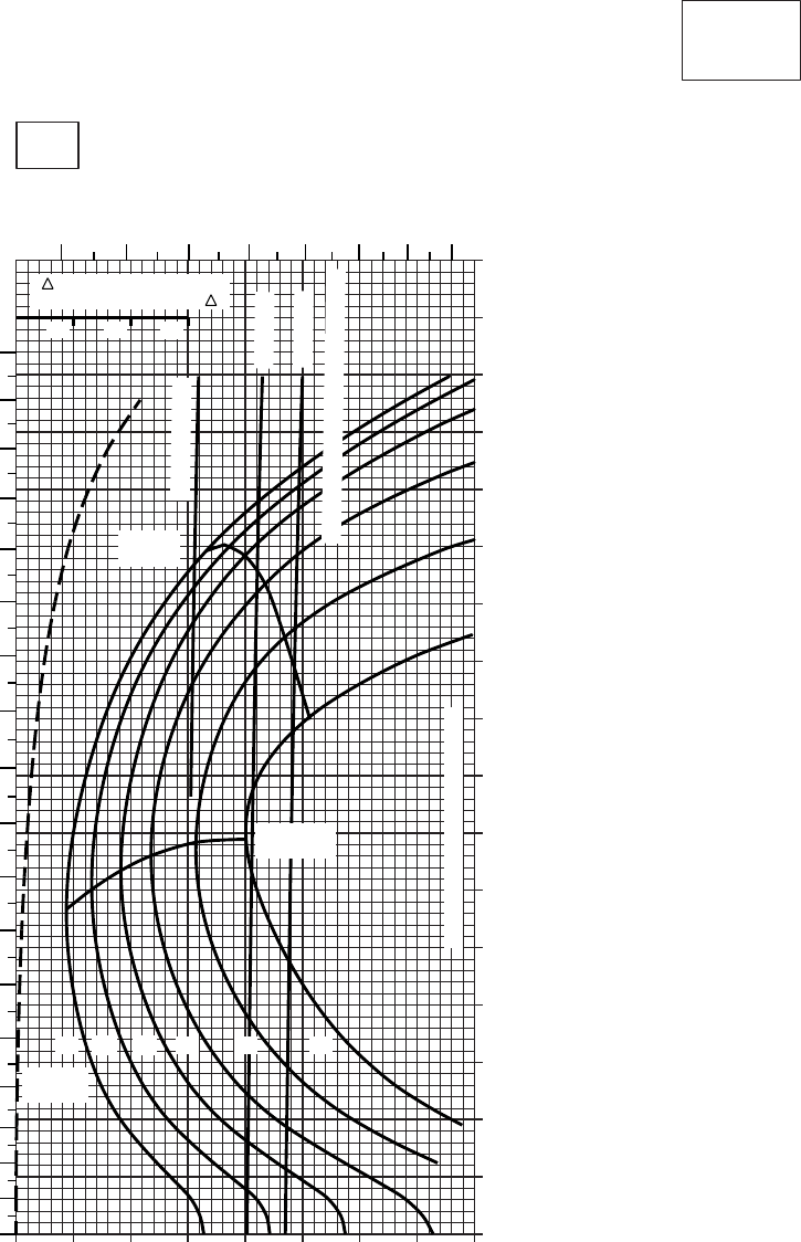
30 40 50 60 70 80 90 100
0
10
20
30
40
50
60
70
80
90
100
110
120
130
140
150
160
170
SA
AA0464A
CRUISE
CLEAN CONFIGURATION
CRUISE
T700 (2)
TORQUE PER ENGINE ~ %
IAS ~ KTSTOTAL FUEL FLOW ~ 100 LB/HR
DATA BASIS:FLIGHT TEST
TRUE AIRSPEED ~ KTS
TRQ ~ % FOR DRAG
AREA OF 10 SQ FT OF F
10 20 30
20
50oC
6000 FT
PRESS ALT: 6000 FT
6 7 8 9 10 11 12 13
0
10
20
30
40
50
60
70
80
90
100
110
120
130
140
150
160
170
180
MAX END
AND R / C
MAX
RANGE
GW~
1000 LB
12 14 16 18 20 22
TRANSMISSION TORQUE LIMIT
~ CONTINUOUS
ATF = 0.9
ATF = 1.0
TORQUE AVAILABLE ~ 30 MINUTES
Figure 7-13. Cruise - Pressure Altitude 6,000 Feet (Sheet 6 of 6)
TM 1-1520-237-10
7-57

20 30 40 50 60 70 80 90 100
0
10
20
30
40
50
60
70
80
90
100
110
120
130
140
150
160
170
20 30 40 50 60 70 80 90 100
SA
AA0552
CRUISE
PRESS ALT: 6000 FT
CRUISE
TORQUE PER ENGINE ~ %TORQUE PER ENGINE ~ %
IAS ~ KTS TOTAL FUEL FLOW ~ 100 LB/HRTOTAL FUEL FLOW ~ 100 LB/HR
DATA BASE:FLIGHT TEST
TRUE AIRSPEED ~ KTS
TRUE AIRSPEED ~ KTS
TRQ ~ % FOR DRAG
AREA OF 10 SQ FT OF F
10 20 30
TRQ ~ % FOR DRAG
AREA OF 10 SQ FT OF F
10 20 30
−50oC−40oC
6000 FT
5 6 7 8 9 10 11 12 13 5 6 7 8 9 10 11 12 13
180
170
160
150
140
130
120
110
100
90
80
70
60
50
40
30
20
10
00
10
20
30
40
50
60
70
80
90
100
110
120
130
140
150
160
170
180
12 14 16 18 20 22 23 24.5
GW ~
1000 LB
TRANSMISSION TORQUE LIMIT
TRANSMISSION TORQUE LIMIT
12 14 16 18 20 22 23 24.5
GW ~
1000 LB
MAX END
AND R / C
MAX END
AND R / C
MAX
RANGE
MAX
RANGE
TORQUE AVAILABLE ~ CONTINUOUS & 30 MIN
TORQUE AVAILABLE ~ CONTINUOUS & 30 MIN
T700 (2)
Figure 7-14. Cruise High Drag - Pressure Altitude 6,000 Feet (Sheet 1 of 6)
TM 1-1520-237-10
7-58
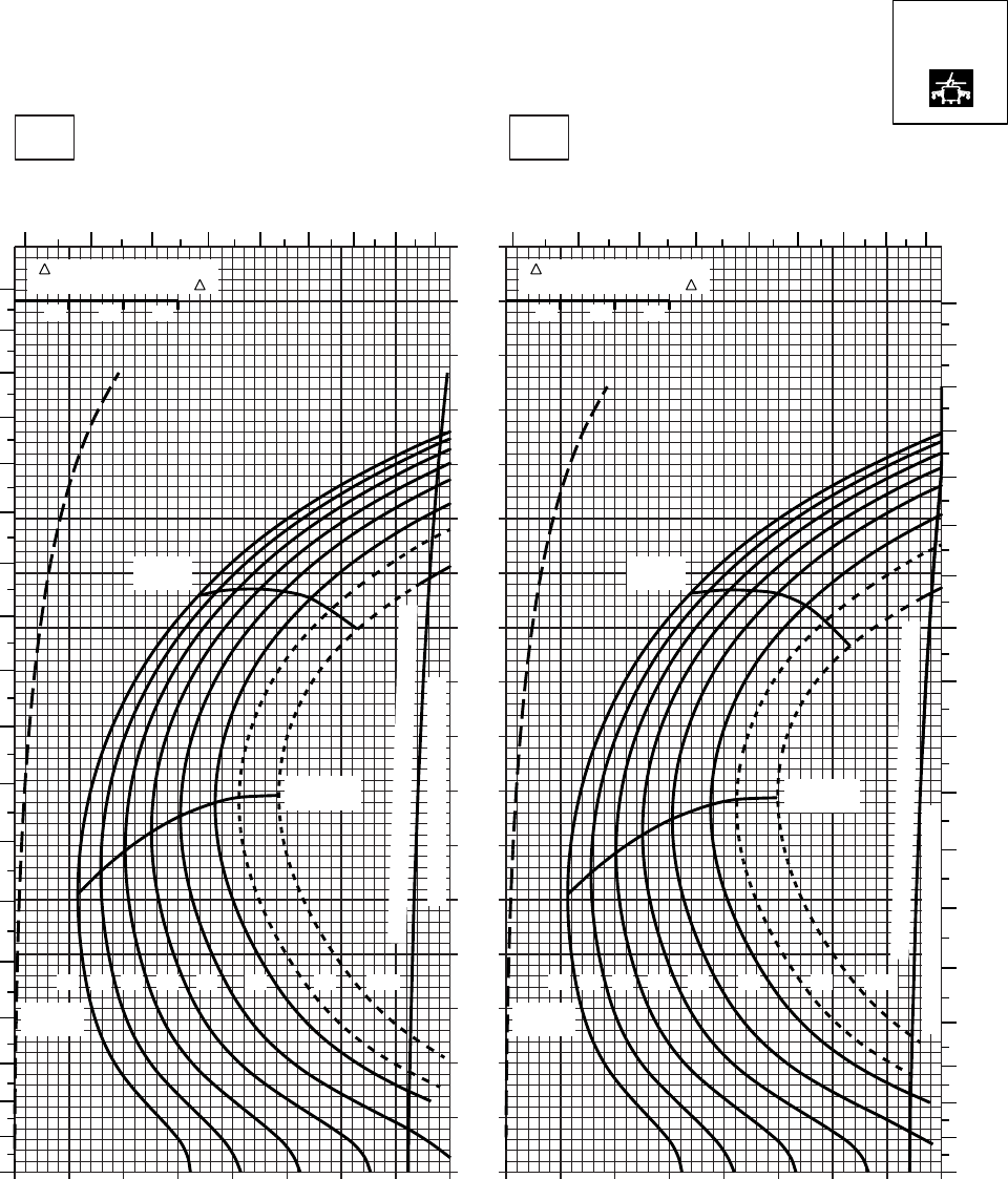
20 30 40 50 60 70 80 90 100
0
10
20
30
40
50
60
70
80
90
100
110
120
130
140
150
160
170
20 30 40 50 60 70 80 90 100
SA
AA0553
CRUISE
PRESS ALT: 6000 FT
CRUISE
TORQUE PER ENGINE ~ %TORQUE PER ENGINE ~ %
IAS ~ KTS TOTAL FUEL FLOW ~ 100 LB/HRTOTAL FUEL FLOW ~ 100 LB/HR
DATA BASE:FLIGHT TEST
TRUE AIRSPEED ~ KTS
TRUE AIRSPEED ~ KTS
TRQ ~ % FOR DRAG
AREA OF 10 SQ FT OF F
10 20 30
TRQ ~ % FOR DRAG
AREA OF 10 SQ FT OF F
10 20 30
−30oC−20oC
6000 FT
5 6 7 8 9 10 11 12 13 5 6 7 8 9 10 11 12 13
180
170
160
150
140
130
120
110
100
90
80
70
60
50
40
30
20
10
00
10
20
30
40
50
60
70
80
90
100
110
120
130
140
150
160
170
180
12 14 16 18 20 22 23 24.5
GW ~
1000 LB
12 14 16 18 20 22 23 24.5
GW ~
1000 LB
TRANSMISSION TORQUE LIMIT
TRANSMISSION TORQUE LIMIT
MAX END
AND R / C
MAX END
AND R / C
MAX
RANGE
MAX
RANGE
TORQUE AVAILABLE ~ CONTINUOUS & 30 MIN
TORQUE AVAILABLE ~ CONTINUOUS & 30 MIN
T700 (2)
Figure 7-14. Cruise High Drag - Pressure Altitude 6,000 Feet (Sheet 2 of 6)
TM 1-1520-237-10
7-59
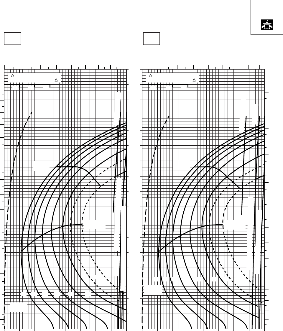
20 30 40 50 60 70 80 90 100
0
10
20
30
40
50
60
70
80
90
100
110
120
130
140
150
160
170
20 30 40 50 60 70 80 90 100
SA
AA0554
CRUISE
PRESS ALT: 6000 FT
CRUISE
TORQUE PER ENGINE ~ %TORQUE PER ENGINE ~ %
IAS ~ KTS TOTAL FUEL FLOW ~ 100 LB/HRTOTAL FUEL FLOW ~ 100 LB/HR
DATA BASE:FLIGHT TEST
TRUE AIRSPEED ~ KTS
TRUE AIRSPEED ~ KTS
TRQ ~ % FOR DRAG
AREA OF 10 SQ FT OF F
10 20 30
TRQ ~ % FOR DRAG
AREA OF 10 SQ FT OF F
10 20 30
−10oC0oC
6000 FT
56
78 9 10 11 12 13
180
170
160
150
140
130
120
110
100
90
80
70
60
50
40
30
20
10
0
MAX
RANGE
MAX END
AND R / C
GW ~
1000 LB
12 14 16 18 20 22
23 24.5
67
891011
12 13
180
170
160
150
140
110
120
130
100
90
80
70
60
50
40
30
20
10
0
~ CONTINUOUS
ATF = 0.9
TORQUE AVAILABLE ~ 30 MINUTES
TRANSMISSION TORQUE LIMIT
MAX END
AND R / C
MAX
RANGE
12 14 16 18 20 22 23 24.5
~ CONTINUOUS
GW ~
1000 LB
ATF = 1.0
TRANSMISSION TORQUE LIMIT
TORQUE AVAILABLE ~ 30 MINUTES
ATF = 0.9
T700 (2)
Figure 7-14. Cruise High Drag - Pressure Altitude 6,000 Feet (Sheet 3 of 6)
TM 1-1520-237-10
7-60
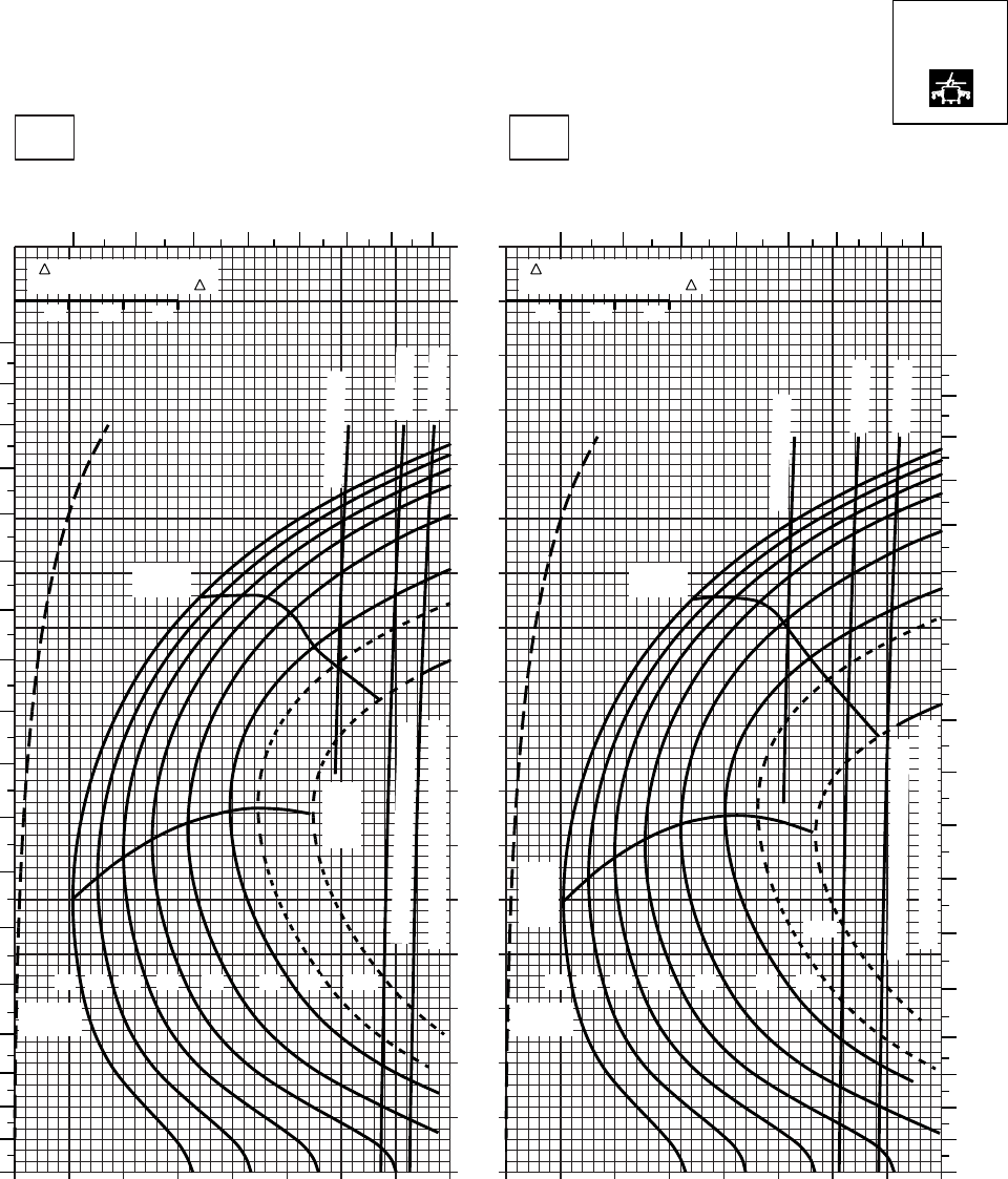
20 30 40 50 60 70 80 90 100
0
10
20
30
40
50
60
70
80
90
100
110
120
130
140
150
160
170
20 30 40 50 60 70 80 90 100
SA
AA0555
CRUISE
PRESS ALT: 6000 FT
CRUISE
TORQUE PER ENGINE ~ %TORQUE PER ENGINE ~ %
IAS ~ KTS TOTAL FUEL FLOW ~ 100 LB/HRTOTAL FUEL FLOW ~ 100 LB/HR
DATA BASE:FLIGHT TEST
TRUE AIRSPEED ~ KTS
TRUE AIRSPEED ~ KTS
TRQ ~ % FOR DRAG
AREA OF 10 SQ FT OF F
10 20 30
TRQ ~ % FOR DRAG
AREA OF 10 SQ FT OF F
10 20 30
10oC20oC
6000 FT
6 7 8 9 10 11 12 13 6 7 8 9 10 11 12 13
180
170
160
150
140
130
120
110
100
90
80
70
60
50
40
30
20
10
00
10
20
30
40
50
60
70
80
90
100
110
120
130
140
150
160
170
180
12 14 16 18 20 22 23 24.5
GW ~
1000 LB
12 14 16 18 20 22 23
24.5
GW ~
1000 LB
TRANSMISSION TORQUE LIMIT
TRANSMISSION TORQUE LIMIT
MAX
RANGE
MAX
RANGE
MAX
END
AND
R / C
MAX
END
AND
R / C
~ CONTINUOUS
~ CONTINUOUS
TORQUE AVAILABLE ~ 30 MIN
TORQUE AVAILABLE ~ 30 MIN
ATF = 0.9
ATF = 1.0
ATF = 1.0
ATF = 0.9
T700 (2)
Figure 7-14. Cruise High Drag - Pressure Altitude 6,000 Feet (Sheet 4 of 6)
TM 1-1520-237-10
7-61
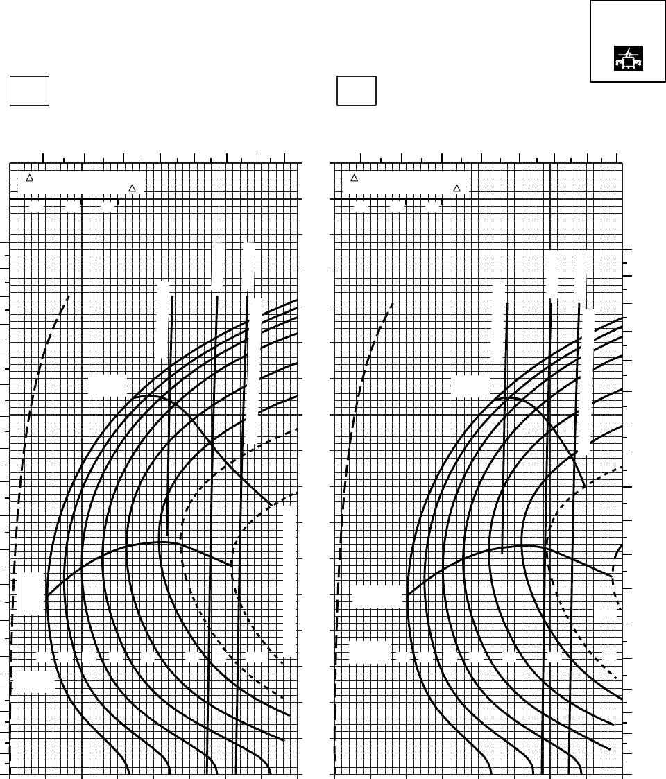
30 40 50 60 70 80 90 100
0
10
20
30
40
50
60
70
80
90
100
110
120
130
140
150
160
170
SA
AA0556A
CRUISE
PRESS ALT: 6000 FT
CRUISE
TORQUE PER ENGINE ~ %TORQUE PER ENGINE ~ %
IAS ~ KTS TOTAL FUEL FLOW ~ 100 LB/HRTOTAL FUEL FLOW ~ 100 LB/HR
DATA BASIS: FLIGHT TEST
TRUE AIRSPEED ~ KTS
TRUE AIRSPEED ~ KTS
TRQ ~ % FOR DRAG
AREA OF 10 SQ FT OF F
10 20 30
TRQ ~ % FOR DRAG
AREA OF 10 SQ FT OF F
10 20 30
20 20 30 40 50 60 70 80 9010
30oC40oC
6000 FT
6 7 8 9 10 11 12 13 5 6 7 8 9 10 11 12
180
170
160
150
140
130
120
110
100
90
80
70
60
50
40
30
20
10
00
10
20
30
40
50
60
70
80
90
100
110
120
130
140
150
160
170
180
12 14 16 18 20 22 23 24.5
GW ~
1000 LB
12 14 16 18 20 22 23
GW ~
1000 LB
TRANSMISSION TORQUE LIMIT
24.5
MAX END
AND R / C
MAX
END
AND
R / C
MAX
RANGE
MAX
RANGE
~ CONTINUOUS
~ CONTINUOUS
ATF = 0.9
ATF = 1.0
ATF = 0.9
ATF = 1.0
TORQUE AVAILABLE ~ 30 MIN
TORQUE AVAILABLE ~ 30 MIN
T700 (2)
Figure 7-14. Cruise High Drag - Pressure Altitude 6,000 Feet (Sheet 5 of 6)
TM 1-1520-237-10
7-62
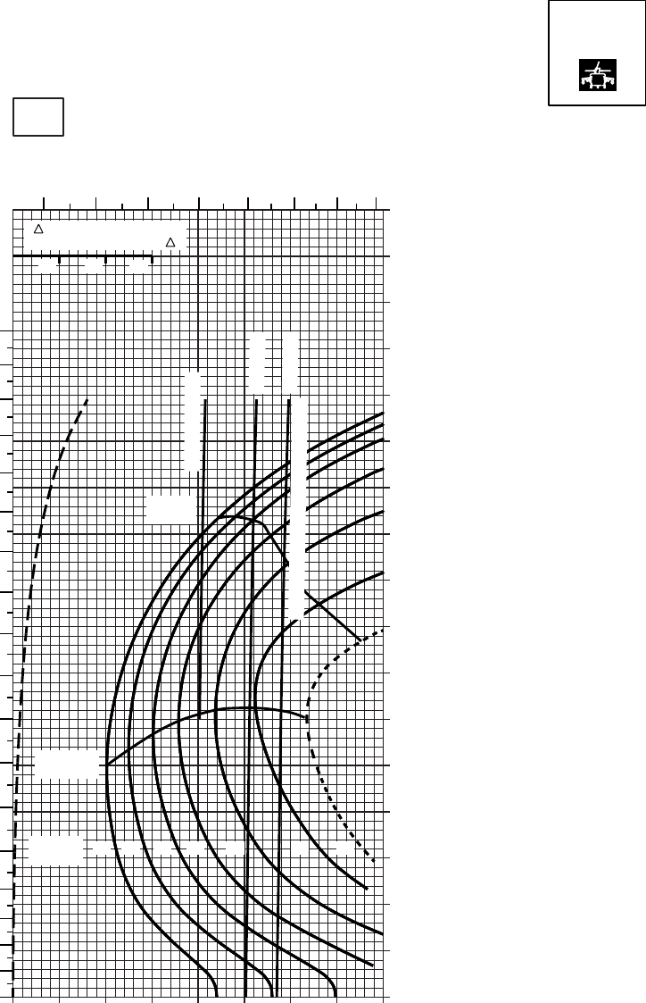
20 30 40 50 60 70 80 90
0
10
20
30
40
50
60
70
80
90
100
110
120
130
140
150
160
170
CRUISE
PRESS ALT: 6000 FT
CRUISE
6000 FT
TORQUE PER ENGINE ~ %
IAS ~ KTSTOTAL FUEL FLOW ~ 100 LB/HR
DATA BASE:FLIGHT TEST
TRUE AIRSPEED ~ KTS
50OC
TRQ ~ % FOR DRAG
AREA OF 10 SQ FT OF F
10 20 30
10
SASA
AA0557
56789
10 11 12
180
170
160
150
140
130
120
110
100
90
80
70
60
50
40
30
20
10
0
MAX
RANGE
MAX END
AND R / C
GW ~
1000 LB 12 14 16 18 20 22 23
ATF = 0.9
ATF = 1.0
~ CONTINUOUS
TORQUE AVAILABLE ~ 30 MINUTES
T700 (2)
Figure 7-14. Cruise High Drag - Pressure Altitude 6,000 Feet (Sheet 6 of 6)
TM 1-1520-237-10
7-63
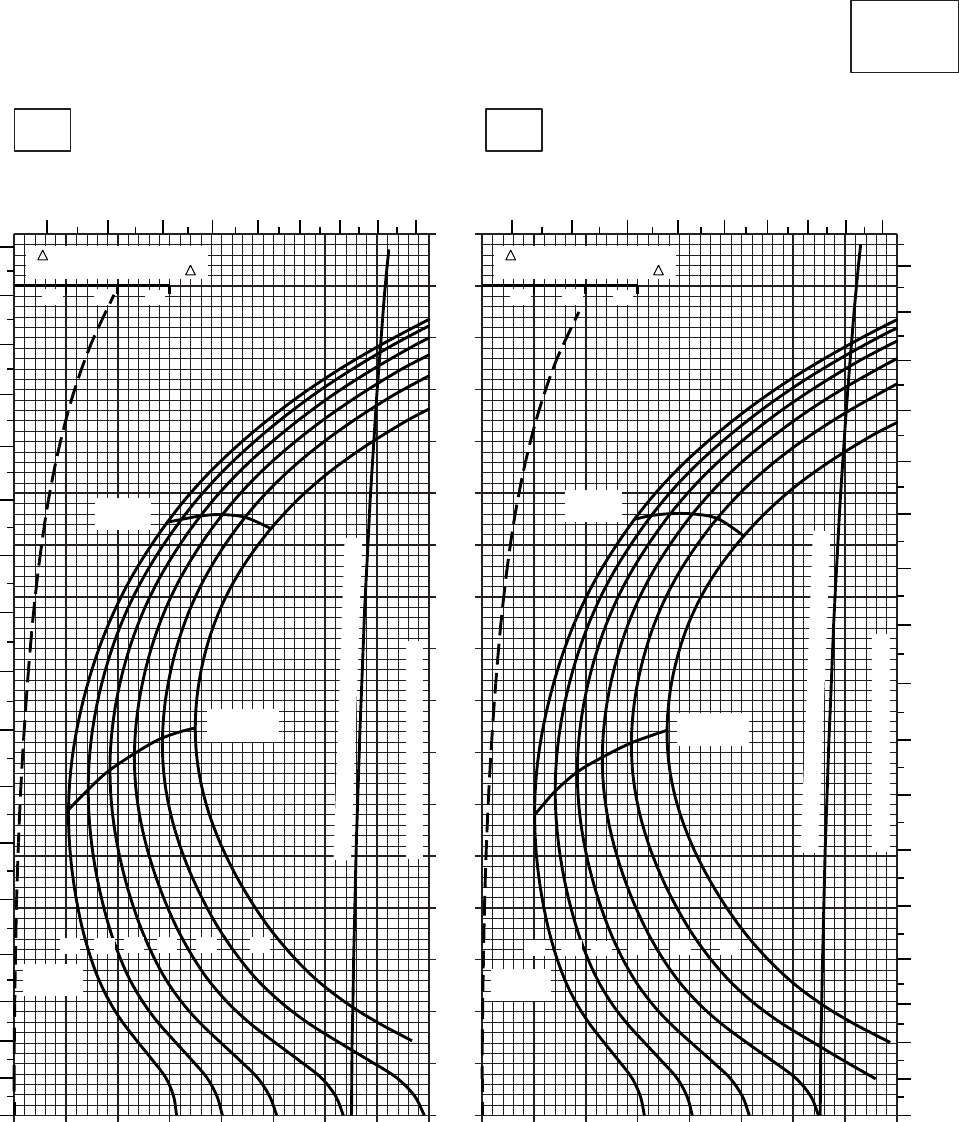
20 30 40 50 60 70 80 90 100
0
10
20
30
40
50
60
70
80
90
100
110
120
130
140
150
160
170
20 30 40 50 60 70 80 90 100
CRUISE
CLEAN CONFIGURATION
CRUISE
T700 (2)
TORQUE PER ENGINE ~ %TORQUE PER ENGINE ~ %
IAS ~ KTS TOTAL FUEL FLOW ~ 100 LB/HRTOTAL FUEL FLOW ~ 100 LB/HR
DATA BASE:FLIGHT TEST
TRUE AIRSPEED ~ KTS
TRUE AIRSPEED ~ KTS
TRQ ~ % FOR DRAG
AREA OF 10 SQ FT OF F
10 20 30
TRQ ~ % FOR DRAG
AREA OF 10 SQ FT OF F
10 20 30
SA
AA0467
−50oC−40oC
8000 FT
PRESS ALT: 8000 FT
567
89
10 11 12 13 5 6 7 8 9 10 11 12 13
0
10
20
30
40
50
60
70
80
90
100
110
120
130
140
150
160
170
0
10
20
30
40
50
60
70
80
90
100
110
120
130
140
150
160
170
MAX
RANGE
MAX END
AND R / C
GW ~
1000 LB
12 14 16 18 20 22
TRANSMISSION TORQUE LIMIT
MAX
RANGE
MAX END
AND R / C
GW ~
1000 LB
12 14 16 18 20 22
TRANSMISSION TORQUE LIMIT
TORQUE AVAILABLE ~ CONTINUOUS & 30 MIN
TORQUE AVAILABLE ~ CONTINUOUS & 30 MIN
Figure 7-15. Cruise - Pressure Altitude 8,000 Feet (Sheet 1 of 6)
TM 1-1520-237-10
7-64
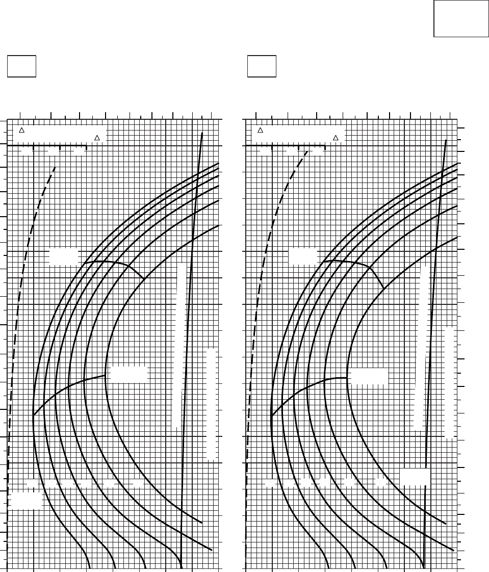
20 30 40 50 60 70 80 90 100
0
10
20
30
40
50
60
70
80
90
100
110
120
130
140
150
160
170
20 30 40 50 60 70 80 90 100
CRUISE
CLEAN CONFIGURATION
CRUISE
T700 (2)
TORQUE PER ENGINE ~ %TORQUE PER ENGINE ~ %
IAS ~ KTS TOTAL FUEL FLOW ~ 100 LB/HRTOTAL FUEL FLOW ~ 100 LB/HR
DATA BASE:FLIGHT TEST
TRUE AIRSPEED ~ KTS
TRUE AIRSPEED ~ KTS
TRQ ~ % FOR DRAG
AREA OF 10 SQ FT OF F
10 20 30
TRQ ~ % FOR DRAG
AREA OF 10 SQ FT OF F
10 20 30
SA
AA0466
−30oC−20oC
8000 FT
PRESS ALT: 8000 FT
5678910111213 567
8910111213
0
10
20
30
40
50
60
70
80
90
100
110
120
130
140
150
160
170
180
0
10
20
30
40
50
60
70
80
90
100
110
120
130
140
150
160
170
180
MAX
RANGE
MAX END
AND R / C
GW ~
1000 LB
12 14 16 18 20 22
TRANSMISSION TORQUE LIMIT
MAX
RANGE
MAX END
AND R / C
GW ~
1000 LB
12 14 16 18 20 22
TRANSMISSION TORQUE LIMIT
TORQUE AVAILABLE ~ CONTINUOUS & 30 MIN
TORQUE AVAILABLE ~ CONTINUOUS & 30 MIN
Figure 7-15. Cruise - Pressure Altitude 8,000 Feet (Sheet 2 of 6)
TM 1-1520-237-10
7-65
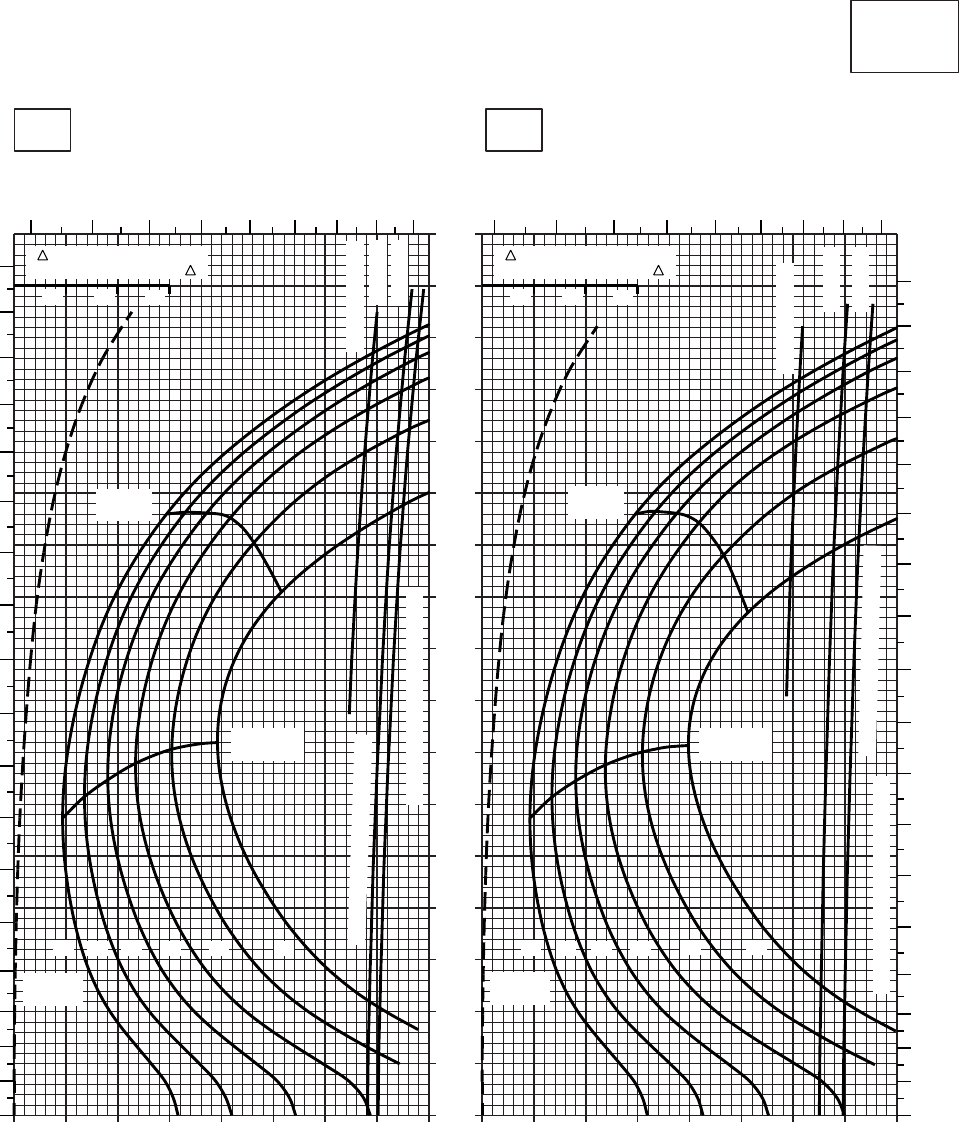
20 30 40 50 60 70 80 90 100
0
10
20
30
40
50
60
70
80
90
100
110
120
130
140
150
160
170
20 30 40 50 60 70 80 90 100
CRUISE
CLEAN CONFIGURATION
CRUISE
T700 (2)
TORQUE PER ENGINE ~ %TORQUE PER ENGINE ~ %
IAS ~ KTS TOTAL FUEL FLOW ~ 100 LB/HRTOTAL FUEL FLOW ~ 100 LB/HR
DATA BASE:FLIGHT TEST
TRUE AIRSPEED ~ KTS
TRUE AIRSPEED ~ KTS
TRQ ~ % FOR DRAG
AREA OF 10 SQ FT OF F
10 20 30
TRQ ~ % FOR DRAG
AREA OF 10 SQ FT OF F
10 20 30
SA
AA0465
−10oC0oC
8000 FT
PRESS ALT: 8000 FT
5 6 7 8 9 10 11 12 13 5 6 7 8 9 10 11 12 13
0
10
20
30
40
50
60
70
80
90
100
110
120
130
140
150
160
170
180
0
10
20
30
40
50
60
70
80
90
100
110
120
130
140
150
160
170
180
MAX
RANGE
MAX END
AND R / C
GW ~
1000 LB
12 14 16 18 20 22
TRANSMISSION TORQUE LIMIT
ATF= 0.9
ATF= 1.0
MAX
RANGE
MAX END
AND R / C
GW ~
1000 LB
12 14 16 18 20 22
TRANSMISSION TORQUE LIMIT
TORQUE AVAILABLE ~ 30 MIN
ATF= 0.9
ATF= 1.0
~ CONTINUOUS
TORQUE AVAILABLE ~ 30 MIN
~ CONTINUOUS
Figure 7-15. Cruise - Pressure Altitude 8,000 Feet (Sheet 3 of 6)
TM 1-1520-237-10
7-66
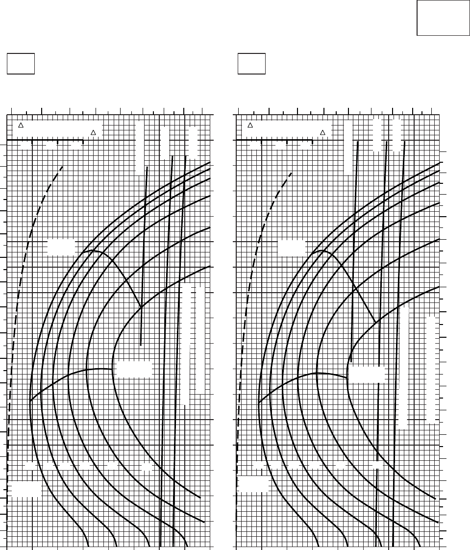
20 30 40 50 60 70 80 90 100
0
10
20
30
40
50
60
70
80
90
100
110
120
130
140
150
160
170
20 30 40 50 60 70 80 90 100
CRUISE
CLEAN CONFIGURATION
CRUISE
T700 (2)
TORQUE PER ENGINE ~ %TORQUE PER ENGINE ~ %
IAS ~ KTS TOTAL FUEL FLOW ~ 100 LB/HRTOTAL FUEL FLOW ~ 100 LB/HR
DATA BASE:FLIGHT TEST
TRUE AIRSPEED ~ KTS
TRUE AIRSPEED ~ KTS
TRQ ~ % FOR DRAG
AREA OF 10 SQ FT OF F
10 20 30
TRQ ~ % FOR DRAG
AREA OF 10 SQ FT OF F
10 20 30
SA
AA0468
10oC20oC
8000 FT
PRESS ALT: 8000 FT
5 6 7 8 9 10 11 12 13 5 6 7 8 9 10 11 12 13
0
10
20
30
40
50
60
70
80
90
100
110
120
130
140
150
160
170
180
0
10
20
30
40
50
60
70
80
90
100
110
120
130
140
150
160
170
180
MAX
RANGE
MAX END
AND R / C
GW ~
1000 LB
12 14 16 18 20 22
TRANSMISSION TORQUE LIMIT
ATF= 0.9
ATF= 1.0
TORQUE AVAILABLE ~ 30 MINUTES
MAX
RANGE
MAX END
AND R / C
GW ~
1000 LB
12 14 16 18 20 22
TRANSMISSION TORQUE LIMIT
ATF= 0.9
ATF= 1.0
TORQUE AVAILABLE ~ 30 MINUTES
~ CONTINUOUS
~ CONTINUOUS
Figure 7-15. Cruise - Pressure Altitude 8,000 Feet (Sheet 4 of 6)
TM 1-1520-237-10
7-67
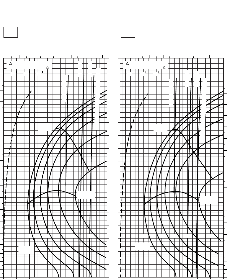
10 20 30 40 50 60 70 80 90
0
10
20
30
40
50
60
70
80
90
100
110
120
130
140
150
160
170
10 20 30 40 50 60 70 80 90
CRUISE
CLEAN CONFIGURATION
CRUISE
T700 (2)
TORQUE PER ENGINE ~ %TORQUE PER ENGINE ~ %
IAS ~ KTS TOTAL FUEL FLOW ~ 100 LB/HRTOTAL FUEL FLOW ~ 100 LB/HR
DATA BASIS: FLIGHT TEST
TRUE AIRSPEED ~ KTS
TRUE AIRSPEED ~ KTS
TRQ ~ % FOR DRAG
AREA OF 10 SQ FT OF F
10 20 30
TRQ ~ % FOR DRAG
AREA OF 10 SQ FT OF F
10 20 30
SA
AA0469A
30oC40oC
8000 FT
PRESS ALT: 8000 FT
456 7 8 9 10 11 12 56789101112
0
10
20
30
40
50
60
70
80
90
100
110
120
130
140
150
160
170
180
0
10
20
30
40
50
60
70
80
90
100
110
120
130
140
150
MAX
RANGE
~ CONTINUOUS
ATF= 0.9
ATF= 1.0
TORQUE AVAILABLE ~ 30 MINUTES
~ CONTINUOUS
ATF= 0.9
ATF= 1.0
TORQUE AVAILABLE ~ 30 MINUTES
MAX
RANGE
GW ~
1000 LB
12 14 16 18 20 22
MAX END
AND R / C
MAX END
AND R / C
GW ~
1000 LB
12 14 16 18 20 22
160
170
180
Figure 7-15. Cruise - Pressure Altitude 8,000 Feet (Sheet 5 of 6)
TM 1-1520-237-10
7-68
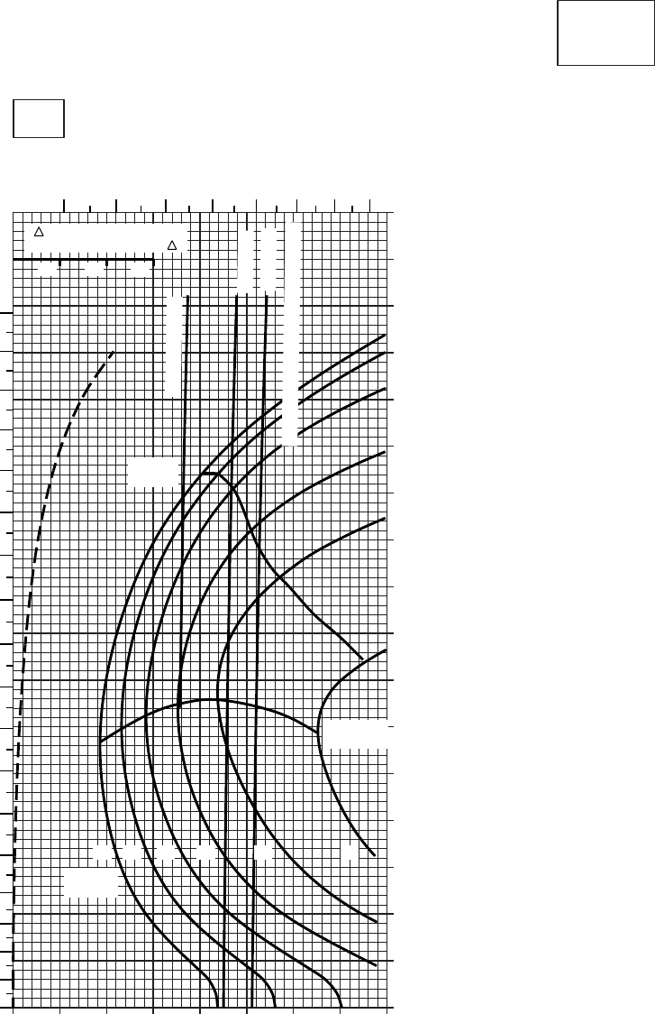
20 30 40 50 60 70 80 90
0
10
20
30
40
50
60
70
80
90
100
110
120
130
140
150
160
170
SA
AA0470
CRUISE
CLEAN CONFIGURATION
CRUISE
T700 (2)
TORQUE PER ENGINE ~ %
IAS ~ KTSTOTAL FUEL FLOW ~ 100 LB/HR
DATA BASE:FLIGHT TEST
TRUE AIRSPEED ~ KTS
TRQ ~ % FOR DRAG
AREA OF 10 SQ FT OF F
10 20 30
10
50oC
8000 FT
PRESS ALT: 8000 FT
56789101112
0
10
20
30
40
50
60
70
80
90
100
110
120
130
140
150
160
170
180
MAX
RANGE
GW~
1000 LB
12 14 16 18 20 22
MAX END
AND R / C
~ CONTINUOUS
ATF = 0.9
ATF = 1.0
TORQUE AVAILABLE ~ 30 MINUTES
Figure 7-15. Cruise - Pressure Altitude 8,000 Feet (Sheet 6 of 6)
TM 1-1520-237-10
7-69
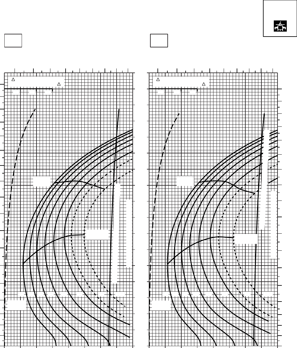
20 30 40 50 60 70 80 90 100
0
10
20
30
40
50
60
70
80
90
100
110
120
130
140
150
160
170
20 30 40 50 60 70 80 90 100
SA
AA0558
CRUISE
PRESS ALT: 8000 FT
CRUISE
8000 FT
TORQUE PER ENGINE ~ %TORQUE PER ENGINE ~ %
IAS ~ KTS TOTAL FUEL FLOW ~ 100 LB/HRTOTAL FUEL FLOW ~ 100 LB/HR
DATA BASE:FLIGHT TEST
TRUE AIRSPEED ~ KTS
TRUE AIRSPEED ~ KTS
−40OC−50OC
TRQ ~ % FOR DRAG
AREA OF 10 SQ FT OF F
10 20 30
TRQ ~ % FOR DRAG
AREA OF 10 SQ FT OF F
10 20 30
567891011
12 13
180
170
160
150
140
130
120
110
100
90
80
70
60
50
40
30
20
10
0
GW ~
1000 LB
12 14 16 18 20 22 23 24.5
MAX END
AND R / C
TRANSMISSION TORQUE LIMIT
MAX
RANGE
GW ~
1000 LB
12 14 16 18 20 22 23 24.5
MAX END
AND R / C
MAX
RANGE
TRANSMISSION TORQUE LIMIT
5678910 11 12 13
180
170
160
150
140
130
120
110
100
90
80
70
60
50
40
30
20
10
0
TORQUE AVAILABLE ~ CONTINUOUS & 30 MIN
TORQUE AVAILABLE ~ CONTINUOUS & 30 MIN
T700 (2)
Figure 7-16. Cruise High Drag - Pressure Altitude 8,000 Feet (Sheet 1 of 6)
TM 1-1520-237-10
7-70
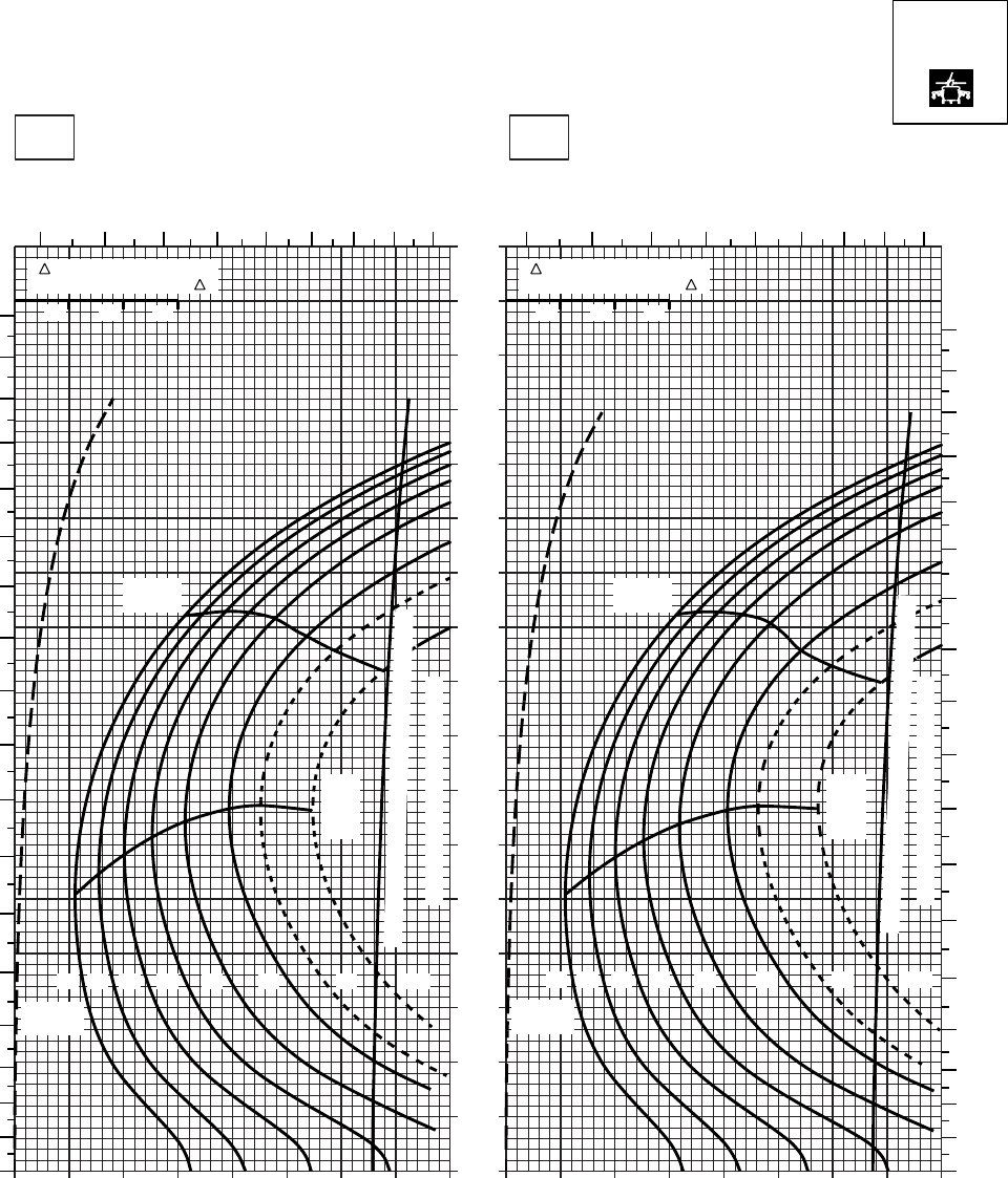
20 30 40 50 60 70 80 90 100
0
10
20
30
40
50
60
70
80
90
100
110
120
130
140
150
160
170
20 30 40 50 60 70 80 90 100
SA
AA0559
CRUISE
PRESS ALT: 8000 FT
CRUISE
TORQUE PER ENGINE ~ %TORQUE PER ENGINE ~ %
IAS ~ KTS TOTAL FUEL FLOW ~ 100 LB/HRTOTAL FUEL FLOW ~ 100 LB/HR
DATA BASE:FLIGHT TEST
TRUE AIRSPEED ~ KTS
TRUE AIRSPEED ~ KTS
TRQ ~ % FOR DRAG
AREA OF 10 SQ FT OF F
10 20 30
TRQ ~ % FOR DRAG
AREA OF 10 SQ FT OF F
10 20 30
−30oC−20oC
8000 FT
5 6 7 8 9 10 11 12 13 5 6 7 8 9 10 11 12 13
180
170
160
150
140
130
120
110
100
90
80
70
60
50
40
30
20
10
00
10
20
30
40
50
60
70
80
90
100
110
120
130
140
150
160
170
180
12 14 16 18 20 22 23 24.5
GW ~
1000 LB
TRANSMISSION TORQUE LIMIT
TRANSMISSION TORQUE LIMIT
12 14 16 18 20 22 23 24.5
GW ~
1000 LB
MAX
RANGE MAX
RANGE
MAX
END
AND
R / C
MAX
END
AND
R / C
TORQUE AVAILABLE ~ CONTINUOUS & 30 MIN
TORQUE AVAILABLE ~ CONTINUOUS & 30 MIN
T700 (2)
Figure 7-16. Cruise High Drag - Pressure Altitude 8,000 Feet (Sheet 2 of 6)
TM 1-1520-237-10
7-71
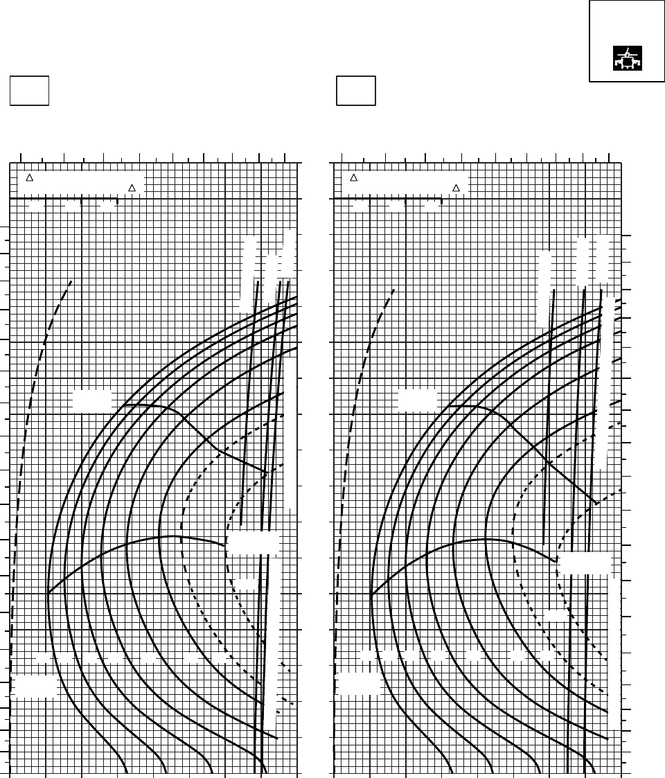
20 30 40 50 60 70 80 90 100
0
10
20
30
40
50
60
70
80
90
100
110
120
130
140
150
160
170
20 30 40 50 60 70 80 90 100
SA
AA0560
CRUISE
PRESS ALT: 8000 FT
CRUISE
8000 FT
TORQUE PER ENGINE ~ %TORQUE PER ENGINE ~ %
IAS ~ KTS TOTAL FUEL FLOW ~ 100 LB/HRTOTAL FUEL FLOW ~ 100 LB/HR
DATA BASE:FLIGHT TEST
TRUE AIRSPEED ~ KTS
TRUE AIRSPEED ~ KTS
0OC−10OC
TRQ ~ % FOR DRAG
AREA OF 10 SQ FT OF F
10 20 30
TRQ ~ % FOR DRAG
AREA OF 10 SQ FT OF F
10 20 30
56
78910
11 12 13
180
170
160
150
140
130
120
110
100
90
80
70
60
50
40
30
20
10
0
567
8910111213
180
170
160
150
140
130
120
110
100
90
80
70
60
50
40
30
20
10
0
MAX
RANGE
~ CONTINUOUS
ATF = 0.9
ATF = 1.0
TRANSMISSION TORQUE LIMIT
TORQUE AVAILABLE ~ 30 MINUTES
MAX END
AND R / C
GW ~
1000 LB
12 14 16 18 20 22 23
24.5
MAX
RANGE
~ CONTINUOUS
ATF = 1.0
ATF = 0.9
TORQUE AVAILABLE ~ 30 MINUTES
TRANSMISSION TORQUE LIMIT
MAX END
AND R / C
GW ~
1000 LB
12 14 16 18 20 22 23
24.5
T700 (2)
Figure 7-16. Cruise High Drag - Pressure Altitude 8,000 Feet (Sheet 3 of 6)
TM 1-1520-237-10
7-72
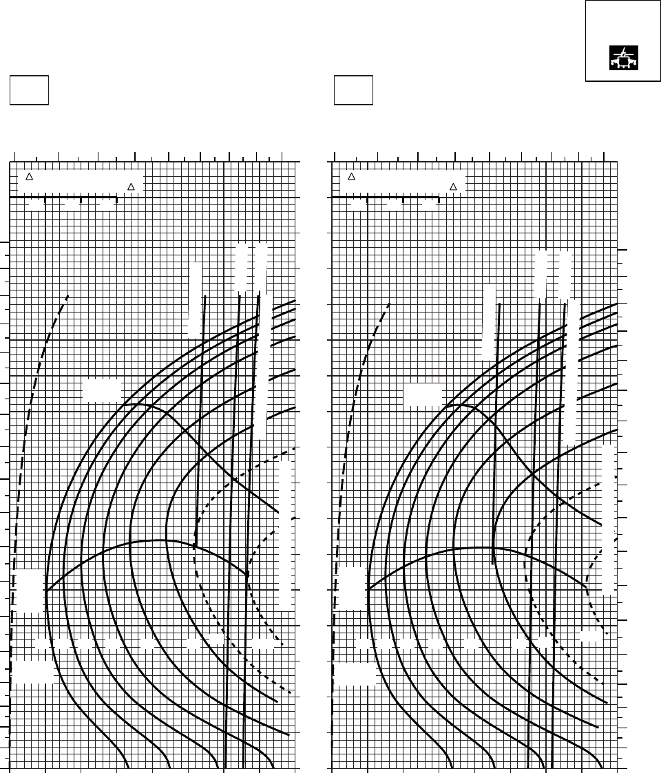
20 30 40 50 60 70 80 90 100
0
10
20
30
40
50
60
70
80
90
100
110
120
130
140
150
160
170
20 30 40 50 60 70 80 90 100
SA
AA0561
CRUISE
PRESS ALT: 8000 FT
CRUISE
TORQUE PER ENGINE ~ %TORQUE PER ENGINE ~ %
IAS ~ KTS TOTAL FUEL FLOW ~ 100 LB/HRTOTAL FUEL FLOW ~ 100 LB/HR
DATA BASE:FLIGHT TEST
TRUE AIRSPEED ~ KTS
TRUE AIRSPEED ~ KTS
TRQ ~ % FOR DRAG
AREA OF 10 SQ FT OF F
10 20 30
TRQ ~ % FOR DRAG
AREA OF 10 SQ FT OF F
10 20 30
10oC20oC
8000 FT
5 6 7 8 9 10 11 12 13 5 6 7 8 9 10 11 12 13
180
170
160
150
140
130
120
110
100
90
80
70
60
50
40
30
20
10
00
10
20
30
40
50
60
70
80
90
100
110
120
130
140
150
160
170
180
12 14 16 18 20 22 23 24.5
GW ~
1000 LB
12 14 16 18 20 22 23 24.5
GW ~
1000 LB
TRANSMISSION TORQUE LIMIT
TRANSMISSION TORQUE LIMIT
MAX
RANGE
MAX
RANGE
MAX
END
AND
R / C
MAX
END
AND
R / C
TORQUE AVAILABLE ~ 30 MIN
TORQUE AVAILABLE ~ 30 MIN
~ CONTINUOUS
~ CONTINUOUS
ATF = 0.9
ATF = 1.0
ATF = 0.9
ATF = 1.0
T700 (2)
Figure 7-16. Cruise High Drag - Pressure Altitude 8,000 Feet (Sheet 4 of 6)
TM 1-1520-237-10
7-73
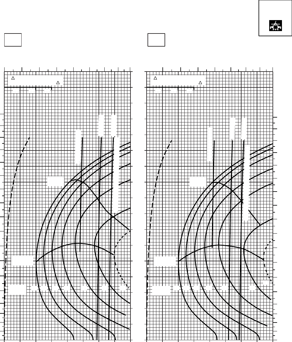
20 30 40 50 60 70 80 90
0
10
20
30
40
50
60
70
80
90
100
110
120
130
140
150
160
170
SA
CRUISE
PRESS ALT: 8000 FT
CRUISE
8000 FT
TORQUE PER ENGINE ~ %TORQUE PER ENGINE ~ %
IAS ~ KTS TOTAL FUEL FLOW ~ 100 LB/HRTOTAL FUEL FLOW ~ 100 LB/HR
DATA BASE:FLIGHT TEST
TRUE AIRSPEED ~ KTS
TRUE AIRSPEED ~ KTS
40OC30OC
TRQ ~ % FOR DRAG
AREA OF 10 SQ FT OF F
10 20 30
TRQ ~ % FOR DRAG
AREA OF 10 SQ FT OF F
10 20 30
10 20 30 40 50 60 70 80 9010
SA
AA0562
5678
9101112456789101112
180
170
160
150
140
130
120
110
100
90
80
70
60
50
40
30
20
10
0
180
170
160
150
140
130
120
110
100
90
80
70
60
50
40
30
20
10
0
~ CONTINUOUS
ATF = 0.9
ATF = 1.0
~ CONTINUOUS
ATF = 0.9
ATF = 1.0
MAX
RANGE
MAX
RANGE
MAX END
AND R / C
MAX END
AND R / C
GW ~
1000 LB 12 14 16 18 20 22 23 GW ~
1000 LB 12 14 16 18 20 22
23
TORQUE AVAILABLE ~ 30 MINUTES
TORQUE AVAILABLE ~ 30 MINUTES
T700 (2)
Figure 7-16. Cruise High Drag - Pressure Altitude 8,000 Feet (Sheet 5 of 6)
TM 1-1520-237-10
7-74
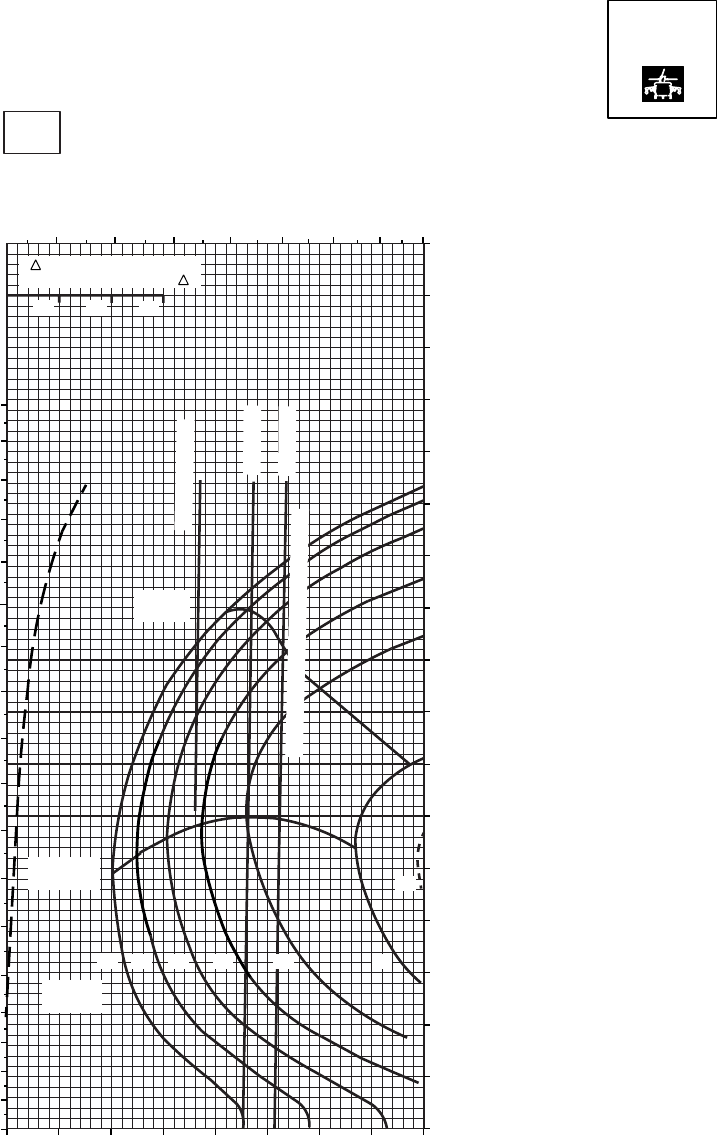
SA
AA0563
CRUISE CRUISE
TORQUE PER ENGINE ~ %
IAS ~ KTSTOTAL FUEL FLOW ~ 100 LB/HR
DATA BASE:FLIGHT TEST
TRUE AIRSPEED ~ KTS
50oC
8000 FT
PRESS ALT: 8000 FT
TRQ ~ % FOR DRAG
AREA OF 10 SQ FT OF F
10 20 30
~ CONTINUOUS
ATF = 0.9
ATF = 1.0
TORQUE AVAILABLE ~ 30 MINUTES
MAX END
AND R / C
MAX
RANGE
170
160
150
140
130
120
110
100
90
80
70
0
10
20
30
40
50
60
10 20 30 40 50 60 70 80 90
5 6 7 8 9 10 11 12
180
170
160
150
140
130
120
110
100
90
80
70
60
50
40
30
20
10
0
12 14 16 18 20 22
23
GW ~
1000 LB
T700 (2)
Figure 7-16. Cruise High Drag - Pressure Altitude 8,000 Feet (Sheet 6 of 6)
TM 1-1520-237-10
7-75
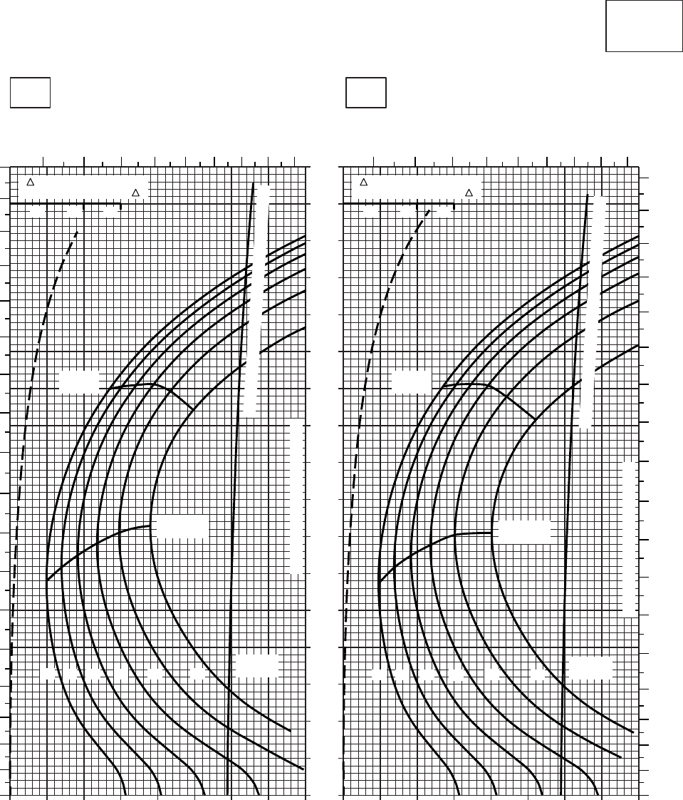
20 30 40 50 60 70 80 90 100
0
10
20
30
40
50
60
70
80
90
100
110
120
130
140
150
160
170
20 30 40 50 60 70 80 90 100
SA
AA0420
CRUISE
CLEAN CONFIGURATION
CRUISE
T700 (2)
TORQUE PER ENGINE ~ %TORQUE PER ENGINE ~ %
IAS ~ KTS TOTAL FUEL FLOW ~ 100 LB/HRTOTAL FUEL FLOW ~ 100 LB/HR
DATA BASE:FLIGHT TEST
TRUE AIRSPEED ~ KTS
TRUE AIRSPEED ~ KTS
TRQ ~ % FOR DRAG
AREA OF 10 SQ FT OF F
10 20 30
TRQ ~ % FOR DRAG
AREA OF 10 SQ FT OF F
10 20 30
−50oC−40oC
10000 FT
PRESS ALT: 10000 FT
567
8910
11 12 13
0
10
20
30
40
50
60
70
80
90
100
110
120
130
140
150
160
170
180
567
8910
11 12 13
0
10
20
30
40
50
60
70
80
90
100
110
120
130
140
150
160
170
180
MAX
RANGE
MAX END
AND R / C
GW ~
1000 LB
12 14 16 18 20 22
TRANSMISSION TORQUE LIMIT
MAX
RANGE
MAX END
AND R / C
GW ~
1000 LB
TRANSMISSION TORQUE LIMIT
12 14 16 18 20 22
TORQUE AVAILABLE ~ CONTINUOUS & 30 MIN.
TORQUE AVAILABLE ~ CONTINUOUS & 30 MIN.
Figure 7-17. Cruise - Pressure Altitude 10,000 Feet (Sheet 1 of 5)
TM 1-1520-237-10
7-76

20 30 40 50 60 70 80 90 100
0
10
20
30
40
50
60
70
80
90
100
110
120
130
140
150
160
170
20 30 40 50 60 70 80 90 100
SA
AA0419
CRUISE
CLEAN CONFIGURATION
CRUISE
T700 (2)
TORQUE PER ENGINE ~ %TORQUE PER ENGINE ~ %
IAS ~ KTS TOTAL FUEL FLOW ~ 100 LB/HRTOTAL FUEL FLOW ~ 100 LB/HR
DATA BASE:FLIGHT TEST
TRUE AIRSPEED ~ KTS
TRUE AIRSPEED ~ KTS
TRQ ~ % FOR DRAG
AREA OF 10 SQ FT OF F
10 20 30
TRQ ~ % FOR DRAG
AREA OF 10 SQ FT OF F
10 20 30
−30oC−20oC
10000 FT
PRESS ALT: 10000 FT
56789
10 11 12 13
0
10
20
30
40
50
60
70
80
90
100
110
120
130
140
150
160
170
180
5678
910 11 12 13
0
10
20
30
40
50
60
70
80
90
100
110
120
130
140
150
160
170
180
MAX
RANGE
MAX END
AND R / C
MAX
RANGE
MAX END
AND R / C
GW ~
1000 LB
12 14 16 18 20 22
TRANSMISSION TORQUE LIMIT
GW ~
1000 LB
TRANSMISSION TORQUE LIMIT
12 14 16 18 20 22
TORQUE AVAILABLE ~ CONTINUOUS & 30 MIN
TORQUE AVAILABLE ~ CONTINUOUS & 30 MIN
Figure 7-17. Cruise - Pressure Altitude 10,000 Feet (Sheet 2 of 5)
TM 1-1520-237-10
7-77

20 30 40 50 60 70 80 90 100
0
10
20
30
40
50
60
70
80
90
100
110
120
130
140
150
160
170
20 30 40 50 60 70 80 90 100
SA
AA0418
CRUISE
CLEAN CONFIGURATION
PRESS ALT: 10000 FT
CRUISE
10000 FT
T700 (2)
TORQUE PER ENGINE ~ %TORQUE PER ENGINE ~ %
IAS ~ KTS TOTAL FUEL FLOW ~ 100 LB/HRTOTAL FUEL FLOW ~ 100 LB/HR
DATA BASE:FLIGHT TEST
TRUE AIRSPEED ~ KTS
TRUE AIRSPEED ~ KTS
0oC−10oC
TRQ ~ % FOR DRAG
AREA OF 10 SQ FT OF F
10 20 30
TRQ ~ % FOR DRAG
AREA OF 10 SQ FT OF F
10 20 30
0
10
20
30
40
50
60
70
80
90
100
110
120
130
140
150
160
170
180
56 7 8 9 10 11 12 13 56 7 8 9 10 11 12 13
0
10
20
30
40
50
60
70
80
90
100
110
120
130
140
150
160
170
180
ATF=0.9
ATF=1.0
TORQUE AVAILABLE ~ 30 MINUTES
MAX
RANGE
MAX END
AND R / C
14 16 18 20 22
12
GW ~
1000 LB
TRANSMISSION TORQUE LIMIT
GW ~
1000 LB
12 14 16 18 20 22
MAX END
AND R / C
TRANSMISSION TORQUE LIMIT
ATF=1.0
ATF=0.9
~ CONTINUOUS
TORQUE AVAILABLE ~ 30 MINUTES
~ CONTINUOUS
MAX
RANGE
Figure 7-17. Cruise - Pressure Altitude 10,000 Feet (Sheet 3 of 5)
TM 1-1520-237-10
7-78
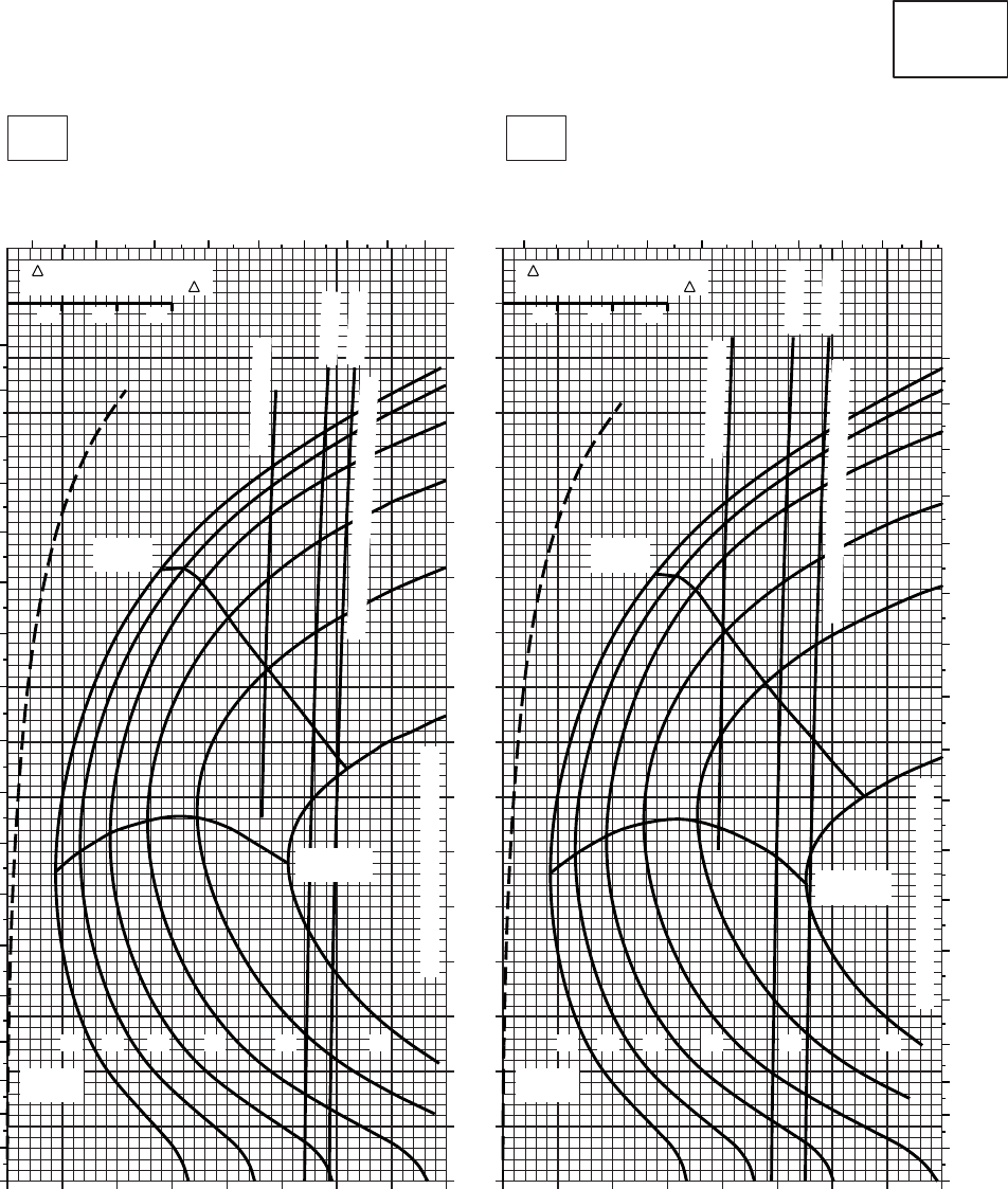
20 30 40 50 60 70 80 90 100
0
10
20
30
40
50
60
70
80
90
100
110
120
130
140
150
160
170
20 30 40 50 60 70 80 90 100
SA
AA0421
CRUISE
CLEAN CONFIGURATION
PRESS ALT: 10000 FT
CRUISE
10000 FT
T700 (2)
TORQUE PER ENGINE ~ %TORQUE PER ENGINE ~ %
IAS ~ KTS TOTAL FUEL FLOW ~ 100 LB/HRTOTAL FUEL FLOW ~ 100 LB/HR
DATA BASE:FLIGHT TEST
TRUE AIRSPEED ~ KTS
TRUE AIRSPEED ~ KTS
20OC10OC
TRQ ~ % FOR DRAG
AREA OF 10 SQ FT OF F
10 20 30
TRQ ~ % FOR DRAG
AREA OF 10 SQ FT OF F
10 20 30
2020 2218161412
GW ~
1000 LB GW ~
1000 LB
18161412 22
MAX
RANGE
MAX END
AND R / C
TRANSMISSION TORQUE LIMIT
TRANSMISSION TORQUE LIMIT
MAX END
AND R / C
MAX
RANGE
~ CONTINUOUS
ATF = 0.9
ATF = 1.0
TORQUE AVAILABLE ~ 30 MINUTES
~ CONTINUOUS
ATF = 0.9
ATF = 1.0
TORQUE AVAILABLE ~ 30 MINUTES
0
10
20
30
40
50
60
70
80
90
100
110
120
130
140
150
160
170
180
5678910111213 5678910111213
180
170
160
150
140
130
120
110
100
90
80
70
60
50
40
30
20
10
0
Figure 7-17. Cruise - Pressure Altitude 10,000 Feet (Sheet 4 of 5)
TM 1-1520-237-10
7-79
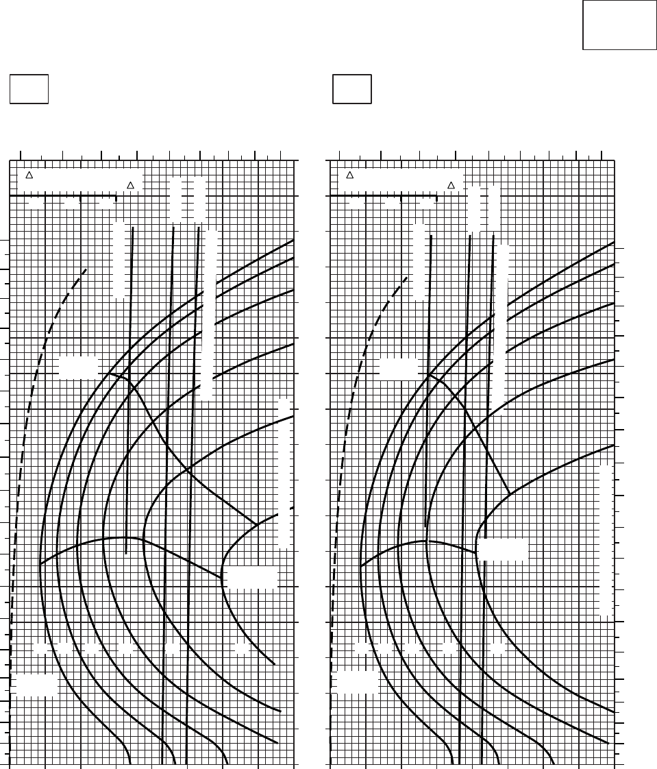
20 30 40 50 60 70 80 90 100
0
10
20
30
40
50
60
70
80
90
100
110
120
130
140
150
160
170
20 30 40 50 60 70 80 90 100
SA
AA0422
CRUISE
CLEAN CONFIGURATION
CRUISE
T700 (2)
TORQUE PER ENGINE ~ %TORQUE PER ENGINE ~ %
IAS ~ KTS TOTAL FUEL FLOW ~ 100 LB/HRTOTAL FUEL FLOW ~ 100 LB/HR
DATA BASE:FLIGHT TEST
TRUE AIRSPEED ~ KTS
TRUE AIRSPEED ~ KTS
TRQ ~ % FOR DRAG
AREA OF 10 SQ FT OF F
10 20 30
TRQ ~ % FOR DRAG
AREA OF 10 SQ FT OF F
10 20 30
30oC40oC
10000 FT
PRESS ALT: 10000 FT
56
78
910 11 12 13 56
78
910 11 12 13
0
10
20
30
40
50
60
70
80
90
100
110
120
130
140
150
160
170
180
0
10
20
30
40
50
60
70
80
90
100
120
110
130
140
150
160
170
180
TORQUE AVAILABLE ~ 30 MINUTES
MAX
RANGE
MAX END
AND R / C
GW ~
1000 LB
12 14 16 18 20 22
TRANSMISSION TORQUE LIMIT
ATF= 0.9
ATF= 1.0
~ CONTINUOUS
MAX
RANGE
MAX END
AND R / C
GW ~
1000 LB
12 14 16 18 20
TRANSMISSION TORQUE LIMIT
ATF= 0.9
ATF= 1.0
TORQUE AVAILABLE ~ 30 MINUTES
~ CONTINUOUS
Figure 7-17. Cruise - Pressure Altitude 10,000 Feet (Sheet 5 of 5)
TM 1-1520-237-10
7-80
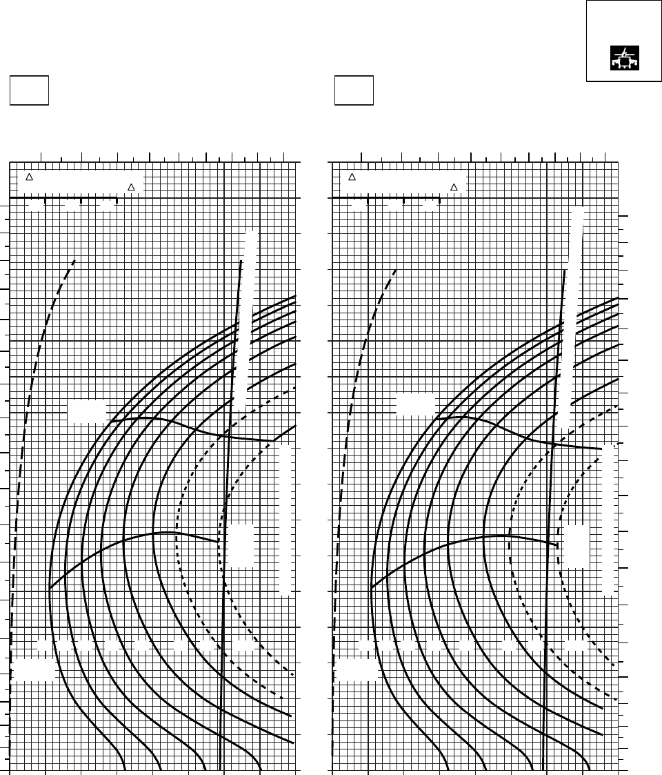
20 30 40 50 60 70 80 90 100
0
10
20
30
40
50
60
70
80
90
100
110
120
130
140
150
160
170
20 30 40 50 60 70 80 90 100
SA
AA0564
CRUISE
PRESS ALT: 10000 FT
CRUISE
TORQUE PER ENGINE ~ %TORQUE PER ENGINE ~ %
IAS ~ KTS TOTAL FUEL FLOW ~ 100 LB/HRTOTAL FUEL FLOW ~ 100 LB/HR
DATA BASE:FLIGHT TEST
TRUE AIRSPEED ~ KTS
TRUE AIRSPEED ~ KTS
TRQ ~ % FOR DRAG
AREA OF 10 SQ FT OF F
10 20 30
TRQ ~ % FOR DRAG
AREA OF 10 SQ FT OF F
10 20 30
−50oC−40oC
10000 FT
5 6 7 8 9 10 11 12 13 5 6 7 8 9 10 11 12 13
180
170
160
150
140
130
120
110
100
90
80
70
60
50
40
30
20
10
00
10
20
30
40
50
60
70
80
90
100
110
120
130
140
150
160
170
180
12 14 16 18 20 22 23 24.5
GW ~
1000 LB
12 14 16 18 20 22 23 24.5
GW ~
1000 LB
TRANSMISSION TORQUE LIMIT
TRANSMISSION TORQUE LIMIT
MAX
RANGE
MAX
RANGE
MAX
END
AND
R / C
MAX
END
AND
R / C
TORQUE AVAILABLE ~ CONTINUOUS
TORQUE AVAILABLE ~ CONTINUOUS & 30 MIN
T700 (2)
Figure 7-18. Cruise High Drag - Pressure Altitude 10,000 Feet (Sheet 1 of 5)
TM 1-1520-237-10
7-81
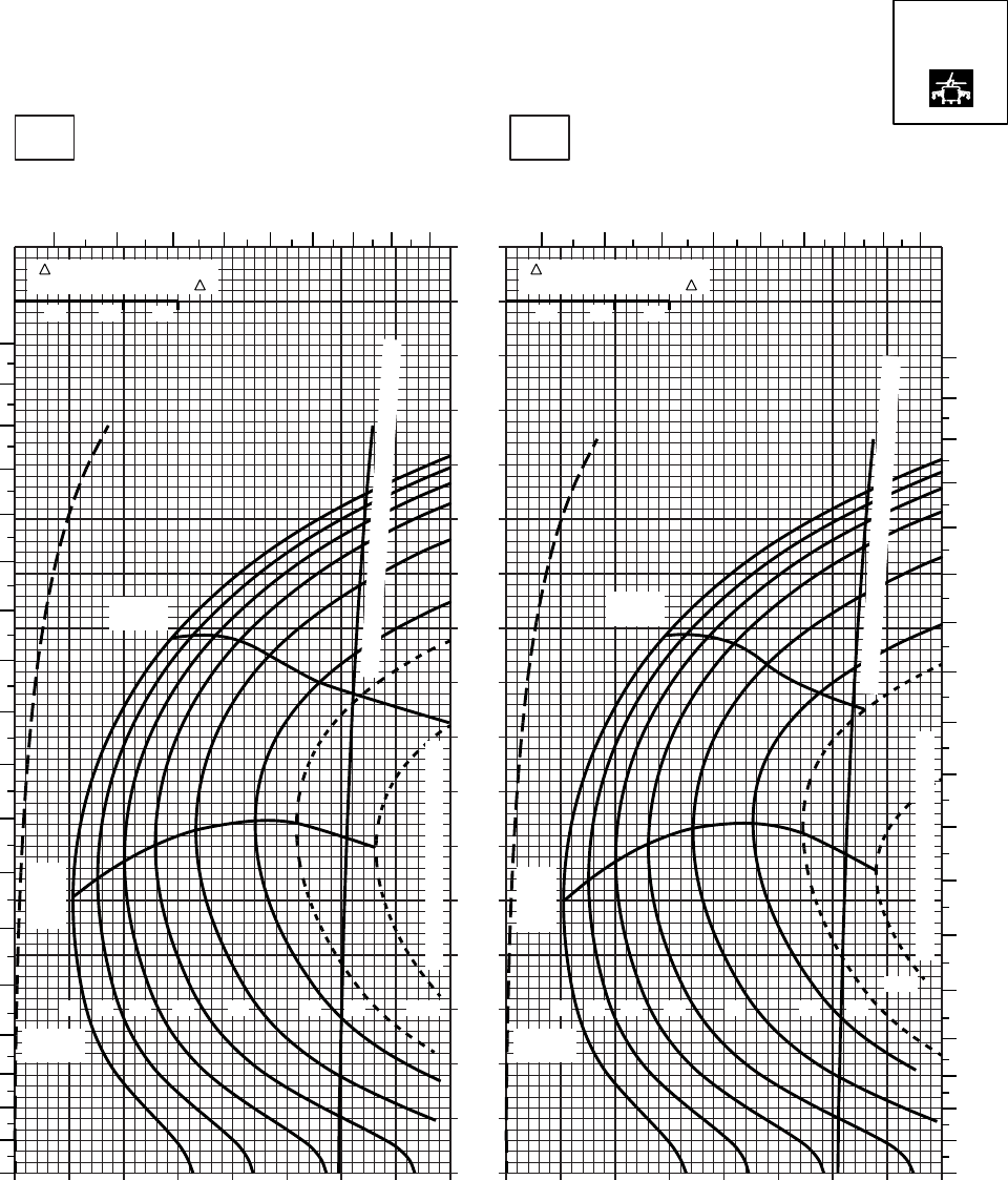
20 30 40 50 60 70 80 90 100
0
10
20
30
40
50
60
70
80
90
100
110
120
130
140
150
160
170
20 30 40 50 60 70 80 90 100
SA
AA0565
CRUISE
PRESS ALT: 10000 FT
CRUISE
TORQUE PER ENGINE ~ %TORQUE PER ENGINE ~ %
IAS ~ KTS TOTAL FUEL FLOW ~ 100 LB/HRTOTAL FUEL FLOW ~ 100 LB/HR
DATA BASE:FLIGHT TEST
TRUE AIRSPEED ~ KTS
TRUE AIRSPEED ~ KTS
TRQ ~ % FOR DRAG
AREA OF 10 SQ FT OF F
10 20 30
TRQ ~ % FOR DRAG
AREA OF 10 SQ FT OF F
10 20 30
−30oC−20oC
10000 FT
5 6 7 8 9 10 11 12 13 5 6 7 8 9 10 11 12 13
180
170
160
150
140
130
120
110
100
90
80
70
60
50
40
30
20
10
00
10
20
30
40
50
60
70
80
90
100
110
120
130
140
150
160
170
180
12 14 16 18 20 22 23 24.5
GW ~
1000 LB
12 14 16 18 22 23
24.5
GW ~
1000 LB
20
TRANSMISSION TORQUE LIMIT
TRANSMISSION TORQUE LIMIT
MAX
RANGE
MAX
RANGE
MAX
END
AND
R / C
MAX
END
AND
R / C
TORQUE AVAILABLE ~ CONTINUOUS & 30 MIN
TORQUE AVAILABLE ~ CONTINUOUS & 30 MIN
T700 (2)
Figure 7-18. Cruise High Drag - Pressure Altitude 10,000 Feet (Sheet 2 of 5)
TM 1-1520-237-10
7-82
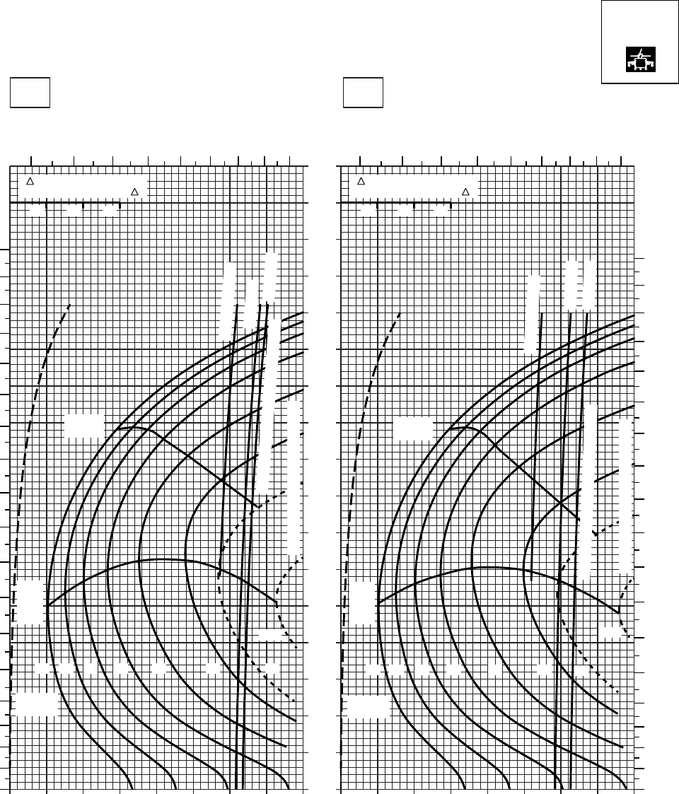
20 30 40 50 60 70 80 90 100
0
10
20
30
40
50
60
70
80
90
100
110
120
130
140
150
160
170
20 30 40 50 60 70 80 90 100
SA
AA0566
CRUISE
PRESS ALT: 10000 FT
CRUISE
10000 FT
TORQUE PER ENGINE ~ %TORQUE PER ENGINE ~ %
IAS ~ KTS TOTAL FUEL FLOW ~ 100 LB/HRTOTAL FUEL FLOW ~ 100 LB/HR
DATA BASE:FLIGHT TEST
TRUE AIRSPEED ~ KTS
TRUE AIRSPEED ~ KTS
0OC−10OC
TRQ ~ % FOR DRAG
AREA OF 10 SQ FT OF F
10 20 30
TRQ ~ % FOR DRAG
AREA OF 10 SQ FT OF F
10 20 30
5678910 11 12 13 5678
910
11 12 13
180
170
160
150
140
130
120
110
100
90
80
70
60
50
40
30
20
10
0
180
170
160
150
140
130
120
110
100
90
80
70
60
50
40
30
20
10
0
~ CONTINUOUS
ATF = 0.9
ATF = 1.0
GW ~
1000 LB
12 14 16 18 20 22 23
24.5
GW ~
1000 LB
12 14 16 18 20 22 23
24.5
~ CONTINUOUS
ATF = 0.9
ATF = 1.0
MAX
END
AND
R / C
MAX
RANGE MAX
RANGE
MAX
END
AND
R / C
TRANSMISSION TORQUE LIMIT
TORQUE AVAILABLE ~ 30 MINUTES
TRANSMISSION TORQUE LIMIT
TORQUE AVAILABLE ~ 30 MINUTES
T700 (2)
Figure 7-18. Cruise High Drag - Pressure Altitude 10,000 Feet (Sheet 3 of 5)
TM 1-1520-237-10
7-83
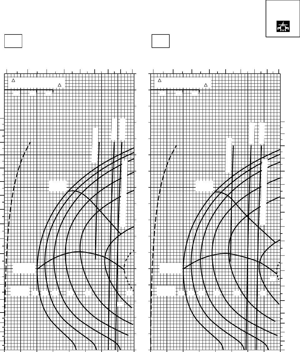
20 30 40 50 60 70 80 90
0
10
20
30
40
50
60
70
80
90
100
110
120
130
140
150
160
170
SA
AA0567
CRUISE
PRESS ALT: 10000 FT
CRUISE
TORQUE PER ENGINE ~ %TORQUE PER ENGINE ~ %
IAS ~ KTS TOTAL FUEL FLOW ~ 100 LB/HRTOTAL FUEL FLOW ~ 100 LB/HR
DATA BASE:FLIGHT TEST
TRUE AIRSPEED ~ KTS
TRUE AIRSPEED ~ KTS
TRQ ~ % FOR DRAG
AREA OF 10 SQ FT OF F
10 20 30
TRQ ~ % FOR DRAG
AREA OF 10 SQ FT OF F
10 20 30
10 20 30 40 50 60 70 80 9010
10oC20oC
10000 FT
4 5 6 7 8 9 10 11 12 4 5 6 7 8 9 10 11 12
180
170
160
150
140
130
120
110
100
90
80
70
60
50
40
30
20
10
00
10
20
30
40
50
60
70
80
90
100
110
120
130
140
150
160
170
180
12 14 16 18 20
22
23
GW ~
1000 LB 12 14 16 18 20 22
23
GW ~
1000 LB
MAX END
AND R / C
MAX END
AND R / C
MAX
RANGE
MAX
RANGE
~ CONTINUOUS
~ CONTINUOUS
TORQUE AVAILABLE ~ 30 MIN
TORQUE AVAILABLE ~ 30 MIN
ATF = 0.9
ATF = 1.0
ATF = 0.9
ATF = 1.0
T700 (2)
Figure 7-18. Cruise High Drag - Pressure Altitude 10,000 Feet (Sheet 4 of 5)
TM 1-1520-237-10
7-84
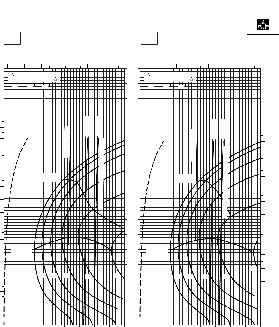
20 30 40 50 60 70 80 90
0
10
20
30
40
50
60
70
80
90
100
110
120
130
140
150
160
170
SA
AA0568
CRUISE
PRESS ALT: 10000 FT
CRUISE
10000 FT
TORQUE PER ENGINE ~ %TORQUE PER ENGINE ~ %
IAS ~ KTS TOTAL FUEL FLOW ~ 100 LB/HRTOTAL FUEL FLOW ~ 100 LB/HR
DATA BASE:FLIGHT TEST
TRUE AIRSPEED ~ KTS
TRUE AIRSPEED ~ KTS
40OC30OC
TRQ ~ % FOR DRAG
AREA OF 10 SQ FT OF F
10 20 30
TRQ ~ % FOR DRAG
AREA OF 10 SQ FT OF F
10 20 30
10 20 30 40 50 60 70 80 9010
45678
910 11 12
45678910
11 12
180
170
160
150
140
130
120
110
100
90
80
70
60
50
40
30
20
10
0
180
170
160
150
140
130
120
110
100
90
80
70
60
50
40
30
20
10
0
~ CONTINUOUS
ATF = 0.9
ATF = 1.0
MAX
RANGE
MAX END
AND R / C
GW ~
1000 LB 12 14 16 18 22
20
TORQUE AVAILABLE ~ 30 MINUTES
~ CONTINUOUS
ATF = 0.9
ATF = 1.0
MAX
RANGE
MAX END
AND R / C
GW ~
1000 LB 12 14 16 18 20
22
TORQUE AVAILABLE ~ 30 MINUTES
T700 (2)
Figure 7-18. Cruise High Drag - Pressure Altitude 10,000 Feet (Sheet 5 of 5)
TM 1-1520-237-10
7-85
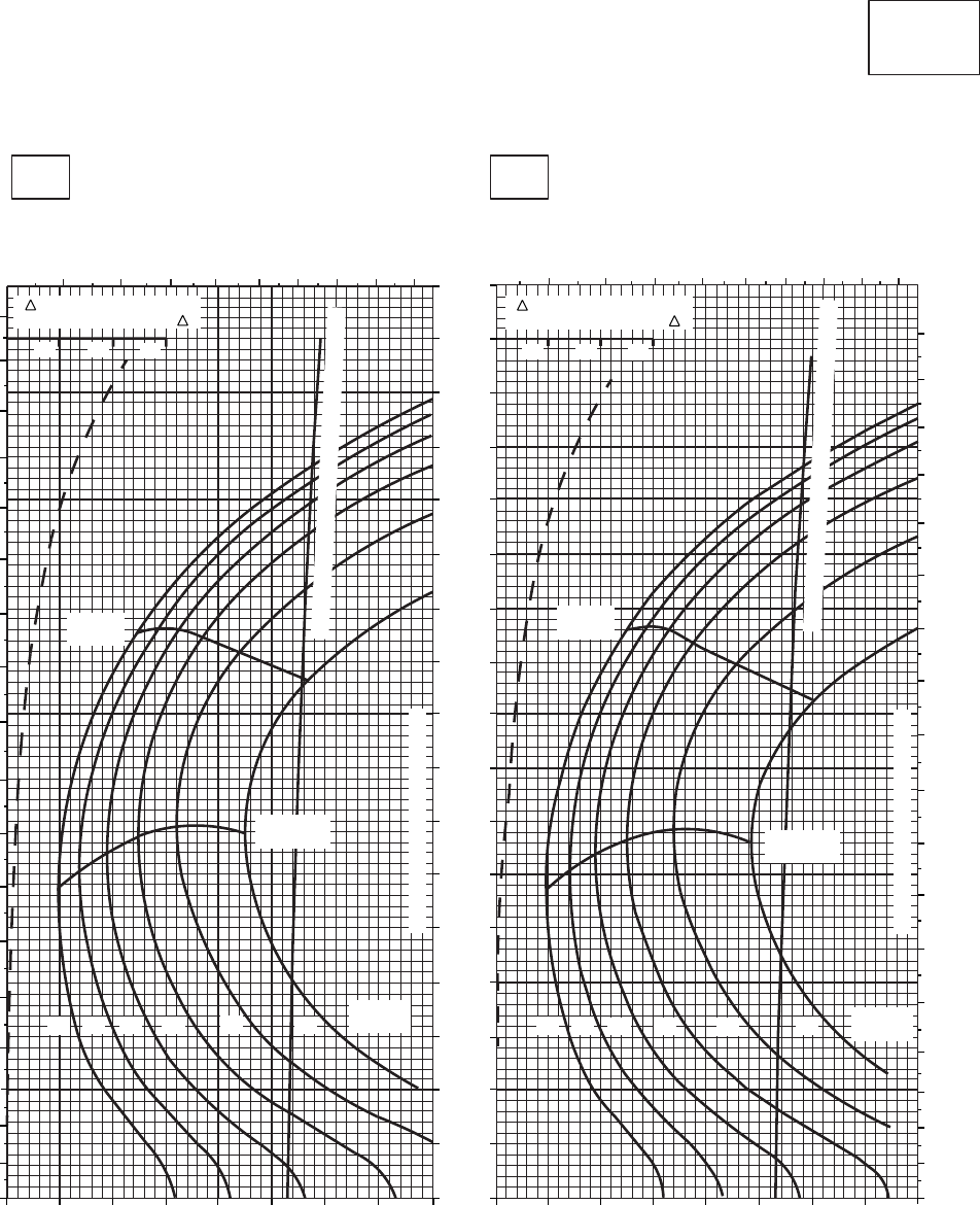
SA
AA0425
CRUISE
CLEAN CONFIGURATION
CRUISE
T700 (2)
−50oC
12000 FT
PRESS ALT: 12000 FT
−40oC
TOTAL FUEL FLOW ~ 100 LB/HR
TRUE AIRSPEED ~ KTS
TRUE AIRSPEED ~ KTS
TOTAL FUEL FLOW ~ 100 LB/HR
IAS ~ KTS
TORQUE PER ENGINE ~ % TORQUE PER ENGINE ~ %
5 6 7 8 9 10 11 12 13
5 6 7 8 9 10 11 12 13
10 20 30
MAX
RANGE
MAX END
AND R / C
160
150
140
130
120
110
90
80
70
100
170
60
50
40
30
20
10
0
30 40 50 60 70 80 90 100 20 30 40 50 60 70 80 90 100
20
180
170
160
150
140
130
120
110
100
90
80
70
60
50
40
30
20
10
0
180
170
160
150
140
130
120
110
100
90
80
70
60
50
40
30
20
10
0
22
20
18
16
14
12 GW ~
1000 LB
TRQ ~ % FOR DRAG
AREA OF 10 SQ FT OF F
TRANSMISSION TORQUE LIMIT
TRQ ~ % FOR DRAG
AREA OF 10 SQ FT OF F
10 20 30
MAX
RANGE
MAX END
AND R / C
GW ~
1000 LB
22
20
18
16
14
12
TRANSMISSION TORQUE LIMIT
TORQUE AVAILABLE ~ CONTINUOUS & 30 MIN
TORQUE AVAILABLE ~ CONTINUOUS & 30 MIN
Figure 7-19. Cruise - Pressure Altitude 12,000 Feet (Sheet 1 of 5)
TM 1-1520-237-10
7-86
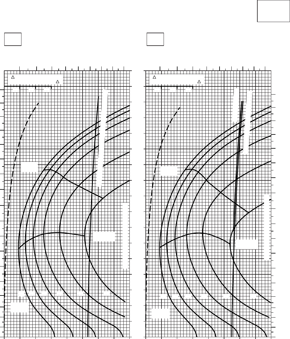
20 30 40 50 60 70 80 90 100
0
10
20
30
40
50
60
70
80
90
100
110
120
130
140
150
160
170
20 30 40 50 60 70 80 90 100
CRUISE
CLEAN CONFIGURATION
CRUISE
T700 (2)
TORQUE PER ENGINE ~ %TORQUE PER ENGINE ~ %
IAS ~ KTS TOTAL FUEL FLOW ~ 100 LB/HRTOTAL FUEL FLOW ~ 100 LB/HR
DATA BASE:FLIGHT TEST
TRUE AIRSPEED ~ KTS
TRUE AIRSPEED ~ KTS
TRQ ~ % FOR DRAG
AREA OF 10 SQ FT OF F
10 20 30
TRQ ~ % FOR DRAG
AREA OF 10 SQ FT OF F
10 20 30
SA
AA0424
−30oC−20oC
12000 FT
PRESS ALT: 12000 FT
5 6 7 8 9 10 11 12 13 5 6 7 8 9 10 11 12 13
180
170
160
150
140
130
120
110
100
90
80
70
60
50
40
30
20
10
0
180
170
160
150
140
130
120
110
100
90
80
70
60
50
40
30
20
10
0
MAX
RANGE
12
MAX END
AND R / C
MAX
RANGE
MAX END
AND R / C
GW ~
1000 LB
12 14 16 18 20 22
TRANSMISSION TORQUE LIMIT
TRANSMISSION TORQUE LIMIT
14 16 18 20 22
TORQUE AVAILABLE ~ CONTINUOUS & 30 MIN
GW ~
1000 LB
~ CONTINUOUS
TORQUE AVAILABLE ~ 30 MIN
Figure 7-19. Cruise - Pressure Altitude 12,000 Feet (Sheet 2 of 5)
TM 1-1520-237-10
7-87
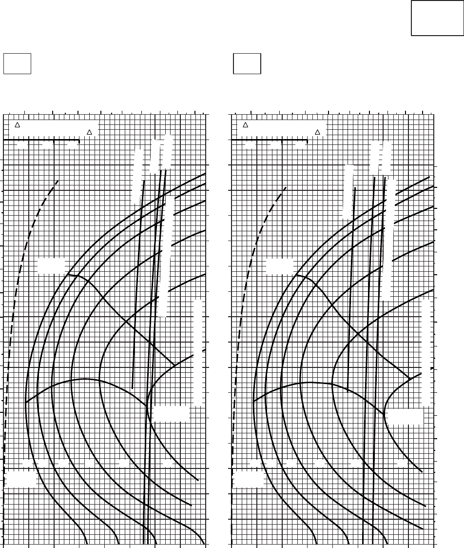
20 30 40 50 60 70 80 90 100
0
10
20
30
40
50
60
70
80
90
100
110
120
130
140
150
160
170
20 30 40 50 60 70 80 90 100
CRUISE
CLEAN CONFIGURATION
PRESS ALT: 12000 FT
CRUISE
12000 FT
T700 (2)
TORQUE PER ENGINE ~ %TORQUE PER ENGINE ~ %
IAS ~ KTS TOTAL FUEL FLOW ~ 100 LB/HRTOTAL FUEL FLOW ~ 100 LB/HR
DATA BASE:FLIGHT TEST
TRUE AIRSPEED ~ KTS
TRUE AIRSPEED ~ KTS
0OC−10OC
TRQ ~ % FOR DRAG
AREA OF 10 SQ FT OF F
10 20 30
TRQ ~ % FOR DRAG
AREA OF 10 SQ FT OF F
10 20 30
SA
AA0423
0
10
20
30
40
50
60
70
80
90
100
110
120
130
140
150
160
170
180
5678910111213 5678910111213
180
170
160
150
140
130
120
110
100
90
80
70
60
50
40
30
20
10
0
222018161412222018161412
GW ~
1000 LB GW ~
1000 LB
MAX END
AND R / C MAX END
AND R / C
TRANSMISSION TORQUE LIMIT
TRANSMISSION TORQUE LIMIT
MAX
RANGE
MAX
RANGE
~ CONTINUOUS
ATF = 0.9
ATF = 1.0
TORQUE AVAILABLE ~ 30 MINUTES
~ CONTINUOUS
ATF = 0.9
ATF = 1.0
TORQUE AVAILABLE ~ 30 MINUTES
Figure 7-19. Cruise - Pressure Altitude 12,000 Feet (Sheet 3 of 5)
TM 1-1520-237-10
7-88
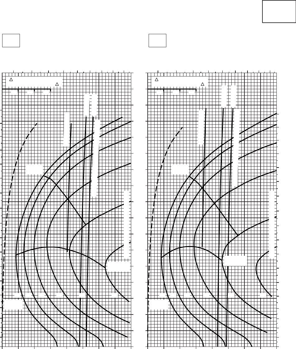
20 30 40 50 60 70 80 90 100
0
10
20
30
40
50
60
70
80
90
100
110
120
130
140
150
160
170
20 30 40 50 60 70 80 90 100
CRUISE
CLEAN CONFIGURATION
PRESS ALT: 12000 FT
CRUISE
12000 FT
T700 (2)
TORQUE PER ENGINE ~ %TORQUE PER ENGINE ~ %
IAS ~ KTS TOTAL FUEL FLOW ~ 100 LB/HRTOTAL FUEL FLOW ~ 100 LB/HR
DATA BASE:FLIGHT TEST
TRUE AIRSPEED ~ KTS
TRUE AIRSPEED ~ KTS
20OC10OC
TRQ ~ % FOR DRAG
AREA OF 10 SQ FT OF F
10 20 30
TRQ ~ % FOR DRAG
AREA OF 10 SQ FT OF F
10 20 30
SA
AA0426
0
10
20
30
40
50
60
70
80
90
100
110
120
130
140
150
160
170
180
5678910111213 5678910111213
180
170
160
150
140
130
120
110
100
90
80
70
60
50
40
30
20
10
0
222018161412222018161412
GW ~
1000 LB GW ~
1000 LB
MAX END
AND R / C
MAX END
AND R / C
TRANSMISSION TORQUE LIMIT
TRANSMISSION TORQUE LIMIT
MAX
RANGE
MAX
RANGE
ATF = 0.9
ATF = 1.0
~ CONTINUOUS
TORQUE AVAILABLE ~ 30 MINUTES
TORQUE AVAILABLE ~ 30 MINUTES
~ CONTINUOUS
ATF = 0.9
ATF = 1.0
Figure 7-19. Cruise - Pressure Altitude 12,000 Feet (Sheet 4 of 5)
TM 1-1520-237-10
7-89
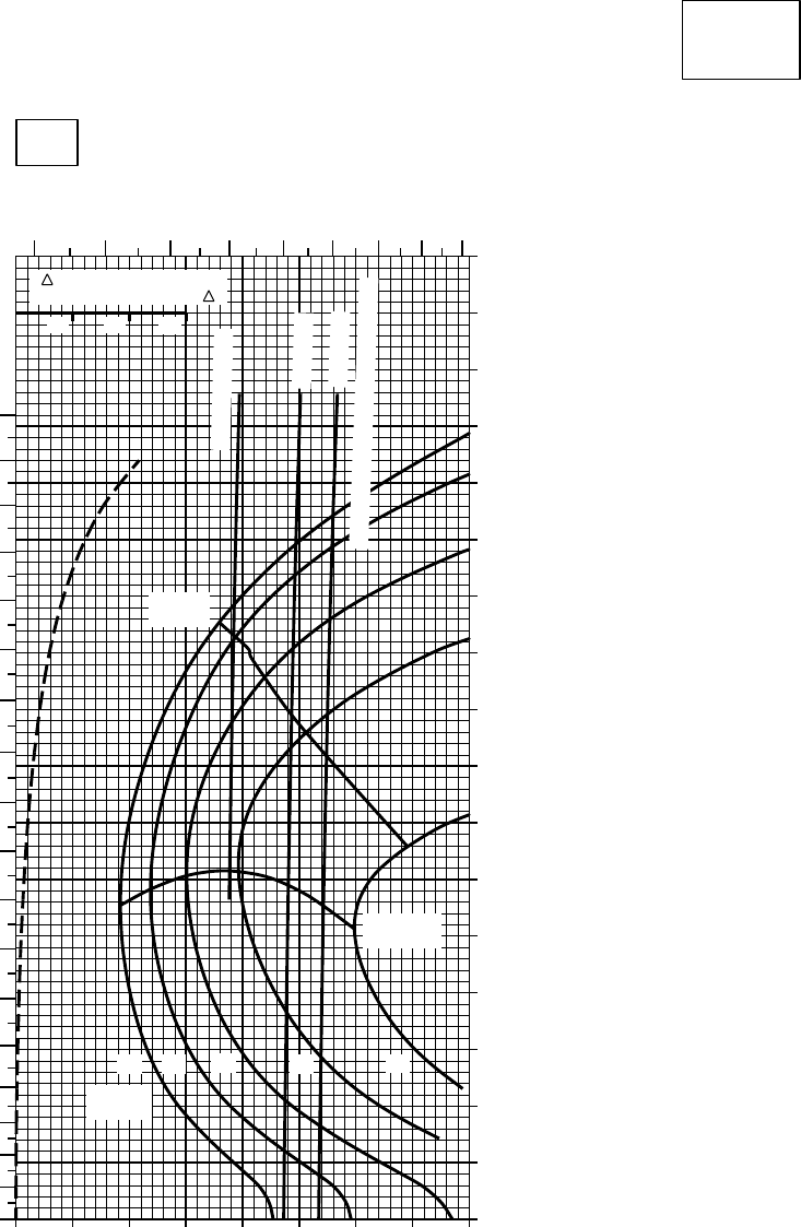
20 30 40 50 60 70 80 90
0
10
20
30
40
50
60
70
80
90
100
110
120
130
140
150
160
170
CRUISE
CLEAN CONFIGURATION
CRUISE
T700 (2)
TORQUE PER ENGINE ~ %
IAS ~ KTSTOTAL FUEL FLOW ~ 100 LB/HR
DATA BASIS: FLIGHT TEST
TRUE AIRSPEED ~ KTS
TRQ ~ % FOR DRAG
AREA OF 10 SQ FT OF F
10 20 30
10
30oC
12000 FT
PRESS ALT: 12000 FT
456
78910 11 12
10
20
30
40
50
60
70
80
90
100
110
120
130
140
150
160
170
180
~ CONTINUOUS
ATF = 0.9
ATF = 1.0
TORQUE AVAILABLE ~ 30 MINUTES
14 16
12 18 20
MAX
RANGE
GW ~
1000 LB
MAX END
AND R / C
SA
AA0427A
0
Figure 7-19. Cruise - Pressure Altitude 12,000 Feet (Sheet 5 of 5)
TM 1-1520-237-10
7-90
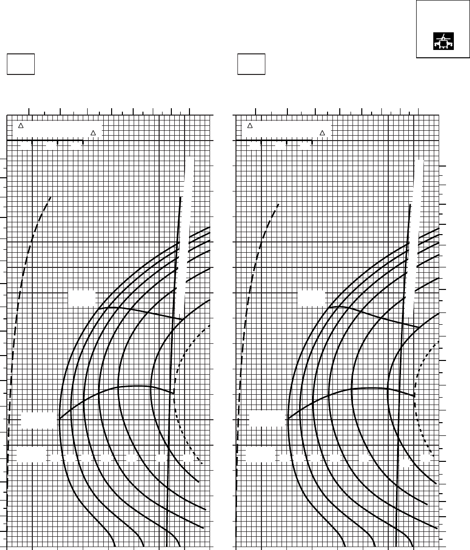
20 30 40 50 60 70 80 90
0
10
20
30
40
50
60
70
80
90
100
110
120
130
140
150
160
170
SA
AA0569
CRUISE
PRESS ALT: 12000 FT
CRUISE
TORQUE PER ENGINE ~ %TORQUE PER ENGINE ~ %
IAS ~ KTS TOTAL FUEL FLOW ~ 100 LB/HRTOTAL FUEL FLOW ~ 100 LB/HR
DATA BASE:FLIGHT TEST
TRUE AIRSPEED ~ KTS
TRUE AIRSPEED ~ KTS
TRQ ~ % FOR DRAG
AREA OF 10 SQ FT OF F
10 20 30
TRQ ~ % FOR DRAG
AREA OF 10 SQ FT OF F
10 20 30
10 20 30 40 50 60 70 80 9010
−50oC−40oC
12000 FT
4 5 6 7 8 9 10 11 4 5 6 7 8 9 10 11
180
170
160
150
140
130
120
110
100
90
80
70
60
50
40
30
20
10
00
10
20
30
40
50
60
70
80
90
100
110
120
130
140
150
160
170
180
12 14 16 18 20 22 23
GW ~
1000 LB 12 14 16 18 20 22 23
GW ~
1000 LB
MAX END
AND R / C
MAX END
AND R / C
MAX
RANGE MAX
RANGE
TORQUE AVAILABLE ~ CONTINUOUS & 30 MIN
TORQUE AVAILABLE ~ CONTINUOUS & 30 MIN
T700 (2)
Figure 7-20. Cruise High Drag - Pressure Altitude 12,000 Feet (Sheet 1 of 5)
TM 1-1520-237-10
7-91
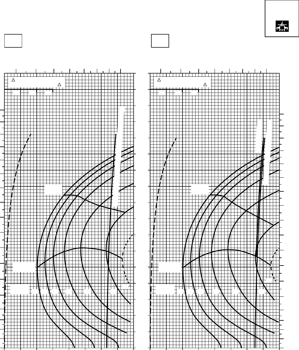
20 30 40 50 60 70 80 90
0
10
20
30
40
50
60
70
80
90
100
110
120
130
140
150
160
170
SA
AA0570
CRUISE
PRESS ALT: 12000 FT
CRUISE
TORQUE PER ENGINE ~ %TORQUE PER ENGINE ~ %
IAS ~ KTS TOTAL FUEL FLOW ~ 100 LB/HRTOTAL FUEL FLOW ~ 100 LB/HR
DATA BASE:FLIGHT TEST
TRUE AIRSPEED ~ KTS
TRUE AIRSPEED ~ KTS
TRQ ~ % FOR DRAG
AREA OF 10 SQ FT OF F
10 20 30
TRQ ~ % FOR DRAG
AREA OF 10 SQ FT OF F
10 20 30
10 20 30 40 50 60 70 80 9010
−30oC−20oC
12000 FT
4 5 6 7 8 9 10 11 4 5 6 7 8 9 10 11
180
170
160
150
140
130
120
110
100
90
80
70
60
50
40
30
20
10
00
10
20
30
40
50
60
70
80
90
100
110
120
130
140
150
160
170
180
12 14 16 18 20 22 23
GW ~
1000 LB
MAX END
AND R / C
12 14 16 18 20 22
23
GW ~
1000 LB
MAX END
AND R / C
MAX
RANGE
MAX
RANGE
TORQUE AVAILABLE ~ CONTINUOUS & 30 MIN
~ CONTINUOUS
TORQUE AVAILABLE ~ 30 MIN
T700 (2)
Figure 7-20. Cruise High Drag - Pressure Altitude 12,000 Feet (Sheet 2 of 5)
TM 1-1520-237-10
7-92
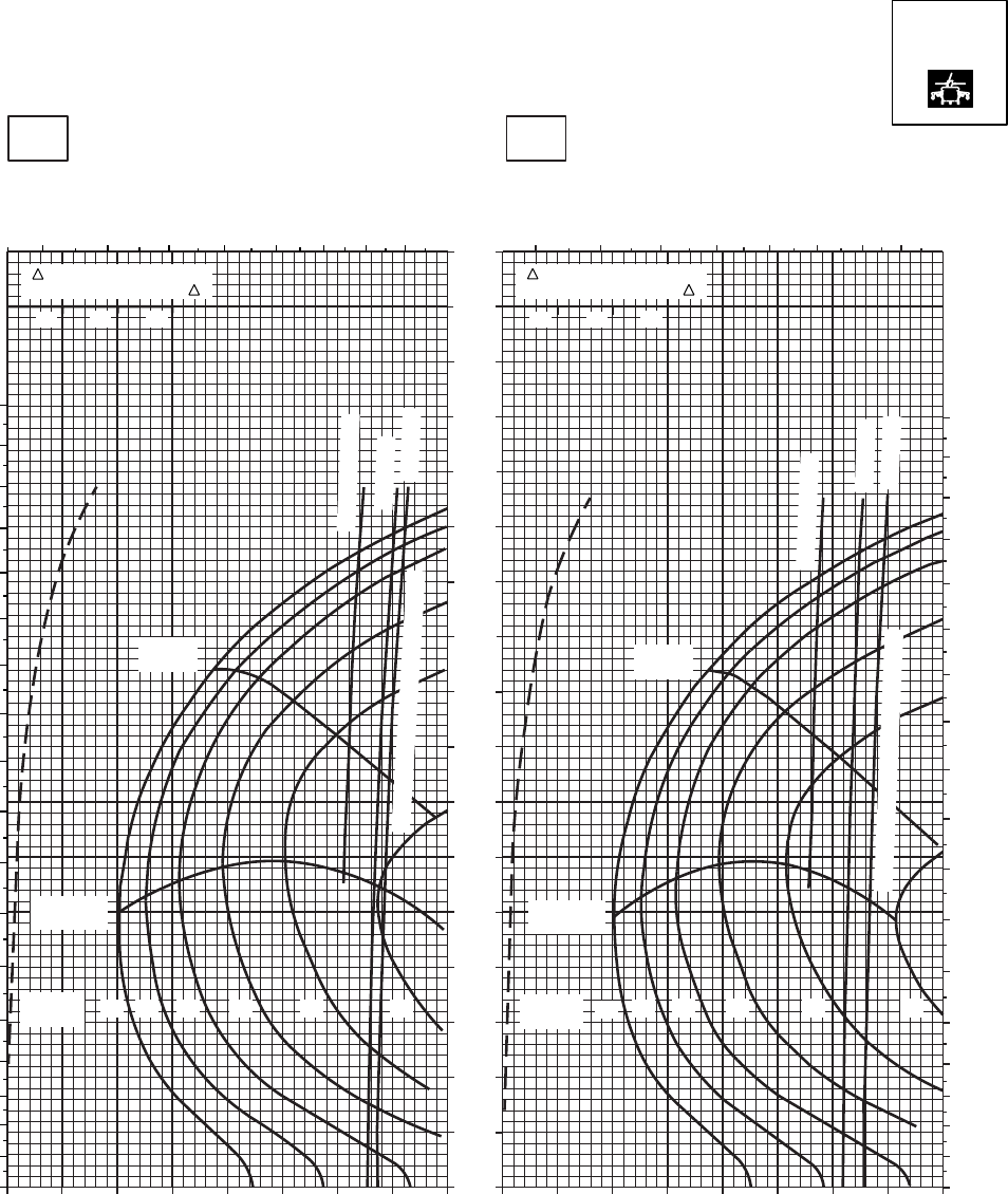
SA
AA0571
CRUISE
PRESS ALT: 12000 FT
CRUISE
12000 FT
TORQUE PER ENGINE ~ %TORQUE PER ENGINE ~ %
IAS ~ KTS TOTAL FUEL FLOW ~ 100 LB/HRTOTAL FUEL FLOW ~ 100 LB/HR
DATA BASE:FLIGHT TEST
TRUE AIRSPEED ~ KTS
TRUE AIRSPEED ~ KTS
0OC−10OC
170
160
150
140
130
120
110
100
90
80
70
60
50
40
30
20
10
0
10 20 30 40 50 60 70 80 90 10 20 30 40 50 60 70 80 90
180
170
160
150
140
130
120
110
100
90
80
70
60
50
40
30
20
10
0
45 6 7 8 9 10 11
TRQ ~ % FOR DRAG
AREA OF 10 SQ FT OF F
10 20 30
MAX
RANGE
MAX END
AND R / C
~ CONTINUOUS
ATF = 0.9
ATF = 1.0
22
20
18
16
14
12
TORQUE AVAILABLE ~ 30 MINUTES
45 6 7 8 9 10 11
180
170
160
150
140
130
120
110
100
90
80
70
60
50
40
30
20
10
0
TRQ ~ % FOR DRAG
AREA OF 10 SQ FT OF F
10 20 30
MAX
RANGE
MAX END
AND R / C
22
20
18
16
14
12
GW ~
1000 LB GW ~
1000 LB
~ CONTINUOUS
ATF = 0.9
ATF = 1.0
TORQUE AVAILABLE ~ 30 MINUTES
T700 (2)
Figure 7-20. Cruise High Drag - Pressure Altitude 12,000 Feet (Sheet 3 of 5)
TM 1-1520-237-10
7-93
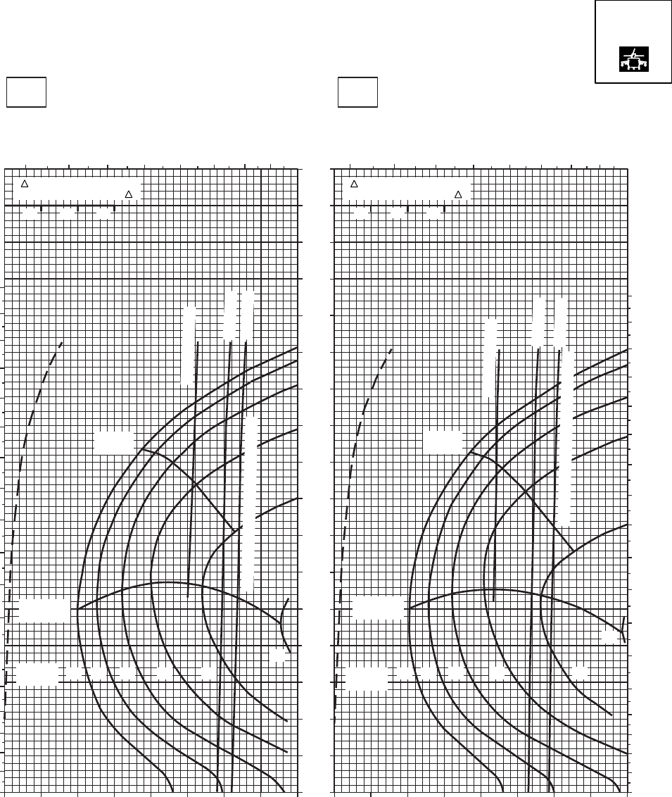
SA
AA0572
CRUISE
PRESS ALT: 12000 FT
CRUISE
12000 FT
TORQUE PER ENGINE ~ %TORQUE PER ENGINE ~ %
IAS ~ KTS TOTAL FUEL FLOW ~ 100 LB/HRTOTAL FUEL FLOW ~ 100 LB/HR
DATA BASE:FLIGHT TEST
TRUE AIRSPEED ~ KTS
TRUE AIRSPEED ~ KTS
20OC10OC
170
160
150
140
130
120
110
100
90
80
70
60
50
40
30
20
10
0
10 20 30 40 50 60 70 80 90 10 20 30 40 50 60 70 80 90
4 5 6 7 8 9 10 11 4 5 6 7 8 9 10 11
180
170
160
150
140
130
120
110
100
90
80
70
60
50
40
30
20
10
0
180
170
160
150
140
130
120
110
100
90
80
70
60
50
40
30
20
10
0
TRQ ~ % FOR DRAG
AREA OF 10 SQ FT OF F
10 20 30
MAX
RANGE
MAX END
AND R / C
~ CONTINUOUS
ATF = 0.9
ATF = 1.0
22
20
1816
14
12
GW ~
1000 LB
TORQUE AVAILABLE ~ 30 MINUTES
TRQ ~ % FOR DRAG
AREA OF 10 SQ FT OF F
10 20 30
MAX
RANGE
MAX END
AND R / C
GW ~
1000 LB 12 14 16 18 20
22
~ CONTINUOUS
ATF = 0.9
ATF = 1.0
TORQUE AVAILABLE ~ 30 MINUTES
T700 (2)
Figure 7-20. Cruise High Drag - Pressure Altitude 12,000 Feet (Sheet 4 of 5)
TM 1-1520-237-10
7-94
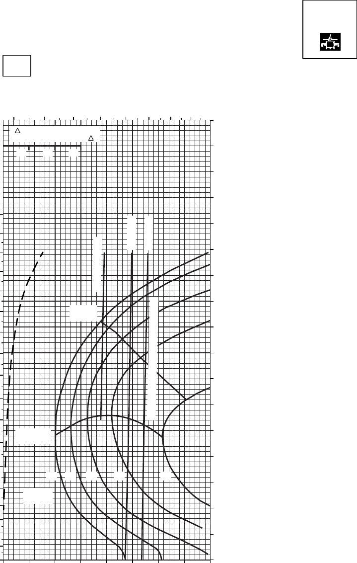
SA
AA0573
CRUISE CRUISE
TORQUE PER ENGINE ~ %
IAS ~ KTSTOTAL FUEL FLOW ~ 100 LB/HR
DATA BASE:FLIGHT TEST
TRUE AIRSPEED ~ KTS
30oC
12000 FT
PRESS ALT: 12000 FT
TRQ ~ % FOR DRAG
AREA OF 10 SQ FT OF F
10 20 30
~ CONTINUOUS
ATF = 0.9
ATF = 1.0
TORQUE AVAILABLE ~ 30 MINUTES
MAX END
AND R / C
MAX
RANGE
160
150
140
130
120
170
110
100
90
80
70
60
50
40
30
20
10
0
10 20 30 40 50 60 70 80 90
4 5 6 7 8 9 10 11
180
170
160
150
140
130
120
110
100
90
80
70
60
50
40
30
20
10
0
20
18
16
14
12
GW ~
1000 LB
T700 (2)
Figure 7-20. Cruise High Drag - Pressure Altitude 12,000 Feet (Sheet 5 of 5)
TM 1-1520-237-10
7-95
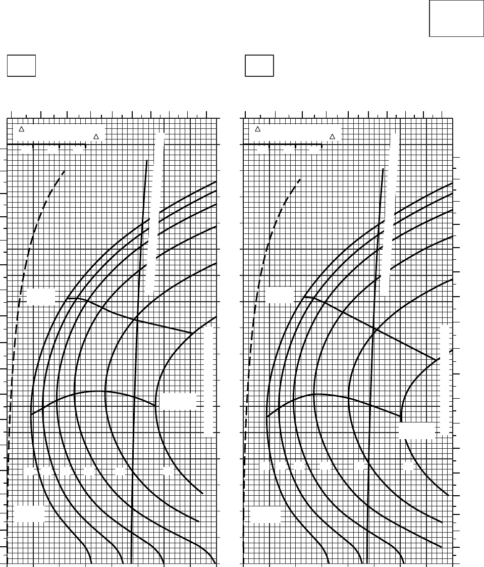
20 30 40 50 60 70 80 90 100
0
10
20
30
40
50
60
70
80
90
100
110
120
130
140
150
160
170
20 30 40 50 60 70 80 90 100
CRUISE
CLEAN CONFIGURATION
CRUISE
T700 (2)
TORQUE PER ENGINE ~ %TORQUE PER ENGINE ~ %
IAS ~ KTS TOTAL FUEL FLOW ~ 100 LB/HRTOTAL FUEL FLOW ~ 100 LB/HR
DATA BASE:FLIGHT TEST
TRUE AIRSPEED ~ KTS
TRUE AIRSPEED ~ KTS
TRQ ~ % FOR DRAG
AREA OF 10 SQ FT OF F
10 20 30
TRQ ~ % FOR DRAG
AREA OF 10 SQ FT OF F
10 20 30
SA
AA0430
−50oC−40oC
14000 FT
PRESS ALT: 14000 FT
4 5 6 7 8 9 10 11 12 13 4 5 6 7 8 9 10 11 12 13
180
170
160
150
140
130
120
110
100
90
80
70
60
50
40
30
20
10
0
180
170
160
150
140
130
120
110
100
90
80
70
60
50
40
30
20
10
0
TRANSMISSION TORQUE LIMIT
TORQUE AVAILABLE ~ CONTINUOUS & 30 MIN
TORQUE AVAILABLE ~ CONTINUOUS & 30 MIN
MAX
RANGE
MAX
RANGE
MAX END
AND R / C
TRANSMISSION TORQUE LIMIT
MAX END
AND R / C
GW ~
1000 LB GW ~
1000 LB
20 20
12 14 16 18 22 12 14 16 18 22
Figure 7-21. Cruise - Pressure Altitude 14,000 Feet (Sheet 1 of 5)
TM 1-1520-237-10
7-96
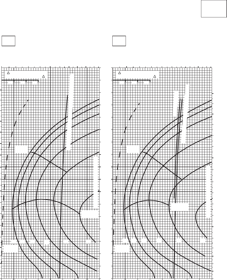
SA
AA0429
CRUISE
CLEAN CONFIGURATION
CRUISE
T700 (2)
−30oC
14000 FT
PRESS ALT: 14000 FT
−20oC
TOTAL FUEL FLOW ~ 100 LB/HR TOTAL FUEL FLOW ~ 100 LB/HR
IAS ~ KTS
TORQUE PER ENGINE ~ % TORQUE PER ENGINE ~ %
TRQ ~ % FOR DRAG
AREA OF 10 SQ FT OF F
10 20 30
TRQ ~ % FOR DRAG
AREA OF 10 SQ FT OF F
10 20 30
TRUE AIRSPEED ~ KTS
TRUE AIRSPEED ~ KTS
45 6 7 8 9 10 11 12 13 5 6 7 8 9 10 11 12 13
170
160
150
140
130
120
110
100
90
80
70
60
50
40
30
20
10
0
180
170
160
150
140
130
120
110
100
90
80
70
60
50
40
30
20
10
0
180
170
160
150
140
130
120
110
100
90
80
70
60
50
40
30
20
10
0
20 30 40 50 60 70 80 90 100 20 30 40 50 60 70 80 90 100
14 1612 18 20
MAX
RANGE
GW ~
1000 LB
MAX END
AND R / C
14 1612 18 22
MAX
RANGE
GW ~
1000 LB
MAX END
AND R / C
22
TRANSMISSION TORQUE LIMIT
TRANSMISSION TORQUE LIMIT
20
~ CONTINUOUS
TORQUE AVAILABLE ~ 30 MINUTES
TORQUE AVAILABLE ~ CONTINUOUS & 30 MIN
Figure 7-21. Cruise - Pressure Altitude 14,000 Feet (Sheet 2 of 5)
TM 1-1520-237-10
7-97
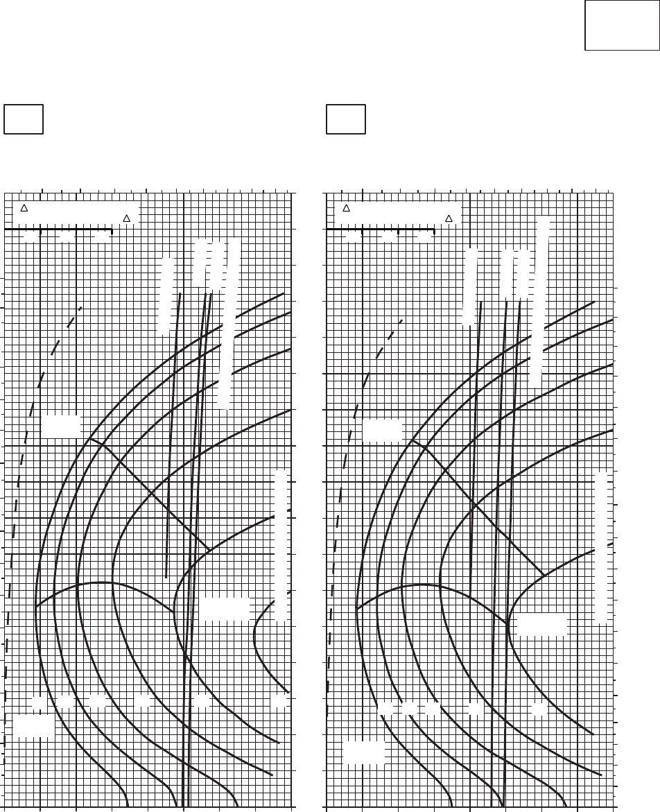
SA
AA0428
CRUISE
CLEAN CONFIGURATION
CRUISE
T700 (2)
−10oC
14000 FT
PRESS ALT: 14000 FT
0oC
5 6 7 8 9 10 11 12 13
TOTAL FUEL FLOW ~ 100 LB/HR
180
170
160
150
140
130
120
110
100
90
80
70
60
50
40
30
20
10
0
5 6 7 8 9 10 11 12 13
180
170
160
150
140
130
120
110
100
90
80
70
60
50
40
30
20
10
0
30
170
160
150
140
130
120
110
100
90
80
70
60
50
40
30
20
10
0
TRUE AIRSPEED ~ KTS
TRUE AIRSPEED ~ KTS
TOTAL FUEL FLOW ~ 100 LB/HR
IAS ~ KTS
TORQUE PER ENGINE ~ %
20 30 40 50 60 70 80 90 100 20 30 40 50 60 70 80 90 100
TORQUE PER ENGINE ~ %
TRQ ~ % FOR DRAG
AREA OF 10 SQ FT OF F
10 20 30
TRQ ~ % FOR DRAG
AREA OF 10 SQ FT OF F
10 20 30
TRANSMISSION TORQUE LIMIT
~ CONTINUOUS
ATF = 0.9
ATF = 1.0
TORQUE AVAILABLE ~ 30 MINUTES
GW ~
1000 LB
MAX
RANGE MAX
RANGE
GW ~
1000 LB
MAX END
AND R / C MAX END
AND R / C
14 16
12 18 22 14 1612 18 20
20
TRANSMISSION TORQUE LIMIT
~ CONTINUOUS
ATF = 0.9
ATF = 1.0
TORQUE AVAILABLE ~ 30 MINUTES
Figure 7-21. Cruise - Pressure Altitude 14,000 Feet (Sheet 3 of 5)
TM 1-1520-237-10
7-98
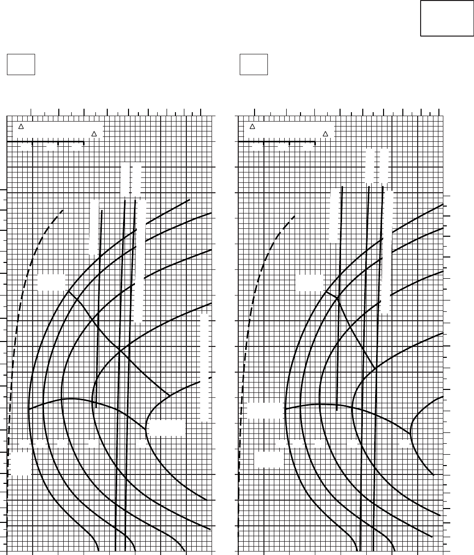
0
10
20
30
40
50
60
70
80
90
100
110
120
130
140
150
160
170
CRUISE
CLEAN CONFIGURATION
PRESS ALT: 14000 FT
CRUISE
14000 FT
T700 (2)
TORQUE PER ENGINE ~ %TORQUE PER ENGINE ~ %
IAS ~ KTS TOTAL FUEL FLOW ~ 100 LB/HRTOTAL FUEL FLOW ~ 100 LB/HR
DATA BASE:FLIGHT TEST
TRUE AIRSPEED ~ KTS
TRUE AIRSPEED ~ KTS
20OC10OC
TRQ ~ % FOR DRAG
AREA OF 10 SQ FT OF F
10 20 30
TRQ ~ % FOR DRAG
AREA OF 10 SQ FT OF F
10 20 30
20 30 40 50 60 70 80 9010
SA
AA0431
0
10
20
30
40
50
60
70
80
90
100
110
120
130
140
150
160
170
180
5678910111213 4 56789101112
180
170
160
150
140
130
120
110
100
90
80
70
60
50
40
30
20
10
0
20181614122018161412
GW ~
1000 LB
GW ~
1000
LB
MAX END
AND R / C
MAX END
AND R / C
MAX
RANGE
MAX
RANGE
TRANSMISSION TORQUE LIMIT
~ CONTINUOUS
~ CONTINUOUS
ATF = 0.9
ATF = 1.0
ATF = 0.9
ATF = 1.0
TORQUE AVAILABLE ~ 30 MINUTES
TORQUE AVAILABLE ~ 30 MINUTES
20 30 40 50 60 70 80 90 100
Figure 7-21. Cruise - Pressure Altitude 14,000 Feet (Sheet 4 of 5)
TM 1-1520-237-10
7-99
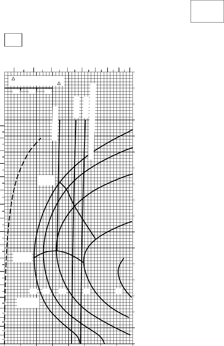
20 30 40 50 60 70 80 90
0
10
20
30
40
50
60
70
80
90
100
110
120
130
140
150
160
170
CRUISE
CLEAN CONFIGURATION
CRUISE
T700 (2)
TORQUE PER ENGINE ~ %
IAS ~ KTSTOTAL FUEL FLOW ~ 100 LB/HR
DATA BASE:FLIGHT TEST
TRUE AIRSPEED ~ KTS
TRQ ~ % FOR DRAG
AREA OF 10 SQ FT OF F
10 20 30
10
30oC
14000 FT
PRESS ALT: 14000 FT
45678910
11 12
0
10
20
30
40
50
60
70
80
90
100
110
120
130
140
150
160
170
180
~ CONTINUOUS
ATF = 0.9
ATF = 1.0
TORQUE AVAILABLE ~ 30 MINUTES
14 1612 18 20
MAX
RANGE
GW ~
1000 LB
MAX END
AND R / C
SA
AA0432
Figure 7-21. Cruise - Pressure Altitude 14,000 Feet (Sheet 5 of 5)
TM 1-1520-237-10
7-100
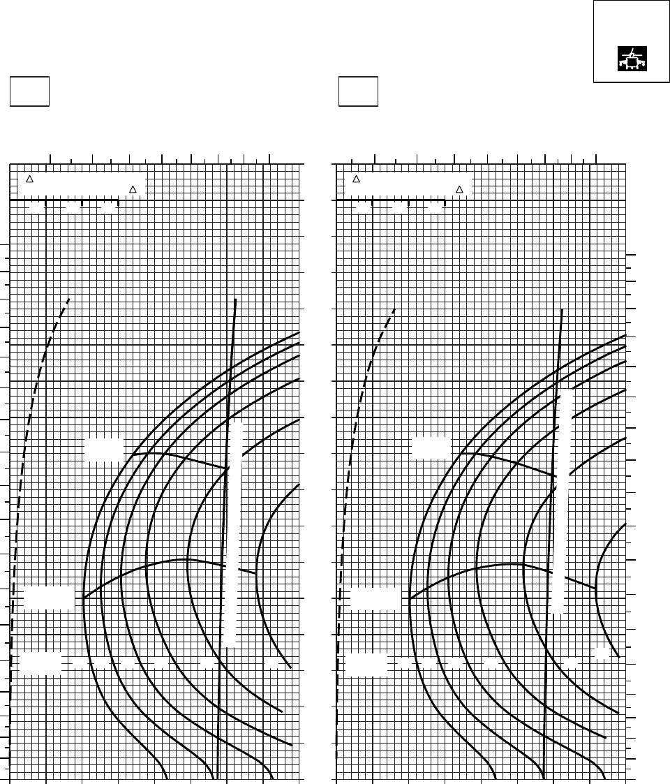
20 30 40 50 60 70 80 90
0
10
20
30
40
50
60
70
80
90
100
110
120
130
140
150
160
170
SA
AA0574
CRUISE
PRESS ALT: 14000 FT
CRUISE
14000 FT
TORQUE PER ENGINE ~ %TORQUE PER ENGINE ~ %
IAS ~ KTS TOTAL FUEL FLOW ~ 100 LB/HRTOTAL FUEL FLOW ~ 100 LB/HR
DATA BASE:FLIGHT TEST
TRUE AIRSPEED ~ KTS
TRUE AIRSPEED ~ KTS
−40OC−50OC
TRQ ~ % FOR DRAG
AREA OF 10 SQ FT OF F
10 20 30
TRQ ~ % FOR DRAG
AREA OF 10 SQ FT OF F
10 20 30
10 20 30 40 50 60 70 80 9010
45
6789
10 11 4 5 6 7 891011
180
170
160
150
140
130
120
110
100
90
80
70
60
50
40
30
20
10
0
180
170
160
150
140
130
120
110
100
90
80
70
60
50
40
30
20
10
0
MAX
RANGE
MAX END
AND R / C MAX END
AND R / C
MAX
RANGE
GW ~
1000 LB 12 14 16 18 20 22 GW ~
1000 LB 12 14 16 18 20 22
TORQUE AVAILABLE ~ CONTINUOUS & 30 MIN
TORQUE AVAILABLE ~ CONTINUOUS & 30 MIN
T700 (2)
Figure 7-22. Cruise High Drag - Pressure Altitude 14,000 Feet (Sheet 1 of 5)
TM 1-1520-237-10
7-101
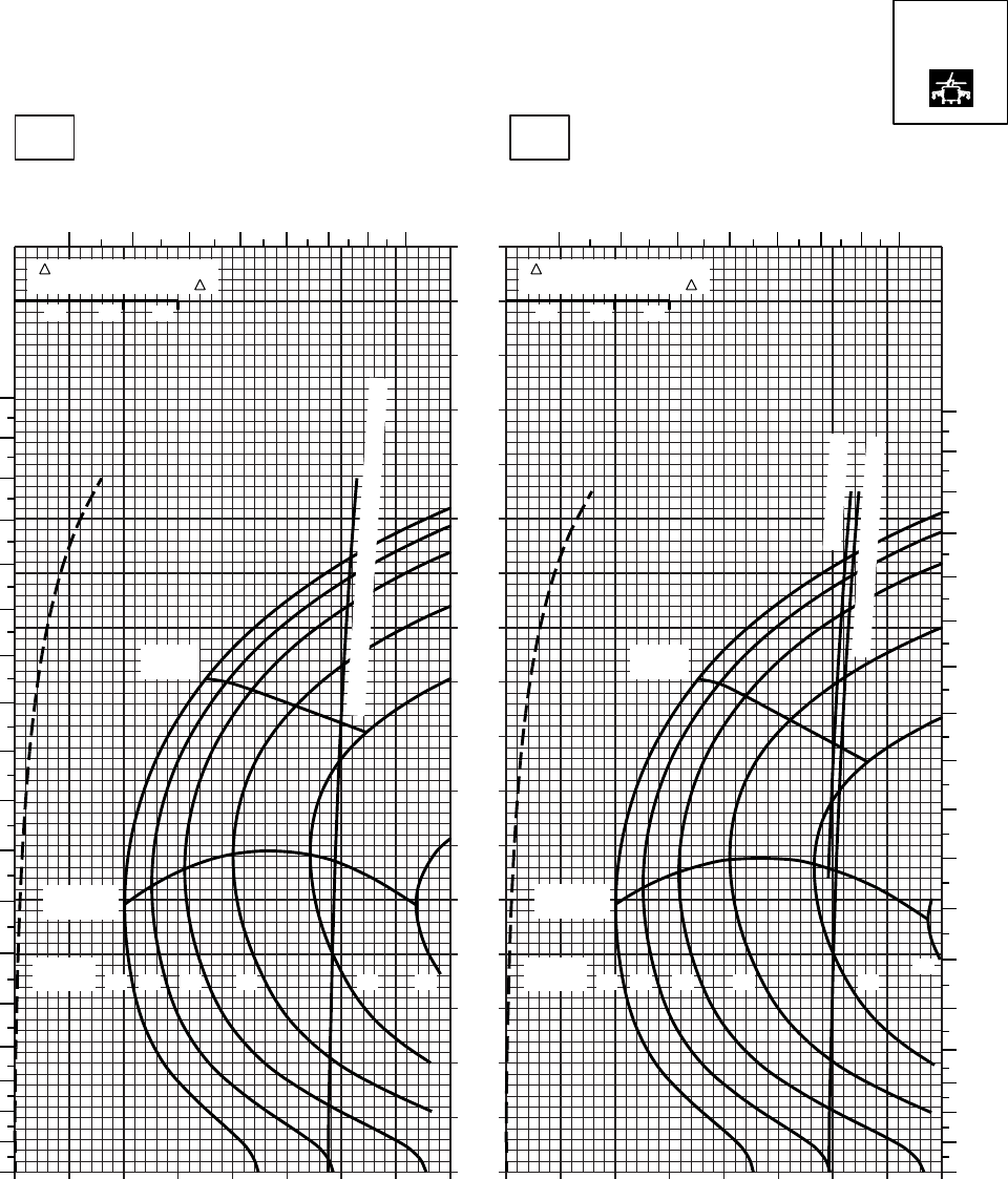
20 30 40 50 60 70 80 90
0
10
20
30
40
50
60
70
80
90
100
110
120
130
140
150
160
170
SA
AA0575
CRUISE
PRESS ALT: 14000 FT
CRUISE
TORQUE PER ENGINE ~ %TORQUE PER ENGINE ~ %
IAS ~ KTS TOTAL FUEL FLOW ~ 100 LB/HRTOTAL FUEL FLOW ~ 100 LB/HR
DATA BASE:FLIGHT TEST
TRUE AIRSPEED ~ KTS
TRUE AIRSPEED ~ KTS
TRQ ~ % FOR DRAG
AREA OF 10 SQ FT OF F
10 20 30
TRQ ~ % FOR DRAG
AREA OF 10 SQ FT OF F
10 20 30
10 20 30 40 50 60 70 80 9010
−30oC−20oC
14000 FT
4 5 6 7 8 9 10 11 4 5 6 7 8 9 10 11
180
170
160
150
140
130
120
110
100
90
80
70
60
50
40
30
20
10
00
10
20
30
40
50
60
70
80
90
100
110
120
130
140
150
160
170
180
12 14 16 18 20 22
GW ~
1000 LB 12 14 16 18 20 22
GW ~
1000 LB
MAX END
AND R / C
MAX END
AND R / C
MAX
RANGE
MAX
RANGE
~ CONTINUOUS
TORQUE AVAILABLE ~ 30 MIN
TORQUE AVAILABLE ~ CONTINUOUS & 30 MIN
T700 (2)
Figure 7-22. Cruise High Drag - Pressure Altitude 14,000 Feet (Sheet 2 of 5)
TM 1-1520-237-10
7-102
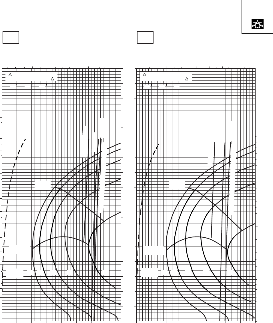
SA
AA0576
CRUISE
PRESS ALT: 14000 FT
CRUISE
14000 FT
TORQUE PER ENGINE ~ %TORQUE PER ENGINE ~ %
IAS ~ KTS TOTAL FUEL FLOW ~ 100 LB/HRTOTAL FUEL FLOW ~ 100 LB/HR
DATA BASE:FLIGHT TEST
TRUE AIRSPEED ~ KTS
TRUE AIRSPEED ~ KTS
0OC−10OC
170
160
150
140
130
120
110
100
90
80
70
60
50
40
30
20
10
0
10 20 30 40 50 60 70 80 90 20 30
10 40 50 60 70 80 90
180
170
160
150
140
130
120
110
100
90
80
70
60
50
40
30
20
10
0
4567 8 9 10 114 56 7 8 9 10 11
180
170
160
150
140
130
120
110
100
90
80
70
60
50
40
30
20
10
0
TRQ ~ % FOR DRAG
AREA OF 10 SQ FT OF F
10 20 30
~ CONTINUOUS
ATF = 0.9
ATF = 1.0
MAX END
AND R / C
MAX
RANGE
TORQUE AVAILABLE ~ 30 MINUTES
20
16 1814
12
GW ~
1000 LB
TRQ ~ % FOR DRAG
AREA OF 10 SQ FT OF F
10 20 30
MAX
RANGE
MAX END
AND R / C
~ CONTINUOUS
ATF = 0.9
ATF = 1.0
TORQUE AVAILABLE ~ 30 MINUTES
20
1816
14
12
GW ~
1000 LB
T700 (2)
Figure 7-22. Cruise High Drag - Pressure Altitude 14,000 Feet (Sheet 3 of 5)
TM 1-1520-237-10
7-103
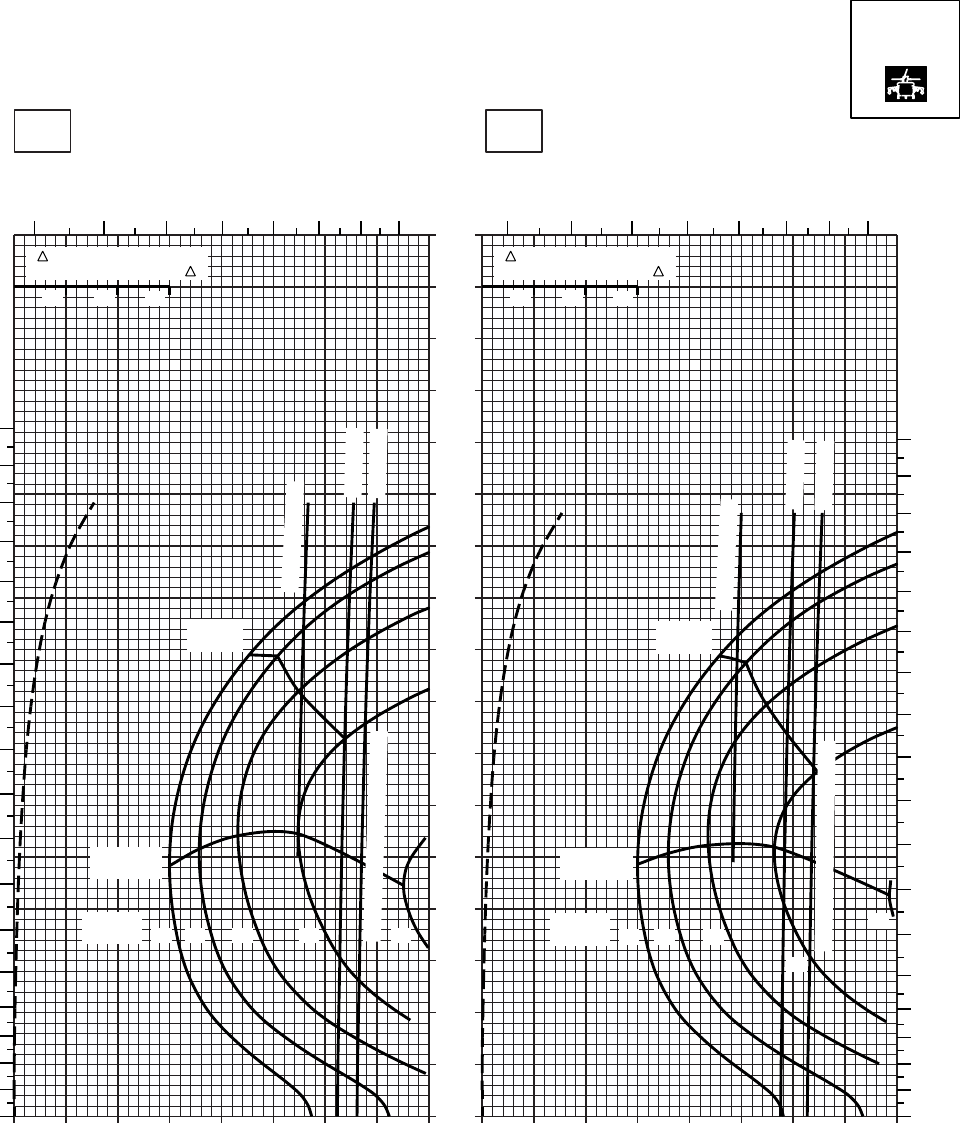
20 30 40 50 60 70 80
0
10
20
30
40
50
60
70
80
90
100
110
120
130
140
150
160
170
SA
AA0577
CRUISE
PRESS ALT: 14000 FT
CRUISE
TORQUE PER ENGINE ~ %TORQUE PER ENGINE ~ %
IAS ~ KTS TOTAL FUEL FLOW ~ 100 LB/HRTOTAL FUEL FLOW ~ 100 LB/HR
DATA BASE:FLIGHT TEST
TRUE AIRSPEED ~ KTS
TRUE AIRSPEED ~ KTS
TRQ ~ % FOR DRAG
AREA OF 10 SQ FT OF F
10 20 30
TRQ ~ % FOR DRAG
AREA OF 10 SQ FT OF F
10 20 30
010 20 30 40 50 60 70 80010
10oC20oC
14000 FT
345678910 345678910
180
170
160
150
140
130
120
110
100
90
80
70
60
50
40
30
20
10
00
10
20
30
40
50
60
70
80
90
100
110
120
130
140
150
160
170
180
12 14 16 18 20
GW ~
1000 LB 12 14 16
18
20
GW ~
1000 LB
MAX END
AND R / C
MAX END
AND R / C
MAX
RANGE
MAX
RANGE
~ CONTINUOUS
~ CONTINUOUS
TORQUE AVAILABLE ~ 30 MIN
TORQUE AVAILABLE ~ 30 MIN
ATF = 0.9
ATF = 1.0
ATF = 0.9
ATF = 1.0
T700 (2)
Figure 7-22. Cruise High Drag - Pressure Altitude 14,000 Feet (Sheet 4 of 5)
TM 1-1520-237-10
7-104
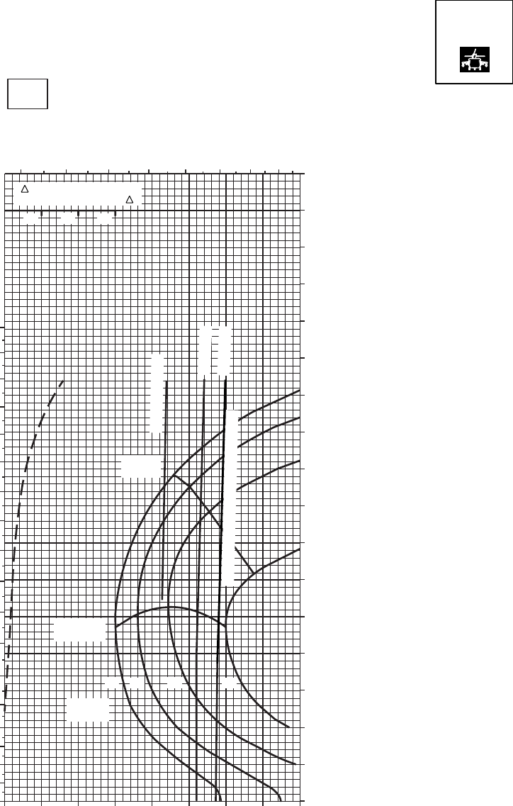
SA
AA0578
CRUISE CRUISE
TORQUE PER ENGINE ~ %
IAS ~ KTSTOTAL FUEL FLOW ~ 100 LB/HR
DATA BASE:FLIGHT TEST
TRUE AIRSPEED ~ KTS
30oC
14000 FT
PRESS ALT: 14000 FT
170
160
150
140
130
120
110
100
90
80
70
60
50
40
30
20
10
0
0 10 20 30 40 50 60 70 80
3 4 5 67 8 9 10
180
170
160
150
140
130
120
110
100
90
80
70
60
50
40
30
20
10
0
TRQ ~ % FOR DRAG
AREA OF 10 SQ FT OF F
10 20 30
12 14 16 18
GW ~
1000 LB
MAX END
AND R / C
MAX
RANGE
TORQUE AVAILABLE ~ 30 MINUTES
~ CONTINUOUS
ATF = 0.9
ATF = 1.0
T700 (2)
Figure 7-22. Cruise High Drag - Pressure Altitude 14,000 Feet (Sheet 5 of 5)
TM 1-1520-237-10
7-105
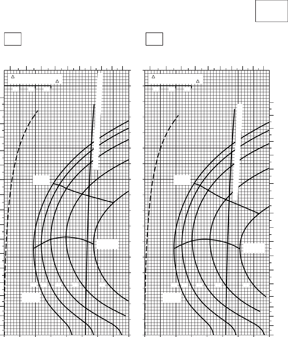
10 20 30 40 50 60 70 80 90
0
10
20
30
40
50
60
70
80
90
100
110
120
130
140
150
160
170
10 20 30 40 50 60 70 80 90
CRUISE
CLEAN CONFIGURATION
CRUISE
T700 (2)
TORQUE PER ENGINE ~ %TORQUE PER ENGINE ~ %
IAS ~ KTS TOTAL FUEL FLOW ~ 100 LB/HRTOTAL FUEL FLOW ~ 100 LB/HR
DATA BASE:FLIGHT TEST
TRUE AIRSPEED ~ KTS
TRUE AIRSPEED ~ KTS
TRQ ~ % FOR DRAG
AREA OF 10 SQ FT OF F
10 20 30
TRQ ~ % FOR DRAG
AREA OF 10 SQ FT OF F
10 20 30
SA
AA0435
−50oC−40oC
16000 FT
PRESS ALT: 16000 FT
34567
8910
11 12
0
10
20
30
40
50
60
70
80
90
100
110
120
130
140
150
160
170
180
34567
8910
11 12
0
10
20
30
40
50
60
70
80
90
100
110
120
130
140
160
170
180
150
MAX
RANGE
MAX END
AND R / C
GW ~
1000 LB
12 14 16 18 20
MAX
RANGE
MAX END
AND R / C
GW ~
1000 LB
12 14 16 18 20
TORQUE AVAILABLE ~ CONTINUOUS & 30 MIN
TORQUE AVAILABLE ~ CONTINUOUS & 30 MIN
Figure 7-23. Cruise - Pressure Altitude 16,000 Feet (Sheet 1 of 5)
TM 1-1520-237-10
7-106
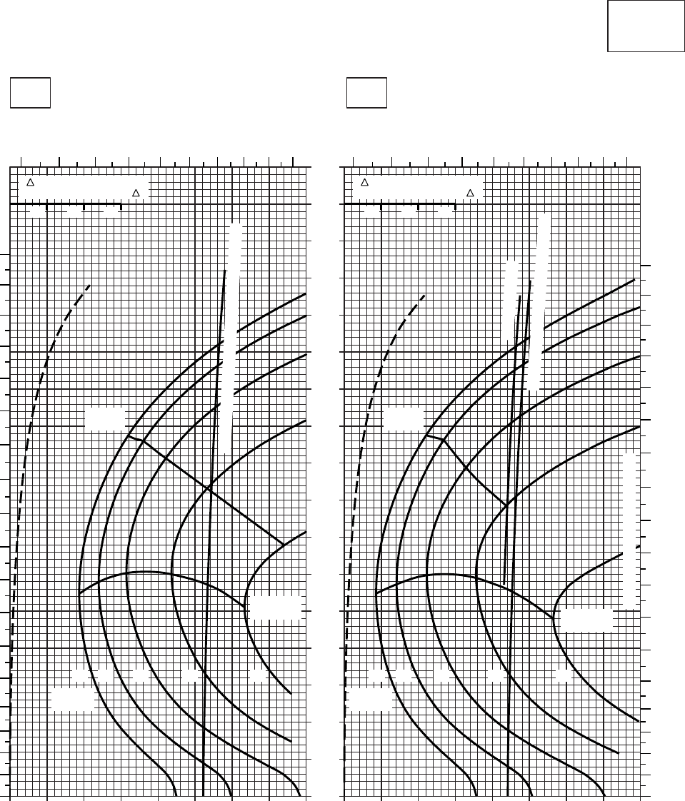
0
10
20
30
40
50
60
70
80
90
100
110
120
130
140
150
160
170
20 30 40 50 60 70 80 90 100
CRUISE
CLEAN CONFIGURATION
PRESS ALT: 16000 FT
CRUISE
16000 FT
T700 (2)
TORQUE PER ENGINE ~ %TORQUE PER ENGINE ~ %
IAS ~ KTS TOTAL FUEL FLOW ~ 100 LB/HRTOTAL FUEL FLOW ~ 100 LB/HR
DATA BASIS: FLIGHT TEST
TRUE AIRSPEED ~ KTS
TRUE AIRSPEED ~ KTS
−20OC−30OC
TRQ ~ % FOR DRAG
AREA OF 10 SQ FT OF F
10 20 30
TRQ ~ % FOR DRAG
AREA OF 10 SQ FT OF F
10 20 30
SA
AA0434A
0
10
20
30
40
50
60
70
80
90
100
110
120
130
140
150
160
170
180
3456789101112 45678910111213
180
170
160
150
140
130
120
110
100
90
80
70
60
50
40
30
20
10
0
18 20161412 12 14 16 18 20
GW ~
1000 LB GW ~
1000 LB
MAX END
AND R / C
MAX END
AND R / C
MAX
RANGE
MAX
RANGE
TORQUE AVAILABLE ~ CONTINUOUS & 30 MIN
~ CONTINUOUS
TORQUE AVAILABLE ~ 30 MINUTES
TRANSMISSION TORQUE LIMIT
10 20 30 40 50 60 70 80 90
Figure 7-23. Cruise - Pressure Altitude 16,000 Feet (Sheet 2 of 5)
TM 1-1520-237-10
7-107
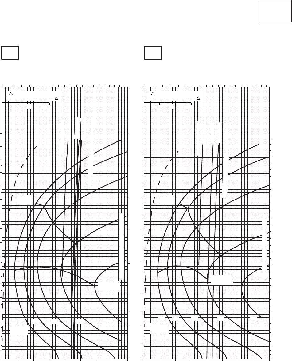
SA
AA0433
CRUISE
CLEAN CONFIGURATION
CRUISE
T700 (2)
−10oC
16000 FT
PRESS ALT: 16000 FT
0oC
TOTAL FUEL FLOW ~ 100 LB/HR TOTAL FUEL FLOW ~ 100 LB/HR
IAS ~ KTS
TORQUE PER ENGINE ~ % TORQUE PER ENGINE ~ %
4 5 6 7 8 9 10 11 12 13 4 5 6 7 8 9 10 11 12 13
180
170
160
150
140
130
120
110
100
90
80
70
60
50
40
30
20
10
0
180
170
160
150
140
130
120
110
100
90
80
70
60
50
40
30
20
10
0
TRUE AIRSPEED ~ KTS
TRUE AIRSPEED ~ KTS
170
160
150
140
130
120
110
100
90
80
70
60
50
40
30
20
10
0
20 30 40 50 60 70 80 90 100 20 30 40 50 60 70 80 90 100
TRQ ~ % FOR DRAG
AREA OF 10 SQ FT OF F
10 20 30
TRQ ~ % FOR DRAG
AREA OF 10 SQ FT OF F
10 20 30
MAX
RANGE MAX
RANGE
MAX END
AND R / C
MAX END
AND R / C
GW ~
1000 LB
GW ~
1000 LB
14 1612 18 14 1612 18 20
TRANSMISSION TORQUE LIMIT
TRANSMISSION TORQUE LIMIT
~ CONTINUOUS
ATF = 0.9
ATF = 1.0
TORQUE AVAILABLE ~ 30 MINUTES
TORQUE AVAILABLE ~ 30 MINUTES
ATF = 1.0
ATF = 0.9
~ CONTINUOUS
20
Figure 7-23. Cruise - Pressure Altitude 16,000 Feet (Sheet 3 of 5)
TM 1-1520-237-10
7-108
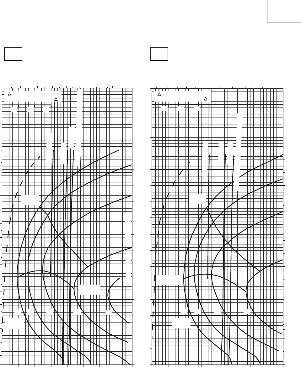
SA
AA0436
CRUISE
CLEAN CONFIGURATION
CRUISE
T700 (2)
10oC
16000 FT
PRESS ALT: 16000 FT
20oC
TOTAL FUEL FLOW ~ 100 LB/HR
TRUE AIRSPEED ~ KTS
TRUE AIRSPEED ~ KTS
TOTAL FUEL FLOW ~ 100 LB/HR
IAS ~ KTS
TORQUE PER ENGINE ~ % TORQUE PER ENGINE ~ %
5 6 7 8 9 10 11 12 13
20 30 40 50 60 70 80 90 100
0
20
10
30
40
50
60
70
80
90
100
110
120
130
140
150
160
170
180
170
160
150
140
130
120
110
100
90
80
70
60
50
40
30
20
10
010 20 30 40 50 60 70 80 90
4 5 6 7 8 9 10 11 12
0
10
20
30
40
50
60
70
80
90
100
110
120
130
140
150
160
170
180
TRQ ~ % FOR DRAG
AREA OF 10 SQ FT OF F
10 20 30
TRQ ~ % FOR DRAG
AREA OF 10 SQ FT OF F
10 20 30
MAX
RANGE
MAX END
AND R / C
GW ~
1000 LB
12 14 16 18 20
~ CONTINUOUS
TORQUE AVAILABLE ~ 30 MINUTES
MAX END
AND R / C
MAX
RANGE
12 14 16 18
GW ~
1000 LB
~ CONTINUOUS
TORQUE AVAILABLE ~ 30 MINUTES
ATF = 1.0
ATF = 0.9
ATF = 0.9
ATF = 1.0
TRANSMISSION TORQUE LIMIT
Figure 7-23. Cruise - Pressure Altitude 16,000 Feet (Sheet 4 of 5)
TM 1-1520-237-10
7-109
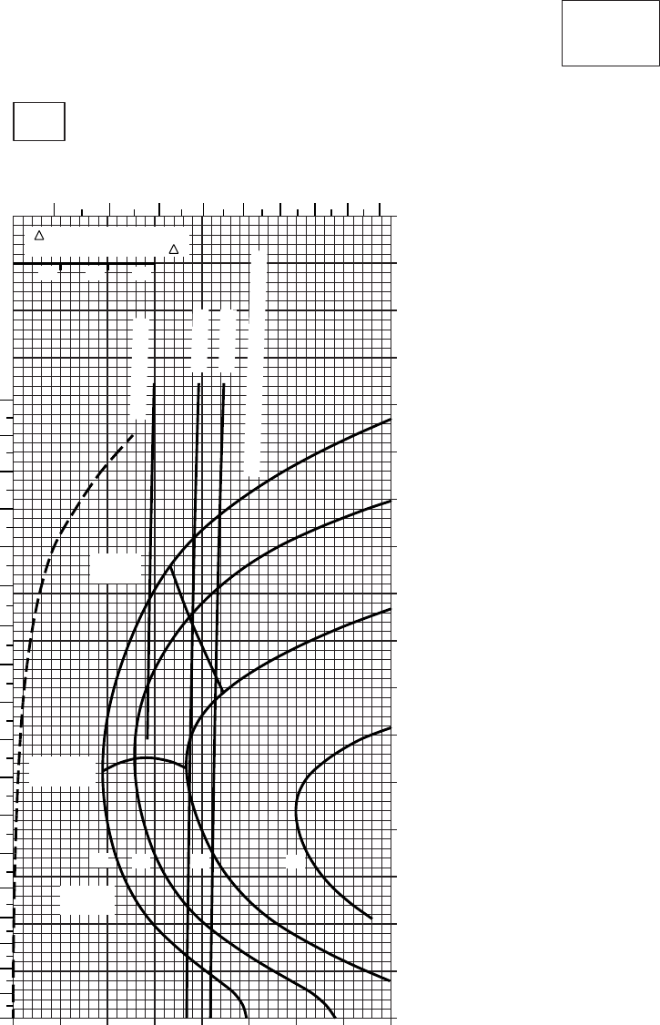
20 30 40 50 60 70 80 90
0
10
20
30
40
50
60
70
80
90
100
110
120
130
140
150
160
170
SA
AA0437
CRUISE
CLEAN CONFIGURATION
CRUISE
T700 (2)
TORQUE PER ENGINE ~ %
IAS ~ KTSTOTAL FUEL FLOW ~ 100 LB/HR
DATA BASE:FLIGHT TEST
TRUE AIRSPEED ~ KTS
TRQ ~ % FOR DRAG
AREA OF 10 SQ FT OF F
10 20 30
10
~ CONTINUOUS
ATF = 0.9
ATF = 1.0
TORQUE AVAILABLE ~ 30 MINUTES
MAX
RANGE
MAX END
AND R / C
GW~
1000 LB
12 14 16 18
30oC
16000 FT
PRESS ALT: 16000 FT
0
10
20
30
40
50
60
70
80
90
100
110
120
130
140
150
160
170
180
4 5 6 7 8 9 10 11 12
Figure 7-23. Cruise - Pressure Altitude 16,000 Feet (Sheet 5 of 5)
TM 1-1520-237-10
7-110
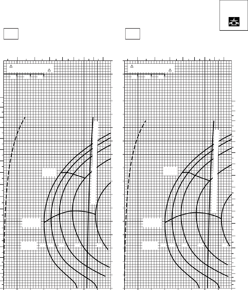
20 30 40 50 60 70 80
0
10
20
30
40
50
60
70
80
90
100
110
120
130
140
150
160
170
SA
AA0579
CRUISE
PRESS ALT: 16000 FT
CRUISE
16000 FT
TORQUE PER ENGINE ~ %TORQUE PER ENGINE ~ %
IAS ~ KTS TOTAL FUEL FLOW ~ 100 LB/HRTOTAL FUEL FLOW ~ 100 LB/HR
DATA BASE:FLIGHT TEST
TRUE AIRSPEED ~ KTS
TRUE AIRSPEED ~ KTS
−40OC−50OC
TRQ ~ % FOR DRAG
AREA OF 10 SQ FT OF F
10 20 30
TRQ ~ % FOR DRAG
AREA OF 10 SQ FT OF F
10 20 30
010 20 30 40 50 60 70 80010
3456
78 9 10 3 4 5 6 7 8 9 10
180
170
160
150
140
130
120
110
100
90
80
70
60
50
40
30
20
10
0
180
170
160
150
140
130
120
110
100
90
80
70
60
50
40
30
20
10
0
GW ~
1000 LB 12 14 16 18 20
MAX
RANGE MAX
RANGE
MAX END
AND R / C MAX END
AND R / C
TORQUE AVAILABLE ~ CONTINUOUS & 30 MIN
GW ~
1000 LB 12 14 16 18 20
TORQUE AVAILABLE ~ CONTINUOUS & 30 MIN
T700 (2)
Figure 7-24. Cruise High Drag - Pressure Altitude 16,000 Feet (Sheet 1 of 4)
TM 1-1520-237-10
7-111

20 30 40 50 60 70 80
0
10
20
30
40
50
60
70
80
90
100
110
120
130
140
150
160
170
SA
AA0580
CRUISE
PRESS ALT: 16000 FT
CRUISE
16000 FT
TORQUE PER ENGINE ~ %TORQUE PER ENGINE ~ %
IAS ~ KTS TOTAL FUEL FLOW ~ 100 LB/HRTOTAL FUEL FLOW ~ 100 LB/HR
DATA BASE:FLIGHT TEST
TRUE AIRSPEED ~ KTS
TRUE AIRSPEED ~ KTS
−20OC−30OC
TRQ ~ % FOR DRAG
AREA OF 10 SQ FT OF F
10 20 30
TRQ ~ % FOR DRAG
AREA OF 10 SQ FT OF F
10 20 30
010 20 30 40 50 60 70 80010
3456
789
10 3456789
10
180
170
160
150
140
130
120
110
100
90
0
10
20
30
50
60
70
80
40
180
170
160
150
140
130
120
110
10
0
20
30
40
50
60
70
80
100
90
GW ~
1000 LB GW ~
1000 LB
MAX END
AND R / C MAX END
AND R / C
MAX
RANGE MAX
RANGE
TORQUE AVAILABLE ~ CONTINUOUS & 30 MIN
12 14 16 18 20 12 14 16 18
20
TORQUE AVAILABLE ~ 30 MINUTES
~ CONTINUOUS
T700 (2)
Figure 7-24. Cruise High Drag - Pressure Altitude 16,000 Feet (Sheet 2 of 4)
TM 1-1520-237-10
7-112
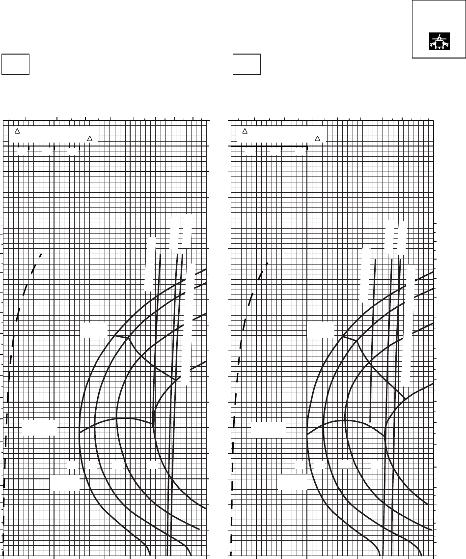
CRUISE
PRESS ALT: 16000 FT
CRUISE
16000 FT
TORQUE PER ENGINE ~ %TORQUE PER ENGINE ~ %
IAS ~ KTS TOTAL FUEL FLOW ~ 100 LB/HRTOTAL FUEL FLOW ~ 100 LB/HR
DATA BASE:FLIGHT TEST
TRUE AIRSPEED ~ KTS
0OC−10OC
TRUE AIRSPEED ~ KTS
SA
AA0581
3 4 5 6 7 8 9 10 3 4 5 6 7 8 9 10
0 10 20 30 40 50 60 70 80 0 10 20 30 40 50 60 70 80
180
170
160
150
140
130
120
110
100
90
80
70
60
50
40
0
10
20
30
180
170
160
150
140
130
120
110
100
90
80
70
60
50
40
30
0
10
20
170
160
150
140
130
120
110
100
90
80
70
60
50
40
30
20
10
0
TRQ ~ % FOR DRAG
AREA OF 10 SQ FT OF F
10 20 30
TRQ ~ % FOR DRAG
AREA OF 10 SQ FT OF F
10 20 30
14 1612 18
MAX
RANGE
GW ~
1000 LB
MAX END
AND R / C
14 16
12 18
MAX
RANGE
GW ~
1000 LB
MAX END
AND R / C
~ CONTINUOUS
ATF = 0.9
ATF = 0.9
~ CONTINUOUS
ATF = 1.0
ATF = 1.0
TORQUE AVAILABLE ~ 30 MINUTES
TORQUE AVAILABLE ~ 30 MINUTES
T700 (2)
Figure 7-24. Cruise High Drag - Pressure Altitude 16,000 Feet (Sheet 3 of 4)
TM 1-1520-237-10
7-113
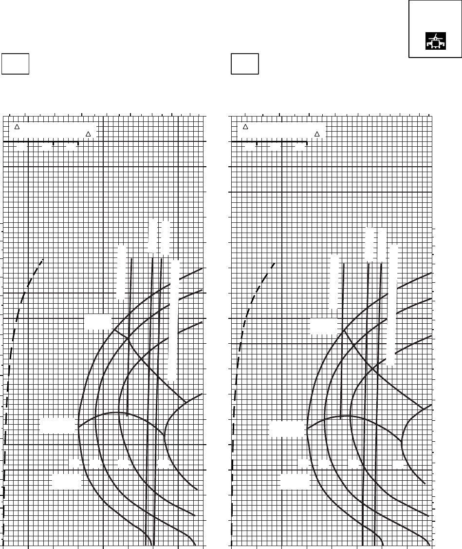
CRUISE
PRESS ALT: 16000 FT
CRUISE
16000 FT
TORQUE PER ENGINE ~ %TORQUE PER ENGINE ~ %
IAS ~ KTS TOTAL FUEL FLOW ~ 100 LB/HRTOTAL FUEL FLOW ~ 100 LB/HR
DATA BASE:FLIGHT TEST
TRUE AIRSPEED ~ KTS
20OC10OC
TRUE AIRSPEED ~ KTS
TRQ ~ % FOR DRAG
AREA OF 10 SQ FT OF F
10 20 30
TRQ ~ % FOR DRAG
AREA OF 10 SQ FT OF F
10 20 30
SA
AA0582
3 4 5 6 7 8 9 10 3 4 5 6 7 8 9 10
170
160
150
140
130
120
110
100
90
80
70
60
50
40
30
20
10
0
0 10 20 30 40 50 60 70 80 0 10 20 30 40 50 60 70 80
180
170
160
150
140
130
120
110
100
90
80
70
60
50
40
30
20
10
0
180
170
160
150
140
130
120
110
100
90
80
70
60
50
40
30
20
10
0
14 16
12 18
MAX
RANGE
GW ~
1000 LB
MAX END
AND R / C
14 16
12 18
MAX
RANGE
GW ~
1000 LB
MAX END
AND R / C
ATF = 0.9
~ CONTINUOUS
~ CONTINUOUS
ATF = 1.0
TORQUE AVAILABLE ~ 30 MINUTES
ATF = 0.9
ATF = 1.0
TORQUE AVAILABLE ~ 30 MINUTES
T700 (2)
Figure 7-24. Cruise High Drag - Pressure Altitude 16,000 Feet (Sheet 4 of 4)
TM 1-1520-237-10
7-114
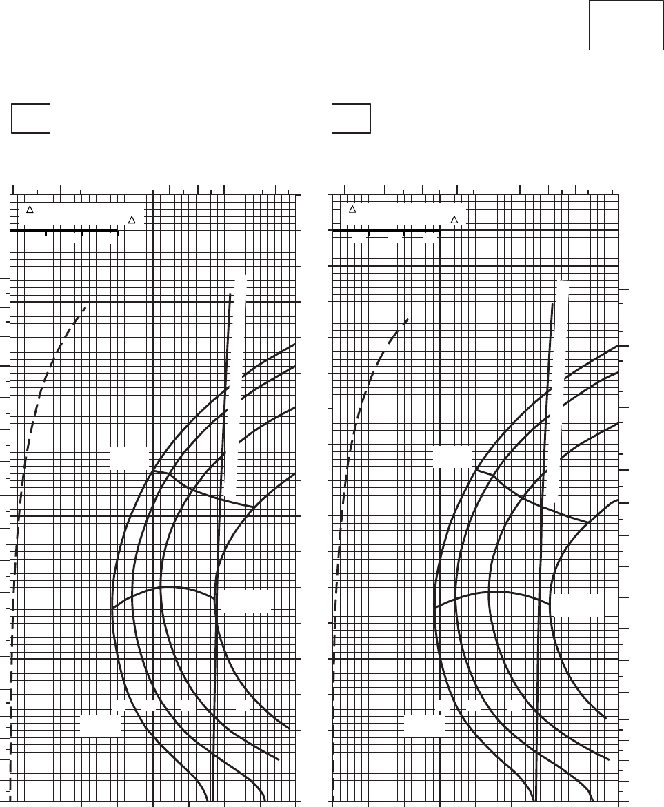
SA
AA0440
CRUISE
CLEAN CONFIGURATION
CRUISE
T700 (2)
−50oC
18000 FT
PRESS ALT: 18000 FT
−40oC
TOTAL FUEL FLOW ~ 100 LB/HR TOTAL FUEL FLOW ~ 100 LB/HR
IAS ~ KTS
TORQUE PER ENGINE ~ % TORQUE PER ENGINE ~ %
TRQ ~ % FOR DRAG
AREA OF 10 SQ FT OF F
10 20 30
TRQ ~ % FOR DRAG
AREA OF 10 SQ FT OF F
10 20 30
0
10
20
30
40
50
60
70
80
90
100
110
120
130
140
150
160
170
0 10 20 30 40 50 60 70 80 0 10 20 30 40 50 60 70 80
0
10
20
30
40
50
60
70
80
90
100
110
120
130
140
150
160
170
180
1098765432
1098765432
180
170
160
150
140
130
120
110
100
90
80
70
60
50
40
30
20
10
0
TRUE AIRSPEED ~ KTS
TRUE AIRSPEED ~ KTS
1816141218161412
GW ~
1000 LB
GW ~
1000 LB
MAX END
AND R / C MAX END
AND R / C
MAX
RANGE
MAX
RANGE
TORQUE AVAILABLE ~ CONTINUOUS & 30 MIN
TORQUE AVAILABLE ~ CONTINUOUS & 30 MIN
Figure 7-25. Cruise - Pressure Altitude 18,000 Feet (Sheet 1 of 5)
TM 1-1520-237-10
7-115
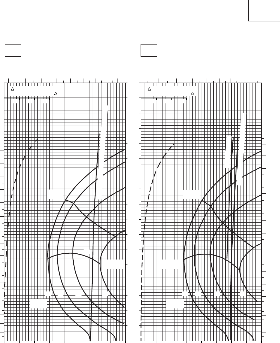
SA
AA0439
CRUISE
CLEAN CONFIGURATION
CRUISE
T700 (2)
−30oC
18000 FT
PRESS ALT: 18000 FT
−20oC
TOTAL FUEL FLOW ~ 100 LB/HR TOTAL FUEL FLOW ~ 100 LB/HR
IAS ~ KTS
TORQUE PER ENGINE ~ % TORQUE PER ENGINE ~ %
TRQ ~ % FOR DRAG
AREA OF 10 SQ FT OF F
10 20 30
TRQ ~ % FOR DRAG
AREA OF 10 SQ FT OF F
10 20 30
0
10
20
30
40
50
60
70
80
90
100
110
120
130
140
150
160
170
8070605040302010080706050403020100
0
10
20
30
40
50
60
70
80
90
100
110
120
130
140
150
160
170
180
2345678910 345678910
180
170
160
150
140
130
120
110
100
90
80
70
60
50
40
30
20
10
0
TRUE AIRSPEED ~ KTS
TRUE AIRSPEED ~ KTS
1816141218161412
GW ~
1000 LB
GW ~
1000 LB
20
MAX END
AND R / C MAX END
AND R / C
MAX
RANGE MAX
RANGE
TORQUE AVAILABLE ~ CONTINUOUS & 30 MIN
~ CONTINUOUS
TORQUE AVAILABLE ~ 30 MINUTES
Figure 7-25. Cruise - Pressure Altitude 18,000 Feet (Sheet 2 of 5)
TM 1-1520-237-10
7-116
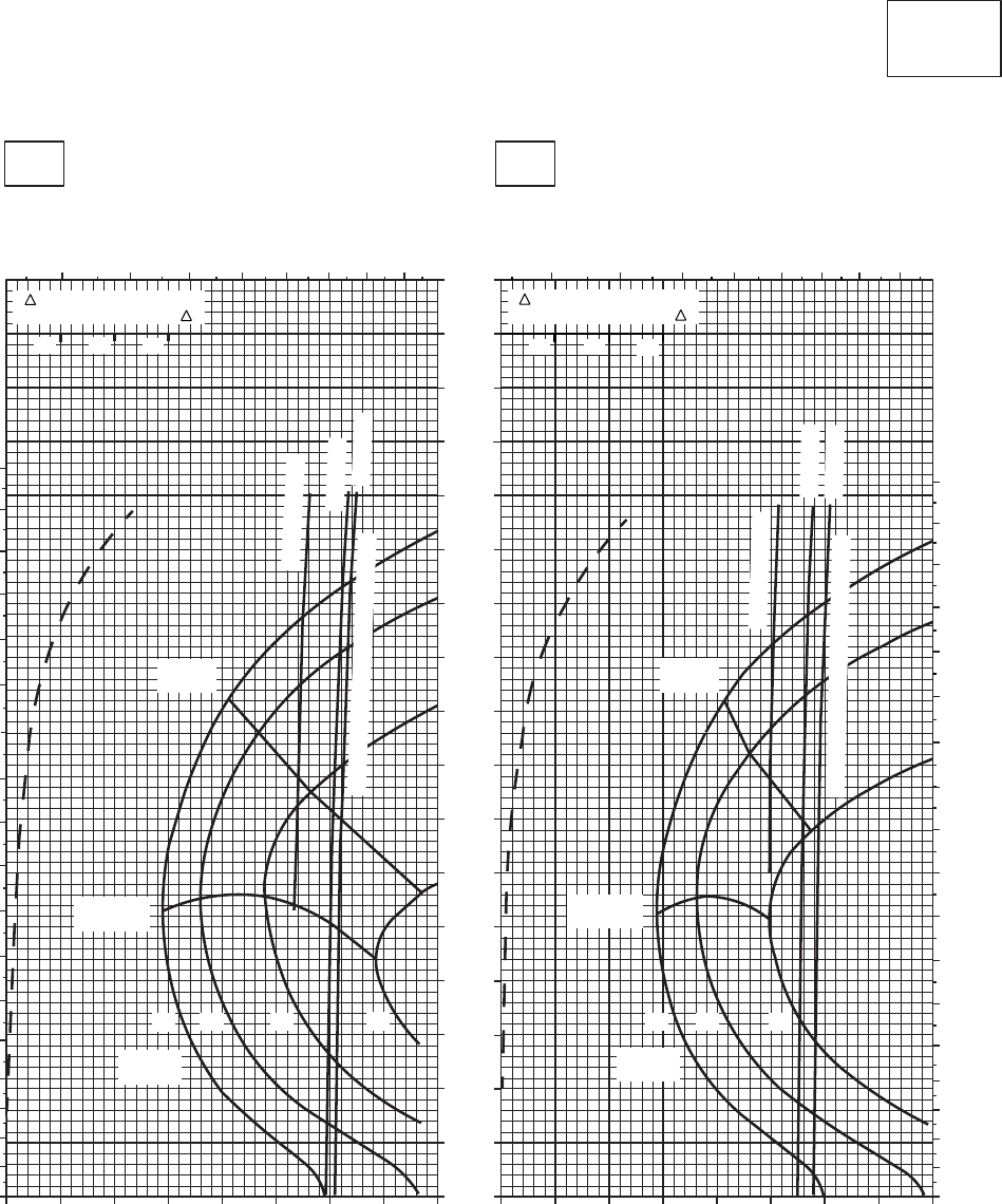
SA
AA0438
CRUISE
CLEAN CONFIGURATION
CRUISE
T700 (2)
−10oC
18000 FT
PRESS ALT: 18000 FT
0oC
TOTAL FUEL FLOW ~ 100 LB/HR
TRUE AIRSPEED ~ KTS
TRUE AIRSPEED ~ KTS
TOTAL FUEL FLOW ~ 100 LB/HR
IAS ~ KTS
TORQUE PER ENGINE ~ % TORQUE PER ENGINE ~ %
0 10 20 30 40 50 7060 80 010 20 30 40 50 60 70 80
170
160
150
140
130
120
110
100
90
80
70
60
50
40
30
20
10
0
345 6 7 8 9 10
0
10
20
30
40
50
60
70
80
90
100
110
120
130
140
150
160
170
180
3 4 5 6 7 89 10
0
10
20
30
40
50
60
70
80
90
100
110
120
130
140
150
160
170
180
TRQ ~ % FOR DRAG
AREA OF 10 SQ FT OF F
10 20 30
TRQ ~ % FOR DRAG
AREA OF 10 SQ FT OF F
10 20 30
MAX
RANGE
MAX END
AND R / C
12 14 16 18
GW ~
1000 LB
MAX
RANGE
MAX END
AND R / C
14
12 16
GW ~
1000 LB
~ CONTINUOUS
~ CONTINUOUS
TORQUE AVAILABLE ~ 30 MINUTES ATF = 1.0
ATF = 0.9
TORQUE AVAILABLE ~ 30 MINUTES
ATF = 0.9
ATF = 1.0
Figure 7-25. Cruise - Pressure Altitude 18,000 Feet (Sheet 3 of 5)
TM 1-1520-237-10
7-117
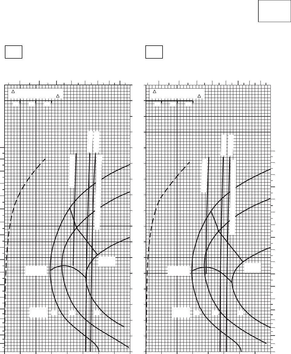
SA
AA0441
CRUISE
CLEAN CONFIGURATION
CRUISE
T700 (2)
10oC
18000 FT
PRESS ALT: 18000 FT
20oC
TOTAL FUEL FLOW ~ 100 LB/HR TOTAL FUEL FLOW ~ 100 LB/HR
IAS ~ KTS
TORQUE PER ENGINE ~ % TORQUE PER ENGINE ~ %
TRQ ~ % FOR DRAG
AREA OF 10 SQ FT OF F
10 20 30
TRQ ~ % FOR DRAG
AREA OF 10 SQ FT OF F
10 20 30
0
10
20
30
40
50
60
70
80
90
100
110
120
130
140
150
160
170
0 10 20 30 40 50 60 70 80 0 10 20 30 40 50 60 70 80
TRUE AIRSPEED ~ KTS
TRUE AIRSPEED ~ KTS
0
10
20
30
40
50
60
70
80
90
100
110
120
130
140
150
160
170
180
345678910 345678910
180
170
160
150
140
130
120
110
100
90
80
70
60
50
40
30
20
10
0
14 1612161412
GW ~
1000 LB GW ~
1000 LB
MAX END
AND R / C MAX END
AND R / C
MAX
RANGE
MAX
RANGE
~ CONTINUOUS
~ CONTINUOUS
ATF = 0.9
ATF = 1.0
ATF = 0.9
ATF = 1.0
TORQUE AVAILABLE ~ 30 MINUTES
TORQUE AVAILABLE ~ 30 MINUTES
Figure 7-25. Cruise - Pressure Altitude 18,000 Feet (Sheet 4 of 5)
TM 1-1520-237-10
7-118
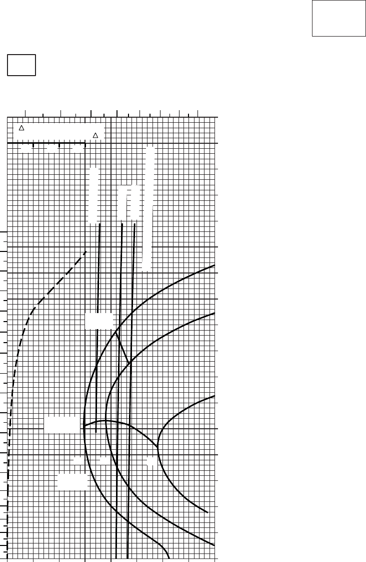
10 20 30 40 50 60 70 80
0
10
20
30
40
50
60
70
80
90
100
110
120
130
140
150
160
170
SA
AA0442A
CRUISE
CLEAN CONFIGURATION
CRUISE
T700 (2)
TORQUE PER ENGINE ~ %
IAS ~ KTSTOTAL FUEL FLOW ~ 100 LB/HR
DATA BASIS: FLIGHT TEST
TRUE AIRSPEED ~ KTS
TRQ ~ % FOR DRAG
AREA OF 10 SQ FT OF F
10 20 30
0
30oC
18000 FT
PRESS ALT: 18000 FT
345678910
0
10
20
30
40
50
60
70
80
90
100
110
120
130
140
150
160
170
180
MAX
RANGE
MAX END
AND R / C
GW~
1000 LB
12 14 16
~ CONTINUOUS
ATF = 0.9
ATF = 1.0
TORQUE AVAILABLE ~ 30 MINUTES
Figure 7-25. Cruise - Pressure Altitude 18,000 Feet (Sheet 5 of 5)
TM 1-1520-237-10
7-119

CRUISE
PRESS ALT: 18000 FT
CRUISE
18000 FT
TORQUE PER ENGINE ~ %TORQUE PER ENGINE ~ %
IAS ~ KTS TOTAL FUEL FLOW ~ 100 LB/HRTOTAL FUEL FLOW ~ 100 LB/HR
DATA BASE:FLIGHT TEST
TRUE AIRSPEED ~ KTS
−40OC−50OC
TRUE AIRSPEED ~ KTS
TRQ ~ % FOR DRAG
AREA OF 10 SQ FT OF F
10 20 30
TRQ ~ % FOR DRAG
AREA OF 10 SQ FT OF F
10 20 30
14 1612 18
MAX
RANGE
GW ~
1000 LB
MAX END
AND R / C
14 16
12 18
MAX
RANGE
GW ~
1000 LB
MAX END
AND R / C
2 3 4 5 6 7 8 9 10 2 3 4 5 6 7 8 9 10
010 20 30 40 50 60 70 80 010 20 30 40 50 60 70 80
180
170
160
150
140
130
120
110
100
90
80
70
60
50
40
30
20
10
0
170
160
150
140
130
120
110
100
90
80
70
60
50
40
30
20
10
0
180
170
160
150
140
130
120
110
100
90
80
70
60
50
40
30
20
10
0
SA
AA0583
TORQUE AVAILABLE ~ CONTINUOUS & 30 MIN
TORQUE AVAILABLE ~ CONTINUOUS & 30 MIN
T700 (2)
Figure 7-26. Cruise High Drag - Pressure Altitude 18,000 Feet (Sheet 1 of 4)
TM 1-1520-237-10
7-120
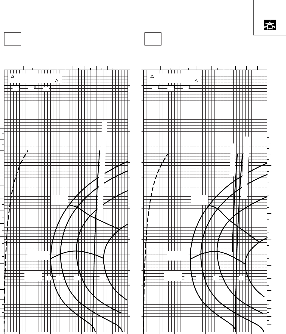
20 30 40 50 60 70 80
0
10
20
30
40
50
60
70
80
90
100
110
120
130
140
150
160
170
SA
AA0584
CRUISE
PRESS ALT: 18000 FT
CRUISE
TORQUE PER ENGINE ~ %TORQUE PER ENGINE ~ %
IAS ~ KTS TOTAL FUEL FLOW ~ 100 LB/HRTOTAL FUEL FLOW ~ 100 LB/HR
DATA BASE:FLIGHT TEST
TRUE AIRSPEED ~ KTS
TRUE AIRSPEED ~ KTS
TRQ ~ % FOR DRAG
AREA OF 10 SQ FT OF F
10 20 30
TRQ ~ % FOR DRAG
AREA OF 10 SQ FT OF F
10 20 30
010 20 30 40 50 60 70 80010
−30oC−20oC
18000 FT
345678910 3 45678910
180
170
160
150
140
130
120
110
100
90
80
70
60
50
40
30
20
10
00
10
20
30
40
50
60
70
80
90
100
110
120
130
140
150
160
170
180
12 14 16 18
GW ~
1000 LB 12 14 16 18
GW ~
1000 LB
MAX END
AND R / C
MAX END
AND R / C
MAX
RANGE
MAX
RANGE
TORQUE AVAILABLE ~ CONTINUOUS & 30 MIN
~ CONTINUOUS
TORQUE AVAILABLE ~ 30 MIN
T700 (2)
Figure 7-26. Cruise High Drag - Pressure Altitude 18,000 Feet (Sheet 2 of 4)
TM 1-1520-237-10
7-121
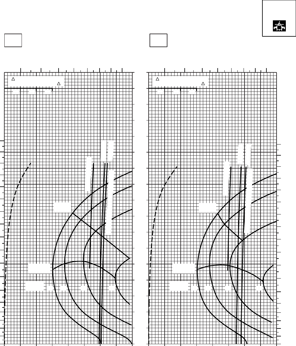
20 30 40 50 60 70 80
0
10
20
30
40
50
60
70
80
90
100
110
120
130
140
150
160
170
SA
AA0585
CRUISE
PRESS ALT: 18000 FT
CRUISE
TORQUE PER ENGINE ~ %TORQUE PER ENGINE ~ %
IAS ~ KTS TOTAL FUEL FLOW ~ 100 LB/HRTOTAL FUEL FLOW ~ 100 LB/HR
DATA BASE:FLIGHT TEST
TRUE AIRSPEED ~ KTS
TRUE AIRSPEED ~ KTS
TRQ ~ % FOR DRAG
AREA OF 10 SQ FT OF F
10 20 30
TRQ ~ % FOR DRAG
AREA OF 10 SQ FT OF F
10 20 30
010 20 30 40 50 60 70 80010
−10oC0oC
18000 FT
345678910 345678910
180
170
160
150
140
130
120
110
100
90
80
70
60
50
40
30
20
10
00
10
20
30
40
50
60
70
80
90
100
110
120
130
140
150
160
170
180
12 14 16 18
GW ~
1000 LB 12 14 16 18
GW ~
1000 LB
MAX END
AND R / C
MAX END
AND R / C
MAX
RANGE
MAX
RANGE
~ CONTINUOUS
~ CONTINUOUS
TORQUE AVAILABLE ~ 30 MIN
TORQUE AVAILABLE ~ 30 MIN
ATF = 0.9
ATF = 1.0
ATF = 0.9
ATF = 1.0
T700 (2)
Figure 7-26. Cruise High Drag - Pressure Altitude 18,000 Feet (Sheet 3 of 4)
TM 1-1520-237-10
7-122
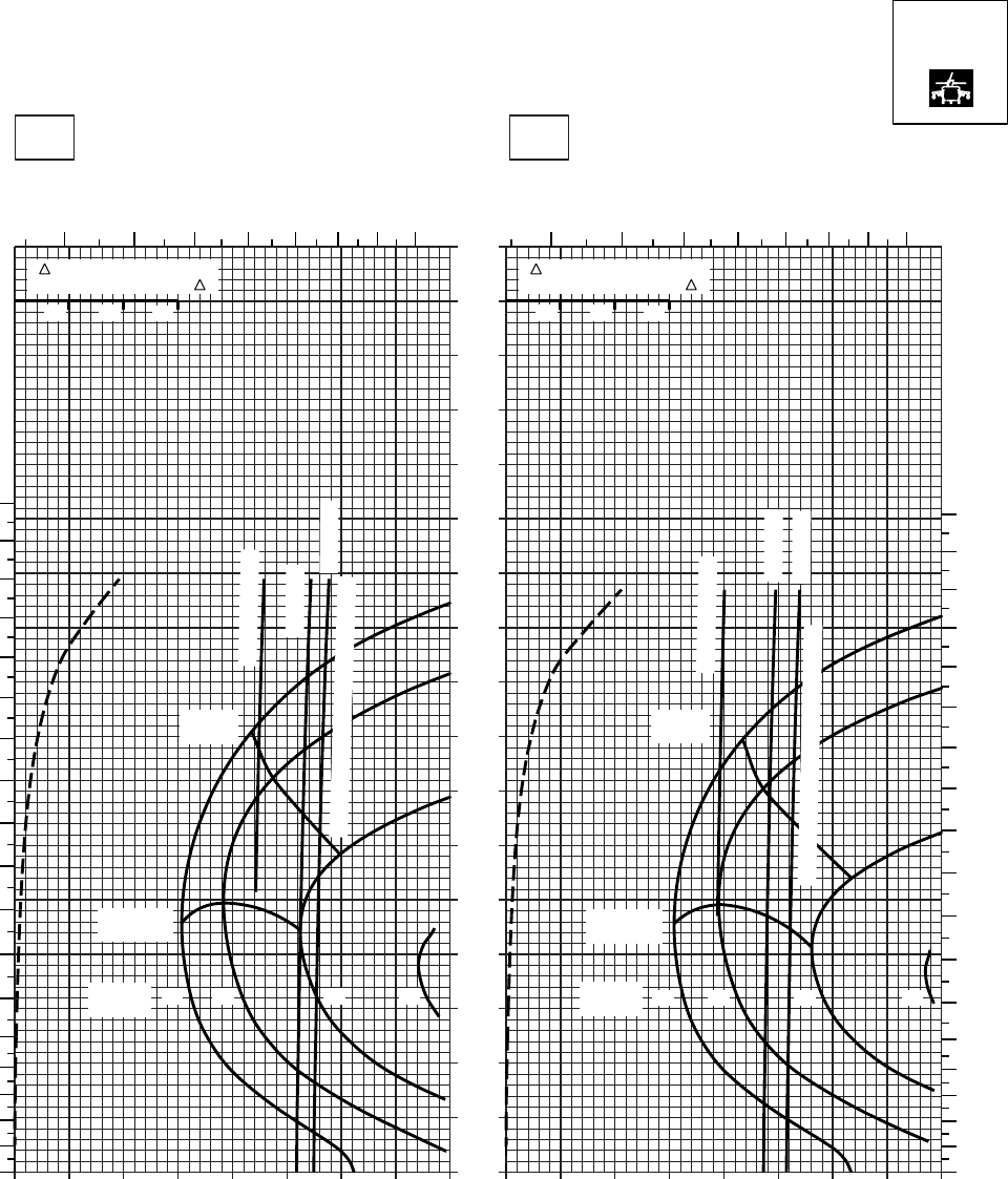
20 30 40 50 60 70 80
0
10
20
30
40
50
60
70
80
90
100
110
120
130
140
150
160
170
SA
AA0586
CRUISE
PRESS ALT: 18000 FT
CRUISE
18000 FT
TORQUE PER ENGINE ~ %TORQUE PER ENGINE ~ %
IAS ~ KTS TOTAL FUEL FLOW ~ 100 LB/HRTOTAL FUEL FLOW ~ 100 LB/HR
DATA BASE:FLIGHT TEST
TRUE AIRSPEED ~ KTS
TRUE AIRSPEED ~ KTS
20OC10OC
TRQ ~ % FOR DRAG
AREA OF 10 SQ FT OF F
10 20 30
TRQ ~ % FOR DRAG
AREA OF 10 SQ FT OF F
10 20 30
010 20 30 40 50 60 70 80010
3456
78910 345678910
180
170
160
150
140
130
120
110
100
90
80
70
60
50
40
30
20
10
0
180
170
160
150
140
130
120
110
100
90
80
70
60
40
30
20
10
50
0
MAX
RANGE
MAX END
AND R / C
GW ~
1000 LB 12 14 16 18
~ CONTINUOUS
ATF = 1.0
ATF = 0.9
TORQUE AVAILABLE ~ 30 MINUTES
MAX END
AND R / C
MAX
RANGE
~ CONTINUOUS
ATF = 0.9
ATF = 1.0
TORQUE AVAILABLE ~ 30 MINUTES
GW ~
1000 LB 12 14 16 18
T700 (2)
Figure 7-26. Cruise High Drag - Pressure Altitude 18,000 Feet (Sheet 4 of 4)
TM 1-1520-237-10
7-123
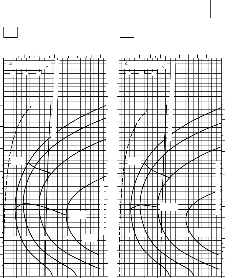
20 30 40 50 60 70 80 90 100
0
10
20
30
40
50
60
70
80
90
100
110
120
130
140
150
160
170
20 30 40 50 60 70 80 90 100
CRUISE
CLEAN CONFIGURATION
CRUISE
T700 (2)
TORQUE PER ENGINE ~ %TORQUE PER ENGINE ~ %
IAS ~ KTS TOTAL FUEL FLOW ~ 100 LB/HRTOTAL FUEL FLOW ~ 100 LB/HR
DATA BASE:FLIGHT TEST
TRUE AIRSPEED ~ KTS
TRUE AIRSPEED ~ KTS
TRQ ~ % FOR DRAG
AREA OF 10 SQ FT OF F
10 20 30
TRQ ~ % FOR DRAG
AREA OF 10 SQ FT OF F
10 20 30
SA
AA0445
−50oC−40oC
20000 FT
PRESS ALT: 20000 FT
4 5 6 7 8 9 10 11 12 13
0
10
20
30
40
50
60
70
80
90
100
110
120
130
140
150
160
170
180
45678
910
11 12 13
0
10
20
30
40
50
60
70
80
90
100
110
120
130
140
150
160
170
180
MAX
RANGE
MAX END
AND R / C
GW ~
1000 LB
12 14 16 18
TRANSMISSION TORQUE LIMIT
MAX
RANGE
MAX END
AND R / C
GW ~
1000 LB
12 14 16 18
TRANSMISSION TORQUE LIMIT
TORQUE AVAILABLE ~ CONTINUOUS & 30 MIN
TORQUE AVAILABLE ~ CONTINUOUS & 30 MIN
Figure 7-27. Cruise - Pressure Altitude 20,000 Feet (Sheet 1 of 4)
TM 1-1520-237-10
7-124
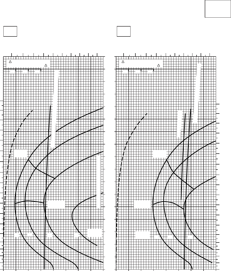
20 30 40 50 60 70 80 90 100
0
10
20
30
40
50
60
70
80
90
100
110
120
130
140
150
160
170
0 10 20 30 40 50 60 70 80
CRUISE
CLEAN CONFIGURATION
CRUISE
T700 (2)
TORQUE PER ENGINE ~ %TORQUE PER ENGINE ~ %
IAS ~ KTS TOTAL FUEL FLOW ~ 100 LB/HRTOTAL FUEL FLOW ~ 100 LB/HR
DATA BASE:FLIGHT TEST
TRUE AIRSPEED ~ KTS
TRUE AIRSPEED ~ KTS
TRQ ~ % FOR DRAG
AREA OF 10 SQ FT OF F
10 20 30
TRQ ~ % FOR DRAG
AREA OF 10 SQ FT OF F
10 20 30
SA
AA0444
−30oC−20oC
20000 FT
PRESS ALT: 20000 FT
4 5 6 7 8 9 10 11 12 13 2 3 4 5 6 7 8 9 10 11
180
170
160
150
140
130
120
110
100
90
80
70
60
50
40
30
20
10
0
180
170
160
150
140
130
120
110
100
90
80
70
60
50
40
30
20
10
0
MAX
RANGE
MAX END
AND R / C
GW ~
1000 LB
12 14 16 18
TRANSMISSION TORQUE LIMIT
TORQUE AVAILABLE ~ CONTINUOUS & 30 MIN
MAX
RANGE
MAX END
AND R / C
GW ~
1000 LB 12 14 16
~ CONTINUOUS
TORQUE AVAILABLE ~ 30 MINUTES
Figure 7-27. Cruise - Pressure Altitude 20,000 Feet (Sheet 2 of 4)
TM 1-1520-237-10
7-125
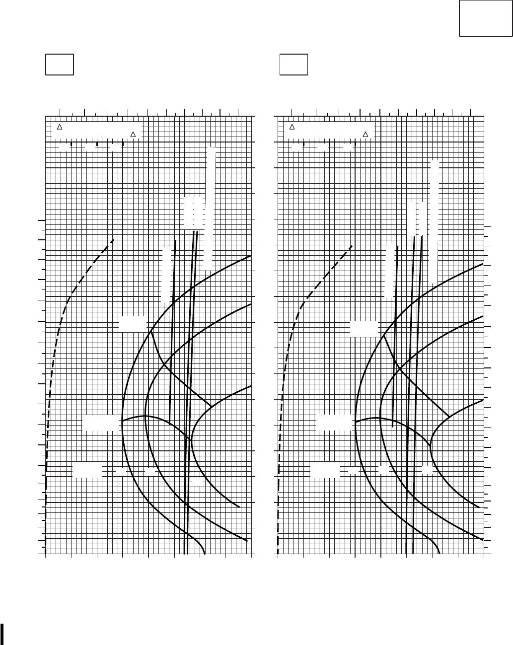
SA
AA0443A
0 10 20 30 40 50 60 70 80
0
10
20
30
40
50
60
70
80
90
100
110
120
130
140
150
160
170
0 10 20 30 40 50 60 70 80
CRUISE
CLEAN CONFIGURATION CRUISE
T700 (2)
TORQUE PER ENGINE ~ %TORQUE PER ENGINE ~ %
IAS ~ KTS TOTAL FUEL FLOW ~ 100 LB/HRTOTAL FUEL FLOW ~ 100 LB/HR
DATA BASE: FLIGHT TEST
TRUE AIRSPEED ~ KTS
TRUE AIRSPEED ~ KTS
TRQ ~ % FOR DRAG
AREA OF 10 SQ FT OF F
10 20 30
TRQ ~ % FOR DRAG
AREA OF 10 SQ FT OF F
10 20 30
−10oC0oC
20000 FT
PRESS ALT: 20000 FT
2 3 4 5 6 7 8 9 10 11
0
10
20
30
40
50
60
70
80
90
100
110
120
130
140
150
160
170
180
2 3 4 5 6 7 8 9 10 11
0
10
20
30
40
50
60
70
80
90
100
110
120
130
140
150
160
170
180
MAX
RANGE
MAX END
AND R / C
GW ~
1000 LB 12 14
16
ATF= 0.9
ATF= 1.0
MAX
RANGE
MAX END
AND R / C
GW ~
1000 LB 12 14 16
ATF= 0.9
ATF= 1.0
TORQUE AVAILABLE ~ 30 MINUTES
~ CONTINUOUS
TORQUE AVAILABLE ~ 30 MINUTES
~ CONTINUOUS
Figure 7-27. Cruise - Pressure Altitude 20,000 Feet (Sheet 3 of 4)
TM 1-1520-237-10
7-126 Change 8
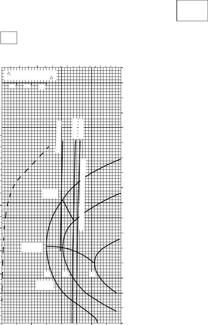
CRUISE
CLEAN CONFIGURATION
CRUISE
T700 (2)
TORQUE PER ENGINE ~ %
IAS ~ KTSTOTAL FUEL FLOW ~ 100 LB/HR
TRUE AIRSPEED ~ KTS
10oC
20000 FT
PRESS ALT: 20000 FT
SA
AA0446
0 10 20 30 40 50 60 70 80
170
160
150
140
130
120
110
100
90
80
70
60
50
40
30
20
10
0
10
0
30
50
20
40
60
70
80
90
100
110
120
130
140
150
160
170
180
3 4 5 6 7 8 9 10
TRQ ~ % FOR DRAG
AREA OF 10 SQ FT OF F
10 20 30
MAX
RANGE
MAX END
AND R / C
12 14 16
GW ~
1000 LB
~ CONTINUOUS
ATF = 0.9
ATF = 1.0
TORQUE AVAILABLE ~ 30 MINUTES
Figure 7-27. Cruise - Pressure Altitude 20,000 Feet (Sheet 4 of 4)
TM 1-1520-237-10
7-127
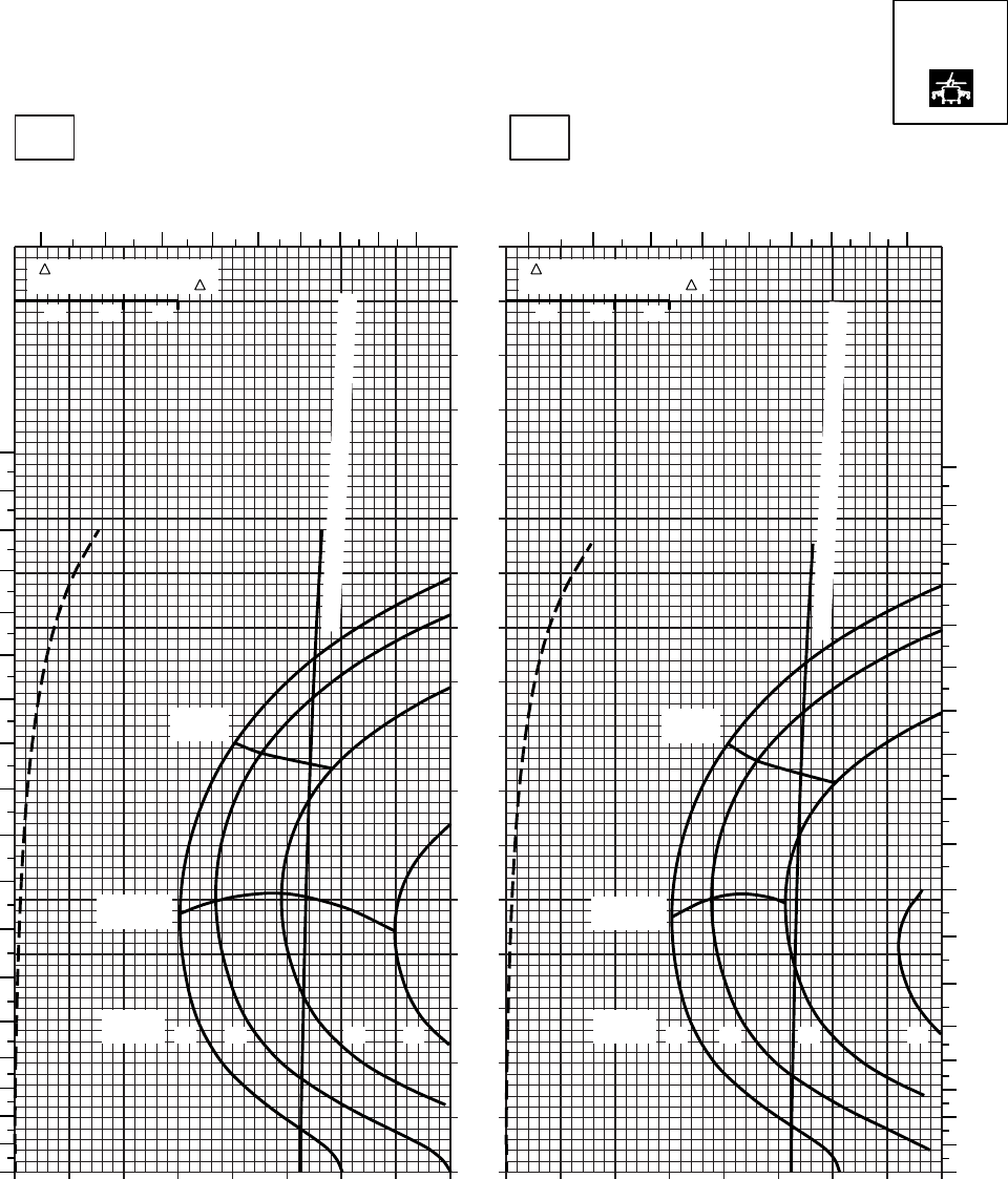
20 30 40 50 60 70 80
0
10
20
30
40
50
60
70
80
90
100
110
120
130
140
150
160
170
SA
AA0587
CRUISE
PRESS ALT: 20000 FT
CRUISE
TORQUE PER ENGINE ~ %TORQUE PER ENGINE ~ %
IAS ~ KTS TOTAL FUEL FLOW ~ 100 LB/HRTOTAL FUEL FLOW ~ 100 LB/HR
DATA BASE:FLIGHT TEST
TRUE AIRSPEED ~ KTS
TRUE AIRSPEED ~ KTS
TRQ ~ % FOR DRAG
AREA OF 10 SQ FT OF F
10 20 30
TRQ ~ % FOR DRAG
AREA OF 10 SQ FT OF F
10 20 30
010 20 30 40 50 60 70 80010
−50oC−40oC
20000 FT
2 3 4 5 6 78910 2 3 4 5 6 78910
180
170
160
150
140
130
120
110
100
90
80
70
60
50
40
30
20
10
00
10
20
30
40
50
60
70
80
90
100
110
120
130
140
150
160
170
180
MAX
RANGE
MAX
RANGE
MAX END
AND R / C
MAX END
AND R / C
TORQUE AVAILABLE ~ CONTINUOUS & 30 MIN
TORQUE AVAILABLE ~ CONTINUOUS & 30 MIN
12 14 16 18
GW ~
1000 LB
12 14 16 18
GW ~
1000 LB
T700 (2)
Figure 7-28. Cruise High Drag - Pressure Altitude 20,000 Feet (Sheet 1 of 4)
TM 1-1520-237-10
7-128
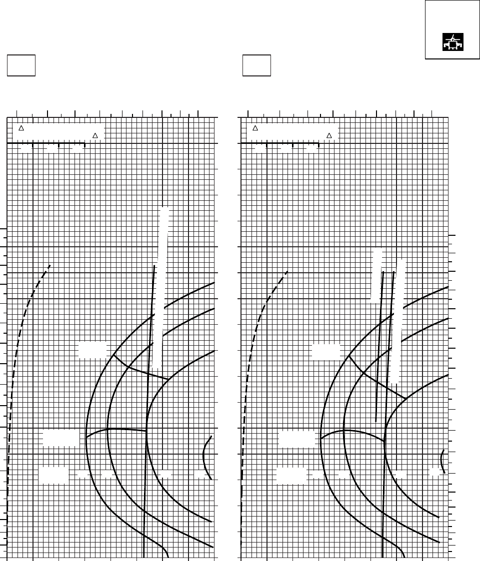
20 30 40 50 60 70 80
0
10
20
30
40
50
60
70
80
90
100
110
120
130
140
150
160
170
SA
AA0588
CRUISE
PRESS ALT: 20000 FT
CRUISE
20000 FT
TORQUE PER ENGINE ~ %TORQUE PER ENGINE ~ %
IAS ~ KTS TOTAL FUEL FLOW ~ 100 LB/HRTOTAL FUEL FLOW ~ 100 LB/HR
DATA BASE:FLIGHT TEST
TRUE AIRSPEED ~ KTS
TRUE AIRSPEED ~ KTS
−20OC−30OC
TRQ ~ % FOR DRAG
AREA OF 10 SQ FT OF F
10 20 30
TRQ ~ % FOR DRAG
AREA OF 10 SQ FT OF F
10 20 30
010 20 30 40 50 60 70 80010
2345
67
8910 2 3 456
78910
180
170
160
150
140
130
120
110
100
90
80
70
60
50
40
30
20
10
0
180
170
160
150
140
130
120
110
100
80
70
90
60
50
40
30
20
10
0
MAX
RANGE MAX
RANGE
MAX END
AND R / C MAX END
AND R / C
GW ~
1000 LB GW ~
1000 LB
TORQUE AVAILABLE ~ CONTINUOUS & 30 MIN
~ CONTINUOUS
TORQUE AVAILABLE ~ 30 MINUTES
12 14 18
16
12 14 16 18
T700 (2)
Figure 7-28. Cruise High Drag - Pressure Altitude 20,000 Feet (Sheet 2 of 4)
TM 1-1520-237-10
7-129
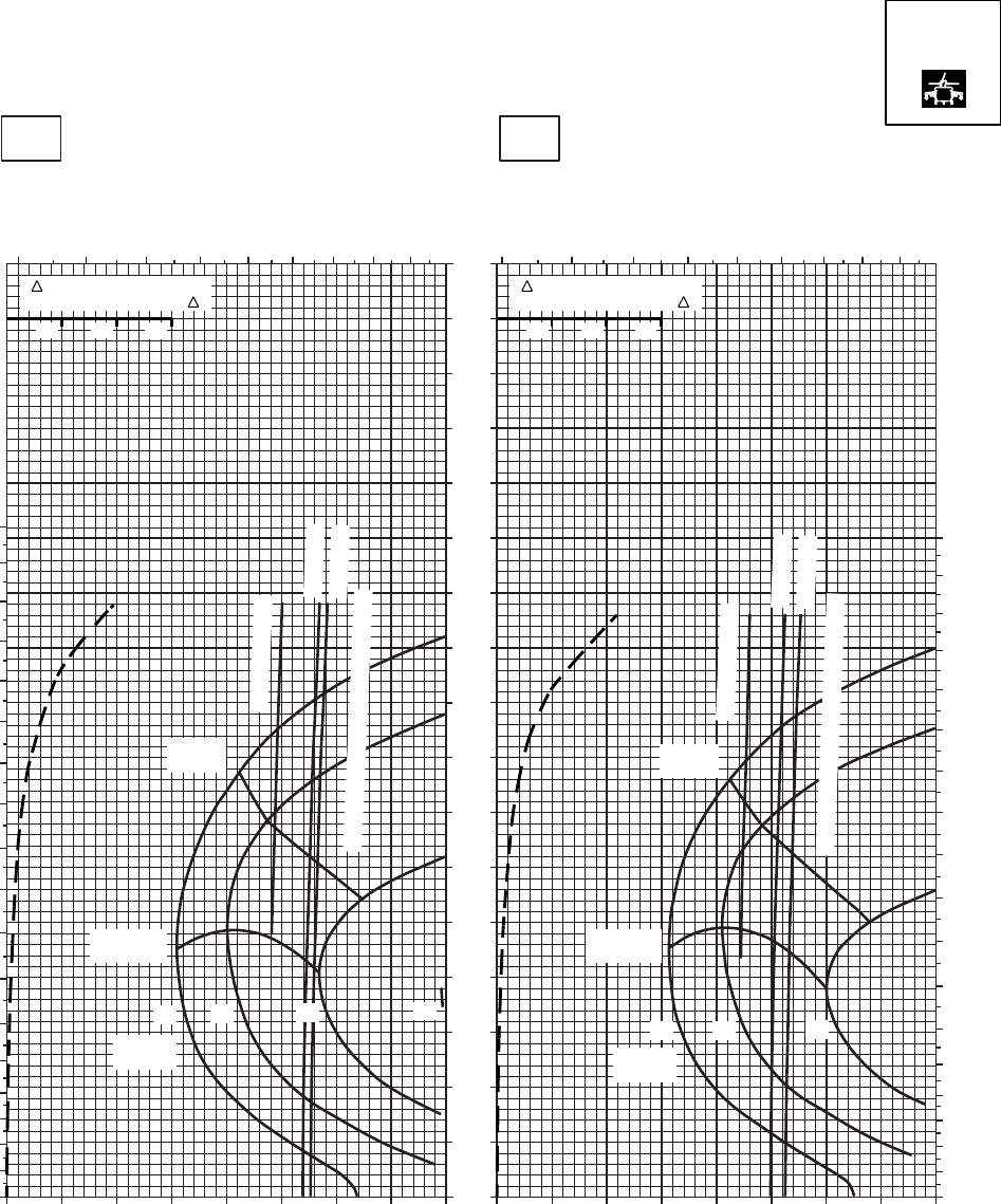
CRUISE
PRESS ALT: 20000 FT
CRUISE
20000 FT
TORQUE PER ENGINE ~ %TORQUE PER ENGINE ~ %
IAS ~ KTS TOTAL FUEL FLOW ~ 100 LB/HRTOTAL FUEL FLOW ~ 100 LB/HR
DATA BASE:FLIGHT TEST
TRUE AIRSPEED ~ KTS
0OC−10OC
TRUE AIRSPEED ~ KTS
2 3 4 5 6 7 8 9 10 1098765432
170
160
150
140
130
120
110
100
90
80
70
60
50
40
30
20
10
0
0 10 20 30 40 50 60 70 80 0 10 20 30 40 50 60 70 80
180
170
160
150
140
130
120
110
100
90
80
70
60
50
40
30
20
10
0
180
170
160
150
140
130
120
110
100
90
80
70
60
50
40
30
20
10
0
14 16
12 18
MAX
RANGE
GW ~
1000 LB
MAX END
AND R / C
14 16
12
MAX
RANGE
GW ~
1000 LB
MAX END
AND R / C
~ CONTINUOUS
~ CONTINUOUS
ATF = 0.9
ATF = 0.9
ATF = 1.0
ATF = 1.0
TORQUE AVAILABLE ~ 30 MINUTES
TORQUE AVAILABLE ~ 30 MINUTES
SA
AA0589
TRQ ~ % FOR DRAG
AREA OF 10 SQ FT OF F
10 20 30
TRQ ~ % FOR DRAG
AREA OF 10 SQ FT OF F
10 20 30
T700 (2)
Figure 7-28. Cruise High Drag - Pressure Altitude 20,000 Feet (Sheet 3 of 4)
TM 1-1520-237-10
7-130
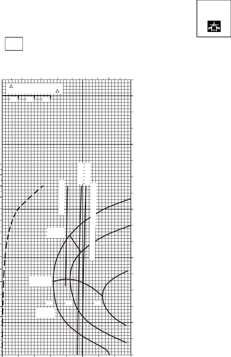
CRUISE
PRESS ALT: 20000 FT
CRUISE
20000 FT
TORQUE PER ENGINE ~ %
TOTAL FUEL FLOW ~ 100 LB/HR
DATA BASE:FLIGHT TEST
TRUE AIRSPEED ~ KTS
10OC
SA
AA0590
3 4 5 6 7 8 9 10
180
170
160
150
140
130
120
110
100
90
80
70
60
50
40
0
10
30
20
INDICATED AIRSPEED ~ KTS
0 10 20 30 40 50 60 70 80
170
160
150
140
130
120
110
100
90
80
70
60
50
40
30
20
10
0
14 1612
MAX
RANGE
GW ~
1000 LB
MAX END
AND R / C
~ CONTINUOUS
ATF = 0.9
ATF = 1.0
TORQUE AVAILABLE ~ 30 MINUTES
TRQ ~ % FOR DRAG
AREA OF 10 SQ FT OF F
10 20 30
T700 (2)
Figure 7-28. Cruise High Drag - Pressure Altitude 20,000 Feet (Sheet 4 of 4)
TM 1-1520-237-10
7-131
Section V OPTIMUM CRUISE
7.19 OPTIMUM RANGE CHARTS.
This section presents a method to optimize cruise per-
formance for long range missions when the altitudes flown
are not restricted by other requirements. The optimum alti-
tude for maximum range chart (Figure 7-29) provides the
pressure altitude at which to cruise to obtain the maximum
possible range for any gross weight and FAT conditions.
The altitude determined for optimum range may also be
used for optimum endurance. Enter the chart at a current
cruise or takeoff temperature condition and move along the
temperature guide lines to the anticipated gross weight for
cruise and obtain the optimum pressure altitude. Turn to the
cruise chart closest to the altitude and temperature predicted
by the optimum range chart for specific cruise information.
The use of this chart is shown by the example.
TM 1-1520-237-10
7-132
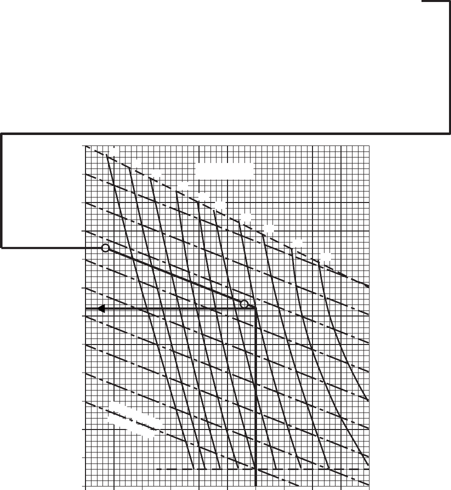
SA
AA0683_1B
OPTIMUM RANGE
CLEAN CONFIGURATION 100% RPM R
HIRSS (BAFFLES INSTALLED)
CRUISE ALTITUDE FOR OPTIMUM RANGE
AND CORRESPONDING CRUISE CHART FOR
FLIGHT CONDITIONS
REFERENCE CONDITIONS OF:
PRESSURE ALTITUDE = 1,500 FT
GROSS WEIGHT = 16,500 LB
TO REFERENCE / OPTIMUM PRESSURE ALTITUDE
(1,500 FT). MOVE PARALLEL WITH THE
TEMPERATURE TREND LINES TO AIRCRAFT
GROSS WEIGHT (16,500 LB). MOVE LEFT OR
RIGHT PARALLELING THE TEMPERATURE TREND
LINE TO NEAREST EVEN THOUSAND
REFERENCE / OPTIMUM PRESSURE ALTITUDE
LINE (12,000). MOVE LEFT TO FREE AIR
TO NEAREST TEN VALUE ON THE FREE AIR
SELECT CRUISE CHART WITH ALTITUDE AND
TEMPERATURE DATA AT THE NEAREST
REFERENCE / OPTIMUM PRESSURE ALTITUDE
(12,000 FT) AND THE NEAREST TEN DEGREE
WANTED:
KNOWN:
METHOD:
EXAMPLE
DATA BASIS: FLIGHT TEST
0 2 4 6 8 10 12 14 16 18 20
−60
−50
−40
−30
−20
−10
0
10
20
30
40
50
60
OPTIMUM PRESSURE ALTITUDE ~ 1000 FT
FREE AIR TEMPERATURE ~ oC
22
21
20
19
18 17
16
15
14
13
GROSS WEIGHT
~ 1000 LBS
TEMPERATURE
TREND LINES
FAT = 24 OC
ENTER CHART AT FAT (24 OC), MOVE RIGHT
TEMPERATURE LINE (2.5 OC), MOVE UP OR DOWN
TEMPERATURE SCALE (0 OC).
FREE AIR TEMPERATURE (0 OC).
Figure 7-29. Optimum Altitude For Maximum Range (Sheet 1 of 2)
TM 1-1520-237-10
7-133

SA
AA0683_2B
OPTIMUM RANGE
0 2 4 6 8 10 12 14 16 18 20 22
−60
−50
−40
−30
−20
−10
0
10
20
30
40
50
60
OPTIMUM PRESSURE ALTITUDE ~ 1000 FT
FREE AIR TEMPERATURE ~ OC
DATA BASIS: FLIGHT TEST
24 23
22
21 20
19 18
17
16
15
14
GROSS WEIGHT
~ 1000 LB
TEMPERATURE
TREND LINES
HIGH DRAG CONFIGURATION 100% RPM R
HIRSS (BAFFLES INSTALLED)
Figure 7-29. Optimum Altitude For Maximum Range (Sheet 2 of 2)
TM 1-1520-237-10
7-134

Section VI DRAG
7.20 EXTERNAL LOAD DRAG CHART.
The general shapes of typical external loads are shown
on Figure 7-30 as a function of the load frontal area. The
frontal area is combined with the typical drag coefficient of
the general shapes to obtain a drag multiplying factor for
use with the 10 sq. ft. drag scale on each cruise chart. The
TRQ ˜% value obtained from the cruise chart is multi-
plied by the drag multiplying factor and added to indicated
torque to obtain total torque required at any airspeed.
7.21 AIRCRAFT CONFIGURATION DRAG
CHANGES FOR USE WITH CLEAN CRUISE
CHARTS.
When external equipment or configuration differs from
the baseline clean configuration as defined in Section I, a
drag correction should be made similarly to the external
drag load method. Typical configuration changes that have
drag areas established from flight test or analysis along with
their drag multiplying factor are shown on Table 7-1.
Table 7-1. Configuration Drag Change
DRAG CHANGES FOR USE WITH CLEAN CRUISE CHARTS
Item Change in Flat Plate Drag
Area- F Sq. Ft. Drag Multiplying Factor
a. Both cargo doors open 6.0 0.60
b. Cargo doors removed 4.0 0.40
c. Cargo mirror installed 0.3 0.03
d. IR Countermeasure Transmitter (ALQ-144) installed 0.8 0.08
e. Chaff Dispenser Installed 0.3 0.03
f. HIRSS not installed -2.2 -0.22
g. Flare Dispenser EH 0.3 0.03
h. EH-60A Mission Antennas Only EH 3.8 0.38
i. Blade Erosion Kit 2.0 0.20
j. Skis installed 3.0 0.30
7.22 AIRCRAFT CONFIGURATION DRAG
CHANGES FOR USE WITH HIGH DRAG CRUISE
CHARTS.
When external equipment differs from the baseline high
drag configuration as defined in this Section, a drag correc-
tion should be made using Figure 7-31 similar to the exter-
nal drag load method. Typical high drag configuration
changes that have been established from flight test or analy-
sis along with the drag multiplying factors are shown.
TM 1-1520-237-10
7-135

SA
AA0684A
EXTERNAL DRAG LOAD
DRAG MULTIPLYING FACTOR
DUE TO EXTERNAL LOAD
SHAPE OF EXTERNAL
LOAD = CYLINDER
FRONTAL AREA OF
EXTERNAL LOAD = 80 SQ FT
ENTER CHART AT SYMBOL
FOR CYLINDER
MOVE RIGHT TO 80 SQ FT.
MOVE DOWN AND READ
DRAG MULTIPLYING FACTOR
= 4.5
LOAD
DRAG
WANTED:
KNOWN:
METHOD:
EXAMPLE
DATA BASIS: ESTIMATED
SPHERE
STREAMLINED
CYLINDER
CYLINDER
CUBE
FLAT
PLATE
BOX
BOX
IN
NET
0 20 40 60 80 100 120 140 160 180 200 220 240
0246810
12 14 16 18 20 22 24
INCREASE IN DRAG AREA DUE TO EXTERNAL LOAD
DRAG MULTIPLYING FACTOR
302010 40 50 60 70 80 90 100
FRONTAL AREA
OF EXTERNAL
LOAD ~ SQ FT
Figure 7-30. External Load Drag
TM 1-1520-237-10
7-136
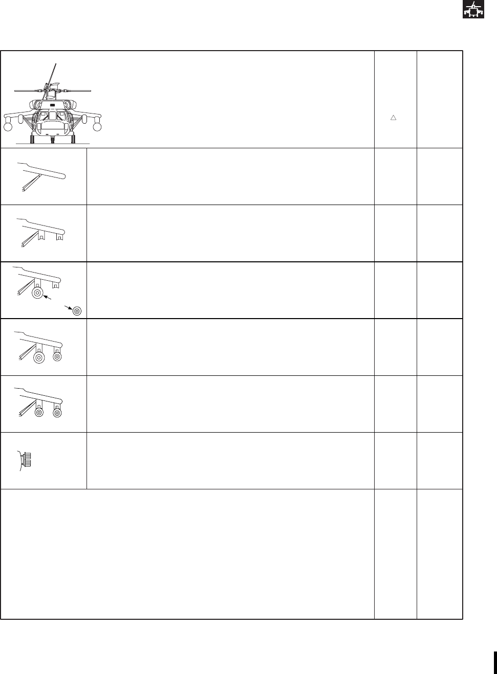
SA
AA0685B
DRAG CONFIGURATIONS
CRUISE CHART BASELINE
SPECIAL MISSION EQUIPMENT CONFIGURATIONS
HIGH DRAG CHANGE
IN
FLAT
PLATE
DRAG
F
SQ FT
DRAG
MULTI−
PLYING
FACTOR
ESSS − CLEAN, PYLONS REMOVED
ESSS − FOUR PYLONS / NO STORES
ESSS−TWO 450−GALLON TANKS INBOARD
ESSS−TWO 230−GALLON TANKS OUTBOARD
−TWO 450−GALLON −TANKS INBOARD
−4.0
−1.7
0.5
2.5
−0.40
−0.17
0.05
0.25
−TWO 230−GALLON TANKS INBOARD 0.0 0.00
ESSS − FOUR 230−GALLON TANKS 2.0 0.20
VOLCANO SYSTEM INSTALLED (BOTH RACKS) 32.5 3.25
SKIS INSTALLED 3.0 0.30
BOTH CARGO DOORS OPEN 6.0 0.60
BOTH CARGO DOORS REMOVED 4.0 0.40
CARGO MIRROR INSTALLED 0.3 0.03
IR COUNTERMEASURE TRANSMITTER (ALQ−144) REMOVED −0.8 −0.08
CHAFF DISPENSER REMOVED −0.3 −0.03
OR
* VOLCANO CORRECTION MUST BE USED WITH HIGH DRAG CHARTS ONLY
VOLCANO SYSTEM INSTALLED (LOWER RACKS ONLY) 10.5 1.05
Figure 7-31. Typical High Drag Configurations
TM 1-1520-237-10
Change 8 7-137
Section VII CLIMB - DESCENT
7.23 CLIMB/DESCENT CHART.
The CLIMB/DESCENT chart (Figures 7-32 and 7-33)
presents the rate of climb or descent resulting from an in-
crease or decrease of engine torque from the value required
for level flight above 40 KIAS. The data are presented at
100% RPM R for various gross weights. The charts may
also be used in reverse to obtain the torque increase or
reduction required to achieve a desired steady rate of climb
or descent. The maximum R/C may be determined by sub-
tracting the cruise chart torque required from the maximum
torque available at the desired flight conditions. Then enter
the difference on the torque increase scale of the climb
chart, move up to the gross weight, and read the resulting
maximum R/C.
TM 1-1520-237-10
7-138
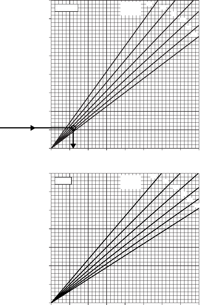
SA
AA0687A
CLIMB/DESCENT
CLEAN CONFIGURATION 100% RPM R
FOR IAS ABOVE 40 KIAS
DATA BASIS: FLIGHT TEST
0 10 20 30 40 50 60 70 80
0 10 20 30 40 50 60 70 80
TORQUE REDUCTION PER ENGINE ~ % TRQ
TORQUE INCREASE PER ENGINE ~ % TRQ
0
1000
1500
2000
2500
3000
3500
4000
0
500
1000
1500
2000
2500
3000
3500
RATE OF CLIMB ~ FT/MIN RATE OF DESCENT ~ FT/MIN
12 14
16
18
20
22
GROSS
WEIGHT
~ 1000 LB
GROSS
WEIGHT
~ 1000 LB
12 14
16
18
20
22
DESCENT
CLIMB
INDICATED TORQUE CHANGE FOR
DESIRED RATE−OF−CLIMB OR DESCENT.
GROSS WEIGHT = 18,000 POUNDS
DESIRED RATE = 550 FEET PER MINUTE
ENTER CHART AT 550 FEET PER MINUTE
MOVE RIGHT TO INTERSECT GROSS
WEIGHT LINE. MOVE DOWN TO READ
12% TRQ CHANGE.
WANTED:
KNOWN:
METHOD:
EXAMPLE
500
Figure 7-32. Climb/Descent
TM 1-1520-237-10
7-139
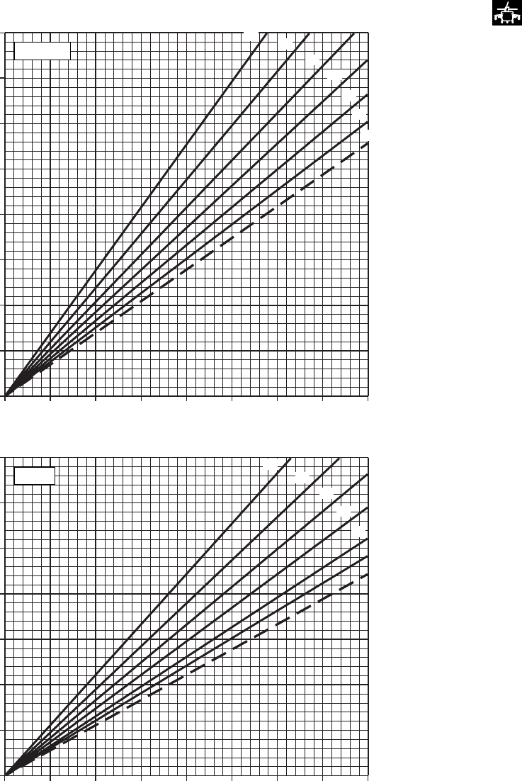
SA
AA0688A
CLIMB/DESCENT
100% RPM R
AIRSPEEDS ABOVE 40 KIAS
DATA BASIS: FLIGHT TEST
0 10 20 30 40 50 60 70 80
0 10 20 30 40 50 60 70 80
TORQUE REDUCTION PER ENGINE ~ % TRQ
TORQUE INCREASE PER ENGINE ~ % TRQ
0
500
1000
1500
2000
2500
3000
3500
4000
0
500
1000
1500
2000
2500
3000
3500
RATE OF CLIMB ~ FT/MIN RATE OF DESCENT ~ FT/MIN
12 14
16
18
20
22
24
GROSS
WEIGHT
~ 1000 LB
GROSS
WEIGHT
~ 1000 LB
12
14
16
18
20
22
24
DESCENT
CLIMB
Figure 7-33. Climb/Descent - High Drag
TM 1-1520-237-10
7-140

Section VIII FUEL FLOW
7.24 IDLE FUEL FLOW.
Dual-engine idle fuel flow is presented as a function of
altitude at 0°C FAT in Table 7-2. The data are based on
operation at 62% to 69% Ng for idle and 85% to 89% for
flat pitch (collective full down) at 100% RPM R. Fuel flow
for the auxiliary power unit (APU) is also presented for a
nominal load of 80% maximum power as a function of
altitude and 0°C FAT for general planning.
7.25 SINGLE-ENGINE FUEL FLOW.
a. Engine fuel flow is presented in Figure 7-34 for vari-
ous torque and pressure altitudes at a baseline FAT of 0°C
with engine bleed air extraction off. When operating at
other than 0°C FAT, engine fuel flow is increased 1% for
each 20°C above the baseline temperature and, decreased
1% for each 20°C below the baseline temperature.
b. To determine single-engine fuel flow during cruise,
enter the fuel flow chart at double the torque required for
dual-engine cruise as determined from the cruise charts and
obtain fuel flow from the single-engine scale. The single-
engine torque may not exceed the transmission limit shown
on the chart. With bleed air on, single-engine fuel flow
increases as follows:
(1) With bleed-air extracted, fuel flow increases:
(a) Engine anti-ice on - About 30 lbs/hr
(b) Heater on - About 10 lbs/hr
(c) Both on - About 40 lbs/hr
(2) When the IR suppressor system is installed and
operating in the benign mode (exhaust baffles removed),
the single-engine fuel flow will decrease about 8 lbs/hr.
7.26 DUAL-ENGINE FUEL FLOW.
Dual-engine fuel flow for level flight is presented on the
cruise charts in Section IV. For other conditions dual-
engine fuel flow may be obtained from Figure 7-34 when
each engine is indicating approximately the same torque by
averaging the indicated torques and reading fuel flow from
the dual-engine fuel flow scale. When operating at other
than the 0° FAT baseline, dual-engine fuel flow is increased
1% for each 20°C above baseline and is decreased 1% for
each 20°C below baseline temperature. With bleed air on,
dual-engine fuel flow increases as follows:
a. With bleed-air extracted, fuel flow increases:
(1) Engine anti-ice on -About 60 lbs/hr
Example: (760 lbs/hour = 820 lbs/hr).
(2) Heater on - About 20 lbs/hr
(3) Both on - About 80 lbs/hr
b. When the cruise or hover IR suppressor system is
installed and operating in the benign mode (exhaust baffles
removed), the dual-engine fuel flow will decrease about 16
lbs/hr.
Table 7–2. Dual Engine Idle and Auxiliary Power Unit Fuel Flow
Pressure Altitude Feet Ng = 62-69%
Ground Idle (No Load)
Lb/Hr
Ng = 85-89%
Flat Pitch (100% RPM R)
Lb/Hr
APU (Nominal) Lb/Hr
0 350 580 120
4,000 326 500 105
8,000 268 440 90
12,000 234 380 75
16,000 206 320 65
20,000 182 270 55
TM 1-1520-237-10
7-141
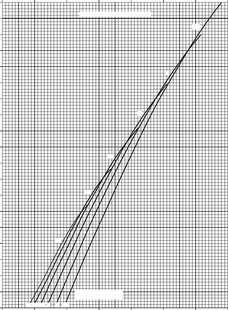
SA
AA0689
SINGLE/DUAL−ENGINE FUEL FLOW
100% RPM R FAT = 0oC BLEED AIR OFF
HIRSS (BAFFLES INSTALLED)
800700600500400300200100
20
25
30
35
40
45
50
55
60
65
70
75
80
85
90
95
100
105
110
115
200 400 600 800 1000 1200 1400 1600
SINGLE−ENGINE FUEL FLOW ~ LB/HR
INDICATED TORQUE PER ENGINE ~ %
DUAL−ENGINE FUEL FLOW ~ LB/HR
TRANSMISSION LIMIT − 1 ENGINE
20 16 12 8 4 SL
PRESSURE ALTITUDE
~ 1000 FT
20
16
12
8
4
SL
NOTE
INCREASE FUEL FLOW
1% FOR EACH 20 oC
ABOVE 0 oC FAT AND
DECREASE FUEL FLOW
1% FOR EACH 20 oC
BELOW 0 oC FAT.
Figure 7-34. Single/Dual-Engine Fuel Flow
TM 1-1520-237-10
7-142
Section IX AIRSPEED SYSTEM CHARACTERISTICS
7.27 AIRSPEED SYSTEM CHARACTERISTICS
NOTE
Indicated airspeeds below 40 KIAS are un-
reliable. Airspeed conversion data KIAS to
KTAS for speeds above 40 KIAS are pro-
vided in Section IV CRUISE.
There are two different pitot-static systems on the UH-
60A. The type of airspeed system may be determined from
the mounting of the pitot-static probes on the cabin roof.
The pitot-static probes were originally flush mounted, the
modified pitot-static probes are mounted on a wedge which
rotates the pitot tube 20° further outboard and 3° nose
down. The wedge is covered by an aerodynamic fairing to
prevent ice accretion. The modified airspeed system was
used to derive the IAS presented on the charts in this
manual.
7.28 AIRSPEED CHARTS.
7.28.1 Airspeed Correction Charts. All indicated air-
speeds shown on the cruise charts are based on level flight
of an aircraft with wedge mounted pitot static probes. Fig-
ures 7-35 through 7-37 provide the airspeed correction to
be added to the cruise chart IAS values to determine the
related airspeed indicator reading for other than level flight
mode. There are small variations in airspeed system errors
in level flight between those aircraft with wedge mounted
pitot static probes and those without wedge mounted pitot
static probes. Correction for these small variations is not
normally warranted. There are relatively large variations in
airspeed system error associated with climbs and descents.
These errors are significant and Figures 7-35 through 7-37
are provided primarily to show the general magnitude and
direction of the errors associated with the various flight
modes. If desired, these figures may be used in the manner
shown by the examples to calculate specific airspeed cor-
rections.
7.28.2 Airspeed System Dynamic Characteristics.
The dynamic characteristics of the pilot and copilot air-
speed indicating systems are normally satisfactory. How-
ever, the following anomalies in the airspeed and IVSI in-
dicating system may be observed during the following
maneuvers or conditions:
a. During takeoffs, in the speed range of 40 to 80 KIAS,
5 to 10 KIAS airspeed fluctuation may be observed on the
pilot’s and copilot’s airspeed indicators.
b. Power changes in high power, low airspeed climbs
may cause as much as 30 knot airspeed changes in indi-
cated airspeed. Increase in power causes increase in indi-
cated airspeed, and a decrease in power causes decrease in
indicated airspeed.
c. The pilot and copilot airspeed indicators may be un-
reliable during high power climbs at low airspeeds (less
than 50 KIAS) with the copilot system reading as much as
30 knots lower than the pilot system.
d. On aircraft with wedge mounted pitot static probes
kit, in-flight opening and closing of doors and windows
may cause momentary fluctuations of approximately 300
feet per minute on the vertical speed indicators.
TM 1-1520-237-10
7-143
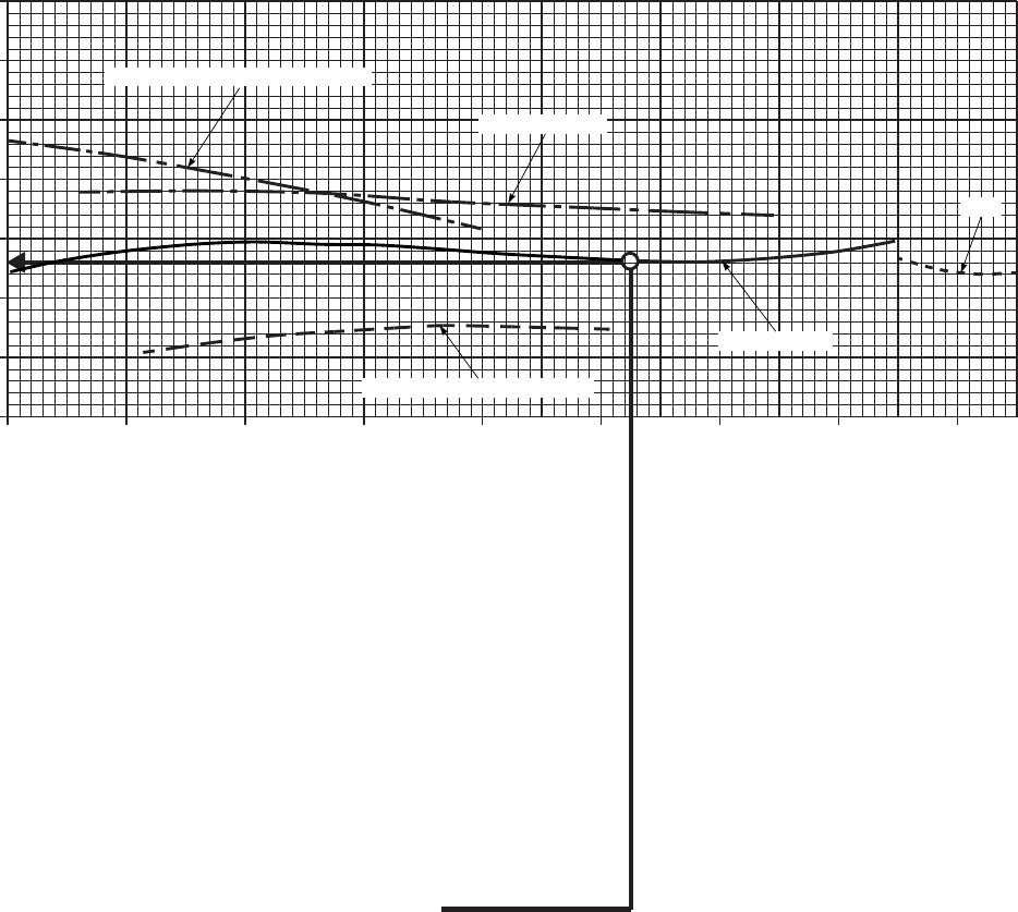
SA
AA0690C
AIRSPEED SYSTEM CORRECTION
CLEAN
AIRCRAFT WITHOUT
WEDGE MOUNTED
INDICATED AIRSPEED TO OBTAIN MAX
RANGE FOR AN AIRCRAFT WITHOUT WEDGE
MOUNTED PITOT−STATIC PROBES.
125 KIAS FOR MAX RANGE CRUISE
CHART AT A GIVEN PRESSURE ALTITUDE,
FAT, AND GROSS WEIGHT.
ENTER AT KNOWN IAS FROM CRUISE
CHART FOR MAX RANGE, MOVE UP TO LEVEL FLIGHT
LINE, MOVE LEFT, READ CORRECTION TO ADD TO
IAS = −2 KIAS. CALCULATE IAS FOR MAX RANGE:
= 125 KIAS − 2 KIAS = 123 KIAS.
DATA BASIS:
WANTED:
KNOWN:
METHOD:
FLIGHT TEST
EXAMPLE
20 40 60 80 100 120 140 160 180
−15
−10
−5
0
5
10
15
20
CORRECTION TO ADD ~ KNOTS
IAS FROM CRUISE ~ KNOTS
R / C GREATER THAN 1400 FT / MIN
AUTOROTATION
DIVE
LEVEL FLIGHT
R / C LESS THAN 1400 FT / MIN
PITOT−STATIC PROBES
Figure 7-35. Airspeed Correction Aircraft Without Wedge Mounted Pitot-Static Probes
TM 1-1520-237-10
7-144
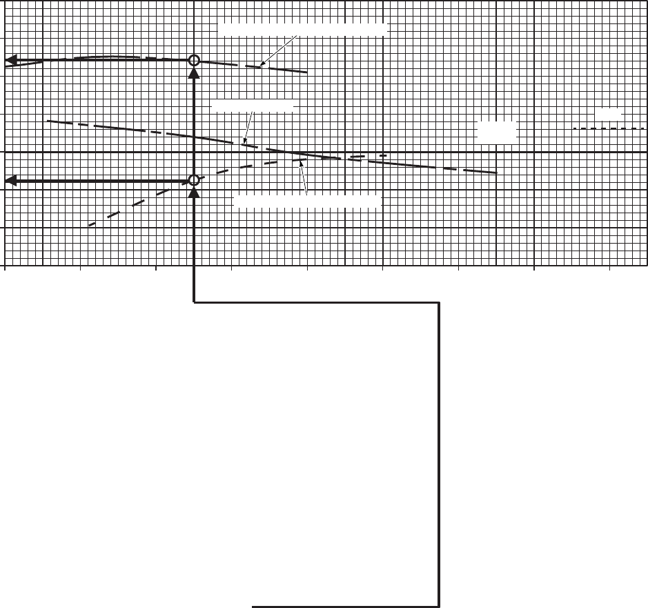
SA
AA0691B
AIRSPEED SYSTEM CORRECTION
DATA BASIS:
WANTED:
KNOWN:
METHOD:
FLIGHT TEST
EXAMPLE
INDICATED AIRSPEED TO CLIMB AT
MAXIMUM RATE OF CLIMB FOR AN
AIRCRAFT WITH WEDGE MOUNTED
70 KIAS MAX END / AND R / C FROM
APPROPRIATE CRUISE CHART FOR
A GIVEN PRESSURE ALTITUDE, FAT,
AND GROSS WEIGHT.
ENTER AT KNOWN IAS FROM
CRUISE CHART, MOVE UP TO R / C GREATER
THAN 1400 FPM, MOVE LEFT READ CORRECTION
TO ADD TO IAS = + 12.5 KTS, RE−ENTER
AT KNOWN IAS FROM CRUISE CHART, MOVE UP
TO R / C LESS THAN 1400 FPM LINE, MOVE LEFT,
READ CORRECTION TO ADD TO IAS = − 4 KTS
CALCULATE IAS FOR MAX R / C WHEN:
−15
−10
−5
0
5
10
15
20
CORRECTION TO ADD ~ KNOTS
20 40 60 80 100 120 140 160 180
IAS FROM CRUISE CHARTS ~ KNOTS
FOR R / C GREATER THAN 1400 FPM, AIRSPEED = 70 KIAS + 12.5 KIAS = 82.5 KIAS
FOR R / C LESS THAN 1400 FPM, AIRSPEED = 70 KIAS − 4 KIAS = 66 KIAS
R / C GREATER THAN 1400 FT / MIN
AUTOROTATION
R / C LESS THAN 1400 FT / MIN
LEVEL
FLIGHT
DIVE
CLEAN
WITH WEDGE MOUNTED PITOT−STATIC PROBES
PITOT−STATIC PROBES.
Figure 7-36. Airspeed Correction Aircraft With Wedge Mounted Pitot-Static Probes
TM 1-1520-237-10
7-145
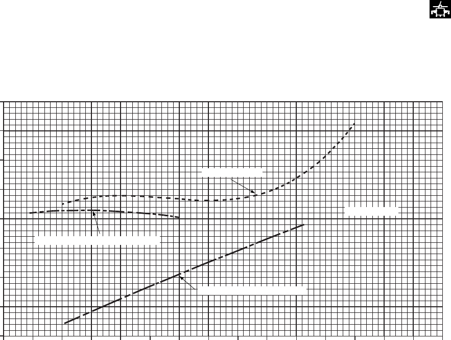
SA
AA1029A
AIRSPEED SYSTEM CORRECTION
20 40 60 80 100 120 140 160
IAS FROM HIGH DRAG CRUISE CHARTS ~ KNOTS
−20
−15
−10
−5
0
5
10
15
20
CORRECTION TO BE ADDED ~ KNOTS
AUTOROTATION
LEVEL FLIGHT
R / C GREATER THAN 1400 FT / MIN
R / C LESS THAN 1400 FT / MIN
FLIGHT TEST
DATA BASIS:
Figure 7-37. Airspeed Correction Chart - High Drag
TM 1-1520-237-10
7-146
Section X SPECIAL MISSION PERFORMANCE
7.29 SPECIAL MISSION FLIGHT PROFILES.
Figures 7-38 through 7-40 show special mission flight
profiles required to obtain near maximum range when
equipped with the ESSS in three different tank configura-
tions. The upper segment of each chart provides the recom-
mended altitude profile along with the IAS and average
TRQ versus distance traveled. An average value of elapsed
time is also presented on the lower axis of the altitude
scale. The lower segment of each chart provides the rela-
tionship between fuel remaining and distance traveled re-
sulting from the flight profile shown. This portion may be
utilized to check actual inflight range data to provide assur-
ance that adequate range is being achieved. The chart is
divided into 3 regions of Adequate Range, Inadequate
range-return to base, and Inadequate range-requiring emer-
gency action. When an inflight range point is in the Ad-
equate range region, the required mission range can be ob-
tained by staying on the recommended flight profile.
However, the range may not be achieved if stronger head-
winds are encountered as the flight progresses, and normal
pilot judgement must be used. These charts also assume
that the flight track is within proper navigational limits.
Standard temperature variation with PA is shown on the
upper segment of the charts. A general correction for tem-
perature variation is to decrease IAS by 2.5 KTS and total
distance traveled by 0.5% for each 10°C above standard.
Detailed flight planning must always be made for the actual
aircraft configuration, fuel load, and flight conditions when
maximum range is required. This data is based on JP-4 fuel.
It can be used with JP-5 or JP-8, aviation gasoline, or any
other approved fuels ONLY IF THE TAKEOFF GROSS
WEIGHT AND THE FUEL LOAD WEIGHT MATCH
THE DATA AT THE TOP OF THE CHART. The Flight
Time and the Distance Traveled data SHOULD NOT be
used with any full tank configuration if the fuel density is
not approximately 6.5 lb/gal (JP-4 fuel).
a. SELF-DEPLOYMENT MISSION. The self-
deployment mission is shown in Figure 7-38 and the ESSS
is configured with two 230-gallon tanks outboard and two
450-gallon tanks inboard. In this configuration, the aircraft
holds in excess of 11,000 lb of JP4 fuel and has a take-off
gross weight of 24,500 pounds in order to achieve the de-
sired mission range of 1,150 Nm. This gross weight is al-
lowed for ferry missions only, requiring low load factors
and less than 30 degree angle banked turns. This mission
was calculated for a standard day with a constant 10 knot
headwind added to be conservative. Since there may not be
any emergency landing areas available, the mission should
not be attempted if headwinds in excess of 10 knots are
forecast. Take-off must be made with a minimum of fuel
used (60 pounds) for engine start and warm-up, and a climb
to 2,000 feet should be made with maximum power and
airspeed between 80 and 105 KIAS. The first segment
should be maintained at 2,000 feet and 105 KIAS for 2
hours. The average engine TRQ should be about 79% for
this segment, but will initially be a little more and gradually
decrease. Altitude is increased in 2,000 feet increments to
maintain the optimum altitude for maximum range to ac-
count for fuel burn. The first 2 segments are for 2 hours
each, followed by 1 hour segments until reaching 10,000
feet. At this altitude, the airspeed for best range should also
be reduced to 95 KIAS for the remainder of the flight.
Engine bleed air was assumed to be off for this mission
except for that required for fuel tank pressurization. Elec-
trical cabin heat may be used. Removal of the HIRSS
baffles (benign mode) will reduce fuel flow by about 16
lbs/hr. If oxygen is available, continuation of the staircase
climb sequence to 15,500 feet PA will result in about 23
additional Nm of range capability.
b. ASSAULT MISSION PROFILE - 4 tanks. The as-
sault mission profile is shown in Figure 7-39 with the ESSS
configured with four 230-gallon tanks. In this configura-
tion, the aircraft holds in excess of 8,300 pounds of JP4
fuel and assumes a take-off gross weight of 22,000 pounds
which provides a maximum mission range of 1140 Nm
with 400 lbs reserve. This mission was calculated for a
standard day with a zero headwind. Take-off must be made
with a minimum of fuel used (80 pounds) for engine start
and warm-up, and a Climb to 4,000 feet should be made
with maximum power and airspeed between 80 and 108
KIAS. The first segment should be maintained at 4,000 feet
and 108 KIAS for 1 hour. The average engine TRQ should
be about 79% for this segment, but will initially be a little
more and gradually decrease. Altitude is increased in 2,000
feet increments to maintain the optimum altitude for maxi-
mum range to account for fuel burn. The segments are for 1
hour each, until reaching 10,000 feet. At this altitude, the
airspeed for best range should be reduced to 95 KIAS for
the remainder of the flight.
TM 1-1520-237-10
7-147

c. ASSAULT MISSION PROFILE - 2 tanks. The as-
sault mission profile is shown in Figure 7-40 with the ESSS
configured with two 230-gallon tanks. In this configuration,
the aircraft holds in excess of 5,300 pounds of JP4 fuel and
assumes a take-off gross weight of 22,000 pounds which
provides a maximum mission range of 630 Nm. with 400 lb
reserve. This mission was calculated for a standard day
with a zero headwind. Take-off must be made with a mini-
mum of fuel used (80 lbs) for engine start and warm-up,
and a Climb to 4,000 feet should be made with max power
and airspeed between 80 and 108 KIAS. The first segment
should be maintained at 4,000 feet and 108 KIAS for 1
hour. The average engine TRQ should be about 77% for
this segment, but will initially be a little more and gradually
decrease as shown on each segment. Altitude is increased
in 2,000 feet increments to maintain the optimum altitude
for maximum range to account for fuel burn. At this alti-
tude, the airspeed for best range should also be reduced to
95 KIAS for the remainder of the flight.
EXAMPLE:
WANTED:
Assurance of adequate aircraft range for mission defined.
KNOWN:
Flight position: 300 nm from base
Flight Track Within Limits
Fuel Remaining = 7,800 pounds
Elapsed flight time = 2 HRS, 50 MINS (2.83 HRS)
Target: Normal Flight Conditions:
Airspeed = 105 KIAS
Press Alt = 4,000 feet
Approx Torque = 75%
METHOD:
(1) Enter chart at total distance flown and at fuel remaining, move to intersection and plot point. If point
falls on or above fuel remaining line (adequate range), remaining fuel is adequate to complete the
mission. If point falls below the fuel remaining line in the inadequate range, abort mission region,
immediately return to departure point while continuing to utilize altitide profile using total elapsed
flight time (see item 2). If point falls below the fuel remaining line in the inadequate range, region,
consult emergency procedures for corrective action.
(2) To determine target nominial flight conditions, enter upper chart at elapsed flight time and move up
to determine target airspeed, approximate torque, and pressure altitude.
Figure 7-38. Self Deployment Mission Profile (Sheet 1 of 2)
TM 1-1520-237-10
7-148 Change 2
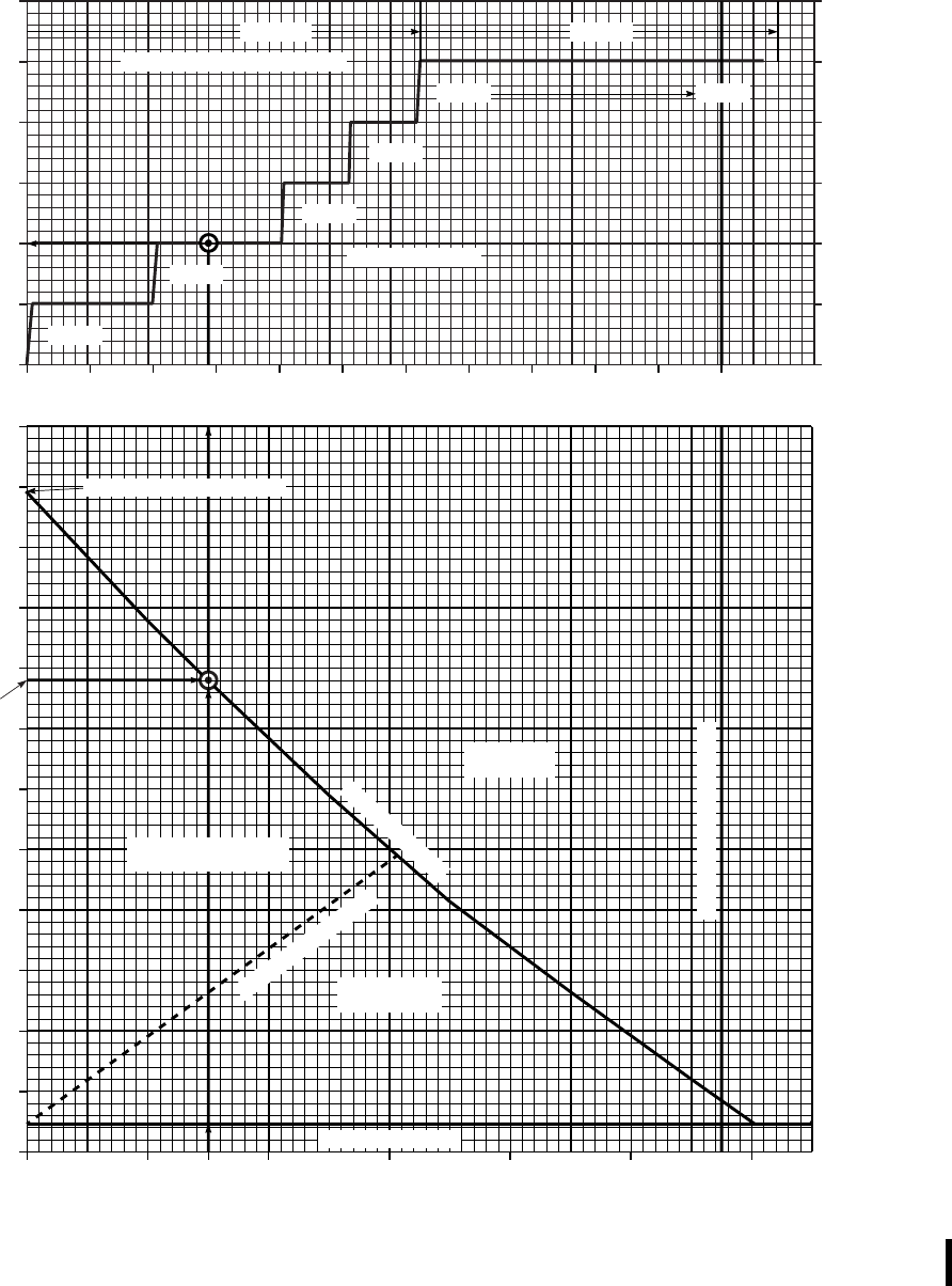
SA
AA0608_2B
SELF DEPLOYMENT MISSION PROFILE
ESSS/2−230 AND 2−450 GALLON TANK CONFIGURATION
STANDARD DAY 10 KT HEADWIND
HIRSS SUPPRESSED MODE
PRESSURE ALT ~ 1000 FT
STANDARD FAT ~ oC
NOMINAL FLIGHT TIME ~ HRS
FUEL REMAINING ~ LBS
GROSS WEIGHT = 24,500 LB
BLEED AIR OFF FUEL LOAD = 11,000 LB (JP4)
60 LB WARM UP
(7800 LBS)
DISTANCE TRAVELED ~ NM
FLIGHT TEST
DATA BASIS:
0
2
4
6
8
10
12
15
11
7
3
−1
−5
−9
(~80%)
(~72%)
(~73%)
(~62%)
95 KIAS105 KIAS
(APPROX TRQ~%)
0 200 400 600 800 1000 1200
0
1000
2000
3000
4000
5000
6000
7000
8000
9000
10000
11000
12000
LOW FUEL LIGHTS
INADEQUATE
RANGE
ADEQUATE
RANGE
DESIRED MISSION RANGE
FUEL REMAINING
INADEQUATE RANGE
ABORT MISSION
(~75%)
(~52%)
(APPROX FULL FUEL − JP4)
01 2 3 4 5 6 7 8 9 10 11
MISSION MAX RADIUS
(RECOMMENDED AIRSPEEDS)
Figure 7-38. Self Deployment Mission Profile (Sheet 2 of 2)
TM 1-1520-237-10
Change 2 7-149
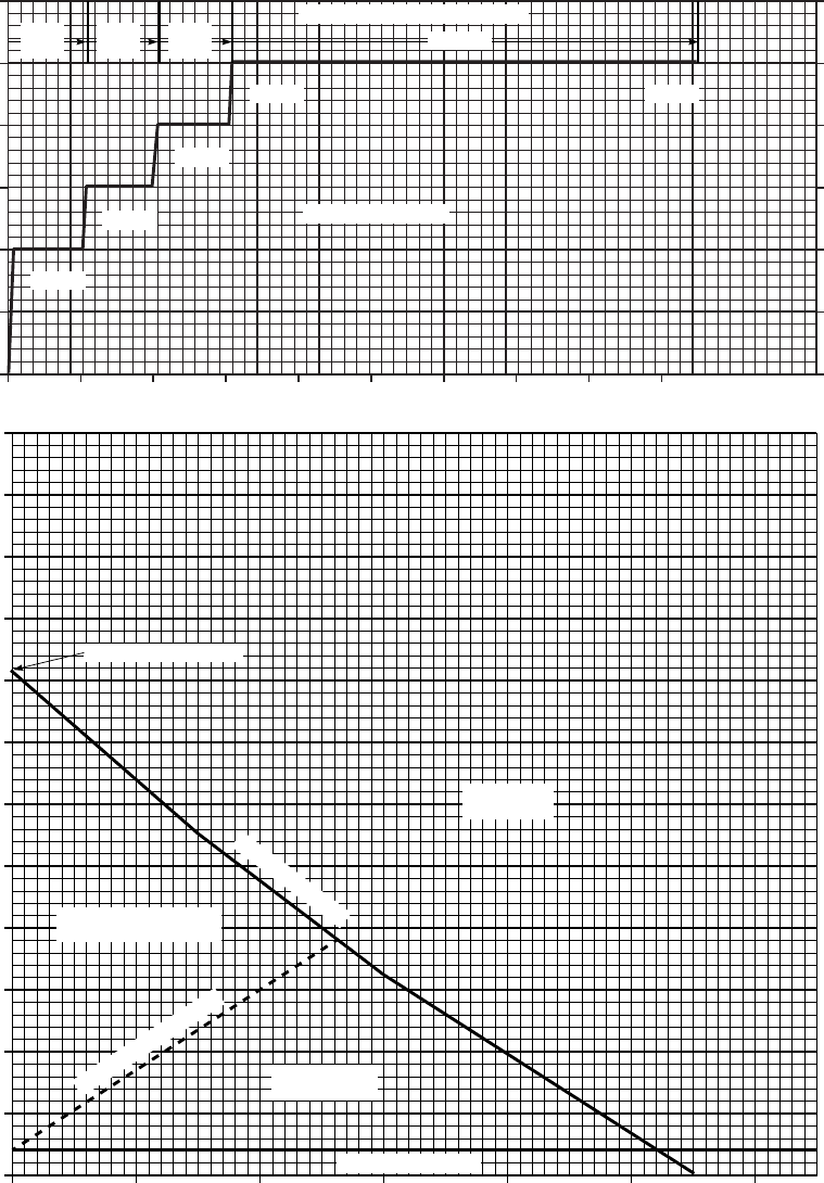
SA
AA0610A
ASSAULT MISSION PROFILE FOR MAX RANGE
ESSS/4−230 GALLON TANK CONFIGURATION
STANDARD DAY ZERO HEADWIND
HIRSS SUPPRESSED MODE
PRESSURE ALT ~ 1000 FT
FUEL REMAINING ~ LBS
STANDARD TEMP ~ oC
APPROX FLIGHT TIME ~ HRS
DISTANCE TRAVELED ~ NM
GROSS WEIGHT = 22,000 LB
BLEED AIR OFF FUEL LOAD = 8,300 LB (JP4)
80 LB WARM UP
DATA BASIS: FLIGHT TEST
0
2
4
6
8
10
12
15
11
7
3
−1
−5
−9
9876543210
(APPROX TRQ ~ %)
(~78%)
(~71%)
(~70%)
(~65%) (~51%)
(RECOMMENDED AIRSPEEDS)
108
KIAS 102
KIAS 100
KIAS 95 KIAS
0 200 400 600 800 1000 1200
0
1000
2000
3000
4000
5000
6000
7000
8000
9000
10000
11000
12000
LOW FUEL LIGHTS
INADEQUATE
RANGE
INADEQUATE RANGE
ABORT MISSION
ADEQUATE
RANGE
APPROX FULL FUEL
FUEL REMAINING
MAX MISSION RADIUS
Figure 7-39. Assault Mission Profile (4 - 230 Gallon Tanks)
TM 1-1520-237-10
7-150
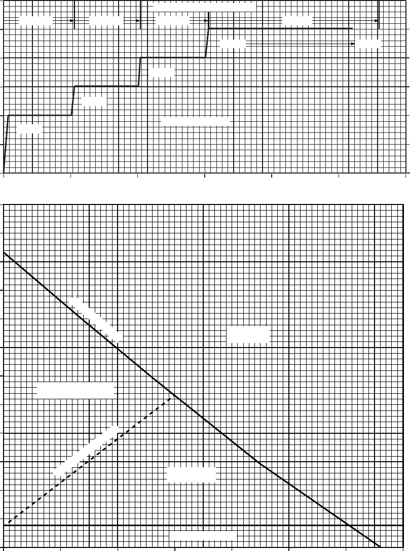
SA
AA0609A
ASSAULT MISSION PROFILE FOR MAX RANGE
ESSS/2−230 GALLON TANK CONFIGURATION
STANDARD DAY ZERO HEADWIND
HIRSS SUPPRESSED MODE
PRESS ALT
APPROX FLIGHT TIME ~ HRS
FUEL REMAINING ~ LBS
−5
−1
3
7
11
15
STANDARD TEMP ~ oC
DISTANCE ~ NM
GROSS WEIGHT = 22,000 LB
BLEED AIR OFF FUEL LOAD = 5,300 LB (JP4)
80 LB WARM UP
FLIGHT TEST
DATA BASIS:
0
2
4
6
8
10
12
6543210
(~76%)
(~70%)
(~69%)
(~65%) (~58%)
(APPROX TRQ ~ %)
(RECOMMENDED AIRSPEED)
108 KIAS 102 KIAS 100 KIAS 95 KIAS
0 100 200 300 400 500 600 700
0
500
1000
1500
2000
2500
3000
3500
4000
4500
5000
5500
6000
LOW FUEL LIGHTS
ADEQUATE
RANGE
INADEQUATE RANGE
ABORT MISSION
INADEQUATE
RANGE
MAX MISSION RADIUS
FUEL REMAINING
Figure 7-40. Assault Mission Profile (2 - 230 Gallon Tanks)
TM 1-1520-237-10
7-151/(7-152 Blank)

CHAPTER 7A
PERFORMANCE DATA 701C
Section I INTRODUCTION
7A.1 PURPOSE.
NOTE
Chapter 7A contains performance data for
aircraft equipped with T700-GE-701C en-
gines. Performance data for other models are
contained in Chapter 7. Users are authorized
to remove whichever chapter is not appli-
cable to their model aircraft, and are not re-
quired to carry both chapters on board.
a. The purpose of this chapter is to provide the best
available performance data for the UH-60L. Regular use of
this information will enable you to receive maximum safe
utilization of the helicopter. Although maximum perfor-
mance is not always required, regular use of this chapter is
recommended for these reasons:
(1) Knowledge of your performance margin will allow
you to make better decisions when unexpected conditions
or alternate missions are encountered.
(2) Situations requiring maximum performance will be
more readily recognized.
(3) Familiarity with the data will allow performance to
be computed more easily and quickly.
(4) Experience will be gained in accurately estimating
the effects of variables for which data are not presented.
b. The information is primarily intended for mission
planning and is most useful when planning operations in
unfamiliar areas or at extreme conditions. The data may
also be used in flight, to establish unit or area standard
operating procedures, and to inform ground commanders of
performance/risk tradeoffs.
7A.2 CHAPTER 7A INDEX.
The following index contains a list of the sections, titles,
figure numbers, subjects and page numbers of each perfor-
mance data chart contained in this chapter.
Section
and
Figure
Number Title Page
I INTRODUCTION ................... 7A-1
7A-1 Temperature Conversion
Chart......................................... 7A-5
II MAXIMUM TORQUE
AVAILABLE........................... 7A-6
7A-2 Aircraft Torque Factor
(ATF) ....................................... 7A-7
7A-3 Torque Conversion
Chart......................................... 7A-9
7A-4 Maximum Torque
Available.................................. 7A-10
7A-5 Dual Engine Torque
Limit......................................... 7A-12
III HOVER.................................... 7A-13
7A-6 Hover - Clean ......................... 7A-14
7A-7 Hover - High Drag .................. 7A-16
IV CRUISE ................................... 7A-17
7A-8 Sample Cruise Chart................ 7A-19
7A-9 Cruise - Pressure Altitude -
Sea Level ................................. 7A-20
7A-10 Cruise High Drag-Pressure
Altitude - Sea Level ................ 7A-26
7A-11 Cruise - Pressure Altitude -
2,000 Feet ................................ 7A-32
7A-12 Cruise High Drag-Pressure
Altitude - 2,000 Feet ............... 7A-38
7A-13 Cruise - Pressure Altitude -
4,000 Feet ................................ 7A-44
7A-14 Cruise High Drag-Pressure
Altitude - 4,000 Feet ............... 7A-50
TM 1-1520-237-10
7A-1

Section
and
Figure
Number Title Page
7A-15 Cruise - Pressure Altitude -
6,000 Feet ................................ 7A-56
7A-16 Cruise High Drag-Pressure
Altitude - 6,000 Feet ............... 7A-62
7A-17 Cruise - Pressure Altitude -
8,000 Feet ................................ 7A-68
7A-18 Cruise High Drag-Pressure
Altitude - 8,000 Feet ............... 7A-74
7A-19 Cruise - Pressure Altitude -
10,000 Feet .............................. 7A-80
7A-20 Cruise High Drag-Pressure
Altitude - 10,000 Feet ............. 7A-85
7A-21 Cruise - Pressure Altitude -
12,000 Feet .............................. 7A-90
7A-22 Cruise High Drag-Pressure
Altitude - 12,000 Feet ............. 7A-95
7A-23 Cruise - Pressure Altitude -
14,000 Feet .............................. 7A-100
7A-24 Cruise High Drag-Pressure
Altitude - 14,000 Feet ............ 7A-105
7A-25 Cruise - Pressure Altitude -
16,000 Feet .............................. 7A-110
7A-26 Cruise High Drag-Pressure
Altitude - 16,000 Feet ............. 7A-114
7A-27 Cruise - Pressure Altitude -
18,000 Feet .............................. 7A-118
7A-28 Cruise High Drag-Pressure
Altitude - 18,000 Feet ............. 7A-122
7A-29 Cruise - Pressure Altitude -
20,000 Feet .............................. 7A-126
7A-30 Cruise High Drag-Pressure
Altitude - 20,000 Feet ............. 7A-130
V OPTIMUM CRUISE ............... 7A-134
7A-31 Optimum Altitude For
Maximum Range ..................... 7A-135
7A-32 Optimum Altitude For
Maximum Range -
High Drag ................................ 7A-136
VI DRAG ...................................... 7A-137
Section
and
Figure
Number Title Page
7A-33 External Load Drag ................. 7A-138
7A-34 Typical High
Drag Configurations ................ 7A-139
VII CLIMB - DESCENT............... 7A-140
7A-35 Climb/Descent.......................... 7A-141
7A-36 Climb/Descent -
High Drag ................................ 7A-142
VIII FUEL FLOW........................... 7A-143
7A-37 Single/Dual Engine
Fuel Flow................................. 7A-144
IX AIRSPEED SYSTEM
CHARACTERISTICS............. 7A-145
7A-38 Airspeed Correction Chart ...... 7A-146
7A-39 Airspeed Correction
Chart - High Drag ................... 7A-147
X SPECIAL MISSION
PERFORMANCE.................... 7A-148
7A-40 Self Deployment Mission
Profile....................................... 7A-150
7A-41 Assault Mission Profile
(4 - 230 Gallon Tanks)............ 7A-152
7A-42 Assault Mission Profile
(2 - 230 Gallon Tanks)............ 7A-153
7A.3 GENERAL.
The data presented covers the maximum range of con-
ditions and performance that can reasonably be expected.
In each area of performance, the effects of altitude, tem-
perature, gross weight, and other parameters relating to that
phase of flight are presented. In addition to the presented
data, your judgment and experience will be necessary to
accurately obtain performance under a given set of circum-
stances. The conditions for the data are listed under the title
of each chart. The effects of different conditions are dis-
cussed in the text accompanying each phase of perfor-
mance. Where practical, data are presented at conservative
conditions. However, NO GENERAL CONSERVATISM
HAS BEEN APPLIED. All performance data presented are
within the applicable limits of the helicopter. All flight per
TM 1-1520-237-10
7A-2 Change 2

formance data are based on JP-4 fuel. The change in fuel
flow and torque available, when using JP-5 or JP-8 aviation
fuel or any other approved fuels is insignificant.
7A.4 LIMITS.
CAUTION
Exceeding operating limits can cause per-
manent damage to critical components.
Overlimit operation can decrease perfor-
mance, cause early failure, or failure on a
subsequent flight.
Applicable limits are shown on the charts. Performance
generally deteriorates rapidly beyond limits. If limits are
exceeded, minimize the amount and time. Enter the maxi-
mum value and time above limits on DA Form 2408-13-1
so proper maintenance action can be taken.
7A.5 USE OF CHARTS.
7A.5.1 Data Basis. The type of data used is indicated at
the bottom of each performance chart under DATA BASIS.
The data provided generally is based on one of three cat-
egories:
a. Flight test data. Data obtained by flight test of the
helicopter by experienced flight test personnel at precise
conditions using sensitive calibrated instruments.
b. Calculated data. Data based on tests, but not on flight
test of the complete helicopter.
c. Estimated data. Data based on estimates using aero-
dynamic theory or other means but not verified by flight
test.
7A.5.2 Specific Conditions. The data presented is ac-
curate only for specific conditions listed under the title of
each chart. Variables for which data is not presented, but
which may affect that phase of performance, are discussed
in the text. Where data is available or reasonable estimates
can be made, the amount that each variable affects perfor-
mance will be given.
7A.6 PERFORMANCE DISCREPANCIES.
Regular use of this chapter will allow you to monitor
instrument and other helicopter systems for malfunction, by
comparing actual performance with planned performance.
Knowledge will also be gained concerning the effects of
variables for which data is not provided, thereby increasing
the accuracy of performance predictions.
7A.7 PERFORMANCE DATA BASIS - CLEAN.
The data presented in the performance charts are prima-
rily derived for a clean UH-60L aircraft and are based on
U. S. Army test data. The clean configuration assumes all
doors and windows are closed and includes the following
external configuration:
a. Fixed provisions for the External Stores Support Sys-
tem (ESSS).
b. Main and tail rotor deice system.
c. Mounting brackets for IR jammer and chaff dispenser.
d. The Hover Infrared Suppressor System (HIRSS) with
baffles installed.
e. Includes wire strike protection system.
NOTE
Aircraft which have an external configura-
tion which differs from the clean configura-
tion may be corrected for drag differences
on cruise performance as discussed in Sec-
tion VI DRAG.
7A.8 PERFORMANCE DATA BASIS - HIGH DRAG.
The data presented in the high drag performance charts
are primarily derived for the UH-60L with the ESSS sys-
tem installed and two 230-gallon tanks mounted on the out-
board pylons, and are based on U. S. Army test data. The
high drag configuration assumes all doors and windows are
closed and includes the following external configuration:
a. External stores support system installed.
b. Two 230–gallon tanks mounted on the outboard py-
lons.
c. Inboard vertical pylons empty.
d. IR jammer and chaff dispenser installed.
e. Hover Infrared Suppressor System (HIRSS) with
baffles are installed.
f. Main and tail rotor deice and wire strike protection
systems are installed.
TM 1-1520-237-10
Change 10 7A-3

NOTE
Aircraft with an external configuration that
differs from the high drag configuration
baseline may be corrected for differences in
cruise performance as discussed in Section
VI DRAG.
g. VOL Use the high drag configuration hover charts
to determine hover performance with the volcano system
installed. Use the high drag cruise charts and the volcano
drag correction factor to determine cruise performance with
volcano installed. The volcano drag correction factor is
based on flight test data obtained with the complete volcano
system installed, to include all of the canisters and mines.
The drag correction factor may be used to provide a con-
servative estimate of cruise performance for volcano con-
figurations which do not include all of the canisters and
mines.
7A.9 FREE AIR TEMPERATURES.
A temperature conversion chart (Figure 7A-1) is in-
cluded for the purpose of converting Fahrenheit tempera-
ture to Celsius.
TM 1-1520-237-10
7A-4
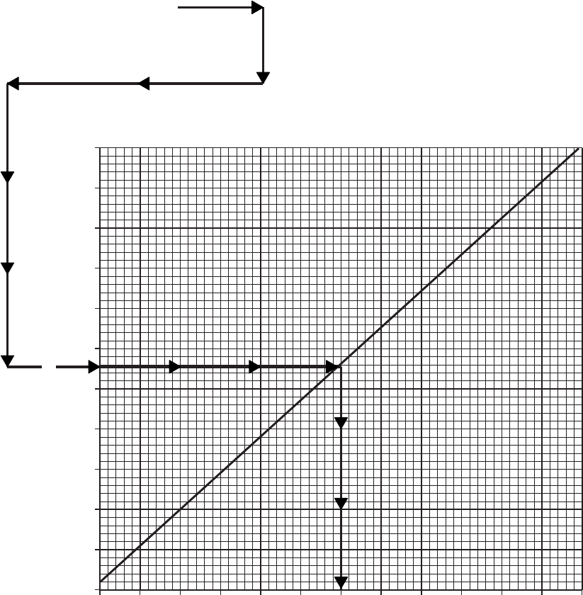
SA
AA0674
TEMPERATURE CONVERSION
FREE AIR TEMPERATURE IN DEGREES CELSIUS
FREE AIR TEMPERATURE = 32oF
ENTER FREE AIR TEMPERATURE HERE
MOVE RIGHT TO DIAGONAL LINE
MOVE DOWN TO DEGREES CELSIUS SCALE
READ FREE AIR TEMPERATURE = 0oC
WANTED:
KNOWN:
METHOD:
EXAMPLE
−60 −50 −40 −30 −20 −10 0 10 20 30 40 50 60
−80
−60
−40
−20
0
20
40
60
80
100
120
140
FAT ~
oC
FAT ~
oF
Figure 7A-1. Temperature Conversion Chart
TM 1-1520-237-10
7A-5

Section II MAXIMUM TORQUE AVAILABLE
7A.10 TORQUE FACTOR METHOD.
The torque factor method provides an accurate indica-
tion of available power by incorporating ambient tempera-
ture effects on degraded engine performance. This section
presents the procedure to determine the maximum dual- or
single-engine torque available. Specification power is de-
fined for a newly delivered low time engine. The aircraft
HIT log forms for each engine provide the engine and air-
craft torque factors which are obtained from the maximum
power check and recorded to be used in calculating maxi-
mum torque available.
7A.10.1 Torque Factor Terms. The following terms
are used when determining the maximum torque available
for an individual aircraft:
a. Torque Ratio (TR). The ratio of torque available to
specification torque at the desired ambient temperature.
b. Engine Torque Factor (ETF). The ratio of an indi-
vidual engine torque available to specification torque at ref-
erence temperature of 35°C (95°F). The ETF is allowed to
range from .85 to 1.0.
c. Aircraft Torque Factor (ATF). The ratio of an indi-
vidual aircraft’s power available to specification power at a
reference temperature of 35°C (95°F). The ATF is the av-
erage of the ETF’s of both engines and its value is allowed
to range from 0.9 to 1.0.
7A.10.2 Torque Factor Procedure. The use of the
ATF or ETF to obtain the TR from Figure 7A-2 for ambi-
ent temperatures between -15°C (5°F) and 35°C (95°F) is
shown by the example. The ATF and ETF values for an
individual aircraft are found on the engine HIT Log. The
TR always equals 1.0 for ambient temperatures of -15°C
(5°F) and below, and the TR equals the ATF or ETF for
temperatures of 35°C (95°F) and above.
7A.11 TORQUE AVAILABLE.
a. This section presents the maximum dual-engine
torque available for the 2.5-minute, 10-minute and 30-
minute limits at zero airspeed and 100% RPM R for the
operational range of pressure altitude and FAT. The single-
and dual-engine transmission limits for continuous opera-
tion are also shown and should not be exceeded.
CAUTION
Do not exceed the UH-60L DUAL EN-
GINE TORQUE LIMITS in Chapter 5.
These torque limits are presented in Fig-
ure 7A-5 and on the TORQUE PLAC-
ARD mounted on the instrument panel.
b. When the TR equals 1.0, the torque available may be
read directly from the torque available per engine scales.
When the TR is less than 1.0, the actual torque available is
determined by multiplying the specification torque avail-
able by the TR (example for TR = 0.98: 90% TRQ x 0.98
= 88.2% TRQ). The torque conversion chart (Figure 7A-3)
is provided to convert specification data to actual torque
available.
7A.11.1 Torque Available - 2.5 Minutes. Figure 7A-4
presents the specification torque available at 903°C TGT
per engine for the 2.5 minute limit. Contingency (2.5
Minute) Power is automatically available when any one
engine torque is less than 50% or when the pilot selects
DEC LOCKOUT and manually maintains the 2.5 minute
TGT limit.
7A.11.2 Torque Available - 10 Minutes. Figure 7A-4
presents the specification torque available per engine for
the 10 minute limit. This is the maximum dual-engine
torque available and is set by the TGT limiter in dual-
engine operation. For one engine operation, the pilot must
maintain the 10 minute TGT limit.
7A.11.3 Torque Available - 30 Minutes. Figure 7A-4
presents the specification torque available per engine for
the 30 minute limit. The pilot must manually maintain the
30 minute TGT limit.
7A.12 ENGINE BLEED AIR.
With engine bleed air on, the available torque per engine
is reduced as follows:
a. Engine anti-ice on - 18% TRQ
(example: 90% TRQ - 18% TRQ = 72% TRQ).
b. Cockpit heater on - 4% TRQ.
TM 1-1520-237-10
7A-6 Change 6
c. Both on - 22% TRQ. 7A.13 INFRARED SUPPRESSOR SYSTEM.
When the IR suppressor is OPERATING IN THE BE-
NIGN MODE (exhaust baffles removed) the torque avail-
able is increased about 1% TRQ.
TM 1-1520-237-10
Change 6 7A-6.1/(7A-6.2 Blank)
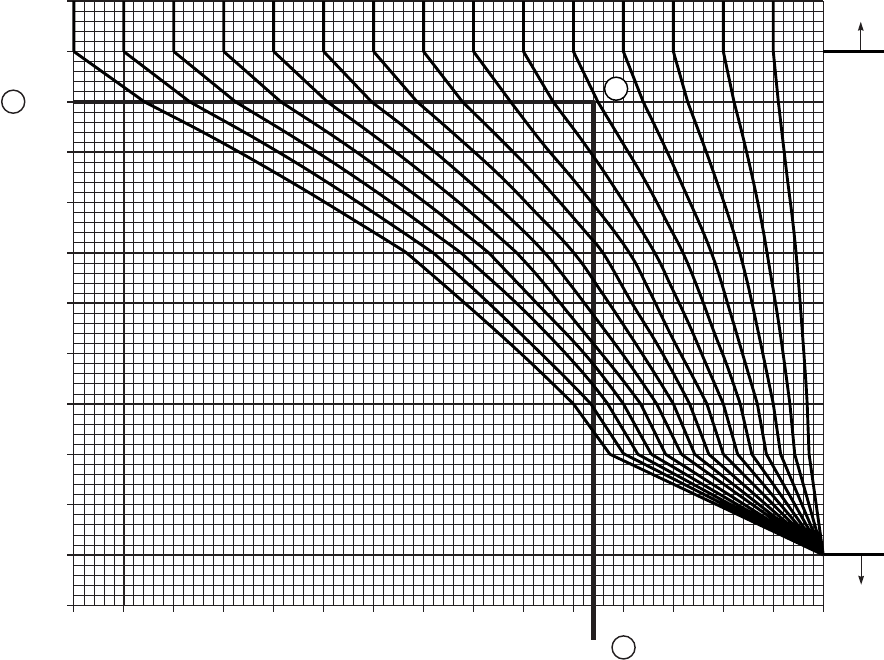
TORQUE FACTOR
T700−GE−701C ENGINE 100% RPM R
DATA BASIS: CALCULATED
NOTE
EITHER OF THE TWO TORQUE
AVAILABLE CHARTS MAY BE USED.
MAXIMUM ALLOWABLE DUAL ENGINE
TORQUE LIMITS SHALL NOT BE
EXCEEDED.
TORQUE RATIO AND MAXIMUM TORQUE AVAILABLE −
10−MINUTE LIMIT
ATF = .95
PRESSURE ALTITUDE = 6000 FT.
FAT = 30oC
TO DETERMINE SPECIFICATION TORQUE AVAILABLE −
10−MINUTE LIMITS:
4. ENTER MAXIMUM TORQUE AVAILABLE CHART AT
KNOWN FAT (FIGURE 7A−4).
5. MOVE RIGHT TO KNOWN PRESSURE ALTITUDE
6.
TO OBTAIN ACTUAL TORQUE VALUE AVAILABLE FROM THE
TORQUE CONVERSION CHART:
7. ENTER TORQUE CONVERSION CHART FIGURE 7A−3 AT %
TORQUE OBTAINED FROM FIGURE 7A−4.
8. MOVE UP TO TORQUE RATIO OBTAINED FROM FIGURE 7A−2
9. MOVE LEFT, READ MAXIMUM TORQUE AVAILABLE − 10
MINUTE LIMIT = 93%.
10. ENTER DUAL−ENGINE TORQUE LIMIT CHART FIGURE 7A−5
AT 30oC. MOVE RIGHT TO INTERSECTION AT 6,000 FT. PA.
MOVE DOWN TO READ 90.4% TORQUE.
TO OBTAIN TORQUE RATIO:
1. ENTER TORQUE FACTOR CHART AT KNOWN FAT
2. MOVE RIGHT TO THE ATF VALUE
3. MOVE DOWN, READ TORQUE RATIO = .954.
WANTED:
KNOWN:
METHOD:
EXAMPLE
FREE AIR TEMPERATURE ~ oC
1
1.0.99.98.97.96.95.94.93.92.91.90.89.88.87.85 .86
1.0
.99.98.97.96.95.94.93.92.91.90.89.88.87.85 .86
−20
−15
−10
−5
0
5
10
15
20
25
30
35
40
FOR FAT’S
OF 35oC AND
ABOVE:
TR = ATF
FOR FAT’S
OF 15oC AND
BELOW:
TR = 1.0
TORQUE RATIO ~ TR
TORQUE FACTOR ~ ATF OR ETF
.954 3
2
−
SA
AA0692C
MOVE DOWN, READ SPECIFICATION TORQUE = 98%.
Figure 7A-2. Aircraft Torque Factor (ATF)
TM 1-1520-237-10
7A-7

7A.14 DUAL-ENGINE TORQUE LIMITS.
Helicopters prior to S/N 91–26354 that are not equipped
with improved main rotor flight controls are further re-
stricted above 80 KIAS to dual-engine continuous torque
limits as indicated by a placard on the instrument panel.
Figure 7A-5 graphically presents the dual-engine torque
limits for use with the torque available charts.
TM 1-1520-237-10
7A-8 Change 6
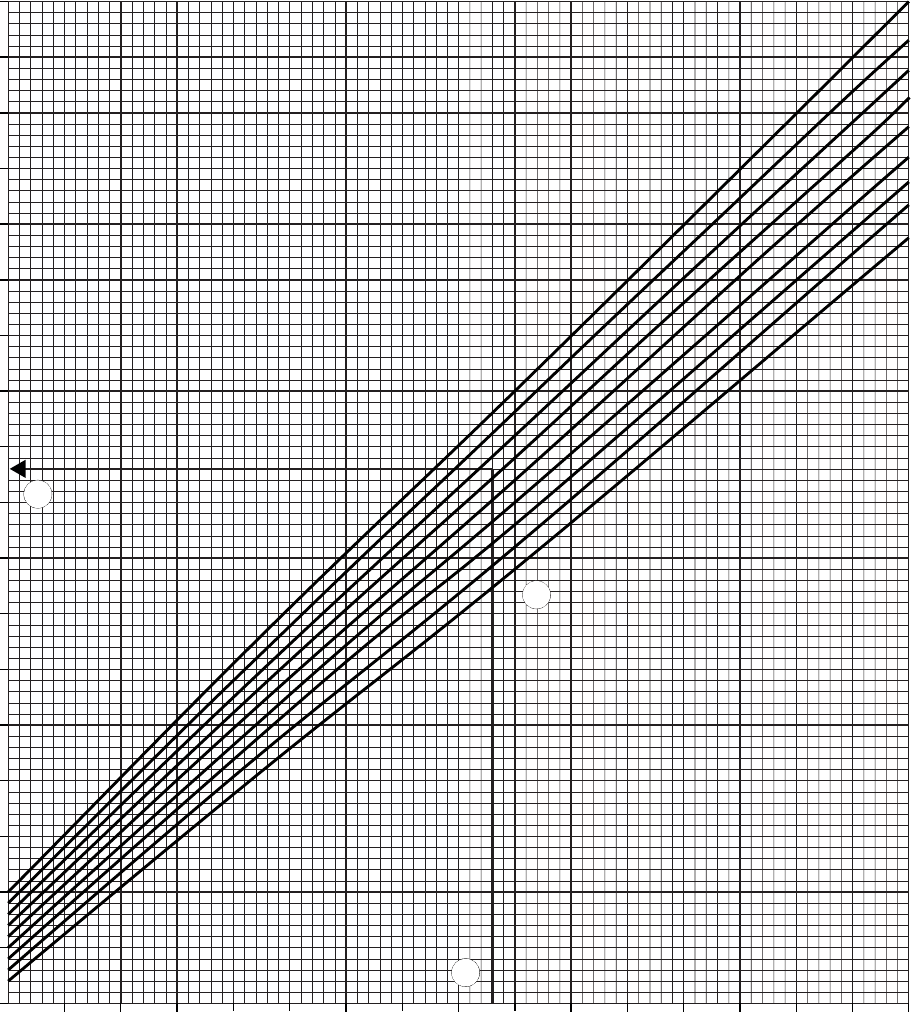
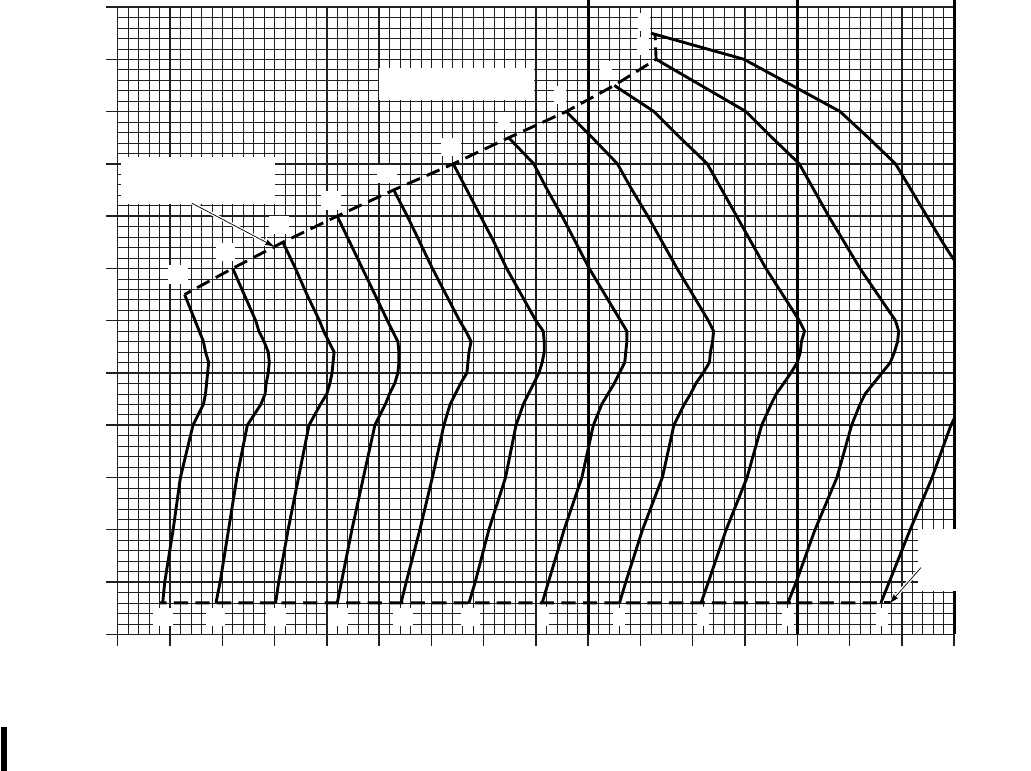
SAF
AA1000_4A
MAXIMUM TORQUE AVAILABLE − 2.5−MINUTE LIMIT
T700−GE−701C HIRSS (BAFFLES INSTALLED)
100% RPM R BLEED AIR OFF
ZERO AIRSPEED
DATA BASIS:
ENGINE MANUFACTURER
SPEC.
2−ENGINE TORQUE
LIMIT ABOVE 80 KIAS 2−ENGINE
TRANSMISSION
LIMIT
1−ENGINE
TRANSMISSION
LIMIT
FREE AIR TEMPERATURE (FAT) ~ OC
TORQUE AVAILABLE PER ENGINE ~ %
60 70 80 90 100 110 120 130
−60
−50
−40
−30
−20
−10
0
10
20
30
40
50
60
2
4
6
8
10
12
14
16
18
20
0
14
16
18
20 8
10
12 2
4
60
PRESSURE ALTITUDE
~ 1000 FT
ENGINE
HIGH AMBIENT
TEMPERATURE LIMIT
ENGINE
LOW AMBIENT
TEMPERATURE
LIMIT
Figure 7A-4. Maximum Torque Available (Sheet 1 of 3)
TM 1-1520-237-10
7A-10 Change 6
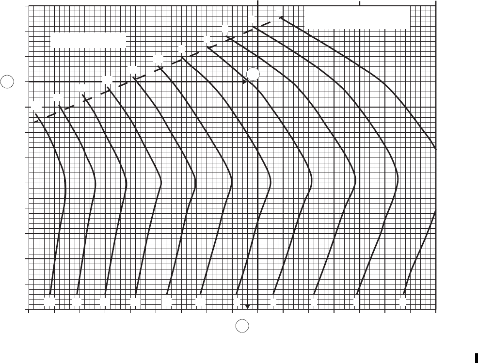
SA
AA1000_1A
MAXIMUM TORQUE AVAILABLE − 10−MINUTE LIMIT
T700−GE−701C HIRSS (BAFFLES INSTALLED)
100% RPM R BLEED AIR OFF
ZERO AIRSPEED
−60
−50
−40
−30
−20
−10
0
10
20
30
40
50
60
60 70 80 90 100 110 120 130
98
66
44
DATA BASIS:
ENGINE MANUFACTURER
SPEC.
2−ENGINE TORQUE
LIMIT ABOVE 80 KIAS 2−ENGINE
TRANSMISSION
LIMIT
1−ENGINE
TRANSMISSION
LIMIT
FREE AIR TEMPERATURE (FAT) ~ OC
TORQUE AVAILABLE PER ENGINE ~ %
PRESSURE ALTITUDE
~ 1000 FT
ENGINE
HIGH AMBIENT TEMPERATURE
LIMIT
20
20
18
18
16
16
14
14
12
12
10
10
8
8
6
6
4
4
2
2
0
0
5
Figure 7A-4. Maximum Torque Available (Sheet 2 of 3)
TM 1-1520-237-10
Change 6 7A-11
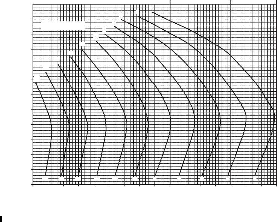
SA
AA1000_2A
MAXIMUM TORQUE AVAILABLE − 30−MINUTE LIMIT
T700−GE−701C HIRSS (BAFFLES INSTALLED)
100% RPM R BLEED AIR OFF
ZERO AIRSPEED
DATA BASIS:
ENGINE MANUFACTURER SPEC.
2−ENGINE TORQUE
LIMIT ABOVE 80 KIAS 2−ENGINE
TRANSMISSION
LIMIT
1−ENGINE
TRANSMISSION
LIMIT
−60
−50
−40
−30
−20
−10
0
10
20
30
40
50
60
60 70 80 90 100 110 120 130
FREE AIR TEMPERATURE (FAT) ~ OC
TORQUE AVAILABLE PER ENGINE ~ %
PRESSURE ALTITUDE
~1000 FT
20
20
18
18
16
16
14
14
12
12
10
10
8
8
6
6
4
4
2
2 0
0
Figure 7A-4. Maximum Torque Available (Sheet 3 of 3)
TM 1-1520-237-10
7A-12 Change 6
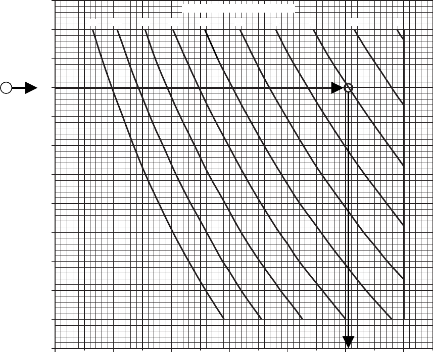
SA
AA1255A
DUAL−ENGINE TORQUE LIMITS ABOVE 80 KIAS
T−700−GE−701C 100% RPM R
FREE AIR TEMPERATURE ~ oC
60
50
40
30
20
10
0
−10
−20
−30
−40
−50
−6040 50 60 70 80 90 100
DATA BASIS: FLIGHT TEST
PRESSURE ALTITUDE ~ 1000 FT
20 18 16 14 12 10 8 6 4 2
FOR AIRCRAFT WITH TORQUE PLACARD ONLY
10
MAXIMUM ALLOWABLE DUAL−ENGINE TORQUE ~ %
Figure 7A-5. Dual-Engine Torque Limit
TM 1-1520-237-10
Change 6 7A-12.1/(7A-12.2 Blank)

Section III HOVER
7A.15 HOVER CHART.
NOTE
VOL For performance calculations with
the volcano system installed, use the appli-
cable high drag performance charts.
a. The primary use of the chart (Figures 7A-6 and 7A-7)
is illustrated by part A of the example. To determine the
torque required to hover, it is necessary to know pressure
altitude, free air temperature, gross weight, and desired
wheel height. Enter the upper right grid at the known free
air temperature, move right to the pressure altitude, move
down to gross weight. For OGE hover, move left to torque
per engine scale and read torque required. For IGE hover,
move left to desired wheel height, deflect down and read
torque required for dual-engine or single-engine operation.
The IGE wheel height lines represent a compromise for all
possible gross weights and altitude conditions. A small
torque error up to 63% torque may occur at extreme tem-
perature and high altitude. This error is more evident at
lower wheel heights.
b. In addition to the primary use, the hover chart (Figure
7A-6) may be used to predict maximum hover height. To
determine maximum hover height, it is necessary to know
pressure altitude, free air temperature, gross weight, and
maximum torque available. Enter the known free air tem-
perature move right to the pressure altitude, move down to
gross weight, move left to intersection with maximum
torque available and read wheel height. This wheel height
is the maximum hover height.
c. The hover chart may also be used to determine maxi-
mum gross weight for hover at a given wheel height, pres-
sure altitude, and temperature as illustrated in method B of
the example (Figure 7A-6). Enter at known free air tem-
perature, move right to the pressure altitude, then move
down and establish a vertical line on the lower grid. Now
enter lower left grid at maximum torque available. Move up
to wheel height, then move right to intersect vertical line
from pressure altitude/FAT intersection. Interpolate from
gross weight lines to read maximum gross weight at which
the helicopter will hover.
7A.16 EFFECTS OF BLADE EROSION KIT.
With the blade erosion kit installed, it will be necessary
to make the following corrections. Multiply the torque re-
quired to hover determined from the charts by 1.02. (Ex-
ample: If indicated torque is 90%, multiply 90 x 1.02 =
91.8% actual torque required.) Multiply the maximum gross
weight to hover obtained from the charts by 0.98. (Ex-
ample: If gross weight is 22,000 lb, multiply by 0.98 =
21,560 lb actual gross weight to hover.) When determining
maximum hover wheel height, enter the chart at 1.02 x
gross weight. (Example: If gross weight is 20,000 lb, mul-
tiply 20,000 x 1.02 = 20,400 lb).
TM 1-1520-237-10
7A-13
EXAMPLE A
WANTED:
TORQUE REQUIRED TO HOVER OGE AND AT A 10-FOOT WHEEL HEIGHT
KNOWN:
FAT = 30°C
PRESSURE ALTITUDE = 3,000 FEET
GROSS WEIGHT = 19,500 POUNDS
METHOD:
ENTER HOVER CHART AT KNOWN FAT. MOVE RIGHT TO PRESSURE ALTITUDE, MOVE DOWN
THROUGH GROSS WEIGHT LINES TO DESIRED GROSS WEIGHT. MOVE LEFT TO INDICATE
TORQUE/ENGINE % (OGE) SCALE AND READ OGE HOVER TORQUE (95%). MOVE DOWN
FROM INTERSECTION OF 10-FOOT HOVER LINE AND HORIZONTAL LINE TO READ TORQUE
REQUIRED TO HOVER 10 FEET (80%).
EXAMPLE B
WANTED:
MAXIMUM GROSS WEIGHT TO HOVER OGE
KNOWN:
ATF = 1.0
FAT = 20°C
PRESSURE ALTITUDE = 5,000 FEET
MAXIMUM TORQUE AVAILABLE = 107%
METHOD:
ENTER INDICATED TORQUE/ENGINE (IGE) SCALE AT MAXIMUM TORQUE AVAILABLE
(107%), MOVE UP TO OGE LINE. ENTER CHART AT KNOWN FAT (20°C). MOVE RIGHT TO
PRESSURE ALTITUDE LINE. MOVE DOWN FROM PRESSURE ALTITUDE LINE AND MOVE
RIGHT FROM OGE LINE. WHERE LINES INTERSECT, READ MAXIMUM GROSS WEIGHT TO
HOVER OGE (20,500 lb).
Figure 7A-6. Hover - Clean (Sheet 1 of 2)
TM 1-1520-237-10
7A-14
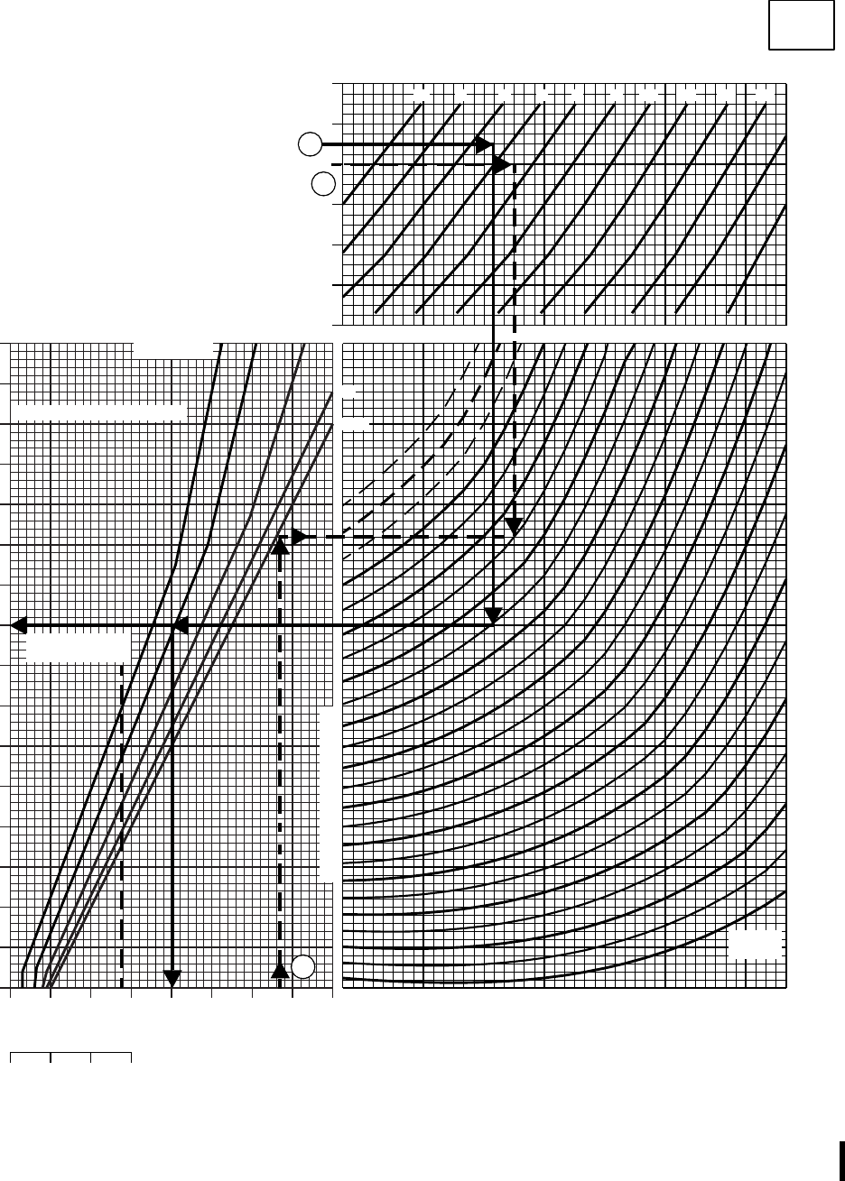
40 50 60 70 80 90 100 110 120
50
55
60
65
70
75
80
85
90
95
100
105
110
115
120
20
10
5
80 100 120 140
12
13
14
15
171819
−60
−40
−20
0
20
40
60 −2 0 2 4 6 8 10 12 14 16
20
HOVER
CLEAN
T701C(2)
SAF
AA2146D
202122
18
16
A
B
B
23
23.5
HOVER
CLEAN CONFIGURATION 100% RPM R
ZERO WIND PRESSURE ALTITUDE ~ 1000 FT
FREE AIR TEMP ~ O C
TORQUE PER ENGINE ~ % (OGE)
TORQUE PER ENGINE ~ % (IGE)
SINGLE ENGINE TORQUE ~ %
DATA BASIS : FLIGHT TEST
GW ~
1000 LB
DUAL ENGINE TRANS LIMIT
SINGLE ENGINE
TRANS LIMIT
WHEEL
HEIGHT ~ FT
DUAL ENGINE TRANS LIMIT OGE
NOTE
FOR LOW WIND CONDITIONS
AIRCRAFT SHOULD BE HEADED
INTO WIND. 3−5 KT CROSSWIND
OR TAILWIND MAY INCREASE
TORQUE REQUIRED BY UP TO
4% OVER ZERO WIND VALUES
40
125
130
Figure 7A-6. Hover - Clean (Sheet 2 of 2)
TM 1-1520-237-10
Change 7 7A-15
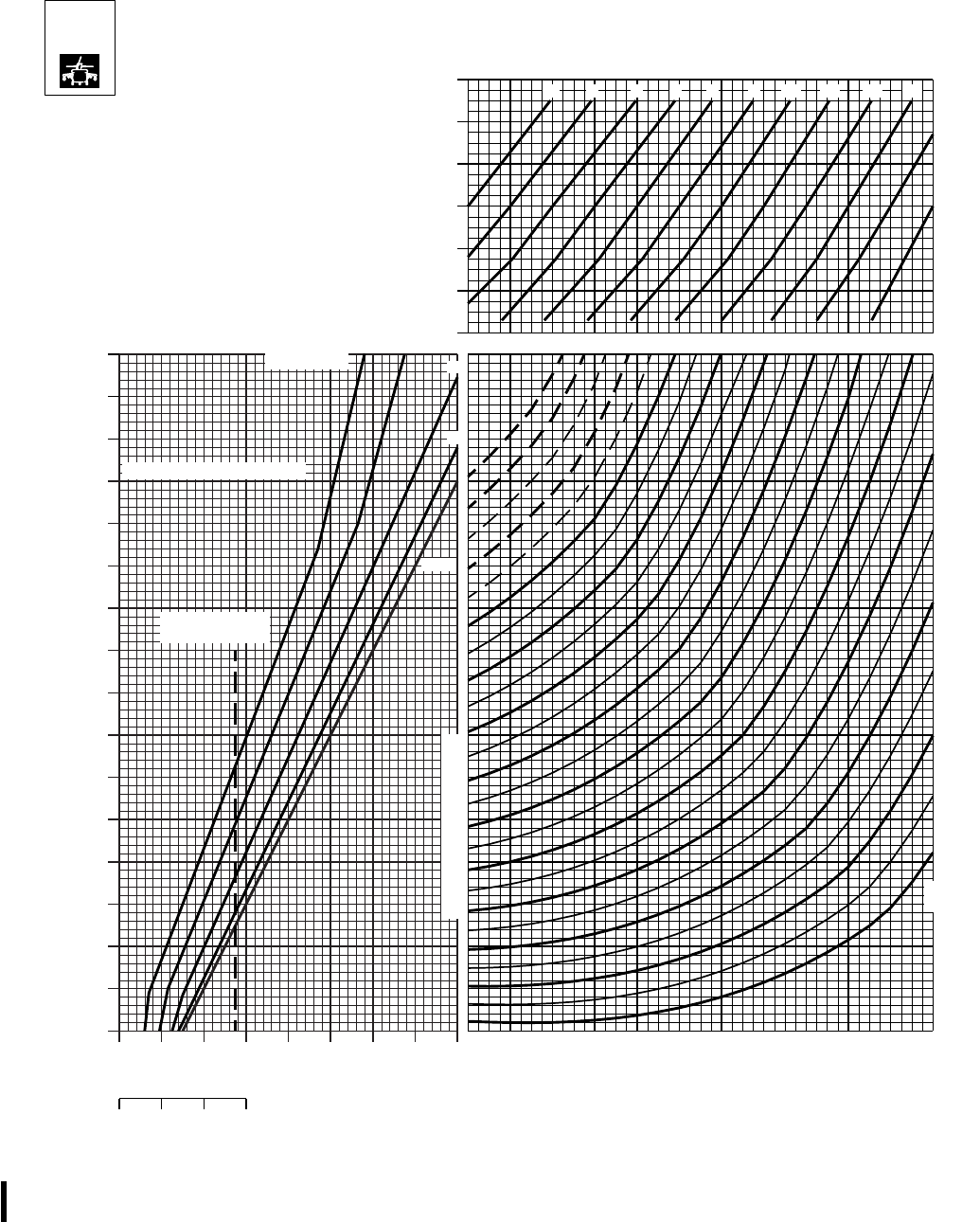
40 50 60 70 80 90 100 110 120
55
60
65
70
75
80
85
90
95
100
105
110
115
120
OGE
40
20
10
5
100 120 140
13
14
15
16
0
20
40
60 −2 0 2 4 6 8 10 12 14 16
18
20
SAF
AA2147C
2223
24 21 20 19 1718
HOVER
ESSS
T701C (2)
24.5
HOVER
HIGH DRAG CONFIGURATION 100% RPM R
ZERO WIND PRESSURE ALTITUDE ~ 1000 FT
FREE AIR TEMP ~ O C
TORQUE PER ENGINE ~ % (OGE)
TORQUE PER ENGINE ~ % (IGE)
SINGLE ENGINE TORQUE ~ %
DATA BASIS : FLIGHT TEST
GW ~
1000 LB
SINGLE ENGINE
TRANS LIMIT
WHEEL
HEIGHT ~ FT
DUAL ENGINE TRANS LIMIT
DUAL ENGINE TRANS LIMIT
80
−60
−40
−20
NOTE
FOR LOW WIND CONDITIONS
AIRCRAFT SHOULD BE HEADED
INTO WIND. 3−5 KT CROSSWIND
OR TAILWIND MAY INCREASE
TORQUE REQUIRED BY UP TO
4% OVER ZERO WIND VALUES
125
130
135
Figure 7A-7. Hover - High Drag
TM 1-1520-237-10
7A-16 Change 7

Section IV CRUISE
7A.17 DESCRIPTION.
The cruise charts (Figures 7A-8 through 7A-30) present
torque required and total fuel flow as a function of airspeed,
altitude, temperature, and gross weight at 100% rotor speed.
Scales for both true airspeed and indicated airspeed are
presented. The baseline aircraft configurations for these
charts are 9clean and high drag 9configuration as defined in
Section I. Each cruise chart also presents the change in
torque ( TRQ) required for 10 sq. ft. of additional flat
plate drag with a dashed line on a separate scale. This line
is utilized to correct torque required for external loads as
discussed in Section VI DRAG. Maximum level flight air-
speed (Vh) is obtained at the intersection of gross weight
arc and torque available - 30 minutes or the transmission
torque limit, whichever is lower. Airspeeds that will pro-
duce maximum range, maximum endurance, and maximum
rate of climb are also shown. Cruise charts are provided
from sea level to 20,000 feet pressure altitude in units of
2,000 feet. Each figure number represents a different alti-
tude. The charts provide cruise data for free air tempera-
tures from -50° to +60°C, in units of 10°. Charts with
FAT’s that exceed the engine ambient temperature limits
by more than 10°C are deleted.
7A.18 USE OF CHARTS.
The primary uses of the charts are illustrated by the
examples of Figure 7A-8. To use the charts, it is usually
necessary to know the planned pressure altitude, estimated
free air temperature, planned cruise speed, TAS, and gross
weight. First, select the proper chart on the basis of pres-
sure altitude and FAT. Enter the chart at the cruise air-
speed, IAS, move horizontal and read TAS, move horizon-
tal to the gross weight, move down and read torque
required, and then move up and read associated fuel flow.
Maximum performance conditions are determined by enter-
ing the chart where the maximum range line or the maxi-
mum endurance and rate of climb line intersects the gross
weight line; then read airspeed, fuel flow, and torque re-
quired. Normally, sufficient accuracy can be obtained by
selecting the chart nearest the planned cruising altitude and
FAT or, more conservatively, by selecting the chart with
the next higher altitude and FAT. If greater accuracy is
required, interpolation between altitudes and/or tempera-
tures is permissible. To be conservative, use the gross
weight at the beginning of the cruise flight. For greater
accuracy on long flights, however, it is preferable to deter-
mine cruise information for several flight segments to allow
for the decreasing gross weight.
a. Airspeed. True and indicated airspeeds are presented
at opposite sides of each chart. On any chart, indicated
airspeed can be directly converted to true airspeed (or vice
versa) by reading directly across the chart without regard
for the other chart information.
b. Torque. Since pressure altitude and temperature are
fixed for each chart, torque required varies according to
gross weight and airspeed. The torque and torque limits
shown on these charts are for dual-engine operation. The
maximum torque available is presented on each chart as
either the transmission torque limit or torque available - 30
minute for both ATF-1.0 and 0.9 values. The maximum
torque available for aircraft with an ATF value between
these must be interpolated. The continuous torque available
values shown represent the minimum torque available for
ATFs of 1.0. For ATFs less than 1.0, maximum continuous
torque available may be reduced. The dual-engine torque
limit placard value is presented below the torque scale of
each chart when applicable. An increase or decrease in
torque required because of a drag area change is calculated
by adding or subtracting the change in torque from the
torque on the curve, and then reading the new fuel flow
total.
c. Fuel Flow. Fuel flow scales are provided opposite the
torque scales. On any chart, torque may be converted di-
rectly to fuel flow without regard to other chart informa-
tion. Data shown in this section is for two-engine operation.
For one-engine fuel flow, refer to Section VIII FUEL
FLOW.
(1) With bleed-air extracted, fuel flow increases:
(a) Engine anti-ice on - About 100 lbs/hr. Example:
(760 lbs/hr + 100 lbs/hr = 860 lbs/hr.)
(b) Heater on - About 12 lbs/hr.
(c) Both on - About 112 lbs/hr.
(2) When the hover IR suppressor system is operating
in the benign mode (exhaust baffles removed), the dual-
engine fuel flow will decrease about 14 lbs/hr.
d. Maximum Range. The maximum range lines (MAX
RANGE) indicate the combinations of gross weight and
airspeed that will produce the greatest flight range per
pound of fuel under zero wind conditions. When maximum
TM 1-1520-237-10
Change 10 7A-17

range airspeed line is above the maximum torque available,
the resulting maximum airspeed should be used for maxi-
mum range. A method of estimating maximum range speed
in winds is to increase IAS by 2.5 knots per each 10 knots
of effective headwind (which reduces flight time and mini-
mizes loss in range) and decrease IAS by 2.5 knots per 10
knots of effective tailwind for economy.
e. Maximum Endurance and Rate of Climb. The maxi-
mum endurance and rate of climb lines (MAX END and
R/C) indicate the combinations of gross weight and air-
speed that will produce the maximum endurance and the
maximum rate of climb. The torque required for level flight
at this condition is a minimum, providing a minimum fuel
flow (maximum endurance) and a maximum torque change
available for climb (maximum rate of climb).
f. Change in Frontal Area. Since the cruise information
is given for the 9clean and high drag configuration,9adjust-
ments to torque should be made when operating with ex-
ternal sling loads or aircraft external configuration changes.
To determine the change in torque, first obtain the appro-
priate multiplying factor from the drag load chart (Figure
7A-33 or Table 7A-1), then enter the cruise chart at the
planned cruise speed TAS, move right to the broken
TRQ line, and move up and read TRQ. Multiply
TRQ by the multiplying factor to obtain change in
torque, then add or subtract change in torque from torque
required for the primary mission configuration. Enter the
cruise chart at resulting torque required, move up, and read
fuel flow. If the resulting torque required exceeds the gov-
erning torque limit, the torque required must be reduced to
the limit. The resulting reduction in airspeed may be found
by subtracting the change in torque from the limit torque;
then enter the cruise chart at the reduced torque, and move
up to the gross weight. Move left or right to read TAS or
IAS. The engine torque setting for maximum range ob-
tained from the clean configuration cruise chart will gener-
ally result in cruise at best range airspeed for the higher
drag configuration. To determine the approximate airspeed
for maximum range for alternative or external load configu-
rations, reduce the value from the cruise chart by 6 knots
for each 10 square foot increase in drag area, F. For
example, if both cabin doors are open the F increases 6
ft
2
and the maximum range airspeed would be reduced by
approximately 4 knots (6 Kts/10 ft
2
x6 ft
2
= 3.6 Kts). Only
the high drag cruise charts have data for gross weights
above 22,000 pounds. For external cargo hook load opera-
tions in excess of 8,000 pounds that attain gross weights
from 22,000 to 23,500 pounds it will be necessary to use
the high drag cruise charts. If the external stores support
system (ESSS) and the two 230-gallon tanks are not in-
stalled and the estimated drag value for the cargo hook load
is greater than 14 square feet , it will be necessary to sub-
tract 14 square feet of drag from the cruise chart drag value
when determining cruise performance. If the ESSS and the
two 230-gallon tanks are not installed and the drag is esti-
mated to be 14 square feet or less, the high drag charts
should be used with no other correction.
g. Additional Uses. The low speed end of the cruise
chart (below 40 knots) is shown primarily to familiarize
you with the low speed power requirements of the helicop-
ter. It shows the power margin available for climb or accel-
eration during maneuvers, such as NOE flight. At zero air-
speed, the torque represents the torque required to hover
out of ground effect. In general, mission planning for low
speed flight should be based on hover out of ground effect.
7A.19 SINGLE-ENGINE.
a. The minimum or maximum single-engine speeds can
be determined by using a combination of the 701C torque
available and cruise charts. To calculate single-engine
speeds, first determine the torque available from Section II
at the TGT limit desired and divide by 2. (Example: 90%
TRQ 42 = 45% TRQ.)
b. Select the appropriate cruise chart for the desired
flight condition and enter the torque scale with the torque
value derived above. Move up to the intersection of torque
available and the mission gross weight arc, and read across
for minimum single-engine airspeed. Move up to the sec-
ond intersection of torque and weight, and read across to
determine the maximum single-engine speed. If no inter-
sections occur, there is no single-engine level flight capa-
bility for the conditions. Single-engine fuel flow at the de-
sired 10 minute, 30 minute, continuous conditions may be
obtained by doubling the torque required from the cruise
chart and referring to Figure 7A-37.
TM 1-1520-237-10
7A-18
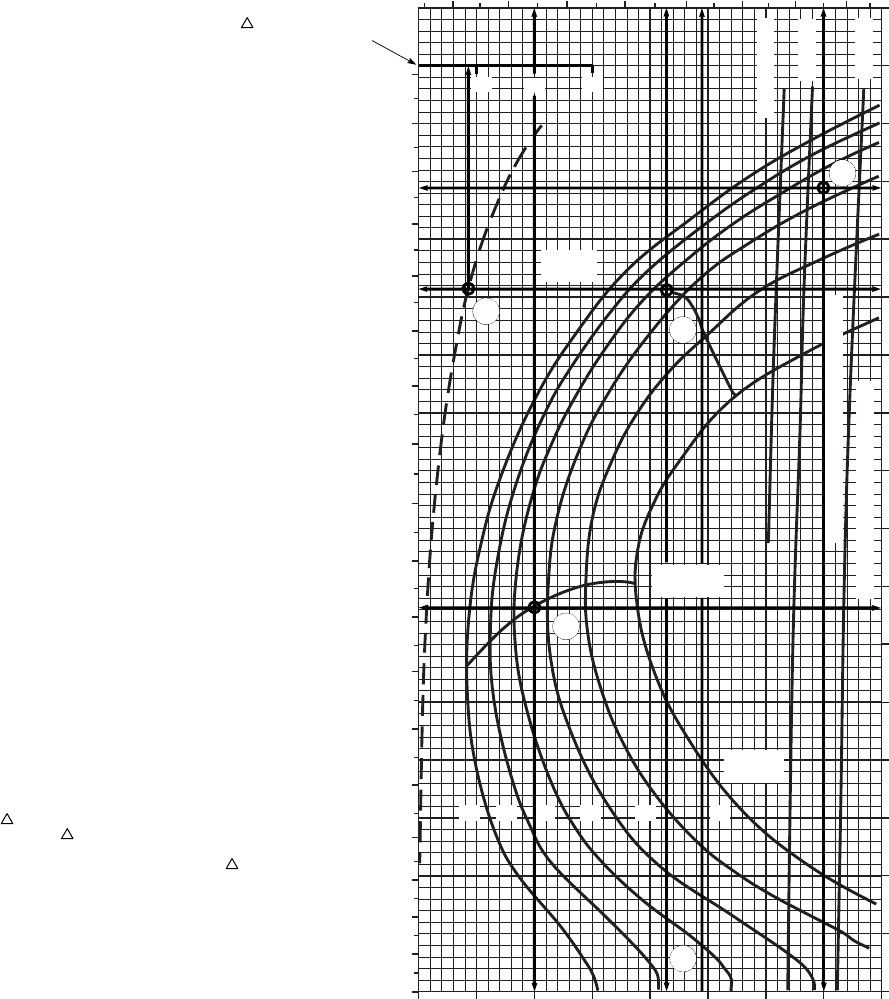
SA
AA1266A
20 30 40 50 60 70 80 90 100
0
10
20
30
40
50
60
70
80
90
100
110
120
130
140
150
160
170
10 30
TRQ ~ % FOR DRAG
AREA OF 10 SQ FT
CONTINUOUS
MAX
RANGE
MAX END
AND R / C
TRANSMISSION TORQUE LIMIT
TORQUE AVAILABLE ~ 30 MINUTES
GW ~
1000 LB
12 14 16 18 20 22
0
10
20
30
40
50
60
70
80
90
100
110
120
130
140
150
160
170
180
6 7 8 9 10 11 12 13
ATF=0.9
ATF=1.0
INDICATED AIRSPEED ~ KTS
TRUE AIRSPEED ~ KTS
FAT: 30O C ALT: 6,000 FT
TOTAL FUEL FLOW 100 LB/HR
TORQUE PER ENGINE ~ %
WANTED
KNOWN
METHOD
A. CRUISE CONDITIONS FOR MAXIMUM RANGE
B. CONDITIONS FOR MAXIMUM ENDURANCE
C. MAXIMUM AIRSPEED IN LEVEL FLIGHT
D. DETERMINE TORQUE AND FUEL FLOW
REQUIRED TO CRUISE WITH CARGO
DOORS OPEN
FAT = 30OC
PRESSURE ALTITUDE = 6000 FT
GW = 17000 LBS
ATF = 0.95
PLACARD TORQUE LIMITS APPLY
A. TURN TO CRUISE CHARTS NEAREST KNOWN
FLIGHT CONDITIONS, AT INTERSECTION
OF MAX RANGE LINE AND KNOWN VALUE OF
GROSS WEIGHT:
MOVE LEFT, READ TAS = 137 KTS
MOVE RIGHT, READ IAS = 121 KTS
MOVE DOWN, READ TORQUE = 63% TRQ
MOVE UP, READ TOTAL FUEL FLOW = 970 LBS / HR
B. AT INTERSECTION OF MAX END AND R / C
LINE AND KNOWN VALUE OF GROSS WEIGHT:
MOVE LEFT, READ TAS = 81 KTS
MOVE RIGHT, READ IAS = 66 KTS
MOVE DOWN, READ TORQUE = 40% TRQ
MOVE UP, READ TOTAL FUEL FLOW = 740 LBS / HR
C. THE 30−MINUTE TORQUE AVAILABLE FOR
AN ATF OF 0.95 IS ABOVE THE PLACARD
TORQUE LIMIT. THEREFORE, AT THE
INTERSECTION OF GROSS WEIGHT AND
90% TRQ:
MOVE LEFT, READ MAXIMUM TAS = 157 KTS
MOVE RIGHT, READ MAXIMUM IAS = 139 KTS
MOVE DOWN, READ MAXIMUM TORQUE = 90% TRQ
MOVE UP, READ TOTAL FUEL FLOW = 1250 LBS / HR
D. ENTER TRQ% PER 10 SQ FT SCALE AT 137 KTAS
MOVE UP READ TRQ = 9.0%
TURN TO DRAG TABLE IN SECTION VII
NOTE CARGO DOORS OPEN = 6.0 SQ FT F
AND HAS A DRAG MULTIPLYING FACTOR VALUE
OF 0.60, CALCULATE TOTAL TORQUE REQUIRED
USING THE CONDITIONS OF EXAMPLE A:
63% + (0.6 X 9.0%) = 68.4% TRQ
READ FUEL FLOW AT TOTAL TORQUE = 1025 LBS / HR
20
A
B
C
D
A
B
C
D
DD
CRUISE EXAMPLE
CLEAN CONFIGURATION
100% RPM R
EXAMPLE
Figure 7A-8. Sample Cruise Chart
TM 1-1520-237-10
7A-19
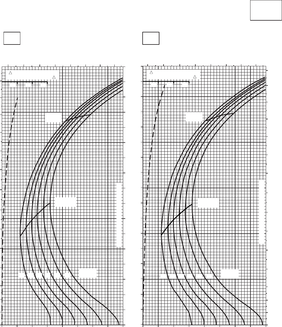
CRUISE CRUISE
T701C (2)
TORQUE PER ENGINE ~ %TORQUE PER ENGINE ~ %
IAS ~ KTS TOTAL FUEL FLOW ~ 100 LB/HRTOTAL FUEL FLOW ~ 100 LB/HR
DATA BASE:FLIGHT TEST
TRUE AIRSPEED ~ KTS
TRUE AIRSPEED ~ KTS
CLEAN CONFIGURATION
0
10
20
30
40
50
60
70
80
90
100
110
120
130
140
150
160
170
SA
AA1060_1
PRESS ALT: 0 FT
0 FT
−50oC−40oC
0
10
20
30
40
50
60
70
80
90
100
110
120
130
140
6 7 89 10 11 12 13 6 7 8 9 10 11 12 13
0
10
20
30
40
50
60
70
80
90
100
110
120
130
140
150
20 30 40 50 60 70 80 90 100 20 30 40 50 60 70 80 90 100
MAX
RANGE
MAX END
AND R / C
GW ~
1000 LB
12 14 16 18 20 22
TRANSMISSION TORQUE LIMIT
MAX
RANGE
MAX END
AND R / C
TRANSMISSION TORQUE LIMIT
GW ~
1000 LB
12 14 16 18 20 22
10 20 30 10 20 30
TRQ ~ % FOR DRAG
AREA OF 10 SQ FT OF F TRQ ~ % FOR DRAG
AREA OF 10 SQ FT OF F
Figure 7A-9. Cruise - Pressure Altitude Sea Level (Sheet 1 of 6)
TM 1-1520-237-10
7A-20
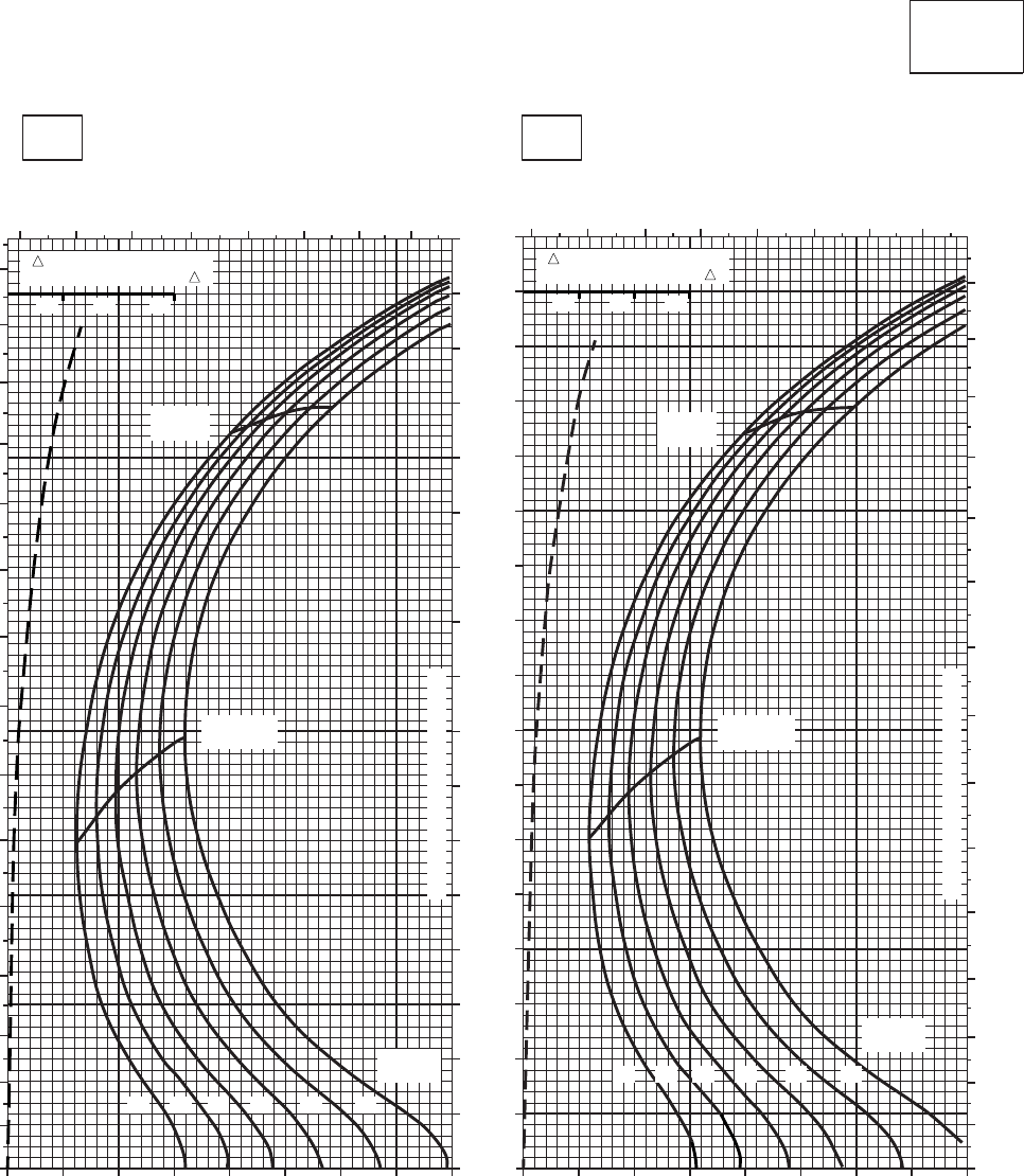
CRUISE CRUISE
T701C (2)
TORQUE PER ENGINE ~ %TORQUE PER ENGINE ~ %
IAS ~ KTS TOTAL FUEL FLOW ~ 100 LB/HRTOTAL FUEL FLOW ~ 100 LB/HR
DATA BASE:FLIGHT TEST
TRUE AIRSPEED ~ KTS
TRUE AIRSPEED ~ KTS
CLEAN CONFIGURATION
0
10
20
30
40
50
60
70
80
90
100
110
120
130
140
150
160
170
SA
AA1060_2
PRESS ALT: 0 FT
0 FT
−30oC−20oC
20 30 40 50 60 70 80 90 100 20 30 40 50 60 70 80 90 100
0
10
20
30
40
50
60
70
80
90
100
110
120
130
140
150
6 7 8 910 11 12 13 6 7 89 10 11 12 13
0
10
20
30
40
50
60
70
80
90
100
110
120
130
140
150
MAX
RANGE
MAX END
AND R / C
GW ~
1000 LB
12 14 16 18 20 22
TRANSMISSION TORQUE LIMIT
MAX
RANGE
MAX END
AND R / C
TRANSMISSION TORQUE LIMIT
GW ~
1000 LB
12 14 16 18 20 22
10 20 30 10 20 30
TRQ ~ % FOR DRAG
AREA OF 10 SQ FT OF F TRQ ~ % FOR DRAG
AREA OF 10 SQ FT OF F
Figure 7A-9. Cruise - Pressure Altitude Sea Level (Sheet 2 of 6)
TM 1-1520-237-10
7A-21
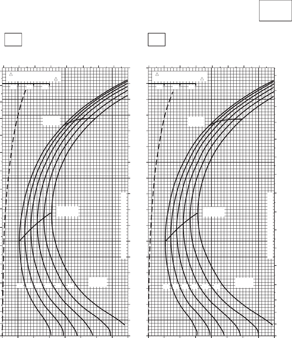
CRUISE CRUISE
T701C (2)
TORQUE PER ENGINE ~ %TORQUE PER ENGINE ~ %
IAS ~ KTS TOTAL FUEL FLOW ~ 100 LB/HRTOTAL FUEL FLOW ~ 100 LB/HR
DATA BASE:FLIGHT TEST
TRUE AIRSPEED ~ KTS
TRUE AIRSPEED ~ KTS
CLEAN CONFIGURATION
0
10
20
30
40
50
60
70
80
90
100
110
120
130
140
150
160
170
SA
AA1060_3
PRESS ALT: 0 FT
0 FT
−10oC0oC
0
10
20
30
40
50
60
70
80
90
100
110
120
130
140
150
160
67 8 9 10 11 12 13 678 9 10 11 12 13
0
10
20
30
40
50
60
70
80
90
100
110
120
130
140
150
160
MAX
RANGE
MAX END
AND R / C
GW ~
1000 LB
12 14 16 18 20 22
TRANSMISSION TORQUE LIMIT
MAX
RANGE
MAX END
AND R / C
GW ~
1000 LB
12 14 16 18 20 22
TRANSMISSION TORQUE LIMIT
20 30 40 50 60 70 80 90 100 20 30 40 50 60 70 80 90 100
10 20 30 10 20 30
TRQ ~ % FOR DRAG
AREA OF 10 SQ FT OF F TRQ ~ % FOR DRAG
AREA OF 10 SQ FT OF F
Figure 7A-9. Cruise - Pressure Altitude Sea Level (Sheet 3 of 6)
TM 1-1520-237-10
7A-22
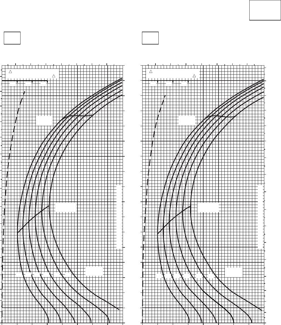
CRUISE CRUISE
T701C (2)
TORQUE PER ENGINE ~ %TORQUE PER ENGINE ~ %
IAS ~ KTS TOTAL FUEL FLOW ~ 100 LB/HRTOTAL FUEL FLOW ~ 100 LB/HR
DATA BASE:FLIGHT TEST
TRUE AIRSPEED ~ KTS
TRUE AIRSPEED ~ KTS
CLEAN CONFIGURATION
0
10
20
30
40
50
60
70
80
90
100
110
120
130
140
150
160
170
SA
AA1060_4
PRESS ALT: 0 FT
0 FT
10oC20oC
0
10
20
30
40
50
60
70
80
90
100
110
120
130
140
150
160
7 8 9 10 11 12 13 7 8 9 10 11 12 13
0
10
20
30
40
50
60
70
80
90
100
110
120
130
140
150
160
170
MAX
RANGE
MAX END
AND R / C
GW ~
1000 LB
12 14 16 18 20 22
TRANSMISSION TORQUE LIMIT
MAX
RANGE
MAX END
AND R / C
TRANSMISSION TORQUE LIMIT
GW ~
1000 LB
12 14 16 18 20 22
20 30 40 50 60 70 80 90 100 20 30 40 50 60 70 80 90 100
10 20 30 10 20 30
TRQ ~ % FOR DRAG
AREA OF 10 SQ FT OF F TRQ ~ % FOR DRAG
AREA OF 10 SQ FT OF F
Figure 7A-9. Cruise - Pressure Altitude Sea Level (Sheet 4 of 6)
TM 1-1520-237-10
7A-23
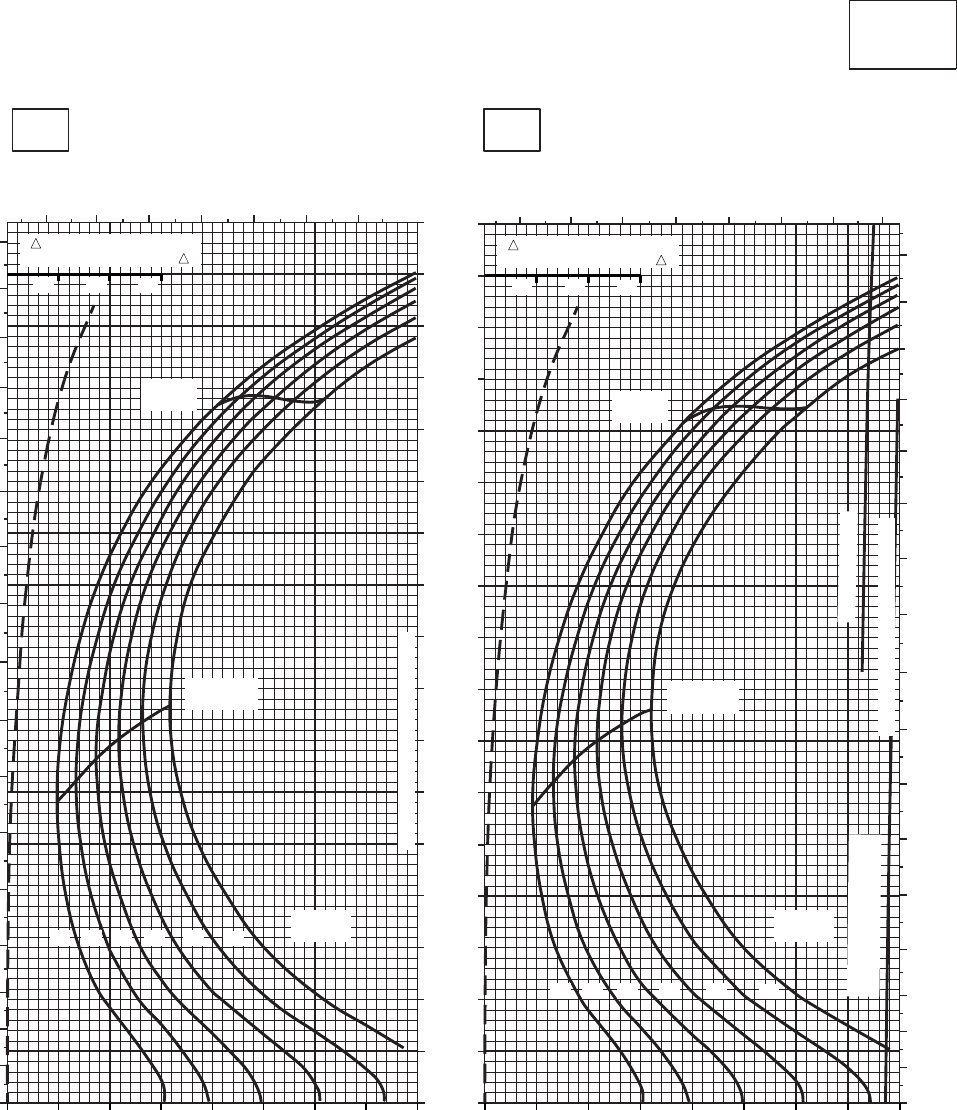
CRUISE CRUISE
T701C (2)
TORQUE PER ENGINE ~ %TORQUE PER ENGINE ~ %
IAS ~ KTS TOTAL FUEL FLOW ~ 100 LB/HRTOTAL FUEL FLOW ~ 100 LB/HR
DATA BASE:FLIGHT TEST
TRUE AIRSPEED ~ KTS
TRUE AIRSPEED ~ KTS
CLEAN CONFIGURATION
0
10
20
30
40
50
60
70
80
90
100
110
120
130
140
150
160
170
SA
AA1060_5
PRESS ALT: 0 FT
0 FT
30oC40oC
0
10
20
30
40
50
60
70
80
90
100
110
120
130
140
150
160
170
7 8 9 10 11 12 13 7 8 9 10 11 12 13 14
0
10
20
30
40
50
60
70
80
90
100
110
120
130
140
150
160
170
MAX
RANGE
MAX END
AND R / C
GW ~
1000 LB
12 14 16 18 20 22
TRANSMISSION TORQUE LIMIT
MAX
RANGE
MAX END
AND R / C
GW ~
1000 LB
TRANSMISSION TORQUE LIMIT
12 14 16 18 20 22
~ CONTINUOUS
TORQUE AVAILABLE
~30 MINUTES ATF = 0.9
20 30 40 50 60 70 80 90 100 20 30 40 50 60 70 80 90 100
10 20 30 10 20 30
TRQ ~ % FOR DRAG
AREA OF 10 SQ FT OF F TRQ ~ % FOR DRAG
AREA OF 10 SQ FT OF F
Figure 7A-9. Cruise - Pressure Altitude Sea Level (Sheet 5 of 6)
TM 1-1520-237-10
7A-24
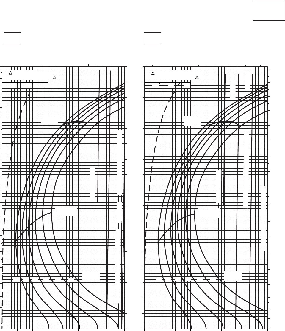
CRUISE CRUISE
T701C (2)
TORQUE PER ENGINE ~ %TORQUE PER ENGINE ~ %
IAS ~ KTS TOTAL FUEL FLOW ~ 100 LB/HRTOTAL FUEL FLOW ~ 100 LB/HR
DATA BASE:FLIGHT TEST
TRUE AIRSPEED ~ KTS
TRUE AIRSPEED ~ KTS
CLEAN CONFIGURATION
0
10
20
30
40
50
60
70
80
90
100
110
120
130
140
150
160
170
SA
AA1060_6
PRESS ALT: 0 FT
0 FT
50oC60oC
0
10
20
30
40
50
60
70
80
90
100
110
120
130
140
150
160
170
180
7 8 9 10 11 12 13 14 7 8 9 10 11 12 13 14
0
10
20
30
40
50
60
70
80
90
100
110
120
130
140
150
160
170
180
MAX
RANGE
MAX END
AND R / C
GW ~
1000 LB
12 14 16 18 20 22
TRANSMISSION TORQUE LIMIT
MAX
RANGE
MAX END
AND R / C
TRANSMISSION TORQUE LIMIT
GW ~
1000 LB
12 14 16 18 20 22
~ CONTINUOUS
~ CONTINUOUS
ATF = 0.9
ATF = 0.9
ATF = 1.0
TORQUE AVAILABLE ~ 30 MINUTES
TORQUE AVAILABLE ~ 30 MINUTES
20 30 40 50 60 70 80 90 100 20 30 40 50 60 70 80 90 100
10 20 30 10 20 30
TRQ ~ % FOR DRAG
AREA OF 10 SQ FT OF F TRQ ~ % FOR DRAG
AREA OF 10 SQ FT OF F
Figure 7A-9. Cruise - Pressure Altitude Sea Level (Sheet 6 of 6)
TM 1-1520-237-10
7A-25
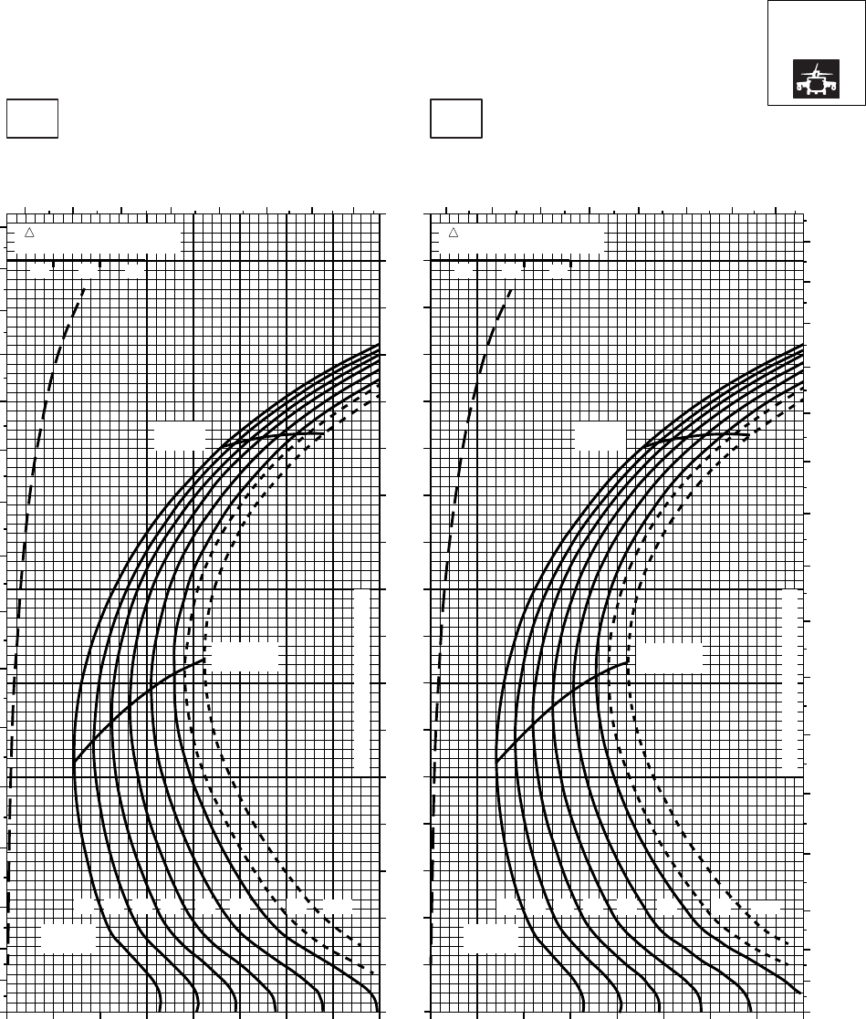
CRUISE CRUISE
T701C (2)
TORQUE PER ENGINE ~ %TORQUE PER ENGINE ~ %
IAS ~ KTS TOTAL FUEL FLOW ~ 100 LB/HRTOTAL FUEL FLOW ~ 100 LB/HR
DATA BASE:FLIGHT TEST
TRUE AIRSPEED ~ KTS
TRUE AIRSPEED ~ KTS
NOTE:SHORT DASH LINES: FERRY MISSION ONLY
SA
AA1065_1
PRESS ALT: 0 FT
0 FT
−50oC−40oC
TRQ ~ % FOR DRAG
AREA OF 10 SQ FT
10 20 30
TRQ ~ % FOR DRAG
AREA OF 10 SQ FT
10 20 30
6 7 8 9 10 11 12 13
0
10
20
30
40
50
60
70
80
90
100
110
120
130
140
150
160
6 7 8 9 10 11 12 13
0
10
20
30
40
50
60
70
80
90
100
110
120
130
140
150
160
20 30 40 50 60 70 80 90 100 20 30 40 50 60 70 80 90 100
0
10
20
30
40
50
60
70
80
90
100
110
120
130
140
150
160
170
14 1612 18 20
MAX
RANGE
GW ~
1000 LB
MAX END
AND R / C
22 23 24.5 14 1612 18 20
MAX
RANGE
GW ~
1000 LB
MAX END
AND R / C
22 23 24.5
CONTINUOUS TORQUE LIMIT
CONTINUOUS TORQUE LIMIT
Figure 7A-10. Cruise High Drag - Pressure Altitude Sea Level (Sheet 1 of 6)
TM 1-1520-237-10
7A-26
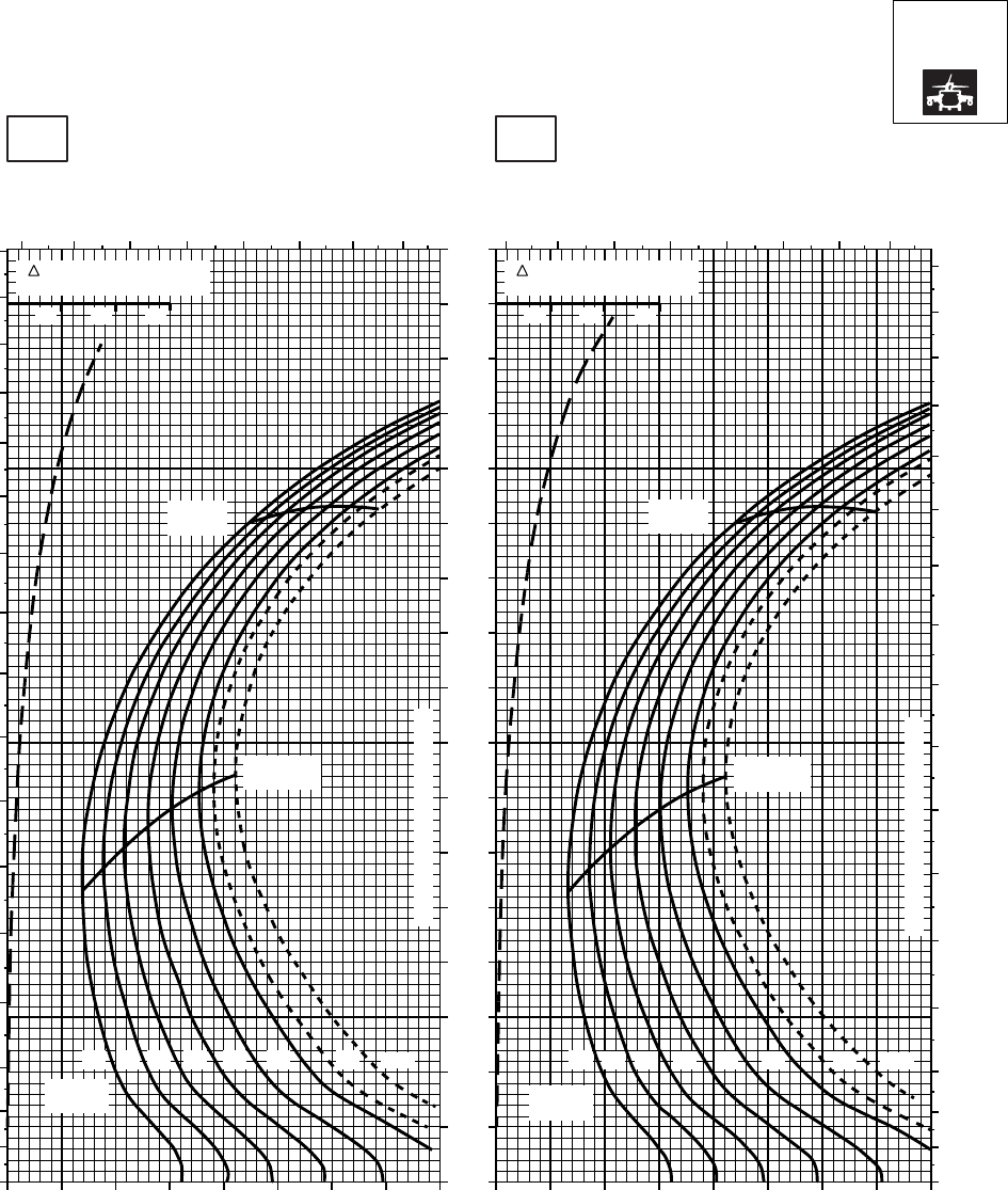
CRUISE CRUISE
T701C (2)
TORQUE PER ENGINE ~ %TORQUE PER ENGINE ~ %
IAS ~ KTS TOTAL FUEL FLOW ~ 100 LB/HRTOTAL FUEL FLOW ~ 100 LB/HR
DATA BASE:FLIGHT TEST
TRUE AIRSPEED ~ KTS
TRUE AIRSPEED ~ KTS
NOTE:SHORT DASH LINES: FERRY MISSION ONLY
SA
AA1065_2
PRESS ALT: 0 FT
0 FT
−30oC−20oC
TRQ ~ % FOR DRAG
AREA OF 10 SQ FT
10 20 30
TRQ ~ % FOR DRAG
AREA OF 10 SQ FT
10 20 30
6 7 8 9 10 11 12 13 6 7 8 9 10 11 12 13
0
10
20
30
40
50
60
70
80
90
100
110
120
130
140
150
160
170
0
10
20
30
40
50
60
70
80
90
100
110
120
130
140
150
160
170
20 30 40 50 60 70 80 90 100 20 30 40 50 60 70 80 90 100
0
10
20
30
40
50
60
70
80
90
100
110
120
130
140
150
160
170
14 1612 18 20
MAX
RANGE
GW ~
1000 LB
MAX END
AND R / C
22 23 24.5 14 1612 18 20
MAX
RANGE
GW ~
1000 LB
MAX END
AND R / C
22 23 24.5
CONTINUOUS TORQUE LIMIT
CONTINUOUS TORQUE LIMIT
12
Figure 7A-10. Cruise High Drag - Pressure Altitude Sea Level (Sheet 2 of 6)
TM 1-1520-237-10
7A-27
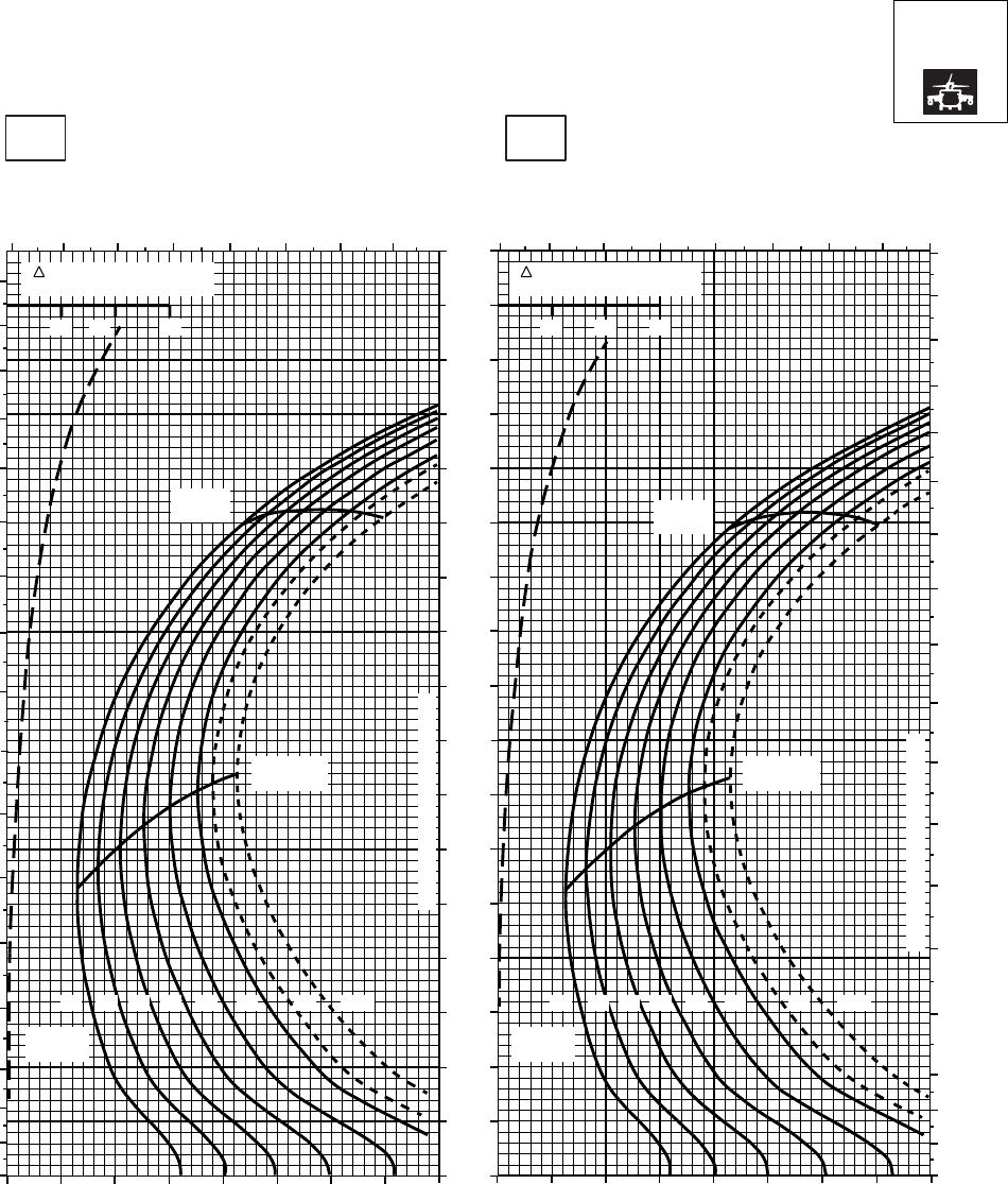
CRUISE CRUISE
T701C (2)
TORQUE PER ENGINE ~ %TORQUE PER ENGINE ~ %
IAS ~ KTS TOTAL FUEL FLOW ~ 100 LB/HRTOTAL FUEL FLOW ~ 100 LB/HR
DATA BASE:FLIGHT TEST
TRUE AIRSPEED ~ KTS
TRUE AIRSPEED ~ KTS
NOTE:SHORT DASH LINES: FERRY MISSION ONLY
SA
AA1065_3
PRESS ALT: 0 FT
0 FT
−10oC0oC
6 7 8 9 10 11 12 13 6 7 8 9 10 11 12 13 14
0
10
20
30
40
50
60
70
80
90
100
110
120
130
140
150
160
170
180
0
10
20
30
40
50
60
70
80
90
100
110
120
130
140
150
160
170
0
10
20
30
40
50
60
70
80
90
100
110
120
130
140
150
160
170
20 30 40 50 60 70 80 90 100 20 30 40 50 60 70 80 90 100
10 20 30
TRQ ~ % FOR DRAG
AREA OF 10 SQ FT
10 20 30
TRQ ~ % FOR DRAG
AREA OF 10 SQ FT
MAX
RANGE MAX
RANGE
MAX END
AND R / C MAX END
AND R / C
GW ~
1000 LB GW ~
1000 LB
12 1214 1416 16 1818 20 2022 2223 23 24.524.5
CONTINUOUS TORQUE LIMIT
CONTINUOUS TORQUE LIMIT
Figure 7A-10. Cruise High Drag - Pressure Altitude Sea Level (Sheet 3 of 6)
TM 1-1520-237-10
7A-28
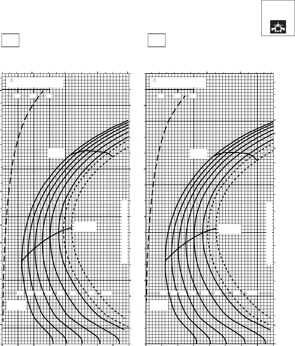
CRUISE CRUISE
T701C (2)
TORQUE PER ENGINE ~ %TORQUE PER ENGINE ~ %
IAS ~ KTS TOTAL FUEL FLOW ~ 100 LB/HRTOTAL FUEL FLOW ~ 100 LB/HR
DATA BASE:FLIGHT TEST
TRUE AIRSPEED ~ KTS
TRUE AIRSPEED ~ KTS
NOTE:SHORT DASH LINES: FERRY MISSION ONLY
SA
AA1065_4
PRESS ALT: 0 FT
0 FT
10oC20oC
6 7 8 9 10 11 12 13 14 7 8 9 10 11 12 13 14
0
10
20
30
40
50
60
70
80
90
100
110
120
130
140
150
160
170
180
0
10
20
30
40
50
60
70
80
90
100
110
120
130
140
150
160
170
180
20 30 40 50 60 70 80 90 100 20 30 40 50 60 70 80 90 100
0
10
20
30
40
50
60
70
80
90
100
110
120
130
140
150
160
170
10 20 30
TRQ ~ % FOR DRAG
AREA OF 10 SQ FT
30
10 20
TRQ ~ % FOR DRAG
AREA OF 10 SQ FT
GW ~
1000 LB GW ~
1000 LB
12 1214 1416 1618 1820 2022 2223 23 24.524.5
MAX END
AND R / C MAX END
AND R / C
MAX
RANGE MAX
RANGE
CONTINUOUS TORQUE LIMIT
CONTINUOUS TORQUE LIMIT
Figure 7A-10. Cruise High Drag - Pressure Altitude Sea Level (Sheet 4 of 6)
TM 1-1520-237-10
7A-29
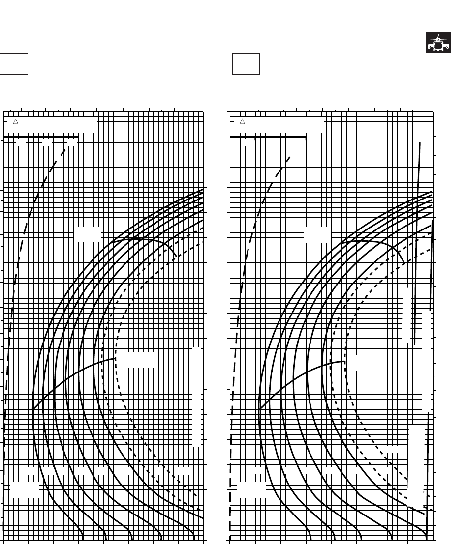
CRUISE CRUISE
T701C (2)
TORQUE PER ENGINE ~ %TORQUE PER ENGINE ~ %
IAS ~ KTS TOTAL FUEL FLOW ~ 100 LB/HRTOTAL FUEL FLOW ~ 100 LB/HR
DATA BASE:FLIGHT TEST
TRUE AIRSPEED ~ KTS
TRUE AIRSPEED ~ KTS
NOTE:SHORT DASH LINES: FERRY MISSION ONLY
SA
AA1065_5
PRESS ALT: 0 FT
0 FT
30oC40oC
0
10
20
30
40
50
60
70
80
90
100
110
120
130
140
150
160
170
180
7 8 9 10 11 12 13 14 7 8 9 10 11 12 13 14
0
10
20
30
40
50
60
70
80
90
100
110
120
130
140
150
160
170
180
0
10
20
30
40
50
60
70
80
90
100
110
120
130
140
150
160
170
20 30 40 50 60 70 80 90 100 20 30 40 50 60 70 80 90 100
MAX
RANGE
MAX END
AND R / C
GW ~
1000 LB
CONTINUOUS TORQUE LIMIT
12 14 16 18 20 22 23 24.5
MAX
RANGE
MAX END
AND R / C
GW ~
1000 LB
12 14 16 18 20 22 23
24.5
~ CONTINUOUS
CONTINUOUS TORQUE LIMIT
TORQUE AVAILABLE
~ 30 MINUTES ATF = 0.9
TRQ ~ % FOR DRAG
AREA OF 10 SQ FT
10 20 30
TRQ ~ % FOR DRAG
AREA OF 10 SQ FT
10 20 30
Figure 7A-10. Cruise High Drag - Pressure Altitude Sea Level (Sheet 5 of 6)
TM 1-1520-237-10
7A-30
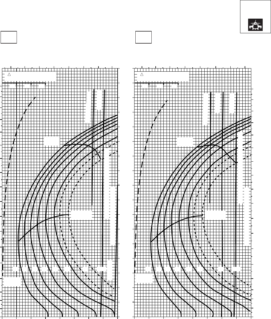
CRUISE CRUISE
T701C (2)
TORQUE PER ENGINE ~ %TORQUE PER ENGINE ~ %
IAS ~ KTS TOTAL FUEL FLOW ~ 100 LB/HRTOTAL FUEL FLOW ~ 100 LB/HR
DATA BASE:FLIGHT TEST
TRUE AIRSPEED ~ KTS
TRUE AIRSPEED ~ KTS
NOTE:SHORT DASH LINES: FERRY MISSION ONLY
SA
AA1065_6
PRESS ALT: 0 FT
0 FT
50oC60oC
0
10
20
30
40
50
60
70
80
90
100
110
120
130
140
150
160
170
180
0
10
20
30
40
50
60
70
80
90
100
110
120
130
140
150
160
170
180
7 8 9 10 11 12 13 14
20 30 40 50 60 70 80 90 100 20 30 40 50 60 70 80 90 100
~ CONTINUOUS
~ CONTINUOUS
ATF = 0.9
ATF = 0.9
ATF = 1.0
MAX
RANGE
MAX
RANGE
MAX END
AND R / C
MAX END
AND R / C
GW ~
1000 LB
GW ~
1000 LB
TORQUE AVAILABLE ~ 30 MINUTES
TORQUE AVAILABLE ~ 30 MINUTES
CONTINUOUS TORQUE LIMIT
CONTINUOUS TORQUE LIMIT
12 12
14 14
16 16
18 18
20 20
22 22
23 23
24.5 24.5
ATF = 1.0
TRQ ~ % FOR DRAG
AREA OF 10 SQ FT
10 20 30
TRQ ~ % FOR DRAG
AREA OF 10 SQ FT
10 20 30
7 8 9 10 11 12 13 14
0
10
20
30
40
50
60
70
80
90
100
110
120
130
140
150
160
170
Figure 7A-10. Cruise High Drag - Pressure Altitude Sea Level (Sheet 6 of 6)
TM 1-1520-237-10
7A-31
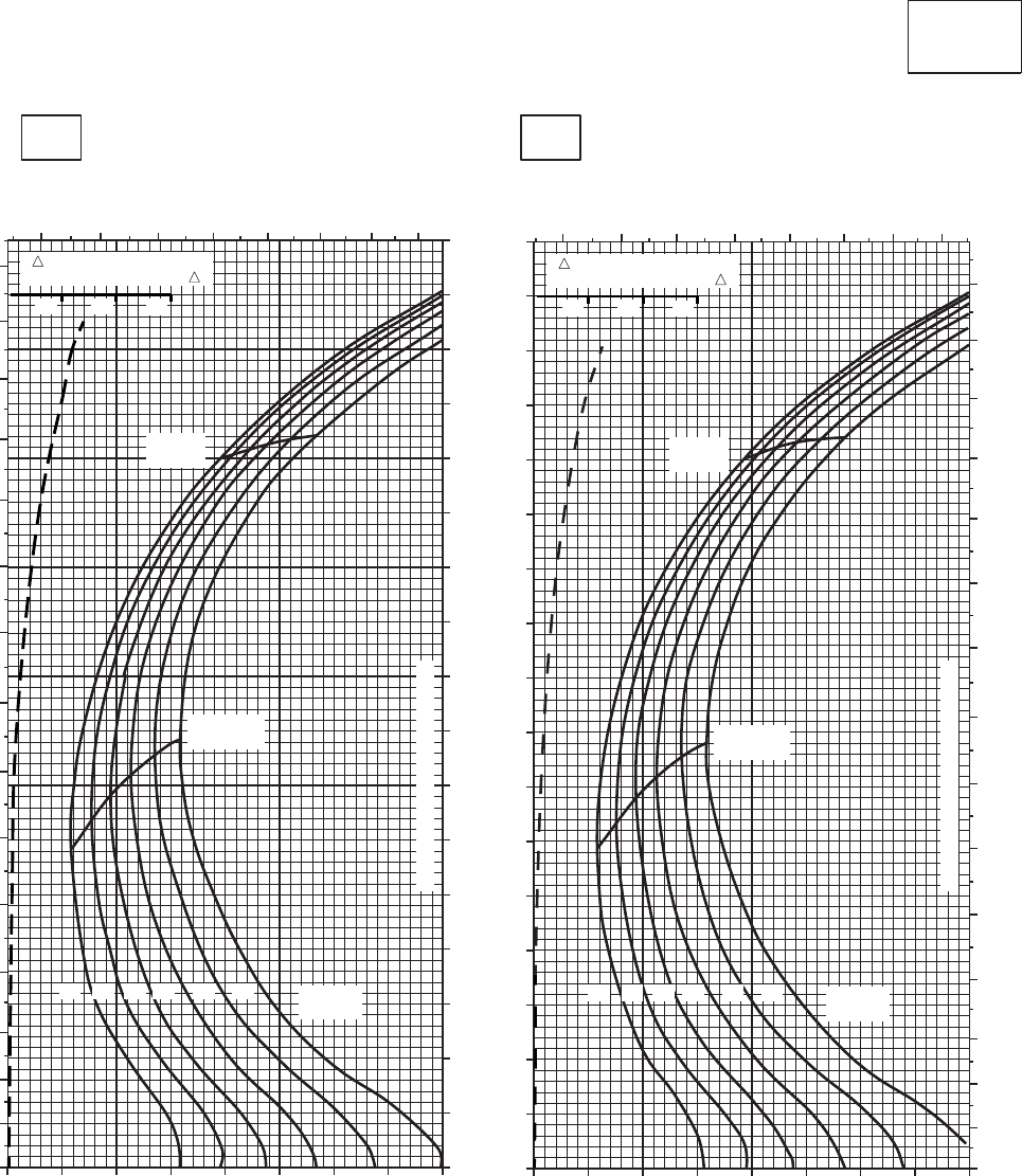
CRUISE CRUISE
T701C (2)
TORQUE PER ENGINE ~ %TORQUE PER ENGINE ~ %
IAS ~ KTS TOTAL FUEL FLOW ~ 100 LB/HRTOTAL FUEL FLOW ~ 100 LB/HR
DATA BASE:FLIGHT TEST
TRUE AIRSPEED ~ KTS
TRUE AIRSPEED ~ KTS
CLEAN CONFIGURATION
SA
AA1061_1
PRESS ALT: 2,000 FT
2,000 FT
−50oC−40oC
0
10
20
30
40
50
60
70
80
90
100
110
120
130
140
150
0
10
20
30
40
50
60
70
80
90
100
110
120
130
140
150
678910 11 12 13 678 9 10 11 12 13
20 30 40 50 60 70 80 90 100 20 30 40 50 60 70 80 90 100
0
10
20
30
40
50
60
70
80
90
100
110
120
130
140
150
160
170
GW ~
1000 LB GW ~
1000 LB
MAX END
AND R / C MAX END
AND R / C
MAX
RANGE MAX
RANGE
12 14 16 18 20 22
12 14 16 18 20 22
10 20 30 10 20 30
TRANSMISSION TORQUE LIMIT
TRANSMISSION TORQUE LIMIT
TRQ ~ % FOR DRAG
AREA OF 10 SQ FT OF F TRQ ~ % FOR DRAG
AREA OF 10 SQ FT OF F
Figure 7A-11. Cruise - Pressure Altitude 2,000 Feet (Sheet 1 of 6)
TM 1-1520-237-10
7A-32
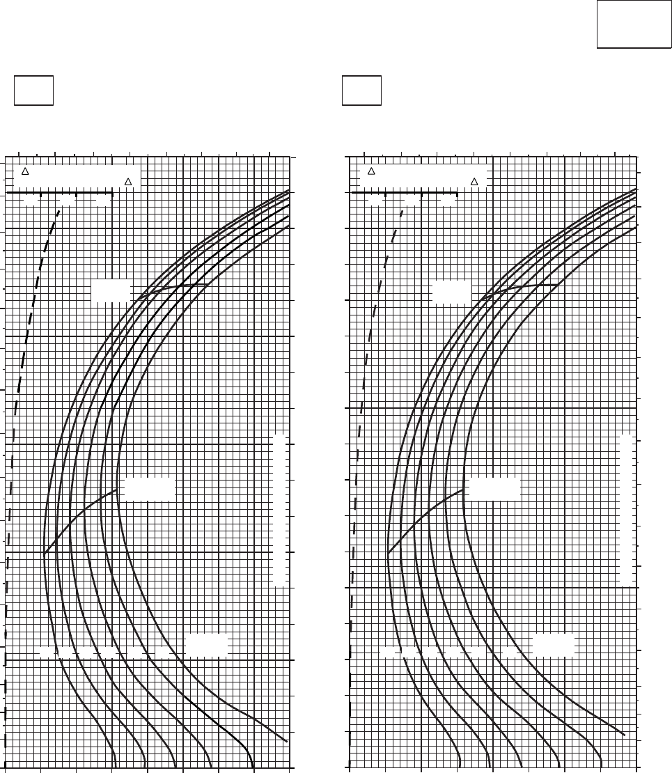
CRUISE CRUISE
T701C (2)
TORQUE PER ENGINE ~ %TORQUE PER ENGINE ~ %
IAS ~ KTS TOTAL FUEL FLOW ~ 100 LB/HRTOTAL FUEL FLOW ~ 100 LB/HR
DATA BASE:FLIGHT TEST
TRUE AIRSPEED ~ KTS
TRUE AIRSPEED ~ KTS
CLEAN CONFIGURATION
0
10
20
30
40
50
60
70
80
90
100
110
120
130
140
150
160
170
SA
AA1061_2
PRESS ALT: 2,000 FT
2,000 FT
−30oC−20oC
20 30 40 50 60 70 80 90 100 20 30 40 50 60 70 80 90 100
678910 11 12 13
67 8 9 10 11 12 13
0
10
20
30
40
50
60
70
80
90
100
110
120
130
140
150
160
0
10
20
30
40
50
60
70
80
90
100
110
120
130
140
150
160
MAX
RANGE
MAX END
AND R / C
MAX END
AND R / C
GW ~
1000 LB GW ~
1000 LB
20 22
12 14 16 18
20 22
12 14 16 18
TRANSMISSION TORQUE LIMIT
TRANSMISSION TORQUE LIMIT
10 20 30 10 20 30
TRQ ~ % FOR DRAG
AREA OF 10 SQ FT OF F TRQ ~ % FOR DRAG
AREA OF 10 SQ FT OF F
MAX
RANGE
Figure 7A-11. Cruise - Pressure Altitude 2,000 Feet (Sheet 2 of 6)
TM 1-1520-237-10
7A-33
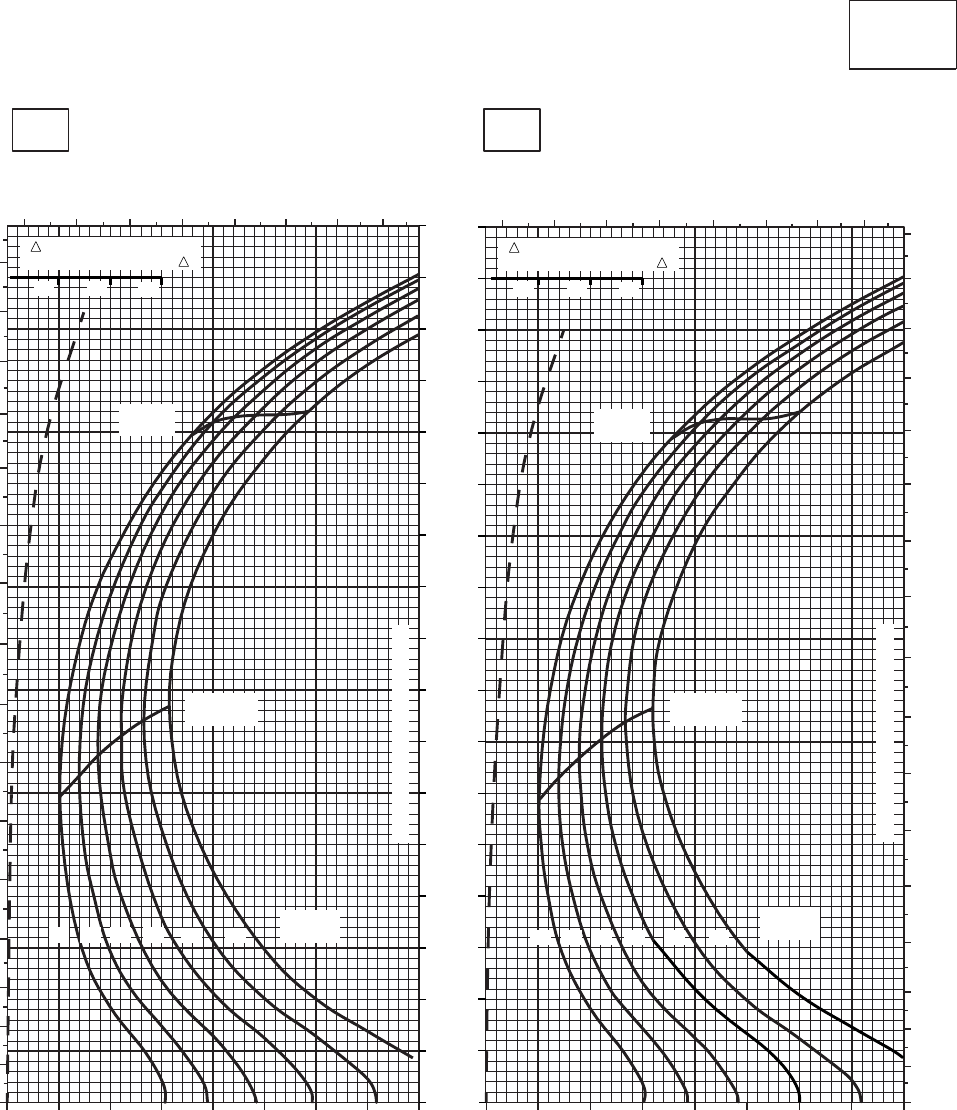
CRUISE CRUISE
T701C (2)
TORQUE PER ENGINE ~ %TORQUE PER ENGINE ~ %
IAS ~ KTS TOTAL FUEL FLOW ~ 100 LB/HRTOTAL FUEL FLOW ~ 100 LB/HR
DATA BASE:FLIGHT TEST
TRUE AIRSPEED ~ KTS
TRUE AIRSPEED ~ KTS
CLEAN CONFIGURATION
0
10
20
30
40
50
60
70
80
90
100
110
120
130
140
150
160
170
SA
AA1061_3
PRESS ALT: 2,000 FT
2,000 FT
−10oC0oC
6 7 8 9 10 11 12 13
678 9 10 11 12 13
20 30 40 50 60 70 80 90 100
20 30 40 50 60 70 80 90 100
0
10
20
30
40
50
60
70
80
90
100
110
120
130
140
150
160
0
10
20
30
40
50
60
70
80
90
100
110
120
130
140
150
160
170
TRANSMISSION TORQUE LIMIT
TRANSMISSION TORQUE LIMIT
MAX
RANGE MAX
RANGE
MAX END
AND R / C
MAX END
AND R / C
GW ~
1000 LB GW ~
1000 LB
12 14 16 18 12 14 16 18
20 22 20 22
10 20 30 10 20 30
TRQ ~ % FOR DRAG
AREA OF 10 SQ FT OF F TRQ ~ % FOR DRAG
AREA OF 10 SQ FT OF F
Figure 7A-11. Cruise - Pressure Altitude 2,000 Feet (Sheet 3 of 6)
TM 1-1520-237-10
7A-34
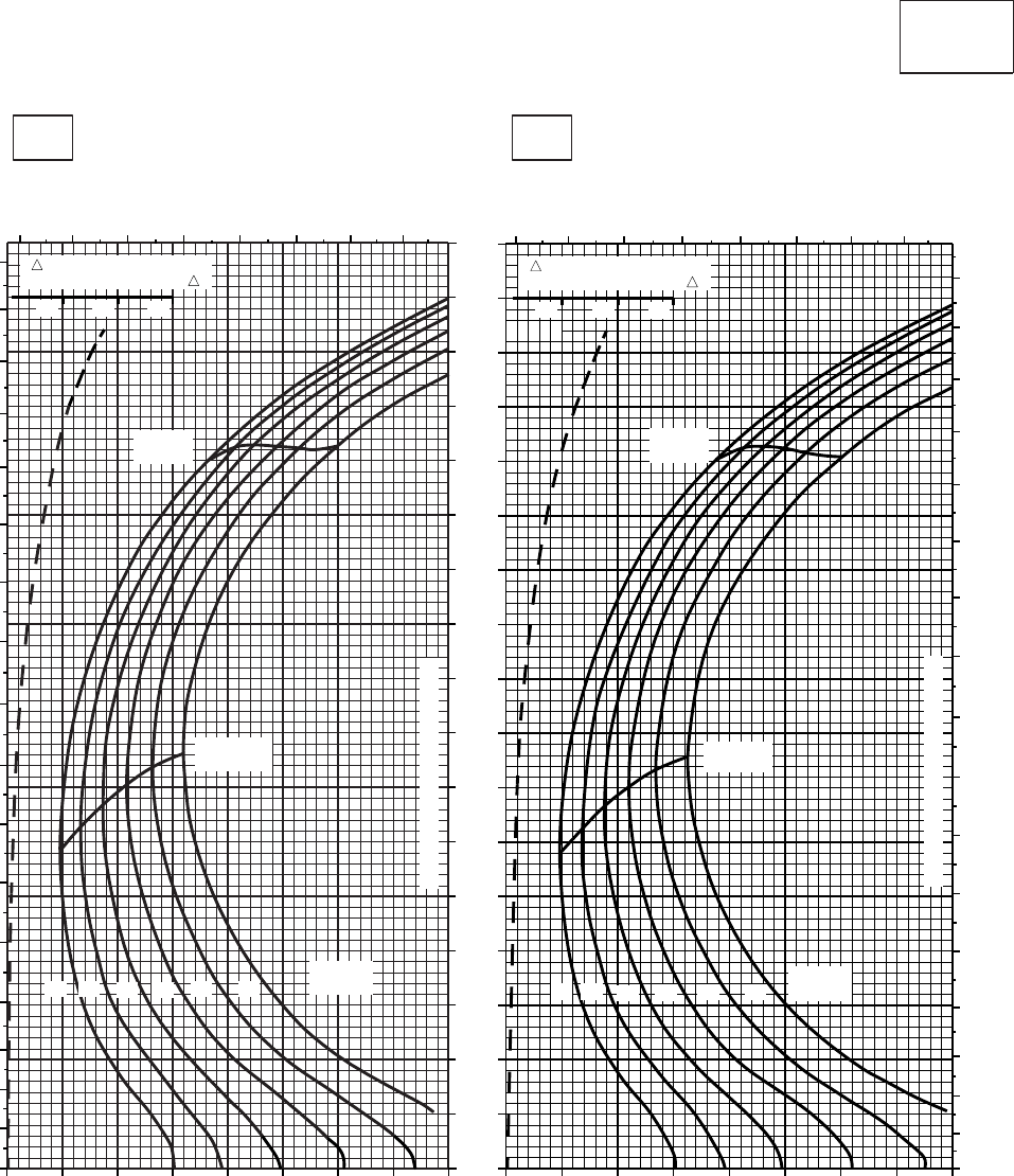
CRUISE CRUISE
T701C (2)
TORQUE PER ENGINE ~ %TORQUE PER ENGINE ~ %
IAS ~ KTS TOTAL FUEL FLOW ~ 100 LB/HRTOTAL FUEL FLOW ~ 100 LB/HR
DATA BASE:FLIGHT TEST
TRUE AIRSPEED ~ KTS
TRUE AIRSPEED ~ KTS
CLEAN CONFIGURATION
0
10
20
30
40
50
60
70
80
90
100
110
120
130
140
150
160
170
SA
AA1061_4
PRESS ALT: 2,000 FT
2,000 FT
10oC20oC
TRANSMISSION TORQUE LIMIT
MAX
RANGE
MAX END
AND R / C
GW ~
1000 LB
12 14 16 20 22
18
20 30 40 50 60 70 80 90 100
67 8 910 11 12 13
0
10
20
30
40
50
60
70
80
90
100
110
120
130
140
150
160
170
20 30 40 50 60 70 80 90 100
6 7 8 9 10 11 12 13
MAX
RANGE
MAX END
AND R / C
TRANSMISSION TORQUE LIMIT
0
10
20
30
40
50
60
70
80
90
100
110
120
130
140
150
160
170
GW ~
1000 LB
12 14 16 20 22
18
10 20 30 10 20 30
TRQ ~ % FOR DRAG
AREA OF 10 SQ FT OF F TRQ ~ % FOR DRAG
AREA OF 10 SQ FT OF F
Figure 7A-11. Cruise - Pressure Altitude 2,000 Feet (Sheet 4 of 6)
TM 1-1520-237-10
7A-35
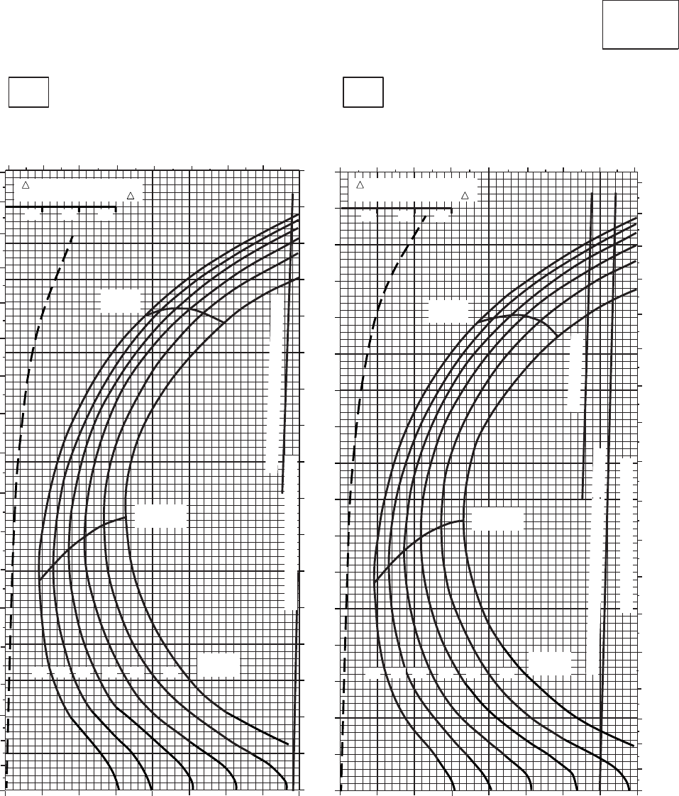
CRUISE CRUISE
T701C (2)
TORQUE PER ENGINE ~ %TORQUE PER ENGINE ~ %
IAS ~ KTS TOTAL FUEL FLOW ~ 100 LB/HRTOTAL FUEL FLOW ~ 100 LB/HR
DATA BASE:FLIGHT TEST
TRUE AIRSPEED ~ KTS
TRUE AIRSPEED ~ KTS
CLEAN CONFIGURATION
0
10
20
30
40
50
60
70
80
90
100
110
120
130
140
150
160
170
SA
AA1061_5
PRESS ALT: 2,000 FT
2,000 FT
30oC40oC
6 7 8910 11 12 13
20 30 40 50 60 70 80 90 100
0
10
20
30
40
50
60
70
80
90
100
110
120
130
140
150
160
170
180
67 8 9 10 11 12 13 14
20 30 40 50 60 70 80 90 100
0
10
20
30
40
50
60
70
80
90
100
110
120
130
140
150
160
170
180
TRQ ~ % FOR DRAG
AREA OF 10 SQ FT OF F
10 20 30
MAX
RANGE MAX
RANGE
MAX END
AND R / C MAX END
AND R / C
GW ~
1000 LB GW ~
1000 LB
12 14 16 18 20 22
TRANSMISSION TORQUE LIMIT
TRANSMISSION TORQUE LIMIT
~ CONTINUOUS
TORQUE AVAILABLE ~ 30 MINUTES ATF = 0.9
TORQUE AVAILABLE~CONTINUOUS
14 16 18 20 22
12
TRQ ~ % FOR DRAG
AREA OF 10 SQ FT OF F
10 20 30
Figure 7A-11. Cruise - Pressure Altitude 2,000 Feet (Sheet 5 of 6)
TM 1-1520-237-10
7A-36
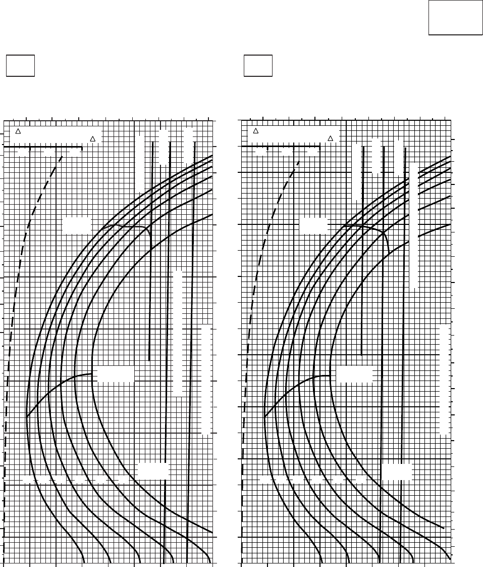
CRUISE CRUISE
T701C (2)
TORQUE PER ENGINE ~ %TORQUE PER ENGINE ~ %
IAS ~ KTS TOTAL FUEL FLOW ~ 100 LB/HRTOTAL FUEL FLOW ~ 100 LB/HR
DATA BASE:FLIGHT TEST
TRUE AIRSPEED ~ KTS
TRUE AIRSPEED ~ KTS
CLEAN CONFIGURATION
0
10
20
30
40
50
60
70
80
90
100
110
120
130
140
150
160
170
SA
AA1061_6
PRESS ALT: 2,000 FT
2,000 FT
50oC60oC
20 30 40 50 60 70 80 90 100
7 8 9 10 11 12 13 14
0
10
20
30
40
50
60
70
80
90
100
110
120
130
140
150
160
170
180 TRQ ~ % FOR DRAG
AREA OF 10 SQ FT OF F
22
MAX
RANGE
MAX END
AND R / C
TRANSMISSION TORQUE LIMIT
12 14 16 18 20
TORQUE AVAILABLE ~ 30 MINUTES
~ CONTINUOUS
ATF = 0.9
ATF = 1.0
20 30 40 50 60 70 80 90 100
7 8 9 10 11 12 13 14
TRQ ~ % FOR DRAG
AREA OF 10 SQ FT OF F
0
0
10
20
30
40
50
60
70
80
90
100
110
120
130
140
150
160
170
180
MAX
RANGE
MAX END
AND R / C
TRANSMISSION TORQUE LIMIT
22
12 14 16 18 20
~ CONTINUOUS
ATF = 0.9
ATF = 1.0
10 20 30 10 20 30
PLACARD TORQUE LIMIT = 96%PLACARD TORQUE LIMIT = 99%
GW ~
1000 LB
TORQUE AVAILABLE ~ 30 MINUTES
GW ~
1000 LB
Figure 7A-11. Cruise - Pressure Altitude 2,000 Feet (Sheet 6 of 6)
TM 1-1520-237-10
7A-37
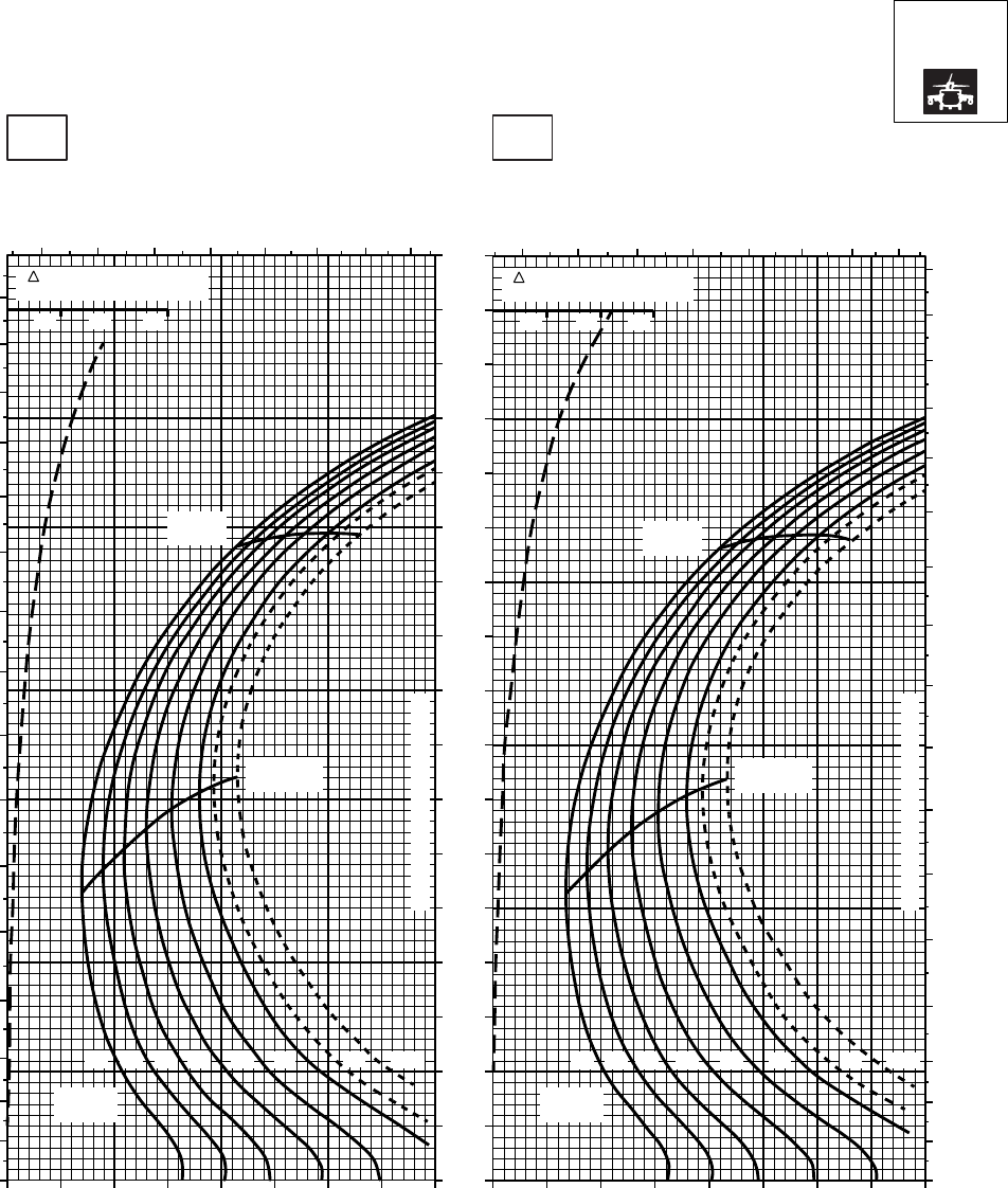
CRUISE CRUISE
T701C (2)
TORQUE PER ENGINE ~ %TORQUE PER ENGINE ~ %
IAS ~ KTS TOTAL FUEL FLOW ~ 100 LB/HRTOTAL FUEL FLOW ~ 100 LB/HR
DATA BASE:FLIGHT TEST
TRUE AIRSPEED ~ KTS
TRUE AIRSPEED ~ KTS
NOTE:SHORT DASH LINES: FERRY MISSION ONLY
SA
AA1062_1
PRESS ALT: 2000 FT
2000 FT
−50oC−40oC
0
10
20
30
40
50
60
70
80
90
100
110
120
130
140
150
160
6 7 8 9 10 11 12 13 6 7 8 9 10 11 12 13
0
10
20
30
40
50
60
70
80
90
100
110
120
130
140
150
160
170
20 30 40 50 60 70 80 90 100 20 30 40 50 60 70 80 90 100
0
10
20
30
40
50
60
70
80
90
100
110
120
130
140
150
160
170
TRQ ~ % FOR DRAG
AREA OF 10 SQ FT
10 20 30
TRQ ~ % FOR DRAG
AREA OF 10 SQ FT
10 20 30
14 1612 18 20
MAX
RANGE
GW ~
1000 LB
MAX END
AND R / C
CONTINUOUS TORQUE LIMIT
CONTINUOUS TORQUE LIMIT
14 1612 18 20
MAX
RANGE
MAX END
AND R / C
GW ~
1000 LB
22 23 24.5 23 24.522
Figure 7A-12. Cruise High Drag - Pressure Altitude 2,000 Feet (Sheet 1 of 6)
TM 1-1520-237-10
7A-38

CRUISE
PRESS ALT: 2000 FT
CRUISE
2000 FT
T701C (2)
TORQUE PER ENGINE ~ %TORQUE PER ENGINE ~ %
IAS ~ KTS TOTAL FUEL FLOW ~ 100 LB/HRTOTAL FUEL FLOW ~ 100 LB/HR
DATA BASE:FLIGHT TEST
TRUE AIRSPEED ~ KTS
−20OC−30OC
NOTE: SHORT DASH LINES: FERRY MISSION ONLY
170
160
150
140
130
120
110
100
90
80
70
60
50
40
30
20
10
0
20 30 40 50 60 70 80 90 100 20 30
180
170
160
170
678 9 10 11 12 13 6 7 8 9 10 11 12 13
TRUE AIRSPEED ~ KTS
TRUE AIRSPEED ~ KTS
150
140
130
120
110
100
90
80
70
60
50
40
30
20
10
0
20 30 40 50 60 70 80 90 100 20 30 40 50 60 70 80 90 100
160
150
140
130
120
110
100
90
80
70
60
50
40
30
20
10
0
150
140
130
120
110
100
90
80
70
60
50
40
30
20
10
0
MAX
RANGE
GW ~
1000 LB
MAX END
AND R / C
MAX
RANGE
MAX END
AND R / C
GW ~
1000 LB
12 14 16 18 20 22 23 24.5
12 14 16 18 20 22 23 24.5
TRQ ~ % FOR DRAG
AREA OF 10 SQ FT
10 20 30
TRQ ~ % FOR DRAG
AREA OF 10 SQ FT
10 20 30
160
SA
AA1062_2
CONTINUOUS TORQUE LIMIT
CONTINUOUS TORQUE LIMIT
Figure 7A-12. Cruise High Drag - Pressure Altitude 2,000 Feet (Sheet 2 of 6)
TM 1-1520-237-10
7A-39
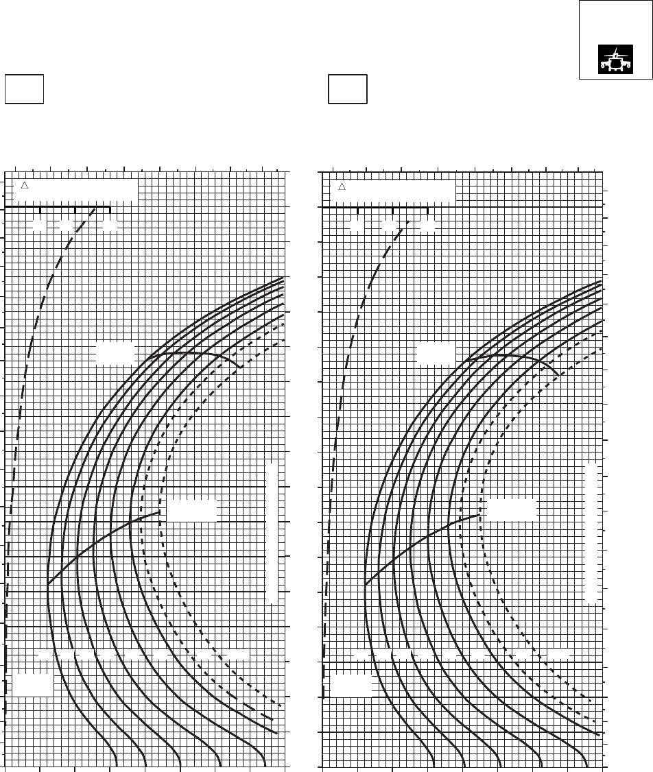
CRUISE
TORQUE PER ENGINE ~ %TORQUE PER ENGINE ~ %
IAS ~ KTS TOTAL FUEL FLOW ~ 100 LB/HRTOTAL FUEL FLOW ~ 100 LB/HR
DATA BASE:FLIGHT TEST
TRUE AIRSPEED ~ KTS
TRUE AIRSPEED ~ KTS
SA
AA1062_3
PRESS ALT: 2000 FT
−10oC0oC
20 30 40 50 60 70 80 90 100 20 30 40 50 60 70 80 90 100
0
10
20
30
40
50
60
70
80
90
100
110
120
130
140
150
160
170
6 7 8 9 10 11 12 13 678 9 10 11 12 13
0
10
20
30
40
50
60
70
80
90
100
110
120
130
140
150
160
170
180
0
10
20
30
40
50
60
70
80
90
100
110
120
130
140
150
160
170
180
MAX
RANGE
MAX END
AND R / C
22
20
18
16
14
12 23 24.5
GW ~
1000 LB GW ~
1000 LB
MAX END
AND R / C
22
20
18
16
14
12 23 24.5
MAX
RANGE
10 20 30
10 20 30
CRUISE
T701C (2)
NOTE:SHORT DASH LINES: FERRY MISSION ONLY
2000 FT
TRQ ~ % FOR DRAG
AREA OF 10 SQ FT TRQ ~ % FOR DRAG
AREA OF 10 SQ FT
CONTINUOUS TORQUE LIMIT
CONTINUOUS TORQUE LIMIT
Figure 7A-12. Cruise High Drag - Pressure Altitude 2,000 Feet (Sheet 3 of 6)
TM 1-1520-237-10
7A-40
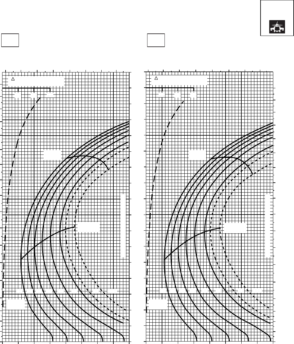
CRUISE CRUISE
T701C (2)
TORQUE PER ENGINE ~ %TORQUE PER ENGINE ~ %
IAS ~ KTS TOTAL FUEL FLOW ~ 100 LB/HRTOTAL FUEL FLOW ~ 100 LB/HR
DATA BASE:FLIGHT TEST
TRUE AIRSPEED ~ KTS
TRUE AIRSPEED ~ KTS
NOTE:SHORT DASH LINES: FERRY MISSION ONLY
SA
AA1062_4
PRESS ALT: 2000 FT
2000 FT
10oC20oC
0
10
20
30
40
50
60
70
80
90
100
110
120
130
140
150
160
170
180
6 7 8 9 10 11 12 13
20 30 40 50 60 70 80 90 100
0
10
20
30
40
50
60
70
80
90
100
110
120
130
140
150
160
170
6 7 8 9 10 11 12 13
20 30 40 50 60 70 80 90 100
0
10
20
30
40
50
60
70
80
90
100
110
120
130
140
150
160
170
180
10 20 30
TRQ ~ % FOR DRAG
AREA OF 10 SQ FT
10 20 30
TRQ ~ % FOR DRAG
AREA OF 10 SQ FT
22
20
18
16
14
12 23 24.5 22
20
18
16
14
12 23 24.5
GW ~
1000 LB GW ~
1000 LB
MAX END
AND R / C MAX END
AND R / C
MAX
RANGE MAX
RANGE
CONTINUOUS TORQUE LIMIT
CONTINUOUS TORQUE LIMIT
Figure 7A-12. Cruise High Drag - Pressure Altitude 2,000 Feet (Sheet 4 of 6)
TM 1-1520-237-10
7A-41
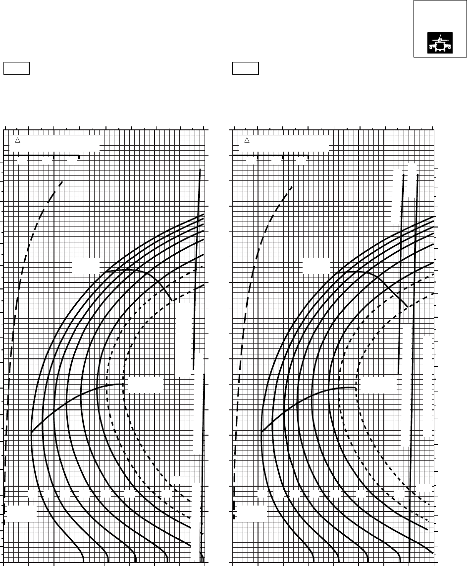
CRUISE
PRESS ALT: 2000 FT
TORQUE PER ENGINE ~ %TORQUE PER ENGINE ~ %
IAS ~ KTS TOTAL FUEL FLOW ~ 100 LB/HRTOTAL FUEL FLOW ~ 100 LB/HR
DATA BASE:FLIGHT TEST
TRUE AIRSPEED ~ KTS
NOTE: SHORT DASH LINES: FERRY MISSION ONLY
170
160
150
140
130
120
110
100
90
80
70
60
50
40
30
20
10
0
20 30 40 50 60 70 80 90 100 20 30
TRUE AIRSPEED ~ KTS
TRUE AIRSPEED ~ KTS
150
140
130
120
110
100
90
80
70
60
50
40
30
20
10
0
20 30 40 50 60 70 80 90 100 20 30 40 50 60 70 80 90 100
0
TRQ ~ % FOR DRAG
AREA OF 10 SQ FT
10 20 30
TRQ ~ % FOR DRAG
AREA OF 10 SQ FT
10 20 30
SA
AA1062_5
30oC 40oC
0
10
20
30
40
50
60
70
80
90
100
110
120
130
140
150
160
170
180
14
6 7 8 9 10 11 12 13 14 6 7 8 9 10 11 12 13
180
170
160
150
140
130
120
110
100
90
80
70
60
50
40
30
20
10
MAX
RANGE
MAX
RANGE
MAX END
AND R / C MAX END
AND R / C
GW ~
1000 LB
12 14 16 18 20 22 23
24.5
~ 30 MINUTE ATF = 0.9
TORQUE AVAILABLE
~ CONTINUOUS
CONTINUOUS TORQUE LIMIT
~ CONTINUOUS
ATF = 0.9
TORQUE AVAILABLE ~ 30 MINUTES
CONTINUOUS TORQUE LIMIT
GW ~
1000 LB
12 14 16 18 20 22 23 24.5
CRUISE
T701C (2)
2000 FT
Figure 7A-12. Cruise High Drag - Pressure Altitude 2,000 Feet (Sheet 5 of 6)
TM 1-1520-237-10
7A-42
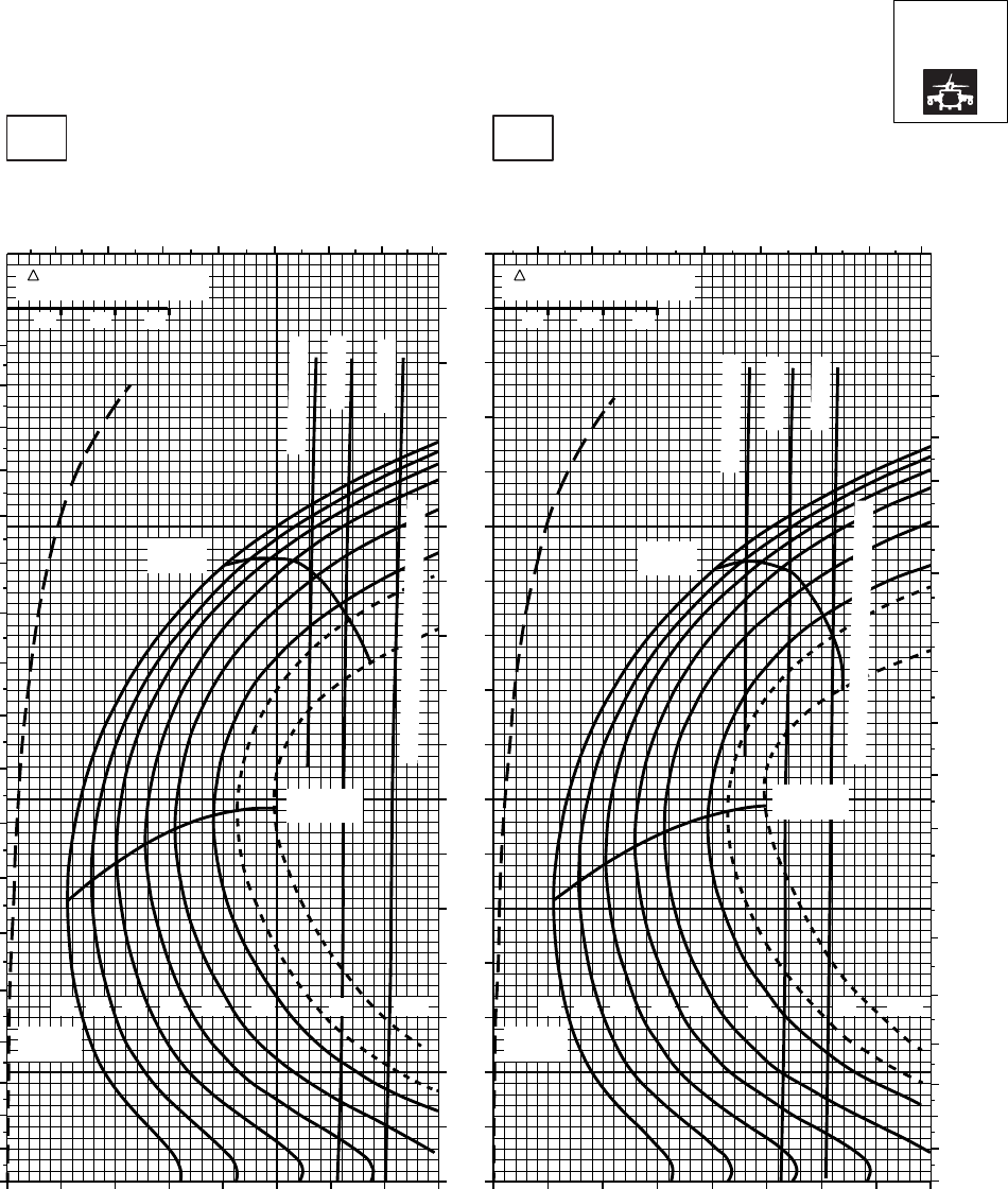
CRUISE CRUISE
T701C (2)
TORQUE PER ENGINE ~ %TORQUE PER ENGINE ~ %
IAS ~ KTS TOTAL FUEL FLOW ~ 100 LB/HRTOTAL FUEL FLOW ~ 100 LB/HR
DATA BASE:FLIGHT TEST
TRUE AIRSPEED ~ KTS
TRUE AIRSPEED ~ KTS
NOTE:SHORT DASH LINES: FERRY MISSION ONLY
SA
AA1062_6
PRESS ALT: 2000 FT
2000 FT
50oC60oC
TRQ ~ % FOR DRAG
AREA OF 10 SQ FT
10 20 30
TRQ ~ % FOR DRAG
AREA OF 10 SQ FT
10 20 30
7 8 9 10 11 12 13 14 7 8 9 10 11 12 13 14
0
10
20
30
40
50
60
70
80
90
100
110
120
130
140
150
160
170
180
0
10
20
30
40
50
60
70
80
90
100
110
120
130
140
150
160
170
180
20 30 40 50 60 70 80 90 100 20 30 40 50 60 70 80 90 100
0
10
20
30
40
50
60
70
80
90
100
110
120
130
140
150
160
170
14 1612 18 20
MAX
RANGE
GW ~
1000 LB
MAX
RANGE
GW ~
1000 LB
22 24.5 14 1612 18 20 22 23 24.5
ATF = 0.9
~ CONTINUOUS
~ CONTINUOUS
ATF = 1.0
TORQUE AVAILABLE ~ 30 MINUTES
TORQUE AVAILABLE ~ 30 MINUTES
MAX END
AND R / C
ATF = 1.0
ATF = 0.9
MAX END
AND R / C
23
PLACARD TORQUE LIMIT = 99% PLACARD TORQUE LIMIT = 99%
Figure 7A-12. Cruise High Drag - Pressure Altitude 2,000 Feet (Sheet 6 of 6)
TM 1-1520-237-10
7A-43
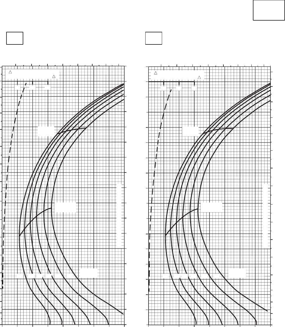
CRUISE CRUISE
T701C (2)
TORQUE PER ENGINE ~ %TORQUE PER ENGINE ~ %
IAS ~ KTS TOTAL FUEL FLOW ~ 100 LB/HRTOTAL FUEL FLOW ~ 100 LB/HR
DATA BASE:FLIGHT TEST
TRUE AIRSPEED ~ KTS
TRUE AIRSPEED ~ KTS
CLEAN CONFIGURATION
0
10
20
30
40
50
60
70
80
90
100
110
120
130
140
150
160
170
SA
AA1063_1
−50oC−40oC
PRESS ALT: 4,000 FT
4,000 FT
678910 11 12 13 678910 11 12 13
0
10
20
30
40
50
60
70
80
90
100
110
120
130
140
150
160
20 30 40 50 60 70 80 90 100 20 30 40 50 60 70 80 90 100
0
10
20
30
40
50
60
70
80
90
100
110
120
130
140
150
160
10 20 30 10 20 30
12 1214 1416 1618 1820 2022 22
GW ~
1000 LB GW ~
1000 LB
MAX END
AND R / C MAX END
AND R / C
MAX
RANGE MAX
RANGE
TRANSMISSION TORQUE LIMIT
TRANSMISSION TORQUE LIMIT
TRQ ~ % FOR DRAG
AREA OF 10 SQ FT OF F TRQ ~ % FOR DRAG
AREA OF 10 SQ FT OF F
Figure 7A-13. Cruise - Pressure Altitude 4,000 Feet (Sheet 1 of 6)
TM 1-1520-237-10
7A-44
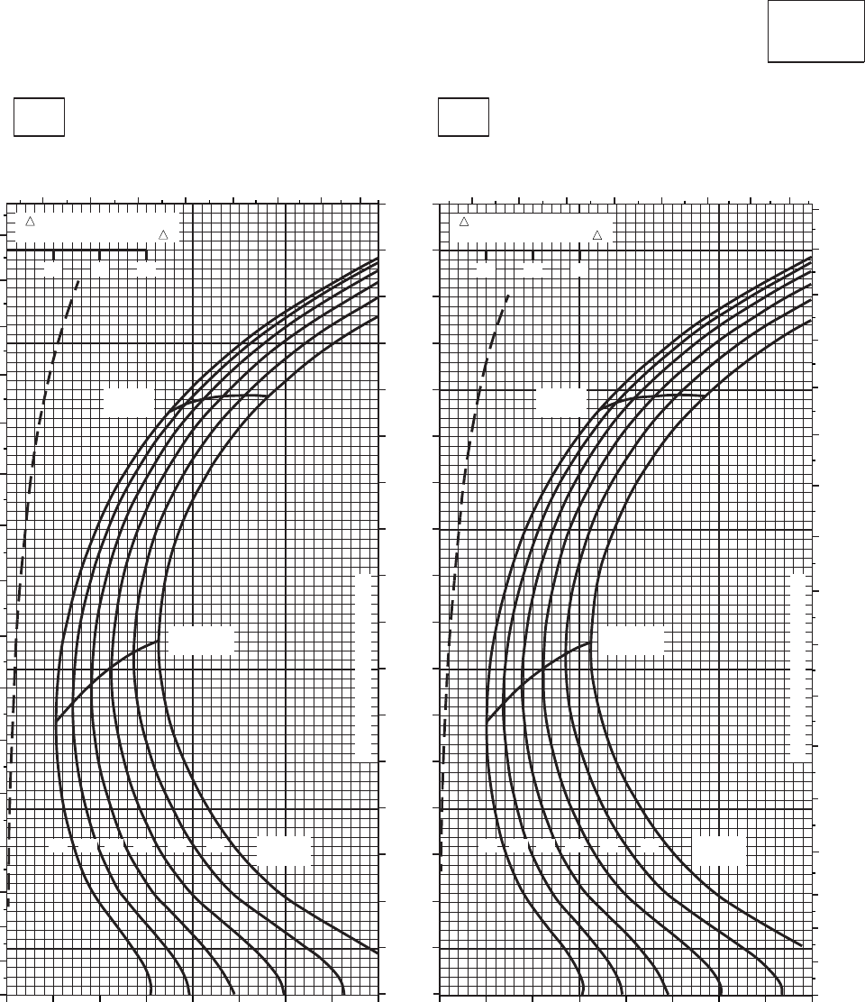
CRUISE CRUISE
T701C (2)
TORQUE PER ENGINE ~ %TORQUE PER ENGINE ~ %
IAS ~ KTS TOTAL FUEL FLOW ~ 100 LB/HRTOTAL FUEL FLOW ~ 100 LB/HR
DATA BASE:FLIGHT TEST
TRUE AIRSPEED ~ KTS
TRUE AIRSPEED ~ KTS
CLEAN CONFIGURATION
0
10
20
30
40
50
60
70
80
90
100
110
120
130
140
150
160
170
SA
AA1063_2
PRESS ALT: 4,000 FT
4,000 FT
−30oC−20oC
0
10
20
30
40
50
60
70
80
90
100
110
120
130
140
150
160
6 7 8 9 10 11 12 13 6 7 8 9 10 11 12 13
0
10
20
30
40
50
60
70
80
90
100
110
120
130
140
150
160
170
10 20 30 10 20 30
GW ~
1000 LB
12 1214 1416 1618 1820 2022 22 GW ~
1000 LB
MAX END
AND R / C MAX END
AND R / C
MAX
RANGE MAX
RANGE
TRANMISSION TORQUE LIMIT
TRANMISSION TORQUE LIMIT
20 30 40 50 60 70 80 90 100 20 30 40 50 60 70 80 90 100
TRQ ~ % FOR DRAG
AREA OF 10 SQ FT OF F TRQ ~ % FOR DRAG
AREA OF 10 SQ FT OF F
Figure 7A-13. Cruise - Pressure Altitude 4,000 Feet (Sheet 2 of 6)
TM 1-1520-237-10
7A-45
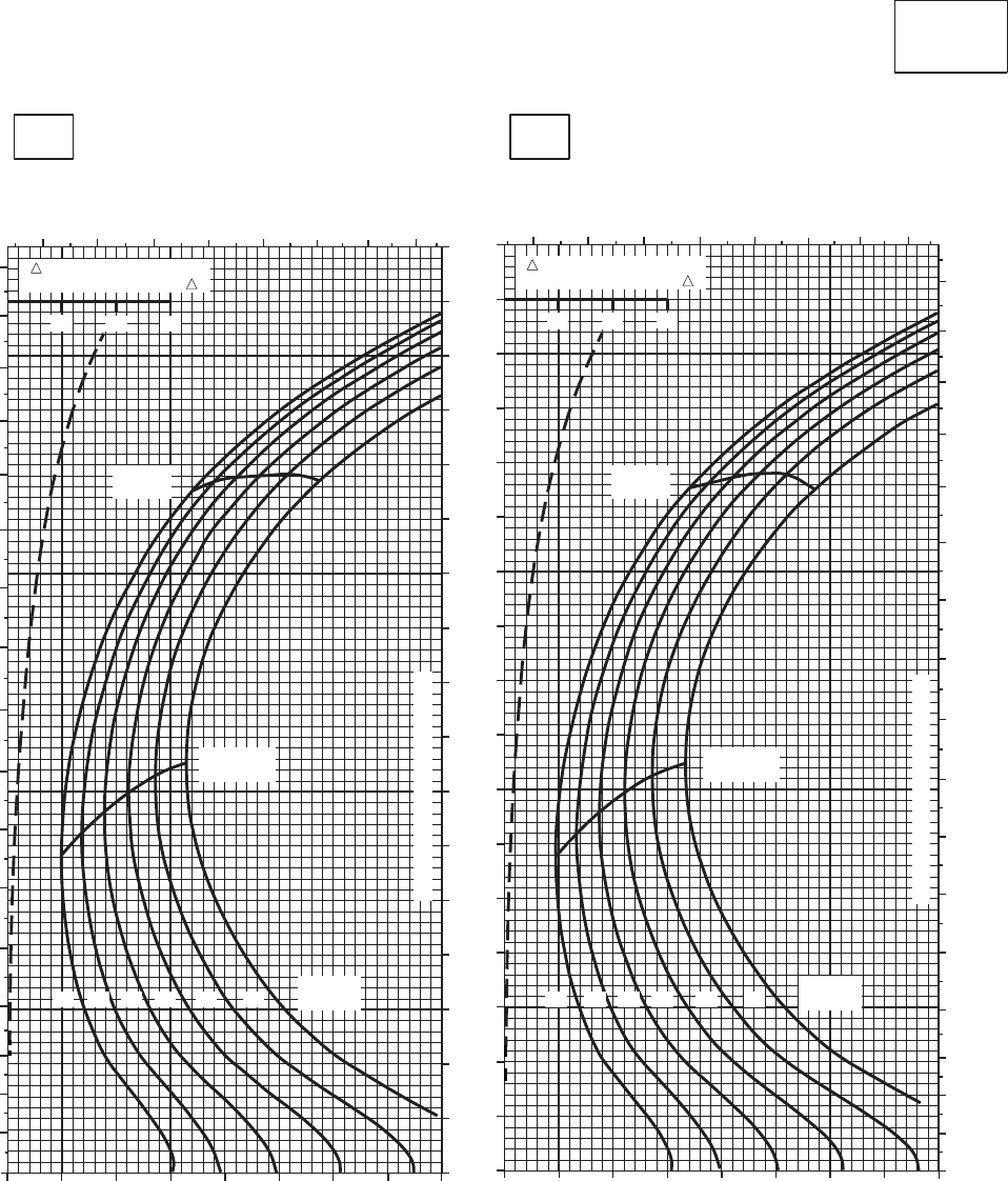
CRUISE CRUISE
T701C (2)
TORQUE PER ENGINE ~ %TORQUE PER ENGINE ~ %
IAS ~ KTS TOTAL FUEL FLOW ~ 100 LB/HRTOTAL FUEL FLOW ~ 100 LB/HR
DATA BASE:FLIGHT TEST
TRUE AIRSPEED ~ KTS
TRUE AIRSPEED ~ KTS
CLEAN CONFIGURATION
SA
AA1063_3
PRESS ALT: 4,000 FT
4,000 FT
−10oC0oC
6 7 8 9 10 11 12 13
0
10
20
30
40
50
60
70
80
90
100
110
120
130
140
150
160
170
20 30 40 50 60 70 80 90 100
6 7 8 910 11 12 13
20 30 40 50 60 70 80 90 100
0
10
20
30
40
50
60
70
80
90
100
110
120
130
140
150
160
170
0
10
20
30
40
50
60
70
80
90
100
110
120
130
140
150
160
170
10 20 30
TRQ ~ % FOR DRAG
AREA OF 10 SQ FT OF F
10 20 30
TRQ ~ % FOR DRAG
AREA OF 10 SQ FT OF F
12 1214 1416 1618 1820 2022 22
GW ~
1000 LB GW ~
1000 LB
MAX END
AND R / C MAX END
AND R / C
MAX
RANGE MAX
RANGE
TRANSMISSION TORQUE LIMIT
TRANSMISSION TORQUE LIMIT
Figure 7A-13. Cruise - Pressure Altitude 4,000 Feet (Sheet 3 of 6)
TM 1-1520-237-10
7A-46
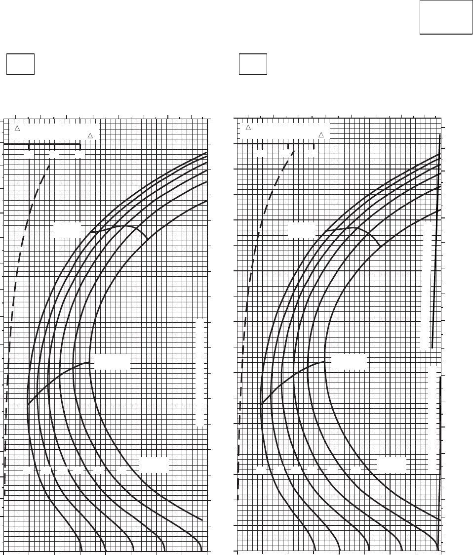
CRUISE CRUISE
T701C (2)
TORQUE PER ENGINE ~ %TORQUE PER ENGINE ~ %
IAS ~ KTS TOTAL FUEL FLOW ~ 100 LB/HRTOTAL FUEL FLOW ~ 100 LB/HR
DATA BASE:FLIGHT TEST
TRUE AIRSPEED ~ KTS
TRUE AIRSPEED ~ KTS
CLEAN CONFIGURATION
PRESS ALT: 4,000 FT
4,000 FT
10oC20oC
20 30 40 50 60 70 80 90 100
0
10
20
30
40
50
60
70
80
90
100
110
120
130
140
150
160
170
180
6 7 8 9 10 11 12 13
6 7 8 9 10 11 12 13
0
10
20
30
40
50
60
70
80
90
100
110
120
130
140
150
160
170
180
20 30 40 50 60 70 80 90 100
0
10
20
30
40
50
60
70
80
90
100
110
120
130
140
150
160
170
10 20 30
TRQ ~ % FOR DRAG
AREA OF 10 SQ FT OF F
10 20 30
TRQ ~ % FOR DRAG
AREA OF 10 SQ FT OF F
12 1214 1416 1618 1820 2022 22
GW ~
1000 LB GW ~
1000 LB
MAX END
AND R / C MAX END
AND R / C
MAX
RANGE MAX
RANGE
TRANSMISSION TORQUE LIMIT
TRANSMISSION TORQUE LIMIT
TORQUE AVAILABLE ~ CONTINUOUS
SA
AA1063_4
Figure 7A-13. Cruise - Pressure Altitude 4,000 Feet (Sheet 4 of 6)
TM 1-1520-237-10
7A-47
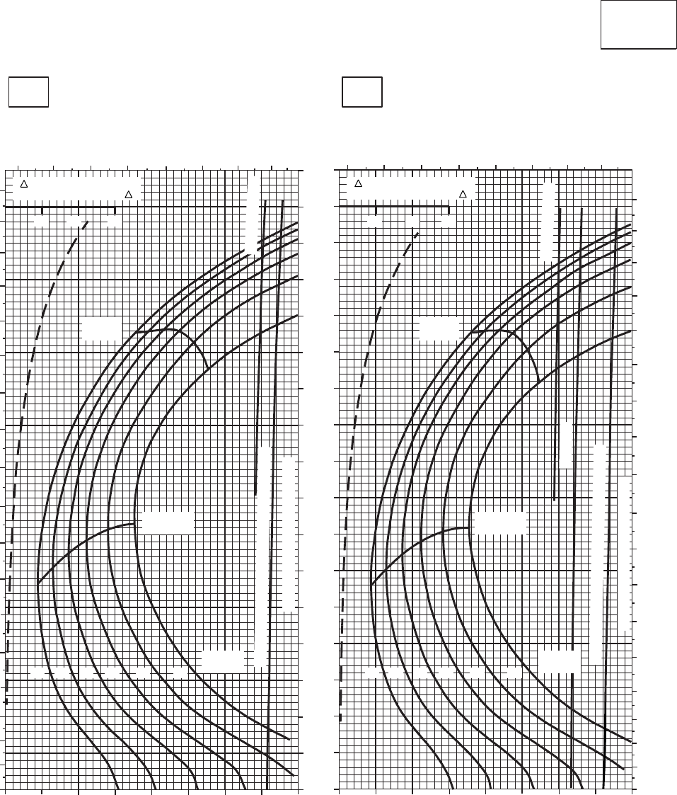
CRUISE CRUISE
T701C (2)
TORQUE PER ENGINE ~ %TORQUE PER ENGINE ~ %
IAS ~ KTS TOTAL FUEL FLOW ~ 100 LB/HRTOTAL FUEL FLOW ~ 100 LB/HR
DATA BASE:FLIGHT TEST
TRUE AIRSPEED ~ KTS
TRUE AIRSPEED ~ KTS
CLEAN CONFIGURATION
SA
AA1063_5
PRESS ALT: 4,000 FT
4,000 FT
30oC40oC
6 7 8 9 10 11 12 13
20 30 40 50 60 70 80 90 100
0
10
20
30
40
50
60
70
80
90
100
110
120
130
140
150
160
170
180
0
10
20
30
40
50
60
70
80
90
100
110
120
130
140
150
160
170
20 30 40 50 60 70 80 90 100
678 9 10 11 12 13
0
10
20
30
40
50
60
70
80
90
100
110
120
130
140
150
160
170
180
10 20 30
TRQ ~ % FOR DRAG
AREA OF 10 SQ FT OF F
10 20 30
TRQ ~ % FOR DRAG
AREA OF 10 SQ FT OF F
12 14 16 18 20 22 12 14 16 18 20 22
GW ~
1000 LB GW ~
1000 LB
MAX END
AND R / C MAX END
AND R / C
MAX
RANGE MAX
RANGE
~ CONTINUOUS
~ CONTINUOUS
TORQUE AVAILABLE ~ 30 MINUTES ATF= 0.9
TORQUE AVAILABLE ~ 30 MINUTES ATF= 0.9
TRANSMISSION TORQUE LIMIT
TRANSMISSION TORQUE LIMIT
ATF= 0.9
PLACARD TORQUE LIMIT = 94%PLACARD TORQUE LIMIT = 97%
Figure 7A-13. Cruise - Pressure Altitude 4,000 Feet (Sheet 5 of 6)
TM 1-1520-237-10
7A-48
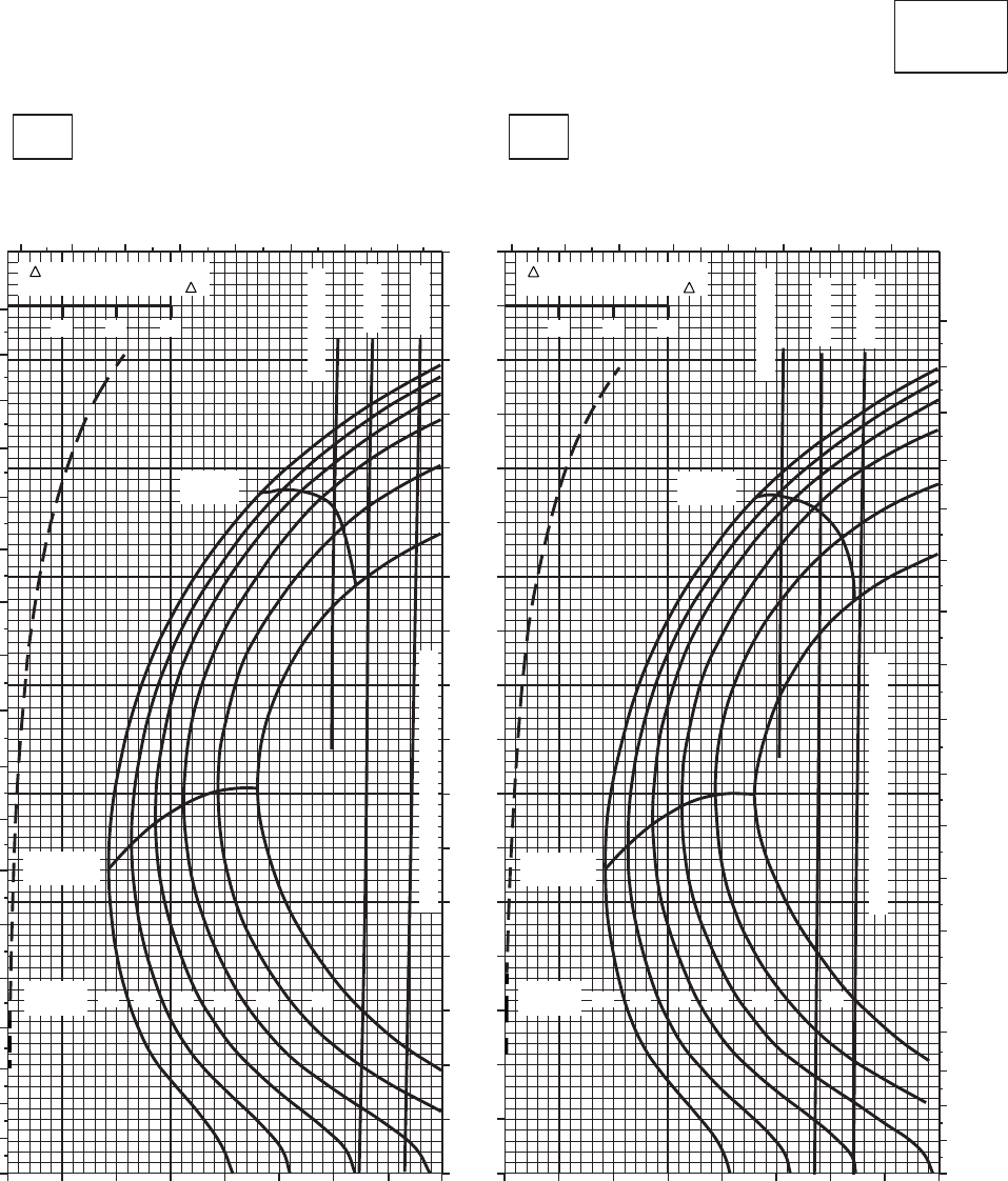
CRUISE CRUISE
T701C (2)
TORQUE PER ENGINE ~ %TORQUE PER ENGINE ~ %
IAS ~ KTS TOTAL FUEL FLOW ~ 100 LB/HRTOTAL FUEL FLOW ~ 100 LB/HR
DATA BASE:FLIGHT TEST
TRUE AIRSPEED ~ KTS
TRUE AIRSPEED ~ KTS
CLEAN CONFIGURATION
SA
AA1063_6
PRESS ALT: 4,000 FT
4,000 FT
50oC60oC
56 7 89 10 11 12 5 6 7 8 9 10 11 12
0
10
20
30
40
50
60
70
80
90
100
110
120
130
140
150
160
170
180
10 20 30 40 50 60 70 80 90
10 20 30 40 50 60 70 80 90
0
10
20
30
40
50
60
70
80
90
100
110
120
130
140
150
160
170
0
10
20
30
40
50
60
70
80
90
100
110
120
130
140
150
160
170
180 10 20 30
TRQ ~ % FOR DRAG
AREA OF 10 SQ FT OF F
10 20 30
TRQ ~ % FOR DRAG
AREA OF 10 SQ FT OF F
ATF= 0.9
ATF= 0.9
ATF= 1.0
ATF= 1.0
~CONTINUOUS
~CONTINUOUS
MAX
RANGE MAX
RANGE
TORQUE AVAILABLE ~ 30 MINUTES
TORQUE AVAILABLE ~ 30 MINUTES
12 1214 1416 1618 1820 2022 22
GW ~
1000 LB GW ~
1000 LB
MAX END
AND R / C MAX END
AND R / C
PLACARD TORQUE LIMNIT = 88%PLACARD TORQUE LIMIT = 91%
Figure 7A-13. Cruise - Pressure Altitude 4,000 Feet (Sheet 6 of 6)
TM 1-1520-237-10
7A-49
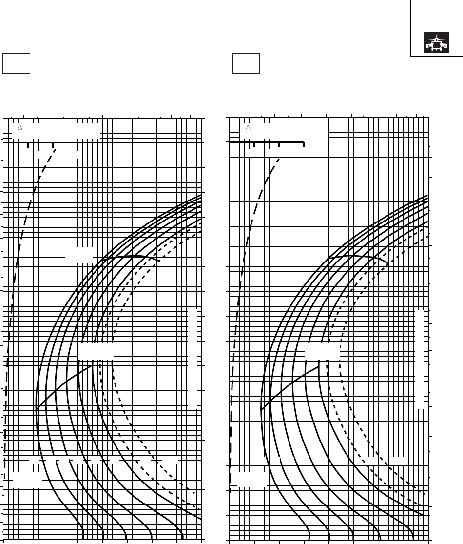
CRUISE CRUISE
T701C (2)
TORQUE PER ENGINE ~ %TORQUE PER ENGINE ~ %
IAS ~ KTS TOTAL FUEL FLOW ~ 100 LB/HRTOTAL FUEL FLOW ~ 100 LB/HR
DATA BASE:FLIGHT TEST
TRUE AIRSPEED ~ KTS
TRUE AIRSPEED ~ KTS
NOTE:SHORT DASH LINES: FERRY MISSION ONLY
PRESS ALT: 4000 FT
4000 FT
−50oC−40oC
20 30 40 50 60 70 80 90 100 20 30 40 50 60 70 80 90 100
0
10
20
30
40
50
60
70
80
90
100
110
120
130
140
150
160
170
6 7 8 9 10 11 12 13 6 7 8 9 10 11 12 13
0
10
20
30
40
50
60
70
80
90
100
110
120
130
140
150
160
170
0
10
20
30
40
50
60
70
80
90
100
110
120
130
140
150
160
170
12 14 16 18 20 22 23 24.5
GW ~
1000 LB GW ~
1000 LB
MAX END
AND R / C MAX END
AND R / C
MAX
RANGE MAX
RANGE
CONTINUOUS TORQUE LIMIT
CONTINUOUS TORQUE LIMIT
10 20 30 10 20 30
TRQ ~ % FOR DRAG
AREA OF 10 SQ FT TRQ ~ % FOR DRAG
AREA OF 10 SQ FT
SA
AA1064_1
12 14 16 18 20 22 23 24.5
Figure 7A-14. Cruise High Drag - Pressure Altitude 4,000 Feet (Sheet 1 of 6)
TM 1-1520-237-10
7A-50
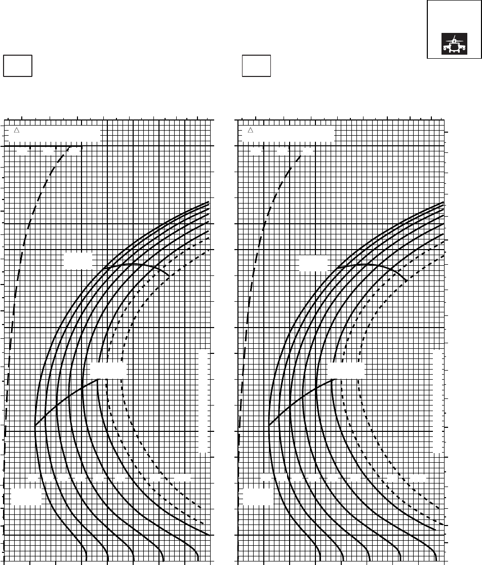
CRUISE CRUISE
T701C (2)
TORQUE PER ENGINE ~ %TORQUE PER ENGINE ~ %
IAS ~ KTS TOTAL FUEL FLOW ~ 100 LB/HRTOTAL FUEL FLOW ~ 100 LB/HR
DATA BASE:FLIGHT TEST
TRUE AIRSPEED ~ KTS
TRUE AIRSPEED ~ KTS
NOTE:SHORT DASH LINES: FERRY MISSION ONLY
SA
AA1064_2
PRESS ALT: 4000 FT
4000 FT
−30oC−20oC
20 30 40 50 60 70 80 90 100 20 30 40 50 60 70 80 90 100
0
10
20
30
40
50
60
70
80
90
100
110
120
130
140
150
160
170
180
678 9 10 11 12 13
0
10
20
30
40
50
60
70
80
90
100
110
120
130
140
150
160
170
TRQ ~ % FOR DRAG
AREA OF 10 SQ FT
10 20 30
TRQ ~ % FOR DRAG
AREA OF 10 SQ FT
10 20 30
678 9 10 11 12 13
0
10
20
30
40
50
60
70
80
90
100
110
120
130
140
150
160
170
180
MAX
RANGE MAX
RANGE
MAX END
AND R / C MAX END
AND R / C
GW ~
1000 LB GW ~
1000 LB
CONTINUOUS TORQUE LIMIT
CONTINUOUS TORQUE LIMIT
12 12
14 1416 16
18 1820 2022 2223 23
24.5 24.5
Figure 7A-14. Cruise High Drag - Pressure Altitude 4,000 Feet (Sheet 2 of 6)
TM 1-1520-237-10
7A-51

CRUISE CRUISE
T701C (2)
TORQUE PER ENGINE ~ %TORQUE PER ENGINE ~ %
IAS ~ KTS TOTAL FUEL FLOW ~ 100 LB/HRTOTAL FUEL FLOW ~ 100 LB/HR
DATA BASE:FLIGHT TEST
TRUE AIRSPEED ~ KTS
TRUE AIRSPEED ~ KTS
NOTE:SHORT DASH LINES: FERRY MISSION ONLY
SA
AA1064_3
PRESS ALT: 4000 FT
4000 FT
−10oC0oC
6 7 8 9 10 11 12 13 6 7 8 9 10 11 12 13
0
10
20
30
40
50
60
70
80
90
100
110
120
130
140
150
160
170
180
0
10
20
30
40
50
60
70
80
90
100
110
120
130
140
150
160
170
180
0
10
20
30
40
50
60
70
80
90
100
110
120
130
140
150
160
170
20 30 40 50 60 70 80 90 100 20 30 40 50 60 70 80 90 100
TRQ ~ % FOR DRAG
AREA OF 10 SQ FT
10 20 30
TRQ ~ % FOR DRAG
AREA OF 10 SQ FT
10 20 30
MAX
RANGE MAX
RANGE
MAX END
AND R / C MAX END
AND R / C
CONTINUOUS TORQUE LIMIT
CONTINUOUS TORQUE LIMIT
GW ~
1000 LB GW ~
1000 LB
12 14 16 18 20 22 23 24.5
12 14 16 18 20 22 23 24.5
Figure 7A-14. Cruise High Drag - Pressure Altitude 4,000 Feet (Sheet 3 of 6)
TM 1-1520-237-10
7A-52
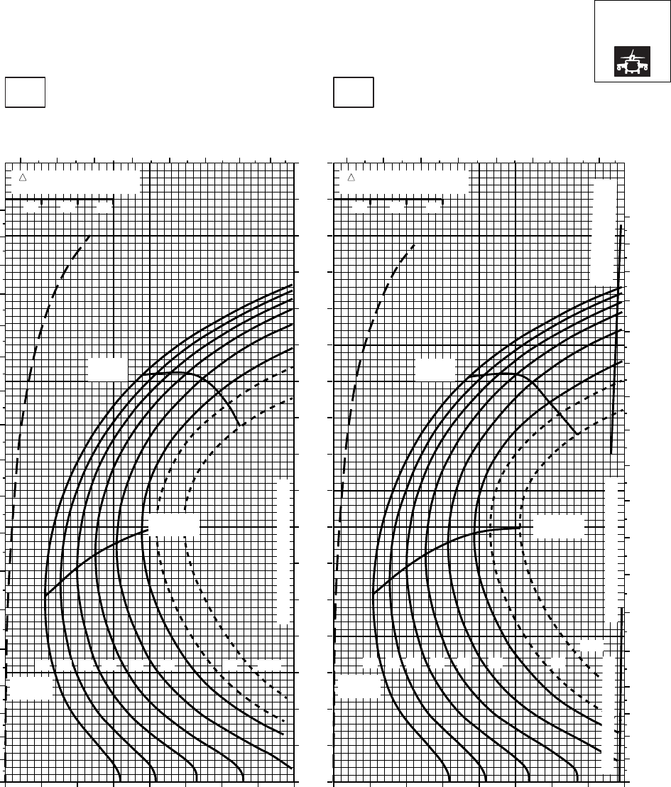
CRUISE CRUISE
T701C (2)
TORQUE PER ENGINE ~ %TORQUE PER ENGINE ~ %
IAS ~ KTS TOTAL FUEL FLOW ~ 100 LB/HRTOTAL FUEL FLOW ~ 100 LB/HR
DATA BASE:FLIGHT TEST
TRUE AIRSPEED ~ KTS
TRUE AIRSPEED ~ KTS
NOTE:SHORT DASH LINES: FERRY MISSION ONLY
SA
AA1064_4
PRESS ALT: 4000 FT
4000 FT
10oC20oC
6 7 8 9 10 11 12 13 6 7 8 9 10 11 12 13
0
10
20
30
40
50
60
70
80
90
100
110
120
130
140
150
160
170
180
0
10
20
30
40
50
60
70
80
90
100
110
120
130
140
150
160
170
180
0
10
20
30
40
50
60
70
80
90
100
110
120
130
140
150
160
170
20 30 40 50 60 70 80 90 100 20 30 40 50 60 70 80 90 100
TRQ ~ % FOR DRAG
AREA OF 10 SQ FT
10 20 30
TRQ ~ % FOR DRAG
AREA OF 10 SQ FT
10 20 30
MAX
RANGE MAX
RANGE
MAX END
AND R / C MAX END
AND R / C
GW ~
1000 LB
CONTINUOUS TORQUE LIMIT
12 14 16 18 20 22 23 24.5
GW ~
1000 LB
CONTINUOUS TORQUE LIMIT
12 14 16 18 20 22 23
24.5
~ 30 MINUTES ATF = 0.9
TORQUE AVAILABLE
~ CONTINUOUS
Figure 7A-14. Cruise High Drag - Pressure Altitude 4,000 Feet (Sheet 4 of 6)
TM 1-1520-237-10
7A-53
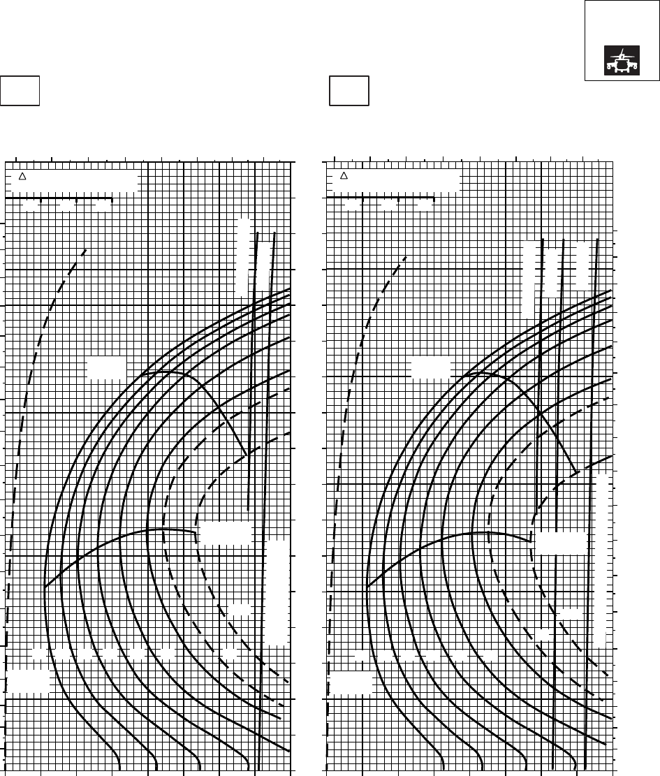
CRUISE CRUISE
T701C (2)
TORQUE PER ENGINE ~ %TORQUE PER ENGINE ~ %
IAS ~ KTS TOTAL FUEL FLOW ~ 100 LB/HRTOTAL FUEL FLOW ~ 100 LB/HR
DATA BASE:FLIGHT TEST
TRUE AIRSPEED ~ KTS
TRUE AIRSPEED ~ KTS
NOTE:SHORT DASH LINES: FERRY MISSION ONLY
SA
AA1064_5
PRESS ALT: 4000 FT
4000 FT
30oC40oC
0
10
20
30
40
50
60
70
80
90
100
110
120
130
140
150
160
170
180
6 7 8 9 10 11 12 13 6 7 8 9 10 11 12 13
0
10
20
30
40
50
60
70
80
90
100
110
120
130
140
150
160
170
180
0
10
20
30
40
50
60
70
80
90
100
110
120
130
140
150
160
170
20 30 40 50 60 70 80 90 100 20 30 40 50 60 70 80 90 100
TRQ ~ % FOR DRAG
AREA OF 10 SQ FT
10 20 30
TRQ ~ % FOR DRAG
AREA OF 10 SQ FT
10 20 30
MAX
RANGE MAX
RANGE
MAX END
AND R / C MAX END
AND R / C
GW ~
1000 LB
12 14 16 18 20 22 23
24.5
GW ~
1000 LB
12 14 16 18 20 22
23
24.5
~ CONTINUOUS
~ CONTINUOUS
ATF = 0.9
ATF = 0.9
ATF = 1.0
TORQUE AVAILABLE
~ 30 MINUTES
TORQUE AVAILABLE ~ 30 MINUTES
PLACARD TORQUE LIMIT = 97% PLACARD TORQUE LIMIT = 94%
Figure 7A-14. Cruise High Drag - Pressure Altitude 4,000 Feet (Sheet 5 of 6)
TM 1-1520-237-10
7A-54
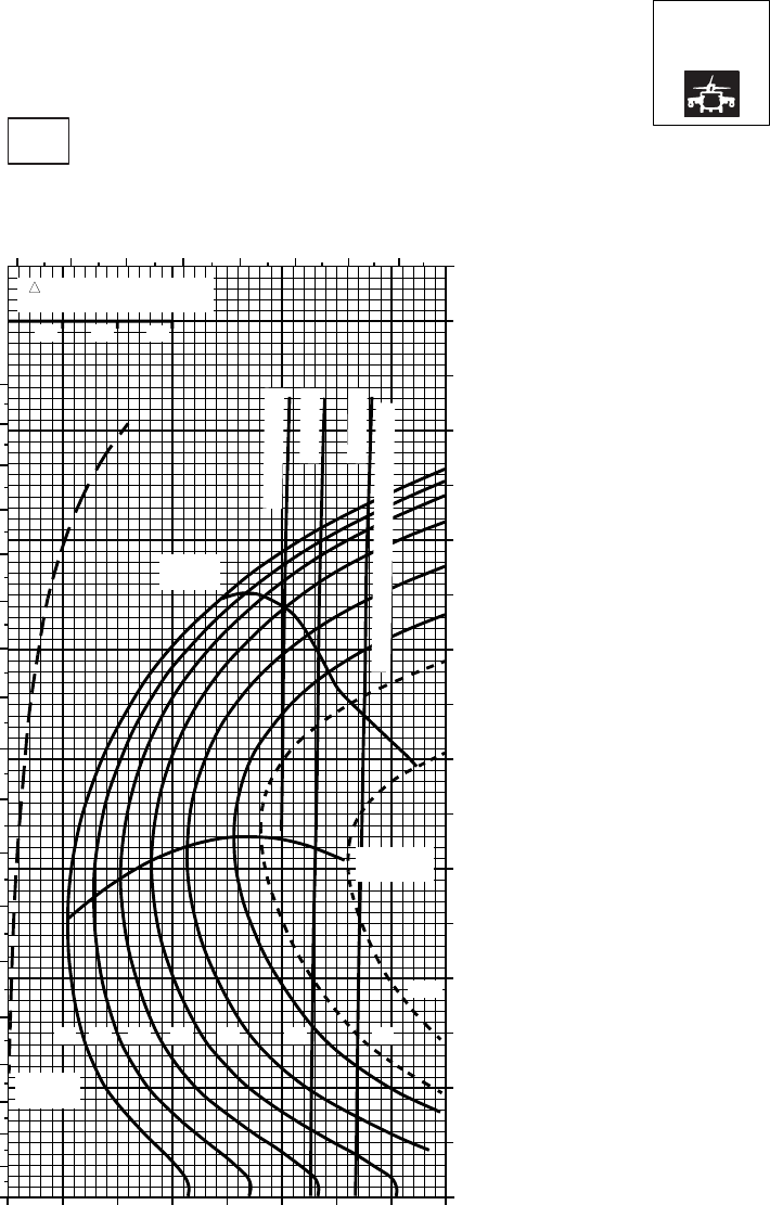
CRUISE CRUISE
T701C (2)
DATA BASE:FLIGHT TEST
NOTE:SHORT DASH LINES: FERRY MISSION ONLY
SA
AA1064_6
PRESS ALT: 4000 FT
4000 FT
50oC
TORQUE PER ENGINE ~ %
TOTAL FUEL FLOW ~ 100 LB/HR
INDICATED AIRSPEED ~ KTS
TRUE AIRSPEED ~ KTS
20 30 40 50 60 70 80 90 1000
10
20
30
40
50
60
70
80
90
100
110
120
130
140
150
160
170
TRQ ~ % FOR DRAG
AREA OF 10 SQ FT
10 20 30
6 7 8 9 10 11 12 13
0
10
20
30
40
50
60
70
80
90
100
110
120
130
140
150
160
170
180
MAX
RANGE
MAX END
AND R / C
GW ~
1000 LB
1412 16 18 20 22 23
24.5
TORQUE AVAILABLE ~ 30 MINUTES
~ CONTINUOUS
ATF = 0.9
ATF = 1.0
PLACARD TORQUE LIMIT = 91%
Figure 7A-14. Cruise High Drag - Pressure Altitude 4,000 Feet (Sheet 6 of 6)
TM 1-1520-237-10
7A-55
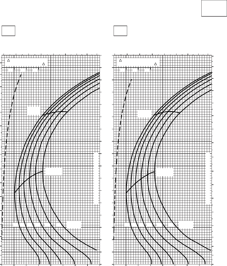
CRUISE CRUISE
T701C (2)
TORQUE PER ENGINE ~ %TORQUE PER ENGINE ~ %
IAS ~ KTS TOTAL FUEL FLOW ~ 100 LB/HRTOTAL FUEL FLOW ~ 100 LB/HR
DATA BASE:FLIGHT TEST
TRUE AIRSPEED ~ KTS
TRUE AIRSPEED ~ KTS
CLEAN CONFIGURATION
PRESS ALT: 6,000 FT
6,000 FT
−50oC−40oC
TRQ ~ % FOR DRAG
AREA OF 10 SQ FT OF F
10 20 30
TRQ ~ % FOR DRAG
AREA OF 10 SQ FT OF F
10 20 30
5 6 7 8 9 10 11 12 13 5 6 7 8 9 10 11 12 13
0
10
20
30
40
50
60
70
80
90
100
110
120
130
140
150
160
0
10
20
30
40
50
60
70
80
90
100
110
120
130
140
150
160
170
20 30 40 50 60 70 80 90 100 20 30 40 50 60 70 80 90 100
0
10
20
30
40
50
60
70
80
90
100
110
120
130
140
150
160
170
14 1612 18 20
MAX
RANGE
GW ~
1000 LB
MAX END
AND R / C
22 14 1612 18 20
MAX
RANGE
GW ~
1000 LB
MAX END
AND R / C
22 GW ~
1000 LB
TRANSMISSION TORQUE LIMIT
TRANSMISSION TORQUE LIMIT
SA
AA1009_1
Figure 7A-15. Cruise - Pressure Altitude 6,000 Feet (Sheet 1 of 6)
TM 1-1520-237-10
7A-56
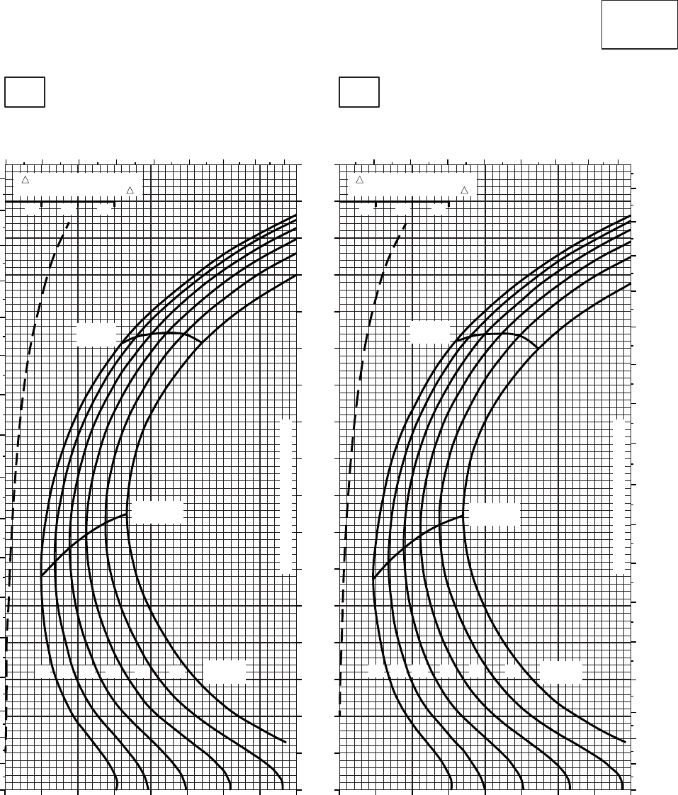
CRUISE CRUISE
T701C (2)
TORQUE PER ENGINE ~ %TORQUE PER ENGINE ~ %
IAS ~ KTS TOTAL FUEL FLOW ~ 100 LB/HRTOTAL FUEL FLOW ~ 100 LB/HR
DATA BASE:FLIGHT TEST
TRUE AIRSPEED ~ KTS
TRUE AIRSPEED ~ KTS
CLEAN CONFIGURATION
PRESS ALT: 6,000 FT
6,000 FT
−30oC−20oC
TRQ ~ % FOR DRAG
AREA OF 10 SQ FT OF F
10 20 30
TRQ ~ % FOR DRAG
AREA OF 10 SQ FT OF F
10 20 30
5 6 7 8 9 10 11 12 13 6 7 8 9 10 11 12 13
0
10
20
30
40
50
60
70
80
90
100
110
120
130
140
150
160
170
0
10
20
30
40
50
60
70
80
90
100
110
120
130
140
150
160
170
20 30 40 50 60 70 80 90 100 20 30 40 50 60 70 80 90 100
0
10
20
30
40
50
60
70
80
90
100
110
120
130
140
150
160
170
14 1612 18 20
MAX
RANGE
GW ~
1000 LB
MAX END
AND R / C
22 14 1612 18 20
MAX
RANGE
GW ~
1000 LB
MAX END
AND R / C
22
TRANSMISSION TORQUE LIMIT
TRANSMISSION TORQUE LIMIT
SA
AA1009_2
Figure 7A-15. Cruise - Pressure Altitude 6,000 Feet (Sheet 2 of 6)
TM 1-1520-237-10
7A-57
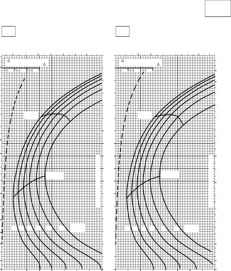
CRUISE CRUISE
T701C (2)
TORQUE PER ENGINE ~ %TORQUE PER ENGINE ~ %
IAS ~ KTS TOTAL FUEL FLOW ~ 100 LB/HRTOTAL FUEL FLOW ~ 100 LB/HR
DATA BASE:FLIGHT TEST
TRUE AIRSPEED ~ KTS
TRUE AIRSPEED ~ KTS
CLEAN CONFIGURATION
PRESS ALT: 6,000 FT
6,000 FT
−10oC0oC
6 7 8 9 10 11 12 13
TRQ ~ % FOR DRAG
AREA OF 10 SQ FT OF F
10 20 30
TRQ ~ % FOR DRAG
AREA OF 10 SQ FT OF F
10 20 30
6 7 8 9 10 11 12 13
0
10
20
30
40
50
60
70
80
90
100
110
120
130
140
150
160
170
180
0
10
20
30
40
50
60
70
80
90
100
110
120
130
140
150
160
170
180
20 30 40 50 60 70 80 90 100 20 30 40 50 60 70 80 90 100
0
10
20
30
40
50
60
70
80
90
100
110
120
130
140
150
160
170
14 1612 18 20
MAX
RANGE
GW ~
1000 LB
MAX END
AND R / C
22 14 1612 18 20
MAX
RANGE
GW ~
1000 LB
MAX END
AND R / C
22
TRANSMISSION TORQUE LIMIT
TRANSMISSION TORQUE LIMIT
SA
AA1009_3
Figure 7A-15. Cruise - Pressure Altitude 6,000 Feet (Sheet 3 of 6)
TM 1-1520-237-10
7A-58
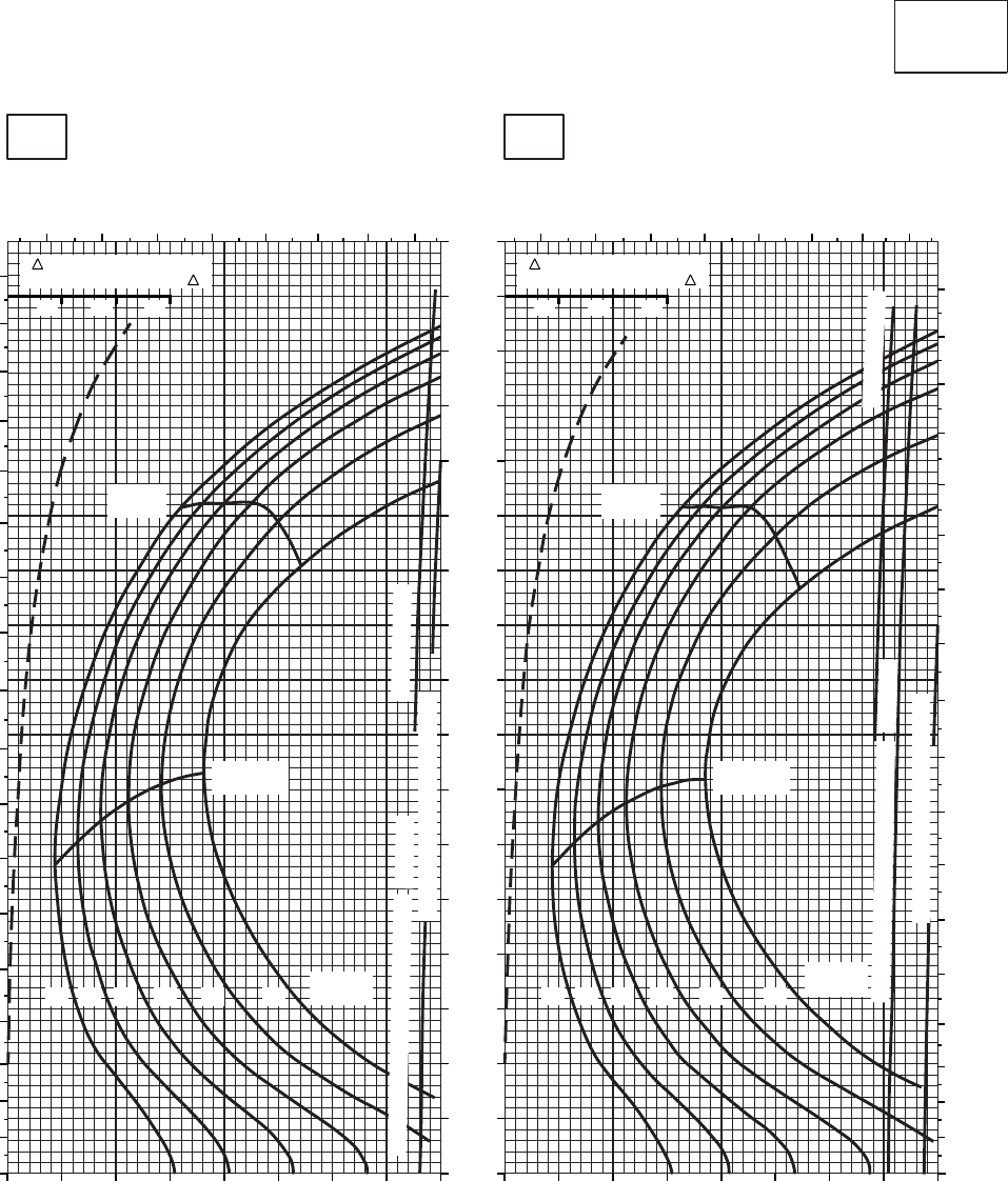
CRUISE CRUISE
T701C (2)
TORQUE PER ENGINE ~ %TORQUE PER ENGINE ~ %
IAS ~ KTS TOTAL FUEL FLOW ~ 100 LB/HRTOTAL FUEL FLOW ~ 100 LB/HR
DATA BASE:FLIGHT TEST
TRUE AIRSPEED ~ KTS
TRUE AIRSPEED ~ KTS
CLEAN CONFIGURATION
PRESS ALT: 6,000 FT
6,000 FT
10oC20oC
TRQ ~ % FOR DRAG
AREA OF 10 SQ FT OF F
10 20 30
TRQ ~ % FOR DRAG
AREA OF 10 SQ FT OF F
10 20 30
6 7 8 9 10 11 12 13 6 7 8 9 10 11 12 13
0
10
20
30
40
50
60
70
80
90
100
110
120
130
140
150
160
170
180
0
10
20
30
40
50
60
70
80
90
100
110
120
130
140
150
160
170
180
20 30 40 50 60 70 80 90 100 20 30 40 50 60 70 80 90 100
0
10
20
30
40
50
60
70
80
90
100
110
120
130
140
150
160
170
~ CONTINUOUS
~ CONTINUOUS
TORQUE AVAILABLE ~ 30 MINUTES
TORQUE AVAILABLE ~ 30 MINUTES
TRANSMISSION TORQUE LIMIT
TRANSMISSION TORQUE LIMIT
ATF = 0.9
ATF = 0.9
14 1612 18 20
MAX
RANGE
GW ~
1000 LB
MAX END
AND R / C
22
14 1612 18 20
MAX
RANGE
GW ~
1000 LB
MAX END
AND R / C
22
SA
AA1009_4
PLACARD TORQUE LIMIT =93%PLACARD TORQUE LIMIT = 97%
Figure 7A-15. Cruise - Pressure Altitude 6,000 Feet (Sheet 4 of 6)
TM 1-1520-237-10
7A-59
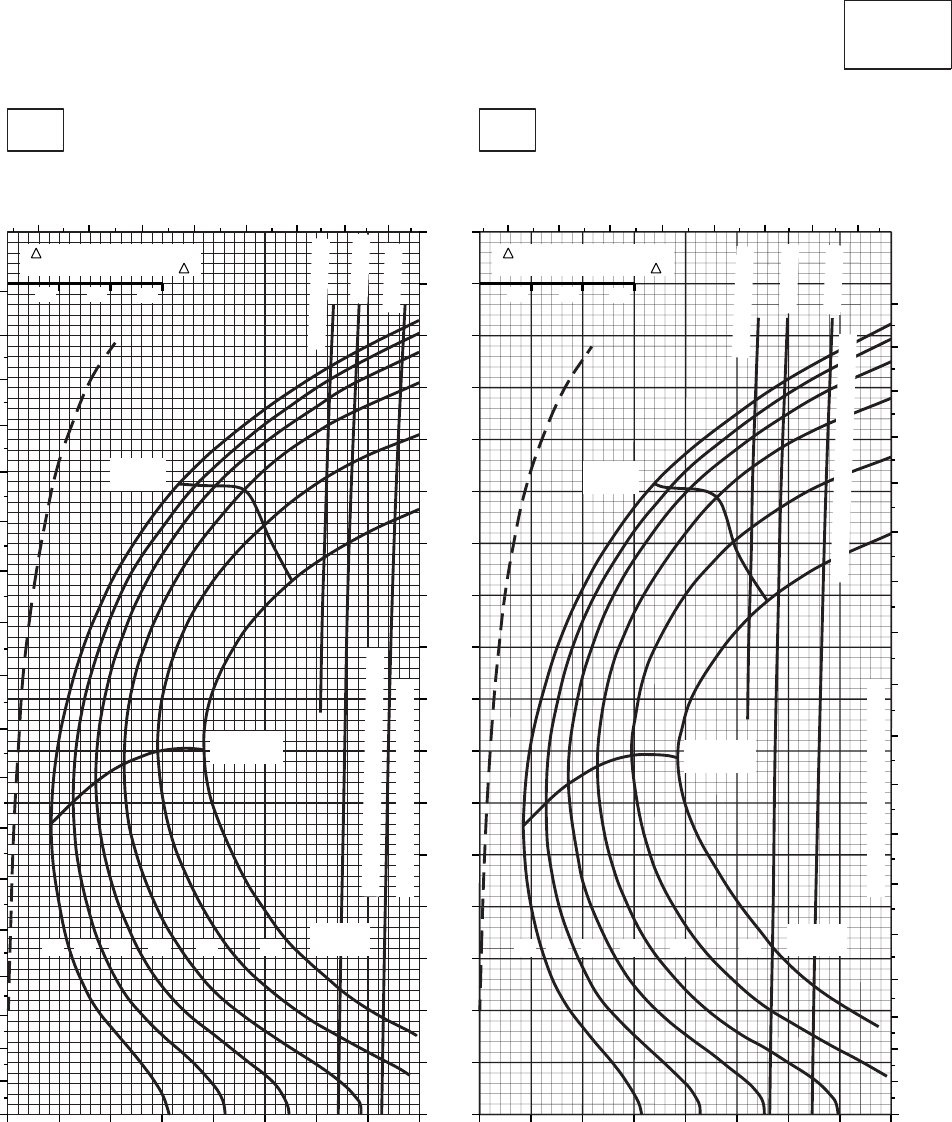
CRUISE CRUISE
T701C (2)
TORQUE PER ENGINE ~ %TORQUE PER ENGINE ~ %
IAS ~ KTS TOTAL FUEL FLOW ~ 100 LB/HRTOTAL FUEL FLOW ~ 100 LB/HR
DATA BASE:FLIGHT TEST
TRUE AIRSPEED ~ KTS
TRUE AIRSPEED ~ KTS
CLEAN CONFIGURATION
PRESS ALT: 6,000 FT
6,000 FT
30oC40oC
TRQ ~ % FOR DRAG
AREA OF 10 SQ FT OF F
10 20 30
TRQ ~ % FOR DRAG
AREA OF 10 SQ FT OF F
10 20 30
6 7 8 9 10 11 12 13 678910 11 12 13
0
10
20
30
40
50
60
70
80
90
100
110
120
130
140
150
160
170
180
0
10
20
30
40
50
60
70
80
90
100
110
120
130
140
150
160
170
180
20 30 40 50 60 70 80 90 100 20 30 40 50 60 70 80 90 100
0
10
20
30
40
50
60
70
80
90
100
110
120
130
140
150
160
170
ATF = 0.9
ATF = 0.9
ATF = 1.0
ATF = 1.0
~ CONTINUOUS
~ CONTINUOUS
TRANSMISSION TORQUE LIMIT
TRANSMISSION TORQUE LIMIT
TORQUE AVAILABLE ~ 30 MINUTES
TORQUE AVAILABLE ~ 30 MINUTES
14 1612 18 20
MAX
RANGE
GW ~
1000 LB
MAX END
AND R / C
22 14 1612 18 20
MAX
RANGE
GW ~
1000 LB
MAX END
AND R / C
22
SA
AA1009_5
PLACARD TORQUE LIMIT = 87%
PLACARD TORQUE LIMIT = 90%
Figure 7A-15. Cruise - Pressure Altitude 6,000 Feet (Sheet 5 of 6)
TM 1-1520-237-10
7A-60
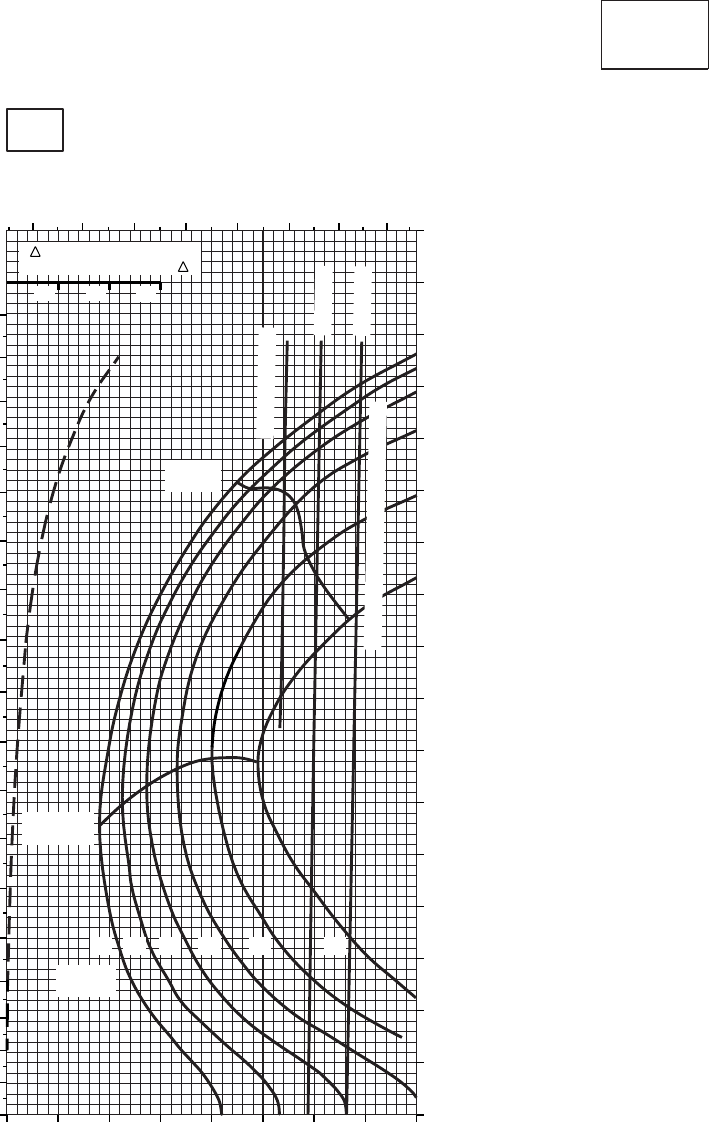
CRUISE CRUISE
T701C (2)
TORQUE PER ENGINE ~ %
TOTAL FUEL FLOW ~ 100 LB/HR
DATA BASE:FLIGHT TEST
TRUE AIRSPEED ~ KTS
CLEAN CONFIGURATION
PRESS ALT: 6,000 FT
6,000 FT
50oC
TRQ ~ % FOR DRAG
AREA OF 10 SQ FT OF F
10 20 30
INDICATED AIRSPEED ~ KTS
5 6 7 8 9 10 11 12
10 20 30 40 50 60 70 80 90
0
10
20
30
40
50
60
70
80
90
100
110
120
130
140
150
160
170
0
10
20
30
40
50
60
70
80
90
100
110
120
130
140
150
160
170
180
~ CONTINUOUS
ATF = 0.9
ATF = 1.0
TORQUE AVAILABLE ~ 30 MINUTES
14 1612 18 20
MAX
RANGE
GW ~
1000 LB
MAX END
AND R / C
22
SA
AA1009_6
PLACARD TORQUE LIMIT = 83%
Figure 7A-15. Cruise - Pressure Altitude 6,000 Feet (Sheet 6 of 6)
TM 1-1520-237-10
7A-61
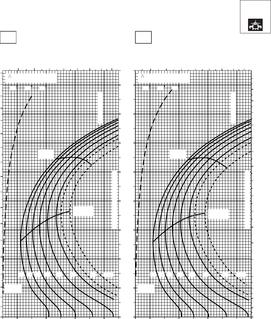
CRUISE CRUISE
T701C (2)
TORQUE PER ENGINE ~ %TORQUE PER ENGINE ~ %
IAS ~ KTS TOTAL FUEL FLOW ~ 100 LB/HRTOTAL FUEL FLOW ~ 100 LB/HR
DATA BASE:FLIGHT TEST
TRUE AIRSPEED ~ KTS
TRUE AIRSPEED ~ KTS
NOTE:SHORT DASH LINES: FERRY MISSION ONLY
SA
AA1010_1
PRESS ALT: 6000 FT
6000 FT
−50oC−40oC
20 30 40 50 60 70 80 90 100 20 30 40 50 60 70 80 90 100
0
10
20
30
40
50
60
70
80
90
100
110
120
130
140
150
160
170
0
10
20
30
40
50
60
70
80
90
100
110
120
130
140
150
160
170
180
6 7 8 9 10 11 12 13 6 7 8 9 10 11 12 13
0
10
20
30
40
50
60
70
80
90
100
110
120
130
140
150
160
170
180
TRQ ~ % FOR DRAG
AREA OF 10 SQ FT
10 20 30
TRQ ~ % FOR DRAG
AREA OF 10 SQ FT
10 20 30
GW ~
1000 LB
12 14 16 18 20 22 23 24.5
GW ~
1000 LB
12 14 16 18 20 22 23 24.5
MAX
RANGE MAX
RANGE
MAX END
AND R / C
MAX END
AND R / C
CONTINUOUS TORQUE LIMIT
CONTINUOUS TORQUE LIMIT
~ CONTINUOUS
~ CONTINUOUS
Figure 7A-16. Cruise High Drag - Pressure Altitude 6,000 Feet (Sheet 1 of 6)
TM 1-1520-237-10
7A-62

CRUISE CRUISE
T701C (2)
TORQUE PER ENGINE ~ %TORQUE PER ENGINE ~ %
IAS ~ KTS TOTAL FUEL FLOW ~ 100 LB/HRTOTAL FUEL FLOW ~ 100 LB/HR
DATA BASE:FLIGHT TEST
TRUE AIRSPEED ~ KTS
TRUE AIRSPEED ~ KTS
NOTE:SHORT DASH LINES: FERRY MISSION ONLY
SA
AA1010_2
PRESS ALT: 6000 FT
6000 FT
−30oC−20oC
20 30 40 50 60 70 80 90 100 20 30 40 50 60 70 80 90 100
0
10
20
30
40
50
60
70
80
90
100
110
120
130
140
150
160
170
TRQ ~ % FOR DRAG
AREA OF 10 SQ FT
10 20 30
TRQ ~ % FOR DRAG
AREA OF 10 SQ FT
10 20 30
0
10
20
30
40
50
60
70
80
90
100
110
120
130
140
150
160
170
180
0
10
20
30
40
50
60
70
80
90
100
110
120
130
140
150
160
170
180
6 7 8 9 10 11 12 13 6 7 8 9 10 11 12 13
GW ~
1000 LB
12 14 16 18 20 22 23 24.5
GW ~
1000 LB
12 14 16 18 20 22 23 24.5
CONTINUOUS TORQUE LIMIT
CONTINUOUS TORQUE LIMIT
MAX END
AND R / C
MAX END
AND R / C
MAX
RANGE MAX
RANGE
~ CONTINUOUS
~ CONTINUOUS
Figure 7A-16. Cruise High Drag - Pressure Altitude 6,000 Feet (Sheet 2 of 6)
TM 1-1520-237-10
7A-63
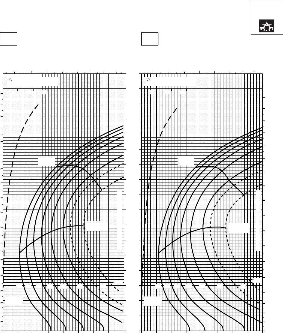
CRUISE CRUISE
T701C (2)
TORQUE PER ENGINE ~ %TORQUE PER ENGINE ~ %
IAS ~ KTS TOTAL FUEL FLOW ~ 100 LB/HRTOTAL FUEL FLOW ~ 100 LB/HR
DATA BASE:FLIGHT TEST
TRUE AIRSPEED ~ KTS
TRUE AIRSPEED ~ KTS
NOTE:SHORT DASH LINES: FERRY MISSION ONLY
SA
AA1010_3
PRESS ALT: 6000 FT
6000 FT
−10oC0oC
20 30 40 50 60 70 80 90 100 20 30 40 50 60 70 80 90 100
0
10
20
30
40
50
60
70
80
90
100
110
120
130
140
150
160
170
TRQ ~ % FOR DRAG
AREA OF 10 SQ FT
10 20 30
TRQ ~ % FOR DRAG
AREA OF 10 SQ FT
10 20 30
0
10
20
30
40
50
60
70
80
90
100
110
120
130
140
150
160
170
180
678 9 10 11 12 13 6 789 10 11 12 13
0
10
20
30
40
50
60
70
80
90
100
110
120
130
140
150
160
170
180
GW ~
1000 LB
12 14 16 18 20 22 23 24.5
GW ~
1000 LB
12 14 16 18 20 22 23
24.5
CONTINUOUS TORQUE LIMIT
CONTINUOUS TORQUE LIMIT
MAX END
AND R / C
MAX END
AND R / C
MAX
RANGE
MAX
RANGE
Figure 7A-16. Cruise High Drag - Pressure Altitude 6,000 Feet (Sheet 3 of 6)
TM 1-1520-237-10
7A-64
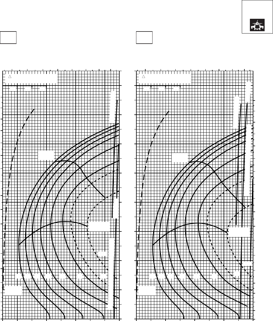
CRUISE CRUISE
T701C (2)
TORQUE PER ENGINE ~ %TORQUE PER ENGINE ~ %
IAS ~ KTS TOTAL FUEL FLOW ~ 100 LB/HRTOTAL FUEL FLOW ~ 100 LB/HR
DATA BASE:FLIGHT TEST
TRUE AIRSPEED ~ KTS
TRUE AIRSPEED ~ KTS
NOTE:SHORT DASH LINES: FERRY MISSION ONLY
SA
AA1010_4
PRESS ALT: 6000 FT
6000 FT
10oC20oC
20 30 40 50 60 70 80 90 100 20 30 40 50 60 70 80 90 100
0
10
20
30
40
50
60
70
80
90
100
110
120
130
140
150
160
170
TRQ ~ % FOR DRAG
AREA OF 10 SQ FT
10 20 30
TRQ ~ % FOR DRAG
AREA OF 10 SQ FT
10 20 30
0
10
20
30
40
50
60
70
80
90
100
110
120
130
140
150
160
170
180
6 7 8 9 10 11 12 13 6 7 8 9 10 11 12 13
0
10
20
30
40
50
60
70
80
90
100
110
120
130
140
150
160
170
180
TORQUE AVAILABLE ~ 30 MINUTES
MAX END
AND R / C MAX END
AND R / C
TORQUE AVAILABLE ~ 30 MINUTES
~ CONTINUOUS
~ CONTINUOUS
ATF = 0.9
ATF = 0.9
MAX
RANGE MAX
RANGE
GW ~
1000 LB
12 14 16 18 20 22 23
24.5
GW ~
1000 LB
12 14 16 18 20 22 23
24.5
PLACARD TORQUE LIMIT = 97% PLACARD TORQUE LIMIT = 93%
Figure 7A-16. Cruise High Drag - Pressure Altitude 6,000 Feet (Sheet 4 of 6)
TM 1-1520-237-10
7A-65
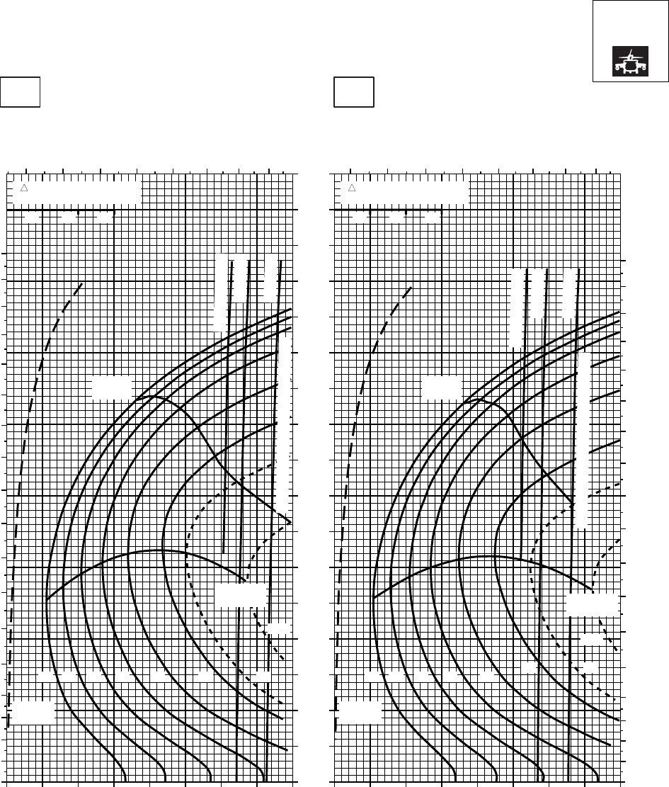
CRUISE CRUISE
T701C (2)
TORQUE PER ENGINE ~ %TORQUE PER ENGINE ~ %
IAS ~ KTS TOTAL FUEL FLOW ~ 100 LB/HRTOTAL FUEL FLOW ~ 100 LB/HR
DATA BASE:FLIGHT TEST
TRUE AIRSPEED ~ KTS
TRUE AIRSPEED ~ KTS
NOTE:SHORT DASH LINES: FERRY MISSION ONLY
SA
AA1010_5
PRESS ALT: 6000 FT
6000 FT
30oC40oC
20 30 40 50 60 70 80 90 100 20 30 40 50 60 70 80 90 100
0
10
20
30
40
50
60
70
80
90
100
110
120
130
140
150
160
170
TRQ ~ % FOR DRAG
AREA OF 10 SQ FT
10 20 30
TRQ ~ % FOR DRAG
AREA OF 10 SQ FT
10 20 30
0
10
20
30
40
50
60
70
80
90
100
110
120
130
140
150
160
170
180
6 7 8 9 10 11 12 13 6 7 8 9 10 11 12 13
0
10
20
30
40
50
60
70
80
90
100
110
120
130
140
150
160
170
180
TORQUE AVAILABLE ~ 30 MINUTES
TORQUE AVAILABLE ~ 30 MINUTES
~ CONTINUOUS
~ CONTINUOUS
ATF = 0.9
ATF = 1.0
ATF = 1.0
ATF = 0.9
MAX
RANGE MAX
RANGE
MAX END
AND R / C
MAX END
AND R / C
GW ~
1000 LB
12 14 16 18 20 22 23
24.5
GW ~
1000 LB
12 14 16 18 20 22 23
24.5
PLACARD TORQUE LIMIT = 90% PLACARD TORQUE LIMIT = 87%
Figure 7A-16. Cruise High Drag - Pressure Altitude 6,000 Feet (Sheet 5 of 6)
TM 1-1520-237-10
7A-66
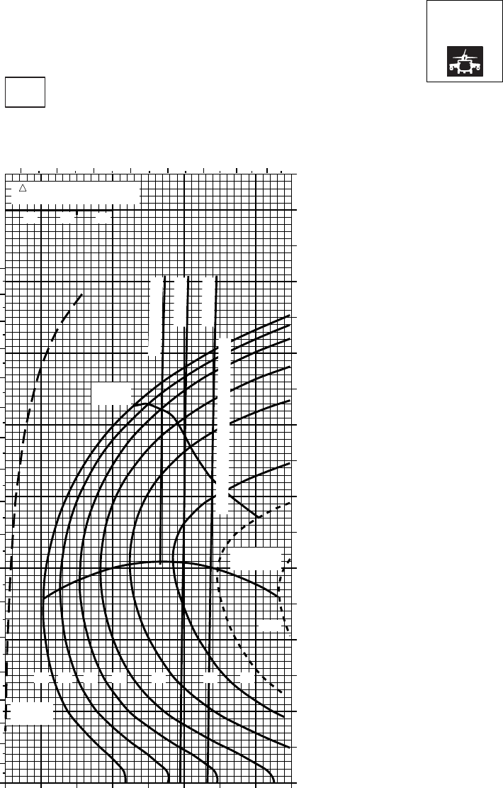
CRUISE CRUISE
T701C (2)
DATA BASIS:FLIGHT TEST
NOTE:SHORT DASH LINES: FERRY MISSION ONLY
PRESS ALT: 6000 FT
6000 FT
50oC
TORQUE PER ENGINE ~ %
TOTAL FUEL FLOW ~ 100 LB/HR
INDICATED AIRSPEED ~ KTS
TRUE AIRSPEED ~ KTS
20 30 40 50 60 70 80 90 1000
10
20
30
40
50
60
70
80
90
100
110
120
130
140
150
160
170
0
10
20
30
40
50
60
70
80
90
100
110
120
130
140
150
160
170
180
6 7 8 9 10 11 12 13
TRQ ~ % FOR DRAG
AREA OF 10 SQ FT
10 20 30
~ CONTINUOUS
ATF = 0.9
ATF = 1.0
TORQUE AVAILABLE ~ 30 MINUTES
MAX
RANGE
MAX END
AND R / C
GW ~
1000 LB
12 14 16 18 20 22 23
24.5
SA
AA2101_6
PLACARD TORQUE LIMIT = 83%
Figure 7A-16. Cruise High Drag - Pressure Altitude 6,000 Feet (Sheet 6 of 6)
TM 1-1520-237-10
7A-67
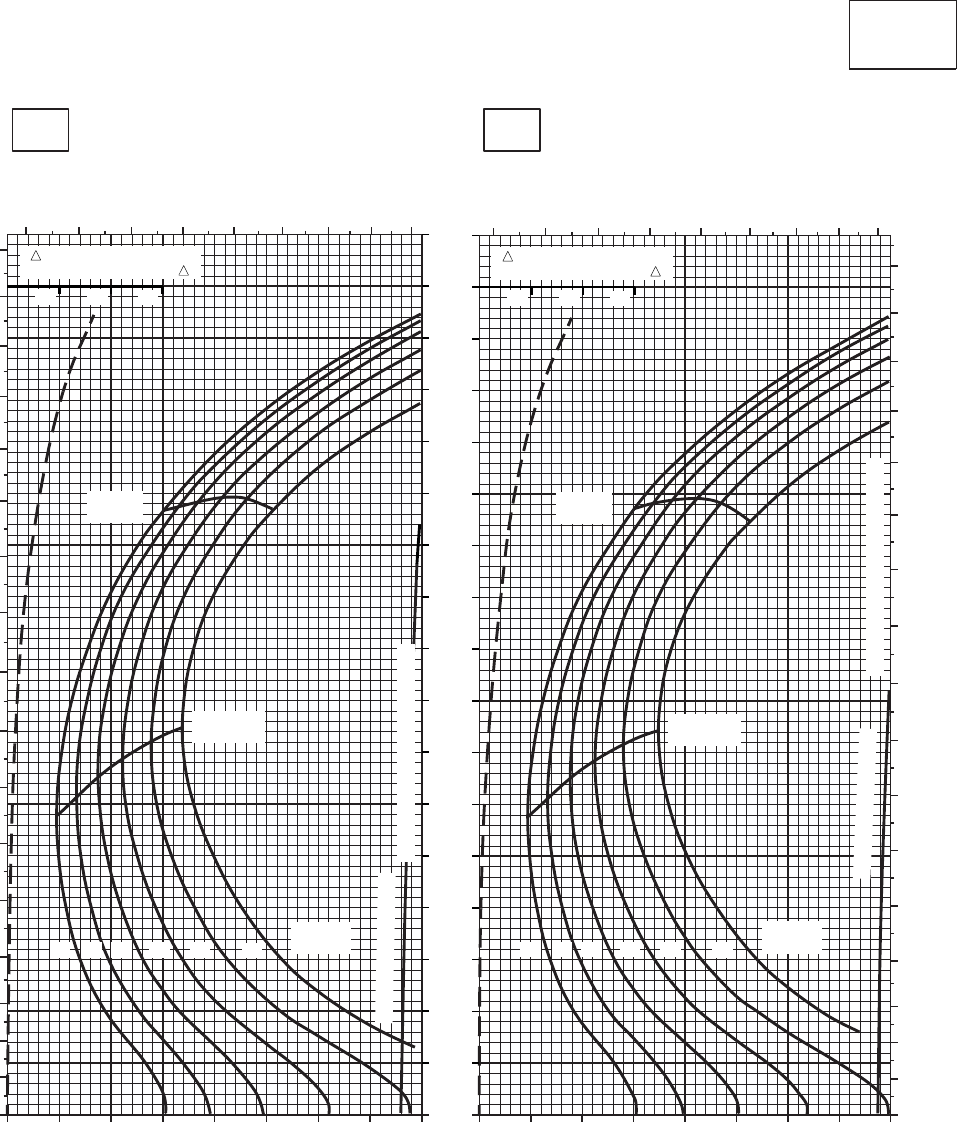
CRUISE CRUISE
T701C (2)
TORQUE PER ENGINE ~ %TORQUE PER ENGINE ~ %
IAS ~ KTS TOTAL FUEL FLOW ~ 100 LB/HRTOTAL FUEL FLOW ~ 100 LB/HR
DATA BASE:FLIGHT TEST
TRUE AIRSPEED ~ KTS
TRUE AIRSPEED ~ KTS
CLEAN CONFIGURATION
0
10
20
30
40
50
60
70
80
90
100
110
120
130
140
150
160
170
SA
AA1011_1
PRESS ALT: 8,000 FT
8,000 FT
−50oC−40oC
0
10
20
30
40
50
60
70
80
90
100
110
120
130
140
150
160
170
5 6 7 8 9 10 11 12 13 5 6 7 8 9 10 11 12 13
0
10
20
30
40
50
60
70
80
90
100
110
120
130
140
150
160
170
20 30 40 50 60 70 80 90 100 20 30 40 50 60 70 80 90 100
MAX
RANGE
MAX END
AND R / C
GW ~
1000 LB
12 14 16 18 20 22
TRANSMISSION TORQUE LIMIT
MAX
RANGE
MAX END
AND R / C
TRANSMISSION TORQUE LIMIT
GW ~
1000 LB
12 14 16 18 20 22
TORQUE AVAILABLE
TORQUE AVAILABLE
TRQ ~ % FOR DRAG
AREA OF 10 SQ FT OF F
10 20 30
TRQ ~ % FOR DRAG
AREA OF 10 SQ FT OF F
10 20 30
Figure 7A-17. Cruise - Pressure Altitude 8,000 Feet (Sheet 1 of 6)
TM 1-1520-237-10
7A-68
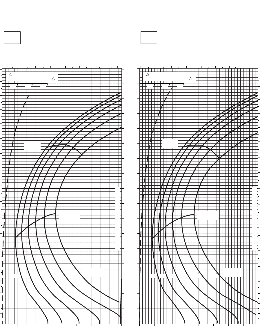
CRUISE CRUISE
T701C (2)
TORQUE PER ENGINE ~ %TORQUE PER ENGINE ~ %
IAS ~ KTS TOTAL FUEL FLOW ~ 100 LB/HRTOTAL FUEL FLOW ~ 100 LB/HR
DATA BASE:FLIGHT TEST
TRUE AIRSPEED ~ KTS
TRUE AIRSPEED ~ KTS
CLEAN CONFIGURATION
0
10
20
30
40
50
60
70
80
90
100
110
120
130
140
150
160
170
SA
AA1011_2
PRESS ALT: 8000 FT
8000 FT
0
10
20
30
40
50
60
70
80
90
100
110
120
130
140
150
160
170
180
5 6 7 8 9 10 11 12 13 5 6 7 8 9 10 11 12 13
0
10
20
30
40
50
60
70
80
90
100
110
120
130
140
150
160
170
180
MAX
RANGE
MAX END
AND R / C
GW ~
1000 LB
12 14 16 18 20 22
TRANSMISSION TORQUE LIMIT
TRANSMISSION TORQUE LIMIT
MAX
RANGE
MAX END
AND R / C
GW ~
1000 LB
12 14 16 18 20 22
20 30 40 50 60 70 80 90 100 20 30 40 50 60 70 80 90 100
TRQ ~ % FOR DRAG
AREA OF 10 SQ FT OF F
10 20 30
TRQ ~ % FOR DRAG
AREA OF 10 SQ FT OF F
10 20 30
20OC
−
30OC
−
Figure 7A-17. Cruise - Pressure Altitude 8,000 Feet (Sheet 2 of 6)
TM 1-1520-237-10
7A-69
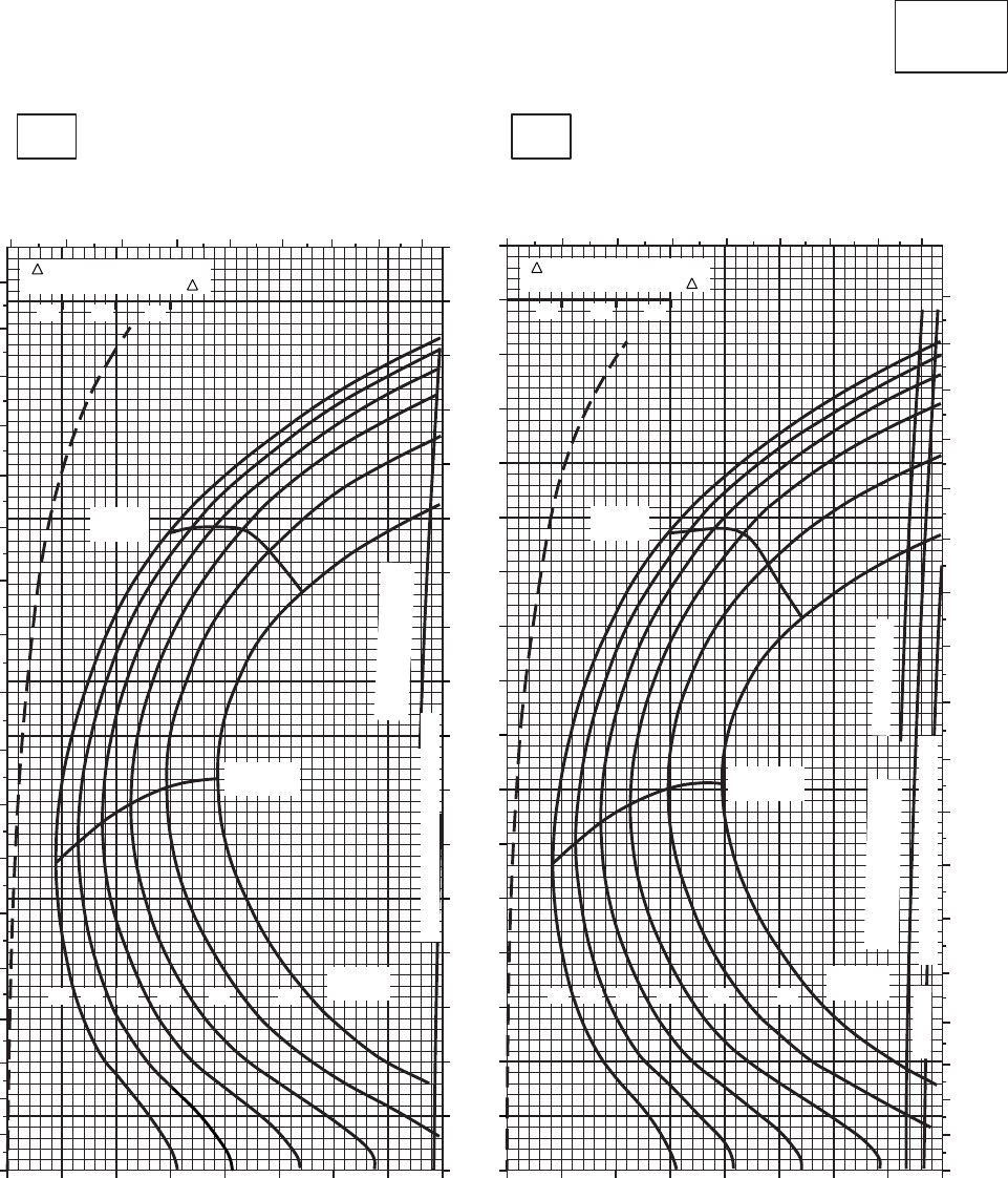
CRUISE CRUISE
T701C (2)
TORQUE PER ENGINE ~ %TORQUE PER ENGINE ~ %
IAS ~ KTS TOTAL FUEL FLOW ~ 100 LB/HRTOTAL FUEL FLOW ~ 100 LB/HR
DATA BASE:FLIGHT TEST
TRUE AIRSPEED ~ KTS
TRUE AIRSPEED ~ KTS
CLEAN CONFIGURATION
0
10
20
30
40
50
60
70
80
90
100
110
120
130
140
150
160
170
SA
AA1011_3
PRESS ALT: 8,000 FT
8,000 FT
−10oC0oC
0
10
20
30
40
50
60
70
80
90
100
110
120
130
140
150
160
170
180
5 6 7 8 9 10 11 12 13 5 6 7 8 9 10 11 12 13
0
10
20
30
40
50
60
70
80
90
100
110
120
130
140
150
160
170
180
20 30 40 50 60 70 80 90 100 20 30 40 50 60 70 80 90 100
MAX
RANGE
MAX END
AND R / C
GW ~
1000 LB
12 14 16 18 20 22
TRANSMISSION TORQUE LIMIT
MAX
RANGE
MAX END
AND R / C
TRANSMISSION TORQUE LIMIT
GW ~
1000 LB
12 14 16 18 20 22
TORQUE AVAILABLE
~30 MINUTES ATF = 0.9
ATF = 1.0
~ CONTINUOUS
TORQUE AVAILABLE
~ CONTINUOUS
TRQ ~ % FOR DRAG
AREA OF 10 SQ FT OF F TRQ ~ % FOR DRAG
AREA OF 10 SQ FT OF F
10 10
20 20
30 30
PLACARD TORQUE LIMIT = 93%PLACARD TORQUE LIMIT = 97%
Figure 7A-17. Cruise - Pressure Altitude 8,000 Feet (Sheet 3 of 6)
TM 1-1520-237-10
7A-70
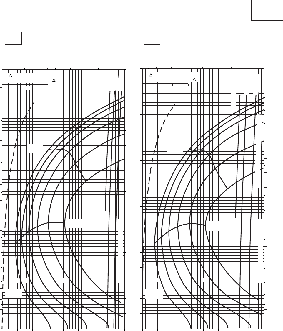
CRUISE CRUISE
T701C (2)
TORQUE PER ENGINE ~ %TORQUE PER ENGINE ~ %
IAS ~ KTS TOTAL FUEL FLOW ~ 100 LB/HRTOTAL FUEL FLOW ~ 100 LB/HR
DATA BASE:FLIGHT TEST
TRUE AIRSPEED ~ KTS
TRUE AIRSPEED ~ KTS
CLEAN CONFIGURATION
0
10
20
30
40
50
60
70
80
90
100
110
120
130
140
150
160
170
SA
AA1011_4
PRESS ALT: 8,000 FT
8,000 FT
10oC20oC
0
10
20
30
40
50
60
70
80
90
100
110
120
130
140
150
160
170
180
6 7 8 9 10 11 12 13 6 7 8 9 10 11 12 13
0
10
20
30
40
50
60
70
80
90
100
110
120
130
140
150
160
170
180
TRQ ~ % FOR DRAG
AREA OF 10 SQ FT OF F TRQ ~ % FOR DRAG
AREA OF 10 SQ FT OF F
20 30 40 50 60 70 80 90 100 20 30 40 50 60 70 80 90 100
MAX
RANGE
MAX END
AND R / C
GW ~
1000 LB
12 14 16 18 20 22
TRANSMISSION TORQUE LIMIT
MAX
RANGE
MAX END
AND R / C
TRANSMISSION TORQUE LIMIT
12 14 16 18 20 22
GW ~
1000 LB
~ CONTINUOUS
~ CONTINUOUS
ATF = 0.9
ATF = 0.9
ATF = 1.0
ATF = 1.0
TORQUE AVAILABLE ~ 30 MINUTES
10 10
20 20
30 30
PLACARD TORQUE LIMIT = 86%PLACARD TORQUE LIMIT = 90%
Figure 7A-17. Cruise - Pressure Altitude 8,000 Feet (Sheet 4 of 6)
TM 1-1520-237-10
7A-71
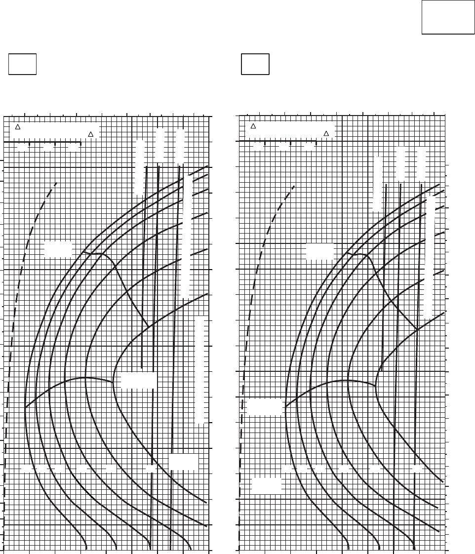
CRUISE CRUISE
T701C (2)
TORQUE PER ENGINE ~ %TORQUE PER ENGINE ~ %
IAS ~ KTS TOTAL FUEL FLOW ~ 100 LB/HRTOTAL FUEL FLOW ~ 100 LB/HR
DATA BASE:FLIGHT TEST
TRUE AIRSPEED ~ KTS
TRUE AIRSPEED ~ KTS
CLEAN CONFIGURATION
0
10
20
30
40
50
60
70
80
90
100
110
120
130
140
150
160
170
SA
AA1011_5
PRESS ALT: 8,000 FT
8,000 FT
30oC40oC
0
10
20
30
40
50
60
70
80
90
100
110
120
130
140
150
160
170
180
6 7 8 9 10 11 12 13 56 7 8 9101112
0
10
20
30
40
50
60
70
80
90
100
110
120
130
140
150
160
170
180
TRQ ~ % FOR DRAG
AREA OF 10 SQ FT OF F TRQ ~ % FOR DRAG
AREA OF 10 SQ FT OF F
20 30 40 50 60 70 80 90 100
MAX
RANGE
MAX END
AND R / C
GW ~
1000 LB
12 14 16 18 20 22
TRANSMISSION TORQUE LIMIT
MAX
RANGE
MAX END
AND R / C
12 14 16 18 20 22
GW ~
1000 LB
~ CONTINUOUS
~ CONTINUOUS
ATF = 0.9
ATF = 0.9
ATF = 1.0
ATF = 1.0
TORQUE AVAILABLE ~ 30 MINUTES
TORQUE AVAILABLE ~ 30 MINUTES
10 10
20 20
30 30
10 20 30 40 50 60 70 80 90
PLACARD TORQUE LIMIT = 81%
PLACARD TORQUE LIMIT = 83%
Figure 7A-17. Cruise - Pressure Altitude 8,000 Feet (Sheet 5 of 6)
TM 1-1520-237-10
7A-72
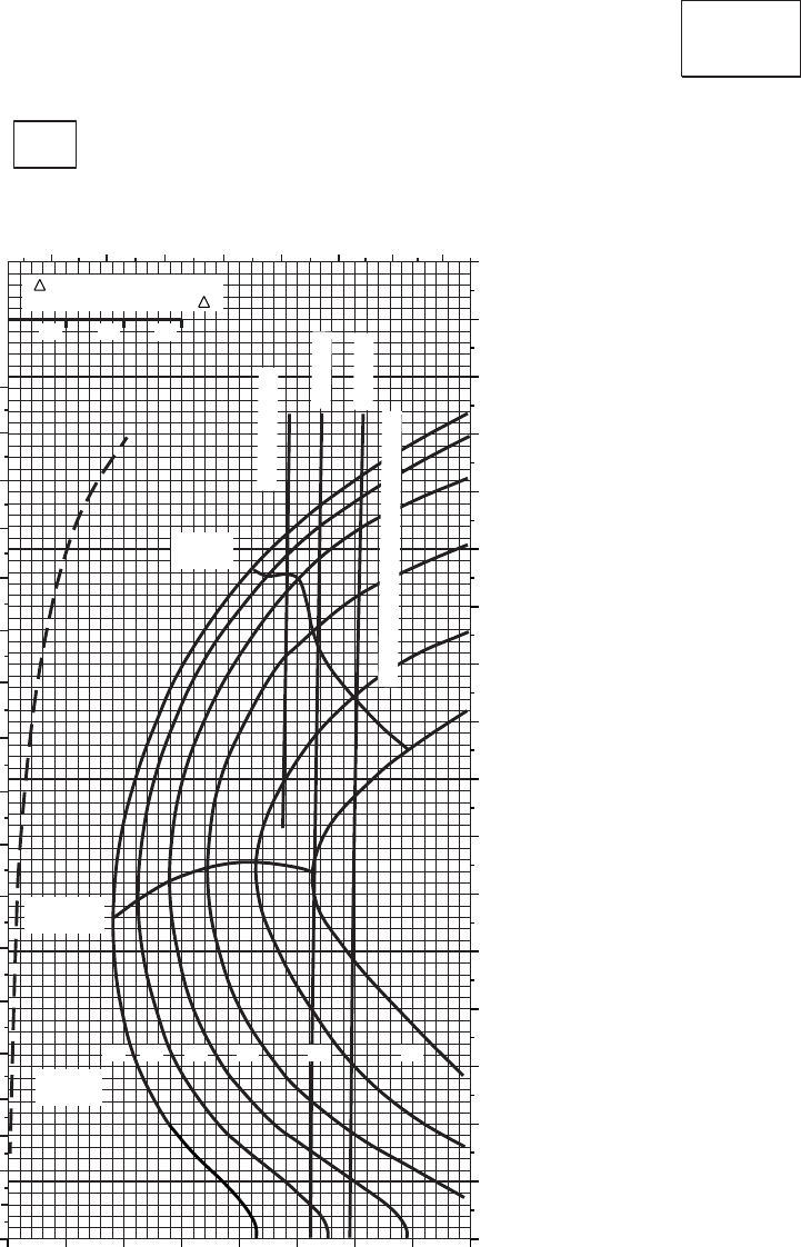
CRUISE CRUISE
T701C (2)
TORQUE PER ENGINE ~ %
TOTAL FUEL FLOW ~ 100 LB/HR
DATA BASE:FLIGHT TEST
INDICATED AIRSPEED ~ KTS
TRUE AIRSPEED ~ KTS
CLEAN CONFIGURATION
PRESS ALT: 8,000 FT
8,000 FT
50oC
0
10
20
30
40
50
60
70
80
90
100
110
120
130
140
150
160
170
180
5 6 7 8 9 10 11 12
TRQ ~ % FOR DRAG
AREA OF 10 SQ FT OF F
10 20 30 40 50 60 70 80 90 0
10
20
30
40
50
60
70
80
90
100
110
120
130
140
150
160
170
MAX
RANGE
MAX END
AND R / C
GW ~
1000 LB
12 14 16 18 20 22
~ CONTINUOUS
ATF = 0.9
ATF = 1.0
TORQUE AVAILABLE ~ 30 MINUTES
10 20 30
SA
AA1011_6
PLACARD TORQUE LIMIT = 77%
Figure 7A-17. Cruise - Pressure Altitude 8,000 Feet (Sheet 6 of 6)
TM 1-1520-237-10
7A-73
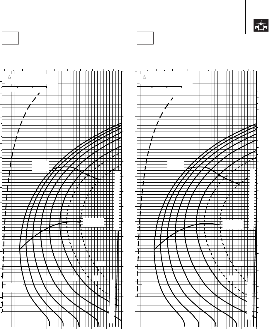
CRUISE CRUISE
T701C (2)
TORQUE PER ENGINE ~ %TORQUE PER ENGINE ~ %
IAS ~ KTS TOTAL FUEL FLOW ~ 100 LB/HRTOTAL FUEL FLOW ~ 100 LB/HR
DATA BASE:FLIGHT TEST
TRUE AIRSPEED ~ KTS
TRUE AIRSPEED ~ KTS
NOTE:SHORT DASH LINES: FERRY MISSION ONLY
SA
AA1012_1
PRESS ALT: 8000 FT
8000 FT
−50oC−40oC
5 6 7 8 9 10 11 12 13
0
10
20
30
40
50
60
70
80
90
100
110
120
130
140
150
160
170
180
5 6 7 8 9 10 11 12 13
0
10
20
30
40
50
60
70
80
90
100
110
120
130
140
150
160
170
180
20 30 40 50 60 70 80 90 100 20 30 40 50 60 70 80 90 100
0
10
20
30
40
50
60
70
80
90
100
110
120
130
140
150
160
170
TRQ ~ % FOR DRAG
AREA OF 10 SQ FT
10 20 30
14 1612 18 20
MAX
RANGE
GW ~
1000 LB
MAX END
AND R / C
MAX
RANGE
MAX END
AND R / C
GW ~
1000 LB
22 23
24.5
14 1612 18 20 22 23
24.5
TRQ ~ % FOR DRAG
AREA OF 10 SQ FT
10 20 30
TORQUE AVAILABLE CONTINUOUS TORQUE LIMIT
TORQUE AVAILABLE CONTINUOUS TORQUE LIMIT
Figure 7A-18. Cruise High Drag - Pressure Altitude 8,000 Feet (Sheet 1 of 6)
TM 1-1520-237-10
7A-74
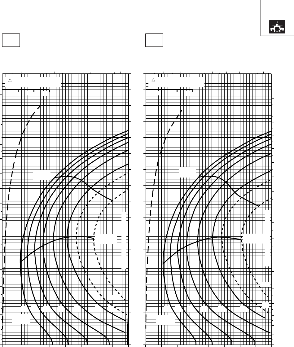
CRUISE CRUISE
T701C (2)
TORQUE PER ENGINE ~ %TORQUE PER ENGINE ~ %
IAS ~ KTS TOTAL FUEL FLOW ~ 100 LB/HRTOTAL FUEL FLOW ~ 100 LB/HR
DATA BASE:FLIGHT TEST
TRUE AIRSPEED ~ KTS
TRUE AIRSPEED ~ KTS
NOTE:SHORT DASH LINES: FERRY MISSION ONLY
SA
AA1012_2
PRESS ALT: 8000 FT
8000 FT
−30oC−20oC
5 6 7 8 9 10 11 12 13 6 7 8 9 10 11 12 13
0
10
20
30
40
50
60
70
80
90
100
110
120
130
140
150
160
170
180
0
10
20
30
40
50
60
70
80
90
100
110
120
130
140
150
160
170
180
20 30 40 50 60 70 80 90 100 20 30 40 50 60 70 80 90 100
TRQ ~ % FOR DRAG
AREA OF 10 SQ FT
10 20 30
TRQ ~ % FOR DRAG
AREA OF 10 SQ FT
10 20 30
14 1612 18 20
MAX
RANGE
GW ~
1000 LB
MAX END
AND R / C
22 23
24.5
14 1612 18 20
MAX
RANGE
GW ~
1000 LB
MAX END
AND R / C
22 23
24.5
0
10
20
30
40
50
60
70
80
90
100
110
120
130
140
150
160
170
CONTINUOUS TORQUE LIMIT
CONTINUOUS TORQUE LIMIT
Figure 7A-18. Cruise High Drag - Pressure Altitude 8,000 Feet (Sheet 2 of 6)
TM 1-1520-237-10
7A-75
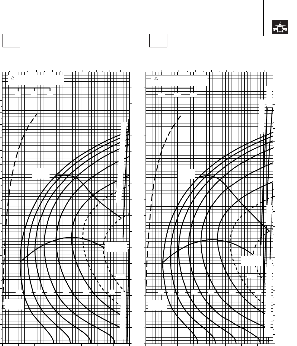
CRUISE CRUISE
T701C (2)
TORQUE PER ENGINE ~ %TORQUE PER ENGINE ~ %
IAS ~ KTS TOTAL FUEL FLOW ~ 100 LB/HRTOTAL FUEL FLOW ~ 100 LB/HR
DATA BASE:FLIGHT TEST
TRUE AIRSPEED ~ KTS
TRUE AIRSPEED ~ KTS
NOTE:SHORT DASH LINES: FERRY MISSION ONLY
PRESS ALT: 8000 FT
8000 FT
−10oC0oC
6 7 8 9 10 11 12 13 6 7 8 9 10 11 12 13
0
10
20
30
40
50
60
70
80
90
100
110
120
130
140
150
160
170
180
0
10
20
30
40
50
60
70
80
90
100
110
120
130
140
150
160
170
20 30 40 50 60 70 80 90 100 20 30 40 50 60 70 80 90 100
0
10
20
30
40
50
60
70
80
90
100
110
120
130
140
150
160
170
180
10 20 30
TRQ ~ % FOR DRAG
AREA OF 10 SQ FT
10 20 30
TRQ ~ % FOR DRAG
AREA OF 10 SQ FT
12 14 16 18 20 22 23
24.5
GW ~
1000 LB
12 14 16 18 20 22 23
24.5
MAX END
AND R / C
MAX END
AND R / C
GW ~
1000 LB
MAX
RANGE MAX
RANGE
TORQUE AVAILABLE ~ CONTINUOUS
~ 30 MINUTE ATF= 0.9
TORQUE AVAILABLE ~ 30 MINUTES ATF= 1.0
~ CONTINUOUS
ATF= 0.9
SA
AA1012_3
PLACARD TORQUE LIMIT = 97% PLACARD TORQUE LIMIT = 93%
Figure 7A-18. Cruise High Drag - Pressure Altitude 8,000 Feet (Sheet 3 of 6)
TM 1-1520-237-10
7A-76
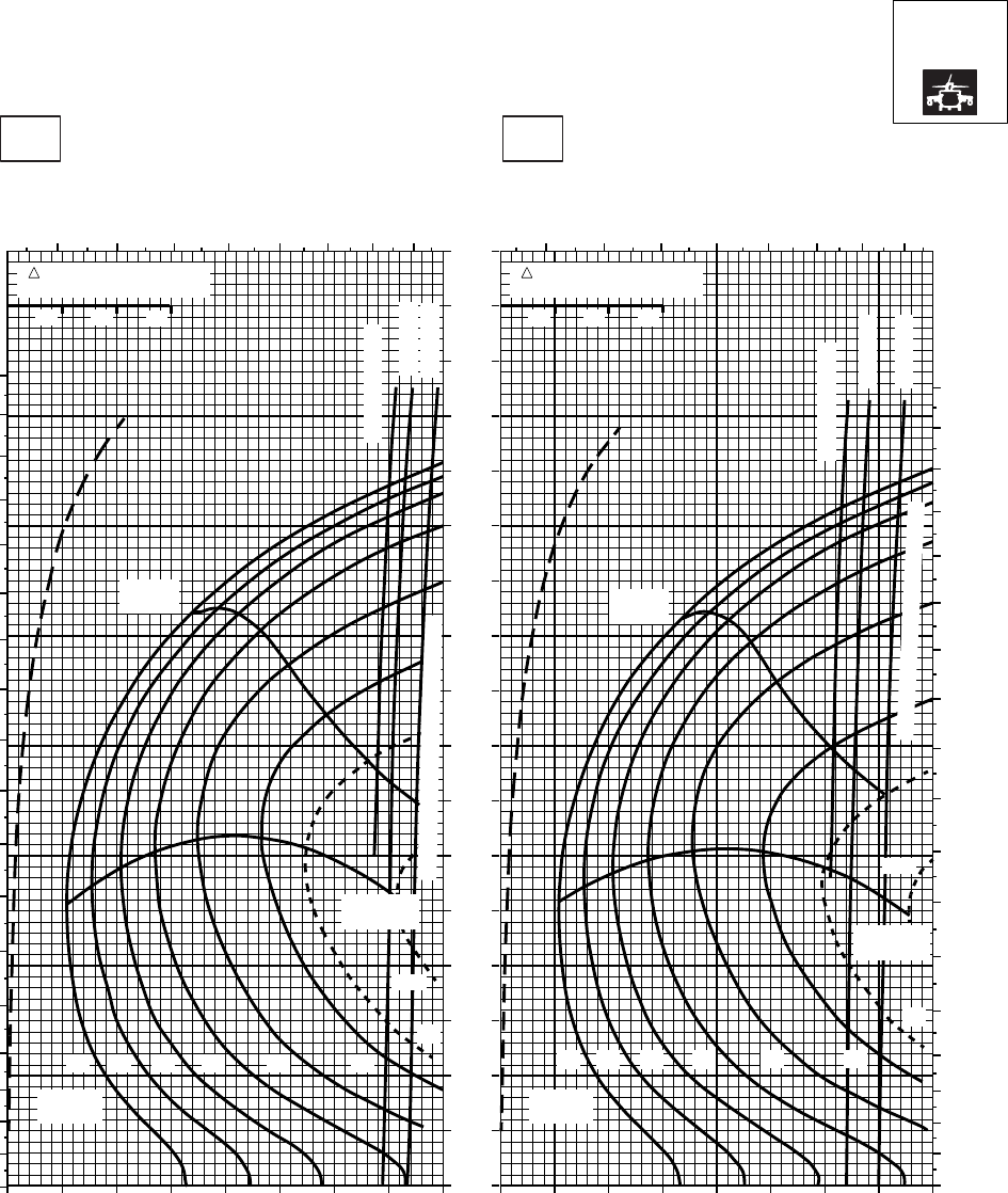
CRUISE CRUISE
T701C (2)
TORQUE PER ENGINE ~ %TORQUE PER ENGINE ~ %
IAS ~ KTS TOTAL FUEL FLOW ~ 100 LB/HRTOTAL FUEL FLOW ~ 100 LB/HR
DATA BASE:FLIGHT TEST
TRUE AIRSPEED ~ KTS
TRUE AIRSPEED ~ KTS
NOTE:SHORT DASH LINES: FERRY MISSION ONLY
PRESS ALT: 8000 FT
8000 FT
10oC20oC
6 7 8 9 10 11 12 13 6 7 8 9 10 11 12 13
0
10
20
30
40
50
60
70
80
90
100
110
120
130
140
150
160
170
20 30 40 50 60 70 80 90 100 20 30 40 50 60 70 80 90 100
0
10
20
30
40
50
60
70
80
90
100
110
120
130
140
150
160
170
180
0
10
20
30
40
50
60
70
80
90
100
110
120
130
140
150
160
170
180
TRQ ~ % FOR DRAG
AREA OF 10 SQ FT
10 20 30
TRQ ~ % FOR DRAG
AREA OF 10 SQ FT
10 20 30
ATF = 0.9
ATF = 0.9
ATF = 1.0
ATF = 1.0
~ CONTINUOUS
~ CONTINUOUS
GW ~
1000 LB
MAX
RANGE MAX
RANGE
MAX END
AND R / C
14 1612 18 20 22
23
14 1612 18 20 22
23
24.5
GW ~
1000 LB
TORQUE AVAILABLE ~ 30 MINUTES
24.5
MAX END
AND R / C
TORQUE AVAILABLE ~ 30 MINUTES
SA
AA1012_4
PLACARD TORQUE LIMIT = 90% PLACARD TORQUE LIMIT = 86%
Figure 7A-18. Cruise High Drag - Pressure Altitude 8,000 Feet (Sheet 4 of 6)
TM 1-1520-237-10
7A-77
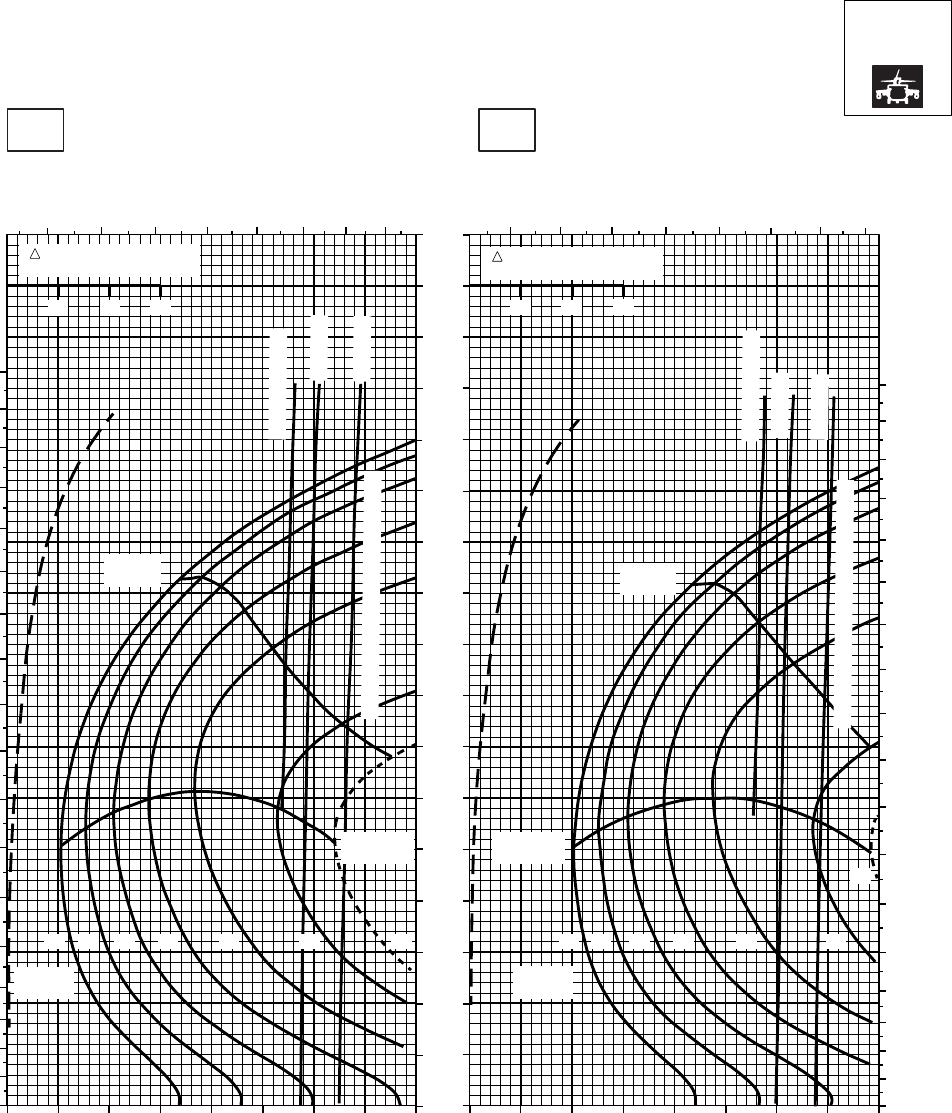
CRUISE CRUISE
T701C (2)
TORQUE PER ENGINE ~ %TORQUE PER ENGINE ~ %
IAS ~ KTS TOTAL FUEL FLOW ~ 100 LB/HRTOTAL FUEL FLOW ~ 100 LB/HR
DATA BASE:FLIGHT TEST
TRUE AIRSPEED ~ KTS
TRUE AIRSPEED ~ KTS
NOTE:SHORT DASH LINES: FERRY MISSION ONLY
PRESS ALT: 8000 FT
8000 FT
30oC40oC
67 8 9 10 11 12 13 5 6 7 8 9 10 11 12
20 30 40 50 60 70 80 90 100 10 20 30 40 50 60 70 80 90
0
10
20
30
40
50
60
70
80
90
100
110
120
130
140
150
160
170
180
0
10
20
30
40
50
60
70
80
90
100
110
120
130
140
150
160
170
180
0
10
20
30
40
50
60
70
80
90
100
110
120
130
140
150
160
170
10 20 30
TRQ ~ % FOR DRAG
AREA OF 10 SQ FT
10 20 30
TRQ ~ % FOR DRAG
AREA OF 10 SQ FT
12 14 16 18 20 22 23
GW ~
1000 LB
12 14 16 18 20 22
GW ~
1000 LB
MAX END
AND R / C
MAX END
AND R / C
MAX
RANGE
MAX
RANGE
23
ATF= 0.9
ATF= 1.0
~ CONTINUOUS
~ CONTINUOUS
ATF= 0.9
ATF= 1.0
TORQUE AVAILABLE ~ 30 MINUTES
TORQUE AVAILABLE ~ 30 MINUTES
SA
AA1012_5
PLACARD TORQUE LIMIT = 83% PLACARD TORQUE LIMIT = 81%
Figure 7A-18. Cruise High Drag - Pressure Altitude 8,000 Feet (Sheet 5 of 6)
TM 1-1520-237-10
7A-78
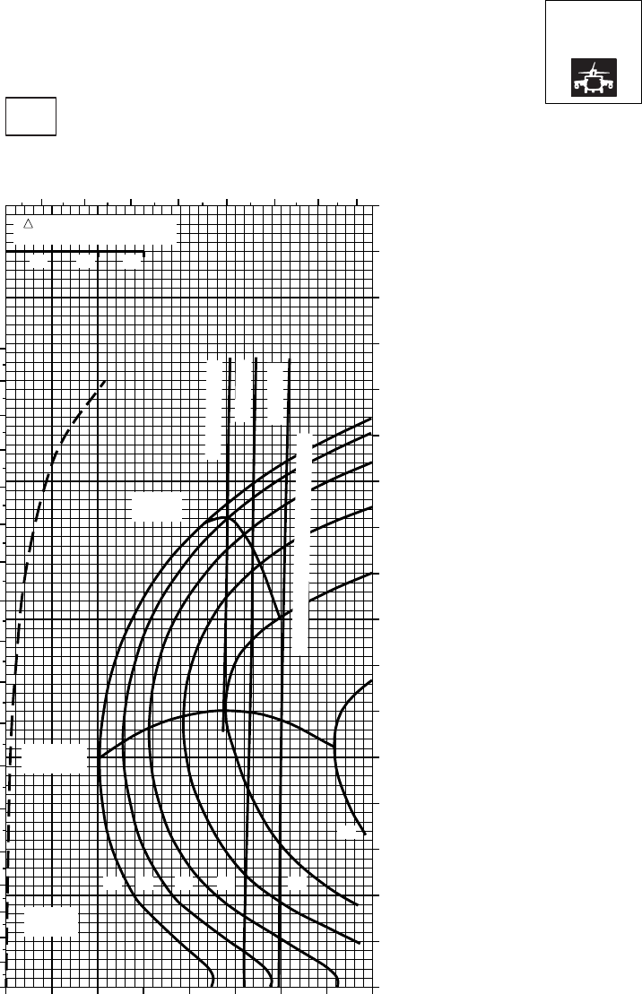
CRUISE CRUISE
T701C (2)
TORQUE PER ENGINE ~ %
TOTAL FUEL FLOW ~ 100 LB/HR
DATA BASIS:FLIGHT TEST
INDICATED AIRSPEED ~ KTS
TRUE AIRSPEED ~ KTS
NOTE:SHORT DASH LINES: FERRY MISSION ONLY
PRESS ALT: 8000 FT
8000 FT
50oC
0
10
20
30
40
50
60
70
80
90
100
110
120
130
140
150
160
170
180
5 6 7 8 9 10 11 12
0
10
20
30
40
50
60
70
80
90
100
110
120
130
140
150
160
170
10 20 30 40 50 60 70 80 90
GW ~
1000 LB
12 14 16 18 20
22
MAX END
AND R / C
MAX
RANGE
~ CONTINUOUS
ATF = 0.9
ATF = 1.0
TORQUE AVAILABLE ~ 30 MINUTES
TRQ ~ % FOR DRAG
AREA OF 10 SQ FT
10 20 30
SA
AA2102_6
PLACARD TORQUE LIMIT = 77%
Figure 7A-18. Cruise High Drag - Pressure Altitude 8,000 Feet (Sheet 6 of 6)
TM 1-1520-237-10
7A-79
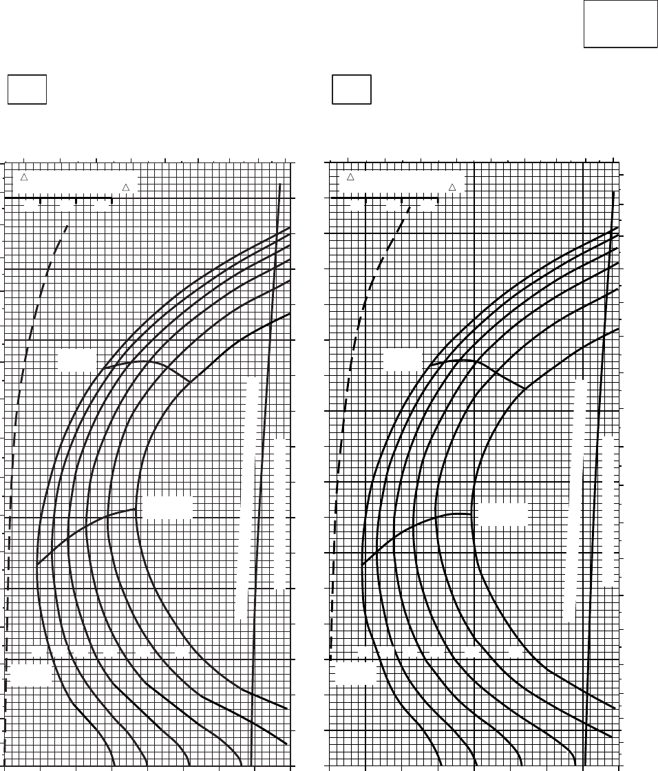
CRUISE CRUISE
T701C (2)
TORQUE PER ENGINE ~ %TORQUE PER ENGINE ~ %
IAS ~ KTS TOTAL FUEL FLOW ~ 100 LB/HRTOTAL FUEL FLOW ~ 100 LB/HR
DATA BASE:FLIGHT TEST
TRUE AIRSPEED ~ KTS
TRUE AIRSPEED ~ KTS
CLEAN CONFIGURATION
0
10
20
30
40
50
60
70
80
90
100
110
120
130
140
150
160
170
PRESS ALT: 10,000 FT
10,000 FT
−50oC−40oC
5 6 7 8 9 10 11 12 13
0
10
20
30
40
50
60
70
80
90
100
110
120
130
140
150
160
170
180
20 30 40 50 60 70 80 90 100
MAX
RANGE
MAX END
AND R / C
GW ~
1000 LB
12 14 16 18 20 22
TRANSMISSION TORQUE LIMIT
TORQUE AVAILABLE~30 MINUTES & CONTINUOUS
56 7 8 9 10 11 12 13
0
10
20
30
40
50
60
70
80
90
100
110
120
130
140
150
160
170
180
20 30 40 50 60 70 80 90 100
MAX
RANGE
MAX END
AND R / C
GW ~
1000 LB
12 14 16 18 20 22
TRANSMISSION TORQUE LIMIT
TORQUE AVAILABLE~30 MINUTES & CONTINUOUS
TRQ ~ % FOR DRAG
AREA OF 10 SQ FT OF F
10 20 30
TRQ ~ % FOR DRAG
AREA OF 10 SQ FT OF F
10 20 30
SA
AA1013_1
Figure 7A-19. Cruise - Pressure Altitude 10,000 Feet (Sheet 1 of 5)
TM 1-1520-237-10
7A-80
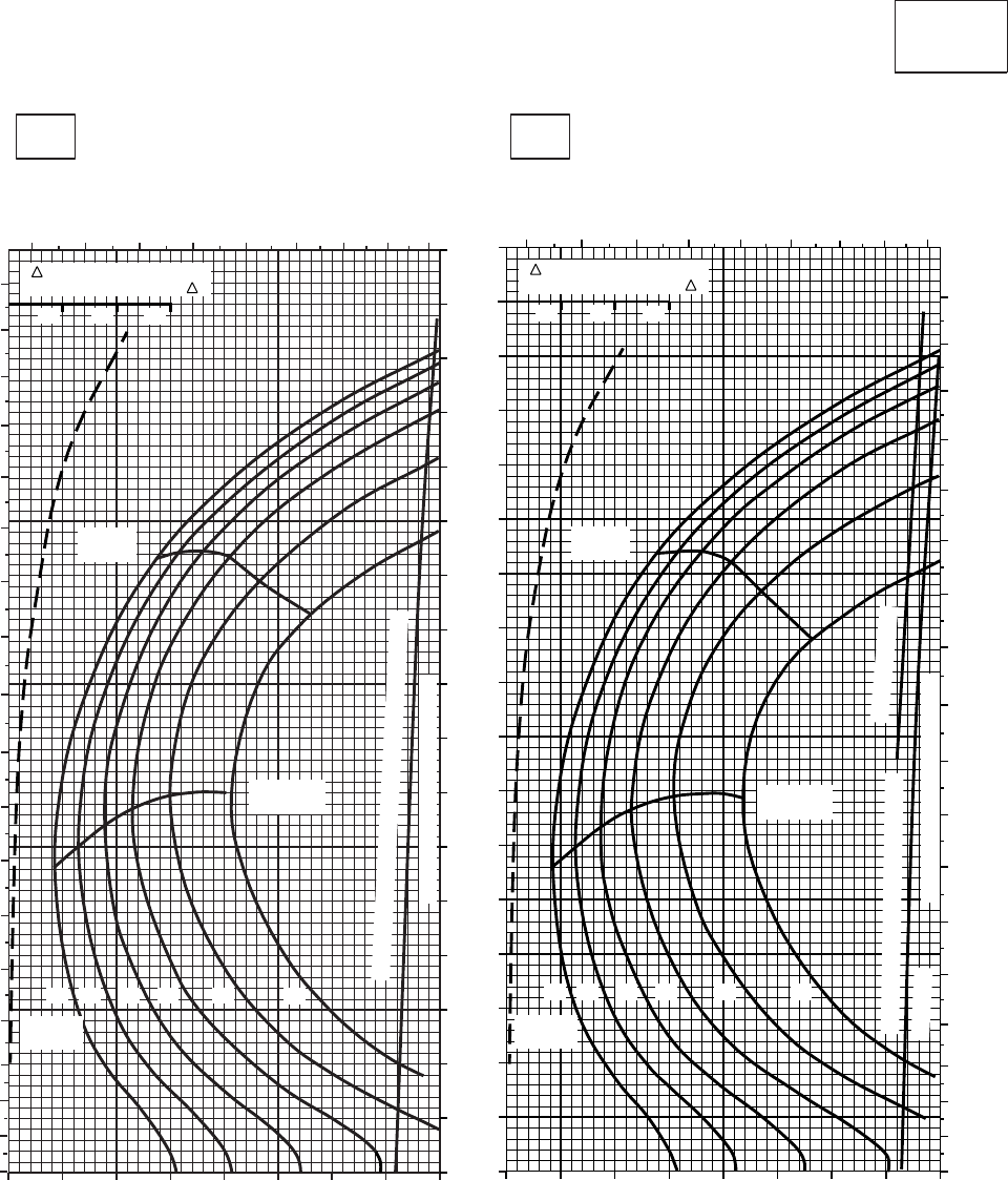
CRUISE CRUISE
T701C (2)
TORQUE PER ENGINE ~ %TORQUE PER ENGINE ~ %
IAS ~ KTS TOTAL FUEL FLOW ~ 100 LB/HRTOTAL FUEL FLOW ~ 100 LB/HR
DATA BASE:FLIGHT TEST
TRUE AIRSPEED ~ KTS
TRUE AIRSPEED ~ KTS
CLEAN CONFIGURATION
0
10
20
30
40
50
60
70
80
90
100
110
120
130
140
150
160
170
PRESS ALT: 10,000 FT
10,000 FT
−30oC−20oC
5 6 7 8 9 10 11 12 13
20 30 40 50 60 70 80 90 100
0
10
20
30
40
50
60
70
80
90
100
110
120
130
140
150
160
170
180
MAX
RANGE
MAX END
AND R / C
GW ~
1000 LB
12 14 16 18 20 22
TRANSMISSION TORQUE LIMIT
TORQUE AVAILABLE~30 MINUTES & CONTINUOUS
5 6 7 8 9 10 11 12 13
20 30 40 50 60 70 80 90 100
0
10
20
30
40
50
60
70
80
90
100
110
120
130
140
150
160
170
180
MAX
RANGE
MAX END
AND R / C
GW ~
1000 LB
TRANSMISSION TORQUE LIMIT
~ CONTINUOUS
ATF = 0.9
TORQUE AVAILABLE ~ 30 MINUTES
TRQ ~ % FOR DRAG
AREA OF 10 SQ FT OF F
10 20 30
TRQ ~ % FOR DRAG
AREA OF 10 SQ FT OF F
10 20 30
12 14 16 18 20 22
SA
AA1013_2
PLACARD TORQUE LIMIT = 93%PLACARD TORQUE LIMIT = 97%
Figure 7A-19. Cruise - Pressure Altitude 10,000 Feet (Sheet 2 of 5)
TM 1-1520-237-10
7A-81
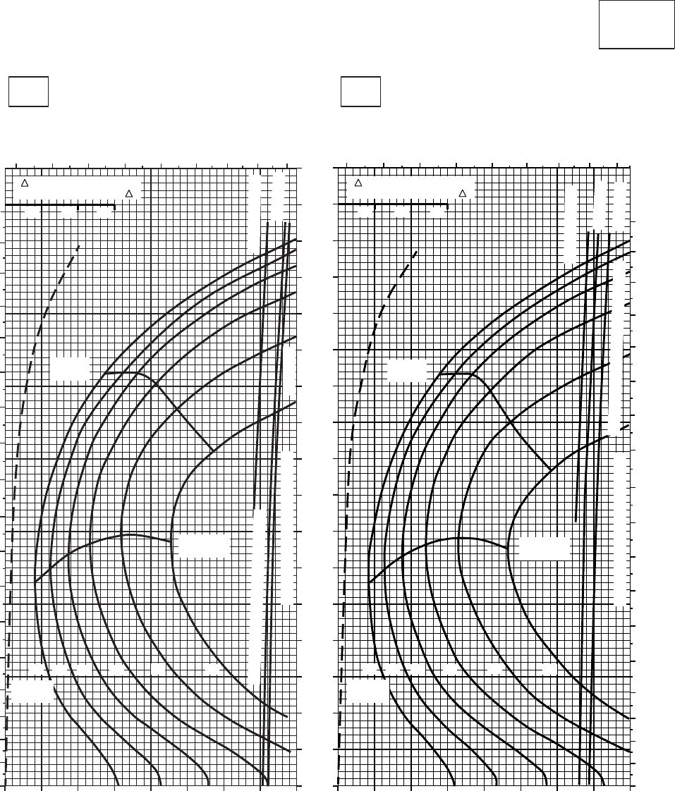
CRUISE CRUISE
T701C (2)
TORQUE PER ENGINE ~ %TORQUE PER ENGINE ~ %
IAS ~ KTS TOTAL FUEL FLOW ~ 100 LB/HRTOTAL FUEL FLOW ~ 100 LB/HR
DATA BASE:FLIGHT TEST
TRUE AIRSPEED ~ KTS
TRUE AIRSPEED ~ KTS
CLEAN CONFIGURATION
0
10
20
30
40
50
60
70
80
90
100
110
120
130
140
150
160
170
PRESS ALT: 10,000 FT
10,000 FT
−10oC0oC
5 6 7 8 9 10 11 12 13
20 30 40 50 60 70 80 90 100
0
10
20
30
40
50
60
70
80
90
100
110
120
130
140
150
160
170
180
~ CONTINUOUS
ATF = 0.9
TRANSMISSION TORQUE LIMIT ATF = 1.0
TORQUE AVAILABLE ~ 30 MINUTES
MAX
RANGE
MAX END
AND R / C
GW ~
1000 LB
22
20
1816
14
12
56 7 8 9 10 11 12 13
20 30 40 50 60 70 80 90 100
0
10
20
30
40
50
60
70
80
90
100
110
120
130
140
150
160
170
180
~ CONTINUOUS
ATF = 0.9
ATF = 1.0
TRANSMISSION TORQUE LIMIT
TORQUE AVAILABLE ~ 30 MINUTES
MAX
RANGE
MAX END
AND R / C
GW ~
1000 LB
22
20
1816
14
12
TRQ ~ % FOR DRAG
AREA OF 10 SQ FT OF F
10 20 30
TRQ ~ % FOR DRAG
AREA OF 10 SQ FT OF F
10 20 30
SA
AA1013_3
PLACARD TORQUE LIMIT = 85%PLACARD TORQUE LIMIT = 89%
Figure 7A-19. Cruise - Pressure Altitude 10,000 Feet (Sheet 3 of 5)
TM 1-1520-237-10
7A-82
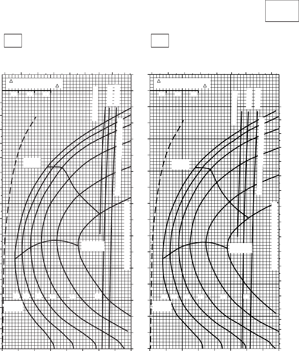
CRUISE CRUISE
T701C (2)
TORQUE PER ENGINE ~ %TORQUE PER ENGINE ~ %
IAS ~ KTS TOTAL FUEL FLOW ~ 100 LB/HRTOTAL FUEL FLOW ~ 100 LB/HR
DATA BASE:FLIGHT TEST
TRUE AIRSPEED ~ KTS
TRUE AIRSPEED ~ KTS
CLEAN CONFIGURATION
0
10
20
30
40
50
60
70
80
90
100
110
120
130
140
150
160
170
PRESS ALT: 10,000 FT
10,000 FT
10oC20oC
20 30 40 50 60 70 80 90 100
56 7 8 910 11 12 13
0
10
20
30
40
50
60
70
80
90
100
110
120
130
140
150
160
170
180
~ CONTINUOUS
ATF = 0.9
ATF = 1.0
TORQUE AVAILABLE ~ 30 MINUTES
TRANSMISSION TORQUE LIMIT
MAX
RANGE
MAX END
AND R / C
GW ~
1000 LB
12 14 16 22
20
18
5 6 7 8 910 11 12 13
20 30 40 50 60 70 80 90 100
0
10
20
30
40
50
60
70
80
90
100
110
120
130
140
150
160
170
180
~ CONTINUOUS
ATF = 0.9
ATF = 1.0
TORQUE AVAILABLE ~ 30 MINUTES
TRANSMISSION TORQUE LIMIT
MAX
RANGE
MAX END
AND R / C
12 14 22
20
18
TRQ ~ % FOR DRAG
AREA OF 10 SQ FT OF F
10 20 30
TRQ ~ % FOR DRAG
AREA OF 10 SQ FT OF F
10 20 30
GW ~
1000 LB
16
SA
AA1013_4
PLACARD TORQUE LIMIT = 80%PLACARD TORQUE LIMIT = 83%
Figure 7A-19. Cruise - Pressure Altitude 10,000 Feet (Sheet 4 of 5)
TM 1-1520-237-10
7A-83
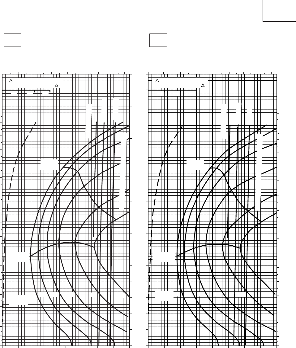
CRUISE CRUISE
T701C (2)
TORQUE PER ENGINE ~ %TORQUE PER ENGINE ~ %
IAS ~ KTS TOTAL FUEL FLOW ~ 100 LB/HRTOTAL FUEL FLOW ~ 100 LB/HR
DATA BASE:FLIGHT TEST
TRUE AIRSPEED ~ KTS
TRUE AIRSPEED ~ KTS
CLEAN CONFIGURATION
0
10
20
30
40
50
60
70
80
90
100
110
120
130
140
150
160
170
PRESS ALT: 10,000 FT
10,000 FT
30oC40oC
4 5 6 7 8 910 11 12
10 20 30 40 50 60 70 80 90
0
10
20
30
40
50
60
70
80
90
100
110
120
130
140
150
160
170
180
~ CONTINUOUS
ATF = 0.9
ATF = 1.0
TORQUE AVAILABLE ~ 30 MINUTES
MAX END
AND R / C
MAX
RANGE
GW ~
1000 LB
22
20
18
16
14
12
45 6 78 9 10 11 12
10 20 30 40 50 60 70 80 90
0
10
20
30
40
50
60
70
80
90
100
110
120
130
140
150
160
170
180
~ CONTINUOUS
ATF = 0.9
ATF = 1.0
TORQUE AVAILABLE ~ 30 MINUTES
MAX END
AND R / C
MAX
RANGE
GW ~
1000 LB 22
20
18
16
14
12
TRQ ~ % FOR DRAG
AREA OF 10 SQ FT OF F
10 20 30
TRQ ~ % FOR DRAG
AREA OF 10 SQ FT OF F
10 20 30
SA
AA1013_5
PLACARD TORQUE LIMIT = 74%PLACARD TORQUE LIMIT = 77%
Figure 7A-19. Cruise - Pressure Altitude 10,000 Feet (Sheet 5 of 5)
TM 1-1520-237-10
7A-84
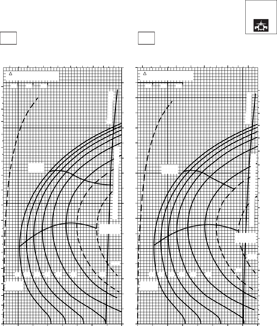
CRUISE CRUISE
T701C (2)
TORQUE PER ENGINE ~ %TORQUE PER ENGINE ~ %
IAS ~ KTS TOTAL FUEL FLOW ~ 100 LB/HRTOTAL FUEL FLOW ~ 100 LB/HR
DATA BASE:FLIGHT TEST
TRUE AIRSPEED ~ KTS
TRUE AIRSPEED ~ KTS
NOTE:SHORT DASH LINES: FERRY MISSION ONLY
SA
AA1014_1
PRESS ALT: 10000 FT
10000 FT
−50oC−40oC
5 6 7 8 9 10 11 12 13 5 6 7 8 9 10 11 12 13
0
10
20
30
40
50
60
70
80
90
100
110
120
130
140
150
160
170
180
0
10
20
30
40
50
60
70
80
90
100
110
120
130
140
150
160
170
180
0
10
20
30
40
50
60
70
80
90
100
110
120
130
140
150
160
170
MAX
RANGE
MAX END
AND R / C
GW ~
1000 LB
12 14 16 18 20 22 23
24.5
MAX
RANGE
MAX END
AND R / C
GW ~
1000 LB
12 14 16 18 20 22 23
24.5
20 30 40 50 60 70 80 90 100 20 30 40 50 60 70 80 90 100
TRQ ~ % FOR DRAG
AREA OF 10 SQ FT
10 20 30
TRQ ~ % FOR DRAG
AREA OF 10 SQ FT
10 20 30
~ CONTINUOUS
TORQUE AVAILABLE ~ 30 MINUTES
TORQUE AVAILABLE ~ 30 MINUTES
~ CONTINUOUS
Figure 7A-20. Cruise High Drag - Pressure Altitude 10,000 Feet (Sheet 1 of 5)
TM 1-1520-237-10
7A-85
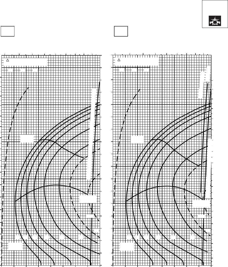
CRUISE CRUISE
T701C (2)
TORQUE PER ENGINE ~ %TORQUE PER ENGINE ~ %
IAS ~ KTS TOTAL FUEL FLOW ~ 100 LB/HRTOTAL FUEL FLOW ~ 100 LB/HR
DATA BASE:FLIGHT TEST
TRUE AIRSPEED ~ KTS
TRUE AIRSPEED ~ KTS
NOTE:SHORT DASH LINES: FERRY MISSION ONLY
SA
AA1014_2
PRESS ALT: 10000 FT
10000 FT
−30oC−20oC
0
10
20
30
40
50
60
70
80
90
100
110
120
130
140
150
160
170
180
5 6 7 8 9 10 11 12 13 5 6 7 8 9 10 11 12 13
0
10
20
30
40
50
60
70
80
90
100
110
120
130
140
150
160
170
180
0
10
20
30
40
50
60
70
80
90
100
110
120
130
140
150
160
170
20 30 40 50 60 70 80 90 100 20 30 40 50 60 70 80 90 100
MAX
RANGE
MAX END
AND R / C
GW ~
1000 LB
12 14 16 18 20 22
23
24.5
MAX
RANGE
MAX END
AND R / C
GW ~
1000 LB
12 14 16 18 20 22
23
24.5
TORQUE AVAILABLE ~ 30 MINUTES AND CONTINUOUS
~ CONTINUOUS
ATF = 0.9
TORQUE AVAILABLE ~ 30 MINUTES
TRQ ~ % FOR DRAG
AREA OF 10 SQ FT
10 20 30
TRQ ~ % FOR DRAG
AREA OF 10 SQ FT
10 20 30
GW ~
1000 LB
PLACARD TORQUE LIMIT = 93%PLACARD TORQUE LIMIT = 97%
Figure 7A-20. Cruise High Drag - Pressure Altitude 10,000 Feet (Sheet 2 of 5)
TM 1-1520-237-10
7A-86
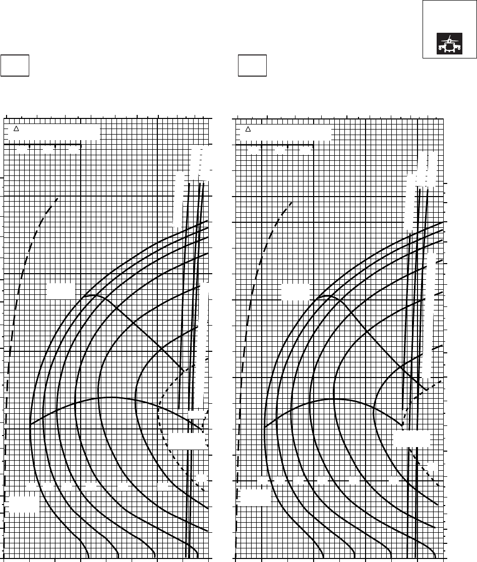
CRUISE CRUISE
T701C (2)
TORQUE PER ENGINE ~ %TORQUE PER ENGINE ~ %
IAS ~ KTS TOTAL FUEL FLOW ~ 100 LB/HRTOTAL FUEL FLOW ~ 100 LB/HR
DATA BASE:FLIGHT TEST
TRUE AIRSPEED ~ KTS
TRUE AIRSPEED ~ KTS
NOTE:SHORT DASH LINES: FERRY MISSION ONLY
SA
AA1014_3
PRESS ALT: 10000 FT
10000 FT
−10oC0oC
0
10
20
30
40
50
60
70
80
90
100
110
120
130
140
150
160
170
180
5 6 7 8 9 10 11 12 13 5 6 7 8 9 10 11 12 13
0
10
20
30
40
50
60
70
80
90
100
110
120
130
140
150
160
170
180
20 30 40 50 60 70 80 90 100 20 30 40 50 60 70 80 90 100
0
10
20
30
40
50
60
70
80
90
100
110
120
130
140
150
160
170
MAX
RANGE
MAX END
AND R / C
GW ~
1000 LB
12 14 16 18 20 22 23
24.5
MAX
RANGE
MAX END
AND R / C
GW ~
1000 LB
12 14 16 18 20 22
23
~ CONTINUOUS
~ CONTINUOUS
ATF = 0.9
ATF = 0.9
ATF = 1.0
ATF = 1.0
TORQUE AVAILABLE ~ 30 MINUTES
TORQUE AVAILABLE ~ 30 MINUTES
TRQ ~ % FOR DRAG
AREA OF 10 SQ FT
10 20 30
TRQ ~ % FOR DRAG
AREA OF 10 SQ FT
10 20 30
PLACARD TORQUE LIMIT = 85%
PLACARD TORQUE LIMIT = 89%
Figure 7A-20. Cruise High Drag - Pressure Altitude 10,000 Feet (Sheet 3 of 5)
TM 1-1520-237-10
7A-87
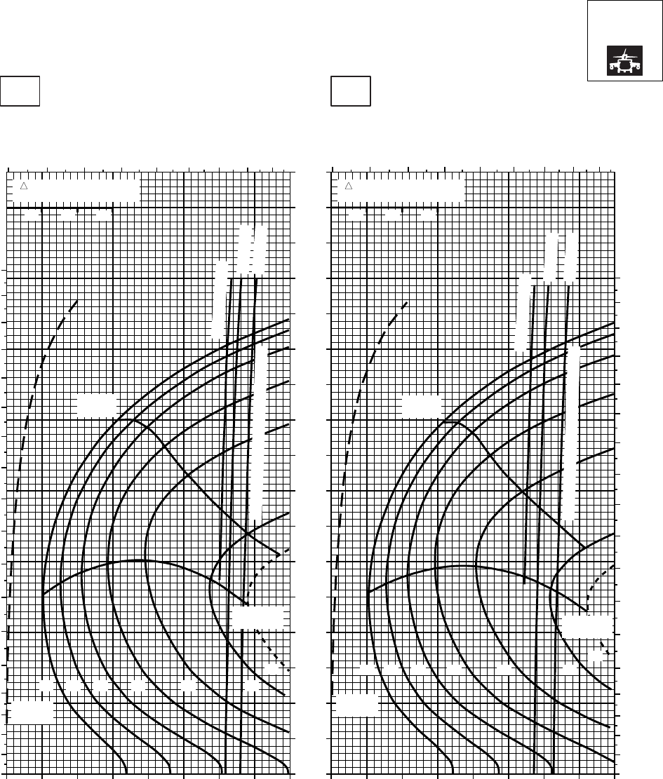
CRUISE CRUISE
T701C (2)
TORQUE PER ENGINE ~ %TORQUE PER ENGINE ~ %
IAS ~ KTS TOTAL FUEL FLOW ~ 100 LB/HRTOTAL FUEL FLOW ~ 100 LB/HR
DATA BASE:FLIGHT TEST
TRUE AIRSPEED ~ KTS
TRUE AIRSPEED ~ KTS
NOTE:SHORT DASH LINES: FERRY MISSION ONLY
SA
AA1014_4
PRESS ALT: 10000 FT
10000 FT
10oC 20oC
20 30 40 50 60 70 80 90 100 20 30 40 50 60 70 80 90 100
0
10
20
30
40
50
60
70
80
90
100
110
120
130
140
150
160
170
TRQ ~ % FOR DRAG
AREA OF 10 SQ FT
10 20 30
TRQ ~ % FOR DRAG
AREA OF 10 SQ FT
10 20 30
0
10
20
30
40
50
60
70
80
90
100
110
120
130
140
150
160
170
180
0
10
20
30
40
50
60
70
80
90
100
110
120
130
140
150
160
170
180
5 6 7 8 9 10 11 12 13 5 6 7 8 9 10 11 12 13
~ CONTINUOUS
~ CONTINUOUS
ATF = 0.9
ATF = 1.0
ATF = 0.9
ATF = 1.0
TORQUE AVAILABLE ~ 30 MINUTES
TORQUE AVAILABLE ~ 30 MINUTES
MAX
RANGE
MAX
RANGE
MAX END
AND R / C MAX END
AND R / C
GW ~
1000 LB
12 14 16 18 20 22
23
GW ~
1000 LB
12 14 16 18 20 22
23
PLACARD TORQUE LIMIT = 83% PLACARD TORQUE LIMIT = 80%
Figure 7A-20. Cruise High Drag - Pressure Altitude 10,000 Feet (Sheet 4 of 5)
TM 1-1520-237-10
7A-88
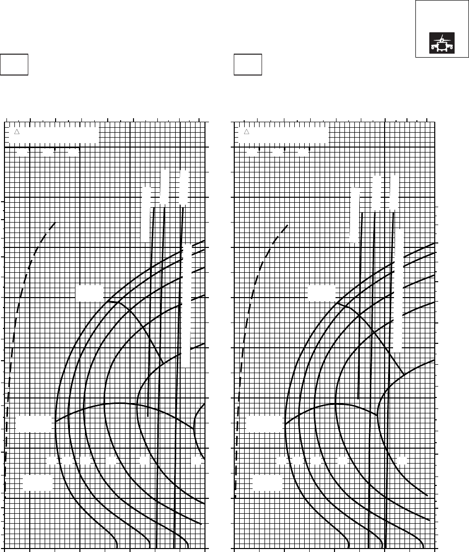
CRUISE CRUISE
T701C (2)
TORQUE PER ENGINE ~ %TORQUE PER ENGINE ~ %
IAS ~ KTS TOTAL FUEL FLOW ~ 100 LB/HRTOTAL FUEL FLOW ~ 100 LB/HR
DATA BASE:FLIGHT TEST
TRUE AIRSPEED ~ KTS
TRUE AIRSPEED ~ KTS
NOTE:SHORT DASH LINES: FERRY MISSION ONLY
SA
AA1014_5
PRESS ALT: 10000 FT
10000 FT
30oC40oC
20 30 40 50 60 70 80 90 20 30 40 50 60 70 80 90
0
10
20
30
40
50
60
70
80
90
100
110
120
130
140
150
160
170
TRQ ~ % FOR DRAG
AREA OF 10 SQ FT
10 20 30
TRQ ~ % FOR DRAG
AREA OF 10 SQ FT
10 20 30
10 10 0
10
20
30
40
50
60
70
80
90
100
110
120
130
140
150
160
170
180
0
10
20
30
40
50
60
70
80
90
100
110
120
130
140
150
160
170
180
4 5 6 7 8 9 10 11 12 5 6 7 8 9 10 11 12
MAX
RANGE MAX
RANGE
MAX END
AND R / C
MAX END
AND R / C
~ CONTINUOUS
~ CONTINUOUS
ATF = 0.9
ATF = 1.0
ATF = 0.9
ATF = 1.0
TORQUE AVAILABLE ~ 30 MINUTES
TORQUE AVAILABLE ~ 30 MINUTES
GW ~
1000 LB
12 14 16 18 20 22
GW ~
1000 LB
12 14 16 18 20
PLACARD TORQUE LIMIT = 74%PLACARD TORQUE LIMIT = 77%
Figure 7A-20. Cruise High Drag - Pressure Altitude 10,000 Feet (Sheet 5 of 5)
TM 1-1520-237-10
7A-89
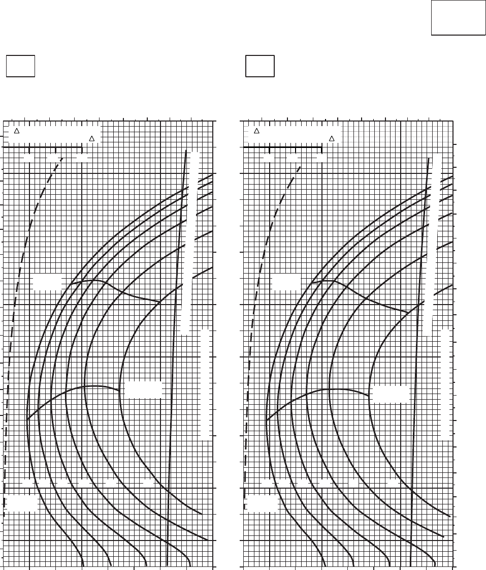
CRUISE CRUISE
T701C (2)
TORQUE PER ENGINE ~ %TORQUE PER ENGINE ~ %
IAS ~ KTS TOTAL FUEL FLOW ~ 100 LB/HRTOTAL FUEL FLOW ~ 100 LB/HR
DATA BASE:FLIGHT TEST
TRUE AIRSPEED ~ KTS
TRUE AIRSPEED ~ KTS
CLEAN CONFIGURATION
SA
AA1015_1
PRESS ALT: 12,000 FT
12,000 FT
−50oC−40oC
5 6 7 8 910 11 12
0
10
20
30
40
50
60
70
80
90
100
110
120
130
140
150
160
170
180
20 30 40 50 60 70 80 90 100 20 30 40 50 60 70 80 90 100
5 6 7 89 10 11 12
0
10
20
30
40
50
60
70
80
90
100
110
120
130
140
150
160
170
180
0
10
20
30
40
50
60
70
80
90
100
110
120
130
140
150
160
170
10 20 30
TRQ ~ % FOR DRAG
AREA OF 10 SQ FT OF F
10 20 30
TRQ ~ % FOR DRAG
AREA OF 10 SQ FT OF F
MAX
RANGE MAX
RANGE
MAX END
AND R / C MAX END
AND R / C
12 14 16 18 20 22 12 14 16 18 20 22
GW ~
1000 LB
GW ~
1000 LB
TRANSMISSION TORQUE LIMIT
TRANSMISSION TORQUE LIMIT
TORQUE AVAILABLE ~ 30 MINUTES & CONTINUOUS
TORQUE AVAILABLE ~ 30 MINUTES & CONTINUOUS
PLACARD TORQUE LIMIT = 93%PLACARD TORQUE LIMIT = 98%
Figure 7A-21. Cruise - Pressure Altitude 12,000 Feet (Sheet 1 of 5)
TM 1-1520-237-10
7A-90
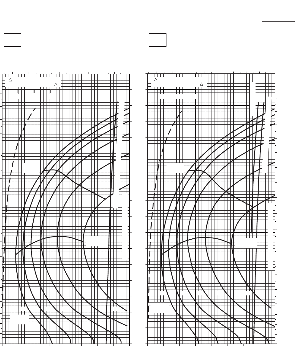
CRUISE CRUISE
T701C (2)
TORQUE PER ENGINE ~ %TORQUE PER ENGINE ~ %
IAS ~ KTS TOTAL FUEL FLOW ~ 100 LB/HRTOTAL FUEL FLOW ~ 100 LB/HR
DATA BASE:FLIGHT TEST
TRUE AIRSPEED ~ KTS
TRUE AIRSPEED ~ KTS
CLEAN CONFIGURATION
PRESS ALT: 12,000 FT
12,000 FT
−30oC−20oC
5 6 7 8 9 10 11 12
20 30 40 50 60 70 80 90 100
0
10
20
30
40
50
60
70
80
90
100
110
120
130
140
150
160
170
180
56 7 8 9 10 11 12 13
0
10
20
30
40
50
60
70
80
90
100
110
120
130
140
150
160
170
180
20 30 40 50 60 70 80 90 100
0
10
20
30
40
50
60
70
80
90
100
110
120
130
140
150
160
170
10 20 30
TRQ ~ % FOR DRAG
AREA OF 10 SQ FT OF F
10 20 30
TRQ ~ % FOR DRAG
AREA OF 10 SQ FT OF F
12 14 16 18 20 22
12 14 16 18 20 22
GW ~
1000 LB
GW ~
1000 LB
MAX END
AND R / C MAX END
AND R / C
MAX
RANGE MAX
RANGE
TRANSMISSION TORQUE LIMIT
TRANSMISSION TORQUE LIMIT
TORQUE AVAILABLE ~ 30 MINUTES & CONTINUOUS
~ CONTINUOUS
TORQUE AVAILABLE ~ 30 MINUTES
SA
AA1015_2
PLACARD TORQUE LIMIT = 89% PLACARD TORQUE LIMIT = 86%
Figure 7A-21. Cruise - Pressure Altitude 12,000 Feet (Sheet 2 of 5)
TM 1-1520-237-10
7A-91
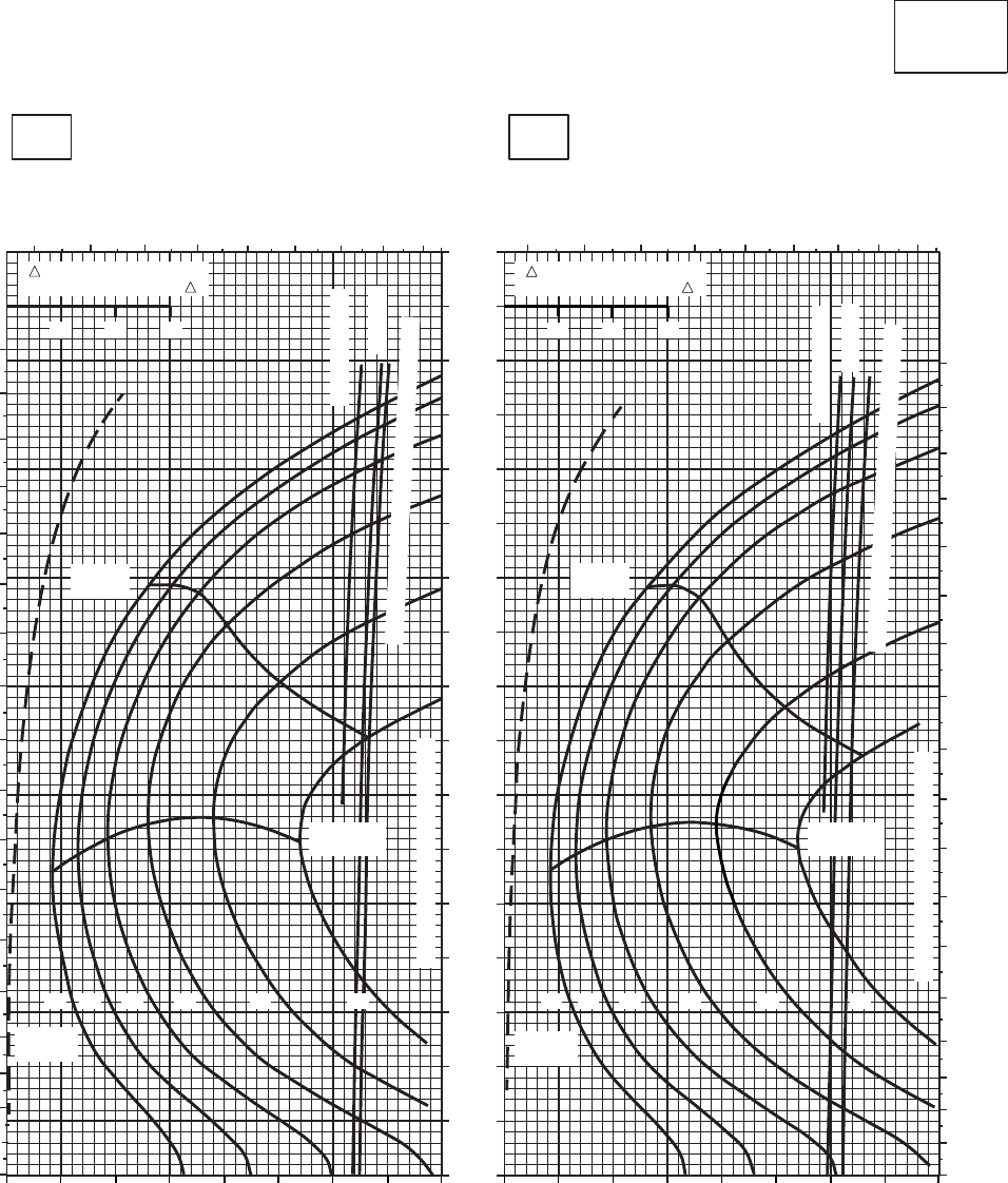
CRUISE CRUISE
T701C (2)
TORQUE PER ENGINE ~ %TORQUE PER ENGINE ~ %
IAS ~ KTS TOTAL FUEL FLOW ~ 100 LB/HRTOTAL FUEL FLOW ~ 100 LB/HR
DATA BASE:FLIGHT TEST
TRUE AIRSPEED ~ KTS
TRUE AIRSPEED ~ KTS
CLEAN CONFIGURATION
PRESS ALT: 12,000 FT
12,000 FT
−10oC0oC
56 7 8 9 10 11 12 13 5 6 7 8 9 10 11 12 13
0
10
20
30
40
50
60
70
80
90
100
110
120
130
140
150
160
170
180
0
10
20
30
40
50
60
70
80
90
100
110
120
130
140
150
160
170
180
0
10
20
30
40
50
60
70
80
90
100
110
120
130
140
150
160
170
10 20 30
TRQ ~ % FOR DRAG
AREA OF 10 SQ FT OF F
10 20 30
TRQ ~ % FOR DRAG
AREA OF 10 SQ FT OF F
12 14 16 18 20 22
GW ~
1000 LB
12 14 16 18 20 22
GW ~
1000 LB
MAX
RANGE MAX
RANGE
MAX END
AND R / C MAX END
AND R / C
TRANSMISSION TORQUE LIMIT
TRANSMISSION TORQUE LIMIT
~ CONTINUOUS
~ CONTINUOUS
ATF= 0.9
ATF= 0.9
TORQUE AVAILABLE ~ 30 MINUTES ATF= 1.0
TORQUE AVAILABLE ~ 30 MINUTES ATF= 1.0
20 30 40 50 60 70 80 90 100 20 30 40 50 60 70 80 90 100
SA
AA1015_3
PLACARD TORQUE LIMIT = 82% PLACARD TORQUE LIMIT = 79%
Figure 7A-21. Cruise - Pressure Altitude 12,000 Feet (Sheet 3 of 5)
TM 1-1520-237-10
7A-92
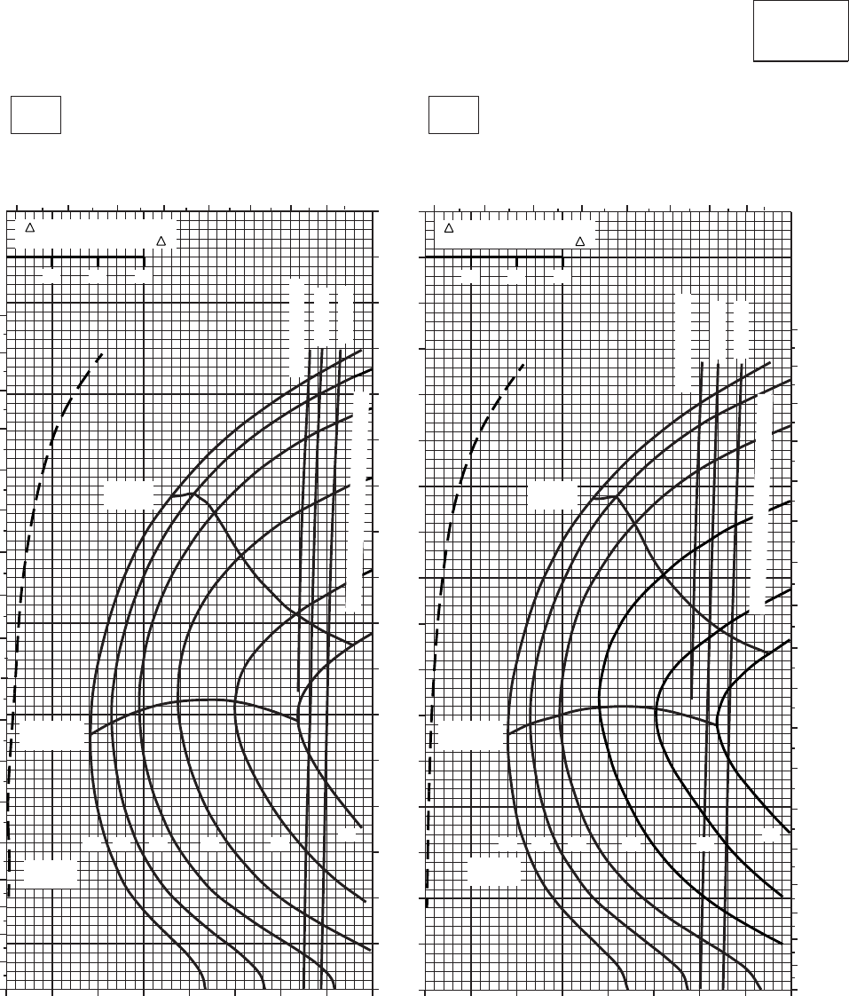
CRUISE CRUISE
T701C (2)
TORQUE PER ENGINE ~ %TORQUE PER ENGINE ~ %
IAS ~ KTS TOTAL FUEL FLOW ~ 100 LB/HRTOTAL FUEL FLOW ~ 100 LB/HR
DATA BASE:FLIGHT TEST
TRUE AIRSPEED ~ KTS
TRUE AIRSPEED ~ KTS
CLEAN CONFIGURATION
PRESS ALT: 12,000 FT
12,000 FT
10oC20oC
4 5 6 7 8 9 10 11
0
10
20
30
40
50
60
70
80
90
100
110
120
130
140
150
160
170
180
10 20 30 40 50 60 70 80 90
0
10
20
30
40
50
60
70
80
90
100
110
120
130
140
150
160
170
20 30 40 50 60 70 80 90
10
4 5 6 7 8 9 10 11
0
10
20
30
40
50
60
70
80
90
100
110
120
130
140
150
160
170
180
12 14 16 18 20 22
GW ~
1000 LB GW ~
1000 LB
12 14 16 18 20 22
MAX END
AND R / C
MAX END
AND R / C
MAX
RANGE MAX
RANGE
~ CONTINUOUS
~ CONTINUOUS
ATF= 0.9
ATF= 0.9
ATF= 1.0
ATF= 1.0
TORQUE AVAILABLE ~ 30 MINUTES
10 20 30
TRQ ~ % FOR DRAG
AREA OF 10 SQ FT OF F
10 20 30
TRQ ~ % FOR DRAG
AREA OF 10 SQ FT OF F
TORQUE AVAILABLE ~ 30 MINUTES
SA
AA1015_4
PLACARD TORQUE LIMIT = 73%PLACARD TORQUE LIMIT = 76%
Figure 7A-21. Cruise - Pressure Altitude 12,000 Feet (Sheet 4 of 5)
TM 1-1520-237-10
7A-93
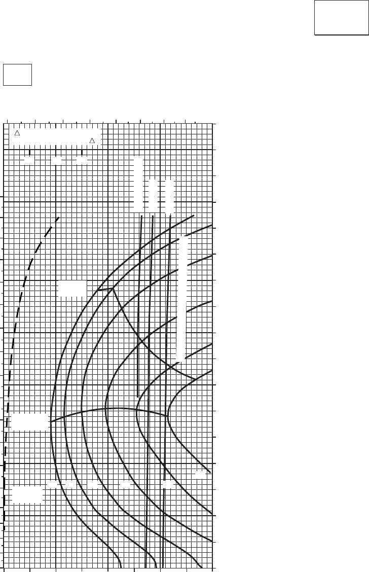
CRUISE CRUISE
T701C (2)
TORQUE PER ENGINE ~ %
TOTAL FUEL FLOW ~ 100 LB/HR
DATA BASE:FLIGHT TEST
INDICATED AIRSPEED ~ KTS
TRUE AIRSPEED ~ KTS
CLEAN CONFIGURATION
PRESS ALT: 12,000 FT
12,000 FT
30oC
45 6 789 10 11
0
10
20
30
40
50
60
70
80
90
100
110
120
130
140
150
160
170
180
10 20 30 40 50 60 70 80 90
0
10
20
30
40
50
60
70
80
90
100
110
120
130
140
150
160
170
10 20 30
TRQ ~ % FOR DRAG
AREA OF 10 SQ FT OF F
12 14 16 18 20
22
GW ~
1000 LB
MAX END
AND R / C
MAX
RANGE
~ CONTINUOUS
ATF= 0.9
ATF= 1.0
TORQUE AVAILABLE ~ 30 MINUTES
SA
AA1015_5
PLACARD TORQUE LIMIT = 70%
Figure 7A-21. Cruise - Pressure Altitude 12,000 Feet (Sheet 5 of 5)
TM 1-1520-237-10
7A-94
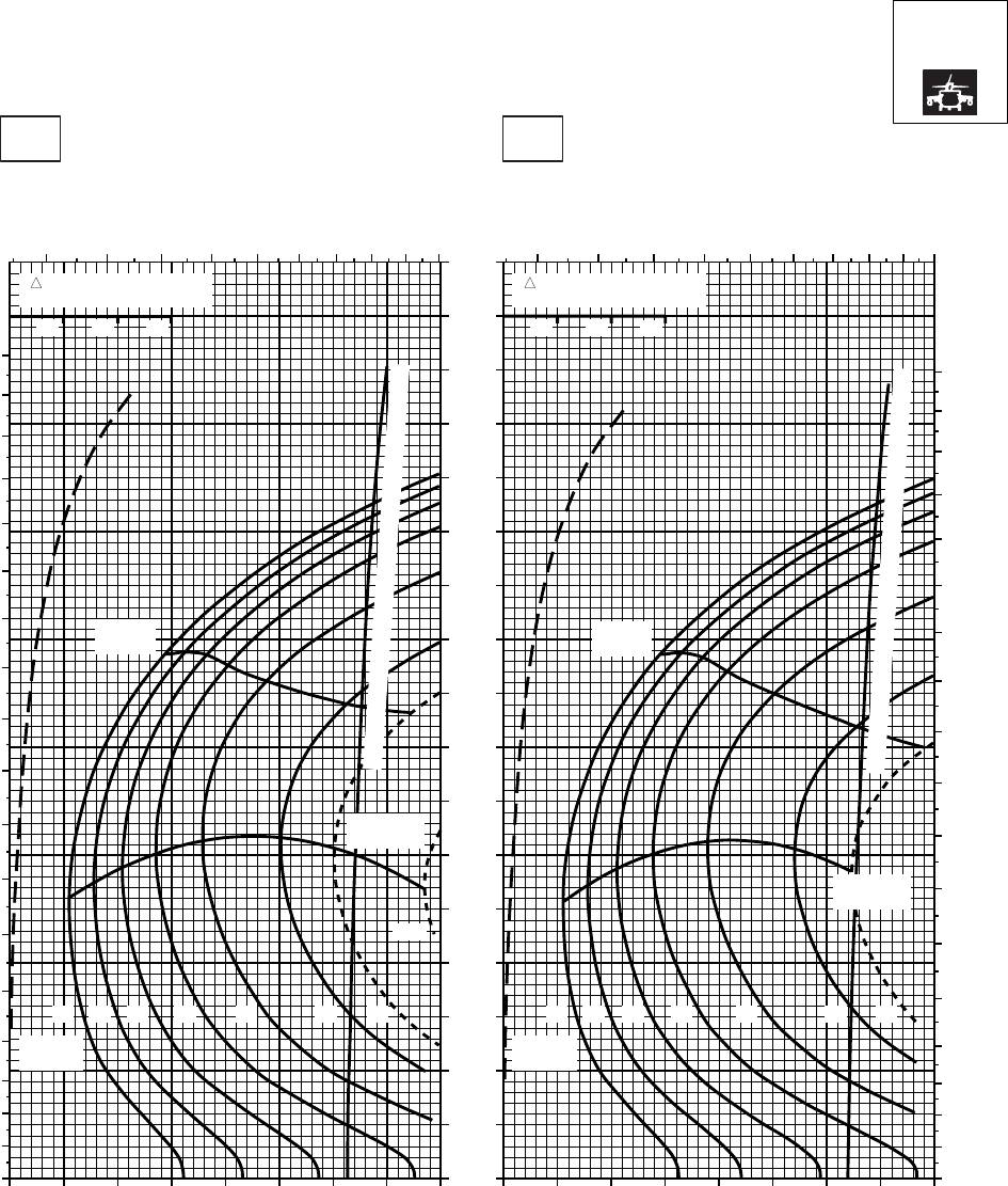
CRUISE CRUISE
T701C (2)
TORQUE PER ENGINE ~ %TORQUE PER ENGINE ~ %
IAS ~ KTS TOTAL FUEL FLOW ~ 100 LB/HRTOTAL FUEL FLOW ~ 100 LB/HR
DATA BASE:FLIGHT TEST
TRUE AIRSPEED ~ KTS
TRUE AIRSPEED ~ KTS
NOTE:SHORT DASH LINES: FERRY MISSION ONLY
SA
AA1016_1
PRESS ALT: 12000 FT
12000 FT
−50oC−40oC
20 30 40 50 60 70 80 90 100 20 30 40 50 60 70 80 90 100
0
10
20
30
40
50
60
70
80
90
100
110
120
130
140
150
160
170
TRQ ~ % FOR DRAG
AREA OF 10 SQ FT
10 20 30
TRQ ~ % FOR DRAG
AREA OF 10 SQ FT
10 20 30
0
10
20
30
40
50
60
70
80
90
100
110
120
130
140
150
160
170
180
5 6 7 8 9 10 11 12 13 14 5 6 7 8 9 10 11 12 13 14
0
10
20
30
40
50
60
70
80
90
100
110
120
130
140
150
160
170
180
MAX
RANGE MAX
RANGE
MAX END
AND R / C
MAX END
AND R / C
TORQUE AVAILABLE ~ 30 MINUTES AND CONTINUOUS
TORQUE AVAILABLE ~ 30 MINUTES AND CONTINUOUS
GW ~
1000 LB
12 14 16 18 20 22 23
GW ~
1000 LB
12 14 16 18 20 22 23
24.5
PLACARD TORQUE LIMIT = 93%
PLACARD TORQUE LIMIT = 98%
Figure 7A-22. Cruise High Drag - Pressure Altitude 12,000 Feet (Sheet 1 of 5)
TM 1-1520-237-10
7A-95
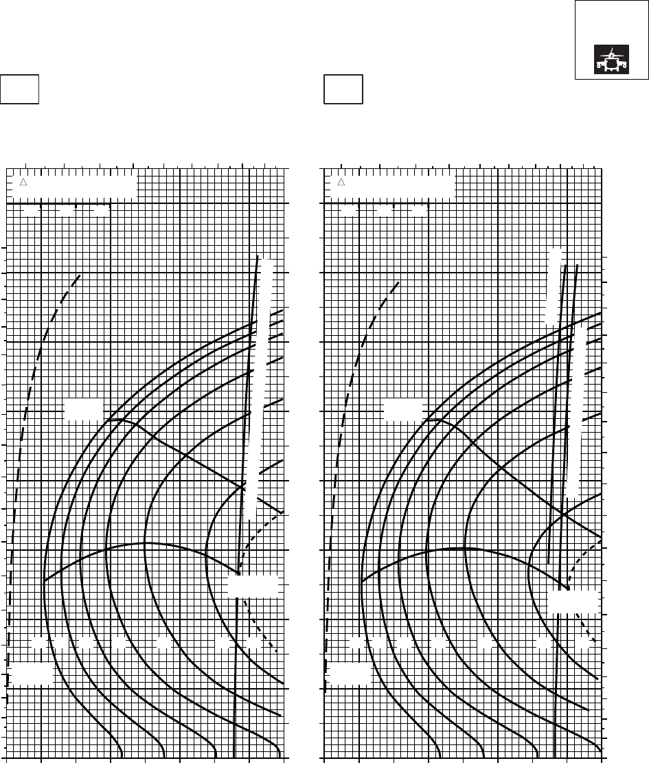
CRUISE CRUISE
T701C (2)
TORQUE PER ENGINE ~ %TORQUE PER ENGINE ~ %
IAS ~ KTS TOTAL FUEL FLOW ~ 100 LB/HRTOTAL FUEL FLOW ~ 100 LB/HR
DATA BASE:FLIGHT TEST
TRUE AIRSPEED ~ KTS
TRUE AIRSPEED ~ KTS
NOTE:SHORT DASH LINES: FERRY MISSION ONLY
SA
AA1016_2
PRESS ALT: 12000 FT
12000 FT
−30oC−20oC
20 30 40 50 60 70 80 90 100 20 30 40 50 60 70 80 90 100
0
10
20
30
40
50
60
70
80
90
100
110
120
130
140
150
160
170
TRQ ~ % FOR DRAG
AREA OF 10 SQ FT
10 20 30
TRQ ~ % FOR DRAG
AREA OF 10 SQ FT
10 20 30
0
10
20
30
40
50
60
70
80
90
100
110
120
130
140
150
160
170
180
5 6 7 8 9 10 11 12 13 5 6 7 89 10 11 12 13
0
10
20
30
40
50
60
70
80
90
100
110
120
130
140
150
160
170
180
MAX
RANGE
MAX
RANGE
MAX END
AND R / C MAX END
AND R / C
TORQUE AVAILABLE ~ 30 MINUTES
TORQUE AVAILABLE ~ 30 MINUTES AND CONTINUOUS
~ CONTINUOUS
GW ~
1000 LB
12 14 16 18 20 22 23
GW ~
1000 LB
12 14 16 18 20 22 23
PLACARD TORQUE LIMIT = 86%PLACARD TORQUE LIMT = 89%
Figure 7A-22. Cruise High Drag - Pressure Altitude 12,000 Feet (Sheet 2 of 5)
TM 1-1520-237-10
7A-96
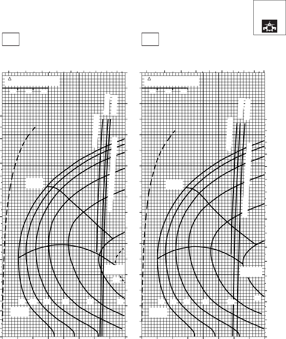
CRUISE CRUISE
T701C (2)
TORQUE PER ENGINE ~ %TORQUE PER ENGINE ~ %
IAS ~ KTS TOTAL FUEL FLOW ~ 100 LB/HRTOTAL FUEL FLOW ~ 100 LB/HR
DATA BASE:FLIGHT TEST
TRUE AIRSPEED ~ KTS
TRUE AIRSPEED ~ KTS
NOTE:SHORT DASH LINES: FERRY MISSION ONLY
SA
AA1016_3
PRESS ALT: 12000 FT
12000 FT
−10oC0oC
5 6 7 8 9 10 11 12 13 5 6 7 8 9 10 11 12 13 14
0
10
20
30
40
50
60
70
80
90
100
110
120
130
140
150
160
170
180
0
10
20
30
40
50
60
70
80
90
100
110
120
130
140
150
160
170
180
20 30 40 50 60 70 80 90 100 20 30 40 50 60 70 80 90 100
0
10
20
30
40
50
60
70
80
90
100
110
120
130
140
150
160
170
TRQ ~ % FOR DRAG
AREA OF 10 SQ FT
10 20 30
TRQ ~ % FOR DRAG
AREA OF 10 SQ FT
10 20 30
14 1612 18 20
MAX
RANGE
GW ~
1000 LB
MAX END
AND R / C
22
23
14 1612 18 20
MAX
RANGE
GW ~
1000 LB
MAX END
AND R / C
22
~ CONTINUOUS
~ CONTINUOUS
ATF = 0.9
ATF = 0.9
ATF = 1.0
ATF = 1.0
TORQUE AVAILABLE ~ 30 MINUTES
TORQUE AVAILABLE ~ 30 MINUTES
PLACARD TORQUE LIMIT = 79%PLACARD TORQUE LIMIT = 82%
Figure 7A-22. Cruise High Drag - Pressure Altitude 12,000 Feet (Sheet 3 of 5)
TM 1-1520-237-10
7A-97
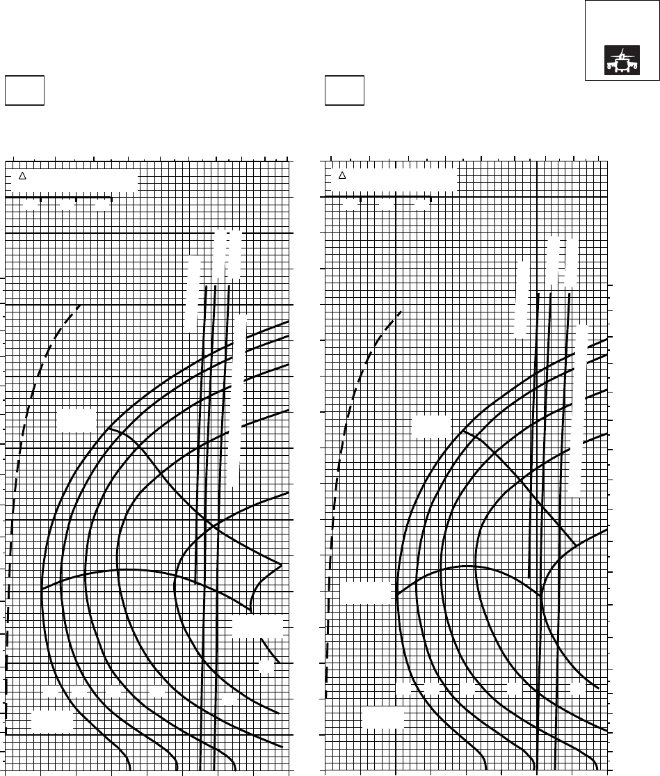
CRUISE CRUISE
T701C (2)
TORQUE PER ENGINE ~ %TORQUE PER ENGINE ~ %
IAS ~ KTS TOTAL FUEL FLOW ~ 100 LB/HRTOTAL FUEL FLOW ~ 100 LB/HR
DATA BASE:FLIGHT TEST
TRUE AIRSPEED ~ KTS
TRUE AIRSPEED ~ KTS
NOTE:SHORT DASH LINES: FERRY MISSION ONLY
SA
AA1016_4
PRESS ALT: 12000 FT
12000 FT
10oC20oC
5 6 7 8 9 10 11 12 13 14 4 5 6 7 8 9 10 11 12
20 30 40 50 60 70 80 90 100 10 20 30 40 50 60 70 80 90
0
10
20
30
40
50
60
70
80
90
100
110
120
130
140
150
160
170
0
10
20
30
40
50
60
70
80
90
100
110
120
130
140
150
160
170
180
0
10
20
30
40
50
60
70
80
90
100
110
120
130
140
150
160
170
180
TRQ ~ % FOR DRAG
AREA OF 10 SQ FT
10 20 30
TRQ ~ % FOR DRAG
AREA OF 10 SQ FT
10 20 30
14 1612 18 20
MAX
RANGE
GW ~
1000 LB
MAX END
AND R / C
22
14 1612 18 20
MAX
RANGE
GW ~
1000 LB
MAX END
AND R / C
~ CONTINUOUS
~ CONTINUOUS
ATF = 0.9
ATF = 0.9
ATF = 1.0
ATF = 1.0
TORQUE AVAILABLE ~ 30 MINUTES
TORQUE AVAILABLE ~ 30 MINUTES
PLACARD TORQUE LIMIT = 73%PLACARD TORQUE LIMIT = 76%
Figure 7A-22. Cruise High Drag - Pressure Altitude 12,000 Feet (Sheet 4 of 5)
TM 1-1520-237-10
7A-98
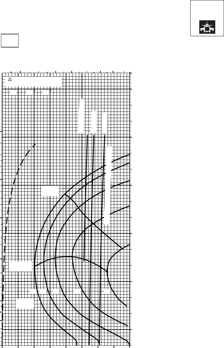
CRUISE CRUISE
T701C (2)
TORQUE PER ENGINE ~ %
TOTAL FUEL FLOW ~ 100 LB/HR
DATA BASE:FLIGHT TEST
INDICATED AIRSPEED ~ KTS
TRUE AIRSPEED ~ KTS
NOTE:SHORT DASH LINES: FERRY MISSION ONLY
SA
AA1016_5
PRESS ALT: 12000 FT
12000 FT
30oC
5 6 7 8 9 10 11 12
0
10
20
30
40
50
60
70
80
90
100
110
120
130
140
150
160
170
180
MAX
RANGE
MAX END
AND R / C
GW ~
1000 LB
12 14 16 18 20
~ CONTINUOUS
ATF = 0.9
ATF = 1.0
TORQUE AVAILABLE ~ 30 MINUTES
10 20 30 40 50 60 70 80 90 0
10
20
30
40
50
60
70
80
90
100
110
120
130
140
150
160
170
TRQ ~ % FOR DRAG
AREA OF 10 SQ FT
10 20 30
PLACARD TORQUE LIMIT = 70%
Figure 7A-22. Cruise High Drag - Pressure Altitude 12,000 Feet (Sheet 5 of 5)
TM 1-1520-237-10
7A-99
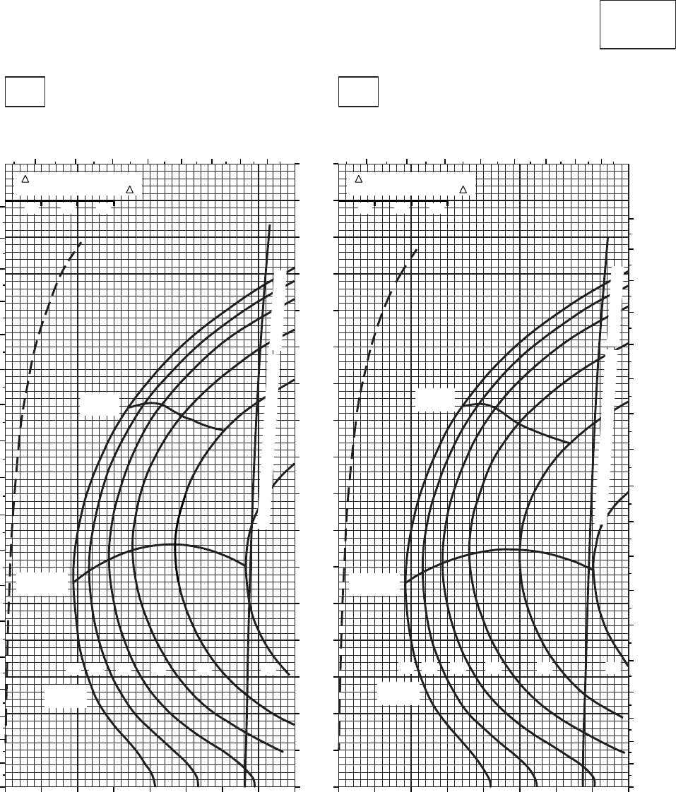
CRUISE CRUISE
T701C (2)
TORQUE PER ENGINE ~ %TORQUE PER ENGINE ~ %
IAS ~ KTS TOTAL FUEL FLOW ~ 100 LB/HRTOTAL FUEL FLOW ~ 100 LB/HR
DATA BASE:FLIGHT TEST
TRUE AIRSPEED ~ KTS
TRUE AIRSPEED ~ KTS
CLEAN CONFIGURATION
SA
AA1017_1
PRESS ALT: 14,000 FT
14,000 FT
−50oC−40oC
TRQ ~ % FOR DRAG
AREA OF 10 SQ FT OF F
10 20 30
TRQ ~ % FOR DRAG
AREA OF 10 SQ FT OF F
10 20 30
14 1612 18 20
MAX
RANGE
GW ~
1000 LB
MAX END
AND R / C
22 14 1612 18 20
MAX
RANGE
GW ~
1000 LB
MAX END
AND R / C
22
TORQUE AVAILABLE ~ 30 MINUTES
TORQUE AVAILABLE ~ 30 MINUTES
& CONTINUOUS
& CONTINUOUS
4 5 6 7 8 9 10 11 4 5 6 7 8 9 10 11
0
10
20
30
40
50
60
70
80
90
100
110
120
130
140
150
160
170
180
0
10
20
30
40
50
60
70
80
90
100
110
120
130
140
150
160
170
180
10 20 30 40 50 60 70 80 90 10 20 30 40 50 60 70 80 90
0
10
20
30
40
50
60
70
80
90
100
110
120
130
140
150
160
170
PLACARD TORQUE LIMIT = 86%PLACARD TORQUE LIMIT = 90%
Figure 7A-23. Cruise - Pressure Altitude 14,000 Feet (Sheet 1 of 5)
TM 1-1520-237-10
7A-100
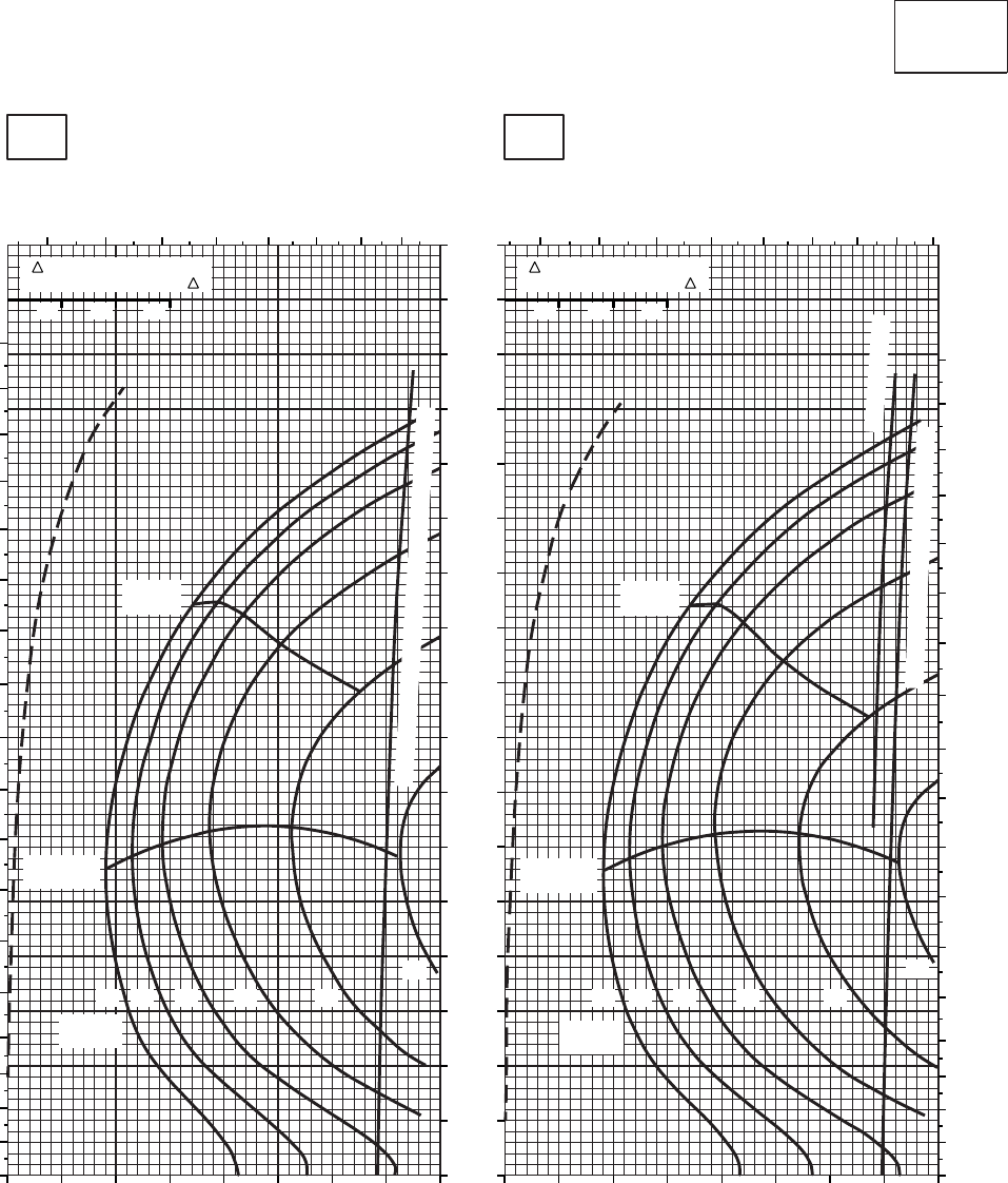
CRUISE CRUISE
T701C (2)
TORQUE PER ENGINE ~ %TORQUE PER ENGINE ~ %
IAS ~ KTS TOTAL FUEL FLOW ~ 100 LB/HRTOTAL FUEL FLOW ~ 100 LB/HR
DATA BASE:FLIGHT TEST
TRUE AIRSPEED ~ KTS
TRUE AIRSPEED ~ KTS
CLEAN CONFIGURATION
SA
AA1017_2
PRESS ALT: 14,000 FT
14,000 FT
−30oC−20oC
TRQ ~ % FOR DRAG
AREA OF 10 SQ FT OF F
10 20 30
TRQ ~ % FOR DRAG
AREA OF 10 SQ FT OF F
10 20 30
4 5 6 7 8 9 10 11 4 5 6 7 8 9 10 11
0
10
20
30
40
50
60
70
80
90
100
110
120
130
140
150
160
170
180
0
10
20
30
40
50
60
70
80
90
100
110
120
130
140
150
160
170
180
10 20 30 40 50 60 70 80 90 10 20 30 40 50 60 70 80 90
0
10
20
30
40
50
60
70
80
90
100
110
120
130
140
150
160
170
TORQUE AVAILABLE ~ 30 MINUTES & CONTINUOUS
TORQUE AVAILABLE ~ 30 MINUTES
14 1612 18 20
MAX
RANGE
GW ~
1000 LB
MAX END
AND R / C
22
14 1612 18 20
MAX
RANGE
GW ~
1000 LB
MAX END
AND R / C
22
~ CONTINUOUS
12
PLACARD TORQUE LIMIT = 79%PLACARD TORQUE LIMIT = 82%
Figure 7A-23. Cruise - Pressure Altitude 14,000 Feet (Sheet 2 of 5)
TM 1-1520-237-10
7A-101
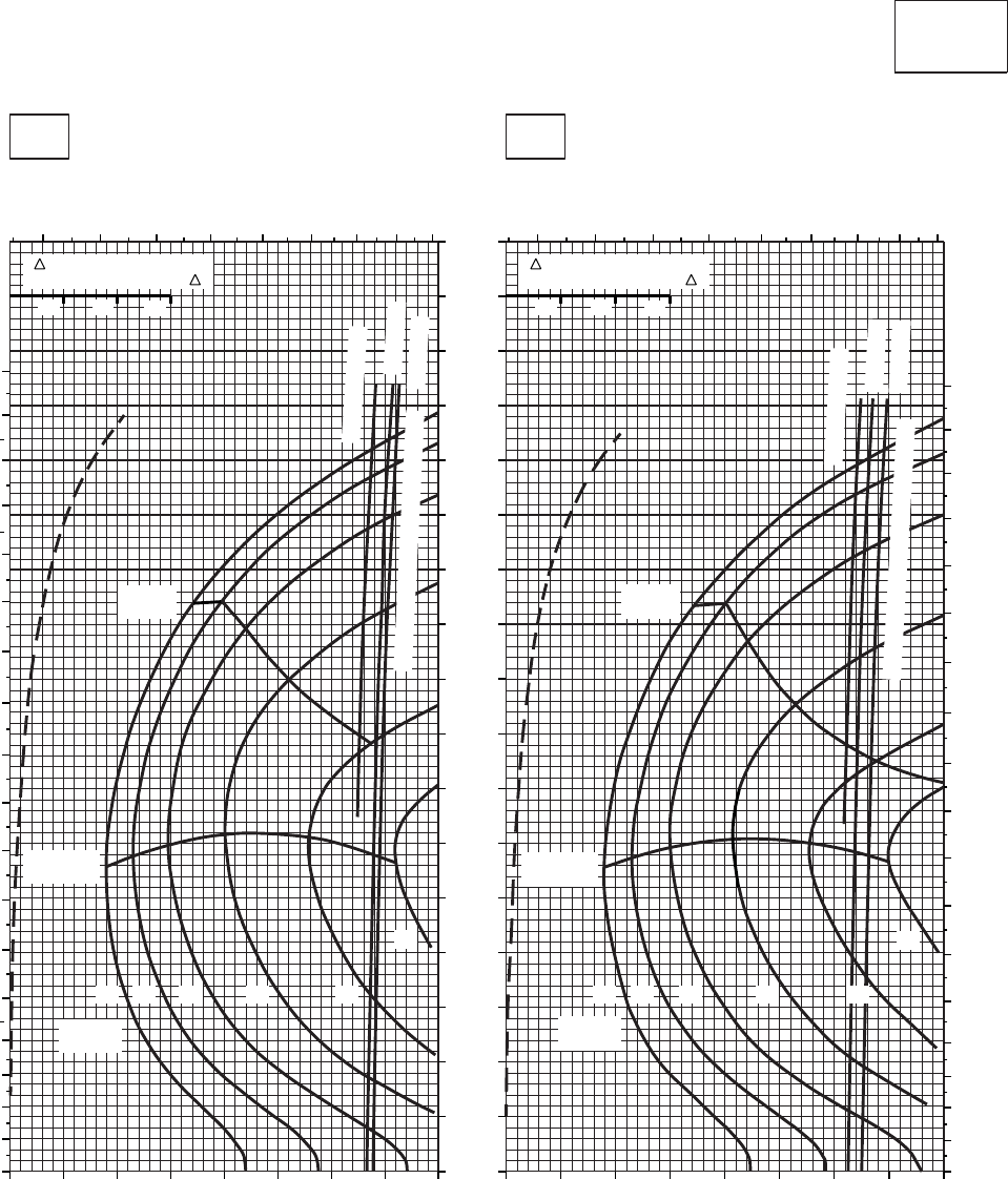
CRUISE CRUISE
T701C (2)
TORQUE PER ENGINE ~ %TORQUE PER ENGINE ~ %
IAS ~ KTS TOTAL FUEL FLOW ~ 100 LB/HRTOTAL FUEL FLOW ~ 100 LB/HR
DATA BASE:FLIGHT TEST
TRUE AIRSPEED ~ KTS
TRUE AIRSPEED ~ KTS
CLEAN CONFIGURATION
SA
AA1017_3
PRESS ALT: 14,000 FT
14,000 FT
−10oC0oC
TRQ ~ % FOR DRAG
AREA OF 10 SQ FT OF F
10 20 30
TRQ ~ % FOR DRAG
AREA OF 10 SQ FT OF F
10 20 30
~ CONTINUOUS
ATF = 0.9
ATF = 1.0
TORQUE AVAILABLE ~ 30 MINUTES
456 7 8 9 10 11 12 4 5 6 7 8 9 10 11 12
0
10
20
30
40
50
60
70
80
90
100
110
120
130
140
150
160
170
180
0
10
20
30
40
50
60
70
80
90
100
110
120
130
140
150
160
170
180
~ CONTINUOUS
ATF = 0.9
ATF = 1.0
TORQUE AVAILABLE ~ 30 MINUTES
14 1612 18 20
MAX
RANGE
GW ~
1000 LB
MAX END
AND R / C
22
14 1612 18 20
MAX
RANGE
GW ~
1000 LB
MAX END
AND R / C
22
10 20 30 40 50 60 70 80 90 10 20 30 40 50 60 70 80 90
0
10
20
30
40
50
60
70
80
90
100
110
120
130
140
150
160
170
PLACARD TORQUE LIMIT = 73%PLACARD TORQUE LIMIT = 75%
Figure 7A-23. Cruise - Pressure Altitude 14,000 Feet (Sheet 3 of 5)
TM 1-1520-237-10
7A-102
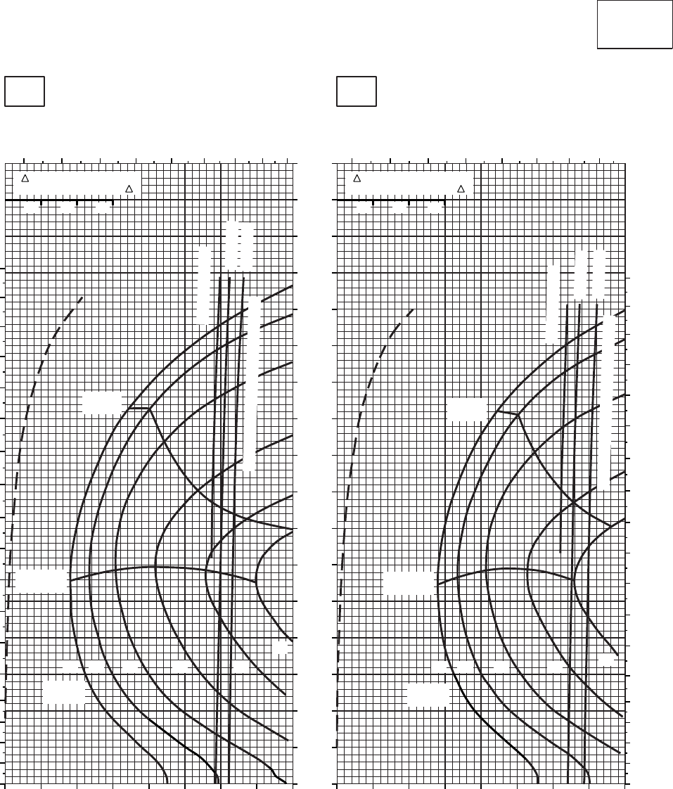
CRUISE CRUISE
T701C (2)
TORQUE PER ENGINE ~ %TORQUE PER ENGINE ~ %
IAS ~ KTS TOTAL FUEL FLOW ~ 100 LB/HRTOTAL FUEL FLOW ~ 100 LB/HR
DATA BASIS: FLIGHT TEST
TRUE AIRSPEED ~ KTS
TRUE AIRSPEED ~ KTS
CLEAN CONFIGURATION
SA
AA1017_4A
PRESS ALT: 14,000 FT
14,000 FT
10oC20oC
TRQ ~ % FOR DRAG
AREA OF 10 SQ FT OF F
10 20 30
TRQ ~ % FOR DRAG
AREA OF 10 SQ FT OF F
10 20 30
4 5 6 7 8 9 10 11 12 3 4 5 6 7 8 9 10
0
10
20
30
40
50
60
70
80
90
100
110
120
130
140
150
160
170
180
0
10
20
30
40
50
60
70
80
90
100
110
120
130
140
150
160
170
180
10 20 30 40 50 60 70 80 90 0 10 20 30 40 50 60 70 80
0
10
20
30
40
50
60
70
80
90
100
110
120
130
140
150
160
170
~ CONTINUOUS
~ CONTINUOUS
ATF = 0.9
ATF = 0.9
ATF = 1.0
ATF = 1.0
TORQUE AVAILABLE ~ 30 MINUTES
TORQUE AVAILABLE ~ 30 MINUTES
14 1612 18 20
MAX
RANGE
GW ~
1000 LB
MAX END
AND R / C
22
14 1612 18 20
MAX
RANGE
GW ~
1000 LB
MAX END
AND R / C
PLACARD TORQUE LIMIT = 67%
PLACARD TORQUE LIMIT = 70%
Figure 7A-23. Cruise - Pressure Altitude 14,000 Feet (Sheet 4 of 5)
TM 1-1520-237-10
7A-103
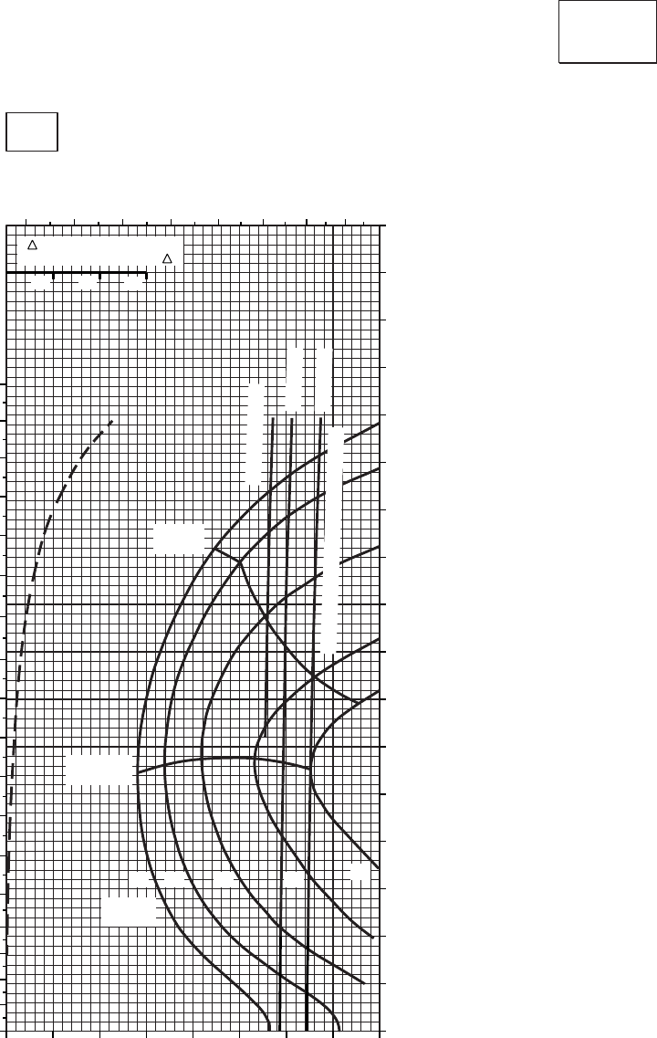
CRUISE CRUISE
T701C (2)
TORQUE PER ENGINE ~ %
TOTAL FUEL FLOW ~ 100 LB/HR
DATA BASE:FLIGHT TEST
TRUE AIRSPEED ~ KTS
CLEAN CONFIGURATION
SA
AA1017_5
PRESS ALT: 14,000 FT
14,000 FT
30oC
INDICATED AIRSPEED ~ KTS
TRQ ~ % FOR DRAG
AREA OF 10 SQ FT OF F
10 20 30
~ CONTINUOUS
ATF = 0.9
ATF = 1.0
TORQUE AVAILABLE ~ 30 MINUTES
14 1612 18 20
MAX
RANGE
GW ~
1000 LB
MAX END
AND R / C
3 4 5 6 7 8 9 10
0
10
20
30
40
50
60
70
80
90
100
110
120
130
140
150
160
170
180
0 10 20 30 40 50 60 70 80
0
10
20
30
40
50
60
70
80
90
100
110
120
130
140
150
160
170
PLACARD TORQUE LIMIT = 65%
Figure 7A-23. Cruise - Pressure Altitude 14,000 Feet (Sheet 5 of 5)
TM 1-1520-237-10
7A-104
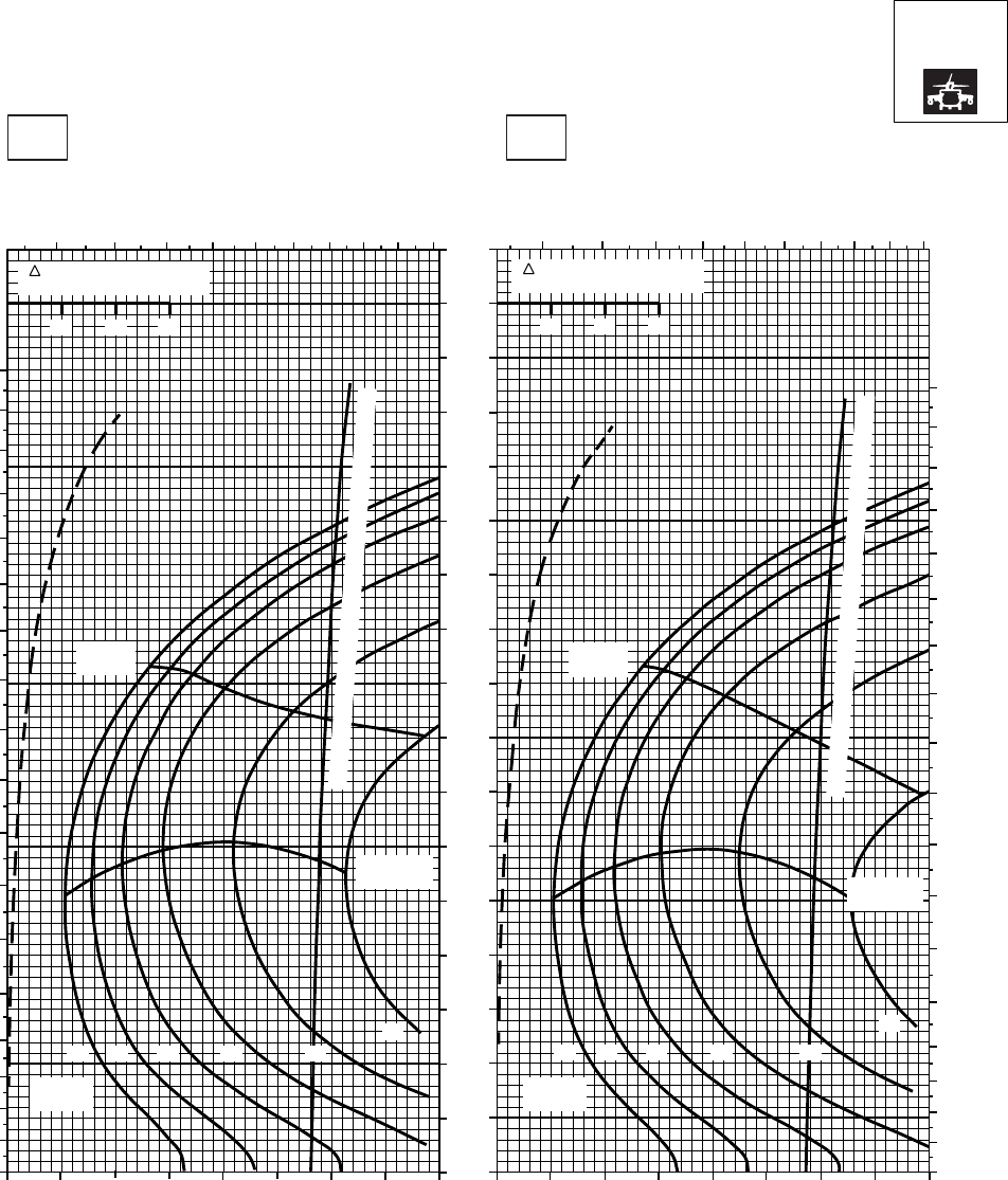
CRUISE CRUISE
T701C (2)
TORQUE PER ENGINE ~ %TORQUE PER ENGINE ~ %
IAS ~ KTS TOTAL FUEL FLOW ~ 100 LB/HRTOTAL FUEL FLOW ~ 100 LB/HR
DATA BASE:FLIGHT TEST
TRUE AIRSPEED ~ KTS
TRUE AIRSPEED ~ KTS
NOTE:SHORT DASH LINES: FERRY MISSION ONLY
SA
AA1018_1
PRESS ALT: 14000 FT
14000 FT
−50oC−40oC
5 6 7 8 9 10 11 12 13 14 5 6 78 9 10 11 12 13 14
0
10
20
30
40
50
60
70
80
90
100
110
120
130
140
150
160
170
180
0
10
20
30
40
50
60
70
80
90
100
110
120
130
140
150
160
170
180
20 30 40 50 60 70 80 90 100 20 30 40 50 60 70 80 90 100
0
10
20
30
40
50
60
70
80
90
100
110
120
130
140
150
160
170
10 20 30
TRQ ~ % FOR DRAG
AREA OF 10 SQ FT
10 20 30
TRQ ~ % FOR DRAG
AREA OF 10 SQ FT
12 14 16 18 20
22
12 14 16 18 20
22
MAX
RANGE MAX
RANGE
MAX END
AND R / C MAX END
AND R / C
GW ~
1000 LB
GW ~
1000 LB
TORQUE AVAILABLE ~ 30 MINUTES AND CONTINUOUS
TORQUE AVAILABLE ~ 30 MINUTES AND CONTINUOUS
PLACARD TORQUE LIMIT = 86%
PLACARD TORQUE LIMIT = 90%
Figure 7A-24. Cruise High Drag - Pressure Altitude 14,000 Feet (Sheet 1 of 5)
TM 1-1520-237-10
7A-105
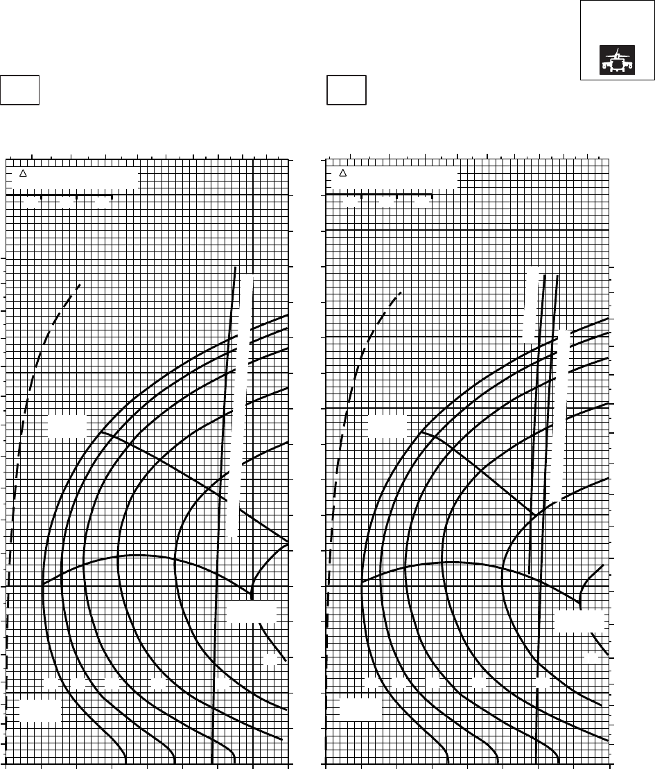
CRUISE CRUISE
T701C (2)
TORQUE PER ENGINE ~ %TORQUE PER ENGINE ~ %
IAS ~ KTS TOTAL FUEL FLOW ~ 100 LB/HRTOTAL FUEL FLOW ~ 100 LB/HR
DATA BASE:FLIGHT TEST
TRUE AIRSPEED ~ KTS
TRUE AIRSPEED ~ KTS
NOTE:SHORT DASH LINES: FERRY MISSION ONLY
SA
AA1018_2
PRESS ALT: 14000 FT
14000 FT
−30oC−20oC
5 6 7 8 9 10 11 12 13 5 6 7 8 9 10 11 12 13
0
10
20
30
40
50
60
70
80
90
100
110
120
130
140
150
160
170
180
0
10
20
30
40
50
60
70
80
90
100
110
120
130
140
150
160
170
180
0
10
20
30
40
50
60
70
80
90
100
110
120
130
140
150
160
170
MAX
RANGE
MAX END
AND R / C
GW ~
1000 LB
12 14 16 18 20
22
MAX
RANGE
MAX END
AND R / C
GW ~
1000 LB
12 14 16 18 20
22
~ CONTINUOUS
TORQUE AVAILABLE ~ 30 MINUTES
TORQUE AVAILABLE ~ 30 MINUTES AND CONTINUOUS
20 30 40 50 60 70 80 90 100 20 30 40 50 60 70 80 90 100
TRQ ~ % FOR DRAG
AREA OF 10 SQ FT
10 20 30
TRQ ~ % FOR DRAG
AREA OF 10 SQ FT
10 20 30
PLACARD TORQUE LIMIT = 79%PLACARD TORQUE LIMIT = 82%
Figure 7A-24. Cruise High Drag - Pressure Altitude 14,000 Feet (Sheet 2 of 5)
TM 1-1520-237-10
7A-106
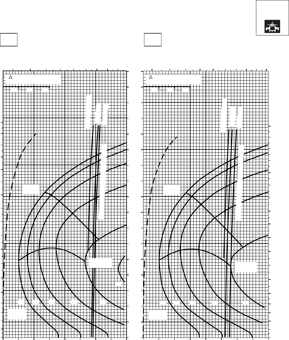
CRUISE CRUISE
T701C (2)
TORQUE PER ENGINE ~ %TORQUE PER ENGINE ~ %
IAS ~ KTS TOTAL FUEL FLOW ~ 100 LB/HRTOTAL FUEL FLOW ~ 100 LB/HR
DATA BASE:FLIGHT TEST
TRUE AIRSPEED ~ KTS
TRUE AIRSPEED ~ KTS
NOTE:SHORT DASH LINES: FERRY MISSION ONLY
SA
AA1018_3
PRESS ALT: 14000 FT
14000 FT
−10oC0oC
0
10
20
30
40
50
60
70
80
90
100
110
120
130
140
150
160
170
180
5 6 7 8 9 10 11 12 13 5 6 7 8 9 10 11 12 13 14
0
10
20
30
40
50
60
70
80
90
100
110
120
130
140
150
160
170
180
MAX
RANGE
MAX END
AND R / C
GW ~
1000 LB
12 14 16 18 20
22
MAX
RANGE
MAX END
AND R / C
GW ~
1000 LB
12 14 16 18 20
0
10
20
30
40
50
60
70
80
90
100
110
120
130
140
150
160
170
~ CONTINUOUS
~ CONTINUOUS
ATF = 0.9
ATF = 0.9
ATF = 1.0
ATF = 1.0
TORQUE AVAILABLE ~ 30 MINUTES
TORQUE AVAILABLE ~ 30 MINUTES
20 30 40 50 60 70 80 90 100 20 30 40 50 60 70 80 90 100
TRQ ~ % FOR DRAG
AREA OF 10 SQ FT
10 20 30
TRQ ~ % FOR DRAG
AREA OF 10 SQ FT
10 20 30
PLACARD TORQUE LIMIT = 73%
PLACARD TORQUE LIMIT = 75%
Figure 7A-24. Cruise High Drag - Pressure Altitude 14,000 Feet (Sheet 3 of 5)
TM 1-1520-237-10
7A-107
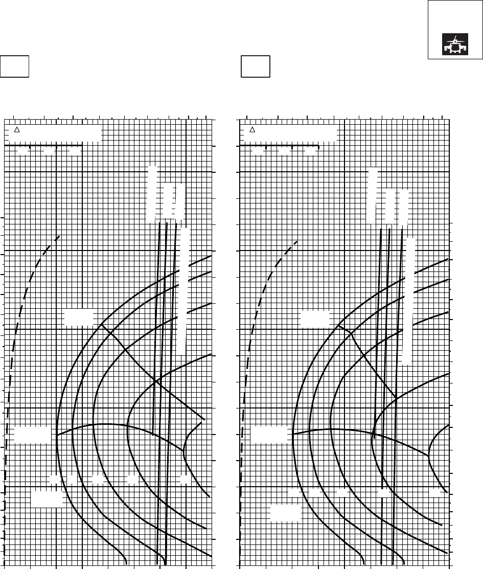
CRUISE CRUISE
T701C (2)
TORQUE PER ENGINE ~ %TORQUE PER ENGINE ~ %
IAS ~ KTS TOTAL FUEL FLOW ~ 100 LB/HRTOTAL FUEL FLOW ~ 100 LB/HR
DATA BASE:FLIGHT TEST
TRUE AIRSPEED ~ KTS
TRUE AIRSPEED ~ KTS
NOTE:SHORT DASH LINES: FERRY MISSION ONLY
SA
AA1018_4
PRESS ALT: 14000 FT
14000 FT
10oC20oC
4 5 6 7 8 9 10 11 12
0
10
20
30
40
50
60
70
80
90
100
110
120
130
140
150
160
170
180
0
10
20
30
40
50
60
70
80
90
100
110
120
130
140
150
160
170
180
4 5 6 7 8 9 10 11 12
0
10
20
30
40
50
60
70
80
90
100
110
120
130
140
150
160
170
MAX
RANGE
MAX END
AND R / C
GW ~
1000 LB
12 14 16 18 20
MAX END
AND R / C
MAX
RANGE
GW ~
1000 LB
12 14 16 18 20
~ CONTINUOUS
~ CONTINUOUS
ATF = 0.9
ATF = 0.9
ATF = 1.0
ATF = 1.0
TORQUE AVAILABLE ~ 30 MINUTES
TORQUE AVAILABLE ~ 30 MINUTES
10 20 30 40 50 60 70 80 90 10 20 30 40 50 60 70 80 90
TRQ ~ % FOR DRAG
AREA OF 10 SQ FT
10 20 30
TRQ ~ % FOR DRAG
AREA OF 10 SQ FT
10 20 30
PLACARD TORQUE LIMIT = 67%PLACARD TORQUE LIMIT = 70%
Figure 7A-24. Cruise High Drag - Pressure Altitude 14,000 Feet (Sheet 4 of 5)
TM 1-1520-237-10
7A-108
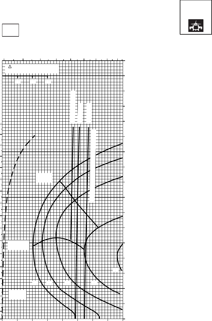
SA
AA1018_5
CRUISE CRUISE
T701C (2)
TORQUE PER ENGINE ~ %
TOTAL FUEL FLOW ~ 100 LB/HR
DATA BASE:FLIGHT TEST
INDICATED AIRSPEED ~ KTS
TRUE AIRSPEED ~ KTS
NOTE:SHORT DASH LINES: FERRY MISSION ONLY
PRESS ALT: 14000 FT
14000 FT
30oC
4 5 6 7 8 9 10 11 12
0
10
20
30
40
50
60
70
80
90
100
110
120
130
140
150
160
170
180
10 20 30 40 50 60 70 80 90 0
10
20
30
40
50
60
70
80
90
100
110
120
130
140
150
160
170
MAX
RANGE
MAX END
AND R / C
GW ~
1000 LB
12 14 16 18
20
~ CONTINUOUS
ATF = 0.9
ATF = 1.0
TORQUE AVAILABLE ~ 30 MINUTES
TRQ ~ % FOR DRAG
AREA OF 10 SQ FT
10 20 30
PLACARD TORQUE LIMIT = 65%
Figure 7A-24. Cruise High Drag - Pressure Altitude 14,000 Feet (Sheet 5 of 5)
TM 1-1520-237-10
7A-109
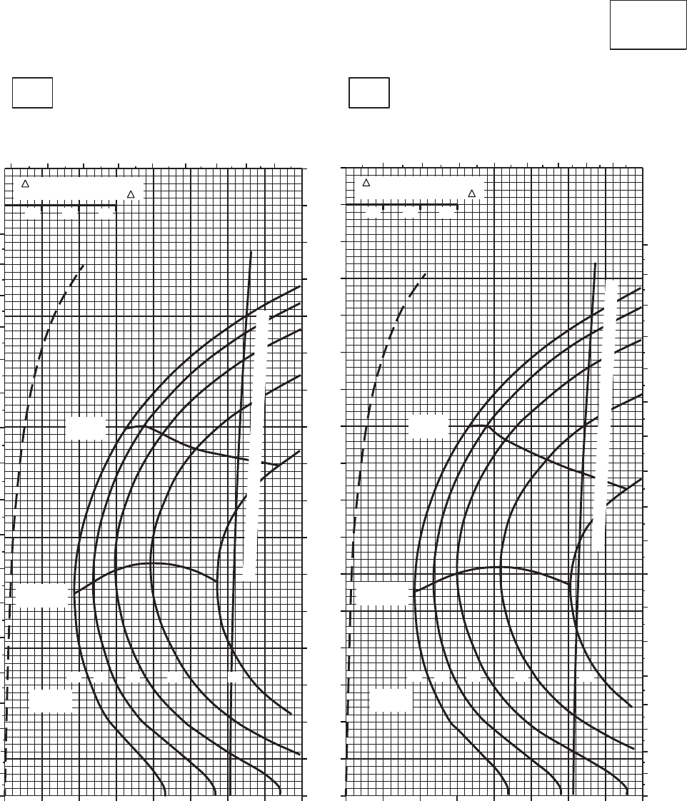
CRUISE CRUISE
T701C (2)
TORQUE PER ENGINE ~ %TORQUE PER ENGINE ~ %
IAS ~ KTS TOTAL FUEL FLOW ~ 100 LB/HRTOTAL FUEL FLOW ~ 100 LB/HR
DATA BASE:FLIGHT TEST
TRUE AIRSPEED ~ KTS
TRUE AIRSPEED ~ KTS
CLEAN CONFIGURATION
0
10
20
30
40
50
60
70
80
90
100
110
120
130
140
150
160
170
SA
AA1019_1
PRESS ALT: 16,000 FT
16,000 FT
−50oC−40oC
0
10
20
30
40
50
60
70
80
90
100
110
120
130
140
150
160
170
180
3 4 5 6 7 8 9 10 11 4 5 6 7 8 9 10 11
0
10
20
30
40
50
60
70
80
90
100
110
120
130
140
150
160
170
180
10 20 30 40 50 60 70 80 90 10 20 30 40 50 60 70 80 90
TRQ ~ % FOR DRAG
AREA OF 10 SQ FT OF F TRQ ~ % FOR DRAG
AREA OF 10 SQ FT OF F
MAX
RANGE
MAX END
AND R / C
GW ~
1000 LB
12 14 16 18 20
MAX
RANGE
MAX END
AND R / C
GW ~
1000 LB
12 14 16 18 20
TORQUE AVAILABLE ~ 30 MINUTES AND CONTINUOUS
TORQUE AVAILABLE ~ 30 MINUTES AND CONTINUOUS
10 10
20 20
30 30
PLACARD TORQUE LIMIT = 79%
PLACARD TORQUE LIMIT = 82%
Figure 7A-25. Cruise - Pressure Altitude 16,000 Feet (Sheet 1 of 4)
TM 1-1520-237-10
7A-110
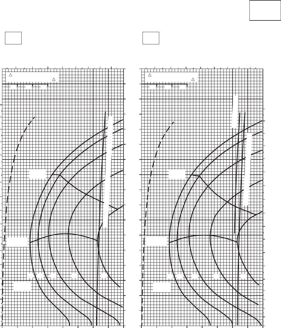
CRUISE CRUISE
T701C (2)
TORQUE PER ENGINE ~ %TORQUE PER ENGINE ~ %
IAS ~ KTS TOTAL FUEL FLOW ~ 100 LB/HRTOTAL FUEL FLOW ~ 100 LB/HR
DATA BASE:FLIGHT TEST
TRUE AIRSPEED ~ KTS
TRUE AIRSPEED ~ KTS
CLEAN CONFIGURATION
0
10
20
30
40
50
60
70
80
90
100
110
120
130
140
150
160
170
SA
AA1019_2
PRESS ALT: 16,000 FT
16,000 FT
−30oC−20oC
0
10
20
30
40
50
60
70
80
90
100
110
120
130
140
150
160
170
180
4 5 6 7 8 9 10 11 4 5 6 7 8 9 10 11
0
10
20
30
40
50
60
70
80
90
100
110
120
130
140
150
160
170
180
MAX
RANGE
MAX END
AND R / C
GW ~
1000 LB
12 14 16 18 20
MAX
RANGE
MAX END
AND R / C
TRQ ~ % FOR DRAG
AREA OF 10 SQ FT OF F TRQ ~ % FOR DRAG
AREA OF 10 SQ FT OF F
GW ~
1000 LB
12 14 16 18 20
~ CONTINUOUS
TORQUE AVAILABLE ~ 30 MINUTES
TORQUE AVAILABLE ~ 30 MINUTES AND CONTINUOUS
10 20 30 40 50 60 70 80 90 10 20 30 40 50 60 70 80 90
10 10
20 20
30 30
PLACARD TORQUE LIMIT = 72%PLACARD TORQUE LIMIT =76%
Figure 7A-25. Cruise - Pressure Altitude 16,000 Feet (Sheet 2 of 4)
TM 1-1520-237-10
7A-111
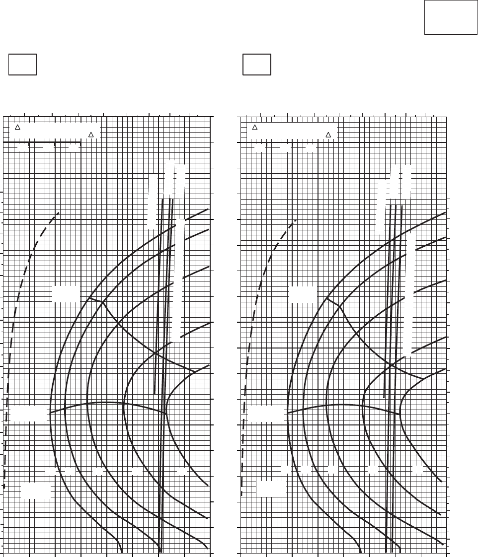
CRUISE CRUISE
T701C (2)
TORQUE PER ENGINE ~ %TORQUE PER ENGINE ~ %
IAS ~ KTS TOTAL FUEL FLOW ~ 100 LB/HRTOTAL FUEL FLOW ~ 100 LB/HR
DATA BASE:FLIGHT TEST
TRUE AIRSPEED ~ KTS
TRUE AIRSPEED ~ KTS
CLEAN CONFIGURATION
0
10
20
30
40
50
60
70
80
90
100
110
120
130
140
150
160
170
SA
AA1019_3
PRESS ALT: 16,000 FT
16,000 FT
−10oC0oC
0
10
20
30
40
50
60
70
80
90
100
110
120
130
140
150
160
170
180
4 5 6 7 8 9 10 11 4 5 6 7 8 9 10 11
0
10
20
30
40
50
60
70
80
90
100
110
120
130
140
150
160
170
180
TRQ ~ % FOR DRAG
AREA OF 10 SQ FT OF F TRQ ~ % FOR DRAG
AREA OF 10 SQ FT OF F
MAX
RANGE
MAX END
AND R / C
GW ~
1000 LB
12 14 16 18 20
MAX
RANGE
MAX END
AND R / C
GW ~
1000 LB
12 14 16 18 20
~ CONTINUOUS
~ CONTINUOUS
ATF = 0.9
ATF = 0.9
ATF = 1.0
ATF = 1.0
TORQUE AVAILABLE ~ 30 MINUTES
TORQUE AVAILABLE ~ 30 MINUTES
10 20 30 40 50 60 70 80 90 10 20 30 40 50 60 70 80 90
10 10
20 20
30 30
PLACARD TORQUE LIMIT = 66%
PLACARD TORQUE LIMIT = 69%
Figure 7A-25. Cruise - Pressure Altitude 16,000 Feet (Sheet 3 of 4)
TM 1-1520-237-10
7A-112
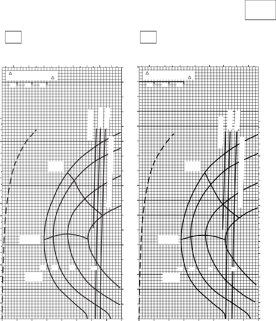
CRUISE CRUISE
T701C (2)
TORQUE PER ENGINE ~ %TORQUE PER ENGINE ~ %
IAS ~ KTS TOTAL FUEL FLOW ~ 100 LB/HRTOTAL FUEL FLOW ~ 100 LB/HR
DATA BASE:FLIGHT TEST
TRUE AIRSPEED ~ KTS
TRUE AIRSPEED ~ KTS
CLEAN CONFIGURATION
0
10
20
30
40
50
60
70
80
90
100
110
120
130
140
150
160
170
SA
AA1019_4
PRESS ALT: 16,000 FT
16,000 FT
10oC20oC
0
10
20
30
40
50
60
70
80
90
100
110
120
130
140
150
160
170
180
3 4 5 6 7 8 9 10
MAX
RANGE
MAX END
AND R / C
GW ~
1000 LB
12 14 16 18
TRQ ~ % FOR DRAG
AREA OF 10 SQ FT OF F
~ CONTINUOUS
ATF = 0.9
ATF = 1.0
TORQUE AVAILABLE ~ 30 MINUTES
0 10 20 30 40 50 60 70 80
3 4 5 6 7 8 9 10
0
10
20
30
40
50
60
70
80
90
100
110
120
130
140
150
160
170
180
TRQ ~ % FOR DRAG
AREA OF 10 SQ FT OF F
MAX
RANGE
MAX END
AND R / C
GW ~
1000 LB
12 14 16 18
~ CONTINUOUS
ATF = 0.9
ATF = 1.0
TORQUE AVAILABLE ~ 30 MINUTES
0 10 20 30 40 50 60 70 80
10 10
20 20
30 30
PLACARD TORQUE LIMIT = 61%PLACARD TORQUE LIMIT = 64%
Figure 7A-25. Cruise - Pressure Altitude 16,000 Feet (Sheet 4 of 4)
TM 1-1520-237-10
7A-113
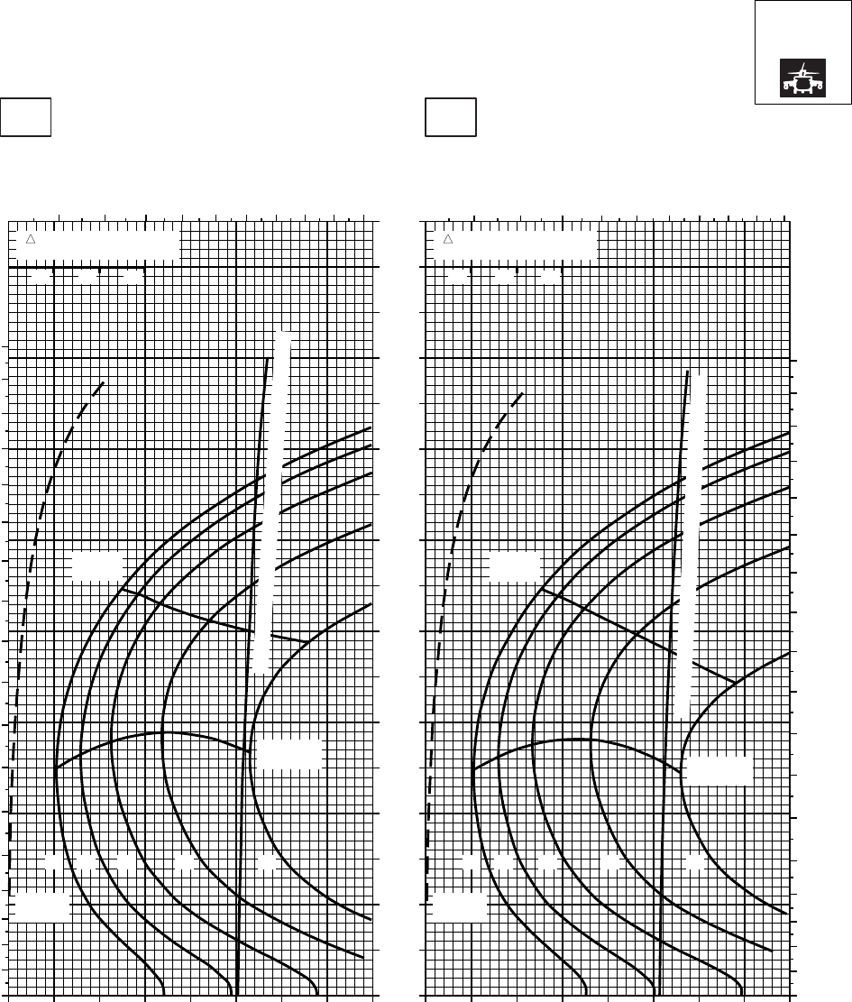
CRUISE CRUISE
T701C (2)
TORQUE PER ENGINE ~ %TORQUE PER ENGINE ~ %
IAS ~ KTS TOTAL FUEL FLOW ~ 100 LB/HRTOTAL FUEL FLOW ~ 100 LB/HR
DATA BASE:FLIGHT TEST
TRUE AIRSPEED ~ KTS
TRUE AIRSPEED ~ KTS
NOTE:SHORT DASH LINES: FERRY MISSION ONLY
SA
AA1020_1
PRESS ALT: 16000 FT
16000 FT
−50oC−40oC
20 30 40 50 60 70 80 90 100 20 30 40 50 60 70 80 90 100
0
10
20
30
40
50
60
70
80
90
100
110
120
130
140
150
160
170
TRQ ~ % FOR DRAG
AREA OF 10 SQ FT
10 20 30
TRQ ~ % FOR DRAG
AREA OF 10 SQ FT
10 20 30
5 6 7 8 9 10 11 12 13 14 5 6 7 8 9 10 11 12 13 14
0
10
20
30
40
50
60
70
80
90
100
110
120
130
140
150
160
170
180
0
10
20
30
40
50
60
70
80
90
100
110
120
130
140
150
160
170
180
TORQUE AVAILABLE ~ 30 MINUTES AND CONTINUOUS
TORQUE AVAILABLE ~ 30 MINUTES AND CONTINUOUS
MAX END
AND R / C
MAX END
AND R / C
MAX
RANGE
MAX
RANGE
GW ~
1000 LB
12 14 16 18 20
GW ~
1000 LB
12 14 16 18 20
PLACARD TORQUE LIMIT = 79%PLACARD TORQUE LIMIT = 83%
Figure 7A-26. Cruise High Drag - Pressure Altitude 16,000 Feet (Sheet 1 of 4)
TM 1-1520-237-10
7A-114
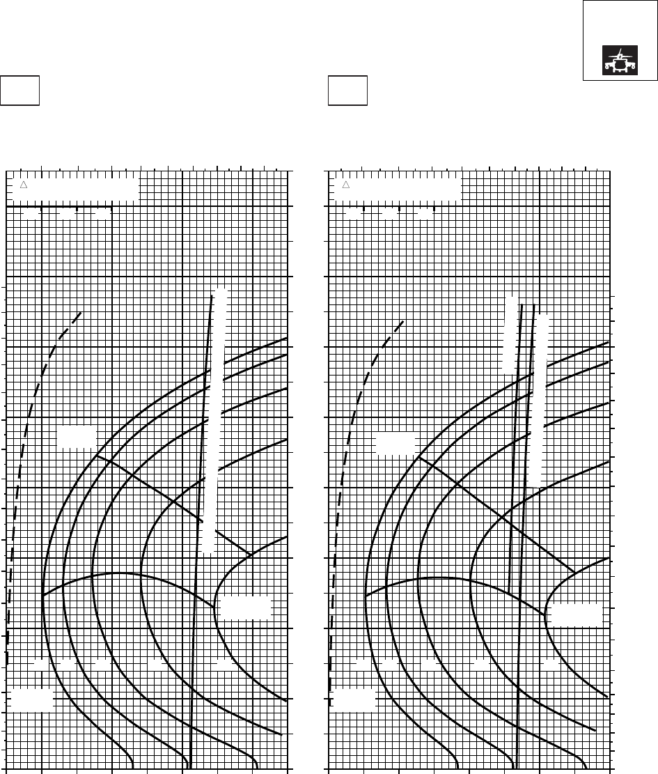
CRUISE CRUISE
T701C (2)
TORQUE PER ENGINE ~ %TORQUE PER ENGINE ~ %
IAS ~ KTS TOTAL FUEL FLOW ~ 100 LB/HRTOTAL FUEL FLOW ~ 100 LB/HR
DATA BASE:FLIGHT TEST
TRUE AIRSPEED ~ KTS
TRUE AIRSPEED ~ KTS
NOTE:SHORT DASH LINES: FERRY MISSION ONLY
SA
AA1020_2
PRESS ALT: 16000 FT
16000 FT
−30oC−20oC
20 30 40 50 60 70 80 90 100 20 30 40 50 60 70 80 90 100
0
10
20
30
40
50
60
70
80
90
100
110
120
130
140
150
160
170
TRQ ~ % FOR DRAG
AREA OF 10 SQ FT
10 20 30
TRQ ~ % FOR DRAG
AREA OF 10 SQ FT
10 20 30
5 6 7 8 9 10 11 12 13 5 6 7 8 9 10 11 12 13
0
10
20
30
40
50
60
70
80
90
100
110
120
130
140
150
160
170
180
0
10
20
30
40
50
60
70
80
90
100
110
120
130
140
150
160
170
180
TORQUE AVAILABLE ~ 30 MINUTES AND CONTINUOUS
~ CONTINUOUS
TORQUE AVAILABLE ~ 30 MINUTES
MAX END
AND R / C
MAX END
AND R / C
MAX
RANGE
MAX
RANGE
GW ~
1000 LB
12 14 16 18 20
GW ~
1000 LB
12 14 16 18 20
PLACARD TORQUE LIMIT = 72%PLACARD TORQUE LIMIT = 75%
Figure 7A-26. Cruise High Drag - Pressure Altitude 16,000 Feet (Sheet 2 of 4)
TM 1-1520-237-10
7A-115
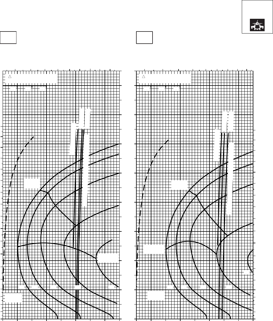
CRUISE CRUISE
T701C (2)
TORQUE PER ENGINE ~ %TORQUE PER ENGINE ~ %
IAS ~ KTS TOTAL FUEL FLOW ~ 100 LB/HRTOTAL FUEL FLOW ~ 100 LB/HR
DATA BASE:FLIGHT TEST
TRUE AIRSPEED ~ KTS
TRUE AIRSPEED ~ KTS
NOTE:SHORT DASH LINES: FERRY MISSION ONLY
SA
AA1020_3
PRESS ALT: 16000 FT
16000 FT
−10oC0oC
20 30 40 50 60 70 80 90 100 20 30 40 50 60 70 80 90
0
10
20
30
40
50
60
70
80
90
100
110
120
130
140
150
160
170
10
TRQ ~ % FOR DRAG
AREA OF 10 SQ FT
10 20 30
TRQ ~ % FOR DRAG
AREA OF 10 SQ FT
10 20 30
5 6 7 8 9 10 11 12 13 4 5 6 7 8 9 10 11 12
0
10
20
30
40
50
60
70
80
90
100
110
120
130
140
150
160
170
180
0
10
20
30
40
50
60
70
80
90
100
110
120
130
140
150
160
170
180
~ CONTINUOUS
~ CONTINUOUS
ATF = 0.9
ATF = 1.0
ATF = 0.9
ATF = 1.0
TORQUE AVAILABLE ~ 30 MINUTES
TORQUE AVAILABLE ~ 30 MINUTES
MAX END
AND R / C
MAX END
AND R / C
MAX
RANGE
MAX
RANGE
GW ~
1000 LB
12 14 16 18
20
GW ~
1000 LB
12 14 16 18 20
PLACARD TORQUE LIMIT = 66%PLACARD TORQUE LIMIT = 69%
Figure 7A-26. Cruise High Drag - Pressure Altitude 16,000 Feet (Sheet 3 of 4)
TM 1-1520-237-10
7A-116
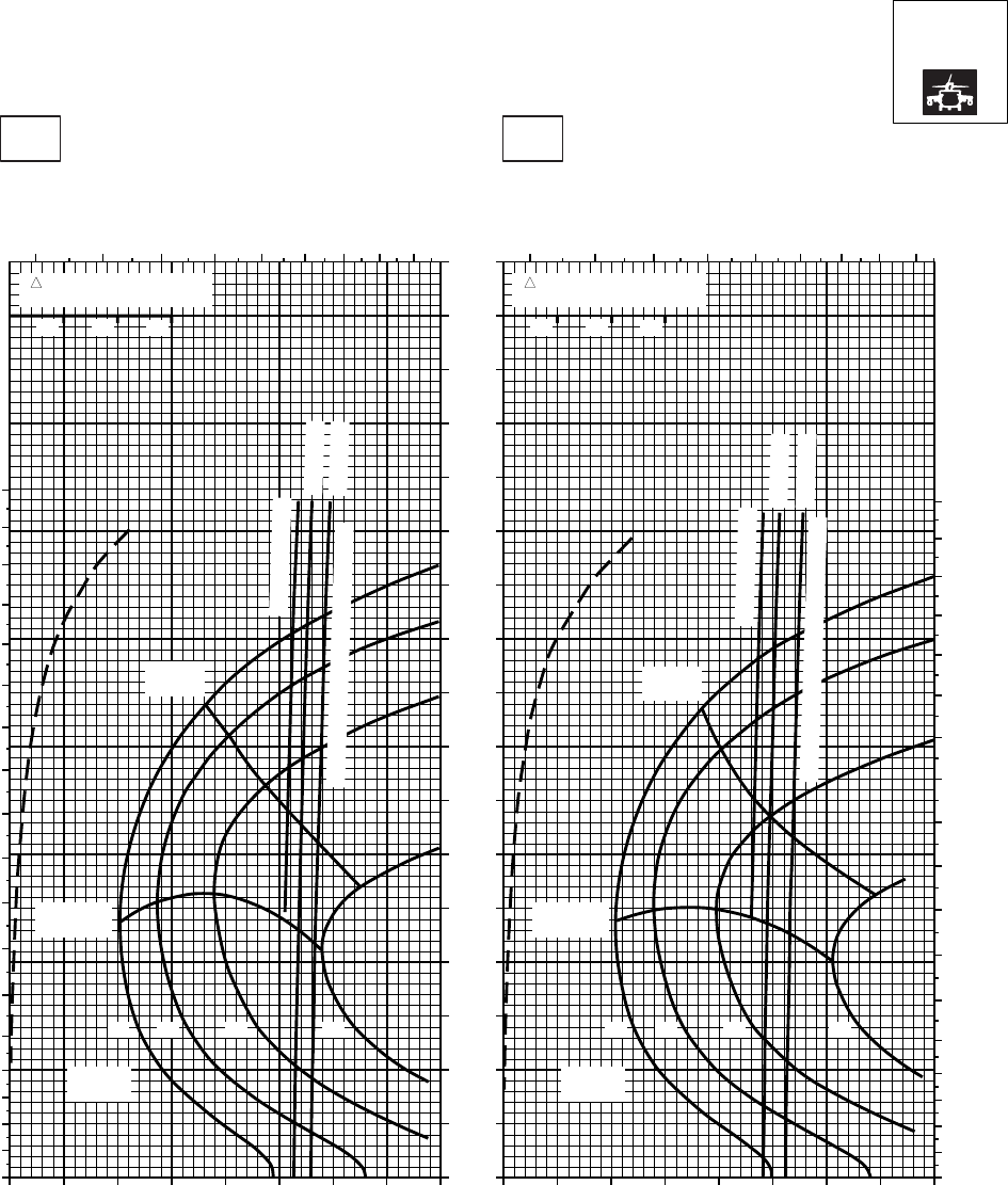
CRUISE CRUISE
T701C (2)
TORQUE PER ENGINE ~ %TORQUE PER ENGINE ~ %
IAS ~ KTS TOTAL FUEL FLOW ~ 100 LB/HRTOTAL FUEL FLOW ~ 100 LB/HR
DATA BASE:FLIGHT TEST
TRUE AIRSPEED ~ KTS
TRUE AIRSPEED ~ KTS
NOTE:SHORT DASH LINES: FERRY MISSION ONLY
SA
AA1020_4
PRESS ALT: 16000 FT
16000 FT
10oC20oC
20 30 40 50 60 70 80 90 20 30 40 50 60 70 80 90
0
10
20
30
40
50
60
70
80
90
100
110
120
130
140
150
160
170
10 10
TRQ ~ % FOR DRAG
AREA OF 10 SQ FT
10 20 30
TRQ ~ % FOR DRAG
AREA OF 10 SQ FT
10 20 30
4 5 6 7 8 9 10 11 12 4 5 6 7 8 9 10 11 12
0
10
20
30
40
50
60
70
80
90
100
110
120
130
140
150
160
170
180
0
10
20
30
40
50
60
70
80
90
100
110
120
130
140
150
160
170
180
~ CONTINUOUS
~ CONTINUOUS
ATF = 0.9
ATF = 1.0
ATF = 0.9
ATF = 1.0
TORQUE AVAILABLE ~ 30 MINUTES
TORQUE AVAILABLE ~ 30 MINUTES
MAX
RANGE
MAX
RANGE
MAX END
AND R / C MAX END
AND R / C
GW ~
1000 LB
12 14 16 18
GW ~
1000 LB
12 14 16 18
PLACARD TORQUE LIMITS = 61%PLACARD TORQUE LIMITS = 64%
Figure 7A-26. Cruise High Drag - Pressure Altitude 16,000 Feet (Sheet 4 of 4)
TM 1-1520-237-10
7A-117
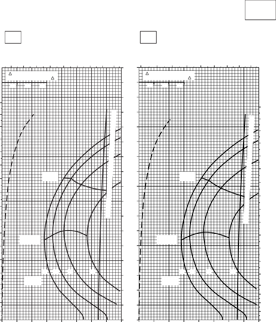
CRUISE CRUISE
T701C (2)
TORQUE PER ENGINE ~ %TORQUE PER ENGINE ~ %
IAS ~ KTS TOTAL FUEL FLOW ~ 100 LB/HRTOTAL FUEL FLOW ~ 100 LB/HR
DATA BASE:FLIGHT TEST
TRUE AIRSPEED ~ KTS
TRUE AIRSPEED ~ KTS
CLEAN CONFIGURATION
0
10
20
30
40
50
60
70
80
90
100
110
120
130
140
150
160
170
SA
AA1021_1
PRESS ALT: 18,000 FT
18,000 FT
−50oC−40oC
0
10
20
30
40
50
60
70
80
90
100
110
120
130
140
150
160
170
180
2 3 4 5 6 7 8 9 10
TRQ ~ % FOR DRAG
AREA OF 10 SQ FT OF F
MAX
RANGE
MAX END
AND R / C
GW ~
1000 LB
12 14 16 18
TORQUE AVAILABLE ~ 30 MINUTES AND CONTINUOUS
010 20 30 40 50 60 70 80
2 3 4 5 6 7 8 9 10
0
10
20
30
40
50
60
70
80
90
100
110
120
130
140
150
160
170
180
TRQ ~ % FOR DRAG
AREA OF 10 SQ FT OF F
MAX
RANGE
MAX END
AND R / C
GW ~
1000 LB
12 14 16 18
TORQUE AVAILABLE ~ 30 MINUTES AND CONTINUOUS
0 10 20 30 40 50 60 70 80
10 10
20 20
30 30
PLACARD TORQUE LIMIT = 72%PLACARD TORQUE LIMIT = 76%
Figure 7A-27. Cruise - Pressure Altitude 18,000 Feet (Sheet 1 of 4)
TM 1-1520-237-10
7A-118
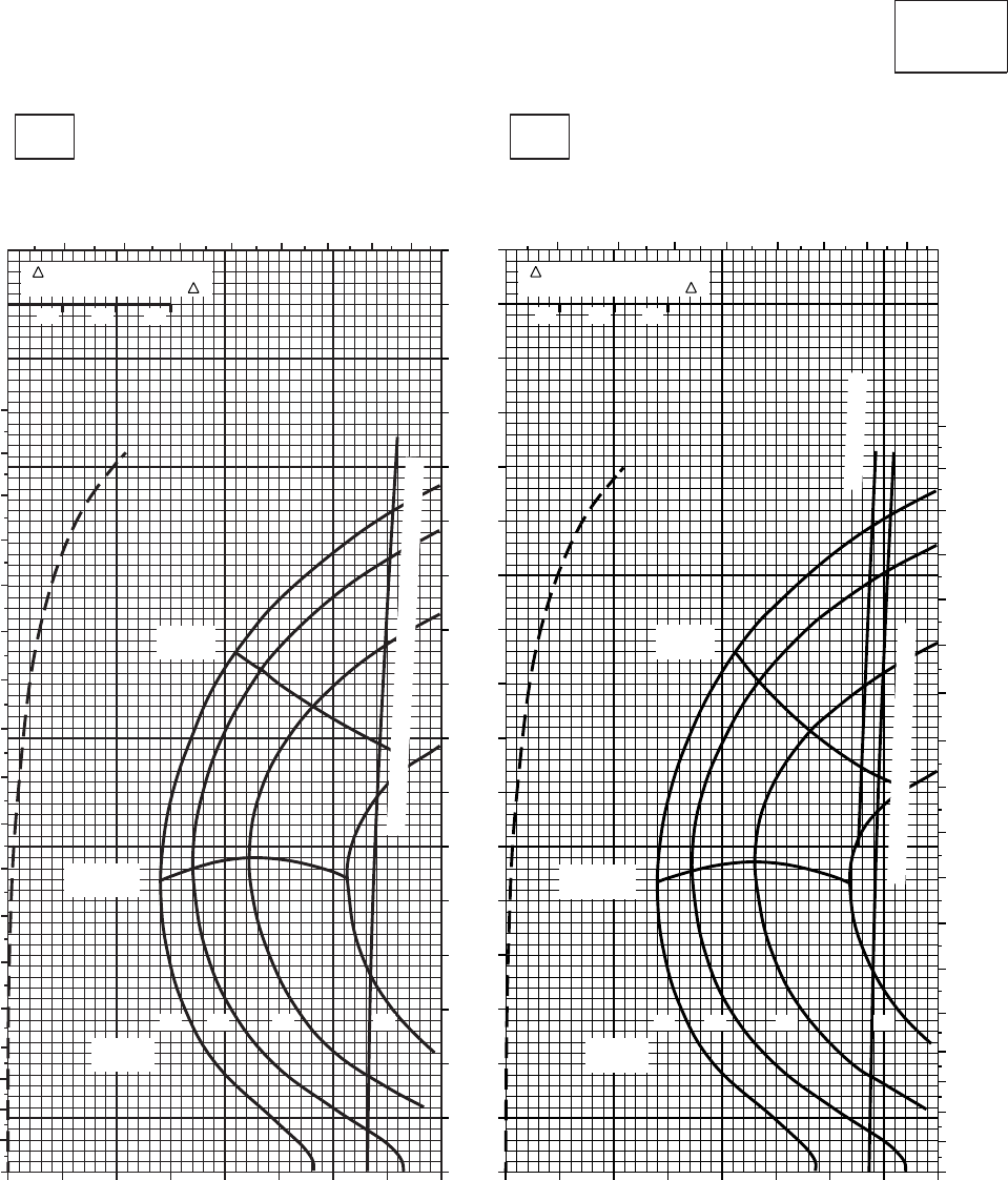
CRUISE CRUISE
T701C (2)
TORQUE PER ENGINE ~ %TORQUE PER ENGINE ~ %
IAS ~ KTS TOTAL FUEL FLOW ~ 100 LB/HRTOTAL FUEL FLOW ~ 100 LB/HR
DATA BASE:FLIGHT TEST
TRUE AIRSPEED ~ KTS
TRUE AIRSPEED ~ KTS
CLEAN CONFIGURATION
0
10
20
30
40
50
60
70
80
90
100
110
120
130
140
150
160
170
SA
AA1021_2
PRESS ALT: 18,000 FT
18,000 FT
−30oC−20oC
0
10
20
30
40
50
60
70
80
90
100
110
120
130
140
150
160
170
180
3 4 5 6 7 8 9 10
010 20 30 40 50 60 70 80
TRQ ~ % FOR DRAG
AREA OF 10 SQ FT OF F
MAX
RANGE
MAX END
AND R / C
GW ~
1000 LB
12 14 16 18
3 4 5 6 7 8 9 10
0
10
20
30
40
50
60
70
80
90
100
110
120
130
140
150
160
170
180
0 10 20 30 40 50 60 70 80
TRQ ~ % FOR DRAG
AREA OF 10 SQ FT OF F
MAX
RANGE
MAX END
AND R / C
GW ~
1000 LB
12 14 16 18
~ CONTINUOUS
TORQUE AVAILABLE ~ 30 MINUTES
10 10
20 20
30 30
TORQUE AVAILABLE~30 MINUTES & CONTINUOUS
PLACARD TORQUE LIMIT = 66%
PLACARD TORQUE LIMIT = 69%
Figure 7A-27. Cruise - Pressure Altitude 18,000 Feet (Sheet 2 of 4)
TM 1-1520-237-10
7A-119
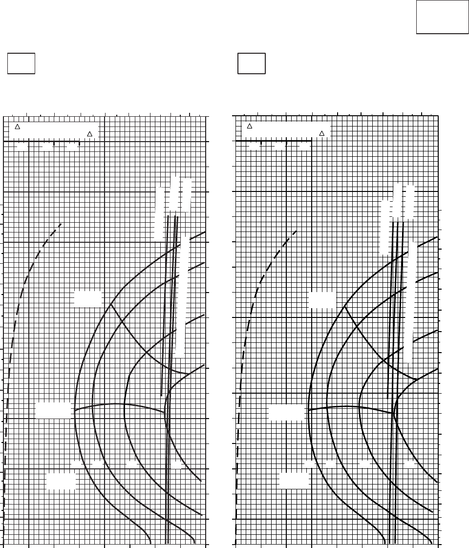
CRUISE CRUISE
T701C (2)
TORQUE PER ENGINE ~ %TORQUE PER ENGINE ~ %
IAS ~ KTS TOTAL FUEL FLOW ~ 100 LB/HRTOTAL FUEL FLOW ~ 100 LB/HR
DATA BASE:FLIGHT TEST
TRUE AIRSPEED ~ KTS
TRUE AIRSPEED ~ KTS
CLEAN CONFIGURATION
0
10
20
30
40
50
60
70
80
90
100
110
120
130
140
150
160
170
SA
AA1021_3
PRESS ALT: 18,000 FT
18,000 FT
−10oC0oC
0
10
20
30
40
50
60
70
80
90
100
110
120
130
140
150
160
170
180
3 4 5 6 7 8 9 10
TRQ ~ % FOR DRAG
AREA OF 10 SQ FT OF F
MAX
RANGE
MAX END
AND R / C
GW ~
1000 LB
12 14 16 18
~ CONTINUOUS
ATF = 0.9
ATF = 1.0
TORQUE AVAILABLE ~ 30 MINUTES
0 10 20 30 40 50 60 70 80
3 4 5 6 7 8 9 10
0
10
20
30
40
50
60
70
80
90
100
110
120
130
140
150
160
170
180
TRQ ~ % FOR DRAG
AREA OF 10 SQ FT OF F
MAX
RANGE
MAX END
AND R / C
GW ~
1000 LB
12 14 16 18
~ CONTINUOUS
ATF = 0.9
ATF = 1.0
TORQUE AVAILABLE ~ 30 MINUTES
0 10 20 30 40 50 60 70 80
10 10
20 20
30 30
PLACARD TORQUE LIMIT = 61%PLACARD TORQUE LIMIT = 63%
Figure 7A-27. Cruise - Pressure Altitude 18,000 Feet (Sheet 3 of 4)
TM 1-1520-237-10
7A-120
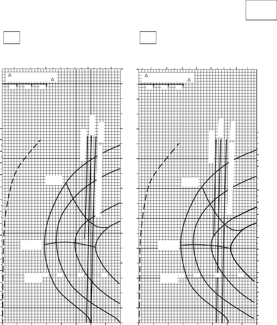
CRUISE CRUISE
T701C (2)
TORQUE PER ENGINE ~ %TORQUE PER ENGINE ~ %
IAS ~ KTS TOTAL FUEL FLOW ~ 100 LB/HRTOTAL FUEL FLOW ~ 100 LB/HR
DATA BASE:FLIGHT TEST
TRUE AIRSPEED ~ KTS
TRUE AIRSPEED ~ KTS
CLEAN CONFIGURATION
0
10
20
30
40
50
60
70
80
90
100
110
120
130
140
150
160
170
SA
AA1021_4
PRESS ALT: 18,000 FT
18,000 FT
10oC20oC
010 20 30 40 50 60 70 80 0 10 20 30 40 50 60 70 80
3 4 5 6 7 89 10 34 5 6 7 8 910
TRQ ~ % FOR DRAG
AREA OF 10 SQ FT OF F
10 20 30
TRQ ~ % FOR DRAG
AREA OF 10 SQ FT OF F
10 20 30
0
10
20
30
40
50
60
70
80
90
100
110
120
130
140
150
160
170
180
0
10
20
30
40
50
60
70
80
90
100
110
120
130
140
150
160
170
180
~ CONTINUOUS
~ CONTINUOUS
ATF = 0.9
ATF = 0.9
TORQUE AVAILABLE ~ 30 MINUTES
TORQUE AVAILABLE ~ 30 MINUTES
ATF = 1.0
ATF = 1.0
MAX
RANGE MAX
RANGE
MAX END
AND R / C MAX END
AND R / C
GW ~
1000 LB
12 14 16 18 GW ~
1000 LB 12 14 16 18
PLACARD TORQUE LIMIT = 56%
PLACARD TORQUE LIMIT = 59%
Figure 7A-27. Cruise - Pressure Altitude 18,000 Feet (Sheet 4 of 4)
TM 1-1520-237-10
7A-121
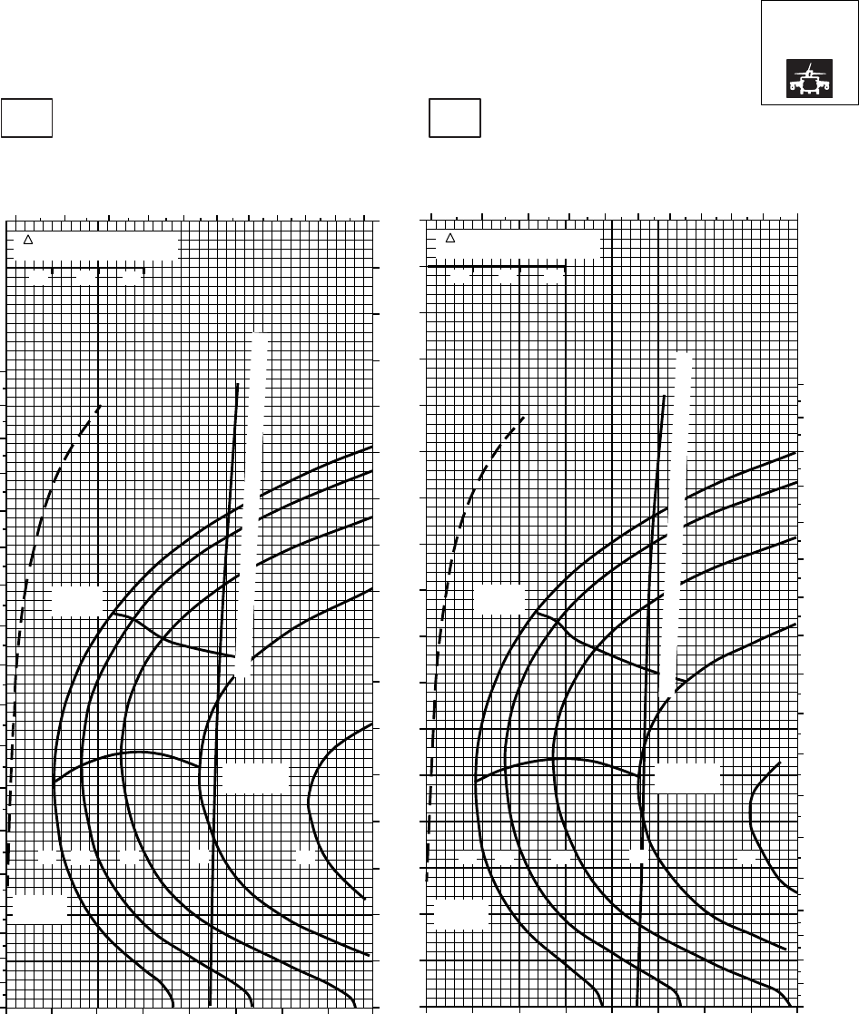
CRUISE CRUISE
T701C (2)
TORQUE PER ENGINE ~ %TORQUE PER ENGINE ~ %
IAS ~ KTS TOTAL FUEL FLOW ~ 100 LB/HRTOTAL FUEL FLOW ~ 100 LB/HR
DATA BASE:FLIGHT TEST
TRUE AIRSPEED ~ KTS
TRUE AIRSPEED ~ KTS
NOTE:SHORT DASH LINES: FERRY MISSION ONLY
SA
AA1022_1
PRESS ALT: 18000 FT
18000 FT
−50oC−40oC
0
10
20
30
40
50
60
70
80
90
100
110
120
130
140
150
160
170
180
0
10
20
30
40
50
60
70
80
90
100
110
120
130
140
150
160
170
180
20 30 40 50 60 70 80 90 100 20 30 40 50 60 70 80 90 100
4 5 6 7 8 9 10 11 12 13 14 4 5 6 7 8 9 10 11 12 13 14
0
10
20
30
40
50
60
70
80
90
100
110
120
130
140
150
160
170
MAX
RANGE MAX
RANGE
GW ~
1000 LB GW ~
1000 LB
MAX END
AND R / C MAX END
AND R / C
12 12
14 14
16 16
18 18
20 20
TORQUE AVAILABLE ~ 30 MINUTES AND CONTINUOUS
TORQUE AVAILABLE ~ 30 MINUTES AND CONTINUOUS
TRQ ~ % FOR DRAG
AREA OF 10 SQ FT
10 20 30
TRQ ~ % FOR DRAG
AREA OF 10 SQ FT
10 20 30
PLACARD TORQUE LIMIT = 72%
PLACARD TORQUE LIMIT = 76%
Figure 7A-28. Cruise High Drag - Pressure Altitude 18,000 Feet (Sheet 1 of 4)
TM 1-1520-237-10
7A-122
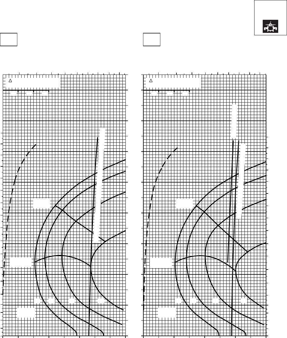
CRUISE CRUISE
T701C (2)
TORQUE PER ENGINE ~ %TORQUE PER ENGINE ~ %
IAS ~ KTS TOTAL FUEL FLOW ~ 100 LB/HRTOTAL FUEL FLOW ~ 100 LB/HR
DATA BASE:FLIGHT TEST
TRUE AIRSPEED ~ KTS
TRUE AIRSPEED ~ KTS
NOTE:SHORT DASH LINES: FERRY MISSION ONLY
SA
AA1022_2
PRESS ALT: 18000 FT
18000 FT
−30oC−20oC
20 30 40 50 60 70 80 90 20 30 40 50 60 70 80 90
0
10
20
30
40
50
60
70
80
90
100
110
120
130
140
150
160
170
10
456 7 8 9 10 11 12
10
0
10
20
30
40
50
60
70
80
90
100
110
120
130
140
150
160
170
180
45678 9 10 11 12
0
10
20
30
40
50
60
70
80
90
100
110
120
130
140
150
160
170
180
TRQ ~ % FOR DRAG
AREA OF 10 SQ FT
10 20 30
GW ~
1000 LB
12 14 16 18
MAX END
AND R / C
MAX
RANGE
MAX
RANGE
TORQUE AVAILABLE ~ 30 MINUTES AND CONTINUOUS
GW ~
1000 LB
12 14 16 18
TORQUE AVAILABLE ~ 30 MINUTES
~ CONTINUOUS
TRQ ~ % FOR DRAG
AREA OF 10 SQ FT
10 20 30
MAX END
AND R / C
PLACARD TORQUE LIMIT = 66%PLACARD TORQUE LIMIT = 69%
Figure 7A-28. Cruise High Drag - Pressure Altitude 18,000 Feet (Sheet 2 of 4)
TM 1-1520-237-10
7A-123
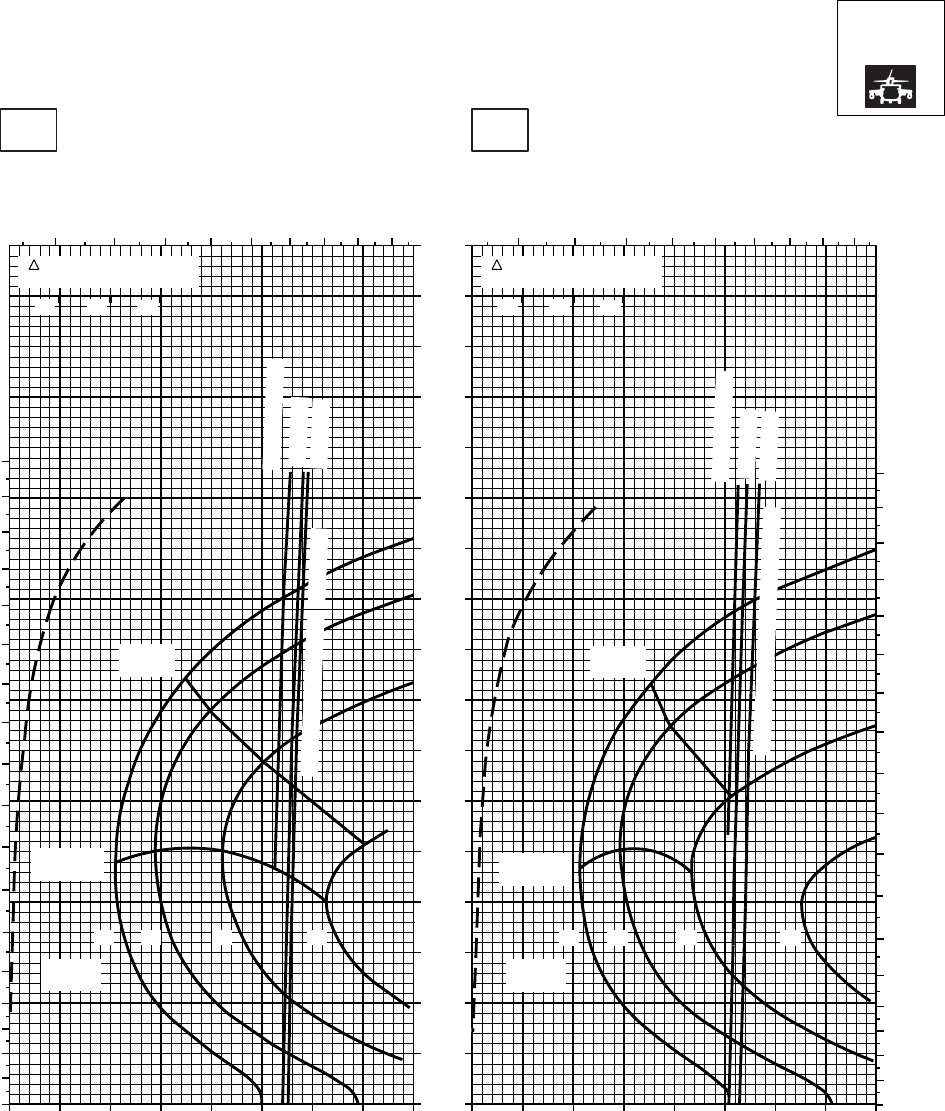
CRUISE CRUISE
T701C (2)
TORQUE PER ENGINE ~ %TORQUE PER ENGINE ~ %
IAS ~ KTS TOTAL FUEL FLOW ~ 100 LB/HRTOTAL FUEL FLOW ~ 100 LB/HR
DATA BASE:FLIGHT TEST
TRUE AIRSPEED ~ KTS
TRUE AIRSPEED ~ KTS
NOTE:SHORT DASH LINES: FERRY MISSION ONLY
SA
A1022_3
PRESS ALT: 18000 FT
18000 FT
−10oC0oC
20 30 40 50 60 70 80 90 20 30 40 50 60 70 80 90
0
10
20
30
40
50
60
70
80
90
100
110
120
130
140
150
160
170
4 5 6 7 8 9 10 11 12 4 5 6 7 8 9 10 11 12
0
10
20
30
40
50
60
70
80
90
100
110
120
130
140
150
160
170
180
0
10
20
30
40
50
60
70
80
90
100
110
120
130
140
150
160
170
180
10 10
MAX
RANGE
MAX
RANGE
14 16 18 14 16 18
TORQUE AVAILABLE ~ 30 MINUTES ATF = 1.0
ATF = 0.9
~ CONTINUOUS
ATF = 1.0
ATF = 0.9
~ CONTINUOUS
TRQ ~ % FOR DRAG
AREA OF 10 SQ FT
10 20 30
TRQ ~ % FOR DRAG
AREA OF 10 SQ FT
10 20 30
TORQUE AVAILABLE ~ 30 MINUTES
MAX END
AND R / C
GW ~
1000 LB
12
MAX END
AND R / C
GW ~
1000 LB
12
PLACARD TORQUE LIMIT = 61%PLACARD TORQUE LIMIT = 63%
Figure 7A-28. Cruise High Drag - Pressure Altitude 18,000 Feet (Sheet 3 of 4)
TM 1-1520-237-10
7A-124
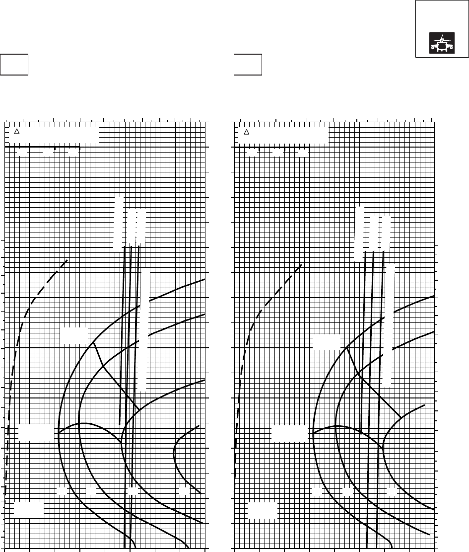
CRUISE CRUISE
T701C (2)
TORQUE PER ENGINE ~ %TORQUE PER ENGINE ~ %
IAS ~ KTS TOTAL FUEL FLOW ~ 100 LB/HRTOTAL FUEL FLOW ~ 100 LB/HR
DATA BASE:FLIGHT TEST
TRUE AIRSPEED ~ KTS
TRUE AIRSPEED ~ KTS
NOTE:SHORT DASH LINES: FERRY MISSION ONLY
SA
AA1022_4
PRESS ALT: 18000 FT
18000 FT
10oC20oC
20 30 40 50 60 70 80 90 20 30 40 50 60 70 80
0
10
20
30
40
50
60
70
80
90
100
110
120
130
140
150
160
170
TRQ ~ % FOR DRAG
AREA OF 10 SQ FT
10 20 30
TRQ ~ % FOR DRAG
AREA OF 10 SQ FT
10 20 30
MAX
RANGE MAX
RANGE
MAX END
AND R / C
MAX END
AND R / C
10 010
TORQUE AVAILABLE ~ 30 MINUTES
TORQUE AVAILABLE ~ 30 MINUTES
~ CONTINUOUS
ATF = 0.9
ATF = 1.0
~ CONTINUOUS
ATF = 0.9
ATF = 1.0
GW ~
1000 LB
12 14 18
GW ~
1000 LB
12 14 16
3 4 5 6 78910 11
45 6 7 89 10 11 12
0
10
20
30
40
50
60
70
80
90
100
110
120
130
140
150
160
170
180
0
10
20
30
40
50
60
70
80
90
100
110
120
130
140
150
160
170
180
16
PLACARD TORQUE LIMIT = 56%
PLACARD TORQUE LIMIT = 59%
Figure 7A-28. Cruise High Drag - Pressure Altitude 18,000 Feet (Sheet 4 of 4)
TM 1-1520-237-10
7A-125
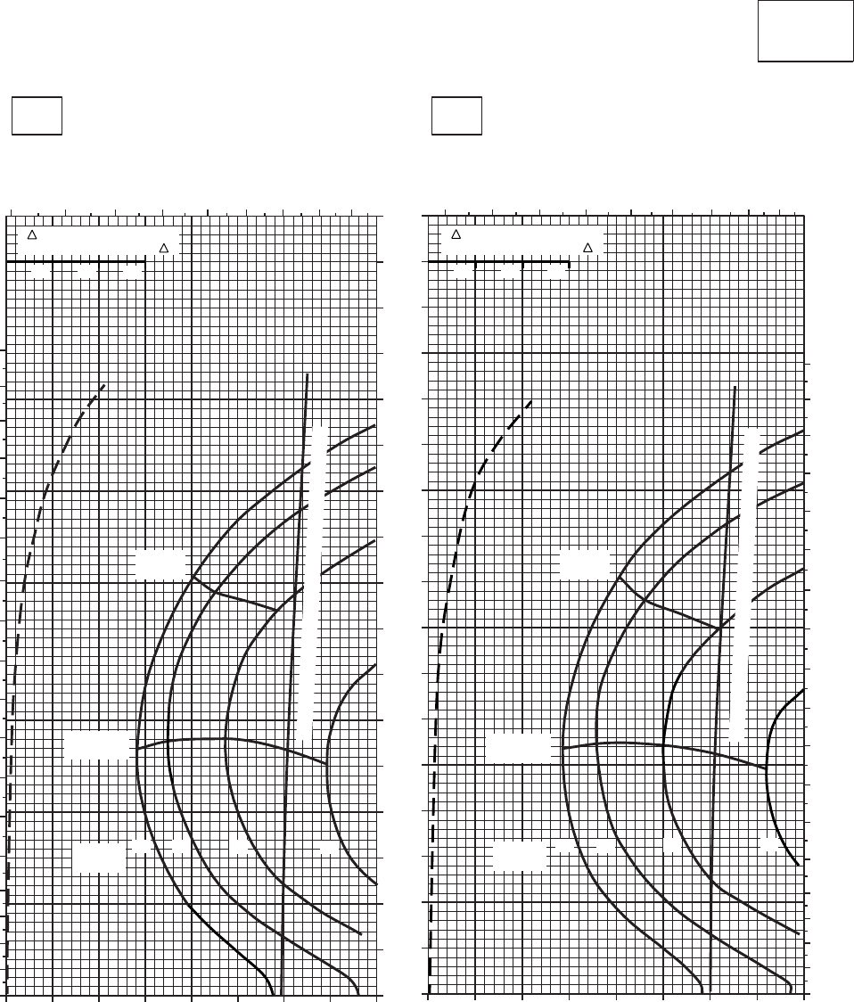
CRUISE CRUISE
T701C (2)
TORQUE PER ENGINE ~ %TORQUE PER ENGINE ~ %
IAS ~ KTS TOTAL FUEL FLOW ~ 100 LB/HRTOTAL FUEL FLOW ~ 100 LB/HR
DATA BASE:FLIGHT TEST
TRUE AIRSPEED ~ KTS
TRUE AIRSPEED ~ KTS
CLEAN CONFIGURATION
0
10
20
30
40
50
60
70
80
90
100
110
120
130
140
150
160
170
PRESS ALT: 20,000 FT
20,000 FT
−50oC−40oC
234 5 6 7 8 910
0 10 20 30 40 50 60 70 80
0
10
20
30
40
50
60
70
80
90
100
110
120
130
140
150
160
170
180
0 10 20 30 40 50 60 70 80
2 3 45 6 78 9 10
0
10
20
30
40
50
60
70
80
90
100
110
120
130
140
150
160
170
180
TRQ ~ % FOR DRAG
AREA OF 10 SQ FT OF F
10 20 30
TRQ ~ % FOR DRAG
AREA OF 10 SQ FT OF F
10 20 30
MAX
RANGE MAX
RANGE
MAX END
AND R / C
MAX END
AND R / C
GW ~
1000 LB
12 14 16 18 GW ~
1000 LB
12 14 16 18
TORQUE AVAILABLE~30 MINUTES & CONTINUOUS
TORQUE AVAILABLE~30 MINUTES & CONTINUOUS
SA
AA1023_1
PLACARD TORQUE LIMIT = 66%PLACARD TORQUE LIMIT = 69%
Figure 7A-29. Cruise - Pressure Altitude 20,000 Feet (Sheet 1 of 4)
TM 1-1520-237-10
7A-126
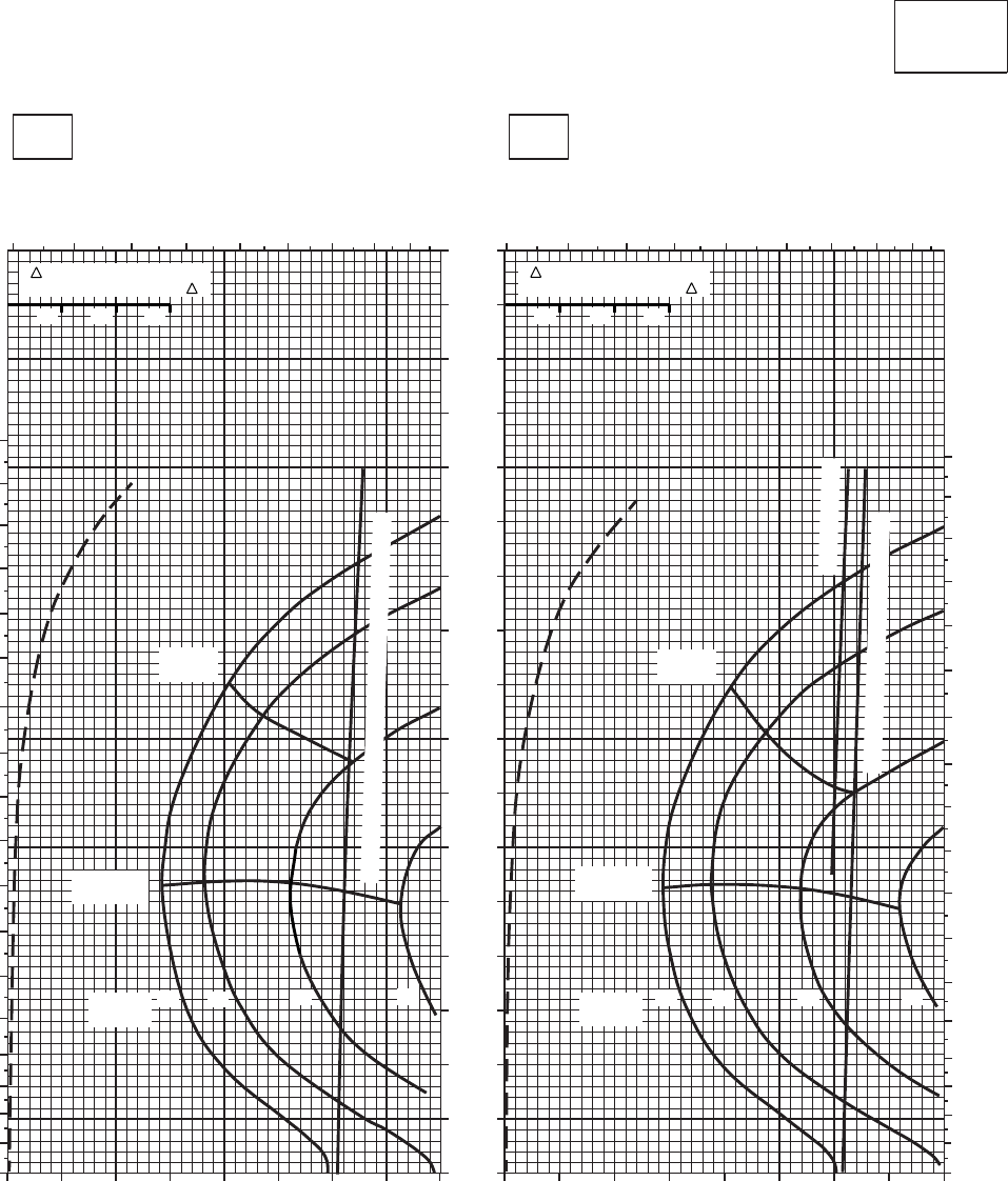
CRUISE CRUISE
T701C (2)
TORQUE PER ENGINE ~ %TORQUE PER ENGINE ~ %
IAS ~ KTS TOTAL FUEL FLOW ~ 100 LB/HRTOTAL FUEL FLOW ~ 100 LB/HR
DATA BASE:FLIGHT TEST
TRUE AIRSPEED ~ KTS
TRUE AIRSPEED ~ KTS
CLEAN CONFIGURATION
0
10
20
30
40
50
60
70
80
90
100
110
120
130
140
150
160
170
PRESS ALT: 20,000 FT
20,000 FT
−30oC−20oC
2 3 4 5 6 7 89 10
0 10 20 30 40 50 60 70 80
0
10
20
30
40
50
60
70
80
90
100
110
120
130
140
150
160
170
180
23456 7 8 9 10
0 10 20 30 40 50 60 70 80
0
10
20
30
40
50
60
70
80
90
100
110
120
130
140
150
160
170
180
TRQ ~ % FOR DRAG
AREA OF 10 SQ FT OF F
10 20 30
TRQ ~ % FOR DRAG
AREA OF 10 SQ FT OF F
10 20 30
MAX
RANGE MAX
RANGE
MAX END
AND R / C
MAX END
AND R / C
GW ~
1000 LB GW ~
1000 LB
12 14 16 18 12 14 16 18
TORQUE AVAILABLE ~ 30 MINUTES
TORQUE AVAILABLE~30 MINUTES & CONTINUOUS
~ CONTINUOUS
SA
AA1023_2
PLACARD TORQUE LIMIT = 60%PLACARD TORQUE LIMIT = 63%
Figure 7A-29. Cruise - Pressure Altitude 20,000 Feet (Sheet 2 of 4)
TM 1-1520-237-10
7A-127
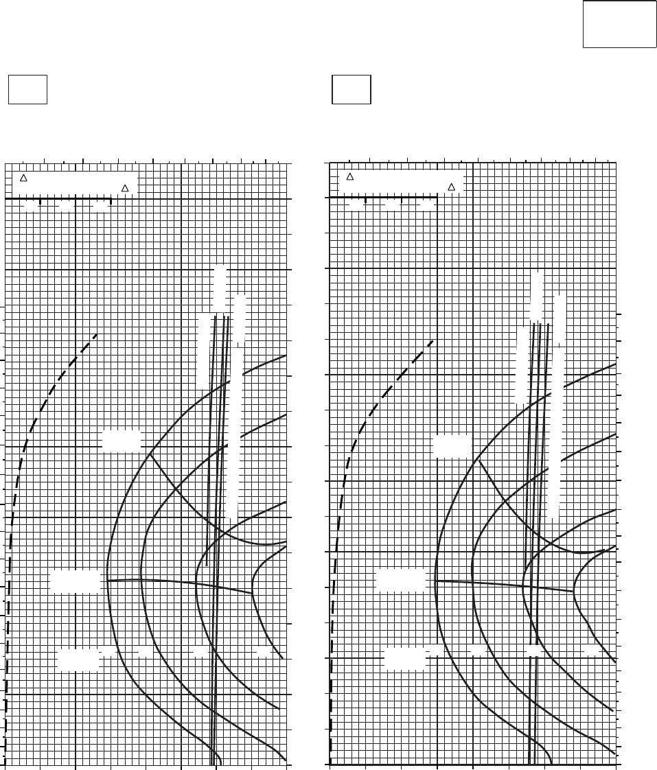
CRUISE CRUISE
T701C (2)
TORQUE PER ENGINE ~ %TORQUE PER ENGINE ~ %
IAS ~ KTS TOTAL FUEL FLOW ~ 100 LB/HRTOTAL FUEL FLOW ~ 100 LB/HR
DATA BASE:FLIGHT TEST
TRUE AIRSPEED ~ KTS
TRUE AIRSPEED ~ KTS
CLEAN CONFIGURATION
0
10
20
30
40
50
60
70
80
90
100
110
120
130
140
150
160
170
SA
AA1023_3
PRESS ALT: 20,000 FT
20,000 FT
−10oC0oC
TRQ ~ % FOR DRAG
AREA OF 10 SQ FT OF F
10 20 30
TRQ ~ % FOR DRAG
AREA OF 10 SQ FT OF F
10 20 30
0 10 20 30 40 50 60 70 80 0 10 20 30 40 50 60 70 80
3456 7 8 9 10
34 5 6 7 8 9 10
0
10
20
30
40
50
60
70
80
90
100
110
120
130
140
150
160
170
180
0
10
20
30
40
50
60
70
80
90
100
110
120
130
140
150
160
170
180
MAX
RANGE MAX
RANGE
MAX END
AND R / C MAX END
AND R / C
GW ~
1000 LB GW ~
1000 LB
12 12
14 14
16 16 18
~ CONTINUOUS
~ CONTINUOUS
ATF = 0.9
ATF = 0.9
TORQUE AVAILABLE ~ 30 MINUTES
TORQUE AVAILABLE ~ 30 MINUTES ATF = 1.0
ATF = 1.0
18
PLACARD TORQUE LIMIT = 56%
PLACARD TORQUE LIMIT = 58%
Figure 7A-29. Cruise - Pressure Altitude 20,000 Feet (Sheet 3 of 4)
TM 1-1520-237-10
7A-128
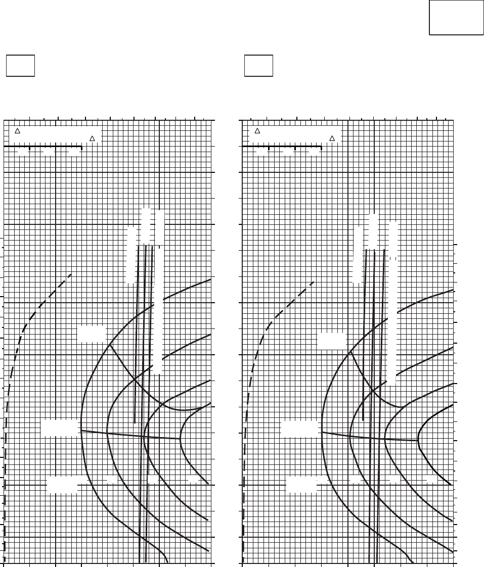
CRUISE CRUISE
T701C (2)
TORQUE PER ENGINE ~ %TORQUE PER ENGINE ~ %
IAS ~ KTS TOTAL FUEL FLOW ~ 100 LB/HRTOTAL FUEL FLOW ~ 100 LB/HR
DATA BASE:FLIGHT TEST
TRUE AIRSPEED ~ KTS
TRUE AIRSPEED ~ KTS
CLEAN CONFIGURATION
0
10
20
30
40
50
60
70
80
90
100
110
120
130
140
150
160
170
PRESS ALT: 20,000 FT
20,000 FT
10oC20oC
TRQ ~ % FOR DRAG
AREA OF 10 SQ FT OF F
10 20 30
TRQ ~ % FOR DRAG
AREA OF 10 SQ FT OF F
10 20 30
0 10 20 30 40 50 60 70 80 0 10 20 30 40 50 60 70 80
345 6 7 8 9 10 34 5 6 7 8 9 10
0
10
20
30
40
50
60
70
80
90
100
110
120
130
140
150
160
170
180
0
10
20
30
40
50
60
70
80
90
100
110
120
130
140
150
160
170
180
MAX
RANGE MAX
RANGE
MAX END
AND R / C MAX END
AND R / C
GW ~
1000 LB
12 14 16 18 GW ~
1000 LB 12 14 16 18
~ CONTINUOUS
~ CONTINUOUS
ATF = 0.9
ATF = 0.9
TORQUE AVAILABLE ~ 30 MINUTES
TORQUE AVAILABLE ~ 30 MINUTES
ATF = 1.0
ATF = 1.0
SA
AA1023_4
PLACARD TORQUE LIMIT = 51%PLACARD TORQUE LIMIT =53%
Figure 7A-29. Cruise - Pressure Altitude 20,000 Feet (Sheet 4 of 4)
TM 1-1520-237-10
7A-129
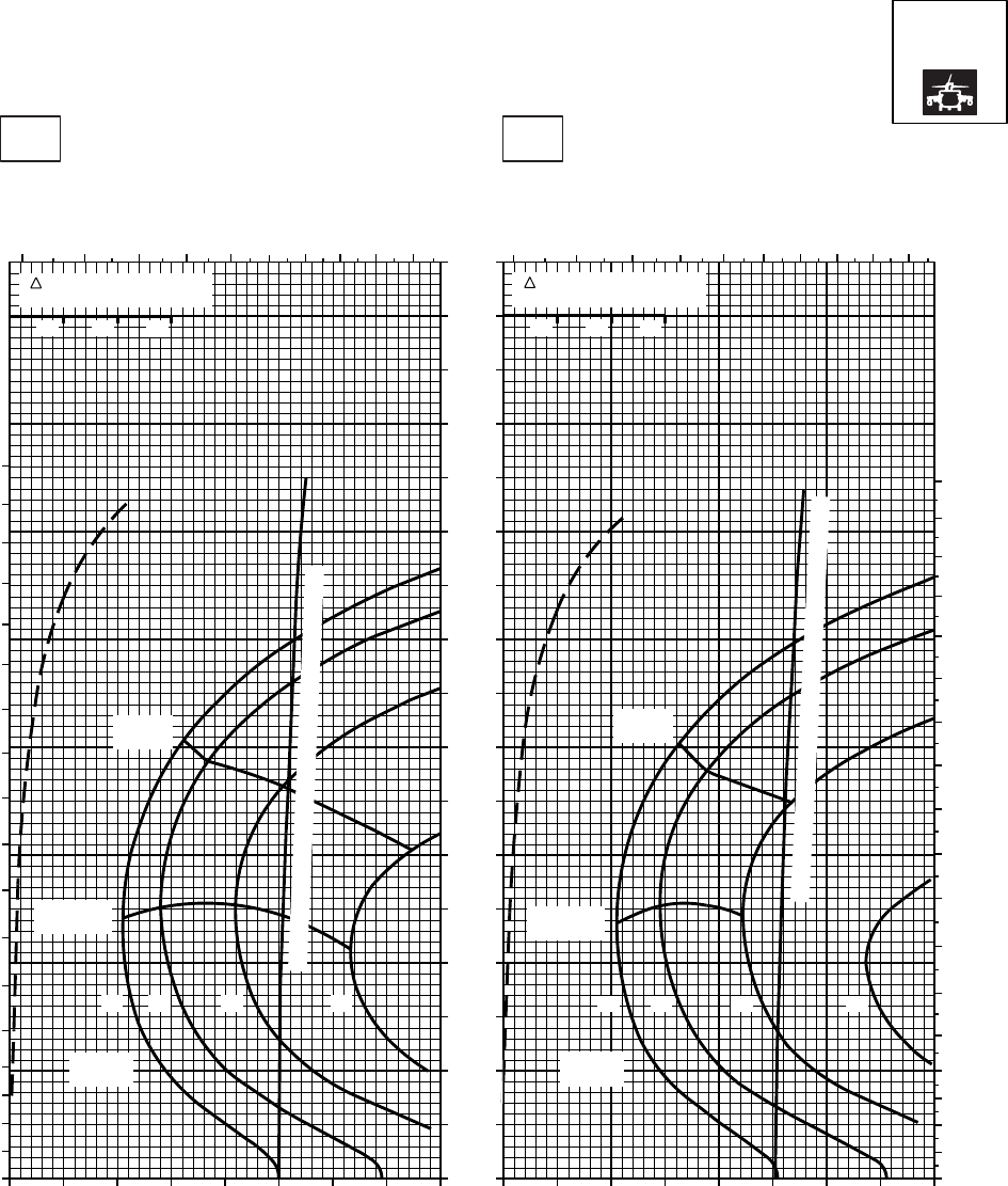
CRUISE CRUISE
T701C (2)
TORQUE PER ENGINE ~ %TORQUE PER ENGINE ~ %
IAS ~ KTS TOTAL FUEL FLOW ~ 100 LB/HRTOTAL FUEL FLOW ~ 100 LB/HR
DATA BASE:FLIGHT TEST
TRUE AIRSPEED ~ KTS
TRUE AIRSPEED ~ KTS
NOTE:SHORT DASH LINES: FERRY MISSION ONLY
SA
AA1024_1
PRESS ALT: 20000 FT
20000 FT
−50oC−40oC
20 30 40 50 60 70 80 90 20 30 40 50 60 70 80 90
0
10
20
30
40
50
60
70
80
90
100
110
120
130
140
150
160
170
10 10
GW ~
1000 LB
12 14 16 18
MAX END
AND R / C
MAX
RANGE
TORQUE AVAILABLE ~ 30 MINUTES AND CONTINUOUS
TRQ ~ % FOR DRAG
AREA OF 10 SQ FT
10 20 30
3 4 5 6 7 8 9 10 11 12
0
10
20
30
40
50
60
70
80
90
100
110
120
130
140
150
160
170
180
3 4 5 6 7 89 10 11 12
TRQ ~ % FOR DRAG
AREA OF 10 SQ FT
10 20 30
0
10
20
30
40
50
60
70
80
90
100
110
120
130
140
150
160
170
180
GW ~
1000 LB
12 14 16 18
MAX END
AND R / C
MAX
RANGE
TORQUE AVAILABLE ~ 30 MINUTES AND CONTINUOUS
PLACARD TORQUE LIMIT = 66%PLACARD TORQUE LIMIT = 69%
Figure 7A-30. Cruise High Drag - Pressure Altitude 20,000 Feet (Sheet 1 of 4)
TM 1-1520-237-10
7A-130
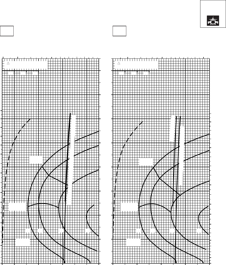
CRUISE CRUISE
T701C (2)
TORQUE PER ENGINE ~ %TORQUE PER ENGINE ~ %
IAS ~ KTS TOTAL FUEL FLOW ~ 100 LB/HRTOTAL FUEL FLOW ~ 100 LB/HR
DATA BASE:FLIGHT TEST
TRUE AIRSPEED ~ KTS
TRUE AIRSPEED ~ KTS
NOTE:SHORT DASH LINES: FERRY MISSION ONLY
SA
AA1024_2
PRESS ALT: 20000 FT
20000 FT
−30oC−20oC
20 30 40 50 60 70 80 90 20 30 40 50 60 70 80 90
0
10
20
30
40
50
60
70
80
90
100
110
120
130
140
150
160
170
10 10
TRQ ~ % FOR DRAG
AREA OF 10 SQ FT
10 20 30
TRQ ~ % FOR DRAG
AREA OF 10 SQ FT
10 20 30
3 4 5 6 7 8 9 10 11 12 4 5 6 7 8 9 10 11 12
0
10
20
30
40
50
60
70
80
90
100
110
120
130
140
150
160
170
180
0
10
20
30
40
50
60
70
80
90
100
110
120
130
140
150
160
170
180
TORQUE AVAILABLE ~ 30 MINUTES AND CONTINUOUS
MAX
RANGE
MAX END
AND R / C MAX END
AND R / C
MAX
RANGE
~ CONTINUOUS
TORQUE AVAILABLE ~ 30 MINUTES
GW ~
1000 LB
12 14 16 18
GW ~
1000 LB
12 14 16 18
PLACARD TORQUE LIMIT = 60%PLACARD TORQUE LIMIT = 63%
Figure 7A-30. Cruise High Drag - Pressure Altitude 20,000 Feet (Sheet 2 of 4)
TM 1-1520-237-10
7A-131
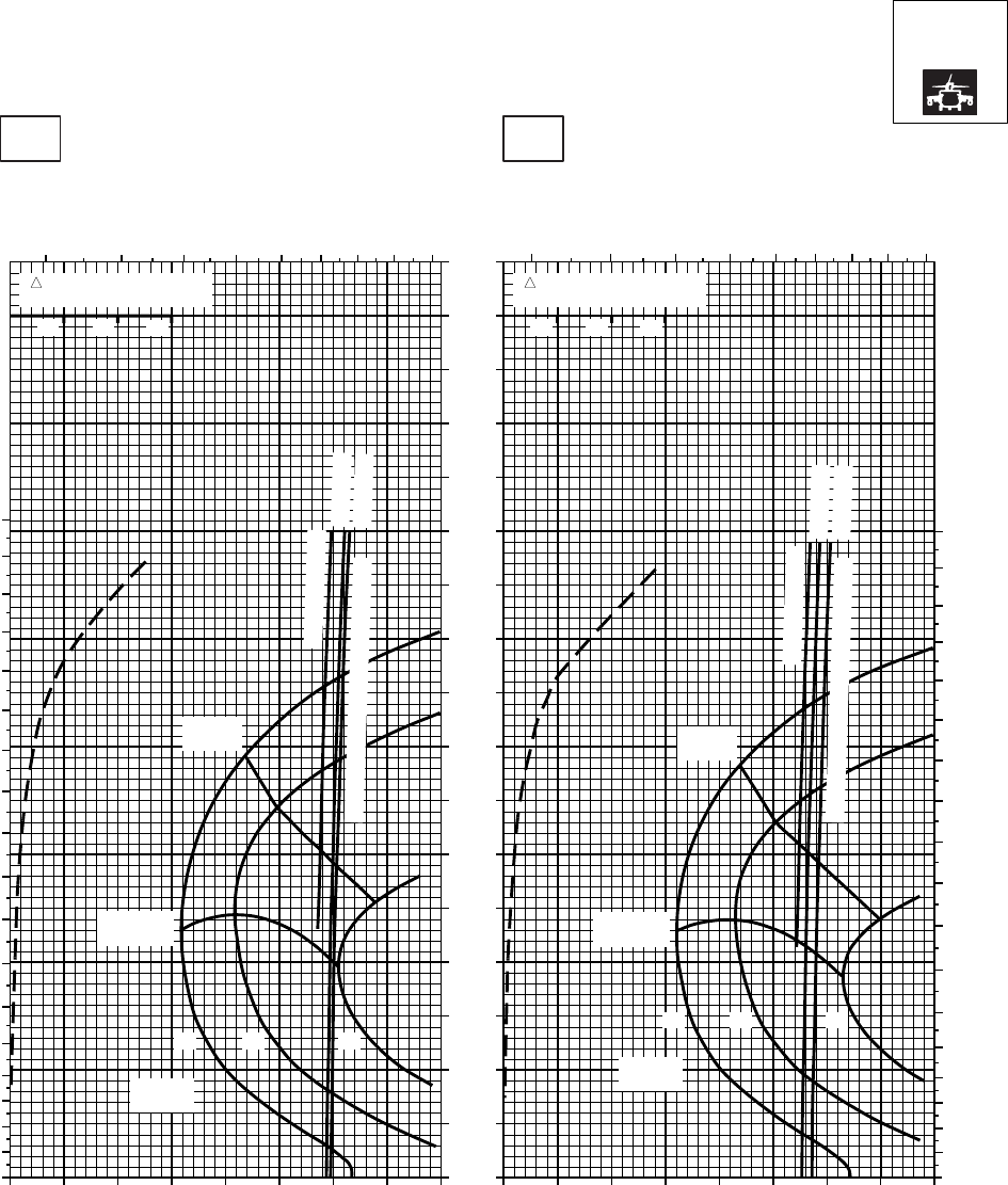
CRUISE CRUISE
T701C (2)
TORQUE PER ENGINE ~ %TORQUE PER ENGINE ~ %
IAS ~ KTS TOTAL FUEL FLOW ~ 100 LB/HRTOTAL FUEL FLOW ~ 100 LB/HR
DATA BASE:FLIGHT TEST
TRUE AIRSPEED ~ KTS
TRUE AIRSPEED ~ KTS
NOTE:SHORT DASH LINES: FERRY MISSION ONLY
SA
AA1024_3
PRESS ALT: 20000 FT
20000 FT
−10oC0oC
20 30 40 50 60 70 80 20 30 40 50 60 70 80
0
10
20
30
40
50
60
70
80
90
100
110
120
130
140
150
160
170
010 010
TRQ ~ % FOR DRAG
AREA OF 10 SQ FT
10 20 30
TRQ ~ % FOR DRAG
AREA OF 10 SQ FT
10 20 30
3 4 5 6 7 8 9 10 11 3 4 5 6 7 8 9 10 11
0
10
20
30
40
50
60
70
80
90
100
110
120
130
140
150
160
170
180
0
10
20
30
40
50
60
70
80
90
100
110
120
130
140
150
160
170
180
~ CONTINUOUS
~ CONTINUOUS
ATF = 0.9
ATF = 1.0
ATF = 0.9
ATF = 1.0
TORQUE AVAILABLE ~ 30 MINUTES
TORQUE AVAILABLE ~ 30 MINUTES
MAX
RANGE
MAX
RANGE
MAX END
AND R / C MAX END
AND R / C
GW ~
1000 LB
12 14 16
GW ~
1000 LB
12 14 16
PLACARD TORQUE LIMIT = 56%PLACARD TORQUE LIMIT = 58%
Figure 7A-30. Cruise High Drag - Pressure Altitude 20,000 Feet (Sheet 3 of 4)
TM 1-1520-237-10
7A-132
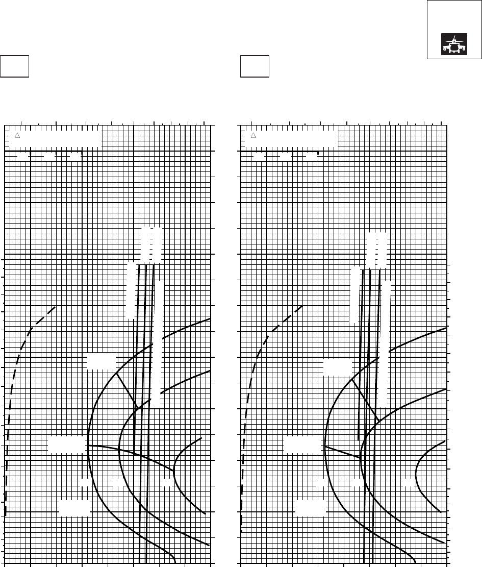
CRUISE CRUISE
T701C (2)
TORQUE PER ENGINE ~ %TORQUE PER ENGINE ~ %
IAS ~ KTS TOTAL FUEL FLOW ~ 100 LB/HRTOTAL FUEL FLOW ~ 100 LB/HR
DATA BASE:FLIGHT TEST
TRUE AIRSPEED ~ KTS
TRUE AIRSPEED ~ KTS
NOTE:SHORT DASH LINES: FERRY MISSION ONLY
SA
AA1024_4
PRESS ALT: 20000 FT
20000 FT
10oC20oC
20 30 40 50 60 70 80 20 30 40 50 60 70 80
0
10
20
30
40
50
60
70
80
90
100
110
120
130
140
150
160
170
010 010
TRQ ~ % FOR DRAG
AREA OF 10 SQ FT
10 20 30
TRQ ~ % FOR DRAG
AREA OF 10 SQ FT
10 20 30
3 4 5 6 7 8 9 10 11 3 4 5 6 7 8 9 10 11
0
10
20
30
40
50
60
70
80
90
100
110
120
130
140
150
160
170
180
0
10
20
30
40
50
60
70
80
90
100
110
120
130
140
150
160
170
180
~ CONTINUOUS
~ CONTINUOUS
ATF = 0.9
ATF = 1.0
ATF = 0.9
ATF = 1.0
TORQUE AVAILABLE ~ 30 MINUTES
TORQUE AVAILABLE ~ 30 MINUTES
MAX
RANGE
MAX
RANGE
MAX END
AND R / C
MAX END
AND R / C
GW ~
1000 LB
12 14 16
GW ~
1000 LB
12 14 16
PLACARD TORQUE LIMIT = 51%PLACARD TORQUE LIMIT = 53%
Figure 7A-30. Cruise High Drag - Pressure Altitude 20,000 Feet (Sheet 4 of 4)
TM 1-1520-237-10
7A-133
Section V OPTIMUM CRUISE
7A.20 OPTIMUM RANGE CHARTS.
This section presents a method to optimize cruise per-
formance for long range missions when the altitudes flown
are not restricted by other requirements. The optimum alti-
tude for maximum range charts (Figures 7A-31 and 7A-32)
provides the pressure altitude at which to cruise to obtain
the maximum possible range for any gross weight and FAT
conditions. The altitude determined for optimum range may
also be used for optimum endurance. Enter the chart at a
current cruise or takeoff temperature condition and move
along the temperature guide lines to the anticipated gross
weight for cruise and obtain the optimum pressure altitude.
Turn to the cruise chart closest to the altitude and tempera-
ture predicted by the optimum range chart for specific
cruise information. The use of this chart is shown by the
example.
TM 1-1520-237-10
7A-134
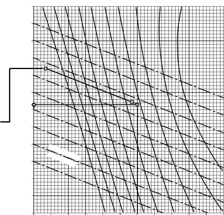
SA
AA1256B
0 2 4 6 8 10 12 14 16 18 20 22
−60
−50
−40
−30
−20
−10
0
10
20
30
40
50
60
TEMPERATURE
TREND LINES
22 21 20 19 18 17 16 15 14 13
WANTED
CRUISE ALTITUDE FOR OPTIMUM RANGE
AND CORRESPONDING CRUISE CHART FOR
FLIGHT CONDITIONS
KNOWN
REFERENCE CONDITIONS OF:
PRESSURE ALTITUDE = 1,500 FT
FAT = 24OC
GW = 16,600 LB
METHOD
OPTIMUM RANGE
GROSS WEIGHT ~ 1000 LB
EXAMPLE
OPTIMUM PRESSURE ALTITUDE ~ 1000 FT
FREE AIR TEMPERATURE ~ OC
ENTER CHART AT FAT (24oC). MOVE
RIGHT TO REFERENCE / OPTIMUM
PRESSURE ALTITUDE (1,500 FT). MOVE
PARALLEL WITH THE TEMPERATURE
TREND LINE TO AIRCRAFT GROSS
WEIGHT (16,600 LB). MOVE LEFT
OR RIGHT PARALLELING THE
TEMPERATURE TREND LINE TO
THE NEAREST EVEN THOUSAND
REFERENCE / OPTIMUM PRESSURE
ALTITUDE LINE (12,000). MOVE
LEFT TO FREE AIR TEMPERATURE
LINE (30). MOVE UP OR DOWN
TO NEAREST TEN VALUE ON THE
FREE AIR TEMPERATURE SCALE (0oC).
SELECT CRUISE CHART WITH
ALTITUDE AND TEMPERATURE
DATA AT THE NEAREST REFERENCE /
OPTIMUM PRESSURE ALTITUDE
(12,000 FT) AND THE NEAREST
TEN DEGREE FREE AIR TEMPERATURE
(0oC).
CLEAN CONFIGURATION 100% RPM R
HIRSS (BAFFLES INSTALLED)
DATA BASIS: FLIGHT TEST
Figure 7A-31. Optimum Altitude For Maximum Range
TM 1-1520-237-10
7A-135
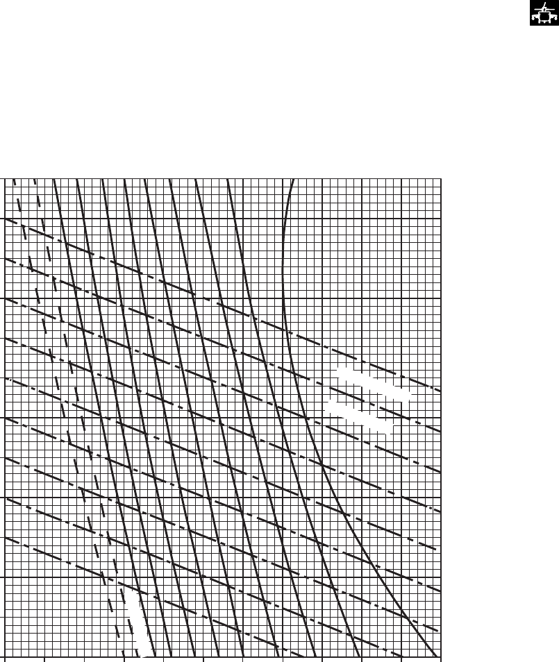
SA
AA1026A
OPTIMUM RANGE
HIGH DRAG CONFIGURATION 100% RPM R
−60
−50
−40
−20
−30
−10
0
10
20
30
40
50
60
04 8 12 16 20
24 23 22 21 20 19 18 17 16 15 14
GROSS WEIGHT ~ 1000 LBS
OPTIMUM PRESSURE ALTITUDE ~ 1000 FT
FREE AIR TEMPERATURE ~ DEG C
TEMPERATURE
TREND LINES
FERRY ONLY
HIRSS (BAFFLES INSTALLED)
Figure 7A-32. Optimum Altitude For Maximum Range - High Drag
TM 1-1520-237-10
7A-136

Section VI DRAG
7A.21 EXTERNAL LOAD DRAG CHART.
The general shapes of typical external loads are shown
on Figure 7A-33. as a function of the load frontal area. The
frontal area is combined with the typical drag coefficient of
the general shapes to obtain a drag multiplying factor for
use with the 10 sq. ft. drag scale on each cruise chart. The
TRQ ˜% value obtained from the cruise chart is multi-
plied by the drag multiplying factor and added to indicated
torque to obtain total torque required at any airspeed.
7A.22 AIRCRAFT CONFIGURATION DRAG
CHANGES FOR USE WITH CLEAN CRUISE
CHARTS.
When external equipment or configuration differs from
the baseline clean configuration as defined in Section I, a
drag correction should be made similarly to the external
drag load method. Typical configuration changes that have
drag areas established from flight test or analysis along with
their drag multiplying factor are listed in Table 7A-1.
Table 7A-1. Configuration Drag Change
DRAG CHANGES FOR USE WITH CLEAN CRUISE CHARTS
Item Change in Flat Plate Drag
Area - F Sq. Ft. Drag Multiplying Factor
a. Both cargo doors open 6.0 0.60
b. Cargo doors removed 4.0 0.40
c. Cargo mirror installed 0.3 0.03
d. IR Countermeasure Transmitter (ALQ-144) installed 0.8 0.08
e. Chaff Dispenser installed 0.3 0.03
f. Blade Erosion Kit 2.0 0.20
g. Skis installed 3.0 0.30
7A.23 AIRCRAFT CONFIGURATION DRAG
CHANGES FOR USE WITH HIGH DRAG CRUISE
CHARTS.
When external equipment differs from the baseline high
drag configuration as defined in this Section, a drag correc-
tion should be made using Figure 7A-34 similar to the ex-
ternal drag load method. Typical high drag configuration
changes that have been established from flight test or analy-
sis along with the drag multiplying factors are shown.
TM 1-1520-237-10
7A-137
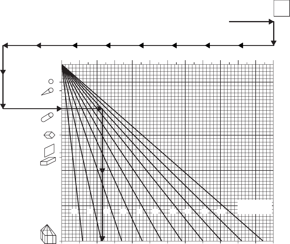
SA
AA0684A
EXTERNAL DRAG LOAD
DRAG MULTIPLYING FACTOR
DUE TO EXTERNAL LOAD
SHAPE OF EXTERNAL
LOAD = CYLINDER
FRONTAL AREA OF
EXTERNAL LOAD = 80 SQ FT
ENTER CHART AT SYMBOL
FOR CYLINDER
MOVE RIGHT TO 80 SQ FT.
MOVE DOWN AND READ
DRAG MULTIPLYING FACTOR
= 4.5
LOAD
DRAG
WANTED:
KNOWN:
METHOD:
EXAMPLE
DATA BASIS: ESTIMATED
SPHERE
STREAMLINED
CYLINDER
CYLINDER
CUBE
FLAT
PLATE
BOX
BOX
IN
NET
0 20 40 60 80 100 120 140 160 180 200 220 240
0246810
12 14 16 18 20 22 24
INCREASE IN DRAG AREA DUE TO EXTERNAL LOAD
DRAG MULTIPLYING FACTOR
302010 40 50 60 70 80 90 100
FRONTAL AREA
OF EXTERNAL
LOAD ~ SQ FT
Figure 7A-33. External Load Drag
TM 1-1520-237-10
7A-138

SA
AA0685B
DRAG CONFIGURATIONS
CRUISE CHART BASELINE
SPECIAL MISSION EQUIPMENT CONFIGURATIONS
HIGH DRAG CHANGE
IN
FLAT
PLATE
DRAG
F
SQ FT
DRAG
MULTI−
PLYING
FACTOR
ESSS − CLEAN, PYLONS REMOVED
ESSS − FOUR PYLONS / NO STORES
ESSS−TWO 450−GALLON TANKS INBOARD
ESSS−TWO 230−GALLON TANKS OUTBOARD
−TWO 450−GALLON −TANKS INBOARD
−4.0
−1.7
0.5
2.5
−0.40
−0.17
0.05
0.25
−TWO 230−GALLON TANKS INBOARD 0.0 0.00
ESSS − FOUR 230−GALLON TANKS 2.0 0.20
VOLCANO SYSTEM INSTALLED (BOTH RACKS) 32.5 3.25
SKIS INSTALLED 3.0 0.30
BOTH CARGO DOORS OPEN 6.0 0.60
BOTH CARGO DOORS REMOVED 4.0 0.40
CARGO MIRROR INSTALLED 0.3 0.03
IR COUNTERMEASURE TRANSMITTER (ALQ−144) REMOVED −0.8 −0.08
CHAFF DISPENSER REMOVED −0.3 −0.03
OR
* VOLCANO CORRECTION MUST BE USED WITH HIGH DRAG CHARTS ONLY
VOLCANO SYSTEM INSTALLED (LOWER RACKS ONLY) 10.5 1.05
Figure 7A-34. Typical High Drag Configurations
TM 1-1520-237-10
Change 8 7A-139
Section VII CLIMB-DESCENT
7A.24 CLIMB/DESCENT CHART.
The CLIMB/DESCENT chart (Figures 7A-35 and 7A-
36) presents the rate of climb or descent resulting from an
increase or decrease of engine torque from the value re-
quired for level flight above 40 KIAS. The data are pre-
sented at 100% RPM R for various gross weights. The
charts may also be used in reverse to obtain the torque
increase or reduction required to achieve a desired steady
rate of climb or descent. The maximum R/C may be deter-
mined by subtracting the cruise chart torque required from
the maximum torque available at the desired flight condi-
tions. Then enter the difference on the torque increase scale
of the climb chart, move up to the gross weight, and read
the resulting maximum R/C.
TM 1-1520-237-10
7A-140
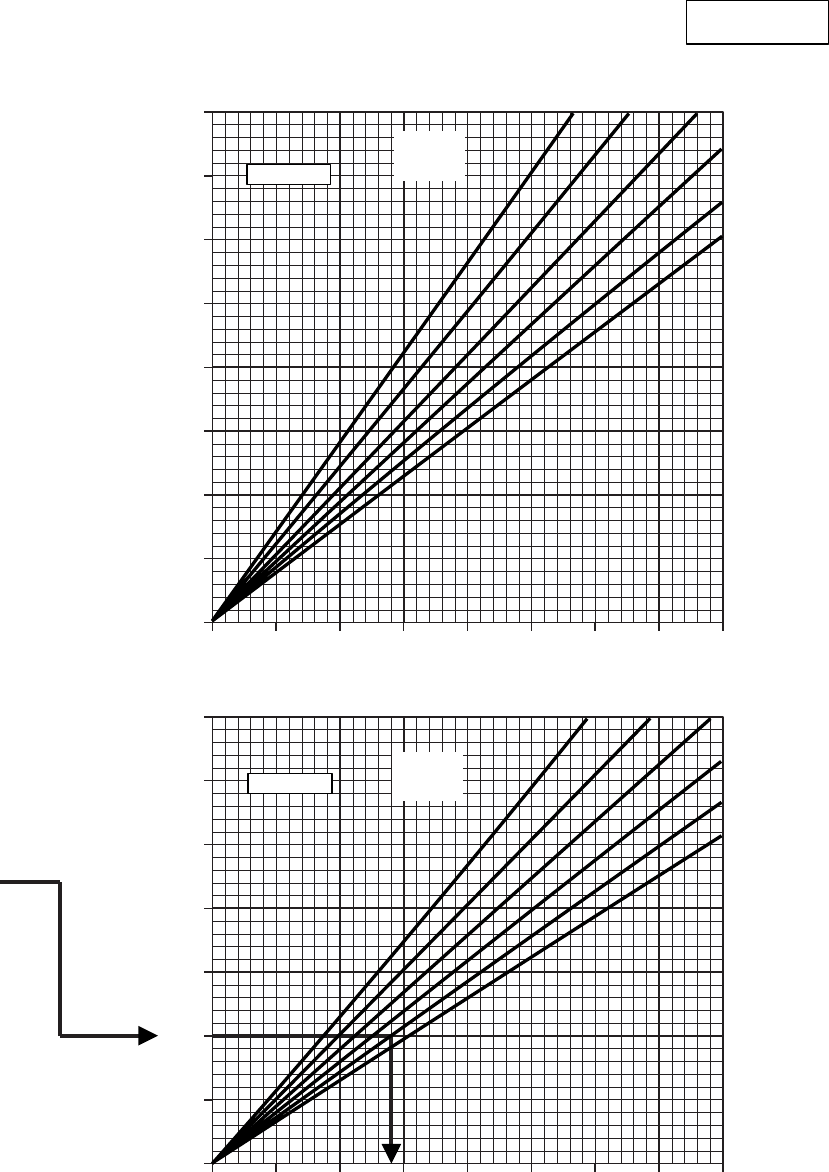
SA
AA1638
CLIMB/DESCENT
100% RPM R CLEAN CONFIGURATION
FOR AIRSPEED ABOVE 40 KIAS
4000
3500
3000
2500
2000
1500
1000
500
0
0 1020304050607080
3500
3000
2500
2000
1500
1000
500
0
0 1020304050607080
TORQUE REDUCTION − PER ENGINE ~% TRQ
TORQUE INCREASE − PER ENGINE ~% TRQ
ENTER AT 1000 FT / MIN
MOVE RIGHT TO 20,000 LB
MOVE DOWN READ TRQ
INCREASE = 28%
RATE OF CLIMB ~ FT. / MIN. RATE OF DESCENT ~ FT. / MIN.
EXAMPLE
DESCENT
CLIMB
12 14 16
18
20
22
12 14 16
18
20
22
DATA BASIS: FLIGHT TEST
GROSS
WEIGHT
~ 1000 LB
GROSS
WEIGHT
~ 1000 LB
CLIMB/DESCENT
Figure 7A-35. Climb/Descent
TM 1-1520-237-10
7A-141
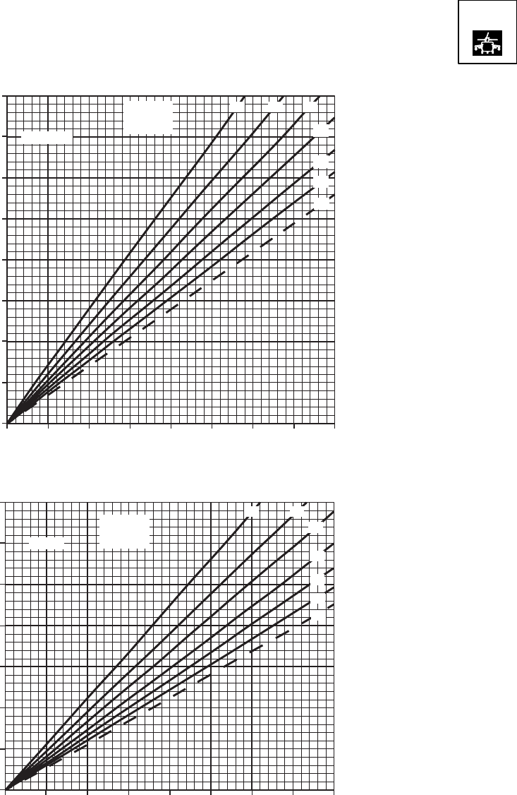
SA
AA1027
CLIMB DESCENT
100% RPM R
FOR AIRSPEED ABOVE 40 KIAS
0 1020304050607080
0
500
1000
1500
2000
2500
3000
3500
4000
0 1020304050607080
0
500
1000
1500
2000
2500
3000
3500
TORQUE REDUCTION − PER ENGINE ~ % Q
TORQUE INCREASE − PER ENGINE ~ % Q
RATE OF CLIMB ~ FT/MIN RATE OF DESCENT ~ FT/MIN
CLIMB /
DESCENT
DATA BASIS: FLIGHT TEST
12 14 16
18
20
22
24
GROSS
WEIGHT
~ 1000 LB
DESCENT
CLIMB
GROSS
WEIGHT
~ 1000 LB
12 14
16
18
20
22
24
Figure 7A-36. Climb/Descent - High Drag
TM 1-1520-237-10
7A-142

Section VIII FUEL FLOW
7A.25 IDLE FUEL FLOW.
Dual-engine idle fuel flow is presented as a function of
altitude at 0°C FAT in Table 7A-2.
7A.26 SINGLE-ENGINE FUEL FLOW.
Engine fuel flow is presented in Figure 7A-37 for vari-
ous torque and pressure altitudes at a baseline FAT of 0°C
with engine bleed air extraction off. When operating at
other than 0°C FAT, engine fuel flow is increased 1% for
each 20°C above the baseline temperature and, decreased
1% for each 20°C below the baseline temperature.
To determine single-engine fuel flow during cruise, en-
ter the fuel flow chart at double the torque required for
dual-engine cruise as determined from the cruise charts and
obtain fuel flow from the single-engine scale. The single-
engine torque may not exceed the transmission limit shown
on the chart. With bleed air extracted, fuel flow increases as
follows:
a. Engine anti-ice on - +50 lbs/hr.
b. Cockpit heater on - +6 lbs/hr.
c. When the IR suppressor system is operating in the
benign mode (exhaust baffles removed), the fuel flow will
decrease about 7 lbs/hr.
7A.27 DUAL-ENGINE FUEL FLOW.
Dual-engine fuel flow may be obtained from Figure
7A-37 when each engine is indicating approximately the
same torque by averaging the indicated torques and reading
fuel flow from the dual-engine fuel flow scale. When oper-
ating at other than the 0° FAT baseline, dual-engine fuel
flow is increased 1% for each 20°C above baseline and is
decreased 1% for each 20°C below baseline temperature.
With bleed air extracted, dual engine fuel flow increases as
follows:
a. Engine anti-ice on - +100 lbs/hr.
b. Cockpit heater on - +12 lbs/hr.
c. When the IR suppressor system is operating in the
benign mode (exhaust baffles removed), the fuel flow de-
creases about 14 lbs/hr.
Table 7A-2. Idle Fuel Flow
Pressure Altitude Feet Ng = 63-71%
Ground Idle (66% RPM R)
Lb/Hr
Ng = 79-88%
Flat Pitch (100% RPM R)
Lb/Hr
APU (Nominal) Lb/Hr
0 360 590 120
4,000 310 515 105
8,000 280 445 90
12,000 250 400 75
16,000 220 340 65
20,000 185 280 55
TM 1-1520-237-10
7A-143
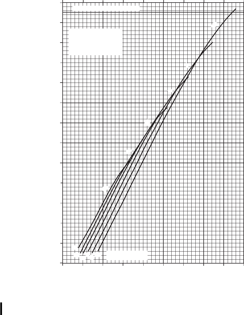
SA
AA1028B
10
20
30
40
50
60
70
80
90
100
110
120
130
140
200 400 600 800 1000 1200 1400 1600 1800 2000
100 200 300 400 500 600 700 800 900 1000
20
16 12 84SL PRESSURE
ALTITUDE ~ 1000 FT
20
16 12 84SL
SINGLE−ENGINE FLOW ~ LB/HR
INDICATED TORQUE PER ENGINE ~ %
DUAL−ENGINE FUEL FLOW ~ LB/HR
SINGLE/DUAL−ENGINE FUEL FLOW
HIRSS SUPPRESSED MODE BLEED AIR OFF
100% RPM R FAT= 0o C
DATA BASIS:
ENGINE MANUFACTURER
SPEC.
NOTE
INCREASE FUEL FLOW 1%
FOR EACH 20o C ABOVE
0o C FAT AND DECREASE
FUEL FLOW 1% FOR EACH
20o C BELOW 0o C FAT
TRANSMISSION LIMIT − 1 ENGINE
Figure 7A-37. Single/Dual-Engine Fuel Flow
TM 1-1520-237-10
7A-144 Change 10
Section IX AIRSPEED SYSTEM CHARACTERISTICS
7A.28 AIRSPEED SYSTEM DESCRIPTION.
NOTE
Indicated airspeeds below 40 KIAS are un-
reliable. Airspeed conversion data KIAS to
KTAS for speeds above 40 KIAS are pro-
vided in Section IV CRUISE.
The UH-60L is equipped with the pitot-static system
with wedge mounted pitot-static probes.
7A.29 AIRSPEED CHARTS.
7A.29.1 Airspeed Correction Charts. All indicated
airspeeds shown on the cruise charts are based on level
flight. Figures 7A-38 and 7A-39 provide the airspeed cor-
rection to be added to the cruise chart IAS value to deter-
mine the related airspeed indicator reading for other than
level flight mode. There are relatively large variations in
airspeed system error associated with climbs and descents.
These errors are significant and Figures 7A-38 and 7A-39
are provided primarily to show the general magnitude and
direction of the errors associated with the various flight
modes. If desired these figures may be used in the manner
shown by the examples to calculate specific airspeed cor-
rections.
7A.29.2 Airspeed System Dynamic Characteris-
tics. The dynamic characteristics of the pilot and copilot
airspeed indicating systems are normally satisfactory. How-
ever, the following anomalies in the airspeed and IVSI in-
dicating system may be observed during the following ma-
neuvers or conditions:
a. During takeoffs, in the speed range of 40 to 80 KIAS,
5 to 10 KIAS airspeed fluctuation may be observed on the
pilot’s and copilot’s airspeed indicators.
b. Power changes in high power, low airspeed climbs
may cause as much as 30 knot airspeed changes in indi-
cated airspeed. Increase in power causes increase in indi-
cated airspeed, and a decrease in power causes decrease in
indicated airspeed.
c. The pilot and copilot airspeed indicators may be un-
reliable during high power climbs at low airspeeds (less
than 50 KIAS) with the copilot system reading as much as
30 knots lower than the pilot system.
d. In-flight opening and closing of doors and windows
may cause momentary fluctuations of approximately 300
feet per minute on the vertical speed indicators.
TM 1-1520-237-10
7A-145
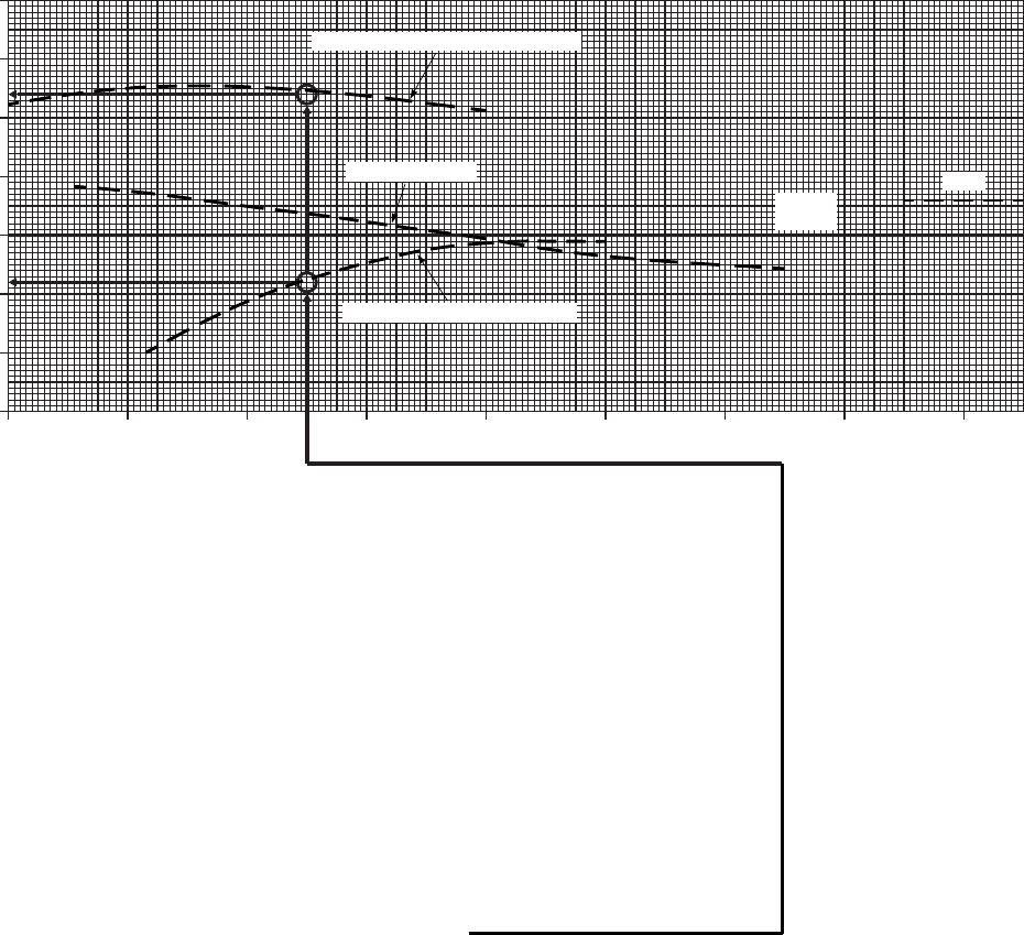
SA
AA0321A
AIRSPEED SYSTEM CORRECTION
CORRECTION TO ADD ~ KNOTS
20
15
10
5
0
−5
−10
−15
IAS FROM CLEAN CRUISE CHARTS ~ KNOTS
20 40 60 80 100 120 140 160 180
R / C GREATER THAN 1400 FT / MIN
AUTOROTATION
R / C LESS THAN 1400 FT / MIN
LEVEL
FLIGHT
DIVE
INDICATED AIRSPEED TO CLIMB AT
MAXIMUM RATE OF CLIMB.
70 KIAS MAX END / AND R / C FROM
APPROPRIATE CRUISE CHART FOR
A GIVEN PRESSURE ALTITUDE, FAT,
AND GROSS WEIGHT.
ENTER AT KNOWN IAS FROM
CRUISE CHART, MOVE UP TO R / C GREATER
THAN 1,400 FPM, MOVE LEFT READ CORRECTION
TO ADD TO IAS = +12.5 KTS, RE−ENTER
AT KNOWN IAS FROM CRUISE CHART, MOVE UP
TO R / C LESS THAN 1,400 FPM LINE, MOVE LEFT,
READ CORRECTION TO ADD TO IAS = −4 KTS
CALCULATE IAS FOR MAX R / C WHEN:
FOR R / C GREATER THAN 1,400 FPM, AIRSPEED = 70 KIAS +12.5 KIAS = 82.5 KIAS
FOR R / C LESS THAN 1,400 FPM, AIRSPEED = 70 KIAS −4 KIAS = 66 KIAS
WANTED:
KNOWN:
METHOD:
EXAMPLE
DATA BASIS: FLIGHT TEST
Figure 7A-38. Airspeed Correction Chart
TM 1-1520-237-10
7A-146
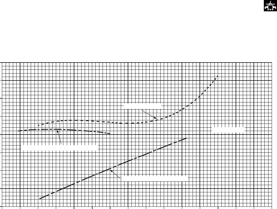
SA
AA1029A
AIRSPEED SYSTEM CORRECTION
20 40 60 80 100 120 140 160
IAS FROM HIGH DRAG CRUISE CHARTS ~ KNOTS
−20
−15
−10
−5
0
5
10
15
20
CORRECTION TO BE ADDED ~ KNOTS
AUTOROTATION
LEVEL FLIGHT
R / C GREATER THAN 1400 FT / MIN
R / C LESS THAN 1400 FT / MIN
FLIGHT TEST
DATA BASIS:
Figure 7A-39. Airspeed Correction Chart - High Drag
TM 1-1520-237-10
7A-147
Section X SPECIAL MISSION PERFORMANCE
7A.30 SPECIAL MISSION FLIGHT PROFILES.
Figures 7A-40 through 7A-42 show special mission
flight profiles required to obtain near maximum range when
equipped with ESSS in three different tank configurations.
The upper segment of each chart provides the recom-
mended altitude profile along with the IAS and average
TRQ versus distance traveled. An average value of elapsed
time is also presented on the lower axis of the altitude
scale. The lower segment of each chart provides the rela-
tionship between fuel remaining and distance traveled re-
sulting from the flight profile shown. This portion may be
utilized to check actual inflight range data to provide assur-
ance that adequate range is being achieved. The chart is
divided into 3 regions of Adequate Range, Inadequate
range-return to base, and Inadequate range-requiring emer-
gency action. When an inflight range point is in the Ad-
equate range region, the required mission range can be ob-
tained by staying on the recommended flight profile.
However, the range may not be achieved if stronger head-
winds are encountered as the flight progresses, and normal
pilot judgement must be used. These charts also assume
that the flight track is within proper navigational limits.
Standard temperature variation with PA is shown on the
upper segment of the charts. A general correction for tem-
perature variation is to decrease IAS by 2.5 KTS and total
distance traveled by 0.5% for each 10°C above standard.
Detailed flight planning must always be made for the actual
aircraft configuration, fuel load, and flight conditions when
maximum range is required. This data is based on JP-4 fuel.
It can be used with JP-5, JP-8, aviation gasoline, or any
other fuels ONLY IF THE TAKEOFF GROSS WEIGHT
AND THE FUEL LOAD WEIGHT MATCH THE DATA
AT THE TOP OF THE CHART. The Flight Time and the
Distance Traveled data SHOULD NOT be used with any
full tank configuration if the fuel density is not approxi-
mately 6.5 lb/gal (JP-4 fuel).
a. SELF-DEPLOYMENT MISSION. The self-
deployment mission is shown in Figure 7A-40 and the
ESSS is configured with two 230-gallon tanks outboard and
two 450-gallon tanks inboard. In this configuration, the air-
craft holds in excess of 11,000 lb of JP4 fuel and has a
take-off gross weight of 24,500 pounds in order to achieve
the desired mission range of 1,150 Nm. This gross weight
is allowed for ferry missions only, requiring low load fac-
tors and less than 30 degree angle banked turns. This mis-
sion was calculated for a standard day with a constant 10
knot headwind added to be conservative. Since there may
not be any emergency landing areas available, the mission
should not be attempted if headwinds in excess of 10 knots
are forecast. Take-off must be made with a minimum of
fuel used (60 pounds) for engine start and warm-up, and a
climb to 2,000 feet should be made with maximum power
and airspeed between 80 and 105 KIAS. The first segment
should be maintained at 2,000 feet and 105 KIAS for 2
hours. The average engine TRQ should be about 79% for
this segment, but will initially be a little more and gradually
decrease. Altitude is increased in 2,000 feet increments to
maintain the optimum altitude for maximum range to ac-
count for fuel burn. The first 2 segments are for 2 hours
each, followed by 1 hour segments until reaching 10,000
feet. At this altitude, the airspeed for best range should also
be reduced to 100 KIAS for the remainder of the flight.
Engine bleed air was assumed to be off for this mission
except for that required for fuel tank pressurization. Elec-
trical cabin heat may be used. Removal of the HIRSS
baffles (benign mode) will reduce fuel flow by about 14
lb/hr. If oxygen is available, continuation of the staircase
climb sequence to 15,500 feet PA will result in about 23
additional Nm of range capability.
b. ASSAULT MISSION PROFILE - 4 tanks. The as-
sault mission profile is shown in Figure 7A-41 with the
ESSS configured with four 230-gallon tanks. In this con-
figuration, the aircraft holds in excess of 8,300 pounds of
JP4 fuel and assumes a take-off gross weight of 22,000
pounds which provides a maximum mission range of 980
Nm with 400 lbs reserve. This mission was calculated for a
standard day with a zero headwind. Take-off must be made
with a minimum of fuel used (80 pounds) for engine start
and warm-up, and a climb to 4,000 feet should be made
with maximum power and airspeed between 80 and 108
KIAS. The first segment should be maintained at 4,000 feet
and 108 KIAS for 1 hour. The average engine TRQ should
be about 79% for this segment, but will initially be a little
more and gradually decrease. Altitude is increased in 2,000
feet increments to maintain the optimum altitude for maxi-
mum range to account for fuel burn. The segments are for 1
hour each, until reaching 10,000 feet. At this altitude, the
airspeed for best range should be reduced to 100 KIAS for
the remainder of the flight.
TM 1-1520-237-10
7A-148
c. ASSAULT MISSION PROFILE – 2 tanks. The as-
sault mission profile is shown in Figure 7A-42 with the
ESSS configured with two 230-gallon tanks. In this con-
figuration, the aircraft holds in excess of 5,300 pounds of
JP4 fuel and assumes a take-off gross weight of 22,000
pounds which provides a maximum mission range of 580
Nm. with 400 lbs reserve. This mission was calculated for a
standard day with a zero headwind. Take-off must be made
with a minimum of fuel used (80 lbs) for engine start and
warm-up, and a climb to 4,000 feet should be made with
maximum power and airspeed between 80 and 108 KIAS.
The first segment should be maintained at 4,000 feet and
108 KIAS for 1 hour. The average engine TRQ should be
about 77% for this segment, but will initially be a little
more and gradually decrease as shown on each segment.
Altitude is increased in 2,000 feet increments to maintain
the optimum altitude for maximum range to account for
fuel burn. At this altitude, the airspeed for best range should
also be reduced to 100 KIAS for the remainder of the flight.
TM 1-1520-237-10
7A-149
EXAMPLE:
WANTED:
Assurance of adequate aircraft range for mission defined.
KNOWN:
Flight position: 300 nm from base
Flight Track Within Limits
Fuel Remaining = 7,900 pounds
Elapsed flight time = 2 HRS, 50 MINS (2.83 HRS)
Target: Normal Flight Conditions:
Airspeed = 105 KIAS
Press Alt = 2,000 feet
Approx Torque = 74%
METHOD:
(1) Enter chart at total distance flown and at fuel remaining, move to intersection and plot point. If point
falls on or above fuel remaining line (adequate range), remaining fuel is adequate to complete the
mission. If point falls below the fuel remaining line in the inadequate range, abort mission region,
immediately return to departure point while continuing to utilize altitide profile using total elapsed
flight time (see item 2). If point falls below the fuel remaining line in the inadequate range, region,
consult emergency procedures for corrective action.
(2) To determine target nominial flight conditions, enter upper chart at elapsed flight time and move up
to determine target airspeed, approximate torque, and pressure altitude.
Figure 7A-40. Self Deployment Mission Profile (Sheet 1 of 2)
TM 1-1520-237-10
7A-150
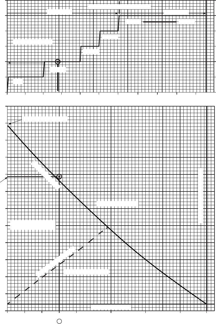
SA
AA1030A
SELF DEPLOYMENT MISSION PROFILE
ESSS/2−230 AND 2−450 GALLON TANK CONFIGURATION
STANDARD DAY 10 KT HEADWIND
HIRSS SUPPRESSED MODE
01 2 3 4 5 6 78 9 10
0
2
4
6
8
10
12
PRESSURE ALT ~ 1000 FT
15
11
7
3
−1
−5
−9
STANDARD TEMP ~ oC
ELAPSED FLIGHT TIME ~ HRS
(RECOMMENDED AIRSPEEDS)
(~ 72%) (~ 56%)
(~ 72%)
(~ 72%)
(−79)
APPROX TRQ (~%)
(~ 74%)
0 100 200 300 400 600 800 1000 1200
0
1000
2000
3000
4000
5000
6000
7000
8000
9000
10000
11000
12000
FUEL REM. ~ LBS
GROSS WEIGHT = 24,500 LB
BLEED AIR OFF FUEL LOAD = 11,000 LB (JP4)
60 LB WARM UP
(APPROX FULL FUEL)
ADEQUATE RANGE
INADEQUATE RANGE
LOW FUEL LIGHTS
INADEQUATE RANGE
ABORT MISSION
FUEL REMAINING
(7900 LBS)
MISSION MAX RADIUS
DISTANCE TRAVELED ~ NM
1
100 KIAS
105 KIAS
FLIGHT TEST
DATA BASIS:
DESIRED MISSION RANGE
Figure 7A-40. Self Deployment Mission Profile (Sheet 2 of 2)
TM 1-1520-237-10
7A-151
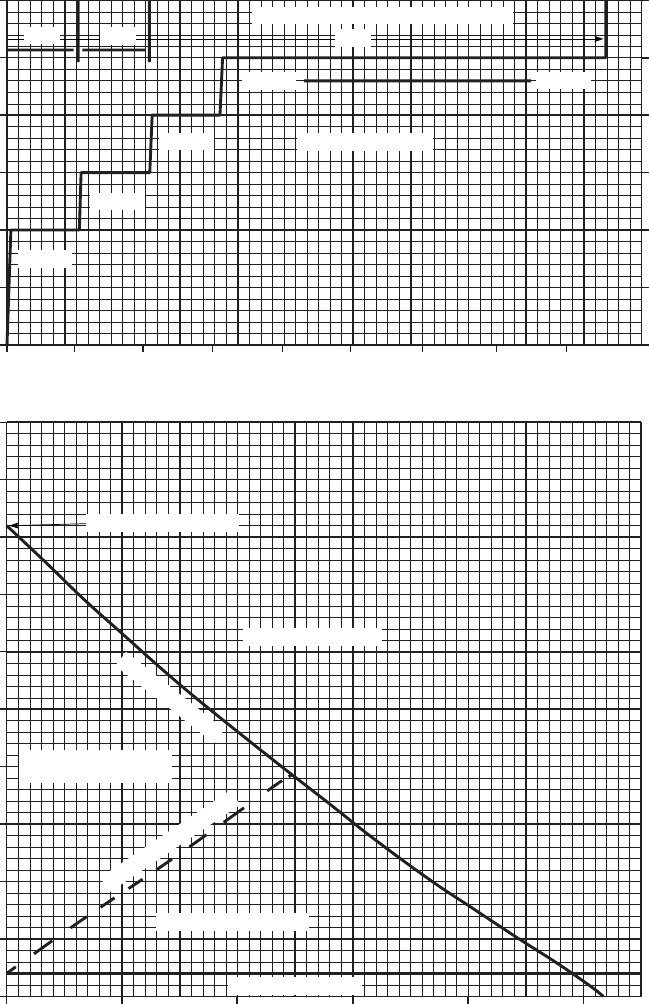
SA
AA1031A
ASSAULT MISSION PROFILE FOR MAX RANGE
ESSS/4−230 GALLON TANK CONFIGURATION
STANDARD DAY ZERO HEADWIND
HIRSS SUPPRESSED MODE
12
10
8
6
4
2
0
PRESSURE ALT ~ 1000 FT
10000
9000
8000
7000
6000
5000
4000
3000
2000
1000
0
FUEL REM. ~ LBS
−5
−1
3
7
15
−9
11
STANDARD TEMP ~ oC
0 1 2 3 4 5 6 7 8
ELAPSED FLIGHT TIME ~ HRS
0 200 400 600 800 1000
DISTANCE TRAVELED ~ NM
GROSS WEIGHT = 22000 LB
BLEED AIR OFF FUEL LOAD = 8280 LB (JP4)
80 LB WARM UP
(RECOMMENDED AIRSPEEDS ~ KIAS)
(~ 71%) (~ 56%)
(~ 70%)
(~ 74%)
(~ 79%)
APPROX TRQ (~ %)
(APPROX FULL FUEL)
ADEQUATE RANGE
INADEQUATE RANGE
LOW FUEL LIGHTS
INADEQUATE RANGE
ABORT MISSION
FUEL REMAINING
MISSION MAX RADIUS
108 104 100
DATA BASIS: FLIGHT TEST
Figure 7A-41. Assault Mission Profile (4 - 230 Gallon Tanks)
TM 1-1520-237-10
7A-152
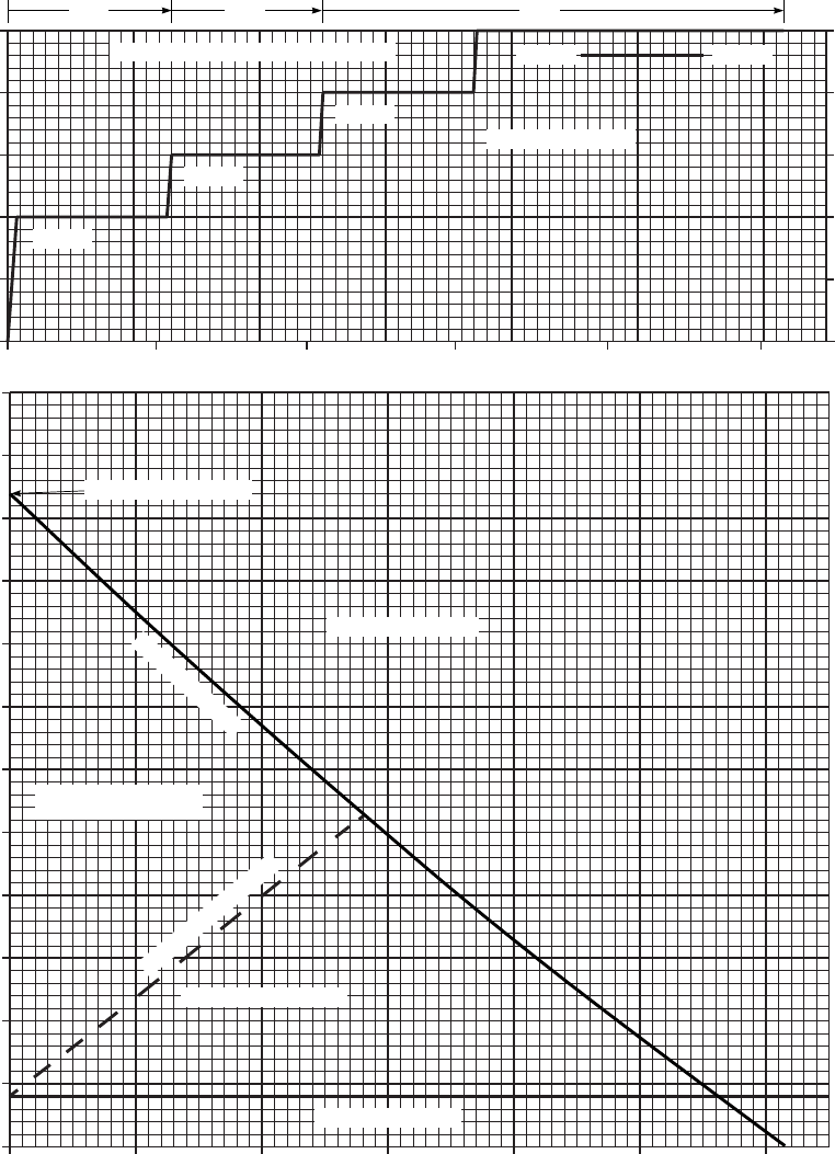
SA
AA1032A
ASSAULT MISSION PROFILE FOR MAX RANGE
ESSS/2−230 GALLON TANK CONFIGURATION
STANDARD DAY ZERO HEADWIND
HIRSS SUPPRESSED MODE
10
8
6
4
2
0
PRESS ALT
01 2 3 4 5
ELAPSED FLIGHT TIME ~ HRS
6000
5500
5000
4500
4000
3500
3000
2500
2000
1500
1000
500
0
FUEL REM. ~ LBS
−5
−1
3
7
11
15
STANDARD TEMP ~ oC
0100 200 300 400 500 600
DISTANCE ~ NM
LOW FUEL LIGHTS
INADEQUATE RANGE
INADEQUATE RANGE
ABORT MISSION
ADEQUATE RANGE
(APPROX FULL FUEL)
FUEL REMAINING
MISSION MAX RADIUS
GROSS WEIGHT = 22000 LB
BLEED AIR OFF FUEL LOAD = 5280 LB (JP4)
80 LB WARM UP
APPROX TRQ (~ %)
(~ 65%)(~ 70%)
(~ 69%)
(~ 73%)
(~ 77%)
(RECOMMENDED AIRSPEEDS ~ KIAS)
100
104108
FLIGHT TEST
DATA BASIS:
Figure 7A-42. Assault Mission Profile (2 - 230 Gallon Tanks)
TM 1-1520-237-10
7A-153/(7A-154 Blank)

CHAPTER 8
NORMAL PROCEDURES
Section I MISSION PLANNING
8.1 MISSION PLANNING.
Mission planning begins when the mission is assigned
and extends to the preflight check of the helicopter. It in-
cludes, but is not limited to checks of operating limits and
restrictions; weight, balance, and loading; performance;
publications; flight plan; and crew and passenger briefings.
The pilot in command shall ensure compliance with the
contents of this manual that are applicable to the mission
and all aviation support equipment required for the mission
(e.g., helmets, gloves, survival vests, survival kits, etc).
8.2 EH-60A DATA. EH
AN/ALQ-151(V)2; mission operator duties, equipment
checks, system initialization procedures, and self-test pro-
cedures are outlined in TM 32-5865-012-10.
8.3 AVIATION LIFE SUPPORT EQUIPMENT
(ALSE).
All aviation life support equipment required for mission;
e.g., helmets, gloves, survival vests, survival kits, etc., shall
be checked.
8.4 CREW DUTIES/RESPONSIBILITIES.
The minimum crew required to fly the helicopter is two
pilots. Additional crewmembers, as required, may be added
at the discretion of the commander. The manner in which
each crewmember performs his related duties is the respon-
sibility of the pilot in command.
a. The pilot in command is responsible for all aspects of
mission planning, preflight, and operation of the helicopter.
He will assign duties and functions to all other crewmem-
bers as required. Prior to or during preflight, the pilot will
brief the crew on items pertinent to the mission; e.g., per-
formance data, monitoring of instruments, communications,
emergency procedures, taxi, and load operations.
b. The pilot in command must be familiar with pilot
duties and the duties of the other crew positions.
c. The crew chief will perform all duties as assigned by
the pilot.
8.5 CREW BRIEFING.
A crew briefing shall be conducted to ensure a thorough
understanding of individual and team responsibilities. The
briefing should include, but not be limited to, pilots, crew
chief, mission equipment operator, ground crew responsi-
bilities, and the coordination necessary to complete the
mission in the most efficient manner. A review of visual
signals is desirable when ground guides do not have direct
voice communications link with the crew.
8.6 PASSENGER BRIEFING.
The following guide may be used in accomplishing re-
quired passenger briefings. Items that do not pertain to a
specific mission may be omitted.
a. Crew introduction.
b. Equipment.
(1) Personal, to include ID tags.
(2) Professional.
(3) Survival.
c. Flight data.
(1) Route.
(2) Altitude.
(3) Time en route.
(4) Weather.
d. Normal procedures.
(1) Entry and exit the helicopter.
TM 1-1520-237-10
8-1
(2) Seating.
(3) Seat belts.
(4) Movement in helicopter.
(5) Internal communications.
(6) Security of equipment.
(7) Smoking.
(8) Oxygen.
(9) Refueling.
(10) Weapons.
(11) Protective masks.
(12) Parachutes.
(13) Hearing protection.
(14) Aviation life support equipment (ALSE).
e. Emergency procedures.
(1) Emergency exits.
(2) Emergency equipment.
(3) Emergency landing/ditching procedures.
TM 1-1520-237-10
8-2

Section II OPERATING PROCEDURES AND MANEUVERS
8.7 OPERATING PROCEDURES AND MANEU-
VERS.
This section deals with normal procedures and includes
all steps necessary to ensure safe and efficient operation of
the helicopter from the time a preflight begins until the
flight is completed and the helicopter is parked and secured.
Unique feel, characteristics, and reaction of the helicopter
during various phases of operation and the techniques and
procedures used for taxiing, takeoff, climb, etc., are de-
scribed, including precautions to be observed. Your flying
experience is recognized; therefore, basic flight principles
are avoided. Only the duties of the minimum crew neces-
sary for the actual operation of the helicopter are included.
Additional crew duties are covered as necessary in Section
I Mission Planning. Mission equipment checks are con-
tained in Chapter 4 Mission Equipment. Procedures specifi-
cally related to instrument flight that are different from nor-
mal procedures are covered in this section, following
normal procedures. Descriptions of functions, operations,
and effects of controls are covered in Section IV Flight
Characteristics, and are repeated in this section only when
required for emphasis. Checks that must be performed un-
der adverse environmental conditions, such as desert and
cold-weather operations, supplement normal procedures
checks in this section and are covered in Section V Adverse
Environmental Conditions.
8.8 SYMBOLS DEFINITION.
Items which apply only to night or only to instrument
flying shall have an N or an I, respectively, immediately
preceding the check to which it is pertinent. The symbol O
shall be used to indicate 9if installed9. Those duties which
are the responsibility of the pilot not on the controls, will be
indicated by a circle around the step number; i.e., ④. The
symbol star.indicates an operational check is required.
Operational checks are contained in the performance sec-
tion of the condensed checklist. The asterisk symbol * in-
dicates that performance of step is mandatory for all thru-
flights. The asterisk applies only to checks performed prior
to takeoff. Placarded items such as switch and control la-
bels appear in uppercase type.
8.9 CHECKLIST.
Normal procedures are given primarily in checklist form,
and amplified as necessary in accompanying paragraph
form, when a detailed description of a procedure or maneu-
ver is required. A condensed version of the amplified
checklist, omitting all explanatory text, is contained in the
operator’s checklist. To provide for easier cross-
referencing, the procedural steps in the checklist are num-
bered to coincide with the corresponding numbered steps in
this manual.
8.10 PREFLIGHT CHECK.
The pilot’s walkaround and interior checks are outlined
in the following procedures. The preflight check is not in-
tended to be a detailed mechanical inspection. The preflight
order is a recommended sequence only. The expanded sub-
steps do not need to be memorized or accomplished in or-
der. The steps that are essential for safe helicopter opera-
tion are included. The preflight may be made as
comprehensive as conditions warrant at the discretion of
the pilot.
8.11 BEFORE EXTERIOR CHECK (FIGURE 8-1).
WARNING
Do not preflight until armament systems
are safe, switches off, safety pins installed
and locking levers in locked position.
1. Publications - Check; required forms and pub-
lications, and availability of operator’s manu-
al(s) (-10) and checklist (-CL).
*2. Helicopter covers, locking devices, tiedowns,
and grounding cables - Removed and secured.
*3. Fuel - Check quantity as required.
4. Fuel sample - As required. Check for contami-
nation before first flight of the day and after
adequate settling time after cold refueling, or if
fuel source is suspected contaminated.
8.12 EXTERIOR CHECK.
Exterior walkaround diagram is shown in Figure 8-1.
TM 1-1520-237-10
8-3

8.13 NOSE SECTION (AREA 1).
CAUTION
Do not deflect main rotor blade tips more
than 6 inches below normal droop posi-
tion when attaching tiedowns. Do not tie
down below normal droop position.
*1. Main rotor blades - Check.
2. Fuselage - Nose area, check as follows:
a. Windshield and wipers - Check.
O b. Blade deice OAT sensor, FAT indicator
probe(s) - Check.
c. Avionics compartment - Check equipment
as required; secure door.
d. Antennas - Check.
e. Landing and searchlights - Check.
8.14 COCKPIT - LEFT SIDE (AREA 2).
1. Cockpit area - Check as follows:
a. Cockpit door - Check.
b. Copilot seat, belts, and harness - Check.
c. FM and EH antennas - Check.
d. Landing gear support fairing and step -
Check.
e. Position light - Check.
f. Main landing gear - Check.
Og.ES HSS, VSP, ejector rack locking levers
locked, fairings, and external tanks -
Check; refueling caps secure.
h. Gunner’s window - Check.
i. Ambient sense port - Check.
*2. Left engine oil level - Check.
*3. Check main landing gear drag beam for cracks.
8.15 CABIN TOP (AREA 3).
1. Cabin top - Check as follows:
a. Left engine - Check inlet.
b. Left pitot tube - Check.
c. Control access - Check flight controls, hy-
draulic reservoir, and filter indicators.
Check tempilabels for safe indication and
security. Check area.
d. Control access cover - Close and check se-
cured.
e. Right pitot tube - Check.
f. Right engine - Check inlet.
O g. IRCM - Check.
2. APU - Check; oil level, use dipstick.
O 3. APU IPS - Check.
4. Gust lock - Check.
5. Main transmission - Check; oil level.
*6. Main rotor system - Check controls, dampers,
head, and blades. BIMtindicators - Check for
safe indication (yellow color).
8.16 INTERIOR CABIN (AREA 4).
1. Cabin - Check as follows:
a. Fire extinguishers - Check.
b. First aid kits - Check.
c. Pilot’s and copilot’s tilt-back release levers
- Lock position.
d. Cabin interior - Check security of stowed
equipment.
e. Cabin seats and belts - Check.
2. APU accumulator pressure gage - Check mini-
mum 2,800 psi.
TM 1-1520-237-10
8-4 Change 10
3. Transmission oil filter impending bypass indi-
cator - Check.
4. Cargo hook:
a. General condition and security.
b. Electrical connections condition and secu-
rity.
5. Survival gear and mission equipment - Check
as required.
TM 1-1520-237-10
Change 8 8-4.1/(8-4.2 Blank)
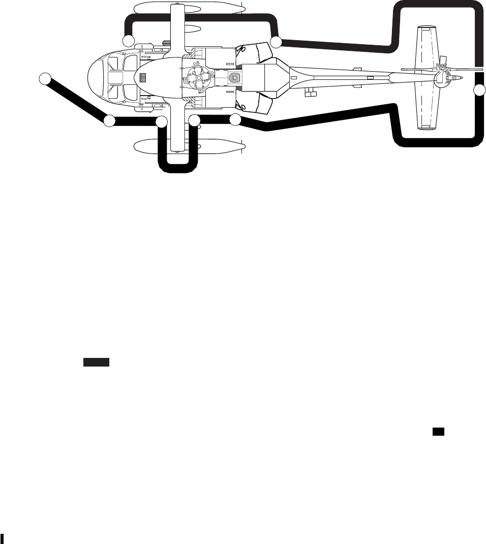
8.17 FUSELAGE - LEFT SIDE (AREA 5).
1. Fuselage - Check as follows:
a. Cabin door - Check.
O*b. VOL Armament system - Check.
c. Fuel tank filler ports - Check; caps secure,
doors secured.
d. External pneumatic inlet port - Door se-
cured.
e. Engine exhaust - Check.
O f. APU IPS exhaust - Check.
g. APU exhaust - Check.
O h. Chaff, flare dispensers - Check; number
and programmer settings.
i. Lower anticollision light - Check.
j. Antennas - Check.
k. Tail landing gear - Check.
*2. Intermediate gear box - Check; oil level.
8.18 TAIL PYLON (AREA 6).
1. Tail pylon - Check as follows:
a. Tail pylon - Check.
b. Stabilator - Check.
O c. Radar detector and EH antennas - Check.
d. Position light - Check.
e. Upper anticollision light - Check.
*2. Tail rotor - Check.
*3. Tail rotor gear box - Check; oil level.
8.19 FUSELAGE - RIGHT SIDE (AREA 7).
1. Fuselage - Check as follows:
a. Antennas - Check.
AREA 1
AREA 2
AREA 3
AREA 4
NOSE SECTION
COCKPIT − LEFT SIDE
CABIN TOP
INTERIOR CABIN
AREA 5
AREA 6
AREA 7
AREA 8
FUSELAGE − LEFT SIDE
TAIL PYLON
FUSELAGE − RIGHT SIDE
COCKPIT − RIGHT SIDE
7
8
1
2345
6
SA
AA0672A
Figure 8-1. Exterior Check Diagram
TM 1-1520-237-10
Change 10 8-5

b. EH Aft avionics compartment circuit
breakers and ECS fluid level - Check.
c. Fire bottles thermal plug - Check.
d. Engine exhaust - Check.
e. Fuel tank gravity filler port - Check cap
secure; door secured.
O*f. VOL Armament system - Check.
g. Cabin door - Check.
8.20 COCKPIT - RIGHT SIDE (AREA 8).
*1. Right engine oil level - Check.
2. Cockpit area - Check as follows:
O a. Ice detector - Check.
b. Ambient sense port - Check.
Oc.ES HSS, VSP, ejector rack locking levers
locked, fairings, and external tanks -
Check; refueling caps secure.
d. Gunner’s window - Check.
e. External electrical power receptacle - Door
secured.
f. Main landing gear - Check.
g. Position light - Check.
h. Landing gear support fairing and step -
Check.
i. FM and EH antennas - Check.
j. Cockpit door - Check.
k. Pilot seat, belt, and harness - Check.
l. Set switch on dimmer control box as de-
sired. NORM for IR dimming.
*3. Check main landing gear drag beam for cracks.
.*4. Crew and passenger briefing - Complete as re-
quired.
8.21 BEFORE STARTING ENGINES.
NOTE
Before engine operation can be performed
with the gust lock engaged, all main rotor tie
downs shall be removed.
*1. Copilot’s collective - Extended and locked.
2. Shoulder harness locks - Check.
3. PARKING BRAKE - Release, then set.
.4. Circuit breakers and switches - Set as follows:
a. Circuit breakers - In.
b. Avionics - Off, frequencies set.
c. BLADE DEICE POWER switch - OFF.
*d. Radar altimeter - Set. EH Left LO bug 200
feet.
e. Clocks - Set and running.
f. BACKUP HYD PUMP -AUTO.
*g. ANTICOLLISION/POSITION LIGHTS
- As required.
*h. EH Q/F PWR switch - OFF.
O*i. EH ECS panel switches - OFF.
j. CARGO HOOK EMERG REL switch -
OPEN,ARMING switch - SAFE.
k. APU CONTR switch - OFF;APU
T-handle - In.
l. GENERATORS NO. 1 and NO. 2
switches - Check ON.
m. Ground power unit - Connected if required.
*n. AIR SOURCE HEAT/START switch -
APU (OFF for external air source).
o. EMER OFF T-handles - Full forward.
*p. BATT switch - ON.
TM 1-1520-237-10
8-6 Change 10
8.22 COCKPIT EQUIPMENT CHECKS.
*1. FUEL PUMP switch - APU BOOST.
*2. APU CONTR switch - ON.
NOTE
If the APU does not start and the APU AC-
CUM LOW advisory light is not on with
the APU CONTR switch ON, the manual
override lever on the accumulator manifold
should be pulled to attempt another start, and
held until the APU has reached self-
sustaining speed.
If APU fails, note and analyze BITE indica-
tions before cycling BATT switch or before
attempting another APU start.
WARNING
Stabilator will move to full trailing edge
down position upon application of AC
power. Assure stabilator area is clear
prior to energizing stabilator system.
*3. APU generator switch - ON.
*4. EXT PWR switch - OFF and cable discon-
nected.
O.5. ERFS AUXILIARY FUEL MANAGE-
MENT control panel - TEST.
O*6. ERFS AUXILIARY FUEL MANAGE-
MENT control panel - Set fuel as required.
*7. EH IINS SYSTEMS SELECT switches - DG
and VG.
.*8. EH IINS - Align.
9. Caution/advisory/warning panels - Check as re-
quired.
NOTE
Pulsating of any caution/advisory lights in
unison with the LOW ROTOR RPM warn-
ing lights may occur in the DIM mode.
The switch legend on the VSI/HSI and CIS
mode select panels may change when the
caution/advisory panel BRT/DIM-TEST
switch is set to TEST. (This can also occur
in flight). The original indications may be
restored by pressing the applicable switches.
a. Caution/advisory panel BRT/DIM-TEST
switch - TEST. Caution/advisory/warning,
CIS/MODE SEL, and VSI advisory lights
on. #1 and #2 FUEL LOW caution lights
flashing. AFCS FAILURE ADVISORY
lights will illuminate. EH SYSTEMS SE-
LECT switches will illuminate. EH ASE
advisory light - Press to test.
Nb.INSTR LT PILOT FLT control - ON.
N c. Caution/advisory BRT/DIM-TEST switch
-BRT/DIM momentarily and then to
TEST.
N d. All caution/advisory/warning panels CIS/
MODE SEL and VSI advisory lights on at
decreased intensity. AFCS FAILURE
ADVISORY lights will not dim.
CAUTION
If DEC signal validation codes are dis-
played on the % TRQ indicator, do not
fly the helicopter.
10. 701C DEC engine fault indicator codes - Check
for signal validation as required.
N 11. Interior/exterior lighting - Set.
O.12. Mission equipment - Check.
.*13. Cold weather control exercise - Check if tem-
perature is below -17°C (1°F).
*14. AFCS FAILURE ADVISORY lights - If on,
POWER ON RESET.
*15. SAS1 off, SAS2,TRIM,FPS, and BOOST
switches - Push ON.
.16. Flight controls - Check first aircraft flight of
day as follows:
a. Collective - Midposition, pedals centered,
friction off.
TM 1-1520-237-10
Change 8 8-7

b. BOOST switch - Press off. There will be a
slight increase in collective and pedal
forces. BOOST SERVO OFF caution and
MASTER CAUTION lights should be on.
c. Right SVO OFF switch - 1ST STG.No
allowable cyclic stick jump. #1 PRI
SERVO PRESS caution and MASTER
CAUTION lights should be on.
d. Move cyclic and pedals slowly through full
range. There should be no binds or restric-
tions. Move collective full up to full down
in about 1 to 2 seconds. Check #2 PRI
SERVO PRESS caution light does not il-
luminate during movement of collective.
e. Right SVO OFF switch - 2ND STG.No
allowable cyclic stick jump. #2 PRI
SERVO PRESS caution and MASTER
CAUTION lights should be on.
f. Repeat step d. above. Check #1 PRI
SERVO PRESS caution light does not il-
luminate during movement of collective.
WARNING
If #1 PRI SERVO PRESS or #2 PRI
SERVO PRESS caution light illuminates
during collective movement, a servo by-
pass valve may be jammed. If this situa-
tion occurs, do not fly the helicopter.
g. SVO OFF switch - Center.
NOTE
During steps h. and i., check for not more
than 1.5 inches of freeplay in control.
h. Collective - Move through full range in no
less than 5 seconds. There should be no
binding.
i. Pedals - Move both pedals through the full
range in no less than 5 seconds. There
should be no binding.
j. TAIL SERVO switch - BACKUP.#1
TAIL RTR SERVO caution light, both
MASTER CAUTION lights, and #2
TAIL RTR SERVO ON advisory light il-
luminate. Move pedals through full range
in no less than 5 seconds. There should be
no binding.
k. TAIL SERVO switch - NORMAL. Cau-
tion and advisory lights out.
l. BOOST switch - ON.BOOST SERVO
OFF caution light should be off.
.17. Stabilator - Check.
WARNING
If any part of stabilator check fails, do not
fly helicopter.
NOTE
For the purpose of this check, the right
STAB POS indicator shall be used. The left
STAB POS indicator may vary from right
indicator as much as 62° throughout the
check.
a. STAB POS indicator should be between
34° and 42° DN.
b. TEST button - Press and hold. Check
STAB POS indicator moves up 5° to 12°.
MASTER CAUTION and STABILA-
TOR caution lights on; stabilator audio
heard.
c. AUTO CONTROL RESET switch -
Press ON. Note that the STABILATOR
caution light and audio are off, and STAB
POS indicator moves to 34° to 42° down.
d. Either cyclic mounted stabilator slew-up
switch - Press and hold until STAB POS
indicator moves approximately 15° trailing
edge up, release, stabilator should stop.
STABILATOR caution and MASTER
CAUTION lights on and beeping audible
warning in pilot’s and copilot’s headsets.
MASTER CAUTION - Press to reset au-
dio tone.
e. Other cyclic mounted stabilator slew-up
switch - Press and hold until STAB POS
TM 1-1520-237-10
8-8 Change 8
indicator moves approximately 15° trailing
edge up, release, stabilator should stop.
f. MAN SLEW switch - UP and hold until
stabilator stops. STAB POS indicator
should be 6° to 10° up.
g. MAN SLEW switch - DN and hold until
STAB POS indicator reads 0°.
TM 1-1520-237-10
Change 8 8-8.1/(8-8.2 Blank)
h. AUTO CONTROL RESET switch -
Press ON.STAB POS indicator should
move 34° to 42° DN.STABILATOR cau-
tion light off.
*18. Avionics - On.
NOTE
Only use map datums WGS-84 and NAD-
27. Other map datums were not verified us-
ing the Aviation Mission Planning System
(AMPS), and should not be used.
*18.1. Doppler/GPS - Program.
*18.2. Doppler/GPS mode select switch - OFF.
*19. COMPASS switch - SLAVED. Set as re-
quired.
20. Barometric altimeters - Set.
*21. Cyclic and pedals centered. Collective raise no
more than 1 inch (to prevent droop stop pound-
ing) and friction.
22. BACKUP HYD PUMP switch - OFF.
O.23. Blade deice system - Test as required.
CAUTION
Do not perform blade deice test when
blade erosion kit is installed.
To prevent overheating of droop stops,
blade deice test shall not be done more
than one time within a 30-minute period
when rotor head is not turning.
a. Ice rate meter PRESS TO TEST button -
Press and release.
b. Ice rate meter indicator - Moves to half
scale (1.0) holds about 50 seconds; then
falls to 0 or below. ICE DETECTED cau-
tion and MASTER CAUTION lights on
after 15 to 20 seconds into the test, and
FAIL flag should not be visible in flag win-
dow. Ice rate meter should move to zero
within 75 seconds after pressing PRESS
TO TEST button.
NOTE
PWR MAIN RTR and PWR TAIL RTR
monitor lights may flicker during tests in
steps e. through q.
c. BLADE DE-ICE TEST panel select
switch - NORM.
c.1. PWR MAIN RTR and TAIL RTR moni-
tor lights - Press to test.
d. BLADE DEICE POWER switch - TEST.
e. PWR MAIN RTR and TAIL RTR moni-
tor lights - Check. MAIN RTR monitor
light may go on for 2 to 4 seconds. If either
light remains on for 10 seconds or more:
(1) BLADE DEICE POWER switch -
OFF. If either light is still on:
(2) APU generator switch and/or EXT
PWR switch - OFF.
f. TEST IN PROGRESS light - Check. The
light should be on for 105 to 135 seconds.
No other blade deice system lights should
be on. PWR MAIN RTR and TAIL RTR
monitor lights may go on momentarily near
end of test. The TEST IN PROGRESS
light should then go off.
WARNING
Droop stop hinge pins and cams may be-
come very hot during test. Use care when
touching those components.
g. Crewman touch each droop stop cam -
Cams should be warm to touch.
h. BLADE DEICE POWER switch - OFF.
i. BLADE DE-ICE TEST panel select
switch - SYNC 1.
j. BLADE DEICE POWER switch - TEST.
MR DE-ICE FAIL caution and MASTER
CAUTION lights on.
k. BLADE DEICE POWER switch - OFF.
MR DE-ICE FAIL caution and MASTER
CAUTION lights off.
TM 1-1520-237-10
Change 10 8-9

l. BLADE DE-ICE TEST panel select
switch - SYNC 2.
m. BLADE DEICE POWER switch - TEST.
MR DE-ICE FAIL caution and MASTER
CAUTION lights on.
n. BLADE DEICE POWER switch - OFF.
MR DE-ICE FAIL caution and MASTER
CAUTION lights off.
o. BLADE DE-ICE TEST panel select
switch - OAT.
p. BLADE DEICE POWER switch - TEST.
MR DE-ICE FAIL caution, TR DE-ICE
FAIL caution, and MASTER CAUTION
lights on.
q. BLADE DEICE POWER switch - OFF.
MR DE-ICE FAIL caution, TR DE-ICE
FAIL caution, and MASTER CAUTION
lights off.
r. BLADE DE-ICE TEST panel select
switch - NORM.
24. Avionics - Check as required.
O.*25. AFMS Auxiliary Fuel Management Panel -
TEST, set as required.
8.23 STARTING ENGINES.
*1. ENG FUEL SYS selector(s) - As required.
XFD for first start of day.
*2. Deleted.
*3. ENGINE IGNITION switch - ON.
*4. GUST LOCK caution light - Off.
*5. Fire guard - Posted if available.
*6. Rotor blades - Check clear.
.*7. Engine(s) - Start as follows:
CAUTION
If start is attempted with ENGINE IGNI-
TION switch OFF, do not place switch
ON. Complete EMER ENG SHUTDOWN
procedure.
a. If any of these indications occur, perform
EMER ENG SHUTDOWN as required.
(1) No TGT TEMP increase (light off)
within 45 seconds.
(2) No ENG OIL PRESS within 45 sec-
onds.
(3) No % RPM 1 or 2within 45 seconds.
(4) ENGINE STARTER caution light
goes off before reaching 52% Ng
SPEED.
(5) TGT TEMP reaches 700 850°C or
701C 851°C before idle is attained
(Ng 63%).
CAUTION
To avoid damage to the engine start
switch actuators, do not move the ENG
POWER CONT lever from IDLE to OFF
while pressing the starter button.
During engine start and runup ensure
that cyclic is kept in neutral, collective no
more than one inch above full down, and
pedals centered until % RPM R reaches
50% minimum to prevent damage to anti-
flap bracket bushings.
b. Starter button(s) - Press until Ng SPEED
increases; release.
NOTE
If an ENGINE STARTER caution light
goes off when the starter button is released,
and the ENG POWER CONT lever is
OFF, the start attempt may be continued by
pressing and holding the starter button until
52% to 65% Ng SPEED is reached; then
release button.
c. TGT TEMP - Check below 700 150°C or
701C 80°C before advancing ENG
POWER CONT levers.
TM 1-1520-237-10
8-10 Change 10

If caution light remains on:
(2) APU -OFF or engine air source re-
move as required.
*8. If single-engine start was made, repeat step 7
for other engine.
*9. Systems - Check.
a. Ng SPEED - 63% or greater and within
3% of each other.
b. % RPM - Check that % RPM 1 or 2is
not in the range of 20% to 40% and 60% to
90%. Advance ENG POWER CONT le-
ver(s) as required.
c. XMSN PRESS - Check.
d. ENG OIL PRESS - Check.
e. #1 and #2 HYD PUMP caution lights -
Check off.
*10.BACKUP HYD PUMP switch - AUTO.
.11.Hydraulic leak test system - Check as follows:
NOTE
EH It is normal for the IINS CDU screen to
blank momentarily during the hydraulic leak
test system check.
When performing the HYD LEAK TEST,
all leak detection/isolation system compo-
nents are checked electrically. Manually
holding the HYD LEAK TEST switch in
the test position does not allow the leak
detection/isolation system to be checked au-
tomatically. It manually holds the circuits
open. The switch must be placed in the
TEST position and released.
a. HYD LEAK TEST switch - TEST.#1
TAIL RTR SERVO,BOOST SERVO
OFF,SAS OFF,#1 and #2 RSVR LOW,
BACK-UP RSVR LOW, and MASTER
CAUTION lights and #2 TAIL RTR
SERVO ON and BACK-UP PUMP ON
advisory lights on. During this check, it is
normal for the collective and pedals to
move slightly.
b. HYD LEAK TEST switch - RESET. The
lights in a. should go off.
NOTE
If the backup pump is still running following
the hydraulic leak test, cycle the BACKUP
HYD PUMP switch to OFF then back to
AUTO.
.12.Tail rotor servo transfer - Check.
a. BACKUP HYD PUMP switch - AUTO
with backup pump not running.
NOTE
Failure of the BACK-UP PUMP ON advi-
sory light or the #2 TAIL RTR SERVO
ON advisory light indicates a failure in the
leak detection/isolation system.
b. TAIL SERVO switch - BACKUP.#1
TAIL RTR SERVO caution light on and
#2 TAIL RTR SERVO ON and
BACK-UP PUMP ON advisory lights on
within 3 to 5 seconds.
c. TAIL SERVO switch - NORMAL.#1
TAIL RTR SERVO caution light and #2
TAIL RTR SERVO ON advisory light
off. BACK-UP PUMP ON advisory light
remains on for approximately 90 seconds.
O13.Deleted.
*14. Deleted.
8.24 ENGINE RUNUP.
*1. Flight controls - Hold.
WARNING
Restrict the rate of ENG POWER CONT
lever’s movement, when the tailwheel
lockpin is not engaged. Rapid application
of ENG POWER CONT levers can result
in turning the helicopter, causing person-
nel injury or loss of life.
*2. ENG POWER CONT lever(s) - FLY.
TM 1-1520-237-10
Change 10 8-11
*3. Droop stops - Check out 70% to 75% RPM R.
*4. #1 and #2 GEN caution lights - Off.
CAUTION
EH During operation of the air condi-
tioner system, the right cabin door should
remain closed. If opening is required, the
right cabin door should not remain open
for more than 1 minute.
*5. EH ECS panel switches - As desired.
O5.1 AUX CABIN HEATER switch - As desired.
NOTE
Cabin temperature must be below 29°C
(84°F) for heat to go on, and above 10°C
(50°F) for the heater to shut off.
The auxiliary cabin heater circuit is reset
when bleed air transitions to and from the
APU. Crew reset of the auxiliary cabin
heater switch may be required after switch-
ing to or from the APU.
*5.2. Engine warmup - Check if temperature is be-
low -17°C (1°F).
a. At temperatures between -17°C (1°F)
and -43°C (-45°F), warm engines at
IDLE for 3 minutes.
b. At temperatures between -43°C (-45°F)
and -54°C (-65°F), warm engines at
IDLE for 5 minutes.
NOTE
ECS heater will operate with either backup
pump or windshield anti-ice operating, but
not with both at the same time.
O.6. DEICE EOT - Check as required.
CAUTION
In ambient temperatures above 21°C
(70°F), operate rotor at 100% RPM R for
5 minutes before doing the deice EOT
check, to prevent blade overheating. Do
not do the deice EOT check if OAT is
above 38°C (100°F).
a. BLADE DE-ICE TEST select switch -
EOT.
b. BLADE DEICE MODE select switch -
MANUAL M.
c. BLADE DEICE POWER switch - ON.
d. TR DE-ICE FAIL caution and MASTER
CAUTION lights on after 15 to 30 sec-
onds, and MR DE-ICE FAIL caution light
on after 50 to 70 seconds.
e. BLADE DEICE POWER switch - OFF.
TR DE-ICE FAIL caution, MR DE-ICE
FAIL caution, and MASTER CAUTION
lights off.
f. BLADE DE-ICE TEST select switch -
NORM.
NOTE
If helicopter engine was started using exter-
nal air source and/or external ac power, the
APU must be started to do APU generator
backup check.
g. GENERATORS NO. 1 or NO. 2 switch -
OFF. Applicable GEN and MASTER
CAUTION lights on.
h. BLADE DEICE POWER switch - ON.
Wait 30 seconds, no deice lights on.
i. GENERATORS switch(es) - ON. Appli-
cable GEN caution light(s) off.
j. BLADE DEICE POWER switch - OFF.
k. BLADE DEICE MODE select switch -
AUTO.
*7. % TRQ 1 and 2- Matched within 5%.
*8. EH Q/F PWR switch - As desired.
*9. FUEL PUMP switch - OFF.
TM 1-1520-237-10
8-12 Change 10

*10.APU CONTR switch - OFF.
*11.AIR SOURCE HEAT/START switch - As re-
quired.
*12.ENG FUEL SYS selectors - As required.
*13.SAS 1 -ON.
NOTE
If a consecutive or random route was pro-
grammed, do not cycle through the test po-
sition. Cycling through test will delete any
preprogrammed routes.
*13.1. Doppler/GPS mode select switch - As desired.
*14. Collective friction - As required.
NOTE
A slight amount of collective friction (ap-
proximately 3 pounds) should be used to
prevent pilot induced collective oscillations.
N O*15. HUD - Adjust brightness, mode, barometric al-
titude, pitch, and roll as necessary.
O* 16. EH IINS NAVRDY light flashing - CDU mode
select switch to NAV.
O* 17. EH IINS SYSTEMS SELECT switches -
IINS.
WARNING
Engine anti-ice bleed and start valve mal-
function can cause engine flameout.
18.Engine Health Indicator Test (HIT)/Anti-Icing
Check - Accomplish. Refer to ENGINE
HEALTH INDICATOR TEST/ANTI-ICE
CHECK IN HELICOPTER LOG BOOK. HIT/
ANTI-ICE checks while operating in adverse
conditions (e.g., dust, desert, coastal beach area,
dry river beds) may be deferred (maximum of 5
flight hours) until a suitable location is reached.
*19. FUEL BOOST PUMP CONTROL switches -
ON (for all fuel types). Indicator lights check -
On.
O.20. ERFS AFMS External extended range fuel
transfer - Check.
8.25 BEFORE TAXI.
WARNING
ES When on the ground, the ejector rack
lock lever should be turned inward to al-
low the pilot visual confirmation from the
cockpit. Prior to flight, the ejector rack
lock lever must be in the unlock (vertical)
position to allow emergency jettisoning of
the tanks in flight.
O*1. ES Ejector rack lock levers unlocked.
O*2. VOL Volcano jettison safety pins - Remove
and red arming levers to arm.
WARNING
Ensure the chaff arm switch is in the
SAFE position before the chaff pin is re-
moved.
O*3. Chaff, flare electronic module(s) safety pin(s) -
Remove.
*4. Chocks - Removed.
*5. Doors - Secure.
*6. PARKING BRAKE - Release.
*7. TAIL WHEEL switch - As required.
TM 1-1520-237-10
Change 10 8-13
8. Wheel brakes - Check as required.
8.26 GROUND TAXI.
CAUTION
When performing these maneuvers, cyclic
inputs should be minimized to prevent
droop-stop pounding.
Landing and searchlight have less than
one foot ground clearance when extended.
Use caution when taxiing over rough ter-
rain when landing light and/or searchlight
are extended.
Increase collective and place cyclic forward of neutral to
start forward movement. Minimize forward cyclic move-
ment to prevent droop stop pounding. Reduce collective to
minimum required to maintain forward movement. Soft or
rough terrain may require additional collective pitch. The
use of excessive collective pitch during taxi, especially at
light gross weights, can cause the tailwheel to bounce.
Regulate taxi speed with cyclic and collective and control
heading with pedals. Use brakes as required.
8.27 HOVER CHECK.
1. Systems - Check caution/advisory panel, CDU
and PDU(s) for normal indication.
2. Flight instruments - Check as required.
3. Power - Check. The power check is done by
comparing the indicated torque required to
hover with the predicted values from perfor-
mance charts.
8.28 BEFORE TAKEOFF.
WARNING
Pitot heat and anti-ice shall be on during
operations in visible moisture with ambi-
ent temperature of 4°C (39°F) and below.
Failure to turn on pitot heat in icing con-
ditions can cause the stabilator to pro-
gram trailing edge down during flight. If
this occurs, manually slew the stabilator
to zero degrees.
*1. ENG POWER CONT levers - FLY.
*2. Systems - Check.
*3. Avionics - As required.
*4. Crew, passengers, and mission equipment -
Check.
8.29 TAKEOFF.
WARNING
If the stabilator has not begun trailing
edge up movement by 30 to 50 KIAS,
abort the takeoff.
Refer to the height-velocity diagram, Figures 9-2 and
9-3, for avoid areas. Since suitable landing areas are often
not available, operating outside avoid areas during takeoff
and climb will provide the highest margin of safety.
8.30 AFTER TAKEOFF.
WARNING
ERFS
AFMS Fuel transfer sequence
must be carefully planned and executed in
order to maintain CG within limits.
O.1.
ERFS
AFMS Extended range fuel system
transfer - As required.
2. EH ASE - As required.
O.3.
VOL
Mine launch, post mine launch - As re-
quired.
8.31 BEFORE LANDING.
1. TAIL WHEEL switch - As required.
2. PARKING BRAKE - As required.
3. Crew, passengers, and mission equipment -
Check.
a. EH ASE check - As required.
TM 1-1520-237-10
8-14 Change 10

Ob.EH ECM ANTENNA switch - RE-
TRACT. Check ANTENNA RE-
TRACTED advisory light - On. ECM op-
erator report antenna deployed light - Off.
Oc.EH IINS TACAN -OFF.
8.32 LANDING.
CAUTION
During roll-on landing aerodynamic
braking with aft cyclic is permitted with
the tail wheel contacting the ground. Once
the main wheels touchdown, the cyclic
must be centered prior to reducing collec-
tive. Excessive aft cyclic may cause droop
stop pounding and contact between main
rotor blades and other portions of the air-
craft. Aerodynamic braking is prohibited
once the main landing gear touches down.
Use brakes to stop the aircraft.
NOTE
Because of the flat profile of the main trans-
mission, pitching the helicopter nose up as
in hover, may cause a transient drop in indi-
cated main transmission oil pressure, de-
pending on degree of nose-up attitude.
a. Roll-on landing. A roll-on landing may be used
when the helicopter will not sustain a hover, to
avoid hovering in snow or dust, if tail rotor
control is lost, or when operating with one
heavy external tank.
CAUTION
EH When landing the EH-60A in a nose
downslope configuration, exercise extreme
caution to prevent the main rotor blades
from contacting the aft DF antennas.
When the main wheels contact the
ground, center the cyclic prior to reduc-
ing collective. The cyclic should be cen-
tered before the collective is placed in full
down to prevent possible rotor/airframe
contact. If droop stop contact is felt prior
to the main wheels touching the ground,
abort landing attempt.
b. Slope landing. The tailwheel should be locked
and the parking brake should be set. For slope
landings and all ground operations, avoid using
combinations of excessive cyclic and low col-
lective settings. Where minimum collective is
used, maintain cyclic near neutral position and
avoid abrupt cyclic inputs. During nose-down
slope landings, low-frequency oscillations may
be eliminated by moving cyclic toward neutral
and lowering collective.
8.33 AFTER LANDING CHECK.
1. TAIL WHEEL switch - As required.
2. Exterior lights - As required.
3. Avionics/mission equipment - As required.
8.34 PARKING AND SHUTDOWN.
1. TAIL WHEEL switch - As required.
2. PARKING BRAKE - Set.
2.1. FUEL BOOST PUMP CONTROL switches -
OFF.
3. Landing gear - Chocked.
O4. AUXILIARY FUEL MANAGEMENT con-
trol panel ERFS FUEL XFR MODE
switch - OFF.AFMS XFER MODE switch
-OFF.
O5. ERFS AFMS AUXILIARY FUEL
MANAGEMENT panel PRESS switch(es) -
Off.
O6. VOL Volcano red arming levers - SAFE and
jettison safety pins install.
O7. ES Ejector rack locking levers - Locked.
WARNING
Ensure the chaff arm switch is in the
SAFE position before the chaff pin is re-
moved.
O 8. Chaff, flare electronic module(s) safety pin(s) -
Install.
TM 1-1520-237-10
Change 10 8-15

9. EH IINS SYSTEMS SELECT switches - DG/
VG.
O10. EH IINS - OFF.
O11. EH ECS panel switches - OFF.
O11.1AUX CABIN HEATER switch - OFF.
12.SAS 1 -Off.
12.1DPLR GPS MODE SEL switch - Off.
13.DEICE,PITOT,ANTI-ICE,HEATER and
EH Q/F PWR switches - OFF.
14.AIR SOURCE HEAT/START switch - APU.
15.FUEL PUMP switch - APU BOOST.
16.APU CONTR switch - ON. The APU ON,
BACK-UP PUMP ON, and APU ACCUM
LOW advisory lights - On.
NOTE
If external electrical power is required for
shutdown, it shall be connected and EXT
PWR switch placed to RESET; then ON.If
external ac power is not available, complete
normal shutdown on right engine before
continuing.
17. Collective raise no more than 1 inch.
18. Flight controls - Hold.
CAUTION
During shutdown ensure that cyclic is
kept in neutral or displaced slightly into
prevailing wind, collective no more than
one inch above full down and pedals cen-
tered.
Restrict the rate of ENG POWER CONT
lever movement, when the tailwheel lock-
pin is not engaged. Abrupt application of
ENG POWER CONT lever can result in
turning the helicopter.
19.ENG POWER CONT levers - IDLE.
20.ENGINE IGNITION switch - OFF.
21. Cyclic - As required to prevent anti-flap pound-
ing.
22. Droop stops - Verify in, about 50% RPM R.If
one or more droop stops do not go in during
rotor shutdown, shut down an engine to lower
rotor idling RPM in an attempt to seat the droop
stops. If droops still do not go in, accelerate
rotor to above 75% RPM R. Repeat rotor shut-
down procedures, slightly displacing cyclic in
an attempt to dislodge jammed droop stop. If
droop stops still do not go in, make certain that
rotor disc area is clear of personnel and proceed
with normal shutdown procedures while keep-
ing cyclic in neutral position.
CAUTION
To prevent damage to anti-flap stops, do
not increase collective pitch at any time
during rotor coast-down.
23.BACKUP HYD PUMP switch - OFF.
24. Stabilator - Slew to 0° after last flight of the
day.
25.BACK-UP PUMP ON advisory light - Check
off.
CAUTION
Before moving ENG POWER CONT le-
ver OFF, engine must be cooled for 2
minutes at an Ng SPEED of 90% or less.
If an engine is shut down from a high
power setting (above 90%) without being
cooled for 2 minutes, and it is necessary to
restart the engine, the restart should be
done within 5 minutes after shutdown. If
the restart can not be done within 5 min-
utes, the engine should be allowed to cool
for 4 hours before attempting an engine
restart.
26.ENG POWER CONT levers - OFF after 2
minutes at Ng SPEED of 90% or less.
27.ENG FUEL SYS selectors - OFF.
TM 1-1520-237-10
8-16 Change 10

28.TGT TEMP - Monitor. If TGT TEMP rises
above 538°C:
a. Start button - Press.
b. ENG POWER CONT lever(s) - Pull after
TGT TEMP is below 538°C.
O29.Deleted.
30. 701C DEC torque indicator fault code - Check.
31. Avionics - Off.
32. Deleted.
O33. HUD ADJ/ON/OFF switch - OFF.
34. Overhead switches - As required:
a. ANTICOLLISION/POSITION
LIGHTS.
b. Left panel light controls.
c. WINDSHIELD WIPER.
d. VENT BLOWER.
e. Right panel light controls.
35. APU generator switch - OFF.
36. FUEL PUMP switch - OFF.
37. APU CONTR switch - OFF.
38. BATT switch - OFF.
8.35 BEFORE LEAVING HELICOPTER.
1. Walkaround - Complete, checking for damage,
fluid leaks and levels.
2. Mission equipment - Secure.
3. Complete log book forms.
4. Secure helicopter - As required.
TM 1-1520-237-10
Change 10 8-16.1/(8-16.2 Blank)

Section IV FLIGHT CHARACTERISTICS
8.37 GENERAL.
WARNING
Pedal trim switches must be pressed while
changing the helicopter heading during
hover. Do not hold hover heading against
yaw trim force. A rapid release of pedal
trim force will allow the FPS heading hold
feature to immediately correct to the last
known engaged heading. This can result
in rapid, divergent helicopter heading de-
viations.
a. Refer to FM 1-203 Fundamentals of Flight for expla-
nation of aerodynamic flight characteristics.
b. The safe maximum operating airspeed range is de-
scribed in Chapter 5. While hovering in high wind,
sideward and rearward flight should be limited to low
ground speeds. The helicopter is directionally stable in for-
ward flight. In sideward and rearward flight, directional
control is more difficult. During approach, or slow flight as
the airspeed reaches about 17 to 20 KIAS, a mild vibration
will be felt.
8.38 GROUND RESONANCE.
Ground resonance is a self-excited vibration created
when a coupling interaction occurs between the movement
of the main rotor blades and the helicopter. For this to
happen, there must be some abnormal lead/lag blade con-
dition which would dynamically unbalance the rotor and a
reaction between the helicopter and ground, which could
aggravate and further unbalance the rotor. Ground reso-
nance can be caused by a blade being badly out of track, a
malfunctioning damper, or a peculiar set of landing condi-
tions. Ground resonance may occur when a wheel reaction
aggravates an out-of-phase main rotor blade condition such
as a hard one-wheel landing, resulting in maximum lead
and lag blade displacement. This helicopter does not have a
history of ground resonance. If it should occur, get the he-
licopter airborne. If this is not possible, immediately reduce
collective pitch, place ENG POWER CONT levers OFF,
and apply wheel brakes.
8.39 MANEUVERING FLIGHT.
8.39.1 Flight with External Loads. Refer to FM 55-
450-1.
WARNING
Static electricity generated by the helicop-
ter should be discharged before attempt-
ing a sling or rescue hoist pickup. Use a
conductor between helicopter and the
ground to discharge the static electricity.
Caution must be exercised when trans-
porting external loads that exhibit un-
stable characteristics. These loads may
amplify any oscillation and cause the load
to contact the aircraft.
a. Load bobble. In forward flight at the higher external
cargo hook load weights, a slight vertical bobble may oc-
casionally be noticed. If experienced, this bobble will in-
crease in amplitude with a corresponding increase in air-
speed or aggressiveness of maneuver. This bobble is caused
by an external disturbance (e.g. turbulence or a control in-
put) that triggers the natural elastic response of the sling.
To correct, airspeed shall be decreased or limit aggressive-
ness of maneuver until bobble is eliminated and pilot is
comfortable with the aircraft’s control.
b. Stabilator angle in level flight. Due to the increased
drag of external loads, collective position for a given level
flight speed will be higher. Correspondingly, the stabilator
angle will be more trailing edge down than usual. Since the
surface area and inherent drag of each external load varies,
exact guidance relative to how much more trailing edge
down angle that results is not possible.
c. Collective friction. With external cargo hook sling
loads, it is especially important to have collective friction
set at a minimum of three pounds.
8.39.2 Flying Qualities with External ERFS
Installed.
ERFS
a. Pitch Attitude vs. Airspeed. The ERFS installation
naturally results in increased drag. Since this drag vector is
below the center of gravity of the helicopter, the pitch atti-
tude will be more nose-down for any speed beyond 60 to
70 KIAS. At mid to high gross weights (and most espe-
cially at a forward CG) there is a slight pitch down at 50 to
55 KIAS. The installation of the ERFS results in a small
increase in this nose-down tendency.
TM 1-1520-237-10
8-18 Change 10

b. Tank Vibration. It will be observed that the right hand
tank(s) will vibrate more than the left tank(s). This is a
normal occurrence.
c. Stabilator Angle vs. Airspeed. With the increased
drag of the ERFS, a given airspeed will require more col-
lective which, due to the collective to stabilator coupling,
results in a more trailing edge down stabilator angle. In the
ferry configuration (full inboard 450-gallon tanks, full out-
board 230-gallon tanks) the stabilator angle at higher speeds
may be increased because of higher collective positions sig-
nal. This is normal as no stabilator program changes were
made for the ERFS.
d. Roll Attitude Hold (FPS ON). With only the ERFS
wings installed, the roll attitude hold feature of the FPS is
not noticeably affected. With full outboard 230-gallon tanks
there is a very slight degradation of roll attitude stability,
evidenced by a slower return to trim after an excitation
(gust). With four full 230-gallon tanks the return to trim is
a bit slower and with full inboard 450-gallon tanks and full
outboard 230-gallon tanks the return to trim is slower. Since
the return to trim is affected by the roll inertia of the heli-
copter, it is therefore recommended that for a four tank
configuration the outboard tanks be used first.
8.39.3 Collective Bounce/Pilot Induced Oscilla-
tion.
NOTE
The friction force refers to the breakaway
force required to move the collective stick in
an upward direction. The three pounds force
is measured with the BOOST servo and SAS
amplifiers operating and collective at mid-
range.
To prevent vertical oscillation (collective bounce), the
collective control system requires a minimum friction of
three pounds measured at the collective head. Vertical os-
cillation can occur in any flight regime and may be caused
by such events as SAS oscillation, turbulence, external load
oscillation, and inadvertent pilot input into the collective.
The oscillation causes the aircraft to vibrate. This vibration
will be felt as a vertical bounce at approximately three
cycles per second. If the severity of the oscillation is al-
lowed to build, very high vibration levels will be experi-
enced. During flight, if vertical oscillation is encountered,
the pilot should remove the hand from the collective grip;
this should eliminate the oscillation.
8.39A 700 TRANSIENT ROTOR DROOP CHARAC-
TERISTICS
a. The T700 engine control system accurately maintains
100 % RPM R throughout the flight envelope for most
maneuvers. However, pilots should be aware that certain
maneuvers performed with minimum collective applied will
result in significant transient rotor droop. High density al-
titudes, heavy gross weights and operation at less than
100% RPM R will aggrevate this condition.
b. During descent with little or no collective applied,
Ng SPEED will be less than 80%. If %RPMRincreases
above 100%, the ECU torque motor input to the HMU is
trimmed down in an attempt to restore 100% RPM 1/2 and
% RPM R. When collective is increased, the LDS input
demands more power, but the ECU continues to trim down
until % RPM 1/2returns to 100%. Since the Ng SPEED is
at a slow speed, engine response time is greater. If rotor
drag increases faster than the engine controller response,
rotor droop occurs.
c. During aggressive level deceleration (quick stop) or
right turn approach maneuvers as the collective is raised
and the nose lowered, % RPM R may droop to 95% or
lower for1-2seconds. %RPMRmay then momentarily
increase to 105-106% as the engine control system over-
compensates for the reduced % RPM 1/2. Similar condi-
tions of low collective, high % RPM R, and low Ng
SPEED may be present during practice autorotations to a
power recovery. After the flare as the nose is leveled and
collective is increased, significant transient droop can oc-
cur. A rapid collective pull will aggravate the rotor droop.
d. Maneuvers that rapidly load the rotor system with no
collective input can result in transient droops as low as
92%. Transient droop is more pronounced at higher alti-
tudes since the HMU reduces Ng SPEED acceleration as
barometric pressure decreases.
e. To minimize transient rotor droop, avoid situations
which result in rapid rotor loading from low Ng SPEED
and % TRQ conditions. Initiate maneuvers with collective
inputs leading or simultaneous to cyclic inputs. During ap-
proach and landing, maintain at least 15% - 20% TRQ and
transient droop will be minimal as hover power is applied.
TM 1-1520-237-10
Change 10 8-19
Section V ADVERSE ENVIRONMENTAL CONDITIONS
8.40 GENERAL.
This section informs the crewmembers of the special
precautions and procedures to be followed during the vari-
ous weather and climatic conditions that may be encoun-
tered. This will be additional material to that already cov-
ered in other chapters regarding the operation of the various
helicopter systems. Refer to FM 1-202 for cold weather
operations.
8.40.1 Shipboard Operations.
8.40.1.1 Helicopter Shutdown.
CAUTION
To avoid damage caused by slowing rotor
blades, crews shall exercise extreme cau-
tion when shutting down the helicopter on
board ships.
During rotor coast down on board ship, changing wind
conditions, gusts, flight deck turbulence, and rotor down-
wash from other helicopters can create excessive blade
flapping and cause helicopter damage.
8.40.1.2 Blade Folding.
CAUTION
Crews shall exercise extreme caution
when folding or spreading blades in high
wind/severe deck motion conditions.
Takeoff and landing adjacent to helicop-
ters with folded blades should not be con-
ducted on board ship. The folded blades
could contact each other and cause dam-
age.
Folding or spreading of main rotor blades may be re-
quired on board ship to conserve flight deck space, to use
the ship’s elevator, or to hangar the helicopter. Controlling
the main rotor blades is significantly more difficult than on
land due to the effects of wind speed and direction, and ship
motion. High winds and/or ship motion can also cause
damage to folded blades.
8.40.1.3 Inboard External Fuel Tanks or Stores.
WARNING
During significant deck motion condi-
tions, chocking must be accomplished ex-
peditiously. On board ship operations will
expose flight deck personnel to risk of in-
jury in the event of inadvertent jettison or
helicopter movement while chocking.
Inboard mounted external fuel tanks or stores signifi-
cantly impede access to main wheels. Under severe deck
motion, the risk of helicopter movement may exceed the
risk of inadvertent stores jettison circuits prior to chocking.
Consideration should be given to not carrying inboard
mounted tanks or stores when severe deck motion is ex-
pected.
8.41 COLD WEATHER OPERATION.
The basic helicopter with normal servicing can operate
at temperatures down to −34°C (−29°F).
WARNING
Static electricity generated by the helicop-
ter should be discharged before attempt-
ing a sling or rescue hoist pickup. In cold,
dry climatic conditions static electricity
buildups are large. Use a conductor be-
tween the helicopter and the ground to
discharge the static charge. Delay lower-
ing rescue hoist hook until helicopter is
over the load, to lessen static charge
buildup.
NOTE
During operation in cold weather, particu-
larly when snow or moisture is present, the
tail wheel locking indicating systems may
give erroneous cockpit indications.
TM 1-1520-237-10
8-20 Change 10

8.41.1 Cold Weather Preflight Check.
CAUTION
Ice removal shall never be done by scrap-
ing or chipping. Remove ice by applying
heat or deicing fluid.
Blade deice operation with erosion strips
installed may cause blade damage.
a. In addition to the checks in Section II check aircraft
for ice or snow. If ice or snow is found, remove as much as
possible by hand and thaw aircraft with heated air or deic-
ing fluid before attempting start. Failure to remove ice and
snow may cause damage.
b. Check main rotor head and blades, tail rotor, flight
controls and engine inlets and hand holds for ice and snow.
Failure to remove snow and ice accumulations can result in
serious aerodynamic, structural effects in flight and serious
foreign object damage if ice is ingested into the engine.
Check ENG POWER CONT levers for freedom of move-
ment.
c. On aircraft equipped with Extended Range Fuel Sys-
tem, check ESSS and 230/450-gallon fuel tank for ice or
snow. Remove as much as possible by hand and then use
heated air. Start APU and turn on pressure to both INBD
and OUTBD fuel tanks. Wing-mounted pressure regulator
may require heated air applied directly onto the exhaust
vent protruding from the ESSS wing. After regulator valve
is operating and fuel tanks are pressurized, leave system on.
DO NOT TURN OFF PRESSURE SWITCHES OR PRES-
SURE REGULATORS MAY FREEZE.
d. When parking the helicopter in temperatures below
freezing, the gust lock may seize due to frozen moisture in
rod assembly. Normal operations may be returned by
warming the assembly. Main rotor tiedowns may be used in
lieu of gust lock to meet parking requirements.
8.41.2 Cold Weather Control Exercise. After start-
ing the APU, the controls must be exercised when operat-
ing in a temperature range of -17°C (1°F) and below. The
control exercise is required
a. At temperatures between -17°C (1°F) and
-31°C (-24°F), cycle collective control slowly
for 1 minute.
(1) Move collective stick grip up about 3
inches from lower stop, and down again 30
times during 1 minute of control cycling in
step a.
(2) Move each tail rotor pedal alternately
through 3/4-inch of travel from neutral po-
sition 30 times during 1 minute of control
cycling in step a.
b. At temperatures between -31°C (-24°F) and
-43°C (-45°F), cycle collective slowly for 2
minutes.
(1) Move collective stick grip up about 1-1/2
inches from lower stop and down again
during first minute, and 3 inches of travel
during second minute of control cycling in
step b.
(2) Move each tail rotor pedal alternately
through 3/8-inch of travel from neutral po-
sition during first minute and 3/4-inch of
travel during second minute of control cy-
cling in step b.
c. At temperatures between -43°C (-45°F) and
-54°C (-65°F), cycle collective stick grip slowly
for 5 minutes.
Move collective and pedals through travel for times
shown below:
Collective
Travel
(Approximately) Pedals Travel
(Approximately) Time
Duration
3/4-inch 1/8-inch First minute
1-1/2 inches 1/4-inch Second minute
1-3/4 inches 1/2-inch Third minute
2-1/2 inches 5/8-inch Fourth minute
3 inches 3/4-inch Fifth minute
8.41.3 Engine Operation.
a. Even though cold weather does not particularly affect
the engine itself, it still causes the usual problems of ice in
the fuel lines, control valves, and fuel sumps, which fre-
quently prevent a successful cold weather start. It may be
found that certain elements or accessories need preheating.
TM 1-1520-237-10
Change 10 8-21

CAUTION
When starting an engine that has been ex-
posed to low temperatures, watch for rise
in TGT TEMP within 45 seconds. If no
TGT TEMP rise is evident, manually
prime the engine and attempt another en-
gine start. If there is no overboard fuel
flow during prime, inspect for ice in the
sumps and filters. During cold weather
operation, allow longer warm-up period
to bring transmission oil temperature up
to desired operating range refer to Chap-
ter 5. Monitor oil pressure and tempera-
ture closely. When advancing the power
control levers, maintain transmission oil
pressure in normal operating range.
b. When starting in cold weather below -40°C (-40°F),
if light-off does not occur within 45 seconds after initial
indication of Ng SPEED, move ENG POWER CONT
lever for the affected engine back to OFF. With the engine
shutdown move the ENG POWER CONT lever from OFF
to FLY. If the force required to move the ENG POWER
CONT lever is higher than normal, suspect possible frozen
PAS cable. This situation may require maintenance prior to
attempting another start. If force is normal then attempt
another start. If light-off still does not occur within 45 sec-
onds, abort start and do the following:
(1) ENG POWER CONT lever(s) - Hold at
LOCKOUT.
(2) FUEL BOOST PUMP CONTROL switch(es)
-ON until crewmember reports fuel from the
overflow drain.
(3) FUEL BOOST PUMP CONTROL switch(es)
-OFF.
(4) ENG POWER CONT lever(s) - OFF.
(5) Attempt another start.
8.41.4 Engine Oil System Characteristics.
a. It is normal to observe high engine oil pressure dur-
ing initial starts when the ambient temperature is 0°C
(32°F) or below. Run engine at idle until oil pressure is
within limits. Oil pressure should return to the normal range
after operating 5 minutes. However, time required for
warm-up will depend on temperature of the engine and lu-
brication system before start.
b. During starts in extreme cold weather (near -54°C
(-65°F)) , the following oil pressure characteristics are typi-
cal:
(1) Oil pressure may remain at zero for the first 20
to 30 seconds after initiating the start. Abort the
start if oil pressure does not register within 1
minute after initiating a start.
(2) Once oil pressure begins to indicate on the
gage, it will increase rapidly and it will exceed
the limit. This condition is normal. The time for
oil pressure to decrease will depend on the am-
bient temperature, but should be normal within
5 minutes after starting the engine.
(3) Oil pressure may increase above the maximum
pressure limit if the engine is accelerated above
idle while oil temperature is within normal op-
erating range. The pressure will decrease to
within the normal operating range as the oil
temperature increases.
c. It is normal for the OIL FLTR BYPASS caution
light to be on when starting an engine with oil temperatures
below normal because of high oil viscosity and the accu-
mulation of oil filter contaminants. When the engine oil
temperature reaches about 38°C (100°F) during warm-up,
the light should go off.
8.41.5 Taxiing. The helicopter should not be taxied until
all engine temperatures and system pressures are within the
normal range. All taxiing should be done at low speeds
with wide-radius turns. If the tires are frozen to the surface,
a slight yawing motion induced by light pedal application
should break them free. Taxiing in soft snow requires
higher than normal power.
8.42 DESERT AND HOT WEATHER OPERATION.
Prolonged hovering flight in hot weather 35°C (95°F) at
higher gross weight may cause transmission oil temperature
to rise into the yellow precautionary range. Hovering op-
erations in the precautionary range under those conditions
may be considered normal.
8.42.1 Taxiing and Ground Operation. Braking and
ground operation should be minimized to prevent system
overheating. During ground operations, if engine oil pres-
sure falls into the red gage range when the power control
lever is in the idle position and/or the engine oil pressure
caution light comes on when the power control lever is in
TM 1-1520-237-10
8-22 Change 10

the idle position, slightly advance the power control lever.
If the engine oil pressure returns to the yellow range and
the engine oil pressure caution light extinguishes, engine
oil pressure is acceptable.
8.43 IN-FLIGHT.
8.43.1 Thunderstorm Operation.
CAUTION
Avoid flight in or near thunderstorms, es-
pecially in areas of observed or antici-
pated lightning discharges.
a. Tests have shown that lightning strikes may result in
loss of automatic flight controls (including stabilator), en-
gine controls or electrical power. The high currents passing
through the aircraft structure are expected to produce sec-
ondary effects whereby damaging voltage surges are
coupled into aircraft wiring.
b. If a lightning strike occurs whereby all aircraft elec-
trical power and electronics subsystems and controls are
lost (including the engine 700 ECU/ 701C DEC and the
engine-driven alternator), both engines go immediately to
maximum power with no temperature limiter or overspeed
protection. In addition, the 701C engine overspeed may re-
sult in single or dual-engine shutdown without automatic
relight.
8.43.2 Turbulence.
a. Recommended maximum turbulence penetration air-
speeds. For moderate turbulence, limit airspeed to the MAX
RANGE ( 700 Chapter 7 or 701C Chapter 7A) or Vne mi-
nus 15 knots, whichever is less.
b. In turbulent air - Maintain constant collective and use
the vertical situation indicator as the primary pitch instru-
ment. The altimeter and vertical velocity indicator may vary
excessively in turbulence and should not be relied upon.
Airspeed indication may vary as much as 40 KIAS. By
maintaining a constant power setting and a level-flight at-
titude on the vertical situation indicator, airspeed will re-
main relatively constant even when erroneous readings are
presented by the airspeed indicator.
TM 1-1520-237-10
Change 10 8-22.1/(8-22.2 Blank)

8.43.3 Ice and Rain Operation.
CAUTION
Operation in rain will result in significant
damage to the blade erosion kit materials
and should be avoided.
At airspeeds greater than 120 KIAS or
during periods of reduced rain intensity
the windshield wipers may slow notice-
ably. If this occurs, wipers must be
parked immediately to avoid wiper motor
failure.
8.43.4 In-Flight Icing.
CAUTION
Activation of anti-ice systems after entry
into potential icing conditions creates the
possibility of engine FOD caused by ice
shedding. The ice detector has been de-
signed primarily as a sensor to indicate
the requirement for activation of the
blade deice system.
a. All anti-ice systems must be turned on prior to enter-
ing visible moisture at ambient temperatures of 4°C (39°F)
or less.
b. If icing conditions are encountered, turn on all anti-
icing equipment immediately. If torque required increases
20% above that required for level flight at the airspeed
being maintained before entering icing, exit the icing envi-
ronment or land as soon as possible. A 20% torque increase
indicates that normal autorotational rotor rpm may not be
possible, should dual-engine failure occur.
c. When the helicopter is equipped with an operating
blade deice, and icing conditions are encountered, a recur-
ring torque increase up to 14% per engine may be experi-
enced during normal operation of the blade deice system
because of ice build-up. The crew should closely monitor
engine instruments to prevent exceeding limits and/or rotor
droop. Significant power losses and increased fuel con-
sumption will occur with the activation of engine inlet anti-
icing systems. Refer to Chapter 7 for torque available. The
main rotor hub and the blades collect ice before initiation of
a deice cycle. When enough ice has collected on the blades,
moderate vibration levels of short duration can be expected
in controls and airframe during normal deicing cycles. If
the blade deice system is not operating, unbalanced loads of
ice, resulting from asymmetric shedding, may cause severe
vibrations. However, these vibrations normally subside af-
ter 30 to 60 seconds when ice from other blades is shed.
d.
ERFS
AFMS When helicopter is equipped with
external extended range fuel system turn on pressure to
both INBD and OUTBD fuel tanks. This will prevent ice
accumulation and assure pneumatic pressure for fuel trans-
fer.
NOTE
After pressurizing the external extended
range fuel tanks, DO NOT TURN OFF if
ambient temperature is below 4°C (39°F).
8.43.5 Ground Operations.
a. Strong gusty winds may cause increased flapping of
the main rotor blades during shutdown following an icing
encounter, because the anti-flap restrainers may be frozen
in the fly position.
b. During flight in icing conditions when droop stop
heaters are not installed or fail to operate properly, the
droop stop hinges may become iced, resulting in the droop
stops not returning to the static position during rotor coast
down. When the droop stops do not return to the static
position, the main rotor blades may droop to within 4 feet
of the ground during shutdown. Strong gusty winds may
also cause excessive flapping of the main rotor blades, pre-
senting the additional hazard of potential contact with the
aft fuselage. If the droop stops are suspected to be stuck in
the fly position, caution must be taken during shutdown to
be sure personnel remain clear of the helicopter.
TM 1-1520-237-10
Change 8 8-23/(8-24 Blank)

CHAPTER 9
EMERGENCY PROCEDURES
Section I AIRCRAFT SYSTEMS
9.1 HELICOPTER SYSTEMS.
This section describes the helicopter systems emergen-
cies that may reasonably be expected to occur and presents
the procedures to be followed. Emergency operation of
mission equipment is contained in this chapter, insofar as
its use affects safety of flight. Emergency procedures are
given in checklist form when applicable. A condensed ver-
sion of these procedures is contained in the condensed
checklist TM 1-1520-237-CL.
9.2 IMMEDIATE ACTION EMERGENCY STEPS.
NOTE
The urgency of certain emergencies requires
immediate and instinctive action by the pi-
lot. The most important single consideration
is helicopter control. All procedures are sub-
ordinate to this requirement. The MASTER
CAUTION should be reset after each mal-
function to allow systems to respond to sub-
sequent malfunctions. If time permits during
a critical emergency, transmit MAYDAY
call, set transponder to emergency, jettison
external stores if required, turn off boost
pumps, and lock shoulder harnesses.
Those steps that shall be performed immediately in an
emergency situation are underlined. These steps must be
performed without reference to the checklist. Nonunder-
lined steps should be accomplished with use of the check-
list.
9.3 DEFINITION OF EMERGENCY TERMS.
For the purpose of standardization, these definitions shall
apply.
a. The term LAND AS SOON AS POSSIBLE is de-
fined as landing at the nearest suitable landing area (e.g.,
open field) without delay. (The primary consideration is to
ensure the survival of occupants.)
b. The term LAND AS SOON AS PRACTICABLE is
defined as landing at a suitable landing area. (The primary
consideration is the urgency of the emergency.)
c. The term AUTOROTATE is defined as adjusting the
flight controls as necessary to establish an autorotational
descent and landing.
d. The term EMER ENG SHUTDOWN is defined as
engine shutdown without delay. Engine shutdown in flight
is usually not an immediate-action item unless a fire exists.
Before attempting an engine shutdown, identify the affected
engine by checking ENG OUT warning lights, % RPM,
% TRQ,ENG OIL PRESS,TGT TEMP, and Ng
SPEED.
1. ENG POWER CONT lever(s) - OFF.
2. ENG FUEL SYS selector(s) - OFF.
3. FUEL BOOST PUMP CONTROL switch(es)
-OFF.
CAUTION
If TGT rises above 538°C after shutdown,
place AIR SOURCE HEAT/START
switch as required, turn ENGINE IGNI-
TION switch OFF, and press starter to
motor engine for 30 seconds or until TGT
TEMP decreases below 538°C.
e. The term LOCKOUT is defined as manual control of
engine RPM while bypassing
700
ECU, or 701C DEC func-
tions. Bypass of the engine control will be required when
% RPM 1 or 2decreases below normal demand speed.
CAUTION
When engine is controlled with ENG
POWER CONT lever in LOCKOUT, en-
gine response is much faster and TGT
limiting system is inoperative. Care must
be taken not to exceed TGT limits and
keeping % RPM R and % RPM 1 and 2
in operating range.
TM 1-1520-237-10
Change 8 9-1

ENG POWER CONT lever - Pull down and advance
full forward while maintaining downward pressure, then
adjust to set % RPM R as required. Engine control mal-
functions can result in % RPM R increasing or decreasing
from normal demand speed. Under certain failure condi-
tions, % TRQ,% RPM, and Ng SPEED may not be in-
dicating and the possibility of the ENG OUT warning light
and audio activating exists. The most reliable indication of
engine power will be TGT TEMP.
f. The term EMER APU START is defined as APU
start to accomplish an emergency procedure.
1. FUEL PUMP switch - APU BOOST.
2. APU CONTR switch - ON.
9.4 AFTER EMERGENCY ACTION.
After a malfunction of equipment has occurred, appro-
priate emergency actions have been taken and the helicop-
ter is on the ground, an entry shall be made in the Remarks
Section of DA Form 2408-13-1 describing the malfunction.
Ground and flight operations shall be discontinued until
corrective action has been taken.
9.5 EMERGENCY EXITS.
Emergency exits are shown in Figure 9-1. Emergency
exit release handles are yellow and black striped.
WARNING
For helicopters without a roll-trim actua-
tor, the cyclic shall be held at all times
with the rotor turning. In cases where
emergency exit is required prior to rotor
coasting to a stop, make sure that the cy-
clic stick is centered until the last crew-
member can depart the cockpit. Since the
main rotor shaft has a 3° forward tilt, an
exit to the right rear or left rear will pro-
vide the greatest rotor clearance safety.
a. Each cockpit door is equipped with a jettison system
for emergency release of the door assembly. Jettison is done
by pulling a handle marked EMERGENCY EXIT PULL,
on the inside of the door (Figure 9-1). To release the door,
the jettison handle is pulled to the rear; the door may then
be jettisoned by kicking the lower forward corner of the
door. On helicopters equipped with jettisonable cockpit
door windows if the door fails to jettison, the windows may
be removed by pulling the emergency strap inward.
b. Cabin door window jettison. To provide emergency
exit from the cabin, two jettisonable windows are installed
in each cabin door. To release the windows, a handle (un-
der a jettison lever guard) marked EMERGENCY EXIT
PULL AFT, (left side; right side, PULL FWD)onthe
inside of the cabin door (Figure 9-1), is moved in the di-
rection of the arrow, releasing the windows. The windows
can then be pushed out.
9.6 EMERGENCY EQUIPMENT (PORTABLE).
Emergency equipment consists of two hand held fire ex-
tinguishers, one crash ax, and three first aid kits, as shown
in Figure 9-1.
9.7 ENGINE MALFUNCTION - PARTIAL OR COM-
PLETE POWER LOSS.
WARNING
Prior to movement of either power-
control lever, it is imperative that the
malfunctioning engine and the corre-
sponding power-control lever be identi-
fied. If the decision is made to shut down
an engine, take at least five full seconds
while retarding the ENG POWER CONT
lever from FLY to IDLE, monitoring %
TRQ, Ng SPEED, TGT TEMP, % RPM,
and ENG OUT warning light on.
The various conditions under which engine failure may
occur, prevent a standard procedure. A thorough knowl-
edge of emergency procedures and flight characteristics will
enable the pilot to respond correctly and automatically in
an emergency. The engine instruments often provide ample
warning of a malfunction before actual engine failure. The
indications of engine malfunction, either partial or com-
plete power loss, may be as follows: Changes in affected
engine % RPM,TGT TEMP,Ng SPEED,% TRQ,ENG
OIL PRESS,% RPM R,LOW ROTOR RPM and/or
ENG OUT warning lights and audio, and change in engine
noise. The amount of change in each depends upon the type
of failure, e.g., compressor stall, as opposed to complete
power loss on one or both engines.
9.8 FLIGHT CHARACTERISTICS.
DUAL-ENGINE FAILURE: The flight characteristics
and the required crewmember control responses after a
dual-engine failure are similar to those during a normal
power-on descent. Full control of the helicopter can be
maintained during autorotational descent. In autorotation,
TM 1-1520-237-10
9-2 Change 8

as airspeed increases above 70 - 80 KIAS, the rate of de-
scent and glide distance increase significantly. As airspeed
decreases below 64 KIAS, the rate of descent will increase
and glide distance will decrease.
SINGLE-ENGINE FAILURE: When one engine has
failed, the helicopter can often maintain altitude and air-
speed until a suitable landing site can be selected. Whether
or not this is possible becomes a function of such combined
variables as aircraft weight, density altitude, height above
ground, airspeed, phase of flight, single engine capability,
and environmental response time and control technique
may be additional factors. In addition, these factors should
be taken into consideration should the functioning engine
fail and a dual-engine failure results.
9.9 SINGLE-ENGINE FAILURE - GENERAL.
WARNING
When the power available during single
engine operation is marginal or less, con-
sideration should be given to jettisoning
the external stores. The engine anti-ice
and cabin heater switches should be
turned off as necessary to ensure maxi-
mum power is available on the remaining
engine.
Crewmember recognition of a single-engine failure and
subsequent action are essential and should be based on the
following general guidelines. At low altitude and low air-
speed, it may be necessary to lower the collective only
enough to maintain % RPM R (normal range). At higher
altitude, however, the collective may be lowered signifi-
cantly to increase % RPM R to 100 percent. When hover-
ing in ground effect, the collective should be used only as
required to cushion the landing, and the primary consider-
ation is in maintaining a level attitude. In forward flight at
low altitude (as in takeoff), when a single-engine capability
to maintain altitude does not exist, a decelerating attitude
will initially be required to prepare for landing. Conversely,
if airspeed is low and altitude sufficient, the helicopter
should be placed in an accelerating attitude to gain suffi-
cient airspeed for single-engine fly away to a selected land-
ing site. The light regions in the height velocity avoid re-
gion diagram s (Figures 9-2 and 9-3) define the ground
speed and wheel-height combinations that will permit a safe
landing in the event of an engine failure for various gross
weights at both sea level 15°C (59°F), and 4,000 feet/35°C
(95°F), ambient condition.
9.10 SINGLE-ENGINE FAILURE.
WARNING
Do not respond to ENG OUT warning
light and audio until checking TGT
TEMP, Ng SPEED, and % RPM 1 and 2.
1. Collective - Adjust to maintain % RPM R.
2.
External cargo/stores - Jettison (if required).
If continued flight is not possible:
3. LAND AS SOON AS POSSIBLE.
If continued flight is possible:
4. Establish single-engine airspeed.
5. LAND AS SOON AS PRACTICABLE.
9.11 ENGINE RESTART DURING FLIGHT.
After an engine failure in flight, an engine restart may be
attempted. If it can be determined that it is reasonably safe
to attempt a start, the APU should be used. Use of a cross-
bleed start could result in a power loss of up to 18% on the
operational engine.
9.12 DUAL-ENGINE FAILURE - GENERAL.
a. If both engines fail, immediate action is required to
make a safe autorotative descent. The altitude and airspeed
(Figure 9-4) at which a two-engine failure occurs will dic-
tate the action to be taken. After the failure, main rotor rpm
will decay rapidly and the aircraft will yaw to the left.
Unless a two-engine failure occurs near the ground, it is
mandatory that autorotation be established immediately.
During cruise, reduce collective immediately to regain %
RPM R and then adjust as required to maintain % RPM
within power off rotor speed limits. The cyclic should be
adjusted as necessary to attain and maintain the desired
airspeed. The recommended airspeed for autorotation is 80
KIAS. Autorotation below 80 knots is not recommended
because the deceleration does not effectively arrest the rate
of descent. Adjusting the cyclic and collective control to
maintain 100% RPM R and 110 KIAS (100 KIAS high
drag) will result in achieving the maximum glide distance.
A landing area must be selected immediately after both
engines fail. Throughout the descent, adjust collective as
TM 1-1520-237-10
Change 8 9-3
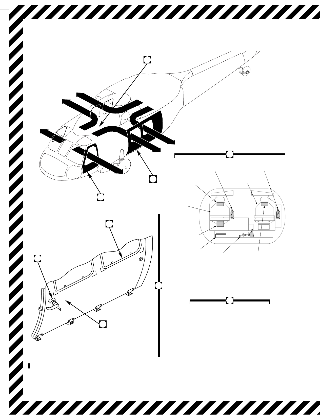
SA
AA0533_1A
IN "CLOSE" POSITION
BEFORE CLOSING
DOOR
HANDLE MUST BE
LOCKED
OPEN
CLOSE
A
B
F
E
D
C
B
FIRE
EXTINGUISHER
(CABIN)
PILOT’S
SEAT
FIRE
EXTINGUISHER
(COCKPIT)
FIRST
AID KIT
COPILOT’S
SEAT
FIRST AID
KIT (CABIN)
BATTERY
CRASH AX
(CABIN) FIRST
AID KIT
HANDLE MUST BE
IN "CLOSE" POSITION
BEFORE CLOSING
DOOR
(SAME FOR RIGHT SIDE)
CABIN AND COCKPIT
DOORS EXTERIOR HANDLE
CABIN DOOR
C
A
VIEW LOOKING FORWARD
Figure 9-1. Emergency Exits and Emergency Equipment Diagram (Sheet 1 of 3)
TM 1-1520-237-10
9-4 Change 2
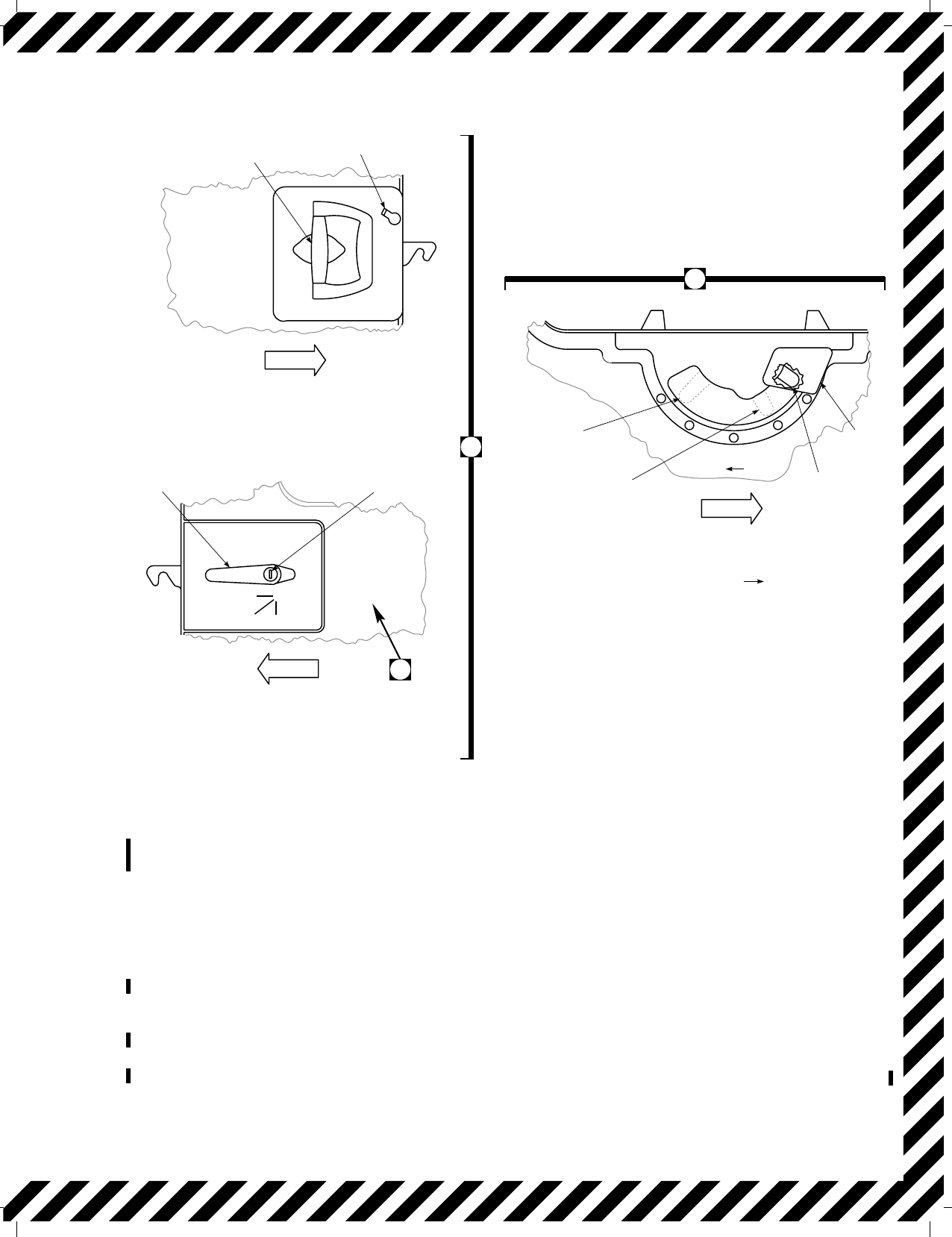
necessary to maintain % RPM R within normal range.
Figure 5-1 shows the rotor limitations. % RPM R should
be maintained at or slightly above 100 percent to allow
ample rpm before touchdown.
b. Main rotor rpm will increase momentarily when the
cyclic is moved aft with no change in collective pitch set-
ting. An autorotative rpm of approximately 100 percent
provides for a good rate of descent. % RPM R above 100
percent will result in a higher rate of descent. At 50 to 75
feet AGL, use aft cyclic to decelerate. This reduces air-
speed and rate of descent and causes an increase in %
RPM R. The degree of increase depends upon the amount
and rate of deceleration. An increase in % RPM R can be
desirable in that more inertial energy in the rotor system
will be available to cushion the landing. Ground contact
should be made with some forward speed. Pitch attitudes
up to 25° at the point of touchdown normally result in an
adequate deceleration and safe landing. If a rough area is
selected, a steeper deceleration and a touchdown speed as
close to zero as possible should be used. With pitch attitude
beyond 25° there is the possibility of ground contact with
the stabilator trailing edge. It is possible that during the
autorotative approach, the situation may require additional
deceleration. In that case, it is necessary to assume a land-
ing attitude at a higher altitude than normal. Should both
engines fail at low airspeed, initial collective reduction may
vary widely. The objective is to reduce collective as neces-
sary to maintain % RPM R within normal range. In some
LATCH LEVER
DOOR
HANDLE
HANDLE MUST BE
IN "CLOSE" POSITION
BEFORE CLOSING
DOOR
CABIN DOOR
INTERIOR RELEASE HANDLE
VIEW LOOKING OUTBOARD
LEFT SIDE
(SAME FOR RIGHT SIDE)
DOOR
HANDLE KEY SLOT
LOCKED
CLOSE OPEN
CABIN DOOR
EXTERIOR RELEASE HANDLE
VIEW LOOKING INBOARD
LEFT SIDE
(SAME FOR RIGHT SIDE)
JETTISON
LEVER
GUARD
LOCKED
POSITION
UNLOCKED
POSITION
OPEN
POSITION
EMERGENCY EXIT
PULL AFT
CABIN DOOR WINDOW JETTISON LEVER
VIEW LOOKING OUTBOARD
LEFT SIDE
(RIGHT SIDE PULL FWD)
D
C
EMERG EXIST DOOR USE ONLY
WHEN SHIPS BLADES ARE AT A FULL STOP.
OTHERWISE YOU COULD LOOSE YOUR HEAD.
SFDGH 6YUOIP 890PO0P
E
FWD
FWD
FWD
SA
AA0533_2A
Figure 9-1. Emergency Exits and Emergency Equipment Diagram (Sheet 2 of 3)
TM 1-1520-237-10
Change 8 9-5
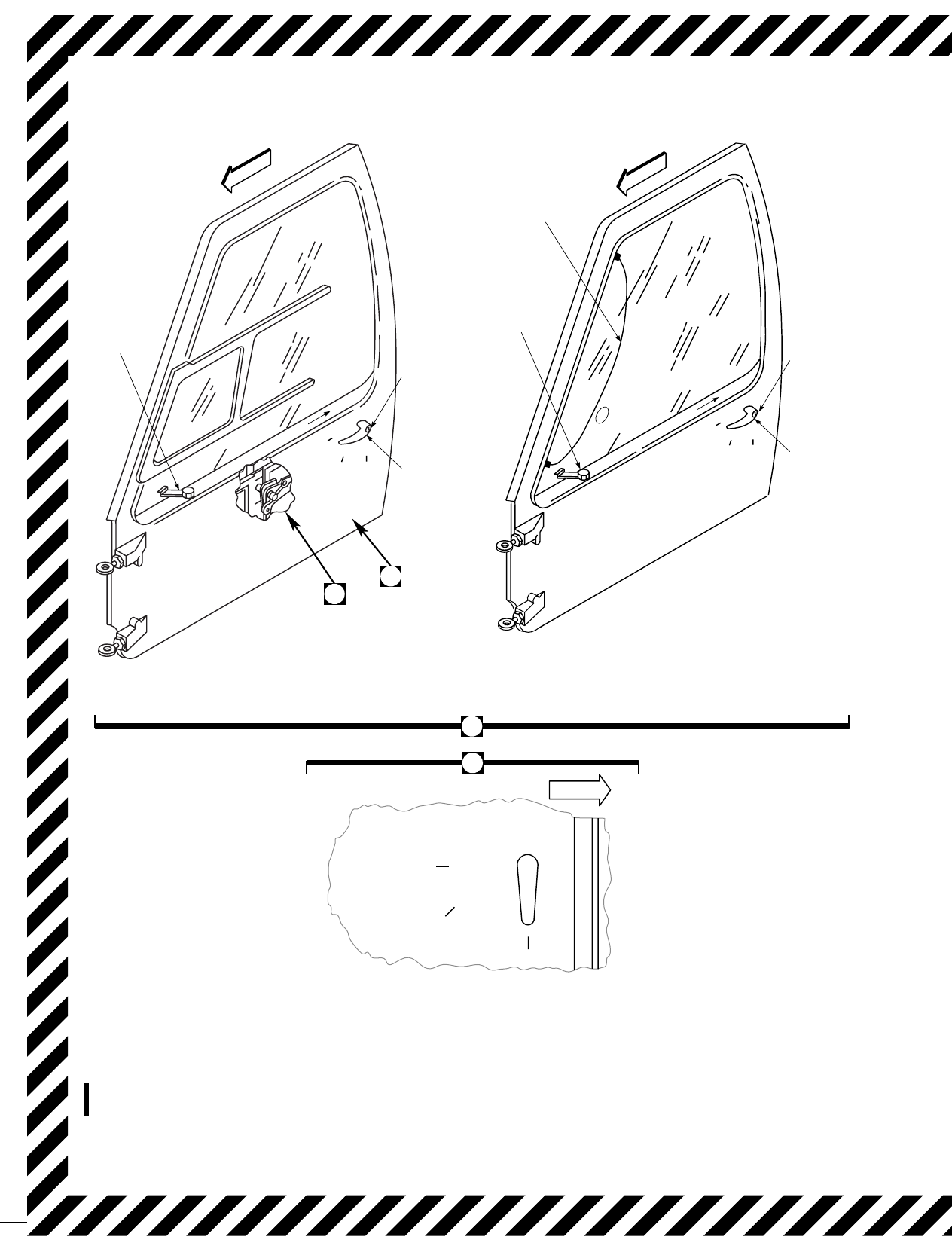
SA
AA0533_3
LOCKED
CLOSE
OPEN
EMERG EXIT PULL
OPEN
CLOSE
LOCKED
HANDLE MUST BE
IN "CLOSE"POSITION
BEFORE CLOSING
DOOR
INTERIOR COCKPIT DOOR RELEASE
HANDLE
VIEW LOOKING OUTBOARD
LEFT SIDE
(SAME FOR RIGHT SIDE)
C
G
JETTISON
LEVER
KEY SLOT
EXTERIOR
RELEASE
HANDLE
EMERG EXIST, USE ONLY WHEN
HELICOPTER BLADES COME TO A FULL
HELICOPTER BLADES COME TO A FULL
HELICOPTER BLADES COME TO A FULL
VIEW LOOKING INBOARD
LEFT SIDE
(SAME FOR RIGHT SIDE)
LOCKED
CLOSE
OPEN
EMERG EXIT PULL
EMERG EXIST, USE ONLY WHEN
HELICOPTER BLADES COME TO A FULL
HELICOPTER BLADES COME TO A FULL
HELICOPTER BLADES COME TO A FULL
CABIN DOOR
INTERIOR JETTISON LEVER
WINDOW
EMERGENCY
EXIT STRAP
KEY SLOT
EXTERIOR
RELEASE
HANDLE
JETTISON
LEVER
(IF INSTALLED)
FWD
FWD
F
G
FWD
Figure 9-1. Emergency Exits and Emergency Equipment Diagram (Sheet 3 of 3)
TM 1-1520-237-10
9-6 Change 1

instances at low altitude or low airspeed, settling may be so
rapid that little can be done to avoid a hard-impact landing.
In that case, it is critical to maintain a level landing attitude.
Cushion the landing with remaining collective as helicopter
settles to the ground. At slow airspeeds, where altitude per-
mits, apply forward cyclic as necessary to increase airspeed
to about 80 KIAS. Jettison external cargo and stores as
soon as possible to reduce weight and drag, improve au-
torotational performance, and reduce the chance of damage
to the helicopter on landing.
9.13 DUAL-ENGINE FAILURE.
WARNING
Do not respond to ENG OUT warning
lights and audio until checking TGT
TEMP and % RPM R.
AUTOROTATE.
9.14 DECREASING % RPM R.
If an engine control unit fails to the low side and the
other engine is unable to provide sufficient torque, % RPM
Rwill decrease.
CAUTION
When engine is controlled with engine
power-control lever in lockout, engine re-
sponse is much faster and the TGT limit-
ing system is inoperative. Care must be
taken not to exceed TGT limits and keep-
ing%RPMRand%RPM1and2in
operating range.
NOTE
If %RPM R reduces from 100% to 95-96%
during steady flight, check %TRQ 1 and 2.
If %TRQ 1 and 2are equal, attempt to in-
crease %RPM R with RPM trim switch.
1. Collective - Adjust to control % RPM R.
2.
ENG POWER CONT lever - LOCKOUT low
% TRQ/TGT TEMP engine. Maintain %
TRQ approximately 10% below other engine.
3. LAND AS SOON AS PRACTICABLE.
9.15 INCREASING % RPM R.
% RPM R increasing will result from an engine control
system failing to the high side. % RPM 1 and 2(Np) will
increase with the rotor % RPM R. Increasing the collective
will probably increase the malfunctioning engine’s TGT
TEMP above 900°C. If an engine control unit fails to the
high side:
1.
ENG POWER CONT lever - Retard high %
TRQ/TGT TEMP engine, maintain % TRQ
approximately 10% below other engine.
2. LAND AS SOON AS PRACTICABLE.
If the affected engine does not respond to ENG
POWER CONT lever movement in the range between
FLY and IDLE, the HMU may be malfunctioning inter-
nally.
If this occurs:
3. Establish single engine airspeed.
4.
Perform EMER ENG SHUTDOWN (affected
engine).
TM 1-1520-237-10
Change 8 9-6.1/(9-6.2 Blank)
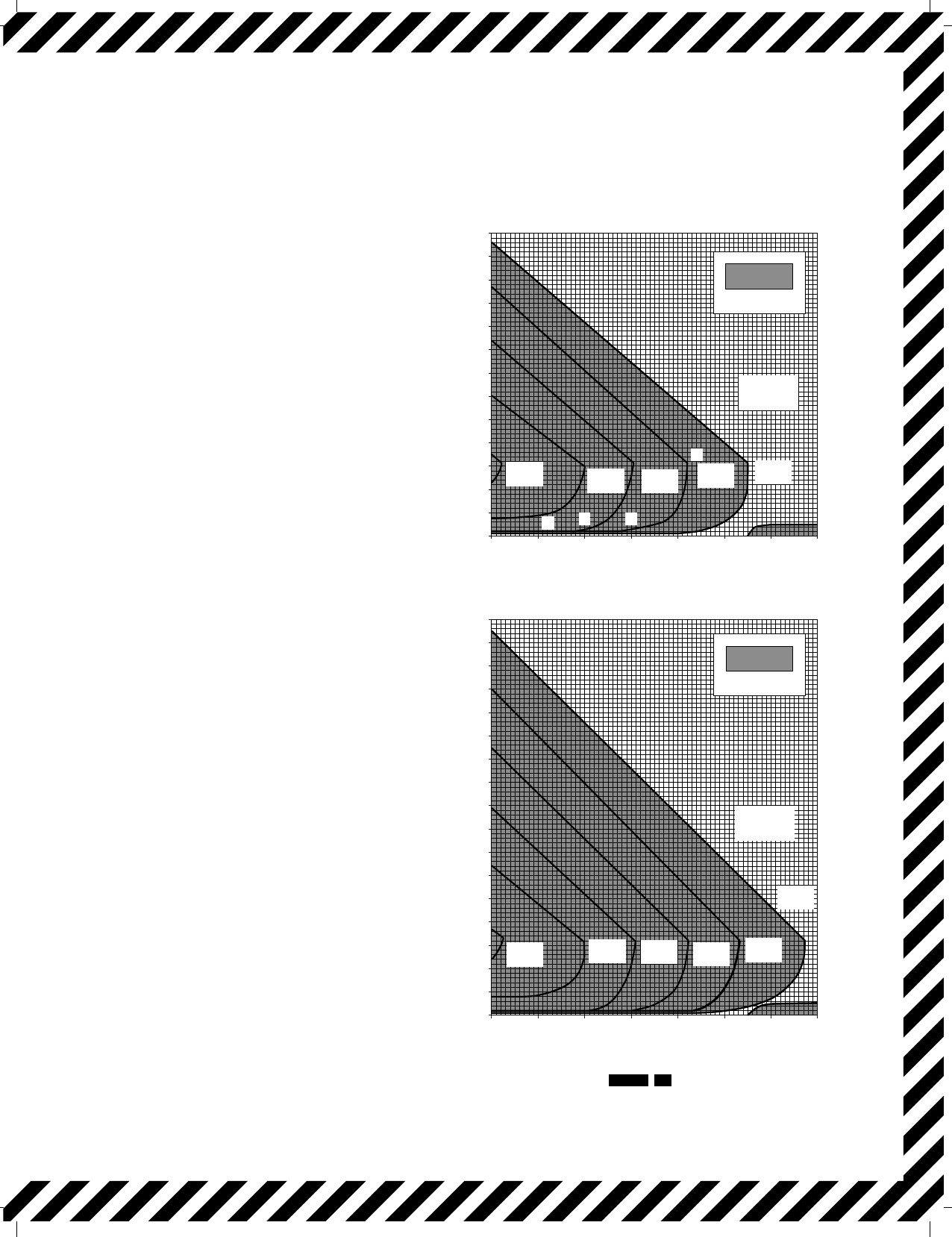
SA
AA0673C
UH−60A/EH−60A
HEIGHT VELOCITY AVOID REGIONS
4000 FT 35OC (95oF)
AIRSPEED ~ KTS
EXAMPLE
WANTED:
A TAKEOFF PROFILE WHICH WILL
PERMIT A SAFE LANDING AFTER
AN ENGINE SUDDENLY BECOMES
INOPERATIVE.
KNOWN:
AMBIENT CONDITIONS:
TEMPERATURE = 15oC
PRESSURE ALTITUDE = SEA LEVEL
AIRCRAFT GROSS WEIGHT = 22,000 LBS
METHOD:
TRACE ALONG GROSS WEIGHT LINE
NOTING WHEEL HEIGHT / AIRSPEED
COMBINATIONS WHICH WILL KEEP
THE TAKEOFF PROFILE BELOW AND
TO THE RIGHT OF THE AVOID REGION.
POINT
A
B
C
AIRSPEED
10
20
30
WHEEL HEIGHT
10
10
15
NOTE:
CALCULATED
DATA BASIS:
SINGLE−ENGINE FAILURE
WIND = 0 KTS
D42 155
BASED ON AN ETF OF .85 OF
MAXIMUM RATED POWER.
WEIGHTS GREATER THAN
22,000 LBS ARE FOR FERRY
MISSION ONLY, FOR WHICH A
FLIGHT RELEASE IS REQUIRED. 0 10 20 30 40 50 60 70
0 10203040
SEA LEVEL STANDARD
650
600
550
500
450
400
350
300
250
50
0
850
800
750
700
650
600
550
500
450
400
350
300
250
200
150
100
50
0
WHEEL HEIGHT ~ FT WHEEL HEIGHT ~ FT
AIRSPEED ~ KTS
GROSS
WEIGHT
~ 1000 LBS
AVOID AREA
12,000
LB
14,000
LB 16,000
LB 18,000
LB
20,000
LB
22,000
LB
GROSS
WEIGHT
~ 1000 LBS
AVOID AREA
12,000
LB
14,000
LB 16,000
LB 18,000
LB
20,000
LB
22,000
LB
50 60 70
200
150
100
ABC
D
AVOID AREA
16,000
LB 18,000
LB 20,000
LB
22,000
LB
24,500
LB
GROSS
WEIGHT
~ 1000 LBS
AVOID AREA
16,000
LB 18,000
LB 20,000
LB
22,000
LB
24,500
LB
GROSS
WEIGHT
~ 1000 LBS
ABC
D
Figure 9-2. Height Velocity Diagram UH−60A EH
TM 1-1520-237-10
9-7
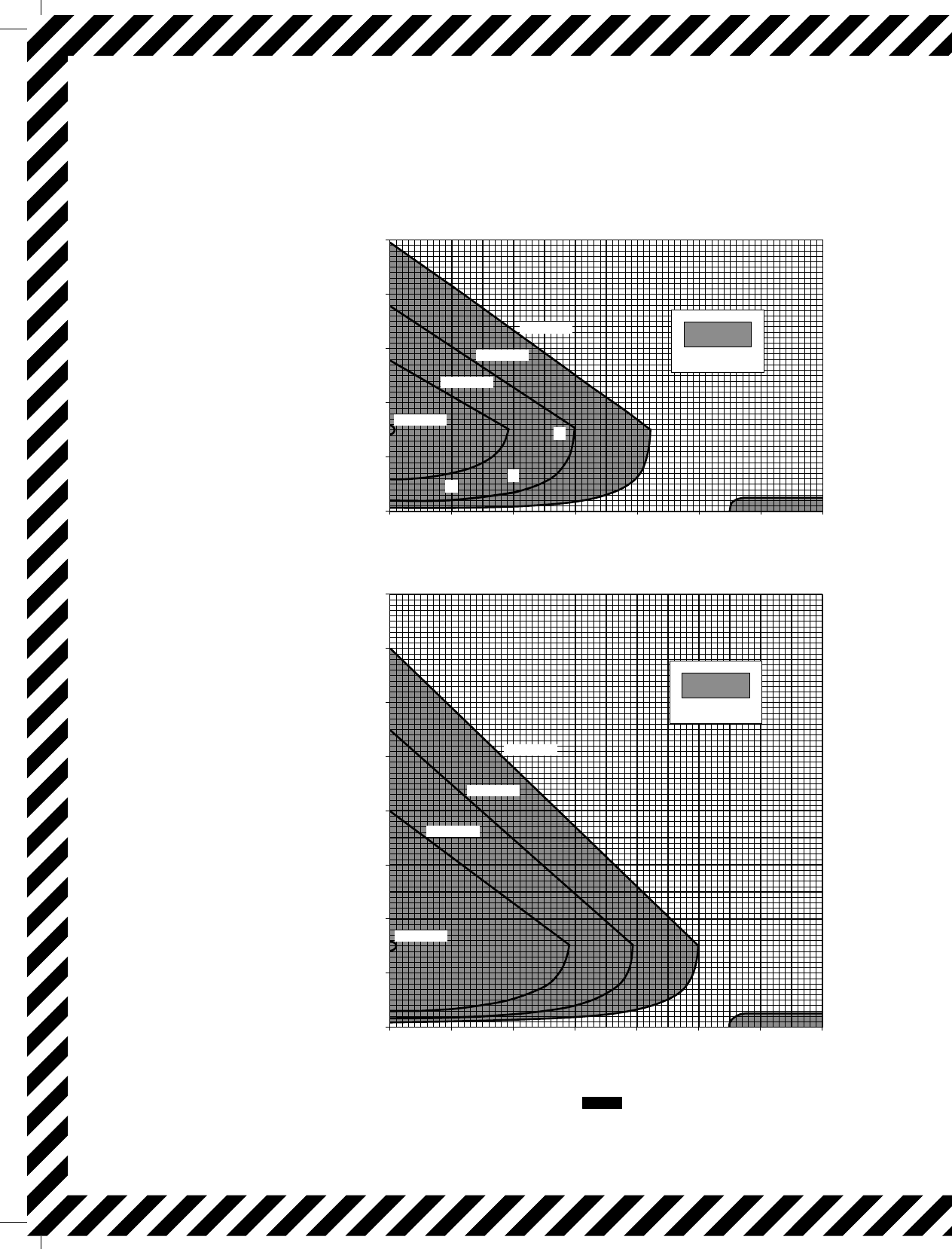
HEIGHT VELOCITY AVOID REGIONS
SEA LEVEL STANDARD
4000 FT 35oC (95oF)
AIRSPEED ~ KTS
WHEEL HEIGHT ~ FT
AIRSPEED ~ KTS
WHEEL HEIGHT ~ FT
EXAMPLE
WANTED
A TAKEOFF PROFILE WHICH WILL
PERMIT A SAFE LANDING AFTER
AN ENGINE SUDDENLY BECOMES
INOPERATIVE.
KNOWN
AMBIENT CONDITIONS:
TEMPERATURE = 15oC
PRESSURE ALTITUDE = SEA LEVEL
AIRCRAFT GROSS WEIGHT = 22,000 LBS
METHOD
TRACE ALONG GROSS WEIGHT LINE
NOTING WHEEL HEIGHT / AIRSPEED
COMBINATIONS WHICH WILL KEEP
THE TAKEOFF PROFILE BELOW AND
TO THE RIGHT OF THE AVOID REGION.
POINT
A
B
C
AIRSPEED
10
20
30
WHEEL HEIGHT
21
33
150
ESTIMATED
DATA BASIS:
SINGLE ENGINE FAILURE
0 10203040506070
0
100
200
300
400
500
0 10203040506070
0
100
200
300
400
500
600
700
800
20,000 LB
22,000 LB
24,500 LB
18,000 LB
AB
C
16,000 LB
22,000 LB
20,000 LB
18,000 LB
WIND = 0 KTS
AVOID AREA
AVOID AREA
NOTE
BASED ON AN ETF OF .90 OF MAXIMUM
RATED POWER.
SA
AA1639A
UH−60L
Figure 9-3. Height Velocity Diagram UH−60L
TM 1-1520-237-10
9-8
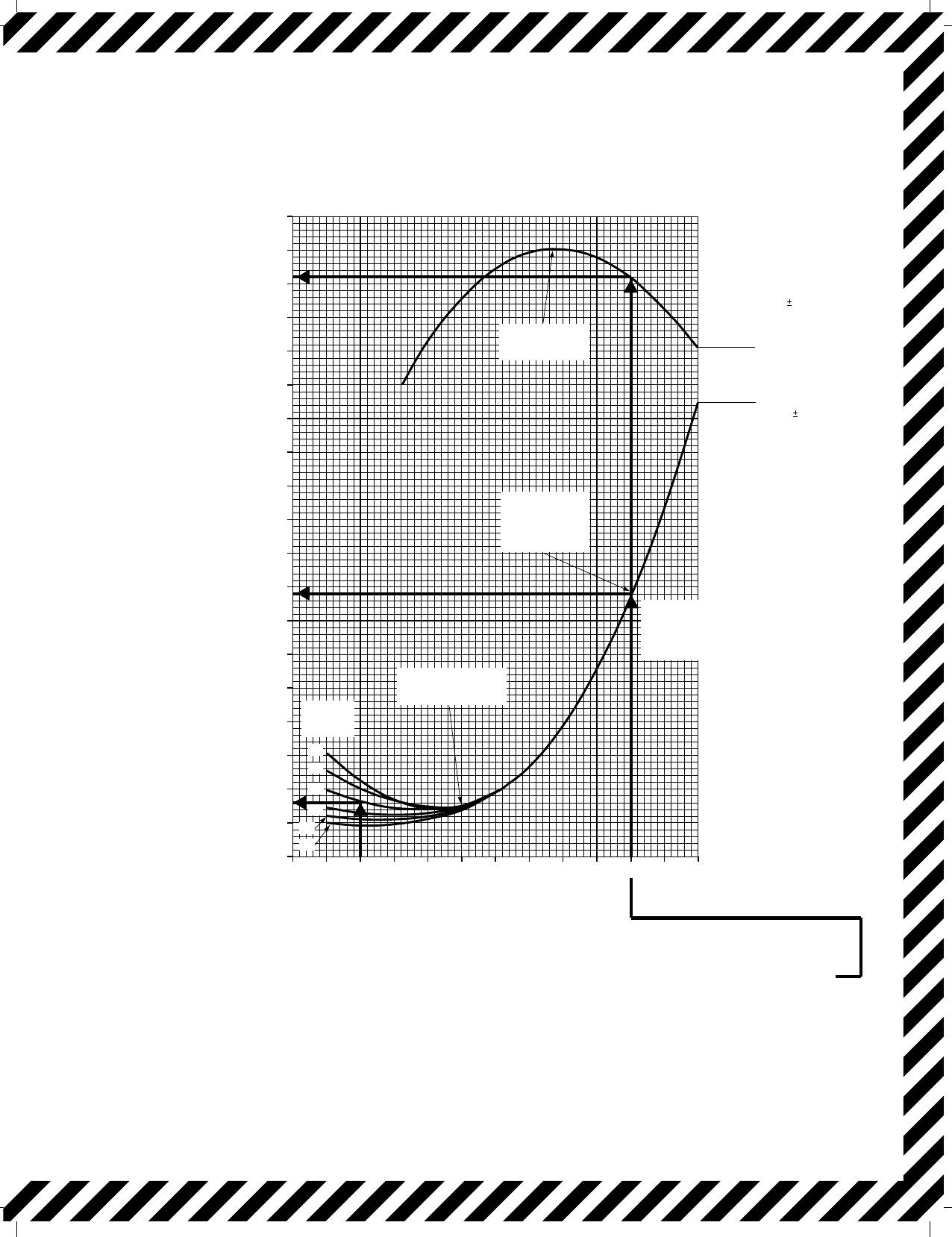
SA
AA0322B
AUTOROTATION
CLEAN CONFIGURATION
100% RPM R ZERO WIND
EXAMPLE
WANTED: KNOWN: METHOD:
RATE OF DESCENT AND GLIDE RATIO IN STEADY
STATE AUTOROTATION AT IAS’S OF:
A. 130 KIAS
B. 50 KIAS
RPM R = 100%
GROSS WEIGHT = 18,000 LB A. ENTER AUTOROTATION CHART AT 130 KIAS,
MOVE UP TO INTERSECTION OF R / D LINE,
MOVE LEFT, READ RD = 3,560 FT / MIN
B. ENTER AUTOROTATION CHART AT 50 KIAS,
MOVE UP TO 18,000 LB GW LINE, MOVE LEFT,
READ R / D = 2,325 FT / MIN
THE GLIDE RATIO IS NOT PROVIDED FOR LOW
AIRSPEEDS
INDICATED AIRSPEED ~ KNOTS
RATE OF DESCENT ~ FT/MIN
GLIDE RATIO ~
NAUTICAL MILES PER 1000 FT
A GR VARIATION
OF .05 MAY
RESULT FROM
FLIGHT CONDITION
ABOVE / BELOW
THE NOMINAL
A R / D VARIATION
OF 300 FT / MIN
MAY RESULT
FROM FLIGHT
CONDITIONS
ABOVE / BELOW
THE NOMINAL
DATA BASIS:FLIGHT TEST
30 40 50 60 70 80 90 100 110 120 130 140 150
2000
2200
2400
2600
2800
3000
3200
3400
3600
3800
4000
4200
4400
4600
.50
.55
.60
.65
.70
.75
AIRSPEED FOR
MAXIMUM GLIDE
110 KIAS
MAXIMUM
AIRSPEED
FOR GW’S
UP TO
16825 LB
RECOMMENDED
AUTOROTATIONAL
AIRSPEED = 80 KIAS
GROSS
WEIGHT
~ 1000 LB
MAXIMUM
AUTOROTATION
AIRSPEED FOR
GW’S ABOVE
16825 LB
22
20
18
16
14
12
Figure 9-4. Autorotative Glide Distance Chart
TM 1-1520-237-10
9-9
SA
AA1253A
AUTOROTATION
HIGH DRAG CONFIGURATION
40 60 80 100 120 140
.75
.70
.65
.60
.55
.50
.45
4600
4400
4200
4000
3800
3600
3400
3200
3000
2800
2600
2400
2200
2000
INDICATED AIRSPEED ~ KNOTS
GLIDE RATIO ~ GR
NAUTICAL MILES TRAVELED
PER 1000 FT ALTITUDE LOSS
RATE OF DESCENT ~ FT / MIN
NOTE: DASH LINE FOR FERRY
MISSION ONLY
24
22
20
18
16
14
AIRSPEED FOR
MAXIMUM GLIDE
100 KIAS
RECOMMENDED
AUTOROTATIONAL
AIRSPEED =
80 KIAS
GROSS WEIGHT
= 1000 LB MAXIMUM
AUTOROTATION
AIRSPEED FOR
GW’S ABOVE
16,825 LB
MAXIMUM
AIRSPEED
FOR GW’S
UP TO
16,825 LB
FLIGHT TEST
DATA BASIS:
100% RPM R ZERO WIND
Figure 9-5. Autorotative Glide Distance Chart-High Drag
TM 1-1520-237-10
9-10

5. Refer to single engine failure emergency proce-
dure.
9.16 % RPM INCREASING/DECREASING (OSCIL-
LATION).
It is possible for a malfunction to occur that can cause
the affected engine to oscillate. The other engine will re-
spond to the change in power by also oscillating, usually
with smaller amplitudes. The engine oscillations will cause
torque oscillations. The suggested pilot corrective action is
to pull back the ENG POWER CONT lever of the sus-
pected engine until oscillation stops. If the oscillation con-
tinues, the ENG POWER CONT lever should be returned
to FLY position and the other ENG POWER CONT lever
pulled back until the oscillation ceases. Once the malfunc-
tioning engine has been identified, it should be placed in
LOCKOUT and controlled manually.
1. Slowly retard the ENG POWER CONT lever
on the suspected engine.
If the oscillation stops:
2. Place that engine in LOCKOUT and manually
control the power.
3. LAND AS SOON AS PRACTICABLE.
If the oscillation continues:
4. Place the ENG POWER CONT lever back to
FLY and retard the ENG POWER CONT le-
ver of the other engine.
When the oscillation stops:
5. Place the engine in LOCKOUT, manually con-
trol the power.
6. LAND AS SOON AS PRACTICABLE.
9.17 % TRQ SPLIT BETWEEN ENGINES 1 AND 2.
It is possible for a malfunction to occur that can cause a
% TRQ split between engines without a significant change
in % RPM R. The % TRQ split can be corrected by manual
control of the ENG POWER CONT lever on the affected
engine.
1. If TGT TEMP of one engine exceeds the lim-
iter ( 700 849°C , 701C 872°C with low power
engine above 50% TRQ or 896°C with low
power engine below 50% TRQ), retard ENG
POWER CONT lever on that engine to reduce
TGT TEMP. Retard the ENG POWER
CONT lever to maintain torque of the manu-
ally controlled engine at approximately 10%
below the other engine.
2.
If TGT TEMP limit on either engine is not
exceeded, slowly retard ENG POWER CONT
lever on high % TRQ engine and observe %
TRQ of low power engine.
3.
If % TRQ of low power engine increases,
ENG POWER CONT lever on high power en-
gine - Retard to maintain % TRQ approxi-
mately 10% below other engine (The high
power engine has been identified as a high side
failure).
4.
If % TRQ of low power engine does not in-
crease, or % RPM R decreases, ENG
POWER CONT lever - Return high power en-
gine to FLY (The low power engine has been
identified as a low side failure).
5.
If additional power is required, low power
ENG POWER CONT lever, momentarily
move to LOCKOUT and adjust to set % TRQ
approximately 10% below the other engine.
6. LAND AS SOON AS PRACTICABLE.
9.18 ENGINE COMPRESSOR STALL.
An engine compressor stall is normally recognized by a
noticeable bang or popping noise and possible aircraft yaw.
These responses are normally accompanied by the rapid
increase in TGT TEMP and fluctuations in Ng SPEED,%
TRQ, and % RPM reading for the affected engine. In the
event of a compressor stall:
1. Collective - Reduce.
If condition persists:
2.
ENG POWER CONT lever (affected engine) -
Retard (TGT TEMP should decrease.)
3.
ENG POWER CONT lever (affected engine) -
FLY.
If stall condition recurs:
4.
EMER ENG SHUTDOWN (affected engine).
TM 1-1520-237-10
Change 8 9-11

5. Refer to single-engine failure emergency proce-
dure.
9.19 ENGINE OIL FILTER BYPASS CAUTION
LIGHT ON, ENGINE CHIP CAUTION LIGHT ON,
ENG OIL PRESS HIGH/LOW, ENGINE OIL TEMP
HIGH, ENGINE OIL TEMP CAUTION LIGHT ON, EN-
GINE OIL PRESS CAUTION LIGHT ON.
1. ENG POWER CONT lever - Retard to reduce
torque on affected engine.
If oil pressure is below minimum limits or if oil tem-
perature remains above maximum limits:
2. EMER ENG SHUTDOWN (affected engine).
3. Refer to single-engine failure emergency proce-
dure.
9.20 ENGINE HIGH-SPEED SHAFT FAILURE.
Failure of the shaft may be complete or partial. A partial
failure may be characterized at first by nothing more than a
loud high-speed rattle and vibration coming from the en-
gine area. A complete failure will be accompanied by a
loud bang that will result in a sudden % TRQ decrease to
zero on the affected engine. % RPM of affected engine
will increase until overspeed system is activated.
1. Collective - Adjust.
2. EMER ENG SHUTDOWN (affected engine).
Do not attempt to restart.
3. Refer to single-engine failure emergency proce-
dure.
9.21 LIGHTNING STRIKE.
WARNING
Lightning strikes may result in loss of au-
tomatic flight control functions, engine
controls, and/or electric power.
Lightning strike may cause one or both engines to im-
mediately produce maximum power with no TGT limiting
or overspeed protection. Systems instruments may also be
inoperative. If this occurs, the flight crew would have to
adjust to the malfunctioning engine(s) power-control le-
ver(s) as required to control % RPM by sound and feel. If
practical, the pilot should reduce speed to 80 KIAS. This
will reduce the criticality of having exactly correct rotor
speed 100%.
1. ENG POWER CONT levers - Adjust as re-
quired to control % RPM.
2. LAND AS SOON AS POSSIBLE.
9.22 ROTORS, TRANSMISSIONS AND DRIVE SYS-
TEMS.
9.22.1 Loss of Tail Rotor Thrust. Failure of the tail
rotor gearbox, intermediate gearbox or tail rotor drive shaft
will result in a loss of tail rotor thrust. The nose of the
helicopter will yaw right regardless of the airspeed at which
the failure occurs. Continued level flight may not be pos-
sible following this type failure. Loss of tail rotor thrust at
low speed will result in rapid right yaw. At higher airspeed,
right yaw may develop more slowly but will continue to
increase. Autorotation should be entered promptly. Retard
ENG POWER CONT levers to OFF position during de-
celeration. Every effort should be made to establish and
maintain an autorotative glide at or above 80 KIAS. This
will maximize the effectiveness of the deceleration during
the landing sequence. If autorotation entry is delayed, large
sideslip angles can develop causing low indicated airspeed
with the stabilator programming down. This can make it
more difficult to establish or maintain adequate autorotative
airspeed.
1. AUTOROTATE.
2. ENG POWER CONT levers - OFF (when in-
tended point of landing is assured).
9.22.2 Loss of Tail Rotor Thrust at Low Airspeed/
Hover.
Loss of tail rotor thrust at slow speed may result in
extreme yaw angles and uncontrolled rotation to the right.
Immediate collective pitch reduction should be initiated to
reduce the yaw and begin a controlled rate of descent. If the
helicopter is high enough above the ground, initiate a
power-on descent. Collective should be adjusted so that an
acceptable compromise between rate of turn and rate of
descent is maintained. At approximately 5 to 10 feet above
touchdown, initiate a hovering autorotation by moving the
ENG POWER CONT levers - OFF.
1. Collective - Reduce.
2. ENG POWER CONT levers - OFF (5 to 10
feet above touchdown).
TM 1-1520-237-10
9-12 Change 9

9.22.3 TAIL ROTOR QUADRANT Caution Light On
With No Loss of Tail Rotor Control.
WARNING
If the helicopter is shut down and/or hy-
draulic power is removed with one tail ro-
tor cable failure, disconnection of the
other tail rotor cable will occur when
force from the boost servo cannot react
against control cable quadrant spring ten-
sion. The quadrant spring will displace
the cable and boost servo piston enough
to unlatch the quadrant cable.
Loss of one tail rotor cable will be indicated by illumi-
nation of TAIL ROTOR QUADRANT caution light. No
change in handling characteristics should occur.
LAND AS SOON AS PRACTICABLE.
9.22.4 TAIL ROTOR QUADRANT Caution Light On
With Loss of Tail Rotor Control.
a. If both tail rotor control cables fail, a centering spring
will position the tail rotor servo linkage to provide 10-1/2
degrees of pitch. This will allow trimmed flight at about 25
KIAS and 145 KIAS (these speeds will vary with gross
weight). At airspeed below 25 and above 145 KIAS, right
yaw can be controlled by reducing collective. Between 25
and 145 KIAS, left yaw can be controlled by increasing
collective.
b. A shallow approach to a roll-on landing technique is
recommended. During the approach, a yaw to the left will
occur. As the touchdown point is approached, a mild decel-
eration should be executed to reduce airspeed. As collective
is increased to cushion touchdown, the nose of the helicop-
ter will yaw right. Careful adjustment of collective and de-
celeration should allow a tail-low touchdown with approxi-
mate runway alignment. Upon touchdown, lower collective
carefully. Use brakes to control heading.
1. Collective - Adjust.
2. LAND AS SOON AS PRACTICABLE.
9.22.5 Pedal Bind/Restriction or Drive With No Ac-
companying Caution Light. If pedal binding, restric-
tion, or driving occurs with no caution light the cause may
not be apparent. A Stability Augmentation System/Flight
Path Stabilization (SAS/FPS) computer induced yaw trim
malfunction can produce about 30 pounds at the pedal. An
internally jammed yaw trim actuator can produce up to 80
pounds until clutch slippage relieves this force. The pilot
can override any yaw trim force by applying opposite pedal
firmly and then turning off trim. A malfunction within the
yaw boost servo or tail rotor servo can produce much higher
force at the pedals and the affected servo must be turned
off. Hardover failure of the yaw boost servo will increase
control forces as much as 250 pounds on the pedals.
1. Apply pedal force to oppose the drive.
2.
TRIM switch - Off.
If normal control forces are not restored:
3.
BOOST switch - Off.
If control forces, normal for boost off flight are not re-
stored:
4.
BOOST switch - ON.
5.
TAIL SERVO switch - BACKUP, if tail rotor
is not restored.
a. If the tail rotor quadrant becomes jammed,
collective control is available, except that
low collective with right pedal or high col-
lective with a left pedal will be restricted.
With a quadrant jam, complete collective
travel is available for most control combi-
nations, provided the pedals are allowed to
move as the collective is displaced.
b. If tail rotor pitch becomes fixed during de-
creased power situations (right pedal ap-
plied), the nose of the helicopter will turn
to the right when power is applied, possi-
bly even greater than complete loss of tail
rotor thrust. Some conditions may require
entry into autorotation to control yaw rate.
If continued flight is possible, a shallow
approach at about 80 KIAS to a roll-on
landing should be made. As the touchdown
point is approached, a mild deceleration
should be executed at about 15 to 25 feet
to reduce airspeed to about 40 KIAS. As
collective is increased to cushion touch-
down, the nose of the helicopter will turn
to the right. Careful adjustment of collec-
tive and deceleration should allow a tail-
low touchdown with approximate runway
alignment. Upon
TM 1-1520-237-10
Change 8 9-13

touchdown, lower collective carefully and
use brakes to control heading.
c. If tail rotor pitch becomes fixed during in-
creased power situations (left pedal ap-
plied), the nose of the helicopter will turn
left when collective is decreased. Under
these conditions, powered flight to a pre-
pared landing site and a powered landing is
possible since the sideslip angle will prob-
ably be corrected when power is applied
for touchdown. Adjust approach speed and
rate of descent to maintain a sideslip angle
of less than 20°. Sideslip angle may be re-
duced by either increasing airspeed or col-
lective. Execute a decelerated touchdown
tailwheel first, and cushion landing with
collective. Upon touchdown, lower collec-
tive carefully and use brakes to control
heading.
6. LAND AS SOON AS PRACTICABLE.
9.22.6 #1 TAIL RTR SERVO Caution Light On and
BACK-UP PUMP ON Advisory Light Off or #2 TAIL
RTR SERVO ON Advisory Light Off. Automatic
switch-over did not take place.
1. TAIL SERVO switch - BACKUP.
2. BACKUP HYD PUMP switch - ON.
3. LAND AS SOON AS PRACTICABLE.
9.22.7 MAIN XMSN OIL PRESS Caution Light On/
XMSN OIL PRESS LOW/XMSN OIL TEMP HIGH or
XMSN OIL TEMP Caution Light On. Loss of cooling
oil supply will lead to electrical and/or mechanical failure
of main generators. If the malfunction is such that oil pres-
sure decays slowly, the generators may fail before MAIN
XMSN OIL PRESS caution light goes on.
1. LAND AS SOON AS POSSIBLE.
If time permits:
2. Slow to 80 KIAS.
3. EMER APU START.
4. GENERATORS NO. 1 and NO. 2 switches -
OFF.
9.22.8 CHIP INPUT MDL LH or RH Caution Light
On.
1. ENG POWER CONT lever on affected engine
-IDLE.
2. LAND AS SOON AS POSSIBLE.
9.22.9 CHIP MAIN MDL SUMP, CHIP ACCESS MDL
LH or RH, CHIP TAIL XMSN or CHIP INT XMSN/
TAIL XMSN OIL TEMP or INT XMSN OIL TEMP Cau-
tion Light On.
LAND AS SOON AS POSSIBLE.
9.22.10 MAIN TRANSMISSION FAILURE.
WARNING
If % RPM R decreases from 100% to be-
low 96% with an increase in torque dur-
ing steady flight with no engine malfunc-
tion, the main transmission planetary
carrier may have failed. During a main
transmission planetary carrier failure, it
may be impossible to maintain % RPM R
at 100%.
NOTE
Decreasing % RPM R may be accompanied
by a drop in transmission oil pressure of 10
PSI or more, and possible unusual helicopter
vibrations.
1. Collective - Adjust only enough to begin a de-
scent with power remaining applied to the main
transmission throughout the descent and land-
ing.
2. LAND AS SOON AS POSSIBLE.
9.23 FIRE.
WARNING
If AC electrical power is not available,
only the reserve fire bottle can be dis-
charged and fire extinguishing capability
for the #2 engine will be lost.
TM 1-1520-237-10
9-14 Change 10

The safety of helicopter occupants is the primary con-
sideration when a fire occurs; therefore, it is imperative that
every effort be made to extinguish the fire. On the ground,
it is essential that the engine be shut down, crew and pas-
sengers evacuated, and fire fighting begun immediately. If
time permits, a 9Mayday9radio call should be made before
the electrical power is OFF to expedite assistance from fire-
fighting equipment and personnel. If the helicopter is air-
borne when a fire occurs, the most important single action
that can be taken by the pilot is to land. Consideration must
be given to jettisoning external stores and turning FUEL
BOOST PUMPS and XFER PUMPS off prior to landing.
9.23.1 Engine/Fuselage Fire On Ground.
1. ENG POWER CONT levers - OFF.
2. ENG EMER OFF handle - Pull if applicable.
3. FIRE EXTGH switch - MAIN/RESERVE as
required.
9.23.2 APU Compartment Fire.
1. APU fire T-handle - Pull.
2. FIRE EXTGH switch - MAIN/RESERVE as
required.
9.23.3 APU OIL TEMP HI Caution Light On.
APU CONTR switch - OFF. Do not attempt restart
until oil level has been checked.
9.23.4 Engine Fire In Flight.
WARNING
Attempt to visually confirm fire before en-
gine shutdown or discharging extinguish-
ing agent.
1. ENG POWER CONT lever (affected engine) -
OFF.
2. ENG EMER OFF handle - Pull.
3. FIRE EXTGH switch - MAIN/RESERVE as
required.
4. LAND AS SOON AS POSSIBLE.
9.23.5 Electrical Fire In Flight. Prior to shutting off all
electrical power, the pilot must consider the equipment that
is essential to a particular flight environment which will be
affected, e.g., flight instruments, flight controls, etc. If a
landing cannot be made as soon as possible the affected
circuit may be isolated by selectively turning off electrical
equipment and/or pulling circuit breakers.
1.
BATT and GENERATORS switches - OFF.
2. LAND AS SOON AS POSSIBLE.
9.24 SMOKE AND FUME ELIMINATION.
WARNING
If battery overheats, do not remove bat-
tery cover or attempt to disconnect or re-
move battery. Battery fluid will cause
burns, and an overheated battery could
cause thermal burns and may explode.
Smoke or fumes in the cockpit/cabin can be eliminated
as follows:
1. Airspeed - 80 KIAS or less.
2. Cabin doors and gunner’s windows - Open.
3. Place helicopter out of trim.
4. LAND AS SOON AS PRACTICABLE.
9.25 FUEL SYSTEM.
9.25.1 #1 or #2 FUEL FLTR BYPASS Caution Light
On.
1.
ENG FUEL SYS selector on affected engine -
XFD.
2. LAND AS SOON AS PRACTICABLE.
9.25.2 #1 and #2 FUEL FLTR BYPASS Caution
Lights On.
LAND AS SOON AS POSSIBLE.
9.25.3 #1 FUEL LOW and #2 FUEL LOW Caution
Lights On.
LAND AS SOON AS PRACTICABLE.
TM 1-1520-237-10
Change 10 9-15

9.25.4 #1 or #2 FUEL PRESS Caution Light On.
a. If the light illuminates, flameout is possible. Do not
make rapid collective movements. This emergency proce-
dure has been written to include corrective action for criti-
cal situations. Critical situations are those where the loss of
an engine represents a greater hazard than the possibility of
pressurizing a fuel leak.
If the caution light illuminates and the situation is criti-
cal:
1. FUEL BOOST PUMP CONTROL switches -
NO. 1 PUMP and NO. 2 PUMP -ON.
2. LAND AS SOON AS PRACTICABLE.
b. This portion of the emergency procedure has been
written to provide the best method of isolating the cause of
the failure and prescribing the proper corrective action
when the situation is not critical. This portion of the emer-
gency procedure assumes the FUEL BOOST PUMP
CONTROL switches are OFF when the malfunction oc-
curs.
If the situation is not critical:
1. ENG FUEL SYS selector on affected engine -
XFD.
If caution light stays on:
2. FUEL BOOST PUMP CONTROL switches -
NO. 1 PUMP and NO. 2 PUMP -ON.
If caution light stays on:
3. FUEL BOOST PUMP CONTROL switches -
NO. 1 PUMP and NO. 2 PUMP -OFF.
4. LAND AS SOON AS PRACTICABLE.
9.26 ELECTRICAL SYSTEM.
9.26.1 #1 and #2 Generator Failure (#1 and #2
CONV and AC ESS BUS OFF Caution Lights On).
1. SAS 1 switch - Press off.
2. Airspeed - Adjust (80 KIAS or less).
3. GENERATORS NO. 1 and NO. 2 switches -
RESET; then ON.
If caution lights remain on:
4. GENERATORS NO. 1 and NO. 2 switches -
OFF.
5. EMER APU START.
6. SAS 1 switch - ON.
7. LAND AS SOON AS PRACTICABLE.
9.26.2 #1 or #2 GEN Caution Light On.
CAUTION
When the #1 ac generator is failed, and
the backup pump circuit breaker is out,
turn off ac electrical power before reset-
ting the backup pump power circuit
breaker, to avoid damaging the current
limiters.
1. Affected GENERATORS switch - RESET;
then ON.
If caution light remains on:
2. Affected GENERATORS switch - OFF.
9.26.3 #1 and #2 CONV Caution Lights On.
1. Unnecessary dc electrical equipment - OFF.
NOTE
When only battery power is available,
NICAD battery life is about 22 minutes day
and 14 minutes night for a battery 80%
charged. SLAB battery life is about 38 min-
utes day and 24 minutes night for a battery
80% charged.
2. LAND AS SOON AS PRACTICABLE.
9.26.4 BATTERY FAULT Caution Light On.
1. BATT switch - OFF; then ON.IfBATTERY
FAULT caution light goes on, cycle BATT
switch no more than two times.
If caution light remains on:
2. BATT switch - OFF.
TM 1-1520-237-10
9-16 Change 10

9.26.5 BATT LOW CHARGE Caution Light On.
If caution light goes on after AC power is applied:
1. BATT switch - OFF; then ON. About 30 min-
utes may be required to recharge battery.
If caution light goes on in flight:
2. BATT switch - OFF, to conserve remaining
battery charge.
9.27 HYDRAULIC SYSTEM.
9.27.1 #1 HYD PUMP Caution Light On.
1. TAIL SERVO switch - BACKUP; then NOR-
MAL.
2. LAND AS SOON AS PRACTICABLE.
9.27.2 #2 HYD PUMP Caution Light On.
1. POWER ON RESET switches - Simulta-
neously press, then release.
2. LAND AS SOON AS PRACTICABLE.
9.27.3 #1 and #2 HYD PUMP Caution Lights On.
LAND AS SOON AS POSSIBLE. Restrict
control movement to moderate rates.
9.27.4 #1 or #2 HYD PUMP Caution Light On and
BACK-UP PUMP ON Advisory Light Off. Loss of
both the No. 1 hydraulic pump and backup pump results in
both stages of the tail-rotor servo being unpressurized. The
yaw boost servo is still pressurized and the mechanical con-
trol system is still intact allowing limited tail-rotor control.
Because of the limited yaw control range available, a
roll-on landing 40 KIAS or above is required. Loss of both
the No. 2 hydraulic pump and the backup pump results in
the loss of pilot-assist servos.
1. Airspeed - Adjust to a comfortable airspeed.
2. BACKUP HYD PUMP switch - ON.
If BACK-UP PUMP ON advisory light remains off:
3. FPS and BOOST switches - Off (for #2 HYD
PUMP caution light).
4. LAND AS SOON AS POSSIBLE.
9.27.5 #1 or #2 PRI SERVO PRESS Caution Light
On. Illumination of #1 or #2 PRI SERVO PRESS caution
light can be caused by inadvertently placing the SVO OFF
switch on either collective control head in 1ST STG or
2ND STG position. Before initiating emergency procedure
action, the pilots should check that both SVO OFF
switches are centered.
1. SVO OFF switch - 1ST STG or 2ND STG as
applicable.
2. LAND AS SOON AS POSSIBLE.
9.27.6 #1 RSVR LOW and #1 HYD PUMP Caution
Lights On With BACK-UP PUMP ON Advisory Light
On.
1. LAND AS SOON AS PRACTICABLE.
If the BACK-UP RSVR LOW caution light also goes
on:
2.
SVO OFF switch - 1ST STG.
WARNING
If #2 PRI SERVO PRESS caution light
goes on, establish landing attitude, mini-
mize control inputs and begin a descent.
3. LAND AS SOON AS POSSIBLE.
9.27.7 #2 RSVR LOW and #2 HYD PUMP Caution
Lights On With BACK-UP PUMP ON Advisory Light
On.
1.
POWER ON RESET switches - Simulta-
neously press then release.
2. LAND AS SOON AS PRACTICABLE.
If BACK-UP RSVR LOW caution light also goes on:
3.
SVO OFF switch - 2ND STG.
WARNING
If #1 PRI SERVO PRESS caution light
goes on, establish landing attitude, mini-
mize control inputs, and begin a descent.
TM 1-1520-237-10
Change 10 9-17

4. LAND AS SOON AS POSSIBLE.
9.27.8 #2 RSVR LOW Caution Light On.
Pilot assist servos will be isolated; if they remain iso-
lated, proceed as follows:
1. BOOST and FPS switches - Off.
2. LAND AS SOON AS PRACTICABLE.
NOTE
Because the logic module will close the
valve supplying pressure to the pilot-assist
servos, BOOST SERVO OFF,SAS OFF,
and TRIM FAIL caution lights will be on.
9.27.9 Collective Boost Servo Hardover/Power
Piston Failure. Hardover failure of the collective boost
servo will increase control forces (as much as 150 pounds)
in the collective. The increased control forces can be im-
mediately eliminated by shutting off the boost servo. Re-
sulting control loads will be the same as for in-flight boost
servo off.
1. BOOST switch - Off.
2. LAND AS SOON AS PRACTICABLE.
9.27.10 Pitch Boost Servo Hardover. Hardover fail-
ure of the pitch boost servo will increase the longitudinal
cyclic control forces (approximately 20 pounds). The in-
creased control forces can be immediately eliminated by
shutting off SAS.
1. SAS (1and 2) and FPS switches - Off.
2. LAND AS SOON AS PRACTICABLE.
9.27.11 BOOST SERVO OFF Caution Light On.
Lighting of the BOOST SERVO OFF caution light with
no other caution lights on indicates a pilot valve jam in
either the collective or yaw boost servo. Control forces in
the affected axis will be similar to flight with boost off.
1. BOOST switch - Off.
2. LAND AS SOON AS PRACTICABLE.
9.28 LANDING AND DITCHING.
9.28.1 Emergency Landing In Wooded Areas.
Power Off.
1. AUTOROTATE. Decelerate helicopter to stop
all forward speed at treetop level.
2. Collective adjust to maximum before main ro-
tor contacts tree branches.
9.28.2 Ditching - Power On. The decision to ditch the
helicopter shall be made by the pilot when an emergency
makes further flight unsafe.
1. Approach to a hover.
2. Cockpit doors jettison and cabin doors open
prior to entering water.
3. Pilot shoulder harness - Lock.
4. Survival gear - Deploy.
5. Personnel, except pilot, exit helicopter.
6. Fly helicopter downwind a safe distance and
hover.
7. ENG POWER CONT levers - OFF.
8. Perform hovering autorotation, apply full col-
lective to decay rotor RPM as helicopter settles.
9. Position cyclic in direction of roll.
10. Exit when main rotor has stopped.
9.28.3 Ditching - Power Off. If ditching is imminent,
accomplish engine malfunction emergency procedures.
During descent, open cockpit and cabin doors. Decelerate
to zero forward speed as the helicopter nears the water.
Apply full collective as the helicopter nears the water.
Maintain a level attitude as the helicopter sinks and until it
begins to roll; then apply cyclic in the direction of the roll.
Exit when the main rotor is stopped.
1. AUTOROTATE.
TM 1-1520-237-10
9-18 Change 10

2. Cockpit doors jettison and cabin doors open
prior to entering water.
3. Cyclic - Position in direction of roll.
4. Exit when main rotor has stopped.
9.29 FLIGHT CONTROL/MAIN-ROTOR SYSTEM
MALFUNCTIONS.
a. Failure of components within the flight control sys-
tem may be indicated through varying degrees of feedback,
binding, resistance, or sloppiness. These conditions should
not be mistaken for malfunction of the AFCS.
b. Failure of a main rotor component may be indicated
by the sudden onset or steady increase in main rotor vibra-
tion or unusual noise. Severe changes in lift characteristics
and/or balance condition can occur due to blade strikes,
skin separation, shift or loss of balance weights or other
material. Malfunctions may result in severe main rotor flap-
ping. The severity of vibrations may be minimized by re-
ducing airspeed.
If the main rotor system malfunctions:
WARNING
Danger exists that the main rotor system
could collapse or separate from the air-
craft after landing. Exit when main rotor
has stopped.
1. LAND AS SOON AS POSSIBLE.
2.
EMER ENG(S) SHUTDOWN after landing.
9.29.1 SAS Failure With No Failure/Advisory Indi-
cation. Erratic electrical input to a SAS actuator can re-
sult in moderate rotor tip path oscillations that are often
accompanied with pounding sounds or 9knocking9which
may be felt in the cyclic or pedal controls. No SAS mal-
function, however, can physically drive the pilots’ flight
controls. Failure of SAS 2 is usually but not necessarily
followed by a failure/advisory indication. Failure of a SAS
1component will not be accompanied by a failure/advisory
indication as SAS 1 does not contain diagnostic capabili-
ties.
If the helicopter experiences erratic motion of the rotor
tip path without failure/advisory indication:
TM 1-1520-237-10
Change 10 9-18.1/(9-18.2 Blank)

1. SAS 1 switch - Off.
If condition persists:
2. SAS 1 switch - ON.
3. SAS 2 switch - Off.
If malfunction still persists:
4. SAS 1 and FPS switches - Off.
9.29.2 SAS 2 Failure Advisory Light On.
POWER ON RESET switches - Simulta-
neously press and then release.
9.29.3 SAS OFF Caution Light On.
FPS switch - Off.
9.29.4 FLT PATH STAB Caution Light On.
a. An FPS malfunction will be detected by the SAS/
FPS computer, which will disengage FPS function in the
applicable axis and light the FLT PATH STAB caution
light and corresponding FAILURE ADVISORY light.
b. EH With the Mode Select Panel switch in the IINS/
IINS position, a failure of the IINS gyro will cause a failure
of the FPS and may possibly cause FPS/SAS 2 to become
erratic in roll motion. In addition to the failure indications
on the IINS Control Display screen, the GYRO segment on
the Failure Advisory Panel will illuminate. The copilot’s
VSI will fail with a ATT warning flag and both HSI’s will
fail with HDG warning flags. The aircraft may drift in
pitch, roll and/or yaw axis due to FPS failure.
1. EH SYSTEMS SELECT -DG/VG.
2. POWER ON RESET switches - Simulta-
neously press and then release.
If failure returns, control affected axis manually.
WARNING
If the airspeed fault advisory light is illu-
minated, continued flight above 70 KIAS
with the stabilator in the AUTO MODE is
unsafe since a loss of the airspeed signal
from the remaining airspeed sensor would
result in the stabilator slewing full-down.
If the airspeed fault light remains illuminated on the
AFCS panel:
NOTE
Use of the cyclic mounted stabilator slew-up
switch should be announced to the crew to
minimize cockpit confusion.
3. Manually slew stabilator - Adjust to 0° if above
40 KIAS. The preferred method of manually
slewing the stabilator up is to use the cyclic
mounted stabilator slew-up switch.
4. LAND AS SOON AS PRACTICABLE.
9.29.5 Pitch, Roll or Yaw/Trim Hardover.
a. A pitch FPS/trim hardover will cause a change in
pitch attitude and a corresponding longitudinal cyclic
movement of about 1/2 inch. This condition will be de-
tected by the SAS/FPS computer which will disengage FPS
and trim functions in the pitch axis and light the FLT
PATH STAB and TRIM FAIL caution lights.
b. A roll FPS/trim hardover will be characterized by a
1/2 inch lateral stick displacement, resulting in a corre-
sponding roll rate and a constant heading sideslip condi-
tion, caused by the yaw FPS attempting to maintain head-
ing. The SAS/FPS computer will detect the hardover
condition and disengage lateral trim and illuminate the FLT
PATH STAB and TRIM FAIL caution lights.
c. A yaw FPS/trim hardover is characterized by an im-
proper motion of the pedals, resulting in about 1/4 inch of
pedal motion followed by a corresponding change in heli-
copter heading trim. This condition will be detected by the
SAS/FPS computer, which will disengage trim and FPS
functions in the yaw axis and light the FLT PATH STAB
and TRIM FAIL caution lights.
If failure occurs:
POWER ON RESET switches - Simulta-
neously press and then release.
If failure returns, control affected axis manually.
9.29.6 Trim Actuator Jammed. Both yaw and roll trim
actuators incorporate slip clutches to allow pilot and copilot
inputs if either actuator should jam. The forces required to
override the clutches are 80 pounds maximum in yaw and
13 pounds maximum in roll.
TM 1-1520-237-10
Change 7 9-19

LAND AS SOON AS PRACTICABLE.
9.30 STABILATOR MALFUNCTION - AUTO MODE
FAILURE.
An Auto Mode Failure will normally result in the stabi-
lator failing in place. The indications to the pilots of the
failure are a beeping audio warning, and MASTER CAU-
TION and STABILATOR caution lights illuminating
when the automatic mode fails. The position of failure may
vary from the ideal programmed position by 10° at 30
KIAS to 4° at 150 KIAS. If an approach is made with the
stabilator fixed 0°, the pitch attitude may be 4° to 5° higher
than normal in the 20 to 40 KIAS range.
WARNING
If acceleration is continued or collective is
decreased with the stabilator in a trailing
edge down position, longitudinal control
will be lost. The stabilator shall be slewed
to 0° above 40 KIAS and full-down when
airspeed is less than 40 KIAS. If the sta-
bilator is slewed up to the 0° position and
the AUTO CONTROL switch is pressed
during acceleration, the helicopter may
pitch to a nose down attitude.
Pressing the AUTO CONTROL RESET
button after a failure occurs results in the
automatic mode coming on for one sec-
ond. If a hardover signal to one actuator
is present, the stabilator could move ap-
proximately 4° to 5° in that one second
before another auto mode failure occurs.
Subsequent reset attempts could result in
the stabilator moving to an unsafe posi-
tion.
If the stabilator AUTO mode repeatedly
disengages during a flight, flight above 70
KIAS is prohibited with the stabilator in
AUTO mode.
If an AUTO Mode Failure Occurs:
NOTE
Use of cyclic mounted stabilator slew-up
switch should be announced to the crew to
minimize cockpit confusion.
1. Cyclic mounted stabilator slew-up switch - Ad-
just if necessary to arrest or prevent nose down
pitch rate.
2. AUTO CONTROL switch - Press ON once
after establishing a comfortable airspeed.
If automatic control is not regained:
3. Manually slew stabilator - Adjust to 0° for
flight above 40 KIAS or full down when air-
speed is below 40 KIAS. The preferred method
of manually slewing the stabilator up is to use
the cyclic mounted stabilator slew-up switch.
4. LAND AS SOON AS PRACTICABLE.
If manual control is not possible:
5. STAB POS indicator - Check and fly at or be-
low KIAS LIMITS shown on placard.
6. LAND AS SOON AS PRACTICABLE.
9.31 UNCOMMANDED NOSE DOWN/UP PITCH AT-
TITUDE CHANGE.
a. An uncommanded nose down/up pitch attitude
change could be the result of a stabilator or other AFCS
malfunction (SAS or FPS). There is a remote possibility
that a stabilator malfunction could occur in the automatic or
manual mode without audio warning or caution light illu-
mination.
b. If an uncommanded nose down pitch attitude change
is detected, the pilot should initially attempt to stop the rate
with aft cyclic. Maintaining or increasing collective posi-
tion may assist in correcting for a nose down pitch attitude.
If the nose down pitch rate continues, and/or inappropriate
stabilator movement is observed, activate the cyclic
mounted stabilator slew-up switch to adjust the stabilator to
control pitch attitude. Continue to monitor the stabilator
position when the cyclic mounted stabilator slew-up switch
is released to ensure movement stops.
c. Uncommanded nose up pitch attitude changes at air-
speeds of 140 KIAS and less should not become severe
even if caused by full up slew of the stabilator and can be
corrected with forward cyclic. If the nose up pitch attitude
is caused by full up stabilator slew at airspeeds above 140
KIAS, full forward cyclic may not arrest the nose up pitch
rate.
d. If an uncommanded nose up pitch attitude change is
detected, the pilot should initially attempt to stop the rate
TM 1-1520-237-10
9-20 Change 10

with forward cyclic. At airspeeds above 140 KIAS, a col-
lective reduction of approximately 3 inches, simultaneously
with forward cyclic will arrest the nose up pitch rate. If
these control corrections are delayed and/or a large nose up
attitude results, a moderate roll to the nearest horizon will
assist in returning the aircraft to level flight. After the nose
returns to the horizon, roll to a level attitude. After coordi-
nation with the pilot, the copilot should adjust the stabilator
to 0° at airspeeds above 40 KIAS and full down at air-
speeds below 40 KIAS.
If an uncommanded nose down pitch attitude occurs:
1. Cyclic - Adjust as required.
2. Collective - Maintain or increase.
3. Cyclic mounted stabilator slew-up switch - Ad-
just as required to arrest nose down pitch rate.
4.
MAN SLEW switch - Adjust to 0° at airspeeds
above 40 KIAS and full down at airspeeds be-
low 40 KIAS.
5. LAND AS SOON AS PRACTICABLE.
If an uncommanded nose up pitch attitude occurs:
1. Cyclic - Adjust as required.
2. Collective - Reduce as required.
3.
MAN SLEW switch - Adjust to 0° at airspeeds
above 40 KIAS and full down at airspeeds be-
low 40 KIAS.
4. LAND AS SOON AS PRACTICABLE.
TM 1-1520-237-10
Change 10 9-21

Section II MISSION EQUIPMENT
9.32 EMERGENCY JETTISONING.
When conditions exist which require the jettisoning of
external loads to ensure continued flight or execution of
emergency procedures, the crew should jettison the load as
follows:
CARGO REL or HOOK EMER REL button
- Press.
9.33 EMERGENCY RELEASE OF RESCUE HOIST
LOAD.
If the rescue hoist becomes jammed, inoperative, or the
cable is entangled and emergency release is required:
To cut cable from cockpit:
1. CABLE SHEAR switch - FIRE.
To cut cable from hoist operator’s position:
2. CABLE CUT switch - FIRE.
9.34 BLADE DEICE SYSTEM MALFUNCTIONS.
9.34.1 MR DE-ICE FAULT, MR DE-ICE FAIL, or TR
DE-ICE FAIL Caution Light On.
a. If the MR DE-ICE FAULT caution light goes on,
the system will continue to function in a degraded mode.
The pilot must be aware of vibration levels and % TRQ
requirements, which could be a result of ice buildup.
b. If the MR DE-ICE FAIL caution light goes on, the
main rotor deice will automatically turn off. Tail rotor deice
will remain on.
c. If the TR DE-ICE FAIL caution light goes on, tail
rotor deice will automatically turn off. Main rotor deice will
remain on.
1. Icing conditions - Exit.
2. BLADE DEICE POWER switch - OFF, when
out of icing conditions.
If vibrations increase:
3. LAND AS SOON AS POSSIBLE.
9.34.2 PWR MAIN RTR and/or TAIL RTR MONITOR
Light On.
If a PWR monitor light is on with BLADE DEICE
POWER switch ON to stop power from being applied to
blades:
1. Icing conditions - EXIT.
2. BLADE DEICE POWER switch - OFF.
If a PWR monitor light is still on with BLADE DEICE
POWER switch OFF:
3. GENERATORS NO. 1 or NO. 2 switch -
OFF.
4. APU generator switch - OFF (if in use).
5. LAND AS SOON AS PRACTICABLE.
9.34.3 Ice Rate Meter Fail or Inaccurate. Failure of
the ice rate meter should be indicated by appearance of the
FAIL flag on the meter face. Inaccuracy of the meter will
be indicated by increased torque required and/or increase of
vibration levels due to ice buildup. If failure or inaccuracy
is suspected, with no other indicated failures, the system
can be manually controlled.
1. BLADE DEICE MODE switch - MANUAL
as required.
If vibration levels increase or % TRQ required increases:
2. Higher icing MODE - Select as required.
If ice buildup continues:
3. LAND AS SOON AS PRACTICABLE.
9.34.4 Loss of NO. 1 or NO. 2 Generator During
Blade Deice Operation. Loss of one generator during
blade deice operation will result in loss of power to the
system. To restore system operation, the APU must be
started and the APU generator switch ON. The APU GEN
ON advisory light will not go on because one main genera-
tor is still operating. The APU generator will supply power
only for blade deice operation.
Pilot not on the controls:
EMER APU START.
TM 1-1520-237-10
9-22 Change 10
9.35 EXTERNAL EXTENDED RANGE FUEL SYS-
TEM FAILURE TO TRANSFER SYMMETRICALLY.
ERFS
a. Total failure of a single external extended range fuel
system tank to transfer fuel could be the result of a loose
filler cap, bleed-air regulator/shutoff valve, fuel shutoff
valve, or line blockage failure.
b. Total failure of one tank to transfer fuel will turn on
the associated tank’s NO FLOW light. Reduced flow from
one tank may not cause a NO FLOW light to go on, but
will change the lateral CG of the helicopter. The pilot will
notice a migration of the lateral cyclic stick position as the
lateral CG offset from neutral increases. For example, a
fully asymmetric outboard 230-gallon tank set (one tank
full, one tank empty), on an otherwise neutrally balanced
helicopter, will result in a level flight lateral stick position
offset of approximately two inches. If asymmetric transfer
is suspected, stop transfer on the selected tank set and ini-
tiate transfer on the other tank set, if installed.
If asymmetric fuel transfer is suspected:
1. Stop transfer on tank set.
2. Select other tank set and initiate transfer.
3. LAND AS SOON AS PRACTICABLE.
WARNING
With asymmetric fuel loading, lateral con-
trol margin will be reduced in the direc-
tion opposite the heavy side. The aircraft
has been flown from hover to 138 KIAS,
with lateral CG equivalent to a fully
asymmetric outboard 230-gallon tank set,
(full right tank, no stores on left side). The
most critical maneuvers are turns toward
the heavy side and approaches with a
crosswind from the lighter side. These
maneuvers are not recommended. The
most adverse condition for lateral control-
lability is right side heavy, in the 20 to 50
KIAS range. Do not exceed 30° angle of
bank. If controllability is in question, jet-
tison the asymmetric tank set.
Should controlled flight with one heavy external tank
become necessary, proceed as follows:
1. Make all turns shallow (up to standard rate),
and in the direction away from heavy side (par-
ticularly when a right tank remains full).
2. Avoid abrupt control motions, especially lateral
cyclic.
3. If possible, shift personnel to the light side of
the helicopter.
4. Select a suitable roll-on landing area, and make
a roll-on landing with touchdown speed in ex-
cess of 30 KIAS. To increase control margin,
execute the approach into the wind or with a
front quartering wind from the heavy side and
align the longitudinal axis of the aircraft with
the ground track upon commencing the ap-
proach. If a suitable roll-on landing area is not
available, make an approach to a hover into the
wind, or with a front quartering wind from the
heavy side.
9.35A AUXILIARY FUEL MANAGEMENT SYSTEM
FAILURE TO TRANSFER SYMMETRICALLY.
AFMS
a. Total failure of a single external extended range fuel
system tank to transfer fuel could be the result of a loose
filler cap, bleed-air regulator/shutoff valve, fuel shutoff
valve, or line blockage failure.
b. Total failure of one tank to transfer fuel will turn on
the associated tank’s NO FLOW light. Reduced flow from
one tank may not cause a NO FLOW light to go on, but
will result in a lateral imbalance between tank pairs whether
AUTO or MAN mode is selected. Occasional monitoring
of the auxiliary fuel management panel (AFMP) fuel quan-
tity displays provides the crew an accurate means of iden-
tifying a developing imbalance condition.
When an asymmetric fuel condition (greater than 400
pound difference between external tank pairs) is identified:
1. XFER MODE switch - MAN.
CAUTION
Monitor fuel transfer to remain within
CG limits and avoid asymmetric loading.
2. MAN XFER switch - Select heavy tank LEFT
or RIGHT until imbalance condition is cor-
TM 1-1520-237-10
Change 10 9-23

rected. If the imbalance condition cannot be
corrected:
3. XFER MODE switch - OFF.
4. LAND AS SOON AS PRACTICABLE.
WARNING
With asymmetric fuel loading, lateral con-
trol margin will be reduced in the direc-
tion opposite the heavy side. The aircraft
has been flown from hover to 138 KIAS,
with lateral CGs equivalent to a fully
asymmetric outboard 230-gallon tank set,
(full right tank, no stores on left side). The
most critical maneuvers are turns toward
the heavy side and approaches with a
crosswind from the lighter side. These
maneuvers are not recommended. The
most adverse condition for lateral control-
lability is right side heavy, in the 20 to 50
KIAS range. Do not exceed 30° angle of
bank. If controllability is in question, jet-
tison the asymmetric tank set.
Should controlled flight with one heavy external tank
become necessary, proceed as follows:
1. Make all turns shallow (up to standard rate),
and in the direction away from heavy side (par-
ticularly when a right tank remains full).
2. Avoid abrupt control motions, especially lateral
cyclic.
3. If possible, shift personnel to the light side of
the helicopter.
4. Select a suitable roll-on landing area, and make
a roll-on landing with touchdown speed in ex-
cess of 30 KIAS. To increase control margin,
execute the approach into the wind or with a
front quartering wind from the heavy side and
align the longitudinal axis of the aircraft with
the ground track upon commencing the ap-
proach. If a suitable roll-on landing area is not
available, make an approach to a hover into the
wind, or with a front quartering wind from the
heavy side.
9.36 EXTERNAL STORES JETTISON. ES
At high gross weights and with one engine inoperative,
or in an emergency or performance limited situation, it may
be necessary to jettison a tank set. Circuitry prevents the
release of any individual tank even if a single tank jettison
has been selected at the STORES JETTISON control
panel. The helicopter will remain controllable even if a
single tank fails to release because of a malfunction in the
jettison system. In the case of a four tank configuration, and
depending on the amount of fuel in the tanks, lateral control
may be lost if both tanks on one side fail to release. For this
reason the use of the EMER JETT ALL or JETT ALL
switches is not recommended. Only in circumstances where
failure to do so would result in certain damage to aircraft
and crew, should the use of these switches be considered, at
the discretion of the pilot in command.
If jettisoning of tanks is required:
1. STORES JETTISON switch - Select INBD
BOTH,OUTBD BOTH or ALL as applicable.
2. JETT switch - Actuate.
If primary jettison system does not operate:
3. EMER JETT ALL switch - Actuate.
9.37 FUEL FUMES IN COCKPIT/CABIN WITH EX-
TERNAL EXTENDED RANGE FUEL SYSTEM
PRESSURIZED.
ERFS
If the bleed air check valve(s) is stuck in the open posi-
tion when the heater is turned on, the resulting bleed air
manifold pressure drops due to the heater bleed air de-
mands. This allows fumes/mist above the tanks to backflow
through the bleed air manifold, through the heater, and into
the cabin. If fuel fumes or mist are noted during external
extended range fuel system operation, perform the follow-
ing:
If heater is on:
1. HEATER switch - OFF.
If heater is off or fumes persist:
2. PRESS OUTBD and INBD switches - OFF.
3. MODE switch - OFF.
TM 1-1520-237-10
9-24 Change 10

4. FUEL BOOST PUMP CONTROL switches -
As required.
9.38 FUEL FUMES IN COCKPIT/CABIN WITH EX-
TERNAL EXTENDED RANGE FUEL SYSTEM
PRESSURIZED. AFMS
If the bleed air check valve(s) is stuck in the open posi-
tion when the heater is turned on, the resulting bleed air
manifold pressure drops due to the heater bleed air de-
mands. This allows fumes/mist above the tanks to backflow
through the bleed air manifold, through the heater, and into
the cabin. If fuel fumes or mist are noted during external
extended range fuel system operation, perform the follow-
ing:
If heater is on:
1. HEATER switch - OFF.
If heater is off or fumes persist:
2. PRESS switch - OFF.
3.
XFER MODE switch - OFF.
4.
FUEL BOOST PUMP CONTROL switches -
As required.
9.39
VOL
LAUNCHER RACKS JETTISON.
At high gross weights and with one engine inoperative
or in an emergency, it may be necessary to jettison the
volcano launcher racks. Both lower launcher racks must
separate from helicopter before upper racks are activated. If
one lower rack remains, upper racks will not jettison.
If jettisoning of launcher rack is required:
1. JETTISON switch - JETTISON.
If jettison procedure above fails, do the following imme-
diately:
2. EMER JETTISON switch - JETTISON.
TM 1-1520-237-10
Change 4 9-25/(9-26 Blank)

REFERENCES
AR 70-50 Designating and Naming Military Aircraft, Rockets and Guided Missiles
AR 95-1 Army Aviation General Provisions and Flight Regulations
AR 95-3 General Provisioning, Training, Standardization, and Resource Management
AR 385-40 Accident Reporting and Records
DA PAM 40-501 Noise and Conservation of Hearing
DA PAM 738-751 Functional Users Manual for the Army Maintenance Management System Aviation
(TAMMS-A)
DOD FLIP Flight Information Publication
FAR Part 91 Federal Air Regulation, General Operating and Flight Rules
FM 1-202 Environmental Flight
FM 1-203 Fundamentals of Flight
FM 1-230 Meteorology for Army Aviators
FM 1-240 Instrument Flying and Navigation for Army Aviators
FM 10-68-1 Aircraft Refueling
FM 55-450-1 Army Helicopter External Load Operations
FM 55-450-2 Army Helicopter Internal Load Operations
TB 55-9150-200-24 Engine and Transmission Oils, Fuels, and Additives for Army Aircraft
TC 1-204 Night Flight Techniques and Procedures
TM 1-1520-237-CL Operator’s and Crewmember’s Checklist, Army Model UH-60A, UH-60L and EH-60A
Helicopters
TM 1-1520-250-23 General Tie-down and Mooring Technical Manual Aviation Unit and Intermediate
Maintenance. All Series Army Models AH-64, UH-60, CH-47, UH-1, AH-1, OH-58
Helicopters.
TM 9-1005-224-10 Operator’s Manual M60 Machinegun
TM 9-1300-206 Ammunition and Explosives
TM 11-5810-262-10 Operator’s Manual for Communication Security Equipment TSEC/KY 58
TM 11-5841-281-12 Operator’s Manual for Doppler Navigation Set
TM 11-5841-283-12 Operator’s Manual for AN/APR 39(V) Radar Signal Detecting Set
TM 11-5865-200-12 AN/ALQ 144 Countermeasure Set
TM 11-5895-1199-12 Operator’s and Organization Maintenance for MARK-12 IFF System AN/APX-100,
AN/APX-72
TM 1-1520-237-10
APPENDIX A
Change 6 A-1
TM 11-5895-1037-12 & P Transponder Set AN/APX-100(V)
TM 55-1500-342-23 Army Aviation Maintenance Engineering Manual: Weight and Balance
TM 750-244-1-5 Procedures for the Destruction of Aircraft and Associated Equipment to Prevent Enemy
Use
TM 1-1520-237-10
APPENDIX A (Cont)
A-2 Change 1

ABBREVIATIONS AND TERMS
AFMP - auxiliary fuel management
panel
AFMS - auxiliary fuel management
system
AJ - anti-jam
ALT - altitude
ANT - antenna
APU - auxiliary power unit
ATF - aircraft torque factor
BL - butt line
°C - degree Celsius
CBIT - continuous built in test
CCU - converter control unit
CDU - central display unit
CG - center of gravity
CL - center line
CRT - cathode ray tube
CW - continuous wave
DCU - dispenser control unit
DEC - digital electronic control (for
engine)
DEG - degree
DF - direction find
DRVS - Doppler radar velocity sensor
DU - display unit
ECM - electronic counter measure
EGR - embedded GPS receiver
F - change in flat plate drag area
TRQ - change in torque
ECU - electrical control unit
EMB - expanded memory board
ENG - engine
EOT - element-on-time
ERFS - extended range fuel system
ESU - electronic sequence unit
ESSS - external stores support system
ETF - engine torque factor
ETL - effective translational lift
°F - degree Fahrenheit
FAT - free-air temperature
FPM - feet-per-minute
ft - feet
GPS - global positioning system
GW - gross weight
HAT - height above terrain
HMU - hydromechanical unit
(fuel control)
HQ - have quick
hr - hour
HSI - horizontal situation indicator
HSP - hot start preventor
HSS - horizontal stores support
HUD - heads up display
IAS - indicated airspeed
IAW - in accordance with
IB - inboard
IBIT - initiated built in test
TM 1-1520-237-10
APPENDIX B
Change 7 B-1

IGE - in ground effect
IINS - integrated inertial navigation
system
IN - inch
IN HG - inch of mercury
IPS - inlet particle separator
- inches per second
IR - infrared
IRCM - infrared countermeasures
KCAS - knots calibrated airspeed
KIAS - knots indicated airspeed
KN - knot
KTAS - knots true airspeed
lb - pound(s)
lb/gal - pounds-per-gallon
lb/hr - pounds-per-hour
LCD - liquid crystal display
LDI - leak detection isolation
LDS - load-demand spindle
LIM - limit
LLL - low light level
LRU - line replaceable unit
LWC - liquid water content
MAX - maximum
MGRS - military grid reference system
MIN - minimum
min - minutes
Ng SPEED 1 or 2 - No. 1 or No. 2 engine
compressor speed % rpm
NM - nautical miles
Np - power turbine speed
NVG - night vision goggles
° - degree
% RPM R - rotor rpm, percent
% RPM 1 or 2 - No. 1 or No. 2 engine Np %
rpm
OAT - outside air temperature
OB - outboard
ODV - overspeed and drain valve
OEI - one engine inoperative
OGE - out of ground effect
PA - pressure altitude
PAS - power available spindle
PBIT - power up built in test
PDU - pilot display unit
POS - position
POU - pressurizing and overspeed
unit
PRESS - pressure
PPM - pounds-per-minute
PSCU - power supply calibration unit
PSI - pounds per square inch
PSID - pounds per square inch
differential
PSIG - pounds per square inch
gauge
R/C - rate of climb
R/D - rate of descent
RDW - ram dump waypoints
RPM - revolutions-per-minute
RTA - Receiver Transmitter Antenna
SDC - signal data converter
TM 1-1520-237-10
APPENDIX B (Cont)
B-2 Change 8
SEL - select
SL - sea level
SLAB - sealed lead acid battery
SPEC - specification
STA - station
STD TEMP - 15°C at sea level
SQ FT - square feet
TAS - true airspeed
TGT - turbine gas temperature
TOD - time of day
% TRQ - torque, percent
TRQ - torque
UTM - universal transverse mercator
VDC - volts direct current
Vh - maximum level flight speed
using torque available - 30
minutes
VIDS - vertical instrument display
systems
Vne - velocity never exceed
(airspeed limitation)
VSI - vertical situation indicator
VSP - vertical support pylon
WL - water line
WOD - word of day
WOW - weight-on-wheels
XMSN - transmission
TM 1-1520-237-10
APPENDIX B (Cont)
Change 8 B-3/(B-4 Blank)
KY-100.
C.1 KY-100 CONFIGURATION SETUP.
CONTROL/
DISPLAY FUNCTION
dand gUsed to scroll through the available
menus or available options. g
scrolls in the opposite direction of
the d. Pressing dand g
simultaneously returns the display
to the previous set of menus (one
level up from the current menu on
the display).
INIT Used to bring up the set of menus
or options that are one level below
the current menu on the display.
C.1.1 KY-100 Audio/Data and Radio Interface Set-
tings Procedure.
a. Audio Data Interface.
(1) PRESET switch - MAN.
(2) MODE switch - OFL.
(3) d- Repeatedly press until INFC is displayed.
(4) INIT - Press, and AUd-dATA will be dis-
played (if necessary use dor gto display
AUd-dATA).
(5) INIT - Press.
(6) Select the item that needs to be changed (Menu
Item column of Table C-1) by repeatedly press-
ing duntil the item is displayed.
(7) INIT - Press, and the default setting will be
displayed.
(8) If the setting does not agree with the setting
shown under the Setting column of Table C-1,
d- Press until the proper setting is displayed.
(9) dand g- Press simultaneously.
(10) Repeat steps (6) through (9) until all of the
menu items shown in Table C-1 have been set
as indicated.
(11) After all menu items from Table C-1 have been
correctly set, dand g- Press simultaneously,
and AUd-dATA will be displayed.
(12) dand g- Press simultaneously, and INFC will
be displayed. Proceed to step b. to set Radio
Interface settings.
b. Radio Interface.
(1) PRESET switch - MAN.
(2) MODE switch - OFL.
(3) d- Repeatedly press until INFC is displayed.
(4) INIT - Press, and AUd-dATA will be dis-
played.
(5) dor g- Press until RAdIO is displayed.
(6) INIT - Press, and NRW-bANd will be dis-
played.
(7) INIT - Press.
(8) dor g- Press until SET dEF is displayed.
(9) INIT - Press, and a flashing SET dEF will be
displayed.
(10) INIT - Press. SET dEF stops flashing and a
pass tone is heard, indicating nrw-band radio
default settings are stored in memory.
(11) dand g- Press simultaneously.
(12) Select the item that needs to be changed (Menu
Item column of Table C-2) by repeatedly press-
ing dor guntil the item is displayed.
(13) INIT - Press, and the default setting or a Sub-
Menu (if one exists) will be displayed. Unless
Table C-2 indicates a SubMenu, go to step (15).
TM 1-1520-237-10
APPENDIX C
Change 8 C-1

(14) In cases with a SubMenu, select the appropriate
SubMenu by pressing duntil the SubMenu in-
dicated in Table C-2 is displayed. Then press
INIT, and the default setting will be displayed.
d- Press until proper setting is displayed. d
and g- Press simultaneously. Repeat this step
for all SubMenus within the same Menu Item.
When all SubMenu settings within the same
Menu Item have been set, dand g- Press si-
multaneously.
(15) If the setting does not agree with the setting
shown under the Setting column of Table C-2,
dor g- Press until the proper setting is dis-
played.
(16) dand g- Press simultaneously.
(17) Repeat steps (12) through (16) until all of the
menu items shown in Table C-2 have been set
as indicated.
Table C-2.
MENU ITEM SUBMENU SETTING DEFAULT
TX CLKS --------- EXT CLK NO
TRN SEQ --------- 6 YES
TX dELAY --------- 135 ms YES
PREAM --------- ENH NO
dAT SENS --------- MARK - YES
CTS Bd/BdL 188 NO
CTS HF/PT 188 NO
CTS LOS 188 NO
MILSTAR --------- OFF YES
TX LVL --------- 0 YES
IMPEd --------- 150 OHMS NO
MENU ITEM SETTING DEFAULT
GUARd GRd OFF YES
MIC MIC UNbAL YES
bALANCE RX UNbAL* YES
IMPEd 150 OHMS NO
dAT SENS MARK + YES
RX COUP RX AC YES
TX COUP TX AC YES
TX CLK J2-V NO
* For MH Series aircraft MIC should be set
to MIC BAL.
Table C-1.
TM 1-1520-237-10
APPENDIX C (Cont)
C-2 Change 8

Table C-2. (Cont)
MENU ITEM SUBMENU SETTING DEFAULT
RTS/PTT Bd/BdL RTS NO
RTS/PTT HF PTT NO
RTS/PTT LOS PTT NO
RTS/PTT PT PTT NO
C.1.2 KY-100 Preset Configuration Procedure.
a. MODE switch - OFL.
b. PRESET switch - Rotate to preset to be modi-
fied (1 - 6).
c. dor g- Press until PRESET is displayed.
d. INIT - Press. If NARROWBAND is not dis-
played, INIT - Press. The preset operating
mode will flash.
e. dor g- Press until NRW-BAND is displayed.
f. INIT - Press, NARROWBAND is now se-
lected.
g. dor g- Press until MODEM SELECT is
displayed.
h. INIT - Press.
i. dor g- Press until BD is displayed. Press
INIT to select this setting.
j. Press dor guntil RATE SELECT is dis-
played. Press INIT to select this setting.
k. dor g- Press until RATE 24 is displayed.
INIT - Press to select this setting.
l. dor g- Press until KEY SELECT is dis-
played. INIT - Press to select this setting.
m. dor g- Press until TEK 1 is displayed. INIT
- Press to select this setting.
n. dor g- Press until MODE SELECT is dis-
played. INIT - Press to select this setting.
o. dor g- Press until HF VC VT is displayed.
INIT - Press to select this setting.
TM 1-1520-237-10
APPENDIX C (Cont)
Change 8 C-3/(C-4 Blank)

#1 and #2
#1 and #2 CONV Caution Lights On ............................................................................................................... 9.26.3
#1 or #2 FUEL FLTR BYPASS Caution Light On ......................................................................................... 9.25.1
#1 and #2 FUEL FLTR BYPASS Caution Lights On ..................................................................................... 9.25.2
#1 or #2 HYD PUMP Caution Light On and BACK-UP PUMP ON Advisory Light Off............................ 9.27.4
#1 HYD PUMP Caution Light On.................................................................................................................... 9.27.1
#1 or #2 PRI SERVO PRESS Caution Light On............................................................................................. 9.27.5
#1 RSVR LOW and #1 HYD PUMP Caution Lights On With BACK-UP PUMP
ON Advisory Light On...................................................................................................................................... 9.27.6
#1 FUEL LOW and #2 FUEL LOW Caution Lights On................................................................................. 9.25.3
#1 or #2 FUEL PRESS Caution Light On........................................................................................................ 9.25.4
#1 and #2 HYD PUMP Caution Lights On...................................................................................................... 9.27.3
#1 and #2 Generator Failure (#1 and #2 CONV and AC ESS BUS OFF
Caution Lights On)............................................................................................................................................. 9.26.1
#1 or #2 GEN Caution Light On....................................................................................................................... 9.26.2
#2 RSVR LOW Caution Light On.................................................................................................................... 9.27.8
#2 RSVR LOW and #2 HYD PUMP Caution Lights On With BACK-UP PUMP
ON Advisory Light On...................................................................................................................................... 9.27.7
#2 HYD PUMP Caution Light On.................................................................................................................... 9.27.2
#1 TAIL RTR SERVO Caution Light On and BACK-UP PUMP ON Advisory light Off or #2 TAIL RTR
SERVO ON Advisory Light Off ....................................................................................................................... 9.22.6
A
AC Power Supply System ................................................................................................................................. 2.65
AC Secondary Bus EH ....................................................................................................................................... 2.65.2
Accept/Reject Page EH ....................................................................................................................................... F 3-27
Accessory Module.............................................................................................................................................. 2.45.2
Accumulator Recharge....................................................................................................................................... 2.69
After Emergency Action.................................................................................................................................... 9.4
After Landing Check.......................................................................................................................................... 8.33
After Takeoff...................................................................................................................................................... 8.30
Air Conditioner System EH ................................................................................................................................ 2.61
Air Conditioning System Power Priority EH ..................................................................................................... T 2-2
TM 1-1520-237-10
INDEX
Subject Paragraph
Figure, Table
Number
Change 1 INDEX-1

Aircraft Configuration Drag Changes For Use With Clean Cruise Charts...................................................... 7.21
7A.22
Aircraft Configuration Drag Changes For Use With High Drag Cruise Charts.............................................. 7.22
7A.23
Aircraft Torque Factor (ATF)............................................................................................................................ F 7-2
F 7A-2
Airspeed Charts.................................................................................................................................................. 7.28
7A.29
Airspeed Correction Aircraft With Wedge Mounted Pitot-Static Probes ........................................................ F 7-36
Airspeed Correction Aircraft Without Wedge Mounted Pitot-Static Probes................................................... F 7-35
Airspeed Correction Chart ................................................................................................................................. F 7A.38
Airspeed Correction Chart - High Drag............................................................................................................ F 7-37
F 7A-39
Airspeed Correction Charts................................................................................................................................ 7.28.1
7A.29.1
Airspeed for Onset of Blade Stall ..................................................................................................................... F 5-9
Airspeed Indicator.............................................................................................................................................. 2.75
Airspeed Limitations Following Failure of the Automatic Stabilator Control System................................... 5.21
Airspeed Operating Limits................................................................................................................................. F 5-6
Airspeed Operating Limits ES ........................................................................................................................... F 5-7
5.19
Airspeed Operating Limits (Volcano) ............................................................................................................... F 5-8
7A.28
Airspeed System Description............................................................................................................................. 7.27
7A.28
Airspeed System Dynamic Characteristics........................................................................................................ 7.28.2
7A.29.2
Altimeter Encoder AAU-32A............................................................................................................................ F 2-22
2.76
Altimeter Set AN/APN-209............................................................................................................................... F 3-29
Altimeter Set AN/APN-209(V) ......................................................................................................................... 3.26
AN/APR-39(V)2 Control Panel......................................................................................................................... F 4-5
TM 1-1520-237-10
INDEX (Cont)
Subject Paragraph
Figure, Table
Number
INDEX-2 Change 1

AN/ASN-132(V) EH ........................................................................................................................................... 3.16
Antenna Arrangement ........................................................................................................................................ F 3-1
Anticollision Lights............................................................................................................................................ 2.71.3
Appendix A, References .................................................................................................................................... 1.4
Appendix B, Abbreviations and Terms............................................................................................................. 1.5
Approved Fuels .................................................................................................................................................. T 2-5
APU ................................................................................................................................................................... 2.68
APU Compartment Fire ..................................................................................................................................... 9.24.2
APU Controls .................................................................................................................................................... 2.68.1
APU Fuel Control System (Helicopters equipped with GTC-P36-150 APU)................................................. 2.68.3
APU Fuel Control System (Helicopters equipped with T-62T-40-1 APU)..................................................... 2.68.2
APU Fuel Supply System.................................................................................................................................. 2.68.4
APU Inlet Particle Separator (IPS) Kit. (Helicopters with IPS kit installed).................................................. 4.26
APU Oil System Servicing................................................................................................................................ 2.87
APU OIL TEMP HI Caution Light On............................................................................................................. 9.23.3
APU Operating Limitations ............................................................................................................................... 5.31
APU Source Engine Start .................................................................................................................................. 2.28.2
Arm..................................................................................................................................................................... 6.6.2
Armament Loading Data Moments ................................................................................................................... F 6-5
6.13
Armament Subsystem......................................................................................................................................... 4.14
Arming Volcano System Canisters.................................................................................................................... F 4-21
Army Aviation Safety Program......................................................................................................................... 1.7
ASE Status Panel EH .......................................................................................................................................... F 4-10
4.13
Assault Mission Profile (4 - 230 Gallon Tanks)............................................................................................... F 7-39
F 7A-41
Assault Mission Profile (2 - 230 Gallon Tanks)............................................................................................... F 7-40
F 7A-42
Attitude Indicating System................................................................................................................................. 2.73
Authorized Ammunition..................................................................................................................................... T 4-2
Automatic Flight Control System (AFCS)........................................................................................................ 2.37
TM 1-1520-237-10
INDEX (Cont)
Subject Paragraph
Figure, Table
Number
Change 1 INDEX-3

Automatic Flight Control System (AFCS) Switch Panel ................................................................................. F 2-15
Autorotative Glide Distance Chart ................................................................................................................... F 9-4
Autorotative Glide Distance Chart-High Drag.................................................................................................. F 9-5
Auxiliary AC Power System ............................................................................................................................. 2.66
Auxiliary Cabin Heater Control Panel .............................................................................................................. F 4-26
Auxiliary Electrical Cabin Heater (On helicopters equipped with auxiliary cabin heater kit)....................... 4.20
Auxiliary Fuel Management Control Panel....................................................................................................... F 4-27
4.20.3
Auxiliary Fuel Management Control Panel AFMS ..................................................................................... F 4-27.1
4.22A.2
Auxiliary Fuel Management Control Panel Test .............................................................................................. 4.20.5
Auxiliary Fuel Management System Fault Messages AFMS ..................................................................... T 4-4
Auxiliary Heater System. EH ......................................................................................................................... 2.62
Auxiliary Power Unit (APU) System................................................................................................................ 2.67
Auxiliary Power Unit (APU) (Typical)............................................................................................................. F 2-21
Average Arm...................................................................................................................................................... 6.6.4
Aviation Life Support Equipment ..................................................................................................................... 8.3
Avionics Equipment Configuration ................................................................................................................... 3.2
Avionics Power Supply...................................................................................................................................... 3.3
B
Backup Hydraulic Pump Hot Weather Limitations .......................................................................................... 5.30
Backup Hydraulic System.................................................................................................................................. 2.40.3
Balance Definitions ............................................................................................................................................ 6.6
Bank Angle Limitation....................................................................................................................................... 5.23.3.4
Basic Moment..................................................................................................................................................... 6.6.5
BATT LOW CHARGE Caution Light On ....................................................................................................... 9.26.5
Battery................................................................................................................................................................. 2.64.2
Battery Charger/Analyzer................................................................................................................................... 2.64.5
BATTERY FAULT Caution Light On ............................................................................................................. 9.26.4
Bearing, Distance, Heading Indicator (BDHI) EH .......................................................................................... 4.5
Before Exterior Check ...................................................................................................................................... 8.11
Before Landing................................................................................................................................................... 8.31
TM 1-1520-237-10
INDEX (Cont)
Subject Paragraph
Figure, Table
Number
INDEX-4 Change 5

Before Leaving Helicopter................................................................................................................................. 8.35
Before Starting Engines ..................................................................................................................................... 8.21
Before Takeoff.................................................................................................................................................... 8.28
Before Taxi......................................................................................................................................................... 8.25
Blackout Curtains............................................................................................................................................... 2.55
Blade Deice System Control Panel ................................................................................................................... 2.54.2
Blade Deice System Malfunctions..................................................................................................................... 9.34
Blade Deice System Operation.......................................................................................................................... 2.54.1
Blade Deice Test................................................................................................................................................ 2.54.3
Blade Deice Test Panel...................................................................................................................................... 2.54.4
Boost Servo ........................................................................................................................................................ 2.36.4
BOOST SERVO OFF Caution Light On..........................................................................................................
Built In Test (BIT) Chip Detectors ................................................................................................................... 2.46.3
C
Cabin Ceiling Tiedown Fittings......................................................................................................................... 5.16
Cabin Dimensions .............................................................................................................................................. F 6-9
6.15
Cabin Dome Lights............................................................................................................................................ 2.70.7
Cabin Doors........................................................................................................................................................ 6.16
Cabin Interior ..................................................................................................................................................... F 2-5
Cabin Mission Equipment Arrangement EH .................................................................................................. F 2-6
Cabin Top (AREA 3)......................................................................................................................................... 8.15
Cargo Center of Gravity Planning..................................................................................................................... 6.20.2
Cargo Hook Moments........................................................................................................................................ F 6-7
Cargo Hook System ........................................................................................................................................... F 4-23
4.17
Cargo Hook Weight Limitation......................................................................................................................... 5.17
Cargo Tiedown Arrangement............................................................................................................................. F 6-11
Caution/Advisory BRT/DIM - TEST Switch.................................................................................................... 2.81.2
Caution/Advisory and Warning Light Lighting Parameters............................................................................. T 2-3
Caution/Advisory Light System......................................................................................................................... 2.81.1
Caution/Advisory Panel UH ............................................................................................................................. F 2-24
TM 1-1520-237-10
INDEX (Cont)
Subject Paragraph
Figure, Table
Number
Change 5 INDEX-5

CDU and PDU Digital Control ......................................................................................................................... 2.10.4.3
CDU Controls and Indicators EH .................................................................................................................... F 3-19
Center of Gravity (CG)...................................................................................................................................... 6.6.6
Center of Gravity Limitations............................................................................................................................ 5.13
Center of Gravity Limits Chart ......................................................................................................................... F 6-13
6.21
Center of Gravity Limits Chart ES ................................................................................................................. F 6-14
Central Display Unit (CDU).............................................................................................................................. 2.10.4
CG Limits........................................................................................................................................................... 6.6.7
Chaff and Flare Dispenser M130....................................................................................................................... 4.3
Chaff Dispenser M130 ....................................................................................................................................... 4.3.1
Chapter 7 Index.................................................................................................................................................. 7.2
Chapter 7A Index............................................................................................................................................... 7A.2
Charging (Cocking) Machinegun M60D........................................................................................................... F 4-18
Checklist ............................................................................................................................................................. 8.9
CHIP INPUT MDL LH or RH Caution Light On ........................................................................................... 9.22.8
CHIP MAIN MDL SUMP, CHIP ACCESS MDL LH or RH, CHIP TAIL XMSN or CHIP INT
XMSN/TAIL XMSN OIL TEMP or INT XMSN OIL TEMP Caution Light On.......................................... 9.22.9
CIS Modes of Operation.................................................................................................................................... F 3-32
Class.................................................................................................................................................................... 6.2
Climb/Descent .................................................................................................................................................... F 7-32
F 7A-35
Climb/Descent Chart.......................................................................................................................................... 7.23
7A.24
Climb/Descent - High Drag............................................................................................................................... F 7-33
F 7A-36
Clock................................................................................................................................................................... 2.80
Cockpit Diagram ................................................................................................................................................ F 2-4
Cockpit Doors..................................................................................................................................................... 2.11.1
Cockpit Equipment Checks................................................................................................................................ 8.22
Cockpit Floodlights............................................................................................................................................ 2.70.2
Cockpit-Left Side (AREA 2)............................................................................................................................. 8.14
TM 1-1520-237-10
INDEX (Cont)
Subject Paragraph
Figure, Table
Number
INDEX-6 Change 5

Cockpit-Right Side (AREA 8)........................................................................................................................... 8.20
Cold Weather Control Exercise......................................................................................................................... 8.41.2
Cold Weather Operation .................................................................................................................................... 8.41
Cold Weather Preflight Check........................................................................................................................... 8.41.1
Collective/Airspeed to Yaw (Electronic Coupling) .......................................................................................... 2.35.4
Collective and Cyclic Grips............................................................................................................................... F 2-14
Collective Boost Servo Hardover/Power Piston Failure................................................................................... 9.27.9
Collective Bounce/Pilot Induced Oscillation..................................................................................................... 8.39.3
Collective Pitch Control Stick ........................................................................................................................... 2.35.2
Communication/Navigation Equipment............................................................................................................. T 3-1
Compartment Diagram EH ............................................................................................................................... 2.7.2
Compartment Diagram UH ............................................................................................................................... 2.7.1
Compass Control Panel C-8021/ASN-75.......................................................................................................... F 3-29
Configuration Drag Change ............................................................................................................................... T 7-1
T 7A-1
Configurations ES ............................................................................................................................................ 5.34
Control Display Unit AN/ARC-220.................................................................................................................. F 3-12.1
Control Panel KY-100(V).................................................................................................................................. F 3-12.2
Control Panel RT-1296/APX-100(V)................................................................................................................ F 3-33
Converters........................................................................................................................................................... 2.64.1
Countermeasures Set AN/ALQ-156(V)2 EH ................................................................................................... 4.10
Countermeasures Set AN/ALQ-162(V) EH ..................................................................................................... 4.11
Crash-Actuated System...................................................................................................................................... 2.14.6
Crash Axe........................................................................................................................................................... 2.15
Crew Briefing ..................................................................................................................................................... 8.5
Crew Chief/Gunner Seats................................................................................................................................... 2.12.3
Crew Chief/Gunner Windows............................................................................................................................ 2.11.3
Crew Call Switch/Indicator EH ....................................................................................................................... 4.2
Crew Duties/Responsibilities ............................................................................................................................. 8.4
Crew Seats.......................................................................................................................................................... 2.12
Crewmember’s Cargo Hook Control Pendant................................................................................................... F 4-24
4.15.3
TM 1-1520-237-10
INDEX (Cont)
Subject Paragraph
Figure, Table
Number
Change 5 INDEX-7
Crossbleed Engine Start System........................................................................................................................ 2.28.3
Cruise-Pressure Altitude Sea Level................................................................................................................... F 7-7
F 7A-9
Cruise - Pressure Altitude 2,000 Feet .............................................................................................................. F 7-9
Cruise - Pressure Altitude 2,000 Feet .............................................................................................................. F 7A-11
Cruise - Pressure Altitude 4,000 Feet ............................................................................................................... F 7-11
F 7A-13
Cruise - Pressure Altitude 6,000 Feet ............................................................................................................... F 7-13
F 7A-15
Cruise - Pressure Altitude 8,000 Feet ............................................................................................................... F 7-15
F 7A-17
Cruise - Pressure Altitude 10,000 Feet ............................................................................................................. F 7-17
F 7A-19
Cruise - Pressure Altitude 12,000 Feet ............................................................................................................. F 7-19
F 7A-21
Cruise - Pressure Altitude 14,000 Feet ............................................................................................................. F 7-21
F 7A-23
Cruise - Pressure Altitude 16,000 Feet ............................................................................................................. F 7-23
F 7A-25
Cruise - Pressure Altitude 18,000 Feet ............................................................................................................. F 7-25
F 7A-27
Cruise - Pressure Altitude 20,000 Feet ............................................................................................................. F 7-27
F 7A-29
Cruise High Drag - Pressure Altitude Sea Level.............................................................................................. F 7-8
F 7A-10
Cruise High Drag - Pressure Altitude 2,000 Feet............................................................................................. F 7-10
F 7A-12
Cruise High Drag - Pressure Altitude 4,000 Feet............................................................................................. F 7-12
F 7A-14
Cruise High Drag - Pressure Altitude 6,000 Feet............................................................................................. F 7-14
F 7A-16
TM 1-1520-237-10
INDEX (Cont)
Subject Paragraph
Figure, Table
Number
INDEX-8 Change 5
Cruise High Drag - Pressure Altitude 8,000 Feet............................................................................................. F 7-16
F 7A-18
Cruise High Drag - Pressure Altitude 10,000 Feet........................................................................................... F 7-18
F 7A-20
Cruise High Drag - Pressure Altitude 12,000 Feet........................................................................................... F 7-20
TM 1-1520-237-10
INDEX (Cont)
Subject Paragraph
Figure, Table
Number
Change 5 INDEX-8.1/(INDEX-8.2 Blank)

Cruise High Drag - Pressure Altitude 12,000 Feet........................................................................................... F 7A-22
Cruise High Drag - Pressure Altitude 14,000 Feet........................................................................................... F 7-22
F 7A-24
Cruise High Drag - Pressure Altitude 16,000 Feet........................................................................................... F 7-24
F 7A-26
Cruise High Drag - Pressure Altitude 18,000 Feet........................................................................................... F 7-26
F 7A-28
Cruise High Drag - Pressure Altitude 20,000 Feet........................................................................................... F 7-28
F 7A-30
Cryptographic Computer Kit-1C ....................................................................................................................... 3.28
Cyclic-Mounted Stabilator Slew Up Switch ..................................................................................................... 2.38.3
Cyclic Stick ........................................................................................................................................................ 2.35.1
D
Dashed Line Data............................................................................................................................................... 7.5.1
Data Basis........................................................................................................................................................... 7.5.2
7A.5.1
Data Compartments............................................................................................................................................ 2.58
DC and AC Circuit Breaker Panels (Typical) .................................................................................................. F 2-20
2.64.6
DC Monitor Bus EH ......................................................................................................................................... 2.64.3
DC Power Supply System ................................................................................................................................. 2.64
DD Form 365-3 (Chart C) Weight and Balance Records ................................................................................ 6.7
DD Form 365-4 (Form F).................................................................................................................................. 6.9
Decreasing % RPM R........................................................................................................................................ 9.14
Definition of Course Terms ............................................................................................................................... F 3-18.2
Definition of Emergency Terms ........................................................................................................................ 9.3
Desert and Hot Weather Operation ................................................................................................................... 8.42
Destruction of Army Materiel to Prevent Enemy Use ..................................................................................... 1.8
DF and ECM Operator’s Seats EH .................................................................................................................. 2.13.2
Digital Electronic Control (DEC) 701C .......................................................................................................... 2.29.2
Dimensions ......................................................................................................................................................... 2.5
Direction Finder Set AN/ARN-89 (LF/ADF) ................................................................................................... 3.13
TM 1-1520-237-10
INDEX (Cont)
Subject Paragraph
Figure, Table
Number
Change 1 INDEX-9

Direction Finder Set AN/ARN-149 (LF/ADF) ................................................................................................. 3.14
Discriminator Off Mode Display....................................................................................................................... F 4-2
Discriminator On Mode Display ....................................................................................................................... F 4-3
Ditching-Power Off............................................................................................................................................ 9.28.3
Ditching-Power On............................................................................................................................................. 9.28.2
Door Locks......................................................................................................................................................... 2.11.4
Doors and Windows........................................................................................................................................... 2.11
Doppler/GPS Navigation Set (DGNS) AN/ASN-128B UH ............................................................................ 3.17A
Doppler/GPS Navigation Set AN/ASN-128B................................................................................................... F 3-18.1
Doppler World UTM Spheroids........................................................................................................................ F 3-22
Doppler Lamp Test Mode Display.................................................................................................................... F 3-18
Doppler Navigation Set AN/ASN-128 UH ...................................................................................................... F 3-17
3.17
Downwind Hovering.......................................................................................................................................... 5.23.2
Dual-Engine Failure ........................................................................................................................................... 9.13
Dual-Engine Failure-General ............................................................................................................................. 9.12
Dual-Engine Fuel Flow...................................................................................................................................... 7.26
7A.27
Dual-Engine Torque Limitations at Airspeeds Above 80 KIAS 701C .......................................................... F 5-4
Dual-Engine Torque Limit................................................................................................................................. F 7A-5
Dual-Engine Torque Limits ............................................................................................................................... 7A.14
E
ECM Antenna Switch EH ................................................................................................................................ 4.9
Effects of Blade Erosion Kit.............................................................................................................................. 7.15
7A.16
EH-60A EH ....................................................................................................................................................... 2.4
EH-60A Helicopters Without Mission Equipment .......................................................................................... 6.14
EH-60A Data EH .............................................................................................................................................. 8.2
Electrical Control Unit (ECU) 700 .................................................................................................................. 2.29.1
Electrical Fire In Flight...................................................................................................................................... 9.23.5
Electrical Power Systems................................................................................................................................... 2.63
Electrical System................................................................................................................................................ F 2-19
TM 1-1520-237-10
INDEX (Cont)
Subject Paragraph
Figure, Table
Number
INDEX-10 Change 1

9.26
Electronic Navigation Instrument Display System ........................................................................................... 3.25
Emergency Equipment (Portable)...................................................................................................................... 9.6
Emergency Exits................................................................................................................................................. 9.5
Emergency Exits and Emergency Equipment Diagram.................................................................................... F 9-1
Emergency Jettisoning ....................................................................................................................................... 9.32
Emergency Landing In Wooded Areas. Power Off.......................................................................................... 9.28.1
Emergency Release of Rescue Hoist Load ....................................................................................................... 9.33
Engine................................................................................................................................................................. 2.17
Engine Alternator 700 ...................................................................................................................................... 2.19.1
Engine Alternator 701C .................................................................................................................................... 2.19.2
Engine and Engine Inlet Anti-Ice Limitations.................................................................................................. 5.29
Engine Anti-Icing............................................................................................................................................... 2.26.1
Engine Anti-Icing Systems ................................................................................................................................ 2.26
Engine Bleed Air .............................................................................................................................................. 7.12
7A.12
Engine Bleed-Air System................................................................................................................................... 2.25
Engine Chip Detector......................................................................................................................................... 2.27.4
Engine Compressor Stall.................................................................................................................................... 9.18
Engine Control Quadrant ................................................................................................................................... F 2-13
2.29.3
Engine Control System ...................................................................................................................................... 2.29
Engine Driven Boost Pump ............................................................................................................................... 2.18.1
Engine Emergency Oil System.......................................................................................................................... 2.27.1
Engine Fire In Flight.......................................................................................................................................... 9.23.4
Engine Fuel Prime System................................................................................................................................. 2.33
Engine Fuel Supply System............................................................................................................................... 2.18
Engine Fuel System Components...................................................................................................................... 2.18.4
Engine Fuel System Selector Control ............................................................................................................... 2.32.2
Engine/Fuselage Fire On Ground...................................................................................................................... 9.23.1
Engine High-Speed Shaft Failure...................................................................................................................... 9.20
Engine Inlet Anti-Icing ...................................................................................................................................... 2.26.2
TM 1-1520-237-10
INDEX (Cont)
Subject Paragraph
Figure, Table
Number
Change 1 INDEX-11

Engine Instruments............................................................................................................................................. 2.31
Engine Limitations ............................................................................................................................................. 5.8
Engine Malfunction-Partial or Complete Power Loss ...................................................................................... 9.7
ENGINE OIL FILTER BYPASS Caution Light On, ENGINE CHIP Caution Light On,
ENG OIL PRESS HIGH/LOW, ENGINE OIL TEMP HIGH, ENGINE OIL TEMP Caution
Light On, ENGINE OIL PRESS Caution Light On......................................................................................... 9.19
Engine Oil Pressure Indicator............................................................................................................................ 2.31.2
Engine Oil System ............................................................................................................................................. 2.27
Engine Oil System Characteristics .................................................................................................................... 8.41.4
Engine Oil System Servicing............................................................................................................................. 2.86
Engine Oil Temperature Indicator..................................................................................................................... 2.31.1
Engine Operation................................................................................................................................................ 8.41.3
Engine Overspeed Check Limitations ............................................................................................................... 5.11
Engine Power Limitations 700 ....................................................................................................................... 5.8.1
Engine Power Limitations 701C ...................................................................................................................... 5.8.2
Engine Power Turbine/Rotor Speed Indicator .................................................................................................. 2.31.5
Engine Restart During Flight............................................................................................................................. 9.11
Engine % RPM Limitations............................................................................................................................... 5.8.3
Engine Runup..................................................................................................................................................... 8.24
Engine Speed Control System ........................................................................................................................... 2.29.5
Engine Start Envelope........................................................................................................................................ F 5-5
Engine Start Limits ............................................................................................................................................ 5.10
Engine Starter Limits ......................................................................................................................................... 5.8.4
Engine Start System........................................................................................................................................... 2.28
Engine T700 ...................................................................................................................................................... F 2-11
Equipment Loading and Unloading................................................................................................................... 6.20
Equipment Stowage Compartments................................................................................................................... 6.19
ESSS Fuel System Degraded Operation Chart ES ........................................................................................ T 4-3
Exceeding Operational Limits ........................................................................................................................... 5.3
Explanation of Change Symbols ....................................................................................................................... 1.10
Exterior Check.................................................................................................................................................... 8.12
Exterior Check Diagram .................................................................................................................................... F 8-1
TM 1-1520-237-10
INDEX (Cont)
Subject Paragraph
Figure, Table
Number
INDEX-12 Change 1

Exterior Lights.................................................................................................................................................... 2.71
External AC Power System ............................................................................................................................... 2.66.2
External Air Source/Electrical Requirements.................................................................................................... 2.85
External Auxiliary Fuel Management System AFMS ................................................................................. 4.22A
External Extended Range Fuel Flow Verification in Manual Mode................................................................ 4.20.7.3
External Extended Range Fuel Quantity Indicating System ............................................................................ 4.20.4
External Extended Range Fuel System Degraded Operation Chart
ERFS
............................................... T 4-3
External Extended Range Fuel System Failure To Transfer Symmetrically In Manual Mode ERFS ...... 9.35
External Extended Range Fuel System Kit ERFS ..................................................................................... 4.22
External Extended Range Fuel System Kit Configurations
ES
..................................................................... 5.34
External Extended Range Fuel System Tanks.................................................................................................. 4.20.2
External Extended Range Fuel System Tank Jettison ES .............................................................................. 9.36
External Extended Range Fuel Transfer Check................................................................................................ 4.20.7
External Extended Range Fuel Transfer In Auto Mode................................................................................... 4.20.7.1
External Extended Range Fuel Transfer In Manual Mode............................................................................... 4.20.7.2
External Extended Range Fuel Transfer Modes ............................................................................................... 4.20.1
External Load Drag............................................................................................................................................ F 7-30
F 7A-33
External Load Drag Chart.................................................................................................................................. 7.20
7A.21
External Source Engine Start............................................................................................................................. 2.28.4
External Stores Fixed Provisions....................................................................................................................... 4.21.1
External Stores Jettison Control Panel.............................................................................................................. 4.21.4
External Stores Removable Provisions.............................................................................................................. 4.21.2
External Stores Support System (ESSS) ES ................................................................................................... 4.23
F
Fire...................................................................................................................................................................... 9.23
Fire Detection System........................................................................................................................................ 2.14.1
Fire Detector Test Panel .................................................................................................................................... 2.14.2
Fire Extinguisher Arming Levers (T-handles) .................................................................................................. 2.14.4
Fire Extinguisher Control Panel ........................................................................................................................ 2.14.5
Fire Extinguishing Systems ............................................................................................................................... 2.14.3
TM 1-1520-237-10
INDEX (Cont)
Subject Paragraph
Figure, Table
Number
Change 5 INDEX-13

Fire Protection Systems ..................................................................................................................................... 2.14
First Aid Kits...................................................................................................................................................... 2.16
Flare Dispenser M130 EH .............................................................................................................................. 4.3.2
Flight Characteristics.......................................................................................................................................... 9.8
Flight Control/Main-Rotor System Malfunctions ............................................................................................. 9.29
Flight Control Servo Low-Pressure Caution Lights ......................................................................................... 2.36.2
Flight Control Servo Systems............................................................................................................................ 2.36
Flight Control Servo Switch.............................................................................................................................. 2.36.1
Flight Control Systems....................................................................................................................................... 2.35
Flight Data Recorder (On Helicopters Equipped with Flight Data Recorder Kit).......................................... 2.57
Flight In Icing Conditions.................................................................................................................................. 5.28
Flight Instrument Lights..................................................................................................................................... 2.70.3
Flight In Instrument Meteorological Conditions (IMC) ................................................................................... 5.27
FLT PATH STAB Caution Light On................................................................................................................ 9.29.4
Flight Path Stabilization (FPS).......................................................................................................................... 2.37.3
Flight With Cabin Door(s)/Window(s) Open.................................................................................................... 5.20
Flight With External Loads ............................................................................................................................... 8.39.1
Flying Qualities with External ERFS Installed ES ......................................................................................... 8.39.2
FM Control AN/ARC-114A .............................................................................................................................. F 3-3
FM Control AN/ARC-201 ................................................................................................................................. F 3-7
Formation Lights................................................................................................................................................ 2.71.5
Forms and Records............................................................................................................................................. 1.9
Free Air Temperatures ....................................................................................................................................... 7.9
7A.9
Free-Air Temperature (FAT) Indicator ............................................................................................................. 2.79
Fuel and Lubricants, Specifications, and Capacities......................................................................................... T 2-4
Fuel Boost Pump................................................................................................................................................ 2.34.2
Fuel Filter ........................................................................................................................................................... 2.18.2
2.32.3
Fuel Fumes in Cockpit/Cabin With External Extended Range Fuel System Pressurized ES ...................... 9.37
Fuel Limitations ................................................................................................................................................. 5.12
Fuel Low Caution Light..................................................................................................................................... 2.34.1
TM 1-1520-237-10
INDEX (Cont)
Subject Paragraph
Figure, Table
Number
INDEX-14 Change 5
Fuel Moments..................................................................................................................................................... F 6-2
6.10
TM 1-1520-237-10
INDEX (Cont)
Subject Paragraph
Figure, Table
Number
Change 5 INDEX-14.1/(INDEX-14.2 Blank)

Fuel Pressure Warning System.......................................................................................................................... 2.18.3
Fuel Quantity Indicating System ....................................................................................................................... 2.34
Fuel Sampling System ....................................................................................................................................... 2.84.5
Fuel Supply System ........................................................................................................................................... 2.32
Fuel System........................................................................................................................................................ 9.25
Fuel System Servicing ....................................................................................................................................... 2.84
Fuel Tanks.......................................................................................................................................................... 2.32.1
Fuel Transfer Sequence...................................................................................................................................... 4.20.6
Fuel Types.......................................................................................................................................................... 2.84.1
Fuselage-Left Side (AREA 5) ........................................................................................................................... 8.17
Fuselage-Right Side (AREA 7) ......................................................................................................................... 8.19
G
Gas Generator Speed (Ng) Indicator................................................................................................................. 2.31.4
General Arrangement ......................................................................................................................................... F 2-1
Generator Control Switches............................................................................................................................... 2.66.1
Generator Control Units (GCU) ........................................................................................................................ 2.65.1
Gravity Refueling............................................................................................................................................... 2.84.3
Ground Operations ............................................................................................................................................. 8.43.5
Ground Resonance ............................................................................................................................................. 8.38
Ground Taxi ....................................................................................................................................................... 8.26
Gust Lock Limitations ....................................................................................................................................... 5.37
Gyro Magnetic Compass Set AN/ASN-43........................................................................................................ 3.24
H
Hand-Operated Fire Extinguishers..................................................................................................................... 2.14.7
Handpump Reservoir Servicing......................................................................................................................... 2.88
Heads Up Display AN/AVS-7........................................................................................................................... F 4-7
4.12
Heat and Ventilation Controls ........................................................................................................................... 2.59.2
Heating System................................................................................................................................................... 2.59
Height Velocity Diagram UH−60A EH ............................................................................................................ F 9-2
Height Velocity Diagram UH−60L .................................................................................................................... F 9-3
Helicopter Compartment and Station Diagram................................................................................................. F 6-1
TM 1-1520-237-10
INDEX (Cont)
Subject Paragraph
Figure, Table
Number
Change 1 INDEX-15

6.3
Helicopter Systems............................................................................................................................................. 9.1
High Drag Symbol ............................................................................................................................................. 1.12
High Speed Yaw Maneuver Limitation............................................................................................................. 5.23.3.1
History Counter 701C ....................................................................................................................................... 2.22
History Recorder 700 ....................................................................................................................................... 2.21
Horizontal Reference Datum ............................................................................................................................. 6.6.1
Horizontal Situation Indicator............................................................................................................................ F 3-31
3.25.2
Hover Chart........................................................................................................................................................ 7.14
7A.15
Hover Check....................................................................................................................................................... 8.27
Hover - Clean..................................................................................................................................................... F 7A-6
Hover-Clean Configuration................................................................................................................................ F 7-4
Hover-High Drag................................................................................................................................................ F 7-5
F 7A-7
Hover Infrared Suppressor Subsystem (HIRSS)............................................................................................... 2.30
HSI/VSI MODE SEL Panel EH ...................................................................................................................... F 3-21
Hydraulic Leak Detection/Isolation System...................................................................................................... 2.41
Hydraulic Logic Module Operation Principle................................................................................................... F 2-16
Hydraulic Pump Modules .................................................................................................................................. 2.40
Hydraulic System ............................................................................................................................................... 2.39
9.27
Hydraulic Systems Servicing............................................................................................................................. 2.89
I
Ice and Rain Operation...................................................................................................................................... 8.43.3
Ice Rate Meter Fail or Inaccurate...................................................................................................................... 9.34.3
Idle Fuel Flow.................................................................................................................................................... T 7-2
T 7A-2
7.24
7A.25
IFM Amplifier Control....................................................................................................................................... F 3-6
TM 1-1520-237-10
INDEX (Cont)
Subject Paragraph
Figure, Table
Number
INDEX-16 Change 1

Ignition System................................................................................................................................................... 2.20
Immediate Action Emergency Steps ................................................................................................................. 9.2
In-flight ............................................................................................................................................................... 8.43
In-flight Icing...................................................................................................................................................... 8.43.4
Increasing % RPM R ......................................................................................................................................... 9.15
Index ................................................................................................................................................................... 1.6
Infrared Countermeasure Set AN/ALQ-144(V) ................................................................................................ 4.8
Infrared Suppressor System ............................................................................................................................... 7.13
7A.13
Input Module...................................................................................................................................................... 2.45.1
INS Page EH ..................................................................................................................................................... F 3-24
Installation and Removal of Ammunition Can on Machinegun M60D........................................................... F 4-16
Installation of Ejector Control Bag on Machinegun M60D............................................................................. F 4-15
Installation of Machinegun M60D on Pintle..................................................................................................... F 4-14
Instrument Flight................................................................................................................................................ 8.36
Instrument Markings ......................................................................................................................................... F 5-1
Instrument Markings 700 ................................................................................................................................. F 5-2
Instrument Markings 701C ............................................................................................................................... F 5-3
Instrument Marking Color Codes...................................................................................................................... 5.5
Instrument Panel................................................................................................................................................. F 2-9
2.10
Instrument Panel UH ......................................................................................................................................... 2.10.1
Instrument Panel EH ......................................................................................................................................... 2.10.2
Integrated Inertial Navigation System (IINS) AN/ASN-132(V) EH .............................................................. 3.18
Intercommunication Control Panel C-6533/ARC ............................................................................................. F 3-2
Intercommunication System C-6533/ARC........................................................................................................ 3.4
Interior Cabin (AREA 4) ................................................................................................................................... 8.16
Interior Lighting ................................................................................................................................................. 2.70
Intermediate and Tail Gear Box Chip/Temperature Systems........................................................................... 2.47.3
Intermediate Gear Box....................................................................................................................................... 2.47.1
J
Jettison Limits .................................................................................................................................................... 5.35
TM 1-1520-237-10
INDEX (Cont)
Subject Paragraph
Figure, Table
Number
Change 1 INDEX-17

L
Landing............................................................................................................................................................... 8.32
Landing and Ditching......................................................................................................................................... 9.28
Landing Gear Limitations.................................................................................................................................. 5.24
Landing Gear System......................................................................................................................................... 2.9
Landing Light..................................................................................................................................................... 2.71.2
Landing Speed Limitations................................................................................................................................ 5.25
VOL Launcher Racks Jettison ..................................................................................................................... 9.38
LF/ADF Control Panel C-7932/ARN-89........................................................................................................... F 3-13
LF/ADF Control Panel AN/ARN-149............................................................................................................... F 3-14
Lightning Strike.................................................................................................................................................. 9.21
Limitations for Maneuvering With Rescue Hoist Loads.................................................................................. 5.23.3.3
Limitations for Maneuvering With Sling Loads............................................................................................... 5.23.3.2
Limits.................................................................................................................................................................. 7.4
7A.4
Litter Support ..................................................................................................................................................... 4.24.1
Load Demand System ....................................................................................................................................... 2.29.4
Loading Data...................................................................................................................................................... 6.8
Location and Identification of Safety on Machinegun M60D.......................................................................... F 4-13
Logic Modules.................................................................................................................................................... 2.42.4
Loss of Tail Rotor Thrust.................................................................................................................................. 9.22.1
Loss of Tail Rotor Thrust at Low Airspeed/Hover .......................................................................................... 9.22.2
Loss of No. 1 or No. 2 Generator During Blade Deice Operation.................................................................. 9.34.4
Lower Console ................................................................................................................................................... F 2-8
M
Machinegun 7.62 Millimeter M60D.................................................................................................................. F 4-12
4.15
Machinegun M60D Installation ......................................................................................................................... F 4-11
Main Landing Gear ........................................................................................................................................... 2.9.1
Main Rotor Blade and BIMtSystem ............................................................................................................... F 2-17
Main Rotor Blades ............................................................................................................................................. 2.49.1
Main Rotor Gust Lock....................................................................................................................................... 2.49.2
TM 1-1520-237-10
INDEX (Cont)
Subject Paragraph
Figure, Table
Number
INDEX-18 Change 1

Main Rotor System ............................................................................................................................................ 2.49
Main Rotor Tiedown.......................................................................................................................................... 2.95.2
Main Transmission BIT Chip Detector............................................................................................................. 2.46.3
Main Transmission Lubrication System............................................................................................................ 2.46
Main Transmission Module Limitations ........................................................................................................... 5.7
Main Transmission Oil System Servicing......................................................................................................... 2.91
MAIN XMSN OIL PRESS Caution Light On/XMSN OIL PRESS LOW/XMSN OIL TEMP
HIGH or XMSN OIL TEMP Caution Light On............................................................................................... 9.22.7
Maintenance Light.............................................................................................................................................. 2.70.8
Maneuvering Flight............................................................................................................................................ 8.39
Maneuvering Limitations ................................................................................................................................... 5.23.3
Manual Operation of the Stabilator................................................................................................................... 5.23.1
Master Mode Display......................................................................................................................................... F 4-6.2
Master Warning Panel........................................................................................................................................ F 2-23
Master Warning System..................................................................................................................................... 2.81
Maximum Cargo Size Diagram for Loading Through Cabin Doors ............................................................... 6.17
Maximum Package Size for Cargo Door .......................................................................................................... F 6-10
Maximum Torque Available ............................................................................................................................. F 7A-4
Maximum Torque Available Chart.................................................................................................................... 7.11
Maximum Torque Available - 30 Minute Limit............................................................................................... F 7-3
Medevac and Seat System ................................................................................................................................. F 4-29
Medevac Kit Personnel Moments...................................................................................................................... 6.12
Medevac Seats Installation................................................................................................................................. 4.25.5
Medical Evacuation (Medevac) Kit................................................................................................................... 4.25
Minimum Crew Requirements........................................................................................................................... 5.4
Mission Equipment Interface EH ..................................................................................................................... 3.30
Mission Kits ....................................................................................................................................................... F 4-1
Mission Planning................................................................................................................................................ 8.1
Mission Readiness Circuit Breaker Panel ......................................................................................................... 4.18
Mixing Unit........................................................................................................................................................ 2.35.3
Moment............................................................................................................................................................... 6.6.3
Mooring .............................................................................................................................................................. F 2-26
TM 1-1520-237-10
INDEX (Cont)
Subject Paragraph
Figure, Table
Number
Change 5 INDEX-19

2.95
Mooring Instructions.......................................................................................................................................... 2.95.1
MR DE-ICE FAULT or MR DE-ICE FAIL, or TR DE-ICE FAIL Caution Light On.................................. 9.34.1
N
No. 1 Transfer Module ...................................................................................................................................... 2.42.1
No. 2 Transfer Module ...................................................................................................................................... 2.42.2
Nose Section (AREA 1)..................................................................................................................................... 8.13
Number 1 Hydraulic System ............................................................................................................................. 2.40.1
Number 2 Hydraulic System ............................................................................................................................. 2.40.2
NVG Lighting System ....................................................................................................................................... 2.70.1
O
Observer’s Seat EH .......................................................................................................................................... 2.13.3
Operating Procedures and Maneuvers............................................................................................................... 8.7
Optimum Altitude For Maximum Range.......................................................................................................... F 7-29
Optimum Altitude For Maximum Range.......................................................................................................... F 7A-31
Optimum Altitude For Maximum Range - High Drag..................................................................................... F 7A-32
Optimum Range Charts...................................................................................................................................... 7.19
7A.20
Overspeed and Drain Valve 701C ................................................................................................................... 2.18.4.2
P
Parking................................................................................................................................................................ 2.93
Parking and Shutdown ....................................................................................................................................... 8.34
Passenger Briefing.............................................................................................................................................. 8.6
Pedal Bind/Restriction or Drive With No Accompanying Caution Light ....................................................... 9.22.5
Performance Data Basis-Clean .......................................................................................................................... 7.7
7A.7
Performance Data Basis-High Drag .................................................................................................................. 7.8
7A.8
Performance Discrepancies................................................................................................................................ 7.6
7A.6
Personnel Moments............................................................................................................................................ F 6-3
6.11
TM 1-1520-237-10
INDEX (Cont)
Subject Paragraph
Figure, Table
Number
INDEX-20 Change 1

Personnel Moments (Medevac Configuration).................................................................................................. F 6-4
Pilot and Copilot VSI/HSI MODE SEL Panel EH ......................................................................................... 3.23
Pilot-Assist Controls........................................................................................................................................... 2.36.5
Pilot-Assist Servos ............................................................................................................................................. 2.36.3
Pilot’s Display Unit (PDU)................................................................................................................................ 2.10.5
Pilot’s Seats........................................................................................................................................................ 2.12.1
Pitch Boost Servo Hardover .............................................................................................................................. 9.27.10
Pitch, Roll or Yaw/Trim Hardover.................................................................................................................... 9.29.5
Pitot Heater......................................................................................................................................................... 2.53
Pitot-Static System ............................................................................................................................................. 2.72
Placarded Aircraft Symbol................................................................................................................................. 1.13
Pneumatic Source Inlet Limits........................................................................................................................... 5.9
Pneumatic Subsystem......................................................................................................................................... 2.44
Position Lights.................................................................................................................................................... 2.71.4
Position Page EH .............................................................................................................................................. F 3-23
Positioning Cartridge Link Belt on Machinegun M60D .................................................................................. F 4-17
Powertrain........................................................................................................................................................... 2.45
Preflight Check................................................................................................................................................... 8.10
Pressure Refueling.............................................................................................................................................. 2.84.4
Pressurizing and Overspeed Unit 700 .............................................................................................................. 2.18.4.1
Principal Dimensions ......................................................................................................................................... F 2-2
Prohibited Maneuvers......................................................................................................................................... 5.22
Protective Covers and Plugs.............................................................................................................................. 2.94
PWR MAIN RTR and/or TAIL RTR MONITOR Light On ........................................................................... 9.34.2
Q
Quick Fix Power EH ........................................................................................................................................ 2.64.4
R
Radar Altimeter Set AN/APN-209(V)............................................................................................................... F 3-34
3.29
Radar Signal Detecting Set AN/APR-39A(V)1 ................................................................................................ 4.7
Radar Signal Detecting Set AN/APR-39(V)2 EH ........................................................................................... 4.6
Radar Signal Detector Set AN/APR-39(V)-1 ................................................................................................... 4.4
TM 1-1520-237-10
INDEX (Cont)
Subject Paragraph
Figure, Table
Number
Change 1 INDEX-21

Radio Receiving Set AN/ARN-123(V) ............................................................................................................. F 3-15
Radio Receiving Set AN/ARN-123(V) (VOR/ILS/MB) .................................................................................. 3.15
Radio Receiving Set AN/ARN-147(V) (VOR/ILS/MB) .................................................................................. 3.16
Radio Retransmission Control ........................................................................................................................... 3.11
Radio Set AN/ARC-114A(VHF-FM) UH ........................................................................................................ 3.5
Radio Set AN/ARC-115A (VHF-AM) UH ...................................................................................................... 3.6
Radio Set AN/ARC-186(V)............................................................................................................................... 3.7
Radio Set AN/ARC-201.....................................................................................................................................
Radio Set, HF AN/ARC-220............................................................................................................................. 3.12A
Rappeling Rope Connectors............................................................................................................................... 4.24
Receiver-Transmitter Radio, RT-1167/ARC-164(V) ........................................................................................ 3.10
Receiver-Transmitter Radio, RT-1167C/ARC-164(V)...................................................................................... 3.9
Recommended Emergency External Fuel Tank Jettison Envelope.................................................................. T 5-1
Refueling/Defueling ........................................................................................................................................... 2.34.3
Remote Fill Panel............................................................................................................................................... F 3-11
Rescue Hoist Kit UH ....................................................................................................................................... F 4-25
Rescue Hoist Lubrication System Servicing..................................................................................................... 2.90
Rescue Hoist Moments ...................................................................................................................................... F 6-8
Rescue Hoist System Kit .................................................................................................................................. 4.19
Rescue Hoist Weight Limitations...................................................................................................................... 5.18
Reservoir Fill System......................................................................................................................................... 2.43
Restraint Criteria ................................................................................................................................................ 6.20.3
Restricted Maneuvers......................................................................................................................................... 5.23
Retransmission Control Panel............................................................................................................................ F 3-12
3.12
Rotor Blade Deice Kit ....................................................................................................................................... F 2-18
2.54
4.19
Rotor Limitations ............................................................................................................................................... 5.6
Rotor Speed Limitations .................................................................................................................................... 5.6.2
Rotor Start and Stop Limits............................................................................................................................... 5.6.1
Rotor Systems..................................................................................................................................................... 2.48
TM 1-1520-237-10
INDEX (Cont)
Subject Paragraph
Figure, Table
Number
INDEX-22 Change 5
Rotors, Transmissions and Drive Systems........................................................................................................ 9.22
TM 1-1520-237-10
INDEX (Cont)
Subject Paragraph
Figure, Table
Number
Change 5 INDEX-22.1/(INDEX-22.2 Blank)

% RPM Increasing/Decreasing (Oscillation)..................................................................................................... 9.16
S
Sample Cruise Chart .......................................................................................................................................... F 7A-8
Sample Cruise Chart - Clean............................................................................................................................. F 7-6
SAS Failure With No Failure/Advisory Indication........................................................................................... 9.29.1
SAS 2 Failure Advisory Light On..................................................................................................................... 9.29.2
SAS OFF Caution Light On.............................................................................................................................. 9.29.3
Scope................................................................................................................................................................... 6.4
Searchlight.......................................................................................................................................................... 2.71.1
Self Deployment Mission Profile....................................................................................................................... F 7-38
F 7A-40
Self-Test Patterns AN/APR-39(V)2................................................................................................................... F 4-6
Series and Effectivity Codes.............................................................................................................................. 1.11
Service Platforms and Fairings.......................................................................................................................... 2.83
Servicing............................................................................................................................................................. 2.82
Servicing Diagram.............................................................................................................................................. F 2-25
Signal Converter Unit,CV-3739/ASN-132. EH ............................................................................................... 3.20
Signal Validation - Fault Codes 701C ............................................................................................................. F 2-12
Single/Dual-Engine Fuel Flow........................................................................................................................... F 7-34
F 7A-37
Single-Engine ..................................................................................................................................................... 7.18
Single-Engine ..................................................................................................................................................... 7A.19
Single-Engine Fuel Flow ................................................................................................................................... 7-25
7A.26
Single-Engine Failure......................................................................................................................................... 9.10
Single-Engine Failure-General........................................................................................................................... 9.9
Sling/Hoist Load Maneuvering Limitations...................................................................................................... F 5-10
Slope Landing Limitations................................................................................................................................. 5.26
Smoke and Fume Elimination ........................................................................................................................... 9.24
Special Mission Flight Profiles.......................................................................................................................... 7.29
7A.30
Specific Conditions............................................................................................................................................. 7.5.3
TM 1-1520-237-10
INDEX (Cont)
Subject Paragraph
Figure, Table
Number
Change 1 INDEX-23

7A.5.2
Spheroid Data Codes EH ................................................................................................................................. T 3-2
Stabilator Control Panel..................................................................................................................................... 2.38.1
Stabilator Malfunction-Auto Mode Failure....................................................................................................... 9.30
Stabilator Position Indicator............................................................................................................................... 2.38.2
Stabilator System .............................................................................................................................................. 2.38
Stability Augmentation System (SAS).............................................................................................................. 2.37.1
Standby Magnetic Compass............................................................................................................................... 2.78
Starting Engines ................................................................................................................................................. 8.23
Stores Jettison Control Panel ES ..................................................................................................................... F 4-28
Stowage Compartment Moments....................................................................................................................... F 6-12
Stowage Provisions ............................................................................................................................................ 5.15
Symbol Generator Test Mode............................................................................................................................ F 4-9
Symbols Definition............................................................................................................................................. 8.8
System Annuciators EH ................................................................................................................................... F 3-28
SYSTEMS SELECT Panel EH ........................................................................................................................ F 3-20
3.22
T
TACAN Control Page EH ................................................................................................................................ F 3-25
TACAN Navigational Set Receiver-Transmitter, RT-1159/A EH .................................................................. 3.21
Tail and Intermediate Gear Box Servicing ....................................................................................................... 2.92
Tail Drive System .............................................................................................................................................. 2.47
Tail Gear Box..................................................................................................................................................... 2.47.2
Tail Landing Gear.............................................................................................................................................. 2.9.3
Tail Pylon (AREA 6)......................................................................................................................................... 8.18
Tail Rotor Control.............................................................................................................................................. 2.35.5
Tail Rotor Pedals................................................................................................................................................ 2.35.6
TAIL ROTOR QUADRANT Caution Light On With Loss of Tail Rotor Control ...................................... 9.22.4
TAIL ROTOR QUADRANT Caution Light On With No Loss of Tail Rotor Control ................................. 9.22.3
Tail Rotor Quadrant/Warning............................................................................................................................ 2.51
Tail Rotor System .............................................................................................................................................. 2.50
Takeoff................................................................................................................................................................ 8.29
TM 1-1520-237-10
INDEX (Cont)
Subject Paragraph
Figure, Table
Number
INDEX-24 Change 1

Taxiing................................................................................................................................................................ 8.41.5
Taxiing and Ground Operation.......................................................................................................................... 8.42.1
Temperature Conversion Chart.......................................................................................................................... F 7-1
F 7A-1
TGT Temperature Indicator............................................................................................................................... 2.31.3
The Main Module............................................................................................................................................... 2.45.3
Thermocouple Harness....................................................................................................................................... 2.23
Thunderstorm Operation .................................................................................................................................... 8.43.1
Tiedown Fittings and Restraint Rings............................................................................................................... 6.18
Torque and Overspeed and % RPM Sensors.................................................................................................... 2.24
Torque Available................................................................................................................................................ 7A.11
Torque Available - 10 Minutes ......................................................................................................................... 7A.11.1
Torque Available - 30 Minutes ......................................................................................................................... 7A.11.2
Torque Conversion Chart................................................................................................................................... F 7A-3
Torque Factor Method ....................................................................................................................................... 7.10
7A.10
Torque Factor Procedure.................................................................................................................................... 7.10.2
7A.10.2
Torque Factor Terms.......................................................................................................................................... 7.10.1
7A.10.1
Torque Indicator................................................................................................................................................. 2.31.6
Transfer Modules ............................................................................................................................................... 2.42
Transmission Chip Detector System ................................................................................................................. 2.46.4
Transmission Oil Pressure Indicator.................................................................................................................. 2.46.2
Transmission Oil Temperature Indicator........................................................................................................... 2.46.1
Transponder AN/APX-100(V)1(IFF)................................................................................................................. 3.26
Transponder Computer KIT-1A/TSEC.............................................................................................................. 3.27
Trim Actuator Jammed ...................................................................................................................................... 9.29.6
Trim System ....................................................................................................................................................... 2.37.2
Troop/Cargo (Cabin) Doors............................................................................................................................... 2.11.2
Troop Commander’s Antenna............................................................................................................................ 4.1
Troop Provisions UH ........................................................................................................................................ 2.13
TM 1-1520-237-10
INDEX (Cont)
Subject Paragraph
Figure, Table
Number
Change 1 INDEX-25

Troop Seat Belt Operation UH ......................................................................................................................... 2.13.1
Troop Seats UH ................................................................................................................................................. F 2-10
% TRQ Split Between Engines 1 and 2 ........................................................................................................... 9.17
Turbulence.......................................................................................................................................................... 8.43.2
Turbulence and Thunderstorm Operation.......................................................................................................... 5.33
Turn Rate Indicating System ............................................................................................................................. 2.74
Turning Radius and Clearance........................................................................................................................... F 2-3
Turning Radius and Ground Clearance............................................................................................................. 2.6
Typical High Drag Configurations .................................................................................................................... F 7-31
F 7A-34
Typical Self-Test Mode Display........................................................................................................................ F 4-4
U
UH-60A UH−60A ................................................................................................................................................ 2.2
UH-60A/L Master Mode Symbology Display (HUD) ..................................................................................... T 4-1
F 4-8
UH-60L UH−60L ................................................................................................................................................ 2.3
UHF Control, AN/ARC-164(V) ........................................................................................................................ F 3-8
Uncommanded Nose Down/Up Pitch Attitude Change.................................................................................... 9.31
Update Page EH ............................................................................................................................................... F 3-26
Upper Console.................................................................................................................................................... F 2-7
Upper and Lower Console Lights ..................................................................................................................... 2.70.5
Upper and Lower Consoles ............................................................................................................................... 2.8
Use of Charts...................................................................................................................................................... 7.5
7.17
7A.5
7A.18
Use of Fuels ....................................................................................................................................................... 2.84.2
Use of M60D Gun(s) with ERFS Kit Installed ES ........................................................................................ 5.36
Use of Words Shall, Should, and May ............................................................................................................. 1.14
Utility Lights ...................................................................................................................................................... 2.70.6
Utility Module.................................................................................................................................................... 2.42.3
TM 1-1520-237-10
INDEX (Cont)
Subject Paragraph
Figure, Table
Number
INDEX-26 Change 1

V
Ventilation System ............................................................................................................................................. 2.60
Ventilation System EH ..................................................................................................................................... 2.60.2
Ventilation System UH ..................................................................................................................................... 2.60.1
Vertical Instrument Display System (VIDS)..................................................................................................... 2.10.3
Vertical Situation Indicator................................................................................................................................ F 3-30
3.25.1
Vertical Speed Indicator..................................................................................................................................... 2.77
VHF Control AN/ARC-115A............................................................................................................................ F 3-4
VHF Control Panel AN/ARC-186(V) ............................................................................................................... F 3-5
Voice Security Equipment ................................................................................................................................. F 3-10
Voice Security System....................................................................................................................................... 3.11
Voice Security System Control C-8157/ARC................................................................................................... F 3-9
Volcano ICP ....................................................................................................................................................... F 4-22
Volcano Mine Dispenser Controls..................................................................................................................... F 4-19
Volcano Mine Moments..................................................................................................................................... F 6-6
Volcano Multiple Mine Delivery System ......................................................................................................... 4.16
Volcano System DCU Displays......................................................................................................................... F 4-20
VOR/ILS/MB Control Panel AN/ARN-147 (V)............................................................................................... F 3-16
VSI/HSI and CIS Mode Selector Panels........................................................................................................... 3.25.4
W
Warnings, Cautions, and Notes ......................................................................................................................... 1.2
Weight Definitions ............................................................................................................................................. 6.5
Weight Limitations............................................................................................................................................. 5.14
Weight-On-Wheels Functions............................................................................................................................ T 2-1
Wheel Brake System.......................................................................................................................................... 2.9.2
Windshield Anti-Ice/Defogging System............................................................................................................ 2.52.2
Windshield Anti-Ice Limitations ....................................................................................................................... 5.32
Windshield Wiper Control................................................................................................................................. 2.52.1
Windshield Wipers............................................................................................................................................. 2.52
Winterized Heater............................................................................................................................................... 2.59.1
TM 1-1520-237-10
INDEX (Cont)
Subject Paragraph
Figure, Table
Number
Change 1 INDEX-27
Wire Strike Protection System........................................................................................................................... 2.56
TM 1-1520-237-10
INDEX (Cont)
Subject Paragraph
Figure, Table
Number
INDEX-28 Change 1

TM 1-1520-237-10
By Order of the Secretary of the Army:
DENNIS J. REIMER
General, United States Army
Chief of Staff
Official:
JOEL B. HUDSON
Administrative Assistant to the
Secretary of the Army
03477
DISTRIBUTION:
To be distributed in accordance with DA Form 12-31-E,
block no. 1284, requirements for TM 1-1520-237-10.
SOMETHINGWRONG
FIGURE
Operator's Manual for UH-60
30 December 1998
P.S.--IFYOUR OUTFITWANTSTOKNOWABOUTYOUR
RECOMMENDATION,MAKE A CARBON COPY OF THIS
AND GIVE TOYOUR HEADQUARTERS.
PAGE
TM 1-1520-237-10
PARA-
RECOMMENDED CHANGES TOEQUIPMENT TECHNICALPUBLICATIONS
WITHTHIS PUBLICATION?
FROM: (PRINTYOUR UNIT’SCOMPLETEADDRESS)
DATE SENT
PUBLICATION NUMBERPUBLICATION DATE PUBLICATIONTITLE
BE EXACTPIN--POINTWHEREITIS
NO GRAPHNOTABLE
NO
INTHIS SPACE,TELL WHATISWRONG
AND WHATSHOULD BEDONEABOUTIT:
PRINTEDNAME,GRADEORTITLE,AND TELEPHONENUMBERSIGN HERE
DA 2028--2
FORM
1JUL79 PREVIOUSEDITIONS
AREOBSOLETE.
DRSTS-Mverprint2,1Nov80
THEN. .JOTDOWNTHE
DOPE ABOUTITONTHIS
FORM,CAREFULLYTEAR
ITOUT,FOLDITAND
DROPITINTHEMAIL!10 January 1999

FIGUREPARA-
THEN. .JOTDOWNTHE
DOPE ABOUTITONTHIS
FORM,CAREFULLYTEAR
ITOUT,FOLDITAND
DROPITINTHEMAIL!
P.S.--IFYOUR OUTFITWANTSTOKNOWABOUTYOUR
RECOMMENDATION,MAKE A CARBON COPY OF THIS
AND GIVE TOYOUR HEADQUARTERS.
PAGE
RECOMMENDED CHANGES TOEQUIPMENT TECHNICALPUBLICATIONS
WITHTHIS PUBLICATION?
FROM: (PRINTYOUR UNIT’SCOMPLETEADDRESS)
DATE SENT
PUBLICATION NUMBERPUBLICATION DATE PUBLICATIONTITLE
BE EXACTPIN--POINTWHEREITIS
NO GRAPHNOTABLE
NO
INTHIS SPACE,TELL WHATISWRONG
AND WHATSHOULD BEDONEABOUTIT:
PRINTEDNAME,GRADEORTITLE,AND TELEPHONENUMBERSIGN HERE
DA 2028--2
FORM
1JUL79 PREVIOUSEDITIONS
AREOBSOLETE.
DRSTS-Mverprint2,1Nov80
SOMETHINGWRONG
REVERSE OF DA FORM 2028-2 Reverse of DRSTS-M Overprint 2,
1 Nov 80
TEAR ALONG PERFORATED LINE
DEPARTMENT OF THE ARMY
OFFICIAL BUSINESS
COMMANDER
U.S. ARMY AVIATION AND MISSILE COMMAND
ATTN: AMSAM-MMC-MA-NP
REDSTONE ARSENAL, AL 35898-5230
FOLD BACK
FILL IN YOUR
UNITS ADDRESS
FIGUREPARA-
THEN. .JOTDOWNTHE
DOPE ABOUTITONTHIS
FORM,CAREFULLYTEAR
ITOUT,FOLDITAND
DROPITINTHEMAIL!
P.S.--IFYOUR OUTFITWANTSTOKNOWABOUTYOUR
RECOMMENDATION,MAKE A CARBON COPY OF THIS
AND GIVE TOYOUR HEADQUARTERS.
PAGE
RECOMMENDED CHANGES TOEQUIPMENT TECHNICALPUBLICATIONS
WITHTHIS PUBLICATION?
FROM: (PRINTYOUR UNIT’SCOMPLETEADDRESS)
DATE SENT
PUBLICATION NUMBERPUBLICATION DATE PUBLICATIONTITLE
BE EXACTPIN--POINTWHEREITIS
NO GRAPHNOTABLE
NO
INTHIS SPACE,TELL WHATISWRONG
AND WHATSHOULD BEDONEABOUTIT:
PRINTEDNAME,GRADEORTITLE,AND TELEPHONENUMBERSIGN HERE
DA 2028--2
FORM
1JUL79 PREVIOUSEDITIONS
AREOBSOLETE.
DRSTS-Mverprint2,1Nov80
SOMETHINGWRONG

REVERSE OF DA FORM 2028-2 Reverse of DRSTS-M Overprint 2,
1 Nov 80
TEAR ALONG PERFORATED LINE
DEPARTMENT OF THE ARMY
OFFICIAL BUSINESS
COMMANDER
U.S. ARMY AVIATION AND MISSILE COMMAND
ATTN: AMSAM-MMC-MA-NP
REDSTONE ARSENAL, AL 35898-5230
FOLD BACK
FILL IN YOUR
UNITS ADDRESS
The Metric System and Equivalents
Linear Measure Liquid Measure
1 centiliter = 10 milliters = .34 fl. ounce
1 centimeter = 10 millimeters = .39 inch 1 deciliter = 10 centiliters = 3.38 fl. ounces
1 decimeter = 10 centimeters = 3.94 inches 1 liter = 10 deciliters = 33.81 fl. ounces
1 meter = 10 decimeters = 39.37 inches 1 dekaliter = 10 liters = 2.64 gallons
1 dekameter = 10 meters = 32.8 feet 1 hectoliter = 10 dekaliters = 26.42 gallons
1 hectometer = 10 dekameters = 328.08 feet 1 kiloliter = 10 hectoliters = 264.18 gallons
1 kilometer = 10 hectometers = 3,280.8 feet Square Measure
Weights 1 sq. centimeter = 100 sq. millimeters = .155 sq. inch
1 centigram = 10 milligrams = .15 grain 1 sq. decimeter = 100 sq. centimeters = 15.5 sq. inches
1 decigram = 10 centigrams = 1.54 grains 1 sq. meter (centare) = 100 sq. decimeters = 10.76 sq. feet
1 gram = 10 decigram = .035 ounce 1 sq. dekameter (are) = 100 sq. meters = 1,076.4 sq. feet
1 decagram = 10 grams = .35 ounce 1 sq. hectometer (hectare) = 100 sq. dekameters = 2.47 acres
1 hectogram = 10 decagrams = 3.52 ounces 1 sq. kilometer = 100 sq. hectometers = .386 sq. mile
1 kilogram = 10 hectograms = 2.2 pounds
1 quintal = 100 kilograms = 220.46 pounds Cubic Measure
1 metric ton = 10 quintals = 1.1 short tons 1 cu. centimeter = 1000 cu. millimeters = .06 cu. inch
1 cu. decimeter = 1000 cu. centimeters = 61.02 cu. inches
1 cu. meter = 1000 cu. decimeters = 35.31 cu. feet
Approximate Conversion Factors
To change To Multiply by To change To Multiply by
inches centimeters 2.540 ounce-inches Newton-meters .007062
feet meters .305 centimeters inches .394
yards meters .914 meters feet 3.280
miles kilometers 1.609 meters yards 1.094
square inches square centimeters 6.451 kilometers miles .621
square feet square meters .093 square centimeters square inches .155
square yards square meters .836 square meters square feet 10.764
square miles square kilometers 2.590 square meters square yards 1.196
acres square hectometers .405 square kilometers square miles .386
cubic feet cubic meters .028 square hectometers acres 2.471
cubic yards cubic meters .765 cubic meters cubic feet 35.315
fluid ounces milliliters 29,573 cubic meters cubic yards 1.308
pints liters .473 milliliters fluid ounces .034
quarts liters .946 liters pints 2.113
gallons liters 3.785 liters quarts 1.057
ounces grams 28.349 liters gallons .264
pounds kilograms .454 grams ounces .035
short tons metric tons .907 kilograms pounds 2.205
pound-feet Newton-meters 1.356 metric tons short tons 1.102
pound-inches Newton-meters .11296
Temperature (Exact)
°FFahrenheit 5/9 (after Celsius °C
temperature subtracting 32) temperature
PIN: 073161-010
