Optotrak Application Programmers Interface Guide(IL 1070086)
Optotrak_Application_Programmers_Interface_Guide(IL-1070086)
User Manual:
Open the PDF directly: View PDF ![]() .
.
Page Count: 314 [warning: Documents this large are best viewed by clicking the View PDF Link!]
- 1 Symbols and Variables
- 2 How to Use the Optotrak API Guide
- 3 System Overview
- 3.1 Optotrak Certus System Components
- 3.2 Detection Region and Characterized Measurement Volume
- 3.3 Comparison of Optotrak Certus and Optotrak 3020 Systems
- 3.4 Mixed System Capability
- 3.5 Optotrak Communications
- 3.6 Initializing the Optotrak System
- 3.7 Data Conversions and Transformations on the Host Computer
- 3.8 Camera Parameter Files
- 3.9 Connecting Two Host Computers to the Optotrak System
- 3.10 API Quick Guide
- 4 Optotrak Programmer’s Guide
- 5 ODAU Programmer’s Guide
- 6 Real-time Rigid Body Programmer’s Guide
- 7 Floating Point Programmer’s Guide
- 8 Retrieving Data With a Secondary Host Computer
- 9 Optotrak API Routines
- 9.1 Overview
- 9.2 Optotrak Certus Specific Routines
- 9.3 Optotrak API Routines
- 9.4 Optotrak Specific Routines
- 9.5 Optotrak Device Handle Routines
- 9.6 ODAU Specific Routines
- 9.7 Real-time Data Retrieval Routines
- 9.8 Buffered Data Retrieval Routines
- 9.9 Rigid Body Specific Routines
- 9.10 Rigid Body Related Routines
- 9.11 File Processing Routines
- 9.12 Registration and Alignment Routines
- 10 Real-time Data Types
Optotrak
Application Programmer’s
Interface Guide
Revision 1.0
December 2003
IMPORTANT
Please read this entire document
before attempting to operate
the Measurement System
Copyright 1992 - 2003 Northern Digital Inc. All Rights Reserved.
NDI and Optotrak are registered trademarks of Northern Digital Inc.
Measurement You Can Trust and Certus are trademarks of Northern Digital Inc.
p Printed in Canada.
Part Number: IL-1070086

Revision 1.0
Published by:
Northern Digital Inc.
103 Randall Dr.
Waterloo, Ontario, Canada N2V 1C5
Telephone: + (519) 884-5142
Toll Free: + (877) 634-6340
Global: + (800) 634-634-00
Facsimile: + (519) 884-5184
Website: www.ndigital.com
Copyright 1992 - 2003, Northern Digital Inc.
All rights reserved. No part of this document may be reproduced, transcribed, transmitted,
distributed, modified, merged, translated into any language or used in any form by any
means - graphic, electronic, or mechanical, including but not limited to photocopying,
recording, taping or information storage and retrieval systems - without the prior written
consent of Northern Digital Inc. Certain copying of the software included herein is unlawful.
Refer to your software license agreement for information respecting permitted copying.
Disclaimer of Warranties and Limitation of Liabilities
Northern Digital Inc. has taken due care in preparing this document and the programs and
data on the electronic media accompanying this document including research, develop-
ment, and testing.
This document describes the state of Northern Digital Inc.’s knowledge respecting the
subject matter herein at the time of its publication, and may not reflect its state of knowledge
at all times in the future. Northern Digital Inc. has carefully reviewed this document for
technical accuracy. If errors are suspected, the user should consult with Northern Digital
Inc. prior to proceeding. Northern Digital Inc. makes no expressed or implied warranty of
any kind with regard to these programs nor the supplemental documentation in this book.
Northern Digital Inc. makes no representation, condition or warranty to the user or any other
party with respect to the adequacy of this document for any particular purpose or with
respect to its adequacy to produce a particular result. The user’s right to recover damages
caused by fault or negligence on the part of Northern Digital Inc. shall be limited to the
amount paid by the user to Northern Digital Inc. for the provision of this document. In no
event shall Northern Digital Inc. be liable for special, collateral, incidental, direct, indirect or
consequential damages, losses, costs, charges, claims, demands, or claim for lost profits,
data, fees or expenses of any nature or kind.
NDI and Optotrak are registered trademarks of Northern Digital Inc. Measurement You Can
Trust and Certus are trademarks of Northern Digital Inc.
Product names listed are trademarks of their respective manufacturers. Company names
listed are trademarks or trade names of their respective companies.

Optotrak Application Programmer’s Interface Guide

Revision 1.0
Table of Contents
1 Symbols and Variables . . . . . . . . . . . . . . . . . . . . . . . . . . . . . . . . . . . . . . . . . . . . . . . . . . 1
1.1 Symbols . . . . . . . . . . . . . . . . . . . . . . . . . . . . . . . . . . . . . . . . . . . . . . . 1
1.2 Abbreviations and Acronyms . . . . . . . . . . . . . . . . . . . . . . . . . . . . . . . 1
1.3 Variables . . . . . . . . . . . . . . . . . . . . . . . . . . . . . . . . . . . . . . . . . . . . . . 2
2 How to Use the Optotrak API Guide . . . . . . . . . . . . . . . . . . . . . . . . . . . . . . . . . . . . . . . 3
2.1 Optotrak Sample Programs . . . . . . . . . . . . . . . . . . . . . . . . . . . . . . . . 4
2.2 Additional Optotrak Manuals . . . . . . . . . . . . . . . . . . . . . . . . . . . . . . 5
3 System Overview . . . . . . . . . . . . . . . . . . . . . . . . . . . . . . . . . . . . . . . . . . . . . . . . . . . . . . . 7
3.1 Optotrak Certus System Components . . . . . . . . . . . . . . . . . . . . . . . . 7
3.2 Detection Region and Characterized Measurement Volume . . . . . . . 11
3.3 Comparison of Optotrak Certus and Optotrak 3020 Systems. . . . . . 12
3.4 Mixed System Capability . . . . . . . . . . . . . . . . . . . . . . . . . . . . . . . . . 13
3.5 Optotrak Communications . . . . . . . . . . . . . . . . . . . . . . . . . . . . . . . 14
3.6 Initializing the Optotrak System. . . . . . . . . . . . . . . . . . . . . . . . . . . . 15
3.7 Data Conversions and Transformations on the Host Computer. . . . 17
3.8 Camera Parameter Files . . . . . . . . . . . . . . . . . . . . . . . . . . . . . . . . . . 18
3.9 Connecting Two Host Computers to the Optotrak System. . . . . . . . 19
3.10 API Quick Guide . . . . . . . . . . . . . . . . . . . . . . . . . . . . . . . . . . . . . . 20
4 Optotrak Programmer’s Guide . . . . . . . . . . . . . . . . . . . . . . . . . . . . . . . . . . . . . . . . . . . 23
4.1 Initializing, Retrieving System Status and Exiting from
the Optotrak System . . . . . . . . . . . . . . . . . . . . . . . . . . . . . . . . . . . . 24
4.2 Retrieving Real-time Optotrak Data . . . . . . . . . . . . . . . . . . . . . . . . . 29
4.3 Retrieving Buffered Optotrak Data. . . . . . . . . . . . . . . . . . . . . . . . . . 34

Optotrak Application Programmer’s Interface Guide
5 ODAU Programmer’s Guide. . . . . . . . . . . . . . . . . . . . . . . . . . . . . . . . . . . . . . . . . . . . . .41
5.1 Setting Up Data Collection from the ODAU . . . . . . . . . . . . . . . . . . 42
5.2 Retrieving ODAU Real-time Data . . . . . . . . . . . . . . . . . . . . . . . . . . 43
5.3 Retrieving Buffered ODAU Data . . . . . . . . . . . . . . . . . . . . . . . . . . . 46
6 Real-time Rigid Body Programmer’s Guide . . . . . . . . . . . . . . . . . . . . . . . . . . . . . . . .51
6.1 Retrieving Real-time Rigid Body Data . . . . . . . . . . . . . . . . . . . . . . . 51
6.2 Changing Rigid Body Settings . . . . . . . . . . . . . . . . . . . . . . . . . . . . . 54
6.3 Changing the Rigid Body Coordinate System. . . . . . . . . . . . . . . . . . 57
6.4 Transforming Previously Obtained Data . . . . . . . . . . . . . . . . . . . . . 61
6.5 Checking for Undetermined Transforms . . . . . . . . . . . . . . . . . . . . . 63
7 Floating Point Programmer’s Guide . . . . . . . . . . . . . . . . . . . . . . . . . . . . . . . . . . . . . .65
7.1 The Northern Digital Floating Point Format . . . . . . . . . . . . . . . . . . 66
7.2 Converting Optotrak and ODAU Raw Data Files . . . . . . . . . . . . . . 73
7.3 Processing NDFP Format Files . . . . . . . . . . . . . . . . . . . . . . . . . . . . . 76
8 Retrieving Data With a Secondary Host Computer . . . . . . . . . . . . . . . . . . . . . . . . .83
8.1 Retrieving Optotrak System Real-time Data on a
Secondary Host Computer. . . . . . . . . . . . . . . . . . . . . . . . . . . . . . . . 84
8.2 Retrieving Buffered Data on a Secondary Host Computer . . . . . . . . 89
9 Optotrak API Routines . . . . . . . . . . . . . . . . . . . . . . . . . . . . . . . . . . . . . . . . . . . . . . . . . .93
9.1 Overview . . . . . . . . . . . . . . . . . . . . . . . . . . . . . . . . . . . . . . . . . . . . . 93
9.2 Optotrak Certus Specific Routines . . . . . . . . . . . . . . . . . . . . . . . . . . 94
9.3 Optotrak API Routines . . . . . . . . . . . . . . . . . . . . . . . . . . . . . . . . . . 96
9.4 Optotrak Specific Routines . . . . . . . . . . . . . . . . . . . . . . . . . . . . . . 101
9.5 Optotrak Device Handle Routines . . . . . . . . . . . . . . . . . . . . . . . . . 135
9.6 ODAU Specific Routines . . . . . . . . . . . . . . . . . . . . . . . . . . . . . . . . 143

Revision 1.0
9.7 Real-time Data Retrieval Routines . . . . . . . . . . . . . . . . . . . . . . . . . 157
9.8 Buffered Data Retrieval Routines . . . . . . . . . . . . . . . . . . . . . . . . . . 198
9.9 Rigid Body Specific Routines . . . . . . . . . . . . . . . . . . . . . . . . . . . . . 206
9.10 Rigid Body Related Routines . . . . . . . . . . . . . . . . . . . . . . . . . . . . 214
9.11 File Processing Routines . . . . . . . . . . . . . . . . . . . . . . . . . . . . . . . . 220
9.12 Registration and Alignment Routines . . . . . . . . . . . . . . . . . . . . . . 231
10 Real-time Data Types . . . . . . . . . . . . . . . . . . . . . . . . . . . . . . . . . . . . . . . . . . . . . . . . 237
10.1 “Missing” Marker Constants. . . . . . . . . . . . . . . . . . . . . . . . . . . . . 237
10.2 Optotrak Raw and Full Raw Data. . . . . . . . . . . . . . . . . . . . . . . . . 238
10.3 Optotrak 3D Data . . . . . . . . . . . . . . . . . . . . . . . . . . . . . . . . . . . . 241
10.4 Optotrak Rigid Body Transformation Data . . . . . . . . . . . . . . . . . 242
10.5 ODAU Raw Data . . . . . . . . . . . . . . . . . . . . . . . . . . . . . . . . . . . . . 246
Appendix A Libraries and Sample Application Programs . . . . . . . . . . . . . . . . . . . 249
A.1 API Installation CD. . . . . . . . . . . . . . . . . . . . . . . . . . . . . . . . . . . . 249
A.2 Sample Programs for All Optotrak Systems . . . . . . . . . . . . . . . . . . 249
A.3 Sample Programs for Optotrak Certus Systems . . . . . . . . . . . . . . . 264
Appendix B Error Messages and Constants . . . . . . . . . . . . . . . . . . . . . . . . . . . . . . . 273
B.1 Error Constants . . . . . . . . . . . . . . . . . . . . . . . . . . . . . . . . . . . . . . . 273
B.2 Error Messages. . . . . . . . . . . . . . . . . . . . . . . . . . . . . . . . . . . . . . . . 273
B.3 Message System Related Error Messages . . . . . . . . . . . . . . . . . . . . . 274
B.4 Transputer Related Error Messages. . . . . . . . . . . . . . . . . . . . . . . . . 277
B.5 Optotrak Related Error Messages . . . . . . . . . . . . . . . . . . . . . . . . . . 277
B.6 ODAU Related Error Messages . . . . . . . . . . . . . . . . . . . . . . . . . . . 280
B.7 Real-time Related Error Messages. . . . . . . . . . . . . . . . . . . . . . . . . . 282
B.8 Data Buffer Spooling Related Error Messages . . . . . . . . . . . . . . . . 285
B.9 Rigid Body Related Error Messages . . . . . . . . . . . . . . . . . . . . . . . . 287
B.10 File Processing Related Error Messages . . . . . . . . . . . . . . . . . . . . . 288

Optotrak Application Programmer’s Interface Guide
Appendix C Flags and Settings Associated with
Rigid Bodies . . . . . . . . . . . . . . . . . . . . . . . . . . . . . . . . . . . . . . . . . . . . .295
C.1 Rigid Body Concepts and Terms . . . . . . . . . . . . . . . . . . . . . . . . . . 295
C.2 Accessing the Rigid Body with the API . . . . . . . . . . . . . . . . . . . . . 295
C.3 Flags Affecting Rigid Bodies . . . . . . . . . . . . . . . . . . . . . . . . . . . . . 297
C.4 Error Settings for Rigid Bodies . . . . . . . . . . . . . . . . . . . . . . . . . . . 298

Chapter 1
Revision 1.0 1
1 Symbols and Variables
1.1 Symbols
1.2 Abbreviations and Acronyms
Symbol Meaning
Follow the information in this
paragraph to avoid either
crashing the system or
overwriting data.
Table 1-1: Abbreviations and Acronyms
Abbreviation
or Acronym Definition
ANSI American National Standards Institute
API Application Programming Interface
IEEE Institute (of) Electrical (and) Electronic Engineers
IRED InfraRed light Emitting Diodes
ISA Industry Standard Architecture
LED Light Emitting Diode
NDFP Northern Digital Floating Point
ODAU Optotrak Data Acquisition Unit
PCI Peripheral Component Interconnect
RISC Reduced Instruction Set Computer
RMS Root Mean Square
SCSI Small Computer Systems Interface
SCU System Control Unit
SGI Silicon Graphics Inc.
Warning!

Symbols and Variables
2 Optotrak Application Programmer’s Interface Guide
1.3 Variables
Table 1-2: Variables
Variable Symbol Variable Definition
M number of markers
N number of frames
S number of sensors
C number of channels
D digital data
B number of rigid bodies
Tx,y,z translation, in mm, in the
x, y, or z direction
Rx,y,z rotation values, in radians, from a
Euler transformation.
Rx = Yaw
Ry = Pitch
Rz = Roll
R00,..., 22 values for a 3 x 3 rotation matrix
transformation
r centroid data
a raw analog data from an ODAU device
vvoltage
q vector values describing the
orientation component of a
quaternion transformation.

Chapter 2
Revision 1.0 3
2 How to Use the Optotrak API Guide
This Application Programmer's Interface (API) guide explains the functions and
routines you will need to write custom application software that can communicate
with the Optotrak System. Users of this guide are expected to be familiar with the
C/C++ programming language.
If you are unfamiliar with the configuration and functions of Optotrak Systems,
refer to “System Overview” on page 7 for a brief description of the devices and a
model of the computer communications.
The next six chapters contain descriptions of the Optotrak Systen and how to write
application programs for the system. The chapters include information on:
• the overview of the Optotrak System and how it communicates with the an
application program
• the structure of an application program: the Program Initialization section,
the Program Body Code section and the Program Exit Code section
• how to control and retrieve data from the Optotrak Data Acquisition Unit
(ODAU)
• using the real-time Rigid Body extension
• manipulating data stored in a Floating Point File
• using a secondary host computer with the Optotrak System
Chapter 9 “Optotrak API Routines” on page 93 is a comprehensive listing of the
routines.
Chapter 10 “Real-time Data Types” on page 237 describes each type of real-time data
returned by the devices in the Optotrak System.
A description of the organization of the API CD included with this manual is
located in Appendix A “Libraries and Sample Application Programs” on page 249.
This includes a description of the sample programs.
Error messages are listed in Appendix B “Error Messages and Constants” on
page 273.
Appendix D “Flags and Settings Associated with Rigid Bodies” on page 295 contains
information about the variables and error messages associated with rigid bodies.

How to Use the Optotrak API Guide
4 Optotrak Application Programmer’s Interface Guide
2.1 Optotrak Sample Programs
Sample programs showing the concepts introduced in this guide are included on the
API CD accompanying this manual. The CD contains sample programs that use the
routine-based interface. The CD also contains the necessary NDI include files and
Optotrak System interface libraries for use with application programs compiled with:
• Microsoft Windows 32-bit
• SGI, Linux and Sun workstations.
See “Libraries and Sample Application Programs” on page 249 for a list of the sample
programs and the operations they perform.

Chapter 2
Revision 1.0 5
2.2 Additional Optotrak Manuals
Other manuals in the Optotrak System family include:
• Optotrak Certus User Guide
• Optotrak Certus System Guide
• Optotrak Certus Marker Strober User Guide
• Optotrak Certus Tool Strober Guide
• Optotrak Certus 3020 Strober Adapter Guide
• Optotrak Certus Axon Strober Guide
• Optotrak SCSI Interface Guide
• Optotrak Accelerated Processing Option Installation Guide *
• Optotrak Data Acquisition Unit II Guide (ODAU II)
• Optotrak PCI Interface Card Intallation Guide
• Optotrak Tetherless Strober Controller User Guide *
• Optotrak 16-Channel Terminal Strip Strober Wiring Guide *
• Optotrak 24-Channel Strober Wiring Guide *
• NDI ToolBench User Guide
• NDI 6D Architect User Guide
• NDI DataView User Guide
• Optotrak Certus Econo-Stand Guide
• Optotrak Certus Stand Adapter Guide
(* for Optotrak 3020 Systems only)
To order these manuals, contact our technical support at:

How to Use the Optotrak API Guide
6 Optotrak Application Programmer’s Interface Guide

Chapter 3
Revision 1.0 7
3System Overview
Read this section for an overview of the Optotrak System. Eight general areas are
covered:
• devices that can be included in an Optotrak System
• the communication model for the Optotrak System
• initializing the Optotrak System
• comparisons of the Optotrak Certus System with the Optotrak 3020 System
• capability of a mixed system
• converting data on the host computer instead of the Optotrak System
• camera parameter files
• using two host computers with the Optotrak System
3.1 Optotrak Certus System Components
An Optotrak Certus System is designed to track diodes that emit infrared light
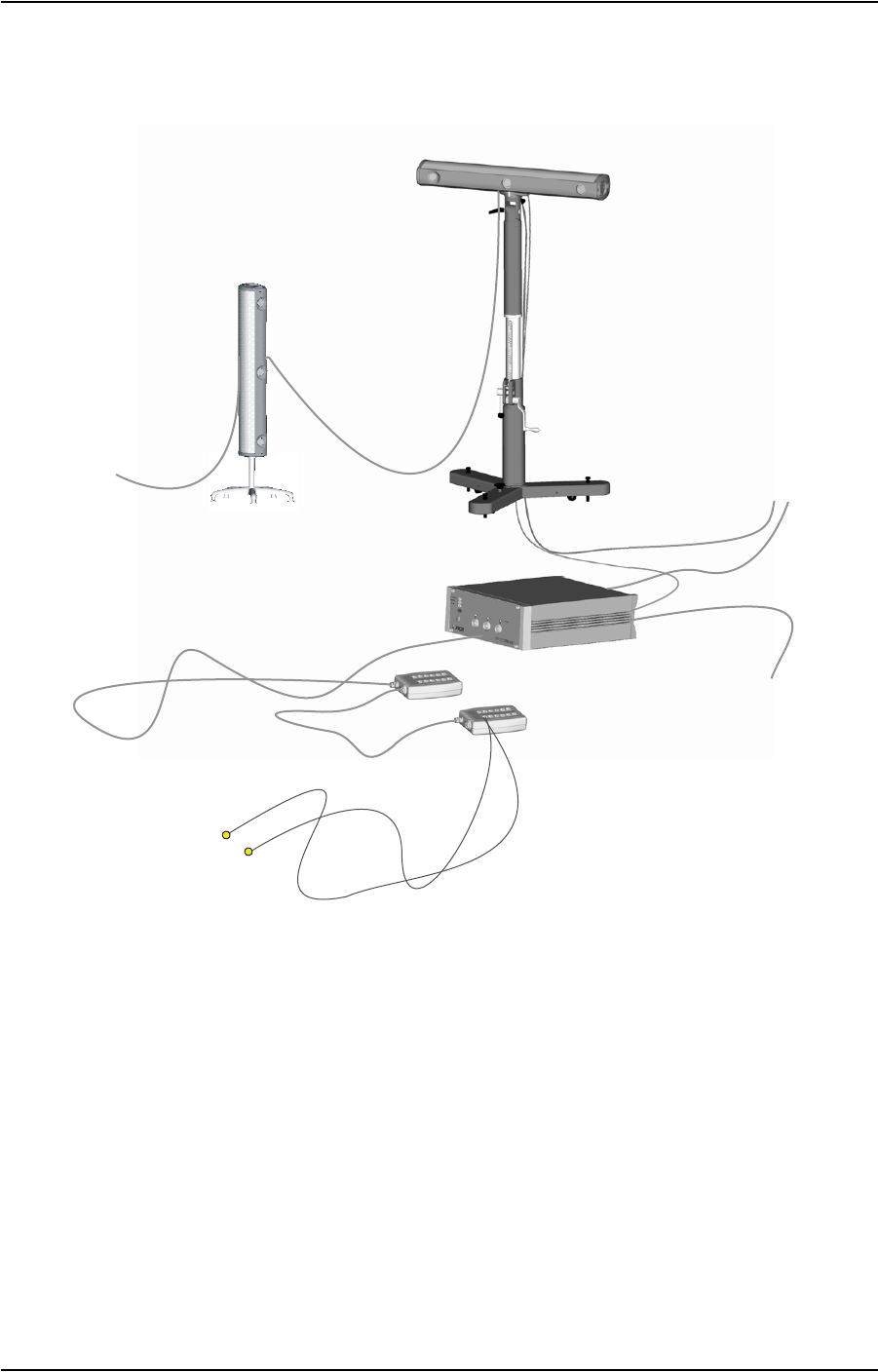
within the measurement volume. The basic Optotrak Certus System, shown in
Figure 3-1 on page 9, consists of:
• a Position Sensor (more are optional)
• a System Control Unit
• one or more strobers, possibly connected with strober extension cables
• infrared light emitting diodes incorporated into a marker
• a host cable to connect the System Control Unit to the host computer
• a link cable to connect the System Control Unit to a Position Sensor
• power cables for both the System Control Unit and the Position Sensor
• a stand or bracket to support the Position Sensor, such as the econo-stand or
Brunson stand (optional)
• an NDI PCI interface card (not shown)
• NDI ToolBench software for controlling of, and receiving data from, the
Optotrak Certus System
• NDI 6D Architect software, for characterizing rigid bodies and tools.

System Overview
8 Optotrak Application Programmer’s Interface Guide
• NDI Register and Align Wizard
• NDI File Convert Wizard
• NDI DataView software, which is used for viewing data files
There are two types of System Control Unit, strobers and some cables. The standard
type is designed for systems where there is electrical isolation from the power mains.
All of the strober ports in the standard type provide this type of electrical isolation.
The second type, called e-type, is designed for applications that require type BF
isolation on some strober ports. The e-type System Control Unit includes two strober
ports with type BF isolation and one standard strober port. E-type strobers and cables
are designed to maintain the type BF isolation. All e-type devices are labelled with the
type BF symbol.
A host computer must be supplied by the user. If the host computer uses a Windows
based operating system, an NDI PCI interface card can be installed in this computer
to communicate with the Optotrak Certus System. Alternatively, communication can
be established through either an Ethernet connection (if the user supplies both an
Ethernet card and a cable) or a SCSI interface. To be fully compliant with the
approvals listed in the “System Guide”, the host computer must also have IEC950
certification.
Additional software and accessories that can be used with the Optotrak Certus
System include:
• Small Computer System Interface (SCSI) Interface Unit, an interface device
alternative to the NDI PCI interface card and Ethernet options. If the host
computer is using either Linux or one of the supported Unix operating
systems, the System Control Unit must be connected to the host computer
through either the NDI SCSI Interface Unit or an Ethernet card.
• Optotrak Data Acquisition Unit II, which can be used to accept and output
both analog and digital signals.
• A vertical or multi-axis head adapter, which is used to attach the Position
Sensor to the Brunson stand
• An econo-stand
•A Brunson stand
• A wall bracket
• Optotrak Application Programmer’s Interface, for users who want to write
their own applications to control and obtain data from the Optotrak Certus
System. This is required if you do not use NDI ToolBench software.
Chapter 3
Revision 1.0 9
• Digitize software, which is used to create imaginary markers and to determine
the coordinates of positions within the volume.
Figure 3-1: Basic Optotrak Certus System
The Position Sensor measures the location of the markers and sends the raw data to
the System Control Unit. It includes a second link port to allow multiple Position
Sensors to be daisy chained together. A total of eight Position Sensors can be used
with one System Control Unit.
The System Control Unit receives the raw marker location data from the Position
Sensor(s). The System Control Unit can calculate the 3D marker location from the
raw data and forward the 3D data to the host computer. Alternatively, the System
Control Unit can forward the raw data for conversion to 3D on the host computer.
3D marker positions are calculated in the default coordinate system of the Position
Sensor. The default coordinate system is characterized at the factory and is specific to
To AC Line Power
To Link Ports
To Host
Computer
Position Sensor
System Control Unit
Marker Strober
Multi-axis Head
To AC Line Power
Link Cable
Econo-stand
Stand
S
trober Extension Cable
Link Cable
Markers Twisted Pair Cable
Host Cable

System Overview
10 Optotrak Application Programmer’s Interface Guide
each Position Sensor, as the exact location of the origin varies slightly with each unit.
Systems consisting of multiple Position Sensors must first be configured by the user
to register all the Position Sensors to a common coordinate system.
The System Control Unit also communicates with and controls the attached strobers
as specified by software used on the host computer. The System Control Unit
interfaces with external devices through a synchronization port and communicates
with the host computer through either the link or Ethernet ports.
The host computer receives data from the System Control Unit and sends collection
instructions, including strober setup, to the System Control Unit. The instructions
are based on settings made in either NDI ToolBench software or through the
Optotrak Application Programmer’s Interface.
Strobers activate the markers in a sequence defined by software on the host computer,
but controlled by the System Control Unit. They can communicate with the System
Control Unit to inform the System Control Unit of their status and configuration.
Markers consist of an infrared light emitting diode fixed to a base. Markers can be
tracked individually or as a group. If a group of markers is to be tracked, the
positions of the markers relative to each other must be fixed; this is called a rigid
body.
Chapter 3
Revision 1.0 11
3.2 Detection Region and Characterized Measurement Volume
The Optotrak Certus System can track markers within one of two detection regions.
The detection region is the volume defined by the field of view of the sensors on the
Position Sensor. The Position Sensor can be focused to only one detection region. To
determine if your Position Sensor is close or far focus, look at the label on the back
of the Position Sensor.
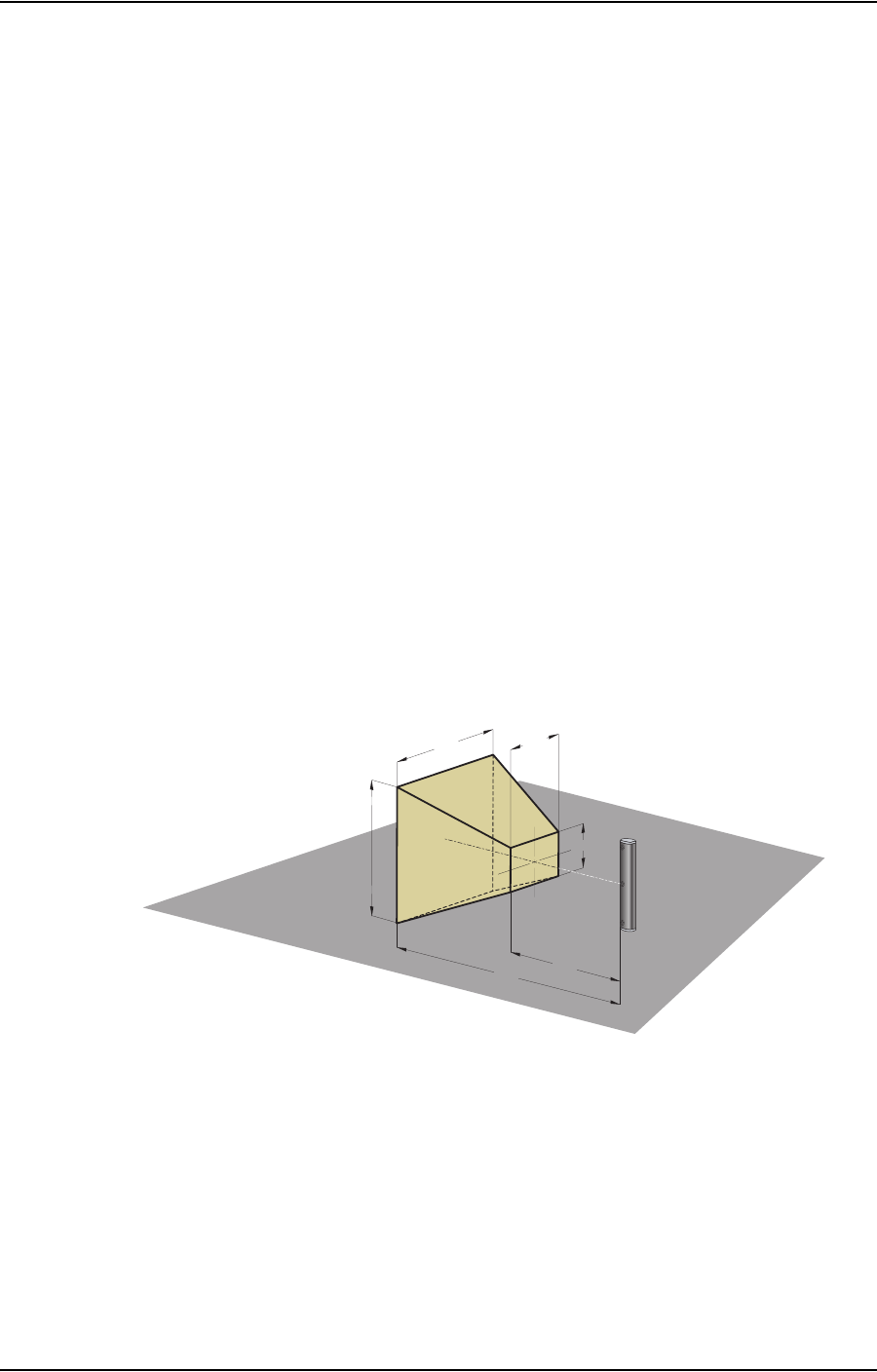
The characterized measurement volume is a subset of the detection region. Within
the characterized measurement volume, the accuracy of the measurement for a single
marker is known. Outside the characterized measurement volume, the accuracy is
unknown. See Figure 3-2 on page 11 and Figure 3-3 on page 12 for diagrams of the
detection regions and the characterized measurement volumes. The characterized
measurement volume and the detection region are the same for the close focus
Position Sensor. Due to continuous product improvement, the dimensions in these
diagrams are subject to change without notice.
Data is reported in the default coordinate system of the Position Sensor that is
developed as part of the characterization process at NDI. The characterization
process is used to develop the camera parameter file for the Position Sensor. This
places the origin (0, 0, 0) on the middle sensor as shown in Figure 3-2 on page 11
and Figure 3-3 on page 12. The coordinate system can be aligned to place the origin
and axes of the coordinate system in a location that is meaningful to you, as
described in the “Optotrak Certus User Guide.”
Figure 3-2 Close Focus Detection Region
1.8 m 0.9 m
1.8 m 0.5 m
3.0 m 1.5 m
System Overview
12 Optotrak Application Programmer’s Interface Guide
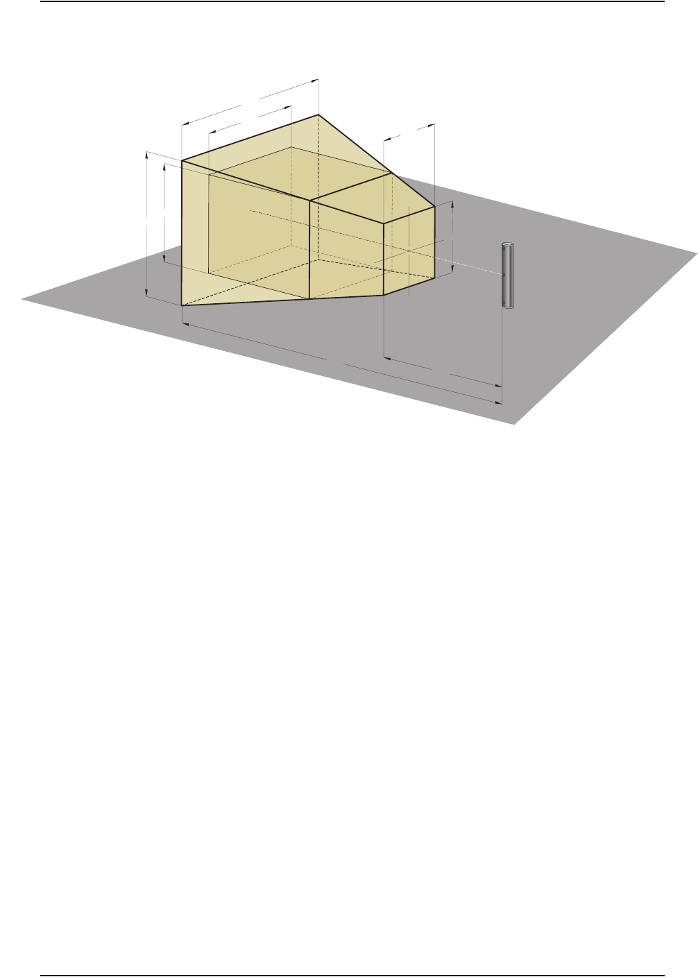
Figure 3-3 Far Focus Detection Region
3.3 Comparison of Optotrak Certus and Optotrak 3020 Systems
The Optotrak Certus System improves performance, while retaining backwards
compatibility to the Optotrak 3020.
Optotrak 3020 components and Optotrak Certus components have different internal
processors. Optotrak 3020 components use transputers while Optotrak Certus
components (Optotrak Certus Position Sensor and Optotrak Certus System Control
Unit) use an improved processor called the SHARC processor. This processor can
process information faster than transputers. All existing API routines that include
transputer in their names such as TransputerDetermineSystemCfg and
TransputerInitializeSystem, are generalized to handle the Optotrak Certus processor
as well as Optotrak 3020 transputers. These routines will work in the same way in
both the Optotrak 3020 System and the Optotrak Certus System.
The Optotrak Certus System is compatible with all Optotrak 3020 components and
all operating systems supported by the Optotrak 3020. All previous file types are
supported.
3.6 m
1.4 m
1.3 m
6.0 m
2.3 m
2.2 m
1.7 m
2.6 m

Chapter 3
Revision 1.0 13
Optotrak Certus System devices can be used with Optotrak 3020 System devices in a
mixed system.
3.4 Mixed System Capability
Optotrak Certus and Optotrak 3020 Systems can be mixed. However, the capabilities
of the mixed system is limited to the 3020 device included in the system. The
Position Sensor and System Control Unit affect different settings:
Table 3-1: Comparison of Optotrak Certus and Optotrak 3020
Feature Optotrak Certus Optotrak 3020
Number of Markers 512 256
Sampling Rates
(Marker Frequency)
4600 Hz 3500 Hz
Real-time Per Marker Data
Rates (Hz)
N = number of markers
Strober Ports 3 4
Maximum Number of
Rigid Bodies
(3 markers/rigid body)
170 85
Hot Connect/Disconnect yes no
Number of Position
Sensors that can be used
simultaneously
8
(6 if ODAU attached)
8
Host Computer
Connection
Ethernet (10/100 mbps)
SCSI
PCI
PCI
SCSI
ISA
4600
N2+
-------------3500
N1+
-------------
Table 3-2: Capabilities of a Mixed System
Setting Minimum Maximum
Duty Cycle (%) 10 85
Voltage (V) 7.0 12.0
Marker Frequency (Hz) 1500 3500

System Overview
14 Optotrak Application Programmer’s Interface Guide
3.5 Optotrak Communications
3.5.1 Client-Server Model
The client-server model illustrates the interface between the Optotrak System and a
user-written application program. Using this model, the Optotrak System acts as the
server, and the host computer application programs are the clients. The services
provided to these clients consist of supplying packets of information of a special
type, such as 3D marker positions, rigid body positions, or the raw values produced
by the Position Sensors. All clients generally communicate with either the Optotrak
Administrator (in the Optotrak System) or the Optoscope Administrator (in the
ODAU II) when making requests.
The client-server analogy can be carried further:
• To obtain information from the server, the client must first introduce itself
to the server.
• After the introduction the client may make requests to the server.
• The server acknowledges that it understands the requests and attempts to
satisfy them by completing each request. An example of this would be setting
up a collection or returning data.
• Finally, when the client has finished using the provided services,
communications with the server stop and the application program is exited.
3.5.2 Messages and Addresses
The Optotrak System is a message-based system. All requests are made to the
Optotrak System via messages to one of the processes (the Optotrak Administrator,
the Optoscope Administrator, or the Data Proprietor) residing within the Optotrak
System.
The message system can be compared to sending a letter through the mail. As with a
letter, all messages contain a destination address and a source address. When you
mail a letter, there is no need to know the physical location of the destination if you
know the address. In the Optotrak System, the client does not need to know where
the Optotrak Administrator is located; it could be on the System Control Unit or
Number of Markers 1 256
Table 3-2: Capabilities of a Mixed System
Setting Minimum Maximum

Chapter 3
Revision 1.0 15
somewhere on one of the Position Sensors. All that is required is the address of the
Optotrak Administrator or the Data Proprietor and the message will be successfully
relayed. The layer in the API responsible for the transmission of messages is called
the message-passing layer.
A message identifier is attached to every message. This identifier determines the type
of message being received and tells the receiver how to interpret the message.
3.5.3 Optotrak System Programming Interface
The programming interface defines how the application programs communicate with
the Optotrak System. The application program must transmit information to and
from the devices in the Optotrak System (the System Control Unit and the ODAU).
With the routine based interface, the application program can control devices in the
Optotrak System by calling the appropriate routines with the proper parameters.
Parameters are passed to the routines using C defined types (int, float, etc.), so the
application program does not have to pack the structures. The routines handle the
packing of structures, the delivery of appropriate message identification to the
Optotrak System, and the receiving of the results from the Optotrak System. By
examining the return value of a routine, the application program can determine if
the routine was completed successfully.
Note Since the routine based interface frees the application program from having to use C
structures, the library routines can easily be called from other programming languages.
Other languages handle data structures, such as strings and arrays, differently than C, so it
is essential that you understand the intricacies of calling the C library routines from
another programming language.
3.6 Initializing the Optotrak System
When the Optotrak System is initialized, the current Optotrak System configuration
is determined. Transputer programs are downloaded into all Optotrak 3020
components that are connected in the system. Predetermined startup code is
downloaded into all Optotrak Certus components from the host computer to switch
the components into run-time mode.
After the configuration has been determined, the results are recorded in a network
information file (nif) and camera parameter file (cam). The default files are
system.nif and standard.cam. They are written to the “realtime” subdirectory under
the path specified in the ND_USER_DIR environment variable. If the environment
variable ND_USER_DIR does not exist, then the files are written to the “realtime”
subdirectory under the path specified in the ND_DIR environment variable.

System Overview
16 Optotrak Application Programmer’s Interface Guide
Network information files define the system configuration and the transputer
programs that need to be downloaded to the Optotrak 3020 components if they are
present in the Optotrak System. Camera parameter files define the operational
characteristics for each Position Sensor in the system.
You must re-determine the system configuration and re-initialize the Optotrak System if
either the cabling connections to the communication ports at the back of the System
Control Unit or the Position Sensor are changed, or if the order of the Position Sensors is
changed. The cabling connection has changed once a cable is disconnected. It is a good
practice to re-initialize your setup and re-determine the system configuration if you are not
certain whether the cabling connections have been changed.
Initialize the system with one of the following:
• application program, call API routines as part of its initialization
• command-line utility programs, before running the application program
• NDI ToolBench, select Optotrak>Build Network Information File in the
Optorak socket options window.
Calling the API routines in the application program is easier than using the
command-line utility programs and is recommended for most applications.
3.6.1 Initializing the Optotrak System From an Application Program
Two steps are required to initialize the system from within the application program.
The first step calls the routine TransputerDetermineSystemCfg and the second step
calls TransputerLoadSystem.
TransputerDetermineSystemCfg generates the default system configuration files
system.nif and standard.cam. The files are written to the “realtime” subdirectory
under the path specified in the ND_USER_DIR environment variable. If the
environment variable ND_USER_DIR does not exist, then the files are written to the
“realtime” subdirectory under the path specified in the ND_DIR environment
variable. TransputerLoadSystem downloads the appropriate transputer programs and
startup code to the system according to the network information stored in system.nif.
If writing the system configurations to disk is undesirable, you can choose to use
TransputerDetermineSystemCfg to store the system configuration information
internally in the API. See “TransputerDetermineSystemCfg” on page 101.
Warning!

Chapter 3
Revision 1.0 17
3.6.2 Initializing the Optotrak System From the Command Line
Two steps are required to initialize the system from the command line. The first step
determines the system configuration and is platform specific; use one of the
following utility programs:
• optset32.exe for Windows NT/2000/XP
• buildnif for Linux, SGI and Sun systems
The second step downloads the system code to the processors. Use one of the
following utility programs:
• dld.exe (Windows)
• dld (Linux, SGI and Sun).
The command line syntax for the DLD program is:
dld - <v>#<nif>
The optional argument <v> specifies the verbosity level that determines the amount
of status information displayed by the DLD. The argument is a number ranging
from 0 to 9 inclusively. At setting 0, no status information is provided.
The argument ‘<nif>’ specifies the network information file. This name of this file is
normally system.nif.
3.6.3 Initializing the Optotrak System During Program Runtime
After the transputer programs and startup code have been downloaded to the system,
the API initiates communications with the system of processors with a call to the
routine TransputerInitializeSystem. This reads the Optotrak System parameter
initialization file optotrak.ini, located in the ‘settings’ subdirectory of the standard
NDI system directory and initializes the system with the settings specified in the file.
3.7 Data Conversions and Transformations on the Host Computer
By default, the Optotrak System performs conversion from raw data to 3D data and
all rigid body transformations internally. If your host computer contains a Pentium
processor (or faster), floating point operations can be performed faster on the host
computer than on the internal processors. The API can arrange to have all the
conversions and transformations done on the host computer. This can be done either
by setting appropriate flags with the routine OptotrakSetProcessingFlags, or by
specifying the options in the initialization file optotrak.ini.

System Overview
18 Optotrak Application Programmer’s Interface Guide
To specify the data conversion and rigid body transformation options in the
initialization file optotrak.ini, add these two lines to the [Optotrak System]
section:
bConvertOnHost = TRUE
bRigidOnHost = TRUE
Setting both values to FALSE or removing the lines completely will cause all the
conversions and transformations to be done on the Optotrak System.
To have the 3D data conversion done on the Optotrak System and the rigid body
transformations on the host computer, use:
bConvertOnHost = FALSE
bRigidOnHost = TRUE
bRigidOnHost can be set to FALSE only if bConvertOnHost is also set to FALSE. If
bConvertOnHost is set to TRUE, the API will implicitly set bRigidOnHost to TRUE.
3.8 Camera Parameter Files
Camera parameters are written to the default camera parameter file called
standard.cam during initialization and are stored internally in the Optotrak System.
An API must load the camera parameters using OptotrakLoadCameraParameters if
either 3D position data or rigid body data are to be collected or manipulated.
Camera parameter files define the operational characteristics for each Position Sensor
in the system. The file contents are determined by calibration and registration
procedures. If you have a single Position Sensor, the calibration parameters are
specific to your unit and you do not need to re-register your unit. These parameters
are in a file called c3xxxxxx.cam where xxxxxx is the serial number of the Position
Sensor. If you have multiple Position Sensors in your system you will need to
generate a suitable camera parameter file. This can be accomplished by either
performing a registration procedure using the routine nOptotrakRegisterSystem, or
by using the Registration and Alignment wizard in the NDI ToolBench software.
3.8.1 Extended Camera Parameter Files
Extended camera parameter files have a different format but the same file extension
(.cam) as standard camera parameter files. All API routines automatically distinguish
between the two file formats.
Extended camera parameter files are comprised of one or more camera parameter sets
associated with each Position Sensor. These files always contain the default camera
parameter set corresponding to the default marker type, marker wavelength and
original lens model. The extended camera parameter files may also contain parameter
sets for additional lens models, marker types and marker wavelengths.

Chapter 3
Revision 1.0 19
When an extended camera parameter file is loaded by the routine
OptotrakLoadCameraParameters, the default camera parameter set is automatically
selected. Select a different set by calling the routine OptotrakSetCameraParameters,
having set the appropriate identifiers within the routine. For more information,
please see “OptotrakSetCameraParameters” on page 118. Call the routine
OptotrakGetCameraParameterStatus to find a complete listing of all the most
recently loaded camera parameter sets.
3.9 Connecting Two Host Computers to the Optotrak System
If you have purchased the additional hardware option that allows you to connect two
host computers to the Optotrak System, then you can include two host computers in
the system and run application programs from either computer. The physical
connection of the second host computer depends on the devices connected to the
Optotrak System. For complete instructions on connecting the second host
computer, refer to the guide “Installing the Secondary PC Interface Kit”.
You must designate one computer as the primary host and the other computer as the
secondary host. All of the sample programs provided in the API CD, except Sample
Program 16, are designed to be used on the primary host. However, all of the sample
programs can be modified to be used on the secondary host computer by making a
few simple changes in the code (see “Retrieving Optotrak System Real-time Data on a
Secondary Host Computer” on page 84 and “Sample Program 16” on page 263).
Sample Programs 16 is designed to be used on a secondary host computer.
Note The primary host initializes the system and loads the camera parameters. The secondary
host must not repeat these procedures or the programs running on the primary host may
display unpredictable behaviors.
An example application of a secondary host computer is to run an application
program to retrieve and manipulate data while the primary host computer runs the
NDI ToolBench software.
A different approach is for the primary host computer to run an application
program that performs all the functions associated with setting up collections and
retrieving data, while the application program on the secondary host is restricted to
retrieving real-time and buffered data. You can also call an API routine to manipulate
the data on the secondary computer.
Note Before you start developing your own custom application programs, try running the sample
programs provided in the API CD in the primary and secondary modes on both computers. If
you experience any problems when attempting to run the applications on both computers
simultaneously, try using the NDI ToolBench software to ensure that your connections have
been made correctly.

System Overview
20 Optotrak Application Programmer’s Interface Guide
3.10 API Quick Guide
This section is a summary of the routines and procedures that are discussed in
Chapters 4 through 9. You will need to go through the chapters to fully understand
each routine.
3.10.1 Initializing the Optotrak System
Within the API
• TransputerDetermineSystemCfg, then TransputerLoadSystem
• TransputerInitializeSystem
From the Command Line
• optset32.exe or buildnif and dld, depending on your system
Using NDI ToolBench
• NDI ToolBench if your host computer is running Windows 9x/NT/2000/Me
• In NDI ToolBench, select Optotrak>Build Network Information File in the
Optorak socket options window
3.10.2 Basic Optotrak Routines
Initialize the System
After TransputerDetermineSystemCfg:
• TransputerLoadSystem
• TransputerInitializeSystem
Shut Down the System
• TransputerShutdownSystem
Retrieve Real-time Data
• OptotrakSetupCollection
•DataGetLatesttype (blocking method)

Chapter 3
Revision 1.0 21
• RequestLatesttype/DataIsReady/DataReceiveLatesttype (non-blocking)
Retrieve Buffered Data
• define spool mapping with DataBufferInitializeFile or
DataBufferInitializeMem
• spool data with DataBufferSpoolData (blocking method)
• DataBufferStart/DataBufferWriteData (non-blocking)
3.10.3 Basic Optotrak Certus Specific Routines
Device Handle Routines
• OptotrakGetNumberDeviceHandles
• OptotrakGetDeviceHandles
• OptotrakDeviceHandleEnable
• OptotrakDeviceHandleGetNumberProperties
• OptotrakDeviceHandleGetProperties
3.10.4 Basic ODAU Routines
Note Always call OptotrakSetupCollection after calling OdauSetupCollection.
Real-time Data Retrieval
• OdauSetupCollection
• OptotrakSetupCollection
• DataGetLatestOdauRaw
Retrieving Buffered Data
• OdauSetupCollection
• OptotrakSetupCollection
• DataBufferInitializeFile - for Optotrak System

System Overview
22 Optotrak Application Programmer’s Interface Guide
• DataBufferInitializeFile - for ODAU
• DataBufferSpoolData
3.10.5 Rigid Body Routines
Retrieve Real-time Data
• RigidBodyAdd or RigidBodyAddFromFile
• DataGetLatestTransforms (blocking)
• RequestLatestTransforms/DataIsReady/RequestLatestTransforms (non-
blocking)
Change the Transformation Settings
• RigidBodyChangeSettings
Determine Transformations from Previously Obtained 3D Data
• OptotrakConvertTransforms
3.10.6 File Handling
File Conversion
• FileConvert for Optotrak raw to 3D or ODAU raw to voltages
Processing Files
• FileOpen/FileOpenAll for all file types
• FileRead/FileReadAll for read only files
• FileWrite/FileWriteAll for read/write files
• FileClose/FileCloseAll for all file types
3.10.7 Using a Secondary Host
• primary host determines the system configuration and loads the processors
• primary host designates which computer is the secondary host with a flag in
the routine TransputerInitializeSystem

Chapter 4
Revision 1.0 23
4 Optotrak Programmer’s Guide
In this section, you will find basic and advanced information on how to:
• initialize the application program, obtain system status and exit the
application program
• obtain real-time data with blocking and non-blocking methods
• obtain buffered data using blocking and non-blocking methods
The API CD contains complete sample programs that can be compiled and run on a
host computer. This section will refer to code fragments from these sample programs
to illustrate the correct usage of the routines and the proper structure of application
programs that can communicate with the Optotrak System effectively. The code
fragments are for illustrating the concepts discussed in the documentation and may
not reflect exactly the actual code in the sample programs.
Follow through the code fragments of the sample programs to learn how API
routines function. Samples begin at the basic level and progress to more advanced
topics. In most cases, the code is simplified and may not include error handling and
storing data to hard disk and other details in order to focus on the major aspects of
the Optotrak System interface.
The flow for each sample program is similar. Each sample program contains a
Program Initialization Code section, a Program Body Code section, and a Program
Exit Code section. The Program Initialization Code section and the Program Exit
Code section are essentially the same for each of the sample programs. These sections
are introduced in the first sample program. In other sample programs, they are only
referred to when necessary and the main focus is on the code fragments comprising
the Program Body Code section.
For a complete listing and description of the available routines, look in “Optotrak
API Routines” on page 93.

Optotrak Programmer’s Guide
24 Optotrak Application Programmer’s Interface Guide
4.1 Initializing, Retrieving System Status and Exiting from
the Optotrak System
To initialize the Optotrak System, retrieve system status information, and exit the
application, three API code sections must be used: Program Initialization Code,
Program Body Code and Program Exit Code.
4.1.1 Program Initialization Code
The Program Initialization Code section consists of three API routine calls:
TransputerLoadSystem, TransputerInitializeSystem, and
OptotrakLoadCameraParameters.
The TransputerLoadSystem routine loads the processors in the Optotrak System with
the transputer program files outlined in the specified network information file (.nif).
This NIF file defines the network connections between all of the Optotrak System
components, and is generated by the TransputerDetermineSystemConfiguration
routine.
Note After a call to the routine TransputerLoadSystem, it is advisable to include a sleep routine
to allow enough time for the routine to finish. The length of time required will depend on
the speed of the host computer — the sample programs use a one second delay. If the sleep
time is too short, the routine will fail and error messages may be generated.
The routine TransputerInitializeSystem initializes a message-passing layer, which
allows the application program to send information to and receive information from
the Optotrak System.
OptotrakLoadCameraParameters loads the camera parameters from the specified
camera parameter file and sends the camera parameters to the Optotrak System. The
default camera parameter file is called standard.cam.
Note All application programs that calculate 3D or 6Ddata must call
OptotrakLoadCameraParameters.
4.1.2 Program Body Code
In the Program Body Code section the application program sets up the collection
parameters and retrieves data from the Optotrak System. For example, the code in
Figure 4-1 on page 28 obtains the current Optotrak System status from the Optotrak
Administrator process. The status information returned describes the collection
parameters (e.g. fFrameFrequency, nMarkers) and other process entities in the current
system configuration (e.g. nNumOdaus, nNumSensors). Use the status information
to determine the sizes of real-time data packets that are returned.

Chapter 4
Revision 1.0 25
4.1.3 Program Exit Code
The Program Exit Code section invokes the routine TransputerShutdownSystem. This
routine removes the host computer from the message-passing layer.
4.1.4 Program Sample Showing How to Initialize and Retrieve System Status
Figure 4-1 on page 28 is an example of how to initialize the Optotrak System and
retrieve the system status information. This program is similar, but not identical, to
Sample Program 1 on the API CD.
In this sample, the network information file system.nif is assumed to have been
created with the routine TransputerDetermineSystemCfg. Alternatively, you can
initialize the Optotrak System using the NDI ToolBench software, or by using a
command-line utility program. For more information, please see “Initializing the
Optotrak System” on page 15.
Note If the Optotrak System was previously initialized by another program the transputer
program files do not need to be reloaded.
In this sample the results obtained in the body code are output to the display screen.
To initialize the Optotrak System, retrieve the system status and exit the program,
follow these steps:
1. Load the Optotrak System with the appropriate transputer programs and startup
code.
2. Connect the application program to the message-passing layer.
3. Load the Optotrak System with the appropriate camera parameters.
4. Request and display the current Optotrak System status.
5. Disconnect the application program from the message-passing layer.
/*****************************************************************
Name: SAMPLE1.C
Description:
Optotrak Sample Program #1.
1. Load the system of processors with the appropriate
transputer programs and startup code.
2. Initiate communications with the system of processors.
3. Load the appropriate camera parameters.
4. Request/receive/display the current Optotrak System status.

Optotrak Programmer’s Guide
26 Optotrak Application Programmer’s Interface Guide
Pass NULL for those status variables that are not requested.
5. Disconnect the PC application program from the system of processors.
******************************************************************/
/*****************************************************************
C Library Files Included
*****************************************************************/
#include <stdio.h>
#include <string.h>
#include <stdlib.h>
#ifdef _MSC_VER
void sleep( unsigned int uSec );
#elif __BORLANDC__
#include <dos.h>
#elif __WATCOMC__
#include <dos.h>
#endif
/*****************************************************************
ND Library Files Included
*****************************************************************/
#include "ndtypes.h"
#include "ndpack.h"
#include "ndopto.h"
/*****************************************************************
Name: main
Input Values:
int
argc :Number of command line parameters.
unsigned char
*argv[] :Pointer array to each parameter.
Output Values:
None.
Return Value:
None.
Description:
The main program routine performs all steps listed in the above program
description.
*****************************************************************/
void main( in argc, unsigned char *argv[])
{
int
nNumSensors,
nNumOdaus,
nMarkers;

Chapter 4
Revision 1.0 27
char
szNDErrorString[MAX_ERROR_STRING_LENGTH + 1];
/*
* STEP 1
* Load the system of processors.
*/
if( TransputerLoadSystem( "system" ) )
{
goto ERROR_EXIT;
} /* if */
/*
*Wait one second to let system finish loading
*/
sleep(1);
/*
* STEP 2
* Initialize the system of processors.
*/
if( TransputerInitializeSystem( OPTO_LOG_ERRORS_FLAG ) )
{
goto ERROR_EXIT;
} /* if */
/*
* STEP 3
* Load the standard camera parameters.
*/
if( OptotrakLoadCameraParameters( "standard" ) )
{
goto ERROR_EXIT;
} /* if */
/*
* STEP 4
* Request and receive the Optotrak status.
*/
if( OptotrakGetStatus(
&nNumSensors, /* Number of sensors in the Optotrak System. */
&nNumOdaus, /* Number of ODAUs in the Optotrak System. */
NULL, /* Number of rigid bodies being tracked by the O/T.*/
&nMarkers, /* Number of markers in the collection. */
NULL, /* Frequency that data frames are being collected.*/
NULL, /* Marker firing frequency. */
NULL, /* Dynamic or Static Threshold value being used.*/
NULL, /* Minimum gain code amplification being used.*/
NULL, /* Stream mode indication for the data buffers*/
NULL, /* Marker Duty Cycle being used.*/

Optotrak Programmer’s Guide
28 Optotrak Application Programmer’s Interface Guide
NULL, /* Voltage being used when turning on markers */
NULL, /* Number of seconds data is being collected.*/
NULL, /* Number of seconds data is being pre-triggered.*/
NULL ) ) /* Configuration flags.*/
{
goto ERROR_EXIT;
} /* if */
/*
* Display elements of the status received.
*/
fprintf( stdout, "Sensors in system :%3d\n", nNumSensors );
fprintf( stdout, "ODAUs in system :%3d\n", nNumOdaus );
fprintf( stdout, "Default Optotrak Markers:%3d\n", nMarkers );
/*
* STEP 5
* Shutdown the message-passing system.
*/
if( TransputerShutdownSystem() )
{
goto ERROR_EXIT;
} /* if */
/*
* Exit the program.
*/
fprintf(stdout, “\nProgram execution complete.\n”);
exit( 0 );
ERROR_EXIT:
if(Optotrak Get Error String(szNDErrorString,
MAX_ERROR_STRING_LENGTH + 1 ) == 0 )
{
fprintf( stdout, szNDErrorString );
} /* if */
TransputerShutdownSystem();
exit( 1 );
} /* main */
Figure 4-1: Retrieving Optotrak System Status

Chapter 4
Revision 1.0 29
4.2 Retrieving Real-time Optotrak Data
The primary function of the Optotrak System is to collect position data and relay it
to the host computer. Data can be retrieved by an application program in real-time,
or from the data buffer. When real-time data is requested, the Optotrak System
returns the most recent frame of data to the application program. Retrieving real-
time data is discussed before retrieving buffered data (see “Retrieving Buffered
Optotrak Data” on page 34).
There are three types of data that can be retrieved from an Optotrak System: raw, full
raw and 3D data. Full raw data is raw (centroid) data with additional status
information including signal strength, amplification, and error code. Full raw data
files are twice as large as raw data files and are used primarily to diagnose problems
in the equipment setup. 3D data cannot be collected as quickly as raw or full raw
data because of the time required to convert the data. You may define the file names
for the data files. In general, filenames for raw data files begin with R# while
filenames for 3D data files begin with C#.
Note Centroid data is raw data. Routines that access raw data have ‘centroid’ in their name (e.g.
DataGetLatestCentroid). Full raw data is centroid data with additional status information.
Routines that access full raw data have ‘raw’ in their name (e.g. DataGetNextRaw).
You must configure the Optotrak System before data can be collected. This sets the
values for the collection parameters such as the number of markers and frame rate.
See “OptotrakSetupCollection” on page 124 for details on the collection parameters.
Raw and 3D data can be collected in real-time or as buffered data.
4.2.1 Basic Real-time Data Retrieval
There are several ways to retrieve real-time data. The sample below illustrates the
simplest, single routine invocation for retrieving data in real-time. An advanced
method is described in the next section, “Advanced Real-time Data Retrieval Without
Blocking” on page 32. Once the data has been received from the Optotrak System, it
can be displayed or processed with the application program. Refer to “Real-time Data
Retrieval Routines” on page 157 for a more detailed explanation of real-time data
retrieval.
Before the application program exits, ensure that the IRED markers are de-activated.
This operation can be considered to be part of the Program Exit Code section
described in the “Program Exit Code” on page 25. Hence, it does not appear in any
further discussions or code fragments.

Optotrak Programmer’s Guide
30 Optotrak Application Programmer’s Interface Guide
You must ensure that enough memory is allocated to accommodate a frame of real-time
data to prevent the possibility of invalid memory regions being overwritten and possible
system crashes. The routines for data retrieval copy the data directly into the memory
allocated by the host application program. Each of the real-time data retrieval routine
descriptions describes how to determine the required amount of memory for its associated
data type. See “Real-time Data Retrieval Routines” on page 157 for the routines. Refer to
“Retrieving Optotrak System Real-time Data on a Secondary Host Computer” on page 84 for
sample code that includes memory allocation.
4.2.2 Sample Program to Retrieve and Display Real-time 3D Marker Positions
Figure 4-2 on page 32 shows an example of how to retrieve and display real-time 3D
marker positions using the simplest method, the routine DataGetLatest3D. This
routine blocks while the Optotrak System calculates the latest frame of 3D
coordinates and returns once the data has been received. This example is similar, but
not identical, to Sample Program 2 on the API CD.
This sample program retrieves real-time 3D data via a routine call and displays the
data on the screen. In addition to returning the 3D data, the Optotrak System
returns three other related data items: uFrameNumber, uElements, and uFlags. For a
description of each of these data items, refer to “DataGetLatestCentroid” on
page 157.
To retrieve and display real-time data from the Optotrak System:
1. Configure the Optotrak System collection settings.
2. Activate the IRED markers.
3. Retrieve the latest frame of 3D marker data.
4. Display the 3D data and the status information.
5. De-activate the IRED markers.
/*
* STEP 1
* Set up a collection for the Optotrak.
*/
if( OptotrakSetupCollection(
NUM_MARKERS, /* Number of markers in the collection. */
(float)100.0, /* Frequency to collect data frames at. */
(float)2500.0, /* Marker frequency for marker maximum on-time. */
30, /* Dynamic or Static Threshold value to use. */
160, /* Minimum gain code amplification to use. */
0, /* Stream mode for the data buffers. */
(float)0.35, /* Marker Duty Cycle to use. */
(float)7.0, /* Voltage to use when turning on markers. */
Warning!

Chapter 4
Revision 1.0 31
(float)1.0, /* Number of seconds of data to collect. */
(float)0.0, /* Number of seconds to pre-trigger data by. */
OPTOTRAK_BUFFER_RAW_FLAG ) )
{
goto ERROR_EXIT;
} /* if */
/*
* STEP 2
* Activate the markers.
*/
if( OptotrakActivateMarkers() )
{
goto ERROR_EXIT;
} /* if */
/*
* Get and display ten frames of 3D data.
*/
fprintf( stdout, "\n\n3D Data Display\n" );
for( uFrameCnt = 0; uFrameCnt < 10; ++uFrameCnt )
{
/*
* STEP 3
* Get a frame of data.
*/
fprintf( stdout, "\n" );
if( DataGetLatest3D( &uFrameNumber,
&uElements,
&uFlags,
p3dData ) )
{
goto ERROR_EXIT;
} /* if */
/*
* STEP 4
*/
fprintf( stdout, "Frame Number: %8u\n", uFrameNumber );
fprintf( stdout, "Elements : %8u\n", uElements );
fprintf( stdout, "Flags : 0x%04x\n", uFlags );
for( uMarkerCnt = 0; uMarkerCnt < NUM_MARKERS; ++uMarkerCnt )
{
fprintf( stdout, "Marker %u X %f Y %f Z %f\n",
uMarkerCnt + 1,
p3dData[ uMarkerCnt].x,
p3dData[ uMarkerCnt].y,
p3dData[ uMarkerCnt].z );

Optotrak Programmer’s Guide
32 Optotrak Application Programmer’s Interface Guide
} /* for */
} /* for */
/*
* STEP 5
* De-activate the markers.
*/
if( OptotrakDeActivateMarkers() )
{
goto ERROR_EXIT;
} /* if */
Figure 4-2: Retrieving and Displaying Real-time
3D Marker Positions
4.2.3 Advanced Real-time Data Retrieval Without Blocking
The Optotrak API also provides a method where the host computer does not block
while waiting for the Optotrak System to return the data. This allows the host
computer to perform other operations while the Optotrak System is determining the
latest frame of data. For example, the application program can process input from
another device, perform calculations, or control other devices.
The non-blocking method uses three routines: RequestLatesttype, DataIsReady, and
DataReceiveLatesttype.
RequestLatesttype requests that the Optotrak System compute the latest frame of
data and to send it back to the host computer. This routine does not block and wait
for the data to be returned. The application program must determine when the real-
time data is ready and then receive it accordingly.
DataIsReady is invoked to determine if the real-time data is ready to be received. If
the real-time data is waiting to be received, DataIsReady returns a non-zero value. The
application program should then promptly receive the data.
DataReceiveLatesttype must be used to retrieve the data that is waiting to be
received. DataReceiveLatesttype copies the data waiting to be received directly into the
pre-allocated memory location on the host computer.

Chapter 4
Revision 1.0 33
Do not send a new request for data until the data from the previous request has been
received. This is especially true if the application program is requesting two types of data.
Suppose an application was requesting both ODAU II raw data and Position Sensor 3D
data, and the requests for the data were made immediately following one another. Once the
routine DataIsReady returns TRUE, the application program has no way of determining
whether it was receiving ODAU or Position Sensor data.
4.2.4 Sample Program to Collect Real-time Data Without Blocking
This sample program is an example of how to collect real-time 3D data using the
non-blocking method:
1. Request the latest 3D data from the Optotrak System.
2. Wait for the data to be returned from the Optotrak System.
3. Receive the data.
/*
* STEP 1
* Request the latest 3D data.
*/
if( RequestLatest3D() )
{
goto ERROR_EXIT;
} /* if */
/*
* STEP 2
* Loop until the data is ready to be received.
*/
while( !DataIsReady() )
{
; /* We could do other processing here while we’re waiting. */
}
/*
* STEP 3
* Get the latest data that is waiting to be received.
*/
if( DataReceiveLatest3D( &uFrameNumber, &uElements, &uFlags, p3dData ) )
{
goto ERROR_EXIT;
} /* if */
Figure 4-3: Advanced Real-time Data Retrieval
Warning!

Optotrak Programmer’s Guide
34 Optotrak Application Programmer’s Interface Guide
4.3 Retrieving Buffered Optotrak Data
Once a collection has been configured, the Optotrak System collects data according
to the specified collection parameters and stores each frame of data in a circular
buffer on the SCU. An application program can retrieve the data stored in this
buffer in fixed-size blocks, and either writes the data to disk, or stores it in the
memory previously allocated by the application program.
Note You must configure the collection and activate the markers before buffered data can be
retrieved. Several of the collection parameters affect the amount of data that is returned.
The program can also specify whether raw (centroid) data, full raw data or 3D data is to be
buffered. For complete details, refer to “OptotrakSetupCollection” on page 124.
Before any data can be retrieved from the data buffer, a spool mapping must be
made between the data buffer on the SCU and the spool destination for the data on
the host computer. A spool mapping defines the destination (e.g. a data file or an
allocated memory block) for the buffered data from a particular source. The
DataBufferInitializeFile routine is invoked to define the spool mapping between the
data buffer and the specified file. The routine DataBufferInitializeMem is invoked to
define the spool mapping between the data buffer and the specified memory block.
Once this relationship is defined, any buffered data the host computer receives from
the Optotrak System is written directly to the file or memory block.
There are two methods to spool the data. The routine DataBufferSpoolData does not
return until all buffered data has been received from the Optotrak System. Some
application programs may need to do other operations while the buffered data is
being spooled. To use an advanced, non-blocking procedure for these programs, refer
to “Advanced Buffered Data Retrieval Without Blocking” on page 36.
4.3.1 Basic Buffered Data Retrieval
The simplest method of data spooling uses the DataBufferSpoolData routine. This
routine instructs the Optotrak System to start sending buffered data back to the host
computer starting at the current frame. The host computer receives buffered data and
writes them directly to the appropriate destination; in the sample below, this is the
file “C#001.SM2.” After all the buffered data has been written, the file is closed, the
appropriate header information is written and the status of the spooling procedure is
returned. If the spool status returned is not zero, then a buffering error has occurred
during the spooling procedure, and the spooled data may not be valid.
Note Once the spool procedure has finished, the previously defined spool mappings are no
longer valid. All spool mappings must be reset before performing the next spool procedure.

Chapter 4
Revision 1.0 35
4.3.2 Basic Sample Program to Collect Buffered Data to Disk
In this sample program, buffered data is written to the file “C#001.SM2”. This code
fragment is similar to Sample Program 3 in the API CD. To collect Optotrak System
buffered data to disk:
1. Configure the Optotrak System collection.
2. Activate the IRED markers.
3. Define the spool mapping between the data buffer and the file “C#001.SM2.”
4. Spool the data and print the spool status.
/*
*STEP 1
* Set up a collection for the Optotrak.
*/
if( OptotrakSetupCollection(
6, /* Number of markers in the collection. */
(float)50.0, /* Frequency to collect data frames at. */
(float)2500.0, /* Marker frequency for marker maximum on-time.*/
30, /* Dynamic or Static Threshold value to use. */
160, /* Minimum gain code amplification to use. */
0, /* Stream mode for the data buffers. */
(float)6.5, /* Voltage to use when turning on markers. */
(float)2.0, /* Number of seconds of data to collect. */
(float)0.0, /* Number of seconds to pre-trigger data by. */
OPTOTRAK_FULL_DATA_FLAG ) )
{
goto ERROR_EXIT;
} /* if */
/*
* STEP 2
* Activate the markers.
*/
if( OptotrakActivateMarkers() )
{
goto ERROR_EXIT;
} /* if */
/*
* STEP 3
* Initialize a data file for spooling of the Optotrak data.
*/
if( DataBufferInitializeFile( OPTOTRAK, "C#001.SM2" ) )

Optotrak Programmer’s Guide
36 Optotrak Application Programmer’s Interface Guide
{
goto ERROR_EXIT;
} /* if */
/*
* STEP 4
* Spool data to the previously initialized file.
*/
if( DataBufferSpoolData( &uSpoolStatus ) )
{
goto ERROR_EXIT;
} /* if */
fprintf( stdout, "Spool Status: 0x%04x\n", uSpoolStatus );
Figure 4-4: Collecting Optotrak Buffered Data to Disk
4.3.3 Advanced Buffered Data Retrieval Without Blocking
Some application programs may need to do other operations while the buffered data
is being spooled. These programs use a non-blocking spool procedure.
Three API routines are used to implement the non-blocking spooling process while
collecting 3D data: DataBufferStart, DataBufferWriteData, and DataBufferStop.
Once all spool mappings are initialized, the data buffers on the SCU and the ODAU
(if connected) start spooling data back to the host computer. This is done by
invoking the routine DataBufferStart.
While the Optotrak System is spooling buffered data back to the host computer, the
application program must repeatedly call the routine DataBufferWriteData. This
routine receives any buffered data from the Optotrak System and writes it to the
appropriate spool destination. This routine also sets the following status variables to
determine the current status of the Optotrak System: uRealtimeDataReady,
uSpoolComplete, uSpoolStatus, and ulFramesBuffered.
uRealtimeDataReady is set to a non-zero value if there is real-time data to be
received by the application program.
uSpoolComplete is set to a non-zero value when the spooling procedure is finished.
Once uSpoolComplete is set to non-zero, the spooling procedure is done, and the
application program need not make further calls to DataBufferWriteData.
uSpoolStatus is zero unless a buffering error has occurred, and the spooled data may
not be valid.
ulFramesBuffered is set to the number of frames of data returned from the
Optotrak System in the collection at the point when this routine is called. If this
information is not of interest, set this parameter to NULL.
Use the DataBufferStop routine to stop the spooling of buffered data before all the
data has been sent by the Optotrak System. A call to this routine stops the Optotrak

Chapter 4
Revision 1.0 37
System from sending buffered data at the current frame being collected. However,
there may still be a block of buffered data sent by the Optotrak System: the
application program must stay in the loop until the uSpoolComplete parameter is set
to be non-zero by the routine DataBufferWriteData.
4.3.4 Advanced Sample Program to Retrieve Buffered Data Without Blocking
Figure 4-5 on page 39 is an example of the non-blocking spooling procedure. This
code fragment is similar to Sample Program 7 on the API CD. The Optotrak System
is initialized, a collection is configured and IRED markers are activated, as in
previous examples. This sample then waits for marker 1 to come into view. At this
point, a data file collection is started and data is collected until all the buffered data
has either been spooled or marker 1 goes out of view. Program Exit Code is run
before returning back to the operating system.
To wait for a marker to come into view, a pause is created by requesting real-time 3D
data in a loop. During each iteration through the loop, the data is examined to
determine if a 3D coordinate could be calculated for marker 1. If a position for
marker 1 cannot be calculated, the X, Y, and Z coordinates of the 3D position are set
to a very large negative number (BAD_FLOAT) by the Optotrak System and the
program compares the returned values with the constant MAX_NEGATIVE. In this
sample, once the X value becomes greater than MAX_NEGATIVE, the program
determines that a valid 3D coordinate has been obtained, and continues with the
data file collection.
Similarly, if marker 1 is out of view, the program repeatedly retrieves 3D data and
compares the X coordinate to the value MAX_NEGATIVE. If the X value is less than
MAX_NEGATIVE, a 3D number cannot be calculated, the marker is assumed to be
out of view and the spooling procedure is terminated.
To collect buffered data to disk:
1. Initialize spooling variables that are used later by the routine
DataBufferWriteData.
2. Wait for marker 1 to come into view.
3. Start the Optotrak System spooling buffered data to the host computer.
4. Get a frame of 3D marker data.
5. If marker 1 is out of view, stop the Optotrak System spooling buffered data.
6. Write data to the appropriate spool destination and check for spooling
completion.
/*
* STEP 1
* Initialize the necessary spooling variables and a file for

Optotrak Programmer’s Guide
38 Optotrak Application Programmer’s Interface Guide
* spooling of the Optotrak data.
*/
uSpoolStatus =
uSpoolComplete =
uRealtimeDataReady = 0;
/*
* STEP 2
* Loop until marker 1 comes into view.
*/
fprintf( stdout, "Waiting for Marker 1...\n" );
do
{
/*
* Get a frame of 3D data.
*/
if( DataGetLatest3D( &uFrameNumber,&uEle ments,&uFlags,p3dData ) )
{
goto ERROR_EXIT;
}
/* if */
} /* do */
while( p3dData[ 0].x < MAX_NEGATIVE );
/*
* STEP 3
* Start the Optotrak spooling data to us.
*/
if( DataBufferStart() )
{
goto ERROR_EXIT;
} /* if */
fprintf( stdout, "Collecting Data File\n" );
/*
* Loop around spooling data to the file until there is no data left.
*/
do
{
/*
* STEP 4
* Get a frame of 3D data.
*/

Chapter 4
Revision 1.0 39
if( DataGetLatest3D( &uFrameNumber,&uElements,&uFlags,p3dData ) )
{
goto ERROR_EXIT;
} /* if */
/*
* STEP 5
* Check to see if marker 1 is out of view and stop the Optotrak
* from spooling data if this is the case.
*/
if( p3dData[ 0].x < MAX_NEGATIVE )
{
if( DataBufferStop() )
{
goto ERROR_EXIT;
} /* if */
} /* if */
/*
* STEP 6
* Write data if there is any to write.
*/
if( DataBufferWriteData( &uRealtimeDataReady,
&uSpoolComplete,
&uSpoolStatus,
NULL ) )
{
goto ERROR_EXIT;
} /* if */
} /* do */
while( !uSpoolComplete );
fprintf( stdout, "Spool Status: 0x%04x\n", uSpoolStatus );
Figure 4-5: Advanced Buffered Data Retrieval

Optotrak Programmer’s Guide
40 Optotrak Application Programmer’s Interface Guide

Chapter 5
Revision 1.0 41
5 ODAU Programmer’s Guide
This section will help you to understand the routines used to control and retrieve data
from an Optotrak Data Acquisition Unit (ODAU). You are assumed to have read and
understood all the concepts presented in the previous section, the “Optotrak
Programmer’s Guide” on page 23. An application program can retrieve both real-
time and buffered data from an ODAU device. Use the sample code fragments in
this section to learn how to retrieve both of these data types.
There are two types of data acquisition units: the ODAU I has been superseded by the
ODAU II. The ODAU II includes all of the ODAU I functions, but supports higher
data rates and has additional features. The multiplexer, analog to digital input/output
and timer functions have all been enhanced in the ODAU II. Some routines in this
section apply only to the ODAU II. The introduction of each routine in “ODAU
Specific Routines” on page 143 states which ODAU unit the routine is applicable to.
When the Optotrak System includes an ODAU, it is capable of collecting
synchronized analog and digital data in addition to centroid (raw), full raw, 3D and
6D transformation data. The ODAU II has 16 analog voltage input channels and 8
digital input/output pins, which are collected synchronously with the Optotrak
System data. See Table 9-11 on page 154 for an ODAU I digital I/O port pin
configuration or Table 9-13 on page 156 for an ODAU II digital I/O port pin
configuration. An application program cannot be written for the ODAU alone
because the ODAU connects to and is controlled by the Optotrak System Control
Unit. ODAU devices must be connected to a complete Optotrak System.

ODAU Programmer’s Guide
42 Optotrak Application Programmer’s Interface Guide
5.1 Setting Up Data Collection from the ODAU
You must set up a valid collection before any data can be retrieved from the ODAU; all
ODAU devices must have their collections set up before the Optotrak System’s. The
order in which these collections are set up is important. After the Optotrak System
receives its collection parameters, it signals all ODAU devices to start sampling data.
This ensures that all devices start collecting data at the same point in time. The
application program can begin to request data after all devices have been successfully
configured.
Use the routine OdauSetupCollection to configure the ODAU collection parameters.
Up to four (4) ODAU devices can be connected to the Optotrak System in a series. A
separate call to the OdauSetupCollection routine must be made for each ODAU
connected in the Optotrak System.
The routine OdauSetupCollection uses the first parameter to identify which set of
collection parameters are for which ODAU device. There are four pre-defined
constants used to identify the ODAU devices: ODAU1, ODAU2, ODAU3, and
ODAU4. The constants identify the ODAU devices in the following manner:
ODAU1 is the first ODAU device connected to the Optotrak System (i.e. connected
to the SCU). ODAU2, ODAU3, and ODAU4 are the second, third, and fourth
ODAU units in the serial connection. For a complete description of the parameters
for OdauSetupCollection, refer to “OdauSetupCollection” on page 149.
Note After a call to the routine OptotrakSetupCollection or OdauSetupCollection, it is advisable
to include a sleep routine to allow enough time for the routine to finish. The length of time
required will depend on the speed of the host computer — the sample programs use a one
second delay. If the sleep time is too short, the routine will fail and error messages may
generated.

Chapter 5
Revision 1.0 43
5.2 Retrieving ODAU Real-time Data
This section explains how to retrieve real-time data from an ODAU device connected
to the Optotrak System.
Use the routine DataGetLatestOdauRaw to retrieve real-time data from the ODAU
device. This routine retrieves the latest complete frame of raw data from the specified
ODAU device. Since the ODAU can collect both analog and digital data, the data
frame returned from the ODAU may contain analog data, digital data or both,
depending on the collection setup. If both analog and digital data are being sampled,
the analog data always precedes the digital data in the data frame. See “Sample
Formats” on page 68 and “ODAU Raw Data” on page 246 for a complete description
of a data frame.
The ODAU device returns analog data only in raw format. If the application requires
the data to be expressed as a voltage, the conversion must be done on the host
computer.
The formula for calculating voltages for an ODAU I, corrected for offset and gain
from the given analog raw data is:
where RawData is the analog raw data for a particular ODAU channel and Gain is the
analog gain used in the current collection setup for that ODAU.
For an ODAU II device, the voltage is calculated using:
where RawData is the analog raw data for a particular ODAU channel and Gain is the
analog gain used in the current collection setup for that ODAU.
In Figure 5-1 on page 45, the formula for an ODAU II device is used to convert the
raw analog data to a voltage, which is then displayed. The upper 8 bits contain the
digital data.
For an ODAU I device, the code fragment for calculating the voltage is replaced with:
((float) ((int)(puRawData[ uChannelCnt] & 0x0FFF) - 2048) / 204.8);
The formula is implemented in the code fragment with one modification — a logical
“AND” is performed with the raw data and the hexadecimal constant 0FFF. This
operation is added to remove the upper 4 bits of the 16-bit raw data value. Since the
analog to digital converter on the ODAU has 12-bit resolution, only the lower 12 bits
are required. The upper 4 bits can contain status information, which, if used in the
formula, would cause the wrong voltage to be computed.
Voltage RawData 2048–
204.8 Gain×
------------------------------------------=
Voltage RawData 0.000305175×
Gain
--------------------------------------------------------------=

ODAU Programmer’s Guide
44 Optotrak Application Programmer’s Interface Guide
When all the analog data has been displayed, the digital data is output as hexadecimal
values. The digital data is in a 16-bit integer format, where each bit represents the
status of the corresponding channel on the digital port. If a bit is 1, then the
corresponding channel was at a logic high when the frame was sampled. If a bit is 0,
the corresponding channel was at a logic low when the frame was sampled.
Program Sample of Retrieving Real-time Data from ODAU
Figure 5-1 on page 45 contains the code that shows how to retrieve and display
ODAU real-time data. The code fragment assumes that a valid network information
file has been set up (“Initializing the Optotrak System” on page 15) and that the
standard Program Initialization Code section has been run successfully. This code
fragment is similar to Sample Program 12 on the API CD.
To retrieve ODAU real-time data:
1. Configure the ODAU collection.
2. Configure the Optotrak System collection.
3. Activate the IRED markers.
4. Convert the raw data to voltage and display the voltages.
5. Display the ODAU digital data in hexadecimal format.
/*
* STEP 1
* Set up a collection for the ODAU.
*/
if( OdauSetupCollection(
ODAU1, /*Id the ODAU parameters are for.*/
NUM_CHANNELS, /*Number of analog channels to collect.*/
ODAU_GAIN, /*Gain to use for the analog channels.*/
ODAU_DIGITAL_INPB_INPA, /*Mode for the Digital I/O port.*/
(float)100.0, /*Frequency to collect data frames at.*/
(float)90000.0, /*Frequency to scan channels at. */
0, /*Stream mode for the data buffers. */
(float)1.0, /* Number of seconds of data to collect.*/
(float)0.0, /* Number of seconds to pretrigger data.*/
0 ) ) /* Flags. */
goto ERROR_EXIT;
} /* if */
/*
* STEP 2
* Set up a collection for the OPTOTRAK.
*/
if( OptotrakSetupCollection(
NUM_MARKERS, /* Number of markers in the collection. */
(float)100.0, /* Frequency to collect data frames at. */

Chapter 5
Revision 1.0 45
(float)2500.0, /* Marker frequency for marker maximum on-time. */
30, /* Dynamic or Static Threshold value to use. */
160, /* Minimum gain code amplification to use. */
0, /* Stream mode for the data buffers. */
(float)0.20, /* Marker Duty Cycle to use. */
(float)6.0, /* Voltage to use when turning on markers. */
(float)1.0, /* Number of seconds of data to collect. */
(float)0.0, /* Number of seconds to pre-trigger data by. */
OPTOTRAK_BUFFER_RAW_FLAG ) )
{
goto ERROR_EXIT;
} /* if */
/*
* Get and display ten frames of ODAU data.
*/
fprintf( stdout, "ODAU Data Display\n" );
for( uFrameCnt = 0; uFrameCnt < 10; ++uFrameCnt )
{
/*
* STEP 3
* Get a frame of ODAU raw data.
*/
if( DataGetLatestOdauRaw( ODAU1, &uFrameNumber, &uElements,
&uFlags,pRawData ) )
{
goto ERROR_EXIT;
} /* if */
/*
* STEP 4
* Print out the data.
*/
fprintf( stdout, "\n" );
fprintf( stdout, "Frame Number: %8u\n", uFrameNumber );
fprintf( stdout, "Elements : %8u\n", uElements );
fprintf( stdout, "Flags : 0x%04x\n", uFlags );
for( uChannelCnt = 0; uChannelCnt < NUM_CHANNELS; ++uChannelCnt )
{
fprintf( stdout, "Channel %u Raw 0x%04x Voltage %f\n",
uChannelCnt + 1, puRawData[
uChannelCnt],(float)(
(int)(puRawData[uChannelCnt]))*0.000305175/(float)ODAU_GAIN);
} /* for */
/*
* STEP 5
* Print out the digital data in hexadecimal.
*/
fprintf( stdout, "Digital 0x%04x\n", puRawData[ NUM_CHANNELS] );
} /* for */
Figure 5-1: Retrieving/Displaying ODAU Real-time Data

ODAU Programmer’s Guide
46 Optotrak Application Programmer’s Interface Guide
5.3 Retrieving Buffered ODAU Data
This section explains the steps that must be followed to retrieve buffered data from
the ODAU, and write that information to a Northern Digital Floating Point format
data file. Please see the “Floating Point Programmer’s Guide” on page 65 and “Real-
time Data Types” on page 237 for an explanation of file types.
Each ODAU device in the Optotrak System has its own circular data buffer. Unlike
the Optotrak System data buffer, which can store either raw data or 3D data, the
ODAU data buffer can store only ODAU raw data. If the data in the file must be in
voltage format, the application program can call the FileConvert routine (see
“FileConvert” on page 221).
A spool mapping must be set for each device that spools buffered data to the host
computer. If a particular device in the Optotrak System has no spool mapping set,
then any buffered data available to the host computer from that device is discarded.
To set a spool mapping for a device’s data buffer, use either of the routines
DataBufferInitializeFile or DataBufferInitializeMem. These two routines identify the
device (e.g. ODAU1), and either the file or memory block to which the buffered data
is written (in Figure 5-2 on page 49).
Once the actual spooling of buffered data has started, all devices in the system send
blocks of buffered data to the application program. The application can use either
the blocking or non-blocking method of data spooling.
The blocking method uses the routine DataBufferSpoolData. This routine starts all
devices in the Optotrak System spooling data back to the host computer. The
Optotrak System ensures that all devices start sending data simultaneously at the
same frame, and that the data remains synchronized throughout the spooling
procedure. As the buffered data arrives at the host computer, it is written to the
appropriate destination, based on the previously initialized spool mappings. When
all of the buffered data has been received from all devices spooling data, the spooling
procedure is completed and the uSpoolStatus variable is updated.
The application program should check the uSpoolStatus variable to ensure that it was
set to a zero value. If it has been set to a non-zero value, then a buffering error has
occurred during the spooling procedure and the data that has been received might
not be valid. For more details on the uSpoolStatus parameter, refer to the routine
documentation for “DataBufferSpoolData” on page 201.

Chapter 5
Revision 1.0 47
Note After the spool procedure is complete, the spool mappings that were last used are no
longer valid. If the application program is to repeat the spooling procedure, it must reset
the spool mappings for each device’s data buffer. This prevents an application program
from inadvertently overwriting the data just spooled. If a new spool mapping is not set for a
device’s data buffer, then any buffered data received by that device during the next spool
procedure is discarded.
Program Sample of Retrieving Buffered Data from ODAU
Figure 5-2 on page 49 is an example of how to retrieve ODAU buffered data. The
DataBufferInitializeFile routine sets a spool mapping for a device’s data buffer and
identifies both the device (in this case ODAU1) and the file to which the buffered data
is written (in this case O1#001.S13). The buffered data is retrieved from the ODAU
using the blocking method invoked by the routine DataBufferSpoolData. This code
fragment is similar to Sample Program 13 on the API CD.
To retrieve ODAU buffered data:
1. Configure the ODAU collection.
2. Configure the Optotrak System collection.
3. Activate the IRED markers.
4. Set the spool mapping for the Optotrak System buffered data.
5. Set the spool mapping for the ODAU buffered data.
6. Spool the buffered data to the files and display the spool status.
/*
* STEP 1
* Set up a collection for the ODAU1.
*/
if( OdauSetupCollection(
ODAU1, /* Id the ODAU parameters are for. */
NUM_CHANNELS, /* Number of analog channels to collect.*/
ODAU_GAIN, /* Gain to use for the analog channels.*/
ODAU_DIGITAL_INPB_INPA, /* Mode for the Digital I/O port.*/
(float)100.0, /* Frequency to collect data frames at.*/
(float)90000.0, /* Frequency to scan channels at.*/
1, /* Stream mode for the data buffers.*/
(float)2.0, /* Number of seconds of data to collect.*/
(float)0.0, /* Number of seconds to pretrigger data.*/
0 ) ) /* Flags. */
{
goto ERROR_EXIT;

ODAU Programmer’s Guide
48 Optotrak Application Programmer’s Interface Guide
} /* if */
/*
* STEP 2
* Set up a collection for the OPTOTRAK.
*/
if( OptotrakSetupCollection(
NUM_MARKERS, /* Number of markers in the collection. */
(float)50.0, /* Frequency to collect data frames at. */
(float)2500.0, /* Marker frequency for marker maximum on-time.*/
30, /* Dynamic or Static Threshold value to use. */
160, /* Minimum gain code amplification to use. */
1, /* Stream mode for the data buffers. */
(float)0.20, /* Marker Duty Cycle to use. */
(float)6.0, /* Voltage to use when turning on markers. */
(float)2.0, /* Number of seconds of data to collect. */
(float)0.0, /* Number of seconds to pre-trigger data by. */
0 ) )
{
goto ERROR_EXIT;
} /* if */
/*
* Activate the markers.
*/
if( OptotrakActivateMarkers() )
{
goto ERROR_EXIT;
} /* if */
/*
* STEP 4
* Initialize a file for spooling of the OPTOTRAK 3D data.
*/
if( DataBufferInitializeFile( OPTOTRAK, "C#001.S13" ) )
{
goto ERROR_EXIT;
} /* if */
/*
* STEP 5
* Initialize a file for spooling of the ODAU raw data.
*/
if( DataBufferInitializeFile( ODAU1, "O1#001.S13" ) )
goto ERROR_EXIT;
} /* if */
/*
* STEP 6
* Spool data to the previously initialized files.

Chapter 5
Revision 1.0 49
*/
fprintf( stdout, "Collecting Data Files\n" );
if( DataBufferSpoolData( &uSpoolStatus ) )
{
goto ERROR_EXIT;
} /* if */
fprintf( stdout, "Spool Status: 0x%04x\n", uSpoolStatus );
Figure 5-2: : Collecting ODAU Data to Disk

ODAU Programmer’s Guide
50 Optotrak Application Programmer’s Interface Guide

Chapter 6
Revision 1.0 51
6 Real-time Rigid Body Programmer’s Guide
Use this section of the guide to learn how to use the API rigid body routines. You need
to have a sound understanding of rigid body concepts, terminology, algorithms, and
data formats to understand the concepts discussed in this section. These are
described in “Flags and Settings Associated with Rigid Bodies” on page 295 and in
the Optotrak Certus Rigid Body and Tool Design Guide. You should also have read and
understood all the API concepts presented in the “Optotrak Programmer’s Guide” on
page 23.
You may perform rigid body calculations if conversions are performed on-host by
setting bConvertOnHost and bRigidOnHost to TRUE in the Optotrak System
parameter file or with the routine OptotrakSetProcessingFlags. If you wish to
perform conversions internally, you must have an Optotrak Certus System or an
Optotrak 3020 System along with the Optotrak Real-time Rigid Body Option to
perform rigid body calculations.
This section of the API describes how to:
• retrieve real-time rigid body data
• change rigid body settings
• change the rigid body coordinate system
• transform raw or 3D data to 6D data
• check for undetermined transformations
The rigid body routines are listed in “Rigid Body Specific Routines” on page 206 and
“Rigid Body Related Routines” on page 214.
6.1 Retrieving Real-time Rigid Body Data
Rigid body data is retrieved by informing the Optotrak System about the rigid body and
then requesting data.
Use the routine RigidBodyAddFromFile to add the rigid body specified in a rigid
body file (plate.rig in Figure 6-1 on page 54) to the Optotrak System’s rigid body list.
RigidBodyAddFromFile reads the definition for the rigid body from the specified
rigid body file, and adds the rigid body to the tracking list using the specified rigid
body identification. Rigid bodies can also be added using the routine RigidBodyAdd.
The Optotrak System maintains a list of up to 10 rigid bodies for which it calculates
transformations on the system (for transformations done on the host computer, the list
can contain up to 85 rigid bodies).

Real-time Rigid Body Programmer’s Guide
52 Optotrak Application Programmer’s Interface Guide
Note The rigid body ID is used to identify the transformation data for this rigid body later on in
the program. Each rigid body inserted in the Optotrak System's tracking list must have a
unique rigid body ID (0 – 9 for on-system conversions, 0 – 84 for on-host conversions). The
Optotrak System uses the rigid body ID to insert the definition into the tracking list. If an ID
is used a second time the previous definition for the rigid body is lost.
Retrieve the rigid body transformation data from the Optotrak System with the
routine DataGetLatestTransforms. This routine causes the Optotrak System to
determine transformations for all rigid bodies in the tracking list using the latest
complete frame of data. The transformation data is returned along with three
variables; uFrameNumber, uElements, and uFlags.
The rigid body transformation data returned by the Optotrak System contains the
calculated transformation, the rigid body’s ID and, the flags associated with the rigid
body. The rigid body ID is the same as the ID used when the rigid body was added
into the Optotrak System's tracking list. For a description of the flags parameter,
refer to “Checking for Undetermined Transforms” on page 63, and the
documentation for the routines “DataGetLatestTransforms” on page 163 and
“RigidBodyChangeSettings” on page 211.
The angular components of the transformation data are returned in one of three
formats; Euler Angle, Quaternion, or Rotation Matrix. The return format of the
transformation is specified when the rigid body is added to the tracking list. If no
format is specified, the default format is Euler Angle. For a description of how to
access the data elements of these three formats, see “DataGetLatestTransforms” on
page 163 and “Optotrak Rigid Body Transformation Data” on page 242.
Sample Program to Retrieve and Display Real-time Rigid Body Data
The code fragments in this section, and all following sections in this guide, assume
that a collection with the appropriate parameters has been set up on the Optotrak
System, and that the markers are activated. In this sample, the routine
Table 6-1: Definition of Variables Returned with Transformation Data
Variable Definition
uFrameNumber The number of frame data used in the
calculations.
uFlags Indicates the current status of the
Optotrak System data buffer.
uElement Is set to the number of rigid bodies for
which transformation data are available.

Chapter 6
Revision 1.0 53
RigidBodyAddFromFile adds the rigid body specified in the file “plate.rig” to the
Optotrak System’s rigid body list. This code fragment is similar to Sample Program 9
on the API CD.
To retrieve and display real-time rigid body data from the Optotrak System:
1. Add the rigid body to the Optotrak System's rigid body tracking list.
2. Get the latest frame of transformation data.
3. Display the rigid body transformation data.
/*
* STEP 1
* Add a rigid body for tracking to the OPTOTRAK System from a.RIG file.
*/
if( RigidBodyAddFromFile(
RIGID_BODY_ID, /* ID associated with this rigid body.*/
1, /* First marker in the rigid body.*/
"plate", /* RIG file containing rigid body coordinates.*/
0 ) ) /* Flags. */
{
goto ERROR_EXIT;
} /* if */
/*
* Get and display ten frames of rigid body data.
*/
fprintf( stdout, "Rigid Body Data Display\n" );
for( uFrameCnt = 0; uFrameCnt < 10; ++uFrameCnt )
{
/*
* STEP 2
* Get a frame of data.
*/
if( DataGetLatestTransforms( &uFrameNumber, &uElements, &uFlags,
&RigidBodyData ) )
{
goto ERROR_EXIT;
} /* if */
/*
* STEP 3
* Print out the data.
*/
fprintf( stdout, "\n" );
fprintf( stdout, "Frame Number: %8u\n", uFrameNumber );
fprintf( stdout, "Transforms : %8u\n", uElements );
fprintf( stdout, "Flags : 0x%04x\n", uFlags );
for( uRigidCnt = 0; uRigidCnt < uElements; ++uRigidCnt )
{
fprintf( stdout, "Rigid Body %u\n",
RigidBodyData.pRigidData[uRigidCnt].RigidId );

Real-time Rigid Body Programmer’s Guide
54 Optotrak Application Programmer’s Interface Guide
fprintf( stdout, "XT = %8.2f YT = %8.2f ZT = %8.2f\n",
RigidBodyData.pRigidData[ uRigidCnt].transformation.
euler.translation.x, RigidBodyData.pRigidData
[ uRigidCnt].transformation. euler.translation.y,
RigidBodyData.pRigidData[ uRigidCnt].transformation.
euler.translation.z );
fprintf( stdout, "Y = %8.2f P = %8.2f R = %8.2f\n",
RigidBodyData.pRigidData
[ uRigidCnt].transformation. euler.rotation.yaw,
RigidBodyData.pRigidData[ uRigidCnt].transformation.
euler.rotation.pitch, RigidBodyData.pRigidData[
uRigidCnt].transformation. euler.rotation.roll );
} /* for */
} /* for */
Figure 6-1: Retrieving and Displaying Rigid Body Data
6.2 Changing Rigid Body Settings
This section shows you how to add a rigid body and change the settings for the added
body.
The routine RigidBodyAddFromFile adds a rigid body to the list of rigid bodies that
the Optotrak System tracks while the routine RigidBodyChangeSettings is used to
customize some parameters.
The routine RigidBodyChangeSettings can be used to customize some parameters:
• minimum number of markers
• cut off angle for marker inclusion
• maximum 3D marker error
• maximum raw sensor error
• maximum 3D RMS marker error
• maximum raw sensor RMS error
If you do not specify these parameters using RigidBodyChangeSettings, the default
values will be used. RigidBodyChangeSettings can also be used to change these
parameters for any rigid body that needs unique settings. A complete listing of all
the locations where parameters are set for rigid bodies can be found “Flags and
Settings Associated with Rigid Bodies” on page 295.

Chapter 6
Revision 1.0 55
Sample Program That Changes Some Defaults In Rigid Body Settings
The sample code fragment in Figure 6-2 on page 57 changes the settings for the
transformation format, the algorithm used to determine the transformation and the
parameters listed above
The routine DataGetLatestTransforms retrieves the latest frame of rigid body
transformation data.
Note DataGetLatestTransforms always includes the 3D marker data. The related routine,
DataGetLatestTransforms2, which optionally includes the 3D data, can been used with
some minor changes to the program’s buffer allocations. Refer to
“DataGetLatestTransforms” on page 163 and “DataGetLatestTransforms2” on page 165 for a
complete description of these routines.
The data display in Figure 6-2 on page 57 is different from Figure 6-1 on page 54.
First, since the rigid body transformation data is in quaternion format, it is displayed
as such. Second, this code fragment displays the 3D marker data used to determine
the rigid body transformations after the rigid body transformations have been
displayed. 3D marker data is available to the application program if required and in
this sample they are simply printed to the screen. This code fragment is similar to
Sample Program 10 on the API CD.
To add a rigid body, change default rigid body parameter settings and retrieve the data:
1. Add the rigid body to the Optotrak System's rigid body tracking list.
2. Change some of the default rigid body parameter settings.
3. Get the latest frame of transformation data.
4. Display the rigid body transformation data.
5. Display associated 3D marker data.
/* STEP 1
* Add rigid body 1 for tracking to the OPTOTRAK System from a .RIG file*/
if( RigidBodyAddFromFile(
RIGID_BODY_ID, /* ID associated with this rigid body.*/
1, /* First marker in the rigid body.*/
"plate", /* RIG file containing rigid body coordinates.*/
0 ) ) /* Flags. */
{
goto ERROR_EXIT;

Real-time Rigid Body Programmer’s Guide
56 Optotrak Application Programmer’s Interface Guide
} /* if */
/* STEP 2
*Change the default settings for this rigid body 1
*/
if( RigidBodyChangeSettings(
RIGID_BODY_1, /* ID associated with this rigid body. */
4, /* Minimum number of markers that must be seen before
performing rigid body calculations.*/
60, /* Cut off angle for marker inclusion in calcs.*/
(float)0.25, /* Maximum 3D marker error for this rigid body.*/
(float)1.0, /* Maximum raw sensor error for this rigid body. */
(float)1.0, /* Max 3D RMS marker error for this rigid body. */
(float)1.0, /* Max raw sensor RMS error for this rigid body. */
OPTOTRAK_QUATERN_RIGID_FLAG
| OPTOTRAK_RETURN_QUATERN_FLAG ) )
{
goto ERROR_EXIT;
} /* if */
/*
*Get and display ten frames of rigid body data
*/
fprintf( stdout, "Rigid Body Data Display\n" );
for( uFrameCnt = 0; uFrameCnt < 10; ++uFrameCnt )
{
/*
* STEP 3
* Get a frame of data*/
if( DataGetLatestTransforms( &uFrameNumber, &uElements,
&uFlags, &RigidBodyData ) )
{
goto ERROR_EXIT;
} /* if */
/* STEP 4
*Print out the rigid body transformation data
*/
fprintf( stdout, "\n" );
fprintf( stdout, "Rigid Body Transformation Data\n\n" );
fprintf( stdout, "Frame Number: %8u\n", uFrameNumber );
fprintf( stdout, "Transforms : %8u\n", uElements );
fprintf( stdout, "Flags : 0x%04x\n", uFlags );
for( uRigidCnt = 0; uRigidCnt < uElements; ++uRigidCnt )
{

Chapter 6
Revision 1.0 57
fprintf( stdout, "Rigid Body %u\n",
RigidBodyData.pRigidData[ uRigidCnt].RigidId );
fprintf( stdout, "XT = %8.2f YT = %8.2f ZT = %8.2f\n",
RigidBodyData.pRigidData[ uRigidCnt].transformation.
quaternion.translation.x, RigidBodyData.pRigidData[
uRigidCnt].transformation.
quaterion.translation.y, RigidBodyData.pRigidData[
uRigidCnt].transformation.
quaterion.translation.z );
fprintf( stdout, "Q0 = %8.2f QX = %8.2f QY = %8.2f QZ =
%8.2f\n",RigidBodyData.pRigidData[ uRigidCnt].transformation.
quaterion.rotation.q0, RigidBodyData.pRigidData[
uRigidCnt].transformation. quaterion.rotation.qx,
RigidBodyData.pRigidData[ uRigidCnt].transformation.
quaterion.rotation.qy, RigidBodyData.pRigidData[
uRigidCnt].transformation. quaterion.rotation.qz
);
} /* for */
/*STEP 5
*Print out the 3D data
*/
fprintf( stdout, "\nAssociated 3D Marker Data\n\n" );
for( uMarkerCnt = 0; uMarkerCnt < 6; ++uMarkerCnt )
{
fprintf( stdout, "Marker %u X %f Y %f Z %f\n", uMarkerCnt + 1,
RigidBodyData.p3dData[ uMarkerCnt].x, RigidBodyData.p3dData[
uMarkerCnt].y, RigidBodyData.p3dData[ uMarkerCnt].z );
} /* for */
} /* for */
Figure 6-2: Changing Default Rigid Body Parameter Settings
6.3 Changing the Rigid Body Coordinate System
This section will show you how to change the coordinate system for a rigid body.
This procedure uses some of the routines discussed in the previous section.
The rigid body transformations returned by the Optotrak System are in the
coordinate system defined by the camera parameters that were first sent to the
Optotrak System in the Program Initialization Code section of the application
program (see “Initializing, Retrieving System Status and Exiting from the Optotrak
System” on page 24). Some applications may need to have the transformations
expressed relative to either a different coordinate system or to a constantly changing
coordinate system. Figure 6-3 on page 60 includes a sample code fragment that
demonstrates the required code to accommodate a constantly changing coordinate
system.
To illustrate how this is done, two rigid bodies are required. The first rigid body,
given the ID “RIGID_BODY_1,” defines the coordinate system in which all other

Real-time Rigid Body Programmer’s Guide
58 Optotrak Application Programmer’s Interface Guide
transformations are measured. This rigid body is added to the Optotrak System's
rigid body tracking list using the routine RigidBodyAddFromFile.
The second rigid body, given the ID “RIGID_BODY_2,” is then added to the
Optotrak System's tracking list using the routine RigidBodyAdd. Instead of using a
rigid body file to define the rigid body, the application program specifies the required
parameters to this routine, namely the number of markers defining the rigid body, and
an array of 3D positions for these markers.
The routine RigidBodyChangeFOR rotates the transformations determined for
RIGID_BODY_2 into the coordinate system defined by RIGID_BODY_1. The
parameters to this routine specify which rigid body defines the coordinate system, and
the mode for changing the coordinate system.
Sample Program that Allows For a Constantly Changing
Coordinate System
After all of the rigid bodies have been added and the coordinate system specified, the
code fragment in Figure 6-3 on page 60 requests and displays the rigid body
transformation data, as well as the associated 3D marker data. With each frame of
rigid body data, the Optotrak System also returns the 3D marker data used to
determine the rigid body transformations. If the transformations are being expressed
in a different coordinate system, the 3D data returned with the transformations are
also transformed into this coordinate system.
Note This only applies to the 3D data retrieved using the routine DataGetLatestTransforms, and
not to 3D data retrieved using the routine DataGetLatest3D. Figure 6-3 on page 60 illustrates
an example session on how to express transformations in a different coordinate system.
In this case, the mode for changing the coordinate system is
OPTOTRAK_CONSTANT_RIGID_FLAG, which means that the coordinate system
is determined each time a frame of rigid body transformation data is produced. This
code fragment is similar to Sample Program 11 on the API CD.
To express transformations in a different coordinate system:
1. Add the first rigid body to the Optotrak System's rigid body tracking list.
2. Add the second rigid body to the Optotrak System's rigid body tracking list.
3. Change the coordinate system for rigid body transformation data.
4. Get the latest frame of transformation data.
5. Display the rigid body transformation data.
6. Display the transformed 3D marker data.

Chapter 6
Revision 1.0 59
/*
* STEP 1
* Add rigid body 1 for tracking to the OPTOTRAK System from a .RIG file.
*/
if( RigidBodyAddFromFile(
RIGID_BODY_1, /* ID associated with this rigid body.*/
1, /* First marker in the rigid body.*/
"plate", /* RIG file containing rigid body coordinates.*/
OPTOTRAK_QUATERN_RIGID_FLAG ) )
{
goto ERROR_EXIT;
} /* if */
/*
* STEP 2
* Add rigid body 2 for tracking to the OPTOTRAK System from an array of *3D
points.
*/
if( RigidBodyAdd(
RIGID_BODY_2, /* ID associated with this rigid body. */
7, /* First marker in the rigid body. */
6, /* Number of markers in the rigid body. */(float
*)RigidBody2, /* 3D coords for each marker in the body. */
NULL, /* no normals for this rigid body. */
OPTOTRAK_QUATERN_RIGID_FLAG ) )
{
goto ERROR_EXIT;
} /* if */
/*
* STEP 3
* Change the default coordinate system to be defined by rigid body one.
*/
if( RigidBodyChangeFOR( RIGID_BODY_1, OPTOTRAK_CONSTANT_RIGID_FLAG ) )
{
goto ERROR_EXIT;
} /* if */
/*
* Get and display ten frames of rigid body data.
*/
fprintf( stdout, "Rigid Body Data Display\n" );
for( uFrameCnt = 0; uFrameCnt < 10; ++uFrameCnt )
{
/*
* STEP 4
* Get a frame of data.
*/

Real-time Rigid Body Programmer’s Guide
60 Optotrak Application Programmer’s Interface Guide
if( DataGetLatestTransforms( &uFrameNumber, &uElements, &uFlags,
&RigidBodyData ) )
{
goto ERROR_EXIT;
} /* if */
/*
* STEP 5
* Print out the rigid body transformation data.
*/
fprintf( stdout, "\n" );
fprintf( stdout, "Rigid Body Transformation Data\n\n" );
fprintf( stdout, "Frame Number: %8u\n", uFrameNumber );
fprintf( stdout, "Transforms : %8u\n", uElements );
fprintf( stdout, "Flags : 0x%04x\n", uFlags );
for( uRigidCnt = 0; uRigidCnt < uElements; ++uRigidCnt )
{
fprintf( stdout, "Rigid Body %u\n",
RigidBodyData.pRigidData[ uRigidCnt].RigidId );
fprintf( stdout, "XT = %8.2f YT = %8.2f ZT = %8.2f\n",
RigidBodyData.pRigidData[ uRigidCnt].transformation.
euler.translation.x, RigidBodyData.pRigidData[
uRigidCnt].transformation. euler.translation.y,
RigidBodyData.pRigidData[ uRigidCnt].transformation.
euler.translation.z );
fprintf( stdout, "Y = %8.2f P = %8.2f R = %8.2f\n",
RigidBodyData.pRigidData[ uRigidCnt].transformation.
euler.rotation.yaw, RigidBodyData.pRigidData[
uRigidCnt].transformation. euler.rotation.pitch,
RigidBodyData.pRigidData[ uRigidCnt].transformation.
euler.rotation.roll );
} /* for */
/*
* STEP 6
* Print out the 3D data.
*/
fprintf( stdout, "\nAssociated 3D Marker Data\n\n" );
for( uMarkerCnt = 0; uMarkerCnt < 12; ++uMarkerCnt )
{
fprintf( stdout, "Marker %u X %f Y %f Z %f\n", uMarkerCnt + 1,
RigidBodyData.p3dData[ uMarkerCnt].x,
RigidBodyData.p3dData[ uMarkerCnt].y,
RigidBodyData.p3dData[ uMarkerCnt].z );
} /* for */
} /* for */
Figure 6-3: Expressing Transformations in a Different
Coordinate System

Chapter 6
Revision 1.0 61
6.4 Transforming Previously Obtained Data
The sample code fragments discussed in this section will help you to understand how
to transform previously obtained raw or 3D data into 6D data. The previous
examples in this chapter obtain rigid body 6D data directly from the system, in real-
time, by using the routine DataGetLatestTransforms.
The routine OptotrakConvertRawTo3D converts raw data to 3D position data on a
frame-by-frame basis according to the current system camera parameters.
OptotrakConvertRawTo3D returns the number of data elements (markers)
comprising the frame as uElements, and the converted 3D positions in the array
pdtPositionData. The raw data may have been collected by spooling directly to a
memory buffer, or to a file that was later loaded to memory.
After the centroid data has been converted to 3D data, use the routine
OptotrakConvertTransforms to transform the 3D position data to 6D data. After
conversion, OptotrakConvertTransforms returns the number of elements (one rigid
body in Figure 6-4 on page 62) and the transformed 6D data in the structure
dtRigidBodyData.
Sample Program to Convert and Transform Raw Data to 6D
Figure 6-4 on page 62 is an example of how to convert previously collected full raw
data to 3D data, and then transform the 3D data to 6D data on a frame by frame
basis. This code fragment is similar to Sample Program 19 on the API CD. To con-
vert and transform raw data to 6D data:
1. Convert each frame of raw data to its corresponding 3D position data.
2. Display the converted 3D position data.
3. Transform the converted 3D position data to 6D data.
4. Display the transformed 6D position data.
fprintf( stdout, "\n\n3D Position data:\n" );
pfRawDataCur = pfRawData;
pdtPositionCur = pdtPositionData;
for( lnFrameCnt = 0; lnFrameCnt < lnFileFrames; lnFrameCnt++ )
{
/*
* STEP 1
* Convert the raw data to 3D position data.
*/
if( OptotrakConvertRawTo3D( &uElements,
pfRawDataCur,
pdtPositionCur ) )
{

Real-time Rigid Body Programmer’s Guide
62 Optotrak Application Programmer’s Interface Guide
goto ERROR_EXIT;
} /* if */
/*
* STEP 2
* Display the converted 3D position data.
*/
for( uElementCnt = 0; uElementCnt < uElements; uElementCnt++ )
{
fprintf( stdout,
"\n%5ld %3u %12.5f %12.5f %12.5f",
lnFrameCnt,
uElementCnt,
pdtPositionCur[uElementCnt].x,
pdtPositionCur[uElementCnt].y,
pdtPositionCur[uElementCnt].z );
} /* for */
pfRawDataCur += uElements * NUM_SENSORS;
pdtPositionCur += uElements;
} /* for */
fprintf( stdout, "\n\nRigid body data:\n" );
pdtPositionCur = pdtPositionData;
for( lnFrameCnt = 0; lnFrameCnt < lnFileFrames; lnFrameCnt++ )
{
/*
* STEP 3
* Transform the 3D position data to 6D.
*/
if( OptotrakConvertTransforms( &uElements,
&dtRigidBodyData,
pdtPositionCur ) )
{
goto ERROR_EXIT;
} /* if */
/*
* STEP 4
* Display the transformed 6D data.
*/
fprintf( stdout, "Frame %04u\n", lnFrameCnt );
fprintf( stdout,
"XT = %12.6f YT = %12.6f ZT =
%12.6f\n",dtRigidBodyData.transformation.euler.translation.x,dtRigidB
odyData.transformation.euler.translation.y,dtRigidBodyData.transforma
tion.euler.translation.z );
fprintf( stdout,
"Y = %12.6f P = %12.6f R =
%12.6f\n",dtRigidBodyData.transformation.euler.rotation.yaw,dtRigidBo
dyData.transformation.euler.rotation.pitch,dtRigidBodyData.transforma
tion.euler.rotation.roll ); pdtPositionCur += uElementCnt;
} /* for */
Figure 6-4: Transforming Previously Collected
Raw Data to 6D Data

Chapter 6
Revision 1.0 63
6.5 Checking for Undetermined Transforms
This section discusses how to check that all transformations were successfully
determined.
There are two flags located in the file specified by the element pdatadest in the
routines DataGetLatestTransforms, DataGetLatestTransforms2,
DataReceiveLatestTransforms and DataReceiveLatestTransforms2. These two flags,
OPTOTRAK_UNDETERMINED_FLAG AND
OPTOTRAK_RIGID_ERR_MKR_SPREAD, indicate if either the transformation
could not be determined or the spread in the markers went out of bounds from the
set values.
For more information on rigid body flags and error settings, see “Flags and Settings
Associated with Rigid Bodies” on page 295, “Description of Rigid Body Real-time
Data Elements” on page 243, and “DataGetLatestTransforms” on page 163.
Note The flag OPTOTRAK_UNDETERMINED_FLAG must be examined for every transformation.
Sample Program to Check For Undetermined Transformations and
Marker Spread Errors
Figure 6-5 on page 64 shows how to check for two possible causes of an
undetermined transformation: the OPTOTRAK_UNDETERMINED_FLAG from
the OptotrakRigidStruct structure and the
OPTOTRAK_RIGID_ERR_MKR_SPREAD that results from rigid body marker
spread errors.
This sample fragment follows these steps:
1. Get the latest frame of transformation data.
2. Check the flags member for indication of an undetermined transform.
3. Further check the flags member for indication of marker spread errors.
/*
* STEP 1
* Get a frame of data.
*/
if( DataGetLatestTransforms( &uFrameNumber, &uElements, &uFlags,
&RigidBodyData ) )
{
goto ERROR_EXIT;
} /* if */

Real-time Rigid Body Programmer’s Guide
64 Optotrak Application Programmer’s Interface Guide
/*
* STEP 2
* Check the returned flags member for improper transforms.
*/
if( RigidBodyData.pRigidData[0].flags & OPTOTRAK_UNDETERMINED_FLAG )
{
fprintf( stdout, "\nUndetermined transform!" );
/*
* STEP 3
* Further check the returned flags member for marker spread errors.
*/
if( RigidBodyData.pRigidData[0].flags & OPTOTRAK_RIGID_ERR_MKR_SPREAD )
{
fprintf( stdout, " Marker spread error." );
} /* if */
continue;
} /* if */
Figure 6-5: Checking for Undetermined Transformations

Chapter 7
Revision 1.0 65
7 Floating Point Programmer’s Guide
This section will help you to understand:
• the file format used for all data files: the Northern Digital Floating Point
(NDFP).
• how to convert raw and full raw data from an Optotrak System or raw data
from an ODAU system to 3D data and voltages, respectively.
• how to read an existing data file, do calculations on the data and write the
results to a new data file.
In an Optotrak System, both the Position Sensor and the ODAU produce raw data.
This raw data can be converted with the NDI ToolBench software or with API
routines. An application program can convert the raw data to a more usable format
anytime after the data was originally collected.
Note To convert raw data to a more usable format, the camera file from the original raw data
collection must be used. Otherwise, the conversion will produce incorrect values.
If either a centroid (raw) or full raw data file is specified, the output data format will
be 3D marker data. If an ODAU raw data file is being converted, the output data
format will be voltages. The raw data file input to this routine must be in NDFP file
format.

Floating Point Programmer’s Guide
66 Optotrak Application Programmer’s Interface Guide
7.1 The Northern Digital Floating Point Format
The Optotrak System is capable of producing several types of data files. All data files
created by either the NDI ToolBench software or the Optotrak System application
programs are written in the NDFP file format. This generalized file format allows all
NDI data processing programs to read and manipulate data files.
This file format is used to describe frames of data consisting of any combination of
character, integer and floating point elements. The naming convention for floating
point files is:
<prefix>#<trialnumber>.<extension>
some standard prefixes are ‘C’ for 3D data, ‘R; for raw data, and ‘Ox’ for data
generated by any analog/digital device. The trial number and file extension are user-
defined.
A floating point file consists of a header describing the file, followed by the data itself.
The data is organized into frames, with each frame describing a single component of
the data (such as the 3D positions of various markers at a particular point in time
during a data collection). Each frame is then divided into a number of items, with each
item describing a component in that frame (for example, the 3D positions of one
marker). Finally, every item is subdivided into a number of subitems, with each
subitem describing a component in that item, (for example, the value for the X
coordinate in a 3D position). The data is stored after the header as a sequence of 4-
byte, floating point numbers. Any data that is considered “missing”, such as the 3D
position of a marker that was not detected by the Position Sensor for a number of
frames, is assigned a special value of constant BAD_FLOAT, which equals -
3.697314E28 (-3.69731x1028). These data points become placeholders and are
subsequently ignored by analysis programs. Any custom programs should check for
these special values by comparing against constant MAX_NEGATIVE before doing
any calculations.
7.1.1 File Header
The file header is fixed-size (256 bytes) and describes the organization of the file data
section. The file data section, which contains the data in binary format, follows
immediately after the header. There are six conventions that apply to the file header
format:
• starting offset and length are measured in bytes
• integers are stored low byte first
• long integers are stored low word then high word
• strings are stored as characters, terminated by a null character (hex 0)

Chapter 7
Revision 1.0 67
• floating point numbers follow IEEE 4 byte float conventions
• double precision floating point numbers follow IEEE 8 byte float conventions
Table 7-1 on page 67 describes the header.
Table 7-1: Floating Point File Header Description
Field Name Start Size Type Description
1 filetype 0 1 byte
File type identifier
(always 32 for float-
ing point files)
2items 12integer
Number of items in
each frame of data
3subitems 32integer
Number of float-
ing point subitems
in each frame
4numframes 54
long
integer
Number of frames
of data
5 frequency 9 4 float Frequency at which
data was collected
6UserComments1360string
A user-supplied
comment
7 SysComments 73 60 string May contain file
information
8 DescripFile 133 30 string Unused at present
9 cutoff 163 2 integer
Cutoff frequency
used if 3D data was
filtered
10 CollTime 165 10 string
The time at which
the data was col-
lected (hh:mm:ss)
11 CollDate 175 10 string
The date on which
the data was col-
lected (mm/dd/yy)
12 FrameStart 185 4 long
integer Unused at present.

Floating Point Programmer’s Guide
68 Optotrak Application Programmer’s Interface Guide
7.1.2 Sample Formats
The following tables describe the floating point file format for the most common files
generated by the Optotrak System.
where:
Number of frames = N
Number of items/frame = M (number of markers)
Float subitems/item = 3
13 Extended-
Header 189 2 integer
Contains the value
12345 if the follow-
ing four fields are
also used
14 CharSubitems 191 2 integer Number of charac-
ter subitems
15 IntSubitems 193 2 integer Number of integer
subitems
16 DoubleSubitems 195 2 integer
Number of double
precision floating
point subitems
17 ItemSize 197 2 integer
Size of each item,
including all its sub-
items (in bytes)
18 padding 199 57 string Unused
Table 7-1: Floating Point File Header Description (Continued)
Field Name Start Size Type Description
Table 7-2: Optotrak 3D Data Format
Items Marker 1 Marker 2 … Marker M
frame 1 X1Y1Z1X1Y1Z1…X1Y1Z1
frame 2 X2Y2Z2X2Y2Z2…X2Y2Z2
……
……
……
……
……
……
……
……
……
……
frame N XNYNZNXNYNZN…XNYNZN

Chapter 7
Revision 1.0 69
Item size = 12 bytes
X, Y and Z translations are in mm.
where:
Number of frames = N
Number of items/frame = M (number of markers)
Float subitems/item = S (number of sensors)
Item Size = (S x 4) bytes
where:
Each status element contains the signal strength high, amplification, error code
and signal strength low.
Number of frames = N
Number of items/frame = M (number of markers)
Float subitems/item = S (number of sensors)
Char subitems/item = 4 x S
Item size = (S x 8) bytes
Table 7-3: Optotrak Raw (Centroid) Data Format
Item Marker 1 Marker 2 Marker M
frame 1 r1r2…rsr1r2…rs…r1r2…rs
frame 2 r1r2…rsr1r2…rs…r1r2…rs
……
……
……
……
……
……
……
……
…
……
……
……
frame N r1r2…rsr1r2…rs…r1r2…rs
Table 7-4: Optotrak Full Raw Data Format
Item Marker 1 Marker M
frame 1 r1r2…rsstatus1status2…statuss…r1r2…rsstatus1status2…statuss
frame 2 r1r2…rsstatus1status2…statuss…r1r2…rsstatus1status2…statuss
……
……
……
……
……
……
……
……
…
……
……
……
……
……
……
……
frame N r1r2…rsstatus1status2…statuss…r1r2…r3status1status2…statuss

Floating Point Programmer’s Guide
70 Optotrak Application Programmer’s Interface Guide
where:
Number of frames = N
Number of items/frame = 1
Integer subitems/item = C (number of channels)
Item size = (C x 2) bytes
where:
Number of Frames = N
Number of items/frame = 1
Integer subitems/item = [C (number of channels) + 1]
Item Size = [(C x 2) + 2] bytes
Table 7-5: ODAU Raw Data Format, Without Digital Input
Item Channel
frame 1 r1r2…… rC
frame 2 r1r2…… rC
……
……
……
……
frame N r1r2…… rC
Table 7-6: ODAU Raw Data Format, With Digital Input
Item Channel Digital Input
frame 1 r1r2…… rCD
frame 2 r1r2…… rCD
……
……
……
……
……
frame N r1r2…… rCD

Chapter 7
Revision 1.0 71
where:
Number of frames = N
Number of items/frame = 1
Float subitems/item = C (number of channels)
Item size = (Cx4) bytes
where:
Number of Frames = N
Number of items/frame = 1
Float subitems/item = C (number of channels)
Integer subitems/item = 1
Item size = ((Cx4) + 2) bytes
Table 7-7: ODAU Converted Data Format, Voltages,
No Digital Input
Item Channel
frame 1 v1v1…… vC
frame 2 v1v2…… vC
……
……
……
……
frame N v1v2…… vC
Table 7-8: ODAU Converted Data Format, Voltages
With Digital Input
Item Channel Digital Input
Frame 1 v1v2…… vCD
Frame 2 v1v2…… vCD
……
……
……
……
……
Frame N v1v2…… vCD

Floating Point Programmer’s Guide
72 Optotrak Application Programmer’s Interface Guide
Tables 7-9 to 7-11 refer to files that are generated by the Data Analysis
Package.
where:
N = Number of frames
Number of items/frame = number of rigid bodies
Float subitems/item = 7
Item size = 28 bytes
where:
Number of frames = N
Number of items/frame = number of rigid bodies
Float subitems/item = 8
Item size = 32 bytes
Table 7-9: Data Analysis Package for One Rigid Body
Euler Representation
Item Rotation Values (radians) Translation Values (mm) Error
frame 1 RzRyRxTxTyTzerror
frame 2 RzRyRxTxTyTzerror
……
……
……
……
……
……
……
……
frame N RzRyRxTxTyTzerror
Table 7-10: Data Analysis Package for One Rigid Body
Quaternion Representation.
Item Rotation Quaternion Format Translation Value (mm) Error
frame 1 q0qxqyqzTxTyTzerror
frame 2 q0qxqyqzTxTyTzerror
……
……
……
……
……
……
……
……
……
frame N q0qxqyqzTxTyTzerror

Chapter 7
Revision 1.0 73
where:
Number of frames = N
Number of items/frame = number of rigid bodies
Float subitems/item = 13
Item size = 52 bytes
7.2 Converting Optotrak and ODAU Raw Data Files
This section explains how to convert raw data files or full raw data files to 3D data
files and ODAU raw data files to voltage files.
Use the routine FileConvert to convert raw data files once the Optotrak System and
ODAU raw data files have been collected (see “Retrieving Buffered Optotrak Data”
on page 34 and “Retrieving Buffered ODAU Data” on page 46). The parameters for
this routine are: the name of the input raw data file, the name of the output file for
the converted data, and the type of raw data that is being converted.
To convert a raw or full raw data file with the routine FileConvert, the data is read
from the input file, converted to 3D using previously loaded camera parameters, and
written to the output file.
Note An application program converting raw data or full raw data must ensure that the correct
camera parameters have been loaded.
Conversion of the ODAU raw data files is done on the host computer and requires no
special parameters.
Table 7-11: Data Analysis Package for One Rigid Body
Rotation Matrix Representation
Item Rotation Matrix Values Translation
Values (mm) Error
frame 1 R00 R01 R02 R10 R11 R12 R20 R21 R22 TxTyTzerror
frame 2 R00 R01 R02 R10 R11 R12 R20 R21 R22 TxTyTzerror
……
……
……
……
……
……
……
……
……
……
……
……
……
……
frame N R00 R01 R02 R10 R11 R12 R20 R21 R22 TxTyTzerror

Floating Point Programmer’s Guide
74 Optotrak Application Programmer’s Interface Guide
Sample Program that Converts an Optotrak System Data File
and an ODAU Raw Data File
Figure 7-1 on page 76 is a sample of how to convert an Optotrak System data file and
an ODAU raw data file. This code fragment is similar to Sample Program 14 on the
API CD.
To convert an Optotrak System data file and an ODAU raw data file, follow the steps
listed below.
1. Collect the Optotrak System data file and the ODAU raw data file.
2. Convert the Optotrak System data file to a 3D format.
3. Convert the ODAU raw data file to a voltage format.
/*
* STEP 1
* Set up a collection for the ODAU.
*/
if( OdauSetupCollection(
ODAU1, /* Id the ODAU parameters are for. */
NUM_CHANNELS, /* Number of analog channels to collect. */
ODAU_GAIN, /* Gain to use for the analog channels.*/
ODAU_DIGITAL_INPB_INPA, /* Mode for the Digital I/O port.*/
(float)100.0, /* Frequency to collect data frames at. */
(float)90000.0, /* Frequency to scan channels at. */
1, /* Stream mode for the data buffers. */
(float)2.0, /* Number of seconds of data to collect. */
(float)0.0, /* Number of seconds to pretrigger data. */
0 ) ) /* Flags. */
{
goto ERROR_EXIT;
} /* if */
/*
* Set up a collection for the OPTOTRAK.
*/
if( OptotrakSetupCollection(
NUM_MARKERS, /* Number of markers in the collection. */
(float)50.0, /* Frequency to collect data frames at. */
(float)2500.0, /* Marker frequency for marker maximum on-time. */
30, /* Dynamic or Static Threshold value to use. */
160, /* Minimum gain code amplification to use. */
1, /* Stream mode for the data buffers. */
(float)0.20, /* Marker Duty Cycle to use. */
(float)6.0, /* Voltage to use when turning on markers. */
(float)2.0, /* Number of seconds of data to collect. */
(float)0.0, /* Number of seconds to pre-trigger data by. */

Chapter 7
Revision 1.0 75
OPTOTRAK_BUFFER_RAW_FLAG ) )
{
goto ERROR_EXIT;
} /* if */
/*
* Activate the markers.
*/
if( OptotrakActivateMarkers() )
{
goto ERROR_EXIT;
} /* if */
/*
* Initialize a file for spooling of the OPTOTRAK centroid data.
*/
if( DataBufferInitializeFile( OPTOTRAK, "R#001.S14" ) )
{
goto ERROR_EXIT;
} /* if */
/*
* Initialize a file for spooling of the ODAU raw data.
*/
if( DataBufferInitializeFile( ODAU1, "O1#001.S14" ) )
{
goto ERROR_EXIT;
} /* if */
/*
* Spool data to the previously initialized files.
*/
fprintf( stdout, "Collecting Data Files\n" );
if( DataBufferSpoolData( &uSpoolStatus ) )
{
goto ERROR_EXIT;
} /* if */
fprintf( stdout, "Spool Status: 0x%04x\n", uSpoolStatus );
/*
* De-activate the markers.
*/
if( OptotrakDeActivateMarkers() )
{
goto ERROR_EXIT;
} /* if */
/*
* STEP 2
* Convert the centroid data in the file 'R#001.S14' and write the
* 3D data to the file 'C#001.S14'
*/
fprintf( stdout, "Converting OPTOTRAK centroid data file\n" );

Floating Point Programmer’s Guide
76 Optotrak Application Programmer’s Interface Guide
if( FileConvert( "R#001.S14", "C#001.S14", OPTOTRAK_RAW ) )
{
goto ERROR_EXIT;
} /* if */
fprintf( stdout, "File conversion complete\n" );
/*
* STEP 3
* Convert the ODAU raw data file to a voltage data file.
*/
fprintf( stdout, "Converting ODAU Data File\n" );
if( FileConvert( "O1#001.S14", "V1#001.S14", ODAU_RAW ) )
{
goto ERROR_EXIT;
} /* if */
fprintf( stdout, "Conversion Complete\n" );
Figure 7-1: Converting Optotrak System Data Files and ODAU Raw Data Files
7.3 Processing NDFP Format Files
Review this section for information on how to read data in an NDFP file, do
calculations based on the data and write to an NDFP file.
A data file can be opened in one of two modes – read-only mode or read-write mode.
When a file is opened, the application program must use a unique file ID so that it
can identify the file in later operations. When a file is opened in read-only mode, the
necessary values are read from the header (which describes the organization of the data
in the file) into the parameters of the FileOpen routine for subsequent use by the
application program. If a file is opened in read-write mode, the application program
must correctly specify these parameters so that they can be written properly to the
file header. For a detailed description of the file header parameters used in FileOpen,
see “FileOpen” on page 222 and “FileOpenAll” on page 224.
If a file is opened in read-only mode, use the routine FileRead to read data, see
“FileRead” on page 226. Data is read directly from the specified file into memory
allocated by the application program. You can specify the number of frames to be
read with a single invocation of FileRead.
If a file is opened in read-write mode, the application program can write data frames to
it. The routine FileWrite (“FileWrite” on page 228) is used to write data to a specified
file. Once the application program is finished with a data file, it must close the data
file using the routine FileClose (“FileClose” on page 220).
If the file is not closed properly before the program exits, data in the file could be lost.
Warning!

Chapter 7
Revision 1.0 77
Figure 7-2 on page 81 is a sample of how to read and write data to and from NDFP
format files.
Collected files are processed in this order:
1. The collected file is opened in read-only mode.
2. The first frame of the input file is read and stored as the base frame for the
calculation phase.
3. Each frame of data from the input file is read and has the values from the base
frame subtracted from it.
4. The resultant data frame is written to the output file.
5. The input and output files are closed and the program exits.
Sample Program to Read, Calculate and Write Data in NDFP Files
The first step in the sample program collects a 3D data file once marker 1 comes into
view. A program similar to this was presented in “Advanced Buffered Data Retrieval
Without Blocking” on page 36 and is not discussed here.
Once the data file has been collected, the sample program shuts down the processor
system in the Optotrak System, since communication with the Optotrak System is
not required for the file processing routines presented here. The program then
processes the data file. This sample code fragment is similar to Sample Program 15
on the API CD.
The code fragment in Figure 7-2 on page 81 follows these steps:
1. Collect a 3D data file once marker 1 comes into view.
2. Open the 3D data file for input.
3. Open a second file for output.
4. Read the first frame of data from the input file.
5. Read the ith frame of data from the input file.
6. Do the calculations on the ith frame of data.
7. Write the ith frame of data to the output file.
8. Close the both input and output files.
/*
* STEP 1
* Set up a collection for the OPTOTRAK.
*/

Floating Point Programmer’s Guide
78 Optotrak Application Programmer’s Interface Guide
if( OptotrakSetupCollection(
NUM_MARKERS, /*Number of markers in the collection. */
FRAME_RATE, /*Frequency to collect data frames at. *
(float)2500.0, /*Marker frequency for marker max on-time.*/
30, /*Dynamic or Static Threshold value to use.*/
160, /*Minimum gain code amplification to use. */
1, /*Stream mode for the data buffers. */
(float)0.2, /*Marker Duty Cycle to use. */
(float)6.5, /*Voltage to use when turning on markers.*/
COLLECTION_TIME, /*Number of seconds of data to collect */
(float)0.0, /*Number of seconds to pre-trigger data by.*/
0 ) )
{
goto ERROR_EXIT;
} /* if */
/*
* Activate the markers.
*/
if( OptotrakActivateMarkers() )
{
goto ERROR_EXIT;
} /* if */
/*
* Loop until marker 1 comes into view.
*/
fprintf( stdout, "Waiting for Marker 1\n" );
do
{
/*
* Get a frame of 3D data.
*/
if( DataGetLatest3D( &uFrameNumber, &uElements, &uFlags,
pBase3dData ) )
{
goto ERROR_EXIT;
} /* if */
} /* do */
while( pBase3dData[ 0].x < MAX_NEGATIVE );
/*
* Initialize a file for spooling of the OPTOTRAK 3D data.
*/
if( DataBufferInitializeFile( OPTOTRAK, "C#001.S15" ) )

Chapter 7
Revision 1.0 79
{
goto ERROR_EXIT;
} /* if */
/*
* Spool data to the previously initialized file.
*/
fprintf( stdout, "Collecting Data File\n" );
if( DataBufferSpoolData( &uSpoolStatus ) )
{
goto ERROR_EXIT;
} /* if */
fprintf( stdout, "Spool Status: 0x%04x\n", uSpoolStatus );
/*
* De-activate the markers.
*/
if( OptotrakDeActivateMarkers() )
{
goto ERROR_EXIT;
} /* if */
/*
* Shutdown the transputer message passing system.
*/
if( TransputerShutdownSystem() )
{
goto ERROR_EXIT;
} /* if */
/*
* STEP 2
* Open the 3D data file we just collected as our input data file.
*/
fprintf( stdout, "Processing 3D data file\n" );
if( FileOpen( "C#001.S15",
INPUT_FILE,
OPEN_READ,
&nFileItems,
&nFileSubItems,
&lnFileFrames,
&fFileFrequency,
szFileComments,
&pFileHeader ) )
{
goto ERROR_EXIT;
} /* if */

Floating Point Programmer’s Guide
80 Optotrak Application Programmer’s Interface Guide
/*
* STEP 3
* Open a new file as our output file.
*/
strcpy( szFileComments, "Normalized 3D data file" );
if( FileOpen( "NC#001.S15",
OUTPUT_FILE,
OPEN_WRITE,
&nFileItems,
&nFileSubItems,
&lnFileFrames,
&fFileFrequency,
szFileComments,
&pFileHeader ) )
{
goto ERROR_EXIT;
} /* if */
/*
* STEP 4
*Read the first frame of 3D data from the input file and store it.
*/
if( FileRead( INPUT_FILE, 0L, 1, pBase3dData ) )
{
goto ERROR_EXIT;
} /* if */
/*
* Read each frame of the input file and subtract the base position.
* Write the resultant frame to the output file.
*/
for( lnFrameCnt = 0L; lnFrameCnt < lnFileFrames; ++lnFrameCnt )
{
/*
* STEP 5
* Read the current frame from the input file.
*/
if( FileRead( INPUT_FILE, lnFrameCnt, 1, pInput3dData ) )
{
goto ERROR_EXIT;
} /* if */
/*
* STEP 6
* Perform the subtraction for each in item in the frame.
*/
for( nItemCnt = 0; nItemCnt < nFileItems; ++nItemCnt )
{

Chapter 7
Revision 1.0 81
/*
* If the input data for this marker is missing set the *output data
to missing as well.
*/
if( pInput3dData[ nItemCnt].x < MAX_NEGATIVE )
{
pOutput3dData[ nItemCnt].x =
pOutput3dData[ nItemCnt].y =
pOutput3dData[ nItemCnt].z = BAD_FLOAT;
} /* if */
/*
* Else perform the subtraction.
*/
else
{
pOutput3dData[ nItemCnt].x = pInput3dData[ nItemCnt].x —
pBase3dData[ nItemCnt].x
pOutput3dData[ nItemCnt].y = pInput3dData[ nItemCnt].y —
pBase3dData[ nItemCnt].y
pOutput3dData[ nItemCnt].z = pInput3dData[ nItemCnt].z —
pBase3dData[ nItemCnt].z
} /* else */
}/* for */
/*
* STEP 7
* Write the calculated frame to the output file.
*/
if( FileWrite( OUTPUT_FILE, lnFrameCnt, 1, pOutput3dData ) )
{
goto ERROR_EXIT;
} /* if */
} /* for */
/*
* STEP 8
* Close the input and output files.
*/
FileClose( INPUT_FILE );
FileClose( OUTPUT_FILE );
fprintf( stdout, "File processing complete\n" );
Figure 7-2: Processing NDFP Format Files

Floating Point Programmer’s Guide
82 Optotrak Application Programmer’s Interface Guide

Chapter 8
Revision 1.0 83
8 Retrieving Data With a Secondary Host Computer
This section will help you to understand how to run user-written application
programs from either the primary or a secondary computer. It includes some basic
information on using two computers with the Optotrak System and explains how to
retrieve both real-time and buffered data from the secondary host.
You need to purchase the Secondary PC Interface Kit, or use an Ethernet connection if
using an Optotrak Certus System, to allow you to connect two computers to your
system. Generally, the primary computer runs the standard NDI ToolBench software,
while the secondary computer runs an API program that retrieves and manipulates
the data. It is also possible to run the NDI ToolBench software on both computers to
test the system connections. Finally, you can write API programs to run on both
computers.
The physical connection of the secondary host computer depends on the devices
connected to the Optotrak System. Complete instructions on connecting the
secondary host computer, are in the guide Installing the Secondary PC Interface Kit.
The primary host program must load the Optotrak System and camera parameters and it
must complete these operations before the secondary host sample application programs
begin. If the primary host does not complete these operations before the secondary host
program starts, it may terminate unsuccessfully.
Warning!

Retrieving Data With a Secondary Host Computer
84 Optotrak Application Programmer’s Interface Guide
8.1 Retrieving Optotrak System Real-time Data on a
Secondary Host Computer
The Program Initialization Code section for a secondary host application differs
from a primary host application. The primary host is responsible for downloading
the appropriate transputer programs and startup code and loading the camera
parameters. The secondary host application simply initializes communications with
the Optotrak System.
Note When the secondary host application invokes the TransputerInitializeSystem routine, the
flag OPTO_SECONDARY_HOST_FLAG must be specified. This flag identifies the application
program as a secondary host application to the Optotrak System
Once communication has been established, the secondary host application program
requests and receives the system status with OptotrakGetStatus. This contains the
configuration of the current Optotrak System collection set up by the primary host
and allows the secondary host to allocate the required amount of memory for the
real-time Optotrak System data. The size of memory required depends upon the type
of data that is requested. There are several types of real-time data that can be
requested from the Optotrak System; 3D data and raw data are the two main formats.
Each data type has a unique frame size; calculate the frame size using:
Size = (Number of elements) x (size of elements) bytes.
To determine the size of the elements see “Sample Formats” on page 68 and “Real-
time Data Types” on page 237. There are also methods that can be used to retrieve
real-time data, a complete listing can be found in “Real-time Data Retrieval
Routines” on page 157.
The routines for data retrieval copy the data directly into memory allocated by the
application program. You must ensure that enough memory is allocated for the frame of
real-time data, to prevent the possibility of invalid memory regions being overwritten and
possible system crashes.
Use the routine TransputerShutdownSystem to remove the secondary host from the
message-passing system. This should be the last operation executed by the secondary
host.
Sample Program that Retrieves and Displays Full Raw Data
From a Secondary Host
Figure 8-1 on page 88 is an example of a secondary host application program that
retrieves and displays full raw data via a routine call. The amount of memory
Warning!

Chapter 8
Revision 1.0 85
required for full raw data is calculated using:
Size = (nMarkers x sizeof[FullRawDataType]) bytes
This sample code fragment is similar to Sample Program 16 on the API CD. Follow
these steps:
1. Initialize communications with the system of processors.
2. Get the current Optotrak System status.
3. Allocate memory for storing the real-time full raw data.
4. Request/receive/display 10 frames of real-time full raw data.
5. Disconnect the application program from the system of processors.
/*****************************************************************
Name: main
Input Values:
int
argc :Number of command line parameters.
unsigned char
*argv[] :Pointer array to each parameter.
Output Values:
None.
Return Value:
None.
*****************************************************************/
void main( int argc, unsigned char *argv[] )
{
int
nFlags,
nNumSensors
nNumOdaus,
nRigidBodies,
nMarkers,
nThreshold,
nMinimumGain,
nStreamData,
nSensorCode;
float
fVoltage,
fDutyCycle,
fCollectionTime,
fFrameFrequency,
fMarkerFrequency,
fPreTriggerTime;

Retrieving Data With a Secondary Host Computer
86 Optotrak Application Programmer’s Interface Guide
unsigned int
uFlags,
uElements,
uFrameCnt,
uMarkerCnt,
uSensorCnt,
uFrameNumber;
FullRawDataType
*pFullRawData;
char
szNDErrorString[MAX_ERROR_STRING_LENGTH + 1];
/*
* STEP 1
* Initialize communications with the system of processors.
*/
if( TransputerInitializeSystem( OPTO_LOG_ERRORS_FLAG |
OPTO_SECONDARY_HOST_FLAG ) )
{
goto ERROR_EXIT;
} /* if */
/*
* STEP 2
* Retrieve the OPTOTRAK System status.
*/
if( OptotrakGetStatus( &nNumSensors, &nNumOdaus, &nRigidBodies, &nMarkers,
&nThreshold, &nMinimumGain, &nStreamData, &fDutyCycle,
&fFrameFrequency, &fMarkerFrequency,&fVoltage, &fCollectionTime,
&fPreTriggerTime, &nFlags ) )
{
goto ERROR_EXIT;
} /* if */
/*
* STEP 3
* Allocate memory for receiving the real-time OPTOTRAK raw data.
*/
pFullRawData = (FullRawDataType *)calloc(nMarkers, sizeof( FullRaw
DataType ) );
if( NULL == pFullRawData )
{
fprintf( stdout, "Error: Unable to allocate required memory\n"
);TransputerShutdownSystem();
exit( 1 );
} /* if */
/*

Chapter 8
Revision 1.0 87
* STEP 4
* Get and display ten frames of OPTOTRAK Raw data.
*/
for( uFrameCnt = 0; uFrameCnt < 10; ++uFrameCnt )
{
/*
* Get a frame of data.
*/
if( DataGetLatestRaw( &uFrameNumber, &uElements, &uFlags,
pFullRawData ) )
{
goto ERROR_EXIT;
} /* if */
/*
* Print out the data.
*/
fprintf( stdout, "Frame Number: %8u\n", uFrameNumber );
fprintf( stdout, "Elements : %8u\n", uElements );
fprintf( stdout, "Flags : 0x%04x\n", uFlags );
for( uMarkerCnt = 0; uMarkerCnt < nMarkers; ++uMarkerCnt )
{
/*
* Print out the current marker number.
*/
fprintf( stdout, "Marker %u\t\tCentroid Peak DRC
Code\n", uMarkerCnt + 1 );
/*
* Print out the information for each sensor.
*/
for( uSensorCnt = 0; uSensorCnt<NUM_SENSORS; ++uSensorCnt )
{
/*
* Print out the current sensor number.
*/
fprintf( stdout, "\tSensor %u\t", uSensorCnt + 1 );
*/
* Print out the centroid. If it is bad print out *the string
'missing'.
*/
if( pFullRawData[ uMarkerCnt].fCentroid[ uSensorCnt]
<MAX_NEGATIVE )
{

Retrieving Data With a Secondary Host Computer
88 Optotrak Application Programmer’s Interface Guide
fprintf( stdout, " missing " );
} /* if */
else
{
fprintf( stdout, "%8.2f ", pFullRawData[
uMarkerCnt].fCentroid[ uSensorCnt] );
} /* else */
/*
* Print out the rest of this sensor’s information.
*/
nSensorCode = pFullRawData[ uMarkerCnt].
SensorData[ uSensorCnt].ucCode;
fprintf( stdout, "%4d %4d %s\n",
pFullRawData[ uMarkerCnt]
.SensorData[ uSensorCnt].ucPeak,
pFullRawData[ uMarkerCnt]
.SensorData[ uSensorCnt].ucDRC,
pSensorStatusString[ nSensorCode] );
} /* for */
} /* for */
} /* for */
/*
* STEP 5
* Shutdown the message-passing system.
*/
if( !TransputerShutdownSystem() )
{
goto ERROR_EXIT;
} /* if */
/*
* Exit the program.
*/
exit( 0 );
ERROR_EXIT:
if( OptotrakGetErrorString( szNDErrorString,
MAX_ERROR_STRING_LENGTH + 1 ) == 0 )
{
frintf( stdout, szNDErrorString );
} /* if */
TransputerShutdownSystem();
exit( 1 );
} /* main */
Figure 8-1: Retrieving Optotrak Full Raw Data on a Secondary Host Computer

Chapter 8
Revision 1.0 89
8.2 Retrieving Buffered Data on a Secondary Host Computer
When you retrieve buffered data on a secondary host computer, the primary compu-
ter has already loaded the appropriate transputer programs and startup code, loaded
the correct camera parameters, and configured a collection on the Optotrak System.
The secondary host must determine the number of markers before it can retrieve
data. After receiving the Optotrak System status, the application program uses this
information to allocate the required memory for the real-time data and a file is ini-
tialized for spooling the data before the spooling variables are defined.
Sample Program that Retrieves Buffered Data to a Secondary Host
Figure 8-2 on page 91 is a code fragment that initiates communication with the
Optotrak System and retrieves the Optotrak System status. The application waits for
marker 1 to come into view and then starts a data file collection. Data are collected
until all the data has been spooled or marker 1 goes out of view. For a detailed expla-
nation of the steps that relate to the markers coming into or out of view, see
“Advanced Buffered Data Retrieval Without Blocking” on page 36 for a detailed
explanation of steps 4 - 7. This code fragment is similar to Sample Program 17 on the
API CD.
To retrieve buffered data to a secondary host:
1. Allocate memory for the real-time 3D data.
2. Initialize a data file for spooling the 3D buffered data.
3. Initialize the spooling variables to the required starting state.
4. Wait for marker 1 to come into view.
5. Start spooling buffered data to the secondary host computer.
6. Retrieve real-time 3D data. If marker 1 goes out of view, stop spooling data.
7. Write any incoming buffered data to the appropriate spool destination and check
for spool complete.
/*
* STEP 1
* Allocate memory for receiving the real-time OPTOTRAK 3D data.
*/
p3dData = (Position3d *)calloc( nMarkers, sizeof( Position3d ) );if( NULL
== p3dData )
{
fprintf( stdout, "Error: Unable to allocate required memory\n" );

Retrieving Data With a Secondary Host Computer
90 Optotrak Application Programmer’s Interface Guide
TransputerShutdownSystem();
exit( 1 );
} /* if */
/*
* STEP 2
* Initialize a file for spooling of the OPTOTRAK 3D data.
*/
if( DataBufferInitializeFile( OPTOTRAK, "C#001.S17" ) )
{
goto ERROR_EXIT;
} /* if */
/*
* STEP 3
* Initialize the necessary spooling variables.
*/
uSpoolStatus =
uSpoolComplete =
uRealtimeDataReady = 0;
/*
* STEP 4
* Loop until marker 1 comes into view.
*/
fprintf( stdout, "Waiting for Marker 1\n" );
do
{
/*
* Get a frame of 3D data.
*/
if( DataGetLatest3D( &uFrameNumber,&uElements,&uFlags,p3dData) )
{
goto ERROR_EXIT;
} /* if */
} /* do */
while( p3dData[ 0].x < MAX_NEGATIVE );
/*
* STEP 5
* Start the OPTOTRAK spooling data to us.
*/
if ( DataBufferStart())

Chapter 8
Revision 1.0 91
{
goto ERROR_EXIT;
} /* if */
fprintf( stdout, "Collecting Data File\n" );
/*
* Loop around spooling data to file until marker 1 goes out of view.
*/
do
{
/*
* STEP 6
* Get a frame of 3D data.
*/
if( DataGetLatest3D(&uFrameNumber,&uElements,&uFlags,p3dData ) )
{
goto ERROR_EXIT;
} /* if */
/*
* Check to see if marker 1 is out of view and stop the OPTOTRAK
* from spooling data if this is the case.
*/
if( p3dData[ 0].x < MAX_NEGATIVE )
{
if( DataBufferStop() )
{
goto ERROR_EXIT;
} /* if */
} /* if */
/*
* STEP 7
* Write data if there is any to write.
*/
if( DataBufferWriteData( &uRealtimeDataReady, &uSpoolComplete,
&uSpoolStatus ) )
{
goto ERROR_EXIT;
} /* if */
} /* do */
while( !uSpoolComplete );
fprintf( stdout, "Spool Status: 0x%04x\n", uSpoolStatus );
Figure 8-2: Retrieving Optotrak Buffered Data on a Secondary Host Computer

Retrieving Data With a Secondary Host Computer
92 Optotrak Application Programmer’s Interface Guide

Chapter 9
Revision 1.0 93
9 Optotrak API Routines
9.1 Overview
This section is your reference for all the routines in the Optotrak API. The function,
inputs and outputs are described. The routines are grouped by functionality in this
order:
• Optotrak Specific
• Optotrak Device Handles
• ODAU Specific
• Real-time Data Retrieval
• Buffered Data Retrieval
• Rigid Body Specific
• Rigid Body Related
• File Processing
• Registration & Alignment
Within each function, the routines are listed alphabetically. A summary of all the
routines is given in Table 9-1 on page 96.
Most of the routines in the Optotrak API return an integer value that indicates
whether the routine has been completed successfully. The application program uses
this value to decide if the program should continue or exit. If a routine returns a
non-zero value, then an error has occurred in the execution of that routine. If a
routine returns NDI_NO_ERROR_CODE (zero) then the routine has completed
successfully.
If a routine returns unsuccessfully, then the API routine OptotrakGetErrorString can
be used to determine the last error. To see all of the error messages:
1. specify the flag OPTO_LOG_ERRORS_FLAG in the routine
TransputerInitializeSystem
2. look in the file opto.err
A complete list of the error messages is provided in “Error Messages and Constants”
on page 273. See “Flags and Settings Associated with Rigid Bodies” on page 295 for
details on rigid body error flags and settings.

Optotrak API Routines
94 Optotrak Application Programmer’s Interface Guide
9.2 Optotrak Certus Specific Routines
9.2.1 Device Handles
The Optotrak Certus System Control Unit is capable of automatically identifying
tools and strobers that are connected to the system. Each tool or strober is assigned a
unique ID, called a device handle, which persists until the tool is unplugged, the
application releases it, or the session is ended. Device handles, which are defined in
“Optotrak Device Handle Routines” on page 135, may assume any of the following
states:
FREE A device handle in the FREE state is not associated with a device.
Initially, all device handles are in the FREE state. A device handle can also enter
the FREE state from the UNOCCUPIED state when instructed by the
application program.
OCCUPIED A device handle enters the OCCUPIED state when the Optotrak
Certus System Control Unit detects that a new device has been connected to the
system. The Optotrak Certus System Control Unit is responsible for informing
the application program that a device handle has entered the OCCUPIED state.
INITIALIZED When the application program recognizes an OCCUPIED
device, the associated device handle changes to the INITIALIZED state. While a
device handle is in the INITIALIZED state, the Optotrak Certus System Control
Unit may receive commands from the host computer to change the configuration
of the device handle. Yet, the device handle will not be able to activate markers,
monitor switches, or set visible LED information.
ENABLED When instructed by the application program, a device handle enters
the ENABLED state from the INITIALIZED state. Devices in the ENABLED
state are able to activate markers, monitor switches, and set visible LED
information.
UNOCCUPIED A device handle enters the UNOCCUPIED state when the
Optotrak Certus System Control Unit detects that a device has been disconnected
from the system. The Optotrak Certus System Control Unit is responsible for
informing the application program that a device handle has entered the
UNOCCUPIED state.
If the Optotrak Certus System Control Unit detects that an INITIALIZED or
ENABLED device has been disconnected from the system, it will mark the device
handle as UNOCCUPIED. The host application program will then be responsible
for instructing the Optotrak Certus System Control Unit to change the status of the
device handle from UNOCCUPIED to FREE.

Chapter 9
Revision 1.0 95
9.2.2 Device Handle Properties
Information about tools and strobers is conveyed using device handle properties.
Device handle properties may describe the physical attributes of a device or describe
parameters set by the application.
Currently supported properties include:
DH_PROPERTY_NAME identifies the device name.
DH_PROPERTY_MARKERSTOFIRE identifies the number of markers to
activate.
DH_PROPERTY_MAXMARKERS identifies the maximum number of markers
on the device.
DH_PROPERTY_STARTMARKERPERIOD identifies the index of the first
marker activated by the device within the system activation order.
DH_PROPERTY_SWITCHES identifies the number of switches available on
the device.
DH_PROPERTY_VLEDS identifies the number of visible LEDs on the device.
DH_PROPERTY_PORT identifies the System Control Unit strober port to
which the device is plugged into.
DH_PROPERTY_ORDER identifies the index within the port.
DH_PROPERTY_SUBPORT identifies the sub-port to which the device is
plugged into.
DH_PROPERTY_FIRINGSEQUENCE identifies the marker activation
sequence.
DH_PROPERTY_HAS_ROM identifies whether or not the device contains a
Read Only Memory (ROM).
DH_PROPERTY_TOOLPORTS identifies the number of ports on a strober.
DH_PROPERTY_3020_CAPABILITY identifies whether or not the system has
the ability to activate Optotrak 3020 markers.
DH_PROPERTY_3020_MARKERSTOFIRE identifies the number of Optotrak
3020 System markers to activate.
DH_PROPERTY_3020_STARTMARKERPERIOD identifies the index of the
first marker activated by the device within the system activation order.
DH_PROPERTY_STATUS identifies the status of the device handle.
Note Additional properties may be added to the Optotrak Certus Firmware in a future revision.

Optotrak API Routines
96 Optotrak Application Programmer’s Interface Guide
9.3 Optotrak API Routines
Table 9-1: Optotrak API Routines
Functionality Routine Name Page
Optotrak
TransputerDetermineSystemCfg page 101
TransputerInitializeSystem page 102
TransputerLoadSystem page 103
TransputerShutdownSystem page 105
OptotrakActivateMarkers page 105
OptotrakChangeCameraFOR page 106
OptotrakConvertRawTo3D page 108
OptotrakConvertTransforms page 109
OptotrakDeActivateMarkers page 110
OptotrakGetCameraParameterStatus page 111
OptotrakGetErrorString page 112
OptotrakGetNodeInfo page 113
OptotrakGetStatus page 114
OptotrakLoadCameraParameters page 116
OptotrakSaveCollectionToFile page 117
OptotrakSetCameraParameters page 118
OptotrakSetProcessingFlags page 120
OptotrakSetStroberPortTable page 123
OptotrakSetupCollection page 124
OptotrakSetupCollectionFromFile page 128
OptotrakStopCollection page 133

Chapter 9
Revision 1.0 97
Optotrak
Device Handles
OptotrakDeviceHandleEnable page 135
OptotrakDeviceHandleFree page 135
OptotrakDeviceHandleGetNumberProperties page 136
OptotrakDeviceHandleGetProperties page 137
OptotrakDeviceHandleGetProperty page 138
OptotrakDeviceHandleSetBeeper page 139
OptotrakDeviceHandleSetProperties page 139
OptotrakDeviceHandleSetVisibleLED page 140
OptotrakGetDeviceHandles page 141
OptotrakGetNumberDeviceHandles page 142
Table 9-1: Optotrak API Routines
Functionality Routine Name Page

Optotrak API Routines
98 Optotrak Application Programmer’s Interface Guide
ODAU Related
Routines
OdauGetStatus page 143
OdauSaveCollectionToFile page 144
OdauSetAnalogOutputs page 145
OdauSetDigitalOutputs page 146
OdauSetTimer page 148
OdauSetupCollection page 149
OdauSetupCollectionFromFile page 152
Real-time Data
Retrieval
DataGetLatestCentroid page 157
DataGetLatest3D page 158
DataGetLatestOdauRaw page 160
DataGetLatestRaw page 161
DataGetLatestTransforms page 163
DataGetLatestTransforms2 page 165
DataGetNext3D page 167
DataGetNextCentroid page 168
DataGetNextOdauRaw page 170
DataGetNextRaw page 171
DataGetNextTransforms page 172
DataGetNextTransforms2 page 174
DataIsReady page 177
DataReceiveLatest3D page 178
DataReceiveLatestCentroid page 179
DataReceiveLatestOdauRaw page 180
Table 9-1: Optotrak API Routines
Functionality Routine Name Page

Chapter 9
Revision 1.0 99
Real-time Data
Retrieval,
continued.
DataReceiveLatestRaw page 182
DataReceiveLatestTransforms page 183
DataReceiveLatestTransforms2 page 185
ReceiveLatestData page 187
RetrieveSwitchData page 187
RequestLatest3D page 188
RequestLatestCentroid page 189
RequestLatestOdauRaw page 190
RequestLatestRaw page 191
RequestLatestTransforms page 192
RequestNext3D page 193
RequestNextCentroid page 194
RequestNextOdauRaw page 195
RequestNextRaw page 196
RequestNextTransforms page 197
Buffered Data
Retrieval
DataBufferAbortSpooling page 198
DataBufferInitializeFile page 199
DataBufferInitializeMem page 200
DataBufferSpoolData page 201
DataBufferStart page 202
DataBufferStop page 203
DataBufferWriteData page 204
Table 9-1: Optotrak API Routines
Functionality Routine Name Page

Optotrak API Routines
100 Optotrak Application Programmer’s Interface Guide
Rigid Body
Specific
RigidBodyAdd page 206
RigidBodyAddFromDeviceHandle page 208
RigidBodyAddFromFile page 208
RigidBodyChangeFOR page 210
RigidBodyChangeSettings page 211
RigidBodyDelete page 213
Rigid Body Related
CombineXfrms page 214
CvtQuatToRotationMatrix page 215
CvtRotationMatrixToQuat page 216
DetermineEuler page 216
DetermineR page 217
InverseXfrm page 218
TransformPoint page 219
File Processing
FileClose page 220
FileCloseAll page 221
FileConvert page 221
FileOpen page 222
FileOpenAll page 224
FileRead page 226
FileReadAll page 227
FileWrite page 228
FileWriteAll page 230
Registration &
Alignment
nOptotrakAlignSystem page 231
nOptotrakCalibrigSystem page 232
nOptotrakRegisterSystem page 234
Table 9-1: Optotrak API Routines
Functionality Routine Name Page

Chapter 9
Revision 1.0 101
9.4 Optotrak Specific Routines
See “Retrieving Real-time Optotrak Data” on page 29, “Retrieving Buffered Optotrak
Data” on page 34, and “Initializing, Retrieving System Status and Exiting from the
Optotrak System” on page 24 for general a discussions of Optotrak System routines.
9.4.1 TransputerDetermineSystemCfg
Function
Determines the current configuration of the networks of internal processors in the
Optotrak System and writes the information to the default network information file,
system.nif. This routine also retrieves the camera parameters from each Position
Sensor and stores that information in the default camera parameter file,
standard.cam.
Prototype
int TransputerDetermineSystemCfg( char *pszInputLogFile )
Parameters
pszInputLogFile points to a null terminated string containing the name of a log
file that can be used to log any status information, messages and errors encountered
while determining and writing the network information file. pszInputLogFile can be
set to NULL if logging is not required.
Description
TransputerDetermineSystemCfg determines the current configuration of the
Optotrak System network of processors, in its default operation mode, and writes the
information to the default network information file, system.nif. It also stores default
camera parameters in standard.cam.
TransputerDetermineSystemCfg is functionally equivalent to the preliminary
initialization of the Optotrak System done with the command-line utility programs
optset32.exe (Windows NT/2000/XP) or buildnif (Linux, SGI, and Sun). This routine
should be called once at the beginning of the application program if the preliminary
Optotrak System initialization has not been done with the command-line utility
programs.
After an application program calls TransputerDetermineSystemCfg, it must call
TransputerLoadSystem to load the network of processors. You only need to invoke
TransputerLoadSystem once after power-up and determining the system
configuration. After the network of processors has been loaded, the application

Optotrak API Routines
102 Optotrak Application Programmer’s Interface Guide
program can connect and disconnect from the processor system as desired by using
the routines TransputerInitializeSystem and TransputerShutdownSystem respectively.
You must re-determine the system configuration and re-initialize the Optotrak System if
either the cabling connections to the communication ports at the back of the System
Control Unit or the Position Sensor are changed, or if the order of the Position Sensors is
changed. The cabling connection has changed once a cable is disconnected. It is a good
practice to re-initialize your setup and re-determine the system configuration if you are not
certain whether the cabling connections have been changed.
In an alternative operation mode, TransputerDetermineSystemCfg can store the
network information file information internally within the API instead of externally
in the default system network information file, system.nif. To do this, set the flag
OPTO_USE_INTERNAL_NIF with a call to OptotrakSetProcessingFlags, prior to
calling TransputerDetermineSystemCfg. The subsequent call to
TransputerLoadSystem will signal access to the internally stored network information
file information by passing an empty string argument.
See Also
TransputerLoadSystem, TransputerInitializeSystem, TransputerShutdownSystem,
OptotrakSetProcessingFlags
9.4.2 TransputerInitializeSystem
Function
Initializes the system so the application program can communicate with the
Optotrak System.
Verifies that the code running on all Optotrak components is compatible with the
current version of the API.
Prototype
int TransputerInitializeSystem( unsigned int uFlags )
Parameters
uFlags specifies the mode in which the application program is to connect to the
Optotrak System. This parameter passes information using bit flags. To pass two or
more flags to the routine, separate them with the logical OR operator “|”.
Warning!

Chapter 9
Revision 1.0 103
Values:
OPTO_LOG_ERRORS_FLAG writes error information to the file opto.err in
the current directory.
OPTO_LOG_MESSAGES_FLAG writes a detailed summary of all messages
sent and received from the Optotrak System to the file opto.err in the current
directory.
OPTO_SECONDARY_HOST_FLAG registers the computer as the secondary
host computer. If this flag is not set the computer is registered as the primary
host computer.
Description
TransputerInitializeSystem initializes the system so the application program can
communicate with the Optotrak System. It verifies that the code running on all
Optotrak components is compatible with the API. This routine must be called if the
application program has just downloaded system code with the routine
TransputerLoadSystem. This routine must also be called to re-establish
communication with the Optotrak System if the TransputerShutdownSystem routine
was previously called.
You must re-determine the system configuration and re-initialize the Optotrak System if
either the cabling connections to the communication ports at the back of the System
Control Unit or the Position Sensor are changed, or if the order of the Position Sensors is
changed. The cabling connection has changed once a cable is disconnected. It is a good
practice to re-initialize your setup and re-determine the system configuration if you are not
certain whether the cabling connections have been changed.
See Sample Program 1 on the API CD for an example that uses this routine.
See Also
TransputerLoadSystem, TransputerShutdownSystem
9.4.3 TransputerLoadSystem
Function
Loads the Optotrak System network of processors with the system code according to
the specified Network Information File (.nif).
Warning!

Optotrak API Routines
104 Optotrak Application Programmer’s Interface Guide
Prototype
int TransputerLoadSystem( char *pszNifFile )
Parameters
pszNifFile is a pointer to a null terminated string that specifies the network
information file to use when loading the network of processors in the Optotrak
System. Do not include the file extension when specifying the file name in this
parameter. For example, use “system” and not “system.nif”.
If pszNifFile is set to NULL, the standard network information file, system.nif, will
be used. If the API flag OPTO_USE_INTERNAL_NIF is set, the internal network
configuration will be used. The network configuration can be stored internally by
calling TransputerDetermineSystemCfg with the API set to use internal network con-
figuration information.
Description
TransputerLoadSystem downloads the appropriate transputer program and startup
code according to the system configuration specified in the network information
file. Once this routine has completed, the application program must call
TransputerInitializeSystem to establish a communications connection with the
Optotrak System.
You only need to invoke TransputerLoadSystem once after power-up. After the
network of processors has been loaded successfully, the application program can
connect and disconnect from the processor system as desired by using the routines
TransputerInitializeSystem and TransputerShutdownSystem respectively.
Note After a call to the routine TransputerLoadSystem, it is advisable to include a sleep routine
to allow enough time for the routine to finish. The length of time required will depend on
the speed of the host computer — the sample programs use a one second delay. If the sleep
time is too short, the routine will fail and error messages may be generated.
You must re-determine the system configuration and re-initialize the Optotrak System if
either the cabling connections to the communication ports at the back of the System
Control Unit or the Position Sensor are changed, or if the order of the Position Sensors is
changed. The cabling connection has changed once a cable is disconnected. It is a good
practice to re-initialize your setup and re-determine the system configuration if you are not
certain whether the cabling connections have been changed.
See Sample Program 1 on the API CD for an example of code that uses this routine.
Warning!

Chapter 9
Revision 1.0 105
See Also
TransputerDetermineSystemCfg, TransputerInitializeSystem,
TransputerShutdownSystem
9.4.4 TransputerShutdownSystem
Function
Informs the Optotrak System that the application program will no longer be
communicating with it.
Prototype
int TransputerShutdownSystem( void )
Parameters
None.
Description
TransputerShutdownSystem disconnects the application program from the Optotrak
System. This routine should be called either before an application program exits, or
once it has finished using the Optotrak System. You must call
TransputerInitializeSystem if TransputerShutdownSystem has been invoked and the
program needs to resume communications with the Optotrak System.
See Sample Program 1 on the API CD for an example of code that uses this routine.
See Also
TransputerLoadSystem, TransputerInitializeSystem
9.4.5 OptotrakActivateMarkers
Function
Activates the IRED markers.
Prototype
int OptotrakActivateMarkers( void )

Optotrak API Routines
106 Optotrak Application Programmer’s Interface Guide
Parameters
None.
Description
OptotrakActivateMarkers turns the markers on.
Markers are automatically activated after the routines OptotrakSetupCollection or
OptotrakSetupCollectionFromFile are called without passing the flag
OPTOTRAK_NO_FIRE_MARKERS_FLAG. However, if the routine
OptotrakDeActivateMarkers has been called since the last system download, then the
routines will not automatically activate the markers.
It is best not to rely on the automatic activation of markers. You should call
OptotrakActivateMarkers before the beginning of a collection and use
OptotrakDeActivateMarkers when the collection has finished.
If there is a significant amount of elapsed time between a call to
OptotrakSetupCollection or OptotrakSetupCollectionFromFile and the time when
the markers are viewed, then it is a good practice to use OptotrakDeActivateMarkers
after calling the collection setup routines. This reduces the wear on the markers. The
markers should then be activated only when needed using OptotrakActivateMarkers.
There may be a short propagation delay between when OptotrakActivateMarkers is
called and when the markers become activated. Some initial frames may be reported
as MISSING if data is requested immediately after a call to this routine. Use a sleep
routine of two seconds after calling OptotrakActivateMarkers before requesting data.
The sleep time may need to be extended to three to five seconds for markers on axon
strobers.
See Sample Program 2 on the API CD for an example of code that uses this routine.
See Also
OptotrakDeActivateMarkers, OptotrakSetupCollectionFromFile,
OptotrakSetupCollection
9.4.6 OptotrakChangeCameraFOR
Function
Changes the Optotrak System’s measurement coordinate system.

Chapter 9
Revision 1.0 107
Prototype
int OptotrakChangeCameraFOR( char *pszInputCamFile,
int nNumMarkers,
Position3d *pdtAlignedPositions,
Position3d *pdtMeasuredPositions,
char *pszAlignedCamFile,
Position3d *pdt3dErrors,
float *pfRmsError )
Parameters
pszInputCamFile points to a null terminated string specifying the name of the
current camera parameter file. If it is NULL then the default file, standard.cam, is
used.
nNumMarkers specifies the number of markers used.
pdtAlignedPositions points to an array containing the positions of the markers in
the desired coordinate system.
pdtMeasuredPositions points to an array containing the measured positions of the
markers in the current coordinate system.
pszAlignedCamFile points to a null terminated string that specifies the name of the
new camera parameter file.
pdt3dErrors points to an array that contains the 3D errors of the alignment
transformation.
pfRmsError points to the RMS distance error of the alignment transformation.
Description
OptotrakChangeCameraFOR changes the Optotrak System’s measurement
coordinate system. This routine produces a new camera parameter file that puts the
markers in aligned positions. The new file is produced by comparing a measured and
aligned (or desired) view.
A typical use of this routine applies to rigid bodies, defined by markers, and placed
in the field of view. The routine takes the measured positions of the markers and sets
the desired positions from the rigid body file description of the object.
You must call OptotrakLoadCameraParameters after calling
OptotrakChangeCameraFOR. Use the new camera parameter filename specified in
pszAlignedCamFile with the new coordinate system.

Optotrak API Routines
108 Optotrak Application Programmer’s Interface Guide
You may also use the nOptotrakAlignSystem routine to change the Optotrak System’s
measurement coordinate system but it requires a data file to be collected using a rigid
body. nOpototrakAlignSystem is intended for users who are familiar with the ‘align’
command-line utility.
See Sample Program 18 on the API CD for an example that uses this routine.
See Also
OptotrakLoadCameraParameters, nOptotrakAlignSystem
9.4.7 OptotrakConvertRawTo3D
Function
Converts a frame of raw data to its corresponding 3D positions, according to the
current camera parameters.
Prototype
int OptotrakConvertRawTo3D( unsigned int *puElements,
void *pSensorReadings,
Position3d *pdt3DPositions )
Parameters
puElements is set to the number of data elements (markers) that were converted.
pSensorReadings points to the frame of raw data.
pdt3DPositions points to memory set aside by the application program that will
receive the converted 3D positions.
Description
OptotrakConvertRawTo3D can be used to convert previously obtained raw position
data to their corresponding 3D positions. The camera parameters currently loaded in
the system are used for the conversion. You can obtain real-time raw data frames at
high frequencies, store them, and convert them to 3D positions at a later time with
this routine.

Chapter 9
Revision 1.0 109
You must ensure that the memory block reserved for the API to store the data is the correct
size. See “Size Calculation” on page 241. This routine copies the 3D positions directly into
a memory block. If the memory block size is too small, the data is copied to an invalid
memory area on the host computer, causing unpredictable behaviour. This may include a
system crash.
See Sample Program 19 on the API CD for an example that uses this routine.
See Also
DataGetLatestRaw
9.4.8 OptotrakConvertTransforms
Function
Transforms an input frame of 3D position data to the corresponding 6D data,
according to the current rigid body definitions.
Prototype
int OptotrakConvertTransforms( unsigned int *puElements,
struct OptotrakRigidStruct *pDataDest6D,
Position3d *pDataDest3D )
Parameters
puElements is set to the number of data elements (rigid bodies) that were used in
the transformation.
pDataDest6D points to the memory set aside by the application program that will
contain the transformed 6D data.
pDataDest3D points to the array of 3D positions to be transformed.
Description
OptotrakConvertTransforms converts previously obtained 3D positions to their
corresponding 6D data. The rigid body definitions currently loaded in the system are
used to determine the transformations. The routine also returns the number of rigid
body transformations in the frame. This routine, in conjunction with
OptotrakConvertRawTo3D, allows an application program to obtain real-time
Warning!

Optotrak API Routines
110 Optotrak Application Programmer’s Interface Guide
centroid data frames at high frequencies, store them, and convert them to 3D
positions and 6D data at a later time.
You must ensure that the memory block reserved for the API to store the data is the correct
size (See “Optotrak 3D Data” on page 241 and “Optotrak Rigid Body Transformation Data”
on page 242.) This routine copies the transformation data directly into a memory block. If
the memory block size is too small, the data is copied to an invalid memory area on the host
computer, causing unpredictable behaviour. This may include a system crash.
See Sample Program 19 on the API CD for an example of code that uses this routine.
See Also
DataGetLatestRaw, OptotrakConvertRawTo3D, OptotrakSetProcessingFlags
9.4.9 OptotrakDeActivateMarkers
Function
De-activates the IRED markers.
Prototype
int OptotrakDeActivateMarkers( void )
Parameters
None.
Description
OptotrakDeActivateMarkers turns the markers off.
De-activate the markers after using either OptotrakSetupCollectionFromFile or
OptotrakSetupCollection if there is a delay between setting up the collection and
viewing the markers. This reduces the wear on the markers. Activate the markers
when needed using OptotrakActivateMarkers.
See Sample Program 2 on the API CD for an example of code that uses this routine.
See Also
OptotrakActivateMarkers
Warning!

Chapter 9
Revision 1.0 111
9.4.10 OptotrakGetCameraParameterStatus
Function
Lists all of the camera parameter sets available in a camera parameter file, as well as
the current camera parameter set marker type, wavelength type and model type.
Prototype
int OptotrakGetCameraParameterStatus( int *pnCurrentMarkerType,
int *pnCurrentWaveLength,
int *pnCurrentModelType,
char *szStatus,
int nStatusLength )
Parameters
pnCurrentMarkerType is set to the current camera parameter set marker type.
pnCurrentWaveLength is set to the current camera parameter set wavelength type.
pnCurrentModelType is set to the current camera parameter set lens model type.
szStatus points to a character buffer that will contain the identifying information
for all of the available camera parameter sets as a null terminated string.
Note Since the number of parameter sets contained within an extended camera parameter file
has no defined upper limit, the buffer size should be large enough to handle large numbers
of sets, otherwise the status string is truncated to fit the buffer.
nStatusLength is the length of the buffer szStatus.
Description
OptotrakGetCameraParameterStatus is an API routine that determines all of the
camera parameter sets available to an application program in an extended camera
parameter file. The extended file has been loaded with the API routine
OptotrakLoadCameraParameters. The parameter set information is returned as a null
terminated string. A typical example is given below for one camera with 3 lens
parameter sets:
C3-03269
Model 0 NDI Metal Base Marker 950 nm
Model 1 NDI Metal Base Marker 950 nm
Model 2 NDI Metal Base Marker 950 nm

Optotrak API Routines
112 Optotrak Application Programmer’s Interface Guide
The routine can return the marker type, marker wavelength and the lens model type
of the parameter set currently being used by the API. Application programs can use
this information to select another camera parameter set by calling the API routine
OptotrakSetCameraParameters with the desired marker type and wavelength and lens
model type as arguments.
See Also
OptotrakLoadCameraParameters, OptotrakSetCameraParameters
9.4.11 OptotrakGetErrorString
Function
Obtains the most recent API error message.
Prototype
int OptotrakGetErrorString( char* szErrorString, int nBufferSize )
Parameters
szErrorString points to a character buffer that contains the error message as a null
terminated string.
nBufferSize is the size of the buffer. Set nBufferSize to
MAX_ERROR_STRING_LENGTH + 1 to ensure that the buffer will contain the
largest message. If the buffer is too small, the message is truncated.
Description
OptotrakGetErrorString obtains error information from the API whenever an API
routine returns unsuccessfully. If several routines fail in succession, only the last error
message of the last failed routine will be available.
OptotrakGetErrorString is a replacement for the global variable szNDErrorString,
which was used in early versions of the API to obtain error messages directly. A
complete list of the error messages is provided in “Error Messages and Constants” on
page 273.
See Sample Program 1 on the API CD for an example of code that uses this routine.
See Also
None.

Chapter 9
Revision 1.0 113
9.4.12 OptotrakGetNodeInfo
Function
Requests and returns the node information for a specified node. A node is any device
connected in the Optotrak System.
Prototype
int OptotrakGetNodeInfo( int nNodeId,
struct OptoNodeInfoStruct *pdtNodeInfo )
Parameters
nNodeId is the node identification number for the node from which information is
being requested. The valid range is from 0 to 6. You may also use the pre-defined
node identifiers corresponding to the node number:
pdtNodeInfo points to a structure that will receive the requested information. The
structure is defined as:
struct OptoNodeInfoStruct
{
unsigned long ulHWType,
ulHWRev,
ulMemSize;
char szFreezeId[ 80],
szSwDesc[ 80],
szSerialNo[ 32];
};
The following hardware types are defined for the element ulHWType:
Table 9-2: Predefined Node Identifiers
Node Name Node Number
OPTOTRAK 0
DATA_PROPRIETOR 1
ODAU1 2
ODAU2 3
ODAU3 4
ODAU4 5
SENSOR_PROP1 6

Optotrak API Routines
114 Optotrak Application Programmer’s Interface Guide
• OPTO_HW_TYPE_SENSOR
• OPTO_HW_TYPE_SU
• OPTO_HW_TYPE_ODAU
• OPTO_HW_TYPE_REALTIME
• OPTO_HW_TYPE_CERTUS_SENSOR
• OPTO_HW_TYPE_CERTUS_SU
Note A System Control Unit equipped with a Real-time option will be reported as
OPTO_HW_TYPE_REALTIME instead of OPTO_HW_TYPE_SU.
Description
OptotrakGetNodeInfo obtains node information from the API for a specified node,
such as ODAU1.
See Also
None.
9.4.13 OptotrakGetStatus
Function
Retrieves the current status information of the Optotrak System.
Prototype
int OptotrakGetStatus( int *pnNumSensors,
int *pnNumOdaus,
int *pnNumRigidBodies,
int *pnMarkers,
float *pfFrameFrequency,
float *pfMarkerFrequency,
int *pnThreshold,
int *pnMinimumGain,
int *pnStreamData,
float *pfDutyCycle,
float *pfVoltage,
float *pfCollectionTime,
float *pfPreTriggerTime,
int *pnFlags )

Chapter 9
Revision 1.0 115
Parameters
Note You can pass a NULL pointer in a parameter if you do not require the data from it.
pnNumSensors is set to the number of sensors that are currently in the Optotrak
System.
pnNumOdaus is set to the number of ODAUs that are currently active in the
Optotrak System.
pnNumRigidBodies is set to the number of rigid bodies for which the Optotrak
System determines and returns transformations when an application program
requests the latest set of rigid body transformations.
pnMarkers is set to the number of markers in the current collection running on the
Optotrak System.
pfFrameFrequency is set to the frame frequency at which the Optotrak System is
collecting data.
pfMarkerFrequency is set to the marker frequency the Optotrak System is using to
strobe the individual markers.
pnThreshold is set to the threshold value the Optotrak System is using to process
sensor pixel data.
pnMinimumGain is set to the minimum gain value for the current Optotrak System
collection.
pnStreamData indicates whether the Optotrak System is to send buffered data back
by request only, or to automatically send buffered data back once data spooling is
initiated.
Values:
*pnStreamData = 0: Send buffered data back at request only.
*pnStreamData = 1: Send buffered data back automatically.
pfDutyCycle is set to the duty cycle value for the current Optotrak System
collection.
pfVoltage is set to the voltage the Optotrak System is using when turning on the
IRED markers.
pfCollectionTime is the duration, in seconds, for buffered data collections.
pfPreTriggerTime is not currently supported and will be 0.
pnFlags is set to the flag values used when the last Optotrak System collection was
configured. This includes the version of the System Control Unit. If the System

Optotrak API Routines
116 Optotrak Application Programmer’s Interface Guide
Control Unit is an Optotrak Certus, pnFlags returns the value
OPTOTRAK_CERTUS_FLAG. If the System Control Unit is an Optotrak 3020,
pnFlags returns OPTOTRAK_3020_FLAG.
Description
OptotrakGetStatus requests and receives the current status information of the
Optotrak System. This routine returns information about the current collection
running on the Optotrak System, as well as general system information (e.g. the
number of sensors and ODAU devices in the system, the Optotrak System variant,
etc.).
See Sample Program 1 on the API CD for an example of code that uses this routine.
See Also
OdauGetStatus, OptotrakSetupCollection
9.4.14 OptotrakLoadCameraParameters
Function
Loads the parameter settings specified in the camera parameter file to the Optotrak
System.
Prototype
int OptotrakLoadCameraParameters( char *pszCamFile )
Parameters
pszCamFile points to a null terminated string that specifies which camera parameter
file to use. If NULL is passed into this parameter, the default camera parameter file
“standard.cam” will be used. Do not include the file extension when specifying the
camera parameter file to this routine. For example, use “standard” and not
“standard.cam”.
Description
OptotrakLoadCameraParameters reads the contents of the specified camera
parameter file, packs the camera parameters into the appropriate format, and sends
the information to the Optotrak System.

Chapter 9
Revision 1.0 117
You must ensure that the Optotrak System is using the correct set of camera parameters.
Without the camera parameters the Optotrak System is unable to properly convert the raw
data into 3D position data.
Camera parameter files for a single Optotrak System are created with
TransputerDetermineSystemCfg.
Camera parameter files for single Optotrak Systems can also be created using the
alignment routines, or by using a command line utility. For information on
registration and alignment routines, please see “Registration and Alignment
Routines” on page 231. For instructions on how to create camera parameter files
from the command line, please see “Initializing the Optotrak System” on page 15.
To create camera parameter files for multiple systems, use the registration facility in
the NDI ToolBench software (see “Using the Calibrate Interface Window” in the
“NDI ToolBench User Guide”) or use the nOptotrakRegisterSystem routine. The
command line utility register.exe or calibrig.exe may also be used to create camera
parameter files for multiple systems.
The routine OptotrakLoadCameraParameters searches for the specified camera
parameter file in a number of directories. The current directory is searched first. If
the file is not in the current directory, the routine searches the “realtime”
subdirectory under the path specified in the environment variables ND_USER_DIR
and ND_DIR.
As an example, suppose ND_USER_DIR was set to c:\ndigital and ND_DIR was set
to d:\ndigital. OptotrakLoadCameraParameters would first look for the file in the
current directory, then in the directory c:\ndigital\realtime, and finally in the
directory d:\ndigital\realtime.
See Sample Program 1 on the API CD for an example of code that uses this routine.
See Also
None.
9.4.15 OptotrakSaveCollectionToFile
Function
Saves the current collection parameters to a collection parameter file in ASCII format
that can be read by OptotrakSetupCollectionFromFile and other programs.
Warning!

Optotrak API Routines
118 Optotrak Application Programmer’s Interface Guide
Prototype
int OptotrakSaveCollectionToFile( char *pszCollectFile )
Parameters
pszCollectFile points to a null terminated string specifying the name of the
collection parameter file.
Description
Use this routine to save the current collection parameter values to an ASCII file.
See Also
OptotrakSetupCollectionFromFile
9.4.16 OptotrakSetCameraParameters
Function
Specifies the camera parameter set used by the API according to the given marker
type, wavelength type, and model type.
Prototype
int OptotrakSetCameraParameters( int nMarkerType,
int nWaveLength,
int nModelType )
Parameters
nMarkerType is the type of marker for which the camera parameter set has been
optimized. The marker types currently supported are:
Table 9-3: Supported Types of Markers
nMarkerType Description
1 Metal base markers (default)
2 Ceramic base markers
3 Unknown marker type

Chapter 9
Revision 1.0 119
nWaveLength is the type of marker wavelength for which the camera parameter set
has been optimized. The marker wavelength types currently supported are:
nModelType is the type of lens model for which the camera parameter set has been
optimized. The lens model types currently supported are:
Description
OptotrakSetCameraParameters specifies the camera parameters to be used by the API.
The camera parameter sets are identified according to their marker type, marker
wavelength, and lens model type. Multiple camera parameter sets can be stored in the
extended camera parameter files. When an extended camera parameter file is loaded
by the API routine OptotrakLoadCameraParameters, the default camera parameter set
is automatically selected. Call OptotrakSetCameraParameters afterwards to select a
non-default camera parameter set. The routine will return an error if the requested
camera parameter set is not part of the loaded camera parameter sets. Use
OptotrakGetCameraParameterStatus to list all of the available camera parameter sets.
See Also
OptotrakLoadCameraParameters, OptotrakGetCameraParameterStatus
Table 9-4: Supported Marker Wavelength
nWaveLength Wavelength (nm)
0950 (default)
1880
Table 9-5: Supported Types of Lens Model
nModelType Description
0 The original lens model type (default).
1 A new lens model.
2A new lens model optimized for larger
volumes.

Optotrak API Routines
120 Optotrak Application Programmer’s Interface Guide
9.4.17 OptotrakSetProcessingFlags
Function
Sets or clears bit flags that enable various processing options for the API. These flags
can also be set in the initialization file, optotrak.ini.
Prototype
int OptotrakSetProcessingFlags( unsigned int uFlags )
Parameters
uFlags specifies the flags used to control various processing options. This parameter
passes information using bit flags. To pass two or more flags to the routine, separate
them using the logical OR operator “|”.
Values:
OPTO_LIB_POLL_REAL_DATA controls blocking in real-time data retrieval
routines.
OPTO_CONVERT_ON_HOST causes 3D conversions to be done on the host
computer instead of on the system.
OPTO_RIGID_ON_HOST causes rigid body 6D transformations to be done
on the host computer instead of on the system.
OPTO_USE_INTERNAL_NIF causes the API to use network information
stored internally rather than the network information loaded from a network
information file (the default file system.nif or some user specified equivalent
file).
Description
OptotrakSetProcessingFlags controls the way various data processing is done. If this
routine is not called, the OPTO_LIB_POLL_REAL_DATA bit is set and
OPTO_CONVERT_ON_HOST, OPTO_RIGID_ON_HOST, and
OPTO_USE_INTERNAL_NIF are not set in the system by default. As a result, all
real-time data retrieval routines will not block. All 3D conversions and rigid body
transformations will be done on the system and the API will get its network
information from an external file such as system.nif.
When the OptotrakSetProcessingFlags routine is called, the bit flags settings in the
parameters will override these default settings.

Chapter 9
Revision 1.0 121
Alternative Methods of Setting the First Three Flags
The first three bit flags (OPTO_LIB_POLL_REAL_DATA,
OPTO_CONVERT_ON_HOST, and OPTO_RIGID_ON_HOST) can either be
specified in a collection parameter file called by OptotrakSetupCollectionFromFile
or during system initialization. To set these flags during system initialization, you
must first specify the corresponding parameters in the [OPTOTRAK System]
section of the parameter file, optotrak.ini:
[OPTOTRAK System]
bConvertOnHost = FALSE
bRigidOnHost = FALSE
PollRealDataFlag = TRUE
After setting the flags, call TransputerInitalizeSystem. If you use
TransputerInitializeSystem to read the values from the file optotrak.ini, the flag
settings are not obvious from the program source code and may be changed by
another program or user. The values are, however, easily viewed in the .ini file. If you
use OptotrakSetProcessingFlags, then it is clear from the program source code what
flags are used, but you cannot change the flag values without recompiling your
program and the flag settings are not easily viewed if you do not have access to the
source code. Choose the method that is most appropriate to your project.
The Effect of OPTO_LIB_POLL_REAL_DATA on DataIsReady
In the default situation, the routine DataIsReady returns FALSE if data is not yet
ready for retrieval, and TRUE when the requested data is waiting to be retrieved. If
OPTO_LIB_POLL_REAL_DATA is not set, DataIsReady blocks until the data is
actually ready, and then returns TRUE. The computer processor will be less busy
because the program will avoid making multiple calls to DataIsReady. For users with
the SCSI option, this saves one SCSI cycle for each group of function calls of the
type {RequestLatesttype, DataIsReady, DataReceiveLatesttype}, where type represents a
data type such as 3D, Transforms, and OdauRaw.
Choosing an Appropriate Value for OPTO_LIB_POLL_REAL_DATA
Most application programs for real-time data retrieval use one of the following three
approaches:
First Approach: With OPTO_LIB_POLL_REAL_DATA not set and using
DataGetLatesttype, call DataIsReady to request for available data. DataIsReady will
block until the data is ready. This approach is the easiest method to use, but may
result in slower processing than other methods.
{
DataGetLatesttype (blocks until data is ready)
some data processing code
}

Optotrak API Routines
122 Optotrak Application Programmer’s Interface Guide
Second Approach With OPTO_LIB_POLL_REAL_DATA not set, and using
RequestLatesttype and DataReceiveLatesttype, the waiting time is reduced because the
request for data is being processed by the system while the user program is doing data
processing steps. In the first approach, the request for the next frame of data is not
sent until the processing of the current frame of data is completed.
RequestLatesttype
{
DataIsReady (blocks until data is ready)
ReceiveLatesttype
RequestLatesttype
some data processing code
}
DataIsReady
ReceiveLatesttype
Third Approach With OPTO_LIB_POLL_REAL_DATA set and using
RequestLatesttype and DataReceiveLatesttype, more processing cycles (and SCSI cycles,
if applicable) are used, but there is no blocking while waiting for data to be ready for
retrieval and your program can do other processing tasks while waiting for data.
{
RequestLatesttype
while( !DataIsReady )
{
some code (not for processing the current frame of data)
}
ReceiveLatesttype
some data processing code for the current frame of data
}
Setting OPTO_CONVERT_ON_HOST and OPTO_RIGID_ON_HOST
The bit flags OPTO_CONVERT_ON_HOST and OPTO_RIGID_ON_HOST
provide you with the option of doing 3D conversions and rigid body 6D
transformations on the host computer, instead of on the system. For computers with
Pentium processors or faster, doing the conversions on the host computer can be
faster than doing them on the system. Also, because the host computer does not have
the same memory constraints as the system, the maximum number of rigid bodies
that can be handled when on-host transformations are enabled is much greater (85
versus 10 for on-system conversions).
If neither OPTO_CONVERT_ON_HOST nor OPTO_RIGID_ON_HOST are set
(the default), then all conversions and rigid body transformations are done on the
system, as in the past, but if both are set, then both are done on the host computer.

Chapter 9
Revision 1.0 123
Note You can set OPTO_RIGID_ON_HOST and not set OPTO_CONVERT_ON_HOST to have only
the rigid body transformations done on the host computer, but the combination of setting
OPTO_CONVERT_ON_HOST, but not OPTO_RIGID_ON_HOST, is not supported.
Setting OPTO_USE_INTERNAL_NIF
To use internally generated and stored network information for downloading the
transputer programs and startup code, use the bit flag
OPTO_USE_INTERNAL_NIF. The default method of obtaining the network
information is the external file system.nif, or a user-specified equivalent file. If this
flag is set, then the application program must subsequently call
TransputerDetermineSystemCfg to determine the network information and store it
locally.
See Sample Program 19 on the API CD for an example of code that uses this routine.
See Also
DataIsReady, DataGetLatesttype, DataReceiveLatesttype, RequestLatesttype,
TransputerDetermineSystemCfg, TransputerInitializeSystem,
OptotrakSetupCollectionFromFile
9.4.18 OptotrakSetStroberPortTable
Function
Configures the strober port firing table for the Optotrak System according to the
specified parameters.
Prototype
int OptotrakSetStroberPortTable( int nPort1,
int nPort2,
int nPort3,
int nPort4 )
Parameters
nPort1 specifies the number of markers connected to strober port 1.
nPort2 specifies the number of markers connected to strober port 2.
nPort3 specifies the number of markers connected to strober port 3.

Optotrak API Routines
124 Optotrak Application Programmer’s Interface Guide
nPort4 specifies the number of markers connected to strober port 4 (Must be set to 0
for Optotrak Certus System).
Note The Optotrak Certus System only has three ports. Port4 must be set to 0 when using the
Optotrak Certus System.
Description
OptotrakSetStroberPortTable is used for programs running on an Optotrak 3020
System or an Optotrak 2020 System. This function should be called before calling
OptotrakSetupCollection or OptotrakSetupCollectionFromFile. The strober port
table can also be specified in the [Strober Table] section of the parameter file
used by OptotrakSetupCollectionFromFile.
This routine can also be used with an Optotrak Certus System, but only if no device
handle routines are called.
The total number of markers specified for the four ports must equal the number of markers
specified by the NumberOfMarkers parameter in the section [OPTOTRAK System] of
the parameter file used by OptotrakSetupCollectionFromFile, or nMarkers specified in
OptotrakSetupCollection. If the two numbers do not match, you will receive an error
message.
See Also
OptotrakSetupCollection, OptotrakSetupCollectionFromFile
9.4.19 OptotrakSetupCollection
Function
Configures the Optotrak System collection using the specified parameters.
Prototype
int OptotrakSetupCollection( int nMarkers,
float fFrameFrequency,
float fMarkerFrequency,
int nThreshold,
int nMinimumGain,
int nStreamData,
float fDutyCycle,

Chapter 9
Revision 1.0 125
float fVoltage,
float fCollectionTime,
float fPreTriggerTime,
int nFlags )
Parameters
Do not set marker voltage, duty cycle or marker power such that the markers become hot
and cause personal injury and/or property damage.
nMarkers specifies the number of markers for which data is collected.
Optotrak 3020 System Bounds: [1, 255]
Optotrak Certus System Bounds: [1, 512]
fFrameFrequency specifies the rate at which an entire frame of data (a position for
each marker) is generated.
Optotrak 3020 System Bounds: [1, ]
Optotrak Certus System Bounds: [1, ] (not for every system configuration)
where N = number of markers.
fMarkerFrequency specifies the frequency at which individual markers are strobed.
Optotrak 3020 System Bounds: [1000, 3500]
Optotrak Certus System Bounds: [1500, 4600]
nThreshold specifies the noise threshold under which all sensor data is ignored
when the centroid is being calculated. The value passed via this parameter defines
either a static threshold value or a dynamic threshold value, depending on the mode
in which the Optotrak System is functioning.
Dynamic Threshold Bounds: [0, 100]
Static Threshold Bounds: [0, 3000]
nMinimumGain is the maximum amplification that can be applied to the signal
received by the sensors. Bounds: [0, 255]
nStreamData indicates whether the Optotrak System is to either send buffered data
back by request only, or automatically send buffered data back once data spooling is
initiated.
Values:
nStreamData = 0: Send buffered data back at request only.
nStreamData = 1: Send buffered data back automatically.
Warning!
3500
N1+
-------------
4600
N2+
-------------

Optotrak API Routines
126 Optotrak Application Programmer’s Interface Guide
fDutyCycle is the fraction of time that a marker is actually turned on during the
marker period. Bounds: [0.1, 0.85] (lower upper bounds for some system
configurations)
fVoltage is the voltage level used for strobing the markers. Bounds: [7.0, 12.0]
fCollectionTime is the duration time, in seconds, for buffered data collections.
Bounds: [0, 99999]
fPreTriggerTime is not supported and must be 0.
nFlags indicates settings of low-level parameters for the collections. Generally the
flags parameter is set to zero. However, different types of collections can be set up by
setting individual bits in the flags parameter using the given constants and the
logical OR “|” operator.
Values:
OPTOTRAK_NO_INTERPOLATION_FLAG suppresses time interpolation of
raw data within a frame.
OPTOTRAK_FULL_DATA_FLAG collects and buffers full raw data rather
than just raw data if it is used in combination with
OPTOTRAK_BUFFER_RAW_FLAG.
OPTOTRAK_BUFFER_RAW_FLAG collects and buffers raw data instead of
3D data.
OPTOTRAK_NO_FIRE_MARKERS_FLAG suppresses the automatic
activation of the markers upon completion of the OptotrakSetupCollection
routine. If this flag is set, OptotrakActivateMarkers must be used to activate the
markers before starting a collection. See “OptotrakActivateMarkers” on page 105
for further details.
OPTOTRAK_STATIC_THRESHOLD_FLAG signals the Optotrak System to
use the nThreshold parameter as a static noise threshold value. If this flag is not
set, a percentage of the waveform peak is used as the threshold. In this case, the
parameter nThreshold specifies the percentage of the peak to use. The
recommended value is 30. Bounds is [0, 255].
OPTOTRAK_AUTO_DUTY_CYCLE_FLAG dynamically adjusts the exposure
time for each marker so that all of the markers have roughly the same perceived
power. This flag is obsolete since Optotrak 3020 Systems and Optotrak Certus
Systems use electronic shutter control.
OPTOTRAK_EXTERNAL_CLOCK_FLAG indicates to the system that a TTL
clock signal will be supplied to either pin 2 of the 9-pin D-shell connector on the
back of the 3020 System Control Unit, or pin 3 of the 9-pin D-shell connector on

Chapter 9
Revision 1.0 127
the back of the Certus System Control Unit. Set the collection frequency in your
program to be as close as possible to the frequency of the clock signal that is in
use.
OPTOTRAK_EXTERNAL_TRIGGER_FLAG requires that a combination of
software and hardware events must be used to start a collection. First the program
must issue the call to start a collection in the usual way (using DataBufferStart or
DataBufferSpoolData). This call will not start the collection, but will set up the
system to prepare for the collection. The data collection actually starts when a
high to low TTL signal is provided to either pin 3 of the 9-pin D-shell connector
on the back of the 3020 System Control Unit, or pin 7 of the 9-pin D-shell on
the back of the Certus System Control Unit.
OPTOTRAK_GET_NEXT_FRAME_FLAG indicates to the system that the
next available frame should be returned instead of the latest frame. This prevents
multiple instances of the same frame from being returned by the system if the
data is being requested more frequently than the frame rate. Instead of using this
flag, you can use the routine DataGetNexttype for the type of data you require.
OPTOTRAK_SWITCH_AND_CONFIG_FLAG indicates that switch data
should be returned by the System Control Unit to the application program. If
this flag is not set, all switch data is ignored. This flag is only used with Optotrak
Certus Systems.
Description
OptotrakSetupCollection uses the specified parameters to configure a collection on
the Optotrak System. This routine only configures the Optotrak System collection
parameters. If an ODAU is connected to the Optotrak System, then
OdauSetupCollection must also be called.
The last collection setup routine called must be for the Optotrak System. For an example of
this, see “Sample Program 11” on page 260.
Note After a call to the routine OptotrakSetupCollection, it is advisable to include a sleep routine
to allow enough time for the routine to finish. The length of time required will depend on
the speed of the host computer — the sample programs use a one second delay. If the sleep
time is too short, the routine will fail and error messages may be generated.
See Sample Program 2 on the API CD for an example of code that uses this routine.
Warning!

Optotrak API Routines
128 Optotrak Application Programmer’s Interface Guide
See Also
OptotrakSetupCollectionFromFile, OdauSetupCollection, OptotrakStopCollection
9.4.20 OptotrakSetupCollectionFromFile
Function
Configures the Optotrak System collection parameters based on the contents of an
collection parameter file.
Prototype
int OptotrakSetupCollectionFromFile( char *pszCollectFile )
Parameters
pszCollectFile points to a null terminated string specifying the collection parameter
file to be used.
Description
OptotrakSetupCollectionFromFile reads a specified collection parameter file and sets
up a collection based on its parameters. Collection parameter files can be created
either by the NDI ToolBench software or by any ASCII editor. A sample parameter
file is found in Figure 9-1 on page 129.
[OPTOTRAK System]
NumberOfMarkers = 10
FrameFrequency = 40
MarkerFrequency = 2500
DutyCycle = 0.50
StroberVoltage = 7.0
DynamicThresholdPercent = 30
InterpolationFlag = TRUE
StaticThresholdFlag = FALSE
StaticThresholdValue = 200
MinimumGain = 160
CollectionTime = 10
[RigidBody 0]
StartMarker = 1
RigidFile = Sample
PerformQuaternionFlag = 1
PerformIterativeFlag = 0
ReturnFormat = EULER

Chapter 9
Revision 1.0 129
[Strober Table]
Port1 = 6
Port2 = 4
Port3 = 0
Port4 = 0
Figure 9-1: A Sample of a Parameter File
Parameter File Details
There are usually three types of sections in a collection parameter file. If the
parameter file is generated by NDI ToolBench or another NDI program, it may
contain some additional sections. There may also be sections for ODAU devices.
The first section type is called [OPTOTRAK System]. Within this section, values
may be specified for any collection setup or system setup parameter. The beginning
of the setup parameters section is indicated by the text “OPTOTRAK System”.
The second section type is called [RigidBody n] where n is the rigid body
identifier. If real-time rigid body calculations are available (see “Real-time Rigid Body
Programmer’s Guide” on page 51), then the RigidBody sections of the collection
parameter file can be used.
For rigid body conversions done on the system, up to 10 rigid bodies can be
specified, with rigid body identifiers ranging from 0 to 9, inclusive. With rigid body
conversions done on the host computer, up to 85 rigid bodies can be specified.
The third section type is called [Strober Table]. This supports multiple
strober ports.
The parameters that are contained in each section type are described below:
The parameters for the [OPTOTRAK System] section are:
Note You must name the parameters exactly as shown in the list below and you must always
include the FrameFrequency and NumberOfMarkers parameters. You do not need to specify
the other parameters: defaults are used if they are not specified.
NumberOfMarkers is the number of markers to setup for the collection.
Optotrak 3020 System Bounds: [1, 255]
Optotrak Certus System Bounds: [1, 512]
FrameFrequency is the frame rate for the collection.
Optotrak 3020 System Bounds: [1, ]
3500
N1+
-------------

Optotrak API Routines
130 Optotrak Application Programmer’s Interface Guide
Optotrak Certus System Bounds: [1, ] (not for every system configuration)
where N = number of markers.
MarkerFrequency is the marker rate for the collection.
Optotrak 3020 System Bounds: [1500, 3500]
Optotrak Certus System Bounds: [1500, 4600]
DutyCycle is the fraction of the marker period that the marker is turned on.
Bounds: [0.1, 0.85] (lower upper bounds for some system configurations)
Default value is 0.5.
StroberVoltage is the voltage applied to the markers. Bounds: [7.0, 12.0]. Default
value is 7.0 Volts.
Do not set marker voltage, duty cycle or marker power such that the markers become hot
and cause personal injury and/or property damage.
CollectionTime is the duration of the file collections, in seconds. Bounds: [0,
99999]. Default value is 2 seconds.
StreamData is set to 1 if the data is to be streamed back to the application. If set to
0, then the application must request the data explicitly. Bounds: [0, 1]. Default value
is 1.
PreTriggerTime is not currently supported. Set to 0 if specified. Default value is 0.
MinimumGain is rarely required in the parameter file. The value indicates the
minimum gain to be used by the system. The gain values affect the amount of signal
amplification on a sensor. Bounds: [0, 255]. Default value is 160.
DynamicThresholdPercent is rarely required in the parameter file. It indicates the
percentage of the signal peak to be considered when determining the centroid.
Bounds: [0, 100]. Default value is 30.
StaticThresholdFlag is rarely required in the parameter file. Set to 1 only if static
thresholding is required rather than dynamic thresholding in the determination of
the centroids. Bounds: [0, 1]. Default value is 0.
StaticThresholdValue is rarely required in the parameter file. If static thresholding is
set, then this value is used as the threshold for determining centroids. Bounds: [0,
3000]. Default value is 200.
InterpolationFlag is rarely required in the parameter file. Set to 0 if no marker
interpolation is desired; set to 1 if marker interpolation is required. Bounds: [0, 1].
Default value is 1 (interpolation on).
Buffer3dFlag is set to 1 if 3D data is to be buffered. Bounds: [0, 1]. Default value is
0 (off).
4600
N2+
-------------
Warning!

Chapter 9
Revision 1.0 131
BufferFullRawFlag is set to 1 if full raw data is to be buffered during data
collections and 0 if raw data is to be buffered. Bounds: [0, 1]. Default value is 0 (off).
GetNextFrameFlag is set to 1 to indicate to the system that the next available frame
should be returned instead of the latest frame. This prevents multiple instances of the
same frame from being returned by the system if the data is being requested more
frequently than the frame rate. Bounds: [0, 1]. Default is 0 (off).
ExternalSyncFlag is set to 1 to indicate to the system that a TTL clock signal will be
supplied to either pin 2 of the 9-pin D-shell connector on the back of the 3020
System Control Unit, or pin 3 of the 9-pin D-shell connector on the back of the
Certus System Control Unit. The collection frequency should be set in the
application program as closely as possible to the frequency of the clock signal that is
used. Bounds: [0, 1]. Default is 0 (off).
ExternalTriggerFlag is set to 1 to require that a combination of software and
hardware events be used to start a data file collection. The application program must
first start a collection in the usual manner (using DataBufferStart or
DataBufferSpoolData), which will not actually start the collection, but will set up the
system to prepare for the collection. The data collection will start when a high-to-low
TTL signal is provided to either pin 3 of the 9-pin D-shell connector on the back of
the 3020 System Control Unit, or pin 7 of the 9-pin D-shell connector on the back of
the Certus System Control Unit. Bounds: [0, 1]. Default is 0 (off).
PollRealDataFlag is set to 1 to have the application program poll the system to
determine if data is ready to be sent from the system. This flag can also be set by
calling OptotrakSetProcessingFlags with the OPTO_LIB_POLL_REAL_DATA bit set.
Bounds: [0, 1]. Default is 1 (on).
bConvertOnHost is set to 1 to have the conversion of centroid data to 3D data done
on the host computer instead of on the system. This flag can also be set by calling
OptotrakSetProcessingFlags with the OPTO_CONVERT_ON_HOST bit set.
Bounds: [0, 1]. Default is 0 (off).
bRigidOnHost is set to 1 to have the transformation of 3D position data to 6D
rigid body data done on the host computer instead of on the system. This flag can
also be set by calling OptotrakSetProcessingFlags with the
OPTO_RIGID_ON_HOST bit set. Bounds: [0, 1]. Default is 0 (off).
bUseColParmOnlyFlag specifies that only the following parameters will be used:
FrameFrequency, MarkerFrequency, DutyCycle, StroberVoltage, and CollectionTime.
This parameter is only used with Optotrak Certus Systems.
bUseSwitchesFlag indicates that switch data should be returned by the System
Control Unit to the application. If this flag is not set, all switch data is ignored. This
parameter is only used with Optotrak Certus Systems.

Optotrak API Routines
132 Optotrak Application Programmer’s Interface Guide
ModelType indicates the camera parameter set model type currently being used by
the API to convert full raw data to 3D positions. Bounds: formally [0, 64564]; the
actual upper bound is dependent on the number camera parameter model types
currently supported. Default is ModelType 0.
MarkerType indicates the marker type that the API has been optimized for in the
current camera parameter set. Bounds: formally [1, 64564]; the actual upper bound is
dependent on the number of marker types currently supported. Default is
MarkerType 1 (metal base).
WaveLength indicates the marker wavelength type that the API has been optimized
for the current camera parameter. Bounds: formally [0, 64564]; the actual upper
bound is dependent on the number of marker wavelengths currently supported.
Default is Wavelength type 0 (950 nm).
The parameters for the [RigidBody]section are:
Note The RigidFile and StartMarker for the rigid body must be specified to correctly load and
use the rigid body.
RigidFile is the name of the file defining the rigid body (without the file extension).
The system searches for the file <RigidFile>.rig under the current directory and
under the “rigid” subdirectory under the path specified in the ND_DIR and
ND_USER_DIR environment variables. No default is provided.
StartMarker is the number of the first marker for the rigid body. Bounds: [1,
NumberOfMarkers]. No default is provided.
PerformQuaternionFlag is set to 1 if the rigid body determination is to be done
using the quaternion algorithm. This is a high-speed rigid body algorithm that
requires 3D position data for at least three markers in the rigid body. This algorithm
can be used in conjunction with the iterative algorithm. If neither the quaternion
nor the iterative algorithm are specified explicitly, the system will use the quaternion
algorithm only by default. Bounds: [0, 1]. Default value is 0.
PerformIterativeFlag is set to 1 if the rigid body determination is to be done using
the iterative algorithm. This is a rigid body algorithm that requires sensor values
(centroids) for the markers in the rigid body rather than 3D values. This algorithm
can be used in conjunction with the quaternion algorithm. If neither the quaternion
nor iterative algorithm are specified explicitly, the system will use the quaternion
algorithm only by default. Bounds: [0, 1]. Default value is 0.

Chapter 9
Revision 1.0 133
ReturnFormat is the desired return format for real-time rigid bodies. There are three
formats available; Euler, rotation matrix, and quaternion. Euler indicates that Euler
parameters are returned when real-time rigid bodies are requested. The Euler
parameters are roll (Rz), pitch (Ry), yaw (Rx), and translation values Tx, Ty, Tz.
Rotation matrix indicates that a 3 × 3 rotation matrix is returned as well as the
translation values (Tx, Ty, Tz). Quaternion signals that quaternion format is returned
by the system. A quaternion is a four dimensional vector (q0, qx, qy, and qz)
providing orientation in addition to the translation values (Tx, Ty, Tz).
Note The return format is independent of the algorithm used to determine the rigid body. All three
formats can be returned when using either the Quaternion algorithm or the iterative
algorithm. Valid values: [EULER, MATRIX, QUATERNION]. Default value is EULER.
The parameters in the [Strober Table] section contain the number of
markers connected to each strober port.
Port1 is the number of markers connected to strober port 1.
Port2 is the number of markers connected to strober port 2.
Port3 is the number of markers connected to strober port 3.
Port4 is the number of markers connected to strober port 4 (option not available
with Optotrak Certus Systems).
Note The Optotrak Certus System only has three ports. Port4 must be set to 0 when using an
Optotrak Certus System.
See the OptotrakSetupCollection routine for further details on the specified values.
Note The total number of markers specified for the four ports must equal the number of markers
specified by the NumberOfMarkers parameter in the section [OPTOTRAK System]. If
the two numbers do not match, you will receive an error message.
See Also
OptotrakSetupCollection, OdauSetupCollection, OptotrakSaveCollectionToFile
9.4.21 OptotrakStopCollection
Function
Stops the collection executing in the Optotrak System.

Optotrak API Routines
134 Optotrak Application Programmer’s Interface Guide
Prototype
int OptotrakStopCollection( )
Parameters
None
Description
OptotrakStopCollection stops the collection executing in the Optotrak Certus
System. This function should be called before changing a device handle’s status.
When a device is either added to, or removed from an Optotrak Certus System, that
device handle’s status is changed within the Optotrak Certus System Control Unit.
The uFlags parameter—found in numerous Optotrak API routines (e.g.
OptotrakGetLatestRaw)—informs the system that a change has occurred. However, if
a device is disconnected from the system during a collection, that collection will
return MISSING for the disconnected device.
The application program should call OptotrakStopCollection and re-initialize the
device handles if a device is either added to, or removed from a system. After all
devices have been re-initialized you may begin a new collection.
See also
OptotrakSetupCollection, OptotrakSetupCollectionFromFile

Chapter 9
Revision 1.0 135
9.5 Optotrak Device Handle Routines
The following routines are commonly used for identifying and manipulating device
handles. Device handles are used in Optotrak Certus Systems only, please see
“Optotrak Certus Specific Routines” on page 94 for a general discussion of Optotrak
Certus device handles.
9.5.1 OptotrakDeviceHandleEnable
Function
Enables the device associated with a specified device handle.
Prototype
int OptotrakDeviceHandleEnable( int nDeviceHandleID )
Parameters
nDeviceHandleID identifies the device.
Description
A device must be enabled before the application can retrieve data from that device.
Once a device is enabled it may activate markers, monitor switches, or set visible LED
information.
9.5.2 OptotrakDeviceHandleFree
Function
Removes a device handle no longer used by the system.
Prototype
int OptotrakDeviceHandleFree ( int nDeviceHandleID )
Parameters
nDeviceHandleID identifies the device.

Optotrak API Routines
136 Optotrak Application Programmer’s Interface Guide
Description
When a device is disconnected from the system the associated device handle is set to
DH_STATUS_UNOCCUPIED by the Optotrak Certus System Control Unit. The
application program should perform all required cleanup (e.g. free memory
associated with the device) and then call OptotrakDeviceHandleFree to indicate that
the device is no longer required by the system. When the Optotrak Certus System
Control Unit receives this command the device handle state changes from
UNOCCUPIED to FREE.
If the same device is later reconnected to the system it will receive a new device
handle.
9.5.3 OptotrakDeviceHandleGetNumberProperties
Function
Determines the number of properties associated with a device handle. The
application should call this routine before calling
OptotrakDeviceHandleGetProperties to retrieve the device properties.
Prototype
int OptotrakDeviceHandleGetNumberProperties( int nDeviceHandleID,
int *pnProperties )
Parameters
nDeviceHandleID identifies the device.
pnProperties is set to the number of properties associated with a specified device.
Description
After a device is initialized the application may request the device properties,
including the physical location, the number of switches, and the device capabilities.
Each of these properties are stored in a DeviceHandleProperty structure. The
application should allocate enough memory for all the device handle properties
before calling the OptotrakDeviceHandleGetProperties routine. Each property
requires the amount of memory needed for a DeviceHandleProperty structure.
See Optotrak Certus Sample Program 3 on the API CD for sample code that uses this
routine.

Chapter 9
Revision 1.0 137
9.5.4 OptotrakDeviceHandleGetProperties
Function
Retrieves the device handle properties for a device, including the physical location,
the number of switches, and the device capabilities.
Prototype
int OptotrakDeviceHandleGetProperties( int nDeviceHandleID,
DeviceHandleProperty *grdtProperties,
int nProperties )
Parameters
nDeviceHandleID identifies the device.
grdtProperties points to the buffer that will store the device handle properties.
nProperties is the number of properties expected in the buffer.
Description
OptotrakDeviceHandleGetProperties retrieves property information from the
specified device. Each property is stored in a DeviceHandleProperty structure. The
application must allocate enough memory for all the device handle properties. Each
property requires the amount of memory needed for a DeviceHandleProperty
structure. To determine the number of properties associated with a device, the
application should first call OptotrakDeviceHandleGetNumProperties. For a list of
properties, please see “Device Handle Properties” on page 95.
Values for dtPropertyType:
DH_PROPERTY_TYPE_STRING,
DH_PROPERTY_TYPE_INT,
DH_PROPERTY_TYPE_FLOAT,
DH_PROPERTY_TYPE_DOUBLE,
DH_PROPERTY_TYPE_CHAR,
typedef struct
{
unsigned int
uPropertyID;
enum DeviceHandlePropertyType
dtPropertyType;
union
{
int

Optotrak API Routines
138 Optotrak Application Programmer’s Interface Guide
nData;
float
fData;
double
dData;
char
cData;
char
szData[MAX_PROPERTY_STRING];
} dtData;
} DeviceHandleProperty;
9.5.5 OptotrakDeviceHandleGetProperty
Function
Retrieves a specified device handle property from a device.
Prototype
int OptotrakDeviceHandleGetProperty( int nDeviceHandleID,
DeviceHandleProperty *pdtProperty,
unsigned int uPropertyID )
Parameters
nDeviceHandleID identifies the device.
pdtProperty points to the buffer where the device handle property information will
be written.
uPropertyID specifies the property to be retrieved from the device.
Description
OptotrakDeviceHandleGetProperty retrieves a single property from a device. The
actual property information—specified by the uPropertyID parameter—is stored at the
location pointed to by pdtProperty. For a list of properties, please see “Device
Handle Properties” on page 95.
See Optotrak Certus Sample Program 3 on the API CD for sample code that uses this
routine.

Chapter 9
Revision 1.0 139
9.5.6 OptotrakDeviceHandleSetBeeper
Function
Starts the beeper on a device for a specified period of time.
Prototype
int OptotrakDeviceHandleSetBeeper( int nDeviceHandleID,
unsigned int uTime_ms )
Parameters
nDeviceHandleID identifies the device.
uTime_ms is the length of time that the beeper will be on, in milliseconds.
Description
OptotrakDeviceHandleSetBeeper starts the beeper on the strober for the specified
period of time.
See Optotrak Certus Sample Program 12 on the API CD for sample code that uses
this routine.
9.5.7 OptotrakDeviceHandleSetProperties
Function
Sets one or more properties for a device.
Prototype
int OptotrakDeviceHandleSetProperties( int nDeviceHandleID,
DeviceHandleProperty *grdtProperties,
int nProperties )
Parameters
nDeviceHandleID identifies the device.
grdtProperties is an array of DeviceHandleProperty structures specifying the
properties to be set for the device.
nProperties is the size of the properties array.

Optotrak API Routines
140 Optotrak Application Programmer’s Interface Guide
Description
OptotrakDeviceHandleSetProperties sends a set of properties to a specified device.
Properties are stored in the grdtProperties array, which must contain at least
nProperties entries. For information on the structure of the properties array, please
see “OptotrakDeviceHandleGetProperties” on page 137.
See Optotrak Certus Sample Program 15 on the API CD for sample code that uses
this routine.
9.5.8 OptotrakDeviceHandleSetVisibleLED
Function
Sets the state of a visible light emitting diode (LED) for a device.
Prototype
int OptotrakDeviceHandleSetVisibleLED ( int nDeviceHandleID,
int nLED,
unsigned int uState )
Parameters
nDeviceHandleID identifies the device.
nLED identifies the visible LED.
uState identifies the state of the visible LED. The three possible states are
VLEDST_ON, VLEDST_OFF, and VLEDST_BLINK.
Description
OptotrakDeviceHandleSetVisibleLED sets the state of a visible LED for a device.
Note The first LED on a strober is reserved. The status of this LED cannot be set. Attempting to
change the status of this LED will return an error.
See Optotrak Certus Sample Program 11 on the API CD for sample code that uses
this routine.

Chapter 9
Revision 1.0 141
9.5.9 OptotrakGetDeviceHandles
Function
Retrieves a list of device handles assigned by the Optotrak System, including the
status of each device.
Prototype
int OptotrakGetDeviceHandles( DeviceHandle *grdtDeviceHandles,
int nDeviceHandles,
unsigned int *puFlags )
Parameters
grdtDeviceHandles is an array of DeviceHandle structures that will be filled by the
System Control Unit with a list of existing device handles.
nDeviceHandles is the size of the array of DeviceHandle structures.
puFlags is the flags returned by the System Control Unit indicating the status of the
device configuration.
Description
OptotrakGetDeviceHandles requests a list of known device handles from the
Optotrak System. The application program should first determine the number of
device handles by calling the OptotrakGetNumberDeviceHandles routine. The
application program should allocate enough memory to accept the expected number
of device handles.
If the number of device handles requested does not match the number of device
handles known by the System Control Unit, the puFlags variable will contain the
flag OPTO_TOOL_CONFIG_CHANGED_FLAG.
The DeviceHandle structure contains the device handle ID and the status of the
device handle.
Device status:
DH_STATUS_UNOCCUPIED,
DH_STATUS_OCCUPIED,
DH_STATUS_INITIALIZED,
DH_STATUS_ENABLED,
DH_STATUS_FREE
typedef struct
{ int

Optotrak API Routines
142 Optotrak Application Programmer’s Interface Guide
nID; /* device ID */
DeviceHandleStatus
dtStatus; /* device status */
} DeviceHandle;
You should check the status of each device handle once the list of device handles has
been determined. If the device status is DH_STATUS_UNOCCUPIED, the
application needs to free the device handle using the OptotrakDeviceHandleFree
routine. If the device status is DH_STATUS_INITIALIZED, the application needs to
enable the device using the OptotrakDeviceHandleEnable routine.
9.5.10 OptotrakGetNumberDeviceHandles
Function
Retrieves the number of device handles currently assigned by the System Control
Unit.
Prototype
int OptotrakGetNumberDeviceHandles( int *pnDeviceHandles )
Parameters
pnDeviceHandles is set to the number of devices assigned by the System Control
Unit.
Description
OptotrakGetNumberDeviceHandles queries the Optotrak System for the number of
assigned devices. The application should allocate enough memory for the assigned
device handles before calling the OptotrakGetDeviceHandles routine.

Chapter 9
Revision 1.0 143
9.6 ODAU Specific Routines
See the “ODAU Programmer’s Guide” on page 41 for a general discussion of ODAU
routines.
9.6.1 OdauGetStatus
Function
Retrieves the current status from the specified ODAU device. This applies to both
ODAU I and II. All parameters are set in the routines “OdauSetupCollection” on
page 149 or “OdauSetupCollectionFromFile” on page 152.
Prototype
int OdauGetStatus( int nOdauId,
int *pnChannels,
int *pnGain,
int *pnDigitalMode,
float *pfFrameFrequency,
float *pfScanFrequency,
int *pnStreamData,
float *pfCollectionTime,
float *pfPreTriggerTime,
unsigned *puCollFlags,
int *pnFlags )
Parameters
nOdauId specifies which ODAU to retrieve status information from. The possible
values are constants ODAU1, ODAU2, ODAU3 and ODAU4.
Note You may set any of the following parameters to NULL if the data provided is not required.
pnChannels is set to the number of analog channels that are being sampled on the
ODAU device.
pnGain specifies the gain to be applied to the analog channels.
pnDigitalMode indicates the operation mode of the digital port.
pfFrameFrequency is set to the frequency at which the frames of data are being
sampled.
pfScanFrequency (ODAU II only) is set to the frequency at which the channels are
being sampled within a frame.

Optotrak API Routines
144 Optotrak Application Programmer’s Interface Guide
pnStreamData indicates whether the ODAU is to send buffered data back by request
only, or to automatically send buffered data back once data spooling is initiated.
Values:
nStreamData = 0: Send buffered data back at request only.
nStreamData = 1: Send buffered data back automatically.
pfCollectionTime specifies the duration time for buffered data collections.
pfPreTriggerTime is not supported and will be 0.
puCollFlags is 0 if the analog data is being collected in single-ended mode, and is
ODAU_DIFFERENTIAL_FLAG if the analog data is being collected in differential
mode.
pnFlags is set to the flag values used when the last ODAU collection was configured.
Description
OdauGetStatus requests and receives the current status information from the
specified ODAU device. Status information returned by this routine consists of the
current collection configuration for the specified ODAU device and the flags
parameters.
See Also
OptotrakGetStatus, OdauSetupCollection
9.6.2 OdauSaveCollectionToFile
Function
Saves the ODAU collection parameters to an ASCII file to be read by
OdauSetupCollectionFromFile, or by other programs. This applies to both ODAU I
and II.
Prototype
int OdauSaveCollectionToFile( char *pszCollectFile )

Chapter 9
Revision 1.0 145
Parameters
pszCollectFile points to a null terminated string specifying the ODAU collection
parameter file to be used. Do not specify the file extension. For example, use “expt1”
not “expt1.ini”.
Description
Use this routine to save the ODAU collection parameter values to an ASCII file. If
ODAU units are currently connected and set up, then the current collection
parameters are saved.
See Also
OdauSetupCollectionFromFile
9.6.3 OdauSetAnalogOutputs
Function
Allows an application program to set or retrieve the voltage values on the analog
output channels on an ODAU II. This applies only to ODAU II units.
Prototype
int OdauSetAnalogOutputs( int nOdauId,
float *pfVoltage1,
float *pfVoltage2,
unsigned uChangeMask )
Parameters
nOdauId specifies on which ODAU unit to set the outputs. The possible values are
constants ODAU1, ODAU2, ODAU3 and ODAU4.
pfVoltage1 is the desired voltage for channel 1, and must be in range –5V to +5V. The
API sets it to the actual value of the output channel upon return from this function.
pfVoltage2 is the desired voltage for channel 2, and must be in range –5V to +5V. The
API sets it to the actual value of the output channel upon return from this function.

Optotrak API Routines
146 Optotrak Application Programmer’s Interface Guide
uChangeMask is a mask used to indicate which channel(s) are to be updated:
0 = no channels
1 = channel 1 only
2 = channel 2 only
3 = channels 1 and 2
Use the value of 0 to obtain the current voltages.
Description
Use OdauSetAnalogOutputs to retrieve the current ODAU II voltages (uChangeMask
set to 0), or to set new voltage values for the analog output channels (uChangeMask
set to 1, 2 or 3).
See Also
None.
9.6.4 OdauSetDigitalOutputs
Function
Allows an application program to set the states of the digital output channels on an
ODAU I or II.
Prototype
int OdauSetDigitalOutputs (int nOdauId,
unsigned *puDigitalOut,
unsigned uUpdateMask )
Parameters
nOdauId specifies on which ODAU unit to set the outputs. The possible values are
constants ODAU1, ODAU2, ODAU3 and ODAU4.
puDigitalOut points to a digital output word (unsigned value) containing the
desired digital states. For an ODAU II, the lower 8 bits are used, while for an ODAU
I, all 16 bits are used. Upon return from this call, puDigitalOut will contain the
current states of the output bits.

Chapter 9
Revision 1.0 147
uUpdateMask is a mask of bits (that is, it is an unsigned value containing the
number 1 in each of the bits corresponding to the channel that should be updated –
lower 8 bits for an ODAU II, 16 bits for an ODAU I) used to alter the digital output
channels. Using a mask comprised of all bits set to zero allows an application
program to obtain the current digital output values without changing them. ODAU I
examples are in Table 9-6 on page 147 while ODAU II examples are in Table 9-7 on
page 147.
Table 9-6: Examples of ODAU I Digital Output and Update Masks
Hex Binary Decimal
All channels 0xFFFF 1111111111111111 65535
All of Port B only 0xFF00 1111111100000000 65280
All of Port A only 0x00FF 0000000011111111 255
Port B Channel 1
(i.e. bit 8) 0x0100 0000000100000000 256
Port A Channel 1
(i.e. bit 0) 0x0001 0000000000000001 1
Table 9-7: Examples of ODAU II Digital Outputs and Update Masks
Hex Binary Decimal
All channels 0xFF 11111111 255
All of Port B only 0xF0 11110000 240
All of Port A only 0x0F 00001111 15
Port B channel 1 0x10 00010000 16
Port A channel 1 0x01 00000001 1

Optotrak API Routines
148 Optotrak Application Programmer’s Interface Guide
Description
Use OdauSetDigitalOutputs to retrieve the current ODAU digital output values
(uUpdateMask set to 0), or to set the states of the digital output channels
(uUpdateMask set to non-zero values).
Note When ODAU II data is returned either as real-time or spooled data, the 8 digital channels (if
requested) will be in the upper 8 bits of the 16 bit data word.
See Also
None
9.6.5 OdauSetTimer
Function
Allows an application program to set the user timer on an ODAU II. This routine
applies only to ODAU II units.
Prototype
int OdauSetTimer( int nOdauId,
unsigned int uTimer,
unsigned int uMode,
unsigned long ulVal )
Parameters
nOdauId is the ODAU unit whose user timer is being set. The possible values are
constants ODAU1, ODAU2, ODAU3 and ODAU4.
uTimer is the timer to be set. The user timer is ODAU_TIMER2.
uMode is the user timer operating mode. Allowed values are in Table 9-8 on
page 148.
Table 9-8: User Timer Operating Mode Values
uMode
Value User Timer Operating Mode
1ODAU_TIMER_ONE_SHOT
2 ODAU_TIMER_RATE_GEN

Chapter 9
Revision 1.0 149
ulVal is the value to be loaded into the user timer. Bounds are [0, 65535].
Description
Use OdauSetTimer to setup the ODAU II user timer in one of the supported modes.
See Also
None.
9.6.6 OdauSetupCollection
Function
Configures the collection parameters for the specified ODAU based on the specified
parameters. This routine applies to both ODAU I and ODAU II devices.
Prototype
int OdauSetupCollection( int nOdauId,
int nChannels,
int nGain,
int nDigitalMode,
float fFrameFrequency,
float fScanFrequency,
int nStreamData,
float fCollectionTime,
float fPreTriggerTime,
unsigned uFlags )
Parameters
nOdauID specifies the ODAU device to which the collection parameters are to be
applied. The possible values are constants ODAU1, ODAU2, ODAU3 and ODAU4.
3 ODAU_TIMER_SQUARE_WAVE
4 ODAU_TIMER_RETRIGGER
Table 9-8: User Timer Operating Mode Values
uMode
Value User Timer Operating Mode

Optotrak API Routines
150 Optotrak Application Programmer’s Interface Guide
nChannels specifies the number of analog channels to collect data from. Bounds are
[1,256].
Note Without the use of multiplexer boards, the maximum values used should be 16 for single-
ended collections and 8 for differential. Multiplexer boards can only be used with an ODAU
II, not an ODAU I. Differential mode is supported only on an ODAU II.
nGain specifies the gain (amplification) to be applied to the analog channels. As the
gain (amplification) increases, the voltage range that can be sampled decreases.
The allowed values for an ODAU I are:
nGain = 1: Voltage range -10 to 10 volts.
nGain = 2: Voltage range -5 to 5 volts.
nGain = 4: Voltage range -2.5 to 2.5 volts.
nGain = 8: Voltage range -1.25 to 1.25 volts.
while the allowed values for an ODAU II are:
nGain = 1: Voltage range -10 to 10 volts.
nGain = 5: Voltage range -2 to 2 volts.
nGain = 10: Voltage range -1 to 1 volts.
nGain = 100: Voltage range -0.1 to 0.1 volts.
nDigitalMode indicates the operation mode of the digital port. The digital port
provides 16 pins of digital input/output for an ODAU I, and 8 pins for an ODAU II.
The pins are grouped into two blocks: RegisterA and RegisterB. The specified digital
mode determines the configuration of each register (input, output or disabled). The
allowed values are set out Table 9-9 on page 150. The Multiplexer values are
supported only for the ODAU II.
Table 9-9: Configuration of Digital Port
nDigitalMode Port A Port B
ODAU_DIGITAL_PORT_OFF Off Off
ODAU_DIGITAL_INPB_INPA Input Input
ODAU_DIGITAL_OUTPB_INPA Input Output
ODAU_DIGITAL_OUTPB_OUTPA Output Output
ODAU_DIGITAL_OFFB_MUXA Multiplexer Off

Chapter 9
Revision 1.0 151
Note To collect digital data at the same time as using Ports A and B in output mode, include the
digital input flag by setting nDigitalMode to:
ODAU_DIGITAL_OUTPB_OUTPA | ODAU_DIGITAL_INPB_INPA. Also, if one or both ports
are set for output, then they should not have external input signals applied to them. Even if
they are set to also read input, they should only read back the values set by the output
function.
fFrameFrequency specifies the sampling frequency at which the ODAU is to collect
frames of data. Bounds are [1,27000] for an ODAU I, and [1,100000] for an ODAU
II.
fScanFrequency [ODAU II only] sets the rate at which the channels are sampled
within the frame. Bounds are [1, 100000]. Maximum recommended scan rates vary
with the gain selected. See Table 9-12 on page 155.
nStreamData indicates whether the ODAU is to send buffered data back by request
only, or to automatically send buffered data back once data spooling is initiated.
Values:
nStreamData = 0: Send buffered data back at request only.
nStreamData = 1: Send buffered data back automatically.
fCollectionTime specifies the duration time for buffered data collections. Bounds:
[1,99999]
fPreTriggerTime is not currently supported and must be 0.
uFlags should be set to 0 to indicate the collection of analog data in single-ended
mode, or it should be set to ODAU_DIFFERENTIAL_FLAG if differential mode is
to be used. For an ODAU I, differential mode is not supported, and uFlags should be
set to 0.
Description
OdauSetupCollection uses the specified parameters to set up a collection on the
specified ODAU device. This routine only configures the collection parameters for
the specified ODAU.
ODAU_DIGITAL_INPB_MUXA Multiplexer Input
ODAU_DIGITAL_OUTPB_MUXA Multiplexer Output
Table 9-9: Configuration of Digital Port
nDigitalMode Port A Port B

Optotrak API Routines
152 Optotrak Application Programmer’s Interface Guide
The correct setup collection routine must be invoked for each device connected to the
Optotrak System. For example, if there were two ODAUs in the Optotrak System
configuration, the application program must invoke OdauSetupCollection for each ODAU,
followed by an invocation of OptotrakSetupCollection. The Optotrak System must be setup
last.
See Sample Program 12 on the API CD for an example of code that uses this routine.
See Also
OptotrakSetupCollectionFromFile, OdauSetupCollection
9.6.7 OdauSetupCollectionFromFile
Function
Allows you to setup ODAU collection parameters from information stored in an
ASCII file. This routine applies to both ODAU I and ODAU II devices.
Prototype
int OdauSetupCollectionFromFile( char *pszCollectFile )
Parameters
pszCollectFile points to a null terminated string specifying the ODAU collection
parameter file to use.
Description
This routine allows you to set up ODAU collection parameters from information in
an ASCII file. These settings may be in the same file as the settings used for
OptotrakSetupCollectionFromFile, or in a different file. The parameters should be in
this format:
[Odau 01]
FrameFrequency = 2000.0
NumberOfChannels = 3
Gain = 1
DigitalModeFlag = 0
bDifferential = FALSE
ScanFrequency = 90000.0
Warning!

Chapter 9
Revision 1.0 153
Parameter File Details:
Note The ASCII file must include a separate section for each ODAU unit in the system. Each
section must start with the heading [Odau 01] (or [Odau 02], [Odau 03] or [Odau 04]). All
parameters are optional and defaults are used if parameters are omitted. The order of the
parameters in the file is not important.
FrameFrequency is the frequency for ODAU collection, in Hz. Bounds are [1,27000]
for ODAU I, and [1,100000] for ODAU II. Default is 100Hz.
NumberOfChannels is the number of channels of analog data to collect. Bounds
are [1,256]. Without the use of multiplexer boards, the maximum values should be 16
for single-ended collections and 8 for differential collections. Multiplexer boards can
only be used with an ODAU II, not an ODAU I. Default is 8.
Gain is the gain used for the analog channels. Range is [1,100], but valid values
depend on the model of ODAU in use. For ODAU I, valid values are 1, 2, 4 and 8.
For the ODAU II, valid values are 1, 5, 10 and 100. Default is 1.
DigitalModeFlag indicates whether there is digital input and/or output, and, if
using an ODAU II, whether or not multiplexer boards are in use. Range is [0,255].
Default is 0. Valid values are in Table 9-10 on page 153.
Note Output readings for ports A and B can be obtained with a DigitalModeFlag setting of either
34 or 51, but a setting of 51 must be used to obtain collected digital data as well. Also, if one
or both ports are set for output, then they should not have external input signals applied to
them. Even if they are set to also read input, they should only read back the values that are
set by the output function.
Table 9-10: Values for Digital Mode Flag
Digital Mode Flag Port A Port B
0offoff
17 input input
33 input output
34 output output
51 input/output input/output
4multiplexeroff
20 multiplexer input
36 multiplexer output
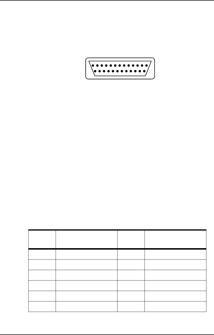
Optotrak API Routines
154 Optotrak Application Programmer’s Interface Guide
Description of Ports A and B:
For an ODAU I, port A is bits 0 to 7 (pins 18, 5, 17, 4, 16, 3, 15, and 2, respectively,
on a 25-pin D-shell), and port B is bits 8 to 15 (pins 25, 12, 24, 11, 23, 10, 22, and 9,
respectively). The pin layout of the 25-pin D-shell is displayed in Figure 9-2 on
page 154 and the pin assignments are indicated in Figure 9-11 on page 154.
Figure 9-2: Numbering on the ODAU I
25-pin D-shell Plug
For an ODAU II, port A consists of pins 25, 27, 29 and 31 of the 50-pin front panel
connector, while port B consists of pins 26, 28, 30 and 32. Pin 1 of the connector is
in the upper left corner as you look at the front of the ODAU II. Pin 2 is beneath
pin 1. All odd numbered pins are in the top row. The signal on each pin is shown in
Figure 9-13 on page 156.
bDifferential [ODAU II only] If set to FALSE (0), then data collection will be in
single-ended mode. If set to TRUE (1), then data collection will be in differential
mode. Default is 0.
ScanFrequency [ODAU II only] This frequency sets the rate at which the channels
are sampled within the frame. Valid values are [1, 100000]. Maximum recommended
scan rates vary with the gain selected. Default is 90000. See Table 9-12,
“Recommended Scan Rates for ODAU II,” on page 155.
1
13
14
25
Table 9-11: ODAU I Digital I/O Port Pin Configuration
Pin
Number Signal Name Pin
Number Signal Name
1 Ground 14 Vcc(+5V)
2 Bit 7 15 Bit 6
3 Bit 5 16 Bit 4
4 Bit 3 17 Bit 2
5 Bit 1 18 Bit 0
6 Unused 19 Unused

Chapter 9
Revision 1.0 155
StreamData indicates whether the ODAU is to send buffered data back by request
only, or to automatically send buffered data back once data spooling is initiated.
Values:
nStreamData = 0: Send buffered data back at request only.
nStreamData = 1: Send buffered data back automatically.
Default is 1.
CollectionTime is the length of data collection, in seconds. It should be set to the
same value for both the ODAU and the Optotrak System. Default is 2.
PreTriggerTime Not currently supported – it must be 0.
See Also
OptotrakSetupCollectionFromFile
7 Unused 20 Unused
8Trigger for Collection
Frame 21 Trigger for Collection
Start
9 Bit 15 22 Bit 14
10 Bit 13 23 Bit 12
11 Bit 11 24 Bit 10
12 Bit 9 25 Bit 8
13 Ground
Table 9-11: ODAU I Digital I/O Port Pin Configuration (Continued)
Pin
Number Signal Name Pin
Number Signal Name
Table 9-12: Recommended Scan Rates for ODAU II
Gain Maximum Recommended
Scan Frequency (Hz)
1 90,000
5 90,000
10 70,000
100 20,000

Optotrak API Routines
156 Optotrak Application Programmer’s Interface Guide
Table 9-13: ODAU II Front Panel Port Pin Configuration
Pin
Number Signal Name Pin
Number Signal Name
1 AI GND 2 AI GND
3ACH0 4ACH8
5ACH1 6ACH9
7ACH2 8ACH10
9 ACH3 10 ACH11
11 ACH4 12 ACH12
13 ACH5 14 ACH13
15 ACH6 16 ACH14
17 ACH7 18 ACH15
19 AI SENSE 20 DAC0 OUT
21 DAC1 OUT 22 EXT REF
23 AO GND 24 DIG GND
25 ADIO0 26 BDIO0
27 ADIO1 28 BDIO1
29 ADIO2 30 BDIO2
31 ADIO3 32 BDIO3
33 DIG GND 34 + 5 V
35 + 5 V 36 SCANCLK
37 !EXT STROBE 38 !START TRIG
39 !STOP TRIG 40 !EXTCONV
41 TIMER CLK 2 42 TIMER GATE 2
43 TIMER OUT 2 44 N/C
45 N/C 46 !FRAME CLK
47 N/C 48 N/C
49 N/C 50 FOUT

Chapter 9
Revision 1.0 157
9.7 Real-time Data Retrieval Routines
See the “Real-time Rigid Body Programmer’s Guide” on page 51 and “Real-time Data
Types” on page 237 for more general information on data types and rigid body
routines.
9.7.1 DataGetLatestCentroid
Function
Requests and receives the latest frame of centroid (raw) data.
Prototype
int DataGetLatestCentroid( unsigned int *puFrameNumber,
unsigned int *puElements,
unsigned int *puFlags,
void *pDataDest )
Parameters
puFrameNumber is set to the frame number associated with the frame of data
received.
puElements is set to the number of markers for which there is data in the received
frame.
puFlags indicates the current status of the Optotrak System.
The OPTOTRAK_SWITCH_AND_CONFIG_FLAG is specific to the Optotrak
Certus System Control Unit. If this flag is specified during a call to the
OptotrakSetupCollection routine, the puFlags parameter will contain a value
indicating that the device configuration has changed or that switch data is available.
If the device configuration has changed, puFlags will contain
OPTO_TOOL_CONFIG_CHANGED_FLAG. If there is new switch data available,
puFlags will contain OPTO_SWITCH_DATA_CHANGED_FLAG. To retrieve the
switch data, call RetrieveSwitchData.
If OPTOTRAK_SWITCH_AND_CONFIG_FLAG is not specified, puFlags will be
set to indicate the current status of the Optotrak System data buffer. In this case, if
puFlags is set to a non-zero value, then a buffering error has occurred.
pDataDest points to memory set aside by the application program to store the data
received by the Optotrak System.

Optotrak API Routines
158 Optotrak Application Programmer’s Interface Guide
Description
DataGetLatestCentroid retrieves the latest frame of centroid data from the Optotrak
System. The routine also returns the frame number associated with the data, the
number of markers for which there are data in the frame, and the status of the
Optotrak System data buffer.
The centroid data can be converted to 3D data or 6D transformation data by using
conversion routines such as OptotrakCovertRawTo3D or
OptotrakConvertTransforms. To optimize real-time capabilities, use the
DataGetLatesttype routines.
This routine copies the centroid data frame from the Optotrak System directly into a
memory block set aside by the application program.
You must ensure that the memory block reserved for the API to store the data is the correct
size. See “Sample Formats” on page 68. If the memory block size is too small, the data is
copied to an invalid memory area on the host computer, causing unpredictable behaviour.
This may include a system crash.
See Also
DataGetNextCentroid, RequestLatestCentroid, RequestNextCentroid
9.7.2 DataGetLatest3D
Function
Requests and receives the latest frame of 3D data.
Prototype
int DataGetLatest3D( unsigned int *puFrameNumber,
unsigned int *puElements,
unsigned int *puFlags,
void *pDataDest )
Parameters
puFrameNumber is set to the frame number associated with the frame of data
received.
puElements is set to the number of 3D positions (number of markers) in the frame
of data received.
Warning!

Chapter 9
Revision 1.0 159
puFlags indicates the current status of the Optotrak System.
The OPTOTRAK_SWITCH_AND_CONFIG_FLAG is specific to the Optotrak
Certus System Control Unit. If this flag is specified during a call to the
OptotrakSetupCollection routine, the puFlags parameter will contain a value
indicating that the device configuration has changed or that switch data is available.
If the device configuration has changed, puFlags will contain
OPTO_TOOL_CONFIG_CHANGED_FLAG. If there is new switch data available,
puFlags will contain OPTO_SWITCH_DATA_CHANGED_FLAG. To retrieve the
switch data, call RetrieveSwitchData.
If OPTOTRAK_SWITCH_AND_CONFIG_FLAG is not specified, puFlags will be
set to indicate the current status of the Optotrak System data buffer. If puFlags is set
to a non-zero value, then a buffering error has occurred.
pDataDest points to memory set aside by the application program to store the data
received by the Optotrak System.
Description
DataGetLatest3D retrieves the latest frame of 3D data from the Optotrak System. The
routine also returns the frame number associated with the data, the number of 3D
marker positions in the frame, and status of the Optotrak System data buffer.
The conversion of the raw data to 3D data can be processed in the Optotrak System
or in the host computer depending on the status OPTO_CONVERT_ON_HOST
flag set in the routine OptotrakSetProcessingFlags.
You must ensure that the memory block reserved for the API to store the data is the correct
size. See “Size Calculation” on page 242 and “Sample Formats” on page 68. This routine
copies the 3D positions directly into a memory block. If the memory block size is too small,
the 3D data is copied to an invalid memory area on the host computer, causing
unpredictable behaviour. This may include a system crash.
The 3D data can be converted to 6D transformation data by using the conversion
routine OptotrakConvertTransforms. To optimize real-time capabilities, use the
DataGetLatesttype routines.
See Sample Program 6 on the API CD for an example of code that uses this routine.
See Also
DataGetNext3D, RequestLatest3D, RequestNext3D, OptotrakSetProcessingFlags
Warning!

Optotrak API Routines
160 Optotrak Application Programmer’s Interface Guide
9.7.3 DataGetLatestOdauRaw
Function
Requests and receives the latest frame of raw data from the specified ODAU.
Prototype
int DataGetLatestOdauRaw( int nOdauId,
unsigned int *puFrameNumber,
unsigned int *puElements,
unsigned int *puFlags,
void *pDataDest )
Parameters
nOdauId specifies the ODAU device from which to retrieve the frame of raw data.
Use the defined constants ODAU1, ODAU2, ODAU3, and ODAU4.
puFrameNumber is set to the frame number associated with the frame of data
received.
puElements is set to the number of data elements in the received frame of data.
puFlags indicates the current status of the Optotrak System.
If OPTOTRAK_SWITCH_AND_CONFIG_FLAG is specified during a call to the
OptotrakSetupCollection routine, the puFlags parameter will contain a value
indicating that the device configuration has changed or that switch data is available.
If the device configuration has changed, puFlags will contain
OPTO_TOOL_CONFIG_CHANGED_FLAG. If there is new switch data available,
puFlags will contain OPTO_SWITCH_DATA_CHANGED_FLAG. To retrieve the
switch data, call RetrieveSwitchData.
If OPTOTRAK_SWITCH_AND_CONFIG_FLAG is not specified, puFlags will be
set to indicate the current status of the Optotrak System data buffer. If puFlags is set
to a non-zero value, then a buffering error has occurred.
pDataDest points to memory set aside by the application program to store the data
received from the ODAU.
Description
DataGetLatestOdauRaw retrieves the latest frame of raw data from the specified
ODAU device. This data frame consists of an integer for each analog channel being
sampled, followed by an integer for the digital port data, if it is being sampled. The
routine also returns

Chapter 9
Revision 1.0 161
• the frame number associated with the data
• the number of data elements in the frame
• the status of the ODAU data buffer.
The number of data elements in the frame equals the number of channels if digital
data is not sampled, or the number of channels plus 1, if digital data is sampled.
You must ensure that the memory block reserved for the API to store the data is the correct
size. See “Size Calculation” on page 247. This routine copies the raw data directly into a
memory block. If the memory block size is too small, the data is copied to an invalid
memory area on the host computer, causing unpredictable behaviour. This may include a
system crash.
Note If digital data is requested from an ODAU II, it is stored in the upper 8 bits of the last
unsigned integer subitem.
See Sample Program 12 on the API CD for an example of code that uses this routine.
See Also
DataGetNextOdauRaw, RequestLatestOdauRaw, RequestNextOdauRaw
9.7.4 DataGetLatestRaw
Function
Requests and receives the latest frame of full raw data.
Prototype
int DataGetLatestRaw( unsigned int *puFrameNumber,
unsigned int *puElements,
unsigned int *puFlags,
void *pDataDest )
Parameters
puFrameNumber is set to the frame number associated with the frame of data
received.
Warning!

Optotrak API Routines
162 Optotrak Application Programmer’s Interface Guide
puElements is set to the number of markers for which there is data in the received
frame.
puFlags indicates the current status of the Optotrak System.
If OPTOTRAK_SWITCH_AND_CONFIG_FLAG is specified during a call to the
OptotrakSetupCollection routine, the puFlags parameter will contain a value
indicating that the device configuration has changed or that switch data is available.
If the device configuration has changed, puFlags will contain
OPTO_TOOL_CONFIG_CHANGED_FLAG. If there is new switch data available,
puFlags will contain OPTO_SWITCH_DATA_CHANGED_FLAG. To retrieve the
switch data, call RetrieveSwitchData.
If OPTOTRAK_SWITCH_AND_CONFIG_FLAG is not specified, puFlags will be
set to indicate the current status of the Optotrak System data buffer. If puFlags is set
to a non-zero value, then a buffering error has occurred.
pDataDest points to memory set aside by the application program to store the data
received by the Optotrak System.
Description
DataGetLatestRaw retrieves the latest frame of full raw data (centroid data and status)
from the Optotrak System. The routine also returns the frame number associated
with the data, the number of markers for which there are data in the frame, and the
status of the Optotrak System data buffer.
You must ensure that the memory block reserved for the API to store the data is the correct
size. See “Size Calculation” on page 241. This routine copies the full raw data directly into
a memory block. If the memory block size is too small, the data is copied to an invalid
memory area on the host computer, causing unpredictable behaviour. This may include a
system crash.
See Sample Program 3 on the API CD for an example of code that uses this routine.
See Also
DataGetNextRaw, RequestLatestRaw, RequestNextRaw
Warning!

Chapter 9
Revision 1.0 163
9.7.5 DataGetLatestTransforms
Function
Requests and receives the latest frame of 6D rigid body transformation data, as well
as the associated 3D position data.
Prototype
int DataGetLatestTransforms( unsigned int *puFrameNumber,
unsigned int *puElements,
unsigned int *puFlags,
void *pDataDest )
Parameters
puFrameNumber is set to the frame number associated with the frame of data
received.
puElements is set to the number of rigid body transformations in the received frame
of data.
puFlags indicates the current status of the Optotrak System.
If OPTOTRAK_SWITCH_AND_CONFIG_FLAG is specified during a call to the
OptotrakSetupCollection routine, the puFlags parameter will contain a value
indicating that the device configuration has changed or that switch data is available.
If the device configuration has changed, puFlags will contain
OPTO_TOOL_CONFIG_CHANGED_FLAG. If there is new switch data available,
puFlags will contain OPTO_SWITCH_DATA_CHANGED_FLAG. To retrieve the
switch data, call RetrieveSwitchData.
If OPTOTRAK_SWITCH_AND_CONFIG_FLAG is not specified, puFlags will be
set to indicate the current status of the Optotrak System data buffer. If puFlags is set
to a non-zero value, then a buffering error has occurred.
pDataDest points to memory set aside by the application program to store the data
received by the Optotrak System.
Description
DataGetLatestTransforms retrieves the:
• latest frame of rigid body transformation 6D data
• 3D data used in the calculation of the rigid body transformations
• frame number associated with the data

Optotrak API Routines
164 Optotrak Application Programmer’s Interface Guide
• number of rigid body transformations in the frame
• status of the Optotrak System data buffer
The number of valid 3D markers returned from DataGetLatestTransforms may be
fewer than the actual number of markers visible to the Optotrak System. The
algorithm may have omitted one or more markers from the best fit routine.
The 6D data is followed immediately by the 3D data, see “Organization of Rigid
Body Transformation Data” on page 242. If you only need the rigid body
transformation data, or wish to collect the 6D and 3D data in separate buffers, use
the routine DataGetLatestTransforms2 instead.
You may use this routine if conversions are performed on-host by setting
bConvertOnHost and bRigidOnHost to TRUE in the Optotrak System parameter
file or with the routine OptotrakSetProcessingFlags. If you wish to perform the
conversion internally, you must have an Optotrak Certus System or an Optotrak
3020 System along with the Optotrak Real-time Rigid Body Option to use this
routine.
Before any rigid body transformations can be determined and returned, the
application program must load the required rigid body parameters using the routines
RigidBodyAdd or RigidBodyAddFromFile.
The conversion of the 3D data to 6D transformation can be processed in the
Optotrak System or in the host computer depending on the status
OPTO_RIGID_ON_HOST flag set in the routine OptotrakSetProcessingFlags.
You must ensure that the memory block reserved for the API to store the data is the correct
size. See “Size Calculation” on page 246 and “Sample Formats” on page 68. This routine
copies the rigid body positions directly into a memory block. If the memory block size is too
small, the rigid body data is copied to an invalid memory area on the host computer,
causing unpredictable behaviour. This may include a system crash.
Note The parameter pdatadest includes the bit flag OPTOTRAK_UNDETERMINED_FLAG. This
flag will be set if the transformation could not be determined. This flag must be checked for
each transformation.
See “Flags and Settings Associated with Rigid Bodies” on page 295 for information
on flag settings and where to set error parameters.
See Sample Program 9 on the API CD for an example of code that uses this routine.
Warning!

Chapter 9
Revision 1.0 165
See Also
DataGetLatestTransforms2, DataGetNextTransforms, RequestLatestTransforms,
RequestNextTransforms, OptotrakSetProcessingFlags, RigidBodyAdd,
RigidBodyAddFromFile
9.7.6 DataGetLatestTransforms2
Function
Requests and receives the latest frame of 6D rigid body transformation data, and the
associated 3D position data, in separate buffers.
Prototype
int DataGetLatestTransforms2(unsigned int *puFrameNumber,
unsigned int *puElements,
unsigned int *puFlags,
struct OptotrakRigidStruct *pDataDest6D,
Position3d *pDataDest3D )
Parameters
puFrameNumber is set to the frame number associated with the frame of data
received.
puElements is set to the number of rigid body transformations in the received frame
of data.
puFlags indicates the current status of the Optotrak System.
If OPTOTRAK_SWITCH_AND_CONFIG_FLAG is specified during a call to the
OptotrakSetupCollection routine, the puFlags parameter will contain a value
indicating that the device configuration has changed or that switch data is available.
If the device configuration has changed, puFlags will contain
OPTO_TOOL_CONFIG_CHANGED_FLAG. If there is new switch data available,
puFlags will contain OPTO_SWITCH_DATA_CHANGED_FLAG. To retrieve the
switch data, call RetrieveSwitchData.
If OPTOTRAK_SWITCH_AND_CONFIG_FLAG is not specified, puFlags will be
set to indicate the current status of the Optotrak System data buffer. If puFlags is set
to a non-zero value, then a buffering error has occurred.
pDataDest6D points to memory set aside by the application program to store the
6D rigid body transformation data returned by the Optotrak System.

Optotrak API Routines
166 Optotrak Application Programmer’s Interface Guide
pDataDest3D points to memory set aside by the application program to store the
associated 3D position data returned by the Optotrak System. If pDataDest3D is set
to NULL, then the 3D data is not returned.
Description
Retrieves data from the Optotrak System. It is similar to DataGetLatestTransforms,
except that it stores the retrieved data into two buffers. The latest frame of rigid body
transformation data, and the associated 3D data used in the calculation of the rigid
body transformations are in separate buffers for easier access. You can also choose
not to have the 3D data returned by passing a NULL value for pDataDest3D. The
routine also returns the frame number associated with the data, the number of rigid
body transformations in the frame, and status of the Optotrak System data buffer.
You may use this routine if conversions are performed on-host by setting
bConvertOnHost and bRigidOnHost to TRUE in the Optotrak System parameter
file or with the routine OptotrakSetProcessingFlags. If you wish to perform the
conversion internally, you must have an Optotrak Certus System or an Optotrak
3020 System along with the Optotrak Real-time Rigid Body Option to use this
routine.
Before any rigid body transformations can be determined and returned, the
application program must load the required rigid body parameters using the routines
RigidBodyAdd or RigidBodyAddFromFile.
The conversion of the 3D data to 6D transformation can be processed in the
Optotrak System or in the host computer depending on the status
OPTO_RIGID_ON_HOST flag set in the routine OptotrakSetProcessingFlags.
You must ensure that the memory block reserved for the API to store the data is the correct
size. See “Size Calculation” on page 242, “Size Calculation” on page 246 and “Sample
Formats” on page 68. This routine copies the 6D rigid body transformation data and 3D
position data directly into a memory blocks. If the memory block sizes are too small, the
data is copied to an invalid memory area on the host computer, causing unpredictable
behaviour. This may include a system crash.
Note The parameter pdatadest6D includes the bit flag OPTOTRAK_UNDETERMINED_FLAG. This
flag will be set if the transformation could not be determined. This flag must be checked for
each transformation.
See “Flags and Settings Associated with Rigid Bodies” on page 295 for information
on flag settings and where to set error parameters.
Warning!

Chapter 9
Revision 1.0 167
See Also
DataGetNextTranforms2, DataGetLatestTransforms, RequestLatestTransforms,
RequestNextTransforms, OptotrakSetProcessingFlags, RigidBodyAdd,
RigidBodyAddFromFile
9.7.7 DataGetNext3D
Function
Requests and receives the next frame of 3D data.
Prototype
int DataGetNext3D( unsigned int *puFrameNumber,
unsigned int *puElements,
unsigned int *puFlags,
void *pDataDest )
Parameters
puFrameNumber is set to the frame number associated with the frame of data
received.
puElements is set to the number of 3D positions (number of markers) in the frame
of data received.
puFlags indicates the current status of the Optotrak System.
If OPTOTRAK_SWITCH_AND_CONFIG_FLAG is specified during a call to the
OptotrakSetupCollection routine, the puFlags parameter will contain a value
indicating that the device configuration has changed or that switch data is available.
If the device configuration has changed, puFlags will contain
OPTO_TOOL_CONFIG_CHANGED_FLAG. If there is new switch data available,
puFlags will contain OPTO_SWITCH_DATA_CHANGED_FLAG. To retrieve the
switch data, call RetrieveSwitchData.
If OPTOTRAK_SWITCH_AND_CONFIG_FLAG is not specified, puFlags will be
set to indicate the current status of the Optotrak System data buffer. If puFlags is set
to a non-zero value, then a buffering error has occurred.
pDataDest points to memory set aside by the application program to store the data
received by the Optotrak System.

Optotrak API Routines
168 Optotrak Application Programmer’s Interface Guide
Description
DataGetNext3D is similar to DataGetLatest3D, except that it retrieves the next
available frame of 3D data from the Optotrak System instead of the latest frame. This
prevents multiple instances of the same frame from being returned by the system if
the data is being requested more frequently than the frame rate. The routine also
returns the frame number associated with the data, the number of 3D marker
positions in the frame, and the status of the Optotrak System data buffer.
DataGetNext3D is the same as DataGetLatest3D with the flag
OPTOTRAK_GET_NEXT_FRAME_FLAG set in the collection.
The conversion of the raw data to 3D data can be processed in the Optotrak System
or in the host computer depending on the status OPTO_CONVERT_ON_HOST
flag set in the routine OptotrakSetProcessingFlags.
You must ensure that the memory block reserved for the API to store the data is the correct
size. See “Size Calculation” on page 242. This routine copies the 3D positions directly into
a memory block. If the memory block size is too small, the data is copied to an invalid
memory area on the host computer, causing unpredictable behaviour. This may include a
system crash.
The 3D data can be converted to 6D transformation data by using the conversion
routine OptotrakConvertTransforms. To optimize real-time capabilities, use the
DataGetLatesttype routines.
See Also
DataGetLatest3D, RequestLatest3D, RequestNext3D, OptotrakSetProcessingFlags
9.7.8 DataGetNextCentroid
Function
Requests and receives the next frame of centroid data.
Prototype
int DataGetNextCentroid( unsigned int *puFrameNumber,
unsigned int *puElements,
unsigned int *puFlags,
void *pDataDest )
Warning!

Chapter 9
Revision 1.0 169
Parameters
puFrameNumber is set to the frame number associated with the frame of data
received.
puElements is set to the number of markers for which there is data in the received
frame.
puFlags indicates the current status of the Optotrak System.
If OPTOTRAK_SWITCH_AND_CONFIG_FLAG is specified during a call to the
OptotrakSetupCollection routine, the puFlags parameter will contain a value
indicating that the device configuration has changed or that switch data is available.
If the device configuration has changed, puFlags will contain
OPTO_TOOL_CONFIG_CHANGED_FLAG. If there is new switch data available,
puFlags will contain OPTO_SWITCH_DATA_CHANGED_FLAG. To retrieve the
switch data, call RetrieveSwitchData.
If OPTOTRAK_SWITCH_AND_CONFIG_FLAG is not specified, puFlags will be
set to indicate the current status of the Optotrak System data buffer. If puFlags is set
to a non-zero value, then a buffering error has occurred.
pDataDest points to memory set aside by the application program to store the data
received by the Optotrak System.
Description
DataGetNextCentroid is similar to DataGetLatestCentroid, except that it retrieves the
next available frame of centroid data from the Optotrak System instead of the latest
frame. This prevents multiple instances of the same frame from being returned by
the system if the data is being requested more frequently than the frame rate. The
routine also returns the frame number associated with the data, the number of
markers for which there is data in the frame, and the status of the Optotrak System
data buffer.
You must ensure that the memory block reserved for the API to store the data is the correct
size. See “Size Calculation” on page 241 and “Sample Formats” on page 68. This routine
copies the centroid data frame directly into a memory block. If the memory block size is too
small, the data is copied to an invalid memory area on the host computer, causing
unpredictable behaviour. This may include a system crash.
See Also
DataGetLatestCentroid, RequestLatestCentroid, RequestNextCentroid,
Warning!

Optotrak API Routines
170 Optotrak Application Programmer’s Interface Guide
9.7.9 DataGetNextOdauRaw
Function
Requests and receives the next frame of raw data from the specified ODAU.
Prototype
int DataGetNextOdauRaw( int nOdauId,
unsigned int *puFrameNumber,
unsigned int *puElements,
unsigned int *puFlags,
void *pDataDest )
Parameters
nOdauId specifies which ODAU device to retrieve the frame of raw data. Use the
defined constants ODAU1, ODAU2, ODAU3, and ODAU4.
puFrameNumber is set to the frame number associated with the frame of data
received.
puElements is set to the number of data elements in the received frame of data.
puFlags indicates the current status of the Optotrak System.
If OPTOTRAK_SWITCH_AND_CONFIG_FLAG is specified during a call to the
OptotrakSetupCollection routine, the puFlags parameter will contain a value
indicating that the device configuration has changed or that switch data is available.
If the device configuration has changed, puFlags will contain
OPTO_TOOL_CONFIG_CHANGED_FLAG. If there is new switch data available,
puFlags will contain OPTO_SWITCH_DATA_CHANGED_FLAG. To retrieve the
switch data, call RetrieveSwitchData.
If OPTOTRAK_SWITCH_AND_CONFIG_FLAG is not specified, puFlags will be
set to indicate the current status of the Optotrak System data buffer. If puFlags is set
to a non-zero value, then a buffering error has occurred.
pDataDest points to memory set aside by the application program to store the data
received from the ODAU.
Description
DataGetNextOdauRaw is similar to DataGetLatestOdauRaw, except that it retrieves
the next available frame of raw data from the specified ODAU device instead of the
latest frame. This prevents multiple instances of the same frame from being returned
by the system if the data is being requested more frequently than the ODAU frame

Chapter 9
Revision 1.0 171
rate. The data frame consists of an integer for each analog channel being sampled,
followed by an integer for the digital port data, if it is being sampled. The routine
also returns the frame number associated with the data, the number of data elements
in the frame, and status of the ODAU data buffer.
DataGetNextOdauRaw is the same as DataGetLatestOdauRaw with the flag
OPTOTRAK_GET_NEXT_FRAME_FLAG set in the collection.
If digital data is requested from an ODAU II, it is stored in the upper 8 bits of the
last unsigned integer subitem.
You must ensure that the memory block reserved for the API to store the data is the correct
size. See “Size Calculation” on page 247 and “Sample Formats” on page 68. This routine
copies the ODAU raw data directly into a memory block. If the memory block size is too
small, the data is copied to an invalid memory area on the host computer, causing
unpredictable behaviour. This may include a system crash.
See Also
RequestLatestOdauRaw, RequestNextOdauRaw, DataGetLatest3D
9.7.10 DataGetNextRaw
Function
Requests and receives the next frame of full raw data.
Prototype
int DataGetNextRaw( unsigned int *puFrameNumber,
unsigned int *puElements,
unsigned int *puFlags,
void *pDataDest )
Parameters
puFrameNumber is set to the frame number associated with the frame of data
received.
puElements is set to the number of markers for which there is data in the received
frame.
puFlags indicates the current status of the Optotrak System.
Warning!

Optotrak API Routines
172 Optotrak Application Programmer’s Interface Guide
If OPTOTRAK_SWITCH_AND_CONFIG_FLAG is specified during a call to the
OptotrakSetupCollection routine, the puFlags parameter will contain a value
indicating that the device configuration has changed or that switch data is available.
If the device configuration has changed, puFlags will contain
OPTO_TOOL_CONFIG_CHANGED_FLAG. If there is new switch data available,
puFlags will contain OPTO_SWITCH_DATA_CHANGED_FLAG. To retrieve the
switch data, call RetrieveSwitchData.
If OPTOTRAK_SWITCH_AND_CONFIG_FLAG is not specified, puFlags will be
set to indicate the current status of the Optotrak System data buffer. If puFlags is set
to a non-zero value, then a buffering error has occurred.
pDataDest points to memory set aside by the application program to store the data
received by the Optotrak System.
Description
DataGetNextRaw is similar to DataGetLatestRaw, except that it retrieves the next
available frame of full raw data from the Optotrak System instead of the latest frame.
This prevents multiple instances of the same frame from being returned by the
system if the data is being requested more frequently than the frame rate. The routine
also returns the frame number associated with the data, the number of markers for
which there is data in the frame, and the status of the Optotrak System data buffer.
DataGetNextRaw is the same as DataGetLatestRaw with the flag
OPTOTRAK_GET_NEXT_FRAME_FLAG set in the collection.
You must ensure that the memory block reserved for the API to store the data is the correct
size. See “Size Calculation” on page 241 and “Sample Formats” on page 68. This routine
copies the raw data frame directly into a memory block. If the memory block size is too
small, the data is copied to an invalid memory area on the host computer, causing
unpredictable behaviour. This may include a system crash.
See Also
DataGetLatestRaw, RequestLatestRaw, DataGetNextCentroid,
DataGetLatestCentroid
9.7.11 DataGetNextTransforms
Function
Requests and receives the next frame of 6D rigid body transformation data, as well as
its associated 3D position data.
Warning!

Chapter 9
Revision 1.0 173
Prototype
int DataGetNextTransforms( unsigned int *puFrameNumber,
unsigned int *puElements,
unsigned int *puFlags,
void *pDataDest )
Parameters
puFrameNumber is set to the frame number associated with the frame of data
received.
puElements is set to the number of rigid body transformations in the received frame
of data.
puFlags indicates the current status of the Optotrak System.
If OPTOTRAK_SWITCH_AND_CONFIG_FLAG is specified during a call to the
OptotrakSetupCollection routine, the puFlags parameter will contain a value
indicating that the device configuration has changed or that switch data is available.
If the device configuration has changed, puFlags will contain
OPTO_TOOL_CONFIG_CHANGED_FLAG. If there is new switch data available,
puFlags will contain OPTO_SWITCH_DATA_CHANGED_FLAG. To retrieve the
switch data, call RetrieveSwitchData.
If OPTOTRAK_SWITCH_AND_CONFIG_FLAG is not specified, puFlags will be
set to indicate the current status of the Optotrak System data buffer. If puFlags is set
to a non-zero value, then a buffering error has occurred.
pDataDest points to memory set aside by the application program to store the data
received by the Optotrak System.
Description
DataGetNextTransforms is similar to DataGetLatestTransforms, except that it
retrieves both the next available frame of rigid body transformation 6D data and the
3D data used in the calculation of the rigid body transformations, instead of the
latest frame. This data is received from the Optotrak System. This prevents multiple
instances of the same frame from being returned by the system if the data is being
requested more frequently than the frame rate.
The 6D data is followed immediately by the 3D data. If you only need the rigid body
transformation data, or wish to collect the 6D and 3D data in separate buffers, use
the routine DataGetNextTransforms2 instead.
You may use this routine if conversions are performed on-host by setting
bConvertOnHost and bRigidOnHost to TRUE in the Optotrak System parameter
file or with the routine OptotrakSetProcessingFlags. If you wish to perform the
conversion internally, you must have an Optotrak Certus System or an Optotrak

Optotrak API Routines
174 Optotrak Application Programmer’s Interface Guide
3020 System along with the Optotrak Real-time Rigid Body Option to use this
routine.
DataGetNextTransforms is the same as DataGetLatestTransforms with the flag
OPTOTRAK_GET_NEXT_FRAME_FLAG set in the collection.
Before any rigid body transformations can be determined and returned, the
application program must load the required rigid body parameters using the routines
RigidBodyAdd or RigidBodyAddFromFile.
The conversion of the 3D data to 6D transformation data can be processed in the
Optotrak System or in the host computer depending on the status
OPTO_RIGID_ON_HOST flag set in the routine OptotrakSetProcessingFlags.
You must ensure that the memory block reserved for the API to store the data is the correct
size. See “Size Calculation” on page 246 and “Sample Formats” on page 68. This routine
copies the rigid body transformation data directly into a memory block. If the memory block
size is too small, the data is copied to an invalid memory area on the host computer,
causing unpredictable behaviour. This may include a system crash.
Note The parameter pdatadest includes the bit flag OPTOTRAK_UNDETERMINED_FLAG. This
flag will be set if the transformation could not be determined. This flag must be checked for
each transformation.
See “Flags and Settings Associated with Rigid Bodies” on page 295 for information
on flag settings and where to set error parameters.
See Also
DataGetNextTransforms2, DataGetLatestTransforms, OptotrakSetProcessingFlags,
RigidBodyAdd, RigidBodyAddFromFile, DataReceiveLatestTransforms,
RequestLatestTransforms.
9.7.12 DataGetNextTransforms2
Function
Requests and receives the next frame of 6D rigid body transformation data, and its
associated 3D position data, in separate buffers.
Prototype
int DataGetNextTransforms2( unsigned int *puFrameNumber,
Warning!

Chapter 9
Revision 1.0 175
unsigned int *puElements,
unsigned int *puFlags,
struct OptotrakRigidStruct *pDataDest6D,
Position3d *pDataDest3D )
Parameters
puFrameNumber is set to the frame number associated with the frame of data
received.
puElements is set to the number of rigid body transformations in the received frame
of data.
puFlags indicates the current status of the Optotrak System.
If OPTOTRAK_SWITCH_AND_CONFIG_FLAG is specified during a call to the
OptotrakSetupCollection routine, the puFlags parameter will contain a value
indicating that the device configuration has changed or that switch data is available.
If the device configuration has changed, puFlags will contain
OPTO_TOOL_CONFIG_CHANGED_FLAG. If there is new switch data available,
puFlags will contain OPTO_SWITCH_DATA_CHANGED_FLAG. To retrieve the
switch data, call RetrieveSwitchData.
If OPTOTRAK_SWITCH_AND_CONFIG_FLAG is not specified, puFlags will be
set to indicate the current status of the Optotrak System data buffer. If puFlags is set
to a non-zero value, then a buffering error has occurred.
pDataDest6D points to memory set aside by the application program to store the
6D rigid body transformation data returned by the Optotrak System.
pDataDest3D points to memory set aside by the application program to store the
associated 3D position data returned by the Optotrak System. If pDataDest3D is set
to NULL, then the 3D data is not returned.
Description
DataGetNextTransforms2 is similar to DataGetLatestTransforms2, except that it
retrieves the next available frame of rigid body transformation 6D data and the 3D
data used in the calculation of the rigid body transformations, instead of the latest
frame. The data is retrieved from the Optotrak System. This prevents multiple
instances of the same frame from being returned by the system if the data is being
requested more frequently than the frame rate.
DataGetNextTransforms2 is also similar to DataGetNextTransforms, except that the
6D and 3D data is retrieved in separate buffers for easier access. You can also choose
not to have the 3D data returned by passing a NULL value for pDataDest3D. The
routine also returns the frame number associated with the data, the number of rigid
body transformations in the frame, and status of the Optotrak System data buffer.

Optotrak API Routines
176 Optotrak Application Programmer’s Interface Guide
The 6D data is followed immediately by the 3D data. If you only need the rigid body
transformation data, or wish to collect the 6D and 3D data in separate buffers, use
the routine DataGetLatestTransforms2 instead.
You may use this routine if conversions are performed on-host by setting bConver-
tOnHost and bRigidOnHost to TRUE in the Optotrak System parameter file or with
the routine OptotrakSetProcessingFlags. If you wish to perform the conversion inter-
nally, you must have an Optotrak Certus System or an Optotrak 3020 System along
with the Optotrak Real-time Rigid Body Option to use this routine.
Before any rigid body transformations can be determined and returned, the
application program must load the required rigid body parameters using the routines
RigidBodyAdd or RigidBodyAddFromFile.
The conversion of the 3D data to 6D transformation data can be processed in the
Optotrak System or in the host computer depending on the status
OPTO_RIGID_ON_HOST flag set in the routine OptotrakSetProcessingFlags.
DataGetNextTransforms2 is the same as DataGetLatestTransforms2 with the flag
OPTOTRAK_GET_NEXT_FRAME_FLAG set in the collection.
You must ensure that the memory block reserved for the API to store the data is the correct
size. See “Size Calculation” on page 242, “Size Calculation” on page 246 and “Sample
Formats” on page 68.This routine copies the 6D rigid body transformation data and 3D
position data directly into a memory block. If the memory block size is too small, the data is
copied to an invalid memory area on the host computer, causing unpredictable behaviour.
This may include a system crash.
Note The parameter pdatadest6D includes the bit flag OPTOTRAK_UNDETERMINED_FLAG. This
flag will be set if the transformation could not be determined. This flag must be checked for
each transformation.
See “Flags Affecting Rigid Bodies” on page 297 for information on flag settings and
where to set error parameters.
See Also
DataGetLatestTransforms, RequestLatestTransforms, RigidBodyAdd,
RigidBodyAddFromFile, RequestNextTransforms
Warning!

Chapter 9
Revision 1.0 177
9.7.13 DataIsReady
Function
Determines if there is a frame of data to be received.
Prototype
int DataIsReady( void )
Parameters
None.
Return Value
Non-zero: if there is a data frame waiting to be received.
Zero: if there is no data waiting to be received.
Description
DataIsReady is used by an application program to determine if a frame of requested
data is ready to be received. If an application program attempts to retrieve data using
one of the RequestNexttype or RequestLatesttype routines, it must call DataIsReady to
determine whether or not the data is ready to be received, and then it should invoke
the appropriate DataReceiveLatesttype routine to receive the waiting data.
DataIsReady is different from all other routines; its return value indicates the
presence of data to be received. If data is ready to be received, then DataIsReady
returns a non-zero value, otherwise it returns a value of zero.
If the bit flag OPTO_LIB_POLL_REAL_DATA has been set in the
OptotrakSetProcessingFlags routine, DataIsReady blocks until the data is ready,
rather than returning FALSE.
See Also
DataReceiveLatest3D, DataReceiveLatestRaw, DataReceiveLatestTransforms,
DataReceiveLatestOdauRaw, OptotrakSetProcessingFlags

Optotrak API Routines
178 Optotrak Application Programmer’s Interface Guide
9.7.14 DataReceiveLatest3D
Function
Receives the currently waiting frame of 3D data.
Prototype
int DataReceiveLatest3D(unsigned int *puFrameNumber
unsigned int *puElements,
unsigned int *puFlags,
void *pDataDest )
Parameters
puFrameNumber is set to the frame number associated with the frame of data
received.
puElements is set to the number of 3D positions (number of markers) in the frame
of data received.
puFlags indicates the current status of the Optotrak System.
If OPTOTRAK_SWITCH_AND_CONFIG_FLAG is specified during a call to the
OptotrakSetupCollection routine, the puFlags parameter will contain a value
indicating that the device configuration has changed or that switch data is available.
If the device configuration has changed, puFlags will contain
OPTO_TOOL_CONFIG_CHANGED_FLAG. If there is new switch data available,
puFlags will contain OPTO_SWITCH_DATA_CHANGED_FLAG. To retrieve the
switch data, call RetrieveSwitchData.
If OPTOTRAK_SWITCH_AND_CONFIG_FLAG is not specified, puFlags will be
set to indicate the current status of the Optotrak System data buffer. If puFlags is set
to a non-zero value, then a buffering error has occurred.
pDataDest points to memory set aside by the application program to store the data
received by the Optotrak System.
Description
DataReceiveLatest3D receives data that was requested previously using
RequestLatest3D. Invoke this routine only after a call to the DataIsReady routine
returns TRUE. The routine also returns the frame number associated with the data,
the number of 3D marker positions in the frame, and status of the Optotrak System
data buffer.

Chapter 9
Revision 1.0 179
You must ensure that the memory block reserved for the API to store the data is the correct
size. “Size Calculation” on page 242 and “Sample Formats” on page 68. This routine copies
the 3D positions directly into a memory block. If the memory block size is too small, the 3D
data is copied to an invalid memory area on the host computer, causing unpredictable
behaviour. This may include a system crash.
Note Do not send out a new request for data until the data from an earlier request has been
received. This is particularly important if the program is requesting different types of data.
For example, if an application requests two types of data, one immediately after the other,
and the routine DataIsReady returns TRUE, the application program does not know which
data type it is receiving.
See Sample Program 5 on the API CD for an example of code that uses this routine.
See Also
DataIsReady, RequestLatest3D
9.7.15 DataReceiveLatestCentroid
Function
Receives the currently waiting frame of centroid (raw) data.
Prototype
int DataReceiveLatestCentroid( unsigned int *puFrameNumber,
unsigned int *puElements,
unsigned int *puFlags,
void *pDataDest )
Parameters
puFrameNumber is set to the frame number associated with the frame of data
received.
puElements is set to the number of markers for which there is data in the received
frame.
puFlags indicates the current status of the Optotrak System.
If OPTOTRAK_SWITCH_AND_CONFIG_FLAG is specified during a call to the
OptotrakSetupCollection routine, the puFlags parameter will contain a value
Warning!

Optotrak API Routines
180 Optotrak Application Programmer’s Interface Guide
indicating that the device configuration has changed or that switch data is available.
If the device configuration has changed, puFlags will contain
OPTO_TOOL_CONFIG_CHANGED_FLAG. If there is new switch data available,
puFlags will contain OPTO_SWITCH_DATA_CHANGED_FLAG. To retrieve the
switch data, call RetrieveSwitchData.
If OPTOTRAK_SWITCH_AND_CONFIG_FLAG is not specified, puFlags will be
set to indicate the current status of the Optotrak System data buffer. If puFlags is set
to a non-zero value, then a buffering error has occurred.
pDataDest points to memory set aside by the application program to store the data
received by the Optotrak System.
Description
DataReceiveLatestCentroid is used by an application program to receive centroid data
that was requested previously using RequestLatestCentroid. This routine should be
invoked only after a call to the DataIsReady routine returns TRUE. The routine also
returns the frame number associated with the data, the number of markers for which
there are data in the frame, and the status of the Optotrak System data buffer.
You must ensure that the memory block reserved for the API to store the data is the correct
size. See “Size Calculation” on page 241 and “Sample Formats” on page 68. This routine
copies the raw data frame directly into a memory block. If the memory block size is too
small, the data is copied to an invalid memory area on the host computer, causing
unpredictable behaviour. This may include a system crash.
Note Do not send out another request for data until the data from an earlier request has been
received. This is particularly important if the program is requesting different types of data.
For example, if an application requests two types of data, one immediately after the other,
and the routine DataIsReady returns TRUE, the application program does not know which
data type it is receiving.
See Also
DataIsReady, RequestLatestCentroid, RequestNextCentroid
9.7.16 DataReceiveLatestOdauRaw
Function
Receives the currently waiting frame of raw data from the specified ODAU.
Warning!

Chapter 9
Revision 1.0 181
Prototype
int DataReceiveLatestOdauRaw( unsigned int *puFrameNumber,
unsigned int *puElements,
unsigned int *puFlags,
int *pDataDest )
Parameters
puFrameNumber is set to the frame number associated with the frame of data
received.
puElements is set to the number of data elements in the received frame of data.
puFlags indicates the current status of the Optotrak System.
If OPTOTRAK_SWITCH_AND_CONFIG_FLAG is specified during a call to the
OptotrakSetupCollection routine, the puFlags parameter will contain a value
indicating that the device configuration has changed or that switch data is available.
If the device configuration has changed, puFlags will contain
OPTO_TOOL_CONFIG_CHANGED_FLAG. If there is new switch data available,
puFlags will contain OPTO_SWITCH_DATA_CHANGED_FLAG. To retrieve the
switch data, call RetrieveSwitchData.
If OPTOTRAK_SWITCH_AND_CONFIG_FLAG is not specified, puFlags will be
set to indicate the current status of the Optotrak System data buffer. If puFlags is set
to a non-zero value, then a buffering error has occurred.
pDataDest points to memory set aside by the application program to store the data
received from the ODAU.
Description
DataReceiveLatestOdauRaw receives data that was requested previously using
RequestLatestOdauRaw. Invoke this routine only after a call to the DataIsReady
routine returns TRUE. The routine also returns the frame number associated with
the data, the number of data elements in the frame, and status of the Optotrak
System data buffer.
Note If digital data is requested from an ODAU II, it is stored in the upper 8 bits of the last
unsigned integer subitem.
You must ensure that the memory block reserved for the API to store the data is the correct
size. See “Size Calculation” on page 247 and “Sample Formats” on page 68. This routine
copies the data from the ODAU directly into a memory block. If the memory block size is too
Warning!

Optotrak API Routines
182 Optotrak Application Programmer’s Interface Guide
small, the data is copied to an invalid memory area on the host computer, causing
unpredictable behaviour. This may include a system crash.
Note Do not send out another request for data until the data from an earlier request has been
received. This is particularly important if the program is requesting different types of data.
For example, if an application requests two types of data, one immediately after the other,
and the routine DataIsReady returns TRUE, the application program does not know which
data type it is receiving.
See Also
DataIsReady, RequestLatestOdauRaw
9.7.17 DataReceiveLatestRaw
Function
Receives the currently waiting frame of full raw data.
Prototype
int DataReceiveLatestRaw( unsigned int *puFrameNumber,
unsigned int *puElements,
unsigned int *puFlags,
void *pDataDest )
Parameters
puFrameNumber is set to the frame number associated with the frame of data
received.
puElements is set to the number of markers for which there is data in the received
frame.
puFlags indicates the current status of the Optotrak System.
If OPTOTRAK_SWITCH_AND_CONFIG_FLAG is specified during a call to the
OptotrakSetupCollection routine, the puFlags parameter will contain a value
indicating that the device configuration has changed or that switch data is available.
If the device configuration has changed, puFlags will contain
OPTO_TOOL_CONFIG_CHANGED_FLAG. If there is new switch data available,
puFlags will contain OPTO_SWITCH_DATA_CHANGED_FLAG. To retrieve the
switch data, call RetrieveSwitchData.

Chapter 9
Revision 1.0 183
If OPTOTRAK_SWITCH_AND_CONFIG_FLAG is not specified, puFlags will be
set to indicate the current status of the Optotrak System data buffer. If puFlags is set
to a non-zero value, then a buffering error has occurred.
pDataDest points to memory set aside by the application program to store the data
received by the Optotrak System.
Description
DataReceiveLatestRaw receives full raw data that was requested previously using
RequestLatestRaw. Invoke this routine only after a call to the DataIsReady routine
returns TRUE. The routine also returns the frame number associated with the data,
the number of markers for which there are data in the frame, and the status of the
Optotrak System data buffer.
You must ensure that the memory block reserved for the API to store the data is the correct
size. See “Size Calculation” on page 241 and “Sample Formats” on page 68. This routine
copies the raw data frame directly into a memory block. If the memory block size is too
small, the data is copied to an invalid memory area on the host computer, causing
unpredictable behaviour. This may include a system crash.
Note Do not send out another request for data until the data from an earlier request has been
received. This is particularly important if the program is requesting different types of data.
For example, if an application requests two types of data, one immediately after the other,
and the routine DataIsReady returns TRUE, the application program does not know which
data type it is receiving.
See Also
DataIsReady, RequestLatestRaw
9.7.18 DataReceiveLatestTransforms
Function
Receives the currently waiting frame of 6D rigid body transformation data and its
associated 3D position data.
Prototype
int DataReceiveLatestTransforms( unsigned int *puFrameNumber,
unsigned int *puElements,
Warning!

Optotrak API Routines
184 Optotrak Application Programmer’s Interface Guide
unsigned int *puFlags,
void *pDataDest )
Parameters
puFrameNumber is set to the frame number associated with the frame of data
received.
puElements is set to the number of rigid body transformations in the received frame
of data.
puFlags indicates the current status of the Optotrak System.
If OPTOTRAK_SWITCH_AND_CONFIG_FLAG is specified during a call to the
OptotrakSetupCollection routine, the puFlags parameter will contain a value
indicating that the device configuration has changed or that switch data is available.
If the device configuration has changed, puFlags will contain
OPTO_TOOL_CONFIG_CHANGED_FLAG. If there is new switch data available,
puFlags will contain OPTO_SWITCH_DATA_CHANGED_FLAG. To retrieve the
switch data, call RetrieveSwitchData.
If OPTOTRAK_SWITCH_AND_CONFIG_FLAG is not specified, puFlags will be
set to indicate the current status of the Optotrak System data buffer. If puFlags is set
to a non-zero value, then a buffering error has occurred.
pDataDest points to memory set aside by the application program to store the data
received by the Optotrak System.
Description
DataReceiveLatestTransforms receives the latest rigid body transformation 6D data
that was requested previously using RequestLatestTransforms, immediately followed
by the 3D data used in the calculation of the rigid body transformations. This data is
received from the Optotrak System. If you only need the rigid body transformation
data, or wish to collect the 6D and 3D data in separate buffers, use the routine
DataReceiveLatestTransforms2 instead. Invoke this routine only after a call to the
DataIsReady routine returns TRUE. The routine also returns the frame number
associated with the data, the number of rigid body transformations in the frame, and
status of the Optotrak System data buffer.
You must ensure that the memory block reserved for the API to store the data is the correct
size. See “Size Calculation” on page 246 and “Sample Formats” on page 68. This routine
copies the rigid body transformation data directly into a memory block. If the memory block
Warning!

Chapter 9
Revision 1.0 185
size is too small, the data is copied to an invalid memory area on the host computer,
causing unpredictable behaviour. This may include a system crash.
Note Do not send out another request for data until the data from an earlier request has been
received. This is particularly important if the program is requesting different types of data.
For example, if an application requests two types of data, one immediately after the other,
and the routine DataIsReady returns TRUE, the application program does not know which
data type it is receiving.
You may use this routine if conversions are performed on-host by setting
bConvertOnHost and bRigidOnHost to TRUE in the Optotrak System parameter
file or with the routine OptotrakSetProcessingFlags. If you wish to perform the
conversion internally, you must have an Optotrak Certus System or an Optotrak
3020 System along with the Optotrak Real-time Rigid Body Option to use this
routine.
Before any rigid body transformations can be determined and returned, the
application program must load the required rigid body parameters using the routine
RigidBodyAdd or RigidBodyAddFromFile
See Also
DataIsReady, RequestLatestTransforms, RigidBodyAdd, RigidBodyAddFromFile,
DataReceiveLatestTransforms2
9.7.19 DataReceiveLatestTransforms2
Function
Receives the currently waiting frame of 6D rigid body transformation data, and its
associated 3D position data, in separate buffers.
Prototype
int DataReceiveLatestTransforms2(
unsigned int *puFrameNumber,
unsigned int *puElements,
unsigned int *puFlags,
struct OptotrakRigidStruct *pDataDest6D,
Position3d *pDataDest3D )

Optotrak API Routines
186 Optotrak Application Programmer’s Interface Guide
Parameters
puFrameNumber is set to the frame number associated with the frame of data
received.
puElements is set to the number of rigid body transformations in the received frame
of data.
puFlags indicates the current status of the Optotrak System.
If OPTOTRAK_SWITCH_AND_CONFIG_FLAG is specified during a call to the
OptotrakSetupCollection routine, the puFlags parameter will contain a value
indicating that the device configuration has changed or that switch data is available.
If the device configuration has changed, puFlags will contain
OPTO_TOOL_CONFIG_CHANGED_FLAG. If there is new switch data available,
puFlags will contain OPTO_SWITCH_DATA_CHANGED_FLAG. To retrieve the
switch data, call RetrieveSwitchData.
If OPTOTRAK_SWITCH_AND_CONFIG_FLAG is not specified, puFlags will be
set to indicate the current status of the Optotrak System data buffer. If puFlags is set
to a non-zero value, then a buffering error has occurred.
pDataDest6D points to memory set aside by the application program to store the
6D rigid body transformation data returned by the Optotrak System.
pDataDest3D points to memory set aside by the application program to store the
associated 3D position data returned by the Optotrak System. If pDataDest3D is set
to NULL, then the 3D data is not returned.
Description
DataReceiveLatestTransforms2 is similar to DataReceiveLatestTransforms, except that
it receives the waiting rigid body transformation data, and the associated 3D data
used in the calculation of the rigid body transformations, in separate buffers for
easier access. The data is received from the Optotrak System. You can also choose not
to have the 3D data returned by passing a NULL value for pDataDest3D. Invoke this
routine only after a call to the DataIsReady routine returns TRUE. The routine also
returns the frame number associated with the data, the number of rigid body
transformations in the frame, and status of the Optotrak System data buffer.
You must ensure that the memory block reserved for the API to store the data is the correct
size. See “Size Calculation” on page 242, “Size Calculation” on page 246, and “Sample
Formats” on page 68. This routine copies the 6D rigid body transformation data and 3D
position data directly into a memory block. If the memory block size is too small, the 3D
data is copied to an invalid memory area on the host computer, causing unpredictable
behaviour. This may include a system crash.
Warning!

Chapter 9
Revision 1.0 187
Note Do not send out another request for data until the data from an earlier request has been
received. This is particularly important if the program is requesting different types of data.
For example, if an application requests two types of data, one immediately after the other,
and the routine DataIsReady returns TRUE, the application program does not know which
data type it is receiving.
You may use this routine if conversions are performed on-host by setting
bConvertOnHost and bRigidOnHost to TRUE in the Optotrak System parameter
file or with the routine OptotrakSetProcessingFlags. If you wish to perform the
conversion internally, you must have an Optotrak Certus System or an Optotrak
3020 System along with the Optotrak Real-time Rigid Body Option to use this
routine.
Before any rigid body transformations can be determined and returned, the
application program must load the required rigid body parameters using the routines
RigidBodyAdd or RigidBodyAddFromFile.
See Also
DataIsReady, RequestLatestTransforms, RigidBodyAdd, RigidBodyAddFromFile,
DataReceiveLatestTransforms
9.7.20 ReceiveLatestData
Note This function is now obsolete. Use DataReceiveLatest3D, DataReceiveLatestRaw,
DataReceiveLatestTransforms, DataReceiveLatestTransforms2, DataReceiveLatestCentroid
or DataReceiveLatestOdauRaw instead.
9.7.21 RetrieveSwitchData
Function
Requests and retrieves the data generated from the switch on an Optotrak Certus
strober that accompanied the latest real-time data received from the Optotrak System.
Prototype
int RetrieveSwitchData( int nNumSwitches,
boolean *pbSwitchData )

Optotrak API Routines
188 Optotrak Application Programmer’s Interface Guide
Parameters
nNumSwitches indicates the number of switches.
pbSwitchData is the data buffer to which switch data will be written.
Description
The Optotrak System returns switch data to the API with every frame of real-time
data. If OPTOTRAK_SWITCH_AND_CONFIG_FLAG is specified during a call to
the OptotrakSetupCollection routine, every API routine that retrieves real-time data
will indicate whether or not new switch data is available. If there is new switch data
available, the puFlags variable in the DataGetLatesttype routine will contain
OPTO_SWITCH_DATA_CHANGED_FLAG. Use the RetrieveSwitchData routine to
retrieve the new switch data if required.
Note If an application program ends with a switch pressed, the System Control Unit will
continue to monitor the changes in switch status. If you start a new application program
without re-initializing and re-determining the configurations (using TransputerLoadSystem
and TransputerDetermineSystemCfg), the application program will assume a change in
switch status.
See Optotrak Certus Sample Program 14 on the API CD for an example of code that
uses this routine.
9.7.22 RequestLatest3D
Function
Requests the latest frame of 3D data from the Optotrak System.
Prototype
int RequestLatest3D( void )
Parameters
None.

Chapter 9
Revision 1.0 189
Description
RequestLatest3D requests that the Optotrak System determine the latest frame of 3D
data and send it back to the application program. Unlike the related routine
DataGetLatest3D, this routine does not block and wait for the data to be returned.
The routine DataIsReady determines if there is 3D data available to be received.
When the data is ready to be received, DataIsReady returns a non-zero value (TRUE).
The application program should then use the routine DataReceiveLatest3D to receive
the data from the Optotrak System. Never request data without a followup call to
receive the data.
Do not send out a new request for data until the data from an earlier request has been
received. This is particularly important if the program is requesting different types of data.
For example, if an application requests two types of data, one immediately after the other,
and the routine DataIsReady returns TRUE, the application program does not know which
data type it is receiving.
See Also
RequestNext3D, DataIsReady, DataReceiveLatest3D, DataGetLatest3D
9.7.23 RequestLatestCentroid
Function
Requests the latest frame of centroid data.
Prototype
int RequestLatestCentroid ( void )
Parameters
None.
Description
RequestLatestCentroid requests the Optotrak System to return the latest frame of
centroid data. Unlike the related routine DataGetLatestCentroid, this routine does
not block and wait for the data to be returned. The application program must
determine if the raw data is ready, and then receive it.
Warning!

Optotrak API Routines
190 Optotrak Application Programmer’s Interface Guide
The routine DataIsReady determines if there is raw data available to be received.
When the data is ready to be received, DataIsReady returns a non-zero value (TRUE).
The application program should then use the routine DataReceiveLatestCentroid to
receive the data from the Optotrak System. Never request data without a followup
call to receive the data.
Do not send out another request for data until the data from an earlier request has been
received. This is particularly important if the program is requesting different types of data.
For example, if an application requests two types of data, one immediately after the other,
and the routine DataIsReady returns TRUE, the application program does not know which
data type it is receiving.
See Also
RequestNextCentroid, DataIsReady, DataReceiveLatestCentroid,
DataGetLatestCentroid
9.7.24 RequestLatestOdauRaw
Function
Requests the latest frame of raw data from the specified ODAU device.
Prototype
int RequestLatestOdauRaw( int nOdauId )
Parameters
nOdauId specifies the ODAU device from which to request the frame of raw data.
Use one of the defined constants ODAU1, ODAU2, ODAU3 and ODAU4.
Description
RequestLatestOdauRaw requests that the specified ODAU return the latest frame of
raw data to the application program. Unlike the related routine
DataGetLatestOdauRaw, this routine does not block and wait for the data to be
returned. The application program determines if the ODAU data is ready, and then
receive it.
The routine DataIsReady determines if there is data that can be received. When data
is ready to be received, DataIsReady returns a non-zero value (TRUE). Use the routine
Warning!

Chapter 9
Revision 1.0 191
DataReceiveLatestOdauRaw to receive the data from the ODAU. Never request data
without a followup call to receive the data.
Do not send out a new request for data until the data from an earlier request has been
received. This is particularly important if the program is requesting different types of data.
For example, if an application requests two types of data, one immediately after the other,
and the routine DataIsReady returns TRUE, the application program does not know which
data type it is receiving.
See Also
DataIsReady, DataReceiveLatestOdauRaw, DataGetLatestOdauRaw,
RequestNextOdauRaw
9.7.25 RequestLatestRaw
Function
Request the latest frame of full raw data.
Prototype
int RequestLatestRaw( void )
Parameters
None.
Description
RequestLatestRaw requests that the Optotrak System return the latest frame of full
raw data. Unlike the related routine DataGetLatestRaw, this routine does not block
and wait for the data to be returned. The application program must determine if the
raw data is ready, and then receive it.
Use DataIsReady to determine if there is full raw data that can be received. When the
data is ready to be received, DataIsReady returns a non-zero value (TRUE). Use the
routine DataReceiveLatestRaw to receive the data from the Optotrak System. Never
request data without a followup call to receive the data.
Warning!

Optotrak API Routines
192 Optotrak Application Programmer’s Interface Guide
Do not send out a new request for data until the data from an earlier request has been
received. This is particularly important if the program is requesting different types of data.
For example, if an application requests two types of data, one immediately after the other,
and the routine DataIsReady returns TRUE, the application program does not know which
data type it is receiving.
See Also
DataIsReady, DataReceiveLatestRaw, DataGetLatestRaw, RequestNextRaw
9.7.26 RequestLatestTransforms
Function
Request the latest frame of rigid body transformation data.
Prototype
int RequestLatestTransforms( void )
Parameters
None.
Description
RequestLatestTransforms requests that the Optotrak System determine the latest
frame of rigid body 6D transformation data and return it to the application
program. Unlike the related routines DataGetLatestTransforms and
DataGetLatestTransforms2, this routine does not block and wait for the data to be
returned. The application program determines if the transformation data is ready
and then receives it.
The routine DataIsReady determines if there is 6D data to be received. When data is
ready to be received, DataIsReady returns a non-zero value (TRUE). The application
program should then use the routines DataReceiveLatestTransforms or
DataReceiveLatestTransforms2 to receive the data from the Optotrak System. Never
request data without a followup call to receive the data.
Do not send out a new request for data until the data from an earlier request has been
received. This is particularly important if the program is requesting different types of data.
For example, if an application requests two types of data, one immediately after the other,
Warning!
Warning!

Chapter 9
Revision 1.0 193
and the routine DataIsReady returns TRUE, the application program does not know which
data type it is receiving.
You may use this routine if conversions are performed on-host by setting
bConvertOnHost and bRigidOnHost to TRUE in the Optotrak System parameter
file or with the routine OptotrakSetProcessingFlags. If you wish to perform the
conversion internally, you must have an Optotrak Certus System or an Optotrak
3020 System along with the Optotrak Real-time Rigid Body Option to use this
routine.
Before any rigid body transformations can be determined and returned, the
application program must load the required rigid body parameters using the routines
RigidBodyAdd or RigidBodyAddFromFile.
See Also
DataIsReady, DataReceiveLatestTransforms, DataReceiveLatestTransforms2,
DataGetLatestTransforms, DataGetLatestTransforms2, RequestNextTransforms
9.7.27 RequestNext3D
Function
Requests the next frame of 3D data from the Optotrak System.
Prototype
int RequestNext3D( void )
Parameters
None.
Description
RequestNext3D is similar to RequestLatest3D, except that it requests the next
available frame of 3D data from the Optotrak System instead of the latest frame. This
prevents multiple instances of the same frame from being returned by the system if
the data is being requested more frequently than the frame rate. Unlike the related
routine DataGetNext3D, this routine does not block and wait for the data to be
returned. The application program determines if the 3D data is ready, and then
receives it.

Optotrak API Routines
194 Optotrak Application Programmer’s Interface Guide
The routine DataIsReady determines if there is 3D data available to be received.
When the data is ready to be received, DataIsReady returns a non-zero value (TRUE).
The application program should then use the routine DataReceiveLatest3D to receive
the data from the Optotrak System. Never request data without a followup call to
receive the data.
Do not send out another request for data until the data from an earlier request has been
received. This is particularly important if the program is requesting different types of data.
For example, if an application requests two types of data, one immediately after the other,
and the routine DataIsReady returns TRUE, the application program does not know which
data type it is receiving.
See Also
DataIsReady, DataReceiveLatest3D, RequestLatest3D, DataGetNext3D
9.7.28 RequestNextCentroid
Function
Request the next frame of centroid data.
Prototype
int RequestNextCentroid( void )
Parameters
None.
Description
RequestNextCentroid is similar to RequestLatestCentroid, except that it requests the
next available frame of centroid (raw) data from the Optotrak System instead of the
latest frame. This prevents multiple instances of the same frame from being returned
by the system if the data is being requested more frequently than the frame rate.
Unlike the related routine DataGetNextCentroid, this routine does not block and
wait for the data to be returned. The application program determines if the centroid
data is ready, and then receives it.
Warning!

Chapter 9
Revision 1.0 195
The routine DataIsReady determines if there is centroid data available to be received.
When the data is ready to be received, DataIsReady returns a non-zero value (TRUE).
The application program should then use the routine DataReceiveLatestRaw to
receive the data from the Optotrak System. Never request data without a followup
call to receive the data.
Do not send out a new request for data until the data from an earlier request has been
received. This is particularly important if the program is requesting different types of data.
For example, if an application requests two types of data, one immediately after the other,
and the routine DataIsReady returns TRUE, the application program does not know which
data type it is receiving.
See Also
DataIsReady, DataReceiveLatestCentroid, RequestLatestCentroid,
DataGetNextCentroid
9.7.29 RequestNextOdauRaw
Function
Requests the next frame of raw data from the specified ODAU device.
Prototype
int RequestNextOdauRaw( int nOdauId )
Parameters
nOdauId specifies the ODAU device from which to request the frame of raw data.
Description
RequestNextOdauRaw is similar to RequestLatestOdauRaw, except that it requests
that the specified ODAU return the next available frame of raw data to the
application program instead of the latest frame. This prevents multiple instances of
the same frame from being returned by the system if the data is being requested more
frequently than the ODAU frame rate. Unlike the related routine
DataGetLatestOdauRaw, this routine does not block and wait for the data to be
returned. The application program determines if the raw data is ready, and then
receives it.
Warning!

Optotrak API Routines
196 Optotrak Application Programmer’s Interface Guide
The routine DataIsReady determines if there is data available to be received. When
data is ready to be received, DataIsReady returns a non-zero value (TRUE). The
application program should then use the routine DataReceiveLatestOdauRaw to
receive the data from the ODAU. Never request data without a followup call to
receive the data.
Do not send out a new request for data until the data from an earlier request has been
received. This is particularly important if the program is requesting different types of data.
For example, if an application requests two types of data, one immediately after the other,
and the routine DataIsReady returns TRUE, the application program does not know which
data type it is receiving.
See Also
DataIsReady, DataReceiveLatestOdauRaw, RequestLatestOdauRaw,
DataGetLatestOdauRaw
9.7.30 RequestNextRaw
Function
Request the next frame of full raw data.
Prototype
int RequestNextRaw( void )
Parameters
None.
Description
RequestNextRaw is similar to RequestLatestRaw, except that it requests the next
available frame of full raw data from the Optotrak System instead of the latest frame.
This prevents multiple instances of the same frame from being returned by the
system if the data is being requested more frequently than the frame rate. Unlike the
related routine DataGetNextRaw, this routine does not block and wait for the data to
be returned. The application program first determines if the raw data is ready, then
receives it.
The routine DataIsReady determines if there is full raw data available to be received.
When the data is ready to be received, DataIsReady returns a non-zero value (TRUE).
Warning!

Chapter 9
Revision 1.0 197
The application program should then use the routine DataReceiveLatestRaw to
receive the data from the Optotrak System. Never request data without a followup
call to receive the data.
Do not send out a new request for data until the data from an earlier request has been
received. This is particularly important if the program is requesting different types of data.
For example, if an application requests two types of data, one immediately after the other,
and the routine DataIsReady returns TRUE, the application program does not know which
data type it is receiving.
See Also
DataIsReady, DataReceiveLatestRaw, RequestLatestRaw, DataGetNextRaw
9.7.31 RequestNextTransforms
Function
Requests the next frame of rigid body transformation data.
Prototype
int RequestNextTransforms( void )
Parameters
None.
Description
RequestNextTransforms is similar to RequestLatestTransforms, except that it requests
the next available frame of rigid body 6D transformation data from the Optotrak
System instead of the latest frame. This prevents multiple instances of the same frame
from being returned by the system if the data is being requested more frequently than
the frame rate. Unlike the related routines DataGetLatestTransforms and
DataGetLatestTransforms2, this routine does not block and wait for the data to be
returned. The application program determines if the raw data is ready, then receives
it.
The routine DataIsReady determines if there are 6D data available to be received.
When data is ready to be received, DataIsReady returns a non-zero value (TRUE). The
application program should then use either DataReceiveLatestTransforms or
Warning!

Optotrak API Routines
198 Optotrak Application Programmer’s Interface Guide
DataReceiveLatestTransforms2 to receive the data from the Optotrak System. Never
request data without a followup call to receive the data.
Do not send out a new request for data until the data from an earlier request has been
received. This is particularly important if the program is requesting different types of data.
For example, if an application requests two types of data, one immediately after the other,
and the routine DataIsReady returns TRUE, the application program does not know which
data type it is receiving.
You may use this routine if conversions are performed on-host by setting
bConvertOnHost and bRigidOnHost to TRUE in the Optotrak System parameter
file or with the routine OptotrakSetProcessingFlags. If you wish to perform the
conversion internally, you must have an Optotrak Certus System or an Optotrak
3020 System along with the Optotrak Real-time Rigid Body Option to use this
routine.
Before any rigid body transformations can be determined and returned, the
application program must load the required rigid body parameters using the routines
RigidBodyAdd or RigidBodyAddFromFile.
See Also
DataIsReady, DataReceiveLatestTransforms, DataReceiveLatestTransforms2,
DataGetLatestTransforms, DataGetLatestTransforms2
9.8 Buffered Data Retrieval Routines
9.8.1 DataBufferAbortSpooling
Function
Nullifies all bindings between devices and spool destinations.
Prototype
int DataBufferAbortSpooling( void )
Parameters
None.
Warning!

Chapter 9
Revision 1.0 199
Description
DataBufferAbortSpooling nullifies any relationship between a device and a spool
destination made using the routines DataBufferInitializeFile or
DataBufferInitializeMem.
Do not confuse this routine with the routine DataBufferStop, which terminates the current
spool operation. DataBufferAbortSpooling only affects the relationship between devices
and spool destinations.
Invoke this routine to associate a different spool destination with a device's data
spooling. Once DataBufferAbortSpooling is called, all data spooling relationships
must be reset using either DataBufferInitializeFile or DataBufferInitializeMem. Do
not invoke DataBufferAbortSpooling if the data spooling procedure has already
started.
See Also
DataBufferInitializeFile, DataBufferInitializeMem
9.8.2 DataBufferInitializeFile
Function
Initializes a Northern Digital Floating Point format file as a destination for buffered
data.
Prototype
int DataBufferInitializeFile( unsigned int uDataId, char *pszFileName )
Parameters
uDataId identifies the device from which buffered data is to be spooled.
Values:
OPTOTRAK specifies the Optotrak System Control Unit’s data buffer.
ODAU1 specifies the first ODAU's data buffer.
ODAU2 specifies the second ODAU's data buffer.
ODAU3 specifies the third ODAU's data buffer.
Warning!

Optotrak API Routines
200 Optotrak Application Programmer’s Interface Guide
ODAU4 specifies the fourth ODAU's data buffer.
pszFileName points to a null terminated string that specifies the name of the file to
which the data is spooled.
Description
DataBufferInitializeFile creates a Northern Digital Floating Point format file to
spool data to from the specified device's data buffer. If the file already exists, it is
replaced by the new one, even if spooling is aborted. Once the spooling process has
begun, data is retrieved from the specified device's data buffer and written to the
initialized file. When the spooling process is complete, the file's header is updated
with the appropriate information, and the file is closed.
See Sample Program 3 on the API CD for an example of code that uses this routine.
See Also
DataBufferInitializeMem, DataBufferAbortSpooling
9.8.3 DataBufferInitializeMem
Function
Initializes a block of memory as a destination for buffered data.
Prototype
int DataBufferInitializeMem( unsigned int uDataId,
SpoolPtrType pMemory )
Parameters
uDataId identifies the device from which buffered data is to be spooled.
Values:
OPTOTRAK specifies the Optotrak System Control Unit’s data buffer.
ODAU1 specifies the first ODAU's data buffer.
ODAU2 specifies the second ODAU's data buffer.
ODAU3 specifies the third ODAU's data buffer.
ODAU4 specifies the fourth ODAU's data buffer.

Chapter 9
Revision 1.0 201
pMemory specifies the memory area to which the buffered data is spooled.
Description
DataBufferInitializeMem does the required initialization to spool data from the
specified device's data buffer to an area of memory reserved by the application
program. Once the spooling process has begun, data is retrieved from the specified
device's data buffer and written to the appropriate memory location.
You must ensure the specified memory block is large enough to store the entire contents of
the data collection. If the memory block reserved by the application program is too small,
data is written to an invalid memory location. This can cause unpredictable results for the
application program. This may include a system crash.
To determine the required amount of memory the application program must know
how much data will be spooled.
Memory = [collection time x frame frequency] x (size of 1 frame) bytes
To determine the size of one frame, see “Real-time Data Types” on page 231.
See Sample Program 4 on the API CD for an example of code that uses this routine.
See Also
DataBufferInitializeFile, DataBufferAbortSpooling
9.8.4 DataBufferSpoolData
Function
Spools an entire data buffer.
Prototype
int DataBufferSpoolData( unsigned int *puSpoolStatus )
Parameters
puSpoolStatus indicates if there was a data buffer error during the data spooling.
Warning!

Optotrak API Routines
202 Optotrak Application Programmer’s Interface Guide
Description
DataBufferSpoolData does everything required to spool buffered data to the
initialized spool destinations. This routine starts all devices spooling buffered data at
the current frame. It then receives and writes the spooled data to the appropriate
spool destinations, either memory or file.
If a spool destination was not initialized for the device's data, then the data spooled
from this device is lost. Once all the data has been spooled to the application
program, this routine fills in the puSpoolStatus parameter and does the required
clean-up (e.g. close data files, etc.).
The status returned via the puSpoolStatus parameter indicates if a data buffering
error occurred on any of the devices spooling data. If the returned spool status is
non-zero, then an error occurred during the spooling period. The lower byte of this
parameter contains a code indicating the error, and the upper byte contains the ID
of the device on which the error occurred, i.e. the Optotrak System or one of the
ODAU devices
See Sample Program 3 on the API CD for an example of code that uses this routine.
See Also
DataBufferInitializeFile, DataBufferInitializeMem
9.8.5 DataBufferStart
Function
Starts all data buffers spooling data back to the host computer.
Prototype
int DataBufferStart( void )
Parameters
None.
Description
DataBufferStart starts spooling all initialized data buffers at the current frame. For
every device that you want to spool data from, either a file or memory block must
have been initialized. Use this routine with DataBufferWriteData. By using these
routines together, an application program can spool data, without blocking for the

Chapter 9
Revision 1.0 203
entire length of the collection time. Once DataBufferStart has been invoked, the
routine DataBufferWriteData must be called repeatedly until it signals that data
spooling has completed.
An application program can stop spooling buffered data before the collection time
has elapsed by invoking the routine DataBufferStop. This routine stops all devices
currently spooling buffered data at the current frame. However, it is still necessary to
stay in the data writing loop until the DataBufferWriteData routine indicates that
the data spooling has completed.
See Sample Program 5 on the API CD for an example of code that uses this routine.
See Also
DataBufferStop, DataBufferWriteData, DataBufferSpoolData
9.8.6 DataBufferStop
Function
Stops all devices spooling buffered data back to the host computer.
Prototype
int DataBufferStop( void )
Parameters
None.
Description
DataBufferStop stops spooling data from the data buffers from all devices to the
application program at the current frame. This routine allows an application
program to terminate data buffer spooling before the entire collection time has
elapsed. However, it is still necessary to stay in the data writing loop until the
DataBufferWriteData routine indicates that the data spooling has completed.
See Sample Program 7 on the API CD for an example of code that uses this routine.
See Also
DataBufferStart, DataBufferWriteData

Optotrak API Routines
204 Optotrak Application Programmer’s Interface Guide
9.8.7 DataBufferWriteData
Function
Receives data buffer data and writes them to the appropriate destination.
Prototype
int DataBufferWriteData( unsigned int *puRealtimeData,
unsigned int *puSpoolComplete,
unsigned int *puSpoolStatus,
unsigned long *pulFramesBuffered )
Parameters
puRealtimeData indicates if there is a frame of real-time data to be received.
puSpoolComplete indicates if the data spooling is complete.
puSpoolStatus indicates if there was a data buffer error during the data spooling.
pulFramesBuffered indicates the number of frames of data received since the latest
call to DataBufferStart, including those received by the current call.
Description
DataBufferWriteData receives and writes spooled buffer data to the appropriate,
initialized, spool destination. The routine first checks if there is any real-time data to
be received that was requested using one of the “Request” prefixed routines. If there
is data to be received, the routine sets the puRealtimeData variable to a non-zero
value (TRUE) and then returns immediately. At this point the application program
must receive the real-time data frame using the corresponding “Receive” prefixed
routine.
If there is no real-time data to receive, but there is spooled buffer data to receive, then
the DataBufferWriteData routine receives the data and writes it to the appropriate
spool destination, or discards the data if no spool destination was initialized for this
device. Once all the data for the collection time has been received, this routine sets
the puSpoolComplete variable to a non-zero value (TRUE), fills in the puSpoolStatus
variable, and does the required clean up (e.g. closes data files, etc.).
The status returned via the puSpoolStatus variable indicates if a data buffering error
occurred on any of the devices spooling data. If the returned spool status is non-zero,
then an error occurred during the spooling period. The lower byte of this variable
contains a code indicating the error and the upper byte contains the ID of the device
on which the error occurred, e.g. the Optotrak System or ODAU1.

Chapter 9
Revision 1.0 205
The pulFramesBuffered value can be used by the application program to determine
the degree to which the data spooling has been completed after each call to the
routine. If pulFramesBuffered is set to NULL when the function is called, then the
variable is not updated with the number of frames buffered.
See Sample Program 5 on the API CD for an example of code that uses this routine.
See Also
DataBufferStart, DataBufferStop

Optotrak API Routines
206 Optotrak Application Programmer’s Interface Guide
9.9 Rigid Body Specific Routines
You may use these routines if conversions are performed on-host by setting
bConvertOnHost and bRigidOnHost to TRUE in the Optotrak System parameter
file or with the routine OptotrakSetProcessingFlags. If you wish to perform the
conversion internally, you must have an Optotrak Certus System or an Optotrak
3020 System along with the Optotrak Real-time Rigid Body Option to use these
routines.
See “Real-time Rigid Body Programmer’s Guide” on page 51 and “Flags and Settings
Associated with Rigid Bodies” on page 295 for more information on rigid bodies.
9.9.1 RigidBodyAdd
Function
Adds a rigid body to the list of rigid bodies that the Optotrak System tracks.
Prototype
int RigidBodyAdd( int nRigidBodyId,
int nStartMarker,
int nNumMarkers,
float *pRigidCoordinates,
float *pNormalCoordinates,
int nFlags )
Parameters
nRigidBodyId specifies a unique identifier to be associated with the rigid body.
nStartMarker specifies the marker number of the first IRED marker in the rigid
body.
nNumMarkers specifies the number of IRED markers in the rigid body.
pRigidCoordinates specifies an array of 3D positions that define the locations of
the IRED marker positions of the rigid body in its home position.
pNormalCoordinates specifies an array of 3D positions, each of which defines the
normal vectors for an IRED marker of the rigid body in its home position. If NULL
is specified for this parameter, then no normal coordinates are added for the
specified rigid body.
nFlags contains the bit flags that configure the manner in which the Optotrak
System processes the rigid body. For a complete description of these flags, see
“RigidBodyChangeSettings” on page 211.

Chapter 9
Revision 1.0 207
Description
RigidBodyAdd adds a rigid body to the Optotrak System rigid body tracking list
according to the specified parameters. Once the rigid body has been added, the
Optotrak System determines transformations for this rigid body whenever it is
requested.
The positions of the rigid body markers are passed to this routine via an array of 3D
(x, y, z) positions. The array must be organized as follows:
The RigidBodyAdd routine assumes the X, Y, Z coordinates are defined as C-type
floats. The X, Y, Z variables for the normal vectors are in the same form as the rigid
body marker positions, but they specify a 3D vector instead of a 3D position.
Normal vectors are used to exclude a marker's data from the rigid body
transformation calculations whenever the marker is viewed at very oblique angles.
Note After a call to the routine RigidBodyAdd, it is advisable to include a sleep routine to allow
enough time for the routine to finish. The length of time required will depend on the speed
of the host computer — the sample programs use a one second delay. If the sleep time is
too short, the routine will fail and error messages may be generated.
See Sample 11 on the API CD for an example of code that uses this routine.
See Also
RigidBodyAddFromFile, RigidBodyChangeSettings, DataGetLatestTransforms,
DataGetLatestTransforms2
Table 9-14: Position Array for Rigid Body Markers
Marker 3D Position
Marker 1 X1Y1Z1
Marker 2 X2Y2Z2
......
......
......
......
Marker MXMYMZM

Optotrak API Routines
208 Optotrak Application Programmer’s Interface Guide
9.9.2 RigidBodyAddFromDeviceHandle
Function
Adds the rigid body defined in a device to the list of rigid bodies tracked by the
Optotrak System.
Prototype
int RigidBodyAddFromDeviceHandle( int nDeviceHandle,
int nFlags )
Parameters
nDeviceHandle identifies the device.
nFlags contains the flags that configure the way in which the Optotrak System
processes the rigid body. For a complete description of these flags, see
“RigidBodyChangeSettings” on page 211.
Description
If the specified device contains rigid body information,
RigidBodyAddFromDeviceHandle informs the System Control Unit that the device
should be tracked as a rigid body.
9.9.3 RigidBodyAddFromFile
Function
Uses the specified rigid body file to add a rigid body to the list of rigid bodies that
the Optotrak System tracks.
Prototype
int RigidBodyAddFromFile( int nRigidBodyId,
int nStartMarker,
char *pszRigFile,
int nFlags )
Parameters
nRigidBodyId specifies a unique identifier to be associated with the rigid body.

Chapter 9
Revision 1.0 209
nStartMarker specifies the marker number of the first IRED marker in the rigid
body.
pszRigFile specifies the rigid body file that defines the rigid body being added.
When specifying the rigid body file to this routine, the application program must
not use the file extension. For example, the application program should specify
“frame” instead of “frame.rig.”
nFlags contains the bit flags that configure the way in which the Optotrak System
processes the rigid body. For a complete description of these flags, see
“RigidBodyChangeSettings” on page 211.
Description
RigidBodyAddFromFile adds a rigid body to the Optotrak System rigid body
tracking list according to the specified parameters. This routine differs from
RigidBodyAdd in that the rigid body coordinates are read from a rigid body file.
Once the rigid body has been added, the Optotrak System determines the rigid
body’s transformations whenever it is requested.
This routine searches for the specified rigid body file in a number of directories. The
first directory searched is the current directory. If the file is not found in the current
directory, the routine makes use of the ND_USER_DIR and ND_DIR environment
variables to search for the file. The default location for a rigid body file is in the
rigid subdirectory under the directory where the Northern Digital software was
installed, e.g. c:\ndigital.
As an example, suppose ND_USER_DIR is set to c:\ndigital and ND_DIR is set to
d:\ndigital. RigidBodyAddFromFile would first look for the file in the current
directory, then in the directory c:\ndigital\rigid, and finally in the directory
d:\ndigital\rigid.
Note After a call to the routine RigidBodyAddFromFile, it is advisable to include a sleep routine
to allow enough time for the routine to finish. The length of time required will depend on
the speed of the host computer — the sample programs use a one second delay. If the sleep
time is too short, the routine will fail and error messages may be generated.
See Sample Program 9 on the API CD for an example of code that uses this routine.
See Also
RigidBodyAdd, RigidBodyChangeSettings, DataGetLatestTransforms

Optotrak API Routines
210 Optotrak Application Programmer’s Interface Guide
9.9.4 RigidBodyChangeFOR
Function
Changes the default coordinate system for the rigid body transformation
calculations.
Prototype
int RigidBodyChangeFOR( int nRigidBodyId, int nRotationMethod )
Parameters
nRigidBodyId specifies the ID of the rigid body that determines the coordinate
system. If -1 is specified as the rigid body ID, then the coordinate system is changed
to the default coordinate system.
nRotationMethod specifies the method used to rotate the coordinate system. The
options are:
OPTOTRAK_STATIC_RIGID_FLAG indicates that the Optotrak System is to
use the current position and orientation of the specified rigid body to define the
static coordinate system.
OPTOTRAK_CONSTANT_RIGID_FLAG indicates that the Optotrak System
is to define the coordinate system based on the specified rigid body's
transformation each time the rigid body transformations are determined. This is
equivalent to measuring one moving rigid body with respect to another moving
rigid body.
Description
RigidBodyChangeFOR changes the coordinate system used to determine the rigid
body transformations. The coordinate system can be changed so that the determined
rigid body transformations are expressed in a coordinate system based on the
position and orientation of one of the rigid bodies. A parameter to the routine
specifies which rigid body to use. If the specified rigid body has an ID of -1, the
default coordinate system is used.
There are two methods of determining the coordinate system in which the other rigid
body transformations are expressed. If OPTOTRAK_STATIC_RIGID_FLAG is
specified, the coordinate system is based on the current position and orientation of
the specified rigid body. If OPTOTRAK_CONSTANT_RIGID_FLAG is specified,
the coordinate system is computed each time rigid body transformations are
requested, based on the position and orientation of the specified rigid body at that

Chapter 9
Revision 1.0 211
time. If the coordinate system is being constantly computed, the transformation of
the specified rigid body is expressed in the default coordinate system. This provides
the application program with the transformation needed to determine the new
coordinate system.
See Sample Program 11 on the API CD for an example of code that uses this routine.
See Also
None.
9.9.5 RigidBodyChangeSettings
Function
Changes parameters affecting the calculations of the specified rigid body.
Prototype
int RigidBodyChangeSettings( int nRigidBodyId,
int nMinMarkers,
int nMaxMarkerAngle,
float fMax3dError,
float fMaxSensorError,
float fMax3dRmsError,
float fMaxSensorRmsError,
int nFlags )
Parameters
nRigidBodyId specifies the ID of the rigid body that is being changed.
nMinMarkers specifies the minimum number of markers that must be viewed to
determine a rigid body transformation.
nMaxMarkerAngle specifies the maximum angle, in degrees, that a marker can
rotate from a Position Sensor, and still have that data included in the determination
of the rigid body transformation. To use this parameter, normal vectors must also be
loaded for the rigid body.
fMax3dError specifies the maximum calculated 3D error, in millimeters, allowed for
a single marker. If a marker has an error greater than this value, then the rigid body
transformation is recalculated with that marker's data ignored.
fMaxSensorError specifies the maximum calculated raw sensor error allowed for a
each marker/sensor pair. If a marker/sensor pair has an error greater than this value,

Optotrak API Routines
212 Optotrak Application Programmer’s Interface Guide
then the rigid body transformation is recalculated with that marker/sensor pair's data
ignored.
fMax3dRmsError specifies the maximum allowable 3D RMS error, in millimeters. If
the calculated 3D RMS error is greater than fMax3dRmsError, then the
transformation is deemed to be undetermined.
fMaxSensorRmsError specifies the maximum allowable raw sensor RMS error. If
the calculated raw sensor RMS error is greater than the fMaxSensorRmsError, then
the transformation is deemed to be undetermined.
nFlags contains the bit flags that configure the way the Optotrak System processes
the rigid body. The following list details the flags and their significance:
OPTOTRAK_NO_RIGID_CALCS_FLAG to stop the Optotrak System from
determining rigid body transformations, but keep the rigid body in the tracking
list.
OPTOTRAK_DO_RIGID_CALCS_FLAG to restart the Optotrak System
determining rigid body transformations if they are turned off for this rigid body.
OPTOTRAK_QUATERN_RIGID_FLAG to force the Optotrak System to use
the quaternion algorithm when determining the rigid body transformation.
The quaternion algorithm is a closed-form solution of absolute position and
orientation of a rigid body based on proprietary enhancements made to the
original algorithm developed by Berthold K.P. Horn.
OPTOTRAK_ITERATIVE_RIGID_FLAG to force the Optotrak System to use
the Iterative Euler Angle algorithm when determining the rigid body
transformation.
The Iterative Euler Angle algorithm calculates an initial estimate using the
quaternion algorithm and further refines the result using sensor information. In
theory, this algorithm generates more accurate results than the quaternion
algorithm. In practice, the improvement is negligible and requires longer time to
complete.
OPTOTRAK_RETURN_QUATERN_FLAG to force the Optotrak System to
return the rigid body transformation in quaternion format.
OPTOTRAK_RETURN_MATRIX_FLAG to force the Optotrak System to
return the rigid body transformation in Rotation Matrix format.
OPTOTRAK_RETURN_EULER_FLAG to force the Optotrak System to return
the rigid body transformation in Euler Angle format in radians.

Chapter 9
Revision 1.0 213
Description
RigidBodyChangeSettings uses the specified parameters to control the way in which
the Optotrak System processes information for the specified rigid body. This routine
can be used to suppress rigid body calculations for a rigid body, change the
algorithm used to determine the rigid body transformation, and select the format for
the rigid body transformation.
Some of the settings (flags) can be combined while others may not. If both the
OPTOTRAK_NO_RIGID_CALCS_FLAG and the
OPTOTRAK_DO_RIGID_CALCS_FLAGS are specified together, the first flag is
ignored and the calculations are performed.
When specifying the transformation determination algorithm, the flags may be used
individually or together. If just the OPTOTRAK_QUATERN_RIGID_FLAG is
specified, then just the Quaternion algorithm is used. If just the
OPTOTRAK_ITERATIVE_RIGID_FLAG is specified, then just the Iterative Euler
Angle algorithm is used. If both flags are specified, then the Quaternion algorithm is
used, and its result is then used as an initial estimate for the Iterative Euler Angle
algorithm. Finally, the flags for the transformation return format must be used
exclusively.
The routines RigidBodyAdd and RigidBodyAddFromFile each include a flags
parameter that uses the above flag definitions. If no flags are specified when adding
a rigid body, a set of default values is used. The default for the minimum markers is
3, the default for the maximum 3D error is 0.25 mm, and the default combination
for the flags is OPTOTRAK_DO_RIGID_CALCS_FLAG,
OPTOTRAK_QUATERN_RIGID_FLAG, OPTOTRAK_ITERATIVE_RIGID_FLAG,
and OPTOTRAK_RETURN_EULER_FLAG.
See Sample Program 10 on the API CD for an example of code that uses this routine.
See Also
RigidBodyAdd, RigidBodyAddFromFile
9.9.6 RigidBodyDelete
Function
Removes the specified rigid body from the Optotrak System rigid body tracking list.
Prototype
int RigidBodyDelete( int nRigidBodyId )

Optotrak API Routines
214 Optotrak Application Programmer’s Interface Guide
Parameters
nRigidBodyId specifies the ID of the rigid body that is to be removed.
Description
RigidBodyDelete completely removes the rigid body associated with the specified ID
from the Optotrak System rigid body tracking list. After a rigid body is removed, no
more transformations are determined for that body.
Note Do not use this routine to remove the rigid body that is being used to define a constantly
changing coordinate system; the rigid body must first be removed from the coordinate
system calculation before it can be deleted.
See Also
RigidBodyAdd, RigidBodyAddFromFile, RigidBodyChangeFOR
9.10 Rigid Body Related Routines
The following routines are commonly used for manipulating rigid body data
structures and transformation data.
9.10.1 CombineXfrms
Function
Combines two Euler angle format transformations specified in roll-pitch-yaw
geometry.
Prototype
void CombineXfrms( transformation *pdtXfrm1,
transformation *pdtXfrm2,
transformation *pdtNewXfrm )
Parameters
pdtXfrm1 points to the first transformation.
pdtXfrm2 points to the second transformation.
pdtNewXfrm points to the combined transformation.

Chapter 9
Revision 1.0 215
Description
CombineXfrms combines two Euler angle format transformations specified by
pdtXfrm1 and pdtXfrm2 into a combined transformation, pdtNewXfrm. The routine
is an implementation of the following relation:
T13 = T23 ⋅Τ12
T12 is the first transformation (pdtXfrm1) and is defined as the transformation from
frame 1 to frame 2
T23 is the second transformation, (pdtXfrm2) and is defined as the transformation
from frame 2 to frame 3
T13 is the transformation from frame 1 to frame 3.
See Also
DetermineR
9.10.2 CvtQuatToRotationMatrix
Function
Determines the rotation matrix corresponding to the specified quaternion.
Prototype
void CvtQuatToRotationMatrix( QuatRotationStruct *pdtQuatRot,
RotationMatrixType pdtRotMatrix)
Parameters
pdtQuatRot points to the quaternion format rotation being converted.
pdtRotMatrix points to the 3 × 3 rotation matrix.
Description
CvtQuatToRotationMatrix converts the input quaternion format rotation specified
by pdtQuatRot to its corresponding rotation matrix, which is returned in
pdtRotMatrix. This routine complements CvtRotationMatrixToQuat, which converts
an input rotation matrix to its corresponding quaternion format.

Optotrak API Routines
216 Optotrak Application Programmer’s Interface Guide
See Also
CvtRotationMatrixToQuat
9.10.3 CvtRotationMatrixToQuat
Function
Determines the quaternion format rotation corresponding to the specified rotation
matrix.
Prototype
void CvtRotationMatrixToQuat( QuatRotationStruct *pdtQuatRot,
RotationMatrixType pdtRotMatrix)
Parameters
pdtQuatRot points to the quaternion defining the rotation.
pdtRotMatrix points to the 3 × 3 rotation matrix being converted.
Description
CvtRotationMatrixToQuat converts the input rotation matrix specified by
pdtRotMatrix to its corresponding quaternion format, which is returned in
pdtQuatRot. This routine complements CvtQuatToRotationMatrix, which converts
an input quaternion to its corresponding rotation matrix.
See Also
CvtQuatToRotationMatrix
9.10.4 DetermineEuler
Function
Determines the Euler angles from the specified 3 × 3 rotation matrix. Values are
returned in radians.
Prototype
void DetermineEuler( RotationMatrixType pdtRotMatrix,

Chapter 9
Revision 1.0 217
rotation *pdtEulerRot )
Parameters
pdtRotMatrix points to the 3 × 3 rotation matrix being converted.
pdtEulerRot points to the resultant Euler angle format rotation.
Description
DetermineEuler converts the input rotation matrix specified by pdtRotMatrix to its
corresponding Euler angle format, which is returned in pdtEulerRot. This routine
complements DetermineR, which converts input Euler angles to their corresponding
rotation matrix.
See Also
DetermineR
9.10.5 DetermineR
Function
Determines the 3 × 3 rotation matrix from the specified Euler angle format rotation.
Prototype
void DetermineR( rotation *pdtEulerRot,
RotationMatrixType pdtRotMatrix )
Parameters
pdtEulerRot points to the Euler angle format rotation being converted.
pdtRotMatrix points to the resultant 3 × 3 rotation matrix.
Description
DetermineR converts the input Euler angle format rotation specified by pdtEulerRot
to its corresponding rotation matrix, which is returned in pdtRotMatrix. The routine
is an implementation of the following relation:
R(r, p, y ) = R(r) ⋅ R(p) ⋅ R(y)

Optotrak API Routines
218 Optotrak Application Programmer’s Interface Guide
R is a 3 × 3 rotation matrix
r is the roll, or the rotation about the z-axis
p is the pitch, or the rotation about the y-axis
y is the yaw, or the rotation about the x-axis
This routine complements DetermineEuler, which converts the input rotation matrix
to the corresponding Euler angles.
See Also
DetermineEuler
9.10.6 InverseXfrm
Function
Determines the inverse to the specified Euler angle format transformation.
Prototype
void InverseXfrm( transformation *pdtXfrm,
transformation *pdtInverseXfrm )
Parameters
pdtXfrm points to the input transformation.
pdtInverseXfrm points to the resultant inverse transformation.
Description
InverseXfrm calculates the inverse of the Euler angle format transformation specified
by pdtXfrm and outputs it as pdtInverseXfrm. This routine implements the relation:
Tinverse = T -1
where T = the Euler angle format transformation.
See Also
None.

Chapter 9
Revision 1.0 219
9.10.7 TransformPoint
Function
This routine calculates the 3-D position of a given point after it has been
transformed by the specified rotation and translation.
Prototype
void TransformPoint( RotationMatrixType pdtRotationMatrix,
Position3d *pdtTranslation,
Position3d *pdtOriginalPositionPtr,
Position3d *pdtTransformedPositionPtr )
Parameters
pdtRotationMatrix points to the 3 x 3 rotation matrix defining the rotational part
of the transformation.
pdtTranslation points to the structure defining the translational part of the
transformation.
pdtOriginalPositionPtr points to the structure defining the original position of the
point being transformed.
pdtTransformedPositionPtr points to the structure containing the transformed
position of the point. The original contents of this structure will be overwritten in a
safe manner so that it can be the same as pdtOriginalPositionPtr if the original
position does not need to be retained.
Description
TransformPoint determines the 3-D position of a given point after being transformed
by the specified rotation and translation according to the following relation:
p1 = Rp0 + T
where
p1=the position after transformation
p0=the position before transformation
R=the matrix rotation component of the transformation
T=the translation component of the transformation
This routine does not require separate memory to be allocated for the output
position if the input position need not be retained – calling TransformPoint with the

Optotrak API Routines
220 Optotrak Application Programmer’s Interface Guide
values for pdtOriginalPositionPtr and pdtTransformedPositionPtr will overwrite the
original position with the transformed position.
See Also
None.
9.11 File Processing Routines
9.11.1 FileClose
Function
Closes the specified file.
Prototype
int FileClose( unsigned int uFileId )
Parameters
uFileId identifies the file that is to be closed.
Description
FileClose closes the file corresponding to a specified file ID that was opened with
FileOpen. This allows the application program to open another file with that ID.
Once the file is closed, the associated file ID remains invalid until a new file is
opened with that ID.
Files that were opened with FileOpenAll should be closed with FileCloseAll, not
FileClose.
See Sample 15 on the API CD for an example of code that uses this routine.
See Also
FileOpen, FileOpenAll, FileCloseAll

Chapter 9
Revision 1.0 221
9.11.2 FileCloseAll
Function
Closes a specified file that was opened with FileOpenAll.
Prototype
int FileCloseAll( unsigned int uFileId )
Parameters
uFileId identifies the file that is to be closed.
Description
Use FileCloseAll to close files opened with FileOpenAll. This routine correctly
handles files having all subitem types. Closing the file allows the application
program to open another file with that ID. Once the file is closed, the associated file
ID remains invalid until a new file is opened with that ID.
Files that were opened with FileOpen should not be closed with FileCloseAll, but
should be closed with FileClose instead.
See Also
FileOpen, FileClose, FileCloseAll
9.11.3 FileConvert
Function
Converts raw data from the specified input file to the appropriate type and writes the
converted data to the specified output file. Within this routine, raw data includes
full raw data, centroid data and ODAU raw data. The camera file that has been
loaded using the OptotrakLoadCameraParameters will be used for the data
conversion.
Prototype
int FileConvert( char *pszInputFilename,
char *pszOutputFilename,
unsigned int uFileType )

Optotrak API Routines
222 Optotrak Application Programmer’s Interface Guide
Parameters
pszInputFilename is a null terminated string specifying the name of the input file
containing the raw data to be converted.
pszOutputFilename is a null terminated string specifying the name of the output
file to which the converted data is to be written.
uFileType specifies the type of raw data that is being converted. This parameter may
have one of the following values:
Values:
OPTOTRAK_RAW indicates that the input file contains raw data, and should
be converted to 3D data.
ANALOG_RAW indicates that the input file contains ODAU raw data, and
should be converted to voltages.
Description
FileConvert converts the raw data stored in the specified input file to the appropriate
type, and writes the converted data to the specified output file. The two types of raw
data are raw data, and analog raw data. These data files are converted to 3D data and
voltage data, respectively. An analog raw data file is created by spooling data from an
ODAU's data buffer.
Do not invoke this routine if the Optotrak System is currently spooling data. Doing so will
corrupt the input file.
See Sample 8 on the API CD for an example of code that uses this routine.
See Also
TransputerInitializeSystem, OptotrakLoadCameraParameters
9.11.4 FileOpen
Function
Opens a Northern Digital Floating Point format file in the specified mode. This
routine only allows access to float subitems.
Warning!

Chapter 9
Revision 1.0 223
Prototype
int FileOpen( char *pszFilename,
unsigned int uFileId,
unsigned int uFileMode,
int *pnItems,
int *pnSubItems,
long int *plnFrames,
float *pfFrequency,
char *pszComments,
void **pFileHeader )
Parameters
pszFilename is a null terminated string specifying the name of the Northern Digital
Floating Point format file that is to be opened.
uFileId specifies a unique ID that is to be used to identify the newly opened file.
uFileMode specifies the mode in which the file is to be opened. Two modes are
possible:
OPEN_READ indicates that the file is to be opened in read-only mode.
OPEN_WRITE indicates that the file is to be opened in read-write mode.
pnItems is the number of items in the file.
pnSubItems is the number of floating point type subitems in the file.
plnFrames is the number of frames in the file.
pfFrequency is the frequency at which the data in the file was collected.
pszComments is a null terminated string, of up to 59 characters in length,
containing user comments for the file.
pFileHeader is set to a pointer to the Northern Digital file header for the specified
file.
Description
FileOpen opens the specified Northern Digital Floating Point format file, allowing
an application program to read or write frames of data from or to the file. The
application program can open up to 16 files, using the file IDs
0 – 15 to identify each of the files. If the file is opened in read mode, then data can
only be read from it, but if the file is opened in read-write mode, then data can be
written to it as well.

Optotrak API Routines
224 Optotrak Application Programmer’s Interface Guide
When a file is opened, the contents of the routine parameters, pnItems, pnSubItems,
plnFrames, pfFrequency, and pszComments are either read from the file's header or
written to it.
The parameter pFileHeader is set to point to the file header for the file. While it is
not recommended that an application program change the contents of the file
header itself, this option is available if necessary.
FileOpen only allows access to float type subitems. Use the related routine,
FileOpenAll to access all subitem types. Any files opened in an application program
should be closed before the program exits. Use FileClose, not FileCloseAll, to close
files opened with FileOpen.
See Sample 15 on the API CD for an example of code that uses this routine.
See Also
FileClose, FileRead, FileWrite, FileOpenAll
9.11.5 FileOpenAll
Function
Opens a Northern Digital Floating Point format file in the specified mode, allowing
access to all subitem types.
Prototype
int FileOpenAll( char *pszFilename,
unsigned int uFileId,
unsigned int uFileMode,
int *pnItems,
int *pnSubItems,
int *pnCharSubItems,
int *pnIntSubItems,
int *pnDoubleSubItems,
long int *plnFrames,
float *pfFrequency,
char *pszComments,
void **pFileHeader )
Parameters
pszFilename is a null terminated string that specifies the name of the Northern
Digital Floating Point format file to be opened.
uFileId specifies a unique ID that identifies the newly opened file.

Chapter 9
Revision 1.0 225
uFileMode specifies the mode in which the file is to be opened. Two modes are
possible:
OPEN_READ indicates that the file is to be opened in read-only mode.
OPEN_WRITE indicates that the file is to be opened in read-write mode.
pnItems is the number of items in the file.
pnSubItems is the number of floating point type subitems in the file.
pnCharSubItems is the number of character type subitems in the file.
pnIntSubItems is the number of integer type subitems in the file.
pnDoubleSubItems is the number of double type subitems in the file.
plnFrames is the number of frames in the file.
pfFrequency is the frequency at which the data in the file was collected.
pszComments is a null terminated string, of up to 59 characters in length
containing user comments for the file.
pFileHeader is set to a pointer to the Northern Digital file header for the specified
file.
Description
FileOpenAll is similar to FileOpen, but allows access to all of the subitem types
(float, char, int and double). This routine opens the specified Northern Digital
Floating Point format file, allowing an application program to read or write frames
of data from or to the file. Up to 16 files can be opened, using the file IDs 0 – 15 to
identify each of the files. If the file is opened in the read mode, then data can only
be read from it, but if the file is opened in the read-write mode, then data can be
written to it as well.
When a file is opened, the contents of the routine parameters, pnItems, pnSubItems,
pnCharSubItems, pnIntSubItems, pnCharSubItems, plnFrames, pfFrequency, and
pszComments are either read from the file's header or written to it.
The parameter pFileHeader is set to point to the file header for the file. While it is
not recommended that an application program change the contents of the file
header itself, this option is available. Any files opened in an application program
should be closed before the program exits. Use FileCloseAll, not FileClose, to close
files opened with FileOpenAll.
See Also
FileOpen, FileCloseAll, FileRead, FileWrite

Optotrak API Routines
226 Optotrak Application Programmer’s Interface Guide
9.11.6 FileRead
Function
Reads the specified frames for the specified file. This routine will only access float
subitems.
Prototype
int FileRead( unsigned int uFileId,
long int lnStartFrame,
unsigned int uNumberOfFrames,
void *pDataDest )
Parameters
uFileId specifies the file ID that identifies the file from which the data frames are to
be read.
lnStartFrame specifies the starting frame of the data to be read. Frame numbers
begin indexing at 0, so for files having N frames, the frames are identified as frames
0 to N-1.
uNumberOfFrames specifies the number of frames of data to be read.
pDataDest is the block of memory that the data frames are to be read into.
Description
FileRead reads data frames from a file previously opened with FileOpen. The
application program may specify the frame to start reading data, and the number of
data frames to be read. The data is read from the file directly into the block of
memory specified by the application program.
FileRead only allows access to float type subitems. To access all subitem types, use the
related routine, FileReadAll.
You must specify a memory block with pDataDest that is large enough to store all the data
for the number of frames being read. If the memory block reserved by an application
program is too small, data is written to an invalid memory location. This can cause
unpredictable results for the application program, including a system crash.
To determine the minimum amount of memory you must reserve, the application
program must know the size of the data frames in the file being read.
Warning!

Chapter 9
Revision 1.0 227
Size of One Frame = [(Number of items in file) x (Number of subitems) x 4] bytes
where 4 is the size of float type subitems.
Amount of Memory = (Number of frames) x (Size of One Frame) bytes
See Sample 15 on the API CD for an example of code that uses this routine.
See Also
FileOpen, FileReadAll, FileWrite
9.11.7 FileReadAll
Function
Reads the specified frames for the specified file, allowing access to all subitem types.
Prototype
int FileReadAll( unsigned int uFileId,
long int lnStartFrame,
unsigned int uNumberOfFrames,
void *pDataDestFloat
void *pDataDestChar
void *pDataDestInt
void *pDataDestDouble )
Parameters
uFileId specifies the file ID identifying the file from which the data frames are to be
read.
lnStartFrame specifies the starting frame of the data to be read. Frame numbers
begin indexing at 0, so for files having N frames, the frames are identified as frames
0 to N-1.
uNumberOfFrames specifies the number of frames of data to be read.
pDataDestFloat is the block of memory that the float type subitem data is to be
read into.
pDataDestChar is the block of memory that the character type subitem data is to be
read into.
pDataDestInt is the block of memory that the integer type subitem data is to be
read into.

Optotrak API Routines
228 Optotrak Application Programmer’s Interface Guide
pDataDestDouble is the block of memory that the double type subitem data is to be
read into.
Description
FileReadAll is similar to FileRead, but recognizes all subitem types (float, char, int
and double) rather then just float type subitems. FileReadAll reads data frames from
a file previously opened with FileOpenAll. The application program may specify at
which frame to start reading data, and the number of data frames to be read. The
data is read from the file directly into the block of memory specified by the
application program.
FileReadAll currently requires that the last four parameters (the destination data
buffers) be non-null values. Even if there are no subitems of a particular type, you
must still provide valid pointers to all four destination buffers.
You must specify memory blocks, using the destination buffers, that are large enough to
store all the data for the number of frames being read. If the memory blocks reserved by an
application program are too small, data is written to invalid memory locations. This can
cause unpredictable results for the application program, including a system crash.
To determine the required amount of memory, the application program must know
the size of the data frames for each type in the file being read.
Size of One Frame = [(Number of items in file) x (Number of subitems) x 8] bytes
Amount of Memory = (Number of frames) x (Size of One Frame) bytes
where 8 is the size of the a double subitem.
The size of a double subitem is used as it is the largest of all the subitem types; any
file size calculated using this value will be large enough for all subitem types.
See Also
FileOpenAll, FileRead, FileWriteAll
9.11.8 FileWrite
Function
Writes the specified frames of float type subitem data to the specified file.
Warning!

Chapter 9
Revision 1.0 229
Prototype
int FileWrite( unsigned int uFileId,
long int lnStartFrame,
unsigned int uNumberOfFrames,
void *pDataSrc )
Parameters
uFileId specifies the file to which the data frames are to be written.
lnStartFrame specifies the starting frame of the data to be written. Frame numbers
begin indexing at 0, so N frames are identified as frames 0 to N-1.
uNumberOfFrames specifies the number of frames of data to be written.
pDataSrc is the block of memory containing the data to be written.
Description
FileWrite writes data frames to a file previously opened using the routine FileOpen.
The routine can specify at which frame to start writing data and the number of data
frames to be written. The data is written from the block of memory specified by the
application program directly to the file.
When the application program first opened the file in read-write mode, it specified the
number of frames that were to be written to the file. The application program must write
exactly that number of frames to the file, since that is the number that is written to the file
header, which governs subsequent file access. If too few frames are written, then another
program reading from the file either fails or reads erroneous data. If extra frames are
written to the file, then other programs will not be unable to read them, since only the
number of frames specified in the file header are read.
FileWrite writes float type subitems only. Use FileWriteAll to write all of the subitem
types.
See Sample 15 on the API CD for an example of code that uses this routine.
See Also
FileOpen, FileRead, FileWriteAll
Warning!

Optotrak API Routines
230 Optotrak Application Programmer’s Interface Guide
9.11.9 FileWriteAll
Function
Writes the specified frames of all subitem type data to the specified file.
Prototype
int FileWriteAll( unsigned int uFileId,
long int lnStartFrame,
unsigned int uNumberOfFrames,
void *pDataSrcFloat
void *pDataSrcChar
void *pDataSrcInt
void *pDataSrcDouble )
Parameters
uFileId specifies the file to which the data frames are to be written.
lnStartFrame specifies the starting frame of the data to be written. Frame numbers
begin indexing at 0, so N frames are identified as frames 0 to N - 1.
uNumberOfFrames specifies the number of frames of data to be written.
pDataSrcFloat is the block of memory containing the float type subitem data to be
written.
pDataSrcChar is the block of memory containing the character type subitem data to
be written.
pDataSrcInt is the block of memory containing the integer type subitem data to be
written.
pDataSrcDouble is the block of memory containing the double type subitem data to
be written.
Description
FileWriteAll is similar to FileWrite, but can be used for all subitem types (float, char,
int and double) instead of just float type subitems. FileWriteAll writes data frames to
a file previously opened using the routine FileOpenAll. An application program can
specify which frame to start writing data at, as well as the number of data frames to
be written. The data is written from the memory blocks specified by the application
program directly to the file.

Chapter 9
Revision 1.0 231
When the application program first opened the file in read-write mode, it specified the
number of frames that were to be written to the file. The application program must write
exactly that number of frames to the file, since that is the number that is written to the file
header, which governs subsequent file access. If too few frames are written, then another
program reading from the file either fails or reads erroneous data. If extra frames are
written to the file, then other programs will not be unable to read them, since only the
number of frames specified in the file header are read.
See Also
FileOpenAll, FileWrite, FileReadAll
9.12 Registration and Alignment Routines
9.12.1 nOptotrakAlignSystem
Function
Creates a camera parameter file that allows Position Sensors to report positions in a
user determined coordinate system.
Prototype
int nOptotrakAlignSystem( AlignParms dtAlignParms,
float* pfRMSError }
Parameters
pfRMSError points to a float structure where the RMS error for the alignment
procedure will be stored.
dtAlignParms an AlignParms structure containing the registration parameters. The
structure is defined as:
typedef struct AlignParametersStruct
{
char
szDataFile[_MAX_FNAME],
szRigidBodyFile[_MAX_FNAME],
szInputCamFile[_MAX_FNAME],
szOutputCamFile[_MAX_FNAME],
szLogFileName[_MAX_FNAME];
boolean
Warning!

Optotrak API Routines
232 Optotrak Application Programmer’s Interface Guide
bVerbose;
} AlignParms;
The AlignParametersStruct contains the following parameters:
szRawDataFile Optotrak System data file collected using unaligned camera
parameters.
szRigidBodyFile file containing the rigid body description for the collected data.
szInputCamFile camera parameter file containing unaligned camera parameters.
szOutputCamFile camera parameter file that will contain the newly aligned
camera parameters.
szLogFileName optional filename for the log file. The log file will contain
details about the alignment operation.
bVerbose indicates if the routine should output processing details to stdout.
Description
A user may define a coordinate system by using a rigid body's local coordinate
system. The nOptotrakAlignSystem routine takes an Optotrak System data file for a
specific rigid body obtained using the unaligned Position Sensor(s), along with the
appropriate camera parameter file, and determines the camera parameters required to
transform data into the rigid body coordinate system.
In order to retrieve data from the Optotrak System in the aligned coordinate system,
call the OptotrakLoadCameraParameters routine before any data retrieval or data
buffering routine.
Note The data file must be collected using the specified rigid body.
9.12.2 nOptotrakCalibrigSystem
Function
Generates a set of camera parameters that allow multiple Position Sensors to report
positions in a common coordinate system. This routine uses a static set of data to
determine the new camera parameters.
Prototype
int nOptotrakCalibrigSystem( CalibrigParms dtCalibrigParms,

Chapter 9
Revision 1.0 233
float* pfRMSError )
Parameters
pfRMSError points to a float structure where the RMS error for the registration
procedure will be stored.
dtCalibrigParms is a CalibrigParms structure containing the registration parameters.
The structure is defined as:
typedef struct CalibrigParametersStruct
{
char
*pszRawDataFile,
*pszRigidBodyFile,
*pszInputCamFile,
*pszOutputCamFile,
*pszLogFileName;
boolean
bVerbose;
} CalibrigParms;
The CalibrigParametersStruct contains the following parameters:
szRawDataFile is a raw data file collected using the unregistered camera
parameters.
szRigidBodyFile is a file containing the rigid body description for the collected
data.
szInputCamFile is a camera parameter file containing unregistered camera
parameters.
szOutputCamFile is a camera parameter file that will contain the newly
registered camera parameters.
szLogFileName is an optional filename for the log file. The log file will contain
details about the registration operation.
bVerbose indicates if the routine should output processing details to stdout.
Description
When using more than one Position Sensor simultaneously, the Position Sensors
must report the marker positions in a common coordinate system. The
nOptotrakCalibrigSystem routine takes a static raw data file for a specific rigid body

Optotrak API Routines
234 Optotrak Application Programmer’s Interface Guide
obtained from the unregistered Position Sensors, along with the appropriate camera
parameter file, and determines a common coordinate system.
In order to retrieve data from the Optotrak System in the common coordinate
system, call the OptotrakLoadCameraParameters routine before any data retrieval or
data buffering routine.
To generate the input data file, collect a raw or full raw data file using the specified
rigid body. Place the rigid body at a location where all Position Sensors can see at
least 3 markers. Ensure that the rigid body is not moved during data collection.
Note The data file must be collected using the specified rigid body.
9.12.3 nOptotrakRegisterSystem
Function
Generates a set of camera parameters that allows multiple Position Sensors to report
marker data in a common coordinate system. This routine uses a dynamic set of data
to determine the new camera parameters.
Prototype
int nOptotrakRegisterSystem( RegisterParms dtRegisterParms,
float* pfRMSError )
Parameters
pfRMSError points to a float structure where the RMS error for the registration
procedure will be stored.
dtRegisterParms a RegisterParms structure containing the registration parameters.
The structure is defined as:
typedef struct RegisterParamsStruct
{
char
zRawDataFile[_MAX_FNAME],
szRigidBodyFile[_MAX_FNAME],
szInputCamFile[_MAX_FNAME],
szOutputCamFile[_MAX_FNAME],
szLogFileName[_MAX_FNAME];
float
fXfrmMaxError,
fXfrm3dRmsError,
fSpread1,

Chapter 9
Revision 1.0 235
fSpread2,
fSpread3;
int
nMinNumberOfXfrms,
nLogFileLevel;
boolean
bCheckCalibration,
bVerbose;
} RegisterParms;
The RegisterParamsStruct contains the following parameters:
szRawDataFile is a raw data file collected using the unregistered camera
parameters.
szRigidBodyFile is a file containing the rigid body description for the collected
data.
szInputCamFile is a camera parameter file containing unregistered camera
parameters.
szOutputCamFile is a camera parameter file that will contain the newly
registered camera parameters.
szLogFileName is an optional filename for the log file. The log file will contain
details about the registration operation.
fXfrmMaxError is the maximum allowable error in the rigid body
transformation. When an Optotrak System performs a collection, it locates the
visible markers on a rigid body and stores that measurement information in a
frame of data. The Optotrak System then performs a best-fit for each visible
marker, by comparing the collected information to the stored information in a
rigid body file. For each best-fit, there is some residual error. Using the residual
error values, the Optotrak System performs an RMS error calculation. If the RMS
error calculation returns a value less than that specified by fXfrmMaxError, the
collected frame of data is used. If the RMS error calculation exceeds the value
specified by fXfrmMaxError, the collected frame of data is rejected. Although,
appropriate values for fXfrmMaxError depend on the type of rigid body you are
measuring, values ranging from 0.2 - 0.5 mm may be considered typical.
fXfrm3dRmsError is the maximum allowable 3D RMS error. When multiple
Optotrak Systems are used to perform a collection, each system creates points in
space which represent a rigid body. The measurement information for these
points in space are stored in a frame of data. The Optotrak Systems then perform
a best-fit for each point in space, by comparing each other’s collected

Optotrak API Routines
236 Optotrak Application Programmer’s Interface Guide
information. For each best-fit, there is some residual error. Using the residual
error values, the Optotrak Systems perform a 3D RMS error calculation. If the
3D RMS error calculation returns a value less than that specified by
fXfrm3dRmsError, each system’s collected frame of data is used. If the 3D RMS
error calculation exceeds the value specified by fXfrm3dRmsError, each system’s
collected frame of data is rejected. Although, appropriate values for
fXfrm3dRmsError depend on the type of rigid body you are measuring, values
ranging from 0.5 - 0.75 mm may be considered typical.
fSpread1, fSpread2, fSpread3 is the minimum length for each side of the
registration volume. The raw data used for registration must cover a volume that
has, at minimum, the size specified by the spread parameters. Set the spread
parameters to 0.0 if there are no minimum dimensions required.
fMinNumberOfXfrms is the minimum number of valid transformations
required for a valid registration.
nLogFileLevel indicates the level of detail contained in the log file. The log file
level must be one of the following: REG_NO_LOG_FILE,
REG_SUMMARY_LOG_FILE, or REG_DETAILED_LOG_FILE.
bCheckCalibration indicates if the registration function should only check an
existing calibration or generate a new camera parameter file.
bVerbose indicates if the routine should output processing details to stdout.
Description
When using more than one Position Sensor simultaneously, the Position Sensors
must report the marker positions in a common coordinate system. The
nOptotrakRegisterSystem routine takes a dynamic raw data file for a specific rigid
body obtained from the unregistered Position Sensors, along with the appropriate
camera parameter file, and determines a common coordinate system.
To retrieve data from the Optotrak System in the common coordinate system, call
the OptotrakLoadCameraParameters routine before any data retrieval or data
buffering routine.
To generate the input data file, collect a raw or full-raw data file using the specified
rigid body. Slowly move the rigid body in the desired volume. Ensure that the
volume covered meets the minimum dimensions specified by the spread parameters.
Note The data file must be collected using the specified rigid body.

Chapter 10
Revision 1.0 237
10 Real-time Data Types
This chapter will help you understand the types of real-time data returned by the
devices in the Optotrak System. These data types are returned in response to requests
for real-time data from an application program. The types of data your Optotrak
System is capable of returning depend on the devices present in the system
configuration, and the options purchased with the system.
An Optotrak System primarily returns raw (centroid) and 3D data. Full raw data may
also be returned; it contains raw data in addition to information on the
amplification, error codes, and signal strength.
An Optotrak System equipped to do rigid body calculations (see the “Real-time Rigid
Body Programmer’s Guide” on page 51) can return data in three formats: Euler
Representation, Quaternion Representation, and Rotation Matrix Representation.
An Optotrak System equipped with an ODAU can also return two additional types
of data; raw analog and raw analog plus digital. (see “ODAU Programmer’s Guide”
on page 41).
Note Routines that have raw in the routine name (for example, DataGetNextRaw) are accessing
full raw data. Routines that have centroid in the routine name (for example,
DataReceiveLatestCentroid) are accessing raw (centroid only) data.
10.1 “Missing” Marker Constants
There are two constants that are commonly used by NDI routines to indicate that a
value is “missing,”: BAD_FLOAT and MAX_NEGATIVE.
If an element of data is “missing” (i.e., it could not be determined), it is set to
BAD_FLOAT. For example, if a sensor could not produce a valid centroid for a
certain marker, then the sensor would assign BAD_FLOAT to that marker’s centroid
value.
An application program can determine if an element of data is valid by comparing it
to the MAX_NEGATIVE constant. Since the BAD_FLOAT value is less than the
MAX_NEGATIVE value, the data element will be less than MAX_NEGATIVE if it is
“missing.”
These constants are defined in the include file, ndtypes.h as follows:
#define BAD_FLOAT(float) -3.697314E28
#define MAX_NEGATIVE(float) -3.0E28

Real-time Data Types
238 Optotrak Application Programmer’s Interface Guide
10.2 Optotrak Raw and Full Raw Data
An Optotrak System primarily returns raw (centroid) and 3D data. Full raw data may
also be returned: it contains raw data in addition to information on the
amplification, error codes and signal strength.
10.2.1 Organization of Optotrak Raw and Full Raw Data
The Optotrak System organizes the full raw or raw (centroid) data by grouping
according to the marker. For example, marker one’s data is followed by marker two's
data, and so on. The raw data for each marker is divided into two parts. First, there is
a centroid for each sensor in the Optotrak System. Second, there is sensor status
information for each sensor. This includes the signal strength high (peak), signal
amplification (DRC), any error codes (marker status) and the signal strength low
(peak nibble).
Table 10-1 on page 238 represents the data organization of one frame of data for
Position Sensors reporting full raw data for M markers. The organization of one
frame of centroid data does not include the sensor status. This information is
presented for a series of frames in “Sample Formats” on page 68.
There are M markers producing raw data for each sensor, rS, and sensor status
information, statusS, The sensor status information describes the signal strength high
(peak), signal amplification (DRC), any error codes (marker status) and the signal
strength low (peak nibble).
Table 10-1: Organization of One Frame of Full Raw Sensor Data
Marker
Number
Centroid Data
for Each Sensor Sensor Status for Each Sensor
Marker 1 r1r2…rSstatus1status2…statusS
Marker 2 r1r2…rSstatus1status2…statusS
……
……
……
……
…….
……
……
Marker
Mr1r2…rSstatus 1status2…statusS

Chapter 10
Revision 1.0 239
10.2.2 Description of Optotrak Raw and Full Raw Data Elements
The information that is reported by a Position Sensor for each marker always
contains the centroid element:
Centroid: Centroid is the positional component of the raw (centroid) data for the
sensor. If the sensor could not determine the marker centroid for any reason, the
centroid value is set to the constant value BAD_FLOAT
The Position Sensor reports the following elements when full raw data is requested:
Signal Strength High (Peak): Signal Strength High is written as peak within the
routines. This value is a number between 0 and 255 and indicates the marker signal
strength measured by the sensor.
Amplification (DRC): The amount of amplification applied to the marker signal is
called DRC within the routines. This value is scaled between 0 and 255, where 0 is
the lowest possible amplification of the marker signal.
Error Code (Marker Status): The error code is also referred to as the marker status.
Possible values are:
CENTROID_OK: the sensor successfully calculated the marker
centroid.
CENTROID_WAVEFORM_TOO_WIDE: the marker wave form
was too wide to determine a valid centroid.
CENTROID_PEAK_TOO_SMALL: the marker signal was too
weak to determine a valid centroid.
CENTROID_PEAK_TOO_LARGE: the marker signal was too
strong to determine a valid centroid.
CENTROID_WAVEFORM_OFF_DEVICE: the marker wave form
was partially out of the field of view of the sensor.
CENTROID_FELL_BEHIND: the sensor failed to process the cur-
rent marker’s signal before required to process the next marker’s sig-
nal.
CENTROID_LAST_CENTROID_BAD: the sensor was unable to
determine the last marker’s centroid and therefore cannot perform
interpolation for the current marker’s centroid. This would only
occur if the currently executing collection was configured to per-
form interpolation on the raw sensor values.
CENTROID_BUFFER_OVERFLOW: the internal centroid (raw)
data buffer on the sensor was full, so it was unable to store this cur-
rent marker’s data.

Real-time Data Types
240 Optotrak Application Programmer’s Interface Guide
CENTROID_MISSED_CCD: the sensor has determined that it has
missed a time control signal from the Optotrak System Control
Unit, probably because of a communication error.
CENTROID_BAD_CRC: a communication error occured in trans-
mission of the marker’s data.
Signal Strength Low (PeakNibble): The signal strength low is called peak nibble
within the routines and is an extra four bits of resolution for the marker signal
strength. The Certus, 3020 and 2020 Position Sensor has 12-bit resolution for a
digitized marker signal. The peak element of the full raw data stores the most
significant 8 bits of the digitized marker signal and the PeakNibble stores the least
significant 4 bits. If Certus, 3020 or 2020 Position Sensors are being used, then
PeakNibble is a value between 0 and 15.
10.2.3 C - Type Definition of Optotrak Full Raw Data
Use the C-type definition of sample type to access the full raw data returned by the
Optotrak System. There are two C-types defined for full raw data: SensorDataType
and FullRawDataType. SensorDataType accesses the sensor status information, while
FullRawDataType provides access to both the centroid and the sensor status
information.
Note You must have a fixed number of sensors in the Optotrak System to use the definition
FullRawDataType.
typedef struct SensorDataStruct
{
unsigned char ucPeak;
unsigned char ucDRC;
unsigned char ucCode;
unsigned char ucPeakNibble;
} SensorDataType;
typedef struct FullRawDataStruct
{
float fCentroid[ NUM_SENSORS];
SensorDataType SensorData[ NUM_SENSORS];
} FullRawDataType;

Chapter 10
Revision 1.0 241
10.2.4 Size Calculation
The full raw data size is the product of the numbers of markers, number of sensors
and the size of the FullRawDataType structure (8 bytes):
Frame Size = Number of Markers × Number of Sensors × 8.
10.2.5 C - Type Definition of Optotrak Centroid Data
Use the C-type definition of sample type to access the centroid data returned by the
Optotrak System.
float fcentroid[ NUM_SENSORS]
10.2.6 Size Calculation
The centroid data size is the product of the numbers of markers and the size of the
centroid data (4 bytes):
Frame Size = Number of Markers x Number of Sensors x 4
10.3 Optotrak 3D Data
A 3D data frame contains the X, Y, and Z coordinates for each marker in the current
collection.
10.3.1 Organization of Optotrak 3D Data
The information is grouped by marker; the X, Y, and Z positions for marker one are
followed by the X, Y, and Z positions for marker two and so on. If the Optotrak
System is unable to determine a 3D position for a certain marker, then the X, Y, and
Z coordinates for that marker are set to BAD_FLOAT. Table 10-2 on page 242 is the
format of a 3D data frame for M markers. The structure for multiple frames in a
Northern Digital Floating Point File is described in the “Floating Point
Programmer’s Guide” on page 65.

Real-time Data Types
242 Optotrak Application Programmer’s Interface Guide
10.3.2 C - Type Definition of Optotrak 3D Data Structure
The sample C-type definition, Position3d, is defined in the header file ndtypes.h. An
application program can use this definition to access the elements of the 3D
positions.
typedef struct Position3dStruct
{
float x;
float y;
float z;
} Position3d;
10.3.3 Size Calculation
The 3D data size is the product of the numbers of markers and the size of the
Position3d structure (12 bytes):
Frame Size = Number of Markers × 12.
10.4 Optotrak Rigid Body Transformation Data
10.4.1 Organization of Rigid Body Transformation Data
The following is an example of a table format for a rigid body transformation data
frame for B rigid bodies and M markers in Euler angle representation. The structure
returned by the Optotrak System is OptotrakRigidStruct.
Note The rotation components are different for each of the three transformations: Euler,
quaternion and rotation matrix.
Table 10-2: An Optotrak 3D Data Frame for M Markers
Marker Coordinate
Marker 1 X1Y1Z1
Marker 2 X2Y2Z2
......
......
......
......
Marker M XMYMZM

Chapter 10
Revision 1.0 243
The header portion of the returned data includes the elements Rigid Id, Flags,
Quaternion Error and Iterative Error. The C-type definition for the 3D marker
positions contained in this data frame was introduced in “C - Type Definition of
Optotrak 3D Data Structure” on page 242.
10.4.2 Description of Rigid Body Real-time Data Elements
Header
RigidId: The RigidId is the identifier assigned to the rigid body when added
using the RigidBodyAdd or RigidBodyAddFromFile routine.
flags: Flags are the bit status flags for the rigid body transformation. If the bit
flag OPTOTRAK_UNDETERMINED_FLAG is set, then the Optotrak System
was unable to determine a transformation for this rigid body. For a complete
description of all the flags that can be set in the element, refer to the
documentation for the routine “RigidBodyChangeSettings” on page 211.
QuaternionError: The QuaternionError is the RMS quaternion error for the
determined rigid body transformation, if the quaternion algorithm was used.
Table 10-3: An Optotrak Rigid Body Transformation Data Frame for B Rigid
Bodies and M Markers (Euler Angle Format)
Header Rotational
Component
Translational
Component
Rigid
Body 1 Header 1 RzRyRxTxTyTz
Rigid
Body 2 Header 2 RzRyRxTxTyTz
……
……
……
……
……
……
……
Rigid
Body B Header B RzRyRxTxTyTz
Marker 1 X1Y1Z1
Marker 2 X2Y2Z2
……
……
……
……
Marker M XMYMZM

Real-time Data Types
244 Optotrak Application Programmer’s Interface Guide
IterativeError: The IterativeError is the RMS error for the determined rigid body
transformation, if the iterative Euler angle algorithm was used.
Rotation
The rotation element varies with the transformation type. For a description of the
rotation values see “Sample Formats” on page 68.
Translation
The translation element is reported for all three representations and describes the
motion of the origin of the rigid body.
10.4.3 C - Type Definition of Rigid Body Transformation Data Structure
There are several pre-defined C-structures for accessing the transformation data
found in the include files, ndopto.h and ndtypes.h. This include file is available on
the API CD. The OptotrakRigidStruct structure allows an application program to
access the transformation.
struct OptotrakRigidStruct
{
long int RigidId;
long int flags;
float QuaternionError,
float IterativeError;
union TransformationUnion transformation;
};
The transformation returned by the Optotrak System is stored and accessed using a
C-union. A C-union is used because it can be expressed in one of three formats:
Euler Angle, Quaternion, and Rotation Matrix. Each of these formats consists of a
rotational component and a translational component. The rotational component is
expressed differently among the different transformation formats. The following
tables illustrate each transformation format and how to access their elements.
Table 10-4: Transformation Formats
Format Accessed Structure Member
Euler Angle Xfrm.transformation.euler
Quaternion Xfrm.transformation.quaternion
Rotation Matrix Xfrm.transformation.rotation

Chapter 10
Revision 1.0 245
* angles are in radians
Table 10-5: Accessing Euler Angle Elements
Euler Angle Element Structure Member
rotation about the x-axis euler.rotation.yaw*
rotation about the y-axis euler.rotation.pitch*
rotation about the z-axis euler.rotation.roll*
translation along the x-axis euler.translation.x
translation along the y-axis euler.translation.y
translation along the z-axis euler.translation.z
Table 10-6: Accessing Quaternion Elements
Quaternion Element Structure Member
first element in the quaternion
orientation quaternion.rotation.q0
second element in the quaternion ori-
entation quaternion.rotation.qx
third element in the quaternion
orientation quaternion.rotation.qy
fourth element in the quaternion
orientation quaternion.rotation.qz
translation along the x-axis quaternion.translation.x
translation along the y-axis quaternion.translation.y
translation along the z-axis quaternion.translation.z

Real-time Data Types
246 Optotrak Application Programmer’s Interface Guide
10.4.4 Size Calculation
To determine the size of the data frame, multiply the number of rigid bodies in your
collection by the size of the rigid body transformation data (64 + 16 bytes header
data), and add to that the number of markers in the collection multiplied by the size
of a 3D position.
Frame Size = (Number of Rigid Bodies × Rigid Body Size ) +
(Number of Markers × 12)
= (B × (24 + 16) ) + (M × 12) Euler Transformation
= (B × (28 + 16) ) + (M × 12) Quaternion Transformation
= (B × (48 + 16) ) + (M × 12) Matrix Transformation
10.5 ODAU Raw Data
An ODAU raw data frame contains raw data for each analog channel being sampled,
followed by digital data, if the Digital I/O port is configured for input. Because both
the analog and the digital data are of the pre-defined C-type integer, it is not
necessary for an application program to define a special type to access the data
cleanly. See Table 10-8 on page 247 for the organization of the elements in a general
ODAU raw data frame.
Table 10-7: Accessing Rotation Matrix Elements
Rotation Matrix Elements Structure Member
a 3 x 3 floating point array;
the rotation matrix rotation matrix[i][i]
translation along the x-axis rotation.translation.x
translation along the y-axis rotation.translation.y
translation along the z-axis rotation.translation.z

Chapter 10
Revision 1.0 247
where:
a = raw analog data
D = digital data
C = number of channels
If only raw data is sampled, the digital information is not returned.
A simple method for accessing the ODAU raw data is to cast it as an array of
integers. The array would need one element for each analog channel being sampled,
plus one element for the digital data if it were being sampled.
10.5.1 C - Type Definition for ODAU Raw Data
int OdauData[ ANALOG_CHANNELS + DIGITAL];
10.5.2 Size Calculation
Determine the size of the data frame multiplying the number of analog channels
being sampled by the size of a 16-bit integer (2 bytes), and add another 2 bytes if
digital data are being collected:
Frame Size = Number of Analog Channels × 2 [+ 2 if digital input]
Note Use the 2 byte integer size for both 32-bit and 16-bit applications, even though the size is
specific to 16-bit applications. The data is formatted to this size by the system.
Table 10-8: The Organization of the Elements in a
General ODAU Raw Data Frame
Channel Data
Channel 1 a1
Channel 2 a2
......
......
ChannelCaC
Digital Data Input D

Real-time Data Types
248 Optotrak Application Programmer’s Interface Guide

Appendix A
Revision 1.0 249
Appendix A Libraries and Sample Application Programs
This appendix is divided into three sections. The first section describes the structure of
the API installation CD. The remaining two sections describe the sample programs
included with the API, as well as describe the operations these sample programs
perform. This information is intended to explain the programmer’s interface
capabilities.
A.1 API Installation CD
The API installation CD contains all the files required to build the sample application
programs, as well as your own application programs. One CD is provided for both the
PC version and Workstation version of the API.
To install the Optotrak API files on a Windows platform, insert the CD into your CD-
ROM drive and click the Install button of the Optotrak Application Programmer’s
Interface dialog.
To install the Optotrak API files on another platform, consult the appropriate
readme.txt file on the API installation CD.
Upon installing the Optotrak API files, three new directories will be created:
•NDIoapi this folder contains the library files and the Optotrak API sample
programs.
•ndlib this folder contains the Optotrak API library files for the compiler(s)
selected during installation. This folder also contains the library include files.
•samples this folder contains sample programs that show how the Optotrak
API routines are used to communicate with an Optotrak System.
A.2 Sample Programs for All Optotrak Systems
The following sample programs can be run on any Optotrak System. They are
separated into five functional groups: Optotrak, Rigid Body, ODAU, File Processing,
and Secondary Host.
• Optotrak specific samples demonstrate the capabilities of the API in
conjunction with the standard Optotrak System.
• Rigid Body specific samples demonstrate how to use the API routines and data
types if the Optotrak System includes either the Optotrak Real-time Rigid Body
Option, the Accelerated Processing/Extended Buffering Option, or when on-
host conversions are enabled.

Libraries and Sample Application Programs
250 Optotrak Application Programmer’s Interface Guide
• ODAU samples are examples of possible application programs when the
configuration of the Optotrak System includes an ODAU device.
• File processing specific samples show how to use the API routines that
manipulate Northern Digital Floating Point files.
• Secondary Host specific samples show how to use the API to interact with the
Optotrak System when two computers are connected to the system.
An ODAU device must not be connected to the Optotrak System to run these sample
programs, except for the ODAU specific programs (Sample Programs 12 and 13)

Appendix A
Revision 1.0 251
.
Table A-1: Sample Program Descriptions
Functional Group Sample
Program Description Location
Optotrak Specific
Sample Programs
1The simplest application program provided,
illustrating the steps required to initialize the
Optotrak System, and then retrieve and display
the Optotrak System status.
page 252
2Shows the steps required to retrieve and display
real-time 3D data from an Optotrak System. page 253
3Illustrates the retrieval/display of real-time data,
and the spooling of Optotrak System buffered
data to a Northern Digital Floating Point File.
page 253
4Shows you how to spool buffered raw sensor
data to a block of memory allocated by the
application program.
page 254
5Shows how to use the non-blocking method of
retrieving real-time data, while at the same time
spooling buffered data to file.
page 254
6Demonstrates the non-blocking method of
spooling buffered data to a memory block, while
at the same time retrieving and displaying real-
time 3D data using the blocking method.
page 255
7Demonstrates a practical application of the non-
blocking method for spooling buffered data. page 255
8Shows how to collect a file of raw sensor data
and convert it to a 3D data file. page 256
18 Shows how to change the camera’s measure-
ment coordinate system to allow the Optotrak
System to compute 3D marker positions in a
new frame.
page 256
20 Demonstrates TransputerDetermineSystemCfg. page 257
21 Demonstrates OptotrakGetCameraParameter-
Status and OptotrakSetCameraParameters. page 257

Libraries and Sample Application Programs
252 Optotrak Application Programmer’s Interface Guide
A.2.1 Optotrak Specific Sample Programs
Sample Program 1
Sample Program 1 is the simplest sample application program provided. This sample
shows you the steps required to initialize the Optotrak System, and then retrieve and
display the Optotrak System status. The sample program follows these steps:
Rigid Body
Specific Sample
Programs
9Shows how to load a rigid body, then retrieve
and display real-time rigid body transformation
data.
page 258
10 Shows how to load a rigid body, then retrieve
and display real-time rigid body transformation
data.
page 259
11 Shows how to load several rigid bodies, and use
one of them to specify a new coordinate system
for the rigid body calculations.
page 260
19 Shows how to convert previously collected raw
data to their corresponding 3D positions, and
then transforms the 3D positions to 6D data.
page 260
ODAU Specific
Sample Programs
12 Shows how to configure Optotrak System col-
lections when an ODAU device is connected. page 261
13 Shows how to configure Optotrak System col-
lections when an ODAU device is connected. page 261
File Processing
Specific Sample
Programs
14 Shows how to collect an Optotrak System raw
data file or an ODAU raw data file, and convert
the file to the appropriate format.
page 262
15 Shows how to use the file processing capabilities
of the Optotrak API. page 263
Secondary Host
Specific Sample
Programs
16 Shows the simplest form of a secondary host
application program. page 263
17 Presents a secondary host application that
spools 3D data to file. page 264
Table A-1: Sample Program Descriptions
Functional Group Sample
Program Description Location

Appendix A
Revision 1.0 253
1. Loads the system of processors with the appropriate transputer programs and
startup code.
2. Initiates communication with the system of processors.
3. Loads the appropriate camera parameters.
4. Request/receives/displays the current Optotrak System status. Passes NULL for
those status variables that are not requested.
5. Disconnects the application program from the system of processors.
Sample Program 2
Sample Program 2 shows you the steps required to retrieve and display real-time 3D
data from the Optotrak System. This sample uses the blocking method of data
retrieval by following these steps:
1. Loads the system of processors with the appropriate transputer programs and
startup code.
2. Initiates communications with the system of processors.
3. Sets the optional processing flags to do the 3D conversions on the host
computer.
4. Loads the appropriate camera parameters.
5. Sets up an Optotrak System collection.
6. Activates the IRED markers.
7. Requests/receives/displays 10 frames of real-time 3D data.
8. De-activates the markers.
9. Disconnects the application program from the system of processors.
Sample Program 3
Sample Program 3 illustrates two main functions of the Optotrak System: the
retrieval/display of real-time data, and the spooling of buffered data to a Northern
Digital Floating Point File. The real-time data is raw sensor data. The program
follows these steps:
1-3. See Sample Program 1.
4. Sets up an Optotrak System collection.

Libraries and Sample Application Programs
254 Optotrak Application Programmer’s Interface Guide
5. Activates the IRED markers.
6. Requests/receives/displays 10 frames of real-time full raw data.
7. Initializes a file for spooling of data.
8. Collects and spools 3D data to disk.
9. De-activates the markers.
10. Disconnects the application program from the system of processors.
Sample Program 4
Sample Program 4 shows you how to spool buffered raw sensor data to a block of
memory allocated by the application program. The raw data is spooled to the memory
block, and then displayed on the monitor. The program follows these steps:
1-3. See Sample Program 1.
4. Sets up an Optotrak System collection.
5. Activates the IRED markers.
6. Initializes a memory block for spooling of data.
7. Spools raw data to the memory block.
8. De-activates the markers.
9. Prints the contents of the memory block to the screen.
10. Disconnects the application program from the system of processors.
Sample Program 5
Sample Program 5 shows you how to use the non-blocking method of retrieving real-
time data, while at the same time spooling buffered data to file. The program follows
these steps:
1-3. See Sample Program 1.
4. Sets up an Optotrak System collection.
5. Activates the IRED markers.
6. Initializes a data file for spooling data.
7. Starts spooling raw sensor data.

Appendix A
Revision 1.0 255
8. Spools raw data to file while at the same time requesting and displaying real-time
3D data.
9. De-activates the markers.
10. Disconnects the application program from the system of processors.
Sample Program 6
Sample Program 6 demonstrates the non-blocking method of spooling buffered data to
a memory block, while at the same time retrieving and displaying real-time 3D data
using the blocking method. The following list details the steps performed by this
sample program:
1-3. See Sample Program 1.
4. Sets up an Optotrak System collection.
5. Activates the IRED markers.
6. Initializes an area of memory for spooling data.
7. Starts spooling 3D data.
8. Spools the 3D data to memory while, at the same time, requesting and displaying
real-time 3D data.
9. De-activates the markers.
10. Disconnects the application program from the system of processors.
Sample Program 7
Sample Program 7 is a practical application of the non-blocking method for spooling
buffered data. The application prepares the system to spool buffered data to disk, then
waits for Marker 1 to come into view of the Optotrak System. The application program
then starts spooling the buffered data to file. Buffered data is spooled until the entire
trial has been spooled or the application program detects that Marker 1 has gone out of
view. The program follows these steps:
1-3. See Sample Program 1.
4. Sets up an Optotrak System collection.
5. Activates the IRED markers.
6. Initializes a file for spooling 3D data.

Libraries and Sample Application Programs
256 Optotrak Application Programmer’s Interface Guide
7. Starts spooling when Marker 1 is in view.
8. Spools 3D data to file while, at the same time, requesting and examining 3D data.
9. Stops the spool once Marker 1 goes out of view or after 100 seconds of data are
spooled.
10. De-activates the markers.
11. Disconnects the application program from the system of processors.
Sample Program 8
Sample Program 8 show you how to collect a file of raw sensor data and convert it to a
3D data file. The program follows these steps:
1-3. See Sample Program 1.
4. Sets up an Optotrak System collection.
5. Activates the IRED markers.
6. Initializes a file for spooling raw data.
7. Spools the raw data to file.
8. De-activates the IRED markers.
9. Converts the raw data file to a 3D data file.
10. Disconnects the application program from the system of processors.
Sample Program 18
This program shows you how to change the camera’s measurement coordinate system
to allow the Optotrak System to compute 3D marker positions in a new frame. The
program follows these steps:
1-3. See Sample Program 1.
4. Sets up an Optotrak System collection.
5. Activates the IRED markers.
6. Requests and averages 50 frames of real-time 3D data.
7. De-activates the markers.
8. Creates a new camera parameter file using the averaged real-time 3D data.

Appendix A
Revision 1.0 257
9. Prints out the alignment transformation fit errors.
10. Loads the new camera parameters into the Optotrak System.
11. Activates the IRED markers.
12. Requests/receives/displays 10 frames of 3D data in the new coordinate system.
13. De-activates the IRED markers.
14. Disconnects the application program from the system of processors.
Sample Program 20
This program demonstrates the routine TransputerDetermineSystemCfg, which can be
used to determine the system configuration from within an application program. This
is an alternative to determining the system configuration beforehand with one of the
command-line utility programs (optset32.exe or buildnif). The program follows these
steps:
1. Determines the system configuration and generates the external network
information configuration file, system.nif, which is stored in the default location in
the ndigital\realtime subdirectory.
2. Loads the system of processors with the appropriate transputer programs and
startup code based on the newly generated external file, system.nif.
3. Initiates communications with the system of processors.
4. Disconnects the application program from the system of processors.
5. Sets the API to use the internally generated and stored system network information
file configuration.
6. Determines the system configuration and store the network information
internally.
7. Loads the system of processors with the appropriate transputer programs and
startup code based on the internal network information file configuration.
8. Initiates communications again with the system of processors.
9. Disconnects the application program from the system of processors again.
Sample Program 21
This program demonstrates the routines OptotrakGetCameraParameterStatus and

Libraries and Sample Application Programs
258 Optotrak Application Programmer’s Interface Guide
OptotrakSetCameraParameters. These can be used both to obtain status information
about the camera parameter sets stored in the extended camera parameter files and to
select a new camera parameter set to use for raw sensor data to 3D conversions. The
program follows these steps:
1. Sets the processing flags to do the 3D conversions on the host computer. Unlike
Sample Program 2, this is not optional. This must be done to use different
camera parameter sets.
2. Loads the system of processors with the appropriate transputer programs and
startup code.
3. Initiates communications with the system of processors.
4. Loads the appropriate camera parameters.
5. Obtains the status information for the parameter sets stored in the camera
parameter files, as well as status information for the current parameter set.
6. Selects a new camera parameter set based on the given marker type, marker
wavelength, and camera model type.
7. Sets up an Optotrak System collection.
8. Activates the IRED markers.
9. Requests/receives/displays 10 frames of real-time 3D data.
10. De-activates the markers.
11. Disconnects the application program from the system of processors.
A.2.2 Rigid Body Specific Sample Programs
Sample Program 9
Sample Program 9 shows you how to use the rigid body specific routines to load a
rigid body, then retrieve and display real-time rigid body transformation data. This
sample assumes:
• there is a six marker rigid body connected to the Optotrak System.
• the rigid body file plate.rig, which defines the rigid body in its home
position, exists in the appropriate directory.
The program follows these steps:

Appendix A
Revision 1.0 259
1. Loads the system of processors with the appropriate transputer programs and
startup code.
2. Initiates communications with the system of processors.
3. Sets the optional processing flags to do the 3D conversions on the host
computer.
4. Loads the appropriate camera parameters.
5. Sets up an Optotrak System collection.
6. Adds a rigid body to the Optotrak System tracking list using a rigid body file.
7. Activates the IRED markers.
8. Requests/receives/displays 10 frames of rigid body transformations.
9. De-activates the IRED markers.
10. Disconnects the application program from the system of processors.
Sample Program 10
Sample 10 shows you how to use the rigid body specific routines to load a rigid body,
then retrieve and display real-time rigid body transformation data.
The routine RigidBodyChangeSettings is also used to alter a number of the
parameters which affect the determination of the rigid body transformations. For
example, the return format for the rigid body is changed from the default Euler
angle format to quaternion format.
This sample assumes:
• there is a six marker rigid body connected to the Optotrak System.
• the rigid body file plate.rig, which defines the rigid body in its home
position, exists in the appropriate directory.
The program follows these steps:
1-3. See Sample Program 1.
4. Sets up an Optotrak System collection.
5. Activates the IRED markers.
6. Adds a rigid body to the Optotrak System tracking list using a rigid body file.
7. Changes the default settings for the rigid body just added.

Libraries and Sample Application Programs
260 Optotrak Application Programmer’s Interface Guide
8. Requests/receives/displays 10 frames of rigid body transforms in Quaternion
format; also display the attached 3D marker position data.
9. De-activates the IRED markers.
10. Disconnects the application program from the system of processors.
Sample Program 11
Sample 11 shows you how to use several rigid bodies. After the rigid bodies have
been loaded, one of them is used to specify a new coordinate system for the rigid
body calculations.
This sample assumes that there are two rigid bodies connected to the Optotrak
System, as indicated by the RigidBodyAdd routines. The program’s source code must
be modified to load the definitions of the connected rigid bodies before
transformations are determined correctly. The program follows these steps:
1-3. See Sample Program 1.
4. Sets up an Optotrak System collection.
5. Activates the IRED markers.
6. Adds a rigid body to the Optotrak System's tracking list using an array of 3D
points.
7. Adds a rigid body to the Optotrak System tracking list using a rigid body file.
8. Changes the coordinate system for the rigid body calculations.
9. Requests/receives/displays 10 frames of rigid body transformations; also displays
attached 3D marker position data.
10. De-activates the IRED markers.
11. Disconnects the application program from the system of processors.
Sample Program 19
This program shows you how to convert previously collected raw data to their
corresponding 3D positions, and then transforms the 3D positions to 6D data. The
program follows these steps:
1-3. See Sample Program 1.
4. Sets up an Optotrak System collection.
5. Adds a rigid body to the Optotrak System tracking list using an array of 3D points.

Appendix A
Revision 1.0 261
6. Activates the IRED markers.
7. Initializes a file for spooling raw data.
8. Spools the raw data to the file.
9. De-activates the markers.
10. Opens the raw data file as an input file (for reading).
11. Reads the raw data from the input file.
12. Converts the raw data to 3D positions and prints them to the screen.
13. Transforms the 3D positions to 6D data and prints them to the screen.
14. Disconnects the application program from the system of processors.
A.2.3 ODAU Specific Sample Programs
Sample Program 12
Sample 12 shows you how to configure the collections when an ODAU device is
connected to the Optotrak System. Once the collections have been configured, this
sample requests real-time ODAU raw data and displays it as voltages.
This sample assumes that the ODAU device is properly connected, and that the
required network information file has been generated. The program follows these
steps:
1-3. See Sample Program 1.
4. Sets up an ODAU collection.
5. Sets up an Optotrak System collection.
6. Activates the IRED markers.
7. Requests/receives/displays 10 frames of ODAU data.
8. De-activates the markers.
9. Disconnects the application program from the system of processors.
Sample Program 13
This sample shows you how to configure Optotrak System collections when an
ODAU device is connected. After the collections are configured, buffered 3D data

Libraries and Sample Application Programs
262 Optotrak Application Programmer’s Interface Guide
and buffered ODAU raw data is spooled to the files c#001.s13 and o1#001.s13,
respectively.
This sample assumes that the ODAU device is properly connected and the required
network information file has been generated. The program follows these steps:
1-3. See Sample Program 1.
4. Sets up an ODAU collection.
5. Sets up an Optotrak System collection.
6. Activates the IRED markers.
7. Initializes files for spooling the Optotrak System and ODAU data.
8. Spools the Optotrak System and ODAU data to the disk files.
9. De-activates the markers.
10. Disconnects the program from the system of processors.
A.2.4 File Processing Specific Sample Programs
Sample Program 14
This sample shows you how to collect both an Optotrak System raw data file and an
ODAU raw data file, and convert the files to the appropriate formats. The program
follows these steps:
1-3. See Sample Program 1.
4. Sets up an ODAU collection.
5. Sets up an Optotrak System collection.
6. Activates the IRED markers.
7. Initializes files for spooling the Optotrak System and ODAU data.
8. Spools the Optotrak System and ODAU data to the disk files.
9. De-activates the markers.
10. Converts the Optotrak System raw data file to a 3D format file.
11. Converts the ODAU raw data file to a voltage format file.
12. Disconnects the application program from the system of processors.

Appendix A
Revision 1.0 263
Sample Program 15
This sample shows you how to use the file processing capabilities of the Optotrak
API. A 3D data file is collected when marker 1 comes into view. After the file has
been collected, it is opened as input and a new file is opened for output. The first
frame of data in the input file is subtracted, on a marker by marker basis, from all
frames in the input file. The resultant frames are written to the output file. The
program follows these steps:
1-3. See Sample Program 1.
4. Sets up an Optotrak System collection.
5. Activates the IRED markers.
6. Waits until marker 1 comes into view.
7. Initializes a file for spooling 3D data.
8. Spools the 3D data to the file.
9. De-activates the markers.
10. Disconnects the application program from the system of processors.
11. Opens the new 3D file as an input file (for reading).
12. Opens another file as an output file (for writing).
13. Writes the data from the input file to the output file after performing the
calculation.
14. Closes both the input and the output files.
A.2.5 Secondary Host Specific Sample Programs
Sample Program 16
Sample Program 16 shows you the simplest form of a secondary host application
program. Its main function is to retrieve and display real-time raw sensor data once a
collection has been configured by the primary host computer. The program follows
these steps:
1. Initializes the communication with the system of processors.
2. Gets the current Optotrak System status.
3. Allocates memory for storing the real-time raw data.

Libraries and Sample Application Programs
264 Optotrak Application Programmer’s Interface Guide
4. Requests/receives/displays 10 frames of real-time raw data.
5. Disconnects the application program from the system of processors.
Sample Program 17
Sample Program 17 presents a secondary host application program that spools 3D
data to file.
This secondary host sample application assumes that the primary host has
configured the collection such that the Optotrak System buffers 3D data and not raw
sensor data. The program follows these steps:
1. Initializes the communication with the system of processors.
2. Gets the current Optotrak System status.
3. Allocates memory for storing the real-time 3D data.
4. Initializes a file for spooling the 3D data.
5. Starts the spooling when Marker 1 is in view.
6. Spools 3D data to file while at the same time requesting and examining 3D data.
7. Stops the spool if Marker 1 goes out of view, or after all the buffered data has
been spooled.
8. Disconnects the PC application program from the system of processors.
A.3 Sample Programs for Optotrak Certus Systems
The following sample programs, which can only be run on an Optotrak Certus
System, are separated into two functional groups: Optotrak and Rigid Body.
• Optotrak specific samples show the capabilities of the API in conjunction
with the standard Optotrak Certus System.
• Rigid Body specific samples show how to use the API routines and data types
if the Optotrak Certus System includes either the Optotrak Real-time Rigid
Body Option, the Accelerated Processing/Extended Buffering Option, or
when on-host conversions are enabled.

Appendix A
Revision 1.0 265
Table 10-9: Sample Program Descriptions
Functional Group
Optotrak
Certus
Sample
Program
Description Location
Optotrak Specific
Sample Programs
1Is the simplest sample application program pro-
vided. This sample uses basic calls to communi-
cate with an Optotrak Certus System.
page 266
2Demonstrates how to free an allocated device
handle. page 266
3Demonstrates how to get the number of proper-
ties associated with a handle, as well as retrieve
one of the handle’s properties.
page 267
4Demonstrates how to get a device handle’s prop-
erties, set one of those properties to a new value,
and verify that the handle received the new value.
page 267
11 Demonstrates how to make a visible LED— asso-
ciated with a specified handle—blink. page 268
12 Demonstrates how to control a beeper device. page 268
13 Demonstrates how to retrieve switch data. page 269
15 Demonstrates how to retrieve and edit a device
handle properly. page 269
16 Demonstrates how to use the blocking and
non-blocking methods for retrieving real-
time data.
page 270
17 Demonstrates how to retrieve and display real-
time 3D data. page 270
18 Demonstrates how to loop the real-time 3D
data retrieval process. page 271
Rigid Body
Specific Sample
Programs
14 Demonstrates how to collect rigid body data.
page 271
ODAU Specific
Sample Programs
19 Demonstrates how to collect ODAU raw data. page 272

Libraries and Sample Application Programs
266 Optotrak Application Programmer’s Interface Guide
A.3.6 Optotrak Specific Sample Programs
Optotrak Certus Sample Program 1
Optotrak Certus Sample Program 1 is the simplest sample application program
provided. This sample program uses basic calls to communicate with an Optotrak
Certus System. The sample program follows these steps:
1. Determines the system configuration.
2. Initializes the communication with the system of processors.
3. Gets the current Optotrak System status to retrieve the system version. If the
system version is that of an Optotrak Certus, the program continues.
4. Loads the Camera Parameters.
5. Initializes the devices.
6. Sets up the collection.
7. Activates the markers.
8. Retrieves 3D data.
9. De-activates the markers.
10. Shuts down the system of processors.
Optotrak Certus Sample Program 2
Optotrak Certus Sample Program 2 illustrates how to free an allocated device handle.
The sample program follows these steps:
1. Determines the system configuration.
2. Initializes the communication with the system of processors.
3. Gets the current Optotrak System status to retrieve the system version. If the
system version is that of an Optotrak Certus, the program continues.
4. Loads the Camera Parameters.
5. Initializes the devices.
6. Frees an allocated device handle.
7. Attempts to access that device handle.

Appendix A
Revision 1.0 267
8. Shuts down the system of processors.
Optotrak Certus Sample Program 3
Optotrak Certus Sample Program 3 illustrates how to get the number of properties
associated with a handle, as well as retrieve one of the handle’s properties. The
sample program follows these steps:
1. Determines the system configuration.
2. Initializes the communication with the system of processors.
3. Gets the current Optotrak System status to retrieve the system version. If the
system version is that of an Optotrak Certus, the program continues.
4. Loads the Camera Parameters.
5. Initializes the devices.
6. Gets the number of properties associated with a device.
7. Gets a specific property value.
8. Shuts down the system of processors.
Optotrak Certus Sample Program 4
Optotrak Certus Sample Program 4 illustrates how to get a device handle's properties,
set one of those properties to a new value, and verify that the handle received the
new value. The sample program follows these steps:
1. Determines the system configuration.
2. Initializes the communication with the system of processors.
3. Gets the current Optotrak System status to retrieve the system version. If the
system version is that of an Optotrak Certus, the program continues.
4. Loads the Camera Parameters.
5. Initializes the devices.
6. Gets number of properties associated with a device.
7. Gets all of the properties associated with that device.
8. Sets a specific property value.

Libraries and Sample Application Programs
268 Optotrak Application Programmer’s Interface Guide
9. Gets all of the properties associated with the device to ensure the new property
value was received.
10. Shuts down the system of processors.
Optotrak Certus Sample Program 11
Optotrak Certus Sample Program 11 illustrates how to make a visible LED—
associated with a specified handle—blink. The sample program follows these steps:
1. Determines the system configuration.
2. Initializes the communication with the system of processors.
3. Gets the current Optotrak System status to retrieve the system version. If the
system version is that of an Optotrak Certus, the program continues.
4. Loads the Camera Parameters.
5. Initializes the devices.
6. Sets the visible LED status to VLEDST_BLINK.
7. Shuts down the system of processors.
Optotrak Certus Sample Program 12
Optotrak Certus Sample Program 12 illustrates how to control a beeper device. The
sample program follows these steps:
1. Determines the system configuration.
2. Initializes the communication with the system of processors.
3. Gets the current Optotrak System status to retrieve the system version. If the
system version is that of an Optotrak Certus, the program continues.
4. Loads the Camera Parameters.
5. Initializes the devices.
6. Sets the beeper device to ‘on’.
7. Sets the beeper device to ‘off’.
8. Shuts down the system of processors.

Appendix A
Revision 1.0 269
Optotrak Certus Sample Program 13
Optotrak Certus Sample Program 13 illustrates how to retrieve switch data. The sample
program follows these steps:
1. Determines the system configuration.
2. Initializes the communication with the system of processors.
3. Gets the current Optotrak System status to retrieve the system version. If the
system version is that of an Optotrak Certus, the program continues.
4. Loads the Camera Parameters.
5. Initializes the devices.
6. Sets up the collection.
7. Activates the markers.
8. Retrieves 3D data.
9. Retrieves switch data.
10. De-activates the markers.
11. Shuts down the system of processors.
Optotrak Certus Sample Program 15
Optotrak Certus Sample Program 15 illustrates how to retrieve and edit a device
handle properly. The sample program follows these steps:
1. Determines the system configuration.
2. Initializes the communication with the system of processors.
3. Gets the current Optotrak System status to retrieve the system version. If the
system version is that of an Optotrak Certus, the program continues.
4. Initializes the devices.
5. Retrieves information for all devices connected.
6. For each device, retrieves and sets the name property value for the device handle.
7. Shuts down the system of processors.

Libraries and Sample Application Programs
270 Optotrak Application Programmer’s Interface Guide
Optotrak Certus Sample Program 16
Optotrak Certus Sample Progarm 16 illustrates both the blocking and non-blocking
methods of real-time data retrieval. The sample program follows these steps:
1. Determines the system configuration.
2. Initializes the communication with the system of processors.
3. Initializes the devices.
4. Loads the Camera Parameters.
5. Sets system to perform data conversion on the host computer.
6. Sets up the collection.
7. Activates the markers.
8. Retrieves and displays a frame of raw data using the non-blocking method.
9. Retrieves and displays a frame of 3D data using the blocking method.
10. De-activates the markers.
11. Shuts down the system of processors.
Optotrak Certus Sample Program 17
Optotrak Certus Sample Program 17 illustrates how to retrieve and display real-time
3D data. The sample program follows these steps:
1. Determines the system configuration.
2. Initializes the communication with the system of processors.
3. Initializes the devices.
4. Sets system to perform data conversion on the host computer.
5. Loads the Camera Parameters.
6. Sets up the collection.
7. Activates the markers.
8. Retrieves and displays a frame of 3D data using the blocking method.
9. De-activates the markers.
10. Shuts down the system of processors.

Appendix A
Revision 1.0 271
Optotrak Certus Sample Program 18
Optotrak Certus Sample Program 18 illustrates how to loop the real-time 3D data
retrieval process. The sample program follows these steps:
1. Determines the system configuration.
2. Initializes the communication with the system of processors.
3. Initializes the devices.
4. Sets system to perform data conversion on the host computer.
5. Loads the Camera Parameters.
6. Sets up the collection.
7. De-activates the markers.
8. Loops the retrieval and display of 3D data using the blocking method.
9. Activate the markers.
10. Stops loop if the strober configuration or switch data changes.
11. De-activates the markers.
12. Shuts down the system of processors.
A.3.7 Rigid Body Specific Sample Programs
Optotrak Certus Sample Program 14
Optotrak Certus Sample Program 14 illustrates how to collect rigid body data. The
sample program follows these steps:
1. Determines the system configuration.
2. Initializes the communication with the system of processors.
3. Gets the current Optotrak System status to retrieve the system version. If the
system version is that of an Optotrak Certus, the program continues.
4. Loads the Camera Parameters.
5. Initializes the devices.
6. Sets up the collection.
7. Activates the markers.

Libraries and Sample Application Programs
272 Optotrak Application Programmer’s Interface Guide
8. Retrieves 3D data.
9. Adds rigid body information from a device handle.
10. Gets the rigid body data to ensure new data accepted.
11. De-activates the markers.
12. Shuts down the system of processors.
A.3.8 ODAU Specific Sample Programs
Optotrak Certus Sample Program 19
Optotrak Certus Sample Program 19 illustrates how to retrieve and display ODAU
raw data. The sample program follows these steps:
1. Determines the system configuration.
2. Initializes the communication with the system of processors.
3. Initializes the devices.
4. Sets system to perform data conversion on the host computer.
5. Loads the Camera Parameters.
6. Sets up the ODAU collection.
7. Sets up the Optotrak collection.
8. Activates the markers.
9. Loops the retrieval and display of 3D data and ODAU raw data.
10. Stops loop if the strober configuration or switch data changes.
11. De-activates the markers.
12. Shuts down the system of processors.

Appendix B
Revision 1.0 273
Appendix B Error Messages and Constants
This section of the guide explains the various error messages and constants used
throughout the Optotrak Application Programmer's Interface.
Each section lists the error message/constant and a brief description of the cause of
the failure. The error messages are grouped according to the area of operation they are
related to, and listed alphabetically within each group.
In general, remember that an error message may be generated much later in the
program than the original coding error. Also, communication problems may be caused
by hardware; check that all connections are secure and the power is on.
B.1 Error Constants
All routines in the Optotrak API use a return value to indicate whether the routine
has completed successfully. If a routine is successful, a zero value is returned,
otherwise, one of the following codes is returned.
OPTO_SYSTEM_ERROR_CODE
This value indicates that the routine failed because of a system related problem. For
example, the application program tried to send a message to an ODAU device that did
not respond.
OPTO_USER_ERROR_CODE
This value indicates that the routine failed because of an invalid parameter. For
example, the application program attempted to open a new file with an ID that was
already in use.
B.2 Error Messages
All error messages are recorded in the file opto.err if you have included the
OPTO_LOG_ERRORS_FLAG in the routine TransputerInitializeSystem (see sample
code from “Program Sample Showing How to Initialize and Retrieve System Status”
on page 25).
Alternatively, if you are only interested in the most recent error, use the routine
OptotrakGetErrorString.
For example, if the OptotrakGetStatus routine was unsuccessful because of a
communications problem, looking in the opto.err file might reveal the information
shown below, depending on the exact failure.

Error Messages and Constants
274 Optotrak Application Programmer’s Interface Guide
ERROR: MessageSystem: Failed sending message preamble
ERROR: Optotrak: Failed requesting status
If the routine OptotrakGetErrorString was used (method 2,) the null terminated string
“Optotrak: Failed requesting status” would be returned.
Note After a call to the routine TransputerLoadSystem, OptotrakSetupCollection, RigidBodyAdd
and RigidBodyAddFromFile, it is advisable to include a sleep routine to allow enough time
for the routine to finish. The length of time required will depend on the speed of the host
computer — the sample programs use a one second delay. If the sleep time is too short, the
routine will fail and error messages may be generated.
B.3 Message System Related Error Messages
MessageSystem: Destination XX is not present: message ID YYYY.
An invalid destination was specified when sending a message. XX is the des-
tination device ID for the message. YYYY is the ID of the message the
application program was attempting to send.
MessageSystem: Failed receiving data. Last Message XXXX.
Failed to receive the data portion of a message meant for the application
program. XXXX is the value of the last message ID sent by the application
program. There is a communication problem between the host computer
and the Optotrak System.
MessageSystem: Failed receiving message header.
The host computer has failed to successfully receive the header portion of a
message. There is a communication problem between the host computer
and the Optotrak System.
MessageSystem: Failed receiving message preamble.
The host computer has failed to receive the preamble portion of a message.
The message preamble is the first four bytes of a message that identifies it
as a standard network message to the Optotrak System. There is a commu-
nication problem between the host computer and the Optotrak System.

Appendix B
Revision 1.0 275
MessageSystem: Failed receiving unsuccessful data: last ID XXXX.
Failed receiving the data portion of an unsuccessful message. XXXX is the
value of the last message ID sent by the application program. There is a
communication problem between the host computer and the Optotrak Sys-
tem.
MessageSystem: Failed receiving YYYY bytes of data: last ID XXXX.
Failed to receive the data portion of a message sent to the application pro-
gram. XXXX is the value of the last message ID sent by the application pro-
gram. YYYY is the size in bytes of the data portion of the message the host
computer failed to receive. There is a communication problem between the
host computer and the Optotrak System.
MessageSystem: Failed sending message data.
Failed sending the data portion of the message. There is a communication
problem between the host computer and the Optotrak System.
MessageSystem: Failed sending message header.
Failed sending the header portion of the message. There is a communica-
tion problem between the host computer and the Optotrak System.
MessageSystem: Failed sending message preamble.
Failed sending the message preamble. The message preamble is the first
four bytes of a message that identifies it as a standard network message to
the Optotrak System. There is a communication problem between the host
computer and the Optotrak System.
MessageSystem: Invalid link address XXX.
The currently specified link adapter address is invalid. XXX is the decimal
value of the currently specified address. This error may be caused either by
a REALTIME environment variable address that does not match the actual
address on the Northern Digital Interface adapter card, or there is another
card in the PC that is conflicting with the Northern Digital Interface
adapter card.
MessageSystem: Received invalid message preamble XXXX.
The host computer has received a message preamble that it is either invalid
or not meant for the host computer. XXXX is the value the host computer

Error Messages and Constants
276 Optotrak Application Programmer’s Interface Guide
received as a message preamble. There is a communication problem
between the host computer and the Optotrak System.
MessageSystem: Receiving invalid data at link address XXX.
The host computer is currently receiving invalid data at the currently speci-
fied link adapter address. XXX is the decimal value of the currently speci-
fied link adapter address. This may be caused either by a REALTIME
environment variable address which does not match the actual address on
the Northern Digital Interface adapter card, or there is another card in the
PC that is conflicting with the Northern Digital Interface adapter card.
MessageSystem: Too many ODAUs defined.
Too many ODAU devices are connected in the Optotrak System. The maxi-
mum number of ODAUs that can be used in the Optotrak System is four.
MessageSystem: Too many sensors defined.
Too many sensors are connected in the Optotrak System. The maximum
number of sensors that can be used in the Optotrak System is 24.
MessageSystem: Unable to initialize communications with the Optotrak.
The host computer could not open a communications link with the
Optotrak System while attempting to set up the message system. There is a
communication problem between the host computer and the Optotrak Sys-
tem.
MessageSystem: Unable to open OPTO.ERR file.
Failed to open the file stream, opto.err, in the current directory. All error
messages are logged to this file, if requested by the application program.
MessageSystem: Unknown message ID XXXX when getting configuration.
Received an unknown message when retrieving configuration information
from the Optotrak System. XXXX is the value of the message ID received.
This is an internal message that should never appear. This may indicate an
incompatibility between the API code and the TLD files in use. Contact
NDI for assistance in resolving this error.
MessageSystem: Unsuccessful received: last ID XXXX.
An unsuccessful message was received by the application program, indicat-
ing that the last request made by the host computer could not be carried

Appendix B
Revision 1.0 277
out. XXXX is the value of the last message ID sent by the application pro-
gram.
B.4 Transputer Related Error Messages
Transputer: Error downloading transputer code.
The program failed to successfully download the transputer code in the
specified network information file. The specified network information file
may be incorrect, or there may be a hardware communications problem.
Transputer: Error shutting down collections.
The program failed sending shutdown collection messages to the Optotrak
System and ODAU devices. This error condition can occur as the Transput-
erShutdownSystem routine attempts to shutdown the Optotrak System and
ODAU collections before discontinuing communication with the Optotrak
System.
Transputer: REALTIME environment variable not defined.
The REALTIME environment variable is not set to the address of the
Northern Digital Interface adapter card. Refer to the Optotrak System
Guide for details.
B.5 Optotrak Related Error Messages
Optotrak: bRigidOnHost must be enabled if bConvertOnHost is enabled; bRigidOn-
Host set TRUE.
An attempt was made to set the flag bRigidOnHost FALSE while the flag
bConvertOnHost is set TRUE. This is an invalid state, and the API corrects
it by setting bRigidOnHost TRUE. bRigidOnHost can only be set FALSE if
bConvertOnHost is also FALSE.
Optotrak: Error shutting down collections.
Failed sending shutdown collection messages to the Optotrak System and
ODAU devices. There is a communication problem between the host com-
puter and the Optotrak System.

Error Messages and Constants
278 Optotrak Application Programmer’s Interface Guide
Optotrak: Failed finding desired camera parameter files for all cameras.
You have requested a parameter set that is not part of the loaded camera
parameter set.
Optotrak: Failed loading camera parameter file.
The specified camera parameter file was found but could not be loaded.
Optotrak: Failed requesting node information.
Failed sending a node information request to the Optotrak Administrator.
There is a communication problem between the host computer and the
Optotrak System.
Optotrak: Failed requesting rigid status.
Failed sending a rigid body status request to the Optotrak Administrator.
There is a communication problem between the host computer and the
Optotrak System.
Optotrak: Failed requesting status.
Failed sending a status request to the Optotrak Administrator. There is a
communication problem between the host computer and the Optotrak Sys-
tem.
Optotrak: Failed sending activate markers.
Failed attempting to send the activate markers message to the Optotrak
Administrator. There is a communication problem between the host com-
puter and the Optotrak System.
Optotrak: Failed sending camera parameters.
Failed attempting to send the camera parameters to the Optotrak Adminis-
trator. There is a communication problem between the host computer and
the Optotrak System.
Optotrak: Failed sending collection parameters.
Failed sending the standard set of collection parameters. There is a commu-
nication problem between the host computer and the Optotrak System, or
one of the collection parameters was specified with an invalid value.

Appendix B
Revision 1.0 279
Optotrak: Failed sending de-activate markers.
Failed attempting to send the de-activate markers message to the Optotrak
Administrator. There is a communication problem between the host com-
puter and the Optotrak System.
Optotrak: Failed sending strober port firing table.
Failed to send the strober table message to the Optotrak. There is either a
communication problem between the host computer and the Optotrak Sys-
tem, or an invalid table entry (i.e. an incorrect number of markers).
Optotrak: Failed sending system parameters.
Failed to send the system the set of collection parameters. There is either a
communication problem between the host computer and the Optotrak Sys-
tem, or one of the system parameters was specified with an invalid value.
Optotrak: Failed to determine FOR transform.
The Optotrak System could not determine the required transformation
while attempting to change the camera coordinate system.
Optotrak: Invalid node number specified.
An attempt was made to obtain node information on a device with an
invalid node number.
Optotrak: Memory block too small for camera parameters.
The camera parameters in the specified camera parameter file exceed the
size of the temporarily allocated memory buffer. This is an internal error
message and should never appear. Contact NDI for assistance in resolving
this error.
Optotrak: Out of memory for camera parameters.
Failed to allocate a temporary memory buffer for the camera parameters.
The host computer has insufficient available memory for this operation.
Optotrak: Strober port table not fully defined.
Some, but not all of strober ports in the port table were correctly specified
in the Strober Table section of the parameter file.

Error Messages and Constants
280 Optotrak Application Programmer’s Interface Guide
Optotrak: Unable to find camera parameter file.
The specified camera parameter file could not be found in any of the
Northern Digital search directories.
Optotrak: Unable to load the collection parameter file.
The system was unsuccessful in attempting to load a collection parameter
file. This error may have occurred because the file could not be found or it
could not be opened for reading.
Optotrak: Unable to load the collection parameter section XXXX.
The section specified by XXXX could not be found in the collection param-
eter file. The section might be either missing, or incorrectly labelled.
Optotrak: Unable to load the strober table from INI file.
The Strober Table section in the collection parameter file could not be
found. The section might be either missing, or incorrectly labelled.
Optotrak: Unable to save the collection parameter file.
The system was unsuccessful in its attempt to save a collection parameter
file. This may be because the file could not be opened for writing.
Optotrak: Unknown rigid return format in the collection parameter file.
The ReturnFormat variable in a RigidBody section of the collection param-
eter file was not recognized. The three valid formats are Euler, quaternion,
and matrix.
B.6 ODAU Related Error Messages
Odau: Error shutting down collections.
Failed to successfully send shutdown collection messages to the Optotrak
System and ODAU devices. There is a communication problem between
the host computer and the Optotrak System.
Odau: Failed loading ODAU Control FiFo.
Failed while sending the FiFo control table to the specified ODAU device.
There is a communication problem between the host computer and the

Appendix B
Revision 1.0 281
Optotrak System. An ODAU I also returns this message since it does not
support the control FiFo option.
Odau: Failed requesting status.
Failed to send status request to the specified ODAU device. There is a com-
munication problem between the host computer and the Optotrak System.
Odau: Failed sending ODAU collection parameters.
Failed sending collection parameters to the specified ODAU device. There
is either a communication problem between the host computer and the
Optotrak System, or one of the collection parameters was specified with an
invalid value.
Odau: Failed setting analog outputs.
The ODAU analog outputs could not be set to the requested values. There
is a communication problem between the PC and the Optotrak System. An
ODAU I also returns this message since it does not support analog outputs.
Odau: Failed setting digital outputs.
The ODAU digital outputs could not be set to the requested values. There
is a communication problem between the host computer and the Optotrak
System.
Odau: Failed setting ODAU Timer.
The ODAU timer could not be set with the requested values. There is
either a communication problem between the host computer and the
Optotrak System, or one of the parameters (such as the mode or timer) was
specified with an invalid value. An ODAU I also returns this message since
it does not support timer setting.
Odau: Invalid Gain.
An invalid gain value was specified to the ODAU. Valid values for the
ODAU II are 1, 5, 10, and 100. Valid values for the ODAU I are 1, 2, 4, and
8.
Odau: Length of FiFo table does not match collection.
The number of FiFo table entries specified does not match the number
specified in the collection.

Error Messages and Constants
282 Optotrak Application Programmer’s Interface Guide
Odau: Unable to load the collection parameter section XXXX, using defaults.
The section specified by XXXX, containing settings for the ODAU, could
not be found in the collection parameter file. The section might either be
missing or mislabelled.
Odau: Unable to save the collection parameter section XXXX.
The section specified by XXXX could not be saved to the collection param-
eter file. There is a file writing problem on the host computer.
B.7 Real-time Related Error Messages
DataIsReady: Failed receiving message header.
Failed to receive the header portion of a message sent to the application
program. There is a communication problem between the host computer
and the Optotrak System.
DataReceiveLatestOdauRaw: Wrong type of data received.
The Optotrak System expected to receive ODAU data, but some other type
of data was received instead. Ensure that a request for ODAU data is sent
before trying to receive it. Programs should not have multiple data requests
outstanding. Each type of request should be followed by the appropriate
type of receive.
Receive: Data buffer was not allocated.
A required data buffer has not been allocated. This is an internal error that
is probably caused either by calling certain API routines in an improper
sequence, or there is insufficient memory on the host computer.
Receive: Failed allocating required buffer for latest transformed data.
Failed to allocate the buffer space needed for transforming the data. The
host computer has insufficient memory available for this operation.
Receive: Failed receiving analog settings.
An attempt to obtain the current ODAU analog output channel settings has
failed. For ODAU II units, there is a communication problem between the
host computer and the Optotrak System. A request made to an ODAU I
also returns this message, since modifying output voltages is not supported
on the ODAU I.

Appendix B
Revision 1.0 283
Receive: Failed receiving digital settings.
An attempt to obtain the current ODAU digital output channel states has
failed. There is a communication problem between the host computer and
the Optotrak System.
Receive: Failed receiving latest data header.
Failed to receive the data header portion of a real-time data frame. There is
a communications problem between the host computer and the Optotrak
System.
Receive: Failed receiving latest data.
Failed to receive the data portion of a real-time data frame. There is a com-
munication problem between the host computer and the Optotrak System.
Receive: Failed receiving latest transformed data.
Failed to receive the data portion of a 6D data frame. There is a communi-
cation problem between the host computer and the Optotrak System.
Receive: Failed resizing temporary buffer.
Failed to reallocate needed buffer space. The host computer has insuffi-
cient available memory for this operation.
Receive: Failed while discarding data.
Failed to receive real-time buffer overflow data. There is a communication
problem between the host computer and the Optotrak System.
Receive: Unknown rigid body type.
The rigid body type received with the transformation data was invalid.
There is probably a communication problem between the host computer
and the Optotrak System.
Receive: Wrong type of data received.
The Optotrak System was expected to send host computer a certain type of
data, but a different type of data was received instead. This error is caused
by an application having previously requested, but not received, a different
data type.

Error Messages and Constants
284 Optotrak Application Programmer’s Interface Guide
Request: Failed requesting latest 3D data.
A failure occurred while sending a request for the latest frame of real-time
3D data. There is a communication problem between the host computer
and the Optotrak System.
Request: Failed requesting latest ODAU raw data.
A failure occurred while sending a request for the latest frame of real-time
ODAU raw data. There is a communication problem between the host
computer and the Optotrak System.
Request: Failed requesting latest raw data.
A failure occurred while sending a request for the latest frame of real-time
raw data. There is a communication problem between the host computer
and the Optotrak System.
Request: Failed requesting latest transformation data.
A failure occurred while sending a request for the latest frame of real-time
rigid body transformation data. There is either a communication problem
between the host computer and the Optotrak System, or the system does
not support transformation data. See the “Real-time Rigid Body Program-
mer’s Guide” on page 51.
Request: Failed requesting next 3D data.
A failure occurred while sending a request for the next frame of real-time
3D data. There is a communication problem between the host computer
and the Optotrak System.
Request: Failed requesting next ODAU raw data.
A failure occurred while sending a request for the next frame of real-time
ODAU raw data. There is a communication problem between the host
computer and the Optotrak System
Request: Failed requesting next raw data.
A failure occurred while sending a request for the next frame of real-time
raw data. There is a communication problem between the host computer
and the Optotrak System.

Appendix B
Revision 1.0 285
Request: Failed requesting next transformation data.
There was a failure while sending a request for the next frame of real-time
rigid body transformation data. There is either a communication problem
between the host computer and the Optotrak System, or the system does
not support transformation data. See the “Real-time Rigid Body Program-
mer’s Guide” on page 51.
B.8 Data Buffer Spooling Related Error Messages
DataBuffer: Failed receiving message header.
Failed to receive the header portion of an incoming message. There is a
communication problem between the host computer and the Optotrak Sys-
tem.
DataBuffer: Failed sending data buffer request.
Failed while sending a request that buffered data be spooled to the applica-
tion program. There is a communication problem between the host com-
puter and the Optotrak System.
DataBuffer: Failed sending start data buffer.
Failed while sending a message that starts all data buffers spooling data
back to the application program. There is a communication problem
between the host computer and the Optotrak System.
DataBuffer: Failed sending stop data buffer.
Failed while sending the message that stops data buffers spooling data back
to the application program. There is a communication problem between
the host computer and the Optotrak System.
DataBuffer: Out of memory for spool buffer.
Failed to allocate memory for temporary storage that receives buffered data
sent to the application program. The host computer has insufficient avail-
able memory for this operation.
DataBuffer: Spool destination already defined for device.
A spool destination has already been defined for the specified device's buff-
ered data. To change spool destination assignments, first remove the cur-
rent associations with DataBufferAbortSpooling.

Error Messages and Constants
286 Optotrak Application Programmer’s Interface Guide
DataBuffer: Unable to open spool file.
Failed to open the specified file for the buffered data. The file may already
exist as a read-only file, or the application may not have write permission
for the file destination.
ReceiveDataBufferBlock: Failed receiving data block.
Failed to receive the data portion of the spooled buffer data block. There is
a communication problem between the host computer and the Optotrak
System.
ReceiveDataBufferBlock: Failed receiving data header.
Failed to receive the data header portion of the spooled buffer data block.
There is a communication problem between the host computer and the
Optotrak System.
ReceiveDataBufferBlock: Failed sending data buffer request.
Failed while sending a request for the next block of buffered data. There is
a communication problem between the host computer and the Optotrak
System.
SpoolDataToFile: Failed receiving data block.
Failed while receiving buffered data to the temporary application memory
buffer. There is a communication problem between the host computer and
the Optotrak System.
SpoolDataToFile: Failed writing data block.
Failed to write data from the host computer memory buffer to the destina-
tion spool file.
WriteFileHeader: Failed writing file header.
Failed to write the Northern Digital file header data to the file at the com-
pletion of the spooling operation.

Appendix B
Revision 1.0 287
B.9 Rigid Body Related Error Messages
RigidBody: Failed sending add normals.
Failed while sending the message that adds normal vectors to a rigid body
that is already in the rigid body tracking list. There is either a communica-
tion problem between the host computer and the Optotrak System, or the
system does not support transformation data. See the “Real-time Rigid
Body Programmer’s Guide” on page 51.
RigidBody: Failed sending add rigid.
Failed while sending the message that adds a rigid body to the rigid body
tracking list. There is either a communication problem between the host
computer and the Optotrak System, or the system does not support trans-
formation data. See “Real-time Rigid Body Programmer’s Guide” on
page 51.
RigidBody: Failed sending delete rigid body.
Failed while sending the message that removes a specified rigid body from
the rigid body tracking list. There is probably a communication problem
between the host computer and the Optotrak System.
RigidBody: Failed sending rotate FOR.
Failed while sending the message that instructs the Optotrak System to
express rigid body transformations in the specified coordinate system.
There is probably a communication problem between the host computer
and the Optotrak System.
RigidBody: Failed sending stop rotating FOR.
Failed while sending the message that stops the Optotrak System from
expressing rigid body transformations in a coordinate system other than the
default one. There is probably a communication problem between the host
computer and the Optotrak System.
RigidBody: Failed setting rigid body status.
Failed while sending the message that changes settings for the specified
rigid body. There is probably a communication problem between the host
computer and the Optotrak System.

Error Messages and Constants
288 Optotrak Application Programmer’s Interface Guide
RigidBody: Out of memory for rigid data.
Failed to allocate memory to temporarily store the rigid body information.
The host computer has insufficient memory available for this operation.
RigidBody: Rigid body ID out of range.
The specified rigid body ID exceeds the maximum limit.
RigidBody: Unable to allocate required memory for transformation.
Failed to allocate memory required for rigid body transformations. The
host computer has insufficient memory available for this operation
RigidBody: Unable to find rigid body file.
Failed to locate the specified rigid body file in any of the Northern Digital
search directories.
RigidBody: Unable to load rigid body file.
Failed to successfully load the information in the specified rigid body file.
B.10 File Processing Related Error Messages
FileClose: Unable to write file header.
Failed to successfully write the Northern Digital file header data to the file
prior to closing the file.
FileConvert: System currently spooling data.
Tried to convert raw data while the system was spooling buffered data.
FileConvert: Unable to allocate required memory for conversion.
Failed to allocate a temporary memory buffer for storage and conversion of
raw data. The host computer has insufficient memory available for this
operation.
FileConvert: Unable to allocate required memory for unpacking file data.
Failed to allocate temporary memory buffers needed for unpacking the file
data. The host computer has insufficient memory available for this opera-
tion.

Appendix B
Revision 1.0 289
FileConvert: Unable to open input file.
Failed to open the input raw data file that is to be converted. Ensure that
the file exists and that the application has read permission.
FileConvert: Unable to open output file.
Failed to open a new file for the converted data. Ensure that the applica-
tion has write permission. This may also indicate that the file already exists
and is read-only.
FileConvert: Unable to read input file header.
Failed to read the Northern Digital file header from the input raw data file.
Check that the file is a valid Northern Digital Floating Point (NDFP) for-
mat file.
FileConvert: Unable to read raw data.
Failed to read data from raw data file that is currently being converted.
FileConvert: Unable to write converted data.
Failed to write the converted data to the output data file.
FileConvert: Unable to write data header.
Failed to write the Northern Digital file header to the output data file.
FileOpen: File ID already in use.
Tried to open a file with a file ID that is currently assigned to an opened
file.
FileOpen: Unable to allocate memory for frame buffer.
Failed to allocate a temporary memory buffer for storage of a frame buffer.
The host computer has insufficient memory available for this operation.
FileOpen: Unable to open file.
Failed to open a file stream for the specified file. Ensure that the applica-
tion has the appropriate permissions.

Error Messages and Constants
290 Optotrak Application Programmer’s Interface Guide
FileOpen: Unable to read file header.
Failed to read the Northern Digital file header from the specified file.
Ensure that the file is a valid NDFP format file.
FileOpen: Unable to write file header.
Failed to write the Northern Digital file header to the specified file.
FileOpenAll: File ID already in use.
Tried to open a file with a file ID that is currently assigned to an opened
file.
FileOpenAll: Unable to allocate memory for frame buffer.
Failed to allocate a temporary memory buffer for storage of a frame buffer.
The host computer has insufficient memory available for this operation.
FileOpenAll: Unable to open file.
Failed to open a file stream for the specified file. Ensure that the applica-
tion has the appropriate permissions
FileOpenAll: Unable to read file header.
Failed to read the Northern Digital file header from the specified file.
Check that the file is a valid NDFP format file.
FileOpenAll: Unable to write file header.
Failed to write the Northern Digital file header to the specified file.
FileRead: File not opened.
Attempted to read from a file using a file ID that has no open file assigned
to it. Before calling FileRead, open the file with FileOpen.
FileRead: Specified destination pointer is null.
The destination buffer pointer argument for FileRead has a null value. This
error is caused by either incorrectly allocating, or failing to allocate, the
required destination buffer in the application program before calling
FileRead.

Appendix B
Revision 1.0 291
FileRead: Specified frames are out of range.
Attempted to read frames from the file that do not exist in the file.
FileRead: Unable to read specified frames.
Failed while attempting to read the specified frames from the specified file.
FileRead: Unable to seek required position.
Failed to move the file pointer to the start of the specified frame read
range.
FileReadAll: File not opened.
Attempted to read from a file using a file ID that is not assigned to the file.
Before calling FileReadAll, call FileOpenAll.
FileReadAll: Specified destination char pointer is null.
The pointer to the buffer for the character subitems read from the file is
null. Before calling FileReadAll, the application must allocate a sufficiently
large buffer for the character subitems. That application must provide a
non-null pointer even if the file contains no character subitems.
FileReadAll: Specified destination double pointer is null.
The pointer to the buffer for the double subitems read from the file is null.
Before calling FileReadAll, the application must allocate a sufficiently large
buffer for the double subitems. The application must provide a non-null
pointer even if the file contains no double subitems.
FileReadAll: Specified destination float pointer is null.
The pointer to the buffer for the float subitems read from the file is null.
Before calling FileReadAll, the application must allocate a sufficiently large
buffer for the float subitems. The application must provide a non-null
pointer even if the file contains no float subitems.
FileReadAll: Specified destination int pointer is null.
The pointer to the buffer for the integer subitems read from the file is null.
Before calling FileReadAll, the application must allocate a sufficiently large
buffer for the integer subitems. That application must provide a non-null
pointer even if the file contains no integer subitems.

Error Messages and Constants
292 Optotrak Application Programmer’s Interface Guide
FileReadAll: Specified frames are out of range.
Attempted to read frames from the file that do not exist in the file.
FileReadAll: Unable to read specified frames.
Failed while attempting to read the specified frames from the specified file.
FileReadAll: Unable to seek required position.
Failed to move the file pointer to the start of the specified frame read
range.
FileWrite: File not opened.
Attempted to write to a file using a file ID that has no open file assigned to
it. Use FileOpen to open the file before calling FileWrite.
FileWrite: File not opened for write.
Attempted to write to a file opened in read-only mode.
FileWrite: Specified frames are out of range.
Attempted to write non-existent frames to the file.
FileWrite: Specified source pointer is null.
The source buffer pointer argument for FileWrite has a null value. The
application program must provide a valid pointer to a buffer containing the
data to be written to the file.
FileWrite: Unable to seek required position.
Failed to move the file pointer to the start of the specified frame write
range.
FileWrite: Unable to write specified frames.
Failed while attempting to write the specified frames to the specified file.
FileWriteAll: File not opened.
Attempted to write to a file using a file ID that has no open file assigned to
it. Use FileOpenAll to open the file before calling FileWriteAll.

Appendix B
Revision 1.0 293
FileWriteAll: File not opened for write.
Attempted to write to a file opened in read-only mode.
FileWriteAll: Specified frames are out of range.
Attempted to write non-existent frames to the file.
FileWriteAll: Specified source char pointer is null.
The source buffer pointer argument for FileWriteAll (character type) has a
null value. The application must provide a non-null pointer to a data buffer
even if the output file contains no character subitems.
FileWriteAll: Specified source double pointer is null.
The source buffer pointer argument for FileWriteAll (double type) has a
null value. The application must provide a valid pointer to a data buffer
even if the output file contains no double subitems.
FileWriteAll: Specified source float pointer is null.
The source buffer pointer argument for FileWriteAll (float type) has a null
value. The application must provide a valid pointer to a data buffer even if
the output file contains no float subitems.
FileWriteAll: Specified source int pointer is null.
The source buffer pointer argument for FileWriteAll (integer type) has a
null value. The application must provide a valid pointer to a data buffer
even if the output file contains no integer subitems.
FileWriteAll: Unable to seek required position.
Failed while moving the file pointer to the start of the specified frame write
range.
FileWriteAll: Unable to write specified frames.
Failed while attempting to write the specified frames to the specified file.

Error Messages and Constants
294 Optotrak Application Programmer’s Interface Guide

Appendix C
Revision 1.0 295
Appendix C Flags and Settings Associated with
Rigid Bodies
This section is a brief description of rigid bodies as they are defined and used with
the Optotrak System. Look in the Optotrak Certus Rigid Body and Tool Design Guide for
more information on constructing rigid bodies and defining the rigid body within
the Optotrak System. This section also summarizes information on the flags and
error settings used within the API that apply to rigid body calculations.
C.1 Rigid Body Concepts and Terms
A rigid body is an object that has at least three markers that are fixed in place so that
they cannot move relative to each other. Rigid bodies require three fixed markers, but
accuracy may be improved if more markers are used. Refer to the Optotrak Certus Rigid
Body and Tool Design Guide and Technical Bulletin TB0021 – Design and Manufacturing
Tools Incorporating IRED Markers for further information on rigid body design.
Markers can be real or imaginary. Imaginary markers are used to identify points
where you do not want to place a marker. For example, it may be necessary to know
the location of a tool tip on a robot. Using an optional digitizing probe, the tip of
the tool can be defined relative to the remainder of the rigid body.
After a rigid body has been constructed, use the Optotrak System to accurately
measure the positions of the markers and record that information in 3D data files.
To do this, either several static positions or a slowly rotating dynamic position of the
rigid body can be measured. NDI 6D Architect uses the 3D files to average the results
to a single frame or view. This data is then used to generate a rigid body file (.rig)
and align the rigid body in a user-defined coordinate system.
C.2 Accessing the Rigid Body with the API
The API can be used to
• add rigid bodies to the rigid body tracking list (RigidBodyAdd or
RigidBodyAddFromFile)
• delete rigid bodies from the rigid body tracking list (RigidBodyDelete)
• set some of the parameters that affect the accuracy of rigid body
measurements (RigidBodyChangeSettings).
• set the type of transformation that will be calculated
(RigidBodyChangeSettings)
• change the coordinate system (RigidBodyChangeFOR)

Flags and Settings Associated with Rigid Bodies
296 Optotrak Application Programmer’s Interface Guide
• obtain 6D transformation data (DataGetLatestTransforms,
DataGetLatestTransforms2, DataGetNextTransforms,
DataGetNextTransforms2, DataReceiveLatestTransforms,
DataReceiveLatestTransforms2, RequestLatestTransforms and
RequestNextTransforms)
• convert the data from one type of transformation to another
(CombineXfrms, CvtQuatToRotationMatrix, CvtRotationMatrixToQuat,
DetermineEuler, DetermineR, InverseXfrm, and TransformPoint)
Each of these routines is described in detail in “Rigid Body Specific Routines” on
page 206 and “Rigid Body Related Routines” on page 214. Examples of rigid body
code are located in the “Real-time Rigid Body Programmer’s Guide” on page 51.
The real-time data retrieval routines typeTransforms have a prototype of the form:
int DataGetLatestTransforms( unsigned int *puFrameNumber
unsigned int *puElements
unsigned int *puFlags
void *pDataDest )
The real-time data retrieval routines typeTransforms2 have a prototype of the form:
int DatGetLatestTransforms2 (unsigned int *puFrameNumber
unsigned int *puElements
unsigned int *puFlags
struct OptotrakRigidStruct *pDataDest6D
Position 3D *pDataDest3D )
The structure of pDataDest is shown in Table 10-3 on page 243.
OptotrakRigidStruct
Rigid body data consists of an array of the structure OptotrakRigidStruct. If the
routine is of the typeTransforms, there will also be an array of position3D data
frames. Transformation data, error flags and error settings are all found in the
structure OptotrakRigidStruct. This structure, shown in detail in “Organization of
Rigid Body Transformation Data” on page 242, is comprised of a header, the
rotation data and the translation data. The 3D marker data that the transformation
data was calculated from may follow the 6D data depending on the API routines
used to obtain the 6D data.
The c-type structure, available on the API CD in ndopto.h, is:
struct OptotrakRigidStruct
{
long int RigidId;
long int flags;

Appendix C
Revision 1.0 297
float QuaternionError,
float IterativeError;
union TransformationUnion transformation;
};
C.3 Flags Affecting Rigid Bodies
Within the API, there are three locations for flags affecting rigid bodies.
Buffering errors are reported with the status flag puFlags in many of the real-time
data retrieval routines. The element puFlags reports the current status of the
Optotrak System buffer. If a buffering error has occurred, puFlags will be set to a
non-zero number.
nFlags are instruction flags that set the way in which transformations are calculated
in routines and can be set in either the routine RigidBodyChangeSettings or
RigidBodyAdd/RigidBodyAddFromFile.
Lastly, flags that warn of errors in the rigid body transformations are reported within
the flags element of OptotrakRigidStruct. These two flags are
OPTOTRAK_UNDETERMINED_FLAG and
OPTOTRAK_RIGID_ERR_MKR_SPREAD.
OPTOTRAK_UNDETERMINED_FLAG
The OPTOTRAK_UNDETERMINED_FLAG is set in the flags field of the
OptotrakRigidStruct of each rigid body for which the Optotrak System was unable to
determine the transformation. This is the most important flag to check to determine
the quality of rigid body transformations.
Note You must check the flags element each time transformation data is received to see if the bit
flags have been set.
OPTOTRAK_RIGID_ERR_MKR_SPREAD
OPTOTRAK_RIGID_ERR_MKR_SPREAD is set if the spread in the markers is
smaller than the values set in the rigid body file. To make the Optotrak System look
for errors in minimum marker spread, load the rigid body files with the routine
RigidBodyAddFromFile. Three minimum distances (in mm) can be specified: the
first is the magnitude of the largest vector found connecting any two visible markers,
the second is the largest component of the vectors orthogonal to the first vector, and
the third is the longest vector found orthogonal to the first two vectors. If any of the
rigid body vectors are smaller than their corresponding spread parameter, then the
transformation is considered undetermined, and the
OPTOTRAK_UNDETERMINED_FLAG and

Flags and Settings Associated with Rigid Bodies
298 Optotrak Application Programmer’s Interface Guide
OPTOTRAK_RIGID_ERR_MKR_SPREAD bit flags are set. Specifying a value of
zero for any of the minimum spread parameters will indicate to the Optotrak System
to ignore that parameter in the check. For example, adding the following lines to the
input rigid body file:
MinSpread1
100
MinSpread2
10
MinSpread3
0
will result in the Optotrak System flagging any transformation as undetermined if
the longest vector found connecting any two markers is less than 100 mm, or if the
largest component of any vector orthogonal to the first is less than 10 mm; the third
spread parameter will be ignored.
C.4 Error Settings for Rigid Bodies
These errors are used to determine the quality of the transformation.
QuaternionError: The QuaternionError is the RMS quaternion error for the
determined rigid body transformation, if the quaternion algorithm was used.
Iterative Error: The IterativeError is the RMS error for the determined rigid body
transformation, if the iterative Euler angle algorithm was used.
C.4.1 Settings Changed in the Routine RigidBodyChangeSettings
There are six elements that define the rejection criteria within this routine. These are:
• nMinMarkers
• nMaxMarkerAngle
• nMax3dError
• fMaxSensorError
•fMax3dRMSError
• fMaxSensorRmsError
See “RigidBodyChangeSettings” on page 211 for a description of these elements. If
the values set in these parameters are exceeded, the transformation will be set to
undetermined.

Revision 1.0 299
Index
Index
Numerics
6D Architect software, 7
A
Additional Optotrak Manuals, 5
amplification, 29, 69, 238, 239
API see Application Programmer’s Interface
Application Programmer’s Interface, 8
B
BAD_FLOAT Constant, 237
buffered data
collection time, 115, 126, 144, 151
error messages, 285
from ODAU, 41, 47
from Optotrak
blocking, 34, 254
non-blocking, 36, 254, 255
initializing files for, 199
initializing memory blocks for, 200
on a secondary computer, 83, 89
set streaming, 115, 125, 144, 151, 155
spooling, 202, 203, 253
Buffered Data Retrieval Routines, 198
C
camera
elements, 118, 132
errors, 119
extended files, 18
files, 7, 15, 16, 18, 111, 119
marker type, 111
marker wavelength, 111
parameter file, creating, 117
parameter files, 18
parameter set, 111, 112, 116
parameter sets, 119
parameters affecting transformations, 108,
111, 117
pointer, 107, 111, 116
routines, 18, 106, 107, 111, 118
two computers, 19
Centroid, 239
centroid data, 29
c-type definition, 241
routines, 157, 168, 179, 189, 194
size calculation, 241
variable definition, 2
Changing Rigid Body Settings, 54
Changing the Rigid Body Coordinate System,
57
characterized measurement volume, 11
Checking for Undetermined Transforms, 63
Client-Server Model, 14
COLLECT
data files, 66
for raw data conversion, 65
to build collection parameter files, 128
Collecting Buffered Optotrak Data, 34
Collection
Advanced Method, 36
Analog Data, 46
ODAU Data, 46
Optotrak Data, 34
Real Time Data, 29, 43, 51, 84
Secondary Host, 89
collection parameter
fCollectionTime, 126
fDutyCycle, 126
fFrameFrequency, 125
fVoltage, 126
nFlags, 126
nMarkerFrequency, 125
nMarkers, 125, 126
nMinimumGain, 125
nStreamData, 125
nThreshold, 125
Collection Parameter File, 128
CombineXfrms, 214
Connecting Two Host Computers to the Op-
totrak, 19
constants
BAD_FLOAT, 237, 239
hexadecimal, 43
MAX_NEGATIVE, 37, 237
OPTO_SYSTEM_ERROR_CODE, 273
OPTO_USER_ERROR_CODE, 273
converting
ODAU Raw Data Files, 73
Optotrak Raw Data Files, 73
coordinate system, 57, 106
changing, 210
Optotrak, 107

300 Optotrak Application Programmer’s Interface Guide
Index
c-type definition
ODAU, 247
Optotrak
3D, 240
centroid, 241
full raw, 242
Rigid Body Transformation Data, 240
sensor, 240
c-type structure
OptotrakRigidStruct, 296
CvtQuatToRotationMatrix, 215
CvtRotationMatrixToQuat, 216
D
data
converting raw files, 73
Data Buffer Spooling Related Error Messages,
285
Data Conversions and Transformations on the
Host Computer, 17
data format
ODAU raw, 246
Optotrak 3D, 241
Optotrak raw sensor, 238
Optotrak rigid body transformation, 242
Data Proprietor, 14
data, collecting
Optotrak, 34
real time, 29
real time 3D, 29
on Secondary Host, 89
real time analog, 43
real time ODAU, 43
real time Optotrak, 29
real time rigid body transformations, 51
DataBufferAbortSpooling, 198
DataBufferGetLatest3D, 30
DataBufferInitializeFile, 34, 46, 199
DataBufferInitializeMem, 200
DataBufferSpoolData, 34, 46
DataBufferStart, 36, 202
DataBufferStop, 36, 203
DataBufferWriteData, 36, 204
DataGetLatest3D, 30, 158, 167
DataGetLatestOdauRaw, 43, 160
DataGetLatestRaw, 157, 161, 168, 171
DataGetLatestTransforms, 52, 55, 61, 63, 163
DataGetLatestTransforms2, 55, 63, 165
DataGetNextOdauRaw, 170
DataGetNextTransforms, 172
DataGetNextTransforms2, 174
DataIsReady, 32, 177
DataReceiveLatest3D, 178
DataReceiveLatestOdauRaw, 180
DataReceiveLatestRaw, 182
DataReceiveLatestTransforms, 183
DataReceiveLatestTransforms2, 63, 185
DataView, 8
DetermineEuler, 216, 219
DetermineR, 217
digital data, 151, 161, 246
format, 44
digital output, 146
digital port, 44, 171
configuration, 150
operation mode, 143
Digitize software, 9
duty cycle, 115
E
error code, 29, 69, 239
error constants, 273
error messages, 273
data buffer spooling, 285
file processing, 288
messagesystem, 274
ODAU, 280
Optotrak, 277
real-time, 282
rigid body related, 287
transputer, 277
Error Settings Within the API, 297
euler transformation, 133
angle elements, 245
combining, 214
from rotation matrix, 216
inverse transformation, 218
rigid body format, 52
rotation values, 2
to rotation matrix, 217
F
file format
Northern Digital Floating Point, 65, 66
samples, 68
File Processing Related Error Messages, 288
File Processing Routines, 220
FileClose, 76, 220
FileCloseAll, 221
FileConvert, 46, 73, 221

Revision 1.0 301
Index
FileOpen, 76, 222
FileOpenAll, 224
FileRead, 226
FileReadAll, 227
files
camera, 18, 117, 258
closing, 221
converting, 73, 222
converting raw data, 73
default, 15, 16, 24
camera, 18
floating point, 65, 66
manipulating, 250
naming, 29, 66
opening, 220, 223, 225
parameter, 128
processing, 76
processing NDFP data, 76
read-write, 77, 226, 227
size, calculating, 228, 241, 242, 246, 247
type, 29
FileWrite, 76, 228
FileWriteAll, 230
flags
low level, for collections, 126
marker spread, 63
rigid body, 52, 63, 212, 243, 295
rigid body error, 63
to set file conversion on host, 17
to set mode to connect to Optotrak, 102
to set processing, 258
to set processing options, 120, 253, 259
frame size
calculating
general, 84
ODAU, 247
Optotrak, 241, 242
rigid body, 246
H
hardware types, 113
I
initializing, 15
during program runtime, 17
from the command line, 17
within the API, 16, 17, 24
Initializing, Retrieving System Status and Exit-
ing from the Optotrak, 24
initiating collection
ODAU, 44
Optotrak, 30
InverseXfrm, 218
iterative algorithm, 212
setting, 132
used with quaternion algorithm, 132
L
LatestTransforms, 183
LatestTransforms2, 185
M
marker
3D error, 56, 211
3D RMS error, 54, 211
cut off angle, 54, 211
data, 3D, 58
displaying positions, 30
duty cycle, 30, 126, 130
error codes, 239
frequency, 30, 115, 125, 130
missing, 237
sensor error, 211
spread errors, 63, 84
spread parameters, 297
type, 111, 118, 132
waiting for, 255
waiting to come into view, 37
wavelength, 112, 119, 132
matrix
rotation values, 2
MAX_NEGATIVE Constant, 37, 237
measurement volume, 11
Message System Related Error Messages, 274
Missing Marker Constants, 237
mixed system capability, 13
N
Naming Conventions Within Routines, 3
NDFP, see Northern Digital Floating Point
NDI PCI interface card, 7
NDI ToolBench software, 7
network information file, 15, 24, 101, 103,
257, 277
node identifiers, 113

302 Optotrak Application Programmer’s Interface Guide
Index
nOptotrakAlignSystem, 231
nOptotrakCalibrigSystem, 232
Northern Digital Floating Point Format, 66
O
ODAU
about, 3
analog data, 43
buffered data, 262
retrieving, 46
collection parameter file, 145, 149, 152,
261
configuration of digital port, 154, 156
constants identifying, 42
converted data
format, 71
converting raw data to voltages, 65, 73
digital data, 43
digital output, 146
digital port, 47
see also digital port
error message, 276, 277, 280–282
gain, 47
order of initializing, 42
raw data
data frame, 246
format, 70
request/receive, 160, 170, 190, 196,
261
retrieving data, 43, 46
routines, 143, 143–156
listing, 98
sample files, 250, 261
setting up collection, 41, 42, 44
status, 143
types of, 41
update masks, 147
user timer, 148
voltages, 43
see also voltages
ODAU see Optotrak Data Acquisition Unit
OdauGetStatus, 143
OdauSaveCollectionToFile, 144
OdauSetAnalogOutputs, 145
OdauSetDigitalOutputs, 146
OdauSetTimer, 148
OdauSetupCollection, 42, 149
OdauSetupCollectionFromFile, 152
on-host
conversion
enabling, 110
number of rigid bodies, 52
enabling rigid body, 120, 129
OPTO_CONVERT_ON_HOST, 121
OPTO_LIB_POLL_REAL_DATA, 121
OPTO_RIGID_ON_HOST, 121
OPTO_SYSTEM_ERROR_CODE Constant,
273
OPTO_USER_ERROR_CODE Constant, 273
Optoscope Administrator, 14
Optotrak
3D data, 188, 193, 241, 242
6D data, 197
additional manuals, 5
buffered data, 34, 36
camera paramter file, 116
collection time, 155
configuring, 29
coordinate system, 106
data conversion, 17, 65, 66, 73
data format, 68
data to secondary host, 84
data types, 237
general size calculation, 241
disconnecting API from, 105
error messages, 277
flags
see also flags
to set rigid body calculations, 212
initializing, 15, 24, 102, 103
low level parameters, 126
node identifier, 113
number of rigid bodies, 51
processors network, 103
raw data, 238, 240, 241
retrieving data, 29
rigid body data, 242, 244
routines, 101–133
sample programs, 252–257
sensor data
c-type definition, 240
sensor status, 238
set up, 124, 128
status, 114
strober table, 123
system configuration, 7
tracking list, 209
Optotrak Data Acquisition Unit, 8
OptotrakActivateMarkers, 105
OptotrakChangeCameraFOR, 106
OptotrakConvertRawTo3D, 61, 108
OptotrakConvertTransforms, 109
OptotrakDeActivateMarkers, 110
OptotrakDeviceHandleEnable, 135
OptotrakDeviceHandleFree, 135

Revision 1.0 303
Index
OptotrakDeviceHandleGetNumberProperties,
136
OptotrakDeviceHandleGetProperties, 137
OptotrakDeviceHandleGetProperty, 138
OptotrakDeviceHandleSetBeeper, 139
OptotrakDeviceHandleSetProperties, 139
OptotrakDeviceHandleSetVisibleLED, 140
OptotrakGetCameraParameterStatus, 19, 257
OptotrakGetDeviceHandles, 141
OptotrakGetErrorString, 111, 112, 118, 273
OptotrakGetNodeInfo, 113
OptotrakGetNumberDeviceHandles, 142
OptotrakGetStatus, 84, 114, 273
OptotrakLoadCameraParameters, 18, 24, 116
OptotrakRigidStruct, 63, 242, 244, 296, 297
OptotrakSaveCollectionToFile, 117
OptotrakSetCameraParameters, 19, 258
OptotrakSetProcessingFlags, 17, 120
OptotrakSetStroberPortTable, 123
OptotrakSetupCollection, 124
OptotrakSetupCollectionFromFile, 128
OptotrakStopCollection, 133
P
PCI interface card, 7
port pin configuration, 154–156
Processing NDFP Data Files, 76
Q
quaternion algorithm, 212
quaternion transformation
corresponding rotation matrix, 215
elements, 245
format, 52
specifying, 132
used with iterative algorithm, 132
values, 2
quick guide, 20
R
raw data
about, 237
converting
to 3D, 73
converting ODAU raw to voltages, 43, 73
c-type definition, 240, 247
elements, 239
error codes, 239
error messages, 284
file format, 69, 70, 238, 246
file name convention, 66
file size, 241
from ODAU, 43
buffered, 46
from Optotrak
blocking, 29
on secondary computer, 84
routines, 108, 160, 161, 170, 171, 180,
182, 189, 190, 191, 195, 196, 221
specifying
buffered, 131
file type, 222
full raw, 126
read-write, 76, 223, 225, 229, 231
real-time data
ODAU, 43
Optotrak, 29
rigid body transformations, 51
routine based interface, 43
secondary host, 84
Real-time Data Retrieval Routines, 157
Real-time Related Error Messages, 282
ReceiveLatestData, 187
RequestLatest3D, 32, 188
RequestLatestOdauRaw, 190
RequestLatestRaw, 189, 191
RequestLatestTransforms, 192
RequestNext3D, 193
RequestNextOdauRaw, 195
RequestNextRaw, 196
RequestNextTransforms, 197
RetrieveSwitchData, 187
retrieving
camera parameters, 111
data
buffered ODAU, 46
buffered Optotrak, 34
on secondary host, 84, 89
real-time ODAU, 43
real-time Optotrak, 29
rigid body real-time, 51
Optotrak System Status, 24
rigid body
3D to 6D, 109
adding, 206, 208
adding a rigid body, 51
changing settings, 54, 211
coordinate system, 57
c-type definition, 244
data frame size calculation, 246

304 Optotrak Application Programmer’s Interface Guide
Index
data organization, 242
default settings, 213
deleting, 213
error messages, 287
excluding marker data, 207
file location, 209
identification, 52
iterative algorithm, 132
marker array, 207
number of, 115
programmer’s guide, 51
retrieving data
real time, 51
transformations, 52, 163, 165, 172,
174, 183, 185, 192, 197
return format, 133
routines, 206
data retrieval, 163, 165, 172, 174,
183, 185, 192, 197
rigid body related, 214–220
rigid body specific, 206–214
sample programs, 258
settings, 54
start marker, 132
transformations, 61, 63
transformations on-host, 18
undetermined transforms, 63
RigidBodyAdd, 58, 206, 243, 260
RigidBodyAddFromDeviceHandle, 208
RigidBodyAddFromFile, 51, 58, 208, 243, 297
RigidBodyChangeFOR, 58, 210
RigidBodyChangeSettings, 54, 211, 259, 297
RigidBodyDelete, 213
rotation matrix, 52, 133
convert from quaternion, 215
convert to quaternion, 216
corresponding to euler, 216, 217
corresponding to quaternion, 215
c-union, 244
file format, 73
pointer, 215, 217, 219
returning from Optotrak, 212
structure member, 244, 246
Routines
CombineXfrms, 214
CvtQuatToRotationMatrix, 215
CvtRotationMatrixToQuat, 216
DataBufferAbortSpooling, 198
DataBufferGetLatest3D, 30
DataBufferInitializeFile, 199
DataBufferInitializeMem, 200
DataBufferSpoolData, 201
DataBufferStart, 202
DataBufferStop, 203
DataBufferWriteData, 204
DataGetLatest3D, 158, 167
DataGetLatestOdauRaw, 160
DataGetLatestRaw, 157, 161, 168, 171
DataGetLatestTransforms, 163
DataGetLatestTransforms2, 165
DataGetNextOdauRaw, 170
DataGetNextTransforms, 172
DataGetNextTransforms2, 174
DataIsReady, 177
DataReceiveLatest3D, 178
DataReceiveLatestOdauRaw, 180
DataReceiveLatestRaw, 179, 182
DataReceiveLatestTransforms, 183
DataReceiveLatestTransforms2, 185
DetermineEuler, 216, 219
DetermineR, 217
FileClose, 220
FileCloseAll, 221
FileConvert, 221
FileOpen, 222
FileOpenAll, 224
FileRead, 226
FileReadAll, 227
FileWrite, 228
FileWriteAll, 230
InverseXfrm, 218
OdauGetStatus, 143
OdauSaveCollectionToFile, 144
OdauSetAnalogOutputs, 145
OdauSetDigitalOutputs, 146
OdauSetTimer, 148
OdauSetupCollection, 149
OdauSetupCollectionFromFile, 152
OptotrakActivateMarkers, 105
OptotrakChangeCameraFOR, 106
OptotrakConvertRawTo3D, 108
OptotrakConvertTransforms, 109
OptotrakDeActivateMarkers, 110
OptotrakDeviceHandleEnable, 135
OptotrakDeviceHandleFree, 135
OptotrakDeviceHandleGetNumberProper-
ties, 136
OptotrakDeviceHandleGetProperties, 137
OptotrakDeviceHandleGetProperty, 138
OptotrakDeviceHandleSetBeeper, 139
OptotrakDeviceHandleSetProperties, 139
OptotrakDeviceHandleSetVisibleLED, 140
OptotrakGetDeviceHandles, 141
OptotrakGetErrorString, 111, 112, 118
OptotrakGetNodeInfo, 113
OptotrakGetNumberDeviceHandles, 142
OptotrakGetStatus, 114
OptotrakLoadCameraParameters, 116

Revision 1.0 305
Index
OptotrakSaveCollectionToFile, 117
OptotrakSetProcessingFlags, 120
OptotrakSetStroberPortTable, 123
OptotrakSetupCollection, 124
OptotrakSetupCollectionFromFile, 128
OptotrakStopCollection, 133
ReceiveLatestData, 187
RequestLatest3D, 188
RequestLatestOdauRaw, 190
RequestLatestRaw, 189, 191
RequestLatestTransforms, 192
RequestNext3D, 193
RequestNextOdauRaw, 195
RequestNextRaw, 196
RequestNextTransforms, 197
RigidBodyAdd, 206
RigidBodyAddFromDeviceHandle, 208
RigidBodyAddFromFile, 208
RigidBodyChangeFOR, 210
RigidBodyChangeSettings, 211
RigidBodyDelete, 213
TransputerInitializeSystem, 102
TransputerLoadSystem, 101, 103
TransputerShutdownSystem, 105
S
Sample Programs, 252–272
Certus Sample 1, 266
Certus Sample 11, 268
Certus Sample 12, 268
Certus Sample 13, 269
Certus Sample 14, 271
Certus Sample 15, 269
Certus Sample 16, 270
Certus Sample 17, 270
Certus Sample 18, 271
Certus Sample 19, 272
Certus Sample 2, 266
Certus Sample 3, 267
Certus Sample 4, 267
File Processing Specific, 262
ODAU Specific, 261
Optotrak, 252
Rigid Body Specific, 258
Sample 1, 252
Sample 10, 259
Sample 11, 260
Sample 12, 261
Sample 13, 261
Sample 14, 262
Sample 15, 263
Sample 16, 263
Sample 17, 264
Sample 18, 256
Sample 19, 260
Sample 2, 253
Sample 3, 253
Sample 4, 254
Sample 5, 254
Sample 6, 255
Sample 7, 255
Sample 8, 256
Sample 9, 258
Secondary Host Specific, 263
scan rates, 151, 154
SCSI, 8
SCU see System Control Unit
secondary host
collecting real time data, 84
connecting, 19
order of operation, 83
raw data, 84
removing from system, 84
retrieving data from, 83, 84, 89
sample programs, 263
specifying a computer as, 103
Setting Up Data Collection from the ODAU,
42
signal strength, 29, 69, 238, 239, 240
sleep routine, 24, 104, 127, 207, 209, 274
software
6D Architect, 7
Digitize, 9
NDI ToolBench, 7
Optotrak Application Programmer’s Inter-
face, 8
spool mapping
ODAU, 46
Optotrak, 34
status
Optotrak System, 24
strobers
error message, 279, 280
port-firing table, 123, 129, 279, 280
symbols, definitions of, 1
system control unit, 114, 126, 131
time control signal, 240
system status, 24, 89, 252, 264
T
TLD files, 276
ToolBench software, 7

306 Optotrak Application Programmer’s Interface Guide
Index
transformations, 51, 259
changing coordinate system, 57, 58, 210,
260
checking, 63
combining, 214
converting, 109
error messages, 287, 288
on host computer, 17, 18, 120
quaternion, 55
raw to 3D, 17
retrieving, 163, 165, 173, 174, 184, 186,
192, 197, 259
Transforming Previously Obtained Data, 61
Transforms, 172, 192
Transforms2, 165, 174
transputer, 12, 17
loading programs, 25, 84, 104
Transputer Related Error Messages, 277
TransputerDetermineSystemCfg, 16, 257
TransputerInitializeSystem, 24, 84, 102, 273
TransputerLoadSystem, 16, 24, 101, 103
TransputerShutdownSystem, 25, 84, 105, 277
two computers
sample programs, 250
where to locate programs, 19, 83
V
variables, definitions of, 2
voltages
calculating, 43
converting raw data to, 65, 73
data format, 71
retrieving, 146
