Orban Optimod 9100A Brochure
User Manual: Orban Optimod 9100A Brochure
Open the PDF directly: View PDF ![]() .
.
Page Count: 6
STEAM POWERED RADIO.COM
OPTIMOD
-
AM
9100A
D-
MONO
OR STEREO
OPTIMOD-AM
91
00A
STEAM POWERED RADIO.COM
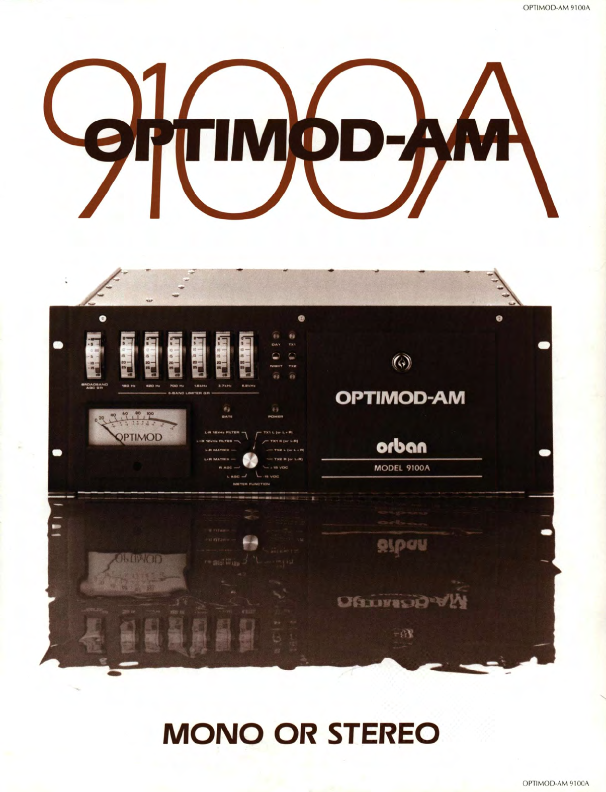
OPTIMOD-AM
:
An int
eg
rated audio pro
cess
ing
sys
tem for
AM
radio,
in
cluding
comp
ress
or, program equalizer,
multiba
nd
limiter, clipper, and
transmitter equalizer
Performance
Highlights
D Supplies very high average modula-
tion (loudness), exceptional fidel
ity,
uncanny naturalness, and freedom
from processing artifact to yield
an
FM-like sound from typical auto, port-
able, and table
rad
i
os.
D Designed for universal application in
domestic or international
LW,
MW,
and
SW
services;
easi
ly adaptable to
relevant government standards.
D Compensates for receiver high fre-
quency
rolloff
with
statistically-de-
rived, adjustable equalizer to extend
perceived bandwidth
at
the receiver
without
introducing
midrange
re-
sponse
anomalies or receiver tuning
difficulties.
D
New
six-band limiter
with
distributed,
distortion-cancelled multiband clip-
per yields
at
least 3dB increase in
RMS
modulation levels compared to old
Model 9000A.
D Consistent output level and equaliza-
tion texture over a 25dB input level
range.
D Versatile and simple setup controls let
you quickly arrive
at
the sound you
really want.
D Improved transmitter equalizer cor-
rects
tilt and ringing in older transmit-
ters and
antenna
systems
for
maximum modulation.
D Outputs for two transmitters
with
in-
dependent output level control and
full remote control switching for TXI/
TX2
and DAY/NI
GHT
status:
i.e.,
four
sets
of
TX
EQ
adjustments available,
all remote-selectable.
D Sum-and-difference stereo
or
mono
versions available; mono unit fully
ready for stereo processing by simply
plugging-in additional circuit
cards.
D Orban-quality construction, docu-
mentation, support, and service.
Why A New
OPTIMOD-AM?
Strangely enough, because
of
the suc-
cessful new OPTIMOD-FM Model
8100A.
Some
of
the innovations introduced in it
turned out to be highly applicable to
AM
processing. Specificall
y,
the
FM
unit in-
troduced a simpler, more economical,
and more elegant means
of
realizing the
now-patented distortion-cancelling clip-
per first introduced in the old 9000A
OPTI
MOD-AM.
And the
FM
unit
fea-
tures a distributed crossover
with
embedded clipper (now patented, too).
This concept, extended to six bands and
combined
with
the distortion-cancelling
filter,
is
the key to the higher loudness
and astonishingly improved naturalness
of
the new
91
00A
OPTIMOD-AM
.
A Smarter
"Smart Clipper"
In the previous
AM
unit, the outputs
of
the six bands in the six-band limiter
are
combined,
fed
through a voltage-con-
trolled amplifier, and then applied to a
distortion-cancelled clipper. A complex
circuit we call the "Smart Clipper'""
controls the gain
of
the YCA by estimat-
ing the amount
of
audible distortion
caused
by the clipping process, and
re-
ducing the VCA gain until such distor-
tion
is
no longer objectionabl
e.
This,alas,
is
a wideband control process,
and must therefore not
be
over-used
if
its
operation
is
to be inaudible.
In
the quest
for ever-higher loudne
s,
many Model
9000A
users
have chosen to operate the
"Smart Clipper"
with
so
much gain
re-
duction that
its
operation
is
audible. It
therefore became clear to
us,
as
design-
ers,
that it would be far better to elimi-
nate the need for any wideband gain
reduction between the output
of
the
multi band section and the final safety
clipper. That
way,
wideband modulation
effect would never occur.
This
is
more easily said than done.
In
the
previous
AM
unit, the "Smart Clipper"
control circuitry
is
absolutely necessary
to avoid either unacceptable loudness
loss
or
unacceptable di tortion on cer-
tain program material. The key turned
out to be multiband clipping combined
with
distortion cancellation, using
our
patented techniques in concert
with
some new developments.
The Bottom
Line:
FM-Like Performance
The exciting result
of
such processing
is
that the combined output
of
the bands
can
be
fed
to a safety clipper without
interspersing wideband gain control -
provided that almost 100 internal
parameters
are
correctly
"tuned"
in the de-
sign process! However, the payoff i
worth it: a dramatically open, effortless,
multiband ound
with
literally no audi-
ble processing on virtually any radio
likely to be in the hands
of
your audi-
ence. A
so
und which
is
"FM-like" not
only in terms
of
frequency response, but
al
so
in terms
of
"punch",
"depth",
"openness", and "definition". And a
sound which, on a true
RMS
meter, aver-
ages
about 3dB higher than the previous
unit for the
same
peak modulation.
In
hort a loud yet unbelievably natural
sound which, we think,
stands
the best
chance yet
of
winning
back
an
audience
becoming more and more attracted to
FM.
AM
Stereo
The
91
00A
is
available
as
a stereo
processor,
or
as
a stereo-convertible mono
processor. Stereo conversion
is
achieved
simply by plugging in circuit cards -no
"accessory chassis"
is
required except
for the stereo generator.
Processing occurs in the "sum-and-dif-
ference" mode, which
is
most appropri-
ate
for
AM
stereo because the
AM
modulation component represents the
sum
(L
+
R)
of
the channels to
assure
compatibility
with
mono receivers. In-
ternal
straps
determine
if
the output
is
to
be
in L
+Rand
L-R mode, or in Land R
mode, yielding complete versatility in
matching it to the stereo generator.
The standard bandwidth
of
the
91
00A
is
limited to 12kHz by means
of
highly
e-
lective filters, enabling it to comply with
STEAM POWERED RADIO.COM
AND
LOUDER,
NATU
the occupied bandwidth requirem nls
of
FCC
73.40.a.12
with
arbitrary pro-
gram material and processing adju l-
ments. An optional plug-in
fill
r
ard,
provided
at
extra cost, (whi h
fully interfa
ces
with
th
DAY/
NIGHT
remote ontrol) p rmits you
to
limit
the bandwidth
of
th
e
L-R
channel
to SkHz, controlling pol nlial
IM
distor-
tion
which
can
be introduced
by
high-
energy high frequen y
inf
ormation in
some
of
the
AM
sl rco
syste
m
s.
This card al
so
has
qrap~
which
permit
realization
of
vi
rluc1I
ly
<lny
com bi nation
of
12kHz and
Sk
i
11
bandwidths
in
the
sum
and
/or
difference hanne
ls,
in
DAY
and/or
NIGi
IT modes, enabling broad-
casters
to limit
mono
or
ste
reo band-
width
to
SkH1 al night (to control inter-
feren
ce
to o
th
er
stat
ion
),
or to operate at
SkHz
at
all tim s to meet
EBU
or other
international
sp
ifi ations.
Stereo or Quality:
What
Really Attracts
Listeners?
Despite the
fa
I Iha
IIh
91
00A
is
well-
equipped for stereo, w suspect that this
may not be
as
imp
ortant
as
so
me peop
le
think.
A very popular· lo al
FM
talion lost its
separation -but not its pilot,
so
liste
n-
ers' stereo I ight
did
1101
go out. The
re-
sult?
In
thr
ee
day
s,
one
listener
ca
lled to
complain -and only because he no-
ticed the problem on
th
e vector scope in
his expensive tuner. None
of
the staff no-
ticed anything awry. The station
's
con-
tract engineer finally noticed the
probl
em
and quietly fixed it.
LEFTINPUT-
RIGHT
INPUT-
INPUT
CON01T10NING
FILTER
INPUT
CONOtTIONING
FILTER
-
BROAOBAND
AGC
STEREO
COUPLING
BROADBAND
AGC
RECEIVER
EO
RECEIVER
EO
1--
o what? Compared 10 attaining FM-like
audio quality,
AM
stereo
ound
(as
op-
pos
d
to
a little light on someone's r
ad
io
say
ing "stereo") just might be a second-
ary consideration for achieving audi-
en
ce
satisfaction. The
91
00A
is
unique
in
it
s ability to make you
sound
good,
whether
in
mono
or stereo. And
we
think that sounding
good
is
what
is
go-
ing to bring listeners back from the
FM
band. Judge for yourself!
The
9100A:
Designed For The Real
World
Operator
Gain-Riding: A classic prob-
lem
of
multi band compressors is
th
eir
sensitivity to
input
level
s.
In
correct oper-
ator gain riding can cha n
ge
frequency
balan
ces
and equaliza
ti
on textures
in
a
disturbing
way.
Be
cause
of
this, the
91
00A
has
a n
ew
ly-
designed AGC amplifier
ahead
of
its six-band
limit
er. It is designed to
do
as
little
as
possible
to the sound except
to
slowly gain-ride over a
25dB range. Accordingly,
despite its being a
wideband device,
it
does not make nasty
wideband sounds.
And it relieves the operator
of
the requirement
of
reading a
comp
li-
cated array offlashing LED's ju
st
to de-
termine
if
th
e processor
is
being driven
correctly!
l+R
MATRIX
l - A
~
6-BAND
LIMITER
6-BANO
LIMITER
STEREO
COUPLING
MULTIBANO
DISTORTION
-
CANCELLED
CLIPPER
MULTIBANO
DISTORTION
-
CANCELLED
CLIPPER
1
2kHz
LOW
-
PASS
FILTER
AUX
INPUT
12kHz
LO
W-PASS
FILTER
OPTIDNALSkHz
LOW-PASS
FILTER
OPTIONAL
SkHz
LOW
-
PASS
FILTER
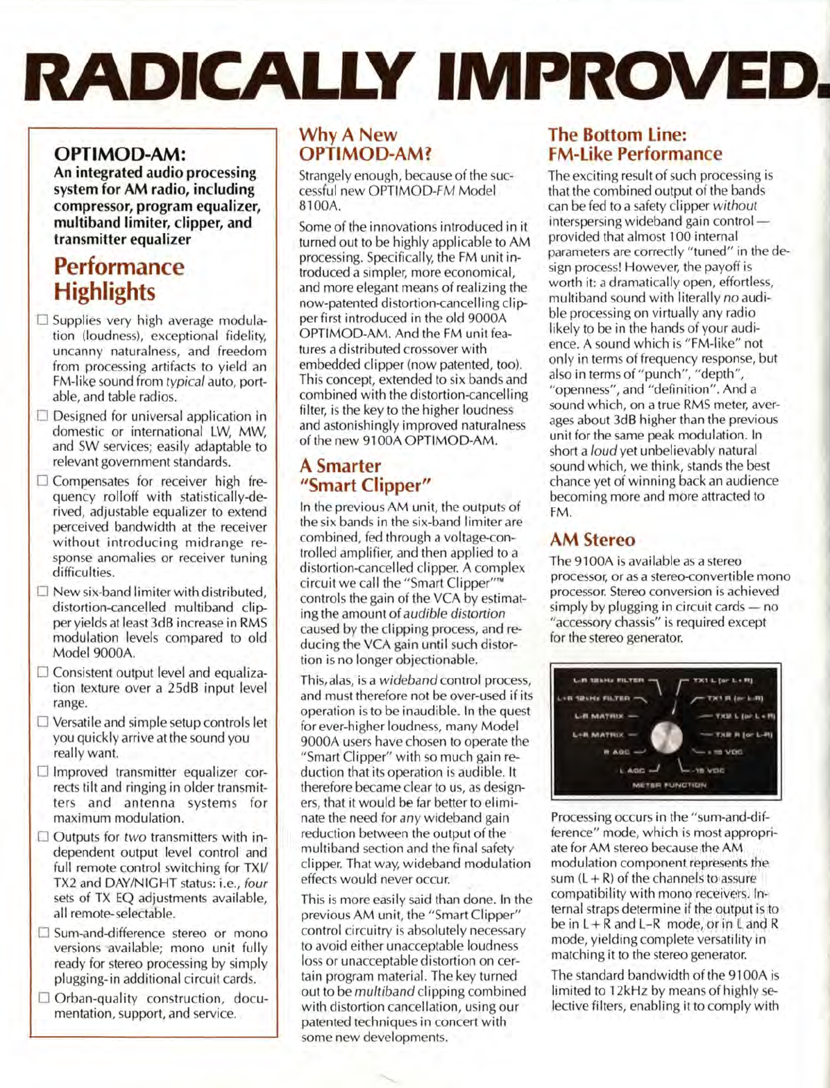
SYSTEM
BLOCK
DIAGRAM
(STEREO
CONFIGURATION)
Receiver Equalization: We carefully
measured the frequency response
of
fif-
teen
of
th
e most
commo
n real-world
AM
radios. We then averaged the curves,
and did a
stat
i
st
i
ca
l analys
is
to make sure
that
our
procedure meant
so
mething.
Finally, we mathematically synthesized
an
inver
se
(preemphasis) curve which can
correctly equalize
th
e radios flat up to a
-3dB
point
of
6kHz. We took this curve
and designed
an
equalizer circuit
which
could create
it
,
or
any part
of
it.
So
broadcasters
who
don't
wi
sh to equalize
out to the full
6kHz
(which requires lots
of
high frequency boost) can equalize
out to SkHz, 4kHz, 3kHz, or whatever
- all
without
introducing midrange
coloration,
as
offsetting the top band on a
conventional triband processor inevita-
bly
does when you try to equalize for
ra-
dio
rolloffs.
Th
e r
esu
lt is a one-knob high frequency
equali
ze
r that
ca
n produce nothing
but
correct
eq
ualization curves!
Much
eas-
ier to
us
e than the three-knob H-F equal-
izer on our previous
AM
processor. And
much more accurate, too!
15
15
!Ort)'
10(\)
5
20~
5
.·
20
EQ
tN
·
•.
~
~2
dB
~
._
.
<22
LEFT
RIGHT
We then complemented this unique H-F
eq
ualizer
with
a versatile parametric
bass
eq
ualizer
which
can tune
bass
response to
your
format and target
audien
ce.
SAFETY
CLIPPER
TRANSMITTER
SWITCHING
LOGIC
SAFETY
CLIPPER
1------4
TRANSMITTER
EO
L + R
~
DE-MATRIX
~
l R
1---
(TX1)
Lor L+R
(TX2)
~
OUTPUTS
!TX1)
R
or
L - R
(TX2)
LLY.
I I R
.__
__
_.I
....
I
__
R_~
MODE
~
OPERATE
.PROOF
SQ WAVE
INJECTION
TPI
r-
TRANSMITTER
EQUALIZER
---i
EQ
Q
IN
OUl
I
l+R
01
l
OUTPUT
ATTEN
I
l-R
o,
R
DAY
I
TX!
NIGHT
DAV
I
TX2
NIGHT
DAY
I
TX!
NIGHT
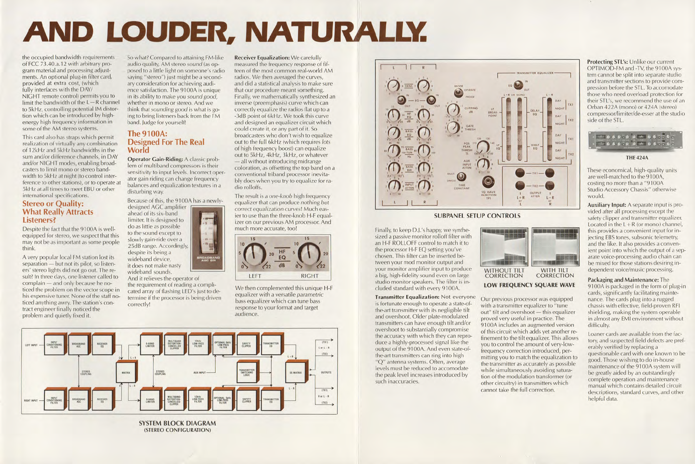
SUBPANEL
SETUP
CONTROLS
Finally, to keep D.J,'s happy,
we
synthe-
sized a passive
monitor
rol loff filter
with
an
H-F ROLLO
FF
control to match
it
to
the processor H-F
EQ
setting
you've
chosen. This filter
ca
n be
in
se
rt
ed
be-
tween your mod
monitor
output and
your
monitor
amplifier
input
to produce
a big, high-fidelity sound even on lar
ge
studio
monitor
speakers. The filter is in-
cluded standard
with
every
91
00A.
Transmitter Equalization:
Not
everyone
is
fortunate enough to operate a state-of-
the-art transmitter
with
its negligible
tilt
and overshoot.
Older
plate-modulated
transmitters can have enough ti It and/or
overshoot to substantially compromise
the accuracy
with
which
they can repro-
duce a highly-proce
ssed
signal like the
output
of
the
91
00A. And even state-of-
the-art transmitters can ring into high
"Q"
antenna systems. Often, average
levels must be reduced to accomodate
the peak level incr
eases
introduced
by
such inaccu
ra
c
ies
.
WITHOUT
TILT WITH
TILT
CORRECTION CORRECTION
LOW
FREQUENCY
SQUARE
WAVE
Our
previous processor was equipped
with
a transmitter equalizer to
"tune
out"
tilt
and
overshoot-
this equalizer
proved very useful in practice. The
91
00A
includes
an
augmented version
of
this circuit
which
adds yet another
re-
finement to the
tilt
equalizer. This allows
you to control the amount
of
very-low-
frequency correction introduced, per-
mitting you to match the equalization to
the transmitter
as
accurately
as
possible
while
simultaneously avoiding
sat
ura-
tion
of
the modulation transformer (or
other circuitry) in transmitters
which
cannot take the full correction.
Protecting
STL's:
Unlike
our
current
OPTIMOD-FM
and
-TV,
the
91
00A
sys-
tem
ca
nnot be split into separate studio
and transmitter sections to provide com-
pression before
th
e
STL.
To
accomodate
those
who
need overload protection for
their
STL's,
we recommend the
use
of
an
Orban
422A
(mono)
or
424A
(stereo)
compressor/limiter/de-esser at the studio
side
of
th
e
STL.
THE424A
These economical, high-quality units
are
wel I-matched to the
91
00A,
costing no more than a "91
00A
Studio Accessory Chassis" otherwise
would.
Auxiliary Input: A separate
input
is pro-
vided after
al
I processing except the
safety clipper and transmitter equalizer.
Located in the L
+ R (or
mono)
channel,
this provides a convenient input for in-
jecting
EBS
tones, subsonic telemetry,
and the like. It also provides a conven-
ient
point
into
whi
ch the output
of
a
sep-
arate voice-processing audio chain can
be mixed for those stations desiring in-
dependent voice/music processing.
Packaging and Maintenance: The
91
00A
is
packaged
in
the form
of
plug-in
cards, significantly facilitating mainte-
nance. The cards plug into a rugged
chassis
with
effective, field-proven
RFI
shielding, making the system operable
in almost any
EMI
environment
without
difficulty.
Loaner cards
are
available from the
fac-
tory, and suspected field defects
are
pref-
erably verified by replacing a
questionable card
with
one
known
to be
good. Those wishing to
do
in-hou
se
maintenance
of
the
91
00A
system
will
be greatly aided
by
an
outstandingly
complete operation and maintenan
ce
manual
whi
ch contains detailed circuit
descriptions, standard curves, and other
helpful data.
STEAM POWERED RADIO.COM
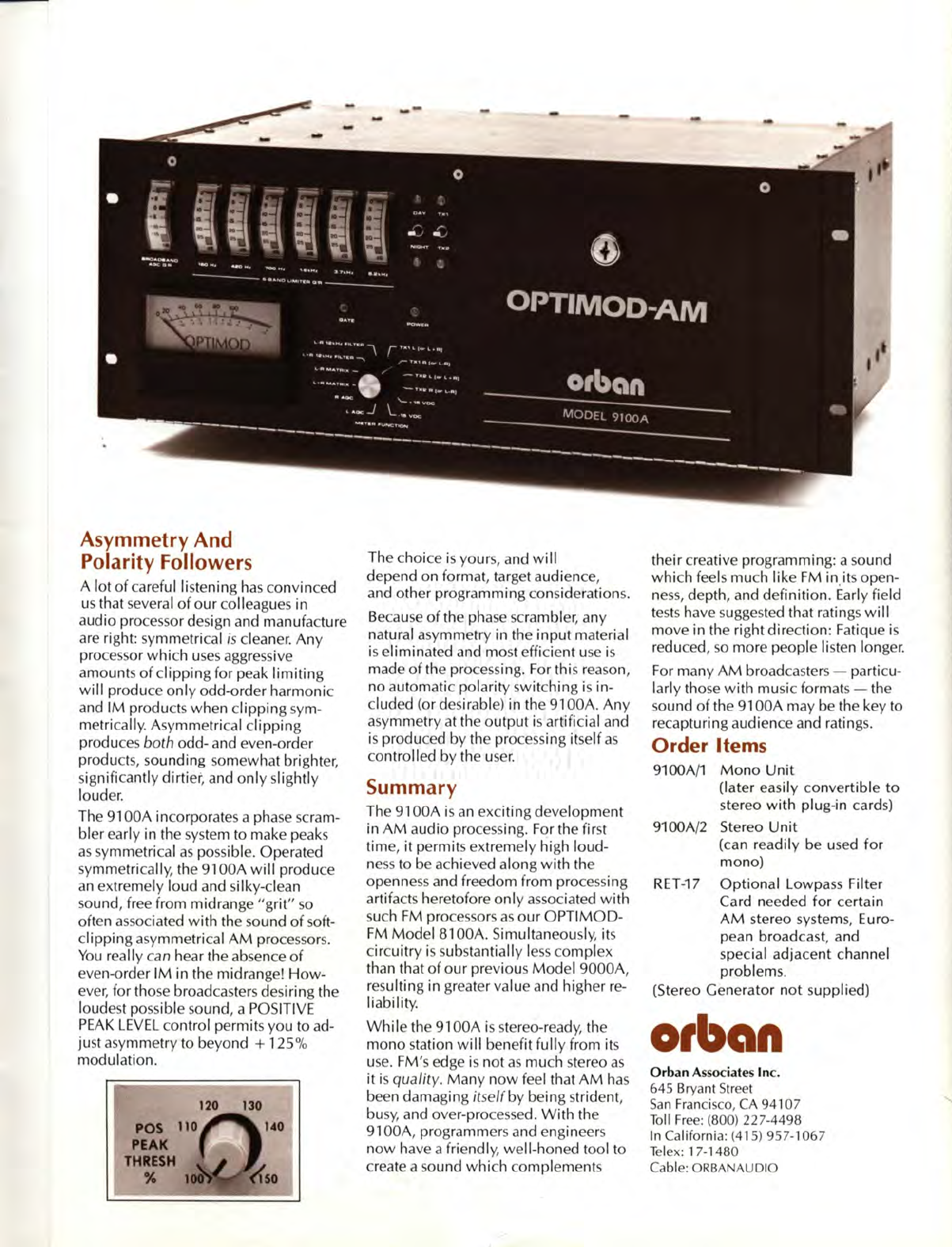
Asymmetry And
Polarity Followers
A lot
of
careful listening
has
convinced
us that several
of
our
colleagues in
audio processor design and manufacture
are
right: symmetrical is cleaner. Any
processor
which
u
es
aggressive
amounts
of
clipping for peak
limiting
will
produce
only
odd-order harmonic
and
IM
products when
clipping
sym-
metrically. Asymmetrical
clipping
produces both odd- and even-order
products, sounding somewhat brighter,
significantly dirtier, and
only
slightly
louder.
The
91
00A incorporates a phase scram-
bler early in the system to make peaks
as
symmetrical
as
possible. Operated
sy
mmetrically, the
91
00A
will
produce
an
extremely loud and silky-clean
sound, free from midrange
"grit"
so
often
as
ociated
with
the sound
of
soft-
clipping asymmetrical
AM
processors.
You
really can hear the absence
of
even-order
IM
in the midrange!
How-
ever,
for tho e broadca ters desiring the
loudest po sible sound, a POSITIVE
PEAK
LEVEL
control permits you to ad-
just asymmetry to beyond
+
125%
modulation.
POS
PEAK
THRESH
"
120 130
The choice
is
yours, and
will
depend on format, target audience,
and other programming considerations.
Because
of
the phase scrambler, any
natural asymmetry in the
input
material
is
eliminated and most efficient
use
is
made
of
the processing. For this reason ,
no automatic polarity switching
is
in-
cluded (or desirable) in the
91
00A. Any
asymmetry at the output
is
artificial and
is
produced by the proce ing itself a
controlled
by
the u
se
r.
Summary
The
91
00A
is
an
exciting development
in
AM
audio proce sing. For the first
time, it permits extremely high loud-
ness
to be achieved along
with
the
openne and freedom from proces ing
artifacts heretofore
only
as
ociated
with
such
FM
processors
as
our
OPTIMOD-
FM
Model
81
00A. Simultaneously, it
circuitry
is
sub tantially
les
s complex
than that
of
our
previous Model
9000A
,
resulting in greater value and higher
re-
liability.
While
the
91
00A
is
stereo-ready, the
mono tation
will
benefit fully from its
use.
FM' edge is
not
as
much stereo
as
it is
quality.
Many
now
feel that
AM
ha
s
been damaging
it
elf
by being strident,
busy, and over-proces ed.
With
the
91
00A, programmers and engineer
now
have a friendly, well-honed tool to
create a sound
which
complement
their creative programming: a sound
which
feels much like FM in.its open-
ness
, depth, and definition. Early field
tests
have suggested that ratings
wi
11
move in the right direction: Fatique
is
reduced,
so
more people listen longer.
For many
AM
broadcasters -particu-
larly those
with
music formats -the
sound
of
the
91
00A may be the key to
recapturing audience and ratings.
Order Items
9100A/1
Mono
Unit
(later easily convertible
to
stereo
with
plug-in cards)
9100A/2 Stereo
Unit
(can readily be used
for
mono)
RET
-17
Optional
Lowpass Filter
Card needed
for
certain
AM
stereo systems, Euro-
pean broadcast, and
special adjacent channel
problems.
(Stereo Generator
not
supplied)
o,ban
Orban
Associates
Inc.
645 Bryant Street
San
Fran
ci co, CA 94107
Toll
Free
: (800) 227-4498
In
California: (415) 957-1067
li
lex: 1
7-
1480
Cable:
ORBANAUDIO
STEAM POWERED RADIO.COM
Specifications
It
is
impossible to define
th
e listening qua
lit
y
of
even
th
e simpl
es
t
limit
er
or
compressor on the
basis
of
the usual specifications b
eca
u
se
such
spec
ifi
ca
tions
ca
nnot adequately de cribe
th
e
c
ru
cial dynamic proces e
which
occur under
program condition
s.
Th
ese
dynamic
pro
cesses
are
eva
luat
ed
at
th
e factory and controlled to
close tolerance .
Th
e m
eas
urements require spe-
cial t
es
t fixtur
es
,
ca
nnot be read il y duplicated by
measurements with tanda
rd
t
est
e
quipm
ent in
th
e field, and
ca
nnot be de cr
ib
ed
in fam iliar
terms.
Certain specifications are
th
erefore
pr
ese
nted
here to
sa
tisfy the engin
ee
r that
th
ey are r
easo
n-
ab
le, to help plan
th
e installation, to he
lp
ma
ke
certain compa
ri
so
ns
with
other pro
cessi
ng equip-
ment, and to verify
th
at
OPTIMOD
-AM
ca
n read-
ily
pas
a
Pro
of of
Performance. In o
rd
er to
faci litate this, all equalization
ca
n be switch-by-
passed
to enable a
Pro
of
to be performed under
"flat" conditions
as
re
quir
ed by
th
e
FCC
(U.S.A.).
INPUT
•
Imp
edance: Greater
th
an 10 K ohm
s,
el
ec
troni-
ca
lly balanced by means of true instrumentation
amplifier.
RF
suppr
esse
d.
Se
nsitivit
y:
Normal operati on may be
ac
hieved
with nominal line levels
of
-30dBm or greater. In-
put
se
n
si
ti vity
is
controlled
by
means
of
I
NPUT
ATTENUATOR control, and al
so
by
means
of
a
bypassable 20dB pad before
th
e input am
plifi
e
r.
INPUT C
ONDITIONING
FILTER
Hi
ghp
ass:
-0.S
dB
@S0Hz
with
roll
off
exceeding
18dB/octave
below
that frequen
cy.
Includ
es
deep
25Hz notch for automation cueton
es
.
L
ow
p
ass:
Rolls
off
frequenci
es
above 12kHz at
rate exceeding 24dB/octave.
Allp
ass:
Ph
a e
sc
rambler makes p
ea
ks more
sy
m-
metrical to
bes
t utilize
th
e
ca
pabi liti
es
of
th
e
processing.
BROADBAN D C
OMPR
ESS
OR
Ran
ge
of Gain Reduction: 25dB
Compr
ess
ion Ratio: gr
ea
ter
th
an 1
0:
1
Time Con
sta
nt
Mod
e: SINGLE/MULTI, switch-
select
ab
le
Attack Tim
e:
approximately 200ms
(S
INGLE);
program-controlled (MULTI)
Release Time:
ap
proximately 3d B/second
(S
IN-
G
LE
),
program-controlled (MULTI)
To
tal Harmonic
Di
stortion: does not exceed
0.05 %
at
any degree
of
gain reduction, 50-
12,000Hz
Noise: gr
ea
ter
th
an 85dB
below
output c
lippin
g
level
Gating:
gai
n
will
dr
if
t sl
ow
ly to 1 0
dB
G/R
if
input
level drops
below
a user-adjusted threshold
Variable-Gain Element: proprietary class-A VCA
PROGRAM
EQUALIZER
B
ass:
"Q
u
as
i-Parametri
c"
second-o
rd
er peak
boost
eq
uali
ze
r. "
Q"
va
ri
ab
le from 0.3 to 1.4.
TUNING
va
riable from 70 to
11
0Hz.
EQ
variable
from Oto + 6d
B.
H
ig
h
Fr
equency:
Pr
oprietary third-o
rd
er shelving
eq
ualizer
(pa
tent pendin
g)
matches inverse
of
"aver
age
"
(see
text) receiver rolloff to a high fre-
quen y
limit
, adj ust
ab
le from no equalization at
all, through any frequency up to 6kHz.
Noi
se
and
Di
stortion are substantially
below
o
th
er elements in
th
e
sys
tem.
800020-
000
-
02
3183
SI
X-
BAND
LIMITER
Filter
s:
1
S0
Hz
lowp
ass;
420Hz
ba
ndp
ass;
700Hz
ba
ndp
ass;
1.6kHz bandpass; 3.7kHz bandpass;
6.2kHz highp
ass
.
Filter
Se
l
ec
tivity: 18dB
/oc
tave
Filter Topolo
gy:
paralle
l.
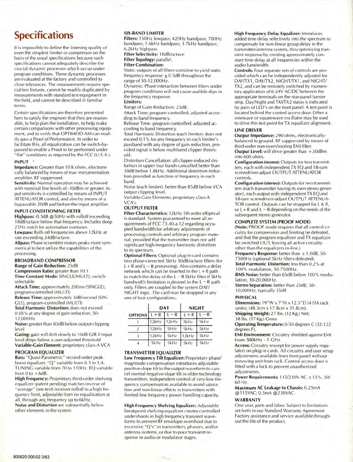
Filter Combination:
Stati
c:
output
of
all filters combine to yield static
frequency r
es
pon
se
± 0.SdB througho
ut
th
e
range
of
50-12,000Hz.
Dynami
c:
Ph
ase
interaction between filters under
progr
am
conditions
will
not
ca
u
se
a
udibl
e
dip
in
th
e fr
eq
uency re pon
se.
Limiters:
Range
of
Gain R
ed
uction:
2S
dB
.
Attack Tim
e:
program controlled; adj ust
ed
accor-
ding to band frequency.
Rel
ease
Tim
e:
prog
ram
controlled; adjusted ac-
cording to band frequency.
Tot
al Harmonic Distortion
(eac
h
limit
er): does not
exceed
0.1
% for any frequency in
eac
h
limit
er
's
passband
with
any degree
of
ga
in reduction,
pr
o-
vid
ed
signal is be
low
mul
tiband clipper thr
es
h-
old.
Distortion Cancellation: all clipper-induced di -
tortion in upper fo ur bands
ca
ncelled better
th
an
30
dB
be
low
1.8kH
z.
Additional distortion re
du
c-
tion provided
as
function
of
frequency in
eac
h
band.
Noi
se
(eac
h li
mit
er
):
better
th
an 8
Sd
B
below
VCA
output
clipp
ing level.
Va
ri
able-Ga in Element
s:
proprietary cl
ass-A
VCA'
s.
OUTPUT
FILTER
Filter Characteri sti
cs:
12kHz 5
th
order e
llipti
cal
i standard. System guarant
ee
d to meet all r
e-
quirement
of
FCC
73.40.
a.
12 regarding occu-
pi
ed
ba
ndwidth
for arbitrary a
dju
stments
of
pro
ess
in
g controls and arbitrary program mate-
rial, provid
ed
th
at
the tran
milter
d
oes
not add
signifi
ca
nt high-frequency harmonic distortion
to
its spectrum .
Option
al Filter
s:
Optional plug-in
ca
rd
conta
in
s
two phase-corrected SkHz 30dB/octave filters (for
L + R and L - R
pr
ocessin
g).
Also contains a delay
network
which
ca
n be in
se
rt
ed in
th
e L + R path
to match
th
e del
ay
of the L- R
Sk
Hz filter
if
Sk
Hz
bandwidt!i
limit
at
ion
is
de ir
ed
in
th
e L- R path
only. Filters are coupl
ed
to
th
e y tern DAY/
NIGHT
logi
c.
Th
e card may be strapped in any
one
of
four configuration
s.
DAY
NIGHT
OPTIONS L + R L- R L+ R L- R
1 12kHz 12kHz
Sk
Hz
Sk
Hz
2 12kHz SkHz
Sk
Hz
Sk
Hz
3
12kHz
SkHz 12kHz
Sk
Hz
4
Sk
Hz
Sk
Hz SkHz SkHz
TRANS
MI
TT
ER
EQUALIZER
Lo
w
Fr
equency Tilt
Equ
alizer: Proprietary phase/
magnitude co
mp
en
sa
tion introduces a
dju
stable
positiv
e-s
lope tilt to
th
e output waveform to
ca
n-
cel normal negative-slope ti lt in older-technology
transmitter
s.
Independent control
of
very-low-fre-
quency co
mp
en
sa
tion available to avoid
sa
tura-
tion and non-lin
ea
r effects in transmitters
with
limit
ed
low
frequency
pow
er handling capacity.
Hi
gh
Fr
equency Shelving
Equ
alizer: Adju table
breakpoint shelving equalizer creat
es
controlled
undershoots in high frequency transient wave-
forms to prevent
RF
envelope overshoot due to
exce sive "
Q's"
in transmitter , ph
aso
rs, and
/o
r
antenna
ys
tems,
or
due to poor tran
sie
nt r
e-
pon
se
in audio
or
modulator st
ages
.
Hi
gh Frequency Delay
Equ
alizer: Introdu
ces
added time delay
se
lectively into
th
e sp
ec
trum to
compen
sa
te for non-lin
ea
r group delay in
th
e
transmitter
/a
ntenna
sys
tem, thru
optimizing
tran-
sient r
es
pon
se
by
r
ea
ting approxi mately co
n-
stant time de
la
y at all frequencies
within
th
e
audio bandwidth.
Control
s:
Four
se
pa
rat
e
se
ts
of
control are pro-
vided
which
ca
n be independently adjusted for
DAY/TX1
, DAY/TX2, NIGHT/TX 1, and
NIGHT
/
TX
2,
and
ca
n be remotely swit h
ed
by momen-
tary application
of
6-24V AC/DC between
th
e
appropriate terminals on
th
e r
ea
r-panel barrier
strip. Day/
Ni
ght and TXI/TX2 sta
tu
s
is
indi
ca
t
ed
by pairs
of
LED
' on
th
e front pane
l.
A t
es
t point
is
lo
ca
t
ed
behind
th
e control acce s door. Either a
sinewave
or
squarewave oscillator m
ay
be u
sed
to
drive this test point for
TX
equalizer alignment.
LINE DRIVER
Output
Impedance: 290 ohms, electroni
ca
lly
-
balanced to ground.
RF
suppre
sse
d by m
ea
ns
of
third-order non-overshooting
EM
I filter.
Output
Level:
wi
ll drive greater than + 20dBm
into 600 ohm
s.
Config
ur
ation (mono
):
Output
for two transmit-
ter
s,
each
with
independent
TX
EQ
and 18-turn
screw
driv
er
-a
dju
t
OUTPUT
ATTENUATOR
control
s.
Config
ur
ation
(s
tereo
):
Outputs for two transmit-
ter
(eac
h tran
sm
itter having its
own
stereo
ge
ner-
ator),
eac
h output
with
independent
TX
EQ
and
18-turn
sc
rewdriv
er-a
dju
t
OUTPUT
ATTENUA-
TOR control. Outputs
ca
n be strapped for L & R,
or
L + Rand L - R depending on the need
of
th
e
sub
seq
uent
ste
reo
ge
n
era
tor.
COMPLETE SYSTEM (
PROOF
MODE
)
(
Not
e:
PROOF mode re
quir
es
th
at all control cir-
cuitry for co
mpr
ess
ion and
limitin
g be d
efea
ted,
and
th
at
th
e program equali
ze
r and
TX
equalizer
be witched OUT, leaving all
ac
ti ve ci rcuitry
o
th
er than
th
e equalizers in-line.)
Fr
equency R
es
pon
se
: better
th
an ± 1.0dB, 50-
7500Hz
(o
ptional S
kHz
fi
lt
ers
defeated).
Total Harmonic
Di
stortion: l
es
th
an 0.2% at
100% modulat
io
n, 50-7500H
z.
RM
S
Noi
se
: better
th
an 6SdB
below
100% modu-
lation, 30-20,000H
z.
Stereo Separation: better than
25
dB, 50-
10,000Hz; typically
3S
dB
PHY
SIC
AL
Dim
ension
s:
1
9"W
x
7"
H x 12.
S"D
(4
EIA
ra
ck
unit
s);
(4
8.3cm x 1
7.
8cm x 31.8cm).
Shipping
Wei
ght: 27 lbs. (12 K
g.)
Net;
38 lb
s.
(17 K
g.)
Gro
ss
Op
erating Tempera
tur
e:
0-50 d
eg
r
ees
C (32-1
22
degrees F
).
EMI Environment: Circuitry shielded against
EM
I
from
SOOkHz
- 1
GHz
.
A
ccess:
Circuitry (except for
pow
er supply r
eg
u-
lator) on plug-i n
ca
rd
s.
All
ci rcuitry and u
se
r
set
up
a
dju
stments avai lable from front panel without
removing unit from rack. Control
access
door is
fitted
with
a lock to prevent un
au
th
orized
ad
justment .
Power Re
quir
ement
s:
115/230V
AC
± 15%, 50/
60 H
z.
Ma
x
imum
AC Leakage to Ch
ass
i
s:
0.25mA
@
11
SVAC;
0.S
mA
@230VAC.
WARRANTY
One
yea
r, pa
rt
and labor. Subj
ec
t to limita
ti
ons
se
t forth in
our
Standa
rd
Warranty Agreement.
Factory
ass
istance and
se
rvice
ava
il
ab
le through-
out
th
e l
if
e
of
th
e produc
t.
STEAM POWERED RADIO.COM
OlbClft
Change:
Add
RET-24;
no
price
changes.
Order/
Model
Number
9100CV1
910)\/2
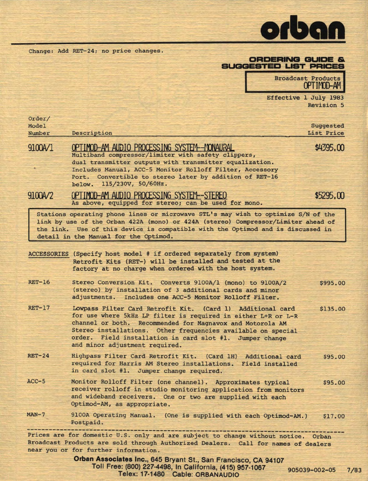
ORDERING
GUIDE
&
SUGGESTED
LIST
PRICES
Broadcast
Products
a:>TI~OD-N~
Effective
1
July
1983
Revision
5
Description
Cf>TU1)D:fV1
AUDIO
PROCESS
I
NG
SYSJEM--tmAUPAL
Multiband
compressor/limiter
with
safety
clippers,
dual
transmitter
outputs
with
transmitter
equalization.
Includes
Manual,
ACC-5
Monitor
Rolloff
Filter,
Accessory
Port.
Convertible
to
stereo
later
by
addition
of
RET-16
below.
115/230V,
50/60Hz.
CfTlfW::N:1
AUDIO
PROCESSl.NG_SYSJB'.l--STEf[()
As
above,
equipped
for
stereo;
can
be
used
for
mono.
Suggested
List
Price
$4395,00
$5295,00
Stations
operating
phone
lines
or
microwave
STL's
may
wish
to
optimize
S/N
of
the
link
by
use
of
the
Orban
422A (mono)
or
424A
(stereo)
Compressor/Limiter
ahead
of
the
link.
Use
of
this
device
is
compatible
with
the
Optimod
and
is
discussed
in
detail
in
the
~nual
for
the
·
Optimod.
ACCESSORIES
(Specify
host
model#
if
ordered
separately
from
system)
Retrofit
Kits
(RET-)
will
be
installed
and
tested
at
the
factory
at
no
charge
when
ordered
with
the
host
system.
RET-16
RET-17
RET-24
ACC-5
MAN-7
Stereo
Conversion
Kit.
Converts
9100A/l
(mono)
to
9100A/2
(stereo)
by
installation
of
3
additional
cards
and
minor
adjustments.
Includes
one
ACC-5
Monitor
Rolloff
Filter.
Lowpass
Filter
card
Retrofit
Kit.
(Card
1}
Additional
card
for
use
where
5kHz
LP
filter
is
required
in
either
L+R
or
L-R
channel
or
both.
Recommended
for
Magnavox
and
Motorola
AM
Stereo
installations.
Other
frequencies
available
on
special
order.
Field
installation
in
card
slot
#1.
Jumper
change
and
minor
adjustment
required.
Highpass
Filter
Card
Retrofit
Kit.
(Card
lH)
required
for
Harris
AM
Stereo
installations.
in
card
slot
#1.
Jumper
change
required.
Additional
card
Field
installed
Monitor
Rolloff
Filter
(one
channel).
Approximates
typical
receiver
rolloff
in
studio
monitoring
application
from
monitors
and
wideband
receivers.
One
or
two
are
supplied
with
each
Optimod-AM,
as
appropriate.
9100A
Operating
Manual.
(One
is
supplied
with
each
Optimod-AM.)
Postpaid.
$995.00
$135.00
$95.00
$95.00
$17.00
--------------------------------------------------------------------------------------
Prices
are
for
domestic
U.S.
only
and
are
subject
to
change
without
notice.
Orban
Broadcast
Products
are
sold
through
Authorized
Dealers.
Call
for
names
of
dealers
near
you
or
for
further
information.
Orban Associates Inc., 645 Bryant St., San Francisco, CA 94107
Toll Free:
(800)
227-4498, In California,
(415)
957-1067
905039
_002
-05
7/83
Telex: 17-1480 Cable:
ORBANAUDIO
