Solana_A4.p65 Precor Solana Strength System Owner’s Manual Owners 120 20050801 ENGLISH
Chest Press Owners-Manual-120_Solana_20050801_ENGLISH
User Manual: Precor Solana Strength System Owner’s Manual Troubleshoot Precor Solana Strength System |
Open the PDF directly: View PDF ![]() .
.
Page Count: 35
Assembly and Maintenance Guide
Solana
Strength-Training
Fitness Equipment
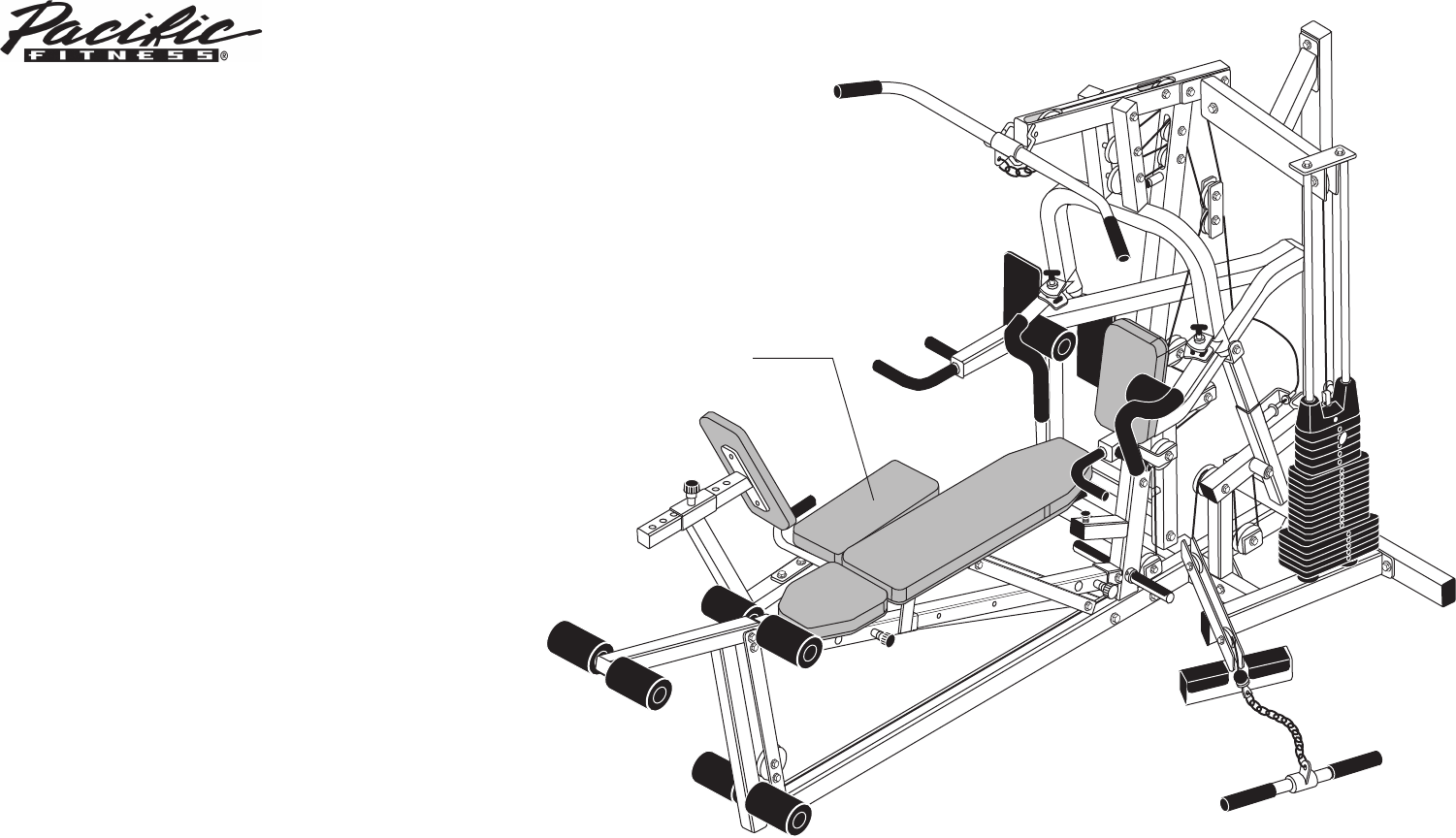
Leg Press
(optional equipment)

Solana Assembly and Maintenance Guide
page 2
IMPORTANT SAFETY INSTRUCTIONS
Important Safety Instructions
Important Safety Instructions
for Using the Equipment
Before beginning any fitness program, you should
obtain a complete physical examination from your
physician.
Il est conseillé de subir un examen médical complet
avant d’entreprendre tout programme d’exercise. Si
vous avez des étourdissements ou des faiblesses,
arrêtez les exercices immédiatement.
When using exercise equipment, basic precautions
should always be taken, including the following:
• Read all instructions before using the Solana
equipment. These instructions are written to
ensure your safety and to protect the unit.
• Do not allow children on or near the equipment.
• Use the equipment only for its intended purpose
as described in this manual. Do not use accessory
attachments that are not recommended by the
manufacturer: such attachments might cause
injuries.
• Wear proper exercise clothing and shoes for your
workout—no loose clothing.
• Use care when getting on or off the unit.
• Do not overexert yourself or work to exhaustion.
• If you feel any pain or abnormal symptoms,
stop your workout immediately and consult
your physician.
• Never operate the unit when it has been dropped or
damaged. Return the equipment to a service center
for examination and repair.
• Never drop or insert objects into any opening. Keep
hands away from moving parts.
• Always check the unit and its cables before each
use. Make sure that all fasteners and cables are
secure and in good working condition.
• Do not use outdoors.
Personal Safety During Assembly
• It is strongly recommended that a qualified dealer
assemble the equipment. Assistance is required.
• Read each step in the assembly instructions and
follow the steps in sequence. Do not skip ahead. If
you skip ahead, you may learn later that you have
to disassemble components and that you may have
damaged the equipment.
• Assemble and operate the Solana on a solid, level
surface. Locate the unit a few feet from walls or
furniture to provide easy access.
The Solana is designed for your enjoyment. By
following these precautions and using common sense,
you will have many safe and pleasurable hours of
healthful exercise with your new equipment.
Obtaining Service
Do not attempt to service the Solana yourself
except for the maintenance tasks described
in this guide. This unit does not contain any
user-serviceable parts.
For information about product operation or
service, check out the Precor web site at
www.precor.com or contact an authorized
Precor dealer or a Precor factory-authorized
service company. To locate the dealer or service
person nearest you, call 1-800-4-PRECOR.
If you call or e-mail Customer Service, have
the serial number and part numbers available.
You can find the serial number printed on a
label affixed to the side of the Solana. For
future reference, write the serial number in
the space provided below.
Serial number: _____________

Solana Assembly and Maintenance Guide
page 3
Table of Contents
Table of Contents
1
2
3
Important Safety Instructions for Using the Equipment ............................................................ 2
Personal Safety During Assembly ............................................................................................ 2
Obtaining Service .................................................................................................................... 2
Before You Begin ........................................................................................... 5
Unpacking the Equipment ........................................................................................................ 5
Optional Equipment ................................................................................................................. 5
Preparations................................................................................................... 6
Required Tools ......................................................................................................................... 6
Installation Requirements ........................................................................................................ 6
Assembly Tips ......................................................................................................................... 6
Assembly Instructions .................................................................................. 7
Open Box 1 .............................................................................................................................. 8
1. Assemble Main Structure .............................................................................................. 9
2. Assemble Weight Stack................................................................................................. 11
Open Box 2 .............................................................................................................................. 12
3. Assemble Press Arm .................................................................................................... 13
4. Assemble Chest Press/Pec Fly ..................................................................................... 17
5. Assemble Seat Pads ..................................................................................................... 18
6. Install Seat Extension.................................................................................................... 21
7. Assemble Leg Extension ............................................................................................... 22
8. Install Main Cable and Pulley ........................................................................................ 23

Solana Assembly and Maintenance Guide
page 4
Table of Contents
Adjustments and Maintenance ..................................................................... 30
1. Cable Adjustments ..................................................................................................... 30
2. Selector Stem Adjustments........................................................................................ 31
Forward Angle Adjustment ......................................................................................... 31
Backward Angle Adjustment ...................................................................................... 32
Side-to-Side Vertical Adjustment ................................................................................ 33
5. Maintenance .............................................................................................................. 33
Warranty Card and Specifications ...................................................................... Back cover
4
Solana Assembly and Maintenance Guide
page 5
1Before You Begin
Before You Begin
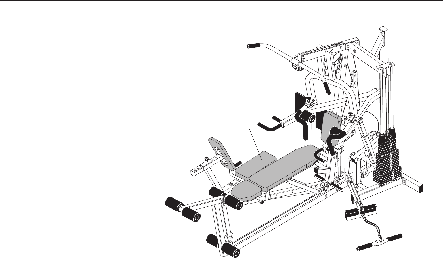
Thank you for purchasing the Solana. This unit is part
of the Pacific Fitness line of quality strength training
machines, which let you target specific muscle groups
to achieve better muscle tone and overall body
conditioning. To maximize your use of the equipment,
please study this guide thoroughly.
Unpacking the Equipment
The Solana is carefully tested and inspected before
shipment. Pacific Fitness ships the unit in several
pieces that require assembly. Ask for assistance during
the assembly process.
• Review the Installation Requirements found on the
next page.
• When instructed to open a box, carefully unpack the
pieces and lay them on the floor near the location
where you plan to use the equipment.
Be careful to open boxes and assemble components in
the sequence presented in this manual.
If any items are missing, contact the dealer from whom
you purchased the unit or call 1-800-4-PRECOR for
the dealer nearest you.
Optional Equipment
Optional equipment that you can purchase through
your dealer includes the 250-lb Weight Stack and the
Leg Press.
Leg Press
(optional equipment)
Solana Assembly and Maintenance Guide
page 6
2Preparations
Preparations
CAUTION: To set up this unit, you will need
ssistance. Do not attempt assembly by yourself.
You must review and follow the instructions in this
guide. If you do not assemble and use the Solana
according to the following guidelines, you could void
the Precor limited warranty.
Required Tools
Tools that you need to obtain before assembling the
unit include:
❏⁹⁄₁₆-inch socket wrench
❏¾-inch socket wrench
❏⁹⁄₁₆-inch box wrench
❏¾-inch box wrench
❏Standard set of metric hex keys
❏Two adjustable pliers or crescent wrenches
❏Measuring tape
❏Wire tie cutter (cuts plastic tie wraps)
❏Rubber mallet
❏Step stool
Installation Requirements
Follow these installation requirements when assembling
the unit:
•Fill out and mail the limited warranty card. The
warranty card is found on the back cover of this
guide.
•Set up the Solana on a solid, flat surface. A
smooth, flat surface under the unit helps keep it
level. A level unit has fewer malfunctions.
•Provide ample space around the machine.
Open space around the machine allows for
easier access.
•Insert all bolts in the same direction. For
aesthetic purposes, insert all the bolts in the
same direction unless specified (in text or
illustrations) to do otherwise.
•Leave room for adjustments. Tighten fasteners
(such as bolts, nuts, and screws), so the unit is
stable, but leave room for adjustments. Do not
fully tighten fasteners until instructed (in the steps)
to do so.
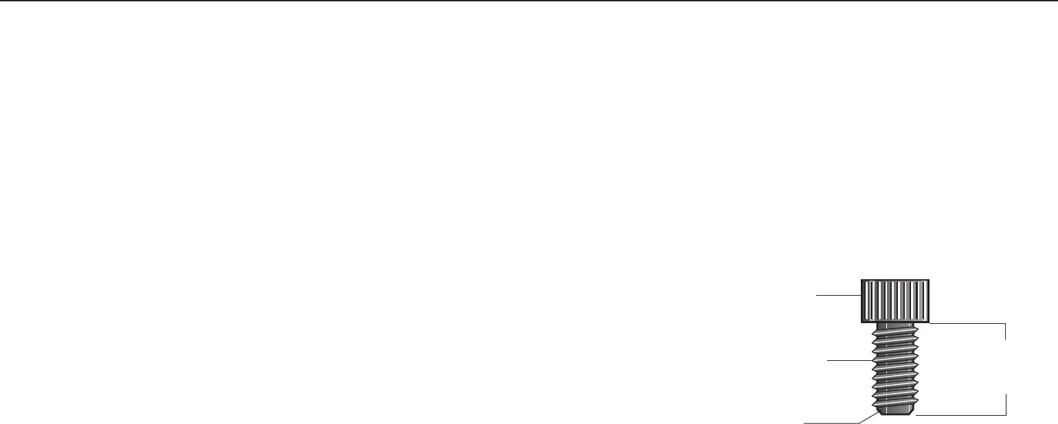
Assembly Tips
• A black 6-inch scale with white numbers is provided
at the bottom of every assembly instruction page.
Use this scale to identify the correct size bolts and
spacers. The head of a bolt is not used in
measuring the length of a bolt.
Note: A few of the bolts used to assemble the
Solana are longer than 6 inches. You may want to
use a measuring tape to accurately identify the
correct sizes.
To find out the length of a particular bolt, measure
its shank (the long, narrow part beneath the head).
Refer to the following diagram:
Bolt head
Bolt threads
Shank
To determine the
length of a bolt,
measure its shank.
• Read all caution notes on each page before
completing that step.
• Some pieces have extra holes that you will not use.
Use only those holes indicated in the instructions
and illustrations.
• While you may be able to assemble the Solana by
reading the illustrations only, refer to the text for
important safety cautions and notes.
Solana Assembly and Maintenance Guide
page 7
1 2 3 4 5 6
3Assembly
Instructions
Assembly Instructions
Assembly of the Solana takes professional installers
about 2 hours to complete. If this is the first time you
have assembled this type of equipment, plan on
significantly more time.
Professional installers are highly recommended!
However, if you acquire the appropriate tools, obtain
assistance, and follow the assembly steps sequentially,
the process will take time, but is fairly easy.
CAUTION: Obtain assistance! Do not attempt
to assemble the Solana by yourself. Review the
Installation Requirements on page 6 before
proceeding with the following steps.
The Solana comes in two boxes.
Be careful to open boxes and assemble components in
the sequence presented in this manual.
Note: With so many assembled parts, proper alignment
and adjustment is critical. While tightening the nuts and
bolts, be sure to leave room for adjustments. Do not
fully tighten bolts until instructed to do so.
Solana Assembly and Maintenance Guide
page 8
1 2 3 4 5 6
Open Box 1Open Box 1
Open Box 1Open Box 1
Open Box 1
Use tie cutters to open the boxes.
In this section, you will assemble the main structure of
the Solana. The illustration shows the different parts
that come in box 1.
Open Box 1
Contents of Box 1
Solana Assembly and Maintenance Guide
page 9
1 2 3 4 5 6
1. Assemble Main StructurAssemble Main Structur
Assemble Main StructurAssemble Main Structur
Assemble Main Structuree
ee
e
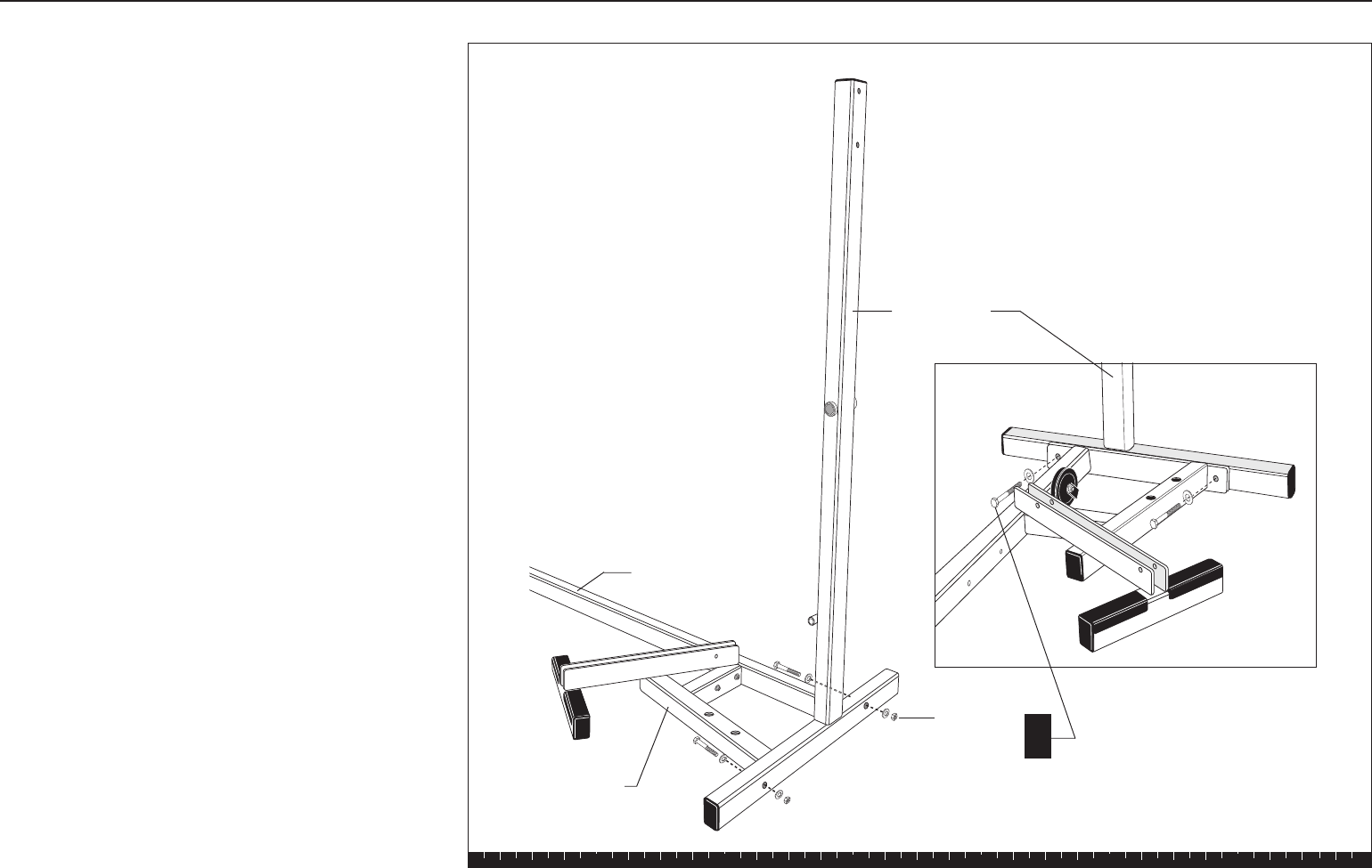
A. Have an assistant hold the Main Upright steady
while you align it with the Base Frame. Attach using
two 3-inch bolts
four washers
two locknuts
Step 1. Assemble Main Structure
Main Upright
2 - 3" bolts
4 - washers
2 - locknuts A
Base Crossbar
Base Frame
Solana Assembly and Maintenance Guide
page 10
1 2 3 4 5 6
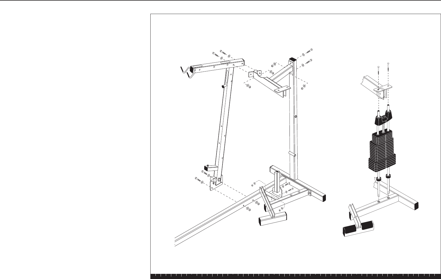
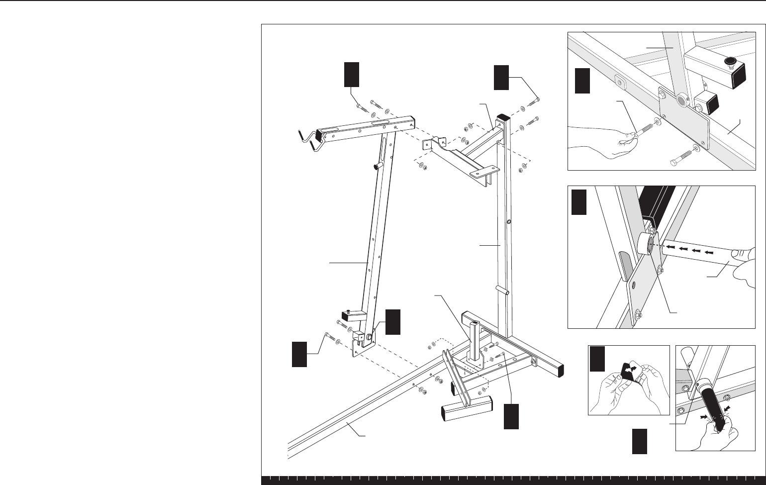
B. Attach the Chest Press Upright to the Base Frame
using
two 3-inch bolts
four washers
two locknuts
CAUTION:
Tighten the bolts enough so that the Chest
Press Upright is secure on the Base Frame. Make sure
that the assembled parts are stable and balanced before
your assistant lets go of the Main Upright.
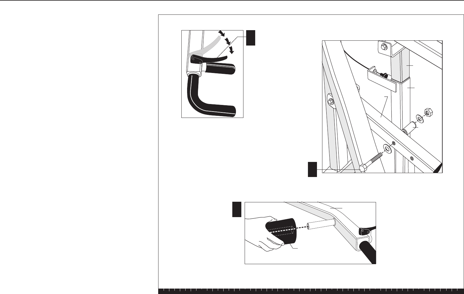
C. Insert the noncoated end of the Foot Support through
the Foot Support Hole at the base of the Chest Press
Upright until the black coated pad touches the
bracket.
D. Attach a black coated pad (found in the hardware
bag) to the noncoated end of the Foot Support.
Remove the adhesive backing from the black coated
pad and attach it in the same manner as the factory-
installed side. Tap a round end cap into the end of
the Foot Support in the same manner as the factory-
installed side.
E. Tighten the set screws with an appropriate hex key
when the Foot Support is positioned properly.
F. Attach the Guide Rod Bracket to the Chest Press
Upright using
two 3-inch bolts
four washers
two locknuts
Finger tighten.
G. Attach the Guide Rod Bracket to the Main Upright
using
two 3-inch bolts
four washers
two locknuts
Finger tighten.
H. Attach the Rest Support to the crossbar of the Base
Frame using
two 2¾-inch bolts
four washers
two locknuts
Wrench tighten.
Step 1. Assemble Main Structure, Continued
Chest Press
Upright
Foot
Support
B
C
D
Guide Rod
Bracket
Foot
Support Hole
See inset.
Set Screw
2 - 3" bolts
4 - washers
2 - locknuts
2 - 3" bolts
4 - washers
2 - locknuts
2 - 3" bolts
4 - washers
2 - locknuts
Rest Support
2 - 2¾" bolts
4 - washers
2 - locknuts
See inset.
E
Foot Support Hole
Base
Frame
Chest Press
Upright
Base Frame
B
H
Main Upright
G
F
C
Solana Assembly and Maintenance Guide
page 11
1 2 3 4 5 6
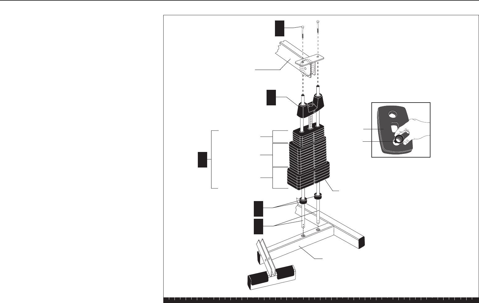
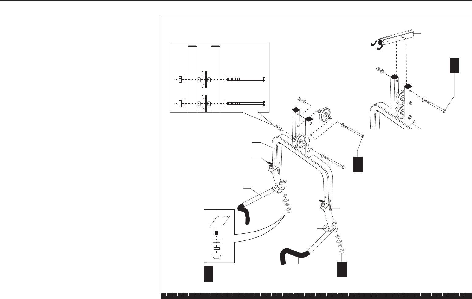
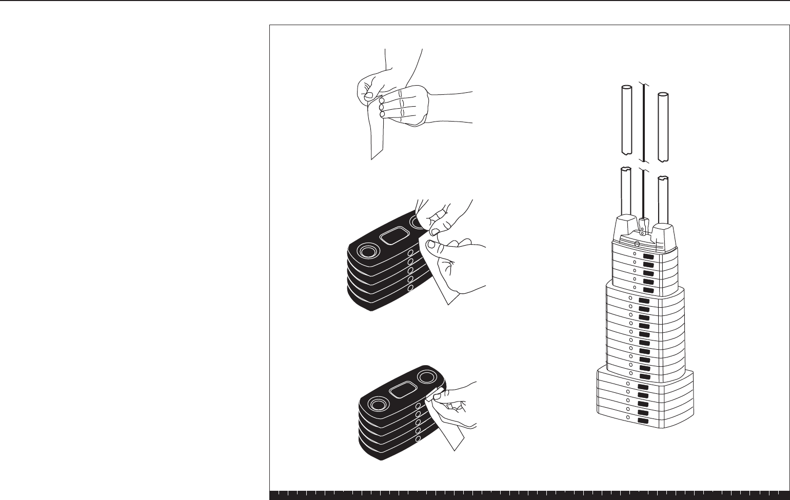
2. Assemble Weight Stack
A. Place two Guide Rods in the large holes on Base
Frame. The Guide Rods will be unstable until you
complete this step. Avoid getting lubricant from the
Rods on your clothing or on other parts of the
machine.
B. Place one Weight Cushion on each Guide Rod and
allow it to slide down to the top of the Base Frame.
C. Add the five 15-lb weights, the ten 10-lb weights,
and the five 5-lb weights. Note the tab location for
the weight stickers (you will attach the stickers
later). Hold your finger over the plastic bushing in
each weight to prevent the bushing from popping
out.
CAUTION: The weights are heavy! Handle the
weights carefully so as not to drop them or injure
yourself. Pick up and place one weight at a time on
the Guide Rods. Have someone hold the Guide
Rods in place while you slide the weights on the
stack.
D. Place the Top Cap Weight on the Guide Rods with
the hole facing away from the Chest Press Upright.
Place it on the weight stack.
E. Attach the Guide Rods to the Guide Rod Bracket
using
two 1-inch bolts
Wrench tighten.
F. Wrench tighten the bolts from step 1F and 1G.
Step 2. Assemble Weight Stack
Plastic
bushing
Weight
Guide rod bracket
E
Top Cap Weight
B
A
Guide Rod
5 - 5-lb Weights
10 - 10-lb Weights
5 - 15-lb Weights
C
Weight
Cushion
D
Base Frame
2 - 1" bolts
Tabs for Weight Stickers
go here.
Solana Assembly and Maintenance Guide
page 12
1 2 3 4 5 6
Open Box 2Open Box 2
Open Box 2Open Box 2
Open Box 2
Use tie cutters to open the box.
Box 2 includes the Seat Frame, Pec Fly Arm, Chest
Press, Lat Bar and cable assemblies.
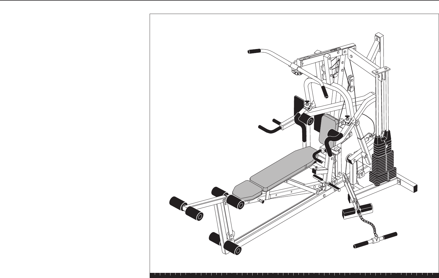
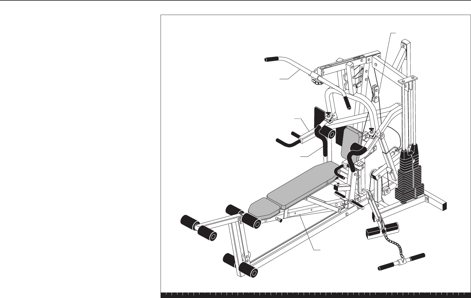
The illustration shows the entire Solana assembly once
you have completed installing the contents of box 2.
Open Box 2
Lar Bar
Chest Press
Pec Fly Arm
Seat Frame
Cable Assemblies
Solana Assembly and Maintenance Guide
page 13
1 2 3 4 5 6
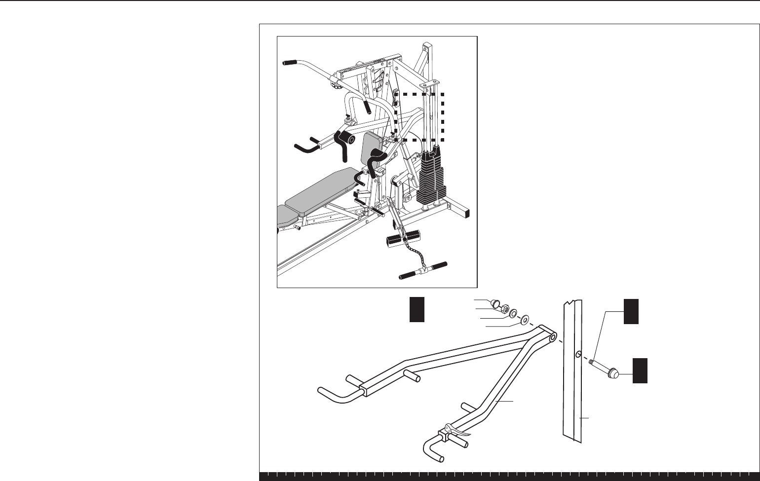
3. Assemble Press Arm
A. On one end of the Threaded Shaft, attach
one 1⁹⁄₁₆-inch washer
one cap washer
one ½-inch locknut
one dome cap
B. Insert the Threaded Shaft through the Main
Upright.
C. While someone supports the Press Arm, align it
with the Threaded Shaft on the Main Upright and
attach it using
one 1⁹⁄₁₆-inch washer
one cap washer
one ½-inch locknut
one dome cap
Wrench tighten, still allowing movement.
Lower the Press Arm slowly.
Note: The Handle will rest temporarily on the
crossbar of the Base Frame. Place a protective
towel underneath its pad until the Height Extender
is assembled in the next step.
Step 3. Assemble Press Arm
A
BThreaded Shaft
Main Upright
C
Press Arm
1 - dome cap
1 - ½" locknut
1 - cap washer
1 - 1⁹⁄₁₆" washer
1 - 1⁹⁄₁₆" washer
1 - cap washer
1 - ½" locknut
1 - dome cap
Solana Assembly and Maintenance Guide
page 14
1 2 3 4 5 6
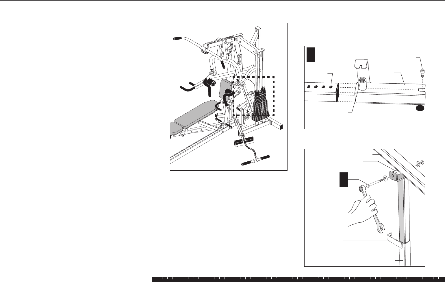
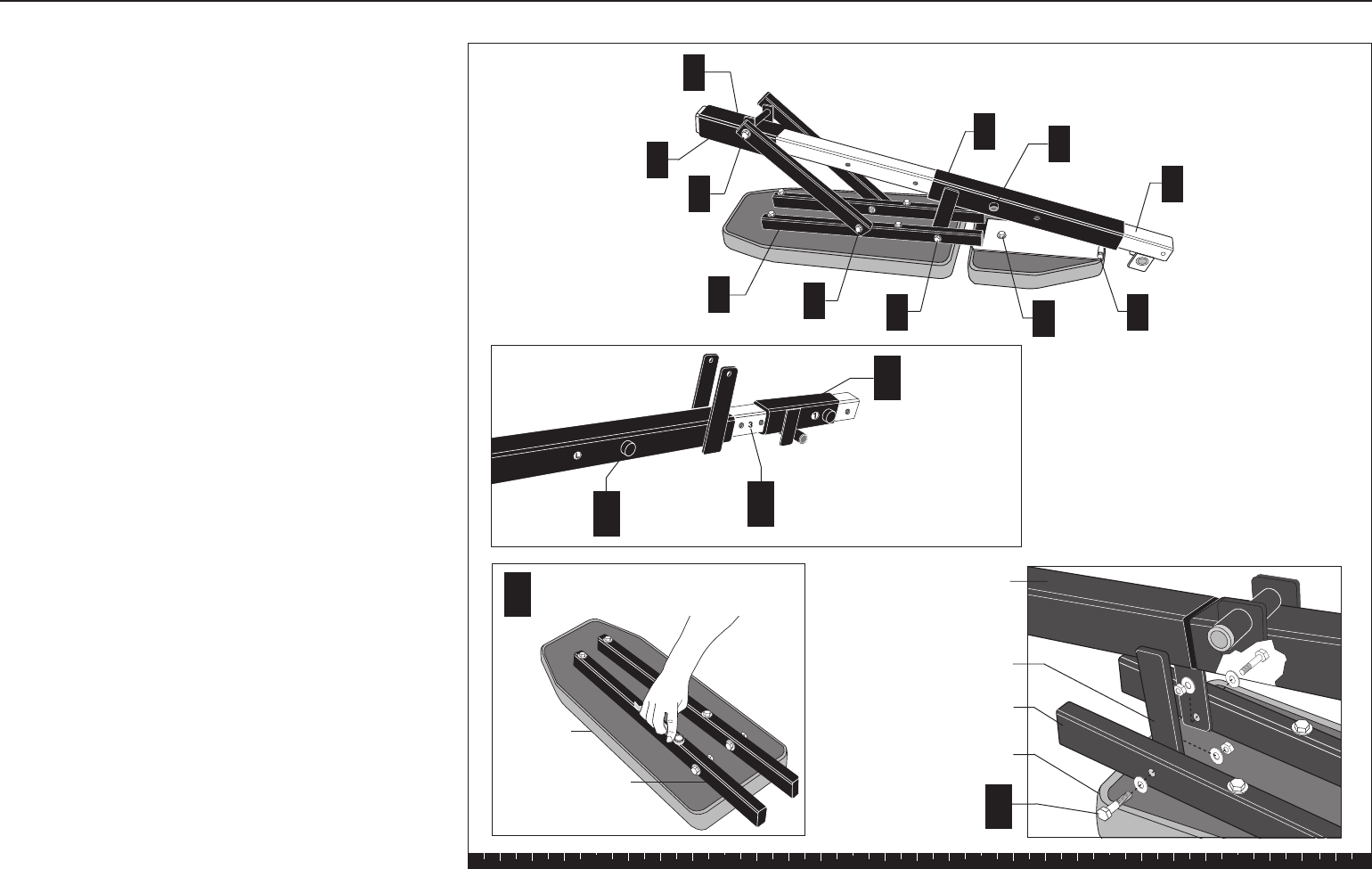
D. Slide the Height Extender through the Press Arm
Bracket and attach them using a small hex head
screw near the base of the Height Extender.
Wrench tighten. The screw acts as a stop so that
the extender cannot slide out of the Press Arm
Bracket.
Note: Ensure that the flange on the Press Arm
Bracket faces the Main Upright.
E. While someone supports the Press Arm, attach the
Height Extender to the Press Arm Mounting Flange
using
one ½-inch by 5¼-inch bolt
two washers
one locknut.
Wrench tighten.
Step 3. Assemble Press Arm, Continued
D
Press Arm
Bracket
Press Arm
Height
Extender
1 - ½" x 51/4"
bolt
2 - washers
1 - locknut
E
Round Mounting Flange
Height
Extender
Position the Press
Arm Bracket so
that this flange
faces the Main
Upright. Press Arm Bracket
Hex Head Screw
Mounting hole for
Press Arm Release
Spring
Press Arm
Mounting Flange
Solana Assembly and Maintenance Guide
page 15
1 2 3 4 5 6
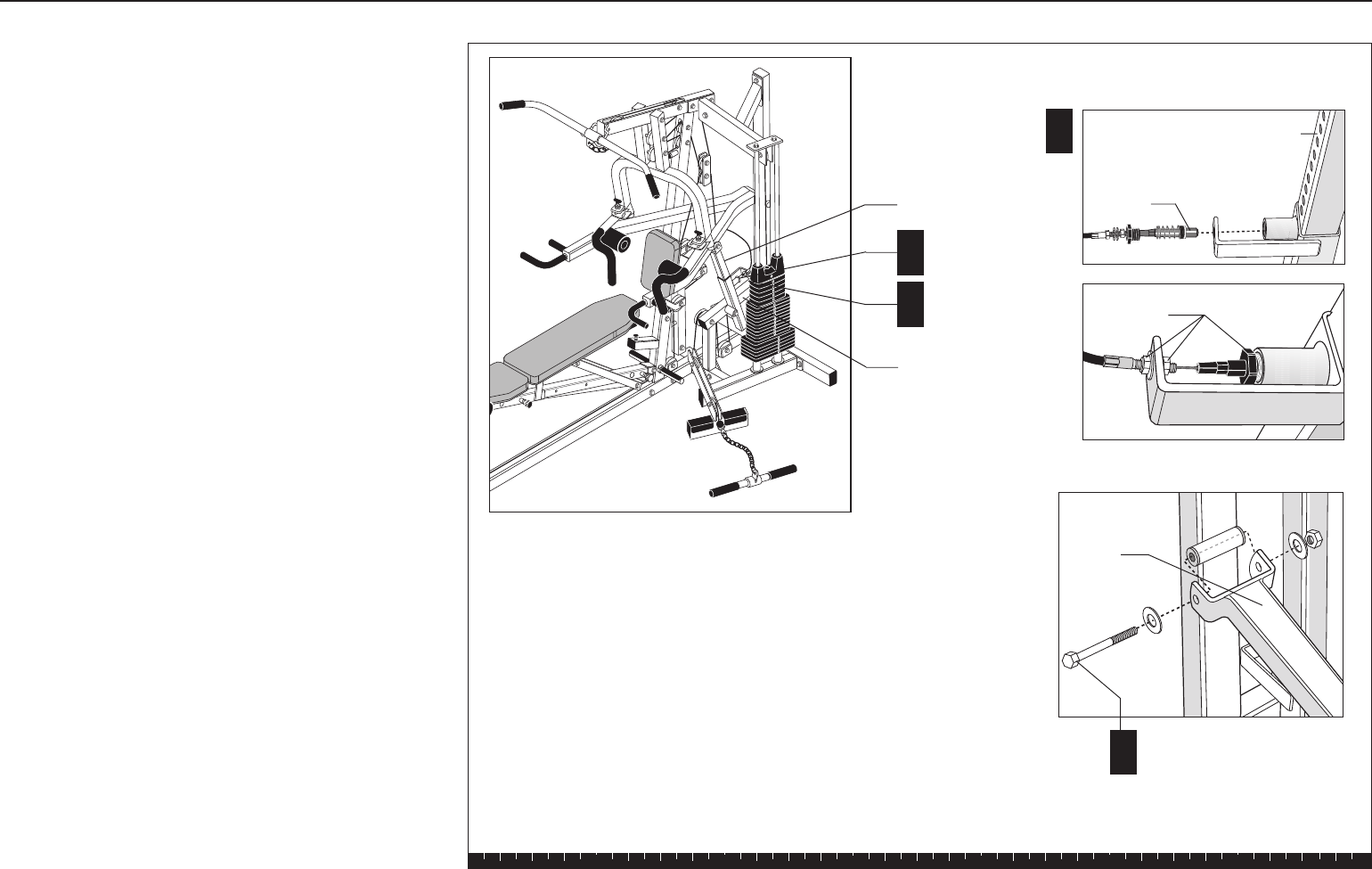
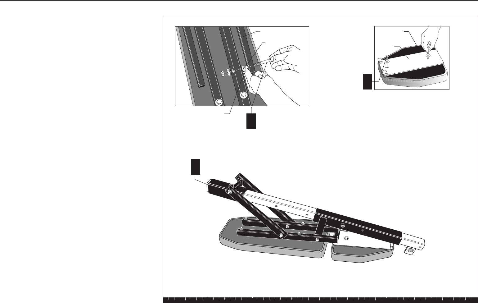
F. Align one of the Height Extender holes with the
mounting hole for the Press Arm Release Spring.
Thread the Press Arm Release Spring (at the end
of the Press Arm Cable) into the Press Arm
Bracket.
CAUTION: Have someone hold the cable attached
to the Press Arm Release Spring away from the
following assembly. Cables pinched, crimped, or
damaged during assembly are not covered by the
warranty.
G. Attach the Support Bracket to the Main Upright
using
one ½-inch by 5¼-inch bolt
two washers
one locknut.
Wrench tighten.
Step 3. Assemble Press Arm, Continued
G
F
Press Arm Release
Spring
Height Extender
1 - ½" x 5¼" bolt
2 - washers
1 - locknut
Support
Bracket
Tighten at all
3 locations
F
G
Height Extender
Support Bracket
Solana Assembly and Maintenance Guide
page 16
1 2 3 4 5 6
H. While someone holds the Quick Release Handle
down, raise the Press Arm and align the Height
Extender with the Round Mounting Flange on the
Press Arm Bracket.
I. Secure the Support Bracket using
one ½-inch by 5-inch bolt
two washers
one locknut.
Wrench tighten.
J. Slide the Press Arm Roller Pads into place. The
Pads are held in place by friction, so you may
need to readjust them from time to time.
H
Round
Mounting
Flange
Quick
Release
Handle
Press Arm
Roller Pad
1 - ½" x 5" bolt
2 - washers
1 - locknut
Support
Bracket
Press Arm
Bracket
Height
Extender
Check that the Quick release
operates smoothly and
efficiently.
I
J
Step 3. Assemble Press Arm, Continued
Solana Assembly and Maintenance Guide
page 17
1 2 3 4 5 6
4. Assemble Chest Press/Pec Fly
Step 4. Assemble Chest Press/Pec Fly
A
2 - 3½" pulleys
2 - 7½" bolts
4 - barrel spacers
4 - washers
2 - locknuts
Pin Hole
Threaded Pec
Fly Mount
Pop Pin
Chest Press
Pec Fly Arm
D2 - 1¼" washers
2 - cap washers
2 - locknuts
EDome Caps
Chest Press
Upright
C
1 - ½" x 7½"
pivot bolt
2 - ½" washers
1 - locknut
A. To ease assembly, place the Chest Press flat on
the floor. Attach two 3½-inch pulleys between the
two uprights using
two 7½-inch bolts
four barrel spacers
four washers
two locknuts
Wrench tighten.
B. With someone helping you, lift the Chest Press into
position. The Pec Fly Pin Holes point away from the
Main Upright.
Note: A step stool might be useful.
C. While someone holds the Chest Press, align it with
the hole at the top end of the Chest Press Upright.
Attach it using
one ½-inch by 7½-inch pivot bolt
two ½-inch washers
one locknut
Wrench tighten.
D. One at a time, slide each Pec Fly Arm onto the
Pivot Shaft. (The Pin Hole should face away from
the Main Upright.) Attach them on the end of each
Threaded Pec Fly Mount using
two 1¼-inch washers
two cap washers
two locknuts
Note: Tighten the locknut until the Pec Fly Arms
don’t move. Then loosen the locknut about a half-
turn until the arms pivot freely with no resistance.
A few threads should show beneath the Pec Fly
Mounts.
E. Secure the Dome Caps on each Threaded Pec Fly
Mount. A rubber mallet may be useful to lightly tap
the Dome Caps into place.
Solana Assembly and Maintenance Guide
page 18
1 2 3 4 5 6
5. Assemble Seat Pads
Note: Lubricate the chrome Seat Extension with the
supplied lubricant. The lubricant helps the two Seat
Brackets slide more easily. To ease installation,
assemble the Seat Brackets and Seat Pads on the
Seat Extension before mounting it on the Chest Press
Upright.
A. Position the Seat Extension so that the letters on it
will appear through the holes in the brackets.
B. Slide the Long Seat Bracket on the Seat Extension
with the flange pointing up.
C. Slide the Short Seat Bracket on the Seat Extension
with the flange pointing down.
D. Align the Backpad Supports so that they extend off
the bottom of the back side of the Backpad. Attach
using
four 2¾-inch bolts
four washers
Wrench tighten.
CAUTION: Assistance is required for the next steps.
E. With the Backpad still on the floor, have someone
hold the Long Seat Bracket flange between the
Backpad Supports close to the mounting holes.
Attach using
two 2-inch bolts
six washers
two locknuts
The sequence will be bolt, washer, Backpad
Support, washer, Flange, washer, locknut. Wrench
tighten, without overtightening.
Step 5. Assemble Seat Pads
A
D
Backpad
Backpad Supports
4 - 2¾" bolts
4 - washers
Letters on Seat
Extension
BLong Seat
Bracket
E
Backpad
Support
Backpad
Flange
2 - 2" bolts
6 - washers
2 - locknuts
Long Seat
Bracket
J
C
G
DFEHI
A
J
B
CShort Seat
Bracket
Solana Assembly and Maintenance Guide
page 19
1 2 3 4 5 6
F. Attach the Backpad Side Bars to the Backpad
Supports using
two 3¼-inch bolts
four washers
two ½-inch barrel spacers
two locknuts
The sequence will be bolt, washer, Side Bar, barrel
spacer, Backpad Support, washer, locknut. Wrench
tighten, without overtightening.
G. Attach the other end of the Side Bars to the Short
Seat Bracket flange using
one ½-inch by 8¾-inch bolt
two ½-inch washers
one locknut
The sequence will be bolt, washer, Side Bar, Seat
Bracket Flange, washer, locknut.
Wrench tighten.
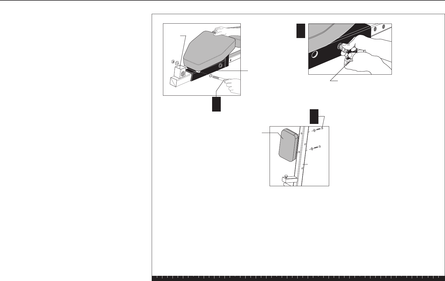
H. Attach the Seat Pad to the Seat Base Flange using
two 1-inch bolts
two washers
Refer to the diagram for proper orientation.
Wrench tighten.
Step 5. Assemble Seat Pads, Continued
Backpad Side Bar
2 - 31/4" bolts
4 - washers
2 - ½" barrel spacers
2 - locknuts
Backpad
Support
Spacer
F
G1 - ½" x 8¾" bolt
2 - ½" washers
1 - locknut
H
2 - 1" bolts
2 - washers
Seat Base
Flange
Seat Pad
Solana Assembly and Maintenance Guide
page 20
1 2 3 4 5 6
I. Align the Seat Base Flange with the mounting
bracket on the Long Seat Bracket. Attach using
one ½-inch by 5¾-inch bolt
two ½-inch washers
one locknut
Wrench tighten.
J. Insert a Pop Pin into each Seat Bracket and wrench
tighten.
K. Attach the Back Rest Pad to the Chest Press
Upright using
two 3¾-inch bolts
two washers
Wrench tighten. I
1 - ½" x 5¾" bolt
2 - ½" washers
1 - locknut
Long Seat
Bracket
2 - 3¾" bolts
2 - washers
Back
Rest Pad
Chest
Press
Upright
Thigh
Pad
Mount
K
J
Pop Pin
Step 5. Assemble Seat Pads, Continued
Solana Assembly and Maintenance Guide
page 21
1 2 3 4 5 6
6. Install Seat Extension
CAUTION: Have an assistant help you install the
Seat Extension to the Chest Press Upright.
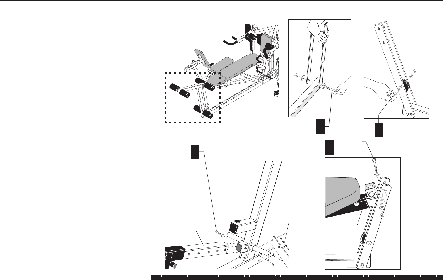
A. Attach two Flat Bars to the end of the Base Frame
using
one 3¼-inch bolt
two washers
one locknut
Wrench tighten, leaving room for adjustment.
Note: See the diagram for the proper mounting
location on the Flat Bar.
B. In the third hole from the bottom, attach one
3½-inch pulley to the Flat Bars using
one 3¼-inch bolt
two washers
two ½-inch barrel spacers
one locknut
Wrench tighten, still allowing movement.
C. Slide the Seat Extension on the mounting stub on
the Chest Press Upright. Attach it using
one 2¾-inch bolt
two washers
one locknut
Wrench tighten.
D. Align the other end of the Seat Extension with the
Flat Bars. Attach it to the second mounting hole
from the top using
one 3¼-inch bolt
two washers
one locknut
Wrench tighten, leaving room for adjustment.
Step 6. Install Seat Extension
AB1 - 3½" pulley
1 - 31/4" bolt
2 - washers
2 - ½" barrel spacers
1 - locknut
1 - 31/4" bolt
2 - washers
1 - locknut
Flat Bar
D1 - 31/4" bolt
2 - washers
1 - locknut
Flat bar
Base
Frame
C
Chest Press
Upright
Thigh Pad
Mount
1 - 2¾" bolt
2 - washers
1 - locknut
Seat
Extension
Solana Assembly and Maintenance Guide
page 22
1 2 3 4 5 6
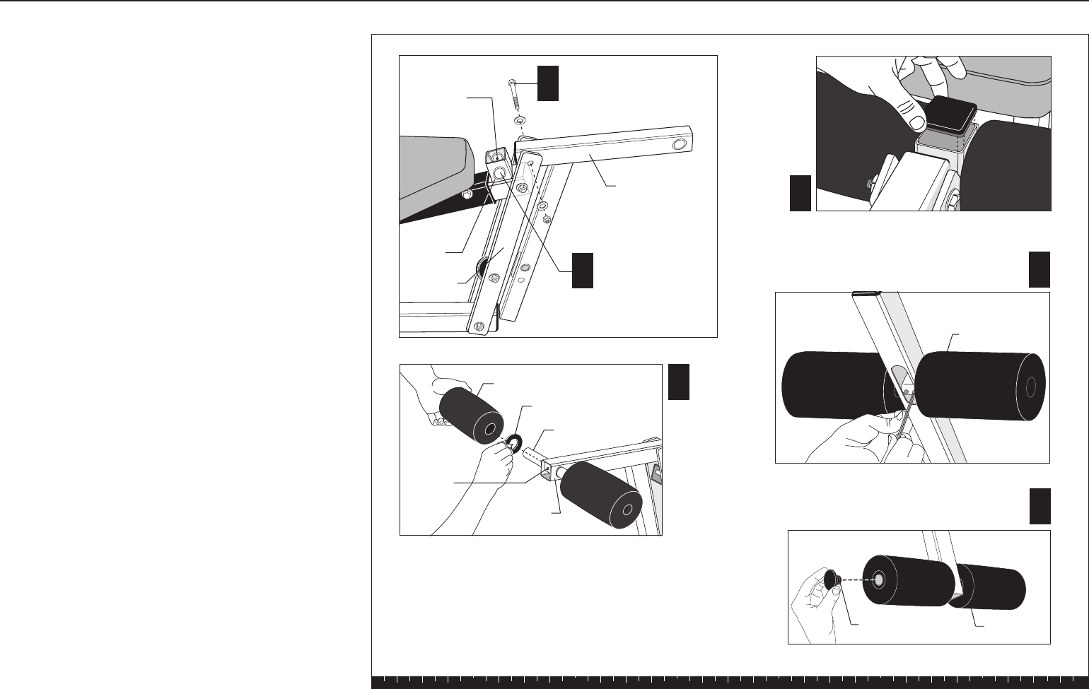
7. Assemble Leg Extension
A. Attach the Leg Extension to the top mounting hole
on the Flat Bars using
one ½-inch by 3¼-inch bolt
two ½-inch washers
one ½-inch locknut
Wrench tighten, still allowing movement.
B. Center the Thigh Pad Rod in the Leg Curl Mount
on the Seat Extension. Attach using two hex set
screws. Place a large washer and Roller Pad on
both ends of the Rod.
C. Cover the set screws with the large square black
cap on the Leg Curl Mount.
D. Center the Knee Pad Rod in the mount at the end
of the Leg Extension. Attach using two hex set
screws. Place a large washer and Roller Pad on
both ends of the Rod. Place the smaller square
black cap into the end of the Leg Extension.
E. Have someone hold the Leg Extension in an
upward position while you assemble the Ankle
Pads. Center the Ankle Pad Rod in the base of the
Leg Extension. Attach using two hex set screws.
Place a large washer and Roller Pad on both ends
of the support tube.
F. Tap the End Caps into all the Roller Pads using a
rubber mallet.
Step 7. Assemble Leg Extension
BThigh Pad Rod
location. Assembly
similar to Diagram D
for Knee Pad.
1 - ½" by 31/4" bolt
2 - ½" washers
1 - ½" locknut
C
D
Roller Pad
1 - Large Washer
Knee Pad Rod
Leg
Extension
E
F
End Cap
2 - hex set
screws (inside)
Leg Curl
Mount
Roller Pad
Tighten the set screws and install
washers and roller pads.
End of Leg
Extension
Ankle Pad
A
Flat Bars
2 - hex set
screws
Leg Extension
Solana Assembly and Maintenance Guide
page 23
1 2 3 4 5 6
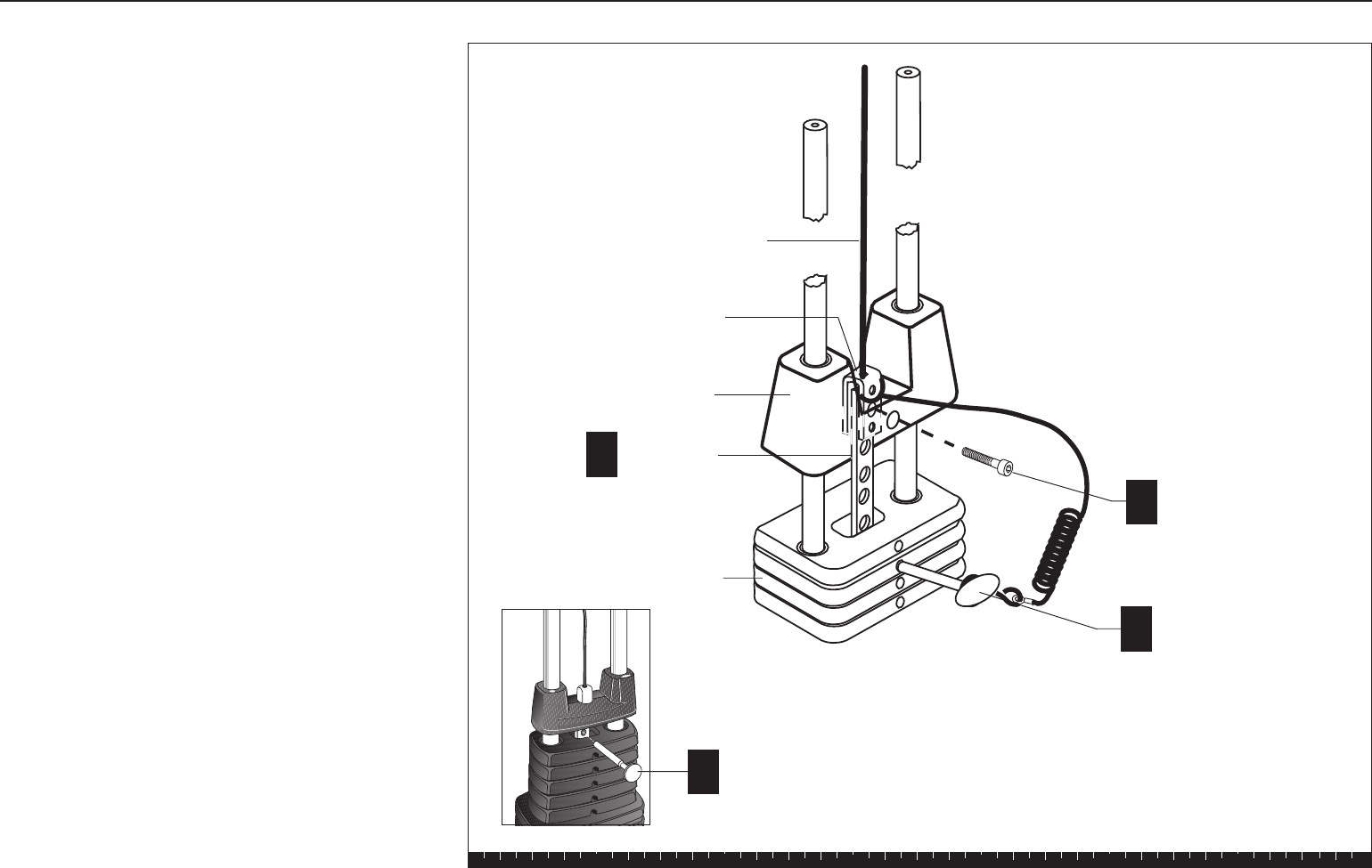
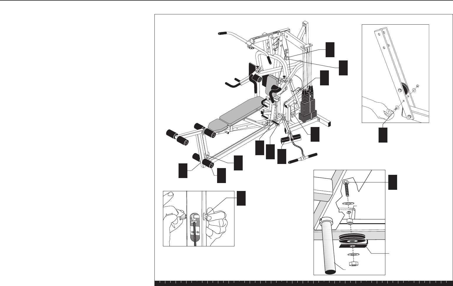
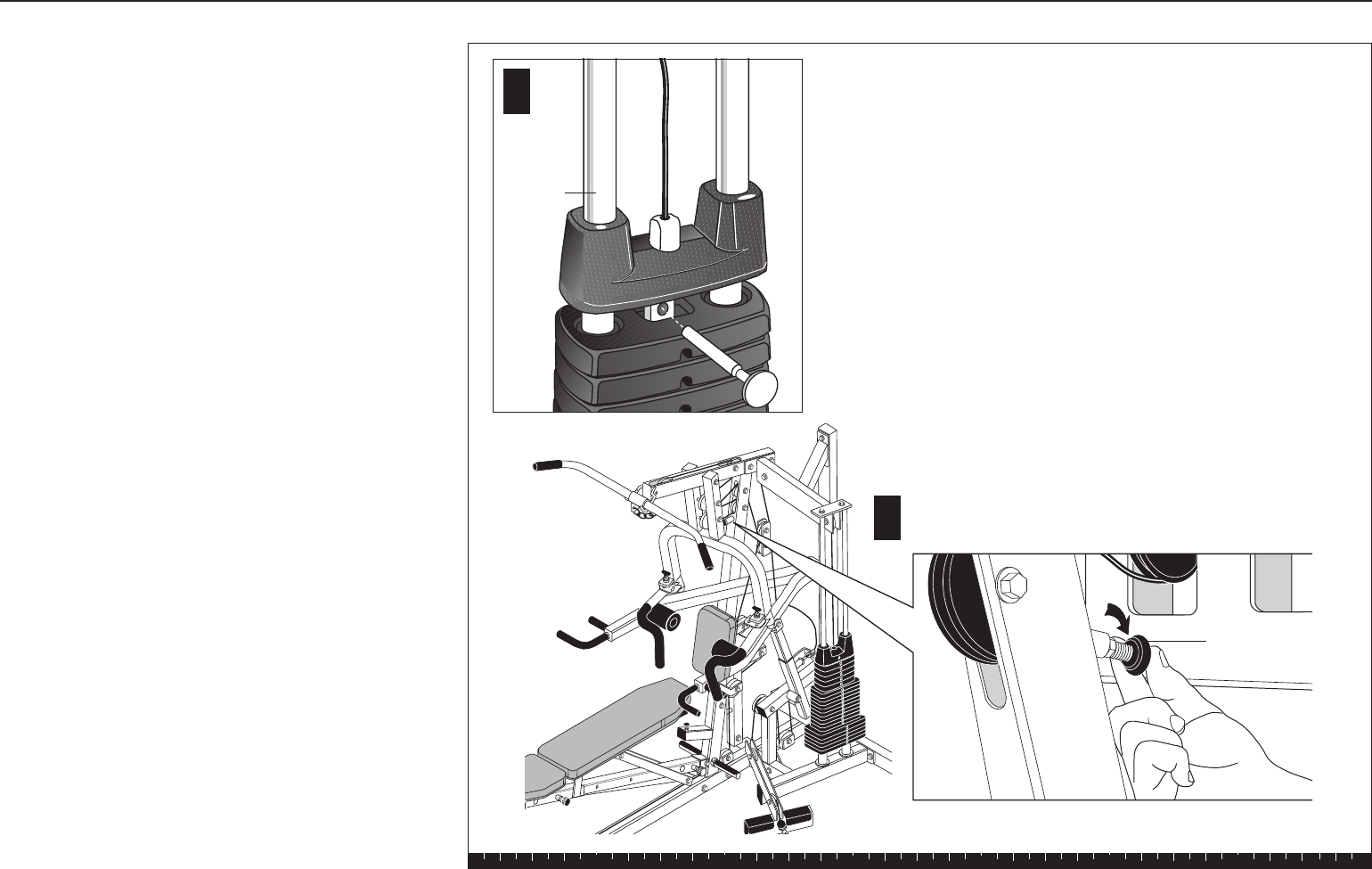
8. Install Main Cable and Pulley
A. Insert the Selector Stem in the Weight Stack with
the threaded hole at the top. Hold the Selector
Stem approximately one foot above the Top Cap
Weight.
B. Insert the Weight Pin to suspend the Selector
Stem.
C. Place the loop end of the Weight Pin Lanyard into
the U end of the Main Cable (#43746-101). Align
the U end of the Main Cable, the top of the Selector
Stem, and the Top Cap Weight. Attach using
one 1½-inch socket cap bolt
Wrench tighten.
D. Remove the Weight Pin and lower the Top Cap
Weight on the Weight Stack. Reinsert the Weight
Pin into the Weight Stack.
Step 8. Install Main Cable and Pulley
Weight Stack
Main Cable
Selector Stem
Top Cap Weight
U bracket
Weight Pin
A
Weight Pin
B
C1 - 1½" socket cap bolt
D

Solana Assembly and Maintenance Guide
page 24
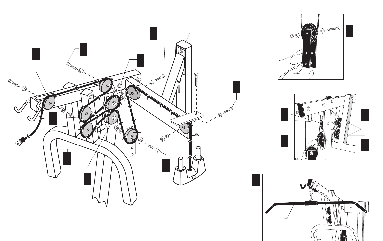
Note: As you feed the cable through the following
steps, remove any twists in the cable before
securing the pulleys. To remove a twist in the cable,
rotate the cable end until the cable becomes
straight. Always check that the pulleys can rotate
freely after the nuts and bolts are wrench tightened.
E. Feed the free end of the Main Cable over one
4½-inch pulley and attach it between the two
upper plates that are welded to the Guide Rod
Bracket using
one 2-inch bolt
two washers
one locknut
Check that the cable moves freely in the pulley and
wrench tighten.
F. Feed the Main Cable over a second 4½-inch pulley
and attach it between the two upper plates at the
other end of the Guide Rod Bracket using
one 2-inch bolt
two washers
one locknut
Check that the cable moves freely in the pulley and
wrench tighten.
G. Feed the cable under one 3½-inch pulley and
attach it between the two Floating Pulley Plates
using
one 2-inch bolt
two washers
one locknut
H. Feed the cable over one 4½-inch pulley and attach
it to the lower hole in the pulley window of the
Chest Press Upright using
one 2¾-inch bolt
two ½-inch step spacers
one locknut
Step 8. Install Main Cable and Pulley, Continued
I. Feed the cable under and then over the bottom
pulley of the Chest Press Arm.
J. Feed the cable under and then over one 3½-inch
pulley and attach it to the upper hole in the pulley
window of the Chest Press Upright using
one 2¾-inch bolt
two ½-inch step spacers
one locknut
K. Feed the cable under and then over the upper
pulley of the Chest Press Arm.
L. Feed the cable under and then over one 3½-inch
pulley and attach it to the pulley window toward
the rear of the top beam of the Chest Press Upright
using
one 2¾-inch bolt
two ½-inch step spacers
one locknut
M. Feed the cable over (not through) the top beam
of the Chest Press Upright and over one 4½-inch
pulley and attach it to the pulley window at the end
of the Chest Press Upright using
one 2¾-inch bolt
two ½-inch step spacers
one locknut
N. Attach the Lat Bar to the end of the Main Cable
using a Spring Clip.
Solana Assembly and Maintenance Guide
page 25
Step 8. Install Main Cable and Pulley, Continued
1 - 4½" pulley
1 - 2" bolt
2 - washers
1 - locknut
F
1 - 4½" pulley
1 - 2" bolt
2 - washers
1 - locknut
Floating Pulley
Plates
G
Guide Rod
Bracket
G
1 - 3½" pulley
1 - 2" bolt
2 - washers
1 - locknut
Floating Pulley
Plates
L
1 - 4½" pulley
1 - 2¾" bolt
2 - ½" step
spacers
1 - locknut
1 - 4½" pulley
1 - 2¾" bolt
2 - ½" step
spacers
1 - locknut
1 - 3½" pulley
1 - 2¾" bolt
2 - ½" step spacers
1 - locknut
1 - 3½" pulley
1 - 2¾" bolt
2 - ½" step
spacers
1 - locknut
Chest Press
Main Upright
Lat Bar
Spring Clip
N
Lat Bar Holder
J
H
E
H
I
M
K
J
K
I
Attached
in Step 4
See inset.
See inset.
See inset.
Solana Assembly and Maintenance Guide
page 26
1 2 3 4 5 6
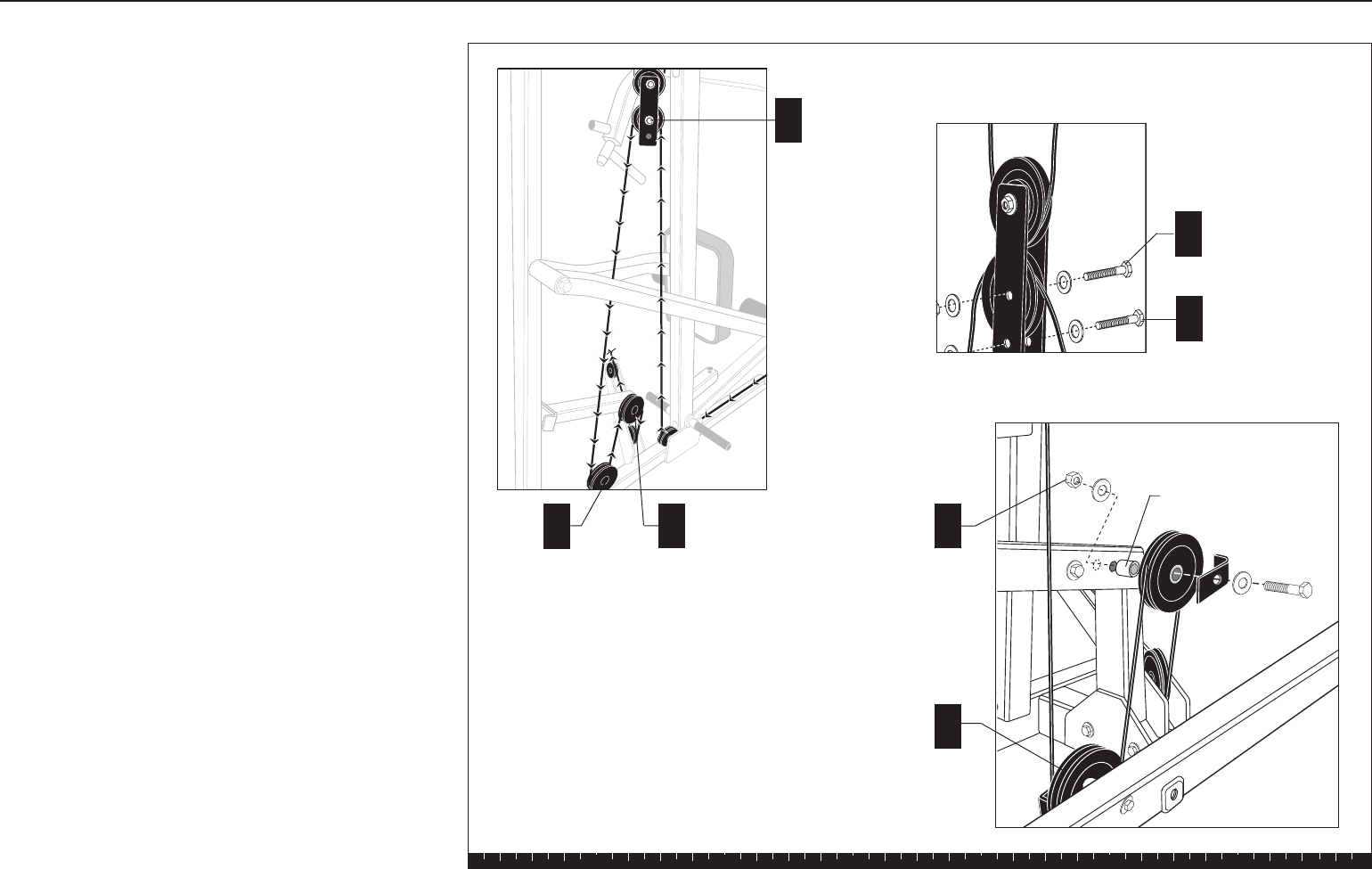
9. Install Lower Cable
and Pulley
A. Attach the lower cable (#43903-101) in the Pulley
Window at the end of the Leg Extension using
one 2½-inch bolt
two ¹³⁄₁₆-inch step spacers
one locknut
Wrench tighten.
B. Feed the cable along the base under the 3½-inch
pulley attached to the Flat Bars and through the
opening in the Chest Press Upright.
C. Create a cable retainer in the hole under the pulley
in the Flat Bars using
one 3¼-inch bolt
two washers
one locknut
Ensure the cable runs between the Pulley and
the bolt.
D. Wrap the cable under one 3½-inch pulley and
attach it to the flange at the base of the Chest
Press Upright using
one 2½-inch bolt
two washers
one ½-inch barrel spacer
one cable retainer
one locknut
The sequence will be bolt, washer, flange, barrel
spacer, pulley, cable retainer, washer, locknut.
Wrench tighten.
A1 - 2½" bolt
2 - 13/16" step spacers
1 - locknut
D
Foot Rest
Cable
Retainer
½" spacer
E
A
B
D
G
J
I
H
1 - 3½" pulley
1 - 2½" bolt
2 - washers
1 - ½"barrel spacer
1 - cable retainer
1 - locknut
F
C
C1 - 3¼" bolt
2 - washers
1 - locknut
Step 9. Install Lower Cable and Pulley
Solana Assembly and Maintenance Guide
page 27
1 2 3 4 5 6
E. Feed the cable over one 3½-inch pulley and attach
it to the Floating Pulley Plates (from
step 8G) using
one 2-inch bolt
two washers
one locknut.
Wrench tighten.
F. Create a cable retainer in the lower hole of the
Pulley Plates using
one 2-inch bolt
two washers
one locknut
Ensure the cable runs between the pulley and the
bolt.
G. Feed the cable under one 4½-inch pulley and
attach it to the bracket on the Base Frame using
one 4¼-inch bolt
two washers
one cable retainer
one locknut
Wrench tighten.
H. Feed the cable over one 4½-inch pulley and attach
it to the mid-level bracket on the Main Upright using
one 4¼-inch bolt
two washers
one ½-inch barrel spacer
one cable retainer
one locknut
The sequence will be bolt, washer, cable retainer,
pulley, barrel spacer, bracket, washer, locknut.
Wrench tighten.
E1 - 3½" pulley
1 - 2" bolt
2 - washers
1 - locknut
1 - 4½" pulley
1 - 41/4" bolt
2 - washers
1 - ½" barrel spacer
1 - cable retainer
1 - locknut
1 - 4½" pulley
1 - 41/4" bolt
2 - washers
1 - cable retainer
1 - locknut
H
G
½" barrel spacer
E
GH
See inset.
F1 - 2" bolt
2 - washers
1 - locknut
Step 9. Install Lower Cable and Pulley, Continued
Solana Assembly and Maintenance Guide
page 28
1 2 3 4 5 6
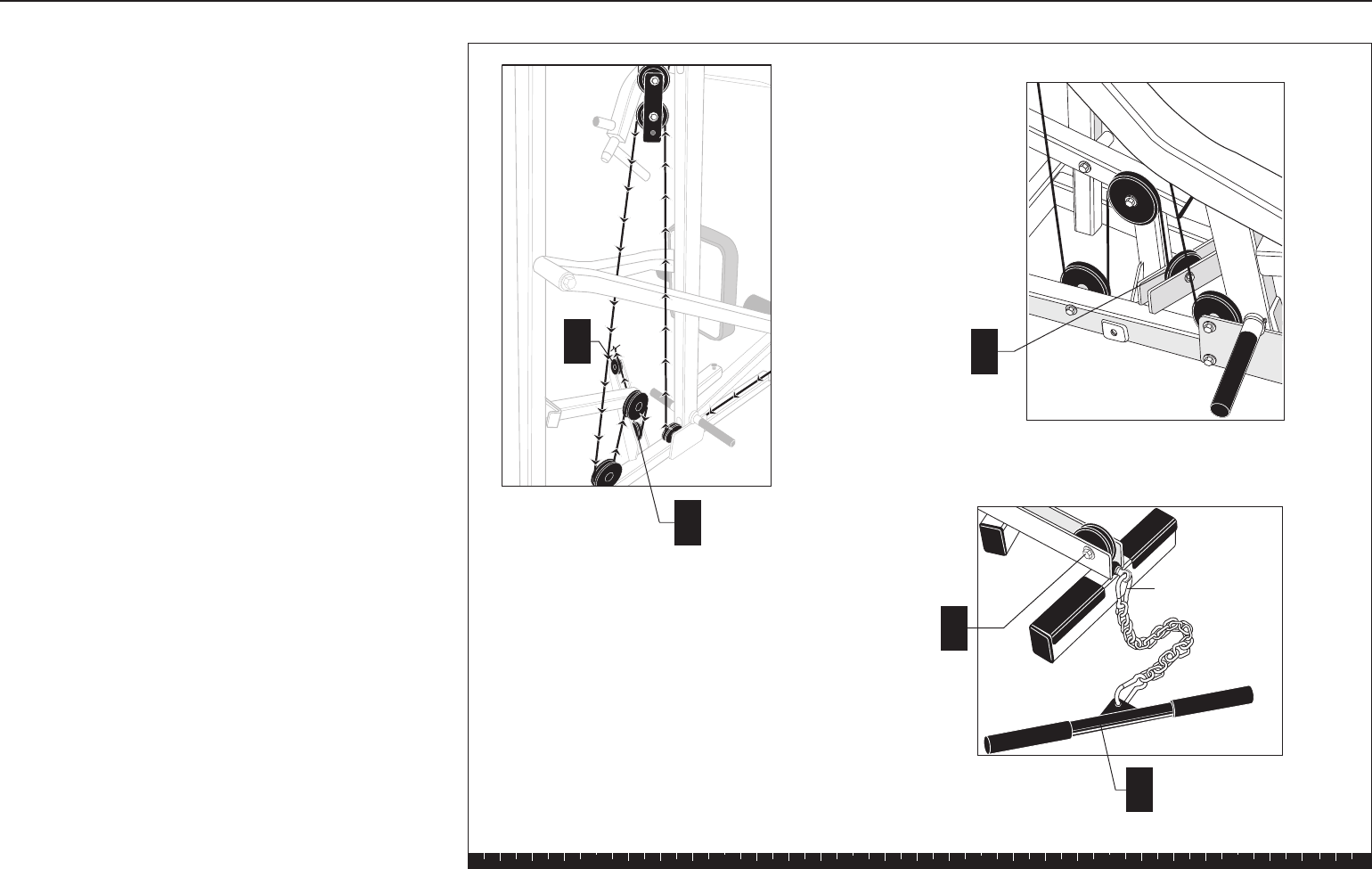
I. Feed the cable under one 3½-inch pulley and
attach it between the two plates on the Base
Frame using
one 2¼-inch bolt
two washers
one locknut
Wrench tighten.
J. Wrap the cable under one 3½-inch pulley and
attach it between the two plates at the other end
of the foot support of the Base Frame using
one 2¼-inch bolt
two washers
one locknut
Wrench tighten.
K. Attach the Curl Bar or Ankle Strap to the end of the
cable using a Spring Clip.
Step 9. Install Lower Cable and Pulley, Continued
I
1 - 3½" pulley
1 - 21/4" bolt
2 - washers
1 - locknut
J
1 - 3½" pulley
1 - 21/4" bolt
2 - washers
1 - locknut
Curl Bar
Spring Clip
I
J
K
See inset.
Solana Assembly and Maintenance Guide
page 29
1 2 3 4 5 6
10. Apply Weight Decals
A. Remove the backing for the decals labeled “1–5.”
Press the decals to the front surface of the top five
weight plates in the tab location as indicated.
Remove the front decal protector.
B. Remove the backing for the decals labeled “6–15.”
Press the decals to the front surface of the middle
ten weight plates in the tab location as indicated.
Remove the front decal protector.
C. Remove the backing for the decals labeled “16–20.”
Press the decals to the front surface of the bottom
five weight plates in the tab location as indicated.
Remove the front decal protector.
This completes the assembly of your Solana Strength-
Training Fitness Equipment.
Step 10. Apply Weight Decals
1
2
3
4
5
6
7
8
9
10
11
12
13
14
15
16
17
18
19
20
Solana Assembly and Maintenance Guide
page 30
1 2 3 4 5 6
4Adjustments and
Maintenance
1. Cable Adjustments
When the Solana is completely assembled, you need to
check the cables for proper tension. Obvious signs that
cable problems exist include:
✔Top Cap Weight does not rest squarely on the top
weight of the Weight Stack.
✔Cable rubs the inside edges of the pulleys.
✔Excess slack exists in the cable.
CAUTION: Take the time to perform the following
steps. If the cables do not have the proper tension
you could void the Precor Limited Warranty.
If you experience any of the above signs of cable
problems, make the adjustment as follows:
A. Place the Weight Pin in the Top Cap Weight to
ensure the least cable resistance.
B. Insert both Pec Fly Locking Pins so that the Pec Fly
Arms are in the locked position.
C. Pull up on the Pec Fly Arms and tighten or loosen
the Press Arm Stop so that it rests on the Chest
Press Upright.
D. Lower the Pec Fly Arms.
E. Make certain that the Weight Pin can be inserted
into every hole in the Weight Stack.
Top Cap
Weight
A
Press arm
stop
C
Step 1. Cable Adjustments

Solana Assembly and Maintenance Guide
page 31
1 2 3 4 5 6
Step 2. Selector Stem Adjustments
Forward Angle
Selector Stem
Top Cap
Weight
1 ½" Socket
Cap Bolt
U Bracket
Allen head
set screw
Inside
surface
Set screw
▲
B
B
A
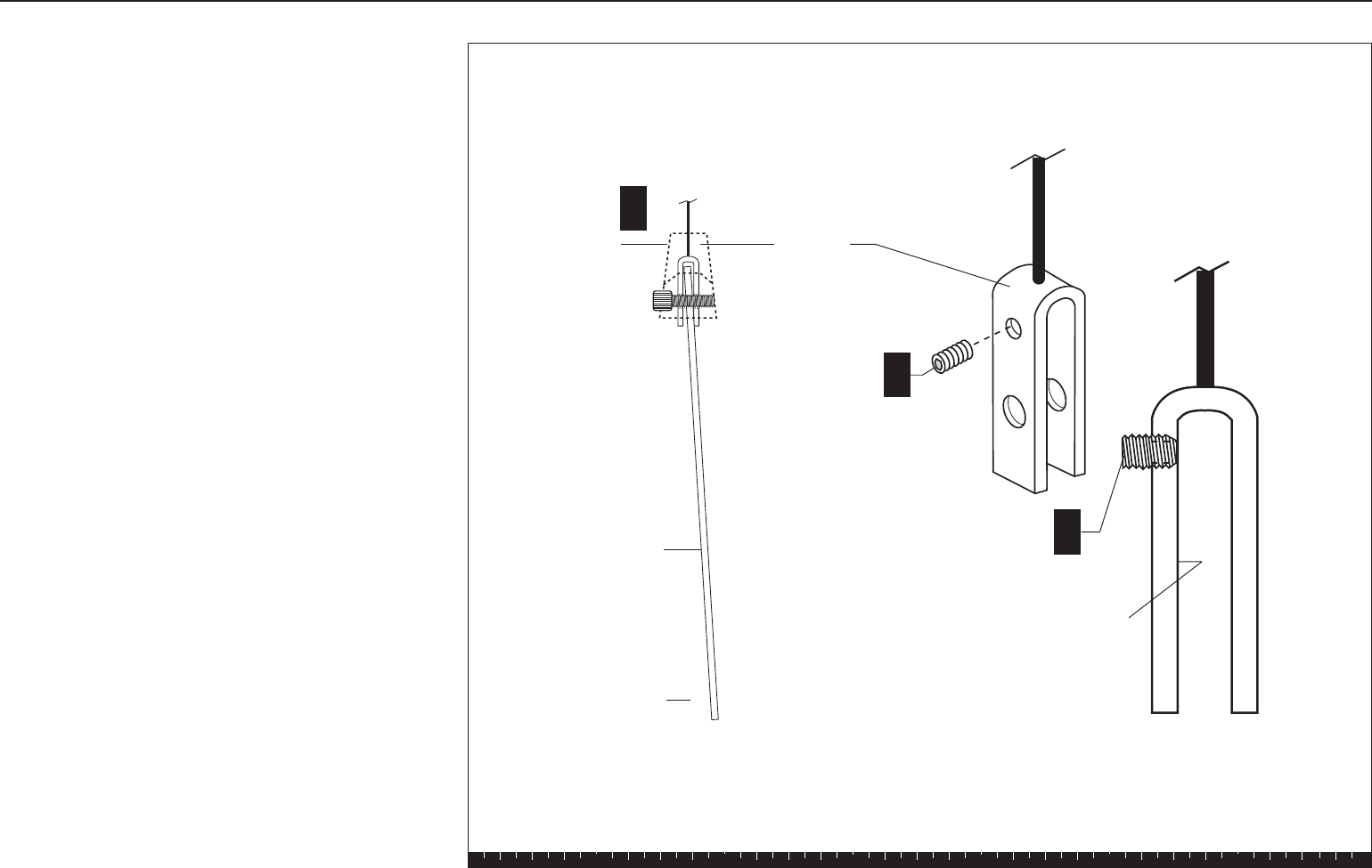
2. Selector Stem Adjustments
To prevent the Selector Stem from contacting the inside
of the Weight Stack when the machine is in use, you
need to check the vertical angle of the Selector Stem
(steps A and B). If the stem slides smoothly without
contacting the inside of the weight plates, assembly of
the unit is complete.
CAUTION: Performing the following tasks requires
two people.
A. Remove the Weight Pin from the Weight Stack.
B. Perform an exercise using each part of the Solana.
When the base of the Selector Stem is clear of the
Weight Stack, observe the position
of the Selector Stem.
The following sections describe how to adjust the
Selector Stem when contact does occur.
The Selector Stem can be adjusted forward, backward,
and vertically depending on the area of contact.
Forward Angle Adjustment
When the Selector Stem angles forward (toward the
seat) and contacts the inside of the Weight Stack
during use, adjust it by following these steps:
CAUTION: This adjustment requires two people.
A. Completely disassemble the Top Cap Weight,
Selector Stem, and U bracket.
B. Thread the Allen head set screw into the hole
closest to the top of the U bracket and turn it
clockwise until the end of the screw is flush with
the inside surface of the U bracket.
C. Turn the set screw clockwise another one-half turn
(see diagram).
Solana Assembly and Maintenance Guide
page 32
1 2 3 4 5 6
Backward Angle
Selector Stem
▲
Top Cap
Weight
Set screw
Allen head
set screw
U Bracket
Inside
surface
B
B
A
Step 2. Selector Stem Adjustments, Continued
D. Reassemble the Top Cap Weight, Selector Stem,
and U bracket.
E. Test again the movement of the Selector Stem
inside the Weight Stack.
F. If the Selector Stem continues to contact the plates,
repeat steps A through E until the Selector Stem
slides through the Weight Stack without contacting
the plates.
Backward Angle Adjustment
When the Selector Stem angles backward (away from
the seat) and contacts the inside of the Weight Stack
during use, adjust it by following these steps:
CAUTION: This adjustment requires two people.
A. Completely disassemble the Top Cap Weight,
Selector Stem, and U bracket.
B. Thread an Allen head set screw into the hole
closest to the top of the U bracket and turn it
clockwise until the end of the screw is flush with
the inside surface of the U bracket.
C. Turn the set screw clockwise another one-half turn
(see diagram).
D. Reassemble the Top Cap Weight, Selector Stem,
and U bracket.
E. Test again the movement of the Selector Stem
inside the Weight Stack.
F. If the Selector Stem continues to contact the plates,
repeat steps A through E until the Selector Stem
slides through the Weight Stack without contacting
the plates.
Solana Assembly and Maintenance Guide
page 33
1 2 3 4 5 6
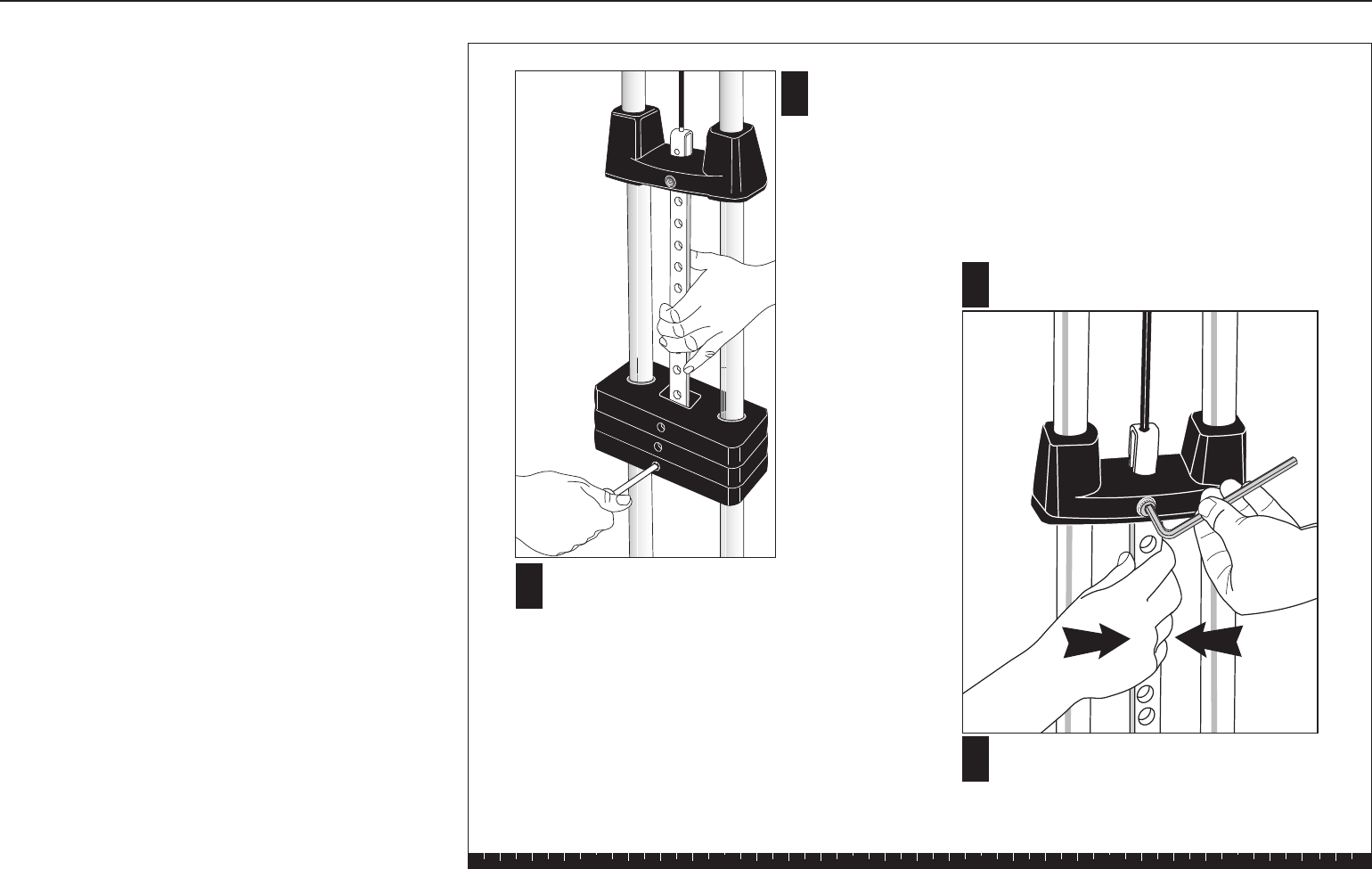
A
B
Pull the Selector Stem and
Top Cap Weight up to
expose at least 5 holes.
Hold the stem in place by inserting
the Weight Pin (through a weight)
near the base of the Selector Stem.
CLoosen the socket cap bolt and align
the Selector Stem.
DOnce the Selector Stem is centered,
retighten the socket cap bolt
securely.
Step 2. Selector Stem Adjustments, Continued
Side-to-Side Vertical Adjustment
If the Selector Stem contacts the inside of the Weight
Stack during use or the Weight Pin becomes difficult to
insert in the Weight Stack, the Selector Stem may be
out of alignment vertically side to side. Adjust the
Selector Stem by following these steps:
CAUTION: This procedure requires two people.
A. Pull the Selector Stem and Top Cap Weight up to
expose at least five Selector Stem holes.
B. Insert the Weight Pin near the base of the Selector
Stem to hold it in place.
C. To center the Selector Stem, loosen the socket
cap bolt that attaches the Top Cap Weight to the
U bracket.
D. Once the Selector Stem is centered, retighten the
socket cap bolt securely.
E. Lower the Selector Stem into the Weight Stack.
Test the movement of the Selector Stem inside the
Weight Stack.
F. Make certain that the Weight Pin can be inserted
into every hole in the Weight Stack. If the Selector
Stem continues to contact the plates, repeat steps
A through E until the Selector Stem slides through
the Weight Stack without contacting the plates.
After completing the adjustments, fill out the warranty
card and mail it in.
3. Maintenance
Lubricate the Guide Rods every six months.
Use a silicon lubricant to lubricate the rods; you can
purchase this lubricant from any hardware store.

Effective 01 August 2001
P/N 36287-108
Residential Equipment Limited Warranty
Precor Incorporated warrants that all new Precor products are free of manufacturing defects in
workmanship and materials. Parts repaired or replaced under the terms of this warranty will be
warranted for the remainder of the original warranty period only. This warranty becomes effective
at the invoice date of the original purchase.
Elliptical Fitness Crosstrainers and Motorized Treadmills (excluding EFX5.17 and
Treadmills: 9.2 and 9.4 series) — Labor is covered for one year, parts are covered for five years
plus a lifetime frame weld warranty covering parts-only repair or replacement parts. (Labor is not
covered on frame replacement after one year.)
Products (StretchTrainer, Strength Equipment — formerly Pacific Fitness) other than
Elliptical Fitness Crosstrainer and Motorized Treadmills (except options)
StretchTrainer — Labor is covered for a period of 90 days, parts are covered for a period of one year
plus a lifetime frame weld warranty covering parts-only repair or replacement parts. (Labor is not covered on
frame replacement after one year.)
Pacific Fitness Branded Strength Products and Precor Strength Products S3.xx
This is a parts only warranty. Labor costs are not covered.
1. Frame & Welds: Defective parts pertaining to frame structure, including all welded assembly
parts, will be warranted for Lifetime.
2. Bearings, Guide rods, Cams, Pulleys, Belts, Cables, Hand grips, and Miscellaneous parts will be
warranted for a period of three years. Note that for the Precor Strength Products S3.xx, and
the Pacific Fitness Solana and Zuma, the warranted period is five years.
3. Upholstery will be warranted for a period of one year. A three month warranty applies to
Naugahyde upholstery for Pacific Fitness Branded Strength Products only.
Return Policy: Proof of purchase is required to determine whether service on a Precor Strength Product/
Pacific Fitness Product during its warranty period will commence. Claims should be made to the dealer
from whom you purchased the product. The purchaser is responsible for all transportation and insurance
costs on returned or replaced equipment or parts. The purchaser also assumes any costs associated with
the disassembling or reassembling of the replacement parts. WARRANTY BECOMES VOID IF PRECOR
FINDS THE DEFECT A RESULT OF INCORRECT INSTALLATION, MISUSE, LACK OF PROPER MAINTE-
NANCE OR ANY MODIFICATION NOT APPROVED BY PRECOR.
Options / Accessories / Battery-powered or Self-Operated Devices
Many options or accessories have components that are connected internally or mounted inside
the electronic console. The following guidelines determine the warranty for these components. If
the internal components are installed by the factory or by an authorized dealer as part of the
original sale and delivery, they have a warranty that is identical to the warranty of the equipment
in which they are connected or mounted. If the internal components are not installed by the
factory or by an authorized dealer as part of the original sale and delivery, they have a 90 days
parts and labor limited warranty. All components that are not internally connected have a 90 days
parts only limited warranty. Satisfactory proof of purchase is required in all cases.
PRECOR'S SOLE LIABILITY IS LIMITED TO REPAIR OR REPLACEMENT OF PARTS ACCORDING TO
THE TERMS AND CONDITIONS OF THESE LIMITED WARRANTIES, AND ANY IMPLIED WARRANTIES
OF MERCHANTABILITY OR FITNESS FOR A PARTICULAR PURPOSE ARE LIMITED TO THE DURATION
OF THE ABOVE WRITTEN WARRANTIES. IN NO EVENT WILL PRECOR OR THE SELLING DEALER BE
LIABLE FOR INCIDENTAL OR CONSEQUENTIAL DAMAGES SUCH AS INCONVENIENCE, COMMERCIAL
LOSS, LOST PROFITS OR DAMAGE TO OTHER PROPERTY.
Some states do not allow the exclusion or limitation of incidental or consequential damages, so the above
limitation may not apply to you. This warranty gives you specific legal rights, and you may also have other
rights which vary from state to state.
Conditions
This warranty is valid only in accordance with the
conditions set forth below.
1. Warranty applies to the Precor product only while
A) it remains in the possession of the original
purchaser and proof of purchase is demonstrated,
B) it has not been subjected to accident, misuse,
abuse, improper service, or non-Precor modification
and C) claims are made within the warranty period.
2. Warranty of all Precor products applies to residential
use only (unless specifically stated by the factory, in
writing, to be warranted for commercial use) and is void
when products are used in a non-residential environ-
ment or installed in a country other than where sold.
3. This warranty does not cover damage or equipment
failure caused by residential wiring not in compliance
with electrical codes or Precor owner’s manual
specifications, or failure to provide reasonable and
necessary maintenance as outlined in the owner's
manual.
4. During the labor period Precor compensates
Servicers for warranty trips within their normal
service area to repair motorized treadmills and
elliptical fitness crosstrainers at the customer’s
location. You may be charged a trip charge outside
the service area, or for on-site warranty repairs, or
for on-site warranty repairs of strength products,
within the service area.
5. Precor Limited Warranty service may be obtained
by contacting the authorized dealer from where
you purchased the equipment or by contacting a
Precor Factory Authorized Service Center, or by
calling 1-800-4-PRECOR (1-800-477-3267).
6. Except in Canada, Precor does not pay labor outside
the United States. Equipment limited warranty is
void when equipment is installed in a country other
than where sold. For specific warranty details,
contact a local Precor dealer.
This Limited Warranty shall not apply to:
1. Software (PROM) limitations or corrections.
2. Batteries or other consumables, or cosmetic
items, grips, seats, labels, or wheels.
3. Repairs performed on Precor equipment missing a
serial number or with a serial tag that has been altered
or defaced.
4. Service calls to correct installation of the equipment
or instruct owners on how to use the equipment.
5. Pick-up, delivery, or freight charges involved with repairs.
6. Any labor costs incurred beyond the applicable labor
warranty period.
Please fill out the Warranty Registration and
mail it to Precor.
▼
Keep this for your records. Purchased From:
Phone Number: Product/Model:
Serial #:
Thank you for purchasing a PRECOR product. In order that we may continue to serve you in the future, please take a few minutes to
complete and return this warranty registration.
The undersigned hereby acknowledges receipt of the Precor Limited Warranty and affirms that the date of purchase was_____________
20___; further, that the undersigned has read and understands the conditions and terms of the Precor Limited Warranty in its entirety. For
your protection, complete the Precor Limited Warranty registration card within 10 days from date of purchase and mail it to Precor. In the
event of a safety modification or for other reasons Precor might deem necessary, we will contact you directly.
Name of Facility
Contact Person
Phone Number
Address
City State Zip Code
Purchased From
City State Zip Code
Serial #
Residential Equipment Limited Warranty
Please detach and return this portion.
Purchaser's Signature ____________________________________________________________
–
–
–
Serial number is located on the shipping box and on the product.
Mr.
Ms.

Precor Incorporated
20031 142nd Avenue NE
P.O. Box 7202
Woodinville, WA USA 98072-4002
PLACE
STAMP
HERE
Warranty Registration Card
Please fill out the Warranty Registration and
mail it to Precor.
▼
Solana Specifications
Length: 99 inches (252 cm)
Height: 82 inches (208 cm)
Width: 44 inches (112 cm) Leg press option adds 15 inches (38 cm)
Shipping weight: 320 lb (144 kg)
Literature Kit# 43682-106
Owner's Manual# 43684-106
Warranty Card# 36287-108
Exploded Views# 43683-103
Effective date: Oct 30, 2001
Precor and Pacific Fitness are registered trademarks of Precor Incorporated.
Specifications subject to change without notice.
Copyright 2001 Precor Incorporated. Precor web site: www.precor.com
Precor Incorporated
20031 142nd Avenue NE
P.O. Box 7202
Woodinville, WA USA 98072-4002
NOTICE:
Precor is widely recognized for its innovative, award winning designs of exercise
equipment. Precor aggressively seeks U.S. and foreign patents for both the mechanical
construction and the visual aspects of its product design. Any party contemplating the use
of Precor’s product designs is hereby forewarned that Precor considers the unauthorized
appropriation of its proprietary rights to be a very serious matter. Precor will vigorously
pursue all unauthorized appropriation of its proprietary rights.
