Service Manual For BBRx Haier Refrigerator HXC 358 P020140307478323461102
Haier Refrigerator HXC-608 P020140307478323461102
User Manual: Haier Refrigerator HXC-358
Open the PDF directly: View PDF ![]() .
.
Page Count: 49
1
Service Manual
BloodBankRefrigerator
HXC-158•HXC-258•HXC-358
HXC-608•HXC-608A•HYC-610
HaierMedical&LaboratoryProductsCo.,Ltd.
FILENo.HMRSM‐002‐02

2
Effective models
This service manual is effective for following models
ModelnameProductcode climate
type
Voltage(V)/
Frequency(Hz)
Plug‐type
HXC‐158BE06L7E1TST220V/50HzBritishroundplug
HXC‐158BE06L8E1TST220V/50HzEuropeanplug
HXC‐158BE06L9E1TST220V/50HzBritishflatplug
HXC‐158BBE06LA01TST220V/50HzEuropeanplug
HXC‐258BE06MAE1TST220V/50HzEuropeanplug
HXC‐258BE06M9E1TST220V/50HzBritishflatplug
HXC‐258BE06MCE1TST220V/50HzBritishroundplug
HXC‐358BE06NFE1TST220V/50HzEuropeanplug
HXC‐358BE06NDE1TST220V/50HzBritishflatplug
HXC‐358BE06NEE1TST220V/50HzBritishroundplug
HXC‐358BBE06NGE1TST220V/50HzEuropeanplug
HXC‐358BE06NJE1TST220V/60HzEuropeanplug
HXC‐608BE06PJE1TST220V/50HzEuropeanplug
HXC‐608BE06PGE1TST220V/50HzBritishflatplug
HXC‐608BE06PHE1TST220V/50HzBritishroundplug
HXC‐608BBE06PQE1TST220V/50HzEuropeanplug
HXC‐608BE06PTE1TST220V/60HzEuropeanplug
HXC‐608BE06PUE1TST115V/60HzAmericanplug
HXC‐608ABE06PKE1TT220V/50HzEuropeanplug
HXC‐608ABE06PNE1TT220V/50HzBritishflatplug
HXC‐608ABE06PME1TT220V/50HzBritishroundplug
3
Content
【Designation】 ............................................................................................................................... 4
【Safe Caution】 .............................................................................................................................. 5
【Product appearance】 ................................................................................................................... 6
Temperature control system of blood storage refrigerator and control principles of each
component.
Color definitions of indicator lamps ............................................................................................... 10
Definitions of keys .......................................................................................................................... 11
Initial state ....................................................................................................................................... 12
Temperature adjustment and control functions ............................................................................... 13
Temperature of machine start-up and shutdown: ............................................................................ 15
Buzzing and luminotron(ALARM)flashing-alarm function: .......................................................... 16
Door-opening alarm function: ......................................................................................................... 17
Long-distance alarm function: ........................................................................................................ 18
Defrosting function: ........................................................................................................................ 19
Fan delay after ending forced defrosting ......................................................................................... 20
Treatment of sensor failure ............................................................................................................. 21
Control of inner fan: ........................................................................................................................ 22
The access rule of compressor and defrosting relays: ..................................................................... 23
Amendment of temperature display ................................................................................................ 24
Requirement for rechargeable battery circuit: ................................................................................. 25
Technical improvement process introduction of blood refrigerator
Box structure of Haier new product blood storage refrigerator ...................................................... 33
Door Body Instructions of New Product - Blood Storage Refrigerator .......................................... 36
Recorder Installation, Operation and Maintenance Manual
Normal Faults Analysis and Maintenance Measures ...................................................................... 47
4
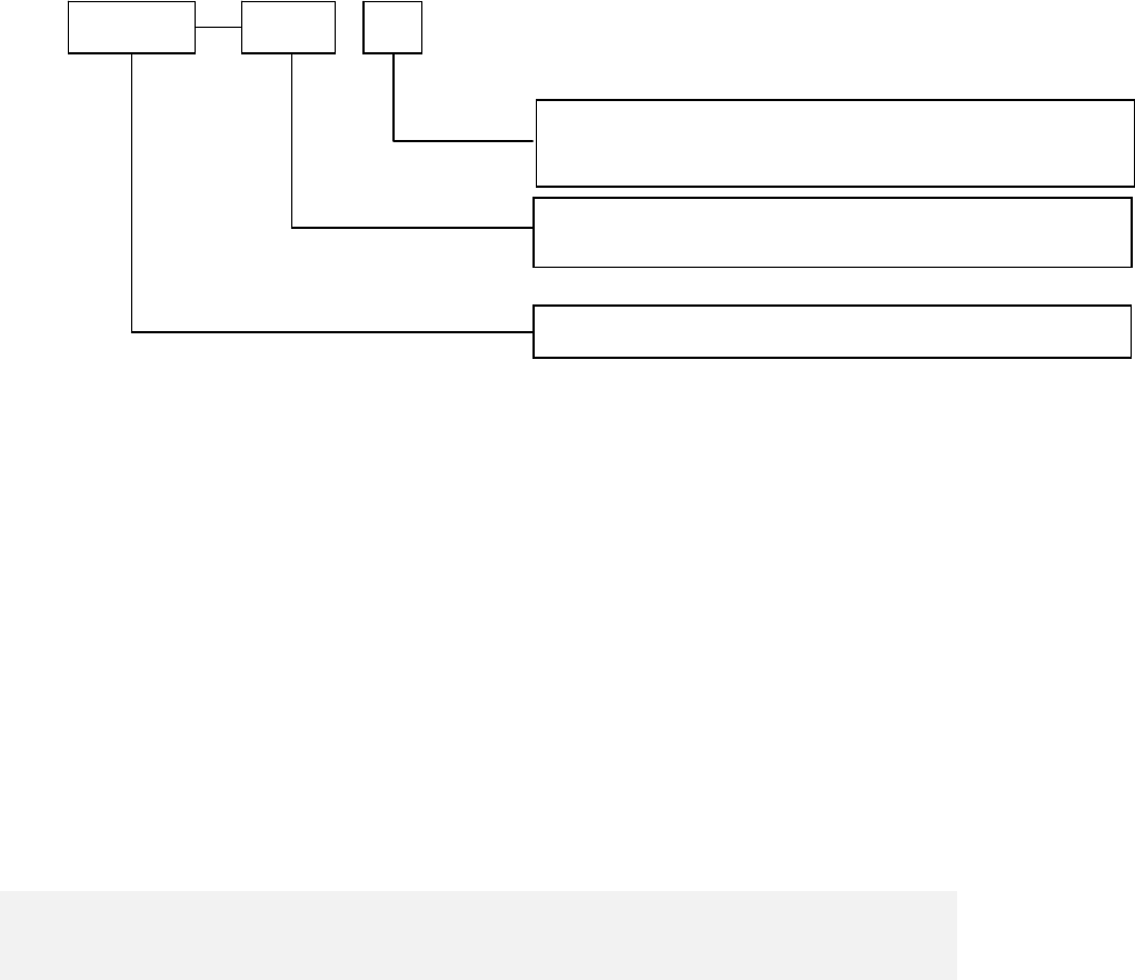
【Designation】
Regulationsfortypenaming:
Note:ratedvolumecanbethegrossvolumeoreffectivevolume;themanufacturer
candecideitbyhimaccordingtotheactualsituation.Theeffectivevolumevalue
mustbemarkedonthenameplatewhethereffectivevolumeorgrossvolumeis
markedintheproductname.
Examples:
HXC‐358meansthattheBloodBankrefrigeratorwiththetemperatureat
characteristictemperature4℃,horizontalandratedeffectivevolume358L.
HYC‐610isderivative of HXC-608, all the structures are the same, so that we write the
service manual here.
HXC XXX X
Design No. is expressed with character sequence
B: Drawer type
Rated volume value is shown with L
Blood storage refrigerator
5
【Safe Caution】
1. The machine is using an AC 220V/50/60HZ power. If the voltage used is lower than
198V or higher than 242V, an auto stabilizer above 4000W shall be equipped. Power line
that required for lengthening shall be with a cross section no less than 1.5mm.
2. An independent private jack shall be used and reliably connected. The power line for
refrigerator is equipped with three-wire, grounding-type plug which meets standard
three-wire, grounding-type receptacle. In no circumstance should the third plug foot
(grounding) of the power line be cut or removed. The plug shall be touchable after
installation of refrigerator. Power line or plug with abrasion shall not be used. Abraded or
damaged power line shall be sent to maintenance point designated by the manufacturer
or be replaced by qualified personnel.
3. Hazardous articles of inflammable, explosive, materials such as acid and alkali with
strong corrosion are prohibited in the refrigerator.
4. Please don’t use flammable spray closely to avid fire.
5. When there is inflammable gas such as coal gas leakage:
● Shut the valve for leakage;
● Open the door and window for ventilation;
● Don’t pull out or insert power plug of the refrigerator.
6. Once the power of the refrigerator is cut, it shall be re-connected at least five
minutes later to avoid damage on compressor or the system. The power shall be cut for
maintenance. Do not roll or damage the power line.
7. Please wear protective equipments during accessing to the refrigerator to avoid
freezing injury. When the refrigerator is scrapped, please remove the doorman. The
scrapped refrigerator shall be away from fire and be sent to appointed site for
disposition.
6
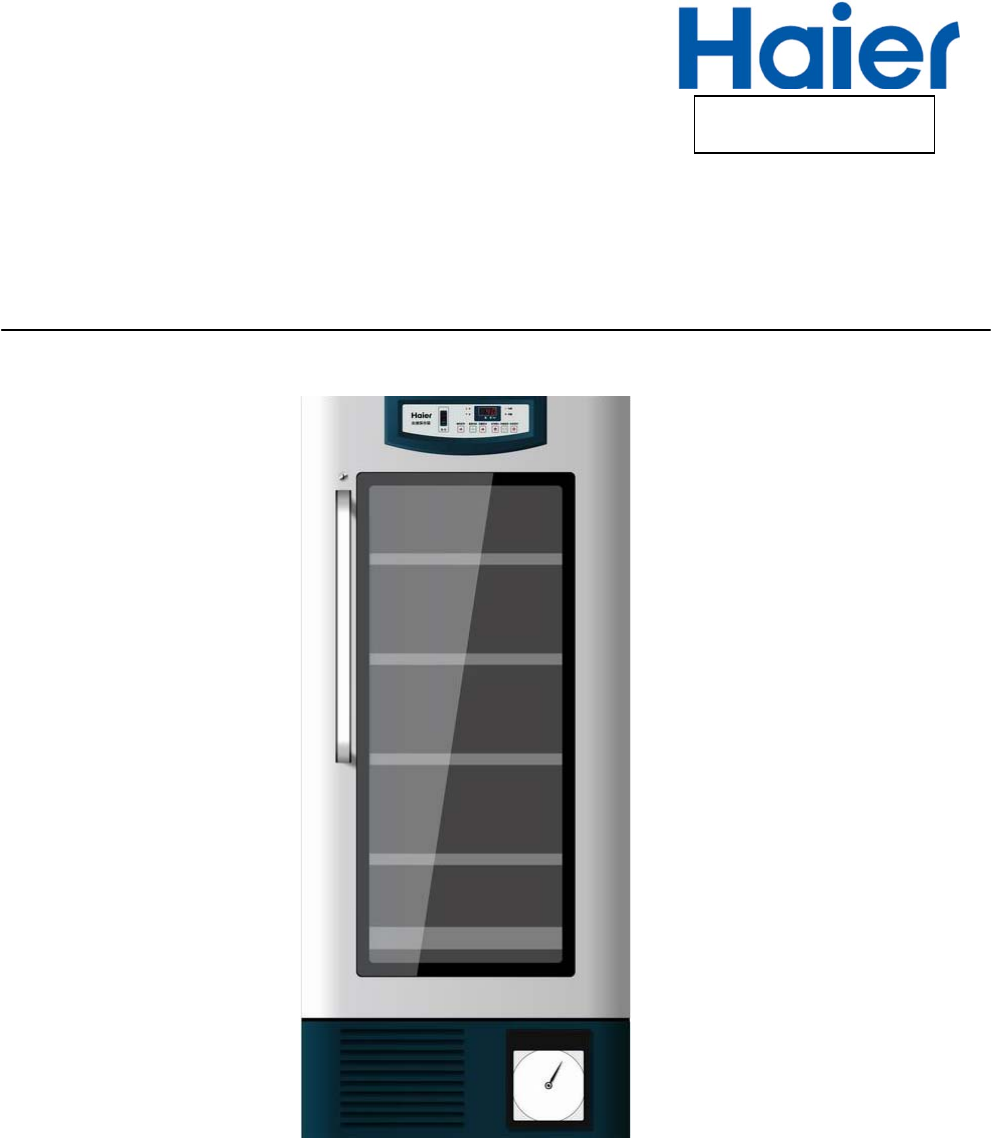
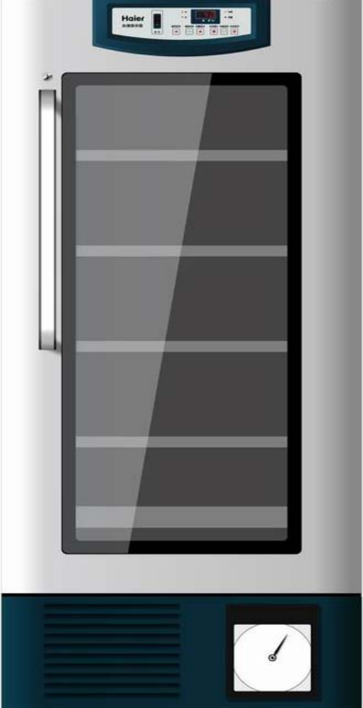
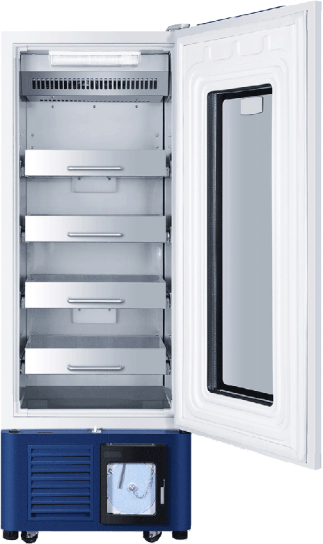
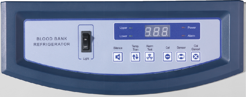
【Product appearance】
7
8
T
e
1.
2.
3.
4.
5.
6.
e
mperat
u
Haier bloo
d
Microcom
p
Full-autom
a
Visual aco
u
can realiz
e
Air cooling
Operation
i
u
re cont
r
contr
o
d
storage re
f
p
uter control
a
tic defrosti
n
u
sto-optic a
l
e
ove
r
-temp
e
system; rel
i
i
nstructions
Ap
p
r
ol syste
o
l princi
p
f
rigerator in
s
, inside-box
n
g function.
l
arm; have
r
e
rature alar
m
i
able operat
of control p
a
p
earance o
9
m of blo
p
les of e
a
s
ide-box te
m
temperatur
r
eal-time al
a
m
, powe
r
-of
f
ion, even in
s
a
nel and ea
f Model 09
od stor
a
a
ch com
m
perature i
s
e
is display
e
a
rm and lon
g
f
alarm, and
s
ide-box te
m
ch compon
e
display pa
n
a
ge refri
g
ponent
s
controlled
w
e
d digitally.
g
-distance
a
doo
r
-openi
n
m
perature.
e
nt.
n
el
g
erator
a
w
ithin 4±1
℃
a
larm functi
o
n
g alarm.
a
nd
℃
.
o
ns,
10
Color definitions of indicator lamps
A. Alarm indicator lamp(red): flashing display, indicates alarm state.
B. upper temperature display indicator lamp(lime orange): when the lamp is lighting,
digital tube displays upper sensor temperature.
C. Lower temperature display indicator lamp(lime orange): when the lamp is lighting,
digital tube displays lower sensor temperature.
D. Upper and lower temperature display indicator lamps are lighting at the same time:
display the average value of upper and lower temperature sensors.
E. Power indicator lamp(red): when the lamp is lighting, indicate that it is under master
power supply state; when the lamp is flashing, it is under master power failure state.
11
Definitions of keys
A. ‘Buzzing Cancel’ key: at the time of buzzing alarm, cancel buzzing;
B. ‘Temperature Change’ key: change the display temperature of digital tube;
C. ‘Alarm Test‘ key: test alarm function; each time it is pressed, the buzzer gives
out 3 sounds of 1Hz, meanwhile, alarm indicator lamp flashes for 3 times; if it is
not under long-distance hardware alarm state, long-distance alarm relay
switches off after 3s suck-shut, then determines action according to whether
alarm is needed, alarm is normal, otherwise, alarm is failure; when
rechargeable battery switch is not turned on, or battery electric quantity is low;
press Alarm Test key once, except for above functions, “E5” is flashed on
display window 3 times, 3 seconds each time.
D. More than 5 seconds ‘Sensing Selection’ key +‘Calibration Cancel’ keys:
temperature setting
E. More than 5 seconds “Temperature Conversion“+“Calibration Confirmation”
keys: amend the temperature value of each sensor.
F. More than 10 seconds “Buzzing Cancel”+“Alarm Test” keys: clear corrected
value and reset to default parameter setting.
12
Initial state
The first-time power-on operation state is initial state: temperature display is the mean
temperature of upper and lower sensors, temperature gear is set at 4 ℃, control whether
starting up compressor or not according to temperature.
13
Temperature adjustment and control functions
Press ‘Sensing Selection’ key and ‘Calibration Cancel ’ key at the same time more than 5
seconds, original setting begins flashing, enter in temperature setting state; latter, each
time ‘Calibration Cancel ’ key is pressed down, temperature value adds 0.1 until reach
setting upper limit; system default is “8”, press again, then change to be setting lower
limit again, system default is “2”, each time ‘Sensing Selection’ key is pressed down,
temperature value reduces 0.1 until reach setting lower limit; system default is “2”, press
again, then change to be setting upper limit again, system default is “8”, restart again;
when the temperature value that is needed to be set appears, if there is no key operation
for more than 5 seconds, temperature setting will be saved in system, and the state of
temperature setting control will automatically exit(default temperature setting range is
2-8 ℃).
Digital window redisplays inside-box sensor temperature value or its mean temperature
value(no flash)before setting. Within 3 seconds after temperature setting is finished,
under that condition that system still does not exit the state of temperature setting control,
continue press ‘Calibration Confirmation’ key for 10 seconds, system enters in the state
of temperature range setting, firstly, display SHE, within 4 seconds, press ‘Calibration
Cancel ’ key or ”Sensing Selection” key , then it displays that temperature upper limit
can be set now, default setting is 8℃, upper limit temperature can be added by
pressing ‘Calibration Cancel ’ key again (can also make adjustment through “Sensing
Selection” key, its adjustment value is opposite to “Calibration Cancel ”), the maximum is
20℃, the minimum is SEL, 4 seconds after adjustment, system will automatically log in
the temperature setting and displays SEL, press ‘Calibration Cancel ’ key or ”Sensing
Selection” key within 4 seconds, display temperature lower limit that can be set now,
default setting is 2℃. lower limit temperature can be added (can also make adjustment
through “Sensing Selection” key, its adjustment value is opposite to “Calibration Cancel ”)
by pressing ‘Calibration Cancel ’ key again, the minimum is -5℃, the maximum is SHE,
4 seconds after adjustment, system will automatically log in the temperature lower limit

14
setting and display AOF, press ‘Calibration Cancel ’ key or ”Sensing Selection” key within
4 seconds, display the value of currently controlled temperature difference, default
setting is 0.5℃, the value of temperature difference can be added by pressing
‘Calibration Cancel ’ key (can also make adjustment through “Sensing Selection” key, its
adjustment value is opposite to “Calibration Cancel ”), adjustment step value is 0.1℃ ,
the maximum is setting temperature 3, the minimum is 0.5℃. 4 seconds after adjustment,
system will automatically log in the setting temperature and display ALH, press
‘Calibration Cancel ’ key or ”Sensing Selection” key within 4 seconds, display the
temperature value of current high temperature alarm, default setting is 6℃. Lower limit
temperature can be added by pressing ‘Calibration Cancel ’ key (can also make
adjustment through “Sensing Selection” key, its adjustment value is opposite to
“Calibration Cancel ”), the maximum is 20℃, the minimum is setting temperature ALL; 4
seconds after adjustment, system will automatically log in the temperature value of high
temperature alarm, and display ALL, press ‘Calibration Cancel ’ key or ”Sensing
Selection” key within 4 seconds, display the temperature value of current low
temperature alarm, upper limit temperature can be added by pressing Calibration
Cancel ” again, the maximum is setting temperature ALH, the minimum is -5℃, (can also
make adjustment through “Sensing Selection” key, its adjustment value is opposite to
“Calibration Cancel ”, default setting is 2℃. 4 seconds after adjustment, system will
automatically log in the temperature value of low temperature alarm; if there is on
operation within 10 seconds, system automatically exit the state of temperature setting
control. Digital window redisplays inside-box sensor temperature value or its event
temperature value(no flash)before setting.
SettemperatureSHESHL
AOFALHALL
15
Temperature of machine start-up and shutdown
1.The start-up and shutdown of compressor is controlled by control sensor RT2.
Compressor start-up temperature : setting Ts)+AOF+0.5
Compressor shutdown temperature : setting(Ts)-AOF+0.5
The downtime of compressor shall not be less than 3 minutes each time.
2.After compressor has continued operation for 1 hour and not shut down, shut down it
forcedly for 5 minutes; at that time, electric heating is OFF, internal fan is
operating normally.
Each time when compressor shuts down, estimate the accumulated operation time of
compressor, if it is longer than 7 hours, shut down compressor.(at that time, electric
heating is OFF, internal fan is operating normally.) When downtime reaches 5 minutes, or
either of the temperature of upper and lower display temperatures exceeds 5.6 ℃, start
up compressor.
3.When either of the upper and lower display temperatures is lower than 2.5℃,
compressor is shut down forcedly, defrosting heater strip is power-off, internal
fan is operating normally; downtime shall not be less than 3 minutes.
16
Buzzing and luminotron(ALARM)flashing-alarm function
1. Temperature requirement for over-temperature alarm: alarm temperature upper limit
ALH— when either of upper and lower display temperatures is over ALH for continuous 2
minutes, start over-temperature alarm;alarm temperature lower limit—when either of
upper and lower display temperatures is lower than ALL, start over-temperature alarm.
Meanwhile, when display temperature reaches requirement, that is, display temperature
reaches close to setting temperature, inside-box actually-measured temperature shall be
in line with display temperature.
2. Power-off alarm function: when power AC220V/110V is off, it is switched by relay,
standby rechargeable battery will provide power to CPU.
After power-off, standby rechargeable battery provides power to computer panel, start
buzzing alarm immediately; power luminotron on panel(ALARM)is flashing;display
screen window displays inside-box upper and lower sensors’ mean temperature for 1
minute, stop displaying for 2 minutes, alternately display, alarm sound can be canceled
by pressing Buzzing Cancel key, but long-distance alarm function can not be canceled.
3. Sensor failure alarm: when there is a failure in either of upper (control ) and lower
(defrosting) sensors, buzzing alarm appears.
When appearing above alarm, buzzer gives out continuous buzzing in 1Hz, the current
failure buzzing can be canceled by pressing “Buzzing Cancel” key. After 20 minutes, if
alarm state continues existing, buzzing alarm would restart until “Buzzing Cancel” key is
pressed again.
17
Door-opening alarm function
when the time of door-opening is ≥600S, luminotron on panel(ALARM)is flashing, buzzer
gives out continuous buzzing in 1Hz.
18
Long-distance alarm function
1. Controller is working normally; long-distance alarm relay is power-on, give out no
alarm.
2. ①There are two control sensors, con and alarm, use CON as first control, con failure,
use ALARM as control. When both of them are failure, it is control failure.
② Either of upper and lower sensors is over-temperature;
③ Either of upper and lower (control and defrosting) sensors is failure;
④ Power AC220V/110V is power-off; (hardware alarm)
⑤ Door-opening time≥600s;
When meeting one of above five items, normally-closed contact closes, start up
long-distance alarm function. (Long-distance alarm function can be realized by
connecting to an electric bell.
19
Defrosting function
1. Normal defrosting function: each time compressor stops, start up defrosting
function; after compressor starts up, defrosting stops.
2. Enter in forced defrosting function: When working environment temperature is
large or there is a wet object in refrigerator, when compressor changes from
shut-down into starting-up state, temperature checked by defrosting sensor is
still ≤-5℃, at this time, start up defrosting relay(coil is power-on);
3. Exit forced defrosting: when upper and lower display temperature ≥5.6℃, or
time ≥20min, or the temperature of control sensor and alarm sensor≥7℃, exit
defrosting state, and enter in automatic normal operation.
4. Forced defrosting is at most carried out once within adjacent 24 hours. When
forced defrosting starts up, compressor and fan stop operating.
20
Fan delay after ending forced defrosting
After forced defrosting, compressor starts up, after delaying for 3 minutes, fan starts
normal operation.
21
Treatment of sensor failure
When a sensor is open circuit or short circuit, alarm lamp on panel is flashing(1Hz),
buzzer gives out alarm.
1 Upper temperature sensor is open circuit or short circuit: display E1.
2 Lower temperature sensor is open circuit or short circuit: display E2.
3 Control sensor is open circuit or short circuit: display E3.
4 Defrosting sensor is open circuit or short circuit: display E4.
E3 display > E1 display > E2 display >E4 display >temperature display
5 When control sensor is failure, compressor is operating according to 5 minutes
starting-up and 5 minutes shut-down.
22
Control of inner fan
When refrigerator door is open, inner fan stops operation; when refrigerator door is
closed, inner fan operates normally.
23
The access rule of compressor and defrosting relays
Three relays are accessed according to the following order: only two of them are used at
each time, one is idle, next time, another one is idle, repeat in this way again and again.
24
Amendment of temperature display
Press ”Temperature Conversion” Key and “Calibration Confirmation” key at the same
time for more than 10 seconds, enter in the amendment state of temperature display, at
this time, screen displays “D1”, can circularly select the sensor that is to be amended
by press ”Sensing Selection” key again, the meaning of each code: “D1” : upper
temperature sensor, “D2” : lower temperature sensor, “D3”: control sensor, “D4”:
defrosting sensor, “D5”: alarm sensor. Press ”Sensing Selection” key to select the
sensor that is to be amended.
Press “Calibration Cancel ” key, display the current value of sensor that is to be amended,
then press “Alarm Test” key, corrected value appears, initial state is 0, the corrected
value of the sensor can be added by pressing “Calibration Cancel” key, each time
“Calibration Cancel ” key is pressed, displayed value increases 0.1 ℃; the corrected
value of the sensor can be reduced by pressing ”Sensing Selection” key, each time
“Calibration Cancel ” key is pressed, corrected value reduces 0.1 ℃; the corrected value
of sensor is ±2℃.
After the completion of temperature sensor corrected value, press “Calibration
Confirmation” key, or there is no operation within 2 seconds, display the current
corrected sensor code, then can continue selecting the sensor that is to be amended by
pressing ”Sensing Selection” key; if there is no operation within 10 seconds,
automatically save corrected value and exit the amendment state of temperature display.
25
Requirement for rechargeable battery circuit
(1) Rechargeable battery circuit is 8V/12V and switchable. Stitching mode: set dial
switch on master control panel. When dial switch is placed at 8V, 8V rechargeable
battery is used; When dial switch is placed at 12V, 12V rechargeable battery is used.
(2) Charge mode:
A. Use 12V rechargeable battery. When blood storage refrigerator is power-on,
check the voltage of rechargeable battery, when the voltage is lower than 11.5V,
rechargeable battery shall be charged, charging voltage is 14.2V. After charging
for 30 minutes, stop for 5 minute, check battery voltage, if it is lower than 13.2V,
continue repeating the process of charging for 30 minutes and stopping for 5
minutes until the voltage is larger than 13.2V, then stop charging. If battery has
been charged continuously for 100 hours and still fails to reach 10.8V, the
battery is broken, don’t charge it again, replace the battery with a new
one(when refrigerator is power-on again, it is defaulted as replacing battery).
B. Use 8V rechargeable battery. When blood storage refrigerator is power-on,
check the voltage of rechargeable battery, when the voltage is lower than 7.4V,
rechargeable battery shall be charged; at the time of charging, the voltage
applied on both ends of battery is 9.5V. After charging for 30 minutes, stop for 5
minute, check battery voltage, if it is lower than 9.2V, continue repeating the
process of charging for 30 minutes and stopping for 5 minutes until the voltage
is larger than 9.2V, then stop charging. If battery has been charged
continuously for 100 hours and still fails to reach 6.5V, the battery is broken,
don’t charge it again, replace the battery with a new one.
C. Rechargeable battery circuit has anti-inverse-plugging-in design. If battery
positive and negative electrodes are connected inversely, control panel buzzer
would give out a sound continuously.
When 220V power and battery switch are OFF at the same time, if solely opens battery
switch, display panel has no display; when 220V power and battery switch are connected
26
at the same time, cut off the normal power supply of 220V power storage battery to
display panel.
27
Technical improvement process introduction of blood
refrigerator
Blood (drug) storage refrigerator computer panel and battery replacement and
maintenance process.
(8 V battery computer panel is replaced with a 12 v battery computer panel or battery)
1. Since June, 2009, all models of batteries of Haier blood (drug) storage refrigerator
have been replaced with 12V batteries(the production of 8V batteries was stopped),
meanwhile, corresponding control panel(new special number: 0074091548 )and
power panel(new special number: 0074091549)were changed at the same time, the
detailed replacement process is introduced as below:
1.1. Latest blood refrigerator computer panel can support 12V or 8V rechargeable
battery at the same time(there is a battery transfer switch on control panel, make
corresponding conversion according to V number of battery).
1.2. When replace Model 09 new computer panel, firstly, check machine battery is 8V or
12V, if it is 12V battery, only need to replace the computer panel that needs to be
replaced; if it is 8V battery, the power panel(special number: 0074090956) and
control panel(special number: 0074090957)on original machine need be replaced at
the same time.
Note: at the time of replacement, battery transfer switch needs to be adjusted to
corresponding position.
1.3. New power panel special number is 0074091549, new control panel special number
is 0074091548. The layout of each connecter on new computer panel and
connection method are the same as old computer panel; When replacing computer
panel, just plug each terminal into new computer panel according to original
plugging-in method.
1.4. Compared with original computer panel, a two-core connecting line is added to new
12V computer panel between master control panel and power panel(special number:
28
0070401668).
1.5. In future maintenance, if a battery needs to be replaced due to a failure, if it is 12V
battery, may directly apply for 12 V battery replacement(special number:
0074091430);if it is 8V battery, 12 V battery, power panel and control panel, and the
connecting wire of power panel and control panel shall be replaced at the same
time.
Note: at the time of replacement, battery transfer switch needs to be adjusted to
corresponding position.
In brief, in future maintenance course of blood (drug) storage refrigerator, if it is an
earlier-stage 8V battery machine, in case of battery failure, when can not apply for
8V battery, can apply for 12V battery replacement, meanwhile, need to apply for
replacing control panel and power panel, and convert battery switch to 12V
position; if it is any part failure of control panel or power panel, under the
condition of using original battery, firstly, apply for original parts to make
replacement, if can not obtain original parts, need to apply for replacing Model 09
control panel or power panel at the same time, battery transfer switch shall be
adjusted to corresponding position.
29
2. Introductions of original control panel and power panel and Model 09 control panel
and power pane:
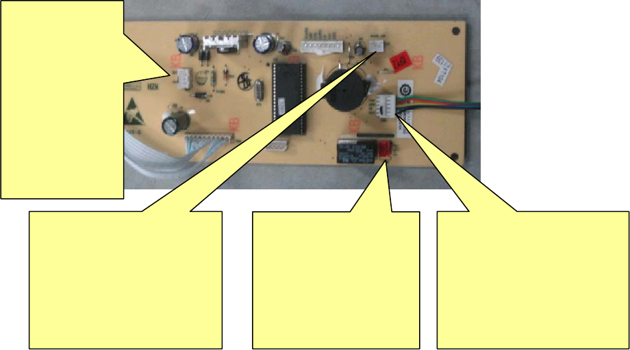
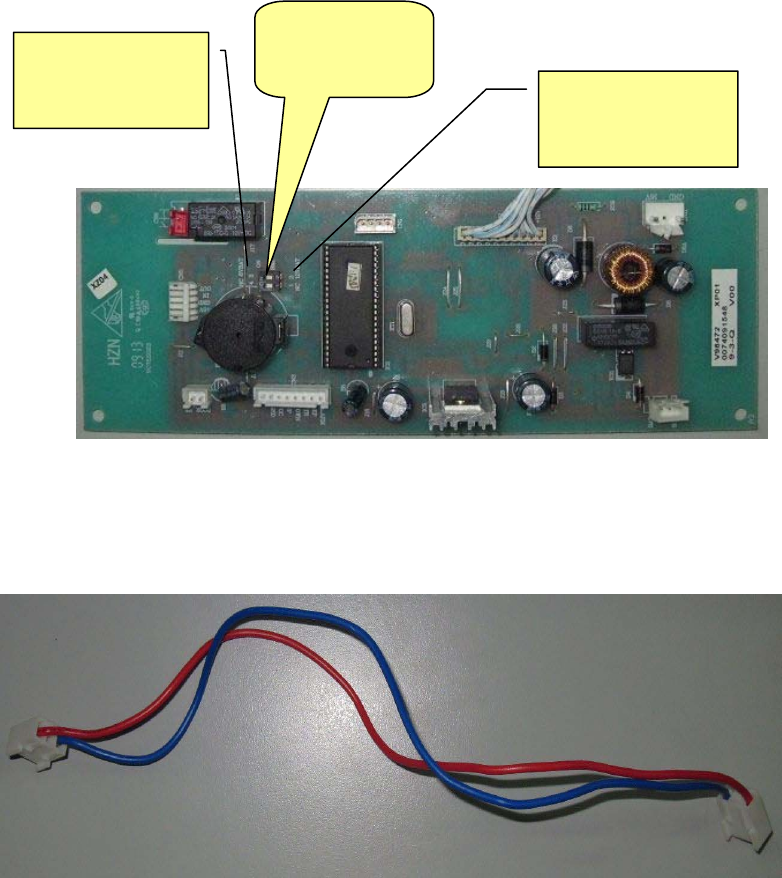
Original 8V rechargeable battery blood refrigerator computer panel—control
panel:
BT1
Rechargeable battery
wire connecting
terminal: the terminal
is connected to
rechargeable battery
wire connecting
terminal( red black
wire)
DOOR SW door alarm
switch wire connecting
terminal:the terminal is
connected to door switch
wire connecting
terminal( two black wires)
CN6 long-distance
alarm terminal:the
terminal is connected
to long-distance alarm
terminal (two red
wires)
CN5 display panel control
panel wire connecting
terminal: the terminal is
connected to five-core wire
terminal in accessory.
30
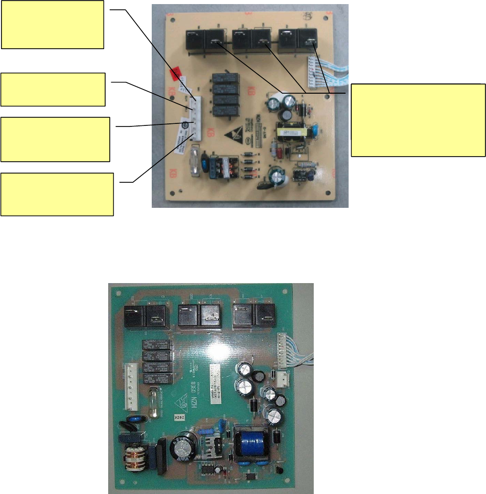
Original 8V rechargeable battery blood refrigerator computer panel— power panel:
New 12V rechargeable battery blood refrigerator computer panel— power
panel(special number: 0074091549)
HTR: control defrosting
heater strip
FAN: control
inner fan
L: brown wire,
connect to junction box
live wire
N: blue wire, connect to
junction box zero wire
Three chicken claws are
connected to three terminals,
control compressor and door
heating transformer.
31
New 12V rechargeable battery blood refrigerator computer panel—control panel
(special number: 0074091548)
New 12V rechargeable battery blood refrigerator control panel power panel
connecting line(special number: 0070401668)
Replacement method: After replacing new computer panel, oppositely plug the white
line socket between control panel and display panel together, use control panel and
power panel connecting line to connect the two computer panels, other terminals are
plugged into new computer panel according to original plugging-positions on old
computer panel.
NC 8V BAT
(8v battery mark)
8V and 12V
battery
i
NC 12V BAT
(12v battery
mark)
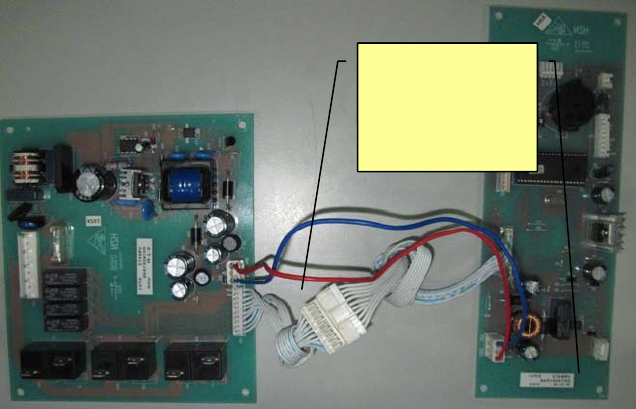
32
Control panel
and power
panel
connecting wire
33
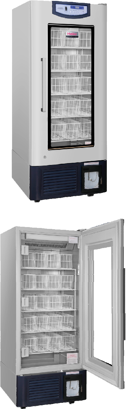
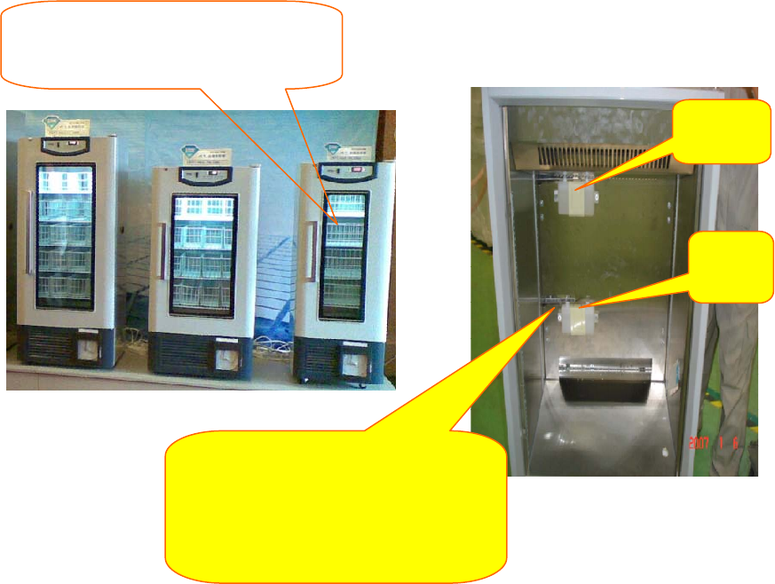
Box structure of Haier new product blood storage refrigerator
Take blood storage basket in blood
refrigerator out (if it is stainless steel drawer,
the drawer needs to be removed
)
,
the
Upper
sensor
Lower
sensor
Take off the covers of upper and lowe
r
sensors, expose sensor probes, remove
temperature-sensing stainless steel trim
strips and upper and lower sensors with a
screwdriver.
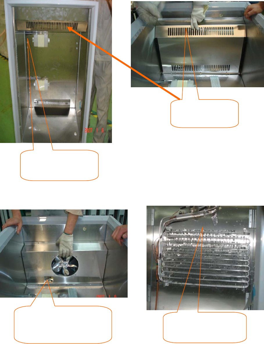
34
Remove the attaching clamp of control
sensor beside inner fan (the attaching
clamp fixes control sensor and alarm
sensor
Cut off the rope that fixes
defrosting sensor, remove
defrosting sensor.
Remove the screws that
fix vertical plate, take the
vertical plate out of box.
Remove the screws
that fix fan shield, take
fan shield out.
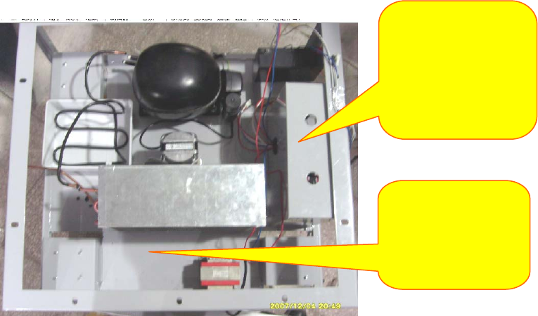
35
Rear
Left
Front
A
fter removing
screws and welded
pipe, the compressor
bottom board can be
Engine chamber inner
electrical control box,
can open from the
right side of engine
chamber, and make
th i i f l t i l
36
Door Body Instructions of New Product - Blood Storage
Refrigerator
Door body
structure: Fill
foam on all sides,
the middle is
electric
heating glass;
electric heating
of glass and
start-stop of
Outgoing lines of lower hinge
of door body are: Connecting
line of glass heating wire is
connected to the transformer
inside the cabin; connecting
line of display board is
connected to the control board
inside the electric
control system of cabin;
connecting line of lamp switch
on the door body is connected
to the ballast and null line.
Glass on the door body has
37
Recorder Installation, Operation and Maintenance Manual
1. Power Supply:
The recorder uses alternating current under normal working condition. If AC power
supply is abnormal, the recorder is equipped with backup power supply, green LED
starts to flicker, means that main power supply is out of order; otherwise green LED is
always on. The recorder has power cord or fixed transformer is connected to AC power
supply. If fixed transformer is connected to AC power supply, as shown in Fig. 6, it can be
connected to AC 115V, 50~60HZ or AC 230V, 50~60HZ main power supply.
2. Temperature Sensing Probe:
(1) Most of temperature recorders have a temperature sensing probe. If the recorder
has a temperature/humidity probe, when the recorder uses the probe, take off the
plastic cap on the temperature sensing probe; when it requires cleaning, push down
the plastic cap.
(2) If you use own temperature sensing probe, we will tell you how to install:
The recorder can accept current input (such as 4~20mA), voltage input (such as 0~1V,
0~5V, 1~5V, or 0~10V), or 100Ω resistance.
3. Notes:
(1) When the recorder is switched on, don’t touch the end of transformer. In order to
prevent electric shock hazard, before turning on the recorder, take off
the power plug. If the recorder is equipped with backup battery, disconnect 9V
battery to avoid damaging the recorder or consuming battery.
(2) 6-inch recording disk is embedded in one metal shell, recording disk on the recorder
should be fastened by four bolts, loosen the bolt, lightly move the recording disk,
microprocessor board is exposed. In addition, the recorder can fasten the recording
38
disk through tightening two bolts at upper right corner and lower right corner. Move
away two bolts and the recording disk can be turned on.
4. PC Control Panel:
J3 and J4 are external terminals, can provide at most two pens of signal input, J4 is used
to connect to the probe that provides the voltage signal for the recorder. 5V voltage is
provided for external probe.
5. Replace Recording Paper:
Press the paper changing button 3# for about one second until the recording pen starts
to move to left of paper, and then loosen the button. When the recording pen is
completely moved to outside of recording paper, counterclockwise loosen the bolt in the
middle of paper, move away recording paper, replace new paper, align the time line on
the paper and time line slot on the recording disk. Refer to Fig. 5 and confirm the time
line slot. Fasten newly the middle bolt so as to fasten recording paper. Press the paper
changing key 3# for about 1 second, the recording pen starts to move toward recording
paper. Check whether recording pen is easy to use; if it is not easy to use, adjust the
cross beam of recording pen and make the pen point contact with recording paper.
6. Recording System:
The model of pen has a multi-hole plastic ink cartridge, is fastened at the outer edge of
cross beam of metal pen. Pen cap is used to protect the recording pen during the
transportation of recording pen or the recording pen is not used. When the pen cap
should be removed, gently lift up the pen beam, take off the pen cap, lightly put the pen
in place, don’t make the pen heavily fall on the recording paper suddenly; otherwise may
damage the pen point and make the recording line on recording paper unclear. Place the
pen cap in a safe place for future use.
39
If recording pen contact is poor, lightly bend the center of cross beam of recording pen,
but don’t use too large force, only make the pen lightly contact with recording paper.
Notes: When ink of recording pen is almost used up, pen color will become shallow; it
means that recording pen should be replaced.
7. Replace Pen:
Notes: No ink recorder (for example, make use of pressure inductive recording paper)
doesn’t need to replace recording pen. The recorder have red and blue ink pens, can be
seen from red and blue pen handles; pen handles are fastened at the end of cross beam
of pen through a U-shaped clamp. For the convenience of replacement, fasten the cross
beam of pen using two bolts. Loosen the plastic U-shaped clamp, take away old pen and
change into new pen.
8. Adjust the Cross Beam of Recording Pen:
(1) In order to check and adjust the precision of recording pen, press the paper
changing key 3# until pen away from recording paper, press newly 3# key until pen
newly return to recording paper. Make the recording pen pause at the outermost
temperature line of recording paper, and then return to starting recording position. If
the pen is not paused at the above positions, it should balance the recording pen
through adjusting 1#(left)or 2#(right)arrow key.
(2) When recording pen is returned to recording paper and paused, you can adjust the
pen position within 5 seconds using 1# or 2# arrow key.
(3) For one double-pen recorder, each pen will pause at the outer edge of temperature
curve, and make an adjustment using 1# or 2# arrow key. If it is time for adjusting
the first pen, the second pen will pause at the outer edge of temperature curve;
make an adjustment at the time.
40
(4) When replaces pen or paper, make an adjustment newly according to the above
methods, otherwise the recorder error will cause incorrect recorded temperature.
9. Precision Check of Recorder:
The recorder has been precisely adjusted before leaving the factory; therefore, the
recorder should work for 24 hours before adjustment. If it really should be adjusted,
please conduct according to the following procedures. Pay attention not to place the
temperature and humidity sensors in any solution.
(1) Place a standard thermocouple in one solution bottle, together with recorder
thermocouple.
(2) If there is curve drawing on the recorder, compare the temperature on recording
paper drawn by the recording pen with temperature of thermocouple.
For double-pen recorder, compare the temperature of the second pen and temperature
of the second standard thermocouple.
(3) If it should be adjusted, calibrate using 1# or 2# arrow head, make two temperatures
consistent. Press the key for 5 seconds, recording pen starts to move.
(4) For double-pen recorder, you should first select the recording pen that requires
calibration. Press 1# key to select red pen, press 2# key to select blue pen, press 1
or 2 key until LED is off, and then operate as described in 3.
10. Backup Battery:
Green LED is always on, which means that battery and main power supply are normal;
position of LED is as shown in Fig. 5. If main power supply is out of order or electric
quantity of backup battery is insufficient, green LED will flicker, it means that main power
supply is out of order or the battery should be replaced; under the circumstances, the
recorder only can normally work 24 hours.
41
11. Fastening and Replacement of Battery:
4-inch, 6-inch and 10-inch recorders
In order to replace the battery, open the recorder door first, the battery is located in the
top right corner of recorder.
Notes: It only can be replaced by 9V alkaline battery.
12. 8-inch Recorder
Notes: When the recorder is connected to main power supply, don’t touch the
transformer terminal. In order to avoid electric shock, before replacing the battery,
disconnect the recorder from main power supply. In order to replace the battery on 8-inch
recorder, open the recorder door first, and then loosen the bolt on the right side of
recording disk, open the recording disk, the battery is fastened on the back of recording
disk. It only can be replaced by 9V alkaline battery.
13. Optional Alarm, Control Relay:
(1) Notes: When the recorder is connected to main power supply, don’t touch the
transformer terminal. In order to avoid clicking, before connecting the relay terminal,
disconnect the recorder and main power supply first. If the recorder is equipped with
backup battery, disconnect 9V battery to avoid damaging the recorder or consuming
electric quantity of battery.
(2) Temperature recording disk on 6-inch recorder embedded in metal shell is fastened
by four screws, loosen the screw, remove the recording disk, and then the relay
being fastened on the back of recorder disk is exposed. In addition, some recorders
have a recording disk with hinge, fastened by two screws in the lower part and upper
part of recording disk. Twist two screws off, and then open the recording disk with
hinge. On 8-inch recorder, one screw on the right is fastened the shell of recording
42
disk, loosen the screw, open the recording disk, the relay terminal should be
exposed. If you don’t know how to connect the relay terminal, please contact with
COBEX recorder company.
(3) The relay on the recorder is self-locking, that is to say, relay contact is off or on
(even it is not powered off) unless the recorder has the signal for changing the
contact position.
(4) The position of relay terminal blocks is as shown in Fig. 1. Notes: Red, black and
white lines have been provided as the external connection module of relay. When
the recording pen is located on the right side of control point, connection position NC
will be closed; when recording pen is located on the left side of control point, NC will
be opened.
(5) Relay current is divided into the following maximum values:
2.0 amperes at AC 30V;
0.6 ampere at AC 125V;
0.6 ampere at AC 110V
Warning: If relay current exceeds standard, it may damage the recorder.
14. Set up the Control Point of Relay:
In order to set up the recording pen’s position on recording paper, confirm the closing
time of relay contact according to the following methods:
(1) Press the paper changing key 3# until pen beam starts to move outside paper, after
a while, recording pen will move outside recording paper. When newly press the
paper changing key 3#, the recording pen moves back to recording paper, and stay
at the outermost scale mark for a short time.
(2) Recording pen will return to the position of the first control point, green LED will go
out. When the recording pen is stayed in five seconds, it is allowed to adjust the
43
control point using 1# or 2# allow key. When time for adjusting control point is 5
seconds, green LED is on, the recorder starts to work.
(3) If the recording pen has two control points, the recording pen is moved to the
second control point; it can adjust the second control point within 5 seconds. Each
pen with two control points can make use of relay closing to control the maximum
temperature and minimum temperature. After adjusting the control point for 5
seconds, LED is on; the recording pen is moved to current temperature position, the
recorder starts to work.
15. Range Selection of Recording Paper:
(1) If the temperature range of your temperature recorder is stored in the memory of
recording disk, the following conditions are suitable for you.
The temperature selection range of recorder is stored in the recorder in the manner of
program.
Notes: Recording paper must match with the temperature range of selected recorder;
otherwise the recording pen’s position above recording paper can not consistent with
measured temperature. In addition, if the recorder keeps still at the center or at the edge
of recording paper, it means that temperature range of selected recorder is abnormal.
The recorder inside has a safety protection device; when current measured temperature
is not within the selected range, the recording pen will move to the maximum
temperature.
(2) The recorder has at most 8 optional ranges, can select a suitable range according to
following methods:
After the recorder is switched on and run normally (record temperature), press the paper
changing key 3#, until recording pen is away from recording paper. When recording pen
is away from recording paper, press left arrowhead 1 or right arrowhead 2 for about 5
44
seconds, and then loosen the key. If presses 1 key, green LED will flicker once; if
presses 2 key, green LED will flicker twice. Press left arrowhead 1 key to increase
temperature range, press right arrowhead 2 key to reduce temperature range. After
completing the temperature range selection, press paper changing key 3# until recording
pen returns to recording paper, selected temperature range will be stored in the recorder
memory.
16. Specification of Recorder:
Input: Normal input voltage: Single-phase AC115/230V, normal input current:
40mA/20mA
Warning: Relay current exceeds standard, may damage the recorder.
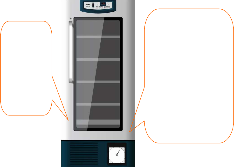
17. Detailed Description of Recorder Installation
(1) Remove the cover plate of recorder first.
(2) Make white wiring harness of recorder pass through marked round hole.
45
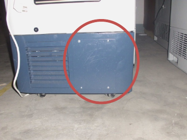
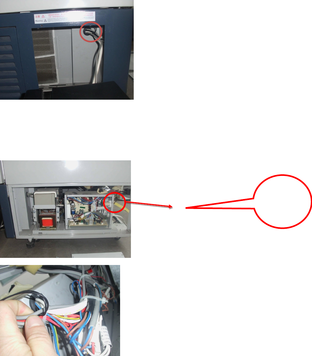
(3) Remove the right side plate of cabin and cover plate of electric control box; make
white wiring harness pass through electric control box from the threading hole in the
upper right part of electric control box.
(4) Fasten three terminals on the connector bar inside the electric control box according
to the graphical position.
Detail
Drawing of
Back of
Electric
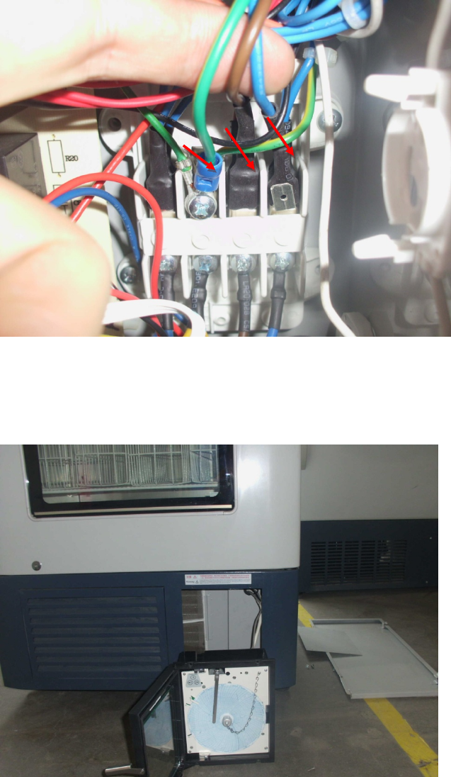
46
(5) Fasten the recorder at the removed cover plate using the screw, install the cover
plate of electric control box and right side plate of cabin.

47
Normal Faults Analysis and Maintenance Measures
Problem Cause Analysis Maintenance Measures
1. Temperature inside the
cabinet is not uniform;
temperature difference of
upper and lower part is too
big.
1. Internal fan failure Replace the fan.
2. Fan duct is blocked up by
obstacles. Remove the obstacles.
3. Door switch is broken. Replace the door switch.
4. Computer board is out of order. Replace the computer board.
2. Display
board
doesn’t
display the
value.
Display E4
1. Battery switch is not turned on or
damaged.
Turn on the switch and
replace the switch.
2. Rechargeable battery is broken. Replace the
rechargeable battery.
Display E3 3. Defrost sensor has open circuit
fault or is damaged. Repair or replace.
Display E2 4. Control sensor has open circuit
fault or is damaged. Repair or replace.
Display E1 5. Lower display sensor has open
circuit fault or is damaged. Repair or replace.
Display E0 6. Upper display sensor has open
circuit fault or is damaged. Repair or replace.
3. Refrigerator refrigeration is
poor.
1. Serious leakage of refrigerant Check the leakage and refill
the refrigerant.
2. Filth blockage of capillary or
system
Clean the capillary or replace
the filter.
4. Recorder failure
1. Record temperature is not correct. Check the recorder.
2. Recording paper can’t record
temperature.
Remove by adjusting the
recording pen.
3. After disconnecting the recorder
battery, the lamp is not on.
Check whether the upper and
lower connectors are
connected in place.
5. No alarm
1. Connection is not in place. Check the installation.
2. Control board failure Replace the control board.

48
Problem Question & Answer Measures
1. Temperature inside the
case is too high or too
low
Display temperature has a certain
relation to ambient temperature; if
temperature is too high or too low, it can
solve the problem through adjusting the
control temperature.
For the specific
operation method, see the
attached instructions.
2. Surface of external glass
door is hot.
Adopt imported electric heating external
glass door, surface heating is normal,
not out of order.
3. There is deviation
between display
temperature and
measured temperature.
Display temperature refers to the
temperature on the surface of
temperature measuring box. When
blood bank is run stably, it equals to the
surface temperature of stored blood
bag; while the thermometer measures
the air temperature inside the box at the
time, and varies within a certain range,
thus can’t correctly reflect the blood bag
temperature at the time.
4. Recorder temperature
has deviation.
Record temperature of recorder reflects
the measuring point temperature inside
the box, it is normal that it has a certain
deviation from display temperature; if
the temperature deviation at the position
measured by thermometer is very large,
it can be calibrated according to the
method introduced by the instructions.
5. There is seeper at the
bottom of box after
running for a period of
time.
If there is a small amount of seeper, it
should be periodically wiped off by a
towel. If there is a lot of seeper, check
whether the drainpipe is blocked or
drainage is smooth, unblock with a
piece of fine iron wire.

49
Inspired living
HaierMedical&LaboratoryProductsCo.,Ltd.
Room403D,BrandBuilding,HaierIndustrialPark,No.1HaierRoad
QingdaoChina
Website:www.haiermedical.com
