STI/PUB/1526 1526 P1526 Web
User Manual: 1526
Open the PDF directly: View PDF ![]() .
.
Page Count: 207 [warning: Documents this large are best viewed by clicking the View PDF Link!]
- FOREWORD
- CONTENTS
- 1. INTRODUCTION
- 2. DESCRIPTION AND RATIONALE FOR GROUPING OF BUILDINGS AND STRUCTURES
- 3. PRE-PROJECT (PRE-DEPLOYMENT) AND SITE INFRASTRUCTURE ACTIVITIES
- 4. CONSTRUCTION ACTIVITIES AND METHODS OFGENERIC APPLICABILITY TO ALL BUILDING GROUPS
- 5. CONSTRUCTION ACTIVITIES AND TECHNOLOGIES SPECIFIC TO GROUP A (NUCLEAR ISLAND) BUILDINGS AND STRUCTURES
- 6. CONSTRUCTION ACTIVITIES AND TECHNOLOGIES SPECIFIC TO GROUP B (TURBINE ISLAND) BUILDINGS AND STRUCTURES
- 7. CONSTRUCTION ACTIVITIES AND TECHNOLOGIES SPECIFIC TO GROUP C (BALANCE OF PLANT) BUILDINGS AND STRUCTURES
- 8. MODULARIZATION
- 8.1. DEFINITIONS
- 8.2. DESCRIPTION
- 8.3. RECENT CONSTRUCTION EXPERIENCE IN MODULARIZATION WITH PREFABRICATION ANDPREASSEMBLY
- 8.4. ADVANTAGES AND DISADVANTAGES
- 8.5. REQUIRED PLANNING
- 8.6. POTENTIAL FUTURE IMPROVEMENTS
- 9. OPEN TOP CONSTRUCTION METHOD
- 9.1. VERY HEAVY LIFTING OPEN TOP CONSTRUCTION
- 9.2. LIFT TOWERS
- 10. QUALITY ASSURANCE, INSPECTION AND TESTING
- 10.1. DEPLOYMENT PLANNING FOR INSPECTION AND TESTING
- 10.2. RADIOGRAPHIC AND ULTRASONIC INSPECTION AND IMAGING
- 10.3. INSPECTION TOOLS
- 10.4. RETRIEVABILITY OF TEST AND CERTIFICATION DOCUMENTATION
- 10.5. AS-BUILT AND BUILDING INFORMATION MANAGEMENT
- 10.6. SHOP INSPECTION AND QUALITY CONTROL FOR MODULE FABRICATION
- 10.7. DOCUMENTATION
- 11. INTEGRATED PROJECT PLANNING AND MANAGEMENT
- Appendix I - SURVEY OF TECHNOLOGIES FOR NUCLEAR POWER PLANT CONSTRUCTION
- Appendix II - SUGGESTED BUILDING LIST
- Appendix III - PLANNING ACTIVITY CHART
- REFERENCES
- BIBLIOGRAPHY
- ABBREVIATIONS
- CONTRIBUTORS TO DRAFTING AND REVIEWING
- Structure of the IAEA Nuclear Energy Series

Basic
Principles
Objectives
IAEA Nuclear Energy Series
Technical
Reports
Construction
Technologies for
Nuclear Power Plants
No. NP-T-2.5
Guides
IAEA Nuclear Energy Series
No. NP-T-2.5 Construction Technologies for Nuclear Power Plants
INTERNATIONAL ATOMIC ENERGY AGENCY
VIENNA
ISBN 978–92–0–119510–4
ISSN 1995–7807
11-31491_P1526_cover.indd 1 2011-12-05 14:48:24
IAEA NUCLEAR ENERGY SERIES PUBLICATIONS
STRUCTURE OF THE IAEA NUCLEAR ENERGY SERIES
Under the terms of Articles III.A and VIII.C of its Statute, the IAEA is
authorized to foster the exchange of scientific and technical information on the
peaceful uses of atomic energy. The publications in the IAEA Nuclear Energy
Series provide information in the areas of nuclear power, nuclear fuel cycle,
radioactive waste management and decommissioning, and on general issues
that are relevant to all of the above mentioned areas. The structure of the
IAEA Nuclear Energy Series comprises three levels: 1 — Basic Principles and
Objectives; 2 — Guides; and 3 — Technical Reports.
The Nuclear Energy Basic Principles publication describes the rationale
and vision for the peaceful uses of nuclear energy.
Nuclear Energy Series Objectives publications explain the expectations
to be met in various areas at different stages of implementation.
Nuclear Energy Series Guides provide high level guidance on how to
achieve the objectives related to the various topics and areas involving the
peaceful uses of nuclear energy.
Nuclear Energy Series Technical Reports provide additional, more
detailed, information on activities related to the various areas dealt with in the
IAEA Nuclear Energy Series.
The IAEA Nuclear Energy Series publications are coded as follows:
NG — general; NP — nuclear power; NF — nuclear fuel; NW — radioactive
waste management and decommissioning. In addition, the publications are
available in English on the IAEA’s Internet site:
http://www.iaea.org/Publications/index.html
For further information, please contact the IAEA at PO Box 100, Vienna
International Centre, 1400 Vienna, Austria.
All users of the IAEA Nuclear Energy Series publications are invited to
inform the IAEA of experience in their use for the purpose of ensuring that
they continue to meet user needs. Information may be provided via the IAEA
Internet site, by post, at the address given above, or by email to
Official.Mail@iaea.org.
11-31491_P1526_cover.indd 2 2011-12-05 14:48:24
CONSTRUCTION TECHNOLOGIES FOR
NUCLEAR POWER PLANTS

AFGHANISTAN
ALBANIA
ALGERIA
ANGOLA
ARGENTINA
ARMENIA
AUSTRALIA
AUSTRIA
AZERBAIJAN
BAHRAIN
BANGLADESH
BELARUS
BELGIUM
BELIZE
BENIN
BOLIVIA
BOSNIA AND HERZEGOVINA
BOTSWANA
BRAZIL
BULGARIA
BURKINA FASO
BURUNDI
CAMBODIA
CAMEROON
CANADA
CENTRAL AFRICAN
REPUBLIC
CHAD
CHILE
CHINA
COLOMBIA
CONGO
COSTA RICA
CÔTE DIVOIRE
CROATIA
CUBA
CYPRUS
CZECH REPUBLIC
DEMOCRATIC REPUBLIC
OF THE CONGO
DENMARK
DOMINICAN REPUBLIC
ECUADOR
EGYPT
EL SALVADOR
ERITREA
ESTONIA
ETHIOPIA
FINLAND
FRANCE
GABON
GEORGIA
GERMANY
GHANA
GREECE
GUATEMALA
HAITI
HOLY SEE
HONDURAS
HUNGARY
ICELAND
INDIA
INDONESIA
IRAN, ISLAMIC REPUBLIC OF
IRAQ
IRELAND
ISRAEL
ITALY
JAMAICA
JAPAN
JORDAN
KAZAKHSTAN
KENYA
KOREA, REPUBLIC OF
KUWAIT
KYRGYZSTAN
LAO PEOPLES DEMOCRATIC
REPUBLIC
LATVIA
LEBANON
LESOTHO
LIBERIA
LIBYA
LIECHTENSTEIN
LITHUANIA
LUXEMBOURG
MADAGASCAR
MALAWI
MALAYSIA
MALI
MALTA
MARSHALL ISLANDS
MAURITANIA
MAURITIUS
MEXICO
MONACO
MONGOLIA
MONTENEGRO
MOROCCO
MOZAMBIQUE
MYANMAR
NAMIBIA
NEPAL
NETHERLANDS
NEW ZEALAND
NICARAGUA
NIGER
NIGERIA
NORWAY
OMAN
PAKISTAN
PALAU
PANAMA
PARAGUAY
PERU
PHILIPPINES
POLAND
PORTUGAL
QATAR
REPUBLIC OF MOLDOVA
ROMANIA
RUSSIAN FEDERATION
SAUDI ARABIA
SENEGAL
SERBIA
SEYCHELLES
SIERRA LEONE
SINGAPORE
SLOVAKIA
SLOVENIA
SOUTH AFRICA
SPAIN
SRI LANKA
SUDAN
SWEDEN
SWITZERLAND
SYRIAN ARAB REPUBLIC
TAJIKISTAN
THAILAND
THE FORMER YUGOSLAV
REPUBLIC OF MACEDONIA
TUNISIA
TURKEY
UGANDA
UKRAINE
UNITED ARAB EMIRATES
UNITED KINGDOM OF
GREAT BRITAIN AND
NORTHERN IRELAND
UNITED REPUBLIC
OF TANZANIA
UNITED STATES OF AMERICA
URUGUAY
UZBEKISTAN
VENEZUELA
VIETNAM
YEMEN
ZAMBIA
ZIMBABWE
The Agency’s Statute was approved on 23 October 1956 by the Conference on the Statute of the IAEA held at
United Nations Headquarters, New York; it entered into force on 29 July 1957. The Headquarters of the Agency are
situated in Vienna. Its principal objective is “to accelerate and enlarge the contribution of atomic energy to peace,
health and prosperity throughout the world’’.
The following States are Members of the International Atomic Energy Agency:
CONSTRUCTION TECHNOLOGIES FOR
NUCLEAR POWER PLANTS
IAEA NUCLEAR ENERGY SERIES No. NP-T-2.5
INTERNATIONAL ATOMIC ENERGY AGENCY
VIENNA, 2011
IAEA Library Cataloguing in Publication Data
Construction technologies for nuclear power plants. — Vienna : International
Atomic Energy Agency, 2011.
p. ; 30 cm. — (IAEA nuclear energy series, ISSN 1995–7807 ;
no. NP-T-2.5)
STI/PUB/1526
ISBN 978–92–0–119510–4
Includes bibliographical references.
1. Nuclear industry. 2. Nuclear power plants — Design and construction.
3. Nuclear power plants — Technological innovations. I. International
Atomic Energy Agency. II. Series.
IAEAL 11–00715
COPYRIGHT NOTICE
All IAEA scientific and technical publications are protected by the terms of
the Universal Copyright Convention as adopted in 1952 (Berne) and as revised in
1972 (Paris). The copyright has since been extended by the World Intellectual
Property Organization (Geneva) to include electronic and virtual intellectual
property. Permission to use whole or parts of texts contained in IAEA
publications in printed or electronic form must be obtained and is usually subject
to royalty agreements. Proposals for non-commercial reproductions and
translations are welcomed and considered on a case-by-case basis. Enquiries
should be addressed to the IAEA Publishing Section at:
Marketing and Sales Unit, Publishing Section
International Atomic Energy Agency
Vienna International Centre
PO Box 100
1400 Vienna, Austria
fax: +43 1 2600 29302
tel.: +43 1 2600 22417
email: sales.publications@iaea.org
http://www.iaea.org/books
© IAEA, 2011
Printed by the IAEA in Austria
November 2011
STI/PUB/1526
FOREWORD
One of the IAEA’s statutory objectives is to “seek to accelerate and enlarge the contribution of atomic energy
to peace, health and prosperity throughout the world”. One way this objective is achieved is through the publication
of a range of technical series. Two of these are the IAEA Nuclear Energy Series and the IAEA Safety Standards
Series.
According to Statute Article III, A.6, the IAEA safety standards establish “standards of safety for protection
of health and minimization of danger to life and property.” The safety standards include the Safety Fundamentals,
Safety Requirements and Safety Guides. These standards are written primarily in a regulatory style, and are binding
on the IAEA for its own programmes. The principal users are the regulatory bodies in Member States and other
national authorities.
The IAEA Nuclear Energy Series comprises reports designed to encourage and assist R&D on and practical
application of, nuclear energy for peaceful uses. This includes practical examples to be used by owners and
operators of utilities in Member States, implementing organizations, academia, and government officials, among
others. This information is presented in guides, reports on technology status and advances, and best practices for
peaceful uses of nuclear energy based on inputs from international experts. The IAEA Nuclear Energy Series
complements the IAEA Safety Standards Series.
There are three distinct significant phases in a nuclear power plant (NPP) project after the signing of a
contract; engineering, procurement, and construction and commissioning. Experience gained over the last forty
years has shown that the construction phase is one of the most critical phases for the success of a project. Success is
defined as completing the project with the specified quality, and within budget and schedule. The key to a
successful construction project is to have an established programme that integrates the critical attributes into the
overall project.
Some of these attributes are:
— Execution, i.e. transferring strong policies, procedures and safety culture to the field;
— Coordination of programmes across organizations such that the licensee, vendor and subcontractors are
working in concert;
— Completion of design and establishment of the procurement process;
— Understanding of the different construction methods that are available.
In line with its mandate, the IAEA is publishing this report to: share information on the conventional and
recently introduced advanced techniques and methods being used in different aspects of the construction phase of a
project, both in the nuclear industry as well as in non-nuclear industries; and provide countries contemplating the
setting up of NPPs with relevant information on the construction phase of a nuclear plant.
Each Member State can adopt the technique which can be best applied to its programme, based on the
construction infrastructure within the country. This report serves as a guide to provide a better understanding of the
tools and steps that will support the construction of NPPs, and consequently improve technical and management
skills.
The IAEA officer responsible for this publication was M. Tyobeka of the Division of Nuclear Power.
CONTENTS
1. INTRODUCTION . . . . . . . . . . . . . . . . . . . . . . . . . . . . . . . . . . . . . . . . . . . . . . . . . . . . . . . . . . . . . . . . . . . 1
1.1. Background. . . . . . . . . . . . . . . . . . . . . . . . . . . . . . . . . . . . . . . . . . . . . . . . . . . . . . . . . . . . . . . . . . . . 1
1.2. Objective, scope and intended audience . . . . . . . . . . . . . . . . . . . . . . . . . . . . . . . . . . . . . . . . . . . . . 2
1.2.1. Objective and scope . . . . . . . . . . . . . . . . . . . . . . . . . . . . . . . . . . . . . . . . . . . . . . . . . . . . . . . 2
1.2.2. Intended audience . . . . . . . . . . . . . . . . . . . . . . . . . . . . . . . . . . . . . . . . . . . . . . . . . . . . . . . . . 3
1.3. Preparation and structure of this publication . . . . . . . . . . . . . . . . . . . . . . . . . . . . . . . . . . . . . . . . . . 3
1.3.1. Preparation . . . . . . . . . . . . . . . . . . . . . . . . . . . . . . . . . . . . . . . . . . . . . . . . . . . . . . . . . . . . . . 3
1.3.2. Structure . . . . . . . . . . . . . . . . . . . . . . . . . . . . . . . . . . . . . . . . . . . . . . . . . . . . . . . . . . . . . . . . 3
2. DESCRIPTION AND RATIONALE FOR GROUPING OF BUILDINGS AND STRUCTURES . . . . . 4
3. PRE-PROJECT (PRE-DEPLOYMENT) AND SITE INFRASTRUCTURE ACTIVITIES . . . . . . . . . . 6
3.1. Activities related to infrastructure and layout for site construction . . . . . . . . . . . . . . . . . . . . . . . . . 6
3.1.1. Background to early site planning and development . . . . . . . . . . . . . . . . . . . . . . . . . . . . . . 6
3.1.1.1. Prerequisites. . . . . . . . . . . . . . . . . . . . . . . . . . . . . . . . . . . . . . . . . . . . . . . . . . . . . . 6
3.1.1.2. Site development schedule. . . . . . . . . . . . . . . . . . . . . . . . . . . . . . . . . . . . . . . . . . . 7
3.1.2. Excavation plan. . . . . . . . . . . . . . . . . . . . . . . . . . . . . . . . . . . . . . . . . . . . . . . . . . . . . . . . . . . 8
3.1.2.1. General excavation. . . . . . . . . . . . . . . . . . . . . . . . . . . . . . . . . . . . . . . . . . . . . . . . . 8
3.1.2.2. Nuclear power island excavation, backfill, and waterproofing —
site conditions . . . . . . . . . . . . . . . . . . . . . . . . . . . . . . . . . . . . . . . . . . . . . . . . . . . . 8
3.1.3. Temporary services, facilities and assembly areas . . . . . . . . . . . . . . . . . . . . . . . . . . . . . . . . 8
3.1.3.1. Services . . . . . . . . . . . . . . . . . . . . . . . . . . . . . . . . . . . . . . . . . . . . . . . . . . . . . . . . . 8
3.1.3.2. Facilities. . . . . . . . . . . . . . . . . . . . . . . . . . . . . . . . . . . . . . . . . . . . . . . . . . . . . . . . . 9
3.1.3.3. Assembly areas . . . . . . . . . . . . . . . . . . . . . . . . . . . . . . . . . . . . . . . . . . . . . . . . . . . 11
3.1.4. Equipment. . . . . . . . . . . . . . . . . . . . . . . . . . . . . . . . . . . . . . . . . . . . . . . . . . . . . . . . . . . . . . . 11
3.1.4.1. Heavy lift crawler type or ringer crane requirements . . . . . . . . . . . . . . . . . . . . . . 11
3.1.4.2. Heavy construction cranes . . . . . . . . . . . . . . . . . . . . . . . . . . . . . . . . . . . . . . . . . . . 11
3.2. Methods for preparing site infrastructure and layout for site construction. . . . . . . . . . . . . . . . . . . . 12
3.2.1. All-weather and around-the-clock construction . . . . . . . . . . . . . . . . . . . . . . . . . . . . . . . . . . 12
3.2.2. Construction personnel mobility. . . . . . . . . . . . . . . . . . . . . . . . . . . . . . . . . . . . . . . . . . . . . . 14
3.2.3. Transportation . . . . . . . . . . . . . . . . . . . . . . . . . . . . . . . . . . . . . . . . . . . . . . . . . . . . . . . . . . . . 14
3.2.3.1. Heavy haul path . . . . . . . . . . . . . . . . . . . . . . . . . . . . . . . . . . . . . . . . . . . . . . . . . . . 14
3.2.3.2. Railroads . . . . . . . . . . . . . . . . . . . . . . . . . . . . . . . . . . . . . . . . . . . . . . . . . . . . . . . . 15
3.2.4. Construction management centre . . . . . . . . . . . . . . . . . . . . . . . . . . . . . . . . . . . . . . . . . . . . . 15
3.2.5. Underground common tunnel . . . . . . . . . . . . . . . . . . . . . . . . . . . . . . . . . . . . . . . . . . . . . . . . 17
3.2.6. Site mapping and measuring. . . . . . . . . . . . . . . . . . . . . . . . . . . . . . . . . . . . . . . . . . . . . . . . . 18
3.2.6.1. Conventional methods . . . . . . . . . . . . . . . . . . . . . . . . . . . . . . . . . . . . . . . . . . . . . . 18
3.2.6.2. Advanced methods. . . . . . . . . . . . . . . . . . . . . . . . . . . . . . . . . . . . . . . . . . . . . . . . . 19
3.2.7. Computerized concrete batching plant . . . . . . . . . . . . . . . . . . . . . . . . . . . . . . . . . . . . . . . . . 20
3.2.8. Shop fabrication mock-up. . . . . . . . . . . . . . . . . . . . . . . . . . . . . . . . . . . . . . . . . . . . . . . . . . . 20
3.2.9. Three dimensional modelling . . . . . . . . . . . . . . . . . . . . . . . . . . . . . . . . . . . . . . . . . . . . . . . . 21
4. CONSTRUCTION ACTIVITIES AND METHODS OF GENERIC APPLICABILITY
TO ALL BUILDING GROUPS. . . . . . . . . . . . . . . . . . . . . . . . . . . . . . . . . . . . . . . . . . . . . . . . . . . . . . . . . 23
4.1. Civil and structural works. . . . . . . . . . . . . . . . . . . . . . . . . . . . . . . . . . . . . . . . . . . . . . . . . . . . . . . . . 23
4.1.1. Discussion of civil and structural works activities . . . . . . . . . . . . . . . . . . . . . . . . . . . . . . . . 23
4.1.2. Construction methods for conducting civil and structural works . . . . . . . . . . . . . . . . . . . . . 23
4.1.2.1. Excavation . . . . . . . . . . . . . . . . . . . . . . . . . . . . . . . . . . . . . . . . . . . . . . . . . . . . . . . 23
4.1.2.2. Remedial measures after excavation . . . . . . . . . . . . . . . . . . . . . . . . . . . . . . . . . . . 25
4.1.2.3. Concrete types . . . . . . . . . . . . . . . . . . . . . . . . . . . . . . . . . . . . . . . . . . . . . . . . . . . . 27
4.1.2.4. Concrete placement . . . . . . . . . . . . . . . . . . . . . . . . . . . . . . . . . . . . . . . . . . . . . . . . 31
4.1.2.5. Foundation construction. . . . . . . . . . . . . . . . . . . . . . . . . . . . . . . . . . . . . . . . . . . . . 32
4.1.2.6. Concrete superstructure construction. . . . . . . . . . . . . . . . . . . . . . . . . . . . . . . . . . . 33
4.1.2.7. Concrete reinforcement . . . . . . . . . . . . . . . . . . . . . . . . . . . . . . . . . . . . . . . . . . . . . 35
4.1.2.8. Embedded parts . . . . . . . . . . . . . . . . . . . . . . . . . . . . . . . . . . . . . . . . . . . . . . . . . . . 39
4.1.2.9. Expansion anchors . . . . . . . . . . . . . . . . . . . . . . . . . . . . . . . . . . . . . . . . . . . . . . . . . 40
4.2. Mechanical installations . . . . . . . . . . . . . . . . . . . . . . . . . . . . . . . . . . . . . . . . . . . . . . . . . . . . . . . . . . 48
4.2.1. Discussion of mechanical installation activities . . . . . . . . . . . . . . . . . . . . . . . . . . . . . . . . . . 48
4.2.2. Construction methods for mechanical installations . . . . . . . . . . . . . . . . . . . . . . . . . . . . . . . 49
4.2.2.1. Installation of heavy equipment. . . . . . . . . . . . . . . . . . . . . . . . . . . . . . . . . . . . . . . 49
4.2.2.2. Welding and elimination of welding . . . . . . . . . . . . . . . . . . . . . . . . . . . . . . . . . . . 50
4.2.2.3. Equipment location and measurements . . . . . . . . . . . . . . . . . . . . . . . . . . . . . . . . . 58
4.2.2.4. Insulation . . . . . . . . . . . . . . . . . . . . . . . . . . . . . . . . . . . . . . . . . . . . . . . . . . . . . . . . 60
4.2.2.5. Fire protection and fire alarm system . . . . . . . . . . . . . . . . . . . . . . . . . . . . . . . . . . 62
4.3. Electrical and I&C installations . . . . . . . . . . . . . . . . . . . . . . . . . . . . . . . . . . . . . . . . . . . . . . . . . . . . 70
4.3.1. Discussion of electrical and I&C installation activities . . . . . . . . . . . . . . . . . . . . . . . . . . . . 70
4.3.2. Construction methods for electrical and I&C installations. . . . . . . . . . . . . . . . . . . . . . . . . . 71
4.3.2.1. Background . . . . . . . . . . . . . . . . . . . . . . . . . . . . . . . . . . . . . . . . . . . . . . . . . . . . . . 71
4.3.2.2. Raceway installation . . . . . . . . . . . . . . . . . . . . . . . . . . . . . . . . . . . . . . . . . . . . . . . 72
4.3.2.3. Cable materials and installation. . . . . . . . . . . . . . . . . . . . . . . . . . . . . . . . . . . . . . . 73
4.3.2.4. Bus duct installation. . . . . . . . . . . . . . . . . . . . . . . . . . . . . . . . . . . . . . . . . . . . . . . . 76
4.3.2.5. Protective relaying . . . . . . . . . . . . . . . . . . . . . . . . . . . . . . . . . . . . . . . . . . . . . . . . . 76
4.3.2.6. Electrical penetration fireproofing (also applies to mechanical penetrations
where fireproofing is required) . . . . . . . . . . . . . . . . . . . . . . . . . . . . . . . . . . . . . . . 77
4.3.2.7. Instrumentation valve and instrumentation designs that
reduce installation time . . . . . . . . . . . . . . . . . . . . . . . . . . . . . . . . . . . . . . . . . . . . . 77
4.3.2.8. Auxiliary power supply system . . . . . . . . . . . . . . . . . . . . . . . . . . . . . . . . . . . . . . . 78
4.3.2.9. Instrumentation . . . . . . . . . . . . . . . . . . . . . . . . . . . . . . . . . . . . . . . . . . . . . . . . . . . 81
4.4. Materials of construction . . . . . . . . . . . . . . . . . . . . . . . . . . . . . . . . . . . . . . . . . . . . . . . . . . . . . . . . . 84
4.4.1. Discussion of materials issues in construction . . . . . . . . . . . . . . . . . . . . . . . . . . . . . . . . . . . 84
4.4.2. Site materials management . . . . . . . . . . . . . . . . . . . . . . . . . . . . . . . . . . . . . . . . . . . . . . . . . . 85
4.4.2.1. Introduction . . . . . . . . . . . . . . . . . . . . . . . . . . . . . . . . . . . . . . . . . . . . . . . . . . . . . . 85
4.4.2.2. Processes . . . . . . . . . . . . . . . . . . . . . . . . . . . . . . . . . . . . . . . . . . . . . . . . . . . . . . . . 85
4.4.2.3. Purpose and benefits of applying materials management principles. . . . . . . . . . . 85
4.4.2.4. Requirements . . . . . . . . . . . . . . . . . . . . . . . . . . . . . . . . . . . . . . . . . . . . . . . . . . . . . 86
4.4.2.5. Responsible positions. . . . . . . . . . . . . . . . . . . . . . . . . . . . . . . . . . . . . . . . . . . . . . . 87
4.4.2.6. Prerequisites. . . . . . . . . . . . . . . . . . . . . . . . . . . . . . . . . . . . . . . . . . . . . . . . . . . . . . 89
4.4.2.7. Typical procedures. . . . . . . . . . . . . . . . . . . . . . . . . . . . . . . . . . . . . . . . . . . . . . . . . 90
4.4.3. Construction methods related to materials of construction. . . . . . . . . . . . . . . . . . . . . . . . . . 90
4.4.3.1. Materials of construction for improved operational performance. . . . . . . . . . . . . 90
4.4.3.2. Materials of construction for rigs and special tools. . . . . . . . . . . . . . . . . . . . . . . . 92
4.5. Eco-friendly (green building) design . . . . . . . . . . . . . . . . . . . . . . . . . . . . . . . . . . . . . . . . . . . . . . . . 93
4.5.1. Introduction. . . . . . . . . . . . . . . . . . . . . . . . . . . . . . . . . . . . . . . . . . . . . . . . . . . . . . . . . . . . . . 93
4.5.2. Conventional methods. . . . . . . . . . . . . . . . . . . . . . . . . . . . . . . . . . . . . . . . . . . . . . . . . . . . . . 93
4.5.3. Advanced methods . . . . . . . . . . . . . . . . . . . . . . . . . . . . . . . . . . . . . . . . . . . . . . . . . . . . . . . . 93
4.5.3.1. Employing integrated design . . . . . . . . . . . . . . . . . . . . . . . . . . . . . . . . . . . . . . . . . 94
4.5.3.2. Optimizing energy performance . . . . . . . . . . . . . . . . . . . . . . . . . . . . . . . . . . . . . . 95
4.5.3.3. Protecting and conserving water . . . . . . . . . . . . . . . . . . . . . . . . . . . . . . . . . . . . . . 95
4.5.3.4. Enhancing indoor environmental quality. . . . . . . . . . . . . . . . . . . . . . . . . . . . . . . . 96
4.5.3.5. Reducing environmental impact of materials . . . . . . . . . . . . . . . . . . . . . . . . . . . . 96
4.5.3.6. Using recycled content products . . . . . . . . . . . . . . . . . . . . . . . . . . . . . . . . . . . . . . 97
4.5.3.7. Using low embodied energy materials and products . . . . . . . . . . . . . . . . . . . . . . . 97
4.5.3.8. Using approved environmental management system protocols. . . . . . . . . . . . . . . 97
5. CONSTRUCTION ACTIVITIES AND TECHNOLOGIES SPECIFIC TO GROUP A
(NUCLEAR ISLAND) BUILDINGS AND STRUCTURES . . . . . . . . . . . . . . . . . . . . . . . . . . . . . . . . . . 99
5.1. Containment building — construction activities and technologies . . . . . . . . . . . . . . . . . . . . . . . . . 99
5.1.1. Base slab . . . . . . . . . . . . . . . . . . . . . . . . . . . . . . . . . . . . . . . . . . . . . . . . . . . . . . . . . . . . . . . . 99
5.1.1.1. Conventional method. . . . . . . . . . . . . . . . . . . . . . . . . . . . . . . . . . . . . . . . . . . . . . . 99
5.1.1.2. Advanced method . . . . . . . . . . . . . . . . . . . . . . . . . . . . . . . . . . . . . . . . . . . . . . . . . 99
5.1.2. Containment wall . . . . . . . . . . . . . . . . . . . . . . . . . . . . . . . . . . . . . . . . . . . . . . . . . . . . . . . . . 100
5.1.2.1. Conventional method. . . . . . . . . . . . . . . . . . . . . . . . . . . . . . . . . . . . . . . . . . . . . . . 100
5.1.2.2. Advanced methods. . . . . . . . . . . . . . . . . . . . . . . . . . . . . . . . . . . . . . . . . . . . . . . . . 100
5.1.3. Containment dome . . . . . . . . . . . . . . . . . . . . . . . . . . . . . . . . . . . . . . . . . . . . . . . . . . . . . . . . 102
5.1.3.1. Conventional method. . . . . . . . . . . . . . . . . . . . . . . . . . . . . . . . . . . . . . . . . . . . . . . 102
5.1.3.2. Advanced methods. . . . . . . . . . . . . . . . . . . . . . . . . . . . . . . . . . . . . . . . . . . . . . . . . 103
5.1.4. Containment liner assembly . . . . . . . . . . . . . . . . . . . . . . . . . . . . . . . . . . . . . . . . . . . . . . . . . 104
5.1.4.1. Conventional methods . . . . . . . . . . . . . . . . . . . . . . . . . . . . . . . . . . . . . . . . . . . . . . 104
5.1.4.2. Advanced methods. . . . . . . . . . . . . . . . . . . . . . . . . . . . . . . . . . . . . . . . . . . . . . . . . 104
5.2. Diesel generator building — construction activities and technologies. . . . . . . . . . . . . . . . . . . . . . . 105
5.2.1. Conventional methods. . . . . . . . . . . . . . . . . . . . . . . . . . . . . . . . . . . . . . . . . . . . . . . . . . . . . . 105
5.2.2. Advanced methods . . . . . . . . . . . . . . . . . . . . . . . . . . . . . . . . . . . . . . . . . . . . . . . . . . . . . . . . 106
5.3. Control room complex — construction activities and technologies. . . . . . . . . . . . . . . . . . . . . . . . . 107
5.3.1. Conventional methods. . . . . . . . . . . . . . . . . . . . . . . . . . . . . . . . . . . . . . . . . . . . . . . . . . . . . . 107
5.3.2. Advanced methods . . . . . . . . . . . . . . . . . . . . . . . . . . . . . . . . . . . . . . . . . . . . . . . . . . . . . . . . 109
5.4. Fuel building — construction activities and technologies . . . . . . . . . . . . . . . . . . . . . . . . . . . . . . . . 109
5.4.1. Conventional methods. . . . . . . . . . . . . . . . . . . . . . . . . . . . . . . . . . . . . . . . . . . . . . . . . . . . . . 109
5.4.2. Advanced methods . . . . . . . . . . . . . . . . . . . . . . . . . . . . . . . . . . . . . . . . . . . . . . . . . . . . . . . . 109
6. CONSTRUCTION ACTIVITIES AND TECHNOLOGIES SPECIFIC TO GROUP B
(TURBINE ISLAND) BUILDINGS AND STRUCTURES . . . . . . . . . . . . . . . . . . . . . . . . . . . . . . . . . . . 112
6.1. Excavation. . . . . . . . . . . . . . . . . . . . . . . . . . . . . . . . . . . . . . . . . . . . . . . . . . . . . . . . . . . . . . . . . . . . . 112
6.2. Setting up of dewatering system. . . . . . . . . . . . . . . . . . . . . . . . . . . . . . . . . . . . . . . . . . . . . . . . . . . . 112
6.3. Construction of base slab . . . . . . . . . . . . . . . . . . . . . . . . . . . . . . . . . . . . . . . . . . . . . . . . . . . . . . . . . 112
6.4. Construction of condenser cooling water piping . . . . . . . . . . . . . . . . . . . . . . . . . . . . . . . . . . . . . . . 112
6.5. Installation of condenser. . . . . . . . . . . . . . . . . . . . . . . . . . . . . . . . . . . . . . . . . . . . . . . . . . . . . . . . . . 113
6.6. Casting of turbogenerator pedestal . . . . . . . . . . . . . . . . . . . . . . . . . . . . . . . . . . . . . . . . . . . . . . . . . . 113
6.7. Erection of structural steel . . . . . . . . . . . . . . . . . . . . . . . . . . . . . . . . . . . . . . . . . . . . . . . . . . . . . . . . 115
6.7.1. Conventional method . . . . . . . . . . . . . . . . . . . . . . . . . . . . . . . . . . . . . . . . . . . . . . . . . . . . . . 115
6.7.2. Advanced methods . . . . . . . . . . . . . . . . . . . . . . . . . . . . . . . . . . . . . . . . . . . . . . . . . . . . . . . . 116
7. CONSTRUCTION ACTIVITIES AND TECHNOLOGIES SPECIFIC TO GROUP C
(BALANCE OF PLANT) BUILDINGS AND STRUCTURES . . . . . . . . . . . . . . . . . . . . . . . . . . . . . . . . 117
7.1. Intake and discharge structures. . . . . . . . . . . . . . . . . . . . . . . . . . . . . . . . . . . . . . . . . . . . . . . . . . . . . 117
7.1.1. Conventional methods (surface seawater intake/discharge system). . . . . . . . . . . . . . . . . . . 117
7.1.1.1. General. . . . . . . . . . . . . . . . . . . . . . . . . . . . . . . . . . . . . . . . . . . . . . . . . . . . . . . . . . 117
7.1.1.2. Major structures of conventional cooling water system . . . . . . . . . . . . . . . . . . . . 117
7.1.2. Advanced methods (submerged seawater intake/discharge system) . . . . . . . . . . . . . . . . . . 119
7.1.2.1. General. . . . . . . . . . . . . . . . . . . . . . . . . . . . . . . . . . . . . . . . . . . . . . . . . . . . . . . . . . 119
7.1.2.2. Major structures of advanced cooling water system . . . . . . . . . . . . . . . . . . . . . . . 119
7.1.2.3. Advantages. . . . . . . . . . . . . . . . . . . . . . . . . . . . . . . . . . . . . . . . . . . . . . . . . . . . . . . 123
7.2. Cathodic protection. . . . . . . . . . . . . . . . . . . . . . . . . . . . . . . . . . . . . . . . . . . . . . . . . . . . . . . . . . . . . . 123
7.2.1. Background to corrosion. . . . . . . . . . . . . . . . . . . . . . . . . . . . . . . . . . . . . . . . . . . . . . . . . . . . 123
7.2.2. Cathodic protection technique . . . . . . . . . . . . . . . . . . . . . . . . . . . . . . . . . . . . . . . . . . . . . . . 125
7.2.2.1. Galvanic system. . . . . . . . . . . . . . . . . . . . . . . . . . . . . . . . . . . . . . . . . . . . . . . . . . . 125
7.2.2.2. Impressed current cathodic protection. . . . . . . . . . . . . . . . . . . . . . . . . . . . . . . . . . 126
8. MODULARIZATION . . . . . . . . . . . . . . . . . . . . . . . . . . . . . . . . . . . . . . . . . . . . . . . . . . . . . . . . . . . . . . . . 129
8.1. Definitions. . . . . . . . . . . . . . . . . . . . . . . . . . . . . . . . . . . . . . . . . . . . . . . . . . . . . . . . . . . . . . . . . . . . . 129
8.2. Description . . . . . . . . . . . . . . . . . . . . . . . . . . . . . . . . . . . . . . . . . . . . . . . . . . . . . . . . . . . . . . . . . . . . 132
8.3. Recent construction experience in modularization with prefabrication and preassembly . . . . . . . . 133
8.4. Advantages and disadvantages . . . . . . . . . . . . . . . . . . . . . . . . . . . . . . . . . . . . . . . . . . . . . . . . . . . . . 135
8.4.1. Advantages . . . . . . . . . . . . . . . . . . . . . . . . . . . . . . . . . . . . . . . . . . . . . . . . . . . . . . . . . . . . . . 136
8.4.2. Disadvantages . . . . . . . . . . . . . . . . . . . . . . . . . . . . . . . . . . . . . . . . . . . . . . . . . . . . . . . . . . . . 137
8.5. Required planning. . . . . . . . . . . . . . . . . . . . . . . . . . . . . . . . . . . . . . . . . . . . . . . . . . . . . . . . . . . . . . . 138
8.6. Potential future improvements . . . . . . . . . . . . . . . . . . . . . . . . . . . . . . . . . . . . . . . . . . . . . . . . . . . . . 138
9. OPEN TOP CONSTRUCTION METHOD. . . . . . . . . . . . . . . . . . . . . . . . . . . . . . . . . . . . . . . . . . . . . . . . 141
9.1. Very heavy lifting open top construction . . . . . . . . . . . . . . . . . . . . . . . . . . . . . . . . . . . . . . . . . . . . . 141
9.1.1. Background. . . . . . . . . . . . . . . . . . . . . . . . . . . . . . . . . . . . . . . . . . . . . . . . . . . . . . . . . . . . . . 141
9.1.2. Qinshan Units — China . . . . . . . . . . . . . . . . . . . . . . . . . . . . . . . . . . . . . . . . . . . . . . . . . . . . 142
9.1.3. Olkiluoto — Finland. . . . . . . . . . . . . . . . . . . . . . . . . . . . . . . . . . . . . . . . . . . . . . . . . . . . . . . 143
9.1.4. Kudankulam — India . . . . . . . . . . . . . . . . . . . . . . . . . . . . . . . . . . . . . . . . . . . . . . . . . . . . . . 144
9.1.5. Tarapur Units — India . . . . . . . . . . . . . . . . . . . . . . . . . . . . . . . . . . . . . . . . . . . . . . . . . . . . . 145
9.1.6. Tomari Unit 3 — Japan. . . . . . . . . . . . . . . . . . . . . . . . . . . . . . . . . . . . . . . . . . . . . . . . . . . . . 145
9.2. Lift towers. . . . . . . . . . . . . . . . . . . . . . . . . . . . . . . . . . . . . . . . . . . . . . . . . . . . . . . . . . . . . . . . . . . . . 145
10. QUALITY ASSURANCE, INSPECTION AND TESTING. . . . . . . . . . . . . . . . . . . . . . . . . . . . . . . . . . . 150
10.1. Deployment planning for inspection and testing . . . . . . . . . . . . . . . . . . . . . . . . . . . . . . . . . . . . . . . 150
10.1.1. Conventional methods. . . . . . . . . . . . . . . . . . . . . . . . . . . . . . . . . . . . . . . . . . . . . . . . . . . . . . 150
10.1.2. Advanced methods . . . . . . . . . . . . . . . . . . . . . . . . . . . . . . . . . . . . . . . . . . . . . . . . . . . . . . . . 150
10.2. Radiographic and ultrasonic inspection and imaging . . . . . . . . . . . . . . . . . . . . . . . . . . . . . . . . . . . . 150
10.2.1. Conventional methods. . . . . . . . . . . . . . . . . . . . . . . . . . . . . . . . . . . . . . . . . . . . . . . . . . . . . . 150
10.2.2. Advanced methods . . . . . . . . . . . . . . . . . . . . . . . . . . . . . . . . . . . . . . . . . . . . . . . . . . . . . . . . 150
10.3. Inspection tools . . . . . . . . . . . . . . . . . . . . . . . . . . . . . . . . . . . . . . . . . . . . . . . . . . . . . . . . . . . . . . . . . 151
10.3.1. Conventional methods. . . . . . . . . . . . . . . . . . . . . . . . . . . . . . . . . . . . . . . . . . . . . . . . . . . . . . 151
10.3.2. Advanced methods . . . . . . . . . . . . . . . . . . . . . . . . . . . . . . . . . . . . . . . . . . . . . . . . . . . . . . . . 151
10.4. Retrievability of test and certification documentation . . . . . . . . . . . . . . . . . . . . . . . . . . . . . . . . . . . 151
10.4.1. Conventional methods. . . . . . . . . . . . . . . . . . . . . . . . . . . . . . . . . . . . . . . . . . . . . . . . . . . . . . 151
10.4.2. Advanced methods . . . . . . . . . . . . . . . . . . . . . . . . . . . . . . . . . . . . . . . . . . . . . . . . . . . . . . . . 152
10.5. As-built and building information management. . . . . . . . . . . . . . . . . . . . . . . . . . . . . . . . . . . . . . . . 152
10.5.1. Conventional methods. . . . . . . . . . . . . . . . . . . . . . . . . . . . . . . . . . . . . . . . . . . . . . . . . . . . . . 152
10.5.2. Advanced methods . . . . . . . . . . . . . . . . . . . . . . . . . . . . . . . . . . . . . . . . . . . . . . . . . . . . . . . . 152
10.6. Shop inspection and quality control for module fabrication. . . . . . . . . . . . . . . . . . . . . . . . . . . . . . . 153
10.6.1. Conventional method . . . . . . . . . . . . . . . . . . . . . . . . . . . . . . . . . . . . . . . . . . . . . . . . . . . . . . 153
10.6.2. Advanced methods . . . . . . . . . . . . . . . . . . . . . . . . . . . . . . . . . . . . . . . . . . . . . . . . . . . . . . . . 153
10.7. Documentation . . . . . . . . . . . . . . . . . . . . . . . . . . . . . . . . . . . . . . . . . . . . . . . . . . . . . . . . . . . . . . . . . 153
10.7.1. Conventional method . . . . . . . . . . . . . . . . . . . . . . . . . . . . . . . . . . . . . . . . . . . . . . . . . . . . . . 154
10.7.2. Advanced method . . . . . . . . . . . . . . . . . . . . . . . . . . . . . . . . . . . . . . . . . . . . . . . . . . . . . . . . . 154
11. INTEGRATED PROJECT PLANNING AND MANAGEMENT . . . . . . . . . . . . . . . . . . . . . . . . . . . . . . 155
11.1. Background. . . . . . . . . . . . . . . . . . . . . . . . . . . . . . . . . . . . . . . . . . . . . . . . . . . . . . . . . . . . . . . . . . . . 155
11.2. Project controls process . . . . . . . . . . . . . . . . . . . . . . . . . . . . . . . . . . . . . . . . . . . . . . . . . . . . . . . . . . 156
11.2.1. Objective . . . . . . . . . . . . . . . . . . . . . . . . . . . . . . . . . . . . . . . . . . . . . . . . . . . . . . . . . . . . . . . . 156
11.2.2. Primary project controls process tools . . . . . . . . . . . . . . . . . . . . . . . . . . . . . . . . . . . . . . . . . 156
11.2.2.1. Integrated project schedule level and details . . . . . . . . . . . . . . . . . . . . . . . . . . . . . 156
11.2.2.2. Per cent complete (progress) and production curves . . . . . . . . . . . . . . . . . . . . . . . 157
11.2.3. Other project controls process tools . . . . . . . . . . . . . . . . . . . . . . . . . . . . . . . . . . . . . . . . . . . 158
11.2.3.1. Schedule reports. . . . . . . . . . . . . . . . . . . . . . . . . . . . . . . . . . . . . . . . . . . . . . . . . . . 158
11.2.3.2. Schedule performance metrics. . . . . . . . . . . . . . . . . . . . . . . . . . . . . . . . . . . . . . . . 160
11.2.3.3. Work breakdown structure. . . . . . . . . . . . . . . . . . . . . . . . . . . . . . . . . . . . . . . . . . . 160
11.2.3.4. Resource based network . . . . . . . . . . . . . . . . . . . . . . . . . . . . . . . . . . . . . . . . . . . . 160
11.2.4. Other aspects of project management . . . . . . . . . . . . . . . . . . . . . . . . . . . . . . . . . . . . . . . . . . 161
12. SUMMARY AND CONCLUSION. . . . . . . . . . . . . . . . . . . . . . . . . . . . . . . . . . . . . . . . . . . . . . . . . . . . . . 163
12.1. Summary. . . . . . . . . . . . . . . . . . . . . . . . . . . . . . . . . . . . . . . . . . . . . . . . . . . . . . . . . . . . . . . . . . . . . . 163
12.1.1. Project infrastructure. . . . . . . . . . . . . . . . . . . . . . . . . . . . . . . . . . . . . . . . . . . . . . . . . . . . . . . 163
12.1.2. Material procurement/manufacturing . . . . . . . . . . . . . . . . . . . . . . . . . . . . . . . . . . . . . . . . . . 163
12.1.3. Modularization . . . . . . . . . . . . . . . . . . . . . . . . . . . . . . . . . . . . . . . . . . . . . . . . . . . . . . . . . . . 163
12.1.4. Construction methods and techniques. . . . . . . . . . . . . . . . . . . . . . . . . . . . . . . . . . . . . . . . . . 164
12.1.5. Quality. . . . . . . . . . . . . . . . . . . . . . . . . . . . . . . . . . . . . . . . . . . . . . . . . . . . . . . . . . . . . . . . . . 164
12.1.6. Integrated project planning and management . . . . . . . . . . . . . . . . . . . . . . . . . . . . . . . . . . . . 164
12.1.7. Labour . . . . . . . . . . . . . . . . . . . . . . . . . . . . . . . . . . . . . . . . . . . . . . . . . . . . . . . . . . . . . . . . . . 164
12.1.8. Safety culture . . . . . . . . . . . . . . . . . . . . . . . . . . . . . . . . . . . . . . . . . . . . . . . . . . . . . . . . . . . . 164
12.2. Conclusion . . . . . . . . . . . . . . . . . . . . . . . . . . . . . . . . . . . . . . . . . . . . . . . . . . . . . . . . . . . . . . . . . . . . 164
APPENDIX I: SURVEY OF TECHNOLOGIES FOR NUCLEAR POWER PLANT
CONSTRUCTION. . . . . . . . . . . . . . . . . . . . . . . . . . . . . . . . . . . . . . . . . . . . . . . . . . . . . . . . . 167
APPENDIX II: SUGGESTED BUILDING LIST. . . . . . . . . . . . . . . . . . . . . . . . . . . . . . . . . . . . . . . . . . . . . . 179
APPENDIX III: PLANNING ACTIVITY CHART. . . . . . . . . . . . . . . . . . . . . . . . . . . . . . . . . . . . . . . . . . . . . 182
REFERENCES . . . . . . . . . . . . . . . . . . . . . . . . . . . . . . . . . . . . . . . . . . . . . . . . . . . . . . . . . . . . . . . . . . . . . . . . . . 183
BIBLIOGRAPHY. . . . . . . . . . . . . . . . . . . . . . . . . . . . . . . . . . . . . . . . . . . . . . . . . . . . . . . . . . . . . . . . . . . . . . . . 183
ABBREVIATIONS. . . . . . . . . . . . . . . . . . . . . . . . . . . . . . . . . . . . . . . . . . . . . . . . . . . . . . . . . . . . . . . . . . . . . . . 185
CONTRIBUTORS TO DRAFTING AND REVIEWING . . . . . . . . . . . . . . . . . . . . . . . . . . . . . . . . . . . . . . . . . 187
STRUCTURE OF THE IAEA NUCLEAR ENERGY SERIES. . . . . . . . . . . . . . . . . . . . . . . . . . . . . . . . . . . . . 189
1
1. INTRODUCTION
1.1. BACKGROUND
With several nuclear power plants (NPPs) presently under construction worldwide, expectations are rising
regarding the quality, cost and schedule associated with the construction of new NPPs. Worldwide experience in
large construction projects, including NPP projects, has resulted in significant advancements in construction
techniques and methods.
This includes advances in the following areas:
— Integrated project planning and management
— Design control is validated by continuous review of a project schedule for implementation and verification
of critical and subcritical paths.
— Deployment planning
— Information and data management of design, schedule, cost, procurement, personnel and job status
information;
— Control of inventory and movement of construction personnel, material, tools and equipment, including
use of radiofrequency identification (RFID) devices, global positioning system (GPS) tracking and
in-camera surveillance;
— Construction efficiency, including use of an alphanumeric Work Breakdown Structure (WBS) that
identifies all structures, systems and engineered components by building-level-area/system-class-code
(BLA/S-C-C).
— Site construction infrastructure and layout for construction
— Methods and equipment for movement and lifting of large modules and very heavy equipment;
— Construction personnel mobility.
— Civil works
— Laser and GPS mapping;
— Excavation and ground preparation.
— Structural erection
— Reinforced concrete and concrete forming;
— Steel structure erection;
— Structural modularization.
— Mechanical installations including all modules
— System and room modularization and placement;
— High deposition rate welding technologies and overall reductions in the number of critical welds;
— Insulation and lagging.
— Electrical and controls installations
— Electrical cable placement and splicing technologies;
— Plant data and controls networking installations.
— Inspection, testing and acceptance criteria management
— Robotic and remote inspection;
— As-built information management.
Subsequent sections and paragraphs of this publication address each of the areas. A summary discussion is
provided of the historical approaches used in previous NPP construction projects, followed by a discussion of
current best practices used in the nuclear power arena and other large construction projects. In Appendix I of this
report, an outline similar to that above is used to assemble a catalogue of current and near term methods, techniques,
tools and applications that may be used to advance complex multidisciplinary construction projects.
Another parameter that is critical to mega-projects is the overall plant cost, including (a) owner’s costs;
(b) direct costs of plant buildings and equipment; (c) the cost of financing; and (d) the cost of skilled labour during
construction. If the construction schedule can be reduced, both the financing and the labour costs involved in
2
construction will usually be lowered. Similarly, improvements in the efficiency of skilled labour have a significant
impact on cost.
The initial construction techniques used for NPPs were adopted from fossil power plant construction
experience in the industrialized countries. However, considerable development and improvements have been
achieved in this area since the first NPPs were constructed. The development was primarily driven by the need to
achieve optimized construction schedules whilst meeting stringent regulatory requirements and achieving high
quality.
To achieve competitive costs for NPPs, it is important that the construction be carried out on the optimized
schedule with the most efficient use of construction labour and materials resources. Recently completed NPP
projects and those currently under construction can give good insight into various means of achieving an optimum
and efficient construction schedule. Lessons learned in constructing large, non-nuclear projects can also be of great
value in planning new NPP construction.
Currently, work is ongoing worldwide to develop various techniques to improve plant design, ensure the
quality of construction, and reduce the time taken to construct NPPs. This report provides Member States with
information related to current and advanced construction technologies that can reduce construction costs and
optimize the schedule for future NPPs. Global experience is consolidated and presented by incorporating insights
from a variety of technology improvement programmes.
Nuclear plant construction techniques are not dependent on nuclear steam supply system (NSSS) technology.
While different NSSS technologies may have unique equipment or systems that will require special installation
instructions, the basic construction techniques remain the same regardless of the NSSS technology. For example,
full site development, including site preparation, is an essential prerequisite for the successful commencement of
power island work. It is recommended that all horizontal, vertical and, most importantly, underground utility
construction tasks are integrated to enhance timely, free and unimpeded access. Full site integrated planning and
development will also reduce peak site personnel power and focus the efforts on the critical and subcritical paths.
Most of these techniques are also used for other large construction projects, regardless of the commercial or
industrial purpose of the project. Due to the predominance in power plants of piping, large equipment, large vessels
and control equipment, power plant construction projects are closely related to petrochemical refinery and process
construction projects. Techniques and technologies discussed in this report are applicable to all types of light and
heavy water cooled NPP construction, unless specifically indicated.
1.2. OBJECTIVE, SCOPE AND INTENDED AUDIENCE
1.2.1. Objective and scope
The objective of this publication is to describe the activities and associated technologies for construction of
NPPs by assimilating global experience from a variety of construction projects. The scope involves collecting
experiences from recent projects that will be relevant to new projects in the near term.
The comprehensive description of construction activities and associated construction methods given in this
report is intended to be useful in planning deployment of new NPPs, both in industrialized and in developing
Member States.
It is intended that in the future, this publication can be used and extended to:
— Identify activities that could be conducted by the Member States’ local labour force and domestic industry;
— Form the basis for examining lessons learned in recent construction projects;
— Plan development of human resources and industrial capability.
Note that this report does not address advancements in best practices relative to design, licensing, regulation
and operations of NPPs.
3
1.2.2. Intended audience
The intended audience includes managers and technical staff involved in the planning and construction of new
NPPs, as well as government officials in Member States that are considering building new plants.
1.3. PREPARATION AND STRUCTURE OF THIS PUBLICATION
1.3.1. Preparation
The approach used to prepare this report was to collect the experience of experts in plant construction
regarding the activities carried out during the construction process, and the construction methods for performing
each activity. Information from recent studies, including those documented in References [1–4] were also
incorporated.
1.3.2. Structure
This report is structured as follows:
— Section 1 provides an introduction to the report; outlines the objectives and scope; and describes its intended
audience;
— Section 2 describes, and gives the rationale for, the grouping of buildings and structures;
— Section 3 presents the pre-project and site infrastructure activities during construction;
— Section 4 deals with construction activities of general applicability to all buildings in a plant;
— Section 5 addresses construction activities and methods specific to Group A buildings (nuclear island);
— Sections 6 and 7 address construction activities and methods for Group B buildings (turbine island) and
Group C buildings (Balance of Plant), respectively;
— Sections 8 and 9 are dedicated to modularization technologies and the open top construction methods,
respectively;
— Section 10 discusses the construction quality assurance (QA) inspection and testing activities;
— Section 11 discusses integrated project planning and management activities;
— Section 12 summarizes the publication and presents a conclusion;
— Appendix I contains a survey of technologies for NPP construction;
— Appendix II provides a suggested building list;
— Appendix III shows an example of a planning activity chart.
A list of all the abbreviations used in this report is provided at the end of this publication.
4
2. DESCRIPTION AND RATIONALE FOR GROUPING OF
BUILDINGS AND STRUCTURES
In conventional NPPs and for the purposes of this report, buildings and structures are grouped into three
categories:
— Group A: Nuclear Island — typically consists of the containment, auxilliary and fuel buildings;
— Group B: Turbine Island — mainly, the turbine building;
— Group C: Balance of Plant — typically covers the reactor plant component cooling and service water,
electrical distribution system and fuel oil supplies, station service system, radioactive waste building, plant
security and monitoring systems, other BOP structures and miscellenaous station support systems.
The basis for the this grouping is as follows: Group A represents safety related structures; Group B represents
structures and systems that support power generation; and Group C represents supplemental systems and structures
required during plant operations. Appendix II provides a summary sample listing of buildings in each of these three
categories.
Sections 5–7 of this publication address unique construction aspects of Group A, B and C buildings,
respectively. Section 4 discusses general construction methods that are generically applicable across all building
groups. These construction methods may be useful for a wide variety of buildings depending on the site, the
constructor’s capabilities and the position of the activity relative to the critical path of the project schedule.
Figure 1 shows a generic typical site layout.
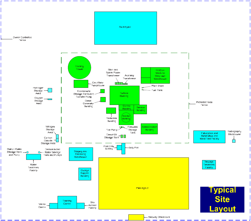
5
FIG. 1. Typical site layout.
6
3. PRE-PROJECT (PRE-DEPLOYMENT) AND
SITE INFRASTRUCTURE ACTIVITIES
3.1. ACTIVITIES RELATED TO INFRASTRUCTURE AND LAYOUT FOR SITE CONSTRUCTION
The discipline of construction management includes significant planning and control of the construction site
infrastructure and layout. Effective managers use their experience and foresight into the specific construction
activities to ensure that site layout allows for smooth movement of personnel, material and equipment.
As large capital projects have become more complex and pressures to reduce construction schedules have
intensified, the ability to effectively plan across an entire construction life cycle has become an activity performed
by an experienced staff of logistics and planning personnel. The ongoing decisions regarding critical construction
activities throughout the construction sequence have been enhanced by careful preplanning.
Advances in material flow modelling, construction sequence modelling, scheduling tools, construction
equipment and personnel equipment have had a significant positive impact on construction efficiency and safety
since commissioning of the first generation of NPPs.
3.1.1. Background to early site planning and development
Typical advanced water cooled reactor plants have, as a minimum, the following significant site planning and
development phases of work: (a) site development; (b) supply-chain infrastructure; (c) off-site management of
module fabrication; (d) module delivery, assembly and outfitting; and (e) power island construction. A major part
of the work involved in prefabrication and pre-assembly of modules, requires a near fully developed site
infrastructure to support the offloading, assembly and outfitting to exact standards before first nuclear concrete. To
support the ‘open top’ construction method, new NPPs need at least one very heavy lift (VHL) crane. All module
lay-down areas are required to be ‘hardstand’, fully trafficable and heavy load capable, since the modules are
engineered lifts, weighing many tons. A significant area, potentially several hectares, is required for storage,
prefabrication and pre-assembly of modules. This was not the case in stick-build construction methods previously
used in NPP construction.
A key attribute of an advanced NPP is an optimized construction schedule, with off-site module fabrication
reducing significant labour person-hours on the site, but requiring full assembly of modules before their
installation. This module assembly and outfitting will require support facilities to be planned and constructed to
reduce craft personnel power in the power island work execution. If the site development is incomplete, it will
affect the length of the construction schedule. Therefore, the site development schedule is one of the most important
aspects of NPP schedules. Early investment in infrastructure gains extraordinary savings in valuable time, and
possibly cost, for the execution of the power island work.
For a multi-unit plant site, an integrated plan needs to be in place to optimize construction work associated
with excavation, crane placement and usage.
If lay-down areas for storage, prefabrication and preassembly of modules become a premium and are not
available, the site construction schedule will be detrimentally affected.
Excavation of the power block is concurrent with site preparation, but it is recommended that it be completed
before site development.
Exacting studies and logic sequencing are necessary for planning ‘maximum radius’ crane locations,
‘maximum area’ hardstand stick-build lay-down areas, ‘maximum pre-work’ lay-down areas and ‘maximum’
heavy haul paths to the VHL crane. Near the VHL crane, a ‘maximum’ platen space for assembly of the
containment rebar mat, containment vessel, modules and other pre-assemblies must be catered for.
3.1.1.1. Prerequisites
It is recommended that the following be completed prior to commencement of site development and plant
construction:
7
— Subsurface (soils and bedrock) testing and analysis to assess site optimum location;
— Environmental assessment;
— Site survey, monuments installed and site survey control programme established;
— Detailed transportation study to and from the site for modules, equipment and personnel;
— Any upgrades and load testing of routes required to handle the traffic and heavy loads of existing roads,
bridges or overpasses and barge offload facilities; railroads;
— Any significant cuts and fills necessary to provide a flat and level site free of encumbrances and obstructions;
— Design for both permanent and temporary construction facilities;
— Electronic three dimensional (3-D) model for all permanent and temporary sites, structures and components.
All utilities, trenching and excavations are entered into a 3-D model that is compatible and interfaces directly
with the existing model for design and construction of the new NPP. Complete designs are incorporated and
checked for interference prior to commencing construction. Design changes will be kept current in the electronic
model. This 3-D model is used in developing the detailed site development schedule and cost tracking. It is essential
that temporary and permanent utilities are designed and constructed in utility corridors at elevations entering the
power island and that they are planned for effective installation and life cycle maintenance. Most importantly, it is
essential to avoid any haphazard or uncoordinated installations that could impede safety, quality and production at
elevations requiring multi-levels of installation outbound of a plant boundary.
It is recommended that permanent and temporary site drainage be designed in such a way that the new NPP
site is ‘waterproofed’ and/or protected against regional natural phenomena in order to quickly recover after
inclement weather and not subject the construction schedule to unnecessary delays.
The design must take into consideration requirements of all the units so as to not interfere with each other’s
construction, i.e. cranes, and the resulting security requirements between an operating unit (the first unit) and the
second unit under construction.
It is recommended that equipment and material be specified and procured in sufficient time to avoid
‘just-in-time’ material and equipment deliveries. They should typically be on site six months prior to the scheduled
installation date.
Facilities and systems including the following should be in place well ahead of time as part of the pre-project
activities:
— Mechanical fabrication shop;
— Electrical fabrication shop;
— Paint shop and blast booth;
— Embedded parts shop;
— Testing laboratories;
— Equipment repair and refuel facility;
— Temporary electric power grid;
— Temporary dewatering system;
— Construction air system;
— Distribution and storage of gases used for construction;
— Temporary sanitary system;
— Batch plant, mix designs;
— Heavy lift designs, lifting points, rigging frames;
— Soil stabilization designs;
— Construction control room;
— Module assembly and system outfitting shops;
— VHL crane foundations;
— Storage areas.
3.1.1.2. Site development schedule
A detailed schedule must be developed to integrate all site development activities with the overall
construction schedule. Environmental controls must be established, including outbound site drainage; debris basins;
8
storm water and erosion interceptors; and solid waste areas. It is recommended that permanent sewage treatment
and potable water treatment facilities are completed and ready to support the construction workforce. Protection of
the entire construction from any accidental events must form part of the site development imperatives. Finally, it is
recommended that all parking; temporary fabrications shops; warehousing; roads; batch plant; blast and paint shop;
construction equipment repair; and refuelling facilities are completed to support the construction schedule.
Labour housing facilities need to be constructed in remote sites to support the construction labour force/phase.
3.1.2. Excavation plan
3.1.2.1. General excavation
A detailed integrated excavation plan must be developed that provides excavation and backfill for the entire
site and the power island. This excavation plan needs to be developed, finalized and incorporated into the Site
Development Project Schedule. The plan should include requirements for equipment methods, soil stabilization,
dewatering, rock removal and backfill. It should detail the required construction equipment personnel power and
materials. It should also include the source of backfill materials as well as the location for the economic disposal of
spoil materials. Excavation needs to be modelled and planned. For example, a soft-soil site may require excavators
and conveyors for excavation and backfill, instead of tracked and wheeled earthmoving equipment. Site excavation
must not impede site development. Deep excavations may need non-traditional excavation methods; e.g. conveying
excavation material to a conveying system running to a long distance spoil area. The same is true for aggregate and
site ‘borrow’ pits.
3.1.2.2. Nuclear power island excavation, backfill, and waterproofing — site conditions
Site development, including installation of utilities, roads, rail spurs and construction facilities, must begin
well before Nuclear Island excavation. All access and egress paths, soil removal procedures and equipment should
have been in place for several months prior to the start of this work.
The new NPP common and yard schedule must show underground piping and utility corridors completed
away from the VHL crane path adjacent to the plant. With the underground utilities complete, backfill and
compaction of the VHL crane path should normally be completed prior to start of excavation.
Site conditions will also dictate the duration of this activity. On the worst possible sites, soil improvements
should take place prior to the start of dewatering. Soil stabilization at the bottom of the excavation may be necessary
to establish a compacted base under the base mat raft.
3.1.3. Temporary services, facilities and assembly areas
3.1.3.1. Services
Gases
Bulk gas tank facilities should be installed early for use during construction and preliminary work.
Underground gas piping should be extended from a permanent plant bulk gas station to distribution points near the
plant facilities; fabrication shops; and module assembly and outfitting areas, in coordination with the installation of
other underground lines and roadways.
Bulk gas tanks should be provided for:
—Argon;
— Acetylene/MAPP gas;
— Oxygen;
— Nitrogen;
— Propane;
— Other gases as required.

9
Compressed air
A temporary air compressor area with underground pipe extended to the building construction and assembly
areas should be made available before major pre-assembly and vessel fabricators arrive at the site.
Electrical power
A complete evaluation of total electrical power demands for construction, startup and testing needs to be
performed during final engineering. It will include temporary transformer sizing and locations necessary to support
the total construction effort for both single and twin installations. The study should also include sufficient
temporary power to supply all early startup testing. Power lines should be installed during the early part of the site
development schedule. This work needs to be coordinated with the piping and road base construction. By installing
temporary power conduits with the designed power, effective power corridors will be established for safety, ease of
location identification, and maintenance and life cycle costs.
Equipment refuelling support
Fuel (both diesel and gasoline) is normally used throughout the construction site. Temporary storage facilities
are needed, as well as appropriate precautions to avoid fire problems. Fuel delivery trucks need to transfer fuel to
large cranes and other construction equipment, therefore provision for their mobility and parking must be made
upfront.
Demineralized water supply
Temporary truck or rail-mounted demineralizer equipment may be used for early demineralized water supply.
Permanent demineralized water systems should be scheduled on-line as soon as possible.
3.1.3.2. Facilities
Temporary construction administration building
Design criteria should be site/owner specific, based on the owner’s future plans for the building. In many
cases, this building remains after the plant is completed, and is converted into a permanent structure.
The administration building could be sized to meet future needs as well as construction needs.
Construction support facilities
The temporary construction support facilities must be available and operable prior to the start of the
construction schedule. The proposed facility should contain office and storage space, meeting rooms and washroom
facilities for the construction staff.
A designated contractor area with temporary trailer type facilities is normally used at an early stage, to
support the first buildup of personnel on site. The facility for the construction staff must be completed
approximately six to eight months prior to first nuclear concrete base mat raft placement. Along with the temporary
construction support facilities, construction parking lots must be established in close walking proximity to the mass
of work. The contractor parking areas are to be placed outside of the perimeter fence, with limited access gates for
people and vehicles, and with craft badging or brass shacks.1
1 ‘Craft badging or brass shacks’ means that access to different areas is restricted to people with certain skills.
10
Construction parking
Construction parking must be designed and laid out to facilitate safe and rapid ingress and egress. Safe
pedestrian paths must be provided, and the design must be reviewed to avoid creating blind spots for drivers exiting
and entering the site during periods of darkness.
On-site concrete batch plants
Site development concrete quantities need conceptual design for accurate quantification. Most of the concrete
activities in new NPPs are on the critical path, and must be constructed as parallel activities with numerous concrete
placements occurring site-wide on the same day. Essentially, all concrete structures are built concurrently. Concrete
thus becomes a critical material commodity. The location and sizing of the site batch plant, as well as a backup plant
in close proximity, are critical to the success of project. One primary batch plant must be designated and the other
backup plant should be of the same type and capacity.
Material handling and warehousing
Of major importance, prior to the start of construction, is a materials management programme, which includes
written procedures as well as procurement, indoor warehousing, outside storage and material staging areas. The
warehouse plan must make provision for sufficient office space for warehouse administration and materials
management personnel, as well as for a central warehousing coordinator for all site subcontractors.
Bulk and module material hardstand lay-down and storage areas
In conjunction with the warehouse facilities, space is required for exterior storage and lay-down areas. The
amount of pre-work, such as prefabrication, pre-assembly and module assembly, demands that dedicated lay-down
be as close to the power island as can be accommodated. This type of lay-down area should also be located as close
as possible to the incoming plant road and railroad unloading facilities.
Fabrication shops and facilities
On-site fabrication shops may be necessary to support the project; but it is more effective to avoid on-site
fabrication. In order to avert schedule delays due to late material deliveries, operational site shop facilities will need
to be available to fabricate and assemble modules; and to rework or modify miscellaneous metals, pipe, tray, HVAC
duct, reinforcing steel and embeds as required. Due to the multiple use capability of the fabrication shop, it should
be equipped to support all types of metal fabrication.
Site temporary medical facility
As early as reasonably possible, a temporary site safety office must be established to serve as the site location
for receiving first aid, and as offices for the site safety and medical staff. If the new NPP is located on an existing
facility, there may be medical services present. Again, construction work necessitates close proximity of the site
safety office.
On-site testing facilities
To meet the fast-paced building schedule, on-site testing facilities, such as a concrete testing laboratory, are
needed. A recommended location of the concrete testing laboratory is adjacent to the primary concrete batch plant.
The test laboratory performs daily monitoring of concrete batch plant operations. In addition to concrete testing, the
facility should accommodate soil testing and rebar testing. This is necessary for random selection, testing and
monitoring of rebar as it arrives on site. In addition, any types of mechanical rebar splicing mechanisms used are
required to be randomly tension tested.
11
The test facility should have (a) sufficient welding booths with appropriate welding equipment and testing
equipment to perform on site welder qualification for contractors, and (b) areas for certifying tube bending.
3.1.3.3. Assembly areas
Equipment and module assembly erection and lift areas
A significant area of the construction site in close proximity to the containment vessel and heavy lift crane
will be dedicated to equipment and module lifts to support the open top construction method for large equipment.
Additional area is required for support of major critical path on-site activities such as equipment and structural liner
assembly and storage; and containment vessel subassembly and storage. Heavy load capable hardstands with
cribbing are required for each assembly. All areas must be provided with a full complement of temporary
construction air and electric services. Consideration should be given to the use of multiple storage locations as
needed to ensure smooth movement of pre-work, and to avoid interference with adjacent unit work.
Containment vessel subassembly area
An area needs to be reserved for subassembly and erection of the containment vessel sections. The assembly
area needs to be available a minimum of many months prior to the placement of the first structural concrete base
mat. Lay-down must be hardstand heavy load capable, and highly trafficable.
Areas for module assembly, haul, and/or lift
This area is reserved for the assembly of large modules for advanced NPP technologies. It is therefore
recommended that this assembly area be complete and available with all services almost a year prior to first
concrete, and in close proximity to the VHL crane. Module assembly and lift areas are required to be heavy
trafficable hardstand and heavy load capable. More than one area may be required, depending on the number of
units being built on a single site.
Spoils, rubble, structural soil backfill borrow pits
A part of the site specific engineering design will be to locate a ‘spoil’ pile area. This is for excess and
unsuitable soil removed during top soil stripping, grading and excavations. The spoil pile area should have as short
a haul cycle time as possible. The size of the area can be determined by specific selection and review of soil tests.
3.1.4. Equipment
3.1.4.1. Heavy lift crawler type or ringer crane requirements
A single VHL crane is normally required for construction of new NPPs by open top construction of modules
and heavy equipment. It requires a foundation at grade, well before first nuclear concrete. Heavy-load prime mover
transporters are required to carry the modules and other heavy lifts from the assembly area to the VHL. Some of the
heavy lifts include the containment vessel heads and rings; large steel and equipment modules; large building space
frame modules; equipment modules; components of the NSSS; and turbogenerator components.
3.1.4.2. Heavy construction cranes
A crane study must be performed to determine the number and size of cranes required to support critical path
construction of each advanced NPP. Each site must be evaluated in detail. A scheduled Crane Usage Report must be
developed and integrated into the overall critical path of the project. Heavy crane pathways must not be interrupted
by underground utility installations. The key to an unimpeded power island construction schedule is early site
planning for underground utility development of underground systems.
12
3.2. METHODS FOR PREPARING SITE INFRASTRUCTURE AND LAYOUT FOR SITE CONSTRUCTION
3.2.1. All-weather and around-the-clock construction
Construction work is affected by the weather; e.g. snowfall, rainfall, low–high ambient temperature, strong
sunlight and high wind, especially at a site in a severe climate. The influence of the weather is one of the possible
reasons for delays in a construction schedule. Modularization and open top construction are advanced methods for
facilitating the construction of the NPP. However, these methods require the construction space to be open in order
to lift in modules/heavy components. An innovative method of managing these advanced construction methods,
compatible with severe climate conditions at a worksite, should be considered.
To assure that work can be conducted continually, an ‘all-weather’ construction method may be applied to the
major buildings of the NPP to protect the worksite from weather conditions. The all-weather construction method
provides an environment that is enclosed and isolated from the ambient weather, and is equipped with cranes and/or
hoists to install rebar, forms and mechanical bulk commodities. The all-weather construction method shall not
prevent modular construction and open top construction, even though the building has temporary enclosures.
The all-weather construction method was used in Japan at Kashiwazaki-Kariwa Unit No. 6 for the reactor
building; and at Higashidori Tohoku Electric Power Co. Unit No. 1 for the reactor building, the turbine building and
the auxiliary building. In this method, the side of the building is protected by a tent attached to the steel frame.
Either temporary or structural steel can be used, which is taken into account in the building structure design.
A temporary roof on a steel framework covers the entire building. The roof over the containment in the reactor
building should be fully movable to provide space for the steel liner module, piping modules and the heavy
components inside the containment to be lifted by open top. The roof can be moved using a VHL crane located
outside the building, or be transported on rails using motor/manual winch operation. The roof over the perimeter of
the containment in the reactor building consists of temporary steel, such as deck steel plates that also can be moved
when equipment is lifted with the VHL crane, using the open top method.
Monorails and overhead cranes installed inside this temporary structure are used to bring in smaller items of
equipment and materials. This horizontal and vertical lifting equipment is installed crosswise to handle rebar,
forms, embedment as well as small equipment and materials. As the overhead crane in the turbine building has a
wide range to lift, it is a good idea to pre-install the overhead crane in the all-weather steel frame. The heavy
components in the turbine building; e.g. feedwater heaters and pumps, can be installed using the overhead crane,
without moving the temporary roof. In the construction of the Higashidori Tohoku Electric Power Co. Unit No. 1,
the overhead crane in the turbine building was pre-installed and used to install the condenser modules.
Permanent staircases are pre-installed inside the all-weather structure, allowing the construction crew easy
floor-to-floor access during construction.
The all-weather construction method improves productivity during the unfavourable season for construction.
For example, in winter, the all-weather construction method protects the process from snowfall, cold wind, low
temperature and snow shovelling at the workplace. Labourers do not need to wear excessive clothing in bad
weather conditions. The all-weather construction method provides a factory-like environment, which is especially
useful to secure the environment and the quality for concrete pouring and curing, and welding. It also protects
equipment installed through the open top construction. The monorails/hoists and cranes installed inside the
all-weather steel frame provide for efficient handling of components and materials without the delays that are often
experienced with the tower crane method.
This construction method brings activities that used to be conducted outdoors, indoors; e.g. the construction
of buildings and the installation of the primary containment vessel.
To optimize the entire schedule, the all-weather construction method requires elaborate and detailed planning
and engineering. The steel frame needs to be coordinated with the permanent structural components, even if it is
designed as temporary. The steel arrangement needs to be coordinated with the lift of the large components. When
components interfere with the steels, they have to be removed during the lift, and restored. The embedments must
be designed early, in order to pre-cut holes in the steels for running pipes/conduits. This means that the entire design
schedule must be approximately six months ahead. This method has potential for worldwide application in the
building of new NPPs. Figures 2 and 3 show some examples of all-weather construction.
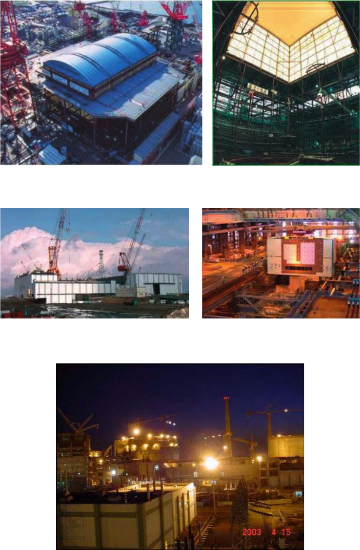
13
Working around the clock (shown in Fig. 4) in critical areas of shop and plant erection can save considerable
time; e.g. during excavation, concrete pouring, structural steel erection, calandria vault construction and various
welding activities.
FIG. 2. All-weather construction for reactor building, Kashiwazaki-Kariwa, Japan.
FIG. 3. All-weather construction for power block, Higashidori Tohoku Electric Power Co., Japan.
FIG. 4. Night view of site activities, Tarapur, India.
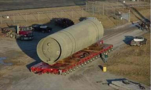
14
3.2.2. Construction personnel mobility
Construction workforce productivity can be enhanced with mobility tools. Construction workers must travel
in both horizontal and vertical directions to perform tasks; obtain tools and materials; and gain access to personal
services.
Vertical travel has conventionally been supported by the erection of temporary scaffolding, which requires
certified carpenters and adds significantly to project scheduling and planning issues. Scaffolding may also need to
be retained in place for some time, unless it obstructs work below.
Mobile scissors lifts and bucket trucks can be used very effectively to allow work at vertical height without
the use of scaffolding. Many products that address this need have entered the marketplace in the past ten years.
These products are used both in construction and in the operation and maintenance of facilities.
Horizontal movement on site can be best addressed by shortening the travel distance. Access to personal
services such as tool sheds, toilet facilities, wash water, drinking water and break facilities is one area in which
travel distance can be reduced. This reduces distraction and keeps construction personnel focused on productive
activities.
Mobile communication systems are another method of reducing on-site travel time. On-site 3G networks,
digital hard hats, hand held personal digital assistants (PDAs) and other smart devices allow labour and supervision
personnel to move through and between tasks without needing to return to a remote construction control point.
3.2.3. Transportation
Three approaches are commonly used for constructing NPPs: stick-build, modularization and a combination
of modularization and stick-build:
— In the stick-build approach, the material is moved in small quantities, mostly using the site tower cranes;
— In the modularization approach, modules are built in accordance with the directions of construction based on
ability to receive and install modules;
— In the combined approach, utilizing modularization and stick-build, the material is moved in both small
quantities and according to the ability to receive and install modules.
The modular concept will be discussed in Section 8. There are several possible methods for transport of
modules. The advantages and disadvantages of each are discussed in the following paragraphs.
3.2.3.1. Heavy haul path
Figure 5 shows a heavy haul transporter.
FIG. 5. Heavy haul transporter.
15
Advantages:
— Shipping and use of a heavy haul path is a standard and accepted method of moving large pieces of
equipment. The difference in this instance is that this method would be used to a much greater extent, due to
modularization. As an example, the latest advanced boiling water reactor (ABWR) now has over 200 modules
per unit, with the largest weighing up to 940 t. Continued assessment of additional modules is being
contemplated as part of technology development.
Disadvantages:
— A barge unloading facility must be available or constructed;
— A heavy haul road must be constructed to the site from the barge facility.
In the past, a barge facility with a large bridge crane would be constructed for offloading equipment from
barges onto the lay-down area. Current methods consist of hydraulics and multi-wheeled heavy haul carriers to
move the load off the barge onto the lay-down area and into the construction area.
3.2.3.2. Railroads
Advantages:
— Railroads can typically haul heavy loads more efficiently than trucks;
— Railroads require less manpower to haul material than trucking.
Disadvantages:
— Railroads are not available at all sites;
— Railroad loads are width and weight limited;
— Loads on railroads must be offloaded from each rail car;
— Railroads must be scheduled for use per the railroad schedule in conjunction with the construction schedule.
3.2.4. Construction management centre
In past projects, construction control was generally dominated by word of mouth reporting and periodic face
to face meetings of interfacing organizations. Current best practices place all organizations and functions into a
central command centre fed by real time progress status. Visual, statistical and data-centric views of the
construction effort are projected and/or accessible on workstations in the control room, and interfacing
organizations work in real time to resolve problems, interferences and resource shortages.
Communication between workers was previously by word of mouth and predetermined meetings. Then voice
communication systems such as the GAI-Tronic system were installed in the plant. However, these systems were
inefficient due to background noise and constant unregulated use.
The construction command centre can be modelled using the latest technology to provide direction and
control of real time field activities; tracking of equipment; and visual and daily debriefing with field personnel
while in the field.
Figures 6 and 7 show examples of a construction command centre.
A critical element of the construction control room that has provided significant benefit is the detailed 3-D
design model of the plant, along with its databases of design detail. The 3-D model provides the command centre
with immediate access to a visual representation of the completed work, along with detailed information about the
attributes and requirements of the design. The model allows a virtual walk-through and pre-job planning before the
start of critical installation activities. Rigging and material movement analysis can be performed, and problems can
be identified and rectified before they are encountered in the field.
Videoconferencing technologies have developed significantly in the past ten years, and are now able to handle
the data streams required for remote viewing of 3-D models while connected in a conferencing mode. New systems
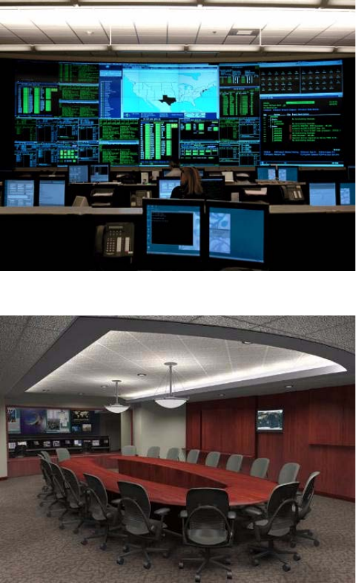
16
can be installed at a site and at other key project locations to aid and greatly enhance communication among project
participants.
Another best practice currently used in construction control for large capital projects is the real time
management of the critical path. With the benefit of highly detailed construction plans showing the interrelationship
between activities and the resources required for each task, construction managers can focus attention on those
issues and activities that have the greatest impact on the ultimate date of completion of the entire project. Critical
path management techniques have been used to achieve significant reductions in outage times for operating
facilities during maintenance and refuelling. Similar real time attention to construction progress along the critical
path of a project helps ensure on-time completion, and avoid the significant cost of construction delays.
Barriers to promulgation are a lack of familiarity with these world class planning and scheduling tools, and a
lack of willingness of construction entities to effectively use them in a day to day, hour to hour progression
throughout an entire multi-year project. Another hurdle could be the reluctance of organizations or entities to work
collaboratively in a central control room environment. Contractual relationships and concerns over scope, risk and
liability control for an individual entity may drive that entity to work more independently and manage the interface
with other entities at only a very high level. In this scenario, construction problems remain hidden for a period of
time before being evaluated and resolved by the best available resources.
FIG. 6. Construction command centre I. (Credit IBM/Exelon)
FIG. 7. Construction command centre II. (Credit IBM/Exelon)
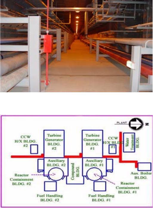
17
3.2.5. Underground common tunnel
Figure 8 shows an example of an underground common tunnel (UCT) at Shin-Wolsong 1 and 2 in the
Republic of Korea, and Fig. 9 shows its location.
Purpose
The main purpose of constructing a UCT is to enhance the construction activities at the construction site:
— To prevent the delay and frequent change in construction schedule resulting from repeated site excavation and
refilling due to mutual interferences among underground utilities;
— To provide the construction pathway over the tunnel to transport equipment and construction materials at an
early stage;
— To provide easy access for maintenance and inspection of piping leakage for underground utilities;
— To facilitate the construction activities inside the UCT regardless of the power block construction schedule.
Configuration
The UCT is structured as follows:
— Rectangular cross-section;
— Straight run type passing through Turbogenerator Building of unit numbers 1 and 2.
FIG. 8. Underground common tunnel in a nuclear plant, Republic of Korea.
FIG. 9. Location of underground tunnel (underground tunnel in bold red).
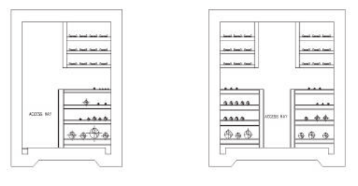
18
The major components of the UCT are:
— Process piping;
— Fire protection piping;
— Domestic water piping;
— Raw water piping;
— Auxiliary steam piping;
— Power cable tray;
— Control cable tray;
— Instrument cable tray;
— Communication cable tray;
— Automatic fire detection facility;
— Lighting facility;
—HVAC duct.
Effects of improvement
— Decreases the amount of construction work;
— Enhances the convenience of maintenance and inspection by providing easy access;
— Maximizes the site efficiency by reducing plant area and the length and volume of the UCT;
— Minimizes interference among other underground utilities and improves constructability.
Remarks
Multiple layered piping runs with common support
In order to maximize space efficiency, common supports are installed instead of individual support, as shown
in Fig. 10.
Construction opening
Permanent construction openings are provided at the proper locations to transport equipment and construction
materials into the UCT and prepare for maintenance.
3.2.6. Site mapping and measuring
3.2.6.1. Conventional methods
Before deforestation and grubbing begin, the location where a facility is to be constructed is measured by
surveying (a) existing conditions, including topography; (b) existing buildings and infrastructure; and
FIG. 10. Multiple layered piping runs with common support.
19
(c) underground infrastructure. The construction surveying establishes a layout of reference points and markers that
guide the construction of new structures. These markers are usually staked out according to the arbitrary coordinate
system used for the project at the particular site.
The coordinate system is an arbitrary system of axes established to correspond to the rows of columns and the
major load-bearing walls of the building. The axes are typically identified alphabetically in one direction and
numerically in the other direction. They are usually but not necessarily perpendicular, and are often but not
necessarily evenly spaced. Floors and basement levels are also numbered. Structures, equipment or architectural
details may be located in reference to the floor and the nearest intersection of the arbitrary axes.
As a structure is erected, reference points and markers on a layout are marked or mounted in the structure for
measurement, from which the placement of equipment, piping, ducting, raceways and conduits, as well as other
items is measured. These markers are typically established by a transit, which is an instrument for measuring both
horizontal and vertical angles, as used in triangulation networks. The instrument consists of a movable telescope
mounted within two perpendicular axes: the horizontal or trunnion axis, and the vertical axis. When the telescope is
pointed at a desired object, the angle of each of these axes can be measured. Starting from these ‘surveyed’
reference marks of known location and elevation, the construction crews measure the distance and angles to the
unknown point where the equipment, piping, etc. is required by design to be placed.
The basic tools used in this layout measuring are a tape measure for determining shorter distances, and a level
for determining height or elevation differences. These methods are dependent on many variables that affect the
precision of the measurements. When the installation of the equipment, piping, etc. is completed, an as-built survey
is conducted to verify that the work has been completed to the dimensions and specifications set on the design
plans. The design drawings and calculations (loading, seismic, etc.) need to be revised if installation is not within
required tolerance. Otherwise, the installation requires disassembly and reassembly to correct.
As discussed in the following paragraphs, technology has advanced to enable a shift from optical-mechanical
devices to fully electronic devices, with an onboard computer and software with electronic distance measurement
(EDM) and levelling device. Modern instruments can electronically connect to design databases and communicate
with positioning systems.
3.2.6.2. Advanced methods
Laser and global positioning system mapping
The use of lasers and GPS equipment for surveying, grading and excavating is becoming the norm on large
construction projects. The GPS control system is designed to offer contractors tools for improving accuracy,
efficiency and overall project productivity on the worksite. The precise GPS technology allows construction
professionals to significantly increase productivity and efficiency. Machine operators using GPS can accurately
perform earthmoving work at construction sites, reducing operator fatigue and improving material usage. The
GPS’s automatic controls option uses leading-edge technology to connect the GPS to the machine hydraulics. The
GPS position and design information allows the earthmoving blade to be automatically controlled to the exact
elevation and cross-slope, providing significant improvements in both productivity and accuracy.
On-board GPS receivers allow scrapers, dozers and graders to plot accurate courses with little or no reference
to in-ground markers. Light bars mounted in the operator’s field of vision signal proper blade angle as the machine
moves, while a video display shows the proper cut or fill on the worksite. Equipment operators work with a
computer screen inside the cabin and know where the blades are within a fraction of a centimetre. The immediate
benefits are speed and extreme accuracy. Productivity is improved by at least 30% with higher quality results.
Grade tolerances are between 3 cm and 0.3 cm.
Utilizing GPS guidance eliminates the need for supervisors and foremen to reset stakes. Instead, they can
concentrate on monitoring the work, haul routes and cycle times. Pickups equipped with GPS can be used to send
progress data to the construction control room so that estimators can check actual progress and productivity against
the original schedule. Real time information allows for more effective monitoring of the job; detailed and accurate
management of individual pieces of equipment; and more precise cost analysis. Earthmoving operations are safer
because less time is spent on the job and fewer people are involved. The cost of the technology is offset by gains in
efficiency and productivity.
20
Inertial technology senses changes in motion and is primarily used when GPS signals are obstructed. Starting
with an initial location based on a landmark, inertial technology uses accelerometers and gyroscopes to determine
the successive position based on movement. Inertial technology complements GPS and is currently used for aerial
photogrammetry, vehicle tracking, high-end road construction and marine applications.
Total stations
Modern total stations make use of electronic theodolites, EDMs and a data collector to lay out the
construction site by locating each necessary point, such as the location of an anchor. This was previously
accomplished by using optical equipment, steel tape measurement and trigonometric calculations. Technology has
allowed the process to become simpler, more automatic and more accurate.
Electronic theodolites, which have been used on many construction sites, measure the angle from the set point
to the location. EDMs use lasers to measure the distance from the set point to the location. The data from the
theodolites and the EDMs is then fed to an external computer used as a data collector to record the locations on the
construction site.
Robotics can be applied to total stations to take the technology one step further. Measurements are typically
taken by two people: one person holding a rod at the location to be measured, and the other operating the total
station. By adding radio communication and servo motors to the total station and receivers to the rod, the total
station can automatically follow the rod and take the required measurements. Therefore, only one person is required
to control the total station by marking each point, and controlling the total station and receiving data wirelessly.
Data collectors have also advanced from simply processing and displaying the data points, to identifying
required measurements. Data collectors are shaped like a hand held calculator with a small computer screen, and
plug directly into the total station. Computer-aided design (CAD) files can be downloaded into the data collector, or
coordinates can be loaded for each point to be laid out in the field. Computer software is also available that
identifies the points needed to be laid out from downloaded plans. When the data collector is plugged into the
instrument, the total station directs the person with the rod where to move the rod in order to find the point.
Underground metal detection
Past and future practices on greenfield and brownfield sites require excavating with a backhoe or similar
equipment, with the potential risk of hitting an underground utility and causing serious injuries and expensive
damage. Several methods are used to prevent these occurrences, all of which are time consuming, labour intensive
or both. Hand held sonar and the removal of material with a vacuum truck are some of the methods used.
Electronic devices provide a real time warning of the presence of utility lines, metal piping and wells
immediately ahead of the digging tool, as well as an easily interpreted, real time computer readout of the depth,
location and size of buried metallic objects. The electronic device is hooked to a warning light and buzzer, which
will notify the operator in advance of contacting buried underground utilities.
3.2.7. Computerized concrete batching plant
Computerized concrete batching plants of various capacities ranging from 20–60 m3/h were used in the
construction of Tarapur NPPs 3 and 4 in India, shown in Fig. 11. The advantage is that good quality concrete can be
produced on a continuous basis, with no human error. Once a concrete mix design is finalized, parameters are set in
the computer, and cement, sand, concrete, water or ice, micro silica, etc. are automatically drawn in required
proportions. Loading of cement to cement silos and transfer of concrete to the mixer are also automated to save
operational time.
3.2.8. Shop fabrication mock-up
At Tarapur 3 and 4, the shop fabrication was optimized at approximately 70–80%, and full-scale mock-ups
were used to save on actual work time. Figure 12 shows mock-up work for one of the critical activities: feeder pipe
installation. This resulted in a saving of almost 50% in erection time.
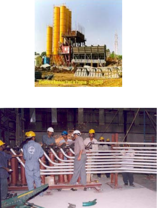
21
3.2.9. Three dimensional modelling
Three dimensional (3-D) modelling is an advanced software design tool that can be used to design the entire
power plant, and produce interference-free drawings with a correct bill of materials (BOM) and bill of quantities.
Figure 13 shows one of the models developed using this advanced technology. Construction sequences can also be
derived from this model.
Figure 13 gives a comprehensive view of a nuclear reactor, showing the layout; position of valves and
equipment; headroom available; and approachability and maintainability of equipment. With this advanced
modelling tool, the functional requirements can be fully understood and the aesthetics of the layout can be
appropriately addressed.
There are two ways of developing a 3-D model:
— It can be developed during early design stages so that the entire plant can be designed using available software
such as the plant design management system (PDMS) or equivalent;
— There would be cases where the vendor already has a design with approved two dimensional (2-D) drawings
that need to be partially modified to account for country specific requirements. In such cases, it is
recommended that the design drawings are input to the 3-D modelling software to derive the required
modifications.
The only disadvantage in using 3-D modelling is that considerable time is needed to develop interference-free
plant layout, to work out the BOM to be procured, and to develop ‘working drawings’ to be used in the field.
FIG. 11. Concrete batch plant at Tarapur 3 and 4 sites (India).
FIG. 12. Mock-up work for feeder pipe installation at Tarapur, India.
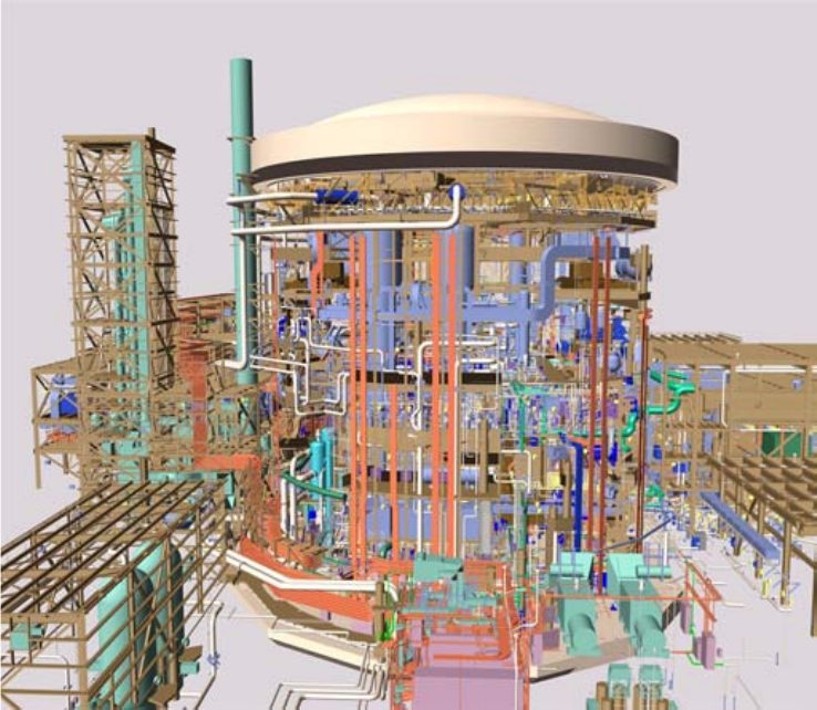
22
FIG. 13. Three dimensional computer model for Qinshan (Credit AECL).
23
4. CONSTRUCTION ACTIVITIES AND METHODS OF
GENERIC APPLICABILITY TO ALL BUILDING GROUPS
4.1. CIVIL AND STRUCTURAL WORKS
4.1.1. Discussion of civil and structural works activities
Civil and structural works are a critical part of the construction of NPPs. The civil works is the longest activity
on the critical path in the construction phase of the schedule. It follows or is part of the site development phase, and
begins with the mass excavation of the NPP buildings and facilities. In some jurisdictions, excavation is part of the
pre-project phase.
After the mass excavation, the civil and structural works continue, with excavation of the foundations and
carrying out of remedial measures, if required. During the mass excavation, the rock and soil slopes are stabilized
for the safety of construction works. This is followed by the construction of the foundations, superstructure, yard
services, backfilling, permanent roads, paving and final landscaping.
Significant civil and structural activities include:
— Protective works against tsunami, flooding, tidal wave breakers; etc.;
— Construction of erosion control and surface runoff systems;
—Excavation;
— Earth/soil/rock removal and/or disposal;
—Site dewatering system set-up;
— Remedial measures on foundation soil/rock;
— Rock/soil slope stabilization;
— Building under drainage and peripheral drainage;
— Foundation works;
— Concrete superstructure;
— Structural steel fabrication and erection;
— Yard services, including storm drainage and sewage system;
— Backfilling works;
— Roads and landscaping;
— Permanent security installations, which are normally set-up as other than civil construction.
The finishing architectural works are also part of civil and structural activities. However, most of this work is
performed after the completion of the mechanical and electrical works, and is not included in this document.
4.1.2. Construction methods for conducting civil and structural works
4.1.2.1. Excavation
Excavation consists of the removal of material from the plant grade elevation to accommodate the plant’s
permanent buildings and facilities. The material can be rock or soil, or a combination of both.
Excavation is performed in accordance with the mass excavation drawings. The mass excavation outline
usually encompasses the footprint of the main plant buildings and the circulating water system.
Conventional methods
The conventional excavation methods consist of using tracked bulldozers and scrapers, supplemented by
excavators and front-end loaders, to remove the soil. Localized rock may be removed with ripper blades on the
bulldozers. However, mass rock excavation requires blasting. The excavated material is either stockpiled for use in
constructing the roads, or as large aggregate in the concrete mix, or disposed of.
24
Main advantages:
— Sophisticated machinery is not required;
— Specialized explosive material is not required;
— Can be used in all countries.
Main disadvantages:
— A longer schedule is required to perform the required excavation works;
— Generally, the base of the excavation, particularly applying to rock foundations, is not smooth and requires
make-up work prior to placing the foundation, thus further extending the schedule;
— Considerable non-manual manpower is required to monitor and control the process.
Advanced methods
Advanced excavation methods such as precision line blasting and chemical foam expansion for breaking rock
are described in the following paragraphs. These advanced methods are being used with the rapid development of
computer based systems to plan, implement and monitor mass excavations. These systems enable extensive use of
aerial photogrammetry to map existing contours, use of lasers for elevation control, and use of surveying ‘total
station’ instrumentation.
Advanced equipment for excavation
Recent increases in the size of equipment used for excavation will improve the ease and efficiency of earth-
moving. Some examples are large excavators designed for heavy workloads; massive grading and material
handling; and large equipment for vibratory soil compacting.
Precision line blasting
Precision line blasting is a mature and well-understood technology. It is an excavation method with many
applications outside of NPP construction, including construction of roads and excavation for large structures. For
NPP construction, precise use of explosives for excavation of rock instead of the more conventional mechanical
excavation methods can reduce excavation costs for the reactor building, turbine building and other buildings.
Several shafts are drilled in the necessary pattern in the area to be excavated, filled with explosives, and then
detonated. The selection of this process for excavation is dependent on site geology and plant design, as well as
regulations governing blasting.
Chemical/foam expansion for breaking rock without blasting
Where blasting is required to excavate and trench through rock at sites with that type of geology, high energy
explosives are used, with all the inherent dangers. These dangers include potential collateral damage from the blast;
specialized handling precautions; special licences and permits; noise; flying rock and particles; and evacuation of
the area.
Recently, advanced proprietary technologies have been developed, based on a non-detonating chemical
compound enclosed in a cartridge, which reacts very quickly when ignited to produce high volumes of harmless
gas, mainly consisting of nitrogen, carbon dioxide and steam. When the cartridge is sealed in a drill hole, the gas
generated by the ignition of the propellant enters into the microfractures created from the percussive drilling
process, and into the natural fractures and planes of weakness of the rock. This produces a shearing (often called
splitting) of the rock or concrete.
Foundation and footing excavations are often required to be precise so that concrete usage is minimized in the
construction of the building. Controlled rock breaking is required to achieve smooth and precise excavations.
Achieving precision rock breaking in foundation excavations requires a practical drilling plan to ensure that at least
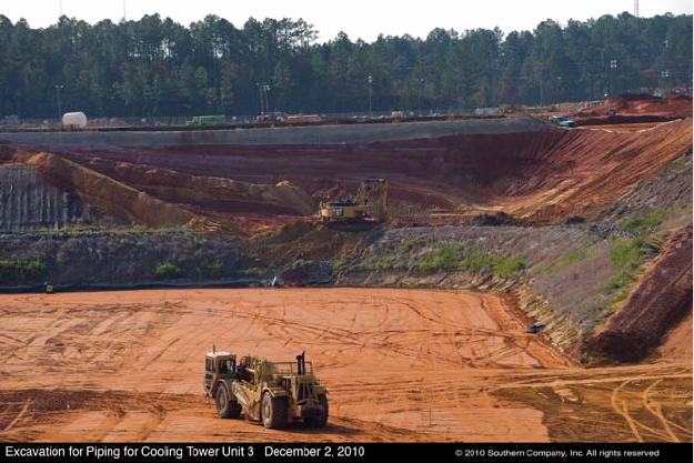
25
one free face is available at all times to control the direction of the break. The creation of the initial free face for the
excavation is also very important.
Main advantages:
— No fly rock with minimal cover requirements for the shot;
— Minimal noise and overpressure;
— Low vibrations;
— Non-interruption of the excavation operations;
— Minimal delays during firing.
Main disadvantages:
— In most cases, these methods are expensive;
— These methods require specific expertise and materials, which may not be available in all countries
contemplating NPPs.
Future actions for excavations:
— Prepare the proper schedule in accordance with the method selected;
— Develop the necessary expertise for the advanced excavation methods.
Figures 14 and 15 show foundation excavations for the Vogtle unit 3 and 4 NPP in the USA, respectively.
4.1.2.2. Remedial measures after excavation
Remedial measures after excavation are defined as measures to:
— Bring the foundation supporting materials to the required specified strength;
— Stabilize the rock and soil slopes for protection of the workers and civil works.
Conventional remedial measures
— The conventional remedial measure for unsuitable in situ foundation material is to remove the material and
replace it with concrete or structural backfill;
FIG. 14. Excavation for cooling tower for Vogtle NPP Unit 3 (Credit Southern Company).
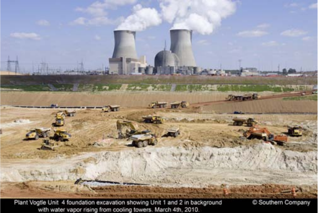
26
— The conventional remedial measure for soil slope stabilization is to slope or bench the sides of the excavation;
— The conventional remedial measure for rock slope stabilization is to place steel netting over rock zones
identified as having the potential to break off and thus endanger workers in the vicinity of the rock excavation.
Main advantages:
— Relatively inexpensive;
— No special equipment/materials required.
Main disadvantages:
— Schedule impact;
— Increased excavation quantities;
— Difficult to apply in small restricted spaces;
— The same degree of certainty of safety is not provided to the workers in the vicinity of the excavation.
Advanced remedial measures after excavation
— The advanced remedial measures for eliminating weak areas in the foundation materials are consolidated
grouting of fissured rock, utilization of rock anchors, bridging of weak spots, or a combination of all these
methods;
— Remedial measures for soils include roller compacted concrete, installing geotextile materials, soil anchors
and stone piles. Wire fabric is installed on rock slopes to protect the workers below. Gunnite is now being
used extensively to stabilize rock and soil slopes. Rock or soil anchors are installed to support weak zones.
Main advantages:
— Less impact on the schedule;
— Greater safety for workers.
Main disadvantages:
— Specialty equipment, material and expertise required;
— Expensive to implement.
FIG. 15. Excavation for cooling tower for Vogtle NPP Unit 4 (Credit Southern Company).
27
4.1.2.3. Concrete types
Site engineering and construction are responsible for developing and qualifying the concrete mixes to meet
the requirements specified by the structural designers. Due to the different functional and performance
requirements, a wide variety of concrete types are typically specified. These include normal strength concretes with
compressive strengths varying from 25–35 MPa. Now, due to new requirements and special applications, concretes
with higher compressive strengths of up to 60 MPa are being specified. In addition, heavy density concrete may be
required for radiation shielding.
It is critical to develop and qualify the concrete mix design early in the project schedule, preferably six
months before the start of the concreting programme on the project.
The following paragraphs provide details on conventional and advanced concrete mix designs for use in
NPPs.
Conventional methods
Conventional concrete design mixes use Portland cement, pozzolans (fly ash) and/or slag with strengths
between 25 MPa and 35 MPa. The most important thing is to qualify the source and suppliers of the constituent
materials (cement, aggregate, sand, water and workability additives, etc.) very early in the project to ensure that the
materials meet all the requirements of the concrete supply specification(s).
Heavy shielding concrete uses iron aggregates, metal fillings or metallic balls to develop the higher densities.
Main advantage:
— Most common technology in use today.
Main disadvantages:
— A thicker structure is obtained, requiring more material;
— Limited flexibility in meeting special applications.
Advanced methods
In recent years, advances in concrete technology have resulted in the availability of concrete mixes with
improved strengths, workability and corrosion resistance. Examples of advanced concretes include self-
consolidating concrete (SCC), high performance concrete and reactive powder concrete.
Some of the advanced concrete design mixes are:
High workability concrete
With the use of additives, concrete mixes that provide the same strength but far more workability have been
developed. Admixtures are added to the concrete to control properties such as time of set and fluidity.
High performance concrete
These concretes provide strength of 45 MPa and above. Some stations have used 60 MPa concrete. In
commercial high-rise construction, strengths of up to 120 MPa have been used.
Fly ash and slag concrete
There has been increased use of these materials to replace cement in the concrete mix. The percentage of these
materials versus cement has also increased, with some projects replacing 35% of the cement with these materials.
Mixes with these materials are workable and generate less heat during the period immediately after the pour. There
is hence less shrinkage and the possibility of cracking is minimized. These mixes are recommended for structural
elements requiring large volume pours.
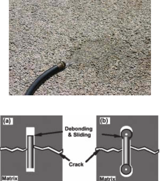
28
Pervious or ‘no-fines’ concrete
Pervious concrete, shown in Fig. 16, is a mixture of pea-sized aggregate, Portland cement and water. There is
generally no sand in the mix. Pervious concrete can be batched in plants that produce conventional concretes.
Pervious concrete will allow for water to pass through the concrete and be absorbed in a large area, rather than
forcing a runoff or drainage situation. This results in water runoff that must be managed in a site specific manner.
Precast concrete
Individually formed and cast-in-place concrete shapes involve separate worker trades to install reinforcing
steel, embedments, sleeves and conduit; to prepare formwork; and to place, compact and finish the concrete. An
alternative to cast-in-place concrete is precast concrete. Precasting is primarily used for repetitive structures such as
manholes and utility vaults. Since precast products are designed and manufactured for simple connection, many
components can be installed in a short time. The modular nature of many precast concrete products enables
structures or systems of many sizes to be accommodated.
Fibre-reinforced concrete
Civil engineers use steel, fibreglass and similar materials to increase the strength and toughness of concrete.
However, using these materials often requires costly construction techniques. Short-wire reinforced concrete should
become a favourite technology, as the process is compatible with standard construction processes, and the steel used
for the bone-shaped fibres is relatively cheap. Figure 17 shows a comparison of straight and bone-shaped fibre.
Straight fibres can pull free of the matrix material if the fibres bond weakly with the surrounding matrix. On
the other hand, if the fibres bond strongly with the matrix, they can snap under the high stresses generated by a
crack in the matrix. Bone shaped fibres connect mechanically with the matrix, predominantly at their ends. They
have a weak interface and so do not experience extreme stress, but remain anchored at their ends and still help carry
FIG. 16. Pervious concrete absorbing water.
FIG. 17. Comparison of straight and bone shaped fibre.
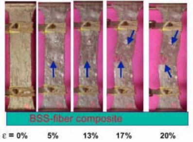
29
the load felt by the composite. The bone shaped fibres promote significant plastic deformation in bridging
ligaments and the formation of multiple cracks. Multiple cracking is another effective mechanism for improving the
composite toughness. Distributed multiple cracking allows more bridging bone shaped fibres to plastically deform,
as shown in Fig. 18.
Compared to the straight fibre concrete, the concrete containing the bone shaped fibres is significantly much
better, both in toughness and strength. The bone shaped fibre concrete resisted the propagation of cracks better.
Close inspection has shown that even though a crack in the concrete matrix had snaked through the sample, the
sample remains intact. The bone-shaped fibres also promote significant plastic deformation in bridging ligaments
and the formation of multiple cracks.
Self-consolidating concrete (or self-compacting concrete)
In the 1980s, a number of countries, including Japan, Sweden and France, developed concretes that are
self-compacting; this is known as self-consolidating concrete (SCC) in the USA. The NPP structures are designed
considering the safety margins required against radiation ground release and for higher seismic loads compared to
the conventional structures. The site specific response spectrum is developed on the basis of past history of seismic
events, and also taking the regulatory requirements into consideration. As a result, the percentage of reinforcement
steel goes to a higher order, leading to congestion of reinforcement, particularly at column beam junctions. The
placement of conventional concrete may sometimes not be a good proposition, due to difficulties in compaction, or
even in defining the maximum size of the aggregate ratio. This also increases the construction time, since concrete
pores have to be taken up at shorter heights. In order to overcome this problem with congestion and to speed up the
work, SCC is a good proposition towards advancement. This type of concrete can be compacted without any
external effort such as vibration, floatation or poking, but needs large powder contents. The economical option of
meeting the requirement of higher powder contents is the use of fly ash. It must, however, be ensured that the
quality of fly ash is consistent, as this has a major bearing on the mix of SCC.
Another major advantage of this concrete is that it facilitates pours of larger heights without sacrificing the
quality and durability, thus reducing the construction time. SCC is considered more impermeable than conventional
concrete. It does, however, take slightly longer to settle; therefore the formwork needs to be designed for higher
loads. Figure 19 shows the type of finish achieved with SCC in a congested reinforced structure.
SCC is characterized by:
— Extreme fluidity as measured by slump flow, typically between 650 mm and 750 mm;
— No need for vibrators to compact the concrete;
— Placement is easier than conventional concrete;
— Limited bleed water, and aggregate segregation;
— Labour savings, since the concrete does not have to be vibrated and there is less handing, as it flows up to
approximately 12 m.
FIG. 18. Good bridging and multiple cracking of bone shaped fibres composite.
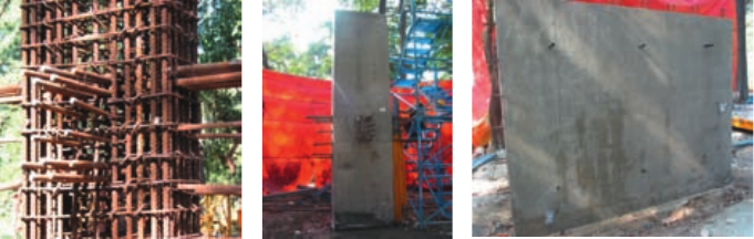
30
As of 2005, throughout the US precast concrete industry, SCC represents over 75% of concrete production.
Thirty-eight departments of transportation in the USA accept the use of SCC for road and bridge projects. This
technology is made possible by the use of plasticizer admixtures and viscosity modifying admixtures to prevent
aggregate segregation.
Traditionally, a concrete mixture with a slump of 2.5–7.6 cm is placed into a form and manually spread
throughout the form. Manually operated vibration equipment is required to ensure proper consolidation. Each step
is labour intensive and can cause injury, due to the nature of the work environment (tripping hazards with rebar,
power cords, air hoses, etc.). SCC is non-segregating concrete that flows very easily, spreads into place, fills the
formwork, and encapsulates the reinforcement without any mechanical consolidation. In general, SCC is concrete
made with conventional concrete materials and, in some cases, with a viscosity-modifying admixture [5]. Concrete
quality is improved due to elimination of vibrator trails and a more uniform air void system.
Self-levelling concrete
Self-levelling concrete is very wet and flows to an even, flat surface. A ‘smoother’ is then used to flatten out
the surface even more, thereby solving height issues. This approach consumes fewer manpower resources and its
settling time is less. When complete, a perfect transition is visible in all places. No vibrator is needed and so there
is no sound pollution. It is also used for speedy backfilling of an area where access is difficult.
The main advantages and disadvantages of the advanced concrete design mixes described in the preceding
paragraphs are as follows.
Advantages:
— Easier placement and hence better quality concrete;
— Significantly reduced schedule;
— Reduced sections where high performance concrete with higher strength is used, hence shorter duration of
construction;
— Reduced personnel power where SCC and self-levelling concrete are used, since these do not require
vibration;
— Some, such as precast concrete, facilitate modular construction.
Disadvantages:
— Expensive to implement;
— Specialty equipment, material and expertise are required, which may not be available in all countries.
Concrete cure monitoring
Systems are available to monitor and log concrete maturity and temperature during cure periods. Using
sacrificial sensors that embed in fresh concrete placements, these systems calculate the in situ strength gain in the
concrete in real time, thus helping adherence to schedule both on and off the critical path. Concrete cure monitoring
allows on-the-spot QA decisions about construction activities such as form stripping, shoring/reshoring,
post-tensioning, saw cutting and opening to traffic.
FIG. 19. Self-consolidating concrete (credit: NPCIL).
31
The preferred method is to use concrete maturity to determine the fitness and strength of the concrete. The
benefit of maturity testing is that it provides immediate and continuous data on the progress of concrete strength
gain of the in-place concrete. This is especially important if the project needs to be opened to traffic quickly, or is
on a fast track schedule. With recent advancements in technology, it is now possible to use radiofrequency
identification (RFID) to gather temperature data in a very cost efficient and cost effective manner. The raw
temperature data provides the information to determine optimum concrete strength, curing rates and documented
quality control data.
4.1.2.4. Concrete placement
This paragraph describes the placement of concrete into formwork (shutters).
Conventional method
The conventional method of placing concrete into formwork (shutters) is through placing the concrete using a
concrete pump or crane and concrete bucket.
Main advantages:
— Low maintenance;
— Economical to implement.
Main disadvantages:
— Labour intensive;
— More time required for placements, therefore a longer schedule is required.
Advanced methods
In recent years, there have been advancements in concrete material technology and improved placement
equipment. A significant improvement has been increased use of plasticizer admixtures to allow the concrete
slumps to be increased from a maximum of 100 mm to 200 mm. An added concrete placement advantage of using
pozzolan and a plasticizer is a more viscous fluid mix that is easier to pump. Its increased workability also allows it
to readily flow through areas with highly congested reinforcing steel.
Concrete pump reliability and sustained output have increased significantly. The operating capacity of
concrete pumps has doubled. In combination with the improved concrete mixes, these concrete pumps are now
capable of sustained pumping rates three times more than what they were 25 years ago, with far fewer breakdowns.
Although the physical concrete batch plant configuration has remained dormant, there have been significant
improvements in the automation and integrated computer hardware and software controlling the process. Another
significant improvement has been the application of in-line moisture monitoring probes to allow for increased
control of the concrete slump.
In parallel, improvements in the concrete mixes, placement equipment and batching operations have made
single monolithic base mat placement more feasible.
Main advantages:
— Significant schedule improvement;
— Overall lower labour and equipment costs;
— Fewer equipment breakdowns;
— Improved control of the concrete quality and consistency.
Main disadvantages:
— Increased cost of the concrete due to the cost of the admixtures;
— More expensive pumping equipment.
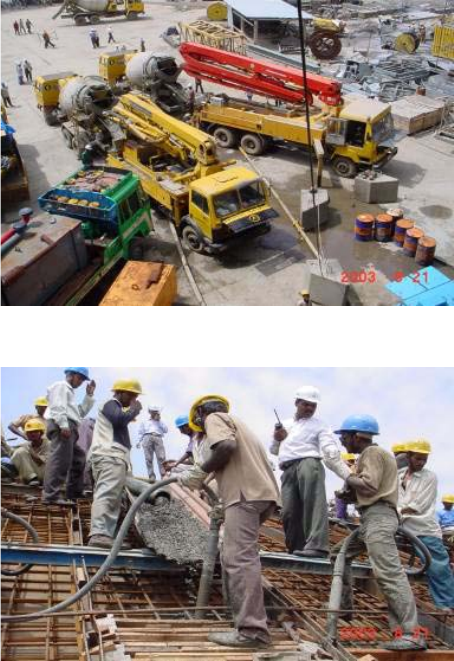
32
Figures 20 and 21 show concrete being pumped, and concrete pumping equipment, respectively.
4.1.2.5. Foundation construction
The following paragraphs describe the conventional and advanced methods for constructing the foundation
works.
Conventional methods
Foundations such as spread footings, combined footings and mat foundations are built using conventional
wood forms, with all reinforcing steel bars placed at site. The concrete is placed with pumps or buckets. In the case
of large mat foundations, multiple pours are used and sequenced to minimize concrete shrinkage. In the case of
foundations where piles are used, piledriving is performed using direct hammer or hydraulic hammer type driving
equipment.
Main advantages:
— Easy to implement without special expertise in the case of spread footings and mat foundations;
— Less expensive to implement.
Main disadvantages:
— More time needed to implement;
— There could be more cracking due to differential shrinkage in the final structure.
FIG. 20. Concrete pumping.
FIG. 21. Concrete pumping equipment at Tarapur 3, India (credit: NPCIL).
33
Advanced methods
The advanced foundation construction methods are seismic isolators, non-replaceable and replaceable; large
single volume pours utilizing pumps; utilization of rock anchors; and prefabricated rebar modules.
Main advantages:
— Shorter duration of construction;
— Less labour intensive.
Main disadvantages:
— Special material, equipment and expertise are required that may not be available in all countries;
— More expensive to implement.
4.1.2.6. Concrete superstructure construction
Conventional formwork
Conventional formwork for walls mostly consists of wooden forms held together in place by form ties spaced
such that bulging of the formwork is prevented during placement of the concrete. In the case of walls, the
conventional formwork is placed after the rebar and the embedded parts are placed. This formwork is stripped three
to four days after placement of the concrete.
Conventional formwork for elevated slabs consists of shoring supporting a wooden deck. The placement of
embedded parts and reinforcing steel starts after the shoring and the wooden deck are installed. The shoring and
wooden deck are removed 10–28 days after placement of the concrete.
Main advantages:
— Easy to install;
— Easy to strip;
— Lower formwork material costs.
Main disadvantages:
— Labour intensive;
— Lower strength of formwork restricts concrete placement rate;
— Many parts or components to the formwork system.
Advanced formwork
Q-deck (permanent formwork) or left-in shutters
This is slab formwork that is supported on temporary or permanent steel beams. The main characteristic of
this formwork is that it is not stripped after the concrete has cured. This formwork is used in areas where shoring is
difficult to place, and where there are no seismically qualified and heavily loaded systems supported on the
underside of the slab.
Main advantages:
— Easy to install;
— Requires no curing from the underside;
— Saves time, as no stripping or painting of the underside of the slab is required;
— Saves time, as the elimination of shoring reduces time of construction;
— Can start subsequent activities such as equipment installation earlier on the floors below the slab, since there
is no interference with shoring.
34
Main disadvantages:
— Lack of availability in many countries;
— More expensive than conventional formwork.
High strength modular formwork
This formwork system consists of modular panel assembled at grade level and lifted into place. Typically, this
formwork system has far less parts than conventional formwork, and is able to resist concrete pressures four to five
times those of conventional systems.
Steel plate reinforced walls
A steel-concrete-steel composite structure is constructed by placing concrete between two steel plates that
serve as stay-in-place forms. Studs welded on the inner surface of the steel plates are embedded in the concrete to
tie the concrete and steel plates together. For erection purposes, the steel plates are connected using tie bars or
trusses. This building construction technique can be used in the construction of floors and walls, and penetrations
and piping runs can be pre-installed. Steel-plate reinforced concrete (SC) construction methods offer significant
schedule advantages over conventional reinforced concrete (RC) construction. The construction schedule is
shortened because the amount of reinforcing steel is minimized (the steel plate/stud assembly acts as a composite
structure, replacing some of the reinforcing steel); and removal of formwork and cosmetic patching and cleanup are
not required. SC wall construction is more efficient to install than conventional RC methods. Since the steel-plated
structure is designed to be self-supporting, it is possible to fabricate the RC sections as modules off-site, and
transport them as a unit to be placed on-site and welded together. This construction technique significantly reduces
on-site work prior to the concrete placement.
The difference in cost of SC compared to the cost of RC is dependent on several factors. The SC construction
method significantly reduces the on-site installation person-hours. Additionally, the quantity of steel needed for an
SC structural element is approximately 25% less than that required for an RC structural element with comparable
strength. Although the fabrication cost of the SC method is higher, since the cost of steel plate is higher than the cost
of reinforcing bar, the overall net production costs are lower using the SC method.
In previous NPP construction, the attachment of supports for piping, electrical raceways and equipment to the
building structure required the installation of concrete expansion anchors. This entailed the time consuming process
of attempting to locate reinforcing steel embedded in the concrete so as to avoid cutting the rebar, thereby reducing
the designed strength of the wall or floor structure. This was then followed by the time consuming process of
drilling into a face of concrete and inserting anchors for bolting steel plate to concrete surface in order to attach
supports by welding. With the SC steel-plate method, this process is not required, and its consequences to the
structure are avoided. Supports can be welded directly to the outside steel plate of the wall or floor.
The SC construction method offers the potential for significant reduction in construction schedule and costs
of NPPs. Improvements in plant layout and overall size may also be realized from the improved structural
capability of SC construction methods. Extension of this construction technique to primary containment structures
will require further development of the technique and expansion of the existing code design requirements.
Steel plate modular floors
Modular floors consist of steel modules (outfitted with reinforcing steel, embedments, sub-modules and
commodities), placed on support structures embedded into the concrete walls during the wall construction at
required floor heights, and fixed to the embedment by means of welding. After the floors are interconnected
(reinforcing steel or welded), the structure is filled with concrete. Modular floors can be installed over the top of the
structure, using the open top method of construction.
Advantages:
— Elimination of shoring below the slab;
— Parallel working, as the modular floor is built out of the building.
35
Disadvantages:
— Use of additional material;
— Good fabrication expertise required.
Steel reinforced concrete composite structure and deck plate construction
The composite structure consists of a composite column and girder. The composite column comprises
concrete and structural steel inside, whereas the composite girder comprises a steel girder and concrete slab on top.
By applying composite structures, deck plate construction can be introduced in concrete buildings, and structural
properties are improved. A steel-reinforced concrete (SRC) composite structure is adopted in the Shin-Wolsong 1
and 2 projects in the Republic of Korea (as shown in Figs 23 and 24.).
Advantages:
— Elimination of traditional formwork for walls and slabs;
— Elimination of shoring below the slab;
— Elimination of reinforcing steel placement effort completely in walls and partially in slabs;
— Parallel working, as the SRC is built out of the building;
— Faster construction of walls and slabs;
— Faster construction of systems, as system components such as piping and cable trays are connected directly to
the plate of the SRC.
Disadvantages:
— Use of additional material;
— Good fabrication expertise required.
Stay-in-place expanded metal forms
There has been increased use of stay-in-place expanded metal forms to either serve as construction joint
formwork, or as an intermediate barrier where a concrete placement may be stopped.
Figure 22 shows a comparison of the traditional construction method and the metal deck construction method.
4.1.2.7. Concrete reinforcement
Conventional methods
The conventional method using reinforcing steel consists of placing bars in positions one at a time in their
final locations, and then tying the bars together as required to hold them in place. The bars are spliced in accordance
with laps specified on the drawings. Bar sizes 44 mm and above are connected by exothermic welding.
Main advantages:
— Deviations are easier to spot and correct in the field;
— A higher built-in factor of safety, and thus can be considered more forgiving;
— Can be installed in all countries;
— Lighter rigging loads;
— Less pre-planning required.
Main disadvantages:
— Longer time to install;
— More material used due to lap slicing;
— Exothermic welding is a multi-step process requiring more quality control oversight.
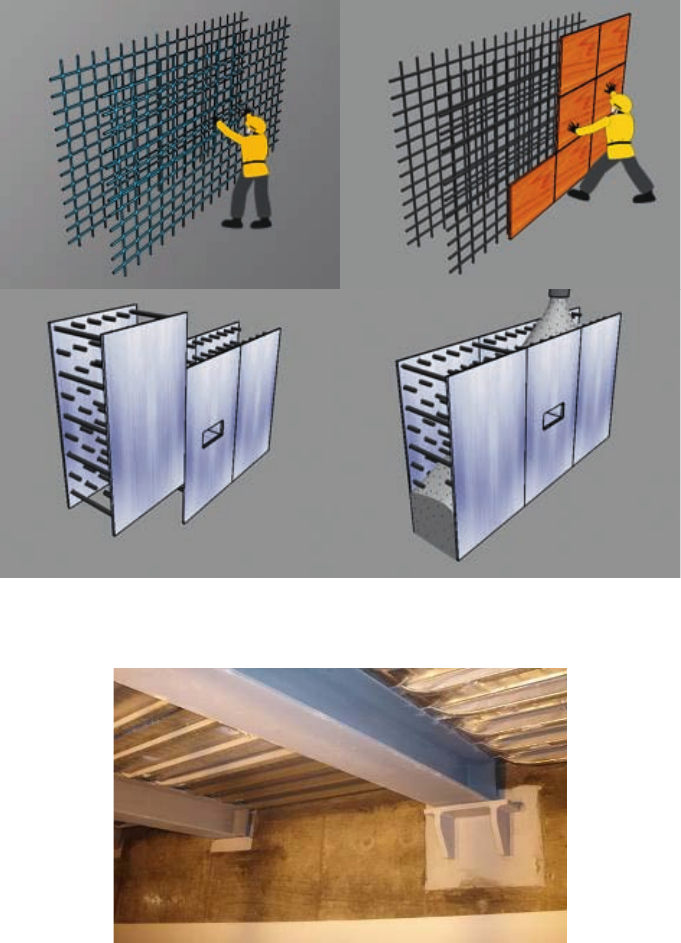
36
Advanced methods
Prefabricated rebar module
Rebar installation by individual placement of bars is quite time consuming. Large quantities of rebar are
needed in the base mat; containment wall and containment dome; and structural walls of the reactor and turbine
buildings. Prefabricated rebar assemblies provided as modules for these areas can provide schedule savings.
Advantages:
— Assembly at grade versus elevation;
— Reduced schedule.
FIG. 22. Comparison of construction methods (the top shows the conventional rebar-form method, and the bottom part shows the
advanced deck-plate method).
FIG. 23. Close up view of deck plate construction at Shin-Wolsong 1 and 2 auxiliary building, Republic of Korea.
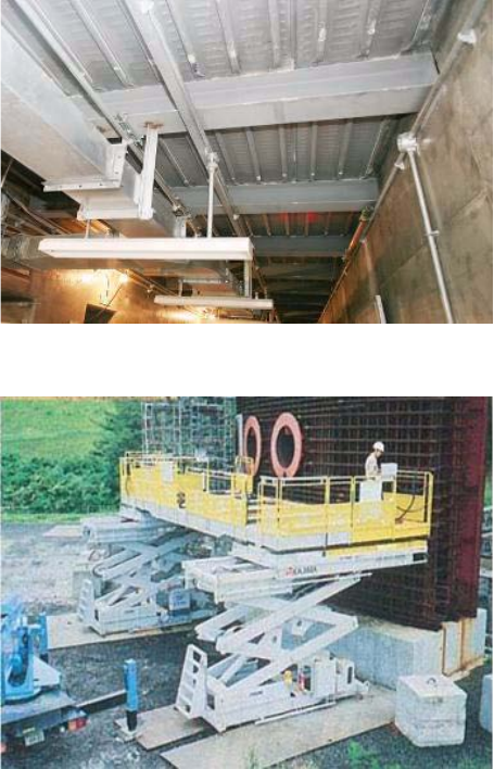
37
Main disadvantages:
— More complex rigging and fit-up requirements;
— Very difficult to use in placements where there are many embedded parts.
Automated installation of rebar
Automated techniques for installing rebar represent an alternative approach that has recently been used to
speed up the installation of rebar and provide consistent results for reinforced concrete structures at NPPs. One
technique is the use of an automatic scaffold elevating horizontal rebar feeding machine that reduces labour
requirements for rebar installation; another is the use of automation to assemble rebar according to instructions
from a 3-D computer design model. Refer to Figs 25 and 26.
Rebar connections — tying
Historic construction methods used hand-tying or welding to join rebar. This was a very labour intensive and
time consuming part of any large construction project. With a lack of skilled manpower in several areas of the
world, alternative methods of tying rebar are required.
New tying machines are now available on the market. They allow one person to do the work of several people
tying rebar by hand. These machines hold the crossed reinforcing bars; feed the tie wire; and wind, cut and tie in one
action. The result is a strong, single-strand, double-wrap tie. This is a method that is easily acquired with minimal
training.
FIG. 24. Deck plate construction at Shin-Wolsong 1 and 2 auxiliary building, Republic of Korea.
FIG. 25. Automatic elevating scaffolding and horizontal rebar feeding machine, Kashiwazaki-Kariwa Unit 6, Japan.
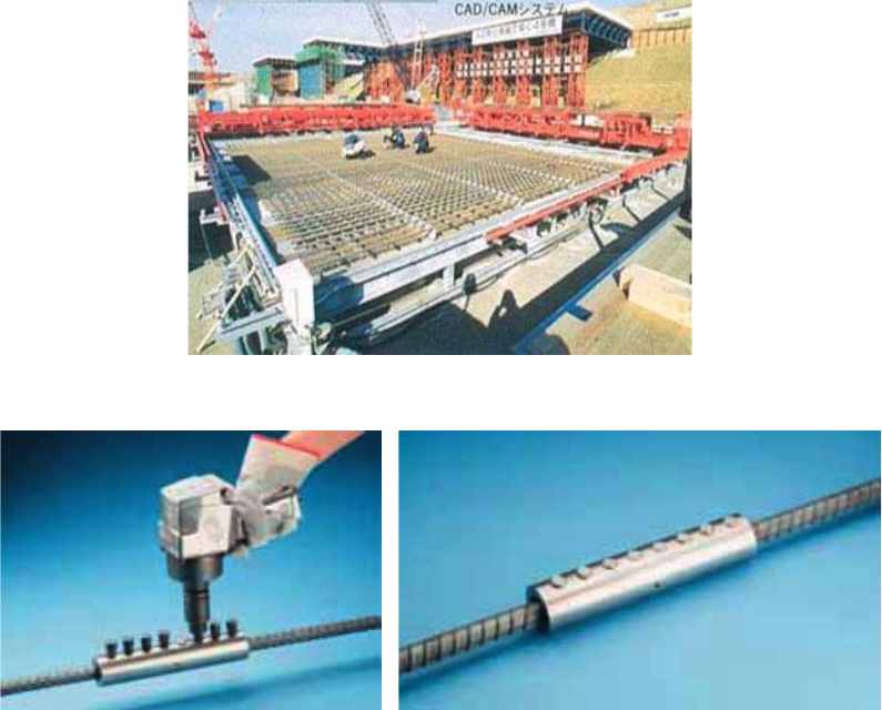
38
Rebar connections — coupling
The gripping technology provides for the development of full rebar strength and improved overall structural
integrity in tension, compression stress-reversal and dynamic applications. This unique design allows the coupler to
be smaller and more streamlined. From a construction point of view, it allows for easy and simple field installation.
All that is needed is a wrench, nut runner or impact wrench, depending on coupler size. The bolt heads will shear
off when proper installation tightness has been reached, allowing for completely visual inspection.
Figure 27 shows rebar coupling and Fig. 28 shows a comparison of rebar tying and rebar coupling.
Rebar connections — mechanical splicing
For many years, the traditional method of connecting reinforcing bars has been with lap splicing. However, as
many structural engineers, architects and specifiers have discovered, lap splicing has very few advantages and quite
a few disadvantages when compared to mechanical splicing.
Mechanical splicing provides the assurance of maintaining load path continuity of the structural
reinforcement, independent of the condition or existence of the concrete.
Advantages:
— Reduces rebar congestion and improves concrete consolidation;
— Improves steel-to-concrete ratio;
— Eliminates lap splices in high stress regions;
— Performs similar to a continuous piece of rebar;
— Speeds up construction.
FIG. 26. Automatic rebar assembly machine, Kashiwazaki-Kariwa Unit 7, Japan.
FIG. 27. Rebar coupling.
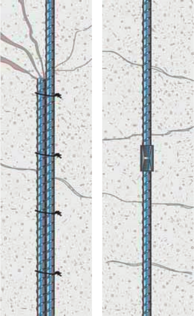
39
Disadvantages:
— Expensive to implement;
— Requires a good level of rebar expertise.
Rebar connections — welded cages
Conventional methods require construction personnel to manually place and tie each piece of reinforcing rod.
Bent bars at splice locations add congestion and cause difficulty in placing concrete. Pre-welded cages are an
alternative.
Welded rebar cages (shown in Fig. 29) can be rapidly set and easily connected using splices at the common
vertical edges of the cages. Forms are set around the dimensionally exact cages, and concrete is rapidly placed and
vibrated over the full height of the hook-free bars of the grids.
Welded grids save labour in both cage fabrication and installation; eliminate congestion; speed up concrete
placement and form setting; and expedite schedules. With ±3 mm manufacturing tolerance, grids provide accurate
vertical bar location, making it possible to install a two-storey welded cage with vertical rebar couplers in less than
30 min.
4.1.2.8. Embedded parts
General types of embedded parts are:
— Plate type embedded parts for attachments of system supports to civil structure and support to steel structures;
— Penetrating type embedded parts for piping and conduits;
— Embedded anchor bolts to anchor equipment and steel columns.
FIG. 28. Comparison of rebar tying (left) and rebar coupling (right).
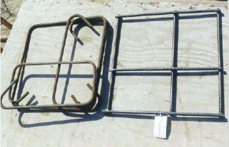
40
Conventional method
In the conventional construction method, embedded parts utilize manual welding of studs on the back of the
embedded plate for transferring load to the supporting structure.
Main advantages:
— Can be fabricated in all countries;
— Increased localization on the project.
Main disadvantage:
— Fabrication process takes longer.
4.1.2.9. Expansion anchors
Expansion anchors are drilled into the hardened concrete, and are used to support structural, mechanical and
electrical equipment and commodities.
Expansion anchors provide flexibility in supporting the systems, but are difficult to install in slabs and walls
with high density reinforcing steel without cutting the reinforcing steel and thus weakening the structural concrete.
If the density of rebar is not heavy in the concrete, rebars can be located using the electronic rebar locaters before
drilling holes to install expansion anchors. For heavily rebar congested structures, it may not be possible to install
the expansion anchors without cutting the rebars in the concrete structures, which would reduce the strength of the
structures and result in potential regulatory issues.
Main advantage:
— Provision of flexibility to the construction effort.
Disadvantages:
— Significant time effort in installing expansion anchors;
— Expansion anchors are far more expensive than embedded parts;
— Reduction in the strength of the structure in which rebars are cut with large diameter expansion anchors.
It is recommended that the number of large diameter expansion anchors be reduced and replaced with
embedded parts. In projects where this has been done, significant savings have been achieved in the construction
effort and schedule.
FIG. 29. Rebar welded cages (credit: BauTech, Inc.).
41
4.1.2.10. Bonding between concrete pours
Good bonding between concrete pours is essential for a concrete structure.
Conventional method
The conventional method for creating bond between pours has been to expose the large aggregates manually,
or with pressurized air or water, and then after saturating the cold joint, to pour the concrete for the next stage.
Advantages:
— Can be implemented in all countries;
— Relatively economical to implement.
Disadvantages:
— Takes longer to prepare;
— Has a longer schedule.
Advanced method
The advanced method being used to prepare cold joints for the next pour and achieve very good bonding is the
green cutting method. Green cutting is an effective and advanced technology. This method results in complete
removal of the thin cement mortar layer on top of the concrete surface and exposes the coarse aggregate, thus
ensuring a rough surface at construction joint locations for achieving a proper bond with the subsequent concrete
pours.
Material and equipment
— Surface retarder compound;
— Air compressor suitable for air pressures up to 10 kg/cm2;
— Spray gun with arrangement for two inlet pipes, one each for air and water, with a fine nozzle to discharge the
mixture in the form of a fine jet;
— Slush pump for removal of green cut slush.
Recommended procedure
The recommended procedure is as follows:
— Spray the surface retarder within 1 h after the concrete is placed and finished, over the uniformed surfaces
such as slabs and rafts;
— Apply the surface retarder on the inner face of formwork (concrete contact surface), approximately 1 h prior
to the expected time of concrete reaching that location and coming into contact with the formwork. The rate
of application of surface retarder is arrived at, based on mock-up trials, using the surface retarder compound
proposed to be used in the actual work. An application rate of approximately 1 L/4 m2 of concrete surface area
was arrived at for the surface retarders used in tropical conditions;
— Immediately after the application of surface retarder, cover the concrete surface with polythene sheets to
protect it from direct exposure to sunlight, maintaining a clear gap with the retarder applied concrete surface;
— Carry out green cutting of the unformed concrete surface within 1 h of the expected final setting time of
concrete. Determine the expected final setting time for a particular grade of concrete separately for day and
night, depending on the weather conditions;
— Carry out green cutting of formed surfaces immediately after removal of formwork/stoppers. Remove
formwork/stoppers after the expiry of the expected final setting time, from the time the concrete made contact
with the formwork;
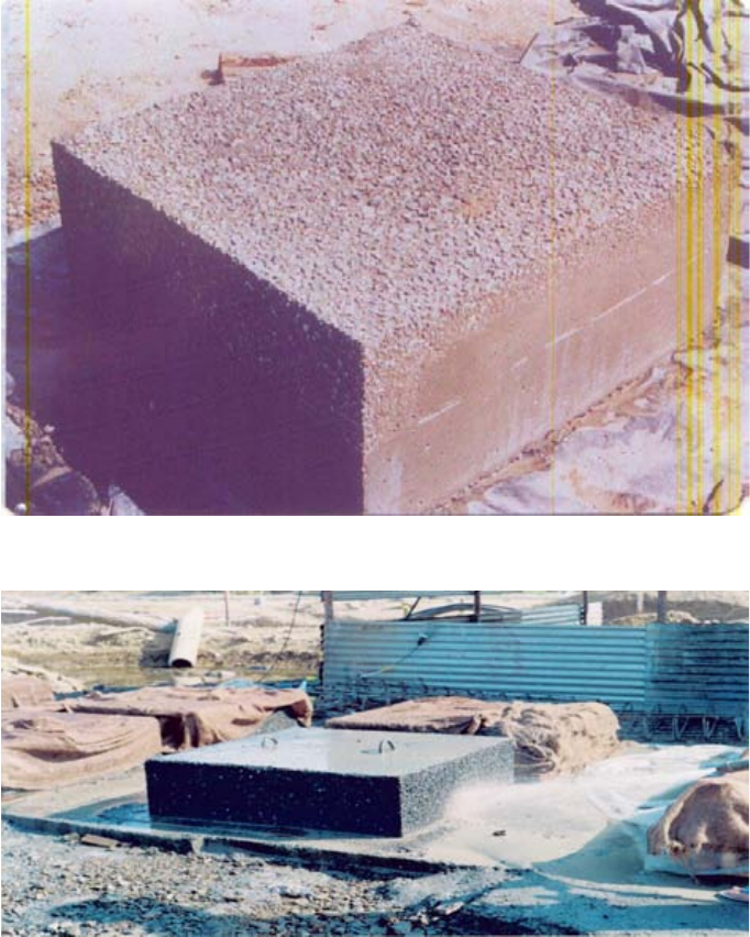
42
— In large concrete pours where green cutting has to be carried out progressively, display suitable identification
boards indicating the time of application of surface retarder and scheduled green cutting time for easy
identification, to ensure the quality of subsequent bonding;
— Carry out green cutting using a fine air-water jet at a pressure of 5–6 kg/cm2 in such a way that the top unset
cement mortar layer is washed off and the aggregates are exposed. The direction of the jet nozzle spraying the
atomized mix of water and air also plays an important role in the green cutting process;
— After completion of green cutting, clean the concrete surface again, using the air-water jet, so as to completely
remove the cement-sand slush from the green cut concrete surface;
— Ensure proper management of green cut water/slush by providing an adequate number of temporary sumps in
the pour being concreted, or in an adjacent location, for collecting the green cut water/slush and pumping it
out.
This advanced process, shown in Figs 30–33, is much faster than the conventional method, optimizes human
resources at the project site, and ensures the required bonding of construction joints.
FIG. 30. Green cutting using surface retarder and subsequent air water jetting (credit: NPCIL).
FIG. 31. Rough concrete surface after green cutting, i.e. spraying of surface retarder within 1 h of finishing of concrete and subsequent
water jetting after final setting of concrete (credit: NPCIL).
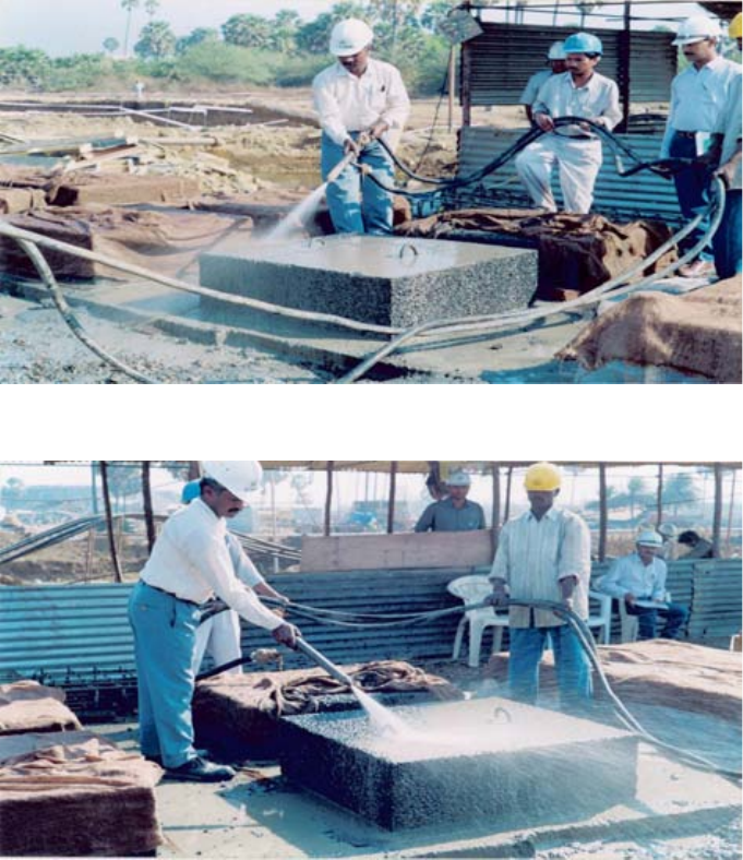
43
4.1.2.11. Structural steel fabrication and erection
Structural steel includes the columns, beams, bracing and steel used to support major equipment systems and,
in some NPPs, large steel water-retaining tanks supported off the containment dome and wall.
Typically, the structural steel design is given to a steel fabricator for preparation of connection design, and for
preparation of erection and shop drawings. In this case, the steel fabricator is responsible for assisting the contractor
during the erection of structural steel. The approval of connection design and erection and shop drawings is
generally the responsibility of the structural steel designers.
Structural steel erection in NPPs is the responsibility of the site construction management.
Structural steel fabrication
Conventional method
This method utilizes cutting and welding of structural steel based on 2-D fabrication drawings, and using
manual measurement equipment.
Advantage:
— Can be implemented in many countries.
FIG. 32. Removal of top skin by air water jetting at pressure 4–6 kg/cm2, exposing aggregates to obtain rough surface (credit: NPC.).
FIG. 33. Removal of top skin by air water jetting at pressure 4–6 kg/cm2, exposing aggregates to obtain rough surface.
44
Disadvantages:
— Difficult to maintain the required tolerances;
— Complicates the entire set-up and prone to human errors.
Advanced method
The advanced method is to use a completely automated fabricating shop. Typically, this system works directly
from 3-D software, and precision control is monitored by lasers.
Advantages:
Improved fabrication schedule:
— Improved quality control;
— Improved tolerances.
Disadvantages:
— Cannot be implemented in all countries;
— High cost of fabrication equipment.
Structural steel erection
Conventional method
A structural steel frame is braced both vertically and horizontally to create stiffness in the building structure,
and to minimize or control the deflection of the building. A typical special concentrically braced frame has diagonal
braces that stretch in tension but buckle in compression, which is not ideal due to the buckled behaviour.
Conventional bracing would consist of standard beam shapes and must use wide-flange sections to the maximum
extent. All beam-to-beam and column-to-beam connections are made with clip angles, permitting greater tolerances
in fabrication and erection.
The conventional method of structural steel erection consists of erecting the columns and then the beam and
bracings, using temporary bracing if required to align these structures in their final location. At site, the structural
steel is connected through bolts to the maximum extent, and field welding is minimized.
Advantages:
— Erection is relatively economical to implement;
— A high level of erection experience is not required.
Disadvantages:
— Relatively longer erection duration;
— Quality of finished product is not as good as that obtained using advanced methods.
Advanced methods
The advanced methods now being followed are modularization of some structural steel sections and, in the
case of buildings where structural steel is the main construction material, the use of buckling restrained braces
(BRBs):
Modularization
Refer to Section 8 for details, advantages and disadvantages of modularization.
45
Buckling restrained braces
BRBs incorporate pinned or welded connections, radiused copes, material consistency, and higher capacity
systems to deliver maximum structural survivability while using less steel, welding and crane time in the erection
process. They also exceed all American Institute of Steel Construction (AISC) provisions, and independent analysis
shows that incorporating BRBs can considerably reduce building costs.
A BRB acts like a large shock absorber, with a central plate or cruciform cross-section stretching in tension
and shortening in compression. The BRB works without global buckling because the central plate is grouted solid,
but free to elongate and shorten inside a larger restraining tube.
When seismic energy is dissipated throughout a BRB system, deformation of beams and columns is
minimized. That means less damage to floors, walls, partitions and other non-structural elements. Compared to
traditional concentric braces, BRBs exhibit nearly identical properties in tension and compression, and have a
substantial ability to undergo numerous cycles of inelastic deformation without degradation or fracture. BRB frame
systems are currently used as primary lateral force resisting elements, both in new construction and seismic retrofit
projects. The sturdy nature of these systems, resulting from the elimination of the buckling mode of the BRB,
makes these braced frames good candidates for a variety of seismic regions.
Advantages:
— Maximum structural serviceability;
— Less steel, welding and crane time used during erection, therefore more economical to implement;
— Shorter duration required.
Disadvantage:
— Cannot be implemented in countries where structural steel experience is limited.
4.1.2.12. Waterproofing
Waterproofing is required for underground structures and basements. A bitumen based compound is generally
used as waterproofing material. Waterproofing material is applied in layers on both horizontal and vertical surfaces.
At coastal sites, it is also necessary to keep the water table down by constructing deep wells connected with
underground pipe drains at suitable locations during construction.
The important steps in the execution of waterproofing are as follows:
— A course of 100 mm thick plain cement concrete (PCC) is laid over the excavated rock at raft area. A layer of
cement sand mortar, approximately 20 mm thick, is applied on the PCC to make an even surface. A first layer
of styrene-butadiene-styrene (SBS) membrane is laid by the torching method. The membrane is then spread
and rolled so that it adequately sticks to the base. A second layer of the SBS membrane is laid using the same
process, after a suitable time gap as specified by the manufacturer. The minimum finished thickness of the
SBS membrane is approximately 4.5 mm. A protected layer of cement, sand and mortar is laid over the SBS
membrane to protect it from any damage. The prefabricated cages of the reinforcement are then placed before
starting the concreting of the raft;
— The vertical faces of the subsoil concrete structure are also waterproofed using the same process, ensuring the
continuity of the already laid bottom membrane over the vertical phases. These vertical protective membranes
are continued beyond the grade level, and are adequately sealed by the plinth protection concrete. The vertical
waterproofing layer is also required to be protected against damage during backfilling around the
substructure. A masonry wall approximately 150 mm thick is constructed around the subsoil structure,
leaving a gap of approximately 20 mm from the waterproofing surface. This gap is filled with cement, sand
and mortar, which provide adequate and proper protection;
— As a matter of abundant precaution, a thick plastic sheet is stuck over the layers of SBS membrane prior to
taking up the protective works. This advanced technology ensures a high level of protection against any
subsoil water ingress.
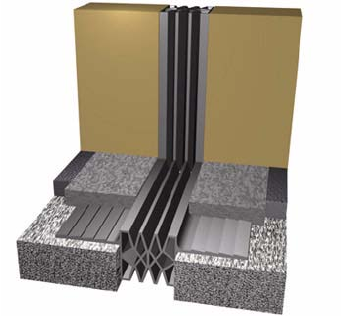
46
At expansion joint locations, metallic water stops or polyvinyl chloride (PVC) water stops are being
conventionally used for sealing. Experience with this type of sealing material has not been very satisfactory,
especially in subsoil conditions and where the joints are open to atmosphere.
As a matter of advancement, an additional metallic water stop is being provided on the inside faces of the
subsoil structure all around the expansion joints. Similar treatment is also given to the vertical faces of the
superstructure, as well as to the roof, depending on the situation. This advanced system ensures zero leakage of
water due to heavy rains or flooding. Additional precautions are taken while installing water stops that corner.
These corners are forged as a single piece, and the welding is carried out either on the horizontal or vertical legs of
the water stops. This ensures a continuity of the flexible groove at the corner locations. The quality of weld joints
on the vertical or horizontal locations is also ensured. Figure 34 shows typical expansion joints.
4.1.2.13. Yard services
These are defined as building peripheral drainage, storm water drainage system, sewage systems, plant
systems, piping and cables, located outside the buildings, plant roads, landscaping, etc.
From a construction point of view, the most critical item in constructing yard services is construction
planning. Construction planning should ensure that during construction of the yard services, access is available to
the buildings for both construction and commissioning and, in case of backfilled pipe trenches, for ensuring that all
systems are leak free and working in accordance with their requirements prior to any backfilling.
4.1.2.14. Backfilling
Backfill may be common backfill, granular backfill or cement-sand backfill:
— Common backfill is best used as the top layer of cover of piping and cable trenches;
— Granular backfill is ideal for covering piping and cables in trenches and road construction, and is generally
applicable to most backfilled areas;
— Cement-sand backfill is expensive, but has the advantages of shortest duration and is ideal for placement
adjacent to buildings.
Backfilling should be performed as quickly as possible so that the site returns to a level stage as early as
possible.
Conventional method
The conventional method of backfilling is to use (a) common backfill as the top layers in the yard, and
(b) granular backfill adjacent to the building, and to cover the pipes and electrical systems in the trenches. The
FIG. 34. Expansion joints (credit: VEXCOLT).
47
common backfill shall be placed in layers not exceeding 450 mm, and shall be compacted to specified dry density
determined by the method specified in national or regional requirements or standards.
The granular backfill shall be placed in continuous horizontal layers. These layers shall not exceed 300 mm
before compaction. The fill shall be spread so as to prevent segregation of the material. The granular backfill shall
not contain frozen lumps when placed, or be placed against or on frozen surfaces.
Placing of the first 300 mm of fill above any piping or structure shall be compacted by hand-operated power
compactors. Placing of granular fill around piping with a diameter greater than 300 mm shall be carried out
simultaneously on both sides of the piping in layers not exceeding 150 mm before compaction.
The granular backfill shall be wetted by sprinkling after being spread on the fill in place (in order to achieve
required compaction level). Jets shall not be directed at the fill with such force that finer materials could be washed
out.
Each layer of granular backfill shall be compacted by not less than two complete passes of an approved
vibratory roller travelling at not more than 1.6 km/h. If the specified compaction is not achieved initially, the
granular backfill shall be compacted by additional passes of an approved vibratory roller, as well as by adjustment
of the moisture content and thickness of the layer until the specified compaction is obtained.
When space will not permit the use of rollers, other types of approved vibratory equipment shall be used to
compact the granular backfill to obtain the specified level of compaction.
The granular backfill shall be compacted to a specified dry density as determined by the method specified in
the national or regional requirements and standards, or to a specified relative density as determined by the
standards.
Field density of compacted granular and common backfill shall be measured using the sand cone replacement
method, or by nuclear methods as specified in the national or regional requirements and standards.
Field density tests shall be performed three times daily if the volume of the backfill compacted that day is not
more than 1000 m3. For each additional 1000 m3, three additional tests shall be performed.
Advantages:
— Relatively inexpensive;
— Can be implemented in all countries contemplating nuclear power.
Disadvantage:
— Takes longer to do.
Advanced method
The advanced method uses cement, sand and water mixed together. This is deposited in considerably deeper
layers. This backfill does not require compaction and testing, and can be excavated readily with a backhoe. The
backfill is applied adjacent to the building, and provides major advantages, particularly in cases where the space
between the excavated rock surface and the building exterior is very limited.
Advantages:
— Self-compaction during placement;
— Compaction not required;
— Significantly faster in completing the backfilling.
Disadvantage:
— Expensive compared to conventional method.
48
4.2. MECHANICAL INSTALLATIONS
4.2.1. Discussion of mechanical installation activities
Project mechanical installation activities begin after the pour and cure of the lowest floor levels. Mechanical
installation involves the placement and interconnection of system equipment. Equipment ranges in size from entire
reactor vessels and turbogenerators, to instrument tubing and valves.
Interconnections between equipment are generally made by piping, tubing or duct work. Equipment is placed
on supports or foundations. Rotating equipment requires shaft alignment and coupling. Valves, vents, drains,
expansion tanks and other piping appurtenances are included in mechanical installation work.
Interconnections between equipment, piping and supports are generally made using welding. In some cases,
bolting is also used.
The work breakdown of mechanical installation activities includes:
— Engineering;
— Labour management;
— Mechanical equipment installation;
— Reactor systems and controls;
— Turbine and generator;
— Water treatment;
— Fire protection;
— Jibs, hoists, cranes and trolleys;
— Elevators and man-lifts;
— Pumps and drivers;
— Plumbing and sanitary systems;
— Radwaste systems;
— Access steel (grating, handrail, ladders, stairs);
— Piping, hangers and pipe specialties;
— Fabrication;
— Welding;
— Fitup, installation and weldout;
— Valves and actuators;
—HVAC ductwork;
— HVAC dampers and actuators;
— HVAC fans and equipment;
— Piping and equipment insulation and lagging;
— Examination, testing and startup;
— Field verification (quality assurance (QA)/quality control (QC)/testing).
Nuclear power plants comprise complicated systems with numerous active components. The quest for
improved performance and enhanced safety for these power systems has, in the past, been pursued through
increased redundancy and diversity of systems and equipment. This has added to the numbers of systems and
volume of structures required. Some designs of possible future generation plants are being founded on system
technology, utilizing fewer high cost components and reducing high cost, seismically designed building volume.
Some of these advanced reactor designs anticipate fewer valves, pumps, pipes, cables and HVAC units; and less
seismic building volume, leading to a reduced mechanical installation effort.
49
4.2.2. Construction methods for mechanical installations
4.2.2.1. Installation of heavy equipment
Conventional methods
NPPs require the assembly of hundreds of pieces of equipment, thousands of metres of piping/tubing, and
thousands of structural supports to hang and restrain the piping and tubing, etc. Traditionally, this was accomplished
by thousands of single component fitting tasks, and in a time relative basis, all occurring in the same physical floor
space at various distances above the floor, and in a progressively decreasing workspace. This approach has
traditionally been called stick-build construction.
Equipment such as pumps, compressors, heat exchangers, small tanks and other items was manufactured at
remote locations and transported to the plant location for installation. Because the process of construction of the
concrete wall and floor structures required forming and temporary support until the concrete achieved
self-supporting strength, temporary openings were required in the floors and walls to enable movement of
mechanical equipment, electrical equipment, and interconnecting piping and electrical cables. This limited the size
of the assemblies that could be joined remotely from the final location, and it further created paths and openings that
limited the ability to use transporting equipment to lift and place these components into final position.
Massive components weighing hundreds of tons (e.g. reactor vessels and steam generators) were
conventionally moved into the vicinity of their final location and upended by temporary structures assembled to
inch them into position. Steam condensers with large surface areas were assembled sheet by sheet in their final
location, and kilometres of condenser tubing were inserted. Conventionally, these activities occurred concurrently,
requiring significant numbers of construction personnel to work in close proximity to each other, cramped by
construction tools and scaffolding.
With advances in lift capacity of cranes, open top construction and modularization have been enabled. The
heavy equipment can now be directly placed into its final location, and large prefabricated modules can be
assembled remotely and placed into final position. The capacity of VHL cranes to lift, travel and install large
modules has increased to above 900 t.
Advanced methods
Modularization with prefabrication and preassembly
The advanced method for the installation of heavy equipment primarily involves modularization with
prefabrication and preassembly, which are discussed in detail in Section 8.
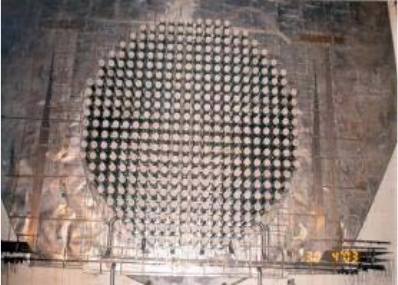
50
Use of laser alignment equipment
Critical equipment installation requires erection to be done within very close tolerances. This is achieved by
using laser alignment equipment. Figure 35 shows an example of the use of laser alignment to align end shields in
the reactor vault. Another example of its use is in aligning the turbo-generator rotor.
4.2.2.2. Welding and elimination of welding
Conventional methods
The most common process applied in the construction of an NPP is the joining of material members by
welding. The welding processes used in NPP construction include structural welds, used to connect structural
members; pressure welds, used to join pressurized components; and weld cladding (i.e. deposition of weld metal on
the surface of another metal), used to improve the characteristics of the component). Quality welding, crucial to the
construction of NPPs, is time consuming. The time required is determined to a large extent by the achievable
deposition rate of the weld material.
The completed process is examined to verify that the completed weldment is defect free. The welding process
is subject to many variables. Various factors contribute to weld problems, and weld defects happen for a host of
reasons.
The most common weld defects include:
— Lack of fusion — Too little heat input and/or too rapid traverse of the welding torch (gas or electric);
— Lack of penetration or excess penetration — Arises from too high heat input and/or too slow transverse of the
welding torch;
— Excess penetration (burning through) — Is more of a problem with thin metal, where a balance between heat
input and torch traverse rate is needed;
— Porosity — Gases are trapped in the solidifying weld metal. This may occur when air creeps into the
weldment due to loss of shielding; or from damp consumables or metal; or from dirt, particularly oil or grease
on the metal in the vicinity of the weld;
— Inclusions — Several passes are made along a joint when joining thick plate using flux-cored or flux-coated
rods, and the resultant slag covering a pass is not totally removed before the following pass;
— Cracking — As a result of the wrong amount of heat. This typically occurs due to thermal shrinkage, or a
combination of strain accompanying phase change and thermal shrinkage. Where alloy steels or steels with a
carbon content greater than approximately 0.2% are being welded, self-cooling may be rapid enough to cause
some (brittle) martensite to form. This will easily develop cracks. To prevent these problems, a process of
preheating in stages may be needed, followed by a slow controlled post-cooling in stages. This increases the
cost of welded joints for high strength steels, such as those used in petrochemical and power plant piping.
Solidification cracking, also called centre line or hot cracking, occurs immediately after welds are completed,
FIG. 35. Use of laser alignment to align end shields at Tarapur 4, India (credit: NPCIL).
51
and sometimes while the welds are being made. These defects, which are often caused by sulphur and
phosphorus, are more likely to occur in higher carbon steels. Solidification cracks are normally
distinguishable from other types of cracks by the following features: they occur only in the weld metal,
although the parent metal is almost always the source of the low melting point contaminants associated with
the cracking; they normally appear in straight lines along the centre line of the weld bead, but may
occasionally appear as transverse cracking; solidification cracks in the final crater may have a branching
appearance — as the cracks open, they are visible to the naked eye;
— Undercut — A groove melted into the base material, usually along the toes of the weld that produces a weak
spot in the weld;
— Lamellar tearing — A plate that has a low ductility in the through thickness direction, which is caused by non-
metallic inclusions, such as sulphides and oxides that have been elongated during the rolling process. These
inclusions mean that the plate cannot tolerate the contraction stresses in the short transverse direction.
Lamellar tearing can occur in both fillet and butt welds, but the most vulnerable joints are ‘T’ and corner
joints, where the fusion boundary is parallel to the rolling plane. Lamellar tearing is associated with low
quality steels.
To achieve a good quality joint, it is essential that the fusion zone extends the full thickness of the sheets being
joined. Thin material can be joined with a single pass, and a clean square edge will be a satisfactory basis for a joint.
However, thicker material will normally need edges cut at a V-angle or J-groove, and several passes will be required
to fill the V or J with weld metal. Where both sides are accessible, one pass (or more) may be made along the
reverse side to ensure the joint extends the full thickness of the metal.
Completed welds are required to be examined to verify conformance of the weldment to the design
requirements.
The most common examination methods include:
— Visual inspection — Performed prior to any welding, to see that the materials are clean, aligned correctly, and
that welding machine settings, filler selection, etc. are correct for the weldment. As a first stage of inspection
of all completed welds, visual inspection under good lighting should be carried out. Undercutting can be
detected with the naked eye and (provided there is access to the reverse side) excess penetration can often also
be visually detected;
— Liquid penetrant inspection — Performed to check for surface cracking. The method entails cleaning the
surface of the weld and the weld vicinity, spraying the surface with a liquid dye that has good penetrating
properties, wiping the dye from the surface, and spraying the surface with a fluorescent or contrasting
coloured powder. Any cracks will have trapped some dye, which will weep out and discolour the coating, and
will be clearly visible;
— Magnetic particle inspection — Used to detect surface and slightly subsurface cracks in ferromagnetic
materials (it therefore cannot be used with austenitic stainless steels). The process involves placing probes on
each side of the area to be inspected and passing a high current between them. This produces a magnetic flux
at right angles to the flow of the current. An alternative technique uses an electromagnet to produce the
magnetic flux in the part. When these lines of force meet a discontinuity, such as a longitudinal crack, they are
diverted and leak through the surface, creating magnetic poles or points of attraction. A magnetic powder
dusted onto the surface will cling to the leakage area more than elsewhere, indicating the location of any
discontinuities. This process may be carried out wet or dry, and use fluorescent or contrasting coloured
particles. The wet process is generally more sensitive, as finer particles, which can detect very small defects,
may be used;
— X ray inspection — Subsurface cracks and inclusions can be detected via X ray examination. This is
expensive, but for safety critical joints; e.g. in submarines and NPPs, 100% X ray examination of welded
joints will normally be carried out;
— Ultrasonic inspection — Surface and subsurface defects can also be detected by ultrasonic inspection. This
involves directing a high frequency sound beam through the base metal and weld on a predictable path. When
the beam strikes a discontinuity, some of it is reflected back. This reflected beam is received, amplified and
processed, and from the time delay, the location of a flaw is estimated. Results from any ultrasonic inspection
require skilled interpretation.
52
Any detected cracks must be ground out and the area re-welded to give the required profile. The joint must
then be inspected again.
Advanced methods
Advanced welding techniques are focused on four goals:
— Eliminating welds — Eliminating the weld altogether eliminates the time cost associated with welding and
inspecting the welds, as well as increases the quality of the element due to the added failure mechanisms
associated with welds;
— Moving from field to shop — Performing the welds in the shop through modularization increases the quality
of the welds. The weld is done in a clean environment, reducing the risk of particles interfering with the weld,
and making the weld positioning easier for the operator;
— Automating the welding process — Automating the welding process can increase productivity and the quality
of the weld. The welds can be repeatable, ensuring that the welds are adequate over the length of the pipeline;
— Increasing deposition welding rate and weld quality — Shortening the plant construction period, and
depositing weld metal at the highest rate achievable without jeopardizing quality is desired. The weld
deposition rate typically achievable today is higher than the rate achievable during construction of the existing
NPPs. High deposition rate welding can significantly contribute to shortening the construction period for
NPPs. High deposition rates can be achieved using advanced welding techniques such as gas metal arc
welding (GMAW).
Bends of small and large bore pipes to reduce welding of pipes and elbows
Elbow fittings and the associated welds can be eliminated by forming bends within pipe lengths for small bore
pipes. This can potentially result in time savings due to reduced welding operations and associated labour needs,
and reduced inspection requirements for non-destructive examination of welds. However, the added cost of the pipe
bending operations at least partially negates these cost savings.
Pipe bending has been used in industries other than the nuclear industry since the 1960s and 1970s, mostly
with small bore piping. Pipe bending in the nuclear industry has had limited use due to the potential for reduction in
wall thickness. If deficiencies are detected due to pipe bending, replacement and field rework may be required.
Computer programs are available that model the pipe bend to ensure that adequate wall thickness is achieved.
It is also possible to bend large bore piping, because the control of the bending process using computer
software better controls the wall thickness. For large bore, the pipe is heated up and bent in a special rig that
maintains the radius and minimizes thinning. The radius and curvature of the bends can be varied in these rigs. To
increase the quality of the bend, the pipes can be modelled using 3-D programs, pre-bent and prefabricated before
being sent to the site.
Automatic and mechanized welding
As shown in Fig. 36, the process of welding depends on a number of variables including environment,
configuration, welder fatigue and embedded material contamination. The application of automation to the process
helps reduce the fatigue and requirement for constant precision imparted by the welder. Advances in control
technology have improved machine precision and reliability for automated welding equipment. In addition, the
mechanized process enables larger amounts of weld metal to be deposited on an ongoing basis than a welder would
typically be able to deliver.
Use of automatic welding equipment is effective in maintaining high quality and in improving the working
environment when welding in narrow spaces. This is useful in getting defect free welds, thus avoiding job
repetition, and resulting in savings in time and cost. Automatic welding equipment has been used to weld titanium
tubes to the condenser tube sheet at Tarapur, India (Fig. 36), and to weld piping at Kashiwazaki-Kariwa, Japan
(Fig. 37).
Mechanized welds utilizing covered electrodes may require low-hydrogen electrodes. Low-hydrogen
shielded metal arc electrodes exhibit reduced productivity.
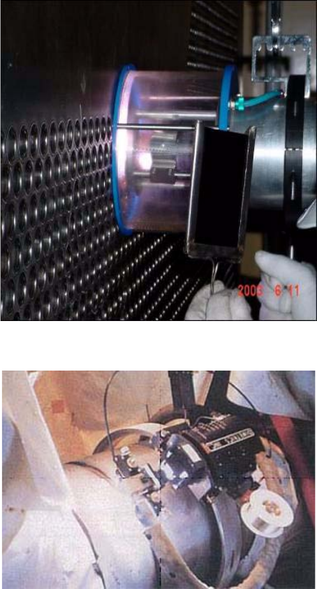
53
Welding processes
Construction of NPPs involves using welds to connect components of structures, components of pressurized
systems, and weld cladding to deposit one metal onto the surface of another to improve its performance
characteristics. Depositing weld metal at the highest rate achievable and with high quality is important. Recent
advances in welding technologies used in large scale construction projects have provided different techniques
capable of meeting these objectives. They include: GMAW, gas tungsten arc welding (GTAW) and submerged arc
welding (SAW), as well as others described in the following paragraphs:
Gas metal arc welding
Gas metal arc welding (GMAW), which includes metal inert gas (MIG) and metal active gas (MAG) welding,
involves an arc created between a consumable electrode and the base metal. Shielding of the arc from the
atmosphere is provided by a gas emitted from a nozzle surrounding the electrode. Advanced GMAW techniques
include the Rapid Arc and Ultra MAG processes. A disadvantage of the GMAW process is that strict process
controls, including extensive workpiece preparation and cleaning, are necessary to ensure quality at higher
deposition rates.
FIG. 36. Automated tube welding process used for tube-to-tube-sheet welding in a condenser, Tarapur, India (credit: NPCIL).
FIG. 37. Automatic piping welding, Kashiwazaki-Kariwa, Japan.
54
GMAW offers better productivity than manual shielded metal arc welding (SMAW). In addition, high
strength steels benefit from the low-hydrogen content of certain solid and tubular wire electrodes.
Short arc process, or short-circuit transfer process, of GMAW is a low heat input process generally used on
thin materials. It is a fast and inexpensive process that allows welding in all positions.
In the short-circuit process, when the electrode touches the base metal, it causes a short circuit. The base metal
and electrode become molten at the point where the wire touches the base metal, and the electrode is pinched off.
Spatter, in the form of round, molten balls that stick to the base metal, is a result of the sudden separation or transfer
of the electrode. Though originally used for thin metals, this process is currently being applied to thicker metals.
Advanced GMAW techniques, including the Rapid Arc and UltraMAG processes, have achieved deposition
rates of 15–17 kg/h, for example, in certain applications. Typical weld deposition rates are in the range of 2–9 kg/h.
The orbital GTAW welding process is an automated welding process. This makes controlling process variables
easier, and facilitates achieving a consistent and high level of quality. The relatively small size of the orbital welder
allows it to be used in locations where personnel access is difficult or impossible. Productivity rates are improved
over manual methods because set-up is easier and less rework is required. The deposit rate of the orbital process is
approximately 0.7 kg/h. In addition, the relative ease of the welding technique eliminates the need for the skilled
welders required for standard methods. Orbital welding is an attractive option for use in construction of a new NPP
in the USA.
Gas tungsten arc welding
Gas tungsten arc welding (GTAW), also referred to as tungsten inert gas (TIG) welding, is a welding process
that involves an arc created between a non-consumable tungsten electrode and the base metal. Shielding of the arc
from the atmosphere is provided by an inert gas emitted from a nozzle surrounding the electrode. A filler metal may
or may not be added to the weld pool. GTAW is a relatively slow, high quality process.
An automated version of GTAW, known as orbital welding, is now accepted practice in nuclear applications.
Orbital welding offers significant improvements over manual methods for butt welds on piping. Some problems
associated with manual GTAW are difficulty in controlling process variables to achieve desired quality, and
difficulty in accessing weld locations. Both of these problems tend to slow the construction process and increase
cost.
Submerged arc welding
Submerged arc welding (SAW) involves a consumable electrode that provides filler metal and shielding. The
arc between the consumable electrode and the base metal is shielded by the gas generated by the melting and
redeposition of the flux coating the electrode. The flux floats to the outside of the deposited weld metal, covering it
and providing additional protection.
An improvement in the SAW process is the technique of multiple-wire welding. This process involves more
than one consumable electrode producing an arc and contributing to the same weld pool. Multiple-wire welding
provides an increase in deposition rate due to the higher rate at which heat and weld metal are added in the process.
SAW with flux-cored wire is a high deposition welding technique. Flux-cored wire is used as the consumable
electrode in the process. The flux is contained at the core of the wire. The use of flux-cored welding significantly
mitigates the major shortcomings of SAW, namely the mechanical properties that can be obtained at high deposition
rates, and sensitivity to base metal surface impurities (e.g. rust and moisture).
A disadvantage of the SAW process is the additional cost due to the large amount of flux cleanup required.
SAW is commonly used in steel fabrication or structural shapes; and for longitudinal and circumferential seams for
pipes, tanks and pressure vessels of large diameters. Typically, steel plates with thicknesses of 2.54 cm or greater
are welded using this process. SAW processes readily weld low-carbon, low-alloy and stainless steels, but not
high-carbon, tool steels, or most nonferrous metals. The use of SAW is traditionally limited to the horizontal
position because of the gravity feed of the granular flux. Therefore, when a weld in the vertical position is required,
positional welds are usually carried out manually or semi-automatically. Because this method is so time consuming,
recent technology has led to SAW in the vertical position with horizontal electrode feeding. This method is used in
shipbuilding, where the joining of large ship sections requires long and mostly straight weld seams in the vertical
55
position under yard conditions. Good mechanical-technological properties of the welded joints are attainable with
deposition melting rates of over 2.0 kg/h.
SAW using gantry units is also used in the construction of various civil structures. Gantry welding units are
structural type frames allowing bidirectional, automatic or semi-automatic travel. Typically, the welding control
units, torches and power sources are mounted permanently on the unit. A qualified welder can perform vertical-up
welding. Gantry welding units can make 8 mm horizontal fillet welds at 0.9–1 m/min in flange-to-web girder
welding (approximately 1.8 m of deposited fillet weld per minute). Using this system, fabricators can produce more
than 91 m of welded girder a day.
For several decades, SAW has been the preferred high deposition rate welding process in many industrial
applications. Deposition rates as high as 15 kg/h have been achieved for standard single wire (i.e. single
consumable electrode) SAW. For a multiple wire process, deposition rates as high as 45 kg/h have been reported.
SAW used in vertical applications has achieved a deposition rate of approximately 2.0 kg/h. For comparison, weld
processes used in existing nuclear plant construction were classified as high deposition rate methods when the weld
metal was deposited at a rate exceeding 5 kg/h.
Hybrid laser-arc welding
Hybrid laser-arc welding (HLAW) is a welding process that combines laser beam welding and arc welding.
HLAW exceeds the advantages laser welding and GMAW offer individually.
These benefits are:
— Welding from one side;
— Increased tolerance to small but variable gap in joint fit-up;
— Increased penetration;
— Reduced filler metal;
— Higher welding speed;
— Higher productivity;
— Lower net heat input;
— Reduced distortion;
— Improved microstructure and properties;
— Improved weld quality and process reliability.
Electron beam welding
Electron beam welding utilizes an electron beam generated in a vacuum to create a fusing source that can
weld almost any metal. This type of welding produces deep welds without adding excess heat, which would
adversely affect the properties of the surrounding metal. Therefore, electron beam welding is typically used where
defects cannot be tolerated and a consistent, reproducible weld is required.
Until recently, electron beam welding was difficult to use. Because electron beams are invisible, operators
could not see the beam and it was therefore difficult to focus the weld. A profiler has been developed to provide
diagnostic tools to measuring the beam properties and create a sharp beam focus. The electron beam currents are
measured, and computed tomography is used to measure the power-density distribution and automatically adjust
the focus of the beam. This tool allows the welds created from the electron beam to be reproducible.
Friction stir welding
Friction stir welding uses a tool with a high rotational speed to crush, stir together and forge a bond between
two metals using the high rotational speed of a tool. This is a solid state process with no melting of the material.
This eliminates problems associated with conventional welding, including porosity, solidification cracking and
shrinkage. Additionally, no filler material is required. This is a safer process than conventional welding, because
there are fewer hazards such as welding fumes, radiation, high voltage, liquid metals and arcing.
A drawback of friction stir welding is its reliance on a single-piece pin tool. The pin is plunged into the joint
at the weld location and rotated at a high speed. If a single-piece tool is used, a keyhole is left in the weld.
56
Additionally, pin tools of different lengths are required when welding materials of varying thickness. An automatic
retractable pin tool that uses a computer-controlled motor has been created to prevent keyholes, and for use with
different material thicknesses.
Friction stir welding is used in other industries, such as shipbuilding, to weld aluminium alloys. It can be used
to weld additional metals.
Tab-and-slot welding
Dedicated welding operations typically use jigs, fixtures and other equipment to hold metal components in
place during welding. However, these devices must be designed for a specific job, validated and then maintained
over the life of the products. Tab-and-slot temporary-fastening technology uses the raw-material metal sheets
themselves as temporary fastening mechanisms. After inserting the tabs into the slots, operators twist them to
engage the radii and lock the pieces together. Once in, the twist tabs extend out of the slots. Personnel then weld the
assembly and remove the tabs from the sheets by twisting them off with a tool.
Tab-and-slot welding saves set-up time compared with traditional methods. This method may also reduce
misalignment problems associated with other welding techniques, thus improving weld quality. The technology’s
mechanical simplicity and ease of use increase efficiency to further reduce production costs. Applications include
situations requiring welding in remote locations rather than in dedicated welding shops.
Narrow groove welding
Narrow groove welding reduces the angle of the bevel that is used to make the weld, which reduces the weld
thickness. Other welding advancements that ensure quality and ease of welding allow the thickness of the weld to
be reduced. The narrower the weld, the less there is to be done. Fewer steam generator replacement modifications
and other heavy welding processes reduce time, heat and stresses associated with the weld.
Reactor coolant piping automatic weld
For the reactor coolant loop (RCL) piping welding, a narrow gap automatic welding method has been used at
the Shin-Kori 1 and 2 sites in the Republic of Korea.
Contributing factors to rising construction costs have been manual welding, with its average defect rate of
3–5% (higher than that of automatic welding), and a limited availability of qualified welders. A narrow gap welding
technique enables the welding time to be shortened, as the welding cross-sectional area is reduced, and provides
effective control of precision fabrication by preventing physical deformation of the weldment as weld deposit is
reduced. Figure 38 shows a composite view comparing the narrow gap welding technique with the weld preparation
configuration of conventional welding. Application of a narrow gap automated welding process, instead of manual
welding, to the RCL piping where precision technique is mandated would not only enhance welding quality with its
consistency throughout the welding, but also shorten the construction schedule by 1.5 months. Such automated
welding equipment is available in a variety of sizes and weld techniques, and can also be customized to meet
specific needs. Precision welding of reactor coolant piping is managed by computerized control as part of the
automated welding machine.
Figure 39 shows automatic welding of RCL piping in Shin-Kori 1, Republic of Korea.
Weld inspection
Automatic weld quality monitoring
Algorithms can be used to automate weld-quality monitoring. It is often difficult for welders to recognize if
they are laving porous welds, convex welds, or welds that burn through to the other side of the workpiece. The
power source currents and voltages can be monitored and used to automatically adjust fill volumes or detect
shielding-gas contaminants in pulse welding. The welding process can be monitored while on-line, ensuring that a
quality weld is acquired as it is performed.
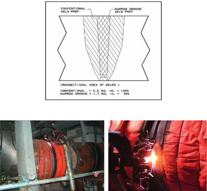
57
Phased array ultrasonic examination
Phased array ultrasonic inspection uses multiple ultrasonic elements and electronic time delays to create
beams by constructive and destructive interference. These beams can be steered, scanned, swept and focused
electronically. The results are typically displayed on a liquid crystal display (LCD) screen, and can be saved and
processed via computer. The phased array units can be portable and allow fast inspection speeds, full data storage,
good imaging, reproducible results and multiple angle inspections. This process can be automated to save time, and
would replace X ray inspection, as it gives better and faster results than radiography.
Eddy current examination
Eddy current examination uses eddy current created through electromagnetic induction to inspect welds.
When the weld, an electrical conductor, is brought into proximity of the electromagnetic field, a current is induced
in the weld. This form of testing is primarily used on tubing, not on pipe welds or structural welds. This is a fast
inspection using very portable equipment.
Robotic snakes and worms for component inspection in confined and inaccessible areas
Robotic mobile equipment can be used during construction to inspect complex pipework and structures in
locations that are difficult to access. Such equipment has flexible arms, can be manoeuvred into confined spaces,
FIG. 38. Narrow gap welding technique.
FIG. 39. Narrow gap automatic reactor coolant loop piping welding, Shin-Kori 1, Republic of Korea.
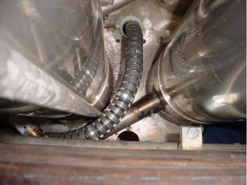
58
and can be equipped with tip cameras. It has also been used to inspect and replace leaky sections of piping in current
plants. Examples include pipe replacement in an extremely awkward area below one of the Ringhals reactors in
Sweden (where the pipe repair, including welding and inspection, was completed within three days), and inspection
of cast iron pipes 45 m underground at Dounreay fast reactor in the United Kingdom (UK) (shown in Fig. 40). The
pipes are encased in the concrete wall of a tunnel that extends some 600 m offshore. The head of the ‘worm’ is
2.5 m in length and 15 cm in diameter. Its flexible tracked chassis can turn through bends in the pipes. An umbilical
‘tail’ allows the pipeline crawler to be controlled remotely from the surface.
4.2.2.3. Equipment location and measurements
Conventional methods
Transits, tape measures, levels, calipers, micrometers, dial indicators and other instruments have
conventionally been used to locate equipment and verify dimensions. Measurements are made based on the
coordinate system that was developed at the start of construction (discussed in Paragraph 0). The same methods
used to develop the coordinate system are used to locate the equipment. Transits and tape measures are used to
locate the position where the equipment needs to be placed, while calipers, micrometers, dial indicators and levels
are used to ensure the equipment is lined up and level within the design tolerance. Traditionally, this equipment is
manually read by the operator from the scales on the instrument, such as a vernier scale.
Other unique methods are used to ensure that sensitive items, such as turbine blades, are placed correctly. In
order to centre the turbine blades and rotor, piano wire is stretched from one end of the turbine casing to the other.
The piano wire is then tapped by a tuning device. The pitch of the tone created by the piano wire indicates if the
turbine blades and rotor are centred.
As-built drawings are created after construction to verify that the structure matches the design and, if not, to
find the actual position of the components. Conventional as-built measurement techniques have been the same as
the measurement techniques used for initial construction.
Advanced methods
Digital instruments
Transits, levels, calipers, micrometers and dial indicators can be equipped with digital readouts to improve the
accuracy of the measurements. Instead of relying on the operator to accurately read the scale on the instruments, the
digital display provides an exact and, if calibrated correctly, accurate readout of the position of the instrument.
FIG. 40. Snake-arm robot inspecting beneath a reactor (image: OC Robotics, United Kingdom).
59
Digital levels are digital height measurement sensors designed for any worksite where fast and accurate
height determination is required. They can be used for applications such as precise levelling of slopes and flat
surfaces; establishing the vertical component of grade and ground profiles; subsidence monitoring; and establishing
the vertical component of control networks.
Laser alignment
Lasers can be used in a range of applications to accurately determine level, grade, vertical alignment and
distance, replacing manual measurements using tape measures and other measurement devices. The lasers are
set-up like traditional transits. Lasers are used for measuring distance at high accuracy by determining phase shift
or beam return time. They also provide a perfectly straight line in order to level or align equipment, such as shafts.
Spinning lasers emit a rotating 360 beam of light that is used as vertical, grade or horizontal reference, a
difficult-to-establish yet critical datum for engineering and construction projects.
Laser transmitter and receiver systems are available that will adapt to traditional optical alignment devices.
The instruments can be installed while at the construction site, vastly improving the measuring accuracy and
precision of these conventional tools. These instruments are battery operated. They fit standard optical hardware
mounts, replacing the visual telescope. A finely focused laser beam is projected from this laser on the exact centre
line for the optical mount. The traditional ruler or machined scale is replaced by a digital receiver, which tracks the
position of the laser beam with an electronic detector. Precision measurements with sensitivity of 0.003 mm can be
made over distances of 0.3–24 m with currently available receivers. The attached display provides a digital reading
of the measurement, offers a variety of user functions, and can be attached to a laptop or wireless transmitter for
recording readings and gathering data.
Optics is an integral part of an essential surveying instrument called a total station. This instrument enables
the surveyor to compare locations. Optics allows survey and construction professionals to accurately pinpoint the
exact feature to be measured, while lasers measure the distance. In the past, making sure the optic lenses were
positioned correctly within the instrument, was an art. Today, sophisticated software helps calibrate these sensitive
instruments, improving the accuracy and productivity of the surveyor.
Post-construction laser scanning
Laser technology, combined with a unique scanning methodology, is also available to capture the shapes of
physical structures or scenes and convert them into digital format. Known as 3-D laser scanning, this technology is
revolutionizing high-end civil engineering and survey projects.
After construction is complete, laser scanners can be used to provide high speed, high resolution 360 data
capture. Laser scanning technology helps ensure that data can be safely collected in a variety of real-world
situations with minimal elevated work. Field time, field personnel and elevated work for as-built measurement can
be reduced by digitizing facilities using laser scanning.
Improper manual field data collection can result in blind spots, missed scope and data misalignment. Using
laser scanners helps ensure that the required information is captured quickly, efficiently and safely.
Numerous software applications are available to manage multiple data sets acquired with laser scanners and
spatial imaging instruments. The software applications create and display photorealistic point cloud models for use
in a viewer or with CAD products, without having to remodel or convert the points into CAD objects. They also go
beyond visualization by providing design specific tools that automate the process of working with existing
conditions data on plant projects. Integration with CAD includes tools to help CAD users gain valuable dimensional
information, as well as manage demolition and interferences between the new design and the existing conditions
data.
To begin the 3-D laser scan survey, target markers are located in the area to be scanned. The exact 3-D
coordinates of the targets are then recorded using a total station theodolite. Each 3-D laser scan requires a minimum
of four targets to be accurately registered.
Once the targets have been placed and recorded, the 3-D laser scanning can begin. The scanner revolves 360,
while emitting a laser beam. Every time the laser touches a solid surface, a point is captured. Each 3-D laser scan
contains millions of these points, which create a 3-D ‘point cloud’. It takes approximately three minutes to complete
each 3-D laser scan.
60
Following the registration process, which ties all the individual 3-D laser scans together, a ‘point cloud’ is
created. The point cloud can be used as the main result of the laser scans. However, a 3-D as-built CAD model is
often required, which can be used directly within CAD packages with no additional training and no additional
software costs.
During field data collection, the individual laser scans must then be registered (integrated) into a single
network. In the field, laser scans can be registered without survey, increasing data collection and turnaround speed,
eliminating errors and providing a statistically calculated registration quality.
Laser scans have incorporated the following features to improve the quality of the scans:
— Temperature and humidity compensation;
— Reports to verify laser scanner calibration;
— Special mounting jigs for difficult-to-reach areas;
— Semi-permanent targets for long term projects.
Software is available to display the 3-D scans as photorealistic images and high-definition models. Each scan
can be displayed as a photorealistic panoramic image, and they can be panned and zoomed like virtual reality
programs. This allows for a ‘virtual’ site visit. Laser models integrate laser scan data to provide detailed, high-
definition solid ‘models’ of a digitized facility. Laser models are 3-D, visually clear and include fine details, unlike
‘point clouds’, whose sparse measurements make it difficult to visualize or understand the facility, and may not
include fine details. Laser models are relatively small and do not require a ‘point server’, so they may be loaded,
rotated and zoomed as needed to view a specific area or an entire facility. Laser models provide more detailed
information for more complete designs. The models can also be imported into CAD programs. Using these models
can reduce field trips, remodelling time, design time and rework from design clashes.
4.2.2.4. Insulation
Conventional methods
Lagging and insulation have long been a labour intensive and time consuming part of construction of new
plants.
In the past, piping was typically covered with asbestos insulation and wrapped with lagging. Asbestos is no
longer allowed on construction sites and is not an accepted method of insulation. The next generation of insulating
materials has been a combination of calcium silicate (Cal-Sil) or perlite. This product must be covered with lagging,
as Cal-Sil is brittle and easily damaged. Cal-Sil also has a large profile, making installation in close areas difficult.
Insulation material (fibrous material), when used in containment, needs to be contained to mitigate the
potential impact of debris blockage on emergency recirculation during design basis accidents.
Advanced methods
In power plants, due to the need for inspections, insulation removal and reinstallation must be done as easily
and quickly as possible. This has been accomplished through forming and installing custom-fit blanket insulation
that can be reused and reinstalled on the same component.
Mirror insulation has also been developed and used. It works well, but periodic maintenance is required
because of the way it fastens on the components with buckles and straps. Mirror insulation also has a large profile
and is hard to use in tight areas.
Scientific breakthroughs have resulted in new insulation products recently entering the construction market;
e.g. the Aerogel insulation products Cryogel and Pyrogel.
Cryogel and Pyrogel are insulation materials made from non-porous Aerogel. Cryogel is for low-temperature
applications (–270°C–90°C). Pyrogel is for high temperature applications (–40°C–650°C). Both products are very
flexible and come in rolls for easy application. They are both fire and moisture resistant, extremely lightweight, and
have a low coefficient of thermal conductivity.

61
Aerogel products tend to have low profiles. The insulation performance of Aerogel with a thickness of 10 mm
is equal to that of 5 cm of Cal-Sil and 6 cm of perlite. Shipping, storage and installation costs for these products are
reduced due to the small profile for the same amount of insulating qualities and the reduction in weight.
Hot insulation
An essential part of piping equipment and ducting is thermal insulation, which is used to minimize heat
transfer. While the insulation on hot systems reduces the loss of heat, it also minimizes heat gain on cold piping
applications.
The important factors to be considered in deciding on the type and material of insulation are:
— Controlling heat gain/loss of piping, equipment and ducting;
— Providing personal protection and comfort limits;
— Retarding surface condensation;
— Economizing energy conservation;
— Providing fire protection;
— Providing freeze protection;
— Providing noise control.
Glass wool material with wire mesh, and resin bonded material wool blankets, etc. have been conventionally
used in hot insulation systems. Similarly, polyurethane slabs cut and made-to-suit pipe sections in situ were
commonly used in cold insulations quoted with bituminous compound as vapour barrier, and followed by the
application of cementation. The use of these materials has been time consuming and labour intensive. This type of
work also creates unhygienic conditions at the project site, requiring a lot of housekeeping and safety measures to
prevent industrial hazards.
Advancements have been taken up on various insulation systems on piping, equipment and ducting.
Preformed resin bonded mineral wool material with a density of more than 150 kg/m2 and thermal conductivity in
the range of 0.04–0.07 W/m-K has now been extensively used. The chloride content of this insulation is less than
25 ppm and it has good qualities. It also has good fire barrier qualities; is corrosion resistant, non-combustible,
radiation resistant and odourless; is easy to cut and maintain; and is anti-rot, anti-fungal and vermin resistant.
The preformed joints are sealed with the sealing compound, which has sufficient resistance against entry of
water and moisture. Aluminium wrap-on sheets are now being used, providing higher efficiency and a better
insulation effect by the reflection process. These advancements reduce the human resource requirement at site, are
easy to install, and produce much better insulation. The upper temperature limit of the surface of the insulation used
as a guideline for personal protection is approximately 60°C. Generally, however, the present insulation system
does not exceed the temperature limits beyond 48.9°C. Lower temperature limits reduce the total chilled water load
in the plant as a whole, thus reducing the auxiliary power in the plant.
It is also essential for the insulation system to be removed at regular intervals for in-service inspection and to
meet other regulatory requirements. Inspection at regular intervals for flow-assisted corrosion in piping has posed
yet another challenge in monitoring of piping thickness at vulnerable points. Advanced methodologies in insulation
systems have addressed all the issues. In addition to adopting preformed high density resin bonded removable pads,
support rings at regular intervals and bolted types of insulation are being provided on the weld joints requiring
regular inspection. This type of arrangement helps reduce exposure of plant personnel to activity. Preformed
insulation shaped to suit the valve body with leak-off connections is attached to the valve. This insulation can be
easily removed and reassembled in two halves, reducing maintenance time on repair of valves. The insulated chair
carriers2 provided in the insulation system help to prevent damage, if any, due to human factors.
2 Chair carriers are also known as pipe supports.
62
Insulation cabinets
Certain areas in NPP projects, such as the feeder header area in a pressurized heavy water reactor (PHWR),
require a box type of cabinet, since it is not possible to provide insulation on the individual piping/component.
Glass wool mattresses with wire mesh sandwiched between two galvanized iron plates have conventionally been
used in construction of the insulation cabinets for such types of systems. The high density preformed resin bonded
insulation, sandwiched between metallic plates as a modular structure (pre-controlled assembled), is much easier to
install. These panels have an adequate number of openings at predefined locations, for taking out various tubing and
system accessories, with the facility to individually insulate them. These types of advancements in the insulation
have also reduced the heat load.
Cold insulation
The prime objective of cold insulation is to reduce heat gain by using chilled water. The most important
controlling factor to minimize heat gain on cold piping is the prevention of moisture migration into the insulation
system. The moisture migration affects the system performance to a great extent. The advanced technology adopted
is the use of polyurethane foam in the form of preformed pieces or in situ spray on the systems. This system is more
efficient, economical and faster. The joints are sealed by a suitable sealant. The surface of the insulation is provided
with a vapour barrier and finally clad with galvanized steel cladding sheets. In a few cases, even hardened
cementation in place of galvanized iron sheets is provided, which is sufficiently strong against any inadvertent
damage. These surfaces can further be quoted with the suitable colour code as per the practice being followed by the
plant designer.
Noise control
Prefabricated insulation panels, generally using polyurethane foam and supplemented by acoustic isolators,
are used to enclose equipment. This reduces the noise level in the plant, and provides sufficient protection to plant
personnel in the vicinity of equipment such as air compressors, diesel generators, turbogenerator equipment and
accessories. Use of this advanced system over conventional advanced methods reduces the consumption of
auxiliary power in the plant and promotes user-friendly working conditions. This increases the overall efficiency of
human resources.
Figures 41–45 show sketches of insulation details.
4.2.2.5. Fire protection and fire alarm system
Fire protection system
The fire protection approach as defined in Ref. [6] is generally adopted as a guideline for the design and
construction of fire protection systems. Creation of multiple fire barriers has been adopted as a general convention.
However, this system poses some problems during construction. Emphasis is now placed on a simplified fire barrier
system with early detection and active fire protection as advancements. The fire water pump house is
conventionally constructed as a part of cooling water pump houses of portable water. Main fire water headers are
conventionally laid as buried piping to various buildings and locations. The water risers are duplicated and sourced
by redundant water headers at various floors of the plant in order to avoid single cause failure.
Some fire water pump houses are now constructed as safety related structures with their own water reservoir,
and the fire water piping is laid in the tunnels with adequate space for maintenance and in-service inspection. The
redundancy in power supply to the fire water pumps, additional diesel-driven fire water pumps (shown in Fig. 46)
working on independent source of power supply, and redundancy in main fire water headers and piping are laid out
and constructed such that any adverse situation can be handled.
It is to be ensured during construction that at least one ring header and one fire water riser of the important
areas are fed from two independent sources of water supply. Such areas have sufficient combustible material or fire
load for firefighting in any of the NPP locations, in spite of the single cause failure as postulated in the design.
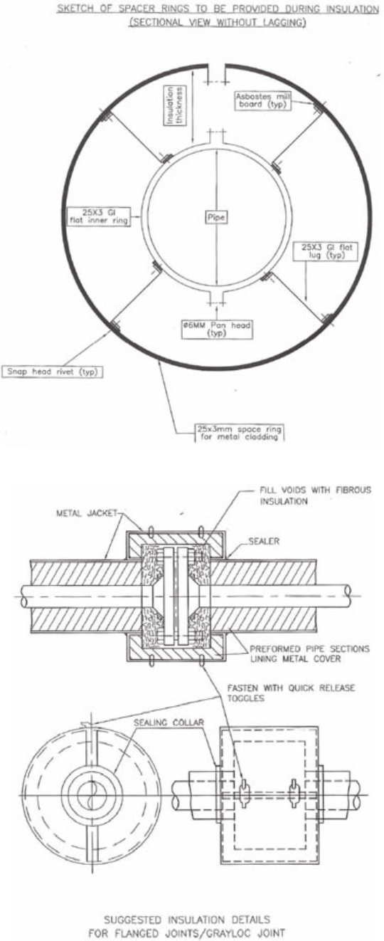
63
FIG. 41. Insulation spacer rings.
FIG. 42. Insulation details for flanged joints/Grayloc joint.
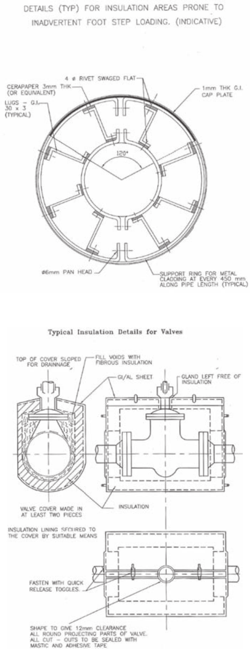
64
FIG. 43. Details for insulation areas prone to inadvertent foot stepping load.
FIG. 44. Typical insulation details for valves.
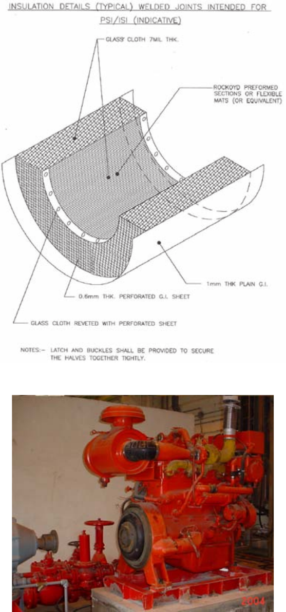
65
Manual firefighting systems were conventionally chosen over the automatic sprinkler system (shown in
Fig. 47) to minimize spurious alarms leading to operation of the automatic system inside the containment building.
However, automatic sprinkler systems inside the containment are now effectively being adopted as a result of
robust advancements that have taken place in fire detection and fire alarm systems.
FIG. 45. Insulation details for welded joints.
FIG. 46. Fire water diesel generator pump (credit: NPCIL).
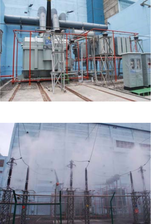
66
The operation of fire protection systems requires positive fire detection. With the advancement of electrical
cable insulation material, use of non-volatile oil and other material with slow burning capabilities, the fire load can
be further reduced.
Major areas vulnerable to fire hazards in an NPP are:
— Turbine oil systems;
— Transformer oil systems;
— Oil hydraulic systems being used as instrumented medium;
— Polymer material;
— Diesel oil;
— Hydrogen used in the turbogenerator cooling system;
— Cable spreading room;
— Other combustion material such as insulation, wood and cotton rags.
Fire water systems with a sufficient number of hydrants are networked in all the buildings of NPPs, except for
diesel generator rooms, main oil tanks and turbine oil tanks, which are provided with an automatic carbon dioxide
system. Use of a carbon dioxide system in these areas is more appropriate and safer than the fire water system,
because of energized equipment.
A high velocity automatic sprinkler system (shown in operation in Fig. 48), commonly known as an automatic
deluge system or mulsifire system, is provided to protect all different types of transformers installed in the plant.
FIG. 47. Automatic sprinkler system (credit: NPCIL).
FIG. 48. Automatic sprinkler system in operation (credit: NPCIL).
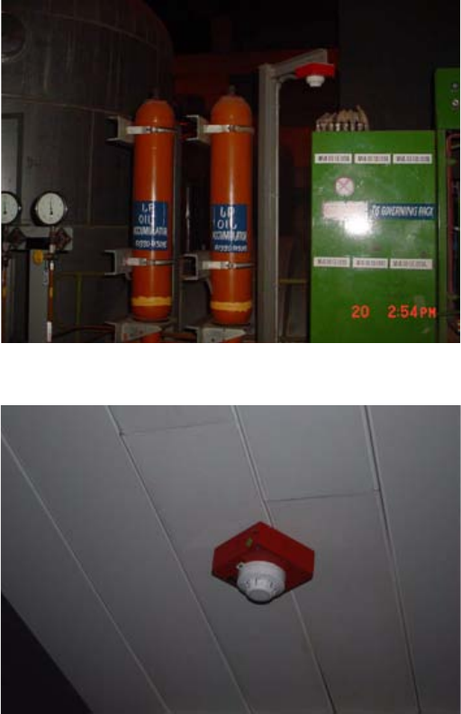
67
Fire water and carbon dioxide are used as the main fire extinguisher materials. The major advancement has
been in early fire detection and effective actuation of fire protection systems in a positive manner. Figure 49 shows
some field fire detectors.
Fire alarm system
The fire alarm system is designed and constructed for the detection of fire in its early stages so that it can be
extinguished effectively and rapidly. The fire detectors may be smoke detectors (shown in Fig. 50), thermal
detectors, flame detectors or manual push button call points installed at various locations in the plant. Ionization
type smoke detectors with a dual ionization chamber have a higher sensitivity to relatively smaller smoke particles
than the optical type of smoke detectors.
Thermal detectors sense the temperature by means of thermisters. The thermisters provide a fast response to
rapid increase in temperature, and are capable of actuating an alarm when the surrounding temperature reaches a
preset point. The beam detector works on the light obscuration principle. These advanced detectors are used most
effectively inside the containment as supplements to other types of detectors.
Advanced flame detectors that work on the principle of detecting the infrared radiation emanating from the
flame are also used to supplement smoke detectors provided in the various rooms and locations of the containment.
Linear heat sensors are provided in the cable trays for detecting the fire in electrical carrier systems at regular
intervals. However, utmost care must be exercised during the installation of these cables. The location of the fire
FIG. 49. Field fire detectors (credit: NPCIL).
FIG. 50. Smoke detector (credit: NPCIL).
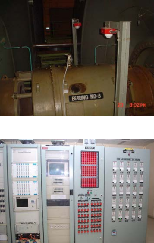
68
detectors is decided after considering the possible air movement as contemplated in normal ventilation,
air-conditioning and contaminated air purge systems. Detectors are also located right above the main equipment
and at other vulnerable points, as shown in Fig. 51.
Guidelines given in Ref. [6] are generally followed for the placement of detectors.
Fire control panels are conventionally kept inside the main control room. As an improvement, local area
control panels are also provided so that the field operator can operate the fire protection system in case of
emergency. There are various methods for looping the detectors, but the class A mode is preferred. The central
control unit of the fire alarm system has undergone major advancements. A software controlled microprocessor
based central control panel has been provided (Fig. 52), as well as an alarm display on supervisory computers
(Fig. 53) and logging on printers.
The control panels are entirely independent of each other so that the failure of one control panel does not
affect the standby control panels. Each control panel provides local indication with a response time of less than one
minute. Each control panel is generally configured with a dual redundant power supply unit, one of them being
through the station power battery system. The self-diagnostic feature of the control unit continuously monitors the
functioning of the detectors and health of the loop wiring, etc.
With the advancements now available in the software for fire alarm detection, all problems are reported to the
control unit in such a manner that quick and easy rectification is possible. Supervisory computers have a colour
graphic facility to store plant floor plans.
FIG. 51. Fire detector on equipment (credit: NPCIL).
FIG. 52. Fire control panel (credit: NPCIL).
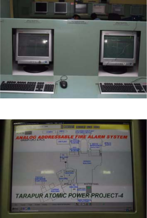
69
As shown in Fig. 54, the operator is able to see the corresponding floor plan should any of the fire detectors
be actuated in plant in a particular zone. This also actuates automatic stoppage of intake ventilation fans and
actuation of various fire dampers.
Conventionally, mineral insulated cables used for interconnecting various fire detectors, and multi-pair fire
retardant low smoke (FRLS) cables were used for interconnecting the various buildings. Use of poly-ether-ether-
ketone (PEEK) is now being preferred as an improvement. The fire alarm system also had audiovisual
annunciations both in the control room and in the affected areas as an effective warning to take immediate remedial
action. The entire fire alarm system, including detectors and control unit, is qualified as per noise immunity
standards. All types of detectors and field modules are also qualified to meet the background gamma radiation
requirements as per applicable codes. Many advancements are incorporated in the fire detection system from time
to time by providing effective sensors on rotating equipment such as bearing temperature control equipment and
field wiring temperature equipment; on the cable carrier system at regular intervals; and in the overall volumetric
area under surveillance.
FIG. 53. Supervisory computer (credit: NPCIL).
FIG. 54. Graphics of plant layout (credit: NPCIL).
70
4.3. ELECTRICAL AND I&C INSTALLATIONS
4.3.1. Discussion of electrical and I&C installation activities
Power distribution in power plants has consisted of a radial distribution system with multiple trains of
medium voltage switchgear feeding large motors and transformers for the low voltage power system. Multiple
feeds have been provided to the medium voltage power system from transformers connected to the main generator
and the transmission system, in order to address off-line and on-line power requirements. Based on equipment
ratings, the distribution systems are optimized for equipment cost, plant arrangement impact and voltage regulation.
Control is through hard-wired electromechanical relay logic. This results in numerous multi-conductor cables
between the control room and/or power distribution equipment and end devices. Instrumentation and low voltage
control wiring is typically run from the end device to the main control room, or to local control panels. This consists
of twisted pair/triads and thermocouple cables.
Cable trays have been used to reduce the space and cost of the electrical installation compared to an
all-conduit installation. The trays have been segregated into power, control and instrumentation to minimize
interaction between different types of signals. Multiple divisions of cable tray have been installed to ensure that if
one division of cable tray supplied equipment is impacted, the other division/divisions remain functional. Special
cable tray designs and cable tray spreading rooms are used to handle the volume of cables in the control building
and under the main control room.
Cable trays are required for power plant designs. The location and number of trays will change based on the
number of cables required, ratings of power distribution equipment, and whether hard-wired, multiplexed, and/or
digital signal control is selected. Most systems will use either a multiplexed or digital signal control process, which
will significantly reduce the number of cables going to the control building. Engineered safeguard systems may use
hard-wired or a combination of manual hard-wired and automatic multiplexed/digital signal control based on
reliability resolutions. Total cable tray requirements should be reduced, especially in the control building.
Physical properties of copper and insulating materials have not changed and installation techniques remain
essentially unchanged. Fibre optic cable has a bending radius much larger than that of copper cable. Improvements
in materials have reduced the training radius of individual fibres to 2.5–5 cm. The installation of fibre optic cable
still requires a larger bending radius than copper insulated cable. Coaxial cables also require a larger bend radius to
ensure proper shield performance.
Electrical and instrumentation and control (I&C) installation activities generally include:
— Power and control raceway;
— Supports;
— Conduit and cable tray installation;
— Instrumentation (racks, mounting, transmitters, switches, etc.);
— Power and control cable and terminations;
— Isophase and non-segregated bus duct;
— Transformers and switchgear;
— Motor installations;
— Control room panels, wiring and termination;
— Local I&C equipment;
— Electrical equipment;
— Motor control centres;
— Digital control systems;
— Switchyard breakers and equipment;
— Equipment and site grounding;
— Heat tracing;
— Lighting;
— Communications and data systems;
— Field verification (QA/QC/Testing);
— Essential power;
— Batteries, chargers;
71
— Emergency generators;
—Switchgear;
— Examination, testing and startup.
4.3.2. Construction methods for electrical and I&C installations
4.3.2.1. Background
Significant advances have been made in I&C technology in the last 20 years. The control technology has
evolved from the analogue control with pen recorders, manual/auto station, and alarm panels prevalent 20 years
ago, to modern distributed control systems (DCSs) with cathode ray tube (CRT) based operator interfaces and new
control algorithms based on modern microprocessor technology. DCS control has the capability either to monitor
system operation and guide control room operators through adjustments that will optimize the process; or to
automate the process, thereby optimizing it. In addition, through sophisticated algorithms, the DCS can correct for
off-design conditions. Advances in computing capabilities have allowed designers to model processes more
precisely. Thus, the computing system is able to determine the most appropriate means of optimizing the system.
DCSs can provide digital processing and logic capability; remote and local data acquisition; and data links and
gateways between systems and components. They also provide operator monitoring and control interfaces; secure
communications to external computer systems and networks; alarm management functions; and communication
between the systems. Utility owners have begun to replace their current analogue control systems for several
reasons. Replacement parts are becoming scarce, the benefits of the DCSs have been proven, and implementation
costs have been minimized. However, while utility-designed control systems are very similar to control systems
that would be found in market-based facilities, utility control systems tend to contain more instrumentation, as well
as more maintenance and diagnostic equipment. Generally, utility owners are interested in ‘expert’ systems, while
owners of market-based plants are not interested in investing in these advanced systems.
The future of control system technology is developing rapidly through technological advancements and the
changing microprocessor industry. Costs are decreasing due to the improvement in microchip technology and
advancements in the manufacturing techniques of microprocessor boards.
DCS equipment will become more robust or environmentally qualified. In the next generation of power
systems, most systems and processes will be automated and controlled through a DCS. They will have improved
system performance in terms of accuracy and computation capabilities, and improved capabilities such as
fault-tolerance, self-testing, signal validation, and process system diagnostics. With the quantity of equipment and
instrumentation that will be controlled through the DCS, dedicated point-to-point connections will result in an
immense wiring system. Industry advances continue in the area of replacing the current wiring scheme of NPPs
with a network or field bus. The field bus communicates digitally with a controller highway, which then
communicates with the operator interface system. Conversion to networked designs will eliminate the long runs of
cable required by dedicated point-to-point connections.
An additional advantage of DCS type control systems is their ability to log and store historical operating data.
The operating system is capable of exporting historical data to a personal computer, where the operator can
manipulate the data in a multitude of ways. In addition, the DCS is able to compare current data to historical data to
determine loss of efficiency or changes in operating parameters.
Another area of improvement in the future of NPP control system is instrumentation. Pressure and
temperature instrumentation has basically remained the same over the past ten years. With the development of fibre
optics, it is feasible that this technology will be incorporated in the instruments, thus improving the accuracy and
precision of temperature and/or pressure measurements.
Even for the case of plants using the current generation active safety system design, the use of advances in
electronics technology has reduced the amount of equipment and construction quantities compared to previous
designs. Previous power systems used hard-wired point-to-point connections for field monitoring and control
systems. Conventionally, this meant one or more wires per function, resulting in anywhere from roughly 30 000 to
50 000 wires coming from the field to the cable spreading room, and then to the control room. The use of fibre optic
networks, which carry substantially more information, instead of copper cabling, has eliminated roughly 400 km of
cabling and 3 800 m3 of cable trays in some power system applications. Use of microprocessors and solid state
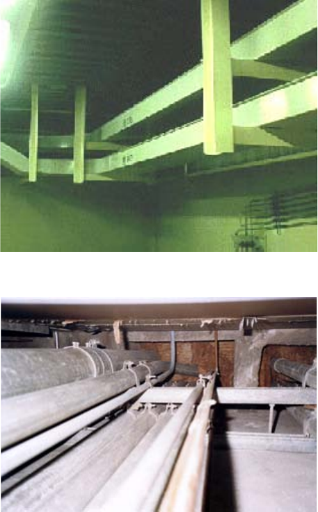
72
devices in the control networks has in some cases reduced the number of safety system cabinets in the control room
from seventeen to three.
4.3.2.2. Raceway installation
Conventional methods
Electrical raceways (shown in Fig. 55) include duct banks, cable trays, and conduit and wire ways (shown in
Fig. 56). The installation needs to take into account seismic classification and proper design of supports.
Because equipment is located in spaces throughout the plant, the electrical cables run throughout the plant in
cable trays or conduit. Penetrations of boxed openings, etc. are arranged within the walls and floors to provide for
penetration openings for the cable tray or conduit raceways. Steel plates are embedded in the concrete walls to
provide a surface for attachment of supports and restraints for equipment, electrical raceway, etc. After the floors
and walls have cured sufficiently, the equipment is moved into position, and assembly is completed within the room
structure, along with the installation of the electrical raceways and cable, piping, HVAC ductwork; etc. as well as
the required structural supports to hang and restrain movement. As discussed in other paragraphs, in previous
methods of construction, tape measures, levels, etc. were used to locate the position of the walls and floors to be
constructed, and subsequently the equipment, piping, electrical raceways, HVAC; etc. Each of these assembly
operations was performed using the stick-build construction method, with thousands of single component fitting
tasks occurring simultaneously in the same physical floor space at various distances above the floor. This meant that
mazes of scaffolding were required to access locations above the floor, resulting in a progressively decreasing
workspace in which to perform the tasks.
FIG. 55. Conventional cable raceway.
FIG. 56. Conventional cable conduits.
73
Advanced methods
Earlier generation cable tray support design had the shape of an H-frame (shown in Fig. 56), which enclosed
the cable tray with structural tubing and/or channels. Cable tray supports have been improved by eliminating the
support on one side of the cable tray. This makes cable pulling and its set-up easier, provides better access to cable
trays, and allows cables to be placed directly into cable trays. The improved cable tray support is applied unless
seismic/safety analysis requires the H-frame-shaped support.
Designs to incorporate cable-pulling installation bracing attach directly to the cable tray for future access. A
minimum space of approximately 700 mm is reserved alongside the cable tray route to attach the cable-pulling
bracing. The cable-pulling space is reviewed in advance when the 3-D model of bulk commodities is prepared.
Electricians use the cable pulling installation bracing to set-up and to pull and train cables in the raceway without
erecting the scaffold on the floor.
4.3.2.3. Cable materials and installation
Conventional methods
Conventional methods of cable installation typically involve applying a lubricant to the cable (or group of
cables) and pulling them into place using a cable-pulling machine (a cable tugger) and a pull rope. The rope is first
routed through the electrical raceway or conduit and connected to the subject cables to be pulled. The cables are
then pulled into place.
In order to keep the cables from binding in the various turns of the raceway, and to prevent piling of the cables
in cable trays, workers conventionally crawl within the limited space or work from scaffolding to hold and train the
cables into an organized pattern.
All cables are pulled in accordance with a detailed cable routing and raceway design. Damage to cables is
prevented by carefully limiting the pulling force applied. QA records are maintained and checked to ensure that the
allowable pulling force has not been exceeded.
Advanced methods
The installation of cables requires significant time and can be part of the critical path. The term ‘cable pulling’
is used for the process of cable installation in electrical raceways to make electrical connections of equipment for
power C&I circuits. The use of electronic cable and raceway routing systems will improve cable routing
documentation. The aforementioned cable tray support design substantially reduces the amount of temporary
scaffolding required to be built when performing cable pulls. This reduces the maze of congestion for movement of
material and workers performing other tasks.
An installation technique that reduces the extent and complexity of cable pulling involves breaking the cable
into segments and then splicing them during installation. Although this concept is not new to construction activities,
the technology of splicing has improved significantly since the previous generation of NPP construction.
Splicing techniques have been established, e.g. in the ship building industry, to connect cables that pass
through different modules or ship sections. Splicing of power cable conductors and thermocouple conductors is
problematic in NPPs because of concerns over splice quality and environmental qualification. Regulatory handling
of cable splices continues to develop as splice technology improves and splices are utilized in the maintenance of
exiting plants. Shielded cable termination materials have improved to a point where heat shrink terminations are
preferred over taped terminations. They are easier, quicker and have proved very reliable.
Fibre optic cables
New plants are likely to have at least some fibre optic cable. Such cable has not been used extensively in
previous generations of NPPs. Technology and techniques for terminating the individual fibres in the telecom
industry have improved dramatically over the last few years, going from very skilled craft requirements to
mechanical connectors requiring normal craft expertise. Techniques for terminating individual fibres under the
many different environmental conditions present in a power plant will need ongoing development and validation.
74
Fibre optics was originally developed in the telecom industry, where extreme environments such as radiation
exposure were not a concern.
The use of digital control equipment is expected to reduce the number of cables required in NPPs. Standards
from several international standards agencies now include requirements for the installation and support of fibre
optic cable. This should improve the consistency and quality of the installation work.
Multimode fibre optic cable design uses individual fibres with a 62.5 µm core diameter/125 µm cladding
diameter, graded index optical fibre, optimized for operation at both 850 nm and 1300 nm transmission windows.
Individual fibres are colour-coded for identification, surrounded with aramid (high-performance fibre) strength
elements and jacketed for high fibre count. Fibre optic cables are designed for a maximum tensile strength during
installation of 272.2 kg and post-installation of 61.2 kg. Safety related fibre optic cables are qualified in accordance
with the guidance in national accepted standards. Fibre optic cable is PVC free, comprises fire-retardant materials
and meets the flame propagation test requirements of national accepted standard. Fibre optic cable will be qualified
for use up to maximum temperature of 65C, and 100% humidity for 60 years’ life. Fibre optic cable will be tested
for normal total integrated radiation dose of 1 × 10⁴ Gy exposures, and design basis accident/loss of coolant
accident total integrated radiation dose of 3 × 10⁵ Gy.
Fibre optic cables can be used for all backbone cabling for control process and video network. All
communication links between process controls, switches, controllers, DCS, etc. are through fibre optic cables.
Plant-wide Plant Data Network (PDN) is designed with fibre optic based backbone cables. The type of fibre optic
cabling used is in accordance with applicable national standards defining acceptable transmission distances
between components. As a rule, single mode fibre optic cables are used for distances greater than 1.5 km; shorter
runs can use multi-mode fibre optic cables.
All fibres at the beginning and end points of a fibre optic run shall be terminated to a fibre termination panel
via straight tip connectors, or other connectors as approved and qualified per national accepted standard.
Stand-alone signal repeaters extend and repeat data signals over single-mode or multimode fibres and provide fibre
optic links up to 130 km, compatible with various protocols, including Ethernet and fibre channel.
Multi-core cables
The cable installation will be the anchor in the construction sequence following the installation of piping,
cable trays, HVAC ducts and conduits. The NPP has a great number of cables; e.g. more than 20 000 cables with a
length of 2 000 km in total. Cable pulling is energy-consuming work that requires allocating labours along the
raceways, as well as taking account of the allowable tension for the cable. Multi-core cables have fewer cables,
resulting in labour-saving at the worksite, and a lower cost of cables.
A multi-core cable is a unified cable that has several cables which run through the same route (from–to).
Multi-cables are identified based on the electrical connecting wiring drawing (ECWD), which shows the ‘from–to’
of each cable. Figure 57 shows the concept of how to apply the multi-core cable. A terminal box is used to unify
four local control cables into a multi-core control cable, and two local instrument cables into a multi-core
instrument cable in Fig. 57. The total cable length can be reduced from 600 m (six local cables × 100 m) to 360 m
(two multi-core cables × 60 m, and six local cables × 40 m). Figure 58 shows a terminal box for multi-core cables.
Person-hours used to pull a multi-core cable are mostly the same as those used to pull a conventional cable;
therefore the person-hours can be significantly reduced by using multi-core cables. A multi-core cable can be
formed into a plug-in connector to a component; e.g. a pump or a motor-operated valve. A plug-in connector
provides the easiest method to connect/disconnect the cable to/from the component, which improves the
maintenance of the component after the commercial operation, as well as the construction of the NPP. However,
plug-in connectors are generally expensive. It is necessary to evaluate plug-in connectors from the total perspective
of the construction and the maintenance. Figure 59 shows a motor-operated valve.
Advantages:
— Reduction in the number of cables, which saves on person-hours for cable pulling;
— Reduction in the cost of the cables;
— Reduction in the size of conduits because the total section of the cables can be decreased;
— Improvement in the maintenance of components using plug-in connectors.
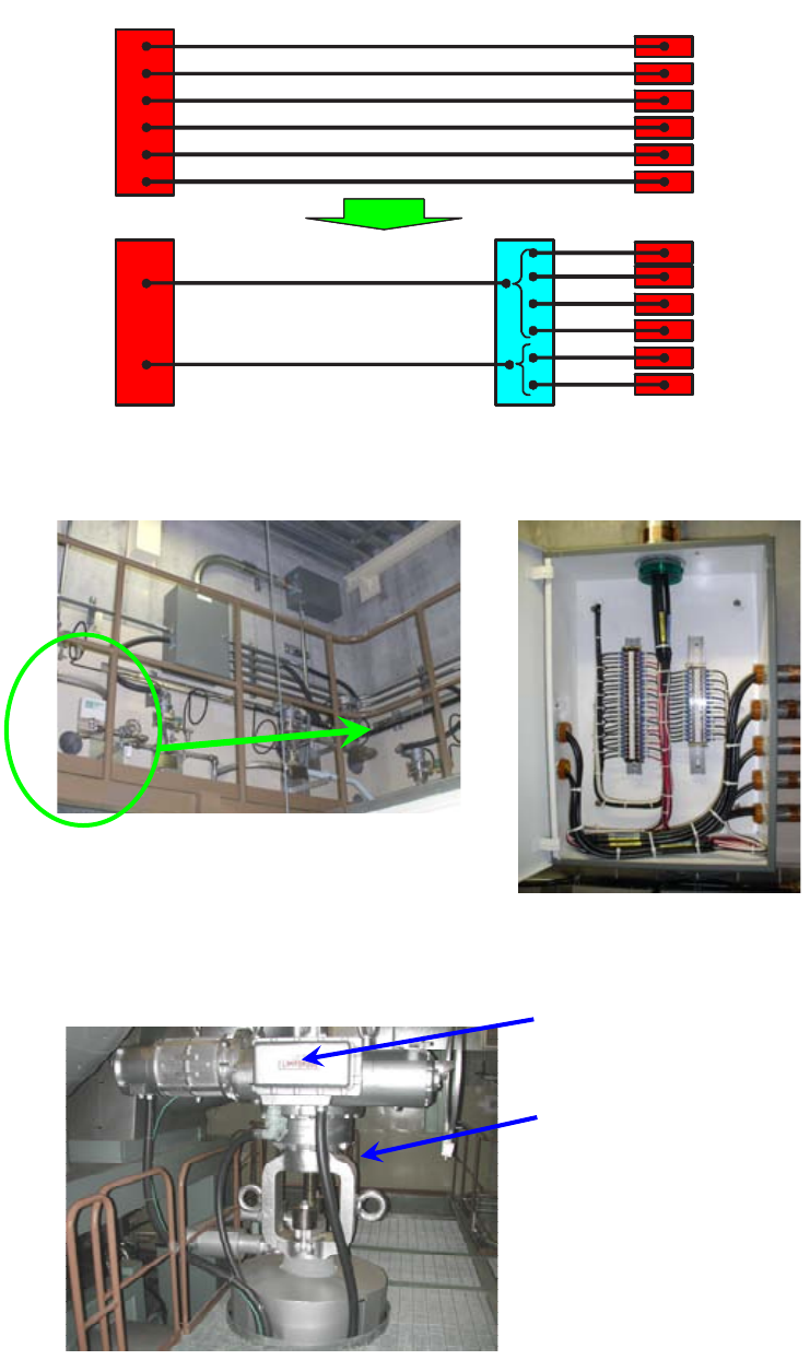
75
Control Cable 3cores 100m
Control Cable 3cores 100m
Control Cable 3cores 100m
Control Cable 3cores 100m
Instrument Cable 2pairs 100m
Instrument Cable 2pairs 100m
Control Cable 12cores 60m
Instrument Cable 4pairs 60m
Terminal Box
Cable Total 600m
40m㽢6
Cable Total 360m
Panel
Panel Local
Local
Control Cable 3cores 100m
Control Cable 3cores 100m
Control Cable 3cores 100m
Control Cable 3cores 100m
Instrument Cable 2pairs 100m
Instrument Cable 2pairs 100m
Control Cable 12cores 60m
Instrument Cable 4pairs 60m
Terminal Box
Cable Total 600m
40m㽢6
Cable Total 360m
Panel
Panel Local
Local
FIG. 57. Concept of multi-core cables.
FIG. 58. Terminal box for multi-core cables.
Instrument Cable
Plug-in Connector
FIG. 59. Motor-operated valve with plug-in connector.
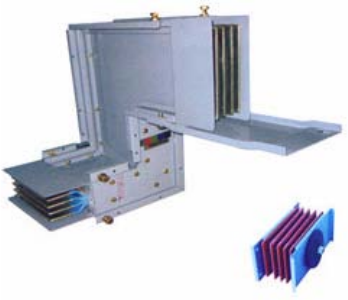
76
Disadvantages:
— Increased engineering is required to identify multi-core cables;
— Early issuing of ECWDs is required. This requires the early finish of the upper stream design to be able to
perform electrical and I&C design.
4.3.2.4. Bus duct installation
Conventional method
The electrical bus duct is conventionally field assembled with the busbar being spaced and attached using
insulating hardware and stand-off bushings. Bolted connections are tightened to a specified torque value, slowing
installation.
Advanced methods
An advanced design for low voltage electrical bus duct, called ‘sandwich’ bus, has been developed to shorten
installation time. Sandwich type bus ducts (shown in Fig. 60) have the busbar directly attached to insulating sheet
material. This type of bus duct requires significantly less installation time and expertise. Sandwich type bus ducts
should be appropriate for non-safety-related applications, and may even be qualified in the future for safety related
applications. Required fittings (elbows, tees, tap offs, etc.) are available.
To further speed up installation and provide for more consistent busbar joint bolt torque, break-away
connecting bolts can be used. The bolt heads will break away once the required torque is achieved.
Cable bus systems may be used to instead of non-segregated phase bus ducts. Cable bus systems use cable
instead of bus work, thereby significantly reducing the number of bolted electrical connections.
4.3.2.5. Protective relaying
Conventional method
Electromechanical relays for transformers, generators, large motors and other power equipment usually have
a single function of protection/monitoring or metering. These delicate devices are installed in large relay and
protection cabinets located above circuit breakers or in a separate large size panel. The electromechanical relays are
sensitive to rough handling during construction and installation, and usually require extensive adjustment and
retesting during the electrical commissioning phase of plant startup.
FIG. 60. Sandwich type bus duct.
77
Advanced method
Proven solid state devices with multifunction protection/monitoring, metering and automation capability have
been used in the industry and the utility industry for several years (refer to Fig. 61). Electrical distribution
switchgear can use one multifunction relay per service instead of three to five single function relays.
Turbine/generator/main transformer protection can now be accomplished using redundant multifunction relays
instead of many single function relays. The installation is straightforward, with simple panel mounting. The control
panel point to point wiring scope of work is significantly reduced. The unit is factory pretested, which requires only
field testing of the wiring connections to sensing devices and programming. The unit installation can be delayed,
minimizing the risk of damage during construction.
4.3.2.6. Electrical penetration fireproofing (also applies to mechanical penetrations where fireproofing is
required)
Conventional method
Once all cables are installed through a building wall penetration and the conductivity of these cables has been
tested and accepted, fireproofing material is installed. Individual pieces of fireproofing material are packed in the
crevices between the cables, and between the cables and the frame surrounding the cables. Once all the crevices are
packed with material, the frame is tightened to form an airtight seal. This process of fireproofing material packing
is tedious and time consuming. Any cable additions to a sealed penetration require careful chipping away of the
fireproofing material with a hand tool, without damaging the cables.
Advanced method
Once all cables are installed, a temporary dam is formed on one side of the penetration. The crevices are then
filled with a free-flowing silicon based caulk that fills all of the void spaces by gravity. Once the caulk cures, the
temporary dam is removed. This process requires much less time than the hand packing process. If a new cable is
added, the caulk is easier to remove than the hand-packed material. The qualifications of the silicone sealant have
been established for use in NPPs.
4.3.2.7. Instrumentation valve and instrumentation designs that reduce installation time
Conventional method
Valves, valve instrument accessories and plant instrumentation have conventionally been installed in NPPs
using a stick-build method, similar to that used for bigger components and structures. Each valve, valve instrument
accessory and plant instrument has been installed individually, with the required connections made after
installation.
FIG. 61. Solid state relay protection.
78
Advanced methods
Valves and valve instrumentation accessories are now available from manufacturers as assembled or
integrated units. Using these integrated units is similar, on a small scale, to the module approach for installing larger
components and structures. The instrumentation is installed on the valve as a unit at the factory, and then the whole
unit is installed in the field. This limits the number of connections needed to be performed on the construction site,
reducing the installation time and improving the construction schedule. The quality of the connections is also
improved because they are done in a more controlled environment at the factory.
Typically, the valve and valve instrumentation accessories are designed as a unit. The plant designers then
request that the valve unit be manufactured as such, as opposed to the vendor providing a standard valve unit. Many
valve suppliers offer these custom-built valve units with the attached instrumentation.
Another advanced method for instrumentation and valve accessory installation is the practice of racking. Rack
designs install the valve instrument accessories and plant instrumentation for a component on a rack that is detached
and installed separately from the component itself. Therefore, minimal instrumentation is installed on or near the
component. The valve instrument accessories and plant instrumentation racks can be installed away from the
components, enabling them to be moved away from harsh environments. With the valve instrument accessories and
instrumentation installed on the rack by the vendor, a minimal amount of work is required to connect the rack and
the components. Finally, the racks can be located in less congested areas of the building, easing installation and
testing.
4.3.2.8. Auxiliary power supply system
Normal auxiliary power supply (off-site) system
Under normal conditions of operation, the power to all the auxiliary loads is fed from an off-site power supply
system. Normal power supply to an NPP is derived from the plant generator and grid. During normal startup and
operation, the power can be supplied totally by a unit auxiliary transformer (UAT); or it can be supplied by a
generator transformer (if a generator circuit-breaker is provided) or by startup transformers, or partly by both these
transformers. These sources are connected at 6.6 kV level in such a way that in the event of failure of the startup
transformer or unit transformer or any source, an automatic fast transfer scheme is initiated to ensure power supply
restoration from the healthy source.
Emergency power supply system
Balance-of-plant (non-safety) power supply system
This system derives its power from a non-safety-related power system under normal conditions of operation.
Safety related power supply system
This power supply system provides uninterrupted alternating current (AC) power to the safety related loads
connected to it and is backed up by emergency diesel generators/batteries.
Off-site power system
The off-site power system provides grid interconnection for power transmission as well as startup power
source. The power transmission system consists of the switchyard for transmission of power generated from both
the units, and serves as the startup source via the generator transformer and unit transformer (where a generator
circuit-breaker is provided between the generator and generator transformer), or via the startup transformer.
Transmission lines are connected between NPP switchyard and grids.
79
Miscellaneous electrical systems
In order to successfully commission and operate the electrical systems, and to feed power supplies to various
process loads, miscellaneous systems such as a cable carrier system, cabling system, lighting system and earthing
(grounding) system are required.
I&C system
In any NPP, I&C systems are basically meant to control the basic parameters of the process and other safety
systems. I&C technology has undergone significant advances in the last 20 years. The future of control system
technology is quickly developing through technological advancements and the changing microprocessor industry.
Costs are decreasing due to improvements in the microchip technology and advancements in the manufacturing
techniques of microprocessor boards.
Advancements
Cable carrier system
The cable tray system, shown in Fig. 62, is very important from a construction point of view. This activity is
planned and executed at the beginning of electrical works, and progresses in parallel with the civil and mechanical
construction. The manpower requirements for the installation of cable tray system are almost 30% of the physical
portion of the electrical works. It is essential that cable tray routes are comprehensively checked for interference,
and are 100% complete before the installation of cables. Conventionally, the cable tray supports are installed in
parts that involve excessive human resources. It has also been experienced that interference with other system
installation is not completely avoidable. An advanced construction technology has now evolved after gaining
sufficient experience in the construction of recent nuclear plants. In this methodology, the cable tray supports with
predefined cantilever arrangement are prefabricated as modules in the shops, and then installed on-site. The
segregation criterion to meet Institute of Electrical and Electronics Engineers Inc. (IEEE) stipulations and other
regulatory requirements is strictly followed while detailing the routes of the cable tray. The steel sections of the
cable tray supports have been standardized for different types of applications, i.e for safety and non-safety-related
systems. The use of slotted type cantilever supports enables further advancement by allowing a significant
reduction in time and cost during erection. Minor adjustments are possible in field with these slotted type supports
to suit the field requirements. The prefabricated steel sections, along with bolted slotted horizontal members, can be
installed in a mechanized way in the field. This advancement in installation of the cable tray support assembly
minimizes time and effort in the construction of power plants. This advanced system also reduces the industrial
safety risk involved. However, care has to be taken that adequately designed vertical and horizontal bends of cable
carrier systems are properly matched with the associated cable trays. Figure 62 shows a cable tray system installed
in parallel with the civil construction. Alternatively, standard extruded box sections for cable tray supports are
useful for on-site erection, as they reduce site work.
Embedded parts
Hundreds of cables are required to be taken inside the reactor building through containment walls both for
electrical and instrumentation systems, including all the safety and non-safety-related systems. Rectangular
embedded parts with welded cable glands have conventionally been used for entry of these cables in the
containment. This, however, poses some problems for civil construction, and also for maintaining the leaktightness
of the containment.
Canister embedded parts that have rounded edges and an individual sleeve for a cable are now being
extensively used as an advanced module. Use of these modules ensures proper compacting of concrete of
containment walls around the embedded parts, as well as protection of other cables against failure of a particular
cable. This simplifies the job of identification and replacement of faulty cable. These embedded parts provide for
leak detection of individual penetration during the entire operation phase of the reactor.
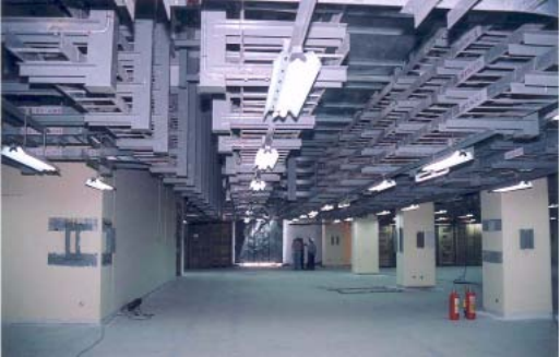
80
Advancement in construction has been given more importance in the cable sealing system specially meant for
reactor containments. Conventionally, heat shrinkable sleeves coupled with sealing compounds were used as a
cable sealing system for the containment building. An advanced cable glanding system has now been adopted for
sealing the cables on both the faces of containment. The stranded conductor cables, sealed by crimping ferrule
combined with casting of epoxy mould and glanding system, give perfect leaktightness. As an additional
precaution, the entire gland assembly is further sealed/protected by the heat sinkable sleeves. The heat sinkable
sleeves are provided only after the entire cable penetration has been tested for zero leakage during containment
testing. This is very important, as a large number of cables enter into the reactor building, and improper sealing may
lead to an increase in leak rates of the containment. The advanced technology being used ensures quality sealing for
an extended period of time.
Earthing (grounding)
The work of main station earthing starts with the commencement of the civil works. Mild steel conductor rods
or copper conductor with welded/brazed joints have been conventionally used to make an integrated earthing
network. However, the quality of brazing/welding and the subsoil corrosive atmosphere have always been matters
of concern. Earthing, being a very important part of the electrical system, has undergone major advancements with
the evolution of construction technology. The brazing joints of multi-strand copper conductors are being made with
CAD welding. These are easy to install and the quality of joints does not depend on the skill of the brazier. A total
grid of the earthing system can be easily developed, interconnecting all the buildings of the plant and connected
with the main earthing electrodes.
Panel erection
Most of the equipment in the electrical systems, such as motor control centres, distribution panels,
transformers and switchgears, is erected as prefabricated modules over a period of time using the advanced
technologies. Each panel (example shown in Fig. 63), switchgear or motor control centre is prefabricated at the
respective shops and transported as a single module. Standardization of terminal numbering in panels facilitates
accurate inter-panel wiring.
All electrical systems are extremely sensitive to humidity and dust. Prior to the erection of these panels, the
locations/rooms receiving the panels are constructed and completed in all respects, including commissioning of
their HVAC systems. All these rooms are left with a panel/wall still to be constructed after the erection of all the
panels. The plant layout should be decided accordingly. This not only ensures easy erection of this equipment in a
dust-free environment, but also improves the productivity of qualified electricians. It is important to note that paper
commissioning checks are carried out as a part of construction activity in order to ensure proper connectivity, and
also to detect grounding of any of the system. The use of a ground fault-detection system starts in the construction
phase. This activity reduces the actual commissioning period.
FIG. 62. Cable tray system installed in parallel with civil construction.
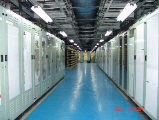
81
4.3.2.9. Instrumentation
Tubing and wiring
The I&C system also includes the erection of panels and the laying of cables as is done for the electrical
system. The additional features in the I&C system for the purpose of construction are installation of various types
of tubing systems, and the advanced termination of wires. The I&C system involves a large amount of process
parameter sensing equipment, field equipment, analysers, data recorders and their associated wiring and tubing.
The network of wiring and tubing of the I&C system is well spread all over the plant. Major emphasis is therefore
placed on the layout of various types of tubing systems for the I&C, and proper termination of the wiring system.
Designers do not usually provide the field layout drawings for the tubing system, as this layout has to be
decided to suit the field conditions. This situation may not be preferred, since the quantity of the material required
may be difficult to estimate and hence remain undefined for some time. Advancements in tubing layout define a
corridor system for laying of the tubing, which is earmarked at the time of initial design. This corridor system
developed during the 3-D model not only improves the aesthetics, but is also operation friendly. Fairly accurate
estimation of quantities is also ensured.
The use of automatic tube welding machines capable of welding of tubes with different sizes and wall
thickness varying from 6–25 mm has reduced erection time. Automatic tube-to-tube welding machines are
available on the market. In order to achieve quality welds, all parameters such as tube thickness, tube size, speed of
rotating head and type of arc required to be generated, are pre-decided. The advancement in these machines has
further increased the output capacity as compared to the machines used in the past.
Three dimensional modelling of tubing layout for a congested system is first developed, using any of the plant
design management tools. This is especially meant for core monitoring systems, and process control of the main
nuclear supply system and reactor regulation and protection system. A proper corridor is framed in order to avoid
any group interference or damage during installation. Use of perforated light channels for laying this delicate tubing
as an advanced construction methodology ensures a well-developed layout with proper identification. Each tube is
identified by a predefined number that is stamped on it by a stamping machine, using halide-free ink. Figure 64
shows prefabricated tubes.
A well established I&C calibration laboratory has to be set-up before the I&C activity takes place. Calibration
of all I&C instruments is considered essential to ensure that commissioning is completed in the scheduled time, and
that defective or damaged instruments are segregated before their installation.
FIG. 63. Prefabricated panels.
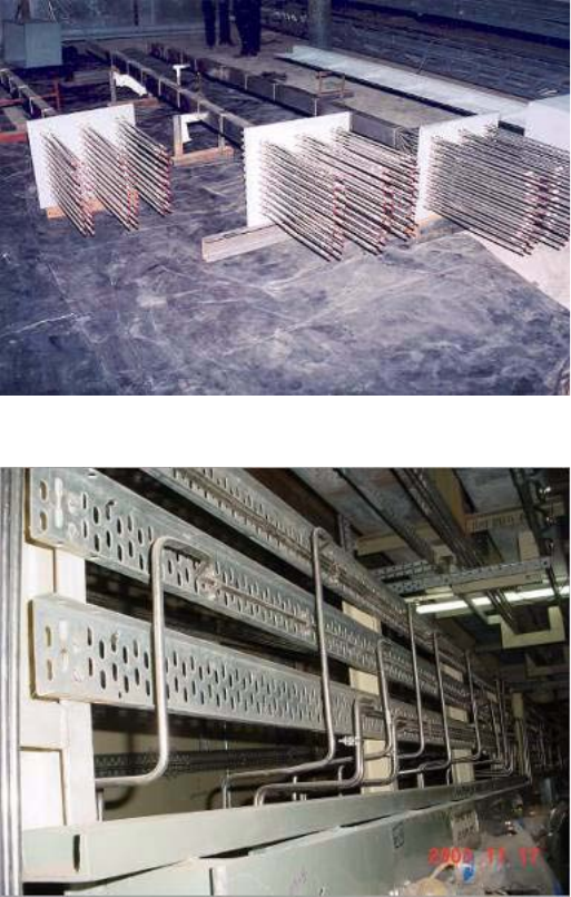
82
Supports for instruments and tubes
Vertical channel frames, H-type or different shapes or size of frames have conventionally been used to suit the
field measurement for supporting sensing equipment, transmitters and various I&C instruments, etc. The
fabrication of supports is mostly related to ‘as-built’ field measurements and location of process instruments, which
takes time and causes congestion in the working space, since all instrumentation jobs are conventionally carried out
on completion of major field activities. As a general practice, most of the support pedestals are fabricated in situ in
the field. This leads to the development some sort of fabrication shop in the plant area, thus interfering with other
plant workers who are fully involved in commissioning activities during such a critical period. This situation is also
not advantageous from an industrial safety point of view.
Prefabricated perforated channel type frames are now being developed to handle all types of installation
arrangements during laying of tubing for I&C systems. Figures 65 and 66 show the typical support arrangement and
height, respectively.
The height of these supports can be suitably adjusted using couplers and extension pieces, thus considerably
saving on installation time.
FIG. 64. Prefabricated tubes.
FIG. 65. Typical frame support arrangement.
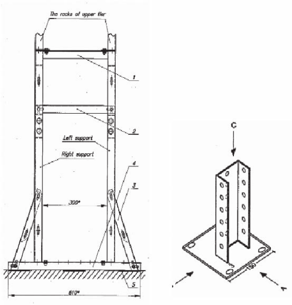
83
Root valves and fittings
Root valves and tube fittings are also an integral part of I&C systems. As root valves provide isolation to the
entire measurement system, their location during installation is extremely important. Isolating root valves are
provided at take-off connections to isolate the entire measurement system from the main pipeline/vessel when
necessary.
The recommended practices which should be followed are:
— Root valves should not affect the pressure signal during normal operation;
— Root valves should be capable of withstanding the maximum working pressure and temperature of the
piping/vessel system to which the take-off adapters or nipples are attached;
— Isolating/root valves should be located immediately following the tapping point;
— It is preferable to use positive isolation valves for root valves;
— Root valve bore should not be less than the inside diameter of impulse tubing/piping;
— The root valve may or may not perform the function of the accessible isolation valve, depending on its
location;
— Root valves and the pipes to which they are connected should be of the same material.
Tube fittings
Tube to tube fittings are being extensively used as a matter of convention in various type of tubing for I&C.
This includes tube to tube connector elbows, reducers and bore-through fittings. Tube fittings are used to join or
connect a tube end to another member. Any tube fitting must accomplish two important functions within the
pressure, temperature and vibration criteria that the tube fitting is designed to meet. Firstly, the tube fitting must grip
the tube end so as to prevent loss of seal or tube blowout. Secondly, the tube fitting must maintain a primary seal
against leakage.
FIG. 66. Frame support height.
84
It is recommended that tube fittings meet the following requirements:
— Offer reliable installation over a range of field conditions, since improper make-up and tightening remain the
leading causes of leakage;
— Cope with the wide variation in tubing characteristics, including differences in wall thickness, hardness,
ovality and burst pressures;
— Be of a compatible material with the tubing or pipe material on which they are used to avoid electrolysis and
to provide acceptable weld joints;
— Be used at pressure temperature ratings not exceeding the recommendation of the tube fitting manufacturer,
and meeting the environmental and process system requirements;
— Be installed in accordance with manufacturer’s recommendations;
— Withstand the temperature and pressure cycling as per the appropriate standard;
— Provide a sufficiently robust grip on the tube such that when a tensile load (e.g. during hydro test or during
operating conditions) is applied to it, the tube does not pull out of the grip. Generally, the acceptable pull-out
tension load is more than four times the hydrostatic test pressure load.
The following types of fittings are generally used:
— Flareless compression type (single terrule);
— Flareless compression type (double terrule);
—Bite type;
— Flared fitting.
Though flared fitting and bite type fittings are more economical than double ferrule flareless fittings, double
ferrule compression fittings have an edge over other type of fittings. They have an enhanced sealing action against
any leakage or vibration; fatigue resistance; a greater margin of performance; and are easy to install. These types of
fittings are available in various materials as per the code requirements, and their use enhances productivity.
4.3.2.10. Control room
Over a period of time, most of the advancements have taken place in developing the new concept of control
panel to provide a user-friendly human–machine interface. The use of modular types of control panels is preferred
over the conventionally made control panels that are wired after installation.
4.4. MATERIALS OF CONSTRUCTION
4.4.1. Discussion of materials issues in construction
The choice of construction materials impacts both construction and operational characteristics of components
and bulk materials. For example, lightweight materials ease the movement and placement of components, and
lighten preassembled skids and modules. Module sizes and content can be increased, lowering the ultimate number
of construction activities required in situ.
Another example of materials issues in construction is the impact of metallurgical properties of steels and
advanced alloys on welding processes and operational performance. Erosion, corrosion, galvanic action, stress
cracking, pitting, thermal weakening and radiation induced degradation all play a role in the design, selection and
advancement of materials used in construction.
Materials used in construction tools and handling rigs also affect construction efficiency. Such tools include a
full range of sizes and purposes, from hand tools to large lifting rigs and cables. Reducing the weight and increasing
performance and safety of construction tools have a direct impact on construction efficiency and cost.
85
4.4.2. Site materials management
4.4.2.1. Introduction
Site materials management is a key construction process that is established early on in the construction phase
to ensure that quality processes are put in place on-site, and that suitable training is provided to all materials
management stakeholders. The intention would be to establish a materials management system used in construction
that would then be carried over to plant operations.
The management of material required to construct an NPP is critically important from placing orders for
materials; to transportation to site; to receiving at warehouse and storage; to issuing to the construction contractors;
and to installation and turnover of completed systems with complete quality records that meet the licence
requirements.
The following paragraphs describe the various processes and how they link up to provide a comprehensive
materials management system.
4.4.2.2. Processes
Examples of processes used for a comprehensive materials management system are:
— Assigning of material codes;
— Recording, coding and incorporating material requirements — Bill of Material (BOM);
— Recording material deliverables;
— Handling of free issue materials;
— Monitoring of project supply vs demand;
— Recording receipt of goods upon delivery;
— Maintenance and preservation of project inventory — indoor and outdoor;
— Maintenance of warehouse storage locations;
— Material traceability;
— Tracking and monitoring of quarantined goods;
— Handling of calibrated goods and identification of calibration completion;
— Preparation and use of Construction Work Packages Material Lists (CWPLs);
— Supply of material shortage reports;
— Recording of material equivalents/replacements/substitutions;
— Requirements for approving material issues;
— Handling of minimum/maximum inventory items;
— Transport of goods to site;
— Return of goods from the field.
4.4.2.3. Purpose and benefits of applying materials management principles
The purposes and project benefits of adhering to the principles of advanced materials management are:
— Coding of materials enforces:
•Complete definition and description of goods;
•Consistent information for all project personnel from the design process; the procurement process; the
manufacturing process; the receiving and inventory process; and including the final issue for installation.
— Project BOM baseline establishes:
•Project material supply requirements;
•Project installer material responsibilities;
•Project free issue materials;
•Project material installation locations for building/area/room/elevation (including weights).
86
— Project Engineering Quotation Request Lists (EQRLs) establish:
•Project baseline of material supply;
•Project spares supply;
•Destination of materials;
— Project free issue material destinations provide:
•Engineering Quotation Request (EQR) responsibility;
•Electronic link from EQRL to material code to electronic documentation system that identifies drawing and
technical specification requirements for an EQR package;
•Ability to analyse demand (BOM baseline) vs supply (EQRL material requirements) to ensure that all
required goods are being supplied in sufficient quantities;
— Purchase order direct link with EQRL establishes that:
•Purchase orders and EQRL must align exactly — item by item, quantity by quantity;
•Items cannot be missed or added in the process of awarding a purchase contract.
— The use of Quality Assurance Reports (QARs) ensures that:
•Each release of goods directed against a purchase order is identified in a complete and consistent manner;
•QA has approved the release of the goods;
— The use of a computerized shipping screen ensures that:
•Each purchase order shipment is directed from an approved QAR and matches exactly the goods released
on the EQR;
•Warehouse receiving staff can view and forecast anticipated arrival date of goods;
•Warehouse receiving staff are presented with consistent, clear shipping documentation to complete the
receiving process successfully.
— The receipt and issue of goods in the computerized material system ensure that:
•Inventory is controlled in a consistent manner and locatable quickly and efficiently.
— The use of the computerized inventory screen ensures that:
•Material is traceable from receipt to release for use and upon return to warehouse (if necessary).
•Minimum and maximum inventory levels of specific goods are maintained.
— The use of CWPLs ensures that:
•The correct material and correct material quantity are issued against the correct scope of work to the correct
contractor/installer.
4.4.2.4. Requirements
The general requirements for the management of material are to establish:
— Complete project material identification;
— A project material requirements baseline;
— A project material supply baseline;
— A process to identify project free issue goods;
— A supply vs demand process to ensure requirements are to be supplied;
— A process to report on project forecast delivery dates;
— A process to report on transportation of project deliverables;
— A process to receive and inventory goods;
— A process to identify and maintain warehouse storage locations;
— An inventory control system that provides immediate inventory status and records all inventory activities;
— An inventory control system that controls quarantined goods;
— An inventory control system that identifies and records the calibration of goods;
— An inventory control system that will identify and maintain minimum/maximum inventory goods;
— An inventory control system that will control the return of goods from the field and maintain material
traceability, from the time of receipt of goods through warehouse inventory period through issue for use;
— That the correct material and correct material quantity are issued against the correct scope of work to the
correct contractor/installer;
— That only goods of acceptable quality are released to the field;
87
— A process to produce project material shortage reports;
— A process to identify material equivalents/replacements/substitutions.
4.4.2.5. Responsible positions
The following is a description of materials management and related positions suggested for NPP construction
execution.
Materials Managers
Materials Managers for the execution of NPP project are generally responsible for:
— Ensuring that the computerized project materials management system has been correctly implemented as
designed and intended in order to support the project’s materials life cycle requirements. This includes but is
not limited to:
•Establishing the project needs regarding the coding of materials and implementing accordingly;
•Establishing all project codes for design BOM;
•Establishing all project codes for EQRL (destinations etc.);
•Establishing the project schedule screen dates;
•Establishing the project applicable warehouse and warehouse locations;
— Providing project material code numbers;
— Providing project supply vs demand analysis;
— Recording project material receipts;
— Maintaining project inventory, including quarantined material status;
— Recording project material issues;
— Recording and ensuring material traceability;
— Recording of project approved material equivalents/replacements;
— Maintaining required inventory of goods identified as requiring minimum/maximum inventory control;
— Recording instrumentation calibration status;
— Maintaining warehouse storage locations;
— Generating material shortage reports as required.
Engineering Managers
Engineering Managers for the execution of NPP projects in relation to materials management are generally
responsible for:
— Complete identification of materials; e.g. full description identifying type of material, ratings, dimensions as
well as Nuclear class, QA level, seismic qualification (SQ), environmental qualification (EQ);
— Identifying drawing, technical specification, etc. references for materials;
— Verifying project BOMs and EQRLs;
— Identifying project free issue materials;
— Identifying acceptable project material equivalents/replacements/substitutions.
Procurement Buyers
Procurement Buyers for the execution of NPP projects are generally responsible for:
— Awarding purchase orders in the contract procurement and materials management systems (CPMMS) as per
procurement procedures.
88
Procurement Order Administrators
Procurement Order Administrators for the execution of NPP projects are generally responsible for:
— Maintaining current and accurate purchase order delivery dates and purchase order status in the CPMMS.
QA Source Inspectors
QA Source Inspectors for the execution of NPP projects are generally responsible for:
— Maintaining QAR data in the CPMMS.
QA Inspectors
QA Inspectors for the execution of NPP projects are generally responsible for:
— Inspection of goods on an ‘as required’ basis;
— Documenting nonconformities of items/materials and verifying that remedial actions on all such
nonconformities have been implemented.
Procurement Logistics Personnel
Procurement logistics personnel for the execution of NPP projects are generally responsible for:
— Updating the CPMMS transportation screens with current and accurate purchase order shipment information.
Warehouse Managers
Warehouse Managers for the execution of NPP projects are generally responsible for:
— Providing warehouse storage locations for materials control staff to maintain in the CPMMS;
— Ensuring that personnel assigned to move or handle heavy loads are fully qualified or professionally trained.
Warehouse Supervisory Staff
Warehouse supervisory staff for the execution of NPP projects are generally responsible for:
— Reviewing the CPMMS shipment data, communicating with transport coordinators and assigning shipment
receiving responsibilities to warehouse receiving staff;
— Arranging periodic inventory audits as planned and implemented by the Materials Control Manager.
Warehouse Receiving Staff
Warehouse receiving staff for the execution of NPP projects are generally responsible for:
— Prior to moving and handling of heavy loads, performing a walkthrough of the job in order to identify
necessary equipment and personnel;
— Inspecting received goods and associated paperwork to assure compliance with purchase order requirements;
— Finalizing Material Receiving Report (MRR) forms on completion of receiving process;
— Locating goods in appropriate warehouse location on completion of receiving process;
— Physically quarantining nonconforming goods in appropriate warehouse location as required;
— Physically removing nonconforming goods from appropriate warehouse location upon resolution of the
nonconforming situation;
89
— Inspecting goods being returned from the field to ensure that the goods are still acceptable for use and that full
material traceability is established prior to returning to project inventory.
Material Control Reviewers
Material Control Reviewers for the execution of NPP projects are generally responsible for:
— Reviewing MRRs to confirm completeness and accuracy;
— Reviewing CWPLs to confirm completeness and accuracy;
— Reviewing Material Inspection Reports (MIRs) to confirm completeness and accuracy;
— Ensuring all warehouse location changes of goods are reflected in the CPMMS.
Calibration Staff
Calibration staff for the execution of NPP projects are generally responsible for:
— Handling of goods requiring calibration while in their custody;
— Identifying goods required for calibration to Material Control and Warehouse staff;
— Recording the calibration of goods in Asset Management module;
— Returning calibrated goods to project warehouse and advising calibration completion status to Material
Control and Warehouse staff.
Project Document Control Coordinators
Document Control Coordinators for the execution of NPP project are generally responsible for:
— Scanning project MRRs and MIRs and forwarding to Information Management for entry into system;
— Retaining hard copies of Project MRRs and MIRs for future reference.
Field Engineering Representatives
Field Engineering Representatives for the execution of NPP project are generally responsible for:
— Providing advice on the acceptability of delivered goods, when necessary;
— Providing advice regarding the acceptability of goods to be issued, when necessary;
— Identifying project minimum/maximum inventory requirements;
— Approving material requirements on Construction Work Packages (CWPs).
Construction Contractors/Installers
Authorized representatives of the Construction Contractors/Installers are responsible for:
— Receiving and installation of materials as per approved CWP and MIR;
— Supplying specified materials as indicated in approved CWP;
— Maintaining the released goods as per specifications in good working condition;
— Continuing and recording preservation activities of the goods while in their custody;
— Returning excess material to the warehouse of issue.
4.4.2.6. Prerequisites
Those assigned responsibility for materials management activities shall have the training, qualifications and
competence necessary to effectively perform their assigned tasks. Confirmation of these prerequisites is the
responsibility of the manager or supervisor of the respective work group.
90
4.4.2.7. Typical procedures
The following are typical procedures that would be developed and issued to all materials management
stakeholders:
— Materials Management Programme;
— Receiving, Receiving Inspection and Positive Recall;
— Receiving of Materials;
— Issue of Materials;
— Warehouse Storage and Handling;
— Warehouse Quarantine;
— Computerized BOM;
— Request for Proposals and Evaluations;
— Preparation and Review of Purchase Orders;
— Post-order Administration of Purchase Orders;
— Release and Shipment of Purchased Goods and Services;
— Supply/Demand Management;
— Nonconformance and Corrective Action Process.
4.4.3. Construction methods related to materials of construction
4.4.3.1. Materials of construction for improved operational performance
Conventional methods
NPPs utilize large vessels and heat exchangers to produce steam for power generation. They produce steam at
much lower temperatures and pressures than fossil-fired power plants. This is especially true when comparing to
super-critical and ultra-super-critical coal plant designs. However, NPPs present other challenges to the material
performance of piping, components and equipment.
Primarily, nuclear reactors involve significant radiation environments, which are a challenge to long term
integrity of all materials, including metals. Safety concerns also produce rigorous requirements. Finally, repair and
replacement within NPPs can be relatively more expensive than at other types of plants, driving the need for
extended life and improved performance.
Pressurized water reactor (PWR) steam generator material performance is a prime example of the evolution of
materials used in NPPs. Steam generators are large tube and shell heat exchangers that pass pressurized reactor
coolant through the tubes and produce steam on the shell side. Two of the most important factors affecting a tube’s
vulnerability to degradation are its material and heat treatment. The two types of tube material conventionally used
for PWR steam generator tubes are alloy 600 and alloy 690. The two types of heat treatment applied to these
materials to improve their mechanical and corrosion resistance properties are mill annealing and thermal treatment.
Early operations of NPPs did not pay close attention to the impact of secondary cycle water chemistry on the
material performance in the steam generators. The dominant cause of tube degradation was thinning of the mill
annealed alloy 600 steam generator tube walls due to the chemistry of the water flowing around them. Changes to
feed-water chemistry control programmes have virtually eliminated this problem with tube thinning. After tube
thinning, tube denting became a primary concern. Denting results from the corrosion of the carbon steel support
plates and the buildup of corrosion product in the crevices between tubes and the tube support plates. Measures
have been taken to control denting, including further changes in the chemistry of the secondary side water
chemistry.
Even after corrections to water chemistry controls were made across the industry, the initial alloy materials
used for steam generators proved ineffective in long term resistance to stress corrosion cracking and pitting. As mill
annealed alloy 600 steam generator tubes began exhibiting degradation in the early 1970s, the design of future
steam generators pursued improvements to reduce the likelihood of corrosion. This resulted in the alloy 600 tubes
being subjected to a high temperature thermal treatment to improve their resistance to corrosion. Although no
significant degradation problems have been observed in plants with thermally treated alloy 600 steam generator
91
tubes, plants which replaced their steam generators since 1989 have primarily used tubes fabricated from thermally
treated alloy 690, which is more corrosion resistant than thermally treated alloy 600. Most of the newer steam
generators, including the aforementioned replacement steam generators, have features that make the tubes less
susceptible to corrosion-related damage. These include using stainless steel tube support plates to minimize the
likelihood of denting, and new fabrication techniques to minimize mechanical stress on tubes.
For reactor pressure vessels (RPVs), long term exposure to high neutron flux rates has caused embrittlement
of the vessel walls. RPVs, which contain the nuclear fuel in NPPs, are made of thick steel plates that are welded
together. Neutrons from the fuel in the reactor irradiate the vessel as the reactor operates. This can embrittle the
steel or lower its strength, subsequently making it less capable of withstanding flaws that may be present.
Embrittlement usually occurs at a vessel’s ‘beltline’, that section of the vessel wall closest to the nuclear fuel.
Many PWR operating plants use core designs that reduce the number of neutrons that reach the vessel wall.
These design features therefore reduce the rate of embrittlement in the reactor vessels. Other factors also contribute
to the degree to which a particular vessel material becomes embrittled. Steels with a higher proportion of copper
and nickel will tend to be more susceptible to embrittlement than steels with lower proportions of these two
elements.
Advanced methods
Materials management matrixes
Decades of worldwide NPP operational history have generated a materials performance knowledge base. The
knowledge and experience have resulted in improved materials being available in current markets. The new
generation of NPP projects has an opportunity to take advantage of these advances, provided the vast collective
experience can be distilled and applied effectively. International research and standards organizations continue to
gather and distil this type of information for the industry as a whole. One such effort is the Electrical Power
Research Institute (EPRI) Materials Management activity under their Advanced Nuclear Technology Programme.
Reference [7] is an example of such work.
The abstract of Ref. [7] is quoted as follows:
“For advanced light water reactor (ALWR) designs currently being considered for new construction, an
opportunity exits to leverage operating plant experience to proactively identify and manage materials
performance issues. In many cases, evaluation of operating plant issues and implementation of mitigation or
management technologies hold the potential to significantly reduce operating costs over the life of these new
plants. Potential benefits include prevention of degraded conditions, more efficient and accurate inspections,
and reductions in repair and replacement costs. To fill this need, EPRI’s Advanced Nuclear Technology
(ANT) has initiated a materials management matrix (MMM) initiative. The focus of the project is on
identification of gaps and opportunities that, if addressed in at appropriate times in the life cycle of the plant,
could significantly improve plant materials performance.”
Materials for sensors and electronics
Emerging technologies in I&C focus on advanced sensors that can affect safety and operating margins. These
include the following areas:
— Sensors and measurement systems;
— Communications media and networking;
— Microprocessors and other integrated circuits (ICs);
— Computational platforms (computers, programmable logic controllers, application specific ICs, etc.);
— Diagnostics and prognostics;
— Control and decision;
— Human–system interactions;
— High-integrity software.
92
Sensor and measurement systems technology that has progressed to becoming potentially applicable includes
silicon carbide neutron-flux monitoring. This sensor has the potential to combine the functions of current
three-range flux monitors into a single system. Data on important parameters such as drift, accuracy, repeatability
and degradation over time needs to be accomplished with review and acceptance by regulatory bodies. It is
important that a combined neutron monitor based on this technology should exhibit the full dynamic range from
startup to 100% power, and should also be shown to not degrade over the long term when at 100% power.
Another sensor with potential applicability is the fuel mimic power monitor (or constant temperature
detector). The instrument represents a unique sensing technology in that it provides a direct measurement of the
nuclear energy deposited into a fuel mimic mass. This type of sensor will have the advantage of providing an
accurate and direct measurement of reactor power. Data on signal drift needs to be accomplished with review and
acceptance by the regulatory body.
The Johnson noise thermometer (JNT) also has potential for NPP applications. The JNT is inherently
drift-free and insensitive to the material condition of the sensor. As a result of the latter characteristic, a sensor
based on Johnson noise is immune to the contamination and thermo-mechanical response shifts that plague
thermocouples and resistance thermometers. This advantage should improve operating as well as safety margins in
NPPs. JNTs include a relatively long response time because of the long integration time required to make a
temperature measurement. Addressing this has been accomplished in a dual-mode thermometer by making the
temperature measurement as a simple resistance measurement whose resistance to temperature conversion is
quasi-continuously updated using Johnson noise. Thus application of the JNT in NPPs could be as an on-line,
self-calibrating resistance temperature detector. The regulatory implication of self-calibration is that required
calibration intervals could be relaxed.
Advances in IC technologies include radiation-hardened ICs and system-on-a-chip (SoC) devices. The
potential impact toward facilitating smart sensors and sensor networks in containment applications continues to be
valuable reason for radiation-hard ICs. Likewise, the potential for sensing applications using SoC circuitry that can
be located in harsh environments and then changed out (perhaps robotically) on a periodic basis provides
motivation for development. Specialized applications for SoC devices are challenged by the high degree of on-chip
integration for complex systems, power consumption and manufacturability, including testability and reliability.
The special application of the SoC technique to nuclear instrument development and control performance
improvement is appropriate. Considerable progress has been made in radiation-hardened IC development using
materials such as silicon-on-insulator. Another innovation in radiation-hardened chip technology is the integration
of chalcogenide material with the radiation-hardened complementary metal oxide semiconductor (CMOS) process
to produce memory arrays. Chalcogenide-based memory is highly radiation resistant. As stated earlier, the
regulatory implication of these advances in radiation-hardened IC technology is that equipment such as smart
transmitters could find their way into containment environments in the near future.
In the area of nanoelectronics, advances in the development and reinvention of the vacuum tube show promise
for high-radiation and high-temperature environments.
Advances have reached a density of 109/cm2, comparable to the density of metal oxide semiconductor (MOS)
transistors. Nanotriodes are advantageous over MOS technology in radiation resistance and temperature tolerance.
This technology could enable smart sensors to migrate into the most inhospitable areas within the reactor
containment.
4.4.3.2. Materials of construction for rigs and special tools
Conventional methods
Conventional construction methods have generally used heavy steel rigs, stays and cables to ensure sufficient
strength for purpose.
Advanced methods
Lightweight materials such as fibre-reinforced composites are reaching adequate strength to perform well in
construction environments. Opportunity exists to reduce weight, manoeuvrability and flexibility (where desired) of
construction tools and rigs so that construction efficiency can be increased.
93
Lightweight materials are also being used by military and logistics organizations for movable bridges and
similar structures. Such applications may be useful at NPP construction sites for haul roads, etc.
Similar materials are questionable for structural building work within NPPs because of the current cost and
issues with qualification under radiological and fire loading conditions. However, composite materials have been
used in selective permanent building applications in NPPs such as fuel pool personnel bridges and other movable,
non-safety appurtenances.
4.5. ECO-FRIENDLY (GREEN BUILDING) DESIGN
4.5.1. Introduction
With the international market focusing on environmental and sustainable issues due to the apparent onset of
global warming, it is incumbent upon all parties to embrace measures to assist with improving the environment. It
is therefore imperative that future NPP projects incorporate eco-friendly (clean environment) design and
construction objectives into the overall project infrastructure.
These measures need to be addressed jointly at the outset of the projects by the designers, contractors and
vendors involved in the NPPs. This is to ensure an integrated approach to providing environmentally friendly
design; choosing sustainable materials for permanent and temporary use; and choosing environmentally friendly
and sustainable construction methodologies.
4.5.2. Conventional methods
The conventional methods of eco-friendly design focused mainly on lessening the impact of construction on
the surrounding environment, and enhancing the landscaping around the plant site. With new worldwide attention
on global warming, advanced approaches to eco-friendly design have resulted in more efficient and Green Building
design and construction as assessed using the Building Research Establishment Environmental Assessment Method
(BREEAM); and the Civil Engineering Environmental Quality (CEEQUAL) and Leadership in Energy and
Environmental Design (LEED) awards, as discussed in this section of the document.
4.5.3. Advanced methods
Advanced methods for eco-friendly design and construction, in addition to landscaping, also focus on site
buildings (construction building, training building, administrative building, etc.) and infrastructure. Where
possible, they use Green Building sustainable design techniques that result in energy efficient, healthier and
environmentally sustainable buildings through practical Green Building design approaches.
The building design incorporates key attributes, where they are cost effective, into the design with the goal of
achieving an energy efficient and environmental design.
The main objective of the Green Building is to avoid depletion of energy, water and raw materials resources,
and to prevent environment degradation caused by facilities and infrastructure throughout the life of the structure.
The eight important attributes of Green Building that need to be considered in the Sustainable Design
Approach are:
— Employing integrated design;
— Optimizing energy performance;
— Protecting and conserving water;
— Enhancing indoor environmental quality;
— Reducing the environmental impact of materials;
— Using recycled content products;
— Using low embodied energy materials and products;
— Using approved environmental management system protocols.
These eight issues are described in more detail in the following paragraphs.
94
4.5.3.1. Employing integrated design
Site development
Design the facility with reuse and minimal disturbance of the natural terrain for future development of the
project. Conduct necessary site analysis on topography, geology, soils, drainage and vegetation; and on previous,
existing and adjacent land uses.
Site enhancement measures can be achieved through preventing soil erosion; creating habitat; and
establishing vegetative connections and/or reinforcements to establish contiguous networks with other natural
systems, both within a site and beyond its boundaries. This means that appropriate site drainage and water retention
for reuse are implemented, heat islands are avoided and regeneration techniques are applied.
Erosion and sedimentation control measures
Design strategy should include the development of an erosion control plan to control negative impacts on
water and air quality.
The plan should meet the following objectives:
— Prevent loss of soil during construction by seasonal storm water runoff and wind erosion;
— Protect stockpiled topsoil;
— Prevent air pollution with dust or particulate matter;
— Regrade and plant vegetation on construction site as soon as possible to minimize dust and erosion potential;
— Avoid major alterations to sensitive topography, vegetation and wildlife habitat;
— Preserve and/or relocate all significant vegetation and natural slopes in order to maintain the existing direction
of water flow and utilize existing landscape for shading, if appropriate.
Building orientation and envelope
Wherever possible, orientate buildings to:
— Reduce solar heat gains;
— Provide natural seasonal cooling using cross-ventilation techniques;
— Maximize natural daylight opportunities and control glare;
— Utilize shading opportunities and avoid south-facing windows if possible, or utilize shading devices;
— Use low U-factor glazing in windows.
General building design
To achieve an integrated design, use a collaborative, integrated planning and design process that:
— Initiates and maintains an integrated project team in all stages of a project’s planning and delivery;
— Establishes performance goals for siting, energy, water, materials and indoor environmental quality along
with other comprehensive design goals; and ensures incorporation of these goals throughout the design and
life cycle of the building;
— Considers integration of sustainability strategies in temporary building designs and materials to be included
therein to plan for ease of dismantling for reuse and/or for recycling for recycling of materials;
— Considers all stages of the building’s life cycle, including deconstruction;
— Incorporates operating and maintenance considerations into the design of the building, which will greatly
contribute to improved work environments, higher productivity, and reduced energy and resource costs. The
design should account for materials and systems that simplify and reduce maintenance requirements; require
less water, energy, and toxic chemicals and cleaners to maintain; are cost effective; and reduce life cycle costs.
95
4.5.3.2. Optimizing energy performance
Energy and atmosphere
Provide work practices, equipment and machinery conforming to minimum emissions.
Energy performance
The building/buildings need to be designed to rely on sustainable energy to the extent practicable, and should
rely on efficiency and passive design measures for their operation. They should meet or exceed applicable energy
performance standards.
The energy required for heating, cooling, lighting and ventilation can be reduced substantially by the
orientation of the building on the site; by using site features such as natural windbreaks and shading; and by careful
attention to building morphology.
Design the orientation of the building/buildings to:
— Maximize passive solar gains and/or control unwanted solar heat gain;
— Maximize opportunities for natural ventilation;
— Maximize opportunities for day lighting and glare control;
— Provide shading devices and systems indicated to reduce excessive summer solar heat.
— Optimize energy performance;
— Use co-generation as indicated to reduce environmental impact of total building energy use;
— Utilize solar hot water heating systems, and photovoltaic systems for external lighting. These systems should
be considered for initial installation;
— Enable installation of photo-sensors and/or timers, which can ensure that lighting is on only when required
and only when natural lighting is insufficient. Buildings can be zoned to control areas to be lit at any one time;
— Where appropriate, integrate lighting controls as specified related to room occupancy, circulation space and
day lighting, using daylight controls. Consider low voltage energy saving lamps.
Other areas to consider:
— Provide high-efficiency boilers and chillers;
— Heat recovery for HVAC systems;
— Desiccant dehumidification extracts moisture from the airstream and exposes the moist portion to another
airstream that dries (or regenerates) the desiccant material;
— Heat pump heat recovery systems or desiccant dehumidification to reduce heating and cooling energy use;
— Install high efficiency lamps.
4.5.3.3. Protecting and conserving water
To reduce the use of water:
— Install water meters for measuring water use;
— Use low-flow faucets, which utilize aeration to function as well as or better than regular faucets with far less
water; i.e. from 0.03–0.16 L/s;
— Provide low-flow toilets;
— Provide urinals to maximum flow rate of 0.06 L/flush cycle complete with adjusting flush valves for
minimum acceptable volume;
— Provide water-saving showerheads;
— Use innovative wastewater technologies — treat for reuse;
— Use grey-water systems to reduce use of potable water on site and/or within the building;
— Utilize treated sewage effluent for landscape irrigation to conserve potable water. In countries that experience
large rainfall, use underground storage tanks or create ponds to retain rainwater runoff for reuse.
96
4.5.3.4. Enhancing indoor environmental quality
The building/buildings need to be designed to maximize day lighting; provide appropriate ventilation and
moisture control; and avoid the use of materials that are high in volatile organic compound (VOC) emissions.
Additionally, consideration must now also be given to ventilation and filtration in order to mitigate chemical,
biological and radiological attacks.
Indoor air quality performance
This establishes minimum indoor air quality (IAQ) performance to maintain occupants’ health and well-
being. It also provides ventilation rates in accordance with standards such as Ref. [8].
Construction IAQ Management Plan
An IAQ Management Plan should be developed to address design issues such as:
— Requirement for HVAC system filtration media with minimum efficiency in accordance with Ref. [9];
— Provisions to protect HVAC system from contamination during construction;
— Provisions for building flush out before occupancy;
— Provisions for carbon dioxide monitoring. Carbon dioxide levels can be considered as a general indicator of
IAQ. A level of ventilation that maintains a low level of carbon dioxide within a building usually keeps
concentrations of other undesirable indoor contaminants acceptably low;
— Provisions to prevent occurrence of legionella in water storage tanks.
Indoor pollutant source control, which can be assisted by considering the following issues during the design
phase:
— Low VOC-emitting materials;
— Engineered or composite wood materials that do not emit formaldehyde;
— Materials that deter microbial without application of anti-microbial testaments;
— Drains plumbed for appropriate disposal of liquid waste in spaces where water and chemical concentrate may
occur.
4.5.3.5. Reducing environmental impact of materials
The building/buildings need to be constructed of materials that minimize life cycle environmental impacts
such as global warming, resource depletion and human toxicity. The design requires the consideration of life cycle
raw materials acquisition, product manufacturing, packaging, transportation, installation, use and
reuse/recycling/disposal.
This entails:
— Maximizing the procurement of as many materials as possible locally, to reduce the carbon footprint of
transportation of materials from distant sources;
— Incorporating materials that have been manufactured from rapidly renewable resources into the design, thus
reducing the depletion of finite resources and resources that have a long regeneration cycle;
— Ensuring that materials made from composite wood materials do not contain urea-formaldehyde resins;
— Avoiding use of tropical hardwoods;
— Using only wood products that are certified as sustainability harvested by a recognized programme;
— Using paints, stains and varnishes with reduced levels of VOCs to reduce emissions which, when released
into the atmosphere, react with sunlight to produce ground level ozone and petrochemical smog.
References [10] and [11] provide standards for products that provide reduced environmental impacts;
97
— Using sealants, adhesives and compounds that comply with acceptable standards for products that provide
reduced environmental impacts. As with paints, these materials also produce VOCs. Refer to Ref. [12] for
advice.
4.5.3.6. Using recycled content products
This can be done by:
— Using recycled materials as much as possible, such as steelwork and plastics, thus reducing the need to extract
raw materials;
— Using substitute materials from recycled sources such as recycled plastics instead of timber;
— Crushing spoil concrete and other demolition or spare material for road sub-base or similar usage;
— Preparing a coordinated waste management procedure to collect recyclable materials. This can be done both
during the construction and operational phases of any project;
— Creating designated areas for the collection of paper, plastics, aluminium cans and glass to recycle;
— Considering reuse of appropriate materials to reduce the environmental impacts associated with
manufacturing processes and transportation.
4.5.3.7. Using low embodied energy materials and products
Essentially this means:
— Using materials that are produced using processes which utilize less energy than conventional process in the
production of the product;
— Using materials that use less energy in transporting to the final destination, such as procuring materials locally
instead of transporting from another country;
— Using materials that have a longer life cycle than alternative materials that perform the same function.
Designers, constructors and operators should therefore carefully choose materials that conform to the
aforementioned criteria. This should particularly include the life cycle replacement of materials where the initial
capital cost may exceed the cost of alternatives, but is actually a cheaper option over the life of the material.
4.5.3.8. Using approved environmental management system protocols
All of the issues in paragraphs 4.5.3.1–4.5.3.8 provide management with basic objectives to be achieved, and
thus enable management to establish requisite procedures to implement, monitor and maintain environment
management policy and procedures. This pertains not only to the design and construction phases of a project, but
also to the operational phase.
To assist with this process, the management team needs to establish environmental and sustainability key
performance indicators (KPIs); i.e. the targets that demonstrate the achievement of goals that are set by
management.
Typical KPIs in respect of design and construction may be:
— Reduction of construction waste;
— Reuse of construction waste; e.g. surplus concrete which may be crushed and used as backfill material;
— Use of local materials — set a percentage of materials that are to be sourced within, say 1000 km;
— Use of sustainable materials — percentage of materials to be Green Guide A, rated, 2008 edition;
— Achievement of Civil Engineering Environmental Quality Assessment and Award Scheme (CEEQUAL) Very
Good Rating;
— Provision of evidence of ISO 14001 (Latest version) Management Standards applied to the project. Where
required, provide evidence of certification process.
98
To effectively implement the management systems, a dedicated Sustainability Manager will need to be
appointed for the design and construction phases of a project. It would be this manager’s responsibility to:
— Set the sustainability objectives to be achieved for the project;
— Develop project specific sustainability training to all personnel;
— Set and monitor the KPIs set for the project;
— Provide sustainability advice to designers and constructors;
— Optimize operational and maintenance practices.
The optimization of operational and maintenance practices (last bulleted item above) in the design is done to
improve working environments, increase productivity, reduce energy and reduce costs. This involves specifying
materials and systems that simplify and reduce maintenance requirements; require less water, energy, toxic
chemicals and fewer cleaners to maintain the plant; are cost effective; and reduce life cycle costs.
99
5. CONSTRUCTION ACTIVITIES AND
TECHNOLOGIES SPECIFIC TO
GROUP A (NUCLEAR ISLAND) BUILDINGS AND STRUCTURES
5.1. CONTAINMENT BUILDING — CONSTRUCTION ACTIVITIES AND TECHNOLOGIES
The containment building generally consists of three major structural elements: the base slab, the containment
wall and the containment dome. Paragraphs 5.1.1–5.1.3 describe the construction activities and technologies used
in these three structural elements. Paragraph 5.1.4 describes the construction activities and technologies associated
with the containment liner assembly.
Since the containment building up to the top of the containment wall is on the critical path of the project,
careful selection of the construction methodology for the base slab and the containment wall is essential.
5.1.1. Base slab
The base slab of the containment building is a large mat foundation with more than approximately 4000 m3 of
concrete. The base slab is part of the containment structure and is generally made of reinforced concrete, but in
some cases it is both reinforced and post-tensioned. The base slab generally sits on a working sub-base, which is
founded on a solid rock surface or on very hard pre-compressed soil.
5.1.1.1. Conventional method
The conventional method used to construct the containment base slab has been to divide it into sections
consisting of a central section and multiple peripheral sections. The concrete is first poured into the central section
then into alternative peripheral sections.
The time between the pours is between 14 and 21 days. This is because the thinking has been to permit a
major part of the shrinkage in the alternative sections to be completed before the next pour. The duration of
construction from start to finish is generally three months.
The concrete type is a Portland cement mix with strength between 30 MPa and 35 MPa. Previously, the
concrete was placed via buckets, but in recent years, pumps have been used.
Very fine surface differential shrinkage cracks can occur on base slabs; these may require repair with epoxy
injection. With the use of steel liners on the base slabs, this is going to become a non-issue.
Advantages:
— Can be performed in all countries;
— More economical in some countries.
Disadvantages:
— Longer duration of construction;
— Occurrence of very fine hairline cracks that require repair.
5.1.1.2. Advanced method
In recent years, due to developments in concrete technology and concrete placement methods, the base slab
has been constructed in one single pour. The concrete mix utilizes low shrinkage cement with fly ash replacing up
to 25% of the cement content. This mix requires very good quality control at site. Regular testing of fly ash is
required to ensure that the design mix that is placed matches the test results of the fly ash used in developing the
original design mix.
100
5.1.2. Containment wall
5.1.2.1. Conventional method
The conventional method used to construct the containment wall is to use the conventional wall formwork
method and construct the wall in several steps. This method requires support from the base slabs throughout the
construction of the wall.
Advantages:
— Can be implemented in all countries;
— Permits non-destructive testing of the level one step below the connecting stage.
Disadvantages:
— Very long duration of construction, which will have a major impact on the project schedule;
— Very labour intensive in requiring preparation of cold joints;
— Quality of construction may be impacted by the cold joints.
5.1.2.2. Advanced methods
Slip forming
Slip forming is the continuous pouring of concrete at a very specific, calculated and monitored rate. It is
achieved by means of continuous hydraulic lifting and moving of a short section of formwork (preferably less than
2 m) while inserting steelwork and casting concrete through the top. Slip forming has been used to construct many
non-steel-lined containment walls of NPPs.
The major advantage of slip forming is that it results in a significant schedule advantage for the project. For
example, a non-slip-formed wall takes more than ten months to construct, whereas a slip-formed wall can be
constructed in less than one month. This is very significant, as the containment wall is on the critical path of the
project schedule.
The success of a slip-form operation, resulting in a high quality concrete structure, is a combination of:
— Very good coordination of the different operations to be performed, such as steel fixing, concrete pouring and
placing of inserts;
— A well organized workforce;
— A sufficient stock of material and transport capacities.
Although the civil design is based on the final strength of the concrete mix, some additional measures must be
taken during slip forming to control the setting during the first hours.
Since the slip forming is a continuous process that does not stop for 14–28 days, the planning for slip forming
is very involved and detailed, and starts a minimum of six months before the slip forming actually starts.
The following are the main points of slip-forming planning:
— Development of concrete mixes. On some plants; e.g. PHWRs, at least five mixes are developed with setting
times between 5 h and 14 h to match the rate of the slip-form lift, which varies between 2.5 cm/h and 15 cm/h.
In areas where large openings, airlocks, equipment hatches, temporary equipment openings, large penetrating
embedded parts and main steam lines are placed, the slip-form lift is slow, close to 2.5 cm/h. For these
sections of the wall, a concrete with a longer setting time, 14 h is used. For elevations where the speed of the
slip form is higher; i.e. 10–15 cm/h, concrete with a setting time of 5–6 h is used.
— Planning for the transitions in the speed of the slip-form lift. A plan is developed prior to the slip form and
monitored throughout the slip form to confirm that the work is proceeding in accordance with the plan, which
has sufficient flexibility to handle problems encountered during the slip-form lift. This is very important, as
instructions are sent to the batch plant to change from concrete with one setting time to another. This avoids
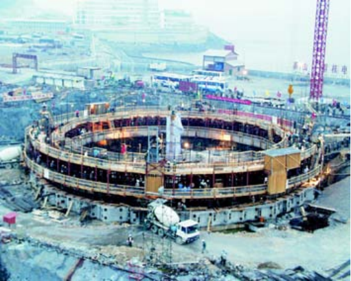
101
the major problems of ‘tears’ during the slip form, as tears are subjected to inquiry from the Regulator, and
subsequent costs involved in repairing the tears can delay the schedule.
— Planning for bad weather, particularly rain. Slip forms have been performed successfully in all seasons, but
this has been due to extensive planning. Crews are on standby to remove water from the concrete in heavy
rains and thus ensure the design requirements of the concrete.
— Organization of the workforce. A workforce plan is developed for the work to be performed on the platforms
at three elevations. The work is normally performed in two 12 h shifts. The major work entails placing of
reinforcing steel and embedded parts; constructing large openings; placing building monitoring
instrumentation; casting concrete; performing surveys; and finishing of concrete. Continuous testing of
concreting and collecting of samples in accordance with the project specifications and governing standards
are ongoing throughout the slip-forming process.
— Organization of material for placement. Material is organized and laid in an open yard or, in the case of
building instrumentation, in a room close to the site, and continuously transported to the site for placement
during the slip form, as required.
It is expected that the vast majority of future NPPs will have steel-lined containment walls. Accordingly,
studies are required to confirm if slip forming, preferably one-sided, can be used to construct a steel-lined wall.
Recently, in Canada, a steel-lined wall was constructed for liquefied natural gas tanks, also a very critical safety
structure, but this was two-sided slip forming.
Figure 67 shows an example of a slip-forming structure in China. Figure 68 shows the application of this
technique in the construction of a 100 m high ventilation stack. Construction was completed in only 30 days as
compared to the 180 days using the conventional methods.
This technique was widely used in the construction of many vertical structures, including the reactor building
containment shown in Fig. 69.
Jump forming
Jump forming is being used to construct practically all new steel-lined containment walls. In this method, the
wall is formed in stages, with the form lifted hydraulically; jumping (climbing) up to the next stage after the
concrete in the lower stage has set.
Advantages:
— Significantly faster than the conventional method;
— Does not require any scaffolding from the base slabs to the jump form;
— Has become the standard for constructing steel-lined containment walls.
FIG. 67. Example of slip-forming structure at Qinshan NPP, China.
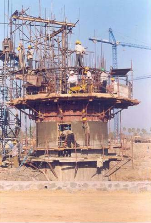
102
Disadvantages:
— Takes far longer than the slip form constructed containment wall;
— Quality of construction may be affected by the presence of cold joints;
— It is labour intensive, as the cold joints have to be prepared for the next stage of concrete.
5.1.3. Containment dome
5.1.3.1. Conventional method
The conventional method used to construct the containment dome is to support the dome formwork, normally
a space truss system, first on a system of shoring from the base slab, and finally off the containment wall. Access
for working is provided only from the exterior surface of the containment.
Advantages:
— Can be implemented in all countries contemplating nuclear power;
— Is relatively economical.
Disadvantages:
— Takes a long time to set-up, perform the construction and disassemble the formwork;
— Imposes constraints on other construction and equipment installation due to excessive scaffolding required
both on the inside and outside of the containment.
FIG. 68. Slip form shutter.
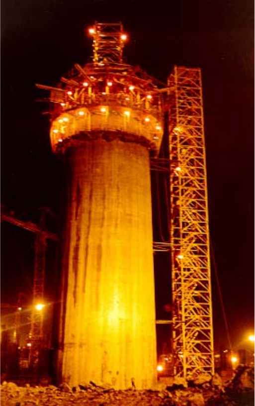
103
5.1.3.2. Advanced methods
The advanced methods used to construct the upper dome are to prepare a permanent steel plate dome
formwork which is lifted into place with the VHL crane as one module; or to jump from the dome from the
container wall upwards; or to use a combination of both methods. Advances in jump forming now permit the jump
to be performed on curved surfaces.
Advantages:
— Faster than the conventional method;
— Fewer constraints, as the extensive scaffolding used in the conventional method is not required.
Disadvantage:
— Requires use of a VHL crane, which may not be available in all countries.
FIG. 69. Slip form shutter reactor building containment.

104
5.1.4. Containment liner assembly
5.1.4.1. Conventional methods
The containment building is a steel-lined reinforced concrete structure enclosing the nuclear reactor. The steel
lining of the containment provides an airtight structure that encloses the reactor from the outside atmosphere.
Containment systems for nuclear power reactors are distinguished by size, shape, materials used and pressure
suppression systems. The type of containment used is determined by the type of reactor, the licensing basis and the
specific plant needs. There are several common designs, which can be categorized as either large-dry,
sub-atmospheric or ice-condenser. The following paragraphs give a high level description of typical boiling water
reactor (BWR) and pressurized water reactor (PWR) containment buildings.
BWR containments consist of a dry well, shaped like an inverted bulb, where the reactor and associated
cooling equipment are located, and a wet well (also known as a torus or suppression pool). Both the dry well and the
wet well are enclosed by a secondary containment building (reactor building). The reactor building is maintained at
a slight negative pressure.
In PWRs, the containment also encloses the steam generators and the pressurizer. In this case, the containment
surrounds the entire reactor building. The steel containment liner for a PWR is a cylindrical domed building. PWR
containments are typically large (up to ten times larger than a BWR), because the containment strategy during the
leakage design basis accident entails providing adequate volume for the steam/air mixture that results from a
loss-of-coolant-accident to expand into, thereby limiting the ultimate pressure reached in the containment building.
The steel is either free-standing or attached to the concrete outer wall. The outer wall protects the containment from
external damage. PHWRs and WWERs3 are similar in layout to PWRs, and the above comments apply.
Early containment construction methods involved the placement of steel plates or sections that made up the
containment liner by individually hoisting and rigging them into final position via a jib crane placed in the centre of
the structure. As equipment lifting capability advanced, whole ring sections were assembled near the final location
and lifted into place. The adjoining plates were welded together in place on the vertical and horizontal seams.
As the ring levels were completed at successively higher elevations, the exterior reinforcing steel bars were
put in place. This was followed by forming of the exterior face in preparation for concrete placement. After the top
of the container liner was assembled into place, the completed containment was pressure tested to confirm
leaktightness. Then, for the PWR containment design, sections were removed to provide construction openings for
interior construction. All interior construction, including placement of the reactor vessel, steam generators and
other large items of equipment, took place after the containment liner was completed.
For BWR construction, similar access was provided by the dry well hatch and temporary opening through the
plate structure. Similar to the PWR containment construction, reinforcing steel bar installation was commenced as
the successively higher elevations were completed, followed by forming and concrete placement.
Conventional interior construction and assembly work inside the containment buildings of both PWR and
BWR plants involved hundreds of items of equipment; thousands of metres of piping and tubing; thousands of
metres of cable raceway and cable; and thousands of structural supports to hang and restrain the piping, tubing and
electrical raceway. The work occurred serially and simultaneously in the small physical floor space available within
the containment, and at various distances above the floor. This stick-build approach in a small space resulted in
limited efficiency and productivity.
5.1.4.2. Advanced methods
Since containment buildings are connected to auxiliary buildings, the installation of the containment liner
plate could be very complicated when installing pipes, ventilation, electric wiring and other equipment. Therefore,
in the construction of the Shin-Wolsong 2 unit, a three-stage-based modularization (weight 197 t, diameter 44 m,
height 9.14 m) of the containment shell liner plates was introduced. With this method, except for the first, second,
ninth, tenth, 11th and 12th stages, the remaining rings are modularized into three-ring sections and installed with
3 WWER = Russian version of pressurized water reactor (PWR).
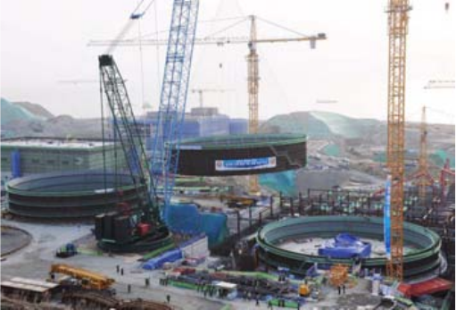
105
one lift by using a 1300 t rigging crane, thereby reducing the number of lifts to shorten the overall plant construction
duration (refer to Fig. 70).
By replacing many works done in high places by ground level works, this modularization contributes to
promoting the overall safety of construction. This method also simplifies connections with auxiliary buildings,
since connecting provisions, such as penetration sleeves for piping and electrical wire, have been already attached
to the ring modules.
5.2. DIESEL GENERATOR BUILDING — CONSTRUCTION ACTIVITIES AND TECHNOLOGIES
5.2.1. Conventional methods
In earlier plant design layouts, the emergency diesel generators were contained within other building
structures. Current plant designs typically house the diesel generators and associated support equipment in a
designated separate structure.
Typically, every nuclear unit has at least two diesel generators that provide emergency electrical power should
all off-site electrical power be lost. The diesel generators have turbochargers that supply combustion air. To ensure
that they start, emergency air storage tanks supply high pressure air to turn the diesel. As with most rotating
mechanical equipment, water cooling systems and oil lubrication systems are used. These generators provide power
to special safety electrical distribution panels, only when needed. The panels in turn supply power to the emergency
pumps, valves and fans.
Figures 70 and 71 show a diesel generator and Fig. 73 shows a diesel generator room.
As discussed in earlier paragraphs, in the previous methods of construction, tape measures, levels, etc. were
used to locate the position of the walls and floors to be constructed. Reinforcing steel bars were wired together to
form an array of steel encompassing the floor or wall area. Penetrations of steel piping, boxed openings, etc. were
arranged within the array of steel to provide for penetration openings for the pipe, cable pan or conduit raceways,
and HVAC ductwork. Forms, typically of wood, were constructed to enclose the reinforcing steel and frame the
volume where concrete was placed to form the walls. Steel plates with anchors welded on the inside face were
attached to the forms to provide a surface for later attachment of supports, and restraints for equipment, piping,
electrical raceway; etc. The same process was performed for the floors of the building structure, except the top
surface remained open.
Because the process of construction of the concrete wall and floor structures required forming and temporary
support until the concrete achieved a strength to be self-supporting, temporary openings in the floors and walls were
required to enable movement of the plant mechanical and electrical equipment, and interconnecting piping and
electrical cables into their required locations. This limited the size of the assemblies that could be made off-site.
FIG. 70. Modularization of the containment liner plate assembly, Shin-Wolsong 2, Republic of Korea.
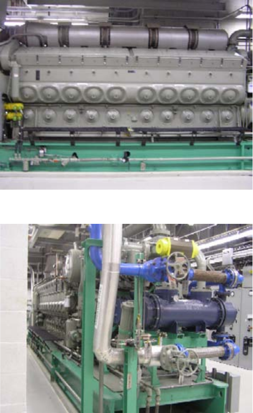
106
After the floors and walls had cured sufficiently, the large equipment was moved into position. Assembly was
then completed within the room structures, along with the installation of the piping; electrical raceways and cable;
HVAC ductwork; etc. along with their structural supports to hang and restrain movement.
By using the stick-build method of construction, each of these thousands of single component fitting tasks
occurred simultaneously on the same physical floor space at various distances above the floor. Extensive
scaffolding was required to provide access to locations above the floor, leaving progressively decreasing workspace
in which to perform the tasks.
5.2.2. Advanced methods
With the advances in lift capacity of cranes, the diesel generators and associated support equipment become a
target area for complete room modularization.
FIG. 71. Diesel generator (view one).
FIG. 72. Diesel generator (view 2).
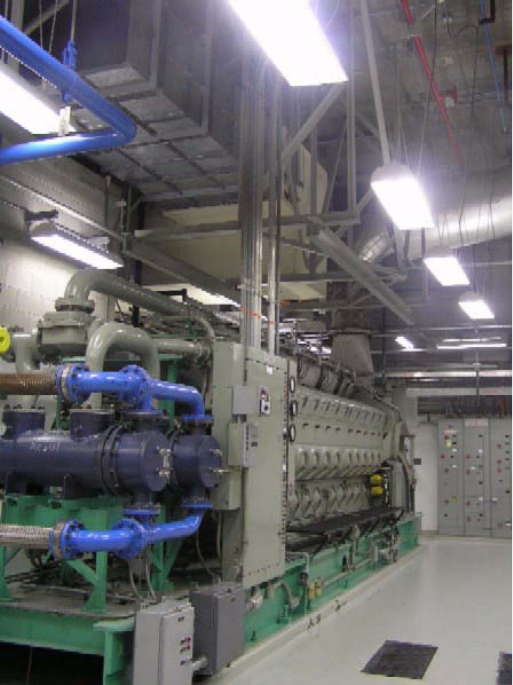
107
5.3. CONTROL ROOM COMPLEX — CONSTRUCTION ACTIVITIES AND TECHNOLOGIES
5.3.1. Conventional methods
Advances in electronics technology and human factors engineering have reduced the building area required
for control rooms. This is true in the nuclear power industry as well as in most other industries using central control
technologies.
In a typical conventional two-unit NPP with a common control room for both units, control room sizes were
approximately 15 m × 30 m or larger. Most designs included a combination of vertical panels and bench boards.
Equipment indications and controls were organized by system. Annunciators with a sound alarm were usually
placed above the control board or at the top part of the control board. The plant computer was used to provide
alarms to alert the operator to problems.
Less frequently used equipment was usually placed on panels in the back part of the control room or behind
the main control board, as shown in Fig. 74 and Fig. 75. In the past, the control technology was analogue with
hardwired connections, mimic displays, hand switches for individual equipment control, and console displays of
dedicated hardware gauges and indicators. Collectively, these features required larger rooms. In a modern
control room, shown in Fig. 76 , advances have resulted in the use of digital technology with fibre optics, overall
plant monitoring with industrial TVs, visual display units (i.e. monitors), all typically contained in reduced size
housings.
FIG. 73. Diesel generator room.
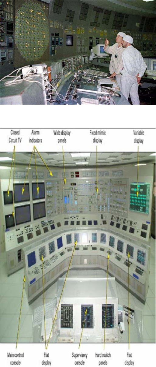
108
FIG. 74. Conventional control room.
FIG. 75. Panels in conventional control room.
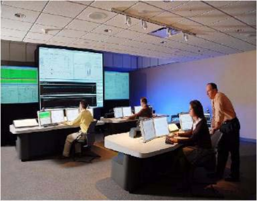
109
5.3.2. Advanced methods
With the above types of advances in electronics and design, control rooms have reduced in size by half or
more; and with the advances in the lift capacity of cranes, the control panels and associated equipment have become
a target area for complete room modularization.
5.4. FUEL BUILDING — CONSTRUCTION ACTIVITIES AND TECHNOLOGIES
5.4.1. Conventional methods
The fuel building is used for the receipt, inspection, storage and transfer of new fuel and spent fuel. The
building encloses the spent fuel pool. This is a water-filled pool which contains the storage racks for the spent fuel
assemblies. The spent fuel racks are typically stainless steel in combination with other absorber (poison) materials.
Poison materials control the chain reaction inside the fuel racks by absorbing the neutrons emitted from the still
active but spent nuclear fuel. Some of the main poison materials are borated stainless steel, boraflex and boral.
The fuel building houses the fuel pool cooling heat exchangers and fuel pool cooling pumps. These items of
equipment and their associated systems clean and remove heat from water that is recirculated to the spent fuel pool.
Cranes overhead in the building, and above and bridging the pool, are used to move individual fuel assemblies and
casks containing multiple assemblies for transport and storage.
Figures 77–80 show the conventional stick-build approach to constructing the fuel building. Note the pool
liner assembly in Fig. 78, conventionally erected in place, which is now a candidate for modularization.
5.4.2. Advanced methods
For those NSSS designs that utilize a building layout where the fuel building is separate yet adjoined to the
containment structure, in contrast to those that have the fuel pool as a part of the reactor building structure, the
potential targets for application of large preassembly modularization with placement by VHL crane are the fuel
pool and storage racks, as well as other aforementioned equipment. The potential benefit of modularization in this
case is that it allows delayed sequencing of the fuel building erection. With the fuel building pushed to the right of
the schedule, the VHL cranes can be placed in the location of the future fuel building for part of the construction
duration. This enables the VHL cranes to place more complete and larger modules in the adjacent building
structures, including the containment, auxiliary/reactor, control and radiation waste (radwaste) building.
FIG. 76. Modern control room.
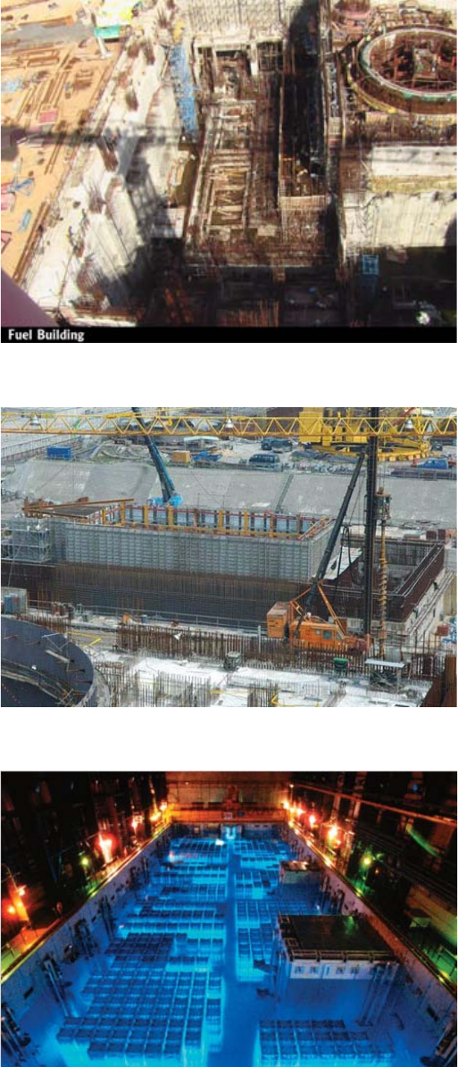
110
As per IAEA safety guide (IAEA Safety Series No. 116), a leakage detection and leakage collection system in
the spent fuel storage bay is recommended. Advanced construction methodology has now adopted ‘tank in tank’
technology for the spent fuel storage building, which provides the following:
FIG. 77. Fuel building foundation work.
FIG. 78. Fuel pool liner assembly.
FIG. 79. Fuel pool in operation.
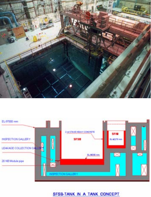
111
— A well designed leakage detection and leakage collection system;
— A mechanism that prevents any contamination of the groundwater, even in case of any remote leakage due to
failure of metallic liner on the inside faces of the spent fuel storage pool;
— Adequate space for in-service inspection of the inner pool during the operating life of the plant.
Figure 81 shows typical details of the spent fuel storage building.
The spent fuel storage building also has a facility for inspection of spent fuel bundles. In the event of any leak
observed in the bundles and transferring mechanism, they are moved to a pre-decided location inside the pool. Any
inadvertent dropping of a spent fuel cask during handling is provided for by adequate reinforcement in the raft, as
well as thick metallic embedded plates in the cask handling area. Use of the cask handling crane is limited to the
cask handling area only.
FIG. 80. Fuel handling equipment above fuel pool.
FIG. 81. Spent fuel storage tank (credit: NPCIL).
112
6. CONSTRUCTION ACTIVITIES AND
TECHNOLOGIES SPECIFIC TO
GROUP B (TURBINE ISLAND) BUILDINGS AND STRUCTURES
The significant construction activities for turbogenerator buildings are:
—Excavation;
— Setting up of the dewatering system;
— Construction of the base slab;
— Construction of the condenser cooling water piping;
— Installation of the condenser;
— Casting of the turbogenerator pedestal;
— Erection of structural steel.
These activities are described in the following paragraphs.
6.1. EXCAVATION
Excavation is one of the critical construction activities for the turbine building. This is especially true for
coastal sites where tidal elevations are significant. This results in deep turbine buildings with excavation depths
greater than 20 m being quite common.
It is recommended that advanced excavation methods such as precision line blasting or chemical foam
expansion be used for deep turbine buildings in order to achieve a short excavation schedule.
6.2. SETTING UP OF DEWATERING SYSTEM
A comprehensive dewatering system must be set-up after the excavation is completed. This is especially
required for deep turbine buildings in rock sites, with multiple sumps strategically located over the whole footprint
of the turbine building.
6.3. CONSTRUCTION OF BASE SLAB
The construction of the base slab is also a crucial construction activity, since the base slab is the largest
concrete element in many NPPs. This is because many designs recommend mass stability for this building. Some
designs use rock anchors to provide stability to the base slab. This activity can take significant time, since the
number of rock anchors will be large, and sometimes instrumentation is set-up to monitor the performance and
condition of the rock anchors and the differential settlement of the turbine building.
It is recommended that advanced construction methods such as large pours with pumped concrete be used to
construct the base slab. Refer to Paragraphs 5.1.1.1. and 5.1.1.2 for the conventional and advanced methods,
respectively.
6.4. CONSTRUCTION OF CONDENSER COOLING WATER PIPING
The condenser cooling water piping is (sometimes) located below the turbine building base slab, and must
therefore be constructed before the base slab. Though the construction is relatively traditional, construction
113
planning is critical for this item. Advanced methods such as pumped concrete should be used for construction, as
they provide a better quality structure.
6.5. INSTALLATION OF CONDENSER
Traditionally, the condenser has been brought into the building in multiple pieces. Openings are left in the
turbine building wall directly in line with the final location of each piece. Each piece is located in the pit, and then
slid into position. All the pieces are then connected into one piece.
In recent plants, advantage has been taken of the VHL cranes now available and used in the open top method
of construction. The condenser has been lifted as one piece, lowered into the turbine building, and then slid into
position as one piece. This approach has eliminated openings in the turbine building wall, and has reduced the
schedule, both for full installation of the condenser, as well as for turbine building construction completion.
6.6. CASTING OF TURBOGENERATOR PEDESTAL
The turbo-generator pedestal consists of the bottom raft, vertical columns and top slab. The turbo-generator
pedestal is designed as per the non–safety system codal requirements but, as a general convention, is checked for
safe shutdown earthquake conditions for a collapse. It is, however, the designer’s choice to consider various loading
combinations, including dead load; live load; erection load; vertical and horizontal dynamic loads; seismic loads;
short-circuit forces on generator supports; and various combinations of behaviour of equipment during normal and
abnormal conditions. This also includes the failure of turbine blades.
The turbo-generator pedestals remain within the turbine building, but are kept structurally isolated from the
rest of the building by providing an isolation gap of approximately 50 mm. This prevents vibrations from the
turbo-generator pedestal from being transferred to the rest of the building structure. Nearly all plant developers use
this approach as a part of modularization and working out the economics during construction.
Normal N-20/40 concrete is conventionally used for casting the turbo-generator pedestals. As turbo-generator
pedestals are heavily reinforced, conventional methods of casting them require large mobilization of human
resources as well as plant and machinery to achieve the desired quality. This is due to the fact that turbo-generator
bottom rafts, columns and top slabs must be cast in a single pour individually, as a codes and standards requirement.
In the casting of turbo-generator pedestals, temperature-controlled concrete is now being used as an
improvement on normal concrete. The use of temperature-controlled concrete facilitates large single pours of mass
concrete, while maintaining the peak temperature within the concrete due to heat of hydration within the specified
limits, and reducing the total time required to pour the large mass of concrete. The use of concrete pumps and
mechanized concrete batching plants of appropriate size with ice flaking facilities in tropical countries; and the
mobilization of concrete transit mixture, further reduce the total time required and improve the quality of
concreting. However, continuous concreting also requires the mobilization of requisite plant and machinery, with
sufficient backup systems and human resources for levelling of concrete, even for a shorter duration. Figure 82
shows the turbo-generator bottom raft being cast.
It should be noted that the turbo-generator pedestal bottom raft is cast on a sound rock foundation, which may
need slightly deeper excavation. However, in the case of deep alluvial soil, suitable pile foundations may be used,
depending on the site conditions.
The concrete pedestals, which are normally 15–20 m high, can be cast in a maximum of two pours as per the
code requirements. Use of temperature controlled concrete and self-vibrating shutters (form vibrators) ensures
proper compaction of the concrete as well as casting of the columns in a single pour. The top sections of the
columns are given a haunch shape to support the top deck and proper distribution of the stresses. Figure 83 shows
turbo-generator pedestal columns cast in a single pour.
The turbo-generator top deck is also cast in a single pour in the same manner in which the bottom raft is cast.
Figure 84 shows the turbo-generator top deck ready for casting.
In the construction of turbo-generator pedestals, vibration isolators are now being used below the turbo-
generator top deck, as an advancement. The vibration control through these isolators suppresses unwanted
vibrations, eliminates transmission of vibrations along with the possible resonance effect, and limits vibration on
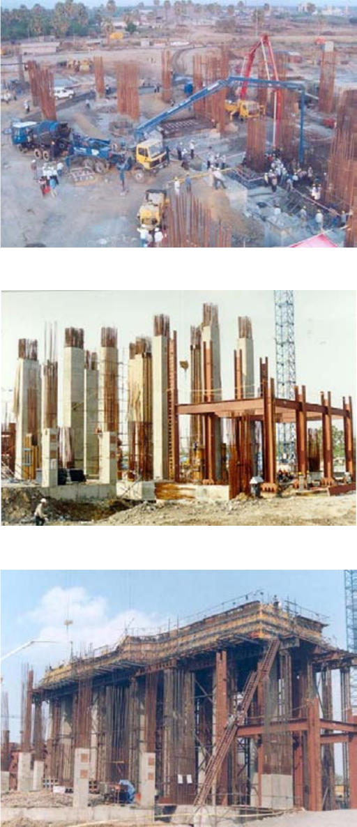
114
the foundation and equipment during operations. Use of these isolators further compensates for settlement and
misalignment of the foundation of equipment. Various varieties of vibration isolators are available on the market. It
is, however, recommended that only reliable and time-tested vibration isolators with an efficiency as high as 95%
are used in the turbo-generator pedestals. The vibration isolators are pre-numbered and designated with respect to
FIG. 82. Construction of turbogenerator pedestal at Tarapur, India (credit: NPCIL).
FIG. 83. Casting of turbo-generator pedestal columns (credit: NPCIL).
FIG. 84. Turbo-generator top deck (credit: NPCIL).
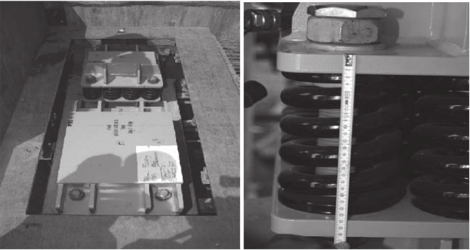
115
their position in a pre-stressed condition. These vibration isolators are placed over a resilient adhesive pad, which in
turn is placed over the prepared smooth concrete surface on the concrete structure column. The relative position
with respect to the design position of each isolator is checked before continuing. The top deck is cast with in-built
machined embedded parts correlated to each vibration isolator. Figure 85 shows vibration isolators being erected in
a turbo-generator pedestal.
While casting the top deck, the specified design gap is kept between the bottom of the machined embedded
part and the top of the isolator. This gap takes care of the settlement after concreting, if any, before the load is
transferred to the isolators.
The turbo-generator pedestal can thus be constructed in parallel with the rest of the turbine building. This
parallel way of working, coupled with open top construction, can appreciably reduce the total time needed to erect
the turbine building and associated systems.
6.7. ERECTION OF STRUCTURAL STEEL
Because of the span of the turbine generator hall and the size of the turbine building crane, the turbine
building structural steel consists of large heavy sections or even built-up sections. The roof trusses, in particular, are
very heavy.
6.7.1. Conventional method
The conventional method used to erect the turbine building structural steel has been to first erect the columns.
These columns are quite large, heavy and self-supporting. Temporary braces are connected to hold the columns
after aligning the structural columns. The roof trusses are then placed one at a time and connected to the steel
column. The permanent bracing, both vertical and horizontal, is connected to the columns and the beams. In some
cases, the permanent vertical bracing is connected to the steel columns before the roof trusses are erected.
The heavy turbine building crane, normally with a lift capacity of 200–300 t, is then installed.
Advantage:
— Can be performed in all countries, as expertise and equipment are readily available.
Disadvantage:
— Requires considerable time.
FIG. 85. Seismic isolators (credit: NPCIL).
116
6.7.2. Advanced methods
The advanced methods that are used in the erection of the turbine building structural steel are the open top
method of construction, and modularization.
In these methods of construction, the structural steel columns may be erected as in the conventional method.
After temporary bracing of the columns, the roof trusses and the roof horizontal bracing are set-up in modules, and
placed in position using the VHL crane.
After the placement of the roof trusses, the vertical bracing is connected to the columns. The turbine building
crane is placed in position using the VHL crane through a bay in which the horizontal roof bracing has not been
erected.
Advantages:
— Very short erection time;
— Better quality final structure;
— Provides very good safety for workers.
Disadvantage:
— More expensive to implement.
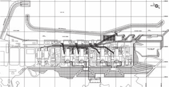
117
7. CONSTRUCTION ACTIVITIES AND
TECHNOLOGIES SPECIFIC TO
GROUP C (BALANCE OF PLANT) BUILDINGS
AND STRUCTURES
7.1. INTAKE AND DISCHARGE STRUCTURES
7.1.1. Conventional methods (surface seawater intake/discharge system)
7.1.1.1. General
Where temperature variation of the surface sea water is stable, a conventional type of surface seawater
intake/discharge system is used. The surface seawater intake/discharge system has been adopted for thermal
discharge management of all NPPs worldwide. The plant circulating water system takes condenser cooling water
from the intake channel and discharges the thermal effluence directly to the sea.
7.1.1.2. Major structures of conventional cooling water system
Figure 86 shows, the typical surface intake/discharge cooling water system consists of the wharf for
unloading heavy equipment, and intake/discharge channel enclosed with breakwaters and revetment.
Surface intake channel
— The structure of the open channel has a natural slope type to transport the cooling water from the sea to the
intake structure;
— The open channel type uses open-cut or banking on existing grade line. Most of the intake channels are
protected Armor Stone (rip-rap) on the rubble mound;
— The width and depth of the intake channel should be established in order to maintain intake velocity below
0.3–0.6 m/s, thus minimizing silt entrainment.
Surface discharge channel
— A structure of the open channel has a natural slope type to transport warm water from the condenser or heat
exchangers to the sea;
FIG. 86. Surface intake/discharge tunnels layout (credit: KHNP).
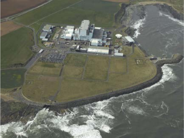
118
— The open channel type uses open-cut or banking on existing grade line. Most of the discharge channels are
protected Armor Stone (rip-rap) on the rubble mound.
Breakwater
— The breakwater is a part of levee for the intake and discharge channel;
— Most of the breakwaters are rubble mound with a superstructure such as a cap concrete block. The rubble
mound is armoured with tetra pods (TTPs) as shown in Fig. 87;
— The maximum weight of the TTP used is more than 70 t. The weight of the TTP can be determined in
accordance with design wave height, the number of TTP layers, unit weight of TTP, etc. which is known as
the Hudson formula;
— The water level for the breakwater can be obtained from the combination of highest high water level and
significant wave height in front of the breakwaters.
Revetment
— The revetment is a structure to prevent the land area from eroding. The plant island is usually located just
behind the revetment;
— The plant grade should be established above the expected seawater levels, including the wave run-up over the
revetment. When calculating the wave run-up height, the 1% wave height is used instead of significant wave
height;
— The armour weights of the revetment are determined using the significant wave;
— A typical section of the revetment is a rubble mound armoured with TTP as shown in Fig. 88.
Wharf
The wharf facility is constructed in an intake mouth basin for unloading heavy equipment, e.g. steam
generator, condenser and reactor vessel. This equipment will be transported to the site via sea.
— A typical section of the wharf is a concrete block type as shown in Fig. 89. Some weak soil layer should be
dredged to obtain a solid foundation for the wharf;
FIG. 87. Example of a breakwater structure at Torness NPP in the UK.
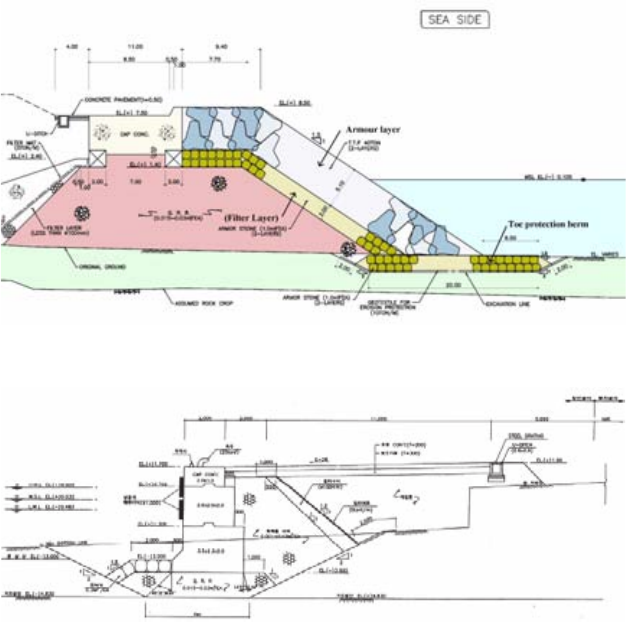
119
— The wave height in front of the wharf should be kept below 0.5 m for unloading efficiency;
— The water level for the wharf is determined depending on the tidal range.
7.1.2. Advanced methods (submerged seawater intake/discharge system)
7.1.2.1. General
— A problem related to the operation of existing units is reduction in overall plant efficiency that results from an
increase in the temperature of cooling water;
— In light of this concern, the submerged intake and discharge was selected as the most appropriate scheme for
the condenser cooling water system;
— The purpose of the submerged intake is to supply cool water from the stratified subsurface to the cooling
system in summer, when thermal stratification appears in the near-shore area at the site;
— The regulatory requirements for limiting discharge temperature are met by designing the discharge structure
to induce rapid mixing. Initial dilution of submerged discharge is maximized by increasing the number of
diffusing ports on condition that spacing should be sufficient to avoid overlapping of plumes from adjacent
ports. Figure 90 shows a comparison of the maximum excess temperature;
— Each segment of concrete channels for the submerged intake and discharge system is laid underwater by a
heavy duty offshore crane as shown in Fig. 91.
7.1.2.2. Major structures of advanced cooling water system
The submerged intake/discharge cooling water system consists of the intake structure and the discharge
structure. The main components of the intake structure include the submerged intake velocity cap, submerged
intake tunnel, intake reservoir, intake structure and intake conduit. The main components of the discharge structure
include the discharge conduit, discharge pond, submerged discharge tunnel and submerged discharge diffuser.
FIG. 88. Typical section of revetment (credit: KHNP).
FIG. 89. Typical section of wharf (credit: KHNP).
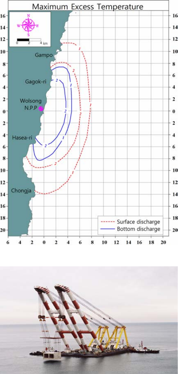
120
FIG. 90. Comparison of maximum excess temperature (credit: KHNP).
FIG. 91. Submerged intake/discharge conduits installation (credit: KHNP).
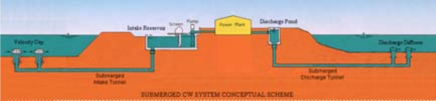
121
The cooling water from the sea flows through the submerged velocity cap, submerged intake tunnel, intake
reservoir, intake pump house, intake conduit, main condensers or heat exchangers, discharge conduit, discharge
pond and submerged discharge tunnel, and is then finally discharged to the sea at the submerged discharge diffuser.
Figure 92 shows a schematic view of a submerged cooling water system. The characteristics of the main
components of a submerged cooling water intake/discharge structure are described in the paragraphs after the
figure.
Submerged intake velocity cap
— Submerged intake velocity caps are precast reinforced concrete structures that are manufactured in the shop
and installed by floating crane at a depth of approximately 20 m from the seawater surface to draw the lower
temperature deepsea water;
— Submerged intake velocity caps are required to prevent fish entrainment from the vertical flow velocity
change. The approach velocity to the velocity cap should therefore be within a range of 0.15–0.45 m/s to
prevent fish entrainment;
— The inlet opening shall be located at a suitable level from the seabed to prevent the inflow of sediment;
— The spacing between the centres of velocity caps shall be determined to minimize the interference of each
flow boundary.
Submerged intake tunnel
— A submerged intake tunnel is a structure with a square section to transport the cooling water drawn through
the submerged velocity caps to the intake reservoir;
— The tunnelling method is selected considering the geological conditions and environmental constraints. Based
on the applied tunnelling method, the structural types are largely divided into two categories: conduit type and
bored type. The conduit type uses the open-cut, laying on and fill method, and the bored type uses the
conventional (drill and blast) or mechanical (tunnel boring machine (TBM) and Shield TBM) tunnelling
method;
— The submerged intake tunnel for an is a precast concrete conduit type, constructed by the immersed tube
method in consideration of geological conditions;
— The optimum diameter of the submerged intake tunnel should be determined considering the head loss
through the line and the gradual reduction of flow area due to marine growth. The design velocity should be
within a range of 1.8–3.0 m/s.
Intake reservoir
— An intake reservoir is a structure of the retaining wall type to transport cooling water from the submerged
intake tunnel to the intake structure;
— This structure is a transition area of the flow toward the intake structure. The bottom elevation of the reservoir
shall be lower than or equal to that of the intake structure/pump house.
FIG. 92. Submerged cooling water system conceptual scheme (credit: KHNP).
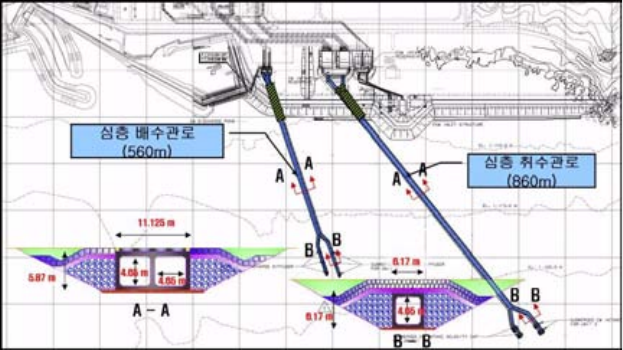
122
Intake structure
— The intake structure is a reinforced concrete structure with shear walls;
— The intake structure is connected to the intake reservoir. It consists of the circulation water system (CWS)
intake structure/pump house and the essential service water system (ESWS) intake structure/pump house,
which contain pumps and travelling screens, and supply the cooling sea water to the main condensers in the
turbine building and component cooling water system (CCWS) heat exchangers, respectively.
Intake conduit
— The intake conduits of the CWS and ESWS supply the cooling sea water from the intake structure/pump
house to the main condensers inside the turbine building and the CCWS heat exchangers, respectively;
— The type of intake conduit is selected considering durability, constructability, economic effectiveness, etc. In
general, the cast-in-place reinforced concrete box type is widely used.
Discharge conduit
— The discharge conduits of the CWS and ESWS transport the warm water from the main condensers inside the
turbine building and the CCWS heat exchangers, respectively, to the discharge pond;
— The type of discharge conduit is selected considering durability, constructability, economic effectiveness, etc.
In general, the cast-in-place reinforced concrete box type is widely used.
Figure 93 shows an example of the layout of submerged intake/discharge conduits.
Discharge pond
— A discharge pond is a rectangular-shaped structure of cast-in-place reinforced concrete pond, functioning as a
surge tank during transient flow conditions;
— It transports the cooling water from the discharge conduit to the submerged discharge tunnel.
Submerged discharge tunnel
— The submerged discharge tunnel is a structure used to transport the warm water from the discharge pond to the
submerged discharge diffusers;
FIG. 93. Submerged intake/discharge conduits layout (credit: KHNP).
123
— The tunnelling method is selected considering the geological conditions and environmental constraints. Based
on the applied tunnelling method, the structural types are largely divided into two categories: conduit type and
bored type. The conduit type uses the open-cut, laying on and fill method, and the bored type uses the
conventional (drill and blast) or mechanical (TBM and Shield TBM) tunnelling method;
— The submerged discharge tunnel is normally a precast concrete conduit type, constructed by the immersed
tube method in consideration of geological conditions;
— The optimum diameter of the submerged discharge tunnel should be determined considering the head loss
through the line and the gradual reduction of flow area due to marine growth. The design velocity should be
within a range of 1.8–3.0 m/s.
Submerged discharge diffuser
— Submerged discharge diffusers are precast reinforced concrete structures that are manufactured in the shop
and installed by floating crane at a depth of approximately 15 ms from the seawater surface to discharge the
warm water to the sea. The discharged warm water is well mixed with the ambient water in the vertical
turbulent entrainment;
— Discharge velocity should be more than 3 m/s in order to enhance the mixing effects by initial dilution;
— The spacing between each diffuser can be determined to minimize the plume overlap under the given current,
jet velocity, water depth, etc.
7.1.2.3. Advantages
— The environmental zone affected by high temperature discharged water could be minimized.
— The thermal recirculation to the existing units could be reduced, thus not impairing the power output of the
existing units.
— By adopting the advanced type (submerged seawater intake/discharge system), the original coastline can be
preserved, minimizing the effect of encroaching and sedimentation. The advanced type is therefore an
environmentally friendly system that protects the existing coastline.
7.2. CATHODIC PROTECTION
7.2.1. Background to corrosion
Corrosion in metallic structures is a natural phenomenon. The metal that has been taken out of or extracted
from its principal metallic structure in the form of metal oxide or as free ions has a natural tendency to regain its
original state under the action of environmental conditions. This action is called corrosion, the most common
example of which is the rusting of steel in a metallic structure. Corrosion is basically an electrochemical
phenomenon that involves the flow of electrical currents on a micro or macro scale. The change from metal
structure to the combined form occurs by an ‘anodic’ reaction. This reaction produces free electrons that flow
within the metal to another location on the metallic surface, and are consumed by a cathodic reaction. Current flows
out of the metallic structure at the anode site, passes through an electrolyte, and re-enters the structure at the cathode
site. Corrosion thus occurs at the anode. The flow of current depends entirely upon the potential difference between
the anode and cathode.
The anode is more negative than the potential of the cathode. The potential difference is the driving force for
the corrosion current as well as the rate of corrosion.
The following three conditions are essentially required for corrosion to take place:
— Two dissimilar metals;
— An electrolyte (i.e. sea water, soil or water with any type of salt dissolved in it);
— A conducting path between the two dissimilar metals.
124
The two dissimilar metals may be two totally different alloys, or either microscopically or macroscopically
different on the same surface of a single piece of metallic structure. The differential stress of any type in the metallic
structure may also result in setting up the potential difference, hence initiating the corrosion process.
The corrosion process is essentially caused by a difference in natural potential in galvanic couples.
Microscopic or macroscopic metallurgical changes in the same piece of metal may also initiate the corrosion
process, as stated above. Local differences in the environment, such as variations in the supply of oxygen at the
metallic surface, are another potential cause of corrosion. The oxygen depleted areas behave as anodes, whereas
oxygen rich areas become potential cathodes.
As in any other chemical process, the corrosion rate depends on a number of variables, such as temperature
and pressure of medium governing the solubility of gases and salts; variation of stresses; hostile environmental
conditions; velocity of the medium; and microscopic or macroscopic structure of the metallic structure.
Important factors associated with environment and soil which can impact the corrosion rates experienced
include:
— Effective electrode potential of metallic structure with regard to surroundings;
— Chemical and physical homogeneity of the metallic structure;
— Inherent ability to form protective film;
— pH of the electrolytic medium;
— Influence of oxygen;
— Presence of specific nature and concentration of ions such as chlorides and sulphides;
— Temperature;
— Velocity of medium;
— Cyclic stress or fatigue;
— Contact conditions between dissimilar metals, causing localized corrosion;
— Differential stresses in the metallic structure;
— Presence of corrosion activating bacteria (microbial corrosion);
— Resistivity of medium, etc.
At present, most NPPs are being constructed on sea shores. The intake structure and outfall structures of the
pump house remain in constant touch with the sea water. The consistent change in the sea level due to high tides and
low tides, coupled with the hostile sea coast environment, make the steel structure seriously susceptible to marine
corrosion. It has been estimated that the rate of corrosion of bare steels in general is approximately 0.15 mm per
year under normal atmospheric conditions. This loss of material thickness is largely accelerated by the variation in
water composition, oxygen concentration, associated marine growth and the velocity of water. These parameters are
also influenced by sunlight photoperiod and photosynthetic activity.
The case is similar for most of the buried piping and subsoil structures that are prone to corrosion attacks
under varying soil conditions such as resistivity, permeability, moisture content, and the presence of chloride and
sulphide ions. The variation of subsoil water table and subsoil hydrodynamic effects also largely influence the rate
of corrosion, especially associated with steel reinforcement bars and steel embedment required for construction and
installation of fore bay equipment, and all other associated components exposed to hostile saline atmospheric
conditions.
Paints and coatings are generally applied in a steel structure in order to prevent corrosion. It has, however,
been experienced that a considerable amount of coating is damaged during construction. Even undamaged coating,
if not applied in total accordance with the requirements of the specification, may also suffer from the presence of
micro pin holes. Micro pin holes may lead to the development of concentrated areas that initiate pitting corrosion.
Moreover, coatings need continuous maintenance. Underground piping/subsoil structures and structures in constant
touch with marine water or normal subsoil water are also affected by pitting corrosion and stress corrosion.
Cathodic protection is applied to structures in order to mitigate the menace of corrosion and increase the life
expectancy of metallic structures, subsoil structures, buried piping, etc. Cathodic protection not only protects the
structure, but also monitors its life expectancy.
125
7.2.2. Cathodic protection technique
The cathodic protection technique for mitigating corrosion is based on various historical performances and
measurable results. Cathodic protection is applied to control the corrosion of a metallic structure in the particular
environment to which it is subjected. The key principle of cathodic protection is based on a physical phenomenon
where the corrosion of the metal is completely stopped under the effect of electric current. When a measured
amount of current is applied, the electrochemical corrosion protection system makes the metal structure a single
non-destructive cathode. There is hence no potential available for flow of current, and the metal is protected. This
is achieved by applying the current from an outside source. When enough current is applied, the whole structure
comes to a uniform potential, thus making anode and cathode sites non–existent.
Experience stipulates that if the steel receives enough current to shift the potential to
(–) 0.800 V v/s silver/silver chloride, the corrosion stops completely. In general, a potential between (–) 0.950 V
and (–) 1.000 V v/s Ag/Agcl (standards reference electrode against steel) is recommended.
Two systems are used for cathodic protection:
— Galvanic protectors (galvanic system), where more electronegative metal (protectors) are connected to the
metallic structures;
— Impressed current cathodic protection system, where the metallic structure is connected to the positive
terminal of the direct current (DC) source.
These systems are described in more detail in the following paragraphs.
7.2.2.1. Galvanic system
The galvanic anode system employs more negatively reactive metal as an auxiliary anode that is directly
connected to the metallic structure required to be protected. In other words, the auxiliary anode sacrificially protects
the structure/piping. The system is therefore also called the ‘sacrificial anode cathodic protection system’. The most
commonly used sacrificial anodes include zinc, aluminium and magnesium.
The galvanic anode protective method is considered one of the simplest and most reliable methods, requiring
no maintenance during the course of operation. The metals mentioned above are sometimes also alloyed to give
these anodes more negative electrolytic potential. Experience has shown that in addition to passive protection
methods such as various varieties of paint coatings, the galvanic anode protection system provides more effective
corrosion control. The use of a well applied and suitable paint coating increases the effective spread of cathodic
protection current. The combination of applying both the protective coating and cathodic protection results in the
most practical and economic corrosion protection system as a whole. The best results are obtained with coatings
that have high electrical resistance, are continuously well spread, and are strongly adhered to the surface of the
component to be protected. The life of the combined protection system is further extended by abrasion resistance
qualities of the coating system.
The galvanic protection system can be summarized as follows:
— Simple to install;
— Independent source of DC power not required;
— Suitable for localized protection;
— Neighbouring structures/components are not affected.
Experience to date with such a protection system for isolated fore bay components of the intake water pump
house and a short length of buried piping has been satisfactory. The major disadvantage of the galvanic system is
the larger size and weight of anodes. The current output of galvanic anodes is also relatively less. This mainly
depends on the electrical resistively of the electrolyte, e.g. subsoil, sea water or concrete. The current from the
anode is not controllable, hence any change in structural behaviour or in resistivity of the medium during operation,
or any general deterioration of the coating, has a larger impact on the consumption of sacrificial anodes. This may
also result in slight miscalculations while designing the system.
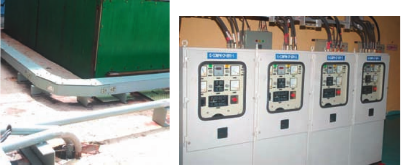
126
7.2.2.2. Impressed current cathodic protection
The impressed current cathodic protection system uses the same principle as the galvanic protection system.
Current is directly applied with a polarity that opposes the natural corrosion mechanism and with sufficient
magnitude to polarize all the cathodic areas up to open circuit potential of anodic areas to arrest the corrosion. The
structure in this system is protected by applying a pre-measured current from the anode. The anode and the structure
to be protected are connected by well-insulated wire as a carrier to the current. The primary difference between the
galvanic and impressed current system is that a properly designed cathodic protection system with impressed
current can completely prevent the corrosion of submerged metallic structures. It is, however, necessary to maintain
optimum levels of impressed current at all times, if the cathodic protection system is to be made effective.
Continuous monitoring of the protected structure to soil/sea water potential and automatically adjusting the
impressed currents to keep structure-to-soil potential constant becomes imperative, if optimum corrosion protection
is desired. The automatic cathodic protection rectifier system accomplishes this by monitoring the protected
structure-to-soil potential with reference to a Ag-AgCl saturated half-cell or a zinc reference electrode, and
continuously adjusting the impressed current automatically to maintain the metallic structure-to-soil potential at a
preset optimum. Thus, optimum cathodic protection can be achieved under varying conditions by use of automatic
cathodic protection rectifiers. The galvanic system has to rely on the natural potential difference between the anode
and the structure, whereas the impressed current system uses an external power source to derive the current. This
system can therefore be regarded as an advancement.
The impressed current system requires:
— An inert anode or a cluster of such anodes connected to the various components to be protected;
— A DC power source;
— Well-insulated and secured conductors between anodes and electrical source with minimum resistance;
— Well-secured connections with the power source and structure with minimum resistance.
The anode material could be a high silicon cast iron, mixed metal oxide or high strontium–chromium-iron
electrodes. Non-consumable electrodes made out of titanium, niobium or platinum are considered techno-
commercial.
The cathodic protection unit (arrangement shown in Fig. 94) is designed to operate on AC single phase, 50 Hz
power supply to a DC rectifier which gives a continuously filtered DC voltage in the range of 0–12 V and current
up to 100–150 A. This unit can operate either manually or in automatic mode, depending on the situation.
Automatic protected structure to sea water potential (APSSP) mode and automatic voltage and current control
(AVCC) mode are generally used in combination in the automatic impressed current system. It is unlikely that both
these automatic modes will fail simultaneously. However, the unit can also be operated in manual mode under such
situations, with a built-in alarm mechanism.
FIG. 94. Cathodic protection arrangement.
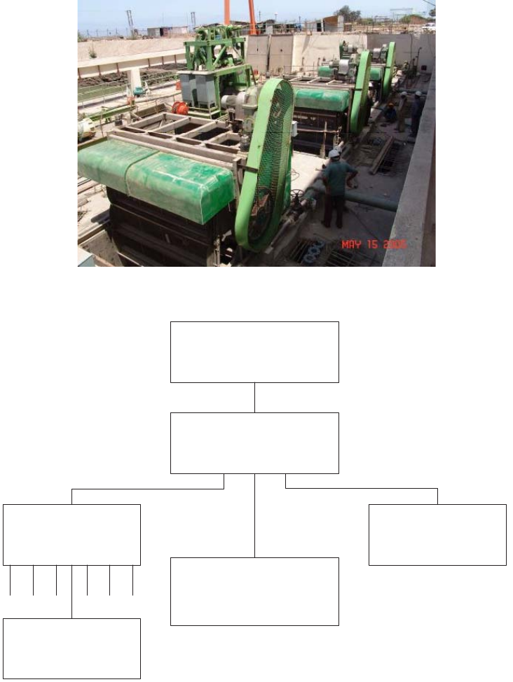
127
It has also been experienced that the impressed current cathodic protection system exhibits far better results if
used together with the passive protective coatings, as in the case of galvanic protection.
As an example, it can be highlighted that the Tarapur Project (India) sea coast environment is very hostile.
Most of the fore bay equipment (shown in Fig. 95), such as embedment for isolation gates, coarse screens, trash
racks, travelling water screens, circulating pumps, associated pipelines, stairs and handrails is subjected to a
continuously hostile saline atmosphere. Use of a good quality paint system along with an impressed cathodic
protection system has been found to be very effective against corrosion. In order to verify the effectiveness of the
system, sacrificial anodes have been added at a few locations that are most vulnerable to corrosion. Monitoring of
the actual loss of weight in sacrificial anodes with regard to the designed value verifies the effectiveness of the
impressed current cathodic protection system.
The flow diagram shown in Fig. 96 can be best used to describe the cathodic protection system required.
FIG. 95. Fore bay equipment.
Motor Control Centre
Transformer Rectifier Unit
Anode
Distribution Box
Potential
Monitoring Station
Cathode Structure
Anode
Junction Box
FIG. 96. Cathodic protection system flow diagram.
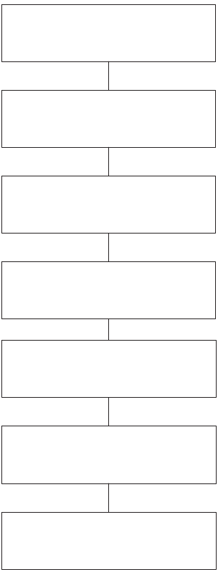
128
Advantages:
The major advantages of the impressed current cathodic protection system are:
— Ability to supply relatively large amount of current;
— Provides high DC driving voltage, hence can be used in all types of electrolytes;
— Ability to provide varying output that may accommodate the changing behaviour of the structures being
protected;
— Requires fewer electrodes to cover large areas.
Disadvantage:
— This system is, however, more expensive than the galvanic system. Transformer rectifier output can be
displayed remotely in the control room and, as an advancement, the cathodic protection system can be
monitored remotely.
— As a rule of thumb, if the current requirements are low, the sacrificial anode cathodic protection system is
chosen. However, if much larger areas are to be covered, and if the resistivity of the medium is high and
current requirements are large, the impressed current cathodic system, shown in Fig. 97, is selected.
Choose type of cathodic system
Review resistivity data
Select anode material, weight,
dimension and conducting medium
Number of electrodes required to
meet current density limitations
Select layout of electrodes
depending on equipment layout
Work out life expectancy and
economics
Prepare detailed design and
specifications
FIG. 97. Improved cathodic protection system flow diagram.
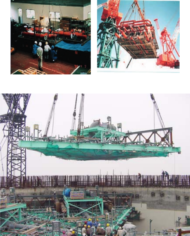
129
8. MODULARIZATION
8.1. DEFINITIONS
There are two main categories of modules:
— Mechanical or electrical modules;
— Civil modules.
There are three levels of modularization, defined as follows:
— Prefabrication — joined materials to form a component part of a final installation;
— Pre-assembly — joined component parts to create a subunit;
— Module — assembly of subunits to create an installation unit or assembly.
Mechanical or electrical modules are defined as a factory or workshop fabricated assembly consisting of
structural elements, equipment and other items such as piping, valves, tubing, conduit, cable trays, supports,
ducting, access platforms, ladders and stairs. Modules may also be fabricated and assembled at a workshop on the
site. Figures 98 and 99 show two examples of mechanical modules.
FIG. 98. Mechanical module — example 1 (credit: Hitachi).
FIG. 99. Mechanical module — example 2 (Credit AECL).
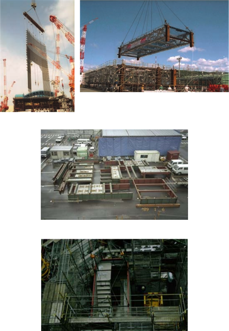
130
A civil module is defined as:
— Assembled structural steels including superstructures for building roofs (Fig. 100);
— Prefabricated rebar mats;
— Assembled deck slabs (Fig. 101);
— Assembled staircases (Fig. 102);
FIG. 100. Assembled roof truss module (left), prefabricated rebar (right), Kashiwazaki-Kariwa 7 — Japan.
FIG 101. Assembled deck slab, Kashiwazaki-Kariwa 7 — Japan.
FIG. 102. Assembled staircase, Kashiwazaki-Kariwa 7 — Japan).
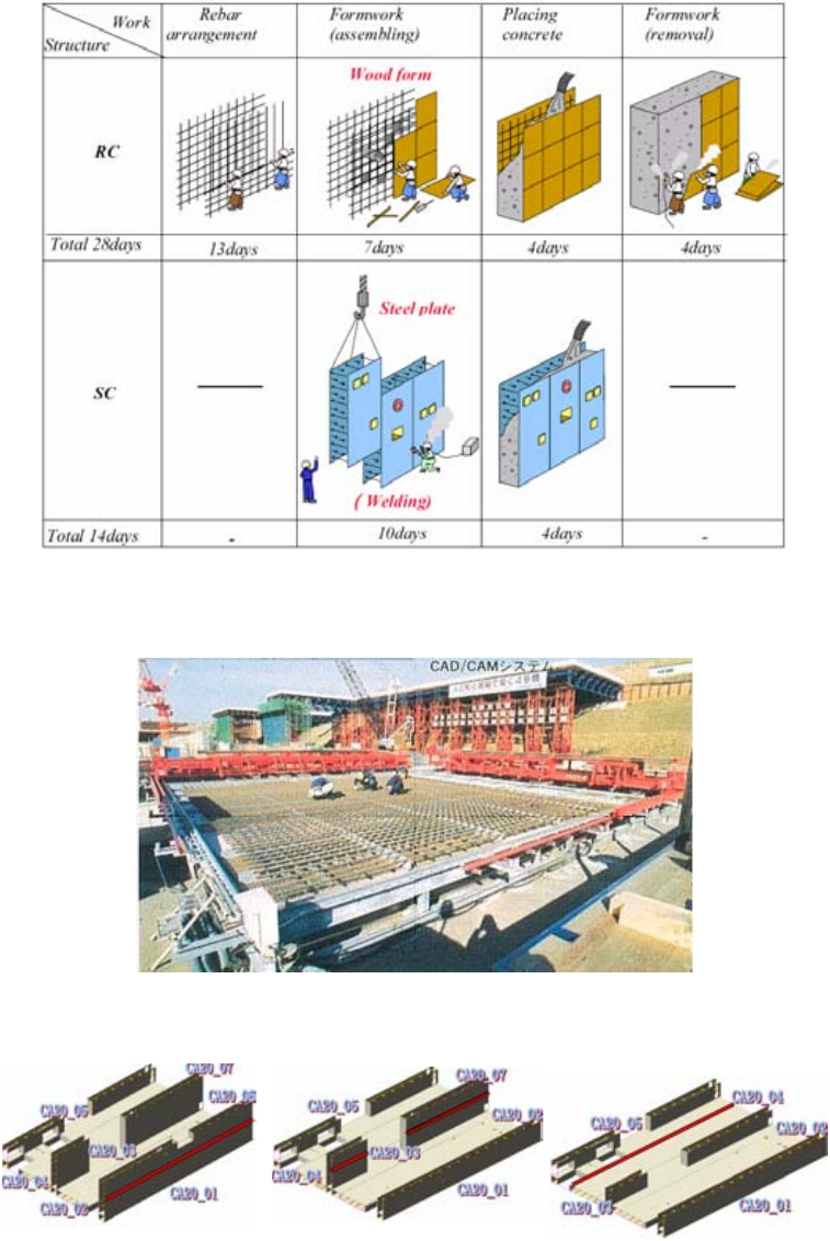
131
— Prefabricated steel plate reinforced structures (Fig. 103) to be filled with concrete after being installed as units
(refer to ‘advanced formwork’ under Paragraph 4.1.2.6).
Refer also to Figs 104–107.
FIG. 103. Steel plate reinforced concrete structures (refer to Paragraph 4.1.2.6 — steel-plate reinforced walls).
FIG. 104. Modular rebar manufacturing at site (Toshiba Japan) (also refer to Paragraph 4.1.2.7).
FIG. 105. Modular wall prefabrication sequence at site — horizontal phase (AP1000).
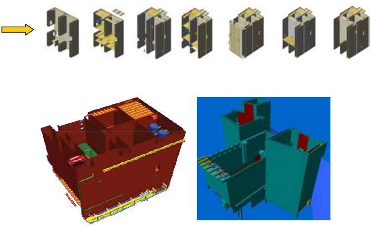
132
8.2. DESCRIPTION
A module is an assembly consisting of, for example, structural elements, equipment and other items such as
piping, valves, tubing, conduit, cable trays, reinforcing bar supports, ducting, access platforms, ladders and stairs.
Structures, systems and components in modern nuclear plants are to be designed as modularized systems that
are shop-fabricated and installed as skid-mounted packaged systems wherever possible, and where such a
configuration suits the schedule and cost of the system.
If modules are to be used, they must be incorporated into the design from the very beginning of the design
process. Otherwise, there is very little chance that the construction organizations can use modular construction
techniques. This approach influences the design philosophy from the feasibility phase, where systems are possibly
combined to form a module, and therefore has a domino effect on all the functions following the design process.
The approach also then has a major impact on the procurement philosophy, and therefore on the construction
strategy.
A modularization methodology plan should be established upfront to allow this approach to be followed
throughout the project, from the conceptual and detailed designs, through engineering, procurement, fabrication,
and erection or installation (construction).
The module designs should be planned with a series of considerations, such as:
— Definition of module envelope parameters;
— Integration of all relevant technical disciplines;
— Temporary bracing;
— Analysis for transportation and lift;
— Selection of installation and alignment tolerances;
— Shipping and storage requirement;
— Handling or lifting requirement;
— Protection requirement;
— Standardization of modular specifications.
The design planning should also consider the necessary features of plant configuration to fit modularization.
An entirely new approach to plant and building layouts may be considered. The use of rectangular structures instead
FIG. 106. Modular wall prefabrication at site — vertical phase (AP1000).
FIG. 107. Civil and mechanical modules lifted as one assembly (CA20 weighing 872 t on the left, and CA01 weighing 750 t on the
right) (AP1000 in China at Sanmen and Haiyang sites).
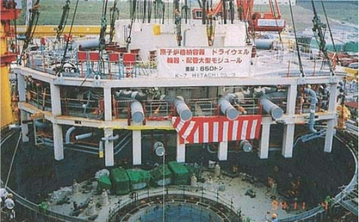
133
of round structures may reduce risks with the modular approach. Designs should ensure sufficient access and
lay-down areas on site and within the plant. Design inputs should include those from construction personnel to
ensure that the plant can be efficiently constructed.
The actual paralleling of activities in the schedule that can be achieved through modularization must be
optimized and utilized to the benefit of the project wherever possible. The advantage is that a large volume of
mechanical/electrical work that is traditionally done on site is moved out of structures for fabrication into modules.
This work can be done in parallel with the early civil programme.
Issues that must be considered in developing the modular construction plan include:
— Module construction schedule driven by the project schedule;
— Sequencing on-site movement, installation and testing of modules;
— Parallel conventional installation work in nearby areas;
— Appropriate use of on-site workshop(s) to support module installation.
It must be ensured that such systems can be installed and removed via the normal access routes of the
building.
8.3. RECENT CONSTRUCTION EXPERIENCE IN MODULARIZATION WITH PREFABRICATION AND
PREASSEMBLY
Modularization with prefabrication and preassembly, in combination with open top construction, has been
applied in some recent construction projects for evolutionary water cooled reactors; e.g. at Kashiwazaki-Kariwa
Unit 7 (Japan), by using the so-called ‘large scale modularizing construction method’. The heaviest and most
complicated module was the ‘upper dry well super large scale module’, shown in Fig. 108, which consisted of a
γ shield wall, pipes, valves, cable trays, air ducts and their support structures, and weighed 650 t.
At Lingao (China), the containment dome was assembled on the ground at the site and installed as a single
module (weight 143 t, diameter 37 m, height 11 m, as shown in Fig. 109). Previously, the dome was assembled by
moving sections into position — a process that took approximately two months.
Another example of modularization is the fabrication and installation of the containment shell liner plates at
the Shin-Wolsong 2 project in the Republic of Korea, where a three-stage based modularization of these
components was adopted. Containment liner plates form an inner structure of the containment building of the
Korean Optimized Power Reactor. The installation process would normally consist of 15 stages, each stage
involving installation of one containment shell liner plate ring. Since containment buildings are connected to
auxiliary buildings, the installation of the containment liner plate could be very complicated when installing pipes,
ventilation, electric wiring and other equipment. Therefore, in the construction of the Shin-Wolsong 2 unit, a three-
stage based modularization (weight 197 t, diameter 44 m, height 9.14 m) of the containment shell liner plates was
FIG. 108. Installation of upper dry well super large scale module, Kashiwazaki-Kariwa, Japan.
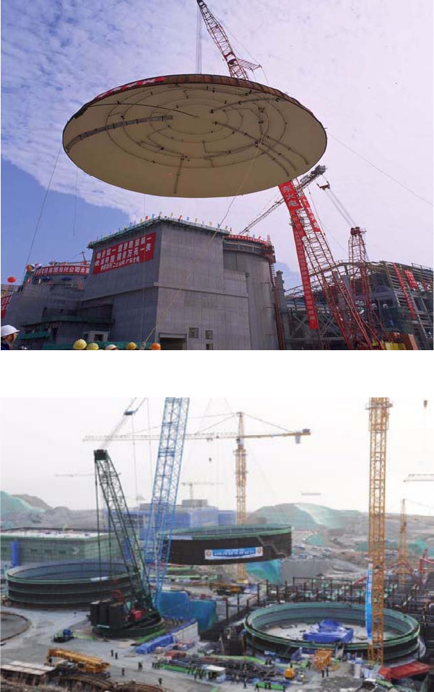
134
introduced. With this method, except for the first two stages, the remaining rings are modularized into three-ring
sections and installed with one lift, thereby reducing the number of lifts and shortening the overall plant
construction time. This modularization resulted in completion of construction in nine months as compared to the
11.5 months taken earlier using conventional methods. This method also simplifies connections with auxiliary
buildings, since connecting provisions have already been attached to the ring modules, such as penetration sleeves
for piping and electrical wire. Figure 110 shows the Manitowoc M-1200 ringer crane (main boom 115.2 m, work
radius 52 m, capacity 238.4 t) being used to lift the 197 t containment shell liner module of Shin-Wolsong 2 into
place in the reactor building.
The containment dome liner plates at the Shin-Wolsong 1 and 2 projects were also modularized. The
containment dome liner plate comprises eight stages, as illustrated in Fig. 111. The dome liner plates were
modularized with two lifts: the lower dome liner plate (shown in Fig. 112, weight 205.7 t, diameter 44 m, height
FIG. 109. Lifting of dome module, Lingao, China.
FIG. 110. Modularization of containment liner plate assembly, Shin-Wolsong 2, Republic of Korea.
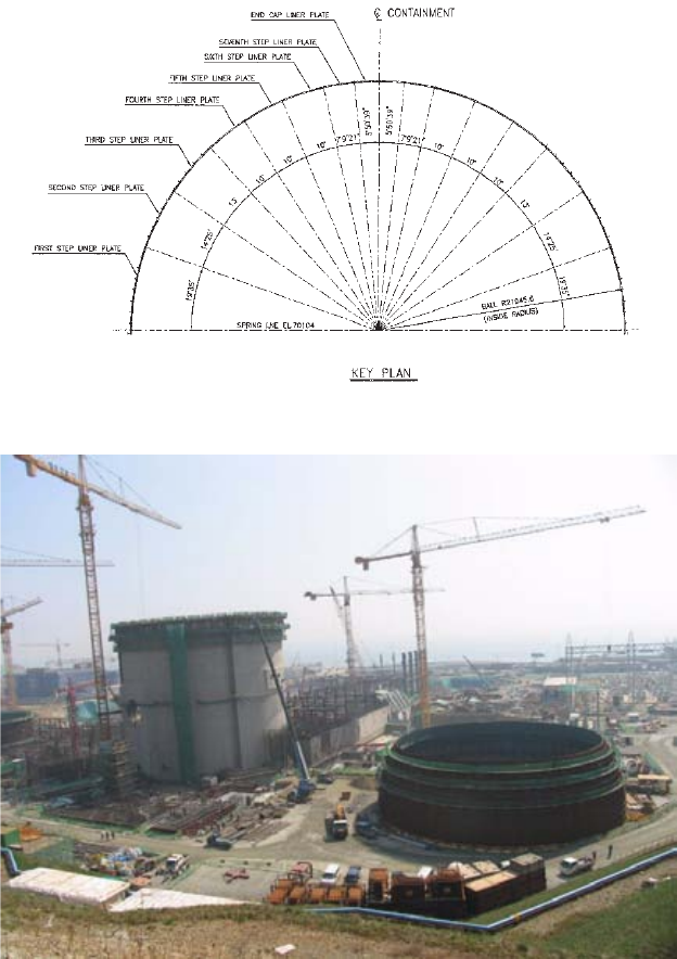
135
13.7 m) and upper dome. The lower dome module was lifted using the Manitowoc M-1200 ringer crane. The
application of dome liner plate modularization shortened the overall plant construction schedule by half a month.
As an example of modularization, at Tarapur (India), the prefabrication of piping was increased to 60-70%, as
opposed to approximately 40% for previous plants in India. This reduced the field welding by 30–40%.
An example of modularization of equipment in the Balance of Plant is the main steam and feedwater piping
module designed by Mitsubishi, Japan, illustrated in Fig. 113.
Figure 114 shows an example of modular construction of gas insulated switchgear in India. In this case, the
construction was completed with 50% saving in time as compared to conventional construction methods.
8.4. ADVANTAGES AND DISADVANTAGES
Prefabrication and preassembly of modules are construction techniques used in many industries, including
NPPs.
FIG. 111. Configuration of containment dome liner plates, Shin-Wolsong 1 and 2, Republic of Korea.
FIG. 112. Modularization of containment dome liner plate assembly, Shin-Wolsong 1 and 2, Republic of Korea.
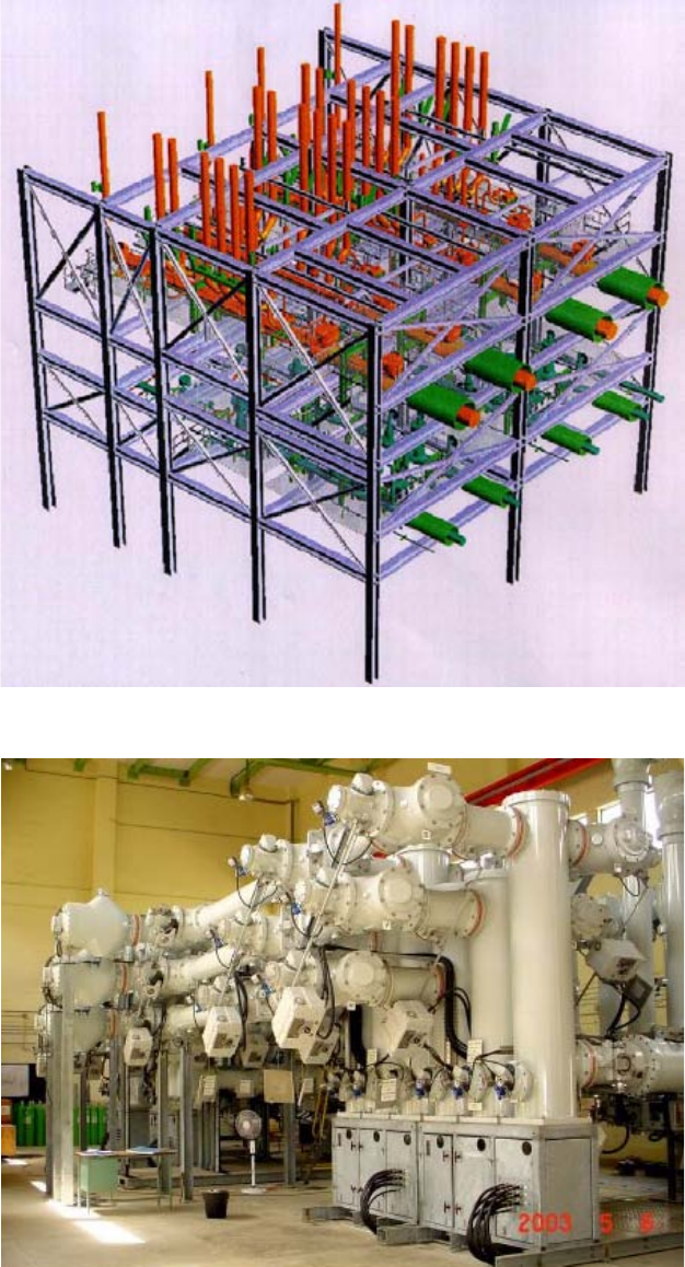
136
8.4.1. Advantages
Modules may be fabricated in a controlled environment in a factory or in a workshop on the plant site.
Multiple modules can be fabricated in factories or workshops, while the civil work is progressing on the site in
preparation to receive the modules. On the site, only sequential assembly of the modularized assemblies is required.
FIG. 113. Large module structure — main steam and feedwater piping module (credit: Mitsubishi Heavy Industries, Ltd).
FIG. 114. Modularized gas insulated switchgear in India on steel-plate reinforced concrete structure construction (NPCIL).
137
This reduces on-site congestion, improves accessibility for personnel and materials, and can improve the
construction schedule. It can also significantly reduce the manpower needs for the site work at an NPP.
Other important attributes and advantages of modularization include:
— Capability for mass production of modules for several units, with the associated benefit of reducing
production time and labour requirements;
— Provision of a controlled environment for module production;
— Manufacturing of modules before the site becomes available;
— Potential to utilize accelerated curing techniques for concrete modules;
— Reduced schedule (if the module is applied to the critical path);
— Reduced field work and levelized on-site manpower;
— Increased productivity and quality under factory environment;
— Increased safety and efficiency at ground level work.
The chief benefit of modularization is that it shortens schedules by:
— Creating parallel construction activities;
— Increasing the productivity of workers by allowing assembly in controlled shop environments as opposed to
construction sites;
— Reducing work-site congestion so that on-site craft is more productive;
— Allowing construction of modules at grade and in easy-to-reach positions (e.g. vertical wall reinforcement
constructed in horizontal position on ground);
— Removing or reducing the effects of weather at the construction site (if module assembly occurs in indoor
facilities);
— Reducing construction time of some systems and equipment, since testing may be conducted within the shop.
With the application of modularization techniques, a reduction of four to five months could be achieved in the
construction schedule.
The decision as to whether to apply the modular approach should be made in the conceptual design stage, and
it must be then followed throughout the project: from detailed design, engineering, procurement, fabrication and
installation, to completion of commissioning. In this way, equipment can be designed to be located so that it
conveniently fits into a module. In addition to the capacity of the VHL crane, considerations in sizing modules
include whether the site is accessible from the sea, or if it is necessary to fabricate sub-modules to be shipped by rail
to the site. Examples of modules include structural modules; containment liner modules; electrical equipment
modules with their own structural frames; cable tray modules; piping and valve modules; and stairwell modules.
Modularization can also influence testing procedures, as preliminary tests can be done on many components at the
fabrication facility to help eliminate potential sources of error before conducting formal tests after installation at the
construction site.
8.4.2. Disadvantages
The use of modularization places several requirements on the project schedule. Engineering design must be
complete prior to module procurement. The quality of the modules off-site and on-site must be strictly ensured for
successful modularization to take place. The schedule for component procurements will also be affected: materials
required for modules will have to be ordered earlier than was necessary for conventional stick-build construction.
The use of multiple module vendors will also require strict coordination to ensure proper delivery times. Finally,
modularization will require a detailed plan for how to sequence and schedule connections between adjoining
modules.
Modularization does introduce challenges to project schedules. These challenges include, but are not
restricted to:
— Design schedules may increase because of additional upfront work;
— Extensive design effort may be required;
138
— Each module might have a unique rigging strategy;
— In some cases, the size and weight of large modules require that modules be delivered by barge to the site;
— Construction of temporary transportation infrastructure and lay-down areas will be required during the site
preparation phase to stage and move large modules once delivered on-site;
— Late delivery of modules can cause schedule delays and setbacks;
— Installation of modules must be highly structured and prioritized so connections can be made expeditiously;
— Damage to modules during shipment to the site can cause delays.
In addition to the impact on construction schedule and reduction of site labour requirements, some important
factors which need to be examined in making the decision to modularize include:
— The necessity to complete the total design of the plant before module fabrication;
— Construction of factories or workshops for fabrication of modules;
— The qualification of separate vendors has an influence on nuclear quality programmes and thus influences and
complicates module fabrication;
— The necessity for earlier outlay of funds for engineering, materials and components before module
fabrication;
— Increased engineering for modules regarding transportability and handling at site;
— Increased engineered temporary support steels;
— The need for expensive heavy lift cranes and the complexity due to placement, movement and establishing
these cranes at site;
— Transportation costs due to size of modules.
8.5. REQUIRED PLANNING
In addition to the impact on construction schedule and reduction of site labour requirements, some important
factors which need to be examined in making the decision to modularize include:
— The necessity to complete the total design of the plant before module fabrication;
— Construction of factories or workshops for fabrication of modules;
— The necessity for earlier outlay of funds for engineering, materials and components before module
fabrication;
— Increased engineering for modules;
— Increased temporary bracing steels;
— The need for expensive heavy lift cranes;
— Increased transportation costs.
8.6. POTENTIAL FUTURE IMPROVEMENTS
Modularization has a great potential to significantly reduce the construction schedule. The steel–plate
reinforced structure (SC structure described in Paragraph 0) allows bulk commodities to be fitted on the surface
plate when the steel plate is reinforced with structural steels attached to the inner surface of the steel plates. The
composite large scale module can be manufactured using the SC structure. The composite module comprises walls
and slabs welded together, and components outfitted along the walls and below the slab, including piping, cable tray
and HVAC ducts. The module can be enlarged according to the capacity of the VHL crane, which could be
500–1000 t. The concrete is to be placed into the wall and slabs after the installation of the modules. This method
of plant construction is similar to assembling toy building blocks. Figure 115 shows the concept of the composite
large scale module method, Figs 116 and 117 show examples of the SC structure technique, and Fig. 118 indicates
early engineering requirements on SC structure construction.
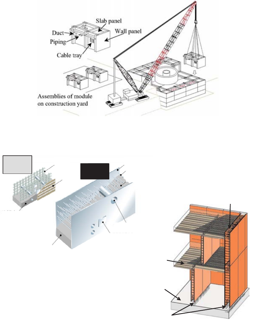
139
FIG. 115. Concept of composite large scale module construction method as being implemented on China AP1000 plants.
Basemat
(RC)
Joint rebar
Half SC slab
SC wall
FRQFUHWH
(PEHGGHGSODWH
Sleeve for piping
SC
structure
)RUP
5HEDU
Structure Steel plate
Concrete
Headed stud
Tie bar
Concrete
FIG. 116. Steel-plate reinforced concrete technique (Toshiba).
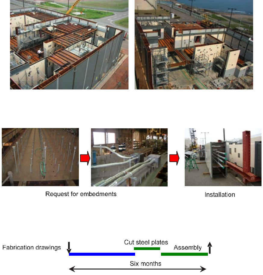
140
FIG. 117. Steel-plate reinforced concrete structure technique being applied to nuclear related buildings and facilities (Tepco).
FIG. 118. Early engineering requirements on steel-plate reinforced concrete structure construction (Toshiba).
141
9. OPEN TOP CONSTRUCTION METHOD
9.1. VERY HEAVY LIFTING OPEN TOP CONSTRUCTION
9.1.1. Background
In the past, the constraints on the installation of components within the reactor building and containment were
a major challenge to the construction schedule. Historically, the reactor building and containment wall were
constructed with temporary openings in the side of the buildings to allow entry of bulk commodities and large
equipment. Recently, mainly due to advances in construction crane technology, significant improvements in
schedule have been achieved through transportation of bulk commodities and installation of heavy equipment
through the open top. Open top installation can provide cost savings and flexibility in delivery of heavy equipment
that is not enclosed by ceiling slabs.
In the open top installation construction sequence, part of the reactor and containment wall is built. Major
items of equipment such as the reactor vessel and steam generators are then placed into position through the
temporary open top in the building, using a VHL crane. Once the equipment has been placed inside, work on
connecting the equipment to the already built piping and electrical systems can proceed in parallel with the ongoing
construction works.
There is a lot of heavy equipment in NPP buildings; e.g. reactor pressure vessel (RPV), containment vessel,
steam generators, emergency diesel generators, heat exchangers, overhead cranes, condensers and feedwater
heaters. This heavy equipment needs to be installed in the correct position. The open top method allows easier
installation of the heavy equipment, as equipment can be installed directly into the final position, unlike the
traditional methods that require complex rigging and manipulation. In addition, installation of these modules and
equipment will affect the construction schedule of the NPP. The containment vessel will be the critical path to the
schedule of the Nuclear Island, and the condenser will be the critical path to the Turbine Island. When larger and
heavier assemblies are installed using this method rather than the stick-build approach, the construction schedule
can be shortened.
Construction efficiency and quality can be enhanced by moving assembly and construction activities away
from the excavation and away from the site in general, and performing the work in parallel in controlled and
spacious environments. The drive to achieve this goal has resulted in larger and heavier assemblies being shipped,
moved and placed on site.
Open top construction is a construction/erection technique that involves integrating the construction of the
walls/slabs of a building with the installation of modules, equipment, and mechanical and electrical commodities.
The commodities are designed, procured and constructed, with equipment and materials being installed in and/or
loaded in their final positions before those areas are fully enclosed by higher elevation slabs and the containment
dome. In some cases, even surrounding walls are not erected until the equipment is set (especially true for large
modules).
When properly used, this open top construction technique permits many of the advantages of modularization
and pre-assembly to speed the construction process and reduce construction labour cost. Open top construction
reduces temporary openings, which are used in the conventional method to carry in modules after the construction
of the buildings. Open top construction also reduces material handling by using modules. The open top construction
method should be used extensively for large equipment and bulk commodities such as piping and cable trays.
The following should be considered when the open top construction method is to be applied:
— The open top construction method requires the early procurement of equipment (four to six months in
advance) compared to the conventional method which uses temporary openings, because the equipment needs
to be installed before the ceiling is installed;
— The equipment to be installed using the open top construction method should be identified in the earliest stage
of the project, and the engineering and procurement schedules should be adjusted to match the open top
construction schedule;
142
— The open top construction method requires strict manufacturing and shipping management of the equipment.
Any delay in the equipment causes a delay in the construction of the building, which will affect the entire
construction schedule;
— Equipment installed using the open top construction method should be properly protected against physical
impact, the weather, humidity, and construction dust and fumes, because the upper slab is installed after the
installation of the equipment;
— Open top modular construction requires VHL cranes:
— A large crane is used to lift the modules or equipment into the buildings. Large items of equipment such as
the RPV, pre-assembled containment vessel, pre-assembled condensers and pre-assembled modules are
lifted ‘over the top’ of the building to avoid interfering with the building construction. The VHL crane
needs to have the capacity to lift the large equipment and modules into the building. Current industry
practice typically uses VHL cranes with the capacity to lift and place modules with a mass of more than
900 t. In some instances, plant construction requires the VHL crane to pick up and travel with large
modules. In current industry practice, the large block method was also introduced to the civil work by
using the VHL cranes for lifting larger assembled rebar blocks, structural steel frames, metal deck blocks
and assembled scaffold blocks;
— Construction crane technology has advanced significantly over the past 15 years. Significant
improvements in lifting are being achieved every three to five years. Current lift limitations allow for
modular prefabrication of major skids and entire rooms or even floors of combined process equipment,
piping, electrical and controls components. Similarly, major vessels and other very large items of
equipment that were previously shipped in sections and assembled on-site are now shipped whole, moved
across the site and placed as a single piece. Marine access to a site has significant advantages in this regard;
— Movement of large assemblies, modules and equipment from port to port, port to site, and site to crane
location is an additional area where efficiency has increased significantly. For example, heavy haul
transporters can be used in conjunction with special barges for inland waterways such that no offloading is
required at the barge port near the site. Ocean delivery vessels and ports can place the transported item
directly on the transporters on the barge. When the barge reaches the site or site access port, the
transporters drive directly off the barge and to the crane location for placement;
— Just-in-time delivery should be evaluated on a case-by-case basis, based on the economics. The concept of
‘single lift,’ which seeks to move material and equipment directly onto the site and into place without any
interim lift or storage, should be utilized where possible;
— Very heavy lifting has been used for large scale capital projects. An important consideration in the
application of a VHL crane is the area needed for strategic placement of the crane to conduct the numerous
lifting activities. Planning for crane placement and movement is a crucial step in open top installation;
— Full exploitation of open top construction is expected to reduce total construction time, but attention must
also be focused on the cost of heavy lift equipment and the facilities necessary for the prefabrication of
modular components;
— The following items should also be considered when a VHL crane is applied to the construction:
— A VHL could be one of the long-lead items which may take two to three years, including design and
manufacturing;
— A VHL crane requires a larger footprint close to the major buildings;
— A VHL crane plan should be in place to control crane movement around the site.
Examples of the use of the VHL open top construction technique are given in the following paragraphs.
9.1.2. Qinshan Units — China
During the construction of Qinshan III Units 1 and 2, approximately 70 items of equipment were set in place
using the VHL crane, as shown in Fig. 119. This equipment included steam generators (shown in Fig. 120 — 220 t
each), pressurizer (103 t), reactivity mechanisms deck (43 t), feeder frames (40 t each), fuelling machine bridges
(16 t each) and major heat exchangers. The steam generator took one day to install, compared to the two weeks
typically required using the traditional horizontal access method.
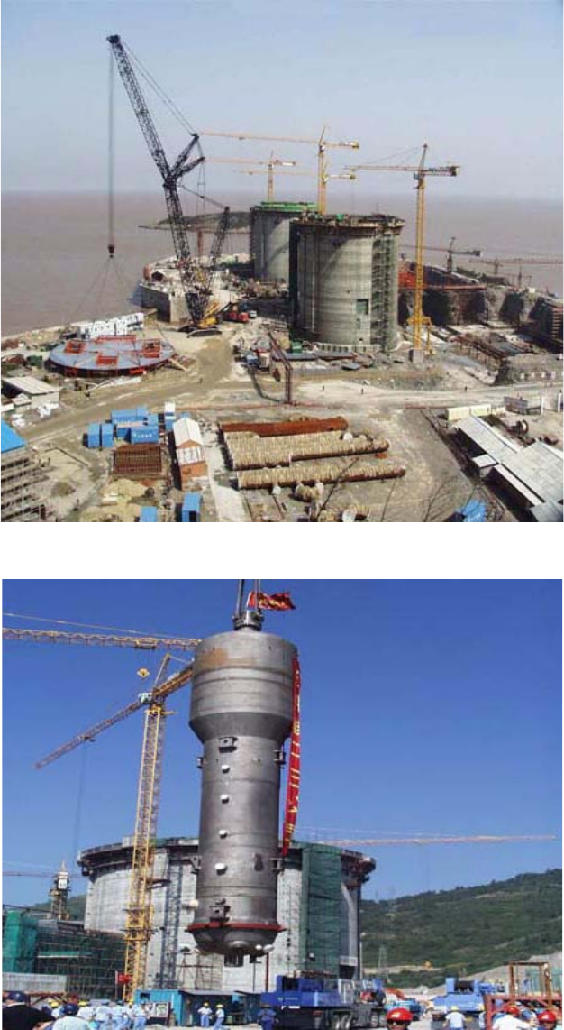
143
9.1.3. Olkiluoto — Finland
Figure 121 shows a VHL crane being used to lift the 200 t metallic containment liner double rings of
Olkiluoto 3 into place in the reactor building, raising the inner containment from +12.50 m up to the 25 m level.
FIG. 119. Very heavy lift crane use in Qinshan, China.
FIG. 120. Steam generator installation in Qinshan, China.
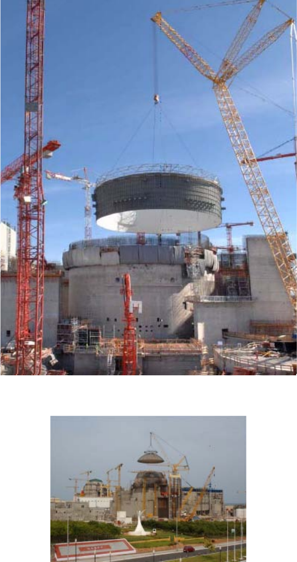
144
9.1.4. Kudankulam — India
Figure 122 shows a VHL crane lifting the containment dome at Kudankulam.
FIG. 121. Lifting of containment liner double rings in Olkiluoto 3, Finland.
FIG. 122. Lifting of WWER-1000 containment dome into position at Kudankulam, India (credit: NPCIL).
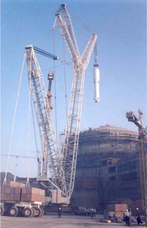
145
9.1.5. Tarapur Units — India
Significant savings in time were also achieved by using open top installation at Tarapur Units 3 and 4. The
VHL crane was used to set approximately 50 items of equipment in position, including the steam generators (shown
in Fig. 123) moderator heat exchangers, pressurizer, calandria (shown in Fig. 124) primary circuit headers, fuelling
machine, and several heat exchangers. The steam generator was lowered and positioned in less than a day, thus
saving considerable construction time compared to that used for earlier heavy water reactors (HWRs) in India.
9.1.6. Tomari Unit 3 — Japan
In Japan, Mitsubishi used a VHL crane to install equipment at Tomari Unit 3 (shown in Fig. 125).
9.2. LIFT TOWERS
An alternative to VHL cranes is the lift tower, also known as a hoist support structure. These structures
(shown in Figs 126–128) can be ideal for locations where hoists are made in a rectangular pattern (such as a bridge
crane) and where the overall height requirement of the lift is limited. Lift towers are therefore more applicable to
drawer or slide-in construction applications than to open top construction of tall structures.
FIG. 123. Steam generator installation at Tarapur, India.
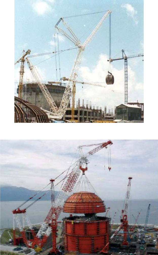
146
Lift towers have the following advantages over high capacity cranes:
— Less mobilization and demobilization cost compared to the high cost of counterweight shipping and assembly
for a high capacity cranes;
— Less susceptibility to wind, with no requirement for a boom lay-down area in high winds.
The key objective of the most cost effective equipment handling strategy is to minimize the lifting radius in
order to minimize the crane size and counterweight requirement. The lift tower has the advantage of requiring no
counterweight.
FIG. 124. Lifting of calandria at Tarapur, India.
FIG. 125. Use of very heavy lift crane to lift 40 m diameter containment vessel upper head (credit: Mitsubishi Heavy Industries, Ltd).
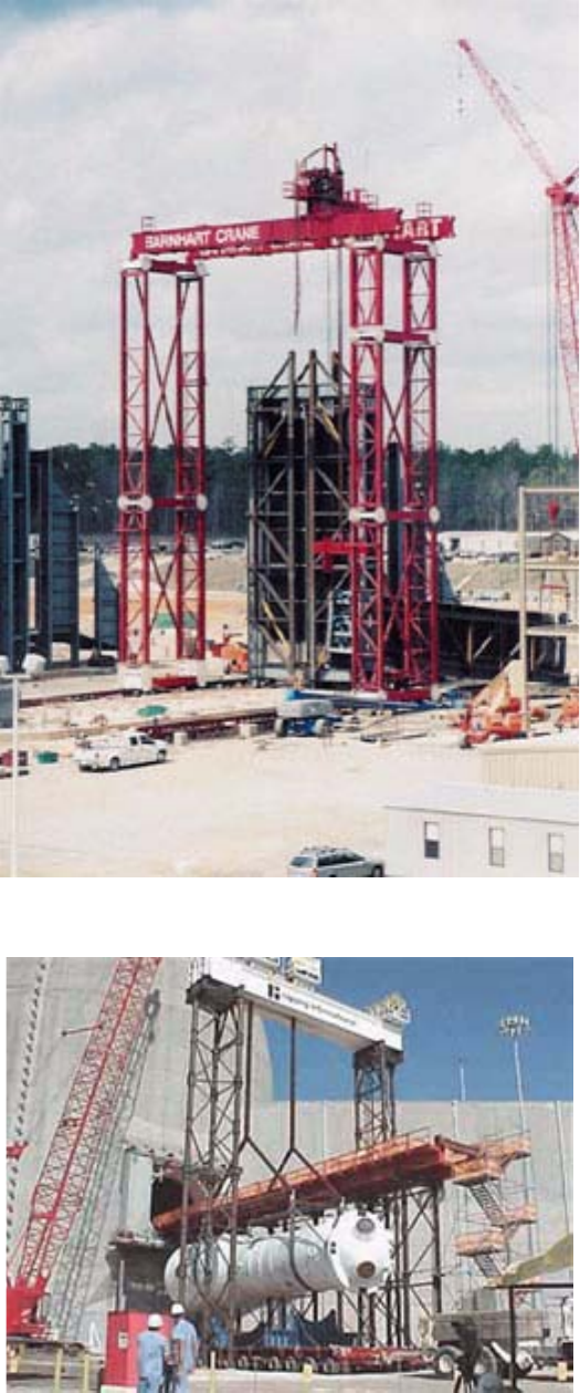
147
FIG. 126. Lift tower used for heat recovery steam generator erection.
FIG. 127. Lift tower used in pressurized water reactor steam generator replacement.
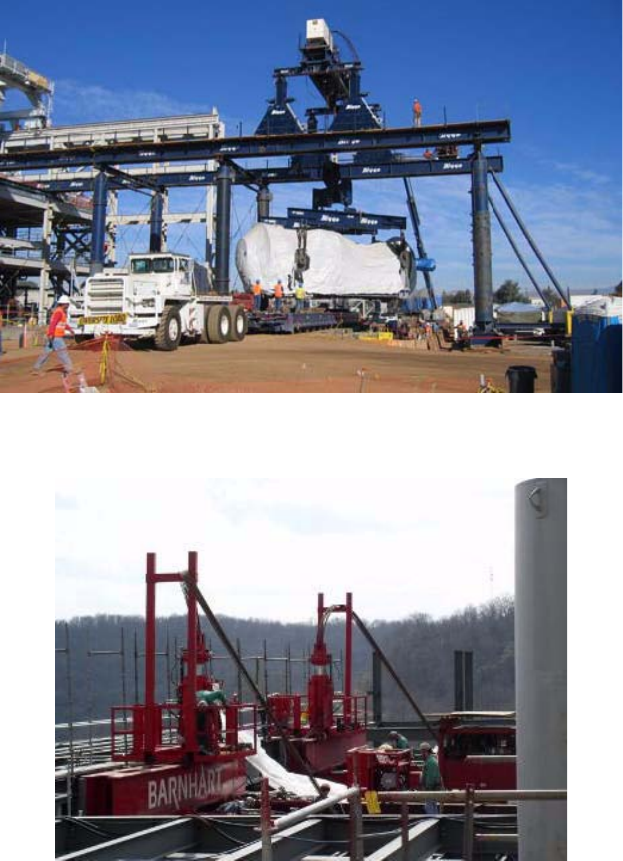
148
A disadvantage of lift tower cranes is that an assist crane is required to build the lift tower structure. However,
the capacity of the assist crane is normally much less than the capacity required to lift the load intended to be lifted
with the lift tower.
Instead of a bridge hoist on top of the lift tower columns, strand jacks can be used as shown in Fig. 129.
The use of a gantry crane that travels on top of the lift tower rails may save additional time. Figure 130 shows
a conceptual drawing of this equipment. This arrangement may be expensive, however, and the cost-benefit of
construction and labour time savings must be reviewed to determine cost—benefit.
FIG. 128. Lift tower used in drive-through arrangement.
FIG. 129. Stand jacks used on top of lift tower arrangement.
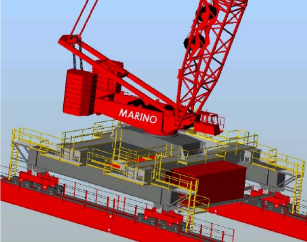
149
FIG. 130. Gantry crane placed on lift tower arrangement.
150
10. QUALITY ASSURANCE, INSPECTION AND TESTING
10.1. DEPLOYMENT PLANNING FOR INSPECTION AND TESTING
10.1.1. Conventional methods
During construction of previous generations of NPPs, construction and commissioning organizations were
often separate and not integrated. This was partially the result of the multiple-contracts approach used by owners at
that time, and partially due to the differing personnel capability and knowledge requirements for each activity.
10.1.2. Advanced methods
Coincident with the construction industry’s elevated focus on construction planning and management
(discussed in Section 11), the industry has worked to integrate design, procurement and testing into the overall
integrated project management effort. This is a result of the fact that constructors in some countries have migrated
from traditional construction subcontracts to integrated engineering, procurement and construction contracts
requiring schedule and cost certainty. The responsibility for project success has been moved more completely to a
single entity. Another reason for the movement to fully integrated design, procurement, construction and testing is
the ability of advanced information management techniques, including planning and database software, to maintain
effective control of project information.
Active deployment planning for testing may alter construction sequencing and even the construction
techniques used, so that the combined performance of construction and testing activities is efficient and
streamlined.
10.2. RADIOGRAPHIC AND ULTRASONIC INSPECTION AND IMAGING
10.2.1. Conventional methods
Conventional radiography methods require the exposure and development of radiographic film. The process
requires time, effort and the use of development chemicals. Due to development processing time, unacceptable
images could not be identified timeously. Re-imaging would therefore often require the reinstallation of imaging
equipment.
10.2.2. Advanced methods
Advances in digital radiography have been achieved in medical and other fields, including construction.
Digital radiographic images are high quality and immediately available for review and acceptance. The digital
images are stored in digital file format, and can be stored, copied and shared without degradation. The digital file
formats are effective for Building Information Management (BIM) applications and QA records retention. Digital
imaging does not require chemical processing.
Ultrasonic imaging is another imaging advance that has been successful in medical practice and is finding use
in other industries. Ultrasonic probes have been very useful in PWR steam generator tube inspections. Probes have
been developed that are able to travel long distances inside small heat exchanger tubing, and provide excellent
indication of intergranular stress corrosion cracking and pitting. This same technology can be used for inspection
and acceptance of new equipment in new installations.
151
10.3. INSPECTION TOOLS
10.3.1. Conventional methods
Conventional methods for visual and imaging inspection activities have generally involved leaving areas open
for actual direct visual inspection, or for access by bulky imaging equipment. This requires that inspections proceed
simultaneously with erection, and can cause excessive construction hold points and congestion in the area of
construction.
Foreign material exclusion is another area of visual inspection that is required prior to system turnover to
operations. Conventionally, sections of piping would be inspected visually and then blocked off by inflatable
bladders or blanking plates. Installation and removal of these items involve time and effort that can be avoided
using advanced methods.
10.3.2. Advanced methods
Advances in video and other imaging probes include miniaturization and remote manipulation. Extensive
areas of installation work that have been closed off from direct visual inspection can now be inspected using robotic
and remote inspection. These advanced methods can be used (a) to inspect weld quality and material
condition/quality, and (b) to search for and remove foreign materials.
Robotic mobile equipment can be used during construction to inspect complex pipework and structures in
locations that are difficult to access. Such equipment has flexible arms, can be manoeuvred into confined spaces,
and can be equipped with tip cameras.
Robotic equipment is currently available for:
— Visual inspections;
— Video measurement;
— Retrievals;
— High pressure jet-spraying;
— Remote manipulation;
— Debris collection and retrieval;
—Brushing;
— Radiation surveying (both dose rate and smears).
10.4. RETRIEVABILITY OF TEST AND CERTIFICATION DOCUMENTATION
10.4.1. Conventional methods
The control and maintenance of nuclear documents during construction of NPPs have remained a constant
challenge. In the past, nuclear and QC documents were gathered and stored as hard copies. The clerical work and
files associated with this process were inefficient with regard to both labour and schedule time. Each form and sign-
off was typically made on paper. Several copies were then made, and files and backup files were maintained. This
would be required for virtually all equipment, piping, wiring, components and building materials in critical
applications.
These large and unwieldy files were intended to be maintained for the life of the plant. In later years, many of
these files were transferred to microfiche or another form of document control. At times in past generations of NPP
construction, the inability to locate documentation would require redundant testing, inspection and verification. The
new data management methods now available will allow effective and efficient retrievability of data for meeting
acceptance criteria requirements.
152
10.4.2. Advanced methods
Documentation of future NPPs will be electronic. Several methods have been proposed. Terms commonly
used are Intelligent Project Life Cycle Management (IPLM) and Building Information Management (BIM).
Platforms that assist in data job modelling using the 3-D models utilize data centric processes for streamlining
engineering design processes while preserving existing data and making it more usable/reusable.
These products are changing the way plants are engineered and designed. They enable optimized design,
thereby increasing productivity and shortening project schedules. The concept leverages access to critical plant
information and knowledge to improve and automate work processes, from construction through testing, operations
and maintenance, and decommissioning.
Some systems develop plant life cycle management application software and services that support industrial
processes and provide a 3-D vision of the entire life cycle of products from conception to maintenance to recycling.
They consist of modules for designing the virtual product for 3-D mechanical design for virtual production, virtual
testing, global collaborative life cycle management and on-line 3-D lifelike experiences.
These methods of electronically recording and cataloguing plant component data are likely to be useful in
maintaining information on material certifications, inspections results and certifications for components and
systems in the NPP. Having this information available and retrievable is essential to meet acceptance criteria
established by owners and regulators. The information will then be available, retrievable and useful for plant
operations and maintenance.
10.5. AS-BUILT AND BUILDING INFORMATION MANAGEMENT
10.5.1. Conventional methods
Conventionally, constructors would generate building as-built records by making detailed measurements after
construction was complete, and updating affected drawings. Due to the large number of drawings and documents
involved, this effort was extended to critical drawings only. The base of plant information then passed to operations
was limited. For existing operating plants, this information has been slowly reconstituted over time to create plant
information databases that meet operational needs. These databases are often segregated, specialized and hard to
update and maintain. New plants will have this information available at turnover to operations in a format that is
easier to maintain and interpret.
10.5.2. Advanced methods
Building Information Management (BIM) is the concept of carrying the 3-D design model and its object-
oriented database structure through the commissioning and into the operations and maintenance of the plant. This
concept can have a significant effect in the nuclear power industry, where design basis information and plant
configuration control issues are paramount throughout the operational life of the plant.
BIM is a concept, the full implementation of which is currently limited by available tools and interface
standards. Proponents believe that BIM can be used to bridge the information loss associated with handing a project
from the design team to the construction team, and to the building owner/operator, by allowing each group to add to
and refer back to all information they acquire during their period of contribution the BIM model.
Further, BIM may offer the following advantages:
— Improved visualization;
— Improved productivity due to easy retrieval of information;
— Increased coordination of construction documents;
— Embedding and linking of vital information such as vendors for specific materials, location of details, and
quantities required for estimation and tendering;
— Increased speed of delivery;
— Reduced costs.
153
Such 3-D computer models can conveniently be linked to the schedule to provide what is referred to as ‘4-D’
modelling. Deliverables that can be extracted from the CAD drawing model include piping system isometric
drawings, general arrangement drawings and materials quantities. These computer models provide visualization for
installation planning. Furthermore, during operation they can be used for the training of operators and system
engineers, and to assist nuclear safety engineers to visualize systems when evaluating performance and safety
issues.
For NPPs, the system can also be expanded to track inspection, test, analysis and acceptance criteria activities
that must be carried out during construction to meet regulatory requirements.
Commercial building projects have been the first to adopt BIM on a comprehensive basis. This is, in part, due
to the lesser degree of complexity in comparison to industrial projects, especially in process or systems based
industries.
Even so, experience to date is demonstrating a number of determining factors that complicate achieving the
full promise of BIM, including:
— Project teams comprised of many participants, each of whom has optimized their work processes to use
pre-existing technology already deployed in-house;
— Reliance on best-in-class applications from different vendors based on specific project requirements;
— Long-standing delineation of professional responsibility and liability among project participants;
— An iterative design process caught up in fast-track project schedules;
— Varying project delivery methods and contractual relationships.
Use of multiple models for a single project is more common and more practical to implement. This will most
likely be true for the next generation of nuclear plants because of interfaces between (a) the Nuclear Island, Turbine
Island and Balance of Plant, and (b) the multiple types of analysis required.
10.6. SHOP INSPECTION AND QUALITY CONTROL FOR MODULE FABRICATION
10.6.1. Conventional method
Using a stick-build approach to construction places all erection and assembly in the field environment. As a
result, testing of that work is also placed in the field. As discussed in other paragraphs, performing work in situ at
the field location causes congestion, inefficiency and potential environmental interference.
10.6.2. Advanced methods
Modularization, skid assembly and rack assembly activities performed in shop locations, either at field shops
or remote shops, improve the efficiency and quality of testing activities in the same way as erection and assembly
activities are enhanced under these conditions. Digital imaging and BIM type data management will support and
enhance extensive testing activities at remote locations. The resulting inspection and interpretation data would then
be communicated to the overall plant documentation model, and reviewed and accepted as the testing activities are
performed. The delivered modules, skids and racks can then be approved for delivery and installation at the site,
knowing that they will not require inspection or rework at the site.
10.7. DOCUMENTATION
It is imperative that the documentation supporting the design and licensing basis of this plant be included as
part of the plant configuration management system to support plant operation and future modifications.
154
10.7.1. Conventional method
The conventional method of maintaining plant configuration management documentation has been to scan all
project deliverables and save them as images for reference and use. This method is cumbersome, as design basis
and licensing documents cannot be easily identified and retrieved. In addition, search capabilities by topic or
component are non-existent or limited.
10.7.2. Advanced method
Configuration Management Plan is an electronic virtual configuration management program that provides full
3-D virtual CAD capability with live interactive scale interface (colour, scratch build, transparent enabled, stack-up
construction simulation).
It normally has the following features:
— Icon interface to all support programmes;
— Construction drawing interface program, fully interactive with printable drawings suitable for field usage;
— Piping and Instrumentation Diagram (P&ID) interface from system description to 3-D CAD model;
— Electrical and instrument drawings interface from system description and 3-D model;
— Mechanical and electrical contractor manual information interface for input into maintenance procedures;
— Software/electrical interface diagram;
— BOM and parts list interface for one-touch printout for input into preventive and corrective maintenance work
packages;
— Historical data interface for cut-and-paste data and archival information retention including digital records
retention to replace film;
— Blueprint interface from system description and 3-D model;
— Out of service interface from system description with isolation point input;
— Equipment specifications with critical operation parameters interface from system description and 3-D model;
— As low as reasonably achievable (ALARA) interface from system description and 3-D model;
— Process computer interface with live equipment diagnostics;
— Full scheduling capability from system description and 3-D model capability with scheduling platform
interface for construction maintenance and surveillance logic inputs;
— Technical specification and licensing documents interface from system description and 3-D model for
operational reviews;
— Vendor specific drawings interface from system description and 3-D model;
— Plant training models with system descriptions.
A copy of all permanent documentation supporting the plant is a must to support plant operation and design
basis. It is recommended that a project numbering system be established and implemented in the early stage of the
project. This will be used to provide a method for identifying and physically tagging all permanent plant structures,
systems and components, including piping subsystems, cables, conduit, conduit supports, pipe supports, cable trays,
cable raceways, cable tray supports, junction boxes, penetrations and mechanical equipment.
As part of the configuration control documentation, an integrated document control system will include all
QA records; equipment and personnel qualification records; maintenance and testing records; technical manuals;
and drawings controlled and maintained to reflect the ‘as-built’ configuration of the plant.
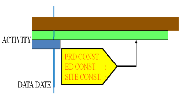
155
11. INTEGRATED PROJECT PLANNING AND MANAGEMENT
11.1. BACKGROUND
A mega-project involving construction of NPP cannot be constructed successfully without time and cost
overruns unless advanced project monitoring software is adopted for integration of all aspects of project
management. The earlier planning tools based on the Programme Evaluation and Review Technique (PERT) and
Critical Path Method (CPM) have now been replaced by the Precedence Diagram Method (PDM). All new project
management software is based on this, due to its inherent advantages of resource-based networking and
computerized computation of time and cost variances, float, etc. with flexibility of adopting a detailed WBS, and
many leading and lagging parallel activities.
The use of project management tools is crucial to the successful completion of an NPP project. The creation
of an integrated project schedule is visually simplified by the implementation of the PDM.
The PDM was developed in the early 1960s. The PDM activities are expressed beyond nodal characters, thus
by using boxes with pertinent information defining their assigned properties and the types of lag as needed, as
shown in Fig. 131.
The assigned properties included on the PDM diagram will include:
— Logical relationships between project activities;
— ‘What if’ scenarios, what to do, and most likely what will happen information/activities;
— Critical activities that are on the critical path and near critical path.
Implementation of PDM will assist in determining the critical path activities for the entire project. Critical
path activities are defined to be those activities which, if delayed, will cause delay on the entire project, regardless
of whether the other project activities are completed on time.
Interdependencies between those PDM activities are expressed by:
— Finish to start. A predecessor to successor logical relationship defined such that the activity cannot start until
some time after the previous activity has ended. This activity is most commonly used;
— Start to start. A predecessor to successor logical relationship defined such that that these are parallel activities
with regard to start dates. These activities may also be staggered with a lag relative to their start dates;
— Finish to finish. A predecessor to successor logical relationship defined such that that these are parallel
activities with regard to their completion dates. These activities may also be staggered with a lag relative to
their completion dates;
— Start to finish. A predecessor to successor logical relationship defined between the start date of one activity
and the completion date of the successor activity. This relationship is not commonly used.
FIG. 131. Precedence diagram method.
156
The use of PDM is critical to the project management of an NPP project. Large scale projects require this
detail planning tool to determine all facets of this project, and to also allow reliable completion of the project within
the allocated budgets and resources.
11.2. PROJECT CONTROLS PROCESS
11.2.1. Objective
The Project Controls Process will be used to plan, monitor, analyze, report on and control projects. Baseline
budgets and schedules will be established as part of the Project Work Plan, from which changes can be identified
and reported. Budget and schedule variances from the established baseline will be monitored using a combination
of target schedule reports, earned value curves, cost reports and production reports.
Project controls reports will be created to provide project team members with information to help them meet
the established budgets and schedules. The project controls tools help identify potential problem areas and will also
be used to report progress to clients, consortium organizations and other project participants.
An integrated project schedule exists when all of the sub-projects are similarly structured/coded and thus
logically linked within the same database of the Master Project Schedule.
11.2.2. Primary project controls process tools
The primary tools used to monitor and control projects include:
— The integrated project schedule;
— Per cent complete (progress) and production curves.
These tools, described in Paragraphs 11.2.2.1 and 11.2.2.2, provide an analytical model from which probable
outcomes can be predicted. Schedule performance indices (SPIs) help identify trends based on past performance,
while schedule forecast and remaining budget help model future events. Each of these tools contributes to the
overall assessment of project health.
11.2.2.1. Integrated project schedule level and details
Levels of schedules
The Integrated Project Schedule will consist of three levels of schedules to be used on the project:
— Level 1: Executive Summary
— Summary level schedule, usually one page;
— Includes the major contractual milestones and summary level activities.
— Level 2: Management Summary
— More extensive summary level schedule;
— Includes the Level 1 and report on similar activities by area or capital equipment.
— Level 3: Publication Schedule
— Level of detail used to support the monthly report;
— Includes all major milestones, major elements of Engineering, Procurement, Construction and Startup.
Current and target dates
Current and target dates will be used in conjunction with early and late dates:
— Early dates can be referred to as the earliest possible completion. These dates are evaluated with regard to
their effect on the current overall integrated project schedule;
157
— Target dates are established based upon project milestones established in the Integrated Project Schedule.
These milestones may include engineering and procurement dates, and will include project milestones for
construction and startup activities. Target dates will be contained in the scheduling tool file with no actual
progress shown. This will allow performing a variance analysis with the current progressed schedule. The
Target Schedule dates are issued for internal use and are the basis for measuring schedule performance.
Schedules are updated and maintained on a monthly basis. Most projects issue this schedule with their
monthly progress reports;
— Data dates reflect the reference date on which updates were input to the schedule. The data dates are identical
for all subprojects and will be based on the current logic, durations, remaining durations and per cent
complete. Progress in the Current Schedule will be compared against the target dates;
— A separate scheduling software file where actual progress will be input, identified as the Current Schedule,
will contain the current forecast dates based on actual progress. This will allow variance analysis to be
performed with the Target Schedule.
Progress monitoring
Controlling processes are used to measure progress, monitor changes and identify possible solutions if
corrective action is required, once the project cost and schedule baselines have been established. The variances
from the Baseline Schedule and planned progress will be measured by comparison of the Current Schedule to
baseline and targets. Project deliverables include a list of deliverables tracked within the Level 3 Engineering and
Construction Schedules. The process control points on the design deliverables are assigned per cent complete
weighted values that will be used to calculate the earned person-hours as process steps are completed. The control
point is a definition of each deliverable type or category that is determined for the project (including per cent weight
values). Individual items can be further modified to meet specific needs.
11.2.2.2. Per cent complete (progress) and production curves
The primary methods of obtaining progress information will be by using per cent complete (progress) and
production curves. Per cent complete (progress) curves will be used to graphically depict progress against the
Baseline Plan. The earned values within engineering will be plotted on a cumulative S-Curve from 0–100% and
will be used to monitor progress for the various disciplines. Per cent complete represented on these curves equates
to control points included in the design deliverables and/or physical per cent complete when applied for
construction.
Per cent complete (progress) curves
Figure 132 shows an example of a per cent complete (progress) curve.
Progress and performance curves provide a one-page summary of the total project, as well as one page
summaries of each of the key entities or contractors. These unique executive summaries provide an accurate
overview of how well the project is doing with regard to schedule and budget. These curves include the budget,
budget changes, planned hours, earned hours, actual hours, cost performance indices (CPIs) and schedule
performance indices (SPIs).
Production curves
Production curves are similar to per cent complete (progress) curves. However, the basis of the production
curve report is the number of deliverables, activities and installed commodities.
Figure 133 shows an example of a production curve.
A production report such as that shown in Fig. 133 can be used to track key commodities and identify trends.
These production reports can be used to help validate the overall progress and performance information generated
by other project controls and management systems.
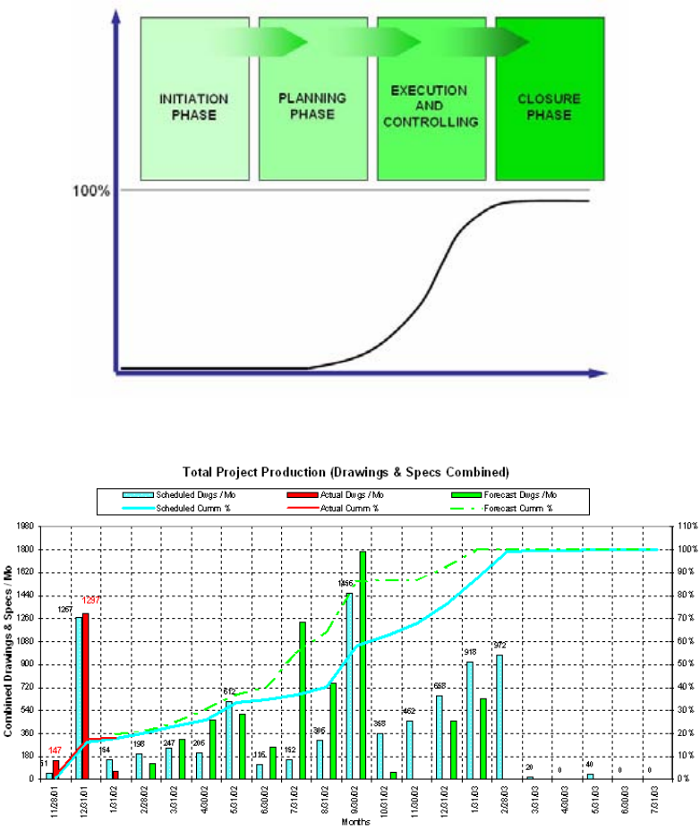
158
Other attributes such as drawing quantities, budget person-hours and statistical information may be used to
generate production reports, earned value calculations and statistical analysis. The resulting earned value/per cent
complete is used to update the summary engineering activities contained in the Integrated Schedule.
11.2.3. Other project controls process tools
11.2.3.1. Schedule reports
Critical path analysis reports
Critical path analysis reports are generated using the schedule to identify the activities or groups of activities
driving the project end date. A critical path analysis report is normally issued as part of the monthly progress report
once the baseline has been established and schedule updates have been initiated.
Figure 134 is an example of a critical path analysis report.
FIG. 132. Example of per cent complete (progress) curve.
FIG. 133. Example of production curve.

159
Milestone target variance reports
Schedule target variances will be used to identify activities that slip from month to month. Positive and
negative movement of dates is expected. However, analysis of this movement by looking at Total Float will identify
negative trends needing further attention.
Figure 135 is an example of a milestone target variance report.
Comparing the Baseline Schedule with the Current Status Schedule, this report provides a quick overview of
selected project milestones with actual or projected variances. This executive type summary visually indicates
whether any milestone dates are in jeopardy.
FIG. 134. Example of critical path analysis report.
FIG. 135. Example of milestone target variance report.
160
11.2.3.2. Schedule performance metrics
Earned value will be used for measuring project performance, comparing the amount of work that was
planned with what was actually accomplished, to determine if cost and schedule performance are as planned. It is
used to calculate various performance and forecasting indices such as CPI and SPI, as well as Schedule Variance.
11.2.3.3. Work breakdown structure
The Work Breakdown Structure (WBS) is a tool used to define and group the project’s discrete work elements
or tasks, in order to organize and define the total work scope. It provides a framework for schedule development and
control.
The WBS will include the following substructures:
— Organizational Breakdown Structure (OBS) — an intermediate level of the WBS in which organizational
relationships are identified and used as the framework for assigning work responsibilities;
— Physical Breakdown Structure (PBS) — an identification of the physical elements of the project. The PBS is
the common thread for obtaining system, structure or indirect costs to be used in identifying items, tasks,
documents and activities that relate to Engineering, Procurement, Material Control, Estimating Construction,
Startup and Operation;
— Functional Breakdown Structure (FBS) — defines the categories of deliverable products and tasks;
— Phase — defines the issue phase of deliverable products and tasks. Those phases define the status of the
activity in general terms, such as internal comments, internal review, bid issue, technical evaluation and
construction issue.
11.2.3.4. Resource based network
It is essential that the Member State should well understand a resource based network, which includes the
person and material requirement for the construction activities; the person and material requirement for the
commissioning; the time duration required by the regulators; the assessment of commissioning results; the
completion of system documents and integration with other systems; and is well demonstrated by the advanced
planning and monitoring software. The monitoring tool should also involve the financing pattern as earlier decided
by the recipient country. The monitoring tool should be able to work out critical path and the most important near
critical path which may have an impact on the Overall Project Schedule. The near critical path may be defined as
those durations essential for the project needs. These monitoring tools keep the project management well informed,
enabling them to take the remedial actions. They also help in mitigating any kind of risk involved in the
construction or commissioning of power plants.
The Integrated System also helps in forecasting the resource requirement and identifying the various
constraints in completing activities. This, however, requires close interaction with the system engineers and
vendor’s representatives in capturing required input data.
The following constraints are to be carefully monitored:
— Procurement and supply chain;
— Design based constraints;
— Site based constraints.
The result of remedial actions taken at an appropriate time on these constraints is appropriately analysed using
the software. Use of these advanced project monitoring tools does not allow project activities to go out of sight. The
project management at the site is expected to monitor all the activities of the project related to the nuclear supply
system, Turbine Island and Balance of Plant, simultaneously. These monitoring tools can be used to do this very
effectively, and to link activities with incentives and rewards.
Figure 136 shows a typical Project Planning Strategy layout.
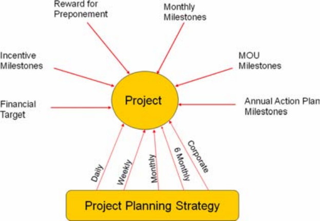
161
11.2.4. Other aspects of project management
Project management also includes all other aspects in addition to monitoring the construction schedule. It has
been observed that it is impossible to describe the total scope of work in the bid documents. There are many
uncertainties, mutual understandings and the surprises observed during the construction of the plant. It is
appropriate that all these issues should be addressed in a structured manner between the plant authorities and the
vendor, and resolved in a time-bound manner. Fast decision making is the key to success in completing the projects
within the schedule.
It is also observed that vendors would like to introduce new technologies during construction, which were not
envisaged in the bid document. Such innovative technologies may reduce the gestation period of the project. It has
been experienced that the adoption of such technologies and carrying out midterm corrections in the contracts,
which have been jointly agreed upon, help in early completion of the project, avoiding time and cost overruns. This
may even be helpful when working out the overall economy of the project.
Figure 137 shows a typical summary network of a PHWR type of NPP.
The advanced approach to the construction of NPPs should be based on strong project planning and use of
advanced construction techniques. The design should be construction friendly, and the sequence should be
determined to take advantage of prefabrication, skid-mounted equipment and the modular nature of components.
Construction optimization is key in which plans are developed such that parallel paths/parallel activities are fully
implemented from construction and transitioning into operation for the plant site and the manufacturing units. A
successful NPP construction needs adequate project planning with risk sharing capabilities, including incentive and
penalties. Finally, there has to be confidence building between the utility and the vendor, working as an integrated
team for the common objective.
FIG. 136. Planning strategy.
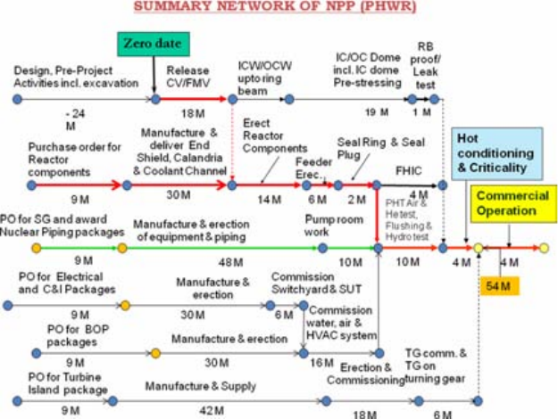
162
FIG. 137. Summary network of pressurized heavy water reactor type nuclear power plant.
163
12. SUMMARY AND CONCLUSION
12.1. SUMMARY
A successful construction project requires:
— Translating strong policies, proven construction methods, established procurement processes, procedures and
safety culture into the field;
— Coordinating programmes across organizations, such that the owner, vendor and subcontractors are working
in concert.
To meet this challenge, strong communications, including contractual arrangements and a detailed chain of
command for various decision making processes, need to be established among organizations and management.
The following paragraphs summarize the construction methods and techniques that have been described in
this guideline, and provide recommendations.
12.1.1. Project infrastructure
Research into past construction schedules indicates that early site preparation activities and an established site
infrastructure (suitable geology site, roads, rails, barge and utility access) prevent unnecessary delays in the
construction schedule.
As part of the project infrastructure, site preparation and design should consider the requirements for all units
operating or under construction. This is done to prevent interference in each unit’s operation or construction
process, and to account for regional natural phenomena in order to quickly recover after inclement weather and not
subject the construction schedule to unnecessary delays.
12.1.2. Material procurement/manufacturing
Long lead equipment, such as RPV fabrication, could be delayed due to limited availability of the nuclear-
grade large ring forgings that are currently only available from limited suppliers. This potential shortfall is a
significant risk to construction schedule and financing.
With the nuclear renaissance on the horizon, the global increase in demand for equipment and material will
have an impact on manufacturers/fabricators and the material suppliers that provide manufacturers with the
material they need to produce finished equipment.
In this global marketplace for NPP equipment and materials, it is recommended that Member States integrate
their planning and coordinate procurement activities to support the construction phase of plants. This is critical to a
successful project.
12.1.3. Modularization
New reactor designs and construction plans call for a high degree of modularization to reduce the duration of
critical path activities, move significant portions of construction work off-site, and decrease the quantity of bulk
supplies that must be installed on-site. Modularization can provide these benefits and others. However, this
construction technique also requires a great deal of upfront engineering and planning to ensure orchestrated
execution. It is therefore recommended that the constructor maximize the use of 3-D computer modelling to
understand the interconnections among modules and throughout the entire plant. These modelling tools can
anticipate and prevent installation issues. The effective use of modelling tools can assist in preventing field
construction delays by anticipating issues with module fits and equipment installation.
164
12.1.4. Construction methods and techniques
This report has listed conventional and recently introduced advanced techniques and methods in different
aspects of the construction phase of a project. Each Member State can adopt the technique which can be best
applied within its programme, based on the construction infrastructure within the country. This publication serves
as a guideline to provide a better understanding of the tools and steps that will support the construction plan for
constructing NPPs, and consequently improve technical and management skills.
Whatever methods or tools are adopted for a construction site, it is recommended that required equipment,
cranes necessary for open top construction, pipe bending machines, automatic welding machines, etc. be available
as needed to support new plant construction.
12.1.5. Quality
Construction projects should implement an independent assessment of the effectiveness of programmes and
processes related to construction activities, as well as the effectiveness of personnel in implementing programme
and process requirements.
The objective is:
— To ensure that the programmes and processes needed to construct a high quality project work effectively. This
should account for construction safety culture, including the establishment of a safety-conscious work
environment, QA, industrial safety, and problem identification and resolution;
— To identify and correct adverse conditions timeously and prevent their recurrence, which may result in
lengthy construction delays.
12.1.6. Integrated project planning and management
A detailed integrated schedule must be developed to integrate all site development activities with the overall
construction schedule. The use of project management tools is crucial in the successful completion of an NPP
project by planning, monitoring, analyzing, reporting and controlling the overall project. Baseline budgets should
be integrated into the overall schedule. Budget and schedule variances from the established baseline can be used to
mitigate project risks that may impact the project schedule and cost overrun.
12.1.7. Labour
Finding qualified labour may be a significant hurdle for new construction projects, especially if multiple
plants are being constructed. The use of modularization may alleviate this problem by allowing work on large
sections of the plant to be performed at many locations, simultaneously. However, as with any construction project
of the scale of a new NPP, finding, training and relocating the labour required to complete the project will be a
major challenge.
12.1.8. Safety culture
Together with quality, a safety culture should be established at all levels among the personnel involved from
the early stages of the project. The importance of the work of personnel in various project phases towards achieving
objectives for quality and safety should be highlighted in the training programme. Experience from the challenges
faced by designers, constructors, contractors/sub-contractors, regulators and other stakeholders have made them
realize the importance of addressing safety culture in their day to day working.
12.2. CONCLUSION
Achieving short and accurately predicted construction durations is critical to the financial success of any new
NPP project. This is one of the challenges facing the global nuclear industry. The key attributes that support the
165
successful construction and commissioning of nuclear projects are complete design, manufacturing, fabrication,
labour, construction methods, industry lessons learned, procurement, and project infrastructures. This guideline has
identified methods and strategies that can be used in the design and construction phases of nuclear projects.
.
167
Appendix I
SURVEY OF TECHNOLOGIES FOR NUCLEAR POWER PLANT CONSTRUCTION
I.1. INTEGRATED PROJECT PLANNING AND MANAGEMENT
I.1.1. Deployment planning
I.1.2. Construction control
Communication technology can create instant contact between everybody on the worksite, thus reducing
transit time and improving the schedule.
I.1.2.1. Construction control room
IBM Construction Command Room — refer to meeting minutes from 2008. A room with monitors,
communication equipment and connections to all of the materials and personnel on the construction site. The entire
site can be monitored and directed from this room.
I.1.2.2. Job assessment field observation and communication tools
— Orinoco Outdoor Wireless LAN — http://rebar.ecn.purdue.edu/ECT/links/technologies/other/orinoco.aspx
— Global Mobile Communications System —
http://rebar.ecn.purdue.edu/ECT/links/technologies/other/iridium.aspx
— ROV Robotic Monitoring Equipment —
http://www.rovtech.com/Vehicles/Index.html
— Digital Hardhat System — http://rebar.ecn.purdue.edu/ECT/links/technologies/civil/digitalhardhat.aspx
— Mobile IT - http://dx.doi.org/10.1061/40794(179)46
— Integrated Wireless Site — http://dx.doi.org/10.1061/(ASCE)0733-9364(2006)132:9(1009)
— Wireless technology —
http://www.cisco.com/en/US/prod/collateral/modules/ps5949/ps7272/case_study_rapid_wireless_wan_deplo
yment_lowers_cost_at_construction_sites.pdf,
http://www.simplyhired.com/job-id/yolup4ryj3/wireless-construction-jobs,
http://www.wivisystems.com/pages/construction/webcam/
I.1.3. Critical path management, schedule control, and risk management
I.1.3.1. Practice of defining and fully scheduling design products in order to manage design completion
I.1.3.2. Primavera product that integrates risk management with scheduling
I.1.4. Design, construction and asset management information integration
I.1.4.1. Building information modelling (BIM) —
http://www.cif.org/noms/2008/09_-_Real-Time_BIM-RFID_Project_Management.pd
http://www.stormingmedia.us/64/6420/A642084.html
I.1.4.2. Modelling
3-D tools are currently being used in the power industry successfully to identify how equipment fits together
and can be installed. A step beyond this is to add the schedule into the 3-D model to see how the entire construction
project unfolds and identify inefficiencies or interferences, known as 4-D modelling.
168
For nuclear design work, Intergraph’s PDS is the current standard technology and the more advanced
SmartPlant is the next generation offering.
— DOE Report MPR-2610 Section F
— CATIA by Dassault Systems —
http://www.3ds.com/products/catia/catia-discovery/, see meeting minutes from 2008
— SmartPlant by Intergraph http://www.intergraph.com/products/ppm/smartplant/default.aspx
— 5-D Virtual Construction — http://www.cif.org/noms/2006/27_-_5D_Virtual_Construction.pdf
— 3-D/4-D Modelling Applications with ‘movie’ feature —
http://dx.doi.org/10.1061/(ASCE)0733-9364(2008)134:10(776), http://dx.doi.org/10.1061/40652(2003)12,
http://dx.doi.org/10.1061/40475(278)103, http://dx.doi.org/10.1061/40754(183)33
— Precast Concrete 3-D Modelling — http://dx.doi.org/10.1061/(ASCE)0887-3801(2004)18:4(301)
I.1.4.3. Information management
— Integrated Product and Process Development, programme developed by Electric Boat — DOE Report MPR-
2610 Section L
— CANDU programme: Asset Information System and TRAK databases — DOE Report MPR-2610 Section L
— CANDU programme: Integrated Electrical and Control Database — DOE Report MPR-2610 Section L
I.1.4.4. Information sharing
Fully Integrated and Automated Technology (FIATECH) — DOE Report MPR-2610 Section L,
www.fiatech.org: FIATECH is a partnership of companies involved in construction, whose purpose is to build a
fully integrated information system for capital projects. Conferences are held to introduce current construction
methods, and projects are undertaken so that advanced construction methods can be introduced to members.
I.1.5. Contracting
Functional Contracting (as opposed to Discipline Contracting).
I.1.6. Procurement and material tracking and control
Using the latest tracking technology, such as GPS and RFID, the location for every construction item can be
known, and planning can be done to reduce or eliminate delays associated with the delivery and retrieval of
construction materials.
I.1.6.1. Just in time procurement
I.1.6.2. Bar coded control of material — http://dx.doi.org/10.1061/40754(183)28
I.1.6.3. Automated warehousing
I.1.6.4. Worldwide GPS tracking
— DOE Report MPR-2610 Section G: Site surveys, control of earth movers, tracking of equipment and material,
measurement of structural deformation and alignment, and indoor as built measurements can all be done
accurately and in a minimal amount of time with GPS and laser scanning;
— IBM Wireless Network — refer to meeting minutes from 2008;

169
— 3D GPS Earthmoving Equipment —
http://www.cif.org/noms/2006/30_-_3D_GPS-Based_Earthmoving_Equipment.pdf,
http://www.cif.org/noms/2002/21_-_GPS_Automatic_Machine_Control.pdf: GPS receivers mounted on the
equipment allow operators to work with a computer screen in a cabin to see exactly where the blades of the
equipment are. These receivers can accurately plot courses with little reference to in-ground markers.
Excavation is done with speed and accuracy;
— RFID Tags — http://dx.doi.org/10.1061/40754(183)108: Densely deployed Radio Frequency Identification
(RFID) tags can monitor all of the materials on a construction site in 2-D and eventually 3-D at a cost less than
pure GPS and other approaches;
— GPS Material Tracking — http://dx.doi.org/10.1061/(ASCE)0733-9364(2006)132:7(741): Utilizing GPS in
materials-locating processes can reduce errors that decrease construction productivity.
I.1.6.5. QA/QC tracking and data management: as material information is shared between design, manufacture
and site, QA/QC certifications can be included. Additional shop QC associated with larger spool pieces
and modules can be accommodated
I.1.6.6. CANDU program: CANDU Material Management System — DOE Report MPR-2610 Section L
I.1.7. Safety
I.1.7.1. Fall protection equipment — DBI-SALA & Protecta (company)
I.1.7.2. Safety assessment of the construction site layout — http://dx.doi.org/10.1061/41002(328)6
http://dx.doi.org/10.1061/(ASCE)0733-9364(2008)134:7(536)
http://dx.doi.org/10.1061/(ASCE)0733-9364(2004)130:4(534)
I.1.8. Construction personnel management
Personnel database — training and fitness for duty, access control.
I.2. SITE CONSTRUCTION INFRASTRUCTURE AND LAYOUT FOR CONSTRUCTION
I.2.1. Heavy hauls and heavy lifts
With modularization becoming the key to nuclear plant construction, the need to transport and lift modules
that are as large as possible is essential. State of the art equipment can allow the modules to be transported and put
in place safely and quickly.
I.2.1.1. Heavy haul roads and transporters
Mammoet crawlers — refer to 2008 meeting minutes —
http://www.mammoet.com/Default.aspx?tabid=888&language=en-US
I.2.1.2. Movable ultra heavy lift cranes
— Mammoet cranes — refer to 2008 meeting minutes;
— ALE lifting machines — refer to brochure.
I.2.1.3. Heavy duty air winches — http://news.thomasnet.com/fullstory/539768
170
I.2.2. Construction site smart layout
I.2.2.1. Mathematical optimization model for construction site layout —
http://dx.doi.org/10.1061/(ASCE)0733-9364(2008)134:8(653)
I.2.2.2. Dynamic site layout planning — http://dx.doi.org/10.1061/(ASCE)0887-3801(2009)23:2(119)
I.2.2.3. Computer aided site layout planning — http://dx.doi.org/10.1061/(ASCE)0733-9364(2006)132:2(143)
I.2.3. On-site module fabrication/assembly
I.2.4. Construction site sequencing
I.2.5. Personnel mobility
Keeping as much of the construction site as mobile as possible reduces the transit time around the
construction site. Mobile lifts eliminate the need for scaffolding and thus save the time required to set-up static
platforms. Personnel services should be able to be moved to where work is being done on the construction site,
reducing the transit time for the personnel on a large site.
I.2.5.1. Mobile lifts (replace scaffolding)
— Bucket trucks;
— Fork lifts and scissor lifts;
— JLG — http://www.jlg.com/en-US/Products.html
— Elevated Rotating Work Platform —
http://www.cif.org/noms/2008/27_-_Elevated_Rotating_Work_Platform.pdf
— Electric Table Formwork Lifting —
http://www.cif.org/noms/2008/22_-_Electric_Table_Formwork_Lifting.pdf
I.2.5.2. Mobile personnel services
—Sanitary;
— Drinking water;
— Access to safety gear, small tools and replacements.
I.3. CIVIL WORKS
I.3.1. Site mapping
I.3.1.1. Laser and GPS mapping: used for mapping of site and existing structures. Use inside facilities under
construction is still future. Has been used in nuclear retrofit projects.
I.3.1.2. Ultrasonic geotechnical surveying — generally used as a method to locate buried utility infrastructure
(pipelines, wells, etc.).
I.3.1.3. Total stations —
http://www.concreteconstructionmagazine.com/industry-news.asp?sectionID=0&articleID=456521
I.3.1.4. http://www.trimble.com/construction/buildingconstruction.aspx
171
I.3.2. Grading and excavating
I.3.2.1. Detailed excavation planning
I.3.2.2. Missile blast excavation
I.3.2.3. Current Generation Earthmoving Equipment — Caterpillar catalogues on file,
http://dx.doi.org/10.1061/(ASCE)0733-9364(2006)132:9(987): New forms of mechanical equipment and
bigger and more efficient forms of traditional equipment need to be used on a construction site to increase
productivity.
I.3.2.4. Precision Blasting — DOE Report MPR-2610 Section J,
http://www.stormingmedia.us/84/8473/A847304.html?searchTerms=excavation: Precision blasting
involves drilling shafts in a specific pattern, filling the shafts with explosives, and setting off the explosives,
thus excavating the area. Blasting removes material much quicker than the traditional mechanical
methods.
I.3.2.5. Intelligent Shovel Excavation (ISE) — DOE paper ‘Novel Excavation Technologies for Efficient and
Economic Surface Mining’.
I.3.2.6. BladePro: 3D automatic grade control system —
http://rebar.ecn.purdue.edu/ECT/links/technologies/civil/bladepro.aspx
I.3.2.7. Shaking table system for geotechnical centrifuge —
http://rebar.ecn.purdue.edu/ECT/links/technologies/civil/shakingtable.aspx
I.3.2.8. 3-D MC three dimensional machine control —
http://rebar.ecn.purdue.edu/ECT/links/technologies/civil/3dmc.aspx
I.3.2.9. Safe excavation — http://rebar.ecn.purdue.edu/ECT/links/technologies/civil/safeexca.aspx
I.3.2.10. Soft trencher — http://rebar.ecn.purdue.edu/ECT/links/technologies/civil/softexec.aspx
I.3.2.11. Soundless chemical demolition agents —
http://rebar.ecn.purdue.edu/ECT/links/technologies/civil/soundche.aspx
I.3.2.12. Foam rocksplitting —
http://www.dexpan.net/nonexplosivesblastingdemolition/product_dexpandemolitionagent.html
I.3.2.13. Chemical expansion rock breaking — http://www.nonex.co.za/civil_excavations.aspx
http://www.demolitiontechnologies.com
I.3.3. Ground stabilization
I.3.3.1. Most nuclear plants are built on rock of rock-like substrate. Sites are selected as such to avoid difficult
analysis and acceptance criteria.
I.3.3.2. Plasma arc torch technology: stabilization and ground improvement —
http://rebar.ecn.purdue.edu/ECT/links/technologies/civil/plasma1.aspx
I.3.3.3. Soil-stiffness gauge for soil compaction control —
http://rebar.ecn.purdue.edu/ECT/links/technologies/civil/humboldt.aspx
172
I.3.3.4. Deep mixing method for ground improvement —
http://rebar.ecn.purdue.edu/ECT/links/technologies/civil/deepmix.aspx
I.3.3.5. Geosynthetic-reinforced soil — http://dx.doi.org/10.1061/40909(228)15
I.3.4. Pipeline placement
I.3.4.1. Pipe-handling excavator attachment —
http://enr.construction.com/projects/technology/archives/030213.asp
I.3.4.2. Polymer concrete pipes — http://rebar.ecn.purdue.edu/ECT/links/technologies/civil/polycon.aspx
I.3.4.3. Smart pigs — http://rebar.ecn.purdue.edu/ECT/links/technologies/mechanical/smartpigs.aspx
I.3.4.4. Pipeman: safety in trenches — http://rebar.ecn.purdue.edu/ECT/links/technologies/civil/pipeman.aspx
I.3.4.5. Trenchless construction — http://dx.doi.org/10.1061/40745(146)61
I.3.4.6. Tele-robotic placement of pipeline — http://dx.doi.org/10.1061/40690(2003)67
I.3.5. Removal/relocation of existing pipelines and wells
State and local requirements dominate. Hot taps are available for nearly all pipe types and sizes.
I.3.6. Railroad
I.3.6.1. Recycled plastic composite railroad crossties —
http://rebar.ecn.purdue.edu/ECT/links/technologies/civil/recyrail.aspx
I.3.6.2. Concrete railroad ties
I.3.7. Site roads and other infrastructure
I.3.7.1. CP40: FRP/concrete piles — http://rebar.ecn.purdue.edu/ECT/links/technologies/civil/cp40.aspx
I.3.7.2. Superpave system — http://rebar.ecn.purdue.edu/ECT/links/technologies/civil/superpave.aspx
I.3.8. Runoff and sewage systems
Packaged (modular) sewage treatment systems.
I.4. STRUCTURAL WORKS
I.4.1. Mud mat placement
I.4.2. Concrete base mat and structure construction
I.4.2.1. Concrete
Concrete is a large part of the construction of buildings. There are many advanced concretes and concrete
techniques to improve the quality of the structures; the time required to pour and let concrete set; and periods when
concrete can be poured.
173
— Self-compacting concrete — DOE Report MPR-2610 Section B —
— High-performance concrete — DOE Report MPR-2610 Section B —
http://rebar.ecn.purdue.edu/ECT/links/technologies/civil/hpc.aspx
— Reactive powder concrete — DOE Report MPR-2610 Section B —
http://newyork.construction.com/features/archive/2007/01_feature2A.asp
http://rebar.ecn.purdue.edu/ECT/links/technologies/civil/reactive.aspx
— Fibre-reinforced bending concrete —
http://newyork.construction.com/features/archive/2007/01_feature2A.asp
— Pervious concrete — http://newyork.construction.com/features/archive/2007/01_feature2A.asp
http://perviousconcrete.info/questions__answers.htm
— Bone shaped short fiber composite —
http://rebar.ecn.purdue.edu/ECT/links/technologies/civil/boneshaped.aspx
— SIMCON: slurry infiltrated mat concrete —
http://rebar.ecn.purdue.edu/ECT/links/technologies/civil/simcon.aspx
— Low temperature concrete admixture —
http://rebar.ecn.purdue.edu/ECT/links/technologies/civil/lowtempadmix.aspx
— Surtreat — concrete restoration and protection system —
http://rebar.ecn.purdue.edu/ECT/links/technologies/civil/surtreat.aspx
— Smart concrete — http://rebar.ecn.purdue.edu/ECT/links/technologies/civil/smartconcrete.aspx
— Rapid-1 hardening accelerator concrete admixture —
http://rebar.ecn.purdue.edu/ECT/links/technologies/civil/rapid1.aspx
— Shrinkage reducing admixture for concrete —
http://rebar.ecn.purdue.edu/ECT/links/technologies/civil/eclipse.aspx
— Corrosion inhibitors for reinforced concrete —
http://rebar.ecn.purdue.edu/ECT/links/technologies/civil/corrosin.aspx
— Advanced concrete framework — http://www.cif.org/noms/2008/35_-_Advanced_Concrete_Framework.pdf
— Precast concrete — http://www.precast.org/
I.4.2.2. Concrete batching plan —
http://www.scaletron.com/code/batcht.htm,
http://www.teco.com/Products/Documents/BatchPlantBroch.pdf
I.4.2.3. Concrete pumping
Slip forming.
I.4.2.4. Concrete setting
Advanced external vibrators — http://newyork.construction.com/features/archive/2007/01_feature2C.asp
I.4.2.5. Base mat continuous pours
I.4.2.6. Slip forming
I.4.2.7. Modular, lift-in floors
— Lift-in steel and pour in place. Use of sufficient structural integrity to limit underfloor shoring during pouring
and setting. Also allows some equipment placement before full cure;
— Completely pre-assembled and precast floor sections;
— Potential problems with wall to floor joints under certain codes.

174
I.4.2.8. Rebar installation
— Automatic rebar tying machine — www.u-tier.net;
— Rebar positioner — www.thewordco.com/rebar;
— Carbon fiber reinforced polymer and glass fiber reinforced polymer rebar — DOE Report MPR-2610
Section C — http://rebar.ecn.purdue.edu/ECT/links/technologies/civil/frprebar.aspx
http://rebar.ecn.purdue.edu/ECT/links/technologies/civil/frp.aspx
http://rebar.ecn.purdue.edu/ECT/links/technologies/civil/cfrp.aspx: FRP rebar provides corrosion resistance,
a higher tensile strength, and a higher strength/weight ratio than traditional steel rebar, but is problematic for
nuclear applications because of reduced strength under heat (fire loads) and qualifications under radiation
loads;
— Welded rebar grid — http://www.bautech.com;
— Rebar modularization.
I.4.2.9. Foundation testing
Lateral STATNAMIC testing — http://rebar.ecn.purdue.edu/ECT/links/technologies/civil/statnamic.aspx
I.4.2.10. Structural connection
— Friction pendulumTM — seismic isolation bearings —
http://rebar.ecn.purdue.edu/ECT/links/technologies/civil/isobearing.aspx
— Precast hybrid moment resistant frames —
http://rebar.ecn.purdue.edu/ECT/links/technologies/civil/phmrf.aspx
— Precast concrete beam-to-column connection system —
http://rebar.ecn.purdue.edu/ECT/links/technologies/civil/bsf-2.aspx
— Concrete to steel bonds — http://www.stormingmedia.us/78/7851/A785184.html
— Bonding of FRP to reinforced concrete — http://dx.doi.org/10.1061/(ASCE)1090-0268(2008)12:3(266)
I.4.3. Pilings
I.4.3.1. Osterberg load cell — http://rebar.ecn.purdue.edu/ECT/links/technologies/civil/oster.aspx
I.4.3.2. Movax robotic: hydraulic vibratory pile driver —
http://rebar.ecn.purdue.edu/ECT/links/technologies/civil/movax.aspx
I.4.4. Steel structure construction
I.4.4.1. Steel-plate reinforced concrete structures — DOE Report MPR-2610 Section A
Steel-plate reinforcement offers schedule benefits, because installing the plates is much faster than installing
rebar and removing the formwork. In addition, since the structures are self-supporting, they can be fabricated and
installed as modules.
I.4.4.2. Post-tensioned steel structure —
http://rebar.ecn.purdue.edu/ECT/links/technologies/civil/posttensionedsteel.aspx
I.4.4.3. High-performance steel — http://rebar.ecn.purdue.edu/ECT/links/technologies/civil/hps.aspx
I.4.4.4. Adjustable steelwork connectors —
http://rebar.ecn.purdue.edu/ECT/links/technologies/civil/ibeamclamps.aspx
175
I.4.4.5. ATLSS beam-to-column connections —
http://rebar.ecn.purdue.edu/ECT/links/technologies/civil/atlss2.aspx
I.4.5. Steel liner plate installation and welding
I.4.6. Roof and dome structural construction
I.4.7. Building construction
I.4.7.1. Tilt-up construction — www.tiltupnews.com
http://www.stormingmedia.us/05/0579/A057974.html
I.4.7.2. Snap joint technology for composite structures —
http://rebar.ecn.purdue.edu/ECT/links/technologies/civil/snap.aspx
I.4.7.3. SNAP-TITE composite column reinforcement —
http://rebar.ecn.purdue.edu/ECT/links/technologies/civil/snaptite.aspx
I.4.7.4. Stay in place (SIP) formwork — http://rebar.ecn.purdue.edu/ECT/links/technologies/civil/sip.aspx
I.4.7.5. Permeable formwork — http://www.stormingmedia.us/56/5661/A566173.html
I.4.8. Scaffolding
Glass-fibre-reinforced plastic scaffolding deck — http://www.layher.com/en/products/innovations.htm
I.4.9. Load testing
Rapid in situ load testing — http://rebar.ecn.purdue.edu/ECT/links/technologies/civil/rapidload.aspx
I.5. MECHANICAL INSTALLATIONS
I.5.1. Equipment assembly
http://dx.doi.org/10.1061/(ASCE)0733-9364(2005)131:6(723)
Prework allows the structures and equipment to be assembled off-site, then shipped to the construction site,
and installed on the site. Therefore, the structures and equipment can be fabricated and put together in a factory
setting instead of on the construction site, which allows access to standard fabrication practices. Prework in a
factory is much more efficient than assembly on the site.
I.5.1.1. Modularization — DOE Report MPR-2610 Section M
Remote assembly operations that may involve prefabrication and preassembly.
I.5.1.2. Prefabrication — DOE Report MPR-2610 Section M
Materials are joined at a specialized facility to form a part of a final installation, typically involving a single
craft.

176
I.5.1.3. Preassembly — DOE Report MPR-2610 Section M
Materials, components and equipment are joined together at a remote location for installation somewhere
else, typically involving multiple crafts.
I.5.2. Equipment and module placement
Laser alignment increases the accuracy and speed of ensuring that equipment is installed correctly. This
replaces manual measurements.
I.5.2.1. Open top and drawer type placements
DOE Report MPR-2610 Section H: The walls of a structure are built, followed by the installation of large
equipment through the opening at the top of the building, followed by finishing construction of the building. The
installation of smaller components can be accomplished while the rest of the building is completed.
I.5.2.2. Laser alignment and plumb lining (optical tooling) — www.mbesi.com
http://news.thomasnet.com/fullstory/28296
I.5.2.3. Indoor GPS — DOE Report MPR-2610 Section G
I.5.2.4. Laser scanning — http://www.cif.org/noms/2008/28_-_3D_Laser_Scanning.pdf
http://www.survey2cad.com/3D_laser_scanning_1.html#3D_laser_scanning
I.5.3. Piping installation
I.5.3.1. Pipe bending — DOE Report MPR-2610 Section I
Pipe bending can be used as opposed to welding in piping systems. This reduces the amount of seams in the
piping system, increasing the quality of the system.
— Ram cold bending;
— Roll cold bending;
— Rotary cold bending;
— Heat induction bending.
I.5.4. HVAC and duct installation
Thermally active building structures —
http://www.cif.org/noms/2008/18_-_Thermally_Active_Building_Structures.pdf
I.5.5. Insulation and lagging
I.5.5.1. Aerogels — www.aerogel.com — Aspen Aerogels
I.5.5.2. Super therm, ceramic paint insulation —
http://rebar.ecn.purdue.edu/ECT/links/technologies/civil/supertherm.aspx
177
I.5.6. System cleaning
I.5.7. Welding
The following are state of the art welding techniques that can be utilized to increase the quality of the welds
and the safety of welding. Many experimental studies and analyses have been done on welding techniques. A
source of studies, if experimental and theoretical information is needed, is the ASME digital library
(http://www.asmedl.org/)
I.5.7.1. Welding processes — http://www.lincolnelectric.com/knowledge/articles/content/migvsfluxcored.asp
http://weldingmag.com/processes/news/wdf_11145/
I.5.7.2. Tab and slot welding — www.weldingmag.com/323/Issue/Article/False/11145/Issue
I.5.7.3. Weld-quality monitoring algorithms — www.weldingmag.com/323/Issue/Article/False/11145/Issue
I.5.7.4. Mechanized/robotic welding —
www.millerwelds.com/education/articles/story2.html, DOE Report MPR-2610 Section E
I.5.7.5. Hybrid laser-arc welding — www.thefabricator.com/LaserWelding/LaserWelding_Article.cfm?ID=1485
I.5.7.6. Nanofoil joining — www.thefabricator.com/LaserWelding/LaserWelding_Article.cfm?ID=1487
I.5.7.7. Plasma window for electron beam welding at atmospheric pressure —
www.thefabricator.com/LaserWelding/LaserWelding_Article.cfm?ID=1486
I.5.7.8. Gas metal arc welding — DOE Report MPR-2610 Section D —
http://dx.doi.org/10.1115/PVP2006-ICPVT-11-93706
I.5.7.9. Gas tungsten arc welding — DOE Report MPR-2610 Section D
I.5.7.10. Submerged arc welding — DOE Report MPR-2610 Section D
I.5.7.11. Weld cladding — DOE Report MPR-2610 Section D
I.5.7.12. Welding clamps — http://rebar.ecn.purdue.edu/ECT/links/technologies/mechanical/clamps.aspx
I.5.7.13. Friction stir welding — http://rebar.ecn.purdue.edu/ECT/links/technologies/mechanical/fsw.aspx
I.6. ELECTRICAL AND CONTROLS INSTALLATIONS
I.6.1. Cable trays
L-shaped cable tray design.
I.6.2. Cable pulls
I.6.2.1. High-performance lubricants — DOE Report MPR-2610 Section K
I.6.2.2. Cable tray rollers — DOE Report MPR-2610 Section K
I.6.2.3. Cable tray sheaves — DOE Report MPR-2610 Section K

178
I.6.2.4. Automatic lubricant application — DOE Report MPR-2610 Section K
I.6.2.5. Assisted pulling devices — DOE Report MPR-2610 Section K
I.6.3. Cable terminations
Fibre optic termination.
I.6.4. Cable splicing — not completely acceptable in nuclear industry
I.6.4.1. Cold shrink — DOE Report MPR-2610 Section K
I.6.4.2. Heat shrink — DOE Report MPR-2610 Section K
I.6.4.3. Premolded — DOE Report MPR-2610 Section K
I.6.5. Data networking
I.6.6. Cable pathway installations
I.7. TESTING MANAGEMENT
I.7.1. Pre-op testing — deployment planning
I.7.2. Inspections
I.7.2.1. Robotic equipment inspections
I.7.2.2. Non-destructive testing
— Full-field vibration measurement for vibrothermography —
http://www.stormingmedia.us/46/4686/A468674.html http://www.stormingmedia.us/32/3296/A329674.html
— 3-D X ray microtomography — http://www.stormingmedia.us/27/2771/A277184.html
— Thermoelastic non-destructive evaluation of structural materials —
http://www.stormingmedia.us/73/7368/A736883.html
I.7.2.3. LADAR and embedded sensing for construction quality control —
http://dx.doi.org/10.1061/40754(183)109

179
Appendix II
SUGGESTED BUILDING LIST
FACILITY/STRUCTURE NAME BWR PWR PHWR
Permanent Inside Exclusion Zone
Administration Building X X X
Secure Area Warehouse X X X
Cold Machine Shop X X X
Hot Machine Shop X X X
Turbine Building X X X
Combustion Turbine Generator Stack X X X
Combustion Turbine Generator Fuel Tank X X X
Plant Stack X
Service Building X X X
Fire Water Storage Tank X X X
Fire Pump House X X X
Secondary Fire Water Storage Tank and Pump Enclosure X X X
Equipment Entry Lock X X X
Diesel Generator Building X
Auxiliary Diesel Building X
Diesel Oil Storage Tank X X X
Reactor Building X X X
Control Building X X X
Control Building Annex X
Radwaste Building X X X
Condensate Storage Tank and Transfer Pumps X X X
Auxiliary Boiler X
Fuel Building X X X
Transformers
Main Power Transformer X X X
Unit Auxiliary Transformer X X X
Reserve Auxiliary Transformer X X X
Electric Boiler Transformer X
Adjustable Speed Drive Transformer X

180
Spare Transformer X
Radwaste Tunnel X X X
Permanent Outside of Exclusion Zone
Fences
Site Perimeter Fence X X X
Delay Fence X X X
Railroad X X X
Outage Support Building X X X
Site In-processing Building X X X
Site Training Centre X X X
Visitor Centre X X X
Security Building X X X
Met Tower X X X
Staging and Receiving Warehouse X X X
Tanks
Nitrogen Storage Tank X X
Carbon Dioxide Storage Tank X X
Hydrogen Storage Tank X X
Oxygen Storage Tanks X X
Chemical Additions Building X X X
Water Treatment Facility X X X
Station Water Storage Tank and Pump X X X
Demineralized Water Storage Tank and Pumps X X X
Fire Water Storage Tank Filling Pumps X X X
Cooling Tower X X X
Cooling Tower Basin X X X
Circulation Water Pumphouse X X X
Cooling Tower Basin Blowdown Line X X X
Sewage Treatment Facility X X X
Storm Water Detention Basin X X X
Main Access Sally Port X X X
Fabrication and Weld Shop X X X
Weld Test Facility X X X
FACILITY/STRUCTURE NAME BWR PWR PHWR

181
Radiography Shop X
Fleet Maintenance and Refuelling X X X
ISFSI/Dry Cask Storage X X X
Switchyard X X X
Raw Water Make-up System Intake Structure or Pipeline X X X
Blowdown Sump X X X
Temporary
Tanks
Temp Bulk Gases X X X
Transformers
Construction Transformers X X X
Warehouse
Construction Receiving Warehouse X X X
Construction Staging Warehouse X X X
Construction Complex
Construction Control Centre X X X
Construction Staff X X X
Construction Offices X X X
First Aid and Fire Brigade X X X
Vending Area X X X
Badge/Fabrication X X X
Construction In-processing and Training Building X X X
Concrete Batch Plant X X X
FACILITY/STRUCTURE NAME BWR PWR PHWR
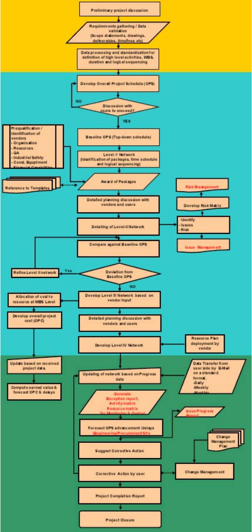
182
Appendix III
PLANNING ACTIVITY CHART
FIG. 138. Planning activity chart.
183
REFERENCES
[1] INTERNATIONAL ATOMIC ENERGY AGENCY, Construction and Commissioning Experience of Evolutionary Water
Cooled Nuclear Power Plants, IAEA-TECDOC-1390, IAEA, Vienna (2004).
[2] Application of Advanced Construction Technologies to New Nuclear Power Plants, MPR-2610 (2004), prepared for the United
States Department of Energy.
[3] INTERNATIONAL ATOMIC ENERGY AGENCY, Improving Economics and Safety of Water Cooled Reactors: Proven
Means and New Approaches, IAEA-TECDOC-1290, IAEA, Vienna (2002).
[4] OECD-Nuclear Energy Agency, Reduction of Capital Costs of Nuclear Power Plants, OECD (2000).
[5] ACI Committee 237, Self-consolidating Concrete, 237R-07 (2007).
[6] INTERNATIONAL ATOMIC ENERGY AGENCY, Protection against Internal Fires and Explosions in the Design of Nuclear
Power Plants, IAEA Guide NS-G-1.7, IAEA, Vienna (2004).
[7] EPRI Materials Management Matrix Project: Westinghouse AP1000 Pressurized Water Reactor Materials Management Tables
(MMTs) — Revision 0. EPRI, Palo Alto. CA: 2008. 1016751.
[8] American Society of Heating, Refrigerating and Air-conditioning Engineers, Inc., Ventilation for Acceptable Indoor Air Quality,
ASHRAE 62 (2001).
[9] American Society of Heating, Refrigerating and Air-conditioning Engineers, Inc., Method of Testing General Ventilation Air-
cleaning Devices for Removal Efficiency by Particle Size, ASHRAE Standard 52.2 (ANSI Approved) (2007).
[10] EcoLogo Program, Architectural Surface Coatings, CCD-047 (2005).
[11] EcoLogo Program, Surface Coatings – Recycled Water-borne, CCD-048 (2006).
[12] EcoLogo Program, Adhesives, CCD-046 (2004).
BIBLIOGRAPHY
INTERNATIONAL ATOMIC ENERGY AGENCY, Construction and Commissioning Experience of Evolutionary Water Cooled
Nuclear Power Plants, IAEA-TECDOC-1390, IAEA, Vienna (2004).
INTERNATIONAL ATOMIC ENERGY AGENCY, Nuclear Power Project Management: A Guidebook, Technical Reports Series
No. 279, IAEA, Vienna (1988).
OECD/NUCLEAR ENERGY AGENCY, Reduction of Capital Costs of Nuclear Power Plants, OECD/NEA, Paris (2000).
.
185
ABBREVIATIONS
2-D two dimensional
3-D three dimensional
4-D four dimensional
ABWR advanced boiling water reactor
AC alternating current
AISC American Institute of Steel Construction
ALARA as low as reasonably achievable
ALWR advanced light water reactor
ANT advanced nuclear technology
APSSP automatic protected structure to sea water potential
AVCC automatic voltage and current control
BIM building information management
BLA/S-C-C building-level-area-system-class-code
BOM bill of materials
BRB buckling restrained brace
BREEAM Building Research Establishment Environmental Assessment Method
BWR boiling water reactor
CAD computer aided design
Cal-Sil calcium silicate
CCWS component cooling water system
CEEQUAL Civil Engineering Environmental Quality Assessment and Award Scheme
CMOS complementary metal oxide semiconductor
CPI cost performance index
CPM critical path method
CPMMS Contract Procurement and Materials Management System
CRT cathode ray tube
CWP concrete work package
CWPL Construction Work Packages Material List
CWS circulation water system
DC direct current
DCS distributed control system
ECWD electrical connection wiring drawing
EDM electronic distance measurement
EQ environmental qualification
EQR engineering quotation request
EQRL engineering quotation request list
ESWS essential service water system
FBS functional breakdown structure
FIATECH fully integrated and automated technology
FRLS fire retarding low smoke
GMAW gas metal arc welding
GPS global positioning system
GTAW gas tungsten arc welding
HLAW hybrid laser-arc welding
HVAC heating, ventilation and air-conditioning
HWR heavy water reactor
I&C instrumentation and control
IAQ indoor air quality
IC integrated circuit
IPCM Intelligent Project Life Cycle Management
IPLM Intelligent Project Life Cycle Management
JNT Johnson noise thermometer
186
KHNP Korea Hydro and Nuclear Power
KPI key performance indicator
LCD liquid crystal display
LEED Leadership in Energy and Environmental Design (Award)
MAG metallic active gas
MIG metal inert gas
MIR material inspection report
MMM materials management matrix
MOS metal oxide semiconductor
MRR material receiving report
NPP nuclear power plant
NSSS nuclear steam supply system
OBS organizational breakdown structure
P&ID piping and instrumentation diagram
PBS physical breakdown structure
PCC plain cement concrete
PDA personal digital assistant
PDM Precedence Diagnostic Method
PDMS plant design management system
PDN plant data network
PEEK poly-ether-ether-ketone
PERT programme evaluation and review technique
ppm parts per million
PVC polyvinyl chloride
QA quality assurance
QAR quality assurance report
QC quality control
RC reinforced concrete
RCL reactor coolant loop
RFID radiofrequency identification
RPV reactor pressure vessel
SAW submerged arc welding
SBS styrene-butadiene-styrene
SC steel-plate reinforced concrete
SCC self-consolidating concrete
SMAW shielded metal arc welding
SoC system-on-a-chip
SPI schedule performance index
SQ seismic qualification
SRC steel-reinforced concrete
SSMAW small shielded metal arc welding
SWN Shin-Wolsong Nuclear Power Plant
TBM tunnel boring machine
TESTING inspections, tests, analyses and acceptance criteria
TIG tungsten inert gas
TTP tetra pod
TV television
UAT unit auxiliary transformer
UCT underground common tunnel
VHL very heavy lift (crane)
VOC volatile organic compound
WWER Russian version of pressurized water reactor (PWR)
WBS work breakdown structure
187
CONTRIBUTORS TO DRAFTING AND REVIEWING
Agrawal, V.C. Nuclear Power Corporation of India Ltd, India
Anbalagan, A. Larsen & Tourbo, India
Berry, F. Sargent & Lundy LLC, USA
Bilbao, S. International Atomic Energy Agency
Byrne, J. Atomic Energy Corporation Limited, Canada
Byron, M. Exelon Corporation, USA
Caron, D. International Atomic Energy Agency
Chaba, M. Murray & Roberts Ltd., South Africa
Chakravarty, P. Hindustan Construction Company, India
Cleveland, J. International Atomic Energy Agency
Concel, V. Westinghouse Electric Company, USA
Cowley, T. Murray & Roberts Ltd, South Africa
Deng, X. China Nuclear Energy Corporation, China
Eleswarapu, S. Larsen & Tourbo, India
Greyling, M. PBMR, Pty, Ltd, South Africa
Hamel, J. Electric Power Research Institute, USA
Jhun, S.J. Daewoo Construction, Republic of Korea
Kawahata, J. Hitachi, Japan
Khan, A.F. Atomic Energy Corporation Limited, Canada
Kim, H.C. Korea Hydro and Nuclear Power Company, Republic of Korea
Moon, S. International Atomic Energy Agency
Mori, H. Toshiba Corp., Japan
Parab, A. Larsen & Tourbo, India
Park, S. Korea Power Engineering Company, Republic of Korea
Purohit, K.C. Kundakullum Nuclear Power Plant, India
Rao, A. International Atomic Energy Agency
Scott, A. Al Jaber Energy Services, United Arab Emirates
188
Shyloski, E. Shaw Power Group, USA
Tyobeka, B. International Atomic Energy Agency
Visvanath, K.R. Hindustan Construction Company, India
Won, J.Y. Korea Hydro and Nuclear Power Company, Republic of Korea
Yahagi, K. Tokyo Electric Power Company, Japan
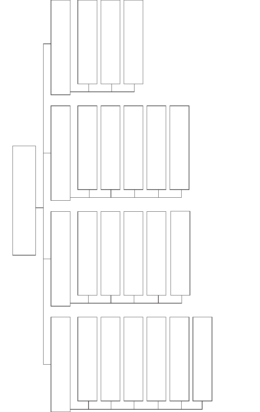
Key Examples
BP: Basic Principles NG-G-3.1: Nuclear General (NG), Guide, Nuclear Infrastructure and Planning (topic 3), #1
O: Objectives NP-T-5.4: Nuclear Power (NP), Report (T), Research Reactors (topic 5), #4
G: Guides NF-T-3.6: Nuclear Fuel (NF), Report (T), Spent Fuel Management and Reprocessing, #6
T: Technical Reports NW-G-1.1: Radioactive Waste Management and Decommissioning (NW), Guide,
Nos. 1-6: Topic designations Radioactive Waste (topic 1), #1
#: Guide or Report number (1, 2, 3, 4, etc.)
Structure of the IAEA Nuclear Energy Series
Radioactive Waste Management
and Decommissioning Objectives
NW-O
Nuclear Fuel Cycle Objectives
NF-O
Nuclear Power Objectives
NP-O
Nuclear General Objectives
NG-O
Nuclear Energy Basic Principles
NE-BP
1. Management Systems
NG-G-1.#
NG-T-1.#
2. Human Resources
NG-G-2.#
NG-T-2.#
3. Nuclear Infrastructure and Planning
NG-G-3.#
NG-T-3.#
4. Economics
NG-G-4.#
NG-T-4.#
5. Energy System Analysis
NG-G-5.#
NG-T-5.#
6. Knowledge Management
NG-G-6.#
NG-T-6.#
1. Technology Development
NP-G-1.#
NP-T-1.#
2. Design and Construction of Nuclear Power Plants
NP-G-2.#
NP-T-2.#
3. Operation of Nuclear Power Plants
NP-G-3.#
NP-T-3.#
4. Non-Electrical Applications
NP-G-4.#
NP-T-4.#
5. Research Reactors
NP-G-5.#
NP-T-5.#
1. Resources
NF-G-1.#
NF-T-1.#
2. Fuel Engineering and Performance
NF-G-2.#
NF-T-2.#
3. Spent Fuel Management and Reprocessing
NF-G-3.#
NF-T-3.#
4. Fuel Cycles
NF-G-4.#
NF-T-4.#
5. Research Reactors — Nuclear Fuel Cycle
NF-G-5.#
NF-T-5.#
1. Radioactive Waste Management
NW-G-1.#
NW-T-1.#
2. Decommissioning of Nuclear Facilities
NW-G-2.#
NW-T-2.#
3. Site Remediation
NW-G-3.#
NW-T-3.#
189
.

@
!"#
!
$!%&'*+-/0"5/6768
09:&76;87<====>?@9:&76;87<==**
9%A>+99CC
"!$%
EH%-8<8JK77;<J
09:688L6*'6<*>?@9:688L6*<*'7
9A>+99CCKK
&'
J'L<7?J%!8<<H/$8<=<&K'6'&!
097K*<<K*&LK6'L=>?@97K*<<K*&LK6'L<
9A>+99CC
-Q"H7KL6&;"-##U7E;E6
09:&76='L8&&L>?@9:&76='L=&&<
9A>+99CC
&(
"9"Q"0!#J@87<6JQ
&)&(*"!&
!"V!-#U%6'=7*<87;
09:'8<8&&<6L6&'>?@9:'8<8*'*87&'&
9AX>+99CCX
+!'
U#J#Y78*ZU7[?K<<7<75
09:6L*;787'7>?@9:6L*;787''L<
9A>+99CC
+&
?KLE#J@8L?K=L;87"@7;
09:667'8<7';';>?@9:667'8<7;<;<
9A>+99CC
H%!!7'L%Q;'86&""@
09:667'='<&=<8>?@:667'='<&=<8
9%A%>+99CC%
$%,
#K\Q\K\Q]55Q7<$KL6776J
09:';88*;';<8<>?@9:';88*;';<8<:';88*;';<888
9QAK%Q>+99CCK%Q
($,
HHJ#J@78&5K7&L&J
09:6&78L=====>?@9:6&78L=='=8>9A
'
]7?$57LE5/QJ/'<<<<7
09:;78888&7=;8&C8=>?@9:;78888&7=;8*
9A%>+99CC
J8C=8"$77<<<;
09:;777868&*=*&:;777868L=8&'>?@9:;777868*767L
9A%
!,
H!^$HJ_#`\"&K8<7'&/
09:6;<8'*;L'LL8'*;L'L&8>?@9:6;<8'*;L'L'*
9A>+9

/*
/X"H76K&6"K07<6K<<8=
09:*7668=L*L*8>?@9:*7668=L;<=8
9AX>+99CCX
*"!&0+70
U!J$!JQ8?8=LK7kQEKQ!"K]!76=K76<
09:<8L*;7='<>?@9:<8L*;7='&>+99CC
(!'
$HJ\/-8<HK='*8JV5Q
09:67Z<[L6L='<<<'>?@9:67Z<[L6L=8;8;&
9A>+99CC
/UL<#J@7*L68=<<"VV
09:67=;6&*''<<>?@9:67=;6&7L&;*
9A>+99CC
!VQ%#J@*6<87&<!VH
09:678L8'6L777>?@9:678L8'7L***
9A>+99CC
)!'
$!%&'*+-/0"5/6768
09:&76;87<====>?@9:&76;87<==**
9%A>+99CC
!08
"%VXU%8!K7L78H
09:6*&7'6867''>?@9:6*&786<7'6L
9A%KX>+99CC%KXC%X
*
$qX!!CEJ%6K8*<<&/
09:6';7=*7;'*<>?@9:6';7L=LLL&6
9AXAXAXAX
+99CCX
'7$'0%
0!#^H!Q#J@8;-67]
0Z[9:''*=<&<<LLL8>Zx[9:''8<=*=6*6=8>?@9:''8<=*=6*8<6
Z[9A>Zx[9xA>+99CC
#K
$H0J+H6;@-!U07L8y
9A>+99CC
J%
H#J@77;!%Q!]7'0
09:''7'6*='*777>?@9:''7'6*='**''
9A>+99CC
'0
$<<'-$"8K<*L6?%'&!kk7<<7=!
Z[09:*<<8L6K;&'&:878;&6K*6<8>?@9:878;&6K6'*;
9AQ>+99CCQ
'0+%&
J'L<7?J%!8<<H/$8<=<&K'6'&
097K*<<K*&LK6'L=>?@97K*<<K*&LK6'L<
9Az+99CC
-Q"H*78%#QQk76&&;
09:***LL7='=<ZK[>?@9:***L&**L'&ZK[
9A>+99CC
09;9
%<=;>>
\"#J@7<<7'<<\
09:'678&<<88L8;Z88L6<[>?@9:'678&<<8;6<8
9AQ>+99CCQC
11-31491

Basic
Principles
Objectives
IAEA Nuclear Energy Series
Technical
Reports
Construction
Technologies for
Nuclear Power Plants
No. NP-T-2.5
Guides
IAEA Nuclear Energy Series
No. NP-T-2.5 Construction Technologies for Nuclear Power Plants
INTERNATIONAL ATOMIC ENERGY AGENCY
VIENNA
ISBN 978–92–0–119510–4
ISSN 1995–7807
11-31491_P1526_cover.indd 1 2011-12-05 14:48:24
