P2120 Fujitsu Life Book User’s Manual Web
P2120 - Web P2120 - Web - powered by h5ai v0.28.1 (s://larsjung.de/h5ai/)
User Manual: Fujitsu LifeBook P2120 User’s Manual Troubleshoot Fujitsu LifeBook P2120 |
Open the PDF directly: View PDF ![]() .
.
Page Count: 110 [warning: Documents this large are best viewed by clicking the View PDF Link!]

Copyright
Copyright
Fujitsu PC Corporation has made every effort to ensure
the accuracy and completeness of this document.
However, as ongoing development efforts are continu-
ally improving the capabilities of our products, we
cannot guarantee the accuracy of the contents of this
document. We disclaim liability for errors, omissions,
or future changes.
Fujitsu and the Fujitsu logo are registered trademarks
and LifeBook is a trademark of Fujitsu Limited.
The following are registered trademarks of IBM
Corporation: IBM, IBM PC AT, IBM PS/2.
The following are registered trademarks of Microsoft
Corporation: MS, MS-DOS, Windows.
PCMCIA is a trademark of the Personal Computer
Memory Card International Association.
Earthlink is a registered trademark of EarthLink
Network, Inc.
Crusoe, LongRun, and Transmeta are trademarks of the
Transmeta Corporation.
Adobe Acrobat Reader is a registered trademark of
Adobe Systems, Inc.
Netscape 6.01 is a registered trademark of Netscape
Communications Corporation.
PowerQuest and Drive Image are registered trademarks
of PowerQuest Corporation.
InterVideo and WinDVD are trademarks of Intervideo,
Inc.
SigmaTel is a registered trademark of SigmaTel, Inc.
MOBILITY and RADEON are trademarks of ATI Tech-
nologies, Inc.
McAfee is a registered trademark of Network Associates/
McAfee.com Inc.
The DVD player found in some models of the LifeBook
notebook incorporates copyright protection technology
that is protected by method claims of certain U.S.
patents and other intellectual property rights owned by
Macrovision Corporation and other rights users. Use of
this copyright protection technology must be authorized
by Macrovision Corporation, and is intended for home
and other limited viewing uses only unless authorized by
Macrovision Corporation. Reverse engineering or disas-
sembly is prohibited.
Dolby Headphone manufactured under license from
Dolby Laboratories. “Dolby”, “Pro Logic”, and the
double-D symbol are trademarks of Dolby Laboratories.
Copyrights 1992-1999 Dolby Laboratories. All rights
reserved.
All other trademarks mentioned herein are the property
of their respective owners.
© Copyright 2002 Fujitsu PC Corporation. All rights
reserved. No part of this publication may be copied,
reproduced, or translated, without prior written consent
of Fujitsu PC Corporation. No part of this publication
may be stored or transmitted in any electronic form
without the written consent of Fujitsu PC Corporation.
B5FH-6591-01EN-00
DECLARATION OF CONFORMITY
according to FCC Part 15
Responsible Party Name: Fujitsu PC Corporation
Address: 5200 Patrick Henry Drive
Santa Clara, CA 95054
Telephone: (408) 982-9500
Declares that product: Base Model Configurations:
LifeBook P2120
Complies with Part 15 of the FCC Rules.
This device complies with Part 15 of the FCC rules. Operations are subject to the following two conditions:
(1) This device must not be allowed to cause harmful interference, (2) This device must accept any
interference received, including interference that may cause undesired operation.
P2120.book Page 1 Friday, September 13, 2002 4:56 PM

LifeBook P2000 Notebook
P2120.book Page 2 Friday, September 13, 2002 4:56 PM

Table of Contents
Fujitsu LifeBook P2000 Notebook
Table of Contents
1
PREFACE
Preface
About This Guide . . . . . . . . . . . . . . . . . . . . . . . . .1
Fujitsu Contact Information . . . . . . . . . . . . . . . . .1
Warranty . . . . . . . . . . . . . . . . . . . . . . . . . . . . . . .1
2
GETTING STARTED
Overview
Unpacking . . . . . . . . . . . . . . . . . . . . . . . . . . . . . .5
Locating the Controls
and Connectors
Top and Front Components . . . . . . . . . . . . . . . . .6
Left-Side Panel Components . . . . . . . . . . . . . . . .7
Right-Side Panel Components . . . . . . . . . . . . . . .8
Back Panel Components . . . . . . . . . . . . . . . . . . . .9
Bottom Components . . . . . . . . . . . . . . . . . . . . .10
Status Indicator Panel
Power Indicator. . . . . . . . . . . . . . . . . . . . . . . . .11
DC-in Indicator . . . . . . . . . . . . . . . . . . . . . . . . .11
Battery Level Indicators . . . . . . . . . . . . . . . . . . .11
Battery Charging Indicator. . . . . . . . . . . . . . . . .12
DVD/CD-RW Drive Access Indicator. . . . . . . . .12
Hard Drive or Removable
Media Drive Access Indicator . . . . . . . . . . . .12
PC Card Access Indicator . . . . . . . . . . . . . . . . .12
Numeric Lock Indicator . . . . . . . . . . . . . . . . . . .12
Caps Lock Indicator. . . . . . . . . . . . . . . . . . . . . .12
Scroll Lock Indicator . . . . . . . . . . . . . . . . . . . . .12
Keyboard
Using the Keyboard . . . . . . . . . . . . . . . . . . . . . .13
Numeric Keypad. . . . . . . . . . . . . . . . . . . . . . . . .13
Windows Keys . . . . . . . . . . . . . . . . . . . . . . . . . .13
Cursor Keys . . . . . . . . . . . . . . . . . . . . . . . . . . . .13
Function Keys. . . . . . . . . . . . . . . . . . . . . . . . . . .14
Quick Point Pointing Device
Clicking . . . . . . . . . . . . . . . . . . . . . . . . . . . . . . .15
Double-Clicking . . . . . . . . . . . . . . . . . . . . . . . . .15
Dragging . . . . . . . . . . . . . . . . . . . . . . . . . . . . . .15
Quick Point Device Control Adjustment . . . . . . .16
Volume Control
Controlling the Volume . . . . . . . . . . . . . . . . . . .17
Flexible Bay Devices
Removing and Installing Modular Devices . . . . .18
LifeBook Application Panel
Application Launch Buttons . . . . . . . . . . . . . . . .20
E-mail Notification LED. . . . . . . . . . . . . . . . . . . .20
Desktop Control Panel . . . . . . . . . . . . . . . . . . . .20
Using the E-mail Notification LED. . . . . . . . . . . .21
Using the CD Player . . . . . . . . . . . . . . . . . . . . . .21
3
USING YOUR SYSTEM
Power Sources
Connecting the Power Adapters. . . . . . . . . . . . .25
Display Panel
Opening the Display Panel . . . . . . . . . . . . . . . . .26
Adjusting Display Panel Brightness . . . . . . . . . . .26
Closing the Display Panel . . . . . . . . . . . . . . . . . .26
P2120.book Page 3 Friday, September 13, 2002 4:56 PM

LifeBook P2000 Notebook
Starting Your LifeBook Notebook
Power On . . . . . . . . . . . . . . . . . . . . . . . . . . . . . 27
Boot Sequence . . . . . . . . . . . . . . . . . . . . . . . . . . 27
BIOS Setup Utility . . . . . . . . . . . . . . . . . . . . . . . 27
Booting the System . . . . . . . . . . . . . . . . . . . . . . 28
Registering Your LifeBook notebook . . . . . . . . . 28
Installing Click Me!. . . . . . . . . . . . . . . . . . . . . . . 28
Power Management
Suspend/Resume Button . . . . . . . . . . . . . . . . . . 29
Suspend Mode. . . . . . . . . . . . . . . . . . . . . . . . . . 29
Hibernation Feature . . . . . . . . . . . . . . . . . . . . . . 29
Display Timeout . . . . . . . . . . . . . . . . . . . . . . . . . 30
Hard Disk Timeout . . . . . . . . . . . . . . . . . . . . . . . 30
Windows Power Management. . . . . . . . . . . . . . 30
Restarting the System. . . . . . . . . . . . . . . . . . . . . 30
Power Off . . . . . . . . . . . . . . . . . . . . . . . . . . . . . 30
4
USER-INSTALLABLE FEATURES
Lithium ion Battery
Recharging the Batteries. . . . . . . . . . . . . . . . . . . 33
Replacing the Battery . . . . . . . . . . . . . . . . . . . . . 34
Floppy Disk Drive
Loading a Disk . . . . . . . . . . . . . . . . . . . . . . . . . . 35
Ejecting a Disk . . . . . . . . . . . . . . . . . . . . . . . . . . 35
Preparing a Disk for Use. . . . . . . . . . . . . . . . . . . 35
DVD/CD-RW Combo Drive
DVD/CD-RW Combo Drive Software . . . . . . . . 36
Loading a DVD, CD, CD-R, or CD-RW . . . . . . . 36
Removing Media . . . . . . . . . . . . . . . . . . . . . . . . 37
Using the DVD/CD-RW Drive Software. . . . . . . 37
Using DolbyTM Headphone. . . . . . . . . . . . . . . . 37
Using the DVD/CD-RW Drive
on Battery Power . . . . . . . . . . . . . . . . . . . . . 38
Auto Insert Notification Function . . . . . . . . . . . . 38
PC Cards
Installing PC Cards . . . . . . . . . . . . . . . . . . . . . . . 39
Removing PC Cards . . . . . . . . . . . . . . . . . . . . . . 39
Memory Upgrade Module
Installing a Memory Upgrade Module . . . . . . . . 40
Removing a Memory Upgrade Module . . . . . . . 41
Checking the Computer Recognition
of New Memory Capacity . . . . . . . . . . . . . . 41
Device Ports
Modem (RJ-11) Telephone Jack. . . . . . . . . . . . . 43
Internal LAN (RJ-45) Jack. . . . . . . . . . . . . . . . . . 43
IEEE 1394 Jack . . . . . . . . . . . . . . . . . . . . . . . . . . 43
S-Video Out Port (TV Out) . . . . . . . . . . . . . . . . 43
Universal Serial Bus Ports . . . . . . . . . . . . . . . . . . 43
Headphone Jack . . . . . . . . . . . . . . . . . . . . . . . . 43
Microphone Jack . . . . . . . . . . . . . . . . . . . . . . . . 44
Mini-VGA Port. . . . . . . . . . . . . . . . . . . . . . . . . . 44
Optical Digital Audio-Out Connector. . . . . . . . . 44
5
WIRELESS LAN USER’S GUIDE
FCC Regulatory Information . . . . . . . . . . . . . . . 47
Before Using This Device . . . . . . . . . . . . . . . . . . 48
Connecting Windows 2000 Systems . . . . . . . . . 49
Network Connection: Windows 2000 . . . . . . . . 50
Connecting Windows XP Systems . . . . . . . . . . . 53
Troubleshooting. . . . . . . . . . . . . . . . . . . . . . . . . 57
About IP Addresses . . . . . . . . . . . . . . . . . . . . . . 60
Specifications . . . . . . . . . . . . . . . . . . . . . . . . . . . 61
6
TROUBLESHOOTING
Troubleshooting
Identifying the Problem . . . . . . . . . . . . . . . . . . . 65
Specific Problems . . . . . . . . . . . . . . . . . . . . . . . . 65
Troubleshooting Table . . . . . . . . . . . . . . . . . . . . 66
Power On Self Test Messages . . . . . . . . . . . . . . 74
Emergency DVD Tray Release . . . . . . . . . . . . . . 75
Modem Result Codes. . . . . . . . . . . . . . . . . . . . . 75
Restoring Your
Pre-installed Software
Drive Image® Special Edition (DISE) . . . . . . . . . 76
P2120.book Page 4 Friday, September 13, 2002 4:56 PM

Table of Contents
7
CARING FOR YOUR SYSTEM
Care and Maintenance
Batteries . . . . . . . . . . . . . . . . . . . . . . . . . . . . . . .80
Floppy Disks and Drives . . . . . . . . . . . . . . . . . . .80
Media Care . . . . . . . . . . . . . . . . . . . . . . . . . . . .81
PC Cards . . . . . . . . . . . . . . . . . . . . . . . . . . . . . .81
8
SYSTEM SPECIFICATIONS
Specifications
Configuration Label . . . . . . . . . . . . . . . . . . . . . .85
Microprocessor. . . . . . . . . . . . . . . . . . . . . . . . . .85
Memory . . . . . . . . . . . . . . . . . . . . . . . . . . . . . . .85
Video . . . . . . . . . . . . . . . . . . . . . . . . . . . . . . . . .85
Audio . . . . . . . . . . . . . . . . . . . . . . . . . . . . . . . . .85
Mass Storage Device Options. . . . . . . . . . . . . . .85
Features . . . . . . . . . . . . . . . . . . . . . . . . . . . . . . .86
Device Ports . . . . . . . . . . . . . . . . . . . . . . . . . . . .86
Keyboard . . . . . . . . . . . . . . . . . . . . . . . . . . . . . .86
Power. . . . . . . . . . . . . . . . . . . . . . . . . . . . . . . . .86
Dimensions and Weight . . . . . . . . . . . . . . . . . . .86
Environmental Requirements . . . . . . . . . . . . . . .86
Popular Accessories . . . . . . . . . . . . . . . . . . . . . .87
Pre-Installed Software . . . . . . . . . . . . . . . . . . . .87
Learning About Your Application Software. . . . .87
Windows XP Software Only . . . . . . . . . . . . . . . .88
Windows 2000 Software Only . . . . . . . . . . . . . .88
Regulatory Information . . . . . . . . . . . . . . . . . . .89
9
GLOSSARY
Glossary . . . . . . . . . . . . . . . . . . . . . . . . . . . . . . .95
Index . . . . . . . . . . . . . . . . . . . . . . . . . . . . . . . . .99
P2120.book Page 5 Friday, September 13, 2002 4:56 PM

LifeBook P2000 Notebook
P2120.book Page 6 Friday, September 13, 2002 4:56 PM

1
Preface
P2120.book Page 1 Friday, September 13, 2002 4:56 PM

LifeBook P2000 Notebook
P2120.book Page 2 Friday, September 13, 2002 4:56 PM

1
Preface
Preface
ABOUT THIS GUIDE
The LifeBook P Series notebook from Fujitsu PC Corpo-
ration is a small but powerful computer. It is powered by
a 933MHz Crusoe™ TM5800 processor with LongRun™
Power Management from Transmeta™, has a built-in
color display, a number of possible configurations, and
brings the functionality of desktop personal computers
(PCs) to a portable environment.
This manual explains how to operate your LifeBook
notebook’s hardware and built-in system software. Your
notebook is compatible with the IBM® PC AT.
It comes with Microsoft Windows® 2000, Windows XP
Home, or Window XP Pro pre-installed.
The LifeBook P Series notebook is a completely self-
contained unit with an active-matrix (TFT) color LCD
display. It has a powerful interface that enables it to
support a variety of optional features.
Conventions Used in the Guide
Keyboard keys and on-screen buttons appear in
brackets. Example: [Fn], [F1], [ESC], and [CTRL].
Pages with additional information about a specific topic
are cross-referenced within the text.
Example: (See page xx.)
DOS commands you enter appear in Courier type.
Example: Shutdown the computer?
FUJITSU CONTACT INFORMATION
Service and Support
You can contact Fujitsu Service and Support in the
following ways:
■Toll free: 1-800-8Fujitsu (1-800-838-5487)
■Fax: 1-901-259-5700
■E-mail: 8fujitsu@fujitsupc.com
■Web site: http://www.fujitsupc.com
Before you place the call, you should have the
following information ready so that the customer
support representative can provide you with the
fastest possible solution:
■Product name
■Product configuration number
■Product serial number
■Purchase date
■Conditions under which the problem occurred
■Any error messages that have occurred
■Hardware configuration
■Type of device connected, if any
Fujitsu Online
You can go directly to the online Fujitsu Product catalog
for your LifeBook notebook by clicking on the LifeBook
Accessories Web site URL link, located in the Windows
Start menu.
You can also reach Fujitsu Service and Support online by
clicking on the Fujitsu Service and Support Web site
URL link, located in the Service and Support Software
folder of the Windows Start menu.
WARRANTY
Your LifeBook notebook is backed by a one year
International Limited Warranty. Check the service kit
that came with your notebook for warranty terms and
conditions.
POINT
The point icon highlights information that will enhance
your understanding of the subject material.
CAUTION
The caution icon highlights information that is
important to the safe operation of your computer, or to
the integrity of your files. Please read all caution
information carefully.
WARNING
The warning icon highlights information that can be
hazardous to you, your LifeBook notebook, or your
files. Please read all warning information carefully.
POINT
You must have an active internet connection to
use the online URL links.
P2120.book Page 1 Friday, September 13, 2002 4:56 PM

2
LifeBook P2000 Notebook – Section One
P2120.book Page 2 Friday, September 13, 2002 4:56 PM

3
2
Getting to Know
Your LifeBook Notebook
P2120.book Page 3 Friday, September 13, 2002 4:56 PM

4
LifeBook P2000 Notebook – Section Two
P2120.book Page 4 Friday, September 13, 2002 4:56 PM
5
Getting to Know Your LifeBook
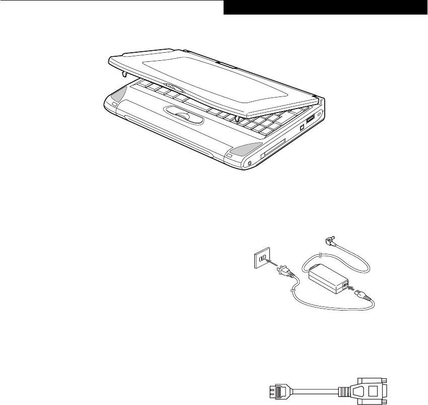
Figure 2-1 Fujitsu LifeBook P Series notebook
Overview
This section describes the components of your Fujitsu
LifeBook P Series notebook. We strongly recommend
that you read it before using your notebook – even if you
are already familiar with notebook computers.
UNPACKING
When you receive your LifeBook notebook, unpack it
carefully, and compare the parts you have received with
the items listed below.
■LifeBook P Series notebook(Figure 2-1)
■AC adapter with AC power cord (Figure 2-2)
■Lithium ion battery
■Weight Saver
■Phone/Modem (RJ-11) telephone cable
■Mini-VGA cable(Figure 2-3)
■Driver and Application Restore CD
■Getting Started Guide
■User’s Guide (this document)
■International Limited Warranty Brochure
■Certification of Authenticity with operating system
manual.
■Premium Care registration card and envelope
Depending upon the configuration of your system, one
or more of the following items may also be included:
■Modular DVD/CD-RW combo drive
■Modular Floppy Disk Drive
■Modular 2nd battery
■High-capacity battery
■DVD Application CD
■CD-RW Application CD
Once you have checked and confirmed that your Life-
Book system is complete, read through the following
pages to learn about all of your notebook’s components.
Figure 2-2 AC Adapter
Figure 2-3 Mini-VGA Cable
P2120.book Page 5 Friday, September 13, 2002 4:56 PM

6
LifeBook P2000 Notebook – Section Two
Figure 2-4 LifeBook notebook with display open
Locating the Controls
and Connectors
TOP AND FRONT COMPONENTS
The following is a brief description of your LifeBook
notebook’s top and front components.
Display Panel Latch
The display panel latch locks and releases the display
panel.
Wireless LAN Cover
The wireless LAN is optional; the wireless LAN cover is
present on all models.
Display Panel
The display panel is a color LCD panel with back
lighting for the display of text and graphics.
E-Mail Button
The E-Mail button helps you manage your e-mail.
(See E-mail Notification LED on page 20 for more infor-
mation)
Closed Cover Switch
The closed cover switch turns off the LCD back
lighting when the display panel is closed.
Stereo Speakers
The built-in dual speakers allow for stereo sound.
Quick Point Pointing Device
The Quick Point pointing device consists of two mouse-
like buttons and one cursor control button. (See Quick
Point Pointing Device on page 15 for more information)
Keyboard
A full-size keyboard with dedicated Windows
keys. (See Keyboard on page 13 for more information)
Suspend/Resume/Power On Button
The Suspend/Resume/Power On button allows you to
suspend notebook activity without powering off, resume
your LifeBook notebook from suspend mode, and
power on your notebook when it has been shut down
from Windows. (See Suspend/Resume Button on page 29
for more information)
Status Indicator Panel
The Status Indicator Panel displays symbols that corre-
spond with a specific component of your LifeBook note-
book. (See Status Indicator Panel on page 11 for more
information)
LifeBook Application Panel
The LifeBook Application Panel provides one-touch
application launch capability. (See LifeBook Application
Panel on page 20 for more information)
Display Panel Latches
Display Panel
Status Indicator Panel
Stereo Speaker
Closed Cover Switch
Keyboard
LifeBook
Quick Point
Pointing Device Stereo Speaker
Suspend/Resume/
Application Panel
Power On Button
E-Mail Button
Wireless LAN cover
(installed WLAN is an option)
P2120.book Page 6 Friday, September 13, 2002 4:56 PM
7
Getting to Know Your LifeBook
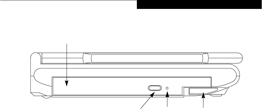
Figure 2-5 LifeBook notebook left-side panel
LEFT-SIDE PANEL COMPONENTS
The following is a brief description of your LifeBook
notebook’s left-side components.
Flexible Bay
The Flexible Bay can accommodate either the standard
DVD/CD-RW Drive or an optional bay battery. If
neither device is installed, the weight saver should be
installed. (See Flexible Bay Devices on page 18 for more
information)
Flexible Bay Eject Lever
The Flexible Bay eject lever releases the Flexible Bay
device.
DVD/CD-RW Drive Eject Button
The DVD/CD-RW Drive eject button releasing the drive
tray under normal circumstances.
Emergency CD Tray Release
The Emergency CD Tray Release allows you to open
the CD tray without powering on your LifeBook note-
book.
Flexible Bay
Flexible Bay Eject Lever
(DVD/CD-RW drive installed)
Emergency CD
DVD/CD-RW
Drive Eject Button Tray Release
P2120.book Page 7 Friday, September 13, 2002 4:56 PM

8
LifeBook P2000 Notebook – Section Two
Figure 2-6 LifeBook notebook right-side panel
RIGHT-SIDE PANEL COMPONENTS
The following is a brief description of your LifeBook
notebook’s right-side components.
Headphone Jack
The headphone jack allows you to connect headphones
or powered external speakers. (See Headphone Jack on
page 43 for more information)
PC Card Slot
The PC Card Slot allows you to install one Type II PC
Card. (See PC Cards on page 39 for more information)
PC Card Eject Button
The PC Card eject button allows you to remove PC
Cards from the PC Card slot. (See PC Cards on page 39
for more information)
IEEE 1394 Jack
The 1394 jack is used to connect between your LifeBook
and a peripheral such as a digital video camera.(See IEEE
1394 Jack on page 43 for more information)
Anti-theft Lock Slot
The anti-theft lock slot allows you to attach an optional
physical lock down device.
Mini-VGA Jack
The mini-VGA jack allows you to connect your LifeBook
notebook to an external monitor with an optional cable
adapter. (See Mini-VGA Port on page 44 for more infor-
mation)
Air Vents
The air vents allow for proper cooling of the system
while it is operating.
PC Card Eject Button
PC Card Slot
Air Vents
Mini-VGA Connector
Anti-theft Lock SlotIEEE 1394 Port
Headphone Jack
P2120.book Page 8 Friday, September 13, 2002 4:56 PM

9
Getting to Know Your LifeBook
Figure 2-7 LifeBook notebook back panel
BACK PANEL COMPONENTS
Following is a brief description of your LifeBook note-
book’s back panel components.
Optical Digital Audio-/Line-Out Jack
The optical digital audio-/line-out jack allows you to
download digital audio onto a MiniDisc recorder’s
SPDIF (Sony Philips Digital Interface) format or to use
external speakers with your LifeBook. (See Optical
Digital Audio-Out Connector on page 44 for more infor-
mation)
Microphone Jack
The microphone jack allows you to connect an external
mono microphone. (See Microphone Jack on page 44 for
more information)
S-Video Port
The S-Video output is used to transmit the S-Video
signal. The S-Video mini-DIN port is used to connect to
a compatible TV or VCR. (See S-Video Out Port (TV
Out) on page 43 for more information)
USB 2.0 Ports
The USB ports allow you to connect Universal Serial Bus
2.0 devices. (See Universal Serial Bus Ports on page 43 for
more information)
Power Off Button
The power off button allows you to shut down the
system in the event that standard methods do not work.
Modem (RJ-11) Telephone Port
The Modem (RJ-11) telephone jack is for attaching
a telephone line to the internal multinational 56K
modem. (See Modem (RJ-11) Telephone Jack on page 43
for more information)
LAN (RJ-45) Jack
The internal LAN (RJ-45) jack is used for an internal
Fast Ethernet (10/100 Base-TX) connection.
(See Internal LAN (RJ-45) Jack on page 43 for more infor-
mation)
DC Power Jack
The DC power jack allows you to plug in the AC adapter
or the optional Auto/Airline adapter to power your note-
book and charge the internal Lithium ion battery.
USB 2.0 Ports
DC Power Jack
Microphone Jack
Optical Digital
LAN (RJ-45) Jack
Modem (RJ-11) Jack
S-Video Jack
Power Off Button
Audio-/Line-Out
WARNING
The internal modem is not intended for use with Digital
PBX systems. Do not connect the internal modem to a
Digital PBX as it may cause serious damage to the
internal modem or your entire notebook. Consult your
PBX manufacturer’s documentation for details. Some
hotels have Digital PBX systems. Be sure to find out
BEFORE you connect your modem.
POINT
The internal multinational modem is designed to the
ITU-T V.90 standard. Its maximum speed of 53000bps
is the highest allowed by FCC, and its actual connection
rate depends on the line conditions. The maximum
speed is 33600bps at upload.
For additional information about the multinational
modem, refer to the Fujitsu web site at:
www.fujitsupc.com/modems
P2120.book Page 9 Friday, September 13, 2002 4:56 PM
10
LifeBook P2000 Notebook – Section Two
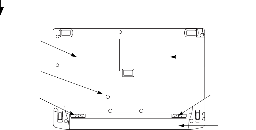
Figure 2-8 LifeBook notebook bottom panel
BOTTOM COMPONENTS
The following is a brief description of your LifeBook
notebook’s bottom panel components.
Lithium ion Battery
The internal Lithium ion battery can be installed in the
battery bay by aligning it with the slides and pushing it
into place. The battery can be removed when swapping
with a charged battery, or when the computer is to be
stored for a long period of time. (See Lithium ion Battery
on page 33 for more information)
Battery Release
Slide the battery releases to unlatch the battery.
Main Unit and Configuration Label
The configuration label shows the model number and
other information about your LifeBook notebook. In
addition, the configuration portion of the label has the
serial number and manufacturer information that you
will need to give your support representative. It identi-
fies the exact version of various components of your
notebook.
Lithium ion
Battery
Battery
Release
Battery
Release
Main Unit and
Configuration
Label
(approximate
location)
Screw Hole
for Removing
the Keyboard
Hard Disk
Drive Cover
P2120.book Page 10 Friday, September 13, 2002 4:56 PM
11
Getting to Know Your LifeBook
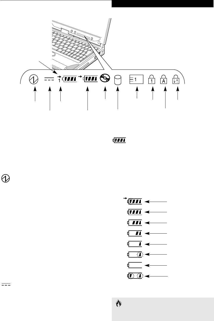
Figure 2-9 Status Indicator Panel
Status Indicator Panel
The Status Indicator displays symbols that correspond to
a specific component of your Fujitsu LifeBook note-
book. These symbols tell you how each of those compo-
nents are operating. (Figure 2-9)
POWER INDICATOR
The Power indicator symbol states whether your
system is operational. It has several different states,
each of which tells you what mode your notebook is
in at that time.
■Steady On: This means that there is power to your
LifeBook notebook and that it is ready for use.
■Flashing: This means that your LifeBook notebook is
in Suspend mode.
■Steady Off: This means that your system is either in
Hibernation mode, or that your LifeBook notebook
has been turned off with the power switch.
If you are charging your battery, the Power indicator
symbol will remain on even if your notebook is shut off.
The Power indicator symbol will also remain on if you
have either adapter connected and are shut down from
Windows, but have not turned off the power switch.
DC-IN INDICATOR
The DC-In indicator states that your notebook is
powered by an external source such as an AC adapter or
Auto/Airline adapter.
BATTERY LEVEL INDICATORS
The Battery Level indicators state whether or not the
primary Lithium ion battery and/or the optional second
Lithium ion battery are installed (Battery 1 refers to the
primary Lithium ion battery, while Battery 2 refers to the
Flexible Bay optional second battery). In addition, this
symbol states how much charge is available within each
installed battery. The symbol will only be displayed for a
battery that is currently installed in your LifeBook note-
book. (Figure 2-10)
Figure 2-10 Battery Level Indicator
2
Power
DC-In Battery
Battery
Identifier
Level
DVD/CD-RW
Combo Drive
Hard Drive
Access
PC Card
Access
Numeric
Caps Lock
Scroll Lock
Access
Battery
Charging
Indicator
Lock
CAUTION
A shorted battery is damaged and must be replaced.
(Figure 2-10)
76%–100% Charging
76%–100%
51%–75%
26%–50%
11%–25%
Low Warning <11%
Critical Low or
Dead Battery
Shorted Battery
P2120.book Page 11 Friday, September 13, 2002 4:56 PM
12
LifeBook P2000 Notebook – Section Two
BATTERY CHARGING INDICATOR
Located to the left of the Battery Level indicator is a
small arrow symbol. This symbol indicates that the
battery is being charged by an external source. This indi-
cator operates whether the power switch is in the On or
Off position, and will flash if the battery is too hot or
cold to charge.
DVD/CD-RW DRIVE
ACCESS INDICATOR
The DVD/CD-RW Access indicator tells you that the
DVD/CD-RW combo drive is being accessed. If the Auto
Insert Notification function is active, the indicator will
flash periodically when your system is checking the
DVD/CD-RW drive. If the Auto Insert Notification
function is not active, the indicator will only flash when
you access the DVD/CD-RW drive. The default setting is
the Auto Insert Notification function active. (See Auto
Insert Notification Function on page 38 for more informa-
tion)
HARD DRIVE OR REMOVABLE
MEDIA DRIVE ACCESS INDICATOR
The Hard Drive Access indicator states whether your
internal hard drive is being accessed.
PC CARD ACCESS INDICATOR
The PC Card Access indicator states whether or not your
notebook is accessing a PC Card. The indicator will flash
if your software tries to access a PC Card, even if there is
no card installed. (See PC Cards on page 39 for more
information)
NUMERIC LOCK INDICATOR
The Numeric Lock indicator states that the internal
keyboard is set in ten-key numeric keypad mode.
CAPS LOCK INDICATOR
The Caps Lock indicator states that your keyboard is set
to type in all capital letters.
SCROLL LOCK INDICATOR
The Scroll Lock indicator states that your scroll lock is
active.
POINT
If there is no battery activity, the power adapters are not
connected, and the power switch is Off, the Battery
Level indicators will also be off.
CAUTION
Batteries subjected to shocks, vibration or extreme
temperatures can be permanently damaged.
P2120.book Page 12 Friday, September 13, 2002 4:56 PM
13
Getting to Know Your LifeBook
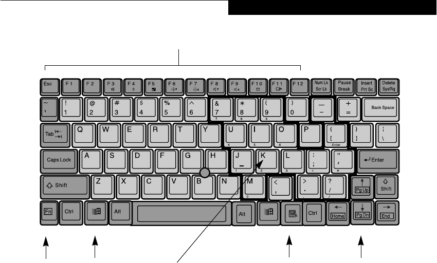
Figure 2-11 Keyboard
Keyboard
USING THE KEYBOARD
Your Fujitsu LifeBook notebook has an integral 83-key
keyboard. The keys perform all the standard functions of
a 101-key keyboard, including the Windows keys and
other special function keys. This section describes the
following keys. (Figure 2-11)
■Numeric keypad: Your notebook allows certain keys to
serve dual purposes, both as standard characters and
as numeric and mathematical keys. The ability to tog-
gle between the standard character and numerical keys
is controlled through the [NumLk] key.
■Cursor keys: Your keyboard contains four arrow
keys for moving the cursor or insertion point to the
right, left, up, or down within windows, applications
and documents.
■Function keys: The keys labeled [F1] through [F12],
are used in conjunction with the [Fn] key to produce
special actions that vary depending on what program
is running.
■Windows keys: These keys work with your Windows
operating system and function the same as the
onscreen Start menu button, or the right button
on your pointing device.
NUMERIC KEYPAD
Certain keys on the keyboard perform dual functions as
both standard character keys and numeric keypad keys.
NumLk can be activated by pressing the [NumLk] keys.
Turning off the NumLk feature is done the same way.
Once this feature is activated you can enter numerals 0
through 9, perform addition ( + ), subtraction ( - ),
multiplication ( * ), or division ( / ), and enter decimal
points ( . ) using the keys designated as ten-key function
keys. The keys in the numeric keypad are marked on the
front edge of the key to indicate their secondary functions.
(Figure 2-11)
WINDOWS KEYS
Your LifeBook notebook has two Windows keys,
consisting of a Start key and an Application key. The
Start key displays the Start menu. This button functions
the same as your onscreen Start menu button. The
Application key functions the same as your right mouse
button and displays shortcut menus for the selected
item. (Please refer to your Windows documentation for
additional information regarding the Windows keys.)
(Figure 2-11)
CURSOR KEYS
The cursor keys are the four arrow keys on the keyboard
which allow you to move the cursor up, down, left and
right in applications. In programs such as Windows
Explorer, it moves the “focus” (selects the next item up,
down, left, or right). (Figure 2-11)
x
S
Fn Key Windows
Function Keys
Numeric Keypad Cursor Keys
Windows
Application Key
Start Key
P2120.book Page 13 Friday, September 13, 2002 4:56 PM

14
LifeBook P2000 Notebook – Section Two
FUNCTION KEYS
Your LifeBook notebook has 12 function keys, F1
through F12. The functions assigned to these keys differ
for each application. You should refer to your software
documentation to find out how these keys are used.
(Figure 2-11)
The [Fn] key provides extended functions for the
notebook and is always used in conjunction with
another key.
■[Fn+F3]: Pressing [F3] while holding [Fn] will toggle
the Audio Mute on and off.
■[Fn+F4]: Pressing [F4] while holding [Fn] will toggle
the Quick Point feature on and off. Note that the
[Fn+F4] combination only works if Manual Setting is
selected in the BIOS. (See “Entering the BIOS Setup
Utility” on page 27)
■[Fn+F5]: Pressing [F5] while holding [Fn] allows
you to toggle between video compensation and no
compensation. (Video compensation controls spacing
on the display. When it is enabled, displays with less
than 1024 x 768 or 800 x 600 pixel resolution will still
cover the entire screen.)
■[Fn+F6]: Pressing [F6] repeatedly while holding [Fn]
will lower the brightness of your display.*
■[Fn+F7]: Pressing [F7] repeatedly while holding [Fn]
will increase the brightness of the display.*
■[Fn+F8]: Pressing [F8] repeatedly while holding [Fn]
will decrease the volume of your LifeBook note-
book.**
■[Fn+F9]: Pressing [F9] repeatedly while holding [Fn]
will increase the volume of your LifeBook notebook.**
■[Fn+F10]: Pressing [F10] while holding [Fn] allows
you to change your selection of where to send your
display video. Each time you press the combination
of keys you will step to the next choice. The choices,
in order, are: built-in display panel only, both built-in
display panel and external monitor or external
monitor only.
■[Fn+F11]: When a television is connected via the S-
Video port, pressing [F11] while holding [Fn] will
toggle the display on and off.
* There are eight brightness levels.
** There are 17 audio levels.
P2120.book Page 14 Friday, September 13, 2002 4:56 PM
15
Getting to Know Your LifeBook
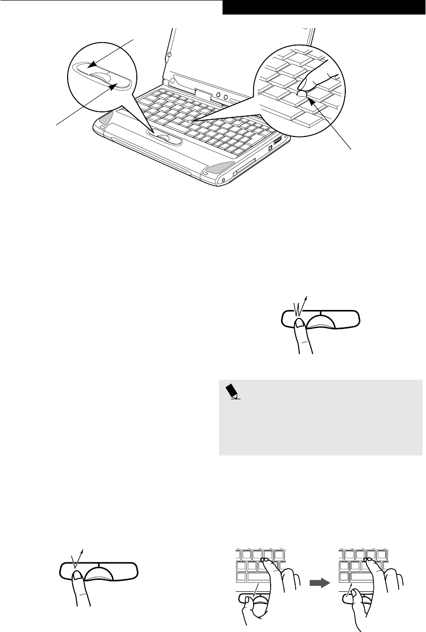
Figure 2-12 Quick Point pointing device
Quick Point
Pointing Device
The Quick Point is built into your LifeBook notebook. It
is used to control the movement of the cursor to select
items on your display panel. The Quick Point is
composed of a cursor control at the center of the
keyboard and three buttons on the palm rest of your
notebook. The cursor control works the same way a
mouse ball does, and moves the cursor around the
display. It only requires light pressure with the tip of
your finger, and the more pressure you use, the faster the
cursor will move. The left button functions the same as a
left mouse button while the right button has the same
function as a right mouse button. When used with the
cursor control, the middle button allows you to scroll up
and down a screen. The actual functionality of the
buttons may vary depending on the application that is
being used. (Figure 2-12)
CLICKING
Clicking means pushing and releasing a button. To left-
click, move the cursor to the item you wish to select,
press the top button once, and then immediately release
it. To right-click, move the cursor to the item you wish
to select, press the bottom button once, and then imme-
diately release it. (Figure 2-13)
Figure 2-13 Clicking
DOUBLE-CLICKING
Double-clicking means pushing and releasing the top
button twice in rapid succession. This procedure does
not function with the right button. To double-click,
move the cursor to the item you wish to select, press
and release the top button twice. (Figure 2-14)
Figure 2-14 Double-clicking
DRAGGING
Dragging means pressing and holding the top button,
while moving the cursor. To drag, move the cursor to
the item you wish to move. Press and hold the top
button while moving the item to its new location
and then release it. (Figure 2-15)
Figure 2-15 Dragging
Cursor Control
Left Button
Right Button
POINTS
■If the interval between clicks is too long, the
double-click will not be executed.
■Parameters for the Quick Point can be adjusted
from the Mouse Properties dialog box located in
the Windows Control Panel.
P2120.book Page 15 Friday, September 13, 2002 4:56 PM

16
LifeBook P2000 Notebook – Section Two
QUICK POINT DEVICE
CONTROL ADJUSTMENT
The Windows Control Panel allows you to customize
your Quick Point with selections made from within the
Mouse Properties dialog box. There are three aspects of
Quick Point operation, which you can adjust:
■Buttons: This tab lets you set up the buttons for right
or left handed operation, in addition to setting up the
time interval allowed between clicks in double-
clicking.
■Pointers: This tab lets you set up the scheme for
the cursor depending on its functionality.
■Motion: This tab lets you set up a relation between
the speed of your finger motion and the speed of the
cursor. It also allows you to enable a Pointer Trail for
the cursor arrow.
P2120.book Page 16 Friday, September 13, 2002 4:56 PM

17
Getting to Know Your LifeBook
Volume Control
Your Fujitsu LifeBook notebook has multiple volume
controls which interact with each other.
CONTROLLING THE VOLUME
The volume can be controlled in several different ways:
■Volume can be set from within the Volume Control on
the Taskbar.
■Volume can be controlled with the [F8] and [F9]
functions keys. Pressing [F8] repeatedly while holding
[Fn] will decrease the volume of your notebook. Press-
ing [F9] repeatedly while holding [Fn] will increase
the volume of your notebook.
■Volume can be controlled by many volume controls
that are set within individual applications.
■Certain external audio devices you might connect to
your system may have hardware volume controls.
Each source discussed above puts an upper limit on the
volume level that must then be followed by the other
sources.
We recommend that you experiment with the various
volume controls to discover the optimal sound level.
POINT
Any software that contains audio files will also contain
a volume control of its own. If you install an external
audio device that has an independent volume control,
the hardware volume control and the software volume
control will interact with each other. It should be noted
that if you set your software volume to Off, you will
override the external volume control setting.
POINT
There are seventeen levels through which the function
keys cycle.
P2120.book Page 17 Friday, September 13, 2002 4:56 PM
18
LifeBook P2000 Notebook – Section Two
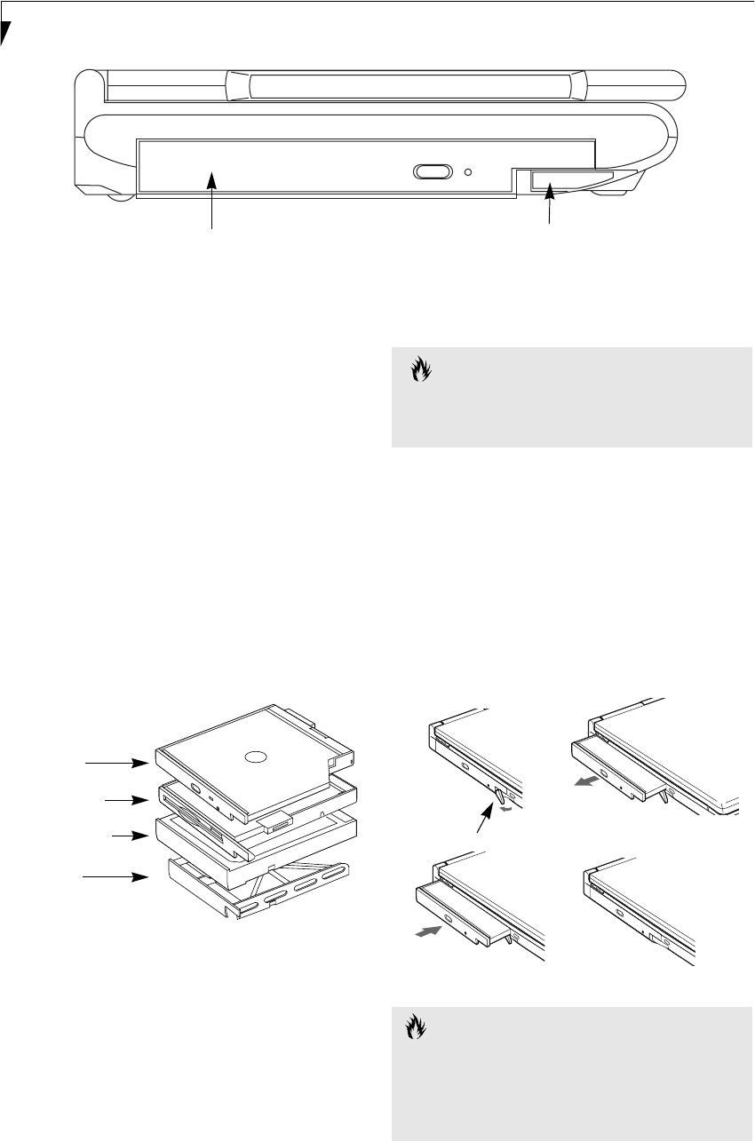
Figure 2-16 Flexible Bay
Flexible Bay Devices
Your Fujitsu LifeBook notebook contains a Flexible Bay.
The Flexible Bay can accommodate a modular DVD/
CD-ROM combo drive, a modular floppy disk drive, a
modular Lithium ion battery, or a weight saver.
(Figure 2-16)
The modular DVD/CD-RW combo drive allows you to
access movies, software and audio DVD/CDs, as well as
the ability to write to CDs.
The modular floppy disk drive allows you to read and
write information on removable 1.44MB and 720KB
floppy disks.
The modular Lithium ion battery is a rechargeable
battery that can be used to power your LifeBook note-
book when an adapter is not connected.
The Weight Saver is used to fill the bay when no device is
needed.
Figure 2-17 Flexible Bay Devices
REMOVING AND INSTALLING
MODULAR DEVICES
To remove and install modular devices in the Flexible
Bay, you can perform either a cold-swapping or hot-
swapping of the device. Cold-swapping means swapping
devices while your LifeBook notebook is powered off.
Hot-swapping occurs when your system is powered on
with a charged main battery or AC Adapter.
Cold-swapping
To cold-swap modular devices in your Flexible Bay
follow these easy steps: (Figure 2-18)
1. Close any open files.
2. Shut down your LifeBook notebook.
3. Pull out the Flexible Bay eject lever. This will push
your device out slightly, allowing you to remove the
device.
4. Slide your device out until it is clear of the bay.
This will require light force.
Figure 2-18 Removing/Installing a device in the Flexible Bay
Flexible Bay Flexible Bay Eject Lever
Weight Saver
Lithium ion Battery
DVD/CD-RW
Combo Drive
Modular Floppy
Disk Drive
CAUTION
You should never leave your Flexible Bay empty when
the notebook is in operation. If left empty, dust or for-
eign matter may accumulate inside the notebook.
CAUTION
Be careful when aligning and seating devices in the bay.
If the fit is incorrect, you may damage the bay or the
device. If the device does not move easily in the bay,
remove it, and check for dirt or foreign objects. It will
require a firm push to latch the device in place.
Flexible Bay Eject Lever
P2120.book Page 18 Friday, September 13, 2002 4:56 PM

19
Getting to Know Your LifeBook
5. Slide the device you are installing into your
notebook until it clicks into place.
6. It is now safe to turn your notebook back on.
7. You can now access and use the device.
Your LifeBook notebook will automatically detect the
new device and activate it within your system. The drive
letters associated with the device will be created and
listed under My Computer and Windows Explorer.
Hot-swapping
To hot-swap Flexible Bay devices while the system is
powered on, follow these steps:
1. Prior to performing the hot-swap, make sure you
have a charged main battery installed, or an AC
Adapter is powering the system.
2. If your system is in Suspend mode, press the
Suspend/Resume button to resume operation.
3. Click the Unplug or Eject Hardware icon (Windows
2000 Professional) or the Safely Remove Hardware
icon (Windows XP) in the lower right-hand corner
of the screen.
4. From the list that appears, click the device you want
to remove.
5. Pull out the Flexible Bay eject lever. This will push
your device out slightly, allowing you to remove the
device.
6. Slide your device out until it is clear of the bay.
This will require light force.
7. Slide the device you are installing into your
notebook until it clicks into place.
8. You can now access and use the device.
Your LifeBook notebook will automatically detect the
new device and activate it within your system. The drive
letters associated with the device will be created and
listed under My Computer and Windows Explorer.
CAUTION
Be careful when aligning and seating devices in the bay.
If the fit is incorrect, you may damage the bay or the
device. If the device does not move easily in the bay,
remove it, and check for dirt or foreign objects. It will
require a firm push to latch the device in place.
P2120.book Page 19 Friday, September 13, 2002 4:56 PM

20
LifeBook P2000 Notebook – Section Two
Figure 2-19 LifeBook Application Panel
LifeBook
Application Panel
One of the unique features of your LifeBook is the Life-
Book Application Panel. This panel allows you to launch
applications with the touch of a button when your
system is actively running or in suspend mode.
Your LifeBook is pre-installed with software utilities that
you use to operate and configure your LifeBook Applica-
tion Panel. These utilities are found in the Start menu,
under Settings -> Control Panel -> Application Panel.
(For Windows XP users, it’s in Start -> Control Panel ->
Application Panel.) They include Application Panel
Setup, E-mail LED Setup, and Internet Setup. The Life-
Book Application Panel makes your LifeBook more than
just another notebook computer.
The panel consists of the following elements:
APPLICATION LAUNCH BUTTONS
There are two application launch buttons. When these
are selected, user-defined applications will be launched.
You can customize these buttons to open whichever
applications you want when they are pressed. Note that
although there is an Internet Setup tab in the Applica-
tion Panel Setup window, there is no Internet-assigned
button in this LifeBook model.
E-MAIL NOTIFICATION LED
By setting up the E-mail LED notification in conjunc-
tion with your E-mail button setup, you can connect to
your ISP, check for and retrieve new mail, terminate
connection, and activate the E-mail LED to notify that
new mail has arrived.
To use the E-mail LED notification, you must have
access to a POP3 Server with no Security Password
Authentication. Contact your service provider to deter-
mine if they support POP3 without Security Password
Authentication.
DESKTOP CONTROL PANEL
To configure your LifeBook Application Panel with
the Application Panel Setup:
1. Click on Start.
2. (Windows 2000 only) Click on Settings.
3. Click on Control Panel.
4. Click on Application Panel.
The Application Panel Setup utility will appear. There
are tabs that correspond to the application buttons on
the LifeBook Application Panel. When you receive your
notebook, these buttons are pre-configured to launch
specific applications. For a list of the default applications
associated with each button, refer to (See Application
Launcher Defaults on page 86 for more information).
To change an application associated with the Application
A, Application B, or E-mail buttons, click on the tab for
the button you would like to reconfigure – for example,
Application A. Click on Go To Start Menu, scroll down
the list of applications, click on the application you wish
to launch with this button, and then click OK. The
button will now launch the new application.
When you have finished with Application Panel Setup
click on OK, and the new settings will take effect. You
LifeBook Application Panel buttons
E-Mail button
E-Mail
Notification
LED
POINT
The E-mail button can be configured to launch any
application you wish, not just an e-mail program.
POINT
The tabs in Application Panel Setup may not be in the
same order as the buttons on your LifeBook. Please
carefully select the tab you wish to change.
P2120.book Page 20 Friday, September 13, 2002 4:56 PM

21
Getting to Know Your LifeBook
can reconfigure your LifeBook Application Panel as
often as you like.
Enabling/disabling Application Launcher button
In the center of each application setup page is a Specify
the Button Action field. When you click on the drop-
down arrow, you are offered two choices: Start a
Program, and Never Use a Button. The first will enable
the button, and the second will disable the button. You
can enable/disable either of these functions simply by
clicking on the option.
At the bottom of each setup page are two check boxes:
■Keep this button active even on Standby
■Keep this button active even on Hard Drive Timeout
The first will enable/disable the button when your
system is in Standby mode, and the second will enable/
disable the button when your hard drive has timed out.
USING THE E-MAIL NOTIFICATION LED
To configure the E-mail Notification LED:
1. Click on Start.
2. (Windows 2000 only) Click on Programs.
3. Click on Control Panel.
4. Click on Application Panel.
5. Click on the E-mail tab.
6. The E-mail Setup screen will appear. Click on the E-
Mail Account Settings button. The E-Mail Account
Settings window appears.
Based upon the configuration of your system and the
method you plan to use for connecting, enter the infor-
mation in the requested fields. If you are unsure of the
information requested, click on the field and press the
[F1] button. If you are still unsure, consult your Service
provider.
After you have filled in the requested information for
each of the E-Mail Account Settings tabs, click OK to
return to the Application Panel window.
Configure the E-mail button to launch the mail software
you want to use (i.e., Outlook Express, Netscape
Messenger, etc.) by either browsing to the application
using the Browse button, or opening the Start Menu
using the Go to Start Menu button.
After the setup (Dial Up Networking/E-mail/E-mail
LED) is completed, you are ready to retrieve mail. When
you press the E-mail button, your system will establish
connection with your provider, check for and retrieve
new mails, terminate the connection, and activate the
blinking LED to alert you of new mail.
USING THE CD PLAYER
Your LifeBook Application Panel utility includes a
desktop media player panel. You may use this panel to
operate as a CD Player.
To use the desktop CD player panel:
1. Click on Start.
2. Click on Programs.
3. Click on Lifebook Application Panel.
4. Click on CD Player.
The desktop control panel will appear in the upper left
corner of your screen.
To close the panel, click on the “x” button.
To minimize the panel, click on the “-” button.
You can select from four appearances for your desktop
control panel. Simply double click on the track display
area of the panel, and a menu will appear which will
allow you to select from a pull down menu. On the same
pop-up are three other options: “Always on top”,
“Continuous Play”, and “Disable Stop/Eject button for
CD removal”. If you click on “Always on top” the
desktop controls will always be seen on your screen, no
matter what other application you are running. If you
click on “Continuous Play,” your CD Player will auto-
matically start over at the beginning as soon as it finishes
the last track.
If you click “Disable Stop/Eject button for CD removal,”
the Stop/Eject button on the CD player toolbar is either
enabled or disabled.
You can move the desktop control panel to anywhere on
your desktop. Drag it by clicking on the display, holding
it down, and dragging the control panel. When you have
POINT
The E-mail button can be configured to launch any
application you wish, not just an e-mail program.
POINT
If you choose to have the buttons work when the note-
book is in standby or off, they will function even if hit
accidentally. This will turn on your notebook even if you
are not present or using your notebook. This could
deplete your battery, and you will need to recharge it
before using the notebook. As a precaution, close the
lid when you are away from your notebook.
POINT
To use the E-mail LED notification, you must have
access to a POP3 Server with no Security Password
Authentication. Contact your service provider to
determine if they support POP3 without Security
Password Authentication.
P2120.book Page 21 Friday, September 13, 2002 4:56 PM

22
LifeBook P2000 Notebook – Section Two
placed it where you would like, release the mouse
button.
System Requirements and Precautions
System Requirements
■Operating System: Microsoft Windows
■Memory: 32MB or more
■Hard drive: 2MB or more free space
Precautions
■LifeBook Application Panel uses the date and time
settings of your LifeBook. If the date and time are off, you
can adjust this setting in the Windows Control Panel.
■If you insert an audio CD which has both audio and data
tracks into the CD Player, the CD Player may fail to play
the first audio track.
■The Volume Up, Volume Down and Mute controls for
the CD Player desktop control panel adjusts the volume
of the CD audio line only. It does not adjust your note-
book’s master software volume control or the manual
volume on the LifeBook notebook.
■The CD Player desktop control panel is designed to be
displayed in High Color (16-bit) or in True Color (24-bit
or more). If you have your notebook’s display set for 256
colors or less, the CD Player control panel will display in a
“basic” mode.
POINTS
■If you have your display set to 256K colors the basic
display will appear no matter which one you select.
You will need to set your display colors to more than
256K in order to select other display appearances.
■When you close the CD Player’s desktop control
panel, it will stop the audio CD Player.
P2120.book Page 22 Friday, September 13, 2002 4:56 PM

23
3
Getting Started
P2120.book Page 23 Friday, September 13, 2002 4:56 PM

24
LifeBook P2000 Notebook – Section Three
P2120.book Page 24 Friday, September 13, 2002 4:56 PM
25
Getting Started
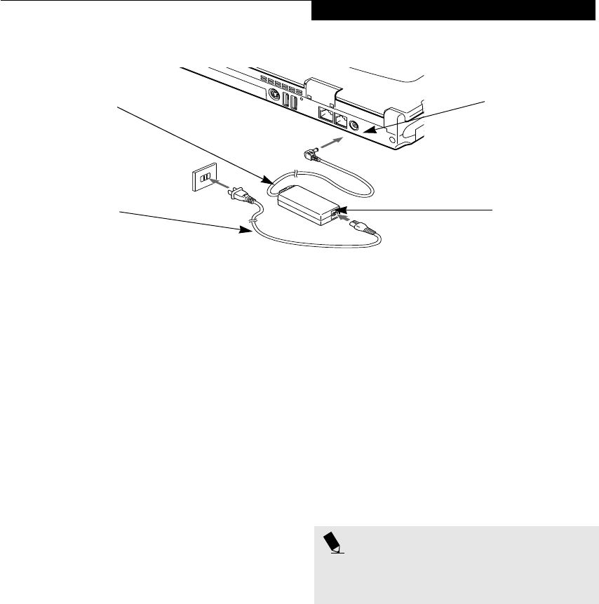
Figure 3-1 Connecting the AC Adapter
Power Sources
Your Fujitsu LifeBook notebook has five possible power
sources: a primary Lithium ion battery, an optional
high-capacity Lithium ion battery, an optional modular
Lithium ion battery, an AC adapter, or an optional Auto/
Airline adapter.
CONNECTING THE POWER ADAPTERS
The AC adapter or optional Auto/Airline adapter
provides power for operating your notebook and
charging the batteries.
Connecting the AC Adapter
1. Plug the DC output cable into the DC power jack
of your LifeBook notebook.
2. Plug the AC adapter into an AC electrical outlet.
(Figure 3-1)
Connecting the Optional Auto/Airline Adapter
1. Plug the DC output cable into the DC power jack
on your notebook.
2. Plug the Auto/Airline adapter into the cigarette
lighter of an automobile with the ignition key in
the On or Accessories position.
OR
3. Plug the Auto/Airline adapter into the DC power
jack on an airplane seat.
Switching from AC Adapter Power or the
Auto/Airline Adapter to Battery Power
1. Be sure that you have at least one charged
battery installed.
2. Remove the AC adapter or the Auto/Airline adapter.
DC Power Jack
DC Output Cable
AC Adapter
AC Cable
POINT
The Lithium ion battery is not charged upon purchase.
Initially, you will need to connect either the AC adapter
or the Auto/Airline adapter to use your notebook.
P2120.book Page 25 Friday, September 13, 2002 4:56 PM

26
LifeBook P2000 Notebook – Section Three
Figure 3-2 Opening the Display Panel
Display Panel
Your Fujitsu LifeBook notebook contains a display panel
that is backlit for easier viewing in bright environments
and maintains top resolution through the use of active-
matrix technology.
OPENING THE DISPLAY PANEL
1. Slide the Display Panel latch to the right. This
releases the locking mechanism and raises the
display slightly.
2. Lift the display backwards, being careful not to
touch the screen, until it is at a comfortable
viewing angle. (Figure 3-2)
ADJUSTING DISPLAY PANEL BRIGHTNESS
Once you have turned on your LifeBook notebook, you
may want to adjust the brightness level of the screen to a
more comfortable viewing level. There are two ways to
adjust the brightness, by using the keyboard or the
power management utility.
Using the Keyboard
Adjusting the brightness using the keyboard changes the
setting only temporarily.
■[Fn+F6]: Pressing repeatedly will lower the
brightness of your display.
■[Fn+F7]: Pressing repeatedly will increase the
brightness of the display.
Using the Power Management Utility (Windows
2000 only)
Adjusting the brightness using the Power Management
changes the setting permanently.
1. Double-click the Battery icon in the lower right
corner of your display. This will open the BatteryAid
Properties dialog box.
2. Select the Power Control tab and adjust your
LCD Backlighting to the desired level.
3. Click OK or Apply to permanently change
the settings.
You may need to readjust the brightness level periodi-
cally depending on your operating environment.
CLOSING THE DISPLAY PANEL
1. Holding the edge of your display panel, pull it
forward until it is flush with the body of your Life-
Book notebook.
2. Push down until you hear a click. This will
engage the locking mechanism and prevent
your display panel from opening unexpectedly.
Display Panel Latch
POINT
The higher the brightness level, the more power the
notebook will consume and the faster your batteries
will discharge. For maximum battery life, make sure that
the brightness is set as low as possible.
P2120.book Page 26 Friday, September 13, 2002 4:56 PM

27
Getting Started
Starting Your LifeBook
Notebook
POWER ON
Suspend/Resume/Power On button
The Suspend/Resume/Power On button is used to turn
on your LifeBook notebook from its off state. Once you
have connected your AC adapter or charged the internal
Lithium ion Battery, you can power on your notebook.
(See figure 2-7 on page 9 for location)
Press the Suspend/Resume/Power On button, which is
located below the display on the right. When you are
done working you can either leave your LifeBook note-
book in Suspend mode, (See Suspend Mode on page 29
for more information), or you can turn it off. (See Power
Off on page 30 for more information)
When you Power On your LifeBook notebook, it will
perform a Power On Self Test (POST) to check the
internal parts and configuration for correct functionality.
If a fault is found, your LifeBook notebook will emit an
audio warning and/or an error message will be displayed.
(See Power On Self Test Messages on page 74 for more
information) Depending on the nature of the problem,
you may be able to continue by starting the operating
system or by entering the BIOS setup utility and revising
the settings.
After satisfactory completion of the Power On Self Test
(POST), your notebook will load your operating system.
BOOT SEQUENCE
The procedure for starting-up your notebook is termed
the Bootup sequence and involves your notebook’s
BIOS. When your LifeBook notebook is first turned on,
the main system memory is empty, and it needs to find
instructions to start up your notebook. This information
is in the BIOS program. Each time you power up or
restart your notebook, it goes through a boot sequence
which displays a Fujitsu logo until your operating system
is loaded. During booting, your notebook is performing
a standard boot sequence including a Power On Self Test
(POST). When the boot sequence is completed without
a failure and without a request for the BIOS Setup
Utility, the system displays the operating system’s
opening screen.
The boot sequence is executed when:
■You turn on the power to your LifeBook notebook.
■You restart your notebook from the Windows
Shut Down dialog box.
■The software initiates a system restart. Example:
When you install a new application.
■You reset the system by pressing the three keys
[CTRL+ALT+DEL].
BIOS SETUP UTILITY
The BIOS Setup Utility is a program that sets up the
operating environment for your LifeBook notebook.
Your BIOS is set at the factory for normal operating
conditions, therefore there is no need to set or change
the BIOS’ environment to operate your notebook.
The BIOS Setup Utility configures:
■Device control feature parameters, such as changing
I/O addresses and boot devices.
■System Data Security feature parameters, such as
passwords.
Entering the BIOS Setup Utility
To enter the BIOS Setup Utility do the following:
1. Turn on or restart your LifeBook notebook.
2. Press the [F2] key once the Fujitsu logo appears on
the screen. This will open the main menu of the
BIOS Setup Utility with the current settings
displayed.
3. Press the [RIGHT ARROW] or [LEFT ARROW] key
to scroll through the other setup menus to review or
alter the current settings.
BIOS Guide
A guide to your notebook’s BIOS is available online.
Please visit our service and support Web site at
www.fujitsupc.com. Once there, select Support, then
select Notebooks under User’s Guides. Select LifeBook
BIOS Guides from the pull-down menu for your Life-
Book series. If you are unsure of your notebook’s BIOS
number, refer to your packing slip.
POINT
When you turn on your LifeBook notebook be sure you
have a power source. This means that at least one bat-
tery is installed and charged, or that the AC or Auto/
Airline adapter is connected and has power.
CAUTION
Do not carry your LifeBook notebook around with the
power on or subject it to shocks or vibration, as you risk
damaging your notebook.
POINT
Never turn off your LifeBook notebook during the
Power On Self Test (POST) or it will cause an error mes-
sage to be displayed when you turn your LifeBook
notebook on the next time. (See Power On Self Test
Messages on page 74 for more information)
P2120.book Page 27 Friday, September 13, 2002 4:56 PM

28
LifeBook P2000 Notebook – Section Three
BOOTING THE SYSTEM
We strongly recommend that you not attach any external
devices and do not put a DVD/CD in your drive until
you have gone through the initial power on sequence.
When you turn on your LifeBook notebook for the first
time, it will display a Fujitsu logo on the screen. If you
do nothing the system will load the operating system,
and then the Windows Welcome will begin.
Designed to accommodate the needs of many users, in
many different countries, Windows needs to be config-
ured the first time you use them. Windows has three
parts:
■Getting Started: You have the opportunity to enter
custom information for your configuration file and
setup your modem so that your LifeBook notebook
will be prepared to dial out.
■Registration: Easy online registration for Windows
with Microsoft, and for your LifeBook notebook with
Fujitsu.
■Windows License Agreement and Final Settings:
You have the opportunity to review the Windows
License Agreement.
Getting Started
Read the instructions on the screens carefully and fill in
the information as directed. You will be asked for such
items as the language you wish to use, the country in
which you live, your first and last name, and about how
you dial out from where you will be using your LifeBook
notebook. For the modem settings, enter your current
location information where you will be using your Life-
Book notebook. If you are not connected to a phone line
and plan to register at a later time, you may click the
Skip button, and you will go directly to the condition of
use page.
Once you have set up your LifeBook notebook to dial
out, Windows will make a free telephone call to test the
settings. If the call is unsuccessful, you will be returned
to the phone settings page where you may try to fix
them. If you are unable to fix the settings please contact
Fujitsu Service and Support. (See Fujitsu Contact Infor-
mation on page 1 for more information). If you would
simply like to move on, and register at a later time, you
may click the Skip button, and you will go directly to the
Condition of Use page.
Windows Registration
If your connection is successful, you will go to a
Registration Confirmation page. Enter the requested
information, then check the box at the bottom to
register your copy of Windows with Microsoft. Once you
have finished, click the Next button to continue.
Final Settings
The first part of your final settings is the Windows End
User License Agreement. Read the agreement carefully.
When you finish reading you must accept or reject the
terms of the agreement and then click on the Next button.
REGISTERING YOUR LIFEBOOK NOTEBOOK
What are the benefits of registering?
You will receive an identification label for your LifeBook
notebook, which, if your notebook is ever lost, may help
in getting it returned to you. You will also receive tech-
nical support access and useful product mailings.
How do I register my LifeBook notebook?
There are several ways to register your LifeBook note-
book.
Complete the pre-printed registration form and submit
it by either of the following methods:
■Fax: 1-800-577-9989
■Mail: Fujitsu PC Corporation
750 139th Ave.
San Leandro, CA 94578
Attn: Warranty Department
You can also register your LifeBook by:
■Web si te: www.fujitsupc.com/support
You will need to be set up with an Internet Service
Provider (ISP) to use the last option.
INSTALLING CLICK ME!
The first time you boot up your system, you will see an
icon called Click Me! on the desktop (Windows 2000) or
in the Start folder (Windows XP). When you click the
Click Me! icon, your system will automatically build the
icon tray in the bottom right of the screen. These icons
provide links to utilities that you will frequently access.
POINT
You may click Cancel at any time within this process to
shut down Windows. You may restart this process at
any time in the future, but you must complete it in
order to use your computer.
POINTS
■If you reject the terms of the license agreement you
will be asked to review the license agreement for
information on returning Windows or to shut down
your LifeBook notebook.
■You cannot use your LifeBook notebook until you
have accepted the License Agreement. If you stop the
process your notebook will return to the beginning of
the Windows Welcome Process, even if you shut your
notebook down and start it up again.
P2120.book Page 28 Friday, September 13, 2002 4:56 PM

29
Getting Started
Power Management
Your Fujitsu LifeBook notebook has many options and
features for conserving battery power. Some of these
features are automatic and need no user intervention,
such as those for the internal modem. However, others
depend on the parameters you set to best suit your oper-
ating conditions, such as those for the display bright-
ness. Internal power management for your notebook
may be controlled from settings made in your operating
system, pre-bundled power management application, or
from settings made in BIOS setup utility.
Besides the options available for conserving battery
power, there are also some things that you can do to
prevent your battery from running down as quickly.
For example, you can create an appropriate power saving
profile, put your notebook into Suspend mode when it
is not performing an operation, and you can limit the
use of high power devices. As with all mobile, battery
powered computers, there is a trade-off between
performance and power savings.
SUSPEND/RESUME BUTTON
When your LifeBook notebook is active, the Suspend/
Resume button can be used to manually put your note-
book into Suspend mode. Push the Suspend/Resume
button when your notebook is active, but not actively
accessing anything, and immediately release the button.
You will hear two short beeps and your system will enter
Suspend mode. (See figure 2-4 on page 6 for location)
If your LifeBook notebook is suspended, pushing the
Suspend/Resume button will return your notebook to
active operation. You can tell whether or not your
system is in Suspend mode by looking at the Power indi-
cator. (See figure 2-4 on page 6) If the indicator is visible
and not flashing, your notebook is fully operational. If
the indicator is both visible and flashing, your notebook
is in Suspend mode. If the indicator is not visible at all,
the power is off or your notebook is in Hibernation
mode.
SUSPEND MODE
Suspend or Standby mode in Windows saves the
contents of your LifeBook notebook’s system memory
during periods of inactivity by maintaining power to
critical parts. This mode will turn off the CPU, the
display, the hard drive, and all of the other internal
components except those necessary to maintain system
memory and allow for restarting. Your notebook can be
put in Suspend mode by:
■Pressing the Suspend/Resume button when your
system is turned on.
■Selecting Standby from the Windows Shut Down menu.
■Timing out from lack of activity.
■Allowing the battery to reach the Dead Battery
Warning condition.
Your LifeBook notebook’s system memory typically
stores the file(s) on which you are working, open applica-
tion(s) information, and any other data required to
support the operation(s) in progress. When you resume
operation from Suspend mode, your notebook will
return to the point where it left off. You must use the
Suspend/Resume button to resume operation, and there
must be an adequate power source available, or your
notebook will not resume.
HIBERNATION FEATURE
The Hibernation feature saves the contents of your
LifeBook notebook’s system memory to the hard drive as
a part of the Suspend/Resume mode. You can enable or
disable this feature.
Enable or Disable the Hibernation Feature
The default settings is not enabled. To enable or disable
the Hibernation feature follow these easy steps:
1. From the Start menu, select Settings, and then select
Control Panel.
2. From the Control Panel select Power Options.
3. Select the Hibernation tab. Select the box to enable
or disable this feature.
POINTS
■If you are running your LifeBook notebook on
battery power, be aware that the battery continues
to discharge while your notebook is in Suspend
mode, though not as fast as when fully operational.
■Disabling the Suspend/Resume button prevents it
from being used to put your LifeBook notebook in
Suspend or Hibernation mode. The resume function
of the button cannot be disabled.
■If your LifeBook notebook is actively accessing
information when you enter the Suspend or Hiber-
nation mode, changes to open files are not lost. The
files are left open and memory is kept active during
Suspend mode or the memory is transferred to the
internal hard drive during Hibernation mode.
CAUTION
The Suspend or Hibernation mode should not be used
with certain PC Cards. Check your PC Card documenta-
tion for more information.
When PC Cards or external devices are in use, Hiberna-
tion mode cannot return to the exact state prior to sus-
pension, because all of the peripheral devices will be re-
initialized when the system restarts.
P2120.book Page 29 Friday, September 13, 2002 4:56 PM

30
LifeBook P2000 Notebook – Section Three
Using the Hibernation Feature
1. From the Start menu, select Settings, and then select
Control Panel.
2. From the Control Panel select Power Options.
3. Select the Advanced tab. Select Hibernate from the
pull down menu for Power buttons.
DISPLAY TIMEOUT
The Video Timeout is one of the power management
parameters. This feature saves power by turning off the
display if there is no keyboard or pointer activity for the
user selected timeout period. Any keyboard or pointer
activity will cause the display to restart automatically.
This feature is independent of the Suspend/Resume
button and can be enabled and disabled in Windows and
BIOS setup utility.
HARD DISK TIMEOUT
The Hard Disk Timeout is another one of the power
management parameters. This feature saves power by
turning off the hard drive if there is no hard drive
activity for the user selected timeout period. Any
attempt to access the hard drive will cause it to restart
automatically. This feature is independent of the
Suspend/Resume button and can be enabled and
disabled in Windows and BIOS setup utility.
WINDOWS POWER MANAGEMENT
Power Management
The Power Management icon located in the Windows
Control Panel allows you to configure some of the power
management settings. For example, you can use the
Power Management to set the timeout values for turning
off the display and hard disks whether you are running
the notebook on battery power or one of the adapters.
The settings may also be changed in the BIOS.
RESTARTING THE SYSTEM
If your system is on and you need to restart it, be sure
that you use the following procedure.
1. Click the Start button, and then click Shut Down.
2. Select the Restart option from within the Windows
Shut Down dialog box.
3. Click OK to restart your notebook. Your notebook
will shut down and then reboot.
POWER OFF
Before turning off the power, check that the Hard Drive,
DVD, CD-ROM, CD-RW, PC Card and the Floppy Disk
Drive Access indicators are all Off. (See figure 2-4 on
page 6) If you turn off the power while accessing a disk
or PC Card there is a risk of data loss. To ensure that
your notebook shuts down without error, use the
Windows shut down procedure.
Using the correct procedure to shut down from Windows
allows your notebook to complete its operations and turn
off power in the proper sequence to avoid errors. The
proper sequence is:
1. Click the Start button, and then click Shut Down.
2. Select the Shut Down option from within the
Windows Shut Down dialog box.
3. Click OK to shut down your notebook.
4. Move the power switch to the off position.
If you are going to store your notebook for a month or
more see Care and Maintenance Section.
POINT
Turning off your LifeBook notebook without exiting
Windows or turning on your notebook within 10 sec-
onds of the notebook being shut off may cause an error
when you start the next time.
CAUTION
Be sure to close all files, exit all applications, and shut
down your operating system prior to turning off the
power with the power switch. If files are open when
you turn the power off, you will lose any changes that
have not been saved, and may cause disk errors.
P2120.book Page 30 Friday, September 13, 2002 4:56 PM

31
4
User-Installable
Features
P2120.book Page 31 Friday, September 13, 2002 4:56 PM

32
LifeBook P2000 Notebook – Section Four
P2120.book Page 32 Friday, September 13, 2002 4:56 PM

33
User Installable Features
Lithium ion Battery
Your Fujitsu LifeBook notebook has a Lithium ion
battery that provides power for operating your notebook
when no external power source is available. The battery
is durable and long lasting, but should not be exposed to
extreme temperatures, high voltages, chemicals or other
hazards.
The Lithium ion battery operating time may become
shorter if it is used under the following conditions:
■When used at temperatures that exceeds a low of 5°C
(41°F) or a high of 35°C (95°F). Extreme temperatures
not only reduce charging efficiency, but can also cause
battery deterioration. The Charging icon on the Status
Indicator panel will flash when you try to charge a
battery that is outside its operating temperature range.
(See Battery Charging Indicator on page 12 for more
information)
■When using a high current device such as a modem,
DVD/CD-RW drive, or the hard drive, using the AC
adapter will conserve your battery life.
RECHARGING THE BATTERIES
If you want to know the condition of the primary
Lithium ion battery, check the Battery Level indicator
located on the Status Indicator panel. The indicator
changes as the battery level changes.
The Lithium ion battery is recharged internally using
the AC adapter or Auto/Airline adapter. To recharge the
battery make sure the battery that needs to be charged
is installed in your LifeBook notebook and connect the
AC or Auto/Airline adapter.
There is no memory effect on the Lithium ion battery
therefore you do not need to discharge the battery
completely before recharging. The charge times will be
significantly longer if your notebook is in use while the
battery is charging.
The approximate charging times follow:
■Main battery:
System off - 4.5 hours, system running - 11 hours
■High-capacity battery:
System off - 6.5 hours, system running - 17 hours
If you want to charge the battery more quickly, put your
notebook into Suspend mode, or turn it off while the
adapter is charging the battery. (See Power Management
on page 29 for more information on Suspend mode and
shutdown procedure)
Low Battery State
When the battery is running low, a low battery notifica-
tion message will appear. If you do not respond to the
low battery message, the batteries will continue to
discharge until they are too low to operate. When this
happens, your notebook will go into Suspend mode.
There is no guarantee that your data will be saved once
the notebook reaches this point.
POINTS
■Actual battery life will vary based on screen bright-
ness, applications, features, power management set-
tings, battery condition and other customer
preferences.DVD, CD-RW, CD-ROM, or hard drive
usage may also have a significant impact on battery
life. The battery charging capacity is reduced as the
battery ages. If your battery is running low quickly,
you should replace it with a new one.
■Under federal, state, or local law it may be illegal to
dispose of batteries by putting them in the trash.
Please take care of our environment and dispose of
batteries properly. Check with your local government
authority for details regarding recycling or disposing
of old batteries. If you cannot find this information
elsewhere, contact your support representative at 1-
800-8Fujitsu (1-800-838-5487)
CAUTION
Do not leave a faulty battery in your LifeBook
notebook. It may damage your AC adapter, optional
Auto/Airline adapter, another battery or your notebook
itself. It may also prevent operation of your notebook
by draining all available current into the bad battery.
POINT
Make sure that the Battery Charging indicator and the
percentage charge is shown inside the Battery Level icon
on the Status Indicator Panel.
CAUTION
Using heavy current devices such as Modem or frequent
DVD/CD-RW/CD-ROM accesses may prevent charging
completely.
CAUTIONS
■Once the low battery notification message appears,
you need to save all your active data and put your
LifeBook notebook into Suspend mode until you can
provide a new power source. You should provide a
charged battery, an AC power adapter, or Auto/Air-
line adapter as soon as possible.
■ When you are in Suspend mode there must always
be at least one power source active. If you turn off
the power with the power switch, or remove all
power sources while your LifeBook notebook is in
Suspend mode, any data that has not been saved to
the hard drive will be lost.
P2120.book Page 33 Friday, September 13, 2002 4:56 PM
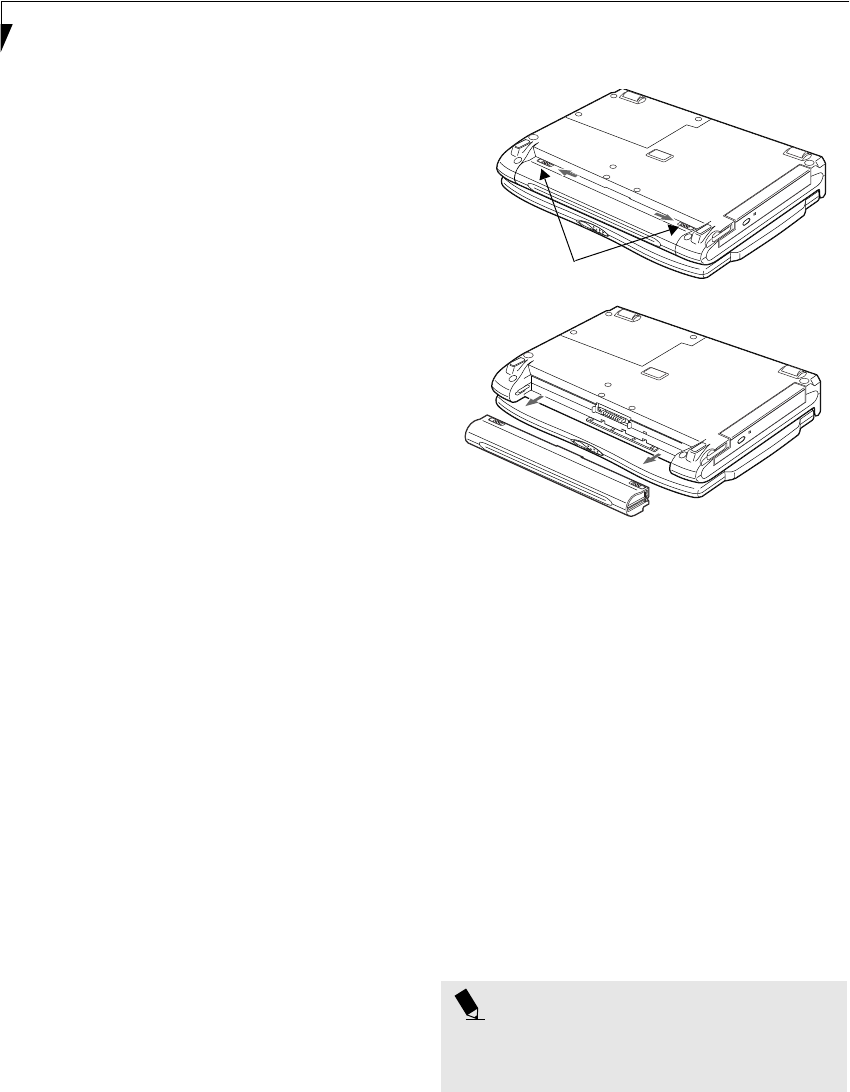
34
LifeBook P2000 Notebook – Section Four
Dead Battery Suspend mode shows on the Status indi-
cator just like the normal Suspend mode. Once your
notebook goes into Dead Battery Suspend mode you
will be unable to resume operation until you provide
a source of power either from an adapter, or a charged
battery. Once you have provided power, you will need to
press the Suspend/Resume button to resume operation.
In the Dead Battery Suspend mode, your data can be
maintained for some time, but if a power source is not
provided promptly, the Power indicator will stop
flashing and go out, meaning that you have lost the data
that was not stored. Once you provide power, you can
continue to use your notebook while an adapter is
charging the battery.
Shorted Batteries
The Status Indicator panel uses a symbol inside the
battery outline of the Battery Level indicator to display
the operating level available in that battery. (See figure 2-
10 on page 11) If this display shows a Shorted Battery, it
means that the battery is damaged and must be replaced
so it does not damage any other parts of your LifeBook
notebook.
REPLACING THE BATTERY
With the purchase of an additional battery, you can have
a fully charged spare to swap with one that is not
charged. There are two ways to swap batteries, cold-
swapping and warm-swapping:
Cold-swapping Batteries
To cold-swap batteries in your battery bay follow these
easy steps: (Figure 4-1)
1. Have a charged battery ready to install.
2. Shut down your notebook and disconnect the AC
adapter.
3. Slide the battery bay release buttons to open the bay.
4. Remove the battery from the bay.
5. Slide the new battery into the bay.
6. Close the bay and slide the battery bay release
button back.
7. Plug in the AC adapter and turn the power on.
Figure 4-1 Replacing the Battery
Warm-swapping Batteries
To warm-swap batteries in your battery bay follow these
easy steps: (Figure 4-1)
1. Close any open files.
2. Put your notebook into suspend mode
3. Plug in an AC Adapter to ensure power is supplied to
the system, or install a fully charged modular battery
in the Flexible Bay.
4. Slide the battery bay release buttons to open the bay.
5. Remove the battery from the bay.
6. Slide the new battery into the bay.
7. Close the bay and slide the battery bay release
button back.
8. Press the Suspend/Resume button to return your
notebook to normal operation.
POINT
If the Lithium ion battery connector is not fully seated,
you may not be able to use your notebook or charge
your battery.
Battery Bay
Release Buttons
P2120.book Page 34 Friday, September 13, 2002 4:56 PM
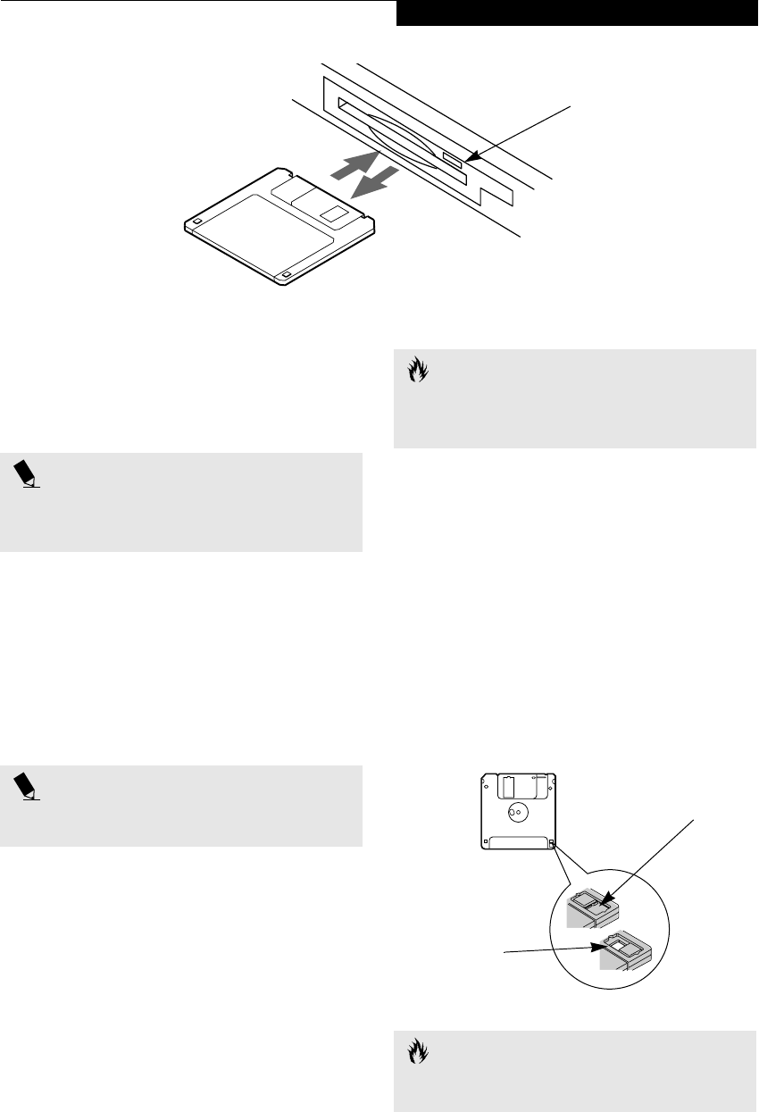
35
User Installable Features
Figure 4-2 Loading/Ejecting a 3.5” Floppy Disk
Floppy Disk Drive
Your LifeBook notebook has a modular floppy disk drive
which can read and write information on removable
1.44MB and 720KB floppy disks.
LOADING A DISK
To load a disk into your disk drive, follow these easy
steps:
1. Orient the disk so that its label is facing upwards
and the shutter side is pointing towards the drive.
(Figure 4-2)
2. Push the disk into the drive until the Eject button
pops out and you hear a click.
EJECTING A DISK
To eject a disk from the disk drive, follow these easy
steps:
1. Check that the Floppy Disk Drive Access indicator
is inactive.
2. Press the Eject button. This will push your disk
partially out of the drive.
3. Remove the disk.
PREPARING A DISK FOR USE
Before you can use a new disk, it needs to be prepared
so your LifeBook notebook knows where to store infor-
mation. This preparation is called formatting or initial-
izing a disk. You will need to format new disks, unless
they are preformatted. (Please refer to your operating
system manual for step-by-step instructions on formatting a
disk)
To prevent accidental erasure of the data stored on a
disk, slide the “write protect” tab until a small hole is
exposed. This sets the disk into a protected state where
nothing can be added or removed. If you want to add or
remove data on a protected disk, slide the “write
protect” tab to close the small hole. (Figure 4-3)
Figure 4-3 Floppy Disk Write Protect
Eject Button
POINT
Your LifeBook notebook is preconfigured to boot from a
floppy drive. Reference the BIOS manual for further
information on changing the default boot drive.
POINT
When there is no disk in the drive, the Eject button is
flush with your notebook.
CAUTION
If you eject the disk while the Floppy Disk Drive Access
indicator is active, there is a risk of damaging the data
on the disk, the disk itself or even the disk drive.
CAUTION
Formatting a floppy disk that already contains data will
erase all of the information on the disk.
Write Protected
Write Enabled
P2120.book Page 35 Friday, September 13, 2002 4:56 PM
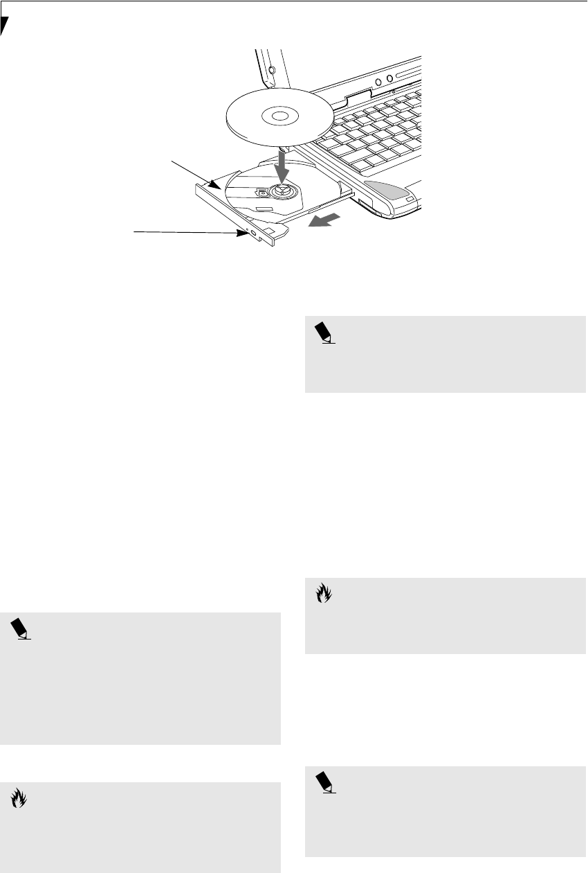
36
LifeBook P2000 Notebook – Section Four
Figure 4-4 DVD/CD-RW Combo Drive
DVD/CD-RW
Combo Drive
Your Fujitsu LifeBook notebook may contain a DVD/
CD-RW combo drive. A DVD player gives you access to
movie, software, and audio DVD/CDs. A CD-RW player
allows you to access software or audio CDs, and to write
data onto recordable CDs.
DVD/CD-RW COMBO DRIVE SOFTWARE
With the DVD/CD-RW drive and DVD/CD-RW drive
software you can play DVD movies on your notebook.
The DVD/CD-RW includes controls which allow you to
take full advantage of the features of a DVD movie, as
well as standard features such as fast forward, fast
reverse, pause, etc. With the CD-RW drive, you can read
audio CDs, and write data onto a recordable CD-R or
CD-RW disc.
LOADING A DVD, CD, CD-R, OR CD-RW
(“MEDIA”)
To load a disc into your DVD/CD-RW drive, follow
these steps (Figure 4-5):
1. Push and release the eject button on the front of the
DVD/CD-RW drive to open the holder tray. The
tray will come out of the notebook a short distance.
2. Gently pull the tray out until a media disc can easily
be placed in the tray.
3. Place the media into the tray, label side up, with the
hole in the center of the disc. Snap the disc onto the
raised circle in the center of the tray.
4. Gently push the holder tray back in until you hear a
click.
Media Holder Tray
Media Eject Button
POINT
■Prior to using your DVD/CD-RW Combo Drive, you
must install the DVD/CD-RW drive software. Refer
to the applicable readme file on the Applications CD-
ROM for instructions on installing you DVD/CD-RW
Combo Drive software.
■You should periodically check the Fujitsu Web site at
www.fujitsupc.com for current updated drivers.
CAUTION
Do not operate your DVD/CD-RW drive unless your
LifeBook notebook is sitting on a flat surface. Using a
drive when the system is not level may damage the
drive or prevent proper operation.
POINT
Prolonged use of the DVD/CD-RW drive, such as
watching a DVD movie, will substantially reduce your
battery life.
CAUTION
There may be a protective sheet in the tray from when it
was shipped; make sure it is removed before operating
the drive, otherwise you may damage the drive.
POINT
If you have disabled the Auto Insert Notification
Function, you will have to start the drive from
your desktop, since your notebook will not automati-
cally recognize that media has been loaded.
P2120.book Page 36 Friday, September 13, 2002 4:56 PM
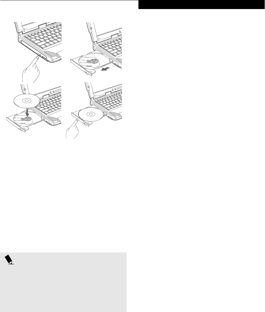
37
User Installable Features
Figure 4-5 Loading/Removing Media
REMOVING MEDIA
1. Push and release the eject button on the front of
the DVD/CD-RW drive. This will stop the drive
and the holder tray will come out of the notebook a
short distance.
2. Gently pull the tray out until the disc can easily be
removed from the tray.
3. Carefully remove the media disc from the holder
tray.
4. Gently push the holder tray back in until you
hear a click.
USING THE DVD/CD-RW DRIVE SOFTWARE
Starting a DVD Movie
1. Insert the DVD movie into the DVD/CD-RW drive of
your notebook. If the CD AutoRun feature activates,
skip Step 2.
2a. Windows 2000 only: From the Start menu, select
Programs, then select InterVideo WINDVD and
click InterVideo WINDVD or double-click on the
InterVideo WINDVD icon on the desktop. This will
launch the DVD movie.
2b. Windows XP only: The first time you insert a movie
into the DVD/CD-RW tray, you will be prompted to
select what you want the system to do when discs are
inserted (e.g., start automatically or wait for a
prompt). Until you make a selection, you will receive
the same prompt whenever you insert a disc.
3. Click OK to close the About DVD Player
Performance dialog box and the movie will begin.
Opening the DVD/CD-RW Drive Control Panel
With most DVD-ROMs, you have the option of altering
how the movie should play and what you wish to view.
You can do this by using the DVD/CD-RW Combo
Drive control panel and the mouse.
1. Right-click on the movie screen to open a
dropdown menu for options.
2. Select View, then Player for all the controls available.
This will open the control panel into the bottom of
the screen.
Using the DVD/CD-RW Drive Control Panel
The DVD/CD-RW Combo Drive software allows you to
watch the movie much like a VCR player. You have the
option to pause, rewind, fast-forward and stop the
movie at any point.
1. To Pause the movie, click the button.
2. To Rewind the movie, click the button to rewind
to a specific portion of the movie, or the button
to return to the opening screen.
3. To Fast-forward the movie, click the button to
forward to a specific portion of the movie, or the
button to jump to the ending credits.
4. To Stop the movie, click the button.
Exiting the DVD/CD-RW Application
1. Click on the U located in the upper right corner of
the title bar. This will open a DVD/CD-RW drive
dialog box.
2. Click Yes to stop and exit the movie, or No to close
the DVD/CD-RW drive dialog box and return to the
movie.
USING DOLBYTM HEADPHONE
The Dolby Headphone utility lets you enjoy multi-
channel sound sources, such as movies, with realistic
surround sound using your conventional stereo head-
phones.
Dolby Headphone is a signal processing system that
enables your stereo headphones to realistically portray
the sound of a five-speaker playback system.
POINT
■Prior to using your DVD/CD-RW Combo Drive, you
must install the DVD/CD-RW drive software. Refer
to the applicable readme file on the Applications CD-
ROM for instructions on installing you DVD/CD-RW
Combo Drive software.
■For details on using your DVD/CD-RW drive, refer to
the Help file that comes with the application.
a. b.
c. d.
P2120.book Page 37 Friday, September 13, 2002 4:56 PM

38
LifeBook P2000 Notebook – Section Four
To use the Dolby Headphone feature, perform the
following steps:
1. Double click the InterVideo WinDVD icon on your
desktop.
2. On the toolbar that appears, click the Properties
button (the fourth button from the left, with the
image of a wrench).
3. On the Properties window, select the Dolby Head-
phone tab.
4. To enable Dolby Headphone, check the Enable
Dolby Headphone box. To change the type of
surround sound, select one of the radio buttons
listed under Room Filter Setting.
5. Click OK. The Dolby Headphone feature will now
be enabled until you disable it by unchecking Enable
Dolby Headphone.
USING THE DVD/CD-RW DRIVE
ON BATTERY POWER
Since a DVD/CD-RW drive consumes a lot of power,
your overall battery life will be shorter when operating
the drive continuously (such as watching a DVD movie)
than during standard operation. Many movies run-times
are longer than your LifeBook notebook can support on a
single battery. If you are watching a DVD movie on
battery power you may need to swap in an additional,
charged battery or attach AC power during the movie to
view it in its entirety.
To Watch a Movie on Battery Power:
1. Have an additional full-charged battery or your
AC adapter ready for use.
2. Start watching your DVD movie.
3. When the low battery warning occurs, immediately
stop the movie and exit the DVD/CD-RW drive.
4. Connect an AC Adapter to your system, or install a
fully charged battery in the Flexible Bay (after
removing any modular devices that may be present
in the bay) prior to removing the main battery.
5. Manually place your notebook into suspend mode
by depressing the Suspend button and replace the
discharged battery with an additional fully-charged
battery.
6. Resume your notebook by pressing the Suspend
button again. This step is not required if you
attached AC power without entering suspend mode.
7. Restart your DVD/CD-RW drive, locate and skip to
the chapter of the movie you were last watching.
8. Continue watching your DVD movie.
AUTO INSERT NOTIFICATION FUNCTION
The Auto Insert Notification function allows your Life-
Book notebook to automatically start a DVD/CD as soon
as it is inserted in the DVD/CD-RW drive and the tray is
closed. Your notebook will begin playing an audio DVD/
CD or will start an application if the DVD/CD includes an
auto run file.
To prevent a CD from playing automatically as soon as it
is inserted, refer to the related help file for your specific
operating system.
POINT
■Media discs which do not have the Dolby Surround
5:1 symbol will not support Dolby Headphone.
■After making changes to the Dolby Headphone
feature and clicking OK, wait at least ten seconds
before making another change in order to allow the
system to stabilize.
POINT
■Prolonged use of the DVD/CD-RW drive, such as
when watching a DVD movie, will substantially
reduce your notebook’s battery life. Many movie
run-times are longer than your system can support
on a single battery. If you are watching a DVD
movie on battery power you may need to swap in
an additional, charged battery or attach AC power
during the movie to view it in its entirety.
■An additional fully-charged battery is highly recom-
mended if you will be watching DVD movies on
battery power. If you don’t have an additional
battery, you may purchase one either on-line at
www.fujitsupc.com or call 1-877-372-3473.
CAUTION
If you do not stop the DVD/CD-RW drive quickly and
the LifeBook notebook attempts to auto-suspend
(critical battery low state) the notebook will shut down
improperly. If this occurs, you will need to install a fresh
power source (either a charged battery or AC Adapter).
POINT
Some shorter DVD movies may not require you to swap
batteries or attach AC power to complete them.
However, it is best to be prepared since actual battery life
while operating the DVD/CD-RW drive cannot be
guaranteed.
P2120.book Page 38 Friday, September 13, 2002 4:56 PM

39
User Installable Features
Figure 4-6 Installing/Removing PC Cards
PC Cards
Your Fujitsu LifeBook notebook supports Type I and II
PC Cards, which can perform a variety of functions.
Some available PC Cards:
■Fax/data modem cards
■Local area network (LAN) cards
■IDE solid-state disk cards
■SCSI cards
■Wireless LAN (802.11b) cards
■Other PC Cards that conform to PCMCIA 2.1 or
CardBus standards
For further information, refer to the instructions
supplied with your PC Card.
INSTALLING PC CARDS
PC Cards are installed in the PC Card slot. To install a
PC Card, follow these easy steps: (Figure 4-6)
1. See your PC Card manual for specific instructions
on the installation of your card. Some PC Cards
may require your notebook to be Off while
installing them.
2. Make sure there is no PC Card currently in the slot.
If there is, see Removing PC Cards.
3. Insert your PC Card into the slot, with the product
label facing up.
4. Push the card into the slot firmly until it is seated
in the opening. You will hear a click and the Eject
button will pop away from your notebook.
REMOVING PC CARDS
To remove a PC Card, follow these easy steps:
1. See your PC Card manual for specific instructions
on removing your card. Some PC Cards may require
your notebook to be in Suspend Mode or Off while
removing them.
2. Push the Eject button in until it is flush with the
notebook. This will push the PC Card slightly out of
the slot allowing you to remove the card.
Eject Button
PC Card Slot
PC Card
WARNINGS
■Installing or removing a PC Card during your Life-
Book notebook’s shutdown or bootup process may
damage the card and/or your notebook.
■Do not insert a PC Card into a slot if there is water or
any other substance on the card as you may perma-
nently damage the card, your LifeBook notebook, or
both.
CAUTION
Windows has a shutdown procedure for PC Cards that
must be followed before removing a card. (Please
review your operating system manual for the correct
procedure).
POINT
If the dialog box states that the device cannot be
removed, you must save all of your open files, close
any open applications and shut down your notebook.
Once your notebook has been shut down, you must
turn Off the power using the power switch.
CAUTION
If the PC Card has an external connector and cable, do
not pull the cable when removing the card.
P2120.book Page 39 Friday, September 13, 2002 4:56 PM
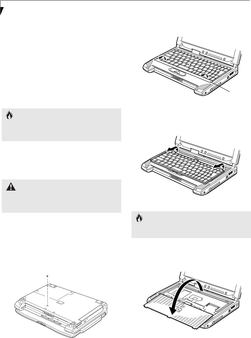
40
LifeBook P2000 Notebook – Section Four
Memory Upgrade
Module
Your Fujitsu LifeBook notebook comes with 256MB of
on-board high speed Synchronous Dynamic RAM
(SDRAM) factory installed. To increase your LifeBook
notebook’s memory capacity, you may install an addi-
tional memory upgrade module. The memory upgrade
must be a dual-in-line (DIMM) SDRAM module. To
ensure 100% compatibility, purchase the SDRAM
module only from the Fujitsu web store at
www.fujitsupc.com.
INSTALLING A MEMORY UPGRADE
MODULE
To install a memory upgrade module follow these steps:
1. Turn off power to your LifeBook notebook, and
remove any power adapter (AC or auto/airline),
battery pack, and modem connection.
2. Place your LifeBook notebook with the bottom
facing up on a clean work surface.
3. Using a Phillips screwdriver, remove the screw from
the hole indicated. (Figure 4-3)
Figure 4-3 Removing screw from bottom
4. Turn the system over and open the top cover all the
way, so that it is lying flat on the work surface.
5. Pry the spacer panel in front of the keyboard away
from the system. (Figure 4-4)
Figure 4-4 Lifting the spacer panel
6. Slide the keyboard forward slightly until it disen-
gages and can be lifted freely. (Figure 4-5)
Figure 4-5 Sliding the keyboard
7. Carefully pivot the front of the keyboard away from
the laptop until it is lying on the display.
(Figure 4-6)
Figure 4-6 Folding the keyboard back
CAUTION
The memory upgrade module can be severely damaged
by electrostatic discharge (ESD). Be sure you are properly
grounded when handling and installing the module.
WARNING
You must turn off power and remove any modem
connection before installing the memory upgrade
module.
CAUTION
Be very careful when pivoting the keyboard below. The
keyboard is connected with fragile flat cables.
Spacer
panel
P2120.book Page 40 Friday, September 13, 2002 4:56 PM
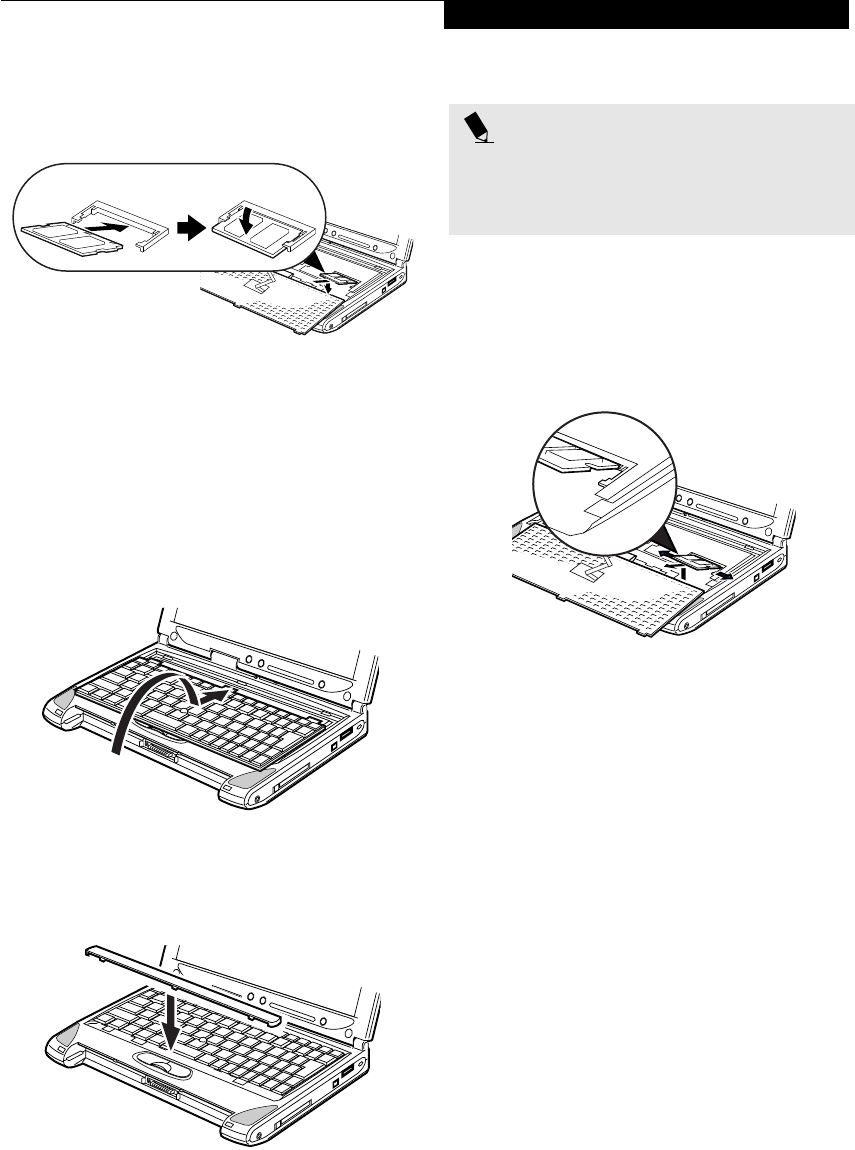
41
User Installable Features
8. Align the connector edge of the memory upgrade
module, chip side up, with the connector slot in the
compartment. (Figure 4-7)
Figure 4-7 Inserting a new memory module
9. Insert the memory upgrade module at a 45o angle
and press it firmly onto the connector.
10. Press the memory upgrade module down into the
compartment until it locks underneath the retaining
clip. You will hear a click when it is properly in place.
(Figure 4-7)
11. Carefully flip the keyboard back into its original
position, and slide it towards the front of the unit
until it is seated. (Figure 4-8)
Figure 4-8 Reinstalling the keyboard
12. Replace the spacer panel you removed in step 4.
(Figure 4-9) Installation of the new memory module
is now complete.
Figure 4-9 Replacing the spacer panel
13. Replace the screw you removed in step 3.
REMOVING A MEMORY UPGRADE MODULE
1. Perform steps 1 through 7 of Installing a Memory
Upgrade Module.
2. Pull the clips sideways away from each side of the
memory upgrade module at the same time.
(Figure 4-10)
Figure 4-10 Removing a memory module
3. While holding the clips out, remove the module
from the slot by lifting it up and pulling towards the
back of your LifeBook notebook.
4. Store the memory upgrade module in a static
guarded sleeve.
5. Replace the keyboard by following steps 10 and 11 of
Installing a Memory Upgrade Module.
CHECKING THE COMPUTER RECOGNITION
OF NEW MEMORY CAPACITY
Once you have changed the system memory capacity
by either adding or removing a memory upgrade
module, be sure to check that your LifeBook notebook
has recognized the change.
You can check the memory capacity by looking at the
main menu of the BIOS setup:
1. Turn on the power to your LifeBook notebook using
the power switch.
2. Allow the system to start booting and press the F2
key once the Fujitsu logo appears on the screen. This
will open the main menu of the BIOS setup with the
current settings displayed. (See BIOS Setup Utility on
page 27 for more information) Use the right arrow
key to select Info in the BIOS Setup menu.
POINT
The memory upgrade module is not something you
routinely remove from your LifeBook notebook. Once it
is installed, you should leave it in place unless you want
to increase system memory capacity.
P2120.book Page 41 Friday, September 13, 2002 4:56 PM
42
LifeBook P2000 Notebook – Section Four
The System Memory and the Extended Memory
capacity, as detected by your LifeBook notebook during
the Power On Self Test (POST), are displayed at the
bottom of the Info menu screen. The chart below shows
you the possible displays that can be shown on the main
menu screen.
* Transmeta CPU uses 16MB of RAM for Code
Morphing Software (CMS). For more information on
CMS, click on the Technology link on the refer to the
Transmeta web site at: www.transmeta.com.
POINT
If the total memory displayed is incorrect, check that
your memory upgrade module is properly installed. (If
the module is properly installed and the capacity is still
not correctly recognized, see the Troubleshooting sec-
tion starting on page 65)
Installed Displayed
On Board
256MB
256MB
Slot 1
0
128MB
Total RAM
Installed
256MB
384MB
System
Memory
640K
640K
Extended
Memory*
240MB
368MB
P2120.book Page 42 Friday, September 13, 2002 4:56 PM

43
User Installable Features
Device Ports
Your Fujitsu LifeBook notebook comes equipped with
multiple ports to which you can connect external devices
including: disk drives, keyboards, modems, printers, etc.
MODEM (RJ-11) TELEPHONE JACK
The modem (RJ-11) telephone jack is used for an
internal modem. To connect the telephone cable follow
these easy steps: (See figure 2-6 on page 8 for location)
1. Align the connector with the port opening.
2. Push the connector into the port until it is seated.
3. Plug the other end of the telephone cable into a
telephone outlet.
The modem sound is deactivated by default, to activate
modem sound follow these easy steps:
1. Right click on the Speaker icon in your system tray.
2. Select Open Volume.
3. Select Option/Properties.
4. Under “Show the following volume controls”, click
on Phone and click OK.
5. Uncheck the Mute box under Phone Balance.
INTERNAL LAN (RJ-45) JACK
The internal LAN (RJ-45) jack is used for an internal
Fast Ethernet (10/100 Base-T/Tx) connection. If your
notebook has been configured with internal LAN
capability you will need to configure your notebook
to work with your particular network. (Please refer to
your network administrator for information on your
network configuration.) To connect the LAN cable follow
these easy steps: (See figure 2-7 on page 9 for location)
1. Align the connector with the port opening.
2. Push the connector into the port until it is seated.
3. Plug the other end of the cable into a LAN outlet.
IEEE 1394 JACK
The IEEE 1394 (also known as “Firewire” or “iLink”)
port allows you to connect devices that are compliant
with IEEE standard 1394. This port is effectively a very
fast communications port. Some digital devices - such as
digital cameras - use IEEE 1394 ports for fast transfer of
digital files and data.
In order to connect an IEEE 1394 device, follow these
steps: (See figure 2-6 on page 8 for location)
1. Align the connector with the port opening.
2. Push the connector into the port until it is seated.
S-VIDEO OUT PORT (TV OUT)
The S-Video port allows you to connect and use directly
any S-Video device, such as a VCR or television. The
S-Video standard provides for a higher quality picture
than NTSC or PAL. In order to connect an S-Video
device, follow these easy steps: (See figure 2-7 on page 9
for port location)
1. Align the connector with the port opening.
2. Push the connector into the port until it is seated.
When S-Video is connected, you can toggle the S-Video
device on and off by pressing the [F11] key while
holding down the [Fn] key.
UNIVERSAL SERIAL BUS PORTS
The Universal Serial Bus 2.0 ports allow you to connect
USB devices such as external game pads, pointing
devices, keyboards and/or speakers. USB 2.0 is much
faster than USB 1.1 (Its 480Mbps transfer rate is 40
times faster than that of USB 1.1). USB 2.0 ports are
backward-compatible to work with USB 1.1 devices.
In order to connect a USB device follow these easy steps:
(See figure 2-7 on page 9 for port location)
1. Align the connector with the port opening.
2. Push the connector into the port until it is seated.
HEADPHONE JACK
The headphone jack allows you to connect headphones
or powered external speakers to your notebook. Your
headphones or speakers must be equipped with a 1/8”
(3.5 mm) stereo mini-plug. In order to connect head-
phones or speakers follow these easy steps: (See figure 2-6
on page 8 for location)
WARNING
The internal modem is not intended for use with Digital
PBX systems. Do not connect the internal modem to a
Digital PBX as it may cause serious damage to the inter-
nal modem or your entire LifeBook notebook. Consult
your PBX manufacturer’s documentation for details.
Some hotels have Digital PBX systems. Be sure to find
out BEFORE you connect your modem.
POINTS
■The internal modem is designed to the ITU-T V.90
standard. Its maximum speed of 53000bps is the
highest allowed by FCC, and its actual connection
rate depends on the line conditions. The maximum
speed is 33600bps at upload.
■The internal modem on all Fujitsu LifeBook notebooks
from Fujitsu are certified for use in the United States
and Canada. The modem may be certified in other
countries.
P2120.book Page 43 Friday, September 13, 2002 4:56 PM

44
LifeBook P2000 Notebook – Section Four
1. Align the connector with the port opening.
2. Push the connector into the port until it is seated.
MICROPHONE JACK
The microphone jack allows you to connect an external
mono microphone. Your microphone must be equipped
with a 1/8”(3.5 mm) mono mini-plug in order to fit into
the microphone jack of your notebook. In order to
connect a microphone follow these easy steps: (See
figure on page 8 for location)
1. Align the connector with the port opening.
2. Push the connector into the port until it is seated.
MINI-VGA PORT
The mini-VGA port allows you to connect an external
monitor. In order to connect an external monitor follow
these easy steps:
1. Take the mini-VGA cable out of the accessory
package that came with your system.
1. Align the connector with the port opening.
2. Push the connector into the port until it is seated.
(Figure 4-11)
Figure 4-11 Installing the Mini-VGA Cable
OPTICAL DIGITAL
AUDIO-OUT CONNECTOR
The optical digital audio-out connector allows you to
download digital audio to MiniDisc recorders. It uses
SPDIF (Sony Philips Digital Interface) format. Use the
following setting when using the digital audio-out
connector. (See figure 2-6 on page 8 for location)
1. Connect the MiniDisc recorder or external speaker
to the Optical Digital Audio-Out Connector.
2. Insert the disk you want to play in the DVD/CD-RW
tray.
3. Click on Start --> Programs --> InterVideo
WinDVD. (In Windows XP systems, you can go
directly from Start to InterVideo WinDVD.)
4. When the WinDVD interface appears, click on the
Properties icon in the bottom of the display (it looks
like a wrench).
5. Click on the Audio tab and select Enable S/PDIF
output.
6. Click [Apply].
POINT
If you plug headphones into the headphone jack, the
built-in stereo speakers will be disabled.
POINT
Pressing the [Fn] + [F10] keys allows you to change
your selection of where to send your display video. Each
time you press the key combination, you will
step to the next choice, starting with the built-in display
panel only, moving to the external monitor only, finally
moving to both the built-in display panel and an
external monitor.
POINTS
■Before using the SPDIF function, make sure that
WinDVD software is installed on your system.
■Certain older CDs and DVDs will not work in conjunc-
tion with the SPDIF connector.
WARNING
Do not look into the connector. There may be a beam
coming out from the SPDIF connector, so do not look
into the connector when inserting the cable, or you can
damage your eyesight.
POINTS
■The frequency of the digital sound output from the
SPDIF output connector is fixed to 48KHz. If a
sampling rate convertor is not installed in your
connecting digital electronic device (e.g., MD player),
recording is not possible. Please see the user manuals
for the electronic devices for further details.
■The sound recorded through connecting a digital
electronic device (e.g., MD player) to the SPDIF
output connector cannot be used as digital output.
All output data from the SPDIF output connector has
copyright protection information included.
■Please be careful, as there are several types of cables
for connecting a digital electronic device (e.g., MD
player) to the digital audio-out connector, depending
on the connector type. The connector on your com-
puter is an Optical Mini Plug (3.5mm diameter mini
plug)
P2120.book Page 44 Friday, September 13, 2002 4:56 PM

45
5
Using the Integrated
Wireless LAN*
*Optional device
P2120.book Page 45 Friday, September 13, 2002 4:56 PM

46
LifeBook P2000 Notebook – Section FIve
P2120.book Page 46 Friday, September 13, 2002 4:56 PM

47
Using the WIreless LAN
FCC REGULATORY INFORMATION
Please note the following regulatory information related
to the optional wireless LAN device.
Regulatory Notes and Statements
Wireless LAN, Health and Authorization for use
Radio frequency electromagnetic energy is emitted from
Wireless LAN devices. The energy levels of these emis-
sions, however, are far much less than the electromag-
netic energy emissions from wireless devices such as
mobile phones. Wireless LAN devices are safe for use by
consumers because they operate within the guidelines
found in radio frequency safety standards and recom-
mendations. The use of Wireless LAN devices may be
restricted in some situations or environments, such as:
• On board an airplane, or
• In an explosive environment, or
• In situations where the interference risk to other
devices or services is perceived or identified as
harmful.
In cases in which the policy regarding use of Wireless
LAN devices in specific environments is not clear (e.g.,
airports, hospitals, chemical/oil/gas industrial plants,
private buildings), obtain authorization to use these
devices prior to operating the equipment.
Regulatory Information/Disclaimers
Installation and use of this Wireless LAN device must be
in strict accordance with the instructions included in the
user documentation provided with the product. Any
changes or modifications made to this device that are
not expressly approved by the manufacturer may void
the user’s authority to operate the equipment. The
Manufacturer is not responsible for any radio or televi-
sion interference caused by unauthorized modification
of this device, or the substitution or attachment of
connecting cables and equipment other than those spec-
ified by the manufacturer. It is the responsibility of the
user to correct any interference caused by such unautho-
rized modification, substitution or attachment. The
Manufacturer and its authorized resellers or distributors
will assume no liability for any damage or violation of
government regulations arising from failure to comply
with these guidelines.
Federal Communications Commission statement
This device complies with Part 15 of FCC Rules.
Operation is subject to the following two conditions:
(1) This device may not cause interference, and, (2) This
device must accept any interference, including interfer-
ence that may cause undesired operation of this device.
FCC Interference Statement
This equipment has been tested and found to comply
with the limits for a Class B digital device, pursuant to
Part 15 of the FCC Rules. These limits are designed to
provide reasonable protection against harmful interfer-
ence in a residential installation. This equipment gener-
ates, uses, and can radiate radio frequency energy. If not
installed and used in accordance with the instructions, it
may cause harmful interference to radio communica-
tions. However, there is no guarantee that interference
will not occur in a particular installation.
If this equipment does cause harmful interference to
radio or television reception, which can be determined
by turning the equipment off and on, the user is encour-
aged to try and correct the interference by one or more
of the following measures:
1. Reorient or relocate the receiving antenna.
2. Increase the distance between the equipment and
the receiver.
3. Connect the equipment to an outlet on a circuit
different from the one the receiver is connected to.
4. Consult the dealer or an experienced radio/TV
technician for help.
FCC Radio Frequency Exposure statement
This Wireless LAN radio device has been evaluated
under FCC Bulletin OET 65C and found compliant with
the requirements as set forth in CFR 47 Sections 2.1091,
2.1093, and 15.247 (b) (4) addressing RF Exposure from
radio frequency devices. The radiated output power of
this Wireless LAN device is far below the FCC radio
frequency exposure limits. Nevertheless, this device shall
be used in such a manner that the potential for human
contact during normal operation is minimized. When
using this device, a certain separation distance between
antenna and nearby persons must be maintained to
ensure RF exposure compliance. In order to comply with
RF exposure limits established in the ANSI C95.1 stan-
dards, the distance between the antennas and the user
should not be less than 20 cm (8 inches).
Export restrictions
This product or software contains encryption code
which may not be exported or transferred from the US
or Canada without an approved US Department of
Commerce export license. This device complies with
Part 15 of FCC Rules., as well as ICES 003 B / NMB 003
B. Operation is subject to the following two conditions:
(1) this device may not cause harmful interference, and
(2) this device must accept any interference received,
including interference that may cause undesirable oper-
ation. Modifications not expressly authorized by Fujitsu
PC Corporation may invalidate the user's right to
operate this equipment.
P2120.book Page 47 Friday, September 13, 2002 4:56 PM

48
LifeBook P2000 Notebook – Section Five
BEFORE USING THIS DEVICE
The integrated Wireless LAN is an optional device avail-
able for the LifeBook P2000 Series laptops. This chapter
describes the basic operating procedures for the Wireless
LAN (referred to as the “device” in this manual) and
how to set up a wireless LAN network. Before using this
device, read this manual carefully to ensure correct oper-
ation of the device. Keep this manual in a safe place for
reference while using the device.
Characteristics of the Device
This device consists of a wireless LAN card that is
attached to the computer via a mini-PCI slot.
The main characteristics are as follows:
■It uses the power saving communications system in
the 2.4 GHz band, and does not require any license for
radio communication.
■It uses Direct Sequence Spread Spectrum (DS-SS),
which is resistant to noise.
■This device complies with Wi-Fi, and is able to com-
municate at the maximum transfer rate of 11 Mbps.
■The maximum communication range is approxi-
mately 80 feet (25 meters) inside a building. The
range may be shorter depending upon the installation
factors, such as walls and columns.
■Unauthorized access can be prevented with the use of
SSID and encryption key.
Wireless LAN Modes Using this Device
AdHoc Mode
The “AdHoc Mode” refers to the network connecting
two computers using wireless LAN cards. This connec-
tion is called an “AdHoc network.”
Using an AdHoc network, you can obtain a network
connection easily and at a low cost.
In the AdHoc mode, you can use the function supported
by Microsoft Network, such as File and Print Sharing to
exchange files and share a printer or other peripheral
devices.
To use the AdHoc Mode, you must set the same SSID
and the same encryption key for all the computers that
are connected. All connected computers can communi-
cate with each other within the communication range.
Infrastructure Mode
If a number of computers are connected simultaneously
in the AdHoc mode, the transfer rate may be reduced,
communications may become unstable, or the network
connection could fail. This is because all wireless LAN
cards are using the same radio frequency in the network.
To improve this situation, you can use a wireless LAN
access point, which is sold separately. The wireless LAN
network is in the “Infrastructure mode” when it uses an
access point, and such a connection is called the “Infra-
structure Network.”
By using an access point, you can set and use a different
communication channel for each network group. Each
channel is given a different radio frequency, and it
eliminates the collision of communications and provides
a more stable communications environment. Infrastruc-
ture mode is most suitable when you are configuring
multiple wireless LAN networks on the same floor.
To connect a wireless LAN network to a wired LAN, you
need an access point.
How to Handle This Device
The Integrated Wireless LAN device is already installed
in LifeBook computers which were purchased with the
wireless LAN option. Under normal circumstances, it
should not be necessary for you to remove or re-install
it. The LAN has been configured to support the oper-
ating system with which your system shipped.
P2120.book Page 48 Friday, September 13, 2002 4:56 PM
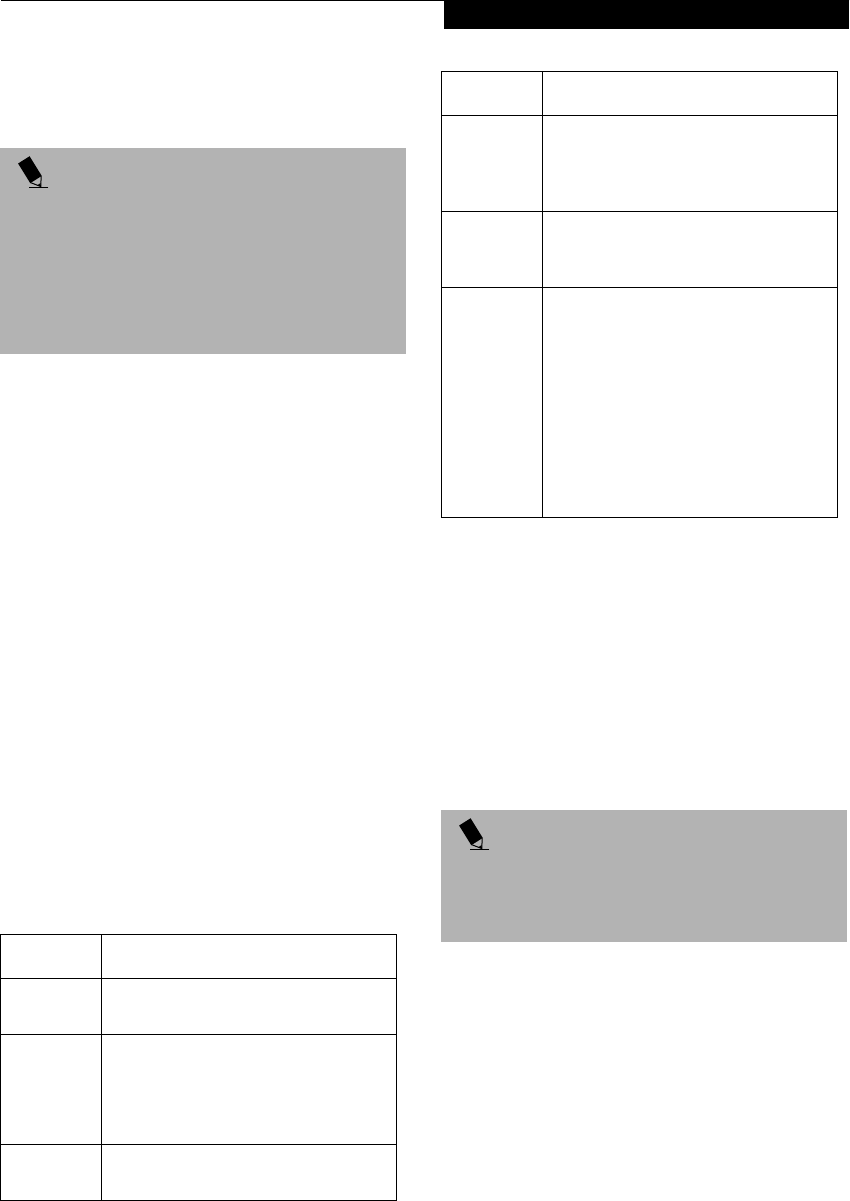
49
Using the WIreless LAN
CONNECTING WINDOWS 2000 SYSTEMS
This chapter describes how to set the wireless LAN
connection for computers running Windows 2000.
Workflow
The proper setup of the wireless LAN requires several
steps which must be performed in the proper order.
Following is a general outline of the steps that must be
performed. Each step is detailed later in this procedure.
1. Setting parameters
■Setting the profile
■Setting the encryption
2. Network settings
■Setting the protocol and checking the network
■Setting file and printer sharing
■Checking the connection
Setting Parameters
1. Click [Start]-> [Settings] -> [Control Panel].
2. Double-click the [PRISM Settings] icon. The
[PRISM Wireless Settings] appears.
3. Set the profile as specified in Table 3. Ask your
network administrators to check the setting.
4. When you finish your entry, click [Apply].
Table 3: Profile Parameters
5. Click the [Encryption] tab.
6. Set the encryption items in accordance with Table 4.
■AdHoc Network: Specify the same value for all the
computers for which the encryption key is used for
connection.
■Infrastructure Network: Specify the identical
encryption keys to the encryption keys set for the
access point. For instructions on how to check the
encryption keys set for the access point, refer to the
access point manual.
POINT
If you purchased a LifeBook with the optional wireless
LAN, the integrated wireless LAN device and drivers
have already been installed. This procedure outlines the
steps for setting the device parameters.
Updated drivers and/or utilities may become available
after this manual is printed; see any addenda or fliers
that may be included in the system packaging.
Item Description
Profile Enter the system file name in which the
parameter information is to be saved.
Mode Ad Hoc Network: Click the down arrow
and select “802.11 AdHoc”.
Infrastructure Network: Click the down
arrow and select “Infrastructure”.
SSID Enter the network name to which you
want to connect
Transmit
Rate
Obtain the information from your
network administrator. If you do not
have a network administrator, select
“Fully Automatic”.
Power
Save
Enabled
Not supported.
AdHoc
Channel
AdHoc Network: Select the same
channel, 1-11, for all connected
computers. If there is more than one
wireless LAN nearby (such as on the
same floor), we recommend that the
channels for each LAN be 5 numbers
apart (e.g., if there are two other LANs
nearby, the channels used should be 1,
6, and 11).
Infrastructure Network: Not an option.
POINT
Make sure that you specify the encryption keys. If you
do not specify the keys, any computer with a wireless
LAN card can be connected. This presents a risk that
your data may be stolen or destroyed.
Item Description
P2120.book Page 49 Friday, September 13, 2002 4:56 PM
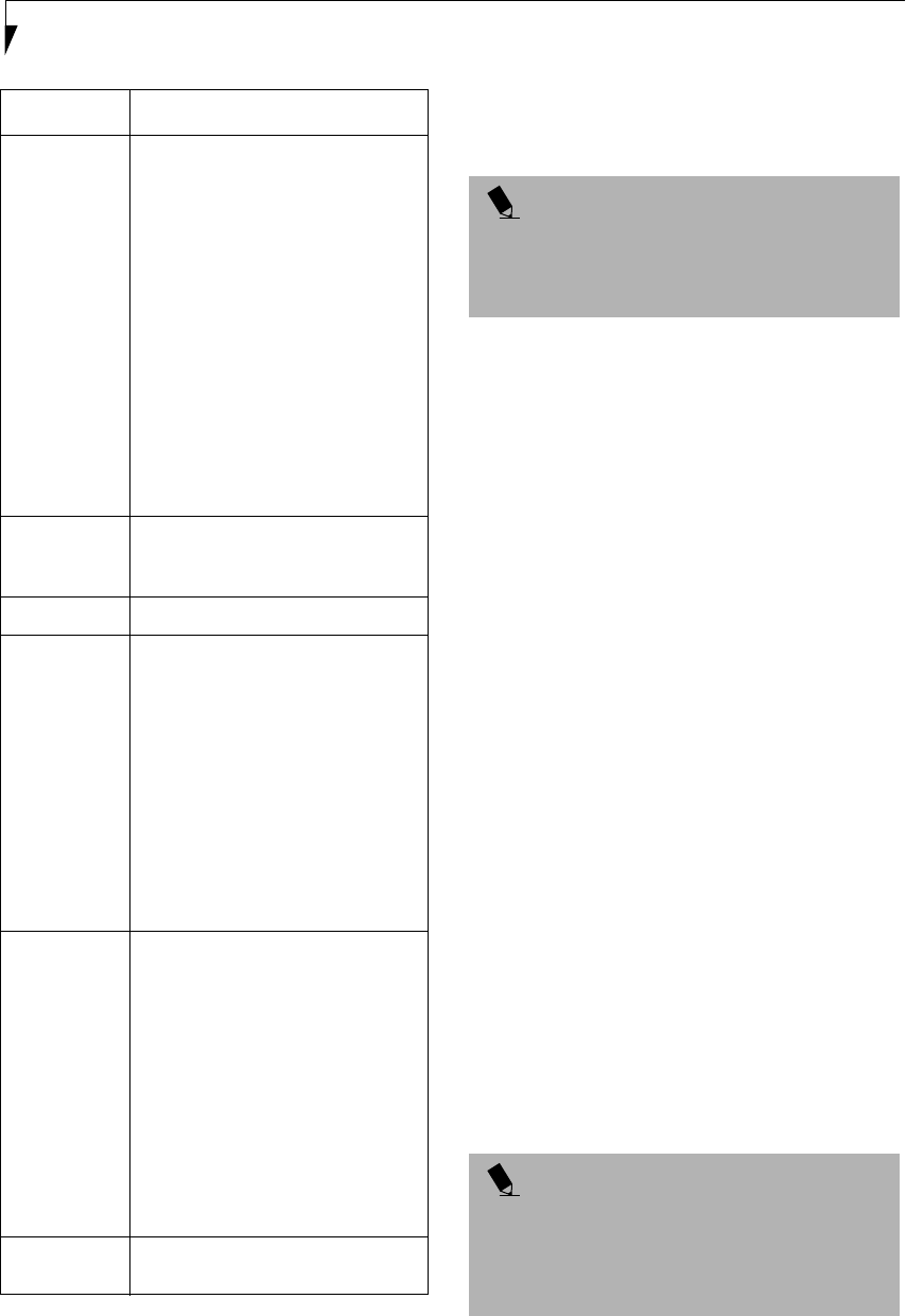
50
LifeBook P2000 Notebook – Section Five
Table 4: Encryption Key Setup
7. When you finish your entry, click [Apply].
8. Click [OK]. [PRISM Wireless Settings] closes.
You have completed the parameter settings.
* 40 bit and 104 bit encryption is the wireless LAN
equivalent of 64 bit and 128 bit encryption, as set by
Microsoft and wireless LAN manufacturers. This is the
same encryption rate that is used by the Windows XP
operating system, and was selected in order to align it
closer to the wireless LAN standard. For consistency, the
Windows 2000 utilities reflect the same modes.
Outside of wireless LAN environments, encryption is
generally set at either 64 bit or 128 bit. However, the
wireless LAN standard requires that 24 bits be reserved
for fixed data. As a result, the user can only use 40 bits
(64 minus 24) or 104 bits (128 minus 24) for encryption.
This requirement also fixes the number of characters
used for 128 bit encryption to 13 which is calculated as
(13 x 8 bits = 104).
NETWORK CONNECTION: WINDOWS 2000
The section describes how to set the network connection
for a computer with Windows 2000.
Network Settings
In this section, you set “TCP/IP Settings,” and complete
“Checking Computer Name and Workgroup,” required
for the network connection.
TCP/IP Settings
1. Click [Start] -> [Settings] -> [Control Panel].
2. Double-click the [Network and Dial-up
Connections] icon. The [Network and Dial-up
Connections] window appears.
3. Right click the [Local Area Connection], then click
[Properties] from the menu that appears. The [Local
Area Connection Properties] window appears.
Item Description
Encryption
(WEP)
Click the down arrow and select an
encryption option.
■Disable: Disables the encryption. In
this case, “Create keys with
Passphrase” and subsequent items
are greyed out, and you cannot
enter anything.
■40 bit*: The encryption is set.
Select either “Create keys with
Passphrase”, “Create keys manu-
ally”, or “ASCII Input”, and enter
the encryption keys.
■104 bit*: The encryption is set.
Select either “Create keys with
Passphrase”, “Create keys manu-
ally”, or “ASCII Input”, and enter
the encryption keys.
Create Keys
with
Passphrase
Not supported.
Passphrase Not supported.
Create Keys
Manually
(Hexadecimal
Input)
Select this to use hexadecimal
character codes to set the encryption
keys (Keys 1 - 4).
Enter a 10-digit value when you have
selected [40 bit]* for the encryption.
Enter a 26-digit value when you have
selected [104 bit]* for encryption.
Select if the network contains a card
that is set with the encryption key
using the character code. Specify the
encryption keys with the same value
used for other wireless LAN cards
that are already set.
ASCII Input Select to use the ASCII codes to set
encryption keys (Keys 1 - 4). Select
this if network does not contain other
wireless LAN cards that are set with
encryption key using character codes.
Enter a 5-digit value when you have
selected [40 bit]* for the encryption.
Enter a 13-digit value when you have
selected [104 bit]* for encryption.
You can use the following characters:
0 - 9, A - Z, a - z, _ (underscore).
For example, to set “ABC12” for the
encryption key, enter “ABC12.”
Default Key Click the down arrow, and select a
key from Keys 1 - 4.
POINT
When using ADSL (PPPoE) with the infrastructure
network to connect to the Internet, you must change
the computer’s MTU size set. To change MTU size, refer
to the manual that comes with the access point.
POINT
More than one network adapter is installed in your
system if more than one [Local Area Connection] entry
is displayed. In this case, select the [Local Area
Connection] entry with [Intersil PRISM Wireless LAN
PCI Card] displayed under [Device Name].
P2120.book Page 50 Friday, September 13, 2002 4:56 PM

51
Using the WIreless LAN
4. Perform the following steps.
■Click [Internet Protocol (TCP/IP)].
■Click [Properties]. The [Internet Protocol (TCP/IP)
Properties] window appears.
5. Set an IP address as indicated in Table 5. Ask your
network administrator to check the setting.
Table 5: Setting an IP Address
6. Click [OK]. The [Local Area Connection Properties]
window appears again.
7. Click [OK]. When a message appears prompting you
to restart the computer, click [Yes].
Checking the full computer name and workgroup
1. Click [Start] -> [Settings] -> [Control Panel].
2. Double-click the [System] icon. [System Properties]
appears.
3. Click the [Network Identification] tab.
4. Check [Full computer name] and [Workgroup]. Ask
your network administrator and check the setting.
Table 6: Checking computer name and workgroup
5. Click [OK]. When a message appears prompting you
to restart the computer, click [Yes].
Sharing
In this section, you set sharing of the drive, folder, and
printer.
You only need to set this when you are sharing files or a
printer with other computers on the network.
When you share a drive, folder, or printer, you can use
them from any computer on the network.
Setting [File and Printer Sharing for Microsoft
Networks]
1. Click [Start] -> [Settings] -> [Control Panel].
2. Double-click the [Network and Dial-up
Connections] icon. The [Network and Dial-up
Connections] windows appears.
3. Right click the [Local Area Connection], then click
[Properties] from the menu that appears. [Local
Area Connection Properties] appears.
4. If [File and Printer Sharing for Microsoft Networks]
is displayed in the list, make sure that it is checked. If
it is not checked, check it and click [OK]. You do not
have to perform the following steps. Go to the next
section, entitled “Sharing Files.”
If [File and Printer Sharing for Microsoft Networks]
is not found in the list, click [Install], and perform
Step 5 and subsequent steps. When you click
Item Description
For AdHoc
Network
Set the IP address and subnet mask:
Click [Use the following IP address],
and enter a value for [IP address] and
[Subnet mask].
Refer to “Setting IP Addresses” on
page 60 to set an IP address and
subnet mask.
For
Infrastructure
Network
Select [Obtain an IP address
automatically]:
For the DNS server, select [Obtain
DNS server address automatically].
For the IP address, DNS server, and
default gateway, follow the network
administrator's instructions, if any.
Item Description
Full
Computer
Name
A name to identify the computer on
the network. You can specify any
name to each computer.
For easier identification, use the model
name or user name.
Workgroup A name for the network group:
■AdHoc Network:
Specify the same name to all com-
puters within the same network.
■Infrastructure Network: Specify a
workgroup name to connect to.
To change the setting, click
[Properties], and follow the instruc-
tions on the screen. [System Proper-
ties] appears again.
POINT
More than one network adapter is installed in your
system if more than one [Local Area Connection] entry
is displayed. In this case, select the [Local Area Connec-
tion] entry with [Intersil PRISM Wireless LAN PCI Card]
displayed under [Device Name].
Item Description
P2120.book Page 51 Friday, September 13, 2002 4:56 PM

52
LifeBook P2000 Notebook – Section Five
[Install], the [Select Network Component Type]
window appears.
5. Perform the following steps.
■Click [Service].
■Click [Add]. The [Select Network Service] window
appears.
6. Perform the following steps.
■Click [File and Printer Sharing for Microsoft
Networks].
■Click [OK]. You will go back to [Local Area Connec-
tion Properties], and [File and Printer Sharing for
Microsoft Networks] is added to the list.
7. Click [OK].
Sharing Files
The following example shows how to set sharing the
“Work” folder on the c: drive.
1. On the desktop, double-click [My Computer]->
C: drive.
2. Right-click the “Work” folder, then click [Sharing]
from the menu. The [Work Properties] window
appears.
3. Click [Share this folder] and set necessary items, as
indicated in the following table.
Table 7: Sharing files
4. Click [OK]. The folder is set shared, and the “Work”
folder icon changes.
Printer Sharing
1. Click [Start] -> [Settings] -> [Printers]. The Printers
window appears, showing the printers that are
connected.
2. Right click the printer that you want to share, then
click [Sharing] from the menu that appears.
3. Click [Sharing], and select necessary items.
Table 8: Printer Sharing
4. Click [OK]. The printer sharing is set, and the icon
changes.
Checking the Connection
After the network setting is completed, access the shared
drive on another computer to check the connectivity of
the wireless LAN network.
Accessing Another Computer
1. Double-click the [My Network Places] icon on the
desktop. [My Network Places] appears.
2. Double-click [Computers near me]. The computers
that are connected to the network are displayed.
3. Double-click the computer that you want to access.
The drive that you set with “Sharing” are displayed.
4. Double-click the drive that you want to access. The
drive is displayed showing its contents and made
available to you. If you have any questions or prob-
lems, refer to “Troubleshooting Table” on page 57.
Checking the Connectivity
1. Click [Start] -> [Settings] -> [Control Panel].
2. Double-click the [PRISM Settings] icon. [PRISM
Wireless Settings] appears.
3. Check the connectivity on the [Link] tab. The
current condition of connection is displayed.
POINT
If you have changed the setting, [Close] is shown
instead. Click [Close].
Item Description
Share name You can specify a share name for the
drive or folder that you want to share.
Comment You can enter the description for the
drive or folder that you want to share.
User limit Specifies the limit for the number of
sharing users.
Permissions Specifies the folder access privileges.
Caching Specifies the caching for the folder.
Item Description
Not Shared Disables printer sharing.
Shared As Enables printer sharing.
Share Name Specifies a share name of the
printer to be shared.
Comment Enter the description of the printer
to be shared.
Passwords If you specify a password, you
need to enter it when using the
printer.
P2120.book Page 52 Friday, September 13, 2002 4:56 PM

53
Using the WIreless LAN
Table 9: Checking connectivity
CONNECTING WINDOWS XP SYSTEMS
This chapter describes how to set up the wireless LAN
connection for computers that are running Windows XP.
Workflow
The proper setup of the wireless LAN connection
requires that several steps be performed in the proper
order. Following is a general outline of the steps to be
performed. Each step is detailed later in this procedure.
1. Setting parameters
■Setting the profile
■Setting the encryption
2. Network settings
■Setting the protocol and checking the network
■Setting file and printer sharing
■Checking the connection
Setting Parameters
1. Click [Start] -> [Control Panel].
2. Click [Network and Internet connection].
3. Click [Network connection]. A list of networks that
are currently installed is displayed.
4. Right click [Intersil PRISM Wireless LAN PCI Card]
in the list, and click [Properties] from the menu that
is displayed. [Wireless Network Connection 2 Prop-
erties] appears.
5. Click the [Wireless Networks] tab. The [Wireless
Networks] tab appears.
6. Perform the following steps.
■Make sure that [Use Windows to configure my wire-
less network settings] is checked.
■Click [Add] under [Preferred networks]. [Wireless
Network Properties] appears.
7. Set parameters.
■For the AdHoc network, specify the same value to all
the computers, for which the encryption key is used
for connection.
■For the infrastructure network, specify the encryp-
tion key (network key) with the same value to the
encryption key of the access point. For how to check
the encryption keys set for the access point, refer to
the manual supplied with the access point.
Item Description
State Shows the current condition of
connection.
The MAC address of the other
computer to which you are
connected is displayed when the
connection is successful. If you are
connected to more than one
computer, the computer that has
the best connectivity is displayed.
Current Channel Shows the current channel used
for the connection.
Current Tx Rate Shows the current transfer rate in
Mbits/sec.
[Radio Off]/
[Radio On]
Click [Radio Off] to disconnect.
Click [Radio On] to connect to the
network.
[Rescan] button Click this button to search for
others to connect to.
Throughput
(Bytes/sec)
Shows the actual transfer rate of
the data transfer for send (Tx) and
receive (Rx).
Link Quality Shows either [Excellent], [Good],
[Fair], [Poor], or [Not Connected],
depending on the link quality.
Not shown for AdHoc connection.
Signal Strength Shows either [Excellent], [Good],
[Fair], [Poor], or [Not Connected],
depending on the signal strength.
Not shown for AdHoc connection.
POINT
If you purchased a LifeBook with the optional wireless
LAN, the integrated wireless LAN device and drivers
have already been installed. This procedure outlines the
steps for setting the device parameters.
Updated drivers and/or utilities may become available
after this manual is printed; see any addenda or fliers
that may be included in the system packaging.
POINT
Be sure to specify the encryption keys. If you do not
specify the keys, any computer with a wireless LAN card
can be connected. This presents a risk that other users
may steal or destroy your data.
P2120.book Page 53 Friday, September 13, 2002 4:56 PM
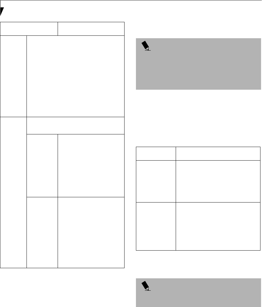
54
LifeBook P2000 Notebook – Section Five
Table 10: Setting parameters
8. When you finish your entry, click [OK]. [Wireless
Network Connection 2 Properties] appears again.
9. Make sure the network name you specified for the
SSID in Step 7 is added under [Preferred networks].
Network Connection
The section describes how to set the network connection
for a computer running Windows XP.
Network Settings
In this section, you set “TCP/IP Settings,” and complete
“Checking Computer Name and Workgroup” required
for the network connection.
TCP/IP Settings
1. On [Wireless Network Connection Properties], click
[General].
2. Perform the following steps.
■Click [Internet Protocol (TCP/IP)].
■Click [Properties]. [Internet Protocol (TCP/IP)
Properties] appears.
3. Set an IP address. Ask your network administrator
and check the setting.
Table 11: Setting an IP address
5. Click [OK].
6. Close [Network Connection].
Checking the Full Computer Name and Workgroup
1. Click [Start] -> [Control Panel]. Make sure the
Classic View is selected.
2. Double-click the [System] icon. [System Properties]
appears.
3. Click the [Computer Name] tab.
Item Description
Network
Name
SSID
Enter the network name to which you
want to connect. This is a required item.
For the network name, ask your LAN
administrator.
AdHoc network: Set the same name for all
of the computers that are to be connected.
Infrastructure network: Specify the same
name as that specified on the access point
that is to be connected. For access point
instructions, refer to the manual that
comes with the access point.
Key
Format
Click the down arrow and select the input
for the Network key.
ASCII
characters
Select this when using
ASCII characters for the
Network Key. Characters
that can be used follow:
0-9, A-Z, a-z, and
_ (underscore)
Example: To set the key to
“ABC12”, input “ABC12”.
Hexa-
decimal
characters
Select this when using
hexadecimal characters for
the Network Key.
Use this if there is a wireless
LAN card in the network
that has the Network Key
set to a character code. In
’Network Key’, input the
same value as the other
wireless LAN card.
POINT
If [Wireless Network Connection 2 Properties] is not
displayed, click [Start] -> [Settings] -> [Control Panel],
and double-click the [Network Connection] icon.
Right click the [Wireless Network Connection], and
then click [Properties] from the menu that appears.
Item Description
AdHoc
Network
Set the IP address and subnet mask.
Click [Use the following IP address].
Enter a value for [IP address] and
[Subnet mask]. See “Setting IP
Addresses” on page 60 to set IP
address and subnet mask.
For
Infrastructure
Network
Select [Obtain an IP address
automatically]. For the DNS server,
select [Obtain DNS server address
automatically]. For the IP address,
DNS server, and default gateway,
follow the network administrator's
instructions, if any.
POINT
If you have changed the setting, [Close] is shown
instead. Click [Close].
P2120.book Page 54 Friday, September 13, 2002 4:56 PM

55
Using the WIreless LAN
4. Check [Full computer name] and [Workgroup]. Ask
your network administrator and check the setting.
Table 12: Setting computer name and workgroup
To change the setting, click [Change], and follow the
instructions on the screen. [System Properties] appears
again.
5. Click [OK]. When a message appears prompting you
to restart the computer, click [Yes].
Sharing
In this section, you set sharing of the drive, folder, and
printer.
You need to set this only when you are sharing files or a
printer with other computers on the network.
When you share a drive, folder, or printer, you can use
these from any computer on the network.
Setting [File and Printer Sharing for Microsoft
Networks]
1. Click [Start] -> [Control Panel]. Make sure the
Classic View is selected.
2. Double-click the [Network Connection] icon.
3. Right click the [Wireless Network Connection], and
then click [Properties] from the menu that appears.
[Wireless Network Connection Properties] appears.
4. If [File and Printer Sharing for Microsoft Networks]
is displayed in the list:
Make sure that it is checked. If it is not checked,
check it, and click [OK]. You do not have to perform
the following steps. Go to the next section, “Sharing
Files.”
If [File and Printer Sharing for Microsoft Networks]
is not found in the list, click [Install], and perform
Step 5 and the subsequent steps. When you click
[Install], [Select Network Component Type]
appears.
5. Perform the following steps.
■Click [Service].
■Click [Add]. [Select Network Service] appears.
6. Perform the following steps.
■Click [File and Printer Sharing for Microsoft
Networks].
■Click [OK]. You will go back to [Wireless Network
Connection 2 Properties], and [File and Printer
Sharing for Microsoft Networks] is added to the list.
7. Click [Close].
Sharing Files
The following example shows how to set sharing the
“Work” folder on the c: drive.
1. Click [Start] -> [My Computer].
2. Double-click the [Local Disk (c:)] icon.
3. Right click the “Work” folder, and then click
[Sharing and Security] from the menu that appears.
[Work Properties] appears.
4. Click [If you understand the security risks but want
to share files without running the wizard, click
here].
In the [Work Properties] window, the description under
[Network Sharing and security] changes.
5. Check [Share this folder on the network].
Uncheck [Allow network users to change my files], if
the shared folder is for read only.
6. Click [OK]. The folder is set shared, and the “Work”
folder icon changes.
Printer Sharing
1. Press [Start]->[Control Panel] (or [Settings], if
viewing in Classic mode)-> [Printers and Faxes].
The Printers and Faxes display will appear and the
connected printers will be displayed.
2. Right-click the printer to be shared, and click
[Sharing] from the menu that appears. The proper-
ties of the printer to be shared will be displayed. Set
printer sharing.
On the display, the printer sharing setting is recom-
mended by the Network Setup Wizard, but for the wire-
less LAN network, security is maintained by network
name (SSID) or network key. The following steps allow
Item Description
Computer
Name
A name to identify the computer on
the network. You can specify any
name to each computer. Use up to 15
single-byte characters. For easier
identification, use the model name or
user name.
Workgroup A name of the network group. Use up
to 15 single-byte characters.
AdHoc Network: Specify the same
name to all computers within the
same network.
Infrastructure Network:
Specify workgroup name to connect
to.
POINT
If you have already clicked [If you understand the
security risks but want to share files without running the
wizard, click here], this window does not appear.
P2120.book Page 55 Friday, September 13, 2002 4:56 PM

56
LifeBook P2000 Notebook – Section Five
you to set up printer sharing without using the Network
Setup Wizard.
3. Click 'If you understand the security risks but want
to share printers without running the wizard, click
here. 'Enable Printer Sharing' will be displayed.
4. Select 'Just enable printer sharing'.
5. Click 'OK'. The printer properties will be indicated.
6. Select 'Share this printer'.
7. Enter the sharing printer name in 'Share name'.
8. Click OK. The printer will be shared, and the printer
icon will become a sharing icon.
Checking the Connection
After the network setting is completed, access the shared
drive on another computer to check the connectivity of
the wireless LAN network.
Accessing Another Computer
1. Click [Start] -> [My Computer].
2. From the left menu in [Other Places], click [My
Network Places].
3. From the left menu in [Network Tasks], click [View
workgroup computers]. The workgroup in which
you are participating will appear.
4. Double click the computer to which you want to
connect. The drive that you set in [Computer
Sharing] appears.
5. Double click the drive to which you want to connect.
The contents of the drive will appear, and is available
for use.
If you have a question or problem, refer to “Trouble-
shooting Table” on page 57.
Checking the Connectivity
1. Click [Start] -> [Control Panel].
2. Double-click the [PRISM Settings] icon. [PRISM
Wireless Setting] appears.
3. Check the connectivity on the [Link] tab. The
current condition of connection is displayed
Table 13: Checking connectivity
Item Description
State Shows the current condition of
connection.
The MAC address of the other
computer that you are connected to is
displayed, when the connection is
successfully made. If you are
connected to more than one
computer, the computer that has the
best connectivity is displayed.
Current
Channel
Shows the current channel used for
the connection.
Current Tx
Rate
Shows the current transfer rate in
Mbits/sec.
Radio Off/
Radio On
Click [Radio OFF] to disconnect.
Click [Radio On] to connect to the
network.
Rescan Click this button to search for others
to connect to.
Throughput
(Bytes/sec)
Shows the actual transfer rate of the
transfer data for send (Tx) and receive
(Rx).
Link Quality Shows the link quality. This is not
shown for the AdHoc connection.
Signal
Strength
Shows the signal strength.
This is not shown for the AdHoc
connection.
Item Description
P2120.book Page 56 Friday, September 13, 2002 4:56 PM

57
Using the WIreless LAN
TROUBLESHOOTING
This section contains troubleshooting information, including causes and actions, for problems you may find while
using this device.
Troubleshooting Table
Problem Possible Cause Possible Solution
An exclamation mark
(!) or cross (x) is
attached to [Intersil
PRISM Wireless LAN
PCI Card].
A failure to
recognize the device.
Restart the computer.
A failure in installing
the driver.
Restart the computer.
Other computers are
not displayed when
the [Network
Computer] icon is
double-clicked.
The network has not
been set up correctly.
Check the setting for the protocol, workgroup, and sharing.
To check this, you need a different procedure, depending upon the
operating system that you use. Refer to the appropriate section of
this chapter.
It takes time before
the network is
searched and the
computer connected
is displayed.
Perform the following steps to search for the computer.
■Click [Start] -> [Search] -> [Other Computers].
■Enter the computer name that you are connecting to in [Name],
and click [Search].
■Double-click the icon of the computer that has been searched.
A failure in installing
the driver.
Make sure that the driver is correctly installed.
The TCP/IP protocol
is not installed, or,
the IP address is not
set correctly.
Make sure that the TCP/IP protocol is installed. To check this, you
need a different procedure, depending on the operating system that
you use. Refer to the appropriate section of this manual.
The TCP/IP protocol
is not installed, or,
the IP address is not
set correctly.
If the TCP/IP protocol is installed, do the following to check the IP
address:
1. Windows 2000:
Click [Start] -> [Programs] -> [Accessories] -> [Command
Prompt].
Windows XP:
Click [Start] -> [All Programs] -> [Accessories] -> [Command
Prompt].
2. Enter “IPCONFIG” command, and press [Enter].
(If your hard disk is C drive, enter
C:\>ipconfig)
Check that the IP address is correctly displayed under the IP Address.
Example:
IP address: 10.0.1.3
Subnet Mask: 255.255.255.0
Default Gateway: 10.0.1.1
No communication
due to poor radio
signal.
Shorten the distance between computers or remove visible obstacles
between them, and retry the connection.
P2120.book Page 57 Friday, September 13, 2002 4:56 PM

58
LifeBook P2000 Notebook – Section Five
IP packet isn’t
reaching its destina-
tion
Run the PING
command to check
the connection
Perform the following steps to run the PING command to check if the
IP packet is correctly delivered to the destination.
To run the PING command, the TCP/IP protocol must be installed.
First you will determine your IP address, then you will make sure your
IP address can respond, and then you will make sure other computers
can be addressed.
1. Windows 2000: Click [Start] -> [Programs] -> [Accessories] ->
[Command Prompt].
Windows XP: Click [Start] -> [All Programs] -> [Accessories] ->
[Command Prompt].
2. Type: ipconfig > directory\filename
where directory and filename represent the location at which you
want to store the IP address.
3. Click [Enter], then go to the location you specified above. The IP
address for your system will be contained in the file.
4. To check that your IP address is functioning properly, go back to
the DOS prompt and type: ping <IP address>, then press [Enter].
You will receive several replies, followed by the PING statistics
(similar to below).
5. To check that your system is communicating with other systems,
go to the DOS prompt and type:
\>ping XXX.XXX.XXX.XXX. (With the destination IP address in
place of XXX.XXX.XXX.XXX).
Example: if the destination IP address is 10.0.1.3:
C:\>ping 10.0.1.3
A message similar to the following appears if the connection is
successful.
Pinging 10.0.1.3 with 32 bytes of data:
Reply from 10.0.1.3: bytes=32 time=1ms TTL=32
Reply from 10.0.1.3: bytes=32 time<10ms TTL=32
Reply from 10.0.1.3: bytes=32 time=4ms TTL=32
Reply from 10.0.1.3: bytes=32 time<10ms TTL=32
If the connection fails, [Request timed out], [Destination host
unreachable], or a similar message appears. In this case, refer to the
“Other computers are not displayed” portion of this chapter.
Cannot connect to
the network
There are several
possible causes, as
listed to the right.
Refer to the
specific section of this
manual or your user’s
manual.
The following causes are possible. Check each one of them.
■The network name or encryption key is not right.
■The driver has not correctly started.
■The destination computer is not turned on.
■You do not have the access privilege to the destination computer.
■The card has failed.
■Hardware conflict.
Problem Possible Cause Possible Solution
P2120.book Page 58 Friday, September 13, 2002 4:56 PM

59
Using the WIreless LAN
I want to remove the
driver
(Windows 2000)
Windows 2000:
When removing the driver, make sure that the device is attached to
the computer. If you try to remove the driver while the device is
detached from the computer, the driver is not removed.
1. Right click the [My Computer] icon on the desktop, and then
click [Properties] from the menu that appears. [System Proper-
ties] appears.
2. Click the [Hardware] tab.
3. Click [Device Manager...]. The [Device Manager] window
appears.
4. Click [+] beside [Network adapters].
5. Right click [Intersil PRISM Wireless LAN PCI Card], and
click [Uninstall] from the menu that is displayed. [Confirm
Device Removal] appears.
6. Click [OK].
7. Close [System Properties]. Make sure that the icon has disap-
peared from the task tray in the lower right corner of the screen.
8. Click [Start] -> [Settings] -> [Control Panel].
9. Double-click [Add/Remove Programs]. [Add/Remove Pro-
grams] appears.
10. Perform the following steps.
■Click [PRISM 11Mbps Wireless LAN for Windows].
■Click [Change/Remove].
11. A window appears asking you if you really want to remove the
driver.
12. Click [Yes]. When the driver is removed, a window appears
showing that the driver has been removed.
13. Click [OK].
14. Close [Add/Remove Programs] and [Control Panel].
15. Shut down Windows, and turn off the computer.
Problem Possible Cause Possible Solution
P2120.book Page 59 Friday, September 13, 2002 4:56 PM

60
LifeBook P2000 Notebook – Section Five
ABOUT IP ADDRESSES
Setting IP Addresses
If you are not sure how to set the IP address, refer to the
following procedure.
If you have an access point (DHCP server) on the
network, set the IP address as follows:
Windows 2000: [Obtain an IP address automatically]
Windows XP: [Obtain an IP address automatically]
If the IP address is already assigned to the computer in
the network, ask the network administrator to check the
IP address to be set for the computer.
If no access point is found in the network:
An IP address is expressed with four values in the range
between 1 and 255.
Set the each computer as follows: The value in paren-
theses is a subnet mask.
<Example>
Computer A: 192.168.100.2 (255.255.255.0)
Computer B: 192.168.100.3 (255.255.255.0)
Computer C: 192.168.100.4 (255.255.255.0)
:
:
Computer X: 192.168.100.254 (255.255.255.0)
Problem Possible Cause Possible Solution
I want to remove
the driver
(Windows XP)
Windows XP:
When removing the driver, make sure that the device is attached to
the computer. If you try to remove the driver while the device is
detached from the computer, the driver is not removed.
1. Click [Start], right click [My Computer], and then click [Proper-
ties] from the menu that appears. [System Properties] appears.
2. Click the [Hardware] tab.
3. Click [Device Manager].
4. Click [+] beside [Network adapters].
5. Right click [Intersil PRISM Wireless LAN PCI Card], and
click [Uninstall] from the menu that is displayed. [Confirm
Device Removal] appears.
6. Click [OK].
7. Close [System Properties].
8. Make sure that the icon has disappeared from the task tray in
the lower right corner of the screen.
9. Click [Start] -> [Control Panel]. [Control Panel] appears.
10. Double-click [Add/Remove Programs]. [Add/Remove Pro-
grams] appears.
11. Perform the following steps.
■Click [PRISM 11Mbps Wireless LAN for Windows].
■Click [Change/Remove].
A window appears asking you if you really want to remove
the driver.
12. Click [Yes]. When the driver is removed, a window appears
showing that the driver has been removed.
13. Click [OK].
14. Close [Add/Remove Programs] and [Control Panel].
15. Shut down Windows, and turn off the computer.
POINT
A DHCP server is a server that automatically assigns IP
addresses to computers or other devices in the network.
There is no DHCP server for the AdHoc network.
P2120.book Page 60 Friday, September 13, 2002 4:56 PM

61
Using the WIreless LAN
SPECIFICATIONS
Technical Specifications for the optional Integrated Wireless LAN Device
Item Description
Network Type IEEE 802.11b (Wi-Fi-compliant)
Transfer Rate 11/5.5/2/1Mbps (auto change)
Frequency Range 2,400 - 2,473 MHz
Channels One of 11 channels is used
Card Type Non-intelligent
VCC Class B
Security Network name, encryption key
Supported Operating Systems Windows 2000, Windows XP
Power Current Max: 350mA
Maximum number of units recommended
for wireless LAN (AdHoc network)
10 or less
P2120.book Page 61 Friday, September 13, 2002 4:56 PM

62
LifeBook P2000 Notebook – Section Five
P2120.book Page 62 Friday, September 13, 2002 4:56 PM

63
6
Troubleshooting
P2120.book Page 63 Friday, September 13, 2002 4:56 PM

64
LifeBook P2000 Notebook – Section Six
P2120.book Page 64 Friday, September 13, 2002 4:56 PM

65
Troubleshooting
Troubleshooting
Your Fujitsu LifeBook notebook is sturdy and subject to
few problems in the field. However, you may encounter
simple setup or operating problems that you can solve
on the spot, or problems with peripheral devices, that
you can solve by replacing the device. The information
in this section helps you isolate and resolve some of these
straightforward problems and identify failures that
require service.
IDENTIFYING THE PROBLEM
If you encounter a problem, go through the following
procedure before pursuing complex troubleshooting:
1. Turn off your LifeBook notebook.
2. Make sure the AC adapter is plugged into your note-
book and to an active AC power source.
3. Make sure that any card installed in the PC Card slot
is seated properly. You can also remove the card
from the slot, thus eliminating it as a possible cause
of failure.
4. Make sure that any devices connected to the external
connectors are plugged in properly. You can also
disconnect such devices, thus eliminating them as
possible causes of failure.
5. Turn on your notebook. Make sure it has been off at
least 10 seconds before you turn it back on.
6. Go through the boot sequence.
7. If the problem has not been resolved, refer to the
Troubleshooting Table, that follows, for more
detailed troubleshooting information.
8. If you are still having problems after referring to the
Troubleshooting Table, go to the Fujitsu PC website
(www.fujitsupc.com), click on the Support button,
and search the list of Frequently Asked Questions
(FAQs) contained there.
9. If you have tried the solutions suggested above
without success, contact your support
representative:
Toll free: 1-800-8Fujitsu (1-800-838-5487)
Fax: 1-901-259-5700
E-mail: 8fujitsu@fujitsupc.com
Web site: http://www.fujitsupc.com
Before you place the call, you should have the following
information ready so that the customer support represen-
tative can provide you with the fastest possible solution:
■Product name
■Product configuration number
■Product serial number
■Purchase date
■Conditions under which the problem occurred
■Any error messages that have occurred
■Hardware configuration
■Type of device connected, if any
See the Configuration Label on the bottom of your
notebook for configuration and serial numbers. (See
figure 2-8 on page 10 for location)
SPECIFIC PROBLEMS
Using the Troubleshooting Table
When you have problems with your LifeBook notebook,
try to find the symptoms under the Problem column of
the troubleshooting table for the feature giving you
difficulty. You will find a description of common causes
for that symptom under the column Possible Cause and
what, if anything, you can do to correct the condition
under Possible Solutions. All possible causes or solutions
may not apply to your notebook.
POINT
If you keep notes about what you have tried, your
support representative may be able to help you
more quickly by giving additional suggestions
over the phone.
P2120.book Page 65 Friday, September 13, 2002 4:56 PM

66
LifeBook P2000 Notebook – Section Six
TROUBLESHOOTING TABLE
Problem Page
Audio Problems . . . . . . . . . . . . . . . . . . . . . . . . . . page 66
DVD/CD-RW Drive Problems . . . . . . . . . . . . . . page 66
Floppy Disk Drive Problems . . . . . . . . . . . . . . . . page 67
Hard Drive Problems . . . . . . . . . . . . . . . . . . . . . . page 67
Keyboard or Mouse Problems. . . . . . . . . . . . . . . page 67
Memory Problems . . . . . . . . . . . . . . . . . . . . . . . . page 68
Modem Problems . . . . . . . . . . . . . . . . . . . . . . . . . page 68
Problem Page
USB Device Problems . . . . . . . . . . . . . . . . . . . . . page 68
PC Card Problems . . . . . . . . . . . . . . . . . . . . . . . . page 69
Power Failures . . . . . . . . . . . . . . . . . . . . . . . . . . . page 69
Shutdown and Startup Problems . . . . . . . . . . . . page 71
Video Problems . . . . . . . . . . . . . . . . . . . . . . . . . . page 71
Miscellaneous Problems . . . . . . . . . . . . . . . . . . . page 73
Problem Possible Cause Possible Solutions
Audio Problems
There is no sound coming
from the built-in speakers.
The volume is turned too low. Adjust the volume control on your notebook.
The software volume control is
set too low.
Adjust the sound volume control settings in your
software, operating system and applications.
Headphones are plugged into
your notebook.
Plugging in headphones disables the built-in
speakers, remove the headphones.
BIOS audio settings
are incorrect.
Set the BIOS setup utility to the default values within
the Multimedia Device Configuration menu. (See
BIOS Setup Utility on page 27 for more information)
Software driver is not
configured correctly.
Refer to your application and operating system
documentation for help.
DVD/CD-RW Drive Problems
LifeBook notebook fails to
recognize DVD/CD-RW
drive
Protective sheet is still in the
DVD/CD-RW drive tray.
Replace DVD/CD-RW disc in tray.
DVD/CD-RW disc is not
pushed down onto raised
center circle of the drive.
Open DVD/CD-RW tray and re-install
DVD/CD-RW disc properly.
DVD/CD-RW drive tray is not
latched shut.
Push on the front of the DVD/CD-RW drive tray
until it latches.
Incorrect DVD Player or no
DVD Player software is
installed.
Install DVD Player software. (See “DVD/CD-RW
Combo Drive Software” on page 36 for more informa-
tion.)
Wrong drive designator was
used for DVD/CD-RW drive in
the application.
Verify the drive designator used by the application is
the same as the one used by the operating system.
When the operating system is booted from a DVD/
CD, drive designations are automatically adjusted.
Windows DVD/CD-RW auto
insertion function is disabled.
Start the DVD/CD-RW drive from the desktop or
application software or re-enable the Windows
DVD/CD-RW auto insertion function. (See Auto
Insert Notification Function on page 38 for more
information)
DVD/CD-RW disc is dirty or
defective.
Wipe disc with a non-abrasive CD cleaning cloth
and reinsert. It if still will not work try another disc
in the drive.
P2120.book Page 66 Friday, September 13, 2002 4:56 PM

67
Troubleshooting
The DVD/CD-RW Access
indicator on the Status
Indicator Panel blinks at
regular intervals when no
DVD/CD-RW disc is in the
tray or the drive is not
installed.
The Windows DVD/CD-RW
auto insertion function is
active and is checking to see if
a DVD/CD-RW disc is ready to
run.
This is normal. However, you may disable this
feature. (See Auto Insert Notification Function on
page 38 for more information)
Floppy Disk Drive Problems
You cannot access your
floppy disk.
You tried to write to a write
protected floppy disk.
Eject the floppy disk and set it to write enable. (See
Preparing a Disk for Use on page 44 for more informa-
tion)
Floppy disk is not loaded
correctly.
Eject floppy disk, check orientation and re-insert.
(See Ejecting a Disk on page 44 for more information)
The floppy disk drive may not
be properly installed.
Remove and re-install your floppy disk drive.
Security is set to protect access
to floppy disk data.
Verify your password and security settings.
Hard Drive Problems
You cannot access your
hard drive.
The setup utility is incorrectly
set for your internal (Primary
Master) or optional second
hard drive (Primary Slave).
Revise BIOS settings to set both Primary Master
and Primary Slave correctly. (See BIOS Setup Utility
on page 27 for more information)
The wrong drive designator
was used by an application
when a bootable CD-ROM was
used to start the notebook.
Verify drive designator used by application is in
use by the operating system. When the operating
system is booted from a CD, drive designations
are automatically adjusted.
Security is set so your oper-
ating system cannot be started
without a password.
Verify your password and security settings.
Keyboard or Mouse Problems
The built-in keyboard does
not seem to work.
The notebook has gone into
Suspend mode.
Push the Suspend/Resume/Power On button.
Your application has locked
out your keyboard.
Try to use your integrated pointing device to restart
your system. If this fails, turn your notebook off
using the Power Off button located on the back of
the system. Wait 10 seconds or more, and then turn
the system back on.
The characters that appear
do not match those which
you typed.
NumLock is set in the BIOS. Go to the BIOS and make sure that NumLock is
disabled. (See BIOS Setup Utility on page 27 for more
information)
You have installed an
external keyboard or
mouse, and it does not
seem to work.
Your external device is not
properly installed.
Re-install your device. (See Device Ports on page 43
for more information)
Your operating system
software is not setup with the
correct software driver for that
device.
Check your device and operating system docu-
mentation and activate the proper driver.
Problem Possible Cause Possible Solutions
P2120.book Page 67 Friday, September 13, 2002 4:56 PM

68
LifeBook P2000 Notebook – Section Six
You have connected an
external keyboard or a
mouse and it seems to be
locking up the system.
Your operating system
software is not setup with
the correct software driver
for that device.
Check your device and operating system
documentation and activate the proper driver.
Your system has crashed. Try to restart your notebook. If that fails, turn off
the power using the Power Off button located on the
back of the system. Wait 10 seconds or more, and
then turn the system back on.
When the system is slightly
inclined and the Quick-
Point device has been
worked with slowly for
several seconds, the cursor
slowly moves across the
screen when you are not
using it.
This happens due to the design
specifications of the Quick
Point device.
If this occurs, wait until the cursor stops moving; it
should then work properly.
Memory Problems
Your Power On screen, or
Main menu of the BIOS
setup utility information,
does not show the correct
amount of installed
memory.
Your memory upgrade module
is not properly installed.
Remove and re-install your memory upgrade
module. (See Memory Upgrade Module on page 40
for more information)
You have a memory failure. Check for Power On Self Test (POST) messages.
(See Power On Self Test Messages on page 74 for more
information)
Modem Problems
Messages about modem
operation.
Messages about modem
operation are generated by
whichever modem application
is in use.
See your application software documentation for
additional information.
USB Device Problems
You have installed a USB
device but your LifeBook
notebook does not recog-
nize the device, or the
device does not seem to
work properly.
The device is not properly
installed.
Remove and re-install the device. (See Device Ports
on page 43 for more information)
The device may have been
installed while an application
was running, so your notebook
is not aware of its installation.
Close the application and restart your notebook.
Yo u r s of t w a r e m a y n o t h a ve
the correct software driver
active.
See your software documentation and activate the
correct driver.
You may have the wrong I/O
address selected for your
device.
See your device documentation and software docu-
mentation to determine the required I/O address.
Change the settings in the BIOS setup utility. (See
BIOS Setup Utility on page 27 for more information)
Yo u r de v i c e a n d a n o t h e r
device are assigned the same
I/O address.
Check all I/O addresses located within the BIOS
setup utility and any other installed hardware or
software to make sure there are no duplications.
Problem Possible Cause Possible Solutions
P2120.book Page 68 Friday, September 13, 2002 4:56 PM

69
Troubleshooting
PC Card Problems
A card inserted in the PC
Card slot does not work or
is locking up the system.
The card is not properly
installed.
Remove and re-install the card. (See PC Cards on
page 39 for more information)
The card may have been
installed while an application
was running, so your notebook
is not aware of its installation.
Close the application and restart your notebook.
Your software may not have
the correct software driver
active.
See your software documentation and activate the
correct driver.
You may h ave t he w ro ng
I/O address selected for your
PC Card device.
See your PC Card documentation to determine
the required I/O address. Change the settings in
the BIOS. (See BIOS Setup Utility on page 27 for
more information)
You r P C C a r d d e v ice an d
another device are assigned the
same I/O address.
Check all I/O addresses located within the BIOS
setup utility and any other installed hardware or
software to make sure there are no duplications.
Power Failures
You turn on your
LifeBook notebook and
nothing seems to happen.
The installed primary
battery is completely
discharged, there is no
optional second battery
installed or there is no
Power adapter (AC or Auto/
Airline) installed.
Check the Status Indicator Panel to determine the
presence and condition of the batteries. (See Status
Indicator Panel on page 11 for more information)
Install a charged battery or a Power adapter.
The primary battery is
installed but is faulty.
Use the Status Indicator panel to verify the presence
and condition of the batteries. (See Status Indicator
Panel on page 11 for more information) If a battery is
indicating a short, remove that battery and operate
from another power source or replace that battery.
The battery or batteries are low. Check the Status Indicator Panel to determine the
presence and condition of the batteries. (See Status
Indicator Panel on page 11 for more information) Use
a Power adapter to operate until a battery is charged
or install a charged battery.
The power adapter (AC or
auto/airline) is not plugged
in properly.
Verify that your adapter is connected correctly. (See
Power Sources on page 25 for more information)
The Power adapter (AC or
auto/airline) has no power
from the AC outlet, airplane
seat jack, or the car’s cigarette
lighter.
Move the AC cord to a different outlet, check for
a line switch or tripped circuit breaker for the AC
outlet. If you are using an auto/airline adapter in
a car make sure the ignition switch is in the On or
Accessories position.
The Power adapter (AC or
auto/airline) is faulty.
Try a different Power adapter or install a charged
optional second battery.
Problem Possible Cause Possible Solutions
P2120.book Page 69 Friday, September 13, 2002 4:56 PM

70
LifeBook P2000 Notebook – Section Six
Your LifeBook notebook
turns off all by itself.
The power management
parameters are set for auto
timeouts which are too short
for your operating needs.
Press any button on the keyboard, or move the
mouse to restore operation. If that fails, push the
Suspend/Resume button. Check your power
management settings, or close your applications
and go to the Power Savings menu of the setup
utility to adjust the timeout values to better suit
your operation needs.
You are operating on battery
power only and have ignored a
low battery alarm until the
batteries are all at the dead
battery state and your machine
has gone into Dead Battery
Suspend mode.
Install a power adapter and then push the Suspend/
Resume button. (See Power Sources on page 25 for
more information)
You have a battery failure. Verify the condition of the batteries using the
Status Indicator panel, and replace or remove
any batteries that are shorted. (See Status Indicator
Panel on page 11 for more information)
Your power adapter has failed
or lost its power source.
Make sure the adapter is plugged in and the outlet
has power.
Your LifeBook notebook
will not work on battery
alone.
The installed batteries are
dead.
Replace the battery with a charged one or install a
Power adapter.
No batteries are installed. Install a charged battery.
The batteries are improperly
installed.
Verify that the batteries are properly connected by
re-installing them.
Your installed batteries are
faulty.
Verify the condition of the batteries using the Status
Indicator panel and replace or remove any batteries
that are shorted. (See Status Indicator Panel on
page 11 for more information)
The batteries seem to
discharge too quickly.
You are running an application
that uses a lot of power due to
frequent hard drive or DVD/
CD-RW drive access, or use of
a modem or LAN PC card.
Use both the primary battery and an optional
second battery and/or use a power adapter for this
application when at all possible.
The power savings features
may be disabled.
Check the power management and/or setup utility
settings in the Power Savings menu and adjust
according to your operating needs.
The brightness is turned all
the way up.
Turn down the brightness adjustment. The higher
the brightness the more power your display uses.
The batteries are very old. Replace the batteries.
The batteries have been
exposed to high temperatures.
Replace the batteries.
The batteries are too hot
or too cold.
Restore the notebook to normal operating tempera-
ture. The Charging icon on the Status Indicator
panel will flash when the battery is outside its
operating range.
Problem Possible Cause Possible Solutions
P2120.book Page 70 Friday, September 13, 2002 4:56 PM

71
Troubleshooting
Shutdown and Startup Problems
The Suspend/Resume/
Power On button does not
work.
The Suspend/Resume/Power
On button is disabled from the
Advanced submenu of the
Power menu of the setup
utility.
Enable the button from the setup utility.
You did not hold the button
in long enough.
Hold the button longer. This may need to be a few
seconds if your application is preventing the CPU
from checking for button pushes.
There may be a conflict with
the application software.
Close all applications and try the button again.
The system powers up, and
displays power on informa-
tion, but fails to load the
operating system.
The boot sequence settings
of the setup utility are not
compatible with your
configuration.
Set the operating source by pressing the [ESC] key
while the Fujitsu logo is on screen or use the [F2]
key and enter the setup utility and adjust the source
settings from the Boot menu. (See BIOS Setup
Utility on page 27 for more information)
You have a secured system
requiring a password to load
your operating system.
Make sure you have the right password. Enter the
setup utility and verify the Security settings and
modify them as accordingly. (See BIOS Setup Utility
on page 27 for more information)
Internal hard drive was
not detected.
Use the BIOS setup utility or Primary Master
submenu, located within the Main menu, to try to
auto detect the internal hard drive.
An error message is
displayed on the screen
during the notebook
(boot) sequence.
Power On Self Test (POST) has
detected a problem.
See the Power On Self Test (POST) messages to
determine the meaning and severity of the problem.
Not all messages are errors; some are simply status
indicators. (See Power On Self Test Messages on
page 74 for more information)
Your notebook appears to
change setup parameters
when you start it.
BIOS setup changes were not
saved when you made them
and exited the BIOS setup
utility returning it to
previous settings.
Make sure you select Save Changes And Exit when
exiting the BIOS setup utility.
The BIOS CMOS hold-up
battery has failed.
Contact your support representative for repairs.
This is not a user serviceable part but has a normal
life of 3 to 5 years.
Video Problems
The built-in display is
blank when you turn on
your LifeBook notebook.
Something is pushing on the
Closed Cover switch.
Clear the Closed Cover switch. (See figure 2-4 on
page 6 for location)
The notebook is set for an
external monitor only.
Pressing [F10] while holding down the [Fn] key
allows you to change your selection of where to
send your display video. Each time you press the
combination of keys you will step to the next
choice. The choices, in order are: built-in display
only, external monitor only, both built-in display
and external monitor.
Problem Possible Cause Possible Solutions
P2120.book Page 71 Friday, September 13, 2002 4:56 PM

72
LifeBook P2000 Notebook – Section Six
The built-in display is
blank when you turn on
your LifeBook notebook.
(continued)
The angle of the display and
the brightness settings are not
adequate for your lighting
conditions.
Move the display and the brightness control until
you have adequate visibility.
The power management time-
outs may be set for very short
intervals and you failed to
notice the display come on
and go off again.
Press any button the keyboard, or move the mouse
to restore operation. If that fails, push the Suspend/
Resume button. (The display may be shut off by
Standby mode, Auto Suspend or Video Timeout)
The notebook is set for
S-Video display only.
While holding down the [Fn] key, click on the [F11]
key to toggle the S-Video display off.
The LifeBook notebook
turned on with a series of
beeps and your built-in
display is blank.
Power On Self Test (POST)
has detected a failure which
does not allow the display
to operate.
Contact your support representative.
The display goes blank by
itself after you have been
using it.
The notebook has gone into
Video timeout, Standby mode,
Suspend mode or Hibernation
mode because you have not
used it for a period of time.
Press any button on the keyboard, or move the
mouse to restore operation. If that fails, push the
Suspend/Resume button. Check your power
management settings, or close your applications
and go to the Power Savings menu of the setup
utility to adjust the timeout values to better suit
your operation needs. (See BIOS Setup Utility on
page 27 for more information)
Something is pushing on the
Closed Cover switch.
Check the Closed Cover switch. (See figure 2-4 on
page 6 for location)
The power management time-
outs may be set for very short
intervals and you failed to
notice the display come on
and go off again.
Press any button on the keyboard, or move the mouse
to restore operation. If that fails, push the Suspend/
Resume button. (The display may be shut off by
Standby Mode, Auto Suspend or Video Timeout)
The Built-in Display does
not close.
A foreign object, such as a
paper clip, is stuck between the
display and the keyboard.
Remove all foreign objects from the keyboard.
The Built-in Display has
bright or dark spots.
If the spots are very tiny and
few in number, this is normal
for a large LCD display.
This is normal; do nothing.
If the spots are numerous or
large enough to interfere with
your operation needs.
Display is faulty; contact your support representative.
The application display
uses only a portion of your
screen and is surrounded
by a dark frame.
You are running an application
that does not support 800 x
600/1024 x 768 pixel resolution
display and display compres-
sion is enabled.
Display compression gives a clearer but smaller
display for applications that do not support 800 x
600/1024 x 768 pixel resolution. You can fill the
screen but have less resolution by changing your
display compression setting, (See the Video Features
submenu, located within the Advanced menu of the
BIOS. (See BIOS Setup Utility on page 27 for more
information)
Problem Possible Cause Possible Solutions
P2120.book Page 72 Friday, September 13, 2002 4:56 PM

73
Troubleshooting
The Display is dark when
on battery power.
The default is set on low
brightness to conserve power.
Press [Fn] + [F7] to increase brightness and adjust
Power Control under battery settings.
You have connected an
external monitor and it
does not display any
information.
Your BIOS setup is not set to
enable your external monitor.
Toggle the video destination by pressing [Fn] and
[F10] together, or check your BIOS setup and enable
your external monitor. (See the Video Features
submenu, located within the Advanced Menu of the
BIOS. (See BIOS Setup Utility on page 27 for more
information)
Your external monitor is not
properly installed.
Reinstall your device. (See Mini-VGA Port on page 44
for more information)
Your operating system soft-
ware is not setup with the
correct software driver for
that device.
Check your device and operating system
documentation and activate the proper driver.
You have connected an
external monitor and it
does not come on.
Your external monitor
is not compatible with
your LifeBook notebook.
See your monitor documentation and the
External Monitor Support portions of the
Specifications section. (See Specifications on page 85
for more information)
Miscellaneous Problems
An error message is
displayed on the screen
during the operation of
an application.
Application software often
has its own set of error
message displays.
See your application manual and help displays
screens for more information. Not all messages are
errors some may simply be status.
Problem Possible Cause Possible Solutions
P2120.book Page 73 Friday, September 13, 2002 4:56 PM

74
LifeBook P2000 Notebook – Section Six
POWER ON SELF TEST MESSAGES
The following is an alphabetic list of error-and-status
messages that the Phoenix BIOS and/or your operating
system can generate and an explanation of each message.
Error messages are marked with an *. If an error message
is displayed that is not in this list, write it down and
check your operating system documentation both on
screen and in the manual. If you can find no reference
to the message and its meaning is not clear, contact
your support representative for assistance.
nnnn Cache SRAM Passed
Where nnnn is the amount of system cache in kilobytes
success-fully tested by the Power On Self Test. (This can
only appear if you have an SRAM PC Card installed.)
*Diskette drive A error or Diskette drive B error
Drive A: or B: is present but fails the BIOS Power On Self
Test diskette tests. Check to see that the drive is defined
with the proper diskette type in the Setup Utility, (See
BIOS Setup Utility on page 27 for more information) and
that the diskette drive is installed correctly. If the disk
drive is properly defined and installed, avoid using it and
contact your support representative.
*Extended RAM Failed at offset: nnnn
Extended memory not working or not configured prop-
erly. If you have an installed memory upgrade module,
verify that the module is properly installed. If it is prop-
erly installed, you may want to check your Windows
Setup to be sure it is not using unavailable memory
until you can contact your support representative.
nnnn Extended RAM Passed
Where nnnn is the amount of memory in kilobytes
successfully tested.
*Failing Bits: nnnn The hex number nnnn
This is a map of the bits at the memory address (in
System, Extended, or Shadow memory) which failed the
memory test. Each 1 (one) in the map indicates a failed
bit. This is a serious fault that may cause you to lose data
if you continue. Contact your support representative.
*Fixed Disk x Failure or Fixed Disk Controller
Failure (where x = 1-4)
The fixed disk is not working or not configured properly.
This may mean that the hard drive type identified in
your setup utility does not agree with the type detected
by the Power On Self Test. Run the setup utility to check
for the hard drive type settings and correct them if
necessary. If the settings are OK and the message appears
when you restart the system, there may be a serious fault
which might cause you to lose data if you continue.
Contact your support representative.
*Incorrect Drive A type – run SETUP
Type of floppy drive A: not correctly identified in Setup.
This means that the floppy disk drive type identified in
your setup utility does not agree with the type detected
by the Power On Self Test. Run the setup utility to
correct the inconsistency.
*Incorrect Drive B type – run SETUP
Type of floppy drive B: not correctly identified in Setup.
This means that the floppy disk drive type identified in
your setup utility does not agree with the type detected
by the Power On Self Test. Run the setup utility to
correct the inconsistency.
*Invalid NVRAM media type
Problem with NVRAM access. In the unlikely case that
you see this message you may have some display prob-
lems. You can continue operating but should contact
your support representative for more information.
*Keyboard controller error
The keyboard controller test failed. You may have to
replace your keyboard or keyboard controller but may
be able to use an external keyboard until then. Contact
your support representative.
*Keyboard error
Keyboard not working. You may have to replace your
keyboard or keyboard controller but may be able to
use an external keyboard until then. Contact your
support representative.
*Keyboard error nn
BIOS discovered a stuck key and displays the scan code
for the stuck key. You may have to replace your keyboard
but may be able to use an external keyboard until then.
Contact your support representative.
*Monitor type does not match CMOS – Run SETUP
Monitor type not correctly identified in Setup. This error
probably means your BIOS is corrupted, run the setup
utility and set all settings to the default conditions. If you
still get this error, contact your support representative.
*Operating system not found
Operating system cannot be located on either drive A: or
drive C: Enter the setup utility and see if both the fixed
disk, and drive A: are properly identified and that the
boot sequence is set correctly. Unless you have changed
your installation greatly, the operating system should be
on drive C:. If the setup utility is correctly set, your hard
drive may be corrupted and your system may have to be
re-installed from your back up media.
*Parity Check 1 nnnn
Parity error found in the system bus. BIOS attempts
to locate the address and display it on the screen. If it
cannot locate the address, it displays ????. This is a
potentially data destroying failure. Contact your
support representative.
P2120.book Page 74 Friday, September 13, 2002 4:56 PM

75
Troubleshooting
*Parity Check 2 nnnn
Parity error found in the I/O bus. BIOS attempts to
locate the address and display it on the screen. If it
cannot locate the address, it displays ????. This is a
potentially data-destroying failure. Contact your
support representative.
*Press <F1> to resume, <F2> to SETUP
Displayed after any recoverable error message. Press
the [F1] key to continue the boot process or the [F2]
key to enter Setup and change any settings.
*Previous boot incomplete –
Default configuration used
Previous Power On Self Test did not complete success-
fully. The Power On Self Test will load default values and
offer to run Setup. If the previous failure was caused by
incorrect values and they are not corrected, the next
boot will likely fail also. If using the default settings does
not allow you to complete a successful boot sequence,
you should turn off the power with the Power Switch
and contact your support representative.
*Real time clock error
Real-time clock fails BIOS test. May require board repair.
Contact your support representative.
*Shadow RAM Failed at offset: nnnn
Shadow RAM failed at offset nnnn of the 64k block at
which the error was detected. You are risking data corrup-
tion if you continue. Contact your support representative.
nnnn Shadow RAM Passed
Where nnnn is the amount of shadow RAM in kilobytes
successfully tested.
*System battery is dead – Replace and run SETUP
The BIOS CMOS RAM memory hold up battery is dead.
This is part of your BIOS and is a board mounted
battery which requires a support representative to
change. You can continue operating but you will have to
use setup utility default values or reconfigure your setup
utility every time you turn off your notebook. This
battery has an expected life of 2 to 3 years.
System BIOS shadowed
System BIOS copied to shadow RAM.
*System CMOS checksum bad – run SETUP
BIOS CMOS RAM has been corrupted or modified
incorrectly, perhaps by an application program that
changes data stored in BIOS memory. Run Setup and
reconfigure the system.
*System RAM Failed at offset: nnnn
System memory failed at offset nnnn of in the 64k block
at which the error was detected. This means that there is
a fault in your built-in memory. If you continue to
operate, you risk corrupting your data. Contact your
support representative for repairs.
nnnn System RAM Passed
Where nnnn is the amount of system memory in
kilobytes successfully tested.
*System timer error
The timer test failed. The main clock that operates the
computer is faulty. Requires repair of system board.
Contact your support representative for repairs.
UMB upper limit segment address: nnnn
Displays the address of the upper limit of Upper
Memory Blocks, indicating released segments of the
BIOS memory which may be reclaimed by a virtual
memory manager.
Video BIOS shadowed
Video BIOS successfully copied to shadow RAM.
EMERGENCY DVD TRAY RELEASE
If for some reason the eject button fails, you can open
the DVD/CD-RW tray with a paper clip or similar tool
inserted into the eject hole in the far right side of the
front of the tray. Straighten one side of a paper clip
and push it gently into the hole. The tray will pop out
a short distance.
MODEM RESULT CODES
The operating system and application software that is
factory installed detects the modem characteristics and
provides the necessary command strings to operate the
modem. The internal modem operation is controlled by
generic AT commands from the operating system and
application software. The standard long form result
codes may, in some cases, be displayed on your screen to
keep you informed of the actions of your modem. The
operating system and application software may suppress
display of the result codes.
Examples of result codes are:
■OK
■NO CARRIER
■NO DIALTONE
■CONNECT 53000 (Connection complete
at 53,000 bps.)
■ERROR
■FAX
■RING (This means an incoming call.)
■BUSY
■NO ANSWER
When using the internal modem with applications
that are not factory installed refer to the
application documentation.
P2120.book Page 75 Friday, September 13, 2002 4:56 PM

76
LifeBook P2000 Notebook – Section Six
Restoring Your
Pre-installed Software
Your system has been loaded with a valuable utility that
allows you to restore your LifeBook notebook disk drive
contents as they were originally shipped from the
factory. Most often this is necessary if files or software
programs (only those files/programs that came pre-
installed) become corrupt or accidentally erased.
DRIVE IMAGE® SPECIAL EDITION (DISE)
PowerQuest® Drive Image Special Edition (DISE)
provides a way to restore your computer if you experi-
ence a hard disk crash or other system failure. Fujitsu has
used DISE to create an image of everything that was
installed on the computer at the time you purchased it.
The image is saved on a separate partition on the hard
disk. You can use DISE to restore the factory image and
return your computer to the state in which it shipped
from Fujitsu.
Although it is not necessary, you can use DISE to store
an additional image file that you create. For example, if
you install several applications and save data files on
your hard disk, you can create a new image file that
includes them and then save that image file on the hard
disk. Then, in the event of a hard disk failure, you can
restore the image that includes the applications and data
files you use.
Fujitsu recommends that you create a DISE disk as a
backup disk. If your computer fails, you can boot and
run DISE from the backup disk.
Creating Drive Image SE Diskettes
Note: You can use a DISE disk to boot your machine and
run DISE if your machine is not bootable or if you do not
have access to Windows.
Insert a formatted floppy disk in your machine.
From the Drive Image Special Edition main window,
click Options > Create Drive Image SE Diskette.
Running DISE from Diskettes
1. Insert the Drive Image SE Disk 1 in the floppy drive.
2. Reboot your computer.
3. Insert Disk 2, type DISE, then press [Enter].
Creating a Backup Image
You can create a backup image of your C:\ drive at any
time. The C:\ partition must be a FAT, FAT32, or NTFS
partition, and it must be directly before the backup
partition on your hard disk.
1. At the Drive Image Special Edition main screen,
click Options> Create New Backup.
There is also a button on the main DISE screen that
performs the same function.
2. You will be prompted to type a password. Type a
password (or leave the password fields blank), then
click OK. DISE displays a warning that it must go to
DOS to create the image.
3. Click Yes.
DISE creates an image file in the backup partition. If
you created a backup image previously, the new
image overwrites the old one.
Enlarging the Backup Partition
If there is not enough unused space in the backup parti-
tion on your hard disk, DISE will resize the partition.
DISE will display the minimum, maximum, and recom-
mended sizes for the backup partition. You choose the
size you want.
DISE takes the space from the FAT, FAT32, or NTFS
partition that you are backing up. If there is not enough
unused space in that partition to take, you will not be
able to resize the backup partition and create an image
file. You can delete files from the FAT, FAT32, or NTFS
partition to create more unused space on the hard disk.
Restoring a Backup Image
You can restore either a factory image or a backup image
you created. Be aware that restoring a backup image will
replace the contents of the C:\ partition with the image
you restore.
1. Disable virus protection software. If virus protection
software is enabled, DISE will hang.
2. From the DISE main window, click Options >
Restore Backup to restore an image you created, or
click Options > Restore Factory Backup to restore
the factory image.
DISE shuts down to DOS and restores the image file.
Drivers and Applications Restore CD
The Drivers and Application CD can be used to selec-
tively re-install drivers and/or applications that may have
been un-installed or corrupted. Please refer to installa-
tion instructions located in the Drivers and Applications
Restore CD.
POINT
Using the DISE feature will reduce the amount of usable
disk space on your hard disk drive.
POINT
Look for and open files with the extensions .DOC .PDF
and/or .TXT.
P2120.book Page 76 Friday, September 13, 2002 4:56 PM

77
7
Care and Maintenance
P2120.book Page 77 Friday, September 13, 2002 4:56 PM

78
LifeBook P2000 Notebook – Section Seven
P2120.book Page 78 Friday, September 13, 2002 4:56 PM

79
Care and Maintenance
Care and Maintenance
If you use your Fujitsu LifeBook notebook carefully, you
will increase its life and reliability. This section provides
some tips for looking after the notebook and its devices.
Caring for your LifeBook notebook
■Your LifeBook notebook is a durable but sensitive
electronic device. Treat it with respect and care.
■Make a habit of transporting it in a suitable carrying
case.
■Do not attempt to service the computer yourself.
Always follow installation instructions closely.
■Keep it away from food and beverages.
■If you accidentally spill liquid on your LifeBook note-
book:
1. Turn it off.
2. Position it so that the liquid can run out.
3. Let it dry out for 24 hours, or longer if needed.
4. If your notebook will not boot after it has dried
out, call your support representative.
■Do not use your Fujitsu LifeBook notebook in a wet
environment (near a bathtub, swimming pool).
■Always use the AC adapter and batteries that are
approved for your notebook.
■Avoid exposure to sand, dust and other
environmental hazards.
■Do not expose your notebook to direct sunlight for
long periods of time as temperatures above 140° F (60°
C) may damage your notebook.
■Keep the covers closed on the connectors and slots
when they are not in use.
■Do not put heavy or sharp objects on the computer.
■If you are carrying your LifeBook notebook in a brief-
case, or any other carrying case, make sure that there
are no objects in the case pressing on the lid.
■Never position your notebook such that the DVD/CD-
RW drive is supporting the weight of the notebook.
■Do not drop your notebook.
■Do not touch the screen with any sharp objects.
Cleaning your LifeBook notebook
■Always disconnect the power plug. (Pull the plug, not
the cord.)
■Clean your LifeBook notebook with a damp, lint-free
cloth. Do not use abrasives or solvents.
■Use a soft cloth to remove dust from the screen.
Never use glass cleaners.
Storing your LifeBook notebook
■If storing your notebook for a month or longer, turn
your LifeBook notebook off, charge the battery, then
remove and store all Lithium ion batteries.
■Store your notebook and batteries separately. If you
store your LifeBook with a battery installed, the bat-
tery will discharge, and battery life will be reduced. In
addition, a faulty battery might damage your Life-
Book.
■Store your Fujitsu LifeBook in a cool, dry location.
Temperatures should remain between 13ºF (-25ºC)
and 140ºF (60ºC).
Traveling with your LifeBook notebook
■Do not transport your notebook while it is turned on.
■Do not check your notebook as baggage. Carry it with
you.
■Always bring your backup disk and Drivers and
Applications CD that came with your notebook when
you travel. If you experience system software problems
while traveling, you may need it to correct any prob-
lems.
■Never put your notebook through a metal detector.
Have your notebook hand-inspected by security per-
sonnel. You can however, put your notebook through a
properly tuned X-ray machine. To avoid problems,
place your notebook close to the entrance of the
machine and remove it as soon as possible or have your
notebook hand-inspected by security personnel. Secu-
rity officials may require you to turn your notebook
On. Make sure you have a charged battery on hand.
■When traveling with the hard drive removed, wrap the
drive in a non-conducting materials (cloth or paper). If
you have the drive checked by hand, be ready to install
the drive if needed. Never put your hard drive through a
metal detector. Have your hard drive hand-inspected by
security personnel. You can however, put your hard
drive through a properly tuned X-ray machine.
■Take the necessary plug adapters if you're traveling
overseas. Check the following diagram to determine
which plug adapter you'll need or ask your travel agent.
CAUTION
Electrical equipment may be hazardous if misused. Oper-
ations of this product or similar products, must always be
supervised by an adult. Do not allow children access to
the interior of any electrical products and do not permit
them to handle any cables.
P2120.book Page 79 Friday, September 13, 2002 4:56 PM
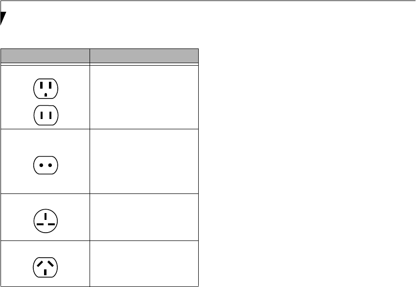
80
LifeBook P2000 Notebook – Section Seven
BATTERIES
Caring for your Batteries
■Always handle batteries carefully.
■Do not short-circuit the battery terminals (that is, do
not touch both terminals with a metal object). Do not
carry lose batteries in a pocket or purse where they
may mix with coins, keys, or other metal objects.
Doing so may cause an explosion or fire.
■Do not drop, puncture, disassemble, mutilate or incin-
erate the battery.
■Recharge batteries only as described in this manual
and only in ventilated areas.
■Do not leave batteries in hot locations for more than a
day or two. Intense heat can shorten battery life.
■Do not leave a battery in storage for longer than 6
months without recharging it.
Increasing Battery Life
■Power your LifeBook notebook through the AC or
optional auto/airline adapter whenever possible.
■If your notebook is running on battery power all day,
connect it to the AC adapter overnight to recharge the
battery.
■Keep brightness to the lowest level comfortable.
■Set the power management for maximum battery life.
■Put your notebook in Suspend mode when it is turned
on and you are not actually using it.
■Limit your media drive access.
■Disable the DVD/CD-RW Combo Drive auto insert noti-
fication function.
■Always use fully charged batteries.
■Eject PCMCIATM cards when not in use.
FLOPPY DISKS AND DRIVES
Caring for your Floppy Disks
■Avoid using the floppy disks in damp and
dusty locations.
■Never store a floppy disk near a magnet or
magnetic field.
■Do not use a pencil or an eraser on a disk or
disk label.
■Avoid storing the floppy disks in extremely hot or cold
locations, or in locations subject to severe temperature
changes. Store at temperatures between 50º F (10ºC)
and 125ºF (52ºC).
■Do not touch the exposed part of the disk
behind the metal shutter.
Caring for your Floppy Disk Drive
■To clean, wipe the floppy disk drive clean with a dry
soft cloth, or with a soft cloth dampened with water or
a solution of neutral detergent. Never use benzene,
paint thinner or other volatile material.
■Avoid storing the floppy disk drive in extremely hot or
cold locations, or in locations subject to severe tem-
perature changes. Store at temperatures between 50º F
(10ºC) and 125ºF (52ºC).
■Keep the floppy disk drive out of direct sunlight and
away from heating equipment.
■Avoid storing the floppy disk drive in locations subject
to shock and vibration.
■Never use the floppy disk drive with any liquid, metal,
or other foreign matter inside the floppy disk
drive or disk.
■Never disassemble or dismantle your floppy disk drive.
Outlet Type Location
United States, Canada,
parts of Latin America,
Mexico, Japan, Korea,
the Philippines, Taiwan
Russia and the Commonwealth
of Independent States (CIS),
most of Europe, parts of Latin
America, the Middle East, parts
of Africa, Hong Kong, India,
most of South Asia
United Kingdom, Ireland,
Malaysia, Singapore,
parts of Africa
China, Australia,
New Zealand
P2120.book Page 80 Friday, September 13, 2002 4:56 PM

81
Care and Maintenance
MEDIA CARE
Caring for your Media (DVD/CD-RW/CD-ROM)
Media discs are precision devices and will function reli-
ably if given reasonable care.
■Always store your media disc in its case when it
is not in use.
■Always handle discs by the edges and avoid touching
the surface.
■Avoid storing any media discs in extreme tempera-
tures.
■Do not bend media discs or set heavy objects on them.
■Do not spill liquids on media discs.
■Do not scratch media discs.
■Do not get dust on media discs.
■Never write on the label surface with a ballpoint pen
or pencil. Always use a felt pen.
■If a media disc is subjected to a sudden change in tem-
perature, cold to warm condensation may form on the
surface. Wipe the moisture off with a clean, soft, lint
free cloth and let it dry at room temperature. DO NOT
use a hair dryer or heater to dry media discs.
■If a disc is dirty, use only a DVD/CD cleaner or wipe it
with a clean, soft, lint free cloth starting from the inner
edge and wiping to the outer edge.
Caring for your DVD/CD-RW Drive
Your DVD/CD-RW drive is durable but you must treat it
with care. Please pay attention to the following points:
■The drive rotates the compact disc at a very high
speed. Do not carry it around or subject it to shock
or vibration with the power on.
■Avoid using or storing the drive where it will be
exposed to extreme temperatures.
■Avoid using or storing the drive where it is
damp or dusty.
■Avoid using or storing the drive near magnets or
devices that generate strong magnetic fields.
■Avoid using or storing the drive where it will be
subjected to shock or vibration.
■Do not disassemble or dismantle the DVD/CD-RW
drive.
■Occasional use of a commercially available lens cleaner
kit is recommended to maintain your drive.
PC CARDS
Caring for your PC Cards
PC Cards are durable, but you must treat them with
care. The documentation supplied with your PC Card
will provide specific information, but you should
pay attention to the following points:
■To keep out dust and dirt, store PC Cards in their
protective sleeves when they are not installed in
your LifeBook notebook.
■Avoid prolonged exposure to direct sunlight or
excessive heat.
■Keep the cards dry.
■Do not flex or bend the cards, and do not place heavy
objects on top of them.
■Do not force cards into the slot.
■Avoid dropping cards, or subjecting them to
excessive vibration.
P2120.book Page 81 Friday, September 13, 2002 4:56 PM

82
LifeBook P2000 Notebook – Section Seven
P2120.book Page 82 Friday, September 13, 2002 4:56 PM

83
8
Specifications
P2120.book Page 83 Friday, September 13, 2002 4:56 PM

84
LifeBook P2000 Notebook – Section Eight
P2120.book Page 84 Friday, September 13, 2002 4:56 PM
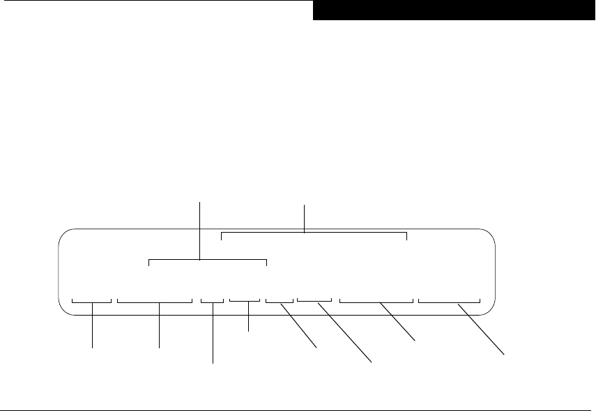
85
Specifications
Specifications
This section provides the hardware and environmental
specifications for your Fujitsu LifeBook notebook.
Specifications of particular configurations will vary.
CONFIGURATION LABEL
There is a configuration label located on the bottom of
your LifeBook notebook. (See figure 2-8 on page 10 for
location) This label contains specific information
regarding the options you’ve chosen for your notebook.
Following is an example label and information on how to
read your own configuration label.
Figure 8-1 Configuration Label
MICROPROCESSOR
■933MHz CrusoeTM TM5800 processor with
LongRunTM Power Management
■133MHz bus speed
■512K on-die L2 cache memory
MEMORY
System Memory*
256MB, expandable to 384MB SDRAM
(256MB on-board, one slot for 144-pin micro-DIMM)
* Transmeta CPU uses 16MB of RAM for Code Morphing Soft-
ware (CMS). For more information on CMS, refer to the
Transmeta web site at: www.transmeta.com.
VIDEO
Built-in color flat-panel TFT active matrix LCD display
with simultaneous display capability
Video Color and Resolution
10.6" TFT wide-SXGA
■Internal: 1280 x 768 pixel resolution, 16M colors
■External: 1280 x 1024 pixel resolution, 16M colors
Simultaneous Video = Yes (1024 x 768, 16M colors)
XGA, SVGA and VGA compatible
Video RAM
ATI MOBILITY™ RADEON™ with 8MB embedded
Video RAM
AUDIO
■SigmaTel STAC9757T codec with 18-bit stereo audio
■SigmaTel Surround Stereo Enhancement
■Stereo headphone jack, 200 mVrms (@32 ohms), 1
Vrms (@10Kohms)
■Stereo line out jack (SPDIF), 1 Vrms (@10 Kohms)
■Mono microphone jack, 100 mVrms max.
■Dolby Headphone signal processing utility (in the
InterVideo DVD software)
■Two built-in stereo speakers, 20 mm diameter (Stereo)
MASS STORAGE DEVICE OPTIONS
Single Flexible Bay devices:
Floppy Disk Drive
Modular 3.5" Floppy Disk Drive, which accommodates
1.44MB or 720KB floppy disks
Hard Drive
40GB or 30GB fixed hard drive, 2.5”, ATA 100
DVD/CD-RW Combo Drive
8x DVD / 10x CD-RW / 16x CD-R / 24x CD-ROM
P2120, TM5800 933, 10T, XPP, 30G, 256M, DVD/CD-RW, MDM/LAN
Configuration P/N: AGJXXXXXXXXXXXXX
FPC P/N: FPCXXXXXX
Operating
Hard Drive
Configuration ID
Part Number
Processor
Model #
Screen Size Memory
System Media Player
Communications
Device
P2120.book Page 85 Friday, September 13, 2002 4:56 PM

86
LifeBook P2000 Notebook – Section Eight
FEATURES
Integrated Pointing Device
Quick Point pointing device with scroll button
Communications
Modem: Internal V.90 standard 56K fax/modem
(ITU V.90, 56K data, 14.4K fax)
LAN: 10/100 Base-TX Ethernet
Optional Wireless LAN: 802.11b
LifeBook Application Panel
The Application Launcher buttons on your LifeBook
notebook default to the following applications:
Theft Prevention Lock Slot
Lock slot for use with physical restraining security
systems.
DEVICE PORTS
■PC Card slot for one Type II card: PCMCIA Standard
2.1 with CardBus support
■One 16-pin mini-VGA connector for external monitor
(see Display specifications)
■Two USB 2.0 connectors for input/output devices
■One S-Video Out jack
■One modular modem (RJ-11) connector
■One LAN (RJ-45) connector
■One IEEE 1394 connector
■One Line-Out/Optical Digital (SPDIF) jack
■One stereo headphone jack. (See Audio specifications)
■One mono microphone jack. (See Audio specifications)
KEYBOARD
Built-in keyboard with all functions of 101 key
keyboards.
■Total number of keys: 83
■Function keys: [F1] through [F12]
■Feature extension key: [Fn]
■Two Windows keys: one Start keys and one
application key
■Key pitch: 17 mm
■Key stroke: 2 mm
■Built-in Quick Point pointing device with left and
right buttons and scroll button.
■Built-in Palm Rest
External Keyboard Support
USB-compatible
External Numeric Keypad Support
USB-compatible
External Mouse Support
USB-compatible
POWER
Batteries
■One main Lithium ion battery, rechargeable, 10.8V,
1900 mAh.
■Optional high-capacity Lithium ion battery,
rechargeable, 10.8V, 3800 mAh
■Optional Flexible Bay battery: Lithium ion battery,
rechargeable, 10.8V, 3400 mAh
AC Adapter
Autosensing 100-240V AC, 40W, supplying 16V DC,
2.5A, to the LifeBook notebook, Fujitsu Model
FPCAC28AP, which includes an AC cable.
Power Management
Conforms to ACPI (Advanced Configuration and Power
Interface).
DIMENSIONS AND WEIGHT
Overall Dimensions
Approximately 10.6"(w) x 7"(d) x 1.59"(h) (270mm x
178mm x 40.4mm)
Weigh t s
Approximately 3.3 lbs (1.5 kg) with standard main
battery and DVD/CD-RW combo drive
Approximately 2.8 lbs. (1.29 kg) with standard main
battery and weight saver
ENVIRONMENTAL REQUIREMENTS
Temp eratu re
Operating: 41° to 95° F (5° to 35° C)
Non-operating: 5° to 140° F (–15° to 60° C)
Humidity
Operating: 20% to 85%, relative, non-condensing
Non-operating; 8% to 85%, relative, non-condensing
Altitude
Operating: 10,000 feet (3,048 m) maximum
Table 8-1 Application Launcher Defaults
Button Label Button Function
A Launch Notepad
BCalculator
Launch Netscape Messenger
P2120.book Page 86 Friday, September 13, 2002 4:56 PM

87
Specifications
POPULAR ACCESSORIES
For ordering or additional information on Fujitsu
accessories please visit our Web site at:
www.fujitsupc.com or call 1-800-733-0884.
Memory Upgrade
■128MB SDRAM
Power
■Main Lithium ion battery
■High-capacity main Lithium ion battery
■Modular 2nd Lithium ion Battery
■Auto/Airline Adapter
■AC Adapter
■2-Bay Battery Charger
Flexible Bay Devices
■Additional DVD/CD-RW combo drive
Additional Accessories
■Mini-VGA Cable
■USB Hub
■USB Camera
■TeleAdapt 16' TeleCord
■Notebook Guardian Lock
■IBM Modem Saver
Carrying Cases
■Diplomat
■Dual Carrying Case
■Slipcase
PRE-INSTALLED SOFTWARE
Depending on your pre-installed operating system, your
Fujitsu LifeBook notebook comes with pre-installed
software for playing audio and video files of various
formats. In addition there is file transfer software, virus
protection software and Power Management software.
LEARNING ABOUT YOUR
APPLICATION SOFTWARE
Tutorials
All operating systems and most application software
have tutorials built into them upon installation. We
highly recommend that you step through the tutorial
before you use an application.
Manuals
Included with your notebook you will find manuals for
your installed operating system and other pre-installed
software. Any manuals that are not included, are avail-
able online through the help system of the software. We
recommend that you review these manuals for general
information on the use of these applications.
Drive Image Special Edition (DISE)
by PowerQuest
DISE is used to restore the factory image and restore the
system to its original state. For future backup, a section
of your hard drive contains an image of the original
installed software and utilities. If necessary, you can
restore your system to the state in which it was shipped
from Fujitsu. (See Drive Image® Special Edition (DISE)
on page 76 for more information)
Adobe Acrobat Reader
The Adobe Acrobat Reader, located in the Service and
Support Software folder, allows you to view, navigate,
and print PDF files from across all of the major
computing platforms.
LifeBook Application Panel Software
Your LifeBook notebook is pre-installed with software
utilities that let you operate and configure your LifeBook
Application Panel.
Your notebook is pre-installed with software utilities that
let you operate and configure your LifeBook Application
Panel. These utilities are found under the Start menu,
under Programs, then LifeBook Application Panel. They
include a Media Player, Application Panel Setup. Applica-
tion Panel Guide, Activate Panel and Deactivate Panel.
Netscape 6
Browser suite, including integrated E-mail accounts,
instant messaging, address book, search, and other tools
and plug-ins.
McAfee.com Scan for Virus
Scan for Virus, by McAfee.com, is an antivirus program
designed to protect your LifeBook notebook from
computer viruses. It assists in the protection of the data
currently residing on your hard disk from destruction or
contamination. (See your online help or manual for more
information on how and when to run this program) Scan
for Virus allows free updates for 30 days from the time
you register the software with McAfee.com.
POINT
As your notebook does not support the CPU Clock
control, the option is not active within the Power Control
menu of BatteryAid.
P2120.book Page 87 Friday, September 13, 2002 4:56 PM

88
LifeBook P2000 Notebook – Section Eight
WINDOWS XP SOFTWARE ONLY
Fujitsu HotKey Utility
Utility for adjusting the brightness level on your Life-
Book.
Earthlink 5.0
Software suite that allows you to connect with the
Internet.
Quicken New User Edition
Quicken New User Edition by Intuit is a personal money
management program. It has features such as portfolio
management, account registries, on-line banking and
bill paying features. This application is for new users
who are using Quicken software for the first time. Full
version upgrade information is available on line.
MS Works
Microsoft Works is a suite of software containing the
basic tools to write letters and reports, track family and
friends with address books, manage home finances, and
create a home inventory.
WINDOWS 2000 SOFTWARE ONLY
Fujitsu BatteryAid
BatteryAid allows you to control the display brightness
of your notebook in order to maximize battery life. (See
your BatteryAid online help for more information on the
correct way to use this program)
P2120.book Page 88 Friday, September 13, 2002 4:56 PM

89
Regulatory Information
Regulatory Information
FCC NOTICES
Notice to Users of Radios and Television
These limits are designed to provide reasonable protec-
tion against harmful interference in a residential installa-
tion. This equipment generates, uses, and can radiate
radio frequency energy and, if not installed and used in
accordance with the instructions, may cause harmful
interference to radio communications. However, there is
no guarantee that interference will not occur in a partic-
ular installation. If this equipment does cause harmful
interference to radio or television reception, which can
be determined by turning the equipment off and on, the
user is encouraged to try to correct the interference by
one or more of the following measures:
nReorient or relocate the receiving antenna.
nIncrease the separation between the equipment and
receiver.
nConnect the equipment into an outlet that is on a
different circuit than the receiver.
nConsult the dealer or an experienced radio/TV
technician for help.
Shielded interconnect cables must be employed with this
equipment to ensure compliance with the pertinent RF
emission limits governing this device.
Notice to Users of the US Telephone Network
Your LifeBook notebook may be supplied with an
internal modem which complies with Part 68 of the FCC
rules. On this LifeBook notebook is a label that contains
the FCC Registration Number and the Ringer Equiva-
lence Number (REN) for this equipment among other
information. If requested, the user must provide their
telephone company with the following information:
1. The telephone number to which the LifeBook note-
book is connected.
2. The Ringer Equivalence Number (REN) for this
equipment.
3. The equipment requires a standard modular jack
type USOC RJ-11C which is FCC Part 68 compliant.
4. The FCC Registration Number.
This equipment is designed to be connected to the tele-
phone network or premises wiring using a standard
modular jack type USOC RJ-11C which is FCC Part 68
compliant and a line cord between the modem and the
telephone network with a minimum of 26AWG.
The REN is used to determine the number of devices
that you may connect to your telephone line and still
have all of those devices ring when your number is
called. Too many devices on one line may result in
failure to ring in response to an incoming call. In most,
but not all, areas the sum of the RENs of all of the
devices should not exceed five (5). To be certain of the
number of devices you may connect to your line, as
determined by the RENs, contact your local
telephone company.
If this equipment causes harm to the telephone network,
your telephone company may discontinue your service
temporarily. If possible, they will notify you in advance.
If advance notice is not practical they will notify you as
soon as possible. You will also be advised of your right to
file a complaint with the FCC.
This fax modem also complies with fax branding
requirements per FCC Part 68.
Your telephone company will probably ask you to
disconnect this equipment from the telephone network
until the problem is corrected and you are sure that the
equipment is not malfunctioning. This equipment may
not be used on coin-operated telephones provided by
your telephone company. Connection to party lines is
subject to state tariffs. Contact your state’s public utility
commission, public service commission or corporation
commission for more information.
This equipment includes automatic dialing capability.
When programming and/or making test calls to
emergency numbers:
nRemain on the line and briefly explain to the
dispatcher the reason for the call.
nPerform such activities in off-peak hours, such as early
morning or late evening.
FCC rules prohibit the use of non-hearing aid compatible
telephones in the following locations or applications:
nAll public or semi-public coin-operated or credit card
telephones.
nElevators, highways, tunnels (automobile, subway,
railroad or pedestrian) where a person with impaired
hearing might be isolated in an emergency.
nPlaces where telephones are specifically installed to
alert emergency authorities such as fire, police or
medical assistance personnel.
nHospital rooms, residential health care facilities,
convalescent homes and prisons.
nWorkstations for the hearing impaired.
nHotel, motel or apartment lobbies.
nStores where telephones are used by patrons to
order merchandise.
nPublic transportation terminals where telephones are
used to call taxis or to reserve lodging or rental cars.
nIn hotel and motel rooms as at least ten percent of the
rooms must contain hearing aid-compatible tele-
CAUTION
Changes or modifications not expressly approved by
Fujitsu could void this user’s authority to operate the
equipment
P2120.book Page 89 Friday, September 13, 2002 4:56 PM

90
LifeBook P2000 Notebook - Section Eight
phones or jacks for plug-in hearing aid compatible
telephones which will be provided to hearing impaired
customers on request.
DOC (INDUSTRY CANADA) NOTICES
Notice to Users of Radios and Television
This Class B digital apparatus meets all requirements of
Canadian Interference-Causing Equipment Regulations.
CET appareil numérique de la class B respecte toutes les
exigence du Réglement sur le matérial brouilleur du
Canada.
Notice to Users of the Canadian Telephone Network
NOTICE: This equipment meets the applicable Industry
Canada Terminal Equipment Technical Specifications.
This is confirmed by the registration number. The
abbreviation, IC, before the registration number signi-
fies that registration was performed based on a Declara-
tion of Conformity indicating that Industry Canada
technical specifications were met. It does not imply that
Industry Canada approved the equipment.
Before connecting this equipment to a telephone line the
user should ensure that it is permissible to connect this
equipment to the local telecommunication facilities.
The user should be aware that compliance with the
certification standards does not prevent service
degradation in some situations.
Repairs to telecommunication equipment should be
made by a Canadian authorized maintenance facility.
Any repairs or alterations not expressly approved by
Fujitsu or any equipment failures may give the telecom-
munication company cause to request the user to
disconnect the equipment from the telephone line.
NOTICE: The Ringer Equivalence Number (REN) for
this terminal equipment is 0.0. The REN assigned to
each terminal equipment provides an indication of the
maximum number of terminals allowed to be connected
to a telephone interface. The termination on an interface
may consist of any combination of devices subject only
to the requirement that the sum of the Ringer Equiva-
lence Numbers of all the devices does not exceed five.
Avis Aux Utilisateurs Du Réseau
Téléphonique Canadien
AVIS: Le présent matériel est conforme aux spécifica-
tions techniques d’Industrie Canada applicables au
matériel terminal. Cette conformité est confirmée par le
numéro d’enregistrement. Le sigle IC, placé devant le
numéro d’enregistrement, signifie que l’enregistrement
s’est effectué conformément à une déclaration de
conformité et indique que les spécifications techniques
d’Industrie Canada ont été respectées. Il n’implique pas
qu’Industrie Canada a approuvé le matériel.
Avant de connecter cet équipement à une ligne télépho-
nique, l’utilisateur doit vérifier s’il est permis de
connecter cet équipement aux installations de télécom-
munications locales. L’utilisateur est averti que même la
conformité aux normes de certification ne peut dans
certains cas empêcher la dégradation du service.
Les réparations de l’équipement de télécommunications
doivent être eVectuées par un service de maintenance
agréé au Canada. Toute réparation ou modification, qui
n’est pas expressément approuvée par Fujitsu, ou toute
défaillance de l’équipement peut entraîner la compagnie
de télécommunications à exiger que l’utilisateur décon-
necte l’équipement de la ligne téléphonique.
AVIS: L’indice d’équivalence de la sonnerie (IES) du
présent matériel est de 0.0. L’IES assigné à chaque
dispositif terminal indique le nombre maximal de
terminaux qui peuvent être raccordés à une interface
téléphonique. La terminaison d’une interface peut
consister en une combinaison quelconque de dispositifs,
à la seule condition que la somme d’indices d’équiva-
lence de la sonnerie de tous les dispositifs n’excède pas 5.
CAUTION
For safety, users should ensure that the electrical
ground of the power utility, the telephone lines and the
metallic water pipes are connected together. Users
should NOT attempt to make such connections
themselves but should contact the appropriate electric
inspection authority or electrician. This may be
particularly important in rural areas.
AVERTISSEMENT
Pour assurer la sécurité, les utilisateurs doivent vérifier
que la prise de terre du service d’électricité, les lignes
télphoniques et les conduites d’eau métalliques sont
connectées ensemble. Les utilisateurs NE doivent PAS
tenter d’établir ces connexions eux-mêmes, mais
doivent contacter les services d’inspection d’installations
électriques appropriés ou un électricien. Ceci peut être
particulièrement important en régions rurales.
P2120.book Page 90 Friday, September 13, 2002 4:56 PM

91
Regulatory Information
UL Notice
This unit requires an AC adapter to operate. Use only UL
Listed Class 2 Adapters with an output rating of 16
VDC, with a current of 2.5 A.
AC Adapter output polarity:
For Authorized Repair Technicians Only
CAUTION
The modem-to-telephone network connection must be
a line cord using a minimum #26 AWG wire.
WARNINGS
nFor continued protection against risk of fire, replace
only with the same type and rating fuse.
nDanger of explosion if Lithium (clock) battery is incor-
rectly replaced. Replace only with the same or equiva-
lent type recommended by the manufacturer. Dispose
of used batteries according to the manufacturer’s
instruction.
+
P2120.book Page 91 Friday, September 13, 2002 4:56 PM

92
LifeBook P2000 Notebook - Section Eight
P2120.book Page 92 Friday, September 13, 2002 4:56 PM

93
9
Glossary
P2120.book Page 93 Friday, September 13, 2002 4:56 PM

94
LifeBook P2000 Notebook – Section Nine
P2120.book Page 94 Friday, September 13, 2002 4:56 PM

95
Glossary
Glossary
AC Adapter
A device which converts the AC voltage from a wall
outlet to the DC voltage needed to power your LifeBook
notebook.
ACPI
Advanced Configuration and Power Interface. An
industry specification for the efficient handling of power
consumption in mobile computers. ACPI determines
how a computer's BIOS, operating system, and periph-
erals communicate with each other about power
management.
Active-Matrix Display
A type of technology for making flat-panel displays
which has a transistor or similar device for every pixel
on the screen.
ADSL
Asymmetric Digital Subscriber Line. Technology for
transporting high bit-rate services over ordinary phone
lines.
APM
Advanced Power Management.
Auto/Airline Adapter
A device which converts the DC voltage from an auto-
mobile cigarette lighter or aircraft DC power outlet to
the DC voltage needed to power your LifeBook note-
book.
BIOS
Basic Input-Output System. A program and set of
default parameters stored in ROM which tests and
operates your LifeBook notebook when you turn it on
until it loads your installed operating system from disk.
Information from the BIOS is transferred to the installed
operating system to provide it with information on
the configuration and status of the hardware.
Bit
An abbreviation for binary digit. A single piece of
information which is either a one (1) or a zero (0).
bps
An abbreviation for bits per second. Used to describe
data transfer rates.
Boot
To start-up a computer and load its operating system
from disk, ROM or other storage media into RAM.
Bus
An electrical circuit which passes data between the CPU
and the sub-assemblies inside your LifeBook notebook.
Byte
8 bits of parallel binary information.
Cache Memory
A block of memory built into the micro-processor which
is much faster to access than your system RAM and used
in specially structured ways to make your overall data
handling time faster.
CardBus
A faster, 32-bit version of the PC Card interface
which offers performance similar to the 32-bit
PCI architecture.
CD-ROM
Compact disc read only memory. This is a form of
digital data storage which is read optically with a laser
rather than a magnetic head. A typical CD-ROM can
contain about 600MB of data and is not subject to heads
crashing into the surface and destroying the data when
there is a failure nor to wear from reading.
CMS
Code Morphing Software. Crusoe processor software
architecture that results in longer battery life. For more
information on CMS, click on the Technology link on
the refer to the Transmeta web site at: www.trans-
meta.com.
Command
An instruction which you give your operating system.
Example: run a particular application or format a floppy
disk.
Configuration
The combination of hardware and software that makes
up your system and how it is allocated for use.
Data
The information a system stores and processes.
DC
Direct current. A voltage or current that does not
fluctuate periodically with time.
Default Value
A pre programmed value to be used if you fail to
set your own.
DIMM
Dual-in-line memory module.
Disk
A spinning platter of magnetic data storage media. If the
platter is very stiff it is a hard drive, if it is highly flexible
it is a floppy disk, if it is a floppy disk in a hard housing
with a shutter it is commonly called a diskette.
Disk Drive
The hardware which spins the disk and has the heads
and control circuitry for reading and writing the data
on the disk.
Diskette
A floppy disk in a hard housing with a shutter.
P2120.book Page 95 Friday, September 13, 2002 4:56 PM

96
LifeBook P2000 Notebook – Section Nine
DMA
Direct Memory Access. Special circuitry for memory
to memory transfers of data which do not require
CPU action.
DMI
Desktop Management Interface. A standard that
provides PC management applications with a common
method of locally or remotely querying and configuring
PC computer systems, hardware and software compo-
nents, and peripherals.
DOS
Disk Operating System (MS-DOS is a Microsoft Disk
Operating System).
Driver
A computer program which converts application and
operating system commands to external devices into the
exact form required by a specific brand and model of
device in order to produce the desired results from that
particular equipment.
ESD
Electro-Static Discharge. The sudden discharge of elec-
tricity from a static charge which has built-up slowly.
Example: the shock you get from a doorknob on a dry day
or the sparks you get from brushing hair on a dry day.
Extended Memory
All memory more than the 640KB recognized by
MS-DOS as system memory.
FCC
Federal Communication Commission.
Floppy Disk
A spinning platter of magnetic data storage media which
is highly flexible.
GB
Gigabyte.
Hard drive
A spinning platter of magnetic data storage media where
the platter is very stiff.
Hexadecimal
A decimal notation for the value of a 4 bit binary
number. (0-9, A, B, C, D, E, F) Example: 2F in
hexadecimal = 00101111 in binary = 47 in decimal.
I/O
Input/Output. Data entering and leaving your LifeBook
notebook in electronic form.
I/O Port
The connector and associated control circuits for data
entering and leaving your LifeBook notebook in elec-
tronic form.
IDE
Intelligent Drive Electronics. A type of control interface
for a hard drive which is inside the hard drive unit.
IEEE 1394
The IEEE 1394 (also known as “Firewire” or “iLink”)
standard allows you to connect devices that are
compliant with IEEE standard 1394. This port is effec-
tively a very fast communications port. This architecture
is very good for transferring large files, such as those
from digital cameras.
IRQ
Interrupt Request. An acronym for the hardware signal
to the CPU that an external event has occurred which
needs to be processed.
KB
Kilobyte.
LAN
Local Area Network. An interconnection of computers
and peripherals within a single limited geographic
location which can pass programs and data amongst
themselves.
LCD
Liquid Crystal Display. A type of display which makes
images by controlling the orientation of crystals in a
crystalline liquid.
Lithium ion Battery
A type of rechargeable battery which has a high power-
time life for its size and is not subject to the memory
effect as Nickel Cadmium batteries.
MB
Megabyte.
Megahertz
1,000,000 cycles per second.
Memory
A repository for data and applications which is readily
accessible to your LifeBook notebook CPU.
MHz
Megahertz.
Modem
A contraction for MOdulator-DEModulator. The
equipment which connects a computer or other data
terminal to a communication line.
Monaural
A system using one channel to process sound
from all sources.
NTSC
National TV Standards Commission. The standard for
TV broadcast and reception for the USA.
P2120.book Page 96 Friday, September 13, 2002 4:56 PM

97
Glossary
Operating System
A group of control programs that convert application
commands, including driver programs, into the exact
form required by a specific brand and model of micro-
processor in order to produce the desired results from
that particular equipment.
Partition
A block of space on a hard drive which is set aside
and made to appear to the operating system as if it
were a separate disk, and addressed by the operating
system accordingly.
PCMCIA
PCMCIA is a trademark of the Personal Computer
Memory Card International Association. The Personal
Computer Memory Card International Association is an
organization that sets standards for add-in cards for
personal computers.
Peripheral Device
A piece of equipment which performs a specific
function associated with but not integral to a computer.
Examples: a printer, a modem, a CD-ROM.
Pitch (keyboard)
The distance between the centers of the letter keys
of a keyboard.
Pixel
The smallest element of a display, a dot of color on your
display screen. The more pixels per area the clearer your
image will appear.
POP3
Post Office Protocol. Protocol that is used to retrieve
email from a mail server.
POST
Power On Self Test. A program which is part of the BIOS
which checks the configuration and operating condition
of your hardware whenever power is applied to your
LifeBook notebook. Status and error messages may be
displayed before the operating system is loaded. If the
self test detects failures that are so serious that operation
can not continue, the operating system will not be
loaded.
PPPoE
Point to Point Protocol over Ethernet. A protocol for
Ethernet, using a Point-to-Point Protocol (PPP), which
is used for connection on the phone line.
Program
An integrated set of coded commands to your
computers telling your hardware what to do and how
and when to do it.
PS/2
An IBM series of personal computers which established
a number of standards for connecting external devices
such as keyboards and monitors.
RAM
Random Access Memory. A hardware component of
your LifeBook notebook that holds binary information
(both program and data) as long as it has the proper
power applied to it.
RAM Module
A printed circuit card with memory and associated
circuitry which allows the user to add additional
memory to the computer without special tools.
Reset
The act of reloading the operating system. A reset erases
all information stored in RAM.
Restart
See Reset.
Resume
To proceed after interruption. In your LifeBook note-
book, this refers to returning to active operation after
having been in one of the suspension states.
ROM
Read Only Memory. A form of memory in which infor-
mation is stored by physically altering the material. Data
stored in this way can not be changed by your LifeBook
notebook and does not require power to maintain it.
SDRAM
Synchronous Dynamic Random Access Memory.
Shadow RAM
A technique of copying data or applications stored in
ROM (Read Only Memory) into RAM (Random Access
Memory) for access during actual operation. RAM is
much faster to access than ROM, however ROM
contents are not lost when power is removed.
Shadowing allows permanently stored information
to be rapidly accessed.
SPDIF
Sony Philips Digital Interface. Technology that allows
you to download digital audio data onto a MiniDisc
recorder.
SSID
Service Set Identifier. Specifies which network you are
joining. Some systems allow you to specify any SSID as
an option so you can join any network.
Status Indicator
A display which reports the condition of some portion
of your hardware. On your LifeBook notebook this is an
LCD screen just above the keyboard.
P2120.book Page 97 Friday, September 13, 2002 4:56 PM

98
LifeBook P2000 Notebook – Section Nine
Stereo (audio)
A system using two channels to process sound from two
different sources.
Stroke (keyboard)
The amount of travel of a key when it is pressed from
resting to fully depressed.
Suspend
To make inoperative for a period of time. Your LifeBook
notebook uses various suspension states to reduce power
consumption and prolong the charge of your battery.
SVGA
Super VGA. Standard that provides 800x600 pixel
resolution and a palette of 16M colors.
S-Video
Super Video. A component video system for driving a
TV or computer monitor.
System Clock
An oscillator of fixed precise frequency which synchro-
nizes the operation of the system and is counted to
provide time of day and date.
TFT
Thin Film Transistor. A technology for flat display
panels which uses a thin film matrix of transistors to
control each pixel of the display screen individually.
UL
Underwriters Laboratories – An independent organiza-
tion that tests and certifies the electrical safety of devices.
USB
Universal Serial Bus. An external bus standard that
allows for fast data transfer. A single USB port can be
used to connect up to 127 peripheral devices, such as
mice, modems, and scanners. USB 1.1 has a transfer
speed of a maximum of 12Mb/s. USB 2.0 is much faster,
transferring at up to 480Mb/s. USB 2.0 is backward-
compatible to work with USB 1.1 devices.
VGA
Video Graphics Array. A video display standard
originally introduced by IBM with the PS/2 series of
personal computers. Provides resolutions of 720 x 400.
VRAM
Video Random Access Memory. A memory dedicated to
video display data and control.
WEP
Wired Equivalent Privacy. WEP is a protocol for
increasing privacy over wireless LANs. The protocol
works by encrypting data while being transmitted over
radio waves.
WFM
Wired for Management is Intel’s broad-based initiative
to reduce the total cost of ownership (TCO) of business
computing without sacrificing power and flexibility.
Wi-Fi Compatible
Wi-Fi (Wireless Fidelity) identifies that the product has
passed the interoperability test, supplied by the WECA
(Wireless Ethernet Compatibility Alliance), which guar-
antees the interoperability of wireless IEEE 802.11 LAN
products. For more information on the Wi-Fi standard,
go to the WECA website at: www.wirelessethernet.com.
Write Protect
Prevent alteration of the binary state of all bits in a
storage media. Example: all information on a device
such as a floppy diskette; a block of space in a storage
media such as a partition of a hard drive; a file or direc-
tory of floppy diskette or hard drive.
XGA
Extended graphics array. Standard that provides
resolutions of 640x480 or 1024x764, supporting 64k
colors.
P2120.book Page 98 Friday, September 13, 2002 4:56 PM

99
Index
Index
A
AC
adapter . . . . . . . . . . . . . . . . . . . . . . . . . . . . . . . . 25, 95
indicator . . . . . . . . . . . . . . . . . . . . . . . . . . . . . . . . . . 11
plug adapters . . . . . . . . . . . . . . . . . . . . . . . . . . . . . . 79
AC Adapter . . . . . . . . . . . . . . . . . . . . . . . . . . . . . . . . . 25
Anti-theft lock slot . . . . . . . . . . . . . . . . . . . . . . . . . . . . 8
Auto Insert Notification . . . . . . . . . . . . . . . . . . . . . . . 38
Auto/Airline Adapter . . . . . . . . . . . . . . . . . . . . . . 25, 95
B
Battery . . . . . . . . . . . . . . . . . . . . . . . . . . . . . . . . . . . . . 33
alarm . . . . . . . . . . . . . . . . . . . . . . . . . . . . . . . . . . . . 33
Battery Bay Release Button . . . . . . . . . . . . . . . . . . 10
care . . . . . . . . . . . . . . . . . . . . . . . . . . . . . . . . . . . . . . 80
charging indicator . . . . . . . . . . . . . . . . . . . . . . . . . . 12
charging times . . . . . . . . . . . . . . . . . . . . . . . . . . . . . 33
cold-swapping . . . . . . . . . . . . . . . . . . . . . . . . . . . . . 34
conserving power . . . . . . . . . . . . . . . . . . . . . . . . . . 29
dead . . . . . . . . . . . . . . . . . . . . . . . . . . . . . . . . . . . . . 70
faulty . . . . . . . . . . . . . . . . . . . . . . . . . . . . . . . . . . . . . 70
increasing life . . . . . . . . . . . . . . . . . . . . . . . . . . . . . . 80
level indicators . . . . . . . . . . . . . . . . . . . . . . . . . . . . . 11
lithium ion battery . . . . . . . . . . . . . . . . . . . . . . 33, 96
low . . . . . . . . . . . . . . . . . . . . . . . . . . . . . . . . . . . . . . 33
problems . . . . . . . . . . . . . . . . . . . . . . . . . . . . . . . . . 70
recharging . . . . . . . . . . . . . . . . . . . . . . . . . . . . . . . . 33
replacing . . . . . . . . . . . . . . . . . . . . . . . . . . . . . . . . . . 34
shorted . . . . . . . . . . . . . . . . . . . . . . . . . . . . . . . . . . . 34
suspend mode . . . . . . . . . . . . . . . . . . . . . . . . . . . . . 33
warm-swapping . . . . . . . . . . . . . . . . . . . . . . . . . . . . 34
BIOS . . . . . . . . . . . . . . . . . . . . . . . . . . . . . . . . . . . . . . . 95
guide . . . . . . . . . . . . . . . . . . . . . . . . . . . . . . . . . . . . . 27
setup utility . . . . . . . . . . . . . . . . . . . . . . . . . . . . . . . 27
Boot . . . . . . . . . . . . . . . . . . . . . . . . . . . . . . . . . . . . . . . 95
Boot Sequence . . . . . . . . . . . . . . . . . . . . . . . . . . . . . . . 27
Built-in Speakers . . . . . . . . . . . . . . . . . . . . . . . . . . . . . 66
C
Cache Memory . . . . . . . . . . . . . . . . . . . . . . . . . . . . . . 95
CapsLock . . . . . . . . . . . . . . . . . . . . . . . . . . . . . . . . . . . 12
CD-ROM
problems . . . . . . . . . . . . . . . . . . . . . . . . . . . . . . . . . 66
Click Me! . . . . . . . . . . . . . . . . . . . . . . . . . . . . . . . . . . . 28
Closed Cover Switch . . . . . . . . . . . . . . . . . . . . . . . . . . . 6
Cold-swap . . . . . . . . . . . . . . . . . . . . . . . . . . . . . . . . . . .18
Cold-swapping . . . . . . . . . . . . . . . . . . . . . . . . . . . . . . .34
Configuration Label . . . . . . . . . . . . . . . . . . . . . . . . . . .10
Contact Information . . . . . . . . . . . . . . . . . . . . . . . . . . .1
cursor control button . . . . . . . . . . . . . . . . . . . . . . . . . . .6
Cursor Keys . . . . . . . . . . . . . . . . . . . . . . . . . . . . . . . . . .13
D
DC Output Cable . . . . . . . . . . . . . . . . . . . . . . . . . . . . .25
DC Power Jack . . . . . . . . . . . . . . . . . . . . . . . . . . . . . . .25
DC power jack . . . . . . . . . . . . . . . . . . . . . . . . . . . . . . . . .9
Device Ports . . . . . . . . . . . . . . . . . . . . . . . . . . . . . . . . . .43
DIMM . . . . . . . . . . . . . . . . . . . . . . . . . . . . . . . . . . . . . .40
DISE . . . . . . . . . . . . . . . . . . . . . . . . . . . . . . . . . . . . . . . .76
Disk
care . . . . . . . . . . . . . . . . . . . . . . . . . . . . . . . . . . . . . . .80
Display . . . . . . . . . . . . . . . . . . . . . . . . . . . . . . . . . . . . . . .6
Display Panel . . . . . . . . . . . . . . . . . . . . . . . . . . . . . . .6, 26
adjusting . . . . . . . . . . . . . . . . . . . . . . . . . . . . . . . . . .26
brightness . . . . . . . . . . . . . . . . . . . . . . . . . . . . . . . . .26
closing . . . . . . . . . . . . . . . . . . . . . . . . . . . . . . . . . . . .26
opening . . . . . . . . . . . . . . . . . . . . . . . . . . . . . . . . . . .26
power management . . . . . . . . . . . . . . . . . . . . . . . . .26
problems . . . . . . . . . . . . . . . . . . . . . . . . . . . . . . .71, 72
Display Timeout . . . . . . . . . . . . . . . . . . . . . . . . . . . . . .30
Dolby Headphone . . . . . . . . . . . . . . . . . . . . . . . . . . . . .37
Drive Image Special Edition . . . . . . . . . . . . . . . . . . . .76
Drivers and Application CD . . . . . . . . . . . . . . . . . . . .76
DVD drive
access indicator . . . . . . . . . . . . . . . . . . . . . . . . . . . . .12
tray release . . . . . . . . . . . . . . . . . . . . . . . . . . . . . . . . .75
DVD/CD-RW Combo Drive . . . . . . . . . . . . . . . . . . . .36
DVD/CD-RW drive
access indicator . . . . . . . . . . . . . . . . . . . . . . . . . . . . .12
Control Panel . . . . . . . . . . . . . . . . . . . . . . . . . . . . . .37
loading . . . . . . . . . . . . . . . . . . . . . . . . . . . . . . . . . . . .36
problems . . . . . . . . . . . . . . . . . . . . . . . . . . . . . . . . . .66
removing . . . . . . . . . . . . . . . . . . . . . . . . . . . . . . . . . .37
Software . . . . . . . . . . . . . . . . . . . . . . . . . . . . . . . . . . .36
using . . . . . . . . . . . . . . . . . . . . . . . . . . . . . . . . . . . . . .38
DVD/CD-RW Drive Eject Button . . . . . . . . . . . . . . . . .7
P2120.book Page 99 Friday, September 13, 2002 4:56 PM

100
LifeBook P2000 Notebook
E
Earthlink 5.0 . . . . . . . . . . . . . . . . . . . . . . . . . . . . . . . . 88
E-Mail Button . . . . . . . . . . . . . . . . . . . . . . . . . . . . . . . . 6
Emergency CD tray release . . . . . . . . . . . . . . . . . . . . . . 7
Error Messages . . . . . . . . . . . . . . . . . . . . . . . . . . . . . . . 74
Extended Memory . . . . . . . . . . . . . . . . . . . . . . . . . . . . 96
External Floppy Disk Drive . . . . . . . . . . . . . . . . . . . . 35
problems . . . . . . . . . . . . . . . . . . . . . . . . . . . . . . . . . 67
F
Flexible Bay . . . . . . . . . . . . . . . . . . . . . . . . . . . . . . . . . . 7
cold-swapping . . . . . . . . . . . . . . . . . . . . . . . . . . . . . 18
eject lever . . . . . . . . . . . . . . . . . . . . . . . . . . . . . . . . . . 7
installing . . . . . . . . . . . . . . . . . . . . . . . . . . . . . . . . . . 18
removing . . . . . . . . . . . . . . . . . . . . . . . . . . . . . . . . . 18
flexible bay . . . . . . . . . . . . . . . . . . . . . . . . . . . . . . . . . . 18
Floppy Disk
ejecting . . . . . . . . . . . . . . . . . . . . . . . . . . . . . . . . . . . 35
formatting . . . . . . . . . . . . . . . . . . . . . . . . . . . . . . . . 35
initializing . . . . . . . . . . . . . . . . . . . . . . . . . . . . . . . . 35
loading . . . . . . . . . . . . . . . . . . . . . . . . . . . . . . . . . . . 35
preparing . . . . . . . . . . . . . . . . . . . . . . . . . . . . . . . . . 35
write protect . . . . . . . . . . . . . . . . . . . . . . . . . . . . . . 35
Floppy Disk Drive
care . . . . . . . . . . . . . . . . . . . . . . . . . . . . . . . . . . . . . . 80
Fujitsu BatteryAid . . . . . . . . . . . . . . . . . . . . . . . . . . . . 88
Fujitsu HotKey Utility . . . . . . . . . . . . . . . . . . . . . . . . 88
Fujitsu LifeBook
traveling . . . . . . . . . . . . . . . . . . . . . . . . . . . . . . . . . . 79
Function Key
F10 . . . . . . . . . . . . . . . . . . . . . . . . . . . . . . . . . . . . . . 14
F11 . . . . . . . . . . . . . . . . . . . . . . . . . . . . . . . . . . . . . . 14
F3 . . . . . . . . . . . . . . . . . . . . . . . . . . . . . . . . . . . . . . . 14
F4 . . . . . . . . . . . . . . . . . . . . . . . . . . . . . . . . . . . . . . . 14
F5 . . . . . . . . . . . . . . . . . . . . . . . . . . . . . . . . . . . . . . . 14
F6 . . . . . . . . . . . . . . . . . . . . . . . . . . . . . . . . . . . . . . . 14
F7 . . . . . . . . . . . . . . . . . . . . . . . . . . . . . . . . . . . . . . . 14
F8 . . . . . . . . . . . . . . . . . . . . . . . . . . . . . . . . . . . . . . . 14
F9 . . . . . . . . . . . . . . . . . . . . . . . . . . . . . . . . . . . . . . . 14
Fn . . . . . . . . . . . . . . . . . . . . . . . . . . . . . . . . . . . . . . . 14
G
Glossary . . . . . . . . . . . . . . . . . . . . . . . . . . . . . . . . . . . . 95
H
Hard Disk Drive
access indicator . . . . . . . . . . . . . . . . . . . . . . . . . . . . .12
problems . . . . . . . . . . . . . . . . . . . . . . . . . . . . . . . . . .67
Hard Disk Timeout . . . . . . . . . . . . . . . . . . . . . . . . . . . .30
Headphone . . . . . . . . . . . . . . . . . . . . . . . . . . . . . . . . . . .8
Headphone Jack . . . . . . . . . . . . . . . . . . . . . . . . . . . .8, 43
Hibernation Feature . . . . . . . . . . . . . . . . . . . . . . . . . . .29
disable/enabled . . . . . . . . . . . . . . . . . . . . . . . . . . . . .29
I
IEEE 1394 Jack . . . . . . . . . . . . . . . . . . . . . . . . . . . . .8, 43
Integrated Wireless LAN . . . . . . . . . . . . . . . . . . . . . . .45
Internal LAN Jack . . . . . . . . . . . . . . . . . . . . . . . . . . . . .43
K
Keyboard . . . . . . . . . . . . . . . . . . . . . . . . . . . . . . . . . .6, 13
cursor keys . . . . . . . . . . . . . . . . . . . . . . . . . . . . . . . . .13
function keys . . . . . . . . . . . . . . . . . . . . . . . . . . . . . . .13
numeric keypad . . . . . . . . . . . . . . . . . . . . . . . . . . . .13
problems . . . . . . . . . . . . . . . . . . . . . . . . . . . . . . . . . .67
windows keys . . . . . . . . . . . . . . . . . . . . . . . . . . . . . .13
L
LAN (RJ-45) jack . . . . . . . . . . . . . . . . . . . . . . . . . . . . . .9
LifeBook . . . . . . . . . . . . . . . . . . . . . . . . . . . . . . . . . . . . .20
LifeBook Application Panel . . . . . . . . . . . . . . . . . . . . . .6
M
Media Player
care . . . . . . . . . . . . . . . . . . . . . . . . . . . . . . . . . . . . . . .81
Media player
care . . . . . . . . . . . . . . . . . . . . . . . . . . . . . . . . . . . . . . .81
Memory
capacity . . . . . . . . . . . . . . . . . . . . . . . . . . . . . . . . . . .41
extended . . . . . . . . . . . . . . . . . . . . . . . . . . . . . . . . . .42
installing . . . . . . . . . . . . . . . . . . . . . . . . . . . . . . . . . .40
problems . . . . . . . . . . . . . . . . . . . . . . . . . . . . . . . . . .68
removing . . . . . . . . . . . . . . . . . . . . . . . . . . . . . . . . . .41
system . . . . . . . . . . . . . . . . . . . . . . . . . . . . . . . . . . . .42
Memory Upgrade Module . . . . . . . . . . . . . . . . . . . . . .40
Microphone Jack . . . . . . . . . . . . . . . . . . . . . . . . . . . .9, 44
Mini-VGA Jack . . . . . . . . . . . . . . . . . . . . . . . . . . . . . . . .8
Mini-VGA Port . . . . . . . . . . . . . . . . . . . . . . . . . . . . . . .44
Modem . . . . . . . . . . . . . . . . . . . . . . . . . . . . . . . . . . . . . . .9
problems . . . . . . . . . . . . . . . . . . . . . . . . . . . . . . . . . .68
Modem Jack . . . . . . . . . . . . . . . . . . . . . . . . . . . . . . . . .43
P2120.book Page 100 Friday, September 13, 2002 4:56 PM

101
Index
Modem Result Codes . . . . . . . . . . . . . . . . . . . . . . . . . 75
Modular Devices . . . . . . . . . . . . . . . . . . . . . . . . . . . . . 18
installing . . . . . . . . . . . . . . . . . . . . . . . . . . . . . . . . . . 18
removing . . . . . . . . . . . . . . . . . . . . . . . . . . . . . . . . . 18
Mouse
problems . . . . . . . . . . . . . . . . . . . . . . . . . . . . . . . . . 67
N
Netscape 6 . . . . . . . . . . . . . . . . . . . . . . . . . . . . . . . . . . 87
Numeric Keypad . . . . . . . . . . . . . . . . . . . . . . . . . . . . . 13
NumLk . . . . . . . . . . . . . . . . . . . . . . . . . . . . . . . . . . . . . 12
O
Optical Digital Audio-Out Jack . . . . . . . . . . . . . . . . . . 9
P
PC Card
access indicator . . . . . . . . . . . . . . . . . . . . . . . . . . . . 12
care . . . . . . . . . . . . . . . . . . . . . . . . . . . . . . . . . . . . . . 81
installing . . . . . . . . . . . . . . . . . . . . . . . . . . . . . . . . . . 39
problems . . . . . . . . . . . . . . . . . . . . . . . . . . . . . . . . . 69
removing . . . . . . . . . . . . . . . . . . . . . . . . . . . . . . . . . 39
slot . . . . . . . . . . . . . . . . . . . . . . . . . . . . . . . . . . . . . . . 8
PC Card Eject/Lock Button . . . . . . . . . . . . . . . . . . . . . 8
POST . . . . . . . . . . . . . . . . . . . . . . . . . . . . . . . . . . . . . . 97
Power
AC adapter . . . . . . . . . . . . . . . . . . . . . . . . . . . . . . . . 25
Auto/Airline adapter . . . . . . . . . . . . . . . . . . . . . . . . 25
failure . . . . . . . . . . . . . . . . . . . . . . . . . . . . . . . . . . . . 69
indicator . . . . . . . . . . . . . . . . . . . . . . . . . . . . . . . . . . 11
management . . . . . . . . . . . . . . . . . . . . . . . . . . . . . . 29
off . . . . . . . . . . . . . . . . . . . . . . . . . . . . . . . . . . . . . . . 30
problems . . . . . . . . . . . . . . . . . . . . . . . . . . . . . . . . . 71
Power Management . . . . . . . . . . . . . . . . . . . . . . . 29, 30
Power Off Button . . . . . . . . . . . . . . . . . . . . . . . . . . . . . 9
Power On Self Test . . . . . . . . . . . . . . . . . . . . . . . . . . . 74
Power Sources . . . . . . . . . . . . . . . . . . . . . . . . . . . . . . . 25
Pre-Installed Software . . . . . . . . . . . . . . . . . . . . . . . . . 87
Adobe Acrobat Reader . . . . . . . . . . . . . . . . . . . . . . 87
LifeBook Application Panel . . . . . . . . . . . . . . . . . . 87
manuals . . . . . . . . . . . . . . . . . . . . . . . . . . . . . . . . . . 87
tutorials . . . . . . . . . . . . . . . . . . . . . . . . . . . . . . . . . . 87
PS/2 . . . . . . . . . . . . . . . . . . . . . . . . . . . . . . . . . . . . . . . . 97
Q
Quick . . . . . . . . . . . . . . . . . . . . . . . . . . . . . . . . . . . . . . 15
Quick Point
clicking . . . . . . . . . . . . . . . . . . . . . . . . . . . . . . . . . . . .15
control adjustment . . . . . . . . . . . . . . . . . . . . . . . . . .16
double-clicking . . . . . . . . . . . . . . . . . . . . . . . . . . . . .15
dragging . . . . . . . . . . . . . . . . . . . . . . . . . . . . . . . . . . .15
Quick Point Pointing Device . . . . . . . . . . . . . . . . . . . . .6
Quicken New User Edition . . . . . . . . . . . . . . . . . . . . .88
R
Registration . . . . . . . . . . . . . . . . . . . . . . . . . . . . . . . . . .28
Regulatory Information . . . . . . . . . . . . . . . . . . . . . . . .89
Restarting . . . . . . . . . . . . . . . . . . . . . . . . . . . . . . . . . . . .30
Restoring your hard disk . . . . . . . . . . . . . . . . . . . . . . .76
RJ-11 . . . . . . . . . . . . . . . . . . . . . . . . . . . . . . . . . . . . . . .43
RJ-45 . . . . . . . . . . . . . . . . . . . . . . . . . . . . . . . . . . . . . . .43
S
ScrLk . . . . . . . . . . . . . . . . . . . . . . . . . . . . . . . . . . . . . . .12
SDRAM . . . . . . . . . . . . . . . . . . . . . . . . . . . . . . . . . . . . .40
Serial Port . . . . . . . . . . . . . . . . . . . . . . . . . . . . . . . . . . .97
Specifications . . . . . . . . . . . . . . . . . . . . . . . . . . . . . . . . .85
Status Indicator Panel . . . . . . . . . . . . . . . . . . . . . . . .6, 11
Stereo Speakers . . . . . . . . . . . . . . . . . . . . . . . . . . . . . . . .6
Storing . . . . . . . . . . . . . . . . . . . . . . . . . . . . . . . . . . . . . .79
Suspend . . . . . . . . . . . . . . . . . . . . . . . . . . . . . . . . . . . . .98
Suspend Mode . . . . . . . . . . . . . . . . . . . . . . . . . . . . . . . .29
Suspend/Resume Button . . . . . . . . . . . . . . . . . . . . . . .29
Suspend/Resume/Power On Button . . . . . . . . . . . . . . .6
S-Video Out Port . . . . . . . . . . . . . . . . . . . . . . . . . . . . .43
S-Video Port . . . . . . . . . . . . . . . . . . . . . . . . . . . . . . . . . .9
T
Troubleshooting . . . . . . . . . . . . . . . . . . . . . . . . . . . . . .65
Troubleshooting Table . . . . . . . . . . . . . . . . . . . . . . . . .66
U
Universal Serial Bus Port . . . . . . . . . . . . . . . . . . . . . . .43
USB
problems . . . . . . . . . . . . . . . . . . . . . . . . . . . . . . . . . .68
USB Ports . . . . . . . . . . . . . . . . . . . . . . . . . . . . . . . . . . . . .9
V
Volume . . . . . . . . . . . . . . . . . . . . . . . . . . . . . . . . . . . . .17
P2120.book Page 101 Friday, September 13, 2002 4:56 PM

102
LifeBook P2000 Notebook
W
Warm-swap . . . . . . . . . . . . . . . . . . . . . . . . . . . . . . . . . 34
Warranty . . . . . . . . . . . . . . . . . . . . . . . . . . . . . . . . . . . . 1
Windows
end user license agreement . . . . . . . . . . . . . . . . . . . 28
Windows keys . . . . . . . . . . . . . . . . . . . . . . . . . . . . . . . 13
Application key . . . . . . . . . . . . . . . . . . . . . . . . . . . . 13
Start keys . . . . . . . . . . . . . . . . . . . . . . . . . . . . . . . . . 13
Wireless LAN
before using . . . . . . . . . . . . . . . . . . . . . . . . . . . . . . . 48
characteristics . . . . . . . . . . . . . . . . . . . . . . . . . . . . . 48
Connecting Windows 98/2000 Systems . . . . . . . . 49
Connecting Windows XP Systems . . . . . . . . . . . . 53
Troubleshooting . . . . . . . . . . . . . . . . . . . . . . . . . . . 57
P2120.book Page 102 Friday, September 13, 2002 4:56 PM
