INATALLATION INSTRUCTIONS P402 43 English 1381963952
2014-01-16
: P402-43-English 1381963952 p402-43-english--1381963952 images 596 p4dbimg
Open the PDF directly: View PDF ![]() .
.
Page Count: 1
INSTALLATION INSTRUCTIONS
For Model # P402-33-084, P402-10-084 (New. 08/23/2012)
READ AND SAVE THESE INSTRUCTIONS
WA R N I N G ! S H UT PO WE R O FF AT F US E OR CI RC UI T BRE AK E R .
AVERTISSEMENT! COUPER LE COURANT AU NIVEAU DES FUSIBLES OU DU DISJONCTEUR.
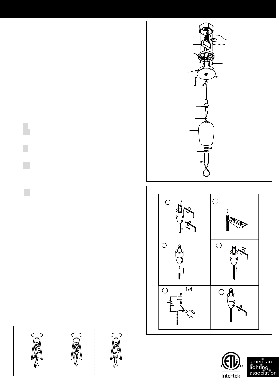
Fig. 1
Fig. 3
Fig. 2
HANGING THE FIXTURE (Fig. 1)
1. Shut off power at the circuit breaker and remove old fixture
including the mounting hardware.
2. Carefully remove the fixture from the carton and check that
all parts are included as shown in the illustration.
3. Attach the Circular Strap (B) to the Outlet box in the ceiling
with two screws (C). The side of the Circular Strap marked
“GND” must face out.
4. Install the Fixture body (F) onto the Ceiling Plate E).
5. Tear the paper off the twin adhesive, then stick
Transformer (A) Into the Outlet Box, make sure it be stuck
tightly.
6. The height of this fixture is adjustable. You can determine
desired distance from ceiling to hang the Fixture and
adjust the length for wire. Please follow the instruction
manual step by step as shown in Fig.2.
Step①. Remove set screw on contact. Back out the lower
set-screw.
Step②. Withdraw cable.
Step③. Use a wire cutter cut to desired length. Strip away
cable and braided sleeve 1-1/4”, Trim 1/4” of plastic
insulation exposing bare wire.
Step④. To prevent lower set screw from penetration inner
wire causing short, secure brass cover (included)
over braided wire using pliers to crimp.
Step⑤. Reinsert cable into contact making sure the rabbet
on the brass tube are vertical with lower set-screw
hole, then tighten set screw and let set screw contact
with exposed wire. Pull gently down along the
braided cable to smooth out any wrinkles.
Step⑥. Use care not to move the cable position and
tighten two lower set-screws first. Be careful not to
pierce the insulation by over tightening.
CONNECTING THE WIRES (Fig. 3)
7. At this point, connect the electrical wire as shown in figure
3, making sure that all wire connectors are secured. If your
outlet has a ground wire (green or bare copper), connect
the fixtures Ground Wire to it. Otherwise, connect the
fixture Ground Wire directly to the circular strap using the
Green Screw provided.
8. Place Canopy (E) over the Circular Strap (B). Turn the
Canopy (E) and let the Stud (D) slide into the slot of
Canopy (E). Tighten the Stud (D).
9. Install Xenon bulb (H) (included) into socket (L) in
accordance with the fixture’s specifications. (DO NOT
EXCEED THE MAXIMUM WATTAGE RATING!) (NE PAS
DEPASSER LA PUISSANCE NOMINALE MAXIMALE!)
10. Place Glass Shade (G) and Plastic Washer (I) over the
Socket (L), fasten with Screw Shell (J) by using the
Spanner (K) provided.
Your installation is now complete. Return power to the
junction box and test the fixture
FIXTURE
WIRES
Black or
Smooth
HOUSE
WIRES
Black
(Hot)
FIXTURE
WIRES
White or
Ribbed
HOUSE
WIRES
White
(Neutral)
FIXTURE
WIRES
Bare
Copper
(Ground)
HOUSE
WIRES
Green
(Ground)
LA-1390E
C
L
K
J
I
H
F
G
D
B
A
1
2
V
3
5
W
E
6
5
1
2
4
3
CONTACT
IMPORTANT: FIXTURE SHOULD BE INSTALLED BY
A QUALIFIED ELECTRICIAN TO ENSURE PROPER
WIRING AND INSTALLATION.
