P50_Operations_Manual_4 04 13_Rev_6 11 15 P50 Operations Manual 4 13 Rev 6
User Manual: P50_Operations_Manual_4-04-13_Rev_6-11-15
Open the PDF directly: View PDF ![]() .
.
Page Count: 47
INSTRUCTIONS
AND REPAIR PARTS
MANUAL FOR
IRONWORKER
MODEL NUMBER
P50
Publication: April, 2013
For Serial Numbers
P50-13,000-Current
to Current Models
www.megafab.com
800-338-5471
Be sure to register your model
and serial number to receive
Piranha Service and Product
Updates.
Piranha Optional Tooling and Attachments
Enhance your Ironworker’s Versatility
Oversize Punch Attachments
• Expand your punching capacity up to 3"
Quickset Gauging Table
Allows you to quickly set-up your punch end
for multiple holes.
Includes an angle gauge bar to index off the
heel of your angle and a plate gauge bar,
which indexes off the end of your plate.
Extensions are available in left and right hand
styles in 5' and 10' lengths.
Backgauge
• Allows you to quickly set-up your machine to
repeat your shearing length by adding a
mechanical backstop.
• Backstop can be positioned in either the
angle, flat bar, or round bar section of the
machine.
• Available in lengths of 3', 6', 9’, or 12'.
• An electronic version is also available, which
cycles the machine automatically when
material makes contact with the backgauge
probe.
Pipe Notching Attachment
• Allows you to single notch Schedule 40 Pipe.
• A must have for handrail jobs.
• Attaches to the punch end of the machine.
• Notching dies available for 3/4", 1", 1-1/4", 1-
1/2", and 2" Schedule 40 Pipe.
•
Oversize Bending Attachments
• Expand your bending capacity to 24" on most
models, 12” on the P2
• Includes a 4-way die block for different
thicknesses of material.
***Additional Options Shown on Inside of Back Cover***

TABLE OF CONTENTS
Refer to second section of this manual for information on repair parts breakdown
and ordering repair parts.
Page No.
FORWARD ................................................................................................. 4
WARRANTY ............................................................................................... 4
INTRODUCTION ........................................................................................ 5
SAFETY PRECAUTIONS ........................................................................... 6
MACHINE SPECIFICATIONS .................................................................... 7
FUNCTIONAL DIAGRAM ........................................................................... 8
DIMENSIONAL DATA ................................................................................. 9
STANDARDS COMPLIANCE. ................................................................... 10
INSTALLATION ......................................................................................... 11
OPERATING INSTRUCTIONS .................................................................. 12
LUBRICATION ........................................................................................... 20
MAINTENANCE ......................................................................................... 21
TROUBLESHOOTING ............................................................................... 22
PUNCH TONNAGE CHART ...................................................................... 17
TOOL LIST ................................................................................................ 18
PUNCH & DIE CLEARANCE CHART ........................................................ 18
ORDERING INSTRUCTIONS .................................................................... 25
REPAIR PARTS ILLUSTRATIONS .......................................................... RP-1
REPAIR PARTS ILLUSTRATION INDEX ................................................ RP-2
SERVICE RECORD CHART .................................................................. RP-20
4
FOREWORD
This manual has been prepared for those persons who will operate and maintain the
Piranha Ironworker. It is important that all persons responsible for the care and
operation of this equipment read and understand the information presented in this
publication.
The illustrations and instructions on the following pages were the most recent
available at the time of publication and selection of this material was made based on
a standard machine arrangement. Differences between the machine you received
and the views contained in this manual are the result of design improvement and / or
the addition of optional accessories specified on your order.
WARRANTY
Mega Manufacturing will replace (F.O.B. our factory), or refund the purchase price
for any goods which are defective in materials and workmanship within 12 months of
date of purchase. The buyer must return the warranty registration card within thirty-
(30) days of the purchase date, and at the seller's option, return the defective
materials freight and delivery prepaid to the seller, which shall be the buyer's sole
remedy for defective materials. Seller shall not be liable to purchaser or any other
person for consequential or incidental damages. Hydraulic and electrical
components are subject to their respective manufacturer's warranties. This warranty
does not apply to machines and / or components, which have been altered in any
way, or subjected to abusive or abnormal use, inadequate maintenance, and
lubrication, or to use beyond seller’s recommended capacities and specifications.
Seller shall not be liable under any circumstances for labor costs expended on such
goods or consequential damages. Seller shall not be liable to purchaser or any
other person for loss or damage directly or indirectly arising from the use of the
goods, or from any other cause. No employee, agent, officer, or seller is authorized
to make oral representations or warranty of fitness or to waive any of the foregoing
terms of sale and none shall be binding on the seller.
5
INTRODUCTION
The Piranha Ironworker is a compact hydraulically powered machine that shears,
punches, bends, notches, and copes, all in a low silhouette, efficiently designed unit,
resulting in minimal floor space requirements. The integral lifting point provides
instant portability and the unit arrives fully assembled, requiring only the addition of
hydraulic oil and electrical power to become fully operational. The platen has six
5/8-11 tapped holes giving a wide base for increased flexibility of attachment sizes.
The shearing operation features an adjustable manual hold-down allowing the
operator to clamp the work piece with a slight initial adjustment. All workstations are
located approximately 42" off the floor for ease of operation.
The first part of this manual provides operations and maintenance instructions,
including a section on troubleshooting various problems that may occur. The
second part of this manual provides repair parts information and a complete parts list
with their respective part numbers.
Proper understanding and application of the information and procedures given in this
manual will aid in establishing a preventative maintenance program and, provide
assistance for correcting malfunctions that may occur in the machine. The repair
parts list provides information for parts procurement as well as assembly
breakdowns to aid in disassembly and re-assembly for repair part installation.
6
SAFETY PRECAUTIONS
The operator of this machine should view the operational video provided with the
machine, and thoroughly understand this manual before starting any operation.
This machine was designed for use by a single operator only.
Wear eye protection at all times.
Use the proper voltage outlet for your machine.
Make sure that all guards and cover shields are down before starting machine.
CAUTION: Do not remove guards.
Keep hands off working tables and out of the path of moving parts during operation.
Remove all material from the tables except for the work piece.
Remove all tooling from the punch end before starting shearing or coping
operations.
Make sure that all tooling is properly held in position before starting any operation.
The area around the machine should be well lighted, dry, and as free from
obstructions as possible.
All maintenance and repair work should be performed by a person familiar with this
publication.
At the end of the working day, the operator should turn the power off to the machine.
Adjust limit switches when punching or bending to allow 1/4" maximum clearance
between bottom of the stripper foot or bending punch and the top of the material.
Contact the factory for limit switch adjustments on special tooling.
Turn the machine "OFF" when changing tooling or performing maintenance work.

7
MACHINE SPECIFICATIONS
HYDRAULIC SYSTEM
Drive Motor
3HP 230 / 460 Volt / 3 Phase
Hydraulic Tank Capacity
12 Gallons
Hydraulic Oil
AW-32 or Equivalent (ISO Grade 32)
Consult your local distributor for a cross reference
WORKING SURFACE
Platen Table
8" x 16"
Coper Table
12" x 14"
CAPACITIES
Punch
Maximum 13/16" Thru 3/4" thick material or 50 Tons
Bending
Maximum 50 Tons
Punch End
Maximum 50 Tons
Bar
1-1/2" Round or 1" Square
Plate
3/4" x 6", 1/2" x 10", or 1/4” x 13”
Angle
3" x 3" x 3/8"
Coper-Notcher
2-1/4" x 3" x 1/4"
WEIGHT
Shipping Weight
1,700 Pounds
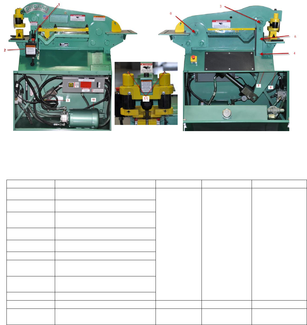
8
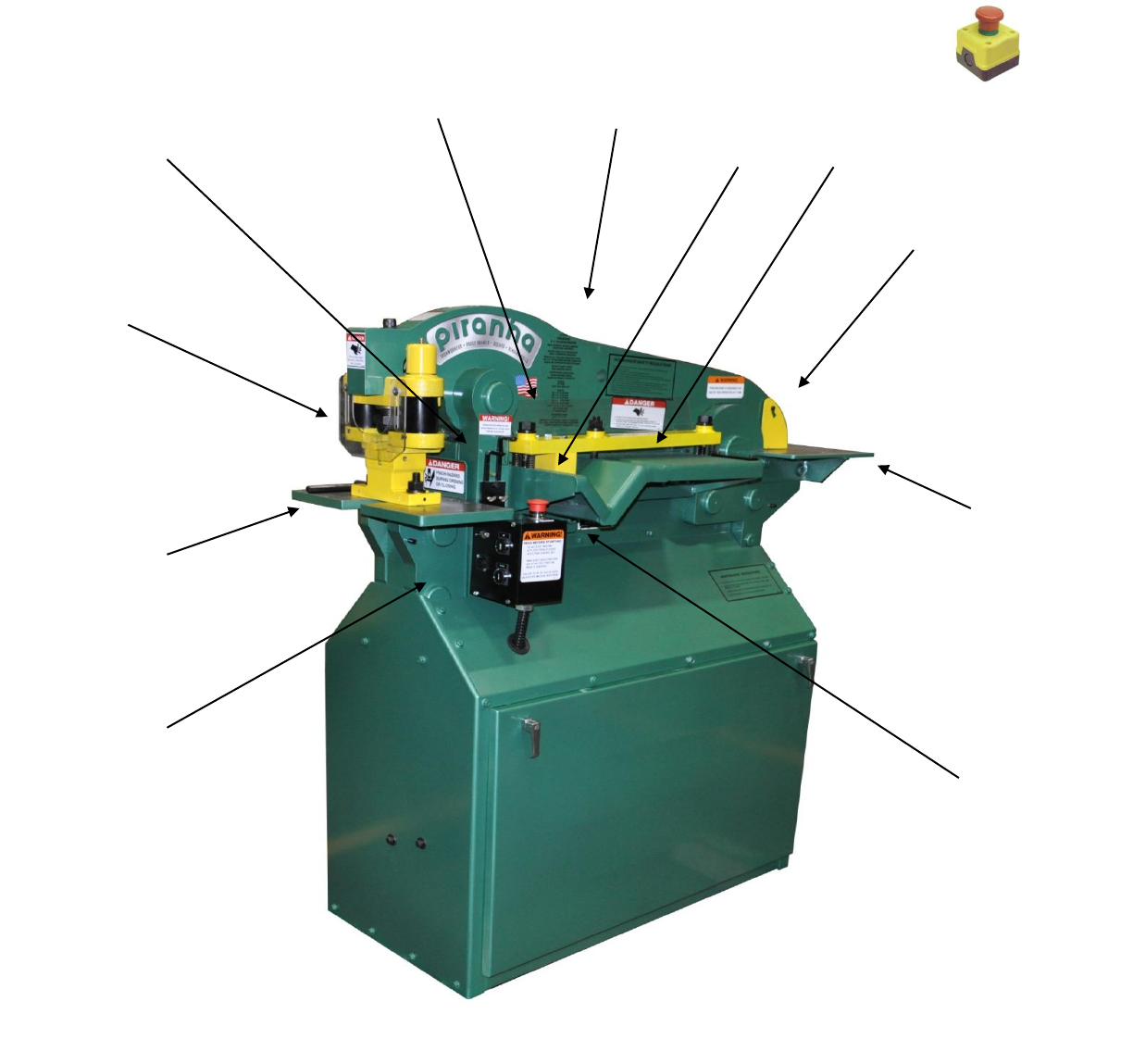
FUNCTIONAL DIAGRAM
Rear Stop Box
(OFF SIDE)
Angle Table
Coper Guard
COPER END
Coper Table
Shear Table
Hold-down
Stroke Control
Punch
Attachment
PUNCH END
Platen Table
Front Control
Box
Serial Number
Plate Location
Lifting Hole
9
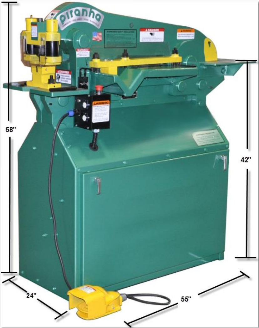
DIMENSIONAL DATA
10
Standards Compliance
Electrical System Design/Manufacture:
The machines manufactured in Rockford, Illinois, USA are furnished with electrical /
electronic products that are UL (Underwriter's Laboratory) approved. These
components have the UL numbers printed or stamped on them and can be easily
traced to the point of manufacture. In addition, all of the machines meet the current
"Ontario Hydro" electrical code for proper manufacture of the electrical circuits.
Hydraulic System Design/Manufacture:
Hydraulic components used in Piranha machines are approved by NFPA (National
Fluid Power Association), and those approval numbers can be traced through the
manufacturer's part numbers.
ANSI/OSHA Compliance:
Mega Manufacturing meets the current ANSI construction standards for
manufacturing of ironworkers, press brakes, and shears:
ANSI Bll.5 - Ironworkers, Construction, Care, and Use
ANSI Bll.3 - Power press brakes, Construction, Care, and Use
ANSI Bll.4 - Shears, Construction, Care, and Use
The ANSI B11 standards were developed to establish levels of responsibility for
manufacturing safe products, and for installing, training, and using these products.
The levels of responsibility are fairly evenly distributed between the manufacturer,
the owner/end-user of the equipment, and the operator. Specific guarding
requirements are, in general, assigned to the owner/end-user of the equipment.
With specific reference to Ironworkers, OSHA (Occupational Safety and Health
Administration) made a ruling on March 4, 1991 - under their standard number
1910.212, specific to the OSHA Machine Guarding Standard 29 CFR
1910.212(a)(1). This ruling is stated verbatim below:
"If an employer provides an iron worker machine (at his or her
workplace), which is manufactured in compliance with the safety
requirements specified in ANSI B 11.5-1988, and the guarding is
maintained as required; then that employer meets OSHA's machine
guarding requirements for that machine."
Please understand that this ruling places the primary burden of responsibility for
maintenance of guarding on the owner/end-user of the equipment. Inherent in this
requirement is the responsibility of the owners/end-users of the equipment to
develop and maintain guarding specific to their application for the equipment. These
ANSI safety requirements may be acquired from:
American National Standard Institute 1430 Broadway
New York, New York 10018 Telephone (212) 354-3300
11
INSTALLATION
Location
For the best overall performance, install the Piranha in a location that is clean and
well lighted. Provide sufficient space in all directions to allow for the material lengths
of the work pieces to be processed by the Piranha.
Foundation
To maintain the accurate alignment built into the Piranha, and to prevent undue
stress on the moving parts under a load, the Piranha should be placed on a stable
base or floor adequately constructed to withstand the unit weight. NOTE: Use the
leveling bolts provided with the machine.
Wiring
The Piranha is shipped totally wired through the electrical enclosure box. It has
been left to the owner's discretion whether to wire direct to an electrical disconnect,
or to install a cord and plug for mobility of the Piranha.
CAUTION: Compare machine wiring to input voltage prior to connecting
power. Only connect the specified voltage to the machine.
Lifting
The lifting hole on the Piranha requires a Deep D-Ring Clevis to lift the machine.
Use a device with adequate lifting capacity to handle the Piranha.
CAUTION: The unit is exceptionally top heavy! Lifting from the underside
of the machine may cause damage to the cabinet structure.
Assembly
The Piranha is pre-assembled at the factory. The only requirements are the addition
of hydraulic oil and electrical power.
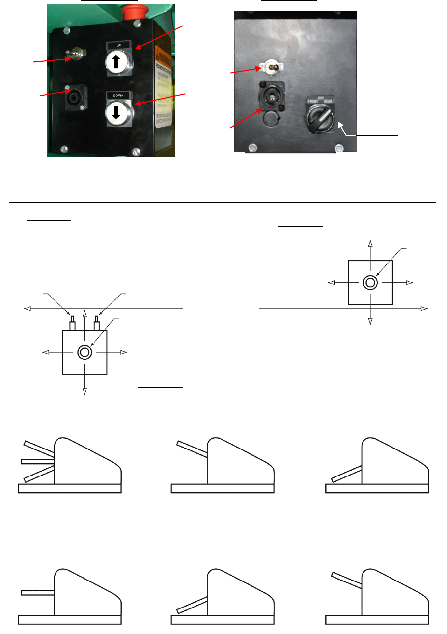
12
Up Button
with Arrow
Toggle
Switch
Down
Button with
Arrow
Rear Foot
Receptacle
Four Pole
Receptacle
Toggle
Switch
Selector Switch
Front- Rear
NOTE: Turn selector
switch to OFF position
when performing
maintenance or
changing tooling.
OFF
Rear Cover
Front Control
Box Only
Front
FIGURE "B"
FIGURE "A"
Rear
FIGURE "E"
View Control Box
Locations
FIGURE "D"
Rear Control Box
MACHINE
Push to Stop/
Pull to Start
Button
Front Cover
Front and Rear
Control Boxes
Up Stroke
Limit Switch
Down Stroke
Limit Switch
Punch End
FIGURE “C”
Front Control Box
Push to Stop/
Pull to Start
Button
Coper End
"F1"
Foot Switch
Foot Switch Lever Positions
1) Beam Moves Up
2) Beam is Stopped
3) Beam Moves Down
Foot Switch Lever
Full Up Position
Beam Elevates
To Limit Setting
Foot Switch Lever
Depressed Past Center
Beam Moves Down
To Limit Setting
Foot Switch Lever
Neutral Position
Beam Travel
Is Halted
Foot Switch Lever
Depressed Past Center
Beam Moves Down
To Limit Setting
Foot Switch Lever
Full Up Position
Beam Elevates
To Limit Setting
Foot Switch
Foot Switch
Foot Switch
Foot Switch
Foot Switch
"F"
"F2"
"F3"
"F4"
"F5"
OFF
ON
13
OPERATING INSTRUCTIONS
(Refer to drawings on page 12)
The Piranha Ironworker comes pre-assembled and pre-wired, requiring only the
addition of hydraulic fluid in the reservoir to the mark on the fill cap dipstick and a
power source from a disconnect to the electrical enclosure box located inside the
cabinet.
The unit can be started and stopped by the Emergency Stop Button operators
located on the top of the control boxes on each end of the unit. (Reference Page 12,
Figure “A”). For the Control Box locations, reference Page 12, Figure "E".
The electrical controls have a selector switch to determine which control box controls
the unit. This safety feature is located on the rear cover of the front control box only,
(reference Figure "B"). The legend plate on the selector switch is printed "Front-
Rear". "Front" allows electrical control to the Front Box only. "Rear" allows electrical
control to the Rear Box only. The Emergency Stop Button should be depressed
when the machine is not being used, such as, changing tooling, maintenance work,
etc. The machine can only be operated from the control box selected via the
selector switch. It can be stopped using either “Emergency Stop” button.
Footswitch Operation
The ironworker can also be controlled by a footswitch (reference Figure "F"). The
footswitch is used by plugging the 4-pole twist lock cap into the 4-pole twist lock
receptacles located in the front cover and rear cover of the front control box
(reference Figure "A" and “B”), and switching the toggle switch (reference Figure "A"
and “B”) from the "OFF" position to the "ON" position.
The footswitch is a three-(3) position switch allowing hands-free operation.
By fully depressing the footswitch lever, machine movement is downward to
limit setting (reference Figure F2).
By allowing the footswitch lever to elevate to the center position, machine
movement stops (reference Figure F3).
Completion of downward cycle is accomplished by depressing footswitch
lever again. Machine movement is down until limit setting is met (reference
Figure F4).
Removing foot pressure from the switch entirely allows machine movement
upward to limit setting, completing upstroke cycle (reference Figure F5).
The footswitch is used in conjunction with the upstroke and down stroke limit
switches located on the front control box only (reference Figure "C").
14
The front limit switch (closest to the punch end and the lower switch of the
two switches) controls the down stroke limit.
The back switch (furthest from the punch end and the higher of the two
switches) controls the upstroke limit.
The limit switches are activated by the limit switch arms: reference part #’s
shown on Page Number RP-5. To set the stroke using the limit switch arms,
use the following procedure:
1) Plug in footswitch.
2) Turn toggle switch to "ON" position.
3) Loosen thumbscrew on down stroke limit-switch arm.
4) Fully depress footswitch lever allowing beam to move downward.
5) Slide limit switch arm until contact with the down stroke switch stops beam
movement at the desired lower limit.
6) Tighten thumbscrew to hold limit switch arm firmly in place.
7) Loosen thumbscrew on upstroke limit-switch arm.
8) Allow footswitch lever to elevate allowing beam to rise.
9) Slide limit switch arm until contact with the upstroke switch stops beam
movement at the desired upper limit.
10) Tighten thumbscrew to hold limit switch arm firmly in place.
NOTE: When punching or using the bending attachment, set upper and lower limits
to allow for 1/4" maximum clearance between the bottom of the punch and
the top of the work material. The setting will change when the work material
thickness changes.
NOTE: The down stroke limit switch on the punch end controls the upstroke limit on
the coper end. The upstroke limit is the only switch active when using the
rear footswitch control. The operator controls the downstroke limit by
allowing the footswitch lever to fully elevate after the upper coper knife
passes through the material.
15
PUNCH ATTACHMENT ALIGNMENT
The alignment of the punch and die should be accomplished in the following
manner. (Reference pages RP-2 and RP-9).
1. Bolt the punch stripper assembly on the upper beam.
2. Tighten the 5/8” x 6” cap screw clockwise (requires 1/2” Allen wrench). This
locks the stripper assembly firmly in place.
3. Remove the coupling nut from the punch stem using the coupling wrench.
4. Insert the punch in the coupling nut and tighten on the punch stem using the
coupling wrench.
5. Insert the female die in the die block.
6. Tighten the setscrew against the female die (requires 3/16” Allen wrench).
7. Slide the die block around the setscrews on the platen table. Do not tighten
the flanged nuts.
8. Push the Emergency Stop Button (reference Figure "E") to turn “OFF” the
machine. Disconnect the foot switch from the receptacle.
9. Start the machine. Use the front control box down push button (reference
Figure "A"), to move the beam downward. Stop beams movement when the
bottom of the stripper foot is approximately 1/8" above the die block.
10. Align the punch and die visually and by hand movement of the die block. Jog
down again slightly and align. Continue this procedure until the punch has
passed through into the die
.
11. Using the wrench supplied with the machine, tighten the flanged nuts on the
setscrews to hold the die block firmly to the platen table.
12. Set the limit switches to control the length of stroke (reference procedures
previously listed).
13. Start operation.
16
STRIPPER ASSEMBLY ADJUSTMENT
NOTE: The Emergency Stop Button should be pushed "OFF" until all
tooling changes are complete. (Reference Page 12, Figure “C”.)
The adjustment of the stripper assembly to compensate for varying punch lengths
should be accomplished in the following manner. (Reference Page RP-9 for a visual
reference).
NOTE: The correct adjustment should have the tip of the punch 1/16" below the
bottom of the stripper footplate and the stripper footplate level.
1. Install the stripper assembly on the upper beam (reference instructions
previously listed).
2. Insert punch in the stripper assembly (reference instructions previously listed).
3. Measure the length of the punch relative to the bottom of the stripper foot.
4. If the tip of the punch extends more than 1/16" below the bottom of the stripper
foot, adjustment is required.
5. Turn the two (2) guide pin adjusting caps counter clockwise until the tip of the
punch extends 1/16" below the bottom of the stripper foot. The stripper foot
MUST remain level or parallel to the work material. The punch tip should be
able to line up on a center punch mark before the stripper foot engages the
material.
6. If the tip of the punch does not extend 1/16" below the bottom of the stripper
foot, or if the stripper foot is not parallel with the work material, adjustment is
required.
7. Turn the two (2) guide pin adjusting caps clockwise until the tip of the punch
extends 1/16" below the bottom of the stripper foot. The stripper foot MUST
remain level or parallel to the work material. The punch tip should be able to
line up on a center punch mark before the stripper foot engages the material.
8. Tighten down the 1/4-20 ball plungers to.
17
(OPTIONAL) BENDING ATTACHMENT ALIGNMENT
The alignment of the bending punch and bending die should be accomplished by the
following manner.
1. Align and bolt the bending punch assembly on the punch end of the machine.
2. Slide the bending die base around the set screws on the platen table, DO NOT
TIGHTEN the 5/8” flanged nuts.
3. Start the machine by pulling both Emergency Stop Buttons up, using the Down
Push Button move the beam downward.
4. When contact between the bending punch and the bending die block opening is
made, the bending die block will center itself.
5. Tighten the 5/8” nuts to hold die block firmly to the platen table.
6. Start operation.
SHEAR/ANGLE HOLD-DOWN ASSEMBLY ADJUSTMENT
The adjustment on the hold-down assembly should be accomplished by the
following manner. (Reference Page RP-6)
1. Raise the upper beam to its full upstroke limit.
2. Loosen the (3) 5/8” flanged nuts without removing them from the studs.
3. Insert material to be sheared under the hold down assembly.
4. Tighten the flanged nuts to allow 1/16” to 1/8” clearance between the hold
down bar and material.
NOTE: Do not attempt to shear any material that will not be held by the Hold-
down Assembly.
18
LUBRICATION
GENERAL
The importance of correct lubrication cannot be over emphasized. Under no
circumstances should the machine be operated without complying with the
lubrication requirements set forth in this publication.
LUBRICATION CHART
Station
Part Lubricated
Frequency
Instructions
Type Lube
1
Upper Pull Arm Material Feed Side
Every 40
Hours Or
Weekly With
Normal Use
Apply Grease
Until It Appears
Around the
Edge Of Parts
Mobile MP Or
Any Multi-
Purpose Grease
2
Lower Pull Arm Material Feed Side
3
Upper Pull Arm Hinge Pin Material
Drop Side
4
Lower Pull Arm Material Drop Side
5
Upper Pull Arm Material Drop Side
6
Rear Hinge Pin Off Side
7
Lower Pull Arm Hinge Pin Material
Drop Side
8
Crank Arm Hinge Pin Material
Feed Side
9
Clevis Pin Material Feed Side
11
Stripper Assembly (2 places)
10
Drive Motor
Once shot per
year
One Shot From
Grease Gun
Multi-Purpose
Grease
19
MAINTENANCE
NOTE: The Emergency Stop Button should be pushed "OFF" while maintenance
checks are being performed. Reference Page 12, Figure “C”.
HYDRAULIC FILTER ELEMENT
The hydraulic oil filter is a vital component of the hydraulic system as it filters
impurities and foreign particles to avoid hydraulic component malfunctions.
CAUTION: When the filter element is plugged, hydraulic fluid will by-pass the
element, allowing contamination to enter the hydraulic system. It is recommended
that the filter element be changed every three-(3) months, depending on workload
and environmental conditions. The element should be changed after the first 40
hours of use. The filter housing is mounted at the tank door inside the machine.
Reference: Repair Parts List for reordering instructions and the item number.
FASTENERS AND CONNECTIONS
The efficiency and accuracy of the Piranha is dependent upon proper alignment of
all parts. Alignment can only be achieved by keeping the fasteners tight. Check all
bolts and nuts for tightness every 40 hours of operation, or when lubricating the
machine. Unless specified in parts illustrations, torque socket head bolts and hinge
pin jam nuts to the specifications in the table on Page 27.
Check all hydraulic hose and fitting connections for tightness when lubricating the
machine. We recommend you use Loctite hydraulic sealant or an equivalent product
on all connectors.
Check to insure the hydraulic cylinder clevis is screwed tight on the piston rod each
time machine is lubricated.
HYDRAULIC OIL LEVEL
Your Piranha ironworker is equipped with a dipstick indicator on the fill cap located
inside the access door. The dipstick is not marked oil should just touch the bottom
of the dipstick for proper fluid level. This should be checked as part of your normal
maintenance cycle.
NOTE: We recommend that you implement a weekly maintenance program to
inspect and lubricate your Piranha. For your convenience, a service record chart
has been provided on Page RP-23.
20
TROUBLESHOOTING
The following material is a trouble-shooting guide to be followed by
maintenance personnel should a problem occur with your machine. Many of
these problems can be solved in your shop by following a step-by-step
procedure for isolating the deficiency. If the deficiency cannot be isolated and
corrected in your shop, any information regarding your effort to isolate the
area should be related to the service technician at Mega Manufacturing, Inc. to
assist him in finding a solution. These efforts will assure restoring your
machine to full operational status with the minimum amount of downtime.
POTENTIAL PROBLEMS AND SOLUTIONS
P1 - MACHINE WILL NOT START
1. Ensure that both Emergency Stop Buttons are pulled up to start.
2. Check fuses at disconnect.
3. Check voltage to motor starter.
4. Transformer control voltage (Output - 120 V). If not, check:
A. Transformer fuse. If blown, inspect circuit for a ground short.
B. Incoming voltage to input side of transformer is correct and the jumper
bars are in the correct location. Reference page RP-11.
C. All wire and fuse holder connections are tight.
D. Possible faulty transformer.
5. Control circuit from transformer to front and rear control boxes to motor
starter coil. (Reference Wiring Diagram page RP-11).
21
P2 - MACHINE STARTS BUT WILL NOT OPERATE
Determine if the problem is electrical or hydraulic by using the manual override
buttons located on the directional valve. (Refer to Page RP-14).
If the machine operates, the problem is electrical. Follow the procedure below:
1. Determine if problem exists in the front control box only, the rear control box
only, or in both control boxes.
A. If problem is isolated to one box only, check the internal wiring and
wiring harness with disconnect plug for loose connection.
B. If the problem exists in both boxes, follow the remaining procedures.
2. Check wiring connections in the electrical enclosure.
3. Check the valve body wiring harness, including the disconnect plugs, for
loose connections.
4. Check coils in the directional control valve.
If the machine does not operate on manual override, the problem is
hydraulic.
1. Check to determine if the pump is developing flow. If not:
A. See if motor rotation is correct.
B. Check motor / pump key is not damaged.
C. Check hydraulic suction line for tightness.
D. Check Oil level.
E. If the above checks out okay, the pump may be defective
2. Check to determine if the spool in the directional control valve is stuck in the
center position. If the valve is stuck, remove the directional control valve
and free the spool. Inspect for contamination.
22
P3 - MACHINE OVERHEATS
1. Check if fluid level in reservoir is low.
2. Check for low line voltage to transformer, causing low control voltage to
directional valve solenoid coils.
3. Determine if limit switches are set improperly when using footswitch,
allowing cylinder to bottom out at retraction and extension. This may cause
hydraulic fluid to by-pass over relief valve, creating heat buildup.
4. Check for restrictions in the hydraulic system. Example: Contaminated
cartridge valve, restricted or kinked hose, etc.
P4 - RESET ON MOTOR STARTER KICKS OUT
1. Internal overheating. Refer to P3, above, for troubleshooting procedure.
2. Insure proper sized heater coils are being used. (Reference the wiring
diagram on Page RP-11).
.
3. Check for proper line voltage.
4. Check for loose connections on motor cable at starter or motor.
P5 - EDGES ON KNIFE BLADE CHIPPED BY MATERIAL
1. Check knife clearance - .007" to .010". If not:
A. Combo table bolts may have become loose, allowing scale and
contamination between table and beam. Remove table and clean.
B. Combo table bolts may have stretched the threads in the beam.
Remove table and sand beam surface flat.
C. Knives may have been ground. Shim to recommended clearance.
2. Knives may be dull and are creating a pulling effect on the shearing edge.
3. Material may be too hard.
4. Material may be thicker than rated capacities.

23
P6 - MACHINE LEAVES BURR WHEN SHEARING
1. Knife clearance: .007" to .010". If not, follow procedure in P-5.
2. Check shear knives for sharpness
3. Check that the automatic hold-down is adjusted to clamp the material
securely.
P7 – MACHINE DOES NOT SEEM TO HAVE ENOUGH PRESSURE TO PUNCH
OR COPE
Install a 3000 PSI pressure gauge into the system at the pump outlet. Then
bottom out the punch end (cylinder extension). The pressure should read
2700 PSI. The coper end bottom out (cylinder retraction) should read 1000
PSI.
1. If pressures are good, check:
A. Tonnage rating of the hole to punch (See page 24).
B. Type of material being punched. Machine capacities are rated on mild
steel. Note: Torching some metals increase their hardness.
C. Proper punch to die clearance on material thickness (See page 25).
D. If punch and die are in good shape.
2. If pressures are low check:
A. Pressure gauge is giving accurate reading.
B. Check cylinder for internal leak or (1) for low punch pressure check
punch relief valve for contamination (See page RP14); (2) for low coper
pressure check coper relief valve for contamination (See page RP14).
Note: Relief valve operating pressure may need reset. Contact factory
technician for adjustment procedure.
Remove pressure gauge when trouble shooting is completed.
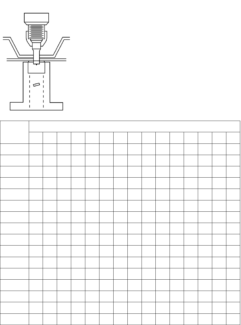
24
TONNAGE REQUIRED FOR PUNCHING HOLES IN MILD STEEL
This table shows the tons of force required for punching
round holes in mild steel derived by the formula:
Force = hole diameter x material thickness x constant 80.
All figures shown are in U.S. tons.
For holes larger than 1 inch, the punching force can be
calculated per the following example:
What pressure is required to punch a 2-1/4" round
hole in 7/8" thick material?
Since a 1" round hole in 7/8" thick material requires
70 tons of pressure, multiply this 70 tons x 2.25 =
157.50 tons.
NOTE: Do not punch a hole with a smaller diameter than
the thickness of the material.
Material
Thickness
Punch Size
1/8
3/16
1/4
5/16
3/8
7/16
1/2
9/16
5/8
11/16
3/4
13/16
7/8
15/16
1
3/32
1
1
2
2
3
3
4
4
5
5
5
6
7
7
8
1/8
1
2
3
3
4
4
5
6
6
7
8
8
9
9
10
3/16
3
4
5
6
7
8
9
9
10
11
12
13
14
15
1/4
5
6
8
9
10
11
13
14
15
16
18
19
20
5/16
8
9
11
13
14
16
17
19
20
22
23
25
3/8
11
13
15
17
19
21
23
24
26
28
30
7/16
15
18
20
22
24
26
28
30
33
35
1/2
20
23
25
28
30
33
35
38
40
9/16
26
28
30
34
36
40
42
45
5/8
31
34
38
41
44
47
50
11/16
38
41
44
48
51
55
3/4
45
49
53
56
60
13/16
53
57
61
65
7/8
61
66
70
15/16
71
75
1
80

25
MAINTENANCE TOOLS LIST
The following tools are required for performing maintenance and to assist you in
troubleshooting your machine:
1. Grease gun with a flexible connection.
2. Open end wrenches. 3/4" thru 1-1/4".
3. Adjustable wrench. 1-1/2" thru 2-1/4" opening.
4. Allen wrenches - 3/16" thru 5/8".
5. Screwdrivers - miscellaneous sizes.
6. Voltmeter.
RECOMMENDED FASTENER
TORQUE SPECIFICATIONS
(Unless Otherwise Specified)
Bolt Size
Torque (Ft-Lbs)
3/8-16
45
7/16-14
70
1/2-13
100
5/8-11
210
3/4-10
375
Jam Nuts
600
DIE CLEARANCE CHART FOR STEEL
Gauge
Decimal
Thickness
Die Clearance
(Add to Punch Size)
13 thru 11
0.089 – 0.125”
0.01”
10 thru 7
0.126 – 0.190”
1/64” (0.016”)
Over 7 thru
1/2" Plate
0.191 – 0.500”
1/32" (0.032”)
Over
1/2” Plate
Over 0.500”
1/16" (0.063”)
ALWAYS PROVIDE THE COMPLETE SERIAL NUMBER FOR PARTS AND SERVICE RP-1
ORDERING REPAIR PARTS FOR A PIRANHA
The following assembly parts lists are shown in four columns. In the first column are
the index numbers of the parts illustrated. The second column contains the Mega
Manufacturing part number, followed by the description in the third column. The last
column shows the quantity of parts required for the assembly.
Electrical wiring diagrams and hydraulic diagrams are shown with the Piranha part
numbers. Some of these items shall be considered as an assembly and only one
part number will be given, even though they are comprised of component parts.
You will receive quicker service when ordering repair parts by adhering to the
following procedure.
1. Provide the complete serial number of the machine. The machine serial number
is stamped on the nameplate and is located on the right hand side of the
machine (when facing the punch end).
2. Provide part number, description, and the quantity of parts that you require.
3. Specify each individual piece required. Do NOT use the term "complete
assembly".
4. Specify how and where to ship. Define the method of transportation desired.
UPS, Old Dominion, and FedEx Freight, are the most frequently used carriers at
Mega Manufacturing.
ALWAYS PROVIDE THE COMPLETE SERIAL NUMBER
FOR PARTS AND SERVICE
ALWAYS PROVIDE THE COMPLETE SERIAL NUMBER FOR PARTS AND SERVICE RP-2
REPAIR PARTS ILLUSTRATIONS
Page No.
Basic Machine.......................................................................................... RP-3
Shear Hold-down Assembly ..................................................................... RP-6
Punch Assembly ...................................................................................... RP-8
Electrical Enclosure ................................................................................ RP-10
Wiring Diagram ....................................................................................... RP-11
Front Control Box .................................................................................... RP-12
Rear Control Box .................................................................................... RP-13
Valve Body Assembly ............................................................................. RP-14
Motor, Filter, and Pump Assembly .......................................................... RP-16
Cylinder ................................................................................................... RP-17
Foot Pedal Assembly .............................................................................. RP-18
Knives (No Illustration) ............................................................................ RP-19
Service Record Chart .............................................................................. RP-20
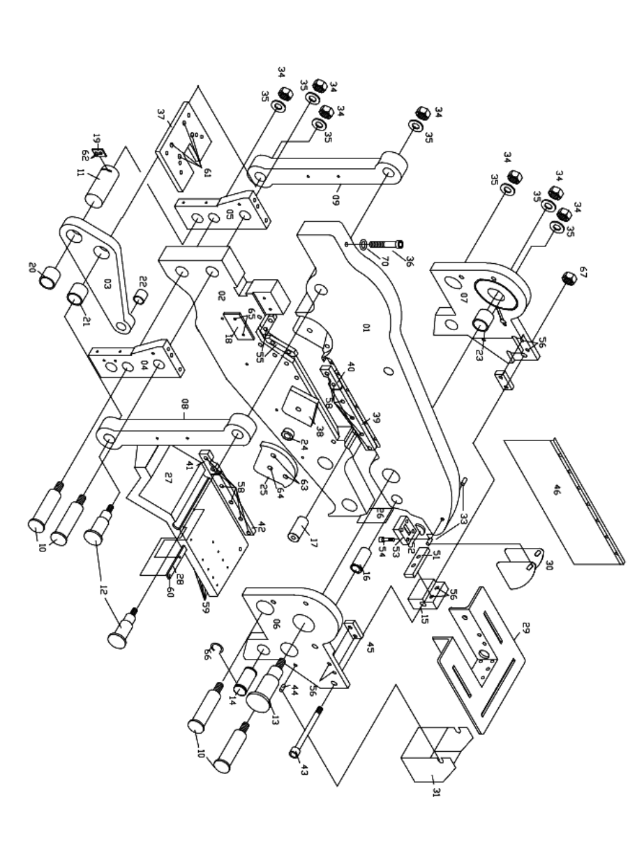
ALWAYS PROVIDE THE COMPLETE SERIAL NUMBER FOR PARTS AND SERVICE RP-3
P50 BASIC MACHINE

ALWAYS PROVIDE THE COMPLETE SERIAL NUMBER FOR PARTS AND SERVICE RP-4
P50 BASIC UNIT
Figure And
Index No.
Part
Number
Description
Qty.
1
0220100
Upper Beam Assembly
1
2
02201011
Lower Beam Assembly
1
3
0220112
Crank Arm Assembly
1
4
0220113
Platen Support-On Side
1
5
0220114
Platen Support-Off Side
1
6
0220115-1
Coper Side Plate-On Side
1
7
0220116-1
Coper Side Plate-Off Side
1
8
02201101-1
Pull Arm-On Side
1
9
0220111
Pull Arm-Off Side
1
10
0220160
Machine Pin
4
11
0220164
Crank Arm Hinge Pin
1
12
02201651
Pull Arm Hinge Pin
2
13
0220166
Rear Hinge Pin
1
14
0220172
Cylinder Pin
1
15
0220117-1
Coper End Knife Support
1
16
0220155
Black Pipe Spacer
1
17
0220154
Urethane Spacer
1
18
0220145
Bronze Wear Plate
1
19
0230148
Crank Arm Pin Lock Plate
1
20
0320168
Crank Arm Bushing
1
21
0320168
Crank Arm Bushing
1
22
0531372
P 125-121 1/4" x 1-1/2" x 1-1/2"
1
23
0320170
Rear Hinge Pin Bushing
1
24
0220167
Angle Knife Bushing
1
25
0220146
Angle Knife Cover
1
26
0321409
Coper End Filler Pit
1
27
0220122
Combo Shear Table
1
28
0220140
Plate Shear Guide
1
29
0220124
Coper Table Assembly
1
30
0220142
Coper Guard Assembly
1
31
0220143
Chip Bucket (optional)
1
32
N/A
Long Reach D-Shackle (not shown)
1
33
0531351
3/8" x 1" Roll Pin
2
34
0521270
1-1/2" NF Jam Nut
7
35
0531303
1.535" I.D. x 3" O.D. x .255" Washer
7
36
0531095
5/8" x 4-1/2" SHCS
1
37
0220120-1
Platen Table
1

ALWAYS PROVIDE THE COMPLETE SERIAL NUMBER FOR PARTS AND SERVICE RP-5
P50 Basic Unit – Continued
Figure And
Index No.
Part
Number
Description
Qty.
38
0220275
Upper Angle Knife
1
39
0220250
"10" Flat Shear Knife"
1
40
0220270
Round Bar Knife Blank
2
41
(Page RP
16)
Round Bar Knife (optional)
2
42
0220250
"10" Flat Shear Knife"
1
43
0531097
5/8" x 6-1/2" SHCS
2
44
0531352
1-1/2" x 1-1/2" Roll Pin
2
45
0220278
Lower Coper Side Knives
2
46
0372415
Shear Guard
1
47
0330128
Coper Table Guides (optional not shown)
3
48
0531715
KP 79 (1/2-13) Plastic Handle (optional not shown)
3
49
0531307
1/2" Flat Plated Washer (optional not shown)
3
50
0531088
1/2" x 1-1/2" Carriage Bolt (optional not shown)
3
51
0220276
Lower Coper End Knife
1
52
0531050
3/8" x 2-3/4" T Woodruff Key
1
53
0220277
Upper Coper End Knife
1
54
0531050
3/8" x 1" SHCS
4
55
0220274
Lower Angle Knives
2
56
0531250
5/8" Nylock HN
2
57
0531086
1/2" x 1-3/4" SCHS
2
58
0531069
7/16" x 1-1/2" SHCS
6
59
0531092
5/8" x 2-1/4" SHCS
9
60
0531000
1/4" x 1/2" SHCS
2
61
0531106
5/8" x 1-1/2" FHCS
4
62
0531060
3/8" x 3/4" HHCS Grade 8
2
63
0531081
1/2" x 1-1/4" SHCS
2
64
0531090
5/8" x 1-1/2" FHCS
1
65
0513062
3/8" x 3/4" FHCS
2
66
0531340
5103-125 Snap Ring
2
67
0531071
7/16" x 2" SHCS
10
68
0531071
7/16" x 2" SHCS
2
69
0531069
7/16" x 1-1/2" SHCS
4
70
0521047
5/8" Flat Washer
1
Not
Pictured
0230153-1
Microswitch Arm Assembly
2
Not
Pictured
0230149
Microswitch Guide Block
1
ALWAYS PROVIDE THE COMPLETE SERIAL NUMBER FOR PARTS AND SERVICE RP-6
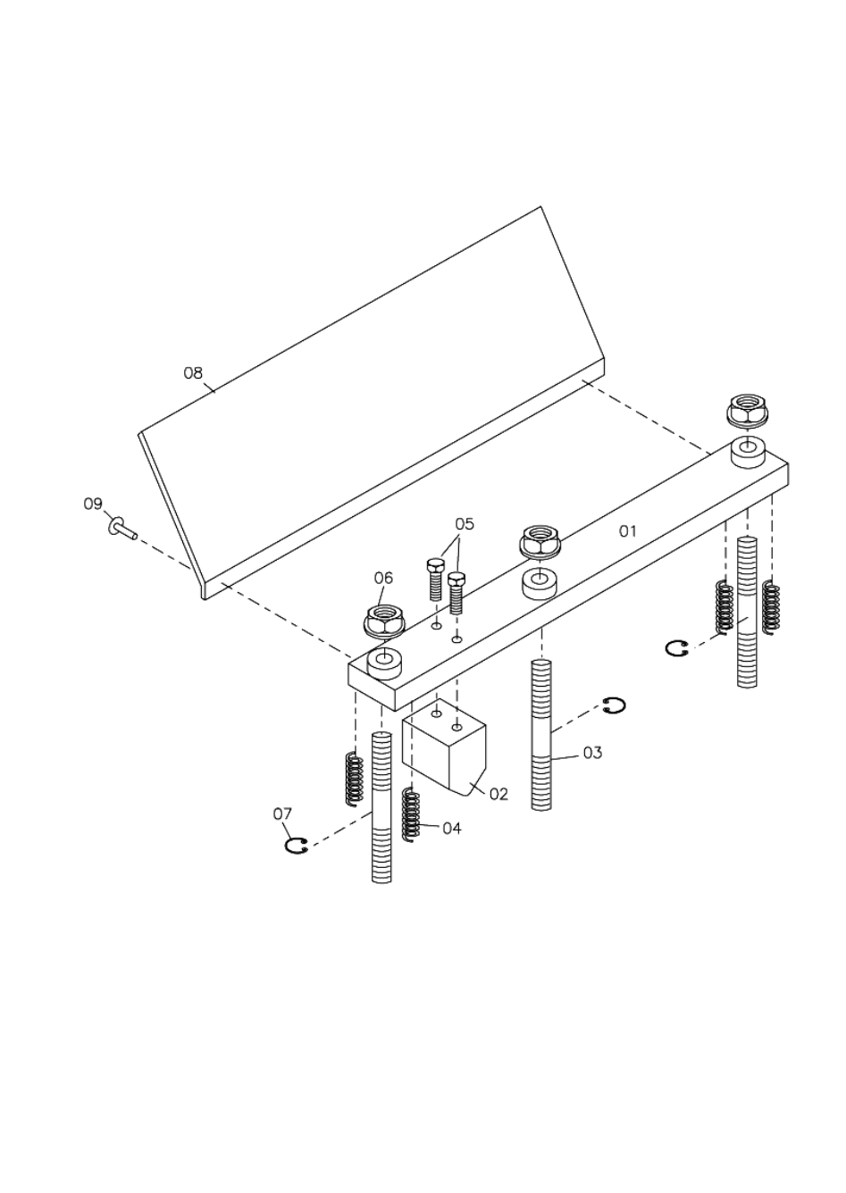
P50 SHEAR HOLD-DOWN ASSEMBLY
PART NUMBER 0220200

ALWAYS PROVIDE THE COMPLETE SERIAL NUMBER FOR PARTS AND SERVICE RP-7
P50 HOLD DOWN ASSEMBLY
PART NUMBER 0220200
Figure And
Index No.
Part
Number
Description
Qty.
1
0320200
Hold Down Bar
1
2
0320204
Angle Block-Hold Down
1
3
0320201
5/8" x 4" Stud W/Groove
3
4
0320208
Hold Down Springs
4
5
0521025
3/8" x 1-3/4" HHCS
2
6
0531251
5/8" Flanged Nuts
3
7
0520155
Snap Ring
3
8
0220203
Hold Down Guard
1
9
0531012
Rivet
2
NOTE: Hold Down Assembly, Number 0220200, Includes Index Numbers 1, 2
and 5.
ALWAYS PROVIDE THE COMPLETE SERIAL NUMBER FOR PARTS AND SERVICE RP-8
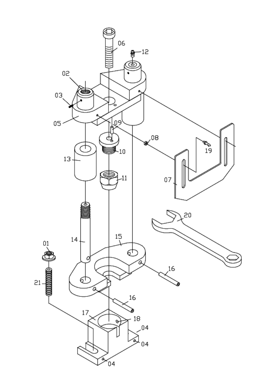
P50 PUNCH ASSEMBLY

ALWAYS PROVIDE THE COMPLETE SERIAL NUMBER FOR PARTS AND SERVICE RP-9
P50 PUNCH ASSEMBLY
PART NUMBER 02204101
Figure And
Index No.
Part
Number
Description
Qty.
1
0531251
5/8" CL-4 FLDG Nut
2
2
0340408
Stripper Guide Pin Adjust Cap
2
3
0541045
W-17N Ball Plunger 1/4-20
2
4
0531002
1/4” x 3/4” SSS
3
5
03204101
Punch Slide Machined
1
6
0531097
5/8” x 6-1/2” SHCS
1
7
0330400
Punch Guard
1
8
0531013
Punch Guard Spacer
2
9
0531350
1/4” x 3/4” Roll Pin
1
10
02204071
Punch Stem
1
11
0330406
Coupling Nut
1
12
0531360
1610 Zerk
2
13
0330403
Stripper Block
2
14
03304021
Stripper Guide Pin
2
15
03304011
Stripper Foot Cast
1
16
0531356
3/8" x 2-1/2" Spiral Pin
2
17
022040011
Die Block
1
18
0531055
3/8” x 1/2” SSS
1
19
0531012
Punch Guard Rivet
2
20
0231410
2" Coupling Wrench
1
21
0531100
5/8” x 3” SSS
2
NOTE: Punch Assembly, Part Number 02204101- Includes Index Numbers 2, 3, 5,
7-16 and 19.
ALWAYS PROVIDE THE COMPLETE SERIAL NUMBER FOR PARTS AND SERVICE RP-10
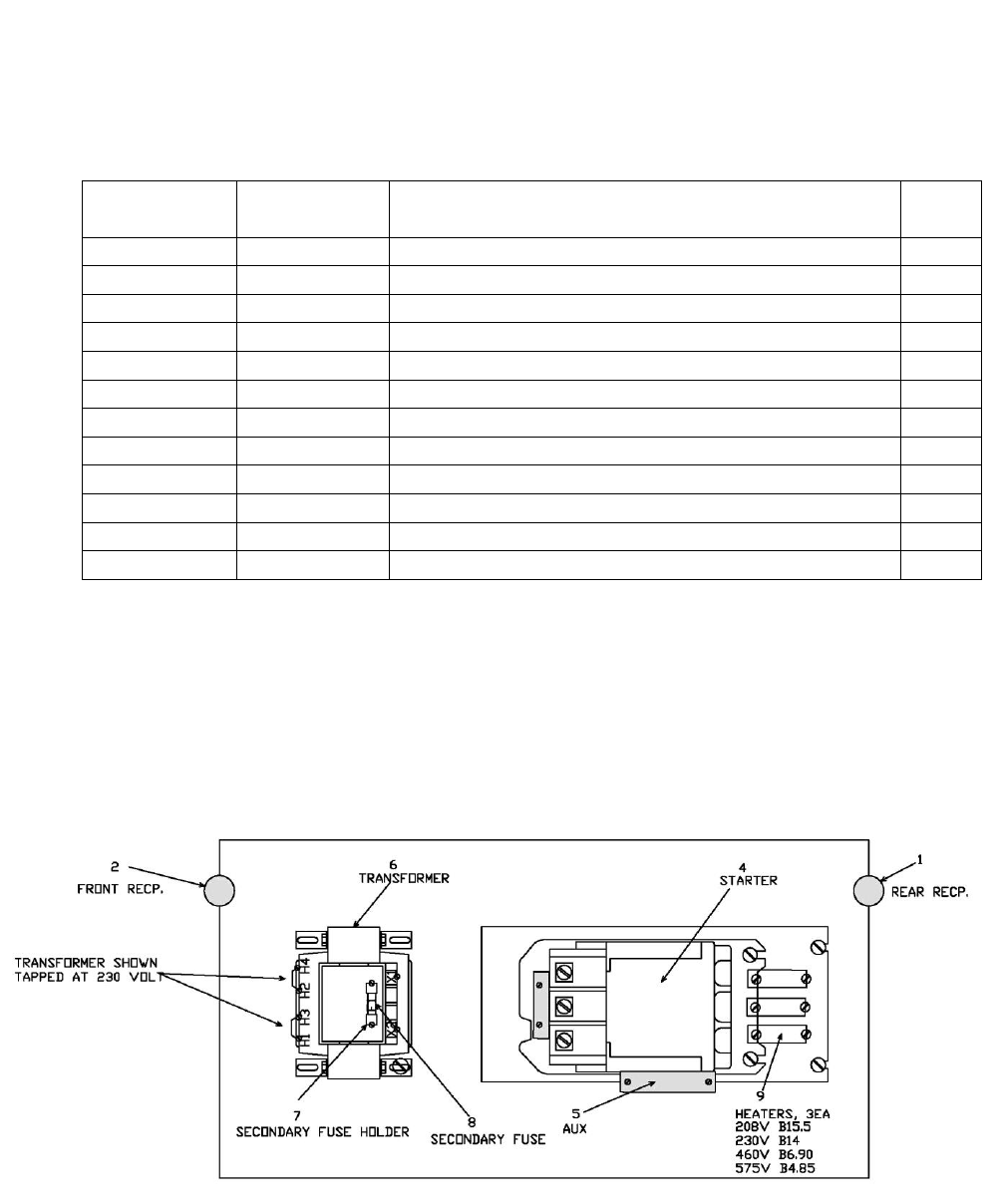
P50 ELECTRICAL ENCLOSURE ASSEMBLY
PART NUMBER 02316402-5
Figure And
Index No.
Part
Number
Description
Qty.
1
0521634
Rear Wiring Harness Receptacle
1
2
0521634
Front Wiring Harness Receptacle
1
4
0521641
Starter
1
5
T2253
Auxiliary Contact
1
6
05316261
220 / 440 Volt Transformer
1
- or -
05316271
575 Volt Transformer
1
- or -
05316281
208 Volt Transformer
1
7
05316221
Fuse Block
1
8
0531606
MDX3 Fuse
1
9
0531635
220 Volt Heater Coil B-15.5
3
- or -
0531810
440 Volt Heater Coil B-6.9
3
- or -
0531811
575 Volt Heater Coil B-4.85
3
.
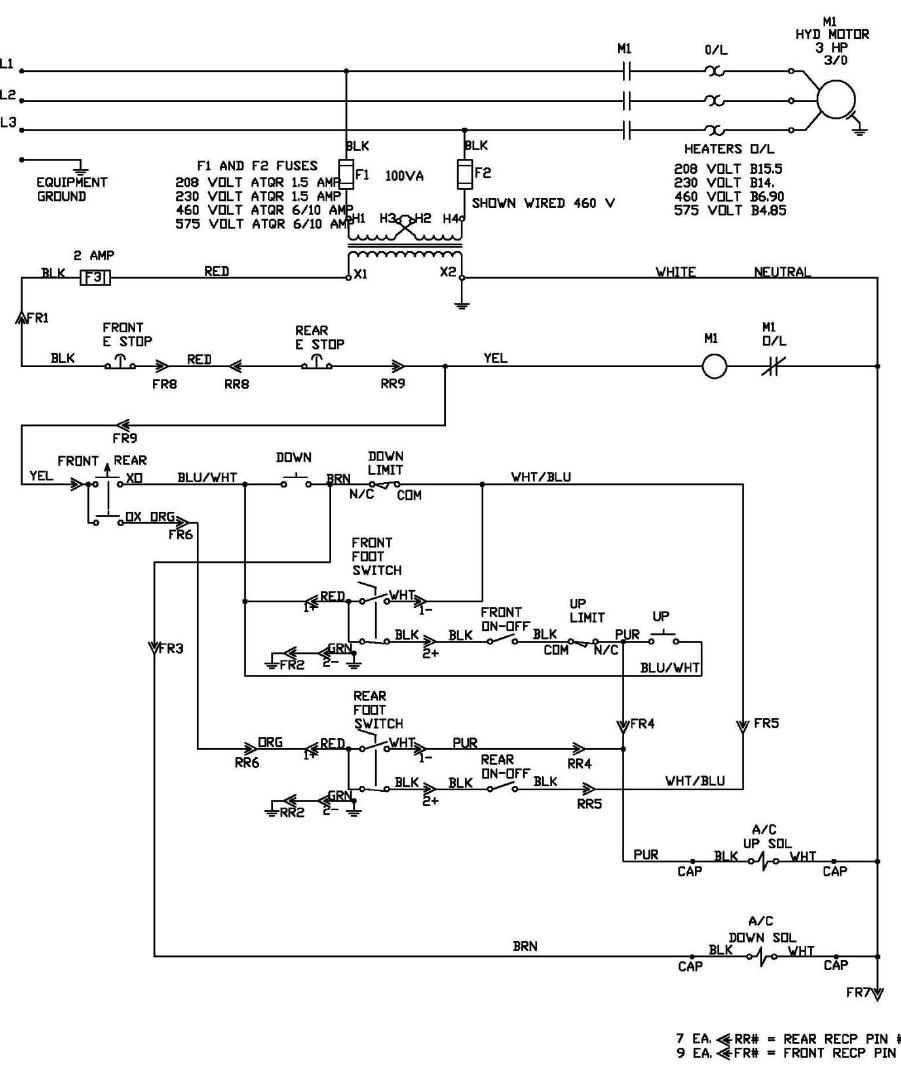
ALWAYS PROVIDE THE COMPLETE SERIAL NUMBER FOR PARTS AND SERVICE RP-11
ALWAYS PROVIDE THE COMPLETE SERIAL NUMBER FOR PARTS AND SERVICE RP-12
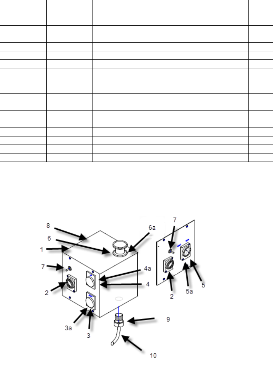
P50 FRONT BOX ASSEMBLY
PART NUMBER 02316292-5
Figure And
Index No.
Part
Number
Description
Qty.
1
05316291
Front Control Box - With Covers
1
2
0531618
4 Pole Receptacle
2
3
?
Down Button
1
3a
0531696-1
Contact Block w/base, N.O. ZB4BZ101*
1
4
?
UP Button
1
4a
0531696-1
Contact Block w/base, N.O. ZB4BZ101*
5
05316451-1
Selector Switch ZB4BD3
1
5a
0531678-1
Mounting Base with 2 each N.O. Contacts
ZB4BZ103*
1
6
0531643-1
Push/Pull Mushroom Button
1
6a
05316121-1
Contact Block w/base, N.C. ZB4BZ102*
1
7
0531619
Toggle Switch
2
8
0531616
Microswitch
2
9
0531654
Liquid Tight Connector, 3/8"
1
10
0531657
JIC Grey Conduit
1
05316781-1
Contact Block N.O. ZB4BE101
0531596-1
Contact Block N.C. ZB4BE102
* Replacement contacts for item number 5a requires 2 each of part number
ZB4BE101 part # 05316781-1. Item Number 3a and 4a requires 1 each.
Replacement contact for item #6a 1 each of 0531596-1.
ALWAYS PROVIDE THE COMPLETE SERIAL NUMBER FOR PARTS AND SERVICE RP-13
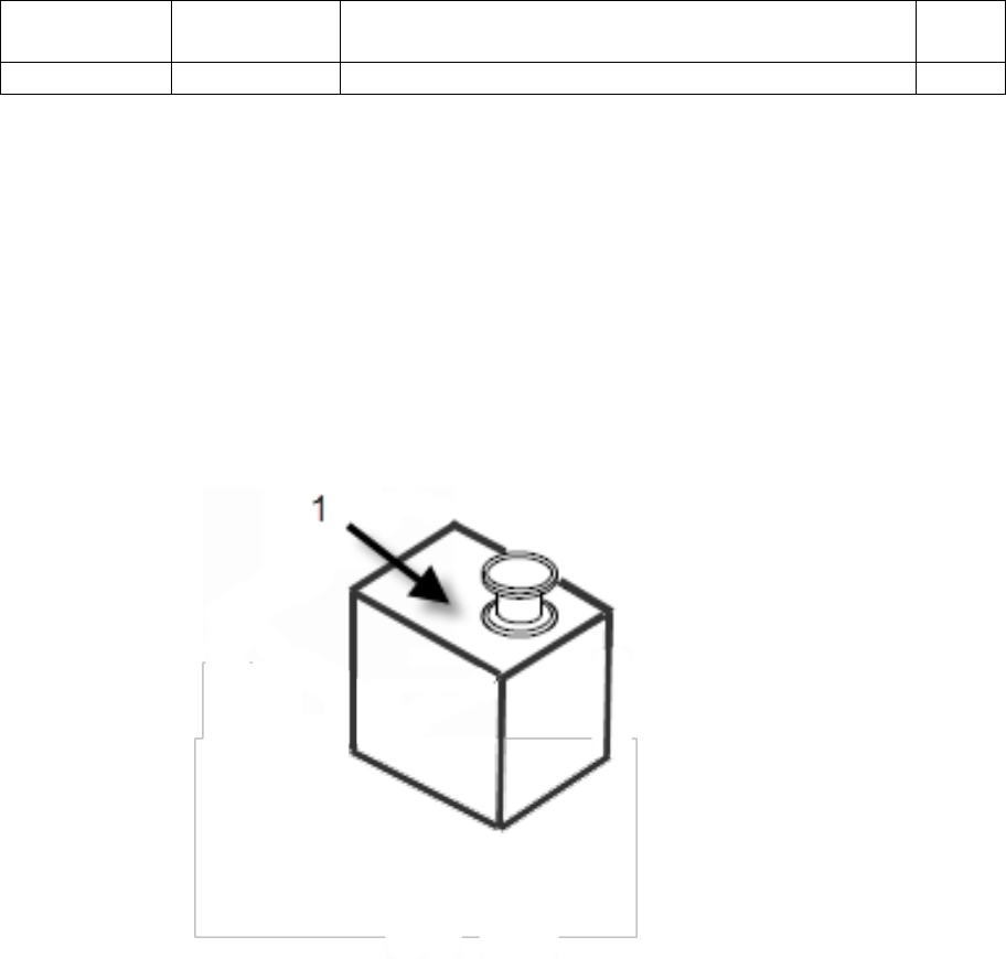
REAR BOX ASSEMBLY
PART NUMBER 02316302-6
Figure And
Index No.
Part
Number
Description
Qty.
1
02316602-6
Rear E-Stop Box
1
ALWAYS PROVIDE THE COMPLETE SERIAL NUMBER FOR PARTS AND SERVICE RP-14
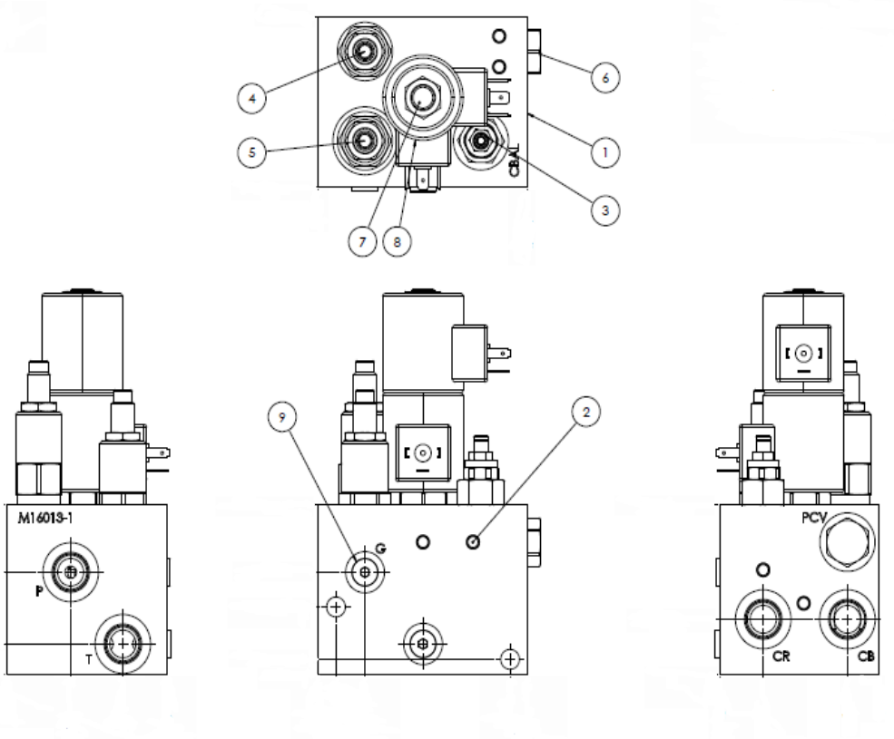
VALVE BODY ASSEMBLY
PART NUMBER 0231530-5
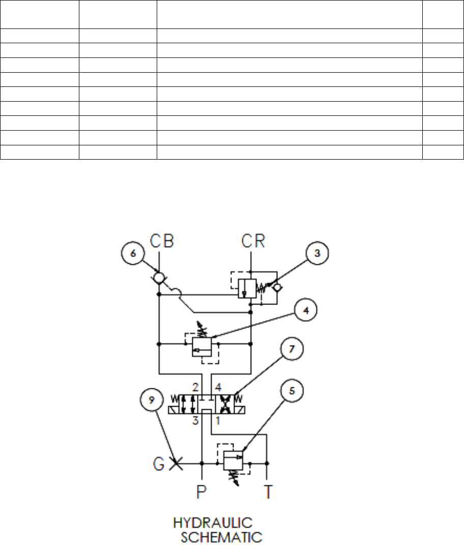
ALWAYS PROVIDE THE COMPLETE SERIAL NUMBER FOR PARTS AND SERVICE RP-15
VALVE BODY ASSEMBLY
PART NUMBER 0231530-5
Figure And
Index No.
Part
Number
Description
Qty.
1
0531812
Valve Body Assembly
1
2
0531813
Expander Plug
1
3
0531814
Counterbalance Valve
1
4
0531815
Coper Relief Valve
1
5
0531816
Punch Relief Valve
1
6
0531737
Cavity Plug
1
7
0531818
Directional Control Valve 4W3P Tandem
1
8
0531819
Solenoid Coil 115V Ac
2
9
0531820
SAE-04 Hex Plug
1
ALWAYS PROVIDE THE COMPLETE SERIAL NUMBER FOR PARTS AND SERVICE RP-16
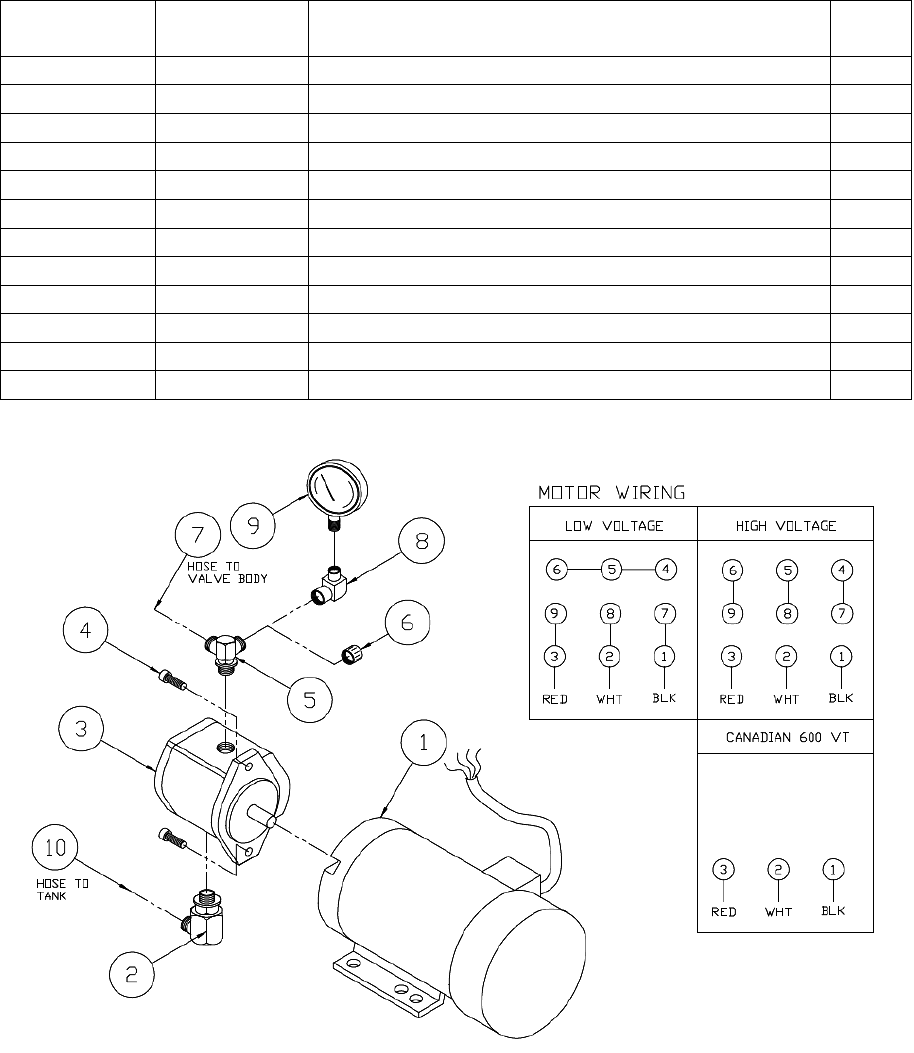
P50 MOTOR ASSEMBLY
PART NUMBER 02216003
Figure And
Index No.
Part
Number
Description
Qty.
1
05216613
3 HP Motor 220/440V (Hollow Shaft)
1
- or -
05216615
3HP Motor 575V (Hollow Shaft)
1
- or -
05216616
3 HP Motor Single Phase (Hollow Shaft)
1
2
0531531
6801-12 Hydraulic Fitting
1
3
05715701-2
Hydraulic Pump
1
4
0531050
3/8" x 1" SHCS
2
5
0531508
6801-10-12LP JM6 Hydraulic Fitting
1
6
0541531
304-C-6 Hydraulic Fitting
1
7
0571532
32" Hose To Valve Body
1
8
0531514
6503-6-4 Hydraulic Fitting
1
9
0541542
Pressure Gauge PGD-25-5000S
1
10
0531544
48" Hose To Tank
1

ALWAYS PROVIDE THE COMPLETE SERIAL NUMBER FOR PARTS AND SERVICE RP-17
P50 CYLINDER ASSEMBLY
Figure And
Index No.
Part
Number
Description
Qty.
1
0521505-1
Cylinder
1
2
0230171
Clevis Pin
1
3
02201521
Clevis
1
4
0531340
5103-125 Snap Ring
4
5
0531362
Straight Zerk
1
6
0531085
1/2" x 1/2" SSS
1
7
0220172
Cylinder Pin
1
8
0521572
6802-10-8 Hydraulic Fitting
2
9
0531521
50" Hose To Valve Body
1
10
0531522
75" Hose To Valve Body
1
11
N/A
Nylock Plug
1
SEAL INSTALLATION
ALWAYS PROVIDE THE COMPLETE SERIAL NUMBER FOR PARTS AND SERVICE RP-18
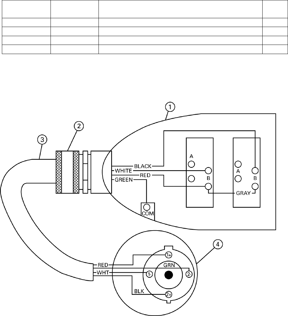
FOOT SWITCH ASSEMBLY
PART NUMBER 0231628CH
Figure And
Index No.
Part
Number
Description
Qty.
1
0531655
Foot Switch
1
2
0531636
Cord Grip
1
3
0531637
16 - 4 SEO Cord (sold by the foot)
6 ft
4
0531617
4 Pole Plug
1
NOTE: Limit Switches in Foot Pedal are not a stock item.

ALWAYS PROVIDE THE COMPLETE SERIAL NUMBER FOR PARTS AND SERVICE RP-19
P50 KNIVES
Index No.
Part
Number
Description
Qty.
0220250
Flat Shear Knives x 10"
2
0220251
Flat Shear Knives x 13"
2
0220252
1/4" Round Bar Knife
2
0220253
3/8" Round Bar Knife
2
0220254
1/2" Round Bar Knife
2
0220255
5/8" Round Bar Knife
2
0220256
3/4" Round Bar Knife
2
0220257
7/8" Round Bar Knife
2
0220258
1" Round Bar Knife
2
0220259
1-1/8" Round Bar Knife
2
0220260
1-1/4" Round Bar Knife
2
0220261
1-3/8" Round Bar Knife
2
0220262
1/2" Square Bar Knife
2
0220263
5/8" Square Bar Knife
2
0220264
3/4" Square Bar Knife
2
0220265
7/8" Square Bar Knife
2
0220266
1" Square Bar Knife
2
0220270
Round Bar Knife Blank
2
0220274
Lower Angle Knife-
2
0220275
Upper Angle Knife
1
0220276
Lower Coper End Knife
1
0220277
Upper Coper Knife
1
0220278
Lower Coper Side Knife
2
0531050
3/8" x 1" SHCS - Upper Coper
4
0531069
7/16" x 1-1/2" SHCS - Lower Coper Side
2
0531069
7/16" x 1-1/2" SHCS - Upper Shear
4
0531069
7/16" x 1-1/2" SHCS - Upper Round Bar
2
0531071
7/16" x 2" SHCS - Lower Coper End
2
0531071
7/16" x 2" SHCS - Lower Shear
4
0531071
7/16" x 2" SHCS - Lower Round Bar
2
0531071
7/16" x 2" SHCS - Lower Angle
4
0531330
Woodruff Key - Upper Coper Knife
1

ALWAYS PROVIDE THE COMPLETE SERIAL NUMBER FOR PARTS AND SERVICE RP-20
DATE
LUBRICATION
KNIFE & TABLE BOLTS
MACHINE & CABINET BOLTS
HYDRAULIC CONNECTIONS
OIL LEVEL AND / OR CHANGE
OIL FILTER
KNIFE EDGES
REMARKS
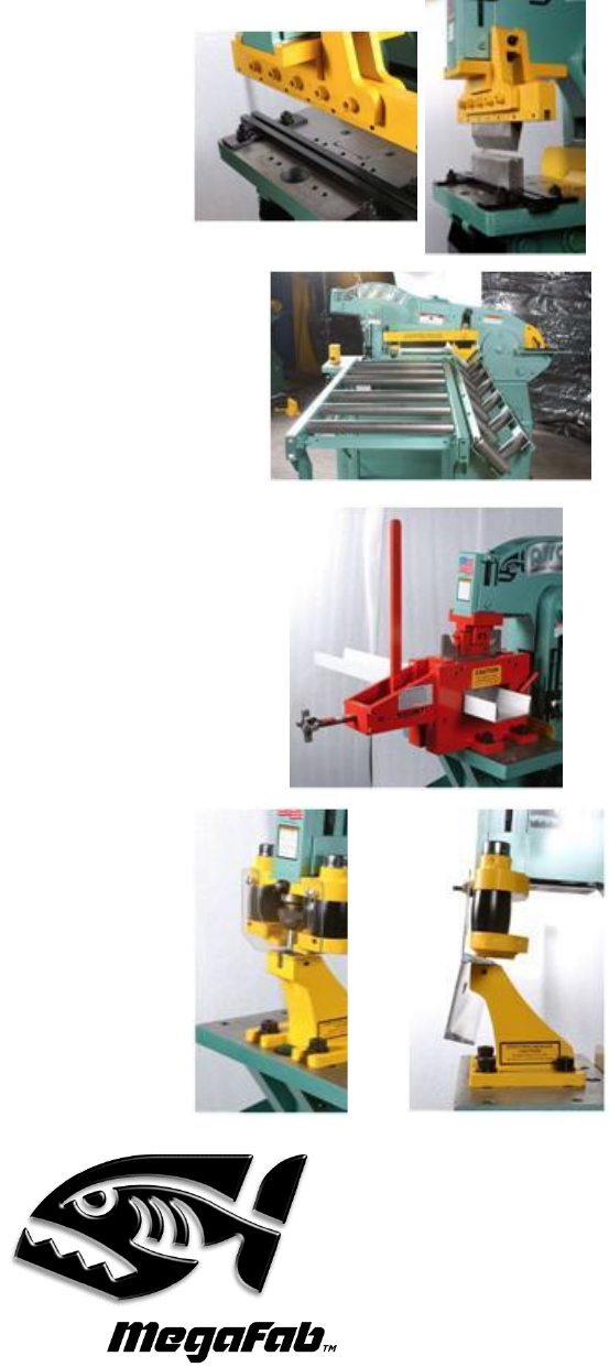
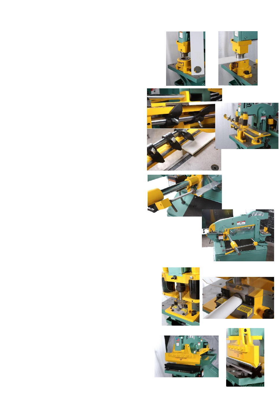
Piranha Optional Tooling and Attachments
***Additional Options Shown on Inside of Front Cover***
Enhance your Piranha’s versatility!
Pressbrake Tooling Holders
Allows you to use pressbrake punches
and dies in your ironworker for higher
precision bending. Not available on the
P2 model.
Roller Feed Tables
Available in 5' lengths.
Includes rollers for angle and flat bar
sections.
20ʺ wide flat rollers and 6ʺ angles.
Channel Shear
Attaches to the punch end of the
machine.
Removes a 1/2ʺ slug for each cut.
Slug must be slid out the front of the
channel shear after each cut.
A pinned slide block is adjusted to
accommodate different widths of channel.
Not available on the P2 model.
Channel Die Block
Enables you to punch into the legs of
channel and other structural shapes.
Mounts in place of your standard die
block.
Still utilizes your urethane punch
attachment.
Can be used in conjunction with offset
dies to punch very near to the web of your
material.
