SM8100/SM9100_Users_Guide PB63023 01 GC9200 Users Guide
User Manual:
Open the PDF directly: View PDF ![]() .
.
Page Count: 47

PB63023_01
GC9200 PLC Demo &
Evaluation Node User Guide
© GridComm Pte. Ltd. Page 1 of 47
GC9200 DIN RAIL PLC MODEM
USER GUIDE

PB63023_01
GC9200 PLC Demo &
Evaluation Node User Guide
© GridComm Pte. Ltd. Page 2 of 47
GC9200, GC-Net and the gridComm logo are trademarks of gridComm Pte Ltd registered in Singapore
and other countries.
GRIDCOMM MAKES NO REPRESENTATION, WARRANTY, OR CONDITION OF ANY KIND,
EXPRESS, IMPLIED, STATUTORY, OR OTHERWISE OR IN ANY COMMUNICATION WITH YOU,
INCLUDING, BUT NOT LIMITED TO, ANY IMPLIED WARRANTIES OF MERCHANTABILITY,
SATISFACTORY QUALITY, FITNESS FOR ANY PARTICULAR PURPOSE, NONINFRINGEMENT, AND
THEIR EQUIVALENTS.
No part of this publication may be reproduced, stored in a retrieval system, or transmitted, in any form or
by any means, electronic, mechanical, photocopying, recording, or otherwise, without the prior written
permission of gridComm Pte Ltd
.
Copyright ©2014 by gridComm Pte. Ltd.

PB63023_01
GC9200 PLC Demo &
Evaluation Node User Guide
© GridComm Pte. Ltd. Page 3 of 47
1. Introduction- GC9200 DIN Rail PLC Modem ..................................................................................................... 4
2. Basic Setup to Connect GC9200 PLC Modem to Host PC via PLCM Utilities GUI ............................................... 6
3. Operation Modes ........................................................................................................................................... 20
4. gridComm GC-Net Simple Broadcast Communications .................................................................................. 20
5. gridComm GC-Net Point-to-Point Communications ....................................................................................... 22
6. gridComm GC-Net Auto-Routing Network Communications .......................................................................... 23
7. gridComm GC-Net Auto-Routing Software ..................................................................................................... 25
8. GC-Net Broadcast Routing Communications .................................................................................................. 35
9. Network Management Commands ................................................................................................................ 37
10. GC-Net PLC Quick Reference .......................................................................................................................... 40
11. FAQ ................................................................................................................................................................ 42
12. Dimensions of DIN Rail PLC Modem ............................................................................................................... 46
13. Contact Information ...................................................................................................................................... 46
14. Revision (051-03) ........................................................................................................................................... 47
PB63023_01
GC9200 PLC Demo &
Evaluation Node User Guide
© GridComm Pte. Ltd. Page 4 of 47
1. Introduction- GC9200 DIN Rail PLC Modem
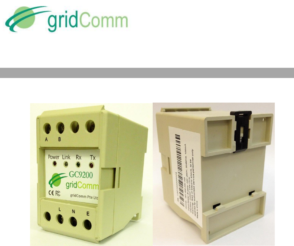
Figure 1 - The GC9200 DIN Rail PLC Modem
The Gridcomm GC9200 is an industrial grade DIN Rail Power Line Communication (PLC) modem.
It mounts to a 35mm x 7.5mm or 35mm x 15mm DIN Rail. The rear of the GC9200 enclosure
contains a spring-loaded DIN Rail lock, which securely grabs the DIN Rail on which the enclosure
is mounted. To release the enclosure from the DIN Rail, insert a flathead screwdriver into the DIN
Rail locking tab and gently pull the tab downwards and away from the enclosure.
GC9200 has been tested to CE and FCC standards and found to comply with the limits of EN
50065-1, EN 55022, EN 55024, EN 61000-3-2, EN 610000-3-3, EN 61000-6-2 and EN 61000-6-
4 FCC Part 15B for EMC and EN 60950 for safety. These limits are designed to provide reasonable
protection against harmful interference.

PB63023_01
GC9200 PLC Demo &
Evaluation Node User Guide
© GridComm Pte. Ltd. Page 5 of 47
When connected with a Single-Phase AC power supply (220~240V at 50/60Hz with 100mA) via
“L” (Live) and “N” (Neutral) input connectors, the GC9200 becomes a smart device which can
automatically configure and self-adapt to the varying conditions on power lines, resulting in
extremely reliable and robust communications in a Low-Voltage power network. The DIN Rail PLC
modem utilizes the industry-leading GridComm GC2200, an OFDMA (Orthogonal Frequency
Division Multiple Access) Power Line Communication Transceiver which has 18 independent
channels capable of communicating over 54 carrier frequencies in a wide frequency range from
5 KHz to 500 KHz. Its good performance and multiple features make it very attractive in
applications such as Advanced Metering Infrastructure (AMI), Smart Lighting Control,
Industrial/Building Automation, Alternative Energy, M2M and others.
The GC9200, powered with gridComm GC-Net software, can hook up with the gridComm
PLCM_Utilities tool via a RS485-USB cable for easy configurations and settings. It can
communicate over a transparent protocol in various operation modes.
PB63023_01
GC9200 PLC Demo &
Evaluation Node User Guide
© GridComm Pte. Ltd. Page 6 of 47
2. Basic Setup to Connect GC9200 PLC Modem to Host PC via PLCM Utilities GUI
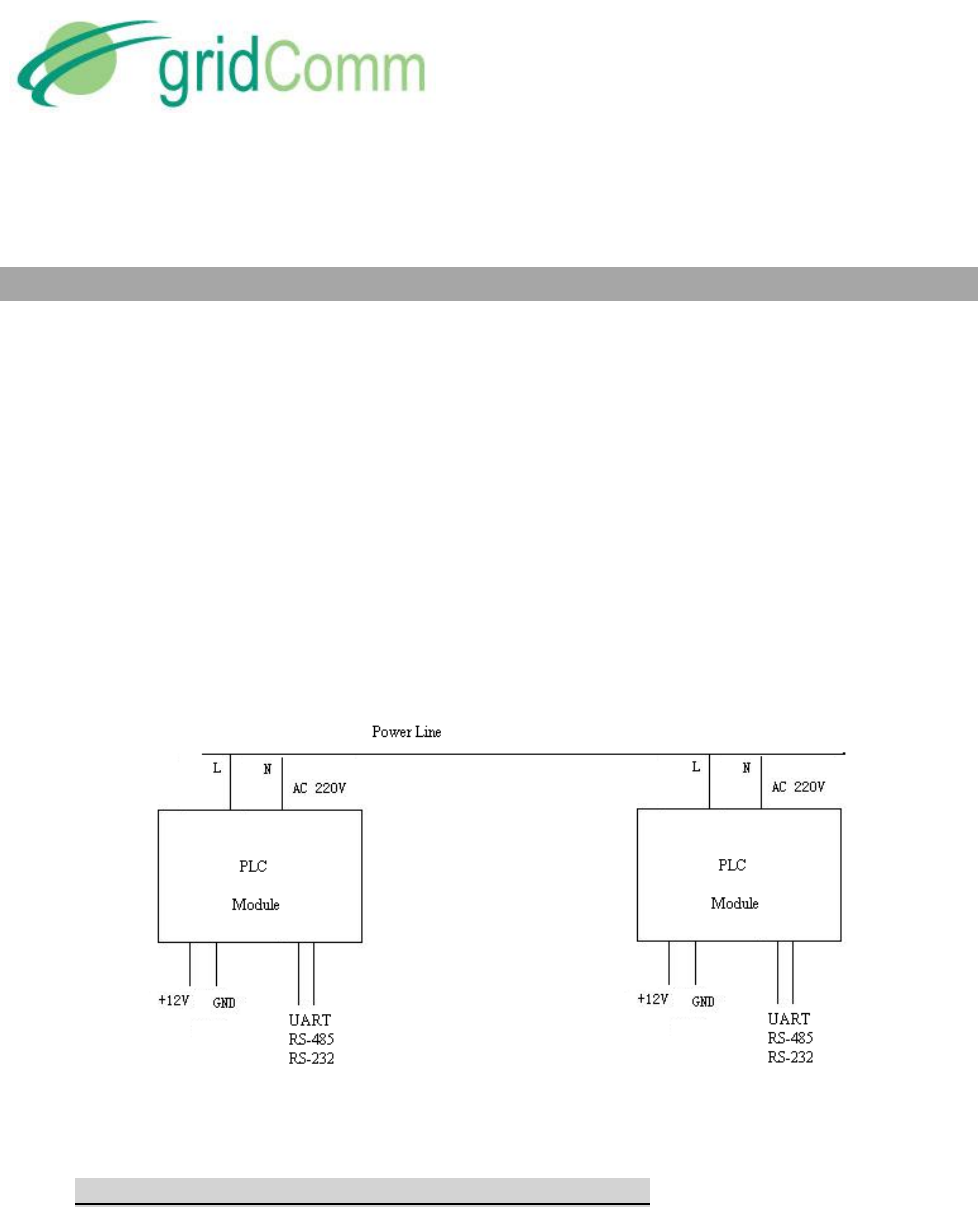
The GC9200 supports a direct RS485 interface.
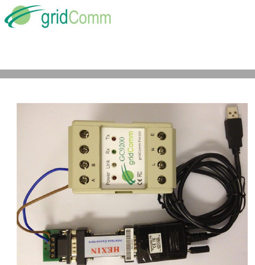
Figure 2 – GC9200Connection with a RS485-RS232-USB Cable
Figure 2 shows a typical RS485-RS232-USB cable (not provided) connection with a GC9200. The
default settings for the PLC modem serial communications are pre-configured ex-factory at
115200 Baud, No Parity Bit, 8 Data Bits and 1 Stop Bit. When the GC9200 is powered up under
“Auto Routing” or “Broadcast Routing” mode, the Link LED will light up and will flash every 10
seconds showing that it is working properly. When in “Point-to-Point” or “Simple Broadcast”
mode, it will flash every 0.2 seconds.
To use the PLCM Utilities GUI, connect the GC9200 to the RS485-RS232-USB cable and connect
the USB connector of the cable to a USB port of a Windows PC.

PB63023_01
GC9200 PLC Demo &
Evaluation Node User Guide
© GridComm Pte. Ltd. Page 7 of 47
Before using the GC9200 to communicate, it is necessary to configure the device. Start the
PLCM Utilities GUI on the PC which is connected to the GC9200 and use the GUI to configure
the GC9200. The following is a description of how to use the GUI.
2.1. “Communication” Tab
Figure 3 – “Communication” Settings
a) Host UART: Click on the “Communication” tab to set the virtual COM port that is
connected to the USB-UART board. To begin with, leave the rest of the serial
communication parameters as default: 115200 Baud rate, No Parity Bit, 8 Data Bits and 1
Stop Bit. These are the PC UART communication settings with the device.
The Host PC simulates a concentrator or terminal device connected to the device.
Start the UART communications by toggling “Open UART” until it is depressed. If the Host
UART is set properly, a message, “gridComm © 2013, Firmware ver. X.X.X (Date in
YYYY.MM.DD)” message, will show up in the message window upon powering up or
resetting of the device.
b) Safe Mode: The Safe Mode serves two functions:

PB63023_01
GC9200 PLC Demo &
Evaluation Node User Guide
© GridComm Pte. Ltd. Page 8 of 47
It can be used to restore the device to default settings (115200 Baud rate, No Parity Bit,
8 Data Bits and 1 Stop Bit) so as to regain access to the device should the user forget
the current UART configuration.
It allows the user to amend the device configurations regardless of whether the
firmware is in locked or unlocked mode. The firmware can be locked or unlocked under
the “Mode Config” tab. Locking the firmware prevents accidental changes to the
settings. Unlocking the firmware from Locked mode allows the user to make changes to
all settings under Module Config, Mode Config and GC2200 Config tabs.
To activate Safe Mode, check the “Safe Mode” checkbox and reset the device. Upon reset,
the system will enter into Safe Mode within 2 seconds. The “Safe Mode” checkbox
automatically unchecks.
c) HEX Display/HEX Input: If HEX data is to be used, check the HEX Display and HEX Input
boxes.
d) “Time”ms/Auto Send: Setting the time in “ms” sets the time interval between each Send
when “AutoSend” is checked. It is highly recommended to start with more than 1000ms
for Point-to-Point mode and larger values for Auto-routing or Broadcast Routing mode
depending on the number of tiers in the network. The 1000ms is to allow sufficient time
for the packet to be sent over the PLC. If the time is too short, the transmissions may
collide and data will be lost. Try setting longer time intervals if packets are lost.
e) Tx/Rx: Under the “Auto Send”, the figure next to the “Tx” and “Rx” shows the number of
characters sent or received.
f) Reset Module: All “Write” functions such as “Write Into Module” and “Write Parameter”
must be followed by resetting the device via the “Reset Module” button. This will then
register the changes into the device. Send Data: Hitting “Send Data” will send the data
contained in the green message window over the power lines to destination PLC node(s).

PB63023_01
GC9200 PLC Demo &
Evaluation Node User Guide
© GridComm Pte. Ltd. Page 9 of 47
2.2. “Module Config” Tab
Figure 4 – “Module Config” Settings
a) Module UART Configuration: Click “Read From Module” to read the UART settings. To
make changes to the settings to connect with the Host UART(or your concentrator or
terminal device UART), enter the values accordingly and click “Write Into Module”. The
default settings of the device are 115200 Baud rate, No Parity Bit, 8 Data Bits and 1 Stop
Bit. After changes are made to the settings, reset the device to effect the changes to the
device. It is important to note that settings for the device UART must be exactly the same
as the Host UART (or the concentrator or terminal device UART) before the
communication link can be established. If the UART settings on the device are not known,
Safe Mode may be entered as described in“Safe Mode” section in page 7 which would
allow the user to gain access to the device to re-configure the UART settings.

PB63023_01
GC9200 PLC Demo &
Evaluation Node User Guide
© GridComm Pte. Ltd. Page 10 of 47
b) Module PHY_ID Configuration: Click “Read From Module” to show the pre-programmed
PHY_ID. The value in each of the four boxes under “Module PHY_ID Configuration” is an 8
bit number. The valid PHY_IDs for the GC9200 device range from 001.000.000.000 to
001.255.255.255. All PHY_IDs are unique and no two devices share the same PHY_ID.
c) Update Firmware: Allows the user to update device firmware (contained in a bin file) via
the UART. This works only in Safe Mode or if Locked mode is unchecked. When the button
is clicked, the GUI will prompt for the bin file to be used as the update. After choosing the
correct bin file in your folder on your PC, the update process starts. When the firmware is
updated, the device will reset automatically.
d) Reset Factory Default Setting: This resets the settings to factory default:
Module UART Configuration to 115200 baud rate, 8 Data Bits, 1 Stop Bit and none Parity
Expected Nuber of Slave Nodes to 1,
Operation Mode Configuration to “Simple Broadcast”,
Assign Master Node PHY_ID of Network to “0.0.0.1”, “0.0.0.2” and “0.0.0.3”,
Connection ID to “1”,
Output Power to “350”, and
GC2200 Parameters Configuration frequencies to 180.6KHz, 214.8KHz, 161.1KHz,
141.6KHz, 195.3KHz, 346.6KHz, 92.77KHz and 395.5 KHz
e) Expected Number of Slave Nodes: The expected number of slave nodes is the total
number of slave nodes (not including the master node) that is expected to be deployed in
a network. The master node will determine if the total number of slave nodes registered
during network discovery phase matches this Expected Number of Slave Nodes. As soon as
this number matches, the RUN LED on the master node will start flashing every 0.4 sec
rather than every 10 sec seen earlier. Hence, without knowing the Routing Table, the user
is able to tell if the given number of slave nodes have been registered in the network by
just observing the rate of flashing of the LED on the master node. If the RUN LED reverts to
flashing every 10 sec, it means that one or more slave nodes have been disconnected from
the network. However, should there be more slave nodes detected (more than the
“Expected Number of Slave Nodes”), the master node will still flash every 0.4 sec. For
details on the number of nodes discovered, one may look at the Routing Table
information, see “Routing Table” section in page 16. Click “Read From Module” to display
the existing settings for this field. To make changes to the existing settings, enter the
values accordingly and click “Write Into Module”. Remember to reset the device after
performing “Write Into Module”.
PB63023_01
GC9200 PLC Demo &
Evaluation Node User Guide
© GridComm Pte. Ltd. Page 11 of 47
2.3. “Mode Config” Tab
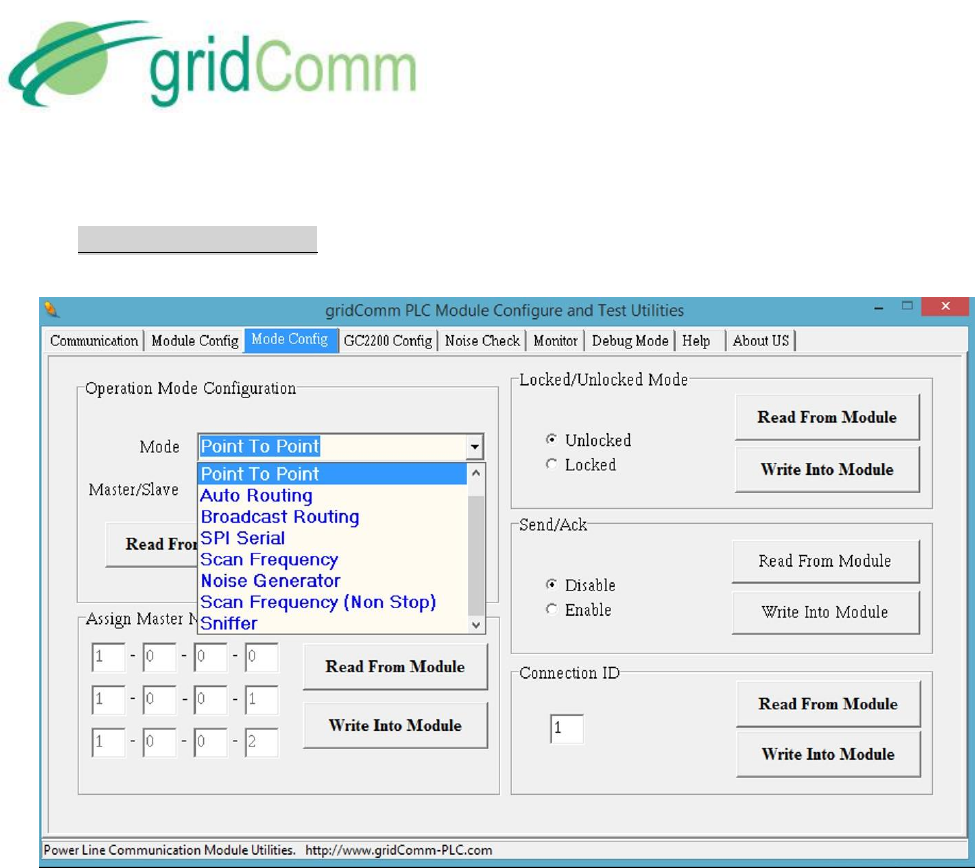
Figure 5 – “Mode Config” Settings
a) Operation Mode Configuration: There are four selectable operation modes to choose
from, namely the “Point-to-Point”, “Simple Broadcast”, “Auto-Routing”and “Broadcast
Routing”. In addition, there is also an evaluation mode called “SPI Serial”.
“Point-to-Point” is between two nodes with no routing/repeater
“Simple Broadcast” is between any node to a group of nodes in a Star-
configuration without routing/repeater.
“Auto-Routing” is using network routing via PHYid addressing.
“Broadcast Routing” is a combination of Broadcast and Auto-Routing without
PHYid addressing.
“SPI Serial” is actually an evaluation option to interface with gridComm PLC_Demo
GUI and Link Adaptation demo software. The PLC_Demo GUI and Link Adaptation
demos enable user detailed evaluations at the chip level of GC2200. When
resetting Operation Mode from “SPI Serial” to other modes, a hard power reset is
required. For more details, please contact your sales agent.
“Scan Frequency” is used between two nodes to scan for the best channel
frequencies with the highest RSSI (Received Signal Strength Indicator) values. This

PB63023_01
GC9200 PLC Demo &
Evaluation Node User Guide
© GridComm Pte. Ltd. Page 12 of 47
operation will complete in about 10 minutes. See “Monitor Tab” section in page 15
for more details.
“Noise Generator” allows the node to become a noise generator sending out
signals based on Output Power setting one frequency at a time across the entire
500KHz spectrum.
“Scan Frequency Non Stop” performs Scan Frequency indefinitely.
“Sniffer” turns the node to only listen to the power lines picking up valid GC2200
signals and in turn transmit these signals to the serial communication link (UART,
RS232, RS485).
More details regarding the operation modes are illustrated in the following sections.
b) Master/Slave: Setting “Master” or “Slave” will assign the particular PLC node as master
node or slave node respectively, which is only available under “Auto-Routing” and
“Broadcast Routing” mode. Note that there can only be one master node in a network.
The maximum number of slave nodes controlled by one master node is 240. For networks
exceeding 240 PLC nodes, multiple master nodes would need to be installed. Each master
node would then be controlled by a commanding node at the concentrator. For more
details, please see “Network Size” in page 35.
“Read From Module” will show the status of the operation mode as well as the assigned
role (master or slave) of the device. “Write into Module” needs to be performed as long as
new configurations are entered. Remember to reset the device after performing “Write
Into Module”.
c) Assign Master Node PHYid of Network: Assigns a particular PLC node with the given PHYid
as the master node of the network that this slave node is in. This will make this device
recognize a particular node in the network as the master node. There are three slots to
assign for Master Node PHYid. This is to enable a slave node, connected in a 3-Phase
network, to freely connect with any of the master nodes. This is useful when one does not
know which phase a slave node is connected to. When the three master nodes are
interconnected to a concentrator via UART or RS485 (round-robin way), it effectively
bridges all the slave nodes in each phase into a single network system.
Perform this operation only under “Auto-Routing” and “Broadcast Routing” mode and only
if the device is set as “Slave” under “Operation Mode Configuration”. Click “Read From
Module” to display the existing settings. To make changes to the existing settings, enter
the values accordingly, and then click “Write Into Module”. Remember to reset the device
after performing “Write Into Module”.
d) Locked/Unlocked Mode: If “Locked” is checked, performing a reset will lock the
parameters of the device from being altered during operation. To make changes to the
parameters, user must enter Safe Mode (see “Safe Mode” section in page 7) to make
changes or to uncheck Locked mode to return to Unlocked mode. Any operation to check

PB63023_01
GC9200 PLC Demo &
Evaluation Node User Guide
© GridComm Pte. Ltd. Page 13 of 47
or uncheck the Locked/Unlocked Mode must be followed by “Write Into Module” and a
reset. Click “Read From Module” to display the existing settings.
e) Send/Ack: This feature is only available for firmware vesion 2.00 and above. With
“Send/Ack” enabled, the network layer will continue to retry sending the same data packet
multiple times over different pre-configured frequencies should a Send from the Master to
the Slave is not Acknowledged. It is important to note that the same “Send/Ack” setting
must be applied across all nodes within the same network. Any operation to check or
uncheck must be followed by “Write Into Module” and a reset. Click “Read From Module”
to display the existing settings.
f) Connection ID: In Point-to-Point mode, a pair of communicating PLC nodes must share the
same Connection ID. A Data Received acknowledgement scheme that checks against the
Connection ID is implemented to ensure that only data packets from the intended
recepients are accepted and not data from other PLC nodes in the vicinity. Click “Read
From Module” to display the existing settings. To make changes to the existing settings,
enter the values accordingly and click “Write Into Module”. Remember to reset the device
after performing “Write Into Module”.
2.4. “GC2200 Config” Tab
Figure 6 – “GC2200 Config” Settings

PB63023_01
GC9200 PLC Demo &
Evaluation Node User Guide
© GridComm Pte. Ltd. Page 14 of 47
a) GC2200 Parameters Configuration: Configures the transmission channels and the
preferred carrier frequencies. Check the channel boxes (you may check any number of
boxes) and select the frequencies from the pull-down menu. Note that communications
between any two PLC nodes can only happen if they have at least one frequency in
common.It is suggested that all nodes in the same network have the same set of
frequencies.
b) Output Power: Select the “Output Power” from 10 to 500. As the power is not regulated, it
is a good practice to set at 250 when the nodes are closely positioned. Setting at 500 in
close proximity may distort the signals resulting in packet losses. Ensure that any change in
settings be followed by clicking “Write Parameter” and power cycling the device.
c) ECC On: This turns on Error Correction Code. It increases packet transmission and
reception timings by about 30%. It is important to note that the same “ECC” setting must
be applied across all nodes within the same network. Any operation to check or uncheck
must be followed by “Write Into Module” and a reset. Click “Read From Module” to
display the existing settings.
d) Modulation Mode: Configures the modulation scheme from a selection of 1BPSK, 3BPSK
and 3QPSK. At the PHY layer, the data rate is 1.22Kbps for 1BPSK, 3.66Kbps for 3BPSK and
7.22Kbps for 3QPSK respectively. As a general rule of thumb, 1BPSK is most preferred for
maximum robustness. While nodes configured with different modulation schemes could
work together, when configuring 3BPSK or 3QPSK, care should be exercised to set the
central frequency for each channel to be at least 3 frequencies apart. Any operation to
check or uncheck must be followed by “Write Into Module” and a reset. Click “Read From
Module” to display the existing settings.
Automatic selection frequencies under CENELEC A Band, CENELEC B Band, CENELEC C
Band, CENELEC D Band, FCC Band or ARIB Band can be done using the appropriately
named buttons. Clicking any of these will automatically assign up to six of the eighteen
channels within the specified band. Click “Read Parameter” to read the existing settings.
To make changes to the existing settings, enter the values accordingly and click “Write
Parameter”. Remember to reset the device after performing “Write Parameter”.
2.5. “Noise Check” Tab

PB63023_01
GC9200 PLC Demo &
Evaluation Node User Guide
© GridComm Pte. Ltd. Page 15 of 47
Figure 7 – Noise Check
a) Go to “Noise Check” tab and click on “Read Noise” to read the noise level on each of the
channels. The noise reading is a relative noise figure and does not have a unit. These
readings may be used to configure the frequencies for the transmission channels as in
“GC2200 Parameters Configuration” section in page 14. It is recommended to use
frequencies with noise levels less than 500. Note that low noise does not guarantee
reliable communications. Attenuation and low impedance loads may also impact
communications adversely.
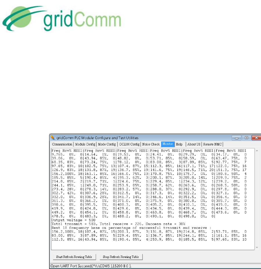
2.6. “Monitor” Tab
The Monitor tab displays essential information regarding: (1) Frequency vs Received
Success Rate and RSSI (2) Routing Table.
a) Frequency vs RSSI: When “Scan Frequency” is selected under “Operation Mode
Configuration” under “Mode Config” tab, for a pair of nodes (configured as Master and
Slave) in communications, the GUI on the master node will scan across the entire
frequency range between the two nodes and display the Received Success Rate and the
corresponding RSSI (Received Signal Strength Indicator) values (divided by a factor of 256
with figures between 0 to 256, 256 being the best signal strength). Under “Monitor” tab,
“Freq” shows the carrier frequency in KHz, “Rcv%” shows the percentage of packets
received over packets transmitted and “RSSI” shows the Received Signal Strength Indicator
values of the particular frequency. The RSSI and Rcv% may be used to determine the best
frequencies for communications. In general, the higher the RSSI value, the higher the
chance of successful communications. However, as shown in Figure 8, there are instances
where low RSSI values correspond with higher success rates. This is possible if there are
PB63023_01
GC9200 PLC Demo &
Evaluation Node User Guide
© GridComm Pte. Ltd. Page 16 of 47
less noise or interference over these frequencies. At the bottom of the table, the “Output
voltage” shows the value of “Outpower” of GC2200 Config, the “Total transmit” shows the
total packets transmitted, the “Total receive” shows the total packets received and the
“Success rate” shows the percentage of received over total transmitted packets. Note
“Total transmit” and “Success rate” only appear on the Master node table. The GUI for the
Slave node is not required to be used in order to perform this function. The table will also
present the best 18 sets of carrier frequencies based on success rate. These 18 sets of
frequencies will automatically be configured at both the master and slave nodes.
Figure 8 – Frequencies versus Received Success Rate and RSSI Values
To get out of Scan Frequency mode and change to a different operation mode, it is always a
good practice to get into Safe mode before making changes.
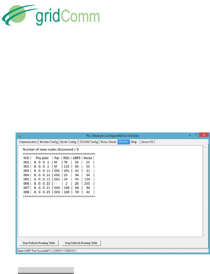
e) Routing Table: When in “Auto Routing” or “Broadcast Routing” mode, click the “Start
Refresh Routing Table” to display the routing information of the PLC network system.
“Stop Refresh Routing Table” stops the display. Double click on the screen to clear the
screen.. Note that the routing table display function should only be used by the Master
node and not the Slave nodes in Auto-Routing or Broadcast Routing mode. “Routing
Table” will have no effect on the GUI connected to a Slave node.
In the routing table, the number of slave nodes discovered will constantly be updated. The
following denotations are also used in the routing table:
“NID” denotes the Net ID of the nodes of the network.
“Phy addr” denotes the PhyID or physical ID of the nodes.
PB63023_01
GC9200 PLC Demo &
Evaluation Node User Guide
© GridComm Pte. Ltd. Page 17 of 47
“Par” denotes the Parent node Net ID of the particular node.
“RSSI” denotes “Received Signal Strenght Indicator” indicating the signal strength
of the message received.
“ABPS” denotes “Average Beakons Per Slot” in percentage (%). This is used to as a
measure of quality of the downward communication link based on the success rate
of receiving a discovery packet.
“Noise” is a value from 0 to 255 indicating the noise level present in the power
lines in absolute form.
Figure 9 – Routing Table Display
2.7. “Debug Mode” Tab
This feature is available only with firmware version plcm_v1_7_3.bin and above using
PLCM_Utilities version plcm_utilities_v205.exe and above. The “Debug Mode” is a useful
feature to help the user to check if any node in the network is incommunicable. Only Auto-
Routing and Broadcast Routing modes are supported. The “Debug Mode” tab allows the
user to be able to configure the Master node (only the Master node needs to be
configured) to remotely poll its Slave nodes registered in the network by sending a data
packet of 10 bytes and expecting a return packet of 30 bytes, 60 bytes or 120 bytes
depending on the setting in the “Connection ID” under “Mode Config” tab. A “0” set in the
“Connection ID” configures for a 30-byte reply, a “1” configures 60 bytes while a “1”
configures 120 bytes. To enable debug mode, go to Figure 10 – “Debug Mode” Tab and

PB63023_01
GC9200 PLC Demo &
Evaluation Node User Guide
© GridComm Pte. Ltd. Page 18 of 47
write 1 into the window followed by clicking “Write Into Module” button and “Reset
Module” button under the “Communication” tab. Upon resetting the module, a message
“Debug Mode = 1” will be shown in the window under the “Communication” tab and the
polling process will begin.
Figure 10 – “Debug Mode” Tab
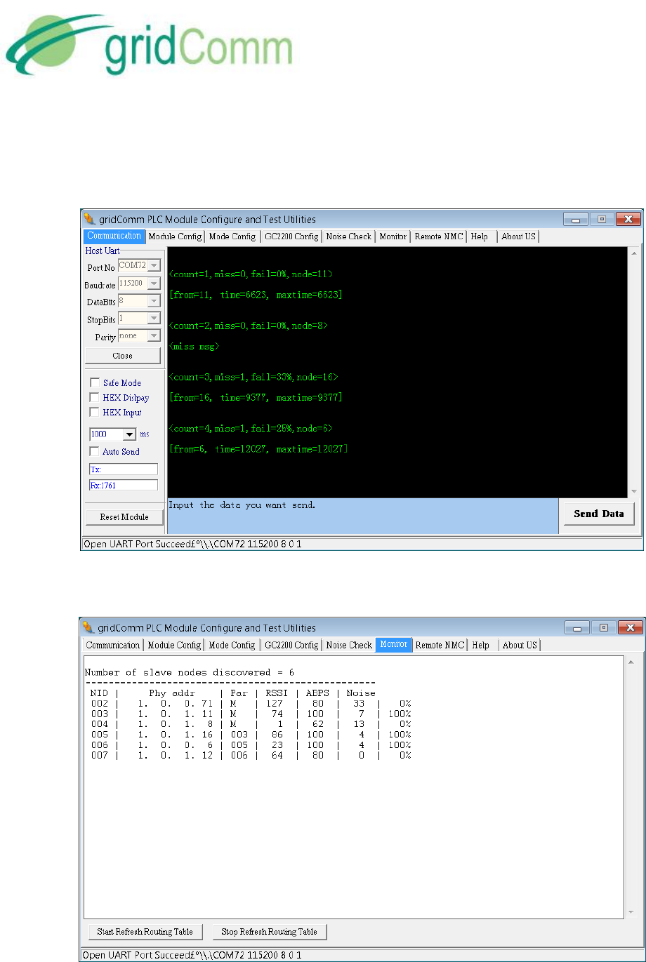
As the polling progresses, the window under the “Communication” tab will tabulate the
results. In Figure 11, the follow messages appear:
<count=1, miss=0, fail=0%, node=11>
[from=11, time=6623, maxtime=6623]
<count=2, miss=0, fail=0%, node=8>
[miss msg]
<count=3, miss=1, fail=33%, node=16>
[from=16, time=9377, maxtime=9377]
Where
“count” is the number of attempts the Master node polls the Slave nodes.
“miss” is the cumulative number Master not getting return packets from Slave
nodes
“fail” is the amount of misses registered at the Master in percentage
“node” is the last byte of the PHYid of the slave node being polled.
PB63023_01
GC9200 PLC Demo &
Evaluation Node User Guide
© GridComm Pte. Ltd. Page 19 of 47
“from=11, time=6623, maxtime=6623” denotes the time taken to & fro from Master
to Node 11 is 6623 msec. while “maxtime” is the maximum time captured thus far.
Figure 11 – Real-Time Polling Results
Figure 12 shows the polling results success rate in percentage under “Monitor” tab.
Figure 12 – Routing Table Display With Polling Success Percentage

PB63023_01
GC9200 PLC Demo &
Evaluation Node User Guide
© GridComm Pte. Ltd. Page 20 of 47
3. Operation Modes
The GC9200 has four operation modes, namely Simple Broadcast, Point-to-Point, Auto-Routing,
and Broadcast Routing. The different operation modes are enabled by configuring the settings
via the “Mode Config” tab. GC9200 is also pre-programmed with a unique PHYid starting from
001.000.000.000 to 001.255.255.255. It can support a total of 16,777,216 unique PHYid
addresses.
In Simple Broadcast, Point-to-Point and Broadcast routing modes, they are protocol transparent
in the sense that serial data is sent verbatim between transmitter and receiver without a need
for adding addressing. In Auto-Routing mode, the transmitting device needs to know the
address of the receiver and needs to append this address to the data being sent.
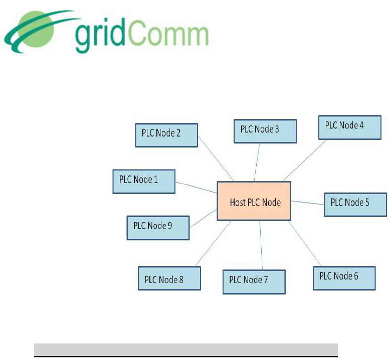
4. gridComm GC-Net Simple Broadcast Communications
This is the simplest form of PLC communications whereby any PLC node will transmit data
packets on the power line in a single hop. The transmitting PLC node will not supply a
destination node address: the data packet is broadcast from the transmitting node, and any PLC
node within receiving range will receive the packet from the power lines and send this data out
its UART.
As there is no addressing at the networking layer, a data acknowledgement scheme is not
implemented, and the transmitting PLC node will not know if the data packet has been
successfully received by the intended PLC node. It will be the responsibility of the receiving
device connected to the UART to authenticate this data: for example, to check if the packet is
addressed to it. Also, a time-out mechanism may need to be implemented at the transmitting
device to re-transmit data if required. For example, if the concentrator, which is connected to
the Host PLC node, does not receive a reply from the intended terminal device after a certain
time has elapsed, it should resend the data.
Figure 13 shows a typical broadcast network in a Star configuration.
PB63023_01
GC9200 PLC Demo &
Evaluation Node User Guide
© GridComm Pte. Ltd. Page 21 of 47
Figure 13 – Star-shaped Simple Broadcast Communication System
4.1 Demo & Evaluation of Simple Broadcast Communications
To evaluate Simple Broadcast mode, the user may use multiple GC9200s, each connected to a
PC via gridComm PLCM_Utilities GUI. Follow the steps below:
a) Configure the appropriate UART settings on both the Host UART and the Module UART
as in “Host UART” and “Module UART Configuration” section in page 7 and page 9.
b) Configure the channel frequencies under “GC2200 Config” in page 14 ensuring that all
the PLC nodes (GC9200) share the same group of frequencies. Note that
communications between any two PLC nodes may only happen over the same set of
channel frequencies.
c) Set the appropriate “Output Power” as recommended.
d) Go to “Mode Config” and set to “Broadcast Mode” under Operaton Mode Configuration
as in “Operation Mode Configuration” section in page 11.
e) Once the configurations are done, you may input any data in the bottom green window
under the “Communication” tab. The data can be in character (default) or HEX form
(check HEX Display and HEX Input). Enter a message in the green box and click “Send
Data”. The message will be received by all the other devices within range and sent
through their UARTs to be displayed on the gridComm PLCM_Utilities GUIs.
f) The standard data byte length per data packet is 42 bytes. It is highly recommended to
use smaller data packets if possible, because longer data packets may have a higher
chance of “packet loss” during transmission. When sending long data packets exceeding
42 bytes up to 512 bytes, such as in ModBus, the device firmware will automatically
break the long packet into multiple packets of up to 42 bytes without user intervention.
These packets will then be reassembled to form the original data packet at the receiving
PLC node.
PB63023_01
GC9200 PLC Demo &
Evaluation Node User Guide
© GridComm Pte. Ltd. Page 22 of 47
5. gridComm GC-Net Point-to-Point Communications
This mode provides a more reliable data communications path between two points over power-
line as in Figure 14. In this set up, there is no need to configure master or slave unlike in the
Routing modes. Communications are transparent, and can be initiated by either end of the
terminal devices to which the PLC nodes are connected once the serial communication settings
are configured. However, the pairing PLC nodes in communications must share the same
Connection ID address, because a Data Received acknowledgement scheme checks against the
Connection ID address, and is implemented to ensure that the intended data packet received
does not come from other irrelevant PLC nodes in the vicinity. Care should also be taken to avoid
data collisions that are caused by other PLC nodes in the vicinity communicating on the same
power lines network over the same set of frequencies. Data collisions may be prevented by
assigning the paired PLC nodes with a unique set of carrier frequencies different from other PLC
nodes in the vicinity.
Figure 14 – Point-to-Point Communication System
5.1 Demo & Evaluation of Point-to-Point Communications
a) To demo and evaluate the GC9200 with Point-to-Point communications, two instances
of the gridComm PLCM_Utilities GUI are required in order to observe the two PLC nodes
in communication.
b) Ensure the pairing PLC devices under test are configured with the same Connection ID
for Point-to-Point mode as per “Connection ID” section in page 13.
c) Go to “Mode Config” and set to “Point-to-Point” under Operaton Mode
PB63023_01
GC9200 PLC Demo &
Evaluation Node User Guide
© GridComm Pte. Ltd. Page 23 of 47
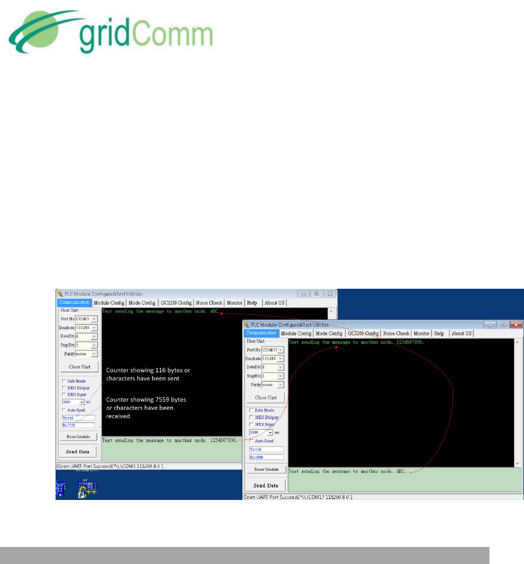
g) In Figure 15, once the basic configurations are set as in “Demo & Evaluation of Simple
Broadcast Communications” section in page 21 from 4.1.a to 4.1.c, you may input any
data in the bottom green window under the “Communication” tab. The data can be in
character (default) or HEX form (check HEX Display and HEX Input). Enter a message in
the green box. The message will be sent to the other device as shown in the other GUI
after clicking “Send Data”. The standard data byte length per data packet is 42 bytes. It
is highly recommended to use smaller data packets if possible, because longer data
packets may have a higher chance of “packet loss” during transmission. When sending
long data packets exceeding 42 bytes up to 512 bytes, such as in ModBus, the device
firmware will automatically break the long packet into multiple packets of up to 42
bytes without user intervention. These packets will then be reassembled to form the
original data packet at the receiving PLC node.
d)
Figure 15 – PLC Device Point-to-Point Communications Demo
6. gridComm GC-Net Auto-Routing Network Communications
While Point-to-Point communications is easy to implement, most PLC systems are installed and
deployed in more complex network configurations today. This is especially true when
deployments require tens or hundreds of PLC nodes. Due to varying power line conditions (eg.
variations in attenuations, noise, distance and load impedance etc.), a smart Auto-Routing
Network system, which constantly searches for optimal routes and automatically reconfigures
itself to enable the master node to maintain communicatons with all its slave nodes is needed.
gridComm’s GC-NET Auto-Routing and Adaptive Routing Software enables users to effectively
and dynamically set up this network system.
PB63023_01
GC9200 PLC Demo &
Evaluation Node User Guide
© GridComm Pte. Ltd. Page 24 of 47
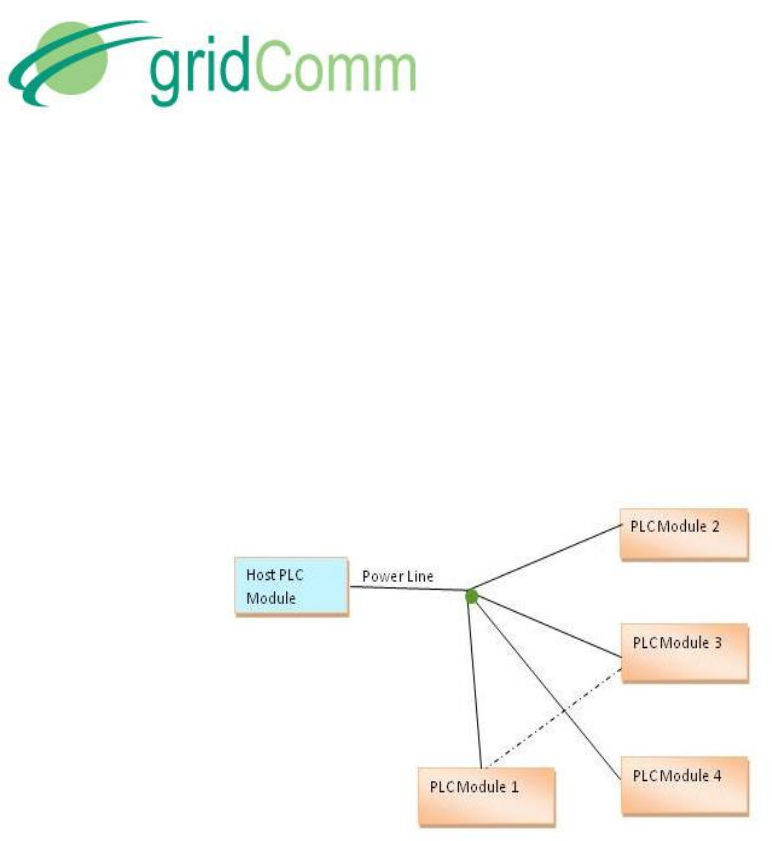
Figure 16, is an example of a Star-shaped PLC network system with five devices on the same
power line. When the power line conditions are ideal for communications, the Host PLC Module
(or master node) may communicate with all other slave devices (nodes) directly. However, if
power line conditions deteriorate between the Host PLC Module and PLC Module 3 and they
cannot communicate directly, the Host PLC Module may still maintain communication with PLC
Module 3 if data packets are routed through PLC Module 1, which acts as a repeater (also known
as a router, or a relay). gridComm’s GC-Net Auto-Routing software enables the setup of such PLC
networks.
Figure 16 – Star-shaped Communication System with a back-up route
A more general example of such a network systems, is in the form of a “Tree” structure
configuration, as in Figure 17. Apart from providing back-up routing over varying power line
conditions, the “Tree” structure extends the potential distance covered between the Host PLC
Module (or Master node) and PLC Modules (Slave nodes). The routers or repeaters are arranged
in different tiers or layers with several communication hops between Master and its most distant
Slave in the network. This is especially true for large complicated network systems. gridComm
GC-Net Auto-Routing software can dynamically reconfigure itself, and perform re-routing of data
paths should there be changes in the network due to an increase or decrease in PLC devices.
PB63023_01
GC9200 PLC Demo &
Evaluation Node User Guide
© GridComm Pte. Ltd. Page 25 of 47
Figure 17 – “Tree” Structure Network
7. gridComm GC-Net Auto-Routing Software
7.1 Master Node Driven Communication Model
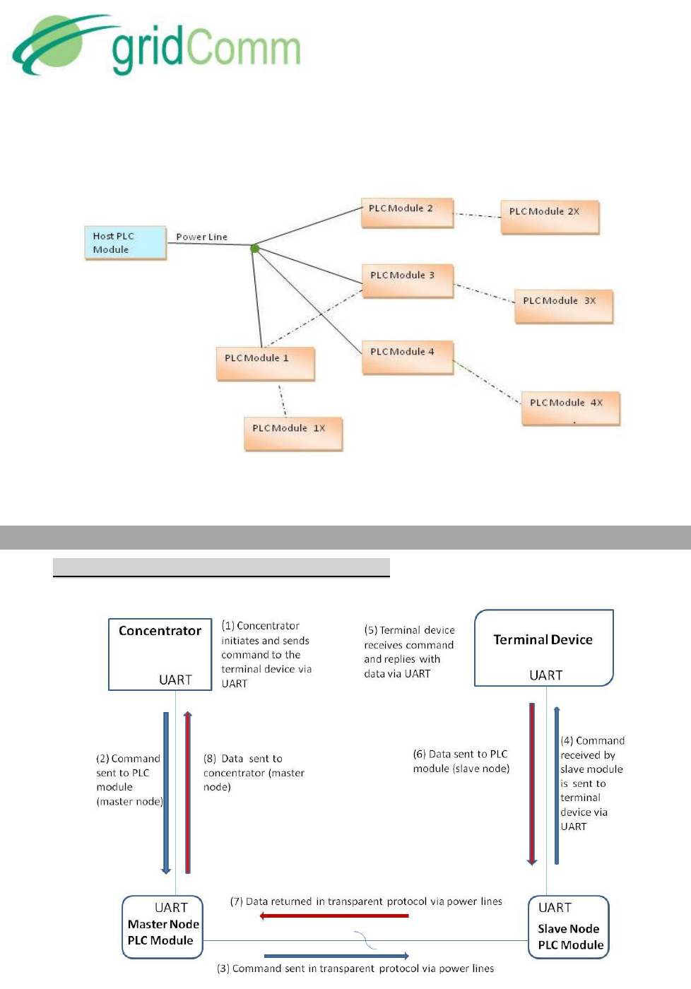
Figure 18 – Operations of a Master Driven Communication Model

PB63023_01
GC9200 PLC Demo &
Evaluation Node User Guide
© GridComm Pte. Ltd. Page 26 of 47
For most applications such as Street Lighting Control and AMI, communications are initiated by
the Master node. The Master node controls most of the communications in the network. This is
how gridComm GC-Net software works, which is a Master-driven communication model based
on a known destination address (PHYid) in auto-routing network mode. Slave nodes may, but
should rarely initiate communications with the Master. Also, a Slave node cannot communicate
with another Slave node directly.
When the concentrator sends a command with a destination address of the terminal device, the
Master node which is attached to the concentrator will look up the route to the Slave PLC node
that is attached to the terminal device and send the command over that route. After the
destination Slave node receives the command, it will send the command via the UART to the
terminal device. The terminal device responds by replying through the UART to the Slave node it
is attached to. The Slave node will then send it via PLC back to the Master node, which is then
sent through the UART to the concentrator. Figure 18 depicts the operations of Master-driven
communication model.
7.2 Operations- Auto-Discovery Phase
When a network of PLC nodes with Auto-routing is installed and powered up, the first thing the
Master node will do is to search for all the Slave nodes within the network based on the
gridComm GC-Net algorithm. It does so by searching the best routes to the Slave nodes based on
the computation of a set of parameters such as noise, signal strength, and others. The Master
node then assigns the Slave nodes into different tiers so that a routing path to each Slave node
is created. The Master node will register those Slave nodes directly contactable with the master
node as tier-1 Slave nodes. Slave nodes that are directly contactable through the tier-1 Slave
nodes, will be assigned as tier-2 slave nodes, and so on.
The Master node will record and constantly update the routing paths for all the Slave nodes
discovered. The Slave nodes will only record the routing path leading back to the Master node.
The process of setting up the routing table during the discovery phase might take several minutes
depending on network complexity: power line conditions, size of network, and the number of
hops in the network. When the Master node wants to communicate with a particular Slave node,
it does so based on the routing path developed in the routing table for that node.
7.3 Demo and Evaluation of Auto-Discovery Phase
To view the building of the routing path network in Auto-Routing mode, a network of PLC devices
(eg. GC9200) will need to be set up. Follow the steps below to set up the network.
a) Perform the basic configurations as described in “Demo & Evaluation of Simple Broadcast
Communications” section in page 21 from 4.1.a to 4.1.c.
PB63023_01
GC9200 PLC Demo &
Evaluation Node User Guide
© GridComm Pte. Ltd. Page 27 of 47
b) Identify which PLC node (eg. GC9200) is to be the Master node. Go to “Mode Config” tab
and set “Master”. Note that there can only be one Master node in a network. The
maximum number of Slave nodes controlled by one Master node is 240. For larger size
of network exceeding 240 PLC nodes, multiple Master nodes would need to be installed
with each Master node controlled by a commanding node. For more details, please see
“Network Size” section in page 35.
c) Set the rest of the PLC nodes in the nework as Slave nodes. Point the Slave nodes to
recognize the Master node by entering the PHYid of the Master node under “Assign
Master Node PHYid in Network”. Perform “Write Into Module” and remember to reset
the device after that.
d) Set the Operation Mode to “Auto-Routing”
e) Go to the “Communication” tab of the PLCM_Utilities GUI and click “Start Refresh Routing
Table”. Once clicked, the routing table information will be displayed and will be updated
dynamically as changes to the network are detected, e.g. upon addition of new nodes or
removal of existing nodes. To disable printing of routing table, click the “Stop Refresh
Routing Table” box or reboot the device. Note that routing table display function is only
for the Master node and not the Slave nodes. Connecting the GUI to the Slave node and
enabling “Routing Table” will have no effect.
f) The number of Slave nodes discovered in the network will be constantly updated and
displayed above the table.
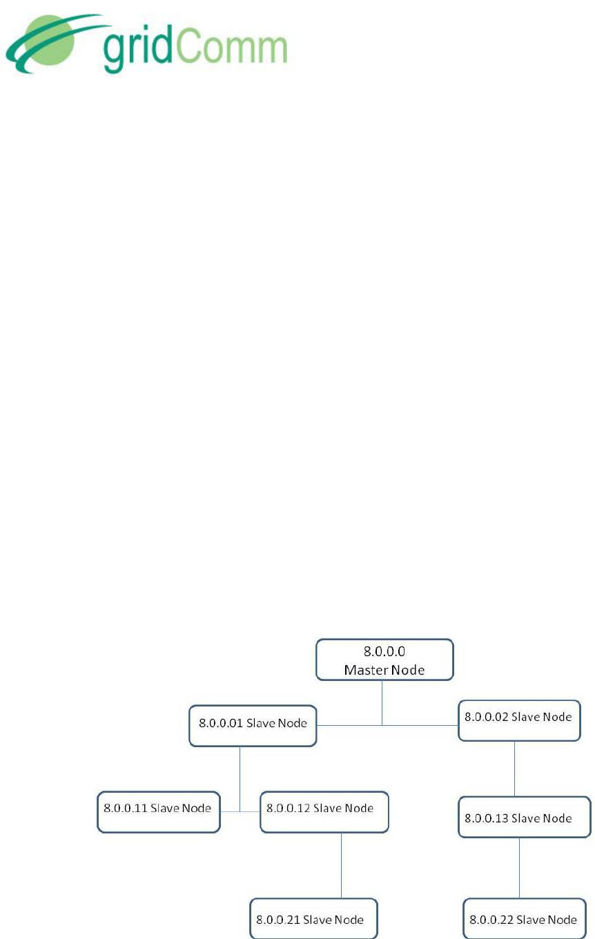
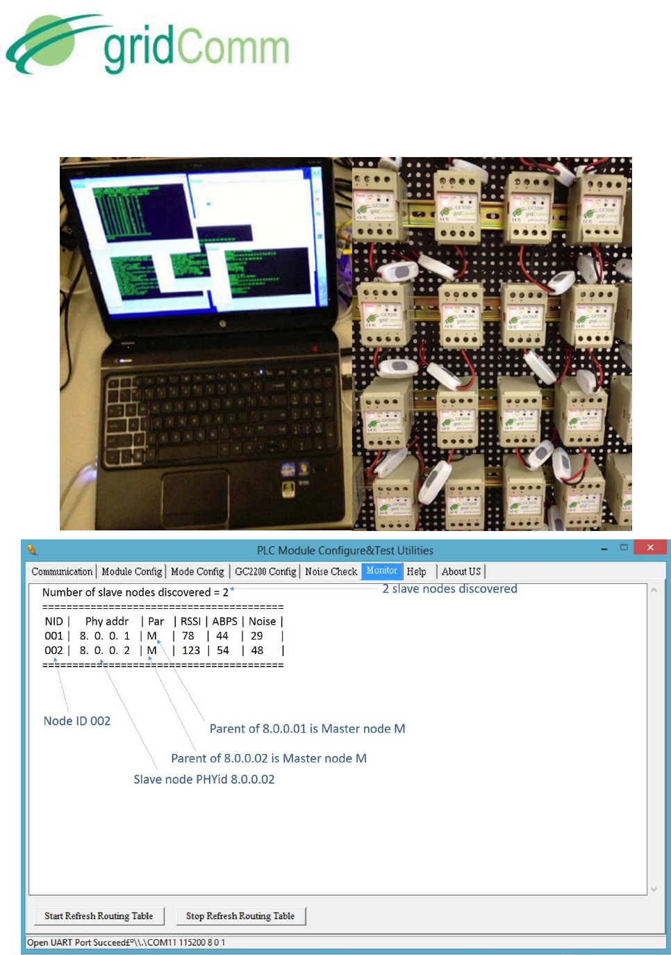
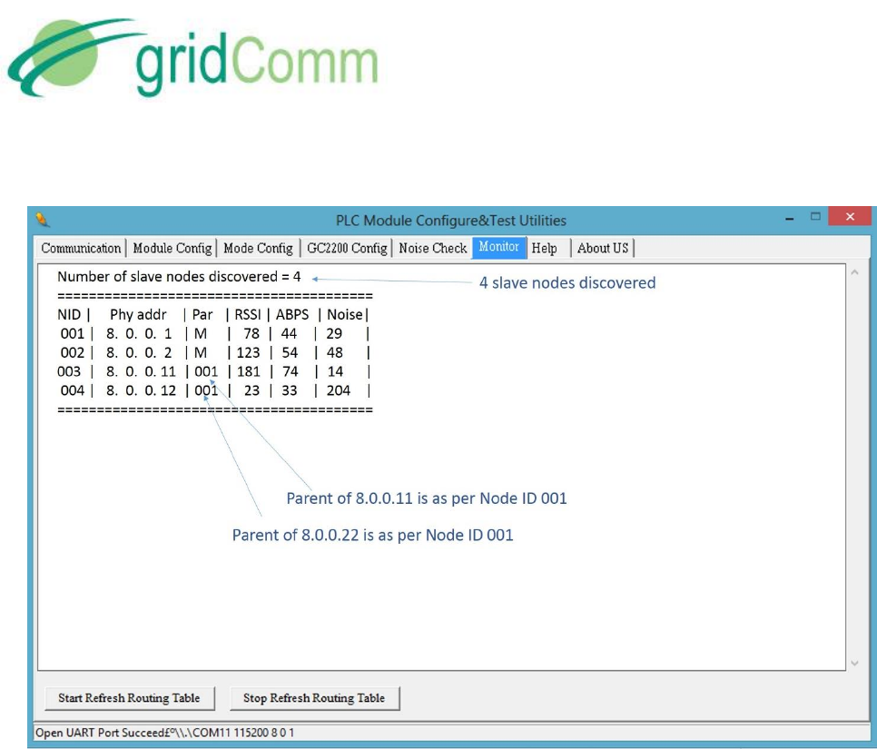
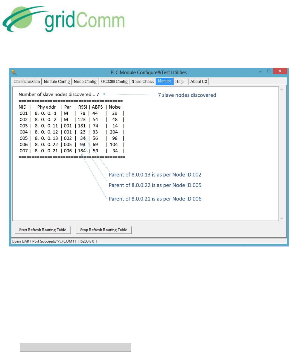
Figure 19 shows a series of diagrams with an example of how the routing table is developed for
a tree structure of one Master node and seven Slave nodes. Click the “Start Refresh Routing
Table” in the “Monitor” tab of the PLCM Utitlities GUI to display the routing table information.
PB63023_01
GC9200 PLC Demo &
Evaluation Node User Guide
© GridComm Pte. Ltd. Page 28 of 47
PB63023_01
GC9200 PLC Demo &
Evaluation Node User Guide
© GridComm Pte. Ltd. Page 29 of 47
PB63023_01
GC9200 PLC Demo &
Evaluation Node User Guide
© GridComm Pte. Ltd. Page 30 of 47
Figure 19 – Routing Table Developed for a Network of PLC Nodes
From the diagrams above, a tree structure with assignments of parent and child nodes is set up
after the Master node has managed to register all the Slave nodes. For example, 8.0.0.21 registers
8.0.0.22 as parent, while 8.0.0.22 registers 8.0.0.13 as parent, 8.0.0.13 registers 8.0.0.02 as
parent and finally 8.0.0.02 registers 8.0.0.0 (master node) as parent. When Master node 8.0.0.0
wants to send a command to 8.0.0.21, it will know the route via 8.0.0.02, 8.0.0.13 and 8.0.0.22
(routing path: 8.0.0.21 - 8.0.0.22 - 8.0.0.13 - 8.0.0.02 - 8.0.0.0).
7.4 Operations- Auto-Recovery Phase
When a Slave node is removed from or added into the network during operations, the Master
node must discover the changes dynamically and rebuild its routing table automatically. Figure
20 shows a new Slave node PHYid 8.0.0.23 (slave node address) being added while Slave node
with PHYid 8.0.0.22 is being removed from the network resulting in the rebuilding of the routing
table.

PB63023_01
GC9200 PLC Demo &
Evaluation Node User Guide
© GridComm Pte. Ltd. Page 31 of 47
Figure 20 – Rebuilding of Routing Path Due to Newly Added and Removed Slave Nodes

PB63023_01
GC9200 PLC Demo &
Evaluation Node User Guide
© GridComm Pte. Ltd. Page 32 of 47
When 8.0.0.23 is added into the network, it finds 8.0.0.11 as parent and forms a routing path to
8.0.0.0 (Master) via 8.0.0.01 and 8.0.0.11 (routing path 8.0.0.23 - 8.0.0.11 - 8.0.0.01 - 8.0.0.0).
When 8.0.0.22 is removed, 8.0.0.21 no longer uses the previous routing path through 8.0.0.21.
Insteads 8.0.0.21 forms a route through 8.0.0.12 as its parent to form a new routing path 8.0.0.21
- 8.0.0.12 - 8.0.0.01 - 8.0.0.0. As soon as 8.0.0.22 is being detected as removed from the network,
its parent node will be labeled with double dashes “_ _” to denote the missing status. Again, it
might take a few minutes to update the routing table in the Auto-Recovery phase when nodes
are being added or removed from the network.
7.5 What if Some PLC Nodes are not discoverable?
It is possible that some PLC nodes in the network are undiscoverable for various reasons such as
bad power line conditions, being on a different phase, being too distant etc. When setting up a
network, it is a good idea to know in advance the total number and the identity (PHYid) of nodes
being deployed. This potential list of nodes may be compared with the actual Slave node PHYids
displayed on the routing table of the gridComm PLCM Utilities GUI to know exactly which ones
are undiscovered.
If running the PLCM Utilities GUI on the Master node in operation is inconvenient, there is
another way to detect if the network is fully set up. Enter the correct number of “Expected
Number of Slave Nodes” in the “Module Config” tab of the PLCM Utilities GUI and perform a
“Write Into Module”. This figure will then be stored in the flash memory and stay there even
after the power down. When a network is initially powered up, all GC9200 devices including the
Master node will flash once every 10 seconds during the discovery phase. When any Slave node
is registered with the Master node, it will start to blink once every 0.2 second incessantly. As soon
as the total number of Slave nodes discovered by the Master corresponds with the number of
“Expected Number of Slave Nodes”, the Link LED on the Master will blink in quick succession at
0.4 seconds interval.
If the number of Slave nodes contactable by the Master drops below the expected number, the
Master will revert to blinking once every 10 seconds. (The contactable Slave nodes will continue
to blink every 0.2 second). Checking the routing table for double dashes “_ _” in the Parent
column will reveal which Slave node which has been disconnected from the network.
If new Slave nodes are added to the network with the total number exceeding the “Expected
Number of Slave Nodes”, the Link LED will continue to blink at 0.4 sec. Note again that network
changes could take several minutes to be detected by the Master especially in a more complex
network.

PB63023_01
GC9200 PLC Demo &
Evaluation Node User Guide
© GridComm Pte. Ltd. Page 33 of 47
7.6 Semi-Transparent Protocol and Mapping of Terminal Device Address
In Auto-Routing mode, a PHYid needs to be added to every packet sent from the Master node.
A mapping table may be required at the host controller (or concentrator) connected to the
Master PLC node to translate the destination terminal device address to the PHYid of the Slave
node attached to it. The 4-byte PHYid is transmitted just before the data packet itself.
When the designated Slave node receives the data packet, it will send the data packet without
the PHYid over the UART to the terminal device.
Unlike the host controller, when the terminal device responds, it must not add a PHYid to the
response data packet. The terminal device sends the data verbatim to the Slave node via the
UART. The Slave node will route the packet to the Master node and hence to the host controller
or concentrator.
Thus, for the Slave node, the protocol is transparent, unlike the Master node.
The auto-routing software is implemented in the network layer and is independent of the
output power, redundancy and modulation settings. The network layer also performs
segmentation and re-assembly of packets. This network layer may be customized to application
needs (may incur NRE, so please contact gridComm). The addressing scheme implemented for
gridComm GC-Net software is based on 32-bit addressing.
The standard length of a data packet of the gridComm PLC transparent protocol is 42 bytes
regardless of operation mode. In cases where the transparent protocol sends data packets larger
than 42 bytes (such as transporting Modbus protocol which could stretch up to 512 bytes in ASCII
form), the gridComm GC-Net software application layer will automatically break them down into
smaller chunks and then reassemble them into a single data packet when they are received at
the destination node.
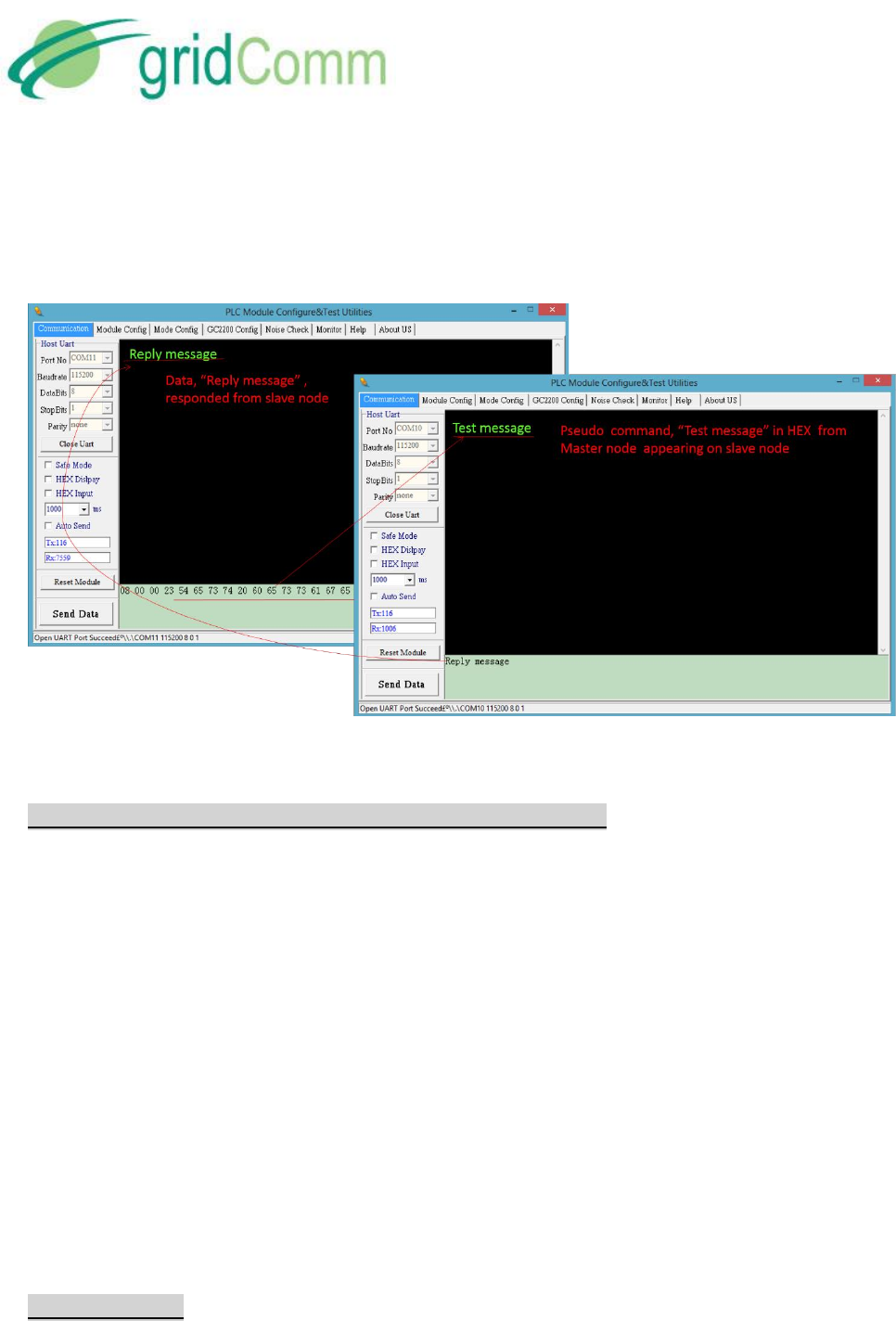
7.7 Demo and Evaluation of Command Send and Data Read Back in Auto-Routing Mode
To demonstrate “command send” and “data read back” between the Master node (depicting a
concentrator) and a Slave node (depicting a terminal device eg. Smart Meter), two instances of
the PLCM Utilities GUI (one for master node and the other for slave node) are needed. Note that
the inputs (both the PHYid and data) needs to be in HEX format in Auto-Routing mode as per
Figure 21. Perform the following steps:
a) Go to the green window under “Communication” tab of the Master node and enter a
pseudo command in HEX in the gr een window with the PHYid of the destination Slave
node with PHYid as 8.0.0.23 in front of the data, eg. “08 00 00 23 54 65 73 74 20 6D 65
73 73 61 67 65…”.
b) Click “Send Data” to send a command to 8.0.0.23 Slave node.
c) “Text message” depicting the command appears on the PLCM_Utilities GUI of 8.0.0.23
Slave node.
PB63023_01
GC9200 PLC Demo &
Evaluation Node User Guide
© GridComm Pte. Ltd. Page 34 of 47
d) Place “Reply message” depicting data to read back in green window of the PLCM_Utilities
GUI of 8.0.0.23 Slave node and click “Send Data”.
e) “Reply message” is read at Master node PLCM_Utilities GUI.
Figure 21 – A GUI Showing Data Transmission Between Master Node and Slave Node
7.8 Implementing a Send-Acknowledge (Send-Ack) Mechanism
To ensure the successful reception of the data packet by the terminal device, a Send-Ack
mechanism may be implemented in the application layer of the host controller (or concentrator).
For example, when the host controller sends a data packet and it is received successfully by the
terminal device, the terminal device may generate a “Received” signal back to the host controller
as an acknowledgement. If the host controller did not receive the acknowledgment from the
terminal device after a specified time-out, it may then assume that the data packet has not been
received by the terminal device. The host controller may then retry sending the same data packet
again to the terminal device. In GC-Net, when Send-Ack is enabled, a total of 5 retries is
implemented.
As a general guideline, when Send-Ack is enabled, it is recommended to allow 3.5 seconds for
the parent node to transmit a data packet one way to the immediate child node at the next tier.
For example, if a network has three tiers of slave nodes under the master node, for the Master
node to send a data packet to the third (bottom) tier of Slave nodes with Send-Ack enabled, it is
best to cater 3.5 x 3 = 10.5 seconds of time-out.
7.9 Network Size

PB63023_01
GC9200 PLC Demo &
Evaluation Node User Guide
© GridComm Pte. Ltd. Page 35 of 47
To avoid the network from becoming sluggish, gridComm Auto-Routing scheme limits a
network to 240 Slave nodes to 1 Master node. When an application requires more than 240
Slave nodes, multiple Master nodes would be needed. For example, a network of 900 Slave nodes
would require at least 4 Master nodes to support it. These Master nodes will then connect with
a Commanding node (at the concentrator) to exchange data.
It is highly recommended that a smaller number of Slave nodes per Master node be used if
possible, because the number of hops in the worst case may increase with a larger number of
Slave nodes and this, in turn, will result in longer latency or even communications failure. Care
should be taken to avoid data collisions that are caused by other PLC nodes of a different
network in the vicinity communicating on the same power lines. Data collisions may be
prevented by setting the network of PLC nodes to use a unique set of carrier frequencies that
are different from other networks of PLC nodes in the vicinity. GC2200 possesses the flexibility
to freely configure the number of channels with different carrier frequencies, which is a very
useful feature to prevent undesired interference from other networks of PLC nodes.
8. GC-Net Broadcast Routing Communications
Broadcast Routing is developed to cater to the needs for users who want to run a transparent
protocol with network routing – in other words, enabling communications over power line
without knowing destination PLC node addresses (or slave node PHYids).
This is convenient since the PHYid is not sent and the protocol is transparent. All that is
required is to set up the UART on the PLC node. The network software will deliver data packets
sent from the Master node to all Slave nodes in the network tree, and data packets sent from
any Slave node back to the Master node.
During initial start-up of Broadcast Routing mode, the PLC system will first develop routing
paths for the network tree as in the Auto-Routing mode. Broadcast Routing will fully function
only after the routing paths have been developed and this could take several minutes
depending on nextwork complexity. Again, a blinking RUN LED every 0.2 seconds on the Master
device will indicate the readiness of the network: that is, the number of slave nodes detected
equals or exceeds the total Expected Number of Slave Nodes entered into the Master node.
When the network is ready, the concentrator will send data packets to a terminal device as if it
were sending it through a simple data communications line without a need for PLC addressing
or protocol handling.
Again, it is the user’s responsibility to define and set the time-out to implement a Send-Ack
scheme. As a general guideline for time-out, allow 3.5 seconds for a send from a parent node to
its immediate child node on the next tier. For example, if a network has three tiers of Slave
nodes, for the Master node to send a data packet to the third (bottom) tier of Slave nodes, it
would require 3.5 x 3 = 10.5 seconds of time-out.

PB63023_01
GC9200 PLC Demo &
Evaluation Node User Guide
© GridComm Pte. Ltd. Page 36 of 47
In Broadcast Routing, there is an increase in network utilisation. Hence, Broadcast Routing is
effective for use in smaller and less complex networks (e.g. 30 nodes with up to 4 tiers, or 100
nodes with up to 3 tiers with most of the nodes in the 2nd tier etc.). As in any form of power line
communications, Broadcast Routing should not be used in time-critical situations due to
latencies in scheduling.
8.3 Demo and Evaluation of Broadcast Routing Communications
To demo and evaluate Broadcast Routing Communications, a network of PLC devices (eg.
GC9200) would need to be set up. Follow the steps below to set up the network.
a) Perform the basic configurations as described in “Demo & Evaluation of Simple Broadcast
Communications” section in page 21 from 4.1.a to 4.1.c.
b) Identify which PLC node (eg. GC9200) is to be the Master node. Go to “Mode Config” tab
and set “Master”. Note that there can only be one Master node in a network. The
maximum number of Slave nodes controlled by one Master node is 240. For larger sizes
of network exceeding 240 PLC nodes, multiple Master nodes would need to be installed.
Each Master node would then be controlled by a commanding node. For more details,
please see “Network Size” section in page 35.
c) Set the rest of the PLC nodes in the nework as Slave nodes. Point the Slave nodes to
recognize the Master node by entering the PHYid of the master node under “Assign
Master Node PHYid in Network”. Perform “Write Into Module” and remember to reset
the device after that.
d) Set the Operation Mode to “Broadcast-Routing”
e) Go to the “Monitor” tab of the PLCM_Utilities GUI and click on the box, “Start Refresh
Routing Table”. Once clicked, the routing table information will be displayed and will be
updated dynamically as changes to the network are detected, e.g. upon addition of new
nodes or removal of existing nodes. To disable printing of the routing table, click on the
“Stop Refresh Routing Table” box or reboot the device. Note that the routing table
display function is only for the Master node only and not the Slave nodes. Connecting
the GUI to the Slave node and enabling “Routing Table” will have no effect.
f) Go to the green window under “Communication” tab of the master node and enter HEX
data in the green window, eg. “54 65 73 74 20 6D 65 73 73 61 67 65…”.
g) Hit “Send Data” to broadcast the data packet.
h) The “Text message” depicting the command will appear on the PLCM_Utilities GUI of any
slave node. In applications, it is likely that all the terminal devices will interpret the
command data packet and only the terminal device which the packet is addressed to
will respond to the command.
i) Place “Reply message” depicting a response to be sent in the green window of the
PLCM_Utilities GUI of any Slave node and hit “Send Data”.
j) The response finds its way to the Master node and “Reply message” is received and
displayed at the Master node PLCM_Utilities GUI.

PB63023_01
GC9200 PLC Demo &
Evaluation Node User Guide
© GridComm Pte. Ltd. Page 37 of 47
9. Network Management Commands
In order to differentiate a PLC data transmission from a Network Management command, a
certain escape sequence needs to be sent.
The format for a Network Management command is:
0x1b 0x67 0x72 0x1d 0xc0 0x6d 0x6d 0x3a FC1 FC2 Len Seq Cmd Obj Sub Values . . .
The format for a response is:
0x1b 0x67 0x72 0x1d 0xc0 0x6d 0x6d 0x3a FC1 FC2 Len Seq Status Values . . .
Seq is a sequence number that is used for matching responses to commands. This is required
for robustness especially on a UART which is asynchronous, full-duplex. Seq will be a wrap-
around unsigned 8-bit counter (that is, 0 - 255). The Fletcher’s checksum FC1 and FC2 are
calculated for all bytes following the checksum bytes. Len is the length of all bytes following the
checksum bytes (thus including the length byte itself).
Fletcher’s checksum is calculated as shown in the ‘C’ code below:
uint8_t fc1=0, fc2=0;
for(i=0;i<size;i++)
{
fc1 = (fc1 + buf[i]) % 255;
fc2 = (fc2 + fc1) % 255;
}
Where buf[ ] contains size number of bytes of data to be checksummed.
All mutli-byte values are big-endian, that is, Most significant byte stored first.
Command codes:
Command code
Operation
0
Get
1
Set
Object-SubObject table
Object
Sub-
object
Name
Size
(bytes)
Remarks
0 (System)
0
PHY ID
4
Get-only

PB63023_01
GC9200 PLC Demo &
Evaluation Node User Guide
© GridComm Pte. Ltd. Page 38 of 47
1
Product ID
2
Get-only
2
FW version
2
Get-only
3
Reset System
0
Set-only, causes a reboot
4
Reboot counter
1
5
Write to Config
Flash
2
Get returns a 16-bit sequence
number
Set, with sequence number. If
sequence number has not
changed, flash is written (this
ensures atomicity of changes)
1 (Run modes)
0
Operation Mode*
1
1
Lock Mode*
1
2
Test Mode*
1
2 (Local Comms)
0
UART Baud rate*
4
1
UART Baud frame
specs*
4
5 (PLC Channels)
0
Channel
Frequency*
18
1
Channel
modulation*
1
2
Channel Enable*
3
3
Transmit power*
2
8 (Point-to-point)
0
Connection ID*
1
9 (AutoRouting
Master)
0
Expected Number
of Slaves*
1
Master Only

PB63023_01
GC9200 PLC Demo &
Evaluation Node User Guide
© GridComm Pte. Ltd. Page 39 of 47
1
Current Number of
Registered Slaves
1
Master Only, Get-only
2
Total Number of
Unique
Registrations since
boot
1
Master Only, Get-only
3
Slave details for
given NetID:
PHY ID, Parent ID,
Node level, Alive,
RSSI, Tx Channel
8
Master Only, Get-only
4
NetID, and PHY ID
of last Reply
5
Master Only, Get-only
5
NetID, PHY ID, and
RSSI of next Slave
that is not Alive
6
Master Only, Get-only
10 (AutoRouting
Slave)
0 – 7
Master ID List*
4
Slave Only
16
(Measurement)
0
Configured
Channels Noise
54 (Get)
0 (Set)
Set to reset noise
1
Temporarily write
channel
frequencies
18
Set-only, for use in
measurement of noise. Should
only be used in safe mode.
18 (Defaults)
0
Set default
configuration 1
0
Set-only
* Objects that are written to config flash when using Write to Config Flash
Possible status codes returned:
0: OK
1: Bad Checksum
2: No Such Object
3: Cannot perform operation
4: Bad length
5: Operation Error
6: Write Error

PB73000_01
GC9200 DIN Rail PLC Modem User Guide
© GridComm Pte. Ltd. Page 40 of 47
Examples of Network Management commands sent through the UART:
To read the FW version of the Node, send:
0x1b 0x67 0x72 0x1d 0xc0 0x6d 0x6d 0x3a 0x08 0x1f 0x05 0x01 0x00 0x00 0x02
- where the Seq is 0x01, FC1 = 0x08, FC2 = 0x1f
A valid reply with OK status would be:
0x1b 0x67 0x72 0x1d 0xc0 0x6d 0x6d 0x3a 0x3e 0x56 0x05 0x01 0x00 0x01 0x37
- where the Seq is 0x01, FC1 = 0x3e, FC2 = 0x56, and the result is 0x0137 as the firmware
version (version 1.55)
To reset the Node, send:
0x1b 0x67 0x72 0x1d 0xc0 0x6d 0x6d 0x3a 0x0e 0x33 0x05 0x05 0x01 0x00 0x03
- where the Seq is 0x05, FC1 = 0x0e, FC2 = 0x33
A valid reply with OK status would be:
0x1b 0x67 0x72 0x1d 0xc0 0x6d 0x6d 0x3a 0x08 0x13 0x03 0x05 0x00
where the Seq is 0x05, FC1 = 0x08, FC2 = 0x13
10. GC-Net PLC Quick Reference
Point to Point
Simple
Broadcast
Auto-Routing
Broadcast Routing
Maximum Number of Tier Support
1 (two layer of nodes)
7 (8 layers of nodes)
Maximum number of PLC nodes
2
Unlimited
240
Communications mode
Connection ID
Peer-to-Peer
Master Driven, 1 Master to multiple
Slaves
Send/Ack Mechanism (Network
Layer)
Built-in
NA
Built--In
Only On Return Path
Auto discovery and recovery of
nodes
NA
Yes
Auto Repeater
NA
Yes
PhyID Agnostic
Yes
Yes
No
Yes

PB73000_01
GC9200 DIN Rail PLC Modem User Guide
© GridComm Pte. Ltd. Page 41 of 47
Module "Link" LED Blinks
Quick Blinks at 200ms/blink
signal Ready for Operations
Marster Blinks at 400ms indicates
network is set up. Slave blinks at
200ms means registered with Parent
Maximum payload per data
packet per transmission
42 bytes
Maximum user data packet size
with auto-scaling
512 bytes
Latency per
direction for upto
42 byte data
packet with ECC
ON and W/O
ACK/SEND
(Broadcat
Routing only
applies for return
path, forward
path is 0.7 sec
per tier)
1 tier or 2
layers
NA
0.7 sec
0.7~1sec
2 tiers or 3
layers
NA
1.4~ 2sec
3 tiers or 4
layers
NA
2.1~ 3 sec
30% more
Latency per
direction for upto
42 byte data
packet WITH ECC
ON and
ACK/SEND
(Broadcat
Routing only
applies for return
path, forward
path is 0.7 sec
per tier)
1 tier or 2
layers
0.7 sec per
channel set
NA
0.7 ~ 5 sec
2 tiers or 3
layers
NA
1.4~ 10sec
3 tiers or 4
layers
NA
2.1~ 15 sec
Date rate at
1BPSK at PHY
layer
1.22 Kbps
Date rate at
3BPSK at PHY
layer
3.66Kbps
Date rate at
3QPSK at PHY
layer
7.22Kbps

PB73000_01
GC9200 DIN Rail PLC Modem User Guide
© GridComm Pte. Ltd. Page 42 of 47
Max. Attenuation
Possible btwn 2
Nodes at 1BPSK
(60dB= 1000
times signal
reduction)
60 to 75dB
Max. Attenuation
Possible btwn 2
Nodes at 3BPSK
(40dB= 100 times
signal reduction)
40dB
Max. Attenuation
Possible btwn 2
Nodes at 3QPSK
(20dB= 10 times
signal reduction)
20dB
Anti- Noise
Capability
Effective against impulsive noise
by switching frequencies
Effective against impulsive noise by
switching frequencies and white-
band noise by setting close range
repeaters or alternate routing paths
11. FAQ
Q1. How do I know if the PLC device is working properly?
Ans: During power up, the red Power LED on the GC9200 device will light up. The yellow Link
will also light up showing that it is working properly. Turning off and on the power supply or
resetting the device will display the message: “gridComm © 2013, Firmware ver. XXXXX (date)”,
via PLCM_Utilities.
Q2. If two PLC devices are not communicating with each other in Point-to-Point mode, what
can be done?
Ans: These actions may be performed:
Check that the PLC devices are working as in Q1.
Check that the two PLC devices have the same Connection ID and frequency settings.
Check that the PLC UART settings matches the device UART settings.
Ensure that there are no other PLC devices in the vicinity transmitting simultaneously.

PB73000_01
GC9200 DIN Rail PLC Modem User Guide
© GridComm Pte. Ltd. Page 43 of 47
Ensure that the PLC devices are on the same power line phase.
Q3. Why may two working PLC devices, even on the same phase, not communicate with each
other?
Ans: Even if the two power points are on the same phase, communication may still fail due to
the unpredictable nature of power line communications. These include: variable load
impedances, variable attenuations, high noise levels, and phase distortions. For example,
attenuation varies from 2x to 500x (3-30db) in outlets of the same building and even in close
proximity to each other.
Q4. How do you overcome the problem mentioned in Question (3)?
Ans: These steps may be performed:
1. Run the Noise test using the PLCM_Utilities GUI to detect the noise level across the
default setting of the frequency spectrum of the PLC device. If the noise level is
extremely high (say > 500) on certain channels, reconfigure those channels affected by
high noise to other frequencies with lower noise. In general, higher frequencies
(>300KHz) experience a lower noise level.
2. Use auto-routing to extend the potential reach of the network. By routing packets
through intermediate, nearer nodes, communication may be made between nodes that
are otherwise out of reach. Refer to “Auto-Routing Network Commumnications” in
page 23 of the user guide.
Q5. When Auto Send is checked under the Communication tab of PLCM_Utilities GUI, why
does the other PLC device not receive the continuous data strings input?
Ans: When using the Auto Send feature under the Communication tab of the PLCM_Utilities
software, it is important to set the time interval to be sufficiently long. This is to allow sufficient
time delay for the PC to respond to the signals coming from the PLC device via the UART-USB
cable which is the bottleneck. If the time interval is too short for Auto Send, there is a high
chance the PC will not capture the incoming data from the UART-USB cable before the next
data string is transmitted. Since there is no display of the data strings on the PC GUI, the PLC
device would look like as if it is unable to receive the data from the other PLC device. Setting
the time to be > 2000ms should fix the problem.
Q6. Can some or all 18 channels be set to the same frequency?

PB73000_01
GC9200 DIN Rail PLC Modem User Guide
© GridComm Pte. Ltd. Page 44 of 47
Ans: Yes, there is no impact in setting the channels to the same frequency except that the PLC
device is not taking advantage of using other frequencies, for example, for redundancy to
increase robustness.
Q7. Can I turn on/off certain channels, or configure the Tx output power of the GC9200 PLC
device?
Ans: Yes, these options are available in GC9200 under Point-to-Point mode.
Q8. How do I make use of the GC9200 PLC devices to communicate without the GUI software
in an embedded system?
Ans: The GC9200 works in transparent protocol. For Point-to-Point mode, simply send the data
over UART to the PLC device and the data will be sent verbatim to the receiving node. For auto-
routing mode, the concentrator (or host) would need to send the PHYid (address of the Slave
PLC node) immediately before the data proper over UART to the Master node. The Slave PLC
node in auto-routing, however, takes the data without a PHYid.
Q9. Does the GC9200 device send the data packet to its attached terminal device
automatically when it receives a data packet?
Ans: Yes, the data packet will be automatically sent from the GC9200 device to its attached
terminal device via the UART port.
Q10. Can GC9200 PLC device be used in a 3-Phase system and be able to withstand 1000 VDC
continuous isolation test?
Ans: Yes, the GC9200 PLC device can be used in a 3-Phase system. However, the default
coupling capacitor rated at 0.47uF/275VAC would have to be replaced to withstand the higher
voltage of 380 to 420V AC. GridComm provides customization service for use in a 3-Phase
system. Please contact your GridComm sales representative.
Q11. Can there be more than one Master node on the same power line?
Ans: Yes it is possible but there will be a greater chance of data collision between nodes if the
networks are in the same vicinity. This can be avoided by choosing a different set of frequencies
for the different networks of nodes.
Q12. Can two Slave nodes under the control of a Master node be able to communicate
between themselves without involving the Master node?

PB73000_01
GC9200 DIN Rail PLC Modem User Guide
© GridComm Pte. Ltd. Page 45 of 47
Ans: All communications need to be handled and initiated by the Master node. Slave nodes are
not able to communicate between themselves.
Q13. What is the maximum number of Slave nodes in a network?
Ans: A network can only have one Master and up to 240 Slave nodes. Take note that a network
system with a larger number of nodes might have more tiers and thus more latency in
communications.
Q14. When the Host MCU receives the data from the GC9200 Master node, does the data need
to be further processed? Does the Host MCU need to respond to the GC9200 Master
node it is attached to?
Ans: The data received by the Host MCU is the actual data as it is a transparent protocol. The
Host MCU does not need to respond to the GC9200 Master node.
Q15. What is the maximum number of tiers or repeaters in network routing?
Ans: Theoretically, the maximum number of tiers is 7. However, more tiers/repeaters will mean
more delay in getting a response from Slave nodes. It is recommended not to have more than 5
tiers or repeaters in a network.
Q16. When two or more Slave nodes send data packets back to the Master node at the same
time, will there be data collision and if so, how could data collision be prevented?
Ans: It is possible that when two or more slave nodes send data packets at the same time, data
collision happens. When this happens, the terminal device devices should repeat sending of
data packets at different timing intervals.
Q17. When performing Noise Check on Master node, why do noise values generated are
incorrect sometimes?
Ans: This is a known bug and will be fixed in future firmware release. The short-term fix is to go
into Safe mode to perform Noise check.
Q.18 Can PLC nodes with different firmware versions interoperate amongst them?
Ans: No, all PLC nodes must operate with the same firmware version.

PB73000_01
GC9200 DIN Rail PLC Modem User Guide
© GridComm Pte. Ltd. Page 46 of 47
12. Dimensions of DIN Rail PLC Modem
13. Contact Information
For more information regarding the GC9200 Demo and Evaluation node including reference
design, pricing and ordering please contact:
sales@gridComm-plc.com GridComm Pte Ltd www.gridComm-plc.com

PB63052-01
GC9200/9200 PLC Demo
& Evaluation Node User Guide
© GridComm Pte. Ltd. Pre Production Product Brief Page 47 of 47
14. Revision (051-03)
Version
Description
Date
1.0
Initial release
28/05/2012
1.1
Device change Updates
29/11/2012
2.1
Major features update
16/06/2013
2.2
Review and rewrite
4/07/2013
2.3
Added Reset Default Factory Setting
9/09/2013
2.4
Edited Monitor Tab and API Commands for Settings
Configurations
5/12/2013
2.5
Expanded on Network Management commands and added
examples
27/1/2014
2.6
Added Send/Ack, ECC On, Modulation Scheme, Noise, ABPS
4/3/2014
2.7
Added Debug Mode, Sniffer, Scan Frequency Non Stop, Noise
Generator. Added GC-NET PLC Quick Reference.
15/4/2014
