Informatica PowerCenter 9.6.1 Transformation Guide (English) PC 961 En
User Manual:
Open the PDF directly: View PDF ![]() .
.
Page Count: 493 [warning: Documents this large are best viewed by clicking the View PDF Link!]
- Table of Contents
- Preface
- Chapter 1: Working with Transformations
- Chapter 2: Aggregator Transformation
- Chapter 3: Custom Transformation
- Chapter 4: Custom Transformation Functions
- Custom Transformation Functions Overview
- Function Reference
- Working with Rows
- Generated Functions
- API Functions
- Set Data Access Mode Function
- Navigation Functions
- Property Functions
- Rebind Datatype Functions
- Data Handling Functions (Row-Based Mode)
- Set Pass-Through Port Function
- Output Notification Function
- Data Boundary Output Notification Function
- Error Functions
- Session Log Message Functions
- Increment Error Count Function
- Is Terminated Function
- Blocking Functions
- Pointer Functions
- Change String Mode Function
- Set Data Code Page Function
- Row Strategy Functions (Row-Based Mode)
- Change Default Row Strategy Function
- Array-Based API Functions
- Chapter 5: Data Masking Transformation
- Data Masking Transformation Overview
- Masking Properties
- Key Masking
- Substitution Masking
- Dependent Masking
- Random Masking
- Applying Masking Rules
- Expression Masking
- Special Mask Formats
- Social Security Number Masking
- Credit Card Number Masking
- Phone Number Masking
- Email Address Masking
- Social Insurance Number Masking
- IP Address Masking
- URL Address Masking
- Default Value File
- Data Masking Transformation Session Properties
- Rules and Guidelines for Data Masking Transformations
- Chapter 6: Data Masking Examples
- Chapter 7: Expression Transformation
- Chapter 8: External Procedure Transformation
- External Procedure Transformation Overview
- Configuring External Procedure Transformation Properties
- Developing COM Procedures
- Developing Informatica External Procedures
- Distributing External Procedures
- Development Notes
- COM Datatypes
- Row-Level Procedures
- Return Values from Procedures
- Exceptions in Procedure Calls
- Memory Management for Procedures
- Wrapper Classes for Pre-Existing C/C++ Libraries or VB Functions
- Generating Error and Tracing Messages
- Unconnected External Procedure Transformations
- Initializing COM and Informatica Modules
- Other Files Distributed and Used in TX
- Service Process Variables in Initialization Properties
- External Procedure Interfaces
- Chapter 9: Filter Transformation
- Chapter 10: HTTP Transformation
- Chapter 11: Identity Resolution Transformation
- Chapter 12: Java Transformation
- Chapter 13: Java Transformation API Reference
- Chapter 14: Java Expressions
- Chapter 15: Java Transformation Example
- Chapter 16: Joiner Transformation
- Chapter 17: Lookup Transformation
- Lookup Transformation Overview
- Lookup Source Types
- Connected and Unconnected Lookups
- Lookup Components
- Lookup Properties
- Lookup Query
- Lookup Condition
- Lookup Caches
- Return Multiple Rows
- Configuring Unconnected Lookup Transformations
- Database Deadlock Resilience
- Creating a Lookup Transformation
- Tips for Lookup Transformations
- Chapter 18: Lookup Caches
- Chapter 19: Dynamic Lookup Cache
- Dynamic Lookup Cache Overview
- Dynamic Lookup Properties
- Lookup Transformation Values
- Dynamic Lookup Cache Updates
- Mappings with Dynamic Lookups
- Conditional Dynamic Cache Updates
- Dynamic Cache Update with Expression Results
- Synchronizing Cache with the Lookup Source
- Dynamic Lookup Cache Example
- Rules and Guidelines for Dynamic Lookup Caches
- Chapter 20: Normalizer Transformation
- Chapter 21: Rank Transformation
- Chapter 22: Router Transformation
- Chapter 23: Sequence Generator Transformation
- Chapter 24: Sorter Transformation
- Chapter 25: Source Qualifier Transformation
- Source Qualifier Transformation Overview
- Source Qualifier Transformation Properties
- Default Query
- Joining Source Data
- Adding an SQL Query
- Entering a User-Defined Join
- Outer Join Support
- Entering a Source Filter
- Using Sorted Ports
- Select Distinct
- Adding Pre- and Post-Session SQL Commands
- Creating a Source Qualifier Transformation
- Troubleshooting Source Qualifier Transformations
- Chapter 26: SQL Transformation
- Chapter 27: Using the SQL Transformation in a Mapping
- Chapter 28: Stored Procedure Transformation
- Stored Procedure Transformation Overview
- Using a Stored Procedure in a Mapping
- Writing a Stored Procedure
- Creating a Stored Procedure Transformation
- Configuring a Connected Transformation
- Configuring an Unconnected Transformation
- Error Handling
- Supported Databases
- Expression Rules
- Tips for Stored Procedure Transformations
- Troubleshooting Stored Procedure Transformations
- Chapter 29: Transaction Control Transformation
- Chapter 30: Union Transformation
- Chapter 31: Unstructured Data Transformation
- Unstructured Data Transformation Overview
- Configuring the Unstructured Data Option
- Data Transformation Service Types
- Unstructured Data Transformation Components
- Unstructured Data Transformation Ports
- Unstructured Data Transformation Service Names
- Relational Hierarchies
- Mappings
- Creating an Unstructured Data Transformation
- Chapter 32: Update Strategy Transformation
- Chapter 33: XML Transformations
- Index

Informatica PowerCenter (Version 9.6.1)
Transformation Guide
Informatica PowerCenter Transformation Guide
Version 9.6.1
January 2014
Copyright (c) 1998-2014 Informatica Corporation. All rights reserved.
This software and documentation contain proprietary information of Informatica Corporation and are provided under a license agreement containing restrictions on use
and disclosure and are also protected by copyright law. Reverse engineering of the software is prohibited. No part of this document may be reproduced or transmitted in
any form, by any means (electronic, photocopying, recording or otherwise) without prior consent of Informatica Corporation. This Software may be protected by U.S.
and/or international Patents and other Patents Pending.
Use, duplication, or disclosure of the Software by the U.S. Government is subject to the restrictions set forth in the applicable software license agreement and as
provided in DFARS 227.7202-1(a) and 227.7702-3(a) (1995), DFARS 252.227-7013©(1)(ii) (OCT 1988), FAR 12.212(a) (1995), FAR 52.227-19, or FAR 52.227-14
(ALT III), as applicable.
The information in this product or documentation is subject to change without notice. If you find any problems in this product or documentation, please report them to us
in writing.
Informatica, Informatica Platform, Informatica Data Services, PowerCenter, PowerCenterRT, PowerCenter Connect, PowerCenter Data Analyzer, PowerExchange,
PowerMart, Metadata Manager, Informatica Data Quality, Informatica Data Explorer, Informatica B2B Data Transformation, Informatica B2B Data Exchange Informatica
On Demand, Informatica Identity Resolution, Informatica Application Information Lifecycle Management, Informatica Complex Event Processing, Ultra Messaging and
Informatica Master Data Management are trademarks or registered trademarks of Informatica Corporation in the United States and in jurisdictions throughout the world.
All other company and product names may be trade names or trademarks of their respective owners.
Portions of this software and/or documentation are subject to copyright held by third parties, including without limitation: Copyright DataDirect Technologies. All rights
reserved. Copyright © Sun Microsystems. All rights reserved. Copyright © RSA Security Inc. All Rights Reserved. Copyright © Ordinal Technology Corp. All rights
reserved.Copyright © Aandacht c.v. All rights reserved. Copyright Genivia, Inc. All rights reserved. Copyright Isomorphic Software. All rights reserved. Copyright © Meta
Integration Technology, Inc. All rights reserved. Copyright © Intalio. All rights reserved. Copyright © Oracle. All rights reserved. Copyright © Adobe Systems
Incorporated. All rights reserved. Copyright © DataArt, Inc. All rights reserved. Copyright © ComponentSource. All rights reserved. Copyright © Microsoft Corporation. All
rights reserved. Copyright © Rogue Wave Software, Inc. All rights reserved. Copyright © Teradata Corporation. All rights reserved. Copyright © Yahoo! Inc. All rights
reserved. Copyright © Glyph & Cog, LLC. All rights reserved. Copyright © Thinkmap, Inc. All rights reserved. Copyright © Clearpace Software Limited. All rights
reserved. Copyright © Information Builders, Inc. All rights reserved. Copyright © OSS Nokalva, Inc. All rights reserved. Copyright Edifecs, Inc. All rights reserved.
Copyright Cleo Communications, Inc. All rights reserved. Copyright © International Organization for Standardization 1986. All rights reserved. Copyright © ej-
technologies GmbH. All rights reserved. Copyright © Jaspersoft Corporation. All rights reserved. Copyright © is International Business Machines Corporation. All rights
reserved. Copyright © yWorks GmbH. All rights reserved. Copyright © Lucent Technologies. All rights reserved. Copyright (c) University of Toronto. All rights reserved.
Copyright © Daniel Veillard. All rights reserved. Copyright © Unicode, Inc. Copyright IBM Corp. All rights reserved. Copyright © MicroQuill Software Publishing, Inc. All
rights reserved. Copyright © PassMark Software Pty Ltd. All rights reserved. Copyright © LogiXML, Inc. All rights reserved. Copyright © 2003-2010 Lorenzi Davide, All
rights reserved. Copyright © Red Hat, Inc. All rights reserved. Copyright © The Board of Trustees of the Leland Stanford Junior University. All rights reserved. Copyright
© EMC Corporation. All rights reserved. Copyright © Flexera Software. All rights reserved. Copyright © Jinfonet Software. All rights reserved. Copyright © Apple Inc. All
rights reserved. Copyright © Telerik Inc. All rights reserved. Copyright © BEA Systems. All rights reserved. Copyright © PDFlib GmbH. All rights reserved. Copyright ©
Orientation in Objects GmbH. All rights reserved. Copyright © Tanuki Software, Ltd. All rights reserved. Copyright © Ricebridge. All rights reserved. Copyright © Sencha,
Inc. All rights reserved.
This product includes software developed by the Apache Software Foundation (http://www.apache.org/), and/or other software which is licensed under various versions
of the Apache License (the "License"). You may obtain a copy of these Licenses at http://www.apache.org/licenses/. Unless required by applicable law or agreed to in
writing, software distributed under these Licenses is distributed on an "AS IS" BASIS, WITHOUT WARRANTIES OR CONDITIONS OF ANY KIND, either express or
implied. See the Licenses for the specific language governing permissions and limitations under the Licenses.
This product includes software which was developed by Mozilla (http://www.mozilla.org/), software copyright The JBoss Group, LLC, all rights reserved; software
copyright © 1999-2006 by Bruno Lowagie and Paulo Soares and other software which is licensed under various versions of the GNU Lesser General Public License
Agreement, which may be found at http:// www.gnu.org/licenses/lgpl.html. The materials are provided free of charge by Informatica, "as-is", without warranty of any
kind, either express or implied, including but not limited to the implied warranties of merchantability and fitness for a particular purpose.
The product includes ACE(TM) and TAO(TM) software copyrighted by Douglas C. Schmidt and his research group at Washington University, University of California,
Irvine, and Vanderbilt University, Copyright (©) 1993-2006, all rights reserved.
This product includes software developed by the OpenSSL Project for use in the OpenSSL Toolkit (copyright The OpenSSL Project. All Rights Reserved) and
redistribution of this software is subject to terms available at http://www.openssl.org and http://www.openssl.org/source/license.html.
This product includes Curl software which is Copyright 1996-2013, Daniel Stenberg, <daniel@haxx.se>. All Rights Reserved. Permissions and limitations regarding this
software are subject to terms available at http://curl.haxx.se/docs/copyright.html. Permission to use, copy, modify, and distribute this software for any purpose with or
without fee is hereby granted, provided that the above copyright notice and this permission notice appear in all copies.
The product includes software copyright 2001-2005 (©) MetaStuff, Ltd. All Rights Reserved. Permissions and limitations regarding this software are subject to terms
available at http://www.dom4j.org/ license.html.
The product includes software copyright © 2004-2007, The Dojo Foundation. All Rights Reserved. Permissions and limitations regarding this software are subject to
terms available at http://dojotoolkit.org/license.
This product includes ICU software which is copyright International Business Machines Corporation and others. All rights reserved. Permissions and limitations
regarding this software are subject to terms available at http://source.icu-project.org/repos/icu/icu/trunk/license.html.
This product includes software copyright © 1996-2006 Per Bothner. All rights reserved. Your right to use such materials is set forth in the license which may be found at
http:// www.gnu.org/software/ kawa/Software-License.html.
This product includes OSSP UUID software which is Copyright © 2002 Ralf S. Engelschall, Copyright © 2002 The OSSP Project Copyright © 2002 Cable & Wireless
Deutschland. Permissions and limitations regarding this software are subject to terms available at http://www.opensource.org/licenses/mit-license.php.
This product includes software developed by Boost (http://www.boost.org/) or under the Boost software license. Permissions and limitations regarding this software are
subject to terms available at http:/ /www.boost.org/LICENSE_1_0.txt.
This product includes software copyright © 1997-2007 University of Cambridge. Permissions and limitations regarding this software are subject to terms available at
http:// www.pcre.org/license.txt.
This product includes software copyright © 2007 The Eclipse Foundation. All Rights Reserved. Permissions and limitations regarding this software are subject to terms
available at http:// www.eclipse.org/org/documents/epl-v10.php and at http://www.eclipse.org/org/documents/edl-v10.php.
This product includes software licensed under the terms at http://www.tcl.tk/software/tcltk/license.html, http://www.bosrup.com/web/overlib/?License, http://
www.stlport.org/doc/ license.html, http:// asm.ow2.org/license.html, http://www.cryptix.org/LICENSE.TXT, http://hsqldb.org/web/hsqlLicense.html, http://
httpunit.sourceforge.net/doc/ license.html, http://jung.sourceforge.net/license.txt , http://www.gzip.org/zlib/zlib_license.html, http://www.openldap.org/software/release/
license.html, http://www.libssh2.org, http://slf4j.org/license.html, http://www.sente.ch/software/OpenSourceLicense.html, http://fusesource.com/downloads/license-
agreements/fuse-message-broker-v-5-3- license-agreement; http://antlr.org/license.html; http://aopalliance.sourceforge.net/; http://www.bouncycastle.org/licence.html;
http://www.jgraph.com/jgraphdownload.html; http://www.jcraft.com/jsch/LICENSE.txt; http://jotm.objectweb.org/bsd_license.html; . http://www.w3.org/Consortium/Legal/
2002/copyright-software-20021231; http://www.slf4j.org/license.html; http://nanoxml.sourceforge.net/orig/copyright.html; http://www.json.org/license.html; http://
forge.ow2.org/projects/javaservice/, http://www.postgresql.org/about/licence.html, http://www.sqlite.org/copyright.html, http://www.tcl.tk/software/tcltk/license.html, http://
www.jaxen.org/faq.html, http://www.jdom.org/docs/faq.html, http://www.slf4j.org/license.html; http://www.iodbc.org/dataspace/iodbc/wiki/iODBC/License; http://
www.keplerproject.org/md5/license.html; http://www.toedter.com/en/jcalendar/license.html; http://www.edankert.com/bounce/index.html; http://www.net-snmp.org/about/
license.html; http://www.openmdx.org/#FAQ; http://www.php.net/license/3_01.txt; http://srp.stanford.edu/license.txt; http://www.schneier.com/blowfish.html; http://
www.jmock.org/license.html; http://xsom.java.net; http://benalman.com/about/license/; https://github.com/CreateJS/EaselJS/blob/master/src/easeljs/display/Bitmap.js;
http://www.h2database.com/html/license.html#summary; http://jsoncpp.sourceforge.net/LICENSE; http://jdbc.postgresql.org/license.html; http://
protobuf.googlecode.com/svn/trunk/src/google/protobuf/descriptor.proto; https://github.com/rantav/hector/blob/master/LICENSE; http://web.mit.edu/Kerberos/krb5-
current/doc/mitK5license.html; http://jibx.sourceforge.net/jibx-license.html; and https://github.com/lyokato/libgeohash/blob/master/LICENSE.
This product includes software licensed under the Academic Free License (http://www.opensource.org/licenses/afl-3.0.php), the Common Development and Distribution
License (http://www.opensource.org/licenses/cddl1.php) the Common Public License (http://www.opensource.org/licenses/cpl1.0.php), the Sun Binary Code License
Agreement Supplemental License Terms, the BSD License (http:// www.opensource.org/licenses/bsd-license.php), the new BSD License (http://opensource.org/
licenses/BSD-3-Clause), the MIT License (http://www.opensource.org/licenses/mit-license.php), the Artistic License (http://www.opensource.org/licenses/artistic-
license-1.0) and the Initial Developer’s Public License Version 1.0 (http://www.firebirdsql.org/en/initial-developer-s-public-license-version-1-0/).
This product includes software copyright © 2003-2006 Joe WaInes, 2006-2007 XStream Committers. All rights reserved. Permissions and limitations regarding this
software are subject to terms available at http://xstream.codehaus.org/license.html. This product includes software developed by the Indiana University Extreme! Lab.
For further information please visit http://www.extreme.indiana.edu/.
This product includes software Copyright (c) 2013 Frank Balluffi and Markus Moeller. All rights reserved. Permissions and limitations regarding this software are subject
to terms of the MIT license.
This Software is protected by U.S. Patent Numbers 5,794,246; 6,014,670; 6,016,501; 6,029,178; 6,032,158; 6,035,307; 6,044,374; 6,092,086; 6,208,990; 6,339,775;
6,640,226; 6,789,096; 6,823,373; 6,850,947; 6,895,471; 7,117,215; 7,162,643; 7,243,110; 7,254,590; 7,281,001; 7,421,458; 7,496,588; 7,523,121; 7,584,422;
7,676,516; 7,720,842; 7,721,270; 7,774,791; 8,065,266; 8,150,803; 8,166,048; 8,166,071; 8,200,622; 8,224,873; 8,271,477; 8,327,419; 8,386,435; 8,392,460;
8,453,159; 8,458,230; and RE44,478, International Patents and other Patents Pending.
DISCLAIMER: Informatica Corporation provides this documentation "as is" without warranty of any kind, either express or implied, including, but not limited to, the
implied warranties of noninfringement, merchantability, or use for a particular purpose. Informatica Corporation does not warrant that this software or documentation is
error free. The information provided in this software or documentation may include technical inaccuracies or typographical errors. The information in this software and
documentation is subject to change at any time without notice.
NOTICES
This Informatica product (the "Software") includes certain drivers (the "DataDirect Drivers") from DataDirect Technologies, an operating company of Progress Software
Corporation ("DataDirect") which are subject to the following terms and conditions:
1.THE DATADIRECT DRIVERS ARE PROVIDED "AS IS" WITHOUT WARRANTY OF ANY KIND, EITHER EXPRESSED OR IMPLIED, INCLUDING BUT NOT
LIMITED TO, THE IMPLIED WARRANTIES OF MERCHANTABILITY, FITNESS FOR A PARTICULAR PURPOSE AND NON-INFRINGEMENT.
2.IN NO EVENT WILL DATADIRECT OR ITS THIRD PARTY SUPPLIERS BE LIABLE TO THE END-USER CUSTOMER FOR ANY DIRECT, INDIRECT,
INCIDENTAL, SPECIAL, CONSEQUENTIAL OR OTHER DAMAGES ARISING OUT OF THE USE OF THE ODBC DRIVERS, WHETHER OR NOT
INFORMED OF THE POSSIBILITIES OF DAMAGES IN ADVANCE. THESE LIMITATIONS APPLY TO ALL CAUSES OF ACTION, INCLUDING, WITHOUT
LIMITATION, BREACH OF CONTRACT, BREACH OF WARRANTY, NEGLIGENCE, STRICT LIABILITY, MISREPRESENTATION AND OTHER TORTS.
Part Number: PC-TRF-96100-0001
Table of Contents
Preface ..................................................................... xix
Informatica Resources.................................................. xix
Informatica My Support Portal.......................................... xix
Informatica Documentation............................................ xix
Informatica Web Site................................................ xix
Informatica How-To Library............................................ xix
Informatica Knowledge Base........................................... xx
Informatica Support YouTube Channel..................................... xx
Informatica Marketplace.............................................. xx
Informatica Velocity................................................. xx
Informatica Global Customer Support...................................... xx
Chapter 1: Working with Transformations...................................... 1
Transformations Overview................................................. 1
Active Transformations................................................ 1
Passive Transformations............................................... 2
Unconnected Transformations........................................... 2
Transformation Descriptions............................................ 2
Creating a Transformation................................................. 4
Configuring Transformations............................................... 5
Renaming Transformations............................................. 5
Transformation Ports.................................................... 6
Create Ports....................................................... 6
Configure Ports..................................................... 6
Linking Ports...................................................... 6
Multi-Group Transformations............................................... 7
Working with Expressions................................................. 7
Using the Expression Editor............................................. 9
Local Variables....................................................... 11
Temporarily Store Data and Simplify Complex Expressions........................ 11
Store Values Across Rows............................................. 11
Capture Values from Stored Procedures.................................... 12
Guidelines for Configuring Variable Ports................................... 12
Default Values for Ports................................................. 13
User-Defined Default Values........................................... 14
User-Defined Default Input Values........................................ 16
User-Defined Default Output Values ...................................... 17
General Rules for Default Values........................................ 19
Default Value Validation.............................................. 20
Configuring Tracing Level in Transformations................................... 20
Table of Contents i
Reusable Transformations................................................ 21
Instances and Inherited Changes........................................ 21
Mapping Variables in Expressions........................................ 21
Creating Reusable Transformations....................................... 21
Promoting Non-Reusable Transformations.................................. 22
Creating Non-Reusable Instances of Reusable Transformations.................... 22
Adding Reusable Transformations to Mappings............................... 23
Modifying a Reusable Transformation..................................... 23
Chapter 2: Aggregator Transformation........................................ 24
Aggregator Transformation Overview......................................... 24
Components of the Aggregator Transformation.................................. 25
Configuring Aggregator Transformation Properties............................. 25
Configuring Aggregator Transformation Ports................................. 26
Configuring Aggregate Caches............................................. 26
Aggregate Expressions.................................................. 27
Aggregate Functions................................................ 27
Nested Aggregate Functions........................................... 27
Conditional Clauses................................................. 28
Non-Aggregate Functions............................................. 28
Null Values in Aggregate Functions....................................... 28
Group By Ports....................................................... 28
Non-Aggregate Expressions............................................ 30
Default Values.................................................... 30
Using Sorted Input..................................................... 30
Sorted Input Conditions............................................... 30
Sorting Data...................................................... 31
Creating an Aggregator Transformation....................................... 32
Tips for Aggregator Transformations......................................... 32
Troubleshooting Aggregator Transformations.................................... 33
Chapter 3: Custom Transformation........................................... 34
Custom Transformation Overview........................................... 34
Working with Transformations Built On the Custom Transformation.................. 35
Code Page Compatibility.............................................. 35
Distributing Custom Transformation Procedures............................... 36
Creating Custom Transformations........................................... 36
Rules and Guidelines for Custom Transformations............................. 36
Custom Transformation Components...................................... 37
Working with Groups and Ports............................................. 37
Creating Groups and Ports............................................ 37
Editing Groups and Ports ............................................. 37
Defining Port Relationships............................................ 38
ii Table of Contents
Working with Port Attributes............................................... 38
Editing Port Attribute Values........................................... 39
Custom Transformation Properties.......................................... 39
Setting the Update Strategy............................................ 41
Working with Thread-Specific Procedure Code ............................... 41
Working with Transaction Control........................................... 42
Transformation Scope............................................... 42
Generate Transaction................................................ 42
Working with Transaction Boundaries...................................... 43
Blocking Input Data.................................................... 43
Writing the Procedure Code to Block Data................................... 44
Configuring Custom Transformations as Blocking Transformations................... 44
Validating Mappings with Custom Transformations............................. 44
Working with Procedure Properties.......................................... 45
Creating Custom Transformation Procedures.................................... 45
Step 1. Create the Custom Transformation.................................. 46
Step 2. Generate the C Files........................................... 48
Step 3. Fill Out the Code with the Transformation Logic.......................... 49
Step 4. Build the Module.............................................. 54
Step 5. Create a Mapping............................................. 56
Step 6. Run the Session in a Workflow..................................... 56
Chapter 4: Custom Transformation Functions................................. 58
Custom Transformation Functions Overview.................................... 58
Working with Handles................................................ 58
Function Reference.................................................... 59
Working with Rows.................................................... 62
Rules and Guidelines for Row-Based and Array-Based Data Access Mode.............. 63
Generated Functions................................................... 63
Initialization Functions............................................... 63
Notification Functions................................................ 65
Deinitialization Functions.............................................. 67
API Functions........................................................ 68
Set Data Access Mode Function......................................... 69
Navigation Functions................................................ 70
Property Functions.................................................. 72
Rebind Datatype Functions............................................ 79
Data Handling Functions (Row-Based Mode)................................. 81
Set Pass-Through Port Function ........................................ 83
Output Notification Function............................................ 84
Data Boundary Output Notification Function................................. 85
Error Functions.................................................... 85
Session Log Message Functions......................................... 85
Table of Contents iii
Increment Error Count Function......................................... 86
Is Terminated Function............................................... 87
Blocking Functions.................................................. 87
Pointer Functions.................................................. 88
Change String Mode Function.......................................... 89
Set Data Code Page Function.......................................... 89
Row Strategy Functions (Row-Based Mode)................................. 90
Change Default Row Strategy Function.................................... 91
Array-Based API Functions............................................... 92
Maximum Number of Rows Functions..................................... 92
Number of Rows Functions............................................ 93
Is Row Valid Function................................................ 94
Data Handling Functions (Array-Based Mode)................................ 95
Row Strategy Functions (Array-Based Mode)................................. 97
Set Input Error Row Functions.......................................... 98
Chapter 5: Data Masking Transformation..................................... 101
Data Masking Transformation Overview...................................... 101
Masking Properties.................................................... 102
Locale......................................................... 102
Masking Types................................................... 102
Repeatable Output................................................. 102
Seed.......................................................... 103
Mapping Parameters................................................ 103
Associated O/P................................................... 104
Key Masking........................................................ 104
Masking String Values.............................................. 104
Masking Numeric Values............................................. 105
Masking Datetime Values............................................ 106
Substitution Masking................................................... 106
Dictionaries..................................................... 106
Storage Tables................................................... 107
Substitution Masking Properties........................................ 108
Relational Dictionary................................................ 109
Connection Requirements............................................ 109
Rules and Guidelines for Substitution Masking............................... 109
Dependent Masking................................................... 109
Dependent Masking Example.......................................... 110
Repeatable Dependent Masking........................................ 111
Random Masking..................................................... 111
Masking Numeric Values............................................. 111
Masking String Values.............................................. 112
Masking Date Values ............................................... 112
iv Table of Contents
Applying Masking Rules................................................ 113
Mask Format..................................................... 113
Source String Characters............................................. 114
Result String Replacement Characters.................................... 115
Range......................................................... 115
Blurring........................................................ 116
Expression Masking................................................... 117
Repeatable Expression Masking........................................ 117
Rules and Guidelines for Expression Masking............................... 118
Special Mask Formats.................................................. 119
Social Security Number Masking........................................... 119
Social Security Number Format......................................... 120
Area Code Requirement............................................. 120
Repeatable Social Security Number Masking................................ 120
Credit Card Number Masking............................................. 120
Phone Number Masking................................................ 121
Email Address Masking................................................. 121
Advanced Email Masking............................................. 121
Social Insurance Number Masking.......................................... 123
SIN Start Digit.................................................... 123
Repeatable SIN Numbers............................................ 123
IP Address Masking................................................... 123
URL Address Masking.................................................. 123
Default Value File.................................................... 124
Data Masking Transformation Session Properties................................ 124
Rules and Guidelines for Data Masking Transformations........................... 125
Chapter 6: Data Masking Examples.......................................... 126
Name and Address Lookup Files........................................... 126
Substituting Data with the Lookup Transformation................................ 126
Masking Data with an Expression Transformation................................ 129
Chapter 7: Expression Transformation....................................... 132
Expression Transformation Overview........................................ 132
Expression Transformation Components...................................... 132
Configuring Ports..................................................... 133
Calculating Values................................................. 133
Creating an Expression Transformation...................................... 133
Chapter 8: External Procedure Transformation............................... 135
External Procedure Transformation Overview................................... 135
Code Page Compatibility............................................. 136
External Procedures and External Procedure Transformations..................... 136
Table of Contents v
External Procedure Transformation Properties............................... 136
COM Versus Informatica External Procedures............................... 137
The BankSoft Example.............................................. 137
Configuring External Procedure Transformation Properties.......................... 137
Developing COM Procedures............................................. 139
Steps for Creating a COM Procedure..................................... 139
COM External Procedure Server Type.................................... 139
Using Visual C++ to Develop COM Procedures............................... 140
Developing COM Procedures with Visual Basic............................... 145
Developing Informatica External Procedures................................... 146
Step 1. Create the External Procedure Transformation.......................... 147
Step 2. Generate the C++ Files......................................... 149
Step 3. Fill Out the Method Stub with Implementation........................... 151
Step 4. Building the Module........................................... 152
Step 5. Create a Mapping............................................ 153
Step 6. Run the Session............................................. 154
Distributing External Procedures........................................... 154
Distributing COM Procedures.......................................... 155
Distributing Informatica Modules........................................ 155
Development Notes................................................... 156
COM Datatypes................................................... 156
Row-Level Procedures.............................................. 157
Return Values from Procedures......................................... 157
Exceptions in Procedure Calls......................................... 157
Memory Management for Procedures..................................... 157
Wrapper Classes for Pre-Existing C/C++ Libraries or VB Functions.................. 158
Generating Error and Tracing Messages................................... 158
Unconnected External Procedure Transformations............................ 159
Initializing COM and Informatica Modules.................................. 160
Other Files Distributed and Used in TX.................................... 161
Service Process Variables in Initialization Properties.............................. 162
External Procedure Interfaces............................................. 162
Dispatch Function................................................. 163
External Procedure Function.......................................... 163
Property Access Functions............................................ 163
Parameter Access Functions.......................................... 164
Code Page Access Functions.......................................... 166
Transformation Name Access Functions................................... 167
Procedure Access Functions.......................................... 167
Partition Related Functions........................................... 167
Tracing Level Function.............................................. 168
vi Table of Contents
Chapter 9: Filter Transformation............................................. 169
Filter Transformation Overview............................................ 169
Filter Transformation Components.......................................... 170
Configuring Filter Transformation Ports.................................... 170
Filter Condition...................................................... 170
Filtering Rows with Null Values......................................... 171
Steps to Create a Filter Transformation....................................... 171
Tips for Filter Transformations............................................ 171
Chapter 10: HTTP Transformation........................................... 173
HTTP Transformation Overview........................................... 173
Authentication.................................................... 174
Connecting to the HTTP Server......................................... 174
Creating an HTTP Transformation.......................................... 174
Configuring the Properties Tab............................................ 175
Configuring the HTTP Tab............................................... 176
Selecting a Method................................................. 176
Configuring Groups and Ports.......................................... 176
Configuring a URL................................................. 178
Examples.......................................................... 179
GET Example.................................................... 179
POST Example................................................... 180
SIMPLE POST Example............................................. 181
Chapter 11: Identity Resolution Transformation ............................. 183
Identity Resolution Transformation Overview................................... 183
Create and Configure the Transformation..................................... 183
Search Server Connection............................................ 184
System and Search Configuration....................................... 184
View Selection................................................... 185
Identity Resolution Transformation Tabs ...................................... 186
Groups and Ports..................................................... 186
Input Groups and Ports ............................................. 187
Output Groups and Ports............................................. 187
Chapter 12: Java Transformation............................................ 188
Java Transformation Overview............................................ 188
Steps to Define a Java Transformation.................................... 189
Active and Passive Java Transformations.................................. 189
Datatype Conversion............................................... 189
Using the Java Code Tab................................................ 190
Configuring Ports..................................................... 191
Table of Contents vii
Creating Groups and Ports............................................ 191
Setting Default Port Values........................................... 192
Configuring Java Transformation Properties.................................... 193
Working with Transaction Control....................................... 194
Setting the Update Strategy........................................... 195
Developing Java Code................................................. 195
Creating Java Code Snippets.......................................... 196
Importing Java Packages............................................. 196
Defining Helper Code............................................... 196
On Input Row Tab................................................. 197
On End of Data Tab................................................ 198
On Receiving Transaction Tab......................................... 198
Using Java Code to Parse a Flat File..................................... 198
Configuring Java Transformation Settings..................................... 199
Configuring the Classpath............................................ 199
Enabling High Precision............................................. 201
Processing Subseconds............................................. 201
Compiling a Java Transformation........................................... 201
Fixing Compilation Errors................................................ 202
Locating the Source of Compilation Errors.................................. 202
Identifying the Source of Compilation Errors................................. 202
Chapter 13: Java Transformation API Reference.............................. 204
Java Transformation API Methods Overview................................... 204
commit........................................................... 205
failSession......................................................... 206
generateRow....................................................... 206
getInRowType....................................................... 207
getMetadata........................................................ 207
incrementErrorCount.................................................. 208
isNull............................................................. 209
logError........................................................... 209
logInfo............................................................ 210
rollBack........................................................... 210
setNull............................................................ 211
setOutRowType...................................................... 211
storeMetadata....................................................... 212
Chapter 14: Java Expressions............................................... 214
Java Expressions Overview.............................................. 214
Expression Function Types........................................... 215
Using the Define Expression Dialog Box to Define an Expression...................... 215
Step 1. Configure the Function......................................... 216
viii Table of Contents
Step 2. Create and Validate the Expression................................. 216
Step 3. Generate Java Code for the Expression.............................. 216
Creating an Expression and Generating Java Code by Using the Define Expression Dialog
Box........................................................... 216
Java Expression Templates........................................... 217
Working with the Simple Interface.......................................... 217
invokeJExpression................................................. 217
Simple Interface Example............................................ 218
Working with the Advanced Interface........................................ 218
Invoking an Expression with the Advanced Interface........................... 219
Rules and Guidelines for Working with the Advanced Interface..................... 219
EDataType Class.................................................. 220
JExprParamMetadata Class........................................... 220
defineJExpression................................................. 221
JExpression Class................................................. 221
Advanced Interface Example.......................................... 222
JExpression Class API Reference.......................................... 223
getBytes....................................................... 223
getDouble...................................................... 223
getInt......................................................... 223
getLong........................................................ 224
getResultDataType................................................. 224
getResultMetadata................................................. 224
getStringBuffer................................................... 224
invoke......................................................... 225
isResultNull..................................................... 225
Chapter 15: Java Transformation Example................................... 226
Java Transformation Example Overview...................................... 226
Step 1. Import the Mapping.............................................. 227
Step 2. Create Transformation and Configure Ports............................... 227
Step 3. Enter Java Code................................................ 228
Import Packages Tab.................................................. 228
Helper Code Tab..................................................... 229
On Input Row Tab.................................................... 229
Step 4. Compile the Java Code............................................ 231
Step 5. Create a Session and Workflow...................................... 231
Sample Data..................................................... 231
Chapter 16: Joiner Transformation.......................................... 233
Joiner Transformation Overview........................................... 233
Working with the Joiner Transformation................................... 234
Joiner Transformation Properties........................................... 234
Table of Contents ix
Defining a Join Condition................................................ 235
Defining the Join Type................................................. 236
Normal Join..................................................... 236
Master Outer Join................................................. 237
Detail Outer Join.................................................. 238
Full Outer Join.................................................... 238
Using Sorted Input.................................................... 238
Configuring the Sort Order............................................ 239
Adding Transformations to the Mapping................................... 239
Configuring the Joiner Transformation.................................... 240
Defining the Join Condition........................................... 240
Joining Data from a Single Source.......................................... 241
Joining Two Branches of the Same Pipeline................................. 241
Joining Two Instances of the Same Source................................. 242
Guidelines for Joining Data from a Single Source............................. 242
Blocking the Source Pipelines............................................. 243
Unsorted Joiner Transformation........................................ 243
Sorted Joiner Transformation.......................................... 243
Working with Transactions............................................... 243
Preserving Transaction Boundaries for a Single Pipeline......................... 244
Preserving Transaction Boundaries in the Detail Pipeline........................ 245
Dropping Transaction Boundaries for Two Pipelines........................... 245
Creating a Joiner Transformation........................................... 245
Tips for Joiner Transformations............................................ 246
Chapter 17: Lookup Transformation......................................... 248
Lookup Transformation Overview.......................................... 248
Lookup Source Types.................................................. 249
Relational Lookups................................................. 249
Flat File Lookups.................................................. 249
Pipeline Lookups.................................................. 251
Connected and Unconnected Lookups....................................... 252
Connected Lookups................................................ 253
Unconnected Lookups............................................... 253
Lookup Components................................................... 254
Lookup Source................................................... 254
Lookup Ports.................................................... 255
Lookup Properties................................................. 255
Lookup Condition.................................................. 255
Lookup Properties.................................................... 256
Configuring Lookup Properties in a Session................................. 261
Lookup Query....................................................... 262
Default Lookup Query............................................... 262
x Table of Contents
Overriding the Lookup Query.......................................... 262
SQL Override for Uncached Lookup...................................... 264
Lookup Source Filter................................................ 265
Lookup Condition..................................................... 266
Uncached or Static Cache............................................ 267
Dynamic Cache................................................... 267
Handling Multiple Matches............................................ 267
Lookup Caches...................................................... 268
Return Multiple Rows.................................................. 268
Rules and Guidelines for Returning Multiple Rows............................. 269
Configuring Unconnected Lookup Transformations............................... 269
Step 1. Add Input Ports.............................................. 269
Step 2. Add the Lookup Condition....................................... 270
Step 3. Designate a Return Value....................................... 270
Step 4. Call the Lookup Through an Expression.............................. 271
Database Deadlock Resilience............................................ 272
Creating a Lookup Transformation.......................................... 272
Creating a Reusable Pipeline Lookup Transformation.......................... 273
Creating a Non-Reusable Pipeline Lookup Transformation....................... 273
Tips for Lookup Transformations........................................... 274
Chapter 18: Lookup Caches................................................. 275
Lookup Caches Overview............................................... 275
Cache Comparison................................................. 277
Building Connected Lookup Caches......................................... 277
Sequential Caches................................................. 277
Concurrent Caches................................................ 278
Using a Persistent Lookup Cache.......................................... 279
Using a Non-Persistent Cache......................................... 279
Using a Persistent Cache............................................. 279
Rebuilding the Lookup Cache.......................................... 279
Working with an Uncached Lookup or Static Cache............................... 280
Sharing the Lookup Cache............................................... 281
Sharing an Unnamed Lookup Cache..................................... 281
Sharing a Named Lookup Cache........................................ 283
Tips for Lookup Caches................................................. 287
Chapter 19: Dynamic Lookup Cache......................................... 288
Dynamic Lookup Cache Overview.......................................... 288
Dynamic Lookup Properties.............................................. 289
NewLookupRows.................................................. 290
Associated Expression.............................................. 290
Null Values...................................................... 291
Table of Contents xi
Ignore Ports in Comparison........................................... 292
SQL Override.................................................... 293
Lookup Transformation Values............................................ 293
Initial Cache Values................................................ 294
Input Values..................................................... 294
Lookup Values................................................... 294
Output Values.................................................... 295
Dynamic Lookup Cache Updates........................................... 296
Insert Else Update................................................. 296
Update Else Insert................................................. 297
Mappings with Dynamic Lookups........................................... 298
Configuring the Upstream Update Strategy Transformation....................... 298
Configuring Downstream Transformations.................................. 299
Configuring Sessions with a Dynamic Lookup Cache........................... 300
Conditional Dynamic Cache Updates........................................ 300
Session Processing................................................ 301
Configuring a Conditional Dynamic Cache Lookup............................. 301
Dynamic Cache Update with Expression Results................................. 301
Null Expression Values.............................................. 302
Session Processing................................................ 302
Configuring an Expression for Dynamic Cache Updates......................... 302
Synchronizing Cache with the Lookup Source.................................. 303
NewLookupRow................................................... 303
Configuring Dynamic Cache Synchronization................................ 304
Dynamic Lookup Cache Example.......................................... 304
Rules and Guidelines for Dynamic Lookup Caches............................... 305
Chapter 20: Normalizer Transformation...................................... 306
Normalizer Transformation Overview........................................ 306
Normalizer Transformation Components...................................... 307
Ports Tab....................................................... 307
Properties Tab................................................... 308
Normalizer Tab................................................... 309
Normalizer Transformation Generated Keys.................................... 310
Storing Generated Key Values......................................... 310
Changing the Generated Key Values..................................... 310
VSAM Normalizer Transformation.......................................... 311
VSAM Normalizer Ports Tab........................................... 312
VSAM Normalizer Tab............................................... 313
Steps to Create a VSAM Normalizer Transformation........................... 314
Pipeline Normalizer Transformation......................................... 315
Pipeline Normalizer Ports Tab.......................................... 316
Pipeline Normalizer Tab............................................. 317
xii Table of Contents
Steps to Create a Pipeline Normalizer Transformation.......................... 318
Using a Normalizer Transformation in a Mapping................................ 319
Generating Key Values.............................................. 321
Troubleshooting Normalizer Transformations................................... 322
Chapter 21: Rank Transformation............................................ 324
Rank Transformation Overview............................................ 324
Ranking String Values............................................... 325
Rank Caches.................................................... 325
Rank Transformation Properties........................................ 325
Ports in a Rank Transformation............................................ 325
Rank Index...................................................... 326
Defining Groups...................................................... 326
Creating a Rank Transformation........................................... 327
Chapter 22: Router Transformation.......................................... 329
Router Transformation Overview........................................... 329
Working with Groups.................................................. 331
Input Group..................................................... 331
Output Groups.................................................... 331
Using Group Filter Conditions.......................................... 331
Adding Groups................................................... 333
Working with Ports.................................................... 333
Connecting Router Transformations in a Mapping................................ 334
Creating a Router Transformation.......................................... 334
Chapter 23: Sequence Generator Transformation............................. 335
Sequence Generator Transformation Overview.................................. 335
Create Keys........................................................ 336
Replace Missing Values................................................ 336
Cycle Through a Range of Values.......................................... 336
Sequence Generator Ports............................................... 337
NEXTVAL Port................................................... 337
CURRVAL...................................................... 339
Sequence Generator Transformation Properties................................. 339
Start Value...................................................... 341
Increment By.................................................... 341
End Value...................................................... 341
Current Value.................................................... 341
Number of Cached Values............................................ 342
Non-Reusable Sequence Generators..................................... 342
Reusable Sequence Generators........................................ 343
Reset......................................................... 343
Table of Contents xiii
Creating a Sequence Generator Transformation................................. 344
Chapter 24: Sorter Transformation........................................... 345
Sorter Transformation Overview........................................... 345
Sorting Data........................................................ 345
Sorter Transformation Properties........................................... 346
Sorter Cache Size................................................. 347
Case Sensitive................................................... 347
Work Directory................................................... 347
Distinct Output Rows............................................... 347
Tracing Level.................................................... 348
Null Treated Low.................................................. 348
Transformation Scope............................................... 348
Creating a Sorter Transformation........................................... 348
Chapter 25: Source Qualifier Transformation................................. 350
Source Qualifier Transformation Overview..................................... 350
Transformation Datatypes............................................ 351
Target Load Order................................................. 351
Datetime Values.................................................. 351
Parameters and Variables............................................ 352
Source Qualifier Transformation Properties.................................... 352
Default Query....................................................... 353
Viewing the Default Query............................................ 354
Overriding the Default Query.......................................... 354
Joining Source Data................................................... 354
Default Join..................................................... 355
Custom Joins.................................................... 355
Heterogeneous Joins............................................... 356
Creating Key Relationships........................................... 356
Adding an SQL Query.................................................. 357
Entering a User-Defined Join............................................. 358
Outer Join Support.................................................... 358
Informatica Join Syntax.............................................. 359
Creating an Outer Join.............................................. 364
Common Database Syntax Restrictions................................... 365
Entering a Source Filter................................................. 365
Using Sorted Ports.................................................... 366
Select Distinct....................................................... 367
Overriding Select Distinct in the Session................................... 368
Adding Pre- and Post-Session SQL Commands................................. 368
Creating a Source Qualifier Transformation.................................... 368
Creating a Source Qualifier Transformation Manually........................... 369
xiv Table of Contents
Configuring Source Qualifier Transformation Options........................... 369
Troubleshooting Source Qualifier Transformations............................... 369
Chapter 26: SQL Transformation............................................ 371
SQL Transformation Overview............................................ 371
Script Mode........................................................ 372
Example....................................................... 372
Rules and Guidelines for Script Mode..................................... 373
Query Mode........................................................ 373
Using Static SQL Queries............................................ 374
Using Dynamic SQL Queries.......................................... 375
Pass-Through Ports Configuration....................................... 377
Passive Mode Configuration........................................... 377
Rules and Guidelines for Query Mode.................................... 378
Connecting to Databases................................................ 378
Using a Static Database Connection..................................... 379
Passing a Logical Database Connection ................................... 379
Passing Full Connection Information..................................... 379
Rules and Guidelines for Database Connections.............................. 381
Session Processing................................................... 382
Transaction Control................................................ 382
High Availability................................................... 383
SQL Query Log................................................... 385
Input Row to Output Row Cardinality........................................ 385
Query Statement Processing.......................................... 385
Number of Rows Affected............................................ 386
Maximum Output Row Count.......................................... 387
Understanding Error Rows............................................ 387
Continuing on SQL Error ............................................. 389
SQL Transformation Properties............................................ 389
Properties Tab................................................... 389
SQL Settings Tab.................................................. 391
SQL Ports Tab................................................... 391
SQL Statements..................................................... 392
Creating an SQL Transformation........................................... 393
Chapter 27: Using the SQL Transformation in a Mapping..................... 395
SQL Transformation Example Overview...................................... 395
Dynamic Update Example............................................... 395
Defining the Source File............................................. 396
Creating a Target Definition........................................... 397
Creating the Database Table.......................................... 397
Configuring the Expression Transformation................................. 398
Table of Contents xv
Defining the SQL Transformation........................................ 398
Configuring Session Attributes......................................... 400
Target Data Results................................................ 400
Dynamic Connection Example............................................ 400
Defining the Source File............................................. 401
Creating a Target Definition........................................... 401
Creating the Database Tables.......................................... 402
Creating the Database Connections...................................... 402
Configuring the Expression Transformation ................................. 402
Defining the SQL Transformation........................................ 403
Configuring Session Attributes......................................... 404
Target Data Results................................................ 404
Chapter 28: Stored Procedure Transformation............................... 405
Stored Procedure Transformation Overview.................................... 405
Input and Output Data............................................... 406
Connected and Unconnected.......................................... 407
Specifying when the Stored Procedure Runs................................ 408
Using a Stored Procedure in a Mapping...................................... 409
Writing a Stored Procedure.............................................. 409
Sample Stored Procedure............................................ 410
Creating a Stored Procedure Transformation................................... 412
Importing Stored Procedures.......................................... 412
Manually Creating Stored Procedure Transformations.......................... 413
Setting Options for the Stored Procedure.................................. 414
Changing the Stored Procedure........................................ 415
Configuring a Connected Transformation...................................... 416
Configuring an Unconnected Transformation................................... 416
Calling a Stored Procedure From an Expression.............................. 417
Calling a Pre- or Post-Session Stored Procedure............................. 419
Error Handling....................................................... 420
Pre-Session Errors................................................. 420
Post-Session Errors................................................ 420
Session Errors................................................... 421
Supported Databases.................................................. 421
SQL Declaration.................................................. 421
Parameter Types.................................................. 421
Input/Output Port in Mapping.......................................... 421
Type of Return Value Supported........................................ 421
Expression Rules..................................................... 422
Tips for Stored Procedure Transformations.................................... 422
Troubleshooting Stored Procedure Transformations............................... 423
xvi Table of Contents
Chapter 29: Transaction Control Transformation............................. 424
Transaction Control Transformation Overview.................................. 424
Transaction Control Transformation Properties.................................. 425
Properties Tab................................................... 425
Example....................................................... 426
Using Transaction Control Transformations in Mappings............................ 427
Sample Transaction Control Mappings with Multiple Targets...................... 427
Mapping Guidelines and Validation......................................... 428
Creating a Transaction Control Transformation.................................. 429
Chapter 30: Union Transformation........................................... 430
Union Transformation Overview........................................... 430
Rules and Guidelines for Union Transformations.............................. 430
Union Transformation Components...................................... 431
Working with Groups and Ports............................................ 431
Creating a Union Transformation........................................... 431
Using a Union Transformation in a Mapping.................................... 432
Chapter 31: Unstructured Data Transformation............................... 433
Unstructured Data Transformation Overview................................... 433
Configuring the Unstructured Data Option..................................... 434
Configuring the Data Transformation Repository Directory....................... 435
Data Transformation Service Types......................................... 435
Unstructured Data Transformation Components................................. 435
Properties Tab................................................... 436
UDT Settings Tab................................................. 436
Viewing Status Tracing Messages....................................... 437
Unstructured Data Transformation Ports...................................... 438
Input and Output Types.............................................. 439
Additional Unstructured Data Transformation Ports............................ 439
Creating Ports From a Data Transformation Service........................... 440
Unstructured Data Transformation Service Names............................... 440
Relational Hierarchies.................................................. 441
Exporting the Hierarchy Schema........................................ 441
Mappings.......................................................... 442
Parsing Word Documents for Relational Tables.............................. 442
Creating an Excel Sheet from XML...................................... 442
Split XML File Output............................................... 443
Rules and Guidelines for Unstructured Data Mappings.......................... 443
Creating an Unstructured Data Transformation.................................. 444
Table of Contents xvii
Chapter 32: Update Strategy Transformation................................. 445
Update Strategy Transformation Overview..................................... 445
Setting the Update Strategy........................................... 445
Flagging Rows Within a Mapping........................................... 446
Forwarding Rejected Rows........................................... 446
Update Strategy Expressions.......................................... 446
Aggregator and Update Strategy Transformations............................. 447
Lookup and Update Strategy Transformations............................... 447
Setting the Update Strategy for a Session..................................... 448
Specifying an Operation for All Rows..................................... 448
Specifying Operations for Individual Target Tables............................ 449
Update Strategy Checklist............................................... 449
Chapter 33: XML Transformations........................................... 451
XML Source Qualifier Transformation........................................ 451
XML Parser Transformation.............................................. 451
XML Generator Transformation............................................ 452
Index........................................................... 453
xviii Table of Contents

Preface
The PowerCenter Transformation Guide is written for the developers and software engineers responsible for
implementing your data warehouse. The PowerCenter Transformation Guide assumes that you have a solid
understanding of your operating systems, relational database concepts, and the database engines, flat files,
or mainframe system in your environment. This guide also assumes that you are familiar with the interface
requirements for your supporting applications.
Informatica Resources
Informatica My Support Portal
As an Informatica customer, you can access the Informatica My Support Portal at
http://mysupport.informatica.com.
The site contains product information, user group information, newsletters, access to the Informatica
customer support case management system (ATLAS), the Informatica How-To Library, the Informatica
Knowledge Base, Informatica Product Documentation, and access to the Informatica user community.
Informatica Documentation
The Informatica Documentation team takes every effort to create accurate, usable documentation. If you
have questions, comments, or ideas about this documentation, contact the Informatica Documentation team
through email at infa_documentation@informatica.com. We will use your feedback to improve our
documentation. Let us know if we can contact you regarding your comments.
The Documentation team updates documentation as needed. To get the latest documentation for your
product, navigate to Product Documentation from http://mysupport.informatica.com.
Informatica Web Site
You can access the Informatica corporate web site at http://www.informatica.com. The site contains
information about Informatica, its background, upcoming events, and sales offices. You will also find product
and partner information. The services area of the site includes important information about technical support,
training and education, and implementation services.
Informatica How-To Library
As an Informatica customer, you can access the Informatica How-To Library at
http://mysupport.informatica.com. The How-To Library is a collection of resources to help you learn more
xix

about Informatica products and features. It includes articles and interactive demonstrations that provide
solutions to common problems, compare features and behaviors, and guide you through performing specific
real-world tasks.
Informatica Knowledge Base
As an Informatica customer, you can access the Informatica Knowledge Base at
http://mysupport.informatica.com. Use the Knowledge Base to search for documented solutions to known
technical issues about Informatica products. You can also find answers to frequently asked questions,
technical white papers, and technical tips. If you have questions, comments, or ideas about the Knowledge
Base, contact the Informatica Knowledge Base team through email at KB_Feedback@informatica.com.
Informatica Support YouTube Channel
You can access the Informatica Support YouTube channel at http://www.youtube.com/user/INFASupport. The
Informatica Support YouTube channel includes videos about solutions that guide you through performing
specific tasks. If you have questions, comments, or ideas about the Informatica Support YouTube channel,
contact the Support YouTube team through email at supportvideos@informatica.com or send a tweet to
@INFASupport.
Informatica Marketplace
The Informatica Marketplace is a forum where developers and partners can share solutions that augment,
extend, or enhance data integration implementations. By leveraging any of the hundreds of solutions
available on the Marketplace, you can improve your productivity and speed up time to implementation on
your projects. You can access Informatica Marketplace at http://www.informaticamarketplace.com.
Informatica Velocity
You can access Informatica Velocity at http://mysupport.informatica.com. Developed from the real-world
experience of hundreds of data management projects, Informatica Velocity represents the collective
knowledge of our consultants who have worked with organizations from around the world to plan, develop,
deploy, and maintain successful data management solutions. If you have questions, comments, or ideas
about Informatica Velocity, contact Informatica Professional Services at ips@informatica.com.
Informatica Global Customer Support
You can contact a Customer Support Center by telephone or through the Online Support.
Online Support requires a user name and password. You can request a user name and password at
http://mysupport.informatica.com.
The telephone numbers for Informatica Global Customer Support are available from the Informatica web site
at http://www.informatica.com/us/services-and-training/support-services/global-support-centers/.
xx Preface

CHAPTER 1
Working with Transformations
This chapter includes the following topics:
•Transformations Overview, 1
•Creating a Transformation, 4
•Configuring Transformations, 5
•Transformation Ports, 6
•Multi-Group Transformations, 7
•Working with Expressions, 7
•Local Variables, 11
•Default Values for Ports, 13
•Configuring Tracing Level in Transformations, 20
•Reusable Transformations, 21
Transformations Overview
A transformation is a repository object that generates, modifies, or passes data. The Designer provides a set
of transformations that perform specific functions. For example, an Aggregator transformation performs
calculations on groups of data.
Transformations in a mapping represent the operations the Integration Service performs on the data. Data
passes through transformation ports that you link in a mapping or mapplet.
Transformations can be active or passive. Transformations can be connected to the data flow, or they can be
unconnected.
Active Transformations
An active transformation can perform any of the following actions:
•Change the number of rows that pass through the transformation. For example, the Filter
transformation is active because it removes rows that do not meet the filter condition. All multi-group
transformations are active because they might change the number of rows that pass through the
transformation.
•Change the transaction boundary. For example, the Transaction Control transformation is active
because it defines a commit or roll back transaction based on an expression evaluated for each row.
1

•Change the row type. For example, the Update Strategy transformation is active because it flags rows
for insert, delete, update, or reject.
The Designer does not allow you to connect multiple active transformations or an active and a passive
transformation to the same downstream transformation or transformation input group because the Integration
Service may not be able to concatenate the rows passed by active transformations. For example, one branch
in a mapping contains an Update Strategy transformation that flags a row for delete. Another branch contains
an Update Strategy transformation that flags a row for insert. If you connect these transformations to a single
transformation input group, the Integration Service cannot combine the delete and insert operations for the
row.
The Sequence Generator transformation is an exception to the rule. The Designer does allow you to connect
a Sequence Generator transformation and an active transformation to the same downstream transformation
or transformation input group. A Sequence Generator transformation does not receive data. It generates
unique numeric values. As a result, the Integration Service does not encounter problems concatenating rows
passed by a Sequence Generator transformation and an active transformation.
Passive Transformations
A passive transformation does not change the number of rows that pass through the transformation,
maintains the transaction boundary, and maintains the row type.
You can connect multiple transformations to the same downstream transformation or to the same
transformation input group when all transformations in the upstream branches are passive. The
transformation that originates the branch can be active or passive.
Unconnected Transformations
Transformations can be connected to the data flow, or they can be unconnected. An unconnected
transformation is not connected to other transformations in the mapping. An unconnected transformation is
called within another transformation, and returns a value to that transformation.
Transformation Descriptions
The following table provides a brief description of each transformation:
Transformation Type Description
Aggregator Active/
Connected
Performs aggregate calculations.
Application Source Qualifier Active/
Connected
Represents the rows that the Integration Service reads from
an application, such as an ERP source, when it runs a
session.
Custom Active or
Passive/
Connected
Calls a procedure in a shared library or DLL.
Data Masking Passive/
Connected
Replaces sensitive production data with realistic test data for
non-production environments.
2 Chapter 1: Working with Transformations

Transformation Type Description
Expression Passive/
Connected
Calculates a value.
External Procedure Passive/
Connected or
Unconnected
Calls a procedure in a shared library or in the COM layer of
Windows.
Filter Active/
Connected
Filters data.
HTTP Passive/
Connected
Connects to an HTTP server to read or update data.
Input Passive/
Connected
Defines mapplet input rows. Available in the Mapplet
Designer.
Java Active or
Passive/
Connected
Executes user logic coded in Java. The byte code for the
user logic is stored in the repository.
Joiner Active/
Connected
Joins data from different databases or flat file systems.
Lookup Active or
Passive/
Connected or
Unconnected
Look up and return data from a flat file, relational table, view,
or synonym.
Normalizer Active/
Connected
Source qualifier for COBOL sources. Can also use in the
pipeline to normalize data from relational or flat file sources.
Output Passive/
Connected
Defines mapplet output rows. Available in the Mapplet
Designer.
Rank Active/
Connected
Limits records to a top or bottom range.
Router Active/
Connected
Routes data into multiple transformations based on group
conditions.
Sequence Generator Passive/
Connected
Generates primary keys.
Sorter Active/
Connected
Sorts data based on a sort key.
Source Qualifier Active/
Connected
Represents the rows that the Integration Service reads from
a relational or flat file source when it runs a session.
Transformations Overview 3

Transformation Type Description
SQL Active or
Passive/
Connected
Executes SQL queries against a database.
Stored Procedure Passive/
Connected or
Unconnected
Calls a stored procedure.
Transaction Control Active/
Connected
Defines commit and rollback transactions.
Union Active/
Connected
Merges data from different databases or flat file systems.
Unstructured Data Active or
Passive/
Connected
Transforms data in unstructured and semi-structured
formats.
Update Strategy Active/
Connected
Determines whether to insert, delete, update, or reject rows.
XML Generator Active/
Connected
Reads data from one or more input ports and outputs XML
through a single output port.
XML Parser Active/
Connected
Reads XML from one input port and outputs data to one or
more output ports.
XML Source Qualifier Active/
Connected
Represents the rows that the Integration Service reads from
an XML source when it runs a session.
When you build a mapping, you add transformations and configure them to handle data according to a
business purpose. Complete the following tasks to incorporate a transformation into a mapping:
1. Create the transformation. Create it in the Mapping Designer as part of a mapping, in the Mapplet
Designer as part of a mapplet, or in the Transformation Developer as a reusable transformation.
2. Configure the transformation. Each type of transformation has a unique set of options that you can
configure.
3. Link the transformation to other transformations and target definitions. Drag one port to another to
link them in the mapping or mapplet.
Creating a Transformation
You can create transformations using the following Designer tools:
•Mapping Designer. Create transformations that connect sources to targets. Transformations in a
mapping cannot be used in other mappings unless you configure them to be reusable.
4 Chapter 1: Working with Transformations
•Transformation Developer. Create individual transformations, called reusable transformations, that use
in multiple mappings.
•Mapplet Designer. Create and configure a set of transformations, called mapplets, that you use in
multiple mappings.
Use the same process to create a transformation in the Mapping Designer, Transformation Developer, and
Mapplet Designer.
To create a transformation:
1. Open the appropriate Designer tool.
2. In the Mapping Designer, open or create a Mapping. In the Mapplet Designer, open or create a Mapplet.
3. Click Transformation > Create and select the type of transformation you want to create.
4. Drag across the portion of the mapping where you want to place the transformation.
The new transformation appears in the workspace. Next, you need to configure the transformation by
adding any new ports to it and setting other properties.
Configuring Transformations
After you create a transformation, you can configure it. Every transformation contains the following common
tabs:
•Transformation. Name the transformation or add a description.
•Port. Add and configure ports.
•Properties. Configure properties that are unique to the transformation.
Some transformations might include other tabs, such as the Condition tab, where you enter conditions in a
Joiner or Normalizer transformation.
When you configure transformations, you might complete the following tasks:
•Add ports. Define the columns of data that move into and out of the transformation.
•Add groups. In some transformations, define input or output groups that define a row of data entering or
leaving the transformation.
•Enter expressions. Enter SQL-like expressions in some transformations that transform the data.
•Define local variables. Define local variables in some transformations that temporarily store data.
•Override default values. Configure default values for ports to handle input nulls and output
transformation errors.
•Enter tracing levels. Choose the amount of detail the Integration Service writes in the session log about
a transformation.
Renaming Transformations
To rename transformations, click the Rename button and enter a descriptive name for the transformation,
and click OK.
Configuring Transformations 5
Transformation Ports
After you create a transformation, define the ports. Create the ports and define the port properties.
When you create some transformations, you do not have to create all of the ports manually. For example, you
might create a Lookup transformation and reference a lookup table. If you view the transformation ports, you
can see that the transformation has an output port for each column in the table that you referenced. You do
not need to define those ports.
Create Ports
Create a port in the following ways:
•Drag a port from another transformation. When you drag a port from another transformation the
Designer creates a port with the same properties, and it links the two ports. Click Layout > Copy Columns
to enable copying ports.
•Click the Add button on the Ports tab. The Designer creates an empty port you can configure.
Configure Ports
When you define the transformation ports, you define port properties. Port properties include the port name,
the data type, the port type, and the default value.
Configure the following port properties:
•Port name. The name of the port. Use the following conventions while naming ports:
-Begin with a single- or double-byte letter or single- or double-byte underscore (_).
-Port names can contain any of the following single- or double-byte characters: a letter, number,
underscore (_), $, #, or @.
•Datatype, precision, and scale. If you plan to enter an expression or condition, verify that the datatype
matches the return value of the expression.
•Port type. Transformations can contain a combination of input, output, input/output, and variable port
types.
•Default value. Assign a default value for a port that contains null values or an output transformation error.
You can override the default value in some ports.
•Description. A description of the port.
•Other properties. Some transformations have properties specific to that transformation, such as
expressions or group by properties.
Linking Ports
After you add and configure a transformation in a mapping, you link it to targets and other transformations.
You link mapping objects through the ports. Data passes into and out of a mapping through the following
ports:
•Input ports. Receive data.
•Output ports. Pass data.
•Input/output ports. Receive data and pass it unchanged.
To link ports, drag between ports in different mapping objects. The Designer validates the link and creates
the link only when the link meets validation requirements.
6 Chapter 1: Working with Transformations
Multi-Group Transformations
A transformation can have multiple input and output groups. A group is a set of ports that define a row of
incoming or outgoing data.
A group is analogous to a table in a relational source or target definition. Most transformations have one input
and one output group. However, some have multiple input groups, multiple output groups, or both. A group is
the representation of a row of data entering or leaving a transformation.
All multi-group transformations are active transformations. You cannot connect multiple active
transformations or an active and a passive transformation to the same downstream transformation or
transformation input group.
Some multiple input group transformations require the Integration Service to block data at an input group
while the Integration Service waits for a row from a different input group. A blocking transformation is a
multiple input group transformation that blocks incoming data. The following transformations are blocking
transformations:
•Custom transformation with the Inputs May Block property enabled
•Joiner transformation configured for unsorted input
When you save or validate a mapping, some mappings that contain active or blocking transformations might
not be valid.
Working with Expressions
You can enter expressions using the Expression Editor in some transformations. Create expressions with the
following functions:
•Transformation language functions. SQL-like functions designed to handle common expressions.
•User-defined functions. Functions you create in PowerCenter based on transformation language
functions.
•Custom functions. Functions you create with the Custom Function API.
Enter an expression in a port that uses the value of data from an input or input/output port. For example, you
have a transformation with an input port IN_SALARY that contains the salaries of all the employees. You
might use the values from the IN_SALARY column later in the mapping, and the total and average salaries
you calculate through this transformation. For this reason, the Designer requires you to create a separate
output port for each calculated value.
Multi-Group Transformations 7

The following table lists the transformations in which you can enter expressions:
Transformation Expression Return Value
Aggregator Performs an aggregate calculation based on all
data passed through the transformation.
Alternatively, you can specify a filter for records in
the aggregate calculation to exclude certain kinds
of records. For example, you can find the total
number and average salary of all employees in a
branch office using this transformation.
Result of an aggregate calculation
for a port.
Data Masking Performs a calculation based on the value of input
or output ports for a row. An expression is a method
to mask production data in the Data Masking
transformation.
Result of a row-level calculation
using input or output ports.
Expression Performs a calculation based on values within a
single row. For example, based on the price and
quantity of a particular item, you can calculate the
total purchase price for that line item in an order.
Result of a row-level calculation for
a port.
Filter Specifies a condition used to filter rows passed
through this transformation. For example, if you
want to write customer data to the BAD_DEBT table
for customers with outstanding balances, you could
use the Filter transformation to filter customer data.
TRUE or FALSE, depending on
whether a row meets the specified
condition. Only rows that return
TRUE are passed through this
transformation. The transformation
applies this value to each row
passed through it.
Rank Sets the conditions for rows included in a rank. For
example, you can rank the top 10 salespeople who
are employed with the company.
Result of a condition or calculation
for a port.
Router Routes data into multiple transformations based on
a group expression. For example, use this
transformation to compare the salaries of
employees at three different pay levels. You can do
this by creating three groups in the Router
transformation. For example, create one group
expression for each salary range.
TRUE or FALSE, depending on
whether a row meets the specified
group expression. Only rows that
return TRUE pass through each
user-defined group in this
transformation. Rows that return
FALSE pass through the default
group.
8 Chapter 1: Working with Transformations

Transformation Expression Return Value
Update Strategy Flags a row for update, insert, delete, or reject. You
use this transformation when you want to control
updates to a target, based on some condition you
apply. For example, you might use the Update
Strategy transformation to flag all customer rows for
update when the mailing address has changed, or
flag all employee rows for reject for people who no
longer work for the company.
Numeric code for update, insert,
delete, or reject. The transformation
applies this value to each row
passed through it.
Transaction
Control
Specifies a condition used to determine the action
the Integration Service performs, either commit, roll
back, or no transaction change. You use this
transformation when you want to control commit
and rollback transactions based on a row or set of
rows that pass through the transformation. For
example, use this transformation to commit a set of
rows based on an order entry date.
One of the following built-in
variables, depending on whether or
not a row meets the specified
condition:
- TC_CONTINUE_TRANSACTION
- TC_COMMIT_BEFORE
- TC_COMMIT_AFTER
- TC_ROLLBACK_BEFORE
- TC_ROLLBACK_AFTER
The Integration Service performs
actions based on the return value.
Using the Expression Editor
Use the Expression Editor to build SQL-like statements. Although you can enter an expression manually, use
the point-and-click method. Select functions, ports, variables, and operators from the point-and-click interface
to minimize errors when you build expressions. The maximum number of characters that you can include in
an expression is 32,767.
Entering Port Names into an Expression
For connected transformations, if you use port names in an expression, the Designer updates that expression
when you change port names in the transformation. For example, you write a valid expression that
determines the difference between two dates, Date_Promised and Date_Delivered. Later, if you change the
Date_Promised port name to Due_Date, the Designer changes the Date_Promised port name to Due_Date in
the expression.
Note: You can propagate the name Due_Date to other non-reusable transformations that depend on this port
in the mapping.
Adding Comments
You can add comments to an expression to give descriptive information about the expression or to specify a
valid URL to access business documentation about the expression.
You can add comments in one of the following ways:
•To add comments within the expression, use -- or // comment indicators.
•To add comments in the dialog box, click the Comments button.
Working with Expressions 9
Validating Expressions
Use the Validate button to validate an expression. If you do not validate an expression, the Designer
validates it when you close the Expression Editor. If the expression is invalid, the Designer displays a
warning. You can save the invalid expression or modify it. You cannot run a session against a mapping with
invalid expressions.
Expression Editor Display
The Expression Editor can display syntax expressions in different colors for better readability. If you have the
latest Rich Edit control, riched20.dll, installed on the system, the Expression Editor displays expression
functions in blue, comments in grey, and quoted strings in green.
You can resize the Expression Editor. Expand the dialog box by dragging from the borders. The Designer
saves the new size for the dialog box as a client setting.
Adding Expressions to a Port
In the Data Masking transformation, you can add an expression to an input port. For all other transformations,
add the expression to an output port.
Complete the following steps to add an expression to a port.
To add expressions:
1. In the transformation, select the port and open the Expression Editor.
2. Enter the expression.
Use the Functions and Ports tabs and the operator keys.
3. Add comments to the expression.
Use comment indicators -- or //.
4. Validate the expression.
Use the Validate button to validate the expression.
Defining Expression Strings in Parameter Files
The Integration Service expands the mapping parameters and variables in an expression after it parses the
expression. If you have an expression that changes frequently, you can define the expression string in a
parameter file so that you do not have to update the mappings that use the expression when the expression
changes.
To define an expression string in a parameter file, you create a mapping parameter or variable to store the
expression string, and set the parameter or variable to the expression string in the parameter file. The
parameter or variable you create must have IsExprVar set to true. When IsExprVar is true, the Integration
Service expands the parameter or variable before it parses the expression.
For example, to define the expression
IIF(color=‘red’,5)
in a parameter file, perform the following steps:
1. In the mapping that uses the expression, create a mapping parameter $$Exp. Set IsExprVar to true and
set the datatype to String.
2. In the Expression Editor, set the expression to the name of the mapping parameter as follows:
$$Exp
3. Configure the session or workflow to use a parameter file.
4. In the parameter file, set the value of $$Exp to the expression string as follows:
$$Exp=IIF(color=‘red’,5)
10 Chapter 1: Working with Transformations

Local Variables
Use local variables in Aggregator, Expression, and Rank transformations to improve performance. You can
reference variables in an expression or use them to temporarily store data.
You might use variables to complete the following tasks:
•Temporarily store data.
•Simplify complex expressions.
•Store values from prior rows.
•Capture multiple return values from a stored procedure.
•Compare values.
•Store the results of an unconnected Lookup transformation.
Temporarily Store Data and Simplify Complex Expressions
Variables increase performance when you enter multiple related expressions in the same transformation. You
can define components as variables instead of parsing and validating the same expression components
mulitple times in the transformation.
For example, if an Aggregator transformation uses the same filter condition before calculating sums and
averages, you can define this condition as a variable, and then reuse the condition in both aggregate
calculations.
You can simplify complex expressions. If an Aggregator includes the same calculation in multiple
expressions, you can increase performance by creating a variable to store the results of the calculation.
For example, you might create the following expressions to find both the average salary and the total salary
with the same data:
AVG( SALARY, ( ( JOB_STATUS = 'Full-time' ) AND (OFFICE_ID = 1000 ) ) )
SUM( SALARY, ( ( JOB_STATUS = 'Full-time' ) AND (OFFICE_ID = 1000 ) ) )
Instead of entering the same arguments for both calculations, you might create a variable port for each
condition in this calculation, and then change the expression to use the variables.
The following table shows how to use variables to simplify complex expressions and temporarily store data:
Port Value
V_CONDITION1 JOB_STATUS = ‘Full-time’
V_CONDITION2 OFFICE_ID = 1000
AVG_SALARY AVG(SALARY, (V_CONDITION1 AND V_CONDITION2) )
SUM_SALARY SUM(SALARY, (V_CONDITION1 AND V_CONDITION2) )
Store Values Across Rows
You can configure variables in transformations to store data from source rows. You can use the variables in
transformation expressions.
Local Variables 11

For example, a source file contains the following rows:
California
California
California
Hawaii
Hawaii
New Mexico
New Mexico
New Mexico
Each row contains a state. You need to count the number of rows and return the row count for each state:
California,3
Hawaii ,2
New Mexico,3
You can configure an Aggregator transformation to group the source rows by state and count the number of
rows in each group. Configure a variable in the Aggregator transformation to store the row count. Define
another variable to store the state name from the previous row.
The Aggregator transformation has the following ports:
Port Port
Type
Expression Description
State Pass-
through
n/a
The name of a state. The source rows are
grouped by the state name. The Aggregator
transformation returns one row for each state.
State_Count Variable
IIF (PREVIOUS_STATE
= STATE,
STATE_COUNT +1, 1)
The row count for the current State. When the
value of the current State column is the same as
the Previous_State column, the Integration
Service increments State_Count. Otherwise, it
resets the State_Count to 1.
Previous_State Variable
State
The value of the State column in the previous
row. When the Integration Service processes a
row, it moves the State value to Previous_State.
State_Counter Output
State_Count
The number of rows the Aggregator
transformation processed for a state. The
Integration Service returns State_Counter once
for each state.
Capture Values from Stored Procedures
Variables provide a way to capture multiple columns of return values from stored procedures.
Guidelines for Configuring Variable Ports
Consider the following factors when you configure variable ports in a transformation:
•Port order. The Integration Service evaluates ports by dependency. The order of the ports in a
transformation must match the order of evaluation: input ports, variable ports, output ports.
•Datatype. The datatype you choose reflects the return value of the expression you enter.
•Variable initialization. The Integration Service sets initial values in variable ports, where you can create
counters.
12 Chapter 1: Working with Transformations
Port Order
The Integration Service evaluates the input ports first. The Integration Service evaluates the variable ports
next, and the output ports last.
The Integration Service evaluates ports in the following order:
1. Input ports. The Integration Service evaluates all input ports first since they do not depend on any other
ports. Therefore, you can create input ports in any order. The Integration Service does not order input
ports because input ports do not reference other ports.
2. Variable ports. Variable ports can reference input ports and variable ports, but not output ports.
Because variable ports can reference input ports, the Integration Service evaluates variable ports after
input ports. Variables can reference other variables, so the display order for variable ports is the same
as the order in which the Integration Service evaluates each variable.
For example, if you calculate the original value of a building and then adjust for depreciation, you might
create the original value calculation as a variable port. This variable port needs to appear before the port
that adjusts for depreciation.
3. Output ports. The Integration Service evaluates output ports last, because output ports can reference
input ports and variable ports. The display order for output ports does not matter beause output ports
cannot reference other output ports. Be sure output ports display at the bottom of the list of ports.
Data Type
When you configure a port as a variable, you can enter any expression or condition in it. The data type you
choose for this port reflects the return value of the expression you enter. If you specify a condition through
the variable port, any numeric data type returns the values for TRUE (non-zero) and FALSE (zero).
Variable Initialization
The Integration Service does not set the initial value for variables to NULL.
The Integration Service uses the following guidelines to set initial values for variables:
•Zero for numeric ports
•Empty strings for string ports
•01/01/0001 for Date/Time ports
Therefore, use variables as counters, which need an initial value. For example, you can create a numeric
variable with the following expression:
VAR1 + 1
This expression counts the number of rows in the VAR1 port. If the initial value of the variable were set to
NULL, the expression would always evaluate to NULL. This is why the initial value is set to zero.
Default Values for Ports
All transformations use default values that determine how the Integration Service handles input null values
and output transformation errors.
Default Values for Ports 13

Input, output, and input/output ports have a system default value that you can sometimes override with a
user-defined default value. Default values have different functions in different types of ports:
•Input port. The system default value for null input ports is NULL. The default value appears as a blank in
the transformation. If an input value is NULL, the Integration Service leaves it as NULL.
•Output port. The system default value for output transformation errors is ERROR. The default value
appears in the transformation as ERROR(‘transformation error’). If a transformation error occurs, the
Integration Service skips the row. The Integration Service notes all input rows that the ERROR function
skips in the log file.
The following errors are transformation errors:
-Data conversion errors, such as passing a number to a date function.
-Expression evaluation errors, such as dividing by zero.
-Calls to an ERROR function.
•Pass-through port. The system default value for null input is the same as input ports, NULL. The system
default value appears as a blank in the transformation. The default value for output transformation errors
is the same as output ports. The default value for output transformation errors does not display in the
transformation.
Note: The Java Transformation converts PowerCenter datatypes to Java datatypes, based on the Java
Transformation port type. Default values for null input differ based on the Java datatype.
The following table shows the system default values for ports in connected transformations:
Port Type Default
Value
Integration Service Behavior User-Defined Default
Value Supported
Input, Pass-
through
NULL Integration Service passes all input null values as
NULL.
Input, Input/Output
Output, Pass-
through
ERROR Integration Service calls the ERROR function for
output port transformation errors. The Integration
Service skips rows with errors and writes the
input data and the error message in the log file.
Output
Variable ports do not support default values. The Integration Service initializes variable ports according to the
datatype.
You can override some of the default values to change the Integration Service behavior when it encounters
null input values and output transformation errors.
User-Defined Default Values
You can override the system default values with user-defined default values for supported input, pass-
through, and output ports within a connected transformation.
Use the following rules and guidelines to override the system default values for ports:
•Input ports. You can enter user-defined default values for input ports if you do not want the Integration
Service to treat null values as NULL.
•Output ports. You can enter user-defined default values for output ports if you do not want the Integration
Service to skip the row or if you want the Integration Service to write a specific message with the skipped
row to the log.
14 Chapter 1: Working with Transformations
•Pass-through ports. You can enter user-defined default values for pass-through ports if you do not want
the Integration Service to treat null values as NULL. You cannot enter user-defined default values for
output transformation errors in an pass-through port.
Note: The Integration Service ignores user-defined default values for unconnected transformations. For
example, if you call a Lookup or Stored Procedure transformation through an expression, the Integration
Service ignores any user-defined default value and it applies the system default value.
Use the following options to enter user-defined default values:
•Constant value. Use any constant (numeric or text), including NULL.
•Constant expression. You can include a transformation function with constant parameters.
•ERROR. Generate a transformation error. Write the row and a message in the session log or row error
log.
•ABORT. Abort the session.
Constant Values
You can enter any constant value as a default value. The constant value must match the port datatype.
For example, a default value for a numeric port must be a numeric constant. Some constant values include:
0
9999
NULL
'Unknown Value'
'Null input data'
Constant Expressions
A constant expression is any expression that uses transformation functions (except aggregate functions) to
write constant expressions. You cannot use values from input, input/output, or variable ports in a constant
expression.
Some valid constant expressions include:
500 * 1.75
TO_DATE('January 1, 1998, 12:05 AM','MONTH DD, YYYY, HH:MI AM')
ERROR ('Null not allowed')
ABORT('Null not allowed')
SESSSTARTTIME
You cannot use values from ports within the expression because the Integration Service assigns default
values for the entire mapping when it initializes the session.
The following examples are not valid because they use values from ports:
AVG(IN_SALARY)
IN_PRICE * IN_QUANTITY
:LKP(LKP_DATES, DATE_SHIPPED)
Note: You cannot call a stored procedure or lookup table from a default value expression.
ERROR and ABORT Functions
Use the ERROR and ABORT functions for input and output port default values, and input values for input/
output ports. The Integration Service skips the row when it encounters the ERROR function. It aborts the
session when it encounters the ABORT function.
Default Values for Ports 15

User-Defined Default Input Values
You can enter a user-defined default input value if you do not want the Integration Service to treat null values
as NULL.
To override null values, complete one of the following tasks:
•Replace the null value with a constant value or constant expression.
•Skip the null value with an ERROR function.
•Abort the session with the ABORT function.
The following table summarizes how the Integration Service handles null input for input and input/output
ports:
Default Value Default Value
Type
Description
NULL (displays blank) System Integration Service passes NULL.
Constant or Constant
expression
User-Defined Integration Service replaces the null value with the value of the
constant or constant expression.
ERROR User-Defined Integration Service treats this as a transformation error:
- Increases the transformation error count by 1.
- Skips the row, and writes the error message to the log file or row
error log.
The Integration Service does not write rows to the reject file.
ABORT User-Defined Session aborts when the Integration Service encounters a null
input value. The Integration Service does not increase the error
count or write rows to the reject file.
Replace Null Values
Use a constant value or expression to substitute a specified value for null values in a port.
For example, if an input string port is called DEPT_NAME and you want to replace null values with the string
‘UNKNOWN DEPT’, you could set the default value to ‘UNKNOWN DEPT’. Depending on the transformation,
the Integration Service passes ‘UNKNOWN DEPT’ to an expression or variable within the transformation or to
the next transformation in the data flow.
For example, the Integration Service replaces all null values in a port with the string ‘UNKNOWN DEPT.’
DEPT_NAME REPLACED VALUE
Housewares Housewares
NULL UNKNOWN DEPT
Produce Produce
Skip Null Records
Use the ERROR function as the default value when you do not want null values to pass into a transformation.
For example, you might want to skip a row when the input value of DEPT_NAME is NULL. You could use the
following expression as the default value:
ERROR('Error. DEPT is NULL')
16 Chapter 1: Working with Transformations
When you use the ERROR function as a default value, the Integration Service skips the row with the null
value. The Integration Service writes all rows skipped by the ERROR function into the log file. It does not
write these rows to the reject file.
DEPT_NAME RETURN VALUE
Housewares Housewares
NULL 'Error. DEPT is NULL' (Row is skipped)
Produce Produce
The following log shows where the Integration Service skips the row with the null value:
TE_11019 Port [DEPT_NAME]: Default value is: ERROR(<<Transformation Error>> [error]:
Error. DEPT is NULL
... error('Error. DEPT is NULL')
).
CMN_1053 EXPTRANS: : ERROR: NULL input column DEPT_NAME: Current Input data:
CMN_1053 Input row from SRCTRANS: Rowdata: ( RowType=4 Src Rowid=2 Targ Rowid=2
DEPT_ID (DEPT_ID:Int:): "2"
DEPT_NAME (DEPT_NAME:Char.25:): "NULL"
MANAGER_ID (MANAGER_ID:Int:): "1"
)
Abort the Session
Use the ABORT function to abort a session when the Integration Service encounters null input values.
User-Defined Default Output Values
You can create user-defined default values to override the system default values for output ports.
You can enter user-defined default values for output ports if you do not want the Integration Service to skip
rows with errors or if you want the Integration Service to write a specific message with the skipped row to the
log. You can enter default values to complete the following functions when the Integration Service encounters
output transformation errors:
•Replace the error with a constant value or constant expression. The Integration Service does not skip the
row.
•Abort the session with the ABORT function.
•Write specific messages in the log for transformation errors.
You cannot enter user-defined default output values for input/output ports.
Default Values for Ports 17

The following table summarizes how the Integration Service handles output port transformation errors and
default values in transformations:
Default Value Default Value
Type
Description
Transformation Error System When a transformation error occurs and you did not override the
default value, the Integration Service performs the following tasks:
- Increases the transformation error count by 1.
- Skips the row, and writes the error and input row to the session log
file or row error log, depending on session configuration.
The Integration Service does not write the row to the reject file.
Constant or Constant
Expression
User-Defined Integration Service replaces the error with the default value.
The Integration Service does not increase the error count or write a
message to the log.
ABORT User-Defined Session aborts and the Integration Service writes a message to the
session log.
The Integration Service does not increase the error count or write
rows to the reject file.
Replace Errors
If you do not want the Integration Service to skip a row when a transformation error occurs, use a constant or
constant expression as the default value for an output port.
For example, if you have a numeric output port called NET_SALARY and you want to use the constant value
‘9999’ when a transformation error occurs, assign the default value 9999 to the NET_SALARY port. If there is
any transformation error (such as dividing by zero) while computing the value of NET_SALARY, the
Integration Service uses the default value 9999.
Aborting the Session
Use the ABORT function as the default value in an output port if you do not want to allow transformation
errors.
Write Messages in the Session Log or Row Error Logs
You can enter a user-defined default value in the output port if you want the Integration Service to write a
specific message in the session log with the skipped row. The system default is ERROR (‘transformation
error’), and the Integration Service writes the message ‘transformation error’ in the session log along with the
skipped row. You can replace ‘transformation error’ if you want to write a different message.
When you enable row error logging, the Integration Service writes error messages to the error log instead of
the session log and the Integration Service does not log Transaction Control transformation rollback or
commit errors. If you want to write rows to the session log in addition to the row error log, you can enable
verbose data tracing.
ERROR Functions in Output Port Expressions
If you enter an expression that uses the ERROR function, the user-defined default value for the output port
might override the ERROR function in the expression.
18 Chapter 1: Working with Transformations
For example, you enter the following expression that instructs the Integration Service to use the value
‘Negative Sale’ when it encounters an error:
IIF( TOTAL_SALES>0, TOTAL_SALES, ERROR ('Negative Sale'))
The following examples show how user-defined default values may override the ERROR function in the
expression:
•Constant value or expression. The constant value or expression overrides the ERROR function in the
output port expression.
For example, if you enter ‘0’ as the default value, the Integration Service overrides the ERROR function in
the output port expression. It passes the value 0 when it encounters an error. It does not skip the row or
write ‘Negative Sale’ in the log.
•ABORT. The ABORT function overrides the ERROR function in the output port expression.
If you use the ABORT function as the default value, the Integration Service aborts the when a
transformation error occurs. The ABORT function overrides the ERROR function in the output port
expression.
•ERROR. If you use the ERROR function as the default value, the Integration Service includes the
following information in the log:
-Error message from the default value
-Error message indicated in the ERROR function in the output port expression
-Skipped row
For example, you can override the default value with the following ERROR function:
ERROR('No default value')
The Integration Service skips the row, and includes both error messages in the log.
TE_7007 Transformation Evaluation Error; current row skipped...
TE_7007 [<<Transformation Error>> [error]: Negative Sale
... error('Negative Sale')
]
Sun Sep 20 13:57:28 1998
TE_11019 Port [OUT_SALES]: Default value is: ERROR(<<Transformation Error>>
[error]: No default value
... error('No default value')
General Rules for Default Values
Use the following rules and guidelines when you create default values:
•The default value must be either a NULL, a constant value, a constant expression, an ERROR function, or
an ABORT function.
•For input/output ports, the Integration Service uses default values to handle null input values. The output
default value of input/output ports is always ERROR(‘Transformation Error’).
•Variable ports do not use default values.
•You can assign default values to group by ports in the Aggregator and Rank transformations.
•Not all port types in all transformations allow user-defined default values. If a port does not allow user-
defined default values, the default value field is disabled.
•Not all transformations allow user-defined default values.
•If a transformation is not connected to the mapping data flow, the Integration Service ignores user-defined
default values.
•If any input port is unconnected, its value is assumed to be NULL and the Integration Service uses the
default value for that input port.
Default Values for Ports 19

•If an input port default value contains the ABORT function and the input value is NULL, the Integration
Service immediately stops the session. Use the ABORT function as a default value to restrict null input
values. The first null value in an input port stops the session.
•If an output port default value contains the ABORT function and any transformation error occurs for that
port, the session immediately stops. Use the ABORT function as a default value to enforce strict rules for
transformation errors. The first transformation error for this port stops the session.
•The ABORT function, constant values, and constant expressions override ERROR functions configured in
output port expressions.
Default Value Validation
You can validate default values as you enter them. The Designer includes a Validate button so you can
ensure valid default values. A message appears indicating if the default is valid.
The Designer also validates default values when you save a mapping. If you enter an invalid default value,
the Designer marks the mapping as not valid.
Configuring Tracing Level in Transformations
When you configure a transformation, you can set the amount of detail the Integration Service writes in the
session log.
The following table describes the session log tracing levels:
Tracing Level Description
Normal Integration Service logs initialization and status information, errors encountered, and
skipped rows due to transformation row errors. Summarizes session results, but not at the
level of individual rows.
Terse Integration Service logs initialization information and error messages and notification of
rejected data.
Verbose
Initialization
In addition to normal tracing, Integration Service logs additional initialization details, names
of index and data files used, and detailed transformation statistics.
Verbose Data In addition to verbose initialization tracing, Integration Service logs each row that passes
into the mapping. Also notes where the Integration Service truncates string data to fit the
precision of a column and provides detailed transformation statistics.
Allows the Integration Service to write errors to both the session log and error log when you
enable row error logging.
When you configure the tracing level to verbose data, the Integration Service writes row
data for all rows in a block when it processes a transformation.
By default, the tracing level for every transformation is Normal. Change the tracing level to a Verbose setting
only when you need to debug a transformation that is not behaving as expected. To add a slight performance
boost, you can also set the tracing level to Terse, writing the minimum of detail to the session log when
running a workflow containing the transformation.
When you configure a session, you can override the tracing levels for individual transformations with a single
tracing level for all transformations in the session.
20 Chapter 1: Working with Transformations
Reusable Transformations
Mappings can contain reusable and non-reusable transformations. Non-reusable transformations exist within
a single mapping. Reusable transformations can be used in multiple mappings.
For example, you might create an Expression transformation that calculates value-added tax for sales in
Canada, which is useful when you analyze the cost of doing business in that country. Rather than perform the
same work every time, you can create a reusable transformation. When you need to incorporate this
transformation into a mapping, you add an instance of it to the mapping. Later, if you change the definition of
the transformation, all instances of it inherit the changes.
The Designer stores each reusable transformation as metadata separate from any mapping that uses the
transformation. If you review the contents of a folder in the Navigator, you see the list of all reusable
transformations in that folder.
Each reusable transformation falls within a category of transformations available in the Designer. For
example, you can create a reusable Aggregator transformation to perform the same aggregate calculations in
multiple mappings, or a reusable Stored Procedure transformation to call the same stored procedure in
multiple mappings.
You can create most transformations as a non-reusable or reusable. However, you can only create the
External Procedure transformation as a reusable transformation.
When you add instances of a reusable transformation to mappings, you must be careful that changes you
make to the transformation do not invalidate the mapping or generate unexpected data.
Instances and Inherited Changes
When you add a reusable transformation to a mapping, you add an instance of the transformation. The
definition of the transformation still exists outside the mapping, while an instance of the transformation
appears within the mapping.
Since the instance of a reusable transformation is a pointer to that transformation, when you change the
transformation in the Transformation Developer, its instances reflect these changes. Instead of updating the
same transformation in every mapping that uses it, you can update the reusable transformation once, and all
instances of the transformation inherit the change. Note that instances do not inherit changes to property
settings, only modifications to ports, expressions, and the name of the transformation.
Mapping Variables in Expressions
Use mapping parameters and variables in reusable transformation expressions. When the Designer validates
the parameter or variable, it treats it as an Integer datatype. When you use the transformation in a mapplet or
mapping, the Designer validates the expression again. If the mapping parameter or variable does not exist in
the mapplet or mapping, the Designer logs an error.
Creating Reusable Transformations
You can create a reusable transformation using the following methods:
•Design it in the Transformation Developer. In the Transformation Developer, you can build new
reusable transformations.
•Promote a non-reusable transformation from the Mapping Designer. After you add a transformation to
a mapping, you can promote it to the status of reusable transformation. The transformation designed in
the mapping then becomes an instance of a reusable transformation maintained elsewhere in the
repository.
Reusable Transformations 21
If you promote a transformation to reusable status, you cannot demote it. However, you can create a non-
reusable instance of it.
Note: Sequence Generator transformations must be reusable in mapplets. You cannot demote reusable
Sequence Generator transformations to non-reusable in a mapplet.
To create a reusable transformation:
1. In the Designer, switch to the Transformation Developer.
2. Click the button on the Transformation toolbar corresponding to the type of transformation you want to
create.
3. Drag within the workbook to create the transformation.
4. Double-click the transformation title bar to open the dialog displaying its properties.
5. Click the Rename button and enter a descriptive name for the transformation, and click OK.
6. Click the Ports tab, then add any input and output ports you need for this transformation.
7. Set the other properties of the transformation, and click OK.
These properties vary according to the transformation you create. For example, if you create an
Expression transformation, you need to enter an expression for one or more of the transformation output
ports. If you create a Stored Procedure transformation, you need to identify the stored procedure to call.
Promoting Non-Reusable Transformations
The other technique for creating a reusable transformation is to promote an existing transformation within a
mapping. By checking the Make Reusable option in the Edit Transformations dialog box, you instruct the
Designer to promote the transformation and create an instance of it in the mapping.
To promote a non-reusable transformation:
1. In the Designer, open a mapping and double-click the title bar of the transformation you want to promote.
2. Select the Make Reusable option.
3. When prompted whether you are sure you want to promote the transformation, click Yes.
4. Click OK to return to the mapping.
Now, when you look at the list of reusable transformations in the folder you are working in, the newly
promoted transformation appears in this list.
Creating Non-Reusable Instances of Reusable Transformations
You can create a non-reusable instance of a reusable transformation within a mapping. Reusable
transformations must be made non-reusable within the same folder. If you want to have a non-reusable
instance of a reusable transformation in a different folder, you need to first make a non-reusable instance of
the transformation in the source folder, and then copy it into the target folder.
To create a non-reusable instance of a reusable transformation:
1. In the Designer, open a mapping.
2. In the Navigator, select an existing transformation and drag the transformation into the mapping
workspace. Hold down the Ctrl key before you release the transformation.
The status bar displays the following message:
Make a non-reusable copy of this transformation and add it to this mapping.
3. Release the transformation.
The Designer creates a non-reusable instance of the existing reusable transformation.
22 Chapter 1: Working with Transformations
Adding Reusable Transformations to Mappings
After you create a reusable transformation, you can add it to mappings.
To add a reusable transformation:
1. In the Designer, switch to the Mapping Designer.
2. Open or create a mapping.
3. In the list of repository objects, drill down until you find the reusable transformation you want in the
Transformations section of a folder.
4. Drag the transformation from the Navigator into the mapping.
A copy (or instance) of the reusable transformation appears.
5. Link the new transformation to other transformations or target definitions.
Modifying a Reusable Transformation
Changes to a reusable transformation that you enter through the Transformation Developer are immediately
reflected in all instances of that transformation. While this feature is a powerful way to save work and enforce
standards, you risk invalidating mappings when you modify a reusable transformation.
To see what mappings, mapplets, or shortcuts may be affected by changes you make to a transformation,
select the transformation in the workspace or Navigator, right-click, and select View Dependencies.
If you make any of the following changes to the reusable transformation, mappings that use instances of it
may be invalidated:
•When you delete a port or multiple ports in a transformation, you disconnect the instance from part or all
of the data flow through the mapping.
•When you change a port datatype, you make it impossible to map data from that port to another port using
an incompatible datatype.
•When you change a port name, expressions that refer to the port are no longer valid.
•When you enter an invalid expression in the reusable transformation, mappings that use the
transformation are no longer valid. The Integration Service cannot run sessions based on invalid
mappings.
Reverting to Original Reusable Transformation
If you change the properties of a reusable transformation in a mapping, you can revert to the original
reusable transformation properties by clicking the Revert button.
Reusable Transformations 23

CHAPTER 2
Aggregator Transformation
This chapter includes the following topics:
•Aggregator Transformation Overview, 24
•Components of the Aggregator Transformation, 25
•Configuring Aggregate Caches, 26
•Aggregate Expressions, 27
•Group By Ports, 28
•Using Sorted Input, 30
•Creating an Aggregator Transformation, 32
•Tips for Aggregator Transformations, 32
•Troubleshooting Aggregator Transformations, 33
Aggregator Transformation Overview
The Aggregator transformation performs aggregate calculations, such as averages and sums. The Integration
Service performs aggregate calculations as it reads and stores data group and row data in an aggregate
cache. The Aggregator transformation is an active transformation.
The Aggregator transformation is unlike the Expression transformation, in that you use the Aggregator
transformation to perform calculations on groups. The Expression transformation permits you to perform
calculations on a row-by-row basis.
When you use the transformation language to create aggregate expressions, you can use conditional clauses
to filter rows, providing more flexibility than SQL language.
After you create a session that includes an Aggregator transformation, you can enable the session option,
Incremental Aggregation. When the Integration Service performs incremental aggregation, it passes source
data through the mapping and uses historical cache data to perform aggregation calculations incrementally.
24

Components of the Aggregator Transformation
The Aggregator is an active transformation that changes the number of rows in the pipeline. The Aggregator
transformation has the following components and options:
•Aggregate cache. The Integration Service stores data in the aggregate cache until it completes
aggregate calculations. The Integration Service stores group values in an index cache and it stores row
data in the data cache.
•Aggregate expression. Enter an expression in an output port. The expression can include nonaggregate
expressions and conditional clauses.
•Group by port. Indicate how to create groups. You can configure an input, input/output, output, or
variable port for the group. When grouping data, the Aggregator transformation outputs the last row of
each group unless otherwise specified.
•Sorted input. Select this option to improve session performance. To use sorted input, you must pass data
to the Aggregator transformation sorted by group by port, in ascending or descending order.
You can configure the Aggregator transformation components and options on the Properties and Ports tab.
Configuring Aggregator Transformation Properties
Modify the Aggregator Transformation properties on the Properties tab.
Configure the following options:
Aggregator Setting Description
Cache Directory Local directory where the Integration Service creates the index and data cache files. By
default, the Integration Service uses the directory entered in the Workflow Manager for
the process variable $PMCacheDir. If you enter a new directory, make sure the
directory exists and contains enough disk space for the aggregate caches.
If you have enabled incremental aggregation, the Integration Service creates a backup
of the files each time you run the session. The cache directory must contain enough
disk space for two sets of the files.
Tracing Level Amount of detail displayed in the session log for this transformation.
Sorted Input Indicates input data is presorted by groups. Select this option only if the mapping
passes sorted data to the Aggregator transformation.
Aggregator Data Cache
Size
Data cache size for the transformation. Default cache size is 2,000,000 bytes. If the
total configured session cache size is 2 GB (2,147,483,648 bytes) or greater, you must
run the session on a 64-bit Integration Service. You can use a numeric value for the
cache, you can use a cache value from a parameter file or you can configure the
Integration Service to set the cache size by using the Auto setting. If you configure the
Integration Service to determine the cache size, you can also configure a maximum
amount of memory for the Integration Service to allocate to the cache.
Components of the Aggregator Transformation 25

Aggregator Setting Description
Aggregator Index
Cache Size
Index cache size for the transformation. Default cache size is 1,000,000 bytes. If the
total configured session cache size is 2 GB (2,147,483,648 bytes) or greater, you must
run the session on a 64-bit Integration Service. You can use a numeric value for the
cache, you can use a cache value from a parameter file or you can configure the
Integration Service to set the cache size by using the Auto setting. If you configure the
Integration Service to determine the cache size, you can also configure a maximum
amount of memory for the Integration Service to allocate to the cache.
Transformation Scope Specifies how the Integration Service applies the transformation logic to incoming data:
- Transaction. Applies the transformation logic to all rows in a transaction. Choose
Transaction when a row of data depends on all rows in the same transaction, but does not
depend on rows in other transactions.
- All Input. Applies the transformation logic on all incoming data. When you choose All
Input, the PowerCenter drops incoming transaction boundaries. Choose All Input when a
row of data depends on all rows in the source.
Configuring Aggregator Transformation Ports
To configure ports in the Aggregator transformation, complete the following tasks:
•Enter an expression in any output port, using conditional clauses or non-aggregate functions in the port.
•Create multiple aggregate output ports.
•Configure any input, input/output, output, or variable port as a group by port.
•Improve performance by connecting only the necessary input/output ports to subsequent transformations,
reducing the size of the data cache.
•Use variable ports for local variables.
•Create connections to other transformations as you enter an expression.
Configuring Aggregate Caches
When you run a session that uses an Aggregator transformation, the Integration Service creates the index
and the data caches in memory to process the transformation. If the Integration Service requires more space,
it stores overflow values in cache files.
You can use a numeric value for the cache, you can use a cache value from a parameter file or you can
configure the Integration Service to set the cache size by using the Auto setting.
Note: The Integration Service uses memory to process an Aggregator transformation with sorted ports. The
Integration Service does not use cache memory. You do not need to configure cache memory for Aggregator
transformations that use sorted ports.
26 Chapter 2: Aggregator Transformation

Aggregate Expressions
The Designer allows aggregate expressions only in the Aggregator transformation. An aggregate expression
can include conditional clauses and nonaggregate functions. The expression can also include one aggregate
function within another aggregate function, such as:
MAX( COUNT( ITEM ))
The result of an aggregate expression varies based on the group by ports in the transformation. For example,
when the Integration Service calculates the following aggregate expression with no group by ports defined, it
finds the total quantity of items sold:
SUM( QUANTITY )
However, if you use the same expression, and you group by the ITEM port, the Integration Service returns
the total quantity of items sold, by item.
You can create an aggregate expression in any output port and use multiple aggregate ports in a
transformation.
RELATED TOPICS:
•“Working with Expressions” on page 7
Aggregate Functions
Use the following aggregate functions within an Aggregator transformation. You can nest one aggregate
function within another aggregate function.
The transformation language includes the following aggregate functions:
•AVG
•COUNT
•FIRST
•LAST
•MAX
•MEDIAN
•MIN
•PERCENTILE
•STDDEV
•SUM
•VARIANCE
When you use any of these functions, you must use them in an expression within an Aggregator
transformation.
Nested Aggregate Functions
You can include multiple single-level or multiple nested functions in different output ports in an Aggregator
transformation. However, you cannot include both single-level and nested functions in an Aggregator
transformation. Therefore, if an Aggregator transformation contains a single-level function in any output port,
you cannot use a nested function in any other port in that transformation. When you include single-level and
nested functions in the same Aggregator transformation, the Designer marks the mapping or mapplet invalid.
If you need to create both single-level and nested functions, create separate Aggregator transformations.
Aggregate Expressions 27
Conditional Clauses
Use conditional clauses in the aggregate expression to reduce the number of rows used in the aggregation.
The conditional clause can be any clause that evaluates to TRUE or FALSE.
For example, use the following expression to calculate the total commissions of employees who exceeded
their quarterly quota:
SUM( COMMISSION, COMMISSION > QUOTA )
Non-Aggregate Functions
You can also use non-aggregate functions in the aggregate expression.
The following expression returns the highest number of items sold for each item (grouped by item). If no
items were sold, the expression returns 0.
IIF( MAX( QUANTITY ) > 0, MAX( QUANTITY ), 0))
Null Values in Aggregate Functions
When you configure the Integration Service, you can choose how you want the Integration Service to handle
null values in aggregate functions. You can choose to treat null values in aggregate functions as NULL or
zero. By default, the Integration Service treats null values as NULL in aggregate functions.
Group By Ports
The Aggregator transformation lets you define groups for aggregations, rather than performing the
aggregation across all input data. For example, rather than finding the total company sales, you can find the
total sales grouped by region.
To define a group for the aggregate expression, select the appropriate input, input/output, output, and
variable ports in the Aggregator transformation. You can select multiple group by ports to create a new group
for each unique combination. The Integration Service then performs the defined aggregation for each group.
When you group values, the Integration Service produces one row for each group. If you do not group values,
the Integration Service returns one row for all input rows. The Integration Service typically returns the last row
of each group (or the last row received) with the result of the aggregation. However, if you specify a particular
row to be returned (for example, by using the FIRST function), the Integration Service then returns the
specified row.
When selecting multiple group by ports in the Aggregator transformation, the Integration Service uses port
order to determine the order by which it groups. Since group order can affect the results, order group by ports
to ensure the appropriate grouping. For example, the results of grouping by ITEM_ID then QUANTITY can
vary from grouping by QUANTITY then ITEM_ID, because the numeric values for quantity are not necessarily
unique.
28 Chapter 2: Aggregator Transformation
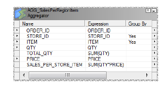
The following Aggregator transformation groups first by STORE_ID and then by ITEM:
If you send the following data through this Aggregator transformation:
STORE_ID ITEM QTY PRICE
101 'battery' 3 2.99
101 'battery' 1 3.19
101 'battery' 2 2.59
101 'AAA' 2 2.45
201 'battery' 1 1.99
201 'battery' 4 1.59
301 'battery' 1 2.45
The Integration Service performs the aggregate calculation on the following unique groups:
STORE_ID ITEM
101 'battery'
101 'AAA'
201 'battery'
301 'battery'
The Integration Service then passes the last row received, along with the results of the aggregation, as
follows:
STORE_ID ITEM TOTAL_QTY SALES_PER_STORE_ITEM
101 'AAA' 2 4.90
101 'battery' 6 17.34
201 'battery' 5 8.35
301 'battery' 1 2.45
Group By Ports 29

Non-Aggregate Expressions
Use non-aggregate expressions in group by ports to modify or replace groups. For example, if you want to
replace ‘AAA battery’ before grouping, you can create a new group by output port, named
CORRECTED_ITEM, using the following expression:
IIF( ITEM = 'AAA battery', battery, ITEM )
Default Values
Define a default value for each port in the group to replace null input values. This allows the Integration
Service to include null item groups in the aggregation.
RELATED TOPICS:
•“Default Values for Ports” on page 13
Using Sorted Input
You can improve Aggregator transformation performance by using the sorted input option. When you use
sorted input, the Integration Service assumes all data is sorted by group and it performs aggregate
calculations as it reads rows for a group. When necessary, it stores group information in memory. To use the
Sorted Input option, you must pass sorted data to the Aggregator transformation. You can gain performance
with sorted ports when you configure the session with multiple partitions.
When you do not use sorted input, the Integration Service performs aggregate calculations as it reads. Since
the data is not sorted, the Integration Service stores data for each group until it reads the entire source to
ensure all aggregate calculations are accurate.
For example, one Aggregator transformation has the STORE_ID and ITEM group by ports, with the sorted
input option selected. When you pass the following data through the Aggregator, the Integration Service
performs an aggregation for the three rows in the 101/battery group as soon as it finds the new group, 201/
battery:
STORE_ID ITEM QTY PRICE
101 'battery' 3 2.99
101 'battery' 1 3.19
101 'battery' 2 2.59
201 'battery' 4 1.59
201 'battery' 1 1.99
If you use sorted input and do not presort data correctly, you receive unexpected results.
Sorted Input Conditions
Do not use sorted input if either of the following conditions are true:
•The aggregate expression uses nested aggregate functions.
•The session uses incremental aggregation.
30 Chapter 2: Aggregator Transformation
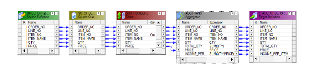
If you use sorted input and do not sort data correctly, the session fails.
Sorting Data
To use sorted input, you pass sorted data through the Aggregator.
Data must be sorted in the following ways:
•By the Aggregator group by ports, in the order they appear in the Aggregator transformation.
•Using the same sort order configured for the session. If data is not in strict ascending or descending order
based on the session sort order, the Integration Service fails the session. For example, if you configure a
session to use a French sort order, data passing into the Aggregator transformation must be sorted using
the French sort order.
For relational and file sources, use the Sorter transformation to sort data in the mapping before passing it to
the Aggregator transformation. You can place the Sorter transformation anywhere in the mapping prior to the
Aggregator if no transformation changes the order of the sorted data. Group by columns in the Aggregator
transformation must be in the same order as they appear in the Sorter transformation.
If the session uses relational sources, you can also use the Number of Sorted Ports option in the Source
Qualifier transformation to sort group by columns in the source database. Group by columns must be in the
same order in both the Aggregator and Source Qualifier transformations.
The following mapping shows a Sorter transformation configured to sort the source data in ascending order
by ITEM_NO:
The Sorter transformation sorts the data as follows:
ITEM_NO ITEM_NAME QTY PRICE
345 Soup 4 2.95
345 Soup 1 2.95
345 Soup 2 3.25
546 Cereal 1 4.49
546 Cereal 2 5.25
With sorted input, the Aggregator transformation returns the following results:
ITEM_NO ITEM_NAME TOTAL_QTY INCOME_PER_ITEM
345 Soup 7 21.25
546 Cereal 3 14.99
Using Sorted Input 31
Creating an Aggregator Transformation
To use an Aggregator transformation in a mapping, add the Aggregator transformation to the mapping. Then
configure the transformation with an aggregate expression and group by ports.
To create an Aggregator transformation:
1. In the Mapping Designer, click Transformation > Create. Select the Aggregator transformation.
2. Enter a name for the Aggregator, click Create. Then click Done.
The Designer creates the Aggregator transformation.
3. Drag the ports to the Aggregator transformation.
The Designer creates input/output ports for each port you include.
4. Double-click the title bar of the transformation to open the Edit Transformations dialog box.
5. Select the Ports tab.
6. Click the group by option for each column you want the Aggregator to use in creating groups.
Optionally, enter a default value to replace null groups.
7. Click Add to add an expression port.
The expression port must be an output port. Make the port an output port by clearing Input (I).
8. Optionally, add default values for specific ports.
If the target database does not handle null values and certain ports are likely to contain null values,
specify a default value.
9. Configure properties on the Properties tab.
Tips for Aggregator Transformations
Use sorted input to decrease the use of aggregate caches.
Sorted input reduces the amount of data cached during the session and improves session performance. Use
this option with the Sorter transformation to pass sorted data to the Aggregator transformation.
The Aggregator transformation might not provide sorted output.
To sort output from an Aggregator transformation, use a Sorter transformation.
Limit connected input/output or output ports.
Limit the number of connected input/output or output ports to reduce the amount of data the Aggregator
transformation stores in the data cache.
Filter the data before aggregating it.
If you use a Filter transformation in the mapping, place the transformation before the Aggregator
transformation to reduce unnecessary aggregation.
32 Chapter 2: Aggregator Transformation
Troubleshooting Aggregator Transformations
I selected sorted input but the workflow takes the same amount of time as before.
You cannot use sorted input if any of the following conditions are true:
•The aggregate expression contains nested aggregate functions.
•The session uses incremental aggregation.
•Source data is data driven.
When any of these conditions are true, the Integration Service processes the transformation as if you do not
use sorted input.
A session using an Aggregator transformation causes slow performance.
The Integration Service may be paging to disk during the workflow. You can increase session performance by
increasing the index and data cache sizes in the transformation properties.
I entered an override cache directory in the Aggregator transformation, but the Integration Service saves
the session incremental aggregation files somewhere else.
You can override the transformation cache directory on a session level. The Integration Service notes the
cache directory in the session log. You can also check the session properties for an override cache directory.
Troubleshooting Aggregator Transformations 33

CHAPTER 3
Custom Transformation
This chapter includes the following topics:
•Custom Transformation Overview, 34
•Creating Custom Transformations, 36
•Working with Groups and Ports, 37
•Working with Port Attributes, 38
•Custom Transformation Properties, 39
•Working with Transaction Control, 42
•Blocking Input Data, 43
•Working with Procedure Properties, 45
•Creating Custom Transformation Procedures, 45
Custom Transformation Overview
Custom transformations operate in conjunction with procedures you create outside of the Designer interface
to extend PowerCenter functionality. You can create a Custom transformation and bind it to a procedure that
you develop using the Custom transformation functions. The Custom transformation can be an active or
passive transformation.
Use the Custom transformation to create transformation applications, such as sorting and aggregation, which
require all input rows to be processed before outputting any output rows. To support this process, the input
and output functions occur separately in Custom transformations compared to External Procedure
transformations.
The Integration Service passes the input data to the procedure using an input function. The output function is
a separate function that you must enter in the procedure code to pass output data to the Integration Service.
In contrast, in the External Procedure transformation, an external procedure function does both input and
output, and its parameters consist of all the ports of the transformation.
You can also use the Custom transformation to create a transformation that requires multiple input groups,
multiple output groups, or both. A group is the representation of a row of data entering or leaving a
transformation. For example, you might create a Custom transformation with one input group and multiple
output groups that parses XML data. Or, you can create a Custom transformation with two input groups and
one output group that merges two streams of input data into one stream of output data.
34
Working with Transformations Built On the Custom Transformation
You can build transformations using the Custom transformation. Some of the PowerCenter transformations
are built using the Custom transformation. The following transformations that ship with Informatica products
are native transformations and are not built using the Custom transformation:
•Aggregator transformation
•Expression transformation
•External Procedure transformation
•Filter transformation
•Joiner transformation
•Lookup transformation
•Normalizer transformation
•Rank transformation
•Router transformation
•Sequence Generator transformation
•Sorter transformation
•Source Qualifier transformation
•Stored Procedure transformation
•Transaction Control transformation
•Update Strategy transformation
All other transformations are built using the Custom transformation. Rules that apply to Custom
transformations, such as blocking rules, also apply to transformations built using Custom transformations. For
example, when you connect a Custom transformation in a mapping, you must verify that the data can flow
from all sources in a target load order group to the targets without the Integration Service blocking all
sources. Similarly, you must also verify this for transformations built using a Custom transformation.
Code Page Compatibility
When the Integration Service runs in ASCII mode, it passes data to the Custom transformation procedure in
ASCII. When the Integration Service runs in Unicode mode, it passes data to the procedure in UCS-2.
Use the INFA_CTChangeStringMode() and INFA_CTSetDataCodePageID() functions in the Custom
transformation procedure code to request the data in a different format or in a different code page.
The functions you can use depend on the data movement mode of the Integration Service:
•ASCII mode. Use the INFA_CTChangeStringMode() function to request the data in UCS-2. When you use
this function, the procedure must pass only ASCII characters in UCS-2 format to the Integration Service.
You cannot use the INFA_CTSetDataCodePageID() function to change the code page when the
Integration Service runs in ASCII mode.
•Unicode mode. Use the INFA_CTChangeStringMode() function to request the data in MBCS (multi-byte
character set). When the procedure requests the data in MBCS, the Integration Service passes data in the
Integration Service code page. Use the INFA_CTSetDataCodePageID() function to request the data in a
different code page from the Integration Service code page. The code page you specify in the
INFA_CTSetDataCodePageID() function must be two-way compatible with the Integration Service code
page.
Note: You can also use the INFA_CTRebindInputDataType() function to change the format for a specific port
in the Custom transformation.
Custom Transformation Overview 35
Distributing Custom Transformation Procedures
You can copy a Custom transformation from one repository to another. When you copy a Custom
transformation between repositories, you must verify that the Integration Service machine the target
repository uses contains the Custom transformation procedure.
Creating Custom Transformations
You can create reusable Custom transformations in the Transformation Developer, and add instances of the
transformation to mappings. You can create non-reusable Custom transformations in the Mapping Designer
or Mapplet Designer.
Each Custom transformation specifies a module and a procedure name. You can create a Custom
transformation based on an existing shared library or DLL containing the procedure, or you can create a
Custom transformation as the basis for creating the procedure. When you create a Custom transformation to
use with an existing shared library or DLL, make sure you define the correct module and procedure name.
When you create a Custom transformation as the basis for creating the procedure, select the transformation
and generate the code. The Designer uses the transformation properties when it generates the procedure
code. It generates code in a single directory for all transformations sharing a common module name.
The Designer generates the following files:
•m_<module_name>.c. Defines the module. This file includes an initialization function,
m_<module_name>_moduleInit() that lets you write code you want the Integration Service to run when it
loads the module. Similarly, this file includes a deinitialization function,
m_<module_name>_moduleDeinit(), that lets you write code you want the Integration Service to run
before it unloads the module.
•p_<procedure_name>.c. Defines the procedure in the module. This file contains the code that
implements the procedure logic, such as data cleansing or merging data.
•makefile.aix, makefile.aix64, makefile.hp, makefile.hp64, makefile.hpparisc64, makefile.linux,
makefile.sol, and makefile.sol64. Make files for the UNIX platforms except zLinux. Use makefile.aix64
for 64-bit AIX platforms, makefile.sol64 for 64-bit Solaris platforms, and makefile.hp64 for 64-bit HP-UX
(Itanium) platforms.
Note: For zLinux, you need to update the makefile.linux. Add -m64 to the FLAGS section. For example,
FLAGS=-Wall -fPIC -DUNIX -m64.
Rules and Guidelines for Custom Transformations
Use the following rules and guidelines when you create a Custom transformation:
•Custom transformations are connected transformations. You cannot reference a Custom transformation in
an expression.
•You can include multiple procedures in one module. For example, you can include an XML writer
procedure and an XML parser procedure in the same module.
•You can bind one shared library or DLL to multiple Custom transformation instances if you write the
procedure code to handle multiple Custom transformation instances.
•When you write the procedure code, you must make sure it does not violate basic mapping rules.
•The Custom transformation sends and receives high precision decimals as high precision decimals.
•Use multi-threaded code in Custom transformation procedures.
36 Chapter 3: Custom Transformation

Custom Transformation Components
When you configure a Custom transformation, you define the following components:
•Transformation tab. You can rename the transformation and add a description on the Transformation
tab.
•Ports tab. You can add and edit ports and groups to a Custom transformation. You can also define the
input ports an output port depends on.
•Port Attribute Definitions tab. You can create user-defined port attributes for Custom transformation
ports.
•Properties tab. You can define transformation properties such as module and function identifiers,
transaction properties, and the runtime location.
•Initialization Properties tab. You can define properties that the external procedure uses at runtime, such
as during initialization.
•Metadata Extensions tab. You can create metadata extensions to define properties that the procedure
uses at runtime, such as during initialization.
Working with Groups and Ports
A Custom transformation has both input and output groups. It also can have input ports, output ports, and
input/output ports. You create and edit groups and ports on the Ports tab of the Custom transformation. You
can also define the relationship between input and output ports on the Ports tab.
Creating Groups and Ports
You can create multiple input groups and multiple output groups in a Custom transformation. You must create
at least one input group and one output group. To create an input group, click the Create Input Group icon.
To create an output group, click the Create Output Group icon. You can change the existing group names by
typing in the group header. When you create a passive Custom transformation, you can only create one input
group and one output group.
When you create a port, the Designer adds it below the currently selected row or group. A port can belong to
the input group and the output group that appears immediately above it. An input/output port that appears
below the input group it is also part of the output group. An input/output port that appears below the output
group it is also part of the input group.
Groups that share ports are called a coupled group. Adjacent groups of opposite type can share ports. One
group can be part of more than one coupled group. For example, in the figure in “Step 1. Create the Custom
Transformation” on page 46, InputGroup1 and OutputGroup1 is a coupled group that shares ORDER_ID1
If the transformation has a Port Attribute Definitions tab, you can edit the attributes for each port.
Editing Groups and Ports
Use the following rules and guidelines when you edit ports and groups in a Custom transformation:
•You can change group names by typing in the group header.
•You can only enter ASCII characters for port and group names.
•Once you create a group, you cannot change the group type. If you need to change the group type, delete
the group and add a new group.
Working with Groups and Ports 37

•When you delete a group, the Designer deletes all ports of the same type in that group. However, all
input/output ports remain in the transformation, belong to the group above them, and change to input
ports or output ports, depending on the type of group you delete. For example, an output group contains
output ports and input/output ports. You delete the output group. The Designer deletes the output ports. It
changes the input/output ports to input ports. Those input ports belong to the input group with the header
directly above them.
•To move a group up or down, select the group header and click the Move Port Up or Move Port Down
button. The ports above and below the group header remain the same, but the groups to which they
belong might change.
•To create an input/output port, the transformation must have an input group and an output group.
Defining Port Relationships
By default, an output port in a Custom transformation depends on all input ports. However, you can define
the relationship between input and output ports in a Custom transformation. When you do this, you can view
link paths in a mapping containing a Custom transformation and you can see which input ports an output port
depends on. You can also view source column dependencies for target ports in a mapping containing a
Custom transformation.
To define the relationship between ports in a Custom transformation, create a port dependency. A port
dependency is the relationship between an output or input/output port and one or more input or input/output
ports. When you create a port dependency, base it on the procedure logic in the code.
To create a port dependency, click Custom Transformation on the Ports tab and choose Port Dependencies.
For example, create a external procedure that parses XML data. You create a Custom transformation with
one input group containing one input port and multiple output groups containing multiple output ports.
According to the external procedure logic, all output ports depend on the input port. You can define this
relationship in the Custom transformation by creating a port dependency for each output port. Define each
port dependency so that the output port depends on the one input port.
To create a port dependency:
1. On the Ports tab, click Custom Transformation and choose Port Dependencies.
2. In the Output Port Dependencies dialog box, select an output or input/output port in the Output Port field.
3. In the Input Ports pane, select an input or input/output port on which the output port or input/output port
depends.
4. Click Add.
5. Repeat steps 3 to 4 to include more input or input/output ports in the port dependency.
6. To create another port dependency, repeat steps 2 to 5.
7. Click OK.
Working with Port Attributes
Ports have attributes, such as datatype and precision. When you create a Custom transformation, you can
create user-defined port attributes. User-defined port attributes apply to all ports in a Custom transformation.
For example, you create a external procedure to parse XML data. You can create a port attribute called “XML
path” where you can define the position of an element in the XML hierarchy.
38 Chapter 3: Custom Transformation

Create port attributes and assign default values on the Port Attribute Definitions tab of the Custom
transformation. You can define a specific port attribute value for each port on the Ports tab.
When you create a port attribute, define the following properties:
•Name. The name of the port attribute.
•Datatype. The datatype of the port attribute value. You can choose Boolean, Numeric, or String.
•Value. The default value of the port attribute. This property is optional. When you enter a value here, the
value applies to all ports in the Custom transformation. You can override the port attribute value for each
port on the Ports tab.
You define port attributes for each Custom transformation. You cannot copy a port attribute from one Custom
transformation to another.
Editing Port Attribute Values
After you create port attributes, you can edit the port attribute values for each port in the transformation. To
edit the port attribute values, click Custom Transformation on the Ports tab and choose Edit Port Attribute.
You can change the port attribute value for a particular port by clicking the Open button. This opens the Edit
Port Attribute Default Value dialog box. Or, you can enter a new value by typing directly in the Value column.
You can filter the ports listed in the Edit Port Level Attributes dialog box by choosing a group from the Select
Group field.
Custom Transformation Properties
Properties for the Custom transformation apply to both the procedure and the transformation. Configure the
Custom transformation properties on the Properties tab of the Custom transformation.
The following table describes the Custom transformation properties:
Option Description
Language Language used for the procedure code. You define the language when you create the
Custom transformation. If you need to change the language, create a new Custom
transformation.
Module Identifier Module name. Applies to Custom transformation procedures developed using C or C+
+.
Enter only ASCII characters in this field. You cannot enter multibyte characters.
This property is the base name of the DLL or the shared library that contains the
procedure. The Designer uses this name to create the C file when you generate the
external procedure code.
Function Identifier Name of the procedure in the module. Applies to Custom transformation procedures
developed using C.
Enter only ASCII characters in this field. You cannot enter multibyte characters.
The Designer uses this name to create the C file where you enter the procedure code.
Class Name Class name of the Custom transformation procedure. Applies to Custom
transformation procedures developed using C++ or Java.
Enter only ASCII characters in this field. You cannot enter multibyte characters.
Custom Transformation Properties 39

Option Description
Runtime Location Location that contains the DLL or shared library. Default is $PMExtProcDir. Enter a
path relative to the Integration Service node that runs the Custom transformation
session.
If this property is blank, the Integration Service uses the environment variable defined
on the Integration Service node to locate the DLL or shared library.
You must copy all DLLs or shared libraries to the runtime location or to the
environment variable defined on the Integration Service node. The Integration Service
fails to load the procedure when it cannot locate the DLL, shared library, or a
referenced file.
Tracing Level Amount of detail displayed in the session log for this transformation. Default is
Normal.
Is Partitionable Indicates if you can create multiple partitions in a pipeline that uses this
transformation:
- No. The transformation cannot be partitioned. The transformation and other
transformations in the same pipeline are limited to one partition.
- Locally. The transformation can be partitioned, but the Integration Service must run all
partitions in the pipeline on the same node. Choose Local when different partitions of the
Custom transformation must share objects in memory.
- Across Grid. The transformation can be partitioned, and the Integration Service can
distribute each partition to different nodes.
Default is No.
Inputs Must Block Indicates if the procedure associated with the transformation must be able to block
incoming data. Default is enabled.
Is Active Indicates if this transformation is an active or passive transformation.
You cannot change this property after you create the Custom transformation. If you
need to change this property, create a new Custom transformation and select the
correct property value.
Update Strategy
Transformation
Indicates if this transformation defines the update strategy for output rows. Default is
disabled. You can enable this for active Custom transformations.
Transformation Scope Indicates how the Integration Service applies the transformation logic to incoming
data:
- Row
- Transaction
- All Input
When the transformation is passive, this property is always Row. When the
transformation is active, this property is All Input by default.
Generate Transaction Indicates if this transformation can generate transactions. When a Custom
transformation generates transactions, it generates transactions for all output groups.
Default is disabled. You can only enable this for active Custom transformations.
40 Chapter 3: Custom Transformation

Option Description
Output is Repeatable Indicates if the order of the output data is consistent between session runs.
- Never. The order of the output data is inconsistent between session runs. This is the
default for active transformations.
- Based On Input Order. The output order is consistent between session runs when the
input data order is consistent between session runs. This is the default for passive
transformations.
- Always. The order of the output data is consistent between session runs even if the
order of the input data is inconsistent between session runs.
Requires Single Thread
Per Partition
Indicates if the Integration Service processes each partition at the procedure with one
thread. When you enable this option, the procedure code can use thread-specific
operations. Default is enabled.
Output is Deterministic Indicates whether the transformation generates consistent output data between
session runs. Enable this property to perform recovery on sessions that use this
transformation.
Warning: If you configure a transformation as repeatable and deterministic, it is your responsibility to ensure
that the data is repeatable and deterministic. If you try to recover a session with transformations that do not
produce the same data between the session and the recovery, the recovery process can result in corrupted
data.
Setting the Update Strategy
Use an active Custom transformation to set the update strategy for a mapping at the following levels:
•Within the procedure. You can write the external procedure code to set the update strategy for output
rows. The external procedure can flag rows for insert, update, delete, or reject.
•Within the mapping. Use the Custom transformation in a mapping to flag rows for insert, update, delete,
or reject. Select the Update Strategy Transformation property for the Custom transformation.
•Within the session. Configure the session to treat the source rows as data driven.
If you do not configure the Custom transformation to define the update strategy, or you do not configure the
session as data driven, the Integration Service does not use the external procedure code to flag the output
rows. Instead, when the Custom transformation is active, the Integration Service flags the output rows as
insert. When the Custom transformation is passive, the Integration Service retains the row type. For example,
when a row flagged for update enters a passive Custom transformation, the Integration Service maintains the
row type and outputs the row as update.
Working with Thread-Specific Procedure Code
Custom transformation procedures can include thread-specific operations. A thread-specific operation is code
that performs an action based on the thread that is processing the procedure.
You can configure the Custom transformation so the Integration Service uses one thread to process the
Custom transformation for each partition using the Requires Single Thread Per Partition property.
When you configure a Custom transformation to process each partition with one thread, the Integration
Service calls the following functions with the same thread for each partition:
•p_<proc_name>_partitionInit()
•p_<proc_name>_partitionDeinit()
Custom Transformation Properties 41
•p_<proc_name>_inputRowNotification()
•p_<proc_name>_dataBdryRowNotification()
•p_<proc_name>_eofNotification()
You can include thread-specific operations in these functions because the Integration Service uses the same
thread to process these functions for each partition. For example, you might attach and detach threads to a
Java Virtual Machine.
Note: When you configure a Custom transformation to process each partition with one thread, the Workflow
Manager adds partition points depending on the mapping configuration.
Working with Transaction Control
You can define transaction control for Custom transformations using the following transformation properties:
•Transformation Scope. Determines how the Integration Service applies the transformation logic to
incoming data.
•Generate Transaction. Indicates that the procedure generates transaction rows and outputs them to the
output groups.
Transformation Scope
You can configure how the Integration Service applies the transformation logic to incoming data. You can
choose one of the following values:
•Row. Applies the transformation logic to one row of data at a time. Choose Row when the results of the
procedure depend on a single row of data. For example, you might choose Row when a procedure parses
a row containing an XML file.
•Transaction. Applies the transformation logic to all rows in a transaction. Choose Transaction when the
results of the procedure depend on all rows in the same transaction, but not on rows in other transactions.
When you choose Transaction, you must connect all input groups to the same transaction control point.
For example, you might choose Transaction when the external procedure performs aggregate calculations
on the data in a single transaction.
•All Input. Applies the transformation logic to all incoming data. When you choose All Input, the Integration
Service drops transaction boundaries. Choose All Input when the results of the procedure depend on all
rows of data in the source. For example, you might choose All Input when the external procedure
performs aggregate calculations on all incoming data, or when it sorts all incoming data.
Generate Transaction
You can write the external procedure code to output transactions, such as commit and rollback rows. When
the external procedure outputs commit and rollback rows, configure the Custom transformation to generate
transactions. Select the Generate Transaction transformation property. You can enable this property for
active Custom transformations.
When the external procedure outputs a commit or rollback row, it outputs or rolls back the row for all output
groups.
When you configure the transformation to generate transactions, the Integration Service treats the Custom
transformation like a Transaction Control transformation. Most rules that apply to a Transaction Control
transformation in a mapping also apply to the Custom transformation. For example, when you configure a
42 Chapter 3: Custom Transformation

Custom transformation to generate transactions, you cannot concatenate pipelines or pipeline branches
containing the transformation.
When you edit or create a session using a Custom transformation configured to generate transactions,
configure it for user-defined commit.
Working with Transaction Boundaries
The Integration Service handles transaction boundaries entering and leaving Custom transformations based
on the mapping configuration and the Custom transformation properties.
The following table describes how the Integration Service handles transaction boundaries at Custom
transformations:
Transformation
Scope
Generate Transactions Enabled Generate Transactions Disabled
Row Integration Service drops incoming
transaction boundaries and does not call the
data boundary notification function.
It outputs transaction rows according to the
procedure logic across all output groups.
When the incoming data for all input
groups comes from the same transaction
control point, the Integration Service
preserves incoming transaction
boundaries and outputs them across all
output groups. However, it does not call
the data boundary notification function.
When the incoming data for the input
groups comes from different transaction
control points, the Integration Service
drops incoming transaction boundaries. It
does not call the data boundary
notification function. The Integration
Service outputs all rows in one open
transaction.
Transaction Integration Service preserves incoming
transaction boundaries and calls the data
boundary notification function.
However, it outputs transaction rows
according to the procedure logic across all
output groups.
Integration Service preserves incoming
transaction boundaries and calls the data
boundary notification function.
It outputs the transaction rows across all
output groups.
All Input Integration Service drops incoming
transaction boundaries and does not call the
data boundary notification function. The
Integration Service outputs transaction rows
according to the procedure logic across all
output groups.
Integration Service drops incoming
transaction boundaries and does not call
the data boundary notification function. It
outputs all rows in one open transaction.
Blocking Input Data
By default, the Integration Service concurrently reads sources in a target load order group. However, you can
write the external procedure code to block input data on some input groups. Blocking is the suspension of the
data flow into an input group of a multiple input group transformation.
To use a Custom transformation to block input data, you must write the procedure code to block and unblock
data. You must also enable blocking on the Properties tab for the Custom transformation.
Blocking Input Data 43

Writing the Procedure Code to Block Data
You can write the procedure to block and unblock incoming data. To block incoming data, use the
INFA_CTBlockInputFlow() function. To unblock incoming data, use the INFA_CTUnblockInputFlow() function.
You might want to block input data if the external procedure needs to alternate reading from input groups.
Without the blocking functionality, you would need to write the procedure code to buffer incoming data. You
can block input data instead of buffering it which usually increases session performance.
For example, you need to create an external procedure with two input groups. The external procedure reads
a row from the first input group and then reads a row from the second input group. If you use blocking, you
can write the external procedure code to block the flow of data from one input group while it processes the
data from the other input group. When you write the external procedure code to block data, you increase
performance because the procedure does not need to copy the source data to a buffer. However, you could
write the external procedure to allocate a buffer and copy the data from one input group to the buffer until it is
ready to process the data. Copying source data to a buffer decreases performance.
RELATED TOPICS:
•“Blocking Functions” on page 87
Configuring Custom Transformations as Blocking Transformations
When you create a Custom transformation, the Designer enables the Inputs Must Block transformation
property by default. This property affects data flow validation when you save or validate a mapping. When
you enable this property, the Custom transformation is a blocking transformation. When you clear this
property, the Custom transformation is not a blocking transformation.
Configure the Custom transformation as a blocking transformation when the external procedure code must be
able to block input data.
You can configure the Custom transformation as a non-blocking transformation when one of the following
conditions is true:
•The procedure code does not include the blocking functions.
•The procedure code includes two algorithms, one that uses blocking and the other that copies the source
data to a buffer allocated by the procedure instead of blocking data. The code checks whether or not the
Integration Service allows the Custom transformation to block data. The procedure uses the algorithm with
the blocking functions when it can block, and uses the other algorithm when it cannot block. You might
want to do this to create a Custom transformation that you use in multiple mapping configurations.
Note: When the procedure blocks data and you configure the Custom transformation as a non-blocking
transformation, the Integration Service fails the session.
Validating Mappings with Custom Transformations
When you include a Custom transformation in a mapping, both the Designer and Integration Service validate
the mapping. The Designer validates the mapping you save or validate and the Integration Service validates
the mapping when you run the session.
Validating at Design Time
When you save or validate a mapping, the Designer performs data flow validation. When the Designer does
this, it verifies that the data can flow from all sources in a target load order group to the targets without
blocking transformations blocking all sources. Some mappings with blocking transformations are invalid.
44 Chapter 3: Custom Transformation
Validating at Runtime
When you run a session, the Integration Service validates the mapping against the procedure code at
runtime. When the Integration Service does this, it tracks whether or not it allows the Custom transformations
to block data:
•Configure the Custom transformation as a blocking transformation. The Integration Service always
allows the Custom transformation to block data.
•Configure the Custom transformation as a non-blocking transformation. The Integration Service
allows the Custom transformation to block data depending on the mapping configuration. If the Integration
Service can block data at the Custom transformation without blocking all sources in the target load order
group simultaneously, it allows the Custom transformation to block data.
You can write the procedure code to check whether or not the Integration Service allows a Custom
transformation to block data. Use the INFA_CT_getInternalProperty() function to access the
INFA_CT_TRANS_MAY_BLOCK_DATA property ID. The Integration Service returns TRUE when the Custom
transformation can block data, and it returns FALSE when the Custom transformation cannot block data.
Working with Procedure Properties
You can define property name and value pairs in the Custom transformation that the procedure can use when
the Integration Service runs the procedure, such as during initialization time. You can create user-defined
properties on the following tabs of the Custom transformation:
•Metadata Extensions. You can specify the property name, datatype, precision, and value. Use metadata
extensions for passing information to the procedure.
•Initialization Properties. You can specify the property name and value.
While you can define properties on both tabs in the Custom transformation, the Metadata Extensions tab lets
you provide more detail for the property. Use metadata extensions to pass properties to the procedure.
For example, you create a Custom transformation external procedure that sorts data after transforming it.
You could create a boolean metadata extension named Sort_Ascending. When you use the Custom
transformation in a mapping, you can choose True or False for the metadata extension, depending on how
you want the procedure to sort the data.
When you define a property in the Custom transformation, use the get all property names functions, such as
INFA_CTGetAllPropertyNamesM(), to access the names of all properties defined on the Initialization
Properties and Metadata Extensions tab. Use the get external property functions, such as
INFA_CT_getExternalPropertyM(), to access the property name and value of a property ID you specify.
Note: When you define a metadata extension and an initialization property with the same name, the property
functions only return information for the metadata extension.
Creating Custom Transformation Procedures
You can create Custom transformation procedures that run on 32-bit or 64-bit Integration Service machines.
Use the following steps as a guideline when you create a Custom transformation procedure:
1. In the Transformation Developer, create a reusable Custom transformation. Or, in the Mapplet Designer
or Mapping Designer, create a non-reusable Custom transformation.
Working with Procedure Properties 45
2. Generate the template code for the procedure.
When you generate the procedure code, the Designer uses the information from the Custom
transformation to create C source code files and makefiles.
3. Modify the C files to add the procedure logic.
4. Use a C/C++ compiler to compile and link the source code files into a DLL or shared library and copy it
to the Integration Service machine.
5. Create a mapping with the Custom transformation.
6. Run the session in a workflow.
This section includes an example to demonstrate this process. The steps in this section create a Custom
transformation that contains two input groups and one output group. The Custom transformation procedure
verifies that the Custom transformation uses two input groups and one output group. It also verifies that the
number of ports in all groups are equal and that the port datatypes are the same for all groups. The
procedure takes rows of data from each input group and outputs all rows to the output group.
Step 1. Create the Custom Transformation
To create a Custom transformation:
1. In the Transformation Developer, click Transformation > Create.
2. In the Create Transformation dialog box, choose Custom transformation, enter a transformation name,
and click Create.
In the Union example, enter
CT_Inf_Union
as the transformation name.
3. In the Active or Passive dialog box, create the transformation as a passive or active transformation, and
click OK.
In the Union example, choose Active.
4. Click Done to close the Create Transformation dialog box.
5. Open the transformation and click the Ports tab. Create groups and ports.
You can edit the groups and ports later, if necessary.
46 Chapter 3: Custom Transformation
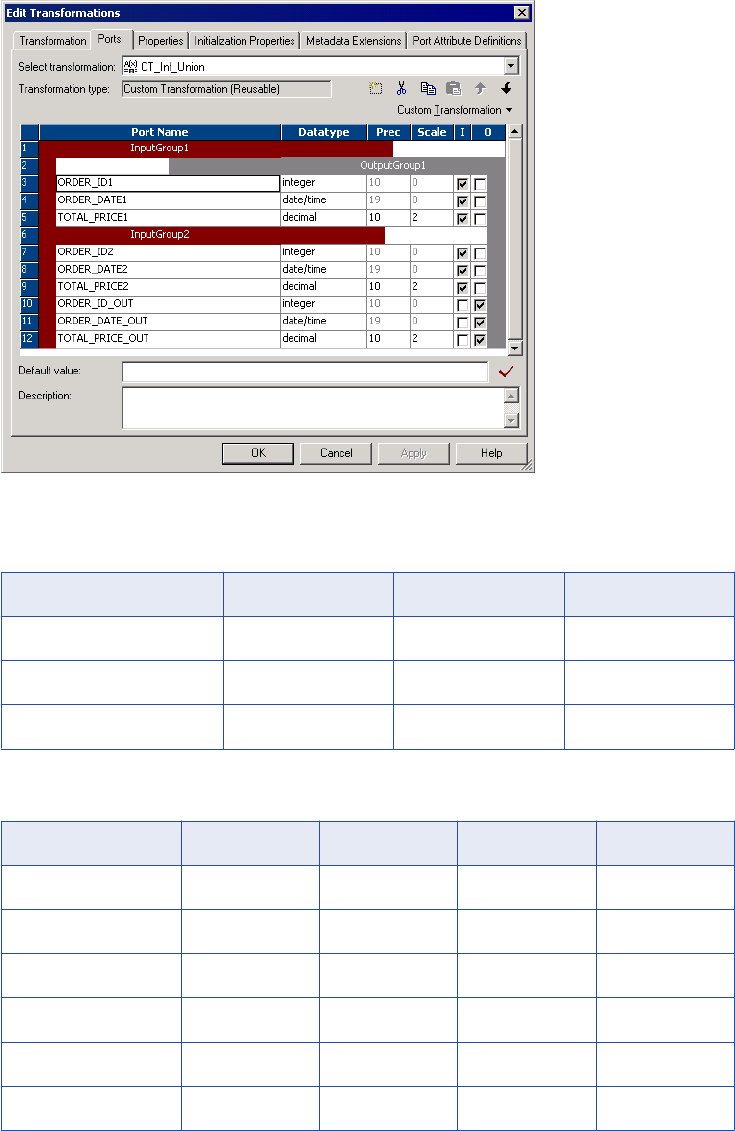
The following figure shows an example of a Union transformation with two groups:
In the Union example, create the groups InputGroup1 and InputGroup2. Create the following ports for
InputGroup1:
Port Name Datatype Precision Scale
ORDER_ID1 integer 10 0
ORDER_DATE1 date/time 19 0
TOTAL_PRICE1 decimal 10 2
Create the following ports for InputGroup2:
Port Name Datatype Precision Scale Input/Output
ORDER_ID2 integer 10 0 Input
ORDER_DATE2 date/time 19 0 Input
TOTAL_PRICE2 decimal 10 2 Input
ORDER_ID_OUT integer 10 0 Output
ORDER_DATE_OUT date/time 19 0 Output
TOTAL_PRICE_OUT decimal 10 2 Output
6. Select the Properties tab and enter a module and function identifier and the runtime location. Edit other
transformation property attributes, such as the Tracing Level, Is Partitionable, Inputs Must Block, Is
Creating Custom Transformation Procedures 47

Active, Update Strategy Transformation, Transformation Scope and Generate Transaction values/
checkboxes.
In the Union example, configure the following properties:
Property Name Value
Module Identifier UnionDemo
Function Identifier Union
Runtime Location $PMExtProcDir
Tracing Level Normal
Is Partitionable No
Inputs Must Block No
Is Active Yes
Update Strategy Transformation No
Transformation Scope All Input
Generate Transaction No
7. Click the Metadata Extensions tab to enter metadata extensions, such as properties the external
procedure might need for initialization.
In the Union example, do not create metadata extensions.
8. Click the Port Attribute Definitions tab to create port attributes, if necessary.
In the Union example, do not create port attributes.
After you create the Custom transformation that calls the procedure, the next step is to generate the C files.
Step 2. Generate the C Files
After you create a Custom transformation, you generate the source code files. The Designer generates file
names in lower case.
To generate the code for a Custom transformation procedure:
1. In the Transformation Developer, select the transformation and click Transformation > Generate Code.
2. Select the procedure you just created. The Designer lists the procedures as
<module_name>.<procedure_name>.
In the Union example, select UnionDemo.Union.
3. Specify the directory where you want to generate the files, and click Generate.
In the Union example, select <client_installation_directory>/TX.
48 Chapter 3: Custom Transformation
The Designer creates a subdirectory, <module_name>, in the directory you specified. In the Union
example, the Designer creates <client_installation_directory>/TX/UnionDemo. It also creates the
following files:
•m_UnionDemo.c
•m_UnionDemo.h
•p_Union.c
•p_Union.h
•makefile.aix (32-bit), makefile.aix64 (64-bit), makefile.hp (32-bit), makefile.hp64 (64-bit),
makefile.hpparisc64, makefile.linux (32-bit), and makefile.sol (32-bit).
Step 3. Fill Out the Code with the Transformation Logic
You must code the procedure C file. Optionally, you can also code the module C file. In the Union example,
you fill out the procedure C file only. You do not need to fill out the module C file.
To code the procedure C file:
1. Open p_<procedure_name>.c for the procedure.
In the Union example, open p_Union.c.
2. Enter the C code for the procedure.
3. Save the modified file.
In the Union example, use the following code:
/**************************************************************************
*
* Copyright (c) 2005 Informatica Corporation. This file contains
* material proprietary to Informatica Corporation and may not be copied
* or distributed in any form without the written permission of Informatica
* Corporation
*
**************************************************************************/
/**************************************************************************
* Custom Transformation p_union Procedure File
*
* This file contains code that functions that will be called by the main
* server executable.
*
* for more information on these files,
* see $(INFA_HOME)/ExtProc/include/Readme.txt
**************************************************************************/
/*
* INFORMATICA 'UNION DEMO' developed using the API for custom
* transformations.
* File Name: p_Union.c
*
* An example of a custom transformation ('Union') using PowerCenter
*
* The purpose of the 'Union' transformation is to combine pipelines with the
* same row definition into one pipeline (i.e. union of multiple pipelines).
* [ Note that it does not correspond to the mathematical definition of union
* since it does not eliminate duplicate rows.]
*
* This example union transformation allows N input pipelines ( each
* corresponding to an input group) to be combined into one pipeline.
*
* To use this transformation in a mapping, the following attributes must be
* true:
Creating Custom Transformation Procedures 49
* a. The transformation must have >= 2 input groups and only one output group.
* b. In the Properties tab set the following properties:
* i. Module Identifier: UnionDemo
* ii. Function Identifier: Union
* iii. Inputs May Block: Unchecked
* iv. Is Active: Checked
* v. Update Strategy Transformation: Unchecked *
* vi. Transformation Scope: All
* vii. Generate Transaction: Unchecked *
*
* * This version of the union transformation does not provide code for
* changing the update strategy or for generating transactions.
* c. The input groups and the output group must have the same number of ports
* and the same datatypes. This is verified in the initialization of the
* module and the session is failed if this is not true.
* d. The transformation can be used in multiple number of times in a Target
* Load Order Group and can also be contained within multiple partitions.
*
*/
/**************************************************************************
Includes
**************************************************************************/
include <stdlib.h>
#include "p_union.h"
/**************************************************************************
Forward Declarations
**************************************************************************/
INFA_STATUS validateProperties(const INFA_CT_PARTITION_HANDLE* partition);
/**************************************************************************
Functions
**************************************************************************/
/**************************************************************************
Function: p_union_procInit
Description: Initialization for the procedure. Returns INFA_SUCCESS if
procedure initialization succeeds, else return INFA_FAILURE.
Input: procedure - the handle for the procedure
Output: None
Remarks: This function will get called once for the session at
initialization time. It will be called after the moduleInit function.
**************************************************************************/
INFA_STATUS p_union_procInit( INFA_CT_PROCEDURE_HANDLE procedure)
{
const INFA_CT_TRANSFORMATION_HANDLE* transformation = NULL;
const INFA_CT_PARTITION_HANDLE* partition = NULL;
size_t nTransformations = 0, nPartitions = 0, i = 0;
/* Log a message indicating beginning of the procedure initialization */
INFA_CTLogMessageM( eESL_LOG,
"union_demo: Procedure initialization started ..." );
INFA_CTChangeStringMode( procedure, eASM_MBCS );
/* Get the transformation handles */
transformation = INFA_CTGetChildrenHandles( procedure,
&nTransformations,
TRANSFORMATIONTYPE);
/* For each transformation verify that the 0th partition has the correct
* properties. This does not need to be done for all partitions since rest
* of the partitions have the same information */
for (i = 0; i < nTransformations; i++)
{
50 Chapter 3: Custom Transformation
/* Get the partition handle */
partition = INFA_CTGetChildrenHandles(transformation[i],
&nPartitions, PARTITIONTYPE );
if (validateProperties(partition) != INFA_SUCCESS)
{
INFA_CTLogMessageM( eESL_ERROR,
"union_demo: Failed to validate attributes of "
"the transformation");
return INFA_FAILURE;
}
}
INFA_CTLogMessageM( eESL_LOG,
"union_demo: Procedure initialization completed." );
return INFA_SUCCESS;
}
/**************************************************************************
Function: p_union_procDeinit
Description: Deinitialization for the procedure. Returns INFA_SUCCESS if
procedure deinitialization succeeds, else return INFA_FAILURE.
Input: procedure - the handle for the procedure
Output: None
Remarks: This function will get called once for the session at
deinitialization time. It will be called before the moduleDeinit
function.
**************************************************************************/
INFA_STATUS p_union_procDeinit( INFA_CT_PROCEDURE_HANDLE procedure,
INFA_STATUS sessionStatus )
{
/* Do nothing ... */
return INFA_SUCCESS;
}
/**************************************************************************
Function: p_union_partitionInit
Description: Initialization for the partition. Returns INFA_SUCCESS if
partition deinitialization succeeds, else return INFA_FAILURE.
Input: partition - the handle for the partition
Output: None
Remarks: This function will get called once for each partition for each
transformation in the session.
**************************************************************************/
INFA_STATUS p_union_partitionInit( INFA_CT_PARTITION_HANDLE partition )
{
/* Do nothing ... */
return INFA_SUCCESS;
}
/**************************************************************************
Function: p_union_partitionDeinit
Description: Deinitialization for the partition. Returns INFA_SUCCESS if
partition deinitialization succeeds, else return INFA_FAILURE.
Input: partition - the handle for the partition
Output: None
Remarks: This function will get called once for each partition for each
transformation in the session.
**************************************************************************/
INFA_STATUS p_union_partitionDeinit( INFA_CT_PARTITION_HANDLE partition )
Creating Custom Transformation Procedures 51
{
/* Do nothing ... */
return INFA_SUCCESS;
}
/**************************************************************************
Function: p_union_inputRowNotification
Description: Notification that a row needs to be processed for an input
group in a transformation for the given partition. Returns INFA_ROWSUCCESS
if the input row was processed successfully, INFA_ROWFAILURE if the input
row was not processed successfully and INFA_FATALERROR if the input row
causes the session to fail.
Input: partition - the handle for the partition for the given row
group - the handle for the input group for the given row
Output: None
Remarks: This function is probably where the meat of your code will go,
as it is called for every row that gets sent into your transformation.
**************************************************************************/
INFA_ROWSTATUS p_union_inputRowNotification( INFA_CT_PARTITION_HANDLE partition,
INFA_CT_INPUTGROUP_HANDLE inputGroup )
{
const INFA_CT_OUTPUTGROUP_HANDLE* outputGroups = NULL;
const INFA_CT_INPUTPORT_HANDLE* inputGroupPorts = NULL;
const INFA_CT_OUTPUTPORT_HANDLE* outputGroupPorts = NULL;
size_t nNumInputPorts = 0, nNumOutputGroups = 0,
nNumPortsInOutputGroup = 0, i = 0;
/* Get the output group port handles */
outputGroups = INFA_CTGetChildrenHandles(partition,
&nNumOutputGroups,
OUTPUTGROUPTYPE);
outputGroupPorts = INFA_CTGetChildrenHandles(outputGroups[0],
&nNumPortsInOutputGroup,
OUTPUTPORTTYPE);
/* Get the input groups port handles */
inputGroupPorts = INFA_CTGetChildrenHandles(inputGroup,
&nNumInputPorts,
INPUTPORTTYPE);
/* For the union transformation, on receiving a row of input, we need to
* output that row on the output group. */
for (i = 0; i < nNumInputPorts; i++)
{
INFA_CTSetData(outputGroupPorts[i],
INFA_CTGetDataVoid(inputGroupPorts[i]));
INFA_CTSetIndicator(outputGroupPorts[i],
INFA_CTGetIndicator(inputGroupPorts[i]) );
INFA_CTSetLength(outputGroupPorts[i],
INFA_CTGetLength(inputGroupPorts[i]) );
}
/* We know there is only one output group for each partition */
return INFA_CTOutputNotification(outputGroups[0]);
}
/**************************************************************************
Function: p_union_eofNotification
Description: Notification that the last row for an input group has already
been seen. Return INFA_FAILURE if the session should fail as a result of
seeing this notification, INFA_SUCCESS otherwise.
52 Chapter 3: Custom Transformation
Input: partition - the handle for the partition for the notification
group - the handle for the input group for the notification
Output: None
**************************************************************************/
INFA_STATUS p_union_eofNotification( INFA_CT_PARTITION_HANDLE partition,
INFA_CT_INPUTGROUP_HANDLE group)
{
INFA_CTLogMessageM( eESL_LOG,
"union_demo: An input group received an EOF notification");
return INFA_SUCCESS;
}
/**************************************************************************
Function: p_union_dataBdryNotification
Description: Notification that a transaction has ended. The data
boundary type can either be commit or rollback.
Return INFA_FAILURE if the session should fail as a result of
seeing this notification, INFA_SUCCESS otherwise.
Input: partition - the handle for the partition for the notification
transactionType - commit or rollback
Output: None
**************************************************************************/
INFA_STATUS p_union_dataBdryNotification ( INFA_CT_PARTITION_HANDLE partition,
INFA_CT_DATABDRY_TYPE transactionType)
{
/* Do nothing */
return INFA_SUCCESS;
}
/* Helper functions */
/**************************************************************************
Function: validateProperties
Description: Validate that the transformation has all properties expected
by a union transformation, such as at least one input group, and only
one output group. Return INFA_FAILURE if the session should fail since the
transformation was invalid, INFA_SUCCESS otherwise.
Input: partition - the handle for the partition
Output: None
**************************************************************************/
INFA_STATUS validateProperties(const INFA_CT_PARTITION_HANDLE* partition)
{
const INFA_CT_INPUTGROUP_HANDLE* inputGroups = NULL;
const INFA_CT_OUTPUTGROUP_HANDLE* outputGroups = NULL;
size_t nNumInputGroups = 0, nNumOutputGroups = 0;
const INFA_CT_INPUTPORT_HANDLE** allInputGroupsPorts = NULL;
const INFA_CT_OUTPUTPORT_HANDLE* outputGroupPorts = NULL;
size_t nNumPortsInOutputGroup = 0;
size_t i = 0, nTempNumInputPorts = 0;
/* Get the input and output group handles */
inputGroups = INFA_CTGetChildrenHandles(partition[0],
&nNumInputGroups,
INPUTGROUPTYPE);
outputGroups = INFA_CTGetChildrenHandles(partition[0],
&nNumOutputGroups,
OUTPUTGROUPTYPE);
/* 1. Number of input groups must be >= 2 and number of output groups must
* be equal to one. */
if (nNumInputGroups < 1 || nNumOutputGroups != 1)
Creating Custom Transformation Procedures 53

{
INFA_CTLogMessageM( eESL_ERROR,
"UnionDemo: There must be at least two input groups "
"and only one output group");
return INFA_FAILURE;
}
/* 2. Verify that the same number of ports are in each group (including
* output group). */
outputGroupPorts = INFA_CTGetChildrenHandles(outputGroups[0],
&nNumPortsInOutputGroup,
OUTPUTPORTTYPE);
/* Allocate an array for all input groups ports */
allInputGroupsPorts = malloc(sizeof(INFA_CT_INPUTPORT_HANDLE*) *
nNumInputGroups);
for (i = 0; i < nNumInputGroups; i++)
{
allInputGroupsPorts[i] = INFA_CTGetChildrenHandles(inputGroups[i],
&nTempNumInputPorts,
INPUTPORTTYPE);
if ( nNumPortsInOutputGroup != nTempNumInputPorts)
{
INFA_CTLogMessageM( eESL_ERROR,
"UnionDemo: The number of ports in all input and "
"the output group must be the same.");
return INFA_FAILURE;
}
}
free(allInputGroupsPorts);
/* 3. Datatypes of ports in input group 1 must match data types of all other
* groups.
TODO:*/
return INFA_SUCCESS;
}
Step 4. Build the Module
You can build the module on a Windows or UNIX platform.
The following table lists the library file names for each platform when you build the module:
Platform Module File Name
Windows <module_identifier>.dll
AIX lib<module_identifier>.a
HP-UX lib<module_identifier>.sl
Linux lib<module_identifier>.so
Solaris lib<module_identifier>.so
Building the Module on Windows
On Windows, use Microsoft Visual C++ to build the module.
54 Chapter 3: Custom Transformation
To build the module on Windows:
1. Start Visual C++.
2. Click File > New.
3. In the New dialog box, click the Projects tab and select the Win32 Dynamic-Link Library option.
4. Enter its location.
In the Union example, enter <client_installation_directory>/TX/UnionDemo.
5. Enter the name of the project.
You must use the module name specified for the Custom transformation as the project name. In the
Union example, enter UnionDemo.
6. Click OK.
Visual C++ creates a wizard to help you define the project components.
7. In the wizard, select An empty DLL project and click Finish. Click OK in the New Project Information
dialog box.
Visual C++ creates the project files in the directory you specified.
8. Click Project > Add To Project > Files.
9. Navigate up a directory level. This directory contains the procedure files you created. Select all .c files
and click OK.
In the Union example, add the following files:
•m_UnionDemo.c
•p_Union.c
10. Click Project > Settings.
11. Click the C/C++ tab, and select Preprocessor from the Category field.
12. In the Additional Include Directories field, enter the following path and click OK:
..; <PowerCenter_install_dir>\extproc\include\ct
13. Click Build > Build <module_name>.dll or press F7 to build the project.
Visual C++ creates the DLL and places it in the debug or release directory under the project directory.
Building the Module on UNIX
On UNIX, use any C compiler to build the module.
To build the module on UNIX:
1. Copy all C files and makefiles generated by the Designer to the UNIX machine.
Note: If you build the shared library on a machine other than the Integration Service machine, you must
also copy the files in the following directory to the build machine:
<PowerCenter_install_dir>\ExtProc\include\ct
In the Union example, copy all files in <client_installation_directory>/TX/UnionDemo.
2. Set the environment variable INFA_HOME to the Integration Service installation directory.
Note: If you specify an incorrect directory path for the INFA_HOME environment variable, the Integration
Service cannot start.
Creating Custom Transformation Procedures 55
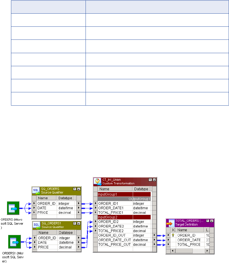
3. Enter a command from the following table to make the project.
UNIX Version Command
AIX (32-bit) make -f makefile.aix
AIX (64-bit) make -f makefile.aix64
HP-UX (32-bit) make -f makefile.hp
HP-UX (64-bit) make -f makefile.hp64
HP-UX PA-RISC make -f makefile.hpparisc64
Linux make -f makefile.linux
Solaris make -f makefile.sol
Step 5. Create a Mapping
In the Mapping Designer, create a mapping that uses the Custom transformation.
In this mapping, two sources with the same ports and datatypes connect to the two input groups in the
Custom transformation. The Custom transformation takes the rows from both sources and outputs them all
through its one output group. The output group has the same ports and datatypes as the input groups.
In the Union example, create a mapping similar to the one in the following figure:
Step 6. Run the Session in a Workflow
When you run the session, the Integration Service looks for the shared library or DLL in the runtime location
you specify in the Custom transformation.
To run a session in a workflow:
1. In the Workflow Manager, create a workflow.
2. Create a session for this mapping in the workflow.
3. Copy the shared library or DLL to the runtime location directory.
56 Chapter 3: Custom Transformation
4. Run the workflow containing the session.
When the Integration Service loads a Custom transformation bound to a procedure, it loads the DLL or
shared library and calls the procedure you define.
Creating Custom Transformation Procedures 57

CHAPTER 4
Custom Transformation Functions
This chapter includes the following topics:
•Custom Transformation Functions Overview, 58
•Function Reference, 59
•Working with Rows, 62
•Generated Functions, 63
•API Functions, 68
•Array-Based API Functions, 92
Custom Transformation Functions Overview
Custom transformations operate in conjunction with procedures you create outside of the Designer to extend
PowerCenter functionality. The Custom transformation functions allow you to develop the transformation logic
in a procedure you associate with a Custom transformation. PowerCenter provides two sets of functions
called generated and API functions. The Integration Service uses generated functions to interface with the
procedure. When you create a Custom transformation and generate the source code files, the Designer
includes the generated functions in the files. Use the API functions in the procedure code to develop the
transformation logic.
When you write the procedure code, you can configure it to receive a block of rows from the Integration
Service or a single row at a time. You can increase the procedure performance when it receives and
processes a block of rows.
Working with Handles
Most functions are associated with a handle, such as INFA_CT_PARTITION_HANDLE. The first parameter
for these functions is the handle the function affects. Custom transformation handles have a hierarchical
relationship to each other. A parent handle has a 1:n relationship to its child handle.
58

The following figure shows the Custom transformation handles:
The following table describes the Custom transformation handles:
Handle Name Description
INFA_CT_MODULE_HANDLE Represents the shared library or DLL. The external procedure can only
access the module handle in its own shared library or DLL. It cannot
access the module handle in any other shared library or DLL.
INFA_CT_PROC_HANDLE Represents a specific procedure within the shared library or DLL.
You might use this handle when you need to write a function to affect a
procedure referenced by multiple Custom transformations.
INFA_CT_TRANS_HANDLE Represents a specific Custom transformation instance in the session.
INFA_CT_PARTITION_HANDLE Represents a specific partition in a specific Custom transformation
instance.
INFA_CT_INPUTGROUP_HANDLE Represents an input group in a partition.
INFA_CT_INPUTPORT_HANDLE Represents an input port in an input group in a partition.
INFA_CT_OUTPUTGROUP_HANDLE Represents an output group in a partition.
INFA_CT_OUTPUTPORT_HANDLE Represents an output port in an output group in a partition.
Function Reference
The Custom transformation functions include generated and API functions.
Function Reference 59

The following table lists the Custom transformation generated functions:
Function Description
m_<module_name>_moduleInit() Module initialization function.
p_<proc_name>_procInit() Procedure initialization function.
p_<proc_name>_partitionInit() Partition initialization function.
p_<proc_name>_inputRowNotification() Input row notification function.
p_<proc_name>_dataBdryNotification() Data boundary notification function.
p_<proc_name>_eofNotification() End of file notification function.
p_<proc_name>_partitionDeinit() Partition deinitialization function.
p_<proc_name>_procedureDeinit() Procedure deinitialization function.
m_<module_name>_moduleDeinit() Module deinitialization function.
The following table lists the Custom transformation API functions:
Function Description
INFA_CTSetDataAccessMode() Set data access mode function.
INFA_CTGetAncestorHandle() Get ancestor handle function.
INFA_CTGetChildrenHandles() Get children handles function.
INFA_CTGetInputPortHandle() Get input port handle function.
INFA_CTGetOutputPortHandle() Get output port handle function.
INFA_CTGetInternalProperty<datatype>() Get internal property function.
INFA_CTGetAllPropertyNamesM() Get all property names in MBCS mode function.
INFA_CTGetAllPropertyNamesU() Get all property names in Unicode mode function.
INFA_CTGetExternalProperty<datatype>M() Get external property in MBCS function.
INFA_CTGetExternalProperty<datatype>U() Get external property in Unicode function.
INFA_CTRebindInputDataType() Rebind input port datatype function.
INFA_CTRebindOutputDataType() Rebind output port datatype function.
INFA_CTGetData<datatype>() Get data functions.
INFA_CTSetData() Set data functions.
INFA_CTGetIndicator() Get indicator function.
60 Chapter 4: Custom Transformation Functions

Function Description
INFA_CTSetIndicator() Set indicator function.
INFA_CTGetLength() Get length function.
INFA_CTSetLength() Set length function.
INFA_CTSetPassThruPort() Set pass-through port function.
INFA_CTOutputNotification() Output notification function.
INFA_CTDataBdryOutputNotification() Data boundary output notification function.
INFA_CTGetErrorMsgU() Get error message in Unicode function.
INFA_CTGetErrorMsgM() Get error message in MBCS function.
INFA_CTLogMessageU() Log message in the session log in Unicode function.
INFA_CTLogMessageM() Log message in the session log in MBCS function.
INFA_CTIncrementErrorCount() Increment error count function.
INFA_CTIsTerminateRequested() Is terminate requested function.
INFA_CTBlockInputFlow() Block input groups function.
INFA_CTUnblockInputFlow() Unblock input groups function.
INFA_CTSetUserDefinedPtr() Set user-defined pointer function.
INFA_CTGetUserDefinedPtr() Get user-defined pointer function.
INFA_CTChangeStringMode() Change the string mode function.
INFA_CTSetDataCodePageID() Set the data code page ID function.
INFA_CTGetRowStrategy() Get row strategy function.
INFA_CTSetRowStrategy() Set the row strategy function.
INFA_CTChangeDefaultRowStrategy() Change the default row strategy of a transformation.
The following table lists the Custom transformation array-based functions:
Function Description
INFA_CTAGetInputRowMax() Get maximum number of input rows function.
INFA_CTAGetOutputRowMax() Get maximum number of output rows function.
INFA_CTASetOutputRowMax() Set maximum number of output rows function.
Function Reference 61

Function Description
INFA_CTAGetNumRows() Get number of rows function.
INFA_CTASetNumRows() Set number of rows function.
INFA_CTAIsRowValid() Is row valid function.
INFA_CTAGetData<datatype>() Get data functions.
INFA_CTAGetIndicator() Get indicator function.
INFA_CTASetData() Set data function.
INFA_CTAGetRowStrategy() Get row strategy function.
INFA_CTASetRowStrategy() Set row strategy function.
INFA_CTASetInputErrorRowM() Set input error row function for MBCS.
INFA_CTASetInputErrorRowU() Set input error row function for Unicode.
Working with Rows
The Integration Service can pass a single row to a Custom transformation procedure or a block of rows in an
array. You can write the procedure code to specify whether the procedure receives one row or a block of
rows. You can increase performance when the procedure receives a block of rows:
•You can decrease the number of function calls the Integration Service and procedure make. The
Integration Service calls the input row notification function fewer times, and the procedure calls the output
notification function fewer times.
•You can increase the locality of memory access space for the data.
•You can write the procedure code to perform an algorithm on a block of data instead of each row of data.
By default, the procedure receives a row of data at a time. To receive a block of rows, you must include the
INFA_CTSetDataAccessMode() function to change the data access mode to array-based. When the data
access mode is array-based, you must use the array-based data handling and row strategy functions to
access and output the data. When the data access mode is row-based, you must use the row-based data
handling and row strategy functions to access and output the data.
All array-based functions use the prefix INFA_CTA. All other functions use the prefix INFA_CT.
Use the following steps to write the procedure code to access a block of rows:
1. Call INFA_CTSetDataAccessMode() during the procedure initialization, to change the data access mode
to array-based.
2. When you create a passive Custom transformation, you can also call INFA_CTSetPassThruPort() during
procedure initialization to pass through the data for input/output ports.
When a block of data reaches the Custom transformation procedure, the Integration Service calls
p_<proc_name>_inputRowNotification() for each block of data. Perform the rest of the steps inside this
function.
62 Chapter 4: Custom Transformation Functions
3. Call INFA_CTAGetNumRows() using the input group handle in the input row notification function to find
the number of rows in the current block.
4. Call one of the INFA_CTAGetData<datatype>() functions using the input port handle to get the data for a
particular row in the block.
5. Call INFA_CTASetData to output rows in a block.
6. Before calling INFA_CTOutputNotification(), call INFA_CTASetNumRows() to notify the Integration
Service of the number of rows the procedure is outputting in the block.
7. Call INFA_CTOutputNotification().
Rules and Guidelines for Row-Based and Array-Based Data
Access Mode
Use the following rules and guidelines when you write the procedure code to use either row-based or array-
based data access mode:
•In row-based mode, you can return INFA_ROWERROR in the input row notification function to indicate
the function encountered an error for the row of data on input. The Integration Service increments the
internal error count.
•In array-based mode, do not return INFA_ROWERROR in the input row notification function. The
Integration Service treats that as a fatal error. If you need to indicate a row in a block has an error, call the
INFA_CTASetInputErrorRowM() or INFA_CTASetInputErrorRowU() function.
•In row-based mode, the Integration Service only passes valid rows to the procedure.
•In array-based mode, an input block may contain invalid rows, such as dropped, filtered, or error rows.
Call INFA_CTAIsRowValid() to determine if a row in a block is valid.
•In array-based mode, do not call INFA_CTASetNumRows() for a passive Custom transformation. You can
call this function for active Custom transformations.
•In array-based mode, call INFA_CTOutputNotification() once.
•In array-based mode, you can call INFA_CTSetPassThruPort() only for passive Custom transformations.
•In array-based mode for passive Custom transformations, you must output all rows in an output block,
including any error row.
Generated Functions
When you use the Designer to generate the procedure code, the Designer includes a set of functions called
generated functions in the m_<module_name>.c and p_<procedure_name>.c files. The Integration Service
uses the generated functions to interface with the procedure. When you run a session, the Integration
Service calls these generated functions in the following order for each target load order group in the mapping:
1. Initialization functions
2. Notification functions
3. Deinitialization functions
Initialization Functions
The Integration Service first calls the initialization functions. Use the initialization functions to write processes
you want the Integration Service to run before it passes data to the Custom transformation. Writing code in
Generated Functions 63

the initialization functions reduces processing overhead because the Integration Service runs these
processes only once for a module, procedure, or partition.
The Designer generates the following initialization functions:
•m_<module_name>_moduleInit()
•p_<proc_name>_procInit()
•p_<proc_name>_partitionInit()
Module Initialization Function
The Integration Service calls the m_<module_name>_moduleInit() function during session initialization,
before it runs the pre-session tasks. It calls this function, once for a module, before all other functions.
If you want the Integration Service to run a specific process when it loads the module, you must include it in
this function. For example, you might write code to create global structures that procedures within this
module access.
Use the following syntax:
INFA_STATUS m_<module_name>_moduleInit(INFA_CT_MODULE_HANDLE module);
The following table describes the arguments for this function:
Argument Datatype Input/
Output
Description
module INFA_CT_MODULE_HANDLE Input Module handle.
The return value datatype is INFA_STATUS. Use INFA_SUCCESS and INFA_FAILURE for the return value.
When the function returns INFA_FAILURE, the Integration Service fails the session.
Procedure Initialization Function
The Integration Service calls p_<proc_name>_procInit() function during session initialization, before it runs
the pre-session tasks and after it runs the module initialization function. The Integration Service calls this
function once for each procedure in the module.
Write code in this function when you want the Integration Service to run a process for a particular procedure.
You can also enter some API functions in the procedure initialization function, such as navigation and
property functions.
Use the following syntax:
INFA_STATUS p_<proc_name>_procInit(INFA_CT_PROCEDURE_HANDLE procedure);
The following table describes the arguments for this function:
Argument Datatype Input/
Output
Description
procedure INFA_CT_PROCEDURE_HANDLE Input Procedure handle.
The return value datatype is INFA_STATUS. Use INFA_SUCCESS and INFA_FAILURE for the return value.
When the function returns INFA_FAILURE, the Integration Service fails the session.
64 Chapter 4: Custom Transformation Functions

Partition Initialization Function
The Integration Service calls p_<proc_name>_partitionInit() function before it passes data to the Custom
transformation. The Integration Service calls this function once for each partition at a Custom transformation
instance.
If you want the Integration Service to run a specific process before it passes data through a partition of the
Custom transformation, you must include it in this function.
Use the following syntax:
INFA_STATUS p_<proc_name>_partitionInit(INFA_CT_PARTITION_HANDLE transformation);
The following table describes the arguments for this function:
Argument Datatype Input/
Output
Description
transformation INFA_CT_PARTITION_HANDLE Input Partition handle.
The return value datatype is INFA_STATUS. Use INFA_SUCCESS and INFA_FAILURE for the return value.
When the function returns INFA_FAILURE, the Integration Service fails the session.
Note: When the Custom transformation requires one thread for each partition, you can include thread-specific
operations in the partition initialization function.
Notification Functions
The Integration Service calls the notification functions when it passes a row of data to the Custom
transformation.
The Designer generates the following notification functions:
•p_<proc_name>_inputRowNotification()
•p_<proc_name>_dataBdryRowNotification()
•p_<proc_name>_eofNotification()
Note: When the Custom transformation requires one thread for each partition, you can include thread-specific
operations in the notification functions.
Input Row Notification Function
The Integration Service calls the p_<proc_name>_inputRowNotification() function when it passes a row or a
block of rows to the Custom transformation. It notes which input group and partition receives data through the
input group handle and partition handle.
Use the following syntax:
INFA_ROWSTATUS p_<proc_name>_inputRowNotification(INFA_CT_PARTITION_HANDLE Partition,
INFA_CT_INPUTGROUP_HANDLE group);
Generated Functions 65

The following table describes the arguments for this function:
Argument Datatype Input/
Output
Description
partition INFA_CT_PARTITION_HANDLE Input Partition handle.
group INFA_CT_INPUTGROUP_HANDLE Input Input group handle.
The datatype of the return value is INFA_ROWSTATUS. Use the following values for the return value:
•INFA_ROWSUCCESS. Indicates the function successfully processed the row of data.
•INFA_ROWERROR. Indicates the function encountered an error for the row of data. The Integration
Service increments the internal error count. Only return this value when the data access mode is row.
If the input row notification function returns INFA_ROWERROR in array-based mode, the Integration
Service treats it as a fatal error. If you need to indicate a row in a block has an error, call the
INFA_CTASetInputErrorRowM() or INFA_CTASetInputErrorRowU() function.
•INFA_FATALERROR. Indicates the function encountered a fatal error for the row of data or the block of
data. The Integration Service fails the session.
Data Boundary Notification Function
The Integration Service calls the p_<proc_name>_dataBdryNotification() function when it passes a commit or
rollback row to a partition.
Use the following syntax:
INFA_STATUS p_<proc_name>_dataBdryNotification(INFA_CT_PARTITION_HANDLE transformation,
INFA_CTDataBdryType dataBoundaryType);
The following table describes the arguments for this function:
Argument Datatype Input/
Output
Description
transformation INFA_CT_PARTITION_HANDLE Input Partition handle.
dataBoundaryType INFA_CTDataBdryType Input Integration Service uses one of the
following values for the
dataBoundaryType parameter:
- eBT_COMMIT
- eBT_ROLLBACK
The return value datatype is INFA_STATUS. Use INFA_SUCCESS and INFA_FAILURE for the return value.
When the function returns INFA_FAILURE, the Integration Service fails the session.
End Of File Notification Function
The Integration Service calls the p_<proc_name>_eofNotification() function after it passes the last row to a
partition in an input group.
Use the following syntax:
INFA_STATUS p_<proc_name>_eofNotification(INFA_CT_PARTITION_HANDLE transformation,
INFA_CT_INPUTGROUP_HANDLE group);
66 Chapter 4: Custom Transformation Functions

The following table describes the arguments for this function:
Argument Datatype Input/
Output
Description
transformation INFA_CT_PARTITION_HANDLE Input Partition handle.
group INFA_CT_INPUTGROUP_HANDLE Input Input group handle.
The return value datatype is INFA_STATUS. Use INFA_SUCCESS and INFA_FAILURE for the return value.
When the function returns INFA_FAILURE, the Integration Service fails the session.
Deinitialization Functions
The Integration Service calls the deinitialization functions after it processes data for the Custom
transformation. Use the deinitialization functions to write processes you want the Integration Service to run
after it passes all rows of data to the Custom transformation.
The Designer generates the following deinitialization functions:
•p_<proc_name>_partitionDeinit()
•p_<proc_name>_procDeinit()
•m_<module_name>_moduleDeinit()
Note: When the Custom transformation requires one thread for each partition, you can include thread-specific
operations in the initialization and deinitialization functions.
Partition Deinitialization Function
The Integration Service calls the p_<proc_name>_partitionDeinit() function after it calls the
p_<proc_name>_eofNotification() or p_<proc_name>_abortNotification() function. The Integration Service
calls this function once for each partition of the Custom transformation.
Use the following syntax:
INFA_STATUS p_<proc_name>_partitionDeinit(INFA_CT_PARTITION_HANDLE partition);
The following table describes the arguments for this function:
Argument Datatype Input/
Output
Description
partition INFA_CT_PARTITION_HANDLE Input Partition handle.
The return value datatype is INFA_STATUS. Use INFA_SUCCESS and INFA_FAILURE for the return value.
When the function returns INFA_FAILURE, the Integration Service fails the session.
Note: When the Custom transformation requires one thread for each partition, you can include thread-specific
operations in the partition deinitialization function.
Procedure Deinitialization Function
The Integration Service calls the p_<proc_name>_procDeinit() function after it calls the
p_<proc_name>_partitionDeinit() function for all partitions of each Custom transformation instance that uses
this procedure in the mapping.
Generated Functions 67

Use the following syntax:
INFA_STATUS p_<proc_name>_procDeinit(INFA_CT_PROCEDURE_HANDLE procedure, INFA_STATUS
sessionStatus);
The following table describes the arguments for this function:
Argument Datatype Input/
Output
Description
procedure INFA_CT_PROCEDURE_HANDLE Input Procedure handle.
sessionStatus INFA_STATUS Input Integration Service uses one of the
following values for the sessionStatus
parameter:
- INFA_SUCCESS. Indicates the session
succeeded.
- INFA_FAILURE. Indicates the session
failed.
The return value datatype is INFA_STATUS. Use INFA_SUCCESS and INFA_FAILURE for the return value.
When the function returns INFA_FAILURE, the Integration Service fails the session.
Module Deinitialization Function
The Integration Service calls the m_<module_name>_moduleDeinit() function after it runs the post-session
tasks. It calls this function, once for a module, after all other functions.
Use the following syntax:
INFA_STATUS m_<module_name>_moduleDeinit(INFA_CT_MODULE_HANDLE module, INFA_STATUS
sessionStatus);
The following table describes the arguments for this function:
Argument Datatype Input/
Output
Description
module INFA_CT_MODULE_HANDLE Input Module handle.
sessionStatus INFA_STATUS Input Integration Service uses one of the following
values for the sessionStatus parameter:
- INFA_SUCCESS. Indicates the session
succeeded.
- INFA_FAILURE. Indicates the session failed.
The return value datatype is INFA_STATUS. Use INFA_SUCCESS and INFA_FAILURE for the return value.
When the function returns INFA_FAILURE, the Integration Service fails the session.
API Functions
PowerCenter provides a set of API functions that you use to develop the transformation logic. When the
Designer generates the source code files, it includes the generated functions in the source code. Add API
functions to the code to implement the transformation logic. The procedure uses the API functions to
68 Chapter 4: Custom Transformation Functions
interface with the Integration Service. You must code API functions in the procedure C file. Optionally, you
can also code the module C file.
Informatica provides the following groups of API functions:
•Set data access mode
•Navigation
•Property
•Rebind datatype
•Data handling (row-based mode)
•Set pass-through port
•Output notification
•Data boundary output notification
•Error
•Session log message
•Increment error count
•Is terminated
•Blocking
•Pointer
•Change string mode
•Set data code page
•Row strategy (row-based mode)
•Change default row strategy
Informatica also provides array-based API Functions.
Set Data Access Mode Function
By default, the Integration Service passes data to the Custom transformation procedure one row at a time.
However, use the INFA_CTSetDataAccessMode() function to change the data access mode to array-based.
When you set the data access mode to array-based, the Integration Service passes multiple rows to the
procedure as a block in an array.
When you set the data access mode to array-based, you must use the array-based versions of the data
handling functions and row strategy functions. When you use a row-based data handling or row strategy
function and you switch to array-based mode, you will get unexpected results. For example, the DLL or
shared library might crash.
You can only use this function in the procedure initialization function.
If you do not use this function in the procedure code, the data access mode is row-based. However, when
you want the data access mode to be row-based, include this function and set the access mode to row-
based.
Use the following syntax:
INFA_STATUS INFA_CTSetDataAccessMode( INFA_CT_PROCEDURE_HANDLE procedure,
INFA_CT_DATA_ACCESS_MODE mode );
API Functions 69

The following table describes the arguments for this function:
Argument Datatype Input/
Output
Description
procedure INFA_CT_PROCEDURE_HANDLE Input Procedure name.
mode INFA_CT_DATA_ACCESS_MODE Input Data access mode.
Use the following values for the mode
parameter:
- eDA_ROW
- eDA_ARRAY
Navigation Functions
Use the navigation functions when you want the procedure to navigate through the handle hierarchy.
PowerCenter provides the following navigation functions:
•INFA_CTGetAncestorHandle()
•INFA_CTGetChildrenHandles()
•INFA_CTGetInputPortHandle()
•INFA_CTGetOutputPortHandle()
Get Ancestor Handle Function
Use the INFA_CTGetAncestorHandle() function when you want the procedure to access a parent handle of a
given handle.
Use the following syntax:
INFA_CT_HANDLE INFA_CTGetAncestorHandle(INFA_CT_HANDLE handle, INFA_CTHandleType
returnHandleType);
The following table describes the arguments for this function:
Argument Datatype Input/
Output
Description
handle INFA_CT_HANDLE Input Handle name.
returnHandleType INFA_CTHandleType Input Return handle type.
Use the following values for the returnHandleType
parameter:
- PROCEDURETYPE
- TRANSFORMATIONTYPE
- PARTITIONTYPE
- INPUTGROUPTYPE
- OUTPUTGROUPTYPE
- INPUTPORTTYPE
- OUTPUTPORTTYPE
70 Chapter 4: Custom Transformation Functions

The handle parameter specifies the handle whose parent you want the procedure to access. The Integration
Service returns INFA_CT_HANDLE if you specify a valid handle in the function. Otherwise, it returns a null
value.
To avoid compilation errors, you must code the procedure to set a handle name to the return value.
For example, you can enter the following code:
INFA_CT_MODULE_HANDLE module = INFA_CTGetAncestorHandle(procedureHandle,
INFA_CT_HandleType);
Get Children Handles Function
Use the INFA_CTGetChildrenHandles() function when you want the procedure to access the children handles
of a given handle.
Use the following syntax:
INFA_CT_HANDLE* INFA_CTGetChildrenHandles(INFA_CT_HANDLE handle, size_t*
pnChildrenHandles, INFA_CTHandleType returnHandleType);
The following table describes the arguments for this function:
Argument Datatype Input/
Output
Description
handle INFA_CT_HANDLE Input Handle name.
pnChildrenHandles size_t* Output Integration Service returns an array of children
handles. The pnChildrenHandles parameter
indicates the number of children handles in the
array.
returnHandleType INFA_CTHandleType Input Use the following values for the returnHandleType
parameter:
- PROCEDURETYPE
- TRANSFORMATIONTYPE
- PARTITIONTYPE
- INPUTGROUPTYPE
- OUTPUTGROUPTYPE
- INPUTPORTTYPE
- OUTPUTPORTTYPE
The handle parameter specifies the handle whose children you want the procedure to access. The Integration
Service returns INFA_CT_HANDLE* when you specify a valid handle in the function. Otherwise, it returns a
null value.
To avoid compilation errors, you must code the procedure to set a handle name to the returned value.
For example, you can enter the following code:
INFA_CT_PARTITION_HANDLE partition = INFA_CTGetChildrenHandles(procedureHandle,
pnChildrenHandles, INFA_CT_PARTITION_HANDLE_TYPE);
Get Port Handle Functions
The Integration Service associates the INFA_CT_INPUTPORT_HANDLE with input and input/output ports,
and the INFA_CT_OUTPUTPORT_HANDLE with output and input/output ports.
API Functions 71

PowerCenter provides the following get port handle functions:
•INFA_CTGetInputPortHandle(). Use this function when the procedure knows the output port handle for
an input/output port and needs the input port handle.
Use the following syntax:
INFA_CTINFA_CT_INPUTPORT_HANDLE INFA_CTGetInputPortHandle(INFA_CT_OUTPUTPORT_HANDLE
outputPortHandle);
The following table describes the argument for this function:
Argument Datatype Input/
Output
Description
outputPortHandle INFA_CT_OUTPUTPORT_HANDLE input Output port handle.
•INFA_CTGetOutputPortHandle(). Use this function when the procedure knows the input port handle for
an input/output port and needs the output port handle.
Use the following syntax:
INFA_CT_OUTPUTPORT_HANDLE INFA_CTGetOutputPortHandle(INFA_CT_INPUTPORT_HANDLE
inputPortHandle);
The following table describes the argument for this function:
Argument Datatype Input/
Output
Description
inputPortHandle INFA_CT_INPUTPORT_HANDLE input Input port handle.
The Integration Service returns NULL when you use the get port handle functions with input or output ports.
Property Functions
Use the property functions when you want the procedure to access the Custom transformation properties.
The property functions access properties on the following tabs of the Custom transformation:
•Ports
•Properties
•Initialization Properties
•Metadata Extensions
•Port Attribute Definitions
Use the following property functions in initialization functions:
•INFA_CTGetInternalProperty<datatype>()
•INFA_CTGetAllPropertyNamesM()
•INFA_CTGetAllPropertyNamesU()
•INFA_CTGetExternalProperty<datatype>M()
•INFA_CTGetExternalProperty<datatype>U()
72 Chapter 4: Custom Transformation Functions

Get Internal Property Function
PowerCenter provides functions to access the port attributes specified on the ports tab, and properties
specified for attributes on the Properties tab of the Custom transformation.
The Integration Service associates each port and property attribute with a property ID. You must specify the
property ID in the procedure to access the values specified for the attributes. For the handle parameter,
specify a handle name from the handle hierarchy. The Integration Service fails the session if the handle
name is invalid.
Use the following functions when you want the procedure to access the properties:
•INFA_CTGetInternalPropertyStringM(). Accesses a value of type string in MBCS for a given property ID.
Use the following syntax:
INFA_STATUS INFA_CTGetInternalPropertyStringM( INFA_CT_HANDLE handle, size_t propId,
const char** psPropValue );
•INFA_CTGetInternalPropertyStringU(). Accesses a value of type string in Unicode for a given property
ID.
Use the following syntax:
INFA_STATUS INFA_CTGetInternalPropertyStringU( INFA_CT_HANDLE handle, size_t propId,
const INFA_UNICHAR** psPropValue );
•INFA_CTGetInternalPropertyInt32(). Accesses a value of type integer for a given property ID.
Use the following syntax:
INFA_STATUS INFA_CTGetInternalPropertyInt32( INFA_CT_HANDLE handle, size_t propId,
INFA_INT32* pnPropValue );
•INFA_CTGetInternalPropertyBool(). Accesses a value of type Boolean for a given property ID.
Use the following syntax:
INFA_STATUS INFA_CTGetInternalPropertyBool( INFA_CT_HANDLE handle, size_t propId,
INFA_BOOLEN* pbPropValue );
•INFA_CTGetInternalPropertyINFA_PTR(). Accesses a pointer to a value for a given property ID.
Use the following syntax:
INFA_STATUS INFA_CTGetInternalPropertyINFA_PTR( INFA_CT_HANDLE handle, size_t propId,
INFA_PTR* pvPropValue );
The return value datatype is INFA_STATUS. Use INFA_SUCCESS and INFA_FAILURE for the return value.
Port and Property Attribute Property IDs
The following tables list the property IDs for the port and property attributes in the Custom transformation.
Each table lists a Custom transformation handle and the property IDs you can access with the handle in a
property function.
The following table lists INFA_CT_MODULE _HANDLE property IDs:
Handle Property ID Datatype Description
INFA_CT_MODULE_NAME String Specifies the module name.
INFA_CT_SESSION_INFA_VERSION String Specifies the Informatica version.
INFA_CT_SESSION_CODE_PAGE Integer Specifies the Integration Service code page.
API Functions 73

Handle Property ID Datatype Description
INFA_CT_SESSION_DATAMOVEMENT_MODE Integer Specifies the data movement mode. The
Integration Service returns one of the
following values:
- eASM_MBCS
- eASM_UNICODE
INFA_CT_SESSION_VALIDATE_CODEPAGE Boolean Specifies whether the Integration Service
enforces code page validation.
INFA_CT_SESSION_PROD_INSTALL_DIR String Specifies the Integration Service installation
directory.
INFA_CT_SESSION_HIGH_PRECISION_MODE Boolean Specifies whether session is configured for
high precision.
INFA_CT_MODULE_RUNTIME_DIR String Specifies the runtime directory for the DLL or
shared library.
INFA_CT_SESSION_IS_UPD_STR_ALLOWED Boolean Specifies whether the Update Strategy
Transformation property is selected in the
transformation.
INFA_CT_TRANS_OUTPUT_IS_REPEATABLE Integer Specifies whether the Custom transformation
produces data in the same order in every
session run. The Integration Service returns
one of the following values:
- eOUTREPEAT_NEVER = 1
- eOUTREPEAT_ALWAYS = 2
- eOUTREPEAT_BASED_ON_INPUT_ORDER
= 3
INFA_CT_TRANS_FATAL_ERROR Boolean Specifies if the Custom Transformation
caused a fatal error. The Integration Service
returns one of the following values:
- INFA_TRUE
- INFA_FALSE
The following table lists INFA_CT_PROC_HANDLE property IDs:
Handle Property ID Datatype Description
INFA_CT_PROCEDURE_NAME String Specifies the Custom transformation
procedure name.
74 Chapter 4: Custom Transformation Functions

The following table lists INFA_CT_TRANS_HANDLE property IDs:
Handle Property ID Datatype Description
INFA_CT_TRANS_INSTANCE_NAME String Specifies the Custom transformation instance name.
INFA_CT_TRANS_TRACE_LEVEL Integer Specifies the tracing level. The Integration Service
returns one of the following values:
- eTRACE_TERSE
- eTRACE_NORMAL
- eTRACE_VERBOSE_INIT
- eTRACE_VERBOSE_DATA
INFA_CT_TRANS_MAY_BLOCK_DATA Boolean Specifies if the Integration Service allows the
procedure to block input data in the current session.
INFA_CT_TRANS_MUST_BLOCK_DATA Boolean Specifies if the Inputs Must Block Custom
transformation property is selected.
INFA_CT_TRANS_ISACTIVE Boolean Specifies whether the Custom transformation is an
active or passive transformation.
INFA_CT_TRANS_ISPARTITIONABLE Boolean Specifies if you can partition sessions that use this
Custom transformation.
INFA_CT_TRANS_IS_UPDATE_STRATE
GY
Boolean Specifies if the Custom transformation behaves like
an Update Strategy transformation.
INFA_CT_TRANS_DEFAULT_UPDATE_S
TRATEGY
Integer Specifies the default update strategy.
- eDUS_INSERT
- eDUS_UPDATE
- eDUS_DELETE
- eDUS_REJECT
- eDUS_PASSTHROUGH
INFA_CT_TRANS_NUM_PARTITIONS Integer Specifies the number of partitions in the sessions that
use this Custom transformation.
INFA_CT_TRANS_DATACODEPAGE Integer Specifies the code page in which the Integration
Service passes data to the Custom transformation.
Use the set data code page function if you want the
Custom transformation to access data in a different
code page.
INFA_CT_TRANS_TRANSFORM_SCOPE Integer Specifies the transformation scope in the Custom
transformation. The Integration Service returns one of
the following values:
- eTS_ROW
- eTS_TRANSACTION
- eTS_ALLINPUT
API Functions 75

Handle Property ID Datatype Description
INFA_CT_TRANS_GENERATE_TRANSA
CT
Boolean Specifies if the Generate Transaction property is
enabled. The Integration Service returns one of the
following values:
- INFA_TRUE
- INFA_FALSE
INFA_CT_TRANS_OUTPUT_IS_REPEAT
ABLE
Integer Specifies whether the Custom transformation
produces data in the same order in every session
run. The Integration Service returns one of the
following values:
- eOUTREPEAT_NEVER = 1
- eOUTREPEAT_ALWAYS = 2
- eOUTREPEAT_BASED_ON_INPUT_ORDER = 3
INFA_CT_TRANS_FATAL_ERROR Boolean Specifies if the Custom Transformation caused a fatal
error. The Integration Service returns one of the
following values:
- INFA_TRUE
- INFA_FALSE
The following table lists INFA_CT_INPUT_GROUP_HANDLE and INFA_CT_OUTPUT_GROUP_HANDLE
property IDs:
Handle Property ID Datatype Description
INFA_CT_GROUP_NAME String Specifies the group name.
INFA_CT_GROUP_NUM_PORTS Integer Specifies the number of ports in the group.
INFA_CT_GROUP_ISCONNECTED Boolean Specifies if all ports in a group are connected to
another transformation.
INFA_CT_PORT_NAME String Specifies the port name.
INFA_CT_PORT_CDATATYPE Integer Specifies the port datatype. The Integration Service
returns one of the following values:
- eINFA_CTYPE_SHORT
- eINFA_CTYPE_INT32
- eINFA_CTYPE_CHAR
- eINFA_CTYPE_RAW
- eINFA_CTYPE_UNICHAR
- eINFA_CTYPE_TIME
- eINFA_CTYPE_FLOAT
- eINFA_CTYPE_DOUBLE
- eINFA_CTYPE_DECIMAL18_FIXED
- eINFA_CTYPE_DECIMAL28_FIXED
- eINFA_CTYPE_INFA_CTDATETIME
INFA_CT_PORT_PRECISION Integer Specifies the port precision.
76 Chapter 4: Custom Transformation Functions

Handle Property ID Datatype Description
INFA_CT_PORT_SCALE Integer Specifies the port scale (if applicable).
INFA_CT_PORT_IS_MAPPED Boolean Specifies whether the port is linked to other
transformations in the mapping.
INFA_CT_PORT_STORAGESIZE Integer Specifies the internal storage size of the data for a
port. The storage size depends on the datatype of
the port.
INFA_CT_PORT_BOUNDDATATYPE Integer Specifies the port datatype. Use instead of
INFA_CT_PORT_CDATATYPE if you rebind the
port and specify a datatype other than the default.
The following table lists INFA_CT_INPUTPORT_HANDLE and INFA_CT_OUTPUT_HANDLE property IDs:
Handle Property ID Datatype Description
INFA_CT_PORT_NAME String Specifies the port name.
INFA_CT_PORT_CDATATYPE Integer Specifies the port datatype. The Integration Service
returns one of the following values:
- eINFA_CTYPE_SHORT
- eINFA_CTYPE_INT32
- eINFA_CTYPE_CHAR
- eINFA_CTYPE_RAW
- eINFA_CTYPE_UNICHAR
- eINFA_CTYPE_TIME
- eINFA_CTYPE_FLOAT
- eINFA_CTYPE_DOUBLE
- eINFA_CTYPE_DECIMAL18_FIXED
- eINFA_CTYPE_DECIMAL28_FIXED
- eINFA_CTYPE_INFA_CTDATETIME
INFA_CT_PORT_PRECISION Integer Specifies the port precision.
INFA_CT_PORT_SCALE Integer Specifies the port scale, if applicable.
INFA_CT_PORT_IS_MAPPED Boolean Specifies whether the port is linked to other
transformations in the mapping.
INFA_CT_PORT_STORAGESIZE Integer Specifies the internal storage size of the data for a
port. The storage size depends on the datatype of
the port.
INFA_CT_PORT_BOUNDDATATYPE Integer Specifies the port datatype. Use instead of
INFA_CT_PORT_CDATATYPE if you rebind the
port and specify a datatype other than the default.
API Functions 77

Get All External Property Names (MBCS or Unicode)
PowerCenter provides two functions to access the property names defined on the Metadata Extensions tab,
Initialization Properties tab, and Port Attribute Definitions tab of the Custom transformation.
Use the following functions when you want the procedure to access the property names:
•INFA_CTGetAllPropertyNamesM(). Accesses the property names in MBCS.
Use the following syntax:
INFA_STATUS INFA_CTGetAllPropertyNamesM(INFA_CT_HANDLE handle, const char*const**
paPropertyNames, size_t* pnProperties);
The following table describes the arguments for this function:
Argument Datatype Input/
Output
Description
handle INFA_CT_HANDLE Input Specify the handle name.
paPropertyNames const char*const** Output Specifies the property name. The
Integration Service returns an array of
property names in MBCS.
pnProperties size_t* Output Indicates the number of properties in
the array.
•INFA_CTGetAllPropertyNamesU(). Accesses the property names in Unicode.
Use the following syntax:
INFA_STATUS INFA_CTGetAllPropertyNamesU(INFA_CT_HANDLE handle, const
INFA_UNICHAR*const** pasPropertyNames, size_t* pnProperties);
The following table describes the arguments for this function:
Argument Datatype Input/
Output
Description
handle INFA_CT_HANDLE Input Specify the handle name.
paPropertyNames const
INFA_UNICHAR*const**
Output Specifies the property name. The
Integration Service returns an array of
property names in Unicode.
pnProperties size_t* Output Indicates the number of properties in
the array.
The return value datatype is INFA_STATUS. Use INFA_SUCCESS and INFA_FAILURE for the return value.
Get External Properties (MBCS or Unicode)
PowerCenter provides functions to access the values of the properties defined on the Metadata Extensions
tab, Initialization Properties tab, or Port Attribute Definitions tab of the Custom transformation.
You must specify the property names in the functions if you want the procedure to access the values. Use the
INFA_CTGetAllPropertyNamesM() or INFA_CTGetAllPropertyNamesU() functions to access property names.
For the handle parameter, specify a handle name from the handle hierarchy. The Integration Service fails the
session if the handle name is invalid.
78 Chapter 4: Custom Transformation Functions

Note: If you define an initialization property with the same name as a metadata extension, the Integration
Service returns the metadata extension value.
Use the following functions when you want the procedure to access the values of the properties:
•INFA_CTGetExternalProperty<datatype>M(). Accesses the value of the property in MBCS.
The following table shows the syntax:
Syntax Property
Datatype
INFA_STATUS INFA_CTGetExternalPropertyStringM(INFA_CT_HANDLE
handle, const char* sPropName, const char** psPropValue);
String
INFA_STATUS INFA_CTGetExternalPropertyINT32M(INFA_CT_HANDLE
handle, const char* sPropName, INFA_INT32* pnPropValue);
Integer
INFA_STATUS INFA_CTGetExternalPropertyBoolM(INFA_CT_HANDLE
handle, const char* sPropName, INFA_BOOLEN* pbPropValue);
Boolean
•INFA_CTGetExternalProperty<datatype>U(). Accesses the value of the property in Unicode.
The following table shows the syntax:
Syntax Property
Datatype
INFA_STATUS INFA_CTGetExternalPropertyStringU(INFA_CT_HANDLE
handle, INFA_UNICHAR* sPropName, INFA_UNICHAR** psPropValue);
String
INFA_STATUS INFA_CTGetExternalPropertyStringU(INFA_CT_HANDLE
handle, INFA_UNICHAR* sPropName, INFA_INT32* pnPropValue);
Integer
INFA_STATUS INFA_CTGetExternalPropertyStringU(INFA_CT_HANDLE
handle, INFA_UNICHAR* sPropName, INFA_BOOLEN* pbPropValue);
Boolean
The return value datatype is INFA_STATUS. Use INFA_SUCCESS and INFA_FAILURE for the return value.
Rebind Datatype Functions
You can rebind a port with a datatype other than the default datatype with PowerCenter. Use the rebind
datatype functions if you want the procedure to access data in a datatype other than the default datatype.
You must rebind the port with a compatible datatype.
You can only use these functions in the initialization functions.
Consider the following rules when you rebind the datatype for an output or input/output port:
•You must use the data handling functions to set the data and the indicator for that port. Use the
INFA_CTSetData() and INFA_CTSetIndicator() functions in row-based mode, and use the
INFA_CTASetData() function in array-based mode.
•Do not call the INFA_CTSetPassThruPort() function for the output port.
API Functions 79

The following table lists compatible datatypes:
Default Datatype Compatible With
Char Unichar
Unichar Char
Date INFA_DATETIME
Use the following syntax:
struct INFA_DATETIME
{
int nYear;
int nMonth;
int nDay;
int nHour;
int nMinute;
int nSecond;
int nNanoSecond;
}
Dec18 Char, Unichar
Dec28 Char, Unichar
PowerCenter provides the following rebind datatype functions:
•INFA_CTRebindInputDataType(). Rebinds the input port. Use the following syntax:
INFA_STATUS INFA_CTRebindInputDataType(INFA_CT_INPUTPORT_HANDLE portHandle,
INFA_CDATATYPE datatype);
•INFA_CTRebindOutputDataType(). Rebinds the output port. Use the following syntax:
INFA_STATUS INFA_CTRebindOutputDataType(INFA_CT_OUTPUTPORT_HANDLE portHandle,
INFA_CDATATYPE datatype);
80 Chapter 4: Custom Transformation Functions

The following table describes the arguments for this function:
Argument Datatype Input/
Output
Description
portHandle INFA_CT_OUTPUTPORT
_HANDLE
Input Output port handle.
datatype INFA_CDATATYPE Input The datatype with which you rebind the
port. Use the following values for the
datatype parameter:
- eINFA_CTYPE_SHORT
- eINFA_CTYPE_INT32
- eINFA_CTYPE_CHAR
- eINFA_CTYPE_RAW
- eINFA_CTYPE_UNICHAR
- eINFA_CTYPE_TIME
- eINFA_CTYPE_FLOAT
- eINFA_CTYPE_DOUBLE
- eINFA_CTYPE_DECIMAL18_FIXED
- eINFA_CTYPE_DECIMAL28_FIXED
- eINFA_CTYPE_INFA_CTDATETIME
The return value datatype is INFA_STATUS. Use INFA_SUCCESS and INFA_FAILURE for the return value.
Data Handling Functions (Row-Based Mode)
When the Integration Service calls the input row notification function, it notifies the procedure that the
procedure can access a row or block of data. However, to get data from the input port, modify it, and set data
in the output port, you must use the data handling functions in the input row notification function. When the
data access mode is row-based, use the row-based data handling functions.
Include the INFA_CTGetData<datatype>() function to get the data from the input port and INFA_CTSetData()
function to set the data in the output port. Include the INFA_CTGetIndicator() or INFA_CTGetLength()
function if you want the procedure to verify before you get the data if the port has a null value or an empty
string.
PowerCenter provides the following data handling functions:
•INFA_CTGetData<datatype>()
•INFA_CTSetData()
•INFA_CTGetIndicator()
•INFA_CTSetIndicator()
•INFA_CTGetLength()
•INFA_CTSetLength()
Get Data Functions (Row-Based Mode)
Use the INFA_CTGetData<datatype>() functions to retrieve data for the port the function specifies.
You must modify the function name depending on the datatype of the port you want the procedure to access.
API Functions 81

The following table lists the INFA_CTGetData<datatype>() function syntax and the datatype of the return
value:
Syntax Return Value
Datatype
void* INFA_CTGetDataVoid(INFA_CT_INPUTPORT_HANDLE dataHandle);
Data void
pointer to the
return value
char* INFA_CTGetDataStringM(INFA_CT_INPUTPORT_HANDLE dataHandle);
String (MBCS)
IUNICHAR* INFA_CTGetDataStringU(INFA_CT_INPUTPORT_HANDLE
dataHandle);
String
(Unicode)
INFA_INT32 INFA_CTGetDataINT32(INFA_CT_INPUTPORT_HANDLE
dataHandle);
Integer
double INFA_CTGetDataDouble(INFA_CT_INPUTPORT_HANDLE dataHandle);
Double
INFA_CT_RAWDATE INFA_CTGetDataDate(INFA_CT_INPUTPORT_HANDLE
dataHandle);
Raw date
INFA_CT_RAWDEC18 INFA_CTGetDataRawDec18( INFA_CT_INPUTPORT_HANDLE
dataHandle);
Decimal BLOB
(precision 18)
INFA_CT_RAWDEC28 INFA_CTGetDataRawDec28( INFA_CT_INPUTPORT_HANDLE
dataHandle);
Decimal BLOB
(precision 28)
INFA_CT_DATETIME INFA_CTGetDataDateTime(INFA_CT_INPUTPORT_HANDLE
dataHandle);
Datetime
Set Data Function (Row-Based Mode)
Use the INFA_CTSetData() function when you want the procedure to pass a value to an output port.
Use the following syntax:
INFA_STATUS INFA_CTSetData(INFA_CT_OUTPUTPORT_HANDLE dataHandle, void* data);
The return value datatype is INFA_STATUS. Use INFA_SUCCESS and INFA_FAILURE for the return value.
Note: If you use the INFA_CTSetPassThruPort() function on an input/output port, do not use set the data or
indicator for that port.
Indicator Functions (Row-Based Mode)
Use the indicator functions when you want the procedure to get the indicator for an input port or to set the
indicator for an output port. The indicator for a port indicates whether the data is valid, null, or truncated.
PowerCenter provides the following indicator functions:
•INFA_CTGetIndicator(). Gets the indicator for an input port. Use the following syntax:
INFA_INDICATOR INFA_CTGetIndicator(INFA_CT_INPUTPORT_HANDLE dataHandle);
The return value datatype is INFA_INDICATOR. Use the following values for INFA_INDICATOR:
-INFA_DATA_VALID. Indicates the data is valid.
82 Chapter 4: Custom Transformation Functions

-INFA_NULL_DATA. Indicates a null value.
-INFA_DATA_TRUNCATED. Indicates the data has been truncated.
•INFA_CTSetIndicator(). Sets the indicator for an output port. Use the following syntax:
INFA_STATUS INFA_CTSetIndicator(INFA_CT_OUTPUTPORT_HANDLE dataHandle, INFA_INDICATOR
indicator);
The following table describes the arguments for this function:
Argument Datatype Input/
Output
Description
dataHandle INFA_CT_OUTPUTPORT_HANDLE Input Output port handle.
indicator INFA_INDICATOR Input The indicator value for the output port.
Use one of the following values:
- INFA_DATA_VALID. Indicates the data
is valid.
- INFA_NULL_DATA. Indicates a null
value.
- INFA_DATA_TRUNCATED. Indicates
the data has been truncated.
The return value datatype is INFA_STATUS. Use INFA_SUCCESS and INFA_FAILURE for the return
value.
Note: If you use the INFA_CTSetPassThruPort() function on an input/output port, do not set the data or
indicator for that port.
Length Functions
Use the length functions when you want the procedure to access the length of a string or binary input port, or
to set the length of a binary or string output port.
Use the following length functions:
•INFA_CTGetLength(). Use this function for string and binary ports only. The Integration Service returns
the length as the number of characters including trailing spaces. Use the following syntax:
INFA_UINT32 INFA_CTGetLength(INFA_CT_INPUTPORT_HANDLE dataHandle);
The return value datatype is INFA_UINT32. Use a value between zero and 2GB for the return value.
•INFA_CTSetLength(). When the Custom transformation contains a binary or string output port, you must
use this function to set the length of the data, including trailing spaces. Verify you the length you set for
string and binary ports is not greater than the precision for that port. If you set the length greater than the
port precision, you get unexpected results. For example, the session may fail.
Use the following syntax:
INFA_STATUS INFA_CTSetLength(INFA_CT_OUTPUTPORT_HANDLE dataHandle, IUINT32 length);
The return value datatype is INFA_STATUS. Use INFA_SUCCESS and INFA_FAILURE for the return
value.
Set Pass-Through Port Function
Use the INFA_CTSetPassThruPort() function when you want the Integration Service to pass data from an
input port to an output port without modifying the data. When you use the INFA_CTSetPassThruPort()
API Functions 83

function, the Integration Service passes the data to the output port when it calls the input row notification
function.
Consider the following rules and guidelines when you use the set pass-through port function:
•Only use this function in an initialization function.
•If the procedure includes this function, do not include the INFA_CTSetData(), INFA_CTSetLength,
INFA_CTSetIndicator(), or INFA_CTASetData() functions to pass data to the output port.
•In row-based mode, you can only include this function when the transformation scope is Row. When the
transformation scope is Transaction or All Input, this function returns INFA_FAILURE.
•In row-based mode, when you use this function to output multiple rows for a given input row, every output
row contains the data that is passed through from the input port.
•In array-based mode, you can only use this function for passive Custom transformations.
You must verify that the datatype, precision, and scale are the same for the input and output ports. The
Integration Service fails the session if the datatype, precision, or scale are not the same for the input and
output ports you specify in the INFA_CTSetPassThruPort() function.
Use the following syntax:
INFA_STATUS INFA_CTSetPassThruPort(INFA_CT_OUTPUTPORT_HANDLE outputport,
INFA_CT_INPUTPORT_HANDLE inputport)
The return value datatype is INFA_STATUS. Use INFA_SUCCESS and INFA_FAILURE for the return value.
Output Notification Function
When you want the procedure to output a row to the Integration Service, use the
INFA_CTOutputNotification() function. Only include this function for active Custom transformations. For
passive Custom transformations, the procedure outputs a row to the Integration Service when the input row
notification function gives a return value. If the procedure calls this function for a passive Custom
transformation, the Integration Service ignores the function.
Note: When the transformation scope is Row, you can only include this function in the input row notification
function. If you include it somewhere else, it returns a failure.
Use the following syntax:
INFA_ROWSTATUS INFA_CTOutputNotification(INFA_CT_OUTPUTGROUP_HANDLE group);
The following table describes the argument for this function:
Argument Datatype Input/
Output
Description
group INFA_CT_OUTPUT_GROUP_HANDLE Input Output group handle.
The return value datatype is INFA_ROWSTATUS. Use the following values for the return value:
•INFA_ROWSUCCESS. Indicates the function successfully processed the row of data.
•INFA_ROWERROR. Indicates the function encountered an error for the row of data. The Integration
Service increments the internal error count.
•INFA_FATALERROR. Indicates the function encountered a fatal error for the row of data. The Integration
Service fails the session.
Note: When the procedure code calls the INFA_CTOutputNotification() function, you must verify that all
pointers in an output port handle point to valid data. When a pointer does not point to valid data, the
Integration Service might shut down unexpectedly.
84 Chapter 4: Custom Transformation Functions

Data Boundary Output Notification Function
Include the INFA_CTDataBdryOutputNotification() function when you want the procedure to output a commit
or rollback transaction.
When you use this function, you must select the Generate Transaction property for this Custom
transformation. If you do not select this property, the Integration Service fails the session.
Use the following syntax:
INFA_STATUS INFA_CTDataBdryOutputNotification(INFA_CT_PARTITION_HANDLE handle,
INFA_CTDataBdryType dataBoundaryType);
The following table describes the arguments for this function:
Argument Datatype Input/
Output
Description
handle INFA_CT_PARTITION_HANDLE Input Handle name.
dataBoundaryType INFA_CTDataBdryType Input The transaction type.
Use the following values for the
dataBoundaryType parameter:
- eBT_COMMIT
- eBT_ROLLBACK
The return value datatype is INFA_STATUS. Use INFA_SUCCESS and INFA_FAILURE for the return value.
Error Functions
Use the error functions to access procedure errors. The Integration Service returns the most recent error.
PowerCenter provides the following error functions:
•INFA_CTGetErrorMsgM(). Gets the error message in MBCS. Use the following syntax:
const char* INFA_CTGetErrorMsgM();
•INFA_CTGetErrorMsgU(). Gets the error message in Unicode. Use the following syntax:
const IUNICHAR* INFA_CTGetErrorMsgU();
Session Log Message Functions
Use the session log message functions when you want the procedure to log a message in the session log in
either Unicode or MBCS.
PowerCenter provides the following session log message functions:
•INFA_CTLogMessageU(). Logs a message in Unicode.
Use the following syntax:
void INFA_CTLogMessageU(INFA_CT_ErrorSeverityLevel errorseverityLevel, INFA_UNICHAR*
msg)
API Functions 85

The following table describes the arguments for this function:
Argument Datatype Input/
Output
Description
errorSeverityLevel INFA_CT_ErrorSeverityLevel Input Severity level of the error message that
you want the Integration Service to
write in the session log. Use the
following values for the
errorSeverityLevel parameter:
- eESL_LOG
- eESL_DEBUG
- eESL_ERROR
msg INFA_UNICHAR* Input Enter the text of the message in
Unicode in quotes.
•INFA_CTLogMessageM(). Logs a message in MBCS.
Use the following syntax:
void INFA_CTLogMessageM(INFA_CT_ErrorSeverityLevel errorSeverityLevel, char* msg)
The following table describes the arguments for this function:
Argument Datatype Input/
Output
Description
errorSeverityLevel INFA_CT_ErrorSeverityLevel Input Severity level of the error message that
you want the Integration Service to
write in the session log. Use the
following values for the
errorSeverityLevel parameter:
- eESL_LOG
- eESL_DEBUG
- eESL_ERROR
msg char* Input Enter the text of the message in MBCS
in quotes.
Increment Error Count Function
Use the INFA_CTIncrementErrorCount() function when you want to increase the error count for the session.
Use the following syntax:
INFA_STATUS INFA_CTIncrementErrorCount(INFA_CT_PARTITION_HANDLE transformation, size_t
nErrors, INFA_STATUS* pStatus);
86 Chapter 4: Custom Transformation Functions

The following table describes the arguments for this function:
Argument Datatype Input/
Output
Description
transformation INFA_CT_PARTITION_HANDLE Input Partition handle.
nErrors size_t Input Integration Service increments the error
count by nErrors for the given
transformation instance.
pStatus INFA_STATUS* Input Integration Service uses INFA_FAILURE
for the pStatus parameter when the error
count exceeds the error threshold and
fails the session.
The return value datatype is INFA_STATUS. Use INFA_SUCCESS and INFA_FAILURE for the return value.
Is Terminated Function
Use the INFA_CTIsTerminated() function when you want the procedure to check if the PowerCenter Client
has requested the Integration Service to stop the session. You might call this function if the procedure
includes a time-consuming process.
Use the following syntax:
INFA_CTTerminateType INFA_CTIsTerminated(INFA_CT_PARTITION_HANDLE handle);
The following table describes the argument for this function:
Argument Datatype Input/
Output
Description
handle INFA_CT_PARTITION_HANDLE input Partition handle.
The return value datatype is INFA_CTTerminateType. The Integration Service returns one of the following
values:
•eTT_NOTTERMINATED. Indicates the PowerCenter Client has not requested to stop the session.
•eTT_ABORTED. Indicates the Integration Service aborted the session.
•eTT_STOPPED. Indicates the Integration Service failed the session.
Blocking Functions
When the Custom transformation contains multiple input groups, you can write code to block the incoming
data on an input group.
Consider the following rules when you use the blocking functions:
•You can block at most n-1 input groups.
•You cannot block an input group that is already blocked.
•You cannot block an input group when it receives data from the same source as another input group.
•You cannot unblock an input group that is already unblocked.
API Functions 87

PowerCenter provides the following blocking functions:
•INFA_CTBlockInputFlow(). Allows the procedure to block an input group.
Use the following syntax:
INFA_STATUS INFA_CTBlockInputFlow(INFA_CT_INPUTGROUP_HANDLE group);
•INFA_CTUnblockInputFlow(). Allows the procedure to unblock an input group.
Use the following syntax:
INFA_STATUS INFA_CTUnblockInputFlow(INFA_CT_INPUTGROUP_HANDLE group);
The following table describes the argument for this function:
Argument Datatype Input/
Output
Description
group INFA_CT_INPUTGROUP_HANDLE Input Input group handle.
The return value datatype is INFA_STATUS. Use INFA_SUCCESS and INFA_FAILURE for the return value.
Verify Blocking
When you use the INFA_CTBlockInputFlow() and INFA_CTUnblockInputFlow() functions in the procedure
code, verify the procedure checks whether or not the Integration Service allows the Custom transformation to
block incoming data. To do this, check the value of the INFA_CT_TRANS_MAY_BLOCK_DATA propID using
the INFA_CTGetInternalPropertyBool() function.
When the value of the INFA_CT_TRANS_MAY_BLOCK_DATA propID is FALSE, the procedure should either
not use the blocking functions, or it should return a fatal error and stop the session.
If the procedure code uses the blocking functions when the Integration Service does not allow the Custom
transformation to block data, the Integration Service might fail the session.
Pointer Functions
Use the pointer functions when you want the Integration Service to create and access pointers to an object or
a structure.
PowerCenter provides the following pointer functions:
•INFA_CTGetUserDefinedPtr(). Allows the procedure to access an object or structure during run time.
Use the following syntax:
void* INFA_CTGetUserDefinedPtr(INFA_CT_HANDLE handle)
The following table describes the argument for this function:
Argument Datatype Input/
Output
Description
handle INFA_CT_HANDLE Input Handle name.
•INFA_CTSetUserDefinedPtr(). Allows the procedure to associate an object or a structure with any handle
the Integration Service provides. To reduce processing overhead, include this function in the initialization
functions.
88 Chapter 4: Custom Transformation Functions

Use the following syntax:
void INFA_CTSetUserDefinedPtr(INFA_CT_HANDLE handle, void* pPtr)
The following table describes the arguments for this function:
Argument Datatype Input/
Output
Description
handle INFA_CT_HANDLE Input Handle name.
pPtr void* Input User pointer.
You must substitute a valid handle for INFA_CT_HANDLE.
Change String Mode Function
When the Integration Service runs in Unicode mode, it passes data to the procedure in UCS-2 by default.
When it runs in ASCII mode, it passes data in ASCII by default. Use the INFA_CTChangeStringMode()
function if you want to change the default string mode for the procedure. When you change the default string
mode to MBCS, the Integration Service passes data in the Integration Service code page. Use the
INFA_CTSetDataCodePageID() function if you want to change the code page.
When a procedure includes the INFA_CTChangeStringMode() function, the Integration Service changes the
string mode for all ports in each Custom transformation that use this particular procedure.
Use the change string mode function in the initialization functions.
Use the following syntax:
INFA_STATUS INFA_CTChangeStringMode(INFA_CT_PROCEDURE_HANDLE procedure,
INFA_CTStringMode stringMode);
The following table describes the arguments for this function:
Argument Datatype Input/
Output
Description
procedure INFA_CT_PROCEDURE_HANDLE Input Procedure handle name.
stringMode INFA_CTStringMode Input Specifies the string mode that you want the
Integration Service to use. Use the following
values for the stringMode parameter:
- eASM_UNICODE. Use this when the
Integration Service runs in ASCII mode and
you want the procedure to access data in
Unicode.
- eASM_MBCS. Use this when the Integration
Service runs in Unicode mode and you want
the procedure to access data in MBCS.
The return value datatype is INFA_STATUS. Use INFA_SUCCESS and INFA_FAILURE for the return value.
Set Data Code Page Function
Use the INFA_CTSetDataCodePageID() when you want the Integration Service to pass data to the Custom
transformation in a code page other than the Integration Service code page.
API Functions 89

Use the set data code page function in the procedure initialization function.
Use the following syntax:
INFA_STATUS INFA_CTSetDataCodePageID(INFA_CT_TRANSFORMATION_HANDLE transformation, int
dataCodePageID);
The following table describes the arguments for this function:
Argument Datatype Input/
Output
Description
transformation INFA_CT_TRANSFORMATION_HANDLE Input Transformation handle name.
dataCodePageID int Input Specifies the code page you
want the Integration Service to
pass data in.
For valid values for the
dataCodePageID parameter,
see “Code Pages” in the
Administrator Guide.
The return value datatype is INFA_STATUS. Use INFA_SUCCESS and INFA_FAILURE for the return value.
Row Strategy Functions (Row-Based Mode)
The row strategy functions allow you to access and configure the update strategy for each row.
PowerCenter provides the following row strategy functions:
•INFA_CTGetRowStrategy(). Allows the procedure to get the update strategy for a row.
Use the following syntax:
INFA_STATUS INFA_CTGetRowStrategy(INFA_CT_INPUTGROUP_HANDLE group,
INFA_CTUpdateStrategy updateStrategy);
The following table describes the arguments for this function:
Argument Datatype Input/
Output
Description
group INFA_CT_INPUTGROUP_HANDLE Input Input group handle.
updateStrategy INFA_CT_UPDATESTRATEGY Input Update strategy for the input port.
The Integration Service uses the
following values:
- eUS_INSERT = 0
- eUS_UPDATE = 1
- eUS_DELETE = 2
- eUS_REJECT = 3
•INFA_CTSetRowStrategy(). Sets the update strategy for each row. This overrides the
INFA_CTChangeDefaultRowStrategy function.
Use the following syntax:
INFA_STATUS INFA_CTSetRowStrategy(INFA_CT_OUTPUTGROUP_HANDLE group,
INFA_CT_UPDATESTRATEGY updateStrategy);
90 Chapter 4: Custom Transformation Functions

The following table describes the arguments for this function:
Argument Datatype Input/
Output
Description
group INFA_CT_OUTPUTGROUP_HANDL
E
Input Output group handle.
updateStrategy INFA_CT_UPDATESTRATEGY Input Update strategy you want to set
for the output port. Use one of the
following values:
- eUS_INSERT = 0
- eUS_UPDATE = 1
- eUS_DELETE = 2
- eUS_REJECT = 3
The return value datatype is INFA_STATUS. Use INFA_SUCCESS and INFA_FAILURE for the return value.
Change Default Row Strategy Function
By default, the row strategy for a Custom transformation is pass-through when the transformation scope is
Row. When the transformation scope is Transaction or All Input, the row strategy is the same value as the
Treat Source Rows As session property by default.
For example, in a mapping you have an Update Strategy transformation followed by a Custom transformation
with Row transformation scope. The Update Strategy transformation flags the rows for update, insert, or
delete. When the Integration Service passes a row to the Custom transformation, the Custom transformation
retains the flag since its row strategy is pass-through.
However, you can change the row strategy of a Custom transformation with PowerCenter. Use the
INFA_CTChangeDefaultRowStrategy() function to change the default row strategy at the transformation level.
For example, when you change the default row strategy of a Custom transformation to insert, the Integration
Service flags all the rows that pass through this transformation for insert.
Note: The Integration Service returns INFA_FAILURE if the session is not in data-driven mode.
Use the following syntax:
INFA_STATUS INFA_CTChangeDefaultRowStrategy(INFA_CT_TRANSFORMATION_HANDLE
transformation, INFA_CT_DefaultUpdateStrategy defaultUpdateStrategy);
API Functions 91

The following table describes the arguments for this function:
Argument Datatype Input/
Output
Description
transformation INFA_CT_TRANSFORMATION_H
ANDLE
Input Transformation handle.
defaultUpdateStrategy INFA_CT_DefaultUpdateStrategy Input Specifies the row strategy you want
the Integration Service to use for
the Custom transformation.
- eDUS_PASSTHROUGH. Flags the
row for passthrough.
- eDUS_INSERT. Flags rows for
insert.
- eDUS_UPDATE. Flags rows for
update.
- eDUS_DELETE. Flags rows for
delete.
The return value datatype is INFA_STATUS. Use INFA_SUCCESS and INFA_FAILURE for the return value.
Array-Based API Functions
The array-based functions are API functions you use when you change the data access mode to array-based.
Informatica provides the following groups of array-based API functions:
•Maximum number of rows
•Number of rows
•Is row valid
•Data handling (array-based mode)
•Row strategy
•Set input error row
Maximum Number of Rows Functions
By default, the Integration Service allows a maximum number of rows in an input block and an output block.
However, you can change the maximum number of rows allowed in an output block.
Use the INFA_CTAGetInputNumRowsMax() and INFA_CTAGetOutputNumRowsMax() functions to determine
the maximum number of rows in input and output blocks. Use the values these functions return to determine
the buffer size if the procedure needs a buffer.
You can set the maximum number of rows in the output block using the INFA_CTASetOutputRowMax()
function. You might use this function if you want the procedure to use a larger or smaller buffer.
You can only call these functions in an initialization function.
92 Chapter 4: Custom Transformation Functions

PowerCenter provides the following functions to determine and set the maximum number of rows in blocks:
•INFA_CTAGetInputNumRowsMax(). Use this function to determine the maximum number of rows
allowed in an input block.
Use the following syntax:
IINT32 INFA_CTAGetInputRowMax( INFA_CT_INPUTGROUP_HANDLE inputgroup );
The following table describes the argument for this function:
Argument Datatype Input/
Output
Description
inputgroup INFA_CT_INPUTGROUP_HANDLE Input Input group handle.
•INFA_CTAGetOutputNumRowsMax(). Use this function to determine the maximum number of rows
allowed in an output block.
Use the following syntax:
IINT32 INFA_CTAGetOutputRowMax( INFA_CT_OUTPUTGROUP_HANDLE outputgroup );
The following table describes the argument for this function:
Argument Datatype Input/
Output
Description
outputgroup INFA_CT_OUTPUTGROUP_HANDLE Input Output group handle.
•INFA_CTASetOutputRowMax(). Use this function to set the maximum number of rows allowed in an
output block.
Use the following syntax:
INFA_STATUS INFA_CTASetOutputRowMax( INFA_CT_OUTPUTGROUP_HANDLE outputgroup,
INFA_INT32 nRowMax );
The following table describes the arguments for this function:
Argument Datatype Input/
Output
Description
outputgroup INFA_CT_OUTPUTGROUP_HANDLE Input Output group handle.
nRowMax INFA_INT32 Input Maximum number of rows you
want to allow in an output
block.
You must enter a positive
number. The function returns a
fatal error when you use a non-
positive number, including zero.
Number of Rows Functions
Use the number of rows functions to determine the number of rows in an input block, or to set the number of
rows in an output block for the specified input or output group.
Array-Based API Functions 93

PowerCenter provides the following number of rows functions:
•INFA_CTAGetNumRows(). You can determine the number of rows in an input block.
Use the following syntax:
INFA_INT32 INFA_CTAGetNumRows( INFA_CT_INPUTGROUP_HANDLE inputgroup );
The following table describes the argument for this function:
Argument Datatype Input/
Output
Description
inputgroup INFA_CT_INPUTGROUP_HANDLE Input Input group handle.
•INFA_CTASetNumRows(). You can set the number of rows in an output block. Call this function before
you call the output notification function.
Use the following syntax:
void INFA_CTASetNumRows( INFA_CT_OUTPUTGROUP_HANDLE outputgroup, INFA_INT32 nRows );
The following table describes the arguments for this function:
Argument Datatype Input/
Output
Description
outputgroup INFA_CT_OUTPUTGROUP_HANDLE Input Output port handle.
nRows INFA_INT32 Input Number of rows you want to
define in the output block. You
must enter a positive number. The
Integration Service fails the output
notification function when specify
a non-positive number.
Is Row Valid Function
Some rows in a block may be dropped, filter, or error rows. Use the INFA_CTAIsRowValid() function to
determine if a row in a block is valid. This function returns INFA_TRUE when a row is valid.
Use the following syntax:
INFA_BOOLEN INFA_CTAIsRowValid( INFA_CT_INPUTGROUP_HANDLE inputgroup, INFA_INT32 iRow);
The following table describes the arguments for this function:
Argument Datatype Input/
Output
Description
inputgroup INFA_CT_INPUTGROUP_HANDLE Input Input group handle.
iRow INFA_INT32 Input Index number of the row in the block.
The index is zero-based.
You must verify the procedure only
passes an index number that exists in
the data block. If you pass an invalid
value, the Integration Service shuts down
unexpectedly.
94 Chapter 4: Custom Transformation Functions

Data Handling Functions (Array-Based Mode)
When the Integration Service calls the p_<proc_name>_inputRowNotification() function, it notifies the
procedure that the procedure can access a row or block of data. However, to get data from the input port,
modify it, and set data in the output port in array-based mode, you must use the array-based data handling
functions in the input row notification function.
Include the INFA_CTAGetData<datatype>() function to get the data from the input port and
INFA_CTASetData() function to set the data in the output port. Include the INFA_CTAGetIndicator() function
if you want the procedure to verify before you get the data if the port has a null value or an empty string.
PowerCenter provides the following data handling functions for the array-based data access mode:
•INFA_CTAGetData<datatype>()
•INFA_CTAGetIndicator()
•INFA_CTASetData()
Get Data Functions (Array-Based Mode)
Use the INFA_CTAGetData<datatype>() functions to retrieve data for the port the function specifies. You
must modify the function name depending on the datatype of the port you want the procedure to access. The
Integration Service passes the length of the data in the array-based get data functions.
The following table lists the INFA_CTGetData<datatype>() function syntax and the datatype of the return
value:
Syntax Return Value
Datatype
void* INFA_CTAGetDataVoid( INFA_CT_INPUTPORT_HANDLE inputport,
INFA_INT32 iRow, INFA_UINT32* pLength);
Data void pointer to
the return value
char* INFA_CTAGetDataStringM( INFA_CT_INPUTPORT_HANDLE
inputport, INFA_INT32 iRow, INFA_UINT32* pLength);
String (MBCS)
IUNICHAR* INFA_CTAGetDataStringU( INFA_CT_INPUTPORT_HANDLE
inputport, INFA_INT32 iRow, INFA_UINT32* pLength);
String (Unicode)
INFA_INT32 INFA_CTAGetDataINT32( INFA_CT_INPUTPORT_HANDLE
inputport, INFA_INT32 iRow);
Integer
double INFA_CTAGetDataDouble( INFA_CT_INPUTPORT_HANDLE
inputport, INFA_INT32 iRow);
Double
INFA_CT_RAWDATETIME
INFA_CTAGetDataRawDate( INFA_CT_INPUTPORT_HANDLE inputport,
INFA_INT32 iRow);
Raw date
INFA_CT_DATETIME
INFA_CTAGetDataDateTime( INFA_CT_INPUTPORT_HANDLE inputport,
INFA_INT32 iRow);
Datetime
Array-Based API Functions 95

Syntax Return Value
Datatype
INFA_CT_RAWDEC18
INFA_CTAGetDataRawDec18( INFA_CT_INPUTPORT_HANDLE inputport,
INFA_INT32 iRow);
Decimal BLOB
(precision 18)
INFA_CT_RAWDEC28
INFA_CTAGetDataRawDec28( INFA_CT_INPUTPORT_HANDLE inputport,
INFA_INT32 iRow);
Decimal BLOB
(precision 28)
Get Indicator Function (Array-Based Mode)
Use the get indicator function when you want the procedure to verify if the input port has a null value.
Use the following syntax:
INFA_INDICATOR INFA_CTAGetIndicator( INFA_CT_INPUTPORT_HANDLE inputport, INFA_INT32
iRow );
The following table describes the arguments for this function:
Argument Datatype Input/
Output
Description
inputport INFA_CT_INPUTPORT_HANDLE Input Input port handle.
iRow INFA_INT32 Input Index number of the row in the block.
The index is zero-based.
You must verify the procedure only
passes an index number that exists in
the data block. If you pass an invalid
value, the Integration Service shuts
down unexpectedly.
The return value datatype is INFA_INDICATOR. Use the following values for INFA_INDICATOR:
•INFA_DATA_VALID. Indicates the data is valid.
•INFA_NULL_DATA. Indicates a null value.
•INFA_DATA_TRUNCATED. Indicates the data has been truncated.
Set Data Function (Array-Based Mode)
Use the set data function when you want the procedure to pass a value to an output port. You can set the
data, the length of the data, if applicable, and the indicator for the output port you specify. You do not use
separate functions to set the length or indicator for the output port.
Use the following syntax:
void INFA_CTASetData( INFA_CT_OUTPUTPORT_HANDLE outputport, INFA_INT32 iRow, void*
pData, INFA_UINT32 nLength, INFA_INDICATOR indicator);
96 Chapter 4: Custom Transformation Functions

The following table describes the arguments for this function:
Argument Datatype Input/
Output
Description
outputport INFA_CT_OUTPUTPORT_HANDLE Input Output port handle.
iRow INFA_INT32 Input Index number of the row in the block. The
index is zero-based.
You must verify the procedure only passes
an index number that exists in the data
block. If you pass an invalid value, the
Integration Service shuts down
unexpectedly.
pData void* Input Pointer to the data.
nLength INFA_UINT32 Input Length of the port. Use for string and binary
ports only.
You must verify the function passes the
correct length of the data. If the function
passes a different length, the output
notification function returns failure for this
port.
Verify the length you set for string and
binary ports is not greater than the precision
for the port. If you set the length greater
than the port precision, you get unexpected
results. For example, the session may fail.
indicator INFA_INDICATOR Input Indicator value for the output port. Use one
of the following values:
- INFA_DATA_VALID. Indicates the data is
valid.
- INFA_NULL_DATA. Indicates a null value.
- INFA_DATA_TRUNCATED. Indicates the
data has been truncated.
Row Strategy Functions (Array-Based Mode)
The array-based row strategy functions allow you to access and configure the update strategy for each row in
a block.
PowerCenter provides the following row strategy functions:
•INFA_CTAGetRowStrategy(). Allows the procedure to get the update strategy for a row in a block.
Use the following syntax:
INFA_CT_UPDATESTRATEGY INFA_CTAGetRowStrategy( INFA_CT_INPUTGROUP_HANDLE inputgroup,
INFA_INT32 iRow);
Array-Based API Functions 97

The following table describes the arguments for this function:
Argument Datatype Input/
Output
Description
inputgroup INFA_CT_INPUTGROUP_HANDLE Input Input group handle.
iRow INFA_INT32 Input Index number of the row in the block.
The index is zero-based.
You must verify the procedure only
passes an index number that exists in
the data block. If you pass an invalid
value, the Integration Service shuts
down unexpectedly.
•INFA_CTASetRowStrategy(). Sets the update strategy for a row in a block.
Use the following syntax:
void INFA_CTASetRowStrategy( INFA_CT_OUTPUTGROUP_HANDLE outputgroup, INFA_INT32 iRow,
INFA_CT_UPDATESTRATEGY updateStrategy );
The following table describes the arguments for this function:
Argument Datatype Input/
Output
Description
outputgroup INFA_CT_OUTPUTGROUP_HANDLE Input Output group handle.
iRow INFA_INT32 Input Index number of the row in the
block. The index is zero-based.
You must verify the procedure only
passes an index number that exists
in the data block. If you pass an
invalid value, the Integration
Service shuts down unexpectedly.
updateStrate
gy
INFA_CT_UPDATESTRATEGY Input Update strategy for the port. Use
one of the following values:
- eUS_INSERT = 0
- eUS_UPDATE = 1
- eUS_DELETE = 2
- eUS_REJECT = 3
Set Input Error Row Functions
When you use array-based access mode, you cannot return INFA_ROWERROR in the input row notification
function. Instead, use the set input error row functions to notify the Integration Service that a particular input
row has an error.
PowerCenter provides the following set input row functions in array-based mode:
•INFA_CTASetInputErrorRowM(). You can notify the Integration Service that a row in the input block has
an error and to output an MBCS error message to the session log.
98 Chapter 4: Custom Transformation Functions

Use the following syntax:
INFA_STATUS INFA_CTASetInputErrorRowM( INFA_CT_INPUTGROUP_HANDLE inputGroup,
INFA_INT32 iRow, size_t nErrors, INFA_MBCSCHAR* sErrMsg );
The following table describes the arguments for this function:
Argument Datatype Input/
Output
Description
inputGroup INFA_CT_INPUTGROUP_HANDLE Input Input group handle.
iRow INFA_INT32 Input Index number of the row in the block.
The index is zero-based.
You must verify the procedure only
passes an index number that exists in
the data block. If you pass an invalid
value, the Integration Service shuts down
unexpectedly.
nErrors size_t Input Use this parameter to specify the number
of errors this input row has caused.
sErrMsg INFA_MBCSCHAR* Input MBCS string containing the error
message you want the function to output.
You must enter a null-terminated string.
This parameter is optional. When you
include this argument, the Integration
Service prints the message in the
session log, even when you enable row
error logging.
•INFA_CTASetInputErrorRowU(). You can notify the Integration Service that a row in the input block has
an error and to output a Unicode error message to the session log.
Use the following syntax:
INFA_STATUS INFA_CTASetInputErrorRowU( INFA_CT_INPUTGROUP_HANDLE inputGroup,
INFA_INT32 iRow, size_t nErrors, INFA_UNICHAR* sErrMsg );
The following table describes the arguments for this function:
Argument Datatype Input/
Output
Description
inputGroup INFA_CT_INPUTGROUP_HANDLE Input Input group handle.
iRow INFA_INT32 Input Index number of the row in the block.
The index is zero-based.
You must verify the procedure only
passes an index number that exists in
the data block. If you pass an invalid
value, the Integration Service shuts
down unexpectedly.
Array-Based API Functions 99

Argument Datatype Input/
Output
Description
nErrors size_t Input Use this parameter to specify the
number of errors this output row has
caused.
sErrMsg INFA_UNICHAR* Input Unicode string containing the error
message you want the function to
output. You must enter a null-
terminated string.
This parameter is optional. When you
include this argument, the Integration
Service prints the message in the
session log, even when you enable row
error logging.
100 Chapter 4: Custom Transformation Functions

CHAPTER 5
Data Masking Transformation
This chapter includes the following topics:
•Data Masking Transformation Overview, 101
•Masking Properties, 102
•Key Masking, 104
•Substitution Masking, 106
•Dependent Masking, 109
•Random Masking, 111
•Applying Masking Rules, 113
•Expression Masking, 117
•Special Mask Formats, 119
•Social Security Number Masking, 119
•Credit Card Number Masking, 120
•Phone Number Masking, 121
•Email Address Masking, 121
•Social Insurance Number Masking, 123
•IP Address Masking, 123
•URL Address Masking, 123
•Default Value File, 124
•Data Masking Transformation Session Properties, 124
•Rules and Guidelines for Data Masking Transformations, 125
Data Masking Transformation Overview
Use the Data Masking transformation to change sensitive production data to realistic test data for non-
production environments. The Data Masking transformation modifies source data based on masking rules
that you configure for each column. Create masked data for software development, testing, training, and data
mining. You can maintain data relationships in the masked data and maintain referential integrity between
database tables. The Data Masking transformation is a passive transformation.
The Data Masking transformation provides masking rules based on the source datatype and masking type
you configure for a port. For strings, you can restrict the characters in a string to replace and the characters
to apply in the mask. For numbers and dates, you can provide a range of numbers for the masked data. You
101

can configure a range that is a fixed or percentage variance from the original number. The Integration Service
replaces characters based on the locale that you configure with the masking rules.
RELATED TOPICS:
•“Default Values for Ports” on page 13
•“Applying Masking Rules” on page 113
•“Default Value File” on page 124
Masking Properties
Define the input ports and configure masking properties for each port on the Masking Properties tab. The
type of masking you can select is based on the port datatype. When you choose a masking type, the
Designer displays the masking rules for the masking type.
Locale
The locale identifies the language and region of the characters in the data. Choose a locale from the list. The
Data Masking transformation masks character data with characters from the locale that you choose. The
source data must contain characters that are compatible with the locale that you select.
If your locale is not in the list, select a locale that has a similar or matching code page. You cannot select
Unicode for locale.
Masking Types
The masking type is the type of data masking to apply to the selected column. Select one of the following
masking types:
•Key masking. Produces deterministic results for the same source data, masking rules, and seed value.
•Substitution masking. Replaces a column of data with similar but unrelated data from a dictionary.
•Dependent masking. Replaces the values of one source column based on the values of another source
column.
•Random masking. Produces random results for the same source data and masking rules.
•Expression masking. Applies an expression to a port to change the data or create data.
•Special mask formats. Applies special mask formats to common types of sensitive data. You can mask
social security numbers, social insurance numbers, credit card numbers, phone numbers, URL addresses,
email addresses, or IP addresses.
•Substitution. Replaces a column of data with similar but unrelated data from a dictionary.
•No Masking. The Data Masking transformation does not change the source data.
Default is No Masking.
Repeatable Output
Repeatable output is the consistent set of values returned by the Data Masking transformation.
102 Chapter 5: Data Masking Transformation
Repeatable output returns deterministic values. For example, you configure repeatable output for a column of
first names. The Data Masking transformation returns the same masked values every time you include the
transformation in a workflow.
You can configure repeatable masking for all the data masking types. To configure repeatable masking click
Repeatable Output and select Seed Value.
Seed
The seed value is a starting point to generate masked values.
The Data Masking transformation creates a default seed value that is a random number between 1 and
1,000. You can enter a different seed value or apply a mapping parameter value. Apply the same seed value
to a column to return the same masked data values in different source data. For example, if you have the
same Cust_ID column in four tables, and you want all of them to output the same masked values, set all four
columns to the same seed value.
Mapping Parameters
You can use a mapping parameter to define a seed value. Create a mapping parameter for each seed value
that you want to add to the transformation. The mapping parameter value is a number between 1 and 1,000.
When you configure data masking for a column, select Mapping Parameter for the seed. The Designer
displays a list of the mapping parameters. Select a mapping parameter from the list. Before you run a
session, you can change the mapping parameter value in a parameter file for the session.
Create the mapping parameters before you create the Data Masking transformation. If you choose to
parametrize the seed value and the mapping has no mapping parameters, an error appears. If you select a
port with a masking rule that references a deleted mapping parameter, the Designer generates a new random
seed value for the port. The seed value is not a mapping parameter. A message appears that the mapping
parameter is deleted and the Designer creates a new seed value.
The Integration Service applies a default seed value in the following circumstances:
•The mapping parameter option is selected for a column but the session has no parameter file.
•You delete the mapping parameter.
•A mapping parameter seed value is not between 1 and 1,000.
The Integration Service applies masked values from the default value file. You can edit the default value file
to change the default values.
The default value file is an XML file in the following location:
<PowerCenter Installation Directory>\infa_shared\SrcFiles\defaultValue.xml
The name-value pair for the seed is
default_seed = "500".
If the seed value in the default value file is not between 1 and 1,000, the Integration Service assigns a value
of 725 to the seed and writes a message in the session log.
Masking Properties 103

RELATED TOPICS:
•“Default Value File” on page 124
Associated O/P
The Associated O/P is the associated output port for an input port. The Data Masking transformation creates
an output port for each input port. The naming convention is out_<port name>. The associated output port is
a read-only port.
Key Masking
A column configured for key masking returns deterministic masked data each time the source value and seed
value are the same. The Data Masking transformation returns unique values for the column.
When you configure a column for key masking, the Data Masking transformation creates a seed value for the
column. You can change the seed value to produce repeatable data between different Data Masking
transformations. For example, configure key masking to enforce referential integrity. Use the same seed
value to mask a primary key in a table and the foreign key value in another table.
You can define masking rules that affect the format of data that the Data Masking transformation returns.
Mask string and numeric values with key masking.
Masking String Values
You can configure key masking for strings to generate repeatable output. Configure a mask format to define
limitations for each character in the output string, define a mask format. Configure source string characters
and result string replacement characters that define the source characters to mask and the characters to
mask them with.
104 Chapter 5: Data Masking Transformation
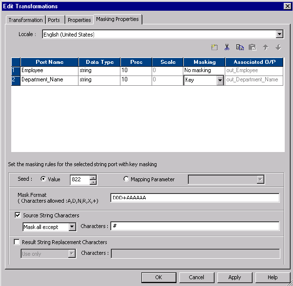
The following figure shows key masking properties for a string datatype:
You can configure the following masking rules for key masking string values:
•Seed. Apply a seed value to generate deterministic masked data for a column. Select one of the following
options:
-Value. Accept the default seed value or enter a number between 1 and 1,000.
-Mapping Parameter. Use a mapping parameter to define the seed value. The Designer displays a list of
the mapping parameters that you create for the mapping. Choose the mapping parameter from the list to
use as the seed value.
•Mask Format. Define the type of character to substitute for each character in the input data. You can limit
each character to an alphabetic, numeric, or alphanumeric character type.
•Source String Characters. Define the characters in the source string that you want to mask. For
example, mask the number sign (#) character whenever it occurs in the input data. The Data Masking
transformation masks all the input characters when Source String Characters is blank. The Data Masking
transformation does not always return unique data if the number of source string characters is less than
the number of result string characters.
•Result String Characters. Substitute the characters in the target string with the characters you define in
Result String Characters. For example, enter the following characters to configure each mask to contain
all uppercase alphabetic characters:
ABCDEFGHIJKLMNOPQRSTUVWXYZ
Masking Numeric Values
Key Masking 105

Configure key masking for numeric source data to generate deterministic output. When you configure a
column for numeric key masking, you assign a random seed value to the column. When the Data Masking
transformation masks the source data, it applies a masking algorithm that requires the seed.
You can change the seed value for a column to produce repeatable results if the same source value occurs in
a different column. For example, you want to maintain a primary-foreign key relationship between two tables.
In each Data Masking transformation, enter the same seed value for the primary-key column as the seed
value for the foreign-key column. The Data Masking transformation produces deterministic results for the
same numeric values. The referential integrity is maintained between the tables.
Masking Datetime Values
When you can configure key masking for datetime values, the Data Masking transformation requires a
random number as a seed. You can change the seed to match the seed value for another column in order to
return repeatable datetime values between the columns.
The Data Masking transformation can mask dates between 1753 and 2400 with key masking. If the source
year is in a leap year, the Data Masking transformation returns a year that is also a leap year. If the source
month contains 31 days, the Data Masking transformation returns a month that has 31 days. If the source
month is February, the Data Masking transformation returns February.
The Data Masking transformation always generates valid dates.
RELATED TOPICS:
•“Date Range ” on page 116
Substitution Masking
Substitution masking replaces a column of data with similar but unrelated data. Use substitution masking to
replace production data with realistic test data. When you configure substitution masking, define the
dictionary that contains the substitute values.
The Data Masking transformation performs a lookup on the dictionary that you configure. The Data Masking
transformation replaces source data with data from the dictionary. Dictionary files can contain string data,
datetime values, integers, and floating point numbers. Enter datetime values in the following format:
mm/dd/yyyy
You can substitute data with repeatable or non-repeatable values. When you choose repeatable values, the
Data Masking transformation produces deterministic results for the same source data and seed value. You
must configure a seed value to substitute data with deterministic results.The Integration Service maintains a
storage table of source and masked values for repeatable masking.
You can substitute more than one column of data with masked values from the same dictionary row.
Configure substitution masking for one input column. Configure dependent data masking for the other
columns that receive masked data from the same dictionary row.
Dictionaries
A dictionary is a flat file or relational table that contains the substitute data for each row in the file. The Data
Masking transformation generates a number to retrieve a dictionary row. The Data Masking transformation
generates a hash key for repeatable substitution masking or a random number for non-repeatable masking.
You can configure an additional lookup condition.
106 Chapter 5: Data Masking Transformation
You can configure a dictionary to mask more than one port in the Data Masking transformation.
The following example shows a flat file dictionary that contains first name and gender:
SNO,GENDER,FIRSTNAME
1,M,Adam
2,M,Adeel
3,M,Adil
4,F,Alice
5,F,Alison
In this dictionary, the first field in the row is the serial number, and the second field is gender. You can add
gender as a lookup condition. The Integration Service retrieves a row from the dictionary using a hash key,
and it finds a row with a gender that matches the gender in the source data.
Use the following rules and guidelines when you create a dictionary:
•The first row of a flat file dictionary must have column labels to identify the fields in each record. The fields
are separated by commas. If the first row does not contain column labels, the Integration Service takes
the values of the fields in the first row as column names.
•A flat file dictionary must be in the $PMLookupFileDir lookup file directory. By default, this directory is in
the following location:
<PowerCenter_Installation_Directory>\server\infa_shared\LkpFiles
•If you create a flat file dictionary on Windows and copy it to a UNIX machine, verify that the file format is
correct for UNIX. For example, Windows and UNIX use different characters for the end of line marker.
•If you configure substitution masking for more than one port, all relational dictionaries must be in the same
database schema.
•The line sequential buffer length of a flat file dictionary must be less than or equal to 600 characters.
•You cannot change the dictionary type or the substitution dictionary name in session properties.
Storage Tables
The Data Masking transformation maintains storage tables for repeatable substitution between sessions. A
storage table row contains the source column and a masked value pair. Each time the Data Masking
transformation masks a value with a repeatable substitute value, it searches the storage table by dictionary
name, locale, column name, input value, and seed. If it finds a row, it returns the masked value from the
storage table. If the Data Masking transformation does not find a row, it retrieves a row from the dictionary
with a hash key.
The dictionary name format in the storage table is different for a flat file dictionary and a relational dictionary.
A flat file dictionary name is identified by the file name. The relational dictionary name has the following
syntax:
<Connection object>_<dictionary table name>
Informatica provides scripts that you can run to create a relational storage table. The scripts are in the
following location:
<PowerCenter Client installation directory>\client\bin\Extensions\DataMasking
The directory contains a script for Sybase, Microsoft SQL Server, IBM DB2, and Oracle databases. Each
script is named Substitution_<database type>. You can create a table in a different database if you configure
the SQL statements and the primary key constraints.
You need to encrypt storage tables for substitution masking when you have unencrypted data in the storage
and use the same seed value and dictionary to encrypt the same columns.
Substitution Masking 107
Encrypting Storage Tables for Substitution Masking
You can use transformation language encoding functions to encrypt storage tables. You need to encrypt
storage tables when you have enabled storage encryption.
1. Create a mapping with the IDM_SUBSTITUTION_STORAGE storage table as source.
2. Create a Data Masking transformation.
3. Apply the substitution masking technique on the input value and the masked value ports.
4. Use the following expression on the INPUTVALUE port:
Enc_Base64(AES_Encrypt(INPUTVALUE, Key))
5. Use the following expression on the MASKEDVALUE port:
Enc_Base64(AES_Encrypt(MASKEDVALUE, Key))
6. Link the ports to the target.
Substitution Masking Properties
You can configure the following masking rules for substitution masking:
•Repeatable Output. Returns deterministic results between sessions. The Data Masking transformation
stores masked values in the storage table.
•Seed. Apply a seed value to generate deterministic masked data for a column. Select one of the following
options:
-Value. Accept the default seed value or enter a number between 1 and 1,000.
-Mapping Parameter. Use a mapping parameter to define the seed value. The Designer displays a list of
the mapping parameters that you create for the mapping. Choose the mapping parameter from the list to
use as the seed value.
-Unique Output. Force the Data Masking transformation to create unique output values for unique input
values. No two input values are masked to the same output value. The dictionary must have enough
unique rows to enable unique output.
When you disable unique output, the Data Masking Transformation might not mask input values to
unique output values. The dictionary might contain fewer rows.
•Dictionary Information. Configure the flat file or relational table that contains the substitute data values.
-Relational Table. Select Relational Table if the dictionary is in a database table. Click Select Table to
configure the database and table.
-Flat File. Select Flat File if the dictionary is in flat file delimited by commas. Click Select Flat File to
browse for and choose a file.
-Dictionary Name. Displays the flat file or relational table name that you selected.
-Output Column. Choose the column to return to the Data Masking transformation.
•Lookup condition. Configure a lookup condition to further qualify what dictionary row to use for
substitution masking. The lookup condition is similar to the WHERE clause in an SQL query. When you
configure a lookup condition you compare the value of a column in the source with a column in the
dictionary.
For example, you want to mask the first name. The source data and the dictionary have a first name
column and a gender column. You can add a condition that each female first name is replaced with a
female name from the dictionary. The lookup condition compares gender in the source to gender in the
dictionary.
-Input port. Source data column to use in the lookup.
-Dictionary column. Dictionary column to compare the input port to.
108 Chapter 5: Data Masking Transformation
Relational Dictionary
When you choose a relational table as a dictionary, configure the database table that contains the dictionary.
When you define the table, the Designer connects to the table and displays the columns in the table.
To select a database, click Select Table on the Data Masking transformation Masking Properties tab.
Configure the following fields in the Select Table dialog box:
•ODBC data source. ODBC data source that connects to the database that contains the dictionary.
•User Name. A database user name to connect to the database. The user name must have the database
permissions to view the tables.
•Owner Name. If the user name is not the owner of the dictionary table, enter the table owner.
•Password. The password for the database user name.
•Search for tables named. Optional. Limits the number of tables that appear in the dialog box.
When you click Connect, the Designer connects to the data source and displays the tables. Scroll through the
list of tables and select the table you want to use for the dictionary. The table name appears in the Dictionary
Name field of the Masking Properties tab.
Connection Requirements
You must configure a database connection for the storage table and relational dictionary if you use them with
substitution masking.
Configure the database connections in the Workflow Manager. Select a relational connection object for the
IDM_Dictionary connection and the IDM_Storage connection on the Mapping tab of the session properties.
Rules and Guidelines for Substitution Masking
Use the following rules and guidelines for substitution masking:
•If a storage table does not exist for a unique repeatable substitution mask, the session fails.
•If the dictionary contains no rows, the Data Masking transformation returns an error message.
•When the Data Masking transformation finds an input value with the locale, dictionary, and seed in the
storage table, it retrieves the masked value, even if the row is no longer in the dictionary.
•If you delete a connection object or modify the dictionary, truncate the storage table. Otherwise, you might
get unexpected results.
•If the number of values in the dictionary is less than the number of unique values in the source data, the
Data Masking Transformation cannot mask the data with unique repeatable values. The Data Masking
transformation returns an error message.
Dependent Masking
Dependent masking substitutes multiple columns of source data with data from the same dictionary row.
When the Data Masking transformation performs substitution masking for multiple columns, the masked data
might contain unrealistic combinations of fields. You can configure dependent masking in order to substitute
data for multiple input columns from the same dictionary row. The masked data receives valid combinations
such as, "New York, New York" or "Chicago, Illinois."
Dependent Masking 109

When you configure dependent masking, you first configure an input column for substitution masking.
Configure other input columns to be dependent on that substitution column. For example, you choose the ZIP
code column for substitution masking and choose city and state columns to be dependent on the ZIP code
column. Dependent masking ensures that the substituted city and state values are valid for the substituted
ZIP code value.
Note: You cannot configure a column for dependent masking without first configuring a column for
substitution masking.
Configure the following masking rules when you configure a column for dependent masking:
Dependent column
The name of the input column that you configured for substitution masking. The Data Masking
transformation retrieves substitute data from a dictionary using the masking rules for that column. The
column you configure for substitution masking becomes the key column for retrieving masked data from
the dictionary.
Output column
The name of the dictionary column that contains the value for the column you are configuring with
dependent masking.
Dependent Masking Example
A data masking dictionary might contain address rows with the following values:
SNO,STREET,CITY,STATE,ZIP,COUNTRY
1,32 Apple Lane,Chicago,IL,61523,US
2,776 Ash Street,Dallas,TX,75240,US
3,2229 Big Square,Atleeville,TN,38057,US
4,6698 Cowboy Street, Houston,TX,77001,US
You need to mask source data with valid combinations of the city, state, and ZIP code from the Address
dictionary.
Configure the ZIP port for substitution masking.
Enter the following masking rules for the ZIP port:
Rule Value
Dictionary FileType Flat file or relational table
Dictionary Name Address.dic
Output Column ZIP
Configure the City port for dependent masking.
Enter the following masking rules for the City port:
Rule Value
Dependent Column ZIP
Output Column City
Configure the State port for dependent masking.
110 Chapter 5: Data Masking Transformation

Enter the following masking rules for the State port:
Rule Value
Dependent Column ZIP
Output Column State
When the Data Masking transformation masks the ZIP code, it returns the correct city and state for the ZIP
code from the dictionary row.
Repeatable Dependent Masking
When you configure multiple input fields to receive masked data from the same dictionary row, you need to
decide which field to configure for substitution masking. With repeatable masking, select a column that
uniquely identifies the source data. The Data Masking transformation uses the key field to determine if a row
already exists in storage for repeatable masking.
Note: When the source data has a primary key, you can configure the primary key column for substitution
masking. Configure another column for dependent masking.
For example, if you mask employee data, you might configure the EmployeeID for substitution masking, and
configure FirstName and LastName for dependent masking.
When you configure repeatable masking, the following rows receive different masked data:
EmployeeID FirstName LastName
111 John Jones
222 Radhika Jones
If you choose LastName as the key field for repeatable dependent masking, each row with the last name
Jones receives the same mask data.
Random Masking
Random masking generates random nondeterministic masked data. The Data Masking transformation returns
different values when the same source value occurs in different rows. You can define masking rules that
affect the format of data that the Data Masking transformation returns. Mask numeric, string, and date values
with random masking.
Masking Numeric Values
When you mask numeric data, you can configure a range of output values for a column. The Data Masking
transformation returns a value between the minimum and maximum values of the range depending on port
precision. To define the range, configure the minimum and maximum ranges or configure a blurring range
based on a variance from the original source value.
You can configure the following masking parameters for numeric data:
Random Masking 111
Range
Define a range of output values. The Data Masking transformation returns numeric data between the
minimum and maximum values.
Blurring Range
Define a range of output values that are within a fixed variance or a percentage variance of the source
data. The Data Masking transformation returns numeric data that is close to the value of the source data.
You can configure a range and a blurring range.
Masking String Values
Configure random masking to generate random output for string columns. To configure limitations for each
character in the output string, configure a mask format. Configure filter characters to define which source
characters to mask and the characters to mask them with.
You can apply the following masking rules for a string port:
Range
Configure the minimum and maximum string length. The Data Masking transformation returns a string of
random characters between the minimum and maximum string length.
Mask Format
Define the type of character to substitute for each character in the input data. You can limit each
character to an alphabetic, numeric, or alphanumeric character type.
Source String Characters
Define the characters in the source string that you want to mask. For example, mask the number sign (#)
character whenever it occurs in the input data. The Data Masking transformation masks all the input
characters when Source String Characters is blank.
Result String Replacement Characters
Substitute the characters in the target string with the characters you define in Result String Characters.
For example, enter the following characters to configure each mask to contain uppercase alphabetic
characters A - Z:
ABCDEFGHIJKLMNOPQRSTUVWXYZ
Masking Date Values
To mask date values with random masking, either configure a range of output dates or choose a variance.
When you configure a variance, choose a part of the date to blur. Choose the year, month, day, hour, minute,
or second. The Data Masking transformation returns a date that is within the range you configure.
You can configure the following masking rules when you mask a datetime value:
Range
Sets the minimum and maximum values to return for the selected datetime value.
Blurring
Masks a date based on a variance that you apply to a unit of the date. The Data Masking transformation
returns a date that is within the variance. You can blur the year, month, day, hour, minute, or second.
Choose a low and high variance to apply.
112 Chapter 5: Data Masking Transformation

Applying Masking Rules
Apply masking rules based on the source datatype. When you click a column property on the Masking
Properties tab, the Designer displays masking rules based on the datatype of the port.
The following table describes the masking rules that you can configure based on the masking type and the
source datatype:
Masking
Types
Source
Datatype
Masking Rules Description
Random and
Key
String Mask Format Mask that limits each character in an output string to
an alphabetic, numeric, or alphanumeric character.
Random and
Key
String Source String
Characters
Set of source characters to mask or to exclude from
masking.
Random and
Key
String Result String
Replacement
Characters
A set of characters to include or exclude in a mask.
Random Numeric
String
Date/Time
Range A range of output values.
- Numeric. The Data Masking transformation returns
numeric data between the minimum and maximum
values.
- String. Returns a string of random characters between
the minimum and maximum string length.
- Date/Time. Returns a date and time within the
minimum and maximum datetime.
Random Numeric
Date/Time
Blurring Range of output values with a fixed or percent
variance from the source data. The Data Masking
transformation returns data that is close to the value
of the source data. Datetime columns require a fixed
variance.
Mask Format
Configure a mask format to limit each character in the output column to an alphabetic, numeric, or
alphanumeric character. Use the following characters to define a mask format:
A, D, N, X, +, R
Note: The mask format contains uppercase characters. When you enter a lowercase mask character, the
Data Masking transformation converts the character to uppercase.
The following table describes mask format characters:
Character Description
A Alphabetical characters. For example, ASCII characters a to z and A to Z.
D Digits 0 to 9. The data masking transformation returns an "X" for characters other than digits 0 to
9.
Applying Masking Rules 113

Character Description
N Alphanumeric characters. For example, ASCII characters a to z, A to Z, and 0-9.
X Any character. For example, alphanumeric or symbol.
+ No masking.
R Remaining characters. R specifies that the remaining characters in the string can be any character
type. R must appear as the last character of the mask.
For example, a department name has the following format:
nnn-<department_name>
You can configure a mask to force the first three characters to be numeric, the department name to be
alphabetic, and the dash to remain in the output. Configure the following mask format:
DDD+AAAAAAAAAAAAAAAA
The Data Masking transformation replaces the first three characters with numeric characters. It does not
replace the fourth character. The Data Masking transformation replaces the remaining characters with
alphabetical characters.
If you do not define a mask format, the Data Masking transformation replaces each source character with any
character. If the mask format is longer than the input string, the Data Masking transformation ignores the
extra characters in the mask format. If the mask format is shorter than the source string, the Data Masking
transformation masks the remaining characters with format R.
Note: You cannot configure a mask format with the range option.
Source String Characters
Source string characters are source characters that you choose to mask or not mask. The position of the
characters in the source string does not matter. The source characters are case sensitive.
You can configure any number of characters. When Characters is blank, the Data Masking transformation
replaces all the source characters in the column.
Select one of the following options for source string characters:
Mask Only
The Data Masking transformation masks characters in the source that you configure as source string
characters. For example, if you enter the characters A, B, and c, the Data Masking transformation
replaces A, B, or c with a different character when the character occurs in source data. A source
character that is not an A, B, or c does not change. The mask is case sensitive.
Mask All Except
Masks all characters except the source string characters that occur in the source string. For example, if
you enter the filter source character “-” and select Mask All Except, the Data Masking transformation
does not replace the “-” character when it occurs in the source data. The rest of the source characters
change.
Source String Example
114 Chapter 5: Data Masking Transformation
A source file has a column named Dependents. The Dependents column contains more than one name
separated by commas. You need to mask the Dependents column and keep the comma in the test data to
delimit the names.
For the Dependents column, select Source String Characters. Choose Don’t Mask and enter “,” as the source
character to skip. Do not enter quotes.
The Data Masking transformation replaces all the characters in the source string except for the comma.
Result String Replacement Characters
Result string replacement characters are characters you choose as substitute characters in the masked data.
When you configure result string replacement characters, the Data Masking transformation replaces
characters in the source string with the result string replacement characters. To avoid generating the same
output for different input values, configure a wide range of substitute characters, or mask only a few source
characters. The position of each character in the string does not matter.
Select one of the following options for result string replacement characters:
Use Only
Mask the source with only the characters you define as result string replacement characters. For
example, if you enter the characters A, B, and c, the Data Masking transformation replaces every
character in the source column with an A, B, or c. The word “horse” might be replaced with “BAcBA.”
Use All Except
Mask the source with any characters except the characters you define as result string replacement
characters. For example, if you enter A, B, and c result string replacement characters, the masked data
never has the characters A, B, or c.
Result String Replacement Characters Example
To replace all commas in the Dependents column with semicolons, complete the following tasks:
1. Configure the comma as a source string character and select Mask Only.
The Data Masking transformation masks only the comma when it occurs in the Dependents column.
2. Configure the semicolon as a result string replacement character and select Use Only.
The Data Masking transformation replaces each comma in the Dependents column with a semicolon.
Range
Define a range for numeric, date, or string data. When you define a range for numeric or date values the Data
Masking transformation masks the source data with a value between the minimum and maximum values.
When you configure a range for a string, you configure a range of string lengths.
String Range
When you configure random string masking, the Data Masking transformation generates strings that vary in
length from the length of the source string. Optionally, you can configure a minimum and maximum string
width. The values you enter as the maximum or minimum width must be positive integers. Each width must
be less than or equal to the port precision.
Applying Masking Rules 115

Numeric Range
Set the minimum and maximum values for a numeric column. The maximum value must be less than or equal
to the port precision. The default range is from one to the port precision length.
Date Range
Set minimum and maximum values for a datetime value. The minimum and maximum fields contain the
default minimum and maximum dates. The default datetime format is MM/DD/YYYY HH24:MI:SS. The
maximum datetime must be later than the minimum datetime.
Blurring
Blurring creates an output value within a fixed or percent variance from the source data value. Configure
blurring to return a random value that is close to the original value. You can blur numeric and date values.
Blurring Numeric Values
Select a fixed or percent variance to blur a numeric source value. The low blurring value is a variance below
the source value. The high blurring value is a variance above the source value. The low and high values must
be greater than or equal to zero. When the Data Masking transformation returns masked data, the numeric
data is within the range that you define.
The following table describes the masking results for blurring range values when the input source value is 66:
Blurring Type Low High Result
Fixed 0 10 Between 66 and 76
Fixed 10 0 Between 56 and 66
Fixed 10 10 Between 56 and 76
Percent 0 50 Between 66 and 99
Percent 50 0 Between 33 and 66
Percent 50 50 Between 33 and 99
Blurring Date Values
Mask a date as a variance of the source date by configuring blurring. Select a unit of the date to apply the
variance to. You can select the year, month, day, or hour. Enter the low and high bounds to define a variance
above and below the unit in the source date. The Data Masking transformation applies the variance and
returns a date that is within the variance.
For example, to restrict the masked date to a date within two years of the source date, select year as the unit.
Enter two as the low and high bound. If a source date is 02/02/2006, the Data Masking transformation returns
a date between 02/02/2004 and 02/02/2008.
By default, the blur unit is year.
116 Chapter 5: Data Masking Transformation
Expression Masking
Expression masking applies an expression to a port to change the data or create new data. When you
configure expression masking, create an expression in the Expression Editor. Select input and output ports,
functions, variables, and operators to build expressions.
You can concatenate data from multiple ports to create a value for another port. For example, you need to
create a login name. The source has first name and last name columns. Mask the first and last name from
lookup files. In the Data Masking transformation, create another port called Login. For the Login port,
configure an expression to concatenate the first letter of the first name with the last name:
SUBSTR(FIRSTNM,1,1)||LASTNM
When you configure expression masking for a port, the port name appears as the expression by default. To
access the Expression Editor, click the open button. The Expression Editor displays input ports and the
output ports which are not configured for expression masking. You cannot use the output from an expression
as input to another expression. If you manually add the output port name to the expression, you might get
unexpected results.
Select functions, ports, variables, and operators from the point-and-click interface to minimize errors when
you build expressions.
When you create an expression, verify that the expression returns a value that matches the port datatype.
The Data Masking transformation returns zero if the data type of the expression port is numeric and the data
type of the expression is not the same. The Data Masking transformation returns null values if the data type
of the expression port is a string and the data type of the expression is not the same.
Repeatable Expression Masking
Configure repeatable expression masking when a source column occurs in more than one table and you need
to mask the column from each table with the same value.
When you configure repeatable expression masking, the Data Masking transformation saves the results of an
expression in a storage table. If the column occurs in another source table, the Data Masking transformation
returns the masked value from the storage table instead of from the expression.
Dictionary Name
When you configure repeatable expression masking you must enter a dictionary name. The dictionary name
is a key that allows multiple Data Masking transformations to generate the same masked values from the
same source values. Define the same dictionary name in each Data Masking transformation. The dictionary
name can be any text.
Storage Table
The storage table contains the results of repeatable expression masking between sessions. A storage table
row contains the source column and a masked value pair. The storage table for expression masking is a
separate table from the storage table for substitution masking.
Each time the Data Masking transformation masks a value with a repeatable expression, it searches the
storage table by dictionary name, locale, column name and input value. If it finds a row in the storage table, it
returns the masked value from the storage table. If the Data Masking transformation does not find a row, it
generates a masked value from the expression for the column.
You need to encrypt storage tables for expression masking when you have unencrypted data in the storage
and use the same dictionary name as key.
Expression Masking 117
Encrypting Storage Tables for Expression Masking
You can use transformation language encoding functions to encrypt storage tables. You need to encrypt
storage tables when you have enabled storage encryption.
1. Create a mapping with the IDM_EXPRESSION_STORAGE storage table as source.
2. Create a Data Masking transformation.
3. Apply the expression masking technique on the masked value ports.
4. Use the following expression on the MASKEDVALUE port:
Enc_Base64(AES_Encrypt(MASKEDVALUE, Key))
5. Link the ports to the target.
Example
For example, an Employees table contains the following columns:
FirstName
LastName
LoginID
In the Data Masking transformation, mask LoginID with an expression that combines FirstName and
LastName. Configure the expression mask to be repeatable. Enter a dictionary name as a key for repeatable
masking.
The Computer_Users table contains a LoginID, but no FirstName or LastName columns:
Dept
LoginID
Password
To mask the LoginID in Computer_Users with the same LoginID as Employees, configure expression
masking for the LoginID column. Enable repeatable masking and enter the same dictionary name that you
defined for the LoginID Employees table. The Integration Service retrieves the LoginID values from the
storage table.
Create a default expression to use when the Integration Service cannot find a row in the storage table for
LoginID. The Computer_Users table does not have the FirstName or LastName columns, so the expression
creates a less meaningful LoginID.
Storage Table Scripts
Informatica provides scripts that you can run to create the storage table. The scripts are in the following
location:
<PowerCenter installation directory>\client\bin\Extensions\DataMasking
The directory contains a script for Sybase, Microsoft SQL Server, IBM DB2, and Oracle databases. Each
script is named <Expression_<database type>.
Rules and Guidelines for Expression Masking
Use the following rules and guidelines for expression masking:
•You cannot use the output from an expression as input to another expression. If you manually add the
output port name to the expression, you might get unexpected results.
•Use the point-and-click method to build expressions. Select functions, ports, variables, and operators from
the point-and-click interface to minimize errors when you build expressions.
118 Chapter 5: Data Masking Transformation

•If the Data Masking transformation is configured for repeatable masking, and the storage table does not
exist, the Integration Service substitutes the source data with default values.
RELATED TOPICS:
•“Using the Expression Editor” on page 9
Special Mask Formats
The following types of masks retain the format of the original data:
•Social Security numbers
•Credit card numbers
•Phone numbers
•URL addresses
•Email addresses
•IP addresses
•Social Insurance numbers
The Data Masking transformation replaces sensitive data with masked values in a realistic format. For
example, when you mask an SSN, the Data Masking transformation returns an SSN that is in the correct
format but is not valid.
When the source data format or datatype is invalid for a mask, the Integration Service applies a default mask
to the data. The Integration Service applies masked values from the default value file. You can edit the
default value file to change the default values.
RELATED TOPICS:
•“Default Value File” on page 124
Social Security Number Masking
The Data Masking transformation generates a Socail Security Number that is not valid based on the latest
High Group List from the Social Security Administration. The High Group List contains valid numbers that the
Social Security Administration has issued. The Data Masking transformation accesses the latest High Group
List from the following location:
<Installation Directory>\infa_shared\SrcFiles\highgroup.txt
The Data Masking transformation generates SSN numbers that are not on the High Group List. The Social
Security Administration updates the High Group List every month. Download the latest version of the list from
the following location:
http://www.socialsecurity.gov/employer/ssns/highgroup.txt
Special Mask Formats 119
Social Security Number Format
The Data Masking transformation accepts any SSN format that contains nine digits. The digits can be
delimited by any set of characters. For example, the Data Masking transformation accepts the following
format:
+=54-*9944$#789-,*()”
.
Area Code Requirement
The Data Masking transformation returns a Social Security Number that is not valid with the same format as
the source. The first three digits of the SSN define the area code. The Data Masking transformation does not
mask the area code. It masks the group number and serial number. The source SSN must contain a valid
area code. The Data Masking transformation locates the area code on the High Group List and determines a
range of unused numbers that it can apply as masked data. If the SSN is not valid, the Data Masking
transformation does not mask the source data.
Repeatable Social Security Number Masking
The Data Masking transformation returns deterministic Social Security numbers with repeatable masking. The
Data Masking transformation cannot return all unique Social Security numbers because it cannot return valid
Social Security numbers that the Social Security Administration has issued.
Credit Card Number Masking
Credit card masking applies a built-in mask format to disguise credit card numbers. You can input multiple
credit card number formats. Optionally, you can replace the credit card issuer.
The PowerCenter Integration Service generates a logically valid credit card number when it masks a valid
credit card number. The length of the source credit card number must be from 13 through 19 digits. The input
credit card number must have a valid checksum based on credit card industry rules.
The source credit card number can contain numbers, spaces, and hyphens. If the credit card has incorrect
characters or is the wrong length, the Integration Service writes an error to the session log. The PowerCenter
Integration Service applies a default credit card number mask when the source data is not valid.
You can configure credit card masking to keep or replace the first six digits of a credit card number.
Together, these digits identify the credit card issuer. If you replace the credit card issuer, you can specify
another credit card issuer. You can specify the following credit card issuers:
•American Express
•Discover
•JCB
•MasterCard
•Visa
•Any
If you select Any, the Data Masking transformation returns a combination of all the credit card issuers. If you
mask the credit card issuer, the Data Masking transformation can return nonunique values.
120 Chapter 5: Data Masking Transformation
For example, the CUSTOMER table has the following credit card numbers:
2131 0000 0000 0008
5500 0000 0000 0004
6334 0000 0000 0004
If you select a single credit card issuer, the credit card numbers share all but the last digit. To generate valid
credit card numbers, the Data Masking transformation sets the last digit of each credit card to the same
value.
Phone Number Masking
The Data Masking transformation masks a phone number without changing the format of the original phone
number. For example, the Data Masking transformation can mask the phone number (408)382 0658 as
(607)256 3106.
The source data can contain numbers, spaces, hyphens, and parentheses. The Integration Service does not
mask alphabetic or special characters.
The Data Masking transformation can mask string, integer, and bigint data.
Email Address Masking
Use the Data Masking transformation to mask the email address that contains string value. The Data Masking
transformation can mask an email address with random ASCII characters or replace the email address with a
realistic email address.
You can apply the following types of masking with email address:
Standard email masking
The Data Masking transformation returns random ASCII characters when it masks an email address. For
example, the Data Masking transformation can mask Georgesmith@yahoo.com as
KtrIupQAPyk@vdSKh.BIC. Default is standard.
Advanced email masking
The Data Masking transformation masks the email address with another realistic email address derived
from the transformation output ports or dictionary columns.
Advanced Email Masking
With advanced email masking, you can mask the email address with another realistic email address. The
Data Masking transformation creates the email address from the dictionary columns or from the
transformation output ports.
You can create the local part in the email address from mapping output ports. Or you can create the local
part in the email address from relational table or flat file columns.
The Data Masking transformation can create the domain name for the email address from a constant value or
from a random value in the domain dictionary.
You can create an advanced email masking based on the following options:
Phone Number Masking 121
Email Address Based on a Mapping
You can create an email address based on the Data Masking transformation output ports. Select the
transformation output ports for the first name and the last name column. The Data Masking
transformation masks the first name, the last name, or both names based on the values you specify for
the first and last name length.
Email Address Based on a Dictionary
You can create an email address based on the columns from a dictionary. The dictionary can be a
relational table or flat file.
Select the dictionary columns for the first name and the last name. The Data Masking transformation
masks the first name, the last name, or both names based on the values you specify for the first and last
name length. You can also configure an expression to mask the email address. If you configure an
expression, then the Data Masking transformation does not mask based on the length of the first name
or last name column.
Configuration Parameters for an Advanced Email Address Masking Type
Specify configuration parameters when you configure advanced email address masking.
You can specify the following configuration paramters:
Delimiter
You can select a delimiter, such as a dot, hyphen, or underscore, to separate the first name and last
name in the email address. If you do not want to separate the first name and last name in the email
address, leave the delimiter as blank.
FirstName Column
Select a Data Masking transformation output port or a dictionary column to mask the first name in the
email address.
LastName Column
Select a Data Masking transformation output port or a dictionary column to mask the last name in the
email address.
Length for the FirstName or LastName columns
Restricts the character length to mask for the first name and the last name columns. For example, the
input data is Timothy for the first name and Smith for the last name. Select 5 as the length of the first
name column. Select 1 as the length of the last name column with a dot as the delimiter. The Data
Masking transformation generates the following email address:
timot.s@<domain_name>
DomainName
You can use a constant value, such as gmail.com, for the domain name. Or, you can specify another
dictionary file that contains a list of domain names. The domain dictionary can be a flat file or a relational
table.
Expressions for the Advanced Email Address Masking Type
You can use expression functions when you select dictionary columns to create an email address.
To configure an expression for the advanced email masking type, choose columns to form the email address
from the dictionary. You can then configure the expression with the dictionary columns, the transformation
ports, or with both the dictionary columns and the transformation ports.
122 Chapter 5: Data Masking Transformation
The dictionary ports are listed in the following syntax in the Expression Editor:
<Input string mapping port>_Dictionary_<dictionary column name>
Social Insurance Number Masking
The Data Masking transformation masks a Social Insurance number that is nine digits. The digits can be
delimited by any set of characters.
If the number contains no delimiters, the masked number contains no delimiters. Otherwise the masked
number has the following format:
xxx-xxx-xxx
SIN Start Digit
You can define the first digit of the masked SIN.
Enable Start Digit and enter the digit. The Data Masking transformation creates masked SIN numbers that
start with the number that you enter.
Repeatable SIN Numbers
You can configure the Data Masking transformation to return repeatable SIN values. When you configure a
port for repeatable SIN masking, the Data Masking transformation returns deterministic masked data each
time the source SIN value and seed value are the same.
To return repeatable SIN numbers, enable Repeatable Values and enter a seed number. The Data Masking
transformation returns unique values for each SIN.
IP Address Masking
The Data Masking transformation masks an IP address as another IP address by splitting it into four
numbers, separated by a period. The first number is the network. The Data Masking transformation masks
the network number within the network range.
The Data Masking transformation masks a Class A IP address as a Class A IP Address and a 10.x.x.x
address as a 10.x.x.x address. The Data Masking transformation does not mask the class and private
network address. For example, the Data Masking transformation can mask 11.12.23.34 as 75.32.42.52. and
10.23.24.32 as 10.61.74.84.
Note: When you mask many IP addresses, the Data Masking transformation can return nonunique values
because it does not mask the class or private network of the IP addresses.
URL Address Masking
Social Insurance Number Masking 123
The Data Masking transformation parses a URL by searching for the ‘://’ string and parsing the substring to
the right of it. The source URL must contain the ‘://’ string. The source URL can contain numbers and
alphabetic characters.
The Data Masking transformation does not mask the protocol of the URL. For example, if the URL is
http://www.yahoo.com
, the Data Masking transformation can return
http://MgL.aHjCa.VsD/
. The Data
Masking transformation can generate a URL that is not valid.
Note: The Data Masking transformation always returns ASCII characters for a URL.
Default Value File
When the source data format or datatype is not valid for a mask, the Integration Service applies a default
mask to the data. The Integration Service applies masked values from the default value file. You can edit the
default value file to change the default values.
The default value file is an XML file in the following location:
<PowerCenter Installation Directory>\infa_shared\SrcFiles\defaultValue.xml
The defaultValue.xml file contains the following name-value pairs:
<?xml version="1.0" standalone="yes" ?>
<defaultValue
default_char = "X"
default_digit = "9"
default_date = "11/11/1111 00:00:00"
default_email = "abc@xyz.com"
default_ip = "99.99.9.999"
default_url = "http://www.xyz.com"
default_phone = "999999999"
default_ssn = "999-99-9999"
default_cc = "9999 9999 9999 9999"
default_seed = "500"
/>
Data Masking Transformation Session Properties
You can configure Data Masking transformation session properties to increase performance.
Configure the following session properties:
Cache Size
The size of the dictionary cache in main memory. Increase the memory size in order to improve
performance. Minimum recommended size is 32 MB for 100,000 records. Default is 8 MB.
Cache Directory
The location of the dictionary cache. You must have write permissions for the directory. Default is
$PMCacheDir.
Shared Storage Table
Enables sharing of the storage table between Data Masking transformation instances. Enable Shared
Storage Table when two Data Masking transformation instances use the same dictionary column for the
database connection, seed value, and locale. You can also enable the shared storage table when two
ports in the same Data Masking transformation use the same dictionary column for the connection, seed,
124 Chapter 5: Data Masking Transformation
and locale. Disable the shared storage table when Data Masking transformations or ports do not share
the dictionary column. Default is disabled.
Storage Commit Interval
The number of rows to commit at a time to the storage table. Increase the value to increase
performance. Configure the commit interval when you do not configure the shared storage table. Default
is 100,000.
Encrypt Storage
Encrypts storage tables, such as IDM_SUBSTITUTION_STORAGE and IDM_EXPRESSION_STORAGE.
Verify that you have encrypted data in storage tables before you enable the encrypt storage property.
Clear this option if you do not want to encrypt the storage tables. Default is disabled.
Storage Encryption Key
The Data Masking transformation encrypts the storage based on the storage encryption key. Use the
same encryption key for each session run of the same Data Masking transformation instance.
Substitution Dictionary Owner Name
Name of the substitution dictionary table owner when you select the substitution masking type. If the
database user specified in the database connection is not the owner of the substitution dictionary table in
a session, you need to specify the table owner.
Storage Owner Name
Name of the table owner for IDM_SUBSTITUTION_STORAGE or IDM_EXPRESSION_STORAGE when
you select repeatable expression or unique repeatable substitution masking type.
Rules and Guidelines for Data Masking
Transformations
Use the following rules and guidelines when you configure a Data Masking transformation:
•The Data Masking transformation does not mask null values. If the source data contains null values, the
Data Masking transformation returns null values. To replace null values, add an upstream transformation
that allows user-defined default values for input ports.
•When the source data format or datatype is not valid for a mask, the Integration Service applies a default
mask to the data. The Integration Service applies masked values from a default values file.
•The Data Masking transformation returns an invalid Social Security number with the same format and area
code as the source. If the Social Security Administration has issued more than half of the numbers for an
area, the Data Masking transformation might not be able to return unique invalid Social Security numbers
with key masking.
Rules and Guidelines for Data Masking Transformations 125

CHAPTER 6
Data Masking Examples
This chapter includes the following topics:
•Name and Address Lookup Files, 126
•Substituting Data with the Lookup Transformation, 126
•Masking Data with an Expression Transformation, 129
Name and Address Lookup Files
The Data Masking installation includes several flat files that contain names, addresses, and company names
for masking data. You can configure a Lookup transformation to retrieve random first names, last names, and
addresses from these files.
When you install the Data Masking server component, the installer places the following files in the
server
\infa_shared\LkpFiles
folder:
•Address.dic. Flat file of addresses. Each record has a serial number, street, city, state, zip code, and
country.
•Company_names.dic. Flat file of company names. Each record has a serial number and company name.
•Firstnames.dic. Flat file of first names. Each record has a serial number, name, and gender code.
•Surnames.dic. Flat file of last names. Each record has a serial number and a last name.
Substituting Data with the Lookup Transformation
You can substitute a column of data with similar but unrelated data. Substitution is an effective way to mask
sensitive data with a realistic looking data.
The following example shows how to configure multiple Lookup transformations to retrieve test data and
substitute it for source data. Create a Data Masking mapping to mask the sensitive fields in
CUSTOMERS_PROD table.
The example includes the following types of masking:
•Name and address substitution from Lookup tables
•Key masking
•Blurring
126

•Special mask formats
Note: This example is the M_CUSTOMERS_MASKING.xml mapping that you can import to your repository
from the
client\samples
folder.
A customer database table called Customers_Prod contains sensitive data. You want to use the customer
data in a test scenario, but you want to maintain security. You mask the data in each column and write the
test data to a target table called Customers_Test.
The Customers_Prod table contains the following columns:
Column Datatype
CustID Integer
FullName String
Address String
Phone String
Fax String
CreatedDate Date
Email String
SSN String
CreditCard String
You can create a mapping that looks up substitute values in dictionary files. The Data Masking transformation
masks the customer data with values from the dictionary files. The files include a first name file, a surname
file, and an address file.
The following table lists the files that are located in the
server\infa_shared\LkpFiles
folder:
File Number of
Records
Fields Description
Firstnames.dic 21,000 SNO, Gender,
Firstname
Alphabetical list of first names. The serial number
goes from 1 to 21,000. Gender indicates whether the
name is male or female.
Surnames.dic 81,000 SNO, Surname Alphabetical list of last names. The serial number
goes from 1 to 81,000.
Address.dic 13,000 SNO, Street,
City, State, Zip,
Country
List of complete addresses. The serial number goes
from 1 to 13,000.
Note: Informatica includes the gender column in the Firstnames.dic file so you can create separate lookup
source files by gender. You can use the gender column in a lookup condition if you need to mask with a male
name and a female name with a female name.
Substituting Data with the Lookup Transformation 127
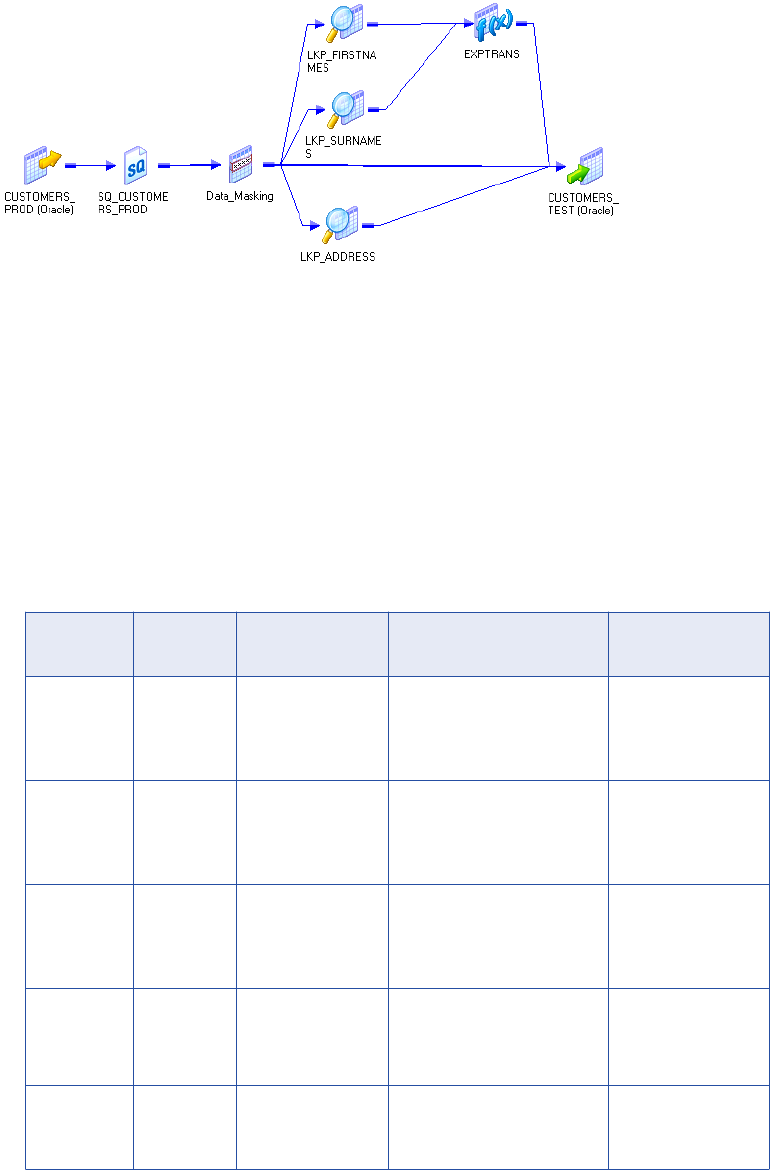
The following figure shows the mapping that you can import:
The mapping has the following transformations along with a source and target:
•Source Qualifier. Passes customer data to the Data Masking transformation. It passes the CustID
column to multiple ports in the transformation:
-CustID. Customer number.
-Randid1. Random number generator for first name lookups.
-Randid2. Random number generator for last name lookups.
-Randid3. Random number generator for address lookups.
•Data Masking transformation. Creates random numbers to look up the replacement first name, last
name, and address. Applies special mask formats to the phone number, fax, email address, and credit
card number. The Data Masking transformation masks the following columns:
Input Port Masking
Type
Masking Rules Description Output
Destination
CustID Key Seed = 934 CustID is the primary key
column. It must be masked
with a random number that is
repeatable and deterministic.
Customers_Test
Randid1 Random Range
Minimum = 0
Maximum = 21000
Random number for first
name lookup in the
LKUP_Firstnames
transformation.
LKUP_Firstnames
Randid2 Random Range
Minimum = 0
Maximum = 13000
Random number for last
name lookup in the
LKUP_Surnames
transformation.
LKUP_Surnames
Randid3 Random Range
Minimum = 0
Maximum = 81000
Random number for address
lookup in the LKUP_Address
transformation.
LKUP_Address
Phone Phone - Phone number has the same
format as the source phone
number.
Customers_Test
128 Chapter 6: Data Masking Examples

Input Port Masking
Type
Masking Rules Description Output
Destination
Fax Phone - Phone number has the same
format as the source phone
number.
Customers_Test
CreatedDate Random Blurring
Unit = Year
Low Bound = 1
High Bound = 1
Random date that is within a
year of the source year.
Customers_Test
Email Email
Address
- Email address has the same
format as the original.
Customers_Test
SSN SSN - SSN is not in the
highgroup.txt file.
Customers_Test
CreditCard Credit Card - Credit card has the same first
six digits as the source and
has a valid checksum.
Customers_Test
•LKUP_Firstnames. Performs a flat file lookup on Firstnames.dic. The transformation retrieves the record
with the serial number equal to the random number Randid1. The lookup condition is:
SNO = out_RANDID1
The LKUP_Firstnames transformation passes the masked first name to the Exptrans Expression
transformation.
•LKUP_Surnames. Performs a flat file lookup on the Surnames.dic file. It retrieves the record with the
serial number equal to Randid2. The LKUP_Firstnames transformation passes a masked last name to the
Exptrans Expression transformation.
•Exptrans. Combines the first and last name and returns a full name. The Expression transformation
passes the full name to the Customers_Test target.
The Expression to combine the first and last names is:
FIRSTNAME || ' ' || SURNAME
•LKUP_Address. Performs a flat file lookup on the Address.dic file. It retrieves the address record with the
serial number equal to Randid3. The Lookup transformation passes the columns in the address to the
target.
You can use the Customer_Test table in a test environment.
Masking Data with an Expression Transformation
Use the Expression transformation with the Data Masking transformation to maintain a relationship between
two columns after you mask one of the columns.
For example, when you mask account information that contains start and end dates for insurance policies,
you want to maintain the policy length in each masked record. Use a Data Masking transformation to mask all
data except the end date. Use an Expression transformation to calculate the policy length and add the policy
length to the masked start date.
Masking Data with an Expression Transformation 129
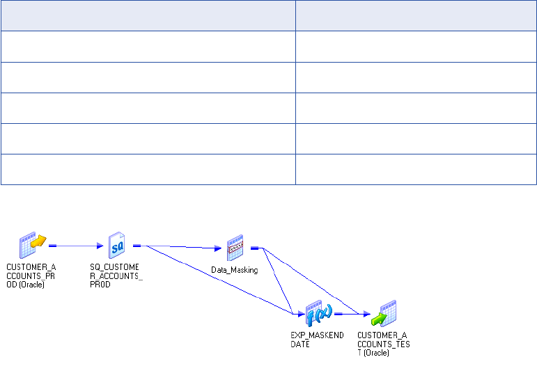
This example includes the following types of masking:
•Key
•Date blurring
•Number blurring
•Mask formatting
Note: This example is the M_CUSTOMER_ACCOUNTS_MASKING.xml mapping that you can import to your
repository from the
client\samples
folder.
A customer database table called Customers_Prod contains sensitive data. You mask the data in each
column and write the test data to a target table called Customers_Test.
Mask the following Customer_Accounts_Prod columns:
Column Datatype
AcctID String
CustID Integer
Balance Double
StartDate Datetime
EndDate Datetime
The following figure shows the mapping that you can import:
The mapping has following transformations along with a source and target:
•Source Qualifier. Passes the AcctID, CustID, Balance, and Start_Date to the Data Masking
transformation. It passes Start_Date and End_Date columns to an Expression transformation.
•Data Masking transformation. Masks all the columns except End_Date. The Data Masking
transformation passes the masked columns to the target. It passes the policy start date, end date, and the
masked start date to the Expression transformation.
130 Chapter 6: Data Masking Examples

The Data Masking transformation masks the following columns:
Input Port Masking
Type
Masking Rules Description Output Destination
AcctID Random Mask format
AA+DDDDD
Result String
Replacement
Characters
ABCDEFGHIJKLM
NOPQRSTUVWXY
Z
The first two characters
are uppercase
alphabetic characters.
The third character is a
dash and is not
masked. The last five
characters are
numbers.
Customer_Account_Test
target
CustID Key Seed = 934 The seed is 934. The
CustID mask is
deterministic.
Customer_Account_Test
target
Balance Random Blurring
Percent
Low bound = 10
High bound = 10
The masked balance is
within ten percent of
the source balance.
Customer_Account_Test
target
Start_Date Random Blurring
Unit = Year
Low Bound = 2
High Bound = 2
The masked start_date
is within two years of
the source date.
Customer_Account_Test
target
Exp_MaskEndDatetransfo
rmation
•Expression transformation. Calculates the masked end date. It calculates the time between the start
and end dates. It adds the time to the masked start date to determine the masked end date.
The expressions to generate the masked end date are:
DIFF = DATE_DIFF(END_DATE,START_DATE,'DD')
out_END_DATE = ADD_TO_DATE(out_START_DATE,'DD',DIFF)
The Expression transformation passes out_END_DATE to the target.
Masking Data with an Expression Transformation 131
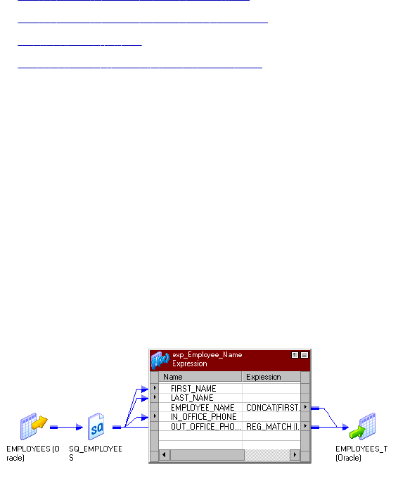
CHAPTER 7
Expression Transformation
This chapter includes the following topics:
•Expression Transformation Overview, 132
•Expression Transformation Components, 132
•Configuring Ports, 133
•Creating an Expression Transformation, 133
Expression Transformation Overview
Use the Expression transformation to calculate values in a single row. For example, you might need to adjust
employee salaries, concatenate first and last names, or convert strings to numbers. You can also use the
Expression transformation to test conditional statements before you pass the results to a target or other
transformations. The Expression transformation is a passive transformation.
Use the Expression transformation to perform non-aggregate calculations. To perform calculations involving
multiple rows, such as sums or averages, use the Aggregator transformation.
The following figure shows a simple mapping with an Expression transformation used to concatenate the first
and last names of employees from the EMPLOYEES table:
Expression Transformation Components
You can create an Expression transformation in the Transformation Developer or the Mapping Designer.
132
An Expression transformation contains the following tabs:
•Transformation. Enter the name and description of the transformation. The naming convention for an
Expression transformation is EXP_TransformationName. You can also make the transformation reusable.
•Ports. Create and configure ports.
•Properties. Configure the tracing level to determine the amount of transaction detail reported in the
session log file.
•Metadata Extensions. Specify the extension name, datatype, precision, and value. You can also create
reusable metadata extensions.
Configuring Ports
You can create and modify ports on the Ports tab.
Configure the following components on the Ports tab:
•Port name. Name of the port.
•Datatype, precision, and scale. Configure the datatype and set the precision and scale for each port.
•Port type. A port can be input, output, input/output, or variable. The input ports receive data and output
ports pass data. The input/output ports pass data unchanged. Variable ports store data temporarily and
can store values across the rows.
•Expression. Use the Expression Editor to enter expressions. Expressions use the transformation
language, which includes SQL-like functions, to perform calculations.
•Default values and description. Set default value for ports and add description.
Calculating Values
To calculate values for a single row using the Expression transformation, you must include the following
ports:
•Input or input/output ports. Provides values used in a calculation. For example, if you need to calculate
the total price for an order, create two input or input/output ports. One port provides the unit price and the
other provides the quantity ordered.
•Output ports. Provides the return value of the expression. You enter the expression as a configuration
option for the output port. You can also configure a default value for each port.
You can enter multiple expressions in a single Expression transformation by creating an expression for each
output port. For example, you might want to calculate different types of withholding taxes from each
employee paycheck, such as local and federal income tax, Social Security and Medicare. Since all of these
calculations require the employee salary, the withholding category, and may require the corresponding tax
rate, you can create input/output ports for the salary and withholding category and a separate output port for
each calculation.
Creating an Expression Transformation
Use the following procedure to create an Expression transformation.
Configuring Ports 133
To create an Expression transformation:
1. In the Mapping Designer, open a mapping.
2. Click Transformation > Create. Select Expression transformation.
3. Enter a name and click Done.
4. Select and drag the ports from the source qualifier or other transformations to add to the Expression
transformation.
You can also open the transformation and create ports manually.
5. Double-click on the title bar and click on Ports tab. You can create output and variable ports within the
transformation.
6. In the Expression section of an output or variable port, open the Expression Editor.
7. Enter an expression. Click Validate to verify the expression syntax.
8. Click OK.
9. Assign the port datatype, precision, and scale to match the expression return value.
10. Create reusable transformations on the Transformation tab.
Note: After you make the transformation reusable, you cannot copy ports from the source qualifier or
other transformations. You can create ports manually within the transformation.
11. Configure the tracing level on the Properties tab.
12. Add metadata extensions on the Metadata Extensions tab.
13. Click OK.
14. Connect the output ports to a downstream transformation or target.
134 Chapter 7: Expression Transformation

CHAPTER 8
External Procedure
Transformation
This chapter includes the following topics:
•External Procedure Transformation Overview, 135
•Configuring External Procedure Transformation Properties, 137
•Developing COM Procedures, 139
•Developing Informatica External Procedures, 146
•Distributing External Procedures, 154
•Development Notes, 156
•Service Process Variables in Initialization Properties, 162
•External Procedure Interfaces, 162
External Procedure Transformation Overview
External Procedure transformations operate in conjunction with procedures you create outside of the
Designer interface to extend PowerCenter functionality.
Although the standard transformations provide you with a wide range of options, there are occasions when
you might want to extend the functionality provided with PowerCenter. For example, the range of standard
transformations, such as Expression and Filter transformations, may not provide the functionality you need. If
you are an experienced programmer, you may want to develop complex functions within a dynamic link
library (DLL) or UNIX shared library, instead of creating the necessary Expression transformations in a
mapping.
To get this kind of extensibility, use the Transformation Exchange (TX) dynamic invocation interface built into
PowerCenter. Using TX, you can create an Informatica External Procedure transformation and bind it to an
external procedure that you have developed. You can bind External Procedure transformations to two kinds
of external procedures:
•COM external procedures (available on Windows only)
•Informatica external procedures (available on Windows, AIX, HP-UX, Linux, and Solaris)
To use TX, you must be an experienced C, C++, or Visual Basic programmer.
Use multi-threaded code in external procedures.
135
Code Page Compatibility
When the Integration Service runs in ASCII mode, the external procedure can process data in 7-bit ASCII.
When the Integration Service runs in Unicode mode, the external procedure can process data that is two-way
compatible with the Integration Service code page.
Configure the Integration Service to run in Unicode mode if the external procedure DLL or shared library
contains multibyte characters. External procedures must use the same code page as the Integration Service
to interpret input strings from the Integration Service and to create output strings that contain multibyte
characters.
Configure the Integration Service to run in either ASCII or Unicode mode if the external procedure DLL or
shared library contains ASCII characters only.
External Procedures and External Procedure Transformations
There are two components to TX: external procedures and External Procedure transformations.
An external procedure exists separately from the Integration Service. It consists of C, C++, or Visual Basic
code written by a user to define a transformation. This code is compiled and linked into a DLL or shared
library, which is loaded by the Integration Service at runtime. An external procedure is “bound” to an External
Procedure transformation.
An External Procedure transformation is created in the Designer. It is an object that resides in the Informatica
repository and serves several purposes:
1. It contains the metadata describing the following external procedure. It is through this metadata that the
Integration Service knows the “signature” (number and types of parameters, type of return value, if any)
of the external procedure.
2. It allows an external procedure to be referenced in a mapping. By adding an instance of an External
Procedure transformation to a mapping, you call the external procedure bound to that transformation.
Note: You can create a connected or unconnected External Procedure.
3. When you develop Informatica external procedures, the External Procedure transformation provides the
information required to generate Informatica external procedure stubs.
External Procedure Transformation Properties
Create reusable External Procedure transformations in the Transformation Developer, and add instances of
the transformation to mappings. You cannot create External Procedure transformations in the Mapping
Designer or Mapplet Designer.
External Procedure transformations return one or no output rows for each input row.
On the Properties tab of the External Procedure transformation, only enter ASCII characters in the Module/
Programmatic Identifier and Procedure Name fields. You cannot enter multibyte characters in these fields. On
the Ports tab of the External Procedure transformation, only enter ASCII characters for the port names. You
cannot enter multibyte characters for External Procedure transformation port names.
136 Chapter 8: External Procedure Transformation

COM Versus Informatica External Procedures
The following table describes the differences between COM and Informatica external procedures:
COM Informatica
Technology Uses COM technology Uses Informatica proprietary technology
Operating System Runs on Windows only Runs on all platforms supported for the Integration
Service: Windows, AIX, HP, Linux, Solaris
Language C, C++, VC++, VB, Perl, VJ++ Only C++
The BankSoft Example
The following sections use an example called BankSoft to illustrate how to develop COM and Informatica
procedures. The BankSoft example uses a financial function, FV, to illustrate how to develop and call an
external procedure. The FV procedure calculates the future value of an investment based on regular
payments and a constant interest rate.
Configuring External Procedure Transformation
Properties
Configure transformation properties on the Properties tab.
The following table describes the External Procedure transformation properties:
Property Description
Type Type of external procedure. Use the following types:
- COM
- Informatica
Default is Informatica.
Module/Programmatic
Identifier
A module is a base name of the DLL (on Windows) or the shared object (on UNIX) that
contains the external procedures. It determines the name of the DLL or shared object
on the operating system.
Enter ASCII characters only.
A programmatic identifier, or ProgID, is the logical name for a class. In the Designer,
you refer to COM classes through ProgIDs. Internally, classes are identified by numeric
CLSID's. For example:
{33B17632-1D9F-11D1-8790-0000C044ACF9}
The standard format of a ProgID is Project.Class[.Version].
Enter ASCII characters only.
Procedure Name Name of the external procedure. Enter ASCII characters only.
Configuring External Procedure Transformation Properties 137

Property Description
Runtime Location Location that contains the DLL or shared library. Enter a path relative to the Integration
Service node that runs the External Procedure session. If you enter $PMExtProcDir,
then the Integration Service looks in the directory specified by the process variable
$PMExtProcDir to locate the library.
If this property is blank, the Integration Service uses the environment variable defined
on the on the Integration Service node to locate the DLL or shared library.
You can hard code a path as the Runtime Location. This is not recommended since the
path is specific to a single machine only.
You must copy all DLLs or shared libraries to the runtime location or to the
environment variable defined on the Integration Service node. The Integration Service
fails to load the procedure when it cannot locate the DLL, shared library, or a
referenced file.
Default is $PMExtProcDir.
Tracing Level Amount of transaction detail reported in the session log file. Use the following tracing
levels:
- Terse
- Normal
- Verbose Initialization
- Verbose Data
Default is Normal.
Is Partitionable Indicates if you can create multiple partitions in a pipeline that uses this transformation.
Use the following values:
- No. The transformation cannot be partitioned. The transformation and other
transformations in the same pipeline are limited to one partition.
- Locally. The transformation can be partitioned, but the Integration Service must run
all partitions in the pipeline on the same node. Choose Local when different partitions
of the BAPI/RFC transformation must share objects in memory.
- Across Grid. The transformation can be partitioned, and the Integration Service can
distribute each partition to different nodes.
Default is No.
Output is Repeatable Indicates whether the transformation generates rows in the same order between
session runs. The Integration Service can resume a session from the last checkpoint
when the output is repeatable and deterministic. Use the following values:
- Always. The order of the output data is consistent between session runs even if the order
of the input data is inconsistent between session runs.
- Based on Input Order. The transformation produces repeatable data between session
runs when the order of the input data from all input groups is consistent between session
runs. If the input data from any input group is not ordered, then the output is not ordered.
- Never. The order of the output data is inconsistent between session runs. You cannot
configure recovery to resume from the last checkpoint if a transformation does not
produce repeatable data.
Default is Based on Input Order.
Output is Deterministic Indicates whether the transformation generates consistent output data between
session runs. You must enable this property to perform recovery on sessions that use
this transformation.
Default is disabled.
Warning: If you configure a transformation as repeatable and deterministic, it is your responsibility to ensure
that the data is repeatable and deterministic. If you try to recover a session with transformations that do not
138 Chapter 8: External Procedure Transformation

produce the same data between the session and the recovery, the recovery process can result in corrupted
data.
The following table describes the environment variables the Integration Service uses to locate the DLL or
shared object on the various platforms for the runtime location:
Table 1. Environment Variables
Operating System Environment Variable
Windows PATH
AIX LIBPATH
HPUX SHLIB_PATH
Linux LD_LIBRARY_PATH
Solaris LD_LIBRARY_PATH
Developing COM Procedures
You can develop COM external procedures using Microsoft Visual C++ or Visual Basic. The following
sections describe how to create COM external procedures using Visual C++ and how to create COM external
procedures using Visual Basic.
Steps for Creating a COM Procedure
To create a COM external procedure, complete the following steps:
1. Using Microsoft Visual C++ or Visual Basic, create a project.
2. Define a class with an IDispatch interface.
3. Add a method to the interface. This method is the external procedure that will be invoked from inside the
Integration Service.
4. Compile and link the class into a dynamic link library.
5. Register the class in the local Windows registry.
6. Import the COM procedure in the Transformation Developer.
7. Create a mapping with the COM procedure.
8. Create a session using the mapping.
COM External Procedure Server Type
The Integration Service only supports in-process COM servers, which have Server Type: Dynamic Link
Library. This is done to enhance performance. It is more efficient when processing large amounts of data to
process the data in the same process, instead of forwarding it to a separate process on the same machine or
a remote machine.
Developing COM Procedures 139

Using Visual C++ to Develop COM Procedures
C++ developers can use Visual C++ version 5.0 or later to develop COM procedures. The first task is to
create a project.
RELATED TOPICS:
•“Distributing External Procedures” on page 154
•“Wrapper Classes for Pre-Existing C/C++ Libraries or VB Functions” on page 158
Step 1. Create an ATL COM AppWizard Project
1. Launch Visual C++ and click File > New.
2. In the dialog box that appears, select the Projects tab.
3. Enter the project name and location.
In the BankSoft example, you enter COM_VC_Banksoft as the project name, and c:\COM_VC_Banksoft
as the directory.
4. Select the ATL COM AppWizard option in the projects list box and click OK.
A wizard used to create COM projects in Visual C++ appears.
5. Set the Server Type to Dynamic Link Library, select the Support MFC option, and click Finish.
The final page of the wizard appears.
6. Click OK to return to Visual C++.
7. Add a class to the new project.
8. On the next page of the wizard, click the OK button. The Developer Studio creates the basic project files.
Step 2. Add an ATL Object to a Project
1. In the Workspace window, select the Class View tab, right-click the tree item
COM_VC_BankSoft.BSoftFin classes, and choose New ATL Object from the local menu that appears.
2. Highlight the Objects item in the left list box and select Simple Object from the list of object types.
3. Click Next.
4. In the Short Name field, enter a short name for the class you want to create.
In the BankSoft example, use the name BSoftFin, since you are developing a financial function for the
fictional company BankSoft. As you type into the Short Name field, the wizard fills in suggested names in
the other fields.
5. Enter the programmatic identifier for the class.
In the BankSoft example, change the ProgID (programmatic identifier) field to
COM_VC_BankSoft.BSoftFin.
A programmatic identifier, or ProgID, is the human-readable name for a class. Internally, classes are
identified by numeric CLSID's. For example:
{33B17632-1D9F-11D1-8790-0000C044ACF9}
The standard format of a ProgID is Project.Class[.Version]. In the Designer, you refer to COM classes
through ProgIDs.
6. Select the Attributes tab and set the threading model to Free, the interface to Dual, and the aggregation
setting to No.
7. Click OK.
140 Chapter 8: External Procedure Transformation
Now that you have a basic class definition, you can add a method to it.
Step 3. Add the Required Methods to the Class
1. Return to the Classes View tab of the Workspace Window.
2. Expand the tree view.
For the BankSoft example, you expand COM_VC_BankSoft.
3. Right-click the newly-added class.
In the BankSoft example, you right-click the IBSoftFin tree item.
4. Click the Add Method menu item and enter the name of the method.
In the BankSoft example, you enter FV.
5. In the Parameters field, enter the signature of the method.
For FV, enter the following:
[in] double Rate,
[in] long nPeriods,
[in] double Payment,
[in] double PresentValue,
[in] long PaymentType,
[out, retval] double* FV
This signature is expressed in terms of the Microsoft Interface Description Language (MIDL). For a
complete description of MIDL, see the MIDL language reference. Note that:
•[in] indicates that the parameter is an input parameter.
•[out] indicates that the parameter is an output parameter.
•[out, retval] indicates that the parameter is the return value of the method.
Also, all [out] parameters are passed by reference. In the BankSoft example, the parameter FV is a
double.
6. Click OK.
The Developer Studio adds to the project a stub for the method you added.
Step 4. Fill Out the Method Stub with an Implementation
1. In the BankSoft example, return to the Class View tab of the Workspace window and expand the
COM_VC_BankSoft classes item.
2. Expand the CBSoftFin item.
3. Expand the IBSoftFin item under the above item.
4. Right-click the FV item and choose Go to Definition.
5. Position the cursor in the edit window on the line after the TODO comment and add the following code:
double v = pow((1 + Rate), nPeriods);
*FV = -(
(PresentValue * v) +
(Payment * (1 + (Rate * PaymentType))) * ((v - 1) / Rate)
);
Since you refer to the pow function, you have to add the following preprocessor statement after all other
include statements at the beginning of the file:
#include <math.h>
The final step is to build the DLL. When you build it, you register the COM procedure with the Windows
registry.
Developing COM Procedures 141
Step 5. Build the Project
1. Pull down the Build menu.
2. Select Rebuild All.
As Developer Studio builds the project, it generates the following output:
------------Configuration: COM_VC_BankSoft - Win32 Debug--------------
Performing MIDL step
Microsoft (R) MIDL Compiler Version 3.01.75
Copyright (c) Microsoft Corp 1991-1997. All rights reserved.
Processing .\COM_VC_BankSoft.idl
COM_VC_BankSoft.idl
Processing C:\msdev\VC\INCLUDE\oaidl.idl
oaidl.idl
Processing C:\msdev\VC\INCLUDE\objidl.idl
objidl.idl
Processing C:\msdev\VC\INCLUDE\unknwn.idl
unknwn.idl
Processing C:\msdev\VC\INCLUDE\wtypes.idl
wtypes.idl
Processing C:\msdev\VC\INCLUDE\ocidl.idl
ocidl.idl
Processing C:\msdev\VC\INCLUDE\oleidl.idl
oleidl.idl
Compiling resources...
Compiling...
StdAfx.cpp
Compiling...
COM_VC_BankSoft.cpp
BSoftFin.cpp
Generating Code...
Linking...
Creating library Debug/COM_VC_BankSoft.lib and object Debug/COM_VC_BankSoft.exp
Registering ActiveX Control...
RegSvr32: DllRegisterServer in .\Debug\COM_VC_BankSoft.dll succeeded.
COM_VC_BankSoft.dll - 0 error(s), 0 warning(s)
Notice that Visual C++ compiles the files in the project, links them into a dynamic link library (DLL) called
COM_VC_BankSoft.DLL, and registers the COM (ActiveX) class COM_VC_BankSoft.BSoftFin in the local
registry.
142 Chapter 8: External Procedure Transformation
Once the component is registered, it is accessible to the Integration Service running on that host.
Step 6. Register a COM Procedure with the Repository
1. Open the Transformation Developer.
2. Click Transformation > Import External Procedure.
The Import External COM Method dialog box appears.
3. Click the Browse button.
4. Select the COM DLL you created and click OK.
In the Banksoft example, select COM_VC_Banksoft.DLL.
5. Under Select Method tree view, expand the class node (in this example, BSoftFin).
6. Expand Methods.
7. Select the method you want (in this example, FV) and press OK.
The Designer creates an External Procedure transformation.
8. Open the External Procedure transformation, and select the Properties tab.
Enter the Module/Programmatic Identifier and Procedure Name fields.
9. Click the Ports tab.
10. Enter the Port names.
11. Click OK.
Step 7. Create a Source and a Target for a Mapping
Use the following SQL statements to create a source table and to populate this table with sample data:
create table FVInputs(
Rate float,
nPeriods int,
Payment float,
PresentValue float,
PaymentType int
)
insert into FVInputs values (.005,10,-200.00,-500.00,1)
insert into FVInputs values (.01,12,-1000.00,0.00,0)
insert into FVInputs values (.11/12,35,-2000.00,0.00,1)
insert into FVInputs values (.005,12,-100.00,-1000.00,1)
Use the following SQL statement to create a target table:
create table FVOutputs(
FVin_ext_proc float,
)
Use the Source Analyzer and the Target Designer to import FVInputs and FVOutputs into the same folder as
the one in which you created the COM_BSFV transformation.
Step 8. Create a Mapping to Test the External Procedure Transformation
Now create a mapping to test the External Procedure transformation:
1. In the Mapping Designer, create a mapping named Test_BSFV.
2. Drag the source table FVInputs into the mapping.
3. Drag the target table FVOutputs into the mapping.
Developing COM Procedures 143
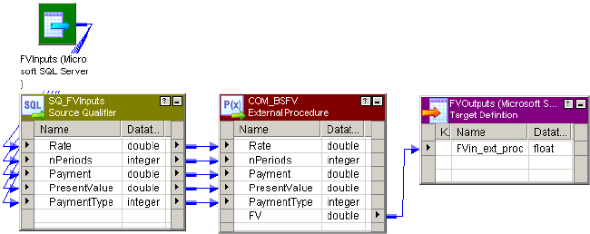
4. Drag the transformation COM_BSFV into the mapping.
5. Connect the Source Qualifier transformation ports to the External Procedure transformation ports as
appropriate.
6. Connect the FV port in the External Procedure transformation to the FVIn_ext_proc target column.
7. Validate and save the mapping.
The following figure shows the complete mapping:
Step 9. Start the Integration Service
Start the Integration Service. The service must be started on the same host as the one on which the COM
component was registered.
Step 10. Run a Workflow to Test the Mapping
When the Integration Service runs the session in a workflow, it performs the following functions:
•Uses the COM runtime facilities to load the DLL and create an instance of the class.
•Uses the COM IDispatch interface to call the external procedure you defined once for every row that
passes through the mapping.
Note: Multiple classes, each with multiple methods, can be defined within a single project. Each of these
methods can be invoked as an external procedure.
To run a workflow to test the mapping:
1. In the Workflow Manager, create the session s_Test_BSFV from the Test_BSFV mapping.
2. Create a workflow that contains the session s_Test_BSFV.
3. Run the workflow. The Integration Service searches the registry for the entry for the
COM_VC_BankSoft.BSoftFin class. This entry has information that allows the Integration Service to
determine the location of the DLL that contains that class. The Integration Service loads the DLL,
creates an instance of the class, and invokes the FV function for every row in the source table.
When the workflow finishes, the FVOutputs table should contain the following results:
FVIn_ext_proc
2581.403374
12682.503013
144 Chapter 8: External Procedure Transformation

FVIn_ext_proc
82846.246372
2301.401830
Developing COM Procedures with Visual Basic
Microsoft Visual Basic offers a different development environment for creating COM procedures. While the
Basic language has different syntax and conventions, the development procedure has the same broad
outlines as developing COM procedures in Visual C++.
RELATED TOPICS:
•“Distributing External Procedures” on page 154
•“Wrapper Classes for Pre-Existing C/C++ Libraries or VB Functions” on page 158
Step 1. Create a Visual Basic Project with a Single Class
1. Launch Visual Basic and click File > New Project.
2. In the dialog box that appears, select ActiveX DLL as the project type and click OK.
Visual Basic creates a new project named Project1.
If the Project window does not display, type Ctrl+R, or click View > Project Explorer.
If the Properties window does not display, press F4, or click View > Properties.
3. In the Project Explorer window for the new project, right-click the project and choose Project1 Properties
from the menu that appears.
4. Enter the name of the new project.
In the Project window, select Project1 and change the name in the Properties window to
COM_VB_BankSoft.
Step 2. Change the Names of the Project and Class
1. Inside the Project Explorer, select the “Project – Project1” item, which should be the root item in the tree
control. The project properties display in the Properties Window.
2. Select the Alphabetic tab in the Properties Window and change the Name property to
COM_VB_BankSoft. This renames the root item in the Project Explorer to COM_VB_BankSoft
(COM_VB_BankSoft).
3. Expand the COM_VB_BankSoft (COM_VB_BankSoft) item in the Project Explorer.
4. Expand the Class Modules item.
5. Select the Class1 (Class1) item. The properties of the class display in the Properties Window.
6. Select the Alphabetic tab in the Properties Window and change the Name property to BSoftFin.
By changing the name of the project and class, you specify that the programmatic identifier for the class you
create is “COM_VB_BankSoft.BSoftFin.” Use this ProgID to refer to this class inside the Designer.
Developing COM Procedures 145

Step 3. Add a Method to the Class
Place the pointer inside the Code window and enter the following text:
Public Function FV( _
Rate As Double, _
nPeriods As Long, _
Payment As Double, _
PresentValue As Double, _
PaymentType As Long _
) As Double
Dim v As Double
v = (1 + Rate) ^ nPeriods
FV = -( _
(PresentValue * v) + _
(Payment * (1 + (Rate * PaymentType))) * ((v - 1) / Rate) _
)
End Function
This Visual Basic FV function performs the same operation as the C++ FV function in “Developing COM
Procedures with Visual Basic” on page 145.
Step 4. Build the Project
To build the project:
1. From the File menu, select the Make COM_VB_BankSoft.DLL. A dialog box prompts you for the file
location.
2. Enter the file location and click OK.
Visual Basic compiles the source code and creates the COM_VB_BankSoft.DLL in the location you specified.
It also registers the class COM_VB_BankSoft.BSoftFin in the local registry.
After the component is registered, it is accessible to the Integration Service running on that host.
Developing Informatica External Procedures
You can create external procedures that run on 32-bit or 64-bit Integration Service machines. Complete the
following steps to create an Informatica-style external procedure:
1. In the Transformation Developer, create an External Procedure transformation.
The External Procedure transformation defines the signature of the procedure. The names of the ports,
datatypes and port type (input or output) must match the signature of the external procedure.
2. Generate the template code for the external procedure.
When you execute this command, the Designer uses the information from the External Procedure
transformation to create several C++ source code files and a makefile. One of these source code files
contains a “stub” for the function whose signature you defined in the transformation.
146 Chapter 8: External Procedure Transformation

3. Modify the code to add the procedure logic. Fill out the stub with an implementation and use a C++
compiler to compile and link the source code files into a dynamic link library or shared library.
When the Integration Service encounters an External Procedure transformation bound to an Informatica
procedure, it loads the DLL or shared library and calls the external procedure you defined.
4. Build the library and copy it to the Integration Service machine.
5. Create a mapping with the External Procedure transformation.
6. Run the session in a workflow.
The BankSoft example illustrates how to implement this feature.
Step 1. Create the External Procedure Transformation
1. Open the Transformation Developer and create an External Procedure transformation.
2. Open the transformation and enter a name for it.
In the BankSoft example, enter
EP_extINF_BSFV
.
3. On the Ports tab, create a port for each argument passed to the procedure you plan to define.
Be sure that you use the correct datatypes.
The following table describes the ports:
Port Name Datatype Precision Scale Input/Output Reusable
Rate double 15 0 Input No
nPeriods integer 10 0 Input No
Payment double 15 0 Input No
PresentValue double 15 0 Input No
PaymentType integer 10 0 Input No
FV double 15 0 Output Yes
Developing Informatica External Procedures 147
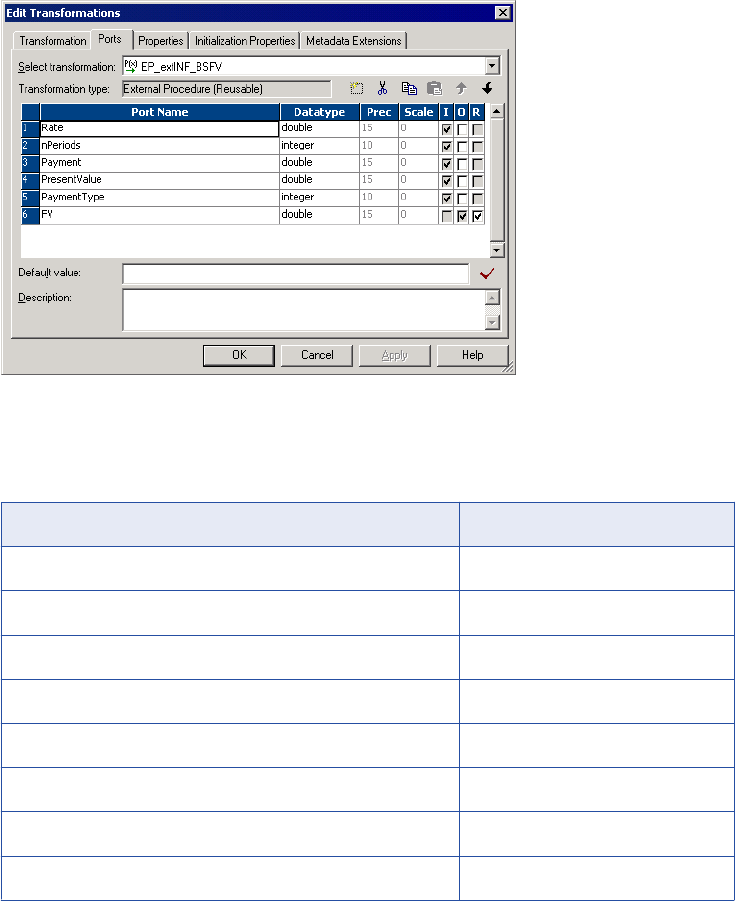
The following BankSoft example shows an example of an External Procedure transformation:
The last port, FV, captures the return value from the procedure.
4. Select the Properties tab and configure the procedure as an Informatica procedure.
In the BankSoft example, configure the following properties:
Transformation Attribute Value
Type Informatica
Module/Programmatic Identifier INF_BankSoft
Procedure Name FV
Runtime Location $PMExtProcDir
Tracing Level Normal
Is Partitionable No
Output is Repeatable Based On Input Order
Output is Deterministic No
148 Chapter 8: External Procedure Transformation
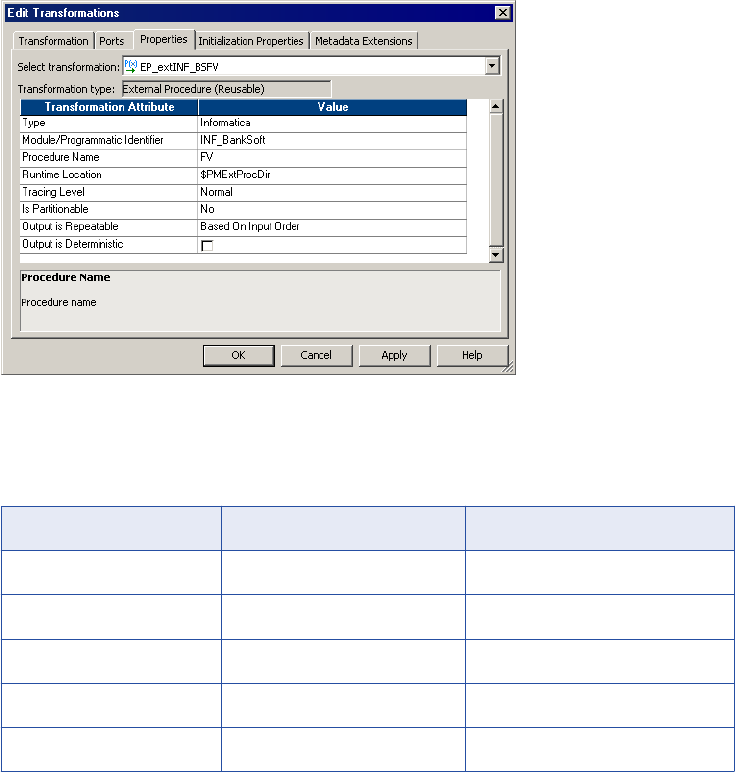
The following BankSoft example shows an example of an Informatica procedure:
Note: on Module/Programmatic Identifier:
The following table describes how the module name determines the name of the DLL or shared object on
the various platforms:
Operating System Module Identifier Library File Name
Windows INF_BankSoft INF_BankSoft.DLL
AIX INF_BankSoft libINF_BankSoftshr.a
HPUX INF_BankSoft libINF_BankSoft.sl
Linux INF_BankSoft libINF_BankSoft.so
Solaris INF_BankSoft libINF_BankSoft.so.1
5. Click OK.
After you create the External Procedure transformation that calls the procedure, the next step is to generate
the C++ files.
Step 2. Generate the C++ Files
After you create an External Procedure transformation, you generate the code. The Designer generates file
names in lower case since files created on UNIX-mapped drives are always in lower case. The following rules
apply to the generated files:
•File names. A prefix ‘tx’ is used for TX module files.
•Module class names. The generated code has class declarations for the module that contains the TX
procedures. A prefix Tx is used for TX module classes. For example, if an External Procedure
transformation has a module name Mymod, then the class name is TxMymod.
To generate the code for an external procedure:
1. Select the transformation and click Transformation > Generate Code.
2. Select the check box next to the name of the procedure you just created.
Developing Informatica External Procedures 149
In the BankSoft example, select INF_BankSoft.FV.
3. Specify the directory where you want to generate the files, and click Generate.
The Designer creates a subdirectory, INF_BankSoft, in the directory you specified.
Each External Procedure transformation created in the Designer must specify a module and a procedure
name. The Designer generates code in a single directory for all transformations sharing a common
module name. Building the code in one directory creates a single shared library.
The Designer generates the following files:
•tx<moduleName>.h. Defines the external procedure module class. This class is derived from a base
class TINFExternalModule60. No data members are defined for this class in the generated code.
However, you can add new data members and methods here.
•tx<moduleName>.cpp. Implements the external procedure module class. You can expand the
InitDerived() method to include initialization of any new data members you add. The Integration
Service calls the derived class InitDerived() method only when it successfully completes the base
class Init() method.
This file defines the signatures of all External Procedure transformations in the module. Any modification
of these signatures leads to inconsistency with the External Procedure transformations defined in the
Designer. Therefore, you should not change the signatures.
This file also includes a C function CreateExternalModuleObject, which creates an object of the external
procedure module class using the constructor defined in this file. The Integration Service calls
CreateExternalModuleObject instead of directly calling the constructor.
•<procedureName>.cpp. The Designer generates one of these files for each external procedure in
this module. This file contains the code that implements the procedure logic, such as data cleansing
and filtering. For data cleansing, create code to read in values from the input ports and generate
values for output ports. For filtering, create code to suppress generation of output rows by returning
INF_NO_OUTPUT_ROW.
•stdafx.h. Stub file used for building on UNIX systems. The various *.cpp files include this file. On
Windows systems, the Visual Studio generates an stdafx.h file, which should be used instead of the
Designer generated file.
•version.cpp. This is a small file that carries the version number of this implementation. In earlier
releases, external procedure implementation was handled differently. This file allows the Integration
Service to determine the version of the external procedure module.
•makefile.aix, makefile.aix64, makefile.hp, makefile.hp64, makefile.hpparisc64, makefile.linux,
makefile.sol. Make files for UNIX platforms. Use makefile.aix, makefile.hp, makefile.linux, and
makefile.sol for 32-bit platforms. Use makefile.aix64 for 64-bit AIX platforms and makefile.hp64 for
64-bit HP-UX (Itanium) platforms.
Example 1
In the BankSoft example, the Designer generates the following files:
•txinf_banksoft.h. Contains declarations for module class TxINF_BankSoft and external procedure FV.
•txinf_banksoft.cpp. Contains code for module class TxINF_BankSoft.
•fv.cpp. Contains code for procedure FV.
•version.cpp. Returns TX version.
•stdafx.h. Required for compilation on UNIX. On Windows, stdafx.h is generated by Visual Studio.
•readme.txt. Contains general help information.
150 Chapter 8: External Procedure Transformation
Example 2
If you create two External Procedure transformations with procedure names ‘Myproc1’ and ‘Myproc2,’ both
with the module name Mymod, the Designer generates the following files:
•txmymod.h. Contains declarations for module class TxMymod and external procedures Myproc1 and
Myproc2.
•txmymod.cpp. Contains code for module class TxMymod.
•myproc1.cpp. Contains code for procedure Myproc1.
•myproc2.cpp. Contains code for procedure Myproc2.
•version.cpp.
•stdafx.h.
•readme.txt.
Step 3. Fill Out the Method Stub with Implementation
The final step is coding the procedure.
1. Open the <Procedure_Name>.cpp stub file generated for the procedure.
In the BankSoft example, you open fv.cpp to code the TxINF_BankSoft::FV procedure.
2. Enter the C++ code for the procedure.
The following code implements the FV procedure:
INF_RESULT TxINF_BankSoft::FV()
{
// Input port values are mapped to the m_pInParamVector array in
// the InitParams method. Use m_pInParamVector[i].IsValid() to check
// if they are valid. Use m_pInParamVector[i].GetLong or GetDouble,
// etc. to get their value. Generate output data into m_pOutParamVector.
// TODO: Fill in implementation of the FV method here.
ostrstream ss;
char* s;
INF_BOOLEAN bVal;
double v;
TINFParam* Rate = &m_pInParamVector[0];
TINFParam* nPeriods = &m_pInParamVector[1];
TINFParam* Payment = &m_pInParamVector[2];
TINFParam* PresentValue = &m_pInParamVector[3];
TINFParam* PaymentType = &m_pInParamVector[4];
TINFParam* FV = &m_pOutParamVector[0];
bVal =
INF_BOOLEAN(
Rate->IsValid() &&
nPeriods->IsValid() &&
Payment->IsValid() &&
PresentValue->IsValid() &&
PaymentType->IsValid()
);
if (bVal == INF_FALSE)
{
FV->SetIndicator(INF_SQL_DATA_NULL);
return INF_SUCCESS;
}
v = pow((1 + Rate->GetDouble()), (double)nPeriods->GetLong());
FV->SetDouble(
-(
(PresentValue->GetDouble() * v) +
(Payment->GetDouble() *
Developing Informatica External Procedures 151
(1 + (Rate->GetDouble() * PaymentType->GetLong()))) *
((v - 1) / Rate->GetDouble())
)
);
ss << "The calculated future value is: " << FV->GetDouble() <<ends;
s = ss.str();
(*m_pfnMessageCallback)(E_MSG_TYPE_LOG, 0, s);
(*m_pfnMessageCallback)(E_MSG_TYPE_ERR, 0, s);
delete [] s;
return INF_SUCCESS;
}
The Designer generates the function profile, including the arguments and return value. You need to enter
the actual code within the function, as indicated in the comments. Since you referenced the POW
function and defined an
ostrstream
variable, you must also include the preprocessor statements:
On Windows:
#include <math.h>
#include <strstream> using namespace std;
On UNIX, the include statements would be the following:
#include <math.h>
#include <strstream.h>
3. Save the modified file.
Step 4. Building the Module
On Windows, use Visual C++ to compile the DLL.
Building the Module on Windows
To build a DLL on Windows:
1. Start Visual C++.
2. Click File > New.
3. In the New dialog box, click the Projects tab and select the MFC AppWizard (DLL) option.
4. Enter its location.
In the BankSoft example, you enter c:\pmclient\tx\INF_BankSoft, assuming you generated files in c:
\pmclient\tx.
5. Enter the name of the project.
It must be the same as the module name entered for the External Procedure transformation. In the
BankSoft example, it is INF_BankSoft.
6. Click OK.
Visual C++ now steps you through a wizard that defines all the components of the project.
7. In the wizard, click MFC Extension DLL (using shared MFC DLL).
8. Click Finish.
The wizard generates several files.
9. Click Project > Add To Project > Files.
10. Navigate up a directory level. This directory contains the external procedure files you created. Select
all .cpp files.
152 Chapter 8: External Procedure Transformation

In the BankSoft example, add the following files:
•fv.cpp
•txinf_banksoft.cpp
•version.cpp
11. Click Project > Settings.
12. Click the C/C++ tab, and select Preprocessor from the Category field.
13. In the Additional Include Directories field, enter ..; <pmserver install dir>\extproc\include.
14. Click the Link tab, and select General from the Category field.
15. Enter <pmserver install dir>\bin\pmtx.lib in the Object/Library Modules field.
16. Click OK.
17. Click Build > Build INF_BankSoft.dll or press F7 to build the project.
The compiler now creates the DLL and places it in the debug or release directory under the project
directory.
Building the Module on UNIX
To build shared libraries on UNIX:
1. If you cannot access the PowerCenter Client tools directly, copy all the files you need for the shared
library to the UNIX machine where you plan to perform the build.
For example, in the BankSoft procedure, use ftp or another mechanism to copy everything from the
INF_BankSoft directory to the UNIX machine.
2. Set the environment variable INFA_HOME to the PowerCenter installation directory.
Warning: If you specify an incorrect directory path for the INFA_HOME environment variable, the
Integration Service cannot start.
3. Enter the command to make the project.
The command depends on the version of UNIX, as summarized below:
UNIX Version Command
AIX (32-bit) make -f makefile.aix
AIX (64-bit) make -f makefile.aix64
HP-UX (32-bit) make -f makefile.hp
HP-UX (64-bit) make -f makefile.hp64
Linux make -f makefile.linux
Solaris make -f makefile.sol
Step 5. Create a Mapping
In the Mapping Designer, create a mapping that uses this External Procedure transformation.
Developing Informatica External Procedures 153
Step 6. Run the Session
When you run the session, the Integration Service looks in the directory you specify as the Runtime Location
to find the library (DLL) you built in Step 4. The default value of the Runtime Location property in the session
properties is $PMExtProcDir.
To run a session:
1. In the Workflow Manager, create a workflow.
2. Create a session for this mapping in the workflow.
Tip: Alternatively, you can create a re-usable session in the Task Developer and use it in the workflow.
3. Copy the library (DLL) to the Runtime Location directory.
4. Run the workflow containing the session.
Running a Session with the Debug Version of the Module on Windows
Informatica ships PowerCenter on Windows with the release build (pmtx.dll) and the debug build
(pmtxdbg.dll) of the External Procedure transformation library. These libraries are installed in the server bin
directory.
If you build a release version of the module in Step 4, run the session in a workflow to use the release build
(pmtx.dll) of the External Procedure transformation library. You do not need to complete the following task.
If you build a debug version of the module in Step 4, follow the procedure below to use the debug build
(pmtxdbg.dll) of the External Procedure transformation library.
To run a session using a debug version of the module:
1. In the Workflow Manager, create a workflow.
2. Create a session for this mapping in the workflow.
You can also create a re-usable session in the Task Developer and use it in the workflow.
3. Copy the library (DLL) to the Runtime Location directory.
4. To use the debug build of the External Procedure transformation library:
•Preserve pmtx.dll by renaming it or moving it from the server bin directory.
•Rename pmtxdbg.dll to pmtx.dll.
5. Run the workflow containing the session.
6. To revert the release build of the External Procedure transformation library back to the default library:
•Rename pmtx.dll back to pmtxdbg.dll.
•Return/rename the original pmtx.dll file to the server bin directory.
Note: If you run a workflow containing this session with the debug version of the module on Windows,
you must return the original pmtx.dll file to its original name and location before you can run a non-debug
session.
Distributing External Procedures
Suppose you develop a set of external procedures and you want to make them available on multiple servers,
each of which is running the Integration Service. The methods for doing this depend on the type of the
external procedure and the operating system on which you built it.
154 Chapter 8: External Procedure Transformation
You can also use these procedures to distribute external procedures to external customers.
Distributing COM Procedures
Visual Basic and Visual C++ register COM classes in the local registry when you build the project. Once
registered, these classes are accessible to the Integration Service running on the machine where you
compiled the DLL. For example, if you build a project on HOST1, all the classes in the project will be
registered in the HOST1 registry and will be accessible to the Integration Service running on HOST1.
Suppose, however, that you also want the classes to be accessible to the Integration Service running on
HOST2. For this to happen, the classes must be registered in the HOST2 registry.
Visual Basic provides a utility for creating a setup program that can install COM classes on a Windows
machine and register these classes in the registry on that machine. While no utility is available in Visual C++,
you can easily register the class yourself.
Distributing a COM Visual Basic Procedure
To distribute a COM Visual Basic procedure:
1. After you build the DLL, exit Visual Basic and launch the Visual Basic Application Setup wizard.
2. Skip the first panel of the wizard.
3. On the second panel, specify the location of the project and select the Create a Setup Program option.
4. In the third panel, select the method of distribution you plan to use.
5. In the next panel, specify the directory to which you want to write the setup files.
For simple ActiveX components, you can continue to the final panel of the wizard. Otherwise, you may
need to add more information, depending on the type of file and the method of distribution.
6. Click Finish in the final panel.
Visual Basic then creates the setup program for the DLL. Run this setup program on any Windows
machine where the Integration Service is running.
Distributing a COM Visual Basic Procedure Manually
To distribute a COM Visual C++/Visual Basic procedure manually:
1. Copy the DLL to the directory on the new Windows machine anywhere you want it saved.
2. Log in to this Windows machine and open a DOS prompt.
3. Navigate to the directory containing the DLL and execute the following command:
REGSVR32 project_name.DLL
project_name is the name of the DLL you created. In the BankSoft example, the project name is
COM_VC_BankSoft.DLL. or COM_VB_BankSoft.DLL.
This command line program then registers the DLL and any COM classes contained in it.
Distributing Informatica Modules
You can distribute external procedures between repositories.
To distribute external procedures between repositories:
1. Move the DLL or shared object that contains the external procedure to a directory on a machine that the
Integration Service can access.
Distributing External Procedures 155

2. Copy the External Procedure transformation from the original repository to the target repository using the
Designer client tool.
You can also export the External Procedure transformation to an XML file and import it in the target
repository.
Development Notes
This section includes some additional guidelines and information about developing COM and Informatica
external procedures.
COM Datatypes
When using either Visual C++ or Visual Basic to develop COM procedures, you need to use COM datatypes
that correspond to the internal datatypes that the Integration Service uses when reading and transforming
data. These datatype matches are important when the Integration Service attempts to map datatypes
between ports in an External Procedure transformation and arguments (or return values) from the procedure
the transformation calls.
The following table compares Visual C++ and transformation datatypes:
Visual C++ COM Datatype Transformation Datatype
VT_I4 Integer
VT_UI4 Integer
VT_R8 Double
VT_BSTR String
VT_DECIMAL Decimal
VT_DATE Date/Time
The following table compares Visual Basic and transformation datatypes:
Visual Basic COM Datatype Transformation Datatype
Long Integer
Double Double
String String
Decimal Decimal
Date Date/Time
156 Chapter 8: External Procedure Transformation
If you do not correctly match datatypes, the Integration Service may attempt a conversion. For example, if
you assign the Integer datatype to a port, but the datatype for the corresponding argument is BSTR, the
Integration Service attempts to convert the Integer value to a BSTR.
Row-Level Procedures
All External Procedure transformations call procedures using values from a single row passed through the
transformation. You cannot use values from multiple rows in a single procedure call. For example, you could
not code the equivalent of the aggregate functions SUM or AVG into a procedure call. In this sense, all
external procedures must be stateless.
Return Values from Procedures
When you call a procedure, the Integration Service captures an additional return value beyond whatever
return value you code into the procedure. This additional value indicates whether the Integration Service
successfully called the procedure.
For COM procedures, this return value uses the type HRESULT.
Informatica procedures use the type INF_RESULT. If the value returned is S_OK/INF_SUCCESS, the
Integration Service successfully called the procedure. You must return the appropriate value to indicate the
success or failure of the external procedure. Informatica procedures return four values:
•INF_SUCCESS. The external procedure processed the row successfully. The Integration Service passes
the row to the next transformation in the mapping.
•INF_NO_OUTPUT_ROW. The Integration Service does not write the current row due to external
procedure logic. This is not an error. When you use INF_NO_OUTPUT_ROW to filter rows, the External
Procedure transformation behaves similarly to the Filter transformation.
Note: When you use INF_NO_OUTPUT_ROW in the external procedure, make sure you connect the
External Procedure transformation to another transformation that receives rows from the External
Procedure transformation only.
•INF_ROW_ERROR. Equivalent to a transformation error. The Integration Service discards the current
row, but may process the next row unless you configure the session to stop on n errors.
•INF_FATAL_ERROR. Equivalent to an ABORT() function call. The Integration Service aborts the session
and does not process any more rows.
Exceptions in Procedure Calls
The Integration Service captures most exceptions that occur when it calls a COM or Informatica procedure
through an External Procedure transformation. For example, if the procedure call creates a divide by zero
error, the Integration Service catches the exception.
In a few cases, the Integration Service cannot capture errors generated by procedure calls. Since the
Integration Service supports only in-process COM servers, and since all Informatica procedures are stored in
shared libraries and DLLs, the code running external procedures exists in the same address space in
memory as the Integration Service. Therefore, it is possible for the external procedure code to overwrite the
Integration Service memory, causing the Integration Service to stop. If COM or Informatica procedures cause
such stops, review the source code for memory access problems.
Memory Management for Procedures
Since all the datatypes used in Informatica procedures are fixed length, there are no memory management
issues for Informatica external procedures. For COM procedures, you need to allocate memory only if an
Development Notes 157

[out] parameter from a procedure uses the BSTR datatype. In this case, you need to allocate memory on
every call to this procedure. During a session, the Integration Service releases the memory after calling the
function.
Wrapper Classes for Pre-Existing C/C++ Libraries or VB Functions
Suppose that BankSoft has a library of C or C++ functions and wants to plug these functions in to the
Integration Service. In particular, the library contains BankSoft’s own implementation of the FV function,
called PreExistingFV. The general method for doing this is the same for both COM and Informatica external
procedures. A similar solution is available in Visual Basic. You need only make calls to preexisting Visual
Basic functions or to methods on objects that are accessible to Visual Basic.
Generating Error and Tracing Messages
The implementation of the Informatica external procedure TxINF_BankSoft::FV in “Step 4. Building the
Module” on page 152 contains the following lines of code.
ostrstream ss;
char* s;
...
ss << "The calculated future value is: " << FV->GetDouble() << ends;
s = ss.str();
(*m_pfnMessageCallback)(E_MSG_TYPE_LOG, 0, s);
(*m_pfnMessageCallback)(E_MSG_TYPE_ERR, 0, s);
delete [] s;
When the Integration Service creates an object of type Tx<MODNAME>, it passes to its constructor a pointer
to a callback function that can be used to write error or debugging messages to the session log. (The code
for the Tx<MODNAME> constructor is in the file Tx<MODNAME>.cpp.) This pointer is stored in the
Tx<MODNAME> member variable m_pfnMessageCallback. The type of this pointer is defined in a typedef in
the file $PMExtProcDir/include/infemmsg.h:
typedef void (*PFN_MESSAGE_CALLBACK)(
enum E_MSG_TYPE eMsgType,
unsigned long Code,
char* Message
);
Also defined in that file is the enumeration E_MSG_TYPE:
enum E_MSG_TYPE {
E_MSG_TYPE_LOG = 0,
E_MSG_TYPE_WARNING,
E_MSG_TYPE_ERR
};
If you specify the eMsgType of the callback function as E_MSG_TYPE_LOG, the callback function will write a
log message to the session log. If you specify E_MSG_TYPE_ERR, the callback function writes an error
message to the session log. If you specify E_MSG_TYPE_WARNING, the callback function writes an warning
158 Chapter 8: External Procedure Transformation
message to the session log. Use these messages to provide a simple debugging capability in Informatica
external procedures.
To debug COM external procedures, you may use the output facilities available from inside a Visual Basic or
C++ class. For example, in Visual Basic use a MsgBox to print out the result of a calculation for each row. Of
course, you want to do this only on small samples of data while debugging and make sure to remove the
MsgBox before making a production run.
Note: Before attempting to use any output facilities from inside a Visual Basic or C++ class, you must add the
following value to the registry:
1. Add the following entry to the Windows registry:
\HKEY_LOCAL_MACHINE\System\CurrentControlSet\Services\PowerMart\Parameters\MiscInfo
\RunInDebugMode=Yes
This option starts the Integration Service as a regular application, not a service. You can debug the
Integration Service without changing the debug privileges for the Integration Service service while it is
running.
2. Start the Integration Service from the command line, using the command PMSERVER.EXE.
The Integration Service is now running in debug mode.
When you are finished debugging, make sure you remove this entry from the registry or set
RunInDebugMode to No. Otherwise, when you attempt to start PowerCenter as a service, it will not start.
1. Stop the Integration Service and change the registry entry you added earlier to the following setting:
\HKEY_LOCAL_MACHINE\System\CurrentControlSet\Services\PowerMart\Parameters\MiscInfo
\RunInDebugMode=No
2. Restart the Integration Service as a Windows service.
The TINFParam Class and Indicators
The <PROCNAME> method accesses input and output parameters using two parameter arrays, and that
each array element is of the TINFParam datatype. The TINFParam datatype is a C++ class that serves as a
“variant” data structure that can hold any of the Informatica internal datatypes. The actual data in a parameter
of type TINFParam* is accessed through member functions of the form Get<Type> and Set<Type>, where
<Type> is one of the Informatica internal datatypes. TINFParam also has methods for getting and setting the
indicator for each parameter.
You are responsible for checking these indicators on entry to the external procedure and for setting them on
exit. On entry, the indicators of all output parameters are explicitly set to INF_SQL_DATA_NULL, so if you do
not reset these indicators before returning from the external procedure, you will just get NULLs for all the
output parameters. The TINFParam class also supports functions for obtaining the metadata for a particular
parameter. For a complete description of all the member functions of the TINFParam class, see the
infemdef.h include file in the tx/include directory.
One of the main advantages of Informatica external procedures over COM external procedures is that
Informatica external procedures directly support indicator manipulation. That is, you can check an input
parameter to see if it is NULL, and you can set an output parameter to NULL. COM provides no indicator
support. Consequently, if a row entering a COM-style external procedure has any NULLs in it, the row cannot
be processed. Use the default value facility in the Designer to overcome this shortcoming. However, it is not
possible to pass NULLs out of a COM function.
Unconnected External Procedure Transformations
When you add an instance of an External Procedure transformation to a mapping, you can choose to connect
it as part of the pipeline or leave it unconnected. Connected External Procedure transformations call the
COM or Informatica procedure every time a row passes through the transformation.
Development Notes 159
To get return values from an unconnected External Procedure transformation, call it in an expression using
the following syntax:
:EXT.transformation_name(arguments)
When a row passes through the transformation containing the expression, the Integration Service calls the
procedure associated with the External Procedure transformation. The expression captures the return value
of the procedure through the External Procedure transformation return port, which should have the Result (R)
option checked.
Initializing COM and Informatica Modules
Some external procedures must be configured at initialization time. This initialization takes one of two forms,
depending on the type of the external procedure:
•Initialization of Informatica-style external procedures. The Tx<MODNAME> class, which contains the
external procedure, also contains the initialization function, Tx<MODNAME>::InitDerived. The signature of
this initialization function is well-known to the Integration Service and consists of three parameters:
-nInitProps. This parameter tells the initialization function how many initialization properties are being
passed to it.
-Properties. This parameter is an array of nInitProp strings representing the names of the initialization
properties.
-Values. This parameter is an array of nInitProp strings representing the values of the initialization
properties.
The Integration Service first calls the Init() function in the base class. When the Init() function
successfully completes, the base class calls the Tx<MODNAME>::InitDerived() function.
The Integration Service creates the Tx<MODNAME> object and then calls the initialization function. It is
the responsibility of the external procedure developer to supply that part of the
Tx<MODNAME>::InitDerived() function that interprets the initialization properties and uses them to
initialize the external procedure. Once the object is created and initialized, the Integration Service can
call the external procedure on the object for each row.
•Initialization of COM-style external procedures. The object that contains the external procedure (or EP
object) does not contain an initialization function. Instead, another object (the CF object) serves as a class
factory for the EP object. The CF object has a method that can create an EP object.
The signature of the CF object method is determined from its type library. The Integration Service creates
the CF object, and then calls the method on it to create the EP object, passing this method whatever
parameters are required. This requires that the signature of the method consist of a set of input
parameters, whose types can be determined from the type library, followed by a single output parameter
that is an IUnknown** or an IDispatch** or a VARIANT* pointing to an IUnknown* or IDispatch*.
The input parameters hold the values required to initialize the EP object and the output parameter
receives the initialized object. The output parameter can have either the [out] or the [out, retval] attributes.
That is, the initialized object can be returned either as an output parameter or as the return value of the
method. The datatypes supported for the input parameters are:
-COM VC type
-VT_UI1
-VT_BOOL
-VT_I2
-VT_UI2
-VT_I4
160 Chapter 8: External Procedure Transformation

-VT_UI4
-VT_R4
-VT_R8
-VT_BSTR
-VT_CY
-VT_DATE
Setting Initialization Properties in the Designer
Enter external procedure initialization properties on the Initialization Properties tab of the Edit
Transformations dialog box. The tab displays different fields, depending on whether the external procedure is
COM-style or Informatica-style.
COM-style External Procedure transformations contain the following fields on the Initialization Properties tab:
•Programmatic Identifier for Class Factory. Enter the programmatic identifier of the class factory.
•Constructor. Specify the method of the class factory that creates the EP object.
You can enter an unlimited number of initialization properties to pass to the Constructor method for both
COM-style and Informatica-style External Procedure transformations.
To add a new initialization property, click the Add button. Enter the name of the parameter in the Property
column and enter the value of the parameter in the Value column. For example, you can enter the following
parameters:
Parameter Value
Param1 abc
Param2 100
Param3 3.17
Note: You must create a one-to-one relation between the initialization properties you define in the Designer
and the input parameters of the class factory constructor method. For example, if the constructor has n
parameters with the last parameter being the output parameter that receives the initialized object, you must
define n – 1 initialization properties in the Designer, one for each input parameter in the constructor method.
You can also use process variables in initialization properties.
Other Files Distributed and Used in TX
Following are the header files located under the path
$PMExtProcDir/include
that are needed for compiling
external procedures:
•infconfg.h
•infem60.h
•infemdef.h
•infemmsg.h
•infparam.h
•infsigtr.h
Development Notes 161

Following are the library files located under the path <PMInstallDir> that are needed for linking external
procedures and running the session:
•libpmtx.a (AIX)
•libpmtx.sl (HP-UX)
•libpmtx.so (Linux)
•libpmtx.so (Solaris)
•pmtx.dll and pmtx.lib (Windows)
Service Process Variables in Initialization Properties
PowerCenter supports built-in process variables in the External Procedure transformation initialization
properties list. If the property values contain built-in process variables, the Integration Service expands them
before passing them to the external procedure library. This can be very useful for writing portable External
Procedure transformations.
The following table describes the initialization properties and values for an External Procedure transformation
on the Initialization Properties tab of the transformation properties.
Table 2. External Procedure Initialization Properties
Property Value Expanded Value Passed to the External Procedure
Library
mytempdir $PMTempDir /tmp
memorysize 5000000 5000000
input_file $PMSourceFileDir/file.in /data/input/file.in
output_file $PMTargetFileDir/file.out /data/output/file.out
extra_var $some_other_variable $some_other_variable
When you run the workflow, the Integration Service expands the property list and passes it to the external
procedure initialization function. Assuming that the values of the built-in process variables $PMTempDir is /
tmp, $PMSourceFileDir is /data/input, and $PMTargetFileDir is /data/output, the last column in “Service
Process Variables in Initialization Properties” on page 162 contains the property and expanded value
information. The Integration Service does not expand the last property “$some_other_variable” because it is
not a built-in process variable.
External Procedure Interfaces
The Integration Service uses the following major functions with External Procedures:
•Dispatch
•External procedure
162 Chapter 8: External Procedure Transformation
•Property access
•Parameter access
•Code page access
•Transformation name access
•Procedure access
•Partition related
•Tracing level
Dispatch Function
The Integration Service calls the dispatch function to pass each input row to the external procedure module.
The dispatch function, in turn, calls the external procedure function you specify.
External procedures access the ports in the transformation directly using the member variable
m_pInParamVector for input ports and m_pOutParamVector for output ports.
Signature
The dispatch function has a fixed signature which includes one index parameter.
virtual INF_RESULT Dispatch(unsigned long ProcedureIndex) = 0
External Procedure Function
The external procedure function is the main entry point into the external procedure module, and is an
attribute of the External Procedure transformation. The dispatch function calls the external procedure function
for every input row. For External Procedure transformations, use the external procedure function for input and
output from the external procedure module. The function can access the IN and IN-OUT port values for every
input row, and can set the OUT and IN-OUT port values. The external procedure function contains all the
input and output processing logic.
Signature
The external procedure function has no parameters. The input parameter array is already passed through the
InitParams() method and stored in the member variable m_pInParamVector. Each entry in the array matches
the corresponding IN and IN-OUT ports of the External Procedure transformation, in the same order. The
Integration Service fills this vector before calling the dispatch function.
Use the member variable m_pOutParamVector to pass the output row before returning the Dispatch()
function.
For the MyExternal Procedure transformation, the external procedure function is the following, where the
input parameters are in the member variable m_pInParamVector and the output values are in the member
variable m_pOutParamVector:
INF_RESULT Tx<ModuleName>::MyFunc()
Property Access Functions
The property access functions provide information about the initialization properties associated with the
External Procedure transformation. The initialization property names and values appear on the Initialization
Properties tab when you edit the External Procedure transformation.
External Procedure Interfaces 163
Informatica provides property access functions in both the base class and the TINFConfigEntriesList class.
Use the GetConfigEntryName() and GetConfigEntryValue() functions in the TINFConfigEntriesList class to
access the initialization property name and value, respectively.
Signature
Informatica provides the following functions in the base class:
TINFConfigEntriesList* TINFBaseExternalModule60::accessConfigEntriesList();
const char* GetConfigEntry(const char* LHS);
Informatica provides the following functions in the TINFConfigEntriesList class:
const char* TINFConfigEntriesList::GetConfigEntryValue(const char* LHS);
const char* TINFConfigEntriesList::GetConfigEntryValue(int i);
const char* TINFConfigEntriesList::GetConfigEntryName(int i);
const char* TINFConfigEntriesList::GetConfigEntry(const char* LHS)
Note: In the TINFConfigEntriesList class, use the GetConfigEntryName() and GetConfigEntryValue() property
access functions to access the initialization property names and values.
You can call these functions from a TX program. The TX program then converts this string value into a
number, for example by using atoi or sscanf. In the following example, “addFactor” is an Initialization
Property. accessConfigEntriesList() is a member variable of the TX base class and does not need to be
defined.
const char* addFactorStr = accessConfigEntriesList()-> GetConfigEntryValue("addFactor");
Parameter Access Functions
Parameter access functions are datatype specific. Use the parameter access function GetDataType to return
the datatype of a parameter. Then use a parameter access function corresponding to this datatype to return
information about the parameter.
A parameter passed to an external procedure belongs to the datatype TINFParam*. The header file
infparam.h defines the related access functions. The Designer generates stub code that includes comments
indicating the parameter datatype. You can also determine the datatype of a parameter in the corresponding
External Procedure transformation in the Designer.
Signature
A parameter passed to an external procedure is a pointer to an object of the TINFParam class. This fixed-
signature function is a method of that class and returns the parameter datatype as an enum value.
The valid datatypes are:
•INF_DATATYPE_LONG
•INF_DATATYPE_STRING
•INF_DATATYPE_DOUBLE
•INF_DATATYPE_RAW
•INF_DATATYPE_TIME
164 Chapter 8: External Procedure Transformation

The following table describes some parameter access functions:
Parameter Access Function Description
INF_DATATYPE GetDataType(void); Gets the datatype of a parameter. Use the parameter datatype to
determine which datatype-specific function to use when accessing
parameter values.
INF_BOOLEAN IsValid(void); Verifies that input data is valid. Returns FALSE if the parameter
contains truncated data for the string or raw datatypes. Also returns
FALSE when the input data exceeds the precision or the input data
is a null value.
INF_BOOLEAN IsNULL(void); Verifies that input data is NULL.
INF_BOOLEAN IsInputMapped (void); Verifies that input port passing data to this parameter is connected
to a transformation.
INF_BOOLEAN IsOutput Mapped (void); Verifies that output port receiving data from this parameter is
connected to a transformation.
INF_BOOLEAN IsInput(void); Verifies that parameter corresponds to an input port.
INF_BOOLEAN IsOutput(void); Verifies that parameter corresponds to an output port.
INF_BOOLEAN GetName(void); Gets the name of the parameter.
SQLIndicator GetIndicator(void); Gets the value of a parameter indicator. The IsValid and ISNULL
functions are special cases of this function. This function can also
return INF_SQL_DATA_TRUNCATED.
void SetIndicator(SQLIndicator Indicator); Sets an output parameter indicator, such as invalid or truncated.
long GetLong(void); Gets the value of a parameter having a Long or Integer datatype.
Call this function only if you know the parameter datatype is Integer
or Long. This function does not convert data to Long from another
datatype.
double GetDouble(void); Gets the value of a parameter having a Float or Double datatype.
Call this function only if you know the parameter datatype is Float or
Double. This function does not convert data to Double from another
datatype.
char* GetString(void); Gets the value of a parameter as a null-terminated string. Call this
function only if you know the parameter datatype is String. This
function does not convert data to String from another datatype.
The value in the pointer changes when the next row of data is read.
If you want to store the value from a row for later use, explicitly copy
this string into its own allocated buffer.
char* GetRaw(void); Gets the value of a parameter as a non-null terminated byte array.
Call this function only if you know the parameter datatype is Raw.
This function does not convert data to Raw from another datatype.
unsigned long GetActualDataLen(void); Gets the current length of the array returned by GetRaw.
TINFTime GetTime(void); Gets the value of a parameter having a Date/Time datatype. Call this
function only if you know the parameter datatype is Date/Time. This
function does not convert data to Date/Time from another datatype.
External Procedure Interfaces 165

Parameter Access Function Description
void SetLong(long lVal); Sets the value of an output parameter having a Long datatype.
void SetDouble(double dblVal); Sets the value of an output parameter having a Double datatype.
void SetString(char* sVal); Sets the value of an output parameter having a String datatype.
void SetRaw(char* rVal, size_t
ActualDataLen);
Sets a non-null terminated byte array.
void SetTime(TINFTime timeVal); Sets the value of an output parameter having a Date/Time datatype.
Only use the SetInt32 or GetInt32 function when you run the external procedure on a 64-bit Integration
Service. Do not use any of the following functions:
•GetLong
•SetLong
•GetpLong
•GetpDouble
•GetpTime
Pass the parameters using two parameter lists.
The following table lists the member variables of the external procedure base class:
Variable Description
m_nInParamCount Number of input parameters.
m_pInParamVector Actual input parameter array.
m_nOutParamCount Number of output parameters.
m_pOutParamVector Actual output parameter array.
Note: Ports defined as input/output show up in both parameter lists.
Code Page Access Functions
Informatica provides two code page access functions that return the code page of the Integration Service and
two that return the code page of the data the external procedure processes. When the Integration Service
runs in Unicode mode, the string data passing to the external procedure program can contain multibyte
characters. The code page determines how the external procedure interprets a multibyte character string.
When the Integration Service runs in Unicode mode, data processed by the external procedure program must
be two-way compatible with the Integration Service code page.
Signature
Use the following functions to obtain the Integration Service code page through the external procedure
program. Both functions return equivalent information.
int GetServerCodePageID() const;
const char* GetServerCodePageName() const;
166 Chapter 8: External Procedure Transformation
Use the following functions to obtain the code page of the data the external procedure processes through the
external procedure program. Both functions return equivalent information.
int GetDataCodePageID(); // returns 0 in case of error
const char* GetDataCodePageName() const; // returns NULL in case of error
Transformation Name Access Functions
Informatica provides two transformation name access functions that return the name of the External
Procedure transformation. The GetWidgetName() function returns the name of the transformation, and the
GetWidgetInstanceName() function returns the name of the transformation instance in the mapplet or
mapping.
Signature
The char* returned by the transformation name access functions is an MBCS string in the code page of the
Integration Service. It is not in the data code page.
const char* GetWidgetInstanceName() const;
const char* GetWidgetName() const;
Procedure Access Functions
Informatica provides two procedure access functions that provide information about the external procedure
associated with the External Procedure transformation. The GetProcedureName() function returns the name
of the external procedure specified in the Procedure Name field of the External Procedure transformation.
The GetProcedureIndex() function returns the index of the external procedure.
Signature
Use the following function to get the name of the external procedure associated with the External Procedure
transformation:
const char* GetProcedureName() const;
Use the following function to get the index of the external procedure associated with the External Procedure
transformation:
inline unsigned long GetProcedureIndex() const;
Partition Related Functions
Use partition related functions for external procedures in sessions with multiple partitions. When you partition
a session that contains External Procedure transformations, the Integration Service creates instances of
these transformations for each partition. For example, if you define five partitions for a session, the
Integration Service creates five instances of each external procedure at session runtime.
Signature
Use the following function to obtain the number of partitions in a session:
unsigned long GetNumberOfPartitions();
Use the following function to obtain the index of the partition that called this external procedure:
unsigned long GetPartitionIndex();
External Procedure Interfaces 167
Tracing Level Function
The tracing level function returns the session trace level, for example:
typedef enum
{
TRACE_UNSET = 0,
TRACE_TERSE = 1,
TRACE_NORMAL = 2,
TRACE_VERBOSE_INIT = 3,
TRACE_VERBOSE_DATA = 4
} TracingLevelType;
Signature
Use the following function to return the session trace level:
TracingLevelType GetSessionTraceLevel();
168 Chapter 8: External Procedure Transformation
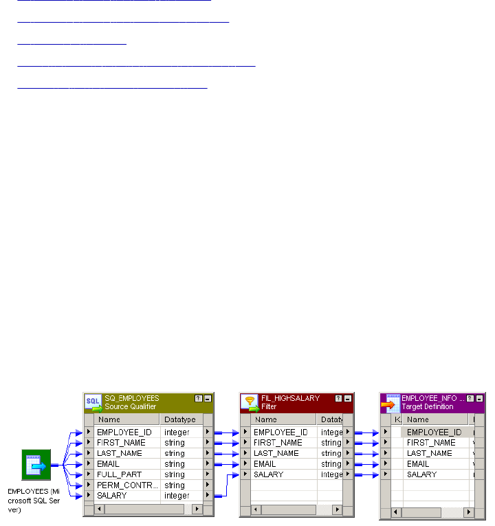
CHAPTER 9
Filter Transformation
This chapter includes the following topics:
•Filter Transformation Overview, 169
•Filter Transformation Components, 170
•Filter Condition, 170
•Steps to Create a Filter Transformation, 171
•Tips for Filter Transformations, 171
Filter Transformation Overview
Use the Filter transformation to filter out rows in a mapping. As an active transformation, the Filter
transformation may change the number of rows passed through it. The Filter transformation allows rows that
meet the specified filter condition to pass through. It drops rows that do not meet the condition. You can filter
data based on one or more conditions. The Filter transformation is an active transformation.
A filter condition returns TRUE or FALSE for each row that the Integration Service evaluates, depending on
whether a row meets the specified condition. For each row that returns TRUE, the Integration Services pass
through the transformation. For each row that returns FALSE, the Integration Service drops and writes a
message to the session log.
The following mapping passes the rows from a human resources table that contains employee data through a
Filter transformation. The filter allows rows through for employees that make salaries of $30,000 or higher.
You cannot concatenate ports from more than one transformation into the Filter transformation. The input
ports for the filter must come from a single transformation.
Tip: Place the Filter transformation as close to the sources in the mapping as possible to maximize session
performance. Rather than passing rows you plan to discard through the mapping, you can filter out unwanted
data early in the flow of data from sources to targets.
169
Filter Transformation Components
You can create a Filter transformation in the Transformation Developer or the Mapping Designer. A Filter
transformation contains the following tabs:
•Transformation. Enter the name and description of the transformation. The naming convention for a Filter
transformation is FIL_TransformationName. You can also make the transformation reusable.
•Ports. Create and configure ports.
•Properties. Configure the filter condition to filter rows. Use the Expression Editor to enter the filter
condition. You can also configure the tracing level to determine the amount of transaction detail reported
in the session log file.
•Metadata Extensions. Create a non-reusable metadata extension to extend the metadata of the
transformation transformation. Configure the extension name, datatype, precision, and value. You can
also promote a metadata extension to be reusable if you want to make it available to all transformations.
Configuring Filter Transformation Ports
You can create and modify ports on the Ports tab.
You can configure the following properties on the Ports tab:
•Port name. Name of the port.
•Datatype, precision, and scale. Configure the datatype and set the precision and scale for each port.
•Port type. All ports are input/output ports. The input ports receive data and output ports pass data.
•Default values and description. Set default value for ports and add description.
Filter Condition
The filter condition is an expression that returns TRUE or FALSE. Enter conditions using the Expression
Editor available on the Properties tab.
Any expression that returns a single value can be used as a filter. For example, if you want to filter out rows
for employees whose salary is less than $30,000, you enter the following condition:
SALARY > 30000
You can specify multiple components of the condition, using the AND and OR logical operators. If you want to
filter out employees who make less than $30,000 and more than $100,000, you enter the following condition:
SALARY > 30000 AND SALARY < 100000
You can also enter a constant for the filter condition. The numeric equivalent of FALSE is zero (0). Any non-
zero value is the equivalent of TRUE. For example, the transformation contains a port named
NUMBER_OF_UNITS with a numeric datatype. You configure a filter condition to return FALSE if the value of
NUMBER_OF_UNITS equals zero. Otherwise, the condition returns TRUE.
You do not need to specify TRUE or FALSE as values in the expression. TRUE and FALSE are implicit return
values from any condition you set. If the filter condition evaluates to NULL, the row is treated as FALSE.
Note: The filter condition is case sensitive.
170 Chapter 9: Filter Transformation
Filtering Rows with Null Values
To filter rows containing null values or spaces, use the ISNULL and IS_SPACES functions to test the value of
the port. For example, if you want to filter out rows that contain NULL value in the FIRST_NAME port, use the
following condition:
IIF(ISNULL(FIRST_NAME),FALSE,TRUE)
This condition states that if the FIRST_NAME port is NULL, the return value is FALSE and the row should be
discarded. Otherwise, the row passes through to the next transformation.
Steps to Create a Filter Transformation
Use the following procedure to create a Filter transformation.
To create a Filter transformation:
1. In the Mapping Designer, open a mapping.
2. Click Transformation > Create. Select Filter transformation.
3. Enter a name for the transformation. Click Create and then click Done.
4. Select and drag all the ports from a source qualifier or other transformation to add them to the Filter
transformation.
5. Double-click on the title bar and click on Ports tab. You can also manually create ports within the
transformation.
6. Click the Properties tab to configure the filter condition and tracing level.
7. In the Value section of the filter condition, open the Expression Editor.
8. Enter the filter condition you want to apply. The default condition returns TRUE.
Use values from one of the input ports in the transformation as part of this condition. However, you can
also use values from output ports in other transformations.
9. Enter an expression. Click Validate to verify the syntax of the conditions you entered.
10. Select the tracing level.
11. Add metadata extensions on the Metadata Extensions tab.
Tips for Filter Transformations
Use the Filter transformation early in the mapping.
To maximize session performance, keep the Filter transformation as close as possible to the sources in the
mapping. Rather than passing rows that you plan to discard through the mapping, you can filter out unwanted
data early in the flow of data from sources to targets.
Use the Source Qualifier transformation to filter.
The Source Qualifier transformation provides an alternate way to filter rows. Rather than filtering rows from
within a mapping, the Source Qualifier transformation filters rows when read from a source. The main
Steps to Create a Filter Transformation 171
difference is that the source qualifier limits the row set extracted from a source, while the Filter transformation
limits the row set sent to a target. Since a source qualifier reduces the number of rows used throughout the
mapping, it provides better performance.
However, the Source Qualifier transformation only lets you filter rows from relational sources, while the Filter
transformation filters rows from any type of source. Also, note that since it runs in the database, you must
make sure that the filter condition in the Source Qualifier transformation only uses standard SQL. The Filter
transformation can define a condition using any statement or transformation function that returns either a
TRUE or FALSE value.
172 Chapter 9: Filter Transformation

CHAPTER 1 0
HTTP Transformation
This chapter includes the following topics:
•HTTP Transformation Overview, 173
•Creating an HTTP Transformation, 174
•Configuring the Properties Tab, 175
•Configuring the HTTP Tab, 176
•Examples, 179
HTTP Transformation Overview
The HTTP transformation enables you to connect to an HTTP server to use its services and applications. The
HTTP transformation is a passive transformation. When you run a session with an HTTP transformation, the
Integration Service connects to the HTTP server and issues a request to retrieve data from or update data on
the HTTP server, depending on how you configure the transformation:
•Read data from an HTTP server. When the Integration Service reads data from an HTTP server, it
retrieves the data from the HTTP server and passes the data to the target or a downstream transformation
in the mapping. For example, you can connect to an HTTP server to read current inventory data, perform
calculations on the data during the PowerCenter session, and pass the data to the target.
•Update data on the HTTP server. When the Integration Service writes to an HTTP server, it posts data to
the HTTP server and passes HTTP server responses to the target or a downstream transformation in the
mapping. For example, you can post data providing scheduling information from upstream transformations
to the HTTP server during a session.
The Integration Service passes data from upstream transformations or the source to the HTTP
transformation, reads a URL configured in the HTTP transformation or application connection, and sends an
HTTP request to the HTTP server to either read or update data.
Requests contain header information and may contain body information. The header contains information
such as authentication parameters, commands to activate programs or web services residing on the HTTP
server, and other information that applies to the entire HTTP request. The body contains the data the
Integration Service sends to the HTTP server.
When the Integration Service sends a request to read data, the HTTP server sends back an HTTP response
with the requested data. The Integration Service sends the requested data to downstream transformations or
the target.
When the Integration Service sends a request to update data, the HTTP server writes the data it receives and
sends back an HTTP response that the update succeeded. The HTTP transformation considers response
173
codes 200, 201, and 202 as a success. The HTTP transformation considers all other response codes as
failures. The session log displays an error when an HTTP server passes a response code that is considered
a failure to the HTTP transformation. The Integration Service then sends the HTTP response to downstream
transformations or the target.
You can configure the HTTP transformation for the headers of HTTP responses. HTTP response body data
passes through the HTTPOUT output port.
Authentication
The HTTP transformation uses the following forms of authentication:
•Basic. Based on a non-encrypted user name and password.
•Digest. Based on an encrypted user name and password.
•NTLM. Based on encrypted user name, password, and domain.
Connecting to the HTTP Server
When you configure an HTTP transformation, you can configure the URL for the connection. You can also
create an HTTP connection object in the Workflow Manager. Configure an HTTP application connection in
the following circumstances:
•The HTTP server requires authentication.
•You want to configure the connection timeout.
•You want to override the base URL in the HTTP transformation.
Creating an HTTP Transformation
You create HTTP transformations in the Transformation Developer or in the Mapping Designer. An HTTP
transformation has the following tabs:
•Transformation. Configure the name and description for the transformation.
•Ports. View input and output ports for the transformation. You cannot add or edit ports on the Ports tab.
The Designer creates ports on the Ports tab when you add ports to the header group on the HTTP tab.
•Properties. Configure properties for the HTTP transformation on the Properties tab.
•HTTP. Configure the method, ports, and URL on the HTTP tab.
To create an HTTP transformation:
1. In the Transformation Developer or Mapping Designer, click Transformation > Create.
2. Select HTTP transformation.
3. Enter a name for the transformation.
4. Click Create.
The HTTP transformation displays in the workspace.
5. Click Done.
6. Configure the tabs in the transformation.
174 Chapter 10: HTTP Transformation

Configuring the Properties Tab
The HTTP transformation is built using the Custom transformation. Some Custom transformation properties
do not apply to the HTTP transformation or are not configurable.
The following table describes the HTTP transformation properties that you can configure:
Option Description
Runtime Location Location that contains the DLL or shared library. Default is $PMExtProcDir. Enter a path
relative to the Integration Service node that runs the HTTP transformation session.
If this property is blank, the Integration Service uses the environment variable defined on
the Integration Service to locate the DLL or shared library.
You must copy all DLLs or shared libraries to the runtime location or to the environment
variable defined on the Integration Service node. The Integration Service fails to load the
procedure when it cannot locate the DLL, shared library, or a referenced file.
Tracing Level Amount of detail displayed in the session log for this transformation. Default is Normal.
Is Partitionable Indicates if you can create multiple partitions in a pipeline that uses this transformation:
- No. The transformation cannot be partitioned. The transformation and other transformations
in the same pipeline are limited to one partition.
- Locally. The transformation can be partitioned, but the Integration Service must run all
partitions in the pipeline on the same node. Choose Local when different partitions of the
Custom transformation must share objects in memory.
- Across Grid. The transformation can be partitioned, and the Integration Service can
distribute each partition to different nodes.
Default is No.
Output is Repeatable Indicates if the order of the output data is consistent between session runs.
- Never. The order of the output data is inconsistent between session runs.
- Based On Input Order. The output order is consistent between session runs when the input
data order is consistent between session runs.
- Always. The order of the output data is consistent between session runs even if the order of
the input data is inconsistent between session runs.
Default is Based on Input Order.
Requires Single
Thread Per Partition
Indicates if the Integration Service processes each partition at the procedure with one
thread.
Output is
Deterministic
Indicates whether the transformation generates consistent output data between session
runs. Enable this property to perform recovery on sessions that use this transformation.
Default is enabled.
Warning: If you configure a transformation as repeatable and deterministic, it is your responsibility to ensure
that the data is repeatable and deterministic. If you try to recover a session with transformations that do not
produce the same data between the session and the recovery, the recovery process can result in corrupted
data.
Configuring the Properties Tab 175

Configuring the HTTP Tab
On the HTTP tab, you can configure the transformation to read data from the HTTP server or write data to the
HTTP server. Configure the following information on the HTTP tab:
•Select the method. Select GET, POST, or SIMPLE POST method based on whether you want to read
data from or write data to an HTTP server.
•Configure groups and ports. Manage HTTP request/response body and header details by configuring
input and output ports. You can also configure port names with special characters.
•Configure a base URL. Configure the base URL for the HTTP server you want to connect to.
Selecting a Method
The groups and ports you define in a transformation depend on the method you select. To read data from an
HTTP server, select the GET method. To write data to an HTTP server, select the POST or SIMPLE POST
method.
The following table explains the different methods:
Method Description
GET Reads data from an HTTP server.
POST Writes data from multiple input ports to the HTTP server.
SIMPLE POST A simplified version of the POST method. Writes data from one input port as a single block of
data to the HTTP server.
To define the metadata for the HTTP request, you must configure input and output ports based on the
method you select:
•GET method. Use the input group to add input ports that the Designer uses to construct the final URL for
the HTTP server.
•POST or SIMPLE POST method. Use the input group for the data that defines the body of the HTTP
request.
For all methods, use the header group for the HTTP request header information.
Configuring Groups and Ports
The ports you add to an HTTP transformation depend on the method you choose and the group. An HTTP
transformation uses the following groups:
•Output. Contains body data for the HTTP response. Passes responses from the HTTP server to
downstream transformations or the target. By default, contains one output port, HTTPOUT. You cannot
add ports to the output group. You can modify the precision for the HTTPOUT output port.
•Input. Contains body data for the HTTP request. Also contains metadata the Designer uses to construct
the final URL to connect to the HTTP server. To write data to an HTTP server, the input group passes
body information to the HTTP server. By default, contains one input port.
•Header. Contains header data for the request and response. Passes header information to the HTTP
server when the Integration Service sends an HTTP request. Ports you add to the header group pass data
for HTTP headers. When you add ports to the header group the Designer adds ports to the input and
output groups on the Ports tab. By default, contains no ports.
176 Chapter 10: HTTP Transformation

Note: The data that passes through an HTTP transformation must be of the String datatype. String data
includes any markup language common in HTTP communication, such as HTML and XML.
The following table describes the groups and ports for the GET method:
Request/
Response
Group Description
REQUEST Input The Designer uses the names and values of the input ports to construct the final
URL.
REQUEST Header You can configure input and input/output ports for HTTP requests. The Designer
adds ports to the input and output groups based on the ports you add to the header
group:
- Input group. Creates input ports based on input and input/output ports from the header
group.
- Output group. Creates output ports based on input/output ports from the header group.
RESPONSE Header You can configure output and input/output ports for HTTP responses. The Designer
adds ports to the input and output groups based on the ports you add to the header
group:
- Input group. Creates input ports based on input/output ports from the header group.
- Output group. Creates output ports based on output and input/output ports from the
header group.
RESPONSE Output All body data for an HTTP response passes through the HTTPOUT output port.
The following table describes the ports for the POST method:
Request/
Response
Group Description
REQUEST Input You can add multiple ports to the input group. Body data for an HTTP request can
pass through one or more input ports based on what you add to the header group.
REQUEST Header You can configure input and input/output ports for HTTP requests. The Designer
adds ports to the input and output groups based on the ports you add to the header
group:
- Input group. Creates input ports based on input and input/output ports from the header
group.
- Output group. Creates output ports based on input/output ports from the header group.
RESPONSE Header You can configure output and input/output ports for HTTP responses. The Designer
adds ports to the input and output groups based on the ports you add to the header
group:
- Input group. Creates input ports based on input/output ports from the header group.
- Output group. Creates output ports based on output and input/output ports from the
header group.
RESPONSE Output All body data for an HTTP response passes through the HTTPOUT output port.
Configuring the HTTP Tab 177

The following table describes the ports for the SIMPLE POST method:
Request /
Response
Group Description
REQUEST Input You can add one input port. Body data for an HTTP request can pass through one
input port.
REQUEST Header You can configure input and input/output ports for HTTP requests. The Designer
adds ports to the input and output groups based on the ports you add to the header
group:
- Input group. Creates input ports based on input and input/output ports from the header
group.
- Output group. Creates output ports based on input/output ports from the header group.
RESPONSE Header You can configure output and input/output ports for HTTP responses. The Designer
adds ports to the input and output groups based on the ports you add to the header
group:
- Input group. Creates input ports based on input/output ports from the header group.
- Output group. Creates output ports based on output and input/output ports from the
header group.
RESPONSE Output All body data for an HTTP response passes through the HTTPOUT output port.
Adding an HTTP Name
The Designer does not allow special characters, such as a dash (-), in port names. If you need to use special
characters in a port name, you can configure an HTTP name to override the name of a port. For example, if
you want an input port named Content-type, you can name the port ContentType and enter Content-Type as
the HTTP name.
Configuring a URL
After you select a method and configure input and output ports, you must configure a URL. Enter a base
URL, and the Designer constructs the final URL. If you select the GET method, the final URL contains the
base URL and parameters based on the port names in the input group. If you select the POST or SIMPLE
POST methods, the final URL is the same as the base URL.
You can use a mapping parameter or variable to configure the base URL. For example, declare the mapping
parameter $$ParamBaseURL, enter the mapping parameter $$ParamBaseURL in the base URL field, and
then define $$ParamBaseURL in the parameter file.
You can also specify a URL when you configure an HTTP application connection. The base URL specified in
the HTTP application connection overrides the base URL specified in the HTTP transformation.
Note: An HTTP server can redirect an HTTP request to another HTTP server. When this occurs, the HTTP
server sends a URL back to the Integration Service, which then establishes a connection to the other HTTP
server. The Integration Service can establish a maximum of five additional connections.
Final URL Construction for GET Method
The Designer constructs the final URL for the GET method based on the base URL and port names in the
input group. It appends HTTP arguments to the base URL to construct the final URL in the form of an HTTP
query string. A query string consists of a question mark (?), followed by name/value pairs. The Designer
appends the question mark and the name/value pairs that correspond to the names and values of the input
ports you add to the input group.
178 Chapter 10: HTTP Transformation
When you select the GET method and add input ports to the input group, the Designer appends the following
group and port information to the base URL to construct the final URL:
?<input group input port 1 name> = $<input group input port 1 value>
For each input port following the first input group input port, the Designer appends the following group and
port information:
& <input group input port n name> = $<input group input port n value>
where n represents the input port.
For example, if you enter www.company.com for the base URL and add the input ports ID, EmpName, and
Department to the input group, the Designer constructs the following final URL:
www.company.com?ID=$ID&EmpName=$EmpName&Department=$Department
You can edit the final URL to modify or add operators, variables, or other arguments. For more information
about HTTP requests and query string, see http://www.w3c.org.
Examples
This section contains examples for each type of method:
•GET
•POST
•SIMPLE POST
GET Example
The source file used with this example contains the following data:
78576
78577
78578
Examples 179
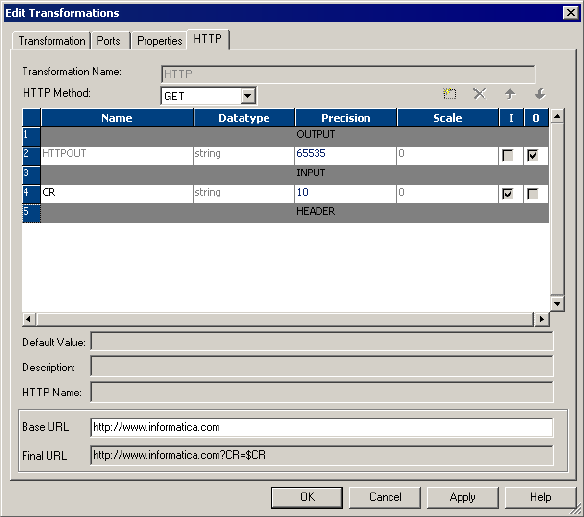
The following figure shows the HTTP tab of the HTTP transformation for the GET example:
The Designer appends a question mark (?), the input group input port name, a dollar sign ($), and the input
group input port name again to the base URL to construct the final URL:
http://www.informatica.com?CR=$CR
The Integration Service sends the source file values to the CR input port of the HTTP transformation and
sends the following HTTP requests to the HTTP server:
http://www.informatica.com?CR=78576
http://www.informatica.com?CR=78577
http://www.informatica.com?CR=78578
The HTTP server sends an HTTP response back to the Integration Service, which sends the data through the
output port of the HTTP transformation to the target.
POST Example
The source file used with this example contains the following data:
33,44,1
44,55,2
100,66,0
180 Chapter 10: HTTP Transformation
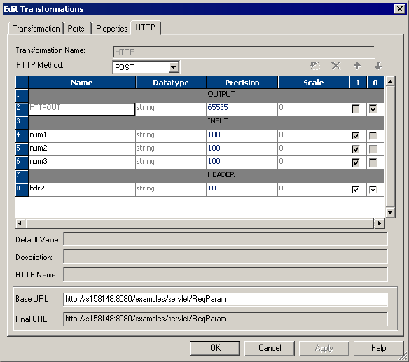
The following figure shows that each field in the source file has a corresponding input port:
The Integration Service sends the values of the three fields for each row through the input ports of the HTTP
transformation and sends the HTTP request to the HTTP server specified in the final URL.
SIMPLE POST Example
The following text shows the XML file used with this example:
<?xml version="1.0" encoding="UTF-8"?>
<n4:Envelope xmlns:cli="http://localhost:8080/axis/Clienttest1.jws" xmlns:n4="http://
schemas.xmlsoap.org/soap/envelope/" xmlns:tns="http://schemas.xmlsoap.org/soap/
encoding/" xmlns:xsi="http://www.w3.org/2001/XMLSchema-instance/" xmlns:xsd="http://
www.w3.org/2001/XMLSchema">
<n4:Header>
</n4:Header>
<n4:Body n4:encodingStyle="http://schemas.xmlsoap.org/soap/encoding/"><cli:smplsource>
<Metadatainfo xsi:type="xsd:string">smplsourceRequest.Metadatainfo106</Metadatainfo></
cli:smplsource>
</n4:Body>
<n4:Envelope>,capeconnect:Clienttest1services:Clienttest1#smplsource
Examples 181

The following figure shows the HTTP tab of the HTTP transformation for the SIMPLE POST example:
The Integration Service sends the body of the source file through the input port and sends the HTTP request
to the HTTP server specified in the final URL.
182 Chapter 10: HTTP Transformation

CHAPTER 1 1
Identity Resolution
Transformation
This chapter includes the following topics:
•Identity Resolution Transformation Overview, 183
•Create and Configure the Transformation, 183
•Identity Resolution Transformation Tabs , 186
•Groups and Ports, 186
Identity Resolution Transformation Overview
The Identity Resolution transformation is an active transformation that you can use to search and match data
in Informatica Identity Resolution (IIR). The PowerCenter Integration Service uses the search definition that
you specify in the Identity Resolution transformation to search and match data residing in the IIR tables. The
input and output views in the system determine the input and output ports of the transformation.
Configure match tolerance and search width parameters in the Identity Resolution transformation to set the
matching scheme and search level. When you run a session, IIR returns the candidate records to the Identity
Resolution transformation.
IIR provides online and batch searching, matching, screening, linking and duplicate discovery for all types of
identification data stored in Oracle, DB2/UDB, and Microsoft SQL Server tables. IIR uses the IIR Search
Server perform to search and match operations.
Create and Configure the Transformation
Create an Identity Resolution transformation in the Transformation Developer. When you create an Identity
Resolution transformation, you first connect to the Informatica Identity Resolution Search Server. The Search
Server provides access to the IIR tables.
After you connect, you configure the system and the search and match parameters. Configure the following
information in the Configure IR Transformation window:
•IR Search Server connection
•System and search configuration
183

•Input and output views
Search Server Connection
To connect to the Search Server you provide a host name and port number. Then, you configure the
Rulebase connection string. The Rulebase contains information about systems that IIR uses to search and
match data. The Rulebase connection in an Identity Resolution transformation specifies the database that
contains the Rulebase.
Note: You cannot change the host name or Rulebase connection after you create the transformation.
IR Hostname
Host name of the machine where the Informatica Identity Resolution Server runs. The IIR Server must be
version 9.0.1 SP1 or higher.
Port
Port number of the Search Server.
Rulebase Connection String
Connection string to the Search Server. You can specify the Rulebase connection as ODBC or SSA.
Configure ODBC and SSA in the IIR host.
ODBC
The following table describes the ODBC connection information:
Connection Property Description
Rulebase Number The number designated for the IR Rulebase.
User Name Database user name.
Password Password for the database user name.
Service Name Service name defined in the odbc.ini file.
SSA
To connect through SSA, you need to provide the alias. The alias hides the connection string from
application programs. IIR uses aliases for Rulebases, databases, and source names.
System and Search Configuration
After you connect to the Search Server, you choose the system and search and match parameters.
You can change these parameters on the IR Settings tab after you create the transformation.
System
Choose the system in the Rulebase. A system is the highest level logical definition in an IIR Rulebase.
Search Definition
Choose the search definition that contains the rules for the system. The search definition resides in a system
and contains the rules to search, match, and display records.
184 Chapter 11: Identity Resolution Transformation

Search Width
Choose the search width that determines the scope of the search that you want to conduct.
The following table describes the search widths that you can choose:
Search Width Description
Narrow Provides a narrow search with a quick response time. Use this option when you have a
low risk associated with missing a match, when you do not require a high match accuracy,
or when the data volume is large and response time is critical.
Typical Provides a balance between quality and response time. Use this option for online or batch
transaction searches. Default is typical.
Exhaustive Provides a detailed search with an extended response time. Use this option when you
have a high risk associated with missing a match, when data quality is a concern, or when
the data volume is low and response time is not critical.
Match Tolerance
Choose the match tolerance that determines how aggressive the matching scheme is to select candidate
records.
The following table describes the match tolerance options that you can choose:
Match Tolerance Description
Extreme Delivers a candidate match with a set of possible methods for processing. Response time
for processing is more. Use this option when you need to find a match even it contains
errors and variation.
Conservative Delivers matches that are not excessive or extreme. Use for online or batch transaction
searches.
Typical Delivers close matches. Use in batch systems when you need an accurate match.
Loose Delivers matches with a higher degree of variation than the typical level. Use in systems
where the risk of missing a match is high and when you can review results.
View Selection
After you select the system and search definition, you can choose the input view and output view.
Input View
The fields in the input view determine the transformation input ports. The input view contains the fields used
for search and match operations. If you do not choose an input view, the transformation uses the IIR Identity
Table (IDT) layout for the input view.
Note: If the system contains the XFORM clause in the view definition to concatenate multiple fields into one
field, you cannot use the view in the Identity Resolution transformation. However, you can concatenate
multiple fields outside the Identity Resolution transformation, and pass the concatenated string to the input
ports of the Identity Resolution transformation.
Create and Configure the Transformation 185

Output View
The fields in the output view determine the transformation output ports. The output view formats search
results returned by the Search Server. If you do not choose an output view, the transformation uses the IIR
Identity Table (IDT) layout for the output view.
Identity Resolution Transformation Tabs
The Identity Resolution transformation has the following tabs:
Transformation
Configure the transformation description.
Ports
View the groups and ports that represent input and output views. You cannot edits the groups and ports.
Properties
The following table describes the properties that you can configure on the Properties tab:
Transformation Attribute Description
Run-time Location Location that contains the DLL or shared library. Default is $PMExtProcDir.
Tracing Level Amount of detail displayed in the session log for this transformation. Default
is Normal.
Is Partitionable Indicates if you can create multiple partitions in a pipeline that uses this
transformation:
- No. The transformation cannot be partitioned. The transformation and the
other transformations in the same pipeline are limited to one partition.
- Locally. The transformation can be partitioned, but the Integration Service
must run all partitions in the pipeline on the same node. Choose Locally when
different partitions of the Custom transformation must share objects in
memory.
- Across Grid. The transformation can be partitioned, and the Integration
Service can distribute each partition to different nodes.
Default is Across Grid.
IR Settings
View the settings that you configured when you created the transformation. You can change the system
and search information.
Groups and Ports
An Identity Resolution transformation contains an input group and an output group. The input group has ports
that represent fields in the input view of the search definition. The output group has ports that represent fields
in the output view of the search definition in addition to ports that describe the result of the search.
You can view groups and ports on the Ports tab. You can also view ports on the IR Settings tab.
186 Chapter 11: Identity Resolution Transformation

Input Groups and Ports
An Identity Resolution transformation contains an input group with input ports. The number of ports in the
input group match the number of fields in the selected input view. Link all input ports required by the search
to the Identity Resolution transformation.
Output Groups and Ports
The output group contains output ports and an input/output port. The output group contains ports from the
output view in addition to default ports for each Identity Resolution transformation.
The output ports that are based on the output view contain candidate records from the Search Server.
The following table describes the default output ports:
Default Output Ports Description
IR_Search_Link Input/output search link port. Use this pass-through port to pass a link between the
source data on the input side and resultant output candidates.
IR_Score_Out Output port that contains the score from the search operation conducted by the
Search Server. Values are positive numbers from 0 through 100.
For example, if you search on name with the input "Rob," the results may contain
candidate records with name "Rob" that have a score of 100. The results may also
contain candidate records with name as "Bob" that have a score of 90. Informatica
Identity Resolution computes the score associated with the result.
IR_Result_Count Output port that contains the number of records.
Groups and Ports 187

CHAPTER 1 2
Java Transformation
This chapter includes the following topics:
•Java Transformation Overview, 188
•Using the Java Code Tab, 190
•Configuring Ports, 191
•Configuring Java Transformation Properties, 193
•Developing Java Code, 195
•Configuring Java Transformation Settings, 199
•Compiling a Java Transformation, 201
•Fixing Compilation Errors, 202
Java Transformation Overview
Extend PowerCenter functionality with the Java transformation. The Java transformation provides a simple
native programming interface to define transformation functionality with the Java programming language. You
can use the Java transformation to quickly define simple or moderately complex transformation functionality
without advanced knowledge of the Java programming language or an external Java development
environment. The Java transformation can be a passive or active transformation.
The PowerCenter Client uses the Java Development Kit (JDK) to compile the Java code and generate byte
code for the transformation. The PowerCenter Client stores the byte code in the PowerCenter repository.
The Integration Service uses the Java Runtime Environment (JRE) to execute generated byte code at run
time. When the Integration Service runs a session with a Java transformation, the Integration Service uses
the JRE to execute the byte code and process input rows and generate output rows.
Create Java transformations by writing Java code snippets that define transformation logic. Define
transformation behavior for a Java transformation based on the following events:
•The transformation receives an input row.
•The transformation has processed all input rows.
•The transformation receives a transaction notification such as commit or rollback.
RELATED TOPICS:
•“Java Transformation API Reference” on page 204
•“Java Expressions” on page 214
188
Steps to Define a Java Transformation
Complete the following steps to write and compile Java code and fix compilation errors in a Java
transformation:
1. Create the transformation in the Transformation Developer or Mapping Designer.
2. Configure input and output ports and groups for the transformation. Use port names as variables in Java
code snippets.
3. Configure the transformation properties.
4. Use the code entry tabs in the transformation to write and compile the Java code for the transformation.
5. Locate and fix compilation errors in the Java code for the transformation.
Active and Passive Java Transformations
When you create a Java transformation, you define its type as active or passive.
After you set the transformation type, you cannot change it.
A Java transformation runs the Java code that you define on the On Input Row tab one time for each row of
input data.
A Java transformation handles output rows based on the transformation type as follows:
•A passive Java transformation generates one output row for each input row in the transformation after
processing each input row.
•An active Java transformation generates multiple output rows for each input row in the transformation.
Use the generateRow method to generate each output row. For example, if the transformation contains
two input ports that represent a start date and an end date, you can use the generateRow method to
generate an output row for each date between the start date and the end date.
Datatype Conversion
A Java transformation converts PowerCenter datatypes to Java datatypes, based on the Java transformation
port type.
When a Java transformation reads input rows, it converts input port datatypes to Java datatypes.
When a Java transformation writes output rows, it converts Java datatypes to output port datatypes.
For example, the following processing occurs for an input port with the integer datatype in a Java
transformation:
1. The Java transformation converts the integer datatype of the input port to the Java primitive int datatype.
2. In the transformation, the transformation treats the value of the input port as the Java primitive int
datatype.
3. When the transformation generates the output row, it converts the Java primitive int datatype to the
integer datatype.
Java Transformation Overview 189

The following table shows how the Java transformation maps PowerCenter datatypes to Java primitive and
complex datatypes:
PowerCenter Datatype Java Datatype
Char String
Binary byte[]
Long (INT32) int
Double double
Decimal double
BigDecimal
BIGINT long
Date/Time BigDecimal
long (number of milliseconds since January 1, 1970 00:00:00.000
GMT)
In Java, the String, byte[], and BigDecimal datatypes are complex datatypes, and the double, int, and long
datatypes are primitive datatypes.
Note: The Java transformation sets null values in primitive datatypes to zero. You can use the isNull and the
setNull API methods on the On Input Row tab to set null values in the input port to null values in the output
port. For an example, see “setNull” on page 211.
Using the Java Code Tab
Use the Java Code tab to define, compile, and fix compilation errors in Java code. Create code snippets in
the code entry tabs.
When you define the java code, you can perform the following task:
•Define static code or a static block, instance variables, and user-defined methods.
•Define Java expressions, and define transformation logic.
•Use Java transformation API methods and standard Java language constructs.
•Import third-party Java APIs, built-in Java packages, or custom Java packages. You can use Java code
snippets from Java packages.
After you develop code snippets, you can compile the Java code and view the results of the compilation in
the Output window or view the full Java code.
190 Chapter 12: Java Transformation
The Java Code tab contains the following components:
•Navigator. Add input or output ports or APIs to a code snippet. The Navigator lists the input and output
ports for the transformation, the available Java transformation APIs, and a description of the port or API
function. For input and output ports, the description includes the port name, type, datatype, precision, and
scale. For API functions, the description includes the syntax and use of the API function.
The Navigator disables any port or API function that is unavailable for the code entry tab. For example,
you cannot add ports or call API functions from the Import Packages code entry tab.
•Code window. Develop Java code for the transformation. The code window uses basic Java syntax
highlighting.
•Code entry tabs. Define transformation behavior. Each code entry tab has an associated Code window.
To enter Java code for a code entry tab, click the tab and write Java code in the Code window.
•Define Expression link. Opens the Define Expression dialog box that you use to create Java
expressions.
•Settings link. Opens the Settings dialog box. Use the Settings dialog box to set the classpath for third-
party and custom Java packages, to enable high precision for Decimal datatypes, and to process
subsecond data. The PowerCenter Client includes files within the classpath when it compiles the java
code.
•Compile link. Compiles the Java code for the transformation. Output from the Java compiler, including
error and informational messages, appears in the Output window.
•Full Code link. Opens the Full Code window to display the complete class code for the Java
transformation. The complete code for the transformation includes the Java code from the code entry tabs
added to the Java transformation class template.
•Output window. Displays the compilation results for the Java transformation class. You can right-click an
error message in the Output window to locate the error in the snippet code or the full code for the Java
transformation class in the Full Code window. You can also double-click an error in the Output window to
locate the source of the error.
Configuring Ports
A Java transformation can have input ports, output ports, and input/output ports. You create and edit groups
and ports on the Ports tab. You can specify default values for ports. After you add ports to a transformation,
use the port names as variables in Java code snippets.
Creating Groups and Ports
When you create a Java transformation, it includes one input group and one output group.
A Java transformation always has one input group and one output group. The transformation is not valid if it
has multiple input or output groups. You can change the existing group names by typing in the group header.
If you delete a group, you can add a new group by clicking the Create Input Group or Create Output Group
icon.
When you create a port, the Designer adds it below the currently selected row or group. An input/output port
that appears below the input group it is also part of the output group. An input/output port that appears below
the output group it is also part of the input group.
Configuring Ports 191
Setting Default Port Values
You can define default values for ports in a Java transformation.
The Java transformation initializes port variables with the default port value based on the datatype of the port.
Input and Output Ports
The Java transformation initializes the value of unconnected input ports or output ports that do not have an
assigned value in the Java code snippets.
Java transformation initializes ports based on the following port datatypes:
Simple
If you define a default value for the port that is not equal to null, the transformation initializes the value of
the port variable to the default value. Otherwise, it initializes the value of the port variable to 0.
Complex
If you define a default value for the port, the transformation creates a new String or byte[] object, and
initializes the object to the default value. Otherwise, the transformation initializes the port variable to null.
Note: If you access an input port variable with a null value in the Java code, a NullPointerException
occurs.
You can enable an input port as a Partition key, Sort key, and assign a sort direction when you run mappings
in a Hive environment. The Data Integration Service ensures that the data is partitioned across the reducer
tasks in the Hadoop cluster and sorts the output by the sort key and sort direction. The Partition Key and Sort
Key are valid in a Hive environment when the transformation scope is set to All Input.
Use the following properties for partitioning and sorting data when you push the transformation to a Hive
environment:
Partition Key
Input port that determines the partition in which a particular row of data is stored. When you select
Partition key and Sort key, the Data Integration Service generates a sorted output.
Sort Key
Input port that determines the sort criteria. You must select Sort key and Partition key to ensure that data
is sorted.
Direction
Ascending or descending order. Default is ascending
Input/Output Ports
The Java transformation treats input/output ports as pass-through ports. If you do not set a value for the port
in the Java code for the transformation, the output value is the same as the input value. The Java
transformation initializes the value of an input/output port in the same it initializes an input port.
If you set the value of a port variable for an input/output port in the Java code, the Java transformation uses
this value when it generates an output row. If you do not set the value of an input/output port, the Java
transformation sets the value of the port variable to 0 for simple datatypes and NULL for complex datatypes
when it generates an output row.
192 Chapter 12: Java Transformation

Configuring Java Transformation Properties
The Java transformation includes properties for both the transformation code and the transformation. If you
create a Java transformation in the Transformation Developer, you can override the transformation properties
when you use it in a mapping.
The following table describes the Java transformation properties:
Property Description
Language Language used for the transformation code. You cannot change this value.
Class Name Name of the Java class for the transformation. You cannot change this value.
Tracing Level Amount of detail displayed in the session log for this transformation. Use the following
tracing levels:
- Terse
- Normal
- Verbose Initialization
- Verbose Data
Default is Normal.
Is Partitionable Multiple partitions in a pipeline can use this transformation. Use the following options:
- No. The transformation cannot be partitioned. The transformation and other
transformations in the same pipeline are limited to one partition. You might choose No if
the transformation processes all the input data together, such as data cleansing.
- Locally. The transformation can be partitioned, but the Integration Service must run all
partitions in the pipeline on the same node. Choose Locally when different partitions of
the transformation must share objects in memory.
- Across Grid. The transformation can be partitioned, and the Integration Service can
distribute each partition to different nodes.
Default is No.
Inputs Must Block The procedure associated with the transformation must be able to block incoming
data. Default is enabled.
Is Active The transformation can generate more than one output row for each input row.
You cannot change this property after you create the Java transformation. If you need
to change this property, create a new Java transformation.
Update Strategy
Transformation
The transformation defines the update strategy for output rows. You can enable this
property for active Java transformations.
Default is disabled.
Transformation Scope The method in which the Integration Service applies the transformation logic to
incoming data. Use the following options:
- Row
- Transaction
- All Input
This property is always Row for passive transformations. Default is All Input for active
transformations.
Configuring Java Transformation Properties 193

Property Description
Generate Transaction The transformation generates transaction rows. You can enable this property for
active Java transformations.
Default is disabled.
Output Is Repeatable The order of the output data is consistent between session runs.
- Never. The order of the output data is inconsistent between session runs.
- Based On Input Order. The output order is consistent between session runs when the
input data order is consistent between session runs.
- Always. The order of the output data is consistent between session runs even if the order
of the input data is inconsistent between session runs.
Default is Never for active transformations. Default is Based On Input Order for
passive transformations.
Requires Single Thread
Per Partition
A single thread processes the data for each partition.
You cannot change this value.
Output Is Deterministic The transformation generates consistent output data between session runs. Enable
this property to perform recovery on sessions that use this transformation.
Default is enabled.
Warning: If you configure a transformation as repeatable and deterministic, it is your responsibility to ensure
that the data is repeatable and deterministic. If you try to recover a session with transformations that do not
produce the same data between the session and the recovery, the recovery process can result in corrupted
data.
Working with Transaction Control
You can define transaction control for a Java transformation using the following properties:
•Transformation Scope. Determines how the Integration Service applies the transformation logic to
incoming data.
•Generate Transaction. Indicates that the Java code for the transformation generates transaction rows
and passes them to the output group.
Transformation Scope
You can configure how the Integration Service applies the transformation logic to incoming data. You can
choose one of the following values:
•Row. Applies the transformation logic to one row of data at a time. Choose Row when the results of the
transformation depend on a single row of data. You must choose Row for passive transformations.
•Transaction. Applies the transformation logic to all rows in a transaction. Choose Transaction when the
results of the transformation depend on all rows in the same transaction, but not on rows in other
transactions. For example, you might choose Transaction when the Java code performs aggregate
calculations on the data in a single transaction.
•All Input. Applies the transformation logic to all incoming data. When you choose All Input, the Integration
Service drops transaction boundaries. Choose All Input when the results of the transformation depend on
all rows of data in the source. For example, you might choose All Input when the Java code for the
transformation sorts all incoming data.
194 Chapter 12: Java Transformation

Generate Transaction
You can define Java code in an active Java transformation to generate transaction rows, such as commit and
rollback rows. To generate transaction rows, enable the transformation to generate transaction rows.
When you configure the transformation to generate transaction rows, the Integration Service treats the Java
transformation like a Transaction Control transformation. Most rules that apply to a Transaction Control
transformation in a mapping also apply to the Java transformation. For example, when you configure a Java
transformation to generate transaction rows, you cannot concatenate pipelines or pipeline branches
containing the transformation.
When you edit or create a session using a Java transformation configured to generate transaction rows,
configure it for user-defined commit.
RELATED TOPICS:
•“commit” on page 205
•“rollBack” on page 210
Setting the Update Strategy
Use an active Java transformation to set the update strategy for a mapping. You can set the update strategy
at the following levels:
•Within the Java code. You can write the Java code to set the update strategy for output rows. The Java
code can flag rows for insert, update, delete, or reject. For more about setting the update strategy, see
“setOutRowType” on page 211.
•Within the mapping. Use the Java transformation in a mapping to flag rows for insert, update, delete, or
reject. Select the Update Strategy Transformation property for the Java transformation.
•Within the session. Configure the session to treat the source rows as data driven.
If you do not configure the Java transformation to define the update strategy, or you do not configure the
session as data driven, the Integration Service does not use the Java code to flag the output rows. Instead,
the Integration Service flags the output rows as insert.
Developing Java Code
Use the code entry tabs to enter Java code snippets that define Java transformation functionality. You can
write Java code using the code entry tabs to import Java packages, write helper code, define Java
expressions, and write Java code that defines transformation behavior for specific transformation events. You
can develop snippets in the code entry tabs in any order.
Enter Java code in the following code entry tabs:
•Import Packages. Import third-party Java packages, built-in Java packages, or custom Java packages.
•Helper Code. Define variables and methods available to all tabs except Import Packages.
•On Input Row. Define transformation behavior when it receives an input row.
•On End of Data. Define transformation behavior when it has processed all input data.
•On Receiving Transaction. Define transformation behavior when it receives a transaction notification.
Use with active Java transformations.
•Java Expressions. Define Java expressions to call PowerCenter expressions. You can use Java
expressions in the Helper Code, On Input Row, On End of Data, and On Transaction code entry tabs.
Developing Java Code 195

Access input data and set output data on the On Input Row tab. For active transformations, you can also set
output data on the On End of Data and On Receiving Transaction tabs.
Creating Java Code Snippets
To create Java code snippets to define transformation behavior, use the Code window on the Java Code tab.
1. Click the appropriate code entry tab.
2. To access input or output column variables in the snippet, double-click the name of the port in the
navigator.
3. To call a Java transformation API in the snippet, double-click the name of the API in the navigator. If
necessary, configure the appropriate API input values.
4. Write appropriate Java code, based on the code snippet.
View the full class code for the Java transformation in the Full Code windows.
Importing Java Packages
On the Import Package tab, you can import Java packages for active or passive Java transformations.
You can import third-party, built-in, or custom Java packages. After you import Java packages, you can use
the imported packages on the other code entry tabs.
Note: On the Import Packages tab, you cannot declare or use static variables, instance variables, or user
methods.
In the PowerCenter Client, when you export or import metadata that contains a Java transformation, the jar or
class files that contain the third-party or custom packages required by the Java transformation are not
included in the export or import.
If you import metadata that contains a Java transformation, you must copy the jar or class files that contain
the required third-party or custom packages to the PowerCenter Client and Integration Service node.
For example, to import the Java I/O package, enter the following code on the Import Packages tab:
import java.io.*;
When you import non-standard Java packages, add the package or class to the classpath in the Java
transformation settings.
RELATED TOPICS:
•“Configuring Java Transformation Settings” on page 199
Defining Helper Code
On the Helper Code tab, you can declare user-defined variables and methods for the Java transformation
class in active or passive Java transformations.
After you declare variables and methods on the Helper Code tab, you can use the variables and methods on
any code entry tab except the Import Packages tab.
On the Helper Code tab, you can declare the following types of code, variables, and methods:
•Static code and static variables.
196 Chapter 12: Java Transformation
Within a static block, you can declare static variables and static code. All instances of a reusable Java
transformation in a mapping and all partitions in a session share static code and variables. Static code
runs before any other code in a Java transformation.
For example, the following code declares a static variable to store the error threshold for all instances of a
Java transformation in a mapping:
static int errorThreshold;
Use this variable to store the error threshold for the transformation and access it from all instances of the
Java transformation in a mapping and from any partition in a session.
Note: You must synchronize static variables in a multiple partition session or in a reusable Java
transformation.
•Instance variables.
You can declare partition-level instance variables. Multiple instances of a reusable Java transformation in
a mapping or multiple partitions in a session do not share instance variables. Declare instance variables
with a prefix to avoid conflicts and initialize non-primitive instance variables.
For example, the following code uses a boolean variable to decide whether to generate an output row:
// boolean to decide whether to generate an output row
// based on validity of input
private boolean generateRow;
•User-defined static or instance methods.
Extends the functionality of the Java transformation. Java methods declared on the Helper Code tab can
use or modify output variables or locally declared instance variables. You cannot access input variables
from Java methods on the Helper Code tab.
For example, use the following code on the tab to declare a function that adds two integers:
private int myTXAdd (int num1,int num2)
{
return num1+num2;
}
On Input Row Tab
Use the On Input Row tab to define the behavior of the Java transformation when it receives an input row.
The Java code in this tab executes one time for each input row. You can access input row data in the On
Input Row tab only.
Access and use the following input and output port data, variables, and methods from the On Input Row tab:
•Input port and output port variables. Access input and output port data as a variable by using the name
of the port as the name of the variable. For example, if “in_int” is an Integer input port, you can access the
data for this port by referring as a variable “in_int” with the Java primitive datatype int. You do not need to
declare input and output ports as variables.
Do not assign a value to an input port variable. If you assign a value to an input variable in the On Input
Row tab, you cannot get the input data for the corresponding port in the current row.
•Instance variables and user-defined methods. Use any instance or static variable or user-defined
method you declared in the Helper Code tab.
For example, an active Java transformation has two input ports, BASE_SALARY and BONUSES, with an
integer datatype, and a single output port, TOTAL_COMP, with an integer datatype. You create a user-
defined method in the Helper Code tab, myTXAdd, that adds two integers and returns the result. Use the
Developing Java Code 197
following Java code in the On Input Row tab to assign the total values for the input ports to the output port
and generate an output row:
TOTAL_COMP = myTXAdd (BASE_SALARY,BONUSES);
generateRow();
When the Java transformation receives an input row, it adds the values of the BASE_SALARY and
BONUSES input ports, assigns the value to the TOTAL_COMP output port, and generates an output row.
•Java transformation API methods. You can call API methods provided by the Java transformation.
On End of Data Tab
Use the On End of Data tab in active or passive Java transformations to define the behavior of the Java
transformation when it has processed all input data. To generate output rows in the On End of Data tab, set
the transformation scope for the transformation to Transaction or All Input. You cannot access or set the
value of input port variables in this tab.
Access and use the following variables and methods from the On End of Data tab:
•Output port variables. Use the names of output ports as variables to access or set output data for active
Java transformations.
•Instance variables and user-defined methods. Use any instance variables or user-defined methods you
declared in the Helper Code tab.
•Java transformation API methods. Call API methods provided by the Java transformation. Use the
commit and rollBack API methods to generate a transaction.
For example, use the following Java code to write information to the session log when the end of data is
reached:
logInfo("Number of null rows for partition is: " + partCountNullRows);
On Receiving Transaction Tab
Use the On Receiving Transaction tab in active Java transformations to define the behavior of an active Java
transformation when it receives a transaction notification. The code snippet for the On Receiving Transaction
tab is only executed if the Transaction Scope for the transformation is set to Transaction. You cannot access
or set the value of input port variables in this tab.
Access and use the following output data, variables, and methods from the On Receiving Transaction tab:
•Output port variables. Use the names of output ports as variables to access or set output data.
•Instance variables and user-defined methods. Use any instance variables or user-defined methods you
declared in the Helper Code tab.
•Java transformation API methods. Call API methods provided by the Java transformation. Use the
commit and rollBack API methods to generate a transaction. For example, use the following Java code to
generate a transaction after the transformation receives a transaction:
commit();
Using Java Code to Parse a Flat File
You can develop Java code to parse a flat file. Use Java code to extract specific columns of data from a flat
file of varying schema or a JMS message.
For example, you want to read the first two columns of data from a delimited flat file. Create a mapping that
reads data from a delimited flat file and passes data to one or more output ports.
198 Chapter 12: Java Transformation
The mapping contains the following components:
•Source definition. The source is a delimited flat file. Configure the source to pass rows of a flat file as a
string to the Java transformation. The source file has the following data:
1a,2a,3a,4a,5a,6a,7a,8a,9a,10a
1b,2b,3b,4b,5b,6b,7b,8b,9b
1c,2c,3c,4c,5c,6c,7c
1d,2d,3d,4d,5d,6d,7d,8d,9d,10d
•Java transformation. Define the Java transformation functionality on the Java Code tab.
Use the Import Packages tab of the Java Code to import the java package. Enter the following code on
the Import Packages tab:
import java.util.StringTokenizer;
Use the On Input Row tab of the Java Code tab to read each row of data from a string and pass the data
to output ports. Enter the following code on the On Input Row tab to retrieve the first two columns of data:
StringTokenizer st1 = new StringTokenizer(row,",");
f1 = st1.nextToken();
f11= st1.nextToken();
•Target definition. Configure the target to receive rows of data from the Java Transformation. After you
run a workflow that contains the mapping, the target contains two columns of data. The target file has the
following data:
1a,2a
1b,2b
1c,2c
1d,2d
Configuring Java Transformation Settings
You can configure Java transformation settings to set the classpath for third-party and custom Java packages
and to enable high precision for Decimal datatypes. You also can configure the transformation to process
subseconds data.
Configuring the Classpath
When you import non-standard Java packages in the Import package tab, set the classpath for the
PowerCenter Client and the Integration Service to each JAR file or class file directory associated with the
Java package. On UNIX, use a colon to separate classpath entries. On Windows, use a semicolon to
separate classpath entries. The JAR or class files must be accessible on the PowerCenter Client and the
Integration Service node.
For example, you import the Java package
converter
in the Import Packages tab and define the package in
converter.jar. You must add converter.jar to the classpath before you compile the Java code for the Java
transformation.
You do not need to set the classpath for built-in Java packages. For example, java.io is a built-in Java
package. If you import java.io, you do not need to set the classpath for java.io.
Configuring Java Transformation Settings 199
Configuring the Classpath for the Integration Service
You can add JAR files or class file directories to the Integration Service classpath. To set the classpath on
the Integration Service node, complete one of the following tasks:
•Configure the Java Classpath session property. Set the classpath using the Java Classpath session
property. This classpath applies to the session.
•Configure the Java SDK Classpath. Configure the Java SDK Classpath on the Processes tab of the
Integration Service properties in the Informatica Administrator. This setting applies to all sessions run on
the Integration Service.
•Configure the CLASSPATH environment variable. Set the CLASSPATH environment variable on the
Integration Service node. Restart the Integration Service after you set the environment variable. This
applies to all sessions run on the Integration Service.
Configuring the Classpath for the Integration Service on UNIX
To configure the CLASSPATH environment variable on UNIX:
uIn a UNIX C shell environment, type:
setenv CLASSPATH <classpath>
In a UNIX Bourne shell environment, type:
CLASSPATH = <classpath>
export CLASSPATH
Configuring the Classpath for the Integration Service on Windows
To configure the CLASSPATH environment variable on Windows:
uEnter the environment variable CLASSPATH, and set the value to the default classpath.
Configuring the Classpath for the PowerCenter Client
You can add jar files or class file directories to the PowerCenter Client classpath.
To set the classpath for the machine where the PowerCenter Client client runs, complete one of the following
tasks:
•Configure the CLASSPATH environment variable. Set the CLASSPATH environment variable on the
PowerCenter Client client machine. This applies to all java processes run on the machine.
•Configure the the classpath in the Java transformation settings. This applies to sessions that include this
Java transformation. The PowerCenter Client client includes files within the classpath when it compiles
the java code.
To add jar or class file directories to the classpath in a Java transformation, complete the following steps:
1. On the Java Code tab, click the Settings linkclick the down arrow icon in the Value column next to
Classpath.
The Settings dialog box appears.
2. Click Browse under Add Classpath to select the jar file or class file directory for the imported package.
Click OK.
3. Click Add.
The jar or class file directory appears in the list of jar and class file directories for the transformation.
4. To remove a jar file or class file directory, select the jar or class file directory and click Remove.
The directory disappears from the list of directories.
200 Chapter 12: Java Transformation
Enabling High Precision
By default, the Java transformation converts ports of type Decimal to double datatypes with a precision of 15.
If you want to process a Decimal datatype with a precision greater than 15, enable high precision to process
decimal ports with the Java class BigDecimal.
When you enable high precision, you can process Decimal ports with precision less than 28 as BigDecimal.
The Java transformation converts decimal data with a precision greater than 28 to the Double datatype. Java
transformation expressions process binary, integer, double, and string data. Java transformation expressions
cannot process bigint data.
For example, a Java transformation has an input port of type Decimal that receives a value of
40012030304957666903. If you enable high precision, the value of the port is treated as it appears. If you do
not enable high precision, the value of the port is 4.00120303049577 x 10^19.
Note: If you enable high precision for a Java transformation, also enable high precision for the session that
includes the Java transformation. If high precision is enabled in the Java Transformation and it is not enabled
in the session, the session may fail with the following error:
[ERROR]Failed to bind column with index <index number> to datatype <datatype name>.
Processing Subseconds
You can process subsecond data up to nanoseconds in the Java code. When you configure the settings to
use nanoseconds in datetime values, the generated Java code converts the transformation Date/Time
datatype to the Java BigDecimal datatype, which has precision to the nanosecond.
By default, the generated Java code converts the transformation Date/Time datatype to the Java Long
datatype, which has precision to the millisecond.
Compiling a Java Transformation
The PowerCenter Client uses the Java compiler to compile the Java code and generate the byte code for the
transformation.
The Java compiler compiles the Java code and displays the results of the compilation in the Output window
on the code entry tabs. The Java compiler installs with the PowerCenter Client in the
java/bin
directory.
To compile the full code for the Java transformation, click Compile on the Java Code tab.
When you create a Java transformation, it contains a Java class that defines the base functionality for a Java
transformation. The full code for the Java class contains the template class code for the transformation, plus
the Java code you define on the code entry tabs.
When you compile a Java transformation, the PowerCenter Client adds the code from the code entry tabs to
the template class for the transformation to generate the full class code for the transformation. The
PowerCenter Client then calls the Java compiler to compile the full class code. The Java compiler compiles
the transformation and generates the byte code for the transformation.
The results of the compilation display in the Output window. Use the results of the compilation to identify and
locate Java code errors.
Note: The Java transformation is also compiled when you click OK in the transformation.
Compiling a Java Transformation 201
Fixing Compilation Errors
You can identify Java code errors and locate the source of Java code errors for a Java transformation in the
Output window. Java transformation errors may occur as a result of an error in a code entry tab or may occur
as a result of an error in the full code for the Java transformation class.
To troubleshoot a Java transformation:
•Locate the source of the error. You can locate the source of the error in the Java snippet code or in the
full class code for the transformation.
•Identify the type of error. Use the results of the compilation in the output window and the location of the
error to identify the type of error.
After you identify the source and type of error, fix the Java code in the code entry tab and compile the
transformation again.
Locating the Source of Compilation Errors
When you compile a Java transformation, the Output window displays the results of the compilation. Use the
results of the compilation to identify compilation errors. When you use the Output window to locate the source
of an error, the PowerCenter Client highlights the source of the error in a code entry tab or in the Full Code
window.
You can locate errors in the Full Code window, but you cannot edit Java code in the Full Code window. To fix
errors that you locate in the Full Code window, modify the code in the appropriate code entry tab. You might
need to use the Full Code window to view errors caused by adding user code to the full class code for the
transformation.
Use the results of the compilation in the Output window to identify errors in the following locations:
•Code entry tabs
•Full Code window
Locating Errors in the Code Entry Tabs
To locate the source of an error in the code entry tabs, right-click on the error in the Output window and
choose View error in snippet or double-click on the error in the Output window. The PowerCenter Client
highlights the source of the error in the appropriate code entry tab.
Locating Errors in the Full Code Window
To locate the source of errors in the Full Code window, right-click on the error in the Output window and
choose View error in full code or double-click the error in the Output window. The PowerCenter Client
highlights the source of the error in the Full Code window.
Identifying the Source of Compilation Errors
Compilation errors can appear as a result of errors in the user code.
Errors in the user code might also generate an error in the non-user code for the class. Compilation errors
occur in user and non-user code for the Java transformation.
202 Chapter 12: Java Transformation
User Code Errors
Errors can occur in the user code on the code entry tabs. User code errors include standard Java syntax and
language errors.
User code errors might also occur when the PowerCenter Client adds the user code from the code entry tabs
to the full class code.
For example, a Java transformation has an input port with a name of int1 and an integer datatype. The full
code for the class declares the input port variable with the following code:
int int1;
However, if you use the same variable name on the On Input Row tab, the Java compiler issues an error for
a redeclaration of a variable. To fix the error, rename the variable on the On Input Row tab.
Non-User Code Errors
User code on the code entry tabs can cause errors in non-user code.
For example, a Java transformation has an input port and an output port, int1 and out1, with integer
datatypes. You write the following code in the On Input Row code entry tab to calculate interest for input port
int1 and assign it to the output port out1:
int interest;
interest = CallInterest(int1); // calculate interest
out1 = int1 + interest;
}
When you compile the transformation, the PowerCenter Client adds the code from the On Input Row code
entry tab to the full class code for the transformation. When the Java compiler compiles the Java code, the
unmatched brace causes a method in the full class code to end prematurely, and the Java compiler issues an
error.
Fixing Compilation Errors 203

CHAPTER 1 3
Java Transformation API
Reference
This chapter includes the following topics:
•Java Transformation API Methods Overview, 204
•commit, 205
•failSession, 206
•generateRow, 206
•getInRowType, 207
•getMetadata, 207
•incrementErrorCount, 208
•isNull, 209
•logError, 209
•logInfo, 210
•rollBack, 210
•setNull, 211
•setOutRowType, 211
•storeMetadata, 212
Java Transformation API Methods Overview
On the Java Code tab of a Java transformation, you can add API methods to the Java code to define
transformation behavior.
To add an API method to the code, expand the Callable APIs list in the navigator on the code entry tab, and
then double-click the name of the method that you want to add to the code.
Alternatively, you can drag the method from the navigator into the Java code snippet or manually enter the
API method in the Java code snippet.
You can add the following API methods to the Java code in a Java transformation:
commit
Generates a transaction.
204
failSession
Throws an exception with an error message and fails the session.
generateRow
Generates an output row for active Java transformations.
getInRowType
Returns the input type of the current row in the transformation.
incrementErrorCount
Increments the error count for the session.
isNull
Checks for a null value in an input column.
logError
Writes an error message to thesession log.
logInfo
Writes an informational message to thesession log.
rollback
Generates a rollback transaction.
setNull
Sets the value of an output column in an active or passive Java transformation to null.
setOutRowType
Sets the update strategy for output rows. Can flag rows for insert, update, or delete.
commit
Generates a transaction.
Use commit in any tab except the Import Packages or Java Expressions code entry tabs. You can only use
commit in active transformations configured to generate transactions. If you use commit in an active
transformation not configured to generate transactions, the Integration Service throws an error and fails the
session.
Use the following syntax:
commit();
Use the following Java code to generate a transaction for every 100 rows processed by a Java transformation
and then set the rowsProcessed counter to 0:
if (rowsProcessed==100) {
commit();
rowsProcessed=0;
}
commit 205

failSession
Throws an exception with an error message and fails the session.
Use the following syntax:
failSession(String errorMessage);
The following table describes the parameter:
Parameter Parameter
Type
Datatyp
e
Description
errorMessage Input String Error message string.
Use the failSession method to end the session. Do not use the failSession method in a try/catch block on a
code entry tab.
You can add the failSession method to the Java code on any code entry tab except the Import Packages
and Java Expressions tabs.
The following Java code shows how to test the input1 input port for a null value and fail the session if it is
null:
if(isNull(”input1”)) {
failSession(“Cannot process a null value for port input1.”);
}
generateRow
Generates an output row for active Java transformations.
Use the following syntax:
generateRow();
When you call the generateRow method, the Java transformation generates an output row using the current
value of the output port variables. If you want to generate multiple rows corresponding to an input row, you
can call the generateRow method more than once for each input row. If you do not use the generateRow
method in an active Java transformation, the transformation does not generate output rows.
You can add the generateRow method to the Java code on any code entry tab except the Import Packages
and Java Expressions tabs.
You can call the generateRow method in active transformations only. If you call the generateRow method in a
passive transformation, the session generates an error.
Use the following Java code to generate one output row, modify the values of the output ports, and generate
another output row:
// Generate multiple rows.
if(!isNull("input1") && !isNull("input2"))
{
output1 = input1 + input2;
output2 = input1 - input2;
}
generateRow();
// Generate another row with modified values.
output1 = output1 * 2;
206 Chapter 13: Java Transformation API Reference

output2 = output2 * 2;
generateRow();
getInRowType
Returns the input type of the current row in the transformation. The method returns a value of insert, update,
delete, or reject.
Use the following syntax:
rowType getInRowType();
The following table describes the parameter:
Parameter Parameter
Type
Datatyp
e
Description
rowType Output String Returns the update strategy type, which is one of the
following values:
- DELETE
- INSERT
- REJECT
- UPDATE
You can add the getInRowType method to the Java code on the On Input Row code entry tab.
You can use the getInRowType method in active transformations configured to set the update strategy. If you
call this method in an active transformation that is not configured to set the update strategy, the session
generates an error.
Use the following Java code to complete the following actions:
•Propagate the current input row type to the output row.
•If the value of the input1 input port is greater than 100, set the output row type to DELETE.
// Set the value of the output port.
output1 = input1;
// Get and set the row type.
String rowType = getInRowType();
setOutRowType(rowType);
// Set row type to DELETE if the output port value is > 100.
if(input1 > 100
setOutRowType(DELETE);
getMetadata
Retrieves Java transformation metadata at runtime. The getMetadata method retrieves metadata that you
save with the storeMetadata method, such as a filter condition that the optimizer passes to the Java
transformation in the pushFilter function.
Use the following syntax:
getMetadata (String key);
getInRowType 207

The following table describes the parameters:
Parameter Parameter
Type
Datatyp
e
Description
key Input String Identifies the metadata. The getMetadata method uses the
key to determine which metadata to retrieve.
You can add the getMetadata method to the Java code on the following code entry tabs:
•Helper
•On Input
•At End
•Optimizer Interfaces
•Functions
You can configure the getMetadata method to retrieve filter conditions for push-into optimization. The
getMetadata method can retrieve each filter condition that you store from the optimizer.
// Retrieve a filter condition
String mydata = getMetadata ("FilterKey");
incrementErrorCount
Increments the error count for the session. If the error count reaches the error threshold for the session, the
session fails.
Use the following syntax:
incrementErrorCount(int nErrors);
The following table describes the parameter:
Parameter Parameter
Type
Datatype Description
nErrors Input Integer Number by which to increment the error count for the
session.
You can add the incrementErrorCount method to the Java code on any code entry tab except the Import
Packages and Java Expressions tabs.
The following Java code shows how to increment the error count if an input port for a transformation has a
null value:
// Check if input employee id and name is null.
if (isNull ("EMP_ID_INP") || isNull ("EMP_NAME_INP"))
{
incrementErrorCount(1);
// if input employee id and/or name is null, don't generate a output row for this
input row
generateRow = false;
}
208 Chapter 13: Java Transformation API Reference

isNull
Checks the value of an input column for a null value.
Use the following syntax:
Boolean isNull(String satrColName);
The following table describes the parameter:
Parameters Parameter
Type
Datatype Description
strColName Input String Name of an input column.
You can add the isNull method to the Java code on the On Input Row code entry tab.
The following Java code shows how to check whether the value of the SALARY input column is null before
adding it to the totalSalaries instance variable:
// if value of SALARY is not null
if (!isNull("SALARY")) {
// add to totalSalaries
TOTAL_SALARIES += SALARY;
}
Alternatively, use the following Java code to achieve the same results:
// if value of SALARY is not null
String strColName = "SALARY";
if (!isNull(strColName)) {
// add to totalSalaries
TOTAL_SALARIES += SALARY;
}
logError
Writes an error message to the session log.
Use the following syntax:
logError(String msg);
The following table describes the parameter:
Parameter Parameter
Type
Datatype Description
msg Input String Error message string.
You can add the logError method to the Java code on any code entry tab except the Import Packages and
Java Expressions tabs.
The following Java code shows how to log an error when the input port is null:
// check BASE_SALARY
if (isNull("BASE_SALARY")) {
logError("Cannot process a null salary field.");
}
isNull 209

When the code runs, the following message appears in the session log:
[JTX_1013] [ERROR] Cannot process a null salary field.
logInfo
Writes an informational message to the session log.
Use the following syntax:
logInfo(String msg);
The following table describes the parameter:
Parameter Parameter
Type
Datatype Description
msg Input String Information message string.
You can add the logInfo method to the Java code on any code entry tab except the Import Packages and
Java Expressions tabs.
The following Java code shows how to write a message to the session log after the Java transformation
processes a message threshold of 1000 rows:
if (numRowsProcessed == messageThreshold) {
logInfo("Processed " + messageThreshold + " rows.");
}
rollBack
Generates a rollback transaction.
Use rollBack in any tab except the Import Packages or Java Expressions code entry tabs. You can only use
rollback in active transformations configured to generate transactions. If you use rollback in an active
transformation not configured to generate transactions, the Integration Service generates an error and fails
the session.
Use the following syntax:
rollBack();
Use the following code to generate a rollback transaction and fail the session if an input row has an illegal
condition or generate a transaction if the number of rows processed is 100:
// If row is not legal, rollback and fail session.
if (!isRowLegal()) {
rollback();
failSession(“Cannot process illegal row.”);
} else if (rowsProcessed==100) {
commit();
rowsProcessed=0;
}
210 Chapter 13: Java Transformation API Reference

setNull
Sets the value of an output column to null in an active or passive Java transformation.
Use the following syntax:
setNull(String strColName);
The following table describes the parameter:
Parameter Parameter Type Datatype Description
strColName Input String Name of an output column.
The setNull method sets the value of an output column in an active or passive Java transformation to null.
After you set an output column to null, you cannot modify the value until you generate an output row.
You can add the setNull method to the Java code on any code entry tab except the Import Packages and
Java Expressions tabs.
The following Java code shows how to check the value of an input column and set the corresponding value of
an output column to null:
// check value of Q3RESULTS input column
if(isNull("Q3RESULTS")) {
// set the value of output column to null
setNull("RESULTS");
}
Alternatively, you can use the following Java code achieve the same results:
// check value of Q3RESULTS input column
String strColName = "Q3RESULTS";
if(isNull(strColName)) {
// set the value of output column to null
setNull(strColName);
}
setOutRowType
Sets the update strategy for output rows. The setOutRowType method can flag rows for insert, update, or
delete.
You can only use setOutRowType in the On Input Row code entry tab. You can only use setOutRowType in
active transformations configured to set the update strategy. If you use setOutRowType in an active
transformation not configured to set the update strategy, the session generates an error and the session fails.
Use the following syntax:
setOutRowType(String rowType);
setNull 211

The following table describes the argument for this method:
Argument Datatype Input/
Output
Description
rowType String Input Update strategy type. Value can be INSERT, UPDATE,
or DELETE.
Use the following Java code to propagate the input type of the current row if the row type is UPDATE or
INSERT and the value of the input port input1 is less than 100 or set the output type as DELETE if the value
of input1 is greater than 100:
// Set the value of the output port.
output1 = input1;
// Get and set the row type.
String rowType = getInRowType();
setOutRowType(rowType);
// Set row type to DELETE if the output port value is > 100.
if(input1 > 100)
setOutRowType(DELETE);
storeMetadata
Stores Java transformation metadata that you can retrieve at runtime with the getMetadata method.
Use the following syntax:
storeMetadata (String key String data);
The following table describes the parameters:
Parameter Parameter
Type
Datatyp
e
Description
key Input String Identifies the metadata. The storeMetadata method requires
a key to identify the metadata. Define the key as any string.
data Input String The data that you want to store as Java transformation
metadata.
You can add the storeMetadata method to the Java code to the following code entry tabs:
•Helper
•On Input
•At End
•Optimizer Interfaces
•Functions
212 Chapter 13: Java Transformation API Reference
You can configure the storeMetadata method in an active transformation to accept filter conditions for push-
into optimization. The storeMetadata method stores a filter condition that the optimizer pushes from the
mapping to the Java transformation.
// Store a filter condition
storeMetadata ("FilterKey", condition);
storeMetadata 213

CHAPTER 1 4
Java Expressions
This chapter includes the following topics:
•Java Expressions Overview, 214
•Using the Define Expression Dialog Box to Define an Expression, 215
•Working with the Simple Interface, 217
•Working with the Advanced Interface, 218
•JExpression Class API Reference, 223
Java Expressions Overview
You can invoke PowerCenter expressions in a Java transformation with the Java programming language.
Use expressions to extend the functionality of a Java transformation. For example, you can invoke an
expression in a Java transformation to look up the values of input or output ports or look up the values of
Java transformation variables.
To invoke expressions in a Java transformation, you generate the Java code or use Java transformation API
methods to invoke the expression. You invoke the expression and use the result of the expression on the
appropriate code entry tab. You can generate the Java code that invokes an expression or use API methods
to write the Java code that invokes the expression.
The following table describes the methods that you can use to create and invoke expressions in a Java
transformation:
Method Description
Define Expression dialog box Enables you to create an expression and generate the code for an
expression.
Simple interface Enables you to call a single API method to invoke an expression and get
the result of the expression.
Advanced interface Enables you to define the expression, invoke the expression, and use the
result of the expression.
If you are familiar with object-oriented programming and want more control
over invoking the expression, use the advanced interface.
214

Expression Function Types
You can create expressions for a Java transformation by using the Expression Editor, by writing the
expression in the Define Expression dialog box, or by using the simple or advanced interface.
You can enter expressions that use input or output port variables or variables in the Java code as input
parameters.
If you use the Define Expression dialog box, you can use the Expression Editor to validate the expression
before you use it in a Java transformation.
You can invoke the following types of expression functions in a Java transformation:
Expression Function Type Description
Transformation language functions SQL-like functions designed to handle common expressions.
User-defined functions Functions that you create in PowerCenter based on transformation
language functions.
Custom functions Functions that you create with the Custom Function API.
You can also use unconnected transformations, built-in variables, user-defined mapping and workflow
variables, and pre-defined workflow variables in expressions. For example, you can use an unconnected
lookup transformation in an expression.
Using the Define Expression Dialog Box to Define an
Expression
When you define a Java expression, you configure the function, create the expression, and generate the
code that invokes the expression.
You can define the function and create the expression in the Define Expression dialog box.
To create an expression function and use the expression in a Java transformation, complete the following
high-level tasks:
1. Configure the function that invokes the expression, including the function name, description, and
parameters. You use the function parameters when you create the expression.
2. Create the expression syntax and validate the expression.
3. Generate the Java code that invokes the expression.
The Designer places the code on the Java Expressions code entry tab in the Transformation
Developer.
After you generate the Java code, call the generated function on the appropriate code entry tab to invoke an
expression or get a JExpression object, based on whether you use the simple or advanced interface.
Note: To validate an expression when you create the expression, you must use the Define Expression
dialog box.
Using the Define Expression Dialog Box to Define an Expression 215
Step 1. Configure the Function
You configure the function name, description, and input parameters for the Java function that invokes the
expression.
Use the following rules and guidelines when you configure the function:
•Use a unique function name that does not conflict with an existing Java function in the transformation or
reserved Java keywords.
•You must configure the parameter name, Java datatype, precision, and scale. The input parameters are
the values you pass when you call the function in the Java code for the transformation.
•To pass the Date datatype to an expression, use the String datatype for the input parameter.
If an expression returns the Date datatype, you can use the return value as the String datatype in the
simple interface and the String or long datatype in the advanced interface.
Step 2. Create and Validate the Expression
When you create the expression, use the parameters you configured for the function.
You can also use transformation language functions, custom functions, or other user-defined functions in the
expression. You can create and validate the expression in the Define Expression dialog box or in the
Expression Editor dialog box.
Step 3. Generate Java Code for the Expression
After you configure the function and function parameters and define and validate the expression, you can
generate the Java code that invokes the expression.
The Designer places the generated Java code on the Java Expressions code entry tab. Use the generated
Java code to call the functions that invoke the expression in the code entry tabs in the Transformation
Developer. You can generate the simple or advanced Java code.
After you generate the Java code that invokes an expression, you cannot edit the expression and revalidate
it. To modify an expression after you generate the code, you must create the expression again.
Creating an Expression and Generating Java Code by Using the
Define Expression Dialog Box
You can create a function that invokes an expression in the Define Expression dialog box.
Complete the following steps to create a function that invokes an expression:
1. In the Transformation Developer, open a Java transformation or create a new Java transformation.
2. On the Java Code tab, click the Define Expression link.
The Define Expression dialog box appears.
3. Enter a function name.
4. Optionally, enter a description for the expression.
Enter up to 2,000 characters.
5. Create the parameters for the function.
When you create the parameters, configure the parameter name, datatype, precision, and scale.
6. Click Launch Editor to create an expression with the parameters that you created.
7. To validate the expression, click Validate.
216 Chapter 14: Java Expressions
8. Optionally, enter the expression in the Expression box. Then, click Validate to validate the expression.
9. To generate Java code by using the advanced interface, select the Generate Advanced Code option.
Then, click Generate.
The Designer generates the function to invoke the expression on the Java Expressions code entry tab.
Java Expression Templates
You can generate Java code for an expression using the simple or advanced Java code for an expression.
The Java code for the expression is generated based on the template for the expression.
The following example shows the template for a Java expression generated for simple Java code:
Object function_name (Java datatype x1[,
Java datatype x2 ...] )
throws SDK Exception
{
return (Object)invokeJExpression( String expression,
new Object [] { x1[, x2, ... ]} );
}
The following example shows the template for a Java expression generated by using the advanced interface:
JExpression function_name () throws SDKException
{
JExprParamMetadata params[] = new JExprParamMetadata[number of parameters];
params[0] = new JExprParamMetadata (
EDataType.STRING, // data type
20, // precision
0 // scale
);
...
params[number of parameters - 1] = new JExprParamMetadata (
EDataType.STRING, // data type
20, // precision
0 // scale
);
...
return defineJExpression(String expression,params);
}
Working with the Simple Interface
Use the invokeJExpression Java API method to invoke an expression in the simple interface.
invokeJExpression
Invokes an expression and returns the value for the expression.
Use the following syntax:
(datatype)invokeJExpression(
String expression,
Object[] paramMetadataArray);
Input parameters for the invokeJExpression method are a string value that represents the expression and an
array of objects that contain the expression input parameters.
Working with the Simple Interface 217

The following table describes the parameters:
Parameter Parameter
Type
Datatype Description
expression Input String String that represents the expression.
paramMetadataArray Input Object[] Array of objects that contain the input parameters
for the expression.
You can add the invokeJExpression method to the Java code on any code entry tab except the Import
Packages and Java Expressions tabs.
Use the following rules and guidelines when you use the invokeJExpression method:
•Return datatype. The return datatype of the invokeJExpression method is an object. You must cast the
return value of the function with the appropriate datatype.
You can return values with Integer, Double, String, and byte[] datatypes.
•Row type. The row type for return values from the invokeJExpression method is INSERT.
To use a different row type for the return value, use the advanced interface.
•Null values. If you pass a null value as a parameter or the return value for the invokeJExpression method
is NULL, the value is treated as a null indicator.
For example, if the return value of an expression is NULL and the return datatype is String, a string is
returned with a value of null.
•Date datatype. You must convert input parameters with a Date datatype to the String datatype.
To use the string in an expression as a Date datatype, use the to_date() function to convert the string to a
Date datatype.
Also, you must cast the return type of any expression that returns a Date datatype as a String datatype.
Note: You must number the parameters that you pass to the expression consecutively, and start the
parameter with the letter x. For example, to pass three parameters to an expression, name the parameters
x1, x2, and x3.
Simple Interface Example
You can define and call expressions that use the invokeJExpression API method on the Helper Code and On
Input Row code entry tabs.
The following example shows how to complete a lookup on the NAME and ADDRESS input ports in a Java
transformation and assign the return value to the COMPANY_NAME output port.
Enter the following code on the On Input Row code entry tab:
COMPANY_NAME = (String)invokeJExpression(":lkp.my_lookup(X1,X2)", new Object []
{str1 ,str2} );
generateRow();
Working with the Advanced Interface
In the advanced interface, you can use object oriented API methods to define, invoke, and get the result of an
expression.
218 Chapter 14: Java Expressions

The following table describes the classes and API methods that are available in the advanced interface:
Class or API Method Description
EDataType class Enumerates the datatypes for an expression.
JExprParamMetadata class Contains the metadata for each parameter in an expression. Parameter
metadata includes datatype, precision, and scale.
defineJExpression API method Defines the expression. Includes PowerCenter expression string and
parameters.
invokeJExpression API method Invokes an expression.
JExpression class Contains the methods to create, invoke, get the metadata and get the
expression result, and check the return datatype.
Invoking an Expression with the Advanced Interface
You can define, invoke, and get the result of an expression by using the advanced interface.
1. On the Helper Code or On Input Row code entry tab, create an instance of JExprParamMetadata class
for each parameter for the expression and set the value of the metadata. Optionally, you can instantiate
the JExprParamMetadata object in the defineJExpression method.
2. Use the defineJExpression method to get the JExpression object for the expression.
3. On the appropriate code entry tab, invoke the expression with the invokeJExpression method.
4. Check the result of the return value with the isResultNull method.
5. You can get the datatype of the return value or the metadata of the return value with the
getResultDataType and getResultMetadata methods.
6. Get the result of the expression by using the appropriate API method. You can use the getInt, getDouble,
getStringBuffer, and getBytes methods.
Rules and Guidelines for Working with the Advanced Interface
When you work with the advanced interfaces, you must be aware of rules and guidelines.
Use the following rules and guidelines:
•If you pass a null value as a parameter or if the result of an expression is null, the value is treated as a
null indicator. For example, if the result of an expression is null and the return datatype is String, a string
is returned with a value of null. You can check the result of an expression by using the isResultNull
method.
•You must convert input parameters with a Date datatype to a String before you can use them in an
expression. To use the string in an expression as a Date datatype, use the to_date() function to convert
the string to a Date datatype.
You can get the result of an expression that returns a Date datatype as a String or long datatype.
To get the result of an expression that returns a Date datatype as a String datatype, use the
getStringBuffer method. To get the result of an expression that returns a Date datatype as a long
datatype, use the getLong method.
Working with the Advanced Interface 219
EDataType Class
Enumerates the Java datatypes used in expressions. Gets the return datatype of an expression or assign the
datatype for a parameter in a JExprParamMetadata object. You do not need to instantiate the EDataType
class.
The following table lists the enumerated values for Java datatypes in expressions:
Datatype Enumerated Value
INT 1
DOUBLE 2
STRING 3
BYTE_ARRAY 4
DATE_AS_LONG 5
The following example Java code shows how to use the EDataType class to assign a datatype of String to a
JExprParamMetadata object:
JExprParamMetadata params[] = new JExprParamMetadata[2];
params[0] = new JExprParamMetadata (
EDataType.STRING, // data type
20, // precision
0 // scale
);
...
JExprParamMetadata Class
Instantiates an object that represents the parameters for an expression and sets the metadata for the
parameters.
You use an array of JExprParamMetadata objects as input to the defineJExpression method to set the
metadata for the input parameters. You can create a instance of the JExprParamMetadata object on the Java
Expressions code entry tab or in defineJExpression.
Use the following syntax:
JExprParamMetadata paramMetadataArray[] = new JExprParamMetadata[numberOfParameters];
paramMetadataArray[0] = new JExprParamMetadata(datatype, precision, scale);
...
paramMetadataArray[numberofParameters - 1] = new JExprParamMetadata(datatype,
precision, scale);;
The following table describes the arguments:
Argument Argument Type Argument Datatype Description
datatype Input EDataType Datatype of the parameter.
precision Input Integer Precision of the parameter.
scale Input Integer Scale of the parameter.
220 Chapter 14: Java Expressions

For example, use the following Java code to instantiate an array of two JExprParamMetadata objects with
String datatypes, precision of 20, and scale of 0:
JExprParamMetadata params[] = new JExprParamMetadata[2];
params[0] = new JExprParamMetadata(EDataType.STRING, 20, 0);
params[1] = new JExprParamMetadata(EDataType.STRING, 20, 0);
return defineJExpression(":LKP.LKP_addresslookup(X1,X2)",params);
defineJExpression
Defines an expression, including the expression string and input parameters. Arguments for the
defineJExpression method include an array of JExprParamMetadata objects that contains the input
parameters and a string value that defines the expression syntax.
Use the following syntax:
defineJExpression(
String expression,
Object[] paramMetadataArray
);
The following table describes the parameters:
Parameter Type Datatype Description
expression Input String String that represents the expression.
paramMetadataArray Input Object[] Array of JExprParaMetadata objects that contain
the input parameters for the expression.
To use the defineJExpression method, you must instantiate an array of JExprParamMetadata objects that
represent the input parameters for the expression. You set the metadata values for the parameters and pass
the array as a parameter to the defineJExpression method.
For example, the following Java code creates an expression to look up the value of two strings:
JExprParaMetadata params[] = new JExprParamMetadata[2];
params[0] = new JExprParamMetadata(EDataType.STRING, 20, 0);
params[1] = new JExprParamMetadata(EDataType.STRING, 20, 0);
defineJExpression(":lkp.mylookup(x1,x2)",params);
Note: You must number the parameters that you pass to the expression consecutively and start the
parameters with the letter x. For example, to pass three parameters to an expression, name the parameters
x1, x2, and x3.
JExpression Class
Contains methods to create and invoke an expression, return the value of an expression, and check the
return datatype.
The following table lists the methods in the JExpression class:
Method Name Description
invoke Invokes an expression.
getResultDataType Returns the datatype of the expression result.
getResultMetadata Returns the metadata of the expression result.
Working with the Advanced Interface 221

Method Name Description
isResultNull Checks the result value of an expression result.
getInt Returns the value of an expression result as an Integer datatype.
getDouble Returns the value of an expression result as a Double datatype.
getStringBuffer Returns the value of an expression result as a String datatype.
getBytes Returns the value of an expression result as a byte[] datatype.
RELATED TOPICS:
•“JExpression Class API Reference” on page 223
Advanced Interface Example
You can use the advanced interface to create and invoke a lookup expression in a Java transformation.
The following example Java code shows how to create a function that calls an expression and how to invoke
the expression to get the return value. This example passes the values for two input ports with a String
datatype, NAME and COMPANY, to the function myLookup. The myLookup function uses a lookup
expression to look up the value for the ADDRESS output port.
Note: This example assumes you have an unconnected lookup transformation in the mapping called
LKP_addresslookup.
Use the following Java code on the Helper Code tab of the Transformation Developer:
JExprParamMetadata addressLookup() throws SDKException
{
JExprParamMetadata params[] = new JExprParamMetadata[2];
params[0] = new JExprParamMetadata (
EDataType.STRING, // data type
50, // precision
0 // scale
);
params[1] = new JExprParamMetadata (
EDataType.STRING, // data type
50, // precision
0 // scale
);
return defineJExpression(":LKP.LKP_addresslookup(X1,X2)",params);
}
JExpression lookup = null;
boolean isJExprObjCreated = false;
Use the following Java code on the On Input Row tab to invoke the expression and return the value of the
ADDRESS port:
...
if(!iisJExprObjCreated)
{
lookup = addressLookup();
isJExprObjCreated = true;
}
lookup = addressLookup();
lookup.invoke(new Object [] {NAME,COMPANY}, ERowType.INSERT);
EDataType addressDataType = lookup.getResultDataType();
if(addressDataType == EDataType.STRING)
{
ADDRESS = (lookup.getStringBuffer()).toString();
222 Chapter 14: Java Expressions
} else {
logError("Expression result datatype is incorrect.");
}
...
JExpression Class API Reference
The JExpression class contains API methods that let you create and invoke an expression, return the value
of an expression, and check the return datatype.
The JExpression class contains the following API methods:
•getBytes
•getDouble
•getInt
•getLong
•getResultDataType
•getResultMetadata
•getStringBuffer
•invoke
•isResultNull
getBytes
Returns the value of an expression result as a byte[] datatype. Gets the result of an expression that encypts
data with the AES_ENCRYPT function.
Use the following syntax:
objectName.getBytes();
Use the following example Java code to get the result of an expression that encrypts the binary data using
the AES_ENCRYPT function, where JExprEncryptData is a JExpression object:
byte[] newBytes = JExprEncryptData.getBytes();
getDouble
Returns the value of an expression result as a Double datatype.
Use the following syntax:
objectName.getDouble();
Use the following example Java code to get the result of an expression that returns a salary value as a
double, where JExprSalary is a JExpression object:
double salary = JExprSalary.getDouble();
getInt
Returns the value of an expression result as an Integer datatype.
JExpression Class API Reference 223
Use the following syntax:
objectName.getInt();
For example, use the following Java code to get the result of an expression that returns an employee ID
number as an integer, where findEmpID is a JExpression object:
int empID = findEmpID.getInt();
getLong
Returns the value of an expression result as a Long datatype. Gets the result of an expression that uses a
Date datatype.
Use the following syntax:
objectName.getLong();
Use the following example Java code to get the result of an expression that returns a Date value as a Long
datatype, where JExprCurrentDate is a JExpression object:
long currDate = JExprCurrentDate.getLong();
getResultDataType
Returns the datatype of an expression result. Returns a value of EDataType.
Use the following syntax:
objectName.getResultDataType();
Use the following example Java code to invoke an expression and assign the datatype of the result to the
variable dataType:
myObject.invoke(new Object[] { NAME,COMPANY }, ERowType INSERT);
EDataType dataType = myObject.getResultDataType();
getResultMetadata
Returns the metadata for an expression result. You can use getResultMetadata to get the precision, scale,
and datatype of an expression result. You can assign the metadata of the return value from an expression to
a JExprParamMetadata object. Use the getScale, getPrecision, and getDataType object methods to retrieve
the result metadata.
Use the following syntax:
objectName.getResultMetadata();
Use the following example Java code to assign the scale, precision, and datatype of the return value of
myObject to variables:
JExprParamMetadata myMetadata = myObject.getResultMetadata();
int scale = myMetadata.getScale();
int prec = myMetadata.getPrecision();
int datatype = myMetadata.getDataType();
Note: The getDataType object method returns the integer value of the datatype, as enumerated in
EDataType.
getStringBuffer
Returns the value of an expression result as a String datatype.
224 Chapter 14: Java Expressions

Use the following syntax:
objectName.getStringBuffer();
Use the following example Java code to get the result of an expression that returns two concatenated strings,
where JExprConcat is an JExpression object:
String result = JExprConcat.getStringBuffer();
invoke
Invokes an expression. Arguments for invoke include an object that defines the input parameters and the row
type. You must instantiate a JExpression object before you can use the invoke method. For the row type, use
ERowType.INSERT, ERowType.DELETE, and ERowType.UPDATE.
Use the following syntax:
objectName.invoke(
new Object[] { param1[, ... paramN ]},
rowType
);
The following table describes the arguments:
Argument Datatype Input/
Output
Description
objectName JExpression Input JExpression object name.
parameters - Input Object array that contains the input values for the
expression.
For example, you create a function on the Java Expressions code entry tab named address_lookup() that
returns an JExpression object that represents the expression. Use the following code to invoke the
expression that uses input ports NAME and COMPANY:
JExpression myObject = address_lookup();
myObject.invoke(new Object[] { NAME,COMPANY }, ERowType INSERT);
isResultNull
Checks the value of an expression result.
Use the following syntax:
objectName.isResultNull();
Use the following example Java code to invoke an expression and assign the return value of the expression
to the variable address if the return value is not null:
JExpression myObject = address_lookup();
myObject.invoke(new Object[] { NAME,COMPANY }, ERowType INSERT);
if(!myObject.isResultNull()) {
String address = myObject.getStringBuffer();
}
JExpression Class API Reference 225

CHAPTER 1 5
Java Transformation Example
This chapter includes the following topics:
•Java Transformation Example Overview, 226
•Step 1. Import the Mapping, 227
•Step 2. Create Transformation and Configure Ports, 227
•Step 3. Enter Java Code, 228
•Import Packages Tab, 228
•Helper Code Tab, 229
•On Input Row Tab, 229
•Step 4. Compile the Java Code, 231
•Step 5. Create a Session and Workflow, 231
Java Transformation Example Overview
You can use the Java code in this example to create and compile an active Java transformation. You import a
sample mapping and create and compile the Java transformation. You can then create and run a session and
workflow that contains the mapping.
The Java transformation processes employee data for a fictional company. It reads input rows from a flat file
source and writes output rows to a flat file target. The source file contains employee data, including the
employee identification number, name, job title, and the manager identification number.
The transformation finds the manager name for a given employee based on the manager identification
number and generates output rows that contain employee data. The output data includes the employee
identification number, name, job title, and the name of the employee’s manager. If the employee has no
manager in the source data, the transformation assumes the employee is at the top of the hierarchy in the
company organizational chart.
Note: The transformation logic assumes the employee job titles are arranged in descending order in the
source file.
Complete the following steps to import the sample mapping, create and compile a Java transformation, and
create a session and workflow that contains the mapping:
1. Import the sample mapping.
2. Create the Java transformation and configure the Java transformation ports.
3. Enter the Java code for the transformation in the appropriate code entry tabs.
226
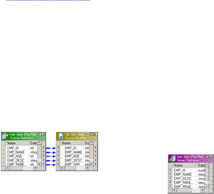
4. Compile the Java code.
5. Create and run a session and workflow.
The PowerCenter Client installation contains a mapping, m_jtx_hier_useCase.xml, and flat file source,
hier_data, that you can use with this example.
RELATED TOPICS:
•“Java Transformation” on page 188
Step 1. Import the Mapping
Import the metadata for the sample mapping in the Designer. The sample mapping contains the following
components:
•Source definition and Source Qualifier transformation. Flat file source definition, hier_input, that
defines the source data for the transformation.
•Target definition. Flat file target definition, hier_data, that receives the output data from the
transformation.
You can import the metadata for the mapping from the following location:
<PowerCenter Client installation directory>\client\bin\m_jtx_hier_useCase.xml
The following figure shows the sample mapping:
Step 2. Create Transformation and Configure Ports
You create the Java transformation and configure the ports in the Mapping Designer. You can use the input
and output port names as variables in the Java code. In a Java transformation, you create input and output
ports in an input or output group. A Java transformation may contain only one input group and one output
group.
In the Mapping Designer, create an active Java transformation and configure the ports. In this example, the
transformation is named jtx_hier_useCase.
Note: To use the Java code in this example, you must use the exact names for the input and output ports.
Step 1. Import the Mapping 227

The following table shows the input and output ports for the transformation:
Port Name Port Type Datatype Precision Scale
EMP_ID_INP Input Integer 10 0
EMP_NAME_INP Input String 100 0
EMP_AGE Input Integer 10 0
EMP_DESC_INP Input String 100 0
EMP_PARENT_EMPID Input Integer 10 0
EMP_ID_OUT Output Integer 10 0
EMP_NAME_OUT Output String 100 0
EMP_DESC_OUT Output String 100 0
EMP_PARENT_EMPNAME Output String 100 0
Step 3. Enter Java Code
Enter Java code for the transformation in the following code entry tabs:
•Import Packages. Imports the
java.util.Map
and
java.util.HashMap
packages.
•Helper Code. Contains a Map object, lock object, and boolean variables used to track the state of data in
the Java transformation.
•On Input Row. Defines the behavior of the Java transformation when it receives an input row.
Import Packages Tab
Import third-party Java packages, built-in Java packages, or custom Java packages in the Import Packages
tab. The example transformation uses the Map and HashMap packages.
Enter the following code in the Import Packages tab:
import java.util.Map;
import java.util.HashMap;
The Designer adds the import statements to the Java code for the transformation.
228 Chapter 15: Java Transformation Example

RELATED TOPICS:
•“Configuring Java Transformation Settings” on page 199
Helper Code Tab
Declare user-defined variables and methods for the Java transformation on the Helper Code tab. The Helper
Code tab defines the following variables that are used by the Java code in the On Input Row tab:
•empMap. Map object that stores the identification number and employee name from the source.
•lock. Lock object used to synchronize the access to empMap across partitions.
•generateRow. Boolean variable used to determine if an output row should be generated for the current
input row.
•isRoot. Boolean variable used to determine if an employee is at the top of the company organizational
chart (root).
Enter the following code in the Helper Code tab:
// Static Map object to store the ID and name relationship of an
// employee. If a session uses multiple partitions, empMap is shared
// across all partitions.
private static Map <Integer, String> empMap = new HashMap <Integer, String> ();
// Static lock object to synchronize the access to empMap across
// partitions.
private static Object lock = new Object();
// Boolean to track whether to generate an output row based on validity
// of the input data.
private boolean generateRow;
// Boolean to track whether the employee is root.
private boolean isRoot;
On Input Row Tab
The Java transformation executes the Java code in the On Input Row tab when the transformation receives
an input row. In this example, the transformation may or may not generate an output row, based on the
values of the input row.
Enter the following code in the On Input Row tab:
// Initially set generateRow to true for each input row.
generateRow = true;
// Initially set isRoot to false for each input row.
isRoot = false;
Helper Code Tab 229
// Check if input employee id and name is null.
if (isNull ("EMP_ID_INP") || isNull ("EMP_NAME_INP"))
{
incrementErrorCount(1);
// If input employee id and/or name is null, don't generate a output
// row for this input row.
generateRow = false;
} else {
// Set the output port values.
EMP_ID_OUT = EMP_ID_INP;
EMP_NAME_OUT = EMP_NAME_INP;
}
if (isNull ("EMP_DESC_INP"))
{
setNull("EMP_DESC_OUT");
} else {
EMP_DESC_OUT = EMP_DESC_INP;
}
boolean isParentEmpIdNull = isNull("EMP_PARENT_EMPID");
if(isParentEmpIdNull)
{
// This employee is the root for the hierarchy.
isRoot = true;
logInfo("This is the root for this hierarchy.");
setNull("EMP_PARENT_EMPNAME");
}
synchronized(lock)
{
// If the employee is not the root for this hierarchy, get the
// corresponding parent id.
if(!isParentEmpIdNull)
EMP_PARENT_EMPNAME = (String) (empMap.get(new Integer (EMP_PARENT_EMPID)));
// Add employee to the map for future reference.
empMap.put (new Integer(EMP_ID_INP), EMP_NAME_INP);
230 Chapter 15: Java Transformation Example

}
// Generate row if generateRow is true.
if(generateRow)
generateRow();
Step 4. Compile the Java Code
Click Compile in the Transformation Developer to compile the Java code for the transformation. The Output
window displays the status of the compilation. If the Java code does not compile successfully, correct the
errors in the code entry tabs and recompile the Java code. After you successfully compile the transformation,
save the transformation to the repository.
RELATED TOPICS:
•“Compiling a Java Transformation” on page 201
•“Fixing Compilation Errors” on page 202
Step 5. Create a Session and Workflow
Create a session and workflow for the mapping in the Workflow Manager, using the m_jtx_hier_useCase
mapping.
When you configure the session, you can use the sample source file from the following location:
<PowerCenter Client installation directory>\client\bin\hier_data
Sample Data
The following data is an excerpt from the sample source file:
1,James Davis,50,CEO,
4,Elaine Masters,40,Vice President - Sales,1
5,Naresh Thiagarajan,40,Vice President - HR,1
6,Jeanne Williams,40,Vice President - Software,1
9,Geetha Manjunath,34,Senior HR Manager,5
10,Dan Thomas,32,Senior Software Manager,6
14,Shankar Rahul,34,Senior Software Manager,6
20,Juan Cardenas,32,Technical Lead,10
21,Pramodh Rahman,36,Lead Engineer,14
22,Sandra Patterson,24,Software Engineer,10
23,Tom Kelly,32,Lead Engineer,10
Step 4. Compile the Java Code 231
35,Betty Johnson,27,Lead Engineer,14
50,Dave Chu,26,Software Engineer,23
70,Srihari Giran,23,Software Engineer,35
71,Frank Smalls,24,Software Engineer,35
The following data is an excerpt from a sample target file:
1,James Davis,CEO,
4,Elaine Masters,Vice President - Sales,James Davis
5,Naresh Thiagarajan,Vice President - HR,James Davis
6,Jeanne Williams,Vice President - Software,James Davis
9,Geetha Manjunath,Senior HR Manager,Naresh Thiagarajan
10,Dan Thomas,Senior Software Manager,Jeanne Williams
14,Shankar Rahul,Senior Software Manager,Jeanne Williams
20,Juan Cardenas,Technical Lead,Dan Thomas
21,Pramodh Rahman,Lead Engineer,Shankar Rahul
22,Sandra Patterson,Software Engineer,Dan Thomas
23,Tom Kelly,Lead Engineer,Dan Thomas
35,Betty Johnson,Lead Engineer,Shankar Rahul
50,Dave Chu,Software Engineer,Tom Kelly
70,Srihari Giran,Software Engineer,Betty Johnson
71,Frank Smalls,Software Engineer,Betty Johnson
232 Chapter 15: Java Transformation Example

CHAPTER 1 6
Joiner Transformation
This chapter includes the following topics:
•Joiner Transformation Overview, 233
•Joiner Transformation Properties, 234
•Defining a Join Condition, 235
•Defining the Join Type, 236
•Using Sorted Input, 238
•Joining Data from a Single Source, 241
•Blocking the Source Pipelines, 243
•Working with Transactions, 243
•Creating a Joiner Transformation, 245
•Tips for Joiner Transformations, 246
Joiner Transformation Overview
Use the Joiner transformation to join source data from two related heterogeneous sources residing in
different locations or file systems. You can also join data from the same source. The Joiner transformation
joins sources with at least one matching column. The Joiner transformation uses a condition that matches
one or more pairs of columns between the two sources. The Joiner transformation is an active
transformation.
The two input pipelines include a master pipeline and a detail pipeline or a master and a detail branch. The
master pipeline ends at the Joiner transformation, while the detail pipeline continues to the target.
To join more than two sources in a mapping, join the output from the Joiner transformation with another
source pipeline. Add Joiner transformations to the mapping until you have joined all the source pipelines.
The Joiner transformation accepts input from most transformations. However, consider the following
limitations on the pipelines you connect to the Joiner transformation:
•You cannot use a Joiner transformation when either input pipeline contains an Update Strategy
transformation.
•You cannot use a Joiner transformation if you connect a Sequence Generator transformation directly
before the Joiner transformation.
233

Working with the Joiner Transformation
When you work with the Joiner transformation, you must configure the transformation properties, join type,
and join condition. You can configure the Joiner transformation for sorted input to improve Integration Service
performance. You can also configure the transformation scope to control how the Integration Service applies
transformation logic. To work with the Joiner transformation, complete the following tasks:
•Configure the Joiner transformation properties. Properties for the Joiner transformation identify the
location of the cache directory, how the Integration Service processes the transformation, and how the
Integration Service handles caching.
•Configure the join condition. The join condition contains ports from both input sources that must match
for the Integration Service to join two rows. Depending on the type of join selected, the Integration Service
either adds the row to the result set or discards the row.
•Configure the join type. A join is a relational operator that combines data from multiple tables in different
databases or flat files into a single result set. You can configure the Joiner transformation to use a
Normal, Master Outer, Detail Outer, or Full Outer join type.
•Configure the session for sorted or unsorted input. You can improve session performance by
configuring the Joiner transformation to use sorted input. To configure a mapping to use sorted data, you
establish and maintain a sort order in the mapping so that the Integration Service can use the sorted data
when it processes the Joiner transformation.
•Configure the transaction scope. When the Integration Service processes a Joiner transformation, it
can apply transformation logic to all data in a transaction, all incoming data, or one row of data at a time.
If you have the partitioning option in PowerCenter, you can increase the number of partitions in a pipeline to
improve session performance.
Joiner Transformation Properties
Properties for the Joiner transformation identify the location of the cache directory, how the Integration
Service processes the transformation, and how the Integration Service handles caching. The properties also
determine how the Integration Service joins tables and files.
When you create a mapping, you specify the properties for each Joiner transformation. When you create a
session, you can override some properties, such as the index and data cache size for each transformation.
The following table describes the Joiner transformation properties:
Option Description
Cache Directory Specifies the directory used to cache master or detail rows and the index
to these rows. By default, the cache files are created in a directory
specified by the process variable $PMCacheDir. If you override the
directory, make sure the directory exists and contains enough disk space
for the cache files. The directory can be a mapped or mounted drive.
Join Type Specifies the type of join: Normal, Master Outer, Detail Outer, or Full
Outer.
Null Ordering in Master Not applicable for this transformation type.
Null Ordering in Detail Not applicable for this transformation type.
234 Chapter 16: Joiner Transformation

Option Description
Tracing Level Amount of detail displayed in the session log for this transformation. The
options are Terse, Normal, Verbose Data, and Verbose Initialization.
Joiner Data Cache Size Data cache size for the transformation. Default cache size is 2,000,000
bytes. If the total configured cache size is 2 GB or more, you must run the
session on a 64-bit Integration Service. You can use a numeric value for
the cache, you can use a cache value from a parameter file or you can
configure the Integration Service to set the cache size by using the Auto
setting. If you configure the Integration Service to determine the cache
size, you can also configure a maximum amount of memory for the
Integration Service to allocate to the cache.
Joiner Index Cache Size Index cache size for the transformation. Default cache size is 1,000,000
bytes. If the total configured cache size is 2 GB or more, you must run the
session on a 64-bit Integration Service. You can use a numeric value for
the cache, you can use a cache value from a parameter file or you can
configure the Integration Service to set the cache size by using the Auto
setting. If you configure the Integration Service to determine the cache
size, you can also configure a maximum amount of memory for the
Integration Service to allocate to the cache.
Sorted Input Specifies that data is sorted. Choose Sorted Input to join sorted data.
Using sorted input can improve performance.
Master Sort Order Specifies the sort order of the master source data. Choose Ascending if
the master source data is in ascending order. If you choose Ascending,
also enable sorted input. Default is Auto.
Transformation Scope Specifies how the Integration Service applies the transformation logic to
incoming data. You can choose Transaction, All Input, or Row.
Defining a Join Condition
The join condition contains ports from both input sources that must match for the Integration Service to join
two rows. Depending on the type of join selected, the Integration Service either adds the row to the result set
or discards the row. The Joiner transformation produces result sets based on the join type, condition, and
input data sources.
Before you define a join condition, verify that the master and detail sources are configured for optimal
performance. During a session, the Integration Service compares each row of the master source against the
detail source. To improve performance for an unsorted Joiner transformation, use the source with fewer rows
as the master source. To improve performance for a sorted Joiner transformation, use the source with fewer
duplicate key values as the master.
By default, when you add ports to a Joiner transformation, the ports from the first source pipeline display as
detail sources. Adding the ports from the second source pipeline sets them as master sources. To change
these settings, click the M column on the Ports tab for the ports you want to set as the master source. This
sets ports from this source as master ports and ports from the other source as detail ports.
Defining a Join Condition 235
You define one or more conditions based on equality between the specified master and detail sources. For
example, if two sources with tables called EMPLOYEE_AGE and EMPLOYEE_POSITION both contain
employee ID numbers, the following condition matches rows with employees listed in both sources:
EMP_ID1 = EMP_ID2
Use one or more ports from the input sources of a Joiner transformation in the join condition. Additional ports
increase the time necessary to join two sources. The order of the ports in the condition can impact the
performance of the Joiner transformation. If you use multiple ports in the join condition, the Integration
Service compares the ports in the order you specify.
The Designer validates datatypes in a condition. Both ports in a condition must have the same datatype. If
you need to use two ports in the condition with non-matching datatypes, convert the datatypes so they match.
If you join Char and Varchar datatypes, the Integration Service counts any spaces that pad Char values as
part of the string:
Char(40) = "abcd"
Varchar(40) = "abcd"
The Char value is “abcd” padded with 36 blank spaces, and the Integration Service does not join the two
fields because the Char field contains trailing spaces.
Note: The Joiner transformation does not match null values. For example, if both EMP_ID1 and EMP_ID2
contain a row with a null value, the Integration Service does not consider them a match and does not join the
two rows. To join rows with null values, replace null input with default values, and then join on the default
values.
Defining the Join Type
In SQL, a join is a relational operator that combines data from multiple tables into a single result set. The
Joiner transformation is similar to an SQL join except that data can originate from different types of sources.
You define the join type on the Properties tab in the transformation. The Joiner transformation supports the
following types of joins:
•Normal
•Master Outer
•Detail Outer
•Full Outer
Note: A normal or master outer join performs faster than a full outer or detail outer join.
If a result set includes fields that do not contain data in either of the sources, the Joiner transformation
populates the empty fields with null values. If you know that a field will return a NULL and you do not want to
insert NULLs in the target, you can set a default value on the Ports tab for the corresponding port.
Normal Join
With a normal join, the Integration Service discards all rows of data from the master and detail source that do
not match, based on the condition.
236 Chapter 16: Joiner Transformation
For example, you might have two sources of data for auto parts called PARTS_SIZE and PARTS_COLOR
with the following data:
PARTS_SIZE (master source)
PART_ID1 DESCRIPTION SIZE
1 Seat Cover Large
2 Ash Tray Small
3 Floor Mat Medium
PARTS_COLOR (detail source)
PART_ID2 DESCRIPTION COLOR
1 Seat Cover Blue
3 Floor Mat Black
4 Fuzzy Dice Yellow
To join the two tables by matching the PART_IDs in both sources, you set the condition as follows:
PART_ID1 = PART_ID2
When you join these tables with a normal join, the result set includes the following data:
PART_ID DESCRIPTION SIZE COLOR
1 Seat Cover Large Blue
3 Floor Mat Medium Black
The following example shows the equivalent SQL statement:
SELECT * FROM PARTS_SIZE, PARTS_COLOR WHERE PARTS_SIZE.PART_ID1 = PARTS_COLOR.PART_ID2
Master Outer Join
A master outer join keeps all rows of data from the detail source and the matching rows from the master
source. It discards the unmatched rows from the master source.
When you join the sample tables with a master outer join and the same condition, the result set includes the
following data:
PART_ID DESCRIPTION SIZE COLOR
1 Seat Cover Large Blue
3 Floor Mat Medium Black
4 Fuzzy Dice NULL Yellow
Because no size is specified for the Fuzzy Dice, the Integration Service populates the field with a NULL.
Defining the Join Type 237
The following example shows the equivalent SQL statement:
SELECT * FROM PARTS_SIZE RIGHT OUTER JOIN PARTS_COLOR ON (PARTS_COLOR.PART_ID2 =
PARTS_SIZE.PART_ID1)
Detail Outer Join
A detail outer join keeps all rows of data from the master source and the matching rows from the detail
source. It discards the unmatched rows from the detail source.
When you join the sample tables with a detail outer join and the same condition, the result set includes the
following data:
PART_ID DESCRIPTION SIZE COLOR
1 Seat Cover Large Blue
2 Ash Tray Small NULL
3 Floor Mat Medium Black
Because no color is specified for the Ash Tray, the Integration Service populates the field with a NULL.
The following example shows the equivalent SQL statement:
SELECT * FROM PARTS_SIZE LEFT OUTER JOIN PARTS_COLOR ON (PARTS_SIZE.PART_ID1 =
PARTS_COLOR.PART_ID2)
Full Outer Join
A full outer join keeps all rows of data from both the master and detail sources.
When you join the sample tables with a full outer join and the same condition, the result set includes:
PART_ID DESCRIPTION SIZE Color
1 Seat Cover Large Blue
2 Ash Tray Small NULL
3 Floor Mat Medium Black
4 Fuzzy Dice NULL Yellow
Because no color is specified for the Ash Tray and no size is specified for the Fuzzy Dice, the Integration
Service populates the fields with NULL.
The following example shows the equivalent SQL statement:
SELECT * FROM PARTS_SIZE FULL OUTER JOIN PARTS_COLOR ON (PARTS_SIZE.PART_ID1 =
PARTS_COLOR.PART_ID2)
Using Sorted Input
You can improve session performance by configuring the Joiner transformation to use sorted input. When
you configure the Joiner transformation to use sorted data, the Integration Service improves performance by
238 Chapter 16: Joiner Transformation
minimizing disk input and output. You see the greatest performance improvement when you work with large
data sets.
To configure a mapping to use sorted data, you establish and maintain a sort order in the mapping so the
Integration Service can use the sorted data when it processes the Joiner transformation. Complete the
following tasks to configure the mapping:
•Configure the sort order. Configure the sort order of the data you want to join. You can join sorted flat
files, or you can sort relational data using a Source Qualifier transformation. You can also use a Sorter
transformation.
•Add transformations. Use transformations that maintain the order of the sorted data.
•Configure the Joiner transformation. Configure the Joiner transformation to use sorted data and
configure the join condition to use the sort origin ports. The sort origin represents the source of the sorted
data.
When you configure the sort order in a session, you can select a sort order associated with the Integration
Service code page. When you run the Integration Service in Unicode mode, it uses the selected session sort
order to sort character data. When you run the Integration Service in ASCII mode, it sorts all character data
using a binary sort order. To ensure that data is sorted as the Integration Service requires, the database sort
order must be the same as the user-defined session sort order.
When you join sorted data from partitioned pipelines, you must configure the partitions to maintain the order
of sorted data.
Configuring the Sort Order
You must configure the sort order to ensure that the Integration Service passes sorted data to the Joiner
transformation.
Configure the sort order using one of the following methods:
•Use sorted flat files. When the flat files contain sorted data, verify that the order of the sort columns
match in each source file.
•Use sorted relational data. Use sorted ports in the Source Qualifier transformation to sort columns from
the source database. Configure the order of the sorted ports the same in each Source Qualifier
transformation.
•Use Sorter transformations. Use a Sorter transformation to sort relational or flat file data. Place a Sorter
transformation in the master and detail pipelines. Configure each Sorter transformation to use the same
order of the sort key ports and the sort order direction.
If you pass unsorted or incorrectly sorted data to a Joiner transformation configured to use sorted data, the
session fails and the Integration Service logs the error in the session log file.
Adding Transformations to the Mapping
When you add transformations between the sort origin and the Joiner transformation, use the following
guidelines to maintain sorted data:
•Do not place any of the following transformations between the sort origin and the Joiner transformation:
-Custom
-Unsorted Aggregator
-Normalizer
-Rank
Using Sorted Input 239
-Union transformation
-XML Parser transformation
-XML Generator transformation
-Mapplet, if it contains one of the above transformations
•You can place a sorted Aggregator transformation between the sort origin and the Joiner transformation if
you use the following guidelines:
-Configure the Aggregator transformation for sorted input.
-Use the same ports for the group by columns in the Aggregator transformation as the ports at the sort
origin.
-The group by ports must be in the same order as the ports at the sort origin.
•When you join the result set of a Joiner transformation with another pipeline, verify that the data output
from the first Joiner transformation is sorted.
Tip: You can place the Joiner transformation directly after the sort origin to maintain sorted data.
Configuring the Joiner Transformation
To configure the Joiner transformation, complete the following tasks:
•Enable Sorted Input on the Properties tab.
•Define the join condition to receive sorted data in the same order as the sort origin.
Defining the Join Condition
Configure the join condition to maintain the sort order established at the sort origin: the sorted flat file, the
Source Qualifier transformation, or the Sorter transformation. If you use a sorted Aggregator transformation
between the sort origin and the Joiner transformation, treat the sorted Aggregator transformation as the sort
origin when you define the join condition. Use the following guidelines when you define join conditions:
•The ports you use in the join condition must match the ports at the sort origin.
•When you configure multiple join conditions, the ports in the first join condition must match the first ports
at the sort origin.
•When you configure multiple conditions, the order of the conditions must match the order of the ports at
the sort origin, and you must not skip any ports.
•The number of sorted ports in the sort origin can be greater than or equal to the number of ports at the
join condition.
Example of a Join Condition
For example, you configure Sorter transformations in the master and detail pipelines with the following sorted
ports:
1. ITEM_NO
2. ITEM_NAME
3. PRICE
When you configure the join condition, use the following guidelines to maintain sort order:
•You must use ITEM_NO in the first join condition.
•If you add a second join condition, you must use ITEM_NAME.
240 Chapter 16: Joiner Transformation
•If you want to use PRICE in a join condition, you must also use ITEM_NAME in the second join condition.
If you skip ITEM_NAME and join on ITEM_NO and PRICE, you lose the sort order and the Integration
Service fails the session.
When you use the Joiner transformation to join the master and detail pipelines, you can configure any one of
the following join conditions:
ITEM_NO = ITEM_NO
or
ITEM_NO = ITEM_NO1
ITEM_NAME = ITEM_NAME1
or
ITEM_NO = ITEM_NO1
ITEM_NAME = ITEM_NAME1
PRICE = PRICE1
Joining Data from a Single Source
You may want to join data from the same source if you want to perform a calculation on part of the data and
join the transformed data with the original data. When you join the data using this method, you can maintain
the original data and transform parts of that data within one mapping. You can join data from the same
source in the following ways:
•Join two branches of the same pipeline.
•Join two instances of the same source.
Joining Two Branches of the Same Pipeline
When you join data from the same source, you can create two branches of the pipeline. When you branch a
pipeline, you must add a transformation between the source qualifier and the Joiner transformation in at least
one branch of the pipeline. You must join sorted data and configure the Joiner transformation for sorted input.
For example, you have a source with the following ports:
•Employee
•Department
•Total Sales
In the target, you want to view the employees who generated sales that were greater than the average sales
for their departments. To do this, you create a mapping with the following transformations:
•Sorter transformation. Sorts the data.
•Sorted Aggregator transformation. Averages the sales data and group by department. When you
perform this aggregation, you lose the data for individual employees. To maintain employee data, you
must pass a branch of the pipeline to the Aggregator transformation and pass a branch with the same
data to the Joiner transformation to maintain the original data. When you join both branches of the
pipeline, you join the aggregated data with the original data.
•Sorted Joiner transformation. Uses a sorted Joiner transformation to join the sorted aggregated data
with the original data.
Joining Data from a Single Source 241
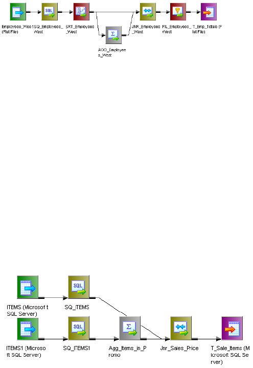
•Filter transformation. Compares the average sales data against sales data for each employee and filter
out employees with less than above average sales.
The following figure shows a mapping that joins two branches of the same pipeline:
Note: You can also join data from output groups of the same transformation, such as the Custom
transformation or XML Source Qualifier transformation. Place a Sorter transformation between each output
group and the Joiner transformation and configure the Joiner transformation to receive sorted input.
Joining two branches might impact performance if the Joiner transformation receives data from one branch
much later than the other branch. The Joiner transformation caches all the data from the first branch, and
writes the cache to disk if the cache fills. The Joiner transformation must then read the data from disk when it
receives the data from the second branch. This can slow processing.
Joining Two Instances of the Same Source
You can also join same source data by creating a second instance of the source. After you create the second
source instance, you can join the pipelines from the two source instances. If you want to join unsorted data,
you must create two instances of the same source and join the pipelines.
The following figure shows two instances of the same source joined with a Joiner transformation:
Note: When you join data using this method, the Integration Service reads the source data for each source
instance, so performance can be slower than joining two branches of a pipeline.
Guidelines for Joining Data from a Single Source
Use the following guidelines when deciding whether to join branches of a pipeline or join two instances of a
source:
•Join two branches of a pipeline when you have a large source or if you can read the source data only
once. For example, you can only read source data from a message queue once.
•Join two branches of a pipeline when you use sorted data. If the source data is unsorted and you use a
Sorter transformation to sort the data, branch the pipeline after you sort the data.
•Join two instances of a source when you need to add a blocking transformation to the pipeline between
the source and the Joiner transformation.
•Join two instances of a source if one pipeline may process slower than the other pipeline.
•Join two instances of a source if you need to join unsorted data.
242 Chapter 16: Joiner Transformation
Blocking the Source Pipelines
When you run a session with a Joiner transformation, the Integration Service blocks and unblocks the source
data, based on the mapping configuration and whether you configure the Joiner transformation for sorted
input.
Unsorted Joiner Transformation
When the Integration Service processes an unsorted Joiner transformation, it reads all master rows before it
reads the detail rows. To ensure it reads all master rows before the detail rows, the Integration Service
blocks the detail source while it caches rows from the master source. Once the Integration Service reads and
caches all master rows, it unblocks the detail source and reads the detail rows. Some mappings with
unsorted Joiner transformations violate data flow validation.
Sorted Joiner Transformation
When the Integration Service processes a sorted Joiner transformation, it blocks data based on the mapping
configuration. Blocking logic is possible if master and detail input to the Joiner transformation originate from
different sources.
The Integration Service uses blocking logic to process the Joiner transformation if it can do so without
blocking all sources in a target load order group simultaneously. Otherwise, it does not use blocking logic.
Instead, it stores more rows in the cache.
When the Integration Service can use blocking logic to process the Joiner transformation, it stores fewer rows
in the cache, increasing performance.
Caching Master Rows
When the Integration Service processes a Joiner transformation, it reads rows from both sources
concurrently and builds the index and data cache based on the master rows. The Integration Service then
performs the join based on the detail source data and the cache data. The number of rows the Integration
Service stores in the cache depends on the partition type, the source data, and whether you configure the
Joiner transformation for sorted input. To improve performance for an unsorted Joiner transformation, use the
source with fewer rows as the master source. To improve performance for a sorted Joiner transformation, use
the source with fewer duplicate key values as the master.
Working with Transactions
When the Integration Service processes a Joiner transformation, it can apply transformation logic to all data
in a transaction, all incoming data, or one row of data at a time. The Integration Service can drop or preserve
transaction boundaries depending on the mapping configuration and the transformation scope. You configure
how the Integration Service applies transformation logic and handles transaction boundaries using the
transformation scope property.
You configure transformation scope values based on the mapping configuration and whether you want to
preserve or drop transaction boundaries.
Blocking the Source Pipelines 243

You can preserve transaction boundaries when you join the following sources:
•You join two branches of the same source pipeline. Use the Transaction transformation scope to
preserve transaction boundaries.
•You join two sources, and you want to preserve transaction boundaries for the detail source. Use
the Row transformation scope to preserve transaction boundaries in the detail pipeline.
You can drop transaction boundaries when you join the following sources:
•You join two sources or two branches and you want to drop transaction boundaries. Use the All
Input transformation scope to apply the transformation logic to all incoming data and drop transaction
boundaries for both pipelines.
The following table summarizes how to preserve transaction boundaries using transformation scopes with the
Joiner transformation:
Transformation
Scope
Input Type Integration Service Behavior
Row Unsorted Preserves transaction boundaries in the detail pipeline.
Row Sorted Session fails.
Transaction Sorted Preserves transaction boundaries when master and detail originate
from the same transaction generator. Session fails when master and
detail do not originate from the same transaction generator
Transaction Unsorted Session fails.
All Input Sorted, Unsorted Drops transaction boundaries.
Note: Sessions fail if you use real-time data with All Input or Transaction transformation scopes.
Preserving Transaction Boundaries for a Single Pipeline
When you join data from the same source, use the Transaction transformation scope to preserve incoming
transaction boundaries for a single pipeline. Use the Transaction transformation scope when the Joiner
transformation joins data from the same source, either two branches of the same pipeline or two output
groups of one transaction generator. Use this transformation scope with sorted data and any join type.
When you use the Transaction transformation scope, verify that master and detail pipelines originate from the
same transaction control point and that you use sorted input. For example, in “Preserving Transaction
Boundaries for a Single Pipeline” on page 244 the Sorter transformation is the transaction control point. You
cannot place another transaction control point between the Sorter transformation and the Joiner
transformation. In the mapping, the master and detail pipeline branches originate from the same transaction
control point, and the Integration Service joins the pipeline branches with the Joiner transformation,
preserving transaction boundaries.
244 Chapter 16: Joiner Transformation
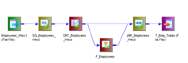
The following figure shows a mapping that joins two branches of a pipeline and preserves transaction
boundaries:
Figure 1. Preserving Transaction Boundaries when You Join Two Pipeline Branches
Preserving Transaction Boundaries in the Detail Pipeline
When you want to preserve the transaction boundaries in the detail pipeline, choose the Row transformation
scope. The Row transformation scope allows the Integration Service to process data one row at a time. The
Integration Service caches the master data and matches the detail data with the cached master data.
When the source data originates from a real-time source, such as IBM MQ Series, the Integration Service
matches the cached master data with each message as it is read from the detail source.
Use the Row transformation scope with Normal and Master Outer join types that use unsorted data.
Dropping Transaction Boundaries for Two Pipelines
When you want to join data from two sources or two branches and you do not need to preserve transaction
boundaries, use the All Input transformation scope. When you use All Input, the Integration Service drops
incoming transaction boundaries for both pipelines and outputs all rows from the transformation as an open
transaction. At the Joiner transformation, the data from the master pipeline can be cached or joined
concurrently, depending on how you configure the sort order. Use this transformation scope with sorted and
unsorted data and any join type.
Creating a Joiner Transformation
To use a Joiner transformation, add a Joiner transformation to the mapping, set up the input sources, and
configure the transformation with a condition and join type and sort type.
To create a Joiner transformation:
1. In the Mapping Designer, click Transformation > Create. Select the Joiner transformation. Enter a name,
and click OK.
The naming convention for Joiner transformations is JNR_TransformationName. Enter a description for
the transformation.
The Designer creates the Joiner transformation.
2. Drag all the input/output ports from the first source into the Joiner transformation.
The Designer creates input/output ports for the source fields in the Joiner transformation as detail fields
by default. You can edit this property later.
Creating a Joiner Transformation 245
3. Select and drag all the input/output ports from the second source into the Joiner transformation.
The Designer configures the second set of source fields and master fields by default.
4. Double-click the title bar of the Joiner transformation to open the transformation.
5. Click the Ports tab.
6. Click any box in the M column to switch the master/detail relationship for the sources.
Tip: To improve performance for an unsorted Joiner transformation, use the source with fewer rows as
the master source. To improve performance for a sorted Joiner transformation, use the source with fewer
duplicate key values as the master.
7. Add default values for specific ports.
Some ports are likely to contain null values, since the fields in one of the sources may be empty. You
can specify a default value if the target database does not handle NULLs.
8. Click the Condition tab and set the join condition.
9. Click the Add button to add a condition. You can add multiple conditions.
The master and detail ports must have matching datatypes. The Joiner transformation only supports
equivalent (=) joins.
10. Click the Properties tab and configure properties for the transformation.
Note: You can edit the join condition from the Condition tab. The keyword AND separates multiple
conditions.
11. Click OK.
12. Click the Metadata Extensions tab to configure metadata extensions.
Tips for Joiner Transformations
Perform joins in a database when possible.
Performing a join in a database is faster than performing a join in the session. In some cases, this is not
possible, such as joining tables from two different databases or flat file systems. If you want to perform a join
in a database, use the following options:
•Create a pre-session stored procedure to join the tables in a database.
•Use the Source Qualifier transformation to perform the join.
Join sorted data when possible.
You can improve session performance by configuring the Joiner transformation to use sorted input. When
you configure the Joiner transformation to use sorted data, the Integration Service improves performance by
minimizing disk input and output. You see the greatest performance improvement when you work with large
data sets.
For an unsorted Joiner transformation, designate the source with fewer rows as the master source.
For optimal performance and disk storage, designate the source with the fewer rows as the master source.
During a session, the Joiner transformation compares each row of the master source against the detail
source. The fewer unique rows in the master, the fewer iterations of the join comparison occur, which speeds
the join process.
246 Chapter 16: Joiner Transformation
For a sorted Joiner transformation, designate the source with fewer duplicate key values as the master
source.
For optimal performance and disk storage, designate the source with fewer duplicate key values as the
master source. When the Integration Service processes a sorted Joiner transformation, it caches rows for
one hundred keys at a time. If the master source contains many rows with the same key value, the
Integration Service must cache more rows, and performance can be slowed.
Tips for Joiner Transformations 247

CHAPTER 1 7
Lookup Transformation
This chapter includes the following topics:
•Lookup Transformation Overview, 248
•Lookup Source Types, 249
•Connected and Unconnected Lookups, 252
•Lookup Components, 254
•Lookup Properties, 256
•Lookup Query, 262
•Lookup Condition, 266
•Lookup Caches, 268
•Return Multiple Rows, 268
•Configuring Unconnected Lookup Transformations, 269
•Database Deadlock Resilience, 272
•Creating a Lookup Transformation, 272
•Tips for Lookup Transformations, 274
Lookup Transformation Overview
Use a Lookup transformation in a mapping to look up data in a flat file, relational table, view, or synonym.
You can import a lookup definition from any flat file or relational database to which both the PowerCenter
Client and Integration Service can connect. You can also create a lookup definition from a source qualifier.
You can use multiple Lookup transformations in a mapping. The Lookup transformation can be an active or
passive transformation. You can configure a connected or unconnected Lookup transformation.
The Integration Service queries the lookup source based on the lookup ports in the transformation and a
lookup condition. The Lookup transformation returns the result of the lookup to the target or another
transformation. You can configure the Lookup transformation to return a single row or multiple rows.
Perform the following tasks with a Lookup transformation:
•Get a related value. Retrieve a value from the lookup table based on a value in the source. For example,
the source has an employee ID. Retrieve the employee name from the lookup table.
•Get multiple values. Retrieve multiple rows from a lookup table. For example, return all employees in a
department.
248
•Perform a calculation. Retrieve a value from a lookup table and use it in a calculation. For example,
retrieve a sales tax percentage, calculate a tax, and return the tax to a target.
•Update slowly changing dimension tables. Determine whether rows exist in a target.
Configure the Lookup transformation to perform the following types of lookups:
•Relational or flat file lookup. Perform a lookup on a flat file or a relational table. When you create a
Lookup transformation using a relational table as the lookup source, you can connect to the lookup source
using ODBC and import the table definition as the structure for the Lookup transformation. When you
create a Lookup transformation using a flat file as a lookup source, the Designer invokes the Flat File
Wizard.
•Pipeline lookup. Perform a lookup on application sources such as a JMS, MSMQ, or SAP. Drag the
source into the mapping and associate the Lookup transformation with the source qualifier. Configure
partitions to improve performance when the Integration Service retrieves source data for the lookup
cache.
•Connected or unconnected lookup. A connected Lookup transformation receives source data, performs
a lookup, and returns data to the pipeline. An unconnected Lookup transformation is not connected to a
source or target. A transformation in the pipeline calls the Lookup transformation with a :LKP expression.
The unconnected Lookup transformation returns one column to the calling transformation.
•Cached or uncached lookup. Cache the lookup source to improve performance. If you cache the lookup
source, you can use a dynamic or static cache. By default, the lookup cache remains static and does not
change during the session. With a dynamic cache, the Integration Service inserts or updates rows in the
cache. When you cache the target table as the lookup source, you can look up values in the cache to
determine if the values exist in the target. The Lookup transformation marks rows to insert or update the
target.
Lookup Source Types
When you create a Lookup transformation, you can choose a relational table, flat file, or a source qualifier as
the lookup source.
Relational Lookups
When you create a Lookup transformation using a relational table as a lookup source, you can connect to the
lookup source using ODBC and import the table definition as the structure for the Lookup transformation.
Use the following options with relational lookups:
•Override the default SQL statement to add a WHERE clause or to query multiple tables.
•Sort null data high or low, based on database support.
•Perform case-sensitive comparisons based on the database support.
Flat File Lookups
When you create a Lookup transformation using a flat file as a lookup source, select a flat file definition in the
repository or import the source when you create the transformation. When you import a flat file lookup
source, the Designer invokes the Flat File Wizard.
Lookup Source Types 249
Use the following options with flat file lookups:
•Use indirect files as lookup sources by configuring a file list as the lookup file name.
•Use sorted input for the lookup.
•Sort null data high or low.
•Use case-sensitive string comparison with flat file lookups.
Using Sorted Input
When you configure a flat file Lookup transformation for sorted input, the condition columns must be grouped.
If the condition columns are not grouped, the Lookup transformation returns incorrect results. For optimal
caching performance, sort the condition columns.
For example, a Lookup transformation has the following condition:
OrderID = OrderID1
CustID = CustID1
In the following flat file lookup source, the keys are grouped, but not sorted. The Integration Service can
cache the data, but performance may not be optimal.
OrderID CustID ItemNo. ItemDesc Comments
1001 CA502 F895S Flashlight
Key data is
grouped, but not sorted.
CustID is out of order
within OrderID.
1001 CA501 C530S Compass -
1001 CA501 T552T Tent -
1005 OK503 S104E Safety Knife
Key data is
grouped, but not sorted.
OrderID is out of order.
1003 CA500 F304T First Aid Kit -
1003 TN601 R938M Regulator System -
The keys are not grouped in the following flat file lookup source. The Lookup transformation returns incorrect
results.
OrderI
D
CustI
D
ItemNo
.
ItemDesc Comments
1001 CA501 T552T Tent -
1001 CA501 C530S Compass -
1005 OK503 S104E Safety Knife -
1003 TN601 R938M Regulator
System
-
1003 CA500 F304T First Aid Kit -
250 Chapter 17: Lookup Transformation
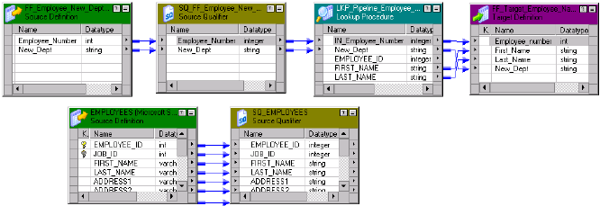
OrderI
D
CustI
D
ItemNo
.
ItemDesc Comments
1001 CA502 F895S Flashlight
Key data for CustID is not
grouped.
If you choose sorted input for indirect files, the range of data must not overlap in the files.
Pipeline Lookups
Create a pipeline Lookup transformation to perform a lookup on an application source that is not a relational
table or flat file. A pipeline Lookup transformation has a source qualifier as the lookup source. You can
perform pipeline lookups on all data sources except on Application Multi-Group Source Qualifier
transformations.
When you configure a pipeline Lookup transformation, the lookup source and source qualifier are in a
different pipeline from the Lookup transformation. The source and source qualifier are in a partial pipeline
that contains no target. The Integration Service reads the source data in this pipeline and passes the data to
the Lookup transformation to create the cache. You can create multiple partitions in the partial pipeline to
improve performance.
To improve performance when processing relational or flat file lookup sources, create a pipeline Lookup
transformation instead of a relational or flat file Lookup transformation. You can create partitions to process
the lookup source and pass it to the Lookup transformation.
Create a connected or unconnected pipeline Lookup transformation.
Note: Do not enable HA recovery for sessions that have real-time sources for pipeline lookups. You might get
unexpected results.
Configuring a Pipeline Lookup Transformation in a Mapping
A mapping that contains a pipeline Lookup transformation includes a partial pipeline that contains the lookup
source and source qualifier. The partial pipeline does not include a target. The Integration Service retrieves
the lookup source data in this pipeline and passes the data to the lookup cache.
The partial pipeline is in a separate target load order group in session properties. You can create multiple
partitions in the pipeline to improve performance. You can not configure the target load order with the partial
pipeline.
The following mapping shows a mapping that contains a pipeline Lookup transformation and the partial
pipeline that processes the lookup source:
Lookup Source Types 251

The mapping contains the following objects:
•The lookup source definition and source qualifier are in a separate pipeline. The Integration Service
creates a lookup cache after it processes the lookup source data in the pipeline.
•A flat file source contains new department names by employee number.
•The pipeline Lookup transformation receives Employee_Number and New_Dept from the source file. The
pipeline Lookup performs a lookup on Employee_ID in the lookup cache. It retrieves the employee first
and last name from the lookup cache.
•A flat file target receives the Employee_ID, First_Name, Last_Name, and New_Dept from the Lookup
transformation.
Connected and Unconnected Lookups
You can configure a connected Lookup transformation or an unconnected Lookup transformation. A
connected Lookup transformation is a transformation that has input and output ports that you connect to
other transformations in a mapping. An unconnected Lookup transformation appears in the mapping, but is
not connected to other transformations.
An unconnected Lookup transformation receives input from the result of a :LKP expression in a
transformation such as an Expression transformation or Aggregator transformation. The :LKP expression
passes parameters to the Lookup transformation and receives a result back from the lookup. The :LKP
expression can pass lookup results to another expression in the transformation to filter results.
The following table lists the differences between connected and unconnected lookups:
Connected Lookup Unconnected Lookup
Receives input values directly from the pipeline. Receives input values from the result of a :LKP expression
in another transformation.
Use a dynamic or static cache. Use a static cache.
Cache includes the lookup source columns in the
lookup condition and the lookup source columns
that are output ports.
Cache includes all lookup and output ports in the lookup
condition and the lookup/return port.
Returns multiple columns from the same row or
insert into the dynamic lookup cache.
Returns one column from each row to a return port.
If there is no match for the lookup condition, the
Integration Service returns the default value for all
output ports. If you configure dynamic caching, the
Integration Service inserts rows into the cache or
leaves it unchanged.
If there is no match for the lookup condition, the Integration
Service returns NULL.
If there is a match for the lookup condition, the
Integration Service returns the result of the lookup
condition for all lookup/output ports. If you
configure dynamic caching, the Integration Service
either updates the row the in the cache or leaves
the row unchanged.
If a match occurs for the lookup condition, the Integration
Service returns the result of the lookup condition to the
return port.
252 Chapter 17: Lookup Transformation

Connected Lookup Unconnected Lookup
Passes multiple output values to another
transformation. Link lookup/output ports to another
transformation.
Returns one output value to another transformation. The
Lookup transformation return port passes the value to the
port that contains the :LKP expression in the other
transformation.
Supports user-defined default values. Does not support user-defined default values.
Connected Lookups
A connected Lookup transformation is a Lookup transformation that is connected to a source or target in a
mapping.
When you run a mapping that contains a connected Lookup transformation, the Integration Service performs
the following steps:
1. The Integration Service passes values from another transformation to input ports in the Lookup
transformation.
2. For each input row, the Integration Service queries the lookup source or cache based on the lookup
ports and the lookup condition in the transformation.
3. If the transformation is uncached or uses a static cache, the Integration Service returns values from the
lookup query.
If the transformation uses a dynamic cache, the Integration Service inserts the row into the cache when
it does not find the row in the cache. When the Integration Service finds the row in the cache, it updates
the row in the cache or leaves it unchanged. It flags the row as insert, update, or no change.
4. The Integration Service returns data from the query and passes it to the next transformation in the
mapping.
If the transformation uses a dynamic cache, you can pass rows to a Filter or Router transformation to
filter new rows to the target.
Note: This chapter discusses connected Lookup transformations unless otherwise specified.
Unconnected Lookups
An unconnected Lookup transformation is a Lookup transformation that is not connected to a source or target
in the mapping. Call the lookup with a :LKP expression in a transformation that allows expressions.
A common use for unconnected Lookup transformations is to update slowly changing dimension tables. For
more information about slowly changing dimension tables, visit the Informatica Knowledge Base at
http://mysupport.informatica.com.
The syntax for the lookup expression is
:LKP lookup_transformation_name(argument, argument, ...)
The order in which you list each argument must match the order of the lookup conditions in the Lookup
transformation. The Lookup transformation returns the result of the query through the Lookup transformation
return port. The transformation that calls the lookup receives the lookup result value in the port that contains
the :LKP expression. If the lookup query fails to return a value, the port receives a null value.
When you perform an unconnected lookup, you can perform the same lookup multiple times in a mapping.
You can test the results of the lookup in another expression and filter rows based on the results.
Connected and Unconnected Lookups 253
When you run a mapping that contains an unconnected Lookup transformation, the Integration Service
performs the following steps:
1. An unconnected Lookup transformation receives input values from the result of a :LKP expression in
another transformation, such as an Aggregator transformation, Expression transformation, or Update
Strategy transformation.
2. The Integration Service queries the lookup source or cache based on the lookup ports and condition in
the Lookup transformation.
3. The Integration Service returns a value through the return port of the Lookup transformation.
4. The Integration Service passes the return value to the port that contains the :LKP expression.
Lookup Components
Define the following components when you configure a Lookup transformation in a mapping:
•Lookup source
•Ports
•Properties
•Condition
Lookup Source
Use a flat file, relational table, or source qualifier for a lookup source. When you create a Lookup
transformation, you can create the lookup source from the following locations:
•Relational source or target definition in the repository
•Flat file source or target definition in the repository
•Table or file that the Integration Service and PowerCenter Client machine can connect to
•Source qualifier definition in a mapping
The lookup table can be a single table, or you can join multiple tables in the same database using a lookup
SQL override. The Integration Service queries the lookup table or an in-memory cache of the table for all
incoming rows into the Lookup transformation.
The Integration Service can connect to a lookup table using ODBC or native drivers. Configure native drivers
for optimal performance.
Indexes and a Lookup Table
If you have privileges to modify the database containing a lookup table, you can improve lookup initialization
time by adding an index to the lookup table. You can improve performance for very large lookup tables. Since
the Integration Service queries, sorts, and compares values in lookup columns, the index needs to include
every column in a lookup condition.
You can improve performance by indexing the following types of lookup:
•Cached lookups. You can improve performance by indexing the columns in the lookup ORDER BY. The
session log contains the ORDER BY clause.
254 Chapter 17: Lookup Transformation

•Uncached lookups. Because the Integration Service issues a SELECT statement for each row passing
into the Lookup transformation, you can improve performance by indexing the columns in the lookup
condition.
Lookup Ports
The Ports tab contains input and output ports. The Ports tab also includes lookup ports that represent
columns of data to return from the lookup source. An unconnected Lookup transformation returns one column
of data to the calling transformation in this port. An unconnected Lookup transformation has one return port.
The following table describes the port types in a Lookup transformation:
Ports Type of
Lookup
Description
I Connected
Unconnected
Input port. Create an input port for each lookup port you want to use in the lookup
condition. You must have at least one input or input/output port in each Lookup
transformation.
O Connected
Unconnected
Output port. Create an output port for each lookup port you want to link to another
transformation. You can designate both input and lookup ports as output ports. For
connected lookups, you must have at least one output port. For unconnected
lookups, select a lookup port as a return port (R) to pass a return value.
L Connected
Unconnected
Lookup port. The Designer designates each column in the lookup source as a lookup
(L) and output port (O).
R Unconnected Return port. Use only in unconnected Lookup transformations. Designates the column
of data you want to return based on the lookup condition. You can designate one
lookup port as the return port.
The Lookup transformation also enables an associated expression property that you configure when you use
a dynamic cache. The associated expression property contains the data to update the lookup cache. It can
contain an expression to update the dynamic cache or it can contain an input port name.
Use the following guidelines to configure lookup ports:
•If you delete lookup ports from a flat file lookup, the session fails.
•You can delete lookup ports from a relational lookup if the mapping does not use the lookup port. This
reduces the amount of memory the Integration Service needs to run the session.
Lookup Properties
On the Properties tab, configure properties such as an SQL override for relational lookups, the lookup source
name caching properties.
RELATED TOPICS:
•“Lookup Properties” on page 256
Lookup Condition
On the Condition tab, enter the condition or conditions you want the Integration Service to use to find data in
the lookup source.
Lookup Components 255

RELATED TOPICS:
•“Lookup Condition” on page 266
Lookup Properties
Configure the lookup properties such as caching and multiple matches on the Lookup Properties tab.
Configure the lookup condition or the SQL statements to query the lookup table. You can also change the
Lookup table name.
When you create a mapping, you configure the properties for each Lookup transformation. When you create
a session, you can override properties such as the index and the data cache size for each transformation.
The following table describes the Lookup transformation properties:
Option Lookup
Type
Description
Lookup SQL Override Relational Overrides the default SQL statement to query the lookup table.
Specifies the SQL statement you want the Integration Service to use
for querying lookup values. Use with the lookup cache enabled.
Lookup Table Name Pipeline
Relational
The name of the table or the source qualifier from which the
transformation looks up and caches values. When you create the
Lookup transformation, choose a source, target, or source qualifier
as the lookup source. You can also import a table, view, or synonym
from another database when you create the Lookup transformation.
If you enter a lookup SQL override, you do not need to enter the
Lookup Table Name.
Lookup Source Filter Relational Restricts the lookups the Integration Service performs based on the
value of data in any port in the Lookup transformation. Use with the
lookup cache enabled.
Lookup Caching Enabled Flat File
Pipeline
Relational
Indicates whether the Integration Service caches lookup values
during the session.
When you enable lookup caching, the Integration Service queries the
lookup source once, caches the values, and looks up values in the
cache during the session. Caching the lookup values can improve
session performance.
When you disable caching, each time a row passes into the
transformation, the Integration Service issues a select statement to
the lookup source for lookup values.
Note: The Integration Service always caches the flat file lookups and
the pipeline lookups.
256 Chapter 17: Lookup Transformation

Option Lookup
Type
Description
Lookup Policy on Multiple
Match
Flat File
Pipeline
Relational
Determines which rows to return when the Lookup transformation
finds multiple rows that match the lookup condition. Select one of the
following values:
- Report Error. The Integration Service reports an error and does not
return a row.
- Use First Value. Returns the first row that matches the lookup
condition.
- Use Last Value. Return the last row that matches the lookup condition.
- Use All Values. Return all matching rows.
- Use Any Value.The Integration Service returns the first value that
matches the lookup condition. It creates an index based on the key
ports instead of all Lookup transformation ports.
- Report Error. The Integration Service reports an error and does not
return a row. If you do not enable the Output Old Value On Update
option, the Lookup Policy On Multiple Match option is set to Report
Error for dynamic lookups.
Lookup Condition Flat File
Pipeline
Relational
Displays the lookup condition you set in the Condition tab.
Connection Information Relational Specifies the database that contains the lookup table. You can define
the database in the mapping, session, or parameter file:
- Mapping. Select the connection object. You can also specify the
database connection type. Type
Relational:
before the connection
name if it is a relational connection. Type
Application:
before the
connection name if it is an application connection.
- Session. Use the $Source or $Target connection variable. If you use
one of these variables, the lookup table must reside in the source or
the target database. Specify the database connection in the session
properties for each variable.
- Parameter file. Use the session parameter $DBConnectionName or
$AppConnectionName, and define it in the parameter file.
By default, the Designer specifies $Source if you choose a source
table and $Target if you choose a target table when you create the
Lookup transformation. You can override these values in the session
properties.
The Integration Service fails the session if it cannot determine the
type of database connection.
Source Type Flat File
Pipeline
Relational
Indicates that the Lookup transformation reads values from a
relational table, flat file, or source qualifier.
Tracing Level Flat File
Pipeline
Relational
Sets the amount of detail included in the session log.
Lookup Properties 257

Option Lookup
Type
Description
Lookup Cache Directory
Name
Flat File
Pipeline
Relational
Specifies the directory used to build the lookup cache files when you
configure the Lookup transformation to cache the lookup source. Also
saves the persistent lookup cache files when you select the Lookup
Persistent option.
By default, the Integration Service uses the $PMCacheDir directory
configured for the Integration Service.
Lookup Cache Persistent Flat File
Pipeline
Relational
Indicates whether the Integration Service uses a persistent lookup
cache, which consists of at least two cache files. If a Lookup
transformation is configured for a persistent lookup cache and
persistent lookup cache files do not exist, the Integration Service
creates the files during the session. Use with the lookup cache
enabled.
Lookup Data Cache Size
Lookup Index Cache Size
Flat File
Pipeline
Relational
Default is Auto. Indicates the maximum size the Integration Service
allocates to the data cache and the index in memory. You can use a
numeric value for the cache, you can use a cache value from a
parameter file or you can configure the Integration Service to set the
cache size by using the Auto setting. If you configure the Integration
Service to determine the cache size, you can also configure a
maximum amount of memory for the Integration Service to allocate to
the cache.
If the Integration Service cannot allocate the configured amount of
memory when initializing the session, it fails the session. When the
Integration Service cannot store all the data cache data in memory, it
pages to disk.
Use with the lookup cache enabled.
Dynamic Lookup Cache Flat File
Pipeline
Relational
Indicates to use a dynamic lookup cache. Inserts or updates rows in
the lookup cache as it passes rows to the target table.
Use with the lookup cache enabled.
Output Old Value On
Update
Flat File
Pipeline
Relational
Use with dynamic caching enabled. When you enable this property,
the Integration Service outputs old values out of the lookup/output
ports. When the Integration Service updates a row in the cache, it
outputs the value that existed in the lookup cache before it updated
the row based on the input data. When the Integration Service inserts
a row in the cache, it outputs null values.
When you disable this property, the Integration Service outputs the
same values out of the lookup/output and input/output ports.
This property is enabled by default.
Update Dynamic Cache
Condition
Flat File
Pipeline
Relational
An expression that indicates whether to update dynamic cache.
Create an expression using lookup ports or input ports. The
expression can contain input values or values in the lookup cache.
The Integration Service updates the cache when the condition is true
and the data exists in the cache. Use with dynamic caching enabled.
Default is true.
258 Chapter 17: Lookup Transformation

Option Lookup
Type
Description
Cache File Name Prefix Flat File
Pipeline
Relational
Use with persistent lookup cache. Specifies the file name prefix to
use with persistent lookup cache files. The Integration Service uses
the file name prefix as the file name for the persistent cache files it
saves to disk. Enter the prefix. Do not enter .idx or .dat.
You can enter a parameter or variable for the file name prefix. Use
any parameter or variable type that you can define in the parameter
file.
If the named persistent cache files exist, the Integration Service
builds the memory cache from the files. If the named persistent cache
files do not exist, the Integration Service rebuilds the persistent
cache files.
Recache From Lookup
Source
Flat File
Pipeline
Relational
Use with the lookup cache enabled. When selected, the Integration
Service rebuilds the lookup cache from the lookup source when it first
calls the Lookup transformation instance.
If you use a persistent lookup cache, it rebuilds the persistent cache
files before using the cache. If you do not use a persistent lookup
cache, it rebuilds the lookup cache in the memory before using the
cache.
Insert Else Update Flat File
Pipeline
Relational
Use with dynamic caching enabled. Applies to rows entering the
Lookup transformation with the row type of insert. When enabled, the
Integration Service inserts rows in the cache and updates existing
rows When disabled, the Integration Service does not update existing
rows.
Update Else Insert Flat File
Pipeline
Relational
Use with dynamic caching enabled. Applies to rows entering the
Lookup transformation with the row type of update.
When enabled, the Integration Service updates existing rows, and
inserts a row if it is new. When disabled, the Integration Service does
not insert new rows.
Datetime Format Flat File Click the Open button to select a datetime format. Define the format
and the field width. Milliseconds, microseconds, or nanoseconds
formats have a field width of 29.
If you do not select a datetime format for a port, you can enter any
datetime format. Default is MM/DD/YYYY HH24:MI:SS. The Datetime
format does not change the size of the port.
Thousand Separator Flat File If you do not define a thousand separator for a port, the Integration
Service uses the properties defined here.
You can choose no separator, a comma, or a period. Default is no
separator.
Decimal Separator Flat File If you do not define a decimal separator for a particular field in the
lookup definition or on the Ports tab, the Integration Service uses the
properties defined here.
You can choose a comma or a period decimal separator. Default is
period.
Case-Sensitive String
Comparison
Flat File
Pipeline
The Integration Service uses case sensitive string comparisons when
performing lookups on string columns.
For relational lookups, the case sensitive comparison depends on the
database support.
Lookup Properties 259

Option Lookup
Type
Description
Null Ordering Flat File
Pipeline
Determines how the Integration Service orders null values. You can
choose to sort null values high or low. By default, the Integration
Service sorts null values high. This overrides the Integration Service
configuration to treat nulls in comparison operators as high, low, or
null.
For relational lookups, null ordering depends on the database default
value.
Sorted Input Flat File
Pipeline
Indicates whether or not the lookup file data is in sorted order. This
increases lookup performance for file lookups. If you enable sorted
input, and the condition columns are not grouped, the Integration
Service fails the session. If the condition columns are grouped, but
not sorted, the Integration Service processes the lookup as if you did
not configure sorted input.
Lookup Source is Static Flat File
Pipeline
Relational
The lookup source does not change in a session.
Pre-build Lookup Cache Flat File
Pipeline
Relational
Allows the Integration Service to build the lookup cache before the
Lookup transformation receives the data. The Integration Service can
build multiple lookup cache files at the same time to improve
performance.
You can configure this option in the mapping or the session. The
Integration Service uses the session-level setting if you configure the
Lookup transformation option as Auto.
Configure one of the following options:
- Auto. The Integration Service uses the value configured in the session.
- Always allowed. The Integration Service can build the lookup cache
before the Lookup transformation receives the first source row. The
Integration Service creates an additional pipeline to build the cache.
- Always disallowed. The Integration Service cannot build the lookup
cache before the Lookup transformation receives the first row.
You must configure the number of pipelines that the Integration
Service can build concurrently. Configure the Additional Concurrent
Pipelines for Lookup Cache Creation session property. The
Integration Service can pre-build lookup cache if this property is
greater than zero.
Subsecond Precision Relational Specifies the subsecond precision for datetime ports.
For relational lookups, you can change the precision for databases
that have an editable scale for datetime data. You can change
subsecond precision for Oracle Timestamp, Informix Datetime, and
Teradata Timestamp datatypes.
Enter a positive integer value from 0 to 9. Default is 6 microseconds.
If you enable pushdown optimization, the database returns the
complete datetime value, regardless of the subsecond precision
setting.
260 Chapter 17: Lookup Transformation

Configuring Lookup Properties in a Session
When you configure a session, you can configure lookup properties that are unique to sessions:
•Flat file lookups. Configure lookup location information, such as the source file directory, file name, and
the file type.
•Relational lookups. You can define $Source and $Target variables in the session properties. You can
also override connection information to use the $DBConnectionName or $AppConnectionName session
parameter.
•Pipeline lookups. Configure the lookup source file properties such as the source file directory, file name,
and the file type. If the source is a relational table or application source, configure the connection
information.
Configuring Flat File Lookups in a Session
When you configure a flat file lookup in a session, configure the lookup source file properties on the
Transformation View of the Mapping tab. Choose the Lookup transformation and configure the flat file
properties in the session properties for the transformation.
The following table describes the session properties you configure for flat file lookups:
Property Description
Lookup Source File Directory Enter the directory name. By default, the Integration Service looks in the
process variable directory, $PMLookupFileDir, for lookup files.
You can enter the full path and file name. If you specify both the directory and
file name in the Lookup Source Filename field, clear this field. The Integration
Service concatenates this field with the Lookup Source Filename field when it
runs the session.
You can also enter the $InputFileName session parameter to configure the file
name.
Lookup Source Filename Name of the lookup file. If you use an indirect file, enter the name of the
indirect file you want the Integration Service to read.
You can also enter the lookup file parameter, $LookupFileName, to change
the name of the lookup file for the session.
If you configure both the directory and file name in the Source File Directory
field, clear Lookup Source Filename. The Integration Service concatenates
Lookup Source Filename with the Lookup Source File Directory field for the
session. For example, the Lookup Source File Directory field contains “C:
\lookup_data\” and the Lookup Source Filename field contains “filename.txt.”
When the Integration Service begins the session, it looks for “C:\lookup_data
\filename.txt.”
Lookup Source Filetype Indicates whether the lookup source file contains the source data or a list of
files with the same file properties. Choose Direct if the lookup source file
contains the source data. Choose Indirect if the lookup source file contains a
list of files.
When you select Indirect, the Integration Service creates one cache for all
files. If you use sorted input with indirect files, verify that the range of data in
the files do not overlap. If the range of data overlaps, the Integration Service
processes the lookup as an unsorted lookup source.
Lookup Properties 261
Configuring Relational Lookups in a Session
When you configure a relational lookup in a session, configure the connection for the lookup database on the
Transformation View of the Mapping tab. Choose the Lookup transformation and configure the connection in
the session properties for the transformation.
Choose from the following options to configure a connection for a relational Lookup transformation:
•Choose a relational or application connection.
•Configure a database connection using the $Source or $Target connection variable.
•Configure the session parameter $DBConnectionName or $AppConnectionName, and define the session
parameter in a parameter file.
Configuring Pipeline Lookups in a Session
When you configure a pipeline Lookup in a session, configure the location of lookup source file or the
connection for the lookup table on the Sources node of the Mapping tab. Choose the Source Qualifier that
represents the lookup source.
Lookup Query
The Integration Service queries the lookup based on the ports and properties you configure in the Lookup
transformation. The Integration Service runs a default lookup query when the first row enters the Lookup
transformation.
If you use a relational lookup or a pipeline lookup against a relational table, you can override the lookup
query. You can use the override to change the ORDER BY clause, add a WHERE clause, or transform the
lookup data before it is cached.
If you configure a SQL override and a filter on the lookup query, the Integration Service ignores the filter.
Default Lookup Query
The default lookup query contains the following statements:
SELECT
The SELECT statement includes all the lookup ports in the mapping. To view the SELECT statement for
the lookup query, select the Lookup SQL Override property.
ORDER BY
The ORDER BY clause orders the columns in the same order they appear in the Lookup transformation.
The Integration Service generates the ORDER BY clause. You cannot view this when you generate the
default SQL.
Overriding the Lookup Query
The lookup SQL override is similar to entering a custom query in a Source Qualifier transformation. You can
override the lookup query for a relational lookup. You can enter the entire override, or you can generate and
edit the default SQL statement. When the Designer generates the default SQL statement for the lookup SQL
override, it includes the lookup/output ports in the lookup condition and the lookup/return port.
You can enter a different lookup query or edit the existing lookup query, which includes the lookup ports,
output ports, and the return port.
262 Chapter 17: Lookup Transformation
Overriding the ORDER BY Clause
By default, the Integration Service generates an ORDER BY clause for a cached lookup. The ORDER BY
clause contains all lookup condition ports. To increase performance, you can suppress the default ORDER
BY clause and enter an override ORDER BY with fewer columns.
Note: The override SQL must return data sorted on the lookup keys. When the transformation retrieves all
rows in a lookup, the Integration Service builds the data cache with the keys in sorted order. The Integration
Service cannot retrieve all the rows from the cache if the rows are not sorted. If the data is not sorted on the
keys, you might get unexpected results.
If you use pushdown optimization, you cannot override the ORDER BY clause or suppress the generated
ORDER BY clause with a comment notation.
The Integration Service always generates an ORDER BY clause, even if you enter one in the override. Place
two dashes ‘--’ after the ORDER BY override to suppress the generated ORDER BY clause. For example, a
Lookup transformation uses the following lookup condition:
ITEM_ID = IN_ITEM_ID
PRICE <= IN_PRICE
The Lookup transformation includes two lookup condition ports used in the mapping, ITEM_ID, and PRICE.
When you enter the ORDER BY clause with one or more columns, enter the columns in the same order as
the ports in the lookup condition. You must also enclose all database reserved words in quotes. Enter the
following lookup query in the lookup SQL override:
SELECT ITEMS_DIM.ITEM_NAME AS ITEM_NAME, ITEMS_DIM.PRICE AS PRICE, ITEMS_DIM.ITEM_ID AS
ITEM_ID FROM ITEMS_DIM ORDER BY ITEMS_DIM.ITEM_ID --
To override the default ORDER BY clause for a relational lookup, complete the following steps:
1. Generate the lookup query in the Lookup transformation.
2. Enter an ORDER BY clause that contains the condition ports in the same order they appear in the
Lookup condition.
3. Place two dashes ‘--’ as a comment notation after the ORDER BY clause to suppress the ORDER BY
clause that the Integration Service generates.
If you override the lookup query with an ORDER BY clause without adding comment notation, the lookup
fails.
Note: Sybase has a 16 column ORDER BY limitation. If the Lookup transformation has more than 16 lookup/
output ports including the ports in the lookup condition, override the ORDER BY clause or use multiple
Lookup transformations to query the lookup table.
Reserved Words
If any lookup name or column name contains a database reserved word, such as MONTH or YEAR, the
session fails with database errors when the Integration Service executes SQL against the database. You can
create and maintain a reserved words file, reswords.txt, in the Integration Service installation directory.
You can create and maintain a reserved words file, reswords.txt, in the Integration Service installation
directory. When the Integration Service initializes a session, it searches the reswords.txt file and places
quotes around reserved words, and then executes the SQL against source, target, and lookup databases.
You might need to enable some databases, such as Microsoft SQL Server and Sybase, to use SQL-92
standards regarding quoted identifiers. Use connection environment SQL to issue the command. For
example, with Microsoft SQL Server, use the following command:
SET QUOTED_IDENTIFIER ON
Lookup Query 263
Guidelines for Overriding the Lookup Query
Certain rules and guidelines apply when you override a lookup query.
Consider the following guidelines when you override the lookup SQL query:
•You can override the lookup SQL query for relational lookups.
•Generate the default query, and then configure the override. This ensures that all the lookup/output ports
are included in the query. If you add or subtract ports from the SELECT statement, the session fails.
•Add a source lookup filter to filter the rows that are added to the lookup cache. This ensures that the
Integration Service inserts rows in the dynamic cache and target table that match the WHERE clause.
•If multiple Lookup transformations share a lookup cache, use the same lookup SQL override for each
Lookup transformation.
•When you configure a Lookup transformation that returns all rows, the Integration Service builds the
lookup cache with sorted keys. When the transformation retrieves all rows in a lookup, the Integration
Service builds the data cache with the keys in sorted order. The Integration Service cannot retrieve all the
rows from the cache if the rows are not sorted. If the data is not sorted on the keys, you might get
unexpected results.
•The ORDER BY clause must contain the condition ports in the same order they appear in the Lookup
condition.
•If you override the ORDER BY clause, use the comment notation to suppress the ORDER BY clause that
the Lookup transformation generates.
•If you use pushdown optimization, you cannot override the ORDER BY clause or suppress the generated
ORDER BY clause with comment notation.
•If a table name or column name in the lookup query contains a reserved word, enclose the reserved word
in quotes.
•To override the lookup query for an uncached lookup, choose to return any value when the Integration
Service finds multiple matches.
•You cannot add or delete any columns from the default SQL statement.
•The SQL override cannot contain parameters or variables.
Steps to Overriding the Lookup Query
Use the following steps to override the default lookup SQL query.
To override the default lookup query:
1. On the Properties tab, open the SQL Editor from within the Lookup SQL Override field.
2. Click Generate SQL to generate the default SELECT statement. Enter the lookup SQL override.
3. Connect to a database, and click Validate to test the lookup SQL override.
4. Click OK to return to the Properties tab.
SQL Override for Uncached Lookup
You can define a SQL override for uncached lookups. The Integration Service does not build a cache from
the override statement for an uncached lookup. You can use SQL functions in the override SELECT
statement. You can override all of the SQL query including the WHERE and ORDER BY clause.
When you generate the default SELECT statement, the Designer generates a SELECT statement that
includes the lookup and output ports and the WHERE clause based on the lookup condition. If the Lookup
transformation is an unconnected lookup, the SELECT statement includes the lookup ports and the return
264 Chapter 17: Lookup Transformation
port. The Integration Service does not generate the WHERE clause from the condition that you configure in
the Condition tab of the Lookup transformation.
Each column in the SELECT query uses an alias to define the output column. Do not change this syntax in
the SQL statement, or the query fails. To reference input ports in the WHERE clause, configure parameter
binding. The following example includes a WHERE statement that references the Name port:
SELECT EMPLOYEE.NAME as NAME, max(EMPLOYEE.ID) as ID from EMPLOYEE WHERE EMPLOYEE.NAME=?
NAME1?
The SQL Editor for uncached lookup displays the input ports and the lookup ports on the Ports tab.
If you add a function to the SQL statement, the return datatype must match the datatype of the ALIAS
column. For example, the datatype of ID matches the return type of the MAX function:
SELECT EMPLOYEE.NAME as NAME, MAX(EMPLOYEE.ID) as ID FROM EMPLOYEE
Note: You cannot use subqueries in the SQL override for uncached lookups.
Lookup Source Filter
You can configure a Lookup source filter for a relational Lookup transformation that has caching enabled.
Add the lookup source filter to limit the number of lookups that the Integration Service performs on a lookup
source table.
When you configure a Lookup source filter, the Integration Service performs lookups based on the results of
the filter statement. For example, you might need to retrieve the last name of every employee whose ID is
greater than 510.
You configure the following lookup source filter on the EmployeeID column:
EmployeeID >= 510
EmployeeID is an input port in the Lookup transformation. When the Integration Service reads the source
row, it performs a lookup on the cache when the value of EmployeeID is greater than 510. When EmployeeID
is less than or equal to 510, the Lookup transformation does not retrieve the last name.
When you add a lookup source filter to the Lookup query for a session configured for pushdown optimization,
the Integration Service creates a view to represent the SQL override. The Integration Service runs an SQL
query against this view to push the transformation logic to the database.
Filtering Lookup Source Rows
Add the lookup source filter to limit the number of lookups that the Integration Service performs on a
relational lookup source.
1. In the Mapping Designer or Transformation Developer, open the Lookup transformation.
2. Select the Properties tab.
3. Verify that caching is enabled.
4. Click the Open button in the Lookup Source Filter field.
5. In the SQL Editor, select the input ports or enter any Lookup transformation port that you want to filter.
6. Enter a filter condition.
Do not include the keyword WHERE in the filter condition. Enclose string mapping parameters and
variables in string identifiers.
7. To validate the condition, select the ODBC data source that has the source included in the query.
8. Enter the user name and the password to connect to this database.
Lookup Query 265
9. Click Validate.
The Designer runs the query and reports whether its syntax is correct.
Lookup Condition
The Integration Service finds data in the lookup source with a lookup condition. The lookup condition is
similar to the WHERE clause in an SQL query. When you configure a lookup condition in a Lookup
transformation, you compare the value of one or more columns in the source data with values in the lookup
source or cache.
For example, the source data contains an employee_number. The lookup source table contains
employee_ID, first_name, and last_name. You configure the following lookup condition:
employee_ID = employee_number
For each employee_number, the Integration Service returns the employee_ID, last_name, and first_name
column from the lookup source.
The Integration Service can return more than one row from the lookup source. You configure the following
lookup condition:
employee_ID > employee_number
The Integration Service returns rows for all employee_ID numbers greater than the source employee number.
Use the following guidelines when you enter a condition for a Lookup transformation:
•The datatypes for the columns in a lookup condition must match.
•You must enter a lookup condition in all Lookup transformations.
•Use one input port for each lookup port in the lookup condition. Use the same input port in more than one
condition in a transformation.
•When you enter multiple conditions, the Integration Service evaluates each condition as an AND, not an
OR. The Integration Service returns rows that match all the conditions you configure.
•If you include multiple conditions, enter the conditions in the following order to optimize lookup
performance:
-Equal to (=)
-Less than (<), greater than (>), less than or equal to (<=), greater than or equal to (>=)
-Not equal to (!=)
•The Integration Service matches null values. For example, if an input lookup condition column is NULL,
the Integration Service evaluates the NULL equal to a NULL in the lookup.
•If you configure a flat file lookup for sorted input, the Integration Service fails the session if the condition
columns are not grouped. If the columns are grouped, but not sorted, the Integration Service processes
the lookup as if you did not configure sorted input.
The Integration Service processes lookup matches differently depending on whether you configure the
transformation for a dynamic cache or an uncached or static cache.
266 Chapter 17: Lookup Transformation
Uncached or Static Cache
Use the following guidelines when you configure a Lookup transformation that has a static lookup cache or an
uncached lookup source:
•Use the following operators when you create the lookup condition:
=, >, <, >=, <=, !=
If you include more than one lookup condition, place the conditions in the following order to optimize
lookup performance:
-Equal to (=)
-Less than (<), greater than (>), less than or equal to (<=), greater than or equal to (>=)
-Not equal to (!=)
For example, create the following lookup condition:
ITEM_ID = IN_ITEM_ID
PRICE <= IN_PRICE
•The input value must meet all conditions for the lookup to return a value.
The condition can match equivalent values or supply a threshold condition. For example, you might look for
customers who do not live in California, or employees whose salary is greater than $30,000. Depending on
the nature of the source and condition, the lookup might return multiple values.
Dynamic Cache
If you configure a Lookup transformation to use a dynamic cache, you can use only the equality operator (=)
in the lookup condition.
Handling Multiple Matches
The Lookup transformation finds values based on the condition you configure in the transformation. If the
lookup condition is not based on a unique key, or if the lookup source is denormalized, the Integration
Service might find multiple matches in the lookup source or the lookup cache.
You can configure a Lookup transformation to handle multiple matches in the following ways:
•Use the first matching value, or use the last matching value. You can configure the transformation to
return the first matching value or the last matching value. The first and last values are the first value and
last value found in the lookup cache that match the lookup condition. When you cache the lookup source,
the Integration Service generates an ORDER BY clause for each column in the lookup cache to determine
the first and last row in the cache. The Integration Service then sorts each lookup source column in
ascending order.
The Integration Service sorts numeric columns in ascending numeric order such as 0 to 10. It sorts date/
time columns from January to December and from the first of the month to the end of the month. The
Integration Service sorts string columns based on the sort order configured for the session.
•Use any matching value. You can configure the Lookup transformation to return any value that matches
the lookup condition. When you configure the Lookup transformation to return any matching value, the
transformation returns the first value that matches the lookup condition. The transformation creates an
index based on the key ports instead of all Lookup transformation ports. When you use any matching
value, performance can improve because the process of indexing rows is simpler.
•Use all values. The Lookup transformation returns all matching rows. To use this option, you must
configure the Lookup transformation to return all matches when you create the transformation. The
Lookup Condition 267

transformation becomes an active transformation. You cannot change the mode between passive and
active after you create the transformation.
•Return an error. When the Lookup transformation uses a static cache or no cache, the Integration
Service marks the row as an error. The Lookup transformation writes the row to the session log by default,
and increases the error count by one. When the Lookup transformation has a dynamic cache, the
Integration Service fails the session when it encounters multiple matches. The session fails while the
Integration Service is caching the lookup table or looking up the duplicate key values. Also, if you
configure the Lookup transformation to output old values on updates, the Lookup transformation returns
an error when it encounters multiple matches. The transformation creates an index based on the key ports
instead of all Lookup transformation ports.
RELATED TOPICS:
•“Return Multiple Rows” on page 268
Lookup Caches
You can configure a Lookup transformation to cache the lookup file or table. The Integration Service builds a
cache in memory when it processes the first row of data in a cached Lookup transformation. It allocates
memory for the cache based on the amount you configure in the transformation or session properties. The
Integration Service stores condition values in the index cache and output values in the data cache. The
Integration Service queries the cache for each row that enters the transformation.
The Integration Service also creates cache files by default in the $PMCacheDir. If the data does not fit in the
memory cache, the Integration Service stores the overflow values in the cache files. When the session
completes, the Integration Service releases cache memory and deletes the cache files unless you configure
the Lookup transformation to use a persistent cache.
When configuring a lookup cache, you can configure the following options:
•Persistent cache
•Recache from lookup source
•Static cache
•Dynamic cache
•Shared cache
•Pre-build lookup cache
Note: You can use a dynamic cache for relational or flat file lookups.
Return Multiple Rows
When you configure the Lookup transformation to return all matching rows, the Lookup transformation returns
all rows that match the lookup condition. You must configure the transformation to return all matching rows
when you create the transformation. The Lookup transformation becomes an active transformation. The
Lookup Policy on Multiple Match property is Use All Values. The property becomes read-only. You cannot
change the property after you create the transformation.
268 Chapter 17: Lookup Transformation

You might have customer order data in a relational table. Each customer has multiple orders in the table. You
can configure the Lookup transformation to return all the orders for a customer from a lookup. You can cache
the lookup table to improve performance.
If you configure the Lookup transformation for caching, the Integration Service caches all rows that it reads
from the lookup source. The Integration Service caches all rows for a lookup key by the key index.
Rules and Guidelines for Returning Multiple Rows
Use the following rules and guidelines when you configure the Lookup transformation to return multiple rows:
•The Integration Service caches all rows from the lookup source for cached lookups.
•You can configure an SQL override for a cached or uncached lookup that returns multiple rows. The
override SQL must return data sorted on the lookup keys. If the data is not sorted on the keys, you might
get unexpected results.
•You cannot enable dynamic cache for a Lookup transformation that returns multiple rows.
•You cannot return multiple rows from an unconnected Lookup transformation.
•You can configure multiple Lookup transformations to share a named cache if the Lookup transformations
have matching cache lookup on multiple match policies.
•A Lookup transformation that returns multiple rows cannot share a cache with a Lookup transformation
that returns one matching row for each input row.
RELATED TOPICS:
•“Creating a Lookup Transformation” on page 272
Configuring Unconnected Lookup Transformations
An unconnected Lookup transformation is a Lookup transformation that is not connected to a source or
target. Call the lookup from another transformation with a :LKP expression.
You can perform the following tasks when you call a lookup from an expression:
•Test the results of a lookup in an expression.
•Filter rows based on the lookup results.
•Mark rows for update based on the result of a lookup and update slowly changing dimension tables.
•Call the same lookup multiple times in one mapping.
To configure an unconnected Lookup transformation, add input ports, configure the lookup condition,
designate a return value, and configure a lookup expression in a different transformation.
Step 1. Add Input Ports
Create an input port in the Lookup transformation for each argument in the :LKP expression. For each lookup
condition you plan to create, you need to add an input port to the Lookup transformation. You can create a
different port for each condition, or use the same input port in more than one condition.
Configuring Unconnected Lookup Transformations 269
For example, a retail store increased prices across all departments during the last month. The accounting
department only wants to load rows into the target for items with increased prices. To accomplish this,
complete the following tasks:
•Create a lookup condition that compares the ITEM_ID in the source with the ITEM_ID in the target.
•Compare the PRICE for each item in the source with the price in the target table.
-If the item exists in the target table and the item price in the source is less than or equal to the price in
the target table, you want to delete the row.
-If the price in the source is greater than the item price in the target table, you want to update the row.
•Create an input port (IN_ITEM_ID) with datatype Decimal (37,0) to match the ITEM_ID and an IN_PRICE
input port with Decimal (10,2) to match the PRICE lookup port.
Step 2. Add the Lookup Condition
After you configure the ports, define a lookup condition to compare transformation input values with values in
the lookup source or cache. To increase performance, add conditions with an equal sign first.
In this case, add the following lookup condition:
ITEM_ID = IN_ITEM_ID
PRICE <= IN_PRICE
If the item exists in the mapping source and lookup source and the mapping source price is less than or
equal to the lookup price, the condition is true and the lookup returns the values designated by the Return
port. If the lookup condition is false, the lookup returns NULL. When you write the update strategy
expression, use ISNULL nested in an IIF function to test for null values.
Step 3. Designate a Return Value
You can pass multiple input values into a Lookup transformation and return one column of data. Designate
one lookup/output port as a return port. The Integration Service can return one value from the lookup query.
Use the return port to specify the return value. If you call the unconnected lookup from an update strategy or
filter expression, you are generally checking for null values. In this case, the return port can be anything. If
you call the lookup from an expression performing a calculation, the return value needs to be the value you
want to include in the calculation.
To continue the update strategy example, you can define the ITEM_ID port as the return port. The update
strategy expression checks for null values returned. If the lookup condition is true, the Integration Service
returns the ITEM_ID. If the condition is false, the Integration Service returns NULL.
270 Chapter 17: Lookup Transformation
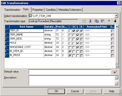
The following figure shows a return port in a Lookup transformation:
Step 4. Call the Lookup Through an Expression
Supply input values for an unconnected Lookup transformation from a :LKP expression in another
transformation. The arguments are local input ports that match the Lookup transformation input ports used in
the lookup condition. Use the following syntax for a :LKP expression:
:LKP.lookup_transformation_name(argument, argument, ...)
To continue the example about the retail store, when you write the update strategy expression, the order of
ports in the expression must match the order in the lookup condition. In this case, the ITEM_ID condition is
the first lookup condition, and therefore, it is the first argument in the update strategy expression.
IIF(ISNULL(:LKP.lkpITEMS_DIM(ITEM_ID, PRICE)), DD_UPDATE, DD_REJECT)
Use the following guidelines to write an expression that calls an unconnected Lookup transformation:
•The order in which you list each argument must match the order of the lookup conditions in the Lookup
transformation.
•The datatypes for the ports in the expression must match the datatypes for the input ports in the Lookup
transformation. The Designer does not validate the expression if the datatypes do not match.
•If one port in the lookup condition is not a lookup/output port, the Designer does not validate the
expression.
•The argument ports in the expression must be in the same order as the input ports in the lookup condition.
•If you use incorrect :LKP syntax, the Designer marks the mapping invalid.
•If you call a connected Lookup transformation in a :LKP expression, the Designer marks the mapping
invalid.
Tip: Avoid syntax errors when you enter expressions by using the point-and-click method to select
functions and ports.
Configuring Unconnected Lookup Transformations 271
Database Deadlock Resilience
The Lookup transformation is resilient to a database deadlock for uncached lookups. When a database
deadlock error occurs, the session does not fail. The Integration Service attempts to re-execute the last
statement for a specified retry period.
You can configure the number of deadlock retries and the deadlock sleep interval for an Integration Service.
These values also affect database deadlocks for the relational writer. You can override these values at the
session level as custom properties.
Configure following Integration Service Properties:
•NumOfDeadlockRetries. The number of times the PowerCenter Integration Service retries a target write
on a database deadlock. Minimum is 0. Default is 10. If you want the session to fail on deadlock set
NumOfDeadlockRetries to zero.
•DeadlockSleep. Number of seconds before the PowerCenter Integration Service retries a target write on
database deadlock.
If a deadlock occurs, the Integration Service attempts to run the statement. The Integration Service waits for
a delay period between each retry attempt. If all attempts fail due to deadlock, the session fails. The
Integration Service logs a message in the session log whenever it retries a statement.
Creating a Lookup Transformation
Create a reusable Lookup transformation in the Transformation Developer. Create a non-reusable Lookup
transformation in the Mapping Designer.
To create a Lookup transformation:
1. To create a reusable Lookup transformation, open the Transformation Developer.
To create a non-reusable Lookup transformation, open a mapping in the Mapping Designer. If you are
creating pipeline Lookup transformation, drag in a source definition to use as a lookup source.
2. Click Transformation > Create. Select the Lookup transformation.
3. Enter a name for the transformation. Click Create.
The naming convention for Lookup transformations is LKP_TransformationName.
4. Choose whether the transformation is active or passive. Click OK. You cannot change this option.
5. In the Select Lookup Table dialog box, choose one of the following options to import a lookup definition:
•Source definition from the repository.
•Target definition from the repository.
•Source qualifier from the mapping.
•Import a relational table or file from the repository.
Note: You can manually add the lookup ports instead of importing a definition. You can choose which
lookup ports are also output ports.
When you choose the lookup source, the Designer creates ports in the transformation based on the ports
in the object that you choose. The Designer configures each port as a lookup port and an output port.
The lookup ports represent the columns in the lookup source. The Lookup transformation receives data
from the lookup source in each lookup port and passes the data to the target.
272 Chapter 17: Lookup Transformation

6. If you want the Lookup transformation to return all matching rows, enable Return All Rows on Multiple
Match. You cannot change this option after you create the transformation. The Lookup transformation
becomes an active transformation.
7. Click OK or click Skip if you want to manually add the lookup ports instead of importing a definition. You
can choose which lookup ports are also output ports.
8. For a connected Lookup transformation, add input and output ports.
You can pass data through the transformation and return data from the lookup table to the target.
9. For an unconnected Lookup transformation, create a return port for the value you want to return from the
lookup.
You can return one column to the transformation that called the lookup.
10. Click the Properties tab to configure the Lookup transformation properties. Configure lookup caching.
Lookup caching is enabled by default for pipeline and flat file Lookup transformations.
11. For a Lookup transformation that has a dynamic lookup cache, associate an input port, output port, or
sequence ID with each lookup port.
The Integration Service inserts or updates rows in the lookup cache with the data from each associated
expression. If you associate a sequence ID, the Integration Service generates a primary key for inserted
rows in the lookup cache.
12. Add the lookup condition on the Condition tab.
The lookup condition compares the source column values with values in the lookup source. The
Condition tab Transformation Port represents the source column values. The Lookup Table represents
the lookup source.
RELATED TOPICS:
•“Creating a Reusable Pipeline Lookup Transformation” on page 273
•“Creating a Non-Reusable Pipeline Lookup Transformation” on page 273
Creating a Reusable Pipeline Lookup Transformation
Create a reusable pipeline Lookup transformation in the Transformation Developer. When you create the
transformation, choose Source for the lookup table location. The Transformation Developer displays a list of
source definitions from the repository.
When you choose a source qualifier that represents a relational table or flat file source definition, the
Designer creates a relational or flat file Lookup transformation. When the source qualifier represents an
application source, the Designer creates a pipeline Lookup transformation. To create a pipeline Lookup
transformation for a relational or flat file lookup source, change the source type to Source Qualifier after you
create the transformation. Enter the name of the source definition in the Lookup Table property.
When you drag a reusable pipeline Lookup transformation into a mapping, the Mapping Designer adds the
source definition from the Lookup Table property to the mapping. The Designer adds the Source Qualifier
transformation.
To change the Lookup Table Name to another source qualifier in the mapping, click the Open button in the
Lookup Table Name property. Choose a Source Qualifier from the list.
Creating a Non-Reusable Pipeline Lookup Transformation
Create a non-reusable pipeline Lookup transformation in the Mapping Designer. Drag a source definition into
a mapping. When you create the transformation in the Mapping Designer, select Source Qualifier as the
lookup table location. The Mapping Designer displays a list of the source qualifiers in the mapping. When you
Creating a Lookup Transformation 273
select a source qualifier, the Mapping Designer populates the Lookup transformation with port names and
attributes from the source qualifier you choose.
Tips for Lookup Transformations
Add an index to the columns used in a lookup condition.
If you have privileges to modify the database containing a lookup table, you can improve performance for
both cached and uncached lookups. This is important for very large lookup tables. Since the Integration
Service needs to query, sort, and compare values in these columns, the index needs to include every column
used in a lookup condition.
Place conditions with an equality operator (=) first.
If you include more than one lookup condition, place the conditions in the following order to optimize lookup
performance:
•Equal to (=)
•Less than (<), greater than (>), less than or equal to (<=), greater than or equal to (>=)
•Not equal to (!=)
Cache small lookup tables.
Improve session performance by caching small lookup tables. The result of the lookup query and processing
is the same, whether or not you cache the lookup table.
Join tables in the database.
If the lookup table is on the same database as the source table in the mapping and caching is not feasible,
join the tables in the source database rather than using a Lookup transformation.
Use a persistent lookup cache for static lookups.
If the lookup source does not change between sessions, configure the Lookup transformation to use a
persistent lookup cache. The Integration Service then saves and reuses cache files from session to session,
eliminating the time required to read the lookup source.
Call unconnected Lookup transformations with the :LKP reference qualifier.
When you write an expression using the :LKP reference qualifier, you call unconnected Lookup
transformations only. If you try to call a connected Lookup transformation, the Designer displays an error and
marks the mapping invalid.
Configure a pipeline Lookup transformation to improve performance when processing a relational or flat
file lookup source.
You can create partitions to process a relational or flat file lookup source when you define the lookup source
as a source qualifier. Configure a non-reusable pipeline Lookup transformation and create partitions in the
partial pipeline that processes the lookup source.
274 Chapter 17: Lookup Transformation

CHAPTER 1 8
Lookup Caches
This chapter includes the following topics:
•Lookup Caches Overview, 275
•Building Connected Lookup Caches, 277
•Using a Persistent Lookup Cache, 279
•Working with an Uncached Lookup or Static Cache, 280
•Sharing the Lookup Cache, 281
•Tips for Lookup Caches, 287
Lookup Caches Overview
You can configure a Lookup transformation to cache the lookup source to increase lookup performance.
Enable lookup caching when the lookup table or file is large.
The Integration Service builds a cache in memory when it processes the first row of data in a cached Lookup
transformation. It allocates memory for the cache based on the amount you configure in the transformation or
session properties. The Integration Service stores condition values in the index cache and output values in
the data cache. The Integration Service queries the cache for each row that enters the transformation.
If the data does not fit in the memory cache, the Integration Service stores the overflow values in the cache
files. The Integration Service also creates cache files in the specified cache directory. When the session
completes, the Integration Service releases cache memory and deletes the cache files unless you configure
the Lookup transformation to use a persistent cache.
If you use a flat file lookup or pipeline lookup, the Integration Service always caches the lookup source. If you
configure a flat file lookup for sorted input, the Integration Service cannot cache the lookup if the condition
columns are not grouped. If the columns are grouped, but not sorted, the Integration Service processes the
lookup as if you did not configure sorted input.
When you configure a lookup cache, you can configure the following cache settings:
Sequential and concurrent caches
You can configure the session to build caches sequentially or concurrently. When you build sequential
caches, the Integration Service creates caches as the source rows enter the Lookup transformation.
When you configure the session to build concurrent caches, the Integration Service does not wait for the
first row to enter the Lookup transformation before it creates caches. Instead, it builds multiple caches
concurrently.
275
Persistent cache
You can save the lookup cache files and reuse them the next time the Integration Service processes a
Lookup transformation configured to use the cache.
Recache from source
If the persistent cache is not synchronized with the lookup source, you can configure the Lookup
transformation to rebuild the lookup cache.
Static cache
You can configure a static cache for any lookup source. By default, the Integration Service creates a
static cache. It caches the lookup file or table and looks up values in the cache for each row that comes
into the transformation. When the lookup condition is true, the Integration Service returns a value from
the lookup cache. The Integration Service does not update the cache while it processes the Lookup
transformation.
Dynamic cache
To cache a lookup source and update the cache, configure a Lookup transformation with dynamic cache.
The Integration Service dynamically inserts or updates data in the lookup cache and passes the data to
the target. The dynamic cache is synchronized with the target.
Shared cache
You can share the lookup cache between multiple transformations. You can share an unnamed cache
between transformations in the same mapping. You can share a named cache between transformations
in the same or different mappings. Lookup transformations can share unnamed static caches within the
same target load order group if the cache sharing rules match. Lookup transformations cannot share
dynamic cache within the same target load order group.
When you do not configure the Lookup transformation for caching, the Integration Service queries the lookup
source for each input row. Whether or not you cache the lookup source, the result of the Lookup query and
processing is the same. However, you can increase lookup performance on a large lookup source if you
enable lookup caching.
276 Chapter 18: Lookup Caches

Cache Comparison
The Integration Service performs differently based on the type of lookup cache that you configure.
The following table compares Lookup transformations with an uncached lookup, a static cache, and a
dynamic cache:
Uncached Static Cache Dynamic Cache
The Integration Service does
not insert or update the cache.
The Integration Service does
not insert or update the cache.
The Integration Service can insert or update
rows in the cache as it passes rows to the
target.
You can use a relational
lookup.
You can use a relational, flat
file, or pipeline lookup.
You can use a relational, flat file, or Source
Qualifier lookup.
When the condition is true, the
Integration Service returns a
value from the lookup table or
cache.
When the condition is not true,
the Integration Service returns
the default value for
connected transformations
and NULL for unconnected
transformations.
When the condition is true, the
Integration Service returns a
value from the lookup table or
cache.
When the condition is not true,
the Integration Service returns
the default value for connected
transformations and NULL for
unconnected transformations.
When the condition is true, the Integration
Service either updates rows in the cache or
leaves the cache unchanged, based on the
row type. This indicates that the row is in
the cache and target table. You can pass
updated rows to a target.
When the condition is not true, the
Integration Service either inserts rows into
the cache or leaves the cache unchanged,
based on the row type. This indicates that
the row is not in the cache or target. You
can pass inserted rows to a target table.
RELATED TOPICS:
•“Working with an Uncached Lookup or Static Cache” on page 280
•“Dynamic Lookup Cache Updates” on page 296
Building Connected Lookup Caches
The Integration Service can build lookup caches for connected Lookup transformations in the following ways:
•Sequential caches. The Integration Service builds lookup caches sequentially. The Integration Service
builds the cache in memory when it processes the first row of the data in a cached lookup transformation.
•Concurrent caches. The Integration Service builds lookup caches concurrently. It does not need to wait
for data to reach the Lookup transformation.
Note: The Integration Service builds caches for unconnected Lookup transformations sequentially regardless
of how you configure cache building. If you configure the session to build concurrent caches for an
unconnected Lookup transformation, the Integration Service ignores this setting and builds unconnected
Lookup transformation caches sequentially.
Sequential Caches
By default, the Integration Service builds a cache in memory when it processes the first row of data in a
cached Lookup transformation. The Integration Service creates each lookup cache in the pipeline
sequentially. The Integration Service waits for any upstream active transformation to complete processing
Building Connected Lookup Caches 277
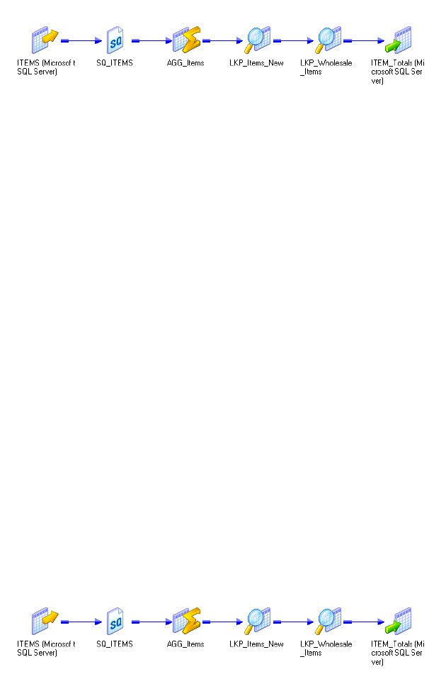
before it starts processing the rows in the Lookup transformation. The Integration Service does not build
caches for a downstream Lookup transformation until an upstream Lookup transformation completes building
a cache.
For example, the following mapping contains an unsorted Aggregator transformation followed by two Lookup
transformations:
Figure 2. Building Lookup Caches Sequentially
The Integration Service processes all the rows for the unsorted Aggregator transformation and begins
processing the first Lookup transformation after the unsorted Aggregator transformation completes. When it
processes the first input row, the Integration Service begins building the first lookup cache. After the
Integration Service finishes building the first lookup cache, it can begin processing the lookup data. The
Integration Service begins building the next lookup cache when the first row of data reaches the Lookup
transformation.
You might want to process lookup caches sequentially if the Lookup transformation may not process row
data. The Lookup transformation may not process row data if the transformation logic is configured to route
data to different pipelines based on a condition. Configuring sequential caching may allow you to avoid
building lookup caches unnecessarily. For example, a Router transformation might route data to one pipeline
if a condition resolves to true, and it might route data to another pipeline if the condition resolves to false. In
this case, a Lookup transformation might not receive data at all.
Concurrent Caches
You can configure the Integration Service to create lookup caches concurrently. You may be able to improve
session performance using concurrent caches. Performance may especially improve when the pipeline
contains an active transformations upstream of the Lookup transformation. You may want to configure the
session to create concurrent caches if you are certain that you will need to build caches for each of the
Lookup transformations in the session.
When you configure the Lookup transformation to create concurrent caches, it does not wait for upstream
transformations to complete before it creates lookup caches, and it does not need to finish building a lookup
cache before it can begin building other lookup caches.
The following figure shows lookup transformation caches built concurrently:
When you run the session, the Integration Service builds the Lookup caches concurrently. It does not wait for
upstream transformations to complete, and it does not wait for other Lookup transformations to complete
cache building.
278 Chapter 18: Lookup Caches
Note: You cannot process caches for unconnected Lookup transformations concurrently.
To configure the session to create concurrent caches, configure a value for the session configuration
attribute, Additional Concurrent Pipelines for Lookup Cache Creation.
Using a Persistent Lookup Cache
You can configure a Lookup transformation to use a non-persistent or persistent cache. The Integration
Service saves or deletes lookup cache files after a successful session based on the Lookup Cache Persistent
property.
If the lookup table does not change between sessions, you can configure the Lookup transformation to use a
persistent lookup cache. The Integration Service saves and reuses cache files from session to session,
eliminating the time required to read the lookup table.
Using a Non-Persistent Cache
By default, the Integration Service uses a non-persistent cache when you enable caching in a Lookup
transformation. The Integration Service deletes the cache files at the end of a session. The next time you run
the session, the Integration Service builds the memory cache from the database.
Using a Persistent Cache
If you want to save and reuse the cache files, you can configure the transformation to use a persistent cache.
Use a persistent cache when you know the lookup table does not change between session runs.
The first time the Integration Service runs a session using a persistent lookup cache, it saves the cache files
to disk instead of deleting them. The next time the Integration Service runs the session, it builds the memory
cache from the cache files. If the lookup table changes occasionally, you can override session properties to
recache the lookup from the database.
When you use a persistent lookup cache, you can specify a name for the cache files. When you specify a
named cache, you can share the lookup cache across sessions.
Rebuilding the Lookup Cache
You can instruct the Integration Service to rebuild the lookup cache if you think that the lookup source
changed since the last time the Integration Service built the persistent cache.
When you rebuild a cache, the Integration Service creates new cache files, overwriting existing persistent
cache files. The Integration Service writes a message to the session log when it rebuilds the cache.
You can rebuild the cache when the mapping contains one Lookup transformation or when the mapping
contains Lookup transformations in multiple target load order groups that share a cache. You do not need to
rebuild the cache when a dynamic lookup shares the cache with a static lookup in the same mapping.
If the Integration Service cannot reuse the cache, it either recaches the lookup from the database, or it fails
the session, depending on the mapping and session properties.
Using a Persistent Lookup Cache 279

The following table summarizes how the Integration Service handles persistent caching for named and
unnamed caches:
Mapping or Session Changes Between Sessions Named Cache Unnamed Cache
Integration Service cannot locate cache files. For example, the file
no longer exists or the Integration Service runs on a grid and the
cache file is not available to all nodes.
Rebuilds cache. Rebuilds cache.
Enable or disable the Enable High Precision option in session
properties.
Fails session. Rebuilds cache.
Edit the transformation in the Mapping Designer, Mapplet Designer,
or Reusable Transformation Developer.
1Fails session. Rebuilds cache.
Edit the mapping (excluding Lookup transformation). Reuses cache. Rebuilds cache.
Change the number of partitions in the pipeline that contains the
Lookup transformation.
Fails session. Rebuilds cache.
Change database connection or the file location used to access the
lookup table.
Fails session. Rebuilds cache.
Change the Integration Service data movement mode. Fails session. Rebuilds cache.
Change the sort order in Unicode mode. Fails session. Rebuilds cache.
Change the Integration Service code page to a compatible code
page.
Reuses cache. Reuses cache.
Change the Integration Service code page to an incompatible code
page.
Fails session. Rebuilds cache.
1. Editing properties such as transformation description or port description does not affect persistent cache
handling.
Working with an Uncached Lookup or Static Cache
By default, the Integration Service creates a static lookup cache when you configure a Lookup transformation
for caching. The Integration Service builds the cache when it processes the first lookup request. It queries the
cache based on the lookup condition for each row that passes into the transformation. The Integration
Service does not update the cache while it processes the transformation. The Integration Service processes
an uncached lookup the same way it processes a cached lookup except that it queries the lookup source
instead of building and querying the cache.
When the lookup condition is true, the Integration Service returns the values from the lookup source or
cache. For connected Lookup transformations, the Integration Service returns the values represented by the
lookup/output ports. For unconnected Lookup transformations, the Integration Service returns the value
represented by the return port.
When the condition is not true, the Integration Service returns either NULL or default values. For connected
Lookup transformations, the Integration Service returns the default value of the output port when the
condition is not met. For unconnected Lookup transformations, the Integration Service returns NULL when
the condition is not met.
280 Chapter 18: Lookup Caches
When you create multiple partitions in a pipeline that use a static cache, the Integration Service creates one
memory cache for each partition and one disk cache for each transformation.
Sharing the Lookup Cache
You can configure multiple Lookup transformations in a mapping to share a single lookup cache. The
Integration Service builds the cache when it processes the first Lookup transformation. It uses the same
cache to perform lookups for subsequent Lookup transformations that share the cache.
You can share caches that are unnamed and named:
•Unnamed cache. When Lookup transformations in a mapping have compatible caching structures, the
Integration Service shares the cache by default. You can only share static unnamed caches.
•Named cache. Use a persistent named cache when you want to share a cache file across mappings or
share a dynamic and a static cache. The caching structures must match or be compatible with a named
cache. You can share static and dynamic named caches.
When the Integration Service shares a lookup cache, it writes a message in the session log.
Sharing an Unnamed Lookup Cache
By default, the Integration Service shares the cache for Lookup transformations in a mapping that have
compatible caching structures. For example, if you have two instances of the same reusable Lookup
transformation in one mapping and you use the same output ports for both instances, the Lookup
transformations share the lookup cache by default.
When two Lookup transformations share an unnamed cache, the Integration Service saves the cache for a
Lookup transformation and uses it for subsequent Lookup transformations that have the same lookup cache
structure.
If the transformation properties or the cache structure do not allow sharing, the Integration Service creates a
new cache.
Guidelines for Sharing an Unnamed Lookup Cache
Use the following guidelines when you configure Lookup transformations to share an unnamed cache:
•You can share static unnamed caches.
•Shared transformations must use the same ports in the lookup condition. The conditions can use different
operators, but the ports must be the same.
•You must configure some of the transformation properties to enable unnamed cache sharing.
•The structure of the cache for the shared transformations must be compatible.
-If you use hash auto-keys partitioning, the lookup/output ports for each transformation must match.
-If you do not use hash auto-keys partitioning, the lookup/output ports for the first shared transformation
must match or be a superset of the lookup/output ports for subsequent transformations.
•If the Lookup transformations with hash auto-keys partitioning are in different target load order groups,
you must configure the same number of partitions for each group. If you do not use hash auto-keys
partitioning, you can configure a different number of partitions for each target load order group.
Sharing the Lookup Cache 281

The following table shows when you can share an unnamed static and dynamic cache:
Shared Cache Location of Transformations
Static with Static Anywhere in the mapping.
Dynamic with Dynamic Cannot share.
Dynamic with Static Cannot share.
The following table describes the guidelines to follow when you configure Lookup transformations to share an
unnamed cache:
Properties Configuration for Unnamed Shared Cache
Lookup SQL Override If you use the Lookup SQL Override property, you must use the same
override in all shared transformations.
Lookup Table Name Must match.
Lookup Caching Enabled Must be enabled.
Lookup Policy on Multiple Match -
Lookup Condition Shared transformations must use the same ports in the lookup condition. The
conditions can use different operators, but the ports must be the same.
Connection Information The connection must be the same. When you configure the sessions, the
database connection must match.
Source Type Must match.
Tracing Level -
Lookup Cache Directory Name Does not need to match.
Lookup Cache Persistent Optional. You can share persistent and non-persistent.
Lookup Data Cache Size Integration Service allocates memory for the first shared transformation in
each pipeline stage. It does not allocate additional memory for subsequent
shared transformations in the same pipeline stage.
Lookup Index Cache Size Integration Service allocates memory for the first shared transformation in
each pipeline stage. It does not allocate additional memory for subsequent
shared transformations in the same pipeline stage.
Dynamic Lookup Cache You cannot share an unnamed dynamic cache.
Output Old Value On Update Does not need to match.
Cache File Name Prefix Do not use. You cannot share a named cache with an unnamed cache.
282 Chapter 18: Lookup Caches

Properties Configuration for Unnamed Shared Cache
Recache From Lookup Source If you configure a Lookup transformation to recache from source, subsequent
Lookup transformations in the target load order group can share the existing
cache whether or not you configure them to recache from source. If you
configure subsequent Lookup transformations to recache from source, the
Integration Service shares the cache instead of rebuilding the cache when it
processes the subsequent Lookup transformation.
If you do not configure the first Lookup transformation in a target load order
group to recache from source, and you do configure the subsequent Lookup
transformation to recache from source, the transformations cannot share the
cache. The Integration Service builds the cache when it processes each
Lookup transformation.
Lookup/Output Ports The lookup/output ports for the second Lookup transformation must match or
be a subset of the ports in the transformation that the Integration Service
uses to build the cache. The order of the ports do not need to match.
Insert Else Update -
Update Else Insert -
Datetime Format -
Thousand Separator -
Decimal Separator -
Case-Sensitive String
Comparison
Must match.
Null Ordering Must match.
Sorted Input -
Sharing a Named Lookup Cache
You can also share the cache between multiple Lookup transformations by using a persistent lookup cache
and naming the cache files. You can share one cache between Lookup transformations in the same mapping
or across mappings.
The Integration Service uses the following process to share a named lookup cache:
1. When the Integration Service processes the first Lookup transformation, it searches the cache directory
for cache files with the same file name prefix.
2. If the Integration Service finds the cache files and you do not specify to recache from source, the
Integration Service uses the saved cache files.
3. If the Integration Service does not find the cache files or if you specify to recache from source, the
Integration Service builds the lookup cache using the database table.
4. The Integration Service saves the cache files to disk after it processes each target load order group.
Sharing the Lookup Cache 283
5. The Integration Service uses the following rules to process the second Lookup transformation with the
same cache file name prefix:
•The Integration Service uses the memory cache if the transformations are in the same target load
order group.
•The Integration Service rebuilds the memory cache from the persisted files if the transformations are
in different target load order groups.
•The Integration Service rebuilds the cache from the database if you configure the transformation to
recache from source and the first transformation is in a different target load order group.
•If you do not configure the first Lookup transformation in a target load order group to recache from
source, and you do configure the subsequent Lookup transformation to recache from source, the
Integration Service does not rebuild the cache.
•If the cache structures do not match, the Integration Service fails the session.
If you run two sessions simultaneously that share a lookup cache, the Integration Service uses the following
rules to share the cache files:
•The Integration Service processes multiple sessions simultaneously when the Lookup transformations
only need to read the cache files.
•The Integration Service fails the session if one session updates a cache file while another session
attempts to read or update the cache file. For example, Lookup transformations update the cache file if
they are configured to use a dynamic cache or recache from source.
Guidelines for Sharing a Named Lookup Cache
Use the following guidelines when you configure Lookup transformations to share a named cache:
•Do not share a lookup cache between sessions if the cache is a dynamic lookup cache or the
transformation is configured to recache from the source.
•You can share a cache between dynamic and static Lookup transformations but you must follow the
guidelines for the cache location.
•You must configure some of the transformation properties to enable named cache sharing.
•A dynamic lookup cannot share the cache if the named cache has duplicate rows.
•A named cache created by a dynamic Lookup transformation with a lookup policy of error on multiple
match can be shared by a static or dynamic Lookup transformation with any lookup policy.
•A named cache created by a dynamic Lookup transformation with a lookup policy of use first, use last, or
use all values can be shared by a Lookup transformation with the same lookup policy.
•Shared transformations must use the same output ports in the mapping. The criteria and result columns
for the cache must match the cache files.
•A dynamic Lookup transformation cannot share the cache with another Lookup transformation within the
same target load order group. In a target load order group, processing of caches takes place in parallel
and completes after the target loads. The PowerCenter Integration Service does not allow cache sharing
because the full cache is unavailable for subsequent Lookup transformations.
The Integration Service might use the memory cache, or it might build the memory cache from the file,
depending on the type and location of the Lookup transformations.
284 Chapter 18: Lookup Caches

The following table shows when you can share a named cache between a static Lookup transformation and a
dynamic Lookup transformation:
Table 3. Location for Sharing Named Cache
Shared Cache Location of Transformations Cache Shared
Static with Static - Same target load order group.
- Separate target load order groups.
- Separate mappings.
- Integration Service uses memory cache.
- Integration Service uses memory cache.
- Integration Service builds memory cache from
file.
Dynamic with Dynamic - Separate target load order groups.
- Separate mappings.
- Integration Service uses memory cache.
- Integration Service builds memory cache from
file.
Dynamic with Static - Separate target load order groups.
- Separate mappings.
- Integration Service builds memory cache from
file.
- Integration Service builds memory cache from
file.
The following table describes the guidelines to follow when you configure Lookup transformations to share a
named cache:
Table 4. Properties for Sharing Named Cache
Properties Configuration for Named Shared Cache
Lookup SQL Override If you use the Lookup SQL Override property, you must use the same override in
all shared transformations.
Lookup Table Name Must match.
Lookup Caching Enabled Must be enabled.
Lookup Policy on Multiple
Match
- A named cache created by a dynamic Lookup transformation with a lookup policy of
error on multiple match can be shared by a static or dynamic Lookup
transformation with any lookup policy.
- A named cache created by a dynamic Lookup transformation with a lookup policy of
use first or use last can be shared by a Lookup transformation with the same
lookup policy.
- A named cached can be shared by a dynamic Lookup transformation with a lookup
policy of use all values if it shares the cache with another active lookup
transformation with the same lookup policy.
Lookup Condition Shared transformations must use the same ports in the lookup condition. The
conditions can use different operators, but the ports must be the same.
Connection Information The connection must be the same. When you configure the sessions, the
database connection must match.
Source Type Must match.
Tracing Level -
Lookup Cache Directory
Name
Must match.
Sharing the Lookup Cache 285

Properties Configuration for Named Shared Cache
Lookup Cache Persistent Must be enabled.
Lookup Data Cache Size When transformations within the same mapping share a cache, the Integration
Service allocates memory for the first shared transformation in each pipeline
stage. It does not allocate additional memory for subsequent shared
transformations in the same pipeline stage.
Lookup Index Cache Size When transformations within the same mapping share a cache, the Integration
Service allocates memory for the first shared transformation in each pipeline
stage. It does not allocate additional memory for subsequent shared
transformations in the same pipeline stage.
Dynamic Lookup Cache For more information about sharing static and dynamic caches, see “Guidelines
for Sharing a Named Lookup Cache” on page 284.
Output Old Value on Update Does not need to match.
Update Dynamic Cache Does not need to match.
Cache File Name Prefix Must match. Enter the prefix only. Do not enter .idx or .dat. You cannot share a
named cache with an unnamed cache.
Recache from Source If you configure a Lookup transformation to recache from source, subsequent
Lookup transformations in the target load order group can share the existing
cache whether or not you configure them to recache from source. If you
configure subsequent Lookup transformations to recache from source, the
Integration Service shares the cache instead of rebuilding the cache when it
processes the subsequent Lookup transformation.
If you do not configure the first Lookup transformation in a target load order
group to recache from source, and you do configure the subsequent Lookup
transformation to recache from source, the Integration Service does not rebuild
the cache.
Lookup/Output Ports Lookup/output ports must be identical, but they do not need to be in the same
order.
Insert Else Update -
Update Else Insert -
Thousand Separator -
Decimal Separator -
Case-Sensitive String
Comparison
-
Null Ordering -
Sorted Input Must match.
Note: You cannot share a lookup cache created on a different operating system. For example, only an
Integration Service on UNIX can read a lookup cache created on a Integration Service on UNIX, and only an
Integration Service on Windows can read a lookup cache created on an Integration Service on Windows.
286 Chapter 18: Lookup Caches
Tips for Lookup Caches
Cache small lookup tables.
Increase performance by caching small lookup tables.
Use a persistent lookup cache for static lookup tables.
If the lookup table does not change between sessions, configure the Lookup transformation to use a
persistent lookup cache. the Integration Service saves and reuses cache files, eliminating the time required
to read the lookup table.
Tips for Lookup Caches 287

CHAPTER 1 9
Dynamic Lookup Cache
This chapter includes the following topics:
•Dynamic Lookup Cache Overview, 288
•Dynamic Lookup Properties, 289
•Lookup Transformation Values, 293
•Dynamic Lookup Cache Updates, 296
•Mappings with Dynamic Lookups, 298
•Conditional Dynamic Cache Updates, 300
•Dynamic Cache Update with Expression Results, 301
•Synchronizing Cache with the Lookup Source, 303
•Dynamic Lookup Cache Example, 304
•Rules and Guidelines for Dynamic Lookup Caches, 305
Dynamic Lookup Cache Overview
Use a dynamic lookup cache to keep the cache synchronized with the target. You can use a dynamic cache
with a relational lookup, flat file lookup, or a pipeline lookup.
The Integration Service builds the dynamic lookup cache when it processes the first lookup request. It
queries the cache based on the lookup condition for each row that passes into the transformation. The
Integration Service updates the lookup cache when it processes each row.
Based on the results of the lookup query, the row type, and the Lookup transformation properties, the
Integration Service performs one of the following actions on the dynamic lookup cache when it reads a row
from the source:
Inserts the row into the cache
The Integration Service inserts the row when the row is not in the cache and you configured the Lookup
transformation to insert rows into the cache. You can configure the transformation to insert rows into the
cache based on input ports or generated sequence IDs. The Integration Service flags the row as insert.
Updates the row in the cache
The Integration Service updates the row when the row exists in the cache and you configured the
Lookup transformation to update rows in the cache. The Integration Service updates the row in the
cache based on the input ports. The Integration Service flags the row as an update row.
288
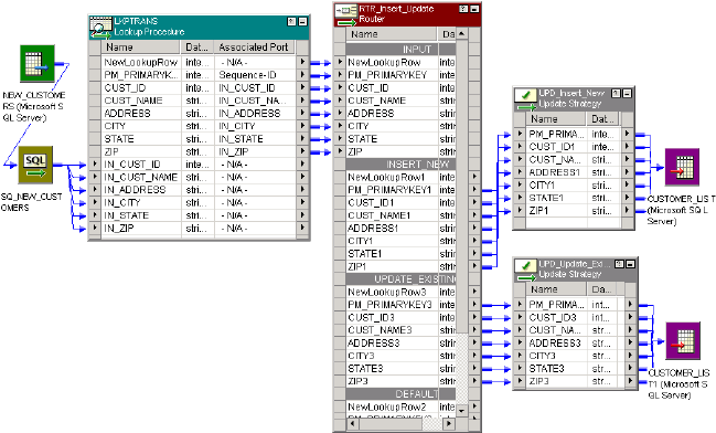
Makes no change to the cache
The Integration Service makes no change when the row exists in the cache and you configured the
Lookup transformation to insert new rows only. Or, the row is not in the cache and you specified to
update existing rows only. Or, the row is in the cache, but based on the lookup condition, nothing
changes. The Integration Service flags the row as unchanged.
Based on the value of the NewLookupRow, you can also configure a Router or Filter transformation with the
dynamic Lookup transformation to route insert or update rows to the target table. You can route unchanged
rows to another target table or flat file, or you can drop them.
The following figure shows a mapping with a Lookup transformation that uses a dynamic lookup cache:
Dynamic Lookup Properties
A Lookup transformation with a dynamic cache has the following properties:
•NewLookupRow. The Designer adds this port to a Lookup transformation configured to use a dynamic
cache. Indicates with a numeric value whether the Integration Service inserts or updates the row in the
cache, or makes no change to the cache. To keep the lookup cache and the target table synchronized,
pass rows to the target when the NewLookupRow value is equal to 1 or 2.
•Associated Expression. Associate lookup ports or the associated ports with an expression, an input/
output port, or a sequence ID. The Integration Service uses the data in the associated expression to insert
or update rows in the lookup cache. If you associate a sequence ID, the Integration Service generates a
primary key for inserted rows in the lookup cache.
•Ignore Null Inputs for Updates. The Designer activates this port property for lookup/output ports when
you configure the Lookup transformation to use a dynamic cache. Select this property when you do not
want the Integration Service to update the column in the cache when the data in this column contains a
null value.
•Ignore in Comparison. The Designer activates this port property for lookup/output ports not used in the
lookup condition when you configure the Lookup transformation to use a dynamic cache. The Integration
Service compares the values in all lookup ports with the values in their associated input ports by default.
Select this property if you want the Integration Service to ignore the port when it compares values before
updating a row.
Dynamic Lookup Properties 289
•Update Dynamic Cache Condition. Allow the Integration Service to update the dynamic cache
conditionally. You can create a boolean expression that determines whether to update the cache for an
input row. Or, you can enable the Integration Service to update the cache with an expression result for an
input row. The expression can contain values from the input row or the lookup cache.
NewLookupRows
When you configure a Lookup transformation to use a dynamic cache, the Designer adds the
NewLookupRow port to the transformation. The Integration Service assigns a value to the port, depending on
the action it performs to the lookup cache.
The following table lists the possible NewLookupRow values:
NewLookupRow Value Description
0 Integration Service does not update or insert the row in the cache.
1 Integration Service inserts the row into the cache.
2 Integration Service updates the row in the cache.
When the Integration Service reads a row, it changes the lookup cache depending on the results of the
lookup query and the Lookup transformation properties you define. It assigns the value 0, 1, or 2 to the
NewLookupRow port to indicate if it inserts or updates the row in the cache, or makes no change.
The NewLookupRow value indicates how the Integration Service changes the lookup cache. It does not
change the row type. Therefore, use a Filter or Router transformation and an Update Strategy transformation
to keep the target table and lookup cache synchronized.
Configure the Filter transformation to pass new and updated rows to the Update Strategy transformation
before passing them to the cached target. Use the Update Strategy transformation to change the row type of
each row to insert or update, depending on the NewLookupRow value.
You can drop the rows that do not change the cache, or you can pass them to another target.
Define the filter condition in the Filter transformation based on the value of NewLookupRow. For example,
use the following condition to pass both inserted and updated rows to the cached target:
NewLookupRow != 0
RELATED TOPICS:
•“Configuring the Upstream Update Strategy Transformation” on page 298
Associated Expression
When you configure a dynamic lookup cache, you must associate each lookup port with an input port, input/
output port, a sequence ID, or an expression. When you choose an input/output port, the Designer associates
the input/output port with the lookup/output port used in the lookup condition. When you configure an
expression, the Integration Service updates the cache with the result of the associated expression. The
expression can contain input values or values from the lookup cache.
To associate a lookup port with an input/output port, click the Associated Expression column for a lookup
port. Select a port from the list.
To create an expression, click the Associated column for the lookup port. Choose Associated Expression
from the list. The Expression Editor appears.
290 Chapter 19: Dynamic Lookup Cache

To create a generated key for a column in the target table, select Sequence-ID in the Associated Expression
column. You can associate a generated key instead of an input port for lookup ports with the Bigint, Integer,
or Small Integer datatype. For Bigint lookup ports, the generated key maximum value is
9,223,372,036,854,775,807. For Integer or Small Integer lookup ports, the generated key maximum value is
2,147,483,647.
When you select Sequence-ID in the Associated Expression column, the Integration Service generates a key
when it inserts a row into the lookup cache.
The Integration Service uses the following process to generate sequence IDs:
1. When the Integration Service creates the dynamic lookup cache, it tracks the range of values for each
port that has a sequence ID in the dynamic lookup cache.
2. When the Integration Service inserts a row of data into the cache, it generates a key for a port by
incrementing the greatest sequence ID value by one.
3. When the Integration Service reaches the maximum number for a generated sequence ID, it starts over
at one. The Integration Service increments each sequence ID by one until it reaches the smallest
existing value minus one. If the Integration Service runs out of unique sequence ID numbers, the session
fails.
The Integration Service generates a sequence ID for each row it inserts into the cache.
RELATED TOPICS:
•“Dynamic Cache Update with Expression Results” on page 301
Null Values
When you update a dynamic lookup cache and target table, the source data might contain some null values.
The Integration Service can handle the null values in the following ways:
•Insert null values. The Integration Service uses null values from the source and updates the lookup
cache and target table using all values from the source.
•Ignore null values. The Integration Service ignores the null values in the source and updates the lookup
cache and target table using only the not null values from the source.
If you know the source data contains null values, and you do not want the Integration Service to update the
lookup cache or target with null values, select the Ignore Null property for the corresponding lookup/output
port.
For example, you want to update the master customer table. The source contains new customers and current
customers whose last names have changed. The source contains the customer IDs and names of customers
whose names have changed, but it contains null values for the address columns. You want to insert new
customers and update the current customer names while retaining the current address information in a
master customer table.
For example, the master customer table contains the following data:
Primary
Key
CUST_ID CUST_NAME ADDRESS CITY STATE ZIP
100001 80001 Marion James 100 Main St. Mt. View CA 94040
100002 80002 Laura Jones 510 Broadway Ave. Raleigh NC 27601
100003 80003 Shelley Lau 220 Burnside Ave. Portland OR 97210
Dynamic Lookup Properties 291
The source contains the following data:
CUST_ID CUST_NAME ADDRESS CITY STATE ZIP
80001 Marion Atkins NULL NULL NULL NULL
80002 Laura Gomez NULL NULL NULL NULL
99001 Jon Freeman 555 6th Ave. San Jose CA 95051
Select Insert Else Update in the Lookup transformation in the mapping. Select the Ignore Null option for all
lookup/output ports in the Lookup transformation. When you run a session, the Integration Service ignores
null values in the source data and updates the lookup cache and the target table with not null values:
PRIMARYKE
Y
CUST_ID CUST_NAME ADDRESS CITY STATE ZIP
100001 80001 Marion Atkins 100 Main St. Mt. View CA 94040
100002 80002 Laura Gomez 510 Broadway Ave. Raleigh NC 27601
100003 80003 Shelley Lau 220 Burnside Ave. Portland OR 97210
100004 99001 Jon Freeman 555 6th Ave. San Jose CA 95051
Note: When you choose to ignore NULLs, you must verify that you output the same values to the target that
the Integration Service writes to the lookup cache. When you choose to ignore NULLs, the lookup cache and
the target table might become unsynchronized if you pass null input values to the target. Configure the
mapping based on the value you want the Integration Service to output from the lookup/output ports when it
updates a row in the cache:
•New values. Connect only lookup/output ports from the Lookup transformation to the target.
•Old values. Add an Expression transformation after the Lookup transformation and before the Filter or
Router transformation. Add output ports in the Expression transformation for each port in the target table
and create expressions to ensure you do not output null input values to the target.
Ignore Ports in Comparison
When you run a session that uses a dynamic lookup cache, the Integration Service compares the values in
all lookup ports with the values in their associated input ports by default. It compares the values to determine
whether or not to update the row in the lookup cache. When a value in an input port differs from the value in
the lookup port, the Integration Service updates the row in the cache.
If you do not want to compare all ports, you can choose the ports you want the Integration Service to ignore
when it compares ports. The Designer only enables this property for lookup/output ports when the port is not
used in the lookup condition. You can improve performance by ignoring some ports during comparison.
You might want to do this when the source data includes a column that indicates whether or not the row
contains data you need to update. Select the Ignore in Comparison property for all lookup ports except the
port that indicates whether or not to update the row in the cache and target table.
You must configure the Lookup transformation to compare at least one port. The Integration Service fails the
session when you ignore all ports.
To clear the Ignore in Comparison property, associate a port with the lookup port. When you clear the Ignore
in Comparison property, the PowerCenter Integration Service updates the row in the cache.
292 Chapter 19: Dynamic Lookup Cache
SQL Override
When you add a WHERE clause in a Lookup transformation using a dynamic cache, connect a Filter
transformation before the Lookup transformation to filter rows that you do not want to insert into the cache or
target table. If you do not include the Filter transformation, you might get inconsistent results between the
cache and the target table.
For example, you configure a Lookup transformation to perform a dynamic lookup on the employee table,
EMP, matching rows by EMP_ID. You define the following lookup SQL override:
SELECT EMP_ID, EMP_STATUS FROM EMP ORDER BY EMP_ID, EMP_STATUS WHERE EMP_STATUS = 4
When you first run the session, the Integration Service builds the lookup cache from the target table based on
the lookup SQL override. All rows in the cache match the condition in the WHERE clause,
EMP_STATUS = 4
.
For example, the Integration Service reads a source row that meets the lookup condition you specify, but the
value of EMP_STATUS is 2. Although the target might have the row where EMP_STATUS is 2, the
Integration Service does not find the row in the cache because of the SQL override. The Integration Service
inserts the row into the cache and passes the row to the target table. When the Integration Service inserts
this row in the target table, you might get inconsistent results when the row already exists. In addition, not all
rows in the cache match the condition in the WHERE clause in the SQL override.
To verify that you only insert rows into the cache that match the WHERE clause, add a Filter transformation
before the Lookup transformation and define the filter condition as the condition in the WHERE clause in the
lookup SQL override.
For the example above, enter the following filter condition in the Filter transformation and the WHERE clause
in the SQL override:
EMP_STATUS = 4
Lookup Transformation Values
The Lookup transformation contains values for input ports, the lookup, and output ports. If you enable a
dynamic lookup cache, the output port values vary based on how you configure the dynamic lookup cache.
The Lookup transformation contains the following types of values:
Input value
Value that the Integration Service passes into the Lookup transformation.
Lookup value
Value that the Integration Service inserts into the cache.
Output value
Value that the Integration Service passes from the output port of the Lookup transformation. The output
value of the lookup/output port depends on whether you choose to output old or new values when the
Integration Service updates a row.
Lookup Transformation Values 293
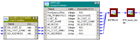
For example, the following Lookup transformation uses a dynamic lookup cache:
You define the following lookup condition:
IN_CUST_ID = CUST_ID
By default, the row type of all rows entering the Lookup transformation is insert. To perform both inserts and
updates in the cache and target table, you select the Insert Else Update property in the Lookup
transformation.
The following sections describe the values of the rows in the cache, the input rows, the lookup rows, and the
output rows as you run the session.
Initial Cache Values
When you run the session, the Integration Service builds the lookup cache from the target table with the
following data:
PK_PRIMARYKEY CUST_ID CUST_NAME ADDRESS
100001 80001 Marion James 100 Main St.
100002 80002 Laura Jones 510 Broadway Ave.
100003 80003 Shelley Lau 220 Burnside Ave.
Input Values
The source contains rows that exist and rows that do not exist in the target table. The following rows pass
into the Lookup transformation from the Source Qualifier transformation:
SQ_CUST_ID SQ_CUST_NAME SQ_ADDRESS
80001 Marion Atkins 100 Main St.
80002 Laura Gomez 510 Broadway Ave.
99001 Jon Freeman 555 6th Ave.
Lookup Values
The Integration Service looks up values in the cache based on the lookup condition. It updates rows in the
cache for existing customer IDs 80001 and 80002. It inserts a row into the cache for customer ID 99001. The
Integration Service generates a new key (PK_PRIMARYKEY) for the new row.
294 Chapter 19: Dynamic Lookup Cache
The following table shows the rows and values returned from the lookup:
PK_PRIMARYKEY CUST_ID CUST_NAME ADDRESS
100001 80001 Marion Atkins 100 Main St.
100002 80002 Laura Gomez 510 Broadway Ave.
100004 99001 Jon Freeman 555 6th Ave.
Output Values
The Integration Service flags the rows in the Lookup transformation based on the inserts and updates it
performs on the dynamic cache. These rows pass through an Expression transformation to a Router
transformation that filters and passes on the inserted and updated rows to an Update Strategy
transformation. The Update Strategy transformation flags the rows based on the value of the NewLookupRow
port.
The output values of the lookup/output and input/output ports depend on whether you choose to output old or
new values when the Integration Service updates a row. However, the output values of the NewLookupRow
port and any lookup/output port that uses the sequence ID is the same for new and updated rows.
When you choose to output new values, the lookup/output ports output the following values:
NewLookupRow PK_PRIMARYKEY CUST_ID CUST_NAME ADDRESS
2 100001 80001 Marion Atkins 100 Main St.
2 100002 80002 Laura Gomez 510 Broadway Ave.
1 100004 99001 Jon Freeman 555 6th Ave.
When you choose to output old values, the lookup/output ports output the following values:
NewLookupRow PK_PRIMARYKEY CUST_ID CUST_NAME ADDRESS
2 100001 80001 Marion James 100 Main St.
2 100002 80002 Laura Jones 510 Broadway Ave.
1 100004 99001 Jon Freeman 555 6th Ave.
When the Integration Service updates rows in the lookup cache it uses the primary key (PK_PRIMARYKEY)
values for rows in the cache and the target table.
The Integration Service uses the sequence ID to generate a primary key for the customer that it does not find
in the cache. The Integration Service inserts the primary key value into the lookup cache and it returns the
value to the lookup/output port.
The Integration Service output values from the input/output ports that match the input values.
Note: If the input value is NULL and you select the Ignore Null property for the associated input port, the
input value does not equal the lookup value or the value out of the input/output port. When you select the
Ignore Null property, the lookup cache and the target table might become unsynchronized if you pass null
values to the target. You must verify that you do not pass null values to the target.
Lookup Transformation Values 295
Dynamic Lookup Cache Updates
The Integration Service updates the dynamic cache based on the row type, query result, and the Lookup
transformation properties.
When you use a dynamic lookup cache, define the row type of the rows entering the Lookup transformation
as either insert or update. You can define some rows as insert and some as update, or all insert, or all
update. By default, the row type of all rows entering a Lookup transformation is insert. You can add an
Update Strategy transformation before the Lookup transformation to define the row type as update.
The Integration Service either inserts or updates rows in the cache, or does not change the cache. By
default, the Lookup transformation inserts a row in the cache when the row type is insert, and updates a row
when the row type is update.
However, you can configure the following Lookup properties to change how the Integration Service handles
inserts and updates to the cache:
•Insert Else Update. Applies to rows entering the Lookup transformation where the row type is insert. Use
this option to update the row in the cache if the data already exists in the cache. If you do not enable this
option, the Integration Service inserts the rows into the cache regardless if they exist.
•Update Else Insert. Applies to rows entering the Lookup transformation where the row type is update.
Use this option to insert an update row if the data does not exist in the cache. If you do not enable this
option, the Integration Service ignores the row if it does not exist in the cache.
Note: You can select either the Insert Else Update or Update Else Insert property, or you can select both
properties or neither property.
You can configure the Lookup transformation to synchronize the Lookup source and the dynamic cache.
When you synchronize the Lookup source and the cache, the Lookup transformation inserts rows directly in
the Lookup source. You do not pass insert rows to the target. Use this configuration to run multiple sessions
with Lookup transformations that insert rows to the same target.
Insert Else Update
Use the Insert Else Update property to update existing rows in the dynamic lookup cache when the row type
is insert.
This property only applies to rows entering the Lookup transformation where the row type is insert. When a
row of any other row type, such as update, enters the Lookup transformation, the Insert Else Update
property has no effect on how the Integration Service handles the row.
When you select Insert Else Update and the row type entering the Lookup transformation is insert, the
Integration Service inserts the row into the cache if it is new. If the row exists in the index cache but the data
cache is different than the current row, the Integration Service updates the row in the data cache.
If you do not select Insert Else Update and the row type entering the Lookup transformation is insert, the
Integration Service inserts the row into the cache if it is new, and makes no change to the cache if the row
exists.
296 Chapter 19: Dynamic Lookup Cache

The following table describes how the Integration Service changes the lookup cache when the row type of the
rows entering the Lookup transformation is insert:
Insert Else
Update Option
Row Found in
Cache
Data Cache is
Different
Lookup Cache
Result
NewLookupRow Value
Cleared - insert
only
Yes - No change 0
Cleared - insert
only
No - Insert 1
Selected Yes Yes Update 2
1
Selected Yes No No change 0
Selected No - Insert 1
1. If you select Ignore Null for all lookup ports not in the lookup condition and if all those ports contain null values,
the Integration Service does not change the cache and the NewLookupRow value equals 0.
Update Else Insert
Use the Update Else Insert property to insert new rows in the dynamic lookup cache when the row type is
update.
You can select the Update Else Insert property in the Lookup transformation. This property only applies to
rows entering the Lookup transformation where the row type is update. When a row of any other row type,
such as insert, enters the Lookup transformation, this property has no effect on how the Integration Service
handles the row.
When you select this property and the row type entering the Lookup transformation is update, the Integration
Service updates the row in the cache if the row exists in the index cache and the cache data is different than
the existing row. The Integration Service inserts the row in the cache if it is new.
If you do not select this property and the row type entering the Lookup transformation is update, the
Integration Service updates the row in the cache if it exists, and makes no change to the cache if the row is
new.
If you select Ignore Null for all lookup ports not in the lookup condition and if all those ports contain null
values, the Integration Service does not change the cache and the NewLookupRow value equals 0.
The following table describes how the Integration Service changes the lookup cache when the row type of the
rows entering the Lookup transformation is update:
Update Else Insert
Option
Row Found in
Cache
Data Cache is
Different
Lookup Cache
Result
NewLookupRow
Value
Cleared (update only) Yes Yes Update 2
Cleared (update only) Yes No No change 0
Cleared (update only) No - No change 0
Selected Yes Yes Update 2
Dynamic Lookup Cache Updates 297

Update Else Insert
Option
Row Found in
Cache
Data Cache is
Different
Lookup Cache
Result
NewLookupRow
Value
Selected Yes No No change 0
Selected No - Insert 1
Mappings with Dynamic Lookups
When you configure a mapping that contains a dynamic Lookup transformation, configure transformations
upstream from the Lookup transformation to affect how the Lookup transformation updates dynamic cache.
Configure transformations downstream from the Lookup transformation to ensure that the Integration Service
updates rows marked for update and inserts rows marked for insert in the target.
Configuring the Upstream Update Strategy Transformation
You can configure an upstream Update Strategy transformation to change the row type of the rows that the
Lookup transformation receives.
When you use a dynamic lookup cache, use Update Strategy transformations to define the row type for the
following rows:
•Rows entering the Lookup transformation. By default, the row type of all rows entering a Lookup
transformation is insert. However, use an Update Strategy transformation before a Lookup transformation
to define rows as update, or some as update and some as insert.
•Rows leaving the Lookup transformation. The NewLookupRow value indicates how the Integration
Service changed the lookup cache, but it does not change the row type. Use a Filter or Router
transformation after the Lookup transformation to direct rows leaving the Lookup transformation based on
the NewLookupRow value. Use Update Strategy transformations after the Filter or Router transformation
to flag rows for insert or update before the target definition in the mapping.
Note: If you want to drop the unchanged rows, do not connect rows from the Filter or Router transformation
to the target where the NewLookupRow equals 0.
When you define the row type as insert for rows entering a Lookup transformation, use the Insert Else Update
property in the Lookup transformation. When you define the row type as update for rows entering a Lookup
transformation, use the Update Else Insert property in the Lookup transformation. If you define some rows
entering a Lookup transformation as update and some as insert, use either the Update Else Insert or Insert
Else Update property, or use both properties.
298 Chapter 19: Dynamic Lookup Cache
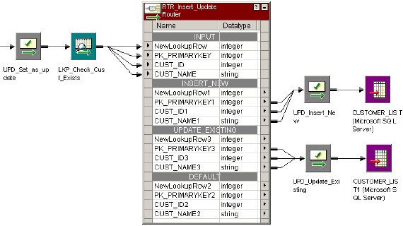
The following figure shows a mapping with multiple Update Strategy transformations and a Lookup
transformation using a dynamic cache:
In this example, the Update Strategy transformation before the Lookup transformation flags all rows as
update. Select the Update Else Insert property in the Lookup transformation. The Router transformation
sends the inserted rows to the Insert_New Update Strategy transformation and sends the updated rows to
the Update_Existing Update Strategy transformation. Output rows that are not connected to the target are
dropped. The two Update Strategy transformations to the right of the Lookup transformation flag the rows as
insert or update for the target.
Configuring Downstream Transformations
Configure downstream transformations to ensure that the dynamic lookup cache and target are syncronized.
When you use a dynamic lookup cache, the Integration Service writes to the lookup cache before it writes to
the target table. The lookup cache and target table can become unsynchronized if the Integration Service
does not write the data to the target. For example, the target database might reject the data.
Consider the following guidelines to keep the lookup cache synchronized with the lookup table:
•Use a Router transformation to pass rows to the cached target when the NewLookupRow value equals
one or two.
•Use the Router transformation to drop rows when the NewLookupRow value equals zero. Or, output the
rows to a different target.
•Use Update Strategy transformations after the Lookup transformation to flag rows for insert or update into
the target.
•Set the error threshold to one when you run a session. When you set the error threshold to one, the
session fails when it encounters the first error. The Integration Service does not write the new cache files
to disk. Instead, it restores the original cache files, if they exist. You must also restore the pre-session
target table to the target database.
•Verify that the Lookup transformation outputs the same values to the target that the Integration Service
writes to the lookup cache. When you choose to output new values on update, only connect lookup/output
ports to the target table instead of input/output ports. When you choose to output old values on update,
add an Expression transformation after the Lookup transformation and before the Router transformation.
Add output ports in the Expression transformation for each port in the target table and create expressions
to ensure you do not output null input values to the target.
•Set the Treat Source Rows As property to Data Driven in the session properties.
Mappings with Dynamic Lookups 299
•Select Insert and Update as Update when you define the update strategy target table options. This
ensures that the Integration Service updates rows marked for update and inserts rows marked for insert.
Select these options in the Transformations View on the Mapping tab in the session properties.
Null Values in Lookup Condition Columns
The Integration Service handles rows with null values in lookup condition columns differently, based on
whether the row exists in the cache.
If the row does not exist in the lookup cache, the Integration Service inserts the row into the cache and
passes it to the target table. If the row exists in the lookup cache, the Integration Service does not update the
row in the cache or target table.
Note: If the source data contains null values in the lookup condition columns, set the error threshold to one.
This ensures that the lookup cache and table remain synchronized if the Integration Service inserts a row in
the cache, but the database rejects the row due to a Not Null constraint.
Configuring Sessions with a Dynamic Lookup Cache
When you configure a session with an Update Strategy transformation and a dynamic lookup cache, you
must configure one of the following update strategy table options:
•Select Insert
•Select Update as Update
•Do not select Delete
The update strategy target table option ensures that the Integration Service updates rows marked for update
and inserts rows marked for insert.
On the General Options settings on the Properties tab in the session properties, define the Treat Source
Rows As option as Data Driven. If you do not choose Data Driven, the Integration Service flags all rows for
the row type you specify in the Treat Source Rows As option and does not use the Update Strategy
transformations in the mapping to flag the rows. The Integration Service does not insert and update the
correct rows. If you do not choose Update as Update, the Integration Service does not correctly update the
rows flagged for update in the target table. As a result, the lookup cache and target table might become
unsynchronized.
Conditional Dynamic Cache Updates
You can update dynamic lookup cache based on the results of a boolean expression. The Integration Service
updates the cache when the expression is true.
For example, you might have a product number, quantity on hand, and a timestamp column in a target table.
You need to update the quantity on hand with the latest source values. You can update the quantity on hand
when the source data has a timestamp greater than the timestamp in the dynamic cache. Create an
expression in the Lookup transformation similar to the following expression:
lookup_timestamp < input_timestamp
The expression can include the lookup and the input ports. You can access built-in, mapping, and parameter
variables. You can include user-defined functions and refer to unconnected transformations.
300 Chapter 19: Dynamic Lookup Cache
The expression returns true, false, or NULL. If the result of the expression is NULL, the expression is false.
The Integration Service does not update the cache. You can add a check for NULL values in the expression if
you need to change the expression result to true. The default expression value is true.
Create the expression with the Transformation Developer. You cannot override the Dynamic Cache Update
Condition at the session level.
Session Processing
When you configure a conditional dynamic cache update, the Integration Service does not consider the
conditional expression if the data does not exist. When you enable Insert Else Update, the Integration
Service inserts a row in the cache if the data does not exist. If the data exists, it updates the cache when the
conditional expression is true. When you enable Update Else Insert, the Integration Service updates the
cache if the data exists in the cache and the conditional expression is true. When the data does not exist in
the cache, the Integration Service inserts the row in the cache.
When the expression is true, the NewLookupRow value is one and the Integration Service updates the row.
When the expression is false or NULL, the NewLookupRow value is zero. The Integration Service does not
update the row.
If you configure the Lookup transformation to synchronize dynamic cache, the Integration Service inserts a
row into the lookup source when it inserts a row into the cache.
Configuring a Conditional Dynamic Cache Lookup
You must enable the Lookup transformation to perform a conditional dynamic cache lookup before you can
create a conditional expression.
Use the following steps to configure a conditional dynamic cache lookup:
1. Create a dynamic Lookup transformation in the Transformation Developer.
2. Click the Properties tab.
3. Enable Lookup Caching and Dynamic Lookup Cache properties.
4. To access the Expression Editor, click the Go button for the Update Dynamic Cache Condition property.
5. Define an expression condition. You can select input ports, lookup ports, and functions for the
expression.
6. Click Validate to verify that the expression is valid.
If you do not validate an expression, the Designer validates it when you close the Expression Editor. If
the expression is not valid, the Designer displays a warning.
Dynamic Cache Update with Expression Results
You can update the dynamic lookup cache values with the results of an expression.
For example, a product table target has a numeric column that contains an order count. Each time the
Lookup transformation receives an order for the product, it updates the dynamic cache order_count with the
results of the following expression:
order_count = order_count + 1
The Lookup transformation returns the order_count.
You can configure how the Integration Service handles the case where the expression evaluates to null.
Dynamic Cache Update with Expression Results 301
Null Expression Values
The expression returns NULL if one of the values in the expression is null. However, you can configure an
expression to return a non-null value.
If the expression refers to a lookup port, but the source data is new, the lookup port contains a default value.
The default might be NULL. You can configure an IsNull expression to check for null values.
For example, the following expression checks if lookup_column is NULL:
iif (isnull(lookup_column), input_port, user_expression)
If the column is null, then return the input_port value. Otherwise return the value of the expression.
Session Processing
The Integration Service can insert and update rows in the dynamic lookup cache based on expression
results. The expression results might vary based on whether the lookup port value is NULL and is included in
the expression.
When you enable Insert Else Update, the Integration Service inserts a row with the expression result if the
data is not in the cache. The lookup port value is NULL when data does not exist in the cache. If the
expression refers to the lookup port value, the Integration Service substitutes the default port value in the
expression. When you enable Insert Else Update and the data exists in the cache, the Integration Service
updates the cache with the expression result.
When you enable Update Else Insert, the Integration Service updates the cache with the expression result if
the data exists in the cache. When the data does not exist in the cache, the Integration Service inserts a row
that contains the expression result. If the expression refers to a lookup port value, the Integration Service
substitutes the default port value in the expression.
If you configure the Lookup transformation to synchronize dynamic cache, the Integration Service inserts a
row into the lookup cache with the expression result. It inserts a row into the lookup source with the
expression result.
Configuring an Expression for Dynamic Cache Updates
You must enable the Lookup transformation to perform dynamic lookups before you can create a conditional
expression.
Use the following steps to configure an expression for dynamic cache lookup:
1. Create a dynamic Lookup transformation in the Transformation Developer.
2. Open the Properties tab.
3. Enable Lookup Caching and Dynamic Lookup Cache properties.
4. To create an expression, click the Associated Expression list for the lookup port you want to update.
5. Select Associated Expression.
The Expression Editor appears.
6. Define an expression by selecting input ports, lookup ports, and functions. The expression return value
must match the lookup port type.
7. Click Validate to verify that the expression is valid.
If you do not validate an expression, the Designer validates it when you close the Expression Editor. If
the expression is not valid, the Designer displays a warning.
302 Chapter 19: Dynamic Lookup Cache
Synchronizing Cache with the Lookup Source
A Lookup transformation maintains a dynamic lookup cache to track the rows that it passes to the target.
When multiple sessions update the same target, you can configure the Lookup transformation in each
session to synchronize the dynamic lookup cache to the same lookup source instead of a target.
When you configure a Lookup transformation to synchronize the cache with the Lookup source, the Lookup
transformation performs a lookup on the Lookup source. If the data does not exist in the Lookup source, the
Lookup transformation inserts the row into the Lookup source before it updates the dynamic lookup cache.
The data might exist in the Lookup source if another session inserted the row. To synchronize the lookup
cache to the lookup source, the Integration Service retrieves the latest values from the Lookup source. The
Lookup transformation inserts the values from the Lookup source in the dynamic lookup cache. The lookup
source must be a relational table.
For example, you have multiple sessions running simultaneously. Each session generates product numbers
for new product names. When a session generates a product number, the other sessions must use the same
product number to identify the product. The product number is generated once and inserted in the lookup
source. If another session processes a row containing the product, it must use the product number that is in
the lookup source. Each session performs a lookup on the lookup source to determine which product
numbers have already been generated.
The Integration Service performs the following tasks for insert rows:
•The Integration Service performs a lookup on the dynamic lookup cache. If data does not exist in the
dynamic lookup cache, the Integration Service performs a lookup on the lookup source.
•If the data exists in the lookup source, the Integration Service retrieves the data from the lookup source. It
inserts a row in the dynamic lookup cache with the columns from the lookup source. It does not update the
cache with the source row.
•If the data is not in the lookup source, the Integration Service inserts the data into the lookup source and
inserts the row into the cache.
The lookup source contains the same columns as the lookup cache. The Integration Service does not insert a
column in the lookup cache unless the column is projected from the Lookup transformation or the column is
part of a lookup condition.
NewLookupRow
When you synchronize dynamic cache with the lookup source, the Lookup transformation behavior does not
change for update rows. When the Integration Service receives update rows, it updates the dynamic lookup
cache and sets the value of NewLookupRow to 2. It does not update the lookup source. You can route the
update rows through an Update Strategy transformation and pass the rows to the target.
When the Integration Service inserts rows into the lookup source, it sets NewLookupRow to 1. The
Integration Service updates the dynamic lookup cache. When the transformation is configured to synchronize
dynamic cache, and NewLookupRow is 1, you do not need to pass insert rows to the target.
When you configure the Insert Else Update property in the Lookup transformation, and the source row is an
insert row, the Integration Service either inserts the row in the cache and the lookup source, or it updates the
cache.
When you configure the Update Else Insert property in the Lookup transformation, and the source row is an
update row, the Integration Service either updates the cache or it inserts the row into the cache and the
lookup source.
Note: When different sessions process update rows for the same table, the processing order varies. You
might get unexpected results.
Synchronizing Cache with the Lookup Source 303
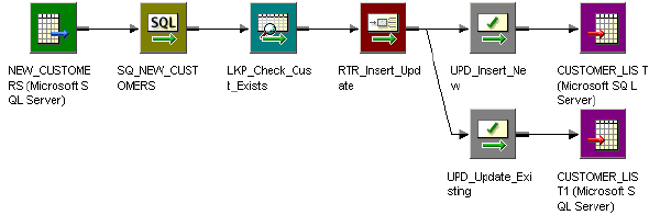
Configuring Dynamic Cache Synchronization
When you create the Lookup transformation, you can configure it to synchronize the dynamic cache to the
lookup source for insert rows.
To configure dynamic cache synchronization:
1. Open the Lookup transformation Properties tab.
2. Enable Dynamic Lookup Cache.
3. Enable Synchronize Dynamic Cache.
Dynamic Lookup Cache Example
Use a dynamic lookup cache when you need to insert and update rows in the target. When you use a
dynamic lookup cache, you can insert and update the cache with the same data you pass to the target to
insert and update.
For example, you need to update a table that contains customer data. The source data contains rows of
customer data to insert or update in the target. Create a dynamic cache that represents the target. Configure
a Lookup transformation to lookup customers in the cache.
The following figure shows a mapping that has a dynamic cache:
The Lookup transformation uses a dynamic lookup cache. When the session starts, the Integration Service
builds the lookup cache from a Customer_List table. The Customer_List table is also the target in the
mapping. When the Integration Service reads a row that is not in the lookup cache, it inserts the row in the
cache.
The Lookup transformation returns the row to a Router transformation. The Router transformation directs the
row to the UPD_Insert_New or the UPD_Update_Existing transformation. The Update Strategy
transformations mark the row as insert or update before passing it to the target.
The Customer_List table changes as the session runs. The Integration Service inserts new rows and updates
existing rows in the lookup cache. The Integration Service keeps the lookup cache and Customer_List table
synchronized.
To generate keys for the target, use Sequence-ID in the associated port. The sequence ID generates primary
keys for new rows the Integration Service inserts into the target table.
You increase session performance when you use a dynamic lookup cache because you build the cache from
the database once. You can continue to use the lookup cache even though the data in the target table
changes.
304 Chapter 19: Dynamic Lookup Cache
Rules and Guidelines for Dynamic Lookup Caches
Certain rules and guidelines apply when you use a dynamic lookup cache.
Consider the following guidelines when you use a dynamic lookup cache:
•You cannot share the cache between a dynamic Lookup transformation and static Lookup transformation
in the same target load order group.
•You can enable a dynamic lookup cache for a relational, flat file, or Source Qualifier transformation
lookup.
•The Lookup transformation must be a connected transformation.
•You can use a persistent or a non-persistent cache.
•If the dynamic cache is not persistent, the Integration Service always rebuilds the cache from the
database, even if you do not enable Recache from Lookup Source.
•When you synchronize dynamic cache files with a lookup source table, the Lookup transformation inserts
rows into the lookup source table and the dynamic lookup cache. If the source row is an update row, the
Lookup transformation updates the dynamic lookup cache only.
•You can only create an equality lookup condition. You cannot look up a range of data in a dynamic cache.
•You must associate each lookup port that is not in the lookup condition with an input port, sequence ID, or
associated expression.
•Use a Router transformation to pass rows to the cached target when the NewLookupRow value equals
one or two.
•Use the Router transformation to drop rows when the NewLookupRow value equals zero. Or, you can
output the rows to a different target.
•Verify that the Integration Service outputs the same values to the target that it writes to the lookup cache.
When you choose to output new values on update, only connect lookup/output ports to the target table
instead of the input/output ports. When you choose to output old values on update, add an Expression
transformation after the Lookup transformation and before the Router transformation. Add output ports in
the Expression transformation for each port in the target table and create expressions to ensure you do
not output null input values to the target.
•When you use a lookup SQL override, map the correct columns to the appropriate targets for lookup.
•When you add a WHERE clause to the lookup SQL override, use a Filter transformation before the
Lookup transformation. This ensures that the Integration Service inserts rows in the dynamic cache and
target table that match the WHERE clause.
•When you configure a reusable Lookup transformation to use a dynamic cache, you cannot edit the
condition or disable the Dynamic Lookup Cache property in a mapping.
•Use Update Strategy transformations after the Lookup transformation to flag the rows for insert or update
for the target.
•Use an Update Strategy transformation before the Lookup transformation to define some or all rows as
update if you want to use the Update Else Insert property in the Lookup transformation.
•Set the row type to Data Driven in the session properties.
•Select Insert and Update as Update for the target table options in the session properties.
Rules and Guidelines for Dynamic Lookup Caches 305

CHAPTER 2 0
Normalizer Transformation
This chapter includes the following topics:
•Normalizer Transformation Overview, 306
•Normalizer Transformation Components, 307
•Normalizer Transformation Generated Keys, 310
•VSAM Normalizer Transformation, 311
•Pipeline Normalizer Transformation, 315
•Using a Normalizer Transformation in a Mapping, 319
•Troubleshooting Normalizer Transformations, 322
Normalizer Transformation Overview
The Normalizer transformation receives a row that contains multiple-occurring columns and returns a row for
each instance of the multiple-occurring data. The transformation processes multiple-occurring columns or
multiple-occurring groups of columns in each source row. The Normalizer transformation is an active
transformation.
The Normalizer transformation parses multiple-occurring columns from COBOL sources, relational tables, or
other sources. It can process multiple record types from a COBOL source that contains a REDEFINES
clause.
For example, you might have a relational table that stores four quarters of sales by store. You need to create
a row for each sales occurrence. You can configure a Normalizer transformation to return a separate row for
each quarter.
The following source rows contain four quarters of sales by store:
Store1 100 300 500 700
Store2 250 450 650 850
The Normalizer returns a row for each store and sales combination. It also returns an index that identifies the
quarter number:
Store1 100 1
Store1 300 2
Store1 500 3
Store1 700 4
Store2 250 1
Store2 450 2
Store2 650 3
Store2 850 4
306
The Normalizer transformation generates a key for each source row. The Integration Service increments the
generated key sequence number each time it processes a source row. When the source row contains a
multiple-occurring column or a multiple-occurring group of columns, the Normalizer transformation returns a
row for each occurrence. Each row contains the same generated key value.
When the Normalizer returns multiple rows from a source row, it returns duplicate data for single-occurring
source columns. For example, Store1 and Store2 repeat for each instance of sales.
You can create a VSAM Normalizer transformation or a pipeline Normalizer transformation:
•VSAM Normalizer transformation. A non-reusable transformation that is a Source Qualifier
transformation for a COBOL source. The Mapping Designer creates VSAM Normalizer columns from a
COBOL source in a mapping. The column attributes are read-only. The VSAM Normalizer receives a
multiple-occurring source column through one input port.
•Pipeline Normalizer transformation. A transformation that processes multiple-occurring data from
relational tables or flat files. You create the columns manually and edit them in the Transformation
Developer or Mapping Designer. The pipeline Normalizer transformation represents multiple-occurring
columns with one input port for each source column occurrence.
Normalizer Transformation Components
A Normalizer transformation contains the following tabs:
•Transformation. Enter the name and description of the transformation. The naming convention for an
Normalizer transformation is NRM_TransformationName. You can also make the pipeline Normalizer
transformation reusable.
•Ports. View the transformation ports and attributes.
•Properties. Configure the tracing level to determine the amount of transaction detail reported in the
session log file. Choose to reset or restart the generated key sequence value in the next session.
•Normalizer. Define the structure of the source data. The Normalizer tab defines source data as columns
and groups of columns.
•Metadata Extensions. Configure the extension name, datatype, precision, and value. You can also
create reusable metadata extensions.
Ports Tab
When you define a Normalizer transformation, you configure the columns in the Normalizer tab. The Designer
creates the ports. You can view the Normalizer ports and attributes on the Ports tab.
Pipeline and VSAM Normalizer transformations represent multiple-occurring source columns differently. A
VSAM Normalizer transformation has one input port for a multiple-occurring column. A pipeline Normalizer
transformation has multiple input ports for a multiple-occurring column.
The Normalizer transformation has one output port for each single-occurring input port. When a source
column is multiple-occurring, the pipeline and VSAM Normalizer transformations have one output port for the
column. The transformation returns a row for each source column occurrence.
The Normalizer transformation has a generated column ID (GCID) port for each multiple-occurring column.
The generated column ID is an index for the instance of the multiple-occurring data. For example, if a column
occurs four times in a source record, the Normalizer returns a value of 1, 2, 3, or 4 in the generated column
ID based on which instance of the multiple-occurring data occurs in the row.
Normalizer Transformation Components 307
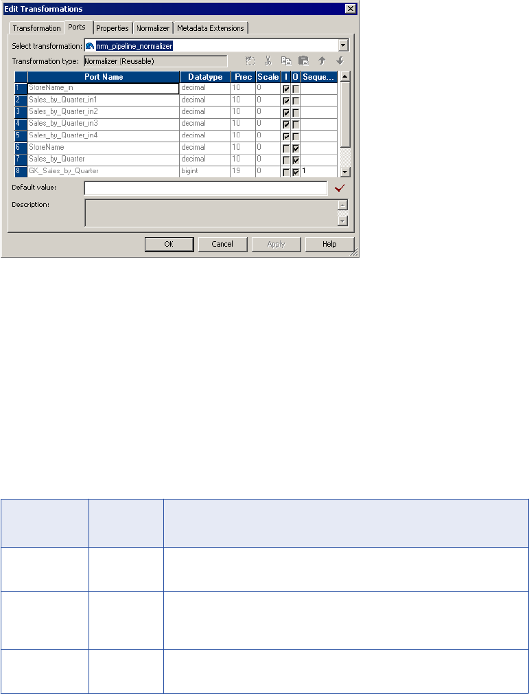
The naming convention for the Normalizer generated column ID is GCID_<occuring_field_name>.
The Normalizer transformation has at least one generated key port. The Integration Service increments the
generated key sequence number each time it processes a source row.
The following figure shows the Normalizer transformation Ports tab:
In this example, Sales_By_Quarter is multiple-occurring in the source. The Normalizer transformation has
one output port for Sales_By_Quarter. It returns four rows for each source row. Generated key start value is
1.
You can change the ports on a pipeline Normalizer transformation by editing the columns on the Normalizer
tab. To change a VSAM Normalizer transformation, you need to change the COBOL source and recreate the
transformation.
Properties Tab
Configure the Normalizer transformation general properties on the Properties tab.
You can configure the following Normalizer transformation properties:
Property Required/
Optional
Description
Reset Required At the end of a session, resets the value sequence for each generated key
value to the value it was before the session.
Restart Required Starts the generated key sequence at 1. Each time you run a session, the key
sequence value starts at 1 and overrides the sequence value on the Ports
tab.
Tracing Level Required Sets the amount of detail included in the session log when you run a session
containing this transformation.
308 Chapter 20: Normalizer Transformation
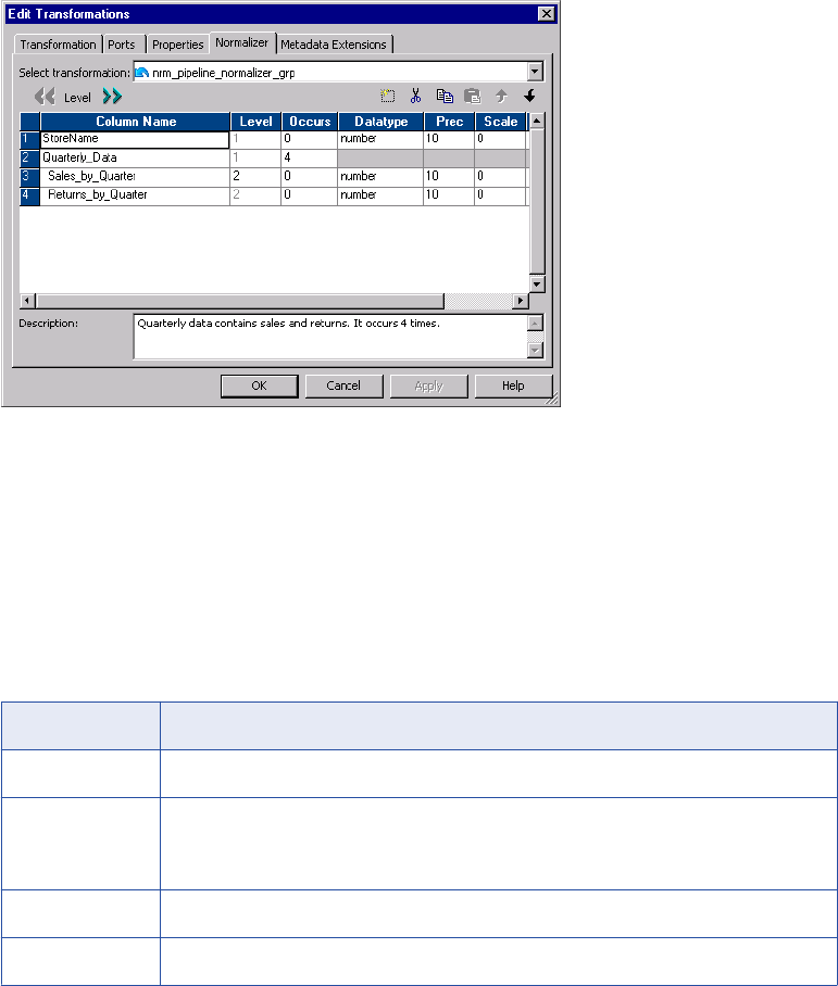
Normalizer Tab
The Normalizer tab defines the structure of the source data. The Normalizer tab defines source data as
columns and groups of columns. A group of columns might define a record in a COBOL source or it might
define a group of multiple-occurring fields in the source.
The column level number identifies groups of columns in the data. Level numbers define a data hierarchy.
Columns in a group have the same level number and display sequentially below a group-level column. A
group-level column has a lower level number, and it contains no data.
The following figure shows the Normalizer tab of a pipeline Normalizer transformation:
Figure 3. Normalizer Tab
Quarterly_Data is a group-level column. It is Level 1. The Quarterly_Data group occurs four times in each
row. Sales_by_Quarter and Returns_by_Quarter are Level 2 columns and belong to the group.
Each column has an Occurs attribute. The Occurs attribute identifies columns or groups of columns that
occur more than once in a source row.
When you create a pipeline Normalizer transformation, you can edit the columns. When you create a VSAM
Normalizer transformation, the Normalizer tab is read-only.
The following table describes the Normalizer tab attributes that are common to the VSAM and pipeline
Normalizer transformations:
Attribute Description
Column Name Name of the source column.
Level Group columns. Columns in the same group occur beneath a column with a lower level
number. When each column is the same level, the transformation contains no column
groups.
Occurs The number of instances of a column or group of columns in the source row.
Datatype The transformation column datatype can be String, Nstring, or Number.
Normalizer Transformation Components 309
Attribute Description
Prec Precision. Length of the column.
Scale Number of decimal positions for a numeric column.
The Normalizer tab for a VSAM Normalizer transformation contains the same attributes as the pipeline
Normalizer transformation, but it includes attributes unique to a COBOL source definition.
Normalizer Transformation Generated Keys
The Normalizer transformation returns at least one generated key column in the output row. The Integration
Service increments the generated key sequence number each time it processes a source row. The
Integration Service determines the initial key value from the generated key value in the Ports tab of the
Normalizer transformation. When you create a Normalizer transformation, the generated key value is 1 by
default. The naming convention for the Normalizer generated key is GK_<redefined_field_name>.
RELATED TOPICS:
•“Generating Key Values” on page 321
Storing Generated Key Values
You can view the current generated key values on the Normalizer transformation Ports tab. At the end of
each session, the Integration Service updates the generated key value in the Normalizer transformation to
the last value generated for the session plus one. The maximum generated key value is
9,223,372,036,854,775,807. If you have multiple instances of the Normalizer transformation in the repository,
the Integration Service updates the generated key value in all versions when it runs a session.
Note: You cannot change the current generated key values on the Normalizer transformation Ports tab.
Changing the Generated Key Values
You can change the generated key value in the following ways:
•Reset the generated key sequence. Reset the generated key sequence on the Normalizer
transformation Properties tab. When you reset the generated key sequence, the Integration Service resets
the generated key start value back to the value it was before the session. Reset the generated key
sequence when want to create the same generated key values each time you run the session.
•Restart the generated key sequence. Restart the generated key sequence on the Normalizer
transformation Properties tab. When you restart the generated key sequence, the Integration Service
starts the generated key sequence at 1 the next time it runs a session. When you restart the generated
key sequence, the generated key start value does not change in the Normalizer transformation until you
run a session. When you run the session, the Integration Service overrides the sequence number value on
the Ports tab.
When you reset or restart the generated key sequence, the reset or restart affects the generated key
sequence values the next time you run a session. You do not change the current generated key sequence
values in the Normalizer transformation. When you reset or restart the generated key sequence, the option is
enabled for every session until you disable the option.
310 Chapter 20: Normalizer Transformation
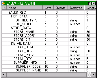
VSAM Normalizer Transformation
The VSAM Normalizer transformation is the source qualifier for a COBOL source definition. A COBOL source
is a flat file that can contain multiple-occurring data and multiple types of records in the same file.
VSAM (Virtual Storage Access Method) is a file access method for an IBM mainframe operating system.
VSAM files organize records in indexed or sequential flat files. However, you can use the VSAM Normalizer
transformation for any flat file source that you define with a COBOL source definition.
A COBOL source definition can have an OCCURS statement that defines a multiple-occurring column. The
COBOL source definition can also contain a REDEFINES statement to define more than one type of record in
the file.
The following COBOL copybook defines a sales record:
01 SALES_RECORD.
03 HDR_DATA.
05 HDR_REC_TYPE PIC X.
05 HDR_STORE PIC X(02).
03 STORE_DATA.
05 STORE_NAME PIC X(30).
05 STORE_ADDR1 PIC X(30).
05 STORE_CITY PIC X(30).
03 DETAIL_DATA REDEFINES STORE_DATA.
05 DETAIL_ITEM PIC 9(9).
05 DETAIL_DESC PIC X(30).
05 DETAIL_PRICE PIC 9(4)V99.
05 DETAIL_QTY PIC 9(5).
05 SUPPLIER_INFO OCCURS 4 TIMES.
10 SUPPLIER_CODE PIC XX.
10 SUPPLIER_NAME PIC X(8).
The sales file can contain two types of sales records. Store_Data defines a store and Detail_Data defines
merchandise sold in the store. The REDEFINES clause indicates that Detail_Data fields might occur in a
record instead of Store_Data fields.
The first three characters of each sales record is the header. The header includes a record type and a store
ID. The value of Hdr_Rec_Type defines whether the rest of the record contains store information or
merchandise information. For example, when Hdr_Rec_Type is “S,” the record contains store data. When
Hdr_Rec_Type is “D,” the record contains detail data.
When the record contains detail data, it includes the Supplier_Info fields. The OCCURS clause defines four
suppliers in each Detail_Data record.
The following figure shows the Sales_File COBOL source definition that you might create from the COBOL
copybook:
VSAM Normalizer Transformation 311
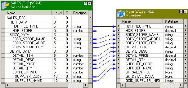
The Sales_Rec, Hdr_Data, Store_Data, Detail_Data, and Supplier_Info columns are group-level columns that
identify groups of lower level data. Group-level columns have a length of zero because they contain no data.
None of these columns are output ports in the source definition.
The Supplier_Info group contains Supplier_Code and Supplier_Name columns. The Supplier_Info group
occurs four times in each Detail_Data record.
When you create a VSAM Normalizer transformation from the COBOL source definition, the Mapping
Designer creates the input/output ports in the Normalizer transformation based on the COBOL source
definition. The Normalizer transformation contains at least one generated key output port. When the COBOL
source has multiple-occurring columns, the Normalizer transformation has a generated column ID output port.
The following figure shows the Normalizer transformation ports the Mapping Designer creates from the
source definition:
The Supplier_Info group of columns occurs four times in each COBOL source row.
The COBOL source row might contain the following data:
Item1 ItemDesc 100 25 A Supplier1 B Supplier2 C Supplier3 D Supplier4
The Normalizer transformation returns a row for each occurrence of the Supplier_Code and Supplier_Name
columns. Each output row contains the same item, description, price, and quantity values.
The Normalizer returns the following detail data rows from the COBOL source row:
Item1 ItemDesc 100 25 A Supplier1 1 1
Item1 ItemDesc 100 25 B Supplier2 1 2
Item1 ItemDesc 100 25 C Supplier3 1 3
Item1 ItemDesc 100 25 D Supplier4 1 4
Each output row contains a generated key and a column ID. The Integration Service updates the generated
key value when it processes a new source row. In the detail data rows, the generated key value is 1.
The column ID defines the Supplier_Info column occurrence number. The Integration Service updates the
column ID for each occurrence of the Supplier_Info. The column ID values are 1, 2, 3, 4 in the detail data
rows.
VSAM Normalizer Ports Tab
The VSAM Normalizer Ports tab shows the transformation input and output ports. It has one input/output port
for each COBOL source column. It has one input/output port for a multiple-occurring column. The
transformation does not have input or output ports for group level columns.
312 Chapter 20: Normalizer Transformation
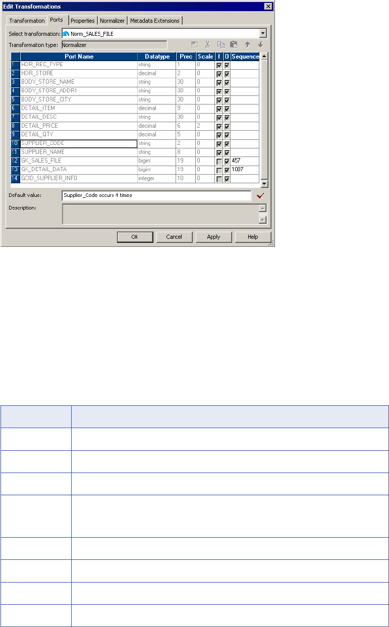
The following figure shows the VSAM Normalizer Ports tab:
In this example, Supplier_Code and Supplier_Name occur four times in the COBOL source. The Ports tab
shows one Supplier_Code port and one Supplier_Name port. The generated key start values are 457 and
1087.
VSAM Normalizer Tab
When you create a VSAM Normalizer transformation, the Mapping Designer creates the columns from a
COBOL source. The Normalizer tab displays the same information as the COBOL source definition. You
cannot edit the columns on a VSAM Normalizer tab.
The following table describes attributes on the VSAM Normalizer tab:
Attribute Description
POffs Physical offset. Location of the field in the file. The first byte in the file is zero.
Plen Physical length. Number of bytes in the field.
Column Name Name of the source field.
Level Provides column group hierarchy. The higher the level number, the lower the data is in the
hierarchy. Columns in the same group occur beneath a column with a lower level number.
When each column is the same level, the transformation contains no column groups.
Occurs The number of instances of a column or group of columns in the source row.
Datatype The transformation datatype can be String, Nstring, or Number.
Prec Precision. Length of the column.
Scale Number of decimal positions for a numeric column.
VSAM Normalizer Transformation 313

Attribute Description
Picture How the data is stored or displayed in the source. Picture 99V99 defines a numeric field with
two implied decimals. Picture X(10) indicates ten characters.
Usage COBOL data storage format such as COMP, BINARY, and COMP-3. When the Usage is
DISPLAY, the Picture clause defines how the source data is formatted when you view it.
Key Type Type of key constraint to apply to the field for a VSAM file. Choose one of the following key
types:
- Not a Key. The field is not an index in a VSAM file.
- Primary Key. The field is the primary index in the VSAM file. The field contains unique values.
- Alternate Key. The field is a secondary index in the VSAM file. The field contains unique values.
- Primary Duplicate Key. The field is the primary index in the VSAM file. The field can contain
duplicate values.
- Alternate Duplicate Key. The field is a secondary index in the VSAM file. The field can contain
duplicate values.
Signed (S) Indicates whether numeric values are signed.
Trailing Sign (T) Indicates that the sign (+ or -) exists in the last digit of the field. If not enabled, the sign
appears as the first character in the field.
Included Sign (I) Indicates whether the sign is included in any value appearing in the field.
Real Decimal
Point (R)
Indicates whether the decimal point is a period (.) or the decimal point is represented by the
V character in a numeric field.
Redefines Indicates that the column REDEFINES another column.
Business Name Descriptive name that you give to a column.
Steps to Create a VSAM Normalizer Transformation
When you create a VSAM Normalizer transformation, you drag a COBOL source into a mapping and the
Mapping Designer creates the transformation columns from the source. The Normalizer transformation is the
source qualifier for the COBOL source in the mapping.
When you add a COBOL source to a mapping, the Mapping Designer creates and configures a Normalizer
transformation. The Mapping Designer identifies nested records and multiple-occurring fields in the COBOL
source. It creates the columns and ports in the Normalizer transformation from the source columns.
To create a VSAM Normalizer transformation:
1. In the Mapping Designer, create a new mapping or open an existing mapping.
2. Drag a COBOL source definition into the mapping.
The Designer adds a Normalizer transformation and connects it to the COBOL source definition. If you
have not enabled the option to create a source qualifier by default, the Create Normalizer Transformation
dialog box appears.
3. If the Create Normalizer Transformation dialog box appears, you can choose from the following options:
•VSAM Source. Create a transformation from the COBOL source definition in the mapping.
314 Chapter 20: Normalizer Transformation

•Pipeline. Create a transformation, but do not define columns from a COBOL source. Define the
columns manually on the Normalizer tab. You might choose this option when you want to process
multiple-occurring data from another transformation in the mapping.
To create the VSAM Normalizer transformation, select the VSAM Normalizer transformation option. The
dialog box displays the name of the COBOL source definition in the mapping. Select the COBOL source
definition and click OK.
4. Open the Normalizer transformation.
5. Select the Ports tab to view the ports in the Normalizer transformation.
The Designer creates the ports from the COBOL source definition by default.
6. Click the Normalizer tab to review the source column organization.
The Normalizer tab contains the same information as the Columns tab of the COBOL source. However,
you cannot modify column attributes in the Normalizer transformation. To change column attributes,
change the COBOL copybook, import the COBOL source, and recreate the Normalizer transformation.
7. Select the Properties tab to set the tracing level.
You can also configure the transformation to reset the generated key sequence numbers at the start of
the next session.
Pipeline Normalizer Transformation
When you create a Normalizer transformation in the Transformation Developer, you create a pipeline
Normalizer transformation by default. When you create a pipeline Normalizer transformation, you define the
columns based on the data the transformation receives from a another type of transformation such as a
Source Qualifier transformation. The Designer creates the input and output Normalizer transformation ports
from the columns you define.
The following figure shows the Normalizer transformation columns for a transformation that receives four
sales columns in each relational source row:
Each source row has a StoreName column and four instances of Sales_By_Quarter.
Pipeline Normalizer Transformation 315
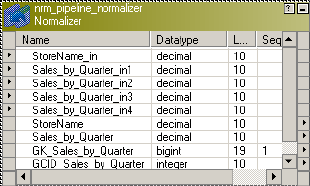
The source rows might contain the following data:
Dellmark 100 450 650 780
Tonys 666 333 444 555
The pipeline Normalizer transformation has an input port for each instance of a multiple-occurring column.
The following figure shows the ports that the Designer creates from the columns in the Normalizer
transformation:
The Normalizer transformation returns one row for each instance of the multiple-occurring column:
Dellmark 100 1 1
Dellmark 450 1 2
Dellmark 650 1 3
Dellmark 780 1 4
Tonys 666 2 1
Tonys 333 2 2
Tonys 444 2 3
Tonys 555 2 4
The Integration Service increments the generated key sequence number each time it processes a source
row. The generated key links each quarter sales to the same store. In this example, the generated key for the
Dellmark row is 1. The generated key for the Tonys store is 2.
The transformation returns a generated column ID (GCID) for each instance of a multiple-occurring field. The
GCID_Sales_by_Quarter value is always 1, 2, 3, or 4 in this example.
Pipeline Normalizer Ports Tab
The pipeline Normalizer Ports tab displays the input and output ports for the transformation. It has one input/
output port for each single-occurring column you define in the transformation. It has one port for each
occurrence of a multiple-occurring column. The transformation does not have input or output ports for group
level columns.
316 Chapter 20: Normalizer Transformation
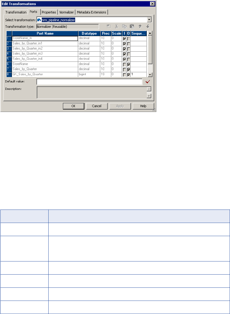
The following figure shows the pipeline Normalizer transformation Ports tab:
The Designer creates an input port for each occurrence of a multiple-occurring column.
To change the ports in a pipeline Normalizer transformation, modify the columns in the Normalizer tab. When
you add a column occurrence, the Designer adds an input port. The Designer creates ports for the lowest
level columns. It does not create ports for group level columns.
Pipeline Normalizer Tab
When you create a pipeline Normalizer transformation, you define the columns on the Normalizer tab. The
Designer creates input and output ports based on the columns you enter on the Normalizer tab.
The following table describes the pipeline Normalizer tab attributes:
Attribute Description
Column Name Name of the column.
Level Identifies groups of columns. Columns in the same group have the same level number.
Default is zero. When each column is the same level, the transformation contains no
column groups.
Occurs The number of instances of a column or group of columns in the source row.
Datatype The column datatype can be String, Nstring, or Number.
Prec Precision. Length of the column.
Scale Number of decimal digits in a numeric value.
Normalizer Tab Column Groups
When a source row contains groups of repeating columns, you can define column groups on the Normalizer
tab. The Normalizer transformation returns a row for each column group occurrence instead for each column
occurrence.
The level number on the Normalizer tab identifies a hierarchy of columns. Group level columns identify
groups of columns. The group level column has a lower level number than columns in the group. Columns in
Pipeline Normalizer Transformation 317
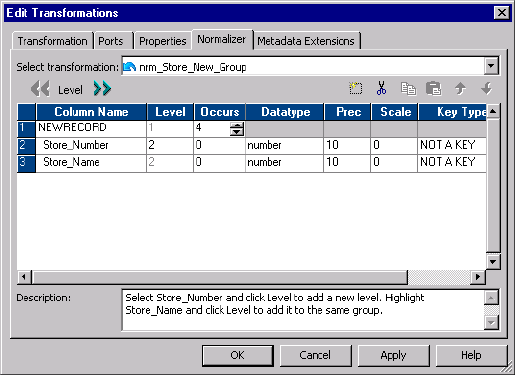
the same group have the same level number and display sequentially below the group level column on the
Normalizer tab.
The following figure shows a group of multiple-occurring columns in the Normalizer tab:
In this example, the NEWRECORD column contains no data. It is a Level 1 group column. The group occurs
four times in each source row. Store_Number and Store_Name are Level 2 columns. They belong to the
NEWRECORD group.
Steps to Create a Pipeline Normalizer Transformation
When you create a pipeline Normalizer transformation, you define the columns on the Normalizer tab.
You can create a Normalizer transformation in the Transformation Developer or in the Mapping Designer.
To create a Normalizer transformation:
1. In the Transformation Developer or the Mapping Designer, click Transformation > Create. Select
Normalizer transformation. Enter a name for the Normalizer transformation.
The naming convention for Normalizer transformations is NRM_TransformationName.
2. Click Create and click Done.
3. Open the Normalizer transformation and click the Normalizer tab.
4. Click Add to add a new column.
The Designer creates a new column with default attributes. You can change the name, datatype,
precision, and scale.
5. To create a multiple-occurring column, enter the number of occurrences in the Occurs column.
6. To create a group of multiple-occurring columns, enter at least one of the columns on the Normalizer tab.
Select the column. Click Level.
The Designer adds a NEWRECORD group level column above the selected column. NEWRECORD
becomes Level 1. The selected column becomes Level 2. You can rename the NEWRECORD column.
All columns are the same level by default. The Level defines columns that are grouped together.
7. You can change the column level for other columns to add them to the same group. Select a column and
click Level to change it to the same level as the column above it.
Columns in the same group must appear sequentially in the Normalizer tab.
318 Chapter 20: Normalizer Transformation

8. Change the occurrence at the group level to make the group of columns multiple-occurring.
9. Click Apply to save the columns and create input and output ports.
The Designer creates the Normalizer transformation input and output ports. In addition, the Designer
creates the generated key columns and a column ID for each multiple-occurring column or group of
columns.
10. Select the Properties tab to change the tracing level or reset the generated key sequence numbers after
the next session.
Using a Normalizer Transformation in a Mapping
When a Normalizer transformation receives more than one type of data from a COBOL source, you need to
connect the Normalizer output ports to different targets based on the type of data in each row. The following
example describes how to map the Sales_File COBOL source definition through a Normalizer transformation
to multiple targets.
The Sales_File source record contains either store information or information about items that a store sells.
The sales file contains both types of records.
The following example includes two sales file records:
Record Type Data
Store Record H01Software Suppliers Incorporated 1111 Battery Street San
Francisco
Item Record D01123456789USB Line - 10 Feet 001495000020 01Supp1
02Supp2 03Supp3 04Supp4
The COBOL source definition and the Normalizer transformation have columns that represent fields in both
types of records. You need to filter the store rows from the item rows and pass them to different targets.
The following figure shows the Sales_File COBOL source with its corresponding Store_Data (which has a
value of “S”) and Detail_Data (which has a value of “D”):
The Hdr_Rec_Type defines whether the record contains store or merchandise data. When the
Hdr_Rec_Type value is “S,” the record contains Store_Data. When the Hdr_Rec_Type is “D,” the record
contains Detail_Data. Detail_Data always includes four occurrences of Supplier_Info fields.
Using a Normalizer Transformation in a Mapping 319

To filter data, connect the Normalizer output rows to a Router transformation to route the store, item, and
supplier data to different targets. You can filter rows in the Router transformation based on the value of
Hdr_Rec_Type.
The following figure shows the mapping that routes Sales_File records to different targets:
The mapping filters multiple record types from the COBOL source to relational targets. The multiple-occurring
source columns are mapped to a separate relational table. Each row is indexed by occurrence in the source
row.
The mapping contains the following transformations:
•Normalizer transformation. The Normalizer transformation returns multiple rows when the source
contains multiple-occurring Detail_Data. It also processes different record types from the same source.
•Router transformation. The Router transformation routes data to targets based on the value of
Hdr_Rec_Type.
•Aggregator transformation. The Aggregator transformation removes duplicate Detail_Data rows that
occur with each Supplier_Info occurrence.
The mapping has the following functionality:
1. The Normalizer transformation passes the header record type and header store number columns to the
Sales_Header target. Each Sales_Header record has a generated key that links the Sales_Header row
to a Store_Data or Detail_Data target row. The Normalizer returns Hdr_Data and Store_Data once per
row.
2. The Normalizer transformation passes all columns to the Router transformation. It passes Detail_Data
data four times per row, once for each occurrence of the Supplier_Info columns. The Detail_Data
columns contain duplicate data, except for the Supplier_Info columns.
3. The Router transformation passes the store name, address, city, and generated key to Store_Data when
the Hdr_Rec_Type is “S.” The generated key links Store_Data rows to Sales_Header rows.
The Router transformation contains one user-defined group for the store data and one user-defined
group for the merchandise items.
4. The Router transformation passes the item, item description, price, quantity, and Detail_Data generated
keys to an Aggregator transformation when the Hdr_Rec_Type is “D.”
5. The Router transformation passes the supplier code, name, and column ID to the Suppliers target when
the Hdr_Rec_Type is “D”. It passes the generated key that links the Suppliers row to the Detail_Data
row.
320 Chapter 20: Normalizer Transformation
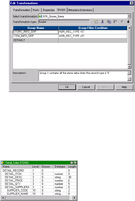
6. The Aggregator transformation removes the duplicate Detail_Data columns. The Aggregator passes one
instance of the item, description, price, quantity, and generated key to Detail_Data. The Detail_Data
generated key links the Detail_Data rows to the Suppliers rows. Detail_Data also has a key that links the
Detail_Data rows to the Sales_Header rows.
The following figure shows the user-defined groups and the filter conditions in the Router transformation:
The Router transformation passes store data or item data based on the record type.
Generating Key Values
The Normalizer transformation creates a generated key when the COBOL source contains a group of
multiple-occurring columns. You can pass a group of multiple-occurring columns to a different target than the
other columns in the row. You can create a primary-foreign key relationship between the targets with the
generated key.
The following figure shows a COBOL source definition that contains a multiple-occurring group of columns:
In this example, the Detail_Suppliers group of columns occurs four times in the Detail_Record.
The Normalizer transformation generates a GK_Detail_Sales key for each source row. The GK_Detail_Sales
key represents one Detail_Record source row.
Using a Normalizer Transformation in a Mapping 321
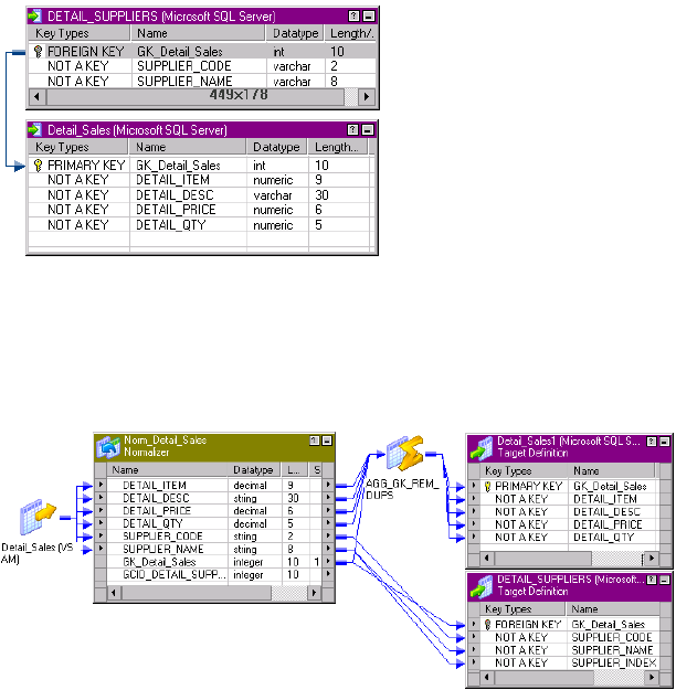
The following figure shows the primary foreign key relationships between the targets:
Multiple-occurring Detail_Supplier rows have a foreign key linking them to the same Detail_Sales row. The
Detail_Sales target has a one-to-many relationship to the Detail_Suppliers target.
The following figure shows the GK_Detail_Sales generated key connected to primary and foreign keys in the
target:
Pass GK_Detail_Sales to the primary key of Detail_Sales and the foreign key of Detail_Suppliers.
Link the Normalizer output columns to the following objects:
•Detail_Sales_Target. Pass the Detail_Item, Detail_Desc, Detail_Price, and Detail_Qty columns to a
Detail_Sales target. Pass the GK_Detail_Sales key to the Detail_Sales primary key.
•Aggregator Transformation. Pass each Detail_Sales row through an Aggregator transformation to
remove duplicate rows. The Normalizer returns duplicate Detail_Sales columns for each occurrence of
Detail_Suppliers.
•Detail_Suppliers. Pass each instance of the Detail_Suppliers columns to a the Detail_Suppliers target.
Pass the GK_Detail_Sales key to the Detail_Suppliers foreign key. Each instance of the Detail_Suppliers
columns has a foreign key that relates the Detail_Suppliers row to the Detail_Sales row.
Troubleshooting Normalizer Transformations
I cannot edit the ports in my Normalizer transformation when using a relational source.
When you create ports manually, add them on the Normalizer tab in the transformation, not the Ports tab.
Importing a COBOL file failed with numberrors. What should I do?
322 Chapter 20: Normalizer Transformation
Verify that the COBOL program follows the COBOL standard, including spaces, tabs, and end of line
characters. The COBOL file headings should be similar to the following text:
identification division.
program-id. mead.
environment division.
select file-one assign to "fname".
data division.
file section.
fd FILE-ONE.
The Designer does not read hidden characters in the COBOL program. Use a text-only editor to make
changes to the COBOL file. Do not use Word or Wordpad. Remove extra spaces.
A session that reads binary data completed, but the information in the target table is incorrect.
Edit the session in the Workflow Manager and verify that the source file format is set correctly. The file format
might be EBCDIC or ASCII. The number of bytes to skip between records must be set to 0.
I have a COBOL field description that uses a non-IBM COMP type. How should I import the source?
In the source definition, clear the IBM COMP option.
In my mapping, I use one Expression transformation and one Lookup transformation to modify two output
ports from the Normalizer transformation. The mapping concatenates them into a single transformation.
All the ports are under the same level. When I check the data loaded in the target, it is incorrect. Why is
that?
You can only concatenate ports from level one. Remove the concatenation.
Troubleshooting Normalizer Transformations 323

CHAPTER 2 1
Rank Transformation
This chapter includes the following topics:
•Rank Transformation Overview, 324
•Ports in a Rank Transformation, 325
•Defining Groups, 326
•Creating a Rank Transformation, 327
Rank Transformation Overview
You can select only the top or bottom rank of data with a Rank transformation. The Rank transformation is an
active transformation. Use a Rank transformation to return the largest or smallest numeric value in a port or
group. You can also use a Rank transformation to return the strings at the top or the bottom of a session sort
order. During the session, the Integration Service caches input data until it can perform the rank calculations.
The Rank transformation differs from the transformation functions MAX and MIN, in that it lets you select a
group of top or bottom values, not just one value. For example, use Rank to select the top 10 salespersons in
a given territory. Or, to generate a financial report, you might also use a Rank transformation to identify the
three departments with the lowest expenses in salaries and overhead. While the SQL language provides
many functions designed to handle groups of data, identifying top or bottom strata within a set of rows is not
possible using standard SQL functions.
You connect all ports representing the same row set to the transformation. Only the rows that fall within that
rank, based on some measure you set when you configure the transformation, pass through the Rank
transformation. You can also write expressions to transform data or perform calculations.
The following figure shows a mapping that passes employee data from a human resources table through a
Rank transformation. The Rank transformation only passes the rows for the top 10 highest paid employees to
the next transformation.
324
As an active transformation, the Rank transformation might change the number of rows passed through it.
You might pass 100 rows to the Rank transformation, but select to rank only the top 10 rows, which pass
from the Rank transformation to another transformation.
You can connect ports from only one transformation to the Rank transformation. You can also create local
variables and write non-aggregate expressions.
Ranking String Values
When the Integration Service runs in the ASCII data movement mode, it sorts session data using a binary
sort order.
When the Integration Service runs in Unicode data movement mode, the Integration Service uses the sort
order configured for the session. You select the session sort order in the session properties. The session
properties lists all available sort orders based on the code page used by the Integration Service.
For example, you have a Rank transformation configured to return the top three values of a string port. When
you configure the workflow, you select the Integration Service on which you want the workflow to run. The
session properties display all sort orders associated with the code page of the selected Integration Service,
such as French, German, and Binary. If you configure the session to use a binary sort order, the Integration
Service calculates the binary value of each string, and returns the three rows with the highest binary values
for the string.
Rank Caches
During a session, the Integration Service compares an input row with rows in the data cache. If the input row
out-ranks a cached row, the Integration Service replaces the cached row with the input row. If you configure
the Rank transformation to rank across multiple groups, the Integration Service ranks incrementally for each
group it finds.
The Integration Service stores group information in an index cache and row data in a data cache. If you
create multiple partitions in a pipeline, the Integration Service creates separate caches for each partition.
Rank Transformation Properties
When you create a Rank transformation, you can configure the following properties:
•Enter a cache directory.
•Select the top or bottom rank.
•Select the input/output port that contains values used to determine the rank. You can select only one port
to define a rank.
•Select the number of rows falling within a rank.
•Define groups for ranks, such as the 10 least expensive products for each manufacturer.
Ports in a Rank Transformation
The Rank transformation includes input or input/output ports connected to another transformation in the
mapping. It also includes variable ports and a rank port. Use the rank port to specify the column you want to
rank.
Ports in a Rank Transformation 325

The following table describes the ports in a Rank transformation:
Ports Number Required Description
I Minimum of one Input port. Create an input port to receive data from another transformation.
O Minimum of one Output port. Create an output port for each port you want to link to another
transformation. You can designate input ports as output ports.
V Not Required Variable port. Can use to store values or calculations to use in an expression.
Variable ports cannot be input or output ports. They pass data within the
transformation only.
R One only Rank port. Use to designate the column for which you want to rank values.
You can designate only one Rank port in a Rank transformation. The Rank
port is an input/output port. You must link the Rank port to another
transformation.
Rank Index
The Designer creates a RANKINDEX port for each Rank transformation. The Integration Service uses the
Rank Index port to store the ranking position for each row in a group.
For example, if you create a Rank transformation that ranks the top five salespersons for each quarter, the
rank index numbers the salespeople from 1 to 5:
RANKINDEX SALES_PERSON SALES
1 Sam 10,000
2 Mary 9,000
3 Alice 8,000
4 Ron 7,000
5 Alex 6,000
The RANKINDEX is an output port only. You can pass the rank index to another transformation in the
mapping or directly to a target.
Defining Groups
Like the Aggregator transformation, the Rank transformation lets you group information. For example, if you
want to select the 10 most expensive items by manufacturer, you would first define a group for each
manufacturer. When you configure the Rank transformation, you can set one of its input/output ports as a
group by port. For each unique value in the group port, the transformation creates a group of rows falling
within the rank definition (top or bottom, and a particular number in each rank).
Therefore, the Rank transformation changes the number of rows in two different ways. By filtering all but the
rows falling within a top or bottom rank, you reduce the number of rows that pass through the transformation.
By defining groups, you create one set of ranked rows for each group.
326 Chapter 21: Rank Transformation
For example, you might create a Rank transformation to identify the 50 highest paid employees in the
company. In this case, you would identify the SALARY column as the input/output port used to measure the
ranks, and configure the transformation to filter out all rows except the top 50.
After the Rank transformation identifies all rows that belong to a top or bottom rank, it then assigns rank
index values. In the case of the top 50 employees, measured by salary, the highest paid employee receives a
rank index of 1. The next highest-paid employee receives a rank index of 2, and so on. When measuring a
bottom rank, such as the 10 lowest priced products in the inventory, the Rank transformation assigns a rank
index from lowest to highest. Therefore, the least expensive item would receive a rank index of 1.
If two rank values match, they receive the same value in the rank index and the transformation skips the next
value. For example, if you want to see the top five retail stores in the country and two stores have the same
sales, the return data might look similar to the following:
RANKINDEX SALES STORE
1 10000 Orange
1 10000 Brea
3 90000 Los Angeles
4 80000 Ventura
Creating a Rank Transformation
You can add a Rank transformation anywhere in the mapping after the source qualifier.
To create a Rank transformation:
1. In the Mapping Designer, click Transformation > Create. Select the Rank transformation. Enter a name
for the Rank. The naming convention for Rank transformations is RNK_TransformationName.
Enter a description for the transformation. This description appears in the Repository Manager.
2. Click Create, and then click Done.
The Designer creates the Rank transformation.
3. Link columns from an input transformation to the Rank transformation.
4. Click the Ports tab and select the Rank (R) option for the rank port.
If you want to create groups for ranked rows, select Group By for the port that defines the group.
5. Click the Properties tab and select whether you want the top or bottom rank.
6. For the Number of Ranks option, enter the number of rows you want to select for the rank.
7. Change the other Rank transformation properties, if necessary.
Creating a Rank Transformation 327

The following table describes the Rank transformation properties:
Setting Description
Cache Directory Local directory where the Integration Service creates the index and data cache
files. By default, the Integration Service uses the directory entered in the
Workflow Manager for the process variable $PMCacheDir. If you enter a new
directory, make sure the directory exists and contains enough disk space for the
cache files.
Top/Bottom Specifies whether you want the top or bottom ranking for a column.
Number of Ranks Number of rows you want to rank.
Case-Sensitive String
Comparison
When running in Unicode mode, the Integration Service ranks strings based on
the sort order selected for the session. If the session sort order is case
sensitive, select this option to enable case-sensitive string comparisons, and
clear this option to have the Integration Service ignore case for strings. If the
sort order is not case sensitive, the Integration Service ignores this setting. By
default, this option is selected.
Tracing Level Determines the amount of information the Integration Service writes to the
session log about data passing through this transformation in a session.
Rank Data Cache Size Data cache size for the transformation. Default is 2,000,000 bytes. If the total
configured session cache size is 2 GB (2,147,483,648 bytes) or more, you must
run the session on a 64-bit Integration Service. You can use a numeric value for
the cache, you can use a cache value from a parameter file or you can
configure the Integration Service to set the cache size by using the Auto setting.
If you configure the Integration Service to determine the cache size, you can
also configure a maximum amount of memory for the Integration Service to
allocate to the cache.
Rank Index Cache Size Index cache size for the transformation. Default is 1,000,000 bytes. If the total
configured session cache size is 2 GB (2,147,483,648 bytes) or more, you must
run the session on a 64-bit Integration Service. You can use a numeric value for
the cache, you can use a cache value from a parameter file or you can
configure the Integration Service to set the cache size by using the Auto setting.
If you configure the Integration Service to determine the cache size, you can
also configure a maximum amount of memory for the Integration Service to
allocate to the cache.
Transformation Scope Specifies how the Integration Service applies the transformation logic to
incoming data:
- Transaction. Applies the transformation logic to all rows in a transaction. Choose
Transaction when a row of data depends on all rows in the same transaction, but
does not depend on rows in other transactions.
- All Input. Applies the transformation logic on all incoming data. When you choose
All Input, the PowerCenter drops incoming transaction boundaries. Choose All
Input when a row of data depends on all rows in the source.
8. Click OK.
328 Chapter 21: Rank Transformation

CHAPTER 2 2
Router Transformation
This chapter includes the following topics:
•Router Transformation Overview, 329
•Working with Groups, 331
•Working with Ports, 333
•Connecting Router Transformations in a Mapping, 334
•Creating a Router Transformation, 334
Router Transformation Overview
A Router transformation is similar to a Filter transformation because both transformations allow you to use a
condition to test data. A Filter transformation tests data for one condition and drops the rows of data that do
not meet the condition. However, a Router transformation tests data for one or more conditions and gives you
the option to route rows of data that do not meet any of the conditions to a default output group. The Router
transformation is an active transformation.
If you need to test the same input data based on multiple conditions, use a Router transformation in a
mapping instead of creating multiple Filter transformations to perform the same task. The Router
transformation is more efficient. For example, to test data based on three conditions, you only need one
Router transformation instead of three filter transformations to perform this task. Likewise, when you use a
Router transformation in a mapping, the Integration Service processes the incoming data only once. When
you use multiple Filter transformations in a mapping, the Integration Service processes the incoming data for
each transformation.
329
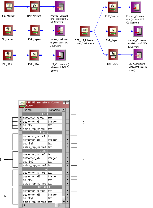
The following figure shows two mappings that perform the same task. The first mapping uses three Filter
transformations while the second mapping produces the same result with one Router transformation:
A Router transformation consists of input and output groups, input and output ports, group filter conditions,
and properties that you configure in the Designer.
The following figure shows a sample Router transformation:
1. Input ports.
2. Input group.
3. User-defined output groups.
4. Output ports
5. Default output group
330 Chapter 22: Router Transformation
Working with Groups
A Router transformation has the following types of groups:
•Input
•Output
Input Group
The Designer copies property information from the input ports of the input group to create a set of output
ports for each output group.
Output Groups
There are two types of output groups:
•User-defined groups
•Default group
You cannot modify or delete output ports or their properties.
User-Defined Groups
You create a user-defined group to test a condition based on incoming data. A user-defined group consists of
output ports and a group filter condition. You can create and edit user-defined groups on the Groups tab with
the Designer. Create one user-defined group for each condition that you want to specify.
The Integration Service uses the condition to evaluate each row of incoming data. It tests the conditions of
each user-defined group before processing the default group. The Integration Service determines the order of
evaluation for each condition based on the order of the connected output groups. The Integration Service
processes user-defined groups that are connected to a transformation or a target in a mapping. The
Integration Service only processes user-defined groups that are not connected in a mapping if the default
group is connected to a transformation or a target.
If a row meets more than one group filter condition, the Integration Service passes this row multiple times.
The Default Group
The Designer creates the default group after you create one new user-defined group. The Designer does not
allow you to edit or delete the default group. This group does not have a group filter condition associated with
it. If all of the conditions evaluate to FALSE, the Integration Service passes the row to the default group. If
you want the Integration Service to drop all rows in the default group, do not connect it to a transformation or
a target in a mapping.
The Designer deletes the default group when you delete the last user-defined group from the list.
Using Group Filter Conditions
You can test data based on one or more group filter conditions. You create group filter conditions on the
Groups tab using the Expression Editor. You can enter any expression that returns a single value. You can
also specify a constant for the condition. A group filter condition returns TRUE or FALSE for each row that
passes through the transformation, depending on whether a row satisfies the specified condition. Zero (0) is
the equivalent of FALSE, and any non-zero value is the equivalent of TRUE. The Integration Service passes
Working with Groups 331
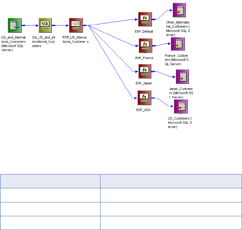
the rows of data that evaluate to TRUE to each transformation or target that is associated with each user-
defined group.
For example, you have customers from nine countries, and you want to perform different calculations on the
data from only three countries. You might want to use a Router transformation in a mapping to filter this data
to three different Expression transformations.
There is no group filter condition associated with the default group. However, you can create an Expression
transformation to perform a calculation based on the data from the other six countries.
The following figure shows a mapping with a Router transformation that filters data based on multiple
conditions:
Since you want to perform multiple calculations based on the data from three different countries, create three
user-defined groups and specify three group filter conditions on the Groups tab.
The following table shows group filter conditions that filter customer data:
Group Name Group Filter Condition
France customer_name=‘France’
Japan customer_name=‘Japan’
USA customer_name=‘USA’
In the session, the Integration Service passes the rows of data that evaluate to TRUE to each transformation
or target that is associated with each user-defined group, such as Japan, France, and USA. The Integration
Service passes the row to the default group if all of the conditions evaluate to FALSE. If this happens, the
Integration Service passes the data of the other six countries to the transformation or target that is associated
with the default group. If you want the Integration Service to drop all rows in the default group, do not connect
it to a transformation or a target in a mapping.
The Router transformation passes data through each group that meets the condition. So, if data meets three
output group conditions, the Router transformation passes the data through three output groups.
332 Chapter 22: Router Transformation

For example, you configure the following group conditions in a Router transformation:
Group Name Group Filter Condition
Output Group 1 employee_salary > 1000
Output Group 2 employee_salary > 2000
When the Router transformation processes an input row data with employee_salary=3000, it routes the data
through output groups 1 and 2.
Adding Groups
Adding a group is similar to adding a port in other transformations. The Designer copies property information
from the input ports to the output ports.
To add a group to a Router transformation:
1. Click the Groups tab.
2. Click the Add button.
3. Enter a name for the new group in the Group Name section.
4. Click the Group Filter Condition field and open the Expression Editor.
5. Enter the group filter condition.
6. Click Validate to check the syntax of the condition.
7. Click OK.
Working with Ports
A Router transformation has input ports and output ports. Input ports are in the input group, and output ports
are in the output groups. You can create input ports by copying them from another transformation or by
manually creating them on the Ports tab.
The Designer creates output ports by copying the following properties from the input ports:
•Port name
•Datatype
•Precision
•Scale
•Default value
When you make changes to the input ports, the Designer updates the output ports to reflect these changes.
You cannot edit or delete output ports. The output ports display in the Normal view of the Router
transformation.
The Designer creates output port names based on the input port names. For each input port, the Designer
creates a corresponding output port in each output group.
Working with Ports 333
Connecting Router Transformations in a Mapping
When you connect transformations to a Router transformation in a mapping, consider the following rules:
•You can connect one group to one transformation or target.
•You can connect one output port in a group to multiple transformations or targets.
•You can connect multiple output ports in one group to multiple transformations or targets.
•You cannot connect more than one group to one target or a single input group transformation.
•You can connect more than one group to a multiple input group transformation, except for Joiner
transformations, when you connect each output group to a different input group.
Creating a Router Transformation
To add a Router transformation to a mapping, complete the following steps.
To create a Router transformation:
1. In the Mapping Designer, open a mapping.
2. Click Transformation > Create.
Select Router transformation, and enter the name of the new transformation. The naming convention for
the Router transformation is RTR_TransformationName. Click Create, and then click Done.
3. Select and drag all the ports from a transformation to add them to the Router transformation, or you can
manually create input ports on the Ports tab.
4. Double-click the title bar of the Router transformation to edit transformation properties.
5. Click the Transformation tab and configure transformation properties.
6. Click the Properties tab and configure tracing levels.
7. Click the Groups tab, and then click the Add button to create a user-defined group.
The Designer creates the default group when you create the first user-defined group.
8. Click the Group Filter Condition field to open the Expression Editor.
9. Enter a group filter condition.
10. Click Validate to check the syntax of the conditions you entered.
11. Click OK.
12. Connect group output ports to transformations or targets.
334 Chapter 22: Router Transformation

CHAPTER 2 3
Sequence Generator
Transformation
This chapter includes the following topics:
•Sequence Generator Transformation Overview, 335
•Create Keys, 336
•Replace Missing Values, 336
•Cycle Through a Range of Values, 336
•Sequence Generator Ports, 337
•Sequence Generator Transformation Properties, 339
•Creating a Sequence Generator Transformation, 344
Sequence Generator Transformation Overview
The Sequence Generator transformation is a passive transformation that generates numeric values. Use the
Sequence Generator transformation to create unique primary key values, replace missing primary keys, or
cycle through a sequential range of numbers.
The Sequence Generator transformation is a connected transformation. It contains two output ports that you
can connect to one or more transformations. The Integration Service generates a block of sequence numbers
each time a block of rows enters a connected transformation. If you connect CURRVAL, the Integration
Service processes one row in each block. When NEXTVAL is connected to the input port of another
transformation, the Integration Service generates a sequence of numbers. When CURRVAL is connected to
the input port of another transformation, the Integration Service generates the NEXTVAL value plus the
Increment By value.
You can create a Sequence Generator transformation to use in a single mapping, or you can create a
reusable Sequence Generator transformation to use in multiple mappings. A reusable Sequence Generator
transformation maintains the integrity of the sequence in each mapping that uses an instance of the
Sequence Generator transformation.
You can make a Sequence Generator transformation reusable, and use it in multiple mappings. You might
reuse a Sequence Generator transformation when you perform multiple loads to a single target.
For example, if you have a large input file that you separate into three sessions running in parallel, use a
Sequence Generator transformation to generate primary key values. If you use different Sequence Generator
transformations, the Integration Service might generate duplicate key values. Instead, use the reusable
Sequence Generator transformation for all three sessions to provide a unique value for each target row.
335
Create Keys
You can create primary or foreign key values with the Sequence Generator transformation by connecting the
NEXTVAL port to a target or downstream transformation. You can use a range of values from 1 to
9,223,372,036,854,775,807 with the smallest interval of 1.
When you create primary or foreign keys, use the Cycle option to prevent the Integration Service from
creating duplicate primary keys. You can do this by selecting the Truncate Target Table option in the session
properties or by creating composite keys.
To create a composite key, you can configure the Integration Service to cycle through a smaller set of values.
For example, if three stores generate order numbers, configure a Sequence Generator transformation to
cycle through values from 1 to 3, incrementing by 1. When you connect the ORDER_NO port to the
Sequence Generator transformation, the generated values create unique composite keys.
The following example shows composite keys and order numbers:
COMPOSITE_KEY ORDER_NO
1 12345
2 12345
3 12345
1 12346
2 12346
3 12346
Replace Missing Values
Use the Sequence Generator transformation to replace missing keys by using NEXTVAL with the IIF and
ISNULL functions.
For example, to replace null values in the ORDER_NO column, you create a Sequence Generator
transformation with the properties and drag the NEXTVAL port to an Expression transformation. In the
Expression transformation, drag the ORDER_NO port into the transformation along with any other required
ports. Then create an output port, ALL_ORDERS.
In ALL_ORDERS, you can then enter the following expression to replace null orders:
IIF( ISNULL( ORDER_NO ), NEXTVAL, ORDER_NO )
Cycle Through a Range of Values
You can establish a range of values for the Sequence Generator transformation. If you use the cycle option,
the Sequence Generator transformation repeats the range when it reaches the end value.
336 Chapter 23: Sequence Generator Transformation
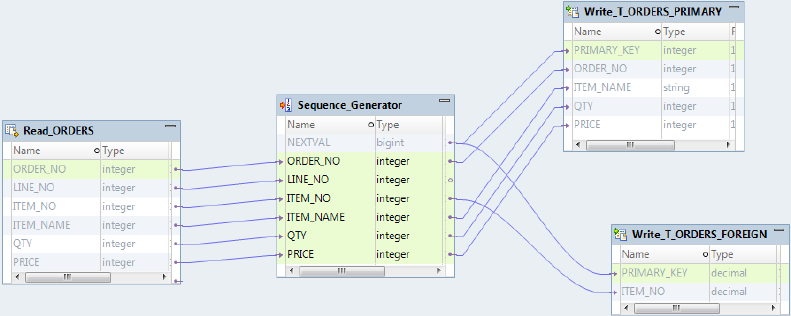
For example, if you set the sequence range to start at 10 and end at 50, and you set an increment value of
10, the Sequence Generator transformation creates the values 10, 20, 30, 40, 50. The sequence starts over
again at 10.
Sequence Generator Ports
The Sequence Generator transformation has two output ports: NEXTVAL and CURRVAL. You cannot edit or
delete these ports. Likewise, you cannot add ports to the transformation.
NEXTVAL Port
You can connect NEXTVAL to a transformation to generate unique values for each row in the transformation.
Connect the NEXTVAL port to a downstream transformation or target to generate a sequence of numbers. If
you connect NEXTVAL to multiple transformations, the Integration Service generates the same sequence of
numbers for each transformation.
You connect the NEXTVAL port to generate the sequence based on the Start Value and Increment Value
properties. If the Sequence Generator is not configured to cycle through the sequence, the NEXTVAL port
generates sequence numbers up to the configured end value.
The following image shows a mapping with the Sequence Generator transformation NEXTVAL port
connected to a source and two targets to generate primary and foreign key values:
When you configure the Sequence Generator transformation with a Start Value = 1 and an
Increment Value = 1, the Integration Service generates the same primary key values for the
T_ORDERS_PRIMARY and T_ORDERS_FOREIGN target tables.
Connect NEXTVAL to multiple transformations to generate unique values for each row in each
transformation. Use the NEXTVAL port to generate sequence numbers by connecting it to a downstream
transformation or target. You connect the NEXTVAL port to generate the sequence based on the Current
Value and Increment By properties. If the Sequence Generator is not configured to cycle through the
sequence, the NEXTVAL port generates sequence numbers up to the configured End Value.
For example, you might connect NEXTVAL to two targets in a mapping to generate unique primary key
values. The Integration Service creates a column of unique primary key values for each target table. The
column of unique primary key values is sent to one target table as a block of sequence numbers. The other
target receives a block of sequence numbers from the Sequence Generator transformation after the first
target receives the block of sequence numbers.
Sequence Generator Ports 337
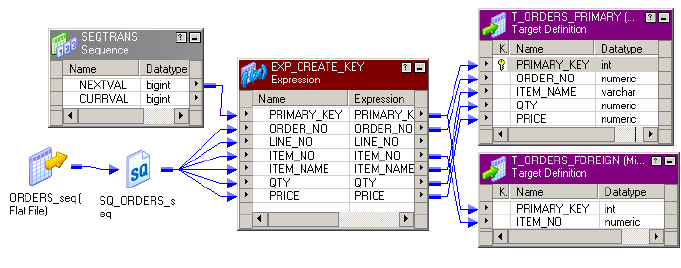
For example, you configure the Sequence Generator transformation as follows: Current Value = 1,
Increment By = 1. The Integration Service generates the following primary key values for the
T_ORDERS_PRIMARY and T_ORDERS_FOREIGN target tables:
T_ORDERS_PRIMARY TABLE:
PRIMARY KEY
T_ORDERS_FOREIGN TABLE:
PRIMARY KEY
1 6
2 7
3 8
4 9
5 10
If you want the same values to go to more than one target that receives data from a single transformation,
you can connect a Sequence Generator transformation to that preceding transformation. The Integration
Service processes the values into a block of sequence numbers. This allows the Integration Service to pass
unique values to the transformation, and then route rows from the transformation to targets.
The following figure shows a mapping with a Sequence Generator that passes unique values to the
Expression transformation:
The Expression transformation populates both targets with identical primary key values.
For example, you configure the Sequence Generator transformation as follows: Current Value = 1,
Increment By = 1. The Integration Service generates the following primary key values for the
T_ORDERS_PRIMARY and T_ORDERS_FOREIGN target tables:
T_ORDERS_PRIMARY TABLE:
PRIMARY KEY
T_ORDERS_FOREIGN TABLE:
PRIMARY KEY
1 1
2 2
3 3
4 4
5 5
Note: When you run a partitioned session on a grid, the Sequence Generator transformation skips values
depending on the number of rows in each partition.
338 Chapter 23: Sequence Generator Transformation
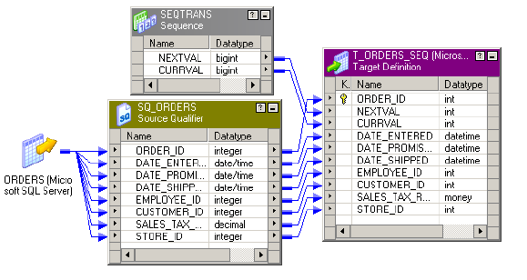
CURRVAL
CURRVAL is NEXTVAL plus the Increment By value. You typically only connect the CURRVAL port when the
NEXTVAL port is already connected to a downstream transformation. When a row enters a transformation
connected to the CURRVAL port, the Integration Service passes the last created NEXTVAL value plus one.
CURRVAL is NEXTVAL plus the Increment Value. You typically only connect the CURRVAL port when the
NEXTVAL port is already connected to a downstream transformation. When a row enters a transformation
connected to the CURRVAL port, the Integration Service passes the last created NEXTVAL value plus one.
The following figure shows connecting CURRVAL and NEXTVAL ports to a target:
For example, you configure the Sequence Generator transformation as follows: Current Value = 1,
Increment By = 1. The Integration Service generates the following values for NEXTVAL and CURRVAL:
If you connect the CURRVAL port without connecting the NEXTVAL port, the Integration Service passes a
constant value for each row. When you connect the CURRVAL port in a Sequence Generator transformation,
the Integration Service processes one row in each block. You can optimize performance by connecting only
the NEXTVAL port in a mapping.
Note: When you run a partitioned session on a grid, the Sequence Generator transformation might skip
values depending on the number of rows in each partition.
Sequence Generator Transformation Properties
Configure transformation properties that the Integration Service uses to generate sequential values.
The following list describes the Sequence Generator transformation properties you can configure:
Start Value
Start value of the generated sequence that you want the Integration Service to use if you use the Cycle
option. If you select Cycle, the Integration Service cycles back to this value when it reaches the end
value.
Default is 0.
Maximum value is 9,223,372,036,854,775,806.
Increment By
Difference between two consecutive values from the NEXTVAL port.
Sequence Generator Transformation Properties 339
Default is 1.
Must be a positive integer.
Maximum value is 2,147,483,647.
End Value
Maximum value that the Integration Service generates. If the Integration Service reaches this value
during the session and the sequence is not configured to cycle, the session fails.
Maximum value is 9,223,372,036,854,775,807.
If you connect the NEXTVAL port to a downstream integer port, set the end value to a value no larger
than the integer maximum value. If the NEXTVAL exceeds the datatype maximum value for the
downstream port, the session fails.
Current Value
Current value of the sequence. Enter the value you want the Integration Service to use as the first value
in the sequence. To cycle through a series of values, the value must be greater than or equal to the start
value and less than the end value.
If the Number of Cached Values is set to 0, the Integration Service updates the current value to reflect
the last-generated value for the session plus one, and then uses the updated current value as the basis
for the next time you run this session. However, if you use the Reset option, the Integration Service
resets this value to its original value after each session.
Note: If you edit this setting, you reset the sequence to the new setting. If you reset Current Value to 10,
and the increment is 1, the next time you use the session, the Integration Service generates a first value
of 10.
Maximum value is 9,223,372,036,854,775,806. The Integration Service sets the value to NULL if the
current value exceeds the maximum value.
Cycle
If enabled, the Integration Service cycles through the sequence range and starts over with the start
value.
If disabled, the Integration Service stops the sequence at the configured end value. The Integration
Service fails the session with overflow errors if it reaches the end value and still has rows to process.
Number of Cached Values
Number of sequential values the Integration Service caches at a time. Use this option when multiple
sessions use the same reusable Sequence Generator at the same time to ensure each session receives
unique values. The Integration Service updates the repository as it caches each value. When set to 0,
the Integration Service does not cache values.
Default value is 0.
Default value for a reusable Sequence Generator is 1,000.
Maximum value is 9,223,372,036,854,775,807.
Reset
If enabled, the Integration Service generates values based on the original current value for each session.
If disabled, the Integration Service updates the current value to reflect the last-generated value for the
session plus one, and then uses the updated current value as the basis for the next session run.
This property is disabled for reusable Sequence Generator transformations.
340 Chapter 23: Sequence Generator Transformation
Tracing Level
Level of detail about the transformation that the Integration Service writes into the session log.
Start Value
Use Cycle to generate a repeating sequence, such as numbers 1 through 12 to correspond to the months in a
year.
1. Enter the lowest value in the sequence that you want the Integration Service to use for the start value.
2. Enter the highest value to be used for End Value.
3. Select Cycle.
As it cycles, the Integration Service reaches the configured end value for the sequence, it wraps around and
starts the cycle again, beginning with the configured start value.
Increment By
The Integration Service generates a sequence in the NEXTVAL port based on the Current Value and
Increment By properties in the Sequence Generator transformation.
The Current Value property is the value at which the Integration Service starts creating the sequence for
each session. Increment By is the integer the Integration Service adds to the existing value to create the new
value in the sequence. By default, the Current Value is set to 1, and Increment By is set to 1.
For example, you might create a Sequence Generator transformation with a current value of 1,000 and an
increment of 10. If you pass three rows through the mapping, the Integration Service generates the following
set of values:
1000
1010
1020
End Value
End Value is the maximum value that you want the Integration Service to generate. If the Integration Service
reaches the end value and the Sequence Generator is not configured to cycle through the sequence, the
session fails with an overflow error.
Set the end value to any integer between 1 and 9,233,372,036,854,775,807. If you connect the NEXTVAL
port to a downstream integer port, set the end value to a value no larger than the integer maximum value. For
example, if you connect the NEXTVAL port to a Small Integer port, set the end value to a maximum of
32,767. If the NEXTVAL exceeds the datatype maximum value for the downstream port, the session fails.
Current Value
The Integration Service uses the current value as the basis for generated values for each session. To
indicate which value you want the Integration Service to use the first time it uses the Sequence Generator
transformation, you must enter that value as the current value. If you want to use the Sequence Generator
transformation to cycle through a series of values, the current value must be greater than or equal to Start
Value and less than the end value.
At the end of each session, the Integration Service updates the current value to the last value generated for
the session plus one if the Sequence Generator Number of Cached Values is 0. For example, if the
Integration Service ends a session with a generated value of 101, it updates the Sequence Generator current
value to 102 in the repository. The next time the Sequence Generator is used, the Integration Service uses
Sequence Generator Transformation Properties 341
102 as the basis for the next generated value. If the Sequence Generator Increment By is 1, when the
Integration Service starts another session using the Sequence Generator, the first generated value is 102.
If you have multiple versions of a Sequence Generator transformation, the Integration Service updates the
current value across all versions when it runs a session. The Integration Service updates the current value
across versions regardless of whether you have checked out the Sequence Generator transformation or the
parent mapping. The updated current value overrides an edited current value for a Sequence Generator
transformation if the two values are different.
For example, User 1 creates Sequence Generator transformation and checks it in, saving a current value of
10 to Sequence Generator version 1. Then User 1 checks out the Sequence Generator transformation and
enters a new current value of 100 to Sequence Generator version 2. User 1 keeps the Sequence Generator
transformation checked out. Meanwhile, User 2 runs a session that uses the Sequence Generator
transformation version 1. The Integration Service uses the checked-in value of 10 as the current value when
User 2 runs the session. When the session completes, the current value is 150. The Integration Service
updates the current value to 150 for version 1 and version 2 of the Sequence Generator transformation even
though User 1 has the Sequence Generator transformation checked out.
If you open the mapping after you run the session, the current value displays the last value generated for the
session plus one. Since the Integration Service uses the current value to determine the first value for each
session, you should edit the current value only when you want to reset the sequence.
If you have multiple versions of the Sequence Generator transformation, and you want to reset the sequence,
you must check in the mapping or reusable Sequence Generator transformation after you modify the current
value.
Note: If you configure the Sequence Generator to Reset, the Integration Service uses the current value as
the basis for the first generated value for each session.
Number of Cached Values
Number of Cached Values determines the number of values the Integration Service caches at one time.
When Number of Cached Values is greater than zero, the Integration Service caches the configured number
of values and updates the current value each time it caches values.
When multiple sessions use the same reusable Sequence Generator transformation at the same time, there
might be multiple instances of the Sequence Generator transformation. To avoid generating the same values
for each session, reserve a range of sequence values for each session by configuring Number of Cached
Values.
Tip: To increase performance when running a session on a grid, increase the number of cached values for
the Sequence Generator transformation. This reduces the communication required between the master and
worker DTM processes and the repository.
Non-Reusable Sequence Generators
For non-reusable Sequence Generator transformations, Number of Cached Values is set to zero by default,
and the Integration Service does not cache values during the session. When the Integration Service does not
cache values, it accesses the repository for the current value at the start of a session. The Integration
Service then generates values for the sequence. At the end of the session, the Integration Service updates
the current value in the repository.
When you set Number of Cached Values greater than zero, the Integration Service caches values during the
session. At the start of the session, the Integration Service accesses the repository for the current value,
caches the configured number of values, and updates the current value accordingly. If the Integration Service
uses all values in the cache, it accesses the repository for the next set of values and updates the current
value. At the end of the session, the Integration Service discards any remaining values in the cache.
342 Chapter 23: Sequence Generator Transformation
For non-reusable Sequence Generator transformations, setting Number of Cached Values greater than zero
can increase the number of times the Integration Service accesses the repository during the session. It also
causes sections of skipped values since unused cached values are discarded at the end of each session.
For example, you configure a Sequence Generator transformation as follows: Number of Cached Values =
50, Current Value = 1, Increment By = 1. When the Integration Service starts the session, it caches 50 values
for the session and updates the current value to 50 in the repository. The Integration Service uses values 1 to
39 for the session and discards the unused values, 40 to 49. When the Integration Service runs the session
again, it checks the repository for the current value, which is 50. It then caches the next 50 values and
updates the current value to 100. During the session, it uses values 50 to 98. The values generated for the
two sessions are 1 to 39 and 50 to 98.
Reusable Sequence Generators
When you have a reusable Sequence Generator transformation in several sessions and the sessions run at
the same time, use Number of Cached Values to ensure each session receives unique values in the
sequence. By default, Number of Cached Values is set to 1000 for reusable Sequence Generators.
When multiple sessions use the same Sequence Generator transformation at the same time, you risk
generating the same values for each session. To avoid this, have the Integration Service cache a set number
of values for each session by configuring Number of Cached Values.
For example, you configure a reusable Sequence Generator transformation as follows: Number of Cached
Values = 50, Current Value = 1, Increment By = 1. Two sessions use the Sequence Generator, and they are
scheduled to run at approximately the same time. When the Integration Service starts the first session, it
caches 50 values for the session and updates the current value to 50 in the repository. The Integration
Service begins using values 1 to 50 in the session. When the Integration Service starts the second session, it
checks the repository for the current value, which is 50. It then caches the next 50 values and updates the
current value to 100. It then uses values 51 to 100 in the second session. When either session uses all its
cached values, the Integration Service caches a new set of values and updates the current value to ensure
these values remain unique to the Sequence Generator.
For reusable Sequence Generator transformations, you can reduce Number of Cached Values to minimize
discarded values, however it must be greater than one. When you reduce the Number of Cached Values, you
might increase the number of times the Integration Service accesses the repository to cache values during
the session.
Reset
If you select Reset for a non-reusable Sequence Generator transformation, the Integration Service generates
values based on the original start value each time it starts the session. Otherwise, the Integration Service
updates the current value to reflect the last-generated value plus the increment value, and then uses the
updated value the next time it uses the Sequence Generator transformation.
For example, you configure a Sequence Generator transformation to create values from 1 to 1,000 with an
increment of 1. You choose reset to reset the start value to 1. During the first session run, the Integration
Service generates numbers 1 through 234. In each subsequent mapping run, the Integration Service again
generates numbers beginning with the initial value of 1.
If you do not reset, the Integration Service updates the current value to 235 at the end of the first run. The
next time it uses the Sequence Generator transformation, the first value generated is 235.
Note: Reset is disabled for reusable Sequence Generator transformations.
Sequence Generator Transformation Properties 343
Creating a Sequence Generator Transformation
To use a Sequence Generator transformation in a mapping, add it to the mapping, configure the
transformation properties, and then connect NEXTVAL or CURRVAL to one or more transformations.
To create a Sequence Generator transformation:
1. In the Mapping Designer, click Transformation > Create. Select the Sequence Generator transformation.
The naming convention for Sequence Generator transformations is SEQ_TransformationName.
2. Enter a name for the Sequence Generator, and click Create. Click Done.
The Designer creates the Sequence Generator transformation.
3. Double-click the title bar of the transformation.
4. Enter a description for the transformation.
5. Select the Properties tab. Enter settings.
Note: You cannot override the Sequence Generator transformation properties at the session level. This
protects the integrity of the sequence values generated.
6. Click OK.
7. To generate new sequences during a session, connect the NEXTVAL port to at least one transformation
in the mapping.
Use the NEXTVAL or CURRVAL ports in an expression in other transformations.
344 Chapter 23: Sequence Generator Transformation

CHAPTER 2 4
Sorter Transformation
This chapter includes the following topics:
•Sorter Transformation Overview, 345
•Sorting Data, 345
•Sorter Transformation Properties, 346
•Creating a Sorter Transformation, 348
Sorter Transformation Overview
You can sort data with the Sorter transformation. You can sort data in ascending or descending order
according to a specified sort key. You can also configure the Sorter transformation for case-sensitive sorting,
and specify whether the output rows should be distinct. The Sorter transformation is an active transformation.
It must be connected to the data flow.
You can sort data from relational or flat file sources. You can also use the Sorter transformation to sort data
passing through an Aggregator transformation configured to use sorted input.
When you create a Sorter transformation in a mapping, you specify one or more ports as a sort key and
configure each sort key port to sort in ascending or descending order. You also configure sort criteria the
Integration Service applies to all sort key ports and the system resources it allocates to perform the sort
operation.
Sorting Data
The Sorter transformation contains only input/output ports. All data passing through the Sorter transformation
is sorted according to a sort key. The sort key is one or more ports that you want to use as the sort criteria.
You can specify more than one port as part of the sort key. When you specify multiple ports for the sort key,
the Integration Service sorts each port sequentially. The order the ports appear in the Ports tab determines
the succession of sort operations. The Sorter transformation treats the data passing through each successive
sort key port as a secondary sort of the previous port.
At session run time, the Integration Service sorts data according to the sort order specified in the session
properties. The sort order determines the sorting criteria for special characters and symbols.
345
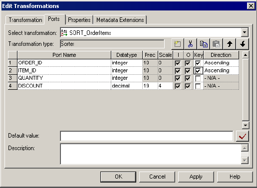
The following figure shows the Ports tab configuration for the Sorter transformation sorting the data in
ascending order by order ID and item ID:
At session run time, the Integration Service passes the following rows into the Sorter transformation:
ORDER_ID ITEM_ID QUANTITY DISCOUNT
45 123456 3 3.04
45 456789 2 12.02
43 000246 6 34.55
41 000468 5 .56
After sorting the data, the Integration Service passes the following rows out of the Sorter transformation:
ORDER_ID ITEM_ID QUANTITY DISCOUNT
41 000468 5 .56
43 000246 6 34.55
45 123456 3 3.04
45 456789 2 12.02
Sorter Transformation Properties
The Sorter transformation has several properties that specify additional sort criteria. The Integration Service
applies these criteria to all sort key ports. The Sorter transformation properties also determine the system
resources the Integration Service allocates when it sorts data.
346 Chapter 24: Sorter Transformation
Sorter Cache Size
The Integration Service uses the Sorter Cache Size property to determine the maximum amount of memory it
can allocate to perform the sort operation. The Integration Service passes all incoming data into the Sorter
transformation before it performs the sort operation. You can use a numeric value for the cache, you can use
a cache value from a parameter file or you can configure the Integration Service to set the cache size by
using the Auto setting. If you configure the Integration Service to determine the cache size, you can also
configure a maximum amount of memory for the Integration Service to allocate to the cache. If the total
configured session cache size is 2 GB (2,147,483,648 bytes) or greater, you must run the session on a 64-bit
Integration Service.
Before starting the sort operation, the Integration Service allocates the amount of memory configured for the
Sorter cache size. If the Integration Service runs a partitioned session, it allocates the specified amount of
Sorter cache memory for each partition.
If it cannot allocate enough memory, the Integration Service fails the session. For best performance,
configure Sorter cache size with a value less than or equal to the amount of available physical RAM on the
Integration Service machine. Allocate at least 16 MB (16,777,216 bytes) of physical memory to sort data
using the Sorter transformation. Sorter cache size is set to 16,777,216 bytes by default.
If the amount of incoming data is greater than the amount of Sorter cache size, the Integration Service
temporarily stores data in the Sorter transformation work directory. The Integration Service requires disk
space of at least twice the amount of incoming data when storing data in the work directory. If the amount of
incoming data is significantly greater than the Sorter cache size, the Integration Service may require much
more than twice the amount of disk space available to the work directory.
The Integration Service also writes the amount of memory the Sorter transformation uses to the session log
when you configure the Sorter transformation tracing level to Normal.
Case Sensitive
The Case Sensitive property determines whether the Integration Service considers case when sorting data.
When you enable the Case Sensitive property, the Integration Service sorts uppercase characters higher
than lowercase characters.
Work Directory
You must specify a work directory the Integration Service uses to create temporary files while it sorts data.
After the Integration Service sorts the data, it deletes the temporary files. You can specify any directory on
the Integration Service machine to use as a work directory. By default, the Integration Service uses the value
specified for the $PMTempDir process variable.
When you partition a session with a Sorter transformation, you can specify a different work directory for each
partition in the pipeline. To increase session performance, specify work directories on physically separate
disks on the Integration Service system.
Distinct Output Rows
You can configure the Sorter transformation to treat output rows as distinct. If you configure the Sorter
transformation for distinct output rows, the Mapping Designer configures all ports as part of the sort key. The
Integration Service discards duplicate rows compared during the sort operation.
Sorter Transformation Properties 347
Tracing Level
Configure the Sorter transformation tracing level to control the number and type of Sorter error and status
messages the Integration Service writes to the session log. At Normal tracing level, the Integration Service
writes the size of the row passed to the Sorter transformation and the amount of memory the Sorter
transformation allocates for the sort operation. The Integration Service also writes the time and date when it
passes the first and last input rows to the Sorter transformation.
If you configure the Sorter transformation tracing level to Verbose Data, the Integration Service writes the
time the Sorter transformation finishes passing all data to the next transformation in the pipeline. The
Integration Service also writes the time to the session log when the Sorter transformation releases memory
resources and removes temporary files from the work directory.
Null Treated Low
You can configure the way the Sorter transformation treats null values. Enable this property if you want the
Integration Service to treat null values as lower than any other value when it performs the sort operation.
Disable this option if you want the Integration Service to treat null values as higher than any other value.
Transformation Scope
The transformation scope specifies how the Integration Service applies the transformation logic to incoming
data:
•Transaction. Applies the transformation logic to all rows in a transaction. Choose Transaction when a row
of data depends on all rows in the same transaction, but does not depend on rows in other transactions.
•All Input. Applies the transformation logic on all incoming data. When you choose All Input, the
PowerCenter drops incoming transaction boundaries. Choose All Input when a row of data depends on all
rows in the source.
Creating a Sorter Transformation
To add a Sorter transformation to a mapping, complete the following steps.
To create a Sorter transformation:
1. In the Mapping Designer, click Transformation > Create. Select the Sorter transformation.
The naming convention for Sorter transformations is SRT_TransformationName. Enter a description for
the transformation. This description appears in the Repository Manager, making it easier to understand
what the transformation does.
2. Enter a name for the Sorter and click Create.
The Designer creates the Sorter transformation.
3. Click Done.
4. Drag the ports you want to sort into the Sorter transformation.
The Designer creates the input/output ports for each port you include.
5. Double-click the title bar of the transformation to open the Edit Transformations dialog box.
6. Select the Ports tab.
7. Select the ports you want to use as the sort key.
348 Chapter 24: Sorter Transformation
8. For each port selected as part of the sort key, specify whether you want the Integration Service to sort
data in ascending or descending order.
9. Select the Properties tab. Modify the Sorter transformation properties.
10. Select the Metadata Extensions tab. Create or edit metadata extensions for the Sorter transformation.
11. Click OK.
Creating a Sorter Transformation 349

CHAPTER 2 5
Source Qualifier Transformation
This chapter includes the following topics:
•Source Qualifier Transformation Overview, 350
•Source Qualifier Transformation Properties, 352
•Default Query, 353
•Joining Source Data, 354
•Adding an SQL Query, 357
•Entering a User-Defined Join, 358
•Outer Join Support, 358
•Entering a Source Filter, 365
•Using Sorted Ports, 366
•Select Distinct, 367
•Adding Pre- and Post-Session SQL Commands, 368
•Creating a Source Qualifier Transformation, 368
•Troubleshooting Source Qualifier Transformations, 369
Source Qualifier Transformation Overview
When you add a relational or a flat file source definition to a mapping, you need to connect it to a Source
Qualifier transformation. The Source Qualifier transformation represents the rows that the Integration Service
reads when it runs a session. The Source Qualifier transformation is an active transformation.
Use the Source Qualifier transformation to complete the following tasks:
•Join data originating from the same source database. You can join two or more tables with primary
key-foreign key relationships by linking the sources to one Source Qualifier transformation.
•Filter rows when the Integration Service reads source data. If you include a filter condition, the
Integration Service adds a WHERE clause to the default query.
•Specify an outer join rather than the default inner join. If you include a user-defined join, the
Integration Service replaces the join information specified by the metadata in the SQL query.
•Specify sorted ports. If you specify a number for sorted ports, the Integration Service adds an ORDER
BY clause to the default SQL query.
•Select only distinct values from the source. If you choose Select Distinct, the Integration Service adds
a SELECT DISTINCT statement to the default SQL query.
350

•Create a custom query to issue a special SELECT statement for the Integration Service to read
source data. For example, you might use a custom query to perform aggregate calculations.
Transformation Datatypes
The Source Qualifier transformation displays the transformation datatypes. The transformation datatypes
determine how the source database binds data when the Integration Service reads it. Do not alter the
datatypes in the Source Qualifier transformation. If the datatypes in the source definition and Source Qualifier
transformation do not match, the Designer marks the mapping invalid when you save it.
Target Load Order
You specify a target load order based on the Source Qualifier transformations in a mapping. If you have
multiple Source Qualifier transformations connected to multiple targets, you can designate the order in which
the Integration Service loads data into the targets.
If one Source Qualifier transformation provides data for multiple targets, you can enable constraint-based
loading in a session to have the Integration Service load data based on target table primary and foreign key
relationships.
Datetime Values
When you use a datetime value or a datetime parameter or variable in the SQL query, change the date
format to the format used in the source. The Integration Service passes datetime values to source systems
as strings in the SQL query. The Integration Service converts a datetime value to a string, based on the
source database.
The following table describes the datetime formats for each database type:
Source Date Format
DB2 YYYY-MM-DD-HH24:MI:SS
Informix YYYY-MM-DD HH24:MI:SS
Microsoft SQL Server MM/DD/YYYY HH24:MI:SS
ODBC YYYY-MM-DD HH24:MI:SS
Oracle MM/DD/YYYY HH24:MI:SS
Sybase MM/DD/YYYY HH24:MI:SS
Teradata YYYY-MM-DD HH24:MI:SS
Some databases require you to identify datetime values with additional punctuation, such as single quotation
marks or database specific functions. For example, to convert the $$$SessStartTime value for an Oracle
source, use the following Oracle function in the SQL override:
to_date (‘$$$SessStartTime’, ‘mm/dd/yyyy hh24:mi:ss’)
For Informix, use the following Informix function in the SQL override to convert the $$$SessStartTime value:
DATETIME ($$$SessStartTime) YEAR TO SECOND
For information about database specific functions, see the database documentation.
Source Qualifier Transformation Overview 351

Parameters and Variables
You can use parameters and variables in the SQL query, user-defined join, source filter, and pre- and post-
session SQL commands of a Source Qualifier transformation. Use any parameter or variable type that you
can define in the parameter file. You can enter a parameter or variable within the SQL statement, or you can
use a parameter or variable as the SQL query. For example, you can use a session parameter,
$ParamMyQuery, as the SQL query, and set $ParamMyQuery to the SQL statement in a parameter file.
The Integration Service first generates an SQL query and expands each parameter or variable. It replaces
each mapping parameter, mapping variable, and workflow variable with its start value. Then it runs the query
on the source database.
When you use a string mapping parameter or variable in the Source Qualifier transformation, use a string
identifier appropriate to the source system. Most databases use a single quotation mark as a string identifier.
For example, to use the string parameter $$IPAddress in a source filter for a Microsoft SQL Server database
table, enclose the parameter in single quotes as follows: ‘$$IPAddress.’
When you use a datetime mapping parameter or variable, or when you use the built-in variable $$
$SessStartTime, change the date format to the format used in the source. The Integration Service passes
datetime values to source systems as strings in the SQL query.
Tip: To ensure the format of a datetime parameter or variable matches that used by the source, validate the
SQL query.
Source Qualifier Transformation Properties
Configure the following Source Qualifier transformation properties on the Properties tab:
Option Description
SQL Query Defines a custom query that replaces the default query the Integration Service uses to read
data from sources represented in this Source Qualifier transformation. A custom query
overrides entries for a custom join or a source filter.
User-Defined
Join
Specifies the condition used to join data from multiple sources represented in the same
Source Qualifier transformation.
Source Filter Specifies the filter condition the Integration Service applies when querying rows.
Number of
Sorted Ports
Indicates the number of columns used when sorting rows queried from relational sources. If
you select this option, the Integration Service adds an ORDER BY to the default query when
it reads source rows. The ORDER BY includes the number of ports specified, starting from
the top of the transformation.
When selected, the database sort order must match the session sort order.
Tracing Level Sets the amount of detail included in the session log when you run a session containing this
transformation.
Select Distinct Specifies if you want to select only unique rows. The Integration Service includes a SELECT
DISTINCT statement if you choose this option.
Pre-SQL Pre-session SQL commands to run against the source database before the Integration
Service reads the source.
352 Chapter 25: Source Qualifier Transformation
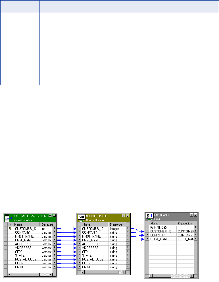
Option Description
Post-SQL Post-session SQL commands to run against the source database after the Integration
Service writes to the target.
Output is
Deterministic
Relational source or transformation output that does not change between session runs when
the input data is consistent between runs. When you configure this property, the Integration
Service does not stage source data for recovery if transformations in the pipeline always
produce repeatable data.
Output is
Repeatable
Relational source or transformation output that is in the same order between session runs
when the order of the input data is consistent. When output is deterministic and output is
repeatable, the Integration Service does not stage source data for recovery.
Warning: If you configure a transformation as repeatable and deterministic, it is your responsibility to ensure
that the data is repeatable and deterministic. If you try to recover a session with transformations that do not
produce the same data between the session and the recovery, the recovery process can result in corrupted
data.
Default Query
For relational sources, the Integration Service generates a query for each Source Qualifier transformation
when it runs a session. The default query is a SELECT statement for each source column used in the
mapping. In other words, the Integration Service reads only the columns that are connected to another
transformation.
The following figure shows a single source definition connected to a Source Qualifier transformation, with
many source definition columns but only three connected to the final transformation:
Although there are many columns in the source definition, only three columns are connected to another
transformation. In this case, the Integration Service generates a default query that selects only those three
columns:
SELECT CUSTOMERS.CUSTOMER_ID, CUSTOMERS.COMPANY, CUSTOMERS.FIRST_NAME
FROM CUSTOMERS
If any table name or column name contains a database reserved word, you can create and maintain a file,
reswords.txt, containing reserved words. When the Integration Service initializes a session, it searches for
reswords.txt in the Integration Service installation directory. If the file exists, the Integration Service places
Default Query 353
quotes around matching reserved words when it executes SQL against the database. If you override the
SQL, you must enclose any reserved word in quotes.
When generating the default query, the Designer delimits table and field names containing the following
characters with double quotes:
/ + - = ~ ` ! % ^ & * ( ) [ ] { } ' ; ? , < > \ | <space>
Viewing the Default Query
You can view the default query in the Source Qualifier transformation.
To view the default query:
1. From the Properties tab, select SQL Query.
The SQL Editor displays the default query the Integration Service uses to select source data.
2. Click Generate SQL.
3. Click Cancel to exit.
If you do not cancel the SQL query, the Integration Service overrides the default query with the custom SQL
query.
Do not connect to the source database. You only connect to the source database when you enter an SQL
query that overrides the default query.
You must connect the columns in the Source Qualifier transformation to another transformation or target
before you can generate the default query.
Overriding the Default Query
You can alter or override the default query in the Source Qualifier transformation by changing the default
settings of the transformation properties. Do not change the list of selected ports or the order in which they
appear in the query. This list must match the connected transformation output ports.
When you edit transformation properties, the Source Qualifier transformation includes these settings in the
default query. However, if you enter an SQL query, the Integration Service uses only the defined SQL
statement. The SQL Query overrides the User-Defined Join, Source Filter, Number of Sorted Ports, and
Select Distinct settings in the Source Qualifier transformation.
Note: When you override the default SQL query, you must enclose all database reserved words in quotes.
Joining Source Data
Use one Source Qualifier transformation to join data from multiple relational tables. These tables must be
accessible from the same instance or database server.
When a mapping uses related relational sources, you can join both sources in one Source Qualifier
transformation. During the session, the source database performs the join before passing data to the
Integration Service. This can increase performance when source tables are indexed.
Tip: Use the Joiner transformation for heterogeneous sources and to join flat files.
354 Chapter 25: Source Qualifier Transformation

Default Join
When you join related tables in one Source Qualifier transformation, the Integration Service joins the tables
based on the related keys in each table.
This default join is an inner equijoin, using the following syntax in the WHERE clause:
Source1.column_name = Source2.column_name
The columns in the default join must have:
•A primary key-foreign key relationship
•Matching datatypes
For example, you might see all the orders for the month, including order number, order amount, and
customer name. The ORDERS table includes the order number and amount of each order, but not the
customer name. To include the customer name, you need to join the ORDERS and CUSTOMERS tables.
Both tables include a customer ID, so you can join the tables in one Source Qualifier transformation.
The following figure shows joining two tables with one Source Qualifier transformation:
When you include multiple tables, the Integration Service generates a SELECT statement for all columns
used in the mapping. In this case, the SELECT statement looks similar to the following statement:
SELECT CUSTOMERS.CUSTOMER_ID, CUSTOMERS.COMPANY, CUSTOMERS.FIRST_NAME,
CUSTOMERS.LAST_NAME, CUSTOMERS.ADDRESS1, CUSTOMERS.ADDRESS2, CUSTOMERS.CITY,
CUSTOMERS.STATE, CUSTOMERS.POSTAL_CODE, CUSTOMERS.PHONE, CUSTOMERS.EMAIL,
ORDERS.ORDER_ID, ORDERS.DATE_ENTERED, ORDERS.DATE_PROMISED, ORDERS.DATE_SHIPPED,
ORDERS.EMPLOYEE_ID, ORDERS.CUSTOMER_ID, ORDERS.SALES_TAX_RATE, ORDERS.STORE_ID
FROM CUSTOMERS, ORDERS
WHERE CUSTOMERS.CUSTOMER_ID=ORDERS.CUSTOMER_ID
The WHERE clause is an equijoin that includes the CUSTOMER_ID from the ORDERS and CUSTOMER
tables.
Custom Joins
If you need to override the default join, you can enter contents of the WHERE clause that specifies the join in
the custom query. If the query performs an outer join, the Integration Service may insert the join syntax in the
WHERE clause or the FROM clause, depending on the database syntax.
Joining Source Data 355
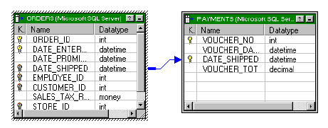
You might need to override the default join under the following circumstances:
•Columns do not have a primary key-foreign key relationship.
•The datatypes of columns used for the join do not match.
•You want to specify a different type of join, such as an outer join.
Heterogeneous Joins
To perform a heterogeneous join, use the Joiner transformation. Use the Joiner transformation when you
need to join the following types of sources:
•Join data from different source databases
•Join data from different flat file systems
•Join relational sources and flat files
Creating Key Relationships
You can join tables in the Source Qualifier transformation if the tables have primary key-foreign key
relationships. However, you can create primary key-foreign key relationships in the Source Analyzer by
linking matching columns in different tables. These columns do not have to be keys, but they should be
included in the index for each table.
Tip: If the source table has more than 1,000 rows, you can increase performance by indexing the primary
key-foreign keys. If the source table has fewer than 1,000 rows, you might decrease performance if you index
the primary key-foreign keys.
For example, the corporate office for a retail chain wants to extract payments received based on orders. The
ORDERS and PAYMENTS tables do not share primary and foreign keys. Both tables, however, include a
DATE_SHIPPED column. You can create a primary key-foreign key relationship in the metadata in the
Source Analyzer.
Note, the two tables are not linked. Therefore, the Designer does not recognize the relationship on the
DATE_SHIPPED columns.
You create a relationship between the ORDERS and PAYMENTS tables by linking the DATE_SHIPPED
columns. The Designer adds primary and foreign keys to the DATE_SHIPPED columns in the ORDERS and
PAYMENTS table definitions.
The following figure shows the DATE_SHIPPED relationship between two tables:
If you do not connect the columns, the Designer does not recognize the relationships.
The primary key-foreign key relationships exist in the metadata only. You do not need to generate SQL or
alter the source tables.
Once the key relationships exist, use a Source Qualifier transformation to join the two tables. The default join
is based on DATE_SHIPPED.
356 Chapter 25: Source Qualifier Transformation
Adding an SQL Query
The Source Qualifier transformation provides the SQL Query option to override the default query. You can
enter an SQL statement supported by the source database. Before entering the query, connect all the input
and output ports you want to use in the mapping.
When you edit the SQL Query, you can generate and edit the default query. When the Designer generates
the default query, it incorporates all other configured options, such as a filter or number of sorted ports. The
resulting query overrides all other options you might subsequently configure in the transformation.
You can use a parameter or variable as the SQL query or include parameters and variables within the query.
When including a string mapping parameter or variable, use a string identifier appropriate to the source
system. For most databases, you need to enclose the name of a string parameter or variable in single
quotes.
When you include a datetime value or a datetime mapping parameter or variable in the SQL query, change
the date format to match the format used by the source. The Integration Service converts a datetime value to
a string based on the source system.
Use the following rules and guidelines when you enter a custom SQL query:
•The SELECT statement must list the port names in the order in which they appear in the transformation.
•If the source is Microsoft SQL Server, the number of columns in the SELECT statement in the query must
match the number of ports in the Source Qualifier transformation. Otherwise, the session might fail with
the following error:
SQL Error [FnName: Fetch Optimize -- [Informatica][ODBC SQL Server Wire
Protocol driver] Number of bound columns exceeds the number of result columns.].
When you override the default SQL query for a session configured for pushdown optimization, the Integration
Service creates a view to represent the SQL override. It then runs an SQL query against this view to push the
transformation logic to the database.
If you edit the SQL query, you must enclose all database reserved words in quotes.
1. Open the Source Qualifier transformation, and click the Properties tab.
2. Click the Open button in the SQL Query field.
The SQL Editor dialog box appears.
3. Click Generate SQL.
The Designer displays the default query it generates when querying rows from all sources included in the
Source Qualifier transformation.
4. Enter a query in the space where the default query appears.
Every column name must be qualified by the name of the table, view, or synonym in which it appears.
For example, if you want to include the ORDER_ID column from the ORDERS table, enter
ORDERS.ORDER_ID. You can double-click column names appearing in the Ports window to avoid
typing the name of every column.
You can use a parameter or variable as the query, or you can include parameters and variables in the
query.
Enclose string mapping parameters and variables in string identifiers. Alter the date format for datetime
mapping parameters and variables when necessary.
5. Select the ODBC data source containing the sources included in the query.
6. Enter the user name and password to connect to this database.
The Use Kerberos Authentication option indicates that the database in the connection runs on a network
that uses Kerberos authentication. If this option is selected, you cannot enter the user name and
Adding an SQL Query 357
password. The connection uses the credentials of the user account logged in to the machine where the
Designer runs.
7. Click Validate.
The Designer runs the query and reports whether its syntax was correct.
8. Click OK to return to the Edit Transformations dialog box. Click OK again to return to the Designer.
Tip: You can resize the Expression Editor. Expand the dialog box by dragging from the borders. The
Designer saves the new size for the dialog box as a client setting.
Entering a User-Defined Join
Entering a user-defined join is similar to entering a custom SQL query. However, you only enter the contents
of the WHERE clause, not the entire query. When you perform an outer join, the Integration Service may
insert the join syntax in the WHERE clause or the FROM clause of the query, depending on the database
syntax.
When you add a user-defined join, the Source Qualifier transformation includes the setting in the default SQL
query. However, if you modify the default query after adding a user-defined join, the Integration Service uses
only the query defined in the SQL Query property of the Source Qualifier transformation.
You can use a parameter or variable as the user-defined join or include parameters and variables within the
join. When including a string mapping parameter or variable, use a string identifier appropriate to the source
system. For most databases, you need to enclose the name of a string parameter or variable in single
quotes.
When you include a datetime parameter or variable, you might need to change the date format to match the
format used by the source. The Integration Service converts a datetime parameter and variable to a string
based on the source system.
To create a user-defined join:
1. Create a Source Qualifier transformation containing data from multiple sources or associated sources.
2. Open the Source Qualifier transformation, and click the Properties tab.
3. Click the Open button in the User Defined Join field.
The SQL Editor dialog box appears.
4. Enter the syntax for the join.
Do not enter the keyword WHERE at the beginning of the join. The Integration Service adds this keyword
when it queries rows.
Enclose string mapping parameters and variables in string identifiers. Alter the date format for datetime
mapping parameters and variables when necessary.
5. Click OK to return to the Edit Transformations dialog box, and then click OK to return to the Designer.
Outer Join Support
Use the Source Qualifier and the Application Source Qualifier transformations to perform an outer join of two
sources in the same database. When the Integration Service performs an outer join, it returns all rows from
one source table and rows from the second source table that match the join condition.
358 Chapter 25: Source Qualifier Transformation

Use an outer join when you want to join two tables and return all rows from one of the tables. For example,
you might perform an outer join when you want to join a table of registered customers with a monthly
purchases table to determine registered customer activity. Using an outer join, you can join the registered
customer table with the monthly purchases table and return all rows in the registered customer table,
including customers who did not make purchases in the last month. If you perform a normal join, the
Integration Service returns only registered customers who made purchases during the month, and only
purchases made by registered customers.
With an outer join, you can generate the same results as a master outer or detail outer join in the Joiner
transformation. However, when you use an outer join, you reduce the number of rows in the data flow. This
can improve performance.
The Integration Service supports two kinds of outer joins:
•Left. Integration Service returns all rows for the table to the left of the join syntax and the rows from both
tables that meet the join condition.
•Right. Integration Service returns all rows for the table to the right of the join syntax and the rows from
both tables that meet the join condition.
Note: Use outer joins in nested query statements when you override the default query.
Informatica Join Syntax
When you enter join syntax, use the Informatica or database-specific join syntax. When you use the
Informatica join syntax, the Integration Service translates the syntax and passes it to the source database
during the session.
Note: Always use database-specific syntax for join conditions.
When you use Informatica join syntax, enclose the entire join statement in braces ({Informatica syntax}).
When you use database syntax, enter syntax supported by the source database without braces.
When using Informatica join syntax, use table names to prefix column names. For example, if you have a
column named FIRST_NAME in the REG_CUSTOMER table, enter “REG_CUSTOMER.FIRST_NAME” in the
join syntax. Also, when using an alias for a table name, use the alias within the Informatica join syntax to
ensure the Integration Service recognizes the alias.
The following table lists the join syntax you can enter, in different locations for different Source Qualifier
transformations, when you create an outer join:
Transformation Transformation Setting Description
Source Qualifier
Transformation
User-Defined Join Create a join override. The Integration Service appends
the join override to the WHERE or FROM clause of the
default query.
Source Qualifier
Transformation
SQL Query Enter join syntax immediately after the WHERE in the
default query.
Application Source
Qualifier
Transformation
Join Override Create a join override. The Integration Service appends
the join override to the WHERE clause of the default
query.
Application Source
Qualifier
Transformation
Extract Override Enter join syntax immediately after the WHERE in the
default query.
Outer Join Support 359

You can combine left outer and right outer joins with normal joins in a single source qualifier. Use multiple
normal joins and multiple left outer joins.
When you combine joins, enter them in the following order:
1. Normal
2. Left outer
3. Right outer
Note: Some databases limit you to using one right outer join.
Normal Join Syntax
You can create a normal join using the join condition in a source qualifier. However, if you are creating an
outer join, you need to override the default join to perform an outer join. As a result, you need to include the
normal join in the join override. When incorporating a normal join in the join override, list the normal join
before outer joins. You can enter multiple normal joins in the join override.
To create a normal join, use the following syntax:
{ source1 INNER JOIN source2 on join_condition }
The following table displays the syntax for Normal Joins in a Join Override:
Syntax Description
source1 Source table name. The Integration Service returns rows from this table that match the join
condition.
source2 Source table name. The Integration Service returns rows from this table that match the join
condition.
join_condition Condition for the join. Use syntax supported by the source database. You can combine multiple
join conditions with the AND operator.
For example, you have a REG_CUSTOMER table with data for registered customers:
CUST_ID FIRST_NAME LAST_NAME
00001 Marvin Chi
00002 Dinah Jones
00003 John Bowden
00004 J. Marks
The PURCHASES table, refreshed monthly, contains the following data:
TRANSACTION_NO CUST_ID DATE AMOUNT
06-2000-0001 00002 6/3/2000 55.79
06-2000-0002 00002 6/10/2000 104.45
06-2000-0003 00001 6/10/2000 255.56
06-2000-0004 00004 6/15/2000 534.95
360 Chapter 25: Source Qualifier Transformation

TRANSACTION_NO CUST_ID DATE AMOUNT
06-2000-0005 00002 6/21/2000 98.65
06-2000-0006 NULL 6/23/2000 155.65
06-2000-0007 NULL 6/24/2000 325.45
To return rows displaying customer names for each transaction in the month of June, use the following
syntax:
{ REG_CUSTOMER INNER JOIN PURCHASES on REG_CUSTOMER.CUST_ID = PURCHASES.CUST_ID }
The Integration Service returns the following data:
CUST_ID DATE AMOUNT FIRST_NAME LAST_NAME
00002 6/3/2000 55.79 Dinah Jones
00002 6/10/2000 104.45 Dinah Jones
00001 6/10/2000 255.56 Marvin Chi
00004 6/15/2000 534.95 J. Marks
00002 6/21/2000 98.65 Dinah Jones
The Integration Service returns rows with matching customer IDs. It does not include customers who made
no purchases in June. It also does not include purchases made by non-registered customers.
Left Outer Join Syntax
You can create a left outer join with a join override. You can enter multiple left outer joins in a single join
override. When using left outer joins with other joins, list all left outer joins together, after any normal joins in
the statement.
To create a left outer join, use the following syntax:
{ source1 LEFT OUTER JOIN source2 on join_condition }
The following tables displays syntax for left outer joins in a join override:
Syntax Description
source1 Source table name. With a left outer join, the Integration Service returns all rows in
this table.
source2 Source table name. The Integration Service returns rows from this table that match
the join condition.
join_condition Condition for the join. Use syntax supported by the source database. You can
combine multiple join conditions with the AND operator.
For example, using the same REG_CUSTOMER and PURCHASES tables described in “Normal Join
Syntax” on page 360, you can determine how many customers bought something in June with the following
join override:
{ REG_CUSTOMER LEFT OUTER JOIN PURCHASES on REG_CUSTOMER.CUST_ID = PURCHASES.CUST_ID }
Outer Join Support 361
The Integration Service returns the following data:
CUST_ID FIRST_NAME LAST_NAME DATE AMOUNT
00001 Marvin Chi 6/10/2000 255.56
00002 Dinah Jones 6/3/2000 55.79
00003 John Bowden NULL NULL
00004 J. Marks 6/15/2000 534.95
00002 Dinah Jones 6/10/2000 104.45
00002 Dinah Jones 6/21/2000 98.65
The Integration Service returns all registered customers in the REG_CUSTOMERS table, using null values
for the customer who made no purchases in June. It does not include purchases made by non-registered
customers.
Use multiple join conditions to determine how many registered customers spent more than $100.00 in a
single purchase in June:
{REG_CUSTOMER LEFT OUTER JOIN PURCHASES on (REG_CUSTOMER.CUST_ID = PURCHASES.CUST_ID
AND PURCHASES.AMOUNT > 100.00) }
The Integration Service returns the following data:
CUST_ID FIRST_NAME LAST_NAME DATE AMOUNT
00001 Marvin Chi 6/10/2000 255.56
00002 Dinah Jones 6/10/2000 104.45
00003 John Bowden NULL NULL
00004 J. Marks 6/15/2000 534.95
You might use multiple left outer joins if you want to incorporate information about returns during the same
time period. For example, the RETURNS table contains the following data:
CUST_ID CUST_ID RETURN
00002 6/10/2000 55.79
00002 6/21/2000 104.45
To determine how many customers made purchases and returns for the month of June, use two left outer
joins:
{ REG_CUSTOMER LEFT OUTER JOIN PURCHASES on REG_CUSTOMER.CUST_ID = PURCHASES.CUST_ID
LEFT OUTER JOIN RETURNS on REG_CUSTOMER.CUST_ID = PURCHASES.CUST_ID }
The Integration Service returns the following data:
CUST_ID FIRST_NAME LAST_NAME DATE AMOUNT RET_DATE RETURN
00001 Marvin Chi 6/10/2000 255.56 NULL NULL
00002 Dinah Jones 6/3/2000 55.79 NULL NULL
362 Chapter 25: Source Qualifier Transformation

CUST_ID FIRST_NAME LAST_NAME DATE AMOUNT RET_DATE RETURN
00003 John Bowden NULL NULL NULL NULL
00004 J. Marks 6/15/2000 534.95 NULL NULL
00002 Dinah Jones 6/10/2000 104.45 NULL NULL
00002 Dinah Jones 6/21/2000 98.65 NULL NULL
00002 Dinah Jones NULL NULL 6/10/2000 55.79
00002 Dinah Jones NULL NULL 6/21/2000 104.45
The Integration Service uses NULLs for missing values.
Right Outer Join Syntax
You can create a right outer join with a join override. The right outer join returns the same results as a left
outer join if you reverse the order of the tables in the join syntax. Use only one right outer join in a join
override. If you want to create more than one right outer join, try reversing the order of the source tables and
changing the join types to left outer joins.
When you use a right outer join with other joins, enter the right outer join at the end of the join override.
To create a right outer join, use the following syntax:
{ source1 RIGHT OUTER JOIN source2 on join_condition }
The following table displays syntax for a right outer join in a join override:
Syntax Description
source1 Source table name. The Integration Service returns rows from this table that match the join
condition.
source2 Source table name. With a right outer join, the Integration Service returns all rows in this table.
join_condition Condition for the join. Use syntax supported by the source database. You can combine multiple
join conditions with the AND operator.
You might use a right outer join with a left outer join to join and return all data from both tables, simulating a
full outer join. For example, you can extract all registered customers and all purchases for the month of June
with the following join override:
{REG_CUSTOMER LEFT OUTER JOIN PURCHASES on REG_CUSTOMER.CUST_ID = PURCHASES.CUST_ID
RIGHT OUTER JOIN PURCHASES on REG_CUSTOMER.CUST_ID = PURCHASES.CUST_ID }
The Integration Service returns the following data:
CUST_ID FIRST_NAME LAST_NAME TRANSACTION_NO DATE AMOUNT
00001 Marvin Chi 06-2000-0003 6/10/2000 255.56
00002 Dinah Jones 06-2000-0001 6/3/2000 55.79
00003 John Bowden NULL NULL NULL
00004 J. Marks 06-2000-0004 6/15/2000 534.95
Outer Join Support 363
CUST_ID FIRST_NAME LAST_NAME TRANSACTION_NO DATE AMOUNT
00002 Dinah Jones 06-2000-0002 6/10/2000 104.45
00002 Dinah Jones 06-2000-0005 6/21/2000 98.65
NULL NULL NULL 06-2000-0006 6/23/2000 155.65
NULL NULL NULL 06-2000-0007 6/24/2000 325.45
Creating an Outer Join
You can enter an outer join as a join override or as part of an override of the default query.
When you create a join override, the Designer appends the join override to the WHERE clause of the default
query. During the session, the Integration Service translates the Informatica join syntax and includes it in the
default query used to extract source data. When possible, enter a join override instead of overriding the
default query.
When you override the default query, enter the join syntax in the WHERE clause of the default query. During
the session, the Integration Service translates Informatica join syntax and then uses the query to extract
source data. If you make changes to the transformation after creating the override, the Integration Service
ignores the changes. Therefore, when possible, enter outer join syntax as a join override.
Creating an Outer Join as a Join Override
To create an outer join as a join override:
1. Open the Source Qualifier transformation, and click the Properties tab.
2. In a Source Qualifier transformation, click the button in the User Defined Join field.
In an Application Source Qualifier transformation, click the button in the Join Override field.
3. Enter the syntax for the join.
Do not enter WHERE at the beginning of the join. The Integration Service adds this when querying rows.
Enclose Informatica join syntax in braces ( { } ).
When using an alias for a table and the Informatica join syntax, use the alias within the Informatica join
syntax.
Use table names to prefix columns names, for example, “table.column”.
Use join conditions supported by the source database.
When entering multiple joins, group joins together by type, and then list them in the following order:
normal, left outer, right outer. Include only one right outer join per nested query.
Select port names from the Ports tab to ensure accuracy.
4. Click OK.
Creating an Outer Join as an Extract Override
To create an outer join as an extract override:
1. After connecting the input and output ports for the Application Source Qualifier transformation, double-
click the title bar of the transformation and select the Properties tab.
2. In an Application Source Qualifier transformation, click the button in the Extract Override field.
3. Click Generate SQL.
364 Chapter 25: Source Qualifier Transformation
4. Enter the syntax for the join in the WHERE clause immediately after the WHERE.
Enclose Informatica join syntax in braces ( { } ).
When using an alias for a table and the Informatica join syntax, use the alias within the Informatica join
syntax.
Use table names to prefix columns names, for example, “table.column”.
Use join conditions supported by the source database.
When entering multiple joins, group joins together by type, and then list them in the following order:
normal, left outer, right outer. Include only one right outer join per nested query.
Select port names from the Ports tab to ensure accuracy.
5. Click OK.
Common Database Syntax Restrictions
Different databases have different restrictions on outer join syntax. Consider the following restrictions when
you create outer joins:
•Do not combine join conditions with the OR operator in the ON clause of outer join syntax.
•Do not use the IN operator to compare columns in the ON clause of outer join syntax.
•Do not compare a column to a subquery in the ON clause of outer join syntax.
•When combining two or more outer joins, do not use the same table as the inner table of more than one
outer join. For example, do not use either of the following outer joins:
{ TABLE1 LEFT OUTER JOIN TABLE2 ON TABLE1.COLUMNA = TABLE2.COLUMNA TABLE3 LEFT OUTER
JOIN TABLE2 ON TABLE3.COLUMNB = TABLE2.COLUMNB }
{ TABLE1 LEFT OUTER JOIN TABLE2 ON TABLE1.COLUMNA = TABLE2.COLUMNA TABLE2 RIGHT OUTER
JOIN TABLE3 ON TABLE2.COLUMNB = TABLE3.COLUMNB}
•Do not use both tables of an outer join in a regular join condition. For example, do not use the following
join condition:
{ TABLE1 LEFT OUTER JOIN TABLE2 ON TABLE1.COLUMNA = TABLE2.COLUMNA WHERE
TABLE1.COLUMNB = TABLE2.COLUMNC}
However, use both tables in a filter condition, like the following:
{ TABLE1 LEFT OUTER JOIN TABLE2 ON TABLE1.COLUMNA = TABLE2.COLUMNA WHERE
TABLE1.COLUMNB = 32 AND TABLE2.COLUMNC > 0}
Note: Entering a condition in the ON clause might return different results from entering the same condition
in the WHERE clause.
•When using an alias for a table, use the alias to prefix columns in the table. For example, if you call the
REG_CUSTOMER table C, when referencing the column FIRST_NAME, use “C.FIRST_NAME.”
Entering a Source Filter
You can enter a source filter to reduce the number of rows the Integration Service queries. If you include the
string ‘WHERE’ or large objects in the source filter, the Integration Service fails the session.
If you add a source filter to the Source Qualifier transformation in the mapping, the default SQL query
contains the filter condition. If, however, you modify the default query after adding a source filter, the
Integration Service uses only the query defined in the SQL query portion of the Source Qualifier
transformation.
Entering a Source Filter 365
You can use a parameter or variable as the source filter or include parameters and variables within the
source filter. When including a string mapping parameter or variable, use a string identifier appropriate to the
source system. For most databases, you need to enclose the name of a string parameter or variable in single
quotes.
When you include a datetime parameter or variable, you might need to change the date format to match the
format used by the source. The Integration Service converts a datetime parameter and variable to a string
based on the source system.
Note: When you enter an SQL query in the session properties, you override the filter condition and the SQL
query at the mapping level.
To enter a source filter:
1. In the Mapping Designer, open a Source Qualifier transformation.
The Edit Transformations dialog box appears.
2. Select the Properties tab.
3. Click the Open button in the Source Filter field.
4. In the SQL Editor dialog box, enter the filter.
Include the table name and port name. Do not include the keyword WHERE in the filter.
Enclose string mapping parameters and variables in string identifiers. Alter the date format for datetime
mapping parameters and variables when necessary.
5. Click OK.
Using Sorted Ports
When you use sorted ports, the Integration Service adds the ports to the ORDER BY clause in the default
query. The Integration Service adds the configured number of ports, starting at the top of the Source Qualifier
transformation. If a subset of ports is connected downstream, the default query only includes the subset of
ports. The sorted ports are applied on the connected ports rather than the ports that start at the top of the
Source Qualifier transformation.
You might use sorted ports to improve performance when you include any of the following transformations in
a mapping:
•Aggregator. When you configure an Aggregator transformation for sorted input, you can send sorted data
by using sorted ports. The group by ports in the Aggregator transformation must match the order of the
sorted ports in the Source Qualifier transformation.
•Joiner. When you configure a Joiner transformation for sorted input, you can send sorted data by using
sorted ports. Configure the order of the sorted ports the same in each Source Qualifier transformation.
Note: You can also use the Sorter transformation to sort relational and flat file data before Aggregator and
Joiner transformations.
Use sorted ports for relational sources only. When using sorted ports, the sort order of the source database
must match the sort order configured for the session. The Integration Service creates the SQL query used to
extract source data, including the ORDER BY clause for sorted ports. The database server performs the
query and passes the resulting data to the Integration Service. To ensure data is sorted as the Integration
Service requires, the database sort order must be the same as the user-defined session sort order.
When you configure the Integration Service for data code page validation and run a workflow in Unicode data
movement mode, the Integration Service uses the selected sort order to sort character data.
366 Chapter 25: Source Qualifier Transformation

When you configure the Integration Service for relaxed data code page validation, the Integration Service
uses the selected sort order to sort all character data that falls in the language range of the selected sort
order. The Integration Service sorts all character data outside the language range of the selected sort order
according to standard Unicode sort ordering.
When the Integration Service runs in ASCII mode, it ignores this setting and sorts all character data using a
binary sort order. The default sort order depends on the code page of the Integration Service.
The Source Qualifier transformation includes the number of sorted ports in the default SQL query. However,
if you modify the default query after choosing the Number of Sorted Ports, the Integration Service uses only
the query defined in the SQL Query property.
To use sorted ports:
1. In the Mapping Designer, open a Source Qualifier transformation, and click the Properties tab.
2. Click in Number of Sorted Ports and enter the number of ports you want to sort.
The Integration Service adds the configured number of columns to an ORDER BY clause, starting from
the top of the Source Qualifier transformation.
The source database sort order must correspond to the session sort order.
Tip: Sybase supports a maximum of 16 columns in an ORDER BY clause. If the source is Sybase, do
not sort more than 16 columns.
3. Click OK.
Select Distinct
If you want the Integration Service to select unique values from a source, use the Select Distinct option. You
might use this feature to extract unique customer IDs from a table listing total sales. Using Select Distinct
filters out unnecessary data earlier in the data flow, which might improve performance.
By default, the Designer generates a SELECT statement. If you choose Select Distinct, the Source Qualifier
transformation includes the setting in the default SQL query.
For example, in the Source Qualifier transformation in “Joining Source Data” on page 354, you enable the
Select Distinct option. The Designer adds SELECT DISTINCT to the default query as follows:
SELECT DISTINCT CUSTOMERS.CUSTOMER_ID, CUSTOMERS.COMPANY, CUSTOMERS.FIRST_NAME,
CUSTOMERS.LAST_NAME, CUSTOMERS.ADDRESS1, CUSTOMERS.ADDRESS2, CUSTOMERS.CITY,
CUSTOMERS.STATE, CUSTOMERS.POSTAL_CODE, CUSTOMERS.EMAIL, ORDERS.ORDER_ID,
ORDERS.DATE_ENTERED, ORDERS.DATE_PROMISED, ORDERS.DATE_SHIPPED, ORDERS.EMPLOYEE_ID,
ORDERS.CUSTOMER_ID, ORDERS.SALES_TAX_RATE, ORDERS.STORE_ID
FROM
CUSTOMERS, ORDERS
WHERE
CUSTOMERS.CUSTOMER_ID=ORDERS.CUSTOMER_ID
However, if you modify the default query after choosing Select Distinct, the Integration Service uses only the
query defined in the SQL Query property. In other words, the SQL Query overrides the Select Distinct setting.
To use Select Distinct:
1. Open the Source Qualifier transformation in the mapping, and click on the Properties tab.
2. Check Select Distinct, and Click OK.
Select Distinct 367
Overriding Select Distinct in the Session
You can override the transformation level option to Select Distinct when you configure the session in the
Workflow Manager.
To override the Select Distinct option:
1. In the Workflow Manager, open the Session task, and click the Mapping tab.
2. Click the Transformations view, and click the Source Qualifier transformation under the Sources node.
3. In the Properties settings, enable Select Distinct, and click OK.
Adding Pre- and Post-Session SQL Commands
You can add pre- and post-session SQL commands on the Properties tab in the Source Qualifier
transformation. You might want to use pre-session SQL to write a timestamp row to the source table when a
session begins.
The Integration Service runs pre-session SQL commands against the source database before it reads the
source. It runs post-session SQL commands against the source database after it writes to the target.
You can override the SQL commands in the Transformations view on the Mapping tab in the session
properties. You can also configure the Integration Service to stop or continue when it encounters errors
running pre- or post-session SQL commands.
Use the following guidelines when you enter pre- and post-session SQL commands in the Source Qualifier
transformation:
•Use any command that is valid for the database type. However, the Integration Service does not allow
nested comments, even though the database might.
•You can use parameters and variables in source pre- and post-session SQL commands, or you can use a
parameter or variable as the command. Use any parameter or variable type that you can define in the
parameter file.
•Use a semicolon (;) to separate multiple statements. The Integration Service issues a commit after each
statement.
•The Integration Service ignores semicolons within /*...*/.
•If you need to use a semicolon outside of comments, you can escape it with a backslash (\). When you
escape the semicolon, the Integration Service ignores the backslash, and it does not use the semicolon as
a statement separator.
•The Designer does not validate the SQL.
Note: You can also enter pre- and post-session SQL commands on the Properties tab of the target instance
in a mapping.
Creating a Source Qualifier Transformation
You can configure the Designer to create a Source Qualifier transformation by default when you drag a
source into a mapping, or you can create a Source Qualifier transformation manually.
368 Chapter 25: Source Qualifier Transformation
Creating a Source Qualifier Transformation Manually
You can manually create a Source Qualifier transformation in the Mapping Designer.
To create a Source Qualifier transformation manually:
1. In the Mapping Designer, click Transformation > Create.
2. Enter a name for the transformation, and click Create.
3. Select a source, and click OK.
4. Click Done.
Configuring Source Qualifier Transformation Options
After you create the Source Qualifier transformation, you can configure several options.
To configure a Source Qualifier transformation:
1. In the Designer, open a mapping.
2. Double-click the title bar of the Source Qualifier transformation.
3. In the Edit Transformations dialog box, click Rename, enter a descriptive name for the transformation,
and click OK.
The naming convention for Source Qualifier transformations is SQ_TransformationName, such as
SQ_AllSources.
4. Click the Properties tab.
5. Enter the Source Qualifier transformation properties.
6. Click the Sources tab and indicate any associated source definitions you want to define for this
transformation.
Identify associated sources only when you need to join data from multiple databases or flat file systems.
7. Click OK.
Troubleshooting Source Qualifier Transformations
I cannot perform a drag and drop operation, such as connecting ports.
Review the error message on the status bar for details.
I cannot connect a source definition to a target definition.
You cannot directly connect sources to targets. Instead, you need to connect them through a Source Qualifier
transformation for relational and flat file sources, or through a Normalizer transformation for COBOL sources.
I cannot connect multiple sources to one target.
The Designer does not allow you to connect multiple Source Qualifier transformations to a single target.
There are two workarounds:
•Reuse targets. Since target definitions are reusable, you can add the same target to the mapping multiple
times. Then connect each Source Qualifier transformation to each target.
Troubleshooting Source Qualifier Transformations 369
•Join the sources in a Source Qualifier transformation. Then remove the WHERE clause from the SQL
query.
The source has QNAN (not a number) values in some columns, but the target shows 1.#QNAN.
Operating systems have different string representations of NaN. The Integration Service converts QNAN
values to 1.#QNAN on Win64EMT platforms. 1.#QNAN is a valid representation of QNAN.
I entered a custom query, but it is not working when I run the workflow containing the session.
Be sure to test this setting for the Source Qualifier transformation before you run the workflow. Return to the
Source Qualifier transformation and reopen the dialog box in which you entered the custom query. You can
connect to a database and click the Validate button to test the SQL. The Designer displays any errors.
Review the session log file if you need further information.
The most common reason a session fails is because the database login in both the session and Source
Qualifier transformation is not the table owner. You need to specify the table owner in the session and when
you generate the SQL Query in the Source Qualifier transformation.
You can test the SQL Query by cutting and pasting it into the database client tool (such as Oracle Net) to see
if it returns an error.
I used a mapping variable in a source filter and now the session fails.
Try testing the query by generating and validating the SQL in the Source Qualifier transformation. If the
variable or parameter is a string, you probably need to enclose it in single quotes. If it is a datetime variable
or parameter, you might need to change its format for the source system.
370 Chapter 25: Source Qualifier Transformation

CHAPTER 2 6
SQL Transformation
This chapter includes the following topics:
•SQL Transformation Overview, 371
•Script Mode, 372
•Query Mode, 373
•Connecting to Databases, 378
•Session Processing, 382
•Input Row to Output Row Cardinality, 385
•SQL Transformation Properties, 389
•SQL Statements, 392
•Creating an SQL Transformation, 393
SQL Transformation Overview
The SQL transformation processes SQL queries midstream in a pipeline. The SQL transformation can be an
active or passive transformation. You can insert, delete, update, and retrieve rows from a database. You can
pass the database connection information to the SQL transformation as input data at run time. The
transformation processes external SQL scripts or SQL queries that you create in an SQL editor. The SQL
transformation processes the query and returns rows and database errors.
For example, you might need to create database tables before adding new transactions. You can create an
SQL transformation to create the tables in a workflow. The SQL transformation returns database errors in an
output port. You can configure another workflow to run if the SQL transformation returns no errors.
When you create an SQL transformation, you configure the following options:
•Mode. The SQL transformation runs in one of the following modes:
-Script mode. The SQL transformation runs ANSI SQL scripts that are externally located. You pass a
script name to the transformation with each input row. The SQL transformation outputs one row for each
input row.
-Query mode. The SQL transformation executes a query that you define in a query editor. You can pass
strings or parameters to the query to define dynamic queries or change the selection parameters. You
can output multiple rows when the query has a SELECT statement.
•Passive or active transformation. The SQL transformation is an active transformation by default. You
can configure it as a passive transformation when you create the transformation.
•Database type. The type of database the SQL transformation connects to.
371
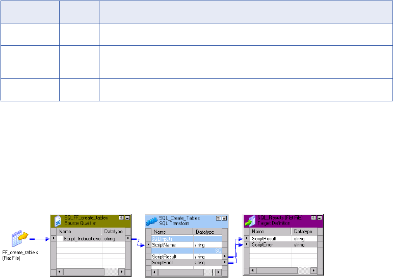
•Connection type. Pass database connection information to the SQL transformation or use a connection
object.
Script Mode
An SQL transformation running in script mode runs SQL scripts from text files. You pass each script file name
from the source to the SQL transformation ScriptName port. The script file name contains the complete path
to the script file.
When you configure the transformation to run in script mode, you create a passive transformation. The
transformation returns one row for each input row. The output row contains results of the query and any
database error.
When the SQL transformation runs in script mode, the query statement and query data do not change. When
you need to run different queries in script mode, you pass the scripts in the source data. Use script mode to
run data definition queries such as creating or dropping tables.
When you configure an SQL transformation to run in script mode, the Designer adds the ScriptName input
port to the transformation. When you create a mapping, you connect the ScriptName port to a port that
contains the name of a script to execute for each row. You can execute a different SQL script for each input
row. The Designer creates default ports that return information about query results.
An SQL transformation configured for script mode has the following default ports:
Port Type Description
ScriptName Input Receives the name of the script to execute for the current row.
ScriptResult Output Returns PASSED if the script execution succeeds for the row. Otherwise contains
FAILED.
ScriptError Output Returns errors that occur when a script fails for a row.
Example
You need to create order and inventory tables before adding new data to the tables. You can create an SQL
script to create the tables and configure an SQL transformation to run the script.
You create a file called create_order_inventory.txt that contains the SQL statements to create the tables.
The following mapping shows how to pass the script name to the SQL transformation:
The Integration Service reads a row from the source. The source row contains the SQL script file name and
path:
C:\81\server\shared\SrcFiles\create_order_inventory.txt
372 Chapter 26: SQL Transformation
The transformation receives the file name in the ScriptName port. The Integration Service locates the script
file and parses the script. It creates an SQL procedure and sends it to the database to process. The database
validates the SQL and executes the query.
The SQL transformation returns the ScriptResults and ScriptError. If the script executes successfully, the
ScriptResult output port returns PASSED. Otherwise, the ScriptResult port returns FAILED. When the
ScriptResult is FAILED, the SQL transformation returns error messages in the ScriptError port. The SQL
transformation returns one row for each input row it receives.
Rules and Guidelines for Script Mode
Use the following rules and guidelines for an SQL transformation that runs in script mode:
•You can use a static or dynamic database connection with script mode.
•To include multiple query statements in a script, you can separate them with a semicolon.
•You can use mapping variables or parameters in the script file name.
•The script code page defaults to the locale of the operating system. You can change the locale of the
script.
•The script file must be accessible by the Integration Service. The Integration Service must have read
permissions on the directory that contains the script. If the Integration Service uses operating system
profiles, the operating system user of the operating system profile must have read permissions on the
directory that contains the script.
•The Integration Service ignores the output of any SELECT statement you include in the SQL script. The
SQL transformation in script mode does not output more than one row of data for each input row.
•You cannot use scripting languages such as Oracle PL/SQL or Microsoft/Sybase T-SQL in the script.
•You cannot use nested scripts where the SQL script calls another SQL script.
•A script cannot accept run-time arguments.
Query Mode
When an SQL transformation runs in query mode, it executes an SQL query that you define in the
transformation. You pass strings or parameters to the query from the transformation input ports to change the
query statement or the query data.
When you configure the SQL transformation to run in query mode, you create an active transformation. The
transformation can return multiple rows for each input row.
Create queries in the SQL transformation SQL Editor. To create a query, type the query statement in the SQL
Editor main window. The SQL Editor provides a list of the transformation ports that you can reference in the
query. You can double-click a port name to add it as a query parameter.
When you create a query, the SQL Editor validates the port names in the query. It also verifies that the ports
you use for string substitution are string datatypes. The SQL Editor does not validate the syntax of the SQL
query.
You can create the following types of SQL queries in the SQL transformation:
•Static SQL query. The query statement does not change, but you can use query parameters to change
the data. The Integration Service prepares the query once and runs the query for all input rows.
•Dynamic SQL query. You can change the query statements and the data. The Integration Service
prepares a query for each input row.
Query Mode 373
When you create a static query, the Integration Service prepares the SQL procedure once and executes it for
each row. When you create a dynamic query, the Integration Service prepares the SQL for each input row.
You can optimize performance by creating static queries.
Using Static SQL Queries
Create a static SQL query when you need to run the same query statements for each input row, but you want
to change the data in the query for each input row. When you create a static SQL query, you use parameter
binding in the SQL Editor to define parameters for query data.
To change the data in the query, configure query parameters and bind them to input ports in the
transformation. When you bind a parameter to an input port, you identify the port by name in the query. The
SQL Editor encloses the name in question marks (?). The query data changes based on the value of the data
in the input port.
The SQL transformation input ports receive the data for the data values in the query, or the values in the
WHERE clause of the query.
The following static queries use parameter binding:
DELETE FROM Employee WHERE Dept = ?Dept?
INSERT INTO Employee(Employee_ID, Dept) VALUES (?Employee_ID?, ?Dept?)
UPDATE Employee SET Dept = ?Dept? WHERE Employee_ID > 100
The following static SQL query has query parameters that bind to the Employee_ID and Dept input ports of
an SQL transformation:
SELECT Name, Address FROM Employees WHERE Employee_Num =?Employee_ID? and Dept = ?Dept?
The source might have the following rows:
Employee_ID Dept
100 Products
123 HR
130 Accounting
The Integration Service generates the following query statements from the rows:
SELECT Name, Address FROM Employees WHERE Employee_ID = ‘100’ and DEPT = ‘Products’
SELECT Name, Address FROM Employees WHERE Employee_ID = ‘123’ and DEPT = ‘HR’
SELECT Name, Address FROM Employees WHERE Employee_ID = ‘130’ and DEPT = ‘Accounting’
Selecting Multiple Database Rows
When the SQL query contains a SELECT statement, the transformation returns one row for each database
row it retrieves. You must configure an output port for each column in the SELECT statement. The output
ports must be in the same order as the columns in the SELECT statement.
When you configure output ports for database columns, you need to configure the datatype of each database
column you select. Select a native datatype from the list. When you select the native datatype, the Designer
configures the transformation datatype for you.
The native datatype in the transformation must match the database column datatype. The Integration Service
matches the column datatype in the database with the native database type in the transformation at run time.
If the datatypes do not match, the Integration Service generates a row error.
Note: Although the Teradata database allows Bigint columns, the Transformation Developer does not include
Bigint datatype as one of the native datatypes you can use in the SQL transformation.
374 Chapter 26: SQL Transformation
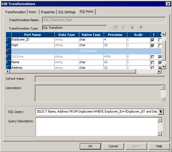
The following figure shows the ports in the transformation configured to run in query mode:
The input ports receive the data in the WHERE clause. The output ports return the columns from the SELECT
statement. The SQL query selects name and address from the employees table. The SQL transformation
writes a row to the target for each database row it retrieves.
Using Dynamic SQL Queries
A dynamic SQL query can execute different query statements for each input row. When you create a dynamic
SQL query, you use string substitution to define string parameters in the query and link them to input ports in
the transformation.
To change a query statement, configure a string variable in the query for the portion of the query you want to
change. To configure the string variable, identify an input port by name in the query and enclose the name
with the tilde (~). The query changes based on the value of the data in the port. The transformation input port
that contains the query parameter must be a string datatype. You can use string substitution to change the
query statement and the query data.
When you create a dynamic SQL query, the Integration Service prepares a query for each input row. You can
pass the full query or pass part of the query in an input port:
•Full query. You can substitute the entire SQL query with query statements from source data.
•Partial query. You can substitute a portion of the query statement, such as the table name.
Passing the Full Query
You can pass the full SQL query through an input port in the transformation. To pass the full query, create a
query in the SQL Editor that consists of one string variable to represent the full query:
~Query_Port~
The transformation receives the query in the Query_Port input port.
Query Mode 375
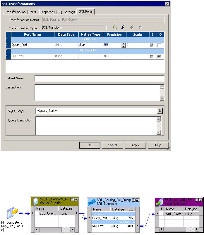
The following figure shows ports in the SQL transformation:
The Integration Service replaces the ~Query_Port~ variable in the dynamic query with the SQL statements
from the source. It prepares the query and sends it to the database to process. The database executes the
query. The SQL transformation returns database errors to the SQLError port.
The following mapping shows how to pass the query to the SQL transformation:
When you pass the full query, you can pass more than one query statement for each input row. For example,
the source might contain the following rows:
DELETE FROM Person WHERE LastName = ‘Jones’; INSERT INTO Person (LastName, Address)
VALUES ('Smith', '38 Summit Drive')
DELETE FROM Person WHERE LastName = ‘Jones’; INSERT INTO Person (LastName, Address)
VALUES ('Smith', '38 Summit Drive')
DELETE FROM Person WHERE LastName = ‘Russell’;
You can pass any type of query in the source data. When you configure SELECT statements in the query,
you must configure output ports for the database columns you retrieve from the database. When you mix
SELECT statements and other types of queries, the output ports that represent database columns contain
null values when no database columns are retrieved.
Substituting the Table Name in a String
You can substitute the table name in a query. To substitute the table name, configure an input port to receive
the table name from each input row. Identify the input port by name in the query and enclose the name with
the tilde (~).
376 Chapter 26: SQL Transformation

The following dynamic query contains a string variable, ~Table_Port~:
SELECT Emp_ID, Address from ~Table_Port~ where Dept = ‘HR’
The source might pass the following values to the Table_Port column:
Table_Port
Employees_USA
Employees_England
Employees_Australia
The Integration Service replaces the ~Table_Port~ variable with the table name in the input port:
SELECT Emp_ID, Address from Employees_USA where Dept = ‘HR’
SELECT Emp_ID, Address from Employees_England where Dept = ‘HR’
SELECT Emp_ID, Address from Employees_Australia where Dept = ‘HR’
RELATED TOPICS:
•“Dynamic Update Example” on page 395
Pass-Through Ports Configuration
You can add pass-through ports to the SQL transformation. Pass-through ports are input/output ports that
pass data through the transformation. The SQL transformation returns data from the pass-through ports
whether a SQL query returns rows or not.
When the source row contains a SELECT query statement, the SQL transformation returns the data in the
pass-through port in each row it returns from the database. If the query result contains multiple rows, the SQL
transformation repeats the pass-through data in each row.
When a query returns no rows, the SQL transformation returns the pass-through column data with null values
in the output columns. For example, queries that contain INSERT, UPDATE, and DELETE statements return
no rows. When the query has errors, the SQL transformation returns the pass-through column data, the
SQLError message, and null values in the output ports.
To create a pass-through port:
•Create an input port and enable it for output. The Designer creates an output port and adds an “_output”
suffix to the port name.
•Drag a port from a Source Qualifier transformation to the SQL transformation. The Designer creates a
pass-through port.
Passive Mode Configuration
When you create a SQL transformation, you can configure the SQL transformation to run in passive mode
instead of active mode. A passive transformation does not change the number of rows that pass through it. It
maintains transaction boundaries, and maintains row types.
If you configure the transformation to run in Query mode, you can configure passive mode when you create
the transformation. You cannot change the mode after you create the transformation.
Query Mode 377
Rules and Guidelines for Passive Mode
Use the following rules and guidelines when you configure the SQL transformation to run in passive mode:
•If a SELECT query returns more than one row, the Integration Service returns the first row and an error to
the SQLError port. The error states that the SQL transformation generated multiple rows.
•If the SQL query has multiple SQL statements, then the Integration Service executes all the statements.
The Integration Service returns data for the first SQL statement only. The SQL transformation returns one
row. The SQLError port contains the errors from all the SQL statements. When multiple errors occur, they
are separated by semi-colons in the SQLError port.
•If the SQL query has multiple SQL statements and a statistics port is enabled, the Integration Service
returns the data and statistics for the first SQL statement. The SQLError port contains the errors for all the
SQL statements.
Rules and Guidelines for Query Mode
Use the following rules and guidelines when you configure the SQL transformation to run in query mode:
•The number and the order of the output ports must match the number and order of the fields in the query
SELECT clause.
•The native datatype of an output port in the transformation must match the datatype of the corresponding
column in the database. The Integration Service generates a row error when the datatypes do not match.
•When the SQL query contains an INSERT, UPDATE, or DELETE clause, the transformation returns data
to the SQLError port, the pass-through ports, and the NumRowsAffected port when it is enabled. If you
add output ports the ports receive NULL data values.
•When the SQL query contains a SELECT statement and the transformation has a pass-through port, the
transformation returns data to the pass-through port whether or not the query returns database data. The
SQL transformation returns a row with NULL data in the output ports.
•You cannot add the "_output" suffix to output port names that you create.
•You cannot use the pass-through port to return data from a SELECT query.
•When the number of output ports is more than the number of columns in the SELECT clause, the extra
ports receive a NULL value.
•When the number of output ports is less than the number of columns in the SELECT clause, the
Integration Service generates a row error.
•You can use string substitution instead of parameter binding in a query. However, the input ports must be
string datatypes.
Connecting to Databases
You can use a static database connection or you can pass database connection information to the SQL
transformation at run time.
You can use a connection environment SQL statement or transactional SQL statement with the SQL
transformation. Configure the SQL statements in a relational connection object. The Integration Service runs
the connection environment SQL when it connects to the database. It runs the transactional SQL statement
before the initiation of each transaction.
378 Chapter 26: SQL Transformation

Use one of the following types of connections to connect the SQL transformation to a database:
•Static connection. Configure the connection object in the session. You must first create the connection
object in Workflow Manager.
•Logical connection. Pass a connection name to the SQL transformation as input data at run time. You
must first create the connection object in Workflow Manager.
•Full database connection. Pass the connect string, user name, password, and other connection
information to the SQL transformation input ports at run time.
Note: If a session has multiple partitions, the SQL transformation creates a separate database connection for
each partition.
Using a Static Database Connection
You can configure the SQL transformation to connect to a database with a static connection. A static
database connection is a database connection defined in the Workflow Manager.
To use a static connection, choose a relational connection object when you configure the session. To avoid
datatype conversion errors, use a relational connection for the same database type that is configured in the
transformation.
Passing a Logical Database Connection
You can configure the SQL transformation to connect to a database with a logical database connection. A
logical database connection is a connection object name that you pass to the transformation at run time.
Define the relational connection object in the Workflow Manager. When you configure the transformation to
use a logical database connection, the Designer creates the LogicalConnectionObject input port.
You can pass a logical connection for each input row. Configure the mapping to pass the connection object
name to the LogicalConnectionObject port. To avoid datatype conversion errors, use a relational connection
for the same database type that is configured in the transformation.
Passing Full Connection Information
You can pass all the database connection information to an SQL transformation as input port data. When you
configure the SQL transformation to connect to a database with a full connection, the Designer creates input
ports for connection components. The database type defaults to the database type you configured for the
transformation.
The following table describes the ports that the Designer creates when you configure an SQL transformation
to connect to a database with a full connection:
Port Required/
Optional
Description
ConnectString Required Contains the database name and database server name.
DBUser Required Name of the user with permissions to read and write from the database.
DBPasswd Required DBUser password.
Connecting to Databases 379

Port Required/
Optional
Description
CodePage Optional Code page the Integration Service uses to read from or write to the
database. Use the ISO code page name, such as ISO-8859-6. The code
page name is not case sensitive.
AdvancedOptions Optional Connection attributes. Pass the attributes as name-value pairs. Delimit
each attribute from another with a semicolon. Attribute names are not case
sensitive.
Passing the Connect String
The native connect string contains the database name and database server name. The connect string allows
PowerCenter and the database client to direct calls to the correct database.
The following table lists the native connect string syntax for each database:
Database Connect String Syntax Example
IBM DB2 dbname mydatabase
Informix dbname@servername mydatabase@informix
Microsoft SQL Server servername@dbname sqlserver@mydatabase
Oracle dbname.world (same as TNSNAMES entry) oracle.world
Sybase ASE
1servername@dbname sambrown@mydatabase
Teradata
2ODBC_data_source_name or
ODBC_data_source_name@db_name or
ODBC_data_source_name@db_user_name
TeradataODBC
TeradataODBC@mydatabase
TeradataODBC@sambrown
1. Sybase ASE servername is the name of the Adaptive Server from the interfaces file.
2. Use Teradata ODBC drivers to connect to source and target databases.
Passing Advanced Options
You can configure optional connection attributes. To configure the attributes, pass the attributes as name-
value pairs. Delimit attributes with a semicolon. Attribute names are not case sensitive.
For example, you might pass the following string to configure connection options:
Use Trusted Connection = 1; Connection Retry Period = 5
380 Chapter 26: SQL Transformation

The following table describes the advanced options that you can configure:
Attribute Database Type Description
Connection Retry Period All Integer.
The number of seconds the Integration Service attempts to
reconnect to the database if the connection fails.
Data Source Name Teradata String.
The name of the Teradata ODBC data source.
Database Name Sybase ASE
Microsoft SQL Server
Teradata
String.
Override the default database name in the ODBC. If you
do not enter a database name, messages related to the
connection do not show a database name.
Domain Name Microsoft SQL Server String.
The name of the domain where Microsoft SQL Server is
running.
Enable Parallel Mode Oracle Integer.
Enable parallel processing when you load data in bulk
mode.
0 is not enabled.
1 is enabled.
Default is enabled.
Owner Name All String.
The table owner name.
Packet Size Sybase ASE
Microsoft SQL Server
Integer.
Optimize the ODBC connection to Sybase ASE and
Microsoft SQL Server.
Server Name Sybase ASE
Microsoft SQL Server
String.
The name of the database server.
Use Trusted Connection Microsoft SQL Server Integer.
When enabled, the Integration Service uses Windows
authentication to access the Microsoft SQL Server
database. The user name that starts the Integration
Service must be a valid Windows user with access to the
Microsoft SQL Server database.
0 is not enabled.
1 is enabled.
Rules and Guidelines for Database Connections
Use the following rules and guidelines when configuring database connections for the SQL transformation:
•You need the PowerCenter license key to connect different database types. A session fails if PowerCenter
is not licensed to connect to the database.
•To improve performance, use a static database connection. When you configure a dynamic connection,
the Integration Service establishes a new connection for each input row.
Connecting to Databases 381

•When you have a limited number of connections to use in a session, you can configure multiple SQL
transformations. Configure each SQL transformation to use a different static connection. Use a Router
transformation to route rows to a SQL transformation based on connectivity information in the row.
•When you configure the SQL transformation to use full connection data, the database password is plain
text. You can pass logical connections when you have a limited number of connections you need to use in
a session. A logical connection provides the same functionality as the full connection, and the database
password is secure.
•When you pass logical database connections to the SQL transformation, the Integration Service accesses
the repository to retrieve the connection information for each input row. When you have many rows to
process, passing logical database connections might have a performance impact.
•The SQL transformation uses a native database type by default. If you want to run the session using
ODBC, you must configure the transformation with an ODBC database type. If the transformation contains
a datetime or datetime2 port, set the corresponding native type as timestamp.
Session Processing
When the Integration Service processes an SQL transformation, it runs SQL queries midstream in the
pipeline. When a SELECT query retrieves database rows, the SQL transformation returns the database
columns in the output ports. For other types of queries, the SQL transformation returns query results, pass-
through data, or database errors in output ports.
The SQL transformation configured to run in script mode always returns one row for each input row. A SQL
transformation that runs in query mode can return a different number of rows for each input row. The number
of rows the SQL transformation returns is based on the type of query it runs and the success of the query.
You can view a log of the SQL query that the Integration Service passes to the database for processing.
When you set logging to verbose, the Integration Service writes each SQL query to the session log. Set
logging to verbose when you need to debug a session with the SQL transformation.
You can use transaction control with the SQL transformation when you configure the transformation to use a
static database connection. You can also issue commit and rollback statements in the query.
The SQL transformation provides some database connection resiliency. It provides resilience for database
deadlocks.
RELATED TOPICS:
•“Input Row to Output Row Cardinality” on page 385
•“High Availability” on page 383
Transaction Control
An SQL transformation that runs in script mode drops any incoming transaction boundary from an upstream
source or transaction generator. The Integration Service issues a commit after executing the script for each
input row in the SQL transformation. The transaction contains the set of rows affected by the script.
An SQL transformation that runs in query mode commits transactions at different points based on the
database connection type:
•Dynamic database connection. The Integration Service issues a commit after executing the SQL for
each input row. The transaction is the set of rows affected by the script. You cannot use a Transaction
Control transformation with dynamic connections in query mode.
382 Chapter 26: SQL Transformation

•Static connection. The Integration Service issues a commit after processing all the input rows. The
transaction includes all the database rows to update. You can override the default behavior by using a
Transaction Control transformation to control the transaction, or by using commit and rollback statements
in the SQL query.
When you configure an SQL statement to commit or rollback rows, configure the SQL transformation to
generate transactions with the Generate Transaction transformation property. Configure the session for
user-defined commit.
The following transaction control SQL statements are not valid with the SQL transformation:
•SAVEPOINT. Identifies a rollback point in the transaction.
•SET TRANSACTION. Changes transaction options.
RELATED TOPICS:
•“Dynamic Connection Example” on page 400
Auto-Commit
You can configure the SQL transformation database connections to operate in auto-commit mode. When you
configure auto-commit mode, a commit occurs when a SQL statement completes.
To enable auto-commit, select AutoCommit on the SQL Settings tab of the SQL transformation.
If HA recovery is enabled with auto-commit, the session log contains a warning message that data integrity
cannot be guaranteed if the query contains an insert, update, or delete statement.
High Availability
When you have high availability, the SQL transformation provides database connection resiliency for static
and dynamic connections. When the Integration Service fails to connect to the database, it retries the
connection. You can configure the connection retry period for a connection. When the Integration Service
cannot connect to the database in the time period that you configure, it generates a row error for a dynamic
connection or fails the session for a static connection.
Note: The SQL transformation database connection is not resilient for Informix or ODBC connections.
Exactly-Once Processing for Real-time Sessions
The Integration Service provides exactly-once delivery of messages of real-time sources with the SQL
transformation. A real-time message has to be delivered once to the SQL transformation. If there is an
interruption in processing, the Integration Service can recover without requiring the message to be sent
again. If the message is sent again, the Integration Service does not run DML statements from the message
twice. The Integration Service might run other SQL statements such as SELECT or SET again.
To perform exactly-once processing, the Integration Service stores a state of operations for a checkpoint in
the PM_REC_STATE table. Each SQL transformation has a separate state of operations. Each SQL
transformation maintains a consistent state and does not share connections. You must have high availability
for exactly-once processing.
Use the following rules and guidelines for recovering real-time sessions with SQL transformations:
•You must set the transformation scope to Transaction to enable recovery for a sessions that contains an
SQL transformation.
•You cannot include auto-commit, commit statements, or DDL statements in SQL queries.
Session Processing 383
•You cannot enable HA recovery for an SQL transformation if it is a passive transformation, or if you
configured it for dynamic connections or for Script Mode .
•A session may fail when you enable recovery for the SQL transformation and the workflow is enabled for
concurrent execution or the session runs in multiple partitions. A database deadlock might occur on the
PM_REC_STATE table.
Query Mode Resilience
When a database connection error occurs while the Integration Service is executing a SQL query for an input
row, the Integration Service attempts to reconnect to the database.
Use the following rules and guidelines for resiliency in query mode:
•When the Integration Service is executing the first query in a list, and a database connection failure
occurs, the Integration Service re-executes the first query in the list for the row. It executes the rest of the
queries for that row.
•If the first query statement is a SELECT statement and a communication failure occurs after some rows
are flushed downstream in the pipeline, the session fails.
•If a connection failure occurs while the Integration Service is executing a query that not the first query in a
list, the Integration Service re-connects to the database and skips the rest of the queries for the current
row. Query results might be lost for the previous rows.
•If the Integration Service is not able to reconnect to the database, the session fails if the SQL
transformation is using a static connection. If the SQL transformation is using a dynamic connection, the
session continues.
•If the SQL query in the list has an explicit commit or rollback statement, any query results that were
created after the commit point will be lost when the session continues.
Script Mode Resilience
When a communication failure occurs while the Integration Service is executing a script for an input row, the
Integration Service tries to re-connect to the database.
Use the following rules and guidelines for resiliency in script mode:
•If the Integration Service fails to connect to the database, and the connection is static, the session fails. If
the SQL transformation is using a dynamic connection, the session continues.
•If the Integration Service re-connects to the database, it skips processing the current row and continues to
the next row.
Database Deadlock Resiliency
The SQL transformation is resilient to database deadlock errors when you enable the Session Retry on
Deadlock session property. The SQL transformation is resilient to database deadlock errors in Query mode
but it is not resilient to deadlock errors in Script mode. If a deadlock occurs in Query mode, the Integration
Service tries to reconnect to the database for the number of deadlock retries that you configure. Configure
the Integration Service to set the number of deadlock retries and the deadlock sleep time period.
When a deadlock occurs, the Integration Service retries the SQL statements in the current row if the current
row has no DML statements. If the row contain a DML statement such as INSERT, UPDATE, or DELETE, the
Integration Service does not process the current row again.
For a dynamic connection, if the retry attempt fails, the Integration Service returns an error in the SQLError
port. The Integration Service processes the next statement based on the Continue on SQL Error Within Row
384 Chapter 26: SQL Transformation
property. If the property is disabled, the Integration Service skips the current row. If the current row contains
a DML statement such as INSERT, UPDATE, or DELETE, the Integration Service increments the error count.
For a static connection, if the retry attempts fail, the Integration Service returns an error in the SQLError port.
If the current row contains a DML statement, then the Integration Service fails the session. The Integration
Service processes the next statement based on Continue on SQL Error Within a Row property. If the property
is disabled the Integration Service skips the current row.
SQL Query Log
You can view a log of the SQL query that the Integration Service passes to the database for processing.
When you set logging to verbose, the Integration Service writes each SQL query to the session log. Set
logging to verbose when you need to debug a session with the SQL transformation.
If the query contains CLOB or BLOB data, the session log contains does not contain the query. The session
log contains a message that describes the data, such as CLOB Data.
Input Row to Output Row Cardinality
When the Integration Service runs a SELECT query, the SQL transformation returns a row for each row it
retrieves. When the query does not retrieve data, the SQL transformation returns zero or one row for each
input row.
The number of output rows the SQL transformation returns depends on the following factors:
•Query statement processing. When the query contains a SELECT statement, the Integration Service
can retrieve multiple output rows. When a SELECT query is successful, the SQL transformation might
retrieve multiple rows. When the query contains other statements, the Integration Service might generate
a row that contains SQL errors or the number of rows affected.
•Port configuration. The NumRowsAffected output port contains the total number of rows affected by
updates, inserts, or deletes for one input row. When the SQL transformation contains pass-through ports,
the transformation returns the column data at least once for each source row.
•The maximum row count configuration. The Max Output Row Count limits the number of rows the SQL
transformation returns from SELECT queries.
•Error rows. The Integration Service returns row errors when it encounters connection or syntax errors.
When the SQL transformation runs in query mode, it returns errors to the SQLError port. When the SQL
transformation runs in script mode, it returns errors to the ScriptError port.
•Continue on SQL Error. You can configure the SQL transformation to continue processing when there is
an error in a SQL statement. The SQL transformation does not generate a row error.
Query Statement Processing
The type of query determines how many rows the SQL transformation returns. The SQL transformation
running in query mode can return zero, one, or multiple rows. When the query contains a SELECT statement,
the SQL transformation returns each column from the database to an output port. The transformation returns
all qualifying rows.
Input Row to Output Row Cardinality 385

The following table lists the output rows the SQL transformation generates for different types of query
statements when no errors occur in query mode:
Query Statement Output Rows
UPDATE, INSERT, DELETE only Zero rows.
One or more SELECT statements Total number of database rows retrieved.
DDL queries such as CREATE, DROP, TRUNCATE Zero rows.
Number of Rows Affected
You can enable the NumRowsAffected output port to return the number of rows affected by the INSERT,
UPDATE, or DELETE query statements in each input row. The Integration Service returns the
NumRowsAffected for each statement in the query. NumRowsAffected is disabled by default.
When you enable NumRowsAffected in query mode, and the SQL query does not contain an INSERT,
UPDATE, or DELETE statement, NumRowsAffected is zero in each output row.
Note: When you enable NumRowsAffected and the transformation is configured to run in script mode,
NumRowsAffected is always NULL.
The following table lists the output rows the SQL transformation generates when you enable
NumRowsAffected in query mode:
Query Statement Output Rows
UPDATE, INSERT, DELETE only One row for each statement with the NumRowsAffected
for the statement.
One or more SELECT statements Total number of database rows retrieved.
NumRowsAffected is zero in each row.
DDL queries such as CREATE, DROP, TRUNCATE One row with zero NumRowsAffected.
When the SQL transformation runs in query mode and a query contains multiple statements, the Integration
Service returns the NumRowsAffected for each statement. NumRowsAffected contains the sum of the rows
affected by each INSERT, UPDATE, and DELETE statement in an input row.
For example, a query contains the following statements:
DELETE from Employees WHERE Employee_ID = ‘101’;
SELECT Employee_ID, LastName from Employees WHERE Employee_ID = ‘103’;
INSERT into Employees (Employee_ID, LastName, Address)VALUES (‘102’, 'Gein', '38 Beach
Rd')
The DELETE statement affects one row. The SELECT statement does not affect any row. The INSERT
statement affects one row.
The Integration Service returns one row from the DELETE statement. NumRowsAffected is equal to one. It
returns one row from the SELECT statement, NumRowsAffected is zero. It returns one row from the INSERT
statement with NumRows Affected equal to one.
The NumRowsAffected port returns zero when all of the following conditions are true:
•The database is Informix.
386 Chapter 26: SQL Transformation
•The transformation is running in query mode.
•The query contains no parameters.
Maximum Output Row Count
You can limit the number of rows the SQL transformation returns for SELECT queries. Configure the Max
Output Row Count property to limit number of rows. When a query contains multiple SELECT statements, the
SQL transformation limits total rows from all the SELECT statements.
For example, you set Max Output Row Count to 100. The query contains two SELECT statements:
SELECT * FROM table1; SELECT * FROM table2;
If the first SELECT statement returns 200 rows, and the second SELECT statement returns 50 rows, the SQL
transformation returns 100 rows from the first SELECT statement. It returns no rows from the second
statement.
To configure unlimited output rows, set Max Output Row Count to zero.
Understanding Error Rows
The Integration Service returns row errors when it encounters a connection error or syntax error. The SQL
transformation has the following default ports to output error text:
•SQLError. Returns database errors when the SQL transformation runs in query mode.
•ScriptError. Returns database errors when the SQL transformation runs in script mode.
When the SQL query contains syntax errors, the error port contains the error text from the database. For
example, the following SQL query generates a row error from an Oracle database:
SELECT Product_ID FROM Employees
The Employees table does not contain Product_ID. The Integration Service generates one row. The
SQLError port contains the error text in one line:
ORA-0094: “Product_ID”: invalid identifier Database driver error... Function Name:
Execute SQL Stmt: SELECT Product_ID from Employees Oracle Fatal Error
When a query contains multiple statements, and you configure the SQL transformation to continue on SQL
error, the SQL transformation might return rows from the database for one query statement, but return
database errors for another query statement. The SQL transformation returns any database error in a
separate row.
When you configure a pass-through port or the NumRowsAffected port, the SQL transformation returns at
least one row for each source row. When a query returns no data, the SQL transformation returns the pass-
through data and the NumRowsAffected values, but it returns null values in the output ports. You can remove
rows with null values by passing the output rows through a Filter transformation.
The following tables describe the output rows that the SQL transformation returns based on the type of query
statements.
Input Row to Output Row Cardinality 387

The following table describes the rows the SQL transformation generates for UPDATE, INSERT, or DELETE
query statements:
NumRowsAffected Port or Pass-
Through Port Configured
SQLError Rows Output
Neither port configured. No Zero rows.
Neither port configured. Yes One row with the error in the SQLError port.
Either port configured. No One row for each query statement with the
NumRowsAffected or the pass-through column data.
Either port configured. Yes One row with the error in the SQLError port, the
NumRowsAffected port, or the pass-through port data.
The following table describes the number of output rows the SQL transformation generates for SELECT
statements:
NumRowsAffected Port or Pass-
Through Port Configured
SQLError Rows Output
Neither port configured. No Zero or more rows, based on the rows returned from each
SELECT statement.
Neither port configured. Yes One row greater than the sum of the output rows for the
successful statements. The last row contains the error in
the SQLError port.
Either port configured. No One or more rows, based on the rows returned for each
SELECT statement:
- If NumRowsAffected is enabled, each row contains a
NumRowsAffected column with a value zero.
- If a pass-through port is configured, each row contains the
pass-through column data. When the query returns multiple
rows, the pass-through column data is duplicated in each
row.
Either port configured. Yes One or more rows, based on the rows returned for each
SELECT statement. The last row contains the error in the
SQLError port:
- When NumRowsAffected is enabled, each row contains a
NumRowsAffected column with value zero.
- If a pass-through port is configured, each row contains the
pass-through column data. When the query returns multiple
rows, the pass-through column data is duplicated in each
row.
388 Chapter 26: SQL Transformation

The following table describes the number of output rows the SQL transformation generates for DDL queries
such as CREATE, DROP, or TRUNCATE:
NumRowsAffected Port or Pass-
Through Port Configured
SQLError Rows Output
Neither port configured. No - Zero rows.
Neither port configured. Yes - One row that contains the error in the SQLError port.
Either port configured. No - One row that includes the NumRowsAffected column with
value zero and the pass-through column data.
Either port configured. Yes - One row with the error in the SQLError port, the
NumRowsAffected column with value zero, and the pass-
through column data.
Continuing on SQL Error
You can choose to ignore an SQL error in a statement by enabling the Continue on SQL Error within a Row
option. The Integration Service continues to run the rest of the SQL statements for the row. The Integration
Service does not generate a row error. However, the SQLError port contains the failed SQL statement and
error messages. A session fails when the row error count exceeds the session error threshold.
For example, a query might have the following statements:
DELETE FROM Persons WHERE FirstName = ‘Ed’;
INSERT INTO Persons (LastName, Address)VALUES ('Gein', '38 Beach Rd')
If the DELETE statement fails, the SQL transformation returns an error message from the database. The
Integration Service continues processing the INSERT statement.
Tip: Disable the Continue on SQL Error option to debug database errors. Otherwise, you might not be able to
associate errors with the query statements that caused them.
SQL Transformation Properties
After you create the SQL transformation, you can define ports and set attributes in the following
transformation tabs:
•Ports. Displays the transformation ports and attributes that you create on the SQL Ports tab.
•Properties. SQL transformation general properties.
•SQL Settings. Attributes unique to the SQL transformation.
•SQL Ports. SQL transformation ports and attributes.
Note: You cannot update the columns on the Ports tab. When you define ports on the SQL Ports tab, they
display on the Ports tab.
Properties Tab
Configure the SQL transformation general properties on the Properties tab. Some transformation properties
do not apply to the SQL transformation or are not configurable.
SQL Transformation Properties 389

The following table describes the SQL transformation properties:
Property Description
RunTime Location Location that contains the DLL or shared library.
Enter a path relative to the Integration Service node that runs the SQL transformation
session.
If this property is blank, the Integration Service uses the environment variable defined on
the Integration Service node to locate the DLL or shared library.
You must copy all DLLs or shared libraries to the run-time location or to the environment
variable defined on the Integration Service node. The Integration Service fails to load the
procedure when it cannot locate the DLL, shared library, or a referenced file.
Tracing Level Sets the amount of detail included in the session log when you run a session containing
this transformation. When you configure the SQL transformation tracing level to Verbose
Data, the Integration Service writes each SQL query it prepares to the session log.
IsPartitionable Multiple partitions in a pipeline can use this transformation. Use the following options:
- No. The transformation cannot be partitioned. The transformation and other transformations in
the same pipeline are limited to one partition. You might choose No if the transformation
processes all the input data together, such as data cleansing.
- Locally. The transformation can be partitioned, but the Integration Service must run all
partitions in the pipeline on the same node. Choose Locally when different partitions of the
transformation must share objects in memory.
- Across Grid. The transformation can be partitioned, and the Integration Service can distribute
each partition to different nodes.
Default is No.
Update Strategy
Transformation
The transformation defines the update strategy for output rows. You can enable this
property for query mode SQL transformations.
Default is disabled.
Transformation
Scope
The method in which the Integration Service applies the transformation logic to incoming
data. Use the following options:
- Row
- Transaction
- All Input
Set transaction scope to transaction when you use transaction control in static query
mode.
Default is Row for script mode transformations.
Default is All Input for query mode transformations.
Output is
Repeatable
Indicates if the order of the output data is consistent between session runs.
- Never. The order of the output data is inconsistent between session runs.
- Based On Input Order. The output order is consistent between session runs when the input
data order is consistent between session runs.
- Always. The order of the output data is consistent between session runs even if the order of
the input data is inconsistent between session runs.
Default is Never.
Generate
Transaction
The transformation generates transaction rows. Enable this property for query mode SQL
transformations that commit data in an SQL query.
Default is disabled.
390 Chapter 26: SQL Transformation

Property Description
Requires Single
Thread Per
Partition
Indicates if the Integration Service processes each partition of a procedure with one
thread.
Output is
Deterministic
The transformation generates consistent output data between session runs. Enable this
property to perform recovery on sessions that use this transformation. Default is enabled.
Warning: If you configure a transformation as repeatable and deterministic, it is your responsibility to ensure
that the data is repeatable and deterministic. If you try to recover a session with transformations that do not
produce the same data between the session and the recovery, the recovery process can result in corrupted
data.
SQL Settings Tab
Configure SQL transformation attributes on the SQL Settings tab. The SQL attributes are unique to the SQL
transformation.
The following table lists the attributes you can configure on the SQL Setting tab:
Option Description
Continue on SQL Error
within row
Continues processing the remaining SQL statements in a query after an SQL error
occurs.
Add Statistic Output Port Adds a NumRowsAffected output port. The port returns the total number of database
rows affected by INSERT, DELETE, and UPDATE query statements for an input row.
AutoCommit Enables auto-commit for each database connection. Each SQL statement in a query
defines a transaction. A commit occurs when the SQL statement completes or the
next statement is executed, whichever comes first
Max Output Row Count Defines the maximum number of rows the SQL transformation can output from a
SELECT query. To configure unlimited rows, set Max Output Row Count to zero.
Scripts Locale Identifies the code page for a SQL script. Choose the code page from the list. Default
is operating system locale.
Use Connection Pooling Maintain a connection pool for database connections. You can enable connection
pooling for dynamic connections only.
Maximum Number of
Connections in Pool
Maximum number of active connections available in the connection pool. Minimum is
one. Maximum is 20. Default is 10.
SQL Ports Tab
When you create an SQL transformation, the Designer adds default ports depending on how you configure
the transformation. After you create the transformation, you can add ports to the transformation on the SQL
Ports tab.
SQL Transformation Properties 391

The following table lists the SQL transformation ports:
Port Type Mode Description
ScriptName Input Script The name of the script to execute for each row.
ScriptError Output Script SQL errors the database passes back to the transformation
when the script fails.
ScriptResult Output Script Results from query execution. Contains PASSED when the
query executes successfully. Contains FAILED when the
query is not successful.
SQLError Output Query SQL errors the database passes back to the transformation.
LogicalConnectionObject Input Query Dynamic connection. The name of a connection defined in
Workflow Manager connections.
Connect String Input Query
Script
Connection object only. The database name and the
database server name.
DBUser Input Query
Script
Full connection only. The name of the user with permissions
to read and write from the database.
DBPasswd Input Query
Script
Full connection only. The database password.
CodePage Input Query
Script
Full connection only. The code page the Integration Service
uses to read from or write to the database.
Advanced Options Input Query
Script
Full connection only. Optional connection attributes such as
packet size, connection retry period, and enable parallel
mode.
NumRowsAffected Output Query
Script
The total number of database rows affected by INSERT,
DELETE, and UPDATE query statements for an input row.
SQL Statements
The following table lists the statements you can use with the SQL transformation:
Statement Type Statement Description
Data Definition ALTER Modifies the structure of the database.
Data Definition COMMENT Adds comments to the data dictionary.
Data Definition CREATE Creates a database, table, or index.
Data Definition DROP Deletes an index, table, or database.
392 Chapter 26: SQL Transformation

Statement Type Statement Description
Data Definition RENAME Renames a database object.
Data Definition TRUNCATE Removes all rows from a table.
Data Manipulation CALL Calls a PL/SQL or Java subprogram.
Data Manipulation DELETE Deletes rows from a table.
Data Manipulation EXPLAIN PLAN Writes the access plan for a statement into the database Explain
tables.
Data Manipulation INSERT Inserts row into a table.
Data Manipulation LOCK TABLE Prevents concurrent application processes from using or
changing a table.
Data Manipulation MERGE Updates a table with source data.
Data Manipulation SELECT Retrieves data from the database.
Data Manipulation UPDATE Updates the values of rows of a table.
Data Control
Language
GRANT Grants privileges to a database user.
Data Control
Language
REVOKE Removes access privileges for a database user.
Transaction Control COMMIT Saves a unit of work and performs the database changes for
that unit of work.
Transaction Control ROLLBACK Reverses changes to the database since the last COMMIT.
Creating an SQL Transformation
You can create an SQL transformation in the Transformation Developer or the Mapping Designer.
To create an SQL transformation:
1. Click Transformation > Create.
2. Select the SQL transformation.
3. Enter a name for the transformation.
The naming convention for an SQL transformation is SQL_TransformationName.
4. Enter a description for the transformation and click Create.
5. Configure the SQL transformation mode:
•Query mode. Configure an active transformation that executes dynamic SQL queries.
•Script mode. Configure a passive transformation that executes external SQL scripts.
Creating an SQL Transformation 393

6. Configure the database type that the SQL transformation connects to. Choose the database type from
the list.
7. Configure the SQL transformation connection options:
Option Description
Static Connection Use a connection object that you configure for the session. The SQL
transformation connects to the database once during a session.
Dynamic Connection Connect to databases depending on connection information you pass to
the transformation in a mapping. When you configure a dynamic
connection, choose whether the transformation requires a connection
object name or the transformation requires all the connection information.
Default is connection object.
Connection Object Dynamic connection only. Use a LogicalConnectionObject port to receive
the connection object name. Define the connection object in the Workflow
Manager connections.
Full Connection Information Dynamic connection only. Use input ports to receive all the connection
components.
8. To configure the SQL transformation to run in passive mode, select SQL Transformation Will Run in
Passive Mode.
9. Click OK to configure the transformation.
The Designer creates default ports in the transformation based on the options that you choose. You
cannot change the configuration except for the database type.
10. Click the Ports tab to add ports to the transformation. Add pass-through ports after database ports.
394 Chapter 26: SQL Transformation

CHAPTER 2 7
Using the SQL Transformation in
a Mapping
This chapter includes the following topics:
•SQL Transformation Example Overview, 395
•Dynamic Update Example, 395
•Dynamic Connection Example, 400
SQL Transformation Example Overview
The SQL transformation processes SQL queries midstream in a pipeline. The transformation processes
external SQL scripts or SQL queries that you create in an SQL editor. You can pass the database connection
information to the SQL transformation as input data at run time.
This chapter provides two examples that illustrate SQL transformation functionality. You use the examples in
this chapter to create and execute dynamic SQL queries and to connect dynamically to databases. The
chapter provides sample data and descriptions of the transformations that you can include in mappings.
The chapter provides the following examples:
•Creating a dynamic SQL query to update a database. The dynamic query update example shows how
update product prices in a table based on a price code received from a source file.
•Configuring a dynamic database connection. The dynamic connection example shows how to connect
to different databases based on the value of a customer location in a source row.
Dynamic Update Example
This example shows how to configure an Expression transformation and an SQL transformation to generate
SQL queries based on the value of a column in a source file.
In this example, you have a database table that contains product prices. You need to update the prices from
a transaction file. Each transaction row updates the wholesale, retail, or manufacturing prices in the database
based on a price code column.
The source file is a flat file. You can configure an Expression transformation to return the column names to
update based on the value of a price code column in each source row. The Expression transformation passes
395

the column names to the SQL transformation. The SQL transformation runs a dynamic SQL query that
updates columns in the Prod_Cost table based on the column names it receives. The SQL transformation
returns database errors to the Error_File target.
The following figure shows the how the Expression transformation passes column names to the SQL
transformation:
The mapping contains the following components:
•PPrices source definition. The PPrices flat file contains a product ID, package price, unit price, and
price code. The price code defines whether the package price and unit price are wholesale, retail, or
manufactured prices.
•Error_File flat file target definition. The target contains the Datastring field that receives database
errors from the SQL transformation.
•Exp_Dynamic_Expression transformation. The Expression transformation defines which Prod_Cost
column names to update based on the value of the PriceCode column. It returns the column names in the
UnitPrice_Query and PkgPrice_Query ports.
•SQL_Dynamic_Query transformation. The SQL transformation has a dynamic SQL query to update a
UnitPrice column and a PkgPrice column in the Prod_Cost table. It updates the columns named in the
UnitPrice_Query and PkgPrice_Query columns.
Note: The mapping does not contain a relational table definition for the Prod_Cost table. The SQL
transformation has a static connection to the database that contains the Prod_Cost table. The transformation
generates the SQL statements to update the unit prices and package prices in the table.
Defining the Source File
The transaction file is a flat file source that contains the prices to update in the database. Each row has a
code that defines whether the prices are wholesale, retail, or manufacturer prices. The source file name is
PPrices.dat.
You can create a PPrices.dat file in Srcfiles that contains the following rows:
100,M,100,110
100,W,120,200
100,R,130,300
200,M,210,400
200,W,220,500
200,R,230,600
300,M,310,666
300,W,320,680
300,R,330,700
You can import the PPrices.dat file to create the PPrices source definition in the repository.
396 Chapter 27: Using the SQL Transformation in a Mapping

The PPrices file contains the following columns:
Column Datatype Precision Description
ProductID String 10 A unique number that identifies the product to update.
PriceCode String 2 M, W, or R. Defines whether the prices are Manufactured,
Wholesale, or Retail prices.
UnitPrice Number 10 The price for each unit of the product.
PkgPrice Number 10 The price for a package of the product.
Creating a Target Definition
The Error_File is a flat file target definition that receives database error messages from the SQL
transformation.
The Error_File definition has the following input port:
Port Name Datatype Precision Scale
DataString String 4000 0
Create the target definition in the Target Designer.
Creating the Database Table
The SQL transformation writes product prices to the Prod_Cost relational table. The Prod_Cost table contains
unit and package prices for each product. It stores the wholesale, retail, and manufacturing prices by unit and
package.
You do not create a relational target definition for the Prod_Cost table in the repository. The SQL
transformation generates the SQL statements to update the table in the database.
The Prod_Cost table contains the following columns:
Type of Costs Datatype Description
ProductID varchar A unique number that identifies the product to update.
WUnitPrice number Wholesale unit price.
WPkgPrice number Wholesale package price.
RUnitPrice number Retail unit price.
RPkgPrice number Retail package price.
MUnitPrice number Manufacturers unit price.
MPkgPrice number Manufacturers package price.
Dynamic Update Example 397
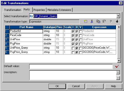
The following SQL statements create the Prod_Cost table and three product rows on an Oracle database:
Create table Prod_Cost (ProductId varchar (10), WUnitPrice number, WPkgPrice number,
RUnitPrice number, RPkgPrice number,MUnitPrice number, MPkgPrice number );
insert into Prod_Cost values('100',0,0,0,0,0,0);
insert into Prod_Cost values('200',0,0,0,0,0,0);
insert into Prod_Cost values('300',0,0,0,0,0,0);
commit;
Configuring the Expression Transformation
The Expression transformation has an input/output port for each source column. It passes column names to
the SQL transformation based on the value of the PriceCode column.
The following figure shows the ports in the Expression transformation that return column names:
The SQL transformation has the following columns that contain the results of expressions:
•UnitPrice_Query. Returns the column name “MUnitprice,” “RUnitPrice,” or “WUnitprice” based on the
whether the price code is “M,” “R,” or “W.”
DECODE(PriceCode,'M', 'MUnitPrice','R', 'RUnitPrice','W', 'WUnitPrice')
•PkgPrice_Query. Returns the column name “MPkgPrice,” “RPkgPrice,” or “WPkgPrice,” based on the
whether the price code is “M,” “R,” or “W.”
DECODE(PriceCode,'M', 'MPkgPrice','R', 'RPkgPrice','W', 'WPkgPrice')
Defining the SQL Transformation
The SQL transformation executes a dynamic SQL query that inserts the unit price and package price data
into the Prod_Cost table. The SQL transformation receives the column names to update in the
UnitPrice_Query and PkgPrice_Query ports.
When you create an SQL transformation, you define the transformation mode, the database type, and the
type of connection. You cannot change the mode or connection type after you create the transformation.
Create an SQL transformation with the following properties:
•Query Mode. The SQL transformation executes dynamic SQL queries.
•Static Connection. The SQL transformation connects once to the database with the connection object
you define in the Workflow Manager.
398 Chapter 27: Using the SQL Transformation in a Mapping
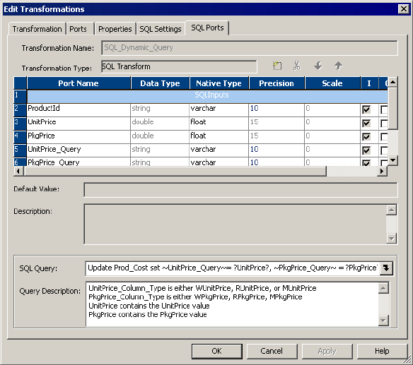
The following figure shows the SQL transformation Ports tab with its SQL Query and Query Description:
The SQL transformation has a dynamic SQL query that updates one of the UnitPrice columns and one of the
PkgPrice columns in the Prod_Cost table based on the column names it receives in the UnitPrice_Query and
the PkgPrice_Query ports.
The SQL transformation has the following query:
Update Prod_Cost set ~UnitPrice_Query~= ?UnitPrice?, ~PkgPrice_Query~ = ?PkgPrice?
where ProductId = ?ProductId?;
The SQL transformation substitutes the UnitPrice_Query and PkgPrice_Query string variables with the
column names to update.
The SQL transformation binds the ProductId, UnitPrice and PkgPrice parameters in the query with data that it
receives in the corresponding ports.
For example, the following source row contains a unit price and a package price for product 100:
100,M,100,110
When the PriceCode is “M,” the prices are manufacturing prices. The Expression transformation passes
MUnitprice and MPkgPrice column names to the SQL transformation to update.
The SQL transformation executes the following query:
Update Prod_Cost set MUnitprice = 100, MPkgPrice = 110 where ProductId = ‘100’;
The following source row contains wholesale prices for product 100:
100,W,120,200
The Expression transformation passes WUnitprice and WPkgPrice column names to the SQL transformation.
The SQL transformation executes the following query:
Update Prod_Cost set WUnitprice = 120, WPkgPrice = 200 where ProductId = ‘100’;
Dynamic Update Example 399
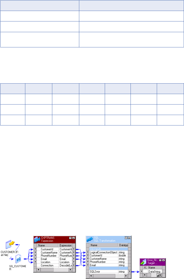
Configuring Session Attributes
When you configure the session, configure the source file, target file, and the database connection:
Attribute Value
Source File Name PPrices.dat
Output File Name ErrorFile.dat
SQL_Dynamic_Query Relational Connection Connection to the test database that contains the Prod_Cost
table.
Target Data Results
When you run a session with the sample data, the Integration Service populates the Prod_Cost target table
with the following data:
ProductID WUnitPrice WPkgPrice RUnitPrice RPkgPrice MUnitPrice MPkgPrice
100 120 200 130 300 100 110
200 220 500 230 600 210 400
300 320 680 330 700 310 666
If the database returns any errors to the SQL transformation, the Error_File target contains the error text.
Dynamic Connection Example
The dynamic connection SQL transformation example shows how to dynamically connect to a database
based on source file data.
In this example, you have a customer database for the United States, United Kingdom, and Canada. You
need to insert customer data from a transaction file into a database based on where the customer is located.
The Expression transformation returns a database connection object name based on the value of the location
column. The Expression transformation passes a connection object name to the SQL transformation
LogicalConnectionObject port. The SQL transformation connects to the database based on value of the
LogicalConnectionObject column.
The following figure shows the Expression transformation and the SQL transformation in a mapping:
400 Chapter 27: Using the SQL Transformation in a Mapping

The mapping contains the following components:
•Customer source definition. A flat file source definition that includes customer information. The
customer location determines which database the SQL transformation connects to when it inserts the
customer data.
•Error_File target definition. The target contains a Datastring field that receives database errors from the
SQL transformation.
•Exp_Dynamic_Connection transformation. The Expression transformation defines which database to
connect to based on the value of the Location column. The Expression transformation returns the
connection object name in the Connection port. The connection object is a database connection defined in
the Workflow Manager.
•SQL_Dynamic_Connection transformation. The SQL transformation receives a connection object name
in the LogicalConnectionPort. It connects to the database and inserts the customer data in the database.
Defining the Source File
The transaction file is a flat file source that contains the customer to add to the database. Each row has a
location that defines the country where the customer lives. The source file name is Customer.dat.
A Customer file record contains the following fields:
Port Name Datatype Precision Scale Description
CustomerID Number 10 0 Customer number that uniquely identifies a
customer.
CustomerName String 25 0 Name of the customer.
PhoneNumber String 15 0 Telephone number includes area code and seven
digits with no spaces.
Email String 25 0 Customer email address.
Location String 10 0 Customer location. Values are US, UK, CAN.
You can create a Customer.dat file in Srcfiles that contains the following rows:
1,John Smith,6502345677,jsmith@catgary.com,US
2,Nigel Whitman,5123456754,nwhitman@nwhitman.com,UK
3,Girish Goyal,5674325321,ggoyal@netcompany.com,CAN
4,Robert Gregson,5423123453,rgregson@networkmail.com,US
You can import the Customer.dat file to create the Customer source definition in the repository.
Creating a Target Definition
The Error_File is a flat file target definition that receives database error messages from the SQL
transformation.
The Error_File definition includes the following input port:
Port Name Datatype Precision Scale
DataString String 4000 0
Create the target definition in the Target Designer.
Dynamic Connection Example 401
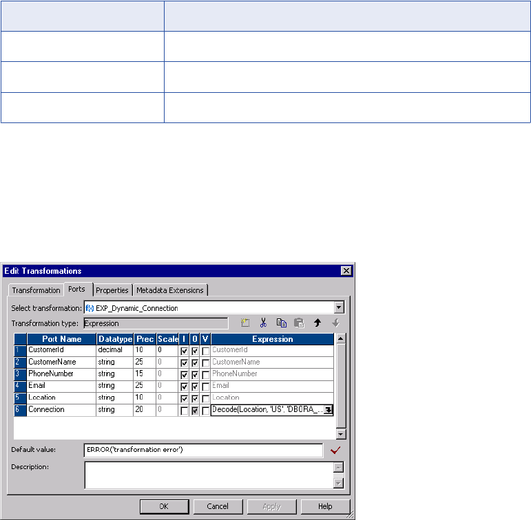
Creating the Database Tables
For this example, you need to create three Oracle databases, a United States database, a United Kingdom
database, and a Canadian database. Each database has a Cust table that contains the customer data for the
region.
The following SQL statements create a Cust table on an Oracle database:
Create table Cust (CustomerId number,CustomerName varchar2(25),PhoneNumber
varchar2(15),Email varchar2(25));
Note: This example includes three databases to illustrate dynamic database connections. If the tables are in
the same database, use a static database connection to improve performance.
Creating the Database Connections
Use the Workflow Manager to create database connections to the US, UK, and CAN databases.
In this example, the SQL transformation connects to the databases using the following connection names:
Database Connection Object Name
US DBORA_US
UK DBORA_UK
CAN DBORA_CAN
Configuring the Expression Transformation
The Expression transformation has an input/output port for each source column. The transformation returns a
connection object name in the Connection port based on the results of an expression.
The following figure shows the Ports tab in the Expression transformation and the input/output port columns
for each source column:
The Connection port has the following expression:
Decode(Location, 'US', 'DBORA_US','UK','DBORA_UK','CAN','DBORA_CAN','DBORA_US')
402 Chapter 27: Using the SQL Transformation in a Mapping
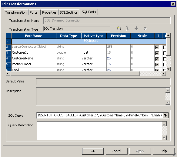
The expression returns a connection object name based on whether the location is US, UK, or CAN. When
the location does not match a location in the expression, the connection object name defaults to
“DBORA_US.”
For example, the following source row customer information for a customer from the United States:
1,John Smith,6502345677,jsmith@catgary.com,US
When the customer location is “US”, the Expression transformation returns the “DBORA_US” connection
object name. The Expression transformation passes “DBORA_US” to the SQL transformation
LogicalConnectionObject port.
Defining the SQL Transformation
The SQL transformation connects to the database and runs a dynamic SQL query that inserts the customer
data into the CUST table.
When you create an SQL transformation, you define the transformation mode, the database type, and the
type of connection. You cannot change the mode or connection type after you create the transformation.
Create an SQL transformation with the following properties:
•Query Mode. The SQL transformation executes dynamic SQL queries.
•Dynamic Connection. The SQL transformation connects to databases depending on connection
information you pass to the transformation in a mapping.
•Connection Object. The SQL transformation has a LogicalConnectionObject port that receives the
connection object name. The connection object must be defined in the Workflow Manager connections.
The following figure shows the ports in the SQL transformation:
The SQL transformation receives the connection object name in the LogicalConnectionObject port. It
connects to the database with the connection object name each time it processes a row.
Dynamic Connection Example 403

The transformation has the following dynamic SQL query to insert the customer data into a CUST table:
INSERT INTO CUST VALUES (?CustomerId?,?CustomerName?,?PhoneNumber?,?Email?);
The SQL transformation substitutes parameters in the query with customer data from the input ports of the
transformation. For example, the following source row contains customer information for customer number 1:
1,John Smith,6502345677,jsmith@catgary.com,US
The SQL transformation connects to the database with the DBORA_US connection object. It executes the
following SQL query:
INSERT INTO CUST VALUES (1,’John Smith’,’6502345677’,’jsmith@catgary.com’);
Configuring Session Attributes
Configure the session to access the following source and target:
Attribute Value
Source File Name Customer.dat
Output File Name Error_File.dat
Note: Do not configure a database connection for the session. The SQL transformation can connect to a
different database each time it processes an input row.
Target Data Results
When you run a session with the sample data, the Integration Service populates the Cust table in the United
States, United Kingdom, or Canada database.
The United States database contains the following rows:
CustomerID CustomerName PhoneNumber Email
1 John Smith 6502345677 jsmith@catagary.com
4 Robert Gregson 5423123453 rgregson@networkmail.com
The United Kingdom database contains the following row:
CustomerID CustomerName PhoneNumber Email
2 Nigel Whitman 5123456754 nwhitman@nwhitman.com
The Canadian database contains the following row:
CustomerID CustomerName PhoneNumber Email
3 Girish Goyal 5423123453 ggoyal@netcompany.com
If the database returns any errors to the SQL transformation, the Error_File target contains the error text.
404 Chapter 27: Using the SQL Transformation in a Mapping

CHAPTER 2 8
Stored Procedure Transformation
This chapter includes the following topics:
•Stored Procedure Transformation Overview, 405
•Using a Stored Procedure in a Mapping, 409
•Writing a Stored Procedure, 409
•Creating a Stored Procedure Transformation, 412
•Configuring a Connected Transformation, 416
•Configuring an Unconnected Transformation, 416
•Error Handling, 420
•Supported Databases, 421
•Expression Rules, 422
•Tips for Stored Procedure Transformations, 422
•Troubleshooting Stored Procedure Transformations, 423
Stored Procedure Transformation Overview
A Stored Procedure transformation is an important tool for populating and maintaining databases. Database
administrators create stored procedures to automate tasks that are too complicated for standard SQL
statements. The Stored Procedure transformation is a passive transformation. You can configure a
connected or unconnected Stored Procedure transformation.
A stored procedure is a precompiled collection of Transact-SQL, PL-SQL or other database procedural
statements and optional flow control statements, similar to an executable script. Stored procedures are
stored and run within the database. You can run a stored procedure with the EXECUTE SQL statement in a
database client tool, just as you can run SQL statements. Unlike standard SQL, however, stored procedures
allow user-defined variables, conditional statements, and other powerful programming features.
Not all databases support stored procedures, and stored procedure syntax varies depending on the
database. You might use stored procedures to complete the following tasks:
•Check the status of a target database before loading data into it.
•Determine if enough space exists in a database.
•Perform a specialized calculation.
•Drop and recreate indexes.
405
Database developers and programmers use stored procedures for various tasks within databases, since
stored procedures allow greater flexibility than SQL statements. Stored procedures also provide error
handling and logging necessary for critical tasks. Developers create stored procedures in the database using
the client tools provided with the database.
The stored procedure must exist in the database before creating a Stored Procedure transformation, and the
stored procedure can exist in a source, target, or any database with a valid connection to the Integration
Service.
You might use a stored procedure to perform a query or calculation that you would otherwise make part of a
mapping. For example, if you already have a well-tested stored procedure for calculating sales tax, you can
perform that calculation through the stored procedure instead of recreating the same calculation in an
Expression transformation.
Input and Output Data
One of the most useful features of stored procedures is the ability to send data to the stored procedure, and
receive data from the stored procedure. There are three types of data that pass between the Integration
Service and the stored procedure:
•Input/output parameters
•Return values
•Status codes
Some limitations exist on passing data, depending on the database implementation, which are discussed
throughout this chapter. Additionally, not all stored procedures send and receive data. For example, if you
write a stored procedure to rebuild a database index at the end of a session, you cannot receive data, since
the session has already finished.
Input/Output Parameters
For many stored procedures, you provide a value and receive a value in return. These values are known as
input and output parameters. For example, a sales tax calculation stored procedure can take a single input
parameter, such as the price of an item. After performing the calculation, the stored procedure returns two
output parameters, the amount of tax, and the total cost of the item including the tax.
The Stored Procedure transformation sends and receives input and output parameters using ports, variables,
or by entering a value in an expression, such as 10 or SALES.
Return Values
Most databases provide a return value after running a stored procedure. Depending on the database
implementation, this value can either be user-definable, which means that it can act similar to a single output
parameter, or it may only return an integer value.
The Stored Procedure transformation captures return values in a similar manner as input/output parameters,
depending on the method that the input/output parameters are captured. In some instances, only a parameter
or a return value can be captured.
If a stored procedure returns a result set rather than a single return value, the Stored Procedure
transformation takes only the first value returned from the procedure.
Note: An Oracle stored function is similar to an Oracle stored procedure, except that the stored function
supports output parameters or return values. In this chapter, any statements regarding stored procedures
also apply to stored functions, unless otherwise noted.
406 Chapter 28: Stored Procedure Transformation

Status Codes
Status codes provide error handling for the Integration Service during a workflow. The stored procedure
issues a status code that notifies whether or not the stored procedure completed successfully. You cannot
see this value. The Integration Service uses it to determine whether to continue running the session or stop.
You configure options in the Workflow Manager to continue or stop the session in the event of a stored
procedure error.
Connected and Unconnected
Stored procedures run in either connected or unconnected mode. The mode you use depends on what the
stored procedure does and how you plan to use it in a session. You can configure connected and
unconnected Stored Procedure transformations in a mapping.
•Connected. The flow of data through a mapping in connected mode also passes through the Stored
Procedure transformation. All data entering the transformation through the input ports affects the stored
procedure. You should use a connected Stored Procedure transformation when you need data from an
input port sent as an input parameter to the stored procedure, or the results of a stored procedure sent as
an output parameter to another transformation.
•Unconnected. The unconnected Stored Procedure transformation is not connected directly to the flow of
the mapping. It either runs before or after the session, or is called by an expression in another
transformation in the mapping.
The following table compares connected and unconnected transformations:
If you want to Use this mode
Run a stored procedure before or after a session. Unconnected
Run a stored procedure once during a mapping, such as pre- or post-session. Unconnected
Run a stored procedure every time a row passes through the Stored Procedure
transformation.
Connected or
Unconnected
Run a stored procedure based on data that passes through the mapping, such as when a
specific port does not contain a null value.
Unconnected
Pass parameters to the stored procedure and receive a single output parameter. Connected or
Unconnected
Pass parameters to the stored procedure and receive multiple output parameters.
Note: To get multiple output parameters from an unconnected Stored Procedure
transformation, you must create variables for each output parameter.
Connected or
Unconnected
Run nested stored procedures. Unconnected
Call multiple times within a mapping. Unconnected
RELATED TOPICS:
•“Configuring an Unconnected Transformation” on page 416
•“Configuring a Connected Transformation” on page 416
Stored Procedure Transformation Overview 407
Specifying when the Stored Procedure Runs
In addition to specifying the mode of the Stored Procedure transformation, you also specify when it runs. In
the case of the unconnected stored procedure above, the Expression transformation references the stored
procedure, which means the stored procedure runs every time a row passes through the Expression
transformation. However, if no transformation references the Stored Procedure transformation, you have the
option to run the stored procedure once before or after the session.
The following list describes the options for running a Stored Procedure transformation:
•Normal. The stored procedure runs where the transformation exists in the mapping on a row-by-row
basis. This is useful for calling the stored procedure for each row of data that passes through the
mapping, such as running a calculation against an input port. Connected stored procedures run only in
normal mode.
•Pre-load of the Source. Before the session retrieves data from the source, the stored procedure runs.
This is useful for verifying the existence of tables or performing joins of data in a temporary table.
•Post-load of the Source. After the session retrieves data from the source, the stored procedure runs.
This is useful for removing temporary tables.
•Pre-load of the Target. Before the session sends data to the target, the stored procedure runs. This is
useful for verifying target tables or disk space on the target system.
•Post-load of the Target. After the session sends data to the target, the stored procedure runs. This is
useful for re-creating indexes on the database.
You can run more than one Stored Procedure transformation in different modes in the same mapping. For
example, a pre-load source stored procedure can check table integrity, a normal stored procedure can
populate the table, and a post-load stored procedure can rebuild indexes in the database. However, you
cannot run the same instance of a Stored Procedure transformation in both connected and unconnected
mode in a mapping. You must create different instances of the transformation.
If the mapping calls more than one source or target pre- or post-load stored procedure in a mapping, the
Integration Service executes the stored procedures in the execution order that you specify in the mapping.
The Integration Service executes each stored procedure using the database connection you specify in the
transformation properties. The Integration Service opens the database connection when it encounters the
first stored procedure. The database connection remains open until the Integration Service finishes
processing all stored procedures for that connection. The Integration Service closes the database
connections and opens a new one when it encounters a stored procedure using a different database
connection.
To run multiple stored procedures that use the same database connection, set these stored procedures to
run consecutively. If you do not set them to run consecutively, you might have unexpected results in the
target. For example, you have two stored procedures: Stored Procedure A and Stored Procedure B. Stored
Procedure A begins a transaction, and Stored Procedure B commits the transaction. If you run Stored
Procedure C before Stored Procedure B, using another database connection, Stored Procedure B cannot
commit the transaction because the Integration Service closes the database connection when it runs Stored
Procedure C.
Use the following guidelines to run multiple stored procedures within a database connection:
•The stored procedures use the same database connect string defined in the stored procedure properties.
•You set the stored procedures to run in consecutive order.
•The stored procedures have the same stored procedure type:
-Source pre-load
-Source post-load
408 Chapter 28: Stored Procedure Transformation
-Target pre-load
-Target post-load
Using a Stored Procedure in a Mapping
You must perform several steps to use a Stored Procedure transformation in a mapping. Since the stored
procedure exists in the database, you must configure not only the mapping and session, but the stored
procedure in the database as well.
To use a Stored Procedure transformation, complete the following steps:
1. Create the stored procedure in the database.
Before using the Designer to create the transformation, you must create the stored procedure in the
database. You should also test the stored procedure through the provided database client tools.
2. Import or create the Stored Procedure transformation.
Use the Designer to import or create the Stored Procedure transformation, providing ports for any
necessary input/output and return values.
3. Determine whether to use the transformation as connected or unconnected.
You must determine how the stored procedure relates to the mapping before configuring the
transformation.
4. If connected, map the appropriate input and output ports.
You use connected Stored Procedure transformations just as you would most other transformations.
Drag the appropriate input flow ports to the transformation, and create mappings from output ports to
other transformations.
5. If unconnected, either configure the stored procedure to run pre- or post-session, or configure it to run
from an expression in another transformation.
Since stored procedures can run before or after the session, you may need to specify when the
unconnected transformation should run. On the other hand, if the stored procedure is called from another
transformation, you write the expression in another transformation that calls the stored procedure. The
expression can contain variables, and may or may not include a return value.
6. Configure the session.
The session properties in the Workflow Manager includes options for error handling when running stored
procedures and several SQL override options.
Writing a Stored Procedure
Write SQL statements to create a stored procedure in the database, and you can add other Transact-SQL
statements and database-specific functions. These can include user-defined datatypes and execution order
statements.
Using a Stored Procedure in a Mapping 409

Sample Stored Procedure
In the following example, the source database has a stored procedure that takes an input parameter of an
employee ID number, and returns an output parameter of the employee name. In addition, a return value of 0
is returned as a notification that the stored procedure completed successfully.
The database table that contains employee IDs and names appears as follows:
Employee ID Employee Name
101 Bill Takash
102 Louis Li
103 Sarah Ferguson
The stored procedure receives the employee ID 101 as an input parameter, and returns the name Bill
Takash. Depending on how the mapping calls this stored procedure, any or all of the IDs may be passed to
the stored procedure.
Since the syntax varies between databases, the SQL statements to create this stored procedure may vary.
The client tools used to pass the SQL statements to the database also vary. Most databases provide a set of
client tools, including a standard SQL editor. Some databases, such as Microsoft SQL Server, provide tools
that create some of the initial SQL statements.
Note: The Integration Service fails sessions that contain stored procedure arguments with large objects.
Informix
In Informix, the syntax for declaring an output parameter differs from other databases. With most databases,
you declare variables using IN or OUT to specify if the variable acts as an input or output parameter. Informix
uses the keyword RETURNING, making it difficult to distinguish input/output parameters from return values.
For example, you use the RETURN command to return one or more output parameters:
CREATE PROCEDURE GET_NAME_USING_ID (nID integer)
RETURNING varchar(20);
define nID integer;
define outVAR as varchar(20);
SELECT FIRST_NAME INTO outVAR FROM CONTACT WHERE ID = nID
return outVAR;
END PROCEDURE;
Notice that in this case, the RETURN statement passes the value of outVAR. Unlike other databases,
however, outVAR is not a return value, but an output parameter. Multiple output parameters would be
returned in the following manner:
return outVAR1, outVAR2, outVAR3
Informix does pass a return value. The return value is not user-defined, but generated as an error-checking
value. In the transformation, the R value must be checked.
Oracle
In Oracle, any stored procedure that returns a value is called a stored function. Rather than using the
CREATE PROCEDURE statement to make a new stored procedure based on the example, you use the
CREATE FUNCTION statement. In this sample, the variables are declared as IN and OUT, but Oracle also
410 Chapter 28: Stored Procedure Transformation
supports an INOUT parameter type, which lets you pass in a parameter, modify it, and return the modified
value:
CREATE OR REPLACE FUNCTION GET_NAME_USING_ID (
nID IN NUMBER,
outVAR OUT VARCHAR2)
RETURN VARCHAR2 IS
RETURN_VAR varchar2(100);
BEGIN
SELECT FIRST_NAME INTO outVAR FROM CONTACT WHERE ID = nID;
RETURN_VAR := 'Success';
RETURN (RETURN_VAR);
END;
/
Notice that the return value is a string value (Success) with the datatype VARCHAR2. Oracle is the only
database to allow return values with string datatypes.
Sybase ASE and Microsoft SQL Server
Sybase and Microsoft implement stored procedures identically, as the following syntax shows:
CREATE PROCEDURE GET_NAME_USING_ID @nID int = 1, @outVar varchar(20) OUTPUT
AS
SELECT @outVar = FIRST_NAME FROM CONTACT WHERE ID = @nID
return 0
Notice that the return value does not need to be a variable. In this case, if the SELECT statement is
successful, a 0 is returned as the return value.
IBM DB2
The following text is an example of an SQL stored procedure on IBM DB2:
CREATE PROCEDURE get_name_using_id ( IN id_in int,
OUT emp_out char(18),
OUT sqlcode_out int)
LANGUAGE SQL
P1: BEGIN
-- Declare variables
DECLARE SQLCODE INT DEFAULT 0;
DECLARE emp_TMP char(18) DEFAULT ' ';
-- Declare handler
DECLARE EXIT HANDLER FOR SQLEXCEPTION
SET SQLCODE_OUT = SQLCODE;
select employee into emp_TMP
from doc_employee
where id = id_in;
SET emp_out = EMP_TMP;
SET sqlcode_out = SQLCODE;
END P1
Teradata
The following text is an example of an SQL stored procedure on Teradata. It takes an employee ID number
as an input parameter and returns the employee name as an output parameter:
CREATE PROCEDURE GET_NAME_USING_ID (IN nID integer, OUT outVAR varchar(40))
BEGIN
SELECT FIRST_NAME INTO :outVAR FROM CONTACT where ID = :nID;
END;
Writing a Stored Procedure 411
Creating a Stored Procedure Transformation
After you configure and test a stored procedure in the database, you must create the Stored Procedure
transformation in the Mapping Designer. There are two ways to configure the Stored Procedure
transformation:
•Use the Import Stored Procedure dialog box to configure the ports used by the stored procedure.
•Configure the transformation manually, creating the appropriate ports for any input or output parameters.
Stored Procedure transformations are created as Normal type by default, which means that they run during
the mapping, not before or after the session.
New Stored Procedure transformations are not created as reusable transformations. To create a reusable
transformation, click Make Reusable in the Transformation properties after creating the transformation.
Note: Configure the properties of reusable transformations in the Transformation Developer, not the Mapping
Designer, to make changes globally for the transformation.
Importing Stored Procedures
When you import a stored procedure, the Designer creates ports based on the stored procedure input and
output parameters. You should import the stored procedure whenever possible.
There are three ways to import a stored procedure in the Mapping Designer:
•Select the stored procedure icon and add a Stored Procedure transformation.
•Click Transformation > Import Stored Procedure.
•Click Transformation > Create, and then select Stored Procedure.
When you import a stored procedure containing a period (.) in the stored procedure name, the Designer
substitutes an underscore (_) for the period in the Stored Procedure transformation name.
To import a stored procedure:
1. In the Mapping Designer, click Transformation > Import Stored Procedure.
2. Select the database that contains the stored procedure from the list of ODBC sources. Enter the user
name, owner name, and password to connect to the database and click Connect.
The folder in the dialog box displays FUNCTIONS. The stored procedures in this folder contain input
parameters, output parameters, or a return value. If stored procedures exist in the database that do not
contain parameters or return values, they appear in a folder called PROCEDURES. This applies
primarily to Oracle stored procedures. For a normal connected Stored Procedure to appear in the
functions list, it requires at least one input and one output port.
Tip: You can select Skip to add a Stored Procedure transformation without importing the stored
procedure. In this case, you need to manually add the ports and connect information within the
transformation.
3. Optionally, use the search field to limit the number of procedures that appear.
4. Select the procedure to import and click OK.
The Stored Procedure transformation appears in the mapping. The Stored Procedure transformation
name is the same as the stored procedure you selected. If the stored procedure contains input
parameters, output parameters, or a return value, you see the appropriate ports that match each
parameter or return value in the Stored Procedure transformation.
412 Chapter 28: Stored Procedure Transformation
In this Stored Procedure transformation, you can see that the stored procedure contains the following
value and parameters:
•An integer return value, called RETURN_VALUE, with an output port.
•A string input parameter, called nNAME, with an input port.
•An integer output parameter, called outVar, with an input and output port.
Note: If you change the transformation name, you need to configure the name of the stored procedure in
the transformation properties. If you have multiple instances of the same stored procedure in a mapping,
you must also configure the name of the stored procedure.
5. Open the transformation, and click the Properties tab.
Select the database where the stored procedure exists from the Connection Information row. If you
changed the name of the Stored Procedure transformation to something other than the name of the
stored procedure, enter the Stored Procedure Name.
6. Click OK.
Manually Creating Stored Procedure Transformations
To create a Stored Procedure transformation manually, you need to know the input parameters, output
parameters, and return values of the stored procedure, if there are any. You must also know the datatypes of
those parameters, and the name of the stored procedure. All these are configured through Import Stored
Procedure.
To create a Stored Procedure transformation:
1. In the Mapping Designer, click Transformation > Create, and then select Stored Procedure.
The naming convention for a Stored Procedure transformation is the name of the stored procedure,
which happens automatically. If you change the transformation name, then you need to configure the
name of the stored procedure in the Transformation Properties. If you have multiple instances of the
same stored procedure in a mapping, you must perform this step.
2. Click Skip.
The Stored Procedure transformation appears in the Mapping Designer.
3. Open the transformation, and click the Ports tab.
You must create ports based on the input parameters, output parameters, and return values in the stored
procedure. Create a port in the Stored Procedure transformation for each of the following stored
procedure parameters:
•An integer input parameter
•A string output parameter
•A return value
For the integer input parameter, you would create an integer input port. The parameter and the port must
be the same datatype and precision. Repeat this for the output parameter and the return value.
The R column should be selected and the output port for the return value. For stored procedures with
multiple parameters, you must list the ports in the same order that they appear in the stored procedure.
4. Click the Properties tab.
Enter the name of the stored procedure in the Stored Procedure Name row, and select the database
where the stored procedure exists from the Connection Information row.
5. Click OK.
Although the repository validates and saves the mapping, the Designer does not validate the manually
entered Stored Procedure transformation. No checks are completed to verify that the proper parameters or
Creating a Stored Procedure Transformation 413

return value exist in the stored procedure. If the Stored Procedure transformation is not configured properly,
the session fails.
Setting Options for the Stored Procedure
The following table describes the properties for a Stored Procedure transformation:
Setting Description
Stored Procedure Name Name of the stored procedure in the database. The Integration Service uses this
text to call the stored procedure if the name of the transformation is different than
the actual stored procedure name in the database. Leave this field blank if the
transformation name matches the stored procedure name. When using the Import
Stored Procedure feature, this name matches the stored procedure.
Connection Information Specifies the database containing the stored procedure. You can define the
database in the mapping, session, or parameter file:
- Mapping. Select the relational connection object.
- Session. Use the $Source or $Target connection variable. If you use one of these
variables, the stored procedure must reside in the source or target database you
specify when you run the session. Specify the database connection for each variable
in the session properties.
- Parameter file. Use the session parameter $DBConnectionName, and define it in the
parameter file.
By default, the Designer specifies $Target for Normal stored procedure types. For
source pre- and post-load, the Designer specifies $Source. For target pre- and
post-load, the Designer specifies $Target. You can override these values in the
session properties.
Call Text Text used to call the stored procedure. Only used when the Stored Procedure Type
is not Normal. You must include all input parameters passed to the stored
procedure within the call text.
You can also use a PowerCenter parameter or variable in the call text. Use any
parameter or variable type that you can define in the parameter file.
Stored Procedure Type Determines when the Integration Service calls the stored procedure. The options
include Normal (during the mapping) or pre- or post-load on the source or target
database. Default is Normal.
Tracing Level Amount of transaction detail reported in the session log file. Use the following
tracing levels:
- Terse
- Normal
- Verbose Initialization
- Verbose Data
Default is Normal.
Execution Order Order in which the Integration Service calls the stored procedure used in the
transformation, relative to any other stored procedures in the same mapping. Only
used when the Stored Procedure Type is set to anything except Normal and more
than one stored procedure exists.
414 Chapter 28: Stored Procedure Transformation

Setting Description
Subsecond Precision Specifies the subsecond precision for datetime ports.
You can change the precision for databases that have an editable scale for
datetime data. You can change subsecond precision for Oracle Timestamp,
Informix Datetime, and Teradata Timestamp datatypes.
Enter a positive integer value from 0 to 9. Default is 6 (microseconds).
Output is Repeatable Indicates whether the transformation generates rows in the same order between
session runs. The Integration Service can resume a session from the last
checkpoint when the output is repeatable and deterministic. Use the following
values:
- Always. The order of the output data is consistent between session runs even if the
order of the input data is inconsistent between session runs.
- Based on Input Order. The transformation produces repeatable data between session
runs when the order of the input data from all input groups is consistent between
session runs. If the input data from any input group is not ordered, then the output is
not ordered.
- Never. The order of the output data is inconsistent between session runs. You cannot
configure recovery to resume from the last checkpoint if a transformation does not
produce repeatable data.
Default is Based on Input Order.
Output is Deterministic Indicates whether the transformation generates consistent output data between
session runs. You must enable this property to perform recovery on sessions that
use this transformation.
Default is disabled.
Warning: If you configure a transformation as repeatable and deterministic, it is your responsibility to ensure
that the data is repeatable and deterministic. If you try to recover a session with transformations that do not
produce the same data between the session and the recovery, the recovery process can result in corrupted
data.
Changing the Stored Procedure
If the number of parameters or the return value in a stored procedure changes, you can either re-import it or
edit the Stored Procedure transformation manually. The Designer does not verify the Stored Procedure
transformation each time you open the mapping. After you import or create the transformation, the Designer
does not validate the stored procedure. The session fails if the stored procedure does not match the
transformation.
Creating a Stored Procedure Transformation 415
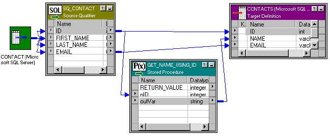
Configuring a Connected Transformation
The following figure shows a mapping that sends the ID from the Source Qualifier to an input parameter in
the Stored Procedure transformation:
The Stored Procedure transformation passes an output parameter to the target. Every row of data in the
Source Qualifier transformation passes data through the Stored Procedure transformation.
Although not required, almost all connected Stored Procedure transformations contain input and output
parameters. Required input parameters are specified as the input ports of the Stored Procedure
transformation. Output parameters appear as output ports in the transformation. A return value is also an
output port, and has the R value selected in the transformation Ports configuration. For a normal connected
Stored Procedure to appear in the functions list, it requires at least one input and one output port.
Output parameters and return values from the stored procedure are used as any other output port in a
transformation. You can link these ports to another transformation or target.
To configure a connected Stored Procedure transformation:
1. Create the Stored Procedure transformation in the mapping.
2. Drag the output ports of the Stored Procedure to other transformations or targets.
3. Open the Stored Procedure transformation, and select the Properties tab.
4. Select the appropriate database in the Connection Information if you did not select it when creating the
transformation.
5. Select the Tracing level for the transformation.
If you are testing the mapping, select the Verbose Initialization option to provide the most information in
the event that the transformation fails.
6. Click OK.
Configuring an Unconnected Transformation
An unconnected Stored Procedure transformation is not directly connected to the flow of data through the
mapping. Instead, the stored procedure runs either:
•From an expression. Called from an expression written in the Expression Editor within another
transformation in the mapping.
•Pre- or post-session. Runs before or after a session.
The sections below explain how you can run an unconnected Stored Procedure transformation.
416 Chapter 28: Stored Procedure Transformation
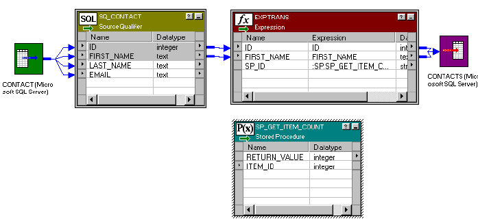
Calling a Stored Procedure From an Expression
In an unconnected mapping, the Stored Procedure transformation does not connect to the pipeline.
The following figure shows a mapping with an Expression transformation that references the Stored
Procedure transformation:
However, just like a connected mapping, you can apply the stored procedure to the flow of data through the
mapping. In fact, you have greater flexibility since you use an expression to call the stored procedure, which
means you can select the data that you pass to the stored procedure as an input parameter.
When using an unconnected Stored Procedure transformation in an expression, you need a method of
returning the value of output parameters to a port. Use one of the following methods to capture the output
values:
•Assign the output value to a local variable.
•Assign the output value to the system variable PROC_RESULT.
By using PROC_RESULT, you assign the value of the return parameter directly to an output port, which can
apply directly to a target. You can also combine the two options by assigning one output parameter as
PROC_RESULT, and the other parameter as a variable.
Use PROC_RESULT only within an expression. If you do not use PROC_RESULT or a variable, the port
containing the expression captures a NULL. You cannot use PROC_RESULT in a connected Lookup
transformation or within the Call Text for a Stored Procedure transformation.
If you require nested stored procedures, where the output parameter of one stored procedure passes to
another stored procedure, use PROC_RESULT to pass the value.
The Integration Service calls the unconnected Stored Procedure transformation from the Expression
transformation. Notice that the Stored Procedure transformation has two input ports and one output port. All
three ports are string datatypes.
To call a stored procedure from within an expression:
1. Create the Stored Procedure transformation in the mapping.
2. In any transformation that supports output and variable ports, create a new output port in the
transformation that calls the stored procedure. Name the output port.
The output port that calls the stored procedure must support expressions. Depending on how the
expression is configured, the output port contains the value of the output parameter or the return value.
3. Open the Expression Editor for the port.
Configuring an Unconnected Transformation 417
The value for the new port is set up in the Expression Editor as a call to the stored procedure using
the :SP keyword in the Transformation Language. The easiest way to set this up properly is to select the
Stored Procedures node in the Expression Editor, and click the name of Stored Procedure
transformation listed. For a normal connected Stored Procedure to appear in the functions list, it requires
at least one input and one output port.
The stored procedure appears in the Expression Editor with a pair of empty parentheses. The necessary
input and/or output parameters are displayed in the lower left corner of the Expression Editor.
4. Configure the expression to send input parameters and capture output parameters or return value.
You must know whether the parameters shown in the Expression Editor are input or output parameters.
You insert variables or port names between the parentheses in the order that they appear in the stored
procedure. The datatypes of the ports and variables must match those of the parameters passed to the
stored procedure.
For example, when you click the stored procedure, something similar to the following appears:
:SP.GET_NAME_FROM_ID()
This particular stored procedure requires an integer value as an input parameter and returns a string
value as an output parameter. How the output parameter or return value is captured depends on the
number of output parameters and whether the return value needs to be captured.
If the stored procedure returns a single output parameter or a return value (but not both), you should use
the reserved variable PROC_RESULT as the output variable. In the previous example, the expression
would appear as:
:SP.GET_NAME_FROM_ID(inID, PROC_RESULT)
inID can be either an input port for the transformation or a variable in the transformation. The value of
PROC_RESULT is applied to the output port for the expression.
If the stored procedure returns multiple output parameters, you must create variables for each output
parameter. For example, if you create a port called varOUTPUT2 for the stored procedure expression,
and a variable called varOUTPUT1, the expression appears as:
:SP.GET_NAME_FROM_ID(inID, varOUTPUT1, PROC_RESULT)
The value of the second output port is applied to the output port for the expression, and the value of the
first output port is applied to varOUTPUT1. The output parameters are returned in the order they are
declared in the stored procedure.
With all these expressions, the datatypes for the ports and variables must match the datatypes for the
input/output variables and return value.
5. Click Validate to verify the expression, and then click OK to close the Expression Editor.
Validating the expression ensures that the datatypes for parameters in the stored procedure match those
entered in the expression.
6. Click OK.
When you save the mapping, the Designer does not validate the stored procedure expression. If the
stored procedure expression is not configured properly, the session fails. When testing a mapping using
a stored procedure, set the Override Tracing session option to a verbose mode and configure the On
Stored Procedure session option to stop running if the stored procedure fails. Configure these session
options in the Error Handling settings of the Config Object tab in the session properties.
The stored procedure in the expression entered for a port does not have to affect all values that pass through
the port. Using the IIF statement, for example, you can pass only certain values, such as ID numbers that
begin with 5, to the stored procedure and skip all other values. You can also set up nested stored procedures
so the return value of one stored procedure becomes an input parameter for a second stored procedure.
418 Chapter 28: Stored Procedure Transformation
Calling a Pre- or Post-Session Stored Procedure
You may want to run a stored procedure once per session. For example, if you need to verify that tables exist
in a target database before running a mapping, a pre-load target stored procedure can check the tables, and
then either continue running the workflow or stop it. You can run a stored procedure on the source, target, or
any other connected database.
To create a pre- or post-load stored procedure:
1. Create the Stored Procedure transformation in the mapping.
2. Double-click the Stored Procedure transformation, and select the Properties tab.
3. Enter the name of the stored procedure.
If you imported the stored procedure, the stored procedure name appears by default. If you manually set
up the stored procedure, enter the name of the stored procedure.
4. Select the database that contains the stored procedure in Connection Information.
5. Enter the call text of the stored procedure.
The call text is the name of the stored procedure, followed by all applicable input parameters in
parentheses. If there are no input parameters, you must include an empty pair of parentheses, or the call
to the stored procedure fails. You do not need to include the SQL statement EXEC, nor do you need to
use the :SP keyword. For example, to call a stored procedure called check_disk_space, enter the
following text:
check_disk_space()
To pass a string input parameter, enter it without quotes. If the string has spaces in it, enclose the
parameter in double quotes. For example, if the stored procedure check_disk_space required a machine
name as an input parameter, enter the following text:
check_disk_space(oracle_db)
When passing a datetime value through a pre- or post-session stored procedure, the value must be in
the Informatica default date format and enclosed in double quotes as follows:
SP(“12/31/2000 11:45:59”)
You can use PowerCenter parameters and variables in the call text. Use any parameter or variable type
that you can define in the parameter file. You can enter a parameter or variable within the call text, or
you can use a parameter or variable as the call text. For example, you can use a session parameter,
$ParamMyCallText, as the call text, and set $ParamMyCallText to the call text in a parameter file.
Note: You must enter values instead of procedure parameters for the input parameters of pre- and post-
session procedures.
6. Select the stored procedure type.
The options for stored procedure type include:
•Source Pre-load. Before the session retrieves data from the source, the stored procedure runs. This
is useful for verifying the existence of tables or performing joins of data in a temporary table.
•Source Post-load. After the session retrieves data from the source, the stored procedure runs. This
is useful for removing temporary tables.
•Target Pre-load. Before the session sends data to the target, the stored procedure runs. This is
useful for verifying target tables or disk space on the target system.
•Target Post-load. After the session sends data to the target, the stored procedure runs. This is
useful for re-creating indexes on the database.
7. Select Execution Order, and click the Up or Down arrow to change the order, if necessary.
Configuring an Unconnected Transformation 419
If you have added several stored procedures that execute at the same point in a session, such as two
procedures that both run at Source Post-load, you can set a stored procedure execution plan to
determine the order in which the Integration Service calls these stored procedures. You need to repeat
this step for each stored procedure you wish to change.
8. Click OK.
Although the repository validates and saves the mapping, the Designer does not validate whether the stored
procedure expression runs without an error. If the stored procedure expression is not configured properly, the
session fails. When testing a mapping using a stored procedure, set the Override Tracing session option to a
verbose mode and configure the On Stored Procedure session option to stop running if the stored procedure
fails. Configure these session options on the Error Handling settings of the Config Object tab in the session
properties.
You lose output parameters or return values called during pre- or post-session stored procedures, since there
is no place to capture the values. If you need to capture values, you might want to configure the stored
procedure to save the value in a table in the database.
Error Handling
Sometimes a stored procedure returns a database error, such as “divide by zero” or “no more rows.” The final
result of a database error during a stored procedure depends on when the stored procedure takes place and
how the session is configured.
You can configure the session to either stop or continue running the session upon encountering a pre- or
post-session stored procedure error. By default, the Integration Service stops a session when a pre- or post-
session stored procedure database error occurs.
Pre-Session Errors
Pre-read and pre-load stored procedures are considered pre-session stored procedures. Both run before the
Integration Service begins reading source data. If a database error occurs during a pre-session stored
procedure, the Integration Service performs a different action depending on the session configuration.
•If you configure the session to stop upon stored procedure error, the Integration Service fails the session.
•If you configure the session to continue upon stored procedure error, the Integration Service continues
with the session.
Post-Session Errors
Post-read and post-load stored procedures are considered post-session stored procedures. Both run after the
Integration Service commits all data to the database. If a database errors during a post-session stored
procedure, the Integration Service performs a different action depending on the session configuration:
•If you configure the session to stop upon stored procedure error, the Integration Service fails the session.
However, the Integration Service has already committed all data to session targets.
•If you configure the session to continue upon stored procedure error, the Integration Service continues
with the session.
420 Chapter 28: Stored Procedure Transformation

Session Errors
Connected or unconnected stored procedure errors occurring during the session are not affected by the
session error handling option. If the database returns an error for a particular row, the Integration Service
skips the row and continues to the next row. As with other row transformation errors, the skipped row
appears in the session log.
Supported Databases
The supported options for Oracle, and other databases, such as Informix, Microsoft SQL Server, and Sybase
are described below.
RELATED TOPICS:
•“Writing a Stored Procedure” on page 409
SQL Declaration
In the database, the statement that creates a stored procedure appears similar to the following Oracle stored
procedure:
create or replace procedure sp_combine_str
(str1_inout IN OUT varchar2,
str2_inout IN OUT varchar2,
str_out OUT varchar2)
is
begin
str1_inout := UPPER(str1_inout);
str2_inout := upper(str2_inout);
str_out := str1_inout || ' ' || str2_inout;
end;
In this case, the Oracle statement begins with CREATE OR REPLACE PROCEDURE. Since Oracle supports
both stored procedures and stored functions, only Oracle uses the optional CREATE FUNCTION statement.
Parameter Types
There are three possible parameter types in stored procedures:
•IN. Defines the parameter something that must be passed to the stored procedure.
•OUT. Defines the parameter as a returned value from the stored procedure.
•INOUT. Defines the parameter as both input and output. Only Oracle supports this parameter type.
Input/Output Port in Mapping
Since Oracle supports the INOUT parameter type, a port in a Stored Procedure transformation can act as
both an input and output port for the same stored procedure parameter. Other databases should not have
both the input and output check boxes selected for a port.
Type of Return Value Supported
Different databases support different types of return value datatypes, and only Informix does not support
user-defined return values.
Supported Databases 421
Expression Rules
Unconnected Stored Procedure transformations can be called from an expression in another transformation.
Use the following rules and guidelines when configuring the expression:
•A single output parameter is returned using the variable PROC_RESULT.
•When you use a stored procedure in an expression, use the :SP reference qualifier. To avoid typing
errors, select the Stored Procedure node in the Expression Editor, and double-click the name of the
stored procedure.
•However, the same instance of a Stored Procedure transformation cannot run in both connected and
unconnected mode in a mapping. You must create different instances of the transformation.
•The input/output parameters in the expression must match the input/output ports in the Stored Procedure
transformation. If the stored procedure has an input parameter, there must also be an input port in the
Stored Procedure transformation.
•When you write an expression that includes a stored procedure, list the parameters in the same order that
they appear in the stored procedure and the Stored Procedure transformation.
•The parameters in the expression must include all of the parameters in the Stored Procedure
transformation. You cannot leave out an input parameter. If necessary, pass a dummy variable to the
stored procedure.
•The arguments in the expression must be the same datatype and precision as those in the Stored
Procedure transformation.
•Use PROC_RESULT to apply the output parameter of a stored procedure expression directly to a target.
You cannot use a variable for the output parameter to pass the results directly to a target. Use a local
variable to pass the results to an output port within the same transformation.
•Nested stored procedures allow passing the return value of one stored procedure as the input parameter
of another stored procedure. For example, if you have the following two stored procedures:
-get_employee_id (employee_name)
-get_employee_salary (employee_id)
And the return value for get_employee_id is an employee ID number, the syntax for a nested stored
procedure is:
:sp.get_employee_salary (:sp.get_employee_id (employee_name))
You can have multiple levels of nested stored procedures.
•Do not use single quotes around string parameters. If the input parameter does not contain spaces, do not
use any quotes. If the input parameter contains spaces, use double quotes.
Tips for Stored Procedure Transformations
Do not run unnecessary instances of stored procedures.
422 Chapter 28: Stored Procedure Transformation
Each time a stored procedure runs during a mapping, the session must wait for the stored procedure to
complete in the database. You have two possible options to avoid this:
•Reduce the row count. Use an active transformation prior to the Stored Procedure transformation to
reduce the number of rows that must be passed the stored procedure. Or, create an expression that tests
the values before passing them to the stored procedure to make sure that the value does not really need
to be passed.
•Create an expression. Most of the logic used in stored procedures can be easily replicated using
expressions in the Designer.
Troubleshooting Stored Procedure Transformations
I get the error “stored procedure not found” in the session log file.
Make sure the stored procedure is being run in the correct database. By default, the Stored Procedure
transformation uses the target database to run the stored procedure. Double-click the transformation in the
mapping, select the Properties tab, and check which database is selected in Connection Information.
My output parameter was not returned using a Microsoft SQL Server stored procedure.
Check if the parameter to hold the return value is declared as OUTPUT in the stored procedure. With
Microsoft SQL Server, OUTPUT implies input/output. In the mapping, you probably have checked both the I
and O boxes for the port. Clear the input port.
The session did not have errors before, but now it fails on the stored procedure.
The most common reason for problems with a Stored Procedure transformation results from changes made
to the stored procedure in the database. If the input/output parameters or return value changes in a stored
procedure, the Stored Procedure transformation becomes invalid. You must either import the stored
procedure again, or manually configure the stored procedure to add, remove, or modify the appropriate ports.
The session has been invalidated since I last edited the mapping. Why?
Any changes you make to the Stored Procedure transformation may invalidate the session. The most
common reason is that you have changed the type of stored procedure, such as from a Normal to a Post-load
Source type.
Troubleshooting Stored Procedure Transformations 423

CHAPTER 2 9
Transaction Control
Transformation
This chapter includes the following topics:
•Transaction Control Transformation Overview, 424
•Transaction Control Transformation Properties, 425
•Using Transaction Control Transformations in Mappings, 427
•Mapping Guidelines and Validation, 428
•Creating a Transaction Control Transformation, 429
Transaction Control Transformation Overview
PowerCenter lets you control commit and roll back transactions based on a set of rows that pass through a
Transaction Control transformation. A Transaction Control transformation is an active transformation. A
transaction is the set of rows bound by commit or roll back rows. You can define a transaction based on a
varying number of input rows. You might want to define transactions based on a group of rows ordered on a
common key, such as employee ID or order entry date.
In PowerCenter, you define transaction control at the following levels:
•Within a mapping. Within a mapping, you use the Transaction Control transformation to define a
transaction. You define transactions using an expression in a Transaction Control transformation. Based
on the return value of the expression, you can choose to commit, roll back, or continue without any
transaction changes.
•Within a session. When you configure a session, you configure it for user-defined commit. You can
choose to commit or roll back a transaction if the Integration Service fails to transform or write any row to
the target.
When you run the session, the Integration Service evaluates the expression for each row that enters the
transformation. When it evaluates a commit row, it commits all rows in the transaction to the target or targets.
When the Integration Service evaluates a roll back row, it rolls back all rows in the transaction from the target
or targets.
If the mapping has a flat file target you can generate an output file each time the Integration Service starts a
new transaction. You can dynamically name each target flat file.
Note: You can also use the transformation scope in other transformation properties to define transactions.
424
Transaction Control Transformation Properties
Use the Transaction Control transformation to define conditions to commit and roll back transactions from
transactional targets. Transactional targets include relational, XML, and dynamic MQSeries targets. Define
these parameters in a transaction control expression on the Properties tab. A transaction is the row or set of
rows bound by commit or roll back rows. The number of rows may vary for each transaction.
When you configure a Transaction Control transformation, you define the following components:
•Transformation tab. You can rename the transformation and add a description on the Transformation
tab.
•Ports tab. You can add input/output ports to a Transaction Control transformation.
•Properties tab. You can define the transaction control expression, which flags transactions for commit,
roll back, or no action.
•Metadata Extensions tab. You can extend the metadata stored in the repository by associating
information with the Transaction Control transformation.
Properties Tab
On the Properties tab, you can configure the following properties:
•Transaction control expression
•Tracing level
Enter the transaction control expression in the Transaction Control Condition field. The transaction control
expression uses the IIF function to test each row against the condition. Use the following syntax for the
expression:
IIF (condition, value1, value2)
The expression contains values that represent actions the Integration Service performs based on the return
value of the condition. The Integration Service evaluates the condition on a row-by-row basis. The return
value determines whether the Integration Service commits, rolls back, or makes no transaction changes to
the row. When the Integration Service issues a commit or roll back based on the return value of the
expression, it begins a new transaction. Use the following built-in variables in the Expression Editor when you
create a transaction control expression:
•TC_CONTINUE_TRANSACTION. The Integration Service does not perform any transaction change for
this row. This is the default value of the expression.
•TC_COMMIT_BEFORE. The Integration Service commits the transaction, begins a new transaction, and
writes the current row to the target. The current row is in the new transaction.
•TC_COMMIT_AFTER. The Integration Service writes the current row to the target, commits the
transaction, and begins a new transaction. The current row is in the committed transaction.
•TC_ROLLBACK_BEFORE. The Integration Service rolls back the current transaction, begins a new
transaction, and writes the current row to the target. The current row is in the new transaction.
•TC_ROLLBACK_AFTER. The Integration Service writes the current row to the target, rolls back the
transaction, and begins a new transaction. The current row is in the rolled back transaction.
If the transaction control expression evaluates to a value other than commit, roll back, or continue, the
Integration Service fails the session.
Transaction Control Transformation Properties 425
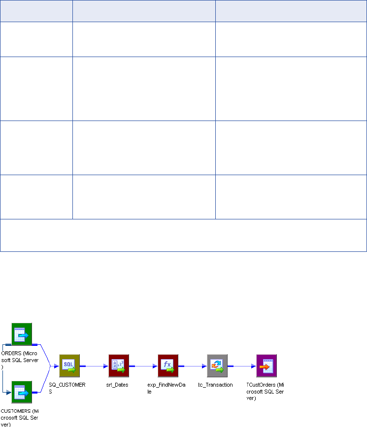
Example
You want to use transaction control to write order information based on the order entry date. You want to
ensure that all orders entered on any given date are committed to the target in the same transaction. To
accomplish this, you can create a mapping with the following transformations:
•Sorter transformation. Sort the source data by order entry date.
•Expression transformation. Use local variables to determine whether the date entered is a new date.
The following table describes the ports in the Expression transformation:
Port Name Expression Description
DATE_ENTERED DATE_ENTERED Input/Output port.
Receives and passes the date entered.
NEW_DATE IIF(DATE_ENTERED=PREVDATE, 0,1) Variable port.
Tests current value for DATE_ENTERED
against the stored value for
DATE_ENTERED in the variable port,
PREV_DATE.
PREV_DATE DATE_ENTERED Variable port.
Receives the value for DATE_ENTERED
after the Integration Service evaluates the
NEW_DATE port.
DATE_OUT NEW_DATE Output port.
Passes the flag from NEW_DATE to the
Transaction Control transformation.
Note: The Integration Service evaluates ports by dependency. The order in which ports display in a
transformation must match the order of evaluation: input ports, variable ports, output ports.
•Transaction Control transformation. Create the following transaction control expression to commit data
when the Integration Service encounters a new order entry date:
IIF(NEW_DATE = 1, TC_COMMIT_BEFORE, TC_CONTINUE_TRANSACTION)
The following figure shows a sample mapping using a Transaction Control transformation:
426 Chapter 29: Transaction Control Transformation
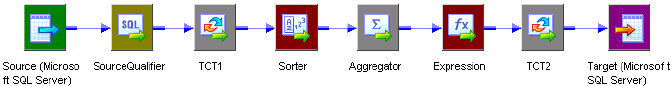
Using Transaction Control Transformations in
Mappings
Transaction Control transformations are transaction generators. They define and redefine transaction
boundaries in a mapping. They drop any incoming transaction boundary from an upstream active source or
transaction generator, and they generate new transaction boundaries downstream.
You can also use Custom transformations configured to generate transactions to define transaction
boundaries.
Transaction Control transformations can be effective or ineffective for the downstream transformations and
targets in the mapping. The Transaction Control transformation becomes ineffective for downstream
transformations or targets if you put a transformation that drops incoming transaction boundaries after it. This
includes any of the following active sources or transformations:
•Aggregator transformation with the All Input level transformation scope
•Joiner transformation with the All Input level transformation scope
•Rank transformation with the All Input level transformation scope
•Sorter transformation with the All Input level transformation scope
•Custom transformation with the All Input level transformation scope
•Custom transformation configured to generate transactions
•Transaction Control transformation
•A multiple input group transformation, such as a Custom transformation, connected to multiple upstream
transaction control points
Mappings with Transaction Control transformations that are ineffective for targets may be valid or invalid.
When you save or validate the mapping, the Designer displays a message indicating which Transaction
Control transformations are ineffective for targets.
Although a Transaction Control transformation may be ineffective for a target, it can be effective for
downstream transformations. Downstream transformations with the Transaction level transformation scope
can use the transaction boundaries defined by an upstream Transaction Control transformation.
The following figure shows a valid mapping with a Transaction Control transformation that is effective for a
Sorter transformation, but ineffective for the target.
In this example, TCT1 transformation is ineffective for the target, but effective for the Sorter transformation.
The Sorter transformation Transformation Scope property is Transaction. It uses the transaction boundaries
defined by TCT1. The Aggregator Transformation Scope property is All Input. It drops transaction boundaries
defined by TCT1. The TCT2 transformation is an effective Transaction Control transformation for the target.
Sample Transaction Control Mappings with Multiple Targets
A Transaction Control transformation may be effective for one target and ineffective for another target.
If each target is connected to an effective Transaction Control transformation, the mapping is valid. If one
target in the mapping is not connected to an effective Transaction Control transformation, the mapping is
invalid.
Using Transaction Control Transformations in Mappings 427
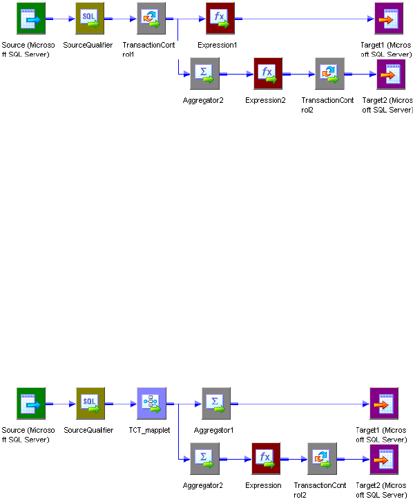
The following figure shows a valid mapping with both an ineffective and an effective Transaction Control
transformation:
The Integration Service processes TransactionControl1, evaluates the transaction control expression, and
creates transaction boundaries. The mapping does not include any transformation that drops transaction
boundaries between TransactionControl1 and Target1, making TransactionControl1 effective for Target1. The
Integration Service uses the transaction boundaries defined by TransactionControl1 for Target1.
However, the mapping includes a transformation that drops transaction boundaries between
TransactionControl1 and Target2, making TransactionControl1 ineffective for Target2. When the Integration
Service processes Aggregator2, with Transformation Scope set to All Input, it drops the transaction
boundaries defined by TransactionControl1 and outputs all rows in an open transaction. Then the Integration
Service evaluates TransactionControl2, creates transaction boundaries, and uses them for Target2.
If a roll back occurs in TransactionControl1, the Integration Service rolls back only rows from Target1. It does
not roll back any rows from Target2.
The following figure shows an invalid mapping with both an ineffective and an effective Transaction Control
transformation:
The mapplet, TCT_mapplet, contains a Transaction Control transformation. It is ineffective for Target1 and
Target2. The Aggregator1 transformation Transformation Scope property is All Input. It is an active source for
Target1. The Aggregator2 transformation Transformation Scope property is All Input. It is an active source for
Target2. The TransactionControl2 transformation is effective for Target2.
The mapping is invalid because Target1 is not connected to an effective Transaction Control transformation.
Mapping Guidelines and Validation
Use the following rules and guidelines when you create a mapping with a Transaction Control transformation:
•If the mapping includes an XML target, and you choose to append or create a new document on commit,
the input groups must receive data from the same transaction control point.
•Transaction Control transformations connected to any target other than relational, XML, or dynamic
MQSeries targets are ineffective for those targets.
•You must connect each target instance to a Transaction Control transformation.
428 Chapter 29: Transaction Control Transformation
•You can connect multiple targets to a single Transaction Control transformation.
•You can connect only one effective Transaction Control transformation to a target.
•You cannot place a Transaction Control transformation in a pipeline branch that starts with a Sequence
Generator transformation.
•If you use a dynamic Lookup transformation and a Transaction Control transformation in the same
mapping, a rolled-back transaction might result in unsynchronized target data.
•A Transaction Control transformation may be effective for one target and ineffective for another target. If
each target is connected to an effective Transaction Control transformation, the mapping is valid.
•Either all targets or none of the targets in the mapping should be connected to an effective Transaction
Control transformation.
Creating a Transaction Control Transformation
Use the following procedure to add a Transaction Control transformation to a mapping.
To create a Transaction Control transformation:
1. In the Mapping Designer, click Transformation > Create. Select the Transaction Control transformation.
2. Enter a name for the transformation.
The naming convention for Transaction Control transformations is TC_TransformationName.
3. Enter a description for the transformation.
This description appears when you view transformation details in the Repository Manager, making it
easier to understand what the transformation does.
4. Click Create.
The Designer creates the Transaction Control transformation.
5. Click Done.
6. Drag the ports into the transformation.
The Designer creates the input/output ports for each port you include.
7. Open the Edit Transformations dialog box, and select the Ports tab.
You can add ports, edit port names, add port descriptions, and enter default values.
8. Select the Properties tab. Enter the transaction control expression that defines the commit and roll back
behavior.
9. Select the Metadata Extensions tab. Create or edit metadata extensions for the Transaction Control
transformation.
10. Click OK.
Creating a Transaction Control Transformation 429

CHAPTER 3 0
Union Transformation
This chapter includes the following topics:
•Union Transformation Overview, 430
•Working with Groups and Ports, 431
•Creating a Union Transformation, 431
•Using a Union Transformation in a Mapping, 432
Union Transformation Overview
The Union transformation is a multiple input group transformation that you use to merge data from multiple
pipelines or pipeline branches into one pipeline branch. It merges data from multiple sources similar to the
UNION ALL SQL statement to combine the results from two or more SQL statements. Similar to the UNION
ALL statement, the Union transformation does not remove duplicate rows. The Union transformation is an
active transformation.
The Data Integration Service processes all input groups in parallel. It concurrently reads sources connected
to the Union transformation and pushes blocks of data into the input groups of the transformation. The Union
transformation processes the blocks of data based on the order it receives the blocks from the Integration
Service.
You can connect heterogeneous sources to a Union transformation. The transformation merges sources with
matching ports and outputs the data from one output group with the same ports as the input groups.
The Union transformation is developed using the Custom transformation.
Rules and Guidelines for Union Transformations
Use the following rules and guidelines when you work with a Union transformation:
•You can create multiple input groups, but only one output group.
•All input groups and the output group must have matching ports. The precision, datatype, and scale must
be identical across all groups.
•The Union transformation does not remove duplicate rows. To remove duplicate rows, you must add
another transformation such as a Router or Filter transformation.
•You cannot use a Sequence Generator or Update Strategy transformation upstream from a Union
transformation.
•The Union transformation does not generate transactions.
430
Union Transformation Components
When you configure a Union transformation, define the following components:
•Transformation tab. You can rename the transformation and add a description.
•Properties tab. You can specify the tracing level.
•Groups tab. You can create and delete input groups. The Designer displays groups you create on the
Ports tab.
•Group Ports tab. You can create and delete ports for the input groups. The Designer displays ports you
create on the Ports tab.
You cannot modify the Ports tab in a Union transformation.
Working with Groups and Ports
A Union transformation has multiple input groups and one output group. Create input groups on the Groups
tab, and create ports on the Group Ports tab.
You can create one or more input groups on the Groups tab. The Designer creates one output group by
default. You cannot edit or delete the output group.
You can create ports by copying ports from a transformation, or you can create ports manually. When you
create ports on the Group Ports tab, the Designer creates input ports in each input group and output ports in
the output group. The Designer uses the port names you specify on the Group Ports tab for each input and
output port, and it appends a number to make each port name in the transformation unique. It also uses the
same metadata for each port, such as datatype, precision, and scale.
The Ports tab displays the groups and ports you create. You cannot edit group and port information on the
Ports tab. Use the Groups and Group Ports tab to edit groups and ports.
Creating a Union Transformation
Use the following procedure to create a Union transformation.
To create a Union transformation:
1. In the Mapping Designer, click Transformations > Create.
2. Select Union Transformation and enter the name of the transformation.
The naming convention for Union transformations is UN_TransformationName.
3. Enter a description for the transformation. Click Create, and then click Done.
4. Click the Groups tab.
5. Add an input group for each pipeline or pipeline branch you want to merge.
The Designer assigns a default name for each group but they can be renamed.
6. Click the Group Ports tab.
7. Add a new port for each row of data you want to merge.
8. Enter port properties, such as name and datatype.
Working with Groups and Ports 431
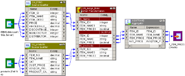
9. Click the Properties tab to configure the tracing level.
10. Click OK.
Using a Union Transformation in a Mapping
The Union transformation is a non-blocking multiple input group transformation. You can connect the input
groups to different branches in a single pipeline or to different source pipelines.
When you add a Union transformation to a mapping, you must verify that you connect the same ports in all
input groups. If you connect all ports in one input group, but do not connect a port in another input group, the
Integration Service passes NULLs to the unconnected port.
The following figure shows a mapping with a Union transformation:
When a Union transformation in a mapping receives data from a single transaction generator, the Integration
Service propagates transaction boundaries. When the transformation receives data from multiple transaction
generators, the Integration Service drops all incoming transaction boundaries and outputs rows in an open
transaction.
432 Chapter 30: Union Transformation

CHAPTER 3 1
Unstructured Data Transformation
This chapter includes the following topics:
•Unstructured Data Transformation Overview, 433
•Configuring the Unstructured Data Option, 434
•Data Transformation Service Types, 435
•Unstructured Data Transformation Components, 435
•Unstructured Data Transformation Ports, 438
•Unstructured Data Transformation Service Names, 440
•Relational Hierarchies, 441
•Mappings, 442
•Creating an Unstructured Data Transformation, 444
Unstructured Data Transformation Overview
The Unstructured Data transformation is a transformation that processes unstructured and semi-structured
file formats, such as messaging formats, HTML pages and PDF documents. It also transforms structured
formats such as ACORD, HIPAA, HL7, EDI-X12, EDIFACT, and SWIFT.
The Unstructured Data transformation calls a Data Transformation service from a PowerCenter session. Data
Transformation is the application that transforms the unstructured and semi-structured file formats. You can
pass data from the Unstructured Data transformation to a Data Transformation service, transform the data,
and return the transformed data to the pipeline. The Unstructured Data transformation can be an active or
passive transformation.
Data Transformation has the following components:
•Data Transformation Studio. A visual editor to design and configure transformation projects.
•Data Transformation service. A Data Transformation project that is deployed to the Data Transformation
repository and is ready to run.
•Data Transformation repository. A directory that stores executable services that you create in Data
Transformation Studio. You can deploy projects to different repositories, such as repositories for test and
production services.
•Data Transformation Engine. A processor that runs the services that you deploy to the repository.
When Data Transformation Engine runs a service, it writes the output data, or it returns output data to the
Integration Service. When Data Transformation Engine returns output to the Integration Service, it returns
433
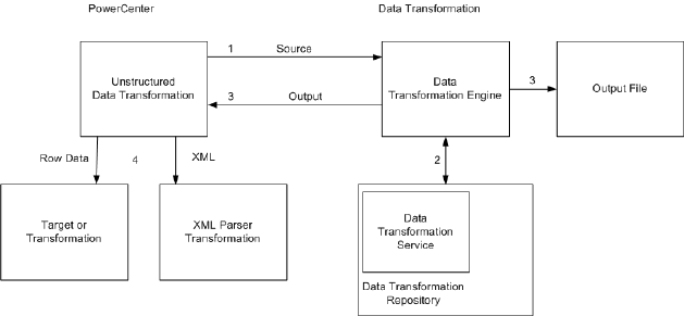
XML data. You can configure the Unstructured Data transformation to return the XML in an output port, or
you can configure output groups to return row data.
The following figure shows the interface between the PowerCenter Unstructured Data transformation and a
Data Transformation service that transforms data from a PowerCenter session:
The following events occur when you call a Data Transformation service from a PowerCenter session:
1. The Unstructured Data transformation passes source data to Data Transformation Engine.
2. Data Transformation Engine runs a Data Transformation service to transform the data. The Data
Transformation service is in the Data Transformation repository folder.
3. Data Transformation Engine writes transformed data directly to output files, or it returns the transformed
data to the Unstructured Data transformation.
4. The Unstructured Data transformation returns XML data or data rows. If the Unstructured Data
transformation returns XML, connect the Unstructured Data transformation to an XML Parser
transformation in the mapping.
Configuring the Unstructured Data Option
The Unstructured Data transformation is installed with PowerCenter. Data Transformation has a separate
installer. Install the Data Transformation Server and Client components after you install PowerCenter.
To install the Unstructured Data option, complete the following steps:
1. Install PowerCenter.
2. Install Data Transformation.
When you install Data Transformation you are prompted to select a Java Runtime Environment. At the
prompt, browse to the JRE that is used by PowerCenter.
By default, the setup configures Data Transformation Engine to run in-process. To use Data
Transformation with the Unstructured Data transformation, do not configure Data Transformation to run
out-of-process.
3. Configure the Data Transformation repository folder.
434 Chapter 31: Unstructured Data Transformation
Configuring the Data Transformation Repository Directory
The Data Transformation repository contains executable Data Transformation services. When you install
Data Transformation, the installer creates the repository in the following folder:
<Data_Transformation_install_dir>\DataTransformation\ServiceDB
To configure a different repository folder location, open Data Transformation Configuration from the Start
menu. The repository location is in the following path in the Data Transformation configuration:
CM Configuration > CM Repository > File System > Base Path
If Data Transformation Studio can access the remote file system, you can change the Data Transformation
repository to a remote location and deploy services directly from Data Transformation Studio to the system
that runs the Integration Service.
Copy custom files from the
<Data_Transformation_install_dir>\DataTransformation\autoInclude\user
directory and the
<Data_Transformation_install_dir>\DataTransformation\externLibs\user
directory
to the same directories on the node that runs the Integration Service.
Data Transformation Service Types
When you create a project in Data Transformation Studio, you choose a Data Transformation service type to
define the project. Data Transformation has the following types of services that transform data:
•Parser. Converts source documents to XML. The output of a parser is always XML. The input can have
any format, such as text, HTML, Word, PDF, or HL7.
•Serializer. Converts an XML file to an output document of any format. The output of a serializer can be
any format, such as a text document, an HTML document, or a PDF.
•Mapper. Converts an XML source document to another XML structure or schema. A mapper processes
the XML input similarly to a serializer. It generates XML output similarly to a parser. The input and the
output are fully structured XML.
•Transformer. Modifies the data in any format. Adds, removes, converts, or changes text. Use transformers
with a parser, mapper, or serializer. You can also run a transformer as stand-alone component.
•Streamer. Splits large input documents, such as multi-gigabyte data streams, into segments. The
streamer processes documents that have multiple messages or records in them, such as HIPAA or EDI
files.
Unstructured Data Transformation Components
The Unstructured Data transformation contains the following tabs:
•Transformation. Enter the name and description of the transformation. The naming convention for an
Unstructured Data transformation is UD_TransformationName. You can also make the Unstructured Data
transformation reusable.
•Properties. Configure the Unstructured Data transformation general properties such as IsPartitionable and
Output is Repeatable.
•UDT Settings. Modify Unstructured Data transformation settings such as input type, output type, and
service name.
Data Transformation Service Types 435

•UDT Ports. Configure Unstructured Data transformation ports and attributes.
•Input Hierarchy. Define a hierarchy of input groups and ports to enable the Unstructured Data
transformation to read rows of data.
•Output Hierarchy. Define a hierarchy of output groups and ports to enable the Unstructured Data
transformation to write rows to relational targets.
Properties Tab
Configure the Unstructured Data transformation general properties on the Properties tab.
The following table describes properties on the Properties tab that you can configure:
Property Description
Tracing Level The amount of detail included in the session log when you run a session containing this
transformation. Default is Normal.
IsPartitionable The transformation can run in more than one partition. Select one of the following options:
- No. The transformation cannot be partitioned.
- Locally. The transformation can be partitioned, but the Integration Service must run all
partitions in the pipeline on the same node.
- Across Grid. The transformation can be partitioned, and the Integration Service can distribute
each partition to different nodes.
Default is Across Grid.
Output is
Repeatable
The order of the output data is consistent between session runs.
- Never. The order of the output data is inconsistent between session runs.
- Based On Input Order. The output order is consistent between session runs when the input
data order is consistent between session runs.
- Always. The order of the output data is consistent between session runs even if the order of the
input data is inconsistent between session runs.
Default is Never for active transformations. Default is Based On Input Order for passive
transformation runs.
Output is
Deterministic
Indicates whether the transformation generates consistent output data between session
runs. Enable this property to perform recovery on sessions that use this transformation.
Warning: If you configure a transformation as repeatable and deterministic, it is your responsibility to ensure
that the data is repeatable and deterministic. If you try to recover a session with transformations that do not
produce the same data between the session and the recovery, the recovery process can result in corrupted
data.
UDT Settings Tab
Configure the Unstructured Data transformation attributes on the UDT Settings tab.
436 Chapter 31: Unstructured Data Transformation

The following table describes the attributes on the UDT settings tab:
Attribute Description
InputType Type of input data that the Unstructured Data transformation passes to Data Transformation
Engine. Choose one of the following input types:
- Buffer. The Unstructured Data transformation receives source data in the InputBuffer port and
passes data from the port to Data Transformation Engine.
- File. The Unstructured Data transformation receives a source file path in the InputBuffer port and
passes the source file path to Data Transformation Engine. Data Transformation Engine opens
the source file.
OutputType Type of output data that the Unstructured Data transformation or Data Transformation Engine
returns. Choose one of the following output types:
- Buffer. The Unstructured Data transformation returns XML data through the OutputBuffer port
unless you configure a relational hierarchy of output ports. If you configure a relational hierarchy
of ports, the Unstructured Data transformation does not write to the OutputBuffer port.
- File. Data Transformation Engine writes the output to a file. It does not return the data to the
Unstructured Data transformation unless you configure a relational hierarchy of ports in the
Unstructured Data transformation.
- Splitting.The Unstructured Data transformation splits a large XML output file into smaller files that
can fit in the OutputBuffer port. You must pass the split XML files to the XML Parser
transformation.
ServiceName Name of the Data Transformation service to run. The service must be present in the local Data
Transformation repository.
Streamer Chunk
Size
Buffer size of the data that the Unstructured Data transformation passes to Data
Transformation Engine when the Data Transformation service runs a streamer. Valid values
are 1-1,000,000 KB. Default is 256 KB.
Dynamic
Service Name
Run a different Data Transformation service for each input row. When Dynamic Service Name
is enabled, the Unstructured Data transformation receives the service name in the Service
Name input port.
When Dynamic Service name is disabled, the Unstructured Data transformation runs the same
service for each input row. The Service Name attribute in the UDT Settings must contain a
service name. Default is disabled.
Status Tracing
Level
Set the level of status messages from the Data Transformation service.
- Description Only. Return a status code and a short description to indicate if the Data
Transformation service was successful or if it failed.
- Full Status. Return a status code and a status message from the Data Transformation service in
XML.
- None. Do not return status from the Data Transformation service. Default is none.
Allow Input
Flush
Enable Allow Input Flush when you configure input groups of ports.
The Unstructured Data transformation creates XML when it has all the data for a group.
Configure the mapping so the transformation receives data that is sorted by group.
When input flush is not enabled, the Unstructured Data transformation stores the data in
memory and creates the XML after it receives data for all the groups.
Viewing Status Tracing Messages
You can view status messages from the Data Transformation service. Set the status tracing level to
Description Only or Full Status. The Designer creates the UDT_Status_Code port and the
UDT_Status_Message output ports in the Unstructured Data transformation.
Unstructured Data Transformation Components 437

When you choose Description Only, Data Transformation Engine returns a status code and one of the
following status messages:
Status Code Status Message
1 Success
2 Warning
3 Failure
4 Error
5 Fatal Error
When you choose Full Status, Data Transformation Engine returns a status code and the error message from
the Data Transformation service. The message is in XML format.
Unstructured Data Transformation Ports
When you create an Unstructured Data transformation, the Designer creates default ports. It creates other
ports based on how you configure the transformation. The Unstructured Data transformation input and output
types determine how the Unstructured Data transformation passes data to and receives data from Data
Transformation Engine.
The following table describes the Unstructured Data transformation default ports:
Port Input/ Output Description
InputBuffer Input Receives source data when the input type is buffer.
Receives a source file name and path when the input type is file.
OutputBuffer Output Returns XML data when the output type is buffer.
Returns the output file name when the output type is file.
Returns no data when you configure hierarchical output groups of ports.
The following table describes other Unstructured Data transformation ports that the Designer creates when
you configure the transformation:
Port Input/
Output
Description
OutputFileName Input Receives a name for an output file when the output type is file.
ServiceName Input Receives the name of a Data Transformation service when you enable
Dynamic Service Name.
438 Chapter 31: Unstructured Data Transformation

Port Input/
Output
Description
UDT_Status_Code Output Returns a status code from Data Transformation Engine when the
status tracing level is Description Only or Full Status.
UDT_Status_ Message Output Returns a status message from Data Transformation Engine when the
status tracing level is Description Only or Full Status.
Note: You can add groups of output ports for relational targets on the Input or Output Hierarchy tabs. When
you configure groups of ports, a message appears on the UDT Ports tab that says hierarchical groups and
ports are defined on another tab.
Input and Output Types
The input type determines the type of data that the Integration Service passes to Data Transformation
Engine. The input type determines whether the input is data or a source file path.
Configure one of the following input types:
•Buffer. The Unstructured Data transformation receives source data in the InputBuffer port. The Integration
Service passes source rows from the InputBuffer port to Data Transformation Engine.
•File. The Unstructured Data transformation receives the source file path in the InputBuffer port. The
Integration Service passes the source file path to Data Transformation Engine. Data Transformation
Engine opens the source file. Use the File input type to parse binary files such as Microsoft Excel or
Microsoft Word files.
If you do not define output groups and ports, the Unstructured Data transformation returns data based on the
output type.
Configure one of the following output types:
•Buffer. The Unstructured Data transformation returns XML through the Outputbuffer port. You must
connect an XML Parser transformation to the Outputbuffer port.
•File. Data Transformation Engine writes the output file instead of passing data to the Integration Service.
Data Transformation Engine names the output file based on the file name from the OutputFilename port.
Choose the File output type to transform XML to binary data such as a PDF file or a Microsoft Excel file.
The Integration Service returns the output file name in the OutputBuffer port for each source row. If the
output file name is blank, the Integration Service returns a row error. When an error occurs, the
Integration Service writes a null value to the OutputBuffer and returns a row error.
•Splitting. The Unstructured Data transformation splits XML data from Data Transformation Engine into
multiple segments. Choose the Splitting output type when the Unstructured Data transformation returns
XML files that are too large for the OutputBuffer port. When you configure Splitting output, pass the XML
data to the XML Parser transformation. Configure the XML Parser transformation to process the multiple
XML rows as one XML file.
Additional Unstructured Data Transformation Ports
A Data Transformation service might require multiple input files, file names, and parameters. It can return
multiple output files. When you create an Unstructured Data transformation, the Designer creates one
InputBuffer port and one OutputBuffer port. If you need to pass additional files or file names between the
Unstructured Data transformation and Data Transformation Engine, add the input or output ports. You can
add ports manually or from the Data Transformation service.
Unstructured Data Transformation Ports 439

The following table describes the ports you can create on the UDT Ports tab:
Port Type Input/ Output Description
Additional Input (buffer) Input Receives input data to pass to Data Transformation Engine.
Additional Input (file) Input Receives the file name and path for Data Transformation Engine to
open.
Service Parameter Input Receives an input parameter for a Data Transformation service.
Additional Output (buffer) Output Receives XML data from Data Transformation Engine.
Additional Output
(file)
Output Receives an output file name from Data Transformation Engine.
Pass-through Input/
Output
Passes data through the Unstructured Data transformation without
changing it.
Creating Ports From a Data Transformation Service
A Data Transformation service can require input parameters, additional input files, or user-defined variables.
The service might return more than one output file to the Unstructured Data transformation. You can add
ports that pass parameters, additional input files, and additional output files. The Designer creates ports that
correspond to the ports in the Data Transformation service.
Note: You must configure a service name to populate ports from a service.
1. Click the Ports tab on the Unstructured Data transformation.
2. Click Populate From Service.
The Designer displays the service parameters, additional input port, and additional output port
requirements from the Data Transformation service. Service parameters include Data Transformation
system variables and user-defined variables.
3. Select the ports to create and configure each port as a buffer port or file port.
4. Click Populate to create the ports that you select. You can select all ports that appear.
Unstructured Data Transformation Service Names
When you create an Unstructured Data transformation, the Designer displays a list of the Data
Transformation services that are in the Data Transformation repository. Choose the name of a Data
Transformation service that you want to call from the Unstructured Data transformation. You can change the
service name after you create the transformation. The service name appears on the UDT Settings tab.
To run a different Data Transformation service for each source row, enable the Dynamic Service Name
attribute. Pass the service name with each source row. The Designer creates the ServiceName input port
when you enable dynamic service names.
When you enable dynamic service names, you cannot create ports from a Data Transformation service.
When you define a relational structure of input ports, you cannot enable dynamic service names. Each Data
Transformation service might require different input data.
440 Chapter 31: Unstructured Data Transformation
Relational Hierarchies
You can define groups of ports and define a relational structure for the groups. To build a hierarchy of input
ports, configure ports on the Input Hierarchy tab. To pass row data to relational tables or other targets,
configure output ports on the Output Hierarchy tab.
When you define a relational structure of input ports, the Unstructured Data transformation generates XML to
pass to a Data Transformation service. To increase performance, enable the PowerCenter Integration
Service to flush XML to the Unstructured Data transformation. When you enable input flushing, the
PowerCenter Integration Service flushes XML from each group after it receives all the data for the root value.
For example, you have an employee group and an employee address group. The PowerCenter Integration
Service can flush data from both groups to the Unstructured Data transformation each time a different
employee occurs in the data. You must sort the data in each group by the primary key of the root group. You
can join groups in the pipeline if a group does not have the same key.
When you configure output groups, the output groups represent the relational tables or the targets that you
want to pass the output data to. Data Transformation Engine returns rows to the group ports instead of
writing an XML file to the OutputBuffer port. The transformation writes rows based on the output type.
Create a hierarchy of groups in the left pane of the Output Hierarchy tab. All groups are under the root
group. You cannot delete the root. Each group can contain ports and other groups. The group structure
represents the relationship between target tables. When you define a group within a group, you define a
parent-child relationship between the groups. The Designer defines a primary key-foreign key relationship
between the groups with a generated key.
Select a group to display the ports for the group. You can add or delete ports in the group. When you add a
port, the Designer creates a default port configuration. Change the port name, datatype, and precision. If the
port must contain data, select Not Null. Otherwise, the output data is optional.
When you view the Unstructured Data transformation in the workspace, each port in a transformation group
has a prefix that contains the group name.
When you delete a group, you delete the ports in the group and the child groups.
Exporting the Hierarchy Schema
When you define hierarchical output groups in the Unstructured Data transformation, you must define the
same structure in the Data Transformation project that you create to transform the data. Export the hierarchy
structure as an XML schema file from the Unstructured Data transformation. Import the schema to your Data
Transformation project. You can then map the content of a source document to the XML elements and
attributes in the Data Transformation project.
To export the group hierarchy from the Relational Hierarchy tab, click Export to XML Schema. Choose a
name and a location for the XSD file. Choose a location that you can access when you import the schema
with Data Transformation Studio.
The Designer creates a schema with the following namespace:
"www.informatica.com/UDT/XSD/<mappingName_<Transformation_Name>>"
The schema includes the following comment:
<!-- ===== AUTO-GENERATED FILE - DO NOT EDIT ===== -->
<!-- ===== This file has been generated by Informatica PowerCenter ===== -->
If you modify the schema, Data Transformation Engine might return data that is not the same format as the
output ports in the Unstructured Data transformation.
The XML elements in the schema represent the output ports in the hierarchy. Columns that can contain null
values have a minOccurs=0 and maxOccurs=1 XML attribute.
Relational Hierarchies 441
Mappings
When you create a mapping, design it according to the type of Data Transformation project you are going to
run. For example, the Data Transformation parser and mapper generate XML data. You can configure the
Unstructured Data transformation to return rows from the XML data or you can configure it to return an XML
file.
The Data Transformation serializer component can generate any output from XML. It can generate HTML or
binary files such as Microsoft Word or Microsoft Excel. When the output is binary data, Data Transformation
Engine writes the output to a file instead of passing it back to the Unstructured Data transformation.
The following examples show how to configure mappings with an Unstructured Data transformation.
Parsing Word Documents for Relational Tables
You can extract order information from a Microsoft Word document and write the order information to an
order header table and an order detail table. Configure an Unstructured Data transformation to call a Data
Transformation parser service and pass the name of each Word document to parse. Data Transformation
Engine opens the Word document, parses it, and returns the rows to the Unstructured Data transformation.
The Unstructured Data transformation passes the order header and order details to the relational targets.
The mapping has the following objects:
•Source Qualifier transformation. Passes each Microsoft Word file name to the Unstructured Data
transformation. The source file name contains the complete path to the file that contains order information.
•Unstructured Data transformation. The input type is file. The output type is buffer. The transformation
contains an order header output group and an order detail output group. The groups have a primary key-
foreign key relationship.
The Unstructured Data transformation receives the source file name in the InputBuffer port. It passes the
name to Data Transformation Engine. Data Transformation Engine runs a parser service to extract the
order header and order detail rows from the Word document. Data Transformation Engine returns the data
to the Unstructured Data transformation. The Unstructured Data transformation passes data from the
order header group and order detail group to the relational targets.
•Relational targets. Receive the rows from the Unstructured Data transformation.
Creating an Excel Sheet from XML
You can extract employee names and addresses from an XML file and create a Microsoft Excel sheet with
the list of names.
The mapping has the following components:
•XML source file. Contains employee names and addresses.
•Source Qualifier transformation. Passes XML data and an output file name to the Unstructured Data
transformation. The XML file contains employee names.
•Unstructured Data transformation. The input type is buffer and the output type is file. The Unstructured
Data transformation receives the XML data in the InputBuffer port and the file name in the
OutputFileName port. It passes the XML data and the file name to Data Transformation Engine.
Data Transformation Engine runs a serializer service to transform the XML data to a Microsoft Excel file. It
writes the Excel file with a file name based on the value of OutputFilename.
The Unstructured Data transformation receives only the output file name from Data Transformation
Engine. The Unstructured Data transformation OutputBuffer port returns the value of OutputFilename.
•Flat file target. Receives the output file name.
442 Chapter 31: Unstructured Data Transformation
Split XML File Output
The Data Transformation parser and mapper components can transform data from any format and generate
XML data. When the XML data is large, you can split the XML into segments and pass the segments to an
XML Parser transformation. The XML Parser transformation receives the segments and processes the XML
data as one document.
When you configure the Unstructured Data transformation to split XML output, the Unstructured Data
transformation returns XML based on the OutputBuffer port size. If the XML file size is greater than the output
port precision, the Integration Service divides the XML into files equal to or less than the port size. The XML
Parser transformation parses the XML and passes the rows to relational tables or other targets.
For example, you can extract the order header and detail information from Microsoft Word documents with a
Data Transformation parser service.
The mapping has the following components:
•Source Qualifier transformation. Passes the Word document file name to the Unstructured Data
transformation. The source file name contains the complete path to the file that contains order information.
•Unstructured Data transformation. The input type is file. The output type is splitting. The Unstructured
Data transformation receives the source file name in the InputBuffer port. It passes the file name to Data
Transformation Engine. Data Transformation Engine opens the source file, parses it, and returns XML
data to the Unstructured Data transformation.
The Unstructured Data transformation receives the XML data, splits the XML file into smaller files, and
passes the segments to an XML Parser transformation. The Unstructured Data transformation returns
data in segments less than the OutputBuffer port size. When the transformation returns XML data in
multiple segments, it generates the same pass-through data for each row. The Unstructured Data
transformation returns data in pass-through ports when a row is successful or not successful.
•XML Parser transformation. The Enable Input Streaming session property is enabled. The XML Parser
transformation receives the XML data in the DataInput port. The input data is split into segments. The
XML Parser transformation parses the XML data into order header and detail rows. It passes order header
and detail rows to relational targets. It returns the pass-through data to a Filter transformation.
•Filter transformation. Removes the duplicate pass-through data before passing it to the relational targets.
•Relational targets. Receive data from each group in the XML Parser transformation and the Filter
transformation.
Rules and Guidelines for Unstructured Data Mappings
Use the following rules and guidelines when you create an unstructured data mapping:
•When you configure hierarchical groups of output ports, the Integration Service writes to the groups of
ports instead of writing to the OutputBuffer port. The Integration Service writes to the groups of ports
regardless of the output type you define for the transformation.
•If an Unstructured Data transformation has the File output type, and you have not defined group output
ports, you must link the OutputBuffer port to a downstream transformation. Otherwise, the mapping is
invalid. The OutputBuffer port contains the output file name when the Data Transformation service writes
the output file.
•Enable Dynamic Service Name to pass a service name to the Unstructured Data transformation in the
Service Name input port. When you enable Dynamic Service Name, the Designer creates the Service
Name input port.
•You must configure a service name with the Unstructured Data transformation or enable the Dynamic
Service Name option. Otherwise the mapping is invalid.
•Link XML output from the Unstructured Data transformation to an XML Parser transformation.
Mappings 443

Creating an Unstructured Data Transformation
Use the PowerCenter Transformation Developer or the Mapping Designer to create an Unstructured Data
transformation.
1. In the Mapping Designer or Transformation Developer, click Transformation > Create.
2. Select Unstructured Data Transformation as the transformation type.
3. Enter a name for the transformation.
4. Click Create.
The Unstructured Data Transformation dialog box appears.
5. Configure the following properties:
Property Description
Service Name Name of the Data Transformation service you want to use. The Designer displays the Data
Transformation services in the Data Transformation repository folder. Do not choose a
name if you plan to enable dynamic service names. You can add a service name on the
UDT Settings tab after you create the transformation.
Input Type Describes how Data Transformation Engine receives input data. Default is Buffer.
Output Type Describes how Data Transformation Engine returns output data. Default is Buffer.
6. Click OK.
7. You can change the service name, input, and output type on the UDT Settings tab.
8. Configure the Unstructured Data transformation properties on the Properties tab.
9. If the Data Transformation service has more than one input or output file, or if it requires input
parameters, you can add ports on the UDT Ports tab. You can also add pass-through ports on the Ports
tab.
10. If you want to return row data from the Unstructured Data transformation instead of XML data, create
groups of output ports on the Relational Hierarchy tab.
11. If you create groups of ports, export the schema that describes them from the Relational Hierarchy tab.
12. Import the schema to the Data Transformation project to define the project output.
444 Chapter 31: Unstructured Data Transformation

CHAPTER 3 2
Update Strategy Transformation
This chapter includes the following topics:
•Update Strategy Transformation Overview, 445
•Flagging Rows Within a Mapping, 446
•Setting the Update Strategy for a Session, 448
•Update Strategy Checklist, 449
Update Strategy Transformation Overview
The Update Strategy transformation is an active transformation. When you design a data warehouse, you
need to decide what type of information to store in targets. As part of the target table design, you need to
determine whether to maintain all the historic data or just the most recent changes.
For example, you might have a target table, T_CUSTOMERS, that contains customer data. When a customer
address changes, you may want to save the original address in the table instead of updating that portion of
the customer row. In this case, you would create a new row containing the updated address, and preserve
the original row with the old customer address. This shows how you might store historical information in a
target table. However, if you want the T_CUSTOMERS table to be a snapshot of current customer data, you
would update the existing customer row and lose the original address.
The model you choose determines how you handle changes to existing rows. In PowerCenter, you set the
update strategy at two different levels:
•Within a session. When you configure a session, you can instruct the Integration Service to either treat
all rows in the same way (for example, treat all rows as inserts), or use instructions coded into the session
mapping to flag rows for different database operations.
•Within a mapping. Within a mapping, you use the Update Strategy transformation to flag rows for insert,
delete, update, or reject.
Note: You can also use the Custom transformation to flag rows for insert, delete, update, or reject.
Setting the Update Strategy
To define an update strategy, complete the following steps:
1. To control how rows are flagged for insert, update, delete, or reject within a mapping, add an Update
Strategy transformation to the mapping. Update Strategy transformations are essential if you want to flag
rows destined for the same target for different database operations, or if you want to reject rows.
445

2. Define how to flag rows when you configure a session. You can flag all rows for insert, delete, or update,
or you can select the data driven option, where the Integration Service follows instructions coded into
Update Strategy transformations within the session mapping.
3. Define insert, update, and delete options for each target when you configure a session. On a target-by-
target basis, you can allow or disallow inserts and deletes, and you can choose three different ways to
handle updates.
RELATED TOPICS:
•“Setting the Update Strategy for a Session” on page 448
Flagging Rows Within a Mapping
For the greatest degree of control over the update strategy, you add Update Strategy transformations to a
mapping. The most important feature of this transformation is its update strategy expression, used to flag
individual rows for insert, delete, update, or reject.
The following table lists the constants for each database operation and their numeric equivalent:
Operation Constant Numeric Value
Insert DD_INSERT 0
Update DD_UPDATE 1
Delete DD_DELETE 2
Reject DD_REJECT 3
The Integration Service treats any other value as an insert.
Forwarding Rejected Rows
You can configure the Update Strategy transformation to either pass rejected rows to the next transformation
or drop them. By default, the Integration Service forwards rejected rows to the next transformation. The
Integration Service flags the rows for reject and writes them to the session reject file. If you do not select
Forward Rejected Rows, the Integration Service drops rejected rows and writes them to the session log file.
If you enable row error handling, the Integration Service writes the rejected rows and the dropped rows to the
row error logs. It does not generate a reject file. If you want to write the dropped rows to the session log in
addition to the row error logs, you can enable verbose data tracing.
Update Strategy Expressions
Frequently, the update strategy expression uses the IIF or DECODE function from the transformation
language to test each row to see if it meets a particular condition. If it does, you can then assign each row a
numeric code to flag it for a particular database operation. For example, the following IIF statement flags a
row for reject if the entry date is after the apply date. Otherwise, it flags the row for update:
IIF( ( ENTRY_DATE > APPLY_DATE), DD_REJECT, DD_UPDATE )
446 Chapter 32: Update Strategy Transformation
To create an Update Strategy transformation:
1. In the Mapping Designer, add an Update Strategy transformation to a mapping.
2. Click Layout > Link Columns.
3. Drag all ports from another transformation representing data you want to pass through the Update
Strategy transformation.
In the Update Strategy transformation, the Designer creates a copy of each port you drag. The Designer
also connects the new port to the original port. Each port in the Update Strategy transformation is a
combination input/output port.
Normally, you would select all of the columns destined for a particular target. After they pass through the
Update Strategy transformation, this information is flagged for update, insert, delete, or reject.
4. Open the Update Strategy transformation and rename it.
The naming convention for Update Strategy transformations is UPD_TransformationName.
5. Click the Properties tab.
6. Click the button in the Update Strategy Expression field.
The Expression Editor appears.
7. Enter an update strategy expression to flag rows as inserts, deletes, updates, or rejects.
8. Validate the expression and click OK.
9. Click OK.
10. Connect the ports in the Update Strategy transformation to another transformation or a target instance.
Aggregator and Update Strategy Transformations
When you connect Aggregator and Update Strategy transformations as part of the same pipeline, put the
Aggregator before the Update Strategy transformation. In this order, the Integration Service performs the
aggregate calculation, and then flags rows that contain the results of this calculation for insert, update,
delete, or reject.
If you put the Update Strategy before the Aggregator transformation, you must consider how the Aggregator
transformation handles rows flagged for different operations. In this order, the Integration Service flag rows
for insert, update, delete, or reject before it performs the aggregate calculation. How you flag a row
determines how the Aggregator transformation treats values in that row used in the calculation. For example,
if you flag a row for delete and then use the row to calculate the sum, the Integration Service subtracts the
value in this row. If you flag a row for reject and then use the row to calculate the sum, the Integration Service
does not include the value in this row. If you flag a row for insert or update and then use the row to calculate
the sum, the Integration Service adds the value in this row to the sum.
Lookup and Update Strategy Transformations
When you create a mapping with a Lookup transformation that uses a dynamic lookup cache, you must use
Update Strategy transformations to flag the rows for the target tables. When you configure a session using
Update Strategy transformations and a dynamic lookup cache, you must define certain session properties.
You must define the Treat Source Rows As option as Data Driven. Specify this option on the Properties tab in
the session properties.
You must also define the following update strategy target table options:
•Select Insert
•Select Update as Update
•Do not select Delete
Flagging Rows Within a Mapping 447

These update strategy target table options ensure that the Integration Service updates rows marked for
update and inserts rows marked for insert.
If you do not choose Data Driven, the Integration Service flags all rows for the database operation you
specify in the Treat Source Rows As option and does not use the Update Strategy transformations in the
mapping to flag the rows. The Integration Service does not insert and update the correct rows. If you do not
choose Update as Update, the Integration Service does not correctly update the rows flagged for update in
the target table. As a result, the lookup cache and target table might become unsynchronized.
Setting the Update Strategy for a Session
When you configure a session, you have several options for handling database operations, including
updates.
Specifying an Operation for All Rows
When you configure a session, you can select a single database operation for all rows using the Treat Source
Rows As setting.
The following table displays the options for the Treat Source Rows As setting:
Setting Description
Insert Treat all rows as inserts. If inserting the row violates a primary or foreign key constraint in the
database, the Integration Service rejects the row.
Delete Treat all rows as deletes. For each row, if the Integration Service finds a corresponding row in
the target table (based on the primary key value), the Integration Service deletes it. Note that
the primary key constraint must exist in the target definition in the repository.
Update Treat all rows as updates. For each row, the Integration Service looks for a matching primary
key value in the target table. If it exists, the Integration Service updates the row. The primary
key constraint must exist in the target definition.
Data Driven Integration Service follows instructions coded into Update Strategy and Custom transformations
within the session mapping to determine how to flag rows for insert, delete, update, or reject.
If the mapping for the session contains an Update Strategy transformation, this field is marked
Data Driven by default.
If you do not choose Data Driven when a mapping contains an Update Strategy or Custom
transformation, the Workflow Manager displays a warning. When you run the session, the
Integration Service does not follow instructions in the Update Strategy or Custom transformation
in the mapping to determine how to flag rows.
The following table describes the update strategy for each setting:
Setting Use To
Insert Populate the target tables for the first time, or maintain a historical data warehouse. In the latter
case, you must set this strategy for the entire data warehouse, not just a select group of target
tables.
Delete Clear target tables.
448 Chapter 32: Update Strategy Transformation

Setting Use To
Update Update target tables. You might choose this setting whether the data warehouse contains
historical data or a snapshot. Later, when you configure how to update individual target tables,
you can determine whether to insert updated rows as new rows or use the updated information to
modify existing rows in the target.
Data Driven Exert finer control over how you flag rows for insert, delete, update, or reject. Choose this setting
if rows destined for the same table need to be flagged on occasion for one operation (for example,
update), or for a different operation (for example, reject). In addition, this setting provides the only
way you can flag rows for reject.
Specifying Operations for Individual Target Tables
Once you determine how to treat all rows in the session, you also need to set update strategy options for
individual targets. Define the update strategy options in the Transformations view on Mapping tab of the
session properties.
You can set the following update strategy options:
•Insert. Select this option to insert a row into a target table.
•Delete. Select this option to delete a row from a table.
•Update. You have the following options in this situation:
-Update as Update. Update each row flagged for update if it exists in the target table.
-Update as Insert. Insert each row flagged for update.
-Update else Insert. Update the row if it exists. Otherwise, insert it.
•Truncate table. Select this option to truncate the target table before loading data.
Update Strategy Checklist
Choosing an update strategy requires setting the right options within a session and possibly adding Update
Strategy transformations to a mapping. This section summarizes what you need to implement different
versions of an update strategy.
•Only perform inserts into a target table.
When you configure the session, select Insert for the Treat Source Rows As session property. Also, make
sure that you select the Insert option for all target instances in the session.
•Delete all rows in a target table.
When you configure the session, select Delete for the Treat Source Rows As session property. Also,
make sure that you select the Delete option for all target instances in the session.
•Only perform updates on the contents of a target table.
When you configure the session, select Update for the Treat Source Rows As session property. When you
configure the update options for each target table instance, make sure you select the Update option for
each target instance.
•Perform different database operations with different rows destined for the same target table.
Update Strategy Checklist 449
Add an Update Strategy transformation to the mapping. When you write the transformation update
strategy expression, use either the DECODE or IIF function to flag rows for different operations (insert,
delete, update, or reject). When you configure a session that uses this mapping, select Data Driven for the
Treat Source Rows As session property. Make sure that you select the Insert, Delete, or one of the
Update options for each target table instance.
•Reject data.
Add an Update Strategy transformation to the mapping. When you write the transformation update
strategy expression, use DECODE or IIF to specify the criteria for rejecting the row. When you configure a
session that uses this mapping, select Data Driven for the Treat Source Rows As session property.
450 Chapter 32: Update Strategy Transformation

CHAPTER 3 3
XML Transformations
This chapter includes the following topics:
•XML Source Qualifier Transformation, 451
•XML Parser Transformation, 451
•XML Generator Transformation, 452
XML Source Qualifier Transformation
You can add an XML Source Qualifier transformation to a mapping by dragging an XML source definition to
the Mapping Designer workspace or by manually creating one. When you add an XML source definition to a
mapping, you need to connect it to an XML Source Qualifier transformation. The XML Source Qualifier
transformation defines the data elements that the Integration Service reads when it executes a session. It
determines how the PowerCenter reads the source data. The XML Source Qualifier transformation is an
active transformation.
An XML Source Qualifier transformation always has one input or output port for every column in the XML
source. When you create an XML Source Qualifier transformation for a source definition, the Designer links
each port in the XML source definition to a port in the XML Source Qualifier transformation. You cannot
remove or edit any of the links. If you remove an XML source definition from a mapping, the Designer also
removes the corresponding XML Source Qualifier transformation. You can link one XML source definition to
one XML Source Qualifier transformation
You can link ports of one XML Source Qualifier group to ports of different transformations to form separate
data flows. However, you cannot link ports from more than one group in an XML Source Qualifier
transformation to ports in the same target transformation.
You can edit some of the properties and add metadata extensions to an XML Source Qualifier transformation.
XML Parser Transformation
Use an XML Parser transformation to extract XML inside a pipeline. The XML Parser transformation lets you
extract XML data from messaging systems, such as TIBCO or MQ Series, and from other sources, such as
files or databases. The XML Parser transformation functionality is similar to the XML source functionality,
except it parses the XML in the pipeline. For example, you might want to extract XML data from a TIBCO
source and pass the data to relational targets. The XML Parser transformation is an active transformation.
451
The XML Parser transformation reads XML data from a single input port and writes data to one or more
output ports.
XML Generator Transformation
Use an XML Generator transformation to create XML inside a pipeline. The XML Generator transformation
lets you read data from messaging systems, such as TIBCO and MQ Series, or from other sources, such as
files or databases. The XML Generator transformation functionality is similar to the XML target functionality,
except it generates the XML in the pipeline. For example, you might want to extract data from relational
sources and pass XML data to targets. The XML Generator transformation is an active transformation.
The XML Generator transformation accepts data from multiple ports and writes XML through a single output
port.
452 Chapter 33: XML Transformations

IN D E X
A
ABORT function
using 15
active transformations
Aggregator 24
Custom 34
Filter 169
Java 188, 189
Joiner 233
Normalizer 306
overview 1
Rank 324
Router 329
Sorter 345
Source Qualifier 350, 371
Transaction Control 425
Union 430
Update Strategy 445
XML Generator 452
XML Parser 451
XML Source Qualifier 451
Add Statistic Output Port (property)
SQL transformation 391
adding
comments to expressions 9
groups 333
address.dic
masking data 126
advanced interface
EDataType class 220
example 222
invoking Java expressions 219
Java expressions 219
JExpression class 221, 223
JExprParaMetadata class 220
advanced options
SQL transformation 380
aggregate functions
list of 27
null values 28
overview 27
using in expressions 27
Aggregator transformation
compared to Expression transformation 24
components 25
conditional clause example 28
creating 32
functions list 27
group by ports 28
nested aggregation 27
non-aggregate function example 28
null values 28
optimizing performance 32
overview 24
ports 26
Aggregator transformation (continued)
sorted ports 30
STDDEV (standard deviation) function 27
tracing levels 25
troubleshooting 33
Update Strategy combination 447
using variables 11
using with the Joiner transformation 240
VARIANCE function 27
All Input transformation scope
behavior in Joiner transformation 243
API functions
Custom transformation 68
API methods
Java transformation 204
Java transformations 204
array-based functions
data handling 95
is row valid 94
maximum number of rows 92
number of rows 93
overview 92
row strategy 97
set input error row 98
ASCII
Custom transformation 35
External Procedure transformation 136
ASCII mode
configuring sort order for Joiner transformation 238
associated ports
Lookup transformation 290
sequence ID 290
auto-commit
configuring with SQL transformation 383
description 391
AutoCommit
SQL Settings tab 391
B
BankSoft example
Informatica external procedure 146
overview 137
Base URL
configuring 178
BigDecimal datatype
Java transformation 201
blocking
detail rows in Joiner transformation 243
blocking data
Custom transformation 43
Custom transformation functions 87
Joiner transformation 243
blocking transformations
description 7
453

blurring
date values 116
numeric values 116
C
C/C++
linking to Integration Service 158
cache directories
configuring lookup cache directory name 256
cache directory
Data Masking transformation 124
Cache Directory (property)
Joiner transformation 234
cache file name
specifying for persistent lookup cache 256
cache file name prefix
overview 281
Cache File Name Prefix (property)
description 256
cache size
Data Masking transformation 124
caches
concurrent 277, 278
dynamic lookup cache 288
Joiner transformation 243
Lookup transformation 275
named persistent lookup 281
sequential 277
sharing lookup 281
static lookup cache 280
caching
master rows in Joiner transformation 243
calculations
aggregate 24
using the Expression transformation 132
using variables with 11
call text
stored procedure, entering 419
Call Text (property)
Stored Procedure transformation 414
Case Sensitive (property)
Sorter transformation 347
Class Name (property)
Java transformation 193
CLASSPATH
Java transformation, configuring 199
COBOL
VSAM Normalizer transformation 311
COBOL source definitions
creating a Normalizer transformation 314
OCCURS statement 311
code page ID
Custom transformation, changing 89
code pages
access functions 166
Custom transformation 35
External Procedure transformation 136
code snippets
creating for Java transformations 196
COM external procedures
adding to repository 143
compared to Informatica external procedures 137
creating 139
creating a source 143
creating a target 143
datatypes 156
COM external procedures (continued)
debugging 158
developing in Visual Basic 145
developing in Visual C++ 140, 143
development notes 156
distributing 155
exception handling 157
initializing 160
memory management 157
overview 139
registering with repositories 143
return values 157
row-level procedures 157
server type 139
unconnected 159
COM servers
type for COM external procedures 139
comments
adding to expressions 9
commit
Java transformation API method 205
company_names.dic
masking data 126
compilation errors
identifying the source of in Java transformations 202
compiling
Custom transformation procedures 54
DLLs on Windows systems 152
Java transformations 201
composite keys
creating with Sequence Generator transformation 336
concurrent caches
See caches 277
conditions
Filter transformation 170
Joiner transformation 235
Lookup transformation 266, 270
Router transformation 331
configuring
ports 5, 6
connect string
syntax 380
connected lookups
creating 272
description 252
overview 253
connected transformations
Aggregator 24
Custom 34
Expression 132
Filter 169
Java 188
Joiner 233
Lookup 248
Normalizer 306
Rank 324
Router 329
Sequence Generator 335
Source Qualifier 350
SQL 371
Stored Procedure 405
Union transformation 430
Update Strategy 445
XML Generator 452
XML Parser 451
XML Source Qualifier 451
connecting to databases
SQL transformation 378
454 Index

Connection Information (property)
Lookup transformation 256
Stored Procedure transformation 414
connection objects
configuring in Lookup transformations 256
configuring in Stored Procedure transformations 414
connection settings
SQL transformation 379
connection variables
using in Lookup transformations 256
using in Stored Procedure transformations 414
connections
SQL transformation 378
connectivity
connect string examples 380
constants
replacing null values with 15
Continue on SQL Error Within Row (property)
SQL transformation 391
creating
Aggregator transformation 32
COM external procedures 139
Custom transformation 36, 46
Expression transformation 133
Filter transformation 171
Informatica external procedures 146
Joiner transformation 245
non-reusable instance of reusable transformation 22
ports 6
Rank transformation 327
reusable transformations 21
Router transformation 334
Sequence Generator transformation 344
Stored Procedure transformation 412
transformations 4
Union transformation 431
Update Strategy transformation 446
current value
Sequence Generator transformation 341
Current Value (property)
Sequence Generator transformation 339
CURRVAL port
Sequence Generator transformation 339
custom functions
using with Java expressions 215
Custom transformation
blocking data 43
building the module 54
code pages 35
compiling procedures 54
components 37
creating 36, 46
creating groups 37
creating ports 37
creating procedures 45
defining port relationships 38
distributing 36
functions 58
Generate Transaction property 42
generating code files 36, 48
initialization properties 45
Inputs May Block property 43
Is Partitionable (property) 39
metadata extensions 45
overview 34
passing rows to procedure 62
port attributes 38
procedure properties 45
Custom transformation (continued)
properties 39
property IDs 73
Requires Single Thread property 39
rules and guidelines 36
setting the update strategy 41
thread-specific code 39
threads 41
transaction boundary 43
transaction control 42
Transformation Scope property 42
Update Strategy property 41
Custom transformation functions
API 68
array-based 92
blocking logic 87
change default row strategy 91
change string mode 89
data boundary output 85
data handling (array-based) 95
data handling (row-based) 81
deinitialization 67
error 85
generated 63
increment error count 86
initialization 63
is row valid 94
is terminated 87
maximum number of rows 92
navigation 70
notification 65
number of rows 93
output notification 84
pointer 88
property 72
rebind datatype 79
row strategy (array-based) 97
row strategy (row-based) 90
session log 85
set data access mode 69
set data code page 89
set input error row 98
set pass-through port 83
working with handles 58, 70
Custom transformation procedures
creating 45
example 49
generating code files 48
thread-specific 39
working with rows 62
cycle
Sequence Generator transformation property 341
Cycle (property)
Sequence Generator transformation property 339
D
data
joining 233
pre-sorting 31
rejecting through Update Strategy transformation 449
selecting distinct 367
storing temporary 11
data access mode function
Custom transformation function 69
data driven
overview 448
Index 455

data handling functions
array-based 95
row-based 81
data masking
mapping with Expression transformation 129
mapping with Lookup transformation 126
data masking transformation
masking IP addresses 123
Data Masking transformation
blurring 116
cache directory 124
cache size 124
configuring relational dictionaries 109
connection requirements 109
Data Masking transformation 124
default value file 124
dependent data masking 109
dictionary for substitution masking 106
dictionary name expression masking 117
expression masking 117
expression masking guidelines 118
mask format 113
masking date values 116
masking email addresses 121
masking phone numbers 121
masking properties 102
masking Social Insurance numbers 123
masking social security numbers 119
masking URLs 123
random masking 111
range 115
repeatable dependent masking 111
repeatable expression masking 117
repeatable SIN numbers 123
repeatable SSN 120
rules and guidelines 125
session properties 124
shared storage table 124
source string characters 114
storage commit interval 124
storage table 117
storage tables 107
substitution masking 106
substitution masking properties 107, 108
unique output 124
using mapping parameters 103
Data Transformation
overview 433
repository location 435
database connections
SQL transformation 378
database resilience
SQL transformation 383
databases
joining data from different 233
options supported 421
datatypes
COM 156
Java transformations 189
Source Qualifier 351
transformation 156
date values
random data masking 112
datetime values
data masking 106
Source Qualifier transformation 351
DB2
See IBM DB2 380
debugging
external procedures 158
Java transformation 202
default groups
Router transformation 331
default join
Source Qualifier 355
default query
methods for overriding 354
overriding using Source Qualifier 357
overview 353
viewing 353
default values
Aggregator group by ports 30
data masking 124
entering 20
input ports 13, 14
output ports 13, 14
overview 13
pass-through ports 13, 14
rules for 19
user-defined 14
validating 20
defineJExpression
Java expression API method 221
defining
port dependencies in Custom transformation 38
deinitialization functions
Custom transformation 67
dependencies
ports in Custom transformations 38
dependent column
data masking 109
dependent masking
description 109
repeatable masking 111
detail outer join
description 238
detail rows
blocking in Joiner transformation 243
processing in sorted Joiner transformation 243
processing in unsorted Joiner transformation 243
developing
COM external procedures 139
Informatica external procedures 146
dictionary
repeatable expression masking 117
substitution data masking 106
dictionary information
Data Masking transformation 108
dispatch function
description 163
distinct output rows
Sorter transformation 347
distributing
Custom transformation procedures 36
external procedures 154
DLLs (dynamic linked libraries)
compiling external procedures 152
double datatypes
Java transformation 201
dynamic connections
performance considerations 381
SQL transformation 379
SQL transformation example 400
dynamic lookup cache
description 288
error threshold 299
456 Index

dynamic lookup cache (continued)
lookup SQL override 293
reject loading 299
synchronizing with target 299
using flat file sources 288
Dynamic Lookup Cache (property)
description 256
Dynamic Service Name
Unstructured Data transformation 437
dynamic SQL queries
SQL transformation 375
SQL transformation example 395
E
EDataType class
Java expressions 220
effective Transaction Control transformation
definition 427
Enable XML Input Streaming
XML Parser session property 443
encrypt storage
Data Masking transformation 124
End Value (property)
Sequence Generator transformation 339
entering
expressions 7, 9
source filters 365
SQL query override 357
user-defined joins 358
environment variables
setting for Java packages 199
error counts
incrementing for Java transformations 208
ERROR function
using 15
error handling
for stored procedures 420
with dynamic lookup cache 299
error messages
for external procedures 158
tracing for external procedures 158
error rows
SQL transformation 387
errors
handling 17
increasing threshold in Java transformations 208
validating in Expression Editor 10
with dynamic lookup cache 299
exactly-once delivery
SQL transformation 383
exceptions
from external procedures 157
Execution Order (property)
Stored Procedure transformation 414
export to XML schema
Unstructured Data transformation 441
Expression Editor
overview 9
syntax colors 10
using with Java expressions 216
validating expressions using 10
expression masking
description 117
repeatable masking 117
repeatable masking example 118
rules and guidelines 118
Expression transformation
creating 133
overview 132
routing data 133
using variables 11
expressions
Aggregator transformation 27
calling lookups 271
calling stored procedure from 417
entering 7, 9
Filter condition 170
Java transformations 214
non-aggregate 30
return values 7
rules for Stored Procedure transformation 422
simplifying 11
update strategy 446
validating 10
External Procedure transformation
64-bit[External Procedure transformation
sixty four] 164
ATL objects 140
BankSoft example 137
building libraries for C++ external procedures 142
building libraries for Informatica external procedures 152
building libraries for Visual Basic external procedures 146
code page access function 166
COM datatypes 156
COM external procedures 139
COM vs. Informatica types 137
creating in Designer 147
debugging 158
description 136
development notes 156
dispatch function 163
exception handling 157
external procedure function 163
files needed 161
IDispatch interface 139
Informatica external procedure using BankSoft example 146
Informatica external procedures 146
initializing 160
interface functions 162
Is Partitionable (property) 137
member variables 164
memory management 157
MFC AppWizard 152
Module (property) 137
multi-threaded code 135
Output is Deterministic (property) 137
Output is Repeatable (property) 137
overview 135
parameter access functions 164
partition related functions 167
process variable support 162
Programmatic Identifier (property) 137
properties 136, 137
property access function 163
return values 157
row-level procedure 157
Runtime Location (property) 137
session 144
Tracing Level (property) 137
tracing level function 168
unconnected 159
using in a mapping 143
Visual Basic 145
Visual C++ 140
Index 457

External Procedure transformation (continued)
wrapper classes 158
external procedures
debugging 158
development notes 156
distributing 154
distributing Informatica external procedures 155
interface functions 162
F
failing sessions
Java transformations 206
failSession method
Java transformations 206
file input type
Unstructured Data transformation 439
file output type
Unstructured Data transformation 442
Filter transformation
condition 170
creating 171
example 169
overview 169
performance tips 171
tips for developing 171
filtering rows
Source Qualifier as filter 171
transformation for 169, 345
filtering source rows
Lookup transformation 265
firstnames.dic
masking data 126
flat file lookups
description 249
sorted input 250
flat files
joining data 233
lookups 249
foreign keys
creating with Sequence Generator transformation 336
Forwarding Rejected Rows
configuring 446
option 446
full code window
Java compilation errors 202
full database connection
passing to SQL transformation 379
full outer join
definition 238
functions
aggregate 27
Custom transformation API 68
non-aggregate 28
G
generate Java code
Java expressions 216
generate output row
Java transformations 206
generate rollback row
Java transformation 210
generate transaction
Java transformation 194
Generate Transaction (property)
Java transformation 193
generated column ID
Normalizer transformation 307
generated functions
Custom transformation 63
generated keys
Normalizer transformation 310
generateRow method
Java transformations 206
generating transactions
Custom transformation 42
Java transformation 195, 205
getBytes method
Java transformations 223
getDouble method
Java transformations 223
getInRowType method
Java transformations 207
getInt method
Java transformations 224
getLong method
Java transformations 224
getMetada method
Java transformations 207
getResultDataType method
Java transformations 224
getResultMetadata method
Java transformations 224
getStringBuffer method
Java transformations 225
group by ports
Aggregator transformation 28
non-aggregate expression 30
using default values 30
group filter condition
Router transformation 331
groups
adding 333
Custom transformation 37
Custom transformation rules 37
HTTP transformation 176
Java transformation 191
Router transformation 331
Union transformation 431
user-defined 331
H
handles
Custom transformation 58
Helper Code tab
example 229
Java transformations 196
high precision
enabling for Java transformation 201
HTTP transformation
authentication 174
Base URL 178
configuring groups and ports 176
configuring HTTP tab 176
configuring properties 176
creating 174
examples 179
groups 176
Is Partitionable (property) 175
Requires Single Thread per Partition property 175
458 Index

HTTP transformation (continued)
response codes 173
thread-specific code 175
I
IBM DB2
connect string syntax 380
IDispatch interface
defining a class 139
IDM_Dictionary
data masking connection 109
IDM_Storage
data masking connection 109
Ignore in Comparison (property)
description 292
Ignore Null (property)
selecting 291
IIF function
replacing missing keys with Sequence Generator transformation
336
Import Packages tab
example 228
Java transformations 196
Increment By (property)
Sequence Generator transformation property 339
incrementErrorCount method
Java transformations 208
incrementing
setting sequence interval 341
indexes
lookup conditions 274
lookup table 254, 274
ineffective Transaction Control transformation
definition 427
Informatica external procedures
compared to COM 137
debugging 158
developing 146
development notes 156
distributing 155
exception handling 157
generating C++ code 149
initializing 160
memory management 157
return values 157
row-level procedures 157
unconnected 159
Informix
connect string syntax 380
stored procedure notes 410
initialization functions
Custom transformation 63
initializing
Custom transformation procedures 45
external procedures 160
Integration Service variable support for 162
variables 13
Input Hierarchy tab
Unstructured Data transformation 441
input parameters
stored procedures 406
input ports
default values 13
Java transformations 192
overview 6
using as variables 197
input rows
getting the row type for 207
input/output ports
overview 6
InputBuffer port
Unstructured Data transformation 438
Inputs Must Block (property)
Java transformation 193
InputType
Unstructured Data transformation 437
Insert Else Update (property)
description 296
instance variable
Java transformation 197, 198
instance variables
Java transformations 196
instances
creating reusable transformations 21
Integration Service
aggregating data 28
datatypes 156
error handling of stored procedures 420
running in debug mode 158
transaction boundary 43
variable support 162
invoke
Java expression API method 225
invokeJExpression
API method 217
Is Active (property)
Java transformation 193
Is Partitionable (property)
Custom transformation 39
External Procedure transformation 137
HTTP transformation 175
Java transformation 193
isNull method
Java transformations 209
isResultNull method
Java transformations 225
J
Java Classpath
session property 200
Java code snippets
creating for Java transformations 196
example 228
Java Code tab
using 190
Java expression API method
getResultDataType 224
Java expression API methods
defineJExpression 221
getBytes 223
getDouble 223
getInt 224
getLong 224
getResultMetadata 224
getStringBuffer 225
invoke 225
isResultNull 225
Java expressions
advanced interface 219
advanced interface example 222
configuring 215
configuring functions 216
Index 459

Java expressions (continued)
creating 216
creating in the Define Expression dialog box 216
EDataType class 220
expression function types 215
generate Java code 216
generating 215
invokeJExpression API method 217
invoking with advanced interface 219
invoking with simple interface 217
Java transformations 214
JExpression class 221, 223
JExprParaMetadata class 220
rules and guidelines 217, 219
simple interface 217
simple interface example 218
using custom functions 215
using transformation language functions 215
using user-defined functions 215
Java packages
importing 196
Java primitive datatypes
Java transformations 189
Java transformation
API methods 204
Class Name (property) 193
compilation errors 202
creating groups 191
creating Java code 195
creating ports 191
debugging 202
example 226
Generate Transaction (property) 195
Generate Transaction property 193
Inputs Must Block (property) 193
Is Partitionable (property) 193
Java Code tab 190
Language (property) 193
locating errors 202
On End of Data tab 198
On Input Row tab 197
On Receiving Transaction tab 198
Output is Deterministic property 193
Output is Ordered property 193
overview 188
parsing a flat file 198
processing subseconds 201
properties 193
Requires Single Thread Per Partition property 193
session-level classpath 200
setting CLASSPATH 199
setting output row type 211
setting the update strategy 195
Tracing Level (property) 193
transaction control 194
transformation level classpath 199
Transformation Scope (property) 193, 194
Update Strategy (property) 195
Java transformation API methods
commit 205
rollback 210
setOutRowType 211
Java transformations
active 189
API methods 204
checking null values in 209
compiling 201
creating groups 191
Java transformations (continued)
creating Java code snippets 196
creating ports 191
datatype conversion 189
default port values 192
failing sessions in 206
failSession method 206
generateRow method 206
getInRowType method 207
getMetadata method 207
getting the input row type 207
Helper Code tab 196
identifying the source of compilation errors 202
Import Package tab 196
incrementErrorCount method 208
input ports 192
isNull method 209
Java primitive datatypes 189
logError method 209
logInfo method 210
logs 209
non-user code errors 203
output ports 192
passive 189
retrieving metadata 207
session logs 210
setNull method 211
setting null values in 211
storeMetadata method 212
storing metadata 212
user code errors 203
JDK
Java transformation 188
JExpression class
Java expressions 221, 223
JExprParaMetadata class
Java expressions 220
join condition
defining 240
overview 235
using sort origin ports 238
join override
left outer join syntax 361
normal join syntax 360
right outer join syntax 363
join syntax
left outer join 361
normal join 360
right outer join 363
join type
detail outer join 238
full outer join 238
Joiner properties 236
left outer join 358
master outer join 237
normal join 236
right outer join 358
Source Qualifier transformation 358
Join Type (property)
Joiner transformation 234
joiner cache
Joiner transformation 243
Joiner data cache size
Joiner transformation property 234
Joiner index cache size
Joiner transformation property 234
Joiner transformation
All Input transformation scope 243
460 Index

Joiner transformation (continued)
behavior with All Input transformation scope 243
behavior with Row transformation scope 243
behavior with Transaction transformation scope 243
blocking source data 243
caches 243
conditions 235
configuring join condition to use sort origin ports 238
configuring sort order 239
configuring sort order in ASCII mode 238
configuring sort order in Unicode mode 238
creating 245
dropping transaction boundaries 245
join types 236
joining data from the same source 241
joining multiple databases 233
overview 233
performance tips 246
preserving transaction boundaries 244
processing real-time data 245
properties 234
real-time data 243
Row transformation scope 243
rules for input 233
Transaction transformation scope 243
transactions 243
transformation scope 243
using with Sorter transformation 239
joining sorted data
configuring to optimize join performance 239
using sorted flat files 239
using sorted relational data 239
using Sorter transformation 239
joins
creating key relationships for 356
custom 355
default for Source Qualifier 355
Informatica syntax 359
user-defined 358
JRE
Java transformation 188
K
key masking
description 104
masking datetime values 106
masking numeric values 105
masking string values 104
numeric values 104
key type attriibute
Normalizer transformation 313
keys
creating for joins 356
creating with Sequence Generator transformation 336
source definitions 356
L
Language (property)
Java transformation 193
left outer join
creating 361
syntax 361
Level attribute
pipeline Normalizer transformation 317
Level attribute (continued)
VSAM Normalizer transformation 313
libraries
for C++ external procedures 142
for Informatica external procedures 152
for VB external procedures 146
load order
Source Qualifier 351
load types
stored procedures 419
local variables
overview 11
logError method
Java transformations 209
logical database connection
passing to SQL transformation 379
performance considerations 381
LogicalConnectionObject
description 379
SQL transformation example 403
logInfo method
Java transformations 210
logs
Java transformations 209
Lookup Cache Directory Name (property)
description 256
Lookup Cache Persistent (property)
description 256
lookup caches
definition 275
dynamic 288
dynamic, error threshold 299
dynamic, synchronizing with lookup source 303
dynamic, synchronizing with target 299
enabling caching 256
handling first and last values 267
Lookup Cache Persistent property 256
Lookup Data Cache Size property 256
named persistent caches 281
overriding ORDER BY 263
overview 275
partitioning guidelines with unnamed caches 281
persistent 279
pre-building cache 256
recache from database 277
reject loading 299
sharing 281
sharing unnamed lookups 281
static 280
Lookup Caching Enabled (property)
description 256
lookup condition
configure 266
Data Masking transformation 108
definition 255
overview 267
Lookup Policy on Multiple Match (property)
description 256
lookup ports
description 255
lookup properties
configuring in a session 261
lookup query
default query 262
description 262
ORDER BY 262
overriding 262
reserved words 263
Index 461

lookup query (continued)
Sybase ORDER BY limitation 263
lookup source filter
description 256
limiting lookups 265
lookup SQL override
dynamic caches 293
Lookup SQL Override option
description 256
mapping parameters and variables 262
reducing cache size 262
lookup table
indexes 254, 274
name 256
Lookup transformation
associated input port 290
cache sharing 281
caches 275
components of 254
condition 266, 270
configuring pipeline lookup session properties 262
connected 252, 253
creating connected lookup 272
default query 262
dynamic cache 288
entering custom queries 264
error threshold 299
expressions 271
flat file lookups 248, 249
ignore in comparison 292
ignore null 291
input port 255
lookup port 255
lookup sources 248
mapping parameters and variables 262
multiple matches 267
named persistent cache 281
non-reusable pipeline 273
output port 255
overriding the default query 262
overview 248
performance tips 274
persistent cache 279
pipeline lookup description 248
pipeline lookup example 251
ports 255
properties 256
recache from database 277
reject loading 299
return values 270
returning multiple rows 268
reusable pipeline 273
sequence ID 290
subsecond precision for datetime ports 256
synchronizing dynamic cache with a lookup source 303
synchronizing dynamic cache with lookup source 303
synchronizing dynamic cache with target 299
unconnected 252, 253, 269
Update Strategy combination 447
using pipeline in mapping 251
M
mapper
Data Transformation 435
Mapping Designer
adding reusable transformation 23
mapping parameters
in lookup SQL override 262
in Source Qualifier transformations 352
mapping variables
in lookup SQL override 262
in Source Qualifier transformations 352
reusable transformations 21
mappings
adding a COBOL source 311
adding reusable transformations 23
adding transformations 4
affected by stored procedures 407
configuring connected Stored Procedure transformation 416
configuring unconnected Stored Procedure transformation 416
flagging rows for update 446
lookup components 254
modifying reusable transformations 23
using an External Procedure transformation 143
using Router transformations 334
mask format
masking string values 113
masking data
sample addresses 126
sample company names 126
sample first names 126
sample last names 126
sample lookup data 126
masking parameters
data masking 103
Masking Properties tab
Data Masking transformation 102
masking rules
applying 113
blurring 116
mask format 113
range 115
result string replacement characters 115
source string characters 114
master outer join
description 237
preserving transaction boundaries 244
master rows
caching 243
processing in sorted Joiner transformation 243
processing in unsorted Joiner transformation 243
Master Sort Order (property)
Joiner transformation 234
Max Output Row Count (property)
SQL transformation 391
Maximum Number of Connections in Pool (property)
SQL transformation 391
memory management
for external procedures 157
metadata extensions
in Custom transformations 45
methods
Java transformation 197, 198
Java transformation API 204
MFC AppWizard
overview 152
Microsoft SQL Server
connect string syntax 380
stored procedure notes 411
missing values
replacing with Sequence Generator 336
Module (property)
External Procedure transformation 137
462 Index

multi-group
transformations 7
multiple matches
lookup policy property 256
Lookup transformation 267
N
named cache
persistent 279
recache from database 279
sharing 283
named persistent lookup cache
overview 281
sharing 283
NaN
converting to 1.#QNAN 369
native datatypes
SQL transformation 374
NEXTVAL port
Sequence Generator 337
non-aggregate expressions
overview 30
non-aggregate functions
example 28
non-user code errors
in Java transformations 203
normal join
creating 360
definition 236
preserving transaction boundaries 244
syntax 360
Normal tracing levels
overview 20
Normalizer transformation
creating a pipeline Normalizer transformation 318
creating a VSAM Normalizer transformation 314
example 319
generated column ID 307
generated key 310
Key Type attribute 313
Level attribute 313, 317
mapping example 319
Normalizer tab 309
Occurs attribute 309
overview 306
pipeline Normalizer 315
pipeline Normalizer Ports tab 316
Ports tab 307
Properties tab 308
troubleshooting 322
VSAM Normalizer 311
notification functions
Custom transformation 65
Null Ordering in Detail (property)
Joiner transformation 234
Null Ordering in Master (property)
Joiner transformation 234
null values
aggregate functions 28
checking in Java transformations 209
filtering 171
replacing using aggregate functions 30
replacing with a constant 15
setting for Java transformation 211
skipping 16
Sorter transformation 348
number of cached values
Sequence Generator property value 339
Sequence Generator transformation property 342
numeric values
key masking 105
random masking 111
NumRowsAffected port
SQL transformation 386
O
Occurs attribute
Normalizer transformation 309
OCCURS statement
COBOL example 311
On End of Data tab
Java transformation 198
On Input Row tab
example 229
Java transformation 197
On Receiving Transaction tab
Java transformation 198
operators
lookup condition 267
Oracle
connect string syntax 380
stored procedure notes 410
ORDER BY
lookup query 262
override 262
overriding 263
outer join
creating 364
creating as a join override 364
creating as an extract override 364
Integration Service supported types 358
See also join type[outer join
aab] 364
Output Hierarchy tab
Unstructured Data transformation 441
Output is Deterministic (property)
External Procedure transformation 137
Java transformation 193
Stored Procedure transformation 414
Output is Ordered (property)
Java transformation 193
Output is Repeatable (property)
External Procedure transformation 137
Stored Procedure transformation 414
Output Old Value On Update (property)
description 256
output parameters
stored procedures 406
unconnected Stored Procedure transformation 417
output ports
default values 13
error handling 13
Java transformations 192
overview 6
required for Expression transformation 133
using as variables 197
output row
setting row type in Java transformation 211
OutputBuffer port
Unstructured Data transformation 438
OutputFileName port
Unstructured Data transformation 438
Index 463

OutputType
Unstructured Data transformation 437
overriding
default Source Qualifier SQL query 357
P
parameter access functions
64-bit 164
description 164
parameter binding
SQL transformation queries 374
parser
Data Transformation 435
Data Transformation output 443
partial query
substituting 376
partition related functions
description 167
partitioned pipelines
joining sorted data 238
pass-through ports
adding to SQL transformation 377
pass-throught ports
default values 13
passive mode
SQL transformation 378
passive transformations
configuring SQL transformation 377
Expression 132
Java 188, 189
Lookup 248
overview 2
Sequence Generator 335
Stored Procedure 405
performance
Aggregator transformation 30
improving filter 171
Joiner transformation 246
logical database connections 381
Lookup transformation 274
static database connections 381
using variables to improve 11
persistent lookup cache
named and unnamed 279
named files 281
overview 279
recache from database 277
sharing 281
pipeline lookup
configuring session properties 262
description 248
Lookup transformation example 251
Lookup transformation properties 251
mapping 251
mapping example 251
non-reusable transformation 273
reusable transformation 273
pipeline Normalizer transformation
creating 318
description 315
Normalizer tab 317
Ports tab 316
pipeline partitioning
Custom transformation 39
HTTP transformation 175
pipelines
merging with Union transformation 430
populating ports
Unstructured Data transformation 440
port attributes
editing 39
overview 38
port dependencies
Custom transformation 38
port values
Java transformations 192
ports
Aggregator transformation 26
configuring 5
creating 5, 6
Custom transformation 37
default values overview 13
evaluation order 12
group by 28
HTTP transformation 176
Java transformation 191
Lookup transformation 255
Rank transformation 325
Router transformation 333
Sequence Generator transformation 337
sorted 30, 366
sorted ports option 366
Source Qualifier 366
Union transformation 431
Unstructured Data transformation 439
variables ports 11
post-session
errors 420
stored procedures 419
pre- and post-session SQL
Source Qualifier transformation 368
Pre-build Lookup Cache
lookup property 256
pre-session
errors 420
stored procedures 419
primary keys
creating with Sequence Generator transformation 336
process variables
in initialization properties 162
Programmatic Identifier (property)
External Procedure transformation 137
promoting
non-reusable transformations 22
property access function
description 163
property functions
Custom transformation 72
property IDs
Custom transformation 73
Q
queries
Lookup transformation 262
overriding lookup 262
Source Qualifier transformation 353, 357
query mode
rules and guidelines 378
SQL transformation 373
quoted identifiers
reserved words 353
464 Index

R
random masking
masking date values 112
masking string values 112
numeric values 111
range
masking numeric values 115
Rank transformation
creating 327
defining groups for 326
options 325
overview 324
ports 325
RANKINDEX port 326
using variables 11
ranking
groups of data 326
string values 325
real-time data
processing with Joiner transformation 245
with Joiner transformation 243
rebind datatype functions
Custom transformation functions 79
recache from database
named cache 279
overview 277
unnamed cache 279
registering
COM procedures with repositories 143
reinitializing lookup cache
See recache from database 277
reject file
update strategies 446
relational databases
joining 233
relational hierarchies
Unstructured Data transformation 441
repeatable dependent masking
description 111
repeatable output
Data Masking transformation 103
repositories
COM external procedures 143
registering COM procedures with 143
Requires Single Thread (property)
Custom transformation 39
Requires Single Thread per Partition (property)
HTTP transformation 175
Java transformation 193
reserved words
generating SQL with 353
lookup query 263
resword.txt 353
reset
Sequence Generator transformation 343
Reset (property)
Sequence Generator transformation 339
resilience
SQL transformation databases 384
result string replacement characters
Data Masking transformation 115
return multiple rows
Lookup transformation 268
return port
Lookup transformation 255, 270
return values
from external procedures 157
return values (continued)
Lookup transformation 270
Stored Procedure transformation 406
reusable transformations
adding to mappings 23
changing 23
creating 21
creating a non-reusable instance 22
mapping variables 21
overview 21
right outer join
creating 363
syntax 363
rollBack
Java transformation API method 210
Router transformation
connecting in mappings 334
creating 334
example 331
filtering Normalizer data 319
group filter condition 331
groups 331
overview 329
ports 333
routing rows
transformation for 329
row strategy functions
array-based 97
row-based 90
Row transformation scope
behavior in Joiner transformation 243
row-based functions
data handling 81
row strategy 90
rows
deleting 449
flagging for update 446
rules
default values 19
Runtime Location (property)
External Procedure transformation 137
S
script mode
rules and guidelines 373
SQL transformation 372
ScriptError port
description 372
ScriptName port
SQL transformation 372
ScriptResults port
SQL transformation 372
scripts locale option
SQL transformation 391
seed value
Data Masking transformation 103
select distinct
overriding in sessions 368
Source Qualifier option 367
Sequence Generator transformation
creating 344
creating composite key 336
Current Value 341
CURRVAL port 339
cycle 341
Cycle 336
Index 465

Sequence Generator transformation (continued)
Increment By property 341
NEXTVAL port 337
non-reusable 342
number of cached values 342
overview 335
ports 337
properties 339
range of values 336
reset 343
reusable 343
start value 341
using IIF function to replace missing keys 336
sequence ID
Lookup transformation 290
sequential caches
See caches 277
serializer
Data Transformation 435
session logs
Java transformations 210
sessions
$$$SessStartTime 352
configuring to handle stored procedure errors 420
External Procedure transformation 144
incremental aggregation 24
overriding select distinct 368
pre- and post-stored procedures, running 419
setting update strategy 448
Stored Procedure transformation 407
set data code page function
Custom transformation function 89
setNull method
Java transformations 211
setOutRowType
Java transformation API method 211
shared storage table
Data Masking transformation 124
sharing
named lookup caches 283
unnamed lookup caches 281
simple interface
example 218
Java expressions 217
Java transformation API methods 217
SIN numbers
masking Social Insurance numbers 123
repeatable data masking 123
Social Security numbers
area code masking 120
repeatable data masking 120
sort order
Aggregator transformation 31
configuring for Joiner transformation 239
Source Qualifier transformation 366
sort origin
configuring the join condition to use 238
definition 238
sorted data
joining from partitioned pipelines 238
using in Joiner transformation 238
sorted flat files
using in Joiner transformation 239
sorted input
flat file lookups 250
Sorted Input (property)
Aggregator transformation 30
Joiner transformation 234
sorted ports
Aggregator transformation 30
caching requirements 26
pre-sorting data 31
reasons not to use 30
sort order 366
Source Qualifier 366
sorted relational data
using in Joiner transformation 239
Sorter transformation
configuring 346
configuring Sorter Cache Size 347
creating 348
overview 345
properties 346
using with Joiner transformation 239
work directory 347
$Source
Stored Procedure transformations 414
Lookup transformations 256
Source Analyzer
creating key relationships 356
source filters
adding to Source Qualifier 365
Source Qualifier transformation
$$$SessStartTime 352
as a lookup source 251
configuring 368
creating key relationships 356
custom joins 355
datatypes 351
default join 355
default query 353
entering source filter 365
entering user-defined join 358
joining source data 354
joins 356
mapping parameters and variables 352
Number of Sorted Ports option 366
outer join support 358
overriding default query 354, 357
overview 350
pre- and post-session SQL 368
properties 369
Select Distinct option 367
sort order with Aggregator 31
SQL override 357
target load order 351
troubleshooting 369
viewing default query 354
XML Source Qualifier 451
source string characters
Data Masking transformation 114
sources
joining 233
joining data from the same source 241
joining multiple 233
merging 430
special format masking
email addresses 121
IP addresses 123
phone numbers 121
repeatable SIN numbers 123
Social Insurance numbers 123
Social Security numbers 119
URLs 123
splitting XML
Unstructured Data transformation 443
466 Index

SQL
adding custom query 357
overriding default query 354, 357
viewing default query 354
SQL override
default query 354
SQL Ports tab
SQL transformation 391
SQL query
adding custom query 357
dynamic connection example 400
dynamic update example 395
overriding default query 354, 357
viewing default query 354
SQL settings tab
SQL transformation 391
SQL statements
supported by SQL transformation 392
SQL transformation
advanced options 380
configuring connections 379
database resilience 383
database resiliency 384
description 371
dynamic connection example 400
dynamic query example 395
dynamic SQL queries 375
exactly-once message delivery 383
HA recovery guidelines 383
native datatype column 374
NumRowsAffected 386
pass-through ports 377
passing full connection information 379
passive mode 377, 378
PM_REC_STATE table
SQL transformation recovery 383
properties 389
query mode 373
script mode 372
ScriptError port 372
ScriptName port 372
ScriptResults port 372
SELECT queries 374
setting SQL attributes 391
setting Verbose Data 389
SQL ports description 391
static query ports 374
static SQL queries 374
supported SQL statements 392
transaction control 382
using string substitution 375
start digit
Social Insurance numbers 123
start value
Sequence Generator transformation 341
Start Value (property)
Sequence Generator transformation 339
static code
Java transformations 196
static database connection
description 379
performance considerations 381
static lookup cache
overview 280
static SQL queries
configuring ports 374
SQL transformation 374
static variables
Java transformations 196
status codes
Stored Procedure transformation 407
status tracing level
Unstructured Data transformation 438
storage commit interval
Data Masking transformation 124
storage encryption key
Data Masking transformation 124
storage table
expression masking 117
substitution data masking 107
Stored Procedure transformation
Call Text (property) 414
configuring 409
configuring connected stored procedure 416
configuring unconnected stored procedure 416
connected 407
Connection Information (property) 414
creating by importing 412
creating manually 413, 414
Execution Order (property) 414
expression rules 422
importing stored procedure 412
input data 406
input/output parameters 406
modifying 415
output data 406
Output is Deterministic (property) 414
Output is Repeatable (property) 414
overview 405
performance tips 422
pre- and post-session 419
properties 414
return values 406
running pre- or post-session 419
session runtime, specifying 408
setting options 414
specifying when run 408
status codes 407
Stored Procedure Type (property) 414
subsecond precision for datetime ports 414
Tracing Level (property) 414
troubleshooting 423
unconnected 407, 416
Stored Procedure Type (property)
Stored Procedure transformation 414
stored procedures
changing parameters 415
creating sessions for pre or post-session run 419
database-specific syntax notes 410
definition 405
error handling 420
IBM DB2 example 411
importing 412
Informix example 410
load types 419
Microsoft example 411
Oracle example 410
order of processing, specifying 408
post-session errors 420
pre-session errors 420
session errors 421
setting type of 414
supported databases 421
Sybase example 411
Teradata example 411
Index 467

stored procedures (continued)
writing 409
writing to variables 12
storeMetada method
Java transformations 212
Streamer Chunk Size
Unstructured Data transformation 437
streamer component
Data Transformation 435
string substitution
SQL transformation queries 375
string values
custom data masking 112
key data masking 104
strings
ranking 325
subsecond precision
Lookup transformation 256
Stored Procedure transformation 414
subseconds
processing in Java transformation 201
substitution masking
configuring relational dictionaries 109
data masking rules and guidelines 109
description 106
masking properties 107
surnames.dic
masking data 126
Sybase ASE
connect string syntax 380
ORDER BY limitation 263
stored procedure notes 411
syntax
common database restrictions 365
creating left outer joins 361
creating normal joins 360
creating right outer joins 363
T
tables
creating key relationships 356
$Target
Stored Procedure transformations 414
Lookup transformations 256
target load order
Source Qualifier 351
target tables
deleting rows 449
inserts 449
setting update strategy for 449
targets
updating 445
TC_COMMIT_AFTER constant
description 425
TC_COMMIT_BEFORE constant
description 425
TC_CONTINUE_TRANSACTION constant
description 425
TC_ROLLBACK_AFTER constant
description 425
TC_ROLLBACK_BEFORE constant
description 425
Teradata
connect string syntax 380
Terse tracing levels
defined 20
thread-specific operations
Custom transformations 39
HTTP transformations 175
writing 41
threads
Custom transformation 41
TINFParam parameter type
definition 159
tracing level function
description 168
tracing levels
External Procedure transformation property 137
Java transformation property 193
Joiner transformation property 234
Normal 20
overriding 20
overview 20
Sequence Generator transformation property 339
session properties 25
Sorter transformation property 348
Stored Procedure transformation property 414
Terse 20
Verbose Data 20
Verbose Initialization 20
tracing messages
for external procedures 158
transaction
definition 425
generating 42, 195, 205
working with in Joiner transformation 243
transaction boundary
Custom transformation 43
dropping in Joiner transformation 245
preserving in Joiner transformation 244
transaction control
Custom transformation 42
example 426
expression 425
Java transformation 194
overview 424
SQL transformation 382
transformation 425
Transaction Control transformation
creating 429
effective 427
in mappings 427
ineffective 427
mapping validation 428
overview 425
properties 425
Transaction transformation scope
behavior in Joiner transformation 243
Transformation Developer
reusable transformations 21
Transformation Exchange (TX)
definition 135
transformation language
aggregate functions 27
using with Java expressions 215
transformation scope
All Input transformation scope with Joiner transformation 243
Custom transformation 42
defining for Joiner transformation 243
Java transformation 194
Joiner transformation property 234
Row transformation scope with Joiner transformation 243
Sorter transformation 348
Transaction transformation scope with Joiner transformation 243
468 Index

Transformation Scope (property)
Java transformation 193
transformations
active and passive 1
adding to mappings 4
Aggregator 24
connected 2
creating 4
Custom 34
definition 1
descriptions 2
Expression 132
Filter 169
handling errors 17
Java 188
Joiner 233
Lookup 248
making reusable 22
multi-group 7
Normalizer 306
overview 1
promoting to reusable 22
Rank 324
reusable transformations 21
Router 329
Sequence Generator 335
Source Qualifier 350
SQL 371
Stored Procedure 405
tracing levels 20
types that allow for expressions 7
unconnected 2
Union 430
Update Strategy 445
XML Generator 452
XML Parser 451
XML Source Qualifier 451
transformer component
Data Transformation 435
Treat Source Rows As
update strategy 448
troubleshooting
Aggregator transformation 33
Java transformation 202
Normalizer transformation 322
Source Qualifier transformation 369
Stored Procedure transformation 423
TX-prefixed files
external procedures 149
U
UDT settings
Unstructured Data transformation 437
unconnected Lookup transformation
input ports 269
return port 270
unconnected lookups
adding lookup conditions 270
calling through expressions 271
description 252
designating return values 270
overview 253, 269
unconnected transformations
External Procedure transformation 159
Lookup 248
Lookup transformation 253, 269
unconnected transformations (continued)
Stored Procedure transformation 405
Unicode mode
configuring sort order for Joiner transformation 238
Custom transformation 35
External Procedure Transformation 136
Union transformation
components 431
creating 431
groups 431
guidelines 430
overview 430
ports 431
unique output
Data Masking transformation 108
unnamed cache
persistent 279
recache from database 279
sharing 281
unsorted Joiner transformation
processing detail rows 243
processing master rows 243
Unstructured Data transformation
components 435
configuring 444
exporting to XML schema 441
file output type example 442
flushing input data 441
InputBuffer port 438
OutputBuffer port 438
OutputFileName port 438
overview 433
populating ports from Data Transformation 440
ports 439
setting status tracing level 438
splitting XML output 443
UDT Settings tab 437
writing to an XML file 443
writing to relational targets 441, 442
Update as Insert (property)
description 449
Update as Update (property)
description 449
Update else Insert (property)
description 449
Update Else Insert (property)
description 297
update strategy
row strategy functions (row-based) 90
setting with a Custom transformation 41
setting with a Java transformation 195
Update Strategy transformation
Aggregator combination 447
checklist 449
creating 446
entering expressions 446
forwarding rejected rows 446
Lookup combination 447
overview 445
setting options for sessions 448, 449
steps to configure 445
Update Strategy Transformation (property)
Java transformation 193
URL
adding through business documentation links 9
Use Connection Pooling (property)
SQL transformation 391
Index 469

user code errors
Java transformations 203
user-defined functions
using with Java expressions 215
user-defined group
Router transformation 331
user-defined joins
entering 358
user-defined methods
Java transformation 197, 198
Java transformations 196
V
Validate button
transformations 20
validating
default values 20
expressions 10
values
calculating with Expression transformation 133
variable ports
overview 11
variables
initializations 13
Java transformation 197, 198
Java transformations 196
overview 11
port evaluation order 12
stored procedure results, capturing 12
Verbose Data tracing level
overview 20
SQL transformation 389
Verbose Initialization tracing level
overview 20
Visual Basic
adding functions to Integration Service 158
Application Setup Wizard 155
code for external procedures 136
COM datatypes 156
developing COM external procedures 145
distributing procedures manually 155
wrapper classes for 158
Visual C++
adding libraries to Integration Service 158
Visual C++ (continued)
COM datatypes 156
developing COM external procedures 140
distributing procedures manually 155
wrapper classes for 158
VSAM Normalizer transformation
creating 314
description 311
Normalizer tab 313
Ports tab 312
W
web links
adding to expressions 9
Windows systems
compiling DLLs on 152
wizards
ATL COM AppWizard 140
MFC AppWizard 152
Visual Basic Application Setup Wizard 155
work directory
Sorter transformation, specifying 347
wrapper classes
for pre-existing libraries or functions 158
X
XML
splitting large output 443
XML Generator transformation
overview 452
XML Parser transformation
enabling split input 443
overview 451
XML transformations
Source Qualifier 451
XML Generator 452
XML Parser 451
470 Index
