Presentation PCPA Rhino Tools Manual
User Manual:
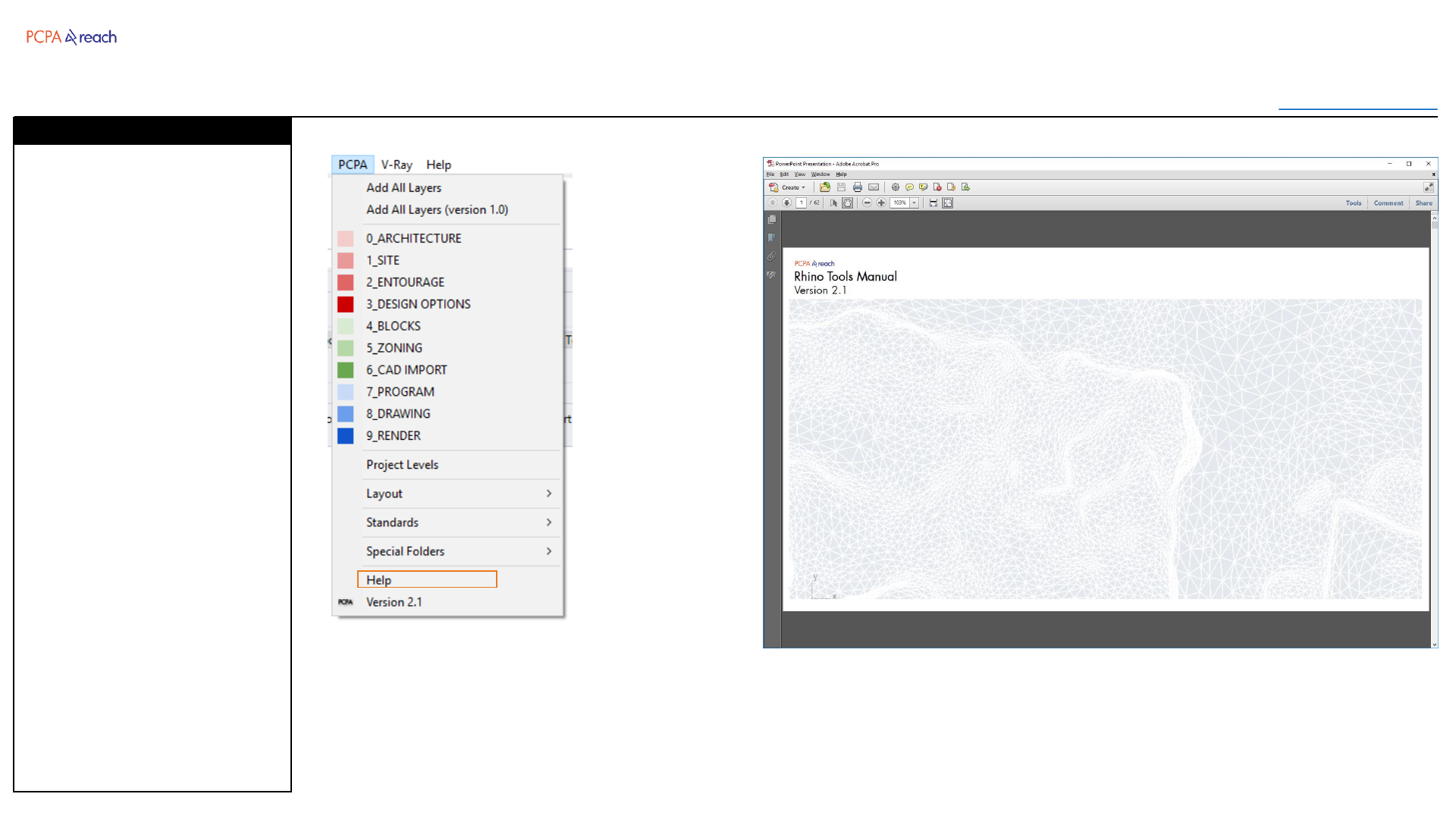
Open the PDF directly: View PDF ![]() .
.
Page Count: 62
Rhino Tools Manual
Version 2.1
Table of Contents
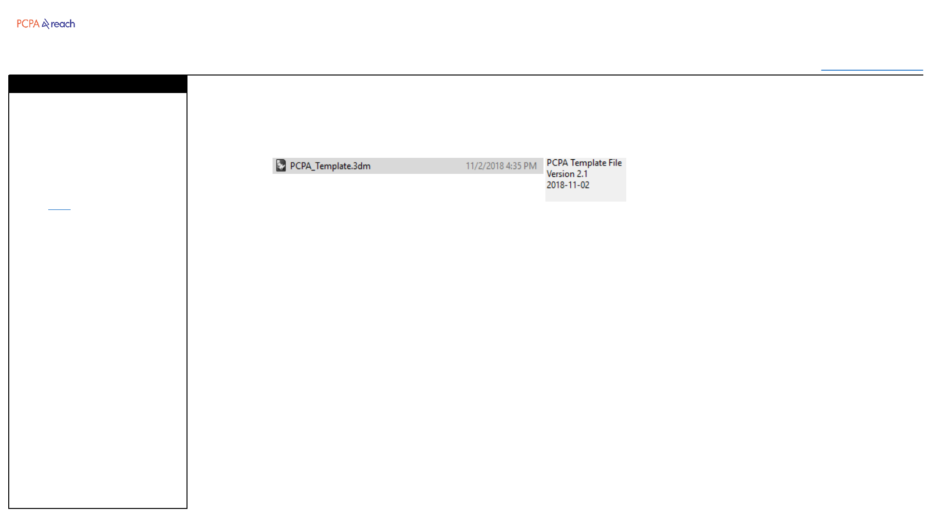
Rhino Template File
Installation
Layers
Layout
Annotation Styles
Rhino Toolbar
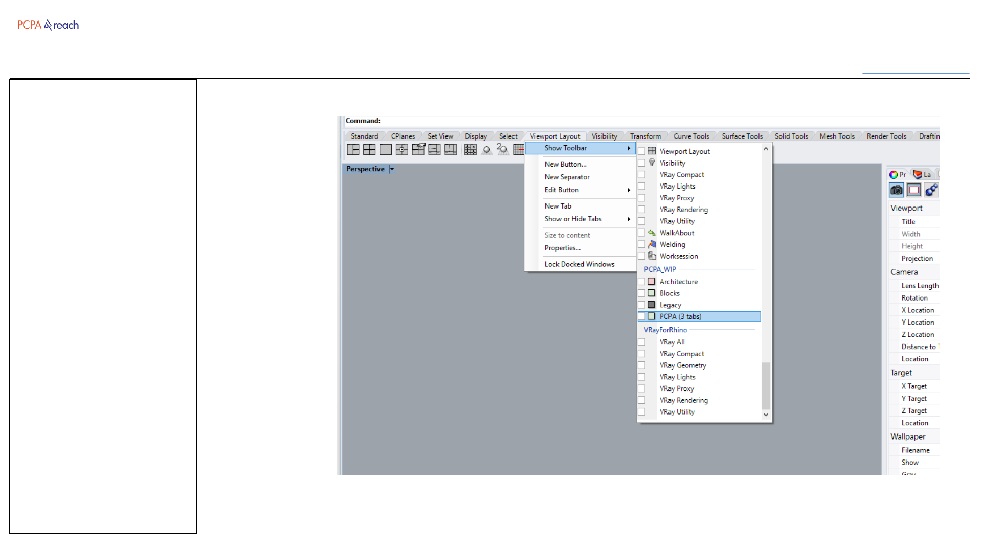
Installation
Architecture
Blocks
Drawing
Geometry
Legacy
I/O
Experimental
Grasshopper Components
Installation
Components
Troubleshooting
Rhino Tools Manual
Table of Contents
Developed by: PCPA NY REACH Core
Jimmy Chang, Spencer Steenblik
Prepared By: Tim Williams
Version Date
2.0 08-06-2018
2.1 12-03-2018
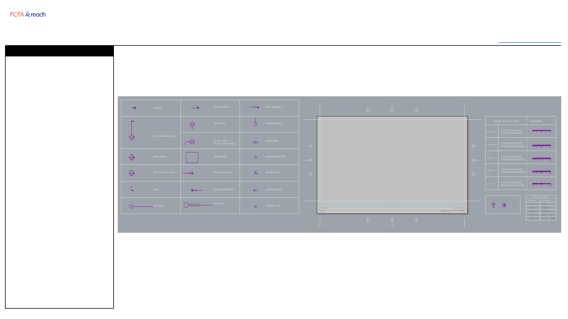
Template
Table of Contents
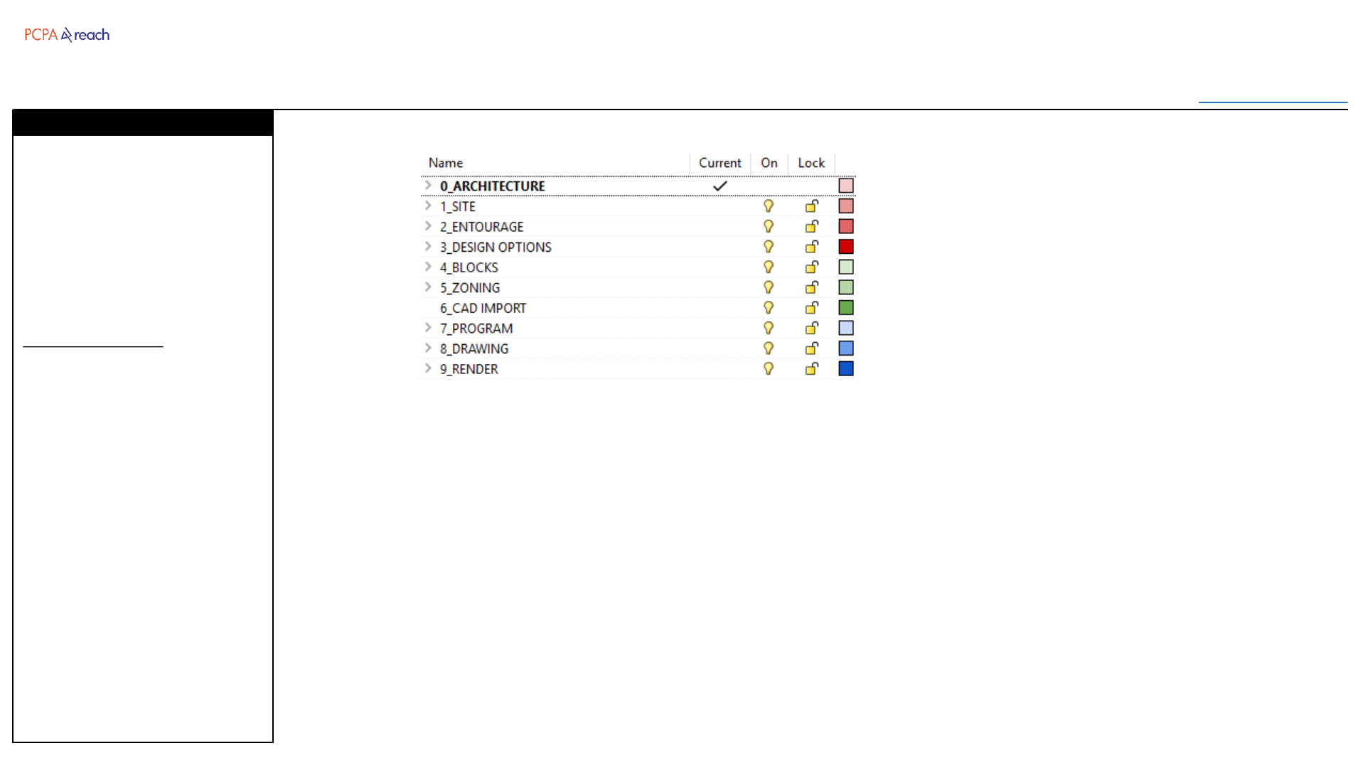
Layers have been simplified for
readability and speed of
navigating.
All objects should fit within this
hierarchy.
Changes since 1.0
•Each root layer has a number
in front for proper sorting.
•Root layers have been
assigned unique colors.
•Architecture layers combined
with Interior and brought to
root.
•Annotation and Hatch
combined into Drawing layer
•Animation and Lights
combined into Render layer
Layers
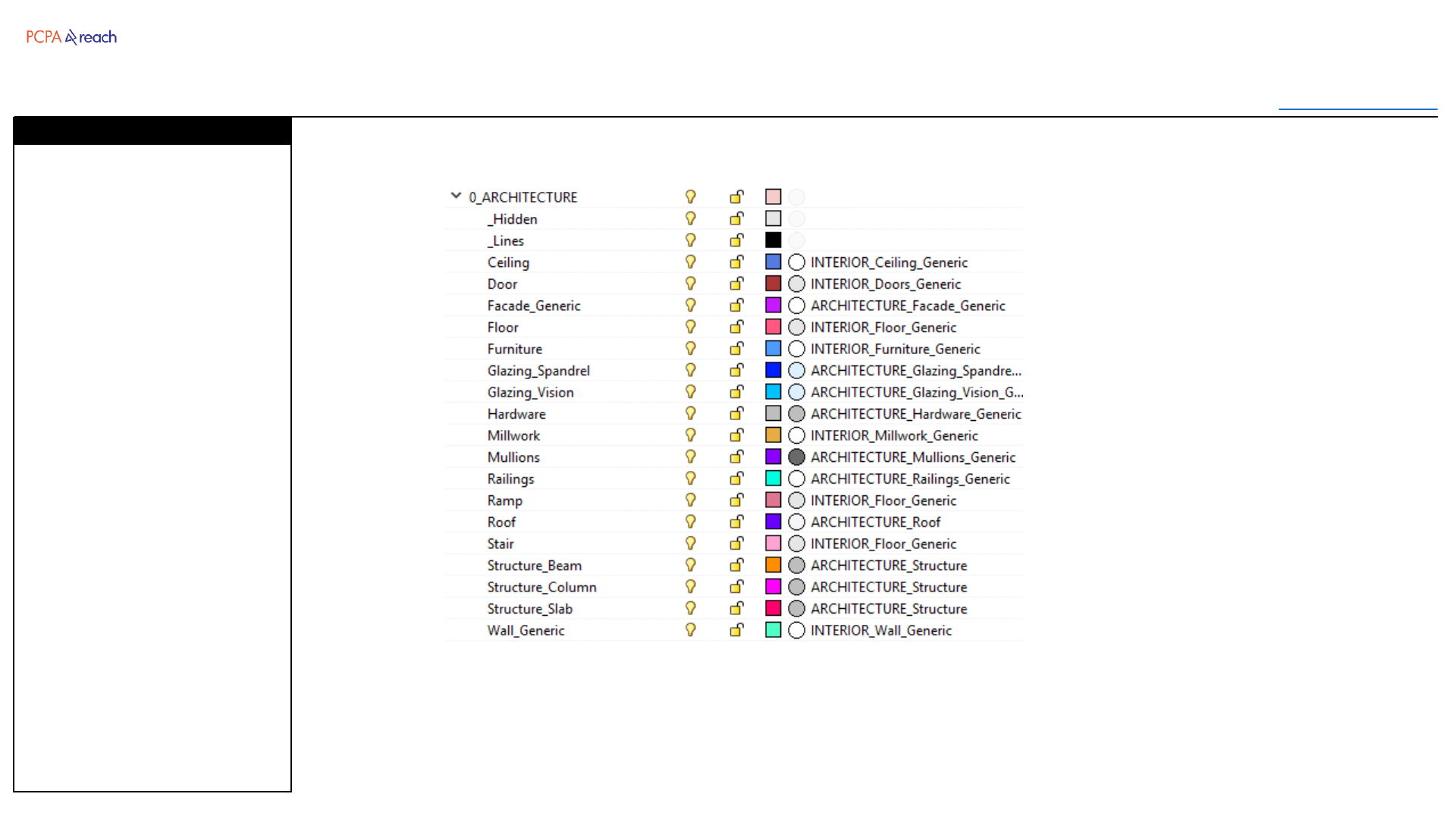
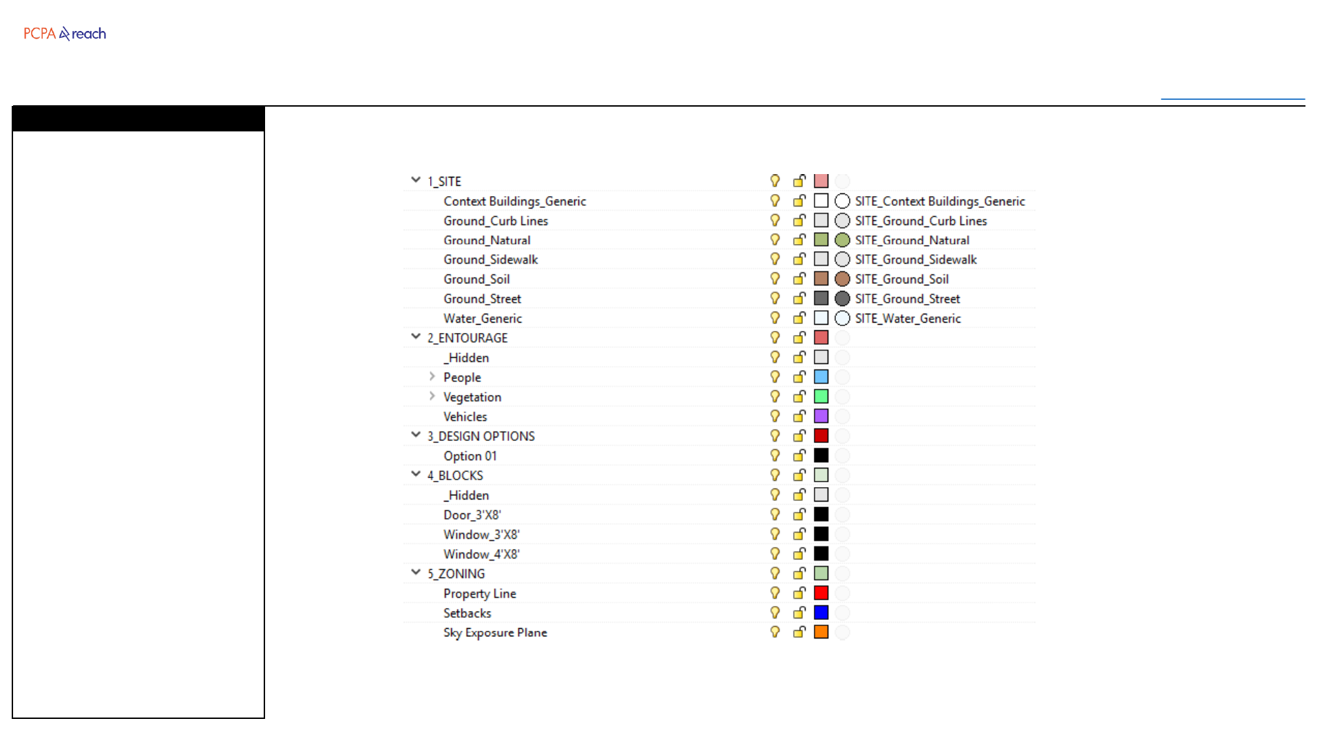
Template
Table of Contents
Site
•For landscape and
surrounding context
Entourage
•For people, plants, and
vehicles (often blocks)
Design Options
•For the master blocks that
contain all objects
describing a design option
Blocks
•For the geometry of
frequently used blocks, and
their block instance.
Zoning
•Geometry describing the
zoning requirements
Layers
Template
Table of Contents
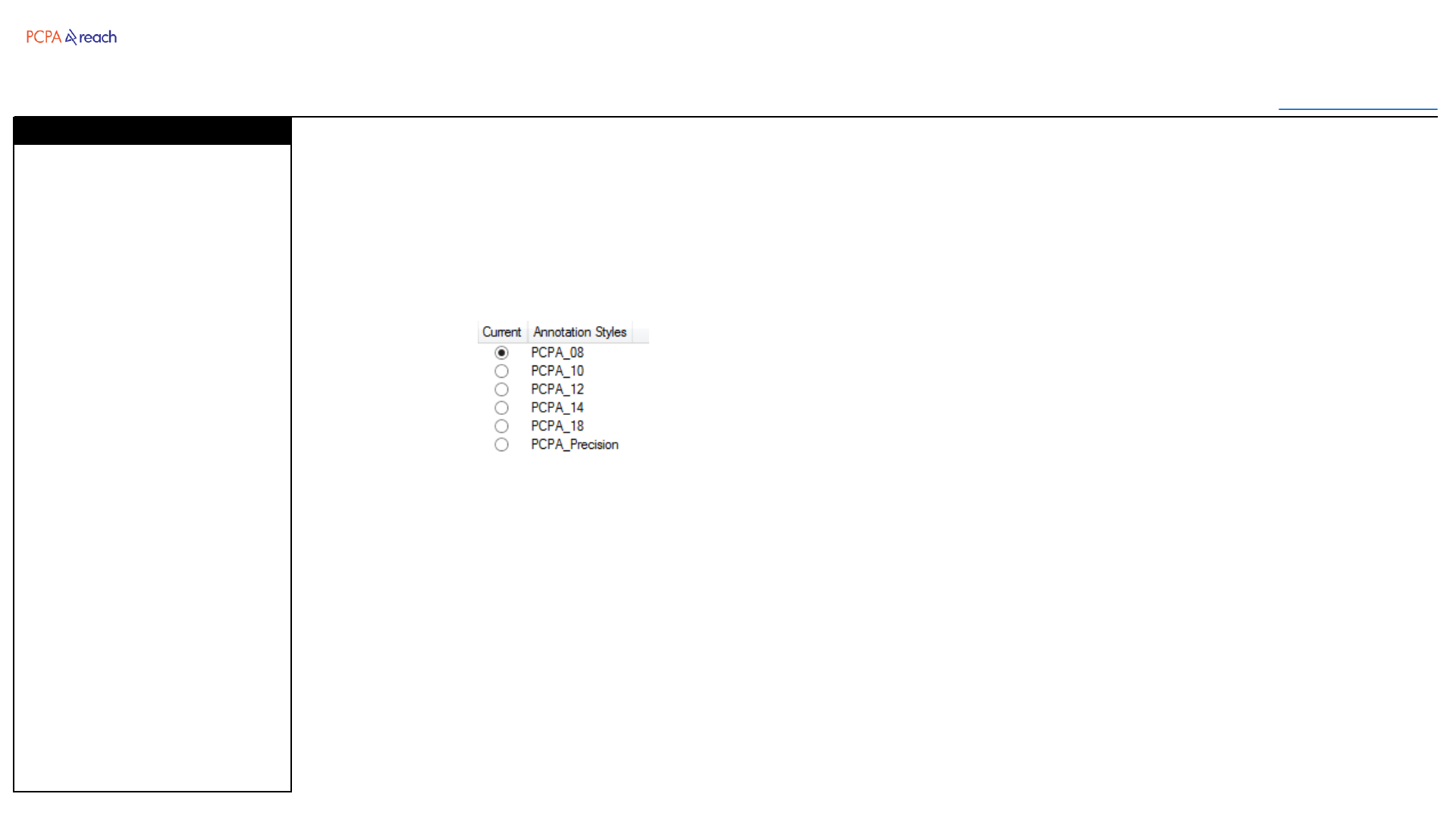
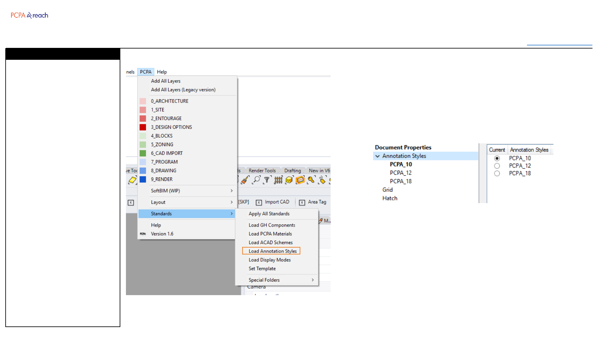
6 PCPA Annotation styles have
been placed in the template file.
•PCPA_08
•PCPA_10
•PCPA_12
•PCPA_14
•PCPA_18
•PCPA_Precision
Model space scale has been set
to 192 by default.
PCPA_Precision is for checking
model geometry.
*Beware that model space
scale does not affect printed
text size.
Annotation Styles
PCPA_08
PCPA_10
PCPA_12
PCPA_14
PCPA_18

Architecture
Toolbar
Table of Contents
INPUT OUTPUT>
INPUT
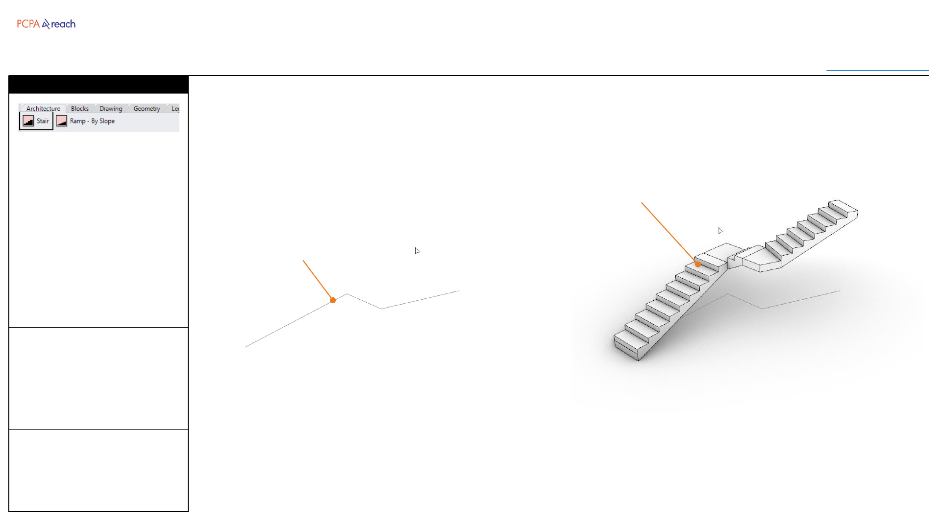
1. Select Guide Polyline
2. Width (inches)
3. Height (inches)
OUTPUT
•Stair
Creates a stair to specified
height, along a guide curve.
Risers kept below 7”, tread is
result of the guide curve length.
*Curved geometry not currently
supported.
Stair
Stair
Guide Polyline
Stair
Architecture
Toolbar
Table of Contents
INPUT OUTPUT>
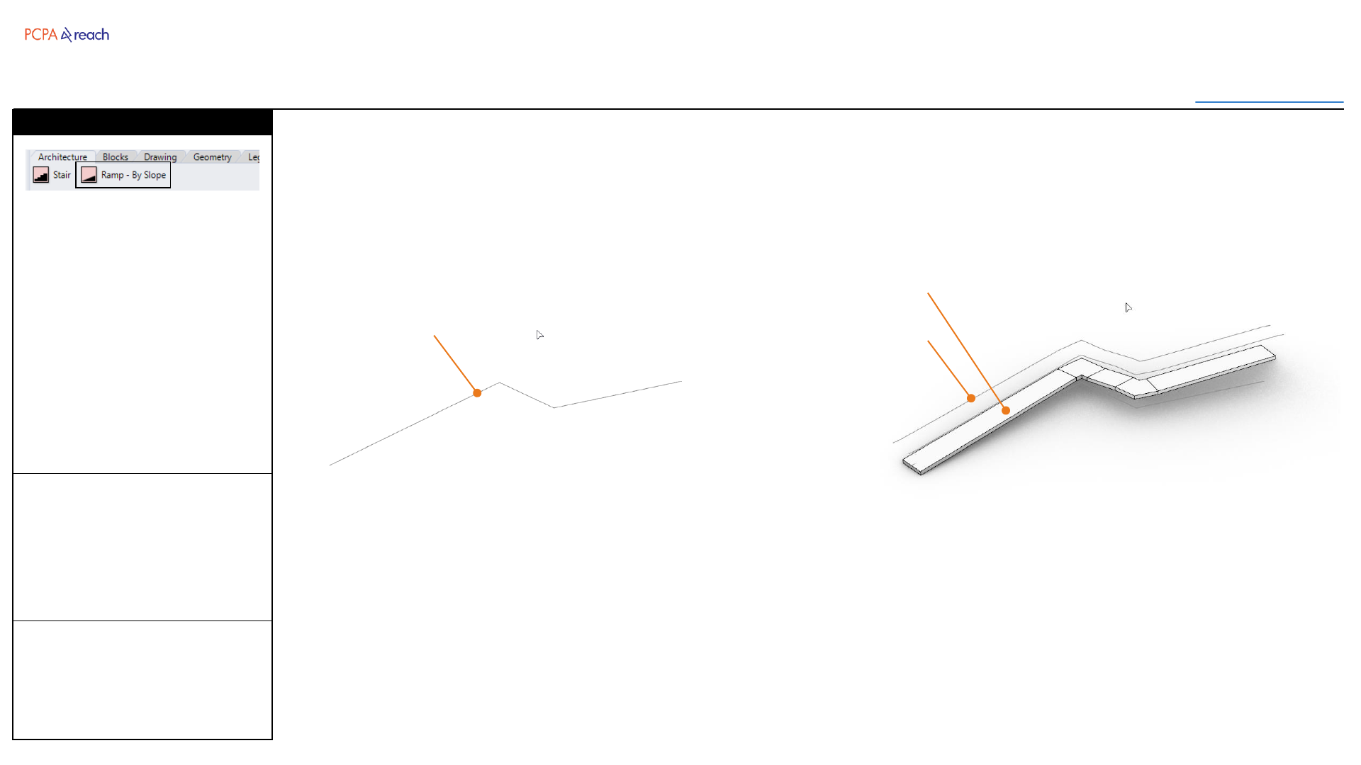
INPUT
1. Select Guide Polyline
2. Width (inches)
3. Slope (%)
OUTPUT
•Ramp
•Handrail
Creates a ramp at specified
slope, along a guide curve.
Handrail inserted if slope > 5%
*Curved geometry not currently
supported.
*Will currently only insert 1
landing per run.
Stair
Ramp
Guide Polyline Handrail
Ramp
Blocks
Toolbar
Table of Contents
INPUT OUTPUT>
INPUT
1. Select Geometry
2. Input design option name
OUTPUT
•Block on layer under
“3_DESIGN OPTIONS”
Selected objects will be
converted into a block and
placed in a new matching
layer, under “3_DESIGN
OPTIONS”.
Stair
Create Design Option
Design Option Block
Design Option Layer
New Design Option Block
New Design Option Layer

Blocks
Toolbar
Table of Contents
INPUT OUTPUT>
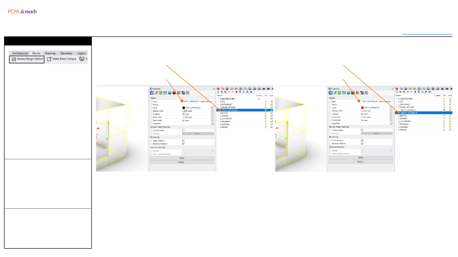
INPUT
1. Select block
2. Input new blocks name
OUTPUT
•Duplicated block, renamed
with suffix +1 or update
date.
•Duplicated layer with same
name
The selected block will be
duplicated and renumbered
with a new block name.
A new matching layer name
with be created and the
previous will be turned off.
Supports numbers and letter
suffix, separated by “-” , “_”, or
“ “.
Stair
Iterate Design Option
Design Option Block
Design Option Layer
New Design Option Block
New Design Option Layer
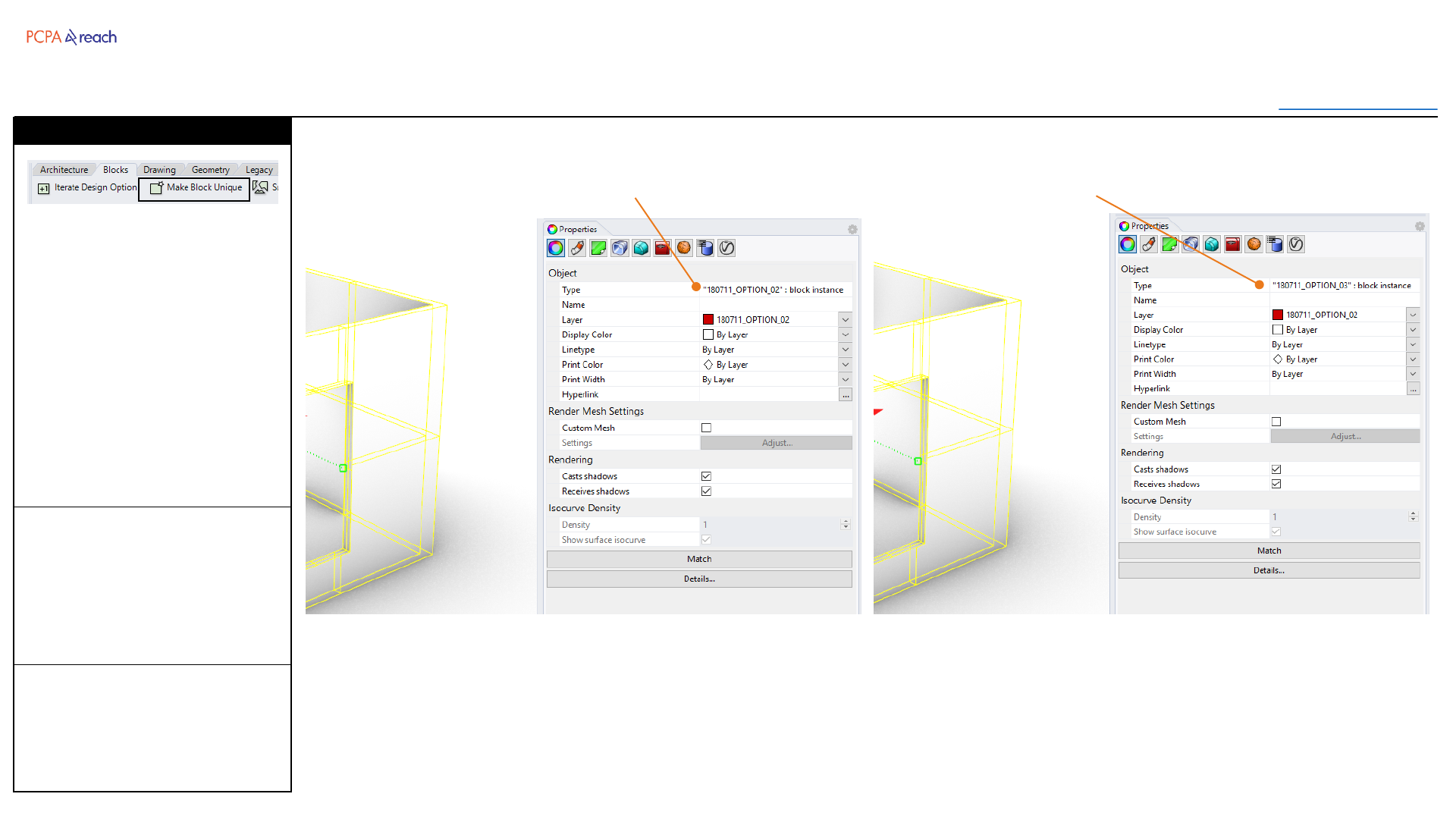
Blocks
Toolbar
Table of Contents
INPUT OUTPUT>
INPUT
1. Select block
2. Input new blocks name
OUTPUT
•New Block with same
geometry and origin pt.
Creates a new block definition
from an old block. (Keeps the
old block in the file, but deletes
the instance)
Default name will be either an
update date, or the name +1 (if
suffixed with a number)
Stair
Make Block Unique
Block New block (same geometry)
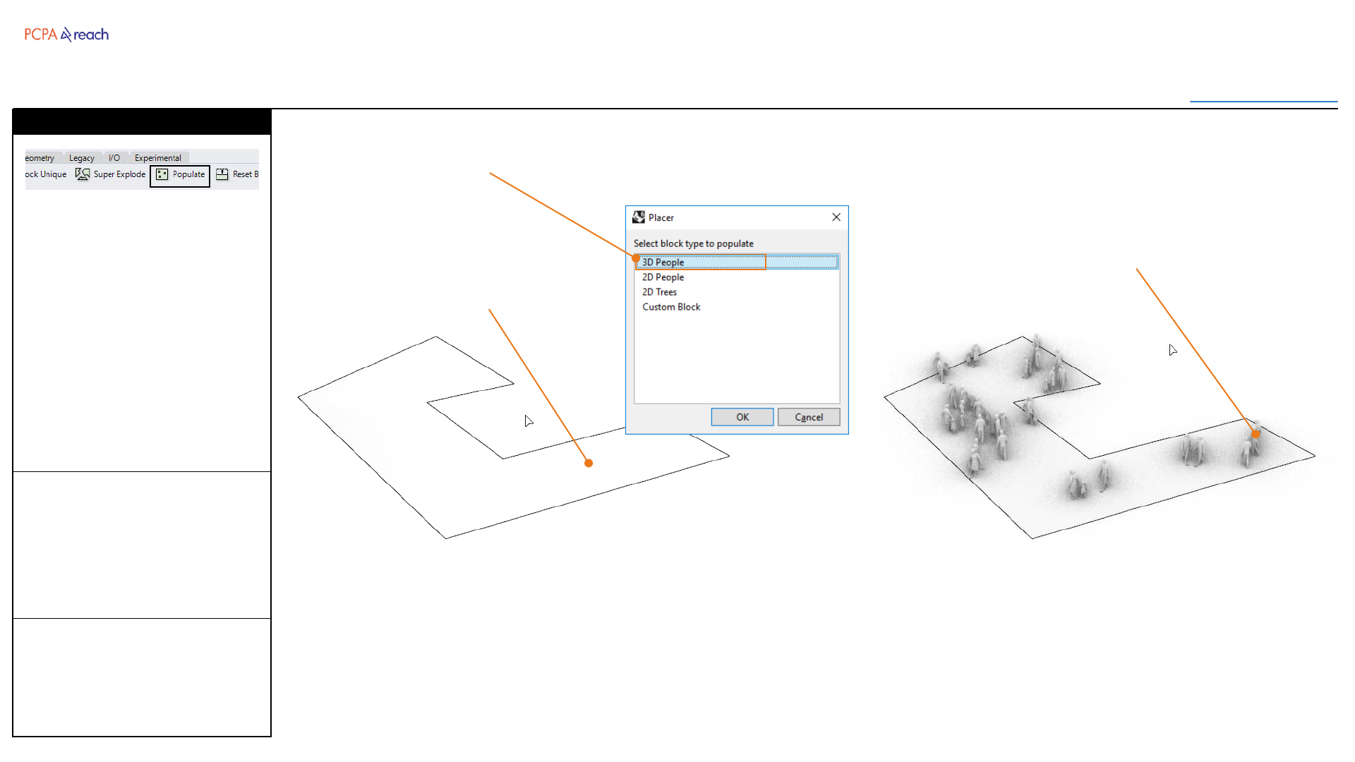
Blocks
Toolbar
Table of Contents
INPUT OUTPUT>
INPUT
1. Select surface
2. Number of objects to place
3. Select Population Type
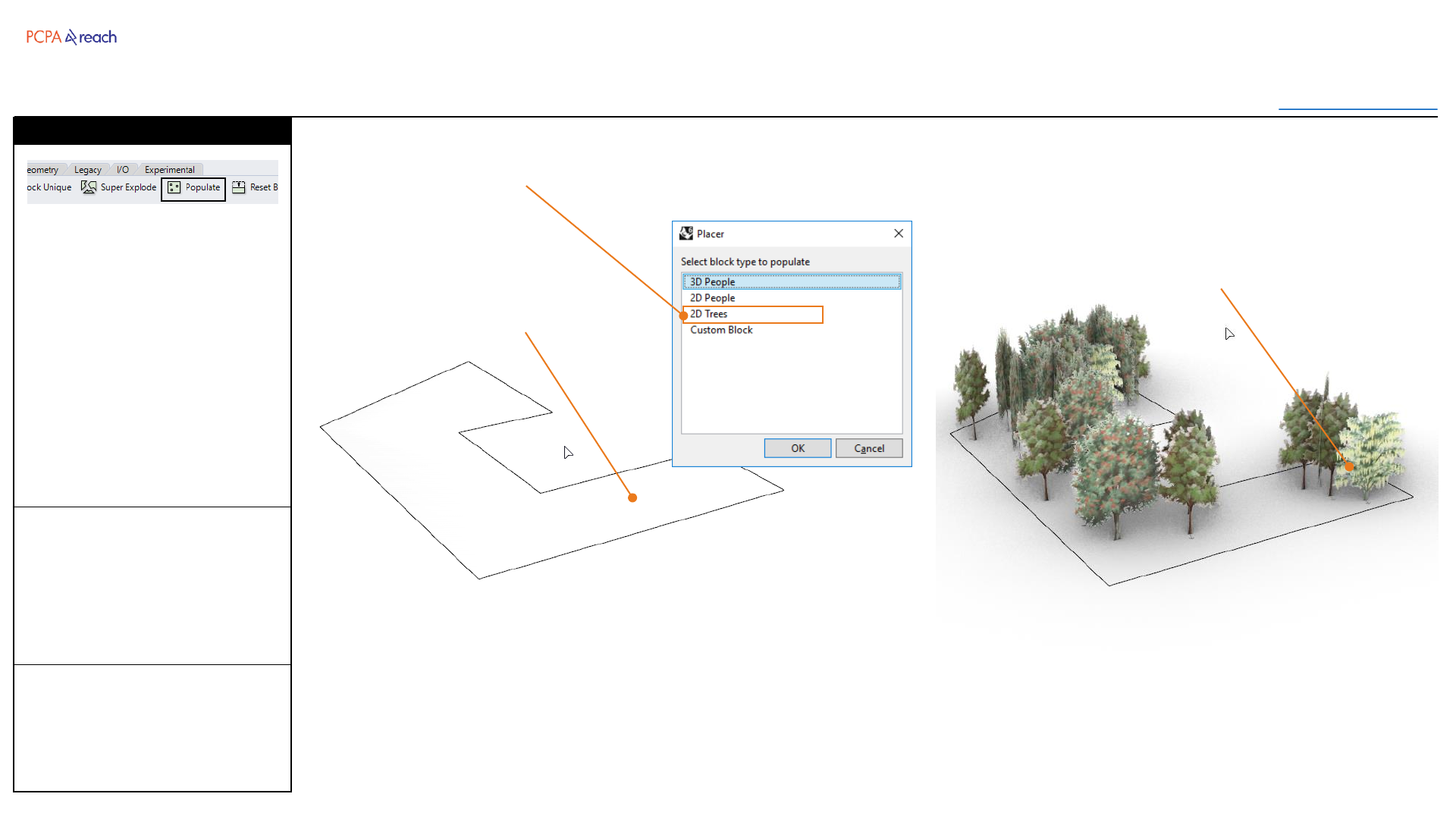
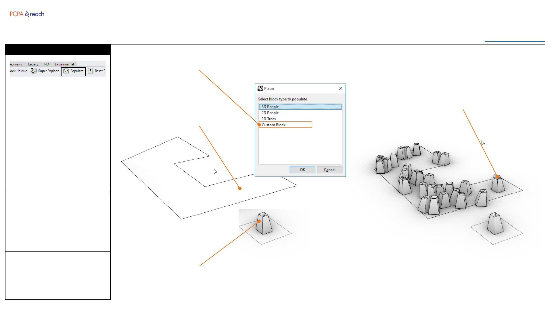
OUTPUT
•Blocks randomly placed on
the surface.
Populates a surface with
selected population type.
Blocks are imported from the
network and randomly placed
across the surface.
Stair
Populate
Surface to populate
Imported blocks randomly
placed.
Population Type
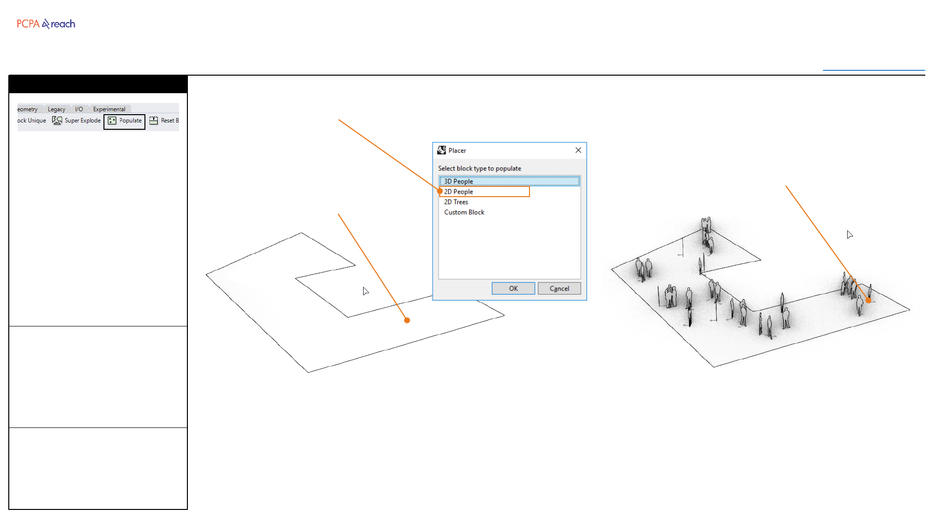
Blocks
Toolbar
Table of Contents
INPUT OUTPUT>
OUTPUT
•Blocks randomly placed on
the surface.
Populates a surface with
selected population type.
Blocks are imported from the
network and randomly placed
across the surface.
Stair
Populate
Surface to populate
Imported blocks randomly
placed.
Population Type
INPUT
1. Select surface
2. Number of objects to place
3. Select Population Type
Blocks
Toolbar
Table of Contents
INPUT OUTPUT>
OUTPUT
•Blocks randomly placed on
the surface.
Populates a surface with
selected population type.
Blocks are imported from the
network and randomly placed
across the surface.
Stair
Populate
Surface to populate
Existing blocks randomly
placed.
Population Type
Existing Block
INPUT
1. Select surface
2. Number of objects to place
3. Select Population Type
4. Select Existing Block
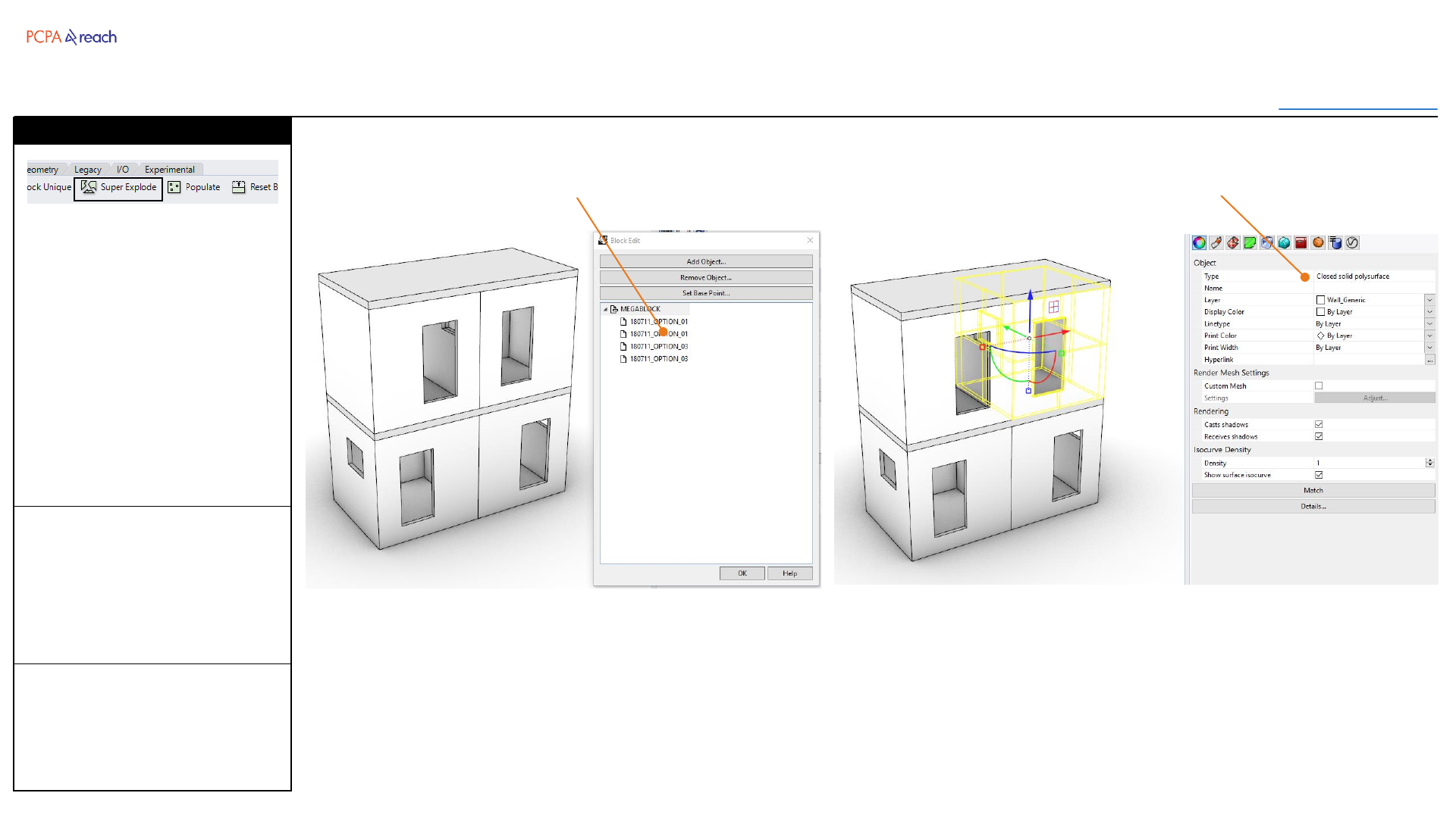
Blocks
Toolbar
Table of Contents
INPUT OUTPUT>
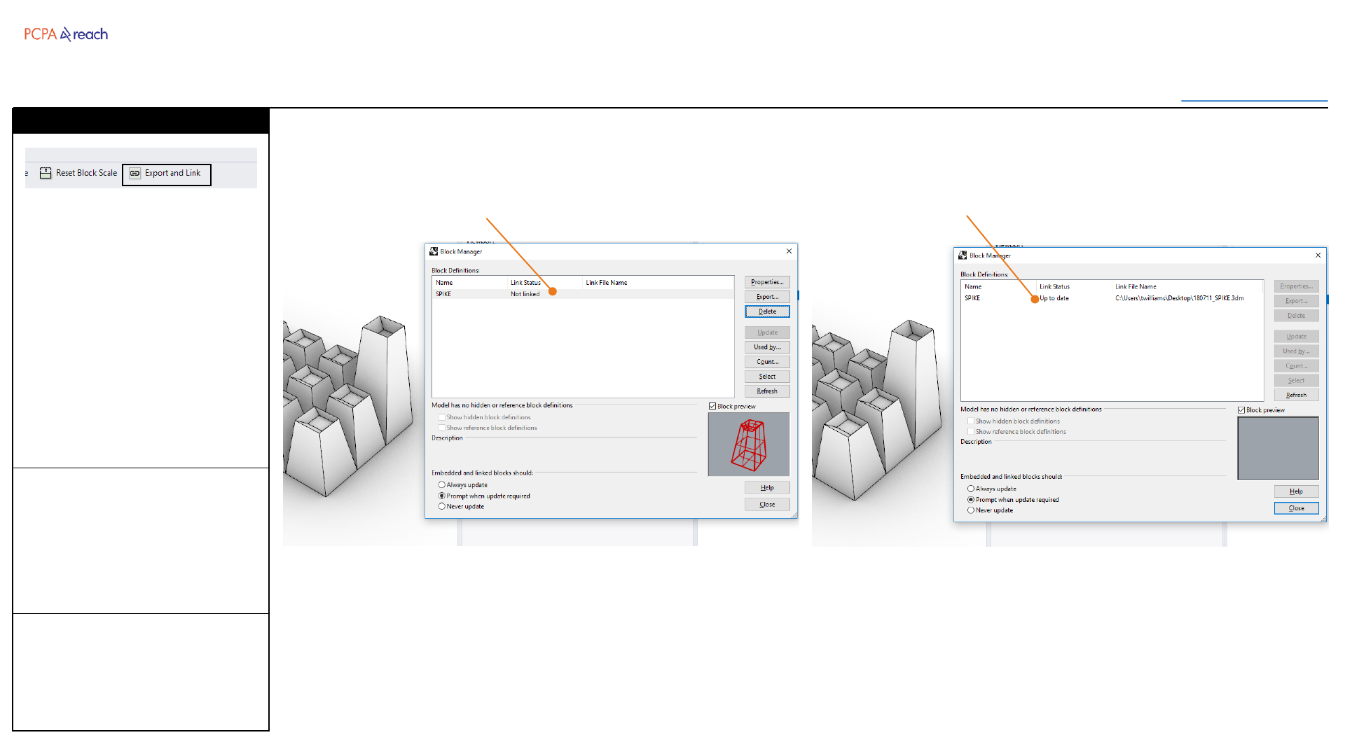
INPUT
1. Select Block
OUTPUT
•Linked Block
Exports a block to another
Rhino file, then links it back to
the original block.
Useful when a block occurs
multiple times in a file, and you
want multiple people on this
file.
Stair
Export and Link
Block within document Block linked
Drawing
Toolbar
Table of Contents
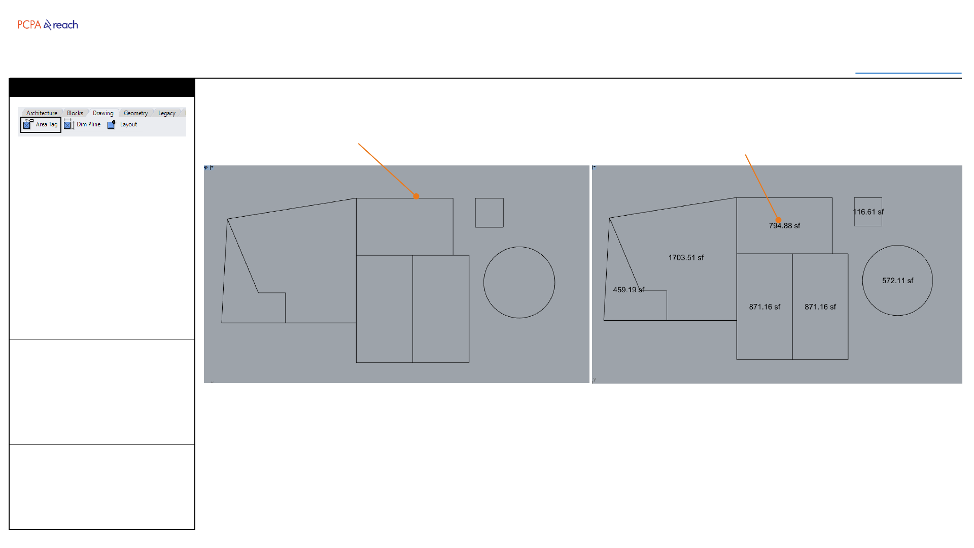
INPUT OUTPUT>
INPUT
1. Select closed planar curves,
surfaces, or hatches
2. Number of decimal places
-1 = X,XX0
0 = X,XXX
1 = X,XXX.X
2 = X,XXX.XX
OUTPUT
•Text object at center of
polyline
Adds a text object according to
the bounding geometries area
at the center of that object.
Text object with appear on
layer: “8_DRAWING::Text”
Stair
Area Tag
Closed Polylines,
Hatches, or Surfaces Text object with Area

Drawing
Toolbar
Table of Contents
INPUT OUTPUT>
INPUT
1. Select Polylines
2. Offset Dimension (inches)
OUTPUT
•Dimensioned Segments
Automatically dimensions
polyline segments.
Will not dimension arcs or
NURBs curves.
Dimensions with appear on
layer:
“8_DRAWING::Dimensions”
Stair
Dimension Polyline
Polylines Dimensioned Segments
Drawing
Toolbar
Table of Contents
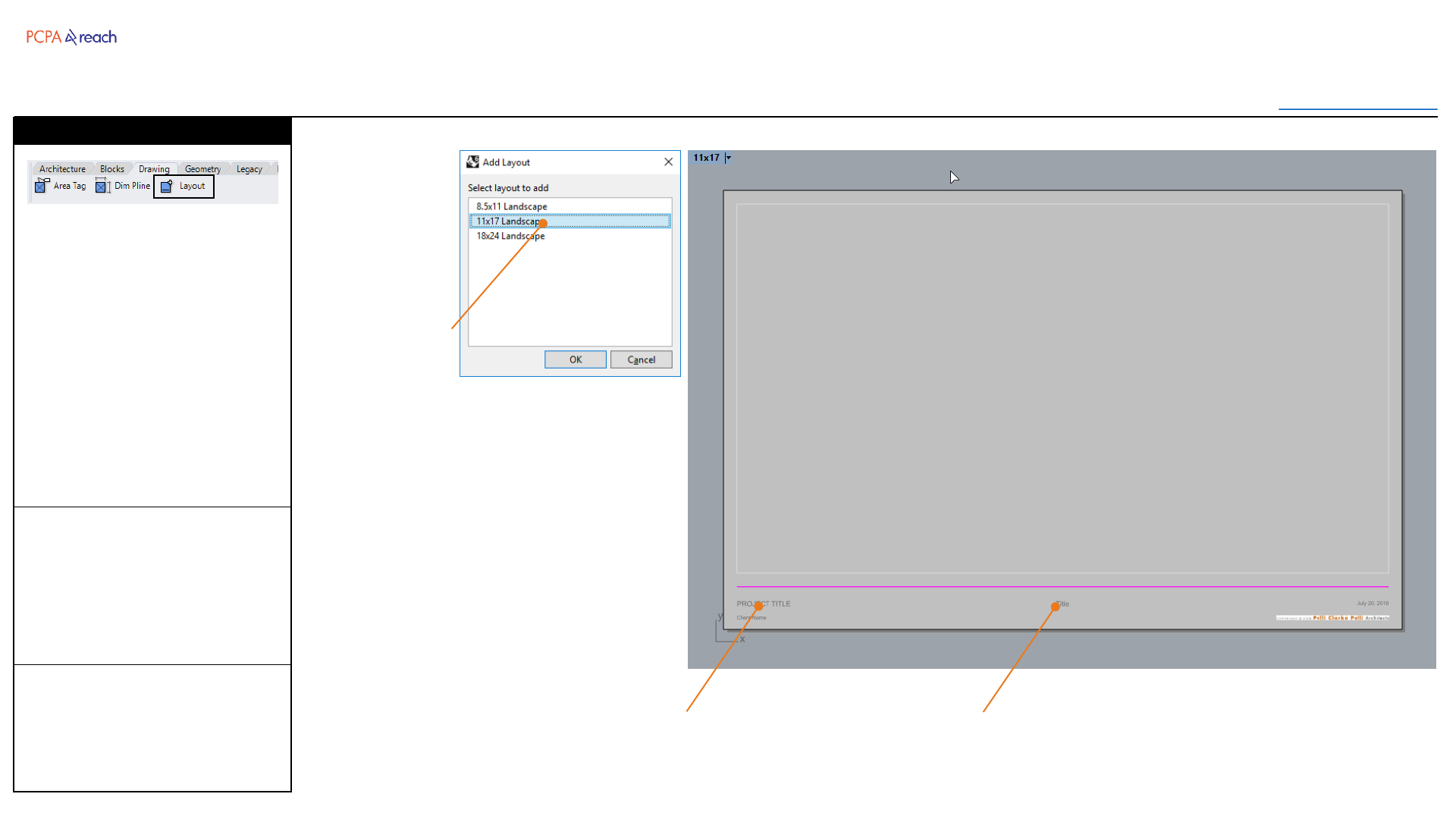
INPUT OUTPUT>
INPUT
1. User Selected Layout Size
OUTPUT
•New Layout with titleblock
Adds a new layout to selected
standard paper size with a
PCPA Presentation Template.
Date is a text field and will
update to the current date.
Project Title and Client Name
can be parametrically changed
through Rhino’s ‘Document
Data’ tab.
Stair
Layout
Selected Layout
New Layout
Presentation Titleblock
Geometry
Toolbar
Table of Contents
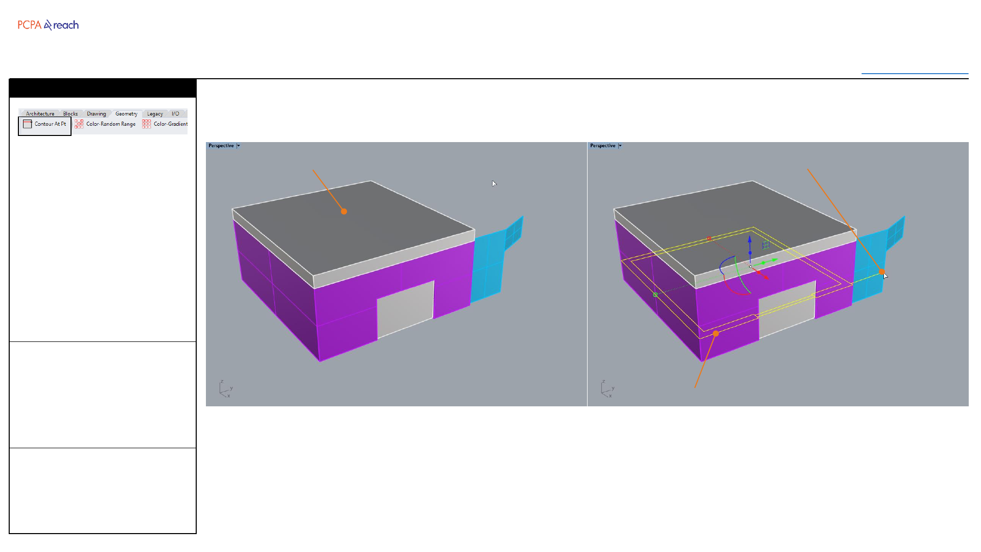
INPUT OUTPUT>
INPUT
1. Select objects
2. Get point to cut contour at
OUTPUT
•Curves joined and on each
original objects layer
Cuts input geometry at a
designated elevation.
Useful for extracting floor plan
cut lines.
Stair
Contour at Point
Input Objects
Resulting contour
Point to cut contour

Geometry
Toolbar
Table of Contents
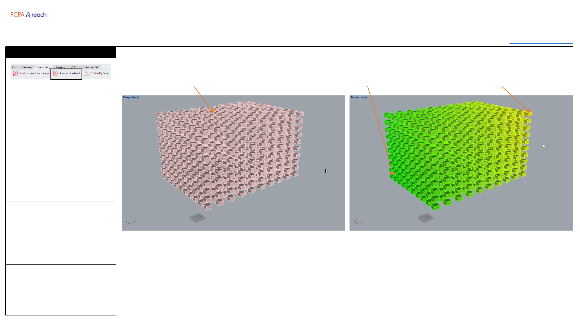
INPUT OUTPUT>
INPUT
1. Select objects to color
2. Pick point 1
3. Pick color 1
4. Pick point 2
5. Pick color 2
OUTPUT
•Colored objects
Assigns a gradient of colors to
objects based on their distance
from two input points and two
input colors.
Stair
Color –Gradient
Input Objects Point 2 (Yellow)Point 1 (Green)
Geometry
Toolbar
Table of Contents
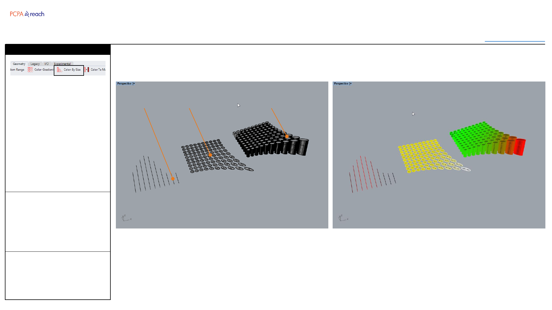
INPUT OUTPUT>
INPUT
1. Select objects to color
2. Pick color 1 (Smallest)
3. Pick color 2 (Largest)
OUTPUT
•Colored objects
Assigns a gradient of colors to
objects based on their length,
area, or volume (depending on
what type of objects are input).
Accepts curves, surface,
hatches, polysurfaces and
closed breps.
Stair
Color –By Size
Curves Surfaces Closed Polysurfaces
Legacy
Toolbar
Table of Contents
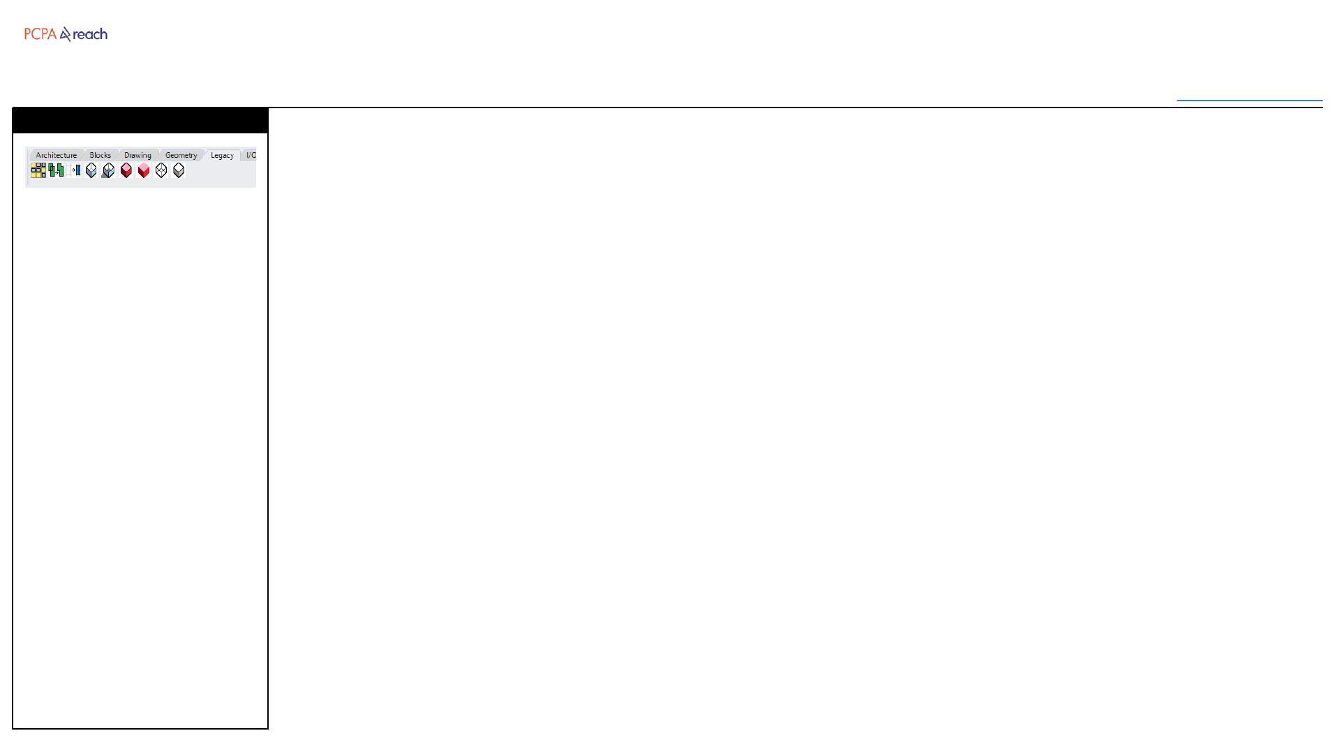
INPUT OUTPUT>
Buttons from the first PCPA
Toolbar.
Random Unselect
•Randomly unselects a
percentage of selected
objects
Clean Boolean
•Macro: Boolean union +
Merge all faces
Curve Boolean + Planar
•Macro: Curveboolean +
Planar Srf
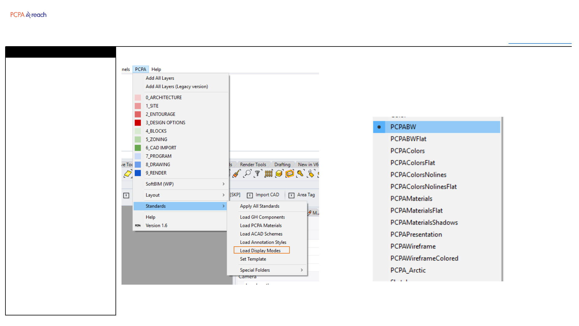
Various PCPA Display Modes
•Changes display mode to
one of the standard PCPA
displays
I/O (Input/Output)
Toolbar
Table of Contents
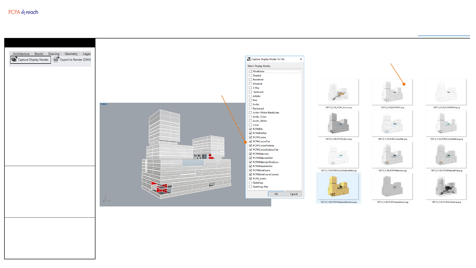
INPUT OUTPUT>
INPUT
1. Select display modes
2. Output path
3. Image Height (pixels)
4. Image Width (pixels)
OUTPUT
•PNG for each display
mode selected.
Exports a PNG from the active
view with the user selected
display modes.
PNG name with be appended
with the display mode name.
Display modes with PCPA at the
front are defaults.
Capture Display Modes
Select Display Modes to Capture
Each display mode exported to
PNG file
I/O (Input/Output)
Toolbar
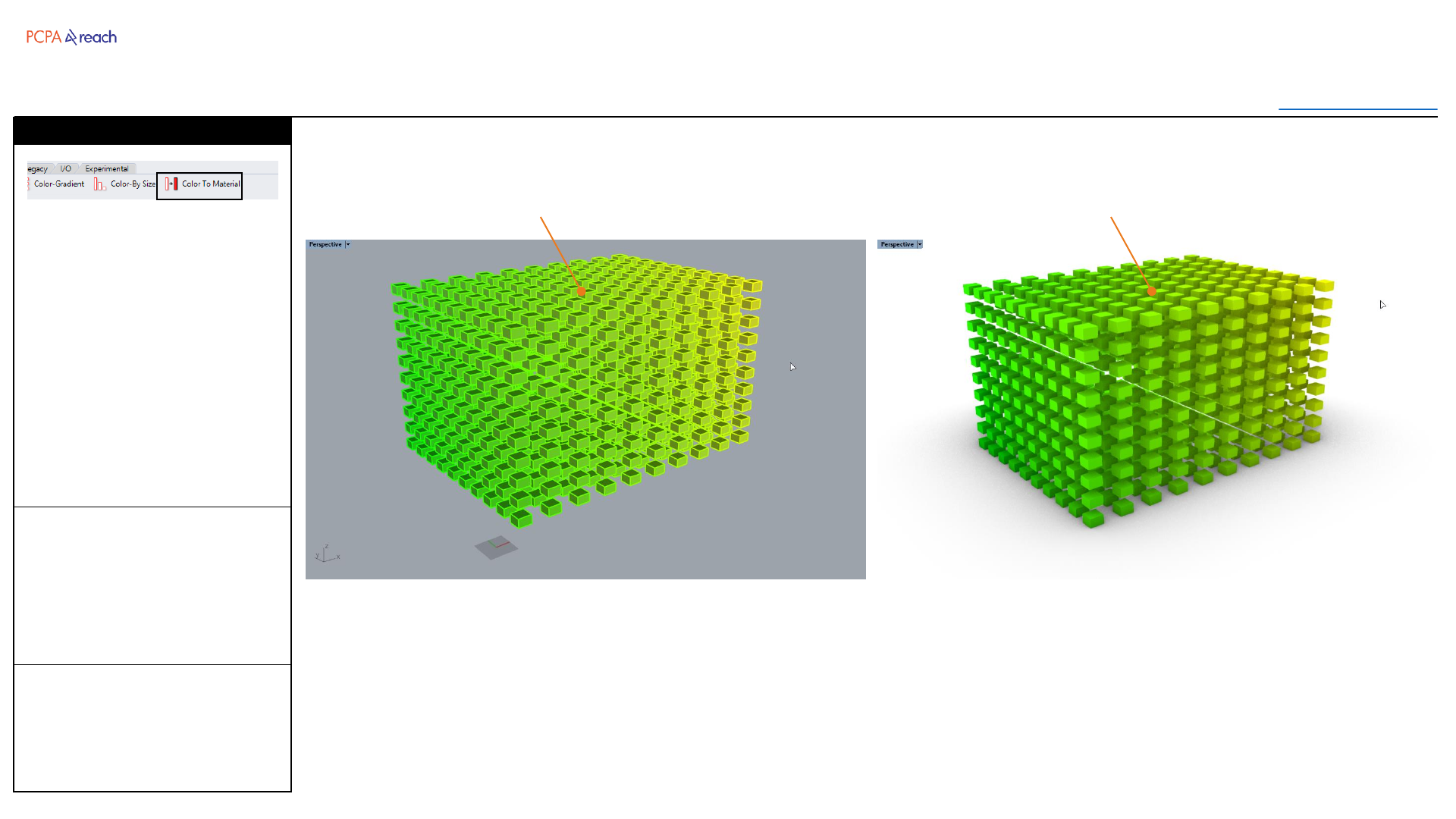
Table of Contents
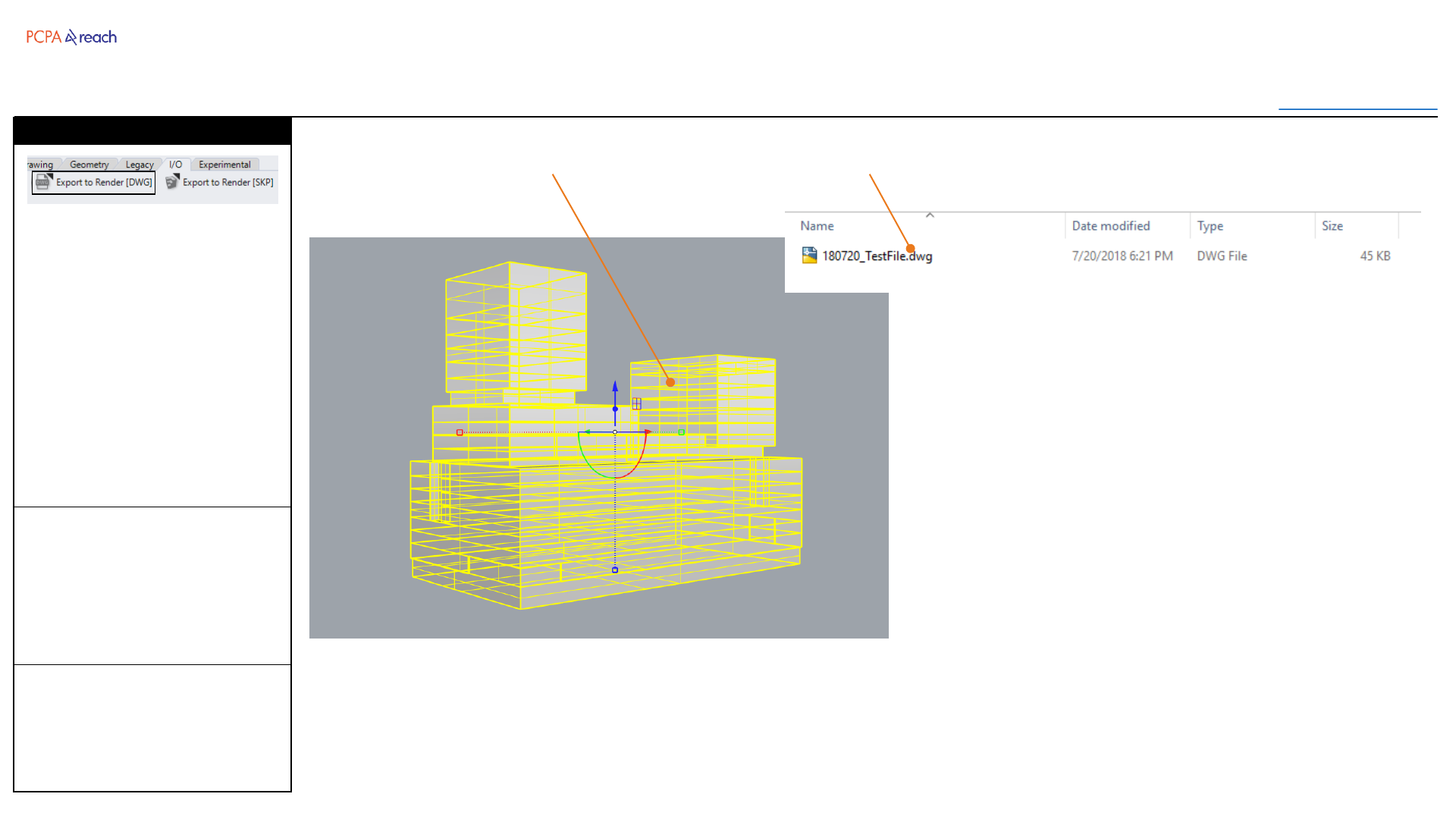
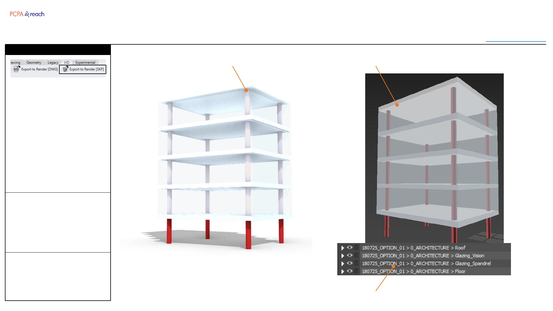
INPUT OUTPUT>
INPUT
1. Select objects
2. Choose file path
OUTPUT
•DWG file
Exports selected objects to SKP
format with the layer names
prefixed with the date and
option name.
SKP Files are preferred because
they maintain materials, layer
names, and proper geometry.
*If mesh settings not ideal,
mesh before export.
Export to Render [SKP]
Geometry to export from Rhino Model in 3ds Max
Properly formatted layer names in 3ds Max
‘Filename > Rhino Layer Names’
I/O (Input/Output)
Toolbar
Table of Contents
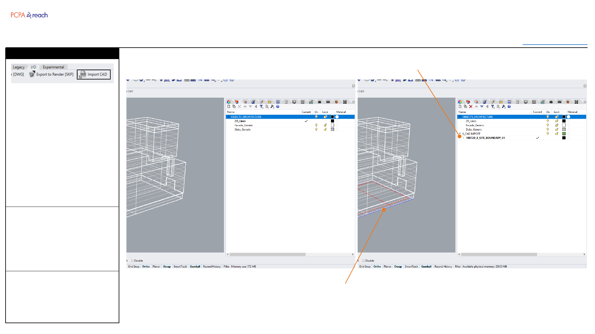
INPUT OUTPUT>
INPUT
1. Select DWG file
OUTPUT
•Generated parent layers
Imports DWG file and nests its
layers under a parent layer,
named “Date_Filename_##”
Empty layers are removed.
All imported blocks come in
exploded.
Import CAD
Automatically generated parent layer names
Imported Lines
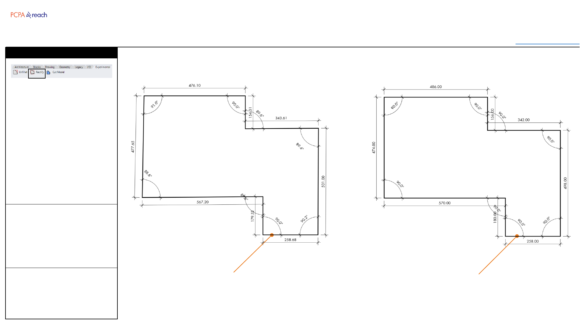
Experimental
Toolbar
Table of Contents
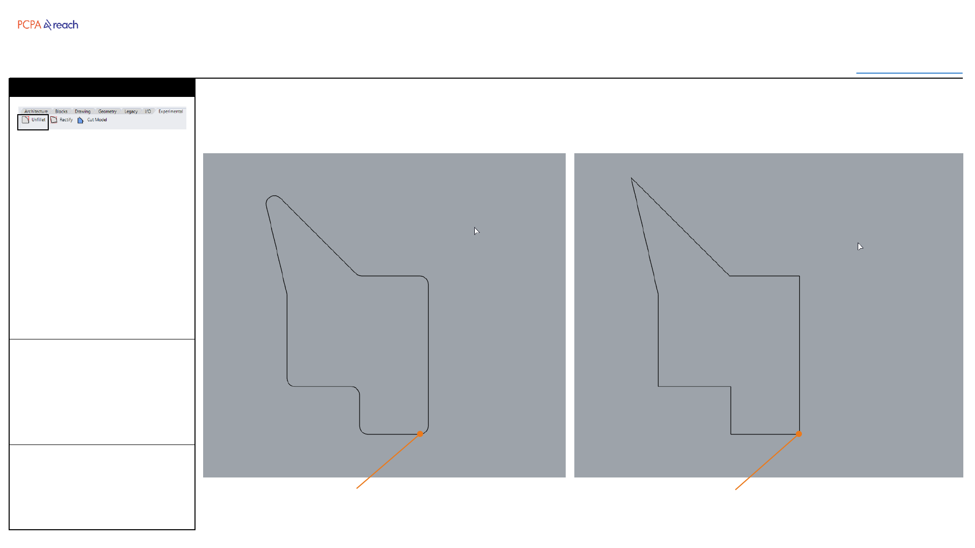
INPUT OUTPUT>
INPUT
1. Select polyline
2. Input angle multiples
3. Input length multiples
OUTPUT
•Polyline
Rebuilds a polyline according to
specified angle and length
multiples.
If 0 is input for the multiples, the
original angle or length is used.
*Curves not currently
supported.
Rectify
Lengths and angles rounded.
In this case 90 degrees and 6 inches.
Polyline with irregular
lengths and angles
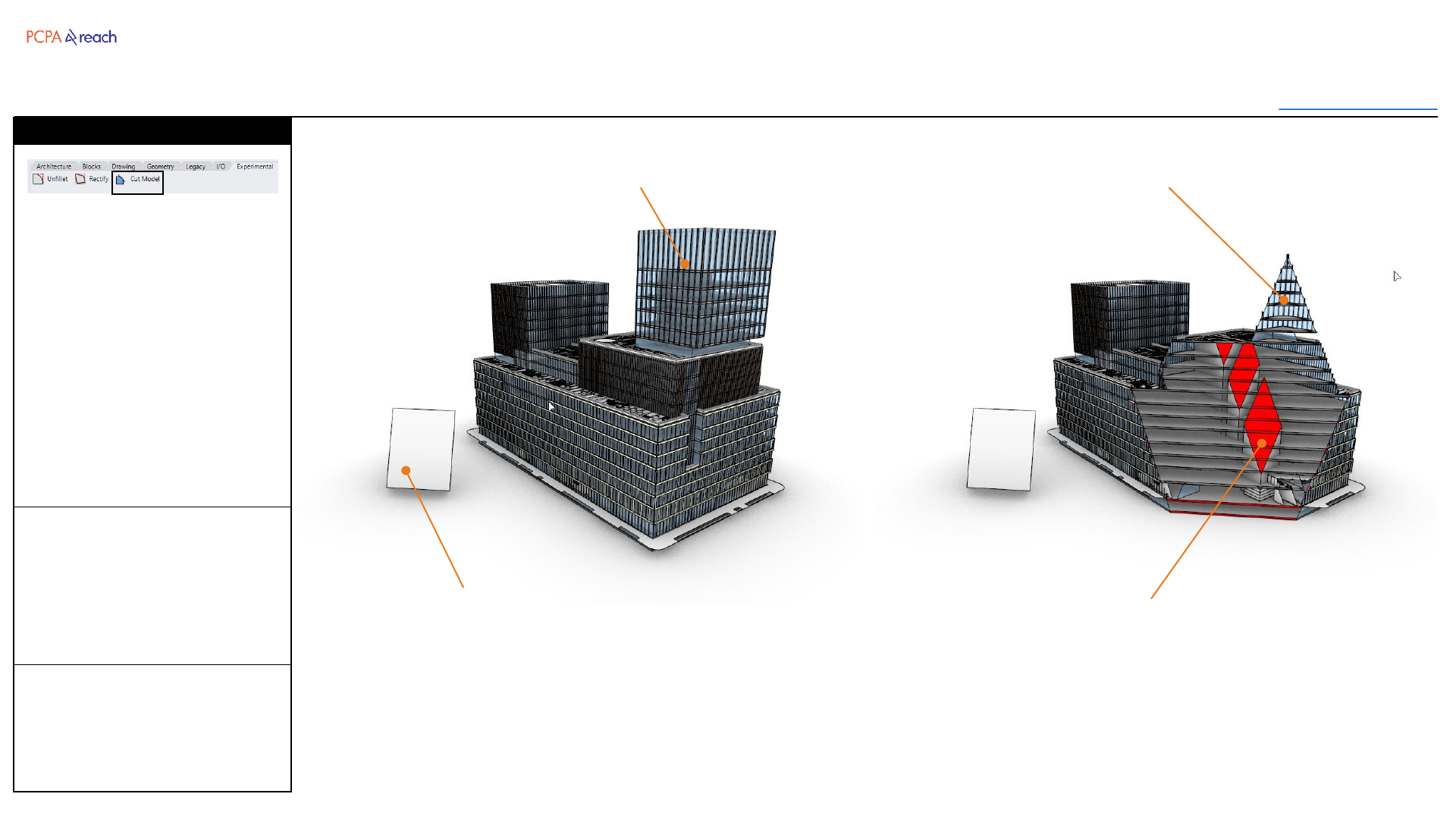
Experimental
Toolbar
Table of Contents
INPUT OUTPUT>
INPUT
1. Select objects to trim
2. Select surface to trim with
OUTPUT
•Duplicated geometry
trimmed by surface plane.
Trims a model with a surface.
Duplicates and hides original
geometry.
Creates two groups, one with
the remaining geometry, the
other with section surfaces
created when cutting through
solid objects.
Useful for rendering or make2d
exports.
Cut Model
Solid objects will be given a surface at
the trim location.
Surface to trim with
Objects to trim Trimmed objects duplicated and grouped

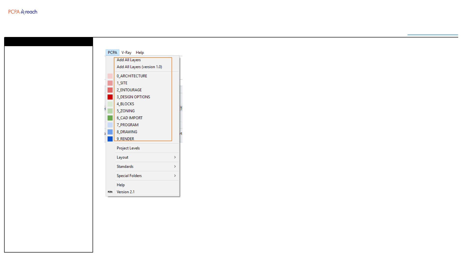
Dropdown
Toolbar
Table of Contents
PCPA Standard layers can be
added to a drawing by
choosing either Add All Layers
to load all layers, or choosing
one of the Root Layers to add
just that Root.
For projects still using 1.0 Layer
Standards,
Add All Layers (version 1.0) will
load all 1.0 layers.
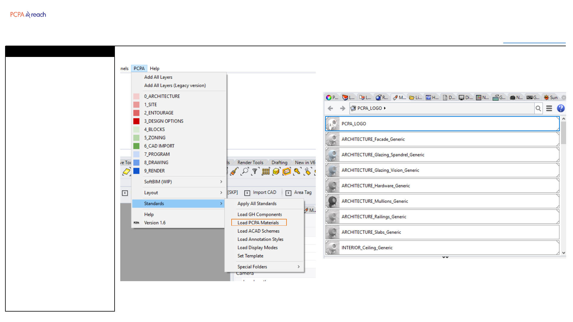
This will also import and assign
PCPA materials if not already in
the document.
Layers
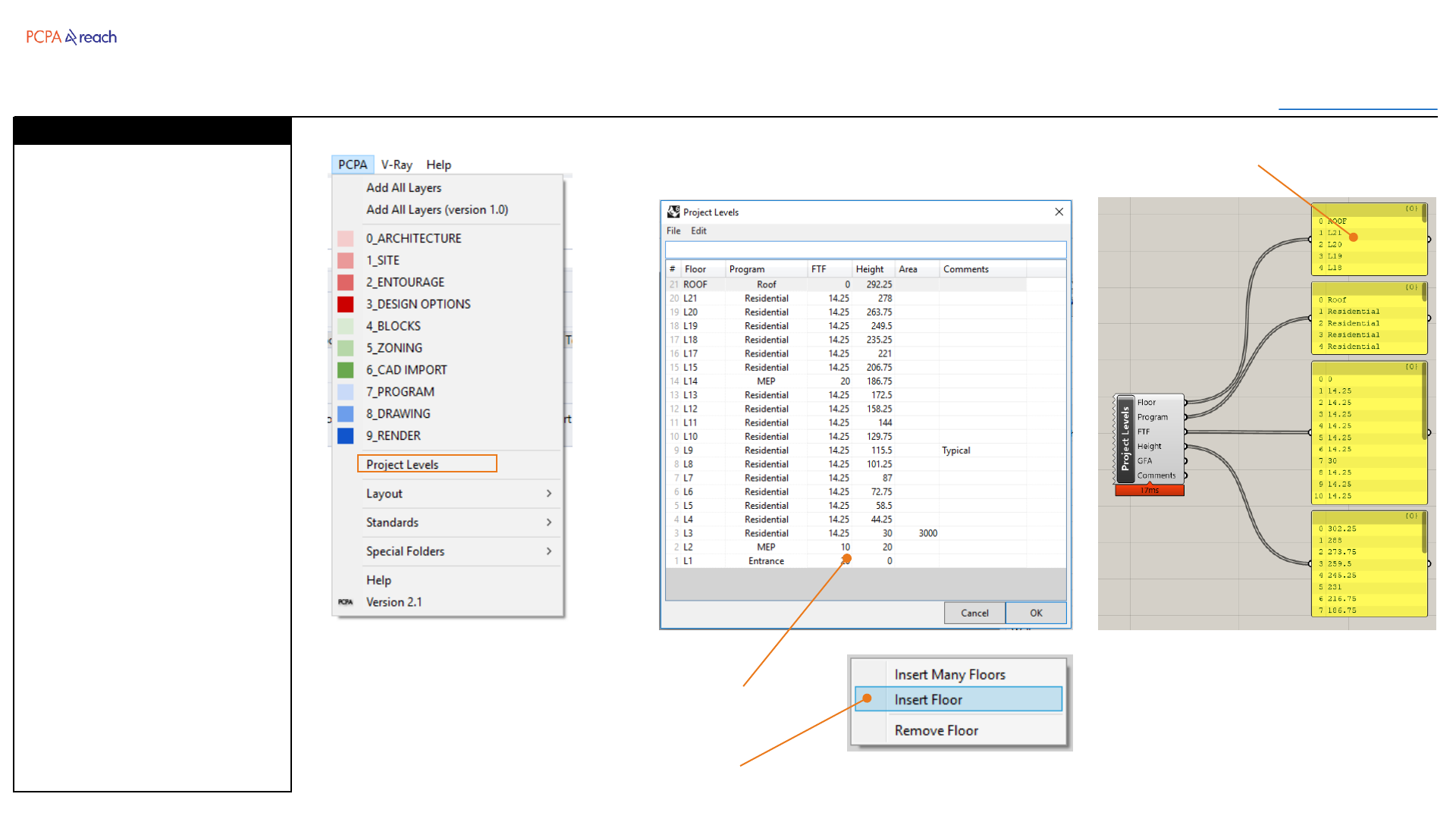
Dropdown
Toolbar
Table of Contents
Stores level data within the rhino
file. Heights and FTF are
formulas, responding to
changes.
Can enter feet, inches, or
decimal.
Can copy paste data to Excel
(Edit > Copy)
Can import levels from another
Rhino file.
(File > Import from 3dm)
Can read level data into
Grasshopper.
*This is still experimental and
may have errors.
Project Levels
Excel-like interface inside of Rhino
Data can be read in Grasshopper
Right click to open the context menu

Dropdown
Toolbar
Table of Contents
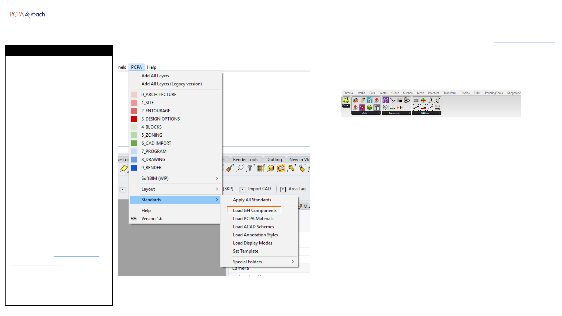
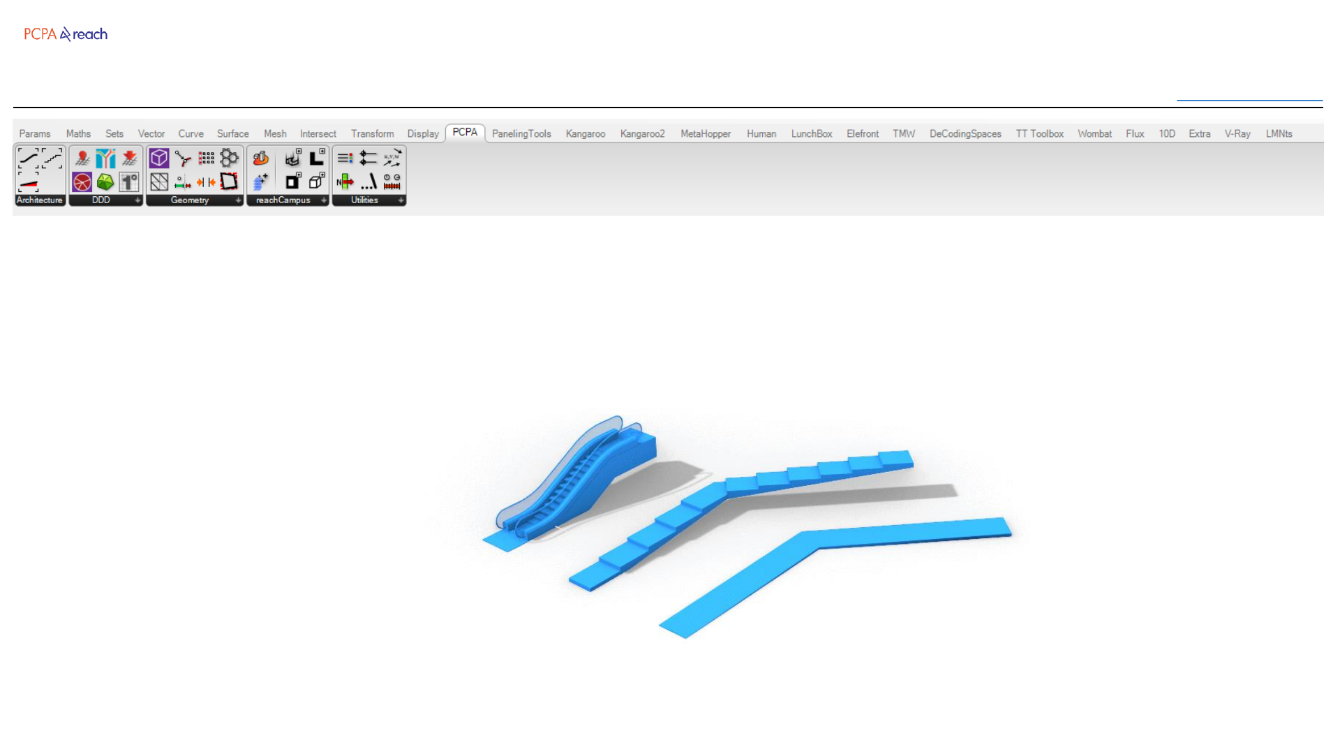
Loads all PCPA GH Components
and PCPA Standard Set (curated
collection of useful GH Plugins)
1. Close all Rhino Sessions.
2. Reopen Rhino
3. From the PCPA Dropdown
menu, choose Load GH
Components
4. Many things will then be
imported. Some things
may fail or say “Broken”.
Stay calm.
5. Open Grasshopper
*Warnings may appear
(depends on how many
grasshopper plugins you have
already installed). This should
only happen the first time you
run Load GH Components
Check out the GH Installation
Troubleshooting if problems
persist
Load GH Components
Rhino Tools Manual
Version 2.1
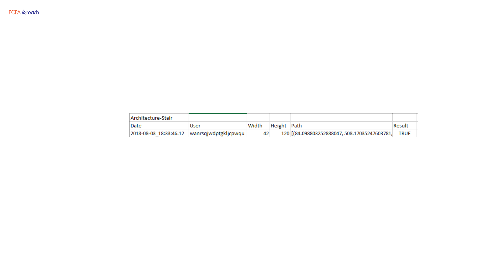
In order to improve the
functionality of the toolbar, user
input in these functions is
dynamically stored in a file on
the network.
Analytics should help us learn:
Which scripts aren’t working
Which are popular
Which are unpopular
Which settings should change
Usernames are encrypted for
anonymity.
Analytics
Rhino Tools Manual
Version 2.1
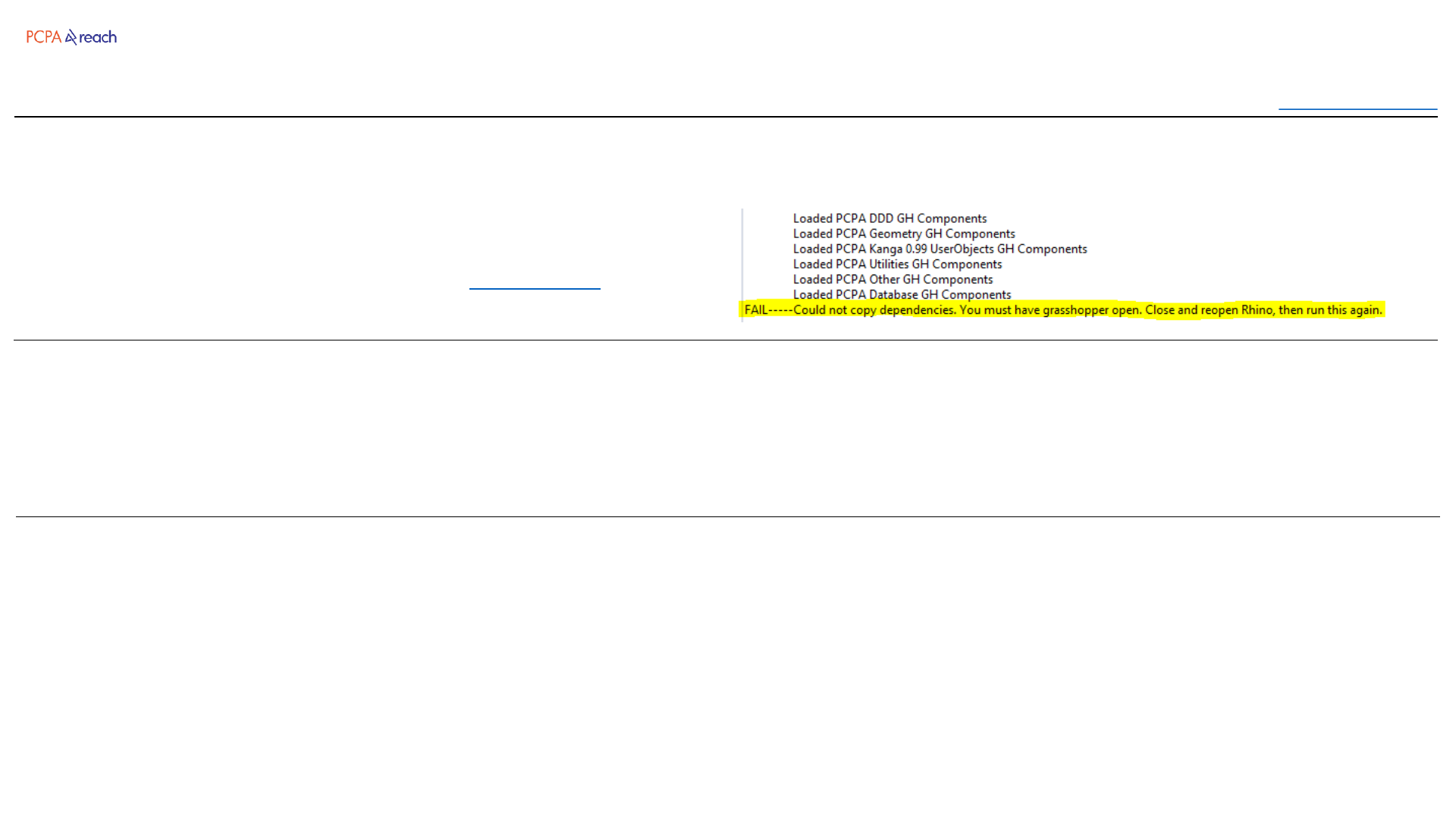
ERROR: “FAIL---Could not copy…” Warning
SOLUTION: Close all Rhino sessions and follow the GH installation steps again.
ERROR: “File Conflict Warning ” Warning
SOLUTION: Choose the Delete button on the left. For each pop-up
ERROR: “Component ID conflict” Warning
SOLUTION: Choose the Replace All button.
If this continues to come up when opening Grasshopper,
paste %appdata%\Grasshopper\Libraries into windows explorer. Then delete
the conflicting file (00_PCPA Standard Set should not be deleted).
Table of Contents
Rhino Tools Manual
Version 2.1
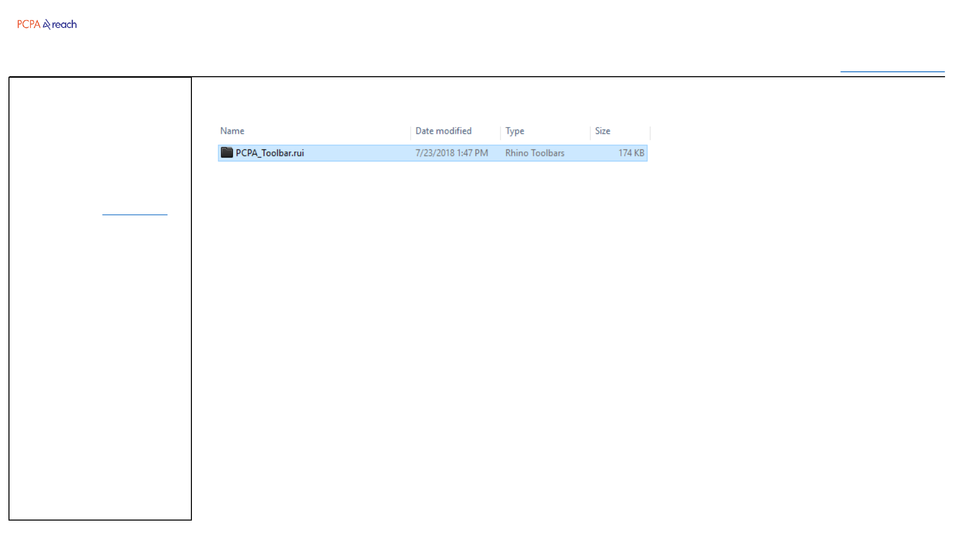
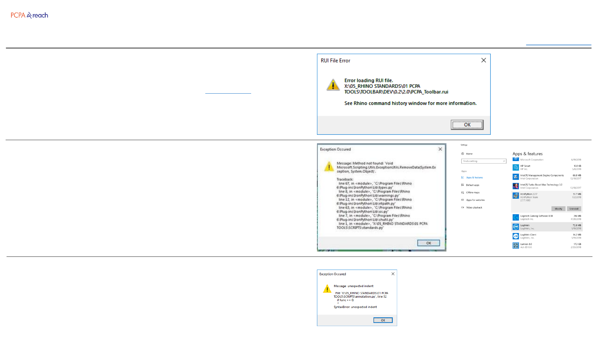
ERROR: “RUI File Error” Warning when Rhino Starts
SOLUTION: Drag and drop the toolbar to install again: Toolbar path
This usually happens when your computer temporarily loses connection to the
network when opening Rhino.
ERROR: “Method Not Found ” Warning
SOLUTION: Go to the “Add & Remove Programs page” in Windows Settings.
Scroll down and Uninstall “IronPython 2.7.3” . Close and reopen Rhino.
*This is a conflict caused when Dynamo has been installed. (Latest versions of
Dynamo do not need this to run).
ERROR: “Exception Occured” Warning
SOLUTION: There is a bug in the script. Please send screenshot and description
to Tim.
Table of Contents