PDP 12_Hardware_Student_Guide_Number_1 12 Hardware Student Guide Number 1
PDP-12_Hardware_Student_Guide_Number_1 PDP-12_Hardware_Student_Guide_Number_1
User Manual: PDP-12_Hardware_Student_Guide_Number_1
Open the PDF directly: View PDF ![]() .
.
Page Count: 78
PDP-12
HARDWARE
STUDENT
GUIDE NO. 1
(Adjustments.,
Diagnostics
&
Troubleshooting)
Educational
Services
CONTENTS
I.
PDP-12 Lab #1 2 Hours
II.
A.
Loading
the
RIM
Loader
B.
Checking
the
RIM
Loader
C.
Loading
the
BINary .·Loader
D. The Use
of
Checkerboard
Low
and High
to
Check
Memory
E.
How
to
Tune
Memory
F.
Program Development
PDP-12 Lab //2 4 Hours
A.
First
Period
1.
Scoping
Processor
Timing
2.
Scoping
Memory
Timing
B.
Second
Period
1.
Scoping
Manual Timing
2.
Troubleshooting
(as
time
permits)
III.
PDP-12
Lab
i¥3
2 Hours
A.
Understanding
the
Front
Panel
Indicators
B.
Use
of
Paper
Tape
Diagnostics
in
Locating
Machine
Failures
C.
Troubleshooting
(as
time
permits)
IV. PDP-12 Lab
#4
2 Hours
A.
TU-55
Alignment,
Torque and
Brake
Adjustments
B.
Troubleshooting
Processor
Problems
V.
PDP-12 Lab
//5
2 Hours
A.
Dial
Lecture
VI.
PDP-12 Lab
#6
2 Hours
A.
Do
Key
Operation
B. Use
of
Linc
Instructions
VII.
PDP-12 Lab
/f7
2 Hours
A.
TU-56
Adjustments
B.
Troubleshooting
Processor
Problems
VIII.
PDP-12 Lab
#8
2 Hours
A.
-Program Debugging
B. Program Development
c.
Troubleshooting
Processor
Problems
IX. PDP-12 Lab
#9
2 Hours
A.
Using
Mark 12
B. Use
of
Tape
Instructions
X.
PDP-12 Lab #lO 2 Hours
A.
Scoping
Linc
Tape Timing
B.
Scoping
the
Mark
Track
C.
Linc
Tape Bugs
(as
time
permits)
XI.
PDP-12 Lab #11 2 Hours
A.
Tape
Delay
Adjustments
B.
Troubleshooting
the
TC-12
XII.
PDP-12 Lab #12 2 Hours
A.
Use
of
Tape
Diagnostics
B. TC-12
Troubleshooting
XIII.
PDP-12 Lab #13 2 Hours
A.
Calibration
of
AD-12
B.
Troubleshooting
AD-12
XIV. PDP-12 Lab #14 2 Hours
A.
VR-12
Adjustments
B. VR-14
Adjustments
C.
Troubleshooting
the
VC-12
XV.
PDP-12 Lab #15 2 Hours
A.
KW-12A
Diagnostic
Usage
B.
KW-12A
Troubleshooting
XVI.
PDP-12 Lab //16 4 Hours
A.
PDP-12/10 System
Troubleshooting
B. PDP-12/20 System
Troubleshooting
c. PDP-12/30 System
Troubleshooting
D.
PDP-12/40 System
Troublesho6ting

PDP-12
LAB
NO.
1
OUTLINE
Time:
2
hours
--
1.
Loading
the
RIN!
Loader
2.
Checking
the
RIM
Loader
3.
Loading
the
Binary
Loader
4.
The Use
of
Checkerb6ard
Low
and
High
to
Check Memory
5.
How
to
Tune Memory
6.
Program
Development
PDP-12
IJ\B
JOB
SHEET
1/1-1
TITLE:
Loading
the
Rim
Loader
OBJECTIVE:
To
insure
th~t
all
students
are
capable
of
manually
inserting
Rim
Loader
into
core
successfully.
··
PROCEDURE:
1.
The
student
should
read
information
sheets
1,
2 and
3.
2.
Using
the
procedure
described
in
in-
formation
sheet
4,
load
the
rim
loader
as
listed
in
info
sheet
3.
3.
Go
to
Job
¥1-2.
PDP-12
Ll\B
JOB
SHEET
.#1-2
TITLE:
Checking
the
Rim
Loader
OBJECTIVE:
1.
To
insure
that
the
rim
loader
is
correctly
loaded
into
core.
2.
To
further
usage
of
the
keys
Exam
and
Step
Exam.
PROCEDURE:
Use
the
nrocedure
described
in
information
sheet
5 and
check
the
rim
loader.
Upon
completion
of
this
exercise
Go
to
Job
Sheet
#1-3
PDP-12
LAB
JOB
SHEET
#1-~
TITLE:
Loading
the
Binary
Loader
OBJECTIVE:
To
insure
that
all
students
understand
the
purpose
of
the
binary
loader
and
can
success-
fully
load
the
binary
loader.
PROCEDURE:
1.
Obtain
a
binary
loader
paper
tape
from
the
instructor.·
2.
Compare
the
format
of
this
tape
to
the
format
as
described
in
information
sheet
¥2
binary
format.
3.
Read
info
sheets
6, 7, 8 and
9.
4.
Use
info
sheet
#9
and
load
the
binary
loader
paper
tape.
5. Upon
successful
completion
Go
to
job
sheet
#1-4
PDP-12
LAB
JOB
SHEET
#1-4
TITLE:
Using
Checkerboard
Low
and High
to
Check
Memory
OBJECTIVE:
1.
To
insure
that
Rim
and
Binary
loader
have
been
used
properly.
2.
To
introduce
the
student
to
paper
tape
diagnostics.
).
To
insure
that
the
memory
stack
is
reliable
before
the
memory
tuning
exercise.
PROCEDURE:
1.
Obtain
paper
tapes,
checkerboard
(Low
and
High) and
their
associated
write-ups
from
the
instructor.
2.
Using
the
procedure
descr~bed
in
info
sheet
#10,
load
and
run
both
programs.
).
Upon
completion
Go
to
job
sheet
#1-5
PDP-12
LAB
JOB
SHEET
#1-5
TITLE:
How
to
Tune
Memory
OBJECTIVE:
To
insure
that
all
students
can
properly
tune
memory on
the
PDP-12.
PROCEDURE:
Perform
this
memory
tuning
exercise
by
the
procedure
described
in
section
4.1
through
4.2.2
of
the
PDP-12
Adjustment
Procedure
manual.
PDP-12
LAB
JOB
SHEET
71-~
TITLE:
Program
Development
OBJECTIVE:
To
develop
the
confidence
of
the
student
in
his
ability
to
successfully
program
a
pro-
cessor.
PROCEDURE:
Write
a
program,
using
LINC
or
8-mode
instruction,
that
detects
the
number
of
4K
fiel~present
in
a
processor.
At
the
com-
pletion
of
the
program,
type
"This
processor
has
__
4K
Fields",
then
HLT.
Show
this
program
to
the
instructor
for
technique
development
suggestions.
Save
the
program
for
further
use.
FLD1.'I
CHI\
RT
RIM
LOADER
PROGRAM
f/rr;
/1w11n~r(
Qr<>.
ft-
Rofu+e 't
Pt~ee.~
le~+
Si#-i
'"'
~,,~
hi+
~-------------~N~O~__J
--~-
··---
..
·-------
NO
· s
fo
""
Ac
· .
"--_..,
(A
OD
R $.t;S)
:-
1
__
.....
___
_____.,
; m
/t;MP
j
l
INFORMATION
SHEET
#1
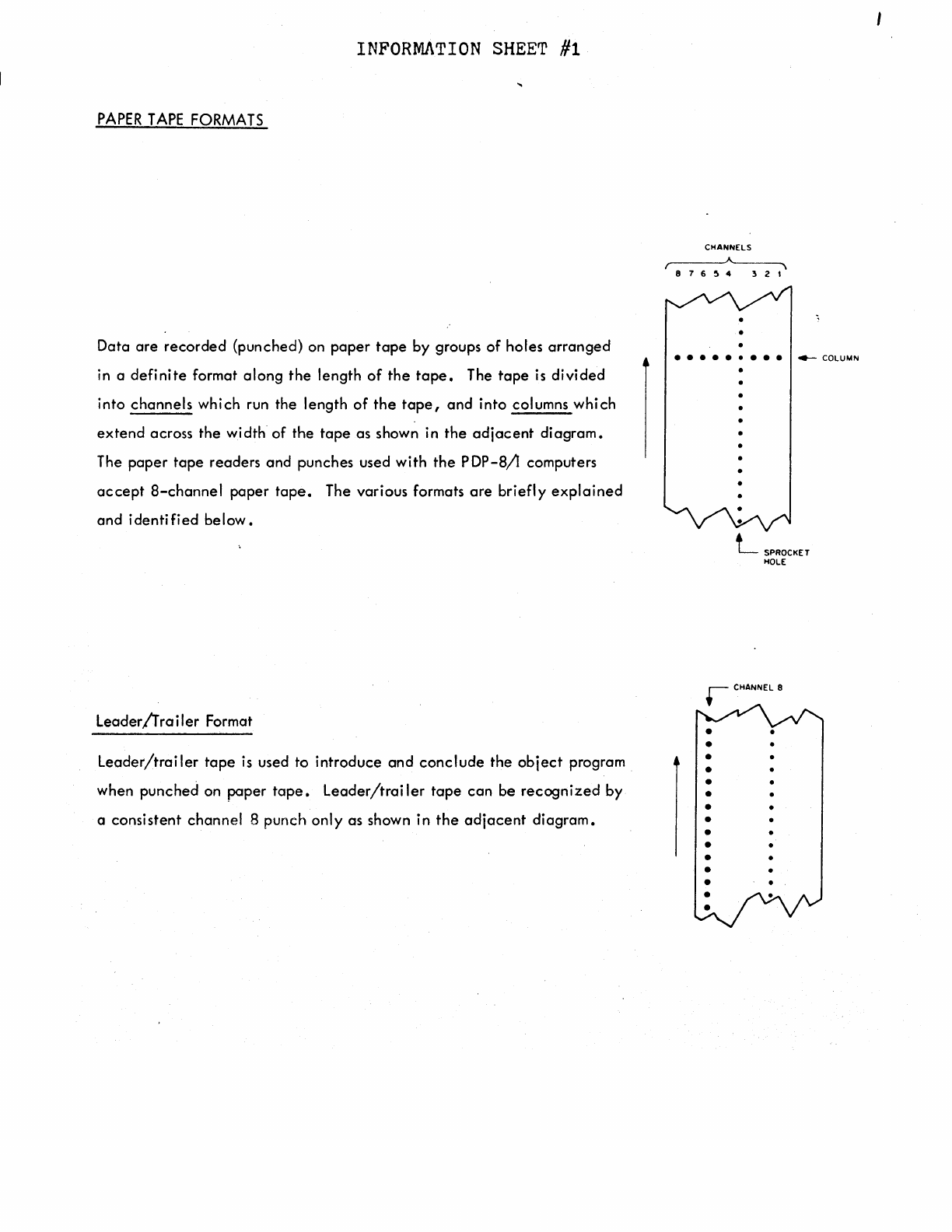
PAPER
TAPE
FORMATS
Data
are
recorded
(punched} on
paper
tape
by
groups
of
holes
arranged
in a
definite
format
along
the
length
of
the
tape.
The
tape
is
divided
into
channels
which run the length
of
the
tape,
and
into
columns
which
extend
across
the
width
of
the
tape
as
shown in
the
adjacent
diagram.
The
paper
tape
readers
and
punches used
with
the
PDP-8/l
computers
accept
8-channel
paper
tape.
The various formats
are
briefly
explained
and
identified
below.
Leader/frailer
Format
Leader/trailer
tape
is
used to
introduce
and
conclude
the
object
program
when
punched
on
paper
tape.
Leader/trailer
tape
can
be
recognized
by
a
consistent
channel
8
punch
only
as shown in
the
adjacent
diagram.
CHANNELS
876~4
321
•
e e e e e • e e e
4--
COLUMN
•
•
•
•
•
•
•
•
•
•
•
•
•
•
•
L
SPROCKET
HOLE
•
•
•
INFORMATION SHEE'l' #2
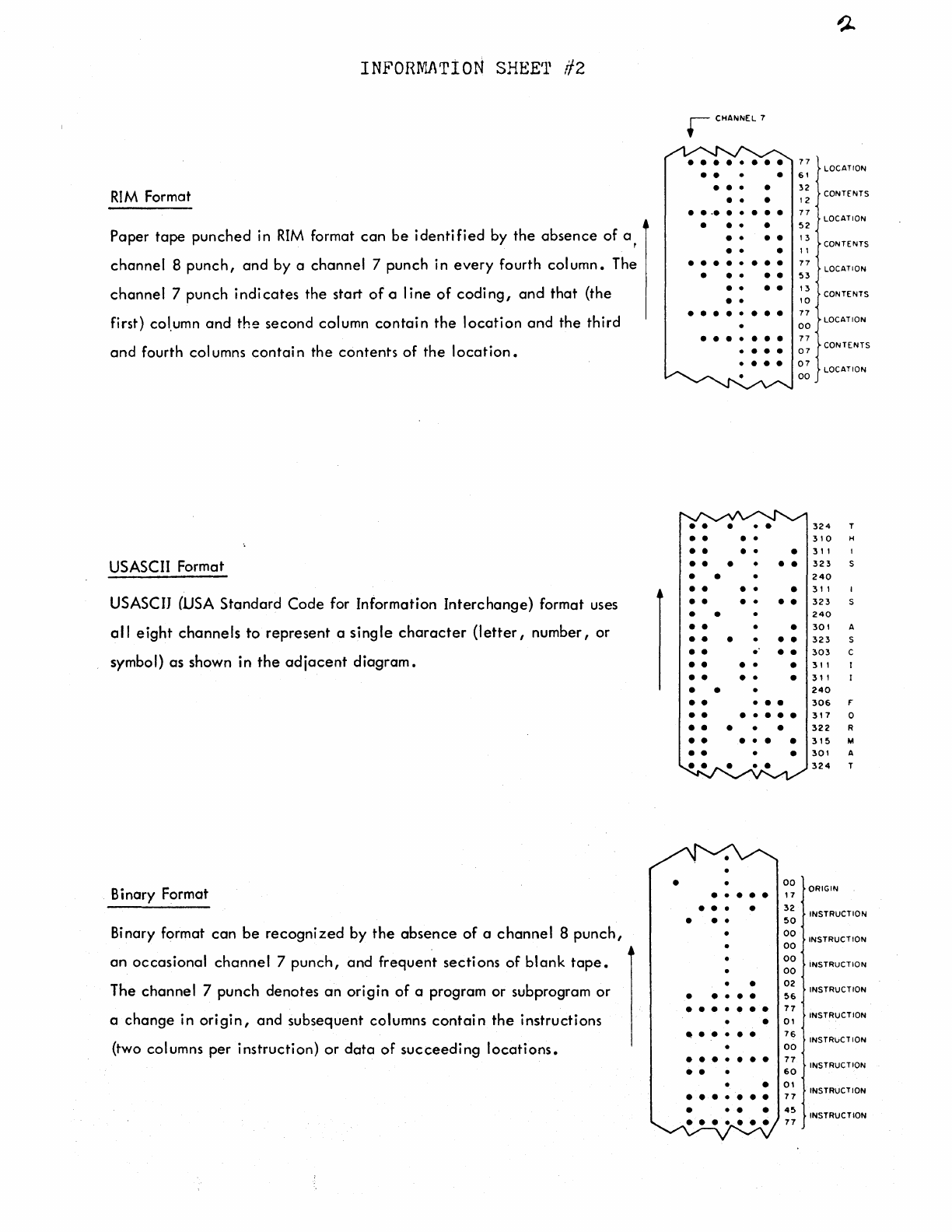
RIM
Format
Paper
tape
punched
in
RIM
format
can
be
identified
by
the
absence
of
a ,
channel
8
punch,
and
by
a
channel
7
punch
in
every
fourth
column.
The
channel
7
punch
indicates
the
start
of
a
line
of
coding,
and
that
(the
first) col.umn
and
the
second
column
contain
the
location
and
the
third
and
fourth columns
contain
the
contents
of
the
location.
USASCII Format
USASCIJ (USA
Standard
Code
for Information
Interchange)
format uses
al
I
eight
channels
to
represent
a
single
character
(letter,
number,
or
symbol)
as
shown in
the
adjacent
diagram.
Bi
nary Format
Binary format
can
be
recognized
by
the
absence
of
a
channel
8
punch,
an
occasional
channel
7
punch,
and
frequent
sections
of
blank
tape.
The
channel
7
punch
denotes
an
origin
of
a program
or
subprogram
or
a
change
in
origin,
and
subsequent
columns
contain
the
instructions
(two columns
per
instruction)
or
data
of
succeeding
locations.
•
r CHANNEL 7
• • • • • • • •
• • •
• • • •
• • •
. .
·•
. .
•••
• • • •
• • • •
• • •
• • • • • • • •
• • • • •
• • • •
• •
• • • • • • • •
• • • • • • •
.
• • •
• • • •
• • • • •
• • • •
• • • • •
••
• • •
• •
• • • • •
• • • • • •
• •
• • •
••
• • •
• • . • •
• • • • •
• • • • •
• •
••
• • •
• • • • • • •
• • • • •
• • • • • •
••
• •
00
• • • • • , 7
• • • •
32
• • •
50
•
00
00
00
00
•
02
• • • • •
56
• • • • • • •
77
•
01
• • • • • •
76
00
• • • • • • •
77
••
60
•
01
• • • • • • •
77
• •
45
77
77
LOCATION
61
32
CONTENTS
12
77
LOCATION
52
1 3 CONTENTS
11
77
LOCATION
53
13
10
CONTENTS
77
00
LOCATION
77
07
CONTENTS
07
LOCATION
00
324
T
310
H
31,
323
240
3,
1
323
240
301
A
323
s
303
c
3,,
31
I
240
306
F'
317
0
322
R
315
M
301
A
324
T
ORIGIN
INSTRUCTION
INSTRUCTION
iNSTRUCTION
INSTRUCTION
INSTRUCTION
INSTRuCTION
INSTRUCTION
INSTRUCTION
INSTRUCTION
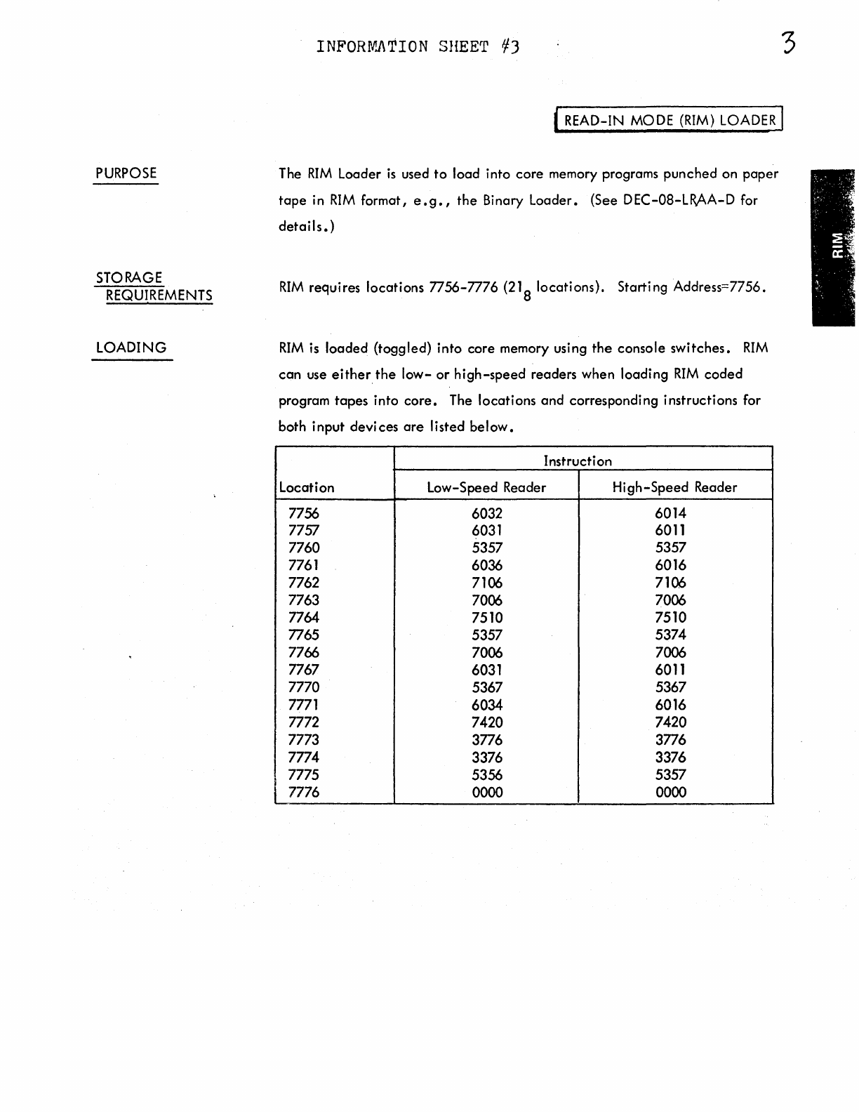
PURPOSE
STORAGE
REQUIREMENTS
LOADING
INFORIV'J\TION SHEET
¥3
3
' READ-IN MODE
(RIM)
LOADER
I
The
RIM
Loader
is
used
to
load into core memory programs punched on
paper
tape
in
RIM
format,
e.g.,
the Binary Loader. (See DEC-08-LR.AA-D for
details.)
RIM
requires locations 7756-7776
(21
8 locations). Starting Address=7756.
RIM
is
loaded (toggled) into core memory using
the
console switches.
RIM
can
use either.
the
low-
or
high-speed
readers when loading
RIM
coded
program
tapes
into
core.
The locations and corresponding instructions for
both input devices
are
Ii
sted be I
ow.
Instruction
Location Low-Speed Reader High-Speed Reader
7756 6032 6014
7757 6031 6011
7760 5357 5357
7761 6036 6016
7762 7106 7106
7763 7006 7006
7764 7510 7510
7765 5357 5374
7766 7006 7006
7767 6031 6011
7770 5367 5367
7771 6034 6016
7772 7420 7420
7773 3776 3776
7774 3376 3376
7775 5356 5357
7776 0000 0000
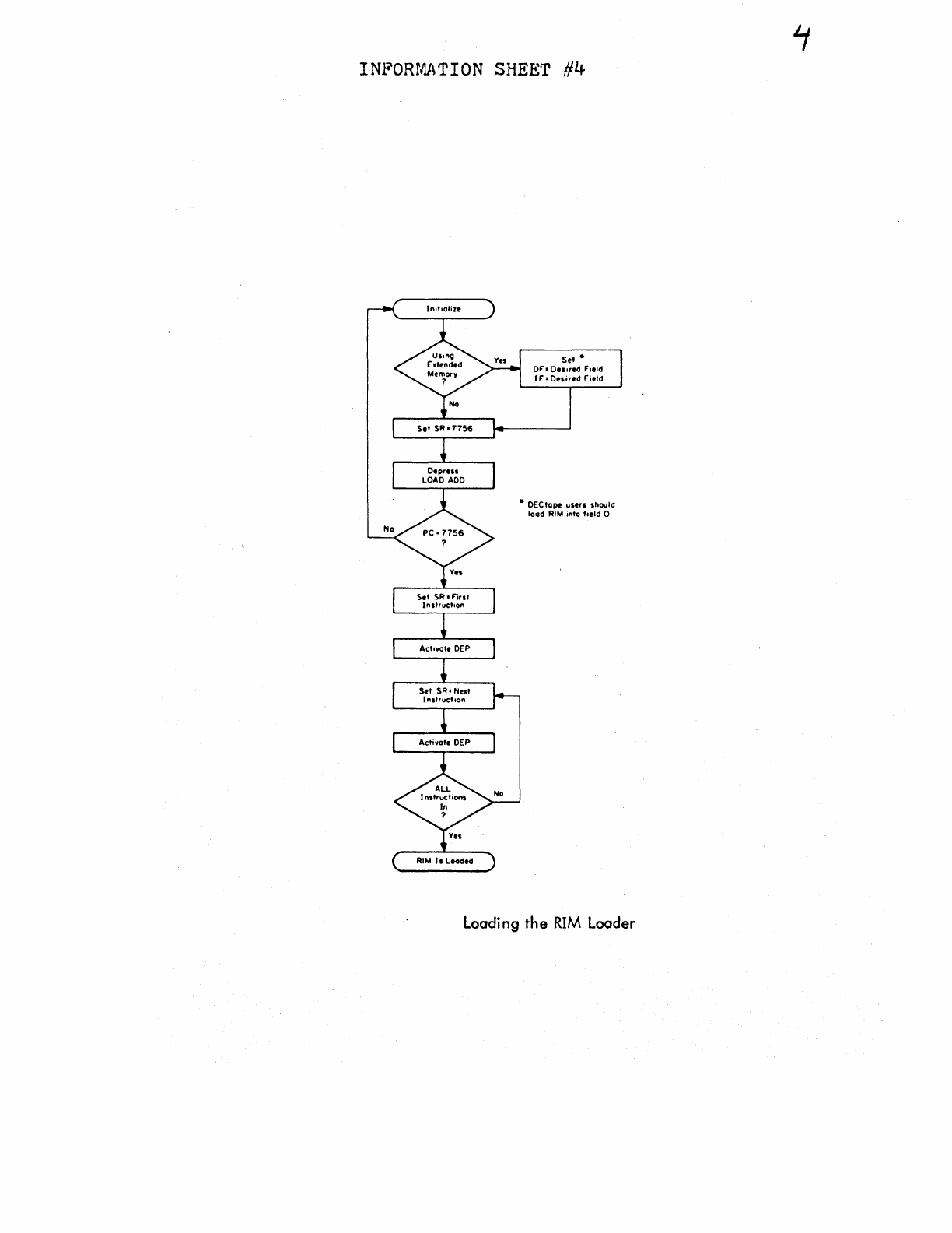
INFORMATION
SHEET
#4
ln1t1olize
Set
SR•7756
Depress
LOAD
ADO
Set
SR•Firsl
I nstructoon
Actovolt
DEP
Set
SR•
Next
lnstrucl1on
Activate DEP
RIM
Is
Loaded
Set*
OF•Onored
Field
IF•Dnired
Field
•
DEC
lope
ustrs
should
load
RIM
into field O
Loading the
RIM
Loader
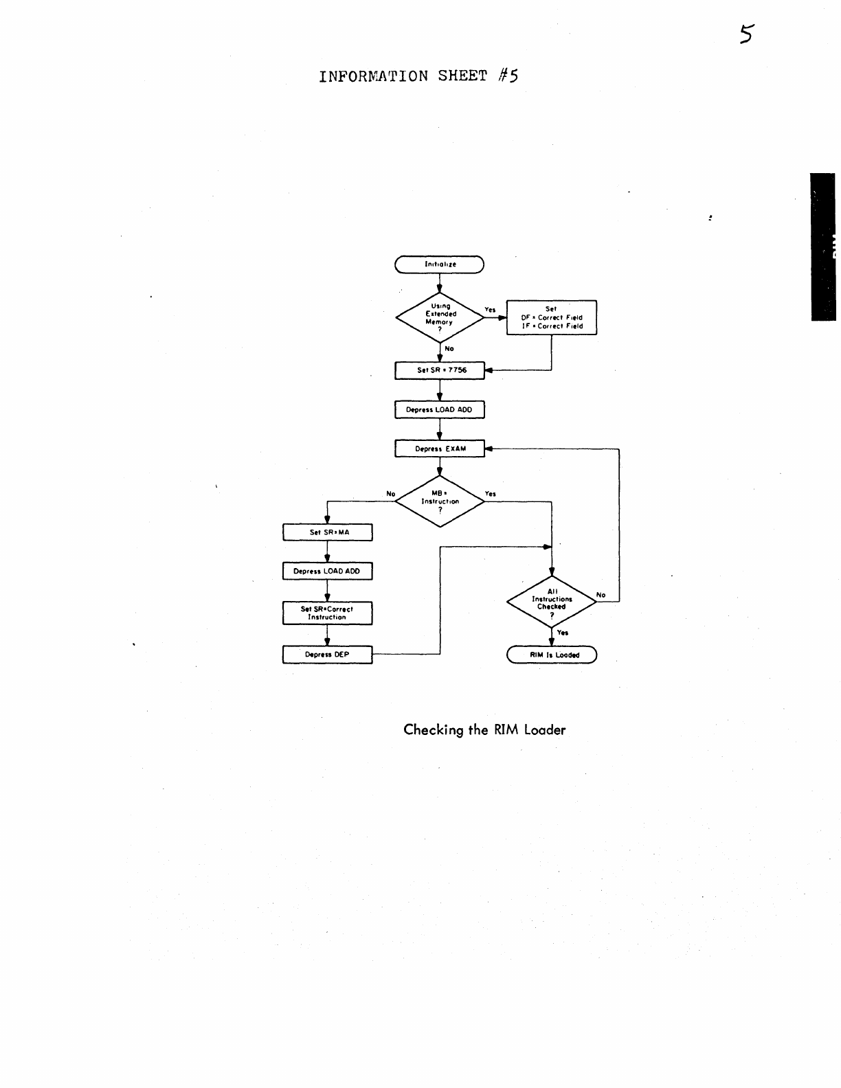
INFORMNrION
SHEET
#5
Set
SR•MA
Depren
LOAD
ADO
S.t
SR•Corrtct
Instruction
Dtprtn
OEP
No
ln1t101o1e
Set
SR•
7756
Depress
LOAD
ADO
Depress
EXAM
Yes
Set
OF"•
Correct
F"oeld
IF"•
Correct
F"oeld
RIM
Is
Loodtd
Checking the
RIM
Loader
5
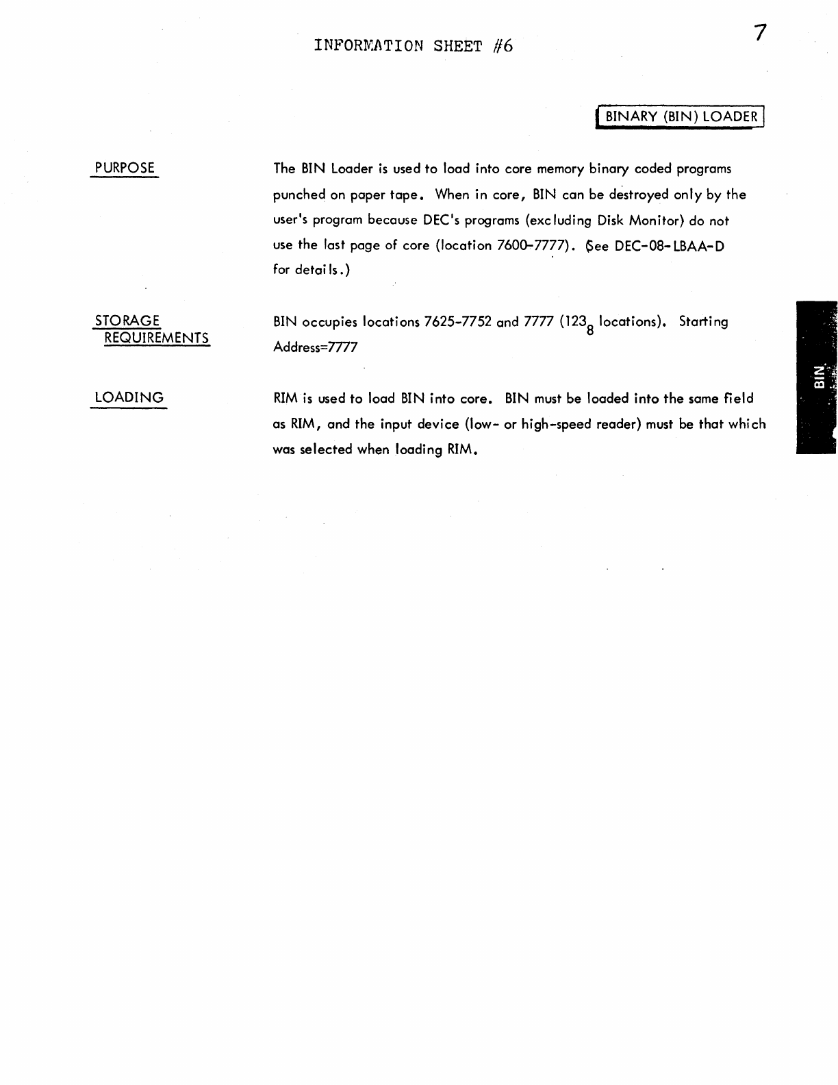
PURPOSE
STORAGE
REQUIREMENTS
LOADING
INPORfv:J\TION SHEET //6 7
( BINARY (BIN) LOADER I
The
BIN
Loader
is
used
to
load into
core
memory
binary
coded
programs
punched
on
paper
tape.
When in
core,
BIN
can
be
destroyed
only
by
the
user's program
because
DEC's programs
(excluding
Disk
Monitor)
do
not
use
the
last
page
of
core
(location
7600-7777).
~ee
DEC-08-LBAA-D
for
detai
Is.)
BIN
occupies
locations
7625-7752
and
7777
(1238
locations).
Starting
Address=m7
RIM
is used
to
load
BIN
into
core.
BIN
must
be
loaded
into
the
same
field
as
RIM,
and
the
input
device
(low-
or
high-speed
reader)
must
be
that
which
was
selected
when
loading
RIM.
INFOHl\.NrION SHEET
/17
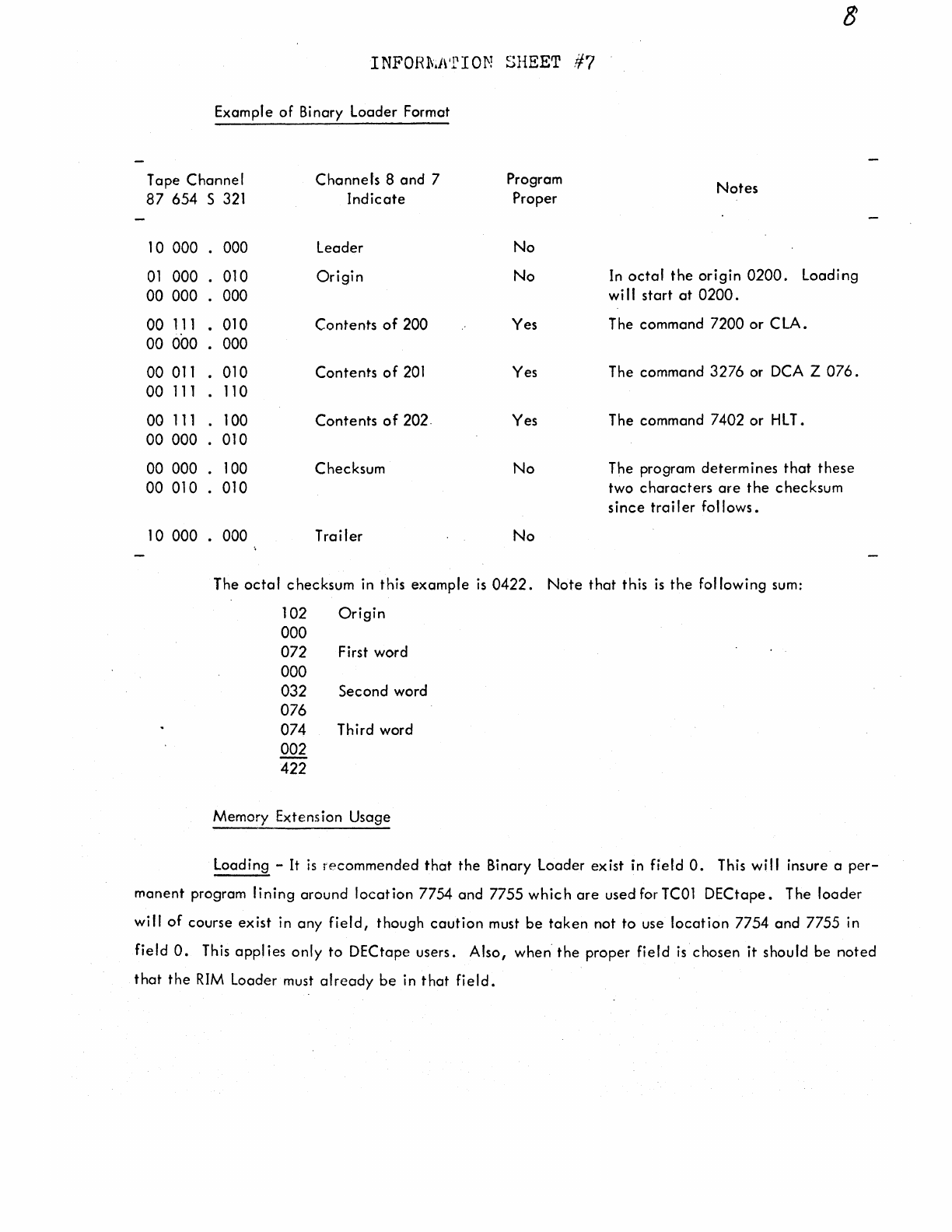
Example
of
Binary
Loader
Format
Tape
Channel
87
654
s
321
10
000
000
01
000
.
010
00
000
.
000
00
111
.
010
00
000
.
000
00
011
.
010
00
111
.
110
00
111
.
100
00
000
.
010
00
000
.
100
00
010
.
010
10
000
000
Channels
8
and
7 Program
Indicate
Proper
leader
No
Origin
No
Contents
of
200
Yes
Contents
of
201
Yes
Contents
of
202.
Yes
Checksum
No
Trailer
No
Notes
In
octal
the
origin
0200.
Loading
wi I I
start
at
0200.
The
command
7200
or
C LA.
The
command
3276
or DCA Z 076.
The
command
7402
or
HLT.
The program
determines
that
these
two
characters
are
the
checksum
since
trailer
follows.
The
octal
checksum
in
this
example
is
0422.
Note
that
this
is
the
fol
lowing
sum:
102
Origin
000
072 First
word
000
032
Second
word
076
074
Third
word
002
422
Memory
Extension
Usage
Loading
-It
is
recommended
that
the
Binary
Loader
exist
in
field
0.
This
will
insure a
per-
manent
program
lining
around
location
7754
and
7755
which
are
used
for TCOl
DECtape.
The
loader
will
of
course
exist
in
any
field,
though
caution
must
be
taken
not
to
use
location
7754
and
7755
in
field
0.
This
applies
only
to
DECtape
users.
Also,
when
the
proper
field
is
chosen
it
should
be
noted
that
the
RIM
Loader
must
already
be
in
that
field.
INPOHMJ\TION SHEET
/18
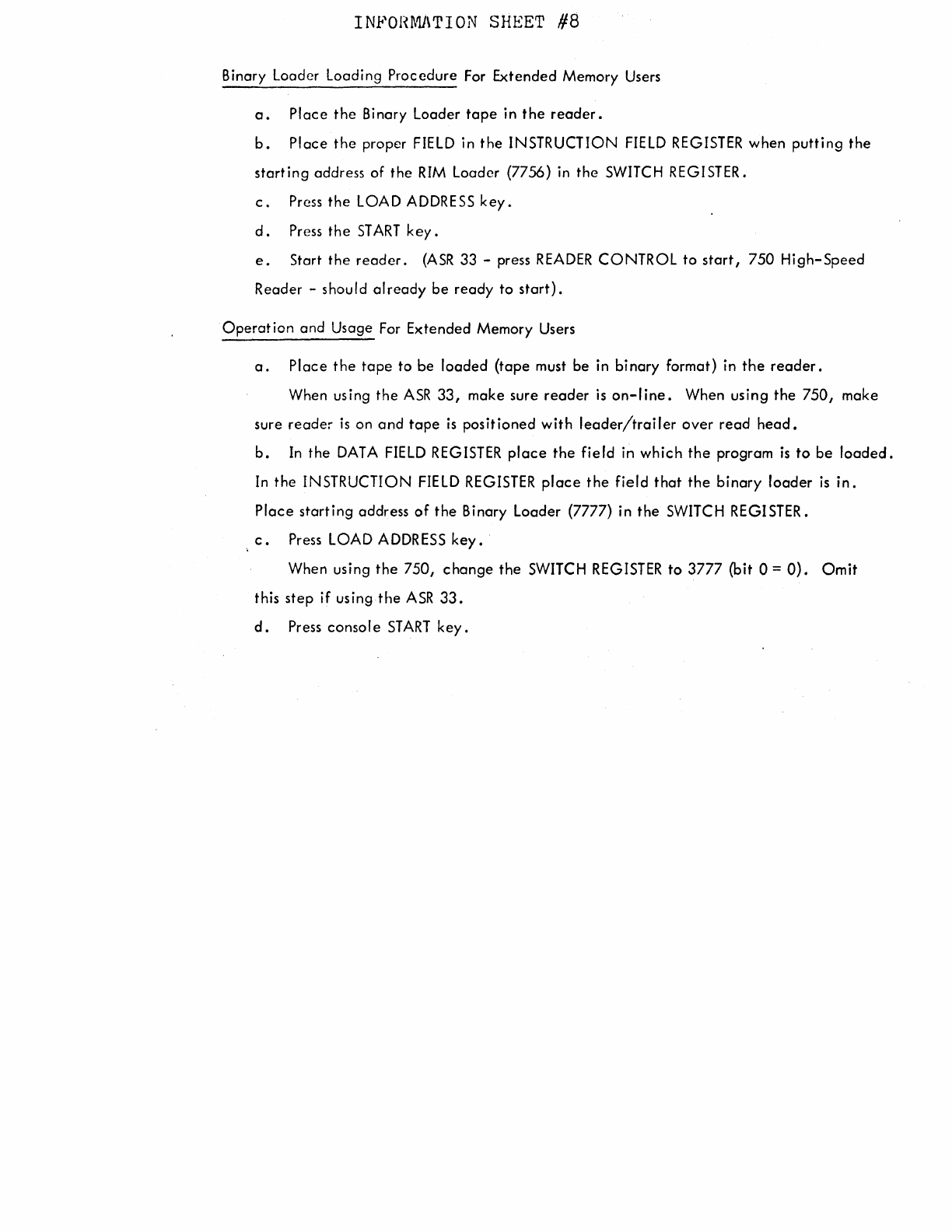
Binary Loader Loading Procedure
For
Extended Memory
Users
a.
Place
the
Binary Loader
tape
in
the
reader.
b.
Place the proper
FIELD
in the INSTRUCTION
FIELD
REGISTER
when putting the
starting address of the
RIM
Loader (7756)
in
the
SWITCH
REGISTER.
c.
Press
the
LOAD
ADDRESS
key.
d.
Press
the
ST
ART
key.
e.
Start the
reader.
(ASR
33 -press
READER
CONTROL to
start,
750 High-Speed
Reader -should already be ready to
start).
Operation and Usage
For
Extended Memory
Users
a.
Place the
tape
to be loaded (tape
must
be
in
binary format) in
the
reader.
When using the
ASR
33,
make sure reader
is
on-line.
When using the 750, make
sure reader
is
on and
tape
is
positioned with
leader/trailer
over read
head.
b.
In
the
DATA
FIELD
REGISTER
place
the field in which the program
is
to
be
loaded.
In
the INSTRUCTION
FIELD
REGISTER
place
the field that the binary loader
is
in.
Place starting address
of
the Binary Loader (7777) in the
SWITCH
REGISTER.
c.
Press
LOAD
ADDRESS
key.
When using the 750, change the
SWITCH
REGISTER
to 3777 (bit 0 =
O).
Omit
this step if using the
ASR
33.
d.
Press console
START
key.
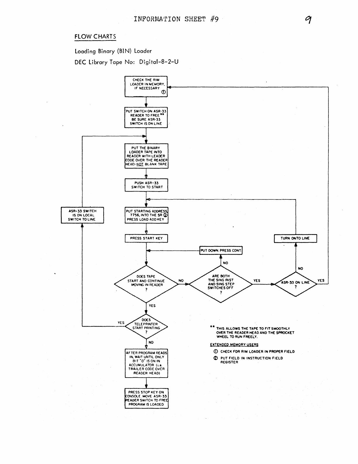
INFORMJ\'rION
SHEET
#9
FLOW
CHARTS
Loading Binary (BIN) Loader
DEC
Library Tape No:
Digital-8-2-U
CHECK
THE RIM
LOADER IN MEMORY,
IF NECESSARY
.,._~~~~~~~~~~~~~~~~~~~~~~~~~~~~~---,
ASR-
33
SWITCH
IS
ON
LOCAL
SWITCH
TO
LINE
©
PUT
SWITCH
ON
ASR-:n
READER
TO
FREE
..
BE
SURE
ASR-33
SWITCH IS
ON
LINE
PUT
THE
BINARY
LOADER TAPE INTO
READER WITH LEADER
CODE
OVER
THE
READER
HEAD-~
BLANK TAPE
PUSH
ASR-33
SWITCH
TO
START
PRESS START KEY
AFTER
PROGRAM
READS
IN,
WAIT
UNTIL ONLY
BIT
"0"
IS
ON
IN
ACCUMULATOR (i.e.
TRAILER
CODE
OVER
READER HEAD!
PRESS STOP KEY ON
ONSOLE.
MOVE
ASR-33
ADER SWITCH
TO
FRE
PROGRAM
IS
LOADED
TURN OfilTO LINE
••
THIS ALLOWS THE TAPE
TO
FIT
SMOOTHLY
OVER THE READER HEAD ANO THE SPROCKET
WHEEL
TO
RUN FREELY.
EXTENQEP MEMORY USERS
G)
CHECK FOR RIM LOADER
IN
PROPER
FIELD
~
PUT
FIELD
IN
INSTRUCTION
FIELD
REGISTER
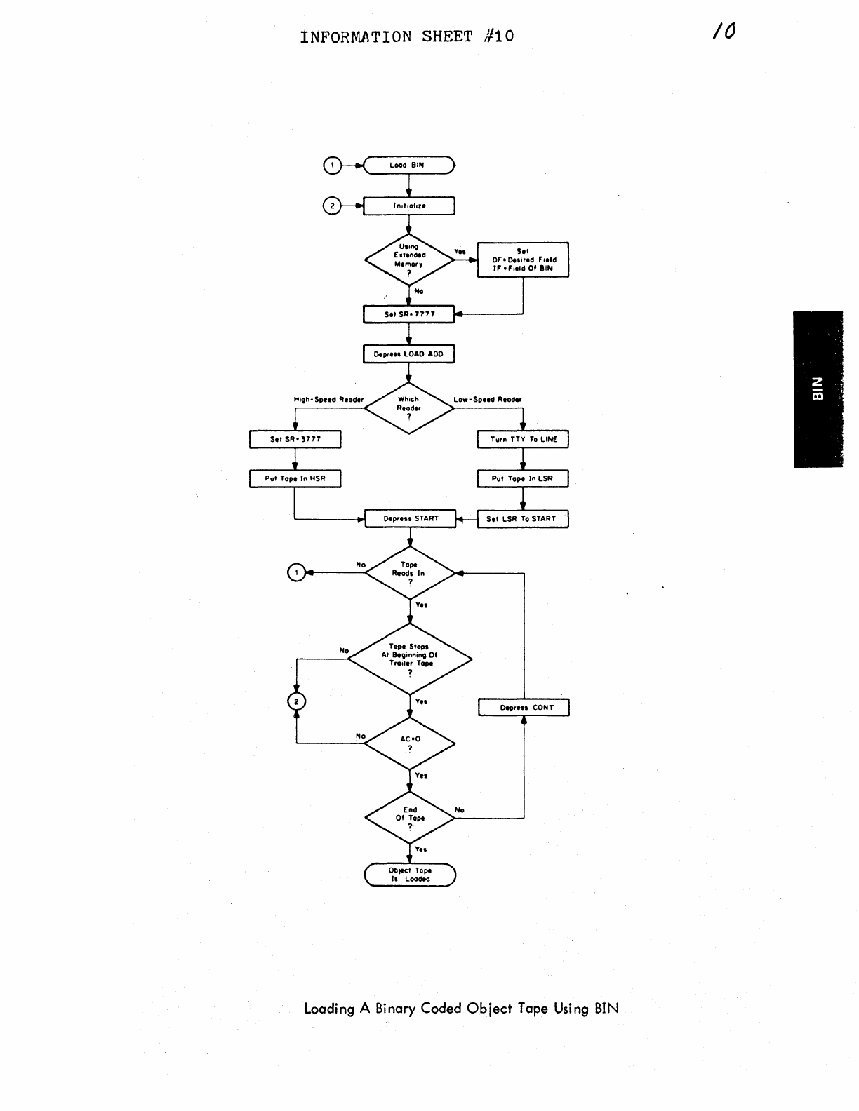
INFORMJ\TION
SHEET
#10
Load
BIN
Set SR•
7777
0.prHI
LOAD
ADO
Set
Or•0.1ired
Field
rr
•f'1eld Of
BIN
Set
SR•
3777
T1.1rn
TTY
To
LINE
P1.1t
Tope
In
HSR
P1.1t
Tope fn LSR
OeprHI
START Set LSR
To
START
Object Tope
h Loaded
OeprH1 CONT
Loading A Binary
Coded
Object
Tape Using
BIN
10
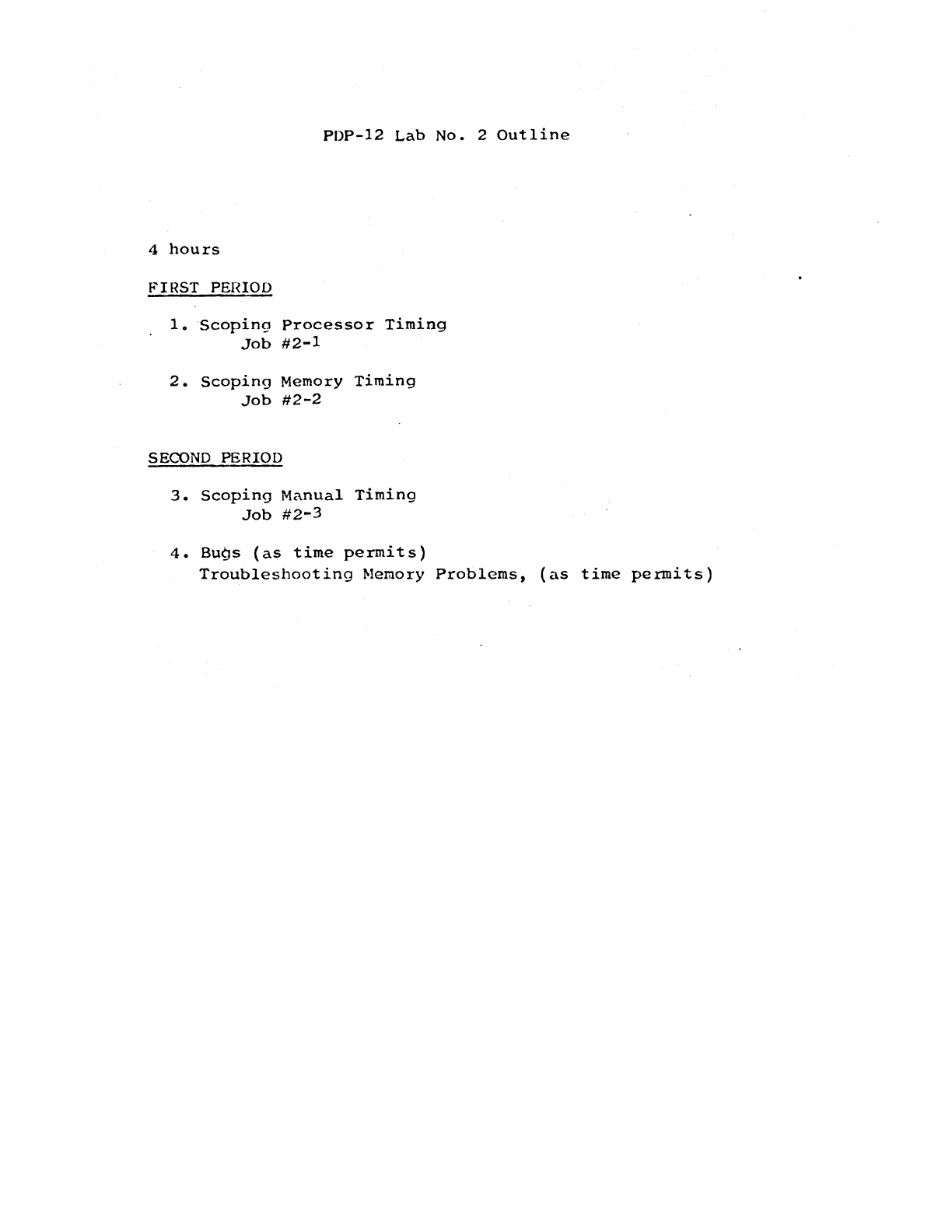
PDP-12
Lab
No.
2
Outline
4
hours
f.'IRST PEHIOD
lo
Scoping
Processor
Timing
Job
#2-1
2.
Scoping
Memory
Timing
Job
#2-2
SECOND
PERIOD
3.
Scoping
Manual
Timing
Job
#2-3
4.
Bugs
(as
time
permits)
Troubleshooting
Memory
Problems,
(as
time
permits)
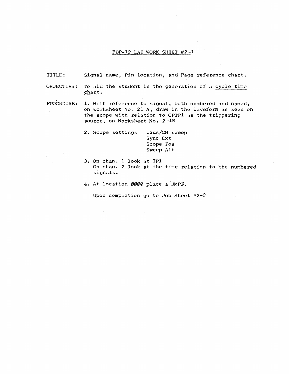
PDP-12
LAB
WOl~K
SHEET
#2
-1
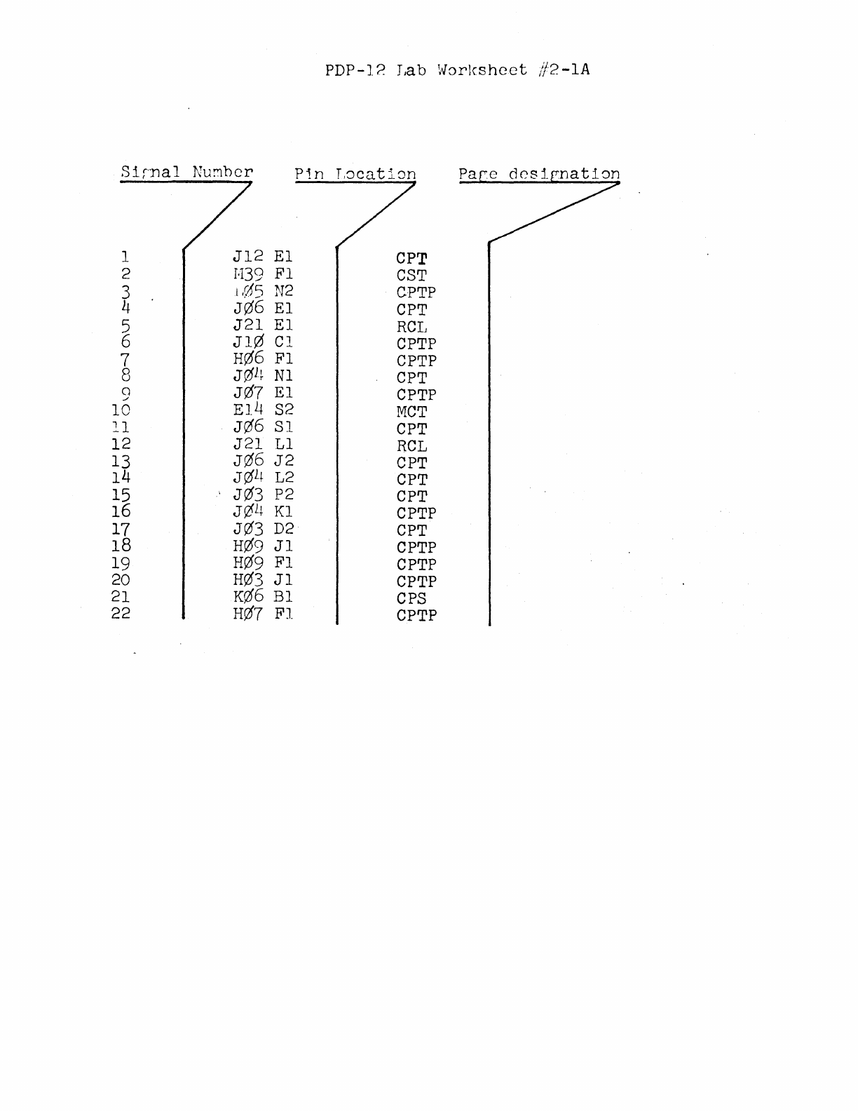
TITLE:
Signal
name,
Pin
location,
and
Page
reference
chart.
OBJECTIVE:
To
aid
the
student
in
the
generation
of
a
cycle
time
chart.
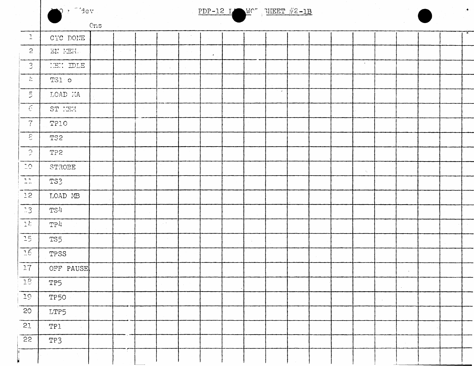
PROCEDURE:
1.
With
reference
to
signal,
both
numbered
and
named,
on
worksheet
Noo
21
A,
draw
in
the
waveform
as
seen
on
the
scope
with
relation
to
CPTPl
as
the
triggering
source,
on
Worksheet
Noo
2-lB
2.
Scope
settings
o 2us/Cf\1
sweep
Sync
Ext
Scope
Pos
Sweep
Alt
3o On
chan.
1
look
at
TPl
On
chan.
2
look
at
the
time
relation
to
the
numbered
signals.
4.
At
location
¢¢¢¢
place
a
JM~.
Upon
completion
go
to
Job
Sheet
#2-2
PDP-12
LAB
JOB SHEET
#~-1
TITLE:
Generation
of
a
processor
cycle
time
charto
OBJECTIVE:
To
aid
the
student.in
generating
a
processor
cycle
timing
chart,
and
in
understanding
processor
cycle
time
with
reference
to
CPTPl.
PROCEDURE:
Use
the
procedure
described
in
Lab
Worksheet
#2-1.
Upon
completion,
go
to
Job
Sheet
#2-2
PDP-12 Lab
Worlcshcet
//2-lA
Sirnal
Nu!:1bcr
Pi.n
L8caticm
1
Jl2
El
CPT
2
J.139
Fl
CST
3 1
(15
N2
CPTP
4
J06
El
CPT
5
J21
El
RCL
6
Jl0
Cl
CPTP
7
H06
Fl
CPTP
8
J01~
Nl
CPT
a
J07
El
CPTP
./
10
El4
S2
MCT
ll
J0'6
Sl
CPT
12
J21
Ll
RCL
13
J06
J2
CPT
14
J0l+
L2
CPT
15
J03
P2
CPT
16 J¢l+
Kl
CPTP
17 J0'3
D2
CPT
18
H0'9
Jl
CPTP
19
H0'9
Fl
CPTP
20
H0'3
Jl
CPTP
21
K0'6
Bl
CPS
22
H0'7
Fl
CPTP
~('~
i!IBET
f/2-lB
•
Ons
l
CYC
DOlJE
3
::E::
IBLE
l~
TSl
o
LOAD
:.:A
---+----------------·"···----+-·---+---+-----+---+----t----+-----+----+----+---+-----+--4--~----+---
r.
r
.,
.,
.,
J
·-
._)
1
c::::
_
___,
1
r:.
-'-''
17
~PlO
TS2
T?2
STROBE
TS3
LOAD
MB
TP4
TS5
TPSS
O?F
PAUSE
13 TP5
19
TP50
20
LTP5
21
TPl
22
TP3

PDP-12 Lab
Job
Sheet
#2-2
TITLE:
Generation
of
a memory
cycle
time
chart
OBJECTIVE:
To
aid
the
student
in
generating
a memor;/
cycle
timing
chart
and,
in
understandine
memory
cycle
time
with
rcfererice
to
Mem
Start.
PROCEDURE:
Draw a
timing
chart
of
memory
c;/cle
time
using
WorkshE:et //2.
Upon
completion,
go
to
Job
Sheet
#2-3
PDP-12 Tab
Worksheet
#2-2
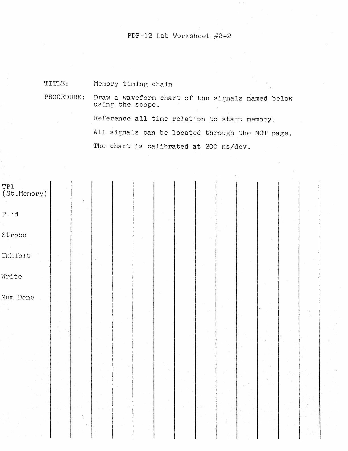
TITLE:
Memory
timin~
chain
PROCEDURE:
Draw a
waveform
chart
of
the
sic;nals
named
below
usinr;
the
scope.
Reference
all
time
relation
to
start
memory.
All
sicnals
can
be
located
through
the
MCT
page.
The
chart
is
calibrated
at
200
ns/dev.
TPl
(St.Memory)
p
'd
Inhibit
Write
Mem
Done
TITLE:
OBJECTIVE:
PROCEDURE:
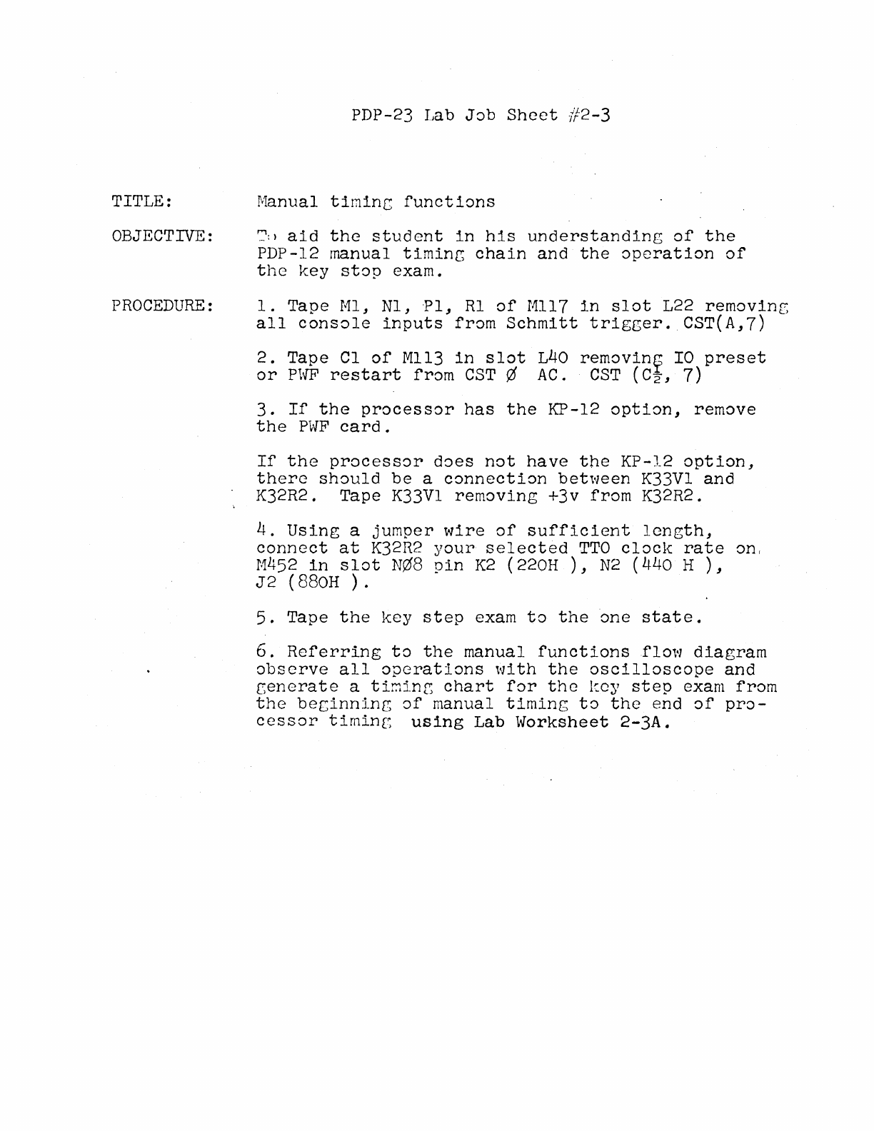
PDP-23 Tab
Job
Sheet
#2-3
Manual
timinc
functions
':':
>
aid
the
student
in
his
understanding
of
the
PDP-12 manual
timinr,
chain
and
the
operation
of
the
key
stop
exam.
1.
Tape
Ml,
Nl,
·Pl,
Rl
of
Mll7
in
slot
L22
removinr,
all
console
inputs
from
Schmitt
trigger.
CST(A,7)
2.
Tape
Cl
of
Mll3
in
slot
L40
removin~
IO
preset
or
PWF
restart
from
CST¢
AC.
CST
(C2,
7)
3.
If
the
processor
has
the
KP-12
option,
remove
the
PWF
card.
If
the
processor
does
not
have
the
KP-12
option,
there
should
be
a
connection
between
K33Vl
and
K32R2. Tape K33Vl
removing
+3v
from
K32R2.
4.
Using
a
jumper
wire
of
sufficient
length,
connect
at
K32R2
your
selected
TTO
clock
rate
on,
M452
in
slot
N¢8
pin
K2 (220H
),
N2 (440 H
),
J2
(880H
).
5.
Tape
the
key
step
exam
to
the
one
state.
6.
Referring
to
the
manual
functions
flow
diagram
observe
all
operations
with
the
oscilloscope
and
cenerate
a tir.1inr;
chart
for
the
kc;/
step
exam
from
the
beginning
of
manual
timing
to
the
end
of
pro-
cessor
timing
using
Lab
Worksheet
2-3A.
PDP-12 Lab
Worksheet
/f2-3A
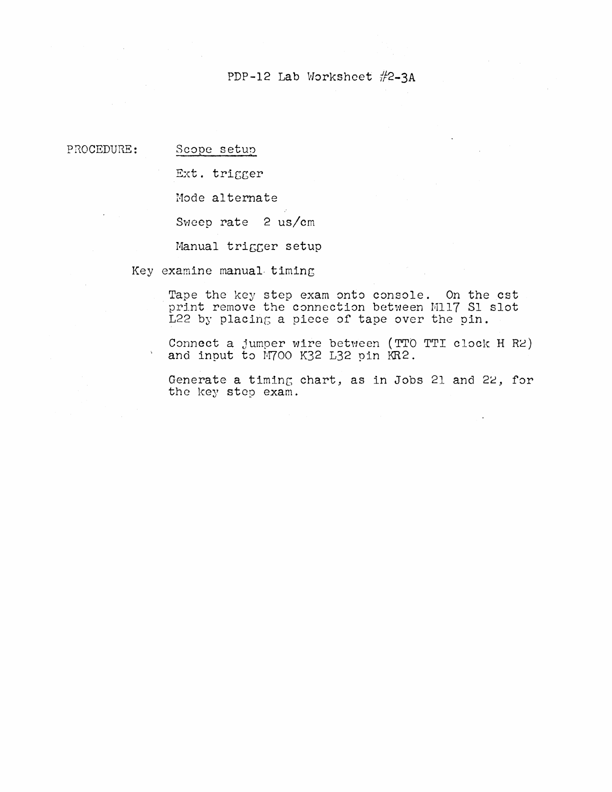
PROCEDURE:
Scope
setun
Ext.
tricger
Mode
alternate
Sweep
rate
2
us/cm
Manual
triccer
setup
Key
examine
manual-
timing
Tape
the
key
step
exam
onto
console.
On
the
est
print
remove
the
connection
between
Mll7
Sl
slot
L22 by
placinG
a
piece
of
tape
over
the
pin.
Connect
a
jumper
wire
bet,·1een
(TTO
TTI clocl-c H
Re)
and
input
to
M700
K32
L32
pin
KR2.
Generate
a
timinc
chart,
as
in
Jobs
21
and
2c,
for
the
key
step
exam.
POP-12
Lab
#3
Outline
1.
Understanding
the
front
panel
indicators
~.
Use
of
paper
tape
diagnostics
in
locating
machine
failures.
3.
Bugs
(as
time
pennits)
PDP-12
Lab
Job
Sheet
#3-1
TITLE:
Understanding
the
front
panel
OBJECTIVE: To
insure
that
the
student
will
learn
to
use
the
front
panel
indicators
as
aids
in
system
troubleshootingo
,
PROCEDURE:
Complete
the
steps
described
in
Lab
Worksheet
#3-1
Any
discrepancies
should
be
corrected
at
this
time.
Upon
completion
go
to
Job
Sheet
#3-2
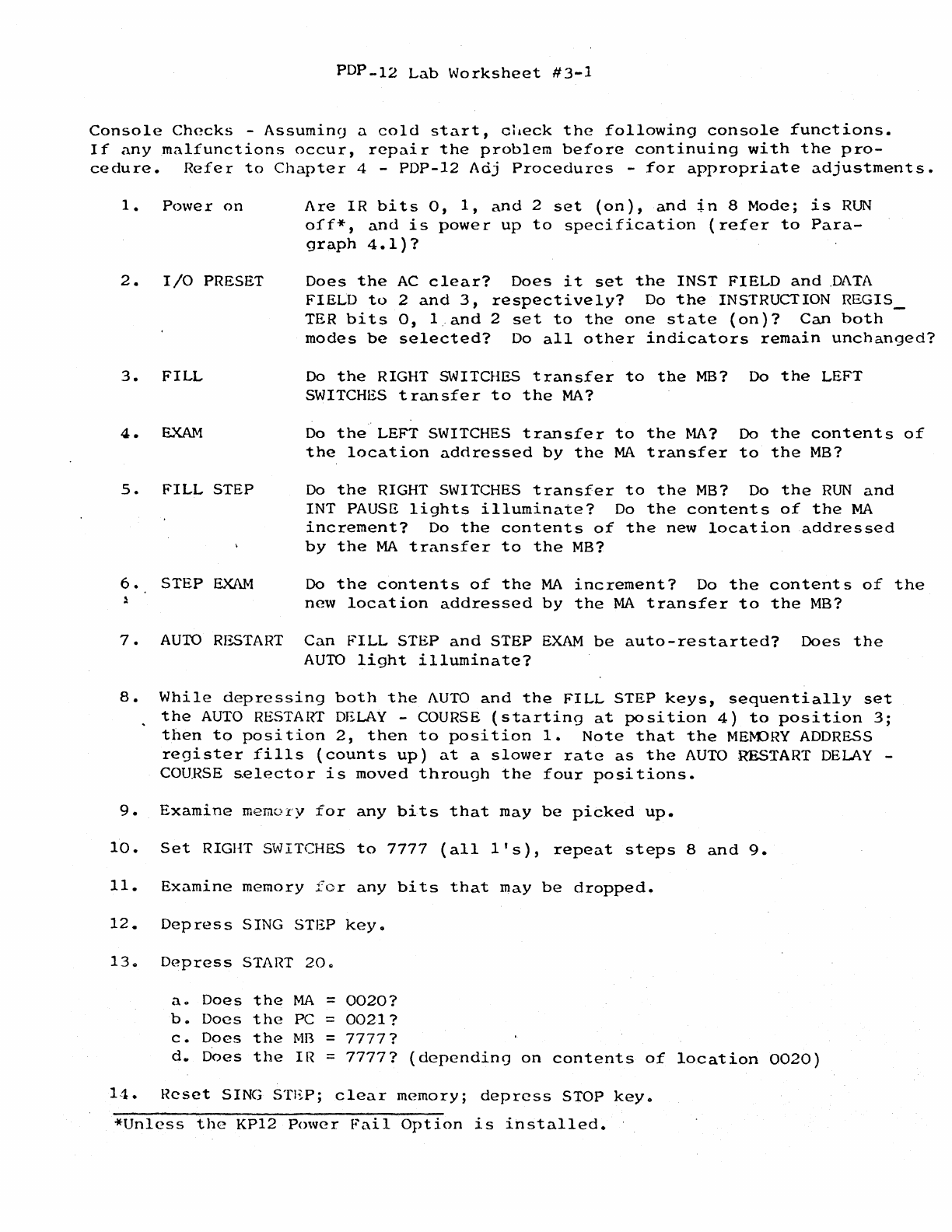
PDP-12
Lab
Worksheet
#3-1
Console
Checks
-
Assumin9
a
cold
start,
check
the
following
console
functions.
If
any
malfunctions
occur,
repair
the
problem
before
continuing
with
the
pro-
cedure.
Refer
to
Chapter
4 -
PDP-12
Adj
Procedures
-
for
appropriate
adjustments.
1.
Power
on
2 • I
/0
PRESET
3.
FILL
4.
EXAM
S.
FILL
STEP
6.
STEP
EXAM
Are
IR
bits
o,
1,
and
2
set
(on),
and
in
8
Mode;
is
RUN
off*,
and
is
power
up
to
specification
(refer
to
Para-
graph
4.1)?
Does
the
AC
clear?
Does
it
set
the
INST
FIELD
and
.DATA
FIELD
to
2
and
3,
respectively?
Do
the
INSTRUCTION
REGIS_
TER
bi
ts
o, 1..
and
2
set
to
the
one
st
ate
(on)?
Can
both
modes
be
selected?
Do
all
other
indicators
remain
unchanged?
Do
the
RIGHT SWITCHES
transfer
to
the
MB?
Do
the
LEFT
SWITCHES
transfer
to
the
MA?
Do
the
LEFT SWITCHES
transfer
to
the
MA?
Do
the
contents
of
the
location
addressed
by
the
MA
transfer
to
the
MB?
Do
the
RIGHT SWITCHES
transfer
to
the
MB?
Do
the
RUN
and
INT
PAUSE
lights
illuminate?
Do
the
contents
of
the
MA
increment?
Do
the
contents
of
the
new
location
addressed
by
the
MA
transfer
to
the
MB?
Do
the
contents
of
the
MA
increment?
Do
the
contents
of
the
new
location
addressed
by
the
MA
transfer
to
the
MB?
7.
AUTO
RESTART
Can
FILL
STEP
and
STEP
EXAM
be
auto-restarted?
Does
the
AUTO
light
illuminate?
8.
While
depressing
both
the
AUTO
and
the
FILL
STEP
keys,
sequentially
set
the
AUTO
RESTART
DELAY
-COURSE
(starting
at
position
4)
to
position
3;
then
to
position
2,
then
to
position
1.
Note
that
the
MEM::>HY
ADDRESS
register
fills
(counts
up)
at
a
slower
rate
as
the
AUTO
RESTART
DELAY
-
COURSE
s.elector
is
moved
through
the
four
positions.
9.
Examine
memory
for
any
bits
that
may
be
picked
up.
10.
Set
RIGHT SWITCHES
to
7777
(all
l's),
repeat
steps
8
and
9.
11.
Examine
memory
for
any
bits
that
may
be
dropped.
12.
Depress
SING
STEP
key.
13a
Depress
START
20a
ao
Does
the
MA
=
0020?
b.
Does
the
PC =
0021?
c.
Does
the
MB
=
7777?
d.
Does
the
IR =
7777?
(
dependin
<J
on
contents
of
14.
Reset
SING
STEP;
clear
memory;
depress
STOP
key.
*Unless
the
KP12
~nver
Fail
Option
is
installed.
location
0020)
PDP-12
Lab
Worksheet
#3-1
Page
2
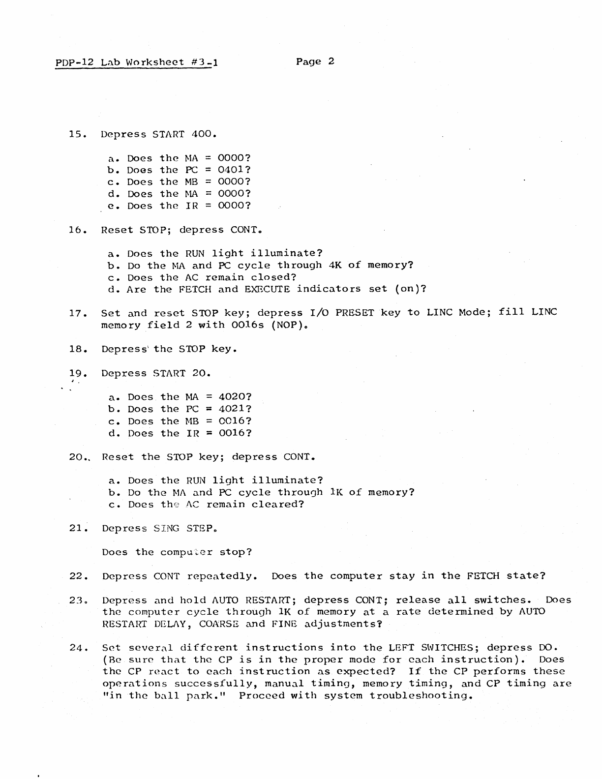
15.
Depress
START
400.
a.
Does
the
MA
=
0000?
b.
Does
the
PC =
0401?
c.
Does
the
MB
=
0000?
d.
Does
the
MA
=
0000?
e.
Does
the
IR
=
0000?
16.
Reset
STOP;
depress
CONTo
a.
Does
the
RUN
light
illuminate?
b.
Do
the
MA
and
PC
cycle
through
4K
of
memory?
c.
Does
the
AC
remain
closed?
d.
Are
the
FETCH
and
EXECUTE
indicators
set
(on
)7
17.
Set
and
reset
STOP
key;
depress
I/O
PRESET
key
to
LINC
Mode;
fill
LINC
memory
field
2
with
0016s
(NOP)o
18.
Depress··
the
STOP
key.
19.
Depress
START
20.
a.
Does
the
MA
=
4020?
b.
Does
the
PC =
4021?
c.
Does
the
MB
=
0016?
d.
Does
the
IR
::
0016?
20..
Reset
the
STOP
key;
depress
CONT.
a.
Does
the
RUN
light
illuminate?
b.
Do
the
Ml\
and
PC
cycle
throuoh
lK
of
memory?
c.
Does
th0
AC
remain
cleared?
21~
Depress
SING STEPo
Does
the
computer
stop?
22.
Depress
CONT
repeatedly.
Does
the
computer
stay
in
the
FETCH
state?
230
Depress
and
hold
AUTO
RESTART;
depress
CONT;
release
all
switches.
Does
the
computer
cycle
through
lK
of
memory
at
a
rate
determined
by
AUTO
HESTAIIT DELJ\Y, COARSE
and
FINE
adjustments?
24.
Set
several
different
instructions
into
the
LEFT SWITCHES;
depress
DO.
{Be
sure
that
the
CP
is
in
the
proper
mode
for
each
instruction).
Does
the
CP
react
to
each
instruction
as
expected?
If
the
CP
performs
these
operations
successfully,
manual
timing,
memory
timing,
and
CP
timing
are
"in
the
ball
park."
Proceed
with
system
troubleshooting.
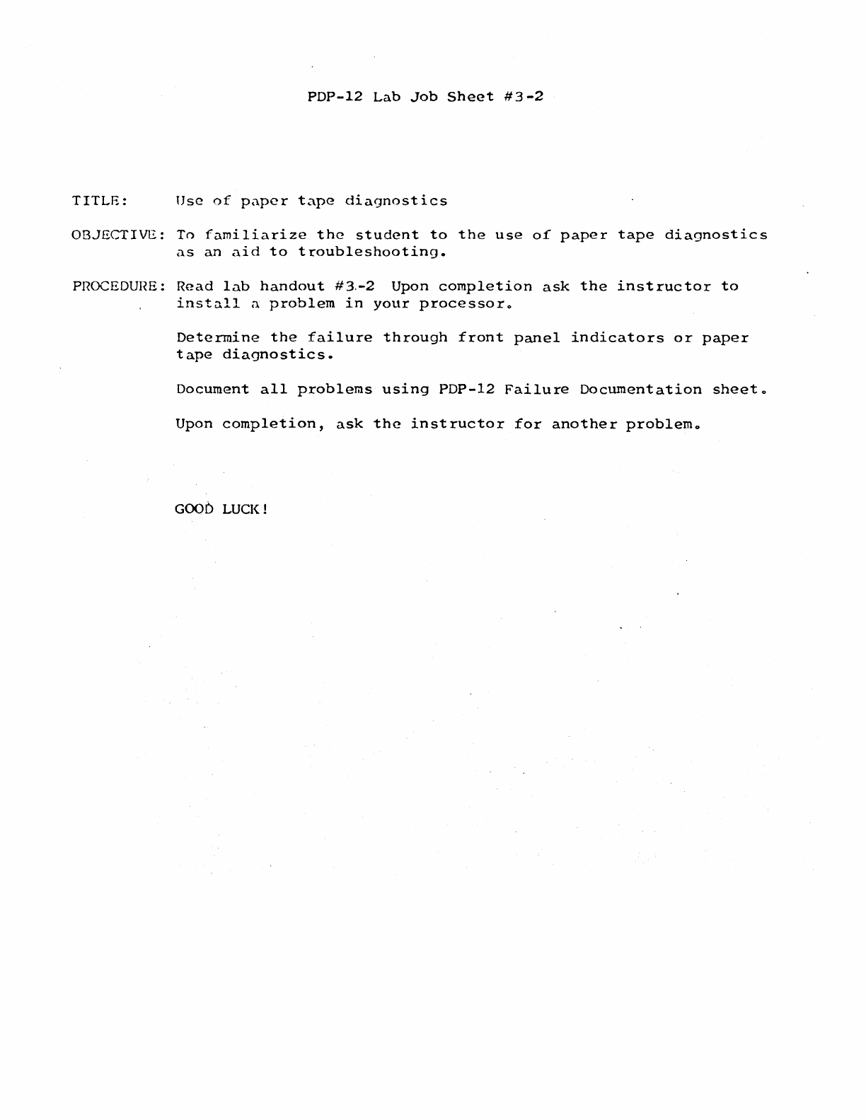
PDP-12
Lab
Job
Sheet
#3-2
TITLE:
Use
of
paper
tape
diagnostics
OBJECTIVE:
To
familiarize
the
student
to
the
use
of
paper
tape
diagnostics
as
an
aid
to
troubleshooting.
PROCEDURE:
Read
lab
handout
#3.-2
Upon
completion
ask
the
instructor
to
install
a
problem
in
your
processoro
Determine
the
failure
through
front
panel
indicators
or
paper
tape
diagnostics.
Document
all
problems
using
PDP-12
Failure
Documentation
sheeto
Upon
completion,
ask
the
instructor
for
another
problemo
GOOb LUCK!
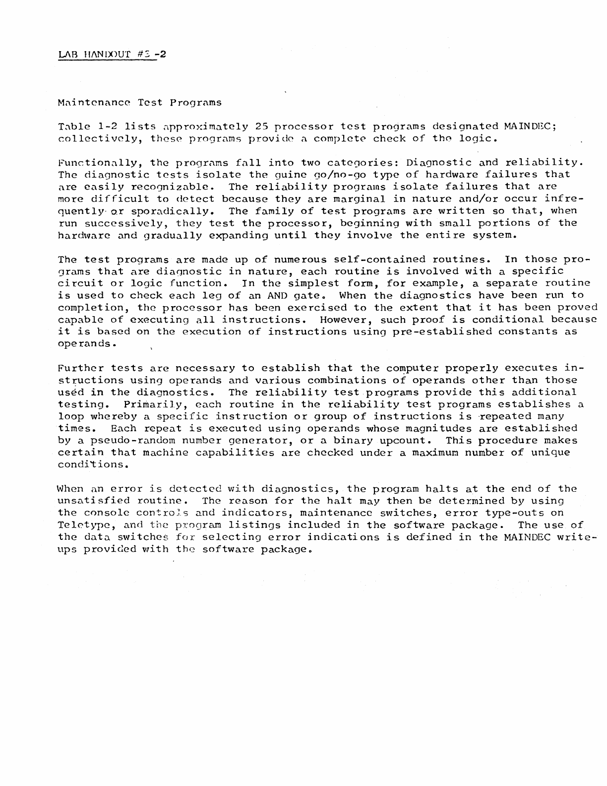
LAB
ll/\N
IX)UT
#:,
-2
M:\intcnance
Test
Programs
T:\ble
1-2
lists
approximately
25
processor
test
programs
designated
MAINDEC;
collectively,
these
programs
provide
a
complete
check
of
th0
logic.
Functionally,
the
programs
fall
into
two
categories:
Diagnostic
and
reliability.
The
diagnostic
tests
isolate
the
guine
00/no-90
type
of
hardware
failures
that
are
easily
reco']nizable.
The
reliability
programs
isolate
failures
that
are
more
difficult
to
detect
because
they
are
marginal
in
nature
and/or
occur
infre-
quently·
or
sporadically.
The
family
of
test
programs
are
written
so
that,
when
run
successively,
they
test
the
processor,
beginning
with
small
portions
of
the
hardware
and
gradually
expanding
until
they
involve
the
entire
system.
The
test
programs
are
made
up
of
numerous
self-contained
routines.
In
those
pro-
grams
that
are
diagnostic
in
nature,
each
routine
is
involved
with
a
specific
circuit
or
logic
function.
In
the
simplest
form,
for
example,
a
separate
routine
is
used
to
check
each
leg
of
an
AND
gateo
When
the
diagnostics
have
been
run
to
completion,
the
processor
has
been
exercised
to
the
extent
that
it
has
been
proved
capable
of
executing
all
instructions.
However,
such
proof
is
conditional
because
it
is
based
on
the
execution
of
instructions
using
pre-established
constants
as
operands.
Further
tests
are
necessary
to
establish
that
the
co~puter
properly
executes
in-
st
~uctions
using
operands
and
various
combinations
of
operands
other
than
those
used
in
the
diagnostics.
The
reliability
test
programs
provide
this
additional
testing.
Primarily,
each
routine
in
the
reliability
test
programs
establishes
a
loop
whereby
a
specific
inst
ruction
or
group
of
instructions
is
·repeated
many
times.
Each
repeat
is
executed
using
operands
whose
magnitudes
are
established
by
a
pseudo-random
number
generator,
or
a
binary
upcount.
This
procedure
makes
certain
that
machine
capabilities
are
checked
under
a
maximum
number
of
unique
con
di
't
ions.
When
an
error
is
detected
with
diagnostics,
the
program
halts
at
the
end
of
the
unsatisfied
routine.
The
reason
for
the
halt
may
then
be
determined
by
using
the
console
controJ_s
and
indicators,
maintenance
switches,
error
type-outs
on
Teletype,
and
the
program
listings
included
in
the
software
package.
The
use
of
the
data
switches
for
selecting
error
indications
is
defined
in
the
MAINDEC
write-
ups
provided
with
the
software
packageo
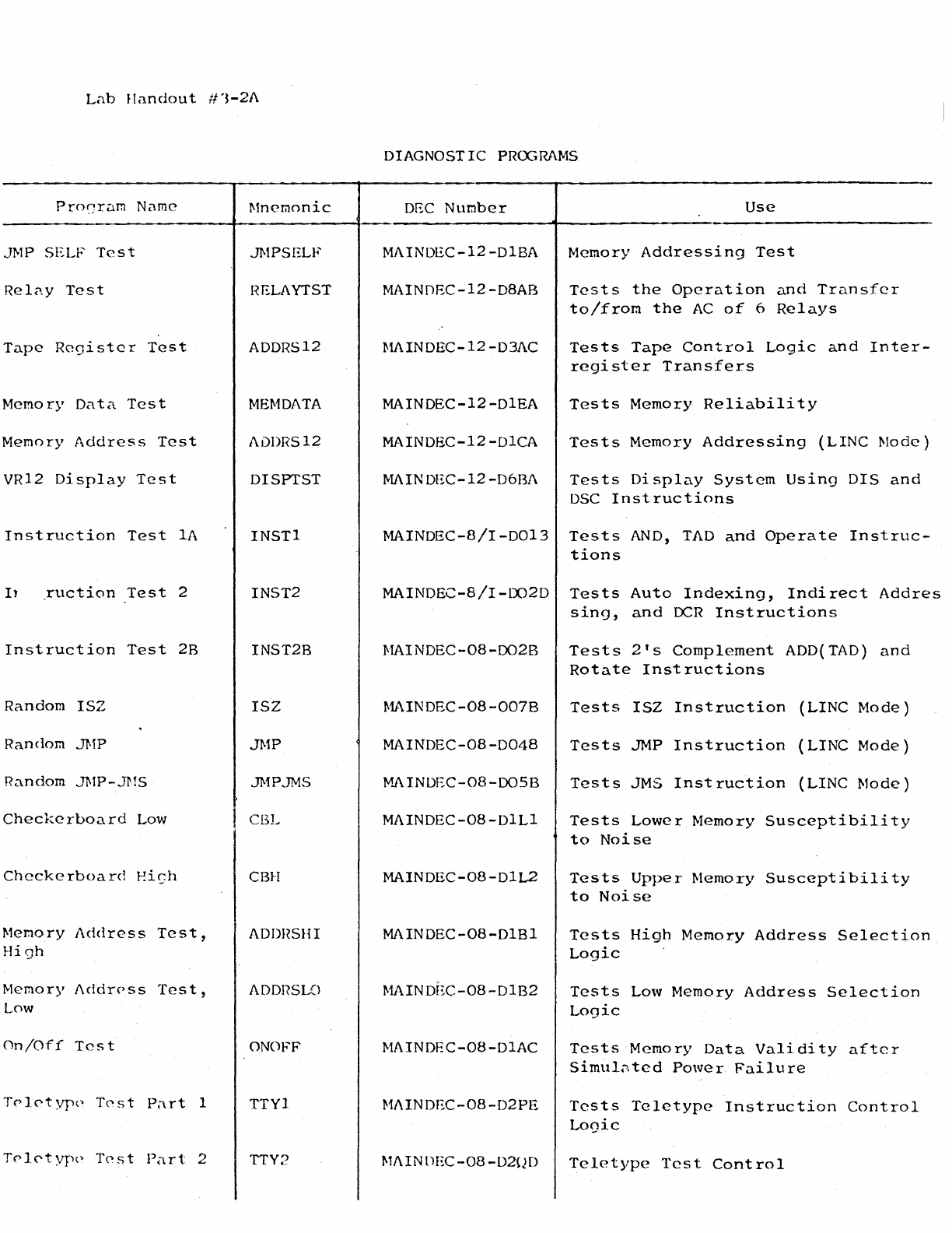
Lab
JI
andou
t #
'3-2/\
Pro~~rarn
Name
JMP SELF
Test
Rel<w
Test
Tape
Register
Test
Memory
Data
Test
Memory
Address
Test
VR12
Display
Test
Instruction
Test
lA
I1
~uction
Test
2
Instruction
Test
2B
Random
ISZ
Random JMP
Random JMP-JMS
Checkerboard
Low
Checkerboard
Ei~h
Memory
Address
Test,
High
Memory
J\ddrPss
Test,
Low
On/Off
Test
Trl0typc•
T0st
P;trt
1
Trl0typc•
T0st
Part
2
Mnemonic
JMPSELF
HELAYTST
ADDRS12
MEMDATA
ADDRS12
DISPTST
INSTl
INST2
INST2B
ISZ
JMP
JMP.JMS
CBL
CBH
ADDHSHI
ADDI?SLO
ONO
FF
TTYl
TTY2
DIAGNOSTIC
PRCGRAMS
DEC
Number
Use
MAINDEC-12-DlBA Memory
Addressing
Test
MAINOEC-12-D8AB
Tests
the
Operation
and
Transfer
to/from
the
AC
of
6
Relays
MAINDEC-12-03/\C
Tests
Tape
Control
Logic
and
Inter-
register
Transfers
MAINDEC-12-DlEA
Tests
Memory
Reliability
MAINDEC-12-DlCA
Tests
Memory
Addressing
(LINC
Mode)
MAINDEC-12-D6BJ\
Tests
Display
System
Using
DIS
and
DSC
Instructions
MAINDEC-8/I-0013
Tests
AND,
TAD
and
Operate
Instruc-
tions
MAINDEC-8/I-LX)2D
Tests
Auto
Indexing,
Indirect
Addres
sing,
and
I:x:R
Instructions
MAINOEC-08-0028
MAINOEC-08-0078
MAINDEC-08-0048
M.A
INDEC-08-00SB
MAINDEC-08-DlLl
MAINDEC-08-DlL2
MAINDEC-08-DlBl
MAINDI~C-08-D1B2
MAINDEC-08-DlAC
MAINDEC-08-D2PE
MAINDEC-08-D20D
Tests
2's
Complement
ADD(TAD)
and
Rotate
Instructions
Tests
ISZ
Instruction
(LINC
Mode)
Tests
JMP
Instruction
(LINC
Mode)
Tests
JMS
Inst
ruction
(LINC
Mode)
Tests
Lower
Memory
Susceptibility
to
Noise
Tests
Upper
Memory
Susceptibility
to
Noise
Tests
High
Memory
Address
Selection
Logic
Tests
Low
Memory
Address
Selection
Logic
Tests
Memory
Data
Validity
after
Simul~ted
Power
Failure
Tests
Teletype
Instruction
Control
Logic
Teletype
Test
Control

Lab
Handout
#1-2A
Page
2
Instruction
Test
1
CPTSTl
MAINDEC-12-00BA
Tests
Instruction
(LINC
Mode)
Inst
ruC"tion
Tc-st
2 CPTST2
Ml\INDEC-12-00AB
Tests
SKIPs
and
Data
Handling
(LINC
Mode)
A-D
Test
ADTST Ml\INDEC-12-D6CB
Tests
A-D
Converter
and
allows
Calibration
of
Preamplifiers

PDP-12
Lab
#4
Outline
~.
TU-55
Alignment
torque
and
brake
adjustment
2.
Troubleshooting
Processor
problems
~ITLE:
OBJECTIVE:
PROCEDURE:
PDP-12
Lab
Job
Sheet
#4-1
TU-55
Adjustments
To
insure
that
all
students
can
successfully
perform
the
required
adjustment
of
the
TU-55
Tape
Transport
With
the
aid
of
a
scope,
perform
the
adjustments
pre-
scribed
in
Information
Sheet
#4-1
Upon
completion,
ask
the
lab
instructor
to
insert
failures
pertaining
to
Lab
#4.
Document
all
trouble-
shooting
using
PDP-12
Lab
Failure
Documentation
Handout.
PDP-12
Lab
Information
Sheet
#4-1
~ROBLEM:
Inconsistency
in
Adjustment
of
TU-55
Brakes
and
Torque
1.
Brake
Adjustment
A.
Energize
the
brake
for
at
least
5
minutes.
This
will
insure
that
the
following
adjustments
will
not
be
too
tight,
causing
brake
drag
when
the
unit
warms
up.
a·..
With
power
off
bring
the
brake
shoe
into
the
brake
solenoid,
then
bring
it
back
to
the
point
at
which
the
show
rotates
free.
C.
The
brakes
may
be
considered
properly
adjusted
when
repeated
energizing
produces
a
minimum
of
audible
"click"
and
yet
the
shoe
doesn't
rub
on
the
high
spot.
If
this
cannot
be
accomplished
it
is
probably
due
to
a
shoe
with
too
much
run
out.
The
ideal
situation
is
to
have
no
"click"
and
no
drag.
2.
Torque
Adjustment
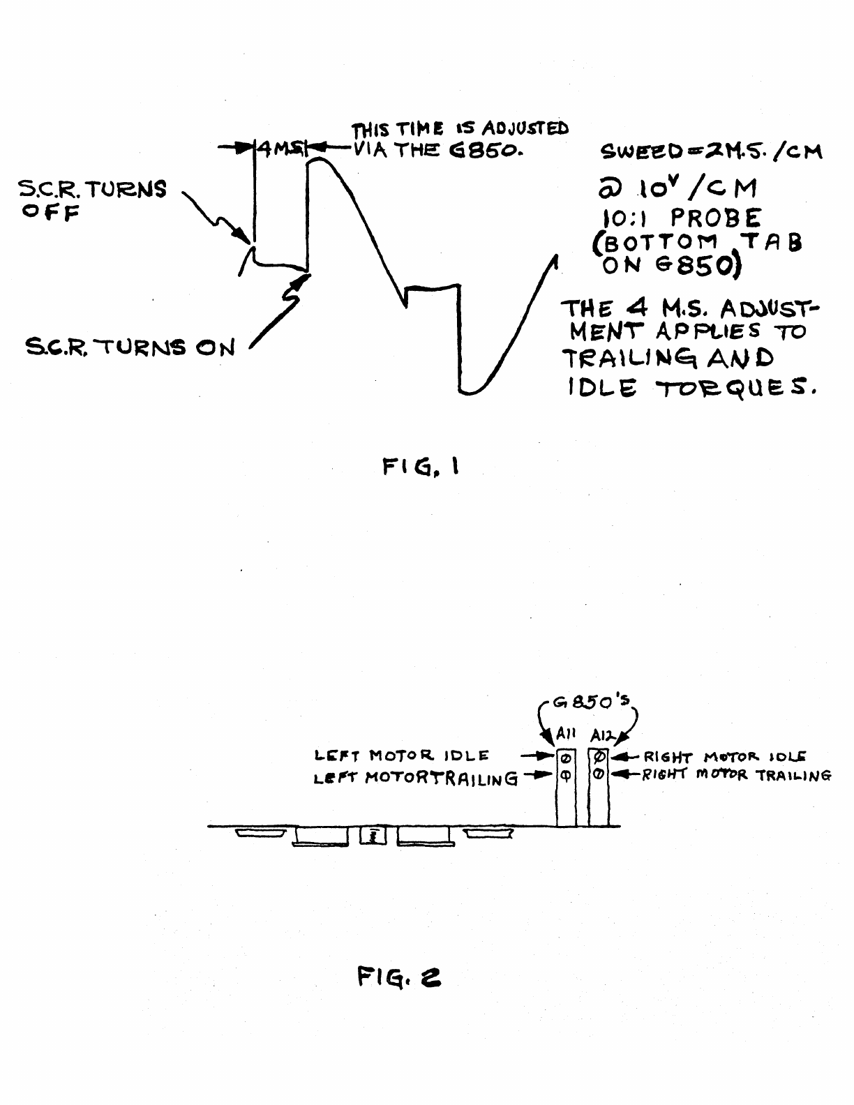
A.
Without
tape
on
the
transport,
apply
idle
torque
to
the
motor.
With
a
scope,
observe
the
bottom
tab·
terminal
on
the
rear
of
the
G850.
Set
the
scope
to
2
M.S./c.M.
at
lOv/CM.
The
waveform
should
be
similar
~
to
what
is
shown
in
Fig.
1.
If
it
is
not,
make
the
necessary
adjustments
shown
in
Fig.
2.
B.
Repeat
step
"A
11
with
trailing
torque
applied
to
the
motor
..
c.
Run a
start
-
stop
-
turn
around
test,
and
adjust
delay
{Loe
.AB4)
until
there
is
a
minimum
of
tape
slap.
This
should
be
approximately
80
M.So
to
90
M.S.
nus
Tl"" E
lS
ADJUSTED
....._..
166
~VlA
THE
cSSoo
..
S.C.R. TOR.NS
"\.
_
OFF
'
Fl
G, l
t f
Fl~.
e
sw~o-~tt~.
/cM
0)
.lov
/c
M
10;1 PROBE
(BOTTOM
~TA
9
ON
6-8501
TME' 4
M.s.
Ao.)UsT-
MEN\
APPL.tes
TO
lteA\L.f
Mtq
A~
C
I DL.E
to~que.
S.
~8Sl
RG'L~Y
/IM
PHE~O
'- PL.\J '1
~
f
EA~
o
~
M o
DU
'-
\N
TUS
S
AMP.
CDAJ~.
LO~
~Bl
AF
~
A\+
-r'(PE
453
09
~U>Pt
~·
'J-1
PR.6B£
AN~
AP
.Of
1-4~J,
S"ov
CP\P
ff?..O
M
S
16.
LI
N e
To
9
RO
SE
6
NO.
AV~
BD
/
Ht:AD
Cot-JAJ,
B
C>
c
AlJ -F
,.
l=
I
Ak r
AP H
AV
p "' p •
AU
N
Bo
~
B
.,...
'""
V I
...,
~,~
v
1---~-0---
Bi::
5P
BM
BN
u,.._
__
.........._~-
LJ,
sH1~
T.T.
Ml.
t>3
D2
DI
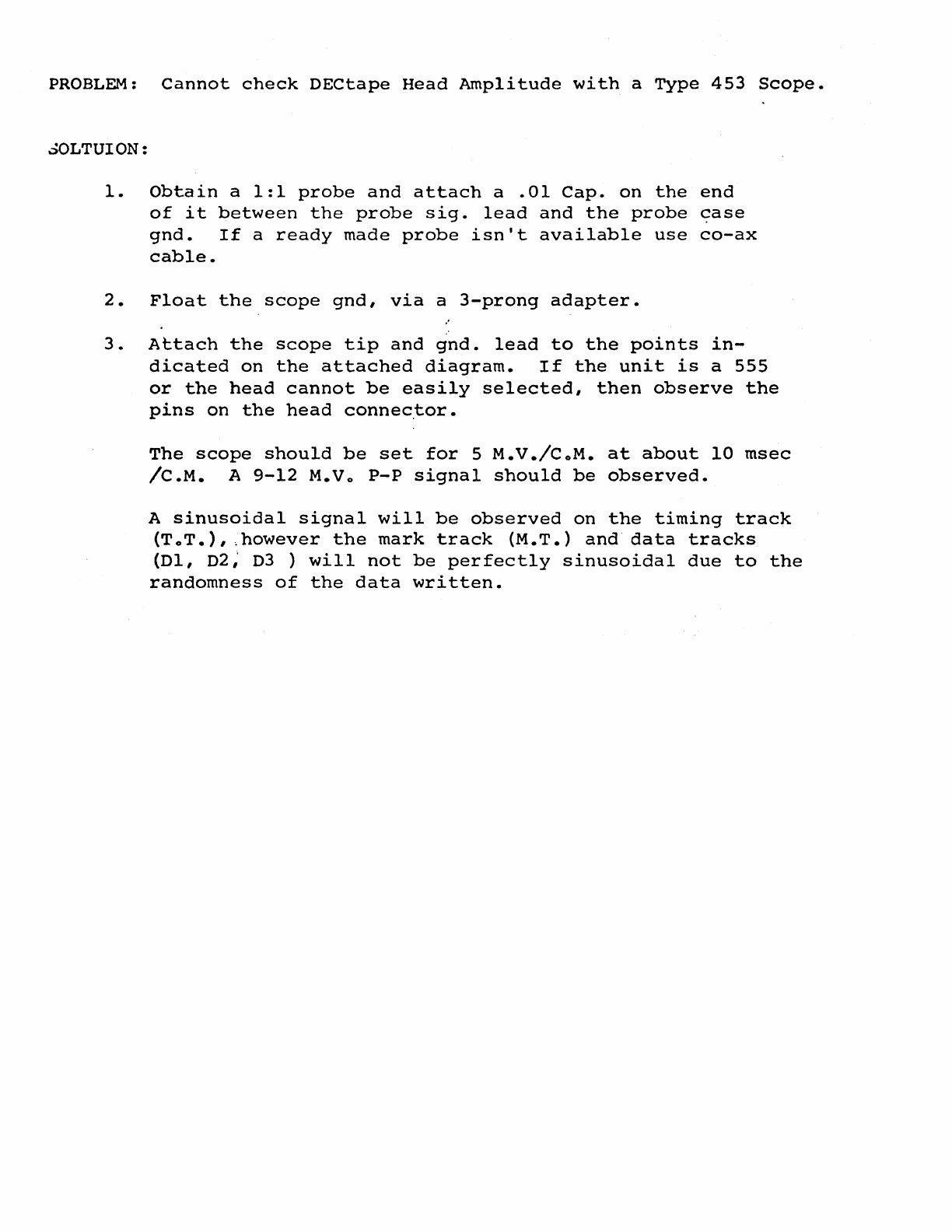
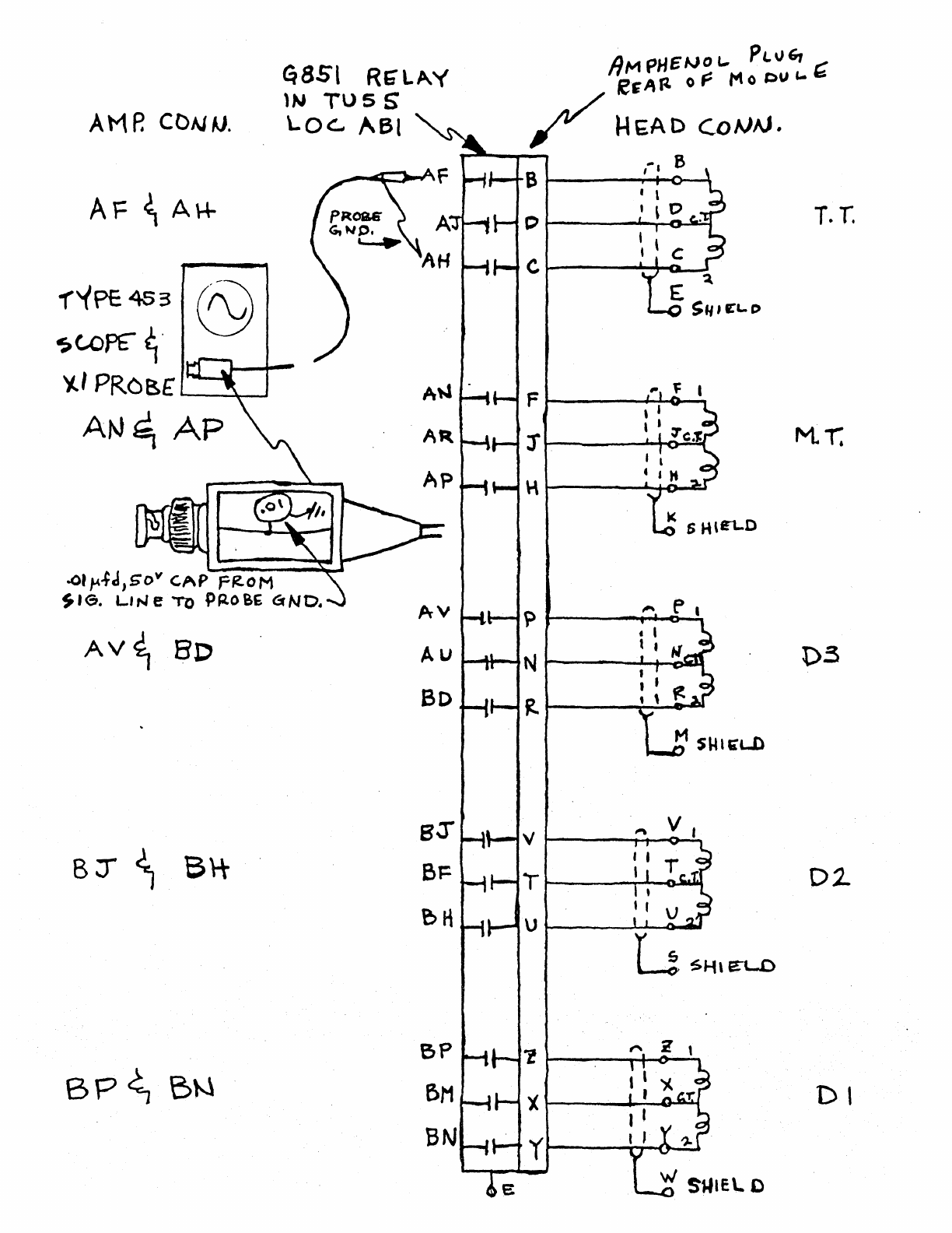
PROBLEM:
Cannot
check
DECtape
Head
Amplitude
with
a
Type
453
Scope.
~OLTUION:
1.
Obtain
a
1:1
probe
and
attach
a
.01
Cap.
on
the
end
of
it
between
the
probe
sig.
lead
and
the
probe
case
gnd.
If
a
ready
made
probe
isn't
available
use
co-ax
cable.
2.
Float
the
scope
gnd,
via
a
3-prong
adapter.
3.
Attach
the
scope
tip
and
gnd.
lead
to
the
points
in-
dicated
on
the
attached
diagram.
If
the
unit
is
a
555
or
the
head
cannot
be
easily
selected,
then
observe
the
pins
on
the
head
connec.tor.
The
scope
should
be
set
for
5
M.V./CoM.
at
about
10
msec
/C.M.
A
9-12
M.Vo
P-P
signal
should
be
observed.
A
sinusoidal
signal
will
be
observed
on
the
timing
track
{ToT.),
.however
the
mark
track
(M.T.)
and
data
tracks
(Dl,
02;
03
)
will
not
be
perfectly
sinusoidal
due
to
the
randomness
of
the
data
written.

PDP-12
LAB
11'5
LESSON
PLAN
To
be
Supplied

PDP-12
Lab
#6
Outline
2
Hours
1.
Do
key
operation
2.
Use
of
instructions
~ITLE:
OBJECTIVE:
PROCEDURE:
PDP-12
Lab
Job
Sheet
#6-1
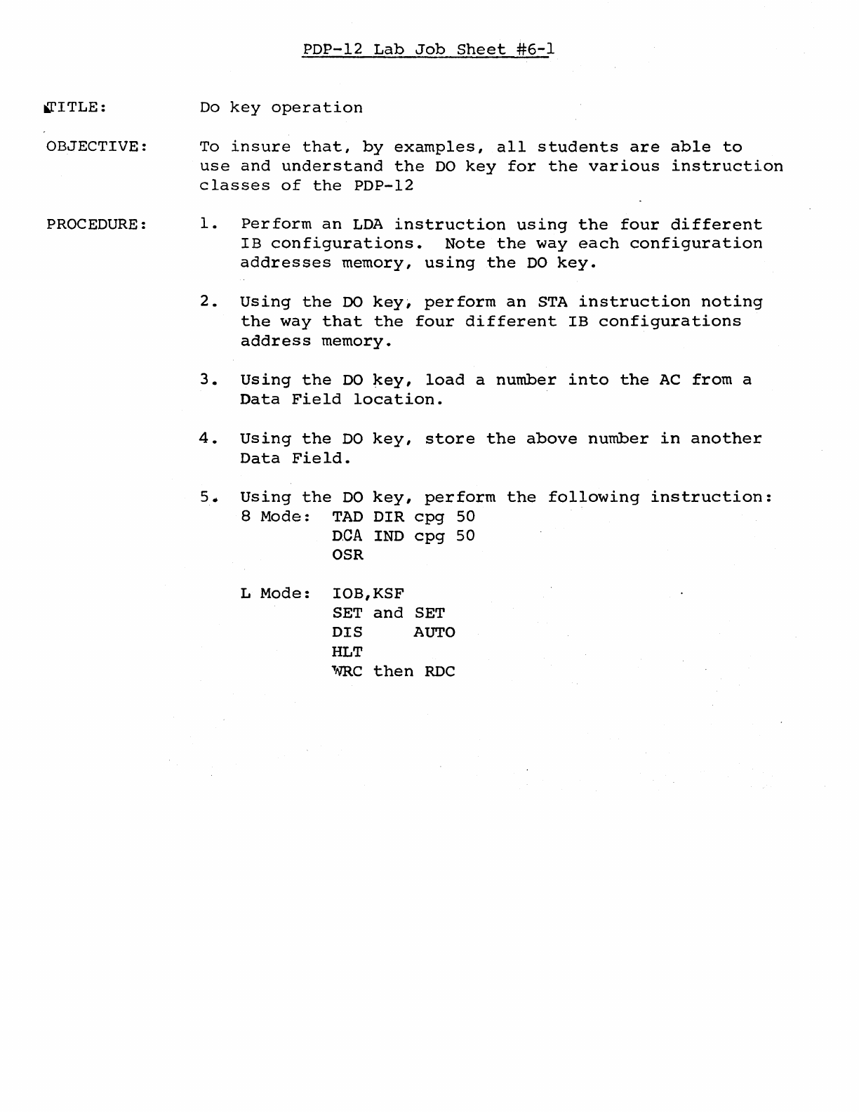
Do
key
operation
To
insure
that,
by
examples,
all
students
are
able
to
use
and
understand
the
DO
key
for
the
various
instruction
classes
of
the
PDP-12
1.
Perform
an
LDA
instruction
using
the
four
different
IB
configurations.
Note
the
way
each
configuration
addresses
memory,
using
the
DO
key.
2.
Using
the
DO
key1
perform
an
STA
instruction
noting
the
way
that
the
four
different
IB
configurations
address
memory.
3.
Using
the
DO
key,
load
a
number
into
the
AC
from
a
Data
Field
location.
4.
Using
the
DO
key,
store
the
above
number
in
another
Data
Field.
5.
Using
the
DO
key,
perform
the
following
instruction:
8
Mode:
TAD
DIR
cpg
50
D.CA
IND
cpg
50
OSR
L
Mode:
IOB,KSF
SET
and
SET
DIS
AUTO
HLT
,..m.c
then
RDC
lPITLE:
OBJECTIVE:
PROCEDURE:
PDP-12
Lab
Job
Sheet
#6-2
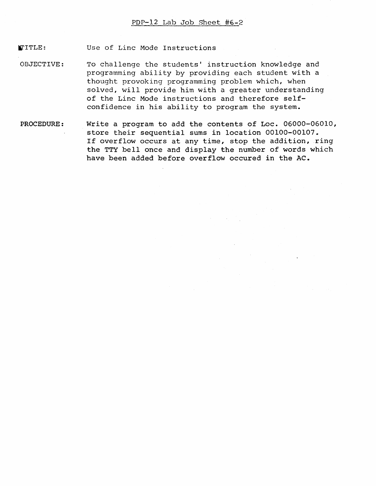
Use
of
Linc
Mode
Instructions
To
challenge
the
students'
instruction
knowledge
and
programming
ability
by
providing
each
student
with
a
thought
provoking
programming
problem
which,
when
solved,
will
provide
him
with
a
greater
understanding
of
the
Linc
Mode
instructions
and
therefore
self-
confidence
in
his
ability
to
program
the
system.
Write
a
program
to
add
the
contents
of
Loe.
06000-06010,
store
their
sequential
sums
in
location
00100-00107.
If
overflow
occurs
at
any
time,
stop
the
addition,
ring
the
TTY
bell
once
and
display
the
number
of
words
which
have
been
added
before
overflow
occured
in
the
AC.

PDP-12
Lab
#7
Outline
Hours
1.
TU-56
adjustments
2.
Bugs

TITLE:
OBJECTIVE:
PROCEDURE:
PDP-12
Lab
Job
Sheet
#7-1
TU-56
Adjustments
To
insure
that
all
students
understand
the
similarities
and
differences
in
the
adjustment
procedures
for
TU55
and
TU56.
Perform
the
adjustments
described
in
the
TU-56
Maintenance
Manual,
Chapter
6.

PDP-12
Lab
#8
Outline
2
Hours
l...
Program
Debugging
2.
Program
Development
3.
Bugs
TITLE:
OBJECTIVE:
PROCEDURE:
PDP-12
Lab
Job
Sheet
#8-J
Program
Debugging
Each
student
will
successfully
write
a
program
to
display
a
line
on
the
VR-12
or
VR-14
Debug
the
Display
Line
program
and
demonstrate
its
operation
to
the
instructor.
l1ITLE:
OBJECTIVE:
PROCEDURE:
PDP-12
Lab
Job
Sheet
#8~2
Program
Development
To
chal.lenge
the
student's
instruction
knowledge
and
programming
ability
by
providing
each
student
with
a
thought
provoking
programming
problem
which,
when
solved,
will
provide
him
with
a
greater
understanding
of
the
Linc
Mode
instructions
and
therefore
self-
confidence
in
his
ability
to
program
the
system.
Using
the
previously
developed
Display
Line
programs,
modify
the
program
with
a
sense
switch
option
to
develop
a
two-part
program:
1.
Line
Display
2.
sweeping
Line
Display

PDP-12
LAB
#9
OtrrLINE
1.
Using
Mark
12
2.
Use
of
Tape
Instructions
PDP-12
LAB
JOB SHEET
#9-1
TITLE:
Using
Mark
12
OBJECTIVE:
To
ensure
that
all
students
understand
the
purpose
and
use
of
the
Mark
12
program
and
its
optionso
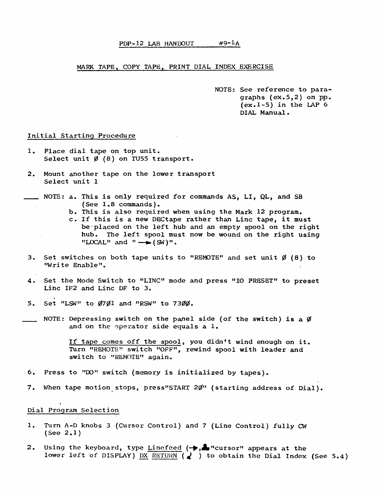
PROCEDURE:
Using
the
procedure
described
in
PDP-12
Lab
Handout
#9-lA,
mark
a
virgin
tape
using
all
three
Mark
12
options
and
ob-
serving
front
panel
indication
as
each
option
is
running.
PDP-12
LAB
HANDOUT
#9-1-A
MARK
TAPE,
COPY
TAPE, PRINT DIAL INDEX EXERCISE
Initial
Starting
Procedure
1.
Place
dial
tape
on
top
unit.
Select
unit
~
(8)
on
TU55
transport.
2.
Mount
another
tape
on
the
lower
transport
Select
unit
1
NOTE:
See
reference
to
para-
graphs
(ex.5,2)
on
pp.
(ex.1-5)
in
the
LAP
6
DIAL
Manual
•
NOTE:
a.
This
is
only
required
for
commands
AS,
LI,
QL,
and
SB
(See
1.8
commands).
b.
This
is
also
required
when
using
the
Mark
12
program.
c.
If
this
is
a
new
DECtape
rather
than
Linc
tape,
it
must
be'placed
on
the
left
hub
and
an
empty
spool
on
the·
right
hub.
The
left
spool
must
now
be
wound
on
the
right
usin9
"LOCAL"
and
"
--..
(SN)".
3.
Set
switches
on
both
tape
units
to
"REMOTE"
and
set
unit
¢
(8)
to
"Write
Enable"
o
4.
Set
the
Mode
Switch
to
"LINC"
mode
and
press
"IO
PRESET"
to
preset
Linc
IF2
and
Linc
OF
to
3o
5.
Set
"LSW"
to
¢7~1
and
"RSW"
to
73~¢o
NOTE:
Depressing
switch
on
the
panel
side
(of
the
switch)
is
a
~
and
on
the
operator
side
equals
a
1.
If
tape
comes
off
the
spool,
you
didn't
wind
enough
on
ito
Turn
"REMOTE"
switch
"OFF",
rewind
spool
with
leader
and
switch
to
"REMOTE"
again.
6.
Press
to
"00"
switch
(memory
is
initialized
by
tapes).
7.
When
tape
motion.stops,
press"START
2ti"
(starting
address
of
Dial).
Dial
Program
Selection
1.
Turn
A-D
knobs
3
(Cursor
Control)
and
7
(Line
Control)
fully
a~
(See
2.1)
2.
Using
the
keyboard,
type
Linefeed
(--.,A.
"cursor"
appears
at
the
lower
left
of
DISPLAY)
DX
RETUHN
( J )
to
obtain
the
Dial
Index
(See
5o4)
9-1A
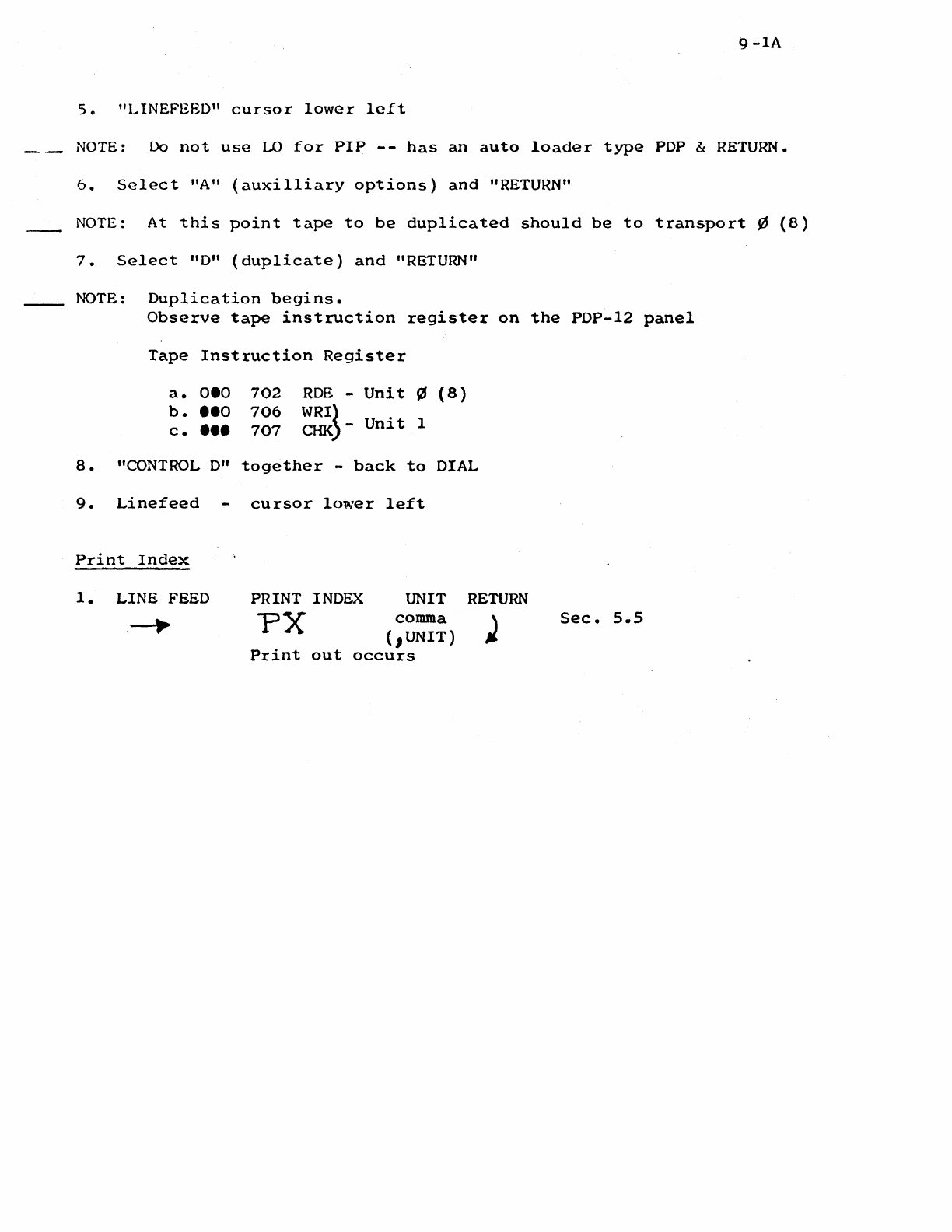
s.
"LINEFEED"
cursor
lower
left
NOTE:
Do
not
use
LO
for
PIP
--
has
an
auto
loader
type
PDP & RETURN.
6.
Select
"A"
(auxilliary
options)
and
"RETURN"
NOTE:
At
this
point
tape
to
be
duplicated
should
be
to
transport
¢
(8)
7.
Select
"D"
(duplicate)
and
"RETURN"
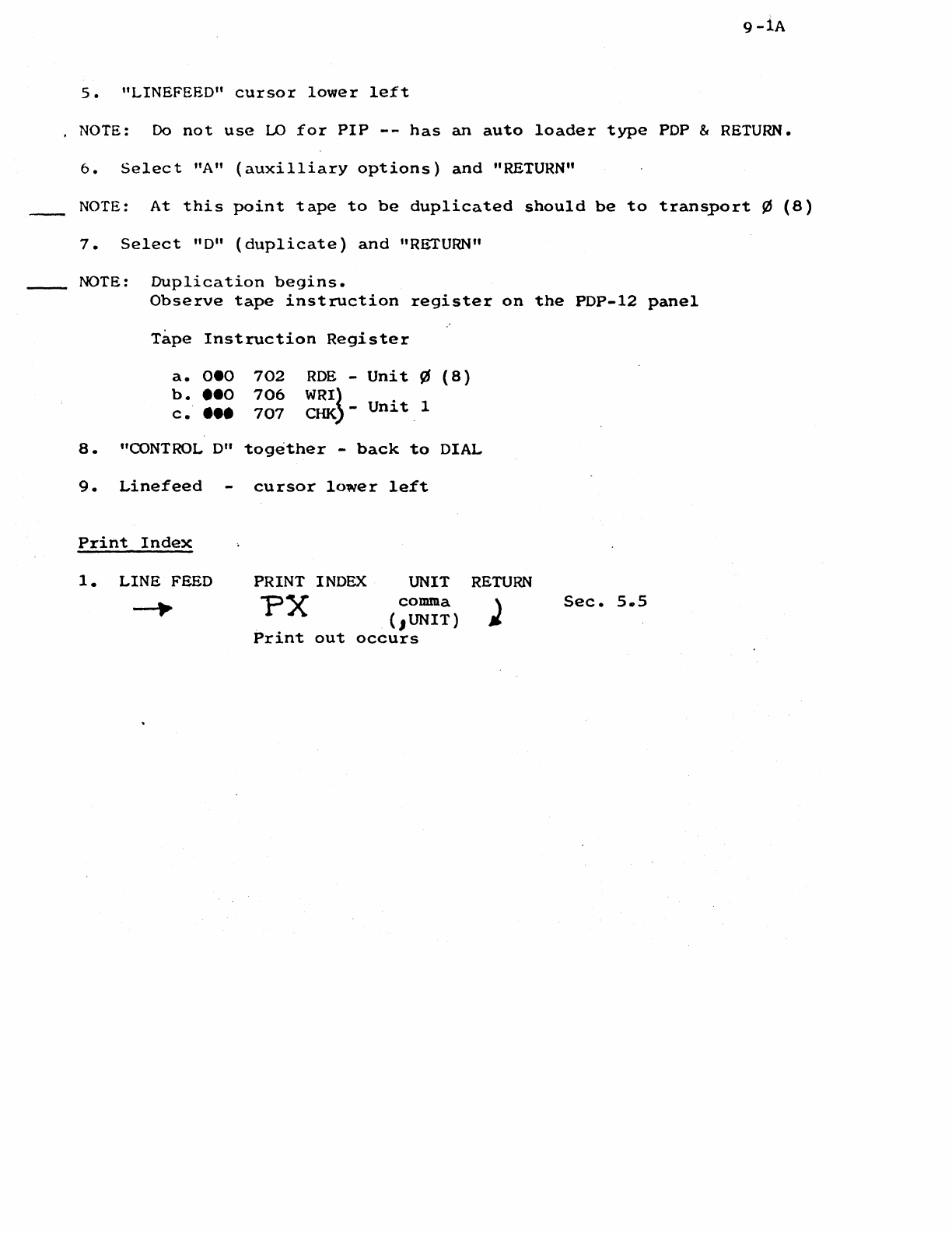
NOTE:
Duplication
begins.
Observe
tape
instruction
register
on
the
PDP-12
panel
Tape
Instruction
Register
a.
oeo
b.
••o
c
••••
702
706
707
ROE
-
Unit
¢
(8)
WRI}
CHK)-
Unit
1
8.
"CONTROL
0"
together
-
back
to
DIAL
9.
Linefeed
Print
Index
1.
LINE FEED
cursor
lower
left
PRINT INDEX
UNIT
comma
PX
(.1UNIT)
Print
out
occurs
RETURN
Sec.
s.s
#9-lA
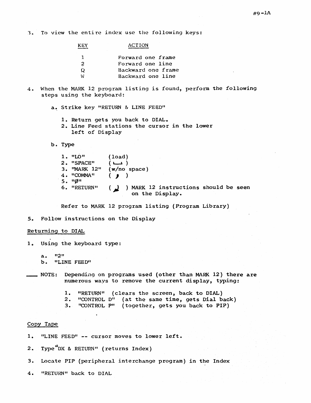
1.
To
view
the
entire
index
use
the
following
keys:
KEY
ACTION
1
Forward
one
frame
2
Forward
one
line
Q
Backward
one
frame
w
Backward
one
line
4.
When
the
MARK
12
program
listing
is
found,
perform
the
following
steps
using
the
keyboard:
a.
Strike
key
"RETURN
& LINE FEED"
b.
1.
Return
gets
you
back
to
DIAL.
2.
Line
Feed
stations
the
cursor
in
the
lower
left
of
Display
Type
1.
"LO"
2.
"SPACE"
3.
''MARK
12"
4.
"COMMA"
s.
"91"
6.
"RETURN"
(load)
(
L-l
)
(w/no
space)
( , )
)
MARK
12
instructions
should
be
seen
on
the
Display.
Refer
to
MARK
12
program
listing
(Program
Library)
5.
Follow
instructions
on
the
Display
Returning
to
DIAL
lo
Using
the
keyboard
type:
a.
"2"
b.
"LINE FEED"
_NOTE:
Depending
on
programs
used
(other
than
MARK
12)
there
are
numerous
ways
to
remove
the
current
display,
tYPing:
1.
"RETURN"
(clears
the
screen,
back
to
DIAL)
2.
"OONTROL
D"
(at
the
same
time,
gets
Dial
back)
3.
''CONTROL
P"
(together,
gets
you
back
to
PIP)
Copy
Tape
1.
"LINE
FEED"
--
cursor
moves
to
lower
left.
2.
•l
Type
DX
&
RETURN"
(returns
Index)
3.
Locate
PIP
(peripheral
interchange
program)
in
the
Index
4.
"RETUllli"
back
to
DIAL
9-lA
So
"LINEFEED"
cursor
lower
left
NOTE: Do
not
use
LO
for
PIP
--
has
an
auto
loader
type
PDP & RETURN.
6.
Select
"A"
(auxilliary
options)
and
"RETURN"
NOTE:
At
this
point
tape
to
be
duplicated
should
be
to
transport
¢
(8)
7.
Select
"D"
(duplicate)
and
"RETURN"
NOTE:
Duplication
begins.
Observe
tape
instruction
register
on
the
PDP-12
panel
Tape
Instruction
Register
a.
oeo
b.
••o
c.
•••
a.
"CONTROL D"
9.
Linefeed
Print
Index
1.
LINE
FEED
702
RDE
-
Unit
¢
(8)
706
WRI~
707
CHK
-
Unit
1
together
-
back
to
DIAL
cursor
lower
left
PRINT INDEX UNIT
comma
PX {1UNIT)
Print
out
occurs
RETURN
Sec.
5
..
5
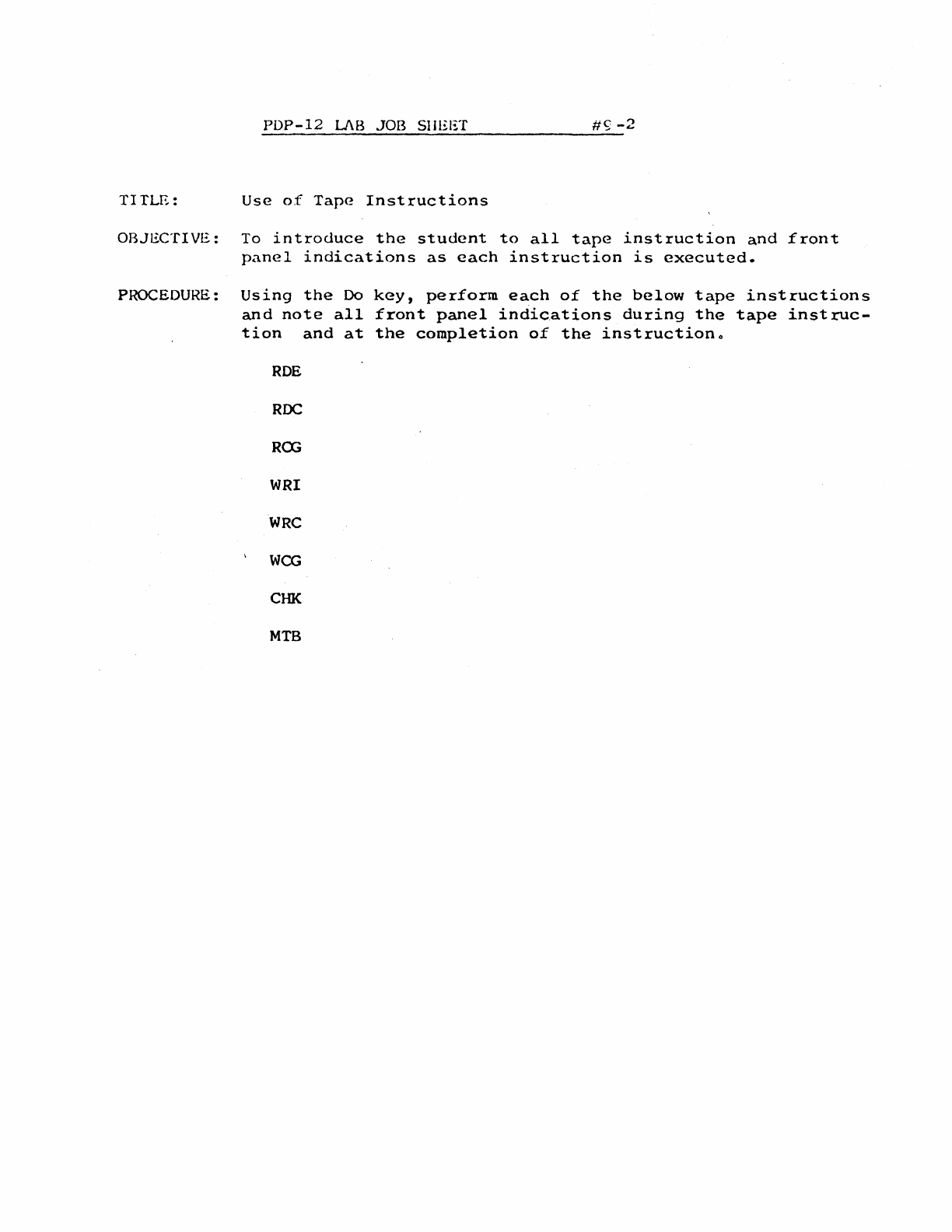
PDP-12
LJ\B
JOB SHEET
#<;;
-2
TITLE:
Use
of
Tape
Instructions
OBJECTIVE:
To
introduce
the
student
to
all
tape
instruction
and
front
panel
indications
as
each
instruction
is
executed.
PROCEDURE:
Using
the
Do
and
note
all
ti
on
and
at
ROE
RDC
RCG
WRI
WRC
WCG
CHK
MTB
key,
perform
each
of
the
below
tape
instructions
front
panel
indications
during
the
tape
instruc-
the
completion
of
the
instructiono
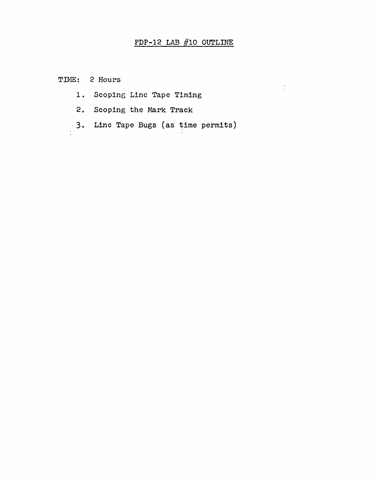
PDP-12
LAB
#10
OUTLINE
TIME:
2 Hours
1.
Scoping
Linc Tape Timing
2.
Scoping
the
Mark
Track
3.
Linc
Tape Bugs
(as
time
permits)
PDP-12
LAB
JOB
SHEET
#10-1
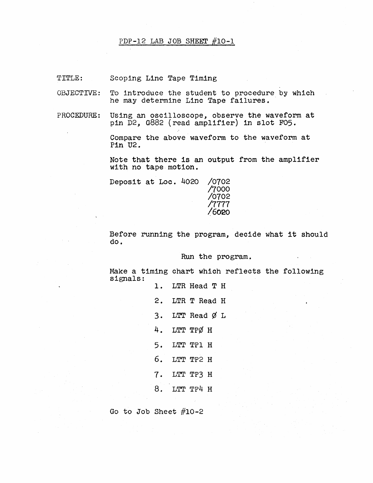
TITLE:
Scoping
Linc
Tape Timing
OBJECTIVE:
To
introduce
the
student
to
procedure
by which
he
may
determine
Linc
Tape
failures.
PROCEDURE:
Using
an
oscilloscope,
observe
the
waveform
at
pin
D2,
G882
(read
amplifier)
in
slot
F05.
Compare
the
above waveform
to
the
waveform
at
Pin
U2.
Note
that
there
is
an
output
from
the
amplifier
with
no
tape.motion.
Deposit
at
Loe.
4020
/0702
/7000
/0702
/7777
/6020
Before
running
the
program,
decide
what
it
should
do.
Run
the
program.
Make
a
timing
chart
which
reflects
the
following
signals:
1 •
LTR
Head T H
2.
LTR
T Read H
3.
LTT
Read ¢ L
4.
LTT
TP¢ H
5.
LTT
TPl H
6.
LTT
TP2
H
7.
L'I'I'
TP3
H
8.
LTT
TP4
H
Go
to
Job
Sheet
#10-2
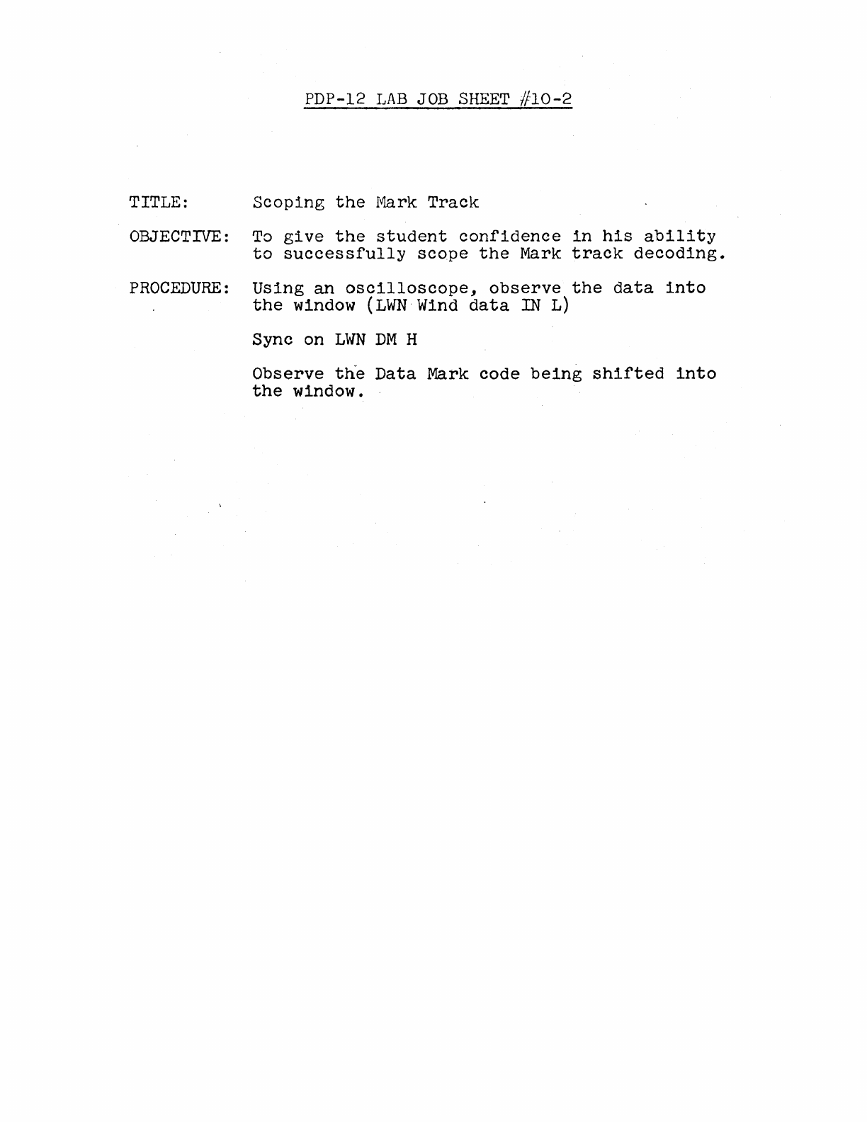
PDP-12
LAB
JOB
SHEET
//10-2
TITLE:
Scoping
the
Mark
Track
OBJECTIVE:
To
give
the
student
confidence
in
his
ability
to
successfully
scope
the
Mark
track
decoding.
PROCEDURE:
Using
an
oscilloscope,
observe
the
data
into
the
window
(LWN
Wind
data
IN L)
Sync on
LWN
DM
H
Observe
the
Data
Mark
code
being
shifted
into
the
window.

PDP-12
LAB
#11
OUTLINE
TIME:
2
hours
.
1.
Tape
Delay
Adjustments
2.
Troubleshooting
the
TC-12
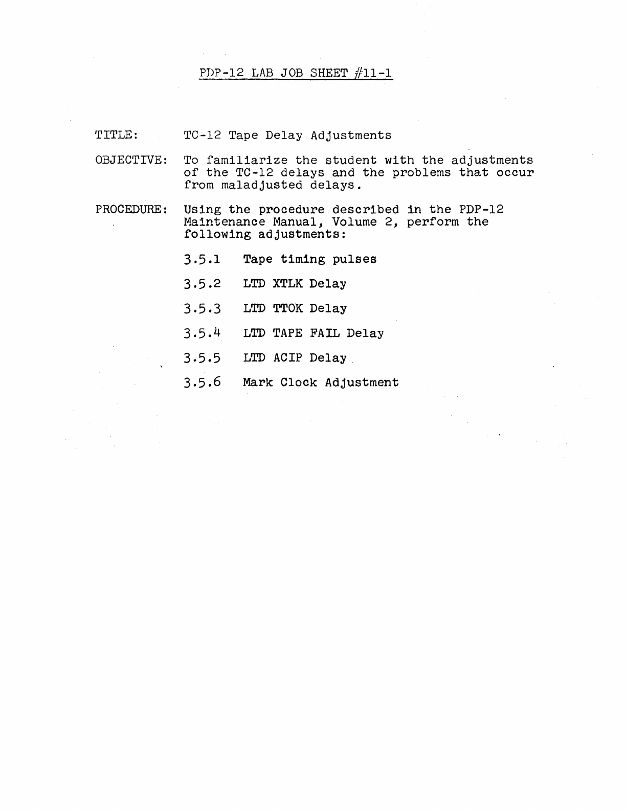
PDP-12
LAB
JOB
SHEET
ffll-1
TITLE: TC-12 Tape
Delay
Adjustments
OBJECTIVE:
To
familiarize
the
student
with
the
adjustments
of
the
TC-12
delays
and
the
problems
that
occur
from
maladjusted
delays.
PROCEDURE:
Using
the
procedure
described
in
the
PDP-12
Maintenance
Manual, Volume
2,
perform
the
following
adjustments:
3.5.1
Tape
timing
pulses
3.5.2
LTD
XTLK
Delay
3.5.3
LTD
TTOK
Delay
3.5.4
LTD
TAPE
FAIL
Delay
3.5.5
LTD
ACIP
Delay
.
3.5.6
Mark
Clock
Adjustment
PDP-12
LAB
#12
OUTLINE
TIME:
2 Hours
1.
Use
of
Tape
Diagnostics
2.
TC-12
Troubleshooting
PDP-12
LAB
JOB
SHEET
#12-1
TITLE: Use
of
Tape
Diagnostics
OBJECTIVE:
To
ensure
that
all
students
understand
the
procedure
for
running
ta
·:
diagnostics
PROCEDURE:
Using
a PDP-12
maintenan~e
tape
or
paper
tapes,
load
and.·
run
the
following
Maindecs:
Tape
Quickie
TC
12-I
TC
12-II
Tape
Data
Any
failures
should
be
corrected
at
this
time·.

PDP-12
LAB
//13
OUTLINE
TIME:
2 Hours
1.
Calibration
of
AD-12
2.
Troubleshooting
AD-12
PDP-12
LAB
JOB
SHEET
#
13-1
TITLE:
Calibration
of
AD-12
OBJECTIVE:
To
ensure
that
all
students
understand
and
can
perform
the
calibration
of
the
AD-12.
PROCEDURE:
Perform
the
adjustments
described
in
the
PDP-12
Maintenance
Manual, Volume
2,
section
3.8.5--
3.9.2
.
PDP-12
LAB
#14 OUTLINE
TIME:
2 Hours
1.
VR-12
adjustments
2.
VR-14
adjustments
3.
Troubleshooting
the
VC-12
PDP-12
LAB
JOB
SHEET
#14-1
TITLE: VR-12
Adjustments
OBJECTIVE:
To
ensure
that
all
students
are
capable
of
correctly
adjusting
the
VR-12
display.
PROCEDURE:
Does
your
PDP-12
system
contain
a VR-12
or
a·vR-14?
VR-12: Use
Job
Sheet
#14-1.
Upon
completion,
go
to
a
system
which
contains
a VR-14
and
use
Job
Sheet
#14-2.
VR-14: Use
Job
Sheet
#14-2.
Upon
completion,
go
to
a
system
which
contains
a VR-12
and
use
Job
Sheet
#14-1.
Perform
the
adjustments
described
in
the
PDP-12
Maintenance
Manual, Volume
2,
section
3.8
through
3.8.4
•
PDP-12
LAB
JOB
SHEET
#14-2
TITLE: VR-14
Adjustments
OBJECTIVE:
To
ensure
that
all
students
are
capable
of
correctly
adjusting
the
VR-14
display.
PROCEDURE:
Does
your
PDP-12
system
contain
a VR-12
or
a VR-14?
VR-12: Use
Job
Sheet
#14~1.
Upon
completion,
go
to
a
system
which
contains
a VR-14 and
use
Job
Sheet
#14-2.
VR-14: Use
Job
Sheet
#14-2.
Upon
completion
go
to
a
system
which
contains
a VR-12 and
use
Job
Sheet
#14-1.
Perform
the
adjustments
described
in
the
PDP-12
Maintenance
Manual, Volume
2,
section
3.8
through
3.8.4
•
PDP-12
LAB
#15
OUTLINE
TIME:
2
Hours.
1.
KW-12A
Diagnostic
usage
2.
KW-12A
Troubleshooting
PDP-12
LAB
JOB
SHEET
#15-1
TITLE:
~~-12A
Diagnostic
OBJECTIVE:
To
ensure
that
all
students
can
successfully
run
the
KW-12A
diagnostic
and
understand
any
failures
which
the
diagnostic
should
indicate.
PROCEDURE:
Load and
run
the
KW-12A
diagnostic.
If
failures
occur,
-obtain
the
appropriate
write-
up and
correct
the
problem.
PDP-12
LAB
JOB
SHEET
//15-1
TITLE:
K~-12A
Diagnostic
OBJ~CTIVE:
To
ensure
that
all
students
can
successfully
run
the
KW-12A
diagnostic
and
understand
any
failures
which
the
diagnostic
should
indicate.
PROCEDURE:
Load
and
run
the
KW-12A
diagnostic.
If
failures
occur,
..
obtain
the
appropriate
write-
up and
correct
the
problem.
PDP-12
LAB
}16
OUTLINE
1.
PDP-12/10
System
Troubleshooting
2.
PDP-12/20
System
Troubleshooting
3.
PDP-12/30
System
Troubleshooting
.4.
PDP-12/40
System
Troubleshooting

PDP-12
LAB
JOB
SHEET
#16-1,
2,
3, 4
To
be
Supplied
