COMMERCIAL AIR COOLED CONDENSING UNITS 576b PDS576H.240.7
User Manual: COMMERCIAL AIR COOLED CONDENSING UNITS 576b
Open the PDF directly: View PDF ![]() .
.
Page Count: 52
- Features/Benefits
- Table of Contents
- Model Number Nomenclature - 576B
- Model Number Nomenclature - 576H
- Model Number Nomenclature - 524A
- ARI Capacity Ratings
- Sound Levels, db
- Physical Data
- Options and Accessories
- Dimensions
- Selection Procedure with 576H240/524A-B240 Example
- Performance Data
- Condensing Unit Ratings
- Combination Ratings
- 576B300/524A-C240 with High-Capacity 4-Row Coil
- 576B300/524A-C300 with High-Capacity 4-Row Coil
- 576B300/524A-C360 with High-Capacity 4-Row Coil
- 576B300/524A-B240 with Standard 3-Row Coil
- 576B300/524A-B300 with Standard 3-Row Coil
- 576B300/524A-B360 with Standard 3-Row Coil
- 576B360/524A-C300 with High-Capacity 4-Row Coil
- 576B360/524A-C360 with High-Capacity 4- Row Coil
- 576B360/524A-B300 with Standard 3-Row Coil
- 576B360/524A-B360 with Standard 3-Row Coil
- 576H240/524A-C180 High-Capacity 4-Row Coils
- 576H240/524A-C240 High-Capacity 4-Row Coils
- 576H240/524A-B180 Standard 3-Row Coil
- 576H240/524A-B240 Standard 3-Row Coil
- 576H240/524A-C300 High-Capacity 4-Row Coils
- 576H300/524A-C240 High-Capacity 4-Row Coils
- 576H240/524A-B300 Standard 3-Row Coil
- 576H300/524A-B240 Standard 3-Row Coil
- 576H300/524A-C300 High- Capacity 4-Row Coils
- 576H300/524A-C360 High-Capacity 4-Row Coils
- 576H300/524A-B300 Standard 3-Row Coil
- 576H300/524A-B360 Standard 3-Row Coil
- 576H360/524A-C300 High-Capacity 4-Row Coils
- 576H360/524A-C360 High-Capacity 4-Row Coils
- 576H360/524A-B300 Standard 3-Row Coil
- 576H360/524A-B360 Standard 3-Row Coil
- 524A with Standard 3-Row Coil Fan Performance Data - 0.0-2.4 ESP
- 524A with High Capacity 4-Row Coil Fan Performance Data - 0.0-2.4 ESP
- 524A Accessory Plenum Air Throw Data
- 524A Accessory Pressure Drop (in. wg)
- 524A Hydronic Heating Capacities
- 524A Heating Correction Factors
- Electrical Data
- Typical Piping and Wiring
- Typical Wiring Schematic
- Controls
- Application Data - 576B300-360, 576H240-360 Units
- Application Data - 524A180-360 Units
- Guide Specifications - 576B300,360
- Guide Specifications - 576H240-360
- Guide Specifications - 524A180-360
Form No. PDS 576H.240.7
COMMERCIAL AIR-COOLED
CONDENSING UNITS WITH 524A
AIR-HANDLING UNITS
FEATURES/BENEFITS
Building owners will appreciate the high unit EERs (Energy
Efficiency Ratios) offered by the 576B and 576H units. These
units provide greater efficiency than similar units in the market-
place, which translates into year-round operating savings. Lat-
est safety standards for 576B and 576H units are assured
through UL and UL, Canada approvals.
CONSTRUCTED FOR LONG LIFE — The 576B and 576H
units are designed and built to last. Cabinets are constructed of
pre-painted galvanized steel, delivering unparalleled protection
against the environment. Inside and outside surfaces are pro-
tected to ensure long life, good looks and reliable performance.
The copper tube-aluminum fin outdoor coil construction pro-
vides long term reliability and improved heat transfer. Where
conditions require them, copper fin coils are available. For cor-
rosive or coastal environments an epoxy barrier is available to
provide superior coil durability.
RELIABILITY — The 576B and 576H condensing units offer
the building owner components and operating controls
designed for performance dependability. These condensing
units feature the time proven highly reliable 06D and 06E com-
pressors. Unloading capability for superior part load perfor-
mance is a standard feature of these compressors.
The compressor mounting system has vibration isolation to
provide quiet operation and reduce component stress.
Each compressor is equipped with a crankcase heater to elimi-
nate the occurrence of liquid slugging at start-up. The com-
pressors also include an oil level sight glass for maintenance
ease.
The following safety features are included in each unit:
• Anti short cycling control
• Low oil pressure safety
• Low refrigerant pressure safety
• High refrigerant pressure safety
• Calibrated circuit breakers
576H SERIES — The 576H condensing units feature 2 com-
pressors and 2 refrigeration circuits. These units can be
matched with a single air handler or two separate air handlers.
Units are designed for constant volume control.
EASE OF INSTALLATION AND SERVICE — These units are
equipped with hinged control box access panels, control inter-
face terminal boards, liquid line shut off valves and compressor
service valves.
INNOVATIVE BRYANT 524A AIR-HANDLING UNITS —
IDEAL MATCHES FOR 576B AND 576H CONDENSING
UNITS — The 524A Series has excellent fan performance, effi-
cient direct-expansion (DX) coils, a unique combination of
indoor air quality features, and easy installation. Its versatility
and state-of-the-art features help to ensure that your split sys-
tem provides economical performance now and in the future.
Indoor Air Quality (IAQ) Features — The unique combination
of IAQ features in the 524A Series air handlers helps to make
sure that only clean, fresh, conditioned air is delivered to the
occupied space.
Direct-expansion (DX) cooling coils prevent the build-up of
humidity in the room, even during part-load conditions. The
524A180-360 sizes feature dual-circuit coils.
Standard 2-in. disposable filters remove dust and airborne par-
ticles from the occupied space.
The pitched PVC drain pan can be adjusted for a right-hand or
left-hand connection to provide positive drainage and to pre-
vent standing condensate.
The 524A accessory economizer can provide ventilation air to
improve indoor-air quality. When used with CO2sensors and
field-supplied actuator adapter, the economizer admits fresh
outdoor air to replace stale, recirculated indoor air.
Models 576B, 576H
with 524A
Sizes 240-360
20 to 30 Tons
524A180-360
576B300-360
576H240-360
2
Economy — The 524A Series packaged air handlers have low
initial costs, and they continue to save money by providing
reduced installation expense and energy-efficient performance.
Quick installation is ensured by the multipoise design. Units can
be installed in either the horizontal or vertical configuration with-
out modifications. All units have drain-pan connections on both
sides, and pans can be pitched for right-hand or left-hand oper-
ation with a simple adjustment. Fan motors and contactors are
prewired and thermostatic expansion valves (TXVs) are factory-
installed on all 524A models.
High efficiency, precision-balanced fans minimize air turbu-
lence, surging, and unbalanced operation, cutting operating
expenses.
The economizer accessory precisely controls the blend of out-
door air and room air to achieve comfort levels. When the out-
side air enthalpy is suitable, outside air dampers can fully open
to provide “free” cooling.
Rugged Dependability — The524Aunitsaremadetolast.
The die-formed galvanized steel panels ensure structural integ-
rity under all operating conditions. Galvanized steel fan hous-
ings are securely mounted to a die-formed galvanized steel
deck. Mechanically bonded coil fins provide improved heat
transfer. Rugged pillow-block bearings are securely fastened to
the solid steel fan shaft with split collets and clamp locking
devices.
Coil Flexibility — Model 524A direct-expansion coils have gal-
vanized steel casings; inlet and outlet connections are on the
same end. The coils are designed for use with Refrigerant 22
and have 3/8-in. diameter copper tubes mechanically bonded to
aluminum sine-wave fins. The coils include matched, factory-
installed TXVs with matching distributor nozzles. Accessory hot
water and steam coils and electric heaters are also available.
Easier Installation and Service — Themultipoisedesignand
component layout help you to get the unit installed and running
quickly. The DX coils have factory-installed TXVs with matching
distributor nozzles. Units can be converted from horizontal to
vertical operation by simply repositioning the unit. Drain pan
connections are duplicated on both sides of the unit. The filters,
motor drive, TXVs, and coil connections are all easily accessed
by removing a single side panel.
TABLE OF CONTENTS
Features/Benefits.................................1,2
ModelNumberNomenclature........................3,4
ARICapacityRatings................................5
PhysicalData.................................... 6-8
OptionsandAccessories.......................... 9-11
Dimensions.................................... 12-16
SelectionProcedure................................17
PerformanceData............................... 17-28
ElectricalData ................................. 29-32
TypicalPipingandWiring.........................33,34
TypicalWiringSchematic......................... 35-38
Controls ......................................39,40
Application Data — 576B300-360, 576H240-360 Units . . 41-43
ApplicationData—524A180-360Units..............44,45
GuideSpecifications—576B300,360 ...............46,47
GuideSpecifications—576H240-360...............48,49
GuideSpecifications—524A180-360...............50,51
3
MODEL NUMBER NOMENCLATURE — 576B
MODEL NUMBER NOMENCLATURE — 576H
Factory-Installed Options
Condenser Coil Protection
AA – Aluminum (Standard)
KA – Pre-Coated Aluminum (Optional)
RA – Copper (Optional)
EA – E-Coated Al Fin/Cu Tube (Optional)
576B P X 300 000 RA
576B – Commercial Air-Cooled Condensing Units
Voltage Designation
E–460-3-60
P–208/230-3-60
Heating Capacity
000 – No Heat
Heating
X– None
Nominal Tons Cooling
300 – 25
360 – 30
Quality Assurance
Certified to ISO 9001:2000
576H E X 240 000 AA
576H — Commercial Air-Cooled
Condensing Unit (Dual-Circuit)
Voltage Designation
E— 460-3-60
P— 208/230-3-60
Nominal Tons
240 20
300 25
360 30
Heating
X—None
Heating Capacity
000 —No Heating
Condenser Coil Protection
AA — Aluminum (Standard)
KA — Pre-Coated Aluminum (Optional)
RA — Copper (Optional)
EA — E-Coated Al Fin/Cu Tube (Optional)
Factory-Installed Options
—
—
—
LEGEND
Al — Aluminum
Cu — Copper
Quality Assurance
Certified to ISO 9001:2000
4
MODEL NUMBER NOMENCLATURE — 524A
524A P B 240 000 GC
524A — Fan Coil
Voltage
T— 575-3-60
P— 208/230-3-60
E— 460-3-60*
Coil Option
B— DX Cooling Coil with TXVs
C— DX High Capacity Cooling with TXVs
Nominal Cooling (Tons)
180 —15
240 —20
300 —25
GC — Unpainted, Standard Motor
and Standard Drive
HC — Unpainted, Standard Motor and
Medium-Static Drive
(not available for 300 size)
TC — Unpainted, Alternate Motor and
Medium-Static Drive (300 size only)
YC — Unpainted, Alternate Motor and
High-Static Drive†
ED — Painted, Standard Motor and
Standard Drive
FD — Painted, Standard Motor and
Medium-Static Drive
(not available for 300 size)
RD — Painted, Alternate Motor and
Medium-Static Drive (300 size only)
WD — Painted, Alternate Motor and
High-Static Drive†
Nominal Heating (Btuh)
(Not applicable to 524A-B)
000 — 524A-B units
360 —30
LEGEND
*Size 524A180 units with an “E” voltage designation are triple voltage
(i.e., 208-230/460-3-60), unless the alternate motor (YC or WD) option
is used.
†The YC and WD option codes for 360 size unit designate standard
motor and high-static drive.
DX—Direct Expansion
TXV— Thermostatic Expansion Valve
Quality Assurance
Certified to ISO 9001:2000
5
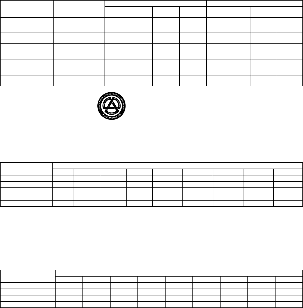
ARI*CAPACITY RATINGS
LEGEND *Air Conditioning and Refrigeration Institute.
†Ratings in accordance with ARI Standard 360/365.
**Condensing unit only ratings are at 45 F SST and 95 F entering-air
temperature.
††System ratings meet or exceed ASHRAE 90.1-1999 efficiency
requirements.
***Ratings meet or exceed ASHRAE 90.1-1999 efficiency requirements
for systems with a heating section other than electric resistance heat.
SOUND LEVELS, dB — 576B AND 576H
NOTES:
1. Estimated sound power levels, dB re 1 Picowatt.
2. This data is based upon a limited amount of actual testing with the
estimated sound power data being generated from this data in
accordance with ARI standard 370 for large outdoor refrigerating
and air-conditioning equipment.
3. Since this data is estimated, the sound power levels should not be
guaranteed or certified as being the actual sound power levels.
4. The acoustic center of the unit is located at the geometric center of
the unit.
ESTIMATED SOUND POWER LEVELS (Lw) — 524A180-360
NOTE:Since this data is calculated, these sound power levels may be different than the actual sound power levels.
The acoustic center of the unit is located at the geometric center of the unit.
CONDENSING
UNIT
576
AIR
HANDLER/
INDOOR COIL
SYSTEM† CONDENSING UNIT ONLY**
Net Capacity
(Btuh) EER IPLV Capacity
(Btuh) EER IPLV
576B300 524A-C240 282,000 8.8 11.0 330,000 10.2 12.1
524A-C300 300,000 9.0 11.2
524A-C360 316,000 8.9 11.0
576B360 524A-C300 332,000 8.6 10.6 370,000 10.1 13.1
524A-C360 345,000 8.8 10.6
576H240 524A-C180 222,000 9.8†† 9.4 250,000 11.7 13.7
524A-C240 240,000 9.6†† 9.7††
524A-C300 250,000 10.2†† 10.3††
576H300 524A-C240 268,000 9.4*** 9.5*** 290,000 11.2 12.9
524A-C300 282,000 9.6*** 9.5***
524A-C360 290,000 9.4 9.3
576H360 524A-C300 324,000 9.4 9.2 344,000 11.1 12.9
524A-C360 332,000 9.5 8.9
EER — Energy Efficiency Ratio
IPLV — Integrated Part Load Value
SST — Saturated Suction Temperature
UNIT OCTAVE BAND
63 125 250 500 1000 2000 4000 8000 dBA
576B300 95 95 93 90 89 84 82 81 93.5
576B360 96 96 94 91 90 85 83 83 94.6
576H240 95 95 93 90 89 84 82 81 93.5
576H300 95 95 93 90 89 84 82 81 93.5
576H360 96 96 94 91 90 85 83 83 94.6
UNIT OCTAVE BAND CENTER FREQUENCY
Cfm dB(A) 63 125 250 500 1000 2000 4000
524A180 6,000 92.7 98.9 94.9 90.9 91.9 85.9 83.9 79.9
524A240 8,000 96.4 102.6 98.6 94.6 95.6 89.6 87.6 83.6
524A300 10,000 96.2 102.5 98.5 94.5 95.5 89.5 87.5 83.5
524A360 12,000 98.5 104.7 100.7 96.7 97.7 91.7 89.7 85.7
6
PHYSICAL DATA
576B300,360 UNITS
*Unit is factory-supplied with holding charge only.
†Typical operating charge with 25 ft of interconnected piping. Operating charge is approximate for maximum system capacity.
**Storage capacity is 80% full at liquid saturated temperature of 125 F.
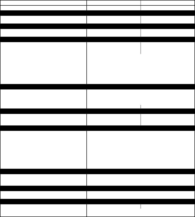
UNIT 576B 300 360
NOMINAL CAPACITY (tons) 25 30
OPERATING WEIGHTS (lb)
With Aluminum-Fin Coils (standard) 1650 1803
With Copper-Fin Coils (optional) 1804 2009
REFRIGERANT*R-22
Operating Charge, Typical (lb)† 30.5 43.5
Shipping Charge (lb) 34
COMPRESSOR Reciprocating, Semi-Hermetic
Qty...Model 1...06E9265 1...06E9275
Oil Charge (pt) 20 20
No.Cylinders 66
Speed (rpm) 1750
Capacity Steps (%)100, 66, 33
Unloader Setting (psig)
Unloader No.1Load 76
Unload 58
Unloader No.2Load 78
Unload 60
Crankcase Heater Watts 180
CONDENSER FANS Propeller Type — Direct Drive
Qty...Rpm 2...1140
Diameter (in.)30
Nominal Hp 1.0
Nominal Airflow (cfmtotal) 15,700
Watts (total) 1490 1750
CONDENSER COIL Enhanced Copper Tubes, Lanced Aluminum Fins
Rows...Fins/in.2...19 3...17
Face Area (sqft) 39.2 39.2
Storage Capacity (lb)** 37.7 56.6
CONTROLS
Pressurestat (psig)
High-Pressure
Open 426 ± 7
Close 320 ± 20
Low-Pressure
Open 27 ± 3
Close 44 ± 5
Oil Pressure (psi)
Open 6.0
Close 9.0
FAN CYCLING CONTROLS
Operating Pressure (psig)
No.2 Fan, Close 255 ± 10
Open 160 ± 10
PRESSURE RELIEF Fusible Plug
Location Liquid and Suction Line
Temperature (F) 210
PIPING CONNECTIONS (in.ODM)
Suction 15/821/8
Liquid 7/8
Hot Gas Stub 5/8
7
PHYSICAL DATA (cont)
576H240-360 UNITS
*Standard unit — single suction pressure-actuated unloader on compressor no. 1.
†Typical operating charge with 25 ft of interconnecting piping. Operating charge is approximate for maximum system capacity.
**Storage capacity is 80% full at liquid saturated temperature of 120 F.
NOTE:Refer to Loading Sequences table, page 40 for additional capacity step data.
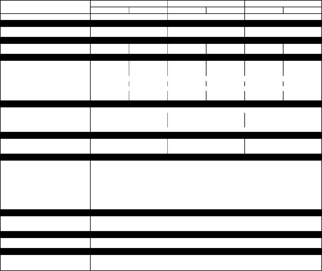
UNIT 576H 240 300 360
Ckt1 Ckt2 Ckt1 Ckt2 Ckt1 Ckt2
NOMINAL CAPACITY (tons)*20 25 30
OPERATING WEIGHT (lb)
With Aluminum-Fin Coil (standard) 1760 1820 1880
With Copper-Fin Coil (optional) 1923 1982 2097
REFRIGERANT, TYPER-22
Operating Charge, Typical (lb)† 20 20 20 20 25 25
Shipping Charge (lb) 333333
COMPRESSOR Reciprocating Semi-Hermetic
Qty...Model 1...06DH824 1...06DA824 1...06DH328 1...06DA328 1...06DH328 1...06DA537
No.Cylinders (per circuit) 666666
Speed (rpm) 1750 1750 1750 1750 1750 1750
Oil Charge Per Circuit (pt) 10
Capacity Steps (%)67 — 67 — 67 —
Unloader Setting (psig) Factory Installed
Load 76 — 76 — 76 —
Unload 58 — 58 — 58 —
CONDENSER FANS Propeller Type — Direct Driven
Qty...Rpm 2...1140
Diameter (in.)30 30 30
Nominal Hp 1.0 1.0 1.0
Nominal Airflow (cfm) 16,700 16,700 15,700
Watts (total) 1550
CONDENSER COIL Enhanced Copper Tubes, Lanced Aluminum Fins
Rows...Fins/in.2...19 2...19 3...17
Face Area (sqft) 39.20 39.20 39.20
Storage Cap.(lb)** 37.7 37.7 56.6
CONTROLS
Pressurestat (psig)
High Pressure
Open 426 ± 7
Close 320 ± 20
Low Pressure
Open 27 ± 3
Close 44 ± 5
Oil Pressure (psi)
Open 6.0
Close 9.0
FAN CYCLING CONTROLS
No.2Fan:
Temp Close (F) 70 ± 3
Temp Open (F) 60 ± 3
PRESSURE RELIEF
Location Liquid Line, Suction Line, Compressor
Temperature (F) 210
PIPING CONNECTIONS (in.ODM)
Suction 13/8
Liquid 5/8
Hot Gas Bypass 5/8
8
PHYSICAL DATA (cont)
524A180-360 UNITS
LEGEND
*Units are shipped without refrigerant charge.
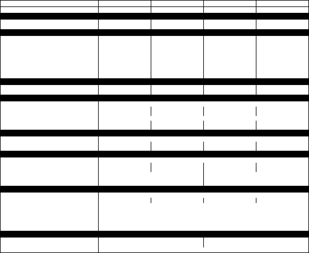
UNIT 524A 180 240 300 360
NOMINAL CAPACITY (tons) 15 20 25 30
OPERATING WEIGHTS (lb)
Base Unit with TXV (3-Row/4-Row) 685/713 690/730 1020/1050 1030/1062
Plenum 225 225 325 325
FANS
Qty...Diam.(in.)2...15 2...15 2...18 2...18
Nominal Airflow (cfm) 6000 8000 10,000 12,000
Airflow Range (cfm) 4500-7500 6000-10,000 7500-12,500 9000-15,000
Nominal Hp (Standard Motor)
208/230-3-60 and 460-3-60 3.7 5.0 7.5 10.0
575-3-60 3.0 5.0 7.5 10.0
Speed (rpm)
208/230-3-60 and 460-3-60 1725 1745 1745 1745
575-3-60 1725 1745 1755 1755
REFRIGERANT R-22
Operating charge (lb)
(approx per circuit)*2.5/2.5 3.5/3.5 4.5/4.5 5.0/5.0
DIRECT-EXPANSION COIL Enhanced Copper Tubes; Aluminum Sine-Wave Fins
Max Working Pressure (psig) 435
Face Area (sqfttotal) 17.67 19.88 24.86 29.83
No.ofSplits 2222
Split Type...Percentage Face...50/50
No.ofCircuits per Split (3 Row/4 Row) 12/16 13/18 15/20 18/24
Fins/in.15 17 15 15
STEAM COIL
Max Working Pressure (psig) 175
Face Area (sqfttotal) 13.33 13.33 15.0 15.0
Rows...Fins/in.1...10 1...10 1...10 1...10
HOT WATER COIL
Max Working Pressure (psig) 150
Face Area (sqfttotal) 13.33 13.33 15.0 15.0
Rows...Fins/in.2...8.5 2...8.5 2...12.5 2...12.5
Water Volume
(gal) 13.9 14.3
(ft3)1.85 1.90
PIPING CONNECTIONS
Qty...Size (in.)
DXCoil — Suction (ODF) 2...11/82...11/82...13/82...13/8
DXCoil — Liquid Refrigerant (ODF) 2...5/8
Steam Coil, In (MPT) 1...21/2
Steam Coil, Out (MPT) 1...11/2
Hot Water Coil, In (MPT) 1...2
Hot Water Coil, Out (MPT) 1...2
Condensate (PVC) 1...11/4
FILTERS Throwaway — Factory Supplied
Qty...Size (in.)4...16 x 20 x 2 4...16 x 24 x 2
4...16 x 24 x 2 4...20 x 25 x 2
Access Location Either Side
DX—Direct Expansion
TXV— Thermostatic Expansion Valve
9
OPTIONS AND ACCESSORIES
576B/576H FACTORY-INSTALLED OPTIONS
Dura-Shield
Condenser Options are available to match coil
protection to site conditions for optimum durability. See table
below and refer to the Application Data for selection guidance.
Consult your Bryant representative for further information.
576B/576H FIELD-INSTALLED ACCESSORIES
Electric Unloader Package includes hardware and solenoid
valve to convert a pressure-operated unloader to electric
unloading.
Pressure Unloader Package includes the unloader valve and
hardware.
–20 F Low-Ambient Temperature Kit (Motormaster®) con-
trols outdoor-fan motor operation to maintain the correct head
pressure at low outdoor ambient temperatures. Only one low
ambient temperature kit is required per unit.
Hot-Gas Bypass Kit (576B only) prevents the indoor coil from
freezing up during low airflow or low return-air temperature
applications by maintaining minimum suction pressure.
Bryant Thermostats provide both programmable and non-
programmable capability.
Part-Winding-Start Timing Relay (576B) reduces inrush cur-
rent and locked rotor amps on start-up. This accessory may
require a special-order unit. See table below.
PART-WINDING-START TABLE
NOTES:
1. Can be field modified to part winding start by adding a time delay
relay (part no. HN67ZA001).
2. Requires special order to change circuit breakers and contactors,
and cannot use triple-voltage compressor.
CONDENSER COIL OPTIONS
LEGEND
UNIT SIZE
576B
VOLTAGE (60 Hz)
208/230 460
300 Note 1 Note 2
360
COPPER-TUBE COILS
WITH
DURA-SHIELD
OPTION
ENVIRONMENT
Standard Mild
Coastal
Moderate
Coastal
Severe
Coastal Industrial Combined
Industrial/Coastal
Al Fins (Standard Coils) X
Cu Fins X
Al Fins, E-Coating XX X
Al Fins, Pre-Coated X
Al — Aluminum
Cu — Copper
Dura-Shield
—Family of Coil Protection Options
E-Coated — Epoxy Coating Applied to Entire Coil Assembly
Pre-Coated — Epoxy Coating Applied to Fin Stock Material
10
OPTIONS AND ACCESSORIES (cont)
524A FACTORY-INSTALLED OPTIONS
Prepainted Steel Units are available from the factory for appli-
cations that require painted units. Units are painted with Ameri-
canSterlingGraycolor.
High Capacity 4-Row Coils are available to provide increased
latent/sensible capacities and efficiencies.
Alternate Fan Motors and Drives are available to provide the
widest possible range of performance.
524A FIELD-INSTALLED ACCESSORIES
Discharge Plenum directs the air discharge into the occupied
space; integral horizontal and vertical louvers enable redirection
of airflow. Accessory is available unpainted or painted.
Two-Row Hot Water Coils have 5/8-in. diameter copper tubes
mechanically bonded to aluminum plate fins. Coils have non-
ferrous headers.
One-Row Steam Coil has 1-in. OD copper tube and aluminum
fins. The Inner Distributing Tube (IDT) design provides uniform
temperatures across the coil face. The steam coil has a broad
operating pressure range; up to 20 psig at 260 F. IDT steam
coils are especially suited to applications where sub-freezing air
enters the unit.
Electric Resistance Heat Coils have an open-wire design and
are mounted in a rigid frame. Safety cutouts for high tempera-
ture conditions are standard.
Economizer (Enthalpy Controlled) provides ventilation air
and “free” cooling if outside ambient temperature and humidity
are suitable. Can also be used with field-supplied CO2sensor
and actuator adapter to help meet indoor air quality require-
ments.
Return-Air Grille provides a protective barrier over the return-
air opening and gives a finished appearance to units installed in
the occupied space. Accessory is available unpainted or
painted.
Subbase provides a stable, raised platform and room for con-
densate drain connection for floor-mounted units. Accessory is
available unpainted or painted.
Overhead Suspension Package includes necessary brackets
to support units in horizontal ceiling installations.
Bryant Thermostats provide both programmable and non-
programmable capability.
CO2Sensors canbeusedinconjunctionwiththeeconomizer
accessory to help meet indoor air quality requirements. The
sensor signals the economizer to open when the CO2level in
the space exceeds the set point.
Condensate Drain Trap includes an overflow shutoff switch
that can be wired to turn off the unit if the trap becomes
plugged. The kit also includes a wire harness that can be con-
nected to an alarm if desired. The transparent trap is designed
for easy service and maintenance.
UV-C Germicidal Lamps kill mold and fungus, which may grow
on evaporator coil and condensate pan surfaces. The use of
UV-C germicidal lamps eliminates the foul odors that result from
this growth of mold and fungus. It also provides a self-cleaning
function for the evaporator coil and drain pan.
Programmable and Non-Programmable Thermostat
11
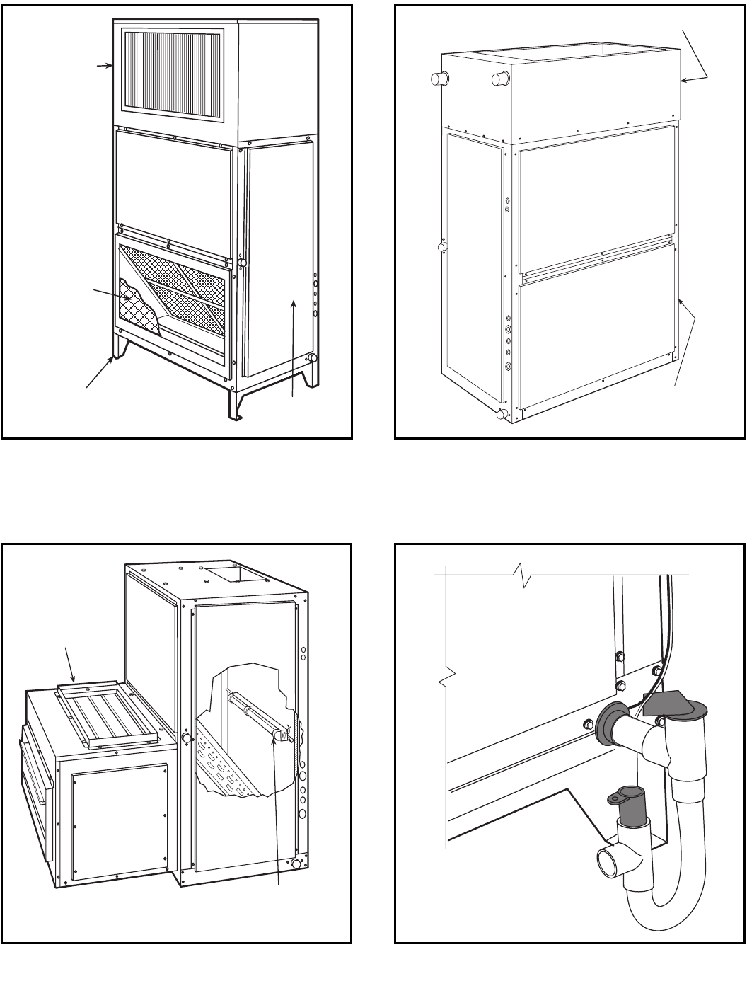
OPTIONS AND ACCESSORIES (cont)
DISCHARGE
PLENUM
RETURN-AIR
GRILLE
SUBBASE
FAN
COIL
UNIT
ECONOMIZER
UV-C GERMICIDAL LAMPS
FAN COIL
UNIT
HOT WATER OR
STEAM COIL
524A with Discharge Plenum,
Return-Air Grille and Subbase
524A with Hot Water or Steam Coil
524A with Economizer and UV-C Germicidal Lamps 524A with Condensate Drain Trap
12
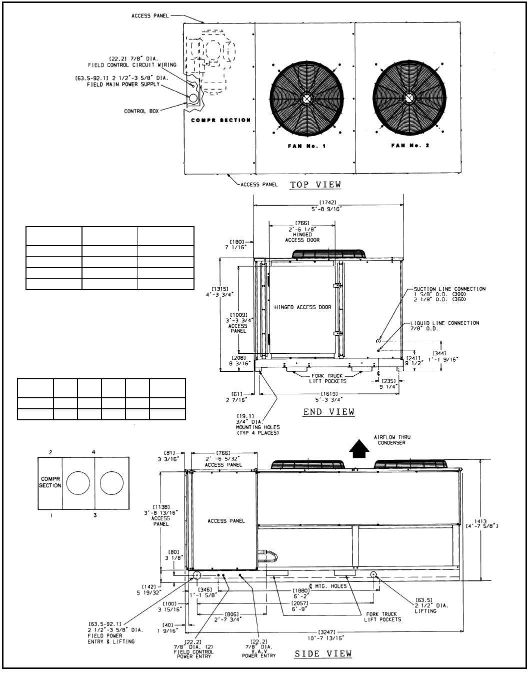
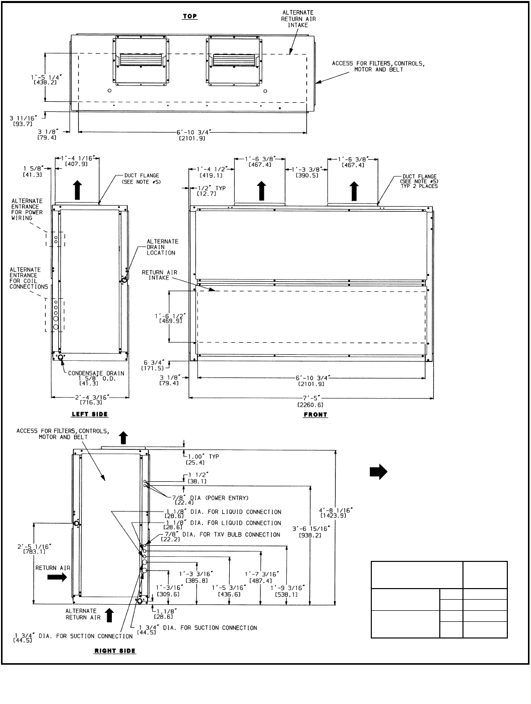
DIMENSIONS
576B300,360
NOTES:
1. There must be 4 ft [1220 mm] for service and for
unrestricted airflow on all sides of unit.
2. There must be minimum 8 ft [2440 mm] clear air
space above unit.
3. The approximate operating weight of the unit is:
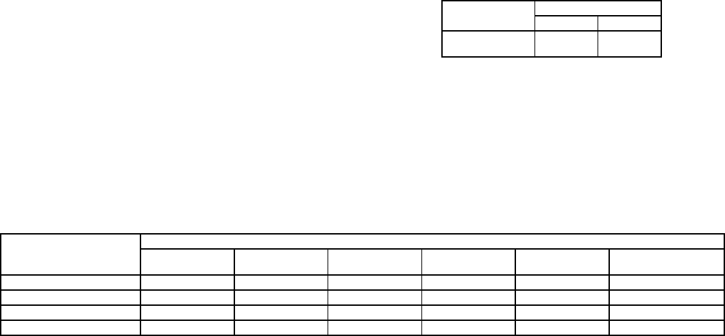
NOTE:“RA” in model number indicates unit has
optional factory-installed copper-fin coil.
UNIT
576B
WEIGHT
(lb)
WEIGHT
(kg)
300 1650 748
300RA 1804 818
360 1803 818
360RA 2009 911
APPROX. OPER.WT (lb)
AT SUPPORT POINTS*
*Standard copper tube aluminum-fin coil.
UNIT
576B 1234TOTAL
300 418 626 242 364 1650
360 459 673 272 399 1803
13
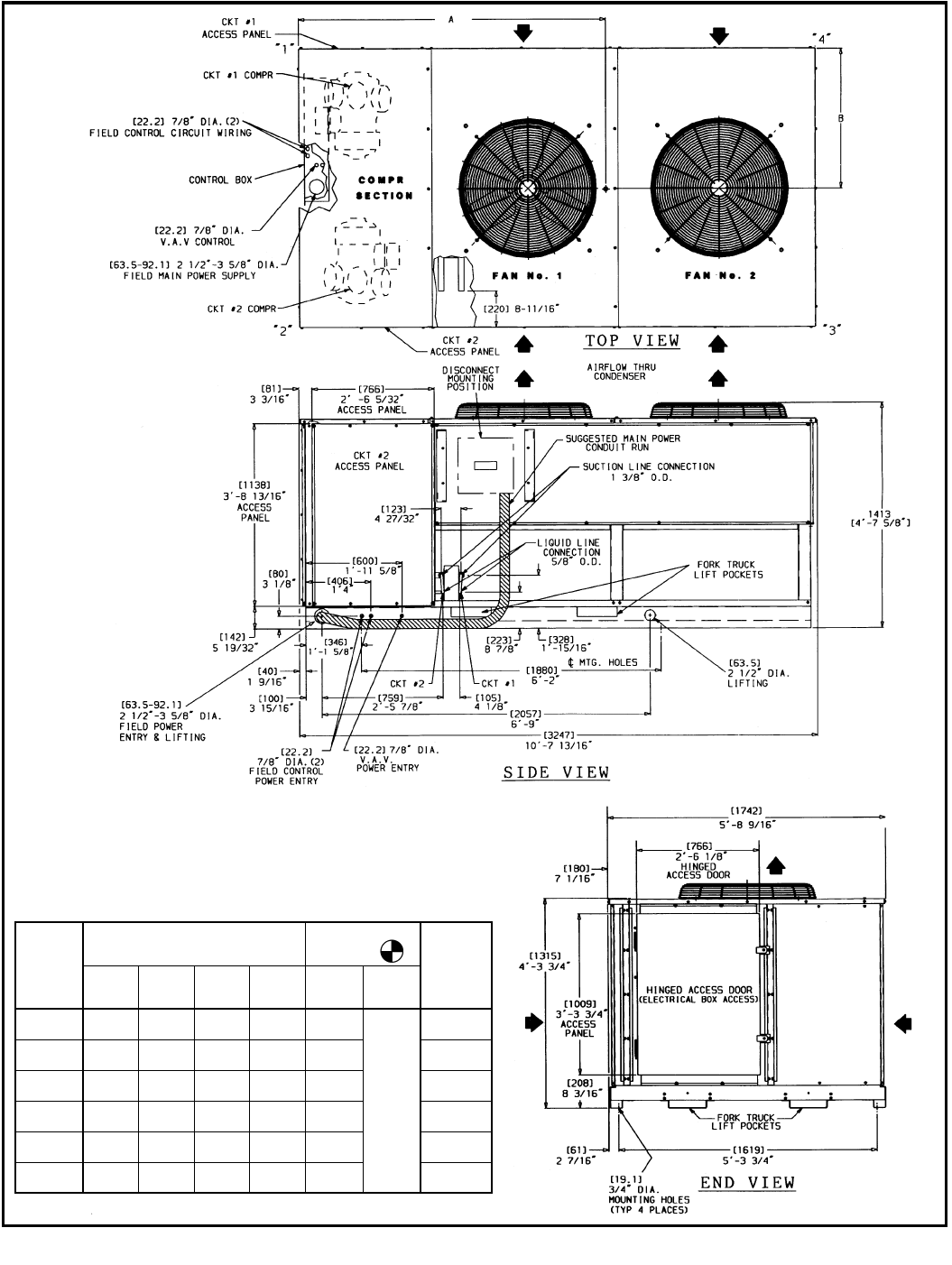
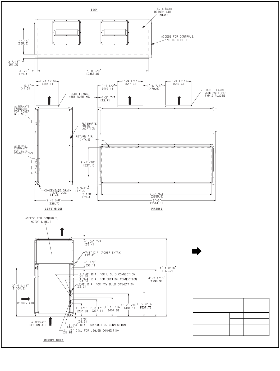
DIMENSIONS (cont)
NOTES:
1. There must be 4 ft [1220 mm] for service and for unrestricted airflow on
all sides of unit.
2. There must be minimum 8 ft [2440 mm] clear air space above unit.
3. “RA” in the model number indicates copper coils.
4. Dimensions in [ ] are in millimeters.
5. The approximate operating weight of the unit is shown below.
6. Certified dimensional drawing is available on request.
UNIT
576H
CORNER WEIGHT — lb [kg]
CENTER OF
GRAVITY TOTAL
UNIT WT
lb [kg]
“1” “2” “3” “4”
ADim.
in.
[mm]
BDim.
in.
[mm]
240 631.6
[286.5]
577.6
[262.0]
263.1
[119.3]
287.7
[130.5]
40.00
[1016]
32.75
[832]
1760
[798.3]
240RA 666.5
[302.3]
609.5
[276.5]
309.0
[140.2]
337.9
[153.3]
43.00
[1092]
1923
[872.3]
300 658.7
[298.8]
602.4
[273.3]
267.0
[121.1]
291.9
[132.4]
39.25
[997]
1820
[825.6]
300RA 693.0
[314.3]
633.8
[287.5]
313.0
[142.0]
342.2
[155.2]
42.25
[1073]
1982
[899.0]
360 667.0
[302.5]
610.0
[276.7]
288.0
[130.7]
315.0
[142.9]
41.00
[1041]
1880
[853.0]
360RA 718.3
[325.8]
656.8
[297.9]
344.8
[156.4]
377.0
[171.0]
44.00
[1117]
2097
[951.2]
576H240-360
14
DIMENSIONS (cont)
524A180,240
LEGEND
TXV—Thermostatic Expansion Valve
NOTES:
1. Dimensions in [ ] are in millimeters.
2. Direction of airflow.
3. Recommended clearance:
•Rear: 3″
•Front: 2′-6″
•Right Side: 2′-6″
•Left Side: 2′-6″
•Local codes or jurisdiction may prevail.
4. Liquid piping not supplied by Bryant.
5. Duct flange is factory supplied and field
installed.
UNIT
524A
UNIT
WEIGHT
(lb)
STANDARD
3-ROW COIL
180 685
240 690
HIGH-
CAPACITY
4-ROW COIL
180 713
240 730
15
DIMENSIONS (cont)
524A300,360
LEGEND
TXV—Thermostatic Expansion Valve
NOTES:
1. Dimensions in [ ] are in millimeters.
2. Direction of airflow.
3. Recommended clearance:
•Rear: 3″
•Front: 2′-6″
•Right Side: 2′-6″
•Left Side: 2′-6″
•Local codes or jurisdiction may prevail.
4. Liquid piping not supplied by Bryant.
5. Duct flange is factory supplied and field
installed.
UNIT
524A
UNIT
WEIGHT
(lb)
STANDARD
3-ROW COIL
300 1020
360 1030
HIGH-CAPACITY
4-ROW COIL
300 1050
360 1062
16
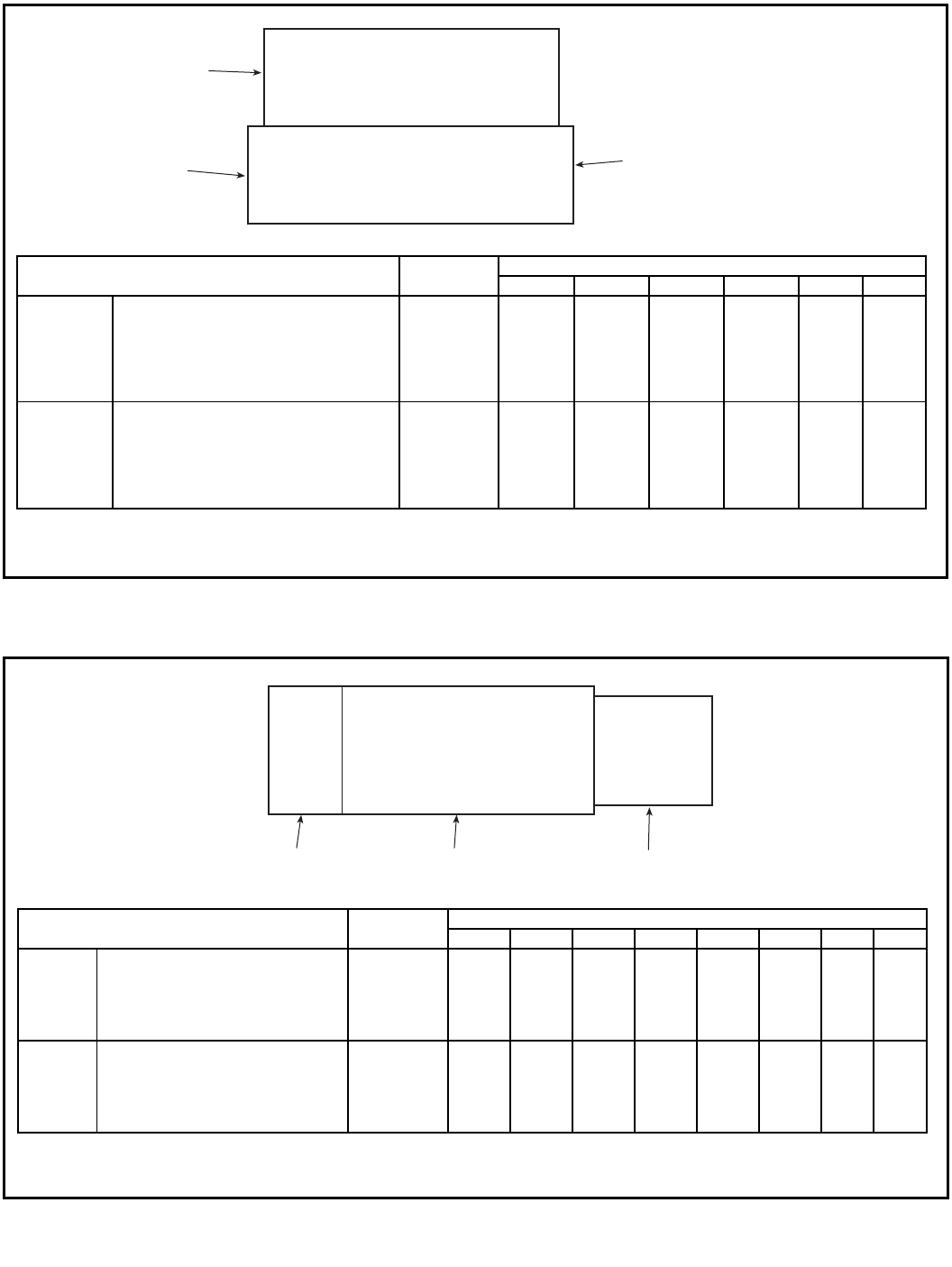
DIMENSIONS (cont)
5
1
2
6
4
3
ECONOMIZER
FAN COIL
BASE UNIT
STEAM COIL, HOT WATER COIL &
PLENUM ON TOP OF
POSITIONS 1, 2, 3, 4
NOTES:
1. Total weight is determined by adding fan coil base unit weight to factory-installed option weight.
2. Corner weights are based on 3-row coil units.
524A UNIT WEIGHT CORNER WEIGHTS
123456
180,240
FAN COIL BASE UNIT (180, 240) 685, 690 188.2 207.2 151.4 137.6 — —
Steam Coil 239 60.0 60.0 59.5 59.5 0.0 0.0
Hot Water Coil 245 61.0 61.0 61.6 61.6 0.0 0.0
Plenum 225 72.5 40.0 40.0 72.5 0.0 0.0
Economizer 217 42.7 0.0 0.0 39.6 70.1 65.1
Economizer and Steam Coil 456 102.7 60.0 59.5 99.1 70.1 65.1
Economizer and Water Coil 463 103.7 61.0 61.6 101.2 70.1 65.1
300,360
FAN COIL BASE UNIT (300, 360) 1020, 1030 249.1 342.5 251.3 182.8 — —
Steam Coil 263 66.1 66.1 65.6 65.6 0.0 0.0
Hot Water Coil 314 78.6 78.6 78.2 78.2 0.0 0.0
Plenum 325 102.0 60.6 60.6 102.0 0.0 0.0
Economizer 306 61.3 0.0 0.0 56.4 98.3 90.5
Economizer and Steam Coil 570 127.4 66.1 65.6 122.0 98.3 90.5
Economizer and Water Coil 620 139.8 78.6 78.2 134.6 98.3 90.5
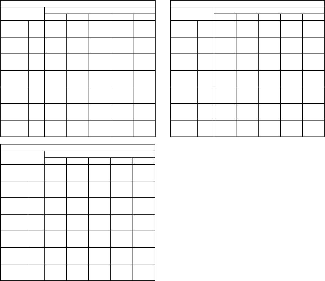
Corner Weights — Vertical Position 524A180-360 Units
NOTES:
1. Total weight is determined by adding fan coil base unit weight to factory-installed option weight.
2. Corner weights are based on 3-row coil units.
524A UNIT WEIGHT CORNER WEIGHTS
12345678
180,240
FAN COIL BASE UNIT (180, 240) 685, 690 220.5 174.9 127.8 161.1 — — — —
Steam Coil 239 43.2 0.0 0.0 43.6 75.8 76.5 0.0 0.0
Hot Water Coil 245 44.5 0.0 0.0 44.1 78.7 77.9 0.0 0.0
Economizer 217 0.0 42.7 39.6 0.0 0.0 0.0 70.1 65.1
Economizer and Steam Coil 456 43.2 42.7 39.6 43.6 75.8 76.5 70.1 65.1
Economizer and Water Coil 463 44.5 42.7 39.6 44.1 78.7 77.9 70.1 65.1
300,360
FAN COIL BASE UNIT (300, 360) 1020, 1030 346.4 245.2 179.9 254.2 — — — —
Steam Coil 263 47.5 0.0 0.0 47.9 83.7 84.4 0.0 0.0
Hot Water Coil 314 54.6 0.0 0.0 54.8 101.9 102.3 0.0 0.0
Economizer 306 0.0 61.3 56.4 0.0 0.0 0.0 98.3 90.5
Economizer and Steam Coil 570 47.5 61.3 56.4 47.9 83.7 84.4 98.3 90.5
Economizer and Water Coil 620 54.6 61.3 56.4 54.8 101.9 102.3 98.3 90.5
Corner Weights — Horizontal Position 524A180-360 Units
6438
7
2
1
5
STEAM COIL OR
HOT WATER COIL
FAN COIL
BASE UNIT
ECONOMIZER

17
SELECTION PROCEDURE WITH 576H240/524A-B240 EXAMPLE
NOTE:See the Performance Data section for combination rat-
ings for 576H240-360 units and matching 524A air handlers. If
the 576H condensing units are matched with 2 independent
524A units, cross-plot for performance ratings or contact Bryant
Application Engineering for assistance.
I DETERMINE COOLING LOAD, EVAPORATOR-AIR TEM-
PERATURE AND QUANTITY.
Given:
Total Cooling Capacity
Required(TC)...................... 235,000Btuh
Sensible Heat Capacity
Required(SHC).................... 185,000Btuh
Temperature Air Entering
Condenser(Edb).......................... 95F
Temperature Air Entering
Evaporator(db/wb)................80Fdb,67Fwb
EvaporatorAirQuantity....................8000cfm
ExternalStaticPressure ................. 0.80in.wg
Length of Interconnecting
RefrigerantPiping ...................30ft(Linear)
II SELECT CONDENSING UNIT AIR-HANDLER
COMBINATION.
For this example, select a 576H240 matched with a
524A-B240. (See Combination Ratings table.) This
576H240/524A-B240 condensing unit-air handler combi-
nation provides 237,200 Btuh of total cooling capacity and
188,600 Btuh of sensible capacity at the given conditions.
If other temperatures or airflow values are required, inter-
polate the values from the combination ratings.
III DETERMINE SIZES OF LIQUID AND SUCTION LINES.
Enter the Refrigerant Pipe Sizes table. The sizes shown
are based on an equivalent length of pipe. This equivalent
length is equal to the linear length of pipe indicated at the
top of each sizing column, plus a 50% allowance for fitting
losses. For this example, note in the linear length column
thattheproperpipesizeis5/8in. for the liquid lines and
13/8in. for the suction lines.
IV DETERMINE FAN RPM AND BHP(Brake Horsepower).
In the 524A Fan Performance table, enter the 524A-B240
sectionat8000cfmandmovetotheExternalStatic
Pressure (ESP) column. Note that the conditions require
876 rpm at 4.21 bhp.
V DETERMINE MOTOR AND DRIVE.
Enter the Fan Motor Data tables and find that the standard
motor for a 524A-B240 unit is rated at 5 hp. Since the bhp
required is 4.21, a standard motor satisfies the require-
ment and should be used.
Next, find the type of drive that satisfies the 876 rpm
requirement in the Drive Data tables. For a 524A-B240
unit, the Medium-Static Drive table shows an rpm range of
798 to 984. Since the rpm required is 876, the medium-
static drive satisfies the requirement and should be used.
Select the standard motor and medium-static drive combi-
nation (option code HC or FD).
PERFORMANCE DATA
CONDENSING UNIT RATINGS
LEGEND
576B300
SST
(F)
Air Temperature Entering Condenser (F)
80 85 95 100 105 115
25
TC 238 230 213 204 196 180
kW21.9 22.2 23.2 23.7 24.1 24.9
SDT 107 111 120 124 129 138
30
TC 269 261 242 233 224 206
kW23.3 23.6 24.8 25.4 25.9 26.8
SDT 110 114 123 127 131 140
35
TC 300 292 271 261 252 232
kW24.7 25.0 26.4 27.0 27.6 28.7
SDT 112 117 125 130 134 143
40
TC 333 323 301 290 279 258
kW26.1 26.4 28.0 28.7 29.3 30.6
SDT 115 120 128 133 137 145
45
TC 365 354 330 319 307 284
kW27.3 27.8 29.5 30.3 31.1 32.4
SDT 118 123 131 135 140 148
50
TC 398 386 361 348 336 312
kW28.8 29.3 31.2 32.0 32.9 34.4
SDT 121 126 134 138 142 151
kW—Compressor Power
SDT — Saturated Discharge Temperature at Compressor (F)
SST — Saturated Suction Temperature (F)
TC — Gross Cooling Capacity (1000 Btuh)
576B360
SST
(F)
Air Temperature Entering Condenser (F)
80 85 95 100 105 115
25
TC 268 260 241 232 223 205
kW25.0 25.1 26.2 26.6 27.0 27.7
SDT 106 110 119 124 128 137
30
TC 302 293 273 264 254 234
kW26.5 26.6 27.9 28.4 28.9 29.8
SDT 109 113 122 126 131 140
35
TC 337 326 305 295 284 263
kW27.9 28.1 29.6 30.2 30.8 31.9
SDT 112 116 125 129 133 142
40
TC 371 359 337 326 314 292
kW29.3 29.6 31.3 32.1 32.8 34.0
SDT 115 119 128 132 136 145
45
TC 405 393 369 357 345 321
kW30.7 31.1 33.0 33.9 34.7 36.1
SDT 117 122 130 135 139 147
50
TC 440 428 402 390 377 351
kW32.3 32.7 34.8 35.7 36.6 38.2
SDT 120 125 133 138 142 150
18
PERFORMANCE DATA (cont)
CONDENSING UNIT RATINGS (cont)
LEGEND
576H240
SST
(F)
Air Temp Ent Condenser (F)
85 95 100 105 115
20
TC 157 143 136 129 115
kW14.1 14.9 15.2 15.5 16.0
SDT 105 115 120 125 135
25
TC 178 163 156 149 134
kW14.7 15.6 16.0 16.4 17.0
SDT 106 116 121 126 135
30
TC 198 183 176 168 153
kW15.3 16.3 16.8 17.3 18.1
SDT 107 117 121 126 135
35
TC 221 205 197 189 173
kW15.9 17.1 17.6 18.1 19.1
SDT 109 118 123 128 137
40
TC 244 227 219 210 193
kW16.6 17.9 18.5 19.0 20.1
SDT 111 120 125 129 138
45
TC 270 251 243 233 215
kW17.2 18.6 19.3 19.9 21.1
SDT 113 122 127 131 140
50
TC 295 276 266 257 237
kW17.8 19.4 20.1 20.8 22.1
SDT 116 125 129 133 142
576H300
SST
(F)
Air Temp Ent Condenser (F)
85 95 100 105 115
20
TC 187 173 167 160 147
kW17.1 18.1 18.6 19.1 19.9
SDT 107 116 121 126 135
25
TC 209 194 187 180 166
kW17.9 19.1 19.6 20.1 21.1
SDT 109 118 123 127 137
30
TC 231 216 208 200 185
kW18.7 20.0 20.6 21.2 22.2
SDT 111 120 124 129 138
35
TC 256 239 231 223 206
kW19.5 20.9 21.6 22.2 23.4
SDT 113 122 126 131 140
40
TC 282 263 254 245 228
kW20.3 21.9 22.6 23.3 24.6
SDT 115 124 128 133 142
45
TC 310 290 280 271 252
kW21.1 22.8 23.6 24.4 25.9
SDT 118 126 131 135 144
50
TC 338 317 306 296 275
kW22.0 23.8 24.6 25.5 27.1
SDT 120 129 133 138 146
576H360
SST
(F)
Air Temp Ent Condenser (F)
85 95 100 105 115
20
TC 223 206 199 190 175
kW21.2 22.5 23.1 23.7 24.8
SDT 107 117 122 127 137
25
TC 249 232 224 215 209
kW22.2 23.6 24.2 24.9 26.2
SDT 109 118 123 128 137
30
TC 276 258 249 241 222
kW23.1 24.7 25.4 26.2 27.6
SDT 110 119 124 129 138
35
TC 307 287 277 267 248
kW24.2 25.9 26.7 27.6 29.0
SDT 112 121 126 130 140
40
TC 336 314 305 294 274
kW25.3 27.1 28.0 28.9 30.5
SDT 115 123 128 132 141
45
TC 369 346 335 324 302
kW26.3 28.3 29.3 30.3 32.0
SDT 117 126 136 135 144
50
TC 402 378 366 354 330
kW27.4 29.6 30.6 31.7 33.6
SDT 120 128 133 137 146
kW—Compressor Power
SDT — Saturated Discharge Temperature at Compressor (F)
SST — Saturated Suction Temperature (F)
TC — Gross Cooling Capacity (1000 Btuh)
19
PERFORMANCE DATA (cont)
CONDENSING UNIT RATINGS (cont)
LEGEND
*Circuits no. 1 and 2 on 576H240 and 300 have identical capacities.
576H240 — CIRCUIT NO.1OR2*
SST
(F)
Air Temp Ent Condenser (F)
85 95 100 105 115
20
TC 78 71 68 65 58
kW7.03 7.44 7.61 7.76 8.01
SDT 105 115 120 125 135
25
TC 89 82 78 74 67
kW7.34 7.80 8.01 8.20 8.52
SDT 106 116 121 126 135
30
TC 99 92 88 84 77
kW7.65 8.17 8.41 8.63 9.03
SDT 107 117 121 126 135
35
TC 111 103 99 95 87
kW7.96 8.55 8.82 9.07 9.54
SDT 109 118 123 128 137
40
TC 122 114 109 105 97
kW8.28 8.93 9.23 9.52 10.0
SDT 111 120 125 129 138
45
TC 135 126 121 117 108
kW8.59 9.30 9.64 9.96 10.6
SDT 113 122 127 131 140
50
TC 148 138 133 128 119
kW8.90 9.68 10.0 10.4 11.1
SDT 116 125 129 133 142
576H300 — CIRCUIT NO.1OR2*
SST
(F)
Air Temp Ent Condenser (F)
85 95 100 105 115
20
TC 93 87 83 80 74
kW8.55 9.07 9.31 9.54 9.97
SDT 107 116 121 126 135
25
TC 104 97 94 90 83
kW8.95 9.53 9.80 10.1 10.5
SDT 109 118 123 127 137
30
TC 116 108 104 100 93
kW9.35 9.99 10.3 10.6 11.1
SDT 111 120 124 129 138
35
TC 128 120 116 111 103
kW9.76 10.5 10.8 11.1 11.7
SDT 113 122 126 131 140
40
TC 141 132 127 123 114
kW10.2 10.9 11.3 11.6 12.3
SDT 115 124 128 133 142
45
TC 155 145 140 135 126
kW10.6 11.4 11.8 12.2 12.9
SDT 118 126 131 135 144
50
TC 169 158 153 148 138
kW11.0 11.9 12.3 12.7 13.5
SDT 120 129 133 138 146
kW—Compressor Power
SDT — Saturated Discharge Temperature at Compressor (F)
SST — Saturated Suction Temperature (F)
TC — Gross Cooling Capacity (1000 Btuh)
576H360 — CIRCUIT NO.1
SST
(F)
Air Temp Ent Condenser (F)
85 95 100 105 115
20
TC 93 85 82 78 71
kW8.69 9.26 9.53 9.78 10.2
SDT 105 115 120 125 135
25
TC 105 97 93 89 81
kW9.02 9.64 9.94 10.2 10.8
SDT 106 116 121 125 135
30
TC 117 109 105 101 92
kW9.34 10.0 10.3 10.7 11.3
SDT 107 116 121 126 135
35
TC 131 122 117 113 104
kW9.70 10.5 10.8 11.2 11.8
SDT 109 118 123 127 137
40
TC 144 134 130 125 116
kW10.1 10.9 11.3 11.7 12.4
SDT 111 120 124 129 138
45
TC 159 148 143 138 128
kW10.4 11.3 11.7 12.2 12.9
SDT 113 122 127 131 140
50
TC 174 163 157 152 141
kW10.8 11.8 12.2 12.7 13.5
SDT 116 124 129 133 142
576H360 — CIRCUIT NO.2
SST
(F)
Air Temp Ent Condenser (F)
85 95 100 105 115
20
TC 130 121 117 112 104
kW12.5 13.2 13.6 13.9 14.6
SDT 109 118 123 128 138
25
TC 144 135 131 126 117
kW13.2 14.0 14.3 14.7 15.4
SDT 111 120 124 129 139
30
TC 159 149 144 140 130
kW13.8 14.7 15.1 15.5 16.3
SDT 113 122 126 131 140
35
TC 176 165 160 154 144
kW14.5 15.4 15.9 16.4 17.2
SDT 115 124 128 133 142
40
TC 192 180 175 169 158
kW15.2 16.2 16.7 17.2 18.1
SDT 118 126 131 135 144
45
TC 210 198 192 186 174
kW15.9 17.0 17.6 18.1 19.1
SDT 120 129 133 138 147
50
TC 228 215 209 202 189
kW16.6 17.8 18.4 19.0 20.1
SDT 123 132 136 140 149
20
PERFORMANCE DATA (cont)
COMBINATION RATINGS
LEGEND
NOTES:
1. Direct interpolation is permissible. Do not extrapolate.
2. Evaporator fan heat not deducted from ratings.
3. Ratings based on approximately 12 F superheat leaving coil.
4. Formulas:
Where hewb = enthalpy of air entering coil.
5. SHC is based on 80 F db temperature of air-entering evaporator coil.
576B300/524A-C240 WITH HIGH-CAPACITY 4-ROW COIL
Temp (F)
Air Entering
Condenser
(Edb)
Evaporator Air — Cfm
6000 8000 10,000
Evaporator Air — Ewb (F)
72 67 62 72 67 62 72 67 62
85
TC 341.7 312.2 284.6 364.1 333.8 304.9 377.8 347.4 318.6
SHC 133.1 175.5 216.7 149.5 203.1 255.5 164.0 228.6 290.8
kW28.00 26.64 25.34 29.05 27.67 26.34 29.67 28.31 26.97
95
TC 327.7 299.3 272.7 347.9 318.9 291.2 360.7 331.7 303.8
SHC 128.9 170.8 211.9 144.6 198.3 250.0 159.7 223.9 284.9
kW29.94 28.46 27.02 31.03 29.51 28.04 31.68 30.19 28.73
100
TC 320.6 292.8 266.6 339.7 311.4 284.4 352.3 323.8 296.9
SHC 126.7 168.7 209.4 142.6 196.0 247.7 157.7 221.7 282.1
kW30.92 29.38 27.88 32.01 30.43 28.91 32.71 31.14 29.64
105
TC 313.3 286.0 260.4 331.5 303.9 277.5 343.6 315.8 289.8
SHC 124.6 166.3 207.0 140.4 193.6 245.1 155.5 219.3 278.9
kW31.91 30.29 28.72 33.00 31.37 29.78 33.73 32.09 30.54
115
TC 298.4 272.2 247.5 315.0 288.7 267.1 326.2 299.3 274.4
SHC 120.2 161.6 202.0 136.1 189.0 240.9 151.4 214.7 274.4
kW33.79 32.01 30.30 34.90 331.6 31.22 35.66 33.87 32.16
576B300/524A-C300 WITH HIGH-CAPACITY 4-ROW COIL
Temp (F)
Air Entering
Condenser
(Edb)
Evaporator Air — Cfm
7500 10,000 12,500
Evaporator Air — Ewb (F)
72 67 62 72 67 62 72 67 62
85
TC 348.1 319.4 292.1 365.9 336.7 309.1 377.1 347.9 320.4
SHC 175.1 191.4 240.3 159.4 222.4 283.2 176.6 251.7 320.4
kW28.21 26.89 25.61 29.06 27.71 26.42 29.55 28.22 26.94
95
TC 333.1 305.7 282.5 349.1 321.3 294.5 359.6 331.8 307.1
SHC 137.2 187.0 236.4 155.2 217.9 277.2 172.5 247.2 307.1
kW30.13 28.70 27.14 30.98 29.52 28.10 31.52 30.08 28.78
100
TC 325.6 298.6 272.9 340.7 313.8 287.7 350.8 323.7 301.0
SHC 135.2 184.7 233.1 153.1 215.6 274.5 170.5 245.0 301.0
kW31.11 29.61 28.12 31.95 30.47 28.97 32.52 31.01 29.75
105
TC 318.0 291.4 266.0 332.3 305.8 281.0 342.1 315.5 294.3
SHC 133.2 182.4 230.4 151.1 213.4 271.3 168.5 242.8 294.3
kW32.10 30.50 28.94 32.94 31.37 29.86 33.53 31.97 30.66
115
TC 301.6 276.8 252.8 315.2 290.1 266.4 324.3 298.7 281.4
SHC 128.6 177.8 225.3 147.0 209.0 266.4 164.5 238.0 281.4
kW33.93 32.22 30.56 34.83 33.14 31.51 35.45 33.73 32.52
576B300/524A-C360 WITH HIGH-CAPACITY 4-ROW COIL
Temp (F)
Air Entering
Condenser
(Edb)
Evaporator Air — Cfm
9000 12,000 15,000
Evaporator Air — Ewb (F)
72 67 62 72 67 62 72 67 62
85
TC 371.5 341.2 312.3 387.9 357.4 328.9 398.8 368.1 345.4
SHC 156.7 216.0 273.5 178.5 253.1 320.9 199.3 288.0 345.4
kW29.39 28.01 26.68 30.14 28.78 27.45 30.66 29.27 28.19
95
TC 354.9 325.8 298.2 370.2 341.0 314.4 380.1 350.5 331.7
SHC 152.3 211.2 268.2 174.3 248.5 314.4 195.2 283.0 331.7
kW31.39 29.87 28.42 32.18 30.69 29.27 32.69 31.18 30.17
100
TC 346.6 318.1 291.3 361.3 332.5 306.7 370.6 341.7 324.8
SHC 150.2 208.9 265.5 172.3 246.2 306.7 193.1 280.5 324.8
kW32.39 30.82 29.31 33.23 31.64 30.17 33.72 32.15 31.18
105
TC 338.1 310.4 283.7 352.2 324.0 300.6 361.0 332.7 318.0
SHC 148.1 206.7 262.0 170.2 243.8 300.6 190.8 277.8 318.0
kW33.40 31.76 30.17 34.24 32.58 31.16 34.75 33.09 32.21
115
TC 321.1 294.7 269.6 333.7 306.8 287.6 341.8 314.9 303.4
SHC 143.7 201.8 256.8 165.9 238.8 287.6 186.7 272.7 303.4
kW35.31 33.57 31.85 36.14 34.37 33.07 36.69 34.91 34.12
576B300/524A-B240 WITH STANDARD 3-ROW COIL
Temp (F)
Air Entering
Condenser
(Edb)
Evaporator Air — Cfm
6000 8000 10,000
Evaporator Air — Ewb (F)
72 67 62 72 67 62 72 67 62
85
TC 305.1 279.8 — 320.3 295.8 — 330.3 305.7 279.5
SHC 150.5 184.8 — 167.6 213.3 — 183.0 239.4 279.5
kW25.59 24.45 — 26.28 25.17 — 26.73 25.62 24.44
95
TC 292.8 268.8 — 306.8 283.5 257.9 315.7 292.9 269.6
SHC 145.8 180.3 — 162.7 208.1 257.9 177.8 233.6 269.6
kW27.58 26.34 — 28.30 27.09 25.77 28.76 27.58 26.38
100
TC 286.3 262.5 237.6 300.0 276.8 252.2 308.6 286.1 263.9
SHC 143.3 177.7 227.0 160.3 205.3 252.2 175.3 230.5 263.9
kW28.50 27.18 25.81 29.25 27.97 26.61 29.72 28.49 27.26
105
TC 279.8 256.7 232.8 292.9 270.3 247.1 300.9 279.4 258.6
SHC 140.8 175.3 222.8 157.7 202.5 247.1 172.6 227.4 258.6
kW29.35 27.86 26.33 30.19 28.74 27.25 30.71 29.32 27.99
115
TC 266.8 245.0 223.2 278.7 257.4 236.9 285.7 265.9 248.0
SHC 135.9 170.5 214.4 152.6 197.1 236.9 167.3 221.3 248.0
kW31.21 29.70 28.19 32.03 30.56 29.14 32.52 31.15 29.91
576B300/524A-B300 WITH STANDARD 3-ROW COIL
Temp (F)
Air Entering
Condenser
(Edb)
Evaporator Air — Cfm
7500 10,000 12,500
Evaporator Air — Ewb (F)
72 67 62 72 67 62 72 67 62
85
TC 330.8 305.4 277.1 344.8 318.8 293.3 353.4 329.1 307.4
SHC 168.9 212.4 270.1 189.8 245.6 293.3 209.5 275.9 307.3
kW26.75 25.61 24.33 27.39 26.21 25.06 27.77 26.67 25.69
95
TC 316.6 292.0 266.5 329.6 304.5 282.3 337.3 314.4 295.9
SHC 163.7 207.0 260.4 184.4 239.8 282.3 204.1 269.5 295.9
kW28.81 27.54 26.22 29.48 28.18 27.03 29.88 28.69 27.73
100
TC 309.7 285.0 260.4 322.5 297.3 276.3 329.8 307.2 289.9
SHC 161.2 204.2 254.8 181.9 236.8 276.3 201.6 266.4 289.9
kW29.79 28.42 27.07 30.49 29.10 27.94 30.90 29.65 28.69
105
TC 302.3 277.9 254.8 314.5 289.8 270.4 321.4 299.5 283.8
SHC 158.4 201.3 249.7 179.1 233.7 270.4 198.8 263.0 283.7
kW30.80 29.23 27.75 31.58 29.99 28.75 32.03 30.62 29.61
115
TC 287.5 264.0 243.6 298.6 274.9 258.7 304.6 284.3 271.5
SHC 153.0 195.7 239.4 173.5 227.6 258.7 193.2 256.4 271.5
kW32.64 31.01 29.60 33.41 31.77 30.65 33.83 32.42 31.53
576B300/524A-B360 WITH STANDARD 3-ROW COIL
Temp (F)
Air Entering
Condenser
(Edb)
Evaporator Air — Cfm
9000 12,000 15,000
Evaporator Air — Ewb (F)
72 67 62 72 67 62 72 67 62
85
TC 353.9 325.8 300.2 367.2 339.2 318.4 374.7 350.2 378.8
SHC 186.0 238.4 293.9 212.4 276.3 318.4 234.9 311.5 272.3
kW27.80 26.53 25.37 28.40 27.13 26.19 28.74 27.63 28.92
95
TC 337.9 310.6 288.0 350.0 323.1 305.6 356.7 333.7 327.6
SHC 179.9 232.4 282.8 206.6 269.8 305.6 228.9 304.2 309.3
kW29.91 28.50 27.33 30.53 29.14 28.24 30.88 29.69 29.37
100
TC 330.6 303.1 281.4 342.4 315.4 299.1 348.8 326.0 305.6
SHC 177.2 229.4 276.8 204.0 266.7 299.1 226.3 300.9 325.3
kW30.94 29.42 28.23 31.59 30.10 29.20 31.94 30.69 29.56
105
TC 322.2 295.2 274.9 333.4 307.1 292.3 339.4 317.4 283.3
SHC 174.0 226.2 270.9 210.0 263.4 292.3 223.1 297.1 341.4
kW32.08 30.34 29.04 32.80 31.10 30.15 33.19 31.77 29.57
115
TC 305.6 279.5 262.0 315.7 290.5 278.7 — 300.4 244.7
SHC 167.7 220.0 259.2 195.0 256.7 278.7 — 289.6 369.4
kW33.90 32.09 30.88 34.59 32.85 32.04 — 33.54 29.68
——Out of Range
Edb — Entering Dry Bulb
Ewb — Entering Wet Bulb
kW—Compressor Motor Power Input
SHC — Sensible Heat Capacity (1000 Btuh) Gross
TC — Total Capacity (1000 Btuh) Gross
Leaving db = entering db – sensible heat capacity (Btuh)
1.1 x cfm
Leaving wb = wet-bulb temperature corresponding to enthalpy of air
leaving coil (hlwb).
hlwb =h
ewb –total capacity (Btuh)
4.5 x cfm
21
PERFORMANCE DATA (cont)
COMBINATION RATINGS (cont)
LEGEND
NOTES:
1. Direct interpolation is permissible. Do not extrapolate.
2. Evaporator fan heat not deducted from ratings.
3. Ratings based on approximately 12 F superheat leaving coil.
4. Formulas:
Where hewb = enthalpy of air entering coil.
5. SHC is based on 80 F db temperature of air-entering evaporator coil.
576B360/524A-C300 WITH HIGH-CAPACITY 4-ROW COIL
Temp (F)
Air Entering
Condenser
(Edb)
Evaporator Air — Cfm
7500 10,000 12,500
Evaporator Air — Ewb (F)
72 67 62 72 67 62 72 67 62
85
TC 368.7 338.3 309.5 387.9 357.4 328.0 401.1 370.3 340.7
SHC 147.1 197.7 247.2 165.2 229.0 290.7 182.6 258.3 328.6
kW30.30 28.87 27.47 31.20 29.77 28.38 31.83 30.38 28.99
95
TC 353.9 324.5 299.7 371.8 342.6 314.2 383.7 354.0 325.2
SHC 142.9 193.1 243.2 161.1 224.3 285.4 178.3 253.6 3252
kW32.14 30.57 28.88 33.09 31.57 30.02 33.72 32.15 30.61
100
TC 346.0 317.4 290.1 363.4 334.7 307.1 374.7 345.7 318.5
SHC 140.7 190.8 239.7 158.9 221.9 282.5 176.2 251.2 318.5
kW33.07 31.42 29.84 34.05 32.43 30.84 34.67 33.05 31.49
105
TC 338.2 310.3 283.5 354.8 326.6 299.5 365.6 337.3 311.5
SHC 138.6 188.4 237.2 156.7 219.5 279.5 174.0 248.8 311.5
kW34.00 32.30 30.65 35.00 33.30 31.64 35.63 33.95 32.37
115
TC 326.3 300.2 269.7 337.0 310.2 284.6 347.0 320.1 298.1
SHC 135.6 185.1 231.9 152.3 214.7 273.2 169.8 244.2 298.1
kW36.68 33.80 32.15 36.79 34.96 33.19 37.47 35.65 34.14
576B360/524A-C360 WITH HIGH-CAPACITY 4-ROW COIL
Temp (F)
Air Entering
Condenser
(Edb)
Evaporator Air — Cfm
9000 12,000 15,000
Evaporator Air — Ewb (F)
72 67 62 72 67 62 72 67 62
85
TC 392.5 360.8 330.6 410.5 378.6 348.0 422.4 390.3 362.6
SHC 162.3 221.7 279.7 183.6 258.3 329.0 204.0 292.9 362.6
kW31.43 29.95 28.53 32.26 30.78 29.35 32.80 31.34 30.03
95
TC 376.4 345.9 316.5 392.9 362.3 333.5 403.9 373.2 349.2
SHC 157.8 217.0 274.5 179.2 253.6 322.5 199.7 288.3 349.2
kW33.35 31.75 30.17 34.23 32.60 31.08 34.80 33.19 31.92
100
TC 368.0 338.0 309.4 383.9 353.9 325.7 394.5 364.6 342.2
SHC 155.5 214.5 271.7 177.0 251.2 318.6 197.7 285.8 342.2
kW34.32 32.64 30.99 35.19 33.52 31.93 35.81 34.14 32.87
105
TC 359.2 330.1 302.1 374.7 345.4 317.9 385.1 355.5 335.2
SHC 153.2 212.0 268.9 174.9 248.8 317.9 195.6 283.3 335.2
kW35.26 33.53 31.82 36.18 34.45 32.79 36.81 35.05 33.84
115
TC 341.5 313.7 287.3 355.9 328.0 303.4 365.1 336.8 320.5
SHC 148.6 207.0 263.2 170.5 244.0 303.4 191.0 278.0 320.5
kW37.09 35.20 33.39 38.06 36.19 34.50 38.66 36.78 35.67
576B360/524A-B300 WITH STANDARD 3-ROW COIL
Temp (F)
Air Entering
Condenser
(Edb)
Evaporator Air — Cfm
7500 10,000 12,500
Evaporator Air — Ewb (F)
72 67 62 72 67 62 72 67 62
85
TC 352.5 326.2 — 368.2 341.0 310.1 378.3 351.7 324.8
SHC 176.9 220.8 — 198.0 254.7 310.1 217.8 285.8 324.8
kW29.31 28.15 — 30.01 28.81 27.44 30.45 29.28 28.09
95
TC 339.4 313.7 283.7 354.1 327.7 300.1 363.2 338.1 314.4
SHC 172.1 215.8 276.1 193.0 249.3 300.1 212.7 279.9 314.4
kW31.43 30.06 28.47 32.21 30.80 29.34 32.69 31.36 30.10
100
TC 332.6 307.3 278.7 346.8 320.8 294.9 355.4 331.0 308.9
SHC 169.6 213.2 271.5 190.4 246.4 294.9 210.1 276.8 308.9
kW32.48 31.01 29.35 33.30 31.80 30.29 33.81 32.39 31.11
105
TC 325.3 299.8 272.2 339.1 313.1 288.5 347.5 323.3 302.6
SHC 166.9 210.2 265.6 187.8 243.3 288.5 207.5 273.4 302.6
kW33.49 31.93 30.24 34.34 32.74 31.24 34.85 33.37 32.10
115
TC 311.0 286.2 261.5 323.8 298.6 277.4 331.2 308.5 291.0
SHC 161.6 204.7 255.8 182.4 237.3 277.4 202.1 267.0 290.9
kW35.38 33.58 31.79 36.30 34.48 32.94 36.84 35.20 33.92
576B360/524A-B360 WITH STANDARD 3-ROW COIL
Temp (F)
Air Entering
Condenser
(Edb)
Evaporator Air — Cfm
9000 12,000 15,000
Evaporator Air — Ewb (F)
72 67 62 72 67 62 72 67 62
85
TC 378.5 349.4 319.1 393.6 364.1 338.1 402.6 375.7 354.0
SHC 195.3 247.7 311.0 221.4 286.4 338.1 244.2 322.7 354.0
kW30.46 29.18 27.84 31.13 29.83 28.68 31.52 30.34 29.38
95
TC 363.6 335.2 307.9 377.5 349.0 326.3 385.6 360.2 341.7
SHC 189.7 242.1 300.8 215.9 280.3 326.3 238.5 315.9 341.7
kW32.71 31.20 29.75 33.45 31.94 30.73 33.88 32.53 31.55
100
TC 355.9 327.8 302.0 369.2 341.3 320.2 376.8 352.2 335.3
SHC 186.7 239.2 295.5 213.1 277.1 320.2 235.6 312.4 335.3
kW33.83 32.21 30.71 34.61 32.99 31.76 35.05 33.62 32.64
105
TC 348.1 319.8 295.0 361.1 333.1 313.3 368.4 344.1 328.4
SHC 183.8 236.0 289.2 210.4 273.8 313.3 232.8 308.8 328.4
kW34.89 33.16 31.64 35.69 33.97 32.75 36.14 34.64 33.70
115
TC 331.9 304.5 282.6 343.8 316.8 300.3 350.2 327.4 314.8
SHC 177.7 229.9 277.9 204.5 267.3 300.3 226.7 301.5 314.8
kW36.89 34.90 33.32 37.75 35.80 34.60 38.22 36.57 35.65
——Out of Range
Edb — Entering Dry Bulb
Ewb — Entering Wet Bulb
kW—Compressor Motor Power Input
SHC — Sensible Heat Capacity (1000 Btuh) Gross
TC — Total Capacity (1000 Btuh) Gross
Leaving db = entering db – sensible heat capacity (Btuh)
1.1 x cfm
Leaving wb = wet-bulb temperature corresponding to enthalpy of air
leaving coil (hlwb).
hlwb =h
ewb –total capacity (Btuh)
4.5 x cfm
22
PERFORMANCE DATA (cont)
COMBINATION RATINGS (cont)
LEGEND
NOTES:
1. Direct interpolation is permissible. Do not extrapolate.
2. Evaporator fan heat not deducted from ratings.
3. Ratings based on approximately 12 F superheat leaving coil.
4. Formulas:
Where hewb = enthalpy of air entering coil.
5. SHC is based on 80 F db temperature of air-entering evaporator coil.
576H240/524A-C180 HIGH-CAPACITY 4-ROW COILS
Temp (F)
Air Entering
Condenser
(Edb)
Evaporator Air — Cfm
4500 6000 7500
Evaporator Air — Ewb (F)
72 67 62 72 67 62 72 67 62
85
TC 247.3 247.3 225.7 262.2 240.8 220.7 273.0 251.1 230.1
SHC 117.0 117.0 140.5 128.9 159.5 189.5 139.3 176.7 211.9
kW16.43 16.43 15.89 16.77 16.27 15.77 17.02 16.52 16.00
95
TC 236.5 215.9 196.4 250.6 230.0 212.4 260.3 239.4 219.4
SHC 112.5 136.1 158.6 123.9 154.8 185.2 134.8 172.1 206.1
kW17.90 17.27 16.64 18.34 17.72 17.13 18.59 17.99 17.38
100
TC 233.0 212.9 191.9 244.7 226.5 206.8 253.8 233.5 213.9
SHC 111.1 135.0 156.5 121.7 153.6 183.7 132.2 169.6 203.2
kW18.95 18.22 17.26 19.09 18.74 17.98 19.37 18.72 18.05
105
TC 225.4 205.9 187.3 240.9 218.8 199.8 247.3 227.5 208.4
SHC 108.1 131.5 154.3 120.4 150.0 179.4 130.0 167.2 200.3
kW19.35 18.62 17.88 20.14 19.10 18.38 20.13 19.42 18.71
115
TC 218.0 202.5 177.8 226.1 207.3 196.3 234.2 215.4 197.3
SHC 105.2 130.3 149.9 114.8 145.6 178.7 125.4 162.5 193.4
kW21.36 19.93 19.10 21.27 20.46 19.60 21.61 20.82 20.02
576H240/524A-C240 HIGH-CAPACITY 4-ROW COILS
Temp (F)
Air Entering
Condenser
(Edb)
Evaporator Air — Cfm
6000 8000 10,000
Evaporator Air — Ewb (F)
72 67 62 72 67 62 72 67 62
85
TC 275.6 252.5 230.6 289.0 265.9 244.2 298.1 274.5 254.5
SHC 132.9 166.6 298.6 148.2 191.3 231.4 162.5 214.1 254.5
kW17.12 16.60 16.07 17.40 16.91 16.42 17.61 17.11 16.64
95
TC 263.1 241.1 220.0 275.7 253.5 232.8 289.8 261.1 244.3
SHC 128.2 161.5 193.8 143.4 186.4 225.4 159.6 208.9 244.3
kW18.72 18.10 17.45 19.06 18.47 17.85 19.99 18.67 18.19
100
TC 256.7 235.2 214.7 269.0 247.0 226.7 276.4 254.4 239.0
SHC 125.7 159.2 191.3 141.1 183.9 222.2 155.1 206.5 239.0
kW19.49 18.82 18.13 19.88 19.21 18.54 20.08 19.43 18.95
105
TC 250.3 229.3 209.3 261.9 240.3 220.7 269.0 247.5 233.8
SHC 123.4 156.8 188.8 138.6 181.3 220.7 152.6 203.8 233.8
kW20.27 19.53 18.79 20.66 19.93 19.21 20.88 20.18 18.70
115
TC 237.4 217.2 197.7 247.6 227.0 210.1 254.0 233.7 222.7
SHC 118.5 151.9 183.3 133.6 176.3 210.1 147.6 198.5 222.7
kW21.78 20.95 20.07 22.18 21.35 20.62 22.43 21.63 21.16
576H240/524A-B180 STANDARD 3-ROW COIL
Temp (F)
Air Entering
Condenser
(Edb)
Evaporator Air — Cfm/BF
4500/0.03 6000/0.05 7500/0.08
Evaporator Air — Ewb (F)
72 67 62 72 67 62 72 67 62
85
TC 231.9 209.9 — 244.2 223.5 203.7 252.5 232.4 213.2
SHC 113.4 139.3 — 127.0 161.0 203.7 138.6 179.7 213.2
kW16.32 15.81 — 16.61 16.13 15.67 16.80 16.33 15.89
95
TC 222.4 202.0 — 233.6 214.6 196.4 241.3 222.8 205.5
SHC 110.0 135.8 — 123.0 156.7 196.3 134.6 174.9 205.5
kW17.77 17.17 — 18.09 17.54 17.01 18.32 17.78 17.27
100
TC 217.8 197.6 179.2 228.6 210.0 192.1 236.2 218.0 201.3
SHC 108.4 133.8 171.6 121.1 154.4 192.1 132.8 172.5 201.3
kW18.46 17.79 17.17 18.82 18.20 17.60 19.07 18.47 17.91
105
TC 212.4 193.1 175.3 222.6 204.9 187.9 229.9 212.5 196.8
SHC 106.5 131.8 168.2 118.9 152.0 187.9 130.5 169.7 196.8
kW19.09 18.34 17.64 19.49 18.80 18.13 19.78 19.10 18.48
115
TC 202.0 183.9 167.1 211.3 194.8 179.0 218.2 201.9 187.8
SHC 102.8 127.6 161.0 114.6 147.1 179.0 126.4 164.4 187.7
kW20.51 19.68 18.92 20.93 20.18 19.46 21.25 20.50 19.86
576H240/524A-B240 STANDARD 3-ROW COIL
Temp (F)
Air Entering
Condenser
(Edb)
Evaporator Air — Cfm/BF
6000/0.03 8000/0.06 10,000/0.07
Evaporator Air — Ewb (F)
72 67 62 72 67 62 72 67 62
85
TC 258.1 236.6 215.6 269.7 248.5 229.3 276.2 257.0 240.4
SHC 132.6 167.1 207.7 149.3 193.3 229.3 163.9 217.2 240.4
kW16.93 16.43 15.94 17.19 16.70 16.26 17.34 16.90 16.52
95
TC 246.6 226.4 207.2 257.1 237.2 220.4 262.7 245.2 231.0
SHC 128.2 162.9 200.5 144.8 188.6 220.4 159.2 211.8 230.9
kW18.47 17.88 17.32 18.78 18.20 17.71 18.94 18.43 18.02
100
TC 241.5 221.5 202.7 251.9 232.0 215.9 257.2 239.9 226.4
SHC 126.2 160.9 196.5 142.8 186.4 215.9 157.3 209.4 226.4
kW19.25 18.58 17.96 19.59 18.93 18.40 19.77 19.20 18.75
105
TC 235.1 215.8 197.9 244.9 225.7 210.8 249.8 233.3 221.1
SHC 123.8 158.5 192.4 140.3 183.7 210.8 154.6 206.4 221.1
kW19.98 19.23 18.53 20.37 19.61 19.03 20.56 19.91 19.43
115
TC 223.2 204.7 188.3 232.3 213.8 200.8 236.5 221.1 210.9
SHC 119.3 154.0 184.0 135.8 178.7 200.8 150.0 200.8 210.9
kW21.47 20.63 19.89 21.89 21.04 20.45 22.08 21.38 20.91
——Out of Range
BF — Bypass Factor
Edb — Entering Dry Bulb
Ewb — Entering Wet Bulb
kW—Compressor Motor Power Input
SHC — Sensible Heating Capacity (1000 Btuh)
TC — Total Capacity (1000 Btuh)
Leaving db = entering db – sensible heat capacity (Btuh)
1.1 x cfm
Leaving wb = wet-bulb temperature corresponding to enthalpy of air
leaving coil (hlwb).
hlwb =h
ewb –total capacity (Btuh)
4.5 x cfm

23
PERFORMANCE DATA (cont)
COMBINATION RATINGS (cont)
LEGEND
NOTES:
1. Direct interpolation is permissible. Do not extrapolate.
2. Evaporator fan heat not deducted from ratings.
3. Ratings based on approximately 12 F superheat leaving coil.
4. Formulas:
Where hewb = enthalpy of air entering coil.
5. SHC is based on 80 F db temperature of air-entering evaporator coil.
576H240/524A-C300 HIGH-CAPACITY 4-ROW COILS
Temp (F)
Air Entering
Condenser
(Edb)
Evaporator Air — Cfm
7500 10,000 12,500
Evaporator Air — Ewb (F)
72 67 62 72 67 62 72 67 62
85
TC 299.4 275.5 245.2 309.9 285.9 258.0 311.2 287.3 272.9
SHC 157.5 204.4 225.2 177.5 236.5 258.0 180.7 241.5 272.9
kW17.65 17.15 16.46 17.86 17.37 16.74 17.88 17.40 17.08
95
TC 291.4 262.2 233.1 295.0 271.9 247.6 296.4 273.2 261.4
SHC 154.7 199.1 219.3 172.3 230.9 247.6 175.6 235.9 261.4
kW20.15 18.72 17.91 19.58 18.99 18.31 19.62 19.03 18.71
100
TC 278.1 255.5 227.4 287.6 265.0 242.4 288.9 266.3 255.6
SHC 150.1 196.8 216.7 169.7 228.2 242.4 173.1 233.2 255.6
kW20.16 19.49 18.59 20.43 19.78 19.08 20.46 19.82 19.48
105
TC 270.8 248.7 221.6 280.0 257.9 237.0 281.2 259.1 249.7
SHC 147.6 194.1 213.8 167.5 225.7 237.0 170.7 230.6 249.7
kW20.96 20.24 19.28 21.25 20.56 19.84 21.29 20.60 20.26
115
TC 256.2 235.0 209.6 264.8 243.4 225.8 265.7 244.1 237.9
SHC 142.5 188.8 206.8 162.1 219.9 225.8 165.3 224.5 237.9
kW22.53 21.71 20.64 22.87 22.05 21.30 22.91 22.08 21.84
576H300/524A-C240 HIGH-CAPACITY 4-ROW COILS
Temp (F)
Air Entering
Condenser
(Edb)
Evaporator Air — Cfm
6000 8000 10,000
Evaporator Air — Ewb (F)
72 67 62 72 67 62 72 67 62
85
TC 302.4 277.4 253.6 318.8 293.3 269.1 329.4 303.6 279.9
SHC 143.6 177.3 209.7 159.1 202.7 243.6 173.3 225.5 272.3
kW20.63 19.94 19.25 21.07 20.40 19.71 21.33 20.68 20.02
95
TC 290.0 266.0 243.1 304.9 280.5 257.5 320.2 290.1 267.4
SHC 138.7 172.3 204.6 154.0 197.1 238.1 170.5 219.9 267.4
kW22.43 21.63 20.83 22.91 22.11 21.33 24.02 22.44 21.68
100
TC 283.8 260.1 237.5 298.0 274.1 251.1 307.3 283.3 261.9
SHC 136.2 169.7 202.1 151.5 194.5 234.9 165.7 217.5 261.9
kW23.32 22.45 21.58 23.82 22.96 22.11 24.14 23.31 22.51
105
TC 277.3 258.7 231.9 290.9 267.4 245.4 300.0 276.4 255.9
SHC 133.6 169.2 199.5 148.9 192.0 232.2 163.1 214.9 255.9
kW24.19 22.96 22.33 24.71 23.80 22.90 25.06 24.15 23.32
115
TC 263.8 241.8 226.3 276.4 254.2 233.6 284.5 262.0 244.9
SHC 128.5 162.0 197.5 143.7 186.8 226.1 157.9 209.5 244.9
kW25.94 24.91 23.87 26.53 25.51 24.53 26.90 25.87 25.05
576H240/524A-B300 STANDARD 3-ROW COIL
Temp (F)
Air Entering
Condenser
(Edb)
Evaporator Air — Cfm/BF
7500/0.04 10,000/0.06 12,500/0.08
Evaporator Air — Ewb (F)
72 67 62 72 67 62 72 67 62
85
TC 278.4 254.6 235.5 289.1 265.4 250.7 294.9 274.8 263.5
SHC 149.6 191.9 232.0 170.2 223.7 250.7 190.0 252.2 263.5
kW17.39 16.85 16.40 17.64 17.09 16.75 17.77 17.31 17.05
95
TC 265.2 242.4 225.7 275.0 252.3 240.3 279.9 261.3 252.5
SHC 144.8 187.0 223.0 165.2 218.3 240.3 185.0 246.4 252.2
kW19.01 18.35 17.86 19.30 18.64 18.29 19.44 18.90 18.64
100
TC 259.8 237.0 220.9 269.4 246.7 235.6 274.2 255.7 247.8
SHC 142.8 184.8 218.6 163.2 216.0 235.6 183.1 243.9 247.8
kW19.86 19.10 18.56 20.18 19.42 19.05 20.34 19.72 19.46
105
TC 252.5 230.2 215.4 261.6 239.5 229.7 266.1 248.3 241.6
SHC 140.1 182.1 213.5 160.5 213.1 229.7 180.4 240.7 241.6
kW20.66 19.79 19.21 21.02 20.15 19.77 21.19 20.50 20.24
115
TC 239.5 217.6 204.7 248.0 226.4 218.8 251.8 235.0 230.3
SHC 135.4 177.0 203.7 155.7 207.7 218.7 175.6 234.9 230.3
kW22.21 21.22 20.63 22.60 21.62 21.27 22.77 22.01 21.80
576H300/524A-B240 STANDARD 3-ROW COIL
Temp (F)
Air Entering
Condenser
(Edb)
Evaporator Air — Cfm/BF
6000/0.03 8000/0.06 10,000/0.07
Evaporator Air — Ewb (F)
72 67 62 72 67 62 72 67 62
85
TC 281.6 258.4 — 294.8 272.1 248.7 302.9 281.2 260.2
SHC 141.5 176.0 — 158.4 203.3 248.7 173.3 228.3 260.2
kW20.29 19.63 — 20.66 20.02 19.35 20.90 20.28 19.68
95
TC 270.0 247.7 225.1 282.4 260.5 239.2 289.7 269.3 250.5
SHC 137.1 171.6 216.1 153.9 198.4 239.2 168.7 222.8 250.5
kW22.13 21.39 20.64 22.55 21.82 21.11 22.79 22.11 21.48
100
TC 264.3 242.6 221.0 276.1 254.8 234.7 283.0 263.4 245.8
SHC 134.9 169.5 212.5 151.6 196.0 234.7 166.3 220.1 245.8
kW23.00 22.16 21.33 23.45 22.63 21.86 23.71 22.96 22.28
105
TC 258.7 237.2 216.1 270.4 249.1 229.9 276.9 257.6 240.9
SHC 132.8 167.3 208.2 149.5 193.6 229.8 164.2 217.5 240.9
kW23.88 22.97 22.08 24.37 23.47 22.66 24.65 23.83 23.13
115
TC 247.3 227.1 207.8 257.8 237.8 220.9 263.4 245.8 231.5
SHC 128.4 163.2 201.0 145.0 188.8 220.9 159.4 212.1 231.5
kW25.64 24.55 23.50 26.21 25.13 24.22 26.52 25.57 24.79
——Out of Range
BF — Bypass Factor
Edb — Entering Dry Bulb
Ewb — Entering Wet Bulb
kW—Compressor Motor Power Input
SHC — Sensible Heating Capacity (1000 Btuh)
TC — Total Capacity (1000 Btuh)
Leaving db = entering db – sensible heat capacity (Btuh)
1.1 x cfm
Leaving wb = wet-bulb temperature corresponding to enthalpy of air
leaving coil (hlwb).
hlwb =h
ewb –total capacity (Btuh)
4.5 x cfm

24
PERFORMANCE DATA (cont)
COMBINATION RATINGS (cont)
LEGEND
NOTES:
1. Direct interpolation is permissible. Do not extrapolate.
2. Evaporator fan heat not deducted from ratings.
3. Ratings based on approximately 12 F superheat leaving coil.
4. Formulas:
Where hewb = enthalpy of air entering coil.
5. SHC is based on 80 F db temperature of air-entering evaporator coil.
576H300/524A-C300 HIGH-CAPACITY 4-ROW COILS
Temp (F)
Air Entering
Condenser
(Edb)
Evaporator Air — Cfm
7500 10,000 12,500
Evaporator Air — Ewb (F)
72 67 62 72 67 62 72 67 62
85
TC 321.7 295.1 270.3 336.2 309.9 285.1 346.1 319.6 297.8
SHC 156.6 197.5 236.7 174.2 226.5 274.6 190.8 253.4 297.8
kW21.19 20.49 19.79 21.56 20.90 20.23 21.83 21.16 20.55
95
TC 307.6 282.6 258.5 321.4 296.3 281.0 330.3 304.8 286.4
SHC 151.0 191.9 231.1 168.9 221.1 272.5 185.7 247.5 286.4
kW23.04 22.24 21.42 23.49 22.71 21.99 23.76 22.98 22.36
100
TC 300.4 276.2 252.6 314.0 289.2 265.9 322.5 297.4 280.7
SHC 148.4 189.3 228.4 166.4 218.4 265.9 183.0 245.0 280.7
kW23.95 23.10 22.22 24.43 23.58 22.71 24.71 23.86 23.26
105
TC 293.5 274.5 246.8 306.3 282.0 260.1 314.4 289.8 274.9
SHC 145.8 188.5 225.7 163.8 215.7 260.1 180.3 242.1 274.9
kW24.86 23.67 23.01 25.34 24.44 23.55 25.63 24.74 24.15
115
TC 279.3 256.5 234.4 290.7 267.5 248.8 298.1 274.8 262.8
SHC 140.5 181.5 219.8 158.4 210.2 248.8 174.9 236.3 262.8
kW26.71 25.68 24.64 27.22 26.19 25.30 27.54 26.52 25.96
576H300/524A-C360 HIGH-CAPACITY 4-ROW COILS
Temp (F)
Air Entering
Condenser
(Edb)
Evaporator Air — Cfm
9000 12,000 15,000
Evaporator Air — Ewb (F)
72 67 62 72 67 62 72 67 62
85
TC 341.1 313.9 288.0 354.8 327.1 303.5 363.5 323.2 320.5
SHC 170.3 219.8 266.7 191.9 254.3 303.5 211.1 280.6 320.5
kW21.75 21.06 20.38 22.10 21.41 20.75 22.31 20.07 21.22
95
TC 326.4 299.9 274.8 338.7 312.1 292.1 347.0 320.4 307.8
SHC 165.1 214.3 260.7 186.2 248.6 292.1 205.9 279.6 307.8
kW23.72 22.89 22.07 24.08 23.27 22.62 24.34 23.54 23.11
100
TC 318.7 292.7 268.4 330.6 304.6 286.4 338.6 312.6 301.4
SHC 162.3 211.5 257.6 183.5 245.8 286.4 203.1 276.8 301.4
kW24.65 23.77 22.89 25.05 24.18 23.53 25.32 24.46 24.05
105
TC 310.9 291.1 262.1 322.4 297.0 280.3 330.2 304.9 294.9
SHC 159.6 210.8 254.3 180.5 242.9 280.3 200.5 273.8 294.9
kW25.59 24.32 23.70 26.00 25.08 24.43 26.30 25.38 24.98
115
TC 295.2 271.0 248.8 306.0 281.6 268.0 313.1 288.2 282.0
SHC 154.2 203.3 248.8 175.4 237.2 268.0 195.0 267.0 282.0
kW27.49 26.44 25.40 27.96 26.92 26.27 28.27 27.21 26.91
576H300/524A-B300 STANDARD 3-ROW COIL
Temp (F)
Air Entering
Condenser
(Edb)
Evaporator Air — Cfm/BF
7500/0.04 10,000/0.06 12,500/0.08
Evaporator Air — Ewb (F)
72 67 62 72 67 62 72 67 62
85
TC 304.2 279.9 256.5 316.4 291.8 272.1 323.5 301.5 285.4
SHC 159.1 202.1 251.2 179.8 234.5 272.1 199.5 263.9 285.4
kW20.93 20.24 19.57 21.28 20.58 20.02 21.48 20.86 20.40
95
TC 291.5 267.4 246.2 303.0 278.7 261.6 309.3 288.3 274.6
SHC 154.4 197.1 241.7 175.0 229.2 261.6 194.8 258.2 274.6
kW22.85 22.05 21.34 23.23 22.42 21.85 23.44 22.74 22.29
100
TC 284.9 261.3 241.3 295.9 272.2 256.4 301.9 281.6 269.2
SHC 152.0 194.6 237.3 172.6 226.5 256.4 192.3 255.2 269.2
kW23.79 22.88 22.11 24.21 23.30 22.69 24.44 23.66 23.18
105
TC 279.0 255.3 236.1 289.8 266.0 251.3 295.6 275.4 264.0
SHC 149.9 192.2 232.5 170.4 224.0 251.3 190.2 252.5 264.0
kW27.74 23.74 22.92 25.20 24.19 23.57 25.44 24.59 24.11
115
TC 265.8 243.1 226.3 275.7 253.0 240.9 280.7 262.0 253.1
SHC 145.0 187.3 223.5 165.4 218.6 240.9 185.2 246.7 253.1
kW26.65 25.42 24.51 27.18 25.95 25.30 27.45 26.44 25.96
576H300/524A-B360 STANDARD 3-ROW COIL
Temp (F)
Air Entering
Condenser
(Edb)
Evaporator Air — Cfm/BF
9000/0.04 12,000/0.06 15,000/0.08
Evaporator Air — Ewb (F)
72 67 62 72 67 62 72 67 62
85
TC 324.3 297.3 276.8 335.5 309.2 294.1 341.6 319.6 289.1
SHC 174.8 227.1 272.6 201.7 264.2 294.1 223.9 298.0 337.2
kW21.51 20.74 20.15 21.83 21.08 20.65 22.00 21.37 20.50
95
TC 310.3 283.6 265.2 320.8 295.0 282.3 326.2 305.1 253.1
SHC 169.4 221.6 262.1 196.7 258.5 282.3 218.7 291.7 363.3
kW23.48 22.59 21.97 23.83 22.96 22.54 24.01 23.30 21.57
100
TC 302.8 276.7 259.5 312.8 287.6 276.3 317.9 297.5 237.4
SHC 166.6 218.9 257.0 194.0 255.5 276.3 216.0 288.4 374.6
kW24.48 23.47 22.81 24.86 23.89 23.46 25.06 24.27 21.96
105
TC 296.6 270.3 253.9 306.4 281.1 270.7 311.3 291.1 221.1
SHC 164.3 216.4 251.9 191.9 252.9 270.7 213.8 285.5 386.4
kW25.48 24.37 23.68 25.90 24.83 24.39 26.10 25.25 22.29
115
TC 281.8 256.6 242.6 290.5 266.6 258.6 294.7 276.0 195.2
SHC 158.6 210.9 241.6 186.5 247.0 258.6 208.2 278.9 405.2
kW27.51 26.15 25.39 27.99 26.69 26.26 28.21 27.20 22.83
BF — Bypass Factor
Edb — Entering Dry Bulb
Ewb — Entering Wet Bulb
kW—Compressor Motor Power Input
SHC — Sensible Heating Capacity (1000 Btuh)
TC — Total Capacity (1000 Btuh)
Leaving db = entering db – sensible heat capacity (Btuh)
1.1 x cfm
Leaving wb = wet-bulb temperature corresponding to enthalpy of air
leaving coil (hlwb).
hlwb =h
ewb –total capacity (Btuh)
4.5 x cfm
25
PERFORMANCE DATA (cont)
COMBINATION RATINGS (cont)
LEGEND
NOTES:
1. Direct interpolation is permissible. Do not extrapolate.
2. Evaporator fan heat not deducted from ratings.
3. Ratings based on approximately 12 F superheat leaving coil.
4. Formulas:
Where hewb = enthalpy of air entering coil.
5. SHC is based on 80 F db temperature of air-entering evaporator coil.
576H360/524A-C300 HIGH-CAPACITY 4-ROW COILS
Temp (F)
Air Entering
Condenser
(Edb
Evaporator Air — Cfm
7500 10,000 12,500
Evaporator Air — Ewb (F)
72 67 62 72 67 62 72 67 62
85
TC 376.4 346.1 317.3 393.3 362.8 334.3 404.4 373.6 350.1
SHC 185.9 234.4 281.1 207.1 269.0 322.7 226.9 300.8 350.1
kW26.61 25.60 24.61 27.19 26.18 25.21 27.55 26.55 25.72
95
TC 361.0 335.7 307.7 376.4 347.0 321.1 386.5 357.1 336.8
SHC 180.1 230.3 276.8 201.2 262.9 313.4 220.8 294.4 336.8
kW28.71 27.60 26.33 29.32 28.19 27.14 29.71 28.60 27.75
100
TC 353.0 324.4 297.3 367.7 339.0 314.5 377.6 348.8 330.1
SHC 177.2 225.4 271.3 198.2 259.8 308.5 217.9 291.3 330.1
kW29.75 28.55 27.37 30.36 29.18 28.11 30.79 29.60 28.76
105
TC 344.9 317.0 290.5 359.0 331.0 307.9 368.5 340.3 326.4
SHC 174.2 222.5 267.9 195.2 256.7 303.7 214.9 288.0 326.3
kW30.80 29.55 28.30 31.44 30.20 29.10 31.87 30.63 29.50
115
TC 328.2 301.8 276.7 341.3 320.1 294.0 350.0 323.0 312.6
SHC 168.0 216.4 262.1 189.1 253.1 294.0 208.7 281.1 312.6
kW32.88 31.50 30.14 33.55 32.23 31.05 33.99 32.63 31.78
576H360/524A-C360 HIGH-CAPACITY 4-ROW COILS
Temp (F)
Air Entering
Condenser
(Edb)
Evaporator Air — Cfm
9000 12,000 15,000
Evaporator Air — Ewb (F)
72 67 62 72 67 62 72 67 62
85
TC 385.1 353.5 323.6 402.4 370.6 342.0 413.9 381.8 358.4
SHC 188.1 238.2 286.2 210.3 274.3 330.0 230.9 307.4 358.4
kW26.95 25.92 24.91 27.52 26.50 25.52 27.90 26.89 26.05
95
TC 369.4 352.8 310.0 385.2 354.6 329.8 395.8 365.3 344.7
SHC 182.2 243.8 279.9 204.3 268.0 321.7 224.8 301.2 344.7
kW29.08 28.20 26.76 29.68 28.53 27.45 30.09 28.97 28.09
100
TC 365.2 346.0 303.2 376.3 346.5 321.8 386.7 356.9 337.8
SHC 180.6 241.9 276.7 201.1 265.0 315.4 221.8 298.0 337.8
kW29.73 29.28 27.69 30.76 29.55 28.48 31.20 30.00 29.13
105
TC 356.5 337.7 296.3 367.6 338.4 315.0 377.6 348.2 331.1
SHC 177.6 238.7 273.3 198.2 261.8 310.5 218.8 294.7 331.1
kW30.99 30.30 28.63 31.85 30.57 29.48 32.30 31.03 30.18
115
TC 335.8 311.7 282.5 349.7 324.0 300.7 358.7 332.7 317.4
SHC 169.9 221.3 266.8 192.1 254.0 300.7 212.6 288.7 317.4
kW33.27 31.09 30.50 33.99 32.59 31.43 34.44 33.05 32.30
576H360/524A-B300 STANDARD 3-ROW COIL
Temp (F)
Air Entering
Condenser
(Edb
Evaporator Air — Cfm/BF
7500/0.04 10,000/0.06 12,500/0.08
Evaporator Air — Ewb (F)
72 67 62 72 67 62 72 67 62
85
TC 338.9 312.7 282.3 353.8 326.9 299.0 363.1 337.4 313.5
SHC 171.9 215.4 274.9 192.9 248.9 299.0 212.7 279.6 313.5
kW25.39 24.59 23.67 25.84 25.02 24.18 26.12 25.34 24.62
95
TC 325.5 299.5 271.5 339.6 313.0 288.1 348.2 323.5 302.4
SHC 167.0 210.0 265.0 187.9 243.3 288.1 207.7 273.5 302.4
kW27.53 26.56 25.51 28.06 27.06 26.13 28.38 27.46 26.66
100
TC 319.5 294.4 268.1 332.8 307.2 284.1 340.8 317.3 297.9
SHC 164.7 208.0 261.8 185.5 240.9 284.1 205.3 270.8 297.9
kW28.63 27.54 26.40 29.21 28.10 27.09 29.55 28.53 27.69
105
TC 312.6 287.4 262.1 325.7 300.0 278.2 333.4 310.2 292.0
SHC 162.2 205.2 256.3 183.1 237.9 278.2 202.8 267.7 292.0
kW29.77 28.59 27.41 30.38 29.18 28.16 30.74 29.66 28.81
115
TC 281.0 257.3 237.8 291.8 268.1 253.0 297.7 277.5 265.8
SHC 150.6 193.0 234.1 171.1 224.8 253.0 190.9 253.4 265.8
kW32.40 31.04 29.91 33.03 31.66 30.79 33.37 32.20 31.52
576H360/524A-B360 STANDARD 3-ROW COIL
Temp (F)
Air Entering
Condenser
(Edb)
Evaporator Air — Cfm/BF
9000/0.04 12,000/0.06 15,000/0.08
Evaporator Air — Ewb (F)
72 67 62 72 67 62 72 67 62
85
TC 363.5 334.5 306.8 377.7 348.6 325.5 385.9 360.0 417.3
SHC 189.6 241.8 299.8 216.0 280.1 325.5 238.6 315.8 244.4
kW26.13 25.25 24.41 26.56 25.68 24.98 26.81 26.03 27.76
95
TC 348.8 319.9 294.7 362.1 333.5 313.2 369.6 344.7 362.7
SHC 184.0 236.0 288.8 210.7 274.0 313.2 233.2 309.1 283.9
kW28.40 27.32 26.37 28.90 27.83 27.07 29.19 28.25 28.93
100
TC 341.4 313.6 290.1 353.9 326.4 308.0 360.8 337.2 337.8
SHC 181.3 233.5 284.7 207.9 271.2 308.0 230.3 305.8 302.0
kW29.58 28.37 27.35 30.12 28.93 28.13 30.42 29.40 29.42
105
TC 334.2 306.1 283.6 346.4 318.8 301.6 353.1 329.6 315.0
SHC 178.5 230.6 278.8 205.4 268.1 301.6 227.7 302.5 318.5
kW30.77 29.47 28.41 31.34 30.06 29.25 31.66 30.56 29.88
115
TC 298.7 272.4 255.8 308.5 283.3 272.6 313.5 293.2 226.5
SHC 165.1 217.2 253.6 192.6 253.8 272.6 214.5 286.5 382.5
kW33.42 31.91 30.95 33.99 32.54 31.92 34.28 33.11 29.26
BF — Bypass Factor
Edb — Entering Dry Bulb
Ewb — Entering Wet Bulb
kW—Compressor Motor Power Input
SHC — Sensible Heating Capacity (1000 Btuh)
TC — Total Capacity (1000 Btuh)
Leaving db = entering db – sensible heat capacity (Btuh)
1.1 x cfm
Leaving wb = wet-bulb temperature corresponding to enthalpy of air
leaving coil (hlwb).
hlwb =h
ewb –total capacity (Btuh)
4.5 x cfm
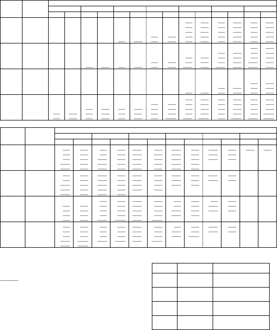
26
PERFORMANCE DATA (cont)
524A WITH STANDARD 3-ROW COIL FAN PERFORMANCE DATA — 0.0-2.4ESP
LEGEND
Bold
indicates special field-supplied drive is required.
Plain type indicates standard drive and standard motor.
Underline indicates a different motor and drive combination is required.
Refer to the fan motor and drive tables, pages 44 and 45, to complete
the selection.
NOTES:
1. Maximum allowable fan speed is 1100 rpm for unit sizes 300 and
360; 1200 rpm for all other sizes.
2. Fan performance is based on deductions for wet coil, clean 2-in.
filters, and unit casing. See right for factory-supplied filter pressure
drop.
3. Factory-supplied motor for 360 size is standard 10 Hp motor only;
alternate motor not available.
FACTORY-SUPPLIED FILTER PRESSURE DROP
(in.wg)
UNIT
524A
AIRFLOW
(Cfm)
EXTERNAL STATIC PRESSURE (in.wg)
0.00.20.40.60.81.01.2
Rpm Bhp Rpm Bhp Rpm Bhp Rpm Bhp Rpm Bhp Rpm Bhp Rpm Bhp
180
4,500 428 0.59475 0.70 570 0.99 656 1.33 730 1.68 796 2.02 856 2.38
5,300 488 0.92 528 1.04 609 1.34 689 1.71 762 2.11 827 2.51 886 2.92
6,000 542 1.29 578 1.43 649 1.74 721 2.11 791 2.55 855 3.00 914 3.46
6,800 604 1.83 637 1.99 700 2.32 763 2.70 826 3.15 888 3.64 946 4.15
7,500 660 2.42 690 2.59 747 2.95 804 3.34 861 3.79 919 4.29 975 4.83
240
6,000 532 1.25 5691.396391.69711 2.06 781 2.48 846 2.93 905 3.39
7,000 608 1.93 641 2.09702 2.42 763 2.80 824 3.23 885 3.71 943 4.23
8,000 686 2.83 716 3.01 770 3.38 823 3.77 876 4.21 930 4.70 983 5.24
9,000 764 3.97 791 4.18 841 4.59 888 5.02 935 5.47 982 5.96 1030 6.51
10,000 843 5.38 868 5.62 914 6.09 957 6.55 1000 7.02 1042 7.53 1084 8.08
300
7,500 456 1.294901.47 556 1.85 621 2.25 678 2.64 729 3.06 778 3.60
8,750 521 1.98 551 2.18 608 2.61 664 3.07 720 3.53 770 3.99 816 4.45
10,000 587 2.88 614 3.11 664 3.59714 4.09 763 4.62 812 5.15 857 5.68
11,250 653 4.03 678 4.29724 4.82 768 5.37 812 5.95 856 6.54 899 7.14
12,500 720 5.46 743 5.75 785 6.33 825 6.93 865 7.55 904 8.20 944 8.86
360
9,000 521 1.99 550 2.25 616 2.77 676 3.23 731 3.72 782 4.20 829 4.70
10,500 5963.16 623 3.40 672 3.89720 4.40 767 4.94 814 5.50 859 6.05
12,000 673 4.63 698 4.90 743 5.45 785 6.02 826 6.62 867 7.23 908 7.87
13,500 751 6.51 773 6.82 815 7.44 853 8.06 890 8.71 927 9.38 963 10.07
15,000 829 8.84 850 9.19 888 9.88 924 10.57 958 11.27 991 11.99 1024 12.73
UNIT
524A
AIRFLOW
(Cfm)
EXTERNAL STATIC PRESSURE (in.wg)
1.41.61.82.02.22.4
Rpm Bhp Rpm Bhp Rpm Bhp Rpm Bhp Rpm Bhp Rpm Bhp
180
4,500 912 2.75 967 3.13 1019 3.52 1070 3.92 1120 4.35 1168 4.79
5,300 940 3.33 992 3.75 1041 4.18 1088 4.61 1134 5.06 11795.52
6,000 968 3.92 1018 4.38 1066 4.85 1112 5.32 1156 5.80 11986.29
6,800 1000 4.67 1050 5.19 1097 5.71 1142 6.23 1185 6.76 ——
7,500 1028 5.39 1078 5.97 1125 6.54 1170 7.11 ————
240
6,000 954 3.83 1005 4.27 1052 4.72 1098 5.22 1142 5.67 ——
7,000 990 4.74 1040 5.24 1090 5.80 1135 6.30 1176 6.84 ——
8,000 1028 5.79 1078 6.38 1130 7.00 1173 7.60 ————
9,000 1073 7.11 1120 7.72 1169 8.37 ——————
10,000 1126 8.75 1166 9.37 — ———————
300
7,500 831 4.41 870 5.10 913 5.90 950 6.88 985 7.70 ——
8,750 859 4.97 901 5.59 944 6.42 980 7.20 1020 8.10 ——
10,000 900 6.20 939 6.74 976 7.33 1013 8.00 1050 8.82 ——
11,250 941 7.73 980 8.32 1017 8.90 1052 9.51 1086 10.16 ——
12,500 984 9.53 1022 10.19 1058 10.84 1093 11.49————
360
9,000 866 5.20 899 5.85 950 6.65 989 7.38 1029 8.32 1077 9.74
10,500 902 6.60 942 7.14 980 7.70 1016 8.31 1051 8.99 1085 9.77
12,000 949 8.50 988 9.14 1026 9.76 1062 10.38 1095 11.01 ——
13,500 1000 10.78 1036 11.49 1073 12.21 ——————
15,000 1057 13.49 1090 14.28 ——————— —
Bhp — Brake Horsepower Input to Fan
ESP—External Static Pressure
UNIT
524A
AIRFLOW
(Cfm)
PRESSURE DROP
(in.wg)
180
4,500
6,000
7,500
0.08
0.12
0.17
240
6,000
8,000
10,000
0.12
0.19
0.26
300
7,500
10,000
12,500
0.15
0.22
0.30
360
9,000
12,000
15,000
0.19
0.29
0.40
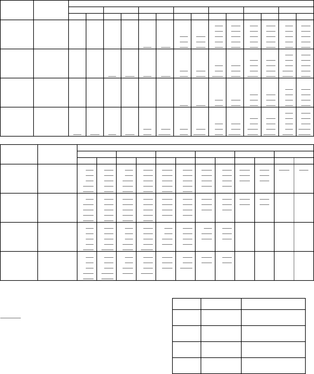
27
PERFORMANCE DATA (cont)
524A WITH HIGH CAPACITY 4-ROW COIL FAN PERFORMANCE DATA — 0.0-2.4ESP
LEGEND
Bold
indicates special field-supplied drive is required.
Plain type indicates standard drive and standard motor.
Underline indicates a different motor and drive combination is required.
Refer to the fan motor and drive tables, pages 44 and 45, to complete
the selection.
NOTES:
1. Maximum allowable fan speed is 1100 rpm for unit sizes 300 and
360; 1200 rpm for all other sizes.
2. Fan performance is based on deductions for wet coil, clean 2-in.
filters, and unit casing. See right for factory-supplied filter pressure
drop.
3. Factory-supplied motor for 360 size is standard 10 Hp motor only;
alternate motor not available.
FACTORY-SUPPLIED FILTER PRESSURE DROP
(in.wg)
UNIT
524A
AIRFLOW
(Cfm)
EXTERNAL STATIC PRESSURE (in.wg)
0.00.20.40.60.81.01.2
Rpm Bhp Rpm Bhp Rpm Bhp Rpm Bhp Rpm Bhp Rpm Bhp Rpm Bhp
180
4,500 437 0.61 483 0.72 576 1.01 660 1.35 732 1.69 797 2.03 856 2.38
5,300 499 0.95538 1.07 617 1.37 696 1.74 767 2.13 830 2.53 888 2.94
6,000 555 1.34 590 1.48 659 1.79 730 2.17 798 2.59 860 3.04 918 3.49
6,800 620 1.91 651 2.06 712 2.39 774 2.78 836 3.22 896 3.71 952 4.21
7,500 677 2.52 706 2.69 761 3.04 817 3.44 873 3.89 929 4.39 984 4.93
240
6,000 542 1.29577 1.42 646 1.72 716 2.09 785 2.51 849 2.95 907 3.40
7,000 620 1.99 652 2.15 711 2.48 771 2.85 831 3.28 890 3.76 947 4.27
8,000 700 2.92 728 3.10 781 3.46 833 3.85 885 4.29 938 4.78 990 5.32
9,000 781 4.10 806 4.30 854 4.71 900 5.13 946 5.58 993 6.08 1039 6.62
10,000 862 5.56 885 5.79 929 6.24 971 6.70 1012 7.18 1054 7.69 1096 8.24
300
7,500 476 1.39510 1.58 5791.99 644 2.40 701 2.81 752 3.29 804 3.96
8,750 545 2.14 574 2.35 633 2.81 691 3.29 747 3.77 797 4.25 842 4.76
10,000 615 3.12 641 3.36 692 3.87 743 4.41 794 4.96 843 5.51 888 6.05
11,250 685 4.37 709 4.64 754 5.20 800 5.79 845 6.40 891 7.02 935 7.64
12,500 756 5.92 778 6.22 819 6.83 860 7.47 901 8.14 942 8.83 983 9.52
360
9,000 5392.18 5692.39626 2.85 683 3.34 739 3.83 791 4.32 837 4.82
10,500 620 3.37 646 3.62 695 4.13 744 4.68 793 5.25 842 5.83 888 6.41
12,000 701 4.94 724 5.22 769 5.80 811 6.40 854 7.04 897 7.69 940 8.36
13,500 783 6.95 804 7.27 844 7.91 883 8.57 920 9.26 958 9.97 996 10.71
15,000 865 9.45 884 9.81 921 10.52 956 11.24 991 11.98 1025 12.75 1059 13.54
UNIT
524A
AIRFLOW
(Cfm)
EXTERNAL STATIC PRESSURE (in.wg)
1.41.61.82.02.22.4
Rpm Bhp Rpm Bhp Rpm Bhp Rpm Bhp Rpm Bhp Rpm Bhp
180
4,500 912 2.75 967 3.12 1019 3.52 1070 3.92 1120 4.35 1168 4.79
5,300 942 3.34 992 3.76 1041 4.18 1088 4.61 1134 5.06 11795.52
6,000 971 3.95 1020 4.40 1067 4.86 1112 5.33 1156 5.81 11986.29
6,800 1005 4.72 1054 5.23 1101 5.75 1145 6.27 1187 6.79——
7,500 1036 5.48 1084 6.04 1131 6.61 1174 7.17 ————
240
6,000 961 3.86 1011 4.31 1058 4.77 1104 5.24 1147 5.71 ——
7,000 1000 4.79 1050 5.32 1097 5.85 1142 6.38 1184 6.91 ——
8,000 1041 5.88 1090 6.47 1137 7.07 1181 7.67 ————
9,000 1086 7.21 1133 7.82 1178 8.47 ——————
10,000 1138 8.83 1180 9.46 —— ——————
300
7,500 874 5.33 897 5.91 940 6.80 990 7.50 ————
8,750 886 5.36 930 6.13 982 7.32 1020 8.10 ————
10,000 930 6.60 969 7.20 1007 7.89 1045 8.71 ————
11,250 976 8.25 1014 8.86 1051 9.49 1086 10.17 ————
12,500 1023 10.20 1061 10.88 1097 11.56 ——————
360
9,000 881 5.37 923 6.03 967 6.89 1020 8.25 ————
10,500 930 6.97 970 7.55 1008 8.17 1045 8.86 ————
12,000 981 9.02 1021 9.67 1058 10.32 1094 10.97————
13,500 1035 11.45 1072 12.20 ————————
15,000 1093 14.35 ——————————
Bhp — Brake Horsepower Input to Fan
ESP—External Static Pressure
UNIT
524A
AIRFLOW
(Cfm)
PRESSURE DROP
(in.wg)
180
4,500
6,000
7,500
0.08
0.12
0.17
240
6,000
8,000
10,000
0.12
0.19
0.26
300
7,500
10,000
12,500
0.15
0.22
0.30
360
9,000
12,000
15,000
0.19
0.29
0.40
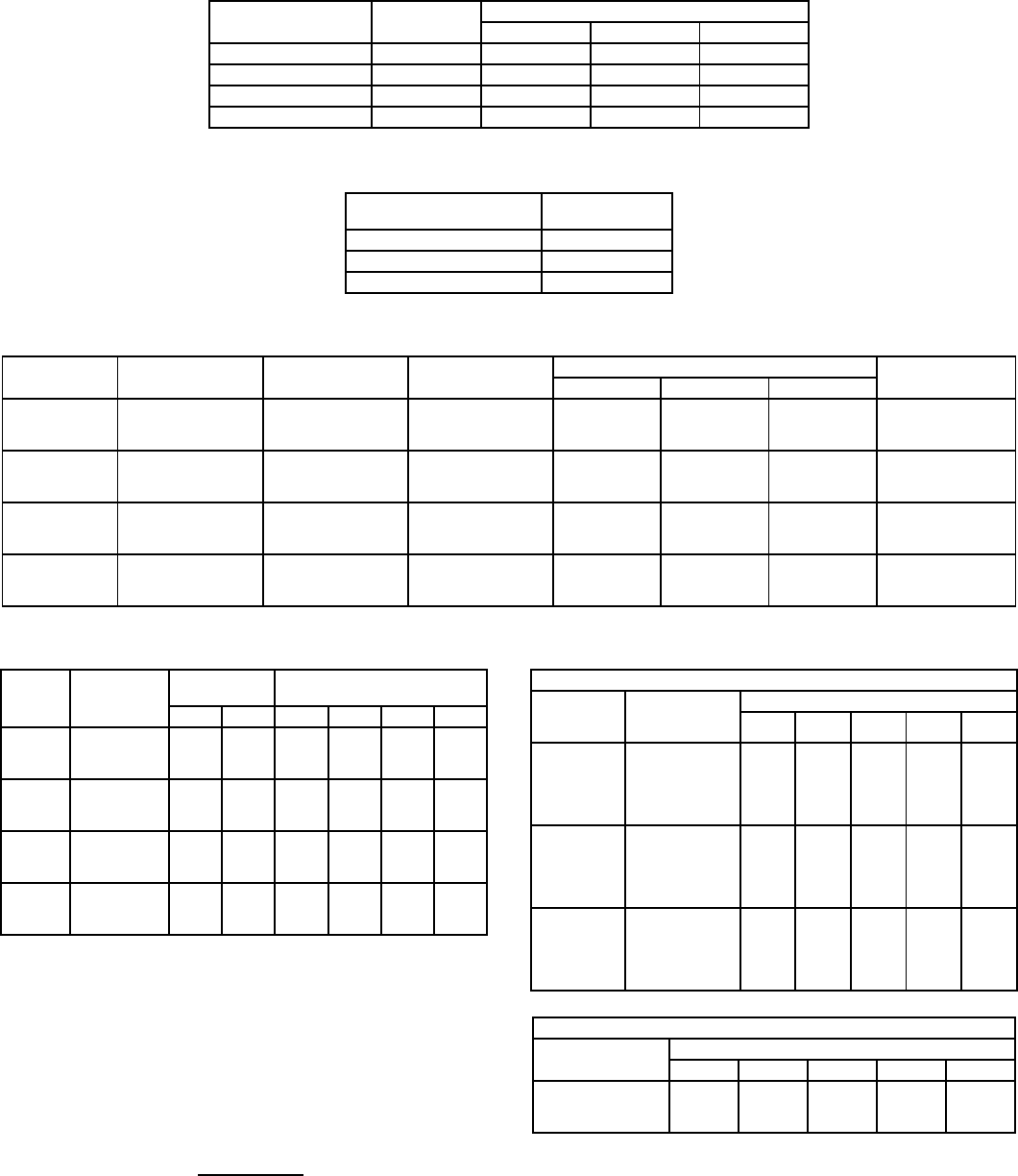
28
PERFORMANCE DATA (cont)
524A ACCESSORY PLENUM AIR THROW DATA
(ft)
NOTE:Throw distances shown are for 75 fpm terminal velocity. Use the following multi-
pliers to determine throw values for other terminal velocities.
524A ACCESSORY PRESSURE DROP(in.wg)
524A HYDRONIC HEATING CAPACITIES
LEGEND
*Based on 5 psig steam, 60 F entering-air temperature. All steam coils
are non-freeze type.
†Based on 200 F entering water, 20 F water temperature drop, 60 F
entering-air temperature.
NOTES:
1. Maximum operating limits for steam heating coils:
175 psig at 400 F.
2. Maximum operating limit for hot water heating coils is 150 psig.
4. See Heating Correction Factors table.
524A HEATING CORRECTION FACTORS
NOTE:Multiply capacity given in the Hydronic Heating Capacities table
by the correction factor for conditions at which unit is actually operating.
Correct leaving-air temperature using formula in Note 3 of Hydronic
Heating Capacities table.
UNIT
524A
AIRFLOW
(Cfm)
VANE DEFLECTION
Straight 221/2° 45°
180 6,000 50 43 31
240 8,000 60 51 37
300 10,000 76 65 47
360 12,000 85 72 52
TERMINAL VELOCITY
(Fpm)
THROW
FACTOR
50 X1.50
100 X0.75
150 X0.50
UNIT
524A
AIRFLOW
(Cfm)
DISCHARGE
PLENUM
RETURN AIR
GRILLE
HEATING COILS ECONOMIZER
Hot Water Steam Electric
180
4,500
6,000
7,500
0.10
0.16
0.23
0.01
0.02
0.03
0.15
0.23
0.33
0.15
0.23
0.33
0.06
0.10
0.15
0.06
0.09
0.15
240
6,000
8,000
10,000
0.16
0.26
0.37
0.02
0.04
0.06
0.23
0.37
0.53
0.23
0.37
0.53
0.10
0.17
0.26
0.09
0.17
0.28
300
7,500
10,000
12,500
0.15
0.24
0.34
0.02
0.03
0.05
0.28
0.44
0.63
0.28
0.44
0.63
0.09
0.16
0.24
0.06
0.09
0.14
360
9,000
12,000
15,000
0.20
0.32
0.46
0.03
0.05
0.07
0.37
0.59
0.85
0.37
0.59
0.85
0.13
0.22
0.34
0.08
0.14
0.21
UNIT
524A
AIRFLOW
(Cfm)
1-ROW
STEAM*
2-ROW HOT WATER
COIL†
Cap.Ldb Cap.Ldb Gpm PD
180
4,500
6,000
7,500
402
458
479
141
129
118
412.0
471.0
529.0
145
133
125
41.2
47.1
52.9
4.5
5.5
6.6
240
6,000
8,000
10,000
458
487
499
129
115
105
506.0
584.0
652.0
138
128
120
50.6
58.4
65.2
5.1
6.3
7.5
300
7,500
10,000
12,500
511
575
626
122
112
106
649.0
752.0
842.0
140
130
122
64.9
75.2
84.2
5.7
7.1
8.5
360
9,000
12,000
15,000
560
621
670
117
107
101
735.0
850.0
950.0
136
126
119
73.5
85.0
95.0
6.2
7.8
9.3
Cap.—Capacity (Btuh in thousands)
Ldb — Leaving-Air Dry-Bulb Temp (F)
PD—Pressure Drop (ft water)
3. Leaving db = ent db (F) + Capacity (Btuh)
1.1 x cfm
HOT WATER COIL
Water
Temp
Drop (F)
Ent Water
Temp (F)
Entering-Air Temp (F)
40 50 60 70 80
10
140 0.72 0.64 0.57 0.49 0.41
160 0.89 0.81 0.74 0.66 0.58
180 1.06 0.98 0.90 0.83 0.75
200 1.22 1.15 1.07 1.00 0.92
220 1.39 1.32 1.24 1.17 1.09
20
140 0.64 0.57 0.49 0.41 0.33
160 0.81 0.74 0.66 0.58 0.51
180 0.98 0.91 0.83 0.75 0.68
200 1.15 1.08 1.00 0.93 0.85
220 1.32 1.25 1.17 1.10 1.02
30
140 0.56 0.49 0.41 0.33 0.24
160 0.74 0.66 0.58 0.51 0.43
180 0.91 0.83 0.76 0.68 0.60
200 1.08 1.00 0.93 0.85 0.78
220 1.25 1.18 1.10 1.03 0.95
STEAM COIL
Steam Pressure
(psig)
Entering-Air Temp (F)
40 50 60 70 80
01.06 0.98 0.91 0.85 0.78
21.09 1.02 0.95 0.89 0.82
51.13 1.06 1.00 0.93 0.87
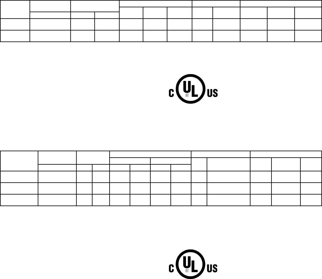
29
ELECTRICAL DATA
576B300-360
LEGEND *Units are suitable for use on electrical systems where voltage sup-
plied to the unit terminals is not below or above the listed minimum
and maximum limits.
†Fuse or HACR circuit breaker.
576H240-360
LEGEND *Units are suitable for use on electrical systems where voltage sup-
plied to unit terminals is not below or above listed minimum and maxi-
mum limits.
†Fuse or HACR circuit breaker.
**All fans are protected by a single circuit breaker.
NOTE:The 208/230-v, and 460-v base units are UL and UL, Canada
approved.
UNIT
576B
NOMINAL
VOLTAGE
VOLTAGE
RANGE*
COMPRESSOR FAN MOTORS POWER SUPPLY
FLA RLA LRA Qty FLA
(ea) MCA MOCP†ICF
(3 Ph, 60-Hz) Min Max
300 208/230 187 254 102.2 89.8 446 26.2 124.6 200 452.2
460 414 508 49.8 43.6 223 3.1 60.7 100 226.1
360 208/230 187 254 118.4 106.5 506 26.2 145.5 250 512.2
460 414 508 56.2 50.0 253 3.1 68.7 110 256.1
FLA — Full Load Amps
HACR — Heating, Air Conditioning, and Refrigeration
ICF — Maximum Instantaneous Current Flow during starting. (The
point in the starting sequence where the sum of the LRA for
the starting compressor, plus the total RLA for all running
compressors, plus the total FLA for all running motors is
maximum.)
LRA — Locked Rotor Amps
MCA — Minimum Circuit Amps (Complies with National Electrical
Code [NEC], Section 430-24)
MOCP—Maximum Overcurrent Protection
RLA — Rated Load Amps
UNIT
576H
NOMINAL
VOLTAGE
VOLTAGE
RANGE*
COMPRESSOR FAN MOTORS** POWER SUPPLY
RLA LRA Qty FLA
(ea) MCA MOCP†ICF
3Ph, 60 Hz Min Max Ckt1 Ckt2 Ckt1 Ckt2
240 208/230 187 254 39.3 39.3 198 198 2(1) 5.5 (2) 6.6 100.5 125 249.7
460 414 508 19.6 19.6 99 99 (1) 2.8 (2) 3.3 50.2 60 124.8
300 208/230 187 254 43.6 43.6 228 228 2(1) 5.5 (2) 6.6 110.2 150 284.0
460 414 508 22.1 22.1 114 114 (1) 2.8 (2) 3.3 55.8 70 142.3
360 208/230 187 254 43.6 63.6 228 266 2(1) 5.5 (2) 6.6 135.2 175 322.0
460 414 508 22.1 30.0 114 120 (1) 2.9 (2) 3.3 65.7 90 148.3
FLA — Full Load Amps
ICF — Maximum Instantaneous Current Flow during starting (the
point in the starting sequence where the sum of the LRA
for the starting compressor, plus the total RLA for all
running compressors, plus the total FLA for all running fan
motors is maximum).
LRA — Locked Rotor Amps
MCA — Minimum Circuit Amps (complies with National Electrical
Code [NEC], Section 430-24)
MOCP—Maximum Overcurrent Protection
RLA — Rated Load Amps
UL — Underwriters’ Laboratories
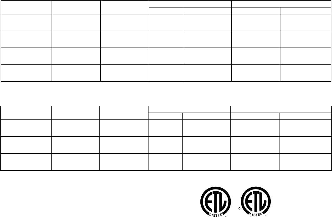
30
ELECTRICAL DATA (cont)
524A STANDARD MOTORS
524A ALTERNATE MOTORS
LEGEND
*Motors are designed for satisfactory operation within 10% of nominal voltages shown.
Voltages should not exceed the limits shown in the Voltage Limits column.
UNIT 524A V*-PH-Hz VOLTAGE
LIMITS
FAN MOTOR POWER SUPPLY
Hp FLA MCA MOCP
180
208/230-3-60 187-253 3.7 10.2 12.8 20
460-3-60 414-506 3.7 4.8 6.0 15
575-3-60 518-632 3.0 3.8 4.8 15
240
208/230-3-60 187-253 5.0 15.3/12.8 19.1/16.0 30/25
460-3-60 414-506 5.0 6.4 8.0 15
575-3-60 518-632 5.0 5.1 6.4 15
300
208/230-3-60 187-253 7.5 21.5/19.4 28.0/24.3 50/40
460-3-60 414-506 7.5 9.7 12.1 20
575-3-60 518-632 7.5 7.8 9.8 15
360
208/230-3-60 187-253 10.0 28.2/26.8 35.3/33.5 60/60
460-3-60 414-506 10.0 13.4 16.8 30
575-3-60 518-632 10.0 10.3 12.9 20
UNIT 524A V*-PH-Hz VOLTAGE
LIMITS
FAN MOTOR POWER SUPPLY
Hp FLA MCA MOCP
180
208/230-3-60 187-253 5.0 15.3/12.8 19.1/16.0 30/25
460-3-60 414-506 5.0 6.4 8.0 15
575-3-60 518-632 5.0 5.1 6.4 15
240
208/230-3-60 187-253 7.5 22.5/19.4 20.8/24.3 50/40
460-3-60 414-506 7.5 9.7 12.1 20
575-3-60 518-632 7.5 7.8 9.8 15
300
208/230-3-60 187-253 10.0 28.2/26.8 35.3/33.5 60/60
460-3-60 414-506 10.0 13.4 16.8 30
575-3-60 518-632 10.0 10.3 12.9 20
FLA — Full Load Amps
MCA — Minimum Circuit Amps
MOCP—Maximum Overcurrent Protection
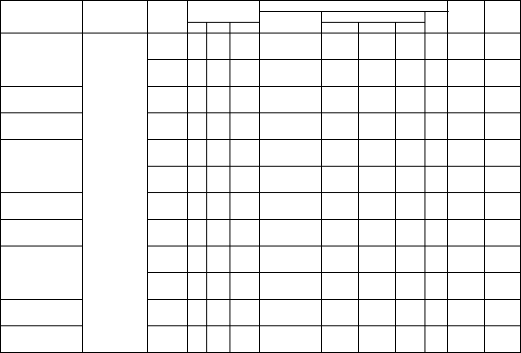
31
ELECTRICAL DATA (cont)
524A ELECTRIC HEATER DATA
HEATER PART NO.UNIT V-PH-Hz FAN MOTOR ELECTRIC HEATER(S)
MCA*MOCP*
Nominal
Capacity (kW)
Actual Capacity (kW) FLA
Hp kW FLA Stage 1 Stage 2 Total
CAELHEAT016A00
524A180,240
208-3-60 3.7 2.76 10.2 10 7.5 — 7.5 20.8 38.8 40
5.0 3.73 14.6 10 7.5 — 7.5 20.8 41.3 50
7.5 5.59 21.5 10 7.5 — 7.5 20.8 52.9 60
240-3-60 3.7 2.76 10.2 10 10.0 — 10.0 24.1 42.8 50
5.0 3.73 12.8 10 10.0 — 10.0 24.1 46.1 50
7.5 5.59 19.4 10 10.0 — 10.0 24.1 54.4 60
CAELHEAT017A00 480-3-60 3.7 2.76 4.8 10 10.0 — 10.0 12.0 21.0 25
5.0 3.73 6.4 10 10.0 — 10.0 12.0 23.0 25
7.5 5.59 9.7 10 10.0 — 10.0 12.0 27.2 30
CAELHEAT018A00 575-3-60 3.0 2.24 3.8 10 10.0 — 10.0 10.0 17.3 20
5.0 3.73 5.1 10 10.0 — 10.0 10.0 19.6 20
7.5 5.59 7.8 10 10.0 — 10.0 10.0 22.1 25
CAELHEAT019A00
208-3-60 3.7 2.76 10.2 20 14.9 — 14.9 41.5 64.6 70
5.0 3.73 14.6 20 14.9 — 14.9 41.5 70.1 80
7.5 5.59 21.5 20 14.9 — 14.9 41.5 78.7 80
240-3-60 3.7 2.76 10.2 20 19.9 — 19.9 47.9 72.6 80
5.0 3.73 12.8 20 19.9 — 19.9 47.9 75.8 80
7.5 5.59 19.4 20 19.9 — 19.9 47.9 84.1 80
CAELHEAT020A00 480-3-60 3.7 2.76 4.8 20 20.0 — 20.0 24.1 36.1 40
5.0 3.73 6.4 20 20.0 — 20.0 24.1 39.1 40
7.5 5.59 9.7 20 20.0 — 20.0 24.1 43.2 50
CAELHEAT021A00 575-3-60 3.0 2.24 3.8 20 20.0 — 20.0 20.1 29.9 30
5.0 3.73 5.1 20 20.0 — 20.0 20.1 31.5 35
7.5 5.59 7.8 20 20.0 — 20.0 20.1 34.9 35
CAELHEAT022A00
208-3-60 3.7 2.76 10.2 30 15.0 7.5 22.5 62.5 90.9 100
5.0 3.73 14.6 30 15.0 7.5 22.5 62.5 96.4 100
7.5 5.59 21.5 30 15.0 7.5 22.5 62.5 105.0 110
240-3-60 3.7 2.76 10.2 30 20.0 10.0 30.0 72.2 103.0 110
5.0 3.73 12.8 30 20.0 10.0 30.0 72.2 106.2 110
7.5 5.59 19.4 30 20.0 10.0 30.0 72.2 114.5 125
CAELHEAT023A00 480-3-60 3.7 2.76 4.8 30 20.0 10.0 30.0 36.1 51.1 60
5.0 3.73 6.4 30 20.0 10.0 30.0 36.1 53.1 60
7.5 5.59 9.7 30 20.0 10.0 30.0 36.1 57.2 60
CAELHEAT024A00 575-3-60 3.0 2.24 3.8 30 20.0 10.0 30.0 30.1 42.4 50
5.0 3.73 5.1 30 20.0 10.0 30.0 30.1 44.0 50
7.5 5.59 7.8 30 20.0 10.0 30.0 30.1 47.4 50
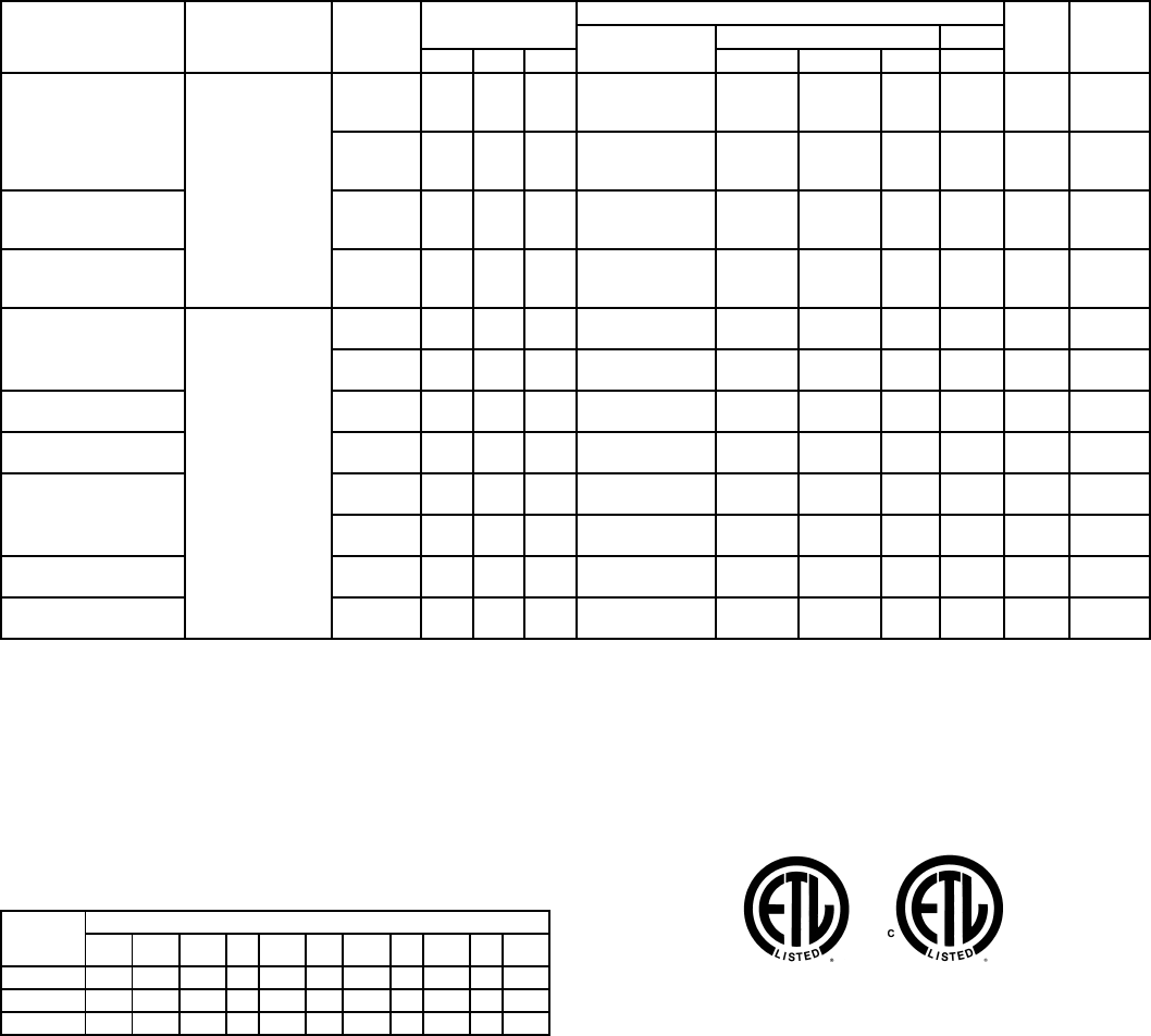
32
ELECTRICAL DATA (cont)
524A ELECTRIC HEATER DATA (cont)
LEGEND
*Values shown are for single-point connection of electric heat acces-
sory and air handler.
NOTES:
1. Electrical resistance heaters are rated at 240 v, 480 v, or 575 v. To
determine heater capacity (kW) at unit nameplate multiply the
240-v, 480-v, or 575-v capacity (kW) by the factor shown in the
table below for the unit voltage.
2. The following equation converts kW of heat energy to Btuh:
kW x 3,412 = Btuh.
3. Heater contactor coils are 24 v and require 8 va holding current.
4. Electric heaters are tested and ETL approved at maximum total
external static pressure of 1.9 in. wg.
5. MCA and MOCP values apply to both standard and alternate
factory-supplied motors.
6. Approximate shipping weight for CAELHEAT016A00-027A00 is
60 lb each. Approximate shipping weight for CAELHEAT028A00-
033A00 is 75 lb each.
HEATER PART NO.UNIT V-PH-Hz FAN MOTOR ELECTRIC HEATER(S)
MCA*MOCP*
Nominal
Capacity (kW)
Actual Capacity (kW) FLA
Hp kW FLA Stage 1 Stage 2 Total
CAELHEAT025A00
524A180,240
208-3-60 3.7 2.76 10.2 50 22.6 15.0 37.6 104.3 143.1 150
5.0 3.73 14.6 50 22.6 15.0 37.6 104.3 148.6 150
7.5 5.59 21.5 50 22.6 15.0 37.6 104.3 157.2 175
240-3-60 3.7 2.76 10.2 50 30.0 20.0 50.0 120.3 163.1 175
5.0 3.73 12.8 50 30.0 20.0 50.0 120.3 166.4 175
7.5 5.59 19.4 50 30.0 20.0 50.0 120.3 174.6 200
CAELHEAT026A00 480-3-60 3.7 2.76 4.8 50 30.0 20.0 50.0 60.1 81.2 90
5.0 3.73 6.4 50 30.0 20.0 50.0 60.1 83.2 90
7.5 5.59 9.7 50 30.0 20.0 50.0 60.1 87.3 90
CAELHEAT027A00 575-3-60 3.0 2.24 3.8 50 30.0 20.0 50.0 50.2 67.5 70
5.0 3.73 5.1 50 30.0 20.0 50.0 50.2 69.1 70
7.5 5.59 7.8 50 30.0 20.0 50.0 50.2 72.5 80
CAELHEAT028A00
524A300,360
208-3-60 7.5 5.59 19.8 20 14.9 — 14.9 41.5 78.7 80
10.0 7.46 28.2 20 14.9 — 14.9 41.5 87.1 100
240-3-60 7.5 5.59 19.4 20 19.9 — 19.9 47.9 81.4 90
10.0 7.46 26.8 20 19.9 — 19.9 47.9 93.3 110
CAELHEAT029A00 480-3-60 7.5 5.59 9.7 20 20.0 — 20.0 24.1 42.2 50
10.0 7.46 13.4 20 20.0 — 20.0 24.1 46.8 50
CAELHEAT030A00 575-3-60 7.5 5.59 7.8 20 20.0 — 20.0 20.1 34.9 35
10.0 7.46 10.3 20 20.0 — 20.0 20.1 38.0 40
CAELHEAT031A00
208-3-60 7.5 5.59 19.8 40 15.0 15.0 30.0 83.4 131.1 150
10.0 7.46 28.0 40 15.0 15.0 30.0 83.4 139.5 150
240-3-60 7.5 5.59 19.4 40 20.0 20.0 40.0 96.2 144.5 150
10.0 7.46 26.8 40 20.0 20.0 40.0 96.2 153.8 175
CAELHEAT032A00 480-3-60 7.5 5.59 9.7 40 20.0 20.0 40.0 47.9 71.9 80
10.0 7.46 13.4 40 20.0 20.0 40.0 47.9 76.6 80
CAELHEAT033A00 575-3-60 7.5 5.59 7.8 40 20.0 20.0 40.0 40.2 60.0 60
10.0 7.46 10.3 40 20.0 20.0 40.0 40.2 63.1 70
FLA — Full Load Amps
Hp — Horsepower
MCA — Minimum Circuit Amps
MOCP—Maximum Overcurrent Protection (Amps)
HEATER
RATING
VOLTAGE
ACTUAL HEATER VOLTAGE
200 208 230 240 400 440 460 480 550 575 600
240 0.694 0.751 0.918 1 — — — — — — —
480 — — — — 0.694 0.84 0.918 1 — — —
575 — — — — — — — — 0.915 1 1.089
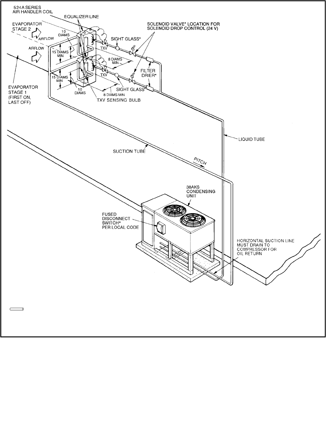
33
TYPICAL PIPING AND WIRING
Ground-Level Installation — 576B300,360
LEGEND
*Field supplied.
TXV—Thermostatic Expansion Valve
Piping
NOTES:
1. All piping must follow standard refrigerant piping techniques.
2. All wiring must comply with the applicable local and national codes.
3. Wiring and piping shown are general points-of-connection guides only and are not intended
for, or to include all details for, a specific installation.
4. Liquid line solenoid valve (solenoid drop control) is recommended to prevent refrigerant
migration to the compressor.
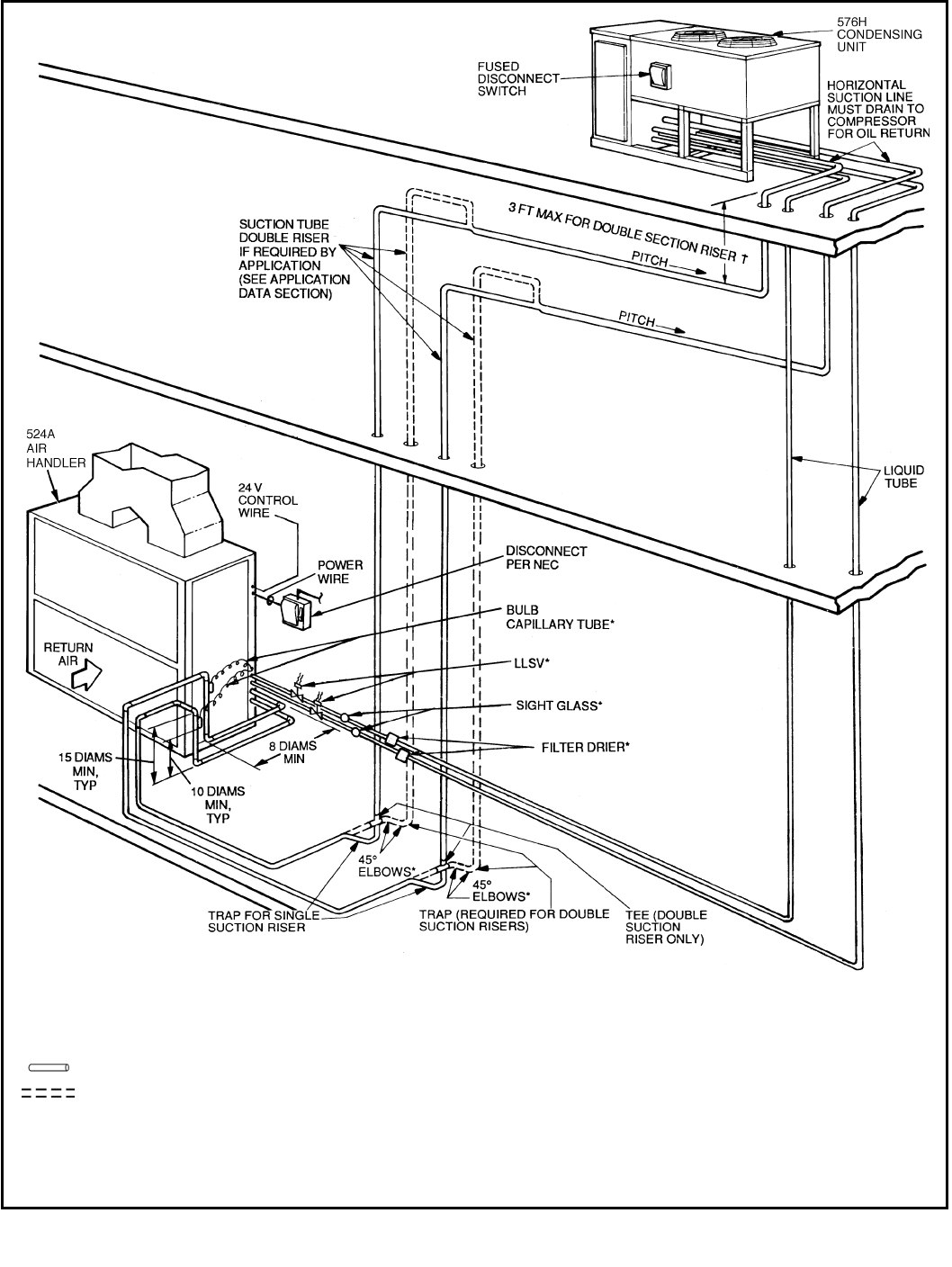
34
TYPICAL PIPING AND WIRING (cont)
Rooftop Installation — 576H240-360
LEGEND
*Field supplied.
†If double suction riser is required for piping
system, size pipe diameter of 3 ft (maxi-
mum) riser according to application data
on page 42.
LLSV — Liquid Line Solenoid Valve
NEC — National Electrical Code
TXV—Thermostatic Expansion Valve
Piping
Double Riser Piping (if required)
NOTES:
1. All piping must follow standard refrigerant piping techniques.
2. All wiring must comply with the applicable local and national codes.
3. Wiring and piping shown are general points-of-connection guides only and are not
intended for, or to include all details for, a specific installation.
4. Liquid line solenoid valve (solenoid drop control) is recommended to prevent refriger-
ant migration to the compressor.
5. Internal factory-supplied TXVs not shown.
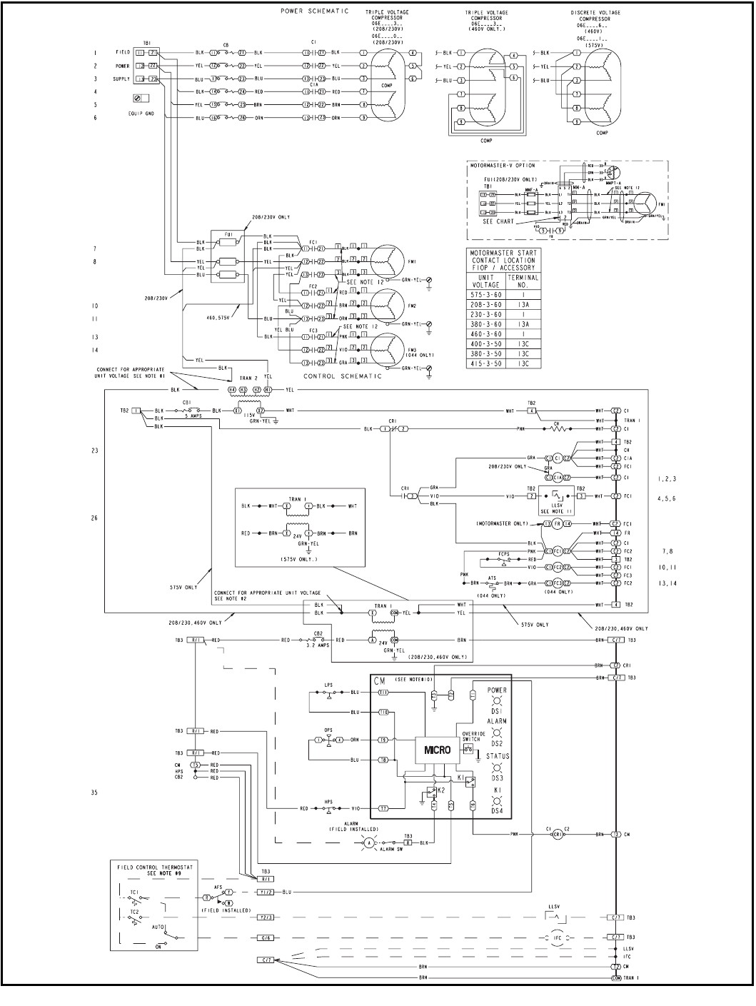
35
TYPICAL WIRING SCHEMATIC
576B300,360
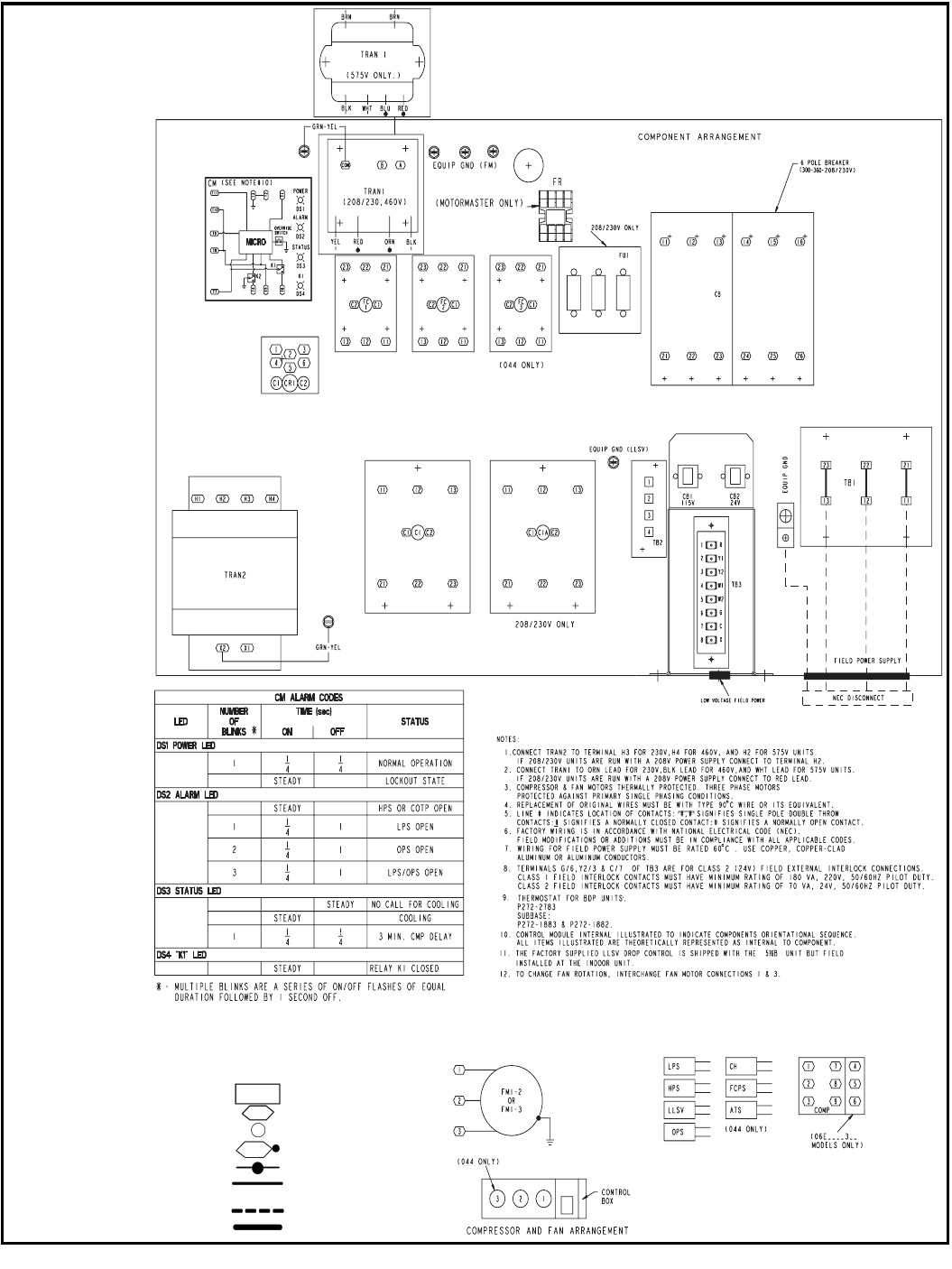
36
TYPICAL WIRING SCHEMATIC (cont)
576B300,360 (cont)
LEGEND
AFS — Airflow Switch
ATS — Air Temperature Switch
BPR—Bypass Relay
C—Contactor, Compressor
CB — Circuit Breaker
CH — Crankcase Heater
CM — Control Module
COMP—Compressor
CR — Control Relay
EQUIP—Equipment
FC — Fan Contactor
FCPS—Fan Cycling PressureSwitch
FM — Fan Motor
FR — Fan Relay
FU — Fuse
GND — Ground
HPS—High-Pressure Switch
IFC — Indoor-Fan Contactor
LLSV — Liquid Line SolenoidValve
LPS—Low-Pressure Switch
MM — Motormaster
MMF — Motormaster Fuse
MMPT—Motormaster Pressure Transducer
OPS—Oil Pressure Switch
TB — Terminal Block
TC — Thermostat-Cooling
TRAN — Tr a n s f o r m e r
Terminal Block Connection
Marked Terminal
Unmarked Terminal
Marked Splice
Unmarked Splice
Factory Wiring
—— Field Control Wiring
Field Power Wiring
Indicates Common Potential,
Does Not Represent Wiring
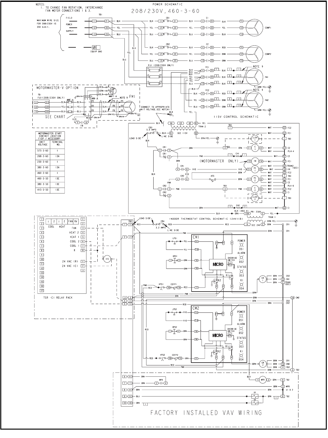
37
TYPICAL WIRING SCHEMATIC (cont)
SEE MODUPANEL™ ACCESSORY INSTALLATION FOR SCHEMATIC
576H240-360
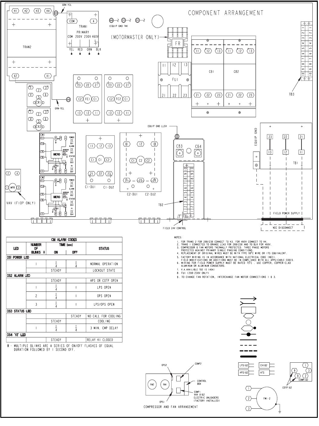
38
TYPICAL WIRING SCHEMATIC (cont)
576H240-360 (cont)
ATS — Air Temperature Switch
C—Contactor, Compressor
CB — Circuit Breaker
CH — Crankcase Heater
CM — Control Module
COMP—Compressor
COTP—Compressor Overtemperature Protection
CR — Control Relay
EQUIP—Equipment
FC — Fan Contactor
FIOP—Factory-Installed Option
FM — Fan Motor
FR — Fan Relay
FU — Fuseblock
GND — Ground
HPS—High-Pressure Switch
IFC — Indoor-Fan Contactor
LLSV — Liquid Line SolenoidValve
LPS—Low-Pressure Switch
MM — Motormaster
MMF — Motormaster Fuse
MMPT—Motormaster Pressure Transducer
MPR—ModuPanel Relay
OPS—Oil Pressure Switch
PL—Plug Assembly
TB — Terminal Block
TRAN — Tr a n s fo r m e r
U—Unloader
VAV — Va r iable Ai r Vol um e
Plug
Receptacle
Terminal Block Connection
Marked Terminal
Unmarked Terminal
Marked Splice
Unmarked Splice
Factory Wiring
Field Control Wiring
Field Power Wiring
Indicates Common Potential,
Does Not Represent Wiring
LEGEND
39
CONTROLS
OPERATING SEQUENCE
576B300,360 — When space thermostat calls for cooling, the
no. 1 condenser fan and compressor starts after control module
(CM) initial time delay of 7 seconds. If an optional airflow switch
is used, compressor and no. 1 condensing fan will not start until
sufficient indoor airflow has closed the switch. After 7 seconds
the compressor starts and the liquid line solenoid valve
(for solenoid drop control) opens. The crankcase heater is
deenergized. If the head pressure reaches 260 psig, the second
condenser fan starts.
If cooling demand is low, suction pressure at the compressor
drops. As the pressure drops, the compressor unloads 1 or
2 banks of cylinders as required. If cooling demand is high and
1 or 2-stage operation is used, the second step of the thermo-
stat activates the capacity control liquid line solenoid which
activates the second stage evaporator coil. The compressor
cylinders load or unload in response to compressor suction
pressure to meet evaporator load.
For two and a half minutes after the compressor starts, the
low-pressure switch (LPS) is ignored. If the LPS trips during
the first 21/2minutes of operation, the compressor remains
operational. If a high-pressure switch (HPS) trips at any time, or
the LPS trips after 21/2minutes, the compressor cannot restart
until the 3-minute CM anti-short cycle timer expires.
As the space cooling load is satisfied, the second stage of the
thermostat opens, and closes the field-supplied capacity control
liquid line solenoid valve to deactivate the second stage coil.
The compressor adjusts the number of active cylinders to meet
the new load. When the space temperature is satisfied, the first
stage of the thermostat opens and the control relay opens. This
closes the solenoid drop control valve. The compressor stops
and the crankcase heater is energized, preventing refrigerant
from migrating to the compressor during the off cycle (solenoid
drop refrigerant control). The CM anti-short-cycling timer is
energized and runs for approximately 3 minutes. During this
time, the compressor is not able to restart.
576H240-360 Standard Constant Volume Unit With 2-Stage
Cooling Thermostat — Seven seconds after a thermostat call
for the first stage of cooling, compressor no. 1 and the outdoor
fans start. The no. 2 fan only starts if the outdoor ambient
temperature is above 70 F. The oil-pressure switch and the
low-pressure switch are bypassed for 1 and 21/2minutes,
respectively. If either the low-pressure switch or oil pressure
switch remain open after the delay, the unit shuts down and
goes into alarm mode. The indoor-fan motor starts immediately
whenever there is a call for cooling. If a liquid line solenoid valve
has been installed (for refrigerant control during the off cycle),
then the solenoid valve for compressor no. 1 opens immediately
upon a call for cooling.
On standard units, compressor no. 1 operates either fully
loaded or at one step of unloading, depending on the suction
pressure, which is dependent on the evaporator load conditions.
As the cooling demand increases, the thermostat calls for the
second stage of cooling. Within 7 seconds from a call for the
second stage of cooling, compressor no. 2 starts. The oil switch
and low-pressure switch for circuit no. 2 are bypassed during
start-up.
As the cooling load is satisfied, the thermostat stops the call for
the second stage of cooling, which in turn deenergizes com-
pressor no. 2, closes the no. 2 liquid line solenoid (if installed)
and energizes the compressor no. 2 crankcase heater.
If the space temperature continues to decrease, then the ther-
mostat stops the call for the first stage of cooling, which then
deenergizes compressor no. 1 and the outdoor fans, closes the
no. 1 liquid line solenoid valve (if installed), and energizes the
compressor no. 1 crankcase heater.
The unit controls prevent both compressors from reenergizing
within 3 minutes from a previous call for operation.
If the unit safeties trip during operation, refer to the Installation,
Start-Up and Service Instructions. To reset the lockout mode,
cycle the unit power.
NOTE: If the thermostat fan switch is in the auto position, the
indoor fan cycles on and off as the thermostat calls for cooling
(or heating). If the switch is in the continuous position, the fan
runs when the outdoor unit is powered.
576H240-360 Optional Variable Air Volume Unit With
ModuPanel™ Control — The ModuPanel control regulates up
to 10 stages of cooling to maintain a leaving-air temperature for
variable air volume (VAV) applications. When connected to one
576H condensing unit, only 6 stages are used. See the table on
page 40 for unit loading and compressor operating sequence.
When the timeclock connected to the panel closes, the
indoor-fan contactor is energized through a field-supplied relay.
(The relay must be a pilot-duty SPST relay with 115-v coil and
30 va maximum coil draw.) After the time delays programmed
into the ModuPanel control have elapsed, and with the leaving
air above the set point, the stages of mechanical cooling are
sequenced as follows:
1. Stage 1 starts compressor no. 1 with 2 banks of cylinders
unloaded (1/3loaded). Both unloader solenoids are
energized.
2. Stage 2 loads one bank of compressor no. 1 cylinders
(2/3loaded) by deenergizing unloader solenoid no. 1.
3. Stage 3 loads the second bank of compressor no. 1 by
deenergizing unloader solenoid no. 2.
4. Stage 4 starts compressor no. 2 and unloads 2 banks of
compressor no. 1 cylinders unloaded (1/3loaded). Both
unloader solenoids are energized.
5. Stage 5 loads one bank of compressor no. 1 cylinders
(2/3loaded) by deenergizing unloader solenoid no. 1.
6. Stage 6 loads one bank of compressor no. 1 cylinders (fully
loaded) by deenergizing unloader solenoid no. 2.
Two 576H240-360 Optional Variable Air Volume Units With
A Single ModuPanel Control — The ModuPanel control reg-
ulates up to 10 stages of cooling to maintain a leaving-air tem-
perature for variable air volume (VAV) applications. When
connected to two 576H condensing units, all 10 stages are
used. See the table on page 40 for unit loading and compressor
operating sequence.
When the timeclock connected to the panel closes, the
indoor-fan contactor is energized through a field-supplied
relay. (The relay must be a pilot-duty SPST relay with 115-v coil
and 30 va maximum coil draw.) After the time delays pro-
grammed into the ModuPanel control have elapsed, and with
the leaving air above the set point, the stages of mechanical
cooling are sequenced as follows:
1. Stage 1 starts unit no. 1 compressor no. 1 with 2 banks of
cylinders unloaded (1/3loaded). Both unloader solenoids
are energized.
2. Stage 2 loads one bank of unit no. 1 compressor no. 1 cylin-
ders (2/3loaded) by deenergizing unloader solenoid no. 1.
3. Stage 3 turns off unit no. 1 compressor no. 1 and starts
compressor no. 2 fully loaded.
4. Stage 4 starts unit no. 1 compressor no. 1 with 2 banks of
cylinders unloaded (1/3loaded). Both unloader solenoids
are energized.
5. Stage 5 loads one bank of unit no. 1 compressor no. 1 cylin-
ders (2/3loaded) by deenergizing unloader solenoid no. 1.
40
CONTROLS (cont)
6. Stage 6 loads one bank of unit no. 1 compressor no. 1
cylinders (fully loaded) by deenergizing unloader solenoid
no. 2.
7. Stage 7 starts unit no. 2 compressor no. 1 with 2 banks of
cylinders unloaded (1/3loaded). Both unloader solenoids
are energized.
8. Stage 8 turns off unit no. 2 compressor no. 1 and starts
compressor no. 2 fully loaded.
9. Stage 9 starts unit no. 2 compressor no. 1 with 2 banks of
cylinders unloaded (1/3loaded). Both unloader solenoids
are energized.
10. Stage 10 loads 2 banks of unit no. 2 compressor no. 1 cylin-
ders (fully loaded) by deenergizing both unloader solenoids.
Restart — Manual reset of the 24-v control circuit is required if
unit is shut down by any of the safety devices. Applicable
devices include the high pressure switch (HPS), low-pressure
switch (LPS), oil-pressure switch (OPS), and compressor over-
temperature protection (COTP) switch. To restart the unit after
the unit has been shut down, raise the thermostat set point
above the space temperature (thereby removing the call for
cooling) and then lower the set point back to the desired setting.
If unit circuit breakers trip during unit shutdown, they must be
reset manually.
Causes ofComplete Unit Shutdown:
• interruption of supplied power
• open compressor overtemperature protection (COTP)
• compressor electrical overload protection (CB1 or CB2)
• open high-pressure or low-pressure safety switches
• open oil pressure switch
576H UNIT LOADING SEQUENCE WITH MODUPANEL™ CONTROL
LOADING SEQUENCE, TWO 576H CONDENSING UNITS WITH MODUPANEL CONTROL
STAGE NO.CYLINDERS LOADED CYLINDERS CAPACITY STEP(%)
Compressor No.1 Compressor No.2
122—17
244—33
366—50
482 6 67
510 4 6 83
612 6 6 100
STAGE NO.CYLINDERS
UNIT 1 LOADED CYLINDERS UNIT 2 LOADED CYLINDERS
CAPACITY STEP(%)
Compressor
No.1
Compressor
No.2
Compressor
No.1
Compressor
No.2
122 — — — 8
244 — — — 17
36— 6 — — 25
482 6 — — 33
510 4 6 — — 41
612 6 6 — — 50
714 6 6 2 — 58
818 6 6 — 6 75
9206626 83
10 24 6 6 6 6 100
41
APPLICATION DATA — 576B300-360, 576H240-360 UNITS
INSTALLATION
Select equipment to match or to be slightly less than peak load.
This provides better humidity control, less unit cycling, and less
part-load operation.
When selecting vapor line sizes, oil return must be evaluated,
particularly at part-load conditions.
The indoor fan must always be operating when outdoor unit is
operating.
Ductwork should be sized according to unit size, not building
load.
To minimize the possibility of air recirculation, avoid the use of
concentric supply/return grilles.
Indoor equipment should be selected at no less than
300 cfm/ton.
OPERATING LIMITS
MINIMUM OUTDOOR-AIR OPERATING
TEMPERATURE (F) — 576B UNITS
576B MAXIMUM LIQUID LIFT (FT)
MINIMUM OUTDOOR-AIR OPERATING TEMPERATURE
AND LOADING SEQUENCES — 576H UNITS
*Accessory unloader on Circuit 1.
†Motormaster® cannot be used with 2 unloaders when unit is con-
nected to 2 separate air handlers.
NOTE:Minimum outdoor-air operating temperature is based on 90 F
saturated condensing temperature and 100% capacity.
UNLOADING SEQUENCES
LEGEND
*Additional unloading available with field-installed accessory unloader.
NOTE:Capacities are based on 45 F saturated suction temperature
and 95 F outdoor air temperature.
576H MAXIMUM LIQUID LIFT (FT)
WIRE SIZES FOR FIELD POWER SUPPLY
LEGEND
Maximum Outdoor Ambient 115 F
Minimum Outdoor Ambient
Additional head pressure
control may be required
below 35 F outdoor
ambient.
Minimum Return-Air Temperature 55 F
Maximum Return-Air Temperature 95 F
Normal Acceptable Saturation 576B
Suction Temperature Range 576H
30 to 55 F
20 to 50 F
Maximum Discharge Temperature 576B
576H
295 F
275 F
Minimum Discharge Superheat 60 F
UNIT
576B
COMPR
CAP.
(%)
COND
TEMP
(F)
MIN OUTDOOR TEMP
Standard
Unit
Low
Ambient
Control
300
100 90 31
–20
67 80 35
33 70 43
360
100 90 30
67 80 34
33 70 42
UNIT 576B FT
300 76
360 67
UNIT 576H
SYSTEM
CAPACITY
(%)
MINIMUM OUTDOOR-AIR
TEMP(F)
Standard
Unit
Low Ambient
Control
240
100
53
–20
83 –20
67* –20†
50 –20
33 –20
17* –20†
300
100
50
–20
83 –20
67* –20†
50 –20
33 –20
17* –20†
360
100
49
–20
85 –20
71* –20†
43 –20
28 –20
14* –20†
UNIT 576H
CAPACITY/STAGE (%)
CV Units
(Standard)*
240 100, 83, 50, 33
300 100, 83, 50, 33
360 100, 85, 43, 28
CV — Constant Volume
UNIT 576H MAXIMUM LIQUID LIFT
PER CIRCUIT (Ft)
240 76
300 73
360 100
UNIT 576H V-Ph-Hz FIELD POWER WIRE SIZE
TB1 WILL ACCEPT
240-360 208-230/3/60 350 kcmil
460-3-60 2/0 AWG
AWG — American Wire Gage
kcmil — Thousand Circular Mils
TB — Terminal Block
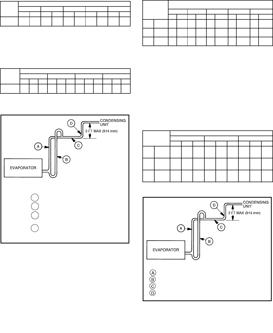
42
APPLICATION DATA — 576B300-360, 576H240-360 UNITS (cont)
REFRIGERANT PIPESIZES
SINGLE SUCTION RISERS
LEGEND
NOTE:Liquid and suction line sizes are OD (in.)
*IMPORTANT:Requires a double suction riser, if evaporator is below condensing
unit. See table below.
DOUBLE SUCTION RISERS
NOTE:A, B, and C dimensions relate to reference diagram below.
REFRIGERANT PIPESIZES
SINGLE SUCTION RISERS
LEGEND
*Double suction riser required if evaporator is below condensing unit and 2 un-
loaders are used on that circuit.
†Double suction riser required if evaporator is below condensing unit and com-
pressor is equipped with 2 unloaders. Note the only time circuit no. 2 may be
equipped with 2 unloaders is if it is serving its own air handler and the unit does
not require low ambient operation (Motormaster® control).
**Double suction riser required if evaporator is below condensing unit and com-
pressor has one or more unloader(s).
NOTES:
1. All line sizes are inches OD.
2. Standard unit comes with one pressure-operated unloader on circuit no. 1. If
unit serves one air handler, an additional unloader may be field installed on cir-
cuit no. 1 compressor only. If the unit serves 2 separate air handlers and low
ambient operation is required (Motormaster III control), each circuit’s compres-
sor may only be equipped with
one
unloader.
DOUBLE SUCTION RISERS
NOTE:Refer to diagram below for A, B, and C dimensions.
UNIT
576B
LENGTH OF INTERCONNECTING PIPING, (Ft)
16-25 26-50 51-75 76-100 101-200
LSLSLSLSLS
300 7/815/87/821/8*7/821/8*7/821/8*7/821/8*
360 7/821/87/821/87/821/811/821/811/825/8*
L—Liquid Line
S—Suction Line
UNIT
576B
LENGTH OF INTERCONNECTING PIPING, (Ft)
26-50 51-75 76-100 101-200
ABCABCABCABC
300 13/815/821/813/815/821/813/815/821/813/815/821/8
360 —————————1
5/821/825/8
UNIT 576H
LENGTH OF INTERCONNECTING PIPING,
FOR EACH CIRCUIT (Ft)
0-25 25-50 50-75 75-100 100-200
LSLSL S L S L S
240 Ckt1 1/211/85/813/85/813/85/815/8*7/815/8*
Ckt2 1/211/85/813/85/813/85/815/8†7/815/8†
300 Ckt1 1/211/85/813/85/813/87/815/8*7/821/8**
Ckt2 1/211/85/813/85/813/87/815/8†7/821/8**
360 Ckt1 1/211/85/813/85/815/8*7/815/8*7/821/8**
Ckt2 1/213/85/815/87/815/87/815/87/821/8†
L— Liquid Line
S— Suction Line
UNIT 576H
LENGTH OF INTERCONNECTING PIPING (Ft)
50-75 75-100 100-200
ABCABCABC
240 Ckt1 ———1
1/813/815/811/813/815/8
Ckt2 ———1
1/813/815/813/813/815/8
300 Ckt1 ———1
1/813/815/813/815/821/8
Ckt2 ———1
1/813/815/813/815/821/8
360 Ckt1 11/813/815/811/813/815/813/815/821/8
Ckt2 ——————1
3/815/821/8
576B Suction Line Piping
LEGEND
Suction Riser
Without
Tra p
Suction Riser
With
Trap
Horizontal Suction Line to Condensing Unit
Short Vertical Riser:
576B300 — 15/8in. OD
576B360 — 21/8in. OD
A
B
C
D
LEGEND
—Suction Riser without Trap
—Suction Riser with Trap
—Suction Line to Condensing Unit
—Pipe Diameter to be Same Size as Riser A
576H Suction Line Piping
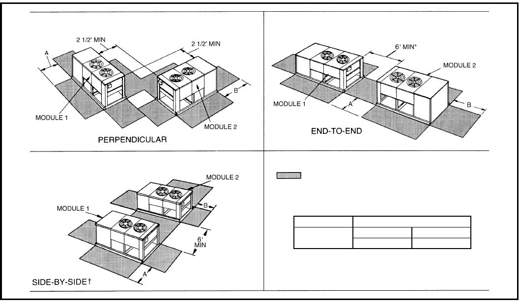
43
APPLICATION DATA — 576B300-360, 576H240-360 UNITS (cont)
E-COATED COILS
E-coated aluminum-fin coils have a flexible and durable
epoxy coating uniformly applied to all coil surfaces. Unlike brittle
phenolic dip and bake coatings, E-coating provides superior
protection with unmatched flexibility, edge coverage, metal
adhesion, thermal performance, and most importantly, corro-
sion resistance.
E-coated coils provide this protection since all coil surfaces are
completely encapsulated from environmental contamination.
This coating is especially suitable in industrial environments.
MULTIPLE CONDENSING UNIT ARRANGEMENTS*
Space for Service and Airflow
*For clearances between controls and grounded surfaces,
check local codes.
†Observe minimum recommended space requirements.
576B, 576H DIMENSIONS (ft)
240-360 AB
44
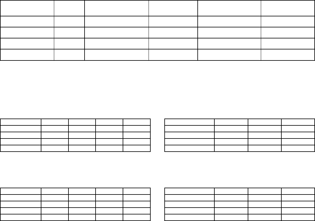
44
APPLICATION DATA — 524A180-360 UNITS
1.OPERATING LIMITS
Maximum fan speed — 524A180,240 . . . . . . . . . 1200 rpm
Maximum fan speed — 524A300,360 . . . . . . . . . 1100 rpm
2.GENERAL
Select equipment to match or to be slightly less than peak
load. This provides better humidity control, less unit cycling,
and less part-load operation. Equipment should be
selected to perform at no less than 300 cfm/ton.
The air handler fan must always be operating when the
condensing unit is operating.
Ductwork should be sized according to unit size, not build-
ing load. For larger units with two fans, a split duct transition
is recommended at the fan outlets, but a plenum can
be used with slight reduction in external static pressure
capability.
FACTORY-INSTALLED NOZZLE AND DISTRIBUTOR DATA
*Danfoss part numbers shown.
†Sporlan Valve Co. part numbers shown.
NOTE:Hot gas bypass applications require field-supplied auxiliary side connector.
STANDARD FAN MOTOR DATA
208/230-3-60 AND 460-3-60 MOTORS
LEGEND
NEMA — National Electrical Manufacturers Association
575-3-60 MOTORS
LEGEND
NEMA — National Electrical Manufacturers Association
ALTERNATE FAN MOTOR DATA
208/230-3-60 AND 460-3-60 MOTORS
LEGEND
NEMA — National Electrical Manufacturers Association
575-3-60 MOTORS
LEGEND
NEMA — National Electrical Manufacturers Association
UNIT
524A
COIL
TYPE
TXV
Qty...Part No.*
DISTRIBUTOR
Qty...Part No.†
FEEDER TUBES
PER DISTRIBUTOR
Qty...Size (in.)
NOZZLE
Qty...Part No.
180 3 Row 2...TDEBX8 2...1116 12...1/42...E6
4 Row 2...TDEBX8 2...1126 16...1/42...C6
240 3 Row 2...TDEBX11 2...1116 13...1/42...E8
4 Row 2...TDEBX11 2...1126 18...3/16 2...C8
300 3 Row 2...TDEBX11 2...1126 15...1/42...C10
4 Row 2...TDEBX11 2...1126 20...3/16 2...C15
360 3Row 2...TDEBX16 2...1126 18...1/42...C12
4 Row 2...TDEBX16 2...1126 24...3/16 2...C17
UNIT 524A 180 240 300 360
Speed (rpm) 1725 1745 1745 1745
Hp 3.7 5.0 7.5 10.0
Frame (NEMA) 56Y S184T S213T S215T
ShaftDia(in.)7/811/813/813/8
UNIT 524A 180 240 300 360
Speed (rpm) 1725 1745 1755 1755
Hp 3.0 5.0 7.5 10.0
Frame (NEMA) 56HZ 184T S213T S215T
ShaftDia(in.)7/811/813/813/8
UNIT 524A 180 240 300
Speed (rpm) 1745 1745 1750
Hp 5.0 7.5 10.0
Frame (NEMA) S184T S213T S215T
ShaftDia(in.)11/813/813/8
UNIT 524A 180 240 300
Speed (rpm) 1745 1755 1750
Hp 5.0 7.5 10.0
Frame (NEMA) 184T S213T S215T
ShaftDia(in.)11/813/813/8
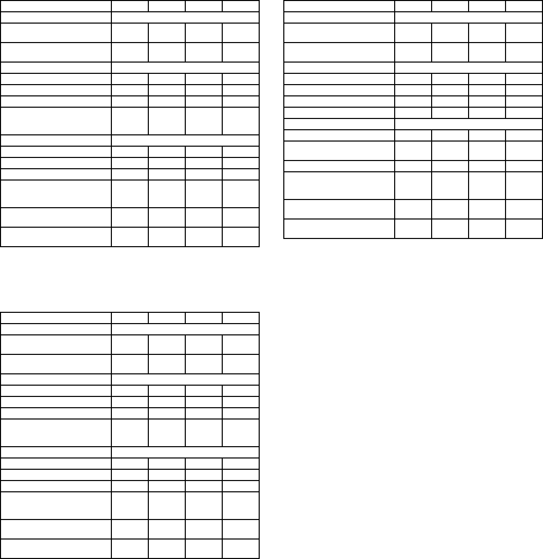
45
APPLICATION DATA — 524A180-360 UNITS (cont)
STANDARD DRIVE DATA
*Four belts shipped with unit. Use one set of 2 belts sized according to
the pulley setting.
MEDIUM-STATIC DRIVE DATA
*Four belts shipped with unit. Use one set of 2 belts sized according to
the pulley setting.
HIGH-STATIC DRIVE DATA
UNIT 524A 180 240 300 360
MOTOR DRIVE
Motor Pulley Pitch
Diameter 2.8-3.8 3.7-4.7 4.3-5.3 4.3-5.3
Pulley Factory Setting
Full Turns Open 2.5 3.0 3.0 3.0
FAN DRIVE
Pulley Pitch Dia (in.)9.0 9.4 11.0 11.0
Pulley Bore (in.)17/16 17/16 115/16 115/16
Belt No.— Section 1—A 2—B 2—B* 2—B*
Belt Pitch (in.)42.3 41.8
(2) 42.8
or
(2) 43.8
(2) 42.8
or
(2) 43.8
FAN SPEEDS (rpm)
Factory Setting 632 771 752 752
Range 537-728 679-863 682-841 674-831
Max Allowable Speed 1200 1200 1100 1100
Change per 1/2Turn o f
Moveable Motor Pulley
Flange
19.1 15.3 13.1 13.1
MAXFULL TURNS FROM
CLOSED POSITION 5666
SHAFTS CENTER
DISTANCE (in.)
10.44-
12.32
9.12-
10.99
6.67-
9.43
6.67-
9.43
UNIT 524A 180 240 300 360
MOTOR DRIVE
Motor Pulley Pitch
Diameter 3.7-4.7 4.3-5.3 4.3-5.3 4.3-5.3
Pulley Factory Setting
Full Turns Open 3.0 3.0 3.0 3.0
FAN DRIVE
Pulley Pitch Dia (in.)8.6 9.4 9.4 9.4
Pulley Bore (in.)17/16 17/16 115/16 115/16
Belt No.— Section 1—B 2—B 2—B* 2—B*
Belt Pitch (in.)41.8 41.8
(2) 38.8
or
(2) 39.8
(2) 38.8
or
(2) 39.8
FAN SPEEDS (rpm)
Factory Setting 842 881 881 881
Range 742-943 798-984 798-984 798-984
Max Allowable Speed 1200 1200 1100 1100
Change per 1/2Turn of
Moveable Motor Pulley
Flange
16.7 15.3 15.3 15.3
MAXFULL TURNS FROM
CLOSED POSITION 6666
SHAFTS CENTER
DISTANCE (in.)
10.44-
12.32
9.16-
10.99
6.67-
9.43
6.67-
9.43
UNIT 524A 180 240 300 360
MOTOR DRIVE
Motor Pulley Pitch
Diameter 4.3-5.3 4.3-5.3 4.3-5.3 4.3-5.3
Pulley Factory Setting
Full Turns Open 2.5 3.0 3.0 3.0
FAN DRIVE
Pulley Pitch Dia (in.)7.9 7.4 8.6 8.6
Pulley Bore (in.)17/16 17/16 115/16 115/16
Belt No.— Section 1—B 2—B 2—B 2—B
Belt Pitch (in.)39.8 36.8 37.8 37.8
FAN SPEEDS (rpm)
Factory Setting 1060 1118 1024 1024
Range 950-
1171
1014-
1200
873-
1075
873-
1075
Max Allowable Speed 1200 1200 1100 1100
Change per 1/2Turn of
Moveable Motor Pulley
Flange
30.8 19.4 16.7 16.7
MAXFULL TURNS FROM
CLOSED POSITION 5666
SHAFTS CENTER
DISTANCE (in.)
9.16-
10.99
8.16-
10.02
6.67-
9.43
6.67-
9.43

46
GUIDE SPECIFICATIONS — 576B300,360
COMMERCIAL AIR-COOLED CONDENSING UNITS
HVAC GUIDE SPECIFICATIONS
SIZE RANGE: 25 AND 30 TONS, NOMINAL
Bryant Model Number: 576B
PART 1 — GENERAL
1.01 SYSTEM DESCRIPTION
Outdoor-mounted, air-cooled condensing unit suitable for
on-the-ground or rooftop installation. Unit shall consist of a
semi-hermetic reciprocating compressor, an air-cooled
coil, propeller-type condenser fans, and a control box. Unit
shall discharge supply air upward as shown on contract
drawings. Unit shall be used in a refrigeration circuit to
match a packaged fan coil unit.
1.02 QUALITY ASSURANCE
A. Unit shall be rated in accordance with ARI Standard 365,
latest edition and shall be certified and listed in the latest
ARI directory.
B. Unit shall be manufactured in a facility registered to the
ISO 9001:2000 manufacturing quality standard.
C. Unit construction shall comply with latest edition of ANSI/
ASHRAE and with NEC.
D. Unit shall be constructed in accordance with UL
standards and shall carry the UL and UL, Canada label of
approval.
E. Unit cabinet shall be capable of withstanding 500-hour
salt spray exposure per ASTM B117 (scribed specimen).
F. Air-cooled condenser coils shall be leak tested at
150 psig and pressure tested at 450 psig.
1.03 DELIVERY, STORAGE AND HANDLING
Unit shall be shipped as single package only, and
shall be stored and handled per unit manufacturer’s
recommendations.
1.04 WARRANTY (FOR INCLUSION BY SPECIFYING
ENGINEER.)
PART 2 — PRODUCTS
2.01 EQUIPMENT
A. General:
Factory assembled, single piece, air-cooled condensing
unit. Contained within the unit enclosure shall be all
factory wiring, piping, controls, compressor, holding
charge (R-22), and special features required prior to field
start-up.
B. Unit Cabinet:
1. Unit cabinet shall be constructed of galvanized steel,
bonderized and coated with a prepainted, baked
enamel finish.
2. End unit access panel shall be hinged for compres-
sor and control box service access.
3. Lifting holes shall be provided to facilitate rigging.
C. Fans:
1. Condenser fans shall be direct-drive propeller type,
discharging air vertically upward.
2. Condenser fan motors shall be totally enclosed,
3-phase type with class B insulation and perma-
nently lubricated bearings.
3. Shafts shall have inherent corrosion resistance.
4. Fan blades shall be statically and dynamically
balanced.
5. Condenser fan openings shall be equipped with
PVC-coated steel wire safety guards.
D. Compressor:
1. Compressor shall be serviceable, reciprocating,
semi-hermetic type.
2. Compressor shall be equipped with an automatically
reversible oil pump, operating oil charge, suction and
discharge shutoff valves, and an insert-type, factory-
sized crankcase heater to control oil dilution.
3. Compressor shall be mounted on spring vibration
isolators with an isolation efficiency of no less than
95%.
4. Compressor speed shall not exceed 1750 rpm.
5. Compressor shall unload using suction cutoff unload-
ing (electrical solenoid unloading shall be available
as an accessory).
E. Condenser Coil:
1. Condenser coil shall be air cooled, circuited for inte-
gral subcooler.
2. Coil shall be constructed of aluminum fins mechani-
cally bonded to internally grooved, seamless copper
tubes which are then cleaned, dehydrated, and
sealed.
3. Coil shall be protected by a sheet metal casing to
eliminate the need for wind baffles for low ambient
temperature operation.
4. Coil shall be protected to avoid damage due to the
elements and vandalism.
F. Refrigeration Components:
Refrigeration circuit components shall include hot gas
muffler, high-side pressure relief device, liquid line shut-
off valve, suction and discharge shutoff valves, holding
charge of refrigerant R-22, and compressor oil.
G. Controls and Safeties:
1. Minimum control functions shall include:
a. Power and control terminal blocks.
b. Three-minute anti-short-cycling timer to prevent
compressor short-cycling.
c. Lockout on auto-reset safety until reset.
d. Capacity control on the compressor shall be by
suction cutoff unloaders in response to compres-
sor suction pressure. Electric solenoid unloading
shall be available as an accessory.
e. A 115-v solenoid shall be provided for solenoid
drop control.
f. Head pressure control to 35 F by fan cycling. One
condenser fan shall be cycled by discharge pres-
sure to maintain proper head pressure.
g. Winter start control to prevent nuisance trip-outs
at low ambient temperatures.
2. Minimum safety devices shall include:
Automatic reset (after resetting first at control circuit
power supply)
a. High discharge-pressure cutout.
b. Low suction-pressure cutout.
c. Condenser fan motors to be protected against
overload or single-phase condition by internal
overloads.

47
GUIDE SPECIFICATIONS — 576B300,360 (cont)
Manual reset at the unit
a. Low oil-pressure cutout.
b. Compressor electrical overload protection
through the use of definite-purpose contactors
and calibrated, ambient-compensated, magnetic-
trip circuit breakers. Circuit breakers shall open all
3phasesintheeventofanoverloadinanyoneof
the phases or a single-phase condition.
H. Operating Characteristics:
1. The capacity of the condensing unit shall meet or
exceed Btuh at a suction temperature of
F. The power consumption at full load shall
not exceed kW.
2. The combination of the condensing unit and the
evaporator or fan coil unit shall have a total net cool-
ing capacity of Btuh or greater at conditions
of: cfm entering-air temperature at the evapo-
rator at F wet bulb and Fdrybulb,and
air entering the condensing unit at F.
3. The system shall have an EER of Btuh/Watt
or greater at standard ARI conditions.
I. Electrical Requirements:
1. Nominal unit electrical characteristics shall be
v, 3-ph, 60 Hz. The unit shall be capable of
satisfactory operation within voltage limits of v
to v.
2. Unit electrical power shall be single point connection.
3. Unit control circuit shall contain a 24-v transformer
for unit control, with capacity to operate an indoor fan
interlock.
J. Special Features:
1. Low-Ambient Control:
Control shall regulate fan motor speed in response
to the saturated condensing temperature of the unit.
The control shall be capable of maintaining a con-
densing temperature of 100 F ± 10° F with outdoor
temperatures at –20 F (motor change required).
2. Electric Solenoid Unloader:
Unloader valve piston, coil, and hardware shall be
supplied to convert any pressure-operated compres-
sor unloader to 115-v electric unloading. Control box
or field-supplied step controller shall be provided for
electrical unloading.
3. Hot-Gas Bypass:
A hot-gas bypass valve and a 115-v pilot line sole-
noid valve shall be provided for low-load operation of
the refrigeration system.
4. Part-Winding Start:
Part-winding start shall be provided to reduce inrush
current and locked rotor amps on start-up.
5. Optional Condenser Coil Materials:
a. Pre-Coated Aluminum-Fin Coils:
Shall have a durable epoxy-phenolic coating to
provideprotectioninmildlycorrosivecoastal
environments. Coating shall be applied to the
aluminum fin stock prior to the fin stamping pro-
cess to create an inert barrier between the alumi-
num fin and copper tube. Epoxy-phenolic barrier
shall minimize galvanic action between dissimilar
metals.
b. Copper-Fin Coils:
Shall be constructed of copper-fins mechanically
bonded to copper-tubes and copper tube sheets.
Galvanized steel tube sheets shall not be accept-
able. A polymer strip shall prevent coil assembly
from contacting sheet metal coil pan to minimize
potential for galvanic corrosion between the coil
and pan. All copper construction shall provide
protection in moderate coastal environments.
c. E-Coated Aluminum-Fin Coils:
Shall have a flexible epoxy polymer coating uni-
formly applied to all coil surface areas without
material bridging between fins. Coating process
shall ensure complete coil encapsulation. Color
shall be high gloss black with gloss requirements
of 60° of 65 to 90% per ASTM D523-89. Uniform
dry film thickness from 0.8 to 1.2 mil on all surface
areas including fin edges. Superior hardness
characteristics of 2H per ASTM D3363-92A and
cross hatch adhesion of 4B-5B per ASTM D3359-
93. Impact resistance shall be up to 160 in./lb
(ASTM D2794-93). Humidity and water immersion
resistance shall be up to a minimum of 1000 and
250 hours respectively (ASTM D2247-92 and
ASTM D870-92). Corrosion durability shall
be confirmed through testing to no less than
1000 hours salt spray per ASTM B117-90. Coil
construction shall be aluminum fins mechanically
bonded to copper tubes.
6. Thermostat Controls:
a. Programmable multi-stage thermostat with 7-day
clock, holiday scheduling, large backlit display,
remote sensor capability, and Title 24 compliance.
b. Commercial Electronic Thermostat with 7-day
timeclock, auto-changeover, multi-stage capabil-
ity, and large LCD temperature display.
c. Non-programmable thermostat with fan switch
subbase.
48
GUIDE SPECIFICATIONS — 576H240-360
COMMERCIAL AIR-COOLED CONDENSING UNITS
HVAC GUIDE SPECIFICATIONS
SIZE RANGE: 20 TO 30 TONS, NOMINAL
Bryant Model Number: 576H
PART 1 — GENERAL
1.01 SYSTEM DESCRIPTION
A. Outdoor-mounted, air-cooled condensing unit suitable for
on-the-ground or rooftop installation. Unit shall have
2 independent refrigerant circuits. Unit shall consist of
semi-hermetic reciprocating compressors, an air-cooled
coil, propeller-type condenser fans, and a control box.
Unit shall discharge condenser air upward as shown on
contract drawings.
B.Unitshallbeusedinarefrigerationcircuittomatcha
packaged fan coil unit.
1.02 QUALITY ASSURANCE
A. Unit shall be rated in accordance with ARI Standard 365,
latest edition.
B. Systems up to 20 tons shall be certified and listed in the
latest ARI directory (ARI Standard 360).
C. Unit construction shall comply with latest edition of
ASHRAE and with NEC.
D. Unit shall be constructed in accordance with UL
standards and shall carry the UL and UL, Canada label
of approval.
E. Unit cabinet shall be capable of withstanding 500-hour
salt spray exposure per ASTM B117 (scribed specimen).
F. Air-cooled condenser coils shall be leak tested at
150 psig and pressure tested at 480 psig.
G. Unit shall be manufactured in facility registered to the
ISO 9001:2000 manufacturing quality standard.
1.03 DELIVERY, STORAGE AND HANDLING
Unit shall be shipped as single package only, and shall
be stored and handled per unit manufacturer’s
recommendations.
1.04 WARRANTY (FOR INCLUSION BY SPECIFYING
ENGINEER)
PART 2 — PRODUCTS
2.01 EQUIPMENT
A. General:
Factory-assembled, single-piece, air-cooled condensing
unit. Contained within the unit enclosure shall be all fac-
tory wiring, piping, controls, compressors, holding charge,
and special features required prior to field start-up.
B. Unit Cabinet:
1. Unit cabinet shall be constructed of galvanized steel,
bonderized and coated with a prepainted, baked
enamel finish.
2. Unit access panels shall be hinged for control box
service access.
3. Lifting holes shall be provided to facilitate rigging.
C. Fans:
1. Condenser fans shall be direct-driven propeller type,
discharging air vertically upward.
2. Condenser fan motors shall be 3-phase type with
class B insulation and permanently lubricated
bearings.
3. Shafts shall have inherent corrosion resistance.
4. Fan blades shall be statically and dynamically
balanced.
5. Condenser fan openings shall be equipped with
PVC-coated steel wire safety guards.
D. Compressors:
1. Compressors shall be serviceable, reciprocating,
semi-hermetic type.
2. Compressors shall be equipped with an automati-
cally reversible oil pump, operating oil charge, suc-
tion and discharge shutoff valves, and an insert-type,
factory-installed crankcase heater to control oil
dilution.
3. Compressor shall be mounted on spring vibration
isolators with an isolation efficiency of no less than
95%.
4. Compressor speed shall not exceed 1750 rpm.
5. Lead compressor shall unload using pressure-
operated suction cutoff unloading (electrical solenoid
unloading shall be available as an accessory).
E. Condenser Coil:
1. Condenser coil shall be air cooled, circuited for inte-
gral subcooler.
2. Coil shall be constructed of aluminum fins (copper
fins optional) mechanically bonded to internally
grooved, seamless copper tubes which are then
cleaned, dehydrated, and sealed.
3. Coil shall be protected by a sheet metal casing to
eliminate the need for wind baffles for low ambient
temperature operation.
4. Coil shall be protected to avoid damage due to the
elements and vandalism.
F. Refrigeration Components:
Refrigeration circuit components shall include hot gas
mufflers, hot gas bypass stub tubes, high-side pressure
relief devices, liquid line shut-off valves, suction and dis-
charge shutoff valves, holding charge, and compressor
oil.
G. Controls and Safeties:
1. Minimum control functions shall include:
a. Power and control terminal blocks.
b. Three-minute time delay protection to prevent
compressor short-cycling.
c. Lockout on auto-reset safety until reset.
d. Capacity control on the lead compressor shall be
by suction cutoff unloaders in response to com-
pressor suction pressure. Electric solenoid
unloading shall be available as an accessory.
e. Head pressure control to 50 F by fan cycling. One
condenser fan shall be cycled by ambient temper-
ature to maintain proper head pressure.
2. Minimum safety devices shall include:
a. Compressor oil pressure switches.
b. High discharge-pressure cutout.
c. Compressor overtemperature cutout.
d. Low suction-pressure cutout.
e. Condenser-fan motors to be protected against
overload or single-phase condition by internal
overloads.
f. Electrical overload protection through the use of
definite-purpose contactors and calibrated, ambi-
ent-compensated, magnetic trip circuit breakers.
Circuit breakers shall open all 3 phases in the
event of an overload in any one of the phases or a
single-phase condition.
49
GUIDE SPECIFICATIONS — 576H240-360 (cont)
H. Operating Characteristics:
1. The capacity of the condensing unit shall meet or
exceed Btuh at a suction temperature
of F. The power consumption at full load
shall not exceed kW.
2. The combination of the condensing unit and the
evaporator or fan coil unit shall have a total net cool-
ing capacity of Btuh or greater at conditions
of: cfm entering-air temperature at the evap-
orator at F wet bulb and Fdrybulb,
and air entering the condensing unit at F.
3. The system shall have an EER of Btuh/Watt
or greater at standard ARI conditions.
I. Electrical Requirements:
1. Nominal unit electrical characteristics shall
be v, 3-ph, 60 Hz. The unit shall be capable
of satisfactory operation within voltage limits
of vto v.
2. Unit electrical power shall be single-point connection.
3. Unit control circuit shall contain a 24-v transformer
for unit control, with capacity to operate an indoor-fan
interlock.
J. Special Features:
1. Low Ambient Temperature Kit:
Control shall regulate fan motor speed in response
to the saturated condensing temperature of the unit.
The control shall be capable of maintaining a con-
densing temperature of 100 F ± 10° F with outdoor
temperatures at –20 F.
2. Electric Solenoid Unloader:
Unloader valve piston, coil, and hardware shall be
supplied to convert any pressure-operated compres-
sor unloader to 115-v electric unloading. Accessory
control box or field-supplied step controller shall be
provided for control of electrical unloading.
3. Pressure-Operated Unloader:
Unloader shall be available to allow compressors to
be unloaded in response to compressor suction
pressure.
4. Optional Condenser Coil Materials:
a. Pre-Coated Aluminum-Fin Coils:
Shall have a durable epoxy-phenolic coating to
provide protection in mildly corrosive coastal envi-
ronments. Coating shall be applied to the alumi-
num fin stock prior to the fin stamping process to
create an inert barrier between the aluminum fin
and copper tube. Epoxy-phenolic barrier shall
minimize galvanic action between dissimilar
metals.
b. Copper-Fin Coils:
Shall be constructed of copper fins mechanically
bonded to copper tubes and copper tube sheets.
Galvanized steel tube sheets shall not be accept-
able. All copper construction shall provide protec-
tion in moderate coastal applications.
A polymer strip shall prevent the coil assembly
from contacting the sheet metal coil pan to
minimize the potential for galvanic corrosion
between the coil and the pan. All copper construc-
tion shall provide protection in moderate coastal
environments.
c. E-Coated Aluminum-Fin Coils:
Shall be constructed of aluminum fins mechani-
cally bonded to copper tubes. Coating process
shall have a flexible epoxy polymer coating uni-
formly applied to all coil surfaces without material
bridging between the fins. The coating process
shall ensure complete coil encapsulation. Color
shall be high-gloss black with gloss at 60° of 65%
to 90% per ASTM D523-89. Uniform dry film thick-
nessshallbe0.8milto1.2milonallsurfaces,
including the fin edges. Superior hardness char-
acteristics shall meet those requirements of 2H,
per ASTM D3363-92A. Cross-hatch adhesion
shall meet the requirements of 4B-5B, per
ASTM D3359-93. Impact resistance shall be up to
160 in./lb, per ASTM D2794-93. Humidity
resistance shall be up to a minimum of
1000 hours per ASTM D2247-92. Water immer-
sion resistance shall be up to a minimum of
250 hours per ASTM D870-92. Durability shall be
confirmed through testing to no less than
1000 hours of salt spray per ASTM B117-90.
5. Thermostat Controls:
a. Programmable multi-stage thermostat with 7-day
clock, holiday scheduling, large backlit display,
remote sensor capability, and Title 24 compliance.
b. Commercial Electronic Thermostat with 7-day
timeclock, auto-changeover, multi-stage capabil-
ity, and large LCD temperature display.
c. Non-programmable thermostat with fan switch
subbase.

50
GUIDE SPECIFICATIONS — 524A180-360
COMMERCIAL PACKAGED AIR-HANDLING UNIT
HVAC GUIDE SPECIFICATIONS
SIZE RANGE: 2,400 TO 12,000 CFM, NOMINAL AIRFLOW
15 TO 30 TONS, NOMINAL COOLING
Bryant Model Number: 524A (DIRECT-EXPANSION COIL)
PART 1 — GENERAL
1.01 SYSTEM DESCRIPTION
A. Indoor, packaged air-handling unit for use in commercial
split systems. Unit shall have a multipoise design and
shall be capable of horizontal or vertical installation on a
floor or in a ceiling, with or without ductwork. (Only verti-
cal units are to be applied without ductwork.)
B. Unit shall have a direct-expansion coil and shall be used
in a refrigerant circuit with a matching air-cooled con-
densing unit.
1.02 QUALITY ASSURANCE
A. Coils shall be designed and tested in accordance with
ASHRAE 15 Safety Code for Mechanical Refrigeration,
latest edition.
B. Unit shall be constructed in accordance with ETL and
ETL, Canada standards and shall carry the ETL and ETL,
Canada labels.
C. Unit insulation and adhesive shall comply with NFPA-90A
requirements for flame spread and smoke generation.
Insulation shall contain an EPA-registered immobilized
antimicrobial agent to effectively resist the growth of bac-
teria and fungi as proven by tests in accordance with
ASTM standards G21 and 22.
D. Unit shall be manufactured in a facility registered to the
ISO 9001:2000 manufacturing quality standard.
E. Direct-expansion coils shall be burst tested at 435 psi and
leak tested at 150 psi.
1.03 DELIVERY AND STORAGE
Units shall be stored and handled per manufacturer’s
recommendations.
PART 2 — PRODUCTS
2.01 EQUIPMENT
Indoor mounted, draw-thru, packaged air-handling unit
that can be used in a suspended horizontal configuration
or a vertical configuration. Unit shall consist of forward-
curved belt-driven centrifugal fan(s), motor and drive
assembly, prewired fan motor contactor, factory-installed
refrigerant metering devices, cooling coil, 2-in. disposable
air filters, and condensate drain pans for vertical or hori-
zontal configurations.
A. Base Unit:
1. Cabinet shall be constructed of mill-galvanized steel.
2. Cabinet panels shall be fully insulated with 1/2-in. fire-
retardant material.
3. Unit shall contain condensate drain pans for both
vertical and horizontal applications. Drain pans shall
have connections on right and left sides of unit to
facilitate field connection. Drain pans shall have the
ability to be sloped toward the right or left side of the
unit to prevent standing water from accumulating in
pans.
4. Unit shall have factory-supplied 2-in. throwaway-type
filters installed upstream from the cooling coil. Filter
access shall be from either the right or left side of the
unit.
B. Coils:
Coils shall consist of 3 rows of 3/8-in. copper tubes with
sine-wave aluminum fins bonded to the tubes by mechan-
ical expansion. Coil tubing shall be internally rifled to
maximize heat transfer. Suction and liquid line connec-
tions shall be made on the same side of the coil. Direct-
expansion coils shall feature factory-installed thermo-
static expansion valves (TXVs) for refrigerant control. The
TXVs shall be capable of external adjustment.
C. Operating Characteristics:
Unit shall be capable of providing cfm airflow at
an external static pressure of in wg.
D. Motor:
Fan motor of the size and electrical characteristics speci-
fied on the equipment schedule shall be factory supplied
and installed.
E. Special Features:
1. Alternate Motor and Drive:
An alternate motor and medium- or high-static drive
shall be available to meet the airflow and external
static pressure requirements specified on the equip-
ment schedule.
2. High-Capacity Coil:
The high capacity coil consists of 4 rows of 3/8-in.
copper tubes with sine-wave aluminum fins bonded
to the tubes by mechanical expansion. Coil tubing
shall be internally rifled to maximize heat transfer.
Suction and liquid line connections shall be made on
the same side of the coil. Direct-expansion coils shall
feature factory-installed thermostatic expansion
valves (TXVs) for refrigerant control. The TXVs shall
be capable of external adjustment.
3. External Paint:
Where conditions require, units shall be painted with
an American Sterling Gray finish.
4. Hot Water Coil:
Coil shall be 2-row, U-bend coil with copper tubes
and aluminum plate fins bonded to the tubes by
mechanical expansion. Coil shall be mounted in a
galvanized steel housing that shall be fastened to the
unit’s fan deck for blow-thru heating operation. Coil
shall have maximum working pressure of 150 psig.
5. Steam Distributing Coil:
Coil shall consist of one row of copper tubes with
aluminum plate fins, and shall have inner steam dis-
tributing tubes. Coil shall be mounted in a galvanized
steel housing and shall be fastened to the unit’s fan
deck for blow-thru heating operation. Coil shall have
maximum working pressure of 20 psig at 260 F.
6. Electric Heaters:
Heaters for nominal 240, 480, or 575-volt, 3-phase,
60 Hz power supply shall be factory-supplied for field
installation as shown on the equipment drawings.
Electric heat assembly shall be ETL agency
approved, and shall have single-point power wiring.
Heater assembly shall include contactors with 24-v
coils, power wiring, 24-v control wiring terminal
blocks, and a hinged access panel.
51
GUIDE SPECIFICATIONS — 524A180-360 (cont)
7. Air Discharge Plenum:
Plenum shall be factory supplied to provide free-blow
air distribution for vertical floor-mounted units. A
grille with moveable vanes for horizontal or vertical
airflow adjustment shall be included. Plenum hous-
ingshallbefield-installedontheunit’sfandeckfor
blow-thru air distribution.
8. Return-Air Grille:
Grille shall be factory supplied for field installation on
the unit’s return air opening.
9. Unit Subbase:
Subbase assembly shall be factory supplied for field
installation. Subbase shall elevate floor-mounted
vertical units to provide access for correct conden-
sate drain connection.
10. Economizer:
Economizer for ventilation or “free” cooling shall be
factory provided for field installation. For free cooling
applications, economizer shall be compatible with
factory-supplied thermostat; economizer dampers
shall open when outdoor air enthalpy is suitable for
free cooling. Economizer shall be compatible with
factory-supplied CO2sensor; economizer dampers
shall open via field-supplied actuator adapter when
indoor CO2level rises above predetermined set
point.
11. Overhead Suspension Package:
Package shall include necessary brackets to support
units in a horizontal ceiling installation.
12. CO2Sensor:
Sensor shall provide the ability to signal the econo-
mizer to open when the space CO2level exceeds the
predetermined set point.
13. Thermostat Controls:
a. Programmable multi-stage thermostat with 7-day
clock, holiday scheduling, large backlit display,
remote sensor capability, and Title 24 compliance.
b. Commercial Electronic Thermostat with 7-day
timeclock, auto-changeover, multi-stage capabil-
ity, and large LCD temperature display.
c. Non-programmable thermostat with fan switch
subbase.
14. Condensate Drain Trap:
Trap shall have transparent, serviceable design for
easy cleaning. Kit shall include overflow shutoff
switch and wiring harness for connection to alarm if
desired.
15. UV-C Germicidal Lamps:
a. UV-C emitters and fixtures shall be specifically
designedforuseinsideanHVACsystem.An
ASME nozzled test apparatus using a 45 F
(7.2 C) airstream moving at not less than 400 fpm
(189 liters/sec.) shall measure individual lamp
output. Lamp output at 253.7 nm shall not be less
than 10µW/cm2per inch of arc length measured
at a distance of one meter.
b. UV-C power supplies shall be high efficiency,
electric type which are matched to the emitters
and are capable of producing the specified output
intensity with an input power no more than
80 watts.
c. Emitters and fixtures shall be installed in sufficient
quantity and arranged so as to provide an equal
distribution of UV-C energy on the coil and drain
pan.
d. The minimum UV-C energy striking the leading
edge of the coil fins shall be not less than
820 µW/cm2at the closest point and through
placement, not less than 60% of that value at the
farthest point. Equal amounts are to strike the
drain pan, either directly or indirectly through
reflection.
e. Emitters and fixtures shall be installed at right
angles to the conforming lines of the coil fins,
such that through incident angle reflection, UV-C
energy strikes all target surfaces of the coil, drain
pan, and the available line of sight airstream.

Copyright 2004 Bryant Heating &Cooling Systems Printed in U.S.A. 7/04 Catalog No. 5257-604
SPECIFICATIONS SUBJECT TO CHANGE WITHOUT NOTICE
UNIT MUST BE INSTALLED IN ACCORDANCE
WITH INSTALLATION INSTRUCTIONS
